the assembly and use of tethered bilayer lipid membranes (tblms)
TRANSCRIPT

45
Dylan M. Owen (ed.), Methods in Membrane Lipids, Methods in Molecular Biology, vol. 1232,DOI 10.1007/978-1-4939-1752-5_4, © Springer Science+Business Media New York 2015
Chapter 4
The Assembly and Use of Tethered Bilayer Lipid Membranes (tBLMs)
Charles Cranfi eld , Sonia Carne , Boris Martinac , and Bruce Cornell
Abstract
Because they are fi rmly held in place, tethered bilayer lipid membranes (tBLMs) are considerably more robust than supported lipid bilayers such as black lipid membranes (BLMs) (Cornell et al. Nature 387(6633): 580–583, 1997). Here we describe the procedures required to assemble and test tethered lipid bilayers that can incorporate various lipid species, peptides, and ion channel proteins.
Key words Tethered bilayer lipid membranes , AC impedance spectroscopy , Ion channels , Lipid bilayers
1 Introduction
Tethered membranes consist of a metal electrode, typically gold, to which tethering moieties are anchored preferably via benzyl disul-fi de groups ( see Note 1 ). The tethers incorporate into one leafl et of a subsequently self-assembled lipid bilayer, thus tethering the bilayer to the metal surface [ 1 ] (Fig. 1 ). Interspersed with the teth-ers are spacer molecules that provide a scaffolding for the tether molecules. When the amphiphilic tethering molecules are inter-spersed with polar short-chained spacer molecules a volume between the metal surface and the bilayer is formed that creates an aqueous reservoir for ions crossing the membrane. Because they can be fi rmly held in place with a chemical attachment to the metal, tethered lipid bilayers are far more robust than solvent based BLMs. The formation of tBLMs is also a more predictable and controllable process than forming untethered BLMs. tBLMs remain intact for months, unlike untethered BLMs which typically have lifetimes of the order of minutes to hours.
The process of depositing smooth (<1.5 nm) ultrapure (99.9995 %) gold onto polymeric substrates with no contaminating intermediate metal layers involves considerable process development.

46
The resulting gold patterned electrodes are, however, ideally suited to the preparation of reproducible, well-sealed tethered mem-branes. The tethering chemistry is coated from an ethanol solution onto the gold surface immediately following gold deposition. This protocol describes the techniques required to use pre-prepared gold electrodes supplied from the company SDx Tethered Membranes Pty Ltd (SDx), the unique supplier in the world of such a tBLM platform. Gold patterned, chemically coated electrodes (as 25 mm × 75 mm slides (Fig. 2a )) are shipped to the user in hermiti-cally sealed foil packages in ethanol solution. This format is chosen in order to provide the user the fl exibility of forming tBLMs com-prising their choice of lipid. The coated electrodes may also be
Fig. 1 Tethered bilayer lipid membrane (tBLM) schematic
Fig. 2 Components required to form a tBLM fl ow cell. ( a ) Electrodes pre-coated with tethering chemistry. ( b ) A fl ow cell cartridge top. ( c ) Alignment jig for use when attaching the electrode to the fl ow cell cartridge ( d ) Silicon rubber pressure pad used when attaching the electrode to the fl ow cell cartridge ( e ) Aluminum pressure plate used when attaching the electrode to the fl ow cell cartridge
Charles Cranfi eld et al.

47
stored at 4 °C for >1 year. Different tether:spacer densities are offered in order to accommodate protein or peptide components of molecular weights from 1 to 350 kDa within the membrane.
2 Materials
Ready-made SDx electrodes comprise a close-packed array of 2–4 nm strands of ethylene glycol that act as spacers and 4 nm strands of ethylene glycol terminated with a C20 phytanyl that act as mem-brane tethers . Typically electrodes are provided that have 10 % tether molecules and 90 % spacer molecules. Electrodes with this ratio of tethers to spacers have been designated as T10 electrodes . T10 elec-trodes create tBLMs that are very stable with little membrane leak-age, and with the ability to incorporate up to 40 kDa of the membrane bound fraction of proteins and peptides. Although T1 electrodes provide greater capacity in the tBLM for molecular weights up to 350 kDa to penetrate the bilayer molecules, the resulting membrane is less stable. The length of the spacer molecules can also be altered. Hydrophilic spacers of hydroxyl- terminated lipid chains can stretch to the inner leafl et of the lipid bilayer membrane, or can extend only halfway to the inner leafl et (as depicted in Fig. 1 ) in order to create additional space between the gold tethering electrode and the teth-ered bilayer in order to accommodate protein loops extending beyond the membrane surface at the inner leafl et.
The SDx six-channel measurement electrodes are assembled into a fl ow cell cartridge (Fig. 4a ) which, in turn, plugs into the SDx tethaPod ™ conductance and capacitance reader (Fig. 4b ). A car-tridge preparation kit is supplied by SDx which consists of:
● Individually packaged electrodes pre-coated with tethering chemistry (Fig. 2a )
● A fl ow cell cartridge top on which is coated the gold counter electrode (Fig. 2b )
● An alignment jig for use when attaching the electrode to the fl ow-cell cartridge (Fig. 2c )
● A silicon rubber pressure pad used when attaching the elec-trode to the fl ow cell cartridge (Fig. 2d )
● An aluminum pressure plate used when attaching the electrode to the fl ow cell cartridge (Fig. 2e )
● A pressure clamp also used when attaching the electrode to the fl ow cell cartridge (Fig. 3f )
● Also supplied by SDx is a standard membrane forming lipid mixture that has been optimized to achieve the best electrical seal which comprises 3 mM ethanolic solution of a 70 %:30 %
2.1 Electrode Selection
2.2 Cartridge Preparation Kit
2.3 Solutions
Tethered Bilayer Lipid Membranes

48
mix of diether diphytanyl (C16) phosphatidyl choline:diether diphatanyl (C16) hydroxyl (mixture designated AM199 by SDx). Alternative lipid combinations may be employed pro-vided they are soluble in ethanol at 3 mM concentrations at room temperature ( see Note 2 ).
● Preferred electrolyte solution such as Phosphate Buffered Saline (PBS).
3 Methods
1. Remove six-channel electrode from its sealed foil package using tweezers. Care should be taken not to touch the six gold regions that will form the gold tethered membrane. The side of the electrode where “SDX” appears inverted is the up - side
3.1 Preparing Cartridges
Fig. 4 ( a ) Assembled fl ow cell cartridge with electrodes. The fl ow cell cartridge provides the counter electrode which is overlayed onto the six tethering electrodes with a 0.1 mm gap for perfusion of reagents and buffer solutions. ( b ) Assembled fl ow cell cartridge fi tted into a tethaPod™ AC impedance reader
Fig. 3 ( a ) The fl ow cell cartridge attached to the electrode slide on the alignment jig. ( b ) The pressure clamp used when attaching the electrode to the fl ow cell cartridge
Charles Cranfi eld et al.

49
upon which the gold has been deposited (Fig. 2a ). Allow 2–3 min for any residual ethanol to evaporate ( see Note 3 ).
2. Place electrode into alignment jig so that the inverted “SDX” on the slide overlays the inverted “SDX” on the alignment jig (Fig. 2b ). This will ensure the gold electrodes are correctly oriented.
3. Peel the thin plastic protective cover from the underside of the fl ow cell cartridge, taking care to leave the 0.1 mm fl ow cell lam-inate and adhesive layer in place .
4. Place the fl ow cell cartridge over the alignment jig with the adhesive laminate facing the electrode (Fig. 3a ). The fl ow cell cartridge should be aligned such that the numbers 1–6 on the cartridge align with the 1–6 on the alignment jig. Insert the short end of the fl ow cell cartridge nearest to well 6 into the matching slot in the alignment jig and lower the cartridge onto the electrode.
5. Press the silicon rubber pressure pad into the fl ow cell car-tridge top. Then position the aluminum pressure plate over the assembly and insert into the pressure clamp.
6. Compress by ¾ of a turn of the knob and leave for at least 1 min (Fig 3b ).
7. Gently remove the assembly from the pressure clamp. Remove the aluminum pressure plate and silicon pressure pad taking care to prevent fl ow cell cartridge separating from the electrode.
8. By gently lifting from the underside of the electrode the electrode- fl ow cell cartridge assembly can be removed intact from the alignment jig. The remaining exposed gold surfaces are not critical to bilayer formation. The functional gold teth-ering electrodes are protected within the fl ow cell cartridge assembly (Fig 4a ).
9. Once the cartridge is made it is important to attach a bilayer lipid membrane to the tethers as soon as practicable (within 1–2 min; see Note 3 ).
When forming a tBLM a solvent exchange method is employed as it permits the formation of tBLMs at low tethering ratios well beyond that possible employing liposomal fusion.
1. To well 1 add 8 μL AM199 or desired ethanolic lipid formula-tion via the circular opening in the cartridge top.
2. Wait 10 s and add 8 μL lipid solution to the second well, and wait a further 10 s before making additions to each of the subsequent four wells. A delay of 10 s provides a convenient
3.2 Creating a Tethered Bilayer Lipid Membrane Using Solvent Exchange
Tethered Bilayer Lipid Membranes
50
operational delay to permit each well to be incubated for same period of time.
3. Let each ethanolic solution of lipid incubate within the wells for exactly 2 min then rinse with 100 μL of PBS (or desired buffer solution, see Note 4 ) taking care not to introduce air bubbles into the fl ow cell chamber as this will damage membrane forma-tion. Alternative lipid mixtures may require optimisation of their concentration and assembly times to achieve the highest possible membrane seal.
4. Rinse with at least 3 × 100 μL aliquots of the PBS. After the fi rst wash with PBS time is no longer a critical factor. From the res-ervoir side of the fl ow cell cartridge remove 100 μL of the wash through solution and then repeat rinses to ensure the removal of any residual ethanol and lipids. Following formation, the assem-bled tethered bilayer must remain totally covered with aqueous solutions to prevent membrane disassociation ( see Note 5 ).
The conductance and capacitance of the tethered membrane may be measured by inserting the assembled electrode within the fl ow cell cartridge into a tethaPod™ reader. The reader simplifi es the interpretation of the AC impedance spectrum and provides a mea-sure of membrane conductance and capacitance. Typical conduc-tion values for a freshly formed membrane using AM199 in PBS are 0.35 ± 0.15 μS and capacitance values of 18 ± 2 nF at room temperature. The conductance is proportional to the ion fl ux through the membrane and the capacitance is inversely propor-tional to the membrane thickness. A signifi cant additional mea-sure using a tethaPod™ is the Goodness of Fit (GOF). This indicates the quality of match between the experimental data and a model of the tethered membrane. GOF values of less than 0.1 indicate a good match of the data to this simple model, and suggest that the membrane is homogenous. The user also has the option to employ their own models to fi t the raw impedance data.
Peptides and proteins such as alamethicin , α-hemolysin , gramicidin A , and valinomycin will spontaneously insert into pre-formed tBLMs [ 1 – 4 ]. The kinetics of their insertion can be measured by the time dependency of the increase in conduction. Although there are no established protocols for inserting ionophores into tBLMs the following guidelines should be considered:
1. Peptides dissolved in ethanol/buffer or methanol/buffer mix-tures should be less than 10 % ethanol or methanol and be thoroughly rinsed to remove any residual solvent.
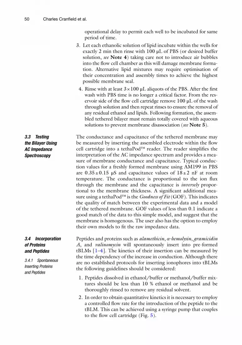
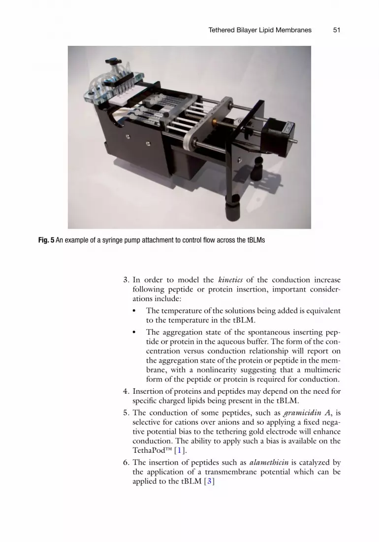
2. In order to obtain quantitative kinetics it is necessary to employ a controlled fl ow rate for the introduction of the peptide to the tBLM. This can be achieved using a syringe pump that couples to the fl ow cell cartridge (Fig. 5 ).
3.3 Testing the Bilayer Using AC Impedance Spectroscopy
3.4 Incorporation of Proteins and Peptides
3.4.1 Spontaneous Inserting Proteins and Peptides
Charles Cranfi eld et al.
51
3. In order to model the kinetics of the conduction increase following peptide or protein insertion, important consider-ations include:
● The temperature of the solutions being added is equivalent to the temperature in the tBLM.
● The aggregation state of the spontaneous inserting pep-tide or protein in the aqueous buffer. The form of the con-centration versus conduction relationship will report on the aggregation state of the protein or peptide in the mem-brane, with a nonlinearity suggesting that a multimeric form of the peptide or protein is required for conduction.
4. Insertion of proteins and peptides may depend on the need for specifi c charged lipids being present in the tBLM.
5. The conduction of some peptides, such as gramicidin A , is selective for cations over anions and so applying a fi xed nega-tive potential bias to the tethering gold electrode will enhance conduction. The ability to apply such a bias is available on the TethaPod™ [ 1 ].
6. The insertion of peptides such as alamethicin is catalyzed by the application of a transmembrane potential which can be applied to the tBLM [ 3 ]
Fig. 5 An example of a syringe pump attachment to control fl ow across the tBLMs
Tethered Bilayer Lipid Membranes
52
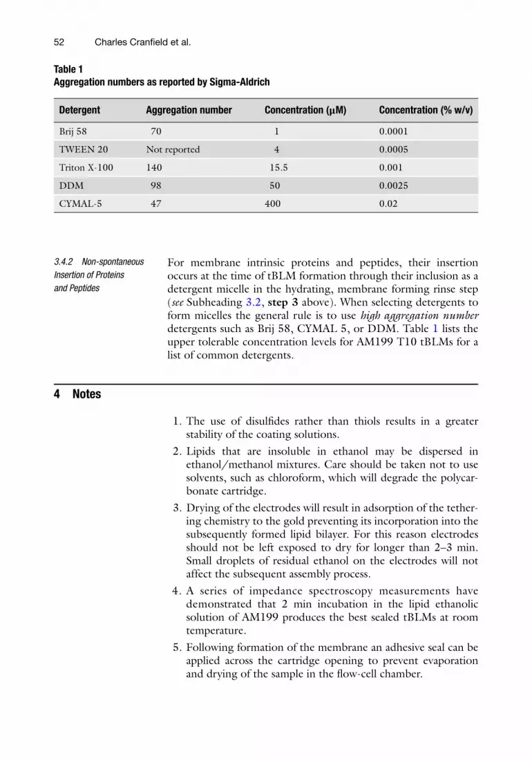
For membrane intrinsic proteins and peptides, their insertion occurs at the time of tBLM formation through their inclusion as a detergent micelle in the hydrating, membrane forming rinse step ( see Subheading 3.2 , step 3 above). When selecting detergents to form micelles the general rule is to use high aggregation number detergents such as Brij 58, CYMAL 5, or DDM. Table 1 lists the upper tolerable concentration levels for AM199 T10 tBLMs for a list of common detergents.
4 Notes
1. The use of disulfi des rather than thiols results in a greater stability of the coating solutions.
2. Lipids that are insoluble in ethanol may be dispersed in ethanol/methanol mixtures. Care should be taken not to use solvents, such as chloroform, which will degrade the polycar-bonate cartridge.
3. Drying of the electrodes will result in adsorption of the tether-ing chemistry to the gold preventing its incorporation into the subsequently formed lipid bilayer. For this reason electrodes should not be left exposed to dry for longer than 2–3 min. Small droplets of residual ethanol on the electrodes will not affect the subsequent assembly process.
4. A series of impedance spectroscopy measurements have demonstrated that 2 min incubation in the lipid ethanolic solution of AM199 produces the best sealed tBLMs at room temperature.
5. Following formation of the membrane an adhesive seal can be applied across the cartridge opening to prevent evaporation and drying of the sample in the fl ow-cell chamber.
3.4.2 Non-spontaneous Insertion of Proteins and Peptides
Table 1 Aggregation numbers as reported by Sigma-Aldrich
Detergent Aggregation number Concentration (μM) Concentration (% w/v)
Brij 58 70 1 0.0001
TWEEN 20 Not reported 4 0.0005
Triton X-100 140 15.5 0.001
DDM 98 50 0.0025
CYMAL-5 47 400 0.02
Charles Cranfi eld et al.

53
Acknowledgments
This work was supported by the Australian Research Council, the National Health and Medical Research Council of Australia (Grant 1047980). We declare that Bruce Cornell is a shareholder, and Sonia Carne is an employee, of SDx Tethered Membranes Pty Ltd .
References
1. Cornell BA, Braach-Maksvytis VLB, King LG, Osman PDJ, Raguse B, Wieczorek L, Pace RJ (1997) A biosensor that uses ion-channel switches. Nature 387(6633):580–583
2. Vockenroth IK, Atanasova PP, Jenkins ATA, Köper I (2008) Incorporation of α-hemolysin in different tethered bilayer lipid membrane archi-tectures. Langmuir 24(2):496–502
3. Yin P, Burns CJ, Osman PD, Cornell BA (2003) A tethered bilayer sensor containing alamethicin channels and its detection of amiloride based inhibitors. Biosens Bioelectron 18(4):389–397
4. Raguse B, Braach-Maksvytis V, Cornell BA, King LG, Osman PD, Pace RJ, Wieczorek L (1998) Tethered lipid bilayer membranes: for-mation and ionic reservoir characterization. Langmuir 14(3):648–659
Tethered Bilayer Lipid Membranes