the arab formation in central abu dhabi: 3-d reservoir
TRANSCRIPT
47
Arab Formation, Abu DhabiGeoArabia, Vol. 8, No. 1, 2003Gulf PetroLink, Bahrain
The Arab Formation in central Abu Dhabi:3-D reservoir architecture and static and dynamic modeling
Jürgen Grötsch, Omar Suwaina, Ghiath Ajlani,Ahmed Taher, Reyad El-Khassawneh, Stephen Lokier, Gordon Coy,
Erik van der Weerd, Shehadeh Masalmeh and Johan van Dorp
ABSTRACT
A 3-D geological model of the Kimmeridgian-Tithonian Manifa, Hith, Arab, and UpperDiyab formations in the area of the onshore Central Abu Dhabi Ridge was based on anewly established sequence stratigraphic, sedimentologic, and diagenetic model. It waspart of an inter-disciplinary study of the large sour-gas reserves in Abu Dhabi that aremainly hosted by the Arab Formation. The model was used for dynamic evaluations andrecommendations for further appraisal and development planning in the studied field.
Fourth-order aggradational and progradational cycles are composed of small-scale fifth-order shallowing-upward cycles, mostly capped by anhydrite within the Arab-ABC. Thestudy area is characterized by a shoreline progradation of the Arab Formation towardthe east-northeast marked by high-energy oolitic/bioclastic grainstones of the UpperArab-D and the Asab Oolite. The Arab-ABC, Hith, and Manifa pinch out toward thenortheast. The strongly bioturbated Lower Arab-D is an intrashelf basinal carbonateramp deposit, largely time-equivalent to the Arab-ABC. The deposition of the ManifaFormation over the Arab Formation was a major back-stepping event of the shallow-water platform before the onset of renewed progradation in the Early Cretaceous.
Well productivity in the Arab-ABC is controlled mainly by thin, permeable dolomiticstreaks in the fifth-order cycles at the base of the fourth-order cycles. This has majorimplications for reservoir management, well completion and stimulation, anddevelopment planning. Good reservoir properties have been preserved in the earlydiagenetic dolomitic streaks. In contrast, the reservoir properties of the Upper Arab-Doolitic/bioclastic grainstones deteriorate with depth due to burial diagenesis.
A rock-type scheme was established because complex diagenetic overprinting preventedthe depositional facies from being directly related to petrophysical properties. Specialcore analysis and the attribution of saturation functions to static and dynamic modelswere made on a cell-by-cell basis using the scheme and honoring the 3-D depositionalfacies and property model. The results demonstrated the importance of integratingsedimentological analysis and diagenesis with rock typing and static and dynamicmodeling so as to enhance the predictive capabilities of subsurface models.
INTRODUCTION
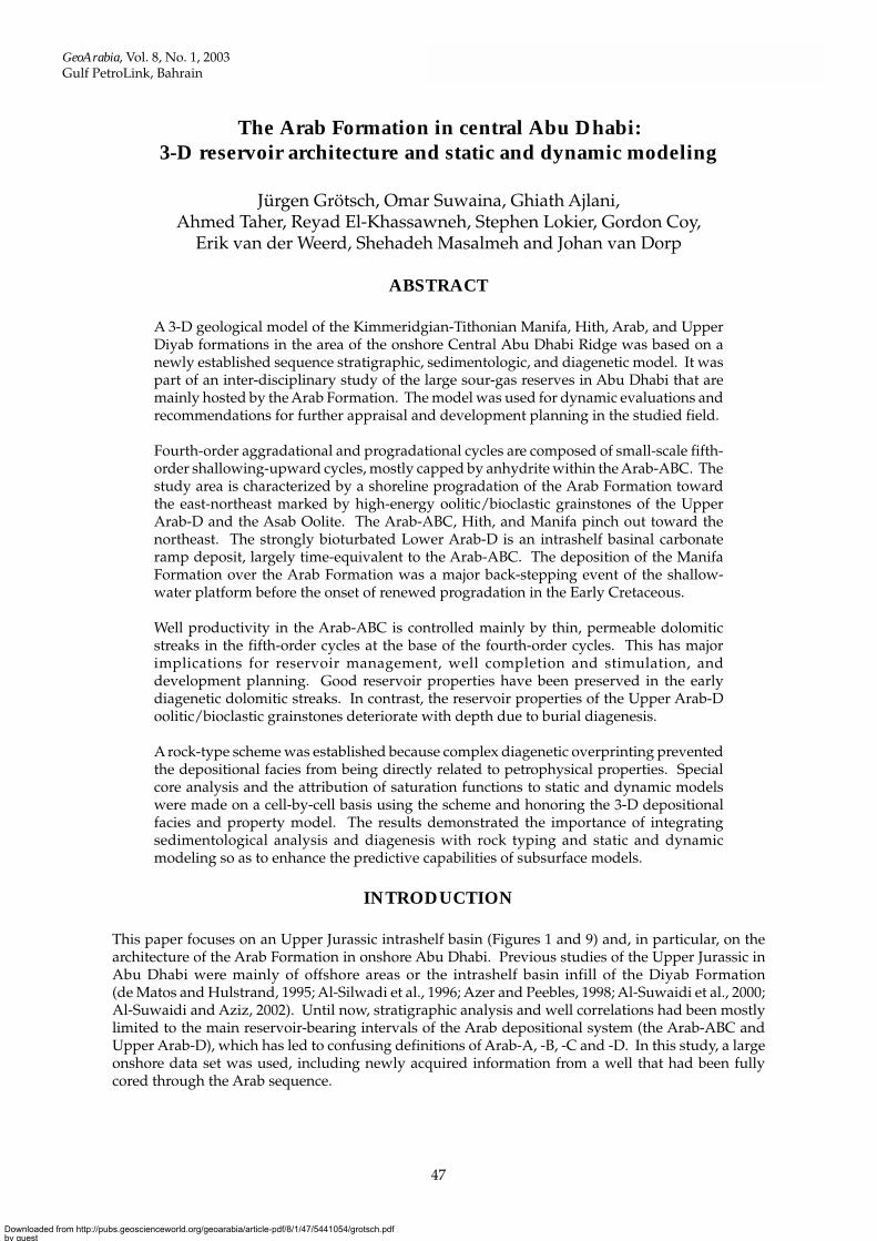
This paper focuses on an Upper Jurassic intrashelf basin (Figures 1 and 9) and, in particular, on thearchitecture of the Arab Formation in onshore Abu Dhabi. Previous studies of the Upper Jurassic inAbu Dhabi were mainly of offshore areas or the intrashelf basin infill of the Diyab Formation(de Matos and Hulstrand, 1995; Al-Silwadi et al., 1996; Azer and Peebles, 1998; Al-Suwaidi et al., 2000;Al-Suwaidi and Aziz, 2002). Until now, stratigraphic analysis and well correlations had been mostlylimited to the main reservoir-bearing intervals of the Arab depositional system (the Arab-ABC andUpper Arab-D), which has led to confusing definitions of Arab-A, -B, -C and -D. In this study, a largeonshore data set was used, including newly acquired information from a well that had been fullycored through the Arab sequence.
Downloaded from http://pubs.geoscienceworld.org/geoarabia/article-pdf/8/1/47/5441054/grotsch.pdfby gueston 21 July 2022
48
Grötsch et al.
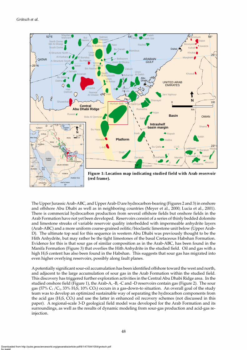
The Upper Jurassic Arab-ABC, and Upper Arab-D are hydrocarbon-bearing (Figures 2 and 3) in onshoreand offshore Abu Dhabi as well as in neighboring countries (Meyer et al., 2000; Lucia et al., 2001).There is commercial hydrocarbon production from several offshore fields but onshore fields in theArab Formation have not yet been developed. Reservoirs consist of a series of thinly bedded dolomiteand limestone streaks of variable reservoir quality interbedded with impermeable anhydrite layers(Arab-ABC) and a more uniform coarse-grained oolitic/bioclastic limestone unit below (Upper Arab-D). The ultimate top seal for this sequence in western Abu Dhabi was previously thought to be theHith Anhydrite, but may rather be the tight limestones of the basal Cretaceous Habshan Formation.Evidence for this is that sour gas of similar composition as in the Arab-ABC, has been found in theManifa Formation (Figure 3) that overlies the Hith Anhydrite in the studied field. Oil and gas with ahigh H2S content has also been found in the Habshan. This suggests that sour gas has migrated intoeven higher overlying reservoirs, possibly along fault planes.
A potentially significant sour-oil accumulation has been identified offshore toward the west and north,and adjacent to the large accumulation of sour gas in the Arab Formation within the studied field.This discovery has triggered further exploration activities in the Central Abu Dhabi Ridge area. In thestudied onshore field (Figure 1), the Arab-A, -B, -C and -D reservoirs contain gas (Figure 2). The sourgas (57% C1 /C2, 33% H2S, 10% CO2) occurs in a gas-down-to situation. An overall goal of the studyteam was to develop an optimized sustainable way of separating the hydrocarbon components fromthe acid gas (H2S, CO2) and use the latter in enhanced oil recovery schemes (not discussed in thispaper). A regional-scale 3-D geological field model was developed for the Arab Formation and itssurroundings, as well as the results of dynamic modeling from sour-gas production and acid-gas re-injection.
Central Abu Dhabi Ridge
Intrashelf basin margin
Basin
Platform
SAUDIARABIA
UNITED ARABEMIRATES
OMAN
QATAR
MoveyeidSajaa
JuwaizaKahaif
Khusub
Margham
Lekhwair
Safah
DhulaimaMezoon
Daleel
Al Barakah
Marzuk
South Dome
North DomeIdd Al-Shargi
BulHanine
MaydanMahzam
A-Structure North
A-Structure South
Al-Karkara El Bunduq
Madiq
Lekhwair E2
Salman(Sassan)
Abu Al Bukhoosh Nasr
Shuweihat
HairDalmah
Dalma
Arzanah
Satah
Jarnain
Bu Jufair
Ghasha
Belbazem
Umm Al Dholou
HailNeewat
Al Ghalan
UmmAl Anbar
Al Dabb'iya
Shanayel
Jarn Yaphour
Rumaitha
Bida Al QemzanRuwais
Bu Hasa
Huwaila
L-II-B
Zarrarah
Shah
Asab
Sahil
Arjan
Qusahwira1
2
3
Mender
L1 G
Riqeah
Haliba
Bu Qalla
Hamidiyah
Khubai
Shams
Shaybah
Dhafra
Mushash
Bu Haseer
UmmShaif
MandousBu Danah
Fateh
Rashid
Fateh SWFalah
Zakum
SaathAl Razbooth
Bin Nashef
UmmAl Salsal
Mubarraz
B
A
C
UmmAl Dalkh
ZalUmmAl Lulu
Dubai
Abu Dhabi
ARABIANGULF
0 100
km
N
52° 54°
25°N
23°
23°
25°
52°E 54° 56°
Murban-Bab
ArabianShield
CaspianSea
Arabian Sea
Med Sea
Gulf of Aden
RedSea
Arabian
Gulf
SYRIA
TURKEY
ETHIOPIA
SAUDI ARABIA
YEMEN
IRAQ
IRAN
ERITREA
SUDAN
EGYPT
JORDAN
BAHRAIN
QATAR
KUWAIT
OMANUAE
0 300km
N
Figure 1: Location map indicating studied field with Arab reservoir(red frame).
Downloaded from http://pubs.geoscienceworld.org/geoarabia/article-pdf/8/1/47/5441054/grotsch.pdfby gueston 21 July 2022
49
Arab Formation, Abu Dhabi
So far, no consensus has been reached on the lithostratigraphic nomenclature of the Upper JurassicArab Formation. No model was available that described the sequence architecture of the Formation inAbu Dhabi beyond discussions by Al-Silwadi et al. (1996), Azer and Peebles (1998), Ayoub andEn Nadi (2000), and the Arabian Plate summary of Sharland et al. (2001). A prime objective of thisstudy was to generate a comprehensive depositional and high-resolution sequence stratigraphic model.The studied field and its surroundings are ideally suited for this as the area straddles the maximumprogradational coastline during Arab times, and therefore allows analysis of lateral as well as verticalfacies changes.
In order to allow for quantitative evaluation, the integrated reservoir characterization and modelingstudy had the following objectives:
1. To assess key geological uncertainties in the Arab Formation.
2. To build a regional 3-D static model of the Arab Formation for the quantitative evaluation of reservoirarchitecture and volumetric ranges.
8,000
9,000
10,000
11,000
12,000
Arab-ABC(Qatar)
Arab-D (Fahahil)
Hith/Manifa
Diyab
Bab Mbr
Kha
raib
Lekh
wai
r F
mH
absh
an F
m
Dep
th (
ft)
Upp
er J
uras
sic
Tha
mam
a G
roup
W
asia
Gro
up
Mid
dle
Cre
tace
ous
Low
er C
reta
ceou
s
Sila
Gro
up
Nah
r U
mr
For
mat
ion
A
B
C
D
South-southwest North-northeast
CENTRAL ABU DHABI RIDGE
Oil
Gas
Water
Bb-427 Bb-2 Bb-389Bb-116
A A'
10,6
00
10,7
00 ft
.10
,500
10,4
0010
,300
10,2
0010
,100
A0 20km
N
A'
X27 X16 X02 X89
Figure 2: Schematic cross-section through the studied field. See Figure 5 for location.
Downloaded from http://pubs.geoscienceworld.org/geoarabia/article-pdf/8/1/47/5441054/grotsch.pdfby gueston 21 July 2022
50
Grötsch et al.
Gypsum, anhydrite
Shale
Oolitic grainstone
Sandstone
Dolomite
Source rock
Limestone
HYDROCARBON HABITAT AND STRATIGRAPHY
Gas
Oil
Minor oil
Aquifer
Simsima
Fiqa
Low
er/M
iddl
eJu
rass
icLo
wer
C
reta
ceou
sM
iddl
eC
reta
ceou
sU
pper
Cre
tace
ous
Upp
er
Jura
ssic
Halul
Laffan
Shilaif
Tuwayil
Ruwaidha
Bab Member
Lower Araej Uwainat
Marrat
Hamlah
MishrifMishrif
Mauddud
Nahr Umr
Shu'aiba
Kharaib
Lekhwair
Habshan
Arab-D (Lower)Arab ABCHith
Arab-D Upper
OoliteAsab
Manifa
DiyabTuwaiq Mountain Lst. HadriyaUpper Araej
Izhara
Sys
tem
Aru
ma
Was
iaT
ham
ama
Sila
Western Central and Northeast Southeast Shows
Seq.Strati-graphy(Sharland
et al., 2001) Gro
up
Hanifa
AP8
AP7
MFS J70
MFS J110
149 Ma
3. To provide input for dynamic modeling to allow for uncertainty analysis related to sour-gasproduction and acid-gas re-injection.
4. To develop the basic decision-making tools for further Arab appraisal and field developmentplanning.
5. To provide, in part, for future Arab exploration, appraisal, recovery process evaluation, and fielddevelopment planning in the Central Abu Dhabi Ridge area.
Using the Arab reservoir as an example, a workflow outline is provided of an integrated reservoircharacterization and modeling study as performed by an asset-based team using Shell’s proprietarysubsurface 3-D modeling tools, such as GEOCAP and MoReS (Grötsch et al., 2000).
GEOLOGIC SETTING
The Jurassic and Cretaceous sedimentary successions of Abu Dhabi (Figures 2 and 3) fill intrashelfbasins that developed as a result of the repeated generation of large volumes of accommodation spaceon the Arabian Plate (Murris, 1980). Until recently, the organization and architecture of the intrashelfbasin infill was poorly understood due to difficulties in dating the events, the limited and low-resolutionregional seismic data, and the traditionally used lithostratigraphic terminology (see page 52). Only inthe past few years has the complexity and depositional architecture of these individual basins begunto be unraveled with the advent of high-resolution seismic data and the application of sequence
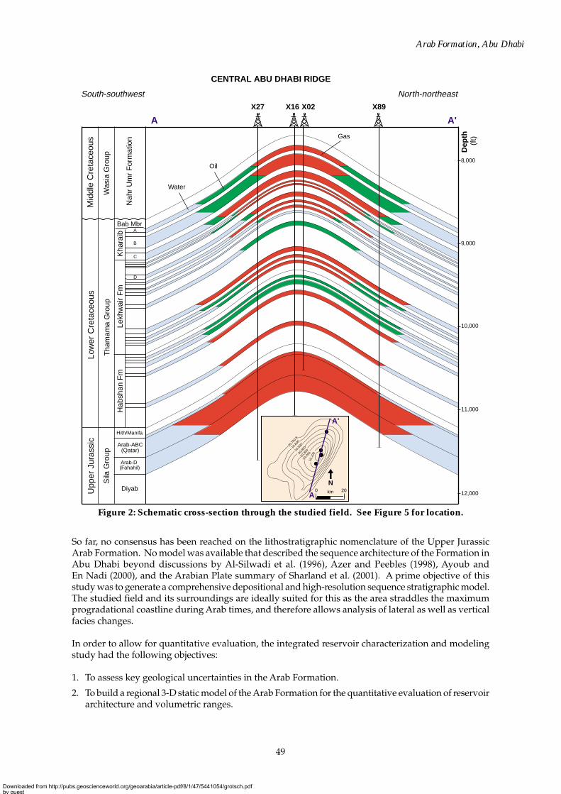
Figure 3: The Arab Formation in the context of the hydrocarbon habitat of the Central Abu DhabiRidge, showing stacked Jurassic and Cretaceous intrashelf basins.
Downloaded from http://pubs.geoscienceworld.org/geoarabia/article-pdf/8/1/47/5441054/grotsch.pdfby gueston 21 July 2022
51
Arab Formation, Abu Dhabi
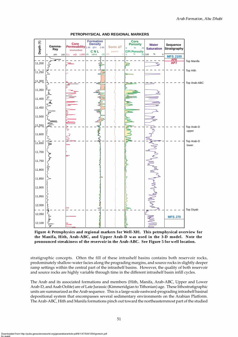
stratigraphic concepts. Often the fill of these intrashelf basins contains both reservoir rocks,predominately shallow-water facies along the prograding margins, and source rocks in slightly deeperramp settings within the central part of the intrashelf basins. However, the quality of both reservoirand source rocks are highly variable through time in the different intrashelf basin infill cycles.
The Arab and its associated formations and members (Hith, Manifa, Arab-ABC, Upper and LowerArab-D, and Asab Oolite) are of Late Jurassic (Kimmeridgian to Tithonian) age. These lithostratigraphicunits are summarized as the Arab sequence. This is a large-scale eastward-prograding intrashelf basinaldepositional system that encompasses several sedimentary environments on the Arabian Platform.The Arab-ABC, Hith and Manifa formations pinch out toward the northeasternmost part of the studied
Figure 4: Petrophysics and regional markers for Well-X01. This petrophysical overview forthe Manifa, Hith, Arab-ABC, and Upper Arab-D was used in the 3-D model. Note thepronounced streakiness of the reservoir in the Arab-ABC. See Figure 5 for well location.
PETROPHYSICAL AND REGIONAL MARKERS
Sequence Stratigraphy
MFS J100AP8AP7
MFS J70
Gamma-Ray
API 1000Dep
th (
ft)
12,100
12,050
12,000
11,800
11,850
11,900
11,950
11,750
11,700
11,650
11,600
11,550
11,450
11,400
11,350
11,300
11,250
11,200
11,500
NPHIC N L
-15
Formation Density
45
2.951.95
Core Permeability
Core Porosity
CPI PorosityUnsmoothed
mD
%
%0.1
0 20
0 20 %100 01,000µsec/m
100 0
g/ccWater
Saturation
Top Manifa
Top Hith
Top Arab-D upper
Top Arab-D lower
Top Diyab
Top Arab-ABC
Downloaded from http://pubs.geoscienceworld.org/geoarabia/article-pdf/8/1/47/5441054/grotsch.pdfby gueston 21 July 2022
52
Grötsch et al.
field. The Lower Arab-D is considered to be an intrashelf basinal deposit, time-equivalent to the Arab-ABC. Coastal deposits are characterized by oolitic grainstones of the Upper Arab-D and its youngerfacies equivalent, the Asab Oolite. In onshore and offshore Abu Dhabi, a large-scale eastwardprogradation of the coastline took place over more than 150 km. This was the expression of the infillof accommodation space in an intrashelf basin generated by a long-term Late Jurassic rise in sea level,which was part of the Tectonostratigraphic Megasequence (TMS) AP7 of Sharland et al. (2001).Slope angles in the intrashelf basin are very low (< 0.5°), which qualifies the depositional system as acarbonate ramp.
Lithostratigraphy
Historically, correlation in the Arab intrashelf basin-infill cycle (Arab-ABC, Manifa, Hith, Arab-D, andAsab Oolite) was primarily based on lithostratigraphic concepts using mainly porosity logs and datafrom reservoir development for guidance. This caused miscorrelation of reservoir units on both fieldscale and regional scales (Al-Silwadi et al., 1996). Therefore, all key marker horizons in the UpperJurassic were re-evaluated with respect to their chronostratigraphic or lithostratigraphic significancefor input into the evaluation of the seismic data and the regional 3-D geological model.
The Top Upper Jurassic (Top Manifa) is defined at the base of the high gamma-ray response below thebasal Cretaceous limestone (Base Habshan) (Figure 4). It marks the beginning of a renewed transgressivephase and has chronostratigraphic significance. It most likely corresponds to the Sharland et al. (2001)Arabian Plate tectonostratigraphic megasequence AP7/8 boundary at 149 Ma—the Late Jurassicunconformity. The Hith Formation is defined in the model area on gamma-ray markers and not simplyon base and top of the anhydrite. This was necessary as the Hith and upper Arab-ABC units becomemore anhydrite-rich toward the west, and therefore cross time lines.
The Arab Formation is traditionally divided into the Arab-A, -B, -C and Arab-D. However, definitionsof Arab-A, -B, and -C vary from field to field and do not necessarily represent the samechronostratigraphic unit. The combined Arab-ABC is here defined as the lithostratigraphic unitcomposed of high-frequency dolomite-anhydrite shallowing-upward cycles capped by the massiveLower and Upper Hith Anhydrite. The top of the Arab-D reservoir is picked at the top of the cleangamma-ray trend, which is an oolitic and bioclastic grainstone section. It coincides with the occurrenceof a black marker limestone that commonly contains pyrite. However, this marker is clearlylithostratigraphic and does not represent a time-line suitable for sequence stratigraphic analysis,although it is important in 3-D model construction (see below). The pick for the Top Diyab Formationis characterized by an increase in the gamma-ray response below the base of the Lower Arab-D(MFS J70 at 152.75 Ma after Sharland et al., 2001). Therefore, the lithostratigraphic unit of the LowerArab-D is a time-transgressive deposit of a mid- to deeper ramp environment within the Arab intrashelfbasin on the Arabian Platform.
Structural History
Pre-Cretaceous structural lineaments are one controlling factor in the development of the present-daylarge-scale structures in Abu Dhabi. Major lineament sets trend approximately north and northwest.
The N-trending lineaments are basement ridges similar to the Qatar Arch. They cross the whole ofAbu Dhabi and are offset by predominantly NW-oriented wrench-fault zones. The studied area ispart of one ridge, here named the Central Abu Dhabi Ridge. It was later tectonically overprinted byseveral anticlines (onshore) and salt domes (offshore) that contain major hydrocarbon accumulationsin Abu Dhabi.
The large-scale regional depositional architecture in the Upper Jurassic and Lower Cretaceous of AbuDhabi shows only small lateral thickness variations. This suggests that the area was tectonically stablewhile expansion of the NeoTethys was ongoing.
Downloaded from http://pubs.geoscienceworld.org/geoarabia/article-pdf/8/1/47/5441054/grotsch.pdfby gueston 21 July 2022
53
Arab Formation, Abu Dhabi
A major phase of tectonic activity in eastern Abu Dhabi occurred in the mid and Late Cretaceous(Aptian to Maastrichtian) in response to the closure of NeoTethys and continental collision with theArabian Plate. During the deposition of the Middle Cretaceous Wasia Group, the first sign of growthof present-day major structures is indicated by slightly reduced formation thicknesses in several fields,and by thickening in the Hamra syncline of southeastern Abu Dhabi. This was probably the initialresponse of the foreland to the onset of collision and the downwarping of the eastern Emirates andOman due to crustal thickening in the Oman Mountains. Progressive infill in this area took placeduring deposition of the Mishrif, Laffan, and Halul formations (Figure 3) in Turonian to Santoniantimes. The increased flexing of the foreland area created small extensional faults in a NNW-strikedirection toward the end of this period.
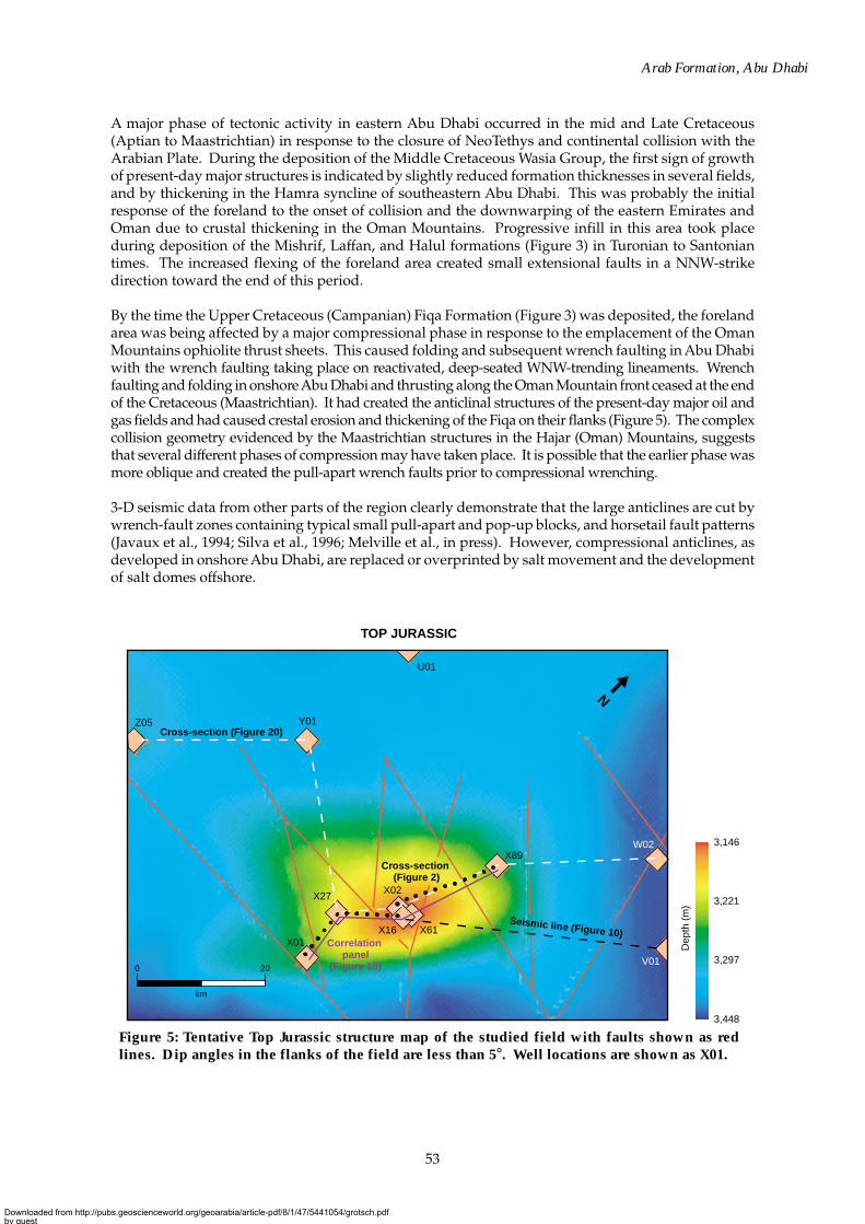
By the time the Upper Cretaceous (Campanian) Fiqa Formation (Figure 3) was deposited, the forelandarea was being affected by a major compressional phase in response to the emplacement of the OmanMountains ophiolite thrust sheets. This caused folding and subsequent wrench faulting in Abu Dhabiwith the wrench faulting taking place on reactivated, deep-seated WNW-trending lineaments. Wrenchfaulting and folding in onshore Abu Dhabi and thrusting along the Oman Mountain front ceased at the endof the Cretaceous (Maastrichtian). It had created the anticlinal structures of the present-day major oil andgas fields and had caused crestal erosion and thickening of the Fiqa on their flanks (Figure 5). The complexcollision geometry evidenced by the Maastrichtian structures in the Hajar (Oman) Mountains, suggeststhat several different phases of compression may have taken place. It is possible that the earlier phase wasmore oblique and created the pull-apart wrench faults prior to compressional wrenching.
3-D seismic data from other parts of the region clearly demonstrate that the large anticlines are cut bywrench-fault zones containing typical small pull-apart and pop-up blocks, and horsetail fault patterns(Javaux et al., 1994; Silva et al., 1996; Melville et al., in press). However, compressional anticlines, asdeveloped in onshore Abu Dhabi, are replaced or overprinted by salt movement and the developmentof salt domes offshore.
Figure 5: Tentative Top Jurassic structure map of the studied field with faults shown as redlines. Dip angles in the flanks of the field are less than 5°. Well locations are shown as X01.
Seismic line (Figure 10)
Z05
U01
Y01
X89
X02
X61
V01
W02
X16
X27
X01
Cross-section (Figure 20)
Cross-section (Figure 2)
Correlation panel
(Figure 19)0
km
20
N
TOP JURASSIC
3,146
3,221
3,297
3,448
Dep
th (
m)
Downloaded from http://pubs.geoscienceworld.org/geoarabia/article-pdf/8/1/47/5441054/grotsch.pdfby gueston 21 July 2022
54
Grötsch et al.
The Maastrichtian Simsima Formation filled part of the residual morphology over the major tectonicstructures. It is thicker in the west due to isostatic uplift of the eastern area during the Maastrichtianthat caused exposure at the mountain front between Al ‘Ain and Ra’s Al-Khaima. Subsequent burialand uplift, with tilting toward the west, plus compaction and possible ongoing growth of some anticlinesdue to movement on deep-seated salt cores, continued into the early Tertiary. The Zagros compressionin the Oligocene caused preferential tilting down toward the northeast.
Older and deeper structural elements may also have controlled some of the main depositional events.Examples are the edge of the Upper Jurassic Hith Anhydrite and the Asab Oolite with its clinoforms,and the Lower Cretaceous progradation of the Habshan Formation with a north-northwesterly strikedirection. The main axis of the Shu’aiba intrashelf basin is oriented northwest and therefore deviatesslightly from the general northerly strike direction.
Hydrocarbon System
Over long distances, significant changes in hydrocarbon fill (gas–condensate–light oil) occur in theArab Formation on the Central Abu Dhabi Ridge. On a smaller scale, the Arab-ABC consists of thinlylayered beds of dolomite and anhydrite. Both examples suggest the possibility of lateral and verticalcompartmentalization in the reservoir.
The principal source rock is the prolific underlying Diyab Formation, and possibly other unknownsources (Figure 3). The Diyab Formation is directly overlain by the Arab reservoirs (Al-Suwaidi et al.,2000; Al-Suwaidi and Aziz, 2002). It is part of the pre-Arab intrashelf basin infill. However, unlike theArab Formation, the progradational direction in Abu Dhabi during the Oxfordian to lowerKimmeridgian was from east to west. This is the opposite direction to that in the upper Kimmeridgianto Tithonian Arab intrashelf-basin infill. The Diyab Formation in onshore Abu Dhabi is still within thegas-generating window and the charge may be ongoing.
The Diyab Formation is subdivided into the Upper, Middle, and Lower Diyab lithological units. TheLower Diyab provides more than 90 percent of the Diyab source potential and is the main hydrocarbon-generating interval. It has a very high gamma-ray log response and relatively low sonic velocity. Inwestern Abu Dhabi it is particularly rich in organic matter with a present-day average Total OrganicCarbon (TOC) value of up to 1.5 weight percent. However, the original source rock potential of theLower Diyab must have been substantially higher. The potential of the Middle Diyab is more moderatewith an effective source-rock thickness ranging from 25 to 75 ft, with the greatest thickness in the west.The Upper Diyab is organically lean and has a residual TOC of less than 0.8 weight percent in much ofAbu Dhabi.
The trapping mechanism for the gas is mainly structural with a stratigraphic component due to theArab-ABC pinch-out toward the eastern edge of the studied field. Wrench faulting has been interpretedfrom 3-D seismic data in several onshore and offshore fields in Abu Dhabi and is likely to also occur inthe studied field where 3-D seismic acquisition has only recently started. As a third component, it isexpected that lateral fault sealing in a ENE-direction supported trapping of hydrocarbons. The HithAnhydrite and anhydrite interbedded within the Arab-ABC reservoir can form additionalintraformational seals or areally limited barriers to vertical flow.
Significant hydrocarbon generation and expulsion started in southwestern onshore Abu Dhabi at theend of the Maastrichtian. The major period of hydrocarbon expulsion was during the early Tertiary inmost onshore areas. The present-day maturity of the Diyab Formation indicates that the studied fieldis still within the gas generation window, as are other onshore structures. However, most of the originalsource-rock potential is largely exhausted, which is consistent with the relatively low source-rockpotential yields recorded from core material. Vertical migration along wrench faults is assumed to bethe main transport path for the hydrocarbons, with an additional lateral component being especiallyimportant for the Arab reservoirs.
Downloaded from http://pubs.geoscienceworld.org/geoarabia/article-pdf/8/1/47/5441054/grotsch.pdfby gueston 21 July 2022
55
Arab Formation, Abu Dhabi
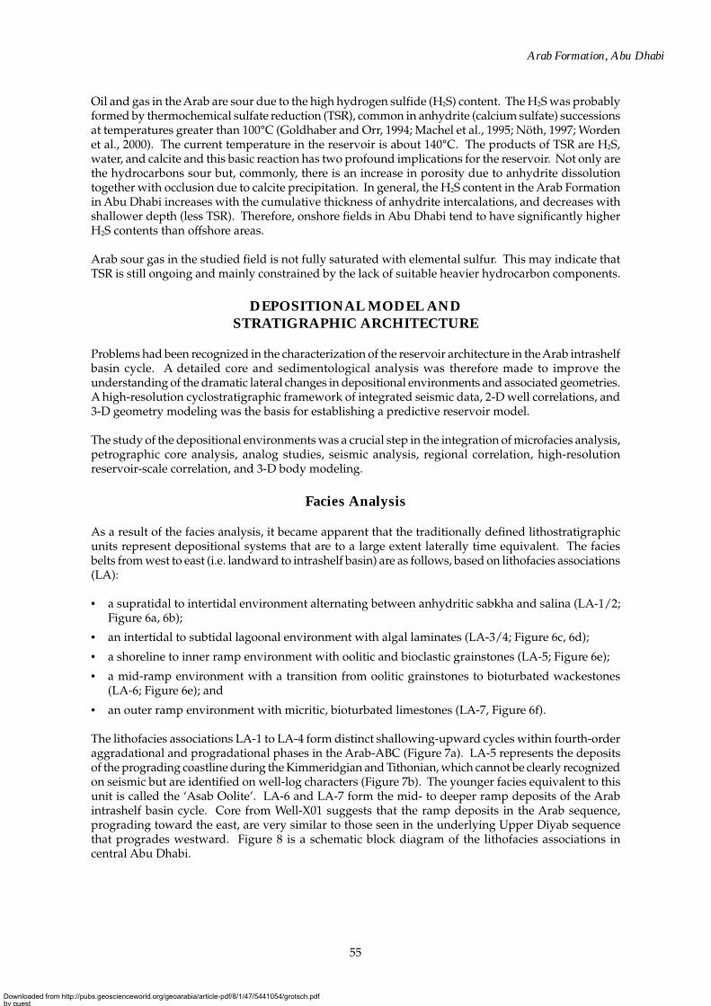
Oil and gas in the Arab are sour due to the high hydrogen sulfide (H2S) content. The H2S was probablyformed by thermochemical sulfate reduction (TSR), common in anhydrite (calcium sulfate) successionsat temperatures greater than 100°C (Goldhaber and Orr, 1994; Machel et al., 1995; Nöth, 1997; Wordenet al., 2000). The current temperature in the reservoir is about 140°C. The products of TSR are H2S,water, and calcite and this basic reaction has two profound implications for the reservoir. Not only arethe hydrocarbons sour but, commonly, there is an increase in porosity due to anhydrite dissolutiontogether with occlusion due to calcite precipitation. In general, the H2S content in the Arab Formationin Abu Dhabi increases with the cumulative thickness of anhydrite intercalations, and decreases withshallower depth (less TSR). Therefore, onshore fields in Abu Dhabi tend to have significantly higherH2S contents than offshore areas.
Arab sour gas in the studied field is not fully saturated with elemental sulfur. This may indicate thatTSR is still ongoing and mainly constrained by the lack of suitable heavier hydrocarbon components.
DEPOSITIONAL MODEL ANDSTRATIGRAPHIC ARCHITECTURE
Problems had been recognized in the characterization of the reservoir architecture in the Arab intrashelfbasin cycle. A detailed core and sedimentological analysis was therefore made to improve theunderstanding of the dramatic lateral changes in depositional environments and associated geometries.A high-resolution cyclostratigraphic framework of integrated seismic data, 2-D well correlations, and3-D geometry modeling was the basis for establishing a predictive reservoir model.
The study of the depositional environments was a crucial step in the integration of microfacies analysis,petrographic core analysis, analog studies, seismic analysis, regional correlation, high-resolutionreservoir-scale correlation, and 3-D body modeling.
Facies Analysis
As a result of the facies analysis, it became apparent that the traditionally defined lithostratigraphicunits represent depositional systems that are to a large extent laterally time equivalent. The faciesbelts from west to east (i.e. landward to intrashelf basin) are as follows, based on lithofacies associations(LA):
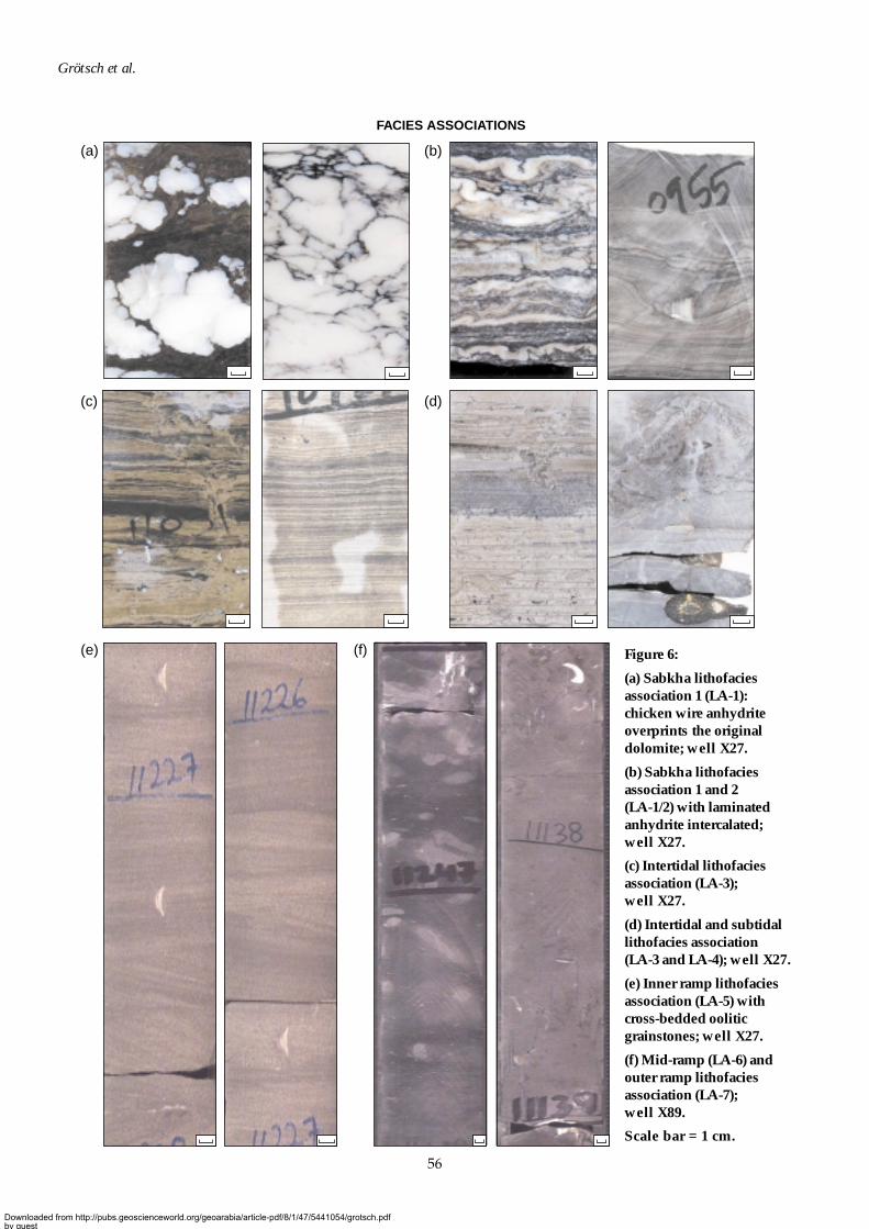
• a supratidal to intertidal environment alternating between anhydritic sabkha and salina (LA-1/2;Figure 6a, 6b);
• an intertidal to subtidal lagoonal environment with algal laminates (LA-3/4; Figure 6c, 6d);
• a shoreline to inner ramp environment with oolitic and bioclastic grainstones (LA-5; Figure 6e);
• a mid-ramp environment with a transition from oolitic grainstones to bioturbated wackestones(LA-6; Figure 6e); and
• an outer ramp environment with micritic, bioturbated limestones (LA-7, Figure 6f).
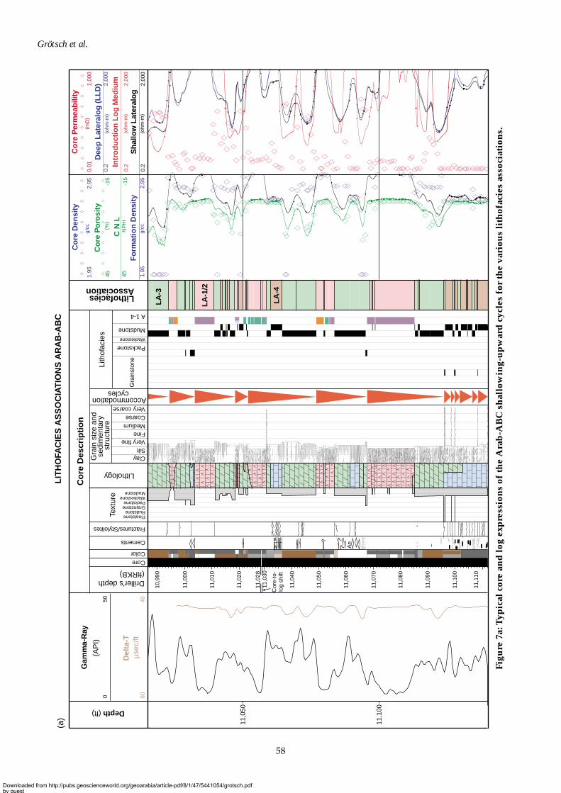
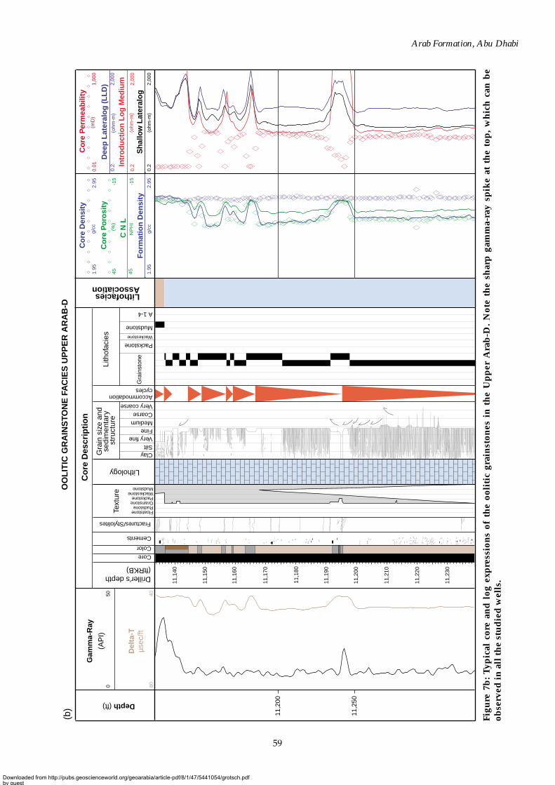
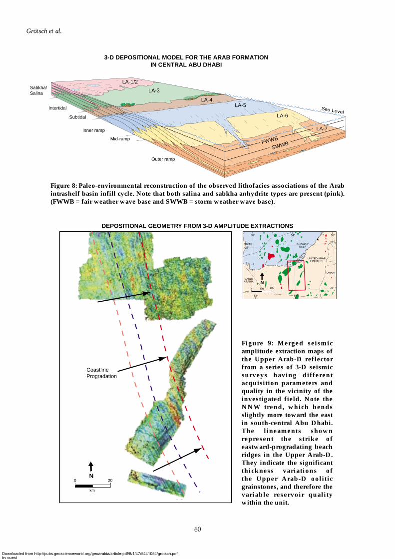
The lithofacies associations LA-1 to LA-4 form distinct shallowing-upward cycles within fourth-orderaggradational and progradational phases in the Arab-ABC (Figure 7a). LA-5 represents the depositsof the prograding coastline during the Kimmeridgian and Tithonian, which cannot be clearly recognizedon seismic but are identified on well-log characters (Figure 7b). The younger facies equivalent to thisunit is called the ‘Asab Oolite’. LA-6 and LA-7 form the mid- to deeper ramp deposits of the Arabintrashelf basin cycle. Core from Well-X01 suggests that the ramp deposits in the Arab sequence,prograding toward the east, are very similar to those seen in the underlying Upper Diyab sequencethat progrades westward. Figure 8 is a schematic block diagram of the lithofacies associations incentral Abu Dhabi.
Downloaded from http://pubs.geoscienceworld.org/geoarabia/article-pdf/8/1/47/5441054/grotsch.pdfby gueston 21 July 2022
56
Grötsch et al.
FACIES ASSOCIATIONS
(a)
(c)
(e) (f)
(b)
(d)
Figure 6:
(a) Sabkha lithofaciesassociation 1 (LA-1):chicken wire anhydriteoverprints the originaldolomite; well X27.
(b) Sabkha lithofaciesassociation 1 and 2(LA-1/2) with laminatedanhydrite intercalated;well X27.
(c) Intertidal lithofaciesassociation (LA-3);well X27.
(d) Intertidal and subtidallithofacies association(LA-3 and LA-4); well X27.
(e) Inner ramp lithofaciesassociation (LA-5) withcross-bedded ooliticgrainstones; well X27.
(f) Mid-ramp (LA-6) andouter ramp lithofaciesassociation (LA-7);well X89.
Scale bar = 1 cm.
Downloaded from http://pubs.geoscienceworld.org/geoarabia/article-pdf/8/1/47/5441054/grotsch.pdfby gueston 21 July 2022
57
Arab Formation, Abu Dhabi
Seismic Stratigraphy and Geometries
As 3-D seismic data are not yet available from the field, the seismic analysis was based on a few 2-Dseismic lines of varying vintage and on 3-D seismic from adjacent fields.
The evaluation of impedance contrast and 1-D synthetic seismograms from several wells suggeststhat the top Arab-D or its lateral equivalent, the top Asab Oolite, is the main mappable reflection in theArab succession in central Abu Dhabi. The acoustic response can be explained by a negative impedancecontrast between the tight lime-mudstones of the lowermost Arab-ABC and the porous UpperArab-D oolitic grainstones (15–50 m thick). Laterally, the transition is from the tight basal Cretaceouslimestones of the Habshan Formation to the porous Asab Oolite. However, the seismic interpretationis complicated, as the amplitudes created at these boundaries are rather weak due to the low averagevelocity contrast between the Arab-ABC and the Upper Arab-D. Nevertheless, results show that themain seismic reflection at the Arab level is a lithostratigraphic boundary not a chronostratigraphicboundary and this hampers a sequence stratigraphic analysis based only on seismic.
The acoustic impedance inversion on a NE-trending 2-D siesmic line across the field (Figure 10)highlights the presence of the porous Asab Oolite zone in the northeast. It also suggests that low-angle clinoforms occur in the Lower Arab-D.
2-D synthetic seismic was generated using the same seismic section, together with the depositionalgeometries to be expected from the sequence stratigraphic model (see below) and the first iteration ofthe 3-D static model. The interpretation of the original 2-D seismic line and the 2-D synthetic seismicmodeling using porosity data from wells and the model, supported the presence of low-angle eastward-prograding clinoforms in the Lower Arab-D, indicating the infill of the intrashelf basin morphology.Sensitivity tests with varying degrees of noise suggested that prograding clinoforms could be imaged,despite low-porosity contrasts in the Lower Arab-D.
The 2-D synthetic seismic was also used to investigate the imaging of small-scale, NS-oriented ridgesof oolitic grainstones in the Upper Arab-D and the younger facies-equivalent of the Asab Oolite. Thesynthetic seismic model was constrained based on observed thickness variations in the Upper Arab-Dfrom core (15–50 m), and velocity contrasts from the well data. The ridges, recognizable from 3-Dseismic surveys in Abu Dhabi (Figure 9), are visible on the 2-D synthetic seismic (Figure 10) and givesupport to the depositional model and its sequence stratigraphic interpretation. The ridges are orientednorth-northwest, parallel to the paleocoastline of the Arab intrashelf basin (Figures 1 and 9). Thus,although the seismic data is sparse, it supports the interpretation of the reservoir architecture.
A comparison of the 3-D seismic amplitude extraction maps with the flattened 2-D seismic data alongthe intrashelf basin margin indicated a good match with the ridge geometries and the spacing observedbetween the ridges (Figure 10). This suggested that the ridge spacing in Central Abu Dhabi was recordinghigh-frequency cyclicity and trends in progradational and aggradational phases of the accommodationspace infill within the intrashelf basin. In addition, the data on ridge spacing can be used as a quantitativeinput for predictive 3-D modeling (Figure 11), as petrographic analysis (discussed below) indicated thatthe reservoir quality in the Upper Arab-D was a function of the abundance of ooids.
SEQUENCE STRATIGRAPHY
The Arab intrashelf basin-infill cycle (including Upper Arab-D, Lower Arab-D, Arab-ABC, Manifa,Hith, and Asab Oolite) is a major depositional system that progrades from west to east through centralAbu Dhabi (Figure 12). This is in the opposite direction to the intrashelf basin cycle of the underlyingDiyab Formation (de Matos and Hulstrand, 1995; Al-Suwaidi et al., 2000). In a chronostratigraphicframework, the dolomite-anhydrite shallowing-upward cycles of the Arab-ABC are time-equivalentto the Upper Arab-D oolitic grainstone belt. This formed the progradational coastline during theKimmeridgian and Tithonian and its trend can be derived from the seismic data (Figure 9). The LowerArab-D (equivalent to the Fahahil Formation) forms the time-equivalent ramp deposit leading intothe intrashelf basin center.
Downloaded from http://pubs.geoscienceworld.org/geoarabia/article-pdf/8/1/47/5441054/grotsch.pdfby gueston 21 July 2022
58
Grötsch et al.
#
??
An
An
An
?
Fo
rmat
ion
Den
sity
LIT
HO
FAC
IES
AS
SO
CIA
TIO
NS
AR
AB
-AB
C
LA
-3
LA
-1/2
LA
-4
Depth (ft)
Driller's depth (ftRKB)
11,0
50
11,1
00
11,1
00
11,1
10
11,0
90
11,0
80
11,0
70
11,0
60
11,0
50
11,0
40
11,0
2811
,030
11,0
20
11,0
10
11,0
00
10,9
90
Gam
ma-
Ray
(AP
I)50
0
Del
ta-T
8040
ClaySiltVery fineFine
CoreColor
Cements
Fractures/Stylolites
MediumCoarse
Wackestone
WackestonePackstoneGrainstoneRudstoneFloatstone
Mudstone
Mudstone
Packstone
Gra
inst
one
Very coarse
Accommodation cycles
Lith
ofac
ies
Lithology
Gra
in s
ize
and
sedi
men
tary
st
ruct
ure
Lithofacies Association
(ohm
-m)
(ohm
-m)
(ohm
-m)
(mD
)
Dee
p L
ater
alo
g (
LL
D)
Intr
od
uct
ion
Lo
g M
ediu
m
Sh
allo
w L
ater
alo
g
Co
re D
ensi
tyC
ore
Per
mea
bili
ty
(a)
1.95
(%)
NP
HI
C N
L
Co
re P
oro
sity
4545-1
5
-15
1.95
2.95
0.2
2,00
0
0.2
2,00
0
0.2
2,00
0
0.01
1,00
0
2.95
Cor
e-to
-lo
g sh
ift
Co
re D
escr
ipti
on
Text
ure
g/cc
g/cc
µsec
/ft
A 1-4
Figu
re 7
a: T
ypic
al c
ore
and
log
exp
ress
ion
s of
the
Ara
b-A
BC
sh
allo
win
g-u
pw
ard
cyc
les
for
the
vari
ous
lith
ofac
ies
asso
ciat
ion
s.
Downloaded from http://pubs.geoscienceworld.org/geoarabia/article-pdf/8/1/47/5441054/grotsch.pdfby gueston 21 July 2022
59
Arab Formation, Abu Dhabi
11,2
30
11,2
20
11,2
10
11,2
00
11,1
90
11,1
80
11,1
70
11,1
60
11,1
50
11,1
40
py p
y
py p
yp
yp
yp
y
py A
n
An
An
An
An
An
6 6
6
6
6 6
6
6
6
66
6
6
6
6
6
6
6
6 6
6
6
6
6
6
6
6
6
6
% %
(b)
Gra
in s
ize
and
sedi
men
tary
st
ruct
ure
Fo
rmat
ion
Den
sity
(%)
(ohm
-m)
(ohm
-m)
(ohm
-m)
(mD
)
NP
HI
C N
L
Dee
p L
ater
alo
g (
LL
D)
Intr
od
uct
ion
Lo
g M
ediu
m
Sh
allo
w L
ater
alo
g1.
95
4545-1
5
-15
1.95
2.95
0.2
2,00
0
0.2
2,00
0
0.2
2,00
0
0.01
1,00
0
2.95
g/cc
g/cc
ClaySiltVery fineFine
Color
Cements
Fractures/Stylolites
MediumCoarseVery coarse
Accommodation cycles
Lith
ofac
ies
Lithology
Lithofacies Association
Co
re D
escr
ipti
on
Text
ure
Core
Gam
ma-
Ray
(AP
I)50
0
Del
ta-T
8040
µsec
/ft
Depth (ft)
Driller's depth (ftRKB)
Co
re D
ensi
ty
Co
re P
oro
sity
Co
re P
erm
eab
ility
OO
LIT
IC G
RA
INS
TON
E F
AC
IES
UP
PE
R A
RA
B-D
11,2
00
11,2
50
Wackestone
Mudstone
Packstone
Gra
inst
one
A 1-4
WackestonePackstoneGrainstoneRudstoneFloatstone
Mudstone
Figu
re 7
b:
Typ
ical
cor
e an
d l
og e
xpre
ssio
ns
of t
he
ooli
tic
grai
nst
ones
in
th
e U
pp
er A
rab
-D.
Not
e th
e sh
arp
gam
ma-
ray
spik
e at
th
e to
p,
wh
ich
can
be
obse
rved
in a
ll th
e st
ud
ied
wel
ls.
Downloaded from http://pubs.geoscienceworld.org/geoarabia/article-pdf/8/1/47/5441054/grotsch.pdfby gueston 21 July 2022
60
Grötsch et al.
Coastline Progradation
DEPOSITIONAL GEOMETRY FROM 3-D AMPLITUDE EXTRACTIONS
0 20
km
N
SAUDIARABIA
UNITED ARABEMIRATES
OMAN
QATAR ARABIANGULF
0 100km
N
52° 54°
25°
23°
23°
25°
52° 54° 56°
3-D DEPOSITIONAL MODEL FOR THE ARAB FORMATIONIN CENTRAL ABU DHABI
Sea Level
Outer ramp
FWWB
SWWBMid-ramp
Inner ramp
Subtidal
Sabkha/Salina
Intertidal
LA-1/2
LA-3
LA-4LA-5
LA-7
LA-6
Figure 8: Paleo-environmental reconstruction of the observed lithofacies associations of the Arabintrashelf basin infill cycle. Note that both salina and sabkha anhydrite types are present (pink).(FWWB = fair weather wave base and SWWB = storm weather wave base).
Figure 9: Merged seismicamplitude extraction maps ofthe Upper Arab-D reflectorfrom a series of 3-D seismicsurveys having differentacquisition parameters andquality in the vicinity of theinvestigated field. Note theNNW trend, which bendsslightly more toward the eastin south-central Abu Dhabi.The lineaments shownrepresent the strike ofeastward-progradating beachridges in the Upper Arab-D.They indicate the significantthickness variations ofthe Upper Arab-D ooliticgrainstones, and therefore thevariable reservoir qualitywithin the unit.
Downloaded from http://pubs.geoscienceworld.org/geoarabia/article-pdf/8/1/47/5441054/grotsch.pdfby gueston 21 July 2022
61
Arab Formation, Abu Dhabi
3-D Seismic
2-D Seismic
Well-X61
Hith Edge
Well-V01
0 4 128 16 20 24
00
1
2
3
1 32 4 5 6
28
Progradation (km) as derived from 3-D seismic
Abu
ndan
ce
Distance between Ridges (km)
ARAB SHELF EDGE WITH PROGRADING OOLITE RIDGES
RIDGE HISTOGRAM
Southwest Northeast
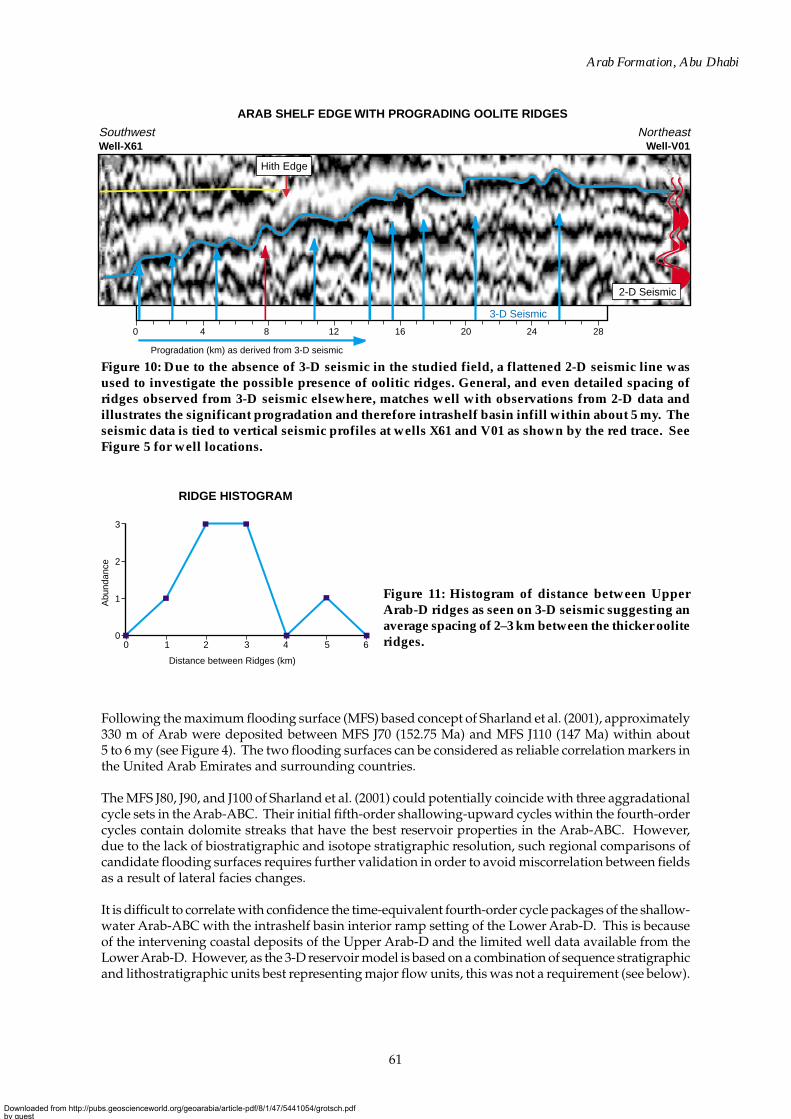
Following the maximum flooding surface (MFS) based concept of Sharland et al. (2001), approximately330 m of Arab were deposited between MFS J70 (152.75 Ma) and MFS J110 (147 Ma) within about5 to 6 my (see Figure 4). The two flooding surfaces can be considered as reliable correlation markers inthe United Arab Emirates and surrounding countries.
The MFS J80, J90, and J100 of Sharland et al. (2001) could potentially coincide with three aggradationalcycle sets in the Arab-ABC. Their initial fifth-order shallowing-upward cycles within the fourth-ordercycles contain dolomite streaks that have the best reservoir properties in the Arab-ABC. However,due to the lack of biostratigraphic and isotope stratigraphic resolution, such regional comparisons ofcandidate flooding surfaces requires further validation in order to avoid miscorrelation between fieldsas a result of lateral facies changes.
It is difficult to correlate with confidence the time-equivalent fourth-order cycle packages of the shallow-water Arab-ABC with the intrashelf basin interior ramp setting of the Lower Arab-D. This is becauseof the intervening coastal deposits of the Upper Arab-D and the limited well data available from theLower Arab-D. However, as the 3-D reservoir model is based on a combination of sequence stratigraphicand lithostratigraphic units best representing major flow units, this was not a requirement (see below).
Figure 10: Due to the absence of 3-D seismic in the studied field, a flattened 2-D seismic line wasused to investigate the possible presence of oolitic ridges. General, and even detailed spacing ofridges observed from 3-D seismic elsewhere, matches well with observations from 2-D data andillustrates the significant progradation and therefore intrashelf basin infill within about 5 my. Theseismic data is tied to vertical seismic profiles at wells X61 and V01 as shown by the red trace. SeeFigure 5 for well locations.
Figure 11: Histogram of distance between UpperArab-D ridges as seen on 3-D seismic suggesting anaverage spacing of 2–3 km between the thicker ooliteridges.
Downloaded from http://pubs.geoscienceworld.org/geoarabia/article-pdf/8/1/47/5441054/grotsch.pdfby gueston 21 July 2022
62
Grötsch et al.
Cyclostratigraphy
The predominantly intertidal to supratidal environments of the Arab-ABC show a distinct high-frequency cycle-stacking pattern (see also Azer and Peebles, 1998). It is a reflection of alternatingaggradational and progradational periods, and it is therefore a function of changes in theaccommodation space through time related to the intrashelf basin infill (Figure 12).
The shallowing-upward cycles have a predominantly dolomitic intertidal facies at the base and arecapped by playa or sabkha-type anhydrite, often with signs of subaerial exposure. Diageneticoverprinting of individual cycles can affect the underlying sediment, and cause cycle amalgamation.
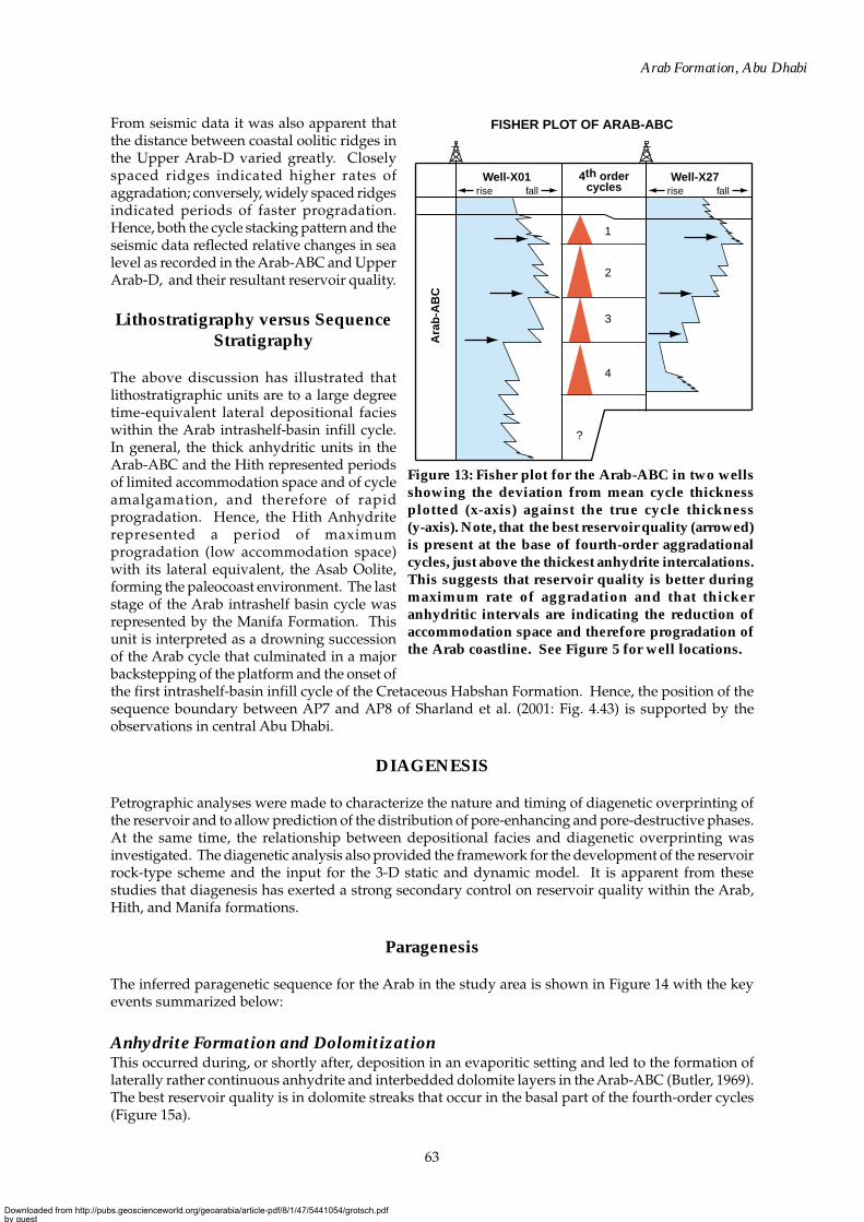
Correlation of fourth-order cycle stacking patterns based on Fisher plots (Fischer, 1964; Sadler et al.,1993) using the approach of Day (1997), indicated that the best reservoir quality (highest permeability)was preserved at the base of the fourth-order cycles immediately above the main thick anhydriteintercalations. This showed that the increase in reservoir quality in the Arab-ABC apparently coincidedwith the maximum increase in accommodation space of the fourth-order cycles during aggradation(Figure 13).
The upper two good-quality reservoir intervals in Figure 13 may be related to MFS J100 and J90 ofSharland et al. (2001: Fig. 4.43) respectively. The lower reservoir is between MFS J90 and J80, and issupport for the observation that best reservoir quality in the study area is related to re-flooding of theplatform and to an overall aggradational fourth-order phase.
DEPOSITIONAL FACIES DISTRIBUTION
Intrashelf basin (mid ramp LA-6)
Intrashelf basin (outer ramp LA-7)
Oolitic ridges/grainstone bodies (LA-5)
Bioclastic grainstone-packstone (LA-5)
Lagoonal dolomite/limestone (LA-3/4)
Black marker limestone
Sabkha/salina anhydrite (LA-1/2)
Prograding intrashelf basin ramp
(slope angles <0.1°)Asab OolitePlatform-drowning succession
and backstepping
Porous dolomite streaks
Intra-shelf basinShallow platform/sabkah/salina
Ara
b-D
Hith
Manifa
Ara
b-A
BC
Upp
er
Ara
b In
tras
hel
f-b
asin
Infi
ll C
ycle
Low
er
West East
Vertical exaggeration: x300
0 20
km
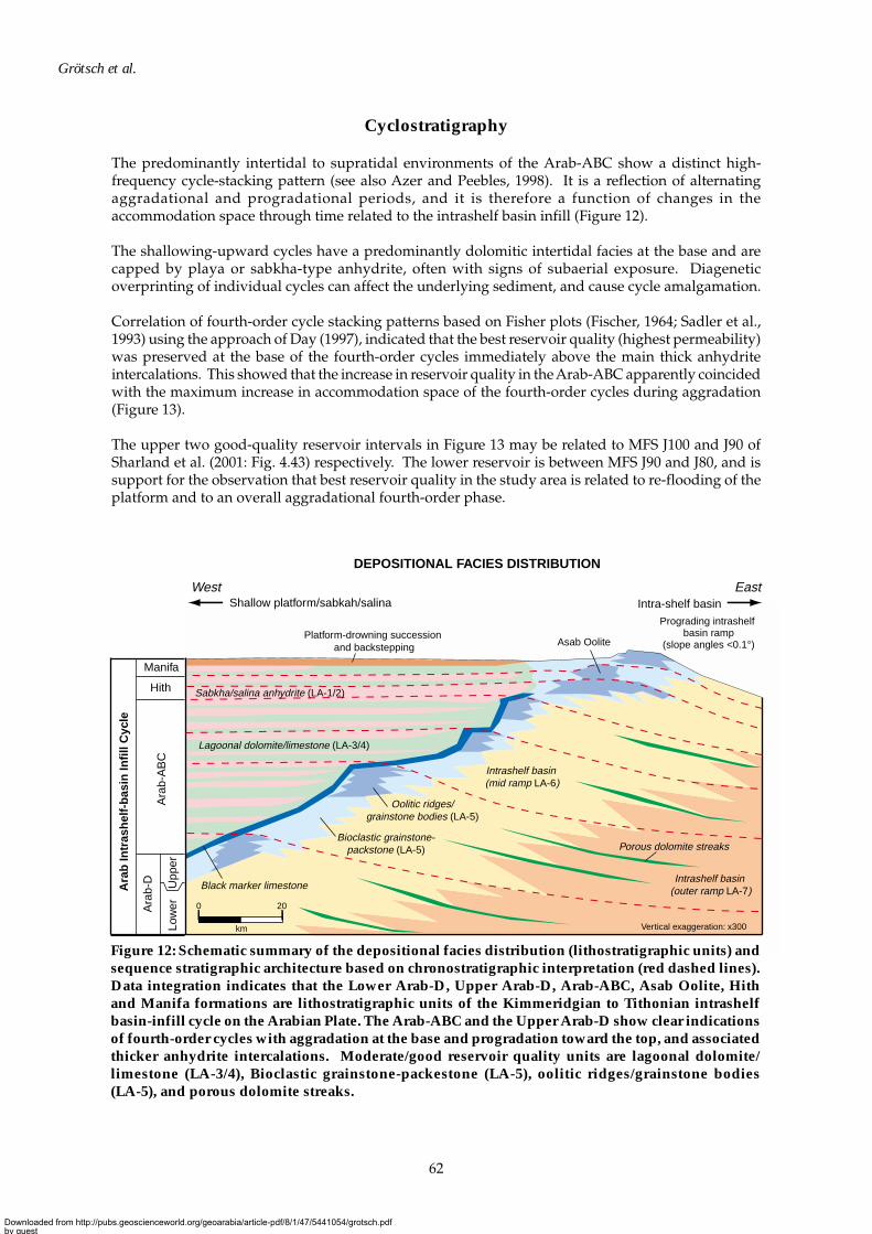
Figure 12: Schematic summary of the depositional facies distribution (lithostratigraphic units) andsequence stratigraphic architecture based on chronostratigraphic interpretation (red dashed lines).Data integration indicates that the Lower Arab-D, Upper Arab-D, Arab-ABC, Asab Oolite, Hithand Manifa formations are lithostratigraphic units of the Kimmeridgian to Tithonian intrashelfbasin-infill cycle on the Arabian Plate. The Arab-ABC and the Upper Arab-D show clear indicationsof fourth-order cycles with aggradation at the base and progradation toward the top, and associatedthicker anhydrite intercalations. Moderate/good reservoir quality units are lagoonal dolomite/limestone (LA-3/4), Bioclastic grainstone-packestone (LA-5), oolitic ridges/grainstone bodies(LA-5), and porous dolomite streaks.
Downloaded from http://pubs.geoscienceworld.org/geoarabia/article-pdf/8/1/47/5441054/grotsch.pdfby gueston 21 July 2022
63
Arab Formation, Abu Dhabi
From seismic data it was also apparent thatthe distance between coastal oolitic ridges inthe Upper Arab-D varied greatly. Closelyspaced ridges indicated higher rates ofaggradation; conversely, widely spaced ridgesindicated periods of faster progradation.Hence, both the cycle stacking pattern and theseismic data reflected relative changes in sealevel as recorded in the Arab-ABC and UpperArab-D, and their resultant reservoir quality.
Lithostratigraphy versus SequenceStratigraphy
The above discussion has illustrated thatlithostratigraphic units are to a large degreetime-equivalent lateral depositional facieswithin the Arab intrashelf-basin infill cycle.In general, the thick anhydritic units in theArab-ABC and the Hith represented periodsof limited accommodation space and of cycleamalgamation, and therefore of rapidprogradation. Hence, the Hith Anhydriterepresented a period of maximumprogradation (low accommodation space)with its lateral equivalent, the Asab Oolite,forming the paleocoast environment. The laststage of the Arab intrashelf basin cycle wasrepresented by the Manifa Formation. Thisunit is interpreted as a drowning successionof the Arab cycle that culminated in a majorbackstepping of the platform and the onset ofthe first intrashelf-basin infill cycle of the Cretaceous Habshan Formation. Hence, the position of thesequence boundary between AP7 and AP8 of Sharland et al. (2001: Fig. 4.43) is supported by theobservations in central Abu Dhabi.
DIAGENESIS
Petrographic analyses were made to characterize the nature and timing of diagenetic overprinting ofthe reservoir and to allow prediction of the distribution of pore-enhancing and pore-destructive phases.At the same time, the relationship between depositional facies and diagenetic overprinting wasinvestigated. The diagenetic analysis also provided the framework for the development of the reservoirrock-type scheme and the input for the 3-D static and dynamic model. It is apparent from thesestudies that diagenesis has exerted a strong secondary control on reservoir quality within the Arab,Hith, and Manifa formations.
Paragenesis
The inferred paragenetic sequence for the Arab in the study area is shown in Figure 14 with the keyevents summarized below:
Anhydrite Formation and DolomitizationThis occurred during, or shortly after, deposition in an evaporitic setting and led to the formation oflaterally rather continuous anhydrite and interbedded dolomite layers in the Arab-ABC (Butler, 1969).The best reservoir quality is in dolomite streaks that occur in the basal part of the fourth-order cycles(Figure 15a).
1
2
3
4
?
rise fall rise fall4th order
cycles Well-X01 Well-X27
FISHER PLOT OF ARAB-ABC
Ara
b-A
BC
Figure 13: Fisher plot for the Arab-ABC in two wellsshowing the deviation from mean cycle thicknessplotted (x-axis) against the true cycle thickness(y-axis). Note, that the best reservoir quality (arrowed)is present at the base of fourth-order aggradationalcycles, just above the thickest anhydrite intercalations.This suggests that reservoir quality is better duringmaximum rate of aggradation and that thickeranhydritic intervals are indicating the reduction ofaccommodation space and therefore progradation ofthe Arab coastline. See Figure 5 for well locations.
Downloaded from http://pubs.geoscienceworld.org/geoarabia/article-pdf/8/1/47/5441054/grotsch.pdfby gueston 21 July 2022

64
Grötsch et al.
Pore-filling Calcite CementationInterparticle pores in the oolitic and bioclastic grainstones of the Upper Arab-D are commonly blockedby porosity-destroying non-ferroan calcite cements (Figure 15b). The intraparticle pore-fillingcementation phase was associated with an initial charge of hydrocarbons, as suggested by residualbitumen within the blocky calcite, and is therefore of burial origin.
Leaching of AllochemsLeaching in the Upper Arab-D postdates the cementation by burial-type calcite and is a function ofooid abundance in the beach deposits. The leaching event predated a last-stage precipitation of pore-filling corrosive cement that reduced the leached porosity in the ooid coatings. This final cementationoccurred late in burial history and is assumed to be a result of thermochemical sulfate reduction onanhydrite to generate calcite and water (Machel et al., 1995).
Principal Diagenetic Controls on Reservoir Quality
The primary depositional fabric of the sediment, and ultimately of the reservoir architecture, can exerta strong control on reservoir quality, especially within the Lower Arab-D clinoforms. However,throughout most of the Arab reservoirs, diagenetic modification has significantly affected reservoirquality. In order to classify the changes, a petrophysically based rock-type scheme was requiredalongside the lithofacies association scheme that could only classify depositional facies (Figure 16).The following diagenetic processes are considered the most important for control on reservoir quality.
DolomitizationLA-3 (and to a lesser extent LA-4 and LA-7) is pervasively dolomitized. Depending on the dolomitefabric, this can lead to either an increase or reduction in reservoir quality, as follows:
• The higher permeability dolomites, mainly in LA-3, generally have crystal-supported planar-e fabrics(Mazzullo, 1992) with moderately well-connected intercrystalline macropores (>10%; seeFigure 15a). However, where intercrystalline pores are occluded by residual limestone and/oranhydrite and non-ferroan calcite cements, permeability is reduced substantially (Figure 6c).
??
BitumenSour gas?
?
?
?
?
1 Grain-rimming non-ferroan calcite cement
Dissolution of aragonitic allochems3
2 Micritization of allochems
4 Gypsum laths
Replacive non-ferroan dolomite 5
6 Displacive anhydrite
7 Replacive/cementing anhydrite
8 Pyrite formation
Non-ferroan dolomite cement
Stylolitization
Grain rotation interpenetration
Fracturing
Leaching of ooids/peloids
Pore-filling non-ferroan calcite
Replacive quartz
Quartz cement
Saddle dolomite
Barite cement
Elemental sulphur
Hydrocarbon
9
10
11
12
13
14
14a
15
16
17
18
19
Paragenetic event MarineSyn-depositional
Evaporitic Early burial Late burial
DIAGENETIC EVENTS
Porosity reductionPorosity enhancementExtent uncertain
Porosity distribution
Figure 14: Paragenesis of diagenetic events as observed from petrographic analysis of the LowerArab-D, Upper Arab-D, Arab-ABC, Hith and Manifa formations.
Downloaded from http://pubs.geoscienceworld.org/geoarabia/article-pdf/8/1/47/5441054/grotsch.pdfby gueston 21 July 2022

65
Arab Formation, Abu Dhabi
POROSITY/PERMEABILITY FROM CORE
0 5 10 15 20 25 30
100
10
1
0.1
0.01
Helium Porosity (%)
Sabkha/salina (LA-1/2)
Intratidal (LA-3)
Intratidal/subtidal (LA-4)
Inner ramp (LA-5)
Mid ramp (LA-6)
Outer ramp (LA-7)
Hor
izon
tal P
erm
eabi
lity
(mD
)
Figure 16: Cross-plot of core porosity andpermeability labelled with the correspondinglithofacies association. Note that there is poorcorrelation except in the sabkha/salinaanhydrite (non-reservoir). Depositional factorsare an important control of reservoir quality.However, early dolomitization and burialdiagenesis with calcite cementation exert astrong secondary control on rock properties.Therefore, depositional facies cannot be usedalone to define reservoir quality and attributionof saturation functions in the static and dynamicmodel (see Figure 18).
• Planar-s fabrics, with high proportions of interlocking dolomite crystals, have a lower permeabilitydue to the blocking of intercrystalline microporosity and/or microfractures.
It is assumed that accommodation space was restricted and water depths during deposition wereshallow enough to permit such pervasive dolomitization of the Arab-ABC host sediment. Asaccommodation space was further reduced later in the third-order highstand systems tract (HST),replacement of the sediment by nodular anhydrite became increasingly common, so destroying porosityand degrading reservoir quality.
Reflux of brines with elevated salinities and/or flood recharge and evaporitic pumping in a sabkhasetting were potential mechanisms for dolomitization of the Arab-ABC during the third-order mid-HST (Adams and Rhodes, 1960; Hardie, 1987; McKenzie, 1991). Due to the deep-water setting of thedolomite units in the Lower Arab-D, it is probable that there was a second mechanism for dolomitizationas a result of the diffusion or circulation of seawater at depositional surfaces.
0 5mm0 5mm
POROSITY AND RESERVOIR QUALITY
a b
Figure 15: (a) The best reservoir quality in the Arab-ABC shallowing-upward cycles is associatedwith crystal-supported planar-e dolomite. Intercrystalline porosity is indicated in blue.(b)Macroporosity in the oolitic grainstone of the Upper Arab-D is occluded by block calcite. Theremaining porosity and permeability is associated with microporosity hosted in the ooid coatings,which developed during leaching in a later stage of diagenesis.
Downloaded from http://pubs.geoscienceworld.org/geoarabia/article-pdf/8/1/47/5441054/grotsch.pdfby gueston 21 July 2022
66
Grötsch et al.
Calcite Cementation and Subsequent LeachingThe interparticle pore system of the Upper Arab-D grainstone lithofacies association (LA-5) has beendestroyed by the precipitation of blocky or drusy non-ferroan calcite cements (Figure 15b). Permeability(0.01–2 mD) is therefore controlled by the degree of microporosity hosted by peloids and ooids, andalso by intercrystalline boundaries.
In summary, dolomitization is the dominant diagenetic controlling factor for porosity preservation withinthe Arab-ABC cycles, whereas calcite cementation and subsequent leaching has determined reservoirquality within Upper Arab-D. However, depositional facies cannot be directly related to reservoir qualitydue to incoherent diagenetic overprinting within the reservoir (Figure 16). From the available core materialin the studied field, no obvious depth-dependant trend in reservoir quality was recognized.
RESERVOIR DEVELOPMENT
The main factors that controlled reservoir development in the Arab Formation were three distinctlydifferent elements within the lithostratigraphic units Arab-ABC (equivalent to the Qatar Formation)and Arab-D (equivalent to the Fahahil/Jubaila).
1. Thin streaks of early diagenetic dolomite within the small-scale, shallowing-upward cycles of theArab-ABC pinch out toward the east-northeast in the studied field.
2. Oolitic and bioclastic grainstones of variable thickness occur in the Upper Arab-D. In them, mostof the porosity is represented by intraparticle micro-porosity within oolitic coatings. Hence, thereservoir quality is largely controlled by the abundance of ooids.
3. Good-quality stratiform dolomite streaks in the Lower Arab-D (mid- to outer-ramp setting) enclosedin tight bioturbated limestones (mudstone to wackestone) of the gently dipping carbonate ramp.
Reservoir Quality
The two main controls on reservoir quality are (1) cyclostratigraphy and (2) a complex series ofdiagenetic events.
1. The best reservoir quality in the lagoonal and sabkha deposits of the Arab-ABC was developedduring the early phases of the generation of accommodation space in fourth-order cycles (Figure13, 15a). This occurred when the shallow-water platforms were flooded (basal fifth-order cycle infourth-order stack). Reservoir properties deteriorated as the accommodation space was reduced.
2. The diagenetic events that affected Arab reservoir quality most significantly are, in approximateparagenetic order:
• replacive dolomitization––variably porosity reducing and enhancing (LA-3, LA-4, rarely LA-7);• anhydrite and gypsum formation––porosity reducing (predominantly LA-1/2);• pore-filling and allochem-replacive non-ferroan calcite cementation––porosity reducing
(predominantly LA-5);• intraparticle leaching of allochems––porosity enhancing (predominantly LA-5); and• syn-depositional/shallow-burial dolomite characteristic of LA-3 and LA-4 (Hith and Arab-ABC)
and rarely bed tops in LA-7 (Lower Arab-D).
Reservoir Rock-type Scheme
As reservoir quality and properties cannot be directly related to depositional facies/architecture, apetrophysically based rock-type scheme was developed. This was for use with open-hole logs andfor input into static and dynamic modeling whereby saturation functions were attributed on acell-by-cell basis.
Downloaded from http://pubs.geoscienceworld.org/geoarabia/article-pdf/8/1/47/5441054/grotsch.pdfby gueston 21 July 2022
67
Arab Formation, Abu Dhabi
As discussed above, individual lithofacies associations have highly variable reservoir properties. Assuch, they cannot be used to predict permeability distribution or to attribute saturation and relativepermeability functions to a 3-D reservoir model (Figure 16). In order to reconcile this issue, apetrophysically based rock-typing approach was followed so as to improve the understanding ofreservoir-quality distribution in the Arab sequence.
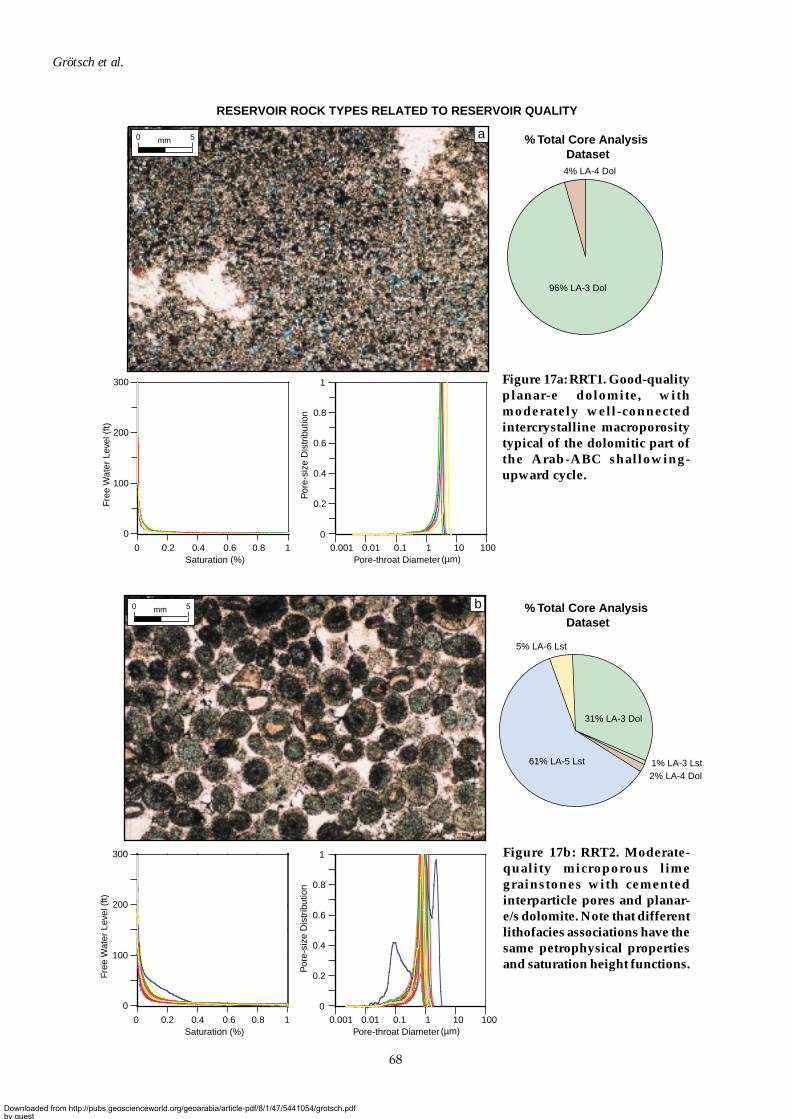
The scheme is that of Grötsch et al. (1998). A preliminary rock-fabric scheme, based on petrographicand core observations was established and used to select representative samples for Mercury InjectionCapillary Pressure (MICP) analysis. The preliminary scheme was refined using MICP curves andassociated pore-throat size distributions to develop the petrophysically based rock-type scheme. Afterseveral iterations, five reservoir rock types––one anhydrite and four carbonates––were defined, eachwith distinctive pore characteristics that could be related to the sedimentary fabrics and diageneticoverprinting (Figure 17).
The five Reservoir Rock Types (RRT) have the following characteristics:
• RRT1 (Figure 17a): good-quality planar-e dolomite with moderately well-connected intercrystallinemacroporosity—porosity = 21%, range 17.5–29.2%; permeability = 10 mD, range 2.87–49.5 mD.
• RRT2 (Figure 17b): moderate-quality microporous lime grainstones (cemented interparticle pores) andplanar-e/s dolomite—porosity = 13%, range 8.1–18.1%; permeability = 0.7 mD, range 0.20–3.48 mD.
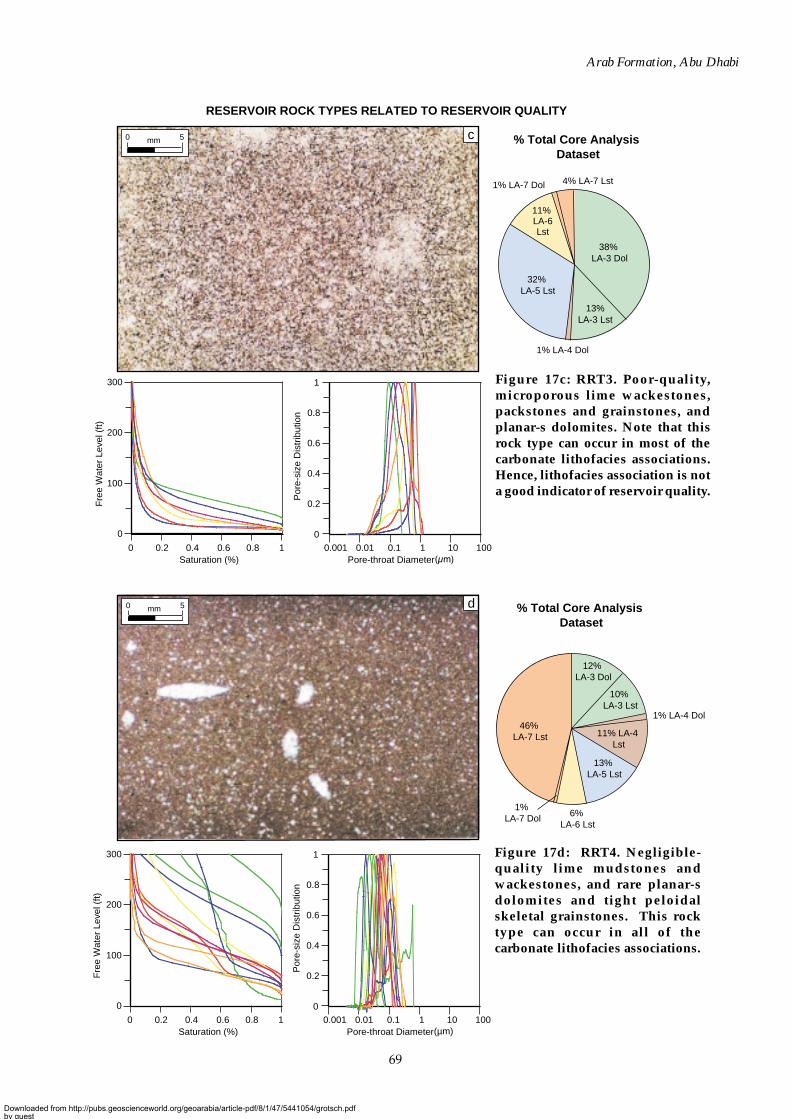
• RRT3 (Figure 17c): poor-quality microporous lime wackestones, packstones and grainstones, andplanar-s dolomites—porosity = 7%, range 5.0–12.0%; permeability = 0.1 mD, range 0.02–0.30 mD.
• RRT4 (Figure 17d): negligible-quality lime mudstones and wackestones and rare planar-s dolomitesand tight peloidal skeletal grainstones, non-reservoir—porosity = 1%, range 0.01–14.2%; permeability= 0.01 mD, range 0.01–0.05 mD.
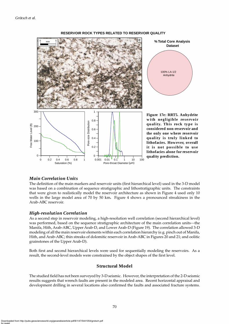
• RRT5 (Figure 17e): negligible-quality anhydrite, non-reservoir—porosity = 1%, range 0.01–7.4%;permeability = 0.02 mD, range 0.01–0.28 mD.
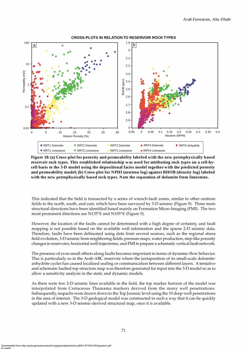
This scheme was then upscaled (Figure 18) so that the rock types could be predicted from open-holelogs and particularly from neutron (NPHI) and density (RHOB) logs. This was achieved by extrapolatingthe rock-type samples from the combined petrographic and MICP dataset of 60 sample from three wells,to the total petrographic dataset of 205 samples from four wells and subsequently to the total routinecore-analysis dataset. The core analysis rock-type dataset and lithofacies association distribution wasused to assign rock-types to the open-hole log data for the cored intervals.
To allow saturation functions to be attributed to the 3-D reservoir model, high case, most likely, and lowcase saturation curve scenarios were defined for each rock type. These were later used to constrainGas Initially In Place (GIIP) uncertainty.
STATIC RESERVOIR MODEL
The main goals of the static (and dynamic) reservoir modeling were to build a 3-D geological modelfor the Arab sequence in order to allow evaluation of uncertainties relating to reservoir architecture,GIIP, sour-gas production, acid-gas re-injection, and field-development planning. Pre-studies andcomputer modeling demonstrated the complexity of the Arab reservoirs and their sequence stratigraphicarchitecture (Figure 12).
Hierarchical Correlation
In order to allow for realistic model construction (including object-based modeling), a detailed andhierarchical digital well-correlation scheme was a pre-requisite. All correlations were performed usingGEOLOGIX, which is a module in the 3-D modeling suite GEOCAP.
Downloaded from http://pubs.geoscienceworld.org/geoarabia/article-pdf/8/1/47/5441054/grotsch.pdfby gueston 21 July 2022
68
Grötsch et al.
0
100
200
300
Free
Wat
er L
evel
(ft)
0 0.2 0.4 0.6 0.8 1Saturation (%)
Por
e-si
ze D
istr
ibut
ion
0
0.2
0.4
0.6
0.8
1
0.001 0.01 0.1 1 10 100Pore-throat Diameter
4% LA-4 Dol
96% LA-3 Dol
(µm)
% Total Core Analysis Dataset
0 5mm
0
100
200
300
Free
Wat
er L
evel
(ft)
0 0.2 0.4 0.6 0.8 1Saturation (%)
Por
e-si
ze D
istr
ibut
ion
0
0.2
0.4
0.6
0.8
1
0.001 0.01 0.1 1 10 100Pore-throat Diameter (µm)
5% LA-6 Lst
1% LA-3 Lst2% LA-4 Dol
31% LA-3 Dol
61% LA-5 Lst
% Total Core Analysis Dataset
0 5mm
RESERVOIR ROCK TYPES RELATED TO RESERVOIR QUALITY
a
b
Figure 17b: RRT2. Moderate-quality microporous limegrainstones with cementedinterparticle pores and planar-e/s dolomite. Note that differentlithofacies associations have thesame petrophysical propertiesand saturation height functions.
Figure 17a: RRT1. Good-qualityplanar-e dolomite, withmoderately well-connectedintercrystalline macroporositytypical of the dolomitic part ofthe Arab-ABC shallowing-upward cycle.
Downloaded from http://pubs.geoscienceworld.org/geoarabia/article-pdf/8/1/47/5441054/grotsch.pdfby gueston 21 July 2022
69
Arab Formation, Abu Dhabi
0
100
200
300
0 0.2 0.4 0.6 0.8 1Saturation (%)
0
0.2
0.4
0.6
0.8
1
0.001 0.01 0.1 1 10 100Pore-throat Diameter
38% LA-3 Dol
32% LA-5 Lst
11% LA-6Lst
1% LA-7 Dol 4% LA-7 Lst
1% LA-4 Dol
13% LA-3 Lst
% Total Core Analysis Dataset
0 5mm
0
100
200
300
0 0.2 0.4 0.6 0.8 1Saturation (%)
0
0.2
0.4
0.6
0.8
1
0.001 0.01 0.1 1 10 100Pore-throat Diameter(µm)
46% LA-7 Lst
12% LA-3 Dol
11% LA-4 Lst
13% LA-5 Lst
6% LA-6 Lst
1% LA-7 Dol
1% LA-4 Dol
10% LA-3 Lst
% Total Core Analysis Dataset
0 5mm
RESERVOIR ROCK TYPES RELATED TO RESERVOIR QUALITY F
ree
Wat
er L
evel
(ft)
Por
e-si
ze D
istr
ibut
ion
Fre
e W
ater
Lev
el (
ft)
Por
e-si
ze D
istr
ibut
ion
c
d
Figure 17d: RRT4. Negligible-quality lime mudstones andwackestones, and rare planar-sdolomites and tight peloidalskeletal grainstones. This rocktype can occur in all of thecarbonate lithofacies associations.
Figure 17c: RRT3. Poor-quality,microporous lime wackestones,packstones and grainstones, andplanar-s dolomites. Note that thisrock type can occur in most of thecarbonate lithofacies associations.Hence, lithofacies association is nota good indicator of reservoir quality.
Downloaded from http://pubs.geoscienceworld.org/geoarabia/article-pdf/8/1/47/5441054/grotsch.pdfby gueston 21 July 2022
70
Grötsch et al.
0
100
200
300
0 0.2 0.4 0.6 0.8 1Saturation (%)
0
0.2
0.4
0.6
0.8
1
0.001 0.01 0.1 1 10 100Pore-throat Diameter (µm)
100% LA-1/2 Anhydrite
% Total Core Analysis Dataset
0 5mm
RESERVOIR ROCK TYPES RELATED TO RESERVOIR QUALITY Fr
ee W
ater
Lev
el (
ft)
Por
e-si
ze D
istr
ibut
ion
e
Figure 17e: RRT5. Anhydritewith negligible reservoirquality. This rock type isconsidered non-reservoir andthe only one where reservoirquality is truly linked tolithofacies. However, overallit is not possible to uselithofacies alone for reservoirquality prediction.
Main Correlation UnitsThe definition of the main markers and reservoir units (first hierarchical level) used in the 3-D modelwas based on a combination of sequence stratigraphic and lithostratigraphic units. The constraintsthat were given to realistically model the reservoir architecture as shown in Figure 4 used only 10wells in the large model area of 70 by 50 km. Figure 4 shows a pronounced streakiness in theArab-ABC reservoir.
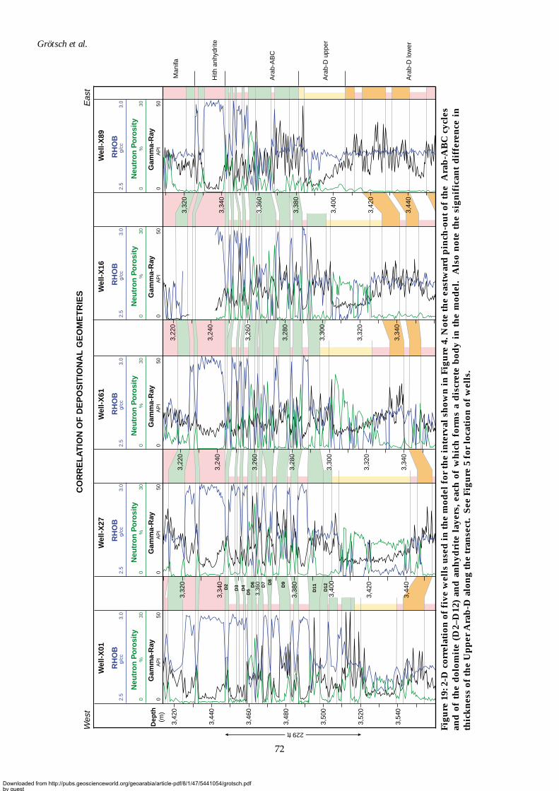
High-resolution CorrelationAs a second step in reservoir modeling, a high-resolution well correlation (second hierarchical level)was performed, based on the sequence stratigraphic architecture of the main correlation units––theManifa, Hith, Arab-ABC, Upper Arab-D, and Lower Arab-D (Figure 19). The correlation allowed 3-Dmodeling of all the main reservoir elements within each correlation hierarchy (e.g. pinch out of Manifa,Hith, and Arab-ABC; thin streaks of dolomitic reservoir in Arab-ABC in Figures 20 and 21; and ooliticgrainstones of the Upper Arab-D).
Both first and second hierarchical levels were used for sequentially modeling the reservoirs. As aresult, the second-level models were constrained by the object shapes of the first level.
Structural Model
The studied field has not been surveyed by 3-D seismic. However, the interpretation of the 2-D seismicresults suggests that wrench faults are present in the modeled area. Recent horizontal appraisal anddevelopment drilling in several locations also confirmed the faults and associated fracture systems.
Downloaded from http://pubs.geoscienceworld.org/geoarabia/article-pdf/8/1/47/5441054/grotsch.pdfby gueston 21 July 2022
71
Arab Formation, Abu Dhabi
Figure 18: (a) Cross-plot for porosity and permeability labeled with the new petrophysically basedreservoir rock types. This established relationship was used for attributing rock types on a cell-by-cell basis to the 3-D model using the depositional facies model together with the predicted porosityand permeability model; (b) Cross-plot for NPHI (neutron log) against RHOB (density log) labeledwith the new petrophysically based rock types. Note the separation of dolomite from limestone.
This indicated that the field is transected by a series of wrench-fault zones, similar to other onshorefields to the north, south, and east, which have been surveyed by 3-D seismic (Figure 9). Three mainstructural directions have been identified based mainly on Formation Micro-Imaging (FMI). The twomost prominent directions are N135°E and N105°E (Figure 5).
However, the location of the faults cannot be determined with a high degree of certainty, and faultmapping is not possible based on the available well information and the sparse 2-D seismic data.Therefore, faults have been delineated using data from several sources, such as the regional stressfield evolution, 3-D seismic from neighboring fields, pressure maps, water production, step-like porositychanges in reservoirs, horizontal well trajectories, and FMI to prepare a schematic vertical fault network.
The presence of even small offsets along faults becomes important in terms of dynamic-flow behavior.This is particularly so in the Arab-ABC reservoir where the juxtaposition of its small-scale dolomite-anhydrite cycles has caused localized sealing or communication between different layers. A tentativeand schematic faulted top-structure map was therefore generated for input into the 3-D model so as toallow a sensitivity analysis in the static and dynamic models.
As there were few 2-D seismic lines available in the field, the top marker horizon of the model wasinterpolated from Cretaceous Thamama markers derived from the many well penetrations.Subsequently, isopachs were drawn down to the Top Jurassic level using the 10 deep-well penetrationsin the area of interest. The 3-D geological model was constructed in such a way that it can be quicklyupdated with a new 3-D seismic-derived structural map, once it is available.
CROSS-PLOTS IN RELATION TO RESERVOIR ROCK TYPES
RRT1 Dolomite
RRT1 Limestone
RRT2 Dolomite
RRT2 Limestone
RRT3 Dolomite
RRT3 Limestone
RRT5 AnhydriteRRT4 Dolomite
RRT4 Limestone
-0.05 0.050 0.1 0.15 0.2 0.25 0.3 0.35 0.4
1.9
2
2.2
2.3
2.4
2.1
2.6
2.7
2.8
2.9
3
2.5
Neutron (NPHI)
RH
OB
(g/
cc)
b
0 5 10 15 20 25 30
100
10
1
0.1
0.01
Helium Porosity (%)
Per
mia
bilit
y (m
D)
a
Downloaded from http://pubs.geoscienceworld.org/geoarabia/article-pdf/8/1/47/5441054/grotsch.pdfby gueston 21 July 2022
72
Grötsch et al.
Figu
re 1
9: 2
-D c
orre
lati
on o
f fi
ve w
ells
use
d in
the
mod
el f
or th
e in
terv
al s
how
n in
Fig
ure
4. N
ote
the
east
war
d p
inch
-ou
t of
the
Ara
b-A
BC
cyc
les
and
of
the
dol
omit
e (D
2–D
12)
and
an
hyd
rite
lay
ers,
eac
h o
f w
hic
h f
orm
s a
dis
cret
e b
ody
in t
he
mod
el.
Als
o n
ote
the
sign
ific
ant
dif
fere
nce
in
thic
kn
ess
of th
e U
pp
er A
rab
-D a
lon
g th
e tr
anse
ct.
See
Fig
ure
5 f
or lo
cati
on o
f w
ells
.
Man
ifa
Hith
anh
ydrit
e
Ara
b-A
BC
Ara
b-D
upp
er
Ara
b-D
low
er
Gam
ma-
Ray
AP
I50
0G
amm
a-R
ayA
PI
500
Gam
ma-
Ray
AP
I50
0G
amm
a-R
ayA
PI
500
Gam
ma-
Ray
AP
I50
0
RH
OB
RH
OB
RH
OB
RH
OB
RH
OB
Neu
tro
n P
oro
sity
0%
30
2.5
3.0
g/cc
Neu
tro
n P
oro
sity
0%
30
2.5
3.0
g/cc
Neu
tro
n P
oro
sity
0%
30
2.5
3.0
g/cc
Neu
tro
n P
oro
sity
0%
30
2.5
3.0
g/cc
Neu
tro
n P
oro
sity
0%
30
2.5
3.0
g/cc
Wel
l-X
01W
ell-
X27
Wel
l-X
61W
ell-
X16
Wel
l-X
89
Wes
tE
ast
Dep
th(m
)
CO
RR
EL
AT
ION
OF
DE
PO
SIT
ION
AL
GE
OM
ET
RIE
S
3,32
0
3,34
0
3,36
0
3,38
0
3,40
0
3,42
0
3,44
0
3,42
0
3,44
0
3,46
0
3,48
0
3,50
0
3,52
0
3,54
0
3,22
0
3,24
0
3,26
0
3,28
0
3,30
0
3,32
0
3,34
0
3,24
0
3,26
0
3,28
0
3,30
0
3,32
0
3,34
0
3,22
0
3,34
0
3,36
0
3,38
0
3,40
0
3,42
0
3,44
0
3,32
0
D2
D3
D4
D5
D6
D7 D8
D9
D11
D12
229 ft
Downloaded from http://pubs.geoscienceworld.org/geoarabia/article-pdf/8/1/47/5441054/grotsch.pdfby gueston 21 July 2022
73
Arab Formation, Abu Dhabi
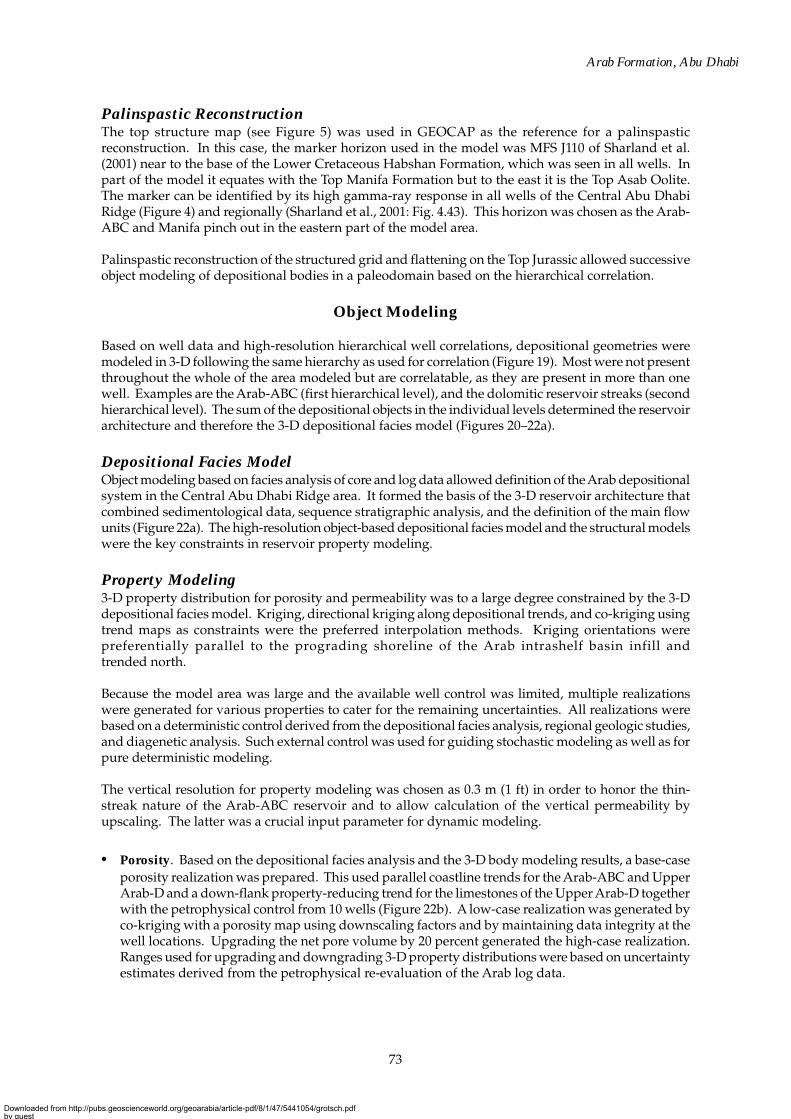
Palinspastic ReconstructionThe top structure map (see Figure 5) was used in GEOCAP as the reference for a palinspasticreconstruction. In this case, the marker horizon used in the model was MFS J110 of Sharland et al.(2001) near to the base of the Lower Cretaceous Habshan Formation, which was seen in all wells. Inpart of the model it equates with the Top Manifa Formation but to the east it is the Top Asab Oolite.The marker can be identified by its high gamma-ray response in all wells of the Central Abu DhabiRidge (Figure 4) and regionally (Sharland et al., 2001: Fig. 4.43). This horizon was chosen as the Arab-ABC and Manifa pinch out in the eastern part of the model area.
Palinspastic reconstruction of the structured grid and flattening on the Top Jurassic allowed successiveobject modeling of depositional bodies in a paleodomain based on the hierarchical correlation.
Object Modeling
Based on well data and high-resolution hierarchical well correlations, depositional geometries weremodeled in 3-D following the same hierarchy as used for correlation (Figure 19). Most were not presentthroughout the whole of the area modeled but are correlatable, as they are present in more than onewell. Examples are the Arab-ABC (first hierarchical level), and the dolomitic reservoir streaks (secondhierarchical level). The sum of the depositional objects in the individual levels determined the reservoirarchitecture and therefore the 3-D depositional facies model (Figures 20–22a).
Depositional Facies ModelObject modeling based on facies analysis of core and log data allowed definition of the Arab depositionalsystem in the Central Abu Dhabi Ridge area. It formed the basis of the 3-D reservoir architecture thatcombined sedimentological data, sequence stratigraphic analysis, and the definition of the main flowunits (Figure 22a). The high-resolution object-based depositional facies model and the structural modelswere the key constraints in reservoir property modeling.
Property Modeling3-D property distribution for porosity and permeability was to a large degree constrained by the 3-Ddepositional facies model. Kriging, directional kriging along depositional trends, and co-kriging usingtrend maps as constraints were the preferred interpolation methods. Kriging orientations werepreferentially parallel to the prograding shoreline of the Arab intrashelf basin infill andtrended north.
Because the model area was large and the available well control was limited, multiple realizationswere generated for various properties to cater for the remaining uncertainties. All realizations werebased on a deterministic control derived from the depositional facies analysis, regional geologic studies,and diagenetic analysis. Such external control was used for guiding stochastic modeling as well as forpure deterministic modeling.
The vertical resolution for property modeling was chosen as 0.3 m (1 ft) in order to honor the thin-streak nature of the Arab-ABC reservoir and to allow calculation of the vertical permeability byupscaling. The latter was a crucial input parameter for dynamic modeling.
• Porosity. Based on the depositional facies analysis and the 3-D body modeling results, a base-caseporosity realization was prepared. This used parallel coastline trends for the Arab-ABC and UpperArab-D and a down-flank property-reducing trend for the limestones of the Upper Arab-D togetherwith the petrophysical control from 10 wells (Figure 22b). A low-case realization was generated byco-kriging with a porosity map using downscaling factors and by maintaining data integrity at thewell locations. Upgrading the net pore volume by 20 percent generated the high-case realization.Ranges used for upgrading and downgrading 3-D property distributions were based on uncertaintyestimates derived from the petrophysical re-evaluation of the Arab log data.
Downloaded from http://pubs.geoscienceworld.org/geoarabia/article-pdf/8/1/47/5441054/grotsch.pdfby gueston 21 July 2022
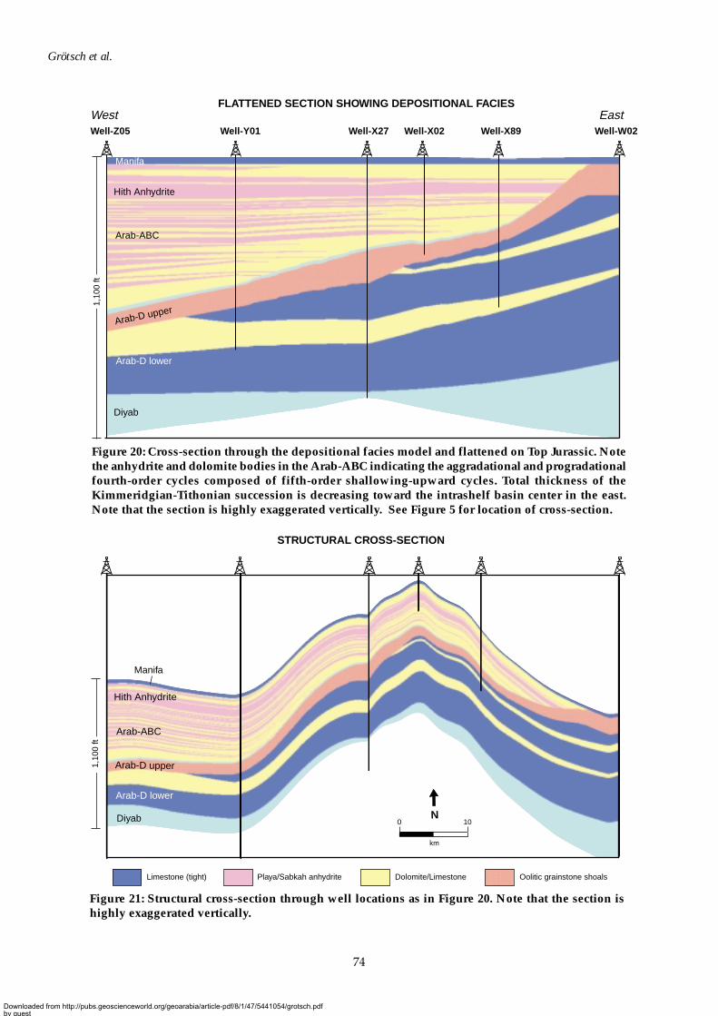
74
Grötsch et al.
Manifa
Manifa
Arab-D lower
Arab-ABC
Diyab
Hith Anhydrite
Arab-D upper
FLATTENED SECTION SHOWING DEPOSITIONAL FACIES
Dolomite/LimestoneLimestone (tight) Oolitic grainstone shoalsPlaya/Sabkah anhydrite
Arab-D upper
Arab-D lower
Arab-ABC
Hith Anhydrite
1,10
0 ft
STRUCTURAL CROSS-SECTION
Well-Z05 Well-Y01 Well-X27 Well-X89 Well-W02Well-X02
EastWest
0 10
km
N
1,10
0 ft
Diyab
Figure 21: Structural cross-section through well locations as in Figure 20. Note that the section ishighly exaggerated vertically.
Figure 20: Cross-section through the depositional facies model and flattened on Top Jurassic. Notethe anhydrite and dolomite bodies in the Arab-ABC indicating the aggradational and progradationalfourth-order cycles composed of fifth-order shallowing-upward cycles. Total thickness of theKimmeridgian-Tithonian succession is decreasing toward the intrashelf basin center in the east.Note that the section is highly exaggerated vertically. See Figure 5 for location of cross-section.
Downloaded from http://pubs.geoscienceworld.org/geoarabia/article-pdf/8/1/47/5441054/grotsch.pdfby gueston 21 July 2022
75
Arab Formation, Abu Dhabi
• Permeability. Permeability data were available from many core plugs as 90 percent of the wells inthe Arab Formation have core data available for the modeling interval. It was therefore not necessaryto apply the inherently uncertain permeability estimation based on log data. The core data provideda good basis for 3-D permeability modeling that was well constrained by the 3-D reservoirarchitecture and the coastline orientation (Figure 22c).
Reservoir Rock-type ModelPetrographic analysis demonstrated that there was no clear relationship between depositional facies,reservoir properties, and saturation functions. A new petrophysically based rock-type scheme wastherefore developed and used as input for the 3-D static and dynamic model.
The reservoir rock-type model presented an additional modeling step between depositional faciesmodeling and property modeling (porosity and permeability) on the one hand and saturation modelingand dynamic simulation on the other (Grötsch et al., 1998). Whereas the main flow units are definedby the structured hierarchical facies model, which are layer or body based, the rock-type model had tobe cell based (Figure 22d). This was essential in order to allow attribution of different saturation-height functions during saturation modeling and model initialization, on a cell-by-cell basis withinsimulation layers.
Rock types were attributed to each cell by using the porosity and permeability models and definitionsfrom the petrographic study. This study had identified the five rock types graphically represented inFigure 18. On a porosity-permeability cross-plot, four distinct areas were defined using petrographicdata and capillary pressure measurements. Attributing these relationships to the cellular propertymodels allowed for gradual lateral changes in saturation-height/relative permeability functions withinthe particular reservoir architecture and within each individual facies body (e.g. down-flank rock-type deterioration in Upper Arab-D). The cell-by-cell based rock-type model was then used as inputfor saturation modeling and the initialization of the dynamic model (Figure 22d).
Saturation
Results from a first-pass model and the petrophysical review showed large uncertainties when using logsaturation data for 3-D interpolation. Uncertainties were the result of calculated log saturations as wellas spatial property distribution using various interpolation techniques. A key constraining factor wasthe number of wells available and their location with respect to the 3-D reservoir architecture. Therefore,saturation-height functions together with the developed rock-type model were used for saturationmodeling in the static model and for model initialization in the dynamic model (Figure 23a).
Saturations were calculated per rock type per cell, as a function of height above Free Water Level(FWL) using the newly acquired mercury capillary pressure data and the resulting saturation-heightfunctions. Connate water saturations were defined for each rock type and honored in the saturationfunctions. To cater for the uncertainty ranges in the data set, three realizations (Low, Mid, High) withone type curve each were defined (Figure 23b).
All Arab wells have a gas-down-to situation, and therefore the FWL for the main reservoir units had tobe estimated. The estimate was based on the dominant rock type in the reservoir unit, saturation-height functions for the dominant rock type, uncertainty range in the saturation-height functions,water saturation ranges measured from logs, and matching saturations from the 3-D model, togetherwith log-derived saturations at well locations. This provided a minimum FWL estimate that was thebasis for further FWL definitions for each realization of the saturation model (Figure 24). Syntheticsaturation logs from the model suggested that the deeper FWLs better matched with actual resistivitylog data and were therefore more realistic.
Downloaded from http://pubs.geoscienceworld.org/geoarabia/article-pdf/8/1/47/5441054/grotsch.pdfby gueston 21 July 2022
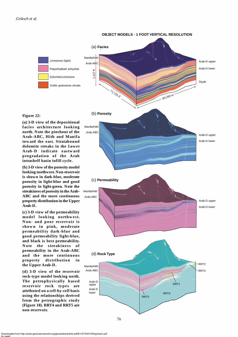
76
Grötsch et al.
Arab-D upper
Arab-D lower
Diyab
1,12
7 ft
(a) Facies
Arab-D upper
Manifa/Hith
Arab-ABC
RRT2
RRT1
RRT4RRT5
RRT3
(d) Rock Type
Arab-D upper
Arab-D lower
Arab-D lower
(c) Permeability
(b) Porosity
OBJECT MODELS - 1 FOOT VERTICAL RESOLUTION
50,250 m
Arab-ABC
Manifa/Hith
Arab-ABC
Manifa/Hith
Arab-ABC
Manifa/Hith
Arab-D upper
Arab-D lower
Dolomite/Limestone
Limestone (tight)
Oolitic grainstone shoals
Playa/Sabkah anhydrite
72,750 m
Figure 22:
(a) 3-D view of the depositionalfacies architecture lookingnorth. Note the pinchout of theArab-ABC, Hith and Manifatoward the east. Stratabounddolomite streaks in the LowerArab-D indicate eastwardprogradation of the Arabintrashelf basin infill cycle.
(b) 3-D view of the porosity modellooking northwest. Non-reservoiris shown in dark-blue, moderateporosity in light-blue and goodporosity in light-green. Note thestreakiness of porosity in the Arab-ABC and the more continuousproperty distribution in the UpperArab-D.
(c) 3-D view of the permeabilitymodel looking northwest.Non- and poor reservoir isshown in pink, moderatepermeability dark-blue andgood permeability light-blue,and black is best permeability.Note the streakiness ofpermeability in the Arab-ABCand the more continuousproperty distribution inthe Upper Arab-D.
(d) 3-D view of the reservoirrock-type model looking north.The petrophysically basedreservoir rock types areattributed on a cell-by-cell basisusing the relationships derivedfrom the petrographic study(Figure 18). RRT4 and RRT5 arenon-reservoir.
Downloaded from http://pubs.geoscienceworld.org/geoarabia/article-pdf/8/1/47/5441054/grotsch.pdfby gueston 21 July 2022
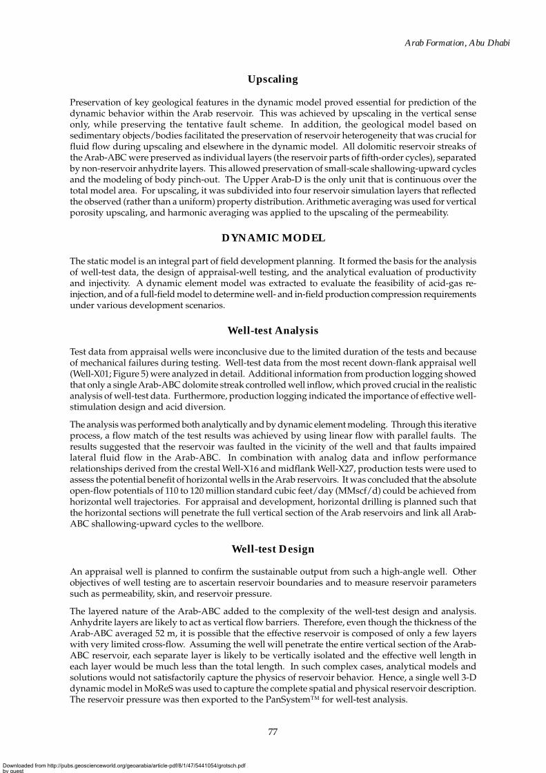
77
Arab Formation, Abu Dhabi
Upscaling
Preservation of key geological features in the dynamic model proved essential for prediction of thedynamic behavior within the Arab reservoir. This was achieved by upscaling in the vertical senseonly, while preserving the tentative fault scheme. In addition, the geological model based onsedimentary objects/bodies facilitated the preservation of reservoir heterogeneity that was crucial forfluid flow during upscaling and elsewhere in the dynamic model. All dolomitic reservoir streaks ofthe Arab-ABC were preserved as individual layers (the reservoir parts of fifth-order cycles), separatedby non-reservoir anhydrite layers. This allowed preservation of small-scale shallowing-upward cyclesand the modeling of body pinch-out. The Upper Arab-D is the only unit that is continuous over thetotal model area. For upscaling, it was subdivided into four reservoir simulation layers that reflectedthe observed (rather than a uniform) property distribution. Arithmetic averaging was used for verticalporosity upscaling, and harmonic averaging was applied to the upscaling of the permeability.
DYNAMIC MODEL
The static model is an integral part of field development planning. It formed the basis for the analysisof well-test data, the design of appraisal-well testing, and the analytical evaluation of productivityand injectivity. A dynamic element model was extracted to evaluate the feasibility of acid-gas re-injection, and of a full-field model to determine well- and in-field production compression requirementsunder various development scenarios.
Well-test Analysis
Test data from appraisal wells were inconclusive due to the limited duration of the tests and becauseof mechanical failures during testing. Well-test data from the most recent down-flank appraisal well(Well-X01; Figure 5) were analyzed in detail. Additional information from production logging showedthat only a single Arab-ABC dolomite streak controlled well inflow, which proved crucial in the realisticanalysis of well-test data. Furthermore, production logging indicated the importance of effective well-stimulation design and acid diversion.
The analysis was performed both analytically and by dynamic element modeling. Through this iterativeprocess, a flow match of the test results was achieved by using linear flow with parallel faults. Theresults suggested that the reservoir was faulted in the vicinity of the well and that faults impairedlateral fluid flow in the Arab-ABC. In combination with analog data and inflow performancerelationships derived from the crestal Well-X16 and midflank Well-X27, production tests were used toassess the potential benefit of horizontal wells in the Arab reservoirs. It was concluded that the absoluteopen-flow potentials of 110 to 120 million standard cubic feet/day (MMscf/d) could be achieved fromhorizontal well trajectories. For appraisal and development, horizontal drilling is planned such thatthe horizontal sections will penetrate the full vertical section of the Arab reservoirs and link all Arab-ABC shallowing-upward cycles to the wellbore.
Well-test Design
An appraisal well is planned to confirm the sustainable output from such a high-angle well. Otherobjectives of well testing are to ascertain reservoir boundaries and to measure reservoir parameterssuch as permeability, skin, and reservoir pressure.
The layered nature of the Arab-ABC added to the complexity of the well-test design and analysis.Anhydrite layers are likely to act as vertical flow barriers. Therefore, even though the thickness of theArab-ABC averaged 52 m, it is possible that the effective reservoir is composed of only a few layerswith very limited cross-flow. Assuming the well will penetrate the entire vertical section of the Arab-ABC reservoir, each separate layer is likely to be vertically isolated and the effective well length ineach layer would be much less than the total length. In such complex cases, analytical models andsolutions would not satisfactorily capture the physics of reservoir behavior. Hence, a single well 3-Ddynamic model in MoReS was used to capture the complete spatial and physical reservoir description.The reservoir pressure was then exported to the PanSystem™ for well-test analysis.
Downloaded from http://pubs.geoscienceworld.org/geoarabia/article-pdf/8/1/47/5441054/grotsch.pdfby gueston 21 July 2022
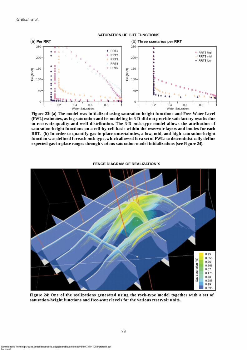
78
Grötsch et al.
0 0.2 0.4 0.6 0.8 1Water Saturation
SATURATION HEIGHT FUNCTIONS
(a) Per RRT (b) Three scenarios per RRT
0
50
100
150
200
250
Hei
ght (
ft)
0 0.2 0.4 0.6 0.8 1Water Saturation
0
50
100
150
200
250
Hei
ght (
ft)
RRT3 highRRT3 midRRT3 low
RRT1
RRT2RRT3
RRT4
RRT5
Figure 23: (a) The model was initialized using saturation-height functions and Free Water Level(FWL) estimates, as log saturation and its modeling in 3-D did not provide satisfactory results dueto reservoir quality and well distribution. The 3-D rock-type model allows the attribution ofsaturation-height functions on a cell-by-cell basis within the reservoir layers and bodies for eachRRT. (b) In order to quantify gas-in-place uncertainties, a low, mid, and high saturation-heightfunction was defined for each rock type, which allowed for a set of FWLs to deterministically defineexpected gas-in-place ranges through various saturation-model initializations (see Figure 24).
FENCE DIAGRAM OF REALIZATION X
0.950.8550.760.6650.570.4750.380.2850.190.095
Gas
sat
urat
ion
(%)
Figure 24: One of the realizations generated using the rock-type model together with a set ofsaturation-height functions and free-water levels for the various reservoir units.
Downloaded from http://pubs.geoscienceworld.org/geoarabia/article-pdf/8/1/47/5441054/grotsch.pdfby gueston 21 July 2022
79
Arab Formation, Abu Dhabi
Two major questions had to be addressed: (1) How long should the test last? and (2) What is theoptimum test strategy? (i.e. whether to test the Arab-ABC alone or commingled with the UpperArab-D). Results showed that testing the Arab-ABC and Upper Arab-D together would not giveproper information on faulting or compartmentalization of the reservoir. Testing the Arab-ABC reservoirstreaks alone reveals faults more easily and this result allowed the test objectives to be refined.Determining the distances to possible faults is the reason for extended testing of the horizontal sectionin the Arab-ABC, whereas the prime objective of testing the Upper Arab-D alone, and commingledwith Arab-ABC, was to establish the overall well deliverability.
Feasibility of Acid-gas Re-injection
The development of the Arab sour gas in the studied field requires the flexibility to re-inject acid gas(80% H2S and 20% CO2) into the Arab reservoirs. Given the layered nature and reservoir propertycontrasts of the Arab-ABC, the issue of long-term reservoir management had to be addressed. It isexpected that future acid-gas injection will take place at the crest of the structure because of the favorablereservoir properties found in appraisal wells, the requirement of limiting acid-gas contamination toonly part of the field, and health and safety considerations such as the proximity to surface facilities.The purpose of this feasibility study was to assess the displacement process and the recovery factor ofmethane in various acid-gas disposal scenarios. For this purpose, an element model was extractedfrom the static model to investigate the feasibility of simultaneous production of sour-gas and re-injection of acid-gas.
A symmetrical element model of dimensions 1,500 by 1,500 m (Figure 25) was generated that reflectedvertical reservoir property contrasts as observed in the mid-dip appraisal Well-X27. The model consistedof one injector/producer pair positioned diagonally across the model. Given the layered nature andreservoir property contrasts of the Arab-ABC—as opposed to the relatively homogenous UpperArab-D reservoir—it was determined that acid-gas injection (if necessary) should be limited to theUpper Arab-D, and that injection into the Arab-ABC should be delayed as long as possible.
It was concluded that no special reservoir management policy was required to maximize the recoveryof sour gas should re-injection of acid gas become necessary. Although it was recommended thatre-injection should be avoided, it may be necessary for a limited amount of time because of operationalcircumstances. Completion of the wells should allow selective monitoring and optional shut-in of theArab-ABC and/or Arab-D reservoir units. Monitoring surrounding producer wells is a requirementfor the detection of potential premature acid-gas breakthrough.
Full-field Modeling
In addition to element models, a full-field model was extracted from the geological model so as tosupport field-development planning (Figure 26). The dynamic model was limited to the main fieldand was slightly refined compared to the static model in order to allow for the modeling of horizontalwells. Faults were transferred from the static model and they separate the dynamic model into 11blocks (Figure 5). Flow across the faults is assumed if the juxtaposition of reservoir versus non-reservoirlayers permits.
In the Arab-ABC, each of the carbonate/dolomite reservoir streaks was represented by a separatesimulation layer or body of grid blocks that were separated by the anhydrite layers/bodies. The latterwere subsequently voided out for flow modeling. Permeabilities and rock types had been previouslydefined from the static model. The rock type selected for each simulation grid cell is that whichoccupied the largest net pore volume in the static model. This rock type was then used to assign thecapillary pressure and relative permeability to each grid cell in the model as defined in the rock-typescheme. The model was initialized, assuming proven contact levels for gas-initially-in-place.
Several development scenarios were investigated to determine the requirements and timing ofdevelopment wells and in-field production compression. A phased development is planned with amaximum off-take rate of 710 MMscf/d. Based on the currently available data for the static and
Downloaded from http://pubs.geoscienceworld.org/geoarabia/article-pdf/8/1/47/5441054/grotsch.pdfby gueston 21 July 2022
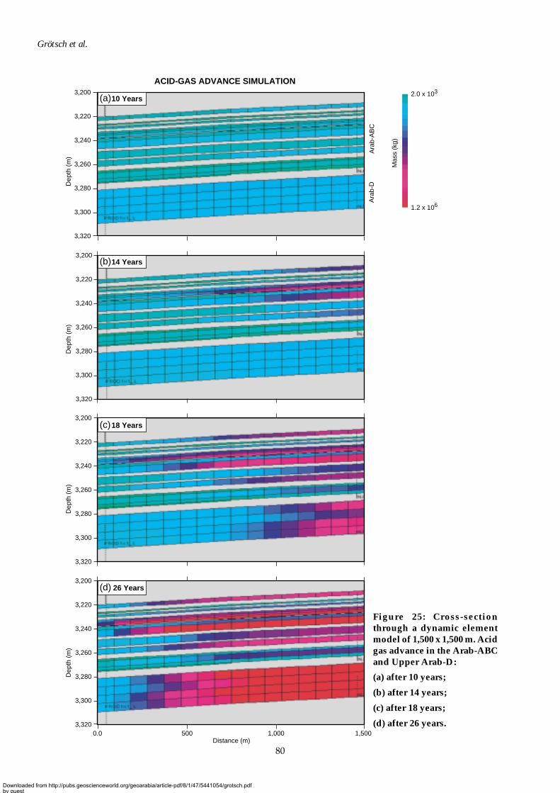
80
Grötsch et al.
Figure 25: Cross-sectionthrough a dynamic elementmodel of 1,500 x 1,500 m. Acidgas advance in the Arab-ABCand Upper Arab-D:
(a) after 10 years;
(b) after 14 years;
(c) after 18 years;
(d) after 26 years.
ACID-GAS ADVANCE SIMULATION
3,200
3,220
3,240
3,260
3,280
3,300
3,320
3,200
3,220
3,240
3,260
3,280
3,300
3,320
3,200
3,220
3,240
3,260
3,280
3,300
3,320
3,200
3,220
3,240
3,260
3,280
3,300
3,3200.0 500
Distance (m)1,000 1,500
Ara
b-D
Ara
b-A
BC
Dep
th (
m)
Dep
th (
m)
Dep
th (
m)
Dep
th (
m)
10 Years
14 Years
18 Years
26 Years
(a)
(b)
(c)
(d)
2.0 x 10³
1.2 x 10⁶
Mas
s (k
g)
Downloaded from http://pubs.geoscienceworld.org/geoarabia/article-pdf/8/1/47/5441054/grotsch.pdfby gueston 21 July 2022
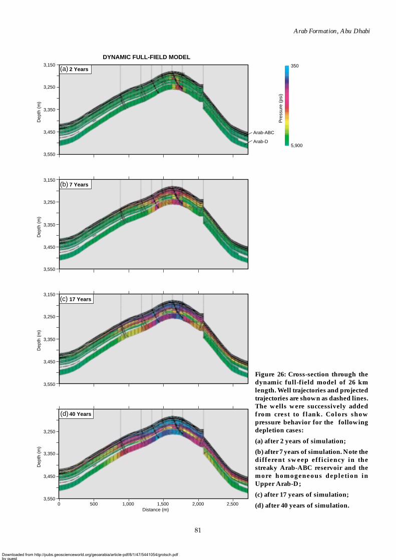
81
Arab Formation, Abu Dhabi
3,150
3,250
3,350
3,450
3,550
Dep
th (
m)
Dep
th (
m)
Dep
th (
m)
Dep
th (
m)
DYNAMIC FULL-FIELD MODEL
3,150
3,250
3,350
3,450
3,550
3,150
3,250
3,350
3,450
3,550
3,250
3,350
3,450
3,5505000 1,000 1,500 2,000 2,500
Distance (m)
350
5,900
Pre
ssur
e (p
si)
Arab-ABC
Arab-D
2 Years
7 Years
17 Years
40 Years
(b)
(c)
(d)
(a)
Figure 26: Cross-section through thedynamic full-field model of 26 kmlength. Well trajectories and projectedtrajectories are shown as dashed lines.The wells were successively addedfrom crest to flank. Colors showpressure behavior for the followingdepletion cases:
(a) after 2 years of simulation;
(b) after 7 years of simulation. Note thedifferent sweep efficiency in thestreaky Arab-ABC reservoir and themore homogeneous depletion inUpper Arab-D;
(c) after 17 years of simulation;
(d) after 40 years of simulation.
Downloaded from http://pubs.geoscienceworld.org/geoarabia/article-pdf/8/1/47/5441054/grotsch.pdfby gueston 21 July 2022
82
Grötsch et al.
dynamic modeling results and the Arab reservoir property trends, the development requires a higherthan expected number of wells. Several alternatives were investigated, which indicated that a flexibleapproach to reservoir development was crucial, and that the appraisal value of early wells positionedboth on the crest and flank of the structure was significant. Appraisal results may lead to a largerproject with a maximum off-take rate of 910 MMscf/d. Several crestal producer wells are planned andwill be completed early in order that they can be converted to acid gas injectors at minimum cost andshort notice.
SUMMARY AND CONCLUSIONS
The following regional trends were observed in the Arab sequence:
• Arab-ABC increases significantly in thickness from east to west and pinches out at the eastern edgeof the investigated field.
• Reservoir quality in the onshore areas is poorer than in the Arab offshore, as related to increaseddiagenetic overprinting caused by the increased depth of burial and thermochemical sulfatereduction.
• Well data suggest a complex variability of lateral reservoir quality within the Arab-ABC shallowing-upward cycles. No simple down-flank decrease in properties is observed in the Arab-ABC in thestudy area whereas this occurs in the overlying Cretaceous Thamama reservoirs (Grötsch et al.,1998; Melville et al., in press). Large lateral variations occur within individual cycles or stacks ofcycles.
• Early diagenetic (syn- to early post-depositional) dolomitization of Arab-ABC reservoir streaksenhances the likelihood of porosity preservation during burial.
• The reservoir quality of the Upper Arab-D oolitic and bioclastic grainstone is likely to deterioratein a down-flank direction due to burial diagenesis.
The new geological model for the onshore part of the Central Abu Dhabi Ridge was prepared for theManifa, Hith, Arab, and Upper Diyab formations. It was built with a high vertical resolution in orderto tackle the crucial issue of well inflow being predominantly controlled by thin streaks of enhancedreservoir properties in the Arab-ABC. The prime advantage of this model is its preservation of thereservoir architecture with its strong vertical and lateral permeability contrast.
The modeling exercise has demonstrated the complexity of the Arab reservoir and its sequence/cyclostratigraphic architecture. In the studied field, clear signs of a westward progradation of theArab Formation coastal deposits (oolitic/bioclastic grainstone in Upper Arab-D, Asab Oolite) havebeen identified. The Arab-ABC, Hith, and Manifa formations pinch out in the northeastern part of thefield, whereas the Lower Arab-D is an intrashelf basinal deposit that is to a large degree the time-equivalent of the Arab-ABC.
The results of the integrated reservoir characterization and modeling exercise show that wellproductivity in the Arab-ABC is predominantly controlled by the development of thin dolomitic streaksin a series of hierarchically organized small-scale, shallowing-upward cycles. This is important forwell completion, well stimulation, and development planning, as the best reservoir properties arepreferentially found at the base of fourth-order aggradational cycles.
The models presented have been greatly improved by using iterative feedback and updating as a vitalpart of the modeling process. The full-field geological model allows for upscaling and input fromvarious dynamic modeling processes (element, sector, full-field) and the evaluation/optimization ofdevelopment scenarios.
The full integration of the various detailed models and a multidisciplinary approach are of paramountimportance for reservoir characterization, modeling, and development planning for the complex gasdevelopment of the Arab Formation. Understanding the remaining uncertainties and constraints hasled to a clear definition of requirements with respect to project phasing, appraisal activities, wellcompletion, reservoir management, and monitoring.
Downloaded from http://pubs.geoscienceworld.org/geoarabia/article-pdf/8/1/47/5441054/grotsch.pdfby gueston 21 July 2022
83
Arab Formation, Abu Dhabi
ACKNOWLEDGMENTS
The authors thank the Abu Dhabi National Oil Company and Shell Abu Dhabi BV for permission topublish these results. In particular, we would like to express our gratitude for the support of MohamedAl-Qubaisi, Mohammed Juma, and Ali Al Shamsi. We also thank Cathy Hollis of Badley Ashton andAssociates (now with Shell) for her support of this work. The comments of GeoArabia’s anonymousreferees were greatly appreciated. The design and drafting of the final figures was by Gulf PetroLink.
REFERENCES
Adams, J.A. and M.L. Rhodes 1960. Dolomitisation by seepage refluxion. American Association ofPetroleum Geologists Bulletin, v. 44, p. 1912-1920.
Al-Silwadi, M.S., A. Kirkham, M.D. Simmons and B.N. Twombley 1996. New insights into regionalcorrelation and sedimentology, Arab Formation (Upper Jurassic), offshore Abu Dhabi.GeoArabia, v. 1, no. 1, p. 6-27.
Al-Suwaidi, A.S. and S.K. Aziz 2002. Sequence stratigraphy of Oxfordian and Kimmeridgian shelfcarbonate reservoirs, offshore Abu Dhabi, GeoArabia, v. 7, no. 1, p. 31-34.
Al-Suwaidi, A.S., A. Taher, A. Alsharhan and M.G. Salah 2000. Stratigraphy and geochemistry of theUpper Jurassic Diyab Formation, Abu Dhabi, U.A.E. Society of Exploration Palaeontologists andMineralogists, Special Publication no. 69, p. 249-271.
Ayoub, M.R. and I. En Nadi 2000. Stratigraphic framework and reservoir development of the UpperJurassic in Abu Dhabi area, U.A.E. Society of Exploration Palaeontologists and Mineralogists, SpecialPublication no. 69, p. 229-248.
Azer, S.R. and R. Peebles 1998. Sequence stratigraphy of the Arab A to C Members and Hith Formation,offshore Abu Dhabi. GeoArabia, v. 3, no. 2, p. 251-268.
Butler, G.P. 1969 Modern evaporative deposition and geochemistry of coexisting brines, the sabkha,Trucial Coast, Arabian Gulf. Journal of Sedimentary Petrology, v. 39, p. 70-89.
Day, P.I. 1997. The Fischer diagram in the depth domain: a tool for sequence stratigraphy. Journal ofSedimentary Research, v. 67, no. 5, p. 982-984.
de Matos, J. and R.F. Hulstrand 1995. Regional characteristics and depositional sequences of theOxfordian and Kimmeridgian––Abu Dhabi. In, M.I. Al-Husseini (Ed.), Middle East GeoscienceConference, GEO’94. Gulf PetroLink, Bahrain, v. 1, p. 346-356.
Fischer, A.L. 1964. The Lofer cyclothems of the Alpine Triassic. Kansas Geological Survey Bulletin,v. 169, p. 107-149.
Goldhaber M.B. and W.L. Orr 1994. Kinetic controls on thermochemical sulphate reduction as a sourceof sedimentary H2S. In, A. Vairavamurthy et al. (Eds.), Geochemical Transformations of SedimentarySulfur. American Chemical Society Symposium Series, no. 612, p. 412-425.
Grötsch, J., O. Al-Jeelani and Y. Al-Mehairi 1998. Integrated reservoir characterization of a giant LowerCretaceous oil field, Abu Dhabi, U.A.E. Proceedings of the Society of Petroleum Engineers 8th AbuDhabi International Petroleum Exhibition and Conference, ADIPEC 98, SPE Paper 49454, p. 77-86.
Grötsch, J., P. Melville, O. Al-Jeelani, K. Leyrer and M.S. Efnik 2000. Integrated 3-D reservoircharacterization in a giant Lower Cretaceous carbonate reservoir, Abu Dhabi. 4th Middle EastGeoscience Conference, GEO2000, Abstracts. GeoArabia, v. 5, no. 1, p. 97-99.
Hardie, L.A. 1987. Perspectives-–dolomitization: a critical view of some current views. Journal ofSedimentary Petrology, v. 57, p. 166-183.
Javaux, C., F. Cochet, B. Gauthier, C. Prinet, I. Marzouk and M.A. Sattar 1994. Wrench tectonics in AbuDhabi, United Arab Emirates. In, M.I. Al-Husseini (Ed.), Middle East Geoscience Conference,GEO’94. Gulf PetroLink, Bahrain, v. 2, p. 655-668.
Lucia, J.F., J.W. Jennings Jr., M. Rahnis and F.O. Meyer 2001. Permeability and rock fabric from wirelinelogs, Arab-D reservoir, Ghawar field, Saudi Arabia. GeoArabia, v. 6, no. 4, p. 619-646.
Machel, H.G., H.R. Krouse and R. Sassen 1995. Products and distinguishing criteria of bacterial andthermochemical sulphate reduction. Applied Geochemistry, v. 10, no. 4, p. 373-389.
Mazzullo, S.J. 1992. Geochemical and neomorphic alteration of dolomite: a review. Carbonates andEvaporites, v. 7, p. 21-37.
McKenzie, J.A. 1991. The dolomite problem: an outstanding controversy. In, D.W. Muller, J.A. McKenzie,and H. Weissert (Eds). Evolution of Geological Theories in Sedimentology, Earth History andTectonics. Academic Press Ltd, London, p. 37-54.
Downloaded from http://pubs.geoscienceworld.org/geoarabia/article-pdf/8/1/47/5441054/grotsch.pdfby gueston 21 July 2022
84
Grötsch et al.
Melville, P., O. Al-Jeelani, S. Al-Menhali and J. Grötsch in press. Comparison of seismic character andgeological model of a giant carbonate field, onshore Abu Dhabi, UAE. American Association ofPetroleum Geologists Special Publication.
Meyer, F.O., R.C. Price and S.M. Al-Raimi 2000. Stratigraphic and petrophysical characteristics of coredArab-D super-k intervals, Hawiya area, Ghawar field, Saudi Arabia. GeoArabia, v. 5, no. 3, p. 355-384.
Murris, R.J. 1980. The Middle East: stratigraphic evolution and oil habitat. American Association ofPetroleum Geologists Bulletin, v. 64, p. 597-618.
Nöth, S. 1997. High H2S contents and other effects of thermochemical sulphate reduction in deeplyburied carbonate reservoirs: a review. Geologische Rundschau, p. 275 -287.
Sadler, P.M., D.A. Osleger and I.P. Montanez 1993. On the labelling, length, and objective basis ofFischer Plots. Journal of Sedimentary Petrology, v. 63, p. 360-368.
Sharland, P.R., R. Archer, D.M. Casey, R.B. Davies, S.H. Hall, A.P. Heward, A.D. Horbury and M.D.Simmons 2001. Arabian Plate Sequence Stratigraphy. GeoArabia Special Publication 2,Gulf PetroLink, Bahrain, 371 p.
Silva, F.P., J.F. Rodrigues, C. Maciel and S. Alomari 1996. NE Abu Dhabi--new evidences of wrenchtectonics associated with the development of the Oman Mountains foredeep. Proceedings of theSociety of Petroleum Engineers 7th Abu Dhabi International Petroleum Exhibition and Conference,ADIPEC 96, SPE Paper 36276, p. 255-262.
Worden, R.H., P.C. Smalley and M.M. Cross 2000. The influence of rock fabric and mineralogy onthermo-chemical sulphate reduction: Khuff Formation, Abu Dhabi. Journal of Sedimentary Research,v. 70, no. 5, p. 1,210-1,221.
ABOUT THE AUTHORS
Jürgen Grötsch is Reservoir Studies Team Leader for the Al Furat PetroleumCompany in Damascus, Syria. He joined Al Furat in late 2002. He waspreviously Geology and Geophysics Co-ordinator at Shell Abu Dhabiassigned to the Abu Dhabi National Oil Company. Jürgen obtained his MSfrom the University of Erlangen, Germany in 1987. After being a ResearchFellow at Scripps Institution of Oceanography, San Diego, he received aPhD from the University of Erlangen-Nürnberg in 1991 for a study on theevolution of Cretaceous carbonate platforms. Following a post-doctoralfellowship at the University of Tübingen, Jürgen joined Shell InternationalExploration and Production as a Seismic Interpreter. Later, he was assignedto Shell Exploration and Production Technology and Research as a Production Geologist. There,he worked mainly on the application and development of novel 3-D modeling techniques forcarbonate reservoirs with emphasis on the integration of 3-D seismic and outcrop analogs. Jürgenhas provided technical services to operating companies in Oman, Abu Dhabi, Venezuela,Kazakhstan, Malaysia, and the Philippines. He has given numerous keynote speeches and lecturesin international conferences around the world and is an editor and reviewer for several internationaljournals. [email protected]
Omar Suwaina is Strategy and Exploration Team Leader with the AbuDhabi National Oil Company (ADNOC). He was awarded a BSc inGeological Engineering from Colorado School of Mines in 1990 and joinedADNOC the same year. Omar has led and worked with severalmultidisciplinary exploration teams, and has been involved in the processingand interpretation of 2-D and 3-D seismic surveys in Abu Dhabi. Hismain interests are in seismic reservoir characterization and exploration. Heis a member of the Emirates Society of Geoscience and SEG.
Downloaded from http://pubs.geoscienceworld.org/geoarabia/article-pdf/8/1/47/5441054/grotsch.pdfby gueston 21 July 2022

85
Arab Formation, Abu Dhabi
Ghiath Ajlani is Team Leader of the Geophysical Technology Support Groupin the Abu Dhabi National Oil Company (ADNOC). He has a BSc inGeology from the University of Damascus, a BSc in Geophysics from theUniversity of Missouri-Rolla, and an MSc in Geophysics from the Universityof Utah, Salt Lake City. Before joining ADNOC in 1996, Ghaith was aGeophysical Advisor for Conoco from 1984 in North America and the MiddleEast. His major areas of interest are seismic modeling, inversion, land andmarine multidisciplinary geophysical feasibility studies, seismic acquisitionand processing, and reservoir geophysics for oil and gas exploration anddevelopment. Ghiath is a member of the SEG. [email protected]
Ahmed Taher is a Senior Geologist with the Strategy and Exploration Teamof the Abu Dhabi National Oil Company (ADNOC). He has a BSc fromUnited Arab Emirates University. He joined ADNOC in 1982 as a Well-site Geologist and became an Explorationist in the Areas Section in 1986.During 1997 and 1998, Ahmed worked as a member of the ZakumDevelopment Team. Ahmed has professional interests in stratigraphic trapand basin modeling evaluation and has published several technical papers.He is a member of the Emirates Society of Geoscience.
Reyad El-Khassawneh is a Senior Geologist with the Abu Dhabi NationalOil Company (ADNOC). He received a BSc degree in Geology from MouselUniversity, Iraq, in 1976 and a PhD in Geology from Bucharest University,Romania, in 1980. Reyad has been involved in numerous exploration andproduction projects in Abu Dhabi, and until recently he was working withthe ADNOC/Shell Sour Gas Development Team.
Stephen Lokier is a Carbonate Reservoir Geologist with Badley Ashtonand Associates. He obtained a BSc in Geological Sciences from OxfordBrookes University in 1996. He then undertook research at Royal HollowayCollege, University of London on the influences of clastic sediments in avariety of equatorial carbonate depositional settings. Since gaining his PhDin 2000, Stephen has been employed by Badley Ashton on several MiddleEastern reservoirs and has coordinated the development of the company’sCarbonate Sedimentology course. Stephen is a fellow of the GeologicalSociety of London and a member of AAPG, BSRG, IAS, PESGB, and SEPM.He has presented papers at many international conferences. Stephen isparticularly interested in the application and integration of sedimentological and petrologicaltechniques so as to enhance paleoenvironmental analysis, and sequence stratigraphic and diageneticinterpretations, thereby aiding the construction of reservoir architecture.
[email protected]@blinternet.com
Downloaded from http://pubs.geoscienceworld.org/geoarabia/article-pdf/8/1/47/5441054/grotsch.pdfby gueston 21 July 2022
86
Grötsch et al.
Gordon Coy is a Carbonate Reservoir Geologist with Badley Ashton andAssociates. He obtained a BSc in Geology from the University ofBirmingham in 1994 before moving to the Department of Earth Sciences,University of Cambridge, to undertake research on regional dolomitizationof the Akhdar Group of Oman. After completing his PhD in 1998, Gordonjoined Badley Ashton where he has worked on several Middle Easternreservoirs. He has been responsible for the development of Microsoft Access-based petrographic databases, and currently acts as Middle East (Abu Dhabi)Team Leader. Gordon is a member of the BSRG, PESGB and SEPM. Hehas presented papers at national and international conferences and haspublished on diagenesis and dolomitization. Gordon has interests in carbonate depositional systems,diagenesis, pore-system analysis and rock typing, and their integration into reservoir models.
H. (Erik) van der Weerd is a Reservoir Studies Coordinator with the jointAbu Dhabi National Oil Company/Shell Sour Gas Team. He received aPetroleum Engineering and Geophysics degree from the Technical Universityof Delft, The Netherlands, in 1979 and joined Shell International the sameyear. Erik has been assigned to various Shell operating units includingSpain, Oman, Denmark, Venezuela, The Netherlands, and now the UnitedArab Emirates. He is a member of the SPE.
[email protected] [email protected]
Shehadeh Masalmeh is a Reservoir Engineer with Shell. He holds a BSc(1990) in Physics from Birzeit University, Palestine. He obtained an MSc(Honors) in Atomic Physics from the University of Amsterdam in 1992and a PhD in Laser Physics from the University of Leiden in 1997. Shehadehjoined Shell the same year to work in the Special Core Analysis Team. He isa member of the Society of Core Analysts and has published several articlescovering SCAL, wettability, hysteresis, and transition zones. Shehadeh’sresearch interests include multiphase flow in porous media, wettability,hysteresis, enhanced oil recovery processes, and asphaltene precipitation andits effect on sweep efficiency.
[email protected]@shelldub.simis.com
Johan van Dorp is Team Leader of a joint Abu Dhabi National OilCompany/Shell Sour Gas Study Team. He has an MSc (1980) inExperimental Physics from RU Utrecht and joined Shell in 1981. After aspell with Shell Expro in North Sea operations, Johan moved to NAM as aReservoir Engineer. This was followed by assignments in California andDenmark. Johan transferred to Shell Abu Dhabi in 1999. He is a memberof the SPE and is professionally interested in recovery mechanisms, welltesting, PVT, and process analysis.
[email protected]@shelldub.simis.com
For additional information about the authors see Geoscience Directory at www.gulfpetrolink.com
Paper presented at the 5th Middle East Geoscience Conference and Exhibition,GEO 2002, Bahrain, April 15–17, 2002
Manuscript Received June 24, 2002Accepted August 3, 2002
Downloaded from http://pubs.geoscienceworld.org/geoarabia/article-pdf/8/1/47/5441054/grotsch.pdfby gueston 21 July 2022