the 600,000-lb. testing machine for the laboratory of ... - core
TRANSCRIPT
Tlie 600,000 -LB.
Testing Machine
For the Laboratory
Of Applied Mechanics
Civil Engineering
1 9 3
<
infTOERSntTfOK
SIX. 3 IHRAKJ
tfc. P
UNIVERSITY OF ILLINOIS
LIBRARY
Class
Je 05-10M
Book Volume
mm
« -4
THE 600,000-LB. TESTING MACHINEFOR THE
LABORATORY OF APPLIED MECHANICS
BY
FRANK ALFRED RANDALL
THESISFOR
DEGREE OF BACHELOR OF SCIENCE
IN
CIVIL ENGINEERING
COLLEGE OF ENGINEERING
UNIVERSITY OF ILLINOIS
PRESENTED JUNE 1905
UNIVERSITY OF ILLINOIS
May 25, 1905
This is to certify that the following thesis prepared
under the direction of Professor A. N. Talbot, Head of the De-
partment of Mimic ipal and Sanitary Engineering, by
PRANK ALPRED RANDALL
entitled THE 600,000-POUND TESTING MACHINE OP THE LABORATORY
OP APPLIED MECHANICS
is hereby approved by me as fulfilling this part of the require-
ments for the Degree of Bachelor of Science in Civil Engineering
S^M^d&A/,
Head of Department of Civil Engineering

Digitized by the Internet Archive
in 2013
http://archive.org/details/600000lbtestingm00rand
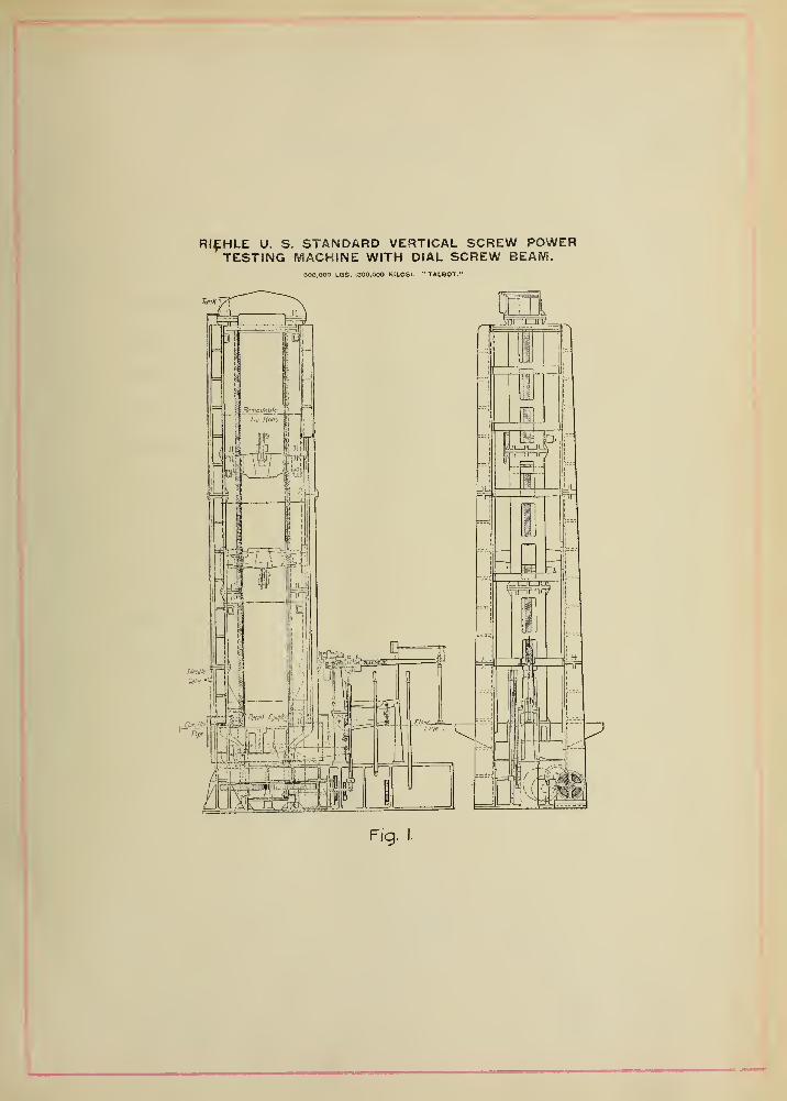
RIEHLE U. S. STANDARD VERTICAL SCREW POWERTESTING MACHINE WITH DIAL SCREW BEAM.
600.OOO LBS. (300,000 KILOS). " TALBOT."
Fig. I.
TABLE OP CONTENTS
Page
Introduction. 2
I. Historical. 3
II. Types of Machines.
III. Examples of Existing Machines. 10
IV. Relative Merits as to Types, Sizes, and Uses. 26
V. Palkenau-Sinclair and 01 sen Plans. 31
VI. Description. 39
VII. Investigation of Design. 45
VIII. Calibration. 67
IX. Specification Tests. 75
X. Conclusions. 80
XI. Chronology. 8S
XII. Tables. 84
XIII. Curves. 109
INTRODUCTION .
The 600,000 pound testing macine in the Laboratory
of Applied Mechanics of the University of Illinois which is dis-
cussed in this thesis is peculiar in several respects, notably in
its design and its capacity. The design is characterized by cer-
tain distinctive features which are not common to other machines,
while in point of capacity and in size of specimen that can be
accomodated, it is exceeded by no other vertical screw power test-A
ing machine in the world.
These facts make its study doubly interesting. The
various types of testing machines will be discussed, a description
will be given of this particular machine, its design will be in-
vestigated, and the calibration and other tests upon which it was
accepted will be given.
I
HISTORICAL.
Although the history of testing machines in this country
does not go hack more than fifty years, it is within the last twen-
ty-five or thirty years that the greatest advance has been made in
their development and use.
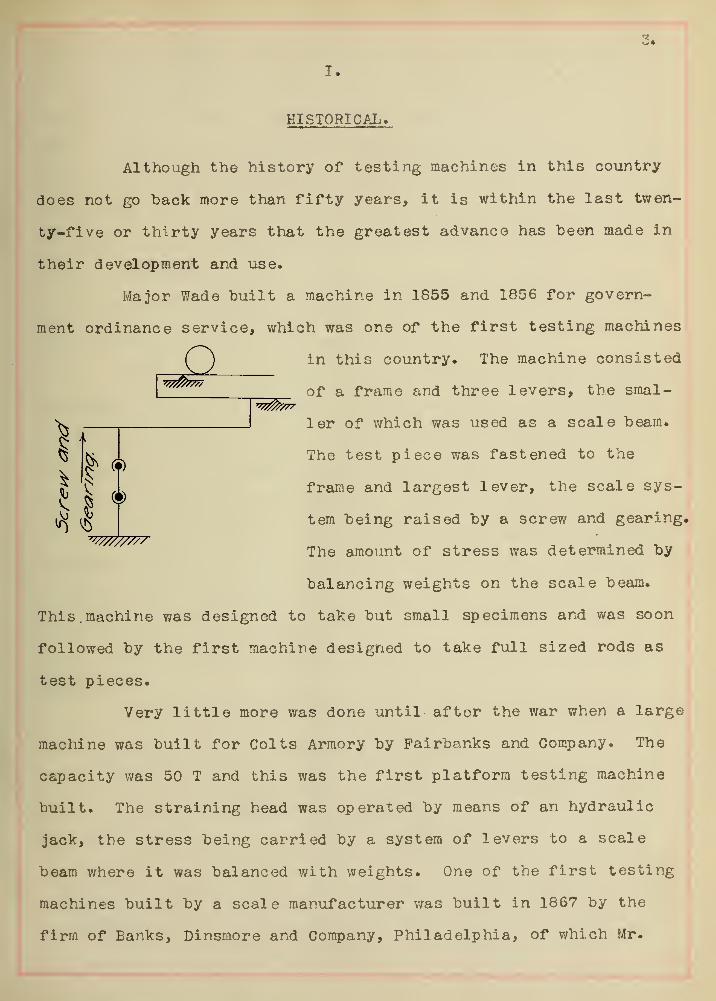
Major Wade built a machine in 1855 and 1856 for govern-
ment ordinance service, which was one of the first testing machines
in this country. The machine consisted
of a frame and three levers, the smal-
ler of which was used as a scale beam.
The test piece was fastened to the
frame and largest lever, the scale sys-
tem being raised by a screw and gearing.
The amount of stress was determined by
balancing weights on the scale beam.
"////////'
This. machine was designed to take but small specimens and was soon
followed by the first machine designed to take full sized rods as
test pieces.
Very little more was done until after the war v/hen a large
machine was built for Colts Armory by Fairbanks and Company. The
capacity was 50 T and this was the first platform testing machine
built. The straining head was operated by means of an hydraulic
jack, the stress being carried by a system of levers to a scale
beam where it was balanced with weights. One of the first testing
machines built by a scale manufacturer was built in 1867 by the
firm of Banks, Dinsmore and Company, Philadelphia, of which Mr.
4.
Riehle was a member. This machine was followed by others and much
interest was awakened in the subject, so much so that at a conven-
tion of the American Society of Civil Engineers held at Chicago in
1872 a coaraittee was appointed to urge upon the government the ne-
cessity for a thorough series of tests of American iron and steel.
The purpose of the committee was achieved aiid in 1879 the celebra-
ted Emery machine at the United States Arsenal at Watertown, Mass-
achusetts, was finished. This has a capacity of 500' T and is cap-
able of testing specimens up to 30 feet in length both in tension
and compression and will be described later.
What is thought to be the first machine autograp hi cal 1
y
recording the results of tests in other than tension was construc-
ted in 1877 by Abbott. Prof. Thurston had built one shortly before
this for torsion. Abbott's machine had a capacity of 50 T, the
length of specimen being limited to 2 feet.
Since 1880 great improvements have been made in testing
machines, new types such as the 01 sen and Riehle have been intro-
duced and the matter has reached a high state of development.
These types will be discussed later.
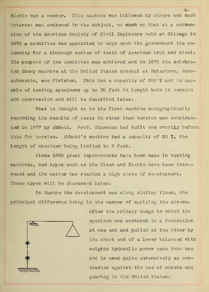
In Europe the development was along similar lines, the
principal difference being in the manner of applying the stress.
After the primary stage in which the
specimen was anchored to a foundation
at one end and pulled at the other by
the short end of a lever balanced with
weights hydraulic power came into use
($) and is used quite extensively as con-
s^s^^^ trasted against the use of screws and
gearing in the United States.
5.
Mr. Tinius 01 sen, who is probably one of the foremost
pioneer testing machine men of this country was asked if he would
tell something of his early connection with the industry and we
take what follows from the notes which he very kindly furnished:
-
"In 1870 while employed as a draftsman by the William Sellers
Company designing tools, I had become socially acquainted with
the Riehle Brothers who had just shortly before this bought out a
small business for manufacturing scales. About this time some
makers of boiler plates had asked them if they could make a testing
machine for them for the purpose of testing the plates. I was
then asked what I knew of testing machines and if I could design
one.
"On this my first drawing for a testing machine was made,
being a simple application of one then well known weighing appar-
atus consisting of a crane beam to one end of the specimen and a
hydraulic jack to the other, with proper tools for securing the
ends of the specimens.
"At a later date a larger machine was desired by the Pennsyl-
vania Railroad Company and I made a new design for this. The ex-
ecution of this drawing was rather too much for Riehle Brothers
shops' knowledge at that time and I was much called upon to guide
the work of these machines. This led them to desire me to accept
the position of superintendent of their works which I did at the
beginning of the year 1872.
"In the following eight years I made many new designs, and
many new patents were taken out, especially in 1879, which were
all assigned to Riehle Brothers." On account of some trouble over
patents Mr. Olsen left Riehle Brothers about this time. To quote
again from the same source :
-
" During the past years Fairbanks Company also had made some
testing machinery, mainly by applying strain mechanism to their
existing scales.
"Having for so many years put my whole attention to testing
machines and scales, and feeling that more was to be developed
in that line, I set to work and designed a new type of machine,
the screw machine, all previous had been hydraulic, which was pat-
ented June 1, 1880. This design in a short time superseded all
previous designs and is the basis of all vertical designs and
forms as made today in this country.
"Fairbanks at once ordered three of these machines to sell to
prospective customers with the understanding that I should take
charge of this business for them but being unable to effect sat-
isfactory business arrangements, I started my own place of business
April 1, 1881.
"The first testing machine designed for a technical institution
was for the Stevens Institute of Technology, Hoboken, N. Y. , and
ordered by the late Doctor Thurston in 18&4«"
7.
II.
TYPES OF MACHINES.
After the preceding brief history of the introduction of
testing machines, their classification will he discussed.
There are four general classes with subdivisions as fol-
lows:
1. As to Use.(a(b
2. As to Position of Sxoecimen.(a(b
3. As to(a(b
4. As to(a(b(c
GeneralSp ecific
VerticalHorizontal
Method of Application of Stress.ScrewHydraulic
Method of Measuring Stress.Knife Edge LeverHydraulic LeverHydraulic or Mercury Gauge
These classes will now be discussed in brief and examples
given of each.
l.(a) General testing machines are those designed to make
experiments in three or four different ways, as for example, in
tension, compression, transverse stress, shear, bulging, punching,
abrasion, impact, denting or torsion. Host general machines are
limited to the first three or four of these although the Kirkaldy
machine, one of the largest in use, was designed for testing in
tension, compression, bending, shearing, bulging and torsion. The
subject of this thesis is also an example of a machine designed for
general uses. These machines are sometimes called universal mach-
ines.

(b) Special machines are those limited to one particular
form of test, as for examples, machines for testing wires, concrete
in tension, springs, chains, etc., or machines limited to tension,
compression, torsion, etc. While many of this class are of hut
small capacity, some large machines may he cited as examples, not-
ably the large machine at the Pencoyd Plant, American Bridge Co.
at Pencoyd, Pa., which is limited to tests in tension and the mach-
ine at the Keystone Bridge Works, Pittsburg, Pa.
2. Vertical and horizontal machines are so called from the
position of the specimen. The advantages and disadvantages of both
will be discussed further on.
(a) The vertical machines generally have the pulling head
operated by screws and gearing and have the stresses measured by
levers and weights. The 01 sen and Riehle types of machine to be
described later on are examples of this style of machine.
(b ) The horizontal machine is the characteristic type for
the larger machines operated by hydraulic power and for the present
Emery machine. The largest machine in the world, that of the Phoe-
nix Iron Co., Phoenixville, Pa., is of this class, I.e. horizontal.
3. (a) As was indicated in (2), screw machines are usedin
great part with the vertical type and hydraulic power with the hor-
izontal type of machines almost without exception. Screws and
knife edge levers are generally used with machines designed for
experimental work and other uses which require higher refinement
and also, of course, for commercial testing while hydraulic power
combined with hydraulic gauge is used for commercial and such other
work as does not require extreme accuracy. The Riehle and 01 sen
are screw machines while the Kirkaldy and Buckton-Wickst eed use
hydraulic power. Screw and gearing is the favorite type in America
and the hydraulic jack in Europe.
4. Probably as important as any classification is the
classification according to the manner in which the stress is
measured.
(a) The knife edge lever method is the most common. In
this the load upon straining head is communicated by means of
knife edges and a system of one or more levers, to a scale beam
upon which the stress is measured by means of a movable balancing
weight. All lever machines except the Emery machine are of this
type.
(b ) The method for which the greatest accuracy is claimed
is the hydraulic lever method which is characteristic of the Emery
machine. The weighing device is a flat cylinder called an hydrau-
lic support. The pressure is conveyed from this cylinder to a
smaller cylinder which operates the weighing levers. These levers
are not balanced upon knife edges but are connected by flexible
steel plates or "platen" designed so that the stress does not ex-
ceed elastic limit and reducing the losses due to friction to prac-
tically nothing.
(c) The crudest and one of the first methods used to
measure the stress was by means of an hydraulic gauge which indic-
ated the unit pressure at base of hydraulic $ack, from which was
easily computed the total stress.
Ill
EXAMPLES OP EXISTING MACHINES,.
The following machines will be described:
1. General types.( a ) Ri ehl e(b) 01 sen(c) Emery(d) Buckton-tficksted(e) Werder
2. Special or particular machines.(a) Watertown(b ) Athens, now Pencojrd(c ) Phoenix
l«(a) The fiiehle machine is manufactured by Riehle Bro-
thers Testing Machine Company, Philadelphia, Pa* They manufacture
horizontal hydraulic power machines with capacities up to 800,000
pounds or more, vertical screw power machines with capacities up
to 600,000 pounds and various smaller ones for particular purposes.
The characteristic machine is the vertical screw power of 100,000
pounds to 400,000 pounds capacity. The following description is
taken in part from their catalogue:-
"The top head • of the machine, of cast steel, is supported by
two cast iron columns which rest on the weighing table. This
table in turn rests upon eight hardened steel knife edges in the
main levers, these levers being held up by cast iron columns rising
from the cover plate. Beneath this is the cast iron box containing
the main gears.
"Through holes in the table two pulling screws pass up and
reach nearly to the top head, running through pulling head which
is raised or lowered according to which direction screws revolve."
For tension the specimen is held in grips in top and pulling heads._) = ^ __ _ ^ 1

12.
For compression, the specimen is placed between tools on lower
side of pulling head and on weighing table. For transverse tests
the specimen rests upon two tools on weighing table and load is
applied through another tool on under side of pulling head.
"The weighing table rests wholly upon the main levers, the
recoil bolts passing through it loosely. There are two main levers
the one inside the other and of nearly equal length. Each of the
levers branch into a Y under table to spread the points of support
and to allow screws to pass into box. The knife edges are in
direct line with pulling screws to insure an even distribution of
load.
"The two pulling screws pass down through bearings in cover
plate and to their lower ends are keyed the main gears." The
machine is generally furnished with six pulling and six reversing
speeds ranging from eight inches per minute to one-tenth inches
per minute.
The machine can be provided with the Riehle automatic
apparatus for operating the poise and the Riehle autographic ap-
paratus for recording the stress and strain of test specimen.
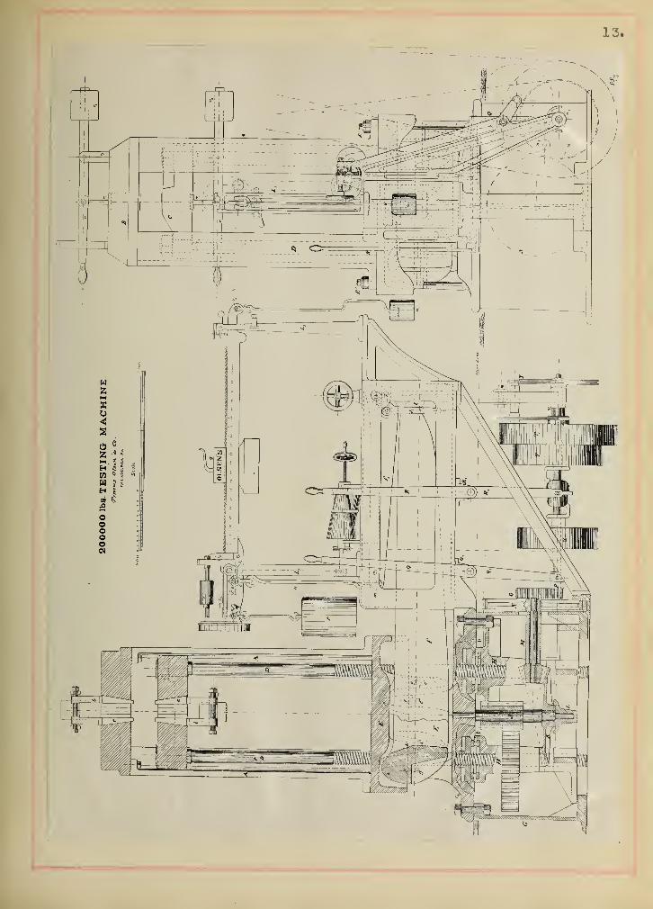
(b) The Olsen machine is manufactured by Tinius Olsen
and Company, Philadelphia, Pa. This machine differs very slightly
in general design from the Riehle machine. The chief difference
is that the Olsen machine has four straining screws and four
weighing columns where the Riehle has but two. This difference
carries with it a difference in the lever system also. The main
lever system consists of three levers. The longest one receives
the load from the rear set of screws, being divided at the "heavy"
end into branches which are supported upon knife edges as nearly
13.
14.
under screws as possible. The shorter levers run to the front
screws and are outside of the long lever.
Under the bed plate is a collar and on the screws below
this collar are nuts aarrying a large gear wheel. These four
wheels mesh with another but smaller gear wheel or pinion which
is located in the center of the machine and is turned through
trains of gears from the driving shaft.
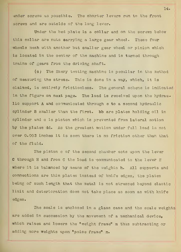
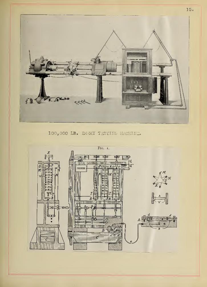
(c; The Emery testing machine is peculiar in the method
of measuring the stress. This is done in a way, which, it is
claimed, is entirely frictionless. The general scheme is indicated
in the figure on next page. The load is received upon the hydrau-
lic support A and conmunicated through e to a second hydraulic
cylinder B smaller than the first, bb are plates holding oil in
cylinder and c is piston which is prevented from lateral motion
by the plates dd. As the greatest motion under full load is not
over 0.003 inches it is seen there is no friction other than that
of the fluid.
The piston c of the second chamber acts upon the lever
C through H and from C the load is -communicated to the lever E
where it is balanced by means of the weights h. All supports and
connections are thin plates instead of knife edges, the plates
being of such length that the metal is not stressed beyond elastic
limit and deterioration does not take place as soon as with knife
edges.
The scale is enclosed in a glass case and the scale weights
are added in succession by the movement of a mechanical device,
which raises and lowers the "weight frame1* m thus subtracting or
adding more weights upon wpoise frame" n.
16.
17*
The last lever of the series is the indicator needle F
which with a movement of 1 3/4 inches to 2 inches at its point
multiplies the movement of the piston w cw 300,000 to 6,000,000
times depending on the size of the machine.
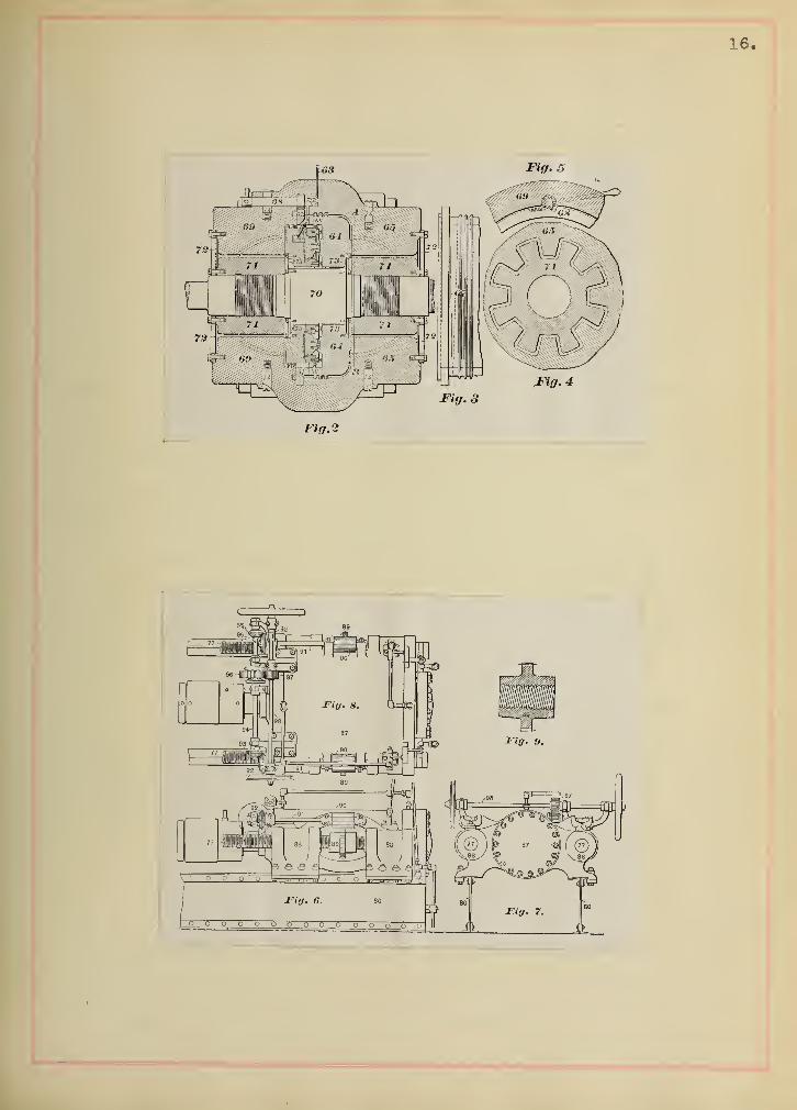
The weighing head consists of two annular "beams 65 (see
figure) bolted tegether and containing the draw bar 70 along their
axis. This drawbar is e entered with respect to the beams by means
of the plates 72 and centers the hydraulic support by plates 73,
attached to the drawbar are the collars ?1 provided with ribs as
shown in Pig. 4. The end of the drawbar projecting at right in
figure is threaded to receive tension and compression tools.
When the specimen is in compression the collar 71 presses against
the piece 64 which rests upon the hydraulic support, the latter
bearing upon the ribs of the annular beam 69.
The shock due to recoil is reduced to minimum by bringing
the beams 65 and 69 as close together as possible by means of the
pinion shaft 68 (Pig. 5), thus reducing the motion and impact of
recoil.
The straining head can be moved to desired position
along two screws. These screws are attached to the weighing head
and pass loosely through rotary nuts in the straining head 87(Fig.
6,7,8), motion being communicated to the nuts 09 through a train
of gears.
"The Emery testing machines are now made horizontal in-
stead of vertical; in the first place to make all sizes of machines
of one type, and in the second place to get certain advantages in
overcoming the shocks of recoil. In all but the very smallest size
of machines the weighing head and the hydraulic cylinder or
straining head are carried by the top surface of a wrought-iron
bed."
The largest Emery machine in use is the one already re-
ferred to at the Watertown Arsenal which is remarkable for its
delicacy and precision. "It can break a hair and a bar of steel
thirty feet long and the relative error in measuring the ultimate
strength will.be closely equal in the two cases." (Merriman and
Jacoby-" Bridge Design" ).
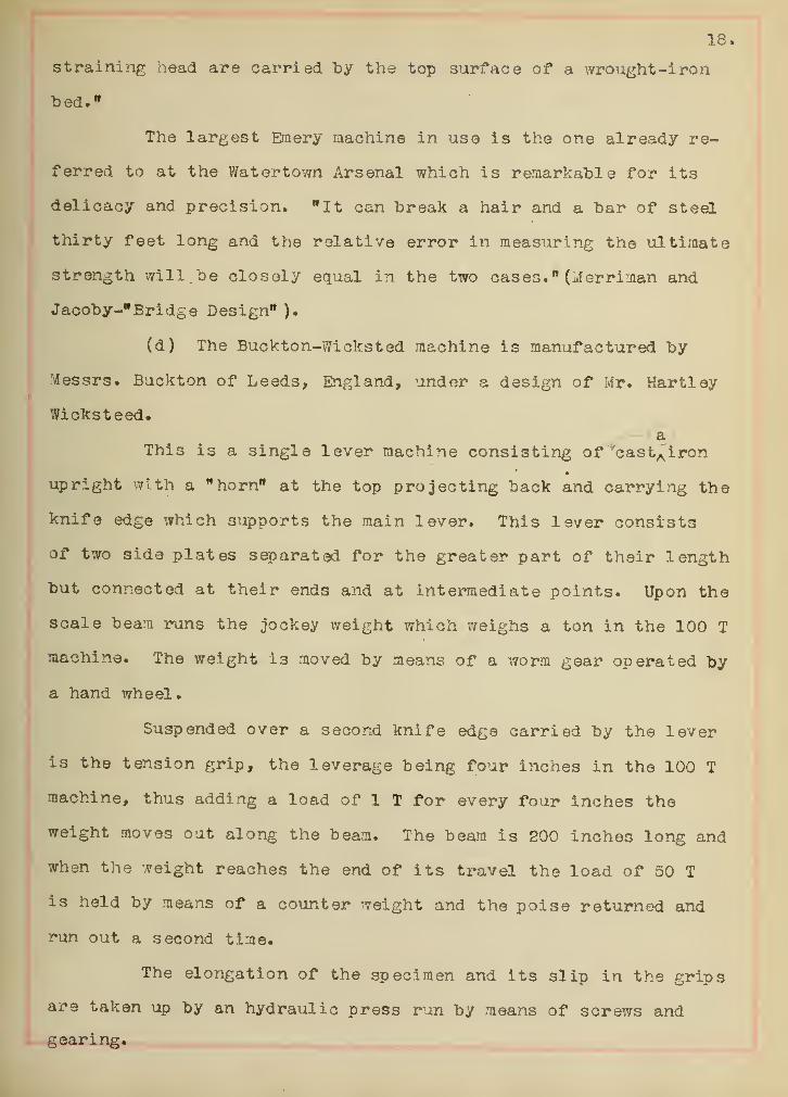
(d) The Buckton-wicks ted machine is manufactured by
Messrs. Buckton of Leeds, England, under a design of Mr. Hartley
Wicksteed.a
This is a single lever machine consisting of castA iron*
upright with a "horn" at the top projecting back and carrying the
knife edge which supports the main lever. This lever consists
of two side plates separated for the greater part of their length
but connected at their ends and at intermediate points. Upon the
scale beam runs the jockey weight which weighs a ton in the 100 T
machine. The weight i3 moved by means of a worm gear operated by
a hand wheel.
Suspended over a second knife edge carried by the lever
is the tension grip, the leverage being four inches in the 100 T
machine, thus adding a load of 1 T for every four inches the
weight moves out along the beam. The beam is 200 inches long and
when the weight reaches the end of its travel the load of 50 T
is held by means of a counter weight and the poise returned and
run out a second tirae»
The elongation of the specimen and its slip in the grips
are taken up by an hydraulic press run by means of screws and
gearing. __
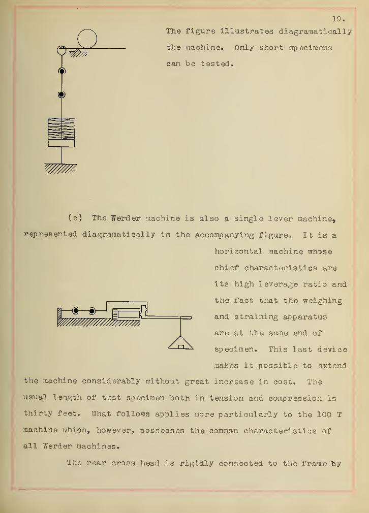
19.
The figure illustrates diagramatically
the machine. Only short specimens
can be tested.
Mm
(e) The Werder machine is also a single lever machine,
represented diagramatically in the accompanying figure. It is a
horizontal machine whose
chief characteristics are
its high leverage ratio and
the fact that the weighing
and straining apparatus
are at the same end of
specimen. This last device
makes it possible to extend
the machine considerably without great increase in cost. The
usual length of test specimen both in tension and compression is
thirty feet. What follows applies more particularly to the 100 T
machine which, however, possesses the common characteristics of
all Werder machines.
The rear cross head is rigidly connected to the frame by
20.
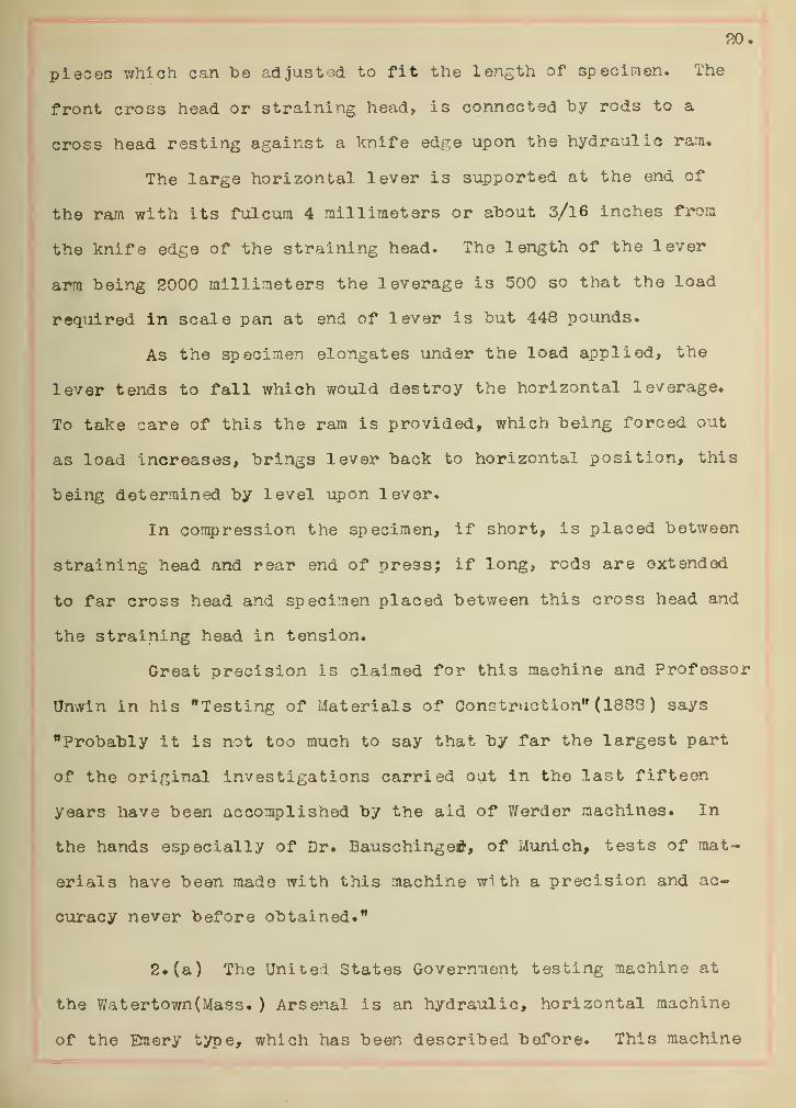
pieces which can be adjusted to fit the length of specimen. The
front cross head or straining head, is connected by rods to a
cross head resting against a knife edge upon the hydraulic ram.
The large horizontal lever is supported at the end of
the raid with its fulcum 4 millimeters or about 3/16 inches from
the knife edge of the straining head. The length of the leverI
arm being 2000 millimeters the leverage is 500 so that the load
required in scale pan at end of lever is but 448 pounds.
As the specimen elongates under the load applied, the
lever tends to fall which would destroy the horizontal leverage.
To take care of this the ram is provided, which being forced out
as load increases, brings lever back to horizontal position, this
being determined by level upon lever.
In compression the specimen, if short, is placed between
straining head and rear end of press; if long, rods are extended
to far cross head and specimen placed between this cross head and
the straining head in tension.
Great precision is claimed for this machine and Professor
Unwin in his "Testing of Materials of Cons truct ion" (1838 ) says
"Probably it is not too much to say that by far the largest part
of the original investigations carried out in the last fifteen
years have been accomplished by the aid of Werder machines. In
the hands especially of Dr. Bauschinge*, of Munich, tests of mat-
erials have been made with this machine with a precision and ac-
curacy never before obtained.
"
2. (a) The United States Government testing machine at
the Watertown(Mass. ) Arsenal is an hydraulic, horizontal machine
of the Emery type, which has been described before. This machine
was designed for a capacity of 800,000 pounds in compression and
tension but at the present time is not used for loads over 600,000
pounds. It is capable of taking specimens up to thirty feet in
length and in compression by a "slight modification of its parts"
can be adapted to specimens thirty-one feet eleven inches in
length and in tension on eye bars to a length of thirty-seven
feet three inches center to center of eyes. As was stated before,
this is the first large testing machine in the United States and
was built to neet the demand which existed for an extensive series
of tests on American steel and iron.
The machine embodies the distinctive features of the
Emery type. It consists of two heads, the straining press and
the hydraulic scale, between which the specimen is placed. The
press has a cylinder twenty inches in diameter with a stroke of
twenty-four inches* The two heads are connected by two screws
8.5 inches in diameter and 48 feet long. The cylinder is moved
along these screws by means of nuts driven by a central shaft.
In this way the machine is adjusted for specimens of different
1 ength.
Among the specifications which were all successfully met
were the following
First.- A machine with a capacity in tension or compression
of 800,000 pounds with a delicacy sufficient to accurately register
the stress required to break a single horse hair.
Second.- The machine should have the capacity of seizing and
giving the necessary strains from the minutest to the greatest,
without a large number of special appliances, and without special
adjustments for the different sizes.
22.
Third.- The machine should be able to give the stresses and
receive fhe shocks of recoil produced "by rupture of the specimen
without injury. The recoil from the breaking of a specimen which
strains the machine to full capacity may amount to 800,000 pounds,
instantly applied. The machine must bear this load in such a
manner as to be sensitive to a load of a single pound placed upon
it, without adjustment, the next moment.
The extreme sensitiveness and the accuracy of this machine
have been spoken of elsewhere.
(b ) The 600 T. testing machine at the works of the Amer-
ican Bridge Company, Pencoyd, Pa., formerly at the works of the
Union Bridge Company, Athens, Pa.
Before this machine was built there was but one large
testing machine in America, that of the United States Arsenal at
Watefctown, which was capable of testing full size bridge members
to destruction. This latter machine, also, was unable to turn
out work excepting at the expense of considerable delay in time
on account of the quantity of work required of it and hence the
demand for another machine which could be controlled by private
parties was very great.
The machine in general is of almost exactly the same de-
sign as that of the Phoenix machine, described later, the latter
being copied from the former. It consists, as does the Phoenix
machine, of:- a hydraulic cylinder securely fastened between two
longitudinal girders, which form the frame of the machine; a tail
block which may be attached to the webs of the girders at conven-
ient intervals; and two connecting blocks to receive the test
23.
pieces, attached respectively to the piston of the cylinder and
the tail "block. These blocks are carried upon finished wheels
running upon an accurately finished and lined track upon the lower
flanges of the girders. In this respect they differ from the
Phoenix machine in which these blocks slide upon guide rods bolted
to the girders.
The cylinder is of cast steel 4 feet 3 3/4 inches in dia-
meter and 6 feet l/2 inches long with an effective area of 20 39
square inches and a working stroke of 4 feet 11 inches. The max-
imum water pressure for which provision is made is 600 pounds per
square inch making a total strain upon test piece 1,223,400 pounds.
The total friction of the machine has been measured as less than
4000 pounds when pressure is off. It is believed that when pres-
sure is on and film of water is escaping that friction is greatly
reduced. The main girders are of wrought iron 60 feet long by
3 feet 5 5/8 inches high. Holes are bored through the webs 6 1/2
inches in diameter and 18 inches center to center for attachment
of tail block. The girders rest on twelve inch cross girders
bolted to masonry foundation.
The tail block is a steel casting attached by pins to
girder and having a connecting block attached to it by four steel
rods.
The remainder of the machine is essentially the same, in
form, as the Phoenix machine to be described later.
The length of specimen that can be tested is forty feet
with an elongation of twelve percent.
(c) The 1200 T testing machine of the Phoenix Iron Com-
\
24.
pany, Phoenixville, Pa.
This large and powerful machine was built to test to de-
struction full sized specimens of the largest members used for
tension and compression in structural iron and steel work.
It is a modification of the machine formerly at Athens
just described, the principal changes being that the head block
runs on guide rods attached to the main girders instead of upon
wheels and that the cylinder has been changed so that tests can
be made in compression as well as in tension.
The double acting cylinder is 7 feet 10 inches long,
64 l/io inches in diameter, has a stroke of 6 feet and weighs 10T
and is bolted to the main girders by turned steel bolts 2 inches
in diameter. The piston rods, four in number, are 8 l/2 inches
in diameter making net area of cylinder 3000 square inches for
tension. The piston rods and piston have brass glands for pack-
ing. The same number and size of rods are used at tail block.
9 1/2 inch stop pins, two in each girder, hold tail block in po-
sition.
The recoil and head blocks are provided with 10 inch pin
holes which will receive eyes 30 inches in diameter and 4 1/2 in-
ches in thickness.
The main girders are I»s 78 feet long, 51 l/2 inches deep,
and weigh 60 T. Each has a gross area of 244 i/2 square inches
with net section at pin holes of 166 square inches. The anchor
pin holes for tail block are 9.56 inches in diameter with 18 inch
centers lengthwise and 24 inch cent err urosswiae. Two inch holes
between pin holes crosswise are for convenience in removing pins
25.
from ends of test piece. The girders rest on transverse plate
girders and are stiffened by riveted gusset brackets. The machine
will take an eye bar 50 feet long.
The machine has been intended for loads up to 2,160,000
pounds or a pressure of 720 pounds per square inch upon piston
but it can be worked safely at pressure of 800 pounds per square
inch upon piston or total load of 2,400,000. Although the diameter
of piston is exceeded by those of many low pressure cylinders for
steam engines, yet when fully loaded it is thought to carry more
than any other piston ever constructed.
The packing of piston is different from that ordinarily
used in hydraulic work. Brass glands surround the piston and rods
confining several rings of ordinary flax packing. As pressure
increases the flax is compressed and a thin film of water escapes
around circumference, thus reducing friction as pressure increases.
This friction has been measured on the Athens machine as was noted.
To make a test, the tail block is rolled along until it
is opposite the pair of holes nearest right for the length of eye
bar to be tested. Pins are then inserted in tail block and recoil
block is adjusted to exact length of bar. Bar is then put in,
stress applied, and readings taken on hydraulic gauge.
The Phoenix machine has been calibrated by means of
comparative tests on the Emery machine at Watertown. The error
was found to be about 15 percent^ The specimens were full sized
columns, the test being in the interest of the City of New York.
IV.
26.
RELATIVE MERITS AS TO TYPES, SIZES , AND USES .
In comparing one machine with another it is neces-
sary that there be a definite basis of comparison, for one machine
will possess certain advantages for one particular kind of work
while it may be almost completely useless or unadapted for an-
other kind of work.
However there are certain qualities to be sought
after in the design of all machines and prominent among these
are the following:-
1. Sensitiveness2. Accuracy3. Adaptability4. Convenience of Manipulation5. Simplicity
1. For a machine to possess sensitiveness it must
be so that it will indicate sharply small increments of stress.
The sensitiveness depends upon the condition of the knife edges,
the platen, oh the amount of the hydraulic friction. Most mach-
ines, especially while new, are amply sensitive. Unwin says
that a good 100 T machine will be moved distinctly by an addition
of a stress of l/lOO T, or a sensitiveness of 1/10,000 or 1/100
of one percent.
A sensitiveness of l/io to 1/4 of one percent would
be amply sufficient for ordinary testing and still less is quite
enough for the rougher and commercial tests. For excessive sen-
sitiveness, the Emery machine stands first. It is claimed that
2T.
a weight of 200 grains laid on the platform of an Emery machine
of 500,000 pounds capacity was sufficient to move the indicator
needle 0.02 inches thus actually setting in motion material wei-
ghing more than 25,000 pounds. Of an Emery machine exhibited
at Paris, it is reported that a horse hair was broken under a
load of 16 ounces after breaking a specimen at load of 90,000
pounds. The Watertown machine, before being accepted, broke a
link of hard iron five inches in diameter at a load of 722,000
pounds and without any readjustment broke a horse hair at a load
of one pound. "In seven weighings of a load of 100 pounds with
the Watertown machine the greatest difference in the observed
weights was1,750 qqq the load. In nine weighings of 200
pounds the difference was onlyg 550,000 of the load" •Unwin.
Sensitiveness decreases with use since the friction
on the knife edges increases as they become dulled by rolling on
their supports and by impact in recoil.
The friction does not increase much with load and
hence proportional sensitiveness increases. This, is not true of
most hydraulic machines, although it is of the Phoenix, due per-piston
haps to the special design of the packing ofAwhich has been de-
scribed.
2. Accuracy is as essential as sensitiveness and,
of course, a very sensitive machine may be inaccurate.
Errors may be due either to a lack of knowledge as
to the true leverage ratio, to incorrect weights, to inertia
forces, or to deflection of the levers.
The leverage ratio may be that given by the manu-
facturer and not verified by user. This ratio will tfhange
28.
slightly to one side or the other. Errors of this nature produce
least effect when distance between knife edges are large as in
Buckton-Wicksteed machine and most effect when knife edges are
close together as in Werder machine.
Weights may easily be standardized and this source
of error need not be discussed.
It is a known fact that the inertia forces influence
readings very materially and hence the adoption of standard rates
of applying the load in order that accurate comparisons may be
made. Mr. Gus C. Kenning says of this, "It is well known that
in the Carnegie Works you test so fast that you simply take the
man's word for it that it carried so much. But if you know your
business you do not let them run a machine so fast." With an
Emery machine, however, this is different, and as long as indic-
ator needle is floating, the correct stress is indicated.
Errors due to deflection are hard to combat and can
be taken care of only by a thorough and complete calibration
throughout the whole range of the machine. Stiffness of the
levers should be sought as well as strength and it is very advis-
able to make an investigation of the flexure throughout large
variation in the stress.
Measurement of the knife edge distance is rarely
satisfactory, and it is much better that the leverage be obtained
by weighing and that this test be applied occasionally afterwards.
Least in accuracy of the machines in common use are
the hydraulic machines, inaccuracies being due to the ever chan-
ging friction of the moving parts and errors of the measuring
gauges. The accuracy of this type is quite sufficient however
*
29.
for ordinary commercial testing of full sized members.
Knife edge machines rank next in accuracy while the
manometer measuring machines of the Emery type are the most ac-
curate,Vjthe Watertown machine feeing the most accurate testing
machine in the world. ^ ^'
3. By adaptability is meant the quality of easy
changing from one kind of test to another and from one size of
specimen to another, also the variety of work it is possible to
do.
It is conceded that in adaptability the horizontal
machine surpasses because in this type in moving about the heavy
and cumbrous parts they need not be lifted or lowered but are
merely shifted horizontally into required position, fa™ ifoC/Uf^\^
4. For convenience in manipulation, the grips should
be easy of access and the operating levers so arranged that all
are within reach and placed so that specimen and scale beam can
be watched throughout test.
5. Simplicity of design is desirable for several
reasons. When there are but a few parts the operator is much
less apt to make mistakes and can give more attention to the
behavior of the test piece. Complications, if any, are almost
always in the weighing apparatus either in the multiplication of
levers and knife edges or in use of variable weights. Besides
adding to the complexity, these features increase initial cost
and cost of repairs. The Buckton-Wicksteed is recommended for
its simplicity on account of its single lever, considerable
fulcrum distance, and constant poise weight.
As embodying the qualities enumerated above and
30.
considering their uses, the following may be said:-
For commericial rapid testing for which no great
refinement is required the horizontal hydraulic machines such as
the college laboratory, more refined than commercial tests, the
Olsen, Riehle, Buckton-Wicksteed, Werder and similar machines are
recommended.
For the highest degree of precision and accuracy the
Emery machine is best.
that at Phoenixville are the best adapted.
For a great variety of work such as will occur in

31.
V.
PALKENAU-SINCLAIR AND PLSEN PLANS .
Sp ecifi cations.
It was desired in connection with the Engineering
Experiment Station at the University of Illinois, to secure a
testing machine which would be capable of taking columns, long
test pieces, beams, large irregular shapes, reinforced concrete,
stone and brick construction, built up metal trusses, and a great
variety of test pieces of considerable size.
Designs were submitted by three firms, Tinius 01 sen
and Company, Falkenau-Sinclair Machine Company, and Riehle Bro-
thers Testing Machine Company.
The Olsen plan embodied the characteristic features
of the Olsen, the principal change being the addition of a fifth
column to act as a guide for the traveling cross head. Three
screws were used which provided for a movement of pulling head,
without readjustment, of something less than eight feet. Three
adjustable bars supplemented the screws and provided an adjustment
to take care of differences in length of specimen.
The Palkenau-Sinclair Machine Company submitted four
designs. All had a clear distance of thirty-six inches between
pulling screws or pulling rods and were capable of taking spec-
imens twenty-five feet in length with a capacity of 600,000 lbs.
in each case. The floor space to be occupied was about 18 feet
by 9 feet. The machines were designed for making transverse

52.
tests with eight feet as distance between supports without ex-
tension to table.
The weighing mechanism consisted of cast steel levers
with seats of hardened tool steel let into machined hearings.
The poise was to consist of two sections one of which could he
moved out at a time. Five speeds were provided of 0.05,0.25, 1,
3, and 10 inches per minute respectively.
Machine tt Dw, the fourth of the four designs submit-
ted, was considered the best type for the purposes desired. This
consisted of two heads connected by three pulling rods which were
made in sections part of which could be removed for long specimens
in tension and short specimens in compression. The lower head
was provided with a nut through which passed the single screw
which furnished the load. The weighing head, in addition to the
two other pulling heads, was capable of but one position, at top
of weighing columns, thus necessitating the use of the upper part
of the machine for all tension tests.
The machine was designed for a capacity of but
300,000 pounds on tensile specimens of very inextensible material.
The specifications provided for an eccentricity of six inches
when this was divided evenly between top and bottom. A sensi-.5 2tiveness of1Q Q0Q
at full load, and ofi 0> qqq
at a load of
10,000 pounds when loaded normally. With eccentric load a sen-
sitiveness of —10 was to be attained.10,000
The design adopted was that of Riehle Brothers
Testing Machine Company as modified by Professor Talbot.
The specifications are found on the succeeding pages.

33
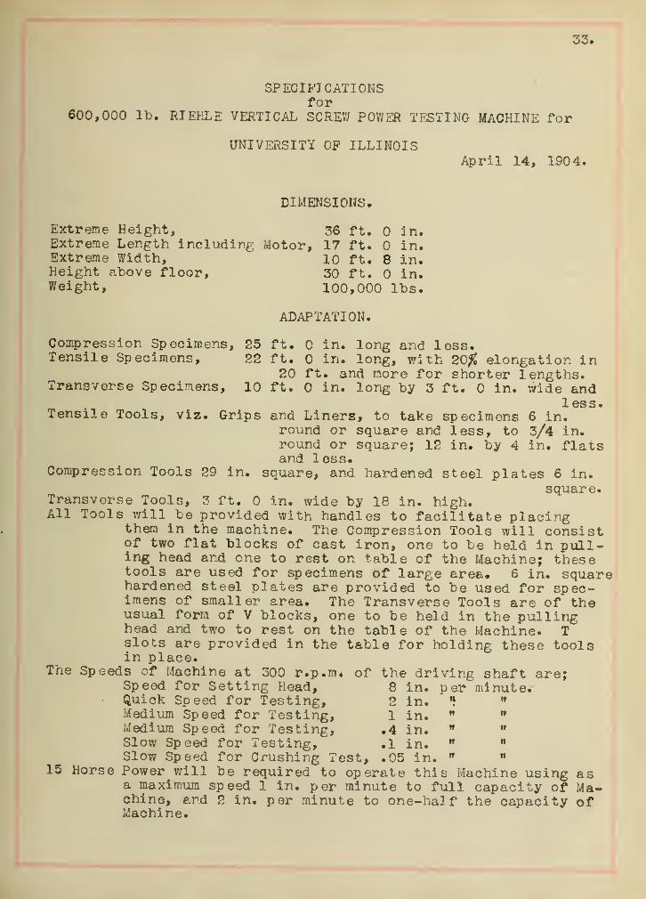
SPECIFICATIONSfor
600,000 lb, RIEHLE VERTICAL SCREW POWER TESTING MACHINE for
UNIVERSITY OP ILLINOISApril 14, 1904.
DIMENSIONS.
Extreme Height, 36 ft. in.Extreme Length including Motor, 17 ft. in.Extreme Width, 10 ft. 8 in.Height above floor, 30 ft. in.Weight,
Compression Specimens,Tensile Specimens,
Transverse Specimens,
Tensile Tools, viz.
2522
10
100,000 lbs.
ADAPTATION.
ft. in. long and less.ft. in. long, with 20$ elongation in20 ft. and more for shorter lengths,
ft. in. long by 3 ft. in. wide and1 ess.
6 in.3/4 in.in. flats
Compre! Tools 29 in,
Grips and Liners, to take specimensround or square and less, toround or square; 12 in. by 4and less.
square, and hardened steel plates 6 in.square.
Transverse Tools, 3 ft. in. wide by 18 in. high.All Tools will be provided with handles to facilitate placing
them in the machine. The Compression Tools will consistof two flat blocks of cast iron, one to be held in pull-ing head and one to rest on table of the Machine; thesetools are used for specimens of large area. 6 in. squarehardened steel plates are provided to be used for spec-imens of smaller area. The Transverse Tools are of theusual form of V blocks, one to be held in the pullinghead and two to rest on the table of the Machine. Tslots are provided in the table for holding these toolsin place.
The Speeds of Machine at 300 r.p.nw ofSpeed for Setting Head,
• Quick Speed for Testing,Medium Speed for Testing,Medium Speed for Testing,Slow Speed for Testing,Slow Speed for Crushing Test,
15 Horse Power will be required to operate this Machine using asa maximum speed 1 in. per minute to full capacity of Ma-chine, and 2 in. per minute to one-half the capacity ofMachine.
the driving shaft are;8 in. per minute.21
.4
.1
.05
in.in.in.in.in,
n
H
N
n
N
n
it
n
n
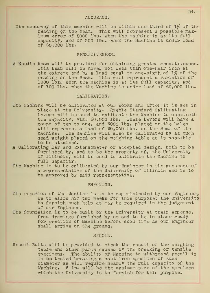
ACCURACY.34.
The accuracy of this machine will he within one-third of 1% of thereading on the beam. This will represent a possible max-imum error of 2000 lbs. when the machine is at its fullcapacity, and of 200 lbs. when the Machine is under loadof 60,000 lbs.
SENSITIVENESS.
A Needle Beam will be provided for obtaining greater sensitiveness.This Beam will be moved not less than one-half inch atthe extreme end by a load equal to one-sixth of lf of thereading on the Beam. This will represent a variation of1000 lbs. when the Machine is at its full capacity, andof 100 lbs. when the Machine is under load of 60,000 lbs.
CALIBRATION.
The Machine will be calibrated at our Works and after it is set inplace at the University. Riehle Standard CalibratingLevers will be used to calibrate the Machine to one-tenththe capacity, viz. 60,000 lbs. These Levers will have acount of ten to one, and 6000 lbs. placed on the baleswill represent a load of 60,000 lbs. on the Beam of theMachine. The Machine will also be calibrated by as muchdead weight placed on the weighing table as is possibleto be attained.
A Calibrating Bar and Extensometer of accepted design, both to befurnished by, and to be the property of, the Universityof Illinois, will be used to calibrate the Machine tofull capacity.
The Machine is to be calibrated by our Engineer in the presence ofa representative of the University of Illinois and is tobe approved by said representative.
ERECTION.
The erection of the Machine is to be superintended by our Engineer,we to allow him two weeks for this purpose; the Universityto furnish such help as may be required in the judgementof our Engineer.
The foundation is to be built by the University at their expense,from drawings furnished by us and to be in place readyfor erection of Machine before such time as our Engineershall arrive on the ground.
RECOIL.
Recoil Bolts will be. provided to check the recoil of the weighingtable and other parts caused by the breaking of tensilespecimens. The ability of Machine to withstand recoil isto be tested breaking a cast iron specimen of suchdiameter as will require nearly the full capacity of theMachine. 6 in. will be the maximum size of the specimenwhich the University is to furnish for this purpose.
35.
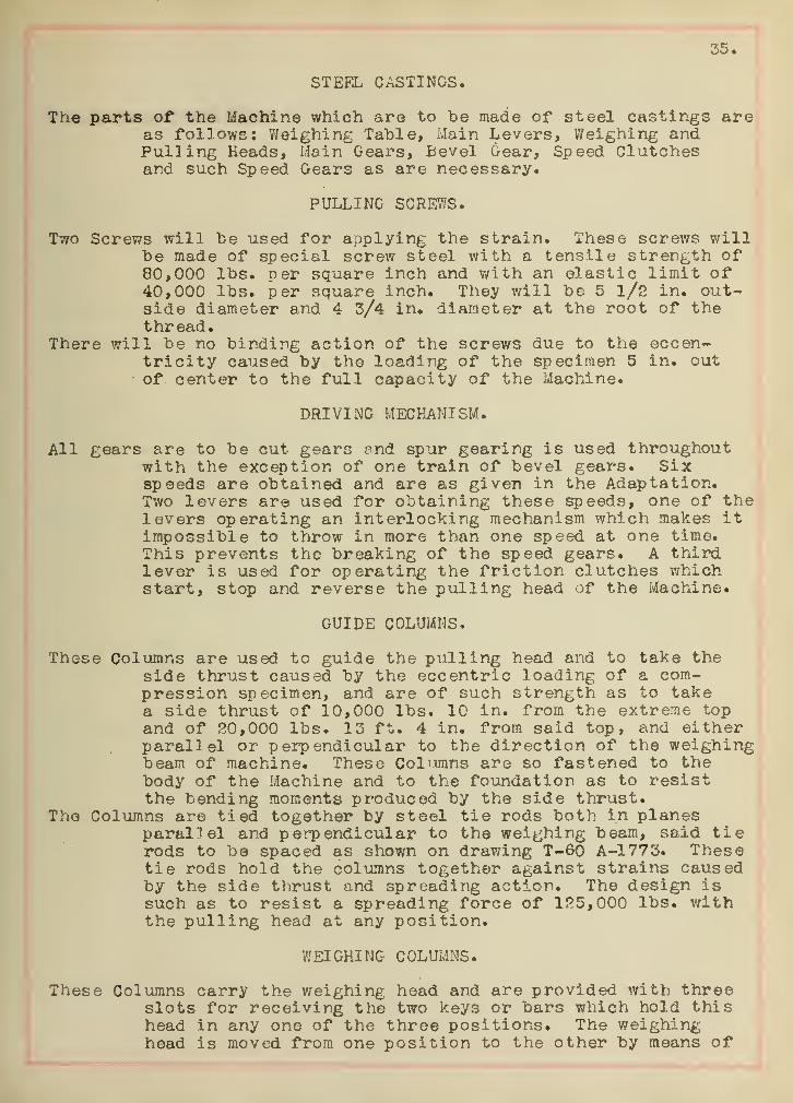
STEEL CASTINGS.
The parts of the Machine which are to be made of steel castings areas follows: Weighing Table, Main Levers, Weighing andPulling Heads, Main Gears, Bevel Gear, Speed Clutchesand such Speed Gears as are necessary.
PULLING SCREWS.
Two Screws will be used for applying the strain. These screws willbe made of special screw steel with a tensile strength of80,000 lbs. per square inch and with an elastic limit of40,000 lbs. per square inch. They will be 5 1/2 in. out-side diameter and 4 3/4 in. diameter at the root of thethread.
There will be no binding action of the screws due to the eccen-tricity caused by the loading of the specimen 5 in. outof. center to the full capacity of the Machine.
DRIVING MECHANISM.
All gears are to be cut gears end spur gearing is used throughoutwith the exception of one train of bevel gears. Sixspeeds are obtained and are as given in the Adaptation.Two levers are used for obtaining these speeds, one of thelevers operating an interlocking mechanism which makes itimpossible to throw in more than one speed at one time.This prevents the breaking of the speed gears. A thirdlever is used for operating the friction clutches whichstart, stop and reverse the pulling head of the Machine.
GUIDE COLUMNS.
These Columns are used to guide the pulling head and to take theside thrust caused by the eccentric loading of a com-pression specimen, and are of such strength as to takea side thrust of 10,000 lbs. 10 in. from the extreme topand of 20,000 lbs. 13 ft. 4 in. from said top, and eitherparallel or perpendicular to the direction of the weighingbeam of machine. These Columns are so fastened to thebody of the Machine and to the foundation as to resistthe bending moments produced by the side thrust.
The Columns are tied together by steel tie rods both in planesparallel and perpendicular to the weighing beam, said tierods to be spaced as shown on drawing T-60 A-1773. Thesetie rods hold the columns together against strains causedby the side thrust and spreading action. The design issuch as to resist a spreading force of 125,000 lbs. withthe pulling head at any position.
WEIGHING COLUMNS.
These Columns carry the weighing head and are provided with threeslots for receiving the two keys or bars which hold thishead in any one of the three positions. The weighinghead is moved from one position to the other by means of
36.
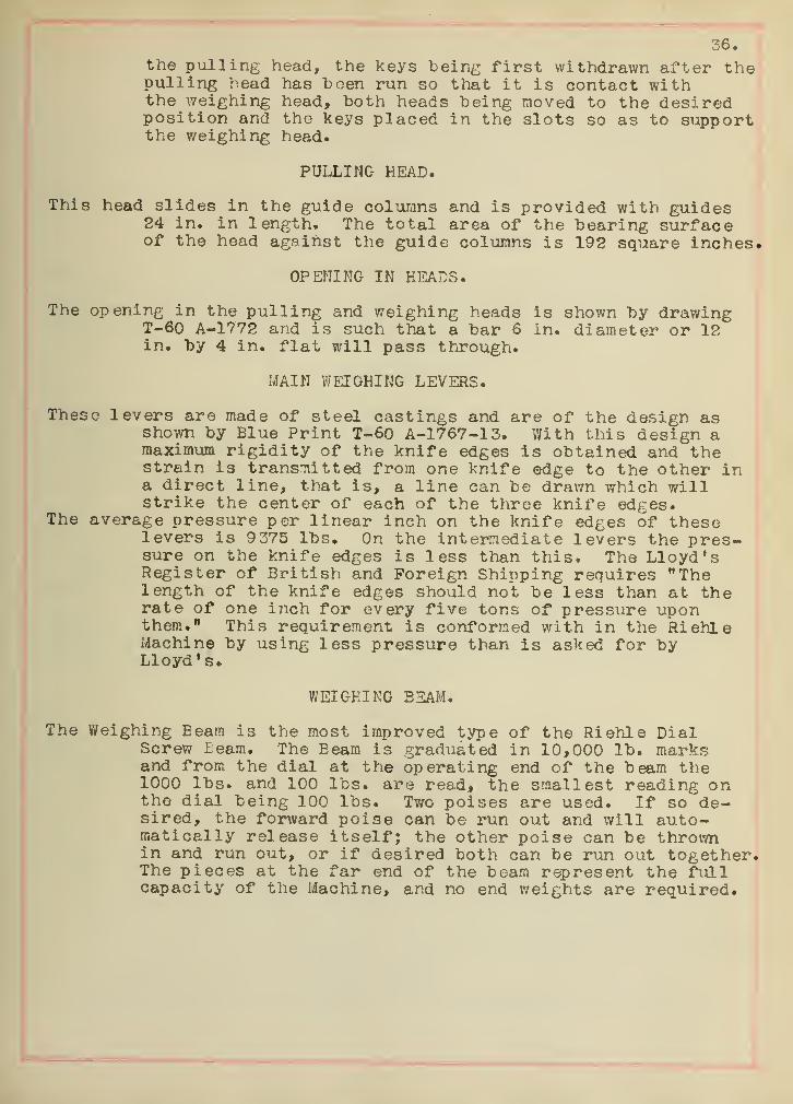
the pulling head, the keys being first withdrawn after thepulling head has been run so that it is contact withthe weighing head, both heads being moved to the desiredposition and the keys placed in the slots so as to supportthe weighing head.
PULLING HEAD.
This head slides in the guide columns and is provided with guides24 in. in length. The total area of the bearing surfaceof the head against the guide columns is 192 square inches.
OPENING IN HEADS.
The opening in the pulling and weighing heads is shown by drawingT-60 A-1772 and is such that a bar 6 in. diameter or 12in. by 4 in. flat will pass through.
MAIN Y/EIGHING LEVERS.
These levers are made of steel castings and are of the design asshown by Elue Print T-60 A-1767-13. With this design amaximum rigidity of the knife edges is obtained and thestrain is transmitted from one knife edge to the other ina direct line, that is, a line can be drawn which willstrike the center of each of the three knife edges.
The average pressure per linear inch on the knife edges of theselevers is 9 375 lbs. On the intermediate levers the pres-sure on the knife edges is less than this. The Lloyd'sRegister of British and Foreign Shipping requires "Thelength of the knife edges should not be less than at therate of one inch for every five tons of pressure uponthem." This requirement is conformed with in the RiehleMachine by using less pressure than is asked for byLloyd's.
WEIGHING BEAM.
The Weighing Beam is the most improved type of the Riehle DialScrew Beam. The Beam is graduated in 10,000 lb. marksand from the dial at the operating end of the beam the1000 lbs. and 100 lbs. are read, the smallest reading onthe dial being 100 lbs. Two poises are used. If so de-sired, the forward poise can be run out and will auto-matically release itself; the other poise can be thrownin and run out, or if desired both can be run out together.The pieces at the far end of the beam represent the fullcapacity of the Machine, and no end weights are required.
37.
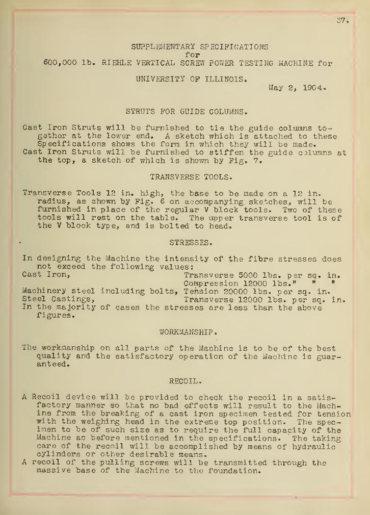
SUPPLEMENTARY SPECIFICATIONSfor
600,000 lb. RIEHLE VERTICAL SCREW POWER TESTING MACHINE for
UNIVERSITY OP ILLINOIS.May 2, 1904.
STRUTS FOR GUIDE COLUMNS.
Cast Iron Struts will be furnished to tie the guide columns to-gether at the lower end. A sketch which is attached to theseSpecifications shows the form in which they will be made.
Cast Iron Struts will be furnished to stiffen the guide columns atthe top, a sketch of which is shown by Pig. 7.
TRANSVERSE TOOLS.
Transverse Tools 12 in. high, the base to be made on a 12 in.radius, as shown by Pig. 6 on accompanying sketches, will befurnished in place of the regular V block tools. Two of thesetools will rest on the table. The upper transverse tool is ofthe V block type, and is bolted to head.
STRESSES.
In designing the Machine the intensity of the fibre stresses doesnot exceed the following values:
Cast Iron, Transverse 5000 lbs. per sq. in.Compression 12000 lbs." n tt
Machinery steel including bolts, Tension 20000 lbs. t>er sq. in.Steel Castings, Transverse 12000 lbs. per sq. in.In the majority of cases the stresses are less than the above
figures.
WORKMANSHIP
.
The workmanship on all parts of the Machine is to be of the bestquality and the satisfactory operation of the Machine is guar-anteed.
RECOIL.
A Recoil device will be provided to check the recoil in a satis-factory manner so that no bad effects will result to the Mach-ine from the breaking of a cast iron specimen tested for tensionwith the weighing head in the extreme top position. The spec-imen to be of such size as to require the full capacity of theMachine as before mentioned in the specifications. The takingcare of the recoil will be accomplished by means of hydrauliccylinders or other desirable means.
A recoil of the pulling screws will be transmitted through themassive base of the Machine to the foundation.
38.
ERECTION.
The erection of the Machine is to be superintended by our Engineerand we will allow him such time at the University as may benecessary, without expense to you. The University to furnishour Engineer ivith such help as may be required in his judgement.
39.
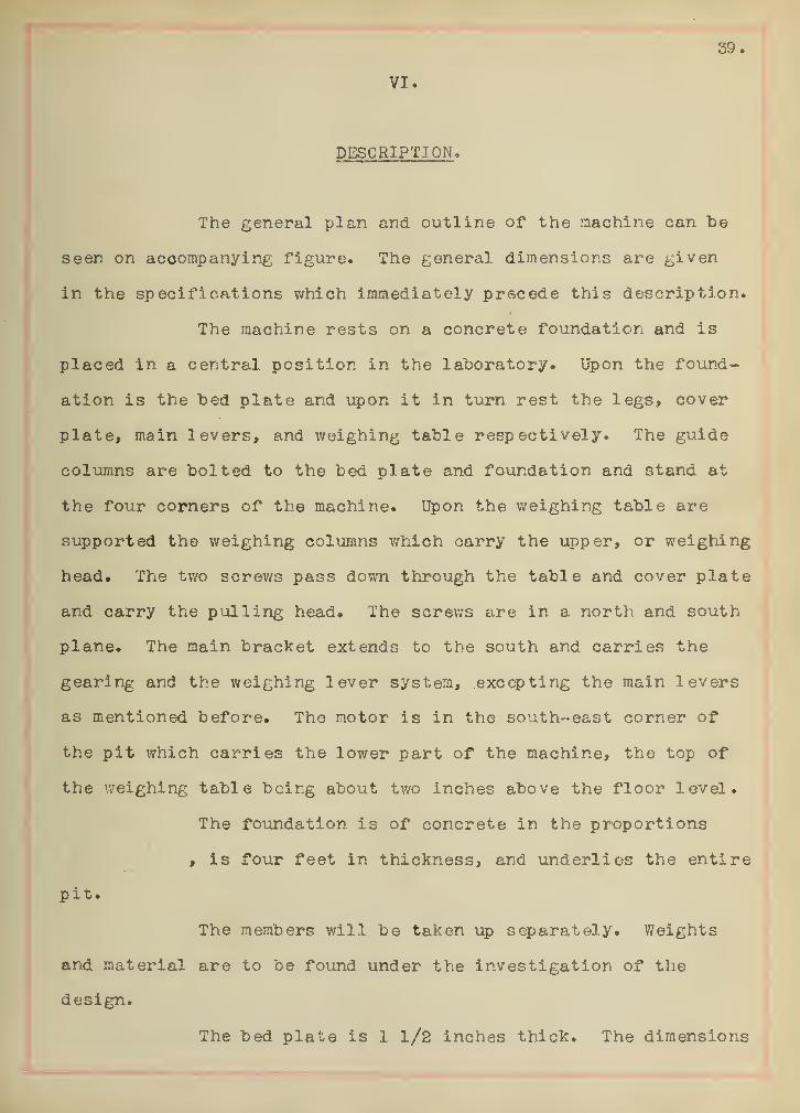
VI.
DESCRIPTION .
The general plan and outline of the machine can "be
seen on accompanying figure. The general dimensions are given
in the specifications which immediately precede this description.
The machine rests on a concrete foundation and is
placed in a central position in the laboratory. Upon the found-
ation is the "bed plate and upon it in turn rest the legs, cover
plate, main levers, and weighing table respectively. The guide
columns are bolted to the bed plate and foundation and stand at
the four corners of the machine. Upon the weighing table are
supported the weighing columns which carry the upper, or weighing
head. The two screws pass down through the table and cover plate
and carry the pulling head. The screws are in a north and south
plane. The main bracket extends to the south and carries the
gearing and the weighing lever system, excepting the main levers
as mentioned before. The motor is in the south-east corner of
the pit which carries the lower part of the machine, the top of
the weighing table being about two inches above the floor level.
The foundation is of concrete in the proportions
, is four feet in thickness, and underlies the entire
pit.
The members will be taken up separately. Weights
and material are to be found under the investigation of the
design.
The bed plate is 1 1/2 inches thick. The dimensions
'10.
are shown in figure under computations.
The legs are about PA inches deep and semicircular
in shape. They support the cover plate and contain between them
the gears driving the screwy.
The cover plate is approximately five feet wide>
eight feet four inches long, and thirteen inches deep. Lugs on
upper face carry steels upon which levers are supported. Roller
bearings beneath cover plate transfers load from screws to -foun-
dation. <^r^^ m&vXjls.
The main levers, of which there are four, are one
of the features of the design. Instead of the ordinary single
webbed lever, double webbed levers are used which makes the knife
edges act as restrained beams instead of as cantilevers, thus
greatly reducing the deflection of knife edges and causing the
load to be more evenly distributed over same. Another feature
is the fact that the middle points of the three knife edges are
all in a straight line with no point in the levers at any great
distance from this line, thus reducing torsional strains.
The weighing table has for its extreme dimensions
the following:- Length, 10 ft. 6 in.; breadth, 6 ft. 5 in.; depth_ , , m^ Sixteen24 in. The ordinary depth is 15 inches. A two inch tapped holes
are provided in table for the insertion of bolts to hold spec-
imens or tools.
The weighing columns are in three sections tied to-
gether at the top. It was found during the tests with eccentric
loading that there was not sufficient clearance between the flan-
ges of the columns and the pulling head. To take care of the
maximum deflection it will be necessary to remove about 1 1/2
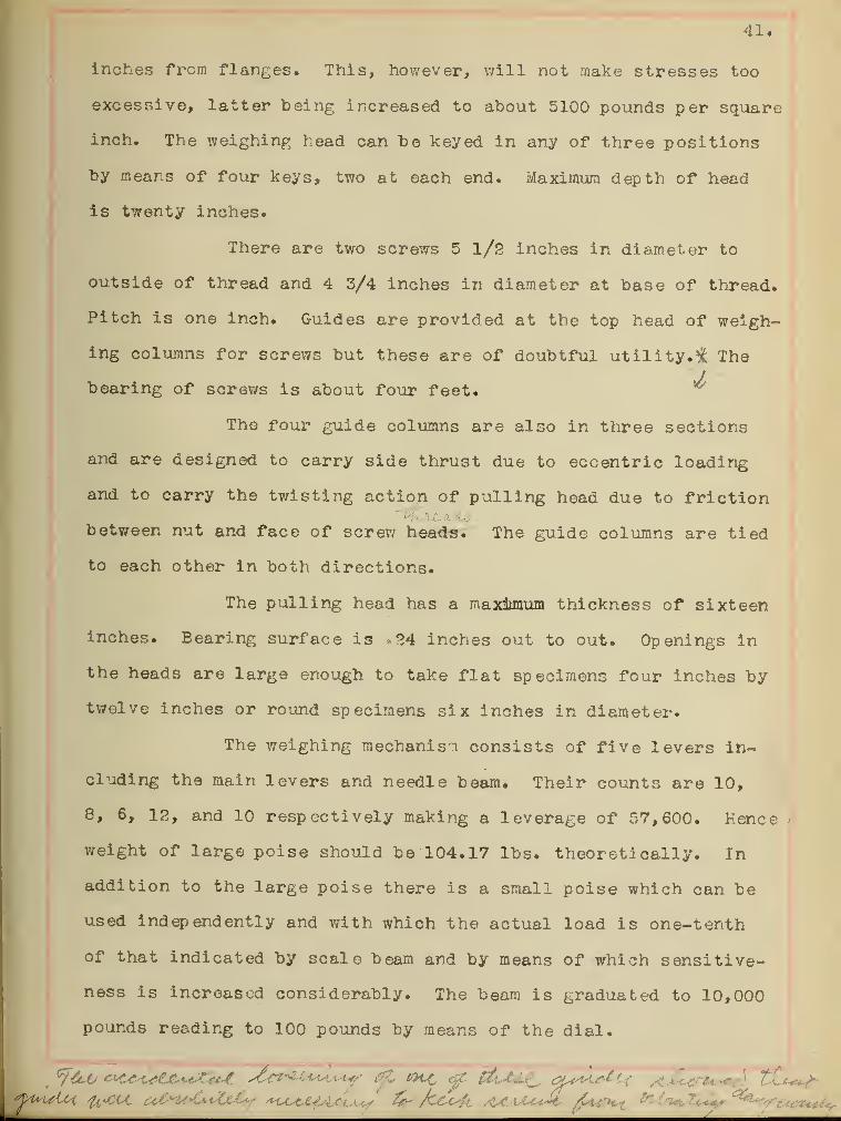
41.
inches from flanges. This, however, will not make stresses too
excessive, latter being increased to about 5100 pounds per square
inch. The weighing head can be keyed in any of three positions
by means of four keys, two at each end. Maximum depth of head
is twenty inches.
There are two screws 5 l/2 inches in diameter to
outside of thread and 4 3/4 inches in diameter at base of thread.
Pitch is one inch. Guides are provided at the top head of weigh-
ing columns for screws but these are of doubtful utility.^ The
bearing of screws is about four feet.
The four guide columns are also in three sections
and are designed to carry side thrust due to eccentric loading
and to carry the twisting action of pulling head due to friction
between nut and face of screw heads. The guide columns are tied
to each other in both directions.
The pulling head has a maximum thickness of sixteen
inches. Bearing surface is °A inches out to out. Openings in
the heads are large enough to take flat specimens four inches by
twelve inches or round specimens six inches in diameter.
The weighing mechanise consists of five levers in-
cluding the main levers and needle beam. Their counts are 10,
8, 6, 12, and 10 respectively making a leverage of 57,600. Hence
weight of large poise should be 104.17 lbs. theoretically. In
addition to the large poise there is a small poise which can be
used independently and with which the actual load is one-tenth
of that indicated by scale beam and by means of which sensitive-
ness is increased considerably. The beam is graduated to 10,000
pounds reading to 100 pounds by means of the dial.
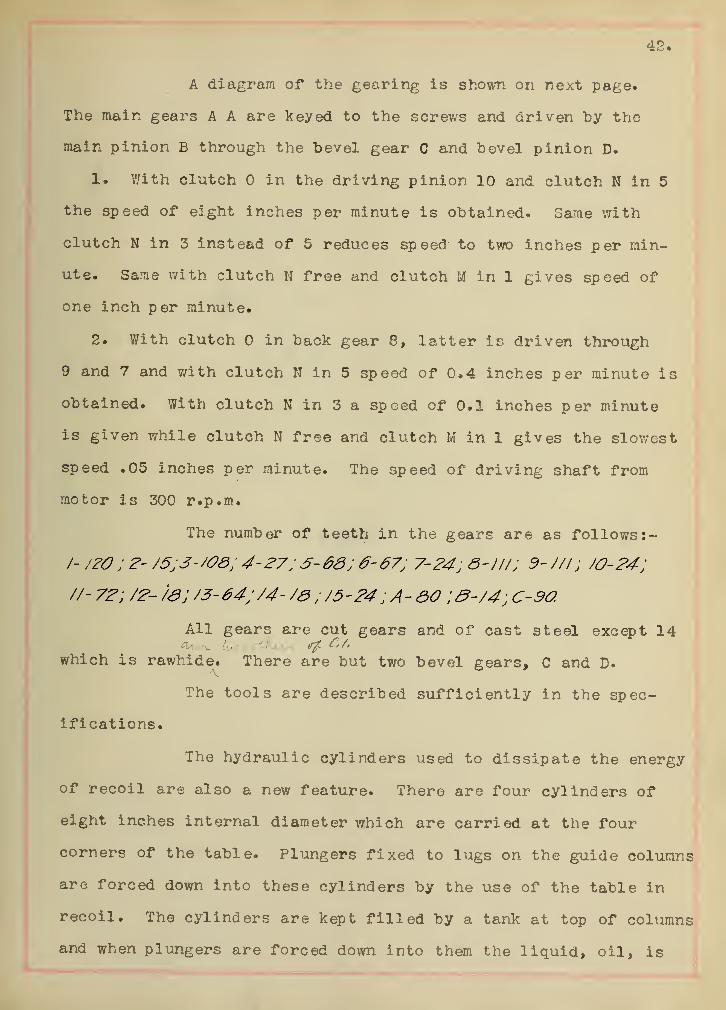
42.
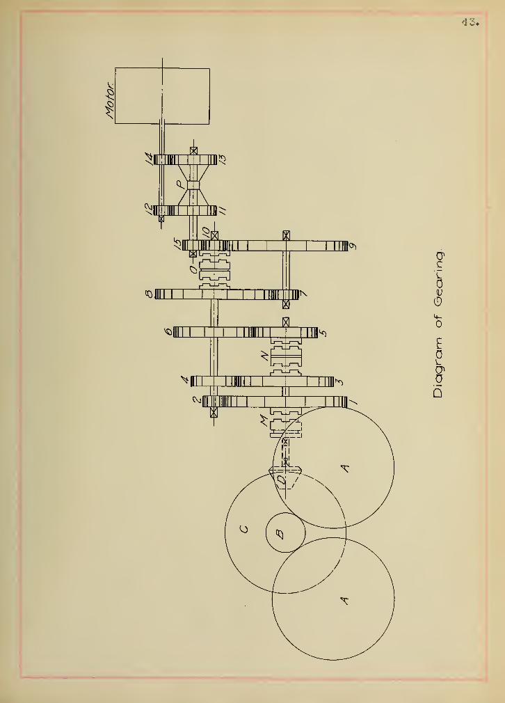
A diagram of the gearing is shown on next page.
The main gears A A are keyed to the screws and driven by the
main pinion B through the bevel gear C and bevel pinion D.
1. With clutch in the driving pinion 10 and clutch N in 5
the speed of eight inches per minute is obtained. Same with
clutch N in 3 instead of 5 reduces speed to two inches per min-
ute. Same with clutch N free and clutch M in 1 gives speed of
one inch per minute.
2. With clutch in back gear 8, latter is driven through
9 and 7 and with clutch N in 5 speed of 0.4 inches per minute is
obtained. With clutch N in 3 a speed of 0.1 inches per minute
is given while clutch N free and clutch M in 1 gives the slowest
speed .05 inches per minute. The speed of driving shaft from
motor is 300 r.p.m.
The number of teeth in the gears are as follows :-
/- J20 ; Z- J5;3-/03; 4-27; 5-68; 6-67; 7-24' 3-JH; 9-///; JO-Z4;
//- 72; /Z- /&) /3- 64J /4- /3 ; /5~Z4;A- 30 ; 0-/4; C-9Q
All gears are cut gears and of cast steel except 14
which is rawhide. There are but two bevel gears, C and D.
The tools are described sufficiently in the spec-
ifications.
The hydraulic cylinders used to dissipate the energy
of recoil are also a new feature. There are four cylinders of
eight inches internal diameter which are carried at the four
corners of the table. Plungers fixed to lugs on the guide columns
are forced down into these cylinders by the use of the table in
recoil. The cylinders are kept filled by a tank at top of columns
and when plungers are forced down into them the liquid, oil, is
43,
CL
v
E
g6
44.
forced to pass through a needle valve, slowly using up the energy
of recoil.
The motor used is a W-estinghouse 15 H.P. induction
motor, direct connected.
45.
VII.
INVESTIGATION OP DESIGN.
The main features of the design will now be taken
up and discussed. The outline below gives the order which
will he followed in the computation of stresses.
Bed Plate—hearing area.
Legs—cross section.
Cover Plate—distribution of load upon webs.
Levers—stresses- form. Deflections of levers and of
knife edges.
Weighing Table—influence of deflection.
Weighing Columns—stresses of fibers and at joints.
Screwsr-s tress, ordinary and under unequal stretch-
shear in threads.
Pulling Head—side action—stresses—-shear in collar.
Weighing Head—stresses.
•Guide Columns—stresses due to eccentric loading—stresses
in bolts—deflections.
Recoil.
46.
COMPUTATION OP STRESSES.
2-/'
7" t
/zi
/EZZ/
//
evzzzi
^ izzzzzza
Investigation of Design.
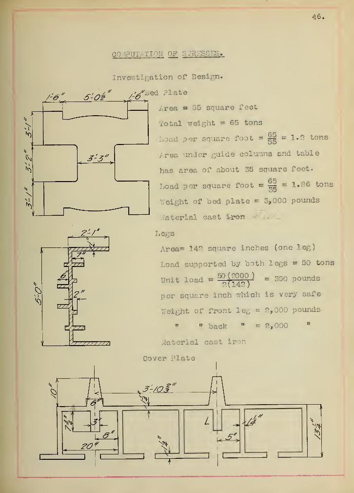
* '^ed Plato
j^rea = 58 square feet
Total weight =65 tons
Load per square foot * ft * X*8 tons
Area under guide columns and table
has area of about 35 square feet.
65Load per square foot m ~m * 1,06 tona
Weight of bed plate • 3,000 pounds
Material oast taeen- s&tuA->>,
Legs
Area= 148 square inches (one log)
Load supported by both Iocs n 50 tons
Unit load = ^f^ry^ = 350 pounds
per square inch '.vhich is very safe
Weight of front leg « 2,000 pounds
M » back " =2,000 n
Material cast iron
Covor Plate
I
"41 »4
47.
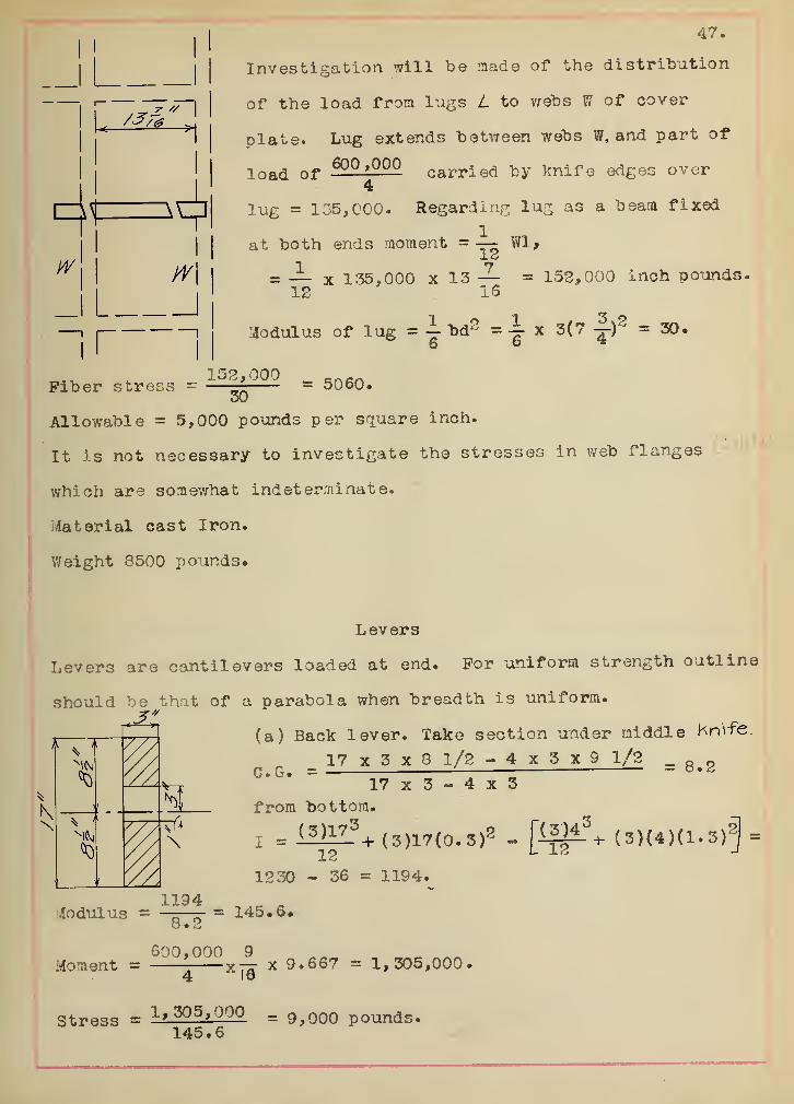
Investigation will be made of the distribution
of the load from lugs L to webs W of oover
plate. Lug extends between webs W, and part of
600,000load of
4carried by knife edges over
3ug = 135,000. Regarding lug as a beam fixed
at both ends moment = Wl,12
= — x 135,000 x 13 — = 152,000 inch pounds.12 16
Modulus of lug = -| bd2 = -|- X 3(7 = 30.
_l L__J
152,000 Kr^Fiber stress - —— - oOoO.ou
Allowable = 5,000 pounds per square inch.
It is not necessary to investigate the stresses in web flanges
which are somewhat indeterminate.
Material cast Iron.
Weight 8500 pounds.
Levers
Levers are cantilevers loaded at end. For uniform strength outline
should be that of a parabola when breadth is uniform.
(a) Back lever. Take section under middle Knife.
°0
T
= 8.2
\
17 x 3 x 8 1/2 - 4 x 3x91/2 _C.G. = ~
17 x 3 - 4 x 3
from bottom.
j = W?+ (3)17(0.3)S - p§t8+ (3)(4)(1.3)?]=
Modulus =
Moment =
1194
600,000 9
1230 - 36 = 1194.
= 145.6.
x— x 9.667 1,305,000.
Stress = x > 305,000 _ 9>000 pounds.145.
6
48.
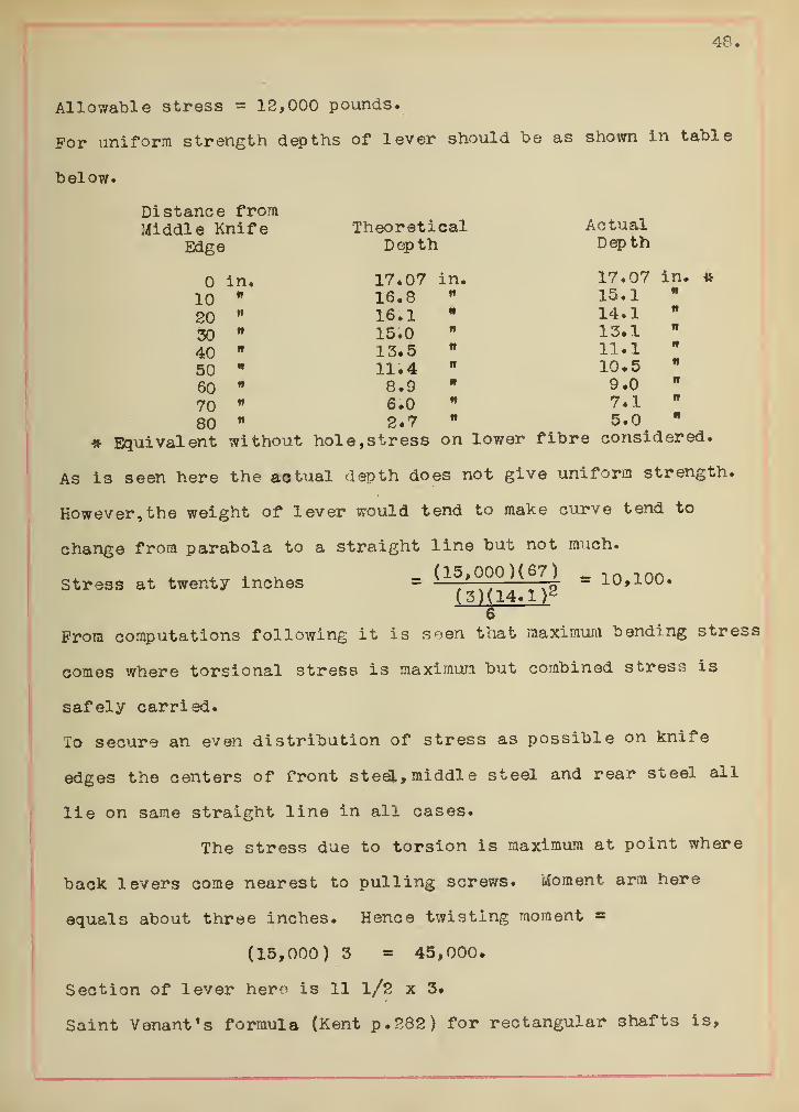
Allowable stress - 12,000 pounds.
For uniform strength depths of lever should be as shown in table
below.
Distance fromMiddle Knife Theoretical Actual
Edge Depth Depth
in. 17.07 in. 17.07 in. *
10 w 16.8 w 15.1 *
20 tt 16.1 14.1 "
30 » 15.0 " 13.1 "
40 " 13.5 tt 11.1 "
50 " 11.4 10.5 w
60 • 8.9 " 9.0 "
70 " 6.0 w 7.1 "
80 " 2.7 " 5.0>
"
* Equivalent without hole, stress on lower fibre considered.
As is seen here the actual depth does not give uniform strength.
However, the weight of lever would tend to make curve tend to
change from parabola to a straight line but not much.
, . . _ (15,000 M67) , n , nnStress at twenty inches =(g)(i4 ~Y~jj~
- 10,100.
6
Prom computations following it is seen that maximum bending stress
comes where torsional stress is maximum but combined stress is
safely carried.
To secure an even distribution of stress as possible on knife
edges the centers of front steel, middle steel and rear steel all
lie on same straight line in all cases.
The stress due to torsion is maximum at point where
back levers come nearest to pulling screws. Moment arm here
equals about three inches. Hence twisting moment =
(15,000) 3 * 45,000.
Section of lever here is 11 l/2 x 3.
Saint Venant*s formula (Kent p. 282) for rectangular shafts is,
49
Moment = (Stress ) (Area ) Where b is longer side and d is3b + 1.8d
shorter side.
Hence 45 000 = (Stress )(ll. 5 x 3)2
Hence 45,000 -( 3 )(11.5) + (1.8 )(3)
Hence torsional stress = 1,510.
Stress due to bending here =— = (1-^000) (48) = 10,900.6_I (3)(11 1/2 )
g
c 6
For combined tension and torsion
f = 1/2(S +Vs2 + 4S|)
= 1/2(10, 900+"Vl0,9002 -h 4(1510 )
2) = 1/2(10,900 + 11,000) =
11,000.
Allowable = 12,000 pounds per square inch.
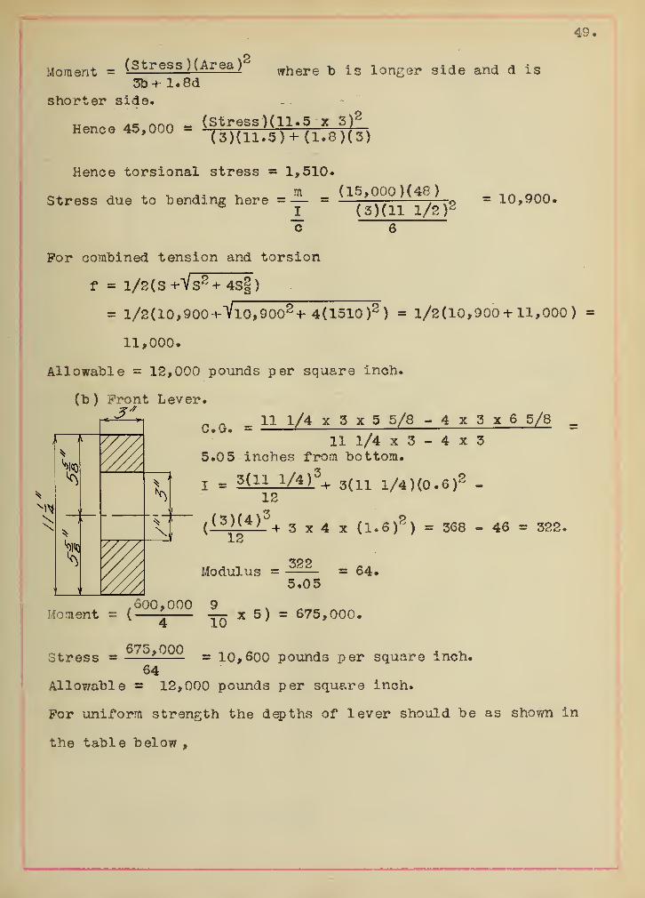
(b) Front Lever.
1
to
\
1 * >
= 11 1/4 x 5 x 5 5/8 - 4 x 3 x 6 5/8 =11 1/4 x 3 - 4 X 3
5.0 5 inches from bottom.
I * 3(11 1/4)^ 3(11 i/4 )(0.6)2 -
12
(
(3)(4)3+ 3 x 4 x (1.6)2
) = 368 - 46 = 322.
322
12
Modulus =5.05
= 64.
Moment =(
oQ0 > 000 |_ x 5 ) = 675,000.4 10
Stress = 67o>Q0Q = 10,600 pounds per square inch.64
Allowable = 12,000 pounds per square inch.
For uniform strength the depths of lever should be as shown in
the tabl e below ,
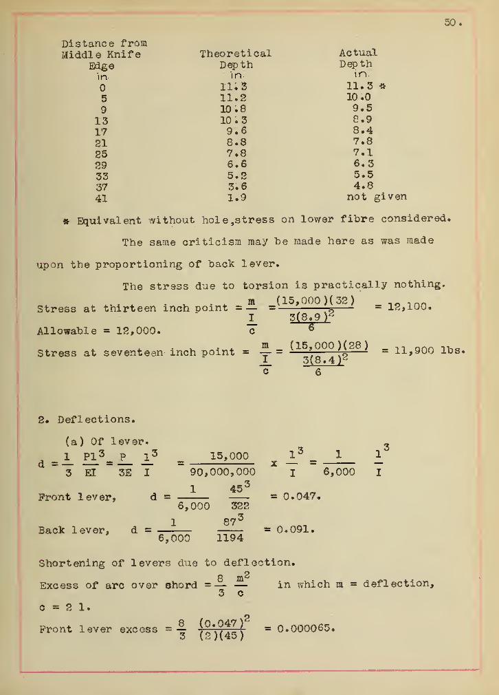
50.
Distance fromMiddle Knife Theoretical Actual
Edge Depth Depthin Vn. in.
11.3 11.3 *5 11.2 10.09 10.8 9.513 10.3 8.917 9.6 8.421 8.8 7.825 7.8 7.129 6.6 6.333 5.2 5.537 3.6 4.841 1.9 not given
* Equivalent without hole,stress on lower fibre considered.
The same criticism may be made here as was made
upon the proportioning of back lever.
The stress due to torsion is practically nothing.
m (15,000)(32) _ , AnStress at thirteen inch point =— = 5 = 12,100.
I_ 3(8.9 rAllowable = 12,000. c 6
* m (15,000 )(28) _ ,., QnnStress at seventeen inch point = — = -— ^ 1 = 11,900 lbI 5(8.4)^
2. Deflections.
(a) Of lever.3
1 Pl_3_ 2_ _1_3
_ 15,000 JL3_ 1 _1
~ T eF '
3E I 90,000,000 I 6,000 I
1 45 3
Front lever, d = = 0.047.6,000 322
1 87 3
Back lever, d = = 0.091.6,000 1194
Shortening of levers due to deflection.
8 m*^Excess of arc over ehord =— — in which m = deflection,
3 c
c = 2 1.
Front lever excess =-| f° = 0.000065.3 (2)(45)
51 *
„ , t 8 (0.091)'Back lever excess =—
(?)(S7
)
= 0.000127.
Difference = 0.000127 - 0.000065 = 0.000062.
This is entirely negligible.
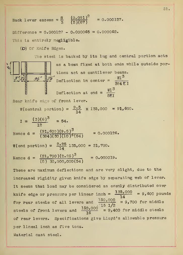
(IO) Of Knife Edges.
The steel is "backed "by its lug and central portion acts
as a "beam fixed at "both ends while outside por-
tions act as cantilever "beams.
2*Deflection in center = Wl
384 EI
Deflection at end =8EI
Rear knife edge of front lever.
W( central portion) = x 135,000 = 91,600.14
, . (3)(6) 5„ g4#
12
„ « - (91,600 )(9. 5 )3 _ n nornoRHenCe d =
(3M)(»)(10)»(54) - 0.000126.
W( end portion) = 135,000 = 21,700.14
Hence d = (21,700 )(2.25 )3
s 0#000019 .
(8) 30,000,000(54)
These are maximum deflections and are very slight, due to the
increased rigidity given knife edge "by separating web of lever.
It seems that load may be considered as evenly distributed over
knife edge or pressure per linear inch = 155,0Q0 = 9,600 pounds14
for rear steels of all levers and150 > 000 = 9,700 for middle15 1/2
steels of front levers and150 > 0QQ = 9,400 for middle steels
16
of rear levers. Specifications give Lloyd's allowable pressure
per lineal inch as five tons.
Material cast steel.
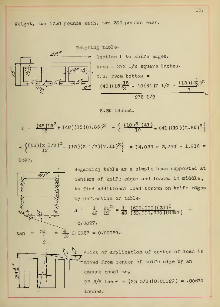
Weight, two 1750 pounds each, two 300 pounds each
48
3^E
Weighing Table.
>\ Section ± to knife edges.
Area = 272 l/2 square inches.
C.G. from "bottom =
(48)(15# - 10(41)7 1/2 -(15)(S8>
g
« 2
272 1/2
8*36 inches.
I = (48)(1S)(0.86)8 _|
(10)^(41) +(41)(10)(o>86)gj
_ ((l?J(2_l/2j3+ (15)(S 1/2)(7.11)2 ) * 14,033 - 3,780 - 1,916 =(12 /
8397.
f
3<S
Regarding table as a simple beam supported at
centers of knife edges and loaded in middle,
to find additional load thrown on knife edges
by deflection of table.
, _ JL_ IL3 = JL (600,000 )( 58
)
5Q
48 EI 48 (30,000,000 )(8!
0.0027.
i397~)
tan = = -|p 0.0027 = 0. 00029
.
1 3o
\i \— Point of application of center of load is
moved from center of knife edge by an
amount equal to
,
23 3/8 tan°< = (23 3/8 )(0. 00029 ) = .00679
inches.
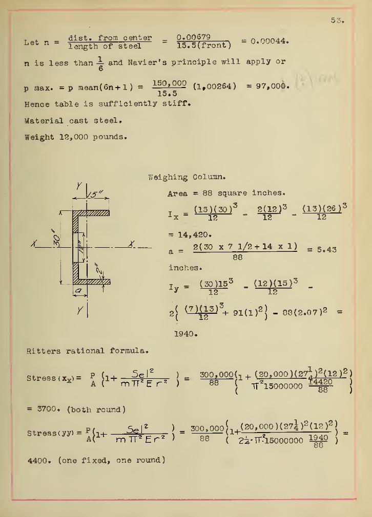
53.
. _ dist. from centerLet n - i erigth of steel
0.00679 _ n nnriAA15.5(front) ~ °- 00044 -
n is less than — and Navier's principle will apply or6
p max. =p mean(6n+l) = 150,000 (1,00264) = 97,000.15.5
Hence table is sufficiently stiff.
Material cast steel.
Weight 12,000 pounds.
Y
X X
//
Weighing Column.
Area 88 square inches.
mm
X
_ (15)(30)3
2(12) 3 (15)(26) 5
1 x ~ ~ 12 "12 " 12
14,420.
= 2(50 x 7 1/2+14 x 1
)
m 5#43a
inches.
88
T
Y
Ritters rational formula.
j - (30)15 5 „ (12)(15) 3_
y 12 12
g ( (7)(15)5+ 91(1)2) _ 08(2.07)2 =
1940.
Stress(xx^ \ fl+Sel* ) 30^^ + (20,000 )(27^i|l2jj
)
A A ( mTr F r 2) 88 ( TT2i CftrtAA^ 14420 JA ( mU 2 E r z) TT 15000000 88
« 3700. (both round)
Stress (yy) = P( 5el 2) - 300,000| 1+
(g0>000)(s4)S (lg)2] ^_
A(1_h mTT*Er 2
>( ^-TT^oooooo i|40
)00
4400. (one fixed, one round)
54.
Stress xx (2 inches eccentricity, 600,000 pounds) =
stress xx k+^f1 ) = 3700<1 + {^~)) = 4370.( r2 ) ( 14420 )
88
Stress in bolts in flanges (bending parallel to beam).
Bending moment = — =(4400 )(^|^-) = 892,000.c 9 . 57
Assume that this is carried by the four bolts having a moment
arm of 16 l/2 inches.
Stress per bolt = 8
^ v = 13,500.
One and one-half inch bolts used. Diameter at base of thread =
1.25 inches. Area at base of thread = 1.23 square inches.
13,500Unit stress = 1.2Z = H»000. stress is actually smaller
however since other holts take part of moment.
Consider joints with buckling perpendicular to beam. Maximum
stress = 4370(2 inches eccen.
)
14420Moment = S x Modulus = 4370 „„ = 4,199,570.
15
Assume that the stress per bolt at unit distance = 10,000 pounds.
Then moment is distributed as follows:
2 at 5 1/4" = 2(5 1/4^(10,000) = 551,200
1 at 11" = (11 )2 (10,000) m 1,210,000
1 at 22 1/4" = (22 l/4
)
2 (10,000 ) = 4,955,000
2 at 28" = 2(28)2(10,000) m 15,680,000
3 at 33 1/4" = 3(33 l/4
)
2 #10,000) = 33,195,000L2J
55,591,200
Hence actual stress at unit distance
• st'.lll'Mo (10 ' 000 > = 750 '
55.
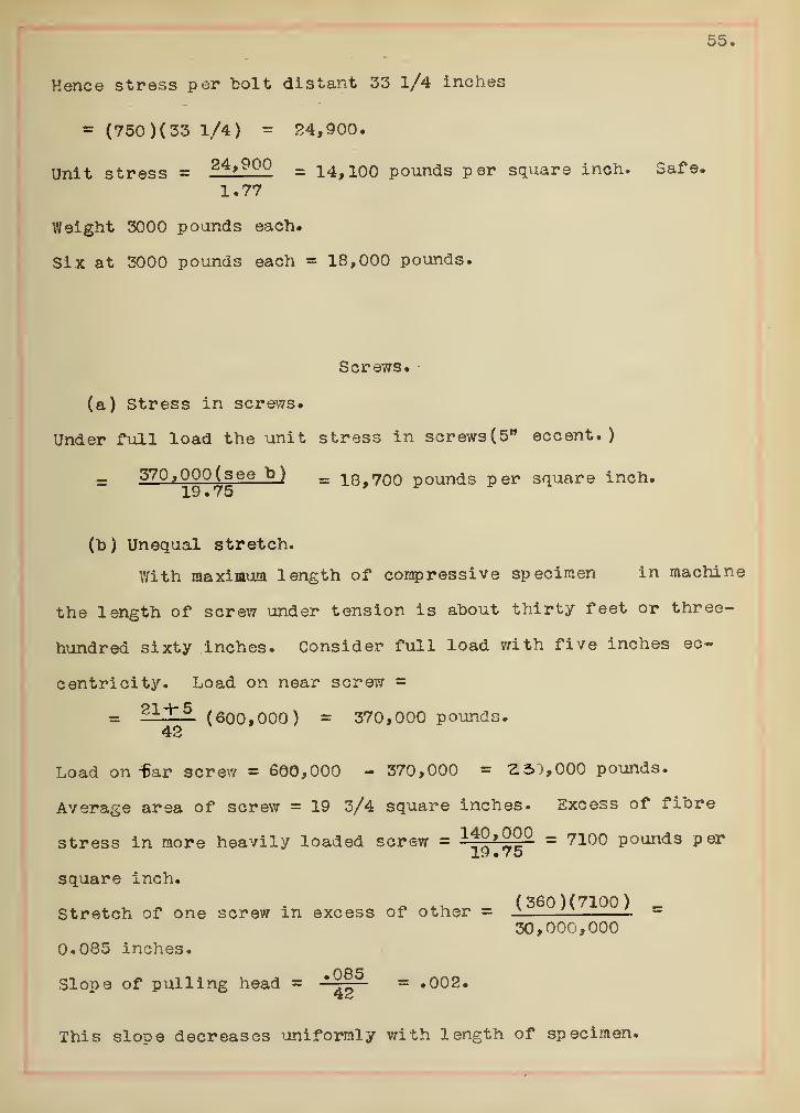
Hence stress per bolt distant 33 l/4 inches
= (750)(33 1/4) = 24,900.
Unit stress = 24>90Q = 14,100 pounds per square inch. Safe,
1.77
Weight 3000 pounds each.
Six at 3000 pounds each = 18,000 pounds.
Screws.
(a) Stress in screws.
Under full load the unit stress in screws(5w eccent.
)
m 370,000(see b) = ^8^700 pounds per square inch.
(b) Unequal stretch.
With maximum length of compressive specimen in machine
the length of screw under tension is about thirty feet or three-
hundred sixty inches. Consider full load with five inches ec-
centricity. Load on near screw =
= £l+_5_( 600, 000 ) = 370,000 pounds.
42
Load on -Car screw = 600,000 - 370,000 = Z5),000 pounds.
Average area of screw = 19 3/4 square inches. Excess of fibre
stress in more heavily loaded screw = ^^S = 7100 pounds periy • 75
square inch.
Stretch of one screw in excess of other = ( 360 )(7100
)
m30,000,000
0.085 inches.
Slope of pulling head = *^|5 = .002.
This slope decreases uniformly with length of specimen.
//
/ \7
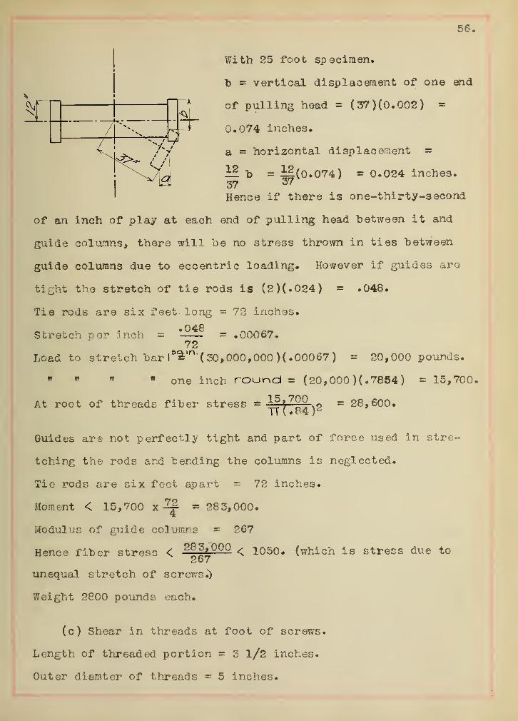
56.
With 25 foot specimen,
b = vertical displacement of one end
of pulling head = (37) (0.002) =
0.074 inches.
a = horizontal displacement =
12 b = 12(0.074) = 0.024 inches.37 37
Hence if there is one-thirty-second
of an inch of play at each end of pulling head between it and
guide columns, there will be no stress thrown in ties between
guide columns due to eccentric loading. However if guides are
tight the stretch of tie rods is (2) (.024) = .048.
Tie rods are six feet long = 72 inches.
• 048Stretch d or inch - = .00067.
72Load to stretch bar |
5^'n( 30,000,000 )(. 000 67) = 20,000 pounds.
" • " " one inch round = (20,000 )( .7854 ) 15,700.
At root of threads fiber stress = 15 ;/
72? = 28,600.
Guides are not perfectly tight and part of force used in stre-
tching the rods and bending the columns is neglected.
Tie rods are six feet apart = 72 inches.
Moment < 15,700 x 72 - 28 3,000.
Modulus of guide columns = 267
Hence fiber stress <2®^> 000 < 1050. (which is stress due to267
unequal stretch of screws.")
Weight 2800 pounds each.
(c) Shear in threads at foot of screws.
Length of threaded portion = 3 1/2 inches.
Outer diamter of threads = 5 inches.
57.
Diameter at "base of threads = 4.6
Efficiency assumed = 2/3*
Shearing area = (4.8)~JT(3 l/2 ) x 2/3 = 35*2 square inches,
370 000Unit stress = —35,0 ~ 10 > 500 pounds per square inch.
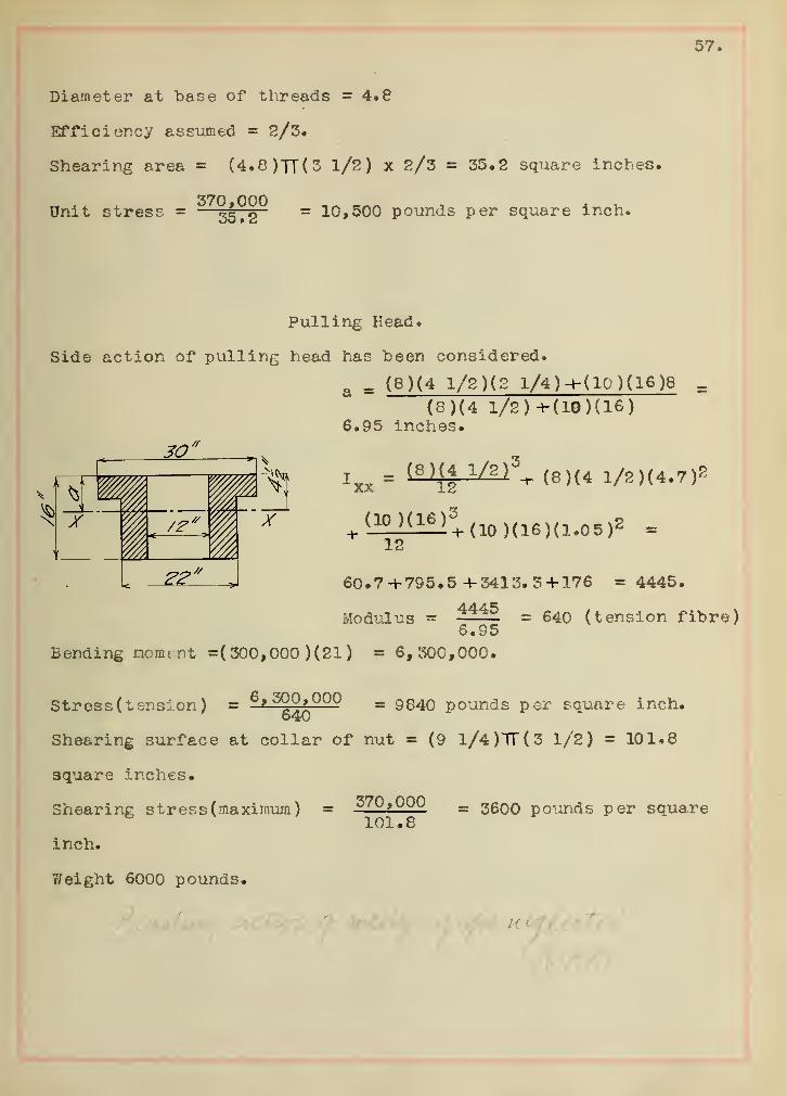
Pulling Head*
Side action of pulling head has been considered.
a = (8)(4 l/2)(2 l/4)-h(10)(l6)8 =
JO
X
(8)(4 l/2) +(19)(16)6.95 inches.
Ixx = (8) (4 1/2) + (8)(4 1/2)(4 .7)2
X (10)(16) + (10)(16)(1.05)g .
22 //
60.7 -+-795.5 4-3413. 3 + 176 = 4445.
Modulus = 444 = 640 (tension fibre)6.95
Bending moment =( 300,000 ) (21 ) = 6,300,000.
Stress (tension) = 6? ^S?^
00 = 9840 pounds per sauare inch.o40
Shearing surface at collar of nut = (9 l/4)TT(3 1/2) = 101.8
square inches.
Shearing stress (maximum ) = 370,000 = 3600 pounds per square101.8
inch.
Weight 6000 pounds.
58.
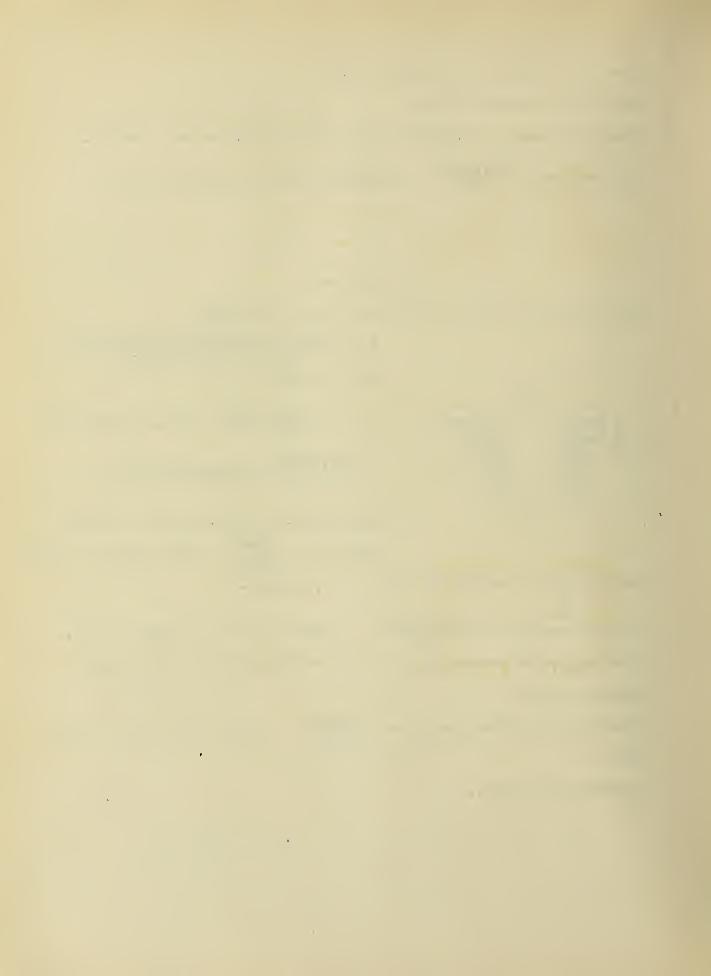
reightng head.
(l4)(6)(3)-t-(l0)(^0)(10) „a =(14)(6)+ (10 )(°0 )
X
U> iyV(14)(Q(i^
X_
xx
(10 )(ro )
X C(10 )(20 )(f%07)'
?52+ n041.2-h G666.7-I- G5G.0 = 9G16.
..iodulus » i*§2£ h 1236 ( tension fiber)r • 3
Bending moment = (300 , 000) (30) =
9,000,000.
Stress (tension) m °' Q^to° ~ ?270 pounds per square inch.
V/ei^ht 4000 pounds.
/// %///////
y
/72
V//////A V//////A
Guide Columns*
Vop tr/o sections are as shown in
sketch. Area * 49 » 6 scmaro inches.
. (12)(17 1/4
)
3„ (i) l/r)(ir V4)
xx
_ (P !/-)(::-)• r- j>300.
Modulus =e 5/6
I = (17 1/1 )(!-)" _ 5(1?) 5 ^ (10 1/4 )(9 V") 3
YY 1?
.Iodulus « 172 (
59.
/
7
7,
/7*
V 7 h\ 7, N
r
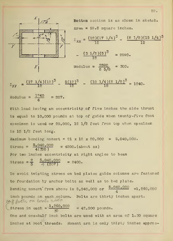
Bottom section is as shown in sketch.
Area =59.8 square inches.
xx= (12)(17 1/4)
3_ (8 l/2)(15 1/4 )
5
12
. (3 1/S)(5) 5=2590 .
12
Modulus = 2590 - 300.8 5/8
yy
'
(17 1/4)(12) 3_ 5(12)5 _ (10 l/4)(8 l/2) 3
= lpAQ ^12 12 12
Modulus = ±£*H = 207.
With load having an eccentricity of five inches the side thrust
is equal to 10,000 pounds at top of guide when twenty-five foot
specimen is used or 20,000, 12 l/2 feet from top when specimen
is 12 1/2 feet long.
Maximum bending moment = 21 x 12 x 20,000 = 5,040,000.
Stress = 5 >Q40 >QQ0 s 4200. (about xx)4(300 )
For two inches eccentricity at right angles to beam
Stress as— 5,040,000 = ?40o.btress -5 ^ (207)
^4UU#
To avoid twisting stress on bed plates guide columns are fastened
to foundation by anchor bolts as well as to bed plate.
Eending moment' from above is 5,040,000 or5,040,000 =1,260,000
4
inch pounds on each .column. Bolts are thirty inches apart.
C x -u ,1,260,000^Stress in each = _ = 42,000 pounds.
One and one-half inch bolts are used with an area of 1.30 square
inches at root threads. Moment arm is only thirty inches appro x-
60.
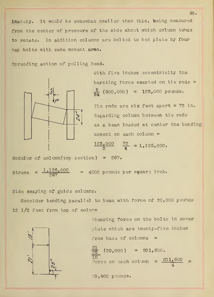
imately. It would be somewhat smaller than this, ^eing measured
from the center of pressure of the side about which column tends
to rotate. In addition columns are bolted to bed plate by four
tap bolts with same moment arms.
Spreading action of pulling head.
With five inches eccentricity the
bursting force exerted on tie rods =
^- (600,000) = 125,000 pounds.
Tie rods are six feet apart = 72 in.
Regarding column between tie rods
as a beam loaded at center the bending
moment on each column =
125 > 0Q0?f-
= 1,125,000.
Modulus of column( top section) = 267.
Stress = 1,125,000 = 4200 pounds per square inch.
Side swaying of guide columns.
Consider bending parallel to beam with force of 20,000 pounds
12 1/2 feet from top of column
Shearing force on the bolts in cover
olate which are twenty-five inches
from base of columns =
-§j=- (20,000) = 201,600.
:?orce on each column = 20 1> 600 =4
0,400 pounds.
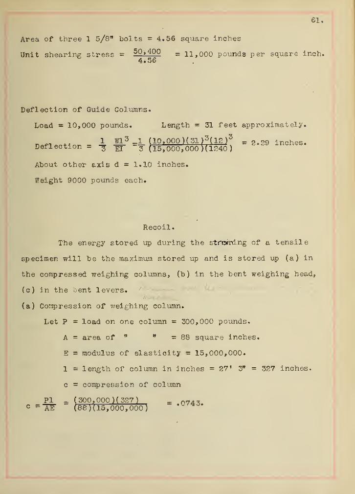
61.
Area of three 1 5/8" bolts = 4.56 square inches
Unit shearing stress = 50)400 = 11,000 pounds per square inch.4. 56
Deflection of Guide Columns.
Load = 10,000 pounds. Length = 31 feet approximat ely,
5
)
mrfwtinn - I WL3 =1_ (10,000 )( 51)^(12)- =2.29 inches.Deflection - 3 3 (15,000,000 )(1240
About other axis d = 1.10 inches.
Weight 9000 pounds each.
Recoil.
The energy stored up during the strcwning of a tensile
specimen will be the maximum stored up and is stored up (a) in
the compressed weighing columns, (b ) in the bent weighing head,
(c) in the cent levers,
(a) Compression of v/eighing column.
Let P = load on one column = 300,000 pounds.
A = area of " " =88 square inches.
E = modulus of elasticity = 15,000,000.
1 = length of column in inches » 27 1 3" = 327 inches.
c = compression of column
PI - (500,000) (527) m 07A »c = AE (88)(15,000,000)
'°743#
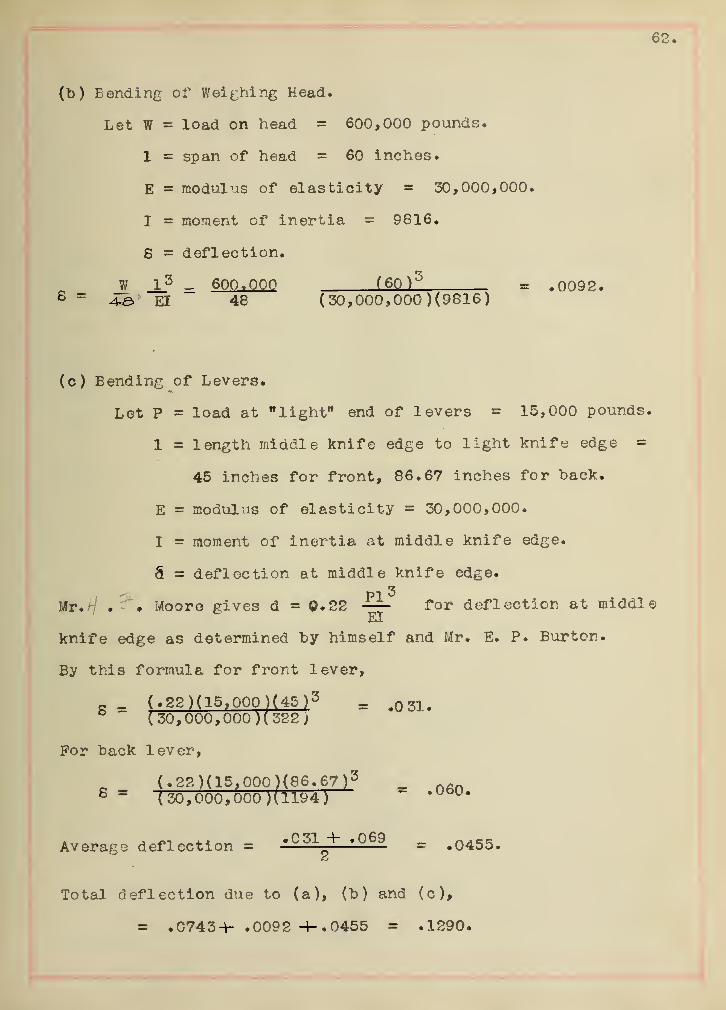
62
(b) Bending of Weighing Head.
Let W = load on head = 600,000 pounds.
1 = span of head = 60 inches.
E = modulus of elasticity = 30,000,000.
I = moment of inertia = 9816.
8 = deflection.
W _1_3 _ 600,000 (60) 5
a .0092.8 =
A~e> EI 48 (30,000,000 ) (9816)
(c) Bending of Levers.
Let P = load at "light" end of levers = 15,000 pounds.
1 = length middle knife edge to light knife edge =
45 inches for front, 86.67 inches for hack.
E = modulus of elasticity = 30,000,000.
I moment of inertia at middle knife edge.
S = deflection at middle knife edge.
Mr.f/ . Moore gives d = 0.22 — for deflection at middleEI
knife edge as determined by himself and Mr. E. P. Burton.
By this formula for front lever,
s = (.22)(15,00qU45)g = .031.* (30,000,000) (322)
For back lever,
(.22)(15,000)(86.67) 3_ nfin8 = (30,000,000) (1194) - * 060 -
Average deflection = «0 31^- .069 = #0455#
Total deflection due to (a), (b ) and (c),
= .07434- .0092 0455 = .1290.
63.
Energy.
Let P = maximum force = 600,000 pounds.
S = total movement = .1290.
PSE = energy stored in inch pounds = — =
( 600, 000)(. 1290) m ^ f7QQ inch pouRds = 3?25 foot2
pounds.
Without means of checking recoil this energy would be employed
in lifting table and weighing columns and head into air and
would he returned in form of a blow upon knife edges.
The weighing columns, table, and weighing head weigh about
3(3000 ) -I- 12,000 -h 4000 = 25,000 pounds.*TR700
38700 inch pounds would raise thisP500Q
= 1*548 inches.
Let W = static value of load applied to member,
h = height from which W falls.
1 = total distortion of member hit.
p = maximum intensity of resulting stress.
P = maximum resulting load.
d = deflection of member due to static load W.
hx = T*
Then from John H. Barr's Notes on Machine Design,
w(h+D =i/2pi or p = OT(*+
1
>
A- 4 orx W w
Hence P = 2W(h +^f) = ^ + 2W,Pd Fa
W
or P2 = 2W£h ^WP = 2W2x +- 2WP.
Solving, P = W( 1-hV 14- 2x)
64
r, 55,000 / \ 'k
d « .22^- = I22 4-x-lO^^
%= .0013 for front lever,
EI (307000,000 (322
(,22) 35 tQOQ
( 86.67) 3
= — 4—x-i u — = .0024 for back lever.(30,000,000)(1194)
.0015 H- .0024Average = - —
_h_ = 1.548d .0019 l^i^cCi^iy PC
Hence P = 25,000 (1-R/ 1 + 2(815 ) ) = (25,000 )(41. 4 ) = 1,035,000
or a pressure of 1,035,000 pounds on knife edges without any
system to take care of recoil.
t 4 *, 1.0 55,000This gives a pressure per lineal inch = —£—
(
164-15 1/2 )4( 2 )
16,400 which is too high.
The system used to dissipate energy of recoil is as fol-
lows:- Pour cylinders eight inches in diameter are used which
rest upon weighing table. In each works a plunger which is at-
tached to a lug upon guide columns. Cylinder is filled with oil
which is supplied from a tank at top of guide columns by suitable
piping. Upon main supply pipe is a valve by means of which the
size of an escape aperture may be regulated. Through this small
opening the liquid is compelled to flow as table rises on recoil.
The work done is thus diverted in a measure from raising the
table and weighing columns and head and thus decreasing the re-
sultant blow upon knife edges. It is presumed that the piston
friction is slight and will not cause large errorin weighing.
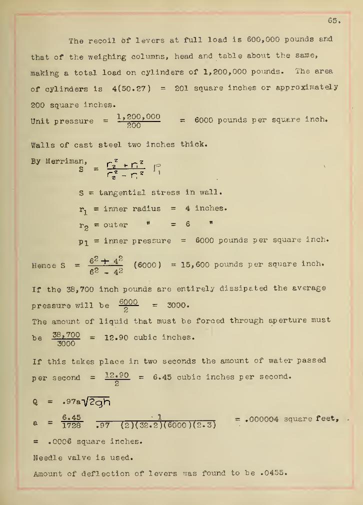
65.
The recoil 6f levers at full load is 600,000 pounds arid
that of the weighing columns, head and table about the same,
making a total load on cylinders of 1,200,000 pounds. The area
of cylinders is 4(50.27) = 201 square inches or approximately
200 square inches.
Unit pressure = 1,q22
>Q°Q = 6000 pounds per square inch.200
Walls of cast steel two inches thick.
By Merriman, ^ ? ^ z
- r * 1
S = tangential stress in wall,
r^ = inner radius = 4 inches.
r2= outer w =6 "
p^ = inner pressure = 6000 pounds per square inch.
2 i 2Hence S = 6 ^"
>
~-
4 (6000) = 15,600 pounds per square inch.62 _ 42
If the 38,700 inch pounds are entirely dissipated the average
pressure will be ^|^- = 3000.
The amount of liquid that must be forced through aperture must
he 58 ' 700 = 12.90 cubic inches.3000
If this takes place in two seconds the amount of water passed
per second 12*90 as 6.45 cubic inches per second.2
Q = .97a~\/2qh
_ 6.45 1 , as .000004 square feet,a - 1728 797 (2 )(32.2)(6000 )(2.3)
.0006 square inches.
Needle valve is used.
Amount of deflection of levers was found to be .0455.
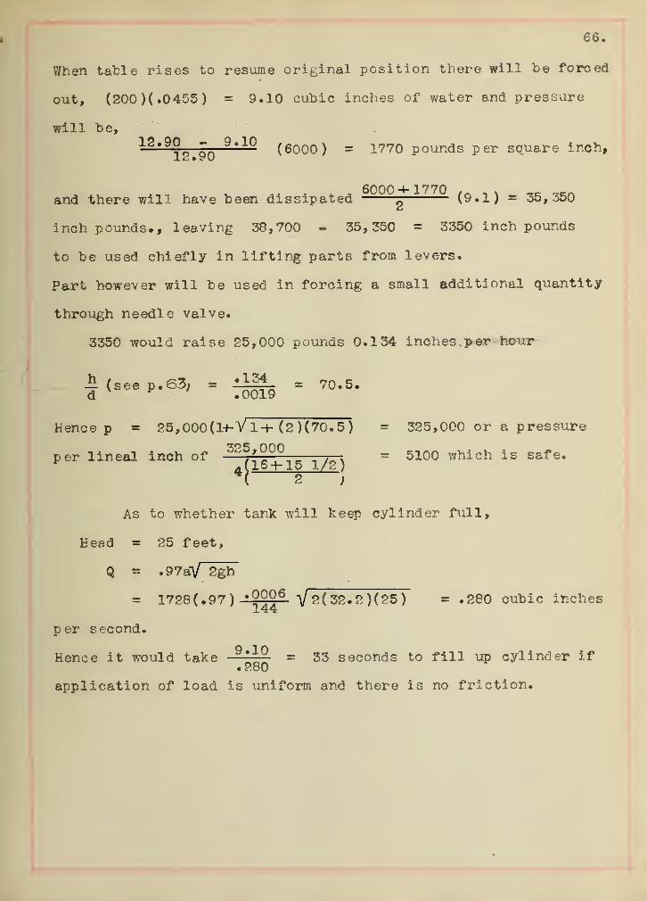
66.
When table rises to resume original position there will be forced
out, (200 )(.0455) = 9*10 cubic inches of water and pressure
will be,1S ' 9
12.909 * 10
( 6oo°) = 1770 P°unds P er square inch,
and there will have been dissipated600Q
^~1770
(9.1) = 35, 350
inch pounds., leaving 38,700 - 35,350 = 3350 inch pounds
to be used chiefly in lifting parts from levers.
Part however will be used in forcing a small additional quantity
through needle valve.
3350 would raise 25,000 pounds 0.134 inches. per hour
(see p. S3, = = 70.5.d » .0019
Hence p = 25,000(1+-VT+ (2 )(70.5 ) = 325,000 or a pressure
per lineal inch of3g5,00^^__ = 51Q0 which is safe#
4( 2 ;
As to whether tank will keep cylinder full,
Head = 25 feet,
Q = .97aV 2gh
= 1728(.97) V2(32.2)(25) = .280 cubic inches144
per second.
Hence it would take9,10 = 33 seconds to fill up cylinder if.280
application of load is uniform and there is no friction.
67.
VIII.
CALIBRATION.
According to the contract and specifications the
machine was to be calibrated at the works of the company and
also at the University after being set in place. The plan of
calibration was first to calibrate up to one tenth of the ca-
pacity of the machine, 600,000 pounds, by means of calibrating
levers and dead weight, using both small and Jarge poise; and
second, to calibrate from 60,000 pounds to 600,000 pounds by
means of a .calibrating bar and extensometer to be furnished by
the University.
The calibration has been divided, somewhat arbitrar-
ily, into seven parts which will be taken up separately. The
data for these tests and the curves plotted are on succeeding
pages.
Test No. 1.
Riehle calibrating levers with a count of ten were
used. The arrangement of levers is shown in figure on the
following page. The small poise was used. As weights, 1000
pounds in standard weights and 5000 pounds of pig iron were
used. The pig iron was divided into two lots of 2000 pounds
each and one Jot of 1000 pounds. The standard weights consisted
of twenty weighing 50 pounds each. Ey the proper combinations,
loads on bales of levers, ranging by even hundreds up to 6000
pounds were secured or the equivalent tc loads on table up to

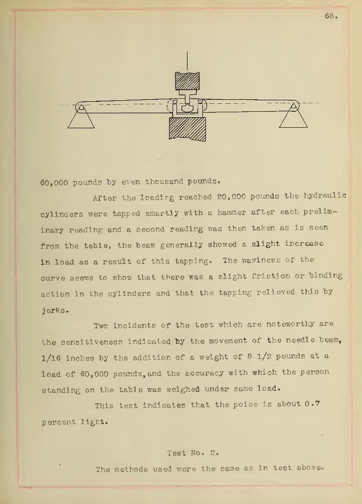
68.
60,000 pounds by even thousand pounds.
After the loading reached 20,000 pounds the hydraulic
cylinders were tapped smartly with a hammer after each prelim-
inary reading and a second reading was then taken as is seen
from the table, the beam generally showed a slight increase
in load as a result of this tapping. The waviness of the
curve seems to show that there was a slight friction or binding
action in the cylinders and that the tapping relieved this by
jerks.
Two incidents of the test which are noteworthy are
the sensitiveness indicated by the movement of the needle beam,
1/16 inches by the addition of a weight of 8 l/2 pounds at a
load of 60,000 pounds, and the accuracy with which the person
standing on the table was weighed under same load.
This test indicates that the poise is about 0.7
percent light.
Test No. 2.
The methods used were the same as in test above.
In (a) and (d) the calibrating levers were used and loads put
on by increments of 1000 pounds up to 6000 pounds. In (b ) and
(c) loads were dead weight on table by same increment. The
results indicate, in general, that the poise is light, within
this range, about one-half of one percent.
Test No. 3.
This test is in five parts, in all of which except
(c) the load increases by increments of 10,000 pounds up to
60,000 pounds. In (c) the load increases by 1000 pound incre-
ments up to 6000 pounds. The large poise is used in first two
parts and small poise in the remaining parts. After (a) the
recoil cylinders were removed and left off for the remainder
of the calibration, this being deemed advisable from the re-
sults of Tests Nos. 1 and S. This test indicates that large
poise is light by 0.7 to 0.8 percent while small poise is in
error in same direction by a slightly smaller percent.
Test No. 4.
Small poise was corrected by adding 31 grams of
lead. The center of gravity was determined by balancing latter
on knife edge and lead was then added as near as possible to
this. 31 grams is. 0.65 percent of the weight of the poise
which is 10.4 pounds.
Large poise was also corrected in same manner by
the addition of 341 grams which is 0.7 percent of its weight
which is 104 pounds.

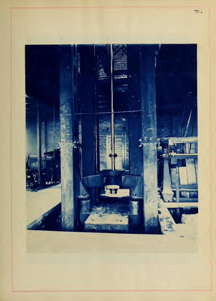
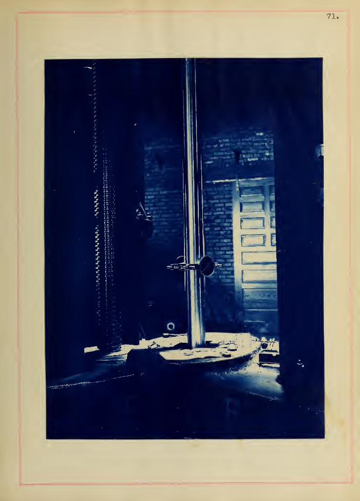
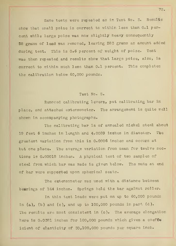
72.
Same tests were repeated as in Test No. 3. Results
show that small poise is correct to within less than 0.1 per-
cent while large poise was now slightly heavy consequently
58 grams of lead was removed, leaving 28 3 grams as amount added
during test. This is 0*6 percent of weight of poise. Test
was then repeated and results show that large poise, also, is
correct to within much less than 0.1 percent. This completes
the calibration helow 60,000 pounds.
Test No. 5.
Removed calibrating levers, put calibrating bar in
place, and attached extensometer. The arrangement is quite well
shown in accompanying photographs.
The calibrating bar is of annealed nickel steel about
19 feet 6 inches in length and 4.0089 inches in diameter. Tbe
greatest variation from this is 0.0006 inches and occurs at
but one place. The average variation from mean for twelve sec-
tions is 0.00018 inches. A physical test of two samples of
steel from which bar was made is given below. The nuts at end
of bar were supported upon spherical seats.
The extensometer was used with a distance between
bearings of 144 inches. Springs held the bar against roller.
In this test loads were put on up to 60,000 pounds
in (a), (b) and (c), and up to 100,000 pounds in part (d).
The results are most consistent in (c)« The average elongation
here is 0.0381 inches for 100,000 pounds which gives a coef©«
icient of elasticity of 30,100,000 pounds per square inch.

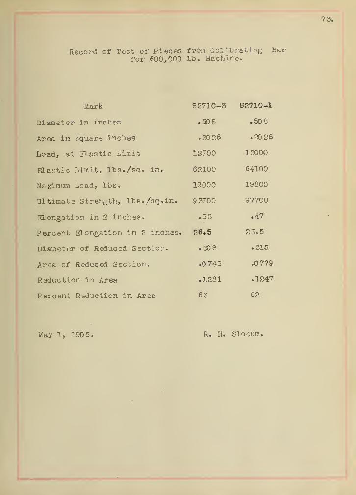
Record of Test of Pieces from Calibrating Barfor 600,000 lb. Machine.
Mark 82710-3 82710-1
Diameter in inches .508 • 50
8
Area in square inches .20 26 .20 26
Load, at Elastic Limit 12700 13000
Elastic Limit, lbs./sq. in. 62100 64100
Maximum Load, lbs. 19000 19800
Ultimate Strength, lbs./sq. in. 9 3700 97700
Elongation in 2 inches. .53 .47
Percent Elongation in 2 inches. 26.5 23.5
Diameter of Reduced Section. .308 .315
Area of Reduced Section. .0 745 .0779
Reduction in Area .1281 .1247
Percent Reduction in Area 63 62
May 1, 190 5. R. H. Slocum
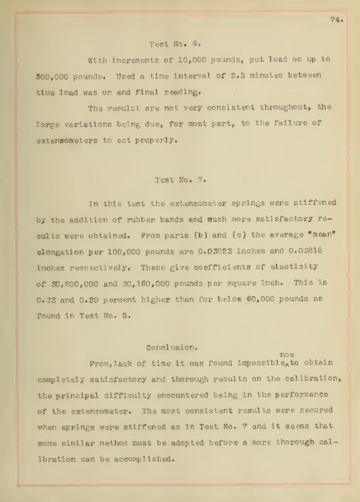
Test No. 6.
With increments of 10,000 pounds, put lead on up to
500,000 pounds. Used a tine interval of 2.5 minutes between
tine load was on and final reading.
The resulst are not very consistent throughout, the
large variations "being due, for most part, to the failure of
extensOmeters to act properly.
Test No. 7.
In this test the extensoraeter springs were stiffened
"by the addition of rubber bands and much more satisfactory re-
sults were obtained. Prom parts (b) and (c) the average "mean"
elongation per 100,000 pounds are 0.03823 inches and 0.03818
inches respectively. These give coefficients of elasticity
of 30,200,000 and 30,160,000 pounds per square inch. This is
0.33 and 0.20 percent higher than for below 60,000 pounds as
found in Test No. 5.
Conclusion.now
Prom, lack of time it was found impossibleAto obtain
completely satisfactory and thorough results on the calibration,
the principal difficulty encountered being in the performance
of the extensoraeter. The most consistent results were secured
when springs were stiffened as in Test No. 7 and it seems that
some similar method must be adopted before a more thorough cal-
ibration can be accomplished.
IX.
SPECIFICATION TESTS.
Seven tests are included here which are to try the
machine as to recoil, eccentric loading, and power required to
operate. These tests will he taken up in order. Data will he
found on succeeding pages.
Test No. 8.
This test was made as a preliminary to Test No. 9.
The stretch of screws was measured hy measuring clearance at
top of same. The jump of weighing head was ohtained hy in-
serting a wooden wedge between weighing head and cross head of
weighing columns. On recoil the amount of jump of head was
given hy amount of crushing of wedge. Observer was seated on
top of machine at failure of specimen. No perceptible jump
of machine was noted but merexy a heavy quiver.
Test No* 9.
This is the same test as no. 8 with a larger piece
and that of cast iron instead of steel. The object was. to get
as large recoil as possible. The jump of weighing head was
quite large but this is not especially objectionable except for
the amount of pounding, or impact, which it will give on fal-
ling back. The pulling head did not jump an amount sufficient
to be measured by means of the apparatus used which consisted
merely of a plank thrown between weighing columns with a peg
76.
in same which was "brought in contact with lower side of head
and which could slide easily under pressure of head.
Test No. 10.
This test was to measure the effect of the maximum
eccentric loading. The deflection of guide columns was obtained
as follows:- Heavy thread was fixed to the lower chords of
the two middle roof trusses and carried in a north and south
direction across the tops of guide columns within say one-
quarter of an inch of their top surfaces. One thread was
used for the east column and one for the west. Planks were
thrown "between roof trusses at each side of machine and threads
in an east and west direction were fixed as before. Punch
marks on top of column indicated by their movement with respect
to the thread the movement of top of the guide columns. The
deflection of weighing columns was obtained as follows:-
Wooden pointers about eight feet long were weighted to the
cross head of the columns, one pointer east and west and one
pointer north and south. The movements of the ends of these
pointers with respect to fixed points was then observed. The
calculated deflection for load of 300,000 pounds is « 1.15
inches(see computations). Actual deflection in this case is
0.71 inches or about 62 percent of the theoretical. Inclination
of column to secure eccentric loading was obtained by the use
of wedge shaped blocks at both ends.

77.
Test No. 11.
This is the same as Test No. 10 except that column
was put in plane at right angles to that of screws. As was to
be expected the deflection was reduced and taking place in
both directions. Deflections are, however, very small in amount.
Test No. 12.
In this test wooden columns were substituted for
cast iron columns of Tests Nos. 10 and 11. Eccentricity of
5 inches was all put at bottom. The deflection at 400,000
pounds load is 0.83 inches as against (2/3)(2.29) = 1*53 inches.
This is 54 percent. It way discovered in this test that these
was insufficient clearance between flanges of weighing columns
and pulling head. These came in contact with the load of
400,000 pounds. For maximum load and this eccentricity it
will be necessary to. increase normal clearance which will prob-
ably be effected by the removal of from an inch to an inch and
a half from the flanges of the columns. Part of the apparent
deflection of weighing columns is no doubt caused by the slight
difference in deflection of main levers due to the 5 inches of
eccentricity. Wooden wedges were used to give eccentricity to
the column.
Test No. 13.
This is the same as No. 12 with plane of eccentric
loading at right angles to plane of screws and with the eccen-
tricity divided equally between top and bottom. The greatest
deflection of guide columns is 0.28E(ar right angles to plane

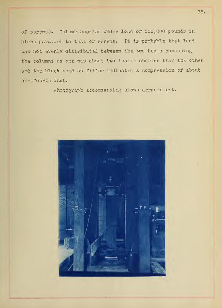
78.
of screws). Column buckled under load of 500,000 pounds in
plane parallel to that of screws. It is probable that load
was not evenly distributed between the two beams composing
the columns as one was about two inches shorter than the other
and the block used as filler indicated a compression of about
one-fourth inch.
Photograph accompanying shows arrangement.
79,
Test No. 14.
Watt meters were connected to the two circuits and
observations taken of power used during Test No. 12 with load
applied at different rates of speed. The results show that
the motor used has an excess of horse-power which, however,
Sois not -teo large to he undesirable.
Conclusion.
The tests show that machine behaves satisfactorily
under eccentric loading as far as expected deflections are
concerned. The lack of clearance between weighing columns
is serious, however, and must be corrected before tests can be
made up to full capacity at maximum eccentricity.
80.
X.
CONCLUSIONS.
The history of the testing machine industry has been
briefly discussed, the types of machines now in use were de-
scribed, a few particular machines were described, and the
qualities which a testing machine should possess were given.
These things were done that a better idea might be had of the
condition of testing machine development and of what might be
expected at the present time in a testing machine.
The plans proposed for the machine under discussion
were described briefly and the machine as adopted more thor-
oughly. The efficiency of the main features of its design
were reviewed and the work of the machine as it showed up in
the calibration and other tests was given.
The results of the tests meet the Specifications.
The sensitiveness of the machine is very much greater than ex-
pected; the accurate response of the weighing mechanism to small
increments of load at all points within limits of capacity is
especially noticeable; the accuracy of the scale beam below
one tenth of the capacity is much beyond specification require-
ments; and the accuracy of the beam for the upper range of the
capacity is at least partially established although it were
better that further investigation be made as to this with the
improvement in extensometer apparatus which was found to be
necessary.
The design of the machine, in general, seems to solve

81.
the problems v/hich arise here as peculiar to the requirements
necessitated by the capacity of the machine and the size of
specimens to be used.

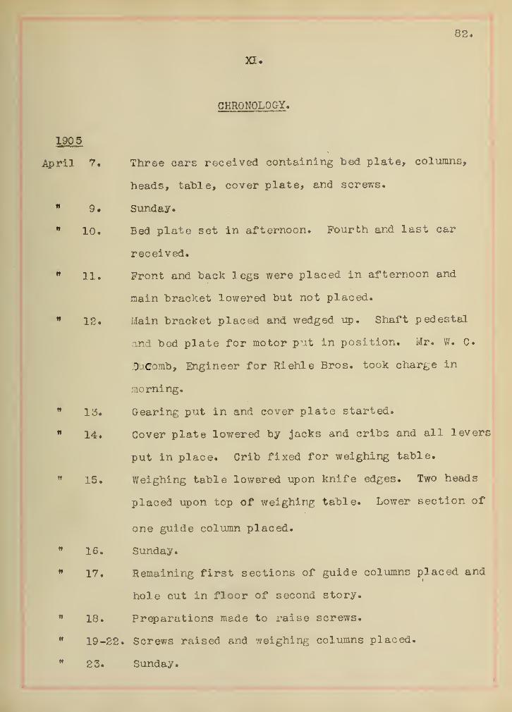
XI.
CHRONOLOGY,
1905
April 7. Three cars received containing bed plate, columns,
heads, table, cover plate, and screws.
w 9. Sunday.
" 10. Bed plate set in afternoon. Fourth and last car
received.
n 11. Front and back legs were placed in afternoon and
main bracket lowered but not placed.
tt 12. Main bracket placed and wedged up. Shaft pedestal
and bed plate for motor put in position. Mr. W. C.
XComb, Engineer for Riehle Bros, took charge in
morning.
" 13. Gearing put in and cover plate started.
n 14. Cover plate lowered by jacks and cribs and all levers
put in place. Crib fixed for weighing table.
15. Weighing table lowered upon knife edges. Two heads
placed upon top of weighing table. Lower section of
one guide column placed.
tt 16. Sunday.
" 17. Remaining first sections of guide columns placed and
hole cut in floor of second story.
" 18. Preparations made to raise screws.
" 19-22. Screws raised and weighing columns placed.
M 23. Sunday.

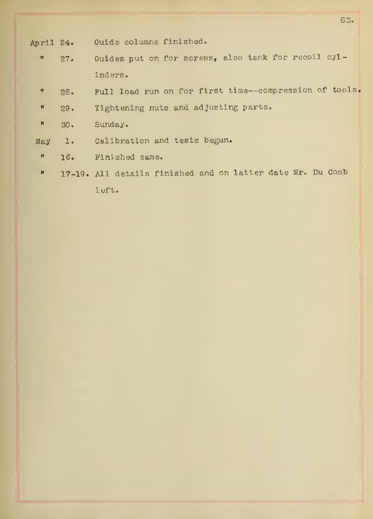
83.
April 24. Guide columns finished.
" 27. Guides put on for screws, also tank for recoil cyl-
ind ers.
M 28. Pull load run on for first time—compression of tools.
" 29. Tightening nuts and adjusting parts.
" 30. Sunday.
May 1. Calibration and tests "begun.
w 16. Finished same.
" 17-19. All details finished and on latter date Mr. Du Comb
left.
I
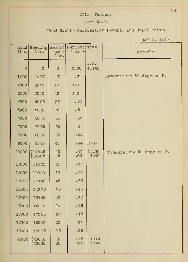
84.XII. Tables.
Test No.l.
Used Riehle Calibration Levers, and Small Poise.
May 1, 190 5.
Loadlbs.
Readinglbs.
Amount+ or -lbs.
Percent+ or -
TimeRemarks
0.00A.M.IH 40
1000 100 7 7 .7 Temperature 62 degrees P.
2000 20 20 20 1.0
3000 30 30 30 1.0
4000 40 25 25 .63
5000 50 30 30 .6
6000 60 35 35 .58
7000 70 35 35 .5
8000 80 35 35 .44
9000 9040 40 .44 P.M.
10000 (10045(10005
455
.45
.0 512 J 101:50
Temperature 62 degrees P.
11000 110 35 35 . 32
12000 12010 10 .08
13000 130 45 45 . 35
14000 140 63 63 .45
15000 15040 40 .27
16000 16010 10 .06
17000 170 25 25 .15
18000 18010 10 .0 6
19000 19015 15 .0 8
20000 (200 30
(2001030
10
.15
.052:202:40
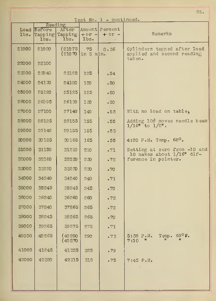
Test No. 1 - continued.Reading
Loadlbs.
BeforeTapping
lbs.
AfterTapping
lbs.
Amount+ or -
lbs.
P ere entor - Remarks
21000
22000
210 20
22100
(210 75(210 70
75in 5 m
0.36Ln.
Cylinders tapped after loadapplied and second readingtaken.
23000 23040 23125 125 .54
24000 24130 24120 120 .50
25000 25120 25125 125 .50
26000 26095 26139 130 .50
27000 27100 27140 140 53 With no load on tabl
e
5
28000
29000
28125
29140
28155
29155
155
155
.55
.53
Adding 10# moves needle beam1/16" to 1/8".
30000 30125 30165 165 .55 4:20 P.M. Temp. 68°.
31000
32000
31150
32180
31210
32230
210
230
.71
.72
Setting at zero from -10 and10 makes about l/l6w dif-ference in pointer.
33000 33220 33230 230 .70
34000 34240 34240 240 .71
35000 35245 35245 245 .70
36000 36240 36260 260 .72
37000 37240 37265 265 .72
38000 38245 38265 265 .70
39000 39 265 39 275 275 • 71
40000 40265 (40 290(40 270
290 .73 5:38 P.M. Temp. 69°F.7:10 " •
41000 41245 41325 325 .79
42000 42320 42315 315 .75 7:45 P.M.
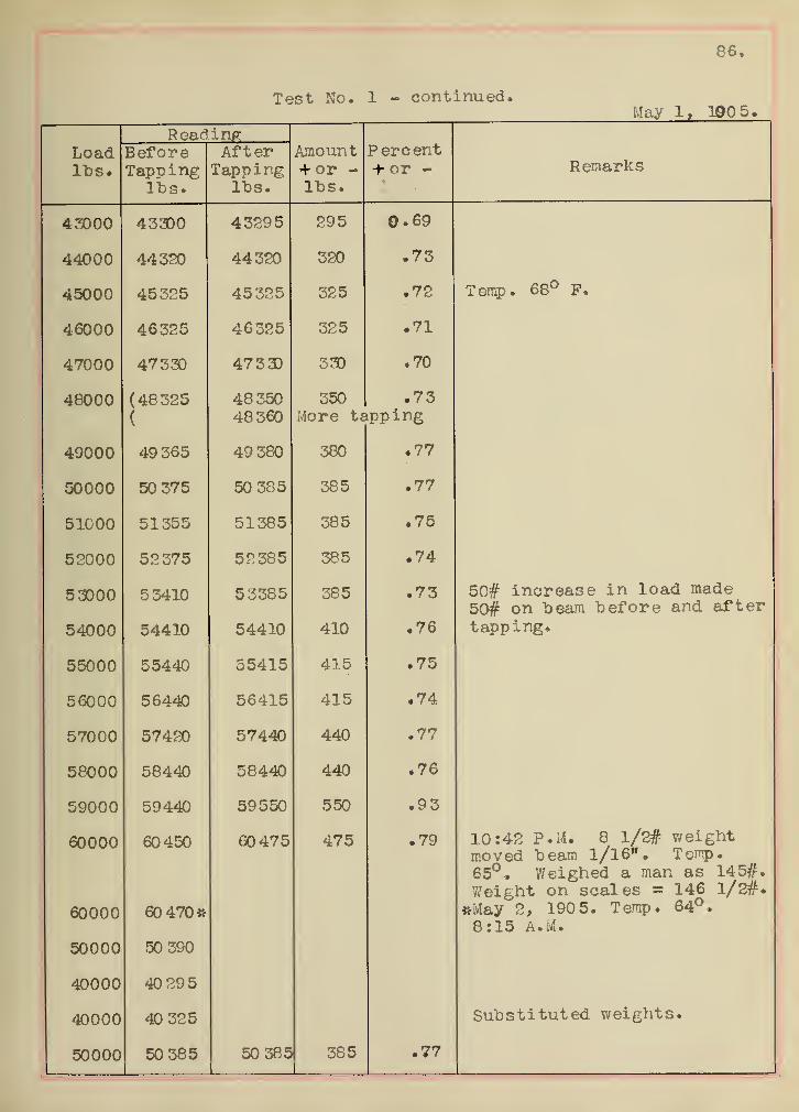
Test No. 1 - continued.May 1, 190 5*
Read ingT.rvfl H
lbs« TappingThe.
AfterAX W
Tappinglbs.
Amount+ or -
lbs •
P ere en
t
+ or - Remarks
43295 295 0.69
44320 320 .73
45000 45325 45325 325 .72 Temp. 68° P.
46000 46 325 46325 325 • 71
47000 47330 47330 330 .70
48000 (48325 4835048 360
350More tc
• 73lp id inc
AO ^fi^ 4Q *^Rr> 3R0 77
50000 50 375 50 385 385 .77
51000 51 355 51385 385 75
52000 52375 52385 385 .74
5 3410 5 3385 385 • 73 50# increase in load made50# on beam before and after
54O00 54410 54410 410 • 76 tapping.
55440 55415 415 .75
O OUUU 41 *5 - 74
57000 57420 57440 440 .77
58000 58440 58440 440 .76
59000 59440 59550 550 .93
60000 60450
60 470
60475 475 .79 10:42 P.M. 8 l/2# weightmoved beam l/l6n . Temp.65°. Weighed a man as 14 5#.Weight on scales = 146 l/2#.*May 2, 1905. Temp. 64°.
8:15 A.M.
50000 50 390
40000 40 29 5
40000 40 325 Substituted weights.
50000 50 385 50 385 385 .77
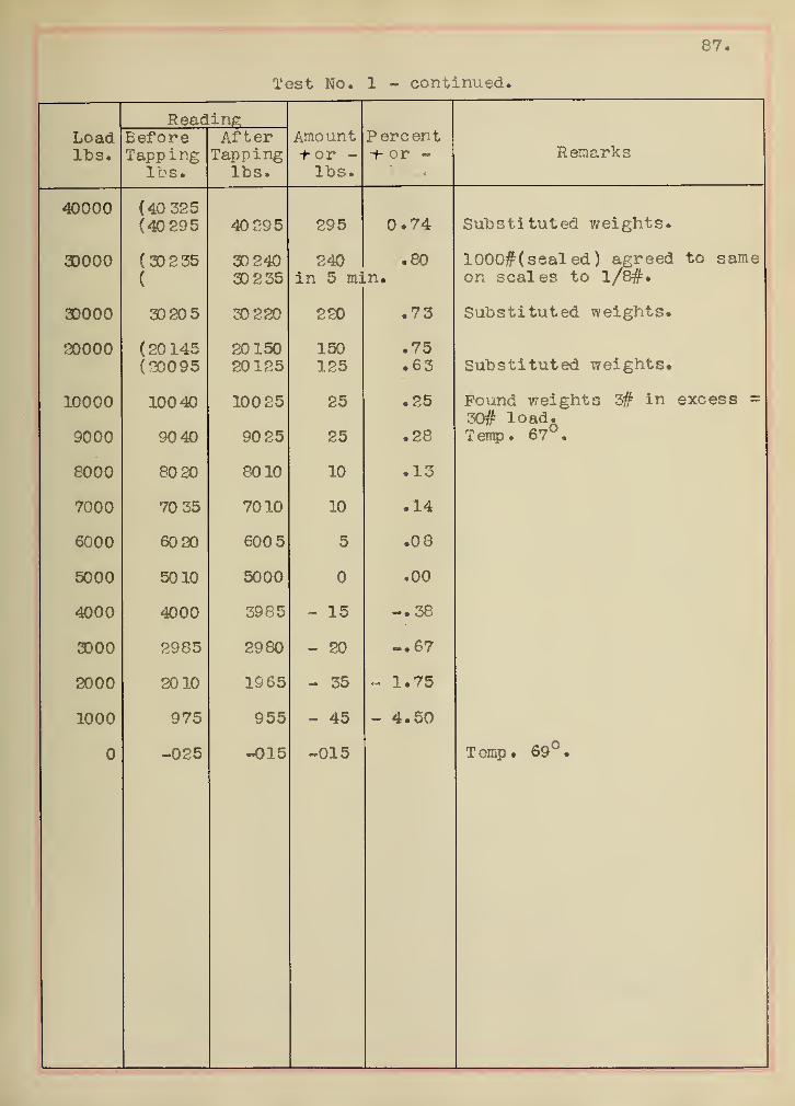
87.
Test No. 1 - continued.
Loadlbs.
ReadingAmounttor -
lbs.
Percenttor - Remarks
B ftforeTapping
lbs.
AfterTapping
lbs.
40000 (40 325( 40 295 40 295 295 0.74 Substituted weights.
30000 (30235 30 240 240 • 80 lOOQfri seal ea ; agreed oo same3D P35 in 5 m: .n. on scales to l/8#.
20000 30 205 30 220 220 .73 Substituted weights.
30000 (20145 20150 150 .75(20095 20125 125 .63 Substituted weights.
10000 10040 100 25 25 .25 Pound weights 3# in excess =
30# load.9000 9040 90 25 25 .28 Temp. 67°.
8000 8020 8010 10 .13
7000 70 35 7010 10 .14
6000 60 20 600 5 5 .08
5000 5010 5000 .00
4000 4000 3985 - 15 38
3000 2985 2980 - 20 -.67
2000 2010 1965 - 35 -1.75
1000 975 955 - 45 - 4.50
-025 -015 -015 Temp. 69°.
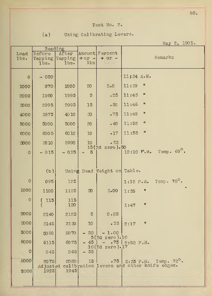
88
Test No. 2»
(a) Using Calibrating Levers.
May 2, 1905.
lbs.
tin*Amount+ or -
lbs
P ercent+ or - RemarksTapping
JC\J- " CJ.
Tapping
- 020 11; 34 A.M.
1000 970 1000 20 2.0 11 : 39 tt
2000 1980 1985 5 OK 11:43 "
3000 2995 2995 15 .50 11:46 n
4000 3975 4010 30 .75 11:49 "
5000 5000 5000 20 .40 11:52 "
6000 600 5 6010 10 .17 11:55 •
3000 3010 2990 10 . 3315(2d zero). 50
- 015 - 25 - 5 12:10 P.M. Temp. 69 .
(b) Using;Dead Weight on Tabl e.
095 1 25X t.i w 1:12 P.M. Temp. 70°.
1000 1100 1125 30 3.00 1:35 "
( 115 115( 120 1:47 n
2000 2140 2125 5 .25
3000 3145 3130 10 .33 2:17 "
5000 5090 5070 - 50 - 1.005( 2d zero ).10
6000 6115 60 75 - 45 - .75 2:52 P.M.io( 2d zero). 17
045 065 - 55
•2000 20 75 2080 15 .75 3:35 P.M. Temp. 72°.
Adjusted calibration levers and other knife edges.
2000 1925 1945
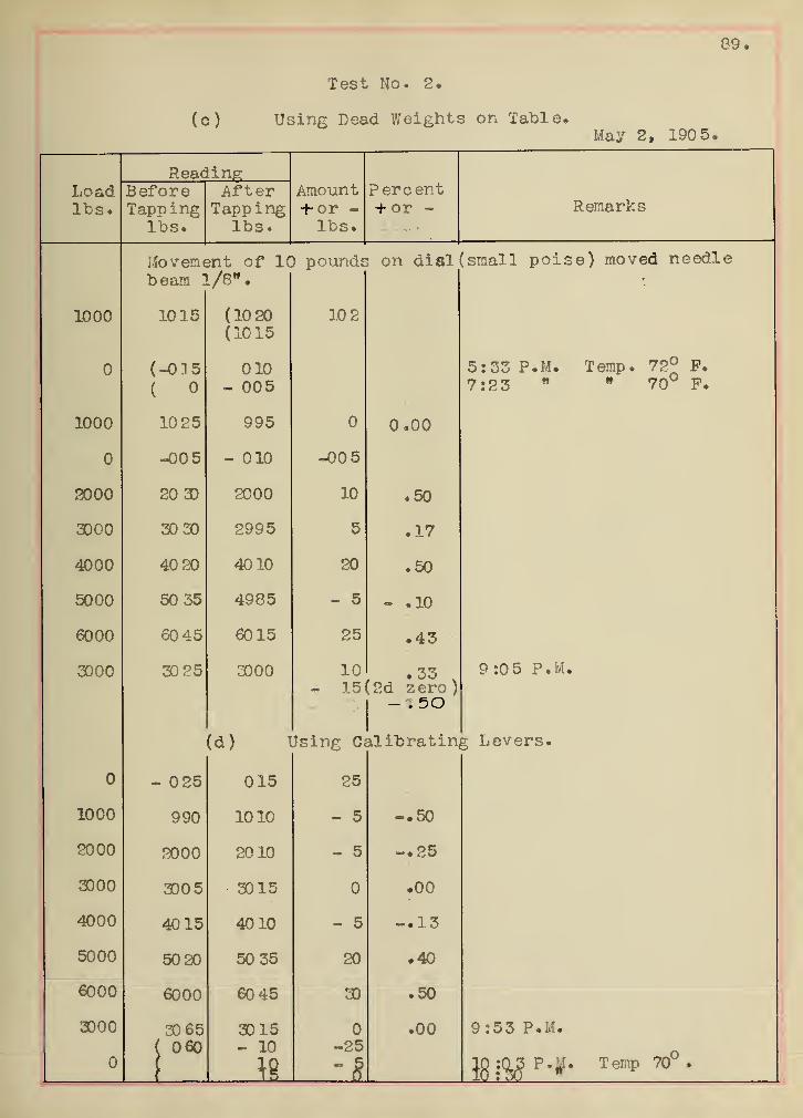
89
(c)
Test No. 2.
Using Dead Weights on Table,May 2, 190 5.
Loadlbs.
BeforeTapping
lbs.
AfterTapping
lbs.
Amountfor -
lbs.
Percentfor - Remarks
1000
1000
2000
3000
4000
5000
6000
3000
Movement of 10 pounds on dialbeam l/8".
(small poise) moved needle
(-015( o
10 25
-00 5
20 3D
30 30
40 20
50 35
60 45
30 25
(1020(1015
010- 005
995
- 010
2000
2995
4010
4985
6015
3000
(d)
10 2
-005
10
5
20
- 5
25
10
0.00
50
.17
.50
- .10
.43
15 (2d zero)- . 50
Using Calibrating Levers.
5:33 P.M. Temp. 72° P.
7:23 n w 70° P.
9 :0 5 P.M.
- 025 015 25
1000 990 1010 * 5 -.50
2000 2000 2010 - 5 -.25
3000 3005 3015 .00
4000 4015 4010 - 5 -.13
5000 50 20 50 35 20 .40
6000 6000 60 45 30 .50
3000 30 65 3015 .00- 10 -25
|
060
IS- 5
9:53 P.M.
Temp 70 .
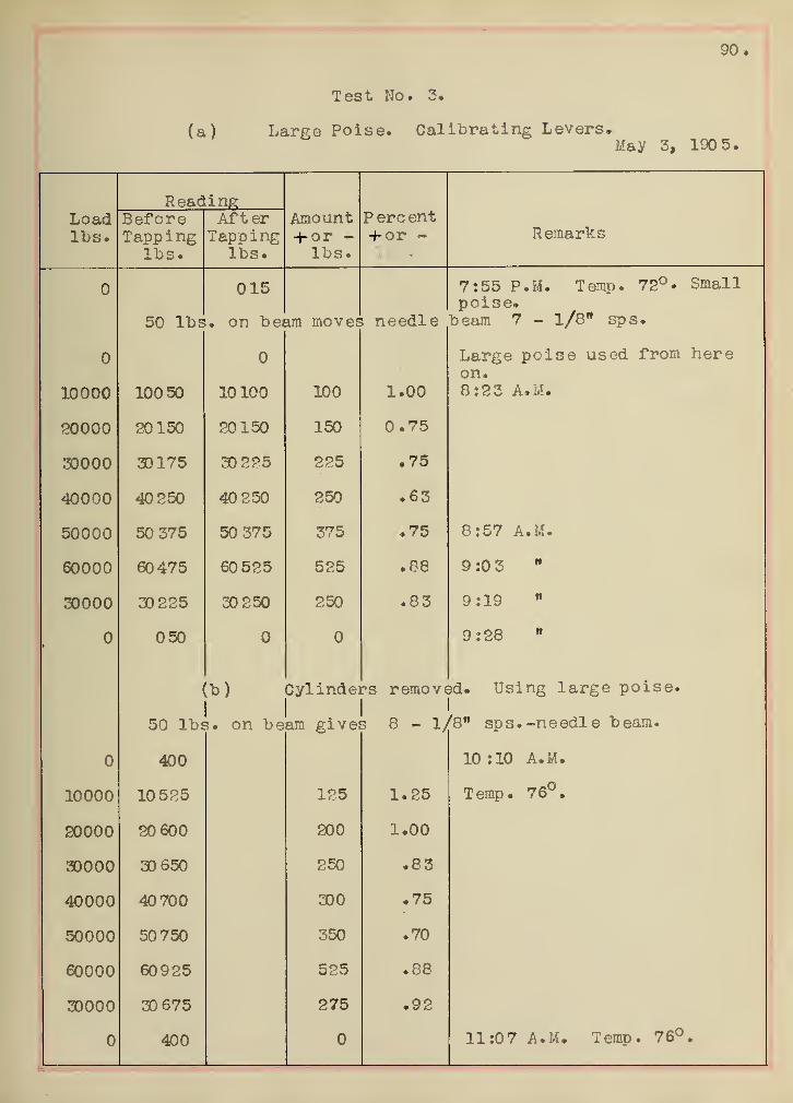
90
(a)
Test No. 3.
Large Poise. Calibrating Levers.May 3, 190 5.
Loadlbs.
R gadj
tg
BeforeTapping
lbs.
AfterTapping
lbs.
Amount+ or -
lbs.
P ere ent+ or - Remarks
7:55 P.M. Temp. 72° • Smallpoise.
50 lbs. on beam moves needle beam 7 - 1/8" sps.
10000 10050 10100 100 1.00
Large poi:>n.
8:23 A.M.
20000 20150 20150 150 .75
30000 30175 30225 225 .75
40000 40250 40 250 250 .63
50000 50 375 50 375 375 .75 8:57 A.M.
60000 60475 60 525 525 .88 9:0 3
30000 30 225 30250 250 .83 9:19 n
050 9 :28 w
(b) Cylinders removed. Using large poise.
I I I
1
50 lbs. on beam gives 8 - l/8n sps. -needle beam.
10 :10 A.M.
Temp. 76°.
400
10000 10 525 125 1.25
20000 20 600 200 1.00
30000 30 650 250 83
40000 40700 300 .75
50000 50750 350 .70
60000 60925 525 .88
30000 30 675 275 .92
400 11:07 A.M. Temp. 76°.
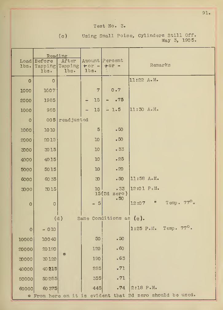
Test No. 3.
(c) Using Small Poise, Cylinders Still Off.May 3, 190 5.
Loadlbs.
ReadingBeforeTapping
lbs*
AfterTapping
lbs.
Amount+-or -lbs.
Percent-for - Remarks
1000
2000
1000
1000
2000
3000
4000
5000
6000
3000
10000
20000
30000
40000
50000
1007
1985
985
005
1010
2015
3015
40 ] 5
5015
60 35
3015
11:22 A.M.
readjusted
(d)
» 010
10040
20120
30120
40 215
50285
60 375
7
15
15
5
10
10
10
10
30
10
0.7
75
1.5
.50
.50
.33
.25
.20
.50
. 33
11:30 A.M.
11:58 A.M.
12:01 P.M.15(2d zero
)
.5012:07 " Temp. 77°.
Same Conditions as (c ).
1:25 P.M. Temp. 77°.
55
.71
4 45 .7460000
% Prom here on it is evident that 2d zero should be used.
2:18 P.M.
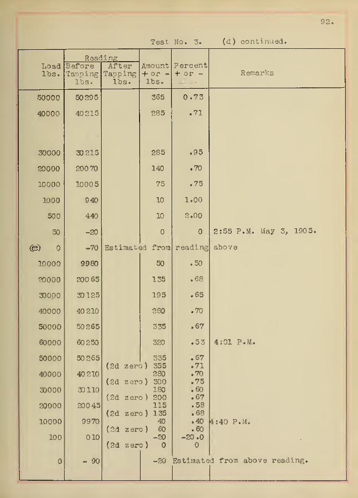
Test No. 3. (d) continued.
Loadlbs.
ReadingBeforeTapping
lbs.
AfterTapDing
lbs.
Amount-+- or -
lbs.
P ere en
t
4- or - Remarks
50000
40000
30000
20000
10000
1000
500
50
10000
20000
30000
40000
50000
60000
50000
40000
30000
20000
10000
100
50 295
40215
365
285
.73
.71
30215
200 70
10005
940
440
-20
-70
9980
200 65
30125
40 210
50 265
60 250
50265
40 210
30110
200 45
9970
010
- 90
285
140
75
10
1C
Estimated from
50
135
195
280
335
320
335(2d zero) 355
280(2d zero) 300
180( 2d z ero ) 200
115( 2d z ero ) 1 35
40
( 2d z ero ) 60-20
( 2d z ero )
.95
.70
.75
1.00
2.00
reading
.50
.68
.65
.70
.67
.53
.6771
.70
.75
.60
.67
.5868
.40
.60-20.0
2:55 P.M. May 3, 190 5.
above
4:01 P.M.
4:40 P.M.
-20 Estimated from above reading.
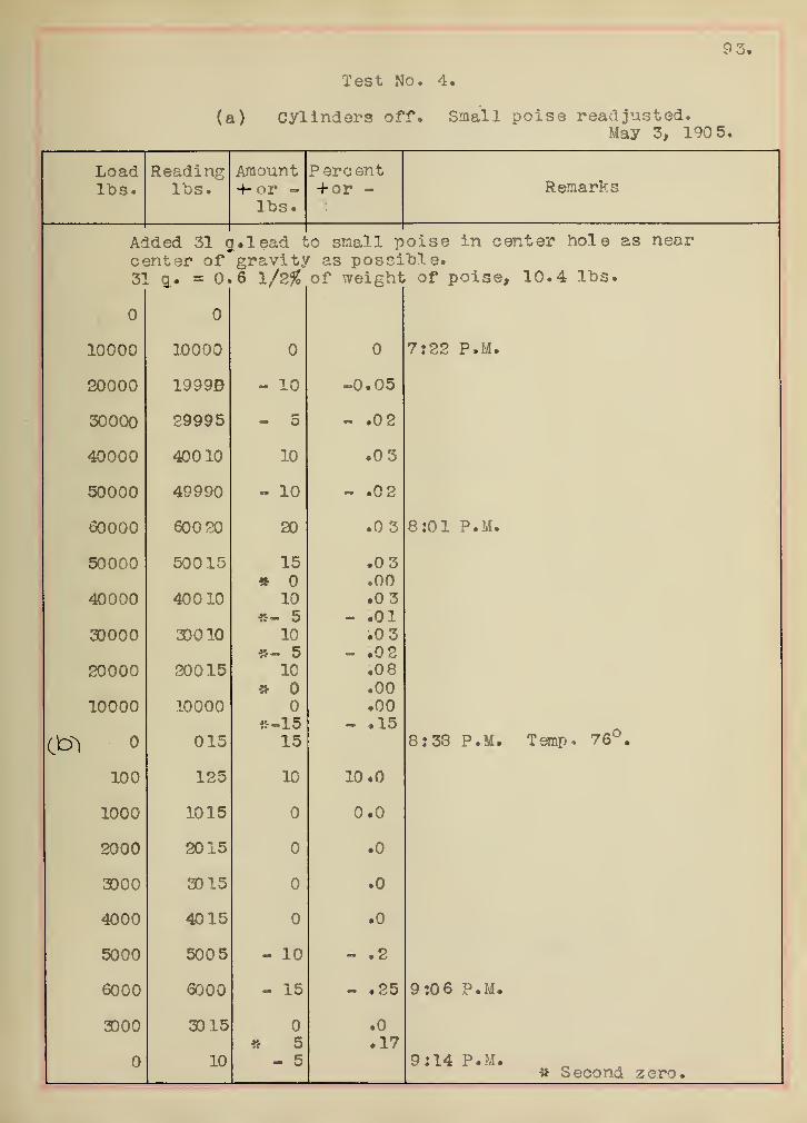
(a)
Test No. 4.
Cylinders off. Small poise readjusted.May 3, 190 5.
Load Reading Amount P ere entlbs. Ids. +- or - + or - Remarks
lbs.
Added 31 g.lead to small poise in center hole as nearcenter of gravity as possible.31 q. =0.6 1/2$ of weight of poise, 10.4 lbs.
10000
20000
30000
40000
50000
60000
50000
40000
30000
20000
10000
#$\ o
100
1000
2000
3000
4000
5000
6000
3000
10000
1999D
29995
40010
49990
600 20
500 15
40010
30010
20015
10000
015
125
1015
2015
3015
4015
5005
6000
3015
10
=* o
10
= 10
20
15*
10*- 5
10«- 5
10»
#-1515
10
- 10
- 15
* 5- 5
-0.05
- .0 2
.0 3
- .0 2
.0 3
.0 3
.00
.0 3- .01
.0 3- .02
.08
.00
.00- .15
10.0
0.0
.0
.0
.0
- .2
- .25
.0
.17
7:22 P.M.
8:01 P.M.
8:38 P.: Temp 76°.
9:06 P.M.
9:14 P.M.* Second zero.
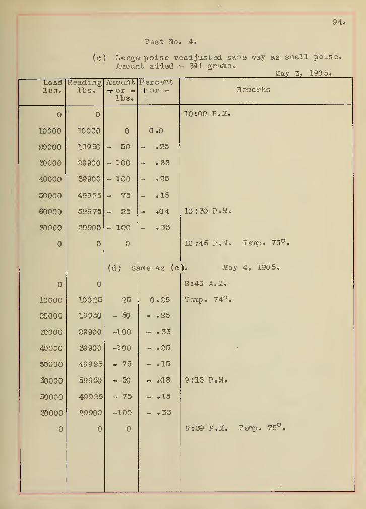
94<
Test No. 4.
(c) Large poise readjusted same way as small poise.Amount added = 341 grams.
May 5, 1905.Loadlbs.
10000
20000
30000
40000
50000
60000
30000
10000
20000
30000
40000
50000
60000
50000
30000
Readinglbs*
10000
19950
29900
39900
49925
59975
29900
100 25
19950
29900
39900
49925
59950
49925
29900
Amount+ or -lbs.
- 50
- 100
- 100
- 75
- 25
- 100
Percent+ or -
0.0
- .25
~ .33
•* • 35
- .15
- .04
- . 33
Remarks
10:00 P.M.
10 :30 P.M.
10 :46 P.M. Temp. 75°.
(d) Same as (c). May 4, 190 5.
8:45 A.M.
Temp. 74°.25
- 50
•100
-100
- 75
- 50
- 75
-100
0.25
- .25
- .33
- .25
- .15
- .08
- .15
- .33
9:18 P.M.
9:39 P.M. Temp. 75°.
r
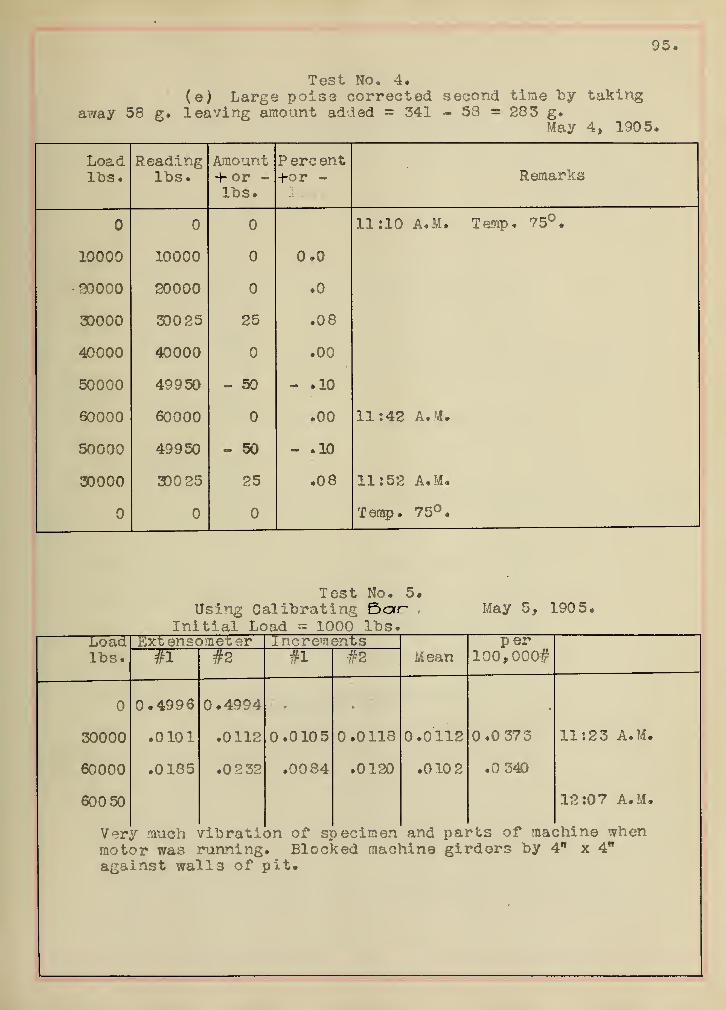
95.
Test No. 4.(e) Large poise corrected second time by taking
away 58 g. leaving amount added = 341 - 58 = 283 g.May 4, 1905.
liUaulbs. lbs. + or -
iUOl
.r tJX oil l»
+or - Remarks
u n
n \J .V/
n
TiOOO -08
AOOOO u OPl
50000 49950 - 50 - .10
60000 60000 .00 11 :42 A.M.
50000 49950 ~ 50 - .10
30000 300 25 25 .08 11:52 A.M.
T emp • 75°.
Test No. 5.Using Calibrating Barr May 5, 1905.
Initial Load = 1000 lbs.Loadlbs.
t'
Meanp er
100,000##1 #2 #1 #2
30000
60000
600 50
Ver,motaga
0.4996
.0101
.0185
/ much 1
or wasinst wa"
0*4994
.0112
.0 232
/ibrati-canningLis of
]
0.0105
.0084
on of sj
. Bloc:pit.
0.0118
.0120
i ecimen*ed mad
0.0112
.010 2
and pailine gii
0*0 373
.0 340
?ts of ma<
*ders by *
11:23 A.M.
12:07 A.M.
shine when1" x 4"
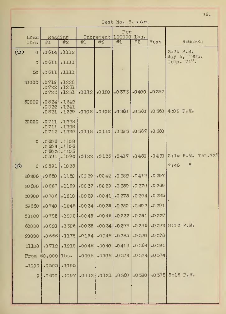
Test No. 5 . con96.
Load IncrementPer
100000 lbs.
1
lbs. n #2 #1 #2 #1 #2 Mean Remarks
(a) o .0 614
.0611
.1112
.1111
3:25May E
Temp.
P.M.1905.
71°.
50 .0 611 .1111
30000 .0719.0 799.0723
.1228
.1231 .0112 .0120 .0 373 .0400 0 387
60000-
.0834-0 83?.0 8 31
.1342
.1341
.1339 .0108 .0108 .0 360 .0 360 .0 360 4:0 2 P.M.
30000 .0711.0 711.0713
.1228
. 1°?8
.1229 •U 1±0 •U ±Jl\J •u o •u o« / .0 380
.0 60 6
.0 60 4n fin rr
.0591
.11081106
.1094 .0122 .0135 .0407 .0 450 .0430 5:16 P.M. Tern. 72°
(p) .0591 10 88 7:46
10200 .0630 .1130 .00 39 .0042 .0 382 .0412 .0 397
20500 .0 667 .1169 .00 37 .00 39 .0 359 .0 379 .0 369
30900 .0 70 6 .1210 .00 39 .0041 .0 375 .0 394 .0 385
39 850 .0740 .1246 .00 34 .00 36 .0 380 .0402 .0 391
51^00 .0785 .1292 .00 45 .0046 .0 333 .0 341 .0 337
60000 .0820 .1326 .00 35 .00 34 .0 398 .0 386 .0 392 8:0 3 P.M.
20000 .0 666 .1178 .0154 .0148 .0 385 .0 370 .0 378
31100 .0712 .1218 .0046 .0040 .0418 0 364 .0 391
Prom (50,000 lbs. .0108 .0108 .0 374 .0 374 .0 374
-1000 .0595 .1095
.0 600 .1097 .0112 .0121 0 360 .0 390 .0 375 8:16 P.M.
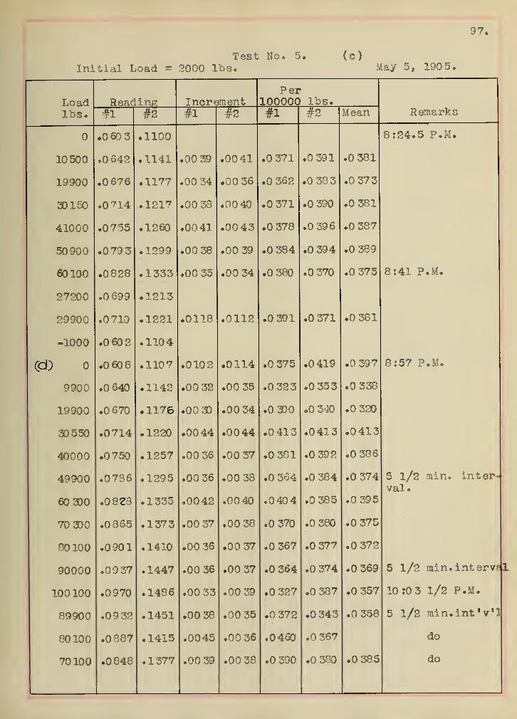
97.
Test No. 5. (c)Initial Load = 2000 lbs. May 5, 190 5.
LoadJL US •
Reading IncranientPer
Remarks#1 #2 #1 #2 #1 #2 Mean
.0 60 3 .1100 8:24.5 P.M.
io 5nr> .0 642 .1141 .00 39 .0041 .0 371 .0 391 .0 381
i qqoo .0 676 .1177 .00 34 .00 36 .0 362 .0 38 3 .0 373
Tfil 50 .0714 .1217 .00 38 00 40 .0 371 .0 390 .0 381
4-1000 .0755 .1260 .0041 .0043 0 378 .0 396 .0 387
50Q00 .079 3 .1299 .00 38 .00 39 •0 384 .0 394 .0 389
.0828 .1333 .00 35 .00 34 .0 380 .0 370 .0 375 8:41 P.M.
07000 .0 699 .1213
.0710 .1221 0118 .0112 .0 391 .0 371 .0 381
_innn .0 602 .1104
(CJJ U .0 608 .1107 .0102 .0114 .0 375 .0419 .0 397 8:57 P.M.
•0 O40 n / o. 1 X.'kd .UU Oc, •uu oo •U Oc, o -0 ^Tfi
19900 .0 670 .1176 .00 30 .00 34 •0 300 .0 340 .0 320
OU v> <JU .0714 .1220 .0044 .0044 .0 413 .0413 .0 413
etkJ\JKJ\J .0750 .1257 .00 36 .00 37 .0 381 .0 392 .0 386
.0786 .1295 00 36 .00 38 .0 364 .0 384 .0 374 5 l/2 min. inter-val.
.0823 .1335 .0042 .00 40 .0404 .0 385 .0 395
/U OUU .0865 .1373 .00 37 .00 38 .0 370 .0 380 .0 375.
no inn .0901 .1410 .00 36 .00 37 .0 367 .0 377 .0 372
yuuuu .0937 .1447 .00 36 00 37 .0 364 .0 374 .0 369 5 l/2 min.int ervs!
100 100 •0970 . I486 •00 33 •00 39 .0 327 •U oo / •U OO I 10 :0 3 1/2 P.M.
89900 .09 32 .1451 .00 38 .00 35 .0 372 .0 343 .0 358 5 1/2 min.int'v'l
80100 .0887 .1415 .0045 .00 36 0460 .0 367 do
70100 .0848 .1377 .00 39 .00 38 .0 390 .0 380 0 385 do
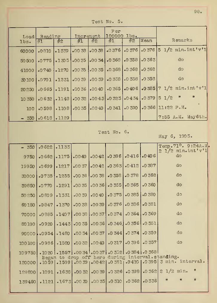
Test No. 5.
PerLoad Reading Increment 100000 Its.
Remarkslbs. #1 #2 #1 #2 #1 #2 Mean
60000 .0 810 .1339 .00 38 .00 38 .0 376 .0 376 0 376 5 1/2 min.int'v*!
50 500 .0775 .1305 .00 35 .00 34 .0 368 .0 358 .0 363 do
41000 .0740 .1270 .00 35 .00 35 .0 368 .0 368 .0 368 do
30100 .0701 .1231 .00 39 .00 39 .0 358 .0 358 .0 358 do
20 250 .0 665 .1191 .00 36 .0040 .0 365 .0 40 6 .0 385 7 1/2 min.int*v'l
10 350 .0 632 .1148 .00 32 .0043 .0 323 .0434 .0 379 5 1/2 " "
100 .0 598 .1108 .00 35 .0040 .0 341•
- 350 .0 613 .1129•7 • ^ *^ A Tuf IJlovfi+Vt( iOO ii.lu. IfilAjf U bll.
Test No. 6.May 6, 190 5.
- 350 .0 622 .1133 Temp. 71°. 9 224A.M,2 1/2 min.int'v'l
9750 .0 662 .1175 .0040 .0042 0 396 .0416 •0 406 do
19950 .0 699 .1217 .00 37 .0042 0 363 .0 412 .0 387 do
30000 .0735 .1255 .00 36 .00 38 0 358 .0 378 .0 368 do
39850 .0 770 .1291 .00 35 .00 36 •0 355 .0 365 .0 360 do
50 250 .0 809 .1331 .00 39 0040 .0 375 .0 385 .0 380 do
60150 .0 847 .1370 .00 38 .00 39 .0 376 .0 386 .0 381 do
70000 .0 885 .140 7 00 38 .00 37 .0 374 .0 364 .0 369 do
80100 .0920 .1443 .00 35 .00 36 .0 346 .0 356 .0 351 do
yoooo .0954 .1480 .00 34 .00 37 .0 344 .0 374 .0 359 do
100100 .0986 .1520 .00 32 .00 40 .0 317 .0 396 0 357 do
109750 .1020 .1557 .00 34 .00 37 0 352 .0 384 .0 368Began to droD off here during interval.
s
ianfiing^
120000 .10 59 .1599 .00 39 .0042 0 381 .0410 .0 395 3 min. interval*
129800 .1091 .1638 .00 32 .00 39 .0 326 .0 398 .0 362 2 1/2 min.
139450 .1121 .1673 .00 30 .00 35 .0 310 .0 362 .0 336 n n it
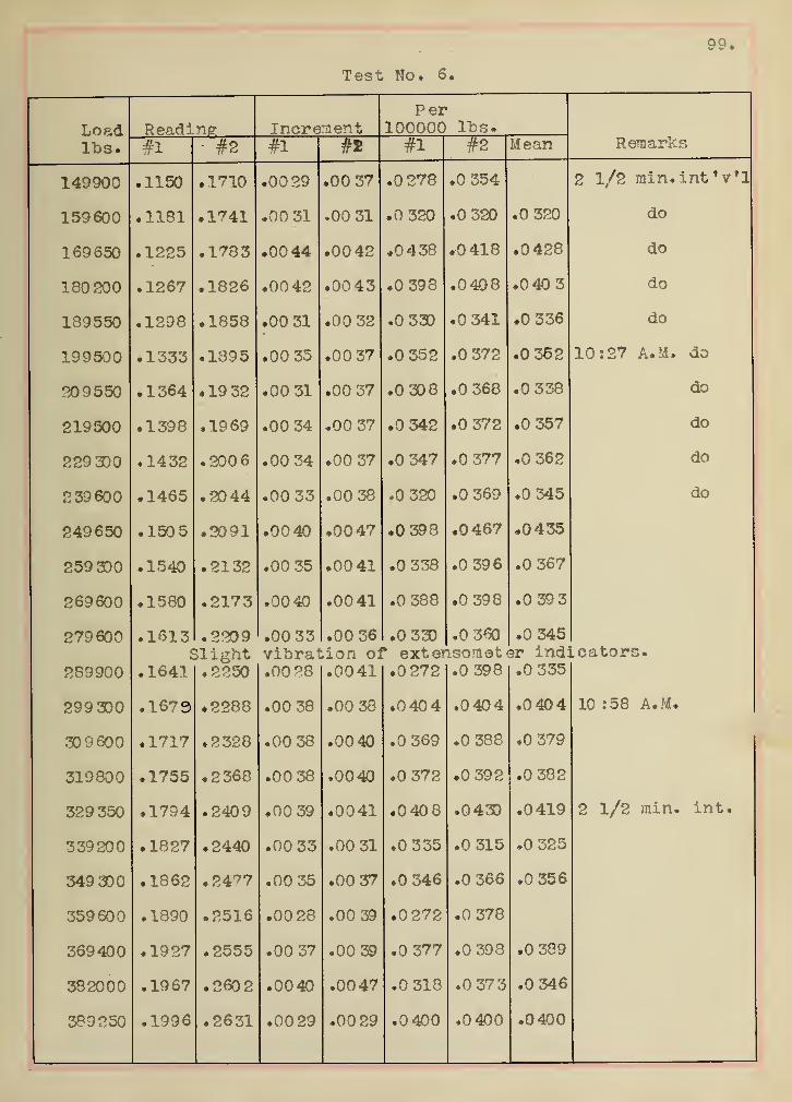
Test No. 6.
Loadlbs.
Readi IncrementPer
100000 lbs.Remarksfl #2 #1 n #1 #2 Mean
149900 .1150 .1710 .0029 .00 37 .0 278 .0 354 2 1/2 min. int * v *1
159600 .1181 .1741 .00 31 .00 31 .0 320 .0 320 .0 320 do
169650 .1225 .1783 .0044 .00 42 .0438 .0 418 .0428 do
180 200 .1267 .1826 .0042 .0043 .0 398 .0408 .0 40 3 do
189550 .1298 .1858 .00 31 .00 32 .0 330 .0 341 .0 336
199500 .1333 .1895 .00 35 .00 37 .0 352 .0 372 .0 352 T /\ _ try10 :27 A.M. OLD
20 9 550 .1364 .19 32 .00 31 .00 37 .0 308 .0 368 .0 338 QD
219500 .1398 .1969 .00 34 .00 37 .0 342 .0 372 .0 357 uO
229 330 .1432 .200 6 .00 34 .00 37 .0 347 .0 377 .0 362 &< '
239600 .1465 20 44 .00 33 .00 38 .0 320 .0 369 .0 345 do
249650 .1505 .2091 .00 40 .0047 .0 398 .0467 .0435
259 390 .1540 .2132 .00 35 .0041 .0 338 .0 396 .0 367
269 600 .1580 .2173 .00 40 .0041 .0 388 .0 398 .0 39 3
279600 .1613 .2209 .00 33 .00 36 .0 330 .0 360 .0 345Slight vibration of extensomet er indicator 5.
289900 .1641 .2250 .0028 .0041 .0 272 .0 398 .0 335
299 390 .1673 2288 .00 38 .00 38 .040 4 .0404 .0 404 10 :58 A.M.
309600 .1717 .2328 .00 38 .00 40 .0 369 .0 388 .0 379
319800 .1755 .2368 .00 38 .0040 .0 372 .0 392 .0 382
329350 .1794 .2409 .00 39 .0041 .0408 .0433 .0419 2 1/2 min. int.
339200 .1827 .2440 .00 33 .00 31 .0 335 .0 315 .0 325
349 300 .1862 2477 .00 35 .00 37 .0 346 .0 366 .0 356
359600 .1390 • 2516 .00 28 .00 39 .0272 .0 378
369400 1927 .2555 .00 37 .00 39 .0 377 .0 398 .0 389
382000 .1967 .2602 .0040 .0047 .0 318 .0373 .0 346
389 250 .1996 .2631 .00 29 .0029 .0400 0400 .0400
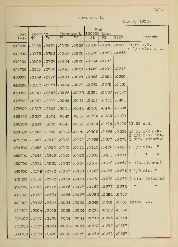
100 .
Test No. 6.May 6, 190 5.
Load Reading IncrementPer
Remarkslbs. #1 w2 -fro#2 #1 «i can
399 300
409900
• 20 35
• 2075
• 2670
• 2708
00 39
•0040
•oo oy
.00 OO
• U ooO
•U Of o
u ooo
A "^fi
u OOO
•U ooo
11:29 A.M.2 l/2 min. int.
419000 .20 99 • 2736 •00 "4 •oo .-SO •U ('D4 n **c\ P*u ou o
458700 « 2140 • 2766 •0041 •00 30 a >i oo4<sc •u ou y • v.^ ooo
438900 • 2169APIA /*
• 2796 •0029 •00 30 <doo A OQ/t A OQA
449200 .220 3 • 2830 •00 34 •00 34 •0 330 .0 OoU •u ooy
459000 • 2241 • 2863 •00 38 .00 33 0 3oo .0 337 • ooo
468700 • 2281 .2901 .0040 .00 38 •0412 .0 391 .0401
478700 • 2317 .2942 .00 36 •0041 •0 360 0410 • OOO
488800 • 2357 • 2981 •0040 •00 39 •0 396 0 ooo A 7Q 1•u oyx
498700 • 2399 • 30 20 •0042 • 00 39 f\ A OA• 4^4 o oy* A /1A Q 11:59 A.M.
490 500
479900
• 2366
.2327
• 2990
• 2949
.00 33
.00 39
•00 30
.00 41
.0402
• 36o
.0 ooo
•0 oo /
.0 OO*
•U Of o
12:05 1/2 P.M.2 1/2 min. int.3 min. interval
470 500 • 2288 • 2908 •00 39 •00 41 • 413 A A 'ZRu **oo A dOfi 2 1/2 min. "
460000 • 2248 . 2866 .00 40 •00 42 • Ool • 4U 1 A XQT• u oy J.
« n it
450700 • 2215 • 28 31 .00 33 •00 35 •0 300 A V7 ft.0 o/o A 7A7•U OO / 2 min. interval
440 600 • 2178 • 2792 •00 37 •00 39 •0 3oo A 'ZD Aooo A• O f o 1 1/2 min. "
430 300 • 2139 • 2753 •00 39 •00 39 • 37o • oro • \J o to 2 min. interval
420500 210 3 • 2716 •00 36 •00 37 •0 367 oV ^ A '?r70%\J Of Ci
n n
411100 • 20 67 • 2679 .00 36 .00 37 •0 3o 3 •0 3S4 •U OOO
401100 .20 33 2643 .00 34 .00 36 .0 340 .0 360 .0 350 12:35 P.M.
39 1700 .2004 .2609 0029 .00 34 .0 309 .0 362 .0 336
380800 .1970 .2568 .00 34 .0041 .0 312 .0 376 .0 344
371000 .19 37 .©531 .00 33 .00 37 .0 337 .0 377 .0 357
360 500 .1899 .2492 .00 38 .00 39 .0 362 .0 371 .0 367
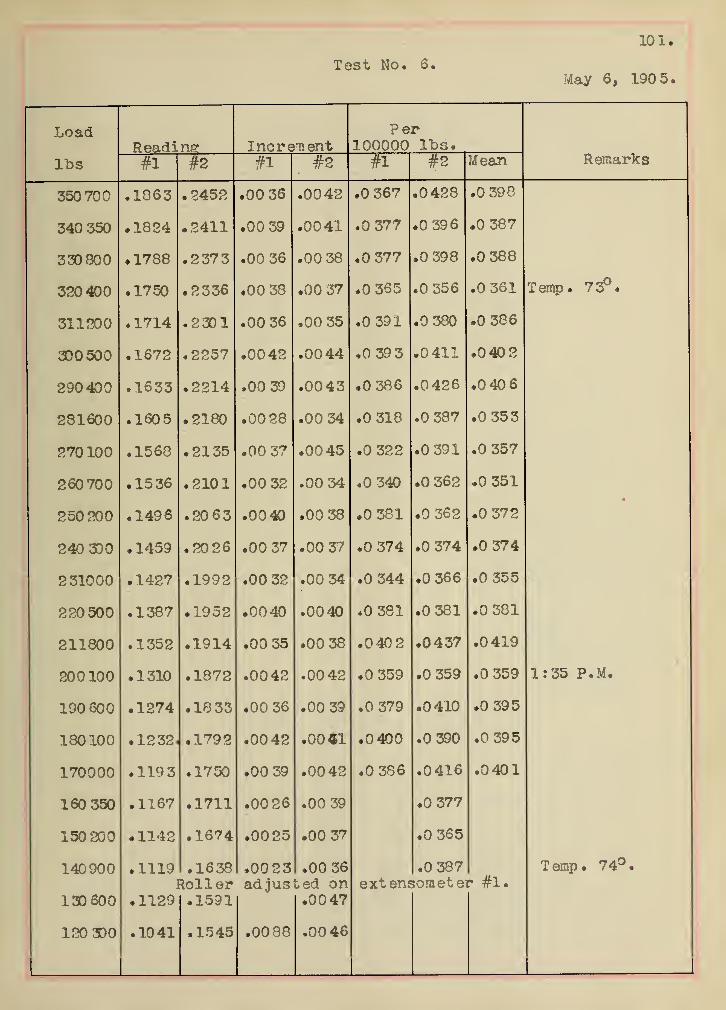
Test No. 6.
101.
May 6, 190 5.
Load
lbsReading Increment
Per100000 lbs.
D .'
I nil1 a#1 #2 #1 #2 #1 #2 Mean
350 700 .1063 .2452 .00 36 .0042 .0 367 0428 .0 398
340 350 .1824 .2411 .00 39 .0041 .0 377 .0 396 .0 387
330800 .1788 .2373 .00 36 .00 38 .0 377 .0 398 .0 388
320400 1750 .2336 .00 38 .00 37 .0 365 .0 356 .0 361 T emp • 72> .
311200 .1714 .2301 .00 36 .00 35 .0 391 .0 380 .0 386
300500 .1672 .2257 .0042 .0044 0 39 3 .0411 .0 40 2
290400 .1633 .2214 .00 39 .0043 .0 386 .0426 .0 40 6
281600 .1605 .2180 .0028 .00 34 .0 318 .0 387 .0 353
270 100 .1568 .2135 .00 37 .0045 .0 322 .0 391 .0 357
260 700 .1536 .2101 .00 32 .00 34 .0 340 .0 362 .0 351
250200 .1496 .2063 .00 40 .00 38 •0 381 .0 362 .0 372•
240 300 .1459 .2026 .00 37 .00 37 .0 374 .0 374 .0 374
231000 .1427 .1992 .00 32 .00 34 .0 344 .0 366 .0 355
220 500 .1387 .1952 .0040 •0040 .0 381 .0 381 .0 381
211800 .1352 .1914 .00 35 .00 38 .0402 .0437 .0419
200100 .1310 .1872 .0042 .0042 .0 359 .0 359 .0 359 1:35 P.M.
190 600 .1274 .18 33 00 36 .00 39 .0 379 .0410 .0 395
180100 .1232< .1792 .00 42 .00*1 .0400 .0 390 .0395
170000 .119 3 .1750 .00 39 .00 42 .0 386 .0416 .0401
160 350 .1167 .1711 .0026 .00 39 .0 377
150 200 .1142 .1674 .00 25 00 37 .0 365
1 40 000 .1119 .1638 .0023 .00 36 .0 387 Temp. 74°.
Roller adjusted on extensometer #1.130 600 1129 .1591 0047
120 300 .1041 .1545 .0088 .00 46
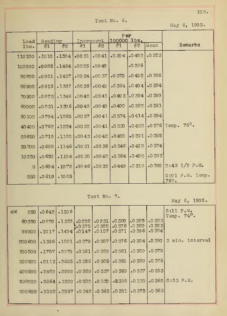
10 2.
Test No. 6.May 6, 1905.
Load Reading IncrementPer
100000 lbs.Remarkslbs. Jin #2 #1 #2 #1 #2 Mean
110100 .1010 .1504 •00 31 .0041 •0 30 4 .040 2 .0 353
100000 •0985 .1464 .0025 .0040 .0 396
90800 .0951 .1427 •00 34 .00 37 .0 370 .0 40 2 .0 386
80900 .0915 .1387 .00 36 .0040 .0 364 .040 4 .0 384
70500 .0873 .1346 .0042 .0041 .040 3 .0 394 .0 399
60000 .0 8 31 .1306 .0042 .00 40 .0400 .0 382 .0 391
50100 .0794 1265 .00 37 .0041 .0 374 .0 414 .0 394
40400 .0762 • 1224 .00 32 .00 41 .0 330 .0 422 .0 376 Temp. 76°.
29650 .0 719 .1182 .0043 .0042 .0400 •0 391 .0 395
20700 .0 688 .1146 .00 31 .00 36 .0 346 .0402 .0 374
10250 .0 650 .1104 .00 38 .0042 .0 364 .0402 .0 383
.0 60 4 .1072 .00 46 00 32 .0449 0 312 .0 380 2:43 1/2 P.M.
250 .0 619 .108576o.
Test No. 7.May 6, 1905.
Co) 250
60 250
99900
.0 642
.0870
.1017
• 110 6
• 1337N
.1494'
.0228^.0 375.0147
•0231.0 388•0157
.0 380
.0 376
.0 371
•0 385.0 389.0 396
.0 383
.0 383
.0 384
8:11 P.M.Tpmn - 74.® *
200600 .1396 .1881 .0 379 .0 387 .0 376 .0 384 .0 380 3 min. interval
300500 .1757 2270 •0 361 0 389 .0 361 .0 389 .0 375
399 500 • 2113 .2655 .0 356 .0 385 .0 360 .0 389 .0 375
499500 .2482 .2992 .0 369 .0 337 .0 369 .0 337 .0 353
598000 .2864 .3322 .0 382 .0 330 .(J388 .0 335 .0 362 8:53 P.M.
500 600 .2522 .2957 .0 342 .0 365 .0 351 .0 375 .0 363
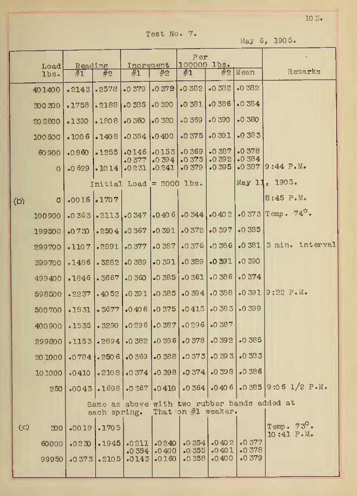
10 3<
Test No. 7.May 6, 1905.
Loadlbs.
401430
300 330
20 2800
100 500
60 900
100900
199500
299700
399700
499400
598500
500 700
400 900
299800
201000
10 1000
250
Cc) 300
60000
99950
Reading#1
• 2143 .2578 .0 379
.2188
.1390 .1808 .i
.100 6 .1408
.0860 .1255
.0 629 .1014
Initial Load
Increment#1
.0146
.0 377
.0 231
#2
.0 379
.0 390
0 380
.0400
.0153
.0 394
.0241
Per100000 lbs.#1
.0 382
.0 381
.0 369
.0 375
.0 369
.0 375
.0 379
= 2000 lbs.
.0016
.0 363
.0730
.1107
.1486
.1846
.2237
.1831
.1535
.1153
0704
.0410
.0043
.1707
.2113
.250 4
.2891
.3282
. 3667
.4052
.3677
. 3290
.2894
.250 6
.2108
.1698
.0 347
•0 367
.0 377
•0 389
.0 360
.0 391
.0406
.0296
.0 382
.0 369
.0 374
.0 367
Same as aboveeach spring.
.0406
.0 391
.0 387
•0 391
•0 385
.0 385
.0 375
.0 387
.0396
.0 388
.0 398
.0 410
.0 344
.0 372
.0 376
.0 389
.0 361
.0 394
.0415
.0296
.0 378
.0373
.0 374
.0 364
#2 Mean
.0 382
.0 386
.0 390
.0 391
.0 387
.0392
.0 395
0 40 2
.0 397
.0 386
.0 391
.0386
.0 388
.0 38 3
.0 387
.0 392
.0 39 3
.0 398
.0406
Remarks
.0 382
.0 384
.0 380
.0 383
.0 378
.0 384•0 387
May 11
.0 373
.0 385
.0 381
.0 390
.0 374
.0 391
.0 399
.0 385
.0 383
.0 386
.0 385
9:44 P.M.
, 1905.
8:45 P.M.
Temp. 74°
•
3 min. interval
9:22 P.M.
9:0 6 1/2 P.M.
with two rubber bands added atThat on #1 weaker.
.0019
.0230
.0 373
.1705
.1945
.210 5
.0211
.0 354
.0143
.0 240
.0400
.0160
.0 354
.0 355
.0 358
.0402
.0401
.0400
.0 377
.0 378
.0 379
Terap. 73°.10 :41 P.M.
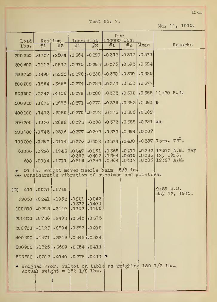
Test No. 7.
104.
May 11, 190 5.
Load Reading IncrementPer
100000 lb 3.lbs. TPJ- Wc> #? Mean
900 350 • \J f of . c,0\) *t »J Ov?<±n 7QQ -0 76? .0 397 .0 379
300400 . 11X6 . coy / -0 775 .0 39 3 .0 384
399750 i Aon 778 -0 7RR .0 780 .0 390 .0 385
500 200 . 1 fi&A• lOO^l - 766R .0 774 .0 787 .0 37? •0 381 .0 377
599 500 . 40 ^6 .0 779 .0 38 3 .0 392 .0 388
500950 1 P7? . «JV/ > o *n ^71W O r J. .0 77R .0 376 .0 38 3 .0 380
400100 .149 3 .3286 .0 379 .0 392 .0 375 .0 388 .0 382
300 200 .1120 .2898 .0 373 .0 388 .0 373 .0 388 .0 381
200 700 .0743 .250 6 .0 377 .0 392 .0 379 •0 394 .0 387
100200 .0 367 .2104 .0 376 .0402 .0 374 .0400 .0 387
60000
600
.0220
.0004
.1943
.1701
.0147
.0 363
.0216
.0161
.040 3
.0242
.0 365
.0 364
.0 364
0401.0305.0407
.0383
.0 3850 386
Remarks
11:20 P.M.
*
»*
Temp. 73°.
12:0 3 A.M. May12, 190 5.
12:27 A.M.
Considerable vibration of specimen and pointers.
(d) 400 .0020 .1710
59850 .0241 .1953 .0 221 .0243.0 373 .0409
100500 0 39 3 2119 .0152 .0166
200 200 0736 2492 .0 343 .0 37 3
300700 .1123 .2894 .0 387 .0402
400 400 .1471 . 3218 .0 348 .0 324
500900 .1825 • 3629 .0 354 •0411
599800 .2203 .40 40 .0 378 .0411
9:59 A.M.May 12, 190 5.
Actual weight = 152 1/2 lbs.
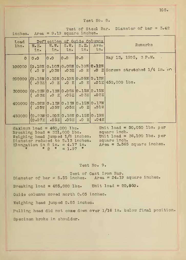
10 5.
inches. Area =
Test No. 8.
Test of Steel Bar.9.19 square inches.
Diameter of bar = 3.42
Load Deflection of Guide Columnslbs. N. E.
in.N.W.in.
s.w.in.
S . E.in.
Ave.in.
Remarks
0.0 0.0 0.0 0.0 May 13, 190 5, 3 P.M.
100000 (0.18N( .0 W
0.10N,0 3W
0.08N.0 3E
0.10N.0 E
0.12N.0 E Screws stretched 1/4 in. in
200000 (0 . 18N( .0 3E
0.10N.0 E
0.10N.0 E
0.08N.0 E
0.12N•OlE 450,000 lbs.
300000 (0.23N( .0 3E
0.13N.0 E
0.08N.0 5E
0.15N.0 3E
0.15N.02E
400000 (0.28N( .05W
0.13N.0 5W
0.13N05E
0.15N.0 E
0.17N•01W
450000 (0.23N(0.07E
0.20N•0 5E
0.18N.05E
0.15N.0 E
0.19N.04E
Maximum load = 460,000 lbs.Breaking load = 331,000 lbs.Weighing head jumped 1/8 inches.Diameter reduced to 2.13 inches.Elongation in 8 in. = 4.17 in*
" " 2 " = 1.97 "
Unit load = 50,050 lbs. persquare inch.Unit load = 36,100 lbs. persquare inch.Area = 3.565 square inches.
Test No. 9.
Test of Cast Iron Bar.Diameter of bar =5.55 inches. Area = 24.19 square inches.
Breaking load = 485,000 lbs. Unit load = 20,050.
Guide columns moved north 0.05 inches.
Weighing head jumped 0.85 inches.
Pulling head did not come down over 1/16 in. below final position.
Specimen broke in shoulder.
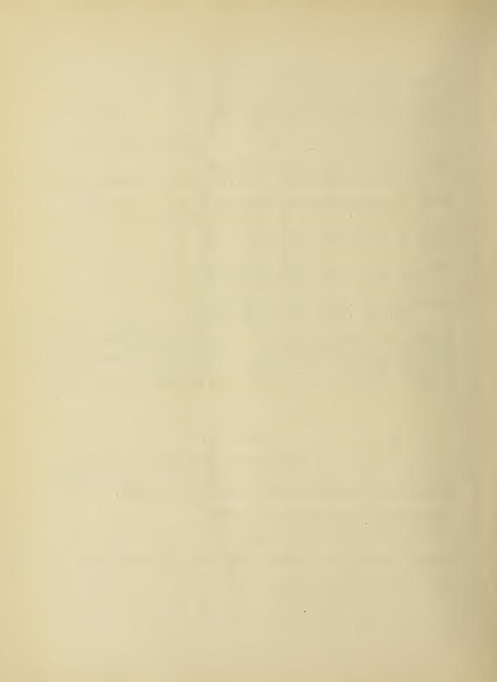
10 6.
Test No. 10.
Test of Eccentric Loading.
C.l. column 6 inches in diameter, 3/4 inches thick, 14 feet l/2
inches long. Plane of column parallel with screws, 5 inches
eccentricity, 2 1/2 inches at each end.
May 15, 1905. 4:30 P.M.
Load De.fl ec"bion of Guide ColumnsDeflection of Top ofWeighing Columns
N.W. N.E. S. E. s.w. Aver. E & W N & S
] 0.0 0.0 0.0 0.0 0.0
100000 (0 .20S(0.0 3W
0.10S.0 3W
.15S
.0 3E0.15S.0 3W
0.15S•02W
0.13N 0.25E
200000 (0.50S( .0 37/
0.43S.0 3W
0.45S.00 E
0.45S.0 3W
0.46S.02W
0.25N 0.25E
300000 (0.73S( .0 3W
0.68S.0 3W
0.73S.0 3W
0.70S.0 3W
0.71S•0 3W
0.25N 0.25E
Test No. 11.Same Eccentricity,
100000
0.0
(0.00S(0 .0 3E
(0.05N( .08E
(0.0 8N( .15E
0.0 0.0 0.0 0.0 0.0
0.0 3N.0 3E
0.0 5N.05E
0.0 5N.05E
0.0 3N•04E
0.00 0.25W
0.0 3N•05E
0.0 8N.10E
0.10N.10E
0.0 7N*08E
0.13N 0.25W
0.0 3N• 15E
0.10N.18E
0.10N.15E
0.0 8N• 16E
0.25N 0.50W
200000
300000
Col umn' buckled on smarting to release load.
Test No. 12.2-7" x 16" Creosoted Beams tied together "by patten plates. 5 incheseccentricity, all at bottom. Plane of beams parallel to screws.May 16, 190 5. 2:00 P.M. Length of column = 14 feet no inches.
0.0 0.0 0.0 0.0 0.0 0.0 0.0
100000 (0.25S 0.23S 0.20S 0.25S 0.23S 0.1 3N 0.0( .08E •08E .08E .08E .08E
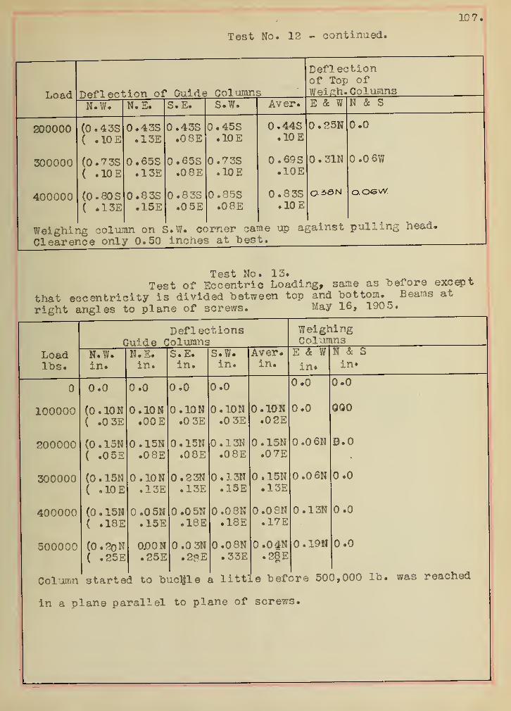
107.
Test No. 12 - continued.
Load n«fl A^t.inn of Guide Columns
Deflectionof Top ofWelsh. Columns
N.W. N.S. S. E. 5.W. Aver. E & W N & S
200000
300000
400000
WeighiiClearei
(0.43S( .10E
(0.73S( .10E
(0.80S( .13E
ig coluiI
0.43S13E
0.65S.13E
0.83S• 15E
nn on i
y 0.50
0.43S•08E
0.65S.08E
.83S•05E
3.W. cc
0.45S.10E
0.73S.10E
0.85S.08E
>rner ca'
3 at "bes
0.44S.10E
0.69S.10E
0.83S.10E
ne up a|
t.
0.25N
0. 31N
gainst
0.0
0.0 6W
O.OGvV
pulling head.
Test No. 13.Test of Eccentric Loading, same as "before except
that eccentricity is divided between top and bottom.^ Beams at
right angles to plane of screws. May 16, 190 5.
Loadlbs.
100000
200000
300000
400000
500000
DeflectionsGuide Columns
N.W.in.
0.0
0.10N.0 3E
0.15N.05E
0.15N.10E
0.15N.18E
0.2oN.25E
N.E.in.
0.0
0.10N.00E
.15N
.08E
0.10N• 13E
0.0 5N.15E
OJDON.25E
S.E.in.
0.0
0.10N.0 3E
0.15N.08E
0.23N.13E
0.0 5N• 18E
0.0 3N• 23E
S.W.in.
0.0
0.10N.0 3E
0.1 3N.08E
1 3N• 15E
0.0 8N.18E
0.0 8N. 33E
Aver,in.
WeighingColumns
N & SE & W
in*
. ION
.02E
0.15N.07E
.15N• 13E
0.08N17E
0.0 4N.28E
0.0
0.0
0.0 6N
0.0 6N
0.13N
0.19N
0.0
000
D.O
0.0
0.0
0.0
Column started to buckle a little before 500,000 lb. was reached
in a plane parallel to plane of screws.
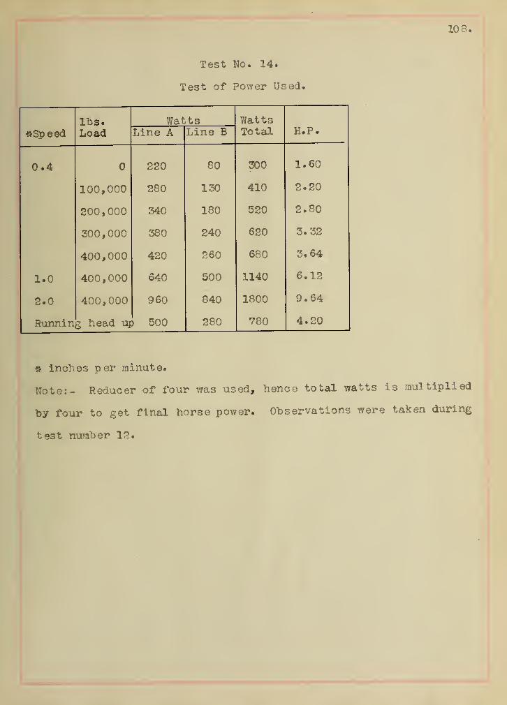
108.
Test No. 14*
Test of Power Used.
lbs. Watts Watts#Speed Load Line A Line B Total H.P.
0.4 220 80 300 1.60
100,000 280 130 410 2.20
200,000 340 180 520 2.80
300,000 380 240 620 3. 32
400,000 420 260 680 3.64
1.0 400,000 640 500 1140 6.12
2.0 400,000 960 840 1800 9.64
Runnin y head uj> 500 280 780 4.20
* inches per minute.
Note:- Reducer of four was used, hence total watts is multiplied
by four to get final horse power. Observations were taken during
test number 12.
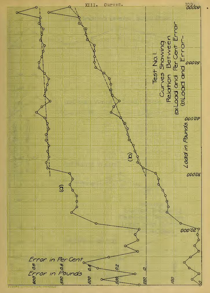
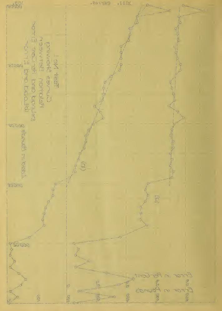
KS— HL-Q^cz
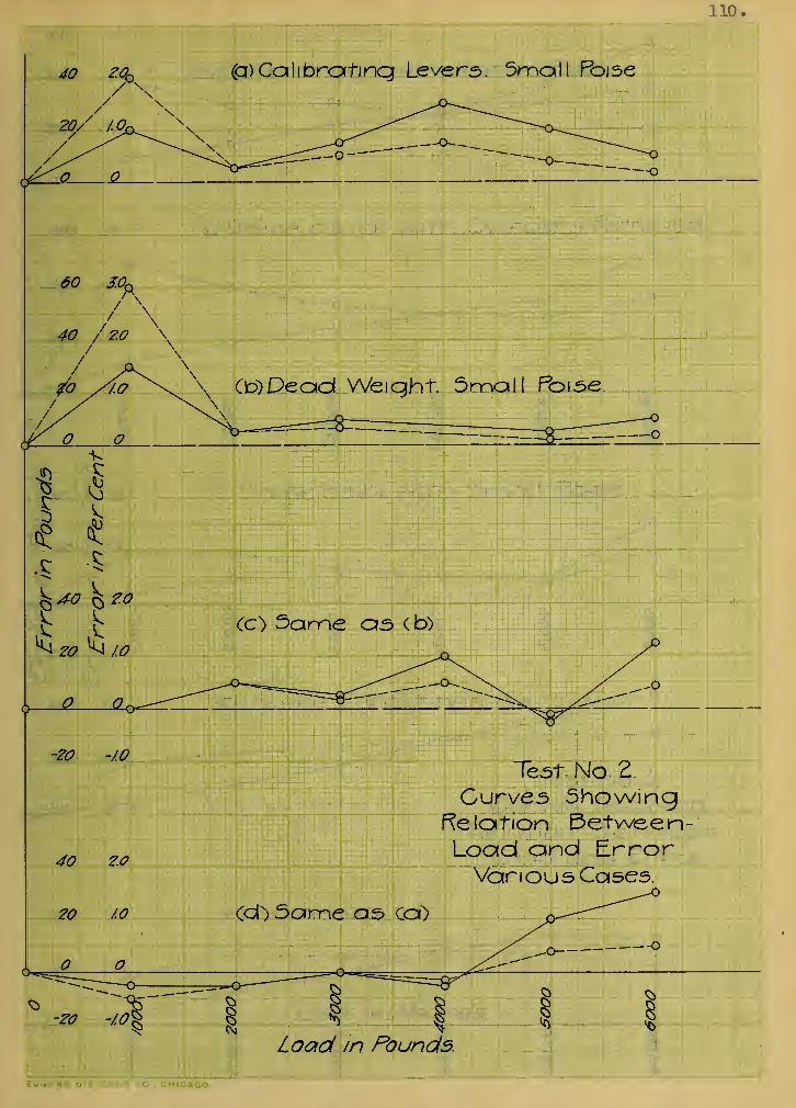
] 10
60 JOQA/
\
40 / 2.0 \
^ zo ^ /.o
-20 -W
40 2.0
20
O
C^D^od Weiqht. 5mai I Poise.
CO 5ame as cb)
Teat. No. 2.
Curves ShowingRe lotion Between-Load ond ErrorVarious Cases.
Cob Same as ca)
Z<7^ //? Found5.
JCiE N E Oil IHICACO.
9 Home
V
5 rt, i
pr
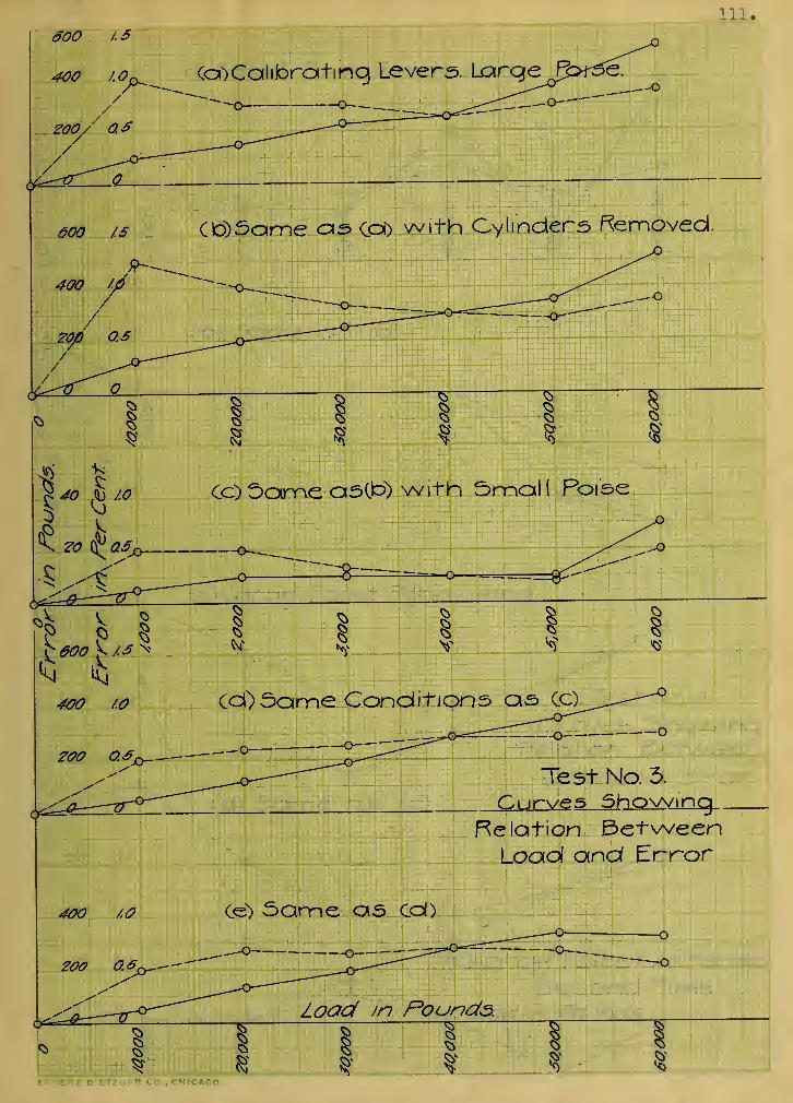
Ill,
600 /. 6
(ooCalibratmq Levers. Larqe r^5e.--cr ______—
o
—o—
600 /.5 (b)Same as Co) with Cylinders Removed.
1 1 f
£ 40 ,<b /.o
1Cc) 5orne as(b) with Small Poise
£ 600 ^\x
400 /0 (d)5ame Conditions as CO.
ZOO GJjy—Test No. 3.
Ca irves 5howinq[Relation BetweenLoad and Error
4O0 /.o Ce) Same as Cd)
—
o
load jd Pounds.
EUGENE DIET7GEN CO. , CHICAGO.
I8
I
V"7
•a
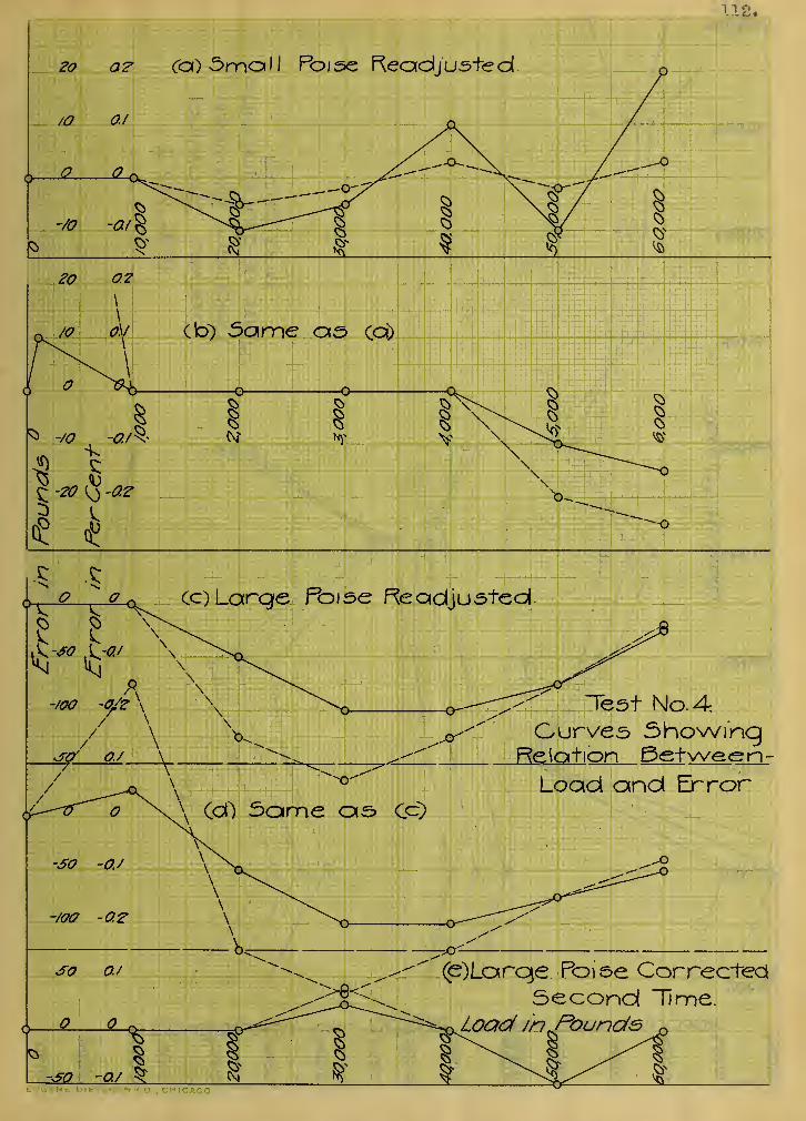
1 1 o
zo az foOSrnoll Poise Readjusted
\
\
Cb) Same as cd)
Cc) Large Poise Readjusted.
Test No. 4-.
Curves ShowingRelation Between -
Load and Error\ (d) 5ome as Cc)
(fe)Lorqje Poise CorrectedSecond Urne.
o
pn iwon£ e svilk
^^M^rv^^S"
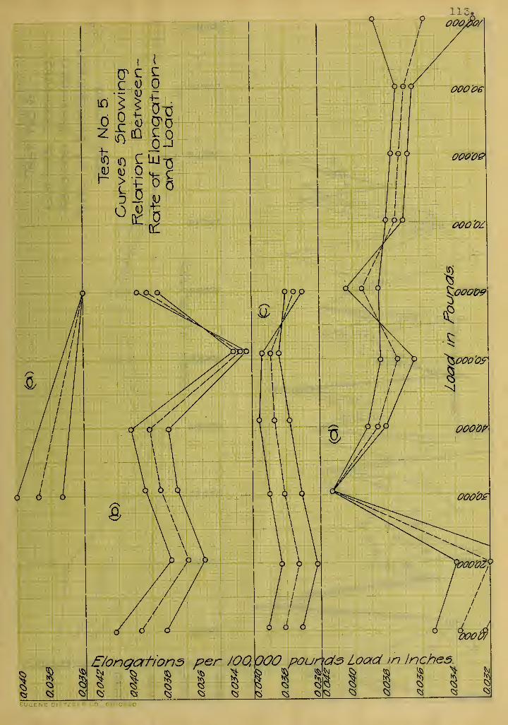
EUGENE DfETZCEN CO., CHICAGO
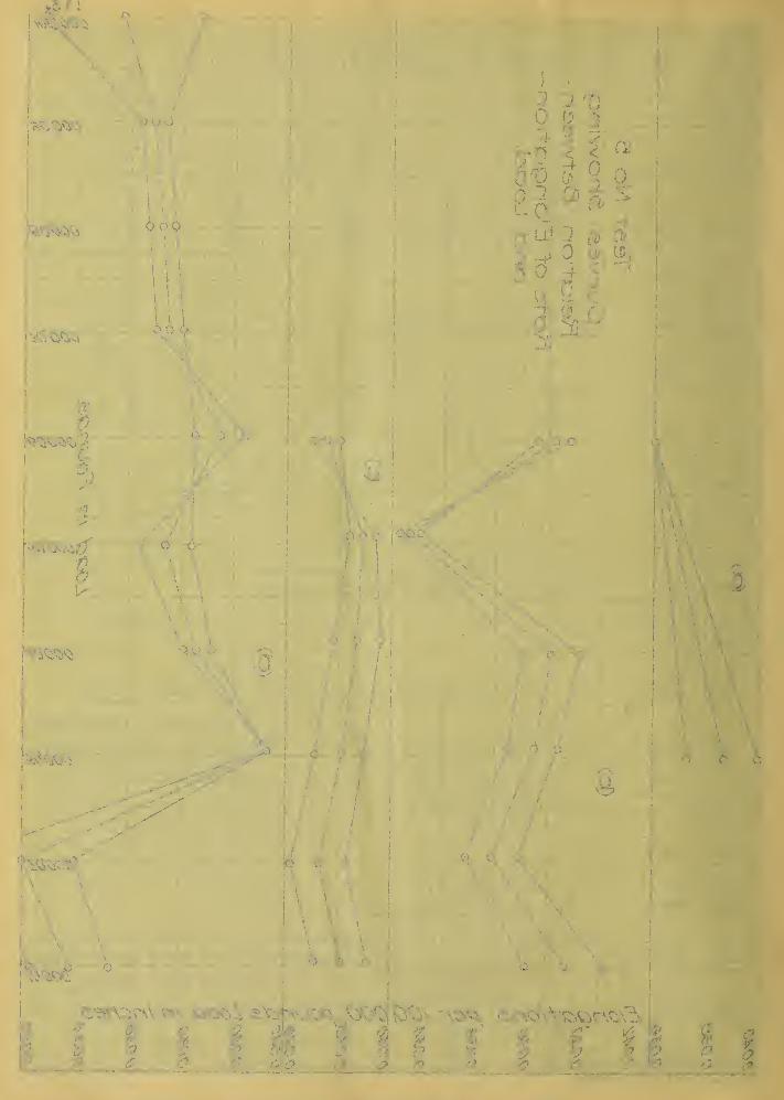
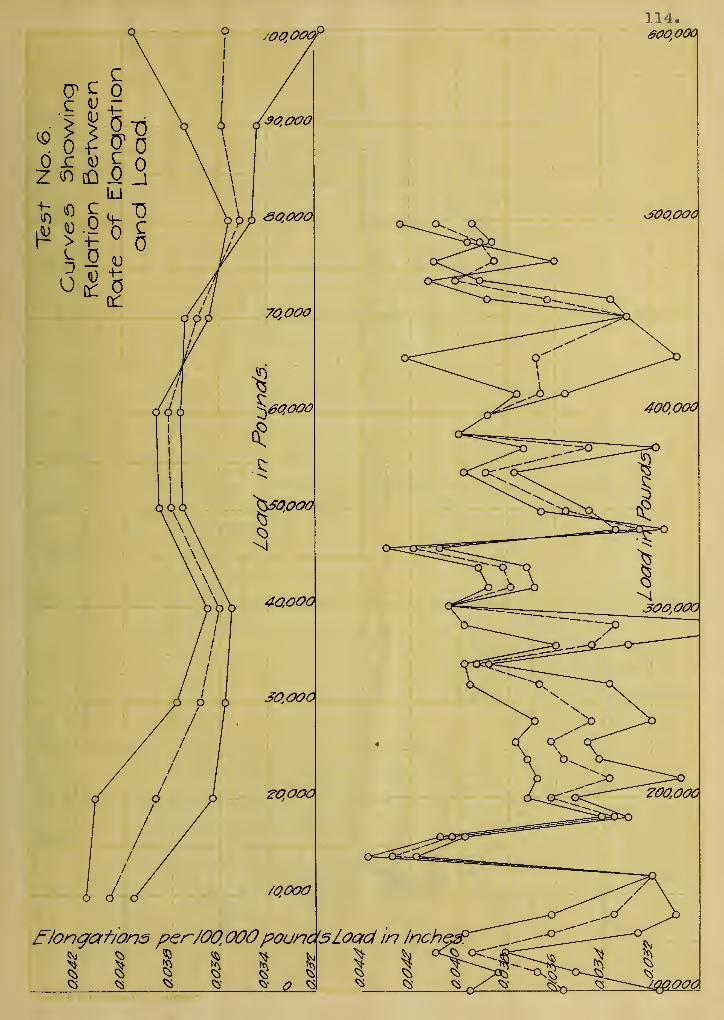
114.600006
40,000
30,000
/0.0OO
fJongaf/on3 per/00,000poun&5Load in Inche*
'
X1* O Q
5»
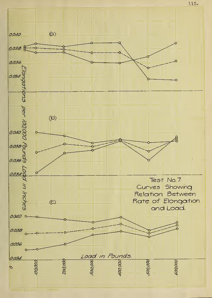
115.
0040
1
0040^
O.OJ0^
Io.oje
i
0.040
(P)
CO
Test No. 7Curves ShowmqRelation BetweenRate of Elonqotion
and Load.
Load /n Founds.s §
l
# '4
illlliiPiliiiW
mIlifMP!iffplf l#lmm 1lat^i
illHiHlHilF
m-#
;
* - #
III*
*
* *
ISpit ii^ l^i^lM^^^^KKIPi^Pc
^ 4 ^ * 4 - * * - 4 -* "* : 4^-
* * % - 4 - 4 ' * " 4-* 4 ' 4* - i
' 4 ****** * ' 4 **- * 4 ^1
* n
4c * * * % * * |fe * *• 4 ; ~4~ ^ 4y. »*< >v* -jje. ' - vlL ->£. ' slL 'OL ^4= . * •tft : >TP* ** TP* * ^p;-: • ;!4""'''
T"''v * '4 .^p--
:--.'^r Ip "V.PP^^O^ypp '
/ 4 4-:
4 * * * * * ;4 * * ^^
* - 4- - 4^-;"4^."4 T^:,"^ 4 "4 4 * . * 41p ,;
T ^* 1*
* ^ * ; 4- " ** * * * *. * ^- lr^^ * ^* * * 4^ .
-* * * * #* * 4 4 * * .
-41
4- :4 / .4,-,,4 *
* 4-'
4'. * 4=' 4'—4; f * 4 * ^ * *
* ^ 4 > ^ % * ^ ^ f * ^ '
4' 4--., ^--T^k" 4'
IN *^ ^ ^ + ^
* ^" * * :̂̂ ;mm 4-
.
1m 4 • * ; ^ ^ ^ . 4 : '^
^ ;?^ :4-'"4'
!
">4^: -4^ ; ;'
;
:
: 4 . 4'-
;4'% ^ .4:," ;4 . i
. ,^ ^ ^ ^ ^ * ~% * ^ "4"-^
* ^ * ^ ^ ^ ^ 4 '"-4 *^r4 •
-:4^::^^>-4^:^ 4^>,4^' 4 * * ^ * 4^
4* ^ ^
i^M^;4^ ^
'..•4 ^* 4=-^ * * % 4 ^. ^ ^ ^ 4 ^ 4A ^ ^ • ^ ^. ^ ' .^L ^ : '
T '7* Hr..-"^.-.. ^ : T5
.
1* ir-. . «f ^ ~,
'
r * W f* T * ^ > W ^ r. .
T- f1
if--. T^v--
^ ^ * ^ ^ 4 * * * 4 % 4 4 *7"*;"if ^ ^. +. ^ ^ ^ '4- ^ ^ * ^ * # ^ + ^ ^
.
-
lP^-.. ^ ^ T" -T"1 ^
4; .--^ * '
4.;;' f 4-; gt #4 4 ^ 4 ,
"4 ^ ^ ^^ 4-;-*
: %
_