tesi a. ricca.pdf - elea@unisa
TRANSCRIPT
INNOVATIVE CATALYSTS FOR
PROCESS INTENSIFICATION
OF METHANE REFORMING
AND PROPANE
DEHYDROGENATION
REACTIONS
Antonio Ricca

Unione Europea UNIVERSITÀ DEGLI
STUDI DI SALERNO
FONDO SOCIALE EUROPEO Programma Operativo Nazionale 2000/2006
“Ricerca Scientifica, Sviluppo Tecnologico, Alta Formazione”
Regioni dell’Obiettivo 1 – Misura III.4
“Formazione superiore ed universitaria”
Department of Chemical and Food Engineering
Ph.D. Course in Chemical Engineering
(XII Cycle-New Series)
INNOVATIVE CATALYSTS FOR PROCESS
INTENSIFICATION OF METHANE
REFORMING AND PROPANE
DEHYDROGENATION REACTIONS
Supervisor Ph.D. student
Prof. Vincenzo Palma Antonio Ricca
Scientific Referees
Prof. Vincenzo Palma
Prof. Paolo Ciambelli
Ing. Gaetano Iaquaniello
Ph.D. Course Coordinator
Prof. Paolo Ciambelli


To Milena, my wife
To Elio, my son

Acknowledgements
Il ringraziamento più grande va al prof. Vincenzo Palma, amico e collega oltre
che tutor e guida scientifica in questo triennio. La sua esperienza e la sua genialità
nell'approccio alla ricerca sono sempre stati il faro rassicurante della mia attività.
Grazie a lui ho imparato a proiettare i risultati verso nuovi obiettivi, e a trasformare
gli insuccessi in opportunità; da lui ho attinto la vera essenza della ricerca scientifica,
e la passione verso questo mondo, passione che porterò sempre con me verso ogni
destinazione futura.
Un doveroso ringraziamento va al prof. Paolo Ciambelli, coordinatore del corso
di dottorato e membro del comitato scientifico, nonché luminare della catalisi
industriale di riconosciuto prestigio internazionale. Aver lavorato con il prof.
Ciambelli è stato per me un privilegio, vanto professionale che custodirò con
orgoglio.
Un sentito ringraziamento alla Prof.ssa Diana Sannino, per la sua cordialità non
disgiunta dalla sua impeccabile competenza, a completare un’equipe didattica e di
ricerca di ineguagliabile talento e prestigio.
Un grazie di cuore va all'Ing. Gaetano Iaquaniello, che con la sua cortese
disponibilità mi ha aiutato a proiettare il lavoro della ricerca scientifica verso la
realtà dell'applicazione industriale.
Un dovuto ringraziamento è rivolto all’amico Antonio Mormile e alla sua
“Officina Elettromeccanica”, per il “sofferto” aiuto nella realizzazione degli
impianti di laboratorio.
Ed al termine di questo percorso, come non esprimere tutta la mia riconoscenza
ed ammirazione verso l’amica e collega Emma Palo, la cui professionalità è stata e
sarà sempre per me l’orizzonte a cui tendere, e la cui vicinanza, dagli albori della
mia carriera accademica sino a quest’ultimo traguardo, è stata sprone e gratifica
negli alti e bassi di questi anni. Grazie di cuore, Emma, per tutto ciò che per me sei
stata, e per ciò che sarai.
In questi tre anni ho avuto il privilegio di collaborare con tesisti eccezionali, ai
quali va tutta la mia riconoscenza, e dei quali conservo in me ricordi straordinari:
dalla briosità di Enrico alla travolgente vitalità di Donatella, dalla simpatia di Evrim
alla straordinaria eccellenza di Marino, dalla paziente saggezza di Biagio alla
freschezza di Erica. La qualità dei risultati illustrati in questa tesi è frutto anche del
loro lavoro, ed a loro va tutta la mia gratitudine e stima.
Un ringraziamento speciale deve essere rivolto a Concetta, perché le ultime fasi
di questo percorso di dottorato sono apparsi spesso buie e inconcludenti. La sua
dolcezza e la sua pazienza mi hanno aiutato a superare le difficoltà e a ridare nuova
forza alle mie giornate.
Un doveroso ringraziamento va poi a tutta la "popolazione" dei laboratori T1 e
T3 del D.I.In. dell'Università di Salerno, a partire dal "capitano" Vincenzo Vaiano
per proseguire con tutta la squadra, partendo dal caro Eugenio per poi passare a
Daniela, Marco, Nico, Katty, Claudia, Anna, Olga, concludendo con il sempre
disponibile Giuseppe. I risultati di un singolo non possono prescindere dalla buona
organizzazione della squadra a cui si appartiene: grazie a tutti voi, ragazzi, per tutto
il supporto che mi avete dato.
Ma in un periodo così lungo, può capitare che qualcuno abbandoni la squadra,
lasciando nel cuore di chi ha avuto il privilegio di conoscerli un sentimento congiunto
di gioia e malinconia. È per questo che mi piace condividere la gioia di questo
traguardo con loro, partendo da Elvirosa, le cui doti umane hanno invaso il mio
animo che tutt’ora non si rassegna alla sua lontananza. E come non rivolgere un
pensiero a Laura, dolce e solare, sempre pronta ad un sorriso di conforto nei non rari
momenti difficili. E mi si lasci condividere la soddisfazione di questi giorni con la
cara Mena, uragano di dolcezza, allegria, spensieratezza, saggezza ed un pizzico di
sana incoscienza; Amica con la “A” maiuscola, seppur lontana, ma sempre presente
in un posto caldo del mio cuore.
Infine, voglio condividere la gioia di questo traguardo con Milena, mia moglie,
ed Elio, mio figlio, perché loro più di tutti hanno sofferto la mia mancanza in questi
lunghi anni di dottorato. Spero che il tempo vi permetterà di capire (e perdonare)
l’assenza di un padre dalla propria famiglia, senz’altro io ho avuto modo di capire la
straordinaria fortuna di avere una famiglia come voi, di avere te, Milena. questo
intenso periodo di lavoro mi ha talvolta conferito una stanchezza alienante, ma non
esiste migliore ricompensa dell’amore di una moglie che aspetta a casa, paziente, del
sorriso di un figlio che corre tra le braccia chiamando: “Papà!”.
The research leading to these results has received funding from the European
Union Seventh Framework Programme FP7-NMP-2010-Large-4, under Grant
Agreement n° 263007 (acronym CARENA).
Special thanks are due to Arend de Groot, Ca.Re.N.A. coordinator, to give me the
possibility to be a part of this very amazing project.
Many thanks to Frans van Berkel, WP1a coordinator, of which I have appreciated
the expertise in a wide range of scientific topics as well as his uncommon
interpersonal skills, and which of course gave a great contribute to my scientific
enrichment.
Publication List
Palma, V., Palo, E., Ricca, A., Ciambelli, P. Compact multi-fuel autothermal
reforming catalytic reactor for H2 production. Chemical Engineering
Transactions, 25 (2011), 641-646.
Palma, V., Ricca, A., Ciambelli, P. Monolith and foam catalysts performances in
ATR of liquid and gaseous fuels. Chemical Engineering Journal, 207–208 (2012),
577-586.
Palma, V., Ricca, A., Ciambelli, P. Structured Catalysts for Methane Auto-Thermal
Reforming in a Compact thermal Integrated ATR Reformer. Chemical
Engineering Transactions, 29 (2012), 1615-1620.
Palma, V., Ricca, A., Ciambelli, P. Fuel cell feed system based on H2 production
by a compact multi-fuel catalytic ATR reactor. International Journal of Hydrogen
Energy, 38 (2013), 406-416.
Palma, V., Ricca, A., Ciambelli, P. Performances analysis of a compact kW-scale
ATR reactor for distributed H2 production. Clean Technologies and
Environmental Policy, 15 (2013), 63-71.
Palma, V., Ricca, A., Ciambelli, P. Methane auto-thermal reforming on honeycomb
and foam structured catalysts: The role of the support on system performances.
Catalysis Today, 216 (2013), 30-37.
Palma, V., Ricca, A., Ciambelli, P. Structured catalysts for methane auto-thermal
reforming in a compact thermal integrated reaction system. Applied Thermal
Engineering, 61 (2013), 128-133.
Palma, V., Palo, E., Ricca, A., Ciambelli, P. Compact multi-fuel autothermal
reforming catalytic reactor for H2 production. Conference PRES '11, 2011,
Florence (ITALY).
Palma, V., Ricca, A., Ciambelli, P. Catalytic multifuel ATR reformer for distributed
H2 production. XXIV Congresso Nazionale della Società Chimica Italiana, 2011,
Lecce (ITALY).
Palma, V., Ricca, A., Ciambelli, P. High efficiency multi-fuel catalytic autothermal
reformer for H2 production. 8th European Congress of Chemical Engineering,
2011, Berlin (GERMANY).
Palma, V., Palo, E., Ricca, A., Ciambelli, P. Fuel cell feed system based on H2
production by a compact multifuel catalytic ATR reactor. 4th European Fuel Cell
Piero - Lunghi Conference & Exhibition, 2011, Roma (ITALY).
Palma, V., Ricca, A., Ciambelli, P. Compact multi-fuel auto-thermal reformer for
H2 production. Fuel Cell 2012 - Science & Technology, 2012, Berlin
(GERMANY).
Palma, V., Ricca, A., Ciambelli, P. Methane auto-thermal reforming in a compact
thermal integrated ATR reformer: monolith and foams structured catalyst
performances. The Energy and Materials Research Conference, 2012,
Torremolinos (SPAIN).
Palma, V., Ricca, A., Ciambelli, P. Structured catalysts for methane auto-thermal
reforming in a compact thermal integrated ATR reformer. Conference PRES'12,
2012, Prague (CZECH REPUIBLIC).
Palma, V., Ricca, A., Ciambelli, P. Monolith and foam catalysts performances in
autothermal reforming of liquid and gaseous fuels. ISCRE22 - International
Symposium on Chemical Reaction Engineering, 2012, Maastricht (THE
NETHERLANDS).
Palma, V., Ricca, A., Ciambelli, P. Methane auto-thermal reforming in a compact
thermal integrated ATR reformer: monolithic catalysts performances. IX
International Conference on Mechanism of Catalytic Reaction, 2012, St.
Petersburg (RUSSIA).
Palma, V., Ricca, A., Ciambelli, P. Foam Catalysts performances in CH4 Auto-
Thermal Reforming. DEMCAMER & Ca.Re.N.A. Workshop, 2013, Eindhoven
(THE NETHERLANDS).
Palma, V., Ricca, A., Ciambelli, P. Auto-thermal reforming of methane: effect of
catalytic support structure. 9th European Congress of Chemical Engineering
ECCE9, 2013, The Hauge (THE NETHERLANDS).
Palo, E., Iaquaniello, G., Cucchiella, B., Palma, V., Ricca, A., Ciambelli, P.,
Akporiaye, D., Tschentscher, R. Membrane assisted propane dehydrogenation
for propylene production. 11th International Conference on Catalysis in
Membrane Reactors, 2013, Porto (PORTUGAL).
Palma, V., Ricca, A., Ciambelli, P. Effect of catalyst support on methane processing
in a compact thermally integrated ATR reactor. XIth European Congress on
Catalysis, 2013, Lyon (FRANCE).
Palma, V., Ricca, A., Ciambelli, P. Methane autothermal reforming in a compact
thermal integrated ATR reformer: monolithic catalysis performances XVII
National Congress of Catalysis, 2013, Riccione (ITALY).
Palma, V., Ricca, A., Ciambelli, P. Effect of catalyst support on methane processing
in a compact thermally integrated ATR reactor. 4th International Conference on
Structured Catalysts and Reactors, 2013, Bejing (CHINA).
Palma, V., Ricca, A., Ciambelli, P. Auto-thermal reforming of methane: the role of
the catalyst support. Conference Pres'13, 2013, Rhodes (GREECE).
Palma, V., Ricca, A., Ciambelli, P. Hydrogen production by methane atr in a
compact catalytic reactor thermally integrated: structured catalysts performances
analysis. 5th European Fuel Cell - Piero Lunghi Conference, 2013, Rome
(ITALY).
I
Contents
INTRODUCTION 1
I.1 PROPANE TO PROPYLENE 1 I.1.1 THE PROPYLENE 1 I.1.2 PROPYLENE PRODUCTION 2 I.1.3 CATALYST 8
I.2 METHANE AND HYDROGEN PRODUCTION 10 I.2.1 HYDROGEN PRODUCTION TECHNOLOGIES 10 I.2.2 STEAM REFORMING 10 I.2.3 PARTIAL OXIDATION 12 I.2.4 AUTO-THERMAL REFORMING 13 I.2.5 WATER-GAS-SHIFT 13
I.3 THE MEMBRANE REACTORS 15 I.4 THE CARENA PROJECT 16
I.4.1 UNISA IN CARENA 18
STATE OF THE ART 21
II.1 METHANE REFORMING: STATE OF THE ART 21 II.2 PROPANE DEHYDROGENATION: STATE OF THE ART 23
PDH THERMODYNAMIC ANALYSIS 35
III.1 PURE PROPANE DEHYDROGENATION 35 III.1.1 PRESSURE INFLUENCE 35 III.1.2 INERT DILUTION EFFECT 37 III.1.3 HYDROGEN DILUTION EFFECT 37
III.2 WATER DILUTION EFFECT 38
II
EXPERIMENTAL APPARATUSES 43
IV.1 AUTO-THERMAL REFORMING 43 IV.1.1 REACTANTS DELIVERY SYSTEM 43 IV.1.2 HEAT EXCHANGE MODULE 43 IV.1.3 MIXING MODULE 45 IV.1.4 REACTION MODULE 45 IV.1.5 ANALYSIS SYSTEM 46 IV.1.6 CATALYSTS 48 IV.1.7 EXPERIMENTAL PROCEDURE 49
IV.2 STEAM REFORMING 51 IV.2.1 TUBULAR REACTOR 52 IV.2.2 ELECTRICAL OVEN 52 IV.2.3 CATALYSTS 54 IV.2.4 EXPERIMENTAL PROCEDURE 54
IV.3 PROPANE DEHYDROGENATION 56 IV.3.1 CATALYTIC REACTOR 56 IV.3.2 ANALYSIS SECTION 57 IV.3.3 CATALYSTS 58 IV.3.4 EXPERIMENTAL PROCEDURE 59
METHANE REFORMING 61
V.1 AUTO-THERMAL REFORMING (ATR) 61 V.1.1 PRELIMINARY TESTS ON REACTION SYSTEM 61 V.1.2 PRELIMINARY TESTS ON AL92 CATALYZED FOAM 67 V.1.3 TESTS ON CATALYZED FOAMS 68
V.2 METHANE STEAM REFORMING 72 V.3 DISCUSSION AND CONCLUSIONS 75
PROPANE DEHYDROGENATION 77
VI.1 CATALYST COMPONENTS ROLE 77 VI.2 REACTION TEMPERATURE INFLUENCE 79 VI.3 TUBULAR REACTOR PRELIMINARY TESTS 82 VI.4 ACTIVITY TESTS ON PTSN/AL2O3 CATALYST 83 VI.5 CATALYTIC SUPPORT ROLE 85 VI.6 REGENERATION TESTS 88
VI.6.1 S-01 SAMPLE 89 VI.6.2 CA.RE.N.A. PARTNERS CATALYSTS COMPARISON 91
III
VI.6.3 FEED STEAM CONTENT 94 VI.6.4 PRESSURE EFFECT 95 VI.6.5 CO – CO2 EFFECT 97
VI.7 DURABILITY TESTS 105 VI.8 DISCUSSION AND CONCLUSIONS 107
CONCLUSIONS 111
VII.1 METHANE REFORMING 111 VII.2 PROPANE DEHYDROGENATION 112
REFERENCES 115

V
Index of figures
Figure I.1 Worldwide Propylene price trend from 2009 to 2011 (Lemos,
2011) ....................................................................................................... 2
Figure I.2 UOP Oleflex Process .............................................................................. 5
Figure I.3 Catofin Process: (a) feed pre-heating; (b) air heating; (c) cleaning
fixed bed reactor; (d) working reactor; (e) regenerating reactor. ......... 6
Figure I.4 Phillips Star process layout .................................................................... 7
Figure I.5 Snamprogetti catalytic dehydrogenation process layout: R:
Reactor; R2: Regenerator; C: Depropanizer; 1: Propane; 2:
reactor effluent; 3: catalyst recirculating; 4: air regeneration; 5:
flue gas; 6: light ends; 7: propylene ....................................................... 8
Figure I.7 CARENA knowledge transfer scheme ................................................... 18
Figure II.1 Coke formation mechanism (Bai et al., 2011) ...................................... 26
Figure II.2 Proposed reaction mechanism of dehydrogenation of C3H8 in the
presence of CO2 (Shishido et al., 2012) ................................................ 27
Figure II.3 Schematic drawing of the TZFBR with two sections and membrane
(Medrano et al., 2013) .......................................................................... 33
Figure III.1 Thermodynamic equilibrium propane conversion vs operating
temperature and pressure ..................................................................... 36
Figure III.2 Thermodynamic equilibrium propane conversion vs operating
temperature and inert dilution .............................................................. 36
Figure III.3 Thermodynamic equilibrium propane conversion vs operating
temperature and hydrogen dilution ...................................................... 38
Figure III.4 Thermodynamic equilibrium propane conversion vs water content
and operating temperature ................................................................... 40
Figure III.5 Thermodynamic equilibrium selectivity to propylene vs water
content and operating temperature ....................................................... 40
Figure III.6 Thermodynamic equilibrium propylene yield vs water content and
operating temperature .......................................................................... 41
Figure IV.1 Heat exchanger: disassembled and assembled views ........................... 44
Figure IV.2 Heat recovery module scheme .............................................................. 44
Figure IV.4 Assembled reaction system ................................................................... 46
Figure IV.5 Analysis system scheme of ATR reformer thermally integrated ............ 47
Figure IV.6 Steam reforming lab-scale plant scheme .............................................. 51
VI
Figure IV.7 Tubular reactor ..................................................................................... 52
Figure IV.8 Electrical oven ...................................................................................... 53
Figure IV.9 Oven thermal profile ............................................................................. 54
Figure IV.10 Tube-shell reactor parts ................................................................... 56
Figure V.1 Temperature trend along catalyst in start-up phase ............................. 62
Figure V.2 Product composition and methane conversion downstream catalyst
in start-up phase ................................................................................... 62
Figure V.3 Temperature trend during the test (GHSV = 40000 h-1, H2O/O2/C
= 0.49/0.56/1) ....................................................................................... 63
Figure V.4 Composition and methane conversion during the test (GHSV =
40000 h-1, H2O/O2/C = 0.49/0.56/1) ..................................................... 63
Figure V.5 Temperature profile along catalyst (GHSV = 40000 h-1, H2O/O2/C
= 0.49/0.56/1......................................................................................... 64
Figure V.6 Composition and conversion profile along catalyst (GHSV =
40000 h-1, H2O/O2/C = 0.49/0.56/1) ..................................................... 65
Figure V.8 AL92 tests: thermal profiles (GHSV = 80,000 h-1; p = 2.5 bar) ........... 67
Figure V.9 AL92 tests: Hydrogen concentration (a) and Methane conversion
(b) (GHSV = 80,000 h-1; p = 2.5 bar) ................................................... 67
Figure V.10 Gas composition and Methane conversion profiles (H2O:O2:C =
0.49:0.56:1; p = 2.5 bar) ...................................................................... 69
Figure V.11 Hydrogen yield and methane conversion (H2O:O2:C =
0.49:0.56:1; p = 2.5 bar) ...................................................................... 70
Figure V.12 Temperature profiles (H2O:O2:C = 0.49:0.56:1; p = 2.5 bar) .......... 70
Figure V.13 Methane conversion for the different catalytic foams (T = 550°C) ...... 73
Figure V.14 H2 production for the different catalytic foams (T = 550°C) ............. 74
Figure VI.1 Propane conversion vs time with and without catalyst and by
varying catalytic formulation (WHSV = 12 h-1; T = 600°C; p = 0
barg; tube-shell reactor) ....................................................................... 78
Figure VI.2 Propylene selectivity vs time with and without catalyst and by
varying catalytic formulation (WHSV = 12 h-1; T = 600°C; p = 0
barg; tube-shell reactor) ....................................................................... 78
Figure VI.3 Propane conversion vs time for 550°C and 600°C reactions
(WHSV = 12 h-1; p = 0 barg; tube-shell reactor) ................................. 80
Figure VI.4 Propylene selectivity vs time for 600°C and 550°C reactions
(WHSV = 12 h-1; p = 0 barg; tube-shell reactor) ................................. 80
Figure VI.5 Products trend (WHSV = 12 h-1; T = 550°C; p = 0 barg; tube-
shell reactor) ......................................................................................... 81
VII
Figure VI.6 Products trend (WHSV = 12 h-1; T = 600°C; p = 0 barg; tube-
shell reactor) ......................................................................................... 82
Figure VI.7 Propane conversion vs temperature in homogenous conditions for
WHSV = 6 h-1 and 12 h-1 (Tubular reactor; p = 0 barg) ..................... 83
Figure VI.8 Propane conversion trend for the two different reaction systems
(WHSV = 12 h-1; T = 600°C; p = 0 barg) ............................................ 84
Figure VI.9 Selectivity to propylene trend for the two different reaction systems
(WHSV = 12 h-1; T = 600°C; p = 0 barg) ............................................ 84
Figure VI.10 TPR results for the Pt-Sn based catalysts ......................................... 85
Figure VI.11 Propane conversion trend for the different Pt-Sn based catalysts
(WHSV = 8 h-1; p = 0.2 barg; 20% fed steam) ..................................... 86
Figure VI.12 Propylene selectivity trend for the different Pt-Sn based
catalysts (WHSV = 8 h-1; p = 0.2 barg; 20% fed steam) ...................... 86
Figure VI.13 Coke selectivity trend for the different Pt-Sn based catalysts
(WHSV = 8 h-1; p = 0.2 barg; 20% fed steam) ..................................... 87
Figure VI.14 Reforming selectivity trend for the different Pt-Sn based
catalysts (WHSV = 8 h-1; p = 0.2 barg; 20% fed steam) ...................... 87
Figure VI.15 Propylene yield trend for the different Pt-Sn based catalysts
(WHSV = 8 h-1; p = 0.2 barg; 20% fed steam) .................................... 88
Figure VI.17 Propylene selectivity trend for S-01 sample (WHSV = 12 h-1; T
= 600°C; p = 0.6 barg; 20% fed steam) ............................................... 90
Figure VI.18 Side-product content trend for S-01 sample (WHSV = 12 h-1; T
= 600°C; p = 0.6 barg; 20% fed steam) ............................................... 91
Figure VI.19 Propane conversion in S-01 sample tests (WHSV = 8 h-1; T =
540°C; p = 0.2 barg; H2O/C3H8 = 0.25) .............................................. 92
Figure VI.20 Propylene selectivity in S-01 sample tests (WHSV = 8 h-1; T =
540°C; p = 0.2 barg; H2O/C3H8 = 0.25) .............................................. 92
Figure VI.21 Propane conversion in S-02 sample tests (WHSV = 8 h-1; T =
540°C; p = 0.6 barg; H2O/C3H8 = 0.25) .............................................. 93
Figure VI.22 Propylene selectivity in S-02 sample tests (WHSV = 8 h-1; T =
540°C; p = 0.6 barg; H2O/C3H8 = 0.25) .............................................. 93
Figure VI.23 Propane conversion, selectivity to propylene (a) and to coke (b),
hydrogen (c) and side-products (d) distribution on fed steam
content for the S-01 sample (T = 540°C; p = 0.4 barg; WHSV = 8
h-1) ......................................................................................................... 94
Figure VI.24 Propane conversion, selectivity to propylene (a) and to coke (b),
hydrogen (c) and side-products (d) distribution on fed steam
content for the S-02 sample (T = 540°C; p = 0.2 barg; WHSV = 8
h-1) ......................................................................................................... 95
VIII
Figure VI.25 Propane conversion, selectivity to propylene (a) and to coke (b),
hydrogen (c) and side-products (d) distribution on fed steam
content for the S-01 sample (T = 540°C; H2O/C3H8 = 0.25; WHSV
= 8 h-1) .................................................................................................. 96
Figure VI.26 Propane conversion, selectivity to propylene (a) and to coke (b),
hydrogen (c) and side-products (d) distribution on fed steam
content for the S-02 sample (T = 540°C; H2O/C3H8 = 0.25;
WHSV = 8 h-1) ....................................................................................... 96
Figure VI.27 Propane conversion and selectivity to propylene dependences on
fed CO content for the S-02 sample (T = 540°C; p = 0.25 barg;
H2O/C3H8 = 0.25; WHSV = 8 h-1) ........................................................ 98
Figure VI.28 H2,C3H6, CO and CO2 distribution dependence on fed CO
content for the S-02 sample (T = 540°C; p = 0.25 barg; H2O/C3H8
= 0.25; WHSV = 8 h-1) .......................................................................... 98
Figure VI.29 CH4, C2H4, and C2H6, distribution dependence on fed CO
content for the S-02 sample (T = 540°C; p = 0.25 barg; H2O/C3H8
= 0.25; WHSV = 8 h-1) .......................................................................... 99
Figure VI.30 Propane conversion and selectivity to propylene dependences
on fed CO2 content for the S-02 sample (T = 540°C; p = 0.25
barg; H2O/C3H8 = 0.25; WHSV = 8 h-1) ............................................... 99
Figure VI.31 H2,C3H6, CO and CO2 distribution dependence on fed CO2
content for the S-02 sample (T = 540°C; p = 0.25 barg; H2O/C3H8
= 0.25; WHSV = 8 h-1) ........................................................................ 100
Figure VI.32 CH4, C2H4, and C2H6, distribution dependence on fed CO2
content for the S-02 sample (T = 540°C; p = 0.25 barg; H2O/C3H8
= 0.25; WHSV = 8 h-1) ........................................................................ 100
Figure VI.33 Propane conversion and selectivity to propylene dependences on
fed CO content for the S-02 sample (T = 540°C; p = 5 barg;
H2O/C3H8 = 5; WHSV = 8 h-1) ........................................................... 101
Figure VI.34 H2,C3H6, CO and CO2 distribution dependence on fed CO
content for the S-02 sample (T = 540°C; p = 5 barg; H2O/C3H8 =
0.25; WHSV = 8 h-1) ........................................................................... 102
Figure VI.35 CH4, C2H4, and C2H6, distribution dependence on fed CO
content for the S-02 sample (T = 540°C; p = 5 barg; H2O/C3H8 =
0.25; WHSV = 8 h-1) ........................................................................... 102
Figure VI.36 Propane conversion and selectivity to propylene dependences
on fed CO2 content for the S-02 sample (T = 540°C; p = 5 barg;
H2O/C3H8 = 0.25; WHSV = 8 h-1) ...................................................... 103
Figure VI.37 H2,C3H6, CO and CO2 distribution dependence on fed CO2
content for the S-02 sample (T = 540°C; p = 5 barg; H2O/C3H8 =
0.25; WHSV = 8 h-1) ........................................................................... 103

IX
Figure VI.38 CH4, C2H4, and C2H6, distribution dependence on fed CO2
content for the S-02 sample (T = 540°C; p = 5 barg; H2O/C3H8 =
0.25; WHSV = 8 h-1) ........................................................................... 104
Figure VI.39 Durability tests results on S-02 sample (T = 540°C; p = 4.5
barg; H2O/C3H8 = 0.25; WHSV = 8 h-1) ............................................ 106

XI
Index of tables
Table I.1 Main steam-cracking products ............................................................ 3
Table I.2 Typical FCC production ...................................................................... 4
Table I.3 Dehydrogenation catalyst performances ............................................. 8
Table IV.1 Heat exchange efficiency for the different heat exchange module
configurations .....................................................................................45
Table IV.2 Relationship between number of catalytic bricks and space
velocity (GHSV) ..................................................................................47
Table IV.3 Foam characteristics ..........................................................................49
Table IV.4 Tube-shell reactor dimensions ............................................................56
Table IV.5 Mass spectrometer AMU correspondence in PDH reaction
analysis ...............................................................................................58
Table IV.6 Tested catalysts in Porpane DeHydrogenation ..................................58
Table V.1 Reaction trend by varying GHSV ( H2O/O2/C = 0.49/0.56/1) ............65
Table VI.1 Regeneration tests procedure .............................................................89

XIII
Abstract
In the early decade, a rapid increase in oil consumption was recorded, that
led to a widening between the predicted demand for oil and the known oil
reserves. Such trend, mainly due to the growing new economies, is causing a
quick increasing in oil price, that effect on European chemical industry
competitiveness. In this dramatic scenario, characterized by higher cost of
naphtha from crude oil, the ability to exploit novel feeds such as natural gas,
coal and biomass may be the keystone for the chemical industry revival.
Innovating chemical processes are thus essential for the future of the chemical
industry to make use of alternative feedstock in the medium and long term
future. In this direction, to open new direct routes with rarely used and less
reactive raw feedstock such as short-chain alkanes and CO2 appears one of the
most promising breakthrough, since in one hand it may reduce the current
dependency of European chemical industry on naphtha, in the other hand may
reduce the energy use and environmental footprint of industry.
Despite light alkanes (C1–C4) and CO2 are stable molecules hard to
activate and transform directly and selectively to added-value products, these
challenges could be overcome thanks to relevant process intensifications
along with the smart implementation of catalytic membrane reactors. Process
intensification consists of the development of novel apparatuses and
techniques, as compared to the present state-of-art, to bring dramatic
improvements in manufacturing and processing, substantially decreasing
equipment size/production capacity ratio, energy consumption, or waste
production. The past decade has seen an increase in demonstration of novel
membrane technology. Such developments are leading to a strong industrial
interest in developing membrane reactors for the chemical industry.
The main target of the CARENA is to address the key issues required to
pave the way to marketing CMRs in the European chemical industry. The
UNISA contribution in CARENA project is to study and optimize supported
and unsupported catalysts in order to match to membrane reactors aimed to
methane reforming and propane dehydrogenation processes. The guideline of
this work was fully jointed to the UNISA involving in CARENA project.
The methane reforming routes (steam- and/or auto-thermal-) are processes
widely analyzed in the literature, and many studies identified Ni and Pt-group
as most active catalysts, as well as the benefits of bimetallic formulation.
Moreover, the crucial role of ceria and zirconia as chemical supports was
demonstrated, due to their oxygen-storage capacity. In this work, great effort
was spent in the reforming process intensification, in order to maximize
catalyst exploit in reforming process.
In order to minimize mass transfer limitations, without precluding the
catalyst-membrane coupling, several foams were selected as catalytic support,
and were activated with a catalytic slurry. The performances of such catalysts
XIV
in the auto-thermal reforming and steam reforming of methane were
investigated. Catalytic tests in methane auto-thermal reforming conditions
were carried out in an adiabatic reactor, investigating the effect of feed ration
and reactants mass rate. Tested catalysts showed excellent performances,
reaching thermodynamic equilibrium even at very low contact time. By
comparing foams catalyst performances to a commercial honeycomb catalyst,
the advantages due to the foam structure was demonstrated. The complex
foam structure in one hand promotes a continuous mixing of the reaction
stream, in the other hand allows conductive heat transfer along the catalyst
resulting in a flatter thermal profile. As a result, the reaction stream quickly
reaches a composition close to the final value.
Steam reforming catalytic tests were carried out on foam catalysts at
relatively low temperature (550°C) and at different steam-to carbon ratios and
GHSV values. The catalytic tests evidenced the relevance of heat transfer
management on the catalytic performances, since the samples characterized
by the highest thermal conductivity showed the best results in terms of
methane conversion and hydrogen yield. The beneficial effect was more
evident in the more extreme conditions (higher S/C ratios, higher reactants
rates), in which the heat transfer limitations are more evident.
The selective propane dehydrogenation (PDH) was one of the most
attractive challenges of the CARENA project, that points to insert a
membrane-assisted PDH process in a wider scheme characterized by the
process stream recirculation. This approach requires to minimize inerts
utilization and side-products formation. Moreover, no papers are present in
literature on the concentrated-propane dehydrogenation, due to the severe
thermodynamic limitations. A wide study is present in this work aimed to
identify and select an optimal catalytic formulation and the appropriate
operating conditions that allows the process intensification for the PDH
reaction by means of a membrane reactor.
In a first stage, the relevance of side-reactions in the catalytic volume and
in the homogeneous gas phase was analyzed, resulting in the optimization of
the reaction system. Platinum-tin catalysts were prepared, in order to study the
role of each compound on the catalytic performances and lifetime. Preliminary
studies have defined the optimal operating conditions, able to minimize the
coke formation and then to slow down catalyst deactivation. Several studies
on catalyst support highlighted the requirement to use a basic supports with a
high specific surface, able to minimize cracking phenomena.
Basing on such indications, CARENA partners provided two catalytic
formulations optimized with respect the indicated operating conditions, that
showed excellent activity ad selectivity. On these catalyst, the effect of the
water dilution, the operating pressure and the presence of CO and CO2 was
investigated, in order to understand the catalytic formulation behavior in the
real scheme conditions.


1
Introduction
I.1 Propane to Propylene
The synthesis of olefins, “building-blocks” in the chemical industry, is
nowadays realized by the steam-cracking technology (for the production of
ethylene from ethane or naphtha), catalytic cracking (used for the formulation
of gasoline, where the olefins are by-products of the process), and catalytic
dehydrogenation (for the selective production of propylene and isobutene).
They are well-established processes, but which are characterized by very high
operating costs, due mainly to the energy needed to provide heat to the highly
endothermic reactions. In addition, for these processes exist the concept of
economies of scale, therefore the production is cost effective only if made in
large plants, for which high investment costs are needed.
I.1.1 The propylene
The propylene (CH3-CH=CH2) at room conditions appears as a colorless,
odorless and higher density than air (1.915 gL-1). It is not a toxic substance. It
shows a high degree of flammability with a flash point of 455°C. Propylene
can also generate explosive mixtures with air within the following limits: 2.0
vol% (35 g/m3) - 11.1 vol% (200 g/m3).
The propylene was one of the first products in the field of petrochemical
to be used on industrial scale: in its first employment in the 40s, it was used
in the production of isopropanol.
Today it is the second largest commodity in the world and it is used in the
production of many important intermediates in the primary chemistry,
including polypropylene, acrylonitrile, cumene (in Europe), and propylene
oxide.
In 2009, 87.4 million tons of propylene were produced in the world
(Davanney, 2009). Since its demand is increasing, an annual production speed
growth of 10% is expected, which in 2020 will lead to a production of 120
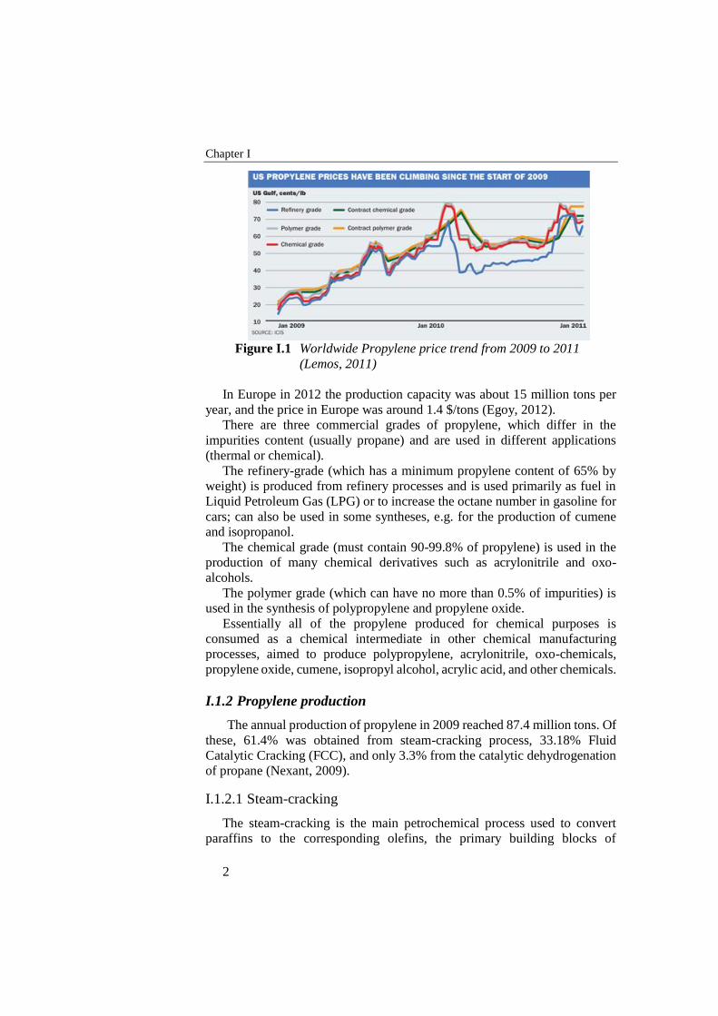
million tons. As a consequence, the propylene price (Figure I.1) had a constant
increasing that led to a quadrupling from 2009 to 2011 (Lemos, 2011).
Chapter I
2
Figure I.1 Worldwide Propylene price trend from 2009 to 2011
(Lemos, 2011)
In Europe in 2012 the production capacity was about 15 million tons per
year, and the price in Europe was around 1.4 $/tons (Egoy, 2012).
There are three commercial grades of propylene, which differ in the
impurities content (usually propane) and are used in different applications
(thermal or chemical).
The refinery-grade (which has a minimum propylene content of 65% by
weight) is produced from refinery processes and is used primarily as fuel in
Liquid Petroleum Gas (LPG) or to increase the octane number in gasoline for
cars; can also be used in some syntheses, e.g. for the production of cumene
and isopropanol.
The chemical grade (must contain 90-99.8% of propylene) is used in the
production of many chemical derivatives such as acrylonitrile and oxo-
alcohols.
The polymer grade (which can have no more than 0.5% of impurities) is
used in the synthesis of polypropylene and propylene oxide.
Essentially all of the propylene produced for chemical purposes is
consumed as a chemical intermediate in other chemical manufacturing
processes, aimed to produce polypropylene, acrylonitrile, oxo-chemicals,
propylene oxide, cumene, isopropyl alcohol, acrylic acid, and other chemicals.
I.1.2 Propylene production
The annual production of propylene in 2009 reached 87.4 million tons. Of
these, 61.4% was obtained from steam-cracking process, 33.18% Fluid
Catalytic Cracking (FCC), and only 3.3% from the catalytic dehydrogenation
of propane (Nexant, 2009).
I.1.2.1 Steam-cracking
The steam-cracking is the main petrochemical process used to convert
paraffins to the corresponding olefins, the primary building blocks of
Introduction
3
chemistry. The main product of this process is ethylene, but other important
co-products are propylene, butadiene and pyrolysis gas.
It consists of the pyrolysis, in presence of steam, of saturated more or less
long hydrocarbons chains, at a temperature of 800-850 °C.
Fed hydrocarbons molecular weight is variable: from light paraffins to
gasoline and diesel, according to the geographical areas of production. In the
United States is fed primarily ethane (natural gas), while in Europe and Japan,
the most widely used feed is naphtha, (naphta-cracking).
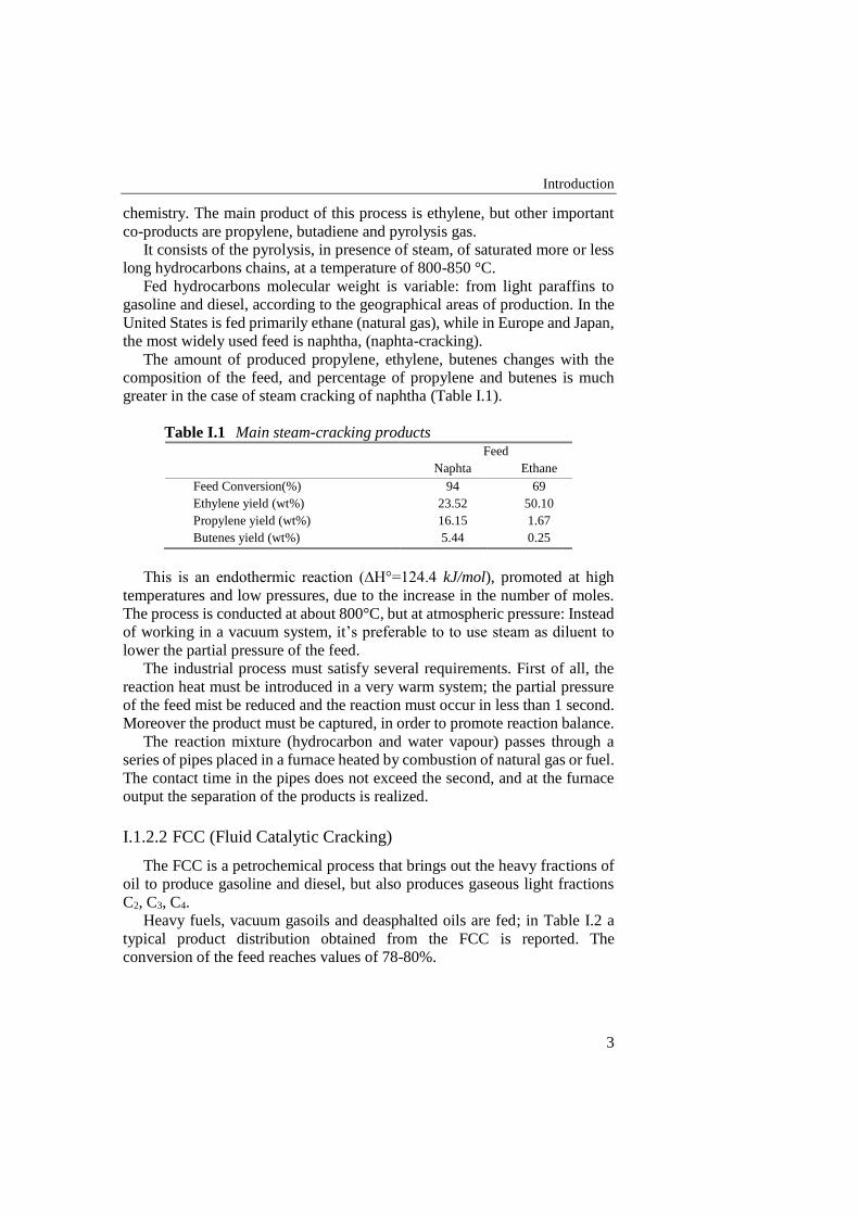
The amount of produced propylene, ethylene, butenes changes with the
composition of the feed, and percentage of propylene and butenes is much
greater in the case of steam cracking of naphtha (Table I.1).
Table I.1 Main steam-cracking products
Feed
Naphta Ethane
Feed Conversion(%) 94 69
Ethylene yield (wt%) 23.52 50.10
Propylene yield (wt%) 16.15 1.67
Butenes yield (wt%) 5.44 0.25
This is an endothermic reaction (∆H°=124.4 kJ/mol), promoted at high
temperatures and low pressures, due to the increase in the number of moles.
The process is conducted at about 800°C, but at atmospheric pressure: Instead
of working in a vacuum system, it’s preferable to to use steam as diluent to
lower the partial pressure of the feed.
The industrial process must satisfy several requirements. First of all, the
reaction heat must be introduced in a very warm system; the partial pressure
of the feed mist be reduced and the reaction must occur in less than 1 second.
Moreover the product must be captured, in order to promote reaction balance.
The reaction mixture (hydrocarbon and water vapour) passes through a
series of pipes placed in a furnace heated by combustion of natural gas or fuel.
The contact time in the pipes does not exceed the second, and at the furnace
output the separation of the products is realized.
I.1.2.2 FCC (Fluid Catalytic Cracking)
The FCC is a petrochemical process that brings out the heavy fractions of
oil to produce gasoline and diesel, but also produces gaseous light fractions
C2, C3, C4.
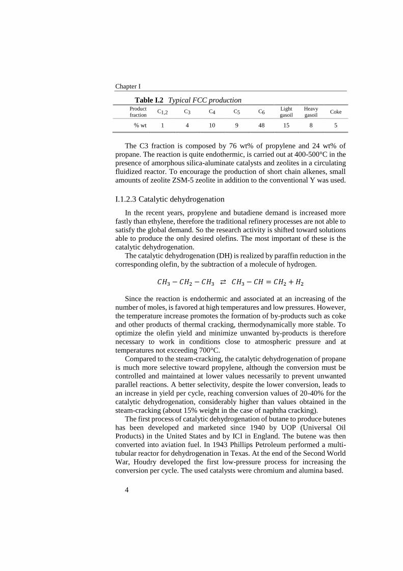
Heavy fuels, vacuum gasoils and deasphalted oils are fed; in Table I.2 a
typical product distribution obtained from the FCC is reported. The
conversion of the feed reaches values of 78-80%.
Chapter I
4
Table I.2 Typical FCC production Product
fraction C1,2 C3 C4 C5 C6
Light
gasoil
Heavy
gasoil Coke
% wt 1 4 10 9 48 15 8 5
The C3 fraction is composed by 76 wt% of propylene and 24 wt% of
propane. The reaction is quite endothermic, is carried out at 400-500°C in the
presence of amorphous silica-aluminate catalysts and zeolites in a circulating
fluidized reactor. To encourage the production of short chain alkenes, small
amounts of zeolite ZSM-5 zeolite in addition to the conventional Y was used.
I.1.2.3 Catalytic dehydrogenation
In the recent years, propylene and butadiene demand is increased more
fastly than ethylene, therefore the traditional refinery processes are not able to
satisfy the global demand. So the research activity is shifted toward solutions
able to produce the only desired olefins. The most important of these is the
catalytic dehydrogenation.
The catalytic dehydrogenation (DH) is realized by paraffin reduction in the
corresponding olefin, by the subtraction of a molecule of hydrogen.
𝐶𝐻3 − 𝐶𝐻2 − 𝐶𝐻3 ⇄ 𝐶𝐻3 − 𝐶𝐻 = 𝐶𝐻2 + 𝐻2
Since the reaction is endothermic and associated at an increasing of the
number of moles, is favored at high temperatures and low pressures. However,
the temperature increase promotes the formation of by-products such as coke
and other products of thermal cracking, thermodynamically more stable. To
optimize the olefin yield and minimize unwanted by-products is therefore
necessary to work in conditions close to atmospheric pressure and at
temperatures not exceeding 700°C.
Compared to the steam-cracking, the catalytic dehydrogenation of propane
is much more selective toward propylene, although the conversion must be
controlled and maintained at lower values necessarily to prevent unwanted
parallel reactions. A better selectivity, despite the lower conversion, leads to
an increase in yield per cycle, reaching conversion values of 20-40% for the
catalytic dehydrogenation, considerably higher than values obtained in the
steam-cracking (about 15% weight in the case of naphtha cracking).
The first process of catalytic dehydrogenation of butane to produce butenes
has been developed and marketed since 1940 by UOP (Universal Oil
Products) in the United States and by ICI in England. The butene was then
converted into aviation fuel. In 1943 Phillips Petroleum performed a multi-
tubular reactor for dehydrogenation in Texas. At the end of the Second World
War, Houdry developed the first low-pressure process for increasing the
conversion per cycle. The used catalysts were chromium and alumina based.
Introduction
5
In 1959 in the Soviet Union an alternative technology to the Houdry’s one
had been developed: the process was conducted in a fluidized bed reactor,
similar to the FCC, with a continuous recirculation of the catalyst.
Since 1980, the consolidated Houdry technology was also applied to
propane for the production of propylene in a process named CATOFIN.
Today there are numerous processes in the world: Oleflex UOP, ABB
Lummus Crest Catofin, STAR Phillips Petroleum and FBD-4 licensed by
Snamprogetti are the most important.
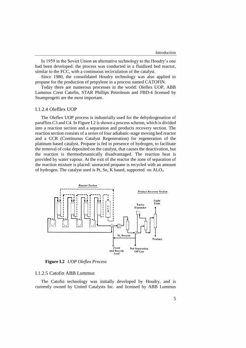
I.1.2.4 Olefllex UOP
The Oleflex UOP process is industrially used for the dehydrogenation of
paraffins C3 and C4. In Figure I.2 is shown a process scheme, which is divided
into a reaction section and a separation and products recovery section. The
reaction section consists of a series of four adiabatic-stage moving bed reactor
and a CCR (Continuous Catalyst Regeneration) for regeneration of the
platinum based catalyst. Propane is fed in presence of hydrogen, to facilitate
the removal of coke deposited on the catalyst, that causes the deactivation, but
the reaction is thermodynamically disadvantaged. The reaction heat is
provided by water vapour. At the exit of the reactor the zone of separation of
the reaction mixture is placed: unreacted propane is recycled with an amount
of hydrogen. The catalyst used is Pt, Sn, K based, supported on Al2O3.
Figure I.2 UOP Oleflex Process
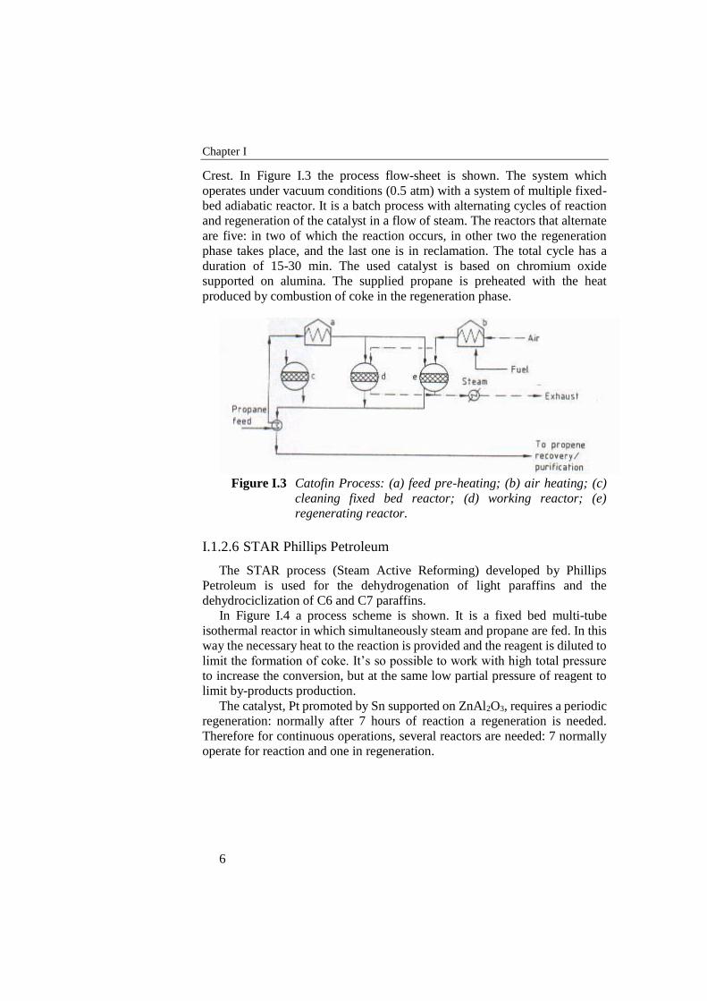
I.1.2.5 Catofin ABB Lummus
The Catofin technology was initially developed by Houdry, and is
currently owned by United Catalysts Inc. and licensed by ABB Lummus
Chapter I
6
Crest. In Figure I.3 the process flow-sheet is shown. The system which
operates under vacuum conditions (0.5 atm) with a system of multiple fixed-
bed adiabatic reactor. It is a batch process with alternating cycles of reaction
and regeneration of the catalyst in a flow of steam. The reactors that alternate
are five: in two of which the reaction occurs, in other two the regeneration
phase takes place, and the last one is in reclamation. The total cycle has a
duration of 15-30 min. The used catalyst is based on chromium oxide
supported on alumina. The supplied propane is preheated with the heat
produced by combustion of coke in the regeneration phase.
Figure I.3 Catofin Process: (a) feed pre-heating; (b) air heating; (c)
cleaning fixed bed reactor; (d) working reactor; (e)
regenerating reactor.
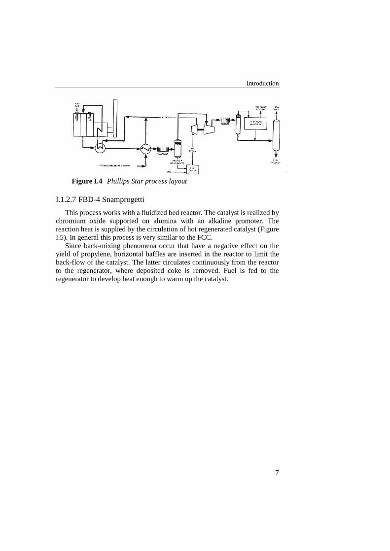
I.1.2.6 STAR Phillips Petroleum
The STAR process (Steam Active Reforming) developed by Phillips
Petroleum is used for the dehydrogenation of light paraffins and the
dehydrociclization of C6 and C7 paraffins.
In Figure I.4 a process scheme is shown. It is a fixed bed multi-tube
isothermal reactor in which simultaneously steam and propane are fed. In this
way the necessary heat to the reaction is provided and the reagent is diluted to
limit the formation of coke. It’s so possible to work with high total pressure
to increase the conversion, but at the same low partial pressure of reagent to
limit by-products production.
The catalyst, Pt promoted by Sn supported on ZnAl2O3, requires a periodic
regeneration: normally after 7 hours of reaction a regeneration is needed.
Therefore for continuous operations, several reactors are needed: 7 normally
operate for reaction and one in regeneration.
Introduction
7
Figure I.4 Phillips Star process layout
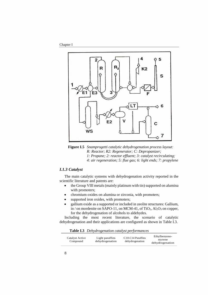
I.1.2.7 FBD-4 Snamprogetti
This process works with a fluidized bed reactor. The catalyst is realized by
chromium oxide supported on alumina with an alkaline promoter. The
reaction heat is supplied by the circulation of hot regenerated catalyst (Figure
I.5). In general this process is very similar to the FCC.
Since back-mixing phenomena occur that have a negative effect on the
yield of propylene, horizontal baffles are inserted in the reactor to limit the
back-flow of the catalyst. The latter circulates continuously from the reactor
to the regenerator, where deposited coke is removed. Fuel is fed to the
regenerator to develop heat enough to warm up the catalyst.
Chapter I
8
Figure I.5 Snamprogetti catalytic dehydrogenation process layout:
R: Reactor; R2: Regenerator; C: Depropanizer;
1: Propane; 2: reactor effluent; 3: catalyst recirculating;
4: air regeneration; 5: flue gas; 6: light ends; 7: propylene
I.1.3 Catalyst
The main catalytic systems with dehydrogenation activity reported in the
scientific literature and patents are:
the Group VIII metals (mainly platinum with tin) supported on alumina
with promoters;
chromium oxides on alumina or zirconia, with promoters;
supported iron oxides, with promoters;
gallium oxide as a supported or included in zeolite structures: Gallium,
in / on mordenite on SAPO-11, on MCM-41, of TiO2, Al2O3 on copper,
for the dehydrogenation of alcohols to aldehydes.
Including the most recent literature, the scenario of catalytic
dehydrogenation and their applications are configured as shown in Table I.3.
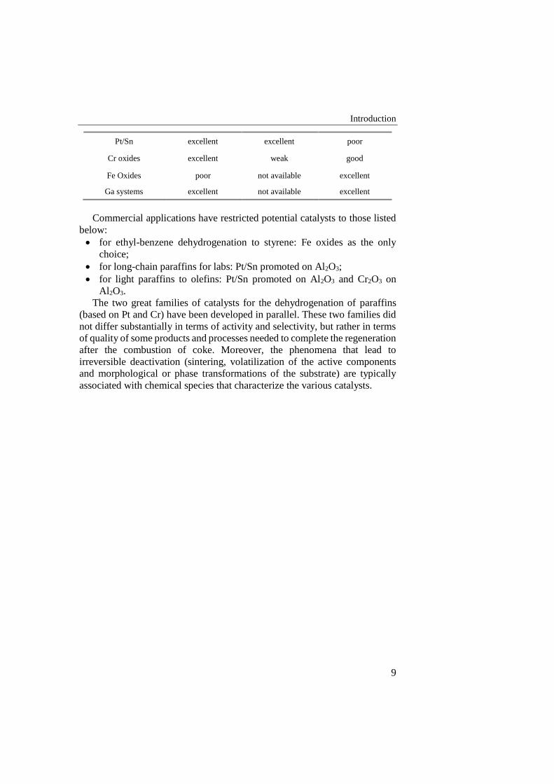
Table I.3 Dehydrogenation catalyst performances
Catalyst Active
Compound
Light paraffins
dehydrogenation
C10-C14 Paraffins
dehydrogenation
Ethylbenzene-
styrene dehydrogenation
Introduction
9
Pt/Sn excellent excellent poor
Cr oxides excellent weak good
Fe Oxides poor not available excellent
Ga systems excellent not available excellent
Commercial applications have restricted potential catalysts to those listed
below:
for ethyl-benzene dehydrogenation to styrene: Fe oxides as the only
choice;
for long-chain paraffins for labs: Pt/Sn promoted on Al2O3;
for light paraffins to olefins: Pt/Sn promoted on Al2O3 and Cr2O3 on
Al2O3.
The two great families of catalysts for the dehydrogenation of paraffins
(based on Pt and Cr) have been developed in parallel. These two families did
not differ substantially in terms of activity and selectivity, but rather in terms
of quality of some products and processes needed to complete the regeneration
after the combustion of coke. Moreover, the phenomena that lead to
irreversible deactivation (sintering, volatilization of the active components
and morphological or phase transformations of the substrate) are typically
associated with chemical species that characterize the various catalysts.
Chapter I
10
I.2 Methane and hydrogen production
Hydrogen is the lightest and the most plentiful chemical element of the
universe: it’s present in the water and in all the organic compounds. It may be
considered as the optimal fuel: it presents the highest energetic density, and
don’t produce pollutant gases. From these considerations, we can conclude
that hydrogen must be the only world energetic source, but it’s not the real
situation. The motivation of this apparent contradiction is due to the fact that
hydrogen is not present in the nature in free form, but it may be extracted
(more or less expensively) from the substance in which it’s contented (mainly
water, but also from organic compounds, alcohols, etc.). For this reason,
hydrogen can’t be considered as an energetic source, but properly an energetic
vector for transfer and/or stock energy. In this direction, hydrogen may be
considered as the only theoretically inexhaustible energetic vector, able to
satisfy the world energy demand for the next years. Moreover, it’s a zero-
carbon fuels: hydrogen combustion produces steam only.
I.2.1 Hydrogen production technologies
Hydrogen may be produced mainly by 2 methods: hydrocarbons
reforming (steam reforming, partial oxidation and auto-thermal reforming), or
water electrolysis. Due the widespread fossil fuels distribution pipelines and
their relatively low costs, the former method is preferred than the latter.
Actually, only 4% of hydrogen production is obtained by electrolytical way,
while hydrocarbons reforming still remain the favorite choice, and results as
the most viable solution in the short and middle term.
I.2.2 Steam Reforming
The steam reforming is a chemical process in which hydrocarbons, by
reacting with high temperature steam, are oxidized by extracting oxygen from
water molecules and so releasing hydrogen molecules.
The process may be divided in 4 main phases:
Feed purification;
Methane Steam Reforming (SR);
Further CO oxidation to produce CO2 (well note as CO-Shift or Water-
Gas-Shift);
Product purification.
Reactants purification is needed because some components (like sulphur
compound) may poison catalysts used in the next stages. Instead in products
purifications several by-products are removed, such as steam in excess, CO2,
CO, non-converted hydrocarbon and eventually nitrogen: the purification
degree strictly depend on the further hydrogen uses.
The steam reforming is substantially exploited in the 3rd and 4th pints,
described by the following reactions:
Introduction
11
𝐶𝐻4 + 𝐻2𝑂 ⇄ 𝐶𝑂 + 3𝐻2
𝐶𝑂 + 𝐻2𝑂 ⇄ 𝐶𝑂2 + 3𝐻2
The steam reforming is an very endothermic equilibrium reaction, so
external heat must be provided to the system. Further, in order to achieve high
hydrocarbon conversion, high operating temperature (higher than 700°C) is
needed. Too high temperature is not a viable solution, because, in order to
sustain the endothermic reaction, external heat must be supplied at a very
warm system, by using heater means warmer than system, and so several
problems due to the material thermal resistance may occur. Therefore, in the
industrial processes, the steam reforming reaction is performed in 2 stages: in
a first stage methane and steam react at 700-800°C, so obtaining a
hydrocarbon conversion up to 90%. In the second stage, an amount of air (or
oxygen) is added to the reforming gas, that reacts with a part of produced
hydrogen. The heat generated to this reaction increase reaction mixing
temperature op to 1000-1200°C, so allowing a quasi-complete hydrocarbon
conversion. This process is carried out a very high temperature, and therefore
don’t undergoes to kinetic limitations, and it easily reach thermodynamic
equilibrium. However, the steam reforming reaction may be followed by
several side-reactions, that lead to the coke formation:
2𝐶𝑂 ⇄ 𝐶𝑂2 + 𝐶
𝐶𝑂 + 𝐻2 ⇄ 𝐶 + 𝐻2𝑂
𝐶𝐻4 ⇄ 𝐶 + 2𝐻2
The steam reforming is a catalytic reaction: the most common catalysts are
Nickel or Platinum supported on calcium aluminate, that assure a good
selectivity towards the reforming reactions and avoid coke formation. The
support has the twice function of improve the mechanical properties of
cat6alytic system and of increase the surface/mass ratio.
The steam reforming reaction is characterized to an increase in total molar
number and therefore it’s favored in low pressure conditions. Steam-to-carbon
ratio must be as higher as possible, both to favor products formation and to
avoid coke formation. However, too high steam-to-carbon ratio results as a
non-ideal operating condition, mainly because to the expensive pre-heating of
the fed steam.
The “top-fired” are the most common steam reforming reactors, designed
as a tube-shell heat exchanger, in which tube-side reactants flow, on the top
of the shell a burner is placed to the heat generation, and combustion gas flows
shell-side so providing heat to the reactants in the tubes. Naturally, catalyst is
placed inside the tubes. This systems have very large sizes (e.g. in order to
produce 5000 Nm3/h of syngas a plant sized 3 x 6 x 11 m is required), and
hardly may be scale-based realized.
Chapter I
12
A little innovation is achieved by the using of plate-exchangers reactors:
this solution lead to great benefits for the reduction in plant size, while several
problems due to pressure drop and operating limitations may be exceeded.
I.2.3 Partial Oxidation
The methane partial oxidation consists on a hydrocarbon oxidation with an
oxygen content less than stoichiometry.
𝐶𝐻4 +1
2𝑂2 ⇄ 𝐶𝑂 + 2𝐻2 ∆𝐻𝑟𝑒𝑎𝑐
0 = −35.6𝑘𝐽/𝑚𝑜𝑙
It’s an exothermic reaction, characterized by a very fast kinetic, that
assures contact time very low: this feature allows reaction plants very smaller
than steam reforming.
However, partial oxidation implies a lower hydrogen yield, in fact e moles
of hydrogen are achieved from a mole of methane, while in the case of steam
reforming 3 moles of hydrogen are achieved.
In a mechanistic hypothesis, the methane partial oxidation results as the
following of several reactions. In a first time, the total oxidation of an amount
of hydrocarbon occurs:
𝐶𝐻4 + 2𝑂2 ⇄ 𝐶𝑂2 + 2𝐻2𝑂
The combustion heat is partially used to supply steam reforming and dry
reforming reactions:
𝐶𝐻4 + 𝐻2𝑂 ⇄ 𝐶𝑂 + 3𝐻2
𝐶𝐻4 + 𝐶𝑂2 ⇄ 2𝐶𝑂 + 2𝐻2
The partial oxidation reaction don’t need any catalysts, showing good
performances for temperatures between 1300 and 1500°C, assuring in the
selected conditions a full hydrocarbon conversion and decreasing coke and
soot production. The absence of catalysts allows to avoid feed
desulphurization, with a notable cost saving. However, such high
temperatures make the process hardly controllable, therefore lower
temperatures (800-1000°C) are preferred, by using a catalytic system. In these
conditions we have a fast reaction kinetic, and side-reactions are avoided. The
most common catalyst is nickel or rhodium based: the first one don’t exclude
coke formation, while the second is very more expensive.
Downstream the partial oxidation reactor, as in the case of steam
reforming, a Water-Gas-Shift stage is needed, followed by a product stream
purification stage.
Introduction
13
I.2.4 Auto-thermal Reforming
The auto-thermal reforming results as a compromise solution between
steam reforming and partial oxidation, in which both reactions occurs. By this
process from one hand well product composition and hydrocarbon conversion
are achieved, from the other no external heat must be supplied.
Fuel (methane), steam and air (or oxygen) are inserted in the reactor. The
oxygen reacts with the hydrocarbon in combustion and partial oxidation
reactions, so generating an amount of energy further used from the system for
the steam reforming reaction between steam and remaining methane. So, the
heat produced for the one reaction is used to by the second in the same reactor,
so no external heat is needed.
Globally, the reaction may be summarized as:
𝐶𝐻4 + 𝑥𝑂2 + 𝑦𝐻2𝑂 ⇄ 𝑎𝐶𝑂 + 𝑏𝐶𝑂2 + 𝑐𝐶𝐻4 + 𝑑𝐻2𝑂 + 𝑒𝐻2 + 𝑓𝐶(𝑠)
Obviously, d represents the excess water and (a+b+c)=1. The reaction
enthalpy (∆H°react) depends of feed parameters (x, y).
The auto-thermal reforming reaction is very flexible and controllable, by
varying x and y parameters as needed. Moreover, between the fuel processes
analysed for the hydrogen production, the auto-thermal reforming has the
lowest coke formation.
Because of no external heat must be provided to the system, no heat
exchangers, steam generators or burners are needed; this feature allows very
smaller plants than the former systems, and scale-sized plants are easier to
realize.
Auto-thermal reforming is a catalytic process: because it’s the synthesis of
steam reforming and partial oxidation, the selected catalyst must either favour
hydrocarbon oxidation and assure high reforming degree. Conventionally
nickel oxide based catalysts based on alumina, calcium oxide and magnesium
oxide are used.
I.2.5 Water-Gas-Shift
Downstream all the three analysed processes, a further purification stage is
needed: it’s the water-gas-shift (WGS) reaction. Mainly, carbon monoxide
must be removed from the stream outgoing to the reforming stages, by
reacting with steam: by this reaction a further mole of hydrogen was produced
for each mole of CO converted.
𝐶𝑂 + 𝐻2𝑂 ⇄ 𝐶𝑂2 + 𝐻2 ∆𝐻𝑟𝑒𝑎𝑐0 = −41𝑘𝐽/𝑚𝑜𝑙
The reaction is weakly exothermic, and is thermodynamically favoured at
relatively low temperature (< 200°C). But low temperatures implies slow
kinetics, therefore catalysts are needed in the process. Since it’s an exothermic

Chapter I
14
reaction, by using an adiabatic reactor, CO conversion develop a reaction heat
that increase reaction stream temperature, so decreasing thermodynamic CO
conversion. In order to reduce this phenomenon, preferentially the process is
split in in 2 stages, separated by a stream cooling.
The first stage, known as high-temperature water-gas-shift (WGS-HT), is
performed at about 350°C, by using an iron-chrome based catalyst.
The second stage, known as low-temperature water-gas-shift (WGS-LT),
is performed at about 220°C, by using a copper-zinc based catalyst.
Introduction
15
I.3 The membrane reactors
Membrane reactors facilitate simultaneous rate based reactive separation
schemes. In addition to the key attributes of membrane technology such as
membrane stability, lower catalyst deactivation, higher selectivity and yield,
and low cost, the optimal performance of a membrane reactor involves the
combinatorial selection of key process variables such as reaction and
permeation temperatures, retentate and permeate zone pressures, membrane
area per unit volume and membrane thickness. The capability of membrane
reactors to enhance reactor conversions has been demonstrated experimentally
for different schemes such as dehydrogenation and hydrogenation, oxidative
dehydrogenation and other reversible reaction schemes. Based on
experimental study of membrane reactors, several literatures attempt to
aggrandize the economic potential of membrane reactors, with a basic rule of
thumb that enhancement of reactor conversions directly translate into higher
profit margins and hence economic competitiveness.
Nonetheless, the admirable characteristics for membrane reactors in
process industries have been summarized by Armor (1998), who indicated
several materials performance issues for their industrial applicability. These
have been summarized as fabrication of crack free thin composite membranes
with materials not susceptible to poisoning or fouling, developing compatible
membrane-support combinations that can resist temperature cycling, balance
between catalyst and membrane distributions for optimal heat and mass
transport. Therefore, a first step towards the selection of membrane reactors
for industrial schemes involves a mandatory exercise on the materials
performance issues.
Based on simulations conducted for various process schemes associated to
fluidized membrane reforming, Roy et al. (1998) concluded that the cost of
producing hydrogen from membrane integrated fluidized reformers was 5%
lower than the cost affordable to produce hydrogen by best configurations
deploying conventional reactor technology only. Petersen et al. (1998)
concluded that the membrane integrated reforming process is not competitive
to the traditional steam reforming process and only with exceptional unit costs
of power and membranes could make the membrane integrated reforming
process an inexpensive and attractive alternative for reforming.
A number of metal membranes are highly hydrogen selective at higher
temperatures. Especially palladium and platinum can therefore be used for the
production of highly purified hydrogen from steam reforming of gases. Ultra-
pure hydrogen, generated from these reactions, is extracted by use of thin
dense metallic membranes that are 100% selective to hydrogen. The
mechanism of the transport is the separation of hydrogen into protons and
electrons at the surface and recombination on the filtrate or raffinate side.
Hydrogen selective membranes offer the possibility of combining reaction
and separation of the hydrogen in a single stage at high temperature and
Chapter I
16
pressure to overcome the equilibrium limitations experienced in conventional
reactor configurations for the production of hydrogen. The reforming reaction
is endothermic and can, with this technique, be forced to completion at lower
temperature than normal (typically 500-600°C). The shift reaction being
exothermic can be forced to completion at higher temperature (300-450°C).
Membrane reactors allow one-step reforming, or a single intermediate water
gas shift reaction, with hydrogen separation (the permeate) leaving behind a
retentate gas which is predominantly CO2 and steam, with some unconverted
methane, CO or H2. After clean-up, condensation of the steam leaves a
concentrated CO2 stream at high pressure, reducing the compression energy
for transport and storage. The need for multiple shift reaction stages is
avoided. Moreover, process intensification with membrane reactors allows for
more compact units, lower investment cost, higher yields and reduced energy
cost. In the same way, hydrogen removing from the products may force
dehydrogenation reactions, thermodynamically limited, towards further
hydrogen production, and therefore increase hydrocarbon conversion.
However, some problems must be exceeded to obtain a stable and optimal
membrane using. The greatest limit of membrane reactors concerns the
operating temperature of a membrane. Previous studies have demonstrated
that high temperature reduces the membrane life, as well as the membrane
perm-selectivity. By working to temperature typical of reforming or
dehydrogenation processes, not only hydrogen permeates the membrane, but
also other stream components, so reducing the desired benefits.
I.4 The CARENA project
(CAtalytic membrane REactors based on New mAterials for C1-C4
valorization)
The last decade has seen an increase in dempstration of novel membrane
technology, mainly in the carbon capture and fuel cell fields, bringing this
technology out of the labs. Dense conducting membranes have been
demonstrated at pilot-scale. These developments are leading to intensified
industrial interest in developing membrane reactors for the chemical industry.
The objective of the CARENA project is to develop and implement novel
nano-structured materials and optimized chemical processes to enable the
efficient conversion of light alkanes into higher value chemicals resulting in
the reduction in the number of process steps and increase in feedstock
flexibility for the European chemical industry.
CARENA aims to achieve break-through in catalytic membrane materials
and processes at 3 levels:
1. Enable selective conversion of raw feedstock such as light alkanes (C1-
C3) by generating in situ active species). The integration of catalyst and
membrane will be optimized.
Introduction
17
2. Develop reactor concepts, that match and control highly intensified
rates of mass and heat transfer resulting from application of novel
materials and architectures. Process intensification combining in-situ
reaction and reparation will be designed for equilibrium-limited
reaction for high industrial relevance.
3. Create novel process schemes, that translate novel materials and
reactions concepts into innovative industrial processes that exploit the
opportunities, such as reduction of the number of process steps and
elimination of energy intensive separations.
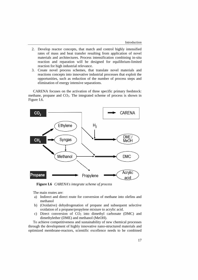
CARENA focuses on the activation of three specific primary feedstock:
methane, propane and CO2. The integrated scheme of process is shown in
Figure I.6.
Figure I.6 CARENA's integrate scheme of process
The main routes are:
a) Indirect and direct route for conversion of methane into olefins and
methanol
b) (Oxidative) dehydrogenation of propane and subsequent selective
oxidation of a propane/propylene mixture to acrylic acid.
c) Direct conversion of CO2 into dimethyl carbonate (DMC) and
dimethylether (DME) and methanol (MeOH).
To achieve competitiveness and sustainability of new chemical processes
through the development of highly innovative nano-structured materials and
optimized membrane-reactors, scientific excellence needs to be combined
Chapter I
18
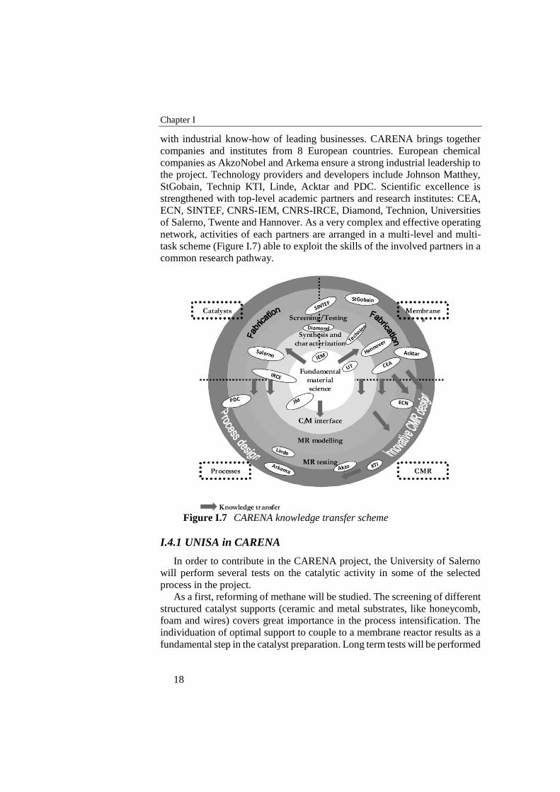
with industrial know-how of leading businesses. CARENA brings together
companies and institutes from 8 European countries. European chemical
companies as AkzoNobel and Arkema ensure a strong industrial leadership to
the project. Technology providers and developers include Johnson Matthey,
StGobain, Technip KTI, Linde, Acktar and PDC. Scientific excellence is
strengthened with top-level academic partners and research institutes: CEA,
ECN, SINTEF, CNRS-IEM, CNRS-IRCE, Diamond, Technion, Universities
of Salerno, Twente and Hannover. As a very complex and effective operating
network, activities of each partners are arranged in a multi-level and multi-
task scheme (Figure I.7) able to exploit the skills of the involved partners in a
common research pathway.
Figure I.7 CARENA knowledge transfer scheme
I.4.1 UNISA in CARENA
In order to contribute in the CARENA project, the University of Salerno
will perform several tests on the catalytic activity in some of the selected
process in the project.
As a first, reforming of methane will be studied. The screening of different
structured catalyst supports (ceramic and metal substrates, like honeycomb,
foam and wires) covers great importance in the process intensification. The
individuation of optimal support to couple to a membrane reactor results as a
fundamental step in the catalyst preparation. Long term tests will be performed
Introduction
19
with the selected coated catalyst samples at reforming conditions, in order to
evaluate the support efforts and the stability of the system.
Great attention was aroused on the propane dehydrogenation, in order to
obtain high selective processes by starting from pure propane. The
formulation of novel catalyst-support combination, active in the selected
operating conditions, results as a starting point towards novel membrane
catalytic reactors. In this objective, UNISA should understand the effect of the
operative conditions in the PDH performances, by validating and supporting
numerical evaluations carried out by partners. In this aim, UNISA will test
catalysts prepared by partners, so understanding any weakness of the
formulations and eventually suggesting appropriate modifications.

21
State of the art
II.1 Methane reforming: state of the art
In the methane auto-thermal reforming, the catalyst selection is of great
importance. An optimal catalytic system play a crucial role both in
hydrocarbon conversion and in the reaction selectivity; so the choice of a
catalyst rather than another can lead to different product compositions.
Naturally, the active species be selected on the basis of the operating
conditions and the used hydrocarbon. As seen, auto-thermal reforming is
composed at least by two reaction: the steam reforming and the partial
oxidation. Therefore, the selected catalyst must assure an high selectivity
toward these two reactions, and must avoid other side-reactions, first of all the
hydrocarbon cracking.
By several studies performed several decades ago, nickel (JR-Rostrup-
Nielsen, 1975) and cobalt (JR-Rostrup-Nielsen, 1993) supported on alumina
or magnesia spinel, often promoted by alkaline compounds (Bharadwaj SS,
1995) to remove carbonaceous compounds, or supported on rare metals
oxides, especially cerium oxide (Craciun R, 2002) , result as the favorite
catalytic systems for steam reforming reactions. In the other hand, partial
oxidation is a very quick process, and so smaller reactors are needed. By using
nickel based catalyst on alumina, the coke deposition on the catalyst surface
was reported (Dhammike Dissanayake, 1991), that produces catalyst pores
clogging and so catalyst deactivation. Moreover, by working with molar feed
ratio C/O2>2 catalyst break-up in very fine powders was observed. A complex
study (Ruckenstein and Hu, 1999) concluded that nickel oxide supported on
magnesium oxide (NiO-MgO) show both a promising catalytic activity and a
high selectivity, in solid solution; while, as a mechanic mixture, an evident
decreasing of these features are reported. However both activity and
selectivity may be improved by increasing calcination time. Moreover, a better
activity, stability and selectivity were remarked for NiO loaded between 9.7
and 35 %mol: too low concentrations lead to a decrease in activity and stability;
concentration too high lead to low stability.
Chapter II
22
The improvement in methane conversion obtained by adding noble metals
as rhodium, platinum and palladium to a NiO-NgO solid solution was
reported(M. Nurunnabi, 2006): such benefits result more evident even by
using very poor content (0.035%). It’s demonstrated that the presence of such
noble metals holds nickel in the reduced state, so improving methane
conversion. Moreover, in pressurized conditions, it’s observed that rhodium
and platinum reduce coke formation.
In a comparative study (S. Ayabe, 2003) the catalytic behavior of several
metals supported on alumina was reported for auto-thermal reforming of
methane and propane. As results of this analysis, an activity classification may
be defined: Rh>Pd>Ni>Pt>Co. Moreover, in rich steam operating conditions,
no coke formation was observed in methane processing, while in propane
auto-thermal reforming more evident coke compounds were achieved.
In study on the effects of ceria (CeO2) (Trovarelli, 1996), especially in
platinum group metal (PGM) catalysts, as Pt, Rh, Pd, was reported that ceria
leads to an increase in catalytic activity toward hydrocarbon and CO, due to
its oxygen storage capacity. This behavior was more marked for ceria-zirconia
mixtures(S. Bedrane, 2002). The improvement achieved by adding zirconia
(Roh et al., 2002) may be due to its high stability at high temperature, as well
as to its high surface area; moreover, Hori et al (X. Wu, 2004) in their studies
have observed the very high oxygen storage capacity in CeO2-ZrO2 mixtures.
The behavior of a 1% platinum based catalyst supported on ZrO2-Al2O3 in
the auto-thermal reforming of methane was analyzed(M. M.V.M. Souza,
2005), by comparing the obtained results with Pt/Al2O3 and Pt/ZrO2 catalysts.
An higher activity and stability of the former was observed by performing an
auto-thermal reforming test at 800°C. The high stability may be due to the
avoiding to coke formation, due in turn to Pt-Zr interaction on the metal-
support interface.
The effect of some transition metals (Cu, Co, Fe) on Ni/Ce0.2Zr0.1Al0.56O
catalysts in the methane auto-thermal reforming was studied(X. Dong, 2007).
The performed tests show that by adding copper and cobalt lead to an
increasing on catalyst activity for low temperature, while by adding iron a
decrease in catalytic activity was observed. The authors conclude that the
presence of copper leads to a high nickel oxide dispersion, so inhibiting the
formation of species as NiAl2O4.
Nickel based catalyst supported on CeO2-ZrO2/SiO2 (silica spheres
impregnated with a ceria-zirconia mixture) was tested in a fluidized bed (J.
Gao, 2008). Such catalyst, due to the presence of silica, is characterized by a
very higher surface area (300 m2/g) than for the only ceria and zirconia
supported (6 m2/g): this feature leads to an higher activity. Moreover, in the
selected catalyst a high active species dispersion is observed, so making nickel
highly reducible and giving to the catalyst a great capacity to activate the
methane.
State of the art
23
Methane auto-thermal reforming tests by using nickel base catalysts
supported on α-Al2O3, on Y2O3 or a combination of both were performed
(D.C.R.M. Santos, 2009). Naturally, the presence of yttrium oxide implies a
strong surface area increasing (8%Ni/α-Al2O3 = 3.9 m2/g; 8%Ni/5%Y2O3/α-
Al2O3 = 18.6 m2/g). Best performance, in order to both conversion and
stability, are obtained by 8%Ni/5%Y2O3/α-Al2O3 configuration; the
configuration without Y2O3 showed very low stability, the configuration
without α-Al2O3 showed low activity. The benefit leaded by adding yttrium
oxide may be explained in the formation of a Ni-Y2O3 intermediate on the
surface, that preserve nickel toward coke deposition.
II.2 Propane dehydrogenation: state of the art
Paraffin dehydrogenation for the production of olefins has been in use
since the late 1930s. During World War II, catalytic dehydrogenation of
butanes over a chromia-alumina catalyst was practiced for the production of
butenes, which were then dimerized to octenes and hydrogenated to octanes
to yield high-octane aviation fuel.
In the dehydrogenation process using chromia-alumina catalysts, the
catalyst is contained in a fixed shallow bed located inside a reactor that may
be either a sphere, a squat vertical cylinder, or a horizontal cylinder. The actual
design reflects a compromise between gas flow distribution across a large
cross-sectional area and the need to maintain a low pressure drop. A
significant amount of coke is deposited on the catalyst during the
dehydrogenation step, therefore, a number of reactors are used in parallel. The
dehydrogenation reactions are strongly endothermic, and the heat is provided,
at least in part, by the sensible heat stored in the catalyst bed during
regeneration (carbon burn); additional heat is provided by direct fuel
combustion and also by heat released in the chromium redox cycle. The length
of the total reactor cycle is limited by the amount of heat available, and can be
as short as 10–20 min.
The Houdry Catadiene process was used extensively for the production of
butadiene, either by itself (n-butane to butadiene) or in conjunction with
catalytic oxydehydrogenation of n-butene to butadiene. The latter was
commercialized by the Petro-Tex Chemical Corp. (Waddams, 1980) and was
called the Oxo-DTM process. A similar oxydehydrogenation approach for the
production of butadiene was also practiced by Phillips Petroleum (Waddams,
1980). Large quantities of butadiene have become available over the past 30
years, mostly as a by-product from the thermal crackin g of naphtha and other
heavy hydrocarbons. This market shift has resulted in the shutdown of all on-
purpose catalytic dehydrogenation units for butadiene production in North
America, western Europe, and the far East.
In the late 1980s, the application of chromia-alumina catalysts was
extended by Houdry to the dehydrogenation of propane to propylene and
Chapter II
24
isobutane to isobutylene. The new process application called CatofinTM
(Weiss, 1970, Graig and Spence, 1986) operates on the same cyclic principle
as in the former Catadiene process. The Catofin process technology is
currently owned by Sud-Chemie and is offered for license by ABB Lummus.
In 1959, an alternative chromia-alumina catalytic dehydrogenation process
was developed in the former Soviet Union. This process avoided the use of
the cyclic operation by using a fluidized bed reactor configuration similar to
the fluidized catalytic cracking (FCC) process used in refineries (Sanfilippo et
al., 1998). However, back-mixing common to dense fluidized bed operations
results in poor selectivity and increases the formation of heavies, sometimes
called “green oils”. Circulating regenerated catalyst is used to provide the heat
of reaction in the riser and spent catalyst is reheated by carbon burn in the
regenerator.
A different approach to catalytic dehydrogenation was first introduced in
the mid-1960s for the supply of long-chain linear olefins for the production of
biodegradable detergents. The work on catalytic reforming with noble metal
(Pt) catalysts done in the 1940s by Haensel clearly demonstrated that Pt-based
catalysts had high activity for the dehydrogenation of paraffins to the
corresponding olefins(Haensel, 1952). In the 1960s, Bloch (Bloch, 1969)
further extended this thinking by developing Pt-based catalysts that could
selectively dehydrogenate long-chain linear paraffins to the corresponding
internal mono-olefins with high activity and stability and with minimum
cracking. This was the basis for the UOP PacolTM process for the production
of linear olefins for the manufacture of biodegradable detergents (Berg and
Vora, 1982). In 1999, there were more than 30 commercial Pt-catalyzed
dehydrogenation units in operation for the manufacture of detergent alkylate.
Long-chain paraffins are both valuable and highly prone to cracking.
Therefore, in order to maintain high selectivity and yield, it is necessary to
operate at relatively mild conditions, typically below 500°C, and at relatively
low per-pass conversions. While this is economical for the production of
heavy linear olefins, it is not for the production of light olefins.
Paraffin dehydrogenation is an endothermic reaction that is limited by
chemical equilibrium and, according to Le Chatelier’s principle, higher
conversion will require either higher temperatures or lower pressures.
Literature propose some kinetics approach to the reactions involved in the
propane dehydrogenation process (Farjoo et al., 2011), underlining that an
optimal management of residence time may maximize selectivity to propylene
vs others side-products
Detailed studies (Kumar et al., 2009) were carried out on the influence of
tin in platinum based catalysts. The active species are supported on SBA-15,
a mesoporous silica-based material with high surface area and high thermal
stability. Dehydrogenation of propane over these catalysts was studied at 793
K. Sn results in higher Pt dispersion by alloy formation in Pt-Sn-SBA-15. This
leads to the formation of smaller Pt particles in Pt-Sn-SBA-15-IW than in Pt-
State of the art
25
SBA-15. Catalytic properties of Pt sites are influenced by modification of
electronic properties of the same sites by Sn in bimetallic Pt–Sn alloy
particles. Higher propane conversion and higher amount of coke formation on
smaller Pt particles (Pt-Sn-SBA-15) than on the larger (Pt-SBA-15) are due to
higher surface roughness of the former than that of the latter. Tin addition so
leads to an higher selectivity to propylene and superior catalyst stability due
to weaker adsorption affinity of hydrocarbons on the surface Pt sites in Pt-Sn
bimetallic particles.
Further studies (Vu et al., 2011a) indicated the role of tin in coke formation.
The increasing of tin loading on a Pt-Al2O3 catalyst effects on the electronic
properties of Pt allowing better coke tolerance and a catalytic performance. In
particular, the tin presence induced the shift of coke oxidation temperature to
higher because Sn addition accelerates the transfer of coke to the support. Tin
addition leads to transfer of coke from the metal to the support, with the ratio
of coke fraction on the metal to support deceasing significantly.
A similar result was observed by studying the Indium effect on a
Pt/Mg(Al)O catalyst in ethane and propane dehydrogenaiton (Sun et al.,
2011). For both reactants, maximum activity was achieved for a bulk In/Pt
ratio of 0.48, and at this In/Pt ratio, the selectivity to alkene was nearly 100%.
Coke deposition was observed after catalyst use for either ethane or propane
dehydrogenation, and it was observed that the alloying of Pt with In greatly
reduced the amount of coke deposited. While the amount of coke deposited
during ethane and propane dehydrogenation are comparable, the effects on
activity are dependent on reactant composition. Coke deposition had no effect
on ethane dehydrogenation activity, but caused a loss in propane
dehydrogenation activity. This difference is attributed to the greater ease with
which coke produced on the surface of PtIn nanoparticles migrates to the
support during ethane dehydrogenation versus propane dehydrogenation.
The effect of sodium on Pt-Sn catalyst was investigated in the literature
(Duan et al., 2010), remarking that the presence of sodium modified the
properties of the Pt metal phase. The Pt dispersion, combined with interaction
between metal and support, were effected by the sodium content,which may
be responsible for catalytic properties. The sodium existence also neutralized
the strong acidic sites of catalysts, thus reduced the formation of coke
effectively. However, the incorporation of excessive sodium prompted the
reduction of Sn species to Sn°, which may be alloyed with Pt, leading to a
decrease in catalytic activity.
An interesting coke formation mechanism was proposed in the literature
(Li et al., 2011), that identify the coke formation starting by a coke precursor.
The coke precursor formed on the metal may migrate to the support and then
undergoes subsequent polymerization/oligomerization, condensation and so
on. Thus, increasing the partial pressure of propane would increase the rate of
coke formation on the support. Sn in the Pt catalyst will weaken the binding
of hydrocarbon to the metal, and promote the migration of the coke precursor
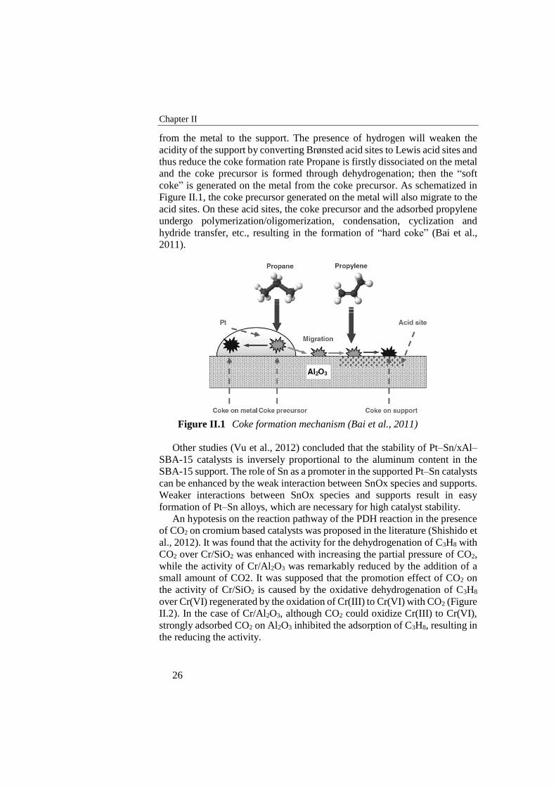
Chapter II
26
from the metal to the support. The presence of hydrogen will weaken the
acidity of the support by converting Brønsted acid sites to Lewis acid sites and
thus reduce the coke formation rate Propane is firstly dissociated on the metal
and the coke precursor is formed through dehydrogenation; then the “soft
coke” is generated on the metal from the coke precursor. As schematized in
Figure II.1, the coke precursor generated on the metal will also migrate to the
acid sites. On these acid sites, the coke precursor and the adsorbed propylene
undergo polymerization/oligomerization, condensation, cyclization and
hydride transfer, etc., resulting in the formation of “hard coke” (Bai et al.,
2011).
Figure II.1 Coke formation mechanism (Bai et al., 2011)
Other studies (Vu et al., 2012) concluded that the stability of Pt–Sn/xAl–
SBA-15 catalysts is inversely proportional to the aluminum content in the
SBA-15 support. The role of Sn as a promoter in the supported Pt–Sn catalysts
can be enhanced by the weak interaction between SnOx species and supports.
Weaker interactions between SnOx species and supports result in easy
formation of Pt–Sn alloys, which are necessary for high catalyst stability.
An hypotesis on the reaction pathway of the PDH reaction in the presence
of CO2 on cromium based catalysts was proposed in the literature (Shishido et
al., 2012). It was found that the activity for the dehydrogenation of C3H8 with
CO2 over Cr/SiO2 was enhanced with increasing the partial pressure of CO2,
while the activity of Cr/Al2O3 was remarkably reduced by the addition of a
small amount of CO2. It was supposed that the promotion effect of CO2 on
the activity of Cr/SiO2 is caused by the oxidative dehydrogenation of C3H8
over Cr(VI) regenerated by the oxidation of Cr(III) to Cr(VI) with CO2 (Figure
II.2). In the case of Cr/Al2O3, although CO2 could oxidize Cr(III) to Cr(VI),
strongly adsorbed CO2 on Al2O3 inhibited the adsorption of C3H8, resulting in
the reducing the activity.
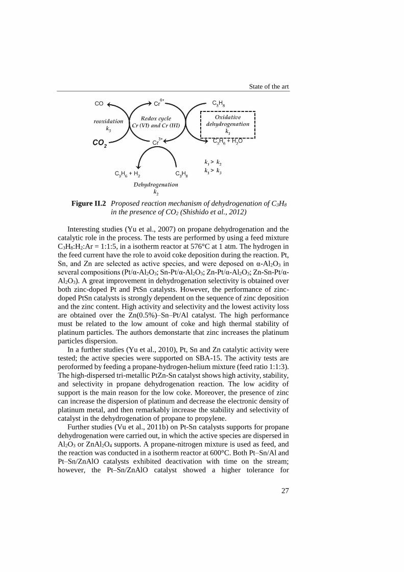
State of the art
27
Figure II.2 Proposed reaction mechanism of dehydrogenation of C3H8
in the presence of CO2 (Shishido et al., 2012)
Interesting studies (Yu et al., 2007) on propane dehydrogenation and the
catalytic role in the process. The tests are performed by using a feed mixture
C3H8:H2:Ar = 1:1:5, in a isotherm reactor at 576°C at 1 atm. The hydrogen in
the feed current have the role to avoid coke deposition during the reaction. Pt,
Sn, and Zn are selected as active species, and were deposed on α-Al2O3 in
several compositions (Pt/α-Al2O3; Sn-Pt/α-Al2O3; Zn-Pt/α-Al2O3; Zn-Sn-Pt/α-
Al2O3). A great improvement in dehydrogenation selectivity is obtained over
both zinc-doped Pt and PtSn catalysts. However, the performance of zinc-
doped PtSn catalysts is strongly dependent on the sequence of zinc deposition
and the zinc content. High activity and selectivity and the lowest activity loss
are obtained over the Zn(0.5%)–Sn–Pt/Al catalyst. The high performance
must be related to the low amount of coke and high thermal stability of
platinum particles. The authors demonstarte that zinc increases the platinum
particles dispersion.
In a further studies (Yu et al., 2010), Pt, Sn and Zn catalytic activity were
tested; the active species were supported on SBA-15. The activity tests are
peroformed by feeding a propane-hydrogen-helium mixture (feed ratio 1:1:3).
The high-dispersed tri-metallic PtZn-Sn catalyst shows high activity, stability,
and selectivity in propane dehydrogenation reaction. The low acidity of
support is the main reason for the low coke. Moreover, the presence of zinc
can increase the dispersion of platinum and decrease the electronic density of
platinum metal, and then remarkably increase the stability and selectivity of
catalyst in the dehydrogenation of propane to propylene.
Further studies (Vu et al., 2011b) on Pt-Sn catalysts supports for propane
dehydrogenation were carried out, in which the active species are dispersed in
Al2O3 or ZnAl2O4 supports. A propane-nitrogen mixture is used as feed, and
the reaction was conducted in a isotherm reactor at 600°C. Both Pt–Sn/Al and
Pt–Sn/ZnAlO catalysts exhibited deactivation with time on the stream;
however, the Pt–Sn/ZnAlO catalyst showed a higher tolerance for
Chapter II
28
deactivation than the Pt–Sn/Al catalyst. By catalysts analysis, the authors
noticed the formation of Pt-Sn alloys especially in alumina supported
catalysts. Therefore, the dominant Pt3Sn alloy was likely responsible for faster
deactivation of the Pt–Sn/Al than that of the Pt–Sn/ZnAlO catalyst. The
amount of coke accumulated on the Pt–Sn/ZnAlO was slightly less than that
on the Pt–Sn/Al catalyst, and the transport of the coke from metallic sites to
the support on Pt–Sn/ZnAlO became easier than that on the Pt–Sn/Al catalyst.
In other studies (Sokolov et al., 2012) the catalyst deactivation mechanism
was investigated, concluding that not only the amount of surface carbon
species, but also their nature may determine the deactivation rate. The
phenomena is highlighted in the regeneration procedures, in which the catalyst
oxidation may lead to several oxidized metals sites, that may have a role in
the catalytic process. In particular, it was demonstrated that vanadium oxide
was less active towards coking than PtO2 and Cr2O3, therefore despite the
latters have an high activity in the fresh state, after several regeneration cycles
the vanadium based catalyst showed an higher stability and selectivity.
A very complex study on indium oxide based catalysts (Chen et al., 2010)
analyzed the influence of adding several metal oxides, as well as the indium
oxide content were analyzed. A propane-carbon dioxide was used as reactant
(in the ratio 1:4), diluted in helium.. Best activity an stability was observed by
using In2O3-Al2O3 at 20% of indium oxide content. which allows the steady
formation of a maximum propylene yield of ca. 27% in the catalytic
dehydrogenation of propane at 873 K. The high catalytic activity of the present
In2O3–Al2O3 catalysts has been attributed to the favorable creation of surface
stabilized metallic In° nanoclusters as a consequence of in situ reduction of
well-dispersed surface indium sites during the induction period.
A similar study was conducted (Ren et al., 2009), in which ZnO2 was
selected as active specie, and zeolite (HZSM-5) at several Si/Al ratio were
studied as support, for propane dehydrogenation. A propane – carbon dioxide
– nitrogen mixture at a feed ratio of 5:10:185 was used as reactant. The initial
activity of HZSM-5 supported zinc oxide catalysts decreases with increasing
the Si/Al ratio, while the stability and the propene selectivity improve. The
ZnO/HZSM-5 catalyst at Si/Al=160 exhibits the best performance at steady
state. The enhancement of the catalyst stability with increasing the Si/Al ratio
of the HZSM-5 support originates from the decrease in acidity of the catalysts,
which leads to the suppression of the side reactions, such as cracking,
oligomerization and aromatization. The promoting effect of CO2 on the
dehydrogenation reaction is observed over ZnO/HZSM-5 catalyst. Results of
the influence of CO2 partial pressure on the dehydrogenation reaction suggest
that there are two roles of CO2: a positive role by transforming H2 with CO2
into CO and H2O through the reverse water-gas shift reaction, and a negative
role by blocking the dissociative adsorption of propane on the catalyst surface.
The catalytic stability is also improved by the addition of CO2 to the feed gas
due to the suppression of coke formation.
State of the art
29
Further studies (Wang et al., 2012) confirmed the negative effect of the
CO2 in the diluted propane dehydrogenation on a gallium oxide on zeolite
supports. The paper demonstrated that a relevant selectivity to aromatics
compounds, other than methane and ethylene and coke, occurred in the
investigated operating conditions (600°C). However the study also
highlighted that the reduction of the Brønsted and Lewis acid sites resulted in
a reduction in cracking phenomena.
The negative influence of acid sites was demonstrated by several tests
(Kley and Traa, 2012), in which the zeolite acid sites were reduced by sodium
borohydride.
The role of SBA-15 modified with γ-Al2O3 as a support for Pt-Sn based
catalysts was investigated (Huang et al., 2008). A propane-hydrogen mixture
in feed ratio of 1:4 was used as reactant current. The tests results show how
the PtSn catalyst supported on Al2O3-modified SBA-15 (Al2O3/SBA-15)
exhibits higher activity than the PtSn/SBA-15 catalyst and higher stability
than conventional PtSn/γ-Al2O3 catalyst for propane dehydrogenation. The
higher catalytic activity and stability of PtSn/Al2O3/SBA-15 catalyst can be
correlated to the nature of interaction between Pt–Sn-support as well as the
mesoporous structure of the support used.
A similar study (Duan et al., 2012) revealed that the SBA-15 support
modification may contribute in the Pt dispersion. The modification may in
turn improve the platinum dispersion on the support and promote interaction
between Pt and support resulting less sensible to the coke deposition and so
increasing in catalyst stability. The improvement in Pt dispersion on zeolitic
supports may be achieved by using HCl adsorbate in the preparation, resulting
also in enhanced interaction between platinum and tin (Bai et al., 2011).
The role of the support on the nature of PtSn alloys formation was reported
in the literature (Vu et al., 2011c), in which the addition of lanthanum, cerium
and yttrium on an al based support was investigated. The formation and
stability of the Pt–Sn alloy in the catalysts were remarkably influenced by the
addition of La, Ce, or Y. Compared to pure Al2O3 supports, La-doped Al2O3
promoted the formation of PtSn, while Ce- and Y-doped Al2O3 promoted the
formation of PtSn2 alloy on reduced catalysts. Moreover, La-, Ce-, and Y-
doped Al2O3 increased the Pt dispersion and decreased the reduction
temperature of the Pt–Sn species However, the stability of Pt–Sn alloy during
the reaction exhibited different tolerances according to the catalyst used.
Compared to those of the Pt–Sn/Al and Pt–Sn/Y–Al catalysts, Pt–Sn/La–Al
and Pt–Sn/Ce–Al catalysts showed superior catalytic performances and
stabilities because of the lower coke contents, higher stabilities of PtSn and
PtSn2 alloys, and smaller losses of Pt dispersion. Moreover, the oxygen
mobility of the support may lead to a lower oxidation temperature during
regeneration of spent catalysts (Vu and Shin, 2010), so enhancing the overall
catalyst life
Chapter II
30
A complex study on Pt-Sn catalysts supports were carried out (Nawaz et
al., 2009). Very concentrated feed was used, by supplying propane and
hydrogen at a feed ratio of 4:1. The superior catalytic performance of Pt–
Sn/SAPO-34 was obtained due to weak acid sites that can convert propyl
cation to propylene selectively. Moreover SAPO-34 was almost inert to
dehydrogenation and cracking, and their shape selectivity effect which only
allowed propylene to form. The SAPO-34 supported catalyst was much better
than a ZSM-5 supported bimetallic catalyst. Both Lewis and Brönsted acid
sites were exist on SAPO-34 supported catalysts and these were stable after
metal incorporation. However, deactivation also occurred due to the loss in
active metallic sites with time-on-stream. The presence of Sn improved the
reduction of Pt. In the propane dehydrogenation mechanism over Pt–
Sn/SAPO-34, only one hydrogen attached to a b-carbon in propane was
available for attack by Pt, to form the propoxy species (Z–O–C3H7). These
propoxy species were selectivity converted to propylene over SAPO-34.
Other tests on propane dehydrogenation over Pt-Sn /Al2O3 catalysts, in a
temperature range of 575-620°C, were found in the literature (Fattahi et al.,
2011). A propane-hydrogen mixture was fed to the test plant, with a feed ratio
H2:HC = 0.8; moreover, the addition of several oxygenate compounds (water
or methanol) is analyzed. The addition of oxygenates to the feed in
dehydrogenation of propane over commercial Pt–Sn/γ-Al2O3 catalyst showed
beneficial effects on catalyst performance. The oxygenates improve propylene
yield when added in appropriate amounts. There is an optimum level of
oxygenate, depending on oxygenate type and operating conditions. Methanol
is a more effective modifier, compared to water, which can be accounted for
by the simple mechanism presented. Finally, the oxygenate modifier increases
the catalyst lifetime as well, through reducing coke formation on the catalyst.
A similar conclusion was obtained by another study (Samavati et al., 2013)
focused on water addition effect on PDH catalyst performances. The
increasing in water content led as expected to an increasing in propane
conversion due in one hand to the hydrocarbon dilution, and so to the
decreasing of its partial pressure, in the other hand to the coke gasification by
steam presence. However, an excessive water content increasing led to the
Platinum sintering in the PtSn/Al2O3 catalyst, that causes the catalyst
deactivation. Therefore, an optimal steam content value was achieved, that
increase in the operating temperature increasing. The same conclusion was
extracted by another paper in the literature (Barghi et al., 2012), that get a
model tool to predict the catalyst behavior in the presence of oxygenated
compounds.
A complex analysis on the support influence on oxidative dehydrogenation
of propane over low-loaded vanadia catalysts was reported in literature (Dinse
et al., 2008). Several metal oxide supports are tested, as ceria, titania, alumina,
zirconia and silica. The catalytic performance seems to depend on a complex
interplay of vanadium surface species and bulk supporting material. All
State of the art
31
catalysts expose differently structured and/or distributed vanadium surface
sites (monomers/oligomers). V-ZrO2 undergoes structural changes under
reaction conditions. To improve selectivity towards the desired product, high
temperatures seem to be appropriate, independent of the nature.
A comparison between non-oxidative and oxidative (lean oxygen) propane
dehydrogenation (Ovsitser et al., 2012) highlighted that in one hand the non-
oxidative process have a very high selectivity to propylene, in the other hand
the oxidative process resulted clearly more stable and one magnitude order
faster.
Monolithic Pt-Sn based catalysts (2-3 wt%) (Pavlova et al., 2003) was
studied for the propane oxidative dehydrogenation. C3H8 and O2 are selected
as reactants, and diluted with nitrogen. In the reaction of the autothermal
propane oxidative dehydrogenation at short contact times on monolithic
supported catalysts, a substantial impact of the homogeneous gas-phase
reactions on the propane conversion and product selectivity is demonstrated.
A share of those reactions is shown to strongly depend upon the longitudinal
temperature gradient within the monolithic layer which is determined by its
design, operation parameters (feed rate and composition) and a nature of the
active component. The yield of propylene is improved when the temperature
maximum is shifted to the monolith inlet, and undesired endothermic reactions
of cracking or steam reforming are suppressed.
An interesting study on the effect of support morphology in the oxidative
dehydrogenation of ethane to ethylene was performed (Donsì et al., 2005).
LaMnO3 and Pt based catalysts were used as active species, while 400 cpsi
honeycomb and 45-80 ppi foam monoliths are used as mechanical support.
Experimental results showed that, even though ethylene formation occurs in
the gas phase, the catalyst composition outscores any morphological
consideration. LaMnO3-based catalysts always give higher performance than
Pt-based ones independently on the support. Nevertheless, support
morphology and cell density may affect ethylene selectivity for more than 10
points%. It can be generally stated that foams perform better than honeycombs
thanks to the higher geometrical surface and to the high degree of tortuosity
and randomness of the pores, which drastically increase the heat and mass
transfer rate. The 45 and 60 ppi foams gave the highest ethylene selectivity
and yield, even though the performance of 400 and 600 cpsi honeycomb
monoliths is only slightly lower. Hence, at increasing cell density above these
optimal values both for foams and for honeycombs, the performance
decreases. Based on the evaluation of the performance, it appears that 45 and
60 ppi foam monoliths are the optimal supports for the ODH reaction.
Nevertheless, honeycomb monoliths guarantee significant advantages with
respect to foams in terms of pressure drops, structural strength and easier
catalyst deposition, resulting only in a minor reduction in performance for 400
and 600 cpsi cell density.
Chapter II
32
A very interesting study on the heat transfer in catalytic metallic foams as
catalysts support in the oxidative dehydrogenation of hydrocarbons is carried
out (Löfberga et al., 2011). Several tests are performed by comparing
VOx/TiO2 catalytic activity as powder or supported on foams, in the oxidative
propane dehydrogenation. The solid foam improves the radial bed
conductivity and decreases the thermal gradients. Using a catalytic stainless
steel foam in the exothermic oxidative dehydrogenation of propane to propene
was clearly responsible for increasing the yield of propene when compared to
catalytic powder. It is assumed that hot spots were reduced, leading to more
isothermal the operation. The isothermicity due to more efficient heat transfer
has to be confirmed by measuring the temperature gradient between the center
of the foam and the wall of reactor.
Some approaches to the membrane assisted propane dehydrogenation were
found in the literature. The use of the membrane led to an increasing in
propane conversion due to the hydrogen removal from the products stream,
however several problems due to the coke formation on the membrane surface
and structure causes a rapid membrane plugging and to a loss in the achieve
advantages (Didenko et al., 2013), more evident at the highest temperatures.
As an innovative configuration, a Two-Zone Fluidized Bed Membrane
Reactor was proposed in the literature (Medrano et al., 2013) for the PDH
reaction of a 50% propane stream. The system, schematized in Figure II.3,
was composed by two zones aimed to the PDH reaction and to the catalyst
regeneration. Such arrangement assured a continuous regeneration loop for
the catalytic powder, as well as the direct catalyst heating by the catalyst
oxidation. The reactor architecture of the reaction system allowed a significant
improvement in propane conversion and catalyst stability, however a sensible
decreasing in propylene selectivity due to the oxygen use.
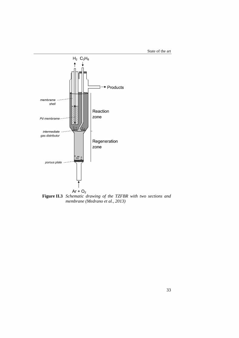
State of the art
33
Figure II.3 Schematic drawing of the TZFBR with two sections and
membrane (Medrano et al., 2013)

35
PDH thermodynamic analysis
In order to investigate the effect of operating conditions in PDH
performances, a thermodynamic analysis was carried out for propane
dehydrogenation. In this phase, the variation of thermodynamic equilibrium
conditions by varying system macroscopic operating parameters was realized.
The analysis was conducted with the GasEq software.
Is worth to underline that pure propane at high temperature will involves
in cracking reactions, so according with the Francis diagram, in the
thermodynamic point of view propane will convert in methane and coke.
Therefore thermodynamic analysis will be carried out by supposing that no
side reactions were involved, in order to evaluate the propylene productivity
limitations in the propane dehydrogenation reaction.
𝐶3𝐻8 ⇄ 𝐶3𝐻6 + 𝐻2
III.1 Pure propane dehydrogenation
III.1.1 Pressure influence
A first approach towards the thermodynamic analysis of propylene
selective PDH reaction was carried out by evaluating the operating pressure
and temperature effect on hydrocarbon conversion.
In Figure III.1 the thermodynamic propane conversion trend was reported
on temperature at several operating pressure values. The propane conversion
increases by increasing operating temperature, due to its endothermic nature;
on the other hand, as the PDH reaction generates an increasing in mole
number, the reactants conversion decreases by increasing the operating
pressure. The thermodynamic analysis underlines that the propane
dehydrogenation is promoted only at very high temperature: by referring to
the atmospheric pressure conditions, below 600°C the propane conversion
was not higher than 50%. If in one hand to operate at pressure below 1 bar is
not convenient in an economical point of view, to increase the process
temperature promotes side products. Of course, to operate at pressure as low
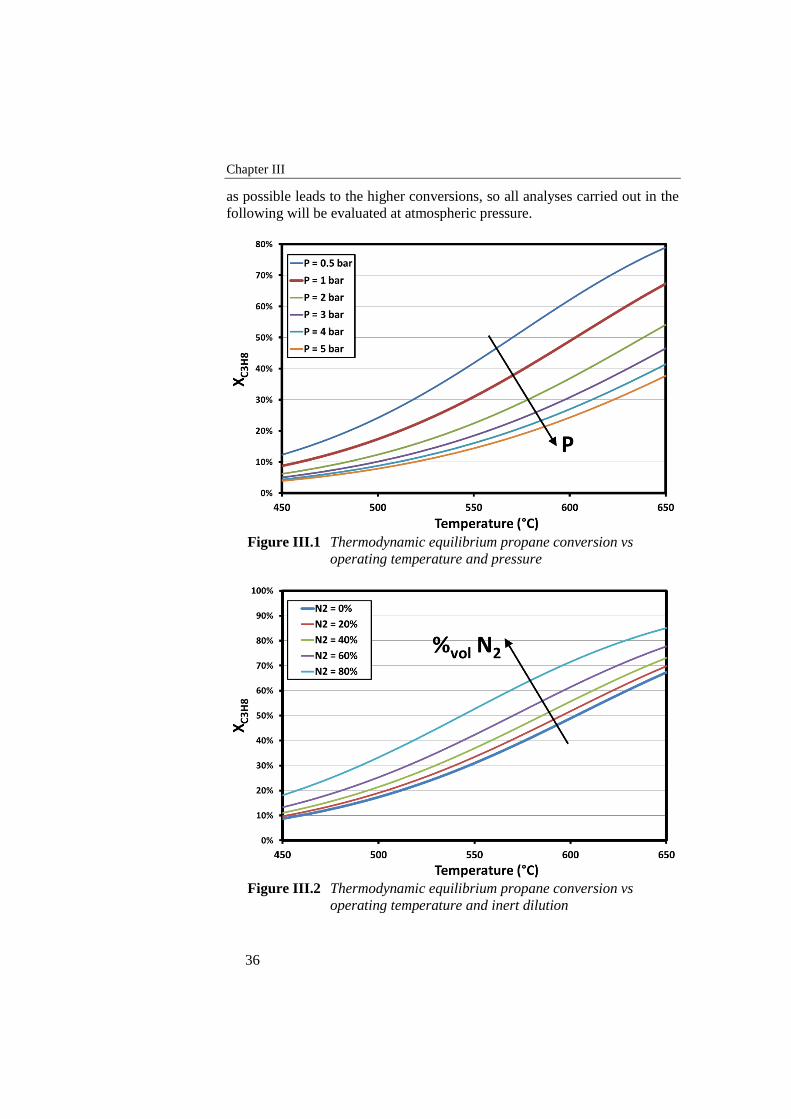
Chapter III
36
as possible leads to the higher conversions, so all analyses carried out in the
following will be evaluated at atmospheric pressure.
Figure III.1 Thermodynamic equilibrium propane conversion vs
operating temperature and pressure
Figure III.2 Thermodynamic equilibrium propane conversion vs
operating temperature and inert dilution
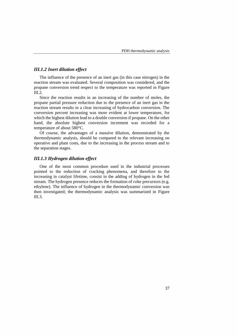
PDH thermodynamic analysis
37
III.1.2 Inert dilution effect
The influence of the presence of an inert gas (in this case nitrogen) in the
reaction stream was evaluated. Several composition was considered, and the
propane conversion trend respect to the temperature was reported in Figure
III.2.
Since the reaction results in an increasing of the number of moles, the
propane partial pressure reduction due to the presence of an inert gas in the
reaction stream results in a clear increasing of hydrocarbon conversion. The
conversion percent increasing was more evident at lower temperature, for
which the highest dilution lead to a double conversion if propane. On the other
hand, the absolute highest conversion increment was recorded for a
temperature of about 580°C.
Of course, the advantages of a massive dilution, demonstrated by the
thermodynamic analysis, should be compared to the relevant increasing on
operative and plant costs, due to the increasing in the process stream and to
the separation stages.
III.1.3 Hydrogen dilution effect
One of the most common procedure used in the industrial processes
pointed to the reduction of cracking phenomena, and therefore to the
increasing in catalyst lifetime, consist in the adding of hydrogen in the fed
stream. The hydrogen presence reduces the formation of coke precursors (e.g.
ethylene). The influence of hydrogen in the thermodynamic conversion was
then investigated; the thermodynamic analysis was summarized in Figure
III.3.
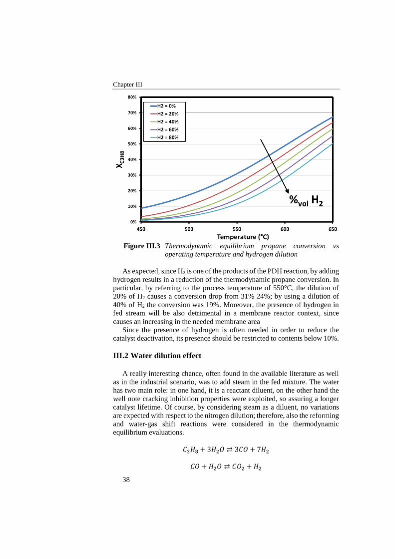
Chapter III
38
Figure III.3 Thermodynamic equilibrium propane conversion vs
operating temperature and hydrogen dilution
As expected, since H2 is one of the products of the PDH reaction, by adding
hydrogen results in a reduction of the thermodynamic propane conversion. In
particular, by referring to the process temperature of 550°C, the dilution of
20% of H2 causes a conversion drop from 31% 24%; by using a dilution of
40% of H2 the conversion was 19%. Moreover, the presence of hydrogen in
fed stream will be also detrimental in a membrane reactor context, since
causes an increasing in the needed membrane area
Since the presence of hydrogen is often needed in order to reduce the
catalyst deactivation, its presence should be restricted to contents below 10%.
III.2 Water dilution effect
A really interesting chance, often found in the available literature as well
as in the industrial scenario, was to add steam in the fed mixture. The water
has two main role: in one hand, it is a reactant diluent, on the other hand the
well note cracking inhibition properties were exploited, so assuring a longer
catalyst lifetime. Of course, by considering steam as a diluent, no variations
are expected with respect to the nitrogen dilution; therefore, also the reforming
and water-gas shift reactions were considered in the thermodynamic
equilibrium evaluations.
𝐶3𝐻8 + 3𝐻2𝑂 ⇄ 3𝐶𝑂 + 7𝐻2
𝐶𝑂 + 𝐻2𝑂 ⇄ 𝐶𝑂2 + 𝐻2
PDH thermodynamic analysis
39
Therefore, beside the propane conversion, also selectivity to propylene
should be taken in account. The selectivity was defined as
𝑆𝐶3𝐻6=
𝑁𝐶3𝐻6
𝑜𝑢𝑡
𝑁𝐶3𝐻8
𝑖𝑛 − 𝑁𝐶3𝐻8
𝑜𝑢𝑡
where 𝑁𝐶3𝐻6
𝑜𝑢𝑡 are the produced moles of propylene, 𝑁𝐶3𝐻8
𝑖𝑛 are the fed moles of
propane and 𝑁𝐶3𝐻8
𝑜𝑢𝑡 are the non-converted moles of propane.
Thermodynamic analysis was carried out by varying water content in the
reactants stream, and by considering several operating temperature values at
atmospheric pressure. The thermodynamic propane conversion was analysed.
The main result highlighted in the Figure III.4 is of course the initial
decreasing trend of propane conversion by adding water, for each investigated
operating temperature. The reduction in propane conversion is more evident
for the lowest temperatures, while for the highest temperature the lack of
conversion is extended for a wider water content range. The effect should be
due to the reforming reactions, that even in one hand results in a propane
conversion, in the other hand causes H2 production, that as observed had a
detrimental effect on hydrocarbon conversion. The dot-line fits for each
isotherm curve the points in which the wet conversion is equal to the dry
conversion. In a thermodynamic point of view, it is not convenient to operate
in conditions resulting on the left side of the dot line, since the adding of water
will lead (at the thermodynamic equilibrium conditions) to a less propane
conversion.
For a wet fed stream, it is clearly important to understand the
thermodynamic trend of selectivity to propylene, resumed in the Figure III.5.
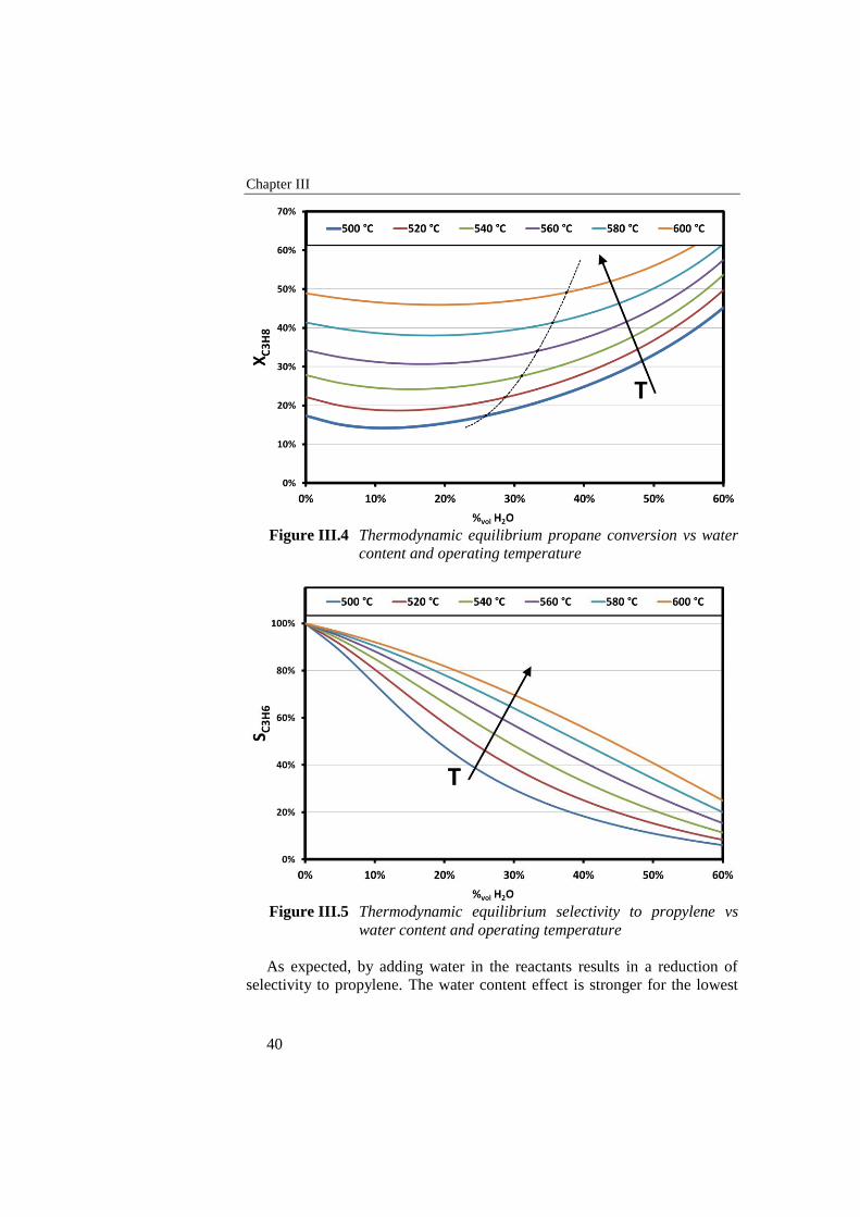
Chapter III
40
Figure III.4 Thermodynamic equilibrium propane conversion vs water
content and operating temperature
Figure III.5 Thermodynamic equilibrium selectivity to propylene vs
water content and operating temperature
As expected, by adding water in the reactants results in a reduction of
selectivity to propylene. The water content effect is stronger for the lowest
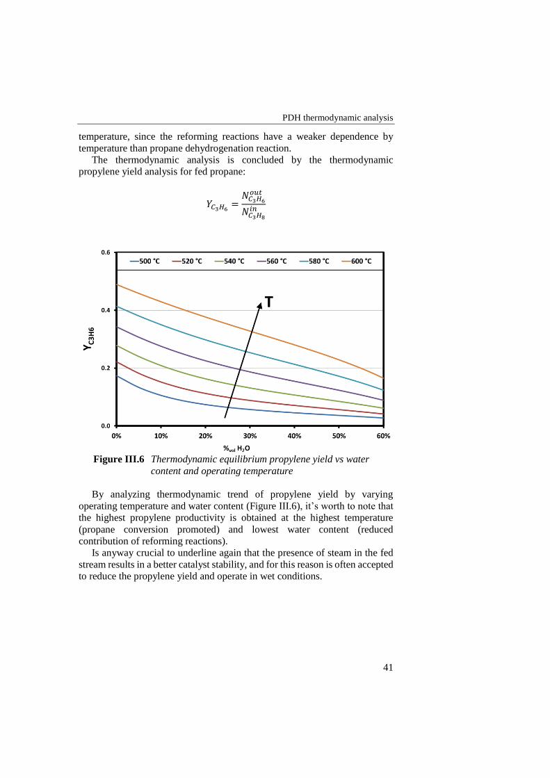
PDH thermodynamic analysis
41
temperature, since the reforming reactions have a weaker dependence by
temperature than propane dehydrogenation reaction.
The thermodynamic analysis is concluded by the thermodynamic
propylene yield analysis for fed propane:
𝑌𝐶3𝐻6=
𝑁𝐶3𝐻6
𝑜𝑢𝑡
𝑁𝐶3𝐻8
𝑖𝑛
Figure III.6 Thermodynamic equilibrium propylene yield vs water
content and operating temperature
By analyzing thermodynamic trend of propylene yield by varying
operating temperature and water content (Figure III.6), it’s worth to note that
the highest propylene productivity is obtained at the highest temperature
(propane conversion promoted) and lowest water content (reduced
contribution of reforming reactions).
Is anyway crucial to underline again that the presence of steam in the fed
stream results in a better catalyst stability, and for this reason is often accepted
to reduce the propylene yield and operate in wet conditions.

43
Experimental apparatuses
IV.1 Auto-thermal Reforming
Experimental tests are conducted in a laboratory scale plant designed and
realized in the Industrial Engineering Department of University of Salerno.
The reaction system consists in three main modules: a thermal exchange
module in which reactants are pre-heated by heat recovery from exhaust gas,
a mixing module in which a homogeneous mixture of reactants was realized
and a reaction module in which reactants pass through the catalytic bed and
ATR reaction occurs.
IV.1.1 Reactants delivery system
In experimental tests, methane as fuel, air instead of oxygen, and distilled
water were used. Methane and air, supplied from Sol S.p.a., are delivered to
the system by means of mass flow controllers (Brooks); distilled water is
stocked in a 10 atm pressurized vessel, and delivered by means of a Coriolis
based mass flow controller (Quantim, Brooks): air and water are fed to the
heat recovery module for pre-heating, while methane are fed directly in the
reaction module. In this way, the risk of methane cracking is very small:
methane is fed in the mixing chamber at room temperature, where is mixed
with superheated steam and air, thus avoiding coke formation risk.
IV.1.2 Heat exchange module
Heat recovery from reactants streams was achieved by means of heat
exchangers, that consists of a series of rectangular coils realized with stainless
steel tubes (o.d. 1/8”, thickness 0,74mm) and mounted in parallel ways on two
manifolds (in and out) in order to distribute uniformly the reactants stream in
all coils (Figure IV.1).
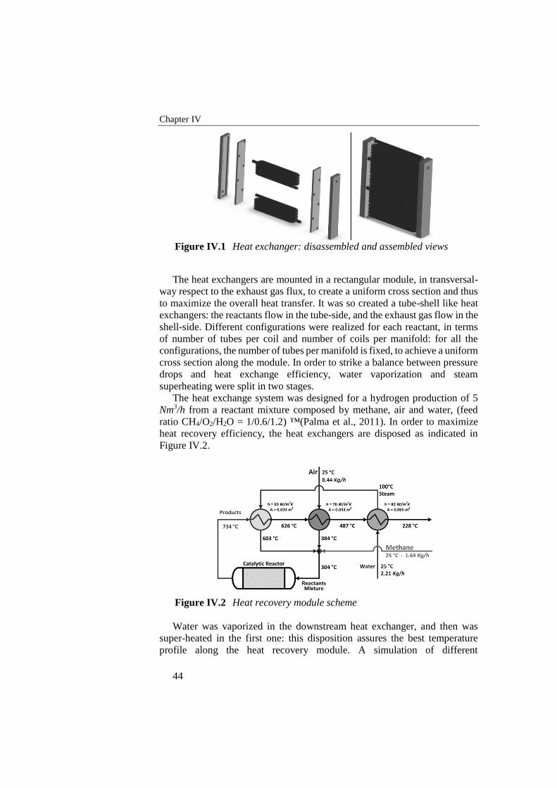
Chapter IV
44
Figure IV.1 Heat exchanger: disassembled and assembled views
The heat exchangers are mounted in a rectangular module, in transversal-
way respect to the exhaust gas flux, to create a uniform cross section and thus
to maximize the overall heat transfer. It was so created a tube-shell like heat
exchangers: the reactants flow in the tube-side, and the exhaust gas flow in the
shell-side. Different configurations were realized for each reactant, in terms
of number of tubes per coil and number of coils per manifold: for all the
configurations, the number of tubes per manifold is fixed, to achieve a uniform
cross section along the module. In order to strike a balance between pressure
drops and heat exchange efficiency, water vaporization and steam
superheating were split in two stages.
The heat exchange system was designed for a hydrogen production of 5
Nm3/h from a reactant mixture composed by methane, air and water, (feed
ratio CH4/O2/H2O = 1/0.6/1.2) ™(Palma et al., 2011). In order to maximize
heat recovery efficiency, the heat exchangers are disposed as indicated in
Figure IV.2.
Figure IV.2 Heat recovery module scheme
Water was vaporized in the downstream heat exchanger, and then was
super-heated in the first one: this disposition assures the best temperature
profile along the heat recovery module. A simulation of different
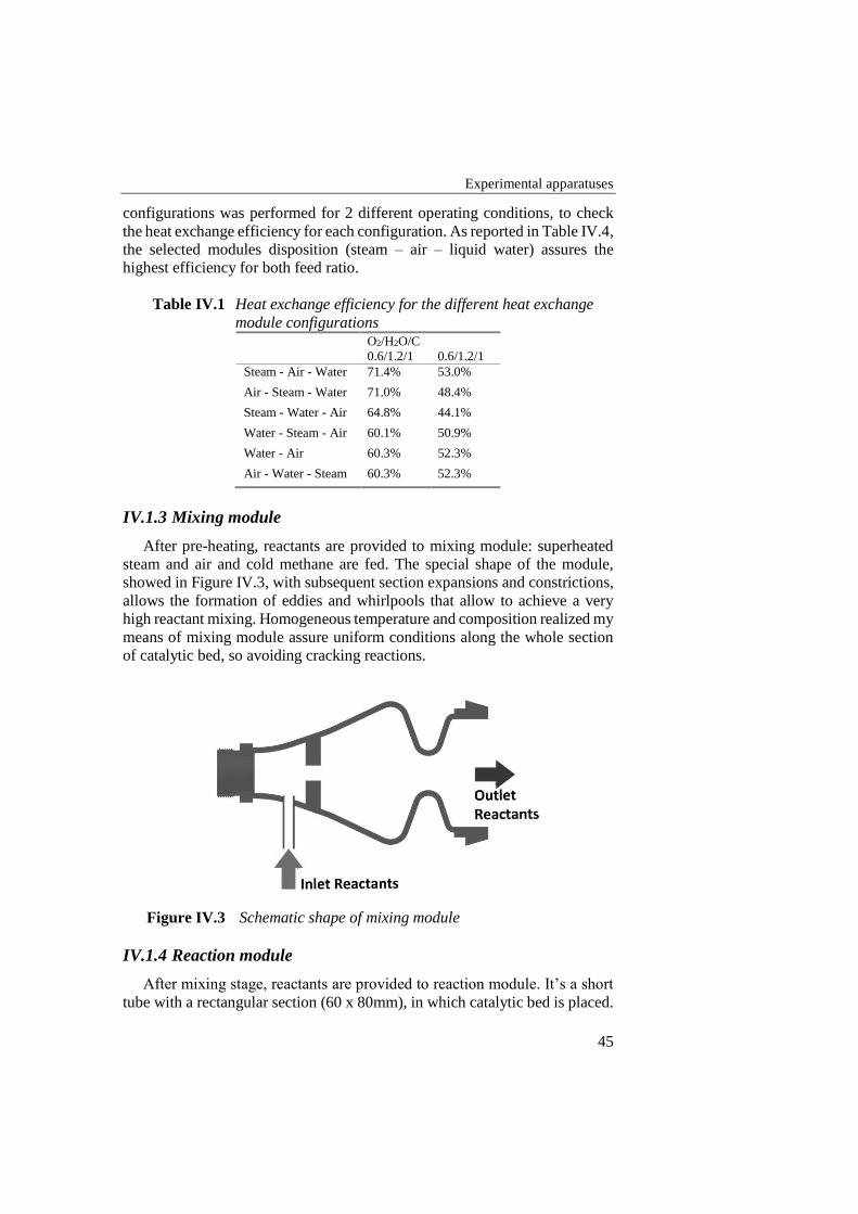
Experimental apparatuses
45
configurations was performed for 2 different operating conditions, to check
the heat exchange efficiency for each configuration. As reported in Table IV.4,
the selected modules disposition (steam – air – liquid water) assures the
highest efficiency for both feed ratio.
Table IV.1 Heat exchange efficiency for the different heat exchange
module configurations
O2/H2O/C
0.6/1.2/1 0.6/1.2/1
Steam - Air - Water 71.4% 53.0%
Air - Steam - Water 71.0% 48.4%
Steam - Water - Air 64.8% 44.1%
Water - Steam - Air 60.1% 50.9%
Water - Air 60.3% 52.3%
Air - Water - Steam 60.3% 52.3%
IV.1.3 Mixing module
After pre-heating, reactants are provided to mixing module: superheated
steam and air and cold methane are fed. The special shape of the module,
showed in Figure IV.3, with subsequent section expansions and constrictions,
allows the formation of eddies and whirlpools that allow to achieve a very
high reactant mixing. Homogeneous temperature and composition realized my
means of mixing module assure uniform conditions along the whole section
of catalytic bed, so avoiding cracking reactions.
Figure IV.3 Schematic shape of mixing module
IV.1.4 Reaction module
After mixing stage, reactants are provided to reaction module. It’s a short
tube with a rectangular section (60 x 80mm), in which catalytic bed is placed.
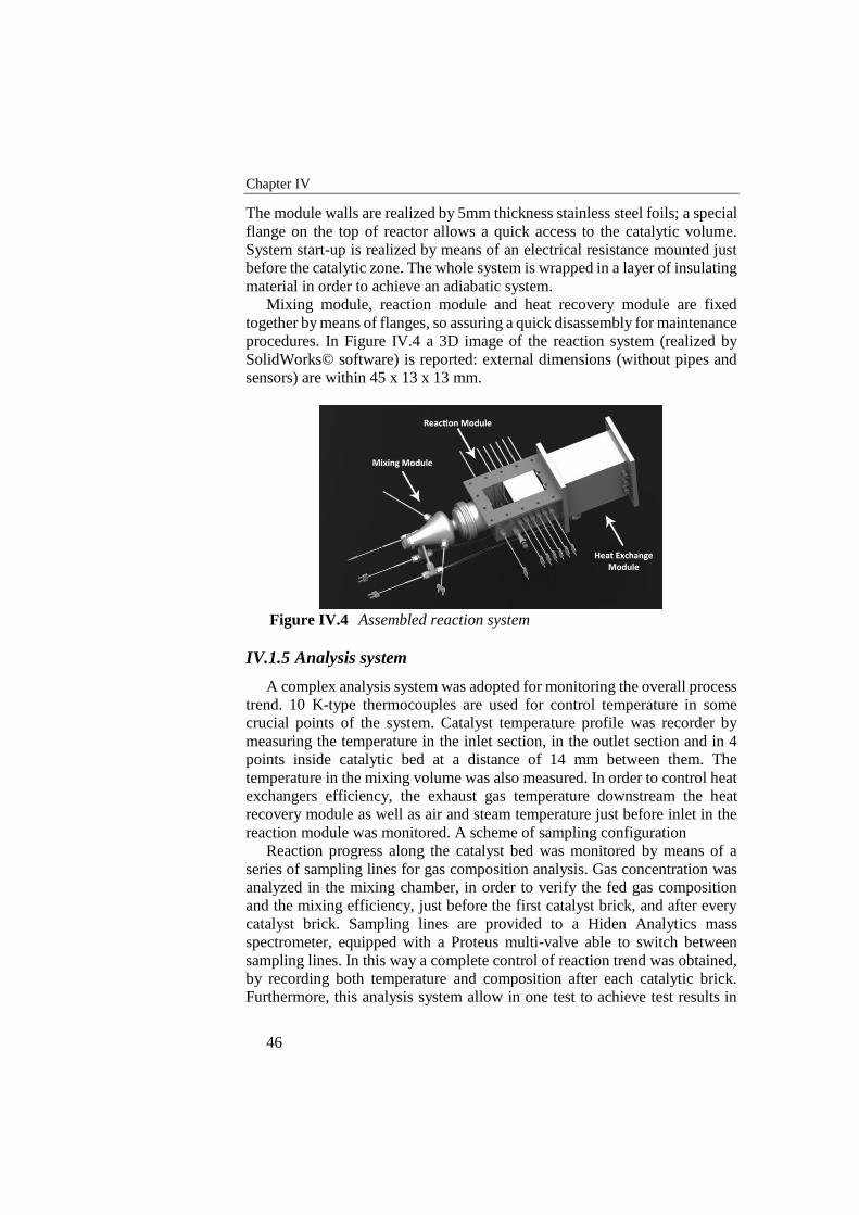
Chapter IV
46
The module walls are realized by 5mm thickness stainless steel foils; a special
flange on the top of reactor allows a quick access to the catalytic volume.
System start-up is realized by means of an electrical resistance mounted just
before the catalytic zone. The whole system is wrapped in a layer of insulating
material in order to achieve an adiabatic system.
Mixing module, reaction module and heat recovery module are fixed
together by means of flanges, so assuring a quick disassembly for maintenance
procedures. In Figure IV.4 a 3D image of the reaction system (realized by
SolidWorks© software) is reported: external dimensions (without pipes and
sensors) are within 45 x 13 x 13 mm.
Figure IV.4 Assembled reaction system
IV.1.5 Analysis system
A complex analysis system was adopted for monitoring the overall process
trend. 10 K-type thermocouples are used for control temperature in some
crucial points of the system. Catalyst temperature profile was recorder by
measuring the temperature in the inlet section, in the outlet section and in 4
points inside catalytic bed at a distance of 14 mm between them. The
temperature in the mixing volume was also measured. In order to control heat
exchangers efficiency, the exhaust gas temperature downstream the heat
recovery module as well as air and steam temperature just before inlet in the
reaction module was monitored. A scheme of sampling configuration
Reaction progress along the catalyst bed was monitored by means of a
series of sampling lines for gas composition analysis. Gas concentration was
analyzed in the mixing chamber, in order to verify the fed gas composition
and the mixing efficiency, just before the first catalyst brick, and after every
catalyst brick. Sampling lines are provided to a Hiden Analytics mass
spectrometer, equipped with a Proteus multi-valve able to switch between
sampling lines. In this way a complete control of reaction trend was obtained,
by recording both temperature and composition after each catalytic brick.
Furthermore, this analysis system allow in one test to achieve test results in
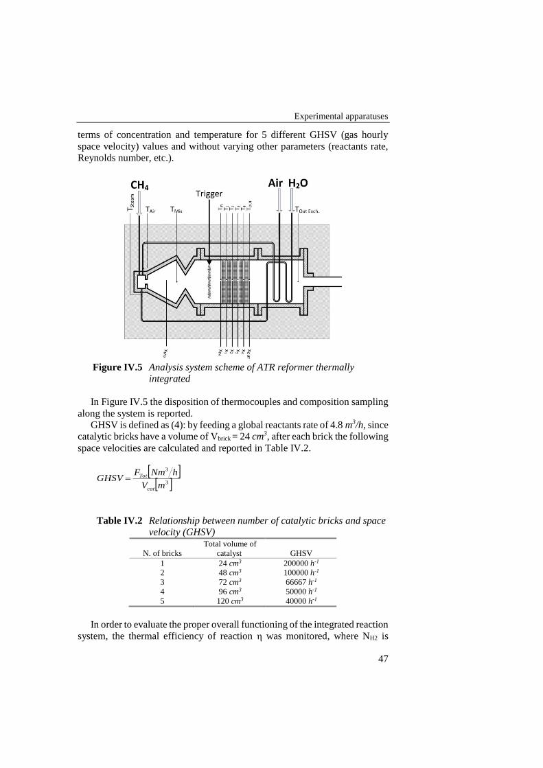
Experimental apparatuses
47
terms of concentration and temperature for 5 different GHSV (gas hourly
space velocity) values and without varying other parameters (reactants rate,
Reynolds number, etc.).
Figure IV.5 Analysis system scheme of ATR reformer thermally
integrated
In Figure IV.5 the disposition of thermocouples and composition sampling
along the system is reported.
GHSV is defined as (4): by feeding a global reactants rate of 4.8 m3/h, since
catalytic bricks have a volume of Vbrick = 24 cm3, after each brick the following
space velocities are calculated and reported in Table IV.2.
3
3
mV
hNmFGHSV
cat
Tot
Table IV.2 Relationship between number of catalytic bricks and space
velocity (GHSV)
N. of bricks
Total volume of
catalyst GHSV
1 24 cm3 200000 h-1
2 48 cm3 100000 h-1
3 72 cm3 66667 h-1
4 96 cm3 50000 h-1
5 120 cm3 40000 h-1
In order to evaluate the proper overall functioning of the integrated reaction
system, the thermal efficiency of reaction η was monitored, where NH2 is
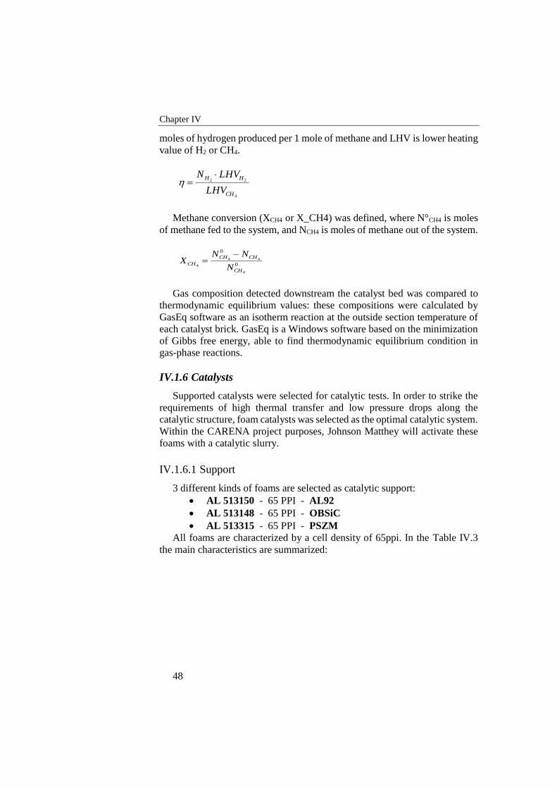
Chapter IV
48
moles of hydrogen produced per 1 mole of methane and LHV is lower heating
value of H2 or CH4.
4
22
CH
HH
LHV
LHVN
Methane conversion (XCH4 or X_CH4) was defined, where N°CH4 is moles
of methane fed to the system, and NCH4 is moles of methane out of the system.
0
0
4
44
4
CH
CHCH
CHN
NNX
Gas composition detected downstream the catalyst bed was compared to
thermodynamic equilibrium values: these compositions were calculated by
GasEq software as an isotherm reaction at the outside section temperature of
each catalyst brick. GasEq is a Windows software based on the minimization
of Gibbs free energy, able to find thermodynamic equilibrium condition in
gas-phase reactions.
IV.1.6 Catalysts
Supported catalysts were selected for catalytic tests. In order to strike the
requirements of high thermal transfer and low pressure drops along the
catalytic structure, foam catalysts was selected as the optimal catalytic system.
Within the CARENA project purposes, Johnson Matthey will activate these
foams with a catalytic slurry.
IV.1.6.1 Support
3 different kinds of foams are selected as catalytic support:
AL 513150 - 65 PPI - AL92
AL 513148 - 65 PPI - OBSiC
AL 513315 - 65 PPI - PSZM
All foams are characterized by a cell density of 65ppi. In the Table IV.3
the main characteristics are summarized:
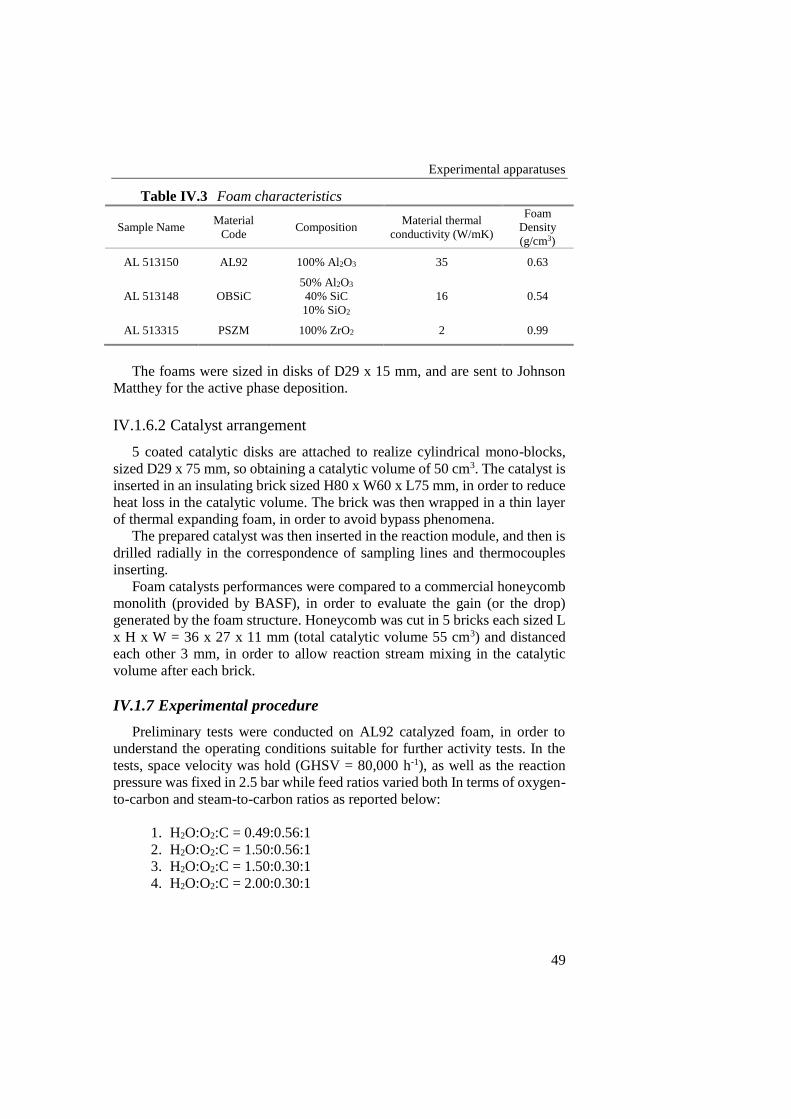
Experimental apparatuses
49
Table IV.3 Foam characteristics
Sample Name Material
Code Composition
Material thermal
conductivity (W/mK)
Foam
Density
(g/cm3)
AL 513150 AL92 100% Al2O3 35 0.63
AL 513148 OBSiC
50% Al2O3
40% SiC
10% SiO2
16 0.54
AL 513315 PSZM 100% ZrO2 2 0.99
The foams were sized in disks of D29 x 15 mm, and are sent to Johnson
Matthey for the active phase deposition.
IV.1.6.2 Catalyst arrangement
5 coated catalytic disks are attached to realize cylindrical mono-blocks,
sized D29 x 75 mm, so obtaining a catalytic volume of 50 cm3. The catalyst is
inserted in an insulating brick sized H80 x W60 x L75 mm, in order to reduce
heat loss in the catalytic volume. The brick was then wrapped in a thin layer
of thermal expanding foam, in order to avoid bypass phenomena.
The prepared catalyst was then inserted in the reaction module, and then is
drilled radially in the correspondence of sampling lines and thermocouples
inserting.
Foam catalysts performances were compared to a commercial honeycomb
monolith (provided by BASF), in order to evaluate the gain (or the drop)
generated by the foam structure. Honeycomb was cut in 5 bricks each sized L
x H x W = 36 x 27 x 11 mm (total catalytic volume 55 cm3) and distanced
each other 3 mm, in order to allow reaction stream mixing in the catalytic
volume after each brick.
IV.1.7 Experimental procedure
Preliminary tests were conducted on AL92 catalyzed foam, in order to
understand the operating conditions suitable for further activity tests. In the
tests, space velocity was hold (GHSV = 80,000 h-1), as well as the reaction
pressure was fixed in 2.5 bar while feed ratios varied both In terms of oxygen-
to-carbon and steam-to-carbon ratios as reported below:
1. H2O:O2:C = 0.49:0.56:1
2. H2O:O2:C = 1.50:0.56:1
3. H2O:O2:C = 1.50:0.30:1
4. H2O:O2:C = 2.00:0.30:1

Chapter IV
50
Activity tests were then repeated on the honeycomb and the 3 different
foam samples by fixing the feed ratio (H2O:O2:C = 0.49:0.56:1) and operating
pressure (p = 2.5 bar) and by varying the feed flow rate (GHSV = 80,000 –
120,000 h-1).
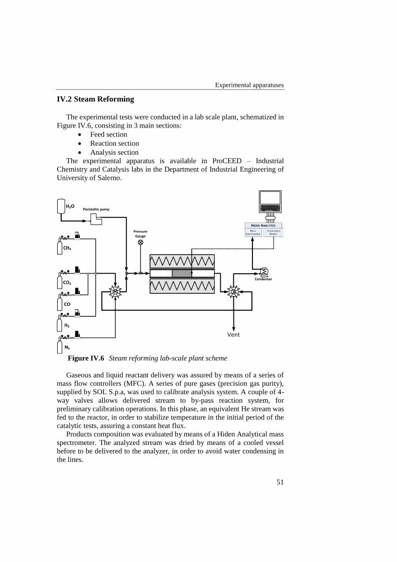
Experimental apparatuses
51
IV.2 Steam Reforming
The experimental tests were conducted in a lab scale plant, schematized in
Figure IV.6, consisting in 3 main sections:
Feed section
Reaction section
Analysis section
The experimental apparatus is available in ProCEED – Industrial
Chemistry and Catalysis labs in the Department of Industrial Engineering of
University of Salerno.
Figure IV.6 Steam reforming lab-scale plant scheme
Gaseous and liquid reactant delivery was assured by means of a series of
mass flow controllers (MFC). A series of pure gases (precision gas purity),
supplied by SOL S.p.a, was used to calibrate analysis system. A couple of 4-
way valves allows delivered stream to by-pass reaction system, for
preliminary calibration operations. In this phase, an equivalent He stream was
fed to the reactor, in order to stabilize temperature in the initial period of the
catalytic tests, assuring a constant heat flux.
Products composition was evaluated by means of a Hiden Analytical mass
spectrometer. The analyzed stream was dried by means of a cooled vessel
before to be delivered to the analyzer, in order to avoid water condensing in
the lines.
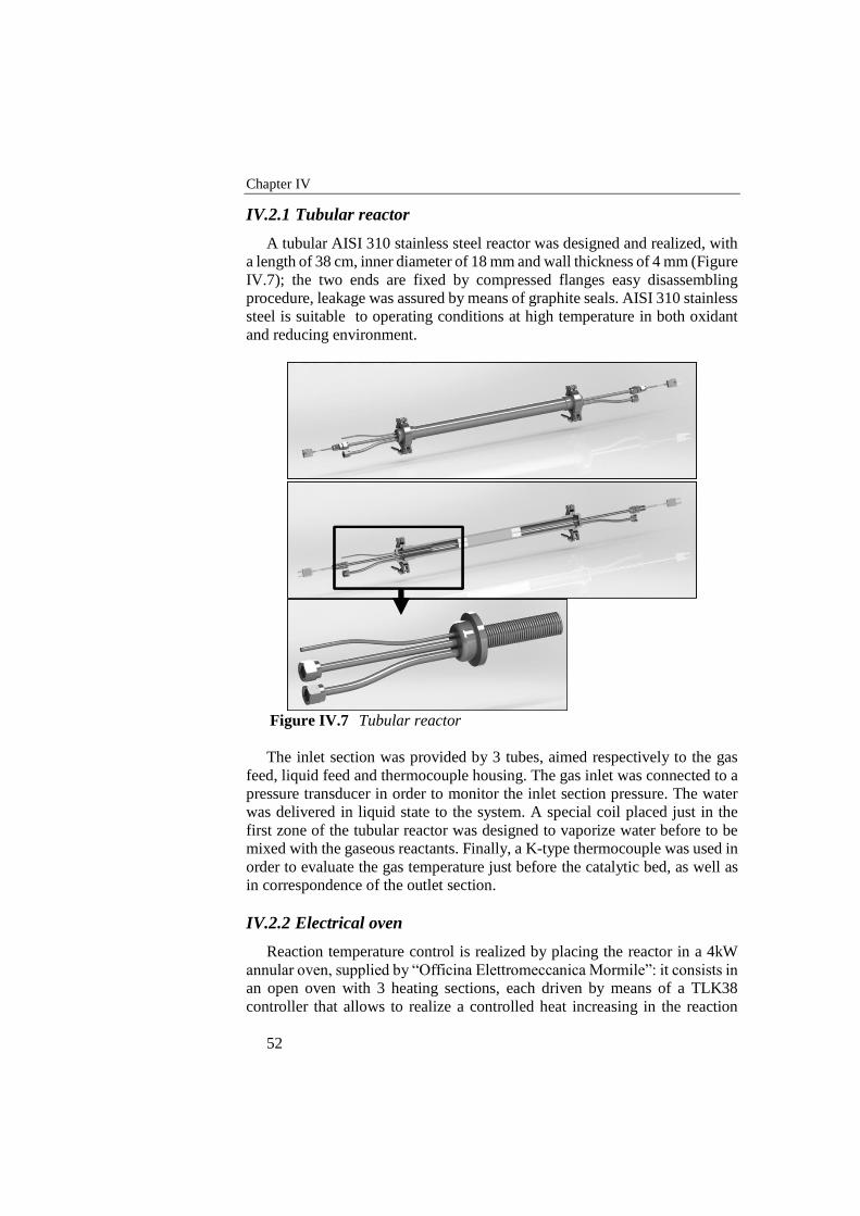
Chapter IV
52
IV.2.1 Tubular reactor
A tubular AISI 310 stainless steel reactor was designed and realized, with
a length of 38 cm, inner diameter of 18 mm and wall thickness of 4 mm (Figure
IV.7); the two ends are fixed by compressed flanges easy disassembling
procedure, leakage was assured by means of graphite seals. AISI 310 stainless
steel is suitable to operating conditions at high temperature in both oxidant
and reducing environment.
Figure IV.7 Tubular reactor
The inlet section was provided by 3 tubes, aimed respectively to the gas
feed, liquid feed and thermocouple housing. The gas inlet was connected to a
pressure transducer in order to monitor the inlet section pressure. The water
was delivered in liquid state to the system. A special coil placed just in the
first zone of the tubular reactor was designed to vaporize water before to be
mixed with the gaseous reactants. Finally, a K-type thermocouple was used in
order to evaluate the gas temperature just before the catalytic bed, as well as
in correspondence of the outlet section.
IV.2.2 Electrical oven
Reaction temperature control is realized by placing the reactor in a 4kW
annular oven, supplied by “Officina Elettromeccanica Mormile”: it consists in
an open oven with 3 heating sections, each driven by means of a TLK38
controller that allows to realize a controlled heat increasing in the reaction
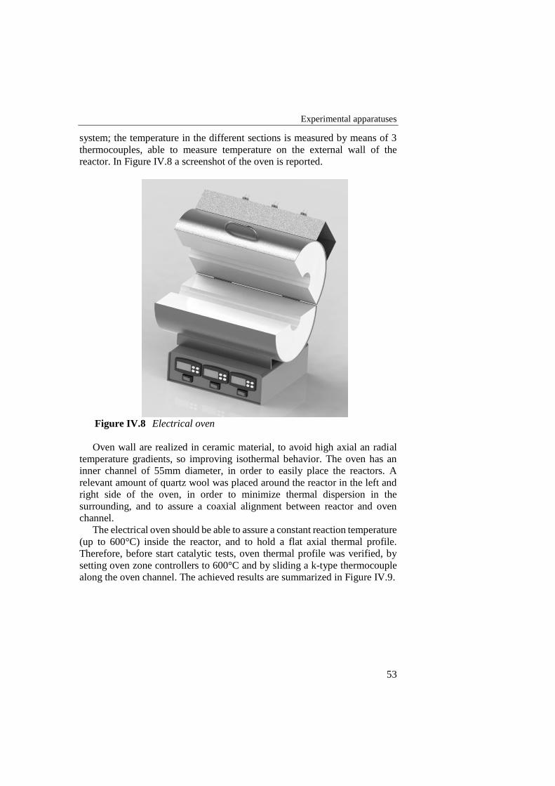
Experimental apparatuses
53
system; the temperature in the different sections is measured by means of 3
thermocouples, able to measure temperature on the external wall of the
reactor. In Figure IV.8 a screenshot of the oven is reported.
Figure IV.8 Electrical oven
Oven wall are realized in ceramic material, to avoid high axial an radial
temperature gradients, so improving isothermal behavior. The oven has an
inner channel of 55mm diameter, in order to easily place the reactors. A
relevant amount of quartz wool was placed around the reactor in the left and
right side of the oven, in order to minimize thermal dispersion in the
surrounding, and to assure a coaxial alignment between reactor and oven
channel.
The electrical oven should be able to assure a constant reaction temperature
(up to 600°C) inside the reactor, and to hold a flat axial thermal profile.
Therefore, before start catalytic tests, oven thermal profile was verified, by
setting oven zone controllers to 600°C and by sliding a k-type thermocouple
along the oven channel. The achieved results are summarized in Figure IV.9.
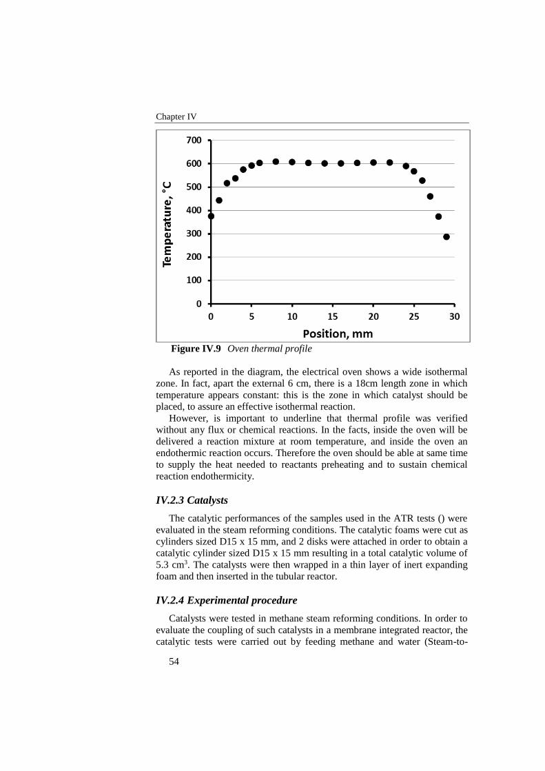
Chapter IV
54
Figure IV.9 Oven thermal profile
As reported in the diagram, the electrical oven shows a wide isothermal
zone. In fact, apart the external 6 cm, there is a 18cm length zone in which
temperature appears constant: this is the zone in which catalyst should be
placed, to assure an effective isothermal reaction.
However, is important to underline that thermal profile was verified
without any flux or chemical reactions. In the facts, inside the oven will be
delivered a reaction mixture at room temperature, and inside the oven an
endothermic reaction occurs. Therefore the oven should be able at same time
to supply the heat needed to reactants preheating and to sustain chemical
reaction endothermicity.
IV.2.3 Catalysts
The catalytic performances of the samples used in the ATR tests () were
evaluated in the steam reforming conditions. The catalytic foams were cut as
cylinders sized D15 x 15 mm, and 2 disks were attached in order to obtain a
catalytic cylinder sized D15 x 15 mm resulting in a total catalytic volume of
5.3 cm3. The catalysts were then wrapped in a thin layer of inert expanding
foam and then inserted in the tubular reactor.
IV.2.4 Experimental procedure
Catalysts were tested in methane steam reforming conditions. In order to
evaluate the coupling of such catalysts in a membrane integrated reactor, the
catalytic tests were carried out by feeding methane and water (Steam-to-

Experimental apparatuses
55
Carbon ratio = 3 and 4) at 550°C. Furthermore, the influence of operating
pressure on the catalyst performances was also evaluated. The effect of
reactants rate was also investigated, by varying GHSV value between 10,000
and 40,000 h-1.
The performances analysis was completed by comparing results with
thermodynamic equilibrium compositions.
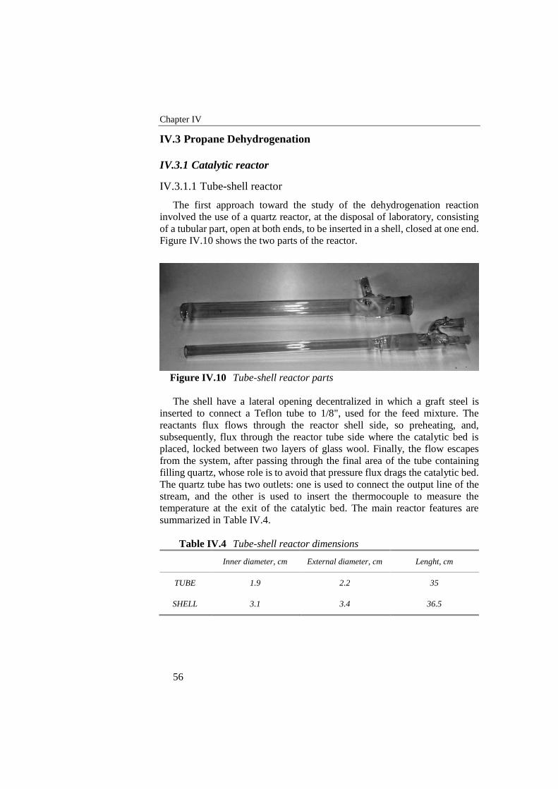
Chapter IV
56
IV.3 Propane Dehydrogenation
IV.3.1 Catalytic reactor
IV.3.1.1 Tube-shell reactor
The first approach toward the study of the dehydrogenation reaction
involved the use of a quartz reactor, at the disposal of laboratory, consisting
of a tubular part, open at both ends, to be inserted in a shell, closed at one end.
Figure IV.10 shows the two parts of the reactor.
Figure IV.10 Tube-shell reactor parts
The shell have a lateral opening decentralized in which a graft steel is
inserted to connect a Teflon tube to 1/8", used for the feed mixture. The
reactants flux flows through the reactor shell side, so preheating, and,
subsequently, flux through the reactor tube side where the catalytic bed is
placed, locked between two layers of glass wool. Finally, the flow escapes
from the system, after passing through the final area of the tube containing
filling quartz, whose role is to avoid that pressure flux drags the catalytic bed.
The quartz tube has two outlets: one is used to connect the output line of the
stream, and the other is used to insert the thermocouple to measure the
temperature at the exit of the catalytic bed. The main reactor features are
summarized in Table IV.4.
Table IV.4 Tube-shell reactor dimensions
Inner diameter, cm External diameter, cm Lenght, cm
TUBE 1.9 2.2 35
SHELL 3.1 3.4 36.5
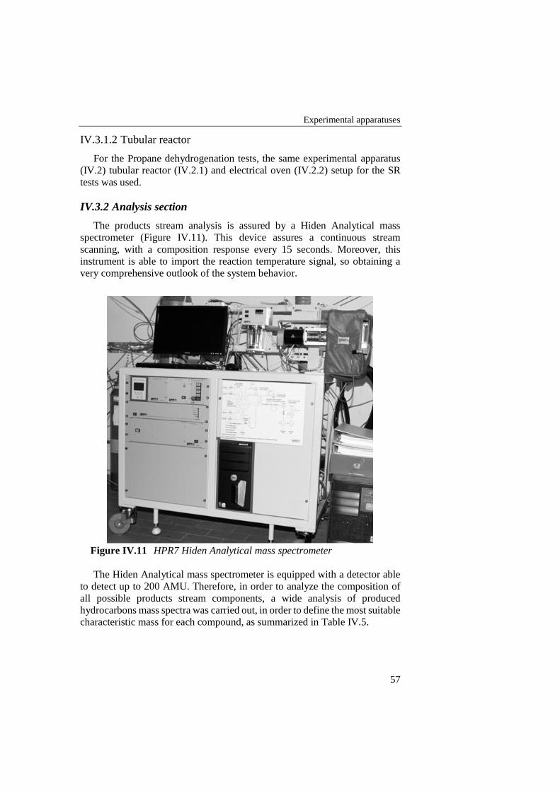
Experimental apparatuses
57
IV.3.1.2 Tubular reactor
For the Propane dehydrogenation tests, the same experimental apparatus
(IV.2) tubular reactor (IV.2.1) and electrical oven (IV.2.2) setup for the SR
tests was used.
IV.3.2 Analysis section
The products stream analysis is assured by a Hiden Analytical mass
spectrometer (Figure IV.11). This device assures a continuous stream
scanning, with a composition response every 15 seconds. Moreover, this
instrument is able to import the reaction temperature signal, so obtaining a
very comprehensive outlook of the system behavior.
Figure IV.11 HPR7 Hiden Analytical mass spectrometer
The Hiden Analytical mass spectrometer is equipped with a detector able
to detect up to 200 AMU. Therefore, in order to analyze the composition of
all possible products stream components, a wide analysis of produced
hydrocarbons mass spectra was carried out, in order to define the most suitable
characteristic mass for each compound, as summarized in Table IV.5.
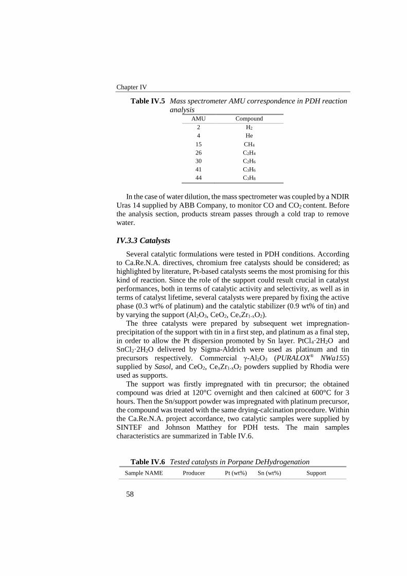
Chapter IV
58
Table IV.5 Mass spectrometer AMU correspondence in PDH reaction
analysis AMU Compound
2 H2
4 He
15 CH4
26 C2H4
30 C2H6
41 C3H6
44 C3H8
In the case of water dilution, the mass spectrometer was coupled by a NDIR
Uras 14 supplied by ABB Company, to monitor CO and CO2 content. Before
the analysis section, products stream passes through a cold trap to remove
water.
IV.3.3 Catalysts
Several catalytic formulations were tested in PDH conditions. According
to Ca.Re.N.A. directives, chromium free catalysts should be considered; as
highlighted by literature, Pt-based catalysts seems the most promising for this
kind of reaction. Since the role of the support could result crucial in catalyst
performances, both in terms of catalytic activity and selectivity, as well as in
terms of catalyst lifetime, several catalysts were prepared by fixing the active
phase (0.3 wt% of platinum) and the catalytic stabilizer (0.9 wt% of tin) and
by varying the support (Al2O3, CeO2, CexZr1-xO2).
The three catalysts were prepared by subsequent wet impregnation-
precipitation of the support with tin in a first step, and platinum as a final step,
in order to allow the Pt dispersion promoted by Sn layer. PtCl4·2H2O and
SnCl2·2H2O delivered by Sigma-Aldrich were used as platinum and tin
precursors respectively. Commercial γ-Al2O3 (PURALOX® NWa155)
supplied by Sasol, and CeO2, CexZr1-xO2 powders supplied by Rhodia were
used as supports.
The support was firstly impregnated with tin precursor; the obtained
compound was dried at 120°C overnight and then calcined at 600°C for 3
hours. Then the Sn/support powder was impregnated with platinum precursor,
the compound was treated with the same drying-calcination procedure. Within
the Ca.Re.N.A. project accordance, two catalytic samples were supplied by
SINTEF and Johnson Matthey for PDH tests. The main samples
characteristics are summarized in Table IV.6.
Table IV.6 Tested catalysts in Porpane DeHydrogenation
Sample NAME Producer Pt (wt%) Sn (wt%) Support
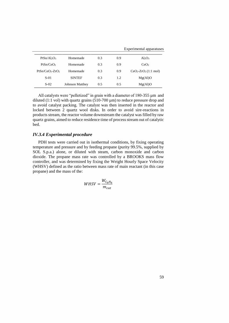
Experimental apparatuses
59
PtSn/Al2O3 Homemade 0.3 0.9 Al2O3
PtSn/CeO2 Homemade 0.3 0.9 CeO2
PtSn/CeO2-ZrO2 Homemade 0.3 0.9 CeO2-ZrO2 (1:1 mol)
S-01 SINTEF 0.3 1.2 Mg(Al)O
S-02 Johnson Matthey 0.5 0.5 Mg(Al)O
All catalysts were “pelletized” in grain with a diameter of 180-355 µm and
diluted (1:1 vol) with quartz grains (510-700 µm) to reduce pressure drop and
to avoid catalyst packing. The catalyst was then inserted in the reactor and
locked between 2 quartz wool disks. In order to avoid sire-reactions in
products stream, the reactor volume downstream the catalyst was filled by raw
quartz grains, aimed to reduce residence time of process stream out of catalytic
bed.
IV.3.4 Experimental procedure
PDH tests were carried out in isothermal conditions, by fixing operating
temperature and pressure and by feeding propane (purity 99.5%, supplied by
SOL S.p.a.) alone, or diluted with steam, carbon monoxide and carbon
dioxide. The propane mass rate was controlled by a BROOKS mass flow
controller, and was determined by fixing the Weight Hourly Space Velocity
(WHSV) defined as the ratio between mass rate of main reactant (in this case
propane) and the mass of the:
𝑊𝐻𝑆𝑉 =𝑊𝐶8𝐻8
𝑚𝑐𝑎𝑡

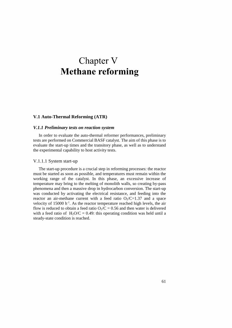
61
Methane reforming
V.1 Auto-Thermal Reforming (ATR)
V.1.1 Preliminary tests on reaction system
In order to evaluate the auto-thermal reformer performances, preliminary
tests are performed on Commercial BASF catalyst. The aim of this phase is to
evaluate the start-up times and the transitory phase, as well as to understand
the experimental capability to host activity tests.
V.1.1.1 System start-up
The start-up procedure is a crucial step in reforming processes: the reactor
must be started as soon as possible, and temperatures must remain within the
working range of the catalyst. In this phase, an excessive increase of
temperature may bring to the melting of monolith walls, so creating by-pass
phenomena and then a massive drop in hydrocarbon conversion. The start-up
was conducted by activating the electrical resistance, and feeding into the
reactor an air-methane current with a feed ratio O2/C=1.37 and a space
velocity of 15000 h-1. As the reactor temperature reached high levels, the air
flow is reduced to obtain a feed ratio O2/C = 0.56 and then water is delivered
with a feed ratio of H2O/C = 0.49: this operating condition was held until a
steady-state condition is reached.
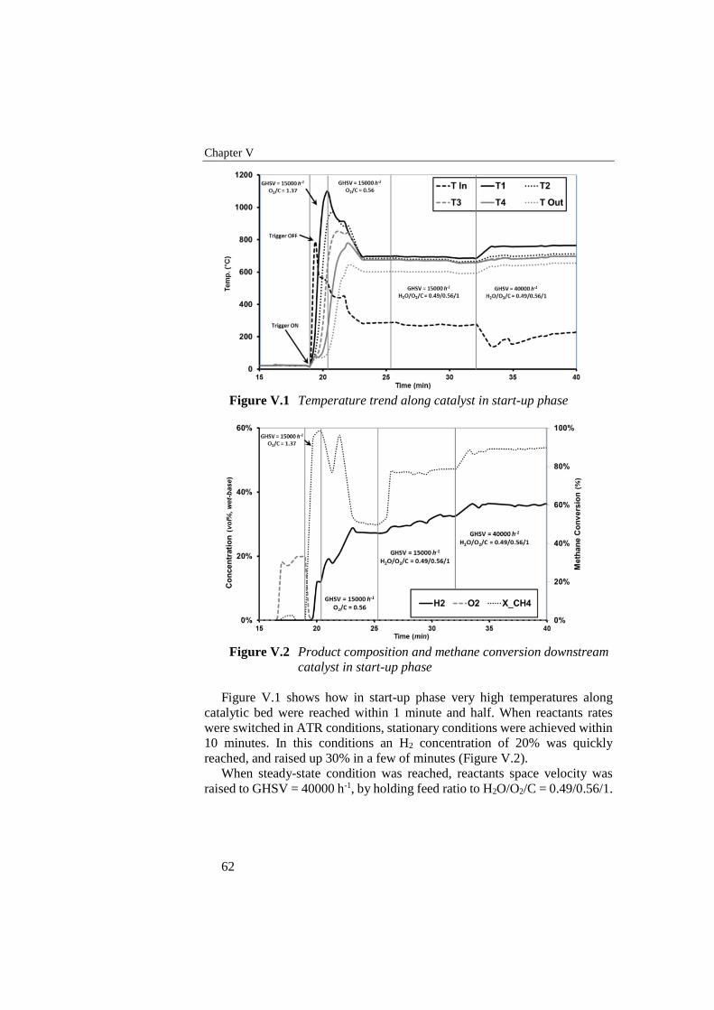
Chapter V
62
Figure V.1 Temperature trend along catalyst in start-up phase
Figure V.2 Product composition and methane conversion downstream
catalyst in start-up phase
Figure V.1 shows how in start-up phase very high temperatures along
catalytic bed were reached within 1 minute and half. When reactants rates
were switched in ATR conditions, stationary conditions were achieved within
10 minutes. In this conditions an H2 concentration of 20% was quickly
reached, and raised up 30% in a few of minutes (Figure V.2).
When steady-state condition was reached, reactants space velocity was
raised to GHSV = 40000 h-1, by holding feed ratio to H2O/O2/C = 0.49/0.56/1.
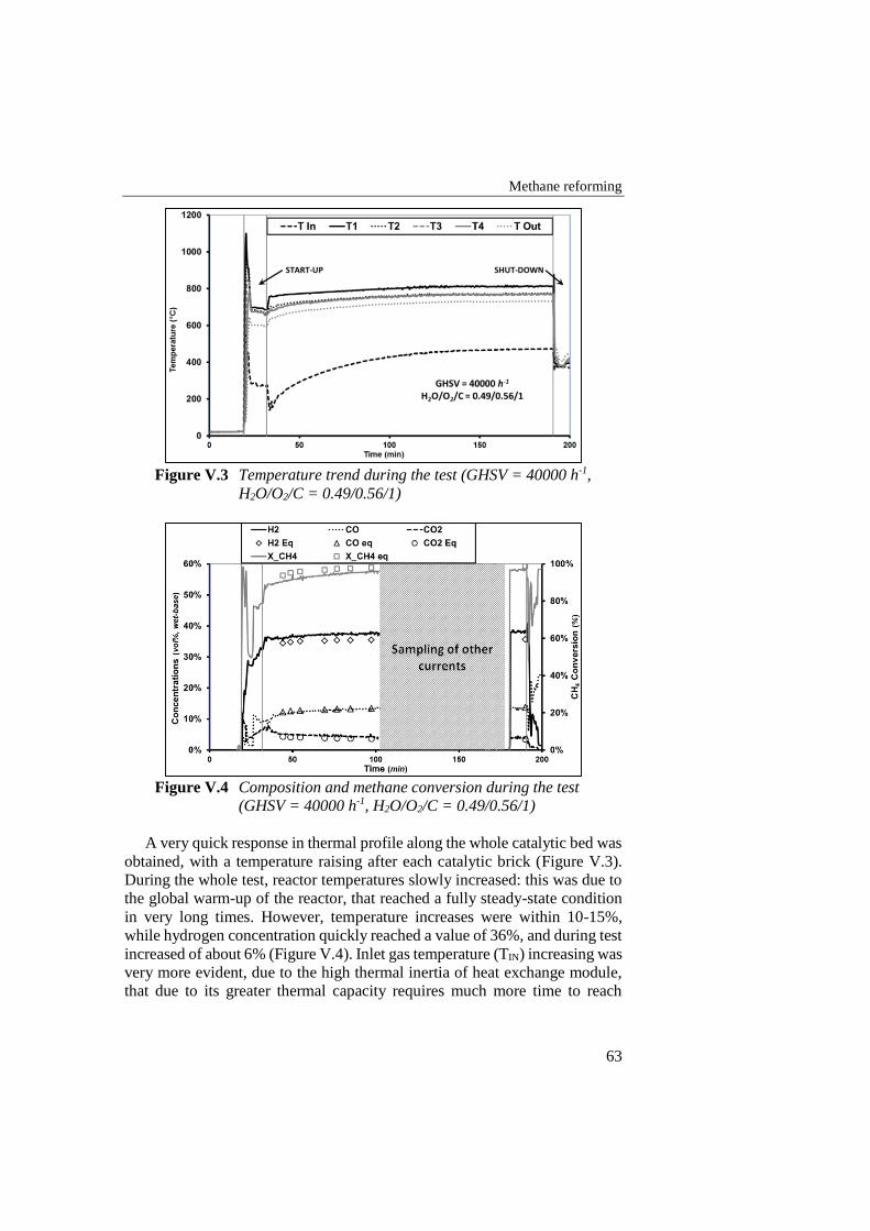
Methane reforming
63
Figure V.3 Temperature trend during the test (GHSV = 40000 h-1,
H2O/O2/C = 0.49/0.56/1)
Figure V.4 Composition and methane conversion during the test
(GHSV = 40000 h-1, H2O/O2/C = 0.49/0.56/1)
A very quick response in thermal profile along the whole catalytic bed was
obtained, with a temperature raising after each catalytic brick (Figure V.3).
During the whole test, reactor temperatures slowly increased: this was due to
the global warm-up of the reactor, that reached a fully steady-state condition
in very long times. However, temperature increases were within 10-15%,
while hydrogen concentration quickly reached a value of 36%, and during test
increased of about 6% (Figure V.4). Inlet gas temperature (TIN) increasing was
very more evident, due to the high thermal inertia of heat exchange module,
that due to its greater thermal capacity requires much more time to reach
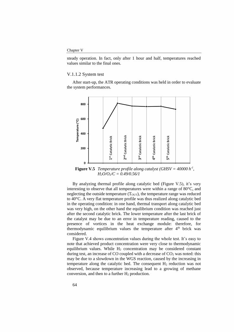
Chapter V
64
steady operation. In fact, only after 1 hour and half, temperatures reached
values similar to the final ones.
V.1.1.2 System test
After start-up, the ATR operating conditions was held in order to evaluate
the system performances.
Figure V.5 Temperature profile along catalyst (GHSV = 40000 h-1,
H2O/O2/C = 0.49/0.56/1
By analyzing thermal profile along catalytic bed (Figure V.5), it’s very
interesting to observe that all temperatures were within a range of 80°C, and
neglecting the outside temperature (TOUT), the temperature range was reduced
to 40°C. A very flat temperature profile was thus realized along catalytic bed
in the operating condition: in one hand, thermal transport along catalytic bed
was very high, on the other hand the equilibrium condition was reached just
after the second catalytic brick. The lower temperature after the last brick of
the catalyst may be due to an error in temperature reading, caused to the
presence of vortices in the heat exchange module: therefore, for
thermodynamic equilibrium values the temperature after 4th brick was
considered.
Figure V.4 shows concentration values during the whole test. It’s easy to
note that achieved product concentration were very close to thermodynamic
equilibrium values. While H2 concentration may be considered constant
during test, an increase of CO coupled with a decrease of CO2 was noted: this
may be due to a slowdown in the WGS reaction, caused by the increasing in
temperature along the catalytic bed. The consequent H2 reduction was not
observed, because temperature increasing lead to a growing of methane
conversion, and then to a further H2 production.
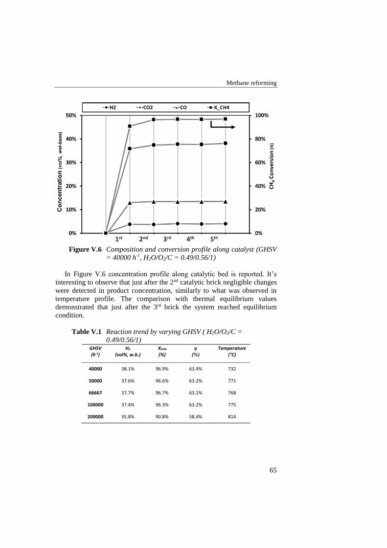
Methane reforming
65
Figure V.6 Composition and conversion profile along catalyst (GHSV
= 40000 h-1, H2O/O2/C = 0.49/0.56/1)
In Figure V.6 concentration profile along catalytic bed is reported. It’s
interesting to observe that just after the 2nd catalytic brick negligible changes
were detected in product concentration, similarly to what was observed in
temperature profile. The comparison with thermal equilibrium values
demonstrated that just after the 3rd brick the system reached equilibrium
condition.
Table V.1 Reaction trend by varying GHSV ( H2O/O2/C =
0.49/0.56/1) GHSV H2 XCH4 η Temperature (h-1) (vol%, w.b.) (%) (%) (°C)
40000 38.1% 96.9% 63.4% 732
50000 37.6% 96.6% 63.2% 771
66667 37.7% 96.7% 63.1% 768
100000 37.4% 96.3% 63.2% 775
200000 35.8% 90.8% 58.4% 814
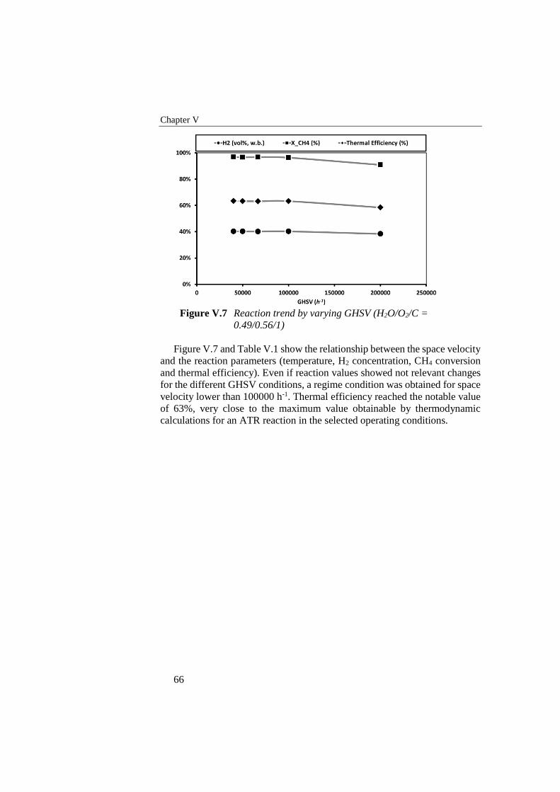
Chapter V
66
Figure V.7 Reaction trend by varying GHSV (H2O/O2/C =
0.49/0.56/1)
Figure V.7 and Table V.1 show the relationship between the space velocity
and the reaction parameters (temperature, H2 concentration, CH4 conversion
and thermal efficiency). Even if reaction values showed not relevant changes
for the different GHSV conditions, a regime condition was obtained for space
velocity lower than 100000 h-1. Thermal efficiency reached the notable value
of 63%, very close to the maximum value obtainable by thermodynamic
calculations for an ATR reaction in the selected operating conditions.
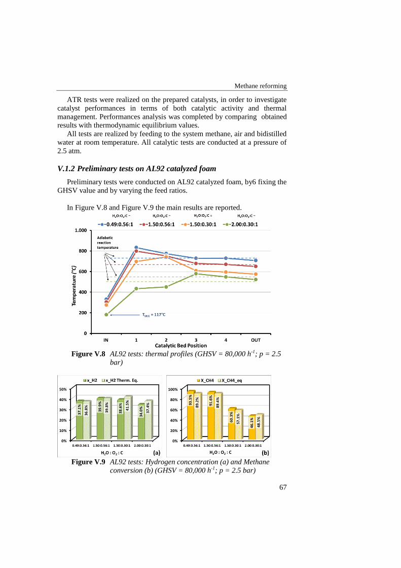
Methane reforming
67
ATR tests were realized on the prepared catalysts, in order to investigate
catalyst performances in terms of both catalytic activity and thermal
management. Performances analysis was completed by comparing obtained
results with thermodynamic equilibrium values.
All tests are realized by feeding to the system methane, air and bidistilled
water at room temperature. All catalytic tests are conducted at a pressure of
2.5 atm.
V.1.2 Preliminary tests on AL92 catalyzed foam
Preliminary tests were conducted on AL92 catalyzed foam, by6 fixing the
GHSV value and by varying the feed ratios.
In Figure V.8 and Figure V.9 the main results are reported.
Figure V.8 AL92 tests: thermal profiles (GHSV = 80,000 h-1; p = 2.5
bar)
Figure V.9 AL92 tests: Hydrogen concentration (a) and Methane
conversion (b) (GHSV = 80,000 h-1; p = 2.5 bar)
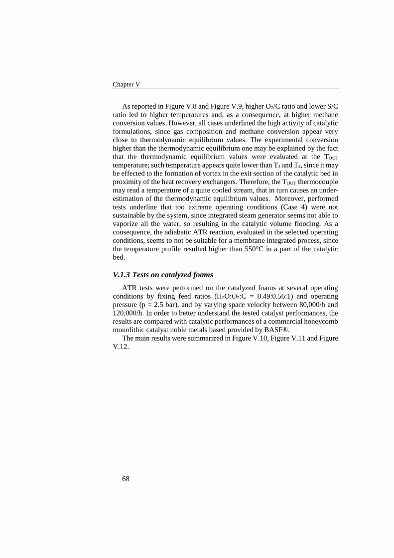
Chapter V
68
As reported in Figure V.8 and Figure V.9, higher O2/C ratio and lower S/C
ratio led to higher temperatures and, as a consequence, at higher methane
conversion values. However, all cases underlined the high activity of catalytic
formulations, since gas composition and methane conversion appear very
close to thermodynamic equilibrium values. The experimental conversion
higher than the thermodynamic equilibrium one may be explained by the fact
that the thermodynamic equilibrium values were evaluated at the TOUT
temperature; such temperature appears quite lower than T3 and T4, since it may
be effected to the formation of vortex in the exit section of the catalytic bed in
proximity of the heat recovery exchangers. Therefore, the TOUT thermocouple
may read a temperature of a quite cooled stream, that in turn causes an under-
estimation of the thermodynamic equilibrium values. Moreover, performed
tests underline that too extreme operating conditions (Case 4) were not
sustainable by the system, since integrated steam generator seems not able to
vaporize all the water, so resulting in the catalytic volume flooding. As a
consequence, the adiabatic ATR reaction, evaluated in the selected operating
conditions, seems to not be suitable for a membrane integrated process, since
the temperature profile resulted higher than 550°C in a part of the catalytic
bed.
V.1.3 Tests on catalyzed foams
ATR tests were performed on the catalyzed foams at several operating
conditions by fixing feed ratios (H2O:O2:C = 0.49:0.56:1) and operating
pressure (p = 2.5 bar), and by varying space velocity between 80,000/h and
120,000/h. In order to better understand the tested catalyst performances, the
results are compared with catalytic performances of a commercial honeycomb
monolithic catalyst noble metals based provided by BASF®.
The main results were summarized in Figure V.10, Figure V.11 and Figure
V.12.
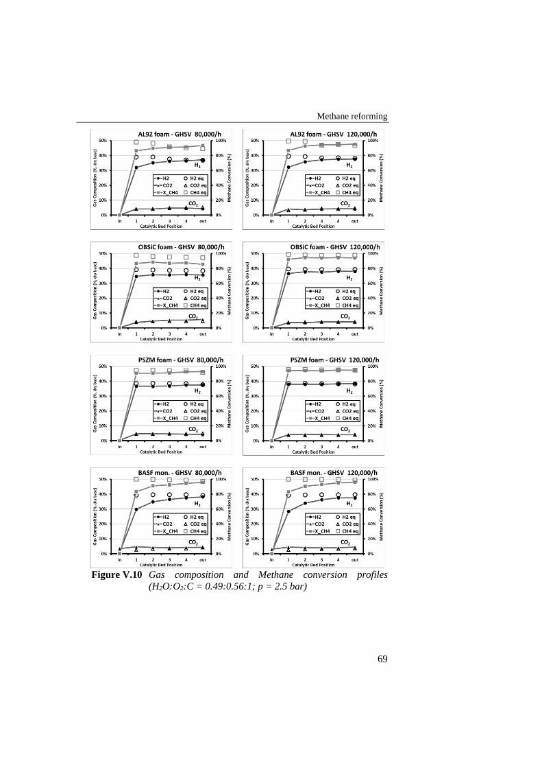
Methane reforming
69
Figure V.10 Gas composition and Methane conversion profiles
(H2O:O2:C = 0.49:0.56:1; p = 2.5 bar)
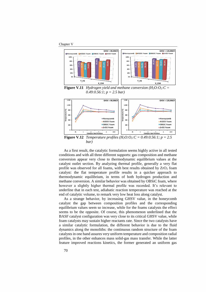
Chapter V
70
Figure V.11 Hydrogen yield and methane conversion (H2O:O2:C =
0.49:0.56:1; p = 2.5 bar)
Figure V.12 Temperature profiles (H2O:O2:C = 0.49:0.56:1; p = 2.5
bar)
As a first result, the catalytic formulation seems highly active in all tested
conditions and with all three different supports: gas composition and methane
conversion appear very close to thermodynamic equilibrium values at the
catalyst outlet section. By analyzing thermal profile, generally a very flat
profile was observed for all foams, with best results obtained by ZrO2 foam
catalyst: the flat temperature profile results in a quicker approach to
thermodynamic equilibrium, in terms of both hydrogen production and
methane conversion. A similar behavior was obtained by OBSiC foam, where
however a slightly higher thermal profile was recorded. It’s relevant to
underline that in each test, adiabatic reaction temperature was reached at the
end of catalytic volume, to remark very low heat loss along catalyst.
As a strange behavior, by increasing GHSV value, in the honeycomb
catalyst the gap between composition profiles and the corresponding
equilibrium values seem so increase, while for the foams catalysts the effect
seems to be the opposite. Of course, this phenomenon underlined that the
BASF catalyst configuration was very close to its critical GHSV value, while
foam catalysts may sustain higher reactants rate. Since the two catalysts have
a similar catalytic formulation, the different behavior is due to the fluid
dynamics along the monoliths: the continuous random structure of the foam
catalysts in one hand assures very uniform temperature and composition radial
profiles, in the other enhances mass solid-gas mass transfer. While the latter
feature improved reactions kinetics, the former generated an uniform gas

Methane reforming
71
condition that promotes the thermodynamic approach. For the foams,
therefore, the highest reactants flow rate helped to reduce the heat losses
relevance on system performances, resulting in an overall performances
improvement.
Chapter V
72
V.2 Methane Steam Reforming
Steam reforming tests were carried out on foam catalyst. The methane
conversion (Figure V.13) and hydrogen yield (Figure V.14) was monitored;
furthermore, hydrogen productivity, in terms of moles of produced hydrogen
per second per m3 of catalyst, was evaluated.
As expected, the too low operating temperature played a crucial role in the
catalysts overall performances: at atmospheric pressure, the methane
conversion was clearly below 42%, resulting evidently far from the
thermodynamic conversion; of course, the increasing of GHSV magnified the
gap between obtained conversion and the thermodynamic value. Of course the
highest S/C ratio weakly improves the methane conversion, however resulting
in a worst approach to thermodynamic equilibrium.
The increasing in operating pressure obviously resulted in a reduction in
methane conversion, as expected by thermodynamic predictions, but on the
other hand reduced the gap between equilibrium and experimental values. In
fact, to increase operating pressure resulted in an increasing of residence time,
so producing a better approach to thermodynamic equilibrium.
In an overall context, in all tests PSZM catalyzed foam evidenced the worst
conversion values and at higher GHSV catalyst performances were improved
by increasing operating pressure. This behavior should be explained with a
catalyst deactivation probably due to a lack of steam during test procedure.
The analysis of the results summarized in Figure V.13 and in Figure V.14
highlights the better performances of the alumina foam catalyst. In this
analysis, a crucial role was covered by the heat transfer properties of the used
foams, and in particular by the material thermal conductivity. The highest
thermal conductive foam is characterized by a flatter radial and axial
temperature profile, that results in a better solid-gas heat transfer. Since in the
steam reforming reactions the heat transfer mechanisms plays a fundamental
role on the overall reaction rate, the alumina foam, characterized by the
highest bulk thermal conductivity, showed the best performances. The more
the operating conditions stressed the heat transfer mechanisms (highest S/C
ratio, highest GHSV values), the more the gain of the AL92 foam was more
evident.
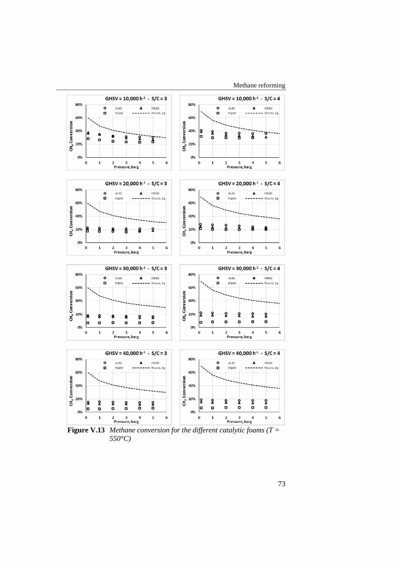
Methane reforming
73
Figure V.13 Methane conversion for the different catalytic foams (T =
550°C)
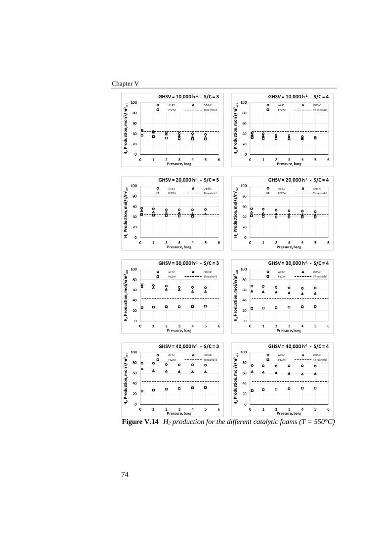
Chapter V
74
Figure V.14 H2 production for the different catalytic foams (T = 550°C)
Methane reforming
75
The CA.RE.N.A. project fixed a H2 production target of 44 mol/s/m3cat at
40 barg, in order to have an useful coupling of selected catalysts with a
membrane reactor. The use of a membrane reactor of course shift the focus
away from the methane conversion; on the other hand, the high operating
pressure becomes a requirement in order to maximize the hydrogen recovery.
From this point of view, the AL92 catalyzed foam was candidate to have the
best performances in terms of both hydrogen production and methane
conversion. Despite catalytic tests at 40 barg in a lab-scale plant were not
possible due to several safety limitations, evaluated H2 production trend vs
operating pressure and the progressive approach of the system by increasing
operating pressure suggests that the proposed target is easily achievable by
OBSiC and AL92 foams for a GHSV higher than 30,000 h-1.
V.3 Discussion and conclusions
Catalytic tests were performed on 3 different kinds of catalyzed foams, in
order to evaluate the influence of heat transfer mechanism in the system
performances. All foams are activated by a catalytic coverage realized by
Johnson Matthey within Ca.Re.N.A project. The catalytic tests were carried
out in a thermally integrated ATR reactor, available in the ProCEED labs of
the University of Salerno.
Preliminary tests were carried out, aimed to demonstrate the possibility to
couple an H2 perm-selective membrane to an ATR reactor. As expected,
involved reactions generated a temperature peak in the first zone of the
catalyst, depending on the feed ratio and the inlet temperature. The
temperature was progressively reduced by increasing S/C ratio and decreasing
O2/C ratio, up to reach an inlet temperature of about 120°C (operative
limitation due to the water condensing). The system appears able to reach
thermodynamic equilibrium even in the more drastic conditions, however in
several zones the catalyst temperature exceeded 540°C. Therefore, despite the
appreciable performances of the catalytic system, the ATR process appears
not suitable for the integration in a membrane reactor. It may be however
considered an open architecture, in which catalytic stage and hydrogen
removal stage are separated.
Activity were tested in ATR conditions, with very critical feed ratio
(H2O:O2:C = 0.49:0.56:1). Performed tests underlines the high activity of the
catalytic systems, that easily reached thermodynamic equilibrium. The use of
thermally conductive catalyzed foams lead to a faster approach to
thermodynamic equilibrium, as reported in the comparison with a commercial
honeycomb monolithic catalyst. The complex foam structure in one hand
promotes a continuous mixing of the reaction stream, in the other hand allows
conductive heat transfer along the catalyst resulting in a flatter thermal profile.
The influence of the thermal profile along the catalyst was evidenced by
comparing temperature and composition profile along the catalytic bed: the
Chapter V
76
more the temperature profile appears flat, the more the reaction stream quickly
reaches a composition close to the final value. Therefore, by achieving a flat
thermal profile, is possible in one hand to reduce hot-spot phenomena, that
may causes local cracking phenomena, in the other hand to promote and then
to accelerate the endothermic reforming reactions, so allowing to operate at
higher GHSV values (both by increasing reactants rate or reducing catalytic
volume).
In a first analysis, no correlations are found between material thermal
conductivity and thermal profile: paradoxically, ZrO2 has the lower thermal
conductivity, but ZrO2 foam results in the flatter thermal profile.
On the contrary, SR catalytic tests carried out on foam catalysts evidenced
the relevance of heat transfer management on the catalytic performances. In
particular, experimental results carried out at relatively low temperature
(550°C) and different operating conditions, demonstrated that the samples
characterized by the highest thermal conductivity showed the best results in
terms of methane conversion and hydrogen yield. The beneficial effect was
more evident in the more extreme conditions (higher S/C ratios, higher
reactants rates), in which the heat transfer limitations are more evident. One
of the most interesting effect resulting by the highest support thermal
conductivity may be the possibility to obtain a flattening of the radial profile,
that in one hand maximizes the heat transfer rate from the reactor walls to the
catalyst.
Moreover, the random tridimensional structure of the foam catalyst,
characterized by very high porosity and tortuosity, enhances the mass transfer
and the mixing of the reacting mixture, obtaining a more uniform reaction
condition along the whole catalytic bed, resulting in a more effective reaction
system.
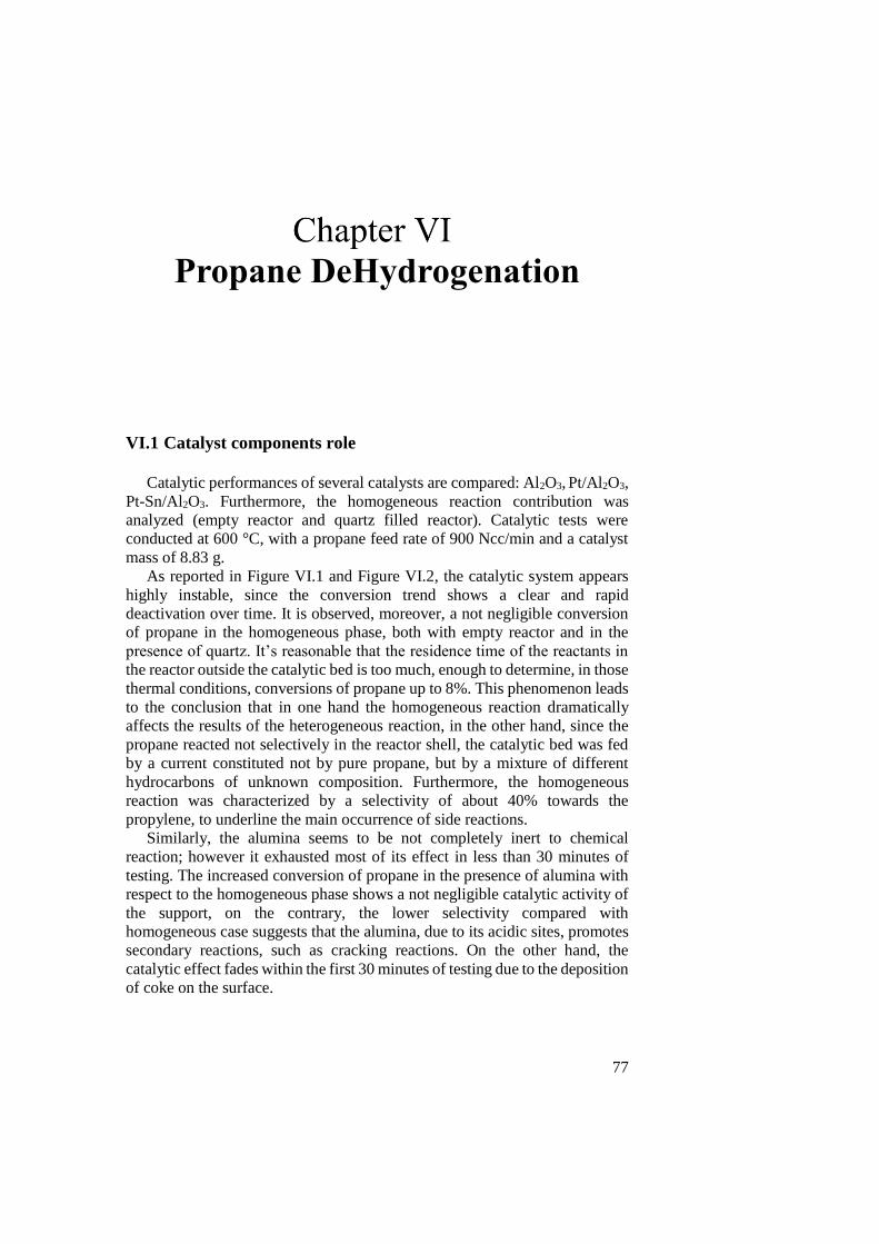
77
Propane DeHydrogenation
VI.1 Catalyst components role
Catalytic performances of several catalysts are compared: Al2O3, Pt/Al2O3,
Pt-Sn/Al2O3. Furthermore, the homogeneous reaction contribution was
analyzed (empty reactor and quartz filled reactor). Catalytic tests were
conducted at 600 °C, with a propane feed rate of 900 Ncc/min and a catalyst
mass of 8.83 g.
As reported in Figure VI.1 and Figure VI.2, the catalytic system appears
highly instable, since the conversion trend shows a clear and rapid
deactivation over time. It is observed, moreover, a not negligible conversion
of propane in the homogeneous phase, both with empty reactor and in the
presence of quartz. It’s reasonable that the residence time of the reactants in
the reactor outside the catalytic bed is too much, enough to determine, in those
thermal conditions, conversions of propane up to 8%. This phenomenon leads
to the conclusion that in one hand the homogeneous reaction dramatically
affects the results of the heterogeneous reaction, in the other hand, since the
propane reacted not selectively in the reactor shell, the catalytic bed was fed
by a current constituted not by pure propane, but by a mixture of different
hydrocarbons of unknown composition. Furthermore, the homogeneous
reaction was characterized by a selectivity of about 40% towards the
propylene, to underline the main occurrence of side reactions.
Similarly, the alumina seems to be not completely inert to chemical
reaction; however it exhausted most of its effect in less than 30 minutes of
testing. The increased conversion of propane in the presence of alumina with
respect to the homogeneous phase shows a not negligible catalytic activity of
the support, on the contrary, the lower selectivity compared with
homogeneous case suggests that the alumina, due to its acidic sites, promotes
secondary reactions, such as cracking reactions. On the other hand, the
catalytic effect fades within the first 30 minutes of testing due to the deposition
of coke on the surface.
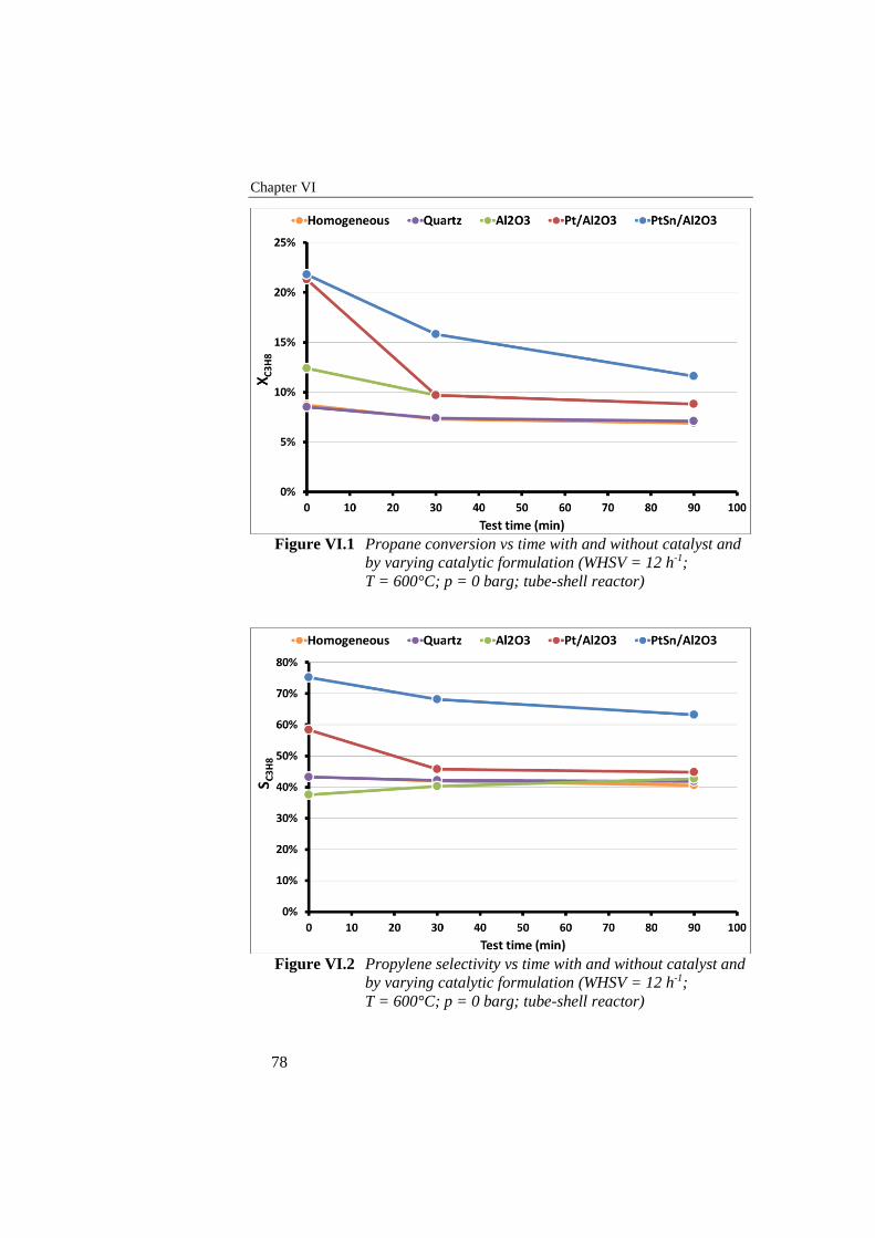
Chapter VI
78
Figure VI.1 Propane conversion vs time with and without catalyst and
by varying catalytic formulation (WHSV = 12 h-1;
T = 600°C; p = 0 barg; tube-shell reactor)
Figure VI.2 Propylene selectivity vs time with and without catalyst and
by varying catalytic formulation (WHSV = 12 h-1;
T = 600°C; p = 0 barg; tube-shell reactor)
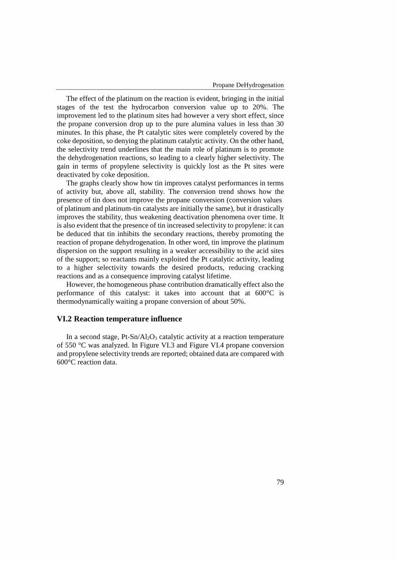
Propane DeHydrogenation
79
The effect of the platinum on the reaction is evident, bringing in the initial
stages of the test the hydrocarbon conversion value up to 20%. The
improvement led to the platinum sites had however a very short effect, since
the propane conversion drop up to the pure alumina values in less than 30
minutes. In this phase, the Pt catalytic sites were completely covered by the
coke deposition, so denying the platinum catalytic activity. On the other hand,
the selectivity trend underlines that the main role of platinum is to promote
the dehydrogenation reactions, so leading to a clearly higher selectivity. The
gain in terms of propylene selectivity is quickly lost as the Pt sites were
deactivated by coke deposition.
The graphs clearly show how tin improves catalyst performances in terms
of activity but, above all, stability. The conversion trend shows how the
presence of tin does not improve the propane conversion (conversion values
of platinum and platinum-tin catalysts are initially the same), but it drastically
improves the stability, thus weakening deactivation phenomena over time. It
is also evident that the presence of tin increased selectivity to propylene: it can
be deduced that tin inhibits the secondary reactions, thereby promoting the
reaction of propane dehydrogenation. In other word, tin improve the platinum
dispersion on the support resulting in a weaker accessibility to the acid sites
of the support; so reactants mainly exploited the Pt catalytic activity, leading
to a higher selectivity towards the desired products, reducing cracking
reactions and as a consequence improving catalyst lifetime.
However, the homogeneous phase contribution dramatically effect also the
performance of this catalyst: it takes into account that at 600°C is
thermodynamically waiting a propane conversion of about 50%.
VI.2 Reaction temperature influence
In a second stage, Pt-Sn/Al2O3 catalytic activity at a reaction temperature
of 550 °C was analyzed. In Figure VI.3 and Figure VI.4 propane conversion
and propylene selectivity trends are reported; obtained data are compared with
600°C reaction data.
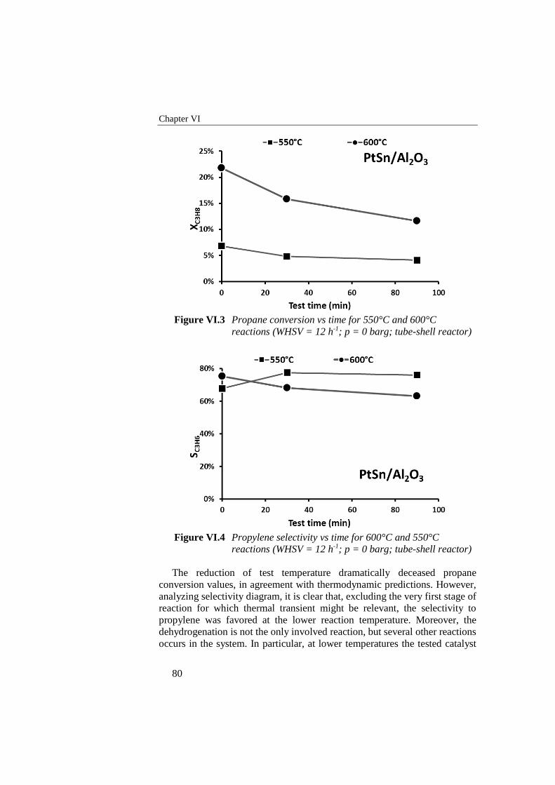
Chapter VI
80
Figure VI.3 Propane conversion vs time for 550°C and 600°C
reactions (WHSV = 12 h-1; p = 0 barg; tube-shell reactor)
Figure VI.4 Propylene selectivity vs time for 600°C and 550°C
reactions (WHSV = 12 h-1; p = 0 barg; tube-shell reactor)
The reduction of test temperature dramatically deceased propane
conversion values, in agreement with thermodynamic predictions. However,
analyzing selectivity diagram, it is clear that, excluding the very first stage of
reaction for which thermal transient might be relevant, the selectivity to
propylene was favored at the lower reaction temperature. Moreover, the
dehydrogenation is not the only involved reaction, but several other reactions
occurs in the system. In particular, at lower temperatures the tested catalyst
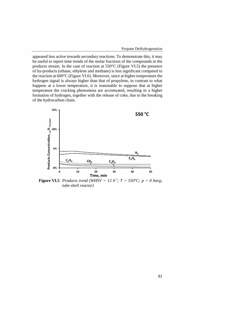
Propane DeHydrogenation
81
appeared less active towards secondary reactions. To demonstrate this, it may
be useful to report time trends of the molar fractions of the compounds in the
products stream. In the case of reaction at 550°C (Figure VI.5) the presence
of by-products (ethane, ethylene and methane) is less significant compared to
the reaction at 600°C (Figure VI.6). Moreover, since at higher temperature the
hydrogen signal is always higher than that of propylene, in contrast to what
happens at a lower temperature, it is reasonable to suppose that at higher
temperature the cracking phenomena are accentuated, resulting in a higher
formation of hydrogen, together with the release of coke, due to the breaking
of the hydrocarbon chain.
Figure VI.5 Products trend (WHSV = 12 h-1; T = 550°C; p = 0 barg;
tube-shell reactor)
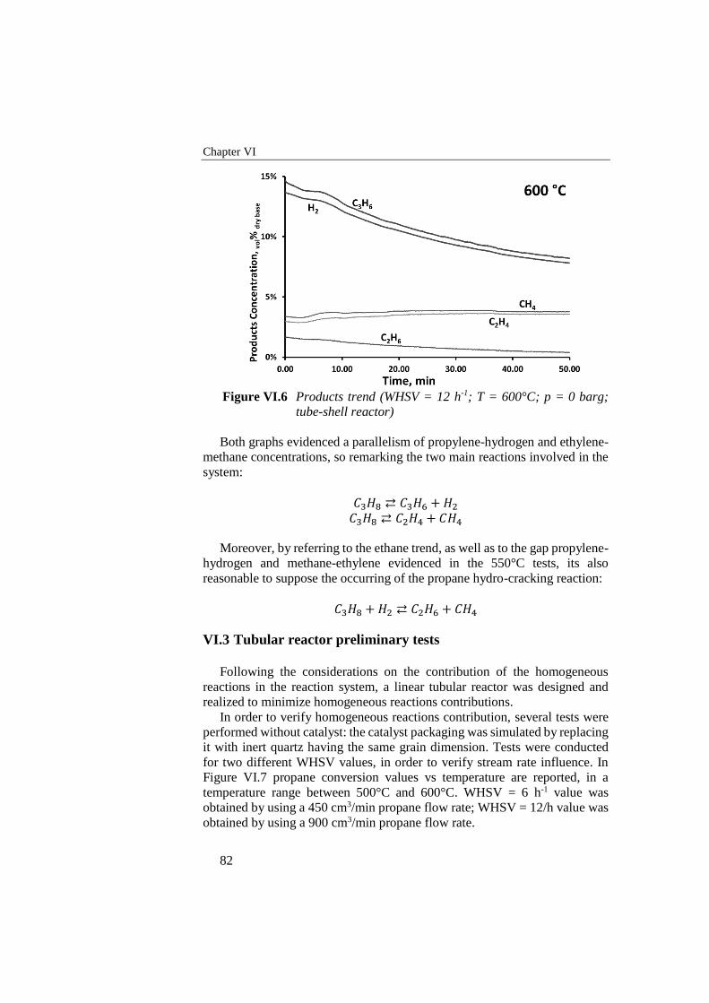
Chapter VI
82
Figure VI.6 Products trend (WHSV = 12 h-1; T = 600°C; p = 0 barg;
tube-shell reactor)
Both graphs evidenced a parallelism of propylene-hydrogen and ethylene-
methane concentrations, so remarking the two main reactions involved in the
system:
𝐶3𝐻8 ⇄ 𝐶3𝐻6 + 𝐻2
𝐶3𝐻8 ⇄ 𝐶2𝐻4 + 𝐶𝐻4
Moreover, by referring to the ethane trend, as well as to the gap propylene-
hydrogen and methane-ethylene evidenced in the 550°C tests, its also
reasonable to suppose the occurring of the propane hydro-cracking reaction:
𝐶3𝐻8 + 𝐻2 ⇄ 𝐶2𝐻6 + 𝐶𝐻4
VI.3 Tubular reactor preliminary tests
Following the considerations on the contribution of the homogeneous
reactions in the reaction system, a linear tubular reactor was designed and
realized to minimize homogeneous reactions contributions.
In order to verify homogeneous reactions contribution, several tests were
performed without catalyst: the catalyst packaging was simulated by replacing
it with inert quartz having the same grain dimension. Tests were conducted
for two different WHSV values, in order to verify stream rate influence. In
Figure VI.7 propane conversion values vs temperature are reported, in a
temperature range between 500°C and 600°C. WHSV = 6 h-1 value was
obtained by using a 450 cm3/min propane flow rate; WHSV = 12/h value was
obtained by using a 900 cm3/min propane flow rate.
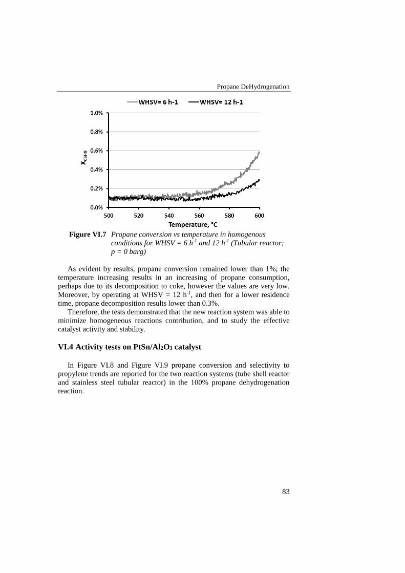
Propane DeHydrogenation
83
Figure VI.7 Propane conversion vs temperature in homogenous
conditions for WHSV = 6 h-1 and 12 h-1 (Tubular reactor;
p = 0 barg)
As evident by results, propane conversion remained lower than 1%; the
temperature increasing results in an increasing of propane consumption,
perhaps due to its decomposition to coke, however the values are very low.
Moreover, by operating at WHSV = 12 h-1, and then for a lower residence
time, propane decomposition results lower than 0.3%.
Therefore, the tests demonstrated that the new reaction system was able to
minimize homogeneous reactions contribution, and to study the effective
catalyst activity and stability.
VI.4 Activity tests on PtSn/Al2O3 catalyst
In Figure VI.8 and Figure VI.9 propane conversion and selectivity to
propylene trends are reported for the two reaction systems (tube shell reactor
and stainless steel tubular reactor) in the 100% propane dehydrogenation
reaction.
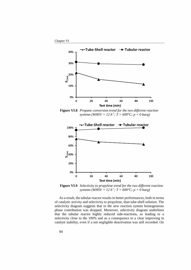
Chapter VI
84
Figure VI.8 Propane conversion trend for the two different reaction
systems (WHSV = 12 h-1; T = 600°C; p = 0 barg)
Figure VI.9 Selectivity to propylene trend for the two different reaction
systems (WHSV = 12 h-1; T = 600°C; p = 0 barg)
As a result, the tubular reactor results in better performances, both in terms
of catalytic activity and selectivity to propylene, than tube-shell solution. The
selectivity diagram suggests that in the new reaction system homogeneous
phase contribution was dropped. Moreover, selectivity diagram underlines
that the tubular reactor highly reduced side-reactions, so leading to a
selectivity close to the 100% and as a consequence to a clear improving in
catalyst stability, even if a not negligible deactivation was still recorded. On
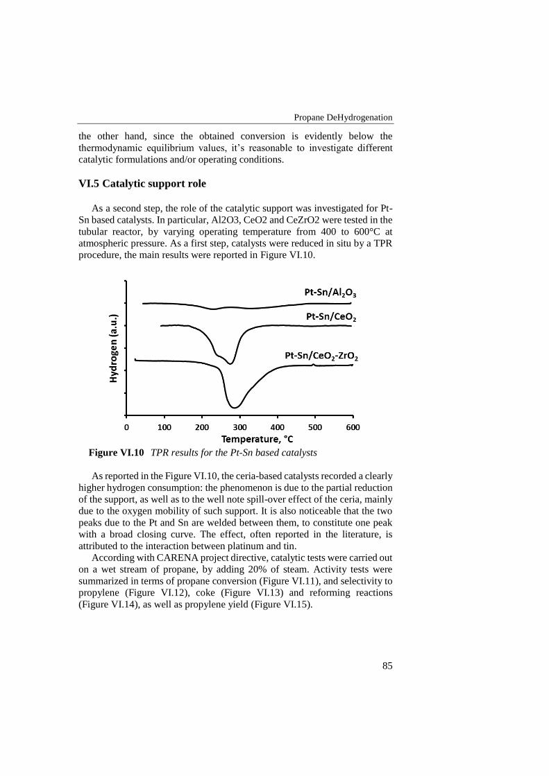
Propane DeHydrogenation
85
the other hand, since the obtained conversion is evidently below the
thermodynamic equilibrium values, it’s reasonable to investigate different
catalytic formulations and/or operating conditions.
VI.5 Catalytic support role
As a second step, the role of the catalytic support was investigated for Pt-
Sn based catalysts. In particular, Al2O3, CeO2 and CeZrO2 were tested in the
tubular reactor, by varying operating temperature from 400 to 600°C at
atmospheric pressure. As a first step, catalysts were reduced in situ by a TPR
procedure, the main results were reported in Figure VI.10.
Figure VI.10 TPR results for the Pt-Sn based catalysts
As reported in the Figure VI.10, the ceria-based catalysts recorded a clearly
higher hydrogen consumption: the phenomenon is due to the partial reduction
of the support, as well as to the well note spill-over effect of the ceria, mainly
due to the oxygen mobility of such support. It is also noticeable that the two
peaks due to the Pt and Sn are welded between them, to constitute one peak
with a broad closing curve. The effect, often reported in the literature, is
attributed to the interaction between platinum and tin.
According with CARENA project directive, catalytic tests were carried out
on a wet stream of propane, by adding 20% of steam. Activity tests were
summarized in terms of propane conversion (Figure VI.11), and selectivity to
propylene (Figure VI.12), coke (Figure VI.13) and reforming reactions
(Figure VI.14), as well as propylene yield (Figure VI.15).
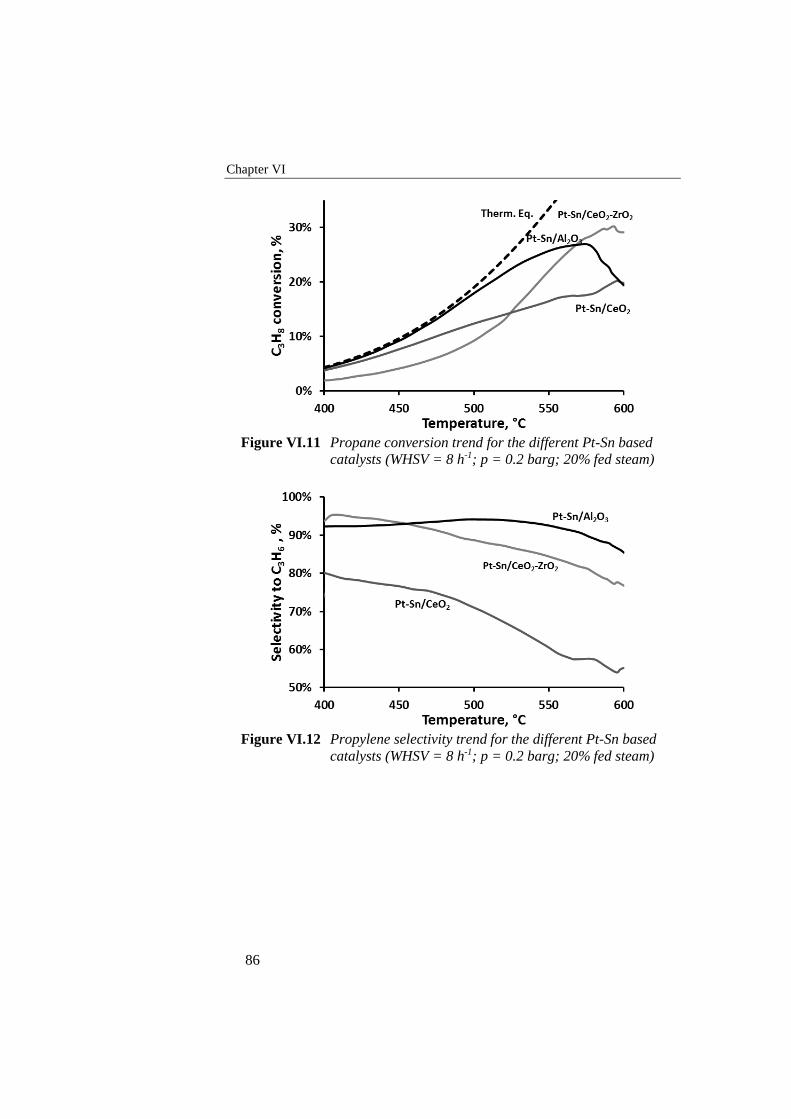
Chapter VI
86
Figure VI.11 Propane conversion trend for the different Pt-Sn based
catalysts (WHSV = 8 h-1; p = 0.2 barg; 20% fed steam)
Figure VI.12 Propylene selectivity trend for the different Pt-Sn based
catalysts (WHSV = 8 h-1; p = 0.2 barg; 20% fed steam)
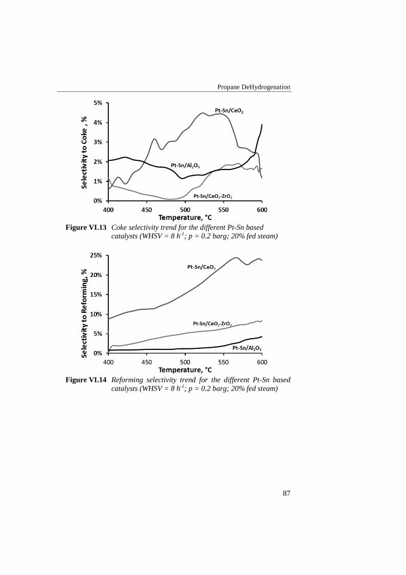
Propane DeHydrogenation
87
Figure VI.13 Coke selectivity trend for the different Pt-Sn based
catalysts (WHSV = 8 h-1; p = 0.2 barg; 20% fed steam)
Figure VI.14 Reforming selectivity trend for the different Pt-Sn based
catalysts (WHSV = 8 h-1; p = 0.2 barg; 20% fed steam)
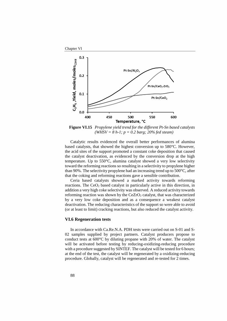
Chapter VI
88
Figure VI.15 Propylene yield trend for the different Pt-Sn based catalysts
(WHSV = 8 h-1; p = 0.2 barg; 20% fed steam)
Catalytic results evidenced the overall better performances of alumina
based catalysts, that showed the highest conversion up to 580°C. However,
the acid sites of the support promoted a constant coke deposition that caused
the catalyst deactivation, as evidenced by the conversion drop at the high
temperature. Up to 550°C, alumina catalyst showed a very low selectivity
toward the reforming reactions so resulting in a selectivity to propylene higher
than 90%. The selectivity propylene had an increasing trend up to 500°C, after
that the coking and reforming reactions gave a sensible contribution.
Ceria based catalysts showed a marked activity towards reforming
reactions. The CeO2 based catalyst in particularly active in this direction, in
addition a very high coke selectivity was observed. A reduced activity towards
reforming reaction was shown by the CeZrO2 catalyst, that was characterized
by a very low coke deposition and as a consequence a weakest catalyst
deactivation. The reducing characteristics of the support so were able to avoid
(or at least to limit) cracking reactions, but also reduced the catalyst activity.
VI.6 Regeneration tests
In accordance with Ca.Re.N.A. PDH tests were carried out on S-01 and S-
02 samples supplied by project partners. Catalyst producers propose to
conduct tests at 600°C by diluting propane with 20% of water. The catalyst
will be activated before testing by reducing-oxidizing-reducing procedure
with a procedure suggested by SINTEF. The catalyst will be tested for 6 hours;
at the end of the test, the catalyst will be regenerated by a oxidizing-reducing
procedure. Globally, catalyst will be regenerated and re-tested for 2 times.
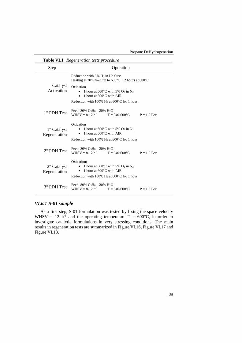
Propane DeHydrogenation
89
Table VI.1 Regeneration tests procedure
Step Operation
Catalyst
Activation
Reduction with 5% H2 in He flux:
Heating at 20°C/min up to 600°C + 2 hours at 600°C
Oxidation
1 hour at 600°C with 5% O2 in N2;
1 hour at 600°C with AIR
Reduction with 100% H2 at 600°C for 1 hour
1° PDH Test Feed: 80% C3H8 20% H2O
WHSV = 8-12 h-1 T = 540-600°C P = 1.5 Bar
1° Catalyst
Regeneration
Oxidation
1 hour at 600°C with 5% O2 in N2;
1 hour at 600°C with AIR
Reduction with 100% H2 at 600°C for 1 hour
2° PDH Test Feed: 80% C3H8 20% H2O
WHSV = 8-12 h-1 T = 540-600°C P = 1.5 Bar
2° Catalyst
Regeneration
Oxidation:
1 hour at 600°C with 5% O2 in N2;
1 hour at 600°C with AIR
Reduction with 100% H2 at 600°C for 1 hour
3° PDH Test Feed: 80% C3H8 20% H2O
WHSV = 8-12 h-1 T = 540-600°C P = 1.5 Bar
VI.6.1 S-01 sample
As a first step, S-01 formulation was tested by fixing the space velocity
WHSV = 12 h-1 and the operating temperature T = 600°C, in order to
investigate catalytic formulations in very stressing conditions. The main
results in regeneration tests are summarized in Figure VI.16, Figure VI.17 and
Figure VI.18.
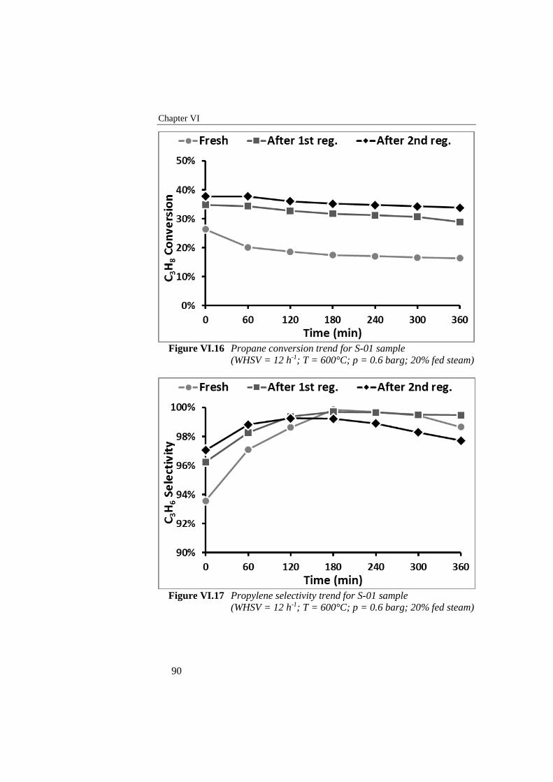
Chapter VI
90
Figure VI.16 Propane conversion trend for S-01 sample
(WHSV = 12 h-1; T = 600°C; p = 0.6 barg; 20% fed steam)
Figure VI.17 Propylene selectivity trend for S-01 sample
(WHSV = 12 h-1; T = 600°C; p = 0.6 barg; 20% fed steam)
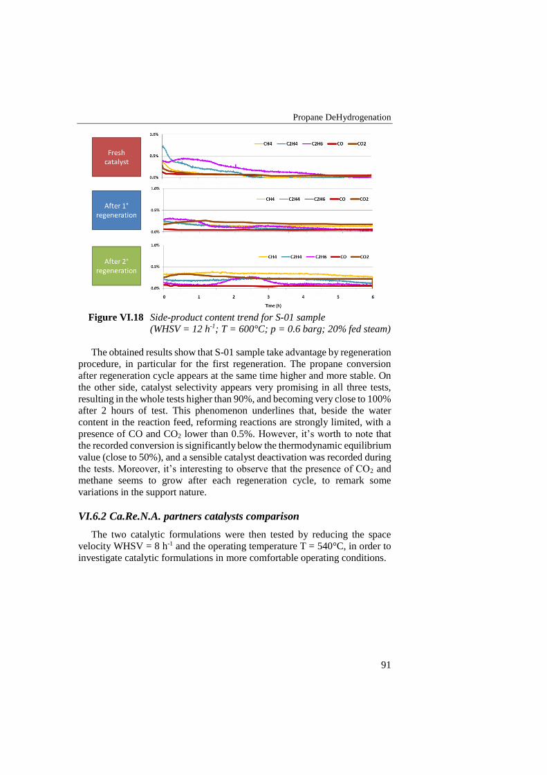
Propane DeHydrogenation
91
Figure VI.18 Side-product content trend for S-01 sample
(WHSV = 12 h-1; T = 600°C; p = 0.6 barg; 20% fed steam)
The obtained results show that S-01 sample take advantage by regeneration
procedure, in particular for the first regeneration. The propane conversion
after regeneration cycle appears at the same time higher and more stable. On
the other side, catalyst selectivity appears very promising in all three tests,
resulting in the whole tests higher than 90%, and becoming very close to 100%
after 2 hours of test. This phenomenon underlines that, beside the water
content in the reaction feed, reforming reactions are strongly limited, with a
presence of CO and CO2 lower than 0.5%. However, it’s worth to note that
the recorded conversion is significantly below the thermodynamic equilibrium
value (close to 50%), and a sensible catalyst deactivation was recorded during
the tests. Moreover, it’s interesting to observe that the presence of CO2 and
methane seems to grow after each regeneration cycle, to remark some
variations in the support nature.
VI.6.2 Ca.Re.N.A. partners catalysts comparison
The two catalytic formulations were then tested by reducing the space
velocity WHSV = 8 h-1 and the operating temperature T = 540°C, in order to
investigate catalytic formulations in more comfortable operating conditions.
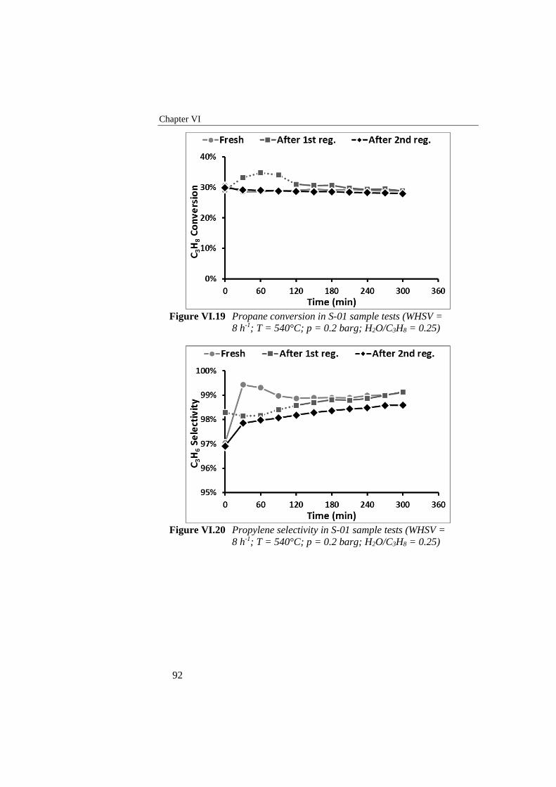
Chapter VI
92
Figure VI.19 Propane conversion in S-01 sample tests (WHSV =
8 h-1; T = 540°C; p = 0.2 barg; H2O/C3H8 = 0.25)
Figure VI.20 Propylene selectivity in S-01 sample tests (WHSV =
8 h-1; T = 540°C; p = 0.2 barg; H2O/C3H8 = 0.25)
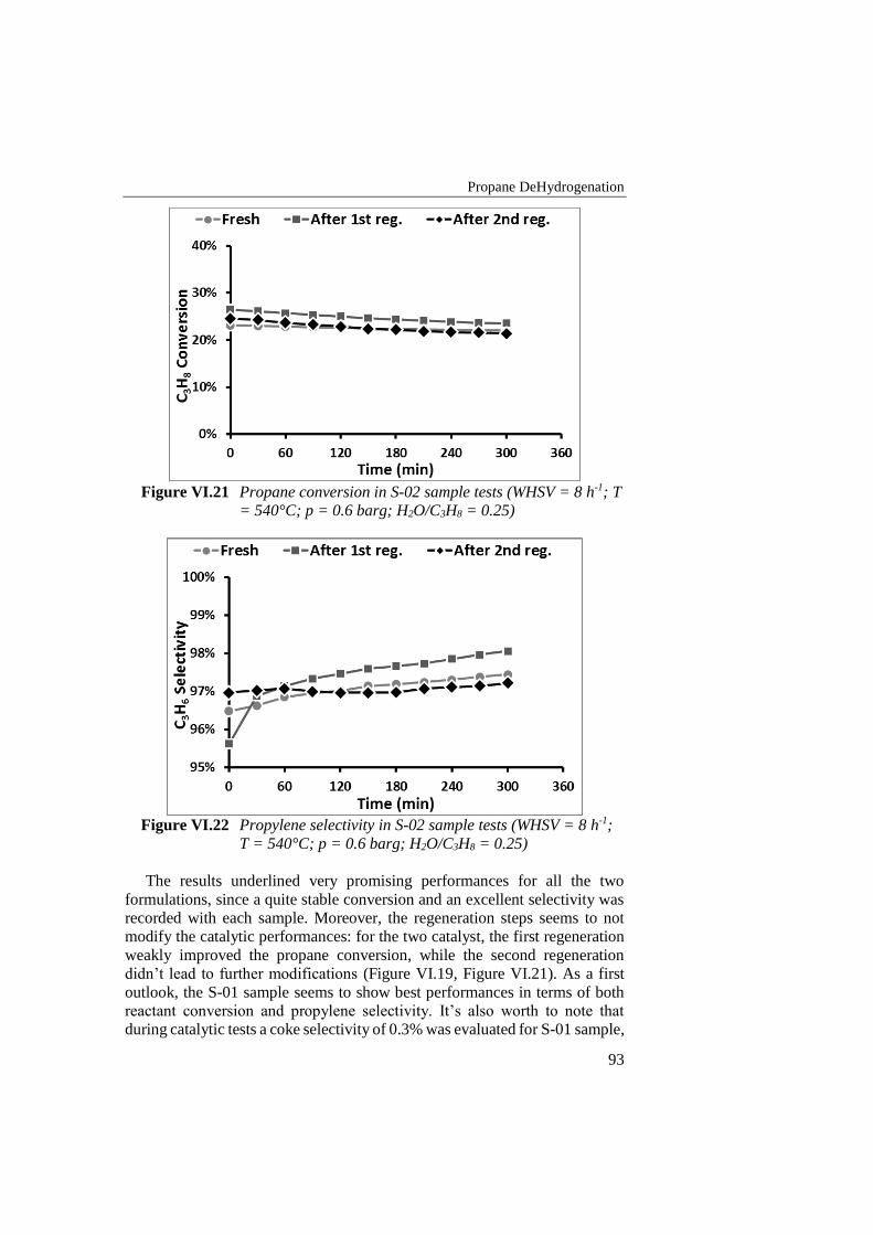
Propane DeHydrogenation
93
Figure VI.21 Propane conversion in S-02 sample tests (WHSV = 8 h-1; T
= 540°C; p = 0.6 barg; H2O/C3H8 = 0.25)
Figure VI.22 Propylene selectivity in S-02 sample tests (WHSV = 8 h-1;
T = 540°C; p = 0.6 barg; H2O/C3H8 = 0.25)
The results underlined very promising performances for all the two
formulations, since a quite stable conversion and an excellent selectivity was
recorded with each sample. Moreover, the regeneration steps seems to not
modify the catalytic performances: for the two catalyst, the first regeneration
weakly improved the propane conversion, while the second regeneration
didn’t lead to further modifications (Figure VI.19, Figure VI.21). As a first
outlook, the S-01 sample seems to show best performances in terms of both
reactant conversion and propylene selectivity. It’s also worth to note that
during catalytic tests a coke selectivity of 0.3% was evaluated for S-01 sample,
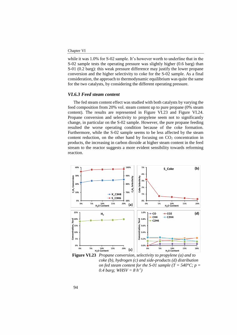
Chapter VI
94
while it was 1.0% for S-02 sample. It’s however worth to underline that in the
S-02 sample tests the operating pressure was slightly higher (0.6 barg) than
S-01 (0.2 barg): this weak pressure difference may justify the lower propane
conversion and the higher selectivity to coke for the S-02 sample. As a final
consideration, the approach to thermodynamic equilibrium was quite the same
for the two catalysts, by considering the different operating pressure.
VI.6.3 Feed steam content
The fed steam content effect was studied with both catalysts by varying the
feed composition from 20% vol. steam content up to pure propane (0% steam
content). The results are represented in Figure VI.23 and Figure VI.24.
Propane conversion and selectivity to propylene seem not to significantly
change, in particular on the S-02 sample. However, the pure propane feeding
resulted the worse operating condition because of the coke formation.
Furthermore, while the S-02 sample seems to be less affected by the steam
content reduction, on the other hand by focusing on CO2 concentration in
products, the increasing in carbon dioxide at higher steam content in the feed
stream to the reactor suggests a more evident sensibility towards reforming
reaction.
Figure VI.23 Propane conversion, selectivity to propylene (a) and to
coke (b), hydrogen (c) and side-products (d) distribution
on fed steam content for the S-01 sample (T = 540°C; p =
0.4 barg; WHSV = 8 h-1)
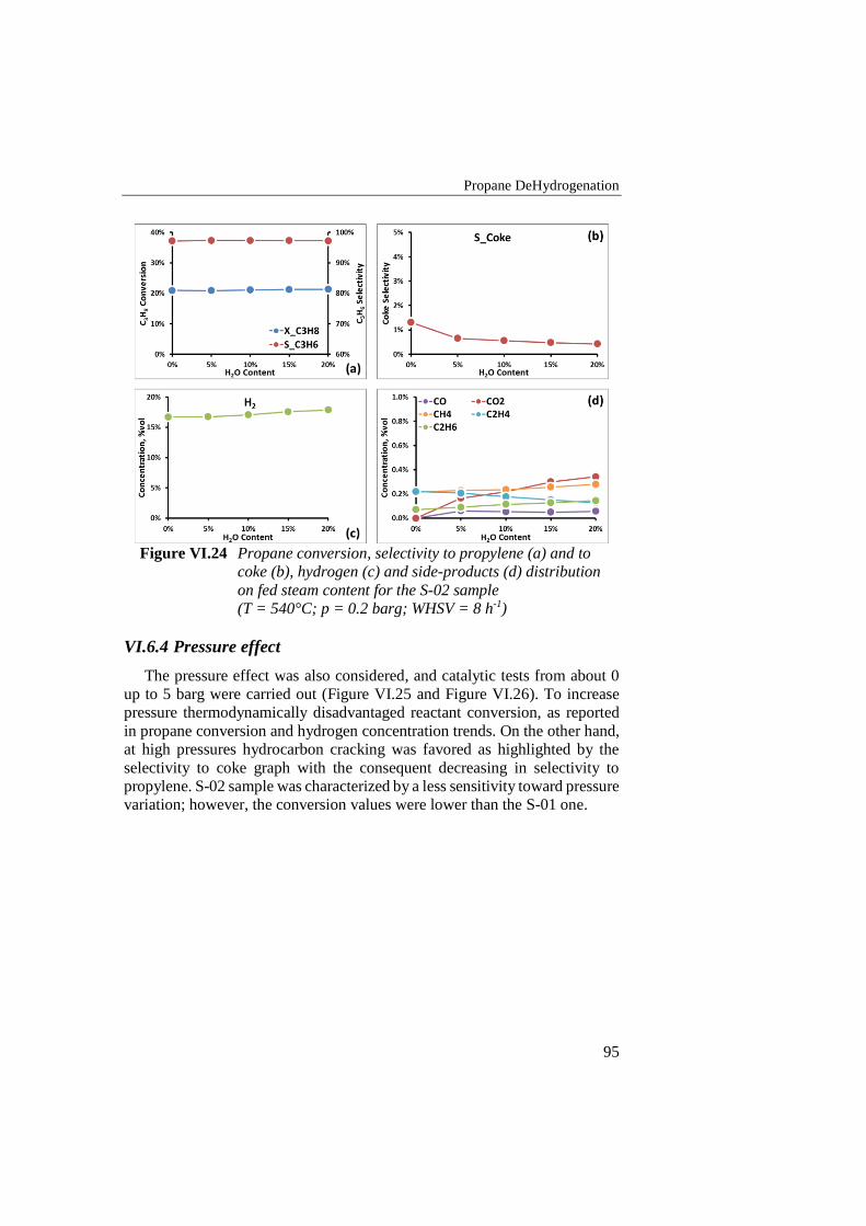
Propane DeHydrogenation
95
Figure VI.24 Propane conversion, selectivity to propylene (a) and to
coke (b), hydrogen (c) and side-products (d) distribution
on fed steam content for the S-02 sample
(T = 540°C; p = 0.2 barg; WHSV = 8 h-1)
VI.6.4 Pressure effect
The pressure effect was also considered, and catalytic tests from about 0
up to 5 barg were carried out (Figure VI.25 and Figure VI.26). To increase
pressure thermodynamically disadvantaged reactant conversion, as reported
in propane conversion and hydrogen concentration trends. On the other hand,
at high pressures hydrocarbon cracking was favored as highlighted by the
selectivity to coke graph with the consequent decreasing in selectivity to
propylene. S-02 sample was characterized by a less sensitivity toward pressure
variation; however, the conversion values were lower than the S-01 one.
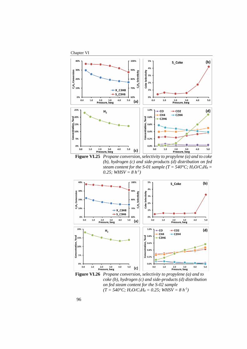
Chapter VI
96
Figure VI.25 Propane conversion, selectivity to propylene (a) and to coke
(b), hydrogen (c) and side-products (d) distribution on fed
steam content for the S-01 sample (T = 540°C; H2O/C3H8 =
0.25; WHSV = 8 h-1)
Figure VI.26 Propane conversion, selectivity to propylene (a) and to
coke (b), hydrogen (c) and side-products (d) distribution
on fed steam content for the S-02 sample
(T = 540°C; H2O/C3H8 = 0.25; WHSV = 8 h-1)

Propane DeHydrogenation
97
VI.6.5 CO – CO2 effect
The effect of carbon monoxide and carbon dioxide content on catalytic
performance was studied with S-02 sample formulation, by fixing the molar
ratio H2O/C3H8 = 0.25 and varying the CO and CO2 content in the feed
composition from 0%vol up to 10%vol; the effects of CO and CO2 were studied
individually. Experimental tests were conducted at 540°C and 0.24 barg at
WHSV = 8 h-1.
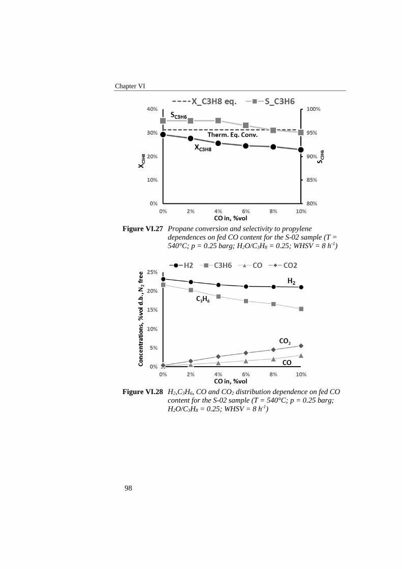
Chapter VI
98
Figure VI.27 Propane conversion and selectivity to propylene
dependences on fed CO content for the S-02 sample (T =
540°C; p = 0.25 barg; H2O/C3H8 = 0.25; WHSV = 8 h-1)
Figure VI.28 H2,C3H6, CO and CO2 distribution dependence on fed CO
content for the S-02 sample (T = 540°C; p = 0.25 barg;
H2O/C3H8 = 0.25; WHSV = 8 h-1)
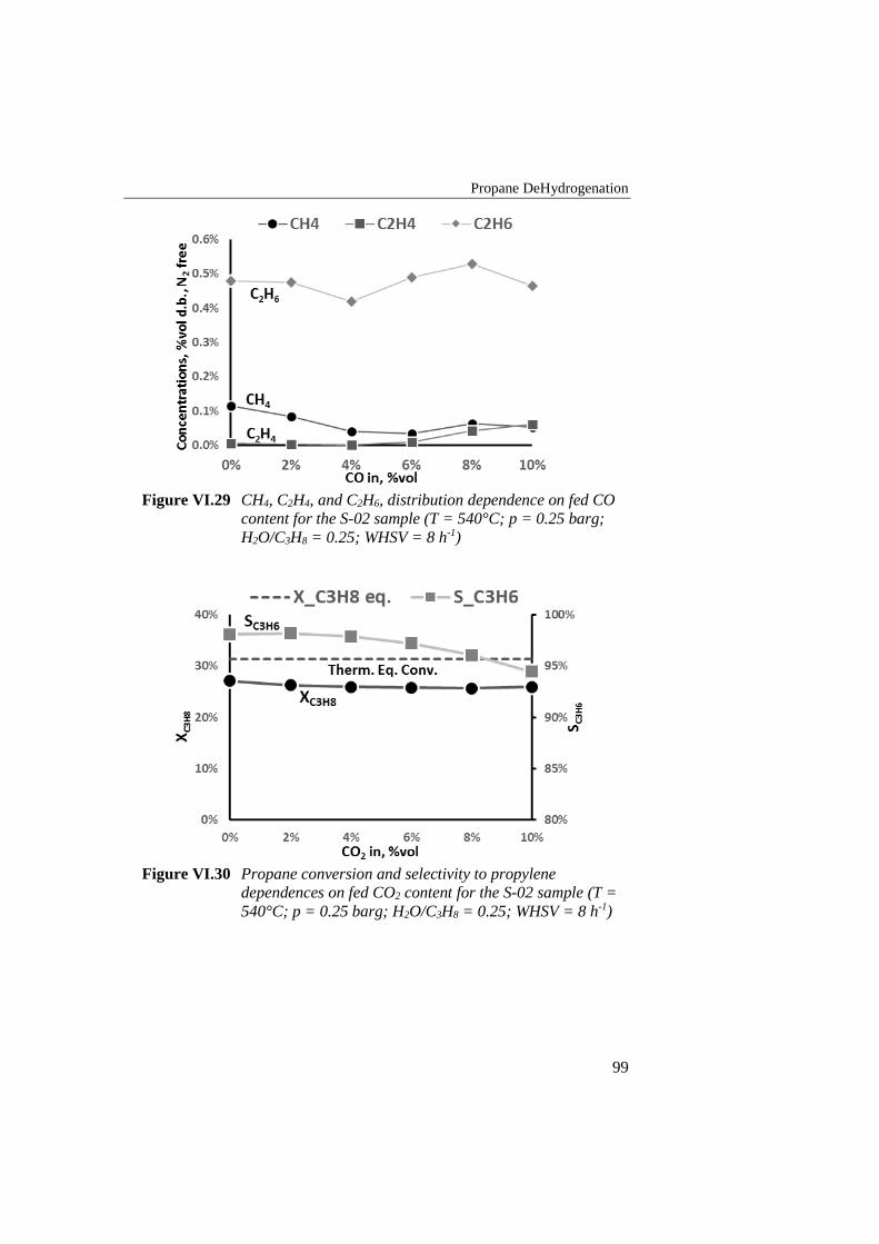
Propane DeHydrogenation
99
Figure VI.29 CH4, C2H4, and C2H6, distribution dependence on fed CO
content for the S-02 sample (T = 540°C; p = 0.25 barg;
H2O/C3H8 = 0.25; WHSV = 8 h-1)
Figure VI.30 Propane conversion and selectivity to propylene
dependences on fed CO2 content for the S-02 sample (T =
540°C; p = 0.25 barg; H2O/C3H8 = 0.25; WHSV = 8 h-1)
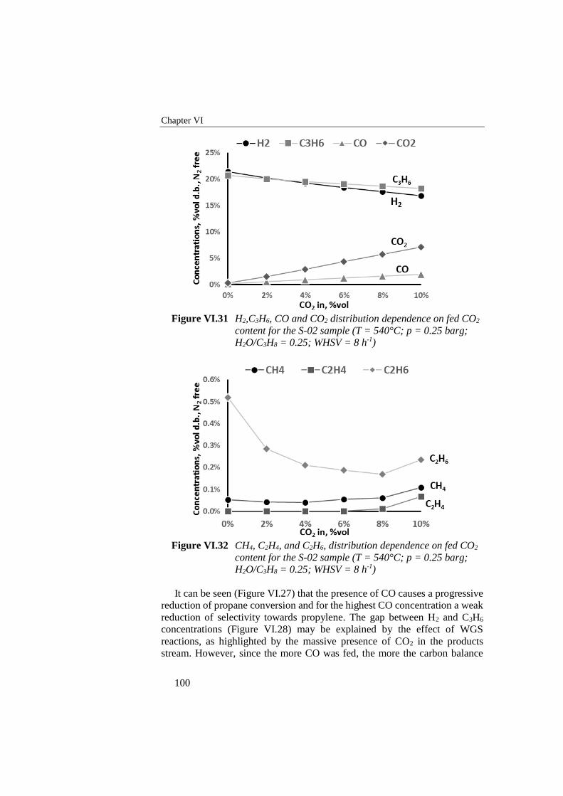
Chapter VI
100
Figure VI.31 H2,C3H6, CO and CO2 distribution dependence on fed CO2
content for the S-02 sample (T = 540°C; p = 0.25 barg;
H2O/C3H8 = 0.25; WHSV = 8 h-1)
Figure VI.32 CH4, C2H4, and C2H6, distribution dependence on fed CO2
content for the S-02 sample (T = 540°C; p = 0.25 barg;
H2O/C3H8 = 0.25; WHSV = 8 h-1)
It can be seen (Figure VI.27) that the presence of CO causes a progressive
reduction of propane conversion and for the highest CO concentration a weak
reduction of selectivity towards propylene. The gap between H2 and C3H6
concentrations (Figure VI.28) may be explained by the effect of WGS
reactions, as highlighted by the massive presence of CO2 in the products
stream. However, since the more CO was fed, the more the carbon balance
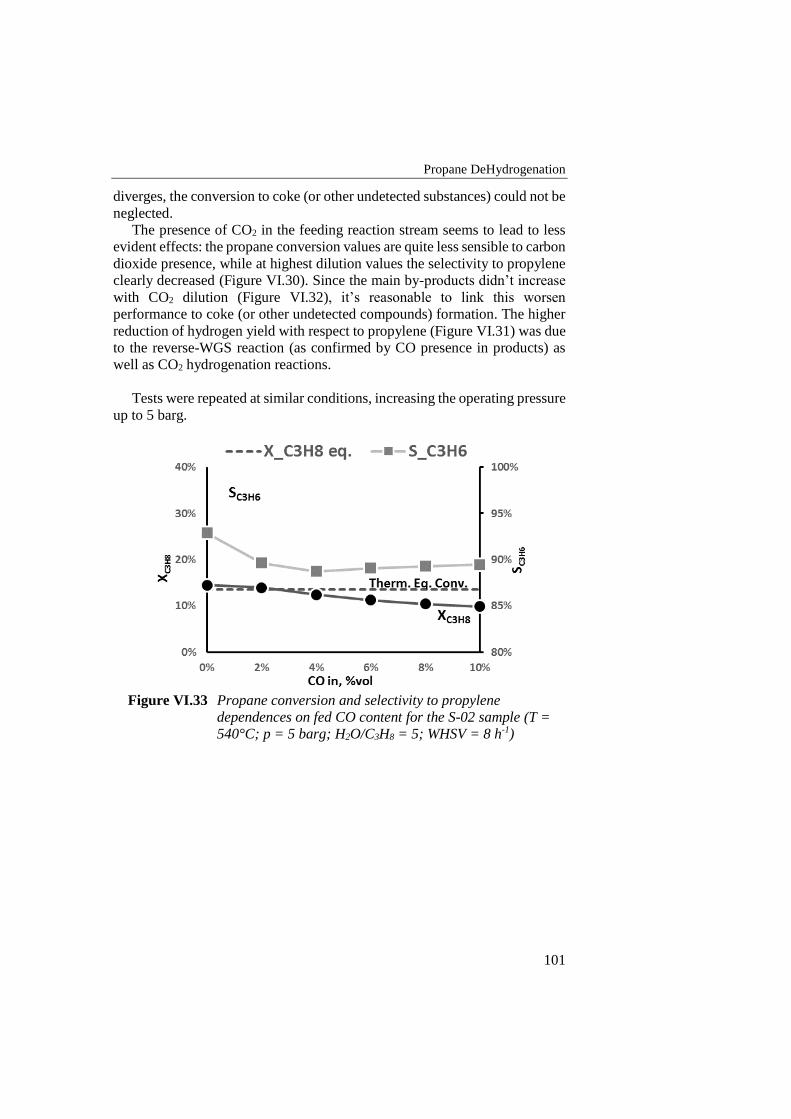
Propane DeHydrogenation
101
diverges, the conversion to coke (or other undetected substances) could not be
neglected.
The presence of CO2 in the feeding reaction stream seems to lead to less
evident effects: the propane conversion values are quite less sensible to carbon
dioxide presence, while at highest dilution values the selectivity to propylene
clearly decreased (Figure VI.30). Since the main by-products didn’t increase
with CO2 dilution (Figure VI.32), it’s reasonable to link this worsen
performance to coke (or other undetected compounds) formation. The higher
reduction of hydrogen yield with respect to propylene (Figure VI.31) was due
to the reverse-WGS reaction (as confirmed by CO presence in products) as
well as CO2 hydrogenation reactions.
Tests were repeated at similar conditions, increasing the operating pressure
up to 5 barg.
Figure VI.33 Propane conversion and selectivity to propylene
dependences on fed CO content for the S-02 sample (T =
540°C; p = 5 barg; H2O/C3H8 = 5; WHSV = 8 h-1)
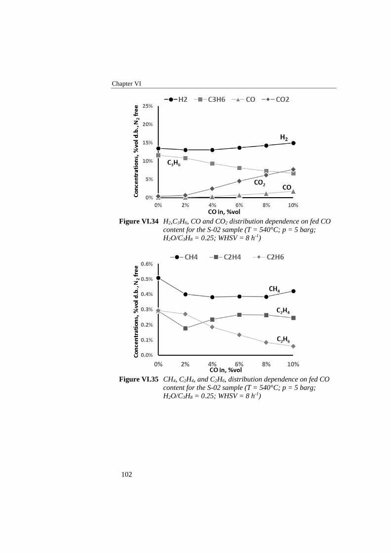
Chapter VI
102
Figure VI.34 H2,C3H6, CO and CO2 distribution dependence on fed CO
content for the S-02 sample (T = 540°C; p = 5 barg;
H2O/C3H8 = 0.25; WHSV = 8 h-1)
Figure VI.35 CH4, C2H4, and C2H6, distribution dependence on fed CO
content for the S-02 sample (T = 540°C; p = 5 barg;
H2O/C3H8 = 0.25; WHSV = 8 h-1)
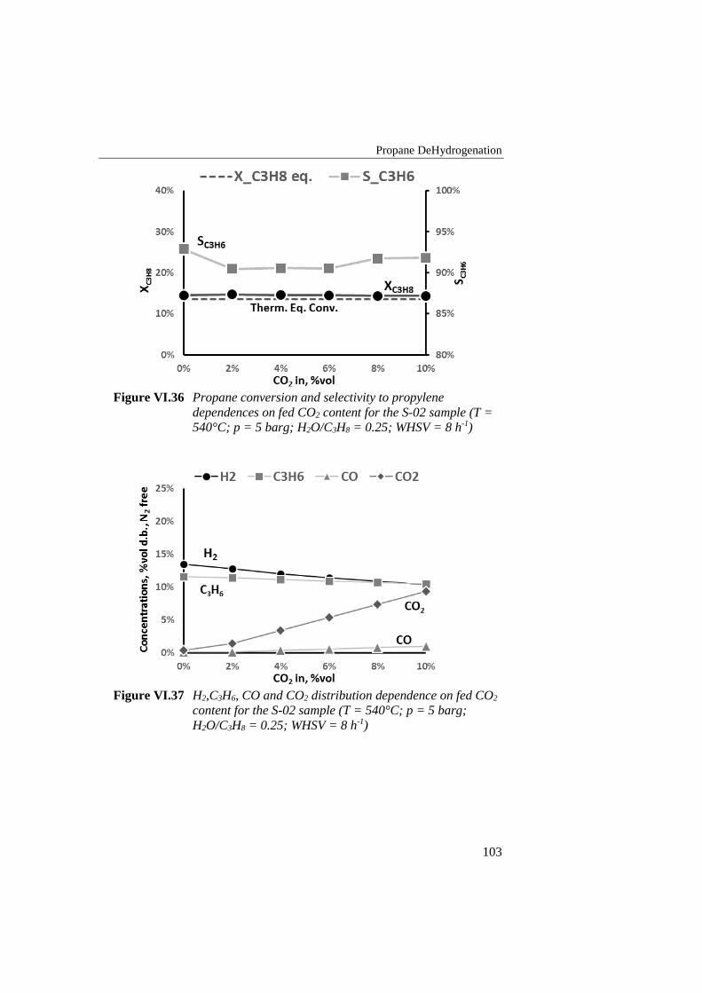
Propane DeHydrogenation
103
Figure VI.36 Propane conversion and selectivity to propylene
dependences on fed CO2 content for the S-02 sample (T =
540°C; p = 5 barg; H2O/C3H8 = 0.25; WHSV = 8 h-1)
Figure VI.37 H2,C3H6, CO and CO2 distribution dependence on fed CO2
content for the S-02 sample (T = 540°C; p = 5 barg;
H2O/C3H8 = 0.25; WHSV = 8 h-1)
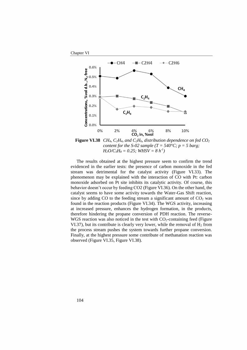
Chapter VI
104
Figure VI.38 CH4, C2H4, and C2H6, distribution dependence on fed CO2
content for the S-02 sample (T = 540°C; p = 5 barg;
H2O/C3H8 = 0.25; WHSV = 8 h-1)
The results obtained at the highest pressure seem to confirm the trend
evidenced in the earlier tests: the presence of carbon monoxide in the fed
stream was detrimental for the catalyst activity (Figure VI.33). The
phenomenon may be explained with the interaction of CO with Pt: carbon
monoxide adsorbed on Pt site inhibits its catalytic activity. Of course, this
behavior doesn’t occur by feeding CO2 (Figure VI.36). On the other hand, the
catalyst seems to have some activity towards the Water-Gas Shift reaction,
since by adding CO to the feeding stream a significant amount of CO2 was
found in the reaction products (Figure VI.34). The WGS activity, increasing
at increased pressure, enhances the hydrogen formation, in the products,
therefore hindering the propane conversion of PDH reaction. The reverse-
WGS reaction was also noticed in the test with CO2-containing feed (Figure
VI.37), but its contribute is clearly very lower, while the removal of H2 from
the process stream pushes the system towards further propane conversion.
Finally, at the highest pressure some contribute of methanation reaction was
observed (Figure VI.35, Figure VI.38).
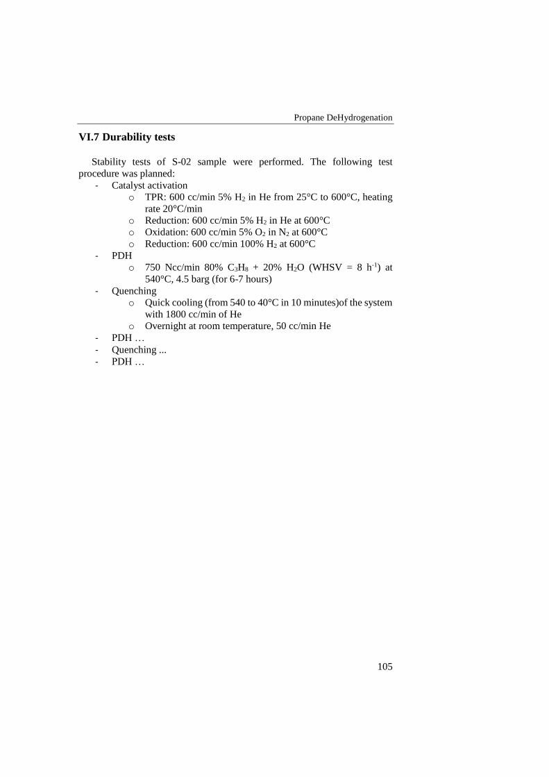
Propane DeHydrogenation
105
VI.7 Durability tests
Stability tests of S-02 sample were performed. The following test
procedure was planned:
- Catalyst activation
o TPR: 600 cc/min 5% H2 in He from 25°C to 600°C, heating
rate 20°C/min
o Reduction: 600 cc/min 5% H2 in He at 600°C
o Oxidation: 600 cc/min 5% O2 in N2 at 600°C
o Reduction: 600 cc/min 100% H2 at 600°C
- PDH
o 750 Ncc/min 80% C3H8 + 20% H2O (WHSV = 8 h-1) at
540°C, 4.5 barg (for 6-7 hours)
- Quenching
o Quick cooling (from 540 to 40°C in 10 minutes)of the system
with 1800 cc/min of He
o Overnight at room temperature, 50 cc/min He
- PDH …
- Quenching ...
- PDH …
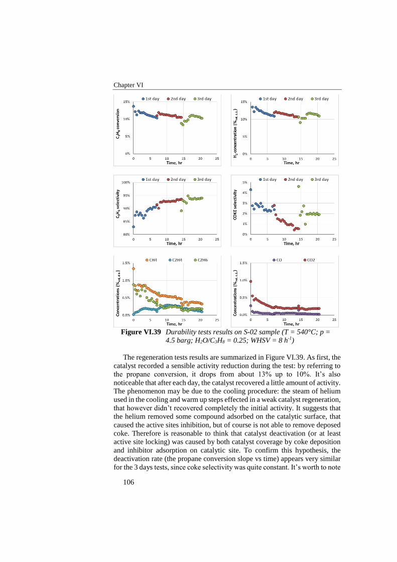
Chapter VI
106
Figure VI.39 Durability tests results on S-02 sample (T = 540°C; p =
4.5 barg; H2O/C3H8 = 0.25; WHSV = 8 h-1)
The regeneration tests results are summarized in Figure VI.39. As first, the
catalyst recorded a sensible activity reduction during the test: by referring to
the propane conversion, it drops from about 13% up to 10%. It’s also
noticeable that after each day, the catalyst recovered a little amount of activity.
The phenomenon may be due to the cooling procedure: the steam of helium
used in the cooling and warm up steps effected in a weak catalyst regeneration,
that however didn’t recovered completely the initial activity. It suggests that
the helium removed some compound adsorbed on the catalytic surface, that
caused the active sites inhibition, but of course is not able to remove deposed
coke. Therefore is reasonable to think that catalyst deactivation (or at least
active site locking) was caused by both catalyst coverage by coke deposition
and inhibitor adsorption on catalytic site. To confirm this hypothesis, the
deactivation rate (the propane conversion slope vs time) appears very similar
for the 3 days tests, since coke selectivity was quite constant. It’s worth to note
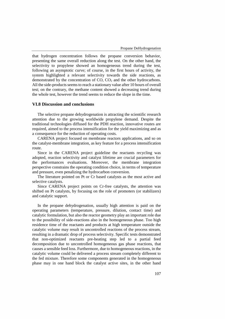
Propane DeHydrogenation
107
that hydrogen concentration follows the propane conversion behavior,
presenting the same overall reduction along the test. On the other hand, the
selectivity to propylene showed an homogeneous trend during the test,
following an asymptotic curve; of course, in the first hours of activity, the
system highlighted a relevant selectivity towards the side reactions, as
demonstrated by the concentration of CO, CO2 and the other hydrocarbons.
All the side-products seems to reach a stationary value after 10 hours of overall
test; on the contrary, the methane content showed a decreasing trend during
the whole test, however the trend seems to reduce the slope in the time.
VI.8 Discussion and conclusions
The selective propane dehydrogenation is attracting the scientific research
attention due to the growing worldwide propylene demand. Despite the
traditional technologies diffused for the PDH reaction, innovative routes are
required, aimed to the process intensification for the yield maximizing and as
a consequence for the reduction of operating costs.
CARENA project focused on membrane reactors applications, and so on
the catalyst-membrane integration, as key feature for a process intensification
route.
Since in the CARENA project guideline the reactants recycling was
adopted, reaction selectivity and catalyst lifetime are crucial parameters for
the performances evaluations. Moreover, the membrane integration
perspective constrains the operating condition choice, in terms of temperature
and pressure, even penalizing the hydrocarbon conversion.
The literature pointed on Pt or Cr based catalysts as the most active and
selective catalysts.
Since CARENA project points on Cr-free catalysts, the attention was
shifted on Pt catalysts, by focusing on the role of promoters (or stabilizers)
and catalytic support.
In the propane dehydrogenation, usually high attention is paid on the
operating parameters (temperature, pressure, dilution, contact time) and
catalytic formulation, but also the reactor geometry play an important role due
to the possibility of side-reactions also in the homogeneous phase. Too high
residence time of the reactants and products at high temperature outside the
catalytic volume may result in uncontrolled reactions of the process stream,
resulting in a dramatic drop of process selectivity. Specific tests demonstrated
that non-optimized reactants pre-heating step led to a partial feed
decomposition due to uncontrolled homogeneous gas phase reactions, that
causes a sensible feed loss. Furthermore, due to homogeneous reactions, in the
catalytic volume could be delivered a process stream completely different to
the fed mixture. Therefore some components generated in the homogeneous
phase may in one hand block the catalyst active sites, in the other hand
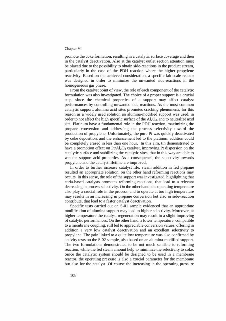
Chapter VI
108
promote the coke formation, resulting in a catalytic surface coverage and then
in the catalyst deactivation. Also at the catalyst outlet section attention must
be played due to the possibility to obtain side-reactions in the product stream,
particularly in the case of the PDH reaction where the higher propylene
reactivity. Based on the achieved consideration, a specific lab-scale reactor
was designed in order to minimize the unwanted side-reactions in the
homogeneous gas phase.
From the catalyst point of view, the role of each component of the catalytic
formulation was also investigated. The choice of a proper support is a crucial
step, since the chemical properties of a support may affect catalyst
performances by controlling unwanted side-reactions. As the most common
catalytic support, alumina acid sites promotes cracking phenomena, for this
reason as a widely used solution an alumina-modified support was used, in
order to not affect the high specific surface of the Al2O3, and to neutralize acid
site. Platinum have a fundamental role in the PDH reaction, maximizing the
propane conversion and addressing the process selectivity toward the
production of propylene. Unfortunately, the pure Pt was quickly deactivated
by coke deposition, and the enhancement led to the platinum addition could
be completely erased in less than one hour. In this aim, tin demonstrated to
have a promotion effect on Pt/Al2O3 catalyst, improving Pt dispersion on the
catalytic surface and stabilizing the catalytic sites, that in this way are able to
weaken support acid properties. As a consequence, the selectivity towards
propylene and the catalyst lifetime are improved.
In order to further increase catalyst life, steam addition in fed propane
resulted an appropriate solution, on the other hand reforming reactions may
occurs. In this sense, the role of the support was investigated, highlighting that
ceria-based catalysts promotes reforming reactions, that lead to a relevant
decreasing in process selectivity. On the other hand, the operating temperature
also play a crucial role in the process, and to operate at too high temperature
may results in an increasing in propane conversion but also in side-reaction
contribute, that lead to a faster catalyst deactivation.
Specific tests carried out on S-01 sample evidenced that an appropriate
modification of alumina support may lead to higher selectivity. Moreover, at
higher temperature the catalyst regeneration may result in a slight improving
of catalytic performances. On the other hand, a lower temperature, compatible
to a membrane coupling, still led to appreciable conversion values, offering in
addition a very low catalyst deactivation and an excellent selectivity to
propylene. The gain linked to a quite low temperature was also confirmed by
activity tests on the S-02 sample, also based on an alumina-modified support.
The two formulations demonstrated to be not much sensible to reforming
reaction, while the fed steam amount help to minimize the selectivity to coke.
Since the catalytic system should be designed to be used in a membrane
reactor, the operating pressure is also a crucial parameter for the membrane
but also for the catalyst. Of course the increasing in the operating pressure
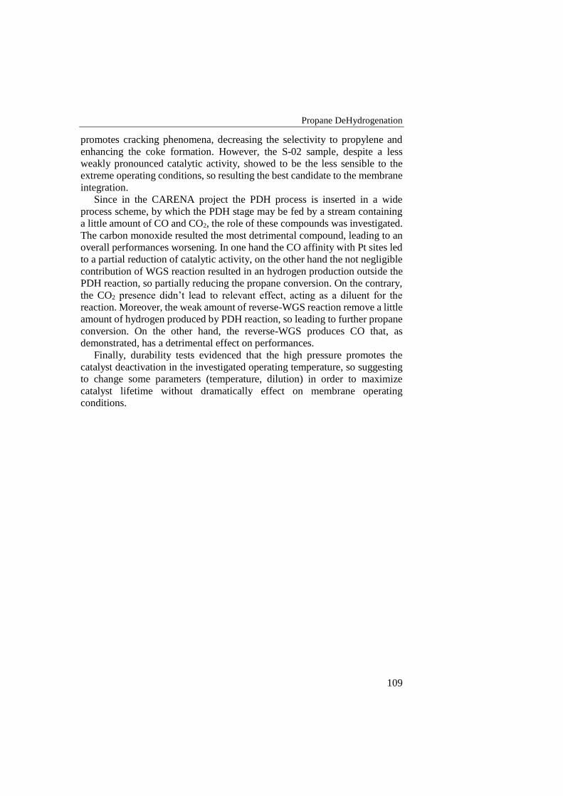
Propane DeHydrogenation
109
promotes cracking phenomena, decreasing the selectivity to propylene and
enhancing the coke formation. However, the S-02 sample, despite a less
weakly pronounced catalytic activity, showed to be the less sensible to the
extreme operating conditions, so resulting the best candidate to the membrane
integration.
Since in the CARENA project the PDH process is inserted in a wide
process scheme, by which the PDH stage may be fed by a stream containing
a little amount of CO and CO2, the role of these compounds was investigated.
The carbon monoxide resulted the most detrimental compound, leading to an
overall performances worsening. In one hand the CO affinity with Pt sites led
to a partial reduction of catalytic activity, on the other hand the not negligible
contribution of WGS reaction resulted in an hydrogen production outside the
PDH reaction, so partially reducing the propane conversion. On the contrary,
the CO2 presence didn’t lead to relevant effect, acting as a diluent for the
reaction. Moreover, the weak amount of reverse-WGS reaction remove a little
amount of hydrogen produced by PDH reaction, so leading to further propane
conversion. On the other hand, the reverse-WGS produces CO that, as
demonstrated, has a detrimental effect on performances.
Finally, durability tests evidenced that the high pressure promotes the
catalyst deactivation in the investigated operating temperature, so suggesting
to change some parameters (temperature, dilution) in order to maximize
catalyst lifetime without dramatically effect on membrane operating
conditions.

111
Conclusions
The research activity was carried out within the involving of the ProCEED
lab of the University of Salerno within the CARENA project. The CARENA
project focused on the process intensification of some productive scheme by
catalytic membrane reactor; the role of UNISA within CARENA was to test
and study catalysts for methane reforming and propane dehydrogenation
formulated by partners, and to address suppliers towards catalytic
formulations able to maximize selectivity and catalyst lifetime.
VII.1 Methane reforming
An auto-thermal reformer thermally integrated was designed and setup in
order to test structured catalysts. Catalytic tests were performed on 3 different
kinds of catalyzed foams, in order to evaluate the influence of heat transfer
mechanism in the system performances. All foams are activated by a catalytic
coverage realized by Johnson Matthey within the Ca.Re.N.A project.
Catalytic foams showed excellent activity in terms of both methane
conversion and hydrogen yield, resulting able to reach thermodynamic
equilibrium in very short residence time.
Preliminary tests, demonstrated that due to the temperature peak in the
catalytic bed the ATR process appears not suitable for the integration in a
membrane reactor. It may be however considered an open architecture, in
which catalytic stage and hydrogen removal stage are separated.
The use of thermally conductive catalyzed foams lead to a faster approach
to thermodynamic equilibrium, as reported in the comparison with a
commercial honeycomb monolithic catalyst. The complex foam structure in
one hand promotes a continuous mixing of the reaction stream, in the other
hand allows conductive heat transfer along the catalyst resulting in a flatter
thermal profile. As a result, the more the temperature profile appears flat, the
more the reaction stream quickly reaches a composition close to the final
value. In addition, by achieving a flat thermal profile, is possible in one hand
to reduce hot-spot phenomena, that may causes local cracking phenomena, in
the other hand to promote and then to accelerate the endothermic reforming
Chapter VII
112
reactions, so allowing to operate at higher GHSV values (both by increasing
reactants rate or reducing catalytic volume).
In a first analysis, no simply direct correlations are found between material
intrinsic thermal conductivity and thermal profile measured in the foam:
paradoxically, ZrO2 has the lower thermal conductivity, but ZrO2 foam results
in the flatter thermal profile. The unexpected result is due to the very complex
solid-gas system, and a very large amount of parameters should be considered.
As a final consideration, the overall heat exchange rates in both solid-gas and
solid-solid phases play a crucial role in this kind of catalytic system, and the
optimal thermal management may improve system performances.
On the contrary, SR catalytic tests carried out on foam catalysts evidenced
the relevance of heat transfer management on the catalytic performances. In
particular, experimental results carried out at relatively low temperature
(550°C) and different operating conditions, demonstrated that the samples
characterized by the highest thermal conductivity showed the best results in
terms of methane conversion and hydrogen yield. The beneficial effect was
more evident in the more extreme conditions (higher S/C ratios, higher
reactants rates), in which the heat transfer limitations are more evident. One
of the most interesting effect resulting by the highest support thermal
conductivity may be the possibility to obtain a flattening of the radial profile,
that in one hand maximizes the heat transfer rate from the reactor walls to the
catalyst.
Moreover, the random tridimensional structure of the foam catalyst,
characterized by very high porosity and tortuosity, enhances the mass transfer
and the mixing of the reacting mixture, obtaining a more uniform reaction
condition along the whole catalytic bed, resulting in a more effective reaction
system.
VII.2 Propane DeHydrogenation
In the propane dehydrogenation, usually high attention is paid on the
operating parameters (temperature, pressure, dilution, contact time) and
catalytic formulation, but also the reactor geometry play an important role due
to the possibility of side-reactions also in the homogeneous phase. Too high
residence time of the reactants and products at high temperature outside the
catalytic volume may result in uncontrolled reactions of the process stream,
resulting in a dramatic drop of process selectivity. Specific tests demonstrated
that non-optimized reactants pre-heating step led to a partial feed
decomposition due to uncontrolled homogeneous gas phase reactions, that
causes a sensible feed loss. Furthermore, due to homogeneous reactions, in the
catalytic volume could be delivered a process stream completely different to
the fed mixture. Therefore some components generated in the homogeneous
phase may in one hand block the catalyst active sites, in the other hand
promote the coke formation, resulting in a catalytic surface coverage and then
Conclusions
113
in the catalyst deactivation. Also at the catalyst outlet section attention must
be played due to the possibility to obtain side-reactions in the product stream,
particularly in the case of the PDH reaction where the higher propylene
reactivity. Based on the achieved consideration, a specific lab-scale reactor
was designed in order to minimize the unwanted side-reactions in the
homogeneous gas phase.
From the catalyst point of view, the role of each component of the catalytic
formulation was also investigated. Performed tests demonstrated the chemical
properties of a support may affect catalyst performances by promoting
unwanted side-reactions. Platinum played a fundamental role in the PDH
reaction, maximizing the propane conversion and addressing the process
selectivity toward the production of propylene. Unfortunately, the pure Pt was
quickly deactivated by coke deposition: in this regard, tin demonstrated to
have a promotion effect on Pt/Al2O3 catalyst, improving Pt dispersion on the
catalytic surface and stabilizing the catalytic sites. As a consequence, the
selectivity towards propylene and the catalyst lifetime are improved.
If in one hand steam addition in fed propane increases catalyst life, on the
other hand reforming reactions may occur. In this sense, the role of the support
was investigated, highlighting that ceria-based catalysts promotes reforming
reactions, leading to a relevant decrease in process selectivity.
Catalytic formulation was addressed to use alumina-modified support, in
order to not affect the high specific surface of the Al2O3, and to neutralize its
surface acidity. CARENA partners provided Pt-Sn based catalysts on
modified alumina. Specific tests carried out on S-01 sample evidenced that an
appropriate modification of alumina support may lead to higher selectivity.
Moreover, at higher temperature the catalyst regeneration may result in an
improving in catalytic performances. On the other hand, a lower temperature,
compatible to a membrane coupling, still led to appreciable conversion values,
offering in addition a very low catalyst deactivation and an excellent
selectivity to propylene. The gain linked to a quite low temperature was also
confirmed by activity tests on the S-02 sample, also based on an alumina-
modified support. The two formulations demonstrated to be not much sensible
to reforming reaction, while the fed steam amount help to minimize the
selectivity to coke. Since the catalytic system should be designed to be used
in a membrane reactor, the operating pressure is also a crucial parameter for
the membrane but also for the catalyst. Of course the increasing in the
operating pressure promotes cracking phenomena, decreasing the selectivity
to propylene and enhancing the coke formation. However, the S-02 sample,
despite a less weakly pronounced initial catalytic activity, resulted the less
sensible to the extreme operating conditions, so resulting the best candidate to
the membrane integration.
According to the PDH stage exploit in the CARENA project, the effect of
the presence of CO and CO2 in the fed stream was investigated. The carbon
monoxide resulted the most detrimental compound, leading to an overall
Chapter VII
114
performances worsening. In one hand the CO affinity with Pt sites led to a
partial reduction of catalytic activity, on the other hand the not negligible
contribution of WGS reaction resulted in an hydrogen production outside the
PDH reaction, so partially reducing the propane conversion. On the contrary,
the CO2 presence didn’t lead to relevant effect, acting as a diluent for the
reaction. Moreover, the weak amount of reverse-WGS reaction remove a little
amount of hydrogen produced by PDH reaction, so leading to further propane
conversion. On the other hand, the reverse-WGS produces CO that, as
demonstrated, has a detrimental effect on performances.
Finally, durability tests evidenced that the high pressure promotes the
catalyst deactivation in the investigated operating temperature, so suggesting
to change some parameters (temperature, dilution) in order to maximize
catalyst lifetime without dramatically effect on membrane operating
conditions.
115
References
BAI, L., ZHOU, Y., ZHANG, Y., LIU, H., SHENG, X. & XUE, M. 2011.
Influence of the Competitive Adsorbates on the Catalytic Properties
of PtSnNaMg/ZSM-5 Catalysts for Propane Dehydrogenation.
Industrial & Engineering Chemistry Research, 50, 4345-4350.
BARGHI, B., FATTAHI, M. & KHORASHEH, F. 2012. Kinetic modeling of
propane dehydrogenation over an industrial catalyst in the presence
of oxygenated compounds. Reaction Kinetics, Mechanisms and
Catalysis, 107, 141-155.
BERG, R. C. & VORA, B. V. 1982. Detergent alkylate. Encyclopedia of
Chemical Processing and Design. New York: Marcel Dekker.
BHARADWAJ SS, S. L. 1995. Catalytic partial oxidation of natural gas to
syngas. 42, 109-127.
BLOCH, H. S. 1969. and other patents on the catalytic. U.S. patent
application.
CHEN, M., XU, J., LIU, Y.-M., CAO, Y., HE, H.-Y. & ZHUANG, J.-H. 2010.
Supported indium oxide as novel efficient catalysts for
dehydrogenation of propane with carbon dioxide. Applied Catalysis
A: General, 35-41.
CRACIUN R, D. W., KNOZINGER H. 2002. The effect of CeO2 structure
on the activity of supported Pd catalysts used for methane dteam
reforming. 230, 153-168.
D.C.R.M. SANTOS, L. M., F.B. PASSOS 2009. The effect of the addition of
Y2O3 to Ni/a-Al2O3 catalysts on the autothermal reforming of
methane. (articolo in stampa).
DAVANNEY, M. 2009. Marketing Research Report: Propylene. In:
CONSULTING, S. (ed.) Chemical Economics Handbook.
DHAMMIKE DISSANAYAKE, M. P. R., KARL C. C. KHARAS2 AND
JACK H. LUNSFORD 1991. Partial oxidation of methane to carbon
monoxide and hydrogen over a Ni/Al2O3 catalyst 132, 117-127
DIDENKO, L. P., SAVCHENKO, V. I., SEMENTSOVA, L. A., CHIZHOV,
P. E. & BYKOV, L. A. 2013. Dehydrogenation of propane in a
combined membrane reactor with hydrogen-permeable palladium
module. Petroleum Chemistry, 53, 27-32.
Chapter VIII
116
DINSE, A., FRANK, B., HESS, C., HABEL, D. & SCHOMACKER, R. 2008.
Oxidative dehydrogenation of propane over low-loaded vanadia
catalysts: Impact of the support material on kinetics and selectivity.
Journal of Molecular Catalysis A: Chemical, 28-37.
DONSÌ, F., CIMINO, S., DI BENEDETTO, A., PIRONE, R. & RUSSO, G.
2005. The effect of support morphology on the reaction of oxidative
dehydrogenation of ethane to ethylene at short contact times.
Catalysis Today, 551-559.
DUAN, Y., ZHOU, Y., ZHANG, Y., SHENG, X. & XUE, M. 2010. Effect of
Sodium Addition to PtSn/AlSBA-15 on the Catalytic Properties in
Propane Dehydrogenation. Catalysis Letters, 141, 120-127.
DUAN, Y., ZHOU, Y., ZHANG, Y., SHENG, X., ZHOU, S. & ZHANG, Z.
2012. Effect of aluminum modification on catalytic properties of
PtSn-based catalysts supported on SBA-15 for propane
dehydrogenation. Journal of Natural Gas Chemistry, 21, 207-214.
EGOY, M. 2012. European propylene sellers face a tough fourth quarter
market [Online].
FARJOO, A., KHORASHEH, F., NIKNADDAF, S. & SOLTANI, M. 2011.
Kinetic modeling of side reactions in propane dehydrogenation over
Pt - Sn/γ - Al2O3 catalyst. Scientia Iranica, 18, 458-464.
FATTAHI, M., KHORASHES, F., SAHEBDELFAR, S., TAHRIRI
ZANGENEHB, F., GANJI, K. & SAEEDIZAD, M. 2011. The effect
of oxygenate additives on the performance of Pt–Sn/γ-Al2O3 catalyst
in the propane dehydrogenation process. Scientia Iranica C ( ) ( ), –.
GRAIG, R. G. & SPENCE, D. C. 1986. Catalytic dehydrogenation of
liquefied petroleum gas by the Houdry Catofin and Catadiene
processes. Handbook of Petroleum Refining Processes. New York:
McGraw-Hill.
HAENSEL, V. 1952. and other patents on catalytic reforming with Pt
catalysts assigned to UOP. U.S. patent application.
HUANG, L., XU, B., YANG, L. & FAN, Y. 2008. Propane dehydrogenation
over the PtSn catalyst supported on alumina-modified SBA-15.
Catalysis Communications, 2593-2597.
J. GAO, J. G., D. LIANG, Z. HOU, J. FEI, X. ZHENG 2008. Production of
syngas via autothermal reforming of methane in a fluidized-bed
reactor over the combined CeO2–ZrO2/SiO2 supported Ni catalysts.
33, 5493-5500.
JR-ROSTRUP-NIELSEN 1975. Steam reforming catalyst - an investigation
of catalyst for tubolar steam reforming of hydrocarbons.
JR-ROSTRUP-NIELSEN 1993. Production of syntesis gas. 18, 305-324.
KLEY, I. & TRAA, Y. 2012. Influence of acid sites on the propene selectivity
during propane dehydrogenation on zeolite Pt/Zn,Na-MCM-22.
Microporous and Mesoporous Materials, 164, 145-147.
References
117
KUMAR, M. S., CHEN, D., HOLMEN, A. & WALMSLEY, J. C. 2009.
Dehydrogenation of propane over Pt-SBA-15 and Pt-Sn-SBA-15:
Effect of Sn on the dispersion of Pt and catalytic behavior. Catalysis
Today, 17-23.
LEMOS, W. 2011. NPRA supplement: Propylene on a rocky upward trend
[Online]. ICIS Chemical Business. Available:
http://www.icis.com/resources/news/2011/03/28/9446613/npra-
supplement-propylene-on-a-rocky-upward-trend/.
LI, Q., SUI, Z., ZHOU, X., ZHU, Y., ZHOU, J. & CHEN, D. 2011. Coke
Formation on Pt–Sn/Al2O3 Catalyst in Propane Dehydrogenation:
Coke Characterization and Kinetic Study. Topics in Catalysis, 54,
888-896.
LÖFBERGA, A., ESSAKHI, A., PAUL, S., SWESI, Y., ZANOTA, M. L.,
PITAULT, I. & SUPIOT, P. 2011. Use of catalytic oxidation and
dehydrogenation of hydrocarbons reactions to highlight improvement
of heat transfer in catalytic metallic foams. Chemical Engineering
Journal, 49-56.
M. M.V.M. SOUZA, M. S. 2005. Autothermal reforming of methane over
Pt/ZrO2/Al2O3 catalysts. 281, 19-24.
M. NURUNNABI, Y. M., S. KADO, B. LI, K. KUNIMORI, K. SUZUKI, K.
FUJIMOTO, K. TOMISHIGE 2006. Additive effect of noble metals
on NiO-MgO solid solution in oxidative steam reforming of methane
under atmospheric and pressurized conditions. 299, 145-156
MEDRANO, J. A., JULIÁN, I., GARCÍA-GARCÍA, F. R., LI, K.,
HERGUIDO, J. & MENÉNDEZ, M. 2013. Two-Zone Fluidized Bed
Reactor (TZFBR) with Palladium Membrane for Catalytic Propane
Dehydrogenation: Experimental Performance Assessment. Industrial
& Engineering Chemistry Research, 130304122611001.
NAWAZ, Z., TANG, X., ZHANG, Q., WANG, D. & FEI, W. 2009. SAPO-
34 supported Pt–Sn-based novel catalyst for propane dehydrogenation
to propylene. Catalysis Communications, 1925-1930.
NEXANT 2009. Alternative Routes to Propylene. ChemSystem PERP
Program. New York, USA.
OVSITSER, O., SCHOMAECKER, R., KONDRATENKO, E. V.,
WOLFRAM, T. & TRUNSCHKE, A. 2012. Highly selective and
stable propane dehydrogenation to propene over dispersed VOx-
species under oxygen-free and oxygen-lean conditions. Catalysis
Today, 192, 16-19.
PALMA, V., PALO, E., RICCA, A. & CIAMBELLI, P. 2011. Compact
Multi-fuel Autothermal Reforming Catalytic Reactor for H2
Production. Chemical Engineering Transactions, 25, 641-646.
PAVLOVA, S. N., SADYKOV, V. A., FROLOVA, Y. V., SAPUTINA, N.
F., VEDENIKIN, P. M., ZOLOTARSKII, I. A. & KUZMIN, V. A.
2003. The effect of the catalytic layer design on oxidative
Chapter VIII
118
dehydrogenation of propane over monoliths at short contact times.
Chemical Engineering Journal, 227-234.
REN, Y., ZHANG, F., HUA, W., YUE, Y. & GAO, Z. 2009. ZnO supported
on high silica HZSM-5 as new catalysts for dehydrogenation of
propane to propene in the presence of CO2. Catalysis Today, 316-
322.
ROH, H. S., JUN, K. W., DONG, W. S., CHANG, J. S., PARK, S. E. & JOE,
Y. I. 2002. Highly active and stable Ni/Ce–ZrO2 catalyst for H2
production from methane 181, 137-142
RUCKENSTEIN, E. & HU, Y. H. 1999. Methane partial oxidation over
NiO/MgO solid solution catalysts 183, 85-92.
S. AYABE, H. O., T. UTAKA, R. KIKUCHI, K. SASAKI, Y. TERAOKA,
K. EGUCHI 2003. Catalytic autothermal reforming of methane and
propane over supported metal catalysts. 241, 261-269.
S. BEDRANE, C. D., D. DUPREZ 2002. Investigation of the oxygen storage
process on ceria- and ceria–zirconia-supported catalysts. 75, 401-405
SAMAVATI, A., FATTAHI, M. & KHORASHEH, F. 2013. Modeling of Pt-
Sn/γ-Al2O3 deactivation in propane dehydrogenation with
oxygenated additives. Korean Journal of Chemical Engineering, 30,
55-61.
SANFILIPPO, D., BUONOMO, F., FUSCO, G. & MIRACCA, I. 1998.
Paraffins Activation through Fluidized Bed Dehydrogenation: the
Answer to Light Olefins Demand Increase. Stud. Surf. Sci. Catal, 919-
924.
SHISHIDO, T., SHIMAMURA, K., TERAMURA, K. & TANAKA, T. 2012.
Role of CO2 in dehydrogenation of propane over Cr-based catalysts.
Catalysis Today, 185, 151-156.
SOKOLOV, S., STOYANOVA, M., RODEMERCK, U., LINKE, D. &
KONDRATENKO, E. V. 2012. Comparative study of propane
dehydrogenation over V-, Cr-, and Pt-based catalysts: Time on-stream
behavior and origins of deactivation. Journal of Catalysis, 293, 67-
75.
SUN, P., SIDDIQI, G., VINING, W. C., CHI, M. & BELL, A. T. 2011. Novel
Pt/Mg(In)(Al)O catalysts for ethane and propane dehydrogenation.
Journal of Catalysis, 282, 165-174.
TROVARELLI, A. 1996. Catalytic Properties of Ceria and CeO2-Containing
Materials 38, 439-520.
VU, B. K. & SHIN, E. W. 2010. Influence of Oxygen Mobility over Supported
Pt Catalysts on Combustion Temperature of Coke Generated in
Propane Dehydrogenation. Catalysis Letters, 141, 699-704.
VU, B. K., SHIN, E. W., AHN, I. Y., HA, J.-M., SUH, D. J., KIM, W.-I.,
KOH, H.-L., CHOI, Y. G. & LEE, S.-B. 2012. The Effect of Tin–
Support Interaction on Catalytic Stability over Pt–Sn/xAl–SBA-15
References
119
Catalysts for Propane Dehydrogenation. Catalysis Letters, 142, 838-
844.
VU, B. K., SONG, M. B., AHN, I. Y., SUH, Y.-W., SUH, D. J., KIM, J. S. &
SHIN, E. W. 2011a. Location and structure of coke generated over
Pt–Sn/Al2O3 in propane dehydrogenation. Journal of Industrial and
Engineering Chemistry, 17, 71-76.
VU, B. K., SONG, M. B., AHN, I. Y., SUH, Y.-W., SUH, D. J., KIM, W.-I.,
KOH, H.-L., CHOI, Y. G. & SHIN, E. W. 2011b. Pt–Sn alloy phases
and coke mobility over Pt–Sn/Al2O3 and Pt–Sn/ZnAl2O4 catalysts
for propane dehydrogenation. Applied Catalysis A: General, 25-33.
VU, B. K., SONG, M. B., AHN, I. Y., SUH, Y.-W., SUH, D. J., KIM, W.-I.
L., KOH, H.-L., CHOI, Y. G. & SHIN, E. W. 2011c. Propane
dehydrogenation over Pt–Sn/Rare-earth-doped Al2O3: Influence of
La, Ce, or Y on the formation and stability of Pt–Sn alloys. Catalysis
Today, 164, 214-220.
WADDAMS, A. L. 1980. Chemicals from Petroleum - 4th edition, Houston,
Gulf Publishing Company.
WANG, J., ZHANG, F., HUA, W., YUE, Y. & GAO, Z. 2012.
Dehydrogenation of propane over MWW-type zeolites supported
gallium oxide. Catalysis Communications, 18, 63-67.
WEISS, A. H. 1970. The manufacture of propylene (158th Meeting of the
American Chemical Society, 10–12 September 1969). Refining
Petroleum for Chemicals, Advances in Chemistry Series. Washington
DC: American Chemical Society.
X. DONG, X. C., Y. SONG, W. LIN 2007. Effect of Transition Metals (Cu,
Co and Fe) on the Autothermal Reforming of Methane over
Ni/Ce0.2Zr0.1 Al0.7 Oδ Catalyst. 16, 31-36.
X. WU, L. X., D. WENG 2004. The thermal stability and catalytic
performance of Ce-Zr promoted Rh-Pd/g-Al2O3 automotive
catalysts. 221, 375-383.
YU, C.-L., XU, H.-Y., CHEN, X.-R., GE, Q.-J. & LI, W.-Z. 2010.
Preparation, characterization, and catalytic performance of PtZn-
Sn/SBA-15 catalyst for propane dehydrogenation. JOURNAL OF
FUEL CHEMISTRY AND TECHNOLOGY, 38 (3), 308-312.
YU, C., XU, H., GE, Q. & LI, W. 2007. Properties of the metallic phase of
zinc-doped platinum catalysts for propane dehydrogenation. Journal
of Molecular Catalysis A: Chemical, 80–87.