terrahawk horizon® - headsight
TRANSCRIPT

HEADSIGHT.COM | 574.546.5022
Horizon® Manual09062203a
TERRAHAWKHORIZON®

i
Installation
Copyright Headsight, Inc. 2018
About Headsight
Headsight Contact InfoHeadsight, Inc. 4845 3B Road Bremen, IN 46506 Phone: 574-546-5022 Fax: 574-546-5760 Email: [email protected] Web: www.headsight.com
Technical AssistancePhone: 574-220-5511
About this Manual
How to use this manualThe instructions in this manual are in the order that they should be completed for new installations. Complete all applicable instructions in each section before proceeding. Note that some sections are labeled to indicate they only apply to certain machines or applications. An index is available in the front of the manual to help find technical information for previously installed systems.
This icon designates information of which you should take note.
This icon indicates a special tool needed for a given task.
This icon designates an important instruction.
DisclaimersHeadsight®, Horizon®, Terrahawk®, Pinpoint®, Insight®, Foresight®, Feathersight® Truesense™ and Truesight® are trademarks of Headsight, Inc. All other trademarks are property of their respective owners.
SuggestionsIf you have any suggestions to improve this manual please call 574-546-5022 or email [email protected].
Headsight’s products are protected by one or more of the following US Patents 6202395, 6833299, 7310931, 7647753, 9609806 and other patents pending.
ii
Installation
Table of ContentsAbout Headsight ��������������������������������������������������������������������������������������������� iAbout this Manual ������������������������������������������������������������������������������������������� iInstallation �������������������������������������������������������������������������������������������������� 1
Before you Start������������������������������������������������������������������������������������������� 2Installation on Combine ��������������������������������������������������������������������������������� 3
Installing Horizon® Bridge ���������������������������������������������������������������������������� 3Horizon® Power Wire Installation (CNH Only) ����������������������������������������������������� 6
Calibration ��������������������������������������������������������������������������������������������������� 7Connecting Horizon Units ������������������������������������������������������������������������������ 7Connecting Horizon Units with Truesight 2 ���������������������������������������������������������� 7Initial Setup ����������������������������������������������������������������������������������������������� 8System Setup ���������������������������������������������������������������������������������������������� 8Assigning Sensors ���������������������������������������������������������������������������������������� 9Calibrate Horizon ����������������������������������������������������������������������������������������10Combine Calibration ������������������������������������������������������������������������������������11
Settings ������������������������������������������������������������������������������������������������������12Range ������������������������������������������������������������������������������������������������������12TH Offset ��������������������������������������������������������������������������������������������������12TH Start Distance ����������������������������������������������������������������������������������������13
Understanding TH Start Distance �������������������������������������������������������������������13Setting TH Start Distance �����������������������������������������������������������������������������13
2 Sensor Tilt vs 4 Sensor Tilt ��������������������������������������������������������������������������14Tilt Sensitivity��������������������������������������������������������������������������������������������15Foresight® - Gain (Corn Heads) ������������������������������������������������������������������������15Feathersight® - HP Balance (Grain Heads) �����������������������������������������������������������16Outer Sensor Comp/Mount Distance (Grain Heads) �����������������������������������������������17
Understanding Outer Sensor Comp ����������������������������������������������������������������17Setting Mount Distance �������������������������������������������������������������������������������17
Header Pitch Comp ��������������������������������������������������������������������������������������18Understanding Header Pitch Comp �����������������������������������������������������������������18Setting HPitch Sensitivity ����������������������������������������������������������������������������18
Header App Settings - Geringhoff ���������������������������������������������������������������������19Select header model ����������������������������������������������������������������������������������19Set shaft speed alarms ��������������������������������������������������������������������������������19Show shaft speed alarm ������������������������������������������������������������������������������19Show deck plate position �����������������������������������������������������������������������������19Show maintenance reminder ������������������������������������������������������������������������19Header hours �������������������������������������������������������������������������������������������19
Header App Settings - Drago ��������������������������������������������������������������������������19Set shaft speed alarms ��������������������������������������������������������������������������������19Show shaft speed alarm ������������������������������������������������������������������������������19Show maintenance reminder ������������������������������������������������������������������������19Header hours �������������������������������������������������������������������������������������������19
Header App Settings - Shelbourne ��������������������������������������������������������������������20

iii
Set min/max rotor lube speeds ���������������������������������������������������������������������20Show rotor speed alarm ������������������������������������������������������������������������������20Speed drop factor ��������������������������������������������������������������������������������������20Show auger speed alarm �����������������������������������������������������������������������������20Set minimum auger speed ���������������������������������������������������������������������������20Show maintenance reminder ������������������������������������������������������������������������20
Header App Settings - Truesense+ ��������������������������������������������������������������������20Select steering system ��������������������������������������������������������������������������������20Steering Sensitivity ������������������������������������������������������������������������������������20Crop Detect Threshold ��������������������������������������������������������������������������������20Center Calibration �������������������������������������������������������������������������������������20
Operation ���������������������������������������������������������������������������������������������������21Finding VT applications ��������������������������������������������������������������������������������21
John Deere (Gen 4 Displays) �������������������������������������������������������������������������21John Deere (2630 and GS3 Command Center) ����������������������������������������������������21CaseIH and New Holland �����������������������������������������������������������������������������22
Operation �������������������������������������������������������������������������������������������������23Advanced Info ����������������������������������������������������������������������������������������������24
Theory of Operation ������������������������������������������������������������������������������������24Updating Horizon Software ����������������������������������������������������������������������������24
Updating with Techlink™ App �����������������������������������������������������������������������24Updating with USB ������������������������������������������������������������������������������������24
Updating Terrahawk Sensor Software ���������������������������������������������������������������25Horizon Status Light ������������������������������������������������������������������������������������25
LED Blink Sequences ����������������������������������������������������������������������������������25Terrahawk Status Light ���������������������������������������������������������������������������������26
LED Blink Sequences ����������������������������������������������������������������������������������26WIFI ��������������������������������������������������������������������������������������������������������26
Diagnostics �������������������������������������������������������������������������������������������������27Overview ��������������������������������������������������������������������������������������������������27Detailed Sensor ������������������������������������������������������������������������������������������27Signals �����������������������������������������������������������������������������������������������������28Errors �����������������������������������������������������������������������������������������������������28
FCC and IC Compliance Statements ���������������������������������������������������������������������29Notices for Operation of Terrahawk in the US ��������������������������������������������������������30Notices for Operation of Terrahawk in Canada �������������������������������������������������������31STATEMENT OF LIMITED WARRANTY �����������������������������������������������������������������32
1
Installation
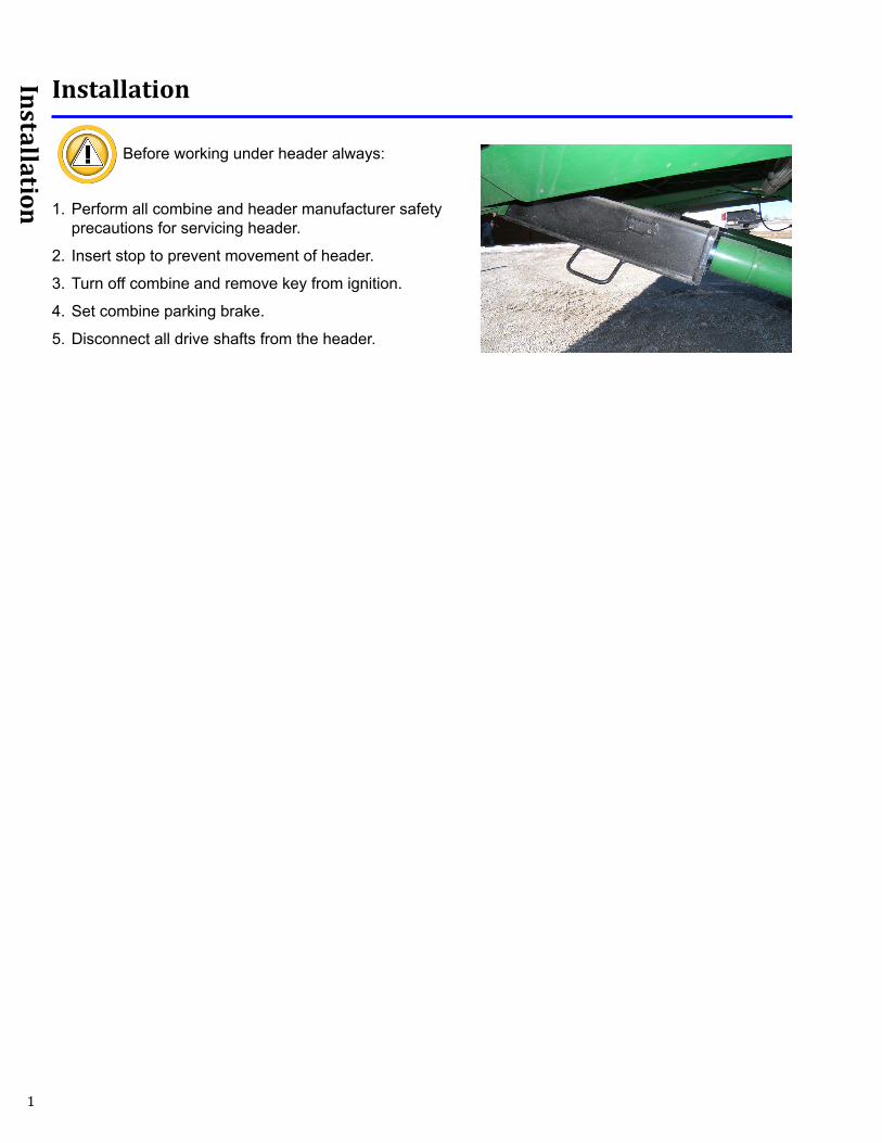
Installation
Before working under header always:
1. Perform all combine and header manufacturer safety precautions for servicing header.
2. Insert stop to prevent movement of header.
3. Turn off combine and remove key from ignition.
4. Set combine parking brake.
5. Disconnect all drive shafts from the header.
2
Installation
Complete the installation portion of the Terrahawk header manual before continuing.
Before you Start
1. Do you have a supported Virtual Terminal Screen?• John Deere - Generation 4 4640, 4600, 2630 or GS3 CommandCenter• CaseIH Pro 700 (must have Virtual Terminal Software installed)• NH Intellivew IV (must have Virtual Terminal Software installed)
If you need VT software for a CIH or CNH display, contact your local dealer and have them install it. The VT software allows Headsight’s Horizon to appear on a VT display. For all CNH displays remove USB (if one is installed) from display until all Headsight VT applications have loaded.
2. Follow “Installation on Combine” specific instructions.
3. Follow “Calibration” section.
4. Follow “Settings” section.
3
Installation
Installation on Combine
Installing Horizon® Bridge
If you are installing a Truesight 2 system with VT display option you will not need to install a bridge. The Truesight 2 control unit will act as a Bridge unit; follow instructions in Truesight 2 installation manual.
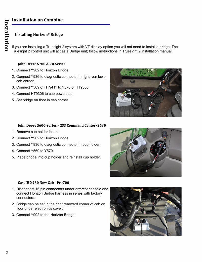
John Deere S700 & 70-Series
1. Connect Y902 to Horizon Bridge.
2. Connect Y936 to diagnostic connector in right rear lower cab corner.
3. Connect Y569 of HT9411 to Y570 of HT9306.
4. Connect HT9306 to cab powerstrip.
5. Set bridge on floor in cab corner.
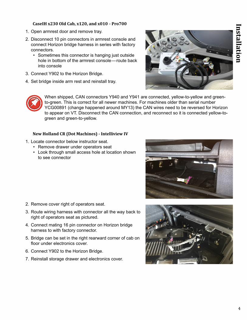
John Deere S600-Series - GS3 Command Center/2630
1. Remove cup holder insert.
2. Connect Y902 to Horizon Bridge.
3. Connect Y936 to diagnostic connector in cup holder.
4. Connect Y569 to Y570.
5. Place bridge into cup holder and reinstall cup holder.
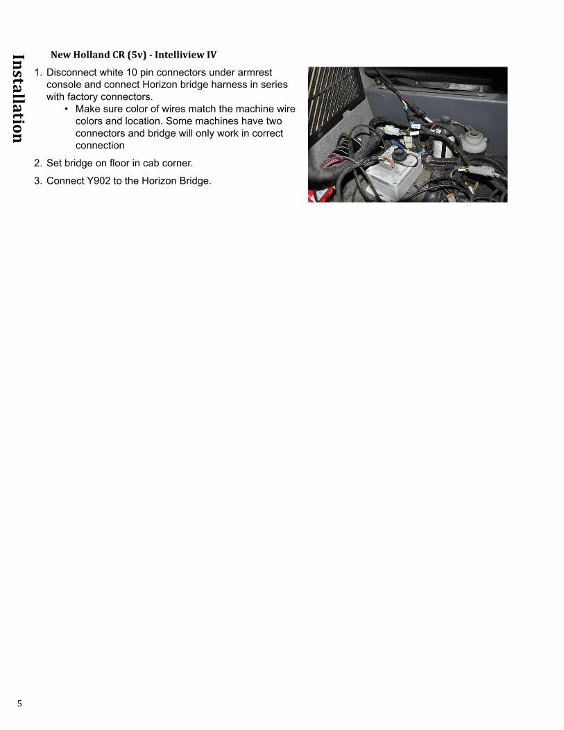
CaseIH X230 New Cab - Pro700
1. Disconnect 16 pin connectors under armrest console and connect Horizon Bridge harness in series with factory connectors.
2. Bridge can be set in the right rearward corner of cab on floor under electronics cover.
3. Connect Y902 to the Horizon Bridge.
4
Installation
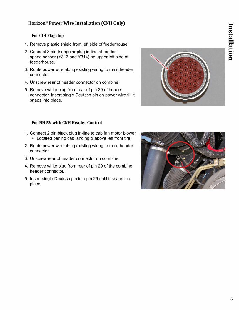
CaseIH x230 Old Cab, x120, and x010 - Pro700
1. Open armrest door and remove tray.
2. Disconnect 10 pin connectors in armrest console and connect Horizon bridge harness in series with factory connectors.• Sometimes this connector is hanging just outside
hole in bottom of the armrest console—route back into console
3. Connect Y902 to the Horizon Bridge.
4. Set bridge inside arm rest and reinstall tray.
When shipped, CAN connectors Y940 and Y941 are connected, yellow-to-yellow and green-to-green. This is correct for all newer machines. For machines older than serial number YCG00891 (change happened around MY13) the CAN wires need to be reversed for Horizon to appear on VT. Disconnect the CAN connection, and reconnect so it is connected yellow-to-green and green-to-yellow.
New Holland CR (Dot Machines) - Intelliview IV
1. Locate connector below instructor seat.• Remove drawer under operators seat• Look through small access hole at location shown
to see connector
2. Remove cover right of operators seat.
3. Route wiring harness with connector all the way back to right of operators seat as pictured.
4. Connect mating 16 pin connector on Horizon bridge harness to with factory connector.
5. Bridge can be set in the right rearward corner of cab on floor under electronics cover.
6. Connect Y902 to the Horizon Bridge.
7. Reinstall storage drawer and electronics cover.
5
Installation
New Holland CR (5v) - Intelliview IV
1. Disconnect white 10 pin connectors under armrest console and connect Horizon bridge harness in series with factory connectors.
• Make sure color of wires match the machine wire colors and location. Some machines have two connectors and bridge will only work in correct connection
2. Set bridge on floor in cab corner.
3. Connect Y902 to the Horizon Bridge.
6
Installation
Horizon® Power Wire Installation (CNH Only)
For CIH Flagship
1. Remove plastic shield from left side of feederhouse.
2. Connect 3 pin triangular plug in-line at feeder speed sensor (Y313 and Y314) on upper left side of feederhouse.
3. Route power wire along existing wiring to main header connector.
4. Unscrew rear of header connector on combine.
5. Remove white plug from rear of pin 29 of header connector. Insert single Deutsch pin on power wire till it snaps into place.
For NH 5V with CNH Header Control
1. Connect 2 pin black plug in-line to cab fan motor blower.• Located behind cab landing & above left front tire
2. Route power wire along existing wiring to main header connector.
3. Unscrew rear of header connector on combine.
4. Remove white plug from rear of pin 29 of the combine header connector.
5. Insert single Deutsch pin into pin 29 until it snaps into place.
7
Calibration
Calibration
Connecting Horizon Units
Horizon only needs to be linked at initial setup or any time a unit is replaced. If you already have or have installed a Truesight 2 system, use the next section to connect units.
1. Select VT application “Horizon Bridge”.• See Operation section of this manual to find Horizon Bridge VT application
2. Select serial number of Horizon base unit to which you want to connect.
3. Wait until screen says “Linked” and Loading of Pools has completed.
4. Go back to main menu and select VT application “Horizon”. • See Operation section of this manual to find Horizon VT Applications
Connecting Horizon Units with Truesight 2
1. Before proceeding, complete the initial setup and calibration in the Truesight 2 manual.
2. Select VT application “Truesight 2”.• See Operation section of this manual to find Truesight 2 VT application
3. Select ”Setup”.
4. Select “WIFI”.
5. Select “Mode” and switch the mode to “Bridge”.
6. Cycle power, be sure that VT and Truesight 2 power cycle to save changes.
7. Go back to VT applications and select “Horizon Bridge”• See Operation section of this manual to find Horizon Bridge VT application
8. Select serial number of Horizon base unit to which you want to connect.
9. Wait until screen says “Linked” and Loading of Pools has completed.
10. Go back to main menu and select VT application “Horizon”. • See Operation section of this manual to find Horizon VT Applications
8
Calibration
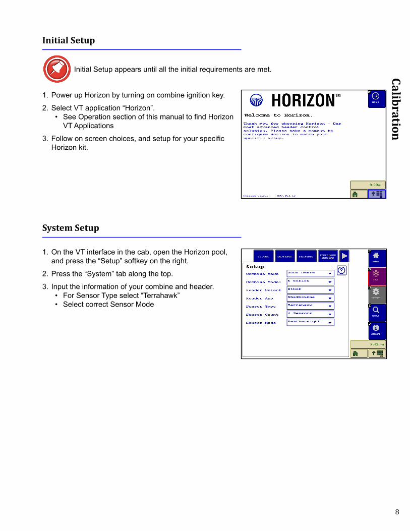
Initial Setup
Initial Setup appears until all the initial requirements are met.
1. Power up Horizon by turning on combine ignition key.
2. Select VT application “Horizon”.• See Operation section of this manual to find Horizon
VT Applications
3. Follow on screen choices, and setup for your specific Horizon kit.
System Setup
1. On the VT interface in the cab, open the Horizon pool, and press the “Setup” softkey on the right.
2. Press the “System” tab along the top.
3. Input the information of your combine and header. • For Sensor Type select “Terrahawk”• Select correct Sensor Mode
9
Calibration
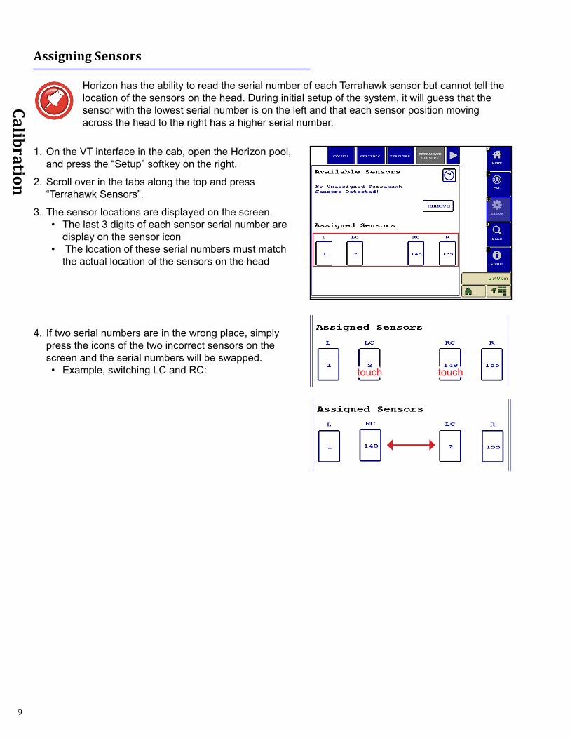
Assigning Sensors
Horizon has the ability to read the serial number of each Terrahawk sensor but cannot tell the location of the sensors on the head. During initial setup of the system, it will guess that the sensor with the lowest serial number is on the left and that each sensor position moving across the head to the right has a higher serial number.
1. On the VT interface in the cab, open the Horizon pool, and press the “Setup” softkey on the right.
2. Scroll over in the tabs along the top and press “Terrahawk Sensors”.
3. The sensor locations are displayed on the screen.• The last 3 digits of each sensor serial number are
display on the sensor icon• The location of these serial numbers must match
the actual location of the sensors on the head
4. If two serial numbers are in the wrong place, simply press the icons of the two incorrect sensors on the screen and the serial numbers will be swapped.• Example, switching LC and RC: touch touch
10
Calibration
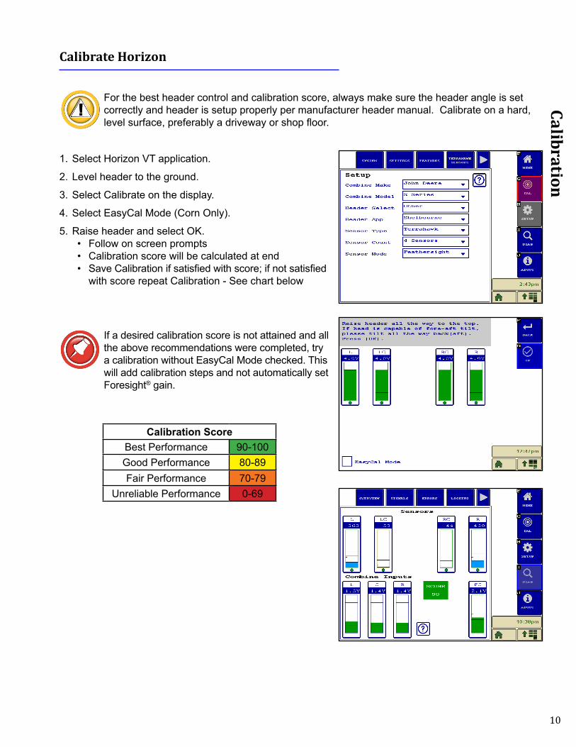
Calibrate Horizon
For the best header control and calibration score, always make sure the header angle is set correctly and header is setup properly per manufacturer header manual. Calibrate on a hard, level surface, preferably a driveway or shop floor.
1. Select Horizon VT application.
2. Level header to the ground.
3. Select Calibrate on the display.
4. Select EasyCal Mode (Corn Only).
5. Raise header and select OK.• Follow on screen prompts• Calibration score will be calculated at end • Save Calibration if satisfied with score; if not satisfied
with score repeat Calibration - See chart below
If a desired calibration score is not attained and all the above recommendations were completed, try a calibration without EasyCal Mode checked. This will add calibration steps and not automatically set Foresight® gain.
Calibration ScoreBest Performance 90-100Good Performance 80-89Fair Performance 70-79
Unreliable Performance 0-69

11
Calibration
Combine Calibration
1. Set Horizon to calibration page.
2. Calibrate header to combine as described in combine user manual.
12
Settings
Settings
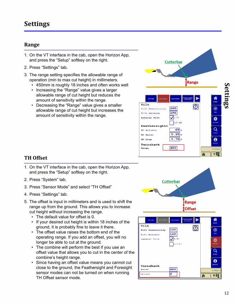
Range
1. On the VT interface in the cab, open the Horizon App, and press the “Setup” softkey on the right.
2. Press “Settings” tab.
3. The range setting specifies the allowable range of operation (min to max cut height) in millimeters. • 450mm is roughly 18 inches and often works well• Increasing the “Range” value gives a larger
allowable range of cut height but reduces the amount of sensitivity within the range.
• Decreasing the “Range” value gives a smaller allowable range of cut height but increases the amount of sensitivity within the range.
TH Offset1. On the VT interface in the cab, open the Horizon App,
and press the “Setup” softkey on the right.
2. Press “System” tab.
3. Press “Sensor Mode” and select “TH Offset”
4. Press “Settings” tab.
5. The offset is input in millimeters and is used to shift the range up from the ground. This allows you to increase cut height without increasing the range.• The default value for offset is 0.• If your desired cut height is within 18 inches of the
ground, it is probably fine to leave it there.• The offset value raises the bottom end of the
operating range. If you add an offset, you will no longer be able to cut at the ground.
• The combine will perform the best if you use an offset value that allows you to cut in the center of the combine’s height range.
• Since having an offset value means you cannot cut close to the ground, the Feathersight and Foresight sensor modes can not be turned on when running TH Offset sensor mode.
13
Settings
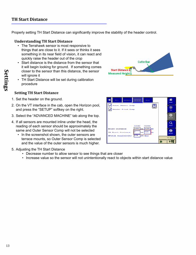
TH Start Distance
Properly setting TH Start Distance can significantly improve the stability of the header control.
Understanding TH Start Distance• The Terrahawk sensor is most responsive to
things that are close to it. If it sees or thinks it sees something in its near field of vision, it can react and quickly raise the header out of the crop
• Start distance is the distance from the sensor that it will begin looking for ground. If something comes closer to the sensor than this distance, the sensor will ignore it
• TH Start Distance will be set during calibration procedure
Setting TH Start Distance1. Set the header on the ground.
2. On the VT interface in the cab, open the Horizon pool, and press the “SETUP” softkey on the right.
3. Select the “ADVANCED MACHINE” tab along the top.
4. If all sensors are mounted inline under the head, the reading of each sensor should be approximately the same and Outer Sensor Comp will not be selected• In the screenshot shown, the outer sensors are
terrace mounts, so Outer Sensor Comp is selected and the value of the outer sensors is much higher.
5. Adjusting the TH Start Distance• Decrease number to allow sensor to see things that are closer• Increase value so the sensor will not unintentionally react to objects within start distance value
14
Settings
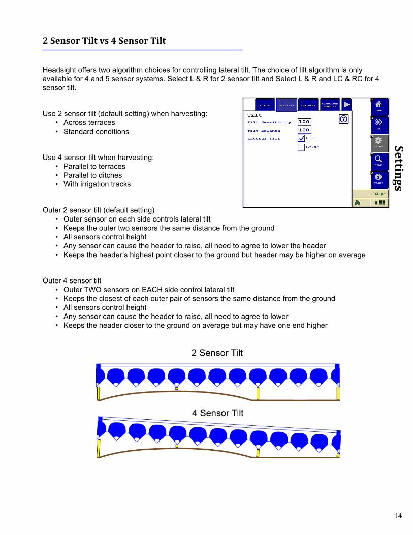
2 Sensor Tilt vs 4 Sensor Tilt
Headsight offers two algorithm choices for controlling lateral tilt. The choice of tilt algorithm is only available for 4 and 5 sensor systems. Select L & R for 2 sensor tilt and Select L & R and LC & RC for 4 sensor tilt.
Use 2 sensor tilt (default setting) when harvesting:• Across terraces• Standard conditions
Use 4 sensor tilt when harvesting:• Parallel to terraces• Parallel to ditches• With irrigation tracks
Outer 2 sensor tilt (default setting)• Outer sensor on each side controls lateral tilt• Keeps the outer two sensors the same distance from the ground • All sensors control height• Any sensor can cause the header to raise, all need to agree to lower the header • Keeps the header’s highest point closer to the ground but header may be higher on average
Outer 4 sensor tilt• Outer TWO sensors on EACH side control lateral tilt• Keeps the closest of each outer pair of sensors the same distance from the ground• All sensors control height• Any sensor can cause the header to raise, all need to agree to lower• Keeps the header closer to the ground on average but may have one end higher
15
Settings
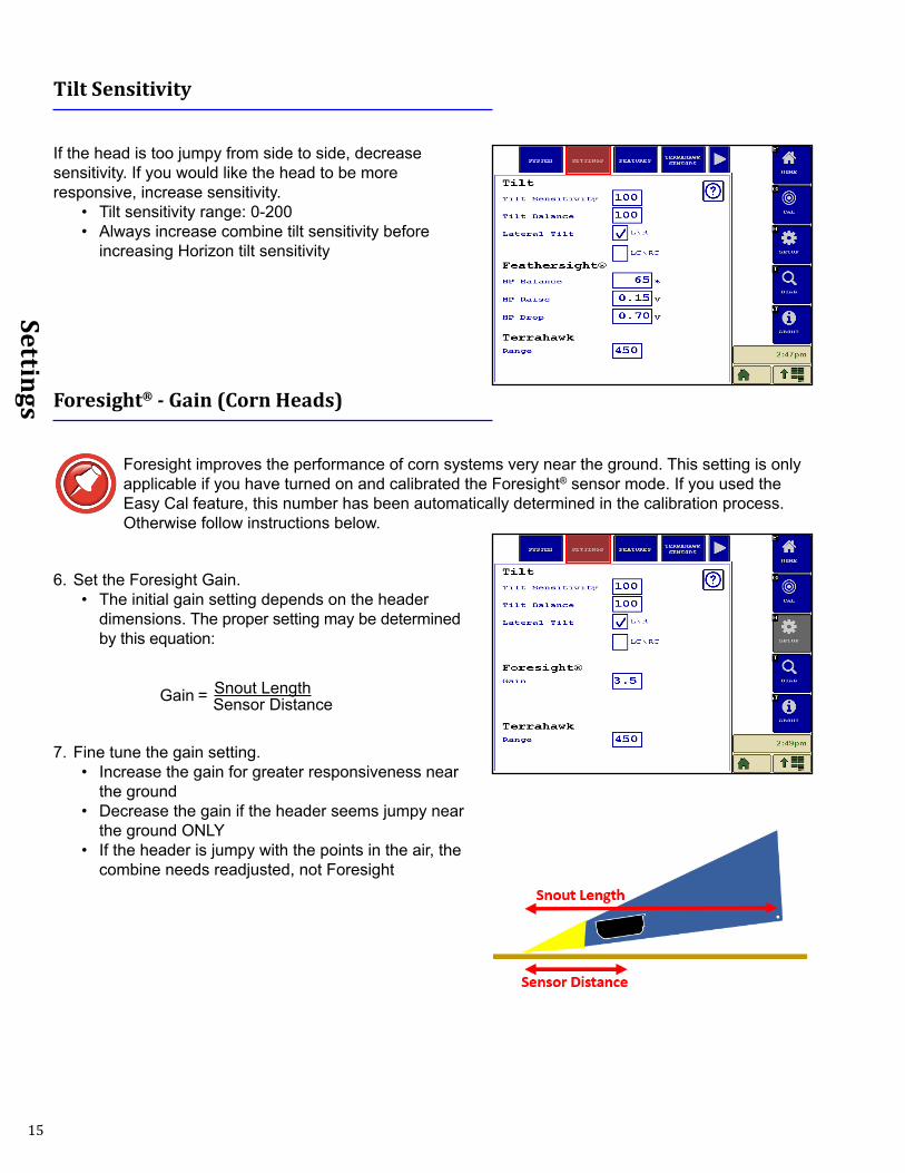
Tilt Sensitivity
If the head is too jumpy from side to side, decrease sensitivity. If you would like the head to be more responsive, increase sensitivity.
• Tilt sensitivity range: 0-200• Always increase combine tilt sensitivity before
increasing Horizon tilt sensitivity
Foresight® - Gain (Corn Heads)
Foresight improves the performance of corn systems very near the ground. This setting is only applicable if you have turned on and calibrated the Foresight® sensor mode. If you used the Easy Cal feature, this number has been automatically determined in the calibration process. Otherwise follow instructions below.
6. Set the Foresight Gain.• The initial gain setting depends on the header
dimensions. The proper setting may be determined by this equation:
Gain = Snout Length
Sensor Distance
7. Fine tune the gain setting.• Increase the gain for greater responsiveness near
the ground• Decrease the gain if the header seems jumpy near
the ground ONLY• If the header is jumpy with the points in the air, the
combine needs readjusted, not Foresight
16
Settings
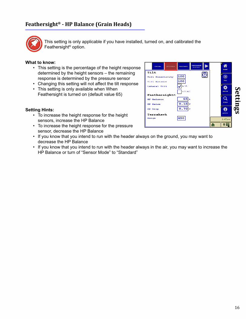
Feathersight® - HP Balance (Grain Heads)
This setting is only applicable if you have installed, turned on, and calibrated the Feathersight® option.
What to know:• This setting is the percentage of the height response
determined by the height sensors – the remaining response is determined by the pressure sensor
• Changing this setting will not affect the tilt response• This setting is only available when When
Feathersight is turned on (default value 65)
Setting Hints:• To increase the height response for the height
sensors, increase the HP Balance• To increase the height response for the pressure
sensor, decrease the HP Balance• If you know that you intend to run with the header always on the ground, you may want to
decrease the HP Balance• If you know that you intend to run with the header always in the air, you may want to increase the
HP Balance or turn of “Sensor Mode” to “Standard”
17
Settings
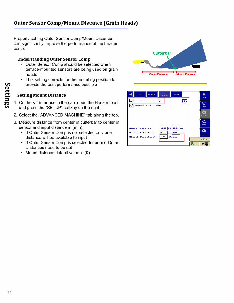
Outer Sensor Comp/Mount Distance (Grain Heads)
Properly setting Outer Sensor Comp/Mount Distance can significantly improve the performance of the header control.
Understanding Outer Sensor Comp• Outer Sensor Comp should be selected when
terrace-mounted sensors are being used on grain heads
• This setting corrects for the mounting position to provide the best performance possible
Setting Mount Distance1. On the VT interface in the cab, open the Horizon pool,
and press the “SETUP” softkey on the right.
2. Select the “ADVANCED MACHINE” tab along the top.
3. Measure distance from center of cutterbar to center of sensor and input distance in (mm) • If Outer Sensor Comp is not selected only one
distance will be available to input• If Outer Sensor Comp is selected Inner and Outer
Distances need to be set• Mount distance default value is (0)
18
Settings
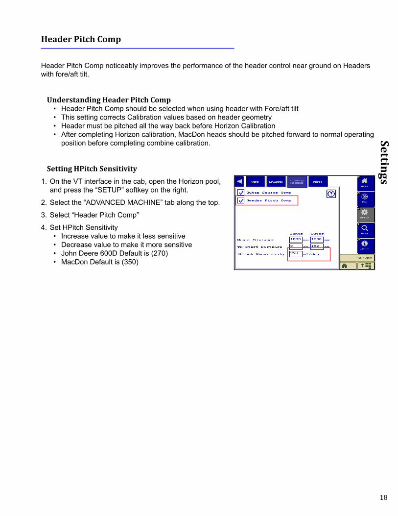
Header Pitch Comp
Header Pitch Comp noticeably improves the performance of the header control near ground on Headers with fore/aft tilt.
Understanding Header Pitch Comp• Header Pitch Comp should be selected when using header with Fore/aft tilt• This setting corrects Calibration values based on header geometry• Header must be pitched all the way back before Horizon Calibration• After completing Horizon calibration, MacDon heads should be pitched forward to normal operating
position before completing combine calibration.
Setting HPitch Sensitivity1. On the VT interface in the cab, open the Horizon pool,
and press the “SETUP” softkey on the right.
2. Select the “ADVANCED MACHINE” tab along the top.
3. Select “Header Pitch Comp”
4. Set HPitch Sensitivity • Increase value to make it less sensitive• Decrease value to make it more sensitive• John Deere 600D Default is (270)• MacDon Default is (350)
19
Settings
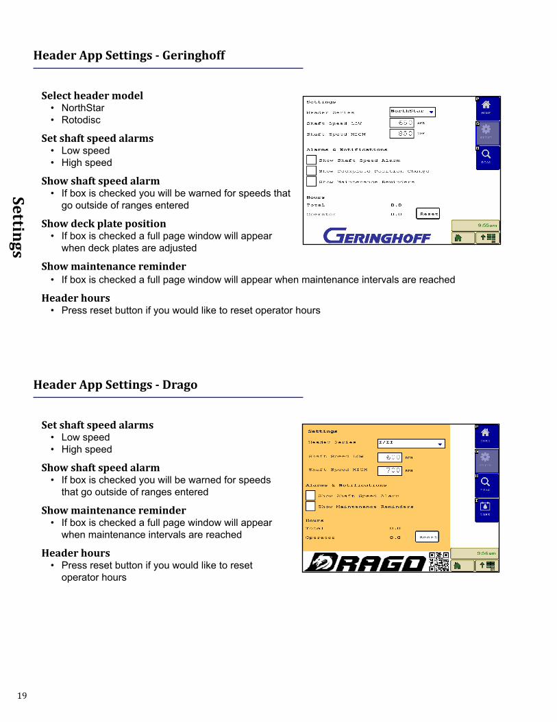
Header App Settings - Geringhoff
Select header model• NorthStar• Rotodisc
Set shaft speed alarms• Low speed• High speed
Show shaft speed alarm• If box is checked you will be warned for speeds that
go outside of ranges entered
Show deck plate position• If box is checked a full page window will appear
when deck plates are adjusted
Show maintenance reminder• If box is checked a full page window will appear when maintenance intervals are reached
Header hours• Press reset button if you would like to reset operator hours
Header App Settings - Drago
Set shaft speed alarms• Low speed• High speed
Show shaft speed alarm• If box is checked you will be warned for speeds
that go outside of ranges entered
Show maintenance reminder• If box is checked a full page window will appear
when maintenance intervals are reached
Header hours• Press reset button if you would like to reset
operator hours
20
Settings
Header App Settings - Shelbourne
Set min/max rotor lube speeds• Minimum speed• Maximum speed
Show rotor speed alarm• If box is checked you will be warned when speeds
go out of range entered
Speed drop factor• Percent of rotor speed drop to trigger alarm
Show auger speed alarm• If box is checked you will be warned when speeds
go below RPM entered
Set minimum auger speed• Minimum auger speed before alarm
Show maintenance reminder• If box is checked a full page window will appear when maintenance intervals are reached
Header App Settings - Truesense+
Select steering system• Straight Through - when using John Deere sensors• Rowsense - when using Truesense+ JD system• Auto Pilot - when using Truesense+ Lexion system
Steering Sensitivity• Over a 100% will increase sensitivity• Under 100% will decrease sensitivity
Crop Detect Threshold• Decrease if crop is not being detected• Increase when crop is detected and there is no crop
Center Calibration• Before adjusting this number makes sure to preform
Rowsense calibration in combine• Higher number will shift machine to right• Lower number will shift combine to left• If Rowsense calibration is off slightly from center, center combine in row and press center button
21
Operation
Operation
Finding VT applications
John Deere (Gen 4 Displays)1. Press Menu button at bottom right corner of display.
2. Press Applications button then ISOBUS VT button
John Deere (2630 and GS3 Command Center)1. Press display menu button, all VT icons will show up in
this menu.
22
Operation
2. Some John Deere machines have 2 Displays. If equipped with 2 displays use the Next VT feature to force Horizon Icons to desired display.
CaseIH and New Holland1. Press the back button on display then select VT icon.
2. Press menu button to display all pools.
23
Operation
Operation
1. Be sure you have the initial settings entered and have calibrated Horizon.
2. Calibrate the header to the combine per operators manual.
3. Operate the Headsight system exactly like you would use your combine OEM height control system.
4. Fine tune all combine speed and sensitivity adjustments for best performance.
24
Advanced Info
Advanced Info
Theory of Operation
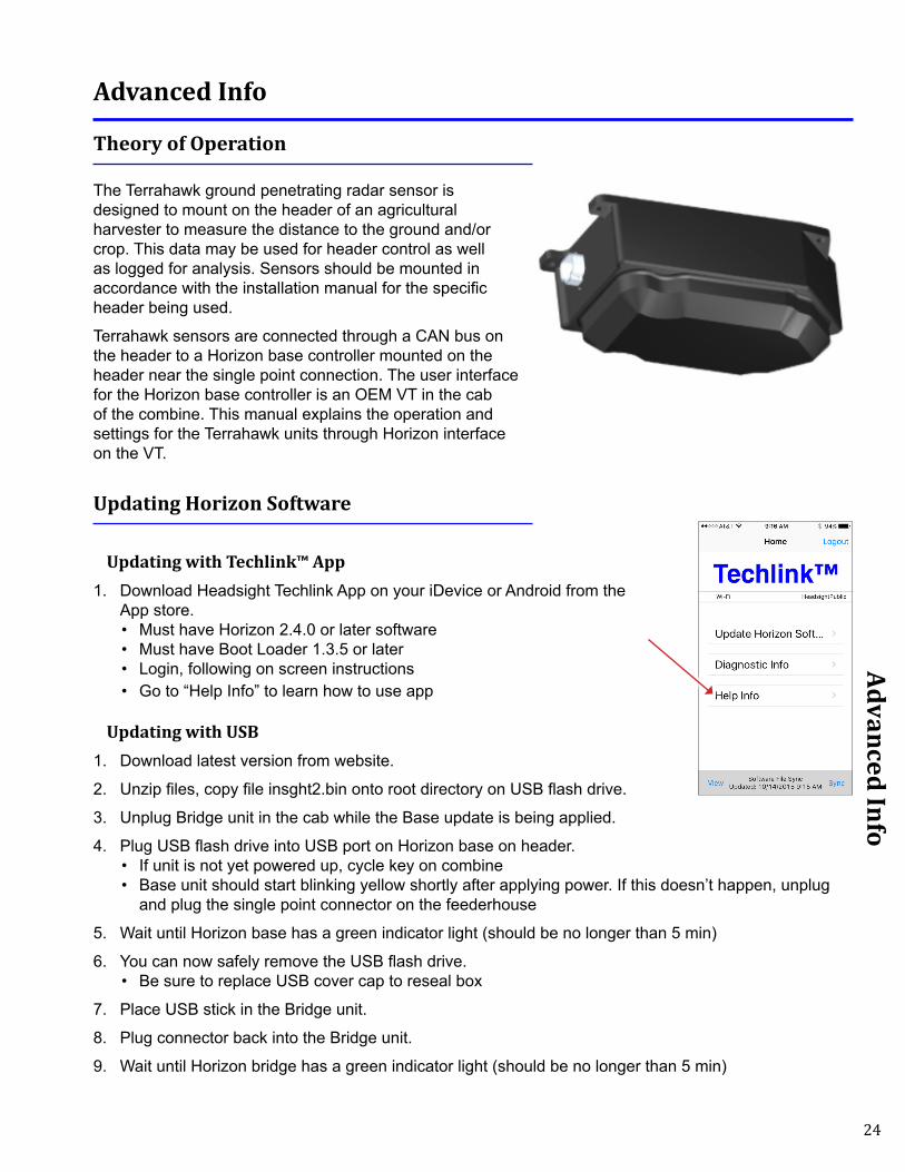
The Terrahawk ground penetrating radar sensor is designed to mount on the header of an agricultural harvester to measure the distance to the ground and/or crop. This data may be used for header control as well as logged for analysis. Sensors should be mounted in accordance with the installation manual for the specific header being used.
Terrahawk sensors are connected through a CAN bus on the header to a Horizon base controller mounted on the header near the single point connection. The user interface for the Horizon base controller is an OEM VT in the cab of the combine. This manual explains the operation and settings for the Terrahawk units through Horizon interface on the VT.
Updating Horizon Software
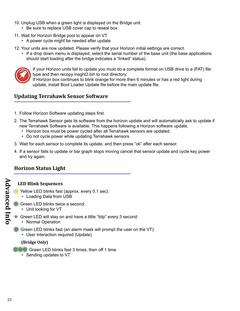
Updating with Techlink™ App1. Download Headsight Techlink App on your iDevice or Android from the
App store.• Must have Horizon 2.4.0 or later software• Must have Boot Loader 1.3.5 or later• Login, following on screen instructions• Go to “Help Info” to learn how to use app
Updating with USB1. Download latest version from website.
2. Unzip files, copy file insght2.bin onto root directory on USB flash drive.
3. Unplug Bridge unit in the cab while the Base update is being applied.
4. Plug USB flash drive into USB port on Horizon base on header.• If unit is not yet powered up, cycle key on combine• Base unit should start blinking yellow shortly after applying power. If this doesn’t happen, unplug
and plug the single point connector on the feederhouse
5. Wait until Horizon base has a green indicator light (should be no longer than 5 min)
6. You can now safely remove the USB flash drive.• Be sure to replace USB cover cap to reseal box
7. Place USB stick in the Bridge unit.
8. Plug connector back into the Bridge unit.
9. Wait until Horizon bridge has a green indicator light (should be no longer than 5 min)
25
Advanced Info
10. Unplug USB when a green light is displayed on the Bridge unit• Be sure to replace USB cover cap to reseal box
11. Wait for Horizon Bridge pool to appear on VT• A power cycle might be needed after update
12. Your units are now updated. Please verify that your Horizon initial settings are correct.• If a drop down menu is displayed, select the serial number of the base unit (the base applications
should start loading after the bridge indicates a “linked” status).
If your Horizon units fail to update you must do a complete format on USB drive to a (FAT) file type and then recopy insght2.bin to root directory. If Horizon box continues to blink orange for more then 6 minutes or has a red light during update, install Boot Loader Update file before the main update file.
Updating Terrahawk Sensor Software
1. Follow Horizon Software updating steps first.
2. The Terrahawk Sensor gets its software from the horizon update and will automatically ask to update if new Terrahawk Software is available. This happens following a Horizon software update.• Horizon box must be power cycled after all Terrahawk sensors are updated.• Do not cycle power while updating Terrahawk sensors
3. Wait for each sensor to complete its update, and then press “ok” after each sensor.
4. If a sensor fails to update or bar graph stops moving cancel that sensor update and cycle key power and try again.
Horizon Status Light
LED Blink Sequences Yellow LED blinks fast (approx. every 0.1 sec):
• Loading Data from USB
Green LED blinks twice a second:• Unit looking for VT
Green LED will stay on and have a little “blip” every 3 second:• Normal Operation
Green LED blinks fast (an alarm mask will prompt the user on the VT):• User interaction required (Update)
(Bridge Only)
Green LED blinks fast 3 times, then off 1 time • Sending updates to VT
26
Advanced Info
Terrahawk Status Light
LED Blink Sequences Yellow LED will stay on and have a little “blip” every 3 second:
• Updating
Green LED will stay on and have a little “blip” every 3 second:
• Normal operation
Red LED • An error has occurred
WIFI
Changing a WIFI channel is only needed when there is signal interference from another device. Renaming is only needed if you want a custom WIFI name.
1. Select SETUP>>WIFI on Horizon VT application.
2. Rename network by selecting box “Network Name”.
3. Switch channel by selecting drop down box “Channel”.
4. Cycle power after any WIFI changes have been made.• Be sure that VT and Horizon power cycle to
save changes.
27
Diagnostics
Diagnostics
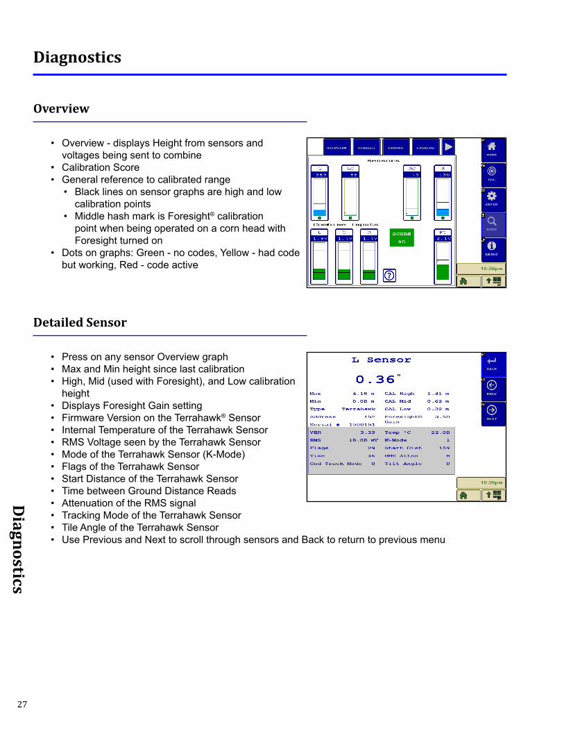
Overview
• Overview - displays Height from sensors and voltages being sent to combine
• Calibration Score• General reference to calibrated range
• Black lines on sensor graphs are high and low calibration points
• Middle hash mark is Foresight® calibration point when being operated on a corn head with Foresight turned on
• Dots on graphs: Green - no codes, Yellow - had code but working, Red - code active
Detailed Sensor
• Press on any sensor Overview graph• Max and Min height since last calibration• High, Mid (used with Foresight), and Low calibration
height • Displays Foresight Gain setting• Firmware Version on the Terrahawk® Sensor• Internal Temperature of the Terrahawk Sensor• RMS Voltage seen by the Terrahawk Sensor• Mode of the Terrahawk Sensor (K-Mode)• Flags of the Terrahawk Sensor• Start Distance of the Terrahawk Sensor • Time between Ground Distance Reads• Attenuation of the RMS signal• Tracking Mode of the Terrahawk Sensor• Tile Angle of the Terrahawk Sensor• Use Previous and Next to scroll through sensors and Back to return to previous menu
28
Diagnostics
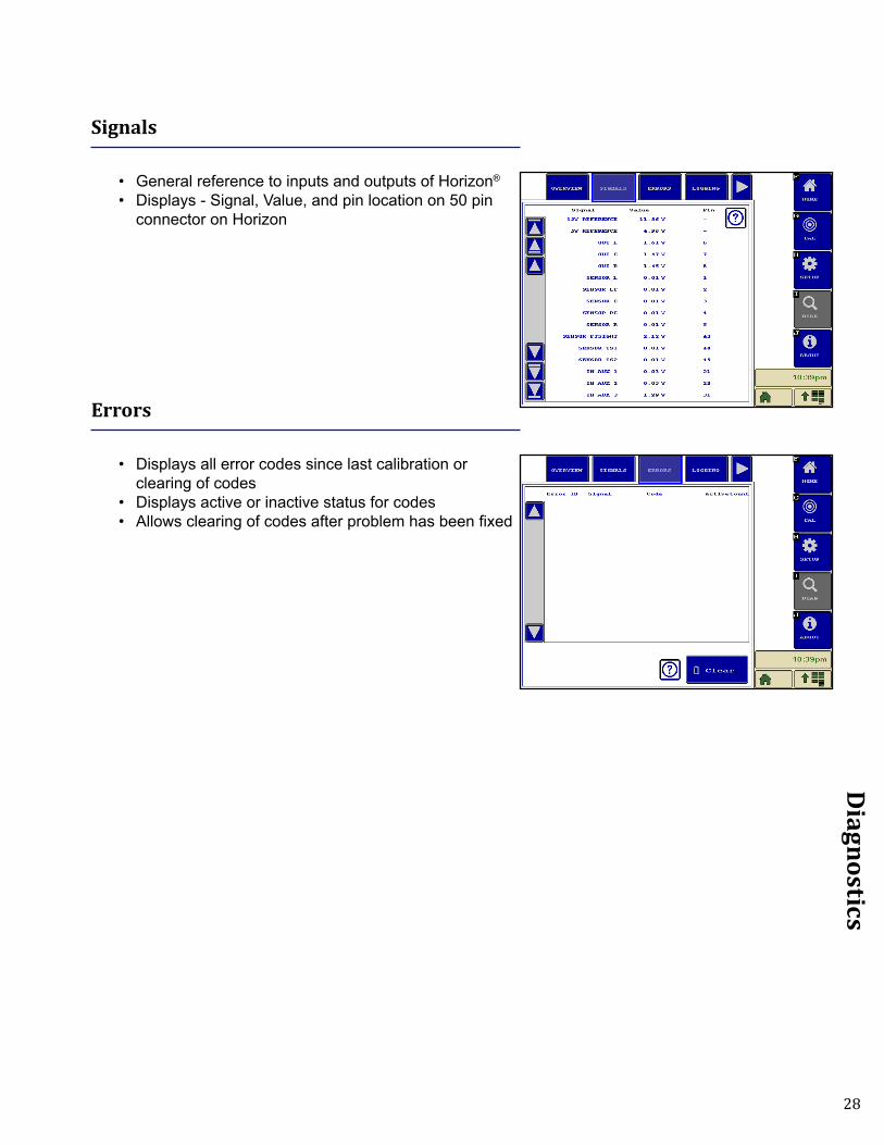
Signals
• General reference to inputs and outputs of Horizon®
• Displays - Signal, Value, and pin location on 50 pin connector on Horizon
Errors
• Displays all error codes since last calibration or clearing of codes
• Displays active or inactive status for codes• Allows clearing of codes after problem has been fixed
29
FCC and IC Compliance Statements
The Horizon Box Contains Transmitter Module SN8200WARNING: To satisfy FCC RF exposure requirements for mobile transmitting devices, a separation distance of 20cm or more should be maintained between the antenna of this device and persons during operation. To ensure compliance, operations at closer distances than this are not recommended.
ATTENTION: This device complies with Part 15 of the FCC rules. Operation is subject to the following two conditions: (1) this device may not cause harmful interference, and (2) this device must accept any interference received, including interference that may cause undesired operation.
The FCC requires the OEM to be notified that any changes or modifications not expressly approved by SyChip, LLC may void the user’s authority to operate the equipment. While an application of the SN8200 module in a product is not required to obtain a new FCC authorization for the module, this does not preclude the possibility that some other form of authorization or testing may be required for that end product.
This device using the integrated antenna has been tested to comply with FCC CFR Part 15. The device meets the requirements for modular transmitter approval as detailed in the FCC public notice DA00.1407.
ATTENTION: The term “IC” before the certification/registration number only signifies that the Industry Canada technical specifications were met.
Le terme “IC” devant le numéro de certification /d’enregistrement signifie seulement que les spécifications techniques Industrie Canada ont été respectées.
This device complies with Industry Canada license-exempt RSS standard(s). Operation is subject to
The following two conditions: (1) this device may not cause interference, and (2) this device must accept any interference, including interference that may cause undesired operation of the device.
Cet appareil est conforme avec Industrie Canada RSS standard exempts de licence (s). Son utilisation est soumise à Les deux conditions suivantes: (1) cet appareil ne peut pas provoquer d’interférences et (2) cet appareil doit accepter Toute interférence, y compris les interférences qui peuvent causer un mauvais fonctionnement du dispositif.
This device complies with Health Canada’s Safety Code 6 / IC RSS-210. The installer of this device should ensure that RF radiation is not emitted in excess of the Health Canada’s requirement. Information can be obtained at: http://www.hc-sc.gc.ca/ewh-semt/pubs/radiation/radio_guide-lignes_direct-eng.php
Cet appareil est conforme avec Santé Canada Code de sécurité 6 / IC RSS-210. Le programme d’installation de cet appareil doit s’assurer que les rayonnements RF n’est pas émis au-delà de l’exigence de Santé Canada. Les informations peuvent être obtenues: http://www.hc-sc.gc.ca/ewh-semt/pubs/radiation/radio_guide-lignes_direct-eng.php
30
Notices for Operation of Terrahawk in the US
Note: This equipment has been tested and found to comply with the limits for a Class A digital device, pursuant to part 15 of the FCC Rules. These limits are designed to provide reasonable protection against harmful interference when the equipment is operated in a commercial environment. This equipment generates, uses, and can radiate radio frequency energy and, if not installed and used in accordance with the instruction manual, may cause harmful interference to radio communications. Operation of this equipment in a residential area is likely to cause harmful interference in which case the user will be required to correct the interference at his own expense.
THIS DEVICE COMPLIES WITH PART 15 OF THE FCC RULES. OPERATION IS SUBJECT TO THE FOLLOWING TWO CONDITIONS.1. THIS DEVICE MAY NOT CAUSE HARMFUL INTERFERENCE, AND
2. THIS DEVICE MUST ACCEPT ANY INTERFERENCE RECEIVED, INCLUDING INTERFERENCE THAT MAY CAUSE UNDESIRED OPERATION.
Warning: Changes or modifications not expressly approved by the party responsible for compliance could void the user’s authority to operate this equipment.
IMPORTANT NOTE: This device is considered a UWB imaging device and is subject to FCC Coordination requirements under the CFR Tile 47 Chapter I, Sub chapter A, Part 15, Subpart F , Section 15.525. As such it is the responsibility of the users of these systems to submit the following information to the FCC prior to use of these systems. The users of UWB imaging devices shall supply operational areas to the FCC Office of Engineering and Technology, which shall coordinate this information with the Federal Government through the National Telecommunications and Information Administration. The information provided by the UWB operator shall include the name, address and other pertinent contact information of the user, the desired geographical area(s) of operation, and the FCC ID number and other nomenclature of the UWB device. If the imaging device is intended to be used for mobile applications, the geographical area(s) of operation may be the state(s) or county(ies) in which the equipment will be operated. The operator of an imaging system used for fixed operation shall supply a specific geographical location or the address at which the equipment will be operated. This material shall be submitted to Frequency Coordination Branch, OET, Federal Communications Commission, 445 12th Street, SW, Washington, D.C. 20554, Attn: UWB Coordination. The operator shall comply with any constraints on equipment usage resulting from this coordination.
Notes: • The device is to be used for agricultural purposes, at a height of up to one meter above crop heights, but not
to exceed 12 feet (3.7 meters) above the soil surface.• Multiple Terrahawk transmitters intended to be mounted on a single piece of farming machinery (a combine
harvester, ground tiller, fertilizer, etc.) in any installation shall be positioned for operation with a minimum separation distance of 1.5 m (~ 5 feet) between transmitters.
• The Terrahawk’s emissions shall be aimed downward toward the ground so they can be attenuated by the presence of crops, and shall not be operated at a height of greater than 1 meter when there are no crops beneath the device.
• The Terrahawk shall only be installed on farming machinery (combine harvesters, ground tillers, fertilizers, etc.) and operated in fields that are located in rural or predominantly agricultural areas as generally defined by the United States Geological Survey National Land Cover Database (NLCD) classifications 81 (Pasture/Hay) and 82 (Cultivated Crops).
• Operation of this device shall be limited to parties eligible for licensing under the provisions of part 90 of the Commission’s rules (e.g., persons regularly involved in activities such as the operation of farms, ranches, or similar land areas, for the quantity production of crops or plants; including soil plowing, soil conditioning, seeding, fertilizing, or harvesting for agricultural activities). No operation in city gardens or on trees is permitted.
• Terrahawk devices used in the US must be coordinated with the FCC prior to use. A coordination postcard was included in the front of this manual for your convenience.

31
Notices for Operation of Terrahawk in Canada
This device complies with Industry Canada license-exempt RSS standard(s). Operation is subject to the following two conditions: (1) this device may not cause interference, and (2) this device must accept any interference, including interference that may cause undesired operation of the device.
Le présent appareil est conforme aux CNR d’Industrie Canada applicables aux appareils radio exempts de licence. L’exploitation est autorisée aux deux conditions suivantes : (1) l’appareil ne doit pas produire de brouillage, et (2) l’utilisateur de l’appareil doit accepter tout brouillage radioélectrique subi, même si le brouillage est susceptible d’en compromettre le fonctionnement.
Under Industry Canada regulations, this radio transmitter may only operate using an antenna of a type and maximum (or lesser) gain approved for the transmitter by Industry Canada. To reduce potential radio interference to other users, the antenna type and its gain should be so chosen that the equivalent isotropically radiated power (e.i.r.p.) is not more than that necessary for successful communication.
Conformément à la réglementation d’Industrie Canada, le présent émetteur radio peut fonctionner avec une antenne d’un type et d’un gain maximal (ou inférieur) approuvé pour l’émetteur par Industrie Canada. Dans le but de réduire les risques de brouillage radioélectrique à l’intention des autres utilisateurs, il faut choisir le type d’antenne et son gain de sorte que la puissance isotrope rayonnée équivalente (p.i.r.e.) ne dépasse pas l’intensité nécessaire à l’établissement d’une communication satisfaisante.
This equipment complies with the ICES RF radiation exposure limits set forth for an uncontrolled environment. This equipment should be installed and operated with a minimum distance of 20cm between the radiator and any part of the human body.
Cet équipement est conforme aux limites d’exposition aux radiations ICES définies pour un environnement non contrôlé . Cet équipement doit être installé et utilisé à une distance minimale de 20 cm entre le radiateur et une partie de votre corps.
Note: This Ground Penetrating Radar Device shall be operated only when directed at the ground within one meter of the surface under analysis.
Remarque: Ce dispositif de radar à pénétration au sol ne doit être utilisé que lorsqu’il est dirigé vers le sol à moins d’un mètre de la surface en analyse.
Note: This Ground Penetrating Radar Device shall only be operated for purposes associated with the agricultural industry.
Remarque: Cet appareil de radar à pénétration au sol ne doit être utilisé qu’à des fins associées à l’industrie agricole.
32
STATEMENT OF LIMITED WARRANTY
For Headsight® Products Headsight Inc. (Headsight) warrants its new products to be free from defects in material and workmanship for a period of twelve (12) consecutive months following the date of purchase by the retail purchaser.
Headsight Inc. (Headsight) warrants its new corn sensors assemblies for a period of thirty-six (36) months.
Headsight warrants genuine Headsight replacement parts and components to be free from defects in material and workmanship for a period of six (6) consecutive months following the date of purchase or the remainder of the original equipment warranty period, whichever is longer.
Headsight’s obligation under these warranties shall be limited to repairing or replacing, free of charge to the original purchaser, any part that, in Headsight’s judgment, shows evidence of such defect.
Limitations to Warranty
This warranty does not cover:• Warranty claims directly resulting from improper installation of the product.• Any product damaged by accident, abuse, misuse, or negligence after shipment from Headsight.• Any unauthorized product alteration or modification.• Any unauthorized repairs made with parts other than genuine Headsight parts.• Any repairs performed by anyone other than Headsight or an authorized Headsight dealer unless specifically authorized
by Headsight.
Warranty Procedure• Troubleshooting should be done between farmer/dealer and Headsight through our technical assistance @
574.220.5511. • Labor reimbursement will occur only pre-arranged through Headsight technical assistance and be scheduled to a flat rate
basis or reasonable time allowance in Headsight’s judgment. • There is no mileage reimbursement. • Diagnostic time will not be reimbursed except in pre-arranged circumstances.• Warranty claims should be on typical dealer service work order with a number and name to be attached for any future
correspondence. • All warranty work must be performed, and claims submitted, within thirty (30) days of the occurrence of the claim and
within the warranty period.• All parts removed during warranty repair must be returned to Headsight with Headsight’s Return Form within thirty (30)
days of the occurrence of the claim and within the warranty period.• Headsight, Inc. reserves the right to either inspect the product at the original retail purchaser’s location or require it to be
returned to Headsight, Inc. for inspection.
Limitation of LiabilityHeadsight makes no express warranties other than those, which are specifically described herein. Any description of the goods sold hereunder, including any reference to buyer’s specifications and any descriptions in circulars and other written material published by Headsight is for the sole purpose of identifying such goods and shall not create an express warranty that the goods shall conform to such description.
THIS WARRANTY IS EXPRESSLY IN LIEU OF ALL OTHER WARRANTIES EXPRESSED OR IMPLIED. There are no implied warranties of merchantability or fitness of a particular purpose. This warranty states Headsight’s entire and exclusive liability and buyer’s exclusive remedy or any claim for damages in connection with the sale of furnishing of Headsight products, their design, suitability for use, installation or operation, or for any claimed defects herein. HEADSIGHT WILL IN NO EVENT BE LIABLE FOR ANY INCIDENTAL OR CONSEQUENTIAL DAMAGES WHATSOEVER, NOR FOR ANY SUM IN EXCESS OF THE PRICE RE-CEIVED FOR THE GOODS FOR WHICH LIABILITY IS CLAIMED.
No representative of Headsight nor any dealer associated with Headsight has the authority to change the items of this warranty in any manner whatsoever, and no assistance to purchaser by Headsight in the repair of operation of any Headsight product shall constitute a waiver of the conditions of this warranty, nor shall such assistance extend or revive it.
Headsight reserves the right to make improvements in design or changes in specifications at any time, without incurring any obligation to owners of units previously sold. Warranty: 1/2017

P 574.546.5022 • F 574.546.57604845 3B Rd • Bremen, IN [email protected]