template for electronic submission to acs journals
TRANSCRIPT
Anbar Journal Of Engineering Science© Vol. 9 (2021) 100 – 112
Unviersty of Anbar
Anbar Journal Of Engineering Science©
journal homepage: http://www.uoanbar.edu.iq/Evaluate/
Performance of a double-pipe heat exchanger with different met-al foam arrangements
Thaer H. Farhana*, Obaid T. Fadhil b, Hamdi E. Ahmed b a Communication Office, Khalidia, 31001, Iraq
b Department of Mechanical Engineering, University of Anbar, Ramadi, 31001, Iraq
P A P E R I N F O
A B S T R A C T
Pa per hist ory:
Received 08/06/2021
Received in revised form
09/08/2021
Accepted 16/08/2021
This paper contributes to the field of improving the performance of heat exchangers using metal
foam (MF) full-filled and partially/periodically-filled within the gap between the two pipes. The
effect of configuration and arrangement of copper MF (15PPI and porosity of 0.95) installed on
the outer surface of the inner pipe of a counter-flow double-pipe heat exchanger on the thermal
and hydraulic performance was studied experimentally. The test section consisted of concentric
two pipes; the inner pipe which was made of copper while the outer pipe was a Polyvinyl chlo-
ride. Air was used as a working fluid in both hot and cold sides. A wide cold air flow rate range
was covered from 3 to 36 m3/h which corresponds to Reynolds number (Re) range from 2811 to
31,335. The hot air flow rate was kept constant at 3m3/h. The temperature difference (∆T) be-
tween the inlet hot air and inlet cold air was adopted to be (20°C, 30°C, 40°C, and 50°C). The re-
sults revealed that the higher Nusselt number (Nu) was at ∆T= 50°C and the thermal performance
of the heat exchanger with the MF for all the arrangements was greater than the smooth heat
exchanger. The highest and lowest friction factor was 1.033 and 0.0833 for the case 1 and 8, re-
spectively, and the optimal performance evaluation criteria (PEC) was 1.62 for case 7 at Re =
2800. The Nu would be increased with a moderate increase in the friction factor by optimizing
the arrangement of the MF. The two essential parameters that played an important role for in-
creasing the PEC were the MF diameter and the MF arrangement along the axial length of the cold
air stream.
Keyw ord s:
Annulus heat exchanger; Metal
foam arrangement; Full-filled;
Partially/periodically-filled; Heat
transfer enhancement.
© 2014 Published by Anbar University Press. All rights reserved.
1. Introduction
There are several types of heat exchangers, and they are widely used in various fields for the pur-pose of dispersing or transferring heat from a hot fluid or object to another cold. The double-pipe heat exchanger is a common type used in industry as well as in thermal plants [1].
Researchers have worked and are still working on improving the performance of the heat exchang-ers in general and the double-pipe heat exchangers in particular, using various technologies. Metal foam is one of the modern technologies that attracted the attention of researchers.
The effect of inserting copper metal foam fins with an inclination angle of (30°) with the flow di-rection on the heat transfer and pressure drop in a double-pipe heat exchanger was investigated exper-imentally by Hamzah and Nima [1]. They claimed that there was a small increase in the pressure drop when the metal foam used. For the counter-flow mode, a higher convection heat transfer coefficient was observed, and this increment increased with increasing Reynolds number. Targui and Kahalerras [2] studied numerically the heat transfer and flow characteristics in a double-tube heat exchanger by installing porous structures within the gap between the two pipes in two stages, one on the outer surface of the inner pipe and the other stage on the inner surface of the outer pipe and on the outer surface of
101
the thinner pipe in an overlapping manner. The op-timal thermal design obtained was when the porous structures used on the inner surface of the outer pipe and on the outer surface of the inner pipe. Also, the heat transfer rate was increased when the thickness of the porous structure increased and, therefore, the distances were reduced. A numerical study was carried out by Kahalerras and Targui [3] to show the effect of porous fins fixed on the outer surface of the inner pipe in a double-pipe heat ex-changer on the heat transfer and fluid flow. The fin height, fins spacing and the ratio of the thermal con-ductivity were the key parameters. It was shown that the heat transfer of the suggested design could be enhanced compared to the traditional one. In addition, the geometry of the fin and each of the thermodynamic and physical properties played an important role in the heat transfer improvement. A numerical study was conducted by Jamarani et al. [4] on a counter-flow double-pipe heat exchanger under turbulent flow condition. The optimum non-dimensional thickness of the porous material which provided higher thermal performance was 0.7 when the porous media installed at the center of the inner pipe and on the inner surface of the outer pipe. Whereas the optimum thickness was 0.4 for the ar-rangement in which the porous material was fixed at the inner and outer surfaces of the inner pipe. Abbas et al. [5] conducted an experimental study on a double-pipe heat exchanger having semi-circular, circular, and spiral carousel fins fixed on the outer surface of the inner pipe. The convection heat trans-fer coefficient was improved up to 260% when the fins used at the inner pipe compared to the smooth case. Maid et al. [6] carried out an experimental in-vestigation on a double-tube heat exchanger by placing a metal pad in the inner tube to find out its effect on heat transfer and pressure drop. The factor of enhancement in the convection heat transfer co-efficient was 2.074 and the increase in effectiveness was 26.5% as compared to that without metal pad. To find out the effect of the distance between the baffles as well as the fluid flow rate on the effective-ness of a double-pipe heat exchanger, Mishra and Nayak [7] conducted a practical study in which they placed triangular baffles on the outer surface of the inner pipe. They concluded that the effectiveness of the heat exchanger increased as the distance be-tween the baffles decreased and the cold fluid flowrate increased.
Nawaz et al. [8] investigated experimentally the effect of copper and aluminum metal foams on the heat exchanger performance. They found that there was more than one factor of the geometry of the metal foam that affected the amount of pressure
drop and heat transfer. Also, the hydrothermal per-formance with metal foams was higher than that with louver-fin. Xu et al. [9] studied numerically heat transfer in a double-tube heat exchanger with metal foam filling the inner tube and the annulus. They stated that the porosity and pore density should be less than 0.9 and greater than 10 PPI, re-spectively, to achieve an effectiveness greater than 0.8.
Sertkaya et al. [10] studied experimentally the thermal performance of two heat exchangers; one had aluminum finned tubes, while the second had tubes covered with aluminum foam under turbulent flow regime. They concluded that the heat transfer rate of the finned tube exchangers was greater than that those tubes covered with aluminum foam. Al husseny and Turan [11] installed a layer of metal foam on the connecting surface between the two pipes in order to enhance the thermal conductivity. The heat exchanger was partly filled with a layer of metal foam with a high porosity and rotating coaxi-ally. They demonstrated that the heat transfer can be further enhanced and save pumping energy com-pared to fully filled heat exchangers.
From the above open literatures, it can be ob-served that studying the metal foam in several con-figurations and arrangements inside the annular spacing of the double-pipe heat exchanger is not explored yet. The main goal of the present work is to enhance the heat transfer of a counter-flow double-pipe heat exchanger by inserting metal foam in dif-ferent arrangements and configurations in the annu-lar space to reduce the fuel required for heating the cold air entering the combustion chamber of power plants. From the view point of the proposal makers, there is no publication that has studied the effect of the arrangement of full filled and partial-ly/periodically filled in the double-pipe heat ex-changer yet.
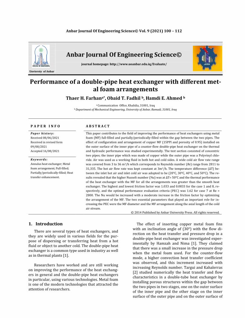
2. Experimental apparatus The experimental setup used in the present study consisted of the test section (double pipe heat ex-changer), two blowers for forcing the hot and cold air, two flow meters for measuring the air flow rates on the hot and cold sides, inclined manometer to measure the pressure difference across the cold air stream for smooth annulus, U-tube manometer to measure the pressure drop across the cold air stream filled with MF, thermocouples to measure the inlet and outlet air temperature at the hot and cold side and the heated wall temperature of the copper cylinder which were connected to a precise digital thermometer, electrical heating system, and
102
power supply with controls as shown in the illustra-tive schematic diagram in Figure. 1(a) and in the photograph Figure. 1(b)
a
b
Figure 1. The experimental apparatus; (a) schematic diagram,
and (b) photog1raph.
2.1. Test rig and instruments
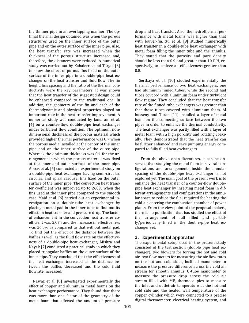
The rig consisted of two concentric pipes where the side view is shown in Figure. 2. The inner pipe of copper and the outer pipe of PVC, which were as-sembled together by connectors. The inner pipe has an inner diameter of (di¬=17 mm) and an outer di-ameter (do=19 mm) and the outer pipe has an in-ternal diameter of (Di¬=43 mm), while the hydraulic diameter of the annulus was (Dh=23 mm). The length of the test section was (L=500 mm), whereas the metal foam was installed along the test section. The entry and exit of cold air is through two holes with a diameter of (37.5mm), at the beginning and end of the PVC pipe. Two small holes were drilled at the upstream and downstream end of the annulus with a diameter of (5 mm) in order to connect the manometer flexible tubes.
Figure 2. Schematic diagram of the side view of the annular
test section.
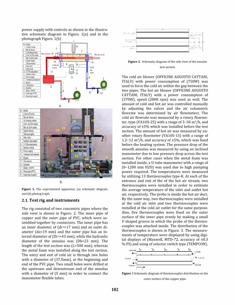
The cold air blower (OFFICINE AUGUSTO CATTANI, ITALY) with power consumption of (750W) was used to force the cold air within the gap between the two pipes. The hot air blower (OFFICINE AUGUSTO CATTANI, ITALY) with a power consumption of (370W), speed (2800 rpm) was used as well. The amount of cold and hot air was controlled manually by adjusting the valves and the air volumetric flowrate was determined by air flowmeters. The cold air flowrate was measured by a rotary flowme-ter, type (VA1OS-25) with a range of 3–50 m3/h, and accuracy of ±5% which was installed before the test section. The amount of hot air was measured by an-other rotary flowmeter (VA10S-15) with a range of 1.2–12 m3/h, and accuracy of ±5%, which was fixed before the heating system. The pressure drop of the smooth annulus was measured by using an inclined manometer due to low pressure drop across the test section. For other cases when the metal foam was installed inside, a U-tube manometer with a range of (0–1200 mm H2O) was used due to high pumping power required. The temperatures were measured by utilizing 13 thermocouples type-K. At each of the entrance and exit of the of the hot air stream, two thermocouples were installed in order to estimate the average temperature of the inlet and outlet hot air, respectively. The probe is inside the hot air duct. By the same way, two thermocouples were installed at the cold air inlet and two thermocouples were installed at the cold air outlet for the same purpose. Also, five thermocouples were fixed on the outer surface of the inner pipe evenly by making a small V-shaped groove in which the probe of the thermo-couples was attached inside. The distribution of the thermocouples is shown in Figure. 3. The measure-ments of temperature were displayed by using digi-tal displays of (Maxwell, MTD-72, accuracy of ±0.3 % FS) and using of selector switch type (TEMPCON).
Figure 3 Schematic diagram of thermocouples distribution on the
outer surface of the copper pipe.
103
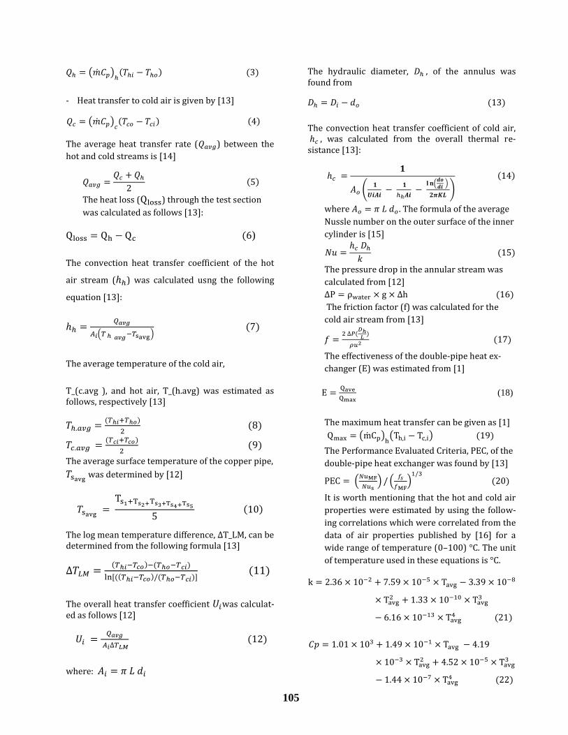
2.2. Metal foam forming and arrangement
The copper metal foam was cut into concentric washers with a thickness of 10 mm and different diameters according to the arrangements required for doing the tests as shown in Table 1. The ar-
rangements and configurations of the metal foam washers is shown in Figure 4 and photographs shown in Figure 5.
Case NO. (DMF/D pipe) Number of MF pieces Description
1 1 50 The annular space is completely filled with MF, as shown in Figure.(4.a)
2 1 25 The annular space is half fill with MF as shown in Figure.(3.b)
3 0.75 50 The MF covered entire annular space at a height of 75% of the annular space, as shown in Figure.(4.c)
4 1 25 The MF installed periodically in the annular space , as shown in Figure.(4.d)
5 1
0.75
0.5
0.25
13
13
12
12
The MF is gradually placed inside the annular space , as shown in Figure.(4.e)
6 1
0.75
0.5
0.25
12
12
12
12
The MF is installed inside the annular space, as shown in Fig-ure.(4.f)
7 1
0.75
0.5
0.25
7
14
14
15
The MF is installed inside the annular space, as shown in Fig-ure.(4.g)
8 0.0 Without MF The annular space is empty (smooth), as shown in Fig-ure.(4.h).
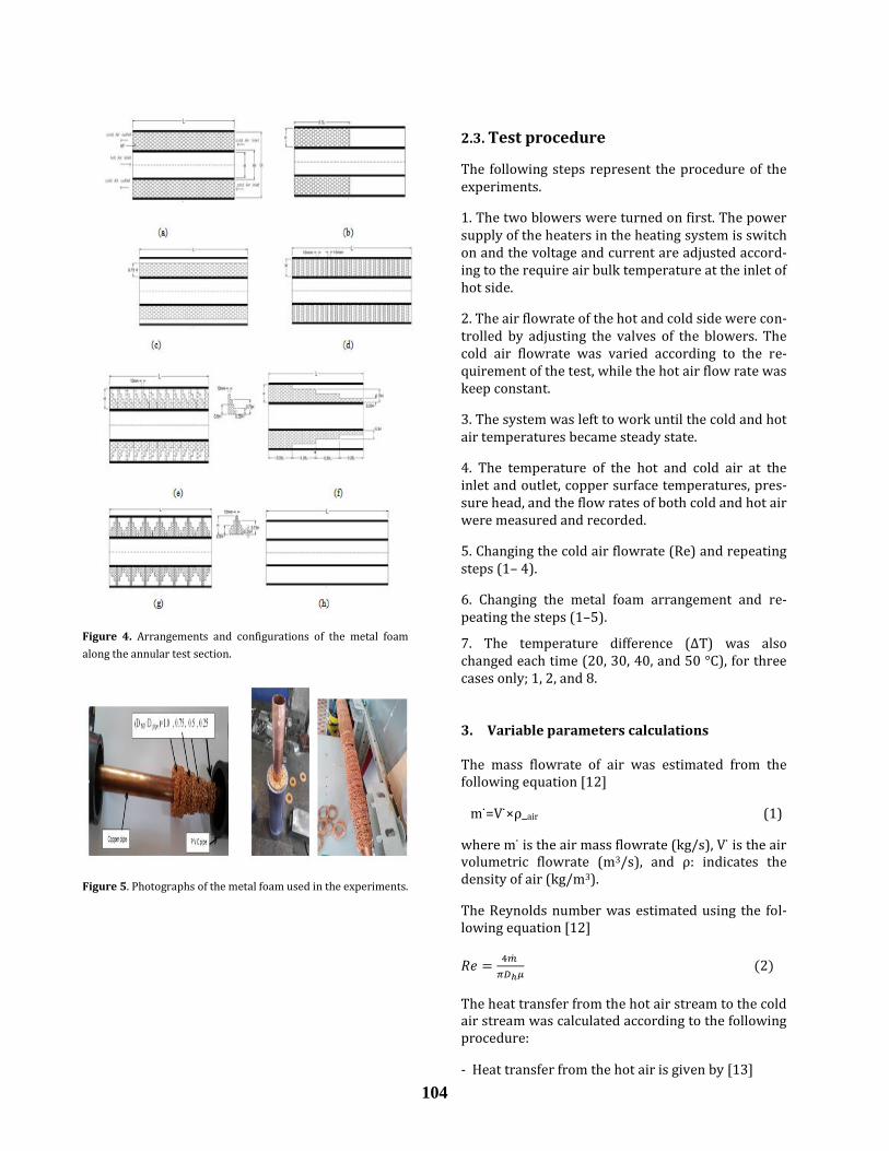
104
Figure 4. Arrangements and configurations of the metal foam
along the annular test section.
Figure 5. Photographs of the metal foam used in the experiments.
2.3. Test procedure
The following steps represent the procedure of the experiments.
1. The two blowers were turned on first. The power supply of the heaters in the heating system is switch on and the voltage and current are adjusted accord-ing to the require air bulk temperature at the inlet of hot side.
2. The air flowrate of the hot and cold side were con-trolled by adjusting the valves of the blowers. The cold air flowrate was varied according to the re-quirement of the test, while the hot air flow rate was keep constant.
3. The system was left to work until the cold and hot air temperatures became steady state.
4. The temperature of the hot and cold air at the inlet and outlet, copper surface temperatures, pres-sure head, and the flow rates of both cold and hot air were measured and recorded.
5. Changing the cold air flowrate (Re) and repeating steps (1– 4).
6. Changing the metal foam arrangement and re-peating the steps (1–5).
7. The temperature difference (ΔT) was also changed each time (20, 30, 40, and 50 °C), for three cases only; 1, 2, and 8.
3. Variable parameters calculations
The mass flowrate of air was estimated from the following equation [12]
m =V ρ_air (1)
where m is the air mass flowrate (kg/s), V is the air volumetric flowrate (m3/s), and ρ: indicates the density of air (kg/m3).
The Reynolds number was estimated using the fol-lowing equation [12]
The heat transfer from the hot air stream to the cold air stream was calculated according to the following procedure:
- Heat transfer from the hot air is given by [13]
105
( )
- Heat transfer to cold air is given by [13]
( )
The average heat transfer rate ( ) between the
hot and cold streams is [14]
The heat loss ( ) through the test section
was calculated as follows [13]:
)
The convection heat transfer coefficient of the hot
air stream ( ) was calculated usng the following
equation [13]:
( )
The average temperature of the cold air,
T_(c.avg ), and hot air, T_(h.avg) was estimated as follows, respectively [13]
The average surface temperature of the copper pipe,
was determined by [12]
The log mean temperature difference, ∆T_LM, can be determined from the following formula [13]
The overall heat transfer coefficient was calculat-ed as follows [12]
where:
The hydraulic diameter, , of the annulus was found from
The convection heat transfer coefficient of cold air, , was calculated from the overall thermal re-sistance [13]:
(
(
)
)
where . The formula of the average
Nussle number on the outer surface of the inner
cylinder is [15]
The pressure drop in the annular stream was
calculated from [12]
The friction factor (f) was calculated for the
cold air stream from [13]
The effectiveness of the double-pipe heat ex-
changer (E) was estimated from [1]
(18)
The maximum heat transfer can be given as [1]
( ) ( )
The Performance Evaluated Criteria, PEC, of the
double-pipe heat exchanger was found by [13]
(
) (
)
It is worth mentioning that the hot and cold air
properties were estimated by using the follow-
ing correlations which were correlated from the
data of air properties published by [16] for a
wide range of temperature (0–100) °C. The unit
of temperature used in these equations is °C.
106
4. Uncertainty Analysis Uncertainties of the experiments have been cal-
culated for parameters such as the Nusselt
number, Reynolds number, and friction factors
using the Kline and McClintock method [17].
Given a dependent parameter;
where , , ,〖 and are independent
measured parameters. Therefore, the uncertain-
ty of R can be calculated as follows
√(
)
(
)
(
)
(
)
(26)
where Ux1, Ux2, Ux3 and Uxn are the uncertain-
ties of independent parameters.
The partial
are estimated
from eq. (25)
Table 2. Uncertainty results
Independent parameter Accuracy
Volumetric flow rate of air ±5.0%FS ,
1.8 m3/h
Air temperature ±0.93%
Pressure head, ∆h ±1mm
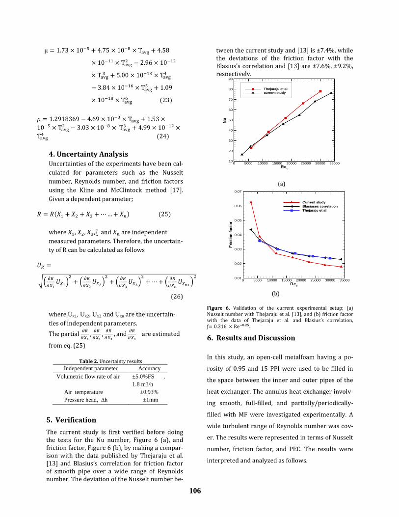
5. Verification
The current study is first verified before doing the tests for the Nu number, Figure 6 (a), and friction factor, Figure 6 (b), by making a compar-ison with the data published by Thejaraju et al. [13] and Blasius’s correlation for friction factor of smooth pipe over a wide range of Reynolds number. The deviation of the Nusselt number be-
tween the current study and [13] is ±7.4%, while the deviations of the friction factor with the Blasius’s correlation and [13] are ±7.6%, ±9.2%, respectively.
(a)
(b)
Figure 6. Validation of the current experimental setup; (a) Nusselt number with Thejaraju et al. [13], and (b) friction factor with the data of Thejaraju et al. and Blasius’s correlation, ƒ .
6. Results and Discussion
In this study, an open-cell metalfoam having a po-
rosity of 0.95 and 15 PPI were used to be filled in
the space between the inner and outer pipes of the
heat exchanger. The annulus heat exchanger involv-
ing smooth, full-filled, and partially/periodically-
filled with MF were investigated experimentally. A
wide turbulent range of Reynolds number was cov-
er. The results were represented in terms of Nusselt
number, friction factor, and PEC. The results were
interpreted and analyzed as follows.
Rec
Nu
0 5000 10000 15000 20000 25000 30000 3500010
20
30
40
50
60
70
80
90
Thejaraju et al
current study
Rec
Fri
ctio
nfa
cto
r
0 5000 10000 15000 20000 25000 30000 350000.01
0.02
0.03
0.04
0.05
0.06
0.07
Current study
Blasiuses correlation
Thejaraju et al
107
6.1 Thermal performance
6.1.1 Heat Transfer Coefficient
Figure (7) Shows the effect of Reynolds number on
the Nusselt number of the cold air stream for all pat-
terns proposed in this study. It can be seen that the
smooth pattern showed the lowest Nu number
while it increased with increasing Re number. In-
creasing Re number could increase the turbulence
of the fluid, and then improve the mixing process of
the fluid. An enhancement in the Nu number as ob-
served when the MF was used in form of case 3 as
DMF/D pipe = 0.75. This is due to compressibility be-
havior of the air which makes the air passes through
the free gap (no MF) because of low flow resistance.
Thus, the convection heat transfer between the air
and the solid edges of the porous matrix reduces.
Nevertheless, it is still higher than the smooth one.
Further enhancement in the Nu number was moni-
tored when the MF was utilized as observed in case
4 and 5. It is worthy to be mentioned that case 4
filled 50% while case 5 filled 62.5% by MF. Never-
theless, case 4 provided greater heat transfer aug-
mentation. Additional heat absorption by the MF
was recorded in case 6 and 7. Case 7 showed higher
heat transfer compared to case 6, whereas it filled
57.1% from the total annulus gap compared to
62.5% for case 6. Therefore, more heat dissipated
was seen in case 7 due to the thermal boundary lay-
er reattachment caused by zigzag MF configuration.
Case 2 showed the optimal heat dissipation com-
pared to all the partially filled configurations, while
it filled only 50% from the annulus gap. This is due
to the fact that this configuration is attach at the
developing thermal boundary layer region of the hot
air stream and the wall temperature is at its higher
value.
The maximum Nu number observed was found in
case 1 as the whole annulus gap was completely
filled with MF. Therefore, the air was forced through
the MF and all the amount of the flow was in contact
with the solid edges of the porous zone. It is worth
to be mentioned that the behavior of the Nusselt
number of this study is observed to be similar to the
data published by [1, 5, 12, 13, and 14].
Figure 7. Effect of Reynolds number on the Nusselt number for
all cases investigated in this study.
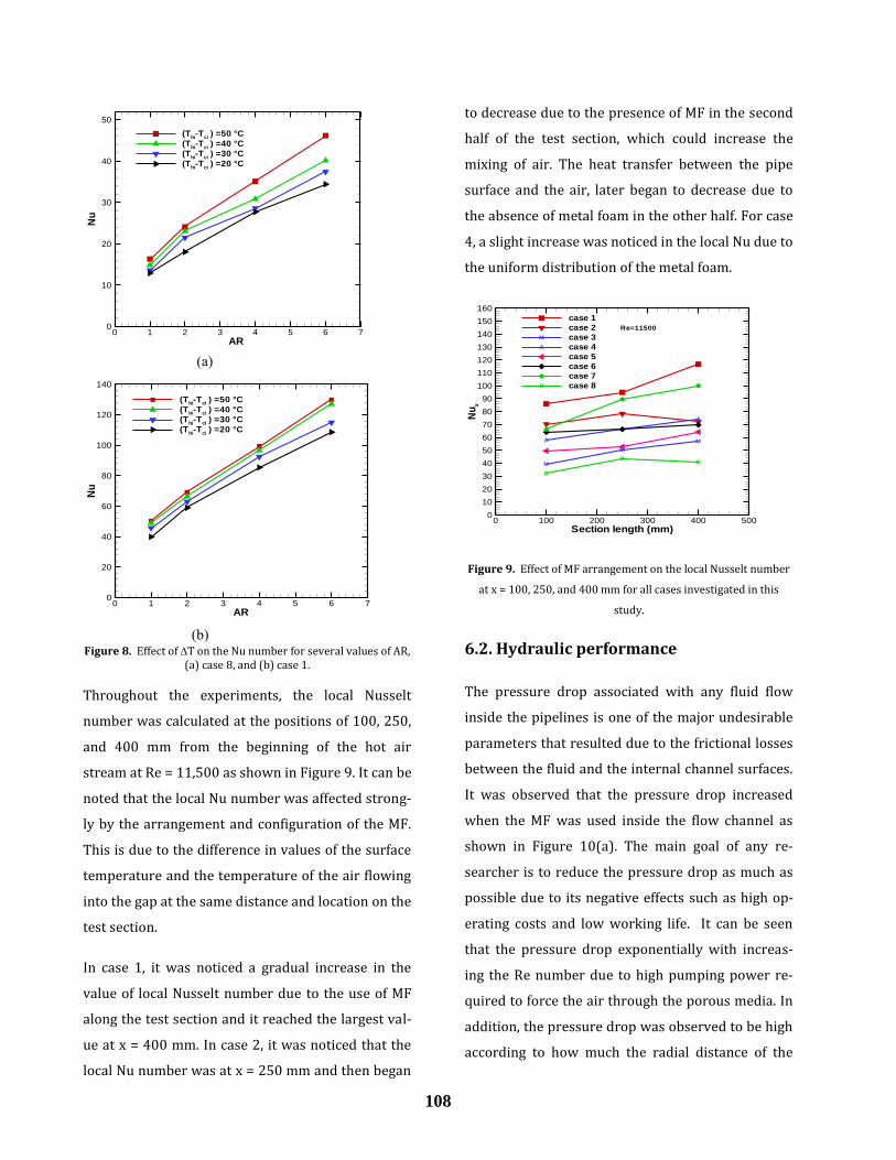
Figure 8(a) and 8(b) show the relationship between
the average Nusselt number and the air ratio, AR, for
all temperature differences considered here, (ΔT =
Th in – Tc in) for case 1 and 8, respectively. The T
values between the inlet hot air and inlet cold air
were 20, 30, 40, and 50°C. It was found that when
the T increased the Nu number increased and
higher amount of heat can be absorbed by the cold
air stream. In that case, the heat recovery increased
and the heat loss to the ambient reduced.
Rec
Nu
0 5000 10000 15000 20000 25000 30000 350000
20
40
60
80
100
120
140
160
180
200
220
240
260
Case 1
Case 2
Case 3
Case 4
Case 5
Case 6
Case 7
Case 8
108
Figure 8. Effect of T on the Nu number for several values of AR, (a) case 8, and (b) case 1.
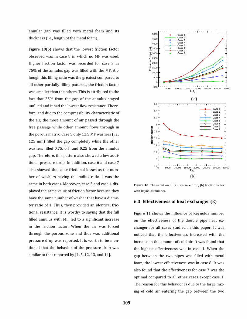
Throughout the experiments, the local Nusselt
number was calculated at the positions of 100, 250,
and 400 mm from the beginning of the hot air
stream at Re = 11,500 as shown in Figure 9. It can be
noted that the local Nu number was affected strong-
ly by the arrangement and configuration of the MF.
This is due to the difference in values of the surface
temperature and the temperature of the air flowing
into the gap at the same distance and location on the
test section.
In case 1, it was noticed a gradual increase in the
value of local Nusselt number due to the use of MF
along the test section and it reached the largest val-
ue at x = 400 mm. In case 2, it was noticed that the
local Nu number was at x = 250 mm and then began
to decrease due to the presence of MF in the second
half of the test section, which could increase the
mixing of air. The heat transfer between the pipe
surface and the air, later began to decrease due to
the absence of metal foam in the other half. For case
4, a slight increase was noticed in the local Nu due to
the uniform distribution of the metal foam.
Figure 9. Effect of MF arrangement on the local Nusselt number
at x = 100, 250, and 400 mm for all cases investigated in this
study.
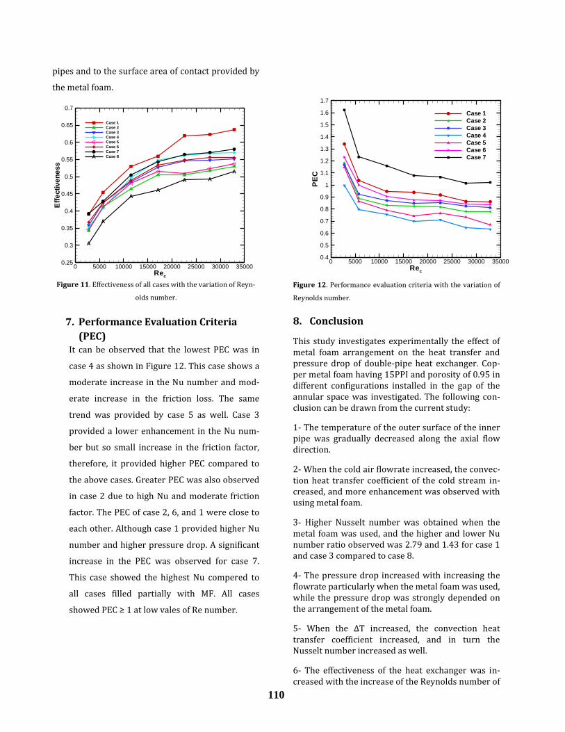
6.2. Hydraulic performance
The pressure drop associated with any fluid flow
inside the pipelines is one of the major undesirable
parameters that resulted due to the frictional losses
between the fluid and the internal channel surfaces.
It was observed that the pressure drop increased
when the MF was used inside the flow channel as
shown in Figure 10(a). The main goal of any re-
searcher is to reduce the pressure drop as much as
possible due to its negative effects such as high op-
erating costs and low working life. It can be seen
that the pressure drop exponentially with increas-
ing the Re number due to high pumping power re-
quired to force the air through the porous media. In
addition, the pressure drop was observed to be high
according to how much the radial distance of the
AR
Nu
0 1 2 3 4 5 6 70
10
20
30
40
50
(Thi-T
ci) =50 °C
(Thi-T
ci) =40 °C
(Thi-T
ci) =30 °C
(Thi-T
ci) =20 °C
AR
Nu
0 1 2 3 4 5 6 70
20
40
60
80
100
120
140
(Thi-T
ci) =50 °C
(Thi-T
ci) =40 °C
(Thi-T
ci) =30 °C
(Thi-T
ci) =20 °C
M
M
MA
A
A
B
BB
Section length (mm)
Nu
x
0 100 200 300 400 5000
10
20
30
40
50
60
70
80
90
100
110
120
130
140
150
160
case 1
case 2
case 3
case 4
case 5
case 6
case 7
case 8
M
A
B
Re=11500
(b)
(a)
109
annular gap was filled with metal foam and its
thickness (i.e., length of the metal foam).
Figure 10(b) shows that the lowest friction factor
observed was in case 8 in which no MF was used.
Higher friction factor was recorded for case 3 as
75% of the annulus gap was filled with the MF. Alt-
hough this filling ratio was the greatest compared to
all other partially filling patterns, the friction factor
was smaller than the others. This is attributed to the
fact that 25% from the gap of the annulus stayed
unfilled and it had the lowest flow resistance. There-
fore, and due to the compressibility characteristic of
the air, the most amount of air passed through the
free passage while other amount flows through in
the porous matrix. Case 5 only 12.5 MF washers (i.e.,
125 mm) filled the gap completely while the other
washers filled 0.75, 0.5, and 0.25 from the annulus
gap. Therefore, this pattern also showed a low addi-
tional pressure drop. In addition, case 6 and case 7
also showed the same frictional losses as the num-
ber of washers having the radius ratio 1 was the
same in both cases. Moreover, case 2 and case 4 dis-
played the same value of friction factor because they
have the same number of washer that have a diame-
ter ratio of 1. Thus, they provided an identical fric-
tional resistance. It is worthy to saying that the full
filled annulus with MF, led to a significant increase
in the friction factor. When the air was forced
through the porous zone and thus was additional
pressure drop was reported. It is worth to be men-
tioned that the behavior of the pressure drop was
similar to that reported by [1, 5, 12, 13, and 14].
( a)
(b)
Figure 10. The variation of (a) pressure drop, (b) friction factor
with Reynolds number.
6.3. Effectiveness of heat exchanger (E)
Figure 11 shows the influence of Reynolds number
on the effectiveness of the double pipe heat ex-
changer for all cases studied in this paper. It was
noticed that the effectiveness increased with the
increase in the amount of cold air. It was found that
the highest effectiveness was in case 1. When the
gap between the two pipes was filled with metal
foam, the lowest effectiveness was in case 8. It was
also found that the effectiveness for case 7 was the
optimal compared to all other cases except case 1.
The reason for this behavior is due to the large mix-
ing of cold air entering the gap between the two
B B BB
BB
B
A AA
A
A
A
A
Rec
Pre
ssu
reD
rop
(p
a)
0 5000 10000 15000 20000 25000 30000 35000-500
0
500
1000
1500
2000
2500
3000
3500
4000
4500
5000 Case 1
Case 2
Case 3
Case 4
Case 5
Case 6
Case 7
Case 8
B
A
Rec
fric
tio
nfa
cto
r
0 5000 10000 15000 20000 25000 30000 35000-0.2
0
0.2
0.4
0.6
0.8
1
1.2
1.4
1.6
Case 1
Case 2
Case 3
Case 4
Case 5
Case 6
Case 7
Case 8
110
pipes and to the surface area of contact provided by
the metal foam.
Figure 11. Effectiveness of all cases with the variation of Reyn-
olds number.
7. Performance Evaluation Criteria
(PEC) It can be observed that the lowest PEC was in
case 4 as shown in Figure 12. This case shows a
moderate increase in the Nu number and mod-
erate increase in the friction loss. The same
trend was provided by case 5 as well. Case 3
provided a lower enhancement in the Nu num-
ber but so small increase in the friction factor,
therefore, it provided higher PEC compared to
the above cases. Greater PEC was also observed
in case 2 due to high Nu and moderate friction
factor. The PEC of case 2, 6, and 1 were close to
each other. Although case 1 provided higher Nu
number and higher pressure drop. A significant
increase in the PEC was observed for case 7.
This case showed the highest Nu compered to
all cases filled partially with MF. All cases
showed PEC ≥ 1 at low vales of Re number.
Figure 12. Performance evaluation criteria with the variation of
Reynolds number.
8. Conclusion
This study investigates experimentally the effect of metal foam arrangement on the heat transfer and pressure drop of double-pipe heat exchanger. Cop-per metal foam having 15PPI and porosity of 0.95 in different configurations installed in the gap of the annular space was investigated. The following con-clusion can be drawn from the current study:
1- The temperature of the outer surface of the inner pipe was gradually decreased along the axial flow direction.
2- When the cold air flowrate increased, the convec-tion heat transfer coefficient of the cold stream in-creased, and more enhancement was observed with using metal foam.
3- Higher Nusselt number was obtained when the metal foam was used, and the higher and lower Nu number ratio observed was 2.79 and 1.43 for case 1 and case 3 compared to case 8.
4- The pressure drop increased with increasing the flowrate particularly when the metal foam was used, while the pressure drop was strongly depended on the arrangement of the metal foam.
5- When the ∆T increased, the convection heat transfer coefficient increased, and in turn the Nusselt number increased as well.
6- The effectiveness of the heat exchanger was in-creased with the increase of the Reynolds number of
A
A
AA
A A
A
Rec
Eff
ective
ne
ss
0 5000 10000 15000 20000 25000 30000 350000.25
0.3
0.35
0.4
0.45
0.5
0.55
0.6
0.65
0.7
Case 1
Case 2
Case 3
Case 4
Case 5
Case 6
Case 7
Case 8A
Rec
PE
C
0 5000 10000 15000 20000 25000 30000 350000.4
0.5
0.6
0.7
0.8
0.9
1
1.1
1.2
1.3
1.4
1.5
1.6
1.7
Case 1
Case 2
Case 3
Case 4
Case 5
Case 6
Case 7
111
the cold air. The maximum effectiveness was 0.637 for case 1 at Re = 31,350.
7- The maximum PEC obtained was 1.62 for case 7 at Re = 2800.
Nomenclature
Symbol Meaning Units
Surface area of inner copper pipe m2
Surface area of the annular gap m2
Diameter of inner copper pipe m
Diameter of outer copper pipe m
Diameter of inner (PVC) pipe m
Diameter of inner (PVC) pipe
Hydraulic diameter of annular m
Convection heat transfer coefficient
of cold air
W/m2
K
Convection heat transfer coefficient
of hot air
W/m2
K
k Thermal conductivity of fluid W/m K
Q Heat transfer W
f friction factor -------
mass flow rate kg/s
u Velocity m/s
V volume of air m3/s
𝑐 Specific heat at constant pressure kJ/kg
T Temperature °C
Re Reynolds number -------
Outlet temperature of hot air (°C)
average temperature of cold air (°C)
Inlet temperature of cold air (°C)
Outlet temperature of cold air (°C)
E
f s
average surface temperature of
inner pipe
Effectiveness
Nusselt number with metal foam
Nusselt number without MF
Friction factor with metal foam
Friction factor without metal foam
(smooth)
(°C)
Greek symbols
ρ Density kg m
Viscosity of air
gravitational acceleration
Pressure head
Pa.s
m/s2
mm
ΔP Pressure drop Pa
ρ Density kg m
Viscosity of air
gravitational acceleration
Pressure head
Pa.s
m/s2
mm
Abbreviation
PPI Pores per inch
PEC Performance Evaluation Criteria
MF Metal foam
i Inlet
o Outlet
PVC Polyvinyl chloride
112
References
[1] J. A. Hamzah and M. A. Nima, “Experimental Study of Heat Transfer Enhancement in Dou-ble-Pipe Heat Exchanger Integrated with Metal Foam Fins,” Arab. J. Sci. Eng., vol. 45, no. 7, pp. 5153–5167, 2020, doi: 10.1007/s13369-020-04371-3.
[2] N. Targui and H. Kahalerras, “Analysis of fluid flow and heat transfer in a double pipe heat ex-changer with porous structures,” Energy Con-vers. Manag., vol. 49, no. 11, pp. 3217–3229, 2008, doi: 10.1016/j.enconman.2008.02.010.
[3] H. Kahalerras and N. Targui, “Numerical analy-sis of heat transfer enhancement in a double pipe heat exchanger with porous fins,” Int. J. Numer. Methods Heat Fluid Flow, vol. 18, no. 5, pp. 593–617, 2008, doi: 10.1108/09615530810879738.
[4] A. Jamarani, M. Maerefat, N. F. Jouybari, and M.
E. Nimvari, “Thermal Performance Evaluation of a Double-Tube Heat Exchanger Partially Filled with Porous Media Under Turbulent Flow Regime,” Transp. Porous Media, vol. 120, no. 3, pp. 449–471, 2017, doi: 10.1007/s11242-017-0933-x.
[5] H. R. Abbasi, E. Sharifi Sedeh, H. Pourrahmani, and M. H. Mohammadi, “Shape optimization of segmental porous baffles for enhanced thermo-hydraulic performance of shell-and-tube heat exchanger,” Appl. Therm. Eng., vol. 180, p. 115835, 2020, doi: 10.1016/j.applthermaleng.2020.115835.
[6] Isbeyeh W. Maid , Kifah H. Hilal, Jawaher K. Hassun" experimental study of heat transfer enhancement in heat exchanger using porous media“G lobal J ournal of E ngineering S cience and R esearch M anagement,” vol. 4, no. 9, pp. 82–91, 2017, doi: 10.5281/zenodo.886915
[7] U. K. N. Madhav Mishra, “Experimental Investi-gations of Double Pipe Heat Exchanger With Triangular Baffles,” Int. Res. J. Eng. Technol., vol. 03, no. 08, pp. 1137–1141, 2016.
[8] K. Nawaz, J. Bock, and A. M. Jacobi, “Thermal- hy-draulic performance of metal foam heat exchang-ers under dry operating conditions,” Appl. Therm. Eng., vol. 119, pp. 222–232, 2017, doi: 10.1016/j.applthermaleng.2017.03.056.
[9] H. J. Xu, Z. G. Qu, and W. Q. Tao, “Numerical inves-tigation on self-coupling heat transfer in a coun-ter-flow double-pipe heat exchanger filled with metallic foams,” Appl. Therm. Eng., vol. 66, no. 1–2, pp. 43–54, 2014, doi: 10.1016/j.applthermaleng.2014.01.053.
[10] A. A. Sertkaya, K. Altinisik, and K. Dincer, “Exper-
imental investigation of thermal performance of aluminum finned heat exchangers and open-cell aluminum foam heat exchangers,” Exp. Therm. Fluid Sci., vol. 36, pp. 86–92, 2012, doi: 10.1016/j.expthermflusci.2011.08.008
[11] A. Nasser, Adel Alhusseny and A. Turan, “Rotating
metal foam structures for performance en-hancement of double-pipe heat exchangers,” Int. J. Heat Mass Transf., vol. 105, pp. 124–139, 2017, doi: 10.1016/j.ijheatmasstransfer.2016.09.055.
[12] M. R. Salem, M. K. Althafeeri, K. M. Elshazly, M. G. Higazy, and M. F. Abdrabbo, “Experimental inves-tigation on the thermal performance of a double pipe heat exchanger with segmental perforated baffles,” Int. J. Therm. Sci., vol. 122, no. 02, pp. 39–52, 2017, doi: 10.1016/j.ijthermalsci.2017.08.008
[13] R. Thejaraju, K. B. Girisha, S. H. Manjunath, and B.
S. Dayananda, “Experimental investigation of tur-bulent flow behavior in an air to air double pipe heat exchanger using novel para winglet tape,” Case Stud. Therm. Eng., vol. 22, no. December, p. 100791, 2020, doi: 10.1016/j.csite.2020.100791.
[14] S. P. Govindani, “Experimental Analysis of Heat
Transfer Enhancement in a Double Pipe Heat Ex-changer Using Inserted Rotor Assembled Strand,” Volume: 03 Issue: 01 | Jan-2016.
[15] H. Arasteh, M. R. Salimpour, and M. R. Tavakoli,
“Optimal distribution of metal foam inserts in a double-pipe heat exchanger,” Int. J. Numer. Meth-ods Heat Fluid Flow, vol. 29, no. 4, pp. 1322–3142, 2019, doi: 10.1108/HFF-04-2018-0162.
[16] Incropera F.P,"Fundamentals of Heat and Mass
Transfer: 6th ed. Notre Dame, Indiana, JOHN WILEY, Son.2005.
[17] S. J. Kline, “Describing uncertainty in single sam-
ple experiments,” Mech. Eng., vol. 75, pp. 3–8, 1953.