temperature–enthalpy curve for energy targeting of distillation columns
TRANSCRIPT
Temperature—enthalpy curve for energy targetingof distillation columns
Santanu Bandyopadhyay!, Ranjan K. Malik" and Uday V. Shenoy#,*
!Energy Systems Engineering, Department of Mechanical Engineering, "Computer Aided Design Centre andDepartment of Chemical Engineering, #Department of Chemical Engineering and Computer Aided Design
Centre, Indian Institute of Technology, Powai, Bombay 400 076, India
Abstract
The temperature—enthalpy (¹—H) diagram of a distillation column at practical near-minimum thermodyn-amic condition (PNMTC) or the column grand composite curve (CGCC) is a useful representation for energytargeting studies and may be generated from a converged simulation of a base-case column design. Thecalculation procedure for the CGCC involves determination of the net enthalpy deficit at each stage bygenerating envelopes from either the condenser end (top-down approach) or the reboiler end (bottom-upapproach). However, the values calculated by the two approaches differ for stages with feeds because existingprocedures for CGCC generation do not consider the enthalpy balances at the feed stages. In fact, the netenthalpy deficits at feed stages calculated by both approaches are erroneous even for the simplest case of binarydistillation. A feed stage correction (FSC) that rigorously considers the mass and enthalpy balance equations atfeed stages is proposed in this work to resolve the discrepancy. Instead of assuming that the compositionsobtained from the converged simulation for a feed stage will remain unchanged at PNMTC, the pinchedcompositions for the feed are determined by the intersection of the equilibrium curve and the feed q-line. Ratherthan perform an additional flash calculation to establish the pinched feed compositions, a quadratic approxi-mation is developed here for column targeting purposes by assuming the relative volatility obtained from thesimulation to remain constant in the neighborhood of the feed stage. The proposed FSC ensures that the CGCCis identical whether the calculations are performed by the top-down approach or the bottom-up approach. Theeffect of the FSC on the targets for energy conservation by reflux modification, feed conditioning, andintroduction of side reboilers/condensers is discussed. As the energy target for reflux modification is determinedby the CGCC pinch which typically occurs at or close to the feed location, the significance of the FSC on thereflux modification target is highlighted through several case studies including a complex column featuringmultiple feeds and consequently multiple pinch points. The CGCCs for these case studies are generated bya computer program based on the FSC and a single analytical equation for the calculation of the net enthalpydeficits that allows every stage to have a feed, liquid product, vapor product, and side exchanger. The studiesshow that the reflux modification targets may be erroneous in many cases, if the FSC is ignored.
Keywords: distillation; thermodynamic minimum; energy targeting; temperature—enthalpy diagram; pinchanalysis; grand composite
1. Introduction
The temperature—enthalpy (¹—H) diagram fora distillation column or the column grand compositecurve (CGCC) is a useful representation to quantitat-ively address the energy-saving potential for possiblestand-alone modifications such as reflux reduction,feed conditioning, and scope for side reboiler/conden-ser (Naka et al., 1980; Terranova and Westerberg,
1989; Dhole and Linnhoff, 1993; Ognisty, 1995; Hallet al., 1995; Trivedi et al., 1996). It may be further usedto explore opportunities for integration of the distilla-tion column with the background process.
The ¹—H curve of a binary distillation column isgenerated by solving the coupled mass and enthalpybalances for the reversible separation scheme (Bene-dict, 1947; Fonyo, 1974; King, 1980; Fitzmorris andMah, 1980; Ho and Keller, 1987). Reversible opera-tion corresponds to minimum net work consumptionand involves minimization of the driving forces forheat and mass transfer within individual stages (or, in
1733
other words, decrease of the gap between the operat-ing and equilibrium curves on the x—y diagram) asdiscussed in detail by King (1980). The operatingcurves come closer to the equilibrium curve (andexhibit a single pinch point on the x—y diagram) at theminimum reflux condition (i.e. infinite stages). Thereversibility in a binary distillation process can befurther increased (away from the single pinch) byintroducing side reboilers and side condensers (whichcorrespond to different operating curves and intro-duce more pinches on the x—y diagram). The limit ofthe minimum thermodynamic condition is achievedwith infinite stages and infinitely many side exchange-rs such that the operating and equilibrium curvescoincide (or complete pinching occurs on the x—ydiagram).
In contrast to binary distillation, the sharpness ofseparation is generally limited in multicomponent re-versible distillation (Fonyo, 1974) and it is impossibleto devise a reversible separation scheme for manypractical multicomponent separations (Franklin andWilkinson, 1982). The limitation in sharpness of re-versible multicomponent distillation can be circum-vented, for the purposes of generation of the ¹—Hcurve, by using the pseudo-binary concept of light andheavy key model (Fonyo, 1974; Dhole and Linnhoff,1993).
Dhole and Linnhoff (1993) describe a procedure forgenerating the CGCC from a converged simulation ofthe base-case distillation column and thus inherentlyaccount for the inevitable feed loss, pressure loss,sharp-separation loss, and loss due to chosen config-uration. The calculation procedure involves gen-erating envelopes from one end of the column andevaluating the net enthalpy deficit at each stage afterdetermining the minimum vapor and liquid flowsthrough that stage. When the net enthalpy deficit isadded to (subtracted from) the existing condenser(reboiler) duty and plotted against the stage temper-ature, a close approximation to the ¹—H curve of thecolumn is obtained at the practical near-minimumthermodynamic condition (PNMTC).
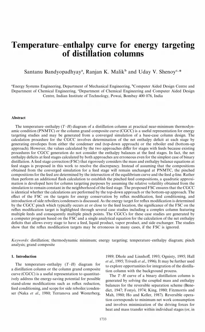
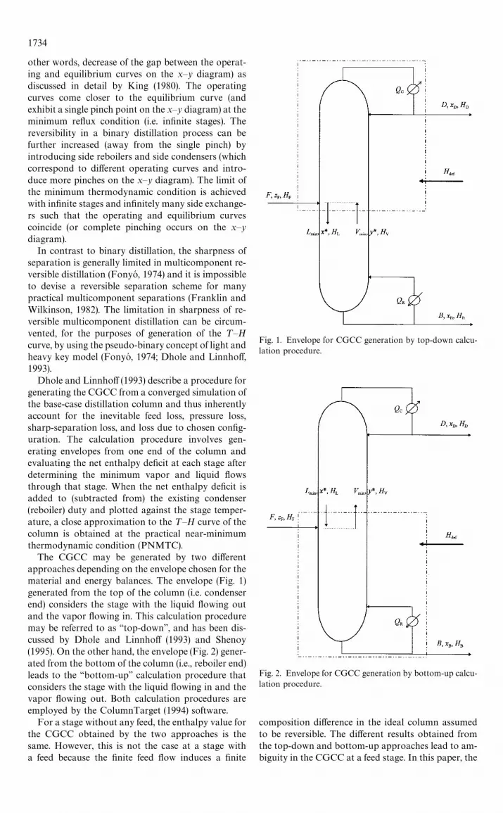
The CGCC may be generated by two differentapproaches depending on the envelope chosen for thematerial and energy balances. The envelope (Fig. 1)generated from the top of the column (i.e. condenserend) considers the stage with the liquid flowing outand the vapor flowing in. This calculation proceduremay be referred to as ‘‘top-down’’, and has been dis-cussed by Dhole and Linnhoff (1993) and Shenoy(1995). On the other hand, the envelope (Fig. 2) gener-ated from the bottom of the column (i.e., reboiler end)leads to the ‘‘bottom-up’’ calculation procedure thatconsiders the stage with the liquid flowing in and thevapor flowing out. Both calculation procedures areemployed by the ColumnTarget (1994) software.
For a stage without any feed, the enthalpy value forthe CGCC obtained by the two approaches is thesame. However, this is not the case at a stage witha feed because the finite feed flow induces a finite
Fig. 1. Envelope for CGCC generation by top-down calcu-lation procedure.
Fig. 2. Envelope for CGCC generation by bottom-up calcu-lation procedure.
composition difference in the ideal column assumedto be reversible. The different results obtained fromthe top-down and bottom-up approaches lead to am-biguity in the CGCC at a feed stage. In this paper, the
1734
ambiguity is eliminated and a fundamentally appro-priate feed stage correction (FSC) is proposed.
2. Column grand composite curve
The generation of the CGCC by the top-down andbottom-up procedures is outlined below with the rel-evant equations. The form of the equations is differentfrom that used by Dhole and Linnhoff (1993) whoutilized all the component balances rather than theoverall material balance.
2.1. Top-down calculation procedure
For the envelope in Fig. 1, the overall materialbalance and the component balance are given below.
».*/
#F"¸.*/
#D, (1)
».*/
y*#FzF"¸
.*/x*#Dx
D. (2)
On solving equations (1) and (2), the minimum liquidflow (¸
.*/) leaving and the minimum vapor flow
(».*/
) entering the stage are obtained as
¸.*/
"[D(xD!y*)!F (z
F!y*)]/(y*!x*), (3)
».*/
"[D(xD!x*)!F(z
F!x*)]/(y*!x*). (4)
Next, the net enthalpy deficit (H$%&
) for the envelopein Fig. 1 may be evaluated from the followingenthalpy balance:
».*/
HV#FH
F#H
$%&"¸
.*/H
L#DH
D. (5)
The stage enthalpy deficit H$%&
may be added to thecondenser duty (Q
C) to obtain the enthalpy values for
plotting the CGCC (HCGCC
). Thus, equations (3)— (5)may be combined to yield the final equation givenbelow:
HCGCC
"QC#H
$%&
"QC(#DMH
D#[H
L!H
V)x
D
#(HVx*!H
Ly*)]/(y*!x*)N
!FMHF#[(H
L!H
V)z
F
#(HVx*!H
Ly*)]/(y*!x*)N. (6)
The right-hand side of equation (6) is directly evalu-ated from the output of a converged simulation ofa distillation column as it involves only the enthalpies,compositions, and molar flows for the feed, the prod-uct and the stage.
For a column with a single feed, the third term onthe right-hand side of equation (6) will be zero forstages above the feed stage.
2.2. Bottom-up calculation procedure
For the envelope in Fig. 2, the overall materialbalance and the component balance are
¸.*/
#F"».*/
#B, (7)
¸.*/
x*#FzF"»
.*/y*#Bx
B. (8)
Thus, the minimum liquid flow (¸.*/
) entering and theminimum vapor flow (»
.*/) leaving the stage are
¸.*/
"[!B(xB!y*)#F (z
F!y*)]/(y*!x*), (9)
».*/
"[!B(xB!x*)#F (z
F!x*)]/(y*!x*). (10)
The net enthalpy deficit (H$%&
) for the envelope inFig. 2 may be determined from:
¸.*/
HL#FH
F#H
$%&"»
.*/H
V#BH
B. (11)
Equations (9)— (11) are combined, and the stage en-thalpy deficit H
$%&then subtracted from the reboiler
duty (QR) to obtain the enthalpy values for plotting
the CGCC (HCGCC
) as given by the following expres-sion:
HCGCC
"QR!H
$%&
"QR!BMH
B#[(H
L!H
V)x
B
#(HVx*!H
Ly*)]/(y*!x*)N
#FMHF#[(H
L!H
V)z
F
#(HVx*!H
Ly*)]/(y*!x*)N. (12)
For a column with a single feed, the last term on theright-hand side of the above equation is zero forstages below the feed stage.
In deriving equations (6) and (12), the fact thatenthalpy surpluses can be cascaded from higher tolower temperatures and enthalpy deficits can be cas-caded from lower to higher temperatures has beenutilized.
2.3. Comparison of top-down and bottom-up calcu-lation procedures
This section compares the results (¸.*/
, ».*/
, andH
CGCC) of the two calculation procedures. The mater-
ial balance, component balance and enthalpy balancefor the overall column as given below may be used forthis purpose.
F"D#B, (13)
FzF"Dx
D#Bx
B, (14)
FHF#Q
R"DH
D#BH
B#Q
C. (15)
Denoting the difference between the top-down andbottom-up values by *, equations (3), (4), (9), (10), (13)and (14) may be simplified to give
*¸.*/
"F(y*!zF)/(y*!x*), (16)
*».*/
"!F(zF!x*)/(y*!x*). (17)
The above equations along with equations (5), (6), (11),(12) and (15) yield
*HCGCC
"*¸.*/
HL!*»
.*/H
V!FH
F
"F[HL(y*!z
F)/(y*!x*)
#HV(z
F!x*)/(y*!x*)!H
F]. (18)
1735
The CGCC must be independent of the calculationprocedure and therefore *H
CGCCmust be zero. This
requires that either the stage not have a feed (i.e.F"0), or the term in square brackets in equation (18)be zero. This second condition may be rewritten in thefollowing form:
(HV!H
F)/(H
V!H
L)"(y*!z
F)/(y*!x*). (19)
Equation (19) highlights the fundamental reason forthe ambiguity in the CGCC at a stage with a feed. Itwill be satisfied only at the minimum reflux condition,where a practical simulation is clearly not possiblebecause it would call for an infinite number of stages.Using the x* and y* values from a converged simula-tion at a feed stage will never lead to equation (19)being satisfied, and therefore will always result indifferent values for H
CGCCfrom a top-down and bot-
tom-up calculation at a feed stage.It must be emphasized that a similar analysis may
be performed for a product drawn at a stage and theequations readily rewritten. However, no ambiguityoccurs in the CGCC at a stage with a product with-drawal because the product composition will necessar-ily be identical to the equilibrium stage composition.In other words, if a liquid product (with molar flowD
L) and/or a vapor product (with molar flow D
V) are
withdrawn at a stage, then *¸.*/
"!DL
and*»
.*/"D
Vbut *H
CGCC"0. Though the minimum
internal flows computed by the two approaches aredifferent for stages with product withdrawals, theCGCC values are identical.
3. Proposed approach based on feed stage correction
It is clear from the previous section that the CGCCis uniquely defined at all stages except those withfeeds. The ambiguity at stages with feeds may beeliminated through a fundamental analysis of a feedstage.
3.1. Fundamental analysis of feed stage
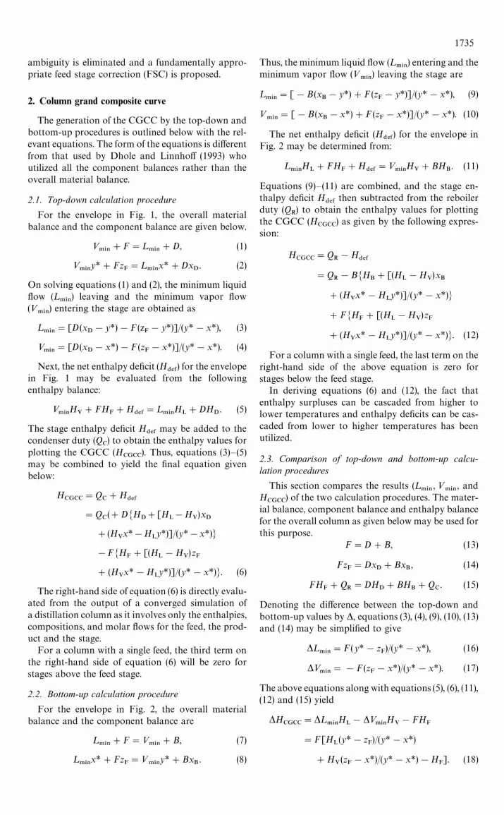
Figure 3 shows a feed stage (generalized to includeliquid and vapor products) for a column operating atthe PNMTC. The material balance, component bal-ance and enthalpy balance at such a feed stage are asfollows:
¸*/#»
*/#F"¸
065#»
065#D
L#D
V, (20)
¸*/x*F#»
*/y*F#Fz
F"¸
065x*F#»
065y*F#D
Lx*#D
Vy*,
(21)
¸*/H
L#»
*/H
V#FH
F"¸
065H
L#»
065H
V
#DLH
L#D
VH
V. (22)
Equations (21) and (22) assume the composition andmolar enthalpy changes of the saturated liquids and
Fig. 3. Fundamental analysis of a generalized feed stage withliquid and vapor products for a PNMTC column.
vapors over the feed stage are negligible. This assump-tion holds when the feed stage is pinched or thecolumn is operating at the PNMTC. Furthermore, inequation (21), the product compositions correspondto the equilibrium compositions (x*, y*) of the feedstage (for the simulated finite column operating atgreater than minimum reflux). Note that these prod-uct compositions are different from the equilibriumcompositions (x*
F,y*
F) of the feed pinch (for an infinite
reversible column at minimum reflux) in order tosatisfy the column mass balance.
Denoting (¸065!¸
*/#D
L)/F"1!(»
065!»
*/#D
V)/F
by q, equations (20)—(22) give
q"(HV!H
F)/(H
V!H
L)
"[(y*F!z
F)!(y*
F!y*)D
V/F
!(x*F!x*)D
L/F]/(y*
F!x*
F). (23)
Equation (23) reduces to the well-known definition ofq (Treybal, 1981) for a feed stage without productwithdrawals (i.e. D
V"D
L"0).
Importantly, equations (19) and (23) indicate that itis appropriate to use x*
Fand y*
F(and not use x* and y*
values from a converged simulation) during theCGCC calculation at a feed stage. Thus, at a feedstage, the value of H
CGCCfrom the top-down and
bottom-up calculation procedures will be identicalprovided x*
Fand y*
Fare used.
3.2. Computation of feed stage correction (FSC)
A separate computation is required for every feedduring the generation of a CGCC because x* and y*values from a converged simulation are not appropri-ate at a feed stage. The feed stage correction (FSC)involves solving equation (23) simultaneously with theequilibrium relationship to determine x*
Fand y*
F. Once
appropriate values of x*F
and y*F
are obtained, then thefollowing modified forms of equations (6) and (12)may be used for calculating the enthalpy value of the
1736
CGCC at the feed stage.
HCGCC
"QC#D[H
D#H
L(x
D!y*
F)/(y*
F!x*
F)
!HV(x
D!x*
F)/(y*
F!x*
F)]
"QR!B[H
B#H
L(x
B!y*
F)/(y*
F!x*
F)
!HV(x
B!x*
F)/(y*
F!x*
F)]. (24)
The values of x*F
and y*F
may be determined by anadiabatic flash calculation. For a two-phase feed, thisflash calculation may be additionally performed onthe simulator. For a subcooled or superheated feed,additional thermal energy is exchanged via condensa-tion of the vapor stream or vaporization of the liquidstream, respectively; however, x*
Fand y*
Fcan still be
calculated from the mathematical solution of theadiabatic flash equations, without their physicalcounterpart (Shiras et al., 1950). Strictly speaking,superheated vapors and subcooled liquids cannot befed reversibly into a distillation column (Koehleret al., 1991) even for binary systems.
As an alternative to the extra simulation/adiabaticflash calculation, excellent approximations to x*
Fand
y*F
that suffice for targeting purposes may be obtainedby simply assuming the relative volatility a for thefeed to be equal to that from the converged simulationat the feed stage.
a"[y*F(1!x*
F)]/[x*
F(1!y*
F)]
"[y* (1!x*)]/[x*(1!y*)]. (25)
Then, equation (25) for the equilibrium curve basedon constant relative volatility near the feed stage issolved with equation (23) to eliminate y*
Fand obtain
the quadratic approximation given below.
(a!1)(q!DL/F)x*2
F#[a (1!D
V/F)!D
L/F
!(a!1)(q#zF!y*D
V/F!x*D
L/F)]x*
F
!zF#y*D
V/F#x*D
L/F"0. (26)
The FSC calculations are performed as follows. Theenthalpy and composition values from the convergedsimulation at the feed stage are used to determineq and a from equations (23) and (25), respectively.Then, equation (26) is solved and only that value ofx*F
is accepted which is between zero and unity.Finally, y*
Fis determined from equation (23) or equa-
tion (25), and HCGCC
is computed from equation (24).As an aside, note that the left-hand-side of equation
(26) for the binary case with no product withdrawalscan be rearranged [after substituting for a and x*
Fin
terms of the K-values for the two components] intothe form of the Rachford-Rice (1952) function; how-ever, equation (26) has the advantage of being for-mulated in terms of a (rather than K-values which arestrongly dependent on temperature). If constancy ofK is assumed in the neighborhood of the feed, thena linear approximation (rather than a quadratic one)is obtained.
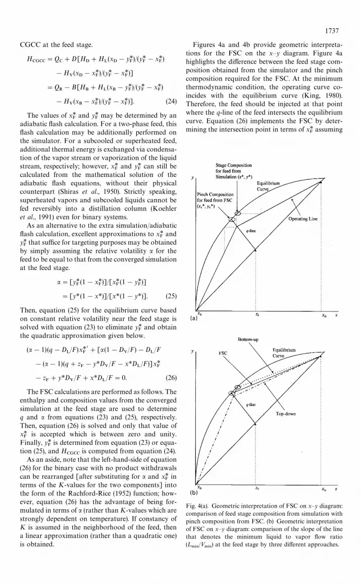
Figures 4a and 4b provide geometric interpreta-tions for the FSC on the x—y diagram. Figure 4ahighlights the difference between the feed stage com-position obtained from the simulator and the pinchcomposition required for the FSC. At the minimumthermodynamic condition, the operating curve co-incides with the equilibrium curve (King, 1980).Therefore, the feed should be injected at that pointwhere the q-line of the feed intersects the equilibriumcurve. Equation (26) implements the FSC by deter-mining the intersection point in terms of x*
Fassuming
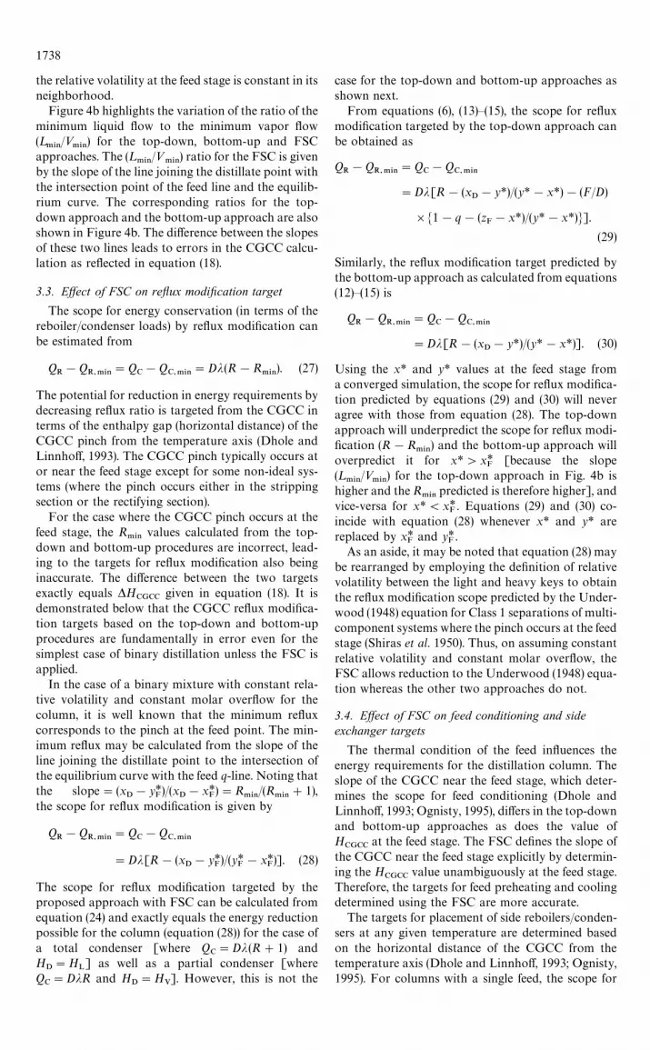
Fig. 4(a). Geometric interpretation of FSC on x—y diagram:comparison of feed stage composition from simulation withpinch composition from FSC. (b) Geometric interpretationof FSC on x—y diagram: comparison of the slope of the linethat denotes the minimum liquid to vapor flow ratio(¸
.*//»
.*/) at the feed stage by three different approaches.
1737
the relative volatility at the feed stage is constant in itsneighborhood.
Figure 4b highlights the variation of the ratio of theminimum liquid flow to the minimum vapor flow(¸
.*//»
.*/) for the top-down, bottom-up and FSC
approaches. The (¸.*/
/».*/
) ratio for the FSC is givenby the slope of the line joining the distillate point withthe intersection point of the feed line and the equilib-rium curve. The corresponding ratios for the top-down approach and the bottom-up approach are alsoshown in Figure 4b. The difference between the slopesof these two lines leads to errors in the CGCC calcu-lation as reflected in equation (18).
3.3. Effect of FSC on reflux modification target
The scope for energy conservation (in terms of thereboiler/condenser loads) by reflux modification canbe estimated from
QR!Q
R,.*/"Q
C!Q
C,.*/"Dj(R!R
.*/). (27)
The potential for reduction in energy requirements bydecreasing reflux ratio is targeted from the CGCC interms of the enthalpy gap (horizontal distance) of theCGCC pinch from the temperature axis (Dhole andLinnhoff, 1993). The CGCC pinch typically occurs ator near the feed stage except for some non-ideal sys-tems (where the pinch occurs either in the strippingsection or the rectifying section).
For the case where the CGCC pinch occurs at thefeed stage, the R
.*/values calculated from the top-
down and bottom-up procedures are incorrect, lead-ing to the targets for reflux modification also beinginaccurate. The difference between the two targetsexactly equals *H
CGCCgiven in equation (18). It is
demonstrated below that the CGCC reflux modifica-tion targets based on the top-down and bottom-upprocedures are fundamentally in error even for thesimplest case of binary distillation unless the FSC isapplied.
In the case of a binary mixture with constant rela-tive volatility and constant molar overflow for thecolumn, it is well known that the minimum refluxcorresponds to the pinch at the feed point. The min-imum reflux may be calculated from the slope of theline joining the distillate point to the intersection ofthe equilibrium curve with the feed q-line. Noting thatthe slope"(x
D!y*
F)/(x
D!x*
F)"R
.*//(R
.*/#1),
the scope for reflux modification is given by
QR!Q
R,.*/"Q
C!Q
C,.*/
"Dj[R!(xD!y*
F)/(y*
F!x*
F)]. (28)
The scope for reflux modification targeted by theproposed approach with FSC can be calculated fromequation (24) and exactly equals the energy reductionpossible for the column (equation (28)) for the case ofa total condenser [where Q
C"Dj(R#1) and
HD"H
L] as well as a partial condenser [where
QC"DjR and H
D"H
V]. However, this is not the
case for the top-down and bottom-up approaches asshown next.
From equations (6), (13)—(15), the scope for refluxmodification targeted by the top-down approach canbe obtained as
QR!Q
R,.*/"Q
C!Q
C,.*/
"Dj[R!(xD!y*)/(y*!x*)!(F/D)
]M1!q!(zF!x*)/(y*!x*)N].
(29)
Similarly, the reflux modification target predicted bythe bottom-up approach as calculated from equations(12)—(15) is
QR!Q
R,.*/"Q
C!Q
C,.*/
"Dj[R!(xD!y*)/(y*!x*)]. (30)
Using the x* and y* values at the feed stage froma converged simulation, the scope for reflux modifica-tion predicted by equations (29) and (30) will neveragree with those from equation (28). The top-downapproach will underpredict the scope for reflux modi-fication (R!R
.*/) and the bottom-up approach will
overpredict it for x*'x*F
[because the slope(¸
.*//»
.*/) for the top-down approach in Fig. 4b is
higher and the R.*/
predicted is therefore higher], andvice-versa for x*(x*
F. Equations (29) and (30) co-
incide with equation (28) whenever x* and y* arereplaced by x*
Fand y*
F.
As an aside, it may be noted that equation (28) maybe rearranged by employing the definition of relativevolatility between the light and heavy keys to obtainthe reflux modification scope predicted by the Under-wood (1948) equation for Class 1 separations of multi-component systems where the pinch occurs at the feedstage (Shiras et al. 1950). Thus, on assuming constantrelative volatility and constant molar overflow, theFSC allows reduction to the Underwood (1948) equa-tion whereas the other two approaches do not.
3.4. Effect of FSC on feed conditioning and sideexchanger targets
The thermal condition of the feed influences theenergy requirements for the distillation column. Theslope of the CGCC near the feed stage, which deter-mines the scope for feed conditioning (Dhole andLinnhoff, 1993; Ognisty, 1995), differs in the top-downand bottom-up approaches as does the value ofH
CGCCat the feed stage. The FSC defines the slope of
the CGCC near the feed stage explicitly by determin-ing the H
CGCCvalue unambiguously at the feed stage.
Therefore, the targets for feed preheating and coolingdetermined using the FSC are more accurate.
The targets for placement of side reboilers/conden-sers at any given temperature are determined basedon the horizontal distance of the CGCC from thetemperature axis (Dhole and Linnhoff, 1993; Ognisty,1995). For columns with a single feed, the scope for
1738
placing side exchangers (away from the feed stage)does not depend on the top-down or the bottom-upprocedure. However, for complex columns with morethan one feed, the targets for placement of side ex-changers between the feed stages can differ signifi-cantly in the top-down and bottom-up approaches.When the FSC is used during the generation of theCGCC for a complex column, the ambiguity inthe targets for side exchangers on stages in betweenthe feed stages is eliminated.
3.5. Generalization and implementation of FSC
In binary distillation, one of the components isheavy and the other is obviously light. However,this is not so obvious for multicomponent reversibledistillation as the sharpness of separation is generallylimited (Fonyo, 1974). The difficulty may be over-come with the pseudo-binary concept of a lightand heavy key model (Fonyo, 1974; Dhole andLinnhoff, 1993), in which case the equations withthe FSC proposed here provide a reliable methodo-logy for CGCC generation. The key components areusually specified by the designer. Light non-key com-ponents are clubbed with the light key, and heavynon-key components with the heavy key. Distributedcomponents can be clubbed with the light or heavykey depending on their K-values. In the case of crudedistillation, the key definition varies from stage-to-stage and keys can be defined according to the K-values of the pseudo-components or by comparingstage compositions (Dhole and Buckingham, 1994). Itmust be noted that the CGCC shape and the refluxmodification targets depend on the key definition.Except for strongly non-ideal mixtures, the minimumreflux separation of multicomponent mixtures ex-hibits a pinch point in each half of the column. Whenthe column products do not contain one or more ofthe components present in the feed, the pinch point iscloser to the product outlet for that half of the columnand does not coincide with the feed stage (Koehler etal., 1995). In general, the pinch point determining theminimum reflux is not known a priori. However, onlythe pinch point controlling the minimum reflux isdetected by pseudo-binarization, and hence the min-imum energy consumption predicted is close to thatcalculated through a rigorous calculation (Koehler etal., 1991).
While implementing the FSC for a multicomponentdistillation column, the pseudo-relative volatility isdetermined from the pseudo-heavy and light keys.Thus, x* and y* are calculated by summation over thelight key components defined at a particular stage.The FSC is then applied in a manner analogous tothat described in Section 3.2.
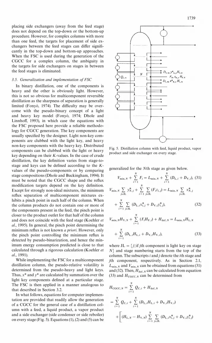
In what follows, equations for computer implemen-tation are provided that readily allow the generationof a CGCC for the general case of a distillation col-umn with a feed, a liquid product, a vapor productand a side exchanger (side condenser or side reboiler)on every stage (Fig. 5). Equations (1), (2) and (5) can be
Fig. 5. Distillation column with feed, liquid product, vaporproduct and side exchanger on every stage.
generalized for the Nth stage as given below.
».*/,N
#
N+i/1
Fi"¸
.*/,N#
N+i/1
(DL, i
#DV, i
), (31)
».*/,N
+j|JL
y*N,j
#
N+i/1
+j|JL
(Fizi,j
)"¸.*/,N
+j|JL
x*N,j
#
N+i/1
+j|JL
(DL, i
x*i,j#D
V,iy*i, j
), (32)
».*/,N
HV,N
#
N+i/1
(FiH
F, i)#H
$%&,N"¸
.*/,NH
L,N
#
N+i/1
(DL, i
HL, i
#DV, i
HV, i
), (33)
where JL"M j D if jth component is light key on stageNN and stage numbering starts from the top of thecolumn. The subscripts i and j denote the ith stage andjth component, respectively. As in Section 2.1,¸.*/,N
and ».*/,N
can be obtained from equations (31)and (32). Then, H
$%&,Ncan be calculated from equation
(33) and HCGCC,N
can be determined from
HCGCC,N
"
N+i/1
QC, i
#H$%&,N
"
N+i/1
QC, i
#
N+i/1
(DL, i
HL, i
#DV, i
HV, i
)
#C(HL,N!H
V,N)
N+i/1
+j|JL
(DL, i
x*i,j#D
V,iy*i, j
)
1739
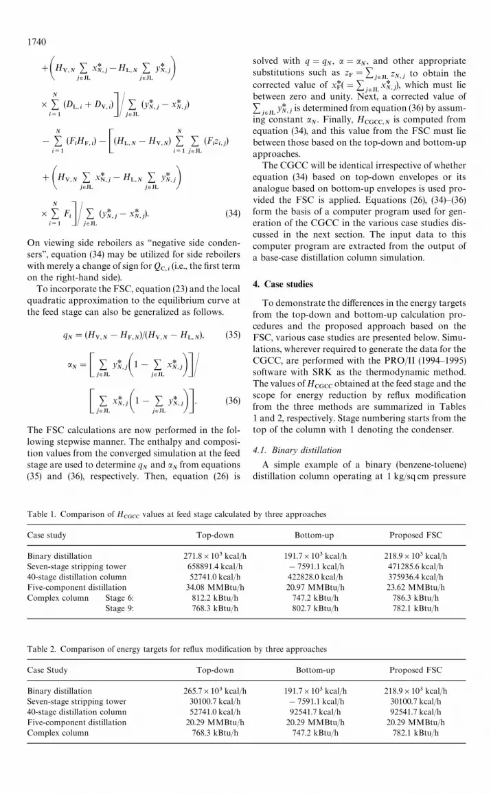
Table 1. Comparison of HCGCC
values at feed stage calculated by three approaches
Case study Top-down Bottom-up Proposed FSC
Binary distillation 271.8]103 kcal/h 191.7]103 kcal/h 218.9]103 kcal/hSeven-stage stripping tower 658891.4 kcal/h !7591.1 kcal/h 471285.6 kcal/h40-stage distillation column 52741.0 kcal/h 422828.0 kcal/h 375936.4 kcal/hFive-component distillation 34.08 MMBtu/h 20.97 MMBtu/h 23.62 MMBtu/hComplex column Stage 6: 812.2 kBtu/h 747.2 kBtu/h 786.3 kBtu/h
Stage 9: 768.3 kBtu/h 802.7 kBtu/h 782.1 kBtu/h
Table 2. Comparison of energy targets for reflux modification by three approaches
Case Study Top-down Bottom-up Proposed FSC
Binary distillation 265.7]103 kcal/h 191.7]103 kcal/h 218.9]103 kcal/hSeven-stage stripping tower 30100.7 kcal/h !7591.1 kcal/h 30100.7 kcal/h40-stage distillation column 52741.0 kcal/h 92541.7 kcal/h 92541.7 kcal/hFive-component distillation 20.29 MMBtu/h 20.29 MMBtu/h 20.29 MMBtu/hComplex column 768.3 kBtu/h 747.2 kBtu/h 782.1 kBtu/h
#AHV,N+j|JL
x*N,j
!HL,N
+j|JL
y*N,jB
]N+i/1
(DL, i
#DV, i
)DN +j|JL
(y*N,j
!x*N,j
)
!
N+i/1
(FiH
F, i)!C(HL,N
!HV,N
)N+i/1
+j|JL
(Fizi,j
)
#AHV,N+j|JL
x*N,j
!HL,N
+j|JL
y*N,jB
]N+i/1
FiDN +
j|JL
(y*N, j
!x*N,j
). (34)
On viewing side reboilers as ‘‘negative side conden-sers’’, equation (34) may be utilized for side reboilerswith merely a change of sign for Q
C, i(i.e., the first term
on the right-hand side).To incorporate the FSC, equation (23) and the local
quadratic approximation to the equilibrium curve atthe feed stage can also be generalized as follows.
qN"(H
V,N!H
F,N)/(H
V,N!H
L,N), (35)
aN"C +
j|JL
y*N,jA1! +
j|JL
x*N,jBDN
C +j|JL
x*N,jA1! +
j|JL
y*N,jBD . (36)
The FSC calculations are now performed in the fol-lowing stepwise manner. The enthalpy and composi-tion values from the converged simulation at the feedstage are used to determine q
Nand a
Nfrom equations
(35) and (36), respectively. Then, equation (26) is
solved with q"qN, a"a
N, and other appropriate
substitutions such as zF"+
j|JLzN,j
to obtain thecorrected value of x*
F("+
j|JLx*N,j
), which must liebetween zero and unity. Next, a corrected value of+
j|JLy*N, j
is determined from equation (36) by assum-ing constant a
N. Finally, H
CGCC,Nis computed from
equation (34), and this value from the FSC must liebetween those based on the top-down and bottom-upapproaches.
The CGCC will be identical irrespective of whetherequation (34) based on top-down envelopes or itsanalogue based on bottom-up envelopes is used pro-vided the FSC is applied. Equations (26), (34)—(36)form the basis of a computer program used for gen-eration of the CGCC in the various case studies dis-cussed in the next section. The input data to thiscomputer program are extracted from the output ofa base-case distillation column simulation.
4. Case studies
To demonstrate the differences in the energy targetsfrom the top-down and bottom-up calculation pro-cedures and the proposed approach based on theFSC, various case studies are presented below. Simu-lations, wherever required to generate the data for theCGCC, are performed with the PRO/II (1994—1995)software with SRK as the thermodynamic method.The values of H
CGCCobtained at the feed stage and the
scope for energy reduction by reflux modificationfrom the three methods are summarized in Tables1 and 2, respectively. Stage numbering starts from thetop of the column with 1 denoting the condenser.
4.1. Binary distillation
A simple example of a binary (benzene-toluene)distillation column operating at 1 kg/sq cm pressure
1740
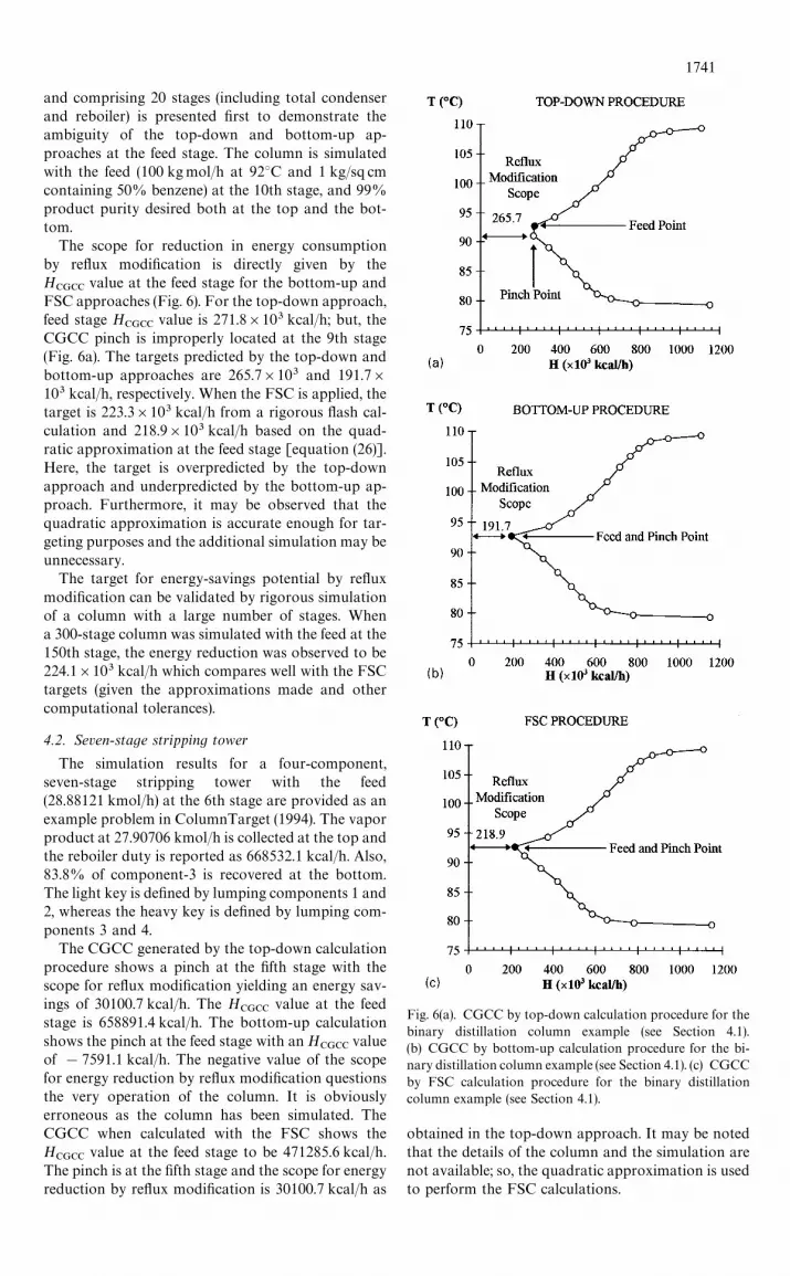
and comprising 20 stages (including total condenserand reboiler) is presented first to demonstrate theambiguity of the top-down and bottom-up ap-proaches at the feed stage. The column is simulatedwith the feed (100 kgmol/h at 92°C and 1 kg/sq cmcontaining 50% benzene) at the 10th stage, and 99%product purity desired both at the top and the bot-tom.
The scope for reduction in energy consumptionby reflux modification is directly given by theH
CGCCvalue at the feed stage for the bottom-up and
FSC approaches (Fig. 6). For the top-down approach,feed stage H
CGCCvalue is 271.8]103 kcal/h; but, the
CGCC pinch is improperly located at the 9th stage(Fig. 6a). The targets predicted by the top-down andbottom-up approaches are 265.7]103 and 191.7]103 kcal/h, respectively. When the FSC is applied, thetarget is 223.3]103 kcal/h from a rigorous flash cal-culation and 218.9]103 kcal/h based on the quad-ratic approximation at the feed stage [equation (26)].Here, the target is overpredicted by the top-downapproach and underpredicted by the bottom-up ap-proach. Furthermore, it may be observed that thequadratic approximation is accurate enough for tar-geting purposes and the additional simulation may beunnecessary.
The target for energy-savings potential by refluxmodification can be validated by rigorous simulationof a column with a large number of stages. Whena 300-stage column was simulated with the feed at the150th stage, the energy reduction was observed to be224.1]103 kcal/h which compares well with the FSCtargets (given the approximations made and othercomputational tolerances).
4.2. Seven-stage stripping tower
The simulation results for a four-component,seven-stage stripping tower with the feed(28.88121 kmol/h) at the 6th stage are provided as anexample problem in ColumnTarget (1994). The vaporproduct at 27.90706 kmol/h is collected at the top andthe reboiler duty is reported as 668532.1 kcal/h. Also,83.8% of component-3 is recovered at the bottom.The light key is defined by lumping components 1 and2, whereas the heavy key is defined by lumping com-ponents 3 and 4.
The CGCC generated by the top-down calculationprocedure shows a pinch at the fifth stage with thescope for reflux modification yielding an energy sav-ings of 30100.7 kcal/h. The H
CGCCvalue at the feed
stage is 658891.4 kcal/h. The bottom-up calculationshows the pinch at the feed stage with an H
CGCCvalue
of !7591.1 kcal/h. The negative value of the scopefor energy reduction by reflux modification questionsthe very operation of the column. It is obviouslyerroneous as the column has been simulated. TheCGCC when calculated with the FSC shows theH
CGCCvalue at the feed stage to be 471285.6 kcal/h.
The pinch is at the fifth stage and the scope for energyreduction by reflux modification is 30100.7 kcal/h as
Fig. 6(a). CGCC by top-down calculation procedure for thebinary distillation column example (see Section 4.1).(b) CGCC by bottom-up calculation procedure for the bi-nary distillation column example (see Section 4.1). (c) CGCCby FSC calculation procedure for the binary distillationcolumn example (see Section 4.1).
obtained in the top-down approach. It may be notedthat the details of the column and the simulation arenot available; so, the quadratic approximation is usedto perform the FSC calculations.
1741
4.3. 40-stage distillation column
The simulation results for a five-component, 40-stage distillation column with the feed (141.4978kmol/h) at the 22nd stage are also given as an exampleproblem in ColumnTarget (1994). The liquid productat 100.2146 kmol/h is collected at the top and thereboiler duty is reported as 2283659.0 kcal/h. Further,99.904% of component-2 is recovered at the top and99.229% of component-3 at the bottom. Compon-ent-2 is defined as the light key and component-3 isdefined as the heavy key. However, the mole fractionsof components 1, 4, and 5 are insignificant; therefore,component-1 may be lumped with component-2 asthe light key, whereas components 4 and 5 may belumped with component-3 as the heavy key.
The CGCC generated by the top-down approachshows the pinch at the feed stage and the energy-savings potential through reflux modification to be52741.0 kcal/h. The bottom-up approach results in anH
CGCCvalue at the feed stage of 422828.0 kcal/h with
the pinch just below the feed stage yielding a energy-savings target by reflux modification of92541.7 kcal/h. The CGCC obtained through the FSCshows the H
CGCCvalue at the feed stage to be
375936.4 kcal/h; however, the pinch at the 23rd stageestablishes the energy-savings scope to be92541.7 kcal/h as obtained in the bottom-up ap-proach. As in the previous case study, the quadraticapproximation is used for the FSC in the absence ofdetails for the column and simulation.
4.4. Five-component distillation
The example problem with the feed and productspecifications is described by Dhole and Linnhoff(1993). The feed stage location, the thermodynamicmethod and the two specifications used in the columnsimulation are, however, not explicitly reported. Asa first step, the simulation of the five-component dis-tillation with 18 stages (including partial condenserand reboiler) is performed with PRO/II (1994—1995)using SRK as the thermodynamic method and thefeed located on the ninth stage. The mole fractions ofnonane in the top product and octane in the bottomproduct are both specified to be 0.009. The condenserand reboiler duties (in MMBtu/h) from the simulationare 39.72 and 82.52, respectively. These compare reas-onably with the values of 39.6 and 83.3 reported byDhole and Linnhoff (1993). The simulation shows thecondenser and reboiler temperatures to be 140.4 and207.4°C, respectively. Although the condenser tem-perature compares well with the value of 140.3°Cgiven by Dhole and Linnhoff (1993), the reboiler tem-perature is about 3.6°C higher than their reportedvalue of 203.8°C.
Here, heptane and octane are grouped as the lightkeys. Nonane, decane and C15 are grouped as theheavy keys. In comparison with the H
CGCCvalues at
the feed stage from the top-down (34.08 MMBtu/h)and bottom-up (20.97 MMBtu/h) calculation pro-
cedures, the FSC approach gives a value of23.62 MMBtu/h. The distance of the CGCC pinch(which occurs at the eighth stage) from the temperatureaxis represents the scope for energy conservationand is observed to be 20.29 MMBtu/h. Dhole andLinnhoff (1993) observed that the CGCC shows scopefor improvement in the reflux ratio by about20—22 MMBtu/h. It may be noted that the feed in thiscase is subcooled, and the column is therefore poten-tially irreversible.
4.5. Complex column
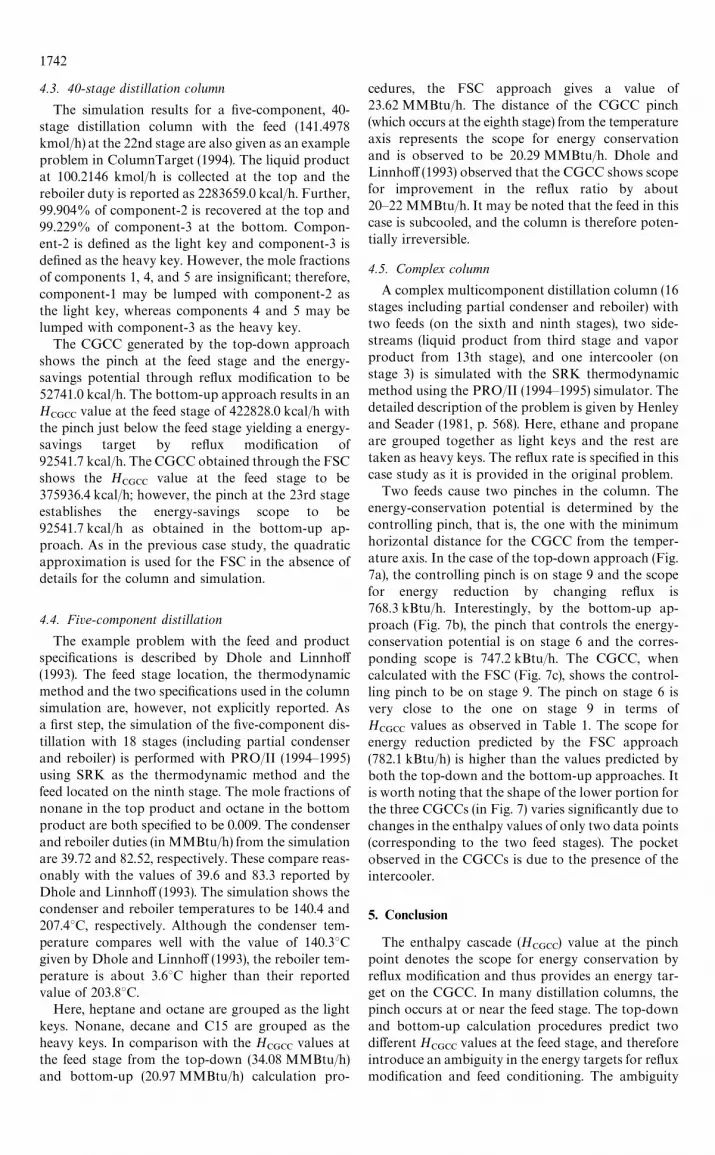
A complex multicomponent distillation column (16stages including partial condenser and reboiler) withtwo feeds (on the sixth and ninth stages), two side-streams (liquid product from third stage and vaporproduct from 13th stage), and one intercooler (onstage 3) is simulated with the SRK thermodynamicmethod using the PRO/II (1994—1995) simulator. Thedetailed description of the problem is given by Henleyand Seader (1981, p. 568). Here, ethane and propaneare grouped together as light keys and the rest aretaken as heavy keys. The reflux rate is specified in thiscase study as it is provided in the original problem.
Two feeds cause two pinches in the column. Theenergy-conservation potential is determined by thecontrolling pinch, that is, the one with the minimumhorizontal distance for the CGCC from the temper-ature axis. In the case of the top-down approach (Fig.7a), the controlling pinch is on stage 9 and the scopefor energy reduction by changing reflux is768.3 kBtu/h. Interestingly, by the bottom-up ap-proach (Fig. 7b), the pinch that controls the energy-conservation potential is on stage 6 and the corres-ponding scope is 747.2 kBtu/h. The CGCC, whencalculated with the FSC (Fig. 7c), shows the control-ling pinch to be on stage 9. The pinch on stage 6 isvery close to the one on stage 9 in terms ofH
CGCCvalues as observed in Table 1. The scope for
energy reduction predicted by the FSC approach(782.1 kBtu/h) is higher than the values predicted byboth the top-down and the bottom-up approaches. Itis worth noting that the shape of the lower portion forthe three CGCCs (in Fig. 7) varies significantly due tochanges in the enthalpy values of only two data points(corresponding to the two feed stages). The pocketobserved in the CGCCs is due to the presence of theintercooler.
5. Conclusion
The enthalpy cascade (HCGCC
) value at the pinchpoint denotes the scope for energy conservation byreflux modification and thus provides an energy tar-get on the CGCC. In many distillation columns, thepinch occurs at or near the feed stage. The top-downand bottom-up calculation procedures predict twodifferent H
CGCCvalues at the feed stage, and therefore
introduce an ambiguity in the energy targets for refluxmodification and feed conditioning. The ambiguity
1742
Fig. 7(a). CGCC by top-down calculation procedure for thecomplex column example (see Section 4.5). (b) CGCC bybottom-up calculation procedure for the complex columnexample (see Section 4.5). (c) CGCC by proposed FSC pro-cedure for the complex column example (see Section 4.5).
manifests itself as two available options in targetingsoftware like ColumnTarget (1994); however, neitherof the CGCCs generated is strictly correct. The ambi-guity has been fundamentally analyzed in this paper
and resolved through a feed stage correction (FSC)procedure.
It has been demonstrated that the existing top-down and bottom-up approaches are both funda-mentally in error at feed stages even in the case ofbinary distillation, and may lead to inaccurate energytargets especially for the reflux modification scope. Ithas been further observed from Table 1 that the twoapproaches may overpredict or underpredict the tar-gets depending on the case study, and this adds to theuncertainty in the column targets at feed stage(s).
The FSC ensures that the ¹—H curve of a column atthe practical near-minimum thermodynamic condi-tion (PNMTC) is independent of the direction ofcalculation. As the proposed method properly ac-counts for the mass and enthalpy balance equations ateach stage, especially the feed stage(s), it does notmatter from which direction the envelopes are gener-ated for the computation of the CGCC. Instead ofassuming that the compositions obtained from theconverged simulation will remain the compositionsfor the feed stage at PNMTC, the FSC suggests thatfeed stage compositions may be calculated assumingthe same relative volatility as that obtained from thesimulation.
The HCGCC
values at the feed stage from the pro-posed FSC lie between those based on the top-downand bottom-up approaches for the various case stud-ies in Table 1, as should be the case. When this value isthe minimum amongst the H
CGCCvalues for all the
stages, then the pinch is at a feed stage and it directlyprovides the energy target for reflux modification.However, the pinch (given by the minimumH
CGCCvalue) may not always occur at a feed stage as
demonstrated in the case studies involving the 7-stagestripping tower, the 40-stage distillation column andthe 5-component distillation. The FSC is especiallysignificant in columns involving multiple feeds as dis-cussed in the complex column case study in the pre-vious section. The FSC is also of prime importance inrefinery columns with several pumparounds (whereeach pumparound is treated as a feed and a product),notably where the pumparound draw and return areon different stages.
Finally, the CGCC computation (even for a com-plex column with a feed, liquid/vapor product andside exchanger at every stage) is shown to involve themere substitution of values outputted by a processsimulator into equation (34). In other words, an im-portant contribution of this work is the derivation ofa single equation (rather than a stepwise procedure)for the calculation of the net enthalpy deficits duringthe generation of the CGCC.
Acknowledgements
The authors wish to thank Dr Hiren K. Shethna forvaluable discussions that helped clarify several issuesrelated to the minimum thermodynamic condition fordistillation.
1743
Nomenclature
B bottom product molar flowCGCC column grand composite curveD distillate molar flowF feed molar flowFSC feed stage correctionH enthalpyJ¸ light key components setK vapor—liquid equilibrium ratio¸ liquid molar flowN stage numberPNMTC practical near-minimum thermodyn-
amic conditionq quantity (related to feed condition) de-
fined in Section 3.1Q heat dutyR refluxSRK Soave—Redlich—Kwong¹ temperature» vapor molar flowx mole fraction in liquidy mole fraction in vaporz mole fraction in feeda relative volatility* difference in values calculated from
top-down and bottom-up proceduresj heat of vaporization
SubscriptB bottom productC condenserCGCC column grand composite curveD distillatedef deficitF feedi stage indexin in to (entering) a stagej component indexL liquidmin minimumN stage numberout out of (leaving) a stageR reboilerV vapor
Superscript
* equilibrium condition
References
Benedict, M. (1947) Multistage separation processes. ¹ransA.I.Ch.E. 43, 41.
ColumnTarget (1994) Super ¹arget for ¼indows, »ersion 3.0ºser Guide, Linnhoff March, Cheshire, England.
Dhole, V.R. and Buckingham, P.R. (1994) Refinery columnintegration for de-bottlenecking and energy saving. Pre-sented at ESCAPE I» Conf., Dublin, March.
Dhole, V.R. and Linnhoff, B. (1993) Distillation columntargets. Comput. Chem. Engng 17(5/6), 549—560.
Fitzmorris, R.E. and Mah, R.S.H. (1980) Improving distilla-tion column design using thermodynamic availabilityanalysis. A.I.Ch.E. J. 26, 265—273.
Fonyo Z. (1974) Thermodynamic analysis of rectification. I.Reversible model of rectification. Int. Chem. Engng 14,18—27.
Franklin, N.L. and Wilkinson, M.B. (1982) Reversibility inthe separation of multicomponent mixtures. ¹rans I.Chem. E. 60, 276—282.
Hall, S.G., Ognisty, T.P. and Northup, A.H. (1995) Useprocess integration to improve FCC/VRU design. Part1. Hydrocarbon Process. 63—74.
Henley, E.J. and Seader, J.D., (1981) Equilibrium-Stage Sep-aration Operations in Chemical Engineering. Wiley, NewYork.
Ho, F.G. and Keller, G.E. (1987) Process integration. InRecent Developments in Chemical Process and PlantDesign, Y.A. Liu, H.A. McGee and W.G. Epperly, Eds.Wiley, New York.
King, C.J. (1980) Separation Processes. McGraw-Hill, NewYork.
Koehler J., Aguirre, P. and Blass, E. (1991) Minimum refluxcalculations for nonideal mixtures using the reversibledistillation model. Chem. Engng Sci. 46(12), 3007—3021.
Koehler, J., Poellmann, P. and Blass, E. (1995) A review onminimum energy calculations for ideal and nonidealdistillations. Ind. Engng Chem. Res. 34, 1003—1020.
Naka, Y., Terashita, M., Hayashiguchi, S. and Takamatsu, T.(1980) An intermediate heating and cooling method fora distillation column. J. Chem. Engng Japan, 13,123—129.
Ognisty T.P. (1995) Analyze distillation columns withthermodynamics. Chem. Engng Prog. 40—46.
PRO/II, (1994—95) »ersion 4.1, Simulation Sciences, Inc.,California, U.S.A.
Rachford, H.H., Jr. and Rice, J.D. (1952) J. Pet. ¹ech. 4(10),sections 1, 19 and 2, 3.
Shenoy, U.V. (1995) Heat Exchanger Network Synthesis:Process Optimization by Energy and Resource Analysis.Gulf Publishing Co., Houston.
Shiras, R.N., Hanson, D.N. and Gibson, C.H. (1950) Calcula-tion of minimum reflux in distillation columns. Ind.Engng Chem. 42, 871—876.
Terranova, B.E. and Westerberg, A.W. (1989) Temperature-heat diagrams for complex columns. 1. Intercooled/in-terheated distillation columns. Ind. Engng Chem. Res.28(9), 1374—1379.
Treybal, R.E. (1981) Mass-¹ransfer Operations. McGraw-Hill, New York.
Trivedi, K.K., Pang, K.H., O’Young, D.L., Klavers H.W. andLinnhoff, B. (1996) Optimize a licensor’s design usingpinch technology. Hydrocarbon Process. 113—126.
Underwood, A.J.V. (1948) Fractional distillation of multi-component mixtures. Chem. Engng Prog. 603—614.
1744