telescope and instrument robotization at dome c
TRANSCRIPT

Astron. Nachr. / AN 328, No. 6, 1 – ?? (2007) / DOI please set DOI!
Telescope and instrument robotization at Dome C
K. G. Strassmeier1,?, K. Agabi2, L. Agnoletto3, A. Allan4, M. I. Andersen1, W. Ansorge5, F. Bortoletto6,R. Briguglio7, J.-T. Buey8, S. Castellini9, V. Coude du Foresto8, L. Dame10,8, H. J. Deeg11, C. Eiroa12,G. Durand13, D. Fappani14, M. Frezzotti15, T. Granzer1, A. Groschke16, H. J. Karcher17, R. Lenzen18,A. Mancini9, C. Montanari3, A. Mora12, A. Pierre19, O. Pirnay20, F. Roncella9, F.-X. Schmider2,I. Steele21, J. W. V. Storey22, N. F. H. Tothill4, T. Travouillon23, L. Vittuari24, and M. Weber1
1 Astrophysikalisches Institut Potsdam (AIP), An der Sternwarte 16, D-14482 Potsdam, Germany2 Laboratoire Universitaire d’Astrophysique de Nice (LUAN), Universite de Nice-Sophia-Antipolis, Nice, France3 Italian National Program for Research in Antarctica (PNRA) S.C.r.l., C.O.ENEA, Casaccia Research Ctr., Rome, Italy4 School of Physics, University of Exeter, Stocker Road, Exeter, EX 4 4 QL, U.K.5 RAMS-CON Management Consultants, D-85617 Assling, Germany6 INAF-Osservatorio Astronomico di Padua, I-35122 Padua, Italy7 Dipartimento di Fisica, Universita di Roma La Sapienza, Roma, Italy8 Observatoire de Paris/LESIA, F-92190 Meudon, France9 Dipartimento di Fisica, Universita di Perugia, Perugia, Italy
10 Service d’Aeronomie du CNRS, F-91371 Verrieres-le-Buisson, France11 Instituto de Astrofisica de Canarias (IAC), La Laguna, Tenerife, Spain12 Departamento de Fısica Teorica C-XI. Universidad Autonoma de Madrid, 28049 Madrid, Spain13 Service d’Astrophysique, DAPNIA, CEA Saclay, F-91191 Gif-sur-Yvette, France14 Societe Europeenne de Systemes Optiques (SESO), Aix-en-Provence, France15 Ente per le Nuove Tecnologie, l’Energia e l’Ambiente, Roma, Italy16 Alfred-Wegener-Institute for Polar and Marine Research (AWI), Bremerhaven, Germany17 MT Mechatronics GmbH, Mainz, Germany18 Max-Planck Institut fur Astronomie (MPIA), Heidelberg, Germany19 Institut Polaire Francais Paul Emile Victore (IPEV), Brest, France20 AMOS S.A., Liege, Belgium21 Liverpool John Moores University, Liverpool, U.K.22 The University of New South Wales, Sydney, Australia23 California Institute of Technology (Caltech), Pasadena, U.S.A.24 DISTART, University of Bologna, I-40136 Bologna, Italy
The dates of receipt and acceptance should be inserted later
Key words telescopes – instrumentation: miscellaneous – site testing – atmospheric effects – optics – Antarctica
This article reviews the situation for robotization of telescopes and instruments at the Antarctic station Concordia onDome C. A brain-storming meeting was held in Tenerife in March 2007 from which this review emerged. We describe andsummarize the challenges for night-time operations of various astronomical experiments at conditions “between Earth andSpace” and conclude that robotization is likely a prerequisite for continuous astronomical data taking during the 2000-hournight at Dome C.
c© 2007 WILEY-VCH Verlag GmbH & Co. KGaA, Weinheim
1 Introduction
Dome C on the east Antarctic plateau is among the mostremote places on Earth. It is 1100 km from the coast ata height of 3233m above sea surrounded by thousands ofkilometers of solid ice and an average winter temperatureof beyond –60◦C. With mostly katabatic winds of less than20 m/s (median 3 m/s), almost no absolute humidity, nolight or air pollution, no seismic activity, very low atmo-spheric turbulence and an inversion layer reaching up to
? Corresponding author: e-mail: [email protected]
just 30–50m above ground, the location is by all means out-standing (see, e.g., Fossat 2005a and the proceedings editedby Giard et al. 2005).
Dome C was originally selected for glaciological rea-sons and was one of the two sites of the EPICA ice-coredrilling project that reached solid ground at a depth of3270m in December 2004 (EPICA 2004). However, one ofthe key drivers for a year-round operation on the plateau wasastronomy. Out of it had developed the French-Italian sta-tion Concordia1 (Fig. 1) that, since its full opening in 2005,is experiencing its third over-wintering season now. First as-
1 http://www.concordiabase.eu
c© 2007 WILEY-VCH Verlag GmbH & Co. KGaA, Weinheim

2 K. G. Strassmeier et al.: Telescope and instrument robotization at Dome C
Fig. 1 360-degree view of the Concordia station on the east Antarctic plateau at 3233m above sea. The French-Italian station is nowpopulated also over winter (=night) with up to 16 desperados. The site’s astronomical conditions are astounding at almost any wavelengthand it is called a place between “Earth and Space”. Image courtesy G. Dargaud, www.gdargaud.net.
tronomical site testings were done by Valenziano & Dall’Oglio (1999). The station had received world-wide atten-tion from the night-time astronomical community when itbecame known that the seeing conditions on the east Antarc-tic plateau are likely the best on the entire planet with a me-dian seeing of 0.3′′ and occasionally even below 0.1′′ at aheight of approximately 30m above ground (Lawrence et al.2004, Agabi et al. 2006).
Astronomical site testing was undertaken by the Con-cordiastro consortium (Aristidi et al. 2003, 2005a) as wellas the Australian AASTINO team (Lawrence et al. 2004).Now complemented by numerous experiments and embed-ded and extended by a large program on atmospheric andmeteorological research (e.g. Geissler & Masciadri 2006),efforts will soon converge on a full astronomical site char-acterization (see http://arena.unice.fr). Dome C is locatedinside the polar vortex where the ozone hole can be de-tected in the Austral spring. The environmental conditionsduring winter time may be best described as “between Earthand Space” and do not allow humans to easily conduct ex-tended physical or mental work although principal accessi-bility is retained. Fully automated systems, and even robots,are likely a mandatory requisite for astronomical night-timeoperation. Generally, “Robotic Astronomy” and “e-science”has received significant attention in the past years and hasa bright future due to initiatives like, e.g., GRID comput-ing or the Virtual Observatory. A number of proceedingson various subtopics of robotic astronomy were publishedand we refer to these for further details (e.g. Paczynski etal. 2001, Strassmeier et al. 2001, Strassmeier & Hessman2004, Nayor et al. 2006).
In order to address the technology and logistics neededto face the construction and operation of robotic telescopesand instruments in the harsh environment of the Antarc-tic, a workshop was jointly organized by the AstrophysicalInstitute Potsdam (AIP) and the Instituto de Astrophysicade Canarias (IAC) under the auspices of the ARENA2 EUnetwork in March 2007. This workshop joined together theConcordia station operators, European, Australian and U.S.research institutes, and industries for a brainstorming dis-cussion about expected problems at Dome C and possiblesolutions. Its key issues are presented in this paper.
2 ARENA “Antarctic Research: a Network for Astronomy” is a FP-6financed networking activity between 20 European partner institutes ledby the University of Nice and compromises institutes from France, Italy,Germany, Spain, Belgium, Australia and ESO.
2 Prerequisites for successful robotization atDome C
Robotization is an integral systems engineering approach.While systems engineering combines optics, mechanics,electronics and software, successful robotization must fur-thermore have precise predictive knowledge of the environ-mental conditions under which a telescope or instrumentis supposed to operate. It must ensure the endurability ofnew technologies at cold temperatures, the calibration pro-cedures of an instrument must be known ahead and welldefined to be automated, the data handling and its teleme-try guaranteed until final data reduction and analysis can beperformed. All these cornerstone issues must be embeddedwithin a realistic operations and maintenance plan which it-self is a question of what logistics are available at the site.Therefore, a great deal must be spent on the issue of localinfrastructure.
2.1 Logistic aspects at Concordia
The station can accommodate 16 persons during the win-ter and up to ≈40 people during the summer season. Lo-gistically, summer is defined as the access time from earlyNovember through early February, the rest is winter. Thesky is dark from May till August.
Fig. 2 Aerial view around the Concordia station and its elec-tronic accessibility. The site with astronomical experiments is en-circled. The two cylinders at the lower left side represent the Con-cordia station.
c© 2007 WILEY-VCH Verlag GmbH & Co. KGaA, Weinheim www.an-journal.org

Astron. Nachr. / AN (2007) 3
2.1.1 Physical and electronic accessibility
Most of the cargo is moved to Dome C by traverse fromthe Dumont d’Urville (DDU) station, covering 1200km in7 to 12 days, while personnel and fragile cargo arrive byTwin Otter aircraft from the Mario Zucchelli station (also1200km away). From DDU, situated on an island, mate-rials are transferred to Cap Prud’Homme station (CPH), asite on the Antarctic continent from which the French tra-verse (RAID) departs. Each RAID is made up of a certainnumber of tractors and trailers, to transport either standardshipping containers or unpacked materials. Because of theDDU’s site shape, the Astrolabe ship can not arrive directlyto CPH, so that materials have to be transferred from DDUto CPH
– during the summer by helicopter;– in January there is the possibility to use a barge, but this
opportunity depends on the marine ice and meteorolog-ical conditions;
– during the winter it is hauled on ice.
The accessibility of DDU itself is also a function of weatherconditions.
To enable phone and data connection on an on-demandbasis, Concordia has Iridium and Inmarsat satellite systemsallowing a bandwidth of 64 kbps at the cost of 6.5 Euro/min,or a data-packet connection with a cost of about 7 Euro foreach Mbit transferred. One Inmarsat “Standard B” and oneInmarsat “Fleet” antenna are installed on the roof of the sta-tion as well as inside the station. Inside the station the localarea network is made up by a physical part (the plugs ineach room connected to a rack for each station level) and anactive part (a switch at each level connected by fiber opticsto the main switch in the radio room). This connection runsat 1 Gbps.
An aerial view of existing data connections is shownin Fig. 2. Electric power is delivered there by silicone ca-bles on wooden sticks while data connection is provided byWiFi or fiber-optics connections. All around the station upto about 1 km, some warmed containers host equipment tosupport the research programs in the field.
Dome C is still in the line of sight of existing geostation-ary satellites. The future AUSSAT communication satellite,accidentally at the same longitude as Dome C, may provideone way for fast data transmission.
2.1.2 The Concordia power system
The Concordia power station is made up of 3 Diesel gen-erators adapted to the particular conditions of the air atDome C. For safety reasons, there is also an emergencyDiesel generator inside the noisy building. Each generatorcan deliver 125 kW at full load. The average power requestwas in total 85 kW during the 2006/7 summer campaign andrequired 610 liters of Diesel per day. 35 kW were needed forscientific activities outside the station. As a rule of thumb,the annual costs per kW is 7100 Euros.
2.1.3 Environmental and atmospheric datadistribution
Existing instruments of astronomical interest are the threeAutomatic Weather Stations (AWS Concordia, Davis andAW11), a radio-sounding station and a BSRN station. Thesedevices provide measurements of the following parameters,respectively:
– Temperature (T ), wind, wind chill, relative humidity(RH), dew-point temperature, and pressure (p), all dur-ing the whole year from Concordia AWS. During sum-mer, data are collected by Davis and AW11 stations too,but the availability and the quality of its data is not guar-anteed because these are operational non-scientific in-struments only.
– Vertical profiles of standard parameters (T , p, RH,wind) during the daily balloon ascent at 12:00UTC.
– Short and long, diffuse, global, and direct solar radiationand optical thickness.
Furthermore, a 12m tower with wind, temperature, rela-tive humidity at standard levels, pressure and a solar radi-ation sensor, and a 30m tower with four sonic anemome-ters (SONICS) are being operated around the clock. Real-time data from AWS-Concordia and from radiosoundingsare disseminated through the Concordia station’s intranet.A software procedure, monitoring the Concordia AWS, runscontinuously in the background at the “Physics of the At-mosphere Lab” and is accessible on the Intranet from ev-ery PC connected to the net. Daily files are generated fromthe BSRN station. Average daily, weekly and monthly val-ues of standard meteorological parameters are also avail-able (see Table 1). All real-time and near-real time dataare preliminary raw data that need to be validated. Takinginto account the extreme meteorological conditions, we canmake the following assumptions and considerations aboutthe uncertainty of the measurements. Temperature:±0.5◦C;relative humidity: the measurement of relative humidity ismore critical, data should be used very carefully; pressure:±0.3 hPa; wind speed: ±1 knts with warning (the warningconcerns essentially the behavior of the wind sensors be-low −50◦C). Also, the wind speeds from our heated cupanemometer are underestimated during the winter due thesnow accumulation on the cups of the sensor. Solar radia-tion: 3 W/m2 raw data. The target accuracy of the BSRN isthe highest of 1 W/m2 or 2%. The measurements availableto the scientific community are summarized in Table 1.
All data are provided after a simple request to the re-sponsible for the “Physics of the Atmosphere” project dur-ing the summer and winter campaigns. Non-real time datacan be obtained via a central web server3 where the routinemeteorological observations are constantly published. Dataand information uploaded to the web site has already passedthe quality survey. Data from specific projects, e.g. locatedon the two towers (12m and 30m), are available from the re-spective P.I. on demand. In conclusion, a wide range of on-
3 http://www.climantartide.it
www.an-journal.org c© 2007 WILEY-VCH Verlag GmbH & Co. KGaA, Weinheim

4 K. G. Strassmeier et al.: Telescope and instrument robotization at Dome C
Table 1 Atmospheric data from Dome C available to the community. T temperature, p pressure, RH relative humidity.
Availability Source Parameters SamplingReal time Concordia AWS T , p, RH, Wind, Wind Chill, Dew Point Temp 1 min and 30 minReal time (at 12:00 UTC) Sounding System T , p, RH, Wind 2 sec and standard levelsDaily BSRN Station Short and long, diffuse, global, direct 1 min (average from
solar radiation and optical thickness 1 Hz sampling)Daily Concordia AWS Mean values of the standard parameters Average daily valuesWeekly Concordia AWS Mean values of the standard parameters Average weekly valuesMonthly Concordia AWS Mean values of the standard parameters Average monthly valuesMonthly Concordia AWS T , p, RH, Wind (daily files of the past month) 1 hour
going and planned scientific activities in the Dome C areaare producing and/or requiring atmospheric observations ofmutual interest. Therefore, it has been suggested to establisha “COmmon Concordia Observatory of the Atmosphere”(COCOA) that would assure coordination between a num-ber of existing and planned atmospheric and atmosphere-related routine observations including meteorology, atmo-spheric chemistry, glaciology and astronomy (Argentini etal. 2006). The main task of this project is to obtain con-tinuous data on temperature, pressure, humidity, wind andrelated parameters from 30m up to the stratosphere, withvery high resolution in the boundary layer near the surface(tower data), and radio-sounding data above.
2.2 Engineering aspects
The following subsections constitute a top-down prioritylisting of telescope robotization prerequisites.
2.2.1 Un-interrupted and clean power supply
A 230V/50Hz power grid from one of three 125 kW Dieselgenerators is available. Scientific experiments run lowestpriority in the power distribution after life support and sta-tion support. Field experiments must be equipped with theirown voltage filters and uninterrupted power supplies to dealwith voltage browning and power interruptions. Standardlead-acid battery banks must be heated if located in the field.NiMH is another possible technology. Lead-acid batteriesare heavy and therefore expensive to transport to Dome Cbut their advantages are that it is proven technology andthat they can be reloaded during summer with solar panels.Lithium batteries are an (expensive) option for power needsof smaller than, say, 1kW for 30 minutes and are frequentlyused in space technology. New developments are currentlyunderway in the auto industry. Ultimately, a full bank of re-fuelable liquid hydrogen cells could provide 1 kW for theentire winter, but not without a well developed safety pro-tocol (but remember, the technology is already used in carson the street).
2.2.2 System-status knowledge at any time
A robotic system must be controlled electronically to alarger extend as a system that has an operator on site. Two
principal levels exist. Firstly, near real-time status messagesmust be piped from the actual sensors to a local control com-puter or network server and then screened by an internal pri-oritization algorithm (“watchdog”). Secondly, left over fromthat screening procedure, important warnings and fatal fail-ure messages are to be forwarded immediately to the oper-ator’s home computer somewhere in Europe. While the firstlevel usually is based on high-speed local ethernet, the sec-ond level requires an outside connection to Dome C. Fortu-nately, a few kbps bandwidth is sufficient for such messagesand an Iridium phone is a viable option. Such a solution hasbeen implemented for automatic site testing facilities like,e.g. AASTINO (Lawrence et al. 2005), and is in the plan-ning for PLATO at Dome A (Sect. 5.10).
2.2.3 System re-start procedures and hardware safemode
Such a prerequisite is a standard item in space technologyand every spacecraft is equipped with at least one boot sys-tem. That boot system is kept completely separated fromevery client and has nothing else to do than watching andcommanding the central computer and its operating soft-ware (read-only disk on flash basis). It can force the sys-tem’s main computer to perform an orderly shutdown, or atleast order it to go into a safe mode. Reboot or ping switchesare an alternative. Additionally, it could store all set-ups forall subcomponents.
Especially prone to a rebooting failure are computerswhen a peripheral component has been disconnected dueto a power failure or is broken and does not reply in duetime or, even worse, has some sort of intermittence error,e.g. due to fluctuating voltage or left-over erroneous statusmessages from a previous power incitant. A flush-processcommand shall be implemented and frequently used. Ash-ley et al. (2004) added that simply a cool down of the CPUto ambient temperature may be enough to prevent a restart.
If all goes wrong, only a human can help. Thus, ground-based robotic systems shall afford an engineer’s console orat least provide the standard interface for it. It is importantfor designers to think about a system’s physical accessibil-ity, especially with thick gloves at −60◦C.
c© 2007 WILEY-VCH Verlag GmbH & Co. KGaA, Weinheim www.an-journal.org

Astron. Nachr. / AN (2007) 5
2.2.4 Environmental-status knowledge at any time
A robotic telescope system at a temperate site is (better) al-ways a slave of a weather station (Granzer et al. 2001). Oth-erwise one runs the danger to damage the system from, e.g.condensed air on critical optical surfaces or in electronics.At Antarctica, we face actually a different situation that is inmany respects simpler than at a temperate site, see e.g. thelist in Ashley et al. (2004). One of the most important con-cerns is the build up of ice crystals. Due to the proportion-ally higher radiative losses at temperatures around −60◦C,any outdoor structure like a telescope and its optics will besoon cooler than ambient and therefore is prone to icing (seeSect. 4.5). One way around is to simply build in a heater oruse special radiating paints or Mylar-like foils to cover up.
Another environmental threat is the horizontal and top-down ice-crystal flow once the wind tops a certain speed,location and height. This “diamond dust” is the most com-mon form of precipitation in Antarctica (see Sect. 2.3.2). Aclassical dome is probably the best protection. However, tosecurely detect and measure such a flow one needs a propersensor and must know the local wind speed and temperaturein nearly real time (see Sect. 2.3).
2.2.5 Reliable intra-networking between activecomponents
No watchdog is of any use if the intra networking betweensystem components does not perform properly. High-speedethernet with either twisted pair or fiber cables and parallelRS232 or RS485 are the basis. Serial ports all use today thesame cables and connectors (RJ-45, cable standard Cat5e orCat6 according TIA/EIA-568-B). The twisted pair ethernethas the advantage to be also useable as a low-power cord.“Power over ethernet” has become a standard IEEE feature4
for remote sensing technologies and represents an optionfor various low-power (approx. 50W per cable) componentslike, e.g., webcams or IP phones.
2.2.6 Data flow from detector to storage computer
Besides the permanent exchange of control messages, thereal bandwidth requirements come from the scientific dataflow. One must assure that both the computer hard diskand its cabling to the detector controller can handle the in-come from its detector in due time. With today’s large CCDframes, and mosaics thereof, coupled with high-speed read-out controller electronics, one can even top the limit of a100Base TX ethernet link. Although not an issue at a tem-perate site with GBit cards, fiber cables and frequent soft-and hardware updates done by dedicated IT staff, it is anissue at a remote site like Dome C.
4 http://standards.ieee.org/getieee802/802.3.html
2.2.7 Data transfer to local mass-storage medium
Additionally to cable-bandwidth limitations, as emphasizedin the previous sections, comes the finite speed of writingdata to tape. Let’s take an example from Sect. 5. ICE-Tis designed to generate 450MB per 16.4-sec interval, i.e.27 MB/s. Two-times lossless compression lowers this to 14MB/s. A today’s HP Storageworks Ultrium 960 SCSI taperobot can write at a speed of 80 MB/s on 400-GB SDLTs,thus leaving a significant time margin for overhead neededby the file server. However, if tape writing fails or if onechooses the safer verification-write mode, i.e. writing ontape and then reading it and comparing the two, one hasa new bottleneck in the system. In case of ICE-T, its 5-TBRAID would be filled after approximately 90 hours of con-tinuous observing and then the system must be shut down.Therefore, at least for some experiments, a parallel data-preprocessing chain seems essential.
2.2.8 Data pre-processing; also a back-up facility
The storage of preliminary reduced data can be viewed as alevel-2 data backup in case full-frame raw-data storage hadfailed. If the level-2 data rate is of order kB/s one could eventransfer it by satellite for on-line quality control in Europe.For medium data rates, say 10kB/s, one could still use (ex-pensive) fast flash disks and just occasionally transfer somebits and bytes. For data rates above a few tens of kB/s noother choice than taping in a temperate environment exists.
2.2.9 Data reduction pipeline and transfer to analysiscomputer
The last item in the chain of prerequisites for successfulrobotization is the timely data reduction and analysis. Be-cause if raw data must be retrieved physically during thesummer visit, then brought back to the host institution byair freight, the total amount of time viewing and judgingthe data becomes too short so that no feedback for the nextobserving season could be implemented. However, it willdepend on the science case whether this is fatal or does notmatter at all.
2.3 Atmospheric and environmental aspects
2.3.1 The atmospheric ground layer
One of the most important characteristics of the Dome Catmosphere is the decoupling between the free atmosphereand the lower part of the atmosphere commonly referred toas ground layer (GL). The stability of the free atmosphere,which translates to very low high altitude turbulence, hasbeen measured independently by Lawrence et al. (2004) andAgabi et al. (2006). The GL, however, is far less forgiving.
As shown in Aristidi et al. (2005a), the temperature pro-file of the first 100m shows a very large temperature inver-sion. In summer, when the Sun oscillates above the horizon,
www.an-journal.org c© 2007 WILEY-VCH Verlag GmbH & Co. KGaA, Weinheim

6 K. G. Strassmeier et al.: Telescope and instrument robotization at Dome C
2 4 6 8 10 12 14 165
10
15
20
25
30
Wind speed (m/s)
Hei
ght (
m)
Wind speed profiles (Jan to Apr)
Median25%75%Max
Fig. 3 Wind speed profiles. 25%, Median, 75%, and maximumwind speed profiles taken at Dome C between January and April2006.
the ground heats enough to swing the inversion to a positivegradient. This daily oscillation, detailed in Fig. 10 of Aris-tidi et al. (2005a), causes the temperature profile to becometotally flat between 3pm and 5pm LT. During this time, theseeing falls to an average of 0.4′′ (Aristidi et al. 2005b),making Dome C excellent for solar astronomy.
During night however, the inversion remains stable andis, to our knowledge, the sharpest so far measured on Earth.The ground is 10◦C cooler than the air at 30m and 20◦Ccooler than the top of the inversion approximately located at100m. This gradient of 0.2◦C/m in the GL has very negativeconsequences for astronomical observations.
In the first 30m, this large temperature gradient is mixedby a wind shear making this part of the atmosphere very tur-bulent. High temporal resolution profiles obtained by fourultra-sonic anemometers located evenly on a 30m towerwere taken from January to April 2006. The results shownin Fig. 3 illustrate the continuous increase of wind speedwith height. At 30m, the median wind speed is 60% higherthan at the ground. On the other end, we see that extremewind conditions do not exist at Dome C. The maximumwind speed that was recorded at 30m over this period was14.3 m/s which is close to the all time maximum wind speedever recorded at the ground at Dome C (20 m/s). This is atremendous advantage for telescope design since the windload is an engineering issue. The turbulence profiles mea-sured by Aristidi et al. (2005b) show that the turbulenceabove 30m dies very quickly, a result also found by thelower resolution measurements made by Lawrence et al.(2004).
Two questions of importance remain however when onewants to solve the problem of the GL seeing. The first con-cerns the fact that the temperature gradient is still strongabove 30m and remains so until 100m. Putting a telescopeon a 30m tower may indeed get rid of the turbulence belowit. However, exposing the structure to the laminar flow may
disturb it and create additional turbulence. The second ques-tion concerns the variation of the elevation of the GL. Basedon our current results we know it is close to the 30m mark.However, there are not enough measurements to assert itsvariation. The statistical distribution of the elevation of theGL is a critical parameter that is needed to determine theGL turbulence. A year’s worth of turbulence profiles mea-sured by the sonic anemometers will give us an acceptableanswer to this question.
2.3.2 Glaciological characteristics of Dome C
The Concordia station (75◦ 06′ 04′′S, 123◦ 20′ 52′′E, 3233m WGS84), is about 1.4 km west of the Dome C summit.Dome C, the Earth’s fourth highest ice dome (3233 m),is about 1200 km from the Southern Ocean. The Dome Careal has an elliptical shape, with a minor axis (NW-SE)about 70% shorter than the major one (Remy & Tabacco2000). The elongation direction of the dome is parallel tothe prevalent wind direction SW-NE (Frezzotti et al. 2004).The very low slope of the surface (less than one decime-ter per km) and its morphology, e.g. sastrugi, makes it dif-ficult to determine the dome’s summit. Accumulation re-sults from precipitation in the form of snow, which is thenmodified by surface sublimation, erosion/deposition dueto divergence/convergence of snowdrift transport and thesublimation of drifting snow particles. Sublimation (wind-driven and surface) removes mass from the surface, whileerosion/deposition transports snow from one place to an-other. Solid atmospheric precipitation occurs at Dome C assnowfall (snowflakes that fall from clouds) and under clear-sky conditions (diamond dust); 50-70% of the solid precip-itation occurs as diamond dust. Diamond dust is observedpractically every day throughout the year in the inner part ofthe plateau (Ekaykin et al. 2004). Backward air parcel pathsreveal that the resulting snowfall trajectories come mainlyfrom the north (Reijmer et al. 2002).
Snow accumulation measurements taken at Dome C(stake, firn core, snow radar) show a variability in time andspace from 25-32mm water equivalent (we) yr−1 compara-ble to 120-150mm of snow (Frezzotti et al. 2005). Spatialvariability of snow accumulation is driven by snowfall tra-jectory and topography. Snow accumulation rates increaseby about 0.02±0.01mm we yr−1 per km from south to Con-cordia station and by about 0.08±0.01mm we yr−1 per kmfrom Concordia to the north. At Dome C a significant tem-poral increase in accumulation has been observed since the1990s (25.3mm we yr−1 1816-1998 AD; 28.3mm we yr−1
1965-2000 AD; 30mm we yr−1 2004-2006 AD), whichcould be correlated with a changed snow accumulation pat-tern reflecting a change in the snowfall trajectory. Snowtransportation by saltation starts less than 30 cm in elevationat wind speeds >2 m s−1, whereas snow erosion and trans-portation by suspension starts at winds >5 m s−1 (elevationup to tens of meters). Due to opposite direction of prevalentwind (from SW to NE) and prevalent snowfall event (North
c© 2007 WILEY-VCH Verlag GmbH & Co. KGaA, Weinheim www.an-journal.org

Astron. Nachr. / AN (2007) 7
Fig. 4 Surface ice velocity (in m yr−1, thick lines) and topo-graphic map of Dome C (thin lines, in meters). Dots indicate theGPS poles. Elevations are above the ellipsoid, while the mappingprojection is UTM-WGS84. The central asterisk is the location ofthe Concordia station. The arrow pointing away from Concordiaindicates the direction of its local ice-flow.
to South), blowing snow accumulation close to obstacle oc-curs along a SW-NE direction with higher accumulation inNE direction. Hoar frost ice deposits on solid surfaces incontact with the air are chilled below the deposition via re-verse sublimations. The growing rate could reach 10-20mmper day and reach dimensions of several centimeters (50-100mm) around structure, with prevalent growing on down-wind direction (NE). Snowfall density is typically very lightfrom 50 to 150 kg m−3. The snow density increases overtime due to snow metamorphism. At Dome C the snow den-sity of the first meter is around 350 kg m−3. Density ρ in-creases with depth d, reaching about 500 kg m−3 at around20m depth and 700 kg m−3 at around 60m, following thepolynomial function in Eq. (1).
ρ = −0.0341 d2 + 8.2417 d + 344 (1)Ice velocity is a complex function of slope, ice thick-
ness/bedrock conditions as well as the distribution of thesnow-accumulation rate. Within 25 km from Dome C thebedrock topography changes with amplitudes up to ±400mwith higher ice thickness in the northern part and thinnerin the southern one (Forieri et al. 2003). GPS measurementsindicate that poles closest to the Dome C summit move up toa few mm yr−1, while poles located 25 km from the summitmove up to 211 mm yr−1 (Vittuari et al. 2004). The direc-tion of the ice movement correlates well with the directionof maximum surface gradient within a 25 km radius of thedome (Fig. 4).
The average velocities along each axis are proportionalto the distance from the summit. The velocity in the SW-NE
direction is three times lower than that in the NW-SE di-rection. The comparison between elevation and ice velocitycontours reveals symmetrically higher velocities along theminor axis of the dome (steeper portion, see Fig. 4). Non-symmetric velocities are present in the NNW area along themajor axis of the dome. One year of continuous GPS mea-surements on the Concordia station allow to measure anabsolute velocity of the station of 11±0.6 mm yr−1 withazimuth 302◦. The vertical velocity due to glaciologicalprocesses is 153±1.3 mm yr−1. The change in elevation atGPS poles shows an average value of 90 mm yr−1 duringthe 1996-1999 period, with a snow accumulation value of120 mm yr−1 (30mm we yr−1). The higher vertical velocity(about 60 mm yr−1) of Concordia allows the hypothesis ofhigher compaction phenomena due to the station structure.
3 Robotic operations at temperate sites:lessons learned
This section aims to summarize the operational experienceswith robotic telescopes at temperate sites. Although a veryincomplete attempt, it should emphasize some of the lessonslearned. We strongly suggest to consult other experience re-ports, e.g. from HST data management (Albrecht 2004) orSDSS data management (Ivezic et al. 2004).
3.1 SOFIA telescope manufacturing
SOFIA, the Stratospheric Observatory for Infrared Astron-omy, is a joint 80/20% enterprise between NASA, U.S.A.and DLR, Germany. SOFIA operates a 2.7m telescope on aBoeing-747SP aircraft at great height. But SOFIA is not arobotic telescope. Main features of the SOFIA observatoryare flights with different science instruments and with ac-cess to those instruments during flight (Krabbe & Karcher2004). The optics of the telescope is exposed to a very harshenvironment in an open port of the aircraft and has to with-stand large temperature changes from ambient to −50◦C,low air pressures and aero-acoustic excitations. The scienceinstrument and the telescope mechanics are located insidethe aircraft cabin, and the telescope structure has to pene-trate the hull of the aircraft (Karcher 2000, 2003). The con-ditions are much worse than that for earth-bound or space-based telescopes, e.g., pointing has a different meaning(Wandner & Karcher 2000), but only the mainly passive op-tical system has to be qualified for the low outside tempera-tures. The main mirror system is made of lightweight mono-lithic glass ceramics on a thermal stable structure made ofcarbon-fiber composites. The mechanics are located in thewarm cabin environment.
The design concept of SOFIA - putting the optics intothe cold, but the mechanics into the warm - may be an attrac-tive alternative for larger optical telescopes in Antarctica.Hints could be gotten also from another telescope projectbuilt in 1996 for DLR/ESA on the Antarctica Peninsula.The design of the telescope follows the “penguin” strategy.
www.an-journal.org c© 2007 WILEY-VCH Verlag GmbH & Co. KGaA, Weinheim

8 K. G. Strassmeier et al.: Telescope and instrument robotization at Dome C
Fig. 5 The “penguin” concept for a 3m-class telescope (c/o H.J. Karcher). Top: the O’Higgins pedestal; a 9m telecommunicationdish near Dumond d’Urville, Antarctica. Bottom: strawman designof a walkable telescope combining the O’Higgins pedestal and theSOFIA approach. All sensitive subsystems are in the “warm” in-side; the telescope is in the cold outside.
The outside of the telescope is minimized as far as the re-quired functions allow; all sensitive subsystems and com-ponents are in the warm inside; all outside surfaces are pro-tected by a thermal insulation. Minimizing the outside sur-faces is achieved by the “slant-axes mount”. For an Antarc-tic telescope a combination of the SOFIA optics with theO’Higgins pedestal may be adequate (Fig. 5). In this de-sign concept the optics is in the outside environment dur-ing observation but during severe weather protected by a re-tractable mirror cover. All mechanical and electronic equip-ment is inside in the warm environment. The science instru-ment is accessible during observation. Obviously, the pen-guin concept would not work for smaller telescope, wherea design with full exposure to the cold (also of the mechan-ical components) may be the only alternative. But such aconcept will need qualification to the low temperatures ofall its subsystems, and the efforts for this in a reliable andservice-free way may be as high as the efforts for the air-worthiness verification in SOFIA.
3.2 The Liverpool robotic telescope experience
The Liverpool Telescope (LT) is a 2.0m fully robotic tele-scope located in La Palma in the Canary Islands that hasbeen in operation since 2004 (Steele et al. 2004). The site istemperate, with nighttime temperatures of between −5 and+20◦C. The telescope is unmanned and unsupervised dur-ing night time operations (either locally or remotely). Thetelescope Acquisition & Guidance (A&G) unit can host upto five instruments with the beam able to be directed to oneof four side ports via a folding mirror, or, with the foldingmirror removed from the beam, to a straight through port.Instrument change time is less than 30 seconds. The tele-scope is operated as a national common-user facility, andsupports both survey and time variable (including rapid re-action) science programmes. There are typically around 30different programmes executed on the telescope at any onetime, selected by a dispatch scheduling (Fraser & Steele2004).
A number of important lessons have been learnt duringthe construction and operation of the LT regarding the deliv-ery of reliable instrumentation. Key to these are the avoid-ance of moving parts where possible, and where not pos-sible, the avoidance of precision mechanisms by using ap-proaches such as the Geneva Mechanism to provide repeat-able positioning without the need for servo control. Powerconditioning is also key, but is difficult to achieve robustlyeven using commercial UPS systems, as the switching cur-rents involved will often trip circuit-breakers even if theUPS remains on line. Software design is also critical. Onthe LT we have made full use of object oriented design tech-niques to construct robust and reliable systems, with knowl-edge of individual systems devolved to the lowest possiblelevels, thereby allowing higher level systems to continuefunction even if the lower level systems are changed. As anexample of this our generic instrument command set (Mot-tram et al. 2004) means that a new instrument can be addedto the LT without the need for changes to the robotic controlsoftware apart from a simple configuration change to makethe robotic system aware of the new instruments existence.
The most important lesson learnt from LT however isthat the effort required to operate a common-user facil-ity both in terms of development and operations staffing ismuch larger than that for a PI-led single experiment. It is im-portant to note this effort is in addition to the required main-tenance and nightly operation of the facility itself. Manage-ment of the full science data flow, from proposal, throughtime allocation, observation specification, data quality con-trol, data reduction, data distribution and archiving requiresa large amount of effort both from scientists and softwarespecialists. It is important to avoid the trap in developinga new facility to concentrate on delivering the performanceof the telescope and its associated instrumentation. With-out early planning for the science data flow, once operationsbegin, this task will quickly absorb all the effort of both de-velopers and operations staff. In the case of the LT, we se-riously underestimated the effort required to deliver it. Our
c© 2007 WILEY-VCH Verlag GmbH & Co. KGaA, Weinheim www.an-journal.org

Astron. Nachr. / AN (2007) 9
24-07-2006 22-09-2006 21-11-2006 20-01-2007 21-03-2007Date
0
5
10
Scie
ntif
ic in
tegr
atio
n tim
e pe
r ni
ght (
hour
s)
Fig. 6 STELLA/SES shutter-open time. The vertical bars repre-sent the sum of science exposure times per night since beginningof robotic operations. The dashed line represents the nightly darktime. Note that some calibration exposures are done during nauti-cal twilight.
initial estimate was that these systems would require ≈ 5staff years to develop and≈ 1 staff-year per year to operate.In fact we have found that such systems took a total of≈ 15staff-years of effort to develop, and to operate them takes≈ 3 staff-years per year.
3.3 STELLA & RoboTel: a robotic telescope network
The STELLA telescope network5 (Strassmeier et al. 2005)is dedicated to stellar activity research and consists of cur-rently three telescopes: two with 1.2m aperture on Tenerife(STELLA-I and II), and one with 0.8m aperture in Potsdam(RoboTel). The one telescope equipped with a high reso-lution spectrograph is currently in commissioning and sci-ence verification mode, while the two telescopes dedicatedto wide-field imaging photometry are under construction.
What follows is a list of lessons learned from experiencegained in the first year of operation of the first STELLAtelescope together with the SES (STELLA Echelle Spec-trograph). Many of the problems are solved now, but couldhave been prevented by more careful planning, as needed atDome C.Software updates: After initial problems the system ranvery stable with a high number of observations only in-terrupted by phases of bad weather and maintenance peri-ods (Fig. 6). But after the latest maintenance run in March2007, the performance has degraded, which is due to unex-pected problems with a new version of the telescope controlsystem. This upgrade was done to improve reliability, butmany of the problems of the old system were already beingworked around in the robotics software. A new problem in-troduced with the software upgrade took several observingnights to solve.Setup changes: The instrument setup should be done oncebefore shipping, and then one more time at commissioning.
5 http://www.aip.de/stella
Alignment problems should be dealt with at home, and thenecessary tools and changes implemented and tested beforeshipping. In our case, the spectrograph was not fully testedin the laboratory, and was fully aligned for the first time onsite. Problems with the alignment (in our case the telescopeside of the fiber injection) were not discovered before dataanalysis showed a not explainable photon loss. The align-ment was done and all components were measured for ef-ficiency on site. This solved the problems, but also broughtup hitherto unknown mechanical stability problems. Thesewere solved later, but no new alignment of the spectrographwas done due to this seemingly minor change.
The lesson learned is to test the complete system if pos-sible. If not, one should at least try to simulate the part thatwas not tested. Necessary alignments need to be easy to doand to redo, which is even more important on a site likeDome C.Computers: Computers hang, and one needs a strategy tomeet this problem. One can use watchdogs and powerswitches (see Sect. 2.2), but one has to carefully plan whatcan and will happen. The following problems have occurredin the last years (yes, computer problems have plagued useven before robotic observations started):
– Boot order. When a device reboots, e.g. a guiding cam-era, it tries to get an IP-address. At that time the dhcpserver needs to be running. If both are on the samepower line, a computer will come up slower than an em-bedded device.
– Serial console. Use server computers that support a se-rial console for the BIOS setup or at least have the bootmanager listen to the serial port by default. Sometimescomputers jump into the BIOS setup screen during boot-ing or the filesystem could be corrupt and asks for userconfirmation.
Error recovery: A plan needs to be made for graceful errorrecovery. A prerequisite for this is proper error detection:
– Limit situations. Motors sometimes end up in positionsthey are not meant to be in. To be able to move out ofsuch positions is mandatory.
– Clearing errors. Priorities must be assigned to error mes-sages. Some errors can stop the system but the major-ity of errors are “normal” and must therefore dealt withautomatically. The STELLA telescopes only know onepriority level, i.e. “fatal errors”, which prevents unrea-soned down time but makes error recovery impossible.
Electronics: Electronics can be very sensitive to tempera-ture, humidity and cable length, among others. Make sureyou test your electronics under realistic conditions and inthe final configuration. One should also galvanically iso-late the signal lines by bridging long distances with fibertrains (works well for serial and ethernet communication).Grounding should be carried out in a pedantic way, andgreat care should be taken when connecting cable shieldsin order not to produce loops: in doubt it is safer to connectonly one end of a shielded cable.
www.an-journal.org c© 2007 WILEY-VCH Verlag GmbH & Co. KGaA, Weinheim

10 K. G. Strassmeier et al.: Telescope and instrument robotization at Dome C
Fuzzy logic: A robot is very strict about its rules. Even ifthe priority of one target is ten times higher than the nextavailable target, it will not be picked if one condition is notmet, even if this condition is only missed by a small margin.
3.4 The future: intelligent agent architectures
Loosely an agent is a computational entity which: acts onbehalf of another entity in an autonomous fashion, performsits actions with some level of proactivity and/or responsive-ness and exhibits some level of the key attributes of learn-ing, co-operation and mobility. Those in search of a goodintroductory text on multi-agent architectures are directedto Wooldridge (2002).The eSTAR project: The eSTAR Project6 is an intelligenttelescope network implemented using a peer-to-peer agentbased architecture, cutting across traditional notions that a“master scheduler” is needed to run a network of telescopes.Effectively, eSTAR can be viewed as a collaborative agentsystem which schedules a collection of geographically dis-tributed telescopes using a multi-agent contract model. Insuch an architecture both the software controlling the sci-ence programme, and the software embedded at the tele-scope acting as a high-level interface to the native telescopecontrol software, are thought of as agents. A negotiationtakes place between these agents in which each of the tele-scopes bids to carry out the work, with the user’s agentscheduling the work with the agent embedded at the tele-scope that promises to return the best result.
This architectural distinction of viewing both sides ofthe negotiation as agents, and as equals, is crucial. Impor-tantly this preserves the autonomy of individual telescopeoperators to implement scheduling of observations at theirfacility as they see fit, and offers adaptability in the face ofasynchronously arriving data. For instance an agent workingautonomously of the user can change, reschedule, or cancelqueries, workflows or follow-up observations based on newinformation received.
The eSTAR architecture represents a “turn-key” systemfor autonomous observations of transient events. A more de-tailed discussion of the project and its architecture can befound in Allan et al. (2006a, 2006b).Heterogeneous networks: The scientific need for a standardprotocol permitting the exchange of generic observing ser-vices is rapidly escalating as more observatories adopt ser-vice observing as a standard operating mode and as more re-mote or robotic telescopes are brought on-line. To respondto this need, the Heterogeneous Telescope Networks (HTN)consortium7 has drafted a protocol (Allan et al. 2006) de-signed to be independent of the specific instrumentation andsoftware that controls the remote and/or robotic telescopes,allowing these telescopes to appear to the user with a unifiedinterface despite any underlying architectural differences.
6 http://www.estar.org.uk/7 http://www.telescope-networks.org/
While this standard is primarily intended for use byremote robotic telescopes, it is equally applicable to non-robotic service facilities (e.g. Economou et al. 2006) andto databases of observations (Allan, Naylor & Saunders2006b) as the standard can be seen as a dialogue between theuser (whether that user is human or a piece of autonomoussoftware) and a resource providing some service.Event networking: The evolution of the IVOA’s VOEvent8
standard (see Williams & Seaman 2006 and White et al.2006) can be seen as a parallel strand to the standards pro-posed by the HTN. The proposed VOEvent standard hasbeen designed to transport timely information concerningtransient events, where as the proposed HTN standard hasbeen designed to allow the recipient of an event message tonegotiate for, and obtain, follow-up observations to these re-ported events from a heterogeneous collection of networkedtelescopes.Advantages for Dome C: The intelligent agent architecturesimplemented inside the eSTAR project could provide cru-cial autonomous decision making in software, allowing usto build systems which will learn and adapt to the local con-ditions. More local autonomy also offers to significantlyreduce the bandwidth needed for real time operations atDome C, while the peer-to-peer architecture of the systemprovides a robustness to various possible failure modes.
4 Design issues at Concordia
4.1 Winterizing a telescope
Winterizing a telescope is making it compatible with the un-usual conditions encountered during its lifetime in Antarc-tica. The design driver constraints identified up to now arethe low temperature and huge temperature range, the in-verted temperature layer, the icing effect on cold surfaces,the high altitude, the long term ice stability and the remote-ness of the site. Fig. 7 is an attempt to summarize the effortsinvolved.
The conceptual phase will determine the need for robo-tization, a high tower, adaptive optics and an enclosure. Theoptical configuration shall be determined at that time. Thiscan be achieved only if the environmental conditions arewell known (see Sect. 2.3). In the engineering phase of theproject, the major issues arising from the above constraintsare the power management, the data transfer, the thermalmanagement of the structure and the electronics, the me-chanical structure design (especially for towers on an ice-based station) and the opto-mechanical design. The deploy-ment, operation and maintenance constraints are also driv-ing the design from the beginning.
A proper development requires a system engineering ap-proach that handles all these issues and manages the risksduring development. The selection of parts, material andprocesses will require specific qualification but one can take
8 http://www.voevent.org/
c© 2007 WILEY-VCH Verlag GmbH & Co. KGaA, Weinheim www.an-journal.org

Astron. Nachr. / AN (2007) 11
Fig. 7 Winterizing a telescope and an instrument is an integral engineering approach. The design constraints are the low temperatureand the huge temperature range, the inverted temperature layer in which the telescope possibly operates, the icing effect on cold surfaces,the high altitude, the long term ice stability and the remoteness of the site. The figure summarizes the various efforts, from quantificationof the environmental conditions to conceptual and engineering issues until operations and maintenance.
advantage of the proven experience in space cryogenic ap-plications (see also Sect. 4.2).
Experience shows that testing in factory is considerablyreducing the risk during the on-site installation. The con-dition of performance testing shall be determined early onsince it could have some impact on the engineering. Thefunctional tests shall be done at low temperature. Some in-stallation and maintenance testing shall be carefully pre-pared for on-site installation and maintenance within veryshort time.
The deployment constraints require to reduce the num-ber of pieces to assemble on-site, but also to keep the weightand size of the pieces compatible with the available shipsand traverses. A deployment plan shall be drawn up earlysince the interaction with the design is high.
The unmanned operation of a telescope requires a highlevel of safety and reliability. A “failure-mode effect andcriticality analysis” (FMECA) shall discover efficiently apossible degraded mode of operation, but also define thestand-by and shut-down modes and how to recover to thesafest mode when failures occur. The reliability and main-tainability shall be considered at the system level since allsubsystems are affected.
In conclusion, the development of medium or largeprojects for Dome C requires to minimize the develop-ment and operation risk because a lack of quality will cost
more than anywhere else on Earth. This calls for a system-engineering approach together with an efficient risk andquality management.
4.2 Optics and coating for –80◦C
A lot of projects using optics and coatings for low temper-ature have been successfully achieved all around the world,either for astronomy or space programs, but most of themwere basically designed for use in vacuum (i.e. cryogenicconditions with stabilized temperature, so without spatialand/or temporal gradients). One of the major issues for op-tics and coatings for Dome C is the fact that there will besuch spatial and temporal gradients.
For large optics (mainly mirrors), and in case the use isfor uniform temperature (possibly varying but slowly), ma-terials such as low expansion Zerodur could appear as beingthe best candidate in terms of specifications and price com-pared to, e.g., Silicone Carbide (SiC) mirrors or low qualityaluminium ones. As an example, the WFCAM experimentfor the UK-Infrared Telescope (UKATC) includes a 820mmZerodur mirror from SESO which procures excellent perfor-mance from ambient to −150◦C by using appropriate IN-VAR flexures to attach the mirror to the aluminium mountof the cryostat in a stress-free way. Nevertheless, due to thevery poor thermal conductivity of Zerodur (and because the
www.an-journal.org c© 2007 WILEY-VCH Verlag GmbH & Co. KGaA, Weinheim

12 K. G. Strassmeier et al.: Telescope and instrument robotization at Dome C
CTE is not strictly zero), this can induce more or less vari-able mirror deformations if the temperature varies with timeand/or with location. For that reason, highly conductive SiCmirrors could be a solution, with important impact on theprice. In case the temperature varies quickly but remains al-ways uniform, aluminium mirrors could possibly be kept asan alternative low-cost solution. As a conclusion, the ma-jor recommendation before choosing the mirror material isto specify the environmental conditions of temperature allaround the optics.
Regarding reflective coatings on mirrors, all kind of tra-ditional protected coatings can be used at −80◦C, e.g. pro-tected aluminium, protected silver, protected gold. Amongall, the protected aluminium is anyway the best one con-cerning environmental behavior and life duration (includingcleaning). One of the major issue to consider for Dome C isthe effect of freezing (directly onto the coatings) which willfor sure limit its life duration.
For optics using lenses, different possible problems are:
– For large diameter optics, one must take care of the rela-tive thermal dilatation from ambient (temperature of in-tegration) to −80◦C between the lenses and the barrel,which are generally of different CTE. Risks are, as aminimum, linked to lens de-centering because of vari-able diameters and, as a maximum, linked to lens break-age if thermal constraints are exceeding the limits of theglasses.
– For large optics too, one must avoid the use of thermalsensitive glasses such as CaF2 or BaF2. These glassescan operate at low temperature but will suffer (majorrisk is breakage) from large spatial thermal gradientsand/or quick temperature changes.
– For optical cementing of doublets, triplets etc., thereare optical glues that can accept a wide range of tem-perature. However, these need to be assessed for eachcase individually because it depends of many parame-ters (sizes of the optics, CTEs of the glasses to cement,a.s.o.).
Regarding anti-reflective coatings on lenses, all kind ofexisting single layer or broad-band coatings can be used at−80◦C but, as for the reflective coatings, one of the majorissue to consider for Dome C is the effect of freezing di-rectly onto the coating. Again, this will for sure limit its lifetime. Preliminary coating qualifications with samples willappear necessary as soon as exact conditions of freezing areknown.
4.3 Absolute encoders and motors for –80◦C
This chapter deals with the IRAIT motor and encoder expe-rience. Its design is based on commercial off-the-shelf prod-ucts and materials, with some additional in-house workingand an extensive testing program.
4.3.1 Encoders
Having chosen a position-feedback system for IRAIT, aprecise angular position readout directly at the end of the1:1440-ratio kinematic chain was adopted. This takes careof backlash issues due to, e.g. mechanics and grease. Noencoders are on the motor axes. The choice of encoder hasbeen the RCN-700 series absolute encoders from Heiden-hain. This encoder has a 29-bit resolution, i.e. 536.870.912positions per revolution, i.e. 414 counts per arc-second onthe sky. These encoders perform precise optical scanningof a Diadur graduated disk. The graduations are extremelyhard chromium lines applied to a carrier substrate of glassusing a photolithographic process. This process offers agrating period of 10µm. The readout is performed by aPCI IK200 interface card, using an EnDat 2.2 protocol.In the IRAIT case, the card is hosted by a dedicated VIAEpia computer, with a custom Linux-based operating sys-tem. There is no mass storage on board. All operations aredone in RAM, loading the operating system at boot from thenetwork. Telescope axes positions are provided to applica-tions over LAN via a simple protocol over TCP. In this way,the system is very robust and the main control software canrun on whatever computer on the IRAIT local network.
The encoder has a large hollow shaft with a diameterof 100 mm. On the azimuth axis, it is used to run powerand signal cables and optical fibers to the telescope. On theelevation axis, it is used to feed the optical beam to oneNasmyth focus. The EN60529 protection is IP64. RCN-700series encoders come from factory without specific thermaltests below 0◦C. Heidenhain suggested a series of tests viathe electric signals coming from the encoder, with a par-ticular attention to the incremental signal in order to checkfor a signal degradation at very low temperatures. Climaticchamber tests from 0◦ to−45◦C were performed at PerugiaUniversity, checking the system behavior in working con-ditions at various temperatures. Although the tests did notcover the full range of expected temperatures at Dome C,the incorporated self-heating of the device will keep it overthe minimum value tested.
4.3.2 Motors
The choice for the IRAIT telescope were the stepper mo-tors ZSH87 from Phytron. This company is well known forits catalogue of vacuum and cryo-stepper motors. A steppermotor moves among particular reproducible step angles dueto defined wiring and triggering of windings. With a con-trol electronic that triggers the phases, a quasi-continuousrotation is achieved. The smallest possible resolution of po-sition depends on the motor as well as on the type of drive.An usual value for the resolution of commercial stepper mo-tors is 200 steps per revolution, as for IRAIT. However, res-olution can be considerably increased by electronic micro-stepping. For IRAIT, 64× micro-stepping is used. With theright design of bearings and windings, a stepper motor isable to work in extreme environmental conditions. This
c© 2007 WILEY-VCH Verlag GmbH & Co. KGaA, Weinheim www.an-journal.org

Astron. Nachr. / AN (2007) 13
Table 2 List of large IR arrays for astronomical application.
Company/type Name Pixel Pixel Wavelength Temp.pitch number range(µm) (µm) (K)
Teledyne Hawaii I 18 1024x1024 0.9 - 2.6 77Teledyne Hawaii I RG 18 2048x2048 0.9 - 2.6 77Teledyne Hawaii II RG 18 2048x2048 0.9 - 2.6 77Teledyne Hawaii II RG 18 2048x2048 0.9 - 5.0 40Raytheon (SBRC) Aladdin III InSb 27 1024x1024 0.9 - 5.4 30Raytheon (SBRC) ORION InSb 25 2048 x 2048 0.9 - 5.4 23Raytheon (SBRC) Si:As IBC 50 320 x 240 2 - 28 4DRS Si:AS BIB 18 1024x1024 5 - 28 3Raytheon (SBRC) Si:As IBC Aquarius 30 (tent.) 1024x1024 5 - 28 8
leads to several advantages. Firstly, the availability of veryhigh torque at low speeds, e.g. during tracking. Secondly,there is no need for an encoder on the motor axis to get re-producible positioning. Obviously, a loss of steps, typicallydue to a bad design and/or a bad tuning of the driving sys-tem in the presence of irregular loads, must be absolutelyavoided. In case it still happens, IRAIT still relies on theabsolute encoders on the telescope axes, enabling monitor-ing of the proper operation of the drive system.
Good smoothness of motion is achieved using PAB 93-70 Micro 256 power stages, again from Phytron. Climaticchamber tests from 0◦ to −80◦C, planned with the sup-plier in Italy, Micos Italia Gmbh, were performed in Ger-many by Phytron. System behavior in working conditionsat various temperature values were tested. Especially lowspeeds, motion smoothness, and resolution and speed uni-formity at low temperature. Finally, the system was cali-brated at −30◦C. With lower temperatures there will be nodamage but the specs are not guaranteed anymore. In theIRAIT case, power supply to the motors will lead to a mo-tor temperature warmer than −30◦C. At that point the tele-scope is ready for slewing. Also, a considerable derating hadbeen applied to take into account the effect of low-pressurevalues. Redundancy is provided by using a pair of motorsfor each axis. The telescope normally moves using only theprimary motor, but the backup motor can be automaticallyactivated any time. All moving parts use the special greaseFomblin PFPE from Solvay Solexis. It has the broadest tem-perature application range of all classes of lubricants, ex-tending down to −90◦C. It was tested and characterized ina climatic chamber in Perugia, and is now already in use atDome C on the sIRAIT telescope (see Sect. 5.1).
4.4 Stability of IR-arrays for robotized observationsat Dome C
Due to low ambient and atmospheric temperatures as wellas low atmospheric turbulence (at least above the groundlayer), Dome C is an excellent place for NIR and MIR widefield imaging: Diffraction limited imaging resolution can beachieved over large FOVs and the thermal background lim-iting the sensitivity at these wavelengths is reduced by a
factor of up to 100 compared to the best temperate astro-nomical sites like Paranal or Mauna Kea. In addition, thereduced thermal background should allow for longer inte-gration times at MIR wavelengths.
Worldwide there is only a small number of compa-nies providing large infrared arrays for the NIR, TIR andMIR wavelength region. The NIR/TIR region is dominatedby Teledyne (Rockwell) and Raytheon (SBRC), while theground based MIR astronomy is mainly using the 320x240Si:As array offered by Raytheon. A summary of the mostinteresting IR arrays is given in Table 2. The developmentof a 1024×1024 MIR array for ground based (large back-ground) application similar to the ORION type detector forspace application has been started by Raytheon, but suchdetectors are not yet available. All recently developed largeIR arrays are at least 2-side buttable, thus, they are suitableto built up 2k×2k array facilities with small gaps.
These IR arrays in general are designed to be oper-ated under controlled cryogenic environment, thus, at a firstglance no special provisions are required using them underambient conditions typical for Dome C. However, specialconstrains like continuous operation over years, cold ambi-ent temperature, no maintenance in situ at winter time, icingproblems, must be taken into account regarding the opto-mechanical and electronic layout. Cooling must be providedby puls-tube closed cycle coolers running at high frequen-cies, specified for low ambient external temperatures. Tominimize flat field and gain variations, the readout elec-tronics and the detector array temperatures must be care-fully stabilized down to an accuracy of 0.02 K and 0.005 K,respectively, temperature stabilities that are already com-mon for current carefully designed ground-based instru-mentations. The dominating effect influencing long timestability of NIR to MIR array instrumentations are not theaging effects of the arrays themselves (storage aging andaging by thermo-cycling are negligible for modern arraysover decades and hundreds of cycles, respectively), thedominating contributions come from contamination effectswithin the cryostat. Unexpected ventilation of the cryostatwith contaminated air (power failure), humidity enteringthe cryostat (maintenance failure) and contamination due toabrasion at cryogenic drive systems or blackened environ-
www.an-journal.org c© 2007 WILEY-VCH Verlag GmbH & Co. KGaA, Weinheim

14 K. G. Strassmeier et al.: Telescope and instrument robotization at Dome C
Fig. 8 The icing experiment GIVRE. Left: Schematic set up and read-out scheme. The test cells are a series of black and shiny cylindersand disks. These are observed during night with two webcams. Right: Typical icing one day after cleaning. Cylinders (from bottom totop): shiny aluminium cylinder; black cylinder without heating; black cylinder kept at air temperature; black cylinder kept 5◦C aboveambient. Disks without heating and one side black, other side aluminium (from bottom to top): aluminium-side facing sky; black-paintside facing sky; again aluminium facing sky; and disk with teflon both sides.
ment are influencing long time efficiency of optical surfacesand the detector array. Beside continuous monitoring of theoptical quality, special care should be taken in designing andplanning the maintenance of IR instruments at Dome C tooptimize long time stability.
4.5 The infamous icing problem
Which temperature does a black body reach during polarnight and at which temperature should we keep a black bodyto avoid frost formation? These two critical questions areaddressed by the GIVRE experiment headed by G. Durand,Saclay. Its set up is such that reference polished aluminiumcylinders will sense the air temperature while black cylin-ders (for total flux) and disks (to discriminate sky versussnow flux), equipped with heaters and sensors, are used tomeasure
– the equilibrium temperature of the cells with no poweradded,
– the heat flow to be added to keep the cells above freezingtemperature,
– the warm up needed to remove diamond dust or accu-mulated frost. Webcams are used to control the frost ac-cumulation.
In order to provide remote control either from Concor-dia station or from Europe, an industrial static PC actingas a server is installed near the experiment at Concordias-tro. Fig. 8 shows the layout of its control system. This PCis archiving all logic data, physical data and images fromthe web cams. The access to this server is via a java pro-gram that allows the remote user to control the experimentthrough a graphic interface and to edit curves. Through thisserver it is possible to update the sequencer parameters andto maintain the software remotely. At the present time, nodirect access from Europe is possible due to the lack of
a stable network. Direct ethernet connection to the exper-iment would be very useful to avoid data transfer throughe-mail (with a lot of work from the over-wintering person-nel). The ANIBUS/FBI server program running in GIVREis also used in many other astronomical and cryogenic ex-periments at the CEA-DAPNIA labs, e.g. it will be used tocontrol the future CAMISTIC camera and its cryogeny at0.3 K on the IRAIT telescope.
First preliminary measurements were obtained at theNacelle platform (at height 2m and 7m) in April 2007 andindicate that the equilibrium temperature is 1.8◦C below theambient air temperature during a clear night. Fig. 8, rightpanel, shows some of the results. The power to keep a blackcylinder of length 110 mm and diameter of 65 mm at am-bient is about 0.2 W in absence of wind. Frost builds up ina few hours on polished aluminium. Quantitative numberswill be made available at the end of the winter 2007 to helpin the design of anti-icing systems.
4.6 Aligning telescopes during daytime
The difficult working environment during winter night timeand a very limited infrastructure does pose some challengesfor aligning and maintenance of alignment of an astro-nomical telescope. It should be assumed that any regularengineering work, such as aligning the optics of a tele-scope, must be conducted during the summer season (earlyNovember to early February). Therefore, commissioningwith initial alignment must be completed in full daylight,when the temperature is 30–40◦C above the typical nighttime temperature. In the following, we consider how align-ment could be achieved for two different larger projects cur-rently being considered for Dome C.
c© 2007 WILEY-VCH Verlag GmbH & Co. KGaA, Weinheim www.an-journal.org

Astron. Nachr. / AN (2007) 15
4.6.1 Aligning ICE-T
ICE-T is a double 60cm wide-field Schmidt telescope fordetecting transiting planets, stellar activity and other vari-able phenomena (Strassmeier 2007, see Sect. 5.5). In or-der to avoid saturation of relatively bright stars, ICE-T willbe de-focused, with image diameters of about 20′′. Eventhough the PSF is very far from diffraction limited, the uni-formity and stability of the PSF is crucial for achievingPoisson-noise limited photometry.
The day sky has a brightness of about V = 5 mag/sqr′′,from which it is clear that direct observations in daytimewould not be feasible. The most obvious way for alignmentof ICE-T would be an auto-collimation test, using a large,but not necessarily full, aperture plane mirror, in combina-tion with a point source in the focal plane. This would allowfor a good but not perfect alignment. There is additionallythe possibility of mounting a Mylar or glass solar filter infront of the telescopes. With an attenuation of 12 magni-tudes, a bright star such as Sirius can be observed as a 10thmagnitude star against a sky background that is comparableto full Moon conditions, allowing on-sky verification of thealignment achieved. The remaining issue is to maintain thisalignment when the temperature drops to−60 or−80◦C. Acontrollable 3-point “active optics” adjustment of the mirror(focus and tip/tilt) is almost certainly required for optimaloperation across the wide temperature range encountered atDome C.
4.6.2 Aligning PILOT
PILOT is foreseen to be a classical two-mirror 2m-classtelescope with RC optics, a Cassegrain focus and two Nas-myth foci (Storey et al. 2007, see Sect. 5.8). Provided thatthe mirror figures are nearly concentric with the circumfer-ence/central hole of the blanks, such a telescope can be ap-proximately aligned in all nine degrees of freedom usingquite simple tools, without the need of any on-sky work.Specifically, using the Cassegrain focus de-rotator axis as areference, M1 can be centered through mechanical measure-ments of the central hole, M2 can be centered using a pupilimager and the tilt of M2 can also be adjusted by viewingM1 through M2 with the pupil imager. Left is the tilt of M1,which is approximately adjusted through auto collimation,using a large undersized flat mirror. Finally, spherical aber-ration, which is the result of an error in the spacing of M1and M2, can be eliminated through the well known penta-prism test. Fine tuning of the alignment can then be doneon the sky in the near-IR, where the contrast between a starand the daytime sky is sufficient for allowing for detailedwavefront sensing on bright stars.
The real challenge is to maintain alignment at a levelwhich allows the science instrument to utilize the excep-tional seeing above Dome C, which occasionally is below0.1′′. This is almost certainly only possible through activeor adaptive optics, or a combination thereof. This issue re-quires detailed studies during the design phase to ensure
that an implementation is identified that allows for an au-tonomous robotic operation of the telescope-optics subsys-tem.
4.7 Automatic pointing models and their qualitycontrol
Fully robotic or remote-control telescope operation is onlypossible if the active pointing model is either reasonably sta-ble or can be redone remotely. Although the environmentalconditions in Antarctica are expected to be more stable thanat temperate sites, the implementation of an automatic tele-scope pointing procedure and its quality control is a centralissue for any robotic telescope. At Dome C we would wantto do this even automatically.
We used the alt-az STELLA-II telescope (see Sect. 3.3),located at the Izana observatory, Tenerife, Spain to auto-matically derive pointing models via commands from Pots-dam, Germany (Granzer 2007). STELLA-II was not carry-ing a scientific instrument at that time, so the 15cm refract-ing guiding telescope was used to measure celestial posi-tions. The main goal was to establish methods to measurethe quality of the pointing models derived and to study theirthermal and temporal dependency. We concentrated on thewell-understood classical pointing model (e.g. Greve et al.1996 and references therein):
∆A = Aoffset −BNP sec E + NPAE tan E
+AN cos A tan E + AE sinA tan E
∆E = Eoffset −AN sin A + AE cosA + TF cos E (2)
where A represents the displacement in azimuth, E the dis-placement in elevation, N the non-perpendicularity anglebetween azimuth and elevation axes, B the (optical) beamnon perpendicularity and T the tube flexure. There are afew caveats in the classic model and its derivatives leadingto quality constraints if unchecked and, most importantly, ifthere is a correlation
– between NPAE and BNP in Eq. 2 due to sec E =±√
1 + tan2 E ≈ tanE,E → 90◦, and/or– between the constant terms Aoffset and Eoffset with coef-
ficients to terms that have a non-vanishing integral overthe hemisphere. This can be avoided by normalizing theappropriate terms to their means.
Using the RMS of the derived pointing model to de-duce the quality of the pointing is dangerous, as the RMSwill decrease with the number of fitted parameters. In theextreme case, where one fits as many parameters as mea-surements available, the RMS could be zero. There are twogood indicators for the quality of a pointing model. Firstly,one can use bootstrapping methods to get confidence lim-its on the model-parameter errors. We used 1000 differentbootstrapping sets for each pointing model to get to theconfidence limits on the measured parameters. Except forthe highly correlated parameters NPAE and BNP, the con-fidence limit decreases with the number of measurementstaken. Secondly, the correlation between NPAE and BNP
www.an-journal.org c© 2007 WILEY-VCH Verlag GmbH & Co. KGaA, Weinheim

16 K. G. Strassmeier et al.: Telescope and instrument robotization at Dome C
-180 -90 0 90 180Azimuth (degree)
-4
-2
0
2
4
resi
dual
(ar
csec
)
-10
-5
0
5
10
resi
dual
(ar
csec
) RMS=5.41"
RMS=1.23"
0 5 10Temperature (deg C)
5
10
15
20
25
Azi
mut
h no
rmal
tilt
(arc
sec) AE(T)=AE
0-0.28 T
AN(T)=AN0+0.76 T
Fig. 9 Top: Residuals of the STELLA altitude model in arc sec-onds as a function of azimuth A in degrees. The top panel showsthe residuals of a pure classic model with a clear 3A wave, whilethe lower panel shows the fit after including three empirical terms(see text). Bottom: Dependency of the azimuth axis alignment pa-rameters AN and AE on the ambient temperature T along withthe corresponding fits. Shown is again the case of the STELLA-IItelescope. The effect is below 1′′ per ◦C.
can be used to estimate the quality of the model because thecorrelation coefficient between these two parameters dropsstrictly as a function of number of measurements.
Non-classic terms that might be present in the pointingmodel can be spotted if the residuals of the classic modelare plotted similar to Fig. 9 (top), where the residuals of theclassic model in altitude is plotted against azimuth. A clearcorrelation of the residuals with a period of 3π/2, i.e. 3A, isvisible (top subpanel). As a matter of fact, STELLA-II hasthree “legs” supporting the azimuth structure, the reminis-cence of this design is visible as a 3A wave. Care must betaken in not over-parameterizing the model, so at least thecorrelation of any term additionally introduced against thealready present ones should be observed. For our data sets,we only included a sin(3A), cos(3A) and spherical harmon-ics Y1,1 and Y1,−1 to Eq. 2. This allows to lower the RMS inthe altitude model down to 1′′, while the azimuth model re-mained at an RMS of ≈3′′ (see Fig. 9 (top), lower subpanelfor the residuals to the extended model).
An important question for Dome C is the thermal andtemporal dependency of the parameters. This was partlyalready investigated e.g. for the MERLIN radio telescope
by Bayley et al. (1993). Studying pure temporal evolutionof the model parameters, no relevant correlation is found.However, analysis of the thermal evolution of the model pa-rameters revealed a relevant dependency of the tilt of thetelescope-azimuth normal, described by parameters AN andAE in Eq. 2, on temperature. For STELLA-II this is shownin Fig. 9 (bottom). The remaining effect is below 1′′ per ◦C,which will still amount to a net effect of ≈30′′ during anAntarctic night if the linearity prevails also for higher tem-perature differences.
4.8 Systems engineering in Antarctic robotictelescopes and instrumentation projects
As all successful technical projects, also Antarctic robotictelescopes and instrumentation projects have to follow cer-tain basic systems engineering principles in order to save theavailable funding for the scientific work rather than wast-ing it for the technical realization. The total life cycle ofAntarctic robotic telescopes and instrumentation should bebroken down into controllable time units, e.g. into individ-ual project phases each ending with a dedicated design re-view (Fig. 10). Of the six project phases from Fig. 10, wediscuss here the first two.
Project Phase 1 is the most important phase in the com-plete life cycle of any project. The real scientific needs areidentified together with the financial, technical and opera-tional boundary conditions. Concerning the ARENA roadmap this phase includes:
1. The demonstration of the scientific needs and justifica-tions;
2. the transformation of the scientific needs into telescopeand instrumentation requirements collected in a “Sys-tem Requirement Specification”;
3. the outline of an operation, maintenance, and logis-tic support concept for the entire operational life cyclestage of the system. This concept should be based on arealistic life cycle cost estimation;
4. the collection of all functional, physical and operationalinterfaces to the Concordia station and the logistic sup-port system;
5. the identification of the on-site and transport environ-mental conditions.
Project Phase 2 is destined for the identification of themost economic solution for the needs and requirements de-fined in Phase 1. The term “most economic” is not only re-lated to the operational stage of the telescope and instru-ments, but includes also the technical financial and sched-ule risks, i.e. the realization risks during the development,the manufacturing, and the installation and commissioningphases. The typical Phase 2 activities in the framework ofthe ARENA road map are:
1. Elaboration of alternative telescope and instrumentationconcepts all capable to meet the specified requirements.This may include the assessment of existing telescope
c© 2007 WILEY-VCH Verlag GmbH & Co. KGaA, Weinheim www.an-journal.org

Astron. Nachr. / AN (2007) 17
Fig. 10 The first two project phases “Requirement Definition” and “Concept Definition” (Phases 1 and 2) could serve as activities forthe remaining time of the ARENA network, i.e. as main parts of an “ARENA Road Map for Telescopes and Instruments at Dome C”.
designs with respect to the ability to meet the environ-mental conditions and the operational and maintenancerequirements, and/or the identification of the necessarydesign modifications;
2. evaluation and comparison of the alternative conceptswith the goal to be able to select the most promisingconcept(s) for realization;
3. validation of selected concept(s);4. definition of the programmatic, technical, financial
and schedule requirements for the subsequent projectphases. These requirements could form the basis for aFP7 Infrastructure proposal.
Project Phase 2 should end with the Preliminary Design Re-view (PDR).
5 Detailed robotization issues of projects forDome C
5.1 sIRAIT: small IRAIT
Small-IRAIT is a precursor for the 80-cm IR Antarctic tele-scope IRAIT (Tosti et al. 2006). It has been designed to ac-complish similar tasks and to experience the same difficul-ties, with the goal of performing a period of full tests on asmaller scale but in the same operative conditions foreseenfor the main project. It is a 25-cm Cassegrain optical tele-scope with an equatorial mount of 15-degree inclination. Itis equipped with a guiding refractor placed along the op-tical tube. It is moved by two very compact stepper mo-tors, originally designed for vacuum and suitable for tem-peratures down to −60◦C. The most remarkable feature ofthese motors is that they are neither supposed to be heatednor insulated (see also Sect. 4.3). Therefore they can workproperly in an open space configuration even in extreme en-vironments. The correct motion of azimuth and elevationaxis at the site temperature is granted by a special grease,originally intended for aeronautic applications. This grease
is fully operating without performance degradation down to−90◦C.
All devices not able to operate at such temperatures areembedded in a box, mounted on the rear of the mirror cell,called the APU (astronomical portable unit). The APU con-tains the CCD camera, the filter wheel, two heaters, twofans, thermocouples and Pt100 probes, the mirror adjust-ment device and other electronics. It is insulated by a thinlayer of foam and it is internally heated by two resistance-heaters. Temperature control is implemented through a PIDfilter performed by a software. A second box with the motordrivers is on the foot of the telescope. It is heated as well, butwith a lower precision system. The reason is its lower sensi-tivity to temperature oscillations than the CCD camera andother devices present in the APU. The achieved precision isabout 0.1◦C in the CCD box, and 5◦C in the motor-driversbox.
The computer that runs the temperature control soft-ware, the “navigator”, is hosted in an ISO20 container, 10maway from the telescope. The main computer, or the “pi-lot”, runs the telescope control software and the motor con-trol software. This computer is in the container as well. En-tering object coordinates or object name, according to thecatalogue in the database, results in the telescope automati-cally pointing and then tracking the desired position on thesky. Manual controls for telescope motion and power con-trol are also present in the container. Besides, there is a thirdcomputer inside the Concordia station. These computers areconnected with an Ethernet wireless link. The computer inthe station can perform some raw operations, like on andoff switching for the heaters or all-system powering-up anddown. Data acquisition is constantly accomplished by in-strumentation in the APU. Images and parameters like volt-age, temperature, error messages a.s.o., are sent to the “nav-igator” computer and then transferred to the base computervia Ethernet, where they are stored in a database.
The telescope has been shipped to Dome C in January2007 and is operative during winter 2007. The major prob-
www.an-journal.org c© 2007 WILEY-VCH Verlag GmbH & Co. KGaA, Weinheim

18 K. G. Strassmeier et al.: Telescope and instrument robotization at Dome C
lem during the early months of work was, and sometimesstill is, icing. Diamond dust can enter even the narrowestspots, especially in two zones: main mirror and gears. Icehas been often found both over and under the mirror. Luck-ily it is dusty ice, easily removable since it does not stickto the mirror. Occasionally, it can melt and then re-freezesas a compact block. In that situation, forcing it to evaporateby blowing warm air is essential to avoid mirror scratching.However, the optical tube is not quick to open: it is com-pletely closed and there are a lot of screws. Ice in the gearsis even more difficult to remove, since it often requires toopen the gear box. Nevertheless, a solution was found fillingall the system with grease, to avoid the presence of emptyspaces. It was mandatory to fill even the narrowest groove.Another problem was cable insulation. The plastic coatingnormally used in temperate sites is excluded, and also sili-cone cables present degradation after days of use, althoughthey are rather reliable if not moved or bent, which is infre-quent in our appliance. The best solution was using Tefloncables with a metal mesh envelope (see also Ashley et al.2004).
Of major importance for the system safety was the avail-ability of LEDs on the telescope, indicating on/off and mas-ter error states. They are suitable for visual inspection bymeans of field glasses from inside the base. Since managingan emergency or an unexpected situation cannot be done im-mediately (6 minutes at least under optimal circumstancesare needed to reach the telescope), the visual inspection ca-pability and computer in the base have been of great helpduring the initial stage. The presence of a computer in thebase, of both manual and automatic control of several meansof inspection and alarm, are all features based on a redun-dancy philosophy.
sIRAIT was designed by the IRAIT team at the Univer-sity of Perugia, built by the Marcon telescope factory of SanDona di Piave, equipped with electronics and installed atDome C by one of the coauthors (R. Briguglio). The CCD,the filter wheel, and the focusing unit were provided by theAstrophysical Institute Potsdam, Germany. The Osservato-rio Astronomico of Teramo provided the motors and thedriver.
5.2 IRAIT - the International Robotic AntarcticInfrared Telescope
The IRAIT telescope is a 80cm robotic telescope to be in-stalled and operated at the Concordia station in 2007/8. Itis provided with a wobbling secondary mirror to performfocusing, dithering (for near-infrared observations) and fastchopping (for mid-infrared observations). A plane tertiarymirror can alternatively feed the two Nasmyth foci. Oneof the Nasmyth focal stations is equipped with AMICA(Antarctic Multiband Infrared Camera), a NIR/MIR doublearmed camera operating in the near- and mid-infrared spec-tral regions, the other focus is tentatively foreseen for theCAMISTIC bolometer.
The NIR and MIR wavelength regions of AMICA arecovered by a Raytheon CRC-463 InSb 256x256 array anda DRS Technologies MF-128 Si:As 128x128 array, respec-tively. Array readout is performed via a couple of indepen-dent video-sampling boards, each one handling four videochannels. Video boards are handled by a SKYTECH PMCcontrol I/F (Bortoletto et al. 2006) and supervised by a CPCIPentium host.
Taking advantage from the large difference of pixelsize between the NIR and MIR detectors a single TMA(three mirror anastigmatic) system with fixed magnifica-tion has been designed to feed the selected detector. Sam-pling scales are 0.54′′/pixel for the short wavelength regionand 1.34′′/pixel for the long wavelength region with criticalsampling at 4.5µm and 8µm, respectively. Detector selec-tion is commanded by a simple step-motor driven flat flipmirror. A second advantage of this simple optical system isthat it requires a single step-motor-driven filter wheel placedin the re-imaged pupil to switch between filters for bothchannels.
Fig. 11 The overall AMICA control system subdivided in coldand warm ambients. See text.
A scheme of the overall control system is shown inFig. 11. The low ambient temperature and the difficulty todissipate heat from electrical components due to air rar-efaction place severe constraints on the system configura-tion. Two basic solutions were envisaged for AMICA: allthe control electronics (CPCI computer, detector controller,PLC master control system) and the cryo-mechanisms (vac-uum pump, cryo-cooler compressor and temperature con-trollers) shall be placed in a temperature controlled rack,while ambient temperature critical parts (the cryo-coolerhead) will be protected and modified in order to properlyoperate.
The CPCI host provides high level system control I.E.:system ON/OFF cycles, vacuum and cryo-cooling cycles,temperature monitoring (inside and outside dewar), racktemperature control and cryo-motors control through a ded-icated PLC.
Communication with the camera (commanding, teleme-try and data), is implemented on an ftp protocol base, allow-
c© 2007 WILEY-VCH Verlag GmbH & Co. KGaA, Weinheim www.an-journal.org

Astron. Nachr. / AN (2007) 19
ing to control the camera both from any remote computer inthe network and from the CPCI as well. To support tests anIDL-atv based user interface is available, allowing to sendcommands, retrieve feedback and telemetry and read the de-tector data. The usual atv functionalities allow data quicklook.
5.3 A-STEP
A-STEP is a 40cm Newton telescope equipped with a com-mercial CCD camera of 4k×4k pixels. It will cover a fieldof 1 square degree, containing between 3000 and 6000 starsbrighter than 16 mag. High declination fields are preferredfor almost continuous visibility for the whole polar nightfrom May to August (Mosser & Aristidi 2007). The ex-pected precision for photometric measurement is 10−3, atleast for the brightest part of the sampling, and a relativeprecision better than a few 10−5 for periods shorter than 20minutes. Such a precision requires good stability of the op-tics despite the external temperature variations.
The A-STEP instrument will use already validated tech-nology, e.g., the telescope mount from Astro-Physics, Inc..It will also include some new devices like an open Serrurierstructure. This is presently under study. Different solutionsto solve the icing problem on the telescope structure and op-tics will be tested through temperature control and properuse of different external treatments (see Sect. 4.5).
The first scientific campaign is foreseen during the year2009, with the monitoring of a single field for the full win-ter. The following year, the instrument automatic capabilitywill be improved, so it could be operated with a reducedmaintenance, and an almost automatic data reduction pro-cedure. It is envisioned to observe several fields simultane-ously, and also to place the instrument on a higher platformin order to reduce the sensibility to the seeing variations, ifthis parameter proves to be a limitation.
For at least the first two years, A-STEP will require hu-man intervention for winter operation and maintenance. Adaily procedure will be necessary to ensure proper work.Each “day”, the cables have to be unwrapped. Although thiscould be fully automatized, our experience has shown thatthe mechanical constraints of such a procedure are quitestringent and occasionally hazardous. It is therefore pre-ferred to operate under the supervision of the winter opera-tor. At the same time, the optics can be cleaned from snowand frost if necessary. The objective is to keep the necessaryoperation time to less than half an hour every day.
For safety reasons, the telescope will be able to operatefor 48 hours without maintenance, but will stop automati-cally if it is not attended after this period. The astronomerwill be able to operate the dome enclosure and to stop thetelescope from the Concordia station in case of bad weatheror mechanical failure. At the station, the astronomer willhave access to several of its health parameters. Every day,pre-processed partial data will be sent to Europe through e-mail so that the proper operation and the data quality can
be monitored. Due to reduced data transfer capability, finaldata will be archived on site and recovered after one year.After validation, a fully automatic data reduction procedurewill be implemented for the second year of observation.
5.4 TAVERN-SP
The TAVERN9 “Star Photometer” (SP) is a project to mea-sure aerosol densities on the Antarctic plateau by meansof stellar spectrophotometry. This is done differentially be-tween two stars, one high in the sky, the other close to thehorizon for a total of 16 bandpasses from 420–1040nm,each 8nm wide. During a first stage, SP provides opticaldepths and information on stratospheric clouds and tropo-spheric ice crystal events. During a second stage, ICE-T(Sect. 5.5) replaces the mount for the SP telescope and thenacts as a wide-field photometry machine with the goal toretrieve the spatial distribution of the aerosol optical depthacross the ICE-T FOV. SP will continue to operate “piggy-back” on the ICE-T mount.
SP uses a modified equatorial GM2000 mount from10Micron in alt-az position. Its load capacity is up to 50 kgwith a positioning precision of ±3′ and a periodic trackingerror of±3′′. Integrated encoders and homing sensors (bothaxes) will enable semi-autonomous operation. A local oper-ator must initially start the observing sequence. It will au-tomatically stop the system after sequence completion andcloses the dome. The SP will be located at the new Concor-dia astronomy section in its own 4.5m Baader-Planetariumall-sky dome. First operation is foreseen for the polar night2009.
5.5 ICE-T - the International Concordia ExplorerTelescope
The case for optical photometry from Dome C was high-lighted by several authors, most recently by Strassmeier(2007), Kenyon et al. (2006), Pont & Bouchy (2005), Fossat(2005b), Deeg et al. (2005), but see also the Vulcan-Southweb site10, the COROT pages11, and the previous sectionson SP and A-STEP. The envisioned observing strategy ofICE-T is to look at one field in the sky for the entire polarnight; one of the unique advantages why we would want todeploy to the Antarctic at Dome C.
ICE-T consists of two 60cm f/1.1 ultra-wide-fieldSchmidt telescopes optimized for Sloan g (402-552nm) andSloan i (691-818nm), respectively (an earlier version wasbased on a single 80/120cm reflective Schmidt; Strassmeieret al. 2004). The technical goal is to perform time-seriesphotometry of a million stars between 9-19th mag. A pho-tometric precision of up to 200 micro-mag for the bright-est 1,000 stars is envisioned. Such ultra-high precision for
9 “Tropospheric Aerosol and Thin Clouds Variability including the Ra-diation Budget over the East Antarctic Plateau”
10 http://www.polartransits.org/index.html11 http://smsc.cnes.fr/COROT/index.htm
www.an-journal.org c© 2007 WILEY-VCH Verlag GmbH & Co. KGaA, Weinheim

20 K. G. Strassmeier et al.: Telescope and instrument robotization at Dome C
stars brighter than 12th mag is possible because the sitehas 3.6-times reduced scintillation (Kenyon et al. 2006)which makes a 60cm telescope in the Antarctic equiva-lent to a global network of 1.5m telescopes at temperatesites. Nominal time resolution would be between 10secand 600sec, depending upon the choice of co-adding andthe on-site disk space, thus even enabling asteroseismol-ogy. The two parallel-mounted 60/80cm telescopes eachfeed a monolithic 10.3k×10.3k thinned, back-illuminated9-micron CCD, operated either in frame-transfer mode or inshutter mode. Its total field of view (FOV) would be 12◦ di-ameter, of which 65 square degrees would be seen by eachCCD (8.1◦×8.1◦). The image scale is 3′′ per pixel with anominal defocus to 6-8 pixels (18-24′′) for optimal point-spread-function sampling.
Opposite to many other highly automated wide-fieldsurveys, e.g. SDSS (Ivezic et al. 2004) or Pan-STARRS(Hodapp et al. 2004), ICE-T would operate in a truly roboticmode, i.e. with no human attendance at all. It is thus morelike a space mission than an advanced queue-scheduled ob-servatory. A master weather station and an internal clock arethe keys for the start/stop of the system. The internal clockgives the first approval to start operation once a certain dis-tance of the Sun below the horizon is reached (possibly 5◦
or less). A sky-brightness sensor provides the second inputapproval.
The main robotization problem for ICE-T is its high datarate. We consider only full-frame operation for the CCD,i.e. no pre-windowing like for space missions. With the twolarge 10k-chips without binning (a total of 225 million pix-els), and 16 bit integer per pixel, a single exposure from bothtelescopes amounts to 450MB (the 50kB of metadata perframe are neglected here). An exceptional 100-day observ-ing night and an optimistic 20% bad-weather/technical lossresults in roughly 8 million useable seconds. For an inte-gration time of 10sec per telescope in frame-transfer mode,the “nightly” data rate would be 360TB. Combining always30 of the 10-sec frames reduces this to 12TB. For the casewith a shutter or in drift-scan mode with a read-out-time ofalso 10sec, the “nightly” data rate would be halved. A factortwo lossless compression would lower this to approximately6.5TB for the frame-transfer case and again half of that forthe shutter case. The bulk of data would be handled by anautomated band station and produce a total of 200 512-GBSDLT tapes that must be carried back to Europe. Possibly,the metadata could be transferred via satellite.
5.6 SIAMOIS
Siamois is a Fourier-Transform interferometer dedicated toasteroseismology. It could observe up to two stars at thesame time during long duration, up to several weeks witha duty cycle of 80%. It is foreseen to be ready for the 2011winter. The instrument is made of several components: atelescope with a dedicated “bonnette” to track the star andcollect the flux, an interferometer based on a scaled mirrorconcept without any moving element, and an optical fiber
from the telescope. The command/control system allows tomanage the instrument, the data flow, and to automate stan-dard operations. One major issue is to minimize the humanintervention during the observations and also during the setup of the instrument. The architecture is based on a com-mand/control system (CCS) which acts as the main softwarereceiving and sending information to specific stand alonesub-systems. Its functions are to control the different ele-ments (camera, thermal-control system, telescope mountingmotors a.s.o.), to store the data (spectra from the camera,temperature probe, motion of the telescope), to process thedata, to send data and ensure the remote control. It is sus-tained by an embedded PC with an UPS control and a RAIDdisk system for maximum robustness of the system. Remotecontrol is done by a distant PC in the main building via anethernet link.
The CCS has very few different modes, two for the setupand specific calibration (co-alignment of the different opti-cal axes, focus set up, optimization of the data processing,a.s.o.) and one for the main observation mode (the data areprocessed, stored locally, some data are sent to the remotecontrol, the different control loops are actives, quick-lookis available). The first two modes may be used with humanintervention. A default configuration file may be used at thebeginning of the set up, then a specific configuration filewill be built corresponding to the current set up and will bestored with the data. The last mode (that runs during weeks)is a fully automatic mode with only human monitoring. Aquick-look analysis shows the current status of the instru-ment over many image acquisitions by average or compa-rable. The data sent to Europe will show the state of theinstrument at a given time, as an accurate estimator of thehealth of the instrument.
5.7 A-FOURMI: Antarctica FOUR MeterInterferometer
A-FOURMI is a solar 4m-class diffraction limited robo-tized facility for high resolution solar imaging, 3D spec-tropolarimetry and coronagraphy from the visible to the IRat 28 µm. It is a compact co-phasing interferometer madeof 9 telescopes (3 triplets of 3×70cm off-axis telescopes),capable of 0.025′′ at 0.4µm and still 0.25′′ at 4µm. It opti-mizes real-time permanent high angular resolution thanks toa fast 60-element adaptive optics (AO) system at the level ofthe small elementary telescope and co-phasing of the tele-scopes and triplets by interferometry (a spatial filtering dou-ble synchronous detection scheme adapted to the extendedsolar object case). The combination of AO and interferome-try also results in reduced mass and dimensions, much eas-ier heat control, smaller relay optics and definite alignmentand tolerance advantages.
A-FOURMI is the ground counterpart (visible, IR) ofthe HIRISE/SOLARNET solar physics space mission pro-posed to ESA’s Cosmic Vision new missions cycle (Dame2006), based on advanced technology readiness demonstra-tions carried for the space programme. As such it uses the
c© 2007 WILEY-VCH Verlag GmbH & Co. KGaA, Weinheim www.an-journal.org
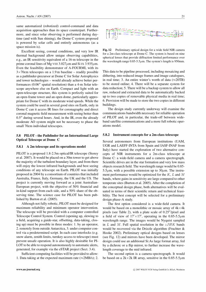
Astron. Nachr. / AN (2007) 21
same automatized (robotized) control-command and dataacquisition approaches than its space counterpart. Further-more, and since solar observing is performed during day-time (and with Sun shining), the Dome C system proposedis powered by solar cells and entirely autonomous (as aspace mission is).
Excellent seeing, coronal conditions, and very low IRthermal background allow unique observing capabilities,e.g., an IR sensitivity equivalent of a 16-m telescope in theprime coronal lines of Mg VIII 3.027µm and Si IX 3.935µm.Even the feasibility demonstrator of A-FOURMI, with its3×70cm telescopes on a 1.9 m baseline – readily possibleas a pathfinder-precursor at Dome C for Solar Astrophysicsand tower technologies – would already achieve better per-formances (0.06′′ spatial resolution) than a 4-m Solar tele-scope anywhere else on Earth. Compact and light with anopen-telescope structure, this system is perfectly suited foran open-frame tower and an open dome, particularly appro-priate for Dome C with its moderate wind speeds. While thesystem could be used in several good sites on Earth, only inDome C can it access IR lines for coronagraphy and directcoronal magnetic field measurement with seeing better than0.5′′ during several hours. And, in the IR, even the alreadymoderate AO system might not be necessary to phase thesmall 70cm individual telescopes.
5.8 PILOT - the Pathfinder for an International LargeOptical Telescope at Dome C
5.8.1 A 2m telescope and its operations model
PILOT is a proposed 1.8-2.5m optical/IR telescope (Storeyet al. 2007). It would be placed on a 30m tower to get abovethe majority of the turbulent boundary layer, and from therewill enjoy the lowest infrared backgrounds and best seeingconditions of any telescope on Earth. PILOT was initiallyproposed in 2004 by a consortium of countries that includedAustralia, France, Italy, Germany, the UK and the US. Theproject is currently moving forward as a joint Australian-European project, with the objective of 50% financial andin-kind support from each side, and a 50% share of the ob-serving time. The science case for PILOT has been pub-lished by Burton et al. (2005).
Although not fully robotic, PILOT must be designed formaximum reliability and minimum operator intervention.The telescope will be provided with a computer controlledTelescope Control System. Control (opening up, slewing toa field, acquiring a guide-star, offsetting, data-taking, clos-ing up) must be possible in three modes: 1. by an operator,2. remotely from outside Antarctica, 3. under computer con-trol via a predetermined script. In each case interlocks (e.g.snow alarm, zenith limits, turnkey access to telescope) mustprevent unsafe operation. It is also highly desirable for PI-LOT to be able to respond autonomously to automatic alerts,generated, for example via the eSTAR project (Sect. 3.4).
Sufficient computing facilities will be provided to allow:1. Data taking at the expected maximum rate (≈2MB/s); 2.
Fig. 12 Preliminary optical design for a wide field NIR camerafor a 2m-class telescope at Dome C. The system is based on ninespherical lenses that provide diffraction limited performance overthe wavelength range 0.85-5.5µm. The system’s length is 950mm.
This data to be pipeline processed, including mosaicing anddithering, into reduced image frames and image catalogues,in real time; 3. An entire winter’s worth of data (≈20TB)to be stored online; 4. There will be a separate system fordata reduction; 5. There will be a backup system to allow allraw, reduced and extracted data to be automatically backedup to two copies of removable physical media in real time;6. Provision will be made to store the two copies in differentbuildings.
The design study currently underway will examine thecommunications bandwidth necessary for reliable operationof PILOT and, in particular, the trade-off between wide-band satellite communications and a more full robotic oper-ations model.
5.8.2 Instrument concepts for a 2m-class telescope
Several astronomers from European institutions (UAM,UGR and LAEFF-INTA from Spain and IASF-INAF fromItaly) have started the exploration of two alternative con-cepts of NIR instruments for a 2m-class telescope atDome C: a wide-field camera and a camera spectrograph.Scientific drives are in the star formation and very low massobjects research field. The wavelength range would be 0.85-5.5µm, with a possible extension up to 30µm. The instru-ment performance would be optimized for the K, L and Mbands, where gains in sensitivity are large compared to othertemperate sites (Burton et al. 2005). After the completion ofthe conceptual design phase, both alternatives will be eval-uated in terms of their scientific return and technical feasi-bility. The best concept will be selected for a preliminarydesign phase-A study.
The first option considered is a wide-field camera. Itwould be based on a monolithic or mosaic array of 4k×4kpixels (see Table 2), with a plate scale of 0.25′′/pixel anda field of view of 17′×17′, operating in the 0.85-5.5µmwavelength range. The images would be Nyquist sampledin L and M . Full spatial resolution in the zJHK bandswould be recovered via the Drizzle algorithm (Fruchter &Hooke 2002). Preliminary optical designs based on lenses(see Fig. 12) and mirrors have been developed. The mirrordesign could use an additional Si:As large format array, fedby a dichroic or a flip mirror, to further increase the wave-length coverage to the mid infrared.
The second option is a camera-spectrograph. It wouldbe based on a 2k×2k IR array, sensitive in the 0.85-5.5µm
www.an-journal.org c© 2007 WILEY-VCH Verlag GmbH & Co. KGaA, Weinheim

22 K. G. Strassmeier et al.: Telescope and instrument robotization at Dome C
wavelength range, with a plate scale of 0.11′′/pixel, givinga field of view of 3.75′×3.75′ and appropriate sampling forhigh spatial resolution imaging and high precision photom-etry. A preliminary optical design uses five spherical lensesand provides diffraction limited performance over the wholewavelength range. Spectroscopic limiting magnitude for theK, L and M bands at several spectral resolutions have beencomputed, for 2m (PILOT) and 8m Antarctic telescopes,and an 8m telescope located on Mauna Kea. It has beenfound that the advantage of Antarctica in terms of NIR pho-tometric limiting magnitude (a 2m telescope at Dome C isroughly equivalent to an 8m at Mauna Kea) is identical forspectroscopy.
5.9 ALADDIN: a ground-based DARWIN pathfinder
ALADDIN (Antarctic L-band Astrophysics DiscoveryDemonstrator for Interferometric Nulling) is a pathfinderfor the DARWIN space mission, whose purpose is the cen-sus of habitable planets around nearby solar-type stars, andthe spectroscopic characterization of their atmosphere. Theprimary goal of ALADDIN is to pave the way for the DAR-WIN mission by measuring the amount of thermal lightemitted by interplanetary dust within the habitable zonearound potential targets. Like DARWIN, ALADDIN will bean interferometric nuller to cancel out on-axis stellar pho-tons while transmitting off-axis light emitted in the stellarenvironment. The baseline concept calls for an instrumentlocated between a pair of 1 m telescopes positioned on a40 m rotating truss (Coude du Foresto et al. 2006, Barillotet al. 2006). Thanks to the combined advantages providedby the low background, high photometric efficiency, andquiet atmosphere above the ground layer, the system willbe more sensitive than a nulling instrument using a pair of8 m telescopes in a temperate site such as Paranal (Absil etal. 2007).
Beyond the need for robotization, there are many simi-larities between the constraints which exist for a space mis-sion and an Antarctic experiment (especially if it is plannedto be operated during the winter): mass, volume, telemetrylimits, deployment and commissioning considerations, op-erations, reliability issues and recovery modes. In these do-mains, the input and expertise of the space astronomy com-munities can be most useful for the development of heavyAntarctic instrumentation.
5.10 PLATO: a 3rd generation robotic site-testingobservatory for Dome A
At 4100m, Dome A is the highest point on the Antarcticplateau. It is therefore expected to be a superb astronomicalsite, possibly surpassing both the South Pole and Dome Cfor some kinds of observations. In January 2005, a Chi-nese expedition made a 30-day traverse to Dome A from thecoastal station of Zhongshan to establish the first automatedweather station there. This expedition will be followed byan even more ambitious one by the Polar Research Institute
of China at the end of 2007. This expedition will deliverPLATO - the third generation of UNSW’s robotic site test-ing observatories (Lawrence et al. 2006).
PLATO is designed to deliver over a kilowatt of elec-trical power from a combination of solar power and smalldiesel generators. To give plenty of redundancy and an abil-ity to deliver additional power in mid-winter, six indepen-dent engines will be used. A system’s overview is shown inFig. 13.
Fig. 13 Block diagram of the PLATO control system.
At Dome C, the wind is predominantly from one di-rection. This greatly simplifies the problem of what to dowith the exhaust gases from the engines. For example, theAASTINO was aligned with its long axis parallel to the pre-vailing wind, with the exhaust stack placed at the downwindend. This meant that all the instruments were upwind ofthe exhaust stack. At Dome A, however, models show thatthere is no preferred wind direction, and this is supportedby preliminary data from the Automatic Weather Stationplaced there in January 2005. The problem of ensuring thatthe instruments do not observe through a plume of exhaustgas can only be solved by physically separating the powergeneration from the instruments. PLATO thus consists oftwo modules: a power module and an instrument module.These will be separated by some 20-30m, with only electri-cal power and a CAN bus connecting the two modules.
This physical separation of the power and instrumentmodules also helps reduce the transmission of noise and vi-bration from the generators to the astronomical instruments.However, with none of the excess generator heat now beingavailable for the instrument module, it must be kept warmsolely by the waste heat from the instruments themselves.
c© 2007 WILEY-VCH Verlag GmbH & Co. KGaA, Weinheim www.an-journal.org

Astron. Nachr. / AN (2007) 23
Extremely good thermal insulation is therefore required forthe instrument module.
As with the AASTINO, two-way communication withPLATO will be via the Iridium satellite network. PLATOwill use three independent ”Supervisor” computers, eachwith its own Iridium link. Independent watchdog timers willensure that no single or double computer problem can causea failure of the PLATO data acquisition system.
5.11 PreHEAT: a robotic sub-mm tipper at Dome A
PreHEAT is a 450 µm-wavelength tipper/telescope to be de-ployed in 2007 to Dome A on PLATO, to serve as a precur-sor to HEAT, a planned THz-frequency telescope for instal-lation on PLATO by austral summer 2008/9. Chris Walkerand Craig Kulesa lead the development of the (Pre)HEATinstruments at the University of Arizona. PreHEAT’s aimsare to monitor the sub-mm opacity of the atmosphere aboveDome A, in order to assess the quality of the site for sub-mm/THz observations, and to map the Galactic plane in theJ=6-5 transition of 13CO by drift-scanning. The 20 cm aper-ture of the tipper mirror will yield a ≈ 9′ FWHM beam,comparable to that of the CO 1–0 surveys carried out by the1.2 m Columbia mm-wave telescopes.
PLATO and PreHEAT are designed to operate withoutany human intervention after deployment. This requires notonly that routine operation (observations, calibration etc.)be automated, but also all other tasks that might be carriedout by a winterover at a crewed site. One particular concernis frost and snow management. A black surface at≈ −70◦Closes a few×10 W m−2 purely by coupling to the cold sky.At this temperature, a heat flux of 10 W m−2 is equivalent toice deposition of 0.3mm per day. In line with this estimate,frost is routinely observed at Dome C, but not at the SouthPole. Since we expect conditions at Dome A to have morein common with Dome C than with the Pole, we expect frostmanagement to be a problem.
A Goretex membrane is planned as a weather shield,and it is not clear whether this is likely to frost up (althoughthe strong frosting observed on an upward-facing teflon discby GIVRE – see Sect. 4.5 – is cause for concern.) Possibleapproaches to preventing or clearing frost include: ambi-ent airflow over the surface; warming, either directly or bywaste heat; and using an ambient-temperature baffle to re-duce the radiative load.
Current plans call for a combined approach, withambient-temperature baffles to restrict the area of sky seenby the tipper membrane to a narrow vertical strip, sufficientto allow the constant-azimuth observations for which thetipper is designed. But these baffles need not extend all theway down to the membrane: by leaving a space between themembrane surface and the baffle, an ambient airflow can beintroduced over the surface of the membrane, perhaps byfans mounted between the baffles and the tipper structure. Itmay also be possible (depending on PLATO’s thermal bud-get) to heat the membrane by allowing some (above ambient
temperature) air from inside PLATO to bleed out, warmingthe membrane.
Pictures of the snow surface at Dome A show essentiallyno sastrugi, which suggests very little wind, so we mightexpect very little blowing snow, but there may be some pre-cipitation. The membrane will prevent snow from gettinginto or onto the tipper mechanism, but it may be necessaryto clean snow off the membrane itself. This will be accom-plished by rotating the cylindrical tipper casing against asmall, flexible brush.
6 Conclusions
Due to the harsh conditions, telescopes and instruments atDome C should be able to perform without much humaninteraction, i.e. automatic or even robotic. Therefore, thequest for “robotization” is a quest for an integral system-engineering approach that links design and constructionwith operation and maintenance, and still is in compliancewith the support that can be given by Concordia. The engi-neering challenges may approach those in space. However,they are performed on Earth, with the huge advantages ofsignificantly lower costs, faster development cycles and thepossibility of some human interaction.
As part of our quest for a scientific road map for as-tronomy at Concordia, the issues detailed in Sect. 2-5 sug-gest the following conclusions for successful robotization atDome C:
– Temperate-site observatories have an extended infras-tructure because it is needed! Eventually, a Concordiaobservatory at Dome C has the same needs.
– The management approach for a fully robotized tele-scope and instrument at Dome C appears more like thatof a space experiment rather than a ground observatory.
– It always requires an integral, i.e. end-to-end, systems-engineering approach.
– The local infrastructure will decide upon the scientificoperations success.
These conclusions are equally valid for day-time andnight-time astronomy. A unique site always requires uniqueexperiments. Currently, the instruments that have been, orshortly will be, placed at Concordia are the 0.8m near andmid-IR telescope IRAIT (Tosti et al. 2006) and the sub-mmdish COCHISE (Dall’Oglio et al. 2003). Several smaller in-struments like sIRAIT (Sect. 5.1, see Tosti et al. 2006) orPAIX (see Chadid-Vernin et al. 2007) are already on site aspathfinders along with the cosmic micro-wave backgroundpolarization experiment BRAIN (Masi et al. 2005). All ofthese and several others are prototypes or pilot projects forlarger (optical/IR/sub-mm) instruments.
Acknowledgements. ARENA has received network funding fromthe European Community’s Sixth Framework Programme undercontract number RICA-026150. The field activities and the resultsat Dome C benefit from the support of the IPEV and PNRA in theframework of the French-Italian Concordia station programme.
www.an-journal.org c© 2007 WILEY-VCH Verlag GmbH & Co. KGaA, Weinheim

24 K. G. Strassmeier et al.: Telescope and instrument robotization at Dome C
References
Absil, O., di Folco, E., Coude Du Foresto, V., Barillot, M., Swain,M.: 2007, A&A, submitted
Agabi, A., Aristidi, E., Azouit, M., Fossat, E., Martin, F.,Sadibekova, T., Vernin, J., Ziad, A.: 2006, PASP 118, 344
Albrecht, R.: 2004, AN 325, 590Allan, A., Adamson, A., Cavanagh, B., et al.: 2006a, SPIE 6274,
627408Allan, A., Naylor, T., Saunders, E.S.: 2006b, AN 327, 767Argentini, S., Genthon, C., Macelloni, G., Pellegrini, A., Vitale,
V.: 2006, “Proposal for a COncordia Common Observatory ofthe Atmosphere (COCOA)”, presented at the Workshop Atmo-spheric Science and Connection with Related Science, Rome,April 26-27, 2006.
Aristidi, E., Agabi, K., Vernin, J., Azouit, M., Martin, F., Ziad, A.,Fossat, E.: 2003, A&A 406, L19
Aristidi, E., Agabi, K., Azouit, M., Fossat, E., Vernin, J., Travouil-lon, T., Lawrence, J. S., Meyer, C. V.: 2005a, A&A 430, 739
Aristidi, E., Agabi, A., Fossat, E., Azouit, M., Martin, F.,Sadibekova, T., Travouillon, T., Vernin, J., Ziad, A.: 2005b,A&A 444, 651
Ashley, M. C. B., Burton, M. G., Lawrence, J. S., Storey, J. W. V.:2004, AN 325, 619
Barillot, M., Courteau, P., Absil, O., Coude du Foresto, V., Swain,M.: 2006, SPIE 6268, 94
Bayley, A.M., Davis, R.J., Haggis, J.S., Karcher, H.J.: 1993,A&A 283, 1051
Bortoletto, F., D’Allessandro, M., Giro, E., et al.: 2006, in Beletic,J.E. et al. (eds.), Scientific Detectors for Astronomy 2005,Springer, Berlin, p.673
Burton, M.G., Lawrence, J., Ashley, M.C.B., Bailey, J.A., et al.:2005, PASA 22, 199
Chadid-Vernin, M., et al.: 2007, in Epchtein, N., et al. (eds.), LargeAstronomical Infrastructures at Concordia, Roscoff, EDP sci-ences, in press
Coude du Foresto, V., Absil, O., Swain, M., Vakili, F., Barillot, M.:2006, SPIE 6268, 32
Dall’Oglio, G., Martinis, L., Pascucci, S., Pizzo, L., Sabbatini, L.,Valenziano, L.: 2003, Mem. Soc. Astr. It. Suppl. 2, 38
Dame, L.: 2006, ESA SP-617, s7.3Deeg, H.J., Belmonte, J.A., Alonso, R., Horne, K., Alsubai, K.,
Doyle, L.R.: 2005, in Giard et al. (eds.), Dome C, Astronomy,and Astrophysics Meeting, EDP Publ. Ser. 14, p. 303
Ekaykin, A.A., Lipenkov, V. Ya., Kuzmina, I.N., Petit, J.R.,Masson-Delmotte, V., Johnsen, S.J.: 2004, AnGla 39, 569
Economou, F., Jenness, T., Cavanagh, B., Adamson, A., Allan, A.:2006, AN 327, 788
EPICA community members: 2004, Nature 429, 623Forieri, A., Tabacco, I.E., Della Vedova, A., Zirizzotti, A., Bianchi,
C., De Michelis, P., Passerini, A.: 2003, Terra Antartica Report8, 169
Fossat, E.: 2005a, in Giard et al. (eds.), Dome C, Astronomy, andAstrophysics Meeting, EDP Publ. Ser. 14, p. 1
Fossat, E.: 2005b, in Giard et al. (eds.), Dome C, Astronomy, andAstrophysics Meeting, EDP Publ. Ser. 14, p. 121
Fraser, S. , Steele, I. A.: 2004, SPIE 5493, 331Frezzotti, M., Pourchet, M., Flora, O., et al.: 2004, ClDy. 23(7-8),
803Frezzotti, M., Pourchet, M., Flora, O., et al.: 2005, JGlac 51(207),
113Fruchter, A.S., Hooke, R.N.: 2002, PASP 114, 144Geissler, K., Masciadri, E.: 2006, PASP 118, 1048
Giard, M., Casoli, F., Paletou, F. (eds.): 2005, Dome C, Astronomy,and Astrophysics Meeting, Toulouse, EDP Publ. Ser. 14, EAS
Granzer, T.: 2007, AN, submittedGranzer, T., Weber, M., Strassmeier, K. G.: 2001, AN 322, 295Greve, A., Panis, J.F., Thum, C.: 1996, A&AS 115, 379Hodapp, K. W., Kaiser, N., Aussel, H., Burgett, W., Chambers, K.
C., Chun, M., Dombeck, T. et al.: 2004, AN 325, 636Ivezic, Z., Lupton, R. H., Schlegel, D., Boroski, B., Adelman-
McCarthy, J., Yanny, B., Kent, S. et al.: 2004, AN 325, 583Karcher, H. J.: 2000, SPIE 4014, 282Karcher, H. J.: 2003, SPIE 4857, 257Kenyon, S. L., Lawrence, J., Ashley, M. C. B., Storey, J. W. V.,
Tokovinin, A., Fossat, E.: 2006, PASP 118, 924Krabbe, A., Karcher, H. J.: 2004, SPIE 5495, 51Lawrence, J. S., Ashley, M. C. B., Burton, M. G., Calisse, P. G.,
Dempsey, J. T., Everett, J. R., Maher, O., Storey, J. W. V.,Travouillon, T.: 2004, Mem.SAI Suppl. 2, 217
Lawrence, J.S., Ashley, M.C.B., Burton, M.G. et al.: 2006, SPIE6267, 51
Lawrence, J.S., Ashley, M. C. B., Tokovinin, A., Travouillon, T.:2004, Nature 431, 278
Lawrence, J.S., Ashley, M.C.B., Storey, J.W.V.: 2005, Aust. Jour-nal. Elec. & Electronic Eng. 2, 1
Masi, S., de Bernardis, P., Giordano, C. et al.: 2005, in Giard et al.(eds.), Dome C, Astronomy, and Astrophysics Meeting, EDPPubl. Ser. Vol. 14, p. 87
Mottram, C. J. , Steele, I. A. , Morales, L.: 2004, SPIE 5492, 677Mosser, B., Aristidi, E.: 2007, PASP 119, 127Nayor, T., Allan, A., Steele, I. A. (eds.): 2006, AN 327, 741Paczynski, B., Che, C. P., Lemme, C. (eds.): 2001, Small Telescope
Astronomy on Global Scales, ASPC 246Pont, F., Bouchy, F.: 2005, in Giard et al. (eds.), Dome C, Astron-
omy, and Astrophysics Meeting, EDP Publ. Ser. 14, p. 155Reijmer, C.H., Van Den Broeke, M.R., Scheele, M.P.: 2002, JCli.
15, 1957Remy, F., Tabacco, I.E.: 2000, GeoRL 27, 405Steele, I. A. , Smith, R. J. , Rees, P. C. , et al.: 2004, SPIE 5489,
679Storey, J.W.V., Ashley, M.C.B., Burton, M.G., Lawrence, J.S.:
2007, in Epchtein, N. et al. (eds.), Large Astronomical Infras-tructures at Concordia, prospects and constraints for Antarcticoptical/IR Astronomy, Roscoff, EDP sciences, in press
Strassmeier, K. G.: 2007, in Epchtein, N. et al. (eds.), Large As-tronomical Infrastructures at Concordia, prospects and con-straints for Antarctic optical/IR Astronomy, Roscoff, EDP sci-ences, in press
Strassmeier, K. G., Andersen, M. I., Steinbach, M.: 2004, AN 325,626
Strassmeier, K. G., Hessman, F. V. (eds.): 2004, AN 325, 455Strassmeier, K. G., Schwope, A., Dreiszler, S. (eds.): 2001, AN
322, 271Strassmeier K. G., Granzer, T., Weber, M. et. al.: 2005, AN 325,
527Tosti, G., Busso, M., Nucciarelli, G., et al.: 2006, SPIE 6267, 47Valenziano, L., Dall ’Oglio, G.: 1999, PASA 16, 167Vittuari, L., Vincent, C., Frezzotti, M., Mancini, F., Gandolfi, S.,
Bitelli, G., Capra, A.: 2004, AnGla 39, 402Wandner, K., Karcher, H. J.: 2000, SPIE 4014, 360White, R.R., Allan, A. et al.: 2006, AN 327, 775Williams, R.D., Seaman, R.L.: 2006, in Gabriel, C. et al. (eds),
ADASS XV, ASP, San Francisco, ASPC 351, 637Wooldridge, M.: 2002, An Introduction to Multi-agent Systems,
John Wiley & Sons, Chichester, England
c© 2007 WILEY-VCH Verlag GmbH & Co. KGaA, Weinheim www.an-journal.org