telemedicine system using gsm wireless network chapter-1
TRANSCRIPT
Telemedicine system using GSM wireless network
1 | P a g e C . U . S H A H C O L L E G E O F E N G & T E C H .
CHAPTER-1:
1.1 INTRODUCTION:
ACCORDING to an estimate, given by the World Health Organization (WHO),
cardiovascular disease kills almost seventeen million people around the globe each year along
with twenty million people at a risk of sudden heart failure.
Some of these lives can often be saved if acute care and cardiac surgery is provided within
the so-called golden hour. So the need for advice on first hand medical attention and
promotion of good health by patient monitoring and follow-up becomes inevitable. Hence,
patients who are at risk require that their cardiac health to be monitored frequently whether
they are indoors or outdoors so that emergency treatment is possible. Telemedicine is widely
considered to be part of the inevitable future of the modern practice of medicine.
It is gaining more and more momentum as a new approach for patients' surveillance outside
of hospitals (at home) to encourage public safety, a ciliate early diagnosis, treatment, and for
increased convenience. Defined as the “use of advanced Tele Communication technologies “
to exchange the information about the patient's health care status and provide health care
services across is now currently being used by doctors, hospitals and other healthcare
providers around the world with conventional mode of treatment. Telemedicine systems are
already available to enable the doctor to monitor a patient remotely for home care emergency
applications. Nowadays, Wireless networking is an emerging technology that will allow
different users to access electronically, regardless of their geographic topography. The use of
wireless communication between mobile users has become increasingly popular due to the
advancements in computer and wireless technologies. Implementation of wireless technology
in the existing heart rate monitoring system eliminates the physical constraints imposed by
hard-wired link and allows users to conduct own check up at anytime anywhere.
Moreover, newer cellular access technologies, such as Third generation (3G), and others
provide much higher data transmission speeds (rates) than basic second generation (2G) GSM
cellular system offering future telemedicine solutions endless choices for high-end designs.
These relatively new wireless technologies are deployed mostly in or around crowded high
income metropolitan areas for our proposed scheme.
Telemedicine system using GSM wireless network
2 | P a g e C . U . S H A H C O L L E G E O F E N G & T E C H .
But the majority (80.8%) of the 3.7 billion cellular phone users in the world are still 2G GSM
users. Hence, we describe a telemedicine system based on mobile messaging service namely:
Short Messaging Service (SMS), which is an integral part of the original 2GGSMcellular
system and subsequent generations since all new phones are SMS capable. Our project aims
at detecting the cardiac disorder of the patient in advance thereby reducing the critical level
of the patient by following precautionary measures at an earlier instant.
1.2 OBJECTIVE OF THE PROJECT:
A mobile telemedicine system includes a small portable hand-held device, such as a
mobile phone, which relays the information collected from patients to the healthcare
provider using GSM wireless network.
GSM system used to support, control, and monitor patients in relatively large areas
by delivering patients’ vital signs and medical information to remote medical
facilities.
Increasing the chances of timely and appropriate actions.
This system provides mobility to the doctor and the patient.
Telemedicine system using GSM wireless network
3 | P a g e C . U . S H A H C O L L E G E O F E N G & T E C H .
CHAPTER-2:
2.1 BRIEF LITERATURE REVIEW:
2.1.1 ABOUT TELEMEDICINE:
Telemedicine can be defined as the delivery of health care and sharing of medical knowledge
over a distance using telecommunication means. It aims at providing expert based medical
care to any place that health care is needed. Telemedicine as a concept was introduced about
30 years ago when telephone and fax machines were the first telecommunication means used.
In recent years, several telemedicine applications have been successfully implemented over
wired communication technologies like POTS, and ISDN. However, nowadays, modern
wireless telecommunication means like the GSM and GPRS and the forthcoming UMTS
mobile telephony standards, as well as satellite communications, allow the operation of
wireless telemedicine systems freeing the medical personnel and/or the subject monitored
bounded to fixed locations.
Telemedicine applications, including those based on wireless technologies span the areas of
emergency health care, telecardiology, teleradiology, telepathology, teledermatology,
teleophtlalmology, teleoncology, and telepsychiatry. In addition, health telematics
applications enabling the availability of prompt and expert medical care have been exploited
for the provision of health care services at understaffed areas like rural health centers,
ambulance vehicles, ships, trains, airplanes as well as for home monitoring.
2.1.2 WIRELESS TECHNOLOGIES:
There are various wireless technology for implementation of telemedicine system such as,
GSM technology
Satellite
Wireless local area network (WLAN)
Radio frequency
Bluetooth
Telemedicine system using GSM wireless network
4 | P a g e C . U . S H A H C O L L E G E O F E N G & T E C H .
The first technology, GSM is a system currently in use, and is the second generation (2G) of
the mobile communication networks. When it is in the standard mode of operation, it
provides data transfer speeds of up to 9.6 kbps. Through the years a new technique was
introduced in the GSM standard called High Speed Circuit Switched Data HSCSD. This
technology makes it possible to use several time slots simultaneously when sending or
receiving data, so the user can increase the data transmission to 14.4 kbps (an increase of
50%) or even triple at 43.3 kbps. The evolution of mobile telecommunication systems from
2G to 2.5G (iDEN 64 kbps, GPRS 171 kbps, EDGE 384 kbps) and subsequently to 3G (W-
CDMA, CDMA2000, TD-CDMA) systems will facilitate the provision of faster data transfer
rates thus enabling the development of telemedicine systems that require high data transfer
rates and are currently only feasible on wired communication networks.
Second technology is Satellite systems are able to provide a variety data transfer rates starting
from 2.4 kbps and moving to high-speed data rates of up to 2x64 kbps and even more.
Satellite links also have the advantage of operating all over the world.
Third is WLAN is a flexible data communications system implemented as an extension to or
as an alternative for a wired LAN. Using radio frequency (RF) technology, WLANs transmit
and receive data over the air, minimizing the need for wired connections. Thus, WLANs
combine data connectivity with user mobility, becoming very popular in a number of vertical
markets, including the healthcare, retail, manufacturing, warehousing, and academia. By
using bluetooth telemedicine system is developed for the shorter range of transmission .
Today wireless LANs are becoming more widely recognized as a general purpose
connectivity alternative for a broad range of applications, forseeing that this technology will
penetrate the health sector in the near future.
2.1.3 DESIGN GUIDELINE:
The development of these systems was guided by the following design guidelines:
easy-to-use interface – the system should provide simple interfaces for the health
provider;
controllability – the system should support remote control functions. The healthcare
provider should be empowered with the ability to control the media content according
Telemedicine system using GSM wireless network
5 | P a g e C . U . S H A H C O L L E G E O F E N G & T E C H .
to medical specialties or his/her personal preference. For example, the health provider
is allowed to control ECG sample rate, video frame rate, and image quality, etc.;
device adaptability – the system should meet th capabilities of the computing device
(e.g. laptop, PDA or mobile phone) on which it runs;
media adaptability – the system should provide support for different medical data,
such as vital bio-signals, images, video, and patient information; and
modular design – the system should have a modular design so that it allows for the
development of a roadmap for growth that can accommodate future generations of
functionality.
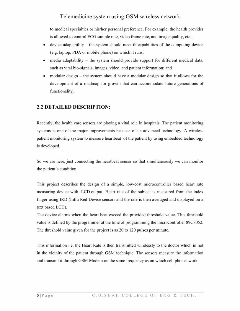
2.2 DETAILED DESCRIPTION:
Recently, the health care sensors are playing a vital role in hospitals. The patient monitoring
systems is one of the major improvements because of its advanced technology. A wireless
patient monitoring system to measure heartbeat of the patient by using embedded technology
is developed.
So we are here, just connecting the heartbeat sensor so that simultaneously we can monitor
the patient’s condition.
This project describes the design of a simple, low-cost microcontroller based heart rate
measuring device with LCD output. Heart rate of the subject is measured from the index
finger using IRD (Infra Red Device sensors and the rate is then averaged and displayed on a
text based LCD).
The device alarms when the heart beat exceed the provided threshold value. This threshold
value is defined by the programmer at the time of programming the microcontroller 89C8052.
The threshold value given for the project is as 20 to 120 pulses per minute.
This information i.e. the Heart Rate is then transmitted wirelessly to the doctor which in not
in the vicinity of the patient through GSM technique. The sensors measure the information
and transmit it through GSM Modem on the same frequency as on which cell phones work.
Telemedicine system using GSM wireless network
6 | P a g e C . U . S H A H C O L L E G E O F E N G & T E C H .
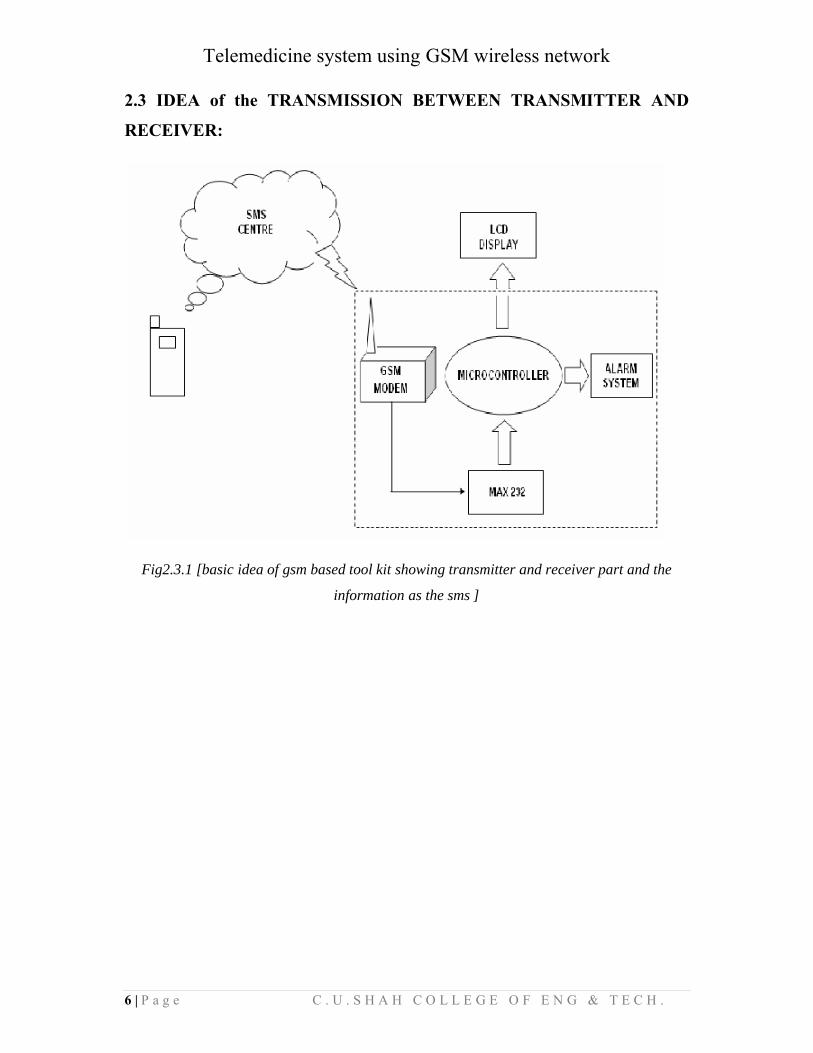
2.3 IDEA of the TRANSMISSION BETWEEN TRANSMITTER AND
RECEIVER:
Fig2.3.1 [basic idea of gsm based tool kit showing transmitter and receiver part and the
information as the sms ]
Telemedicine system using GSM wireless network
CHAPTER 3:
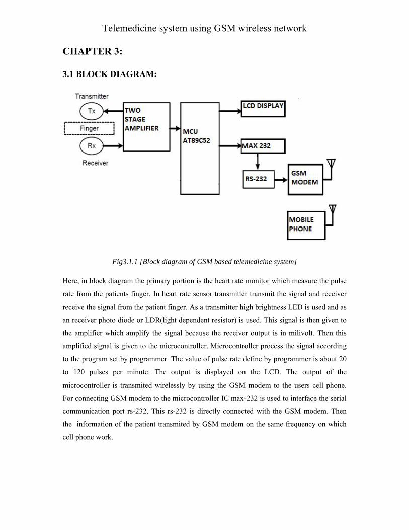
3.1 BLOCK DIAGRAM:
Fig3.1.1 [Block
Here, in block diagram the primary
rate from the patients finger. In
receive the signal from the patient
an receiver photo diode or LDR(light
the amplifier which amplify the
amplified signal is given to the micro
to the program set by programmer.
to 120 pulses per minute. The
microcontroller is transmited wirelessly
For connecting GSM modem to
communication port rs-232. This
the information of the patient transmited
cell phone work.
Telemedicine system using GSM wireless network
diagram of GSM based telemedicine system]
primary portion is the heart rate monitor which measure
heart rate sensor transmitter transmit the signal
patient finger. As a transmitter high brightness LED is
LDR(light dependent resistor) is used. This signal is
the signal because the receiver output is in milivolt.
microcontroller. Microcontroller process the signal
programmer. The value of pulse rate define by programmer
The output is displayed on the LCD. The output
wirelessly by using the GSM modem to the users
the microcontroller IC max-232 is used to interface
This rs-232 is directly connected with the GSM modem.
transmited by GSM modem on the same frequency
Telemedicine system using GSM wireless network
measure the pulse
signal and receiver
is used and as
then given to
milivolt. Then this
signal according
programmer is about 20
output of the
users cell phone.
interface the serial
modem. Then
frequency on which
Telemedicine system using GSM wireless network
8 | P a g e C . U . S H A H C O L L E G E O F E N G & T E C H .
3.2 COMPONENTS:
The Major Components used in Our Project are:
1. MICROCONTROLLER 89c52
2. MAX 232
3. LCD DISPLAY
4. SIM 300 GSM MODEM
5. CRYSTAL 11.0592 MHz
6. BUZZER
7. CAPACITORS
8. RESISTORS
9. CONNECTING WIRES
10. POWER SUPPLY
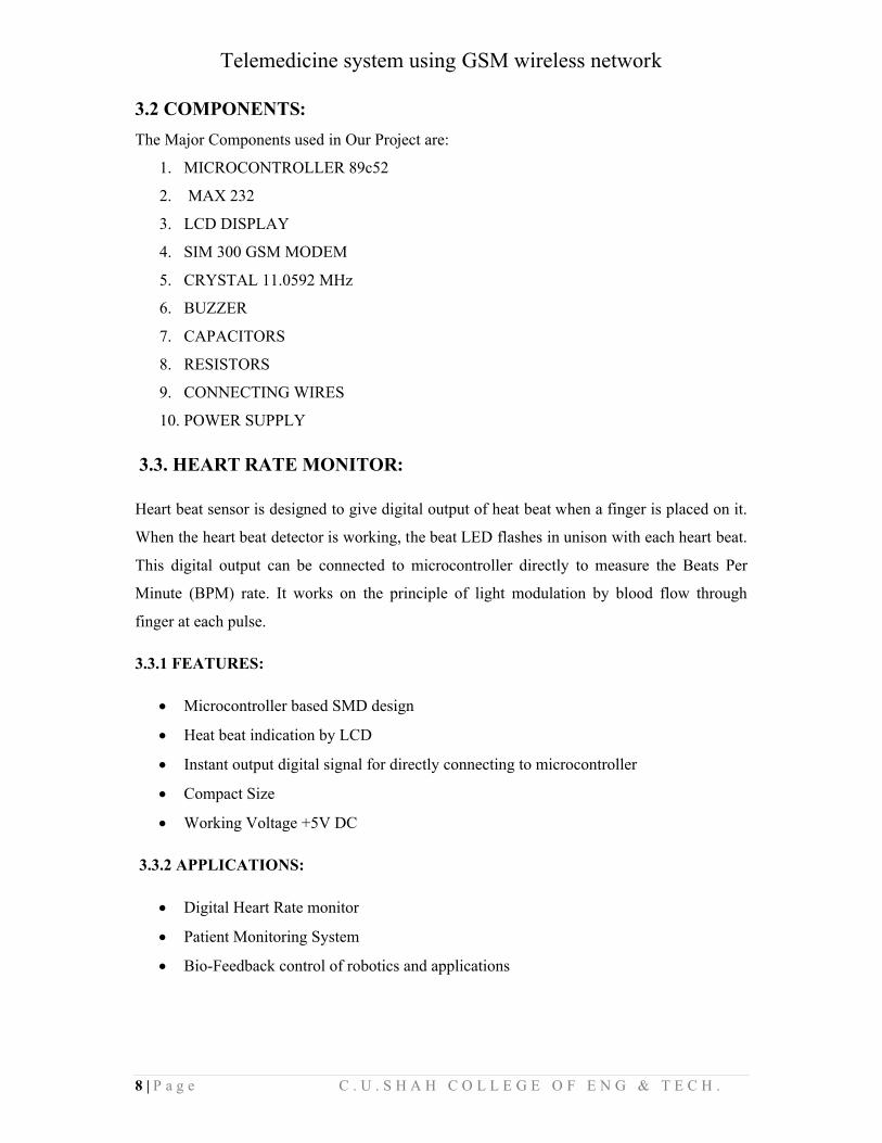
3.3. HEART RATE MONITOR:
Heart beat sensor is designed to give digital output of heat beat when a finger is placed on it.
When the heart beat detector is working, the beat LED flashes in unison with each heart beat.
This digital output can be connected to microcontroller directly to measure the Beats Per
Minute (BPM) rate. It works on the principle of light modulation by blood flow through
finger at each pulse.
3.3.1 FEATURES:
Microcontroller based SMD design
Heat beat indication by LCD
Instant output digital signal for directly connecting to microcontroller
Compact Size
Working Voltage +5V DC
3.3.2 APPLICATIONS:
Digital Heart Rate monitor
Patient Monitoring System
Bio-Feedback control of robotics and applications
Telemedicine system using GSM wireless network
9 | P a g e C . U . S H A H C O L L E G E O F E N G & T E C H .
3.3.3 USING THE SENSOR:
Connect regulated DC power supply of 5 Volts. Black wire is Ground, Nextmiddle
wire is Brown which is output and Red wire is positive supply. Thesewires are also
marked on PCB.
To test sensor you only need power the sensor by connect two wires +5V andGND.
You can leave the output wire as it is. When Beat LED is off the output isat 0V.
Put finger on the marked position, and you can view the beat LED blinking oneach
heart beat.
The output is active high for each beat and can be given directly to microcontroller for
interfacing applications.
3.3.4 WORKING PRINCIPLE:
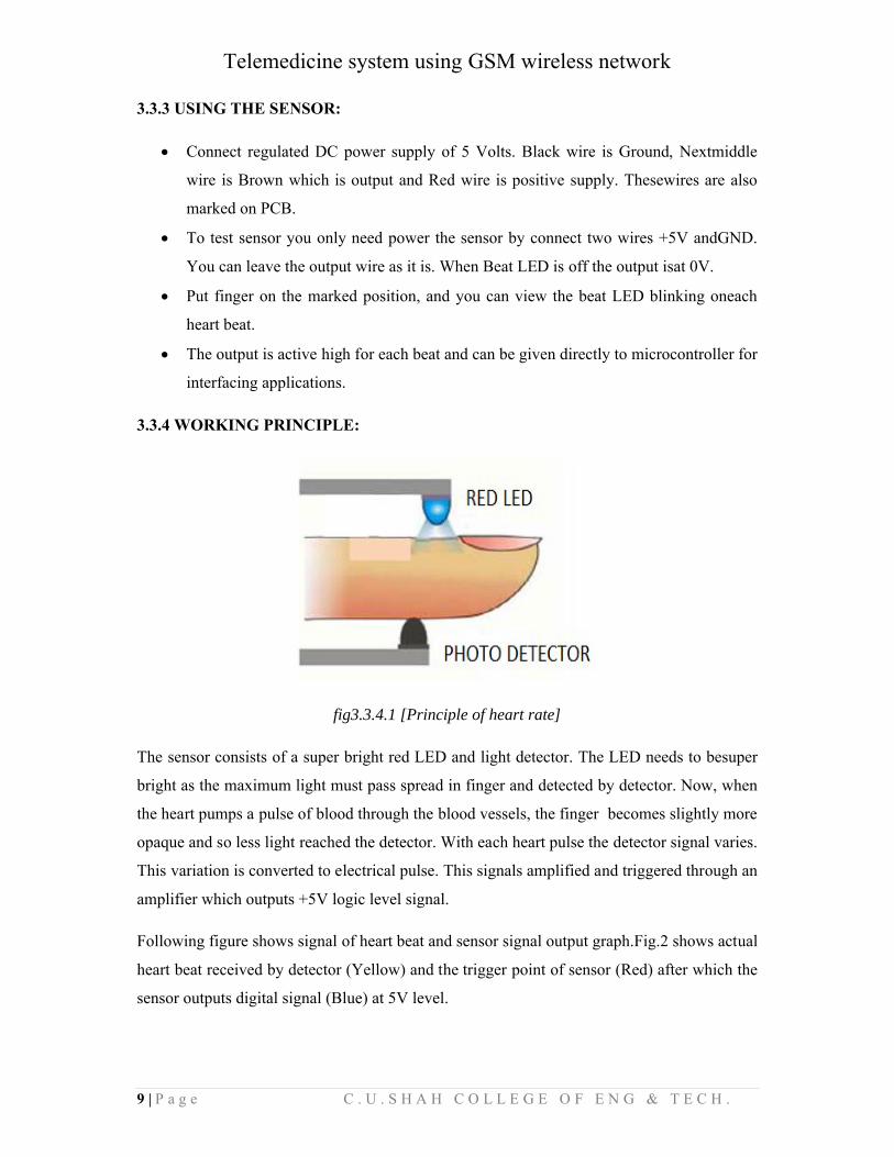
fig3.3.4.1 [Principle of heart rate]
The sensor consists of a super bright red LED and light detector. The LED needs to besuper
bright as the maximum light must pass spread in finger and detected by detector. Now, when
the heart pumps a pulse of blood through the blood vessels, the finger becomes slightly more
opaque and so less light reached the detector. With each heart pulse the detector signal varies.
This variation is converted to electrical pulse. This signals amplified and triggered through an
amplifier which outputs +5V logic level signal.
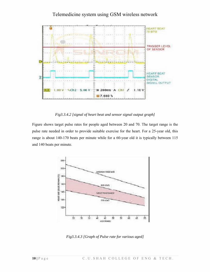
Following figure shows signal of heart beat and sensor signal output graph.Fig.2 shows actual
heart beat received by detector (Yellow) and the trigger point of sensor (Red) after which the
sensor outputs digital signal (Blue) at 5V level.
Telemedicine system using GSM wireless network
10 | P a g e C . U . S H A H C O L L E G E O F E N G & T E C H .
Fig3.3.4.2 [signal of heart beat and sensor signal output graph]
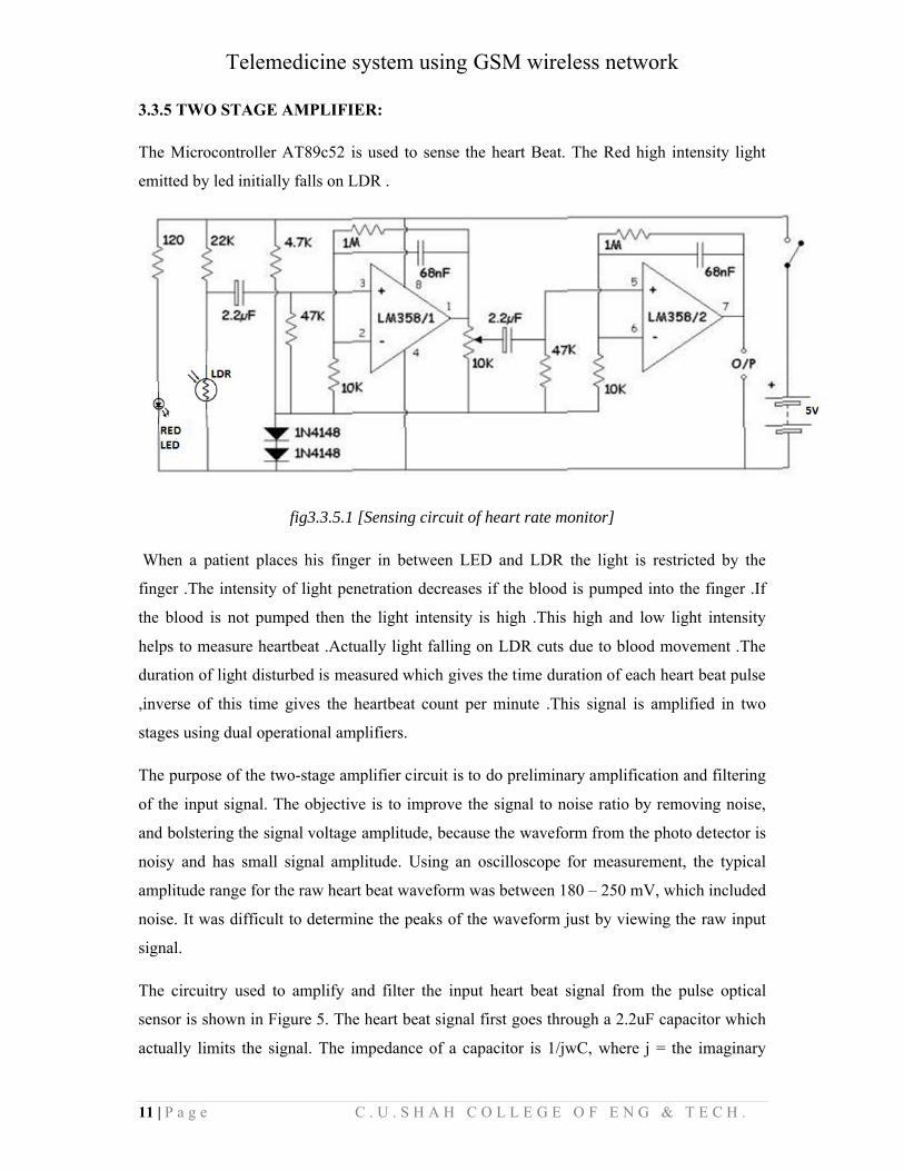
Figure shows target pulse rates for people aged between 20 and 70. The target range is the
pulse rate needed in order to provide suitable exercise for the heart. For a 25-year old, this
range is about 140-170 beats per minute while for a 60-year old it is typically between 115
and 140 beats per minute.
Fig3.3.4.3 [Graph of Pulse rate for various aged]
Telemedicine system using GSM wireless network
11 | P a g e C . U . S H A H C O L L E G E O F E N G & T E C H .
3.3.5 TWO STAGE AMPLIFIER:
The Microcontroller AT89c52 is used to sense the heart Beat. The Red high intensity light
emitted by led initially falls on LDR .
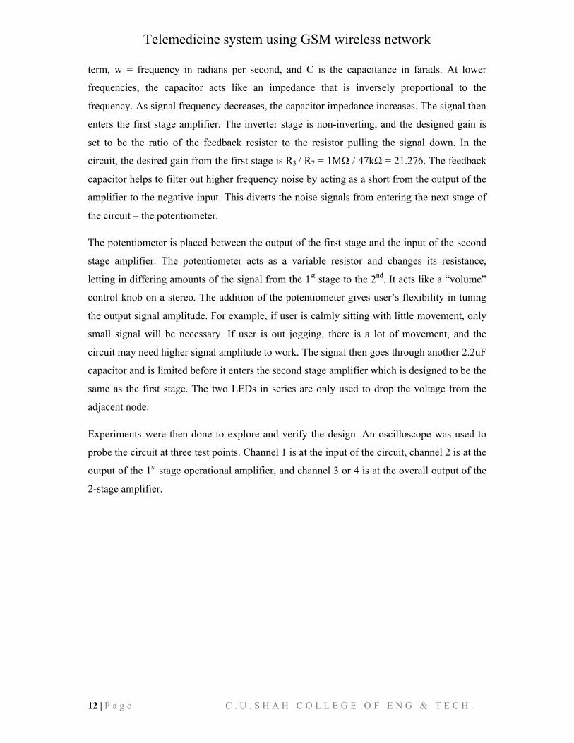
fig3.3.5.1 [Sensing circuit of heart rate monitor]
When a patient places his finger in between LED and LDR the light is restricted by the
finger .The intensity of light penetration decreases if the blood is pumped into the finger .If
the blood is not pumped then the light intensity is high .This high and low light intensity
helps to measure heartbeat .Actually light falling on LDR cuts due to blood movement .The
duration of light disturbed is measured which gives the time duration of each heart beat pulse
,inverse of this time gives the heartbeat count per minute .This signal is amplified in two
stages using dual operational amplifiers.
The purpose of the two-stage amplifier circuit is to do preliminary amplification and filtering
of the input signal. The objective is to improve the signal to noise ratio by removing noise,
and bolstering the signal voltage amplitude, because the waveform from the photo detector is
noisy and has small signal amplitude. Using an oscilloscope for measurement, the typical
amplitude range for the raw heart beat waveform was between 180 – 250 mV, which included
noise. It was difficult to determine the peaks of the waveform just by viewing the raw input
signal.
The circuitry used to amplify and filter the input heart beat signal from the pulse optical
sensor is shown in Figure 5. The heart beat signal first goes through a 2.2uF capacitor which
actually limits the signal. The impedance of a capacitor is 1/jwC, where j = the imaginary
Telemedicine system using GSM wireless network
12 | P a g e C . U . S H A H C O L L E G E O F E N G & T E C H .
term, w = frequency in radians per second, and C is the capacitance in farads. At lower
frequencies, the capacitor acts like an impedance that is inversely proportional to the
frequency. As signal frequency decreases, the capacitor impedance increases. The signal then
enters the first stage amplifier. The inverter stage is non-inverting, and the designed gain is
set to be the ratio of the feedback resistor to the resistor pulling the signal down. In the
circuit, the desired gain from the first stage is R3 / R7 = 1MΩ / 47kΩ = 21.276. The feedback
capacitor helps to filter out higher frequency noise by acting as a short from the output of the
amplifier to the negative input. This diverts the noise signals from entering the next stage of
the circuit – the potentiometer.
The potentiometer is placed between the output of the first stage and the input of the second
stage amplifier. The potentiometer acts as a variable resistor and changes its resistance,
letting in differing amounts of the signal from the 1st stage to the 2nd. It acts like a “volume”
control knob on a stereo. The addition of the potentiometer gives user’s flexibility in tuning
the output signal amplitude. For example, if user is calmly sitting with little movement, only
small signal will be necessary. If user is out jogging, there is a lot of movement, and the
circuit may need higher signal amplitude to work. The signal then goes through another 2.2uF
capacitor and is limited before it enters the second stage amplifier which is designed to be the
same as the first stage. The two LEDs in series are only used to drop the voltage from the
adjacent node.
Experiments were then done to explore and verify the design. An oscilloscope was used to
probe the circuit at three test points. Channel 1 is at the input of the circuit, channel 2 is at the
output of the 1st stage operational amplifier, and channel 3 or 4 is at the overall output of the
2-stage amplifier.
Telemedicine system using GSM wireless network
Fig3.3.5.2
As seen in Figure, the input signal (ch.1) from the photo detector in the finger sensor is a
noisy and it is hard to see changes in signal amplitudes (where a
of the first stage (ch.2) amplifier, the signal is still a noisy, but amplitude is noticeably
increased, and the heart beats are discernable. At the output after both stages of the amplifier,
a distinct heart beat pattern is seen with a voltage swing of 0V~2V. The potentiometer is set
to the middle of its range. Therefore the output signal is at an amplitude of about 2V. If the
potentiometer is tuned so that its variable resistance is smaller, the output voltage amplitude
will be higher. The output after amplification is obtained at pin number 7 of OP
to microcontroller.
Telemedicine system using GSM wireless network
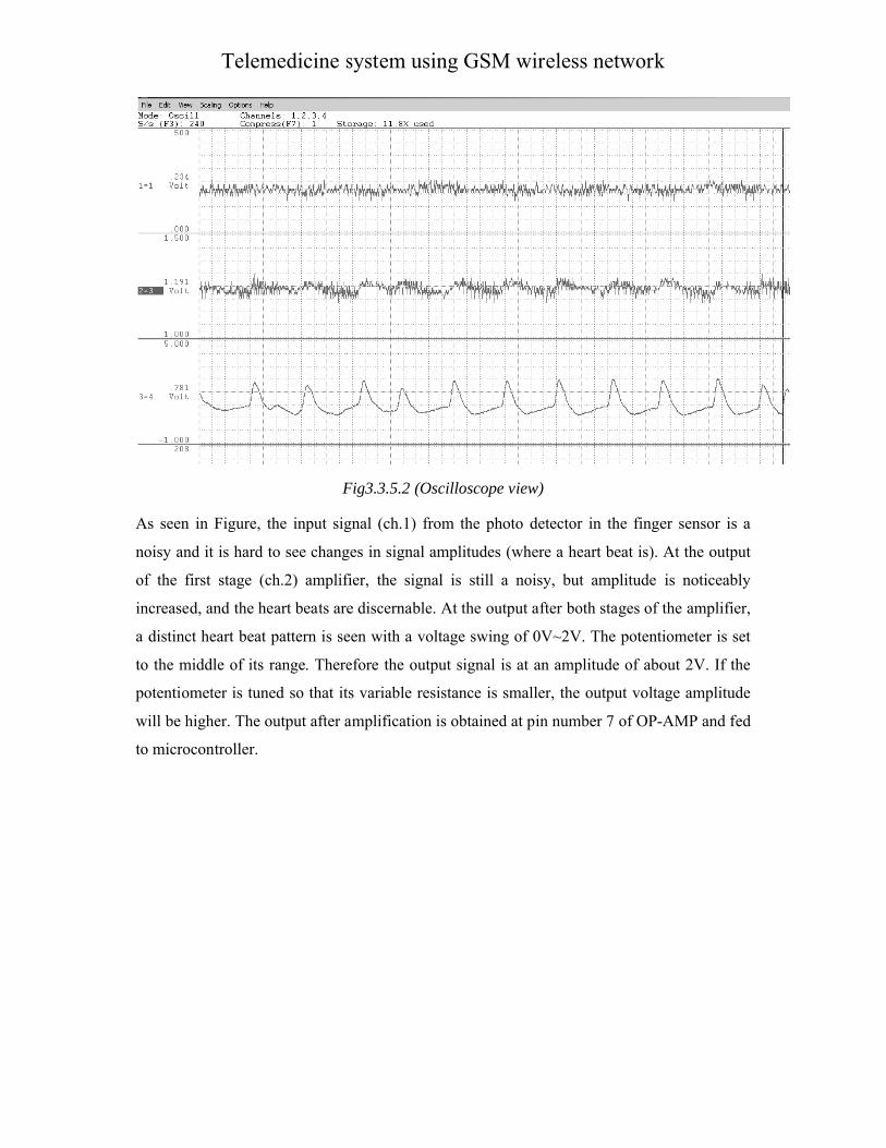
Fig3.3.5.2 (Oscilloscope view)
As seen in Figure, the input signal (ch.1) from the photo detector in the finger sensor is a
noisy and it is hard to see changes in signal amplitudes (where a heart beat is). At the output
of the first stage (ch.2) amplifier, the signal is still a noisy, but amplitude is noticeably
increased, and the heart beats are discernable. At the output after both stages of the amplifier,
een with a voltage swing of 0V~2V. The potentiometer is set
to the middle of its range. Therefore the output signal is at an amplitude of about 2V. If the
potentiometer is tuned so that its variable resistance is smaller, the output voltage amplitude
The output after amplification is obtained at pin number 7 of OP-
Telemedicine system using GSM wireless network
As seen in Figure, the input signal (ch.1) from the photo detector in the finger sensor is a
heart beat is). At the output
of the first stage (ch.2) amplifier, the signal is still a noisy, but amplitude is noticeably
increased, and the heart beats are discernable. At the output after both stages of the amplifier,
een with a voltage swing of 0V~2V. The potentiometer is set
to the middle of its range. Therefore the output signal is at an amplitude of about 2V. If the
potentiometer is tuned so that its variable resistance is smaller, the output voltage amplitude
-AMP and fed
Telemedicine system using GSM wireless network
14 | P a g e C . U . S H A H C O L L E G E O F E N G & T E C H .
3.4 DESIGN CONSIDERATION:
3.4.1 POWER SUPPLY:
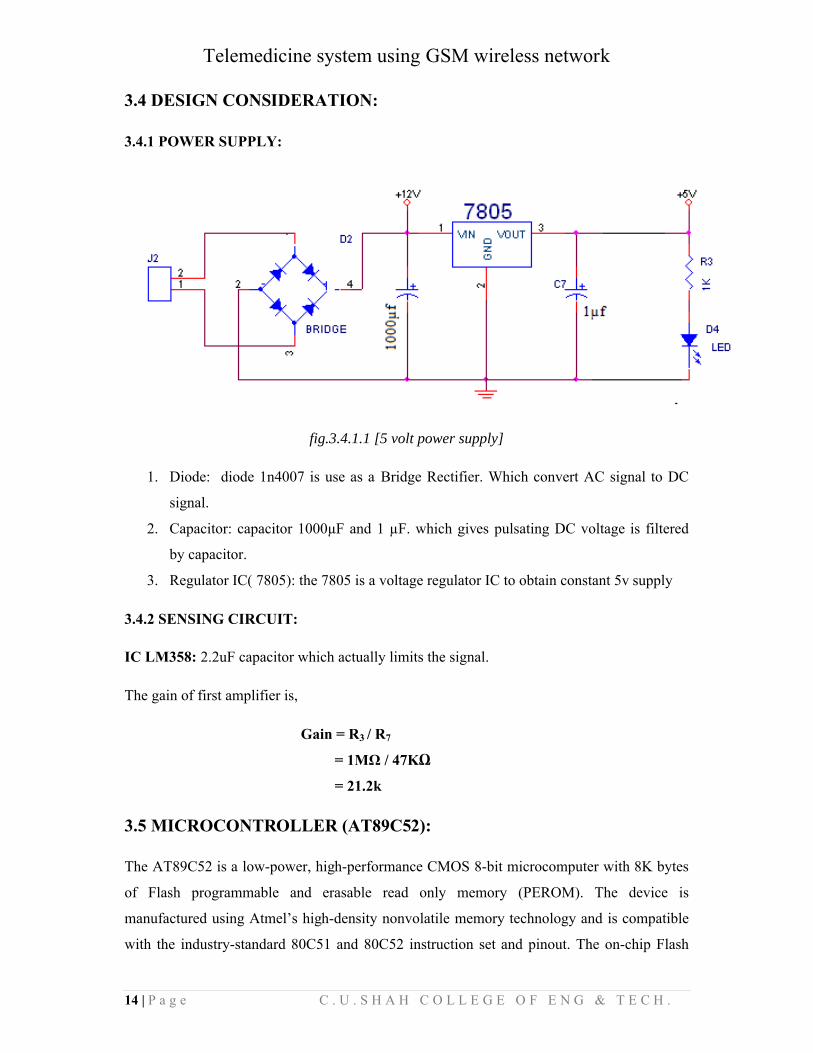
fig.3.4.1.1 [5 volt power supply]
1. Diode: diode 1n4007 is use as a Bridge Rectifier. Which convert AC signal to DC
signal.
2. Capacitor: capacitor 1000µF and 1 µF. which gives pulsating DC voltage is filtered
by capacitor.
3. Regulator IC( 7805): the 7805 is a voltage regulator IC to obtain constant 5v supply
3.4.2 SENSING CIRCUIT:
IC LM358: 2.2uF capacitor which actually limits the signal.
The gain of first amplifier is,
Gain = R3 / R7
= 1MΩ / 47KΩ
= 21.2k
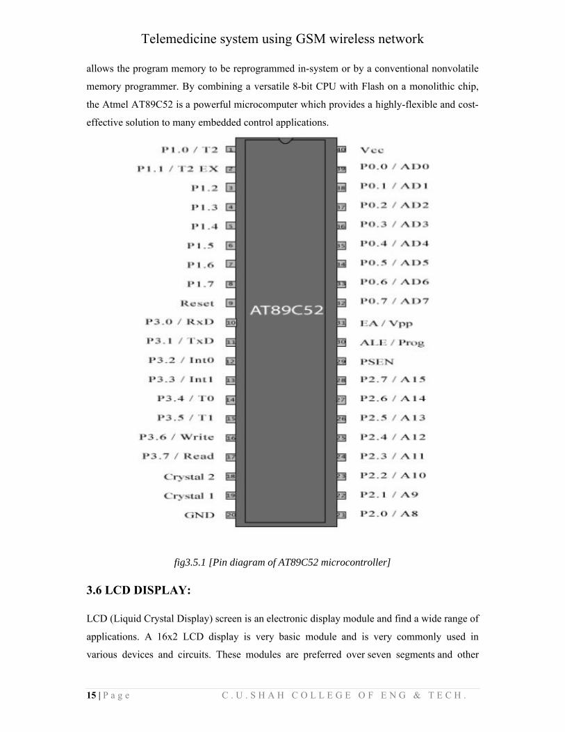
3.5 MICROCONTROLLER (AT89C52):
The AT89C52 is a low-power, high-performance CMOS 8-bit microcomputer with 8K bytes
of Flash programmable and erasable read only memory (PEROM). The device is
manufactured using Atmel’s high-density nonvolatile memory technology and is compatible
with the industry-standard 80C51 and 80C52 instruction set and pinout. The on-chip Flash
Telemedicine system using GSM wireless network
15 | P a g e C . U . S H A H C O L L E G E O F E N G & T E C H .
allows the program memory to be reprogrammed in-system or by a conventional nonvolatile
memory programmer. By combining a versatile 8-bit CPU with Flash on a monolithic chip,
the Atmel AT89C52 is a powerful microcomputer which provides a highly-flexible and cost-
effective solution to many embedded control applications.
fig3.5.1 [Pin diagram of AT89C52 microcontroller]
3.6 LCD DISPLAY:
LCD (Liquid Crystal Display) screen is an electronic display module and find a wide range of
applications. A 16x2 LCD display is very basic module and is very commonly used in
various devices and circuits. These modules are preferred over seven segments and other
Telemedicine system using GSM wireless network
16 | P a g e C . U . S H A H C O L L E G E O F E N G & T E C H .
multi segment LEDs. The reasons being: LCDs are economical; easily programmable; have
no limitation of displaying special & even custom characters (unlike in seven
segments), animations and so on.
A 16x2 LCD means it can display 16 characters per line and there are 2 such lines. In this
LCD each character is displayed in 5x7 pixel matrix. This LCD has two registers, namely,
Command and Data.
The command register stores the command instructions given to the LCD. A command is an
instruction given to LCD to do a predefined task like initializing it, clearing its screen, setting
the cursor position, controlling display etc. The data register stores the data to be displayed
on the LCD. The data is the ASCII value of the character to be displayed on the LCD. Click
to learn more about internal structure of a LCD.
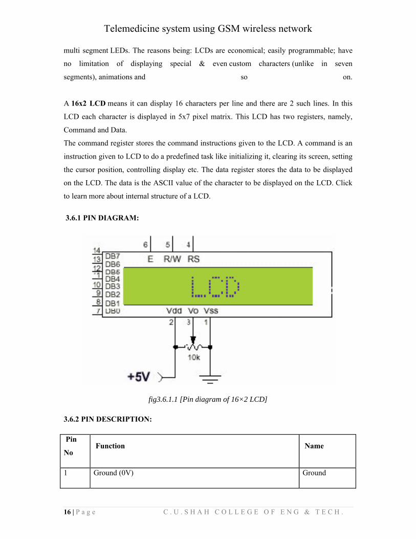
3.6.1 PIN DIAGRAM:
fig3.6.1.1 [Pin diagram of 16×2 LCD]
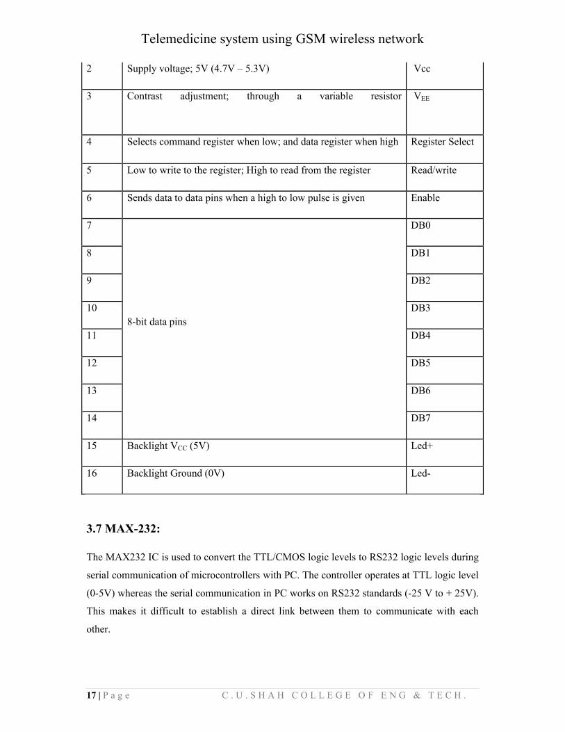
3.6.2 PIN DESCRIPTION:
Pin
NoFunction Name
1 Ground (0V) Ground
Telemedicine system using GSM wireless network
17 | P a g e C . U . S H A H C O L L E G E O F E N G & T E C H .
2 Supply voltage; 5V (4.7V – 5.3V) Vcc
3 Contrast adjustment; through a variable resistor VEE
4 Selects command register when low; and data register when high Register Select
5 Low to write to the register; High to read from the register Read/write
6 Sends data to data pins when a high to low pulse is given Enable
7
8-bit data pins
DB0
8 DB1
9 DB2
10 DB3
11 DB4
12 DB5
13 DB6
14 DB7
15 Backlight VCC (5V) Led+
16 Backlight Ground (0V) Led-
3.7 MAX-232:
The MAX232 IC is used to convert the TTL/CMOS logic levels to RS232 logic levels during
serial communication of microcontrollers with PC. The controller operates at TTL logic level
(0-5V) whereas the serial communication in PC works on RS232 standards (-25 V to + 25V).
This makes it difficult to establish a direct link between them to communicate with each
other.
Telemedicine system using GSM wireless network
18 | P a g e C . U . S H A H C O L L E G E O F E N G & T E C H .
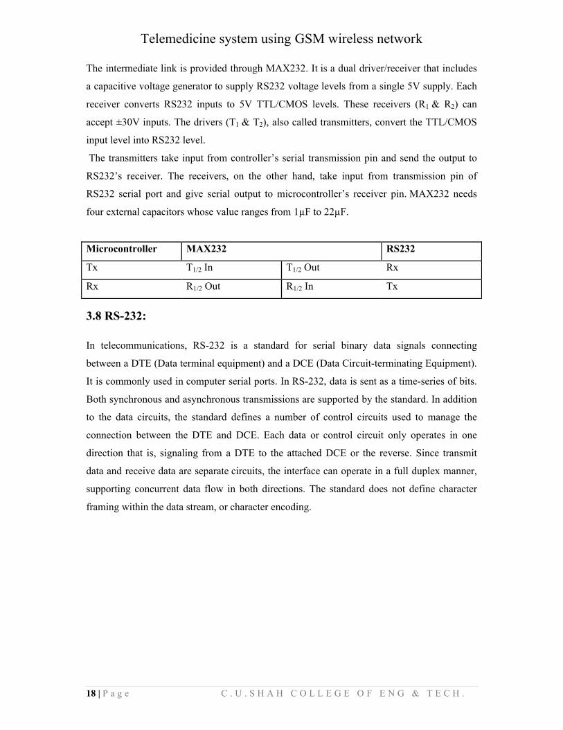
The intermediate link is provided through MAX232. It is a dual driver/receiver that includes
a capacitive voltage generator to supply RS232 voltage levels from a single 5V supply. Each
receiver converts RS232 inputs to 5V TTL/CMOS levels. These receivers (R1 & R2) can
accept ±30V inputs. The drivers (T1 & T2), also called transmitters, convert the TTL/CMOS
input level into RS232 level.
The transmitters take input from controller’s serial transmission pin and send the output to
RS232’s receiver. The receivers, on the other hand, take input from transmission pin of
RS232 serial port and give serial output to microcontroller’s receiver pin. MAX232 needs
four external capacitors whose value ranges from 1µF to 22µF.
Microcontroller MAX232 RS232
Tx T1/2 In T1/2 Out Rx
Rx R1/2 Out R1/2 In Tx
3.8 RS-232:
In telecommunications, RS-232 is a standard for serial binary data signals connecting
between a DTE (Data terminal equipment) and a DCE (Data Circuit-terminating Equipment).
It is commonly used in computer serial ports. In RS-232, data is sent as a time-series of bits.
Both synchronous and asynchronous transmissions are supported by the standard. In addition
to the data circuits, the standard defines a number of control circuits used to manage the
connection between the DTE and DCE. Each data or control circuit only operates in one
direction that is, signaling from a DTE to the attached DCE or the reverse. Since transmit
data and receive data are separate circuits, the interface can operate in a full duplex manner,
supporting concurrent data flow in both directions. The standard does not define character
framing within the data stream, or character encoding.
Telemedicine system using GSM wireless network
19 | P a g e C . U . S H A H C O L L E G E O F E N G & T E C H .
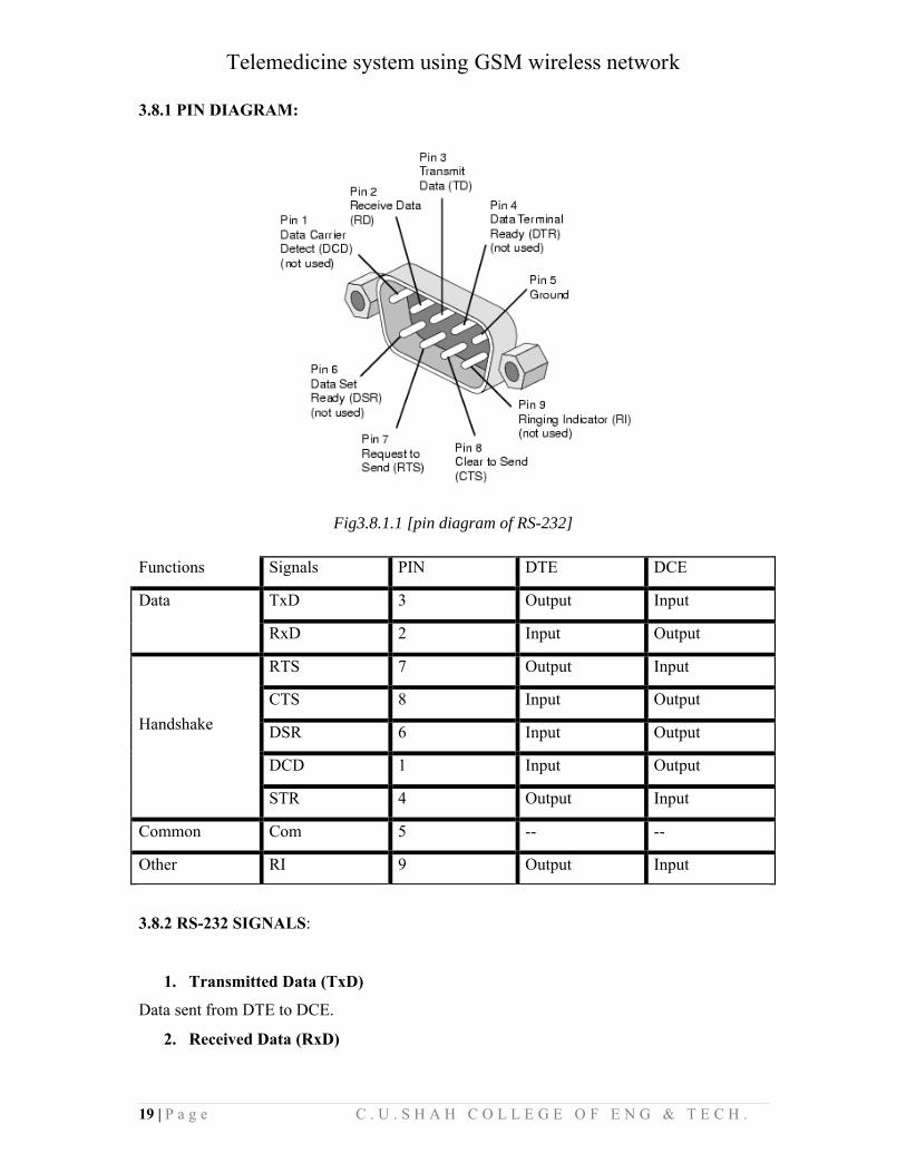
3.8.1 PIN DIAGRAM:
Fig3.8.1.1 [pin diagram of RS-232]
Functions Signals PIN DTE DCE
Data TxD 3 Output Input
RxD 2 Input Output
Handshake
RTS 7 Output Input
CTS 8 Input Output
DSR 6 Input Output
DCD 1 Input Output
STR 4 Output Input
Common Com 5 -- --
Other RI 9 Output Input
3.8.2 RS-232 SIGNALS:
1. Transmitted Data (TxD)
Data sent from DTE to DCE.
2. Received Data (RxD)
Telemedicine system using GSM wireless network
20 | P a g e C . U . S H A H C O L L E G E O F E N G & T E C H .
Data sent from DCE to DTE.
3. Request To Send (RTS)
Asserted (set to 0) by DTE to prepare DCE to receive data. This may require action on the
part of the DCE, e.g. transmitting a carrier or reversing the direction of a half-duplex line.
4. Clear To Send (CTS)
Asserted by DCE to acknowledge RTS and allow DTE to transmit.
5. Data Terminal Ready (DTR)
Asserted by DTE to indicate that it is ready to be connected. If the DCE is a modem, it should
go "off hook" when it receives this signal. If this signal is de-asserted, the modem should
respond by immediately hanging up.
6. Data Set Ready (DSR)
Asserted by DCE to indicate an active connection. If DCE is not a modem (e.g. a null-modem
cable or other equipment), this signal should be permanently asserted (set to 0), possibly by a
jumper to another signal.
7. Carrier Detect (CD)
Asserted by DCE when a connection has been established with remote equipment.
8. Ring Indicator (RI)
Asserted by DCE when it detects a ring signal from the telephone line.
3.8.3 RTS/CTS Handshaking:
The standard RS-232 use of the RTS and CTS lines is asymmetrical. The DTE asserts RTS
to indicate a desire to transmit and the DCE asserts CTS in response to grant permission. This
allows for half-duplex modems that disable their transmitters when not required and must
transmit a synchronization preamble to the receiver when they are re-enabled. There is no
way for the DTE to indicate that it is unable to accept data from the DCE. A non-standard
symmetrical alternative is widely used: CTS indicates permission from the DCE for the DTE
to transmit, and RTS indicates permission from the DTE for the DCE t1o transmit. The
"request to transmit" is implicit and continuous. The standard defines RTS/CTS as the
signaling protocol for flow control for data transmitted from DTE to DCE. The standard has
no provision for flow control in the other direction. In practice, most hardware seems to have
repurposed the RTS signal for this function. A minimal “3-wire” RS-232 connection
consisting only of transmits data, receives data and Ground, and is commonly used when the
full facilities of RS-232 are not required. When only flow control is required, the RTS and
CTS lines are added in a 5-wire version. In our case it was imperative that we connected the
Telemedicine system using GSM wireless network
21 | P a g e C . U . S H A H C O L L E G E O F E N G & T E C H .
RTS line of the microcontroller (DTE) to ground to enable receipt of bit streams from the
modem.
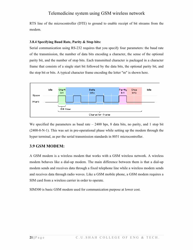
3.8.4 Specifying Baud Rate, Parity & Stop bits:
Serial communication using RS-232 requires that you specify four parameters: the baud rate
of the transmission, the number of data bits encoding a character, the sense of the optional
parity bit, and the number of stop bits. Each transmitted character is packaged in a character
frame that consists of a single start bit followed by the data bits, the optional parity bit, and
the stop bit or bits. A typical character frame encoding the letter "m" is shown here.
We specified the parameters as baud rate – 2400 bps, 8 data bits, no parity, and 1 stop bit
(2400-8-N-1). This was set in pre-operational phase while setting up the modem through the
hyper terminal, as per the serial transmission standards in 8051 microcontroller.
3.9 GSM MODEM:
A GSM modem is a wireless modem that works with a GSM wireless network. A wireless
modem behaves like a dial-up modem. The main difference between them is that a dial-up
modem sends and receives data through a fixed telephone line while a wireless modem sends
and receives data through radio waves. Like a GSM mobile phone, a GSM modem requires a
SIM card from a wireless carrier in order to operate.
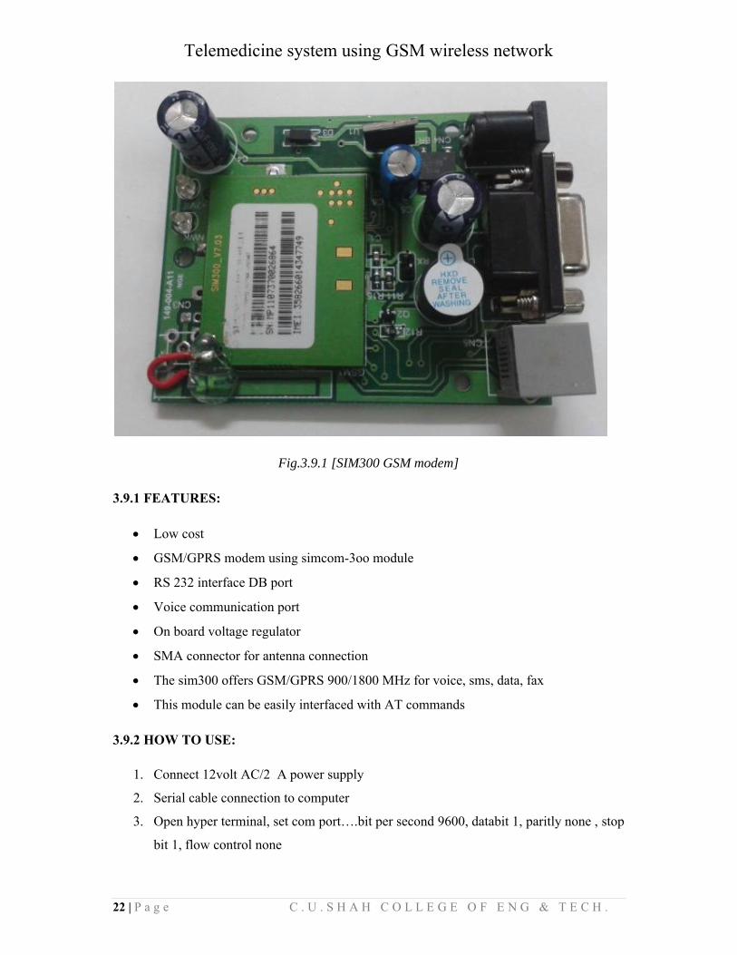
SIM300 is basic GSM modem used for communication purpose at lower cost.
Telemedicine system using GSM wireless network
22 | P a g e C . U . S H A H C O L L E G E O F E N G & T E C H .
Fig.3.9.1 [SIM300 GSM modem]
3.9.1 FEATURES:
Low cost
GSM/GPRS modem using simcom-3oo module
RS 232 interface DB port
Voice communication port
On board voltage regulator
SMA connector for antenna connection
The sim300 offers GSM/GPRS 900/1800 MHz for voice, sms, data, fax
This module can be easily interfaced with AT commands
3.9.2 HOW TO USE:
1. Connect 12volt AC/2 A power supply
2. Serial cable connection to computer
3. Open hyper terminal, set com port….bit per second 9600, databit 1, paritly none , stop
bit 1, flow control none
Telemedicine system using GSM wireless network
23 | P a g e C . U . S H A H C O L L E G E O F E N G & T E C H .
4. Property go setting asch setup, send line end with line feeds tick, append line feeds to
incoming line, end tick.
Computers use AT commands to control modems. Both GSM modems and dial-up modems
support a common set of standard AT commands. GSM modem can be used just like a dial-
up modem. In addition to the standard AT commands, GSM modems support an extended set
of AT commands. These extended AT commands are defined in the GSM standards. With the
extended AT commands, various things can be done:-
Reading, writing and deleting SMS messages.
Sending SMS messages.
Monitoring the signal strength.
Monitoring the charging status and charge level of the battery.
Reading, writing and searching phone book entries.
The number of SMS messages that can be processed by a GSM modem per minute is very
low -- only about six to ten SMS messages per minute.
3.9.3 Accessing GSM MODEM using Microsoft HyperTerminal:
Microsoft HyperTerminal is a small program that comes with Microsoft Windows. We use it
to send AT commands to the GSM modem. It can be found at
Start -> Programs -> Accessories -> Communications -> HyperTerminal.
Before programming our SMS application, it is required to check if the GSM modem and
SIM card are working properly first. The MS HyperTerminal is a handy tool when it comes
to testing the GSM device. It is a good idea to test the GSM devices beforehand.
When a problem occurs, sometimes it is difficult to tell what causes the problem. The cause
can be the program, the GSM device or the SIM card. If GSM device and SIM card with MS
HyperTerminal and they operate properly, then it is very likely that the problem is caused by
the program or other hard wares.
For Linux users, Mincom can be used instead of HyperTerminal.
Telemedicine system using GSM wireless network
24 | P a g e C . U . S H A H C O L L E G E O F E N G & T E C H .
3.9.4 Testing of GSM MODEM:
To use MS HyperTerminal to send AT commands to the GSM modem, the following
procedure is followed:
1. We put a valid SIM card into the GSM modem. We can obtain a SIM card by
subscribing to the GSM service of a wireless network operator.
2. Since in our case the modem drivers were pre installed, we need not to install any such
drivers.
3. Then we start up MS HyperTerminal by selecting Start -> Programs -> Accessories ->
Communications -> HyperTerminal.
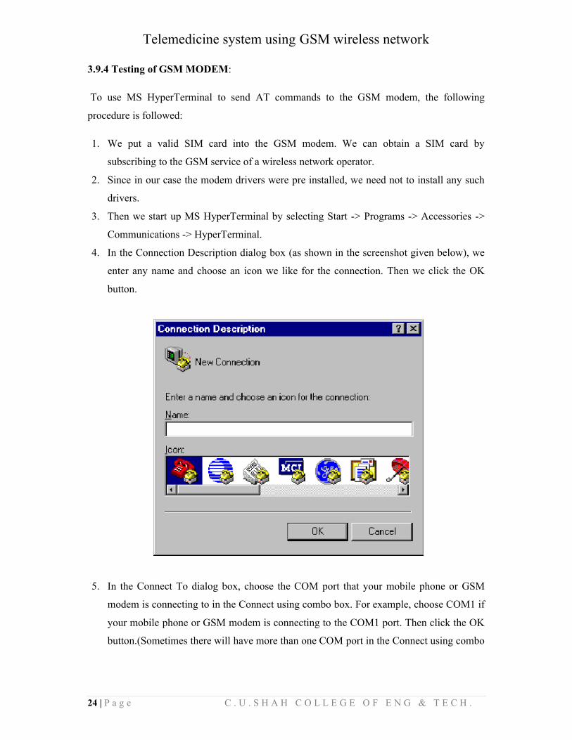
4. In the Connection Description dialog box (as shown in the screenshot given below), we
enter any name and choose an icon we like for the connection. Then we click the OK
button.
5. In the Connect To dialog box, choose the COM port that your mobile phone or GSM
modem is connecting to in the Connect using combo box. For example, choose COM1 if
your mobile phone or GSM modem is connecting to the COM1 port. Then click the OK
button.(Sometimes there will have more than one COM port in the Connect using combo
Telemedicine system using GSM wireless network
25 | P a g e C . U . S H A H C O L L E G E O F E N G & T E C H .
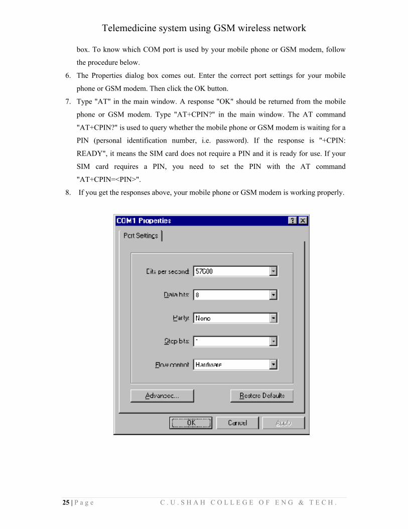
box. To know which COM port is used by your mobile phone or GSM modem, follow
the procedure below.
6. The Properties dialog box comes out. Enter the correct port settings for your mobile
phone or GSM modem. Then click the OK button.
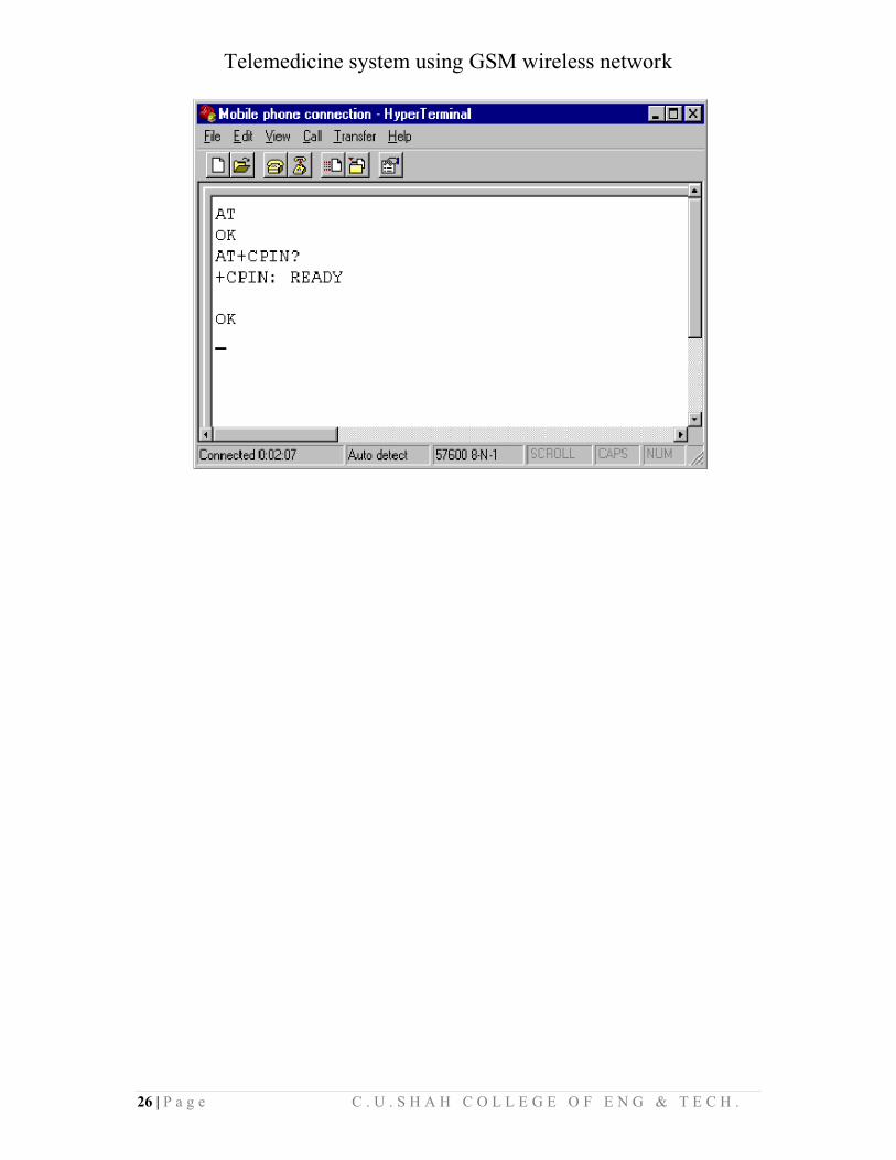
7. Type "AT" in the main window. A response "OK" should be returned from the mobile
phone or GSM modem. Type "AT+CPIN?" in the main window. The AT command
"AT+CPIN?" is used to query whether the mobile phone or GSM modem is waiting for a
PIN (personal identification number, i.e. password). If the response is "+CPIN:
READY", it means the SIM card does not require a PIN and it is ready for use. If your
SIM card requires a PIN, you need to set the PIN with the AT command
"AT+CPIN=<PIN>".
8. If you get the responses above, your mobile phone or GSM modem is working properly.
Telemedicine system using GSM wireless network
26 | P a g e C . U . S H A H C O L L E G E O F E N G & T E C H .
Telemedicine system using GSM wireless network
27 | P a g e C . U . S H A H C O L L E G E O F E N G & T E C H .
CHAPTER-4: INTERFACING
4.1 MICROCONTROLLER – MODEM INTERFACING:
4.1.1 DTE and DCE:
The terms DTE and DCE are very common in the data communications market. DTE is short
for Data Terminal Equipment and DCE stands for Data Communications Equipment. As the
full DTE name indicates this is a piece of device that ends a communication line, whereas the
DCE provides a path for communication.
For example, the PC is a Data Terminal (DTE). The two modems (yours and that one of your
provider) are DCEs, they make the communication between you and your provider possible.
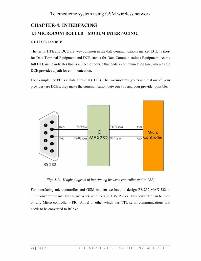
Fig4.1.1.1 [Logic diagram of interfacing between controller and rs-232]
For interfacing microcontroller and GSM modem we have to design RS-232,MAX-232 to
TTL converter board. This board Work with 5V and 3.3V Power. This converter can be used
on any Micro controller - PIC, Atmel or other which has TTL serial communications that
needs to be converted to RS232.
Telemedicine system using GSM wireless network
28 | P a g e C . U . S H A H C O L L E G E O F E N G & T E C H .
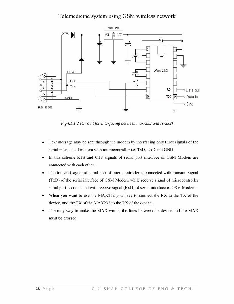
Fig4.1.1.2 [Circuit for Interfacing between max-232 and rs-232]
Text message may be sent through the modem by interfacing only three signals of the
serial interface of modem with microcontroller i.e. TxD, RxD and GND.
In this scheme RTS and CTS signals of serial port interface of GSM Modem are
connected with each other.
The transmit signal of serial port of microcontroller is connected with transmit signal
(TxD) of the serial interface of GSM Modem while receive signal of microcontroller
serial port is connected with receive signal (RxD) of serial interface of GSM Modem.
When you want to use the MAX232 you have to connect the RX to the TX of the
device, and the TX of the MAX232 to the RX of the device.
The only way to make the MAX works, the lines between the device and the MAX
must be crossed.
Telemedicine system using GSM wireless network
29 | P a g e C . U . S H A H C O L L E G E O F E N G & T E C H .
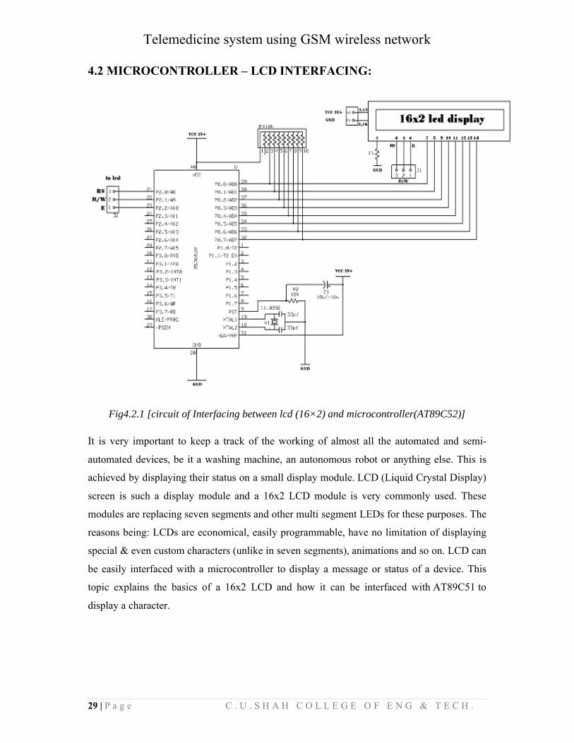
4.2 MICROCONTROLLER – LCD INTERFACING:
Fig4.2.1 [circuit of Interfacing between lcd (16×2) and microcontroller(AT89C52)]
It is very important to keep a track of the working of almost all the automated and semi-
automated devices, be it a washing machine, an autonomous robot or anything else. This is
achieved by displaying their status on a small display module. LCD (Liquid Crystal Display)
screen is such a display module and a 16x2 LCD module is very commonly used. These
modules are replacing seven segments and other multi segment LEDs for these purposes. The
reasons being: LCDs are economical, easily programmable, have no limitation of displaying
special & even custom characters (unlike in seven segments), animations and so on. LCD can
be easily interfaced with a microcontroller to display a message or status of a device. This
topic explains the basics of a 16x2 LCD and how it can be interfaced with AT89C51 to
display a character.
Telemedicine system using GSM wireless network
30 | P a g e C . U . S H A H C O L L E G E O F E N G & T E C H .
4.3 TESTING AND TROUBLESHOTING:
Problem-1: LCD don't responding.
Solution: Here we find that there is voltage reaches at the lcd and controller,
but grounding was not done properly. Than we implement common grounding
between power supply, controller and LCD.
Problem-2: voltage drop after connecting sensing circuit.
Solution: There is voltage drop approximately 1.5v when we connect sensing
circuit with controller. There is a problem regarding to impedance matching. To
overcome this problem we connect 1k resistor between output of sensing circuit
and controller.
Telemedicine system using GSM wireless network
31 | P a g e C . U . S H A H C O L L E G E O F E N G & T E C H .
CHAPTER 5:
5.1 APPLICATIONS:
The project is used to transfer the information from the transmitter side to the receiver side
wirelessly. The project is an advance application of GSM based DISPLAY TOOLKIT.
In our project we are basically focussing on the situation where the where the patient(s) and
the doctor are at the distant location and it is quite necessary to give the details about the
patient(s) heartbeat to the doctor. In this type of situation where the information becomes the
indespensable part of the life this project emerges out as best to acknowledge the doctor with
he correct and the fast information.
Besides this if made certain changes in the project, it can also be used as way of
acknowledging the students of the institutes with the fastest mode of information regarding
certain Notices. Again it is the application of GSM BASED DISPLAY TOOLKIT.
Looking into current trend of information transfer in the campus, it is seen that important
notice take time to be displayed in the notice boards. This latency is not expected in most of
the cases and must be avoided.
Also the electronics displays which are currently used are programmable displays which need
to be reprogrammed each time a new notice comes. The process of reprogramming includes
burning the microcontroller again and again. This makes it inefficient for immediate
information transfer, and thus the display board looses its importance.
5.2 CONCLUSION:
This Project which demonstrates an automated patient monitoring system has its own merits
and demerits which are discussed below:
5.2.1 MERITS:
The wireless alert system using WAP notifies physicians of critical results on their Display
(Cellular Phones can also be used as a display).
1. With online recording of medical parameters, the workload of the case providers and the
nursing staff is reduced.
Telemedicine system using GSM wireless network
32 | P a g e C . U . S H A H C O L L E G E O F E N G & T E C H .
2. The clinical information database contains all data regarding the patients in electronic
form.
3. The patient call switches help emergency situations to be handled quickly.
Future enhancements can be easily implemented with the PLC controller.
5.2.2 DE-MERITS:
1. The heart beat sensor is highly temperature dependent and the dynamic characteristics
change with different levels of ambient light and temperature level.
2. The dual operational amplifier needs a high CMRR and additional narrowband filters are
necessary to attenuate effects of the noise interference.
3. Network Congestion and Noise interference involved, delays the transmission and
reception of the signal, hence delayed observations are obtained.
5.3 FUTURE ENHANCEMENTS:
The entire medical data acquisition could be made wireless and wearable. Such a package
would contain the circuiting for inputs from ECG sensors, EEG sensors, pressure
measurement and pulse rate transducers. This wearable module can transmit the data
continuously over a fiber optic link or through an internet digital radio. The received data can
be stored in separate memory and be processed by a microcontroller. This enhancement will
enable monitoring of patients to be more flexible and strain-free.
In addition to above the following enhancement can also be made:
A graphical LCD can be used to display a graph of the change of heart rate over time.
Sound can be added to the device so that a sound is output each time a pulse is
received.
The maximum and minimum heart rates over a period of time can be displayed.
Serial output can be attached to the device so that the heart rates can be sent to a PC
for further online or offline analysis.

Telemedicine system using GSM wireless network
33 | P a g e C . U . S H A H C O L L E G E O F E N G & T E C H .
5.4 REFFERENCES:
WWW.SCRIBE.COM
WWW.ENGINEERSGARAGE.COM
WWW.EMBEDED.COM
WWW.ALLDATASHEET.COM
BOOK:
8051-MICROCONTROLLER AND PROGRAMMING-MAZIDI