int-gsm - satel.eu
TRANSCRIPT
INT-GSM
GPRS communication module
Firmware version 1.02 int-gsm_en 11/20
SATEL sp. z o.o. • ul. Budowlanych 66 • 80-298 Gdańsk • POLAND tel. +48 58 320 94 00
www.satel.eu
IMPORTANT
The module should be installed by qualified personnel.
Prior to installation, please read carefully this manual in order to avoid mistakes that can lead to malfunction or even damage to the equipment.
Disconnect power before making any electrical connections.
Changes, modifications or repairs not authorized by the manufacturer shall void your rights under the warranty.
The name plate of the device is located on the enclosure base.
FreeRTOS is used in this device (www.freertos.org).
SATEL aims to continually improve the quality of its products, which may result in changes in
their technical specifications and software. Current information about the changes being introduced is available on our website.
Please visit us: http://support.satel.eu
Hereby, SATEL sp. z o.o. declares that the radio equipment type INT-GSM is in compliance with Directive 2014/53/EU. The full text of the EU declaration of conformity is available at the following internet address: www.satel.eu/ce
The following symbols may be used in this manual:
- note,
- caution.
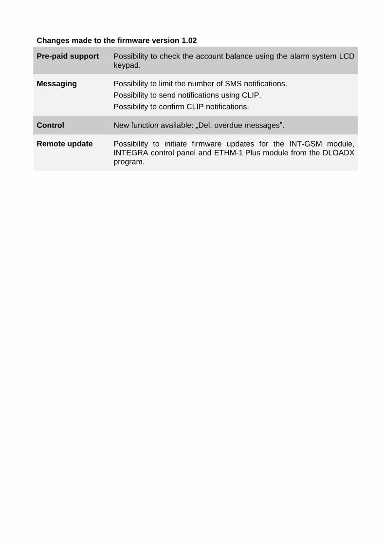
Changes made to the firmware version 1.02
Pre-paid support Possibility to check the account balance using the alarm system LCD keypad.
Messaging Possibility to limit the number of SMS notifications.
Possibility to send notifications using CLIP.
Possibility to confirm CLIP notifications.
Control New function available: „Del. overdue messages”.
Remote update Possibility to initiate firmware updates for the INT-GSM module, INTEGRA control panel and ETHM-1 Plus module from the DLOADX program.
2 INT-GSM SATEL
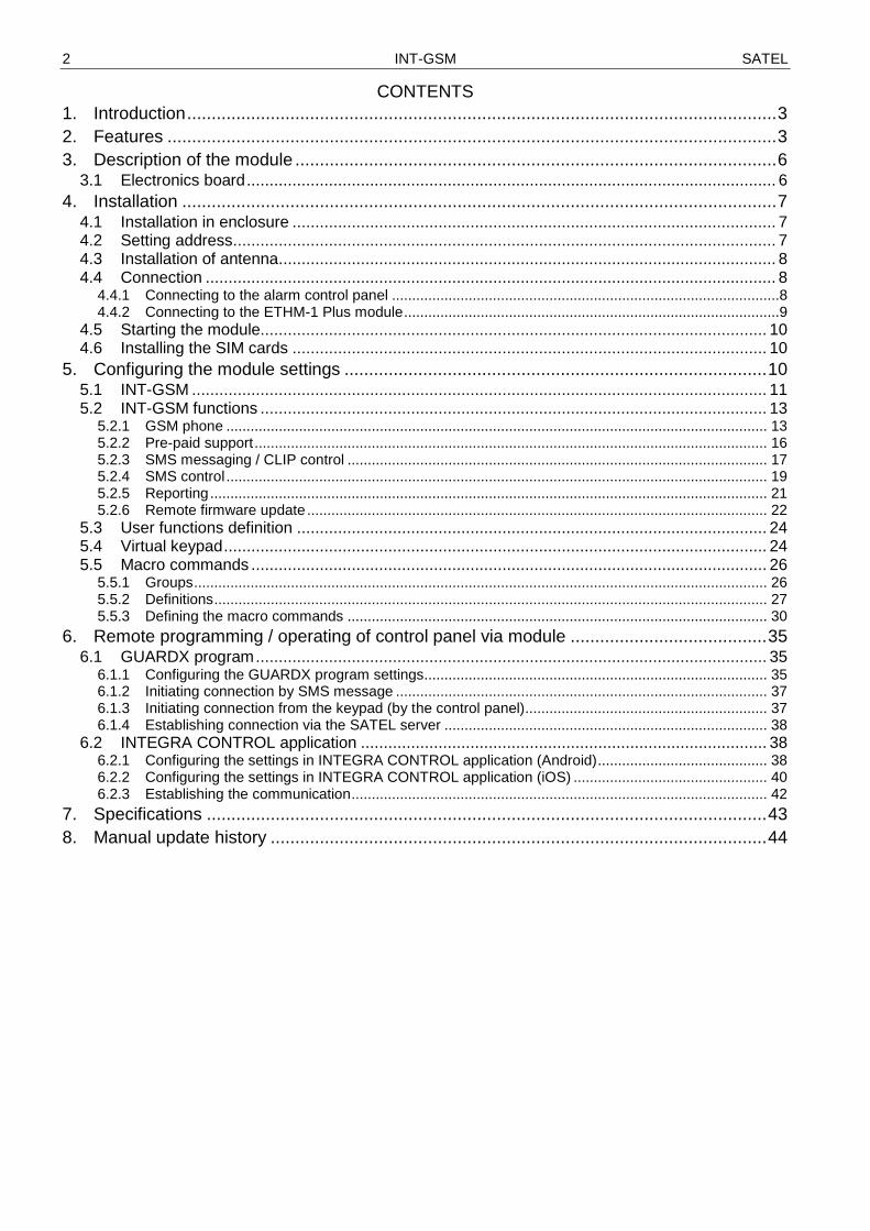
CONTENTS
1. Introduction ........................................................................................................................ 3
2. Features ............................................................................................................................ 3
3. Description of the module .................................................................................................. 6 3.1 Electronics board .................................................................................................................... 6
4. Installation ......................................................................................................................... 7 4.1 Installation in enclosure .......................................................................................................... 7 4.2 Setting address ....................................................................................................................... 7 4.3 Installation of antenna ............................................................................................................. 8 4.4 Connection ............................................................................................................................. 8
4.4.1 Connecting to the alarm control panel ................................................................................................8 4.4.2 Connecting to the ETHM-1 Plus module .............................................................................................9
4.5 Starting the module............................................................................................................... 10 4.6 Installing the SIM cards ........................................................................................................ 10
5. Configuring the module settings ...................................................................................... 10 5.1 INT-GSM .............................................................................................................................. 11 5.2 INT-GSM functions ............................................................................................................... 13
5.2.1 GSM phone ...................................................................................................................................... 13 5.2.2 Pre-paid support ............................................................................................................................... 16 5.2.3 SMS messaging / CLIP control ........................................................................................................ 17 5.2.4 SMS control ...................................................................................................................................... 19 5.2.5 Reporting .......................................................................................................................................... 21 5.2.6 Remote firmware update .................................................................................................................. 22
5.3 User functions definition ....................................................................................................... 24 5.4 Virtual keypad ....................................................................................................................... 24 5.5 Macro commands ................................................................................................................. 26
5.5.1 Groups .............................................................................................................................................. 26 5.5.2 Definitions ......................................................................................................................................... 27 5.5.3 Defining the macro commands ........................................................................................................ 30
6. Remote programming / operating of control panel via module ........................................ 35 6.1 GUARDX program ................................................................................................................ 35
6.1.1 Configuring the GUARDX program settings..................................................................................... 35 6.1.2 Initiating connection by SMS message ............................................................................................ 37 6.1.3 Initiating connection from the keypad (by the control panel)............................................................ 37 6.1.4 Establishing connection via the SATEL server ................................................................................ 38
6.2 INTEGRA CONTROL application ......................................................................................... 38 6.2.1 Configuring the settings in INTEGRA CONTROL application (Android) .......................................... 38 6.2.2 Configuring the settings in INTEGRA CONTROL application (iOS) ................................................ 40 6.2.3 Establishing the communication ....................................................................................................... 42
7. Specifications .................................................................................................................. 43
8. Manual update history ..................................................................................................... 44
SATEL INT-GSM 3
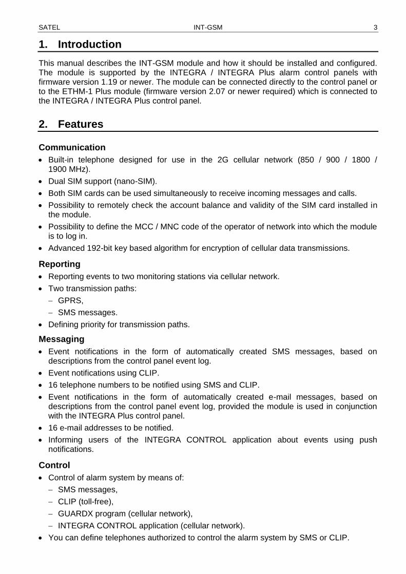
1. Introduction
This manual describes the INT-GSM module and how it should be installed and configured. The module is supported by the INTEGRA / INTEGRA Plus alarm control panels with firmware version 1.19 or newer. The module can be connected directly to the control panel or to the ETHM-1 Plus module (firmware version 2.07 or newer required) which is connected to the INTEGRA / INTEGRA Plus control panel.
2. Features
Communication
Built-in telephone designed for use in the 2G cellular network (850 / 900 / 1800 / 1900 MHz).
Dual SIM support (nano-SIM).
Both SIM cards can be used simultaneously to receive incoming messages and calls.
Possibility to remotely check the account balance and validity of the SIM card installed in the module.
Possibility to define the MCC / MNC code of the operator of network into which the module is to log in.
Advanced 192-bit key based algorithm for encryption of cellular data transmissions.
Reporting
Reporting events to two monitoring stations via cellular network.
Two transmission paths:
GPRS,
SMS messages.
Defining priority for transmission paths.
Messaging
Event notifications in the form of automatically created SMS messages, based on descriptions from the control panel event log.
Event notifications using CLIP.
16 telephone numbers to be notified using SMS and CLIP.
Event notifications in the form of automatically created e-mail messages, based on descriptions from the control panel event log, provided the module is used in conjunction with the INTEGRA Plus control panel.
16 e-mail addresses to be notified.
Informing users of the INTEGRA CONTROL application about events using push notifications.
Control
Control of alarm system by means of:
SMS messages,
CLIP (toll-free),
GUARDX program (cellular network),
INTEGRA CONTROL application (cellular network).
You can define telephones authorized to control the alarm system by SMS or CLIP.
4 INT-GSM SATEL
You can indicate the control functions available from any telephone.
INTEGRA CONTROL mobile application
Operating the alarm system from mobile devices:
control of the alarm system,
checking the alarm system status.
Configuring the alarm system from mobile devices.
Communication between the INTEGRA CONTROL application and the module can be established simply and easily with the SATEL connection setup service.
Configuring the alarm system
Remote configuration of the alarm system from a computer with DLOADX program installed (data transfer via cellular network).
Managing the alarm system
Remote managing of the alarm system from a computer with GUARDX program installed (data transfer via cellular network).
Module firmware update
Updating the firmware via a computer connected to the RS-232 port of the control panel.
Updating the firmware via cellular network using the UPSERV update server (remote update).
Interaction with the ETHM-1 Plus Ethernet module
Cellular network used as backup communication path for Ethernet network.
Defining priority for different paths of event reporting (Ethernet, cellular data and SMS).
Dual Path Reporting compliant with EN 50136.
Electronics board
RS-485 port to enable connection of INT-GSM module to ETHM-1 Plus module.
Communication bus for connection of INT-GSM module to keypad bus of the alarm control panel.
RS-232 port to allow:
connection to the RS-232 port of the alarm control panel (required for remote configuration from the DLOADX program and recommended for remote administration from the GUARDX program),
computer to be connected for the module firmware update.
LEDs indicating the module status.
Powering with 12 V DC (±15%).
SATEL INT-GSM 5
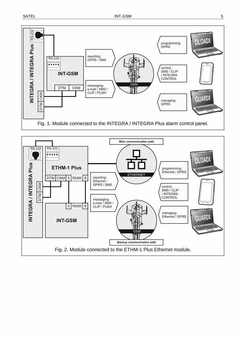
Fig. 1. Module connected to the INTEGRA / INTEGRA Plus alarm control panel.
Fig. 2. Module connected to the ETHM-1 Plus Ethernet module.
6 INT-GSM SATEL
3. Description of the module
3.1 Electronics board
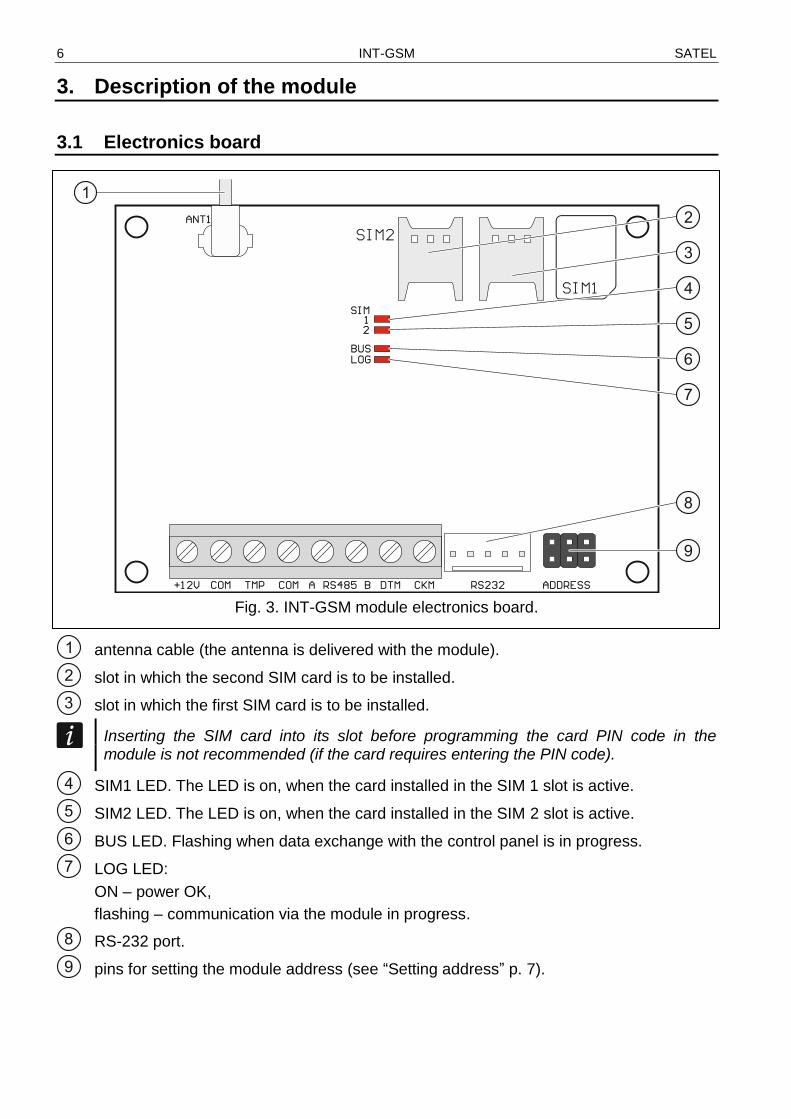
Fig. 3. INT-GSM module electronics board.
antenna cable (the antenna is delivered with the module).
slot in which the second SIM card is to be installed.
slot in which the first SIM card is to be installed.
Inserting the SIM card into its slot before programming the card PIN code in the module is not recommended (if the card requires entering the PIN code).
SIM1 LED. The LED is on, when the card installed in the SIM 1 slot is active.
SIM2 LED. The LED is on, when the card installed in the SIM 2 slot is active.
BUS LED. Flashing when data exchange with the control panel is in progress.
LOG LED:
ON – power OK,
flashing – communication via the module in progress.
RS-232 port.
pins for setting the module address (see “Setting address” p. 7).
SATEL INT-GSM 7
Description of terminals
+12V – power input (12 V DC ±15%).
COM – common ground.
TMP – tamper input (NC) – if not used, it should be shorted to common ground.
A RS485 B – RS-485 port for connection with the ETHM-1 Plus module.
DTM – data (communication bus).
CKM – clock (communication bus).
4. Installation
Disconnect power before making any electrical connections.
It is not advisable to power up the module if the antenna is not connected.
The installation to which the module is to be connected should be provided with:
2-pole disconnector,
short-circuit protection with a 16 A time delay circuit breaker.
The INT-GSM module should be installed indoors, in spaces with normal air humidity. When selecting the mounting location, remember that thick masonry walls, metal partitions, etc. will reduce the range of radio signal. It is not advisable to install the module in close vicinity to electrical installations, because this can result in malfunctioning of the device.
4.1 Installation in enclosure
The enclosure in which the module is to be installed shall meet the requirements for fireproof enclosures.
If the module is to be directly connected to the alarm control panel, it should be installed in the same enclosure with the control panel. This will facilitate connecting the RS-232 ports of control panel and module.
1. Secure the module electronics board in the enclosure.
2. If the module is to supervise the enclosure tamper switch, connect the tamper switch wires to the TMP and COM terminals. Otherwise, connect the TMP terminal to the module COM terminal.
4.2 Setting address
Setting the address is required if the module will be connected to the keypad bus of the alarm control panel. If the INT-GSM module will be connected to the ETHM-1 Plus module, you do not have to set the address.
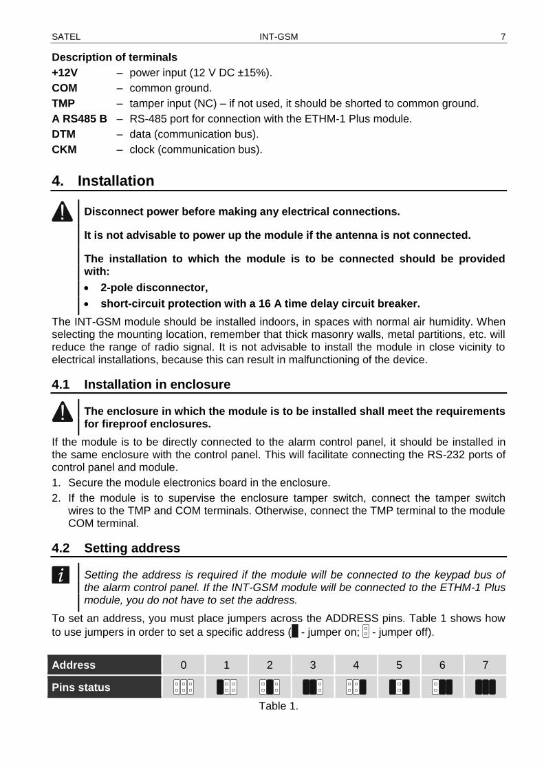
To set an address, you must place jumpers across the ADDRESS pins. Table 1 shows how
to use jumpers in order to set a specific address ( - jumper on; - jumper off).
Address 0 1 2 3 4 5 6 7
Pins status
Table 1.
8 INT-GSM SATEL
Set an address in the module within the range:
from 0 to 3, if it is connected to INTEGRA 24 or INTEGRA 32 control panel,
from 0 to 7, if it is connected to another INTEGRA or INTEGRA Plus control panel.
The address set must be different from that in the other devices connected to the keypad bus of the control panel (the control panel does not support devices with the same address).
4.3 Installation of antenna
The INT-GSM module is delivered with an antenna. The antenna can be replaced with another antenna mounted on the enclosure or at some distance from it. If this is the case, you will need the IPX-SMA adapter.
Using the antenna mounted at some distance from the enclosure is recommended wherever thick masonry walls, metal partitions etc. may decrease the range of radio signal at the module installation place.
The antenna must not be installed in parallel to low-voltage electrical wires, or it can affect performance of the antenna.
4.4 Connection
The module can be connected directly to the alarm control panel or to the ETHM-1 Plus module. It is recommended that unshielded non-twisted cable to be used.
4.4.1 Connecting to the alarm control panel
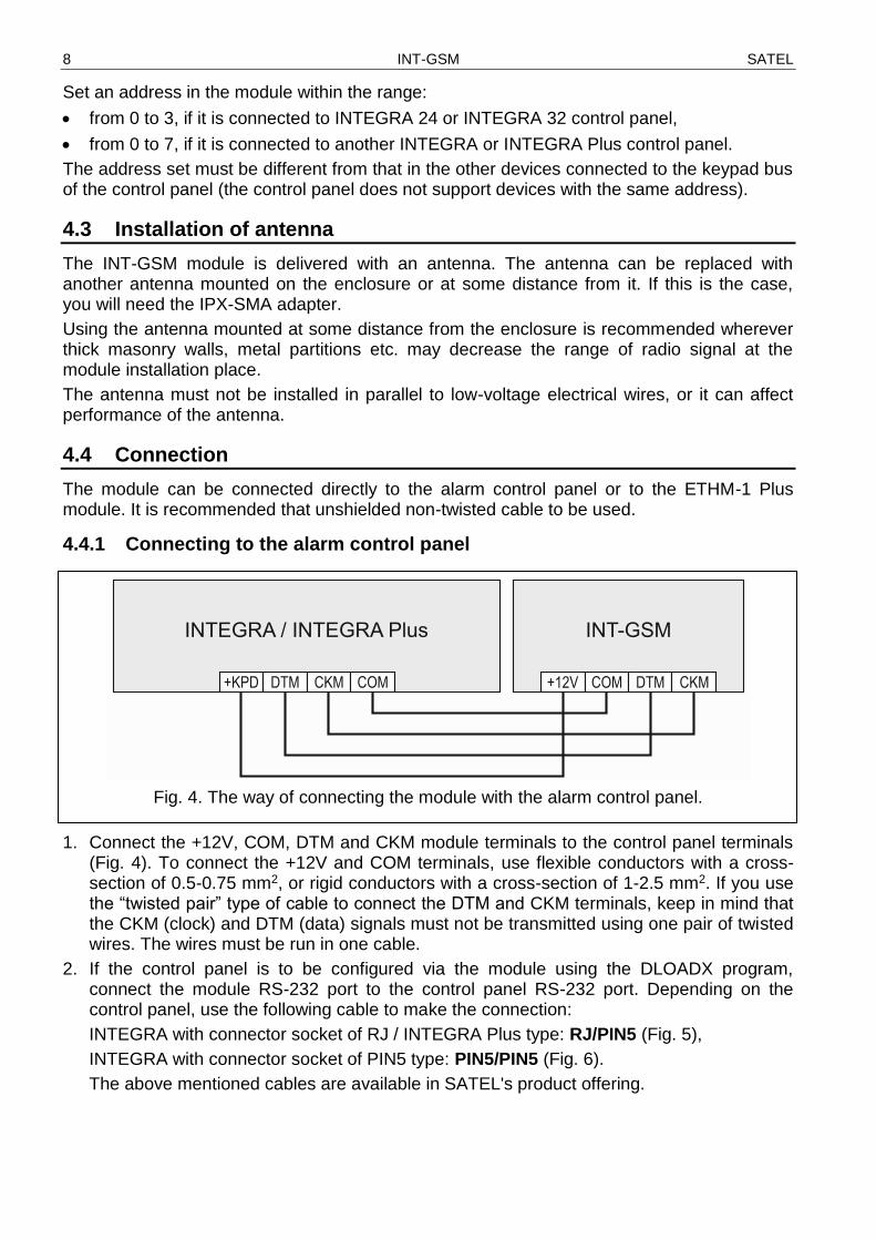
Fig. 4. The way of connecting the module with the alarm control panel.
1. Connect the +12V, COM, DTM and CKM module terminals to the control panel terminals
(Fig. 4). To connect the +12V and COM terminals, use flexible conductors with a cross-section of 0.5-0.75 mm2, or rigid conductors with a cross-section of 1-2.5 mm2. If you use the “twisted pair” type of cable to connect the DTM and CKM terminals, keep in mind that the CKM (clock) and DTM (data) signals must not be transmitted using one pair of twisted wires. The wires must be run in one cable.
2. If the control panel is to be configured via the module using the DLOADX program, connect the module RS-232 port to the control panel RS-232 port. Depending on the control panel, use the following cable to make the connection:
INTEGRA with connector socket of RJ / INTEGRA Plus type: RJ/PIN5 (Fig. 5),
INTEGRA with connector socket of PIN5 type: PIN5/PIN5 (Fig. 6).
The above mentioned cables are available in SATEL's product offering.
SATEL INT-GSM 9
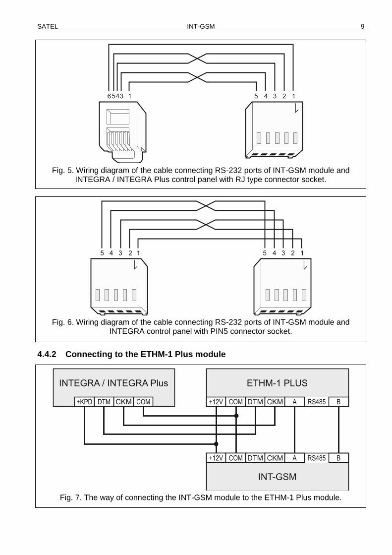
Fig. 5. Wiring diagram of the cable connecting RS-232 ports of INT-GSM module and INTEGRA / INTEGRA Plus control panel with RJ type connector socket.
Fig. 6. Wiring diagram of the cable connecting RS-232 ports of INT-GSM module and INTEGRA control panel with PIN5 connector socket.
4.4.2 Connecting to the ETHM-1 Plus module
Fig. 7. The way of connecting the INT-GSM module to the ETHM-1 Plus module.
10 INT-GSM SATEL
If the module is to be used in conjunction with the ETHM-1 Plus module (firmware version 2.07 or newer required), connections between the modules and the control panel must be made as shown in Fig. 7.
4.5 Starting the module
1. Power up the alarm system.
2. Start the identification function in the control panel (see the control panel installer manual). If the module is connected to the alarm control panel, it will be identified as “INT-GSM”. If the module is connected to the ETHM-1 Plus module, “ETHM+-GSM” (instead of “ETHM-1”) will appear on the list of devices.
3. Configure the module (see „Configuring the module settings”). If PIN code(s) is / are required by the SIM card(s), use the DLOADX program to program the code(s) (see p. 13).
4.6 Installing the SIM cards
You can install up to two nano-SIM cards in the module.
1. Power down the alarm system.
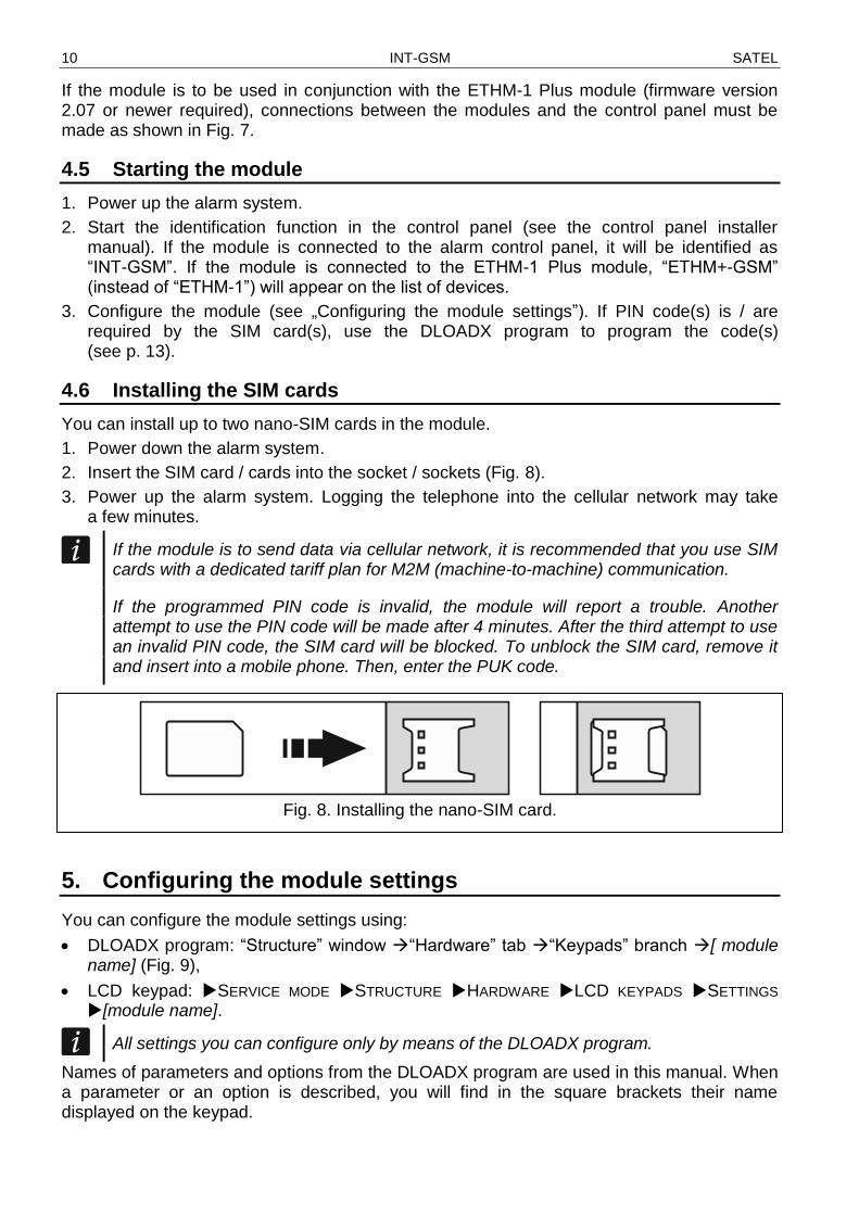
2. Insert the SIM card / cards into the socket / sockets (Fig. 8).
3. Power up the alarm system. Logging the telephone into the cellular network may take a few minutes.
If the module is to send data via cellular network, it is recommended that you use SIM cards with a dedicated tariff plan for M2M (machine-to-machine) communication.
If the programmed PIN code is invalid, the module will report a trouble. Another attempt to use the PIN code will be made after 4 minutes. After the third attempt to use an invalid PIN code, the SIM card will be blocked. To unblock the SIM card, remove it and insert into a mobile phone. Then, enter the PUK code.
Fig. 8. Installing the nano-SIM card.
5. Configuring the module settings
You can configure the module settings using:
DLOADX program: “Structure” window “Hardware” tab “Keypads” branch [ module name] (Fig. 9),
LCD keypad: SERVICE MODE STRUCTURE HARDWARE LCD KEYPADS SETTINGS [module name].
All settings you can configure only by means of the DLOADX program.
Names of parameters and options from the DLOADX program are used in this manual. When a parameter or an option is described, you will find in the square brackets their name displayed on the keypad.
SATEL INT-GSM 11
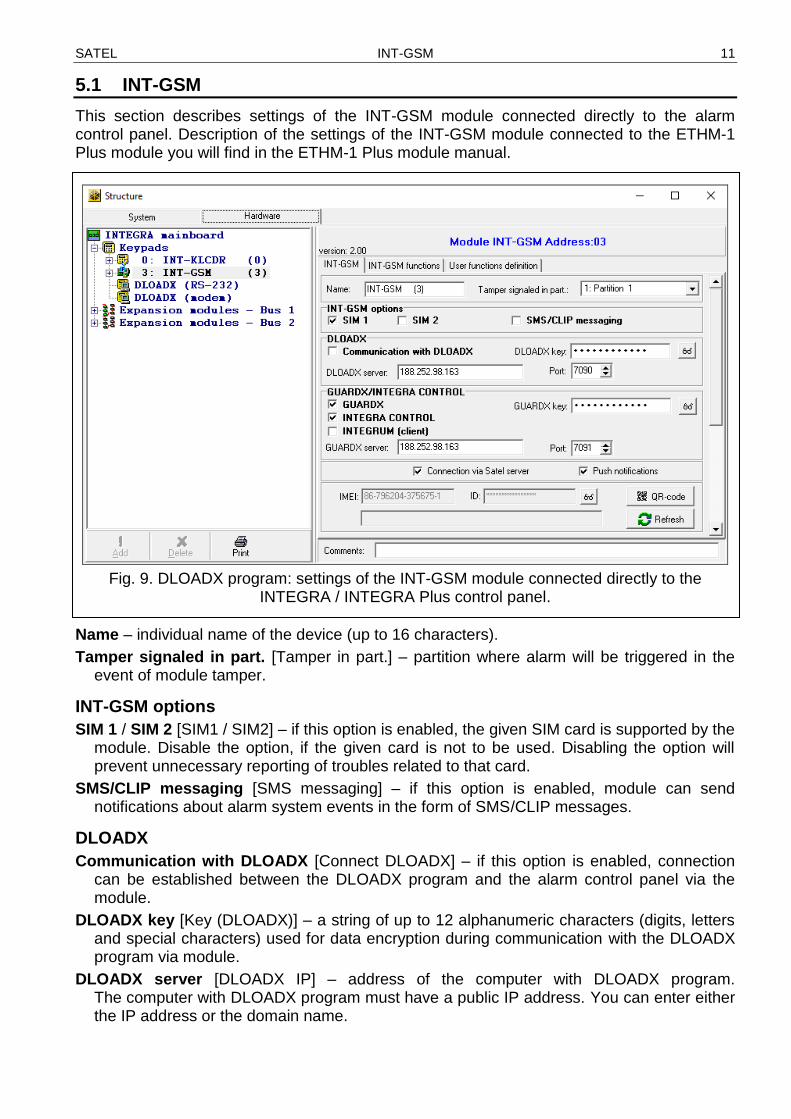
5.1 INT-GSM
This section describes settings of the INT-GSM module connected directly to the alarm control panel. Description of the settings of the INT-GSM module connected to the ETHM-1 Plus module you will find in the ETHM-1 Plus module manual.
Fig. 9. DLOADX program: settings of the INT-GSM module connected directly to the INTEGRA / INTEGRA Plus control panel.
Name – individual name of the device (up to 16 characters).
Tamper signaled in part. [Tamper in part.] – partition where alarm will be triggered in the event of module tamper.
INT-GSM options
SIM 1 / SIM 2 [SIM1 / SIM2] – if this option is enabled, the given SIM card is supported by the module. Disable the option, if the given card is not to be used. Disabling the option will prevent unnecessary reporting of troubles related to that card.
SMS/CLIP messaging [SMS messaging] – if this option is enabled, module can send notifications about alarm system events in the form of SMS/CLIP messages.
DLOADX
Communication with DLOADX [Connect DLOADX] – if this option is enabled, connection can be established between the DLOADX program and the alarm control panel via the module.
DLOADX key [Key (DLOADX)] – a string of up to 12 alphanumeric characters (digits, letters and special characters) used for data encryption during communication with the DLOADX
program via module.
DLOADX server [DLOADX IP] – address of the computer with DLOADX program. The computer with DLOADX program must have a public IP address. You can enter either the IP address or the domain name.
12 INT-GSM SATEL
In the LCD keypad, the function for programming address of the computer with DLOADX program is available in the user menu, CHANGE OPTIONS submenu (available to service and administrators).
Port [Port (DLOADX)] – number of the TCP port used for communication with the DLOADX
program. You can enter values from 1 to 65535. The value must be different from that entered for the other ports. Default value: 7090.
GUARDX / INTEGRA CONTROL
GUARDX [Connect GUARDX] – if this option is enabled, connection can be established between the GUARDX program and the alarm control panel via the module. The option is not available when the “INTEGRUM (client)” option is enabled.
INTEGRA CONTROL [Connect GSM] – if this option is enabled, connection can be established between the INTEGRA CONTROL application and the alarm control panel via the module. The connection is set up by the SATEL server. The option is not available when the “INTEGRUM (client)” option is enabled.
INTEGRUM (client) [INTEGRUM] – if this option is enabled, connection can be established between the INTEGRUM system (version 2.0 or newer) and the alarm control panel via the module. When the option is enabled, the “GUARDX” and “INTEGRA CONTROL” options are not available (the module does not support the GUARDX program / INTEGRA CONTROL application).
GUARDX server [GUARDX IP] – address of the computer with GUARDX program or the INTEGRUM server The computer with GUARDX program / INTEGRUM server must have a public IP address. For the computer with GUARDX program, you can enter the IP address or domain name. For the INTEGRUM system server, enter the domain name (e.g. integrum.ip.com).
In the LCD keypad, the function for programming address of the computer with GUARDX program / INTEGRUM system server is available in the user menu, CHANGE
OPTIONS submenu (available to service and administrators).
GUARDX key [Key (others)] – a string of up to 12 alphanumeric characters (digits, letters and special characters) used for data encryption during communication with:
GUARDX program,
INTEGRA CONTROL application,
INTEGRUM system.
Port [Port (others)] – number of the TCP port used for communication with:
GUARDX program,
INTEGRA CONTROL application,
INTEGRUM system.
You can enter values from 1 to 65535. The value must be different from that entered for the other ports. Default value: 7091.
SATEL server
Connection via Satel server [SATEL server] – if this option is enabled, connection can be established via the SATEL server (Connection Setup Service).
Push notifications [PUSH messages] – if this option is enabled, the INTEGRA CONTROL application can provide information about alarm system events by means of push notifications. The option is available if communication with SATEL server is enabled in the module.
SATEL INT-GSM 13
Information
IMEI – individual identification number of the module cellular phone.
ID – individual ID number for the purposes of communication through the SATEL server. The number is assigned automatically by the SATEL server during the first connection to
the server (before the number is assigned, “F” characters are displayed). Click to see the number.
If the module is to be used in another alarm system, the hitherto used ID number must be deleted. You should do it after connecting the module to the new control panel and establishing connection with the SATEL server, using the CHANGE ID function available from the keypad (SERVICE MODE STRUCTURE HARDWARE LCD KEYPADS
SETTINGS [module name] CHANGE ID). Having deleted the old ID number, the module will receive a new one. The INTEGRA CONTROL applications using the old ID number will be unable to connect to the control panel.
[Cellular network signal] – information about cellular signal level.
– click the button to open the window in which the QR code is displayed. The QR code contains information required when configuring settings of communication through the SATEL server. You can read the QR code by using a mobile device or export to the file and transmit to the users. The QR code facilitates configuring the INTEGRA CONTROL application settings.
Refresh – click to refresh all information.
5.2 INT-GSM functions
The settings configured in the “INT-GSM functions” tab are stored in the module memory. Before starting configuration, click on the “Read” button, and after completing it, click on the “Write” button. These settings will not be read / written after you click on
the button in the main menu of DLOADX program.
Buttons
Read – click to read the settings from the module.
Write – click to write the settings to the module.
Quit – click to cancel reading or writing the settings.
Reset – click to delete the settings (and restore factory default settings).
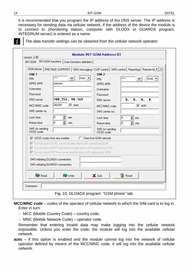
5.2.1 GSM phone
SIM 1 / SIM 2
PIN – PIN code of the SIM card.
If an incorrectly programmed PIN code is used, the module will report a trouble. After the third attempt to use a wrong PIN code, the SIM card will be blocked. To unblock the SIM card, remove it and insert into a mobile phone. Then, enter the PUK code.
[Preferred network type] – do not configure.
GPRS APN – access point name for Internet GPRS connection.
Username – user name for Internet GPRS connection.
Password – password for Internet GPRS connection.
DNS server – IP address of DNS server to be used by the module. If the address has been saved by the operator to the SIM card memory, you do not have to program it. Otherwise,
14 INT-GSM SATEL
it is recommended that you program the IP address of the DNS server. The IP address is necessary for sending data via cellular network, if the address of the device the module is to connect to (monitoring station, computer with DLODX or GUARDX program, INTEGRUM server) is entered as a name.
The data transfer settings can be obtained from the cellular network operator.
Fig. 10. DLOADX program: “GSM phone” tab.
MCC/MNC code – codes of the operator of cellular network to which the SIM card is to log in.
Enter in turn:
MCC (Mobile Country Code) – country code,
MNC (Mobile Network Code) – operator code.
Remember that entering invalid data may make logging into the cellular network impossible. Unless you enter the code, the module will log into the available cellular network.
auto – if this option is enabled and the module cannot log into the network of cellular operator defined by means of the MCC/MNC code, it will log into the available cellular network.

SATEL INT-GSM 15
SMS center number – telephone number of the short message service center. It is required if the module is to send / receive SMS messages. It is usually stored in the SIM card and you do not have to program it. If the number is not stored in the SIM card, enter the number required by the SIM card operator.
Lock time – the time during which switch-over to the other SIM card is impossible. The time is counted from the moment of switch-over to the given card. For reporting, the transmission paths programmed as subsequent ones, if they require switch-over to the other card, will be skipped during the lock time countdown. Entering the value 0 means that instant switch-over to the other SIM card is possible.
Return time – the time after which the other SIM card is to be used. Entering the value 0 means that automatic switch-over to the other SIM card will not take place.
If two SIM cards are to be used, one of them must be treated as the priority card. It is recommended that return time equal to 0 be programmed for it.
SMS for sending USSD code – control command that will be sent in the SMS message together with USSD code. The control panel will run the USSD code and send the response received from the operator to the phone number from which the SMS message with control command was sent. You can enter up to 16 alphanumeric characters (digits, letters and special characters).
The command content must be different from that of the other control commands.
The SMS message with the USSD code must look like this: “xxxxxx=yyyy=”, where: “xxxxxx” - control command, “yyyy” – USSD code supported by the GSM network operator.
It is not advisable to use the advanced functions available due to the USSD service if menu is presented in response to the entered code.
The control command for sending USSD codes can be used for sending SMS messages through the control panel.
USSD codes from any number – if this option is enabled, the control command for sending the USSD codes or checking the SIM card balance (see “Check balance SMS” p. 16) can be sent from any telephone. If the option is disabled, the command can only be sent from the telephone whose number is stored in the module (see “SMS messaging / CLIP control” p. 17).
Time from GSM network – if this option is enabled, the control panel clock can be synchronized with the time of the cellular network operator.
Do not report SATEL server trouble when LAN replaced by GSM – the option is available if the INT-GSM module is connected to the ETHM-1 Plus module. If this option is enabled, loss of connection with the SATEL server via the Ethernet network will not be reported, when the connection has been successfully established via the INT-GSM module (cellular data transmission).
Do not report SMTP mail server trouble when LAN replaced by GSM – the option is available if the INT-GSM module is connected to the ETHM-1 Plus module. If this option is enabled, loss of connection with the SMTP server via the Ethernet network will not be reported, when the connection has been successfully established via the INT-GSM module (cellular data transmission).
Do not report NTP time server trouble when LAN replaced by GSM – the option is available if the INT-GSM module is connected to the ETHM-1 Plus module. If this option is enabled, loss of connection with the NTP server via the Ethernet network will not be
16 INT-GSM SATEL
reported, when the connection has been successfully established via the INT-GSM module (cellular data transmission).
SMS
SMS initiating DLOADX connection – the control command which, if sent in the SMS message, will initiate communication between the alarm control panel and the DLOADX program via:
INT-GSM module connected to the control panel (cellular data transmission),
ETHM-1 Plus module to which the INT-GSM module is connected (Ethernet). If connection cannot be established over Ethernet, an attempt will be made to establish communication via cellular network.
You can enter up to 16 alphanumeric characters (digits, letters and special characters).
SMS initiating GUARDX connection – the control command which, if sent in the SMS message, will initiate connection between the alarm control panel and the GUARDX program via:
INT-GSM module connected to the control panel (cellular data transmission),
ETHM-1 Plus module to which the INT-GSM module is connected (Ethernet). If connection cannot be established over Ethernet, an attempt will be made to establish communication via cellular network.
You can enter up to 16 alphanumeric characters (digits, letters and special characters).
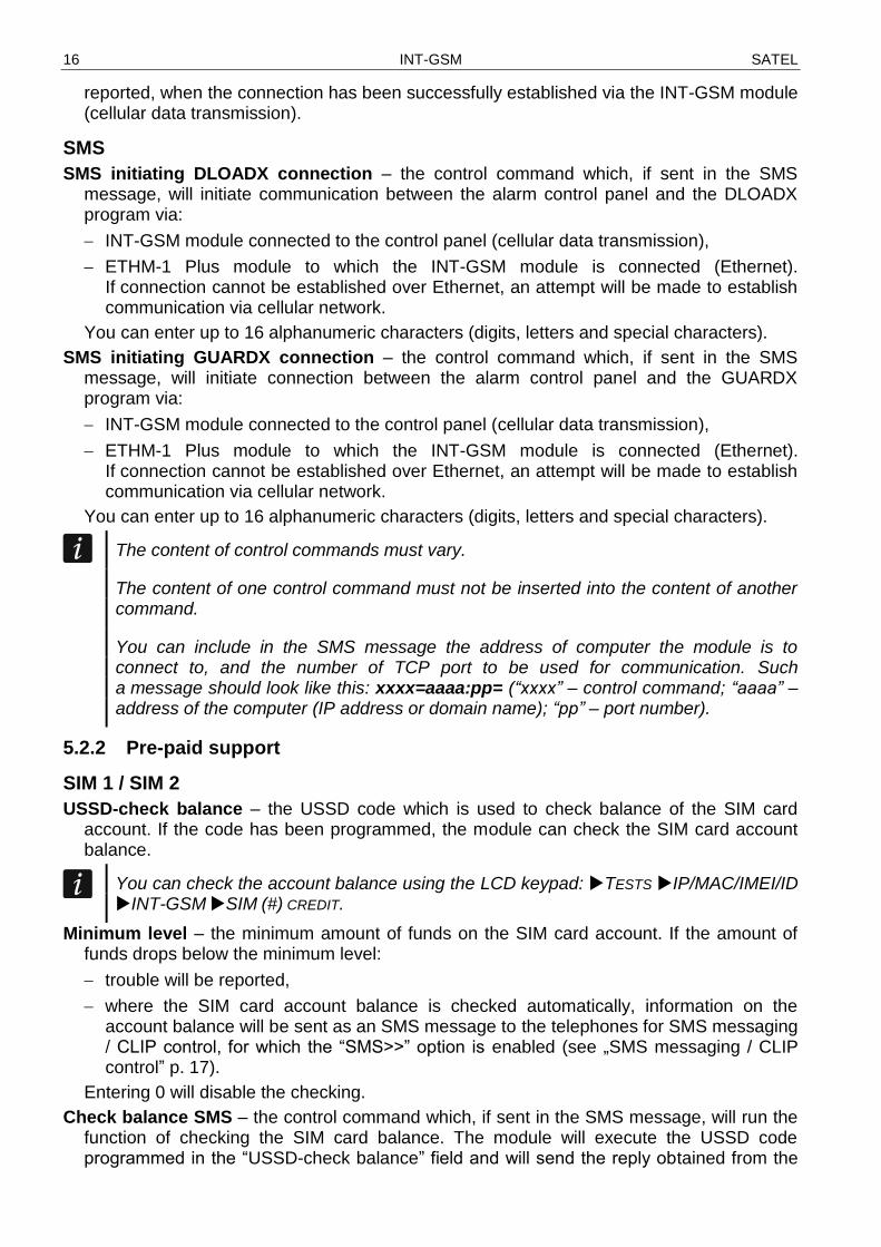
The content of control commands must vary.
The content of one control command must not be inserted into the content of another command.
You can include in the SMS message the address of computer the module is to connect to, and the number of TCP port to be used for communication. Such a message should look like this: xxxx=aaaa:pp= (“xxxx” – control command; “aaaa” – address of the computer (IP address or domain name); “pp” – port number).
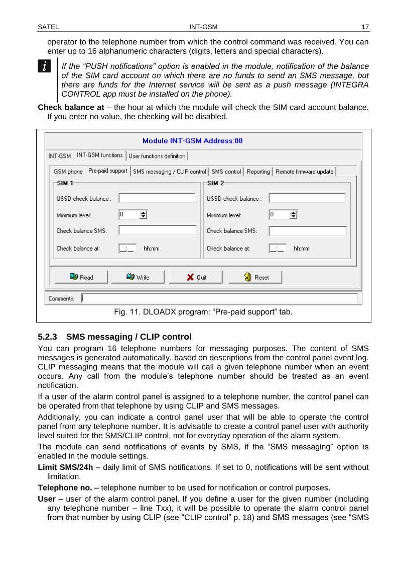
5.2.2 Pre-paid support
SIM 1 / SIM 2
USSD-check balance – the USSD code which is used to check balance of the SIM card account. If the code has been programmed, the module can check the SIM card account balance.
You can check the account balance using the LCD keypad: TESTS IP/MAC/IMEI/ID INT-GSM SIM (#) CREDIT.
Minimum level – the minimum amount of funds on the SIM card account. If the amount of funds drops below the minimum level:
trouble will be reported,
where the SIM card account balance is checked automatically, information on the account balance will be sent as an SMS message to the telephones for SMS messaging / CLIP control, for which the “SMS>>” option is enabled (see „SMS messaging / CLIP control” p. 17).
Entering 0 will disable the checking.
Check balance SMS – the control command which, if sent in the SMS message, will run the function of checking the SIM card balance. The module will execute the USSD code programmed in the “USSD-check balance” field and will send the reply obtained from the
SATEL INT-GSM 17
operator to the telephone number from which the control command was received. You can enter up to 16 alphanumeric characters (digits, letters and special characters).
If the “PUSH notifications” option is enabled in the module, notification of the balance of the SIM card account on which there are no funds to send an SMS message, but there are funds for the Internet service will be sent as a push message (INTEGRA CONTROL app must be installed on the phone).
Check balance at – the hour at which the module will check the SIM card account balance. If you enter no value, the checking will be disabled.
Fig. 11. DLOADX program: “Pre-paid support” tab.
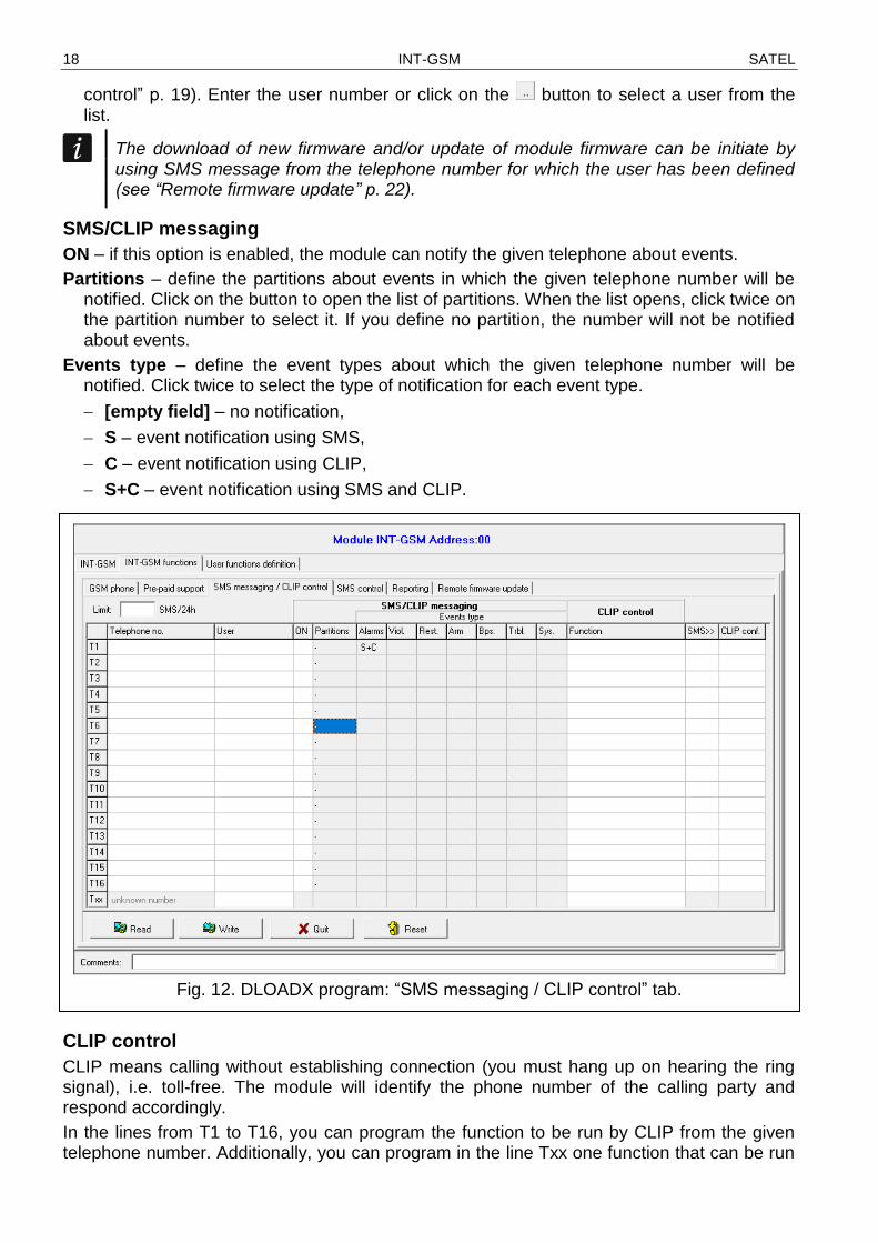
5.2.3 SMS messaging / CLIP control
You can program 16 telephone numbers for messaging purposes. The content of SMS messages is generated automatically, based on descriptions from the control panel event log. CLIP messaging means that the module will call a given telephone number when an event occurs. Any call from the module’s telephone number should be treated as an event notification.
If a user of the alarm control panel is assigned to a telephone number, the control panel can be operated from that telephone by using CLIP and SMS messages.
Additionally, you can indicate a control panel user that will be able to operate the control panel from any telephone number. It is advisable to create a control panel user with authority level suited for the SMS/CLIP control, not for everyday operation of the alarm system.
The module can send notifications of events by SMS, if the “SMS messaging” option is enabled in the module settings.
Limit SMS/24h – daily limit of SMS notifications. If set to 0, notifications will be sent without limitation.
Telephone no. – telephone number to be used for notification or control purposes.
User – user of the alarm control panel. If you define a user for the given number (including any telephone number – line Txx), it will be possible to operate the alarm control panel from that number by using CLIP (see “CLIP control” p. 18) and SMS messages (see “SMS
18 INT-GSM SATEL
control” p. 19). Enter the user number or click on the button to select a user from the list.
The download of new firmware and/or update of module firmware can be initiate by using SMS message from the telephone number for which the user has been defined (see “Remote firmware update” p. 22).
SMS/CLIP messaging
ON – if this option is enabled, the module can notify the given telephone about events.
Partitions – define the partitions about events in which the given telephone number will be notified. Click on the button to open the list of partitions. When the list opens, click twice on the partition number to select it. If you define no partition, the number will not be notified about events.
Events type – define the event types about which the given telephone number will be notified. Click twice to select the type of notification for each event type.
[empty field] – no notification,
S – event notification using SMS,
C – event notification using CLIP,
S+C – event notification using SMS and CLIP.
Fig. 12. DLOADX program: “SMS messaging / CLIP control” tab.
CLIP control
CLIP means calling without establishing connection (you must hang up on hearing the ring signal), i.e. toll-free. The module will identify the phone number of the calling party and respond accordingly.
In the lines from T1 to T16, you can program the function to be run by CLIP from the given telephone number. Additionally, you can program in the line Txx one function that can be run
SATEL INT-GSM 19
in the control panel by CLIP from any telephone number. In both cases, the telephone number must be assigned to the control panel user.
The telephone numbers programmed in the lines from T1 to T16 are not treated by the module as any numbers.
Function – the function to be run by CLIP. Enter the function number or click on the button to select the function from the list. The list of available functions is defined in the “SMS control” tab (see “Function” p. 20).
Others
SMS>> – if this option is enabled, unknown SMS messages received by the module are forwarded to the phone number (e.g. information received from the cellular network operator).
CLIP conf. – if this option is enabled, the module will inform the user about events by calling the given number up to 3 times or until confirmation. In order to confirm a CLIP notification, reject the call (the notification will then be toll-free) or accept it. If this option is disabled, the call will be made only once.
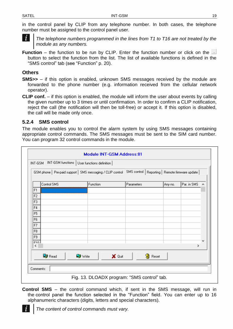
5.2.4 SMS control
The module enables you to control the alarm system by using SMS messages containing appropriate control commands. The SMS messages must be sent to the SIM card number. You can program 32 control commands in the module.
Fig. 13. DLOADX program: “SMS control” tab.
Control SMS – the control command which, if sent in the SMS message, will run in
the control panel the function selected in the “Function” field. You can enter up to 16 alphanumeric characters (digits, letters and special characters).
The content of control commands must vary.
20 INT-GSM SATEL
The content of one control command must not be inserted into the content of another command.
Several control commands may be included in one SMS message (should be separated by spaces).
The control command may be just a fragment of the SMS message. This makes it is possible to write the control command, including the comments, to the telephone memory and send the whole to the module.
Function – function run by the control command received in the SMS message or by CLIP (see “CLIP control” p. 18). If you program the function without defining any control command (“Control SMS” field), the function can only be run by using CLIP. Enter the
function number or click on the button to select the function from the list:
1: State (text)
2: State (symb.)
3: Arm (0) – full arming.
4: Arm (1) – full arming + bypasses.
5: Arm (2) – arming without interior.
6: Arm (3) – arming without interior and without entry delay.
7: Disarm
8: Clear alarm
9: Outputs ON
10: Outputs OFF
11: Switch state
12: Bypass zones
13: Isolate zones
14: Unbypass zones
15: Trigger zone
16: Del. overdue messages
The partitions must be controlled by user code.
The zones that are to be bypassed, must not have the BYPASS DISABLED option enabled.
The outputs must be the 24. MONO SWITCH, 25. BI SWITCH, 105. SHUTTER UP, 106. SHUTTER DOWN or REMOTE SWITCH type.
Parameters – define the parameters the given function will be run with. Click on the button to open the list of parameters. When the list opens, click twice on the number to select the partition / output / zone (for the “15: Trigger zone” function, you can only select one zone).
Any no. – if this option is enabled, the given function can be run from any telephone number. The control panel can be controlled from any telephone number if the alarm control panel user has been selected for any telephone number in the “SMS messaging / CLIP control” tab (see “User” p. 17).
Par. in SMS – if this option is enabled, the given function can be run with parameters sent together with the control command in the SMS message. This makes it possible to run the function with other parameters than those programmed for it in the “Parameters” field. If this is the case, the SMS message must look like this: “xxxxxx=a,b,c,d=”, where:
SATEL INT-GSM 21
“xxxxxx” - control command, “a,b,c,d” - parameters, e.g. 1,2,3,4 (numbers of partitions / outputs / zones separated with commas). For the “15: Trigger zone” function, the control command must have the following form: “xxxxxx=a=”, where: “xxxxxx” - control command, “a” – zone number, e.g. 1 (you can indicate only one zone).
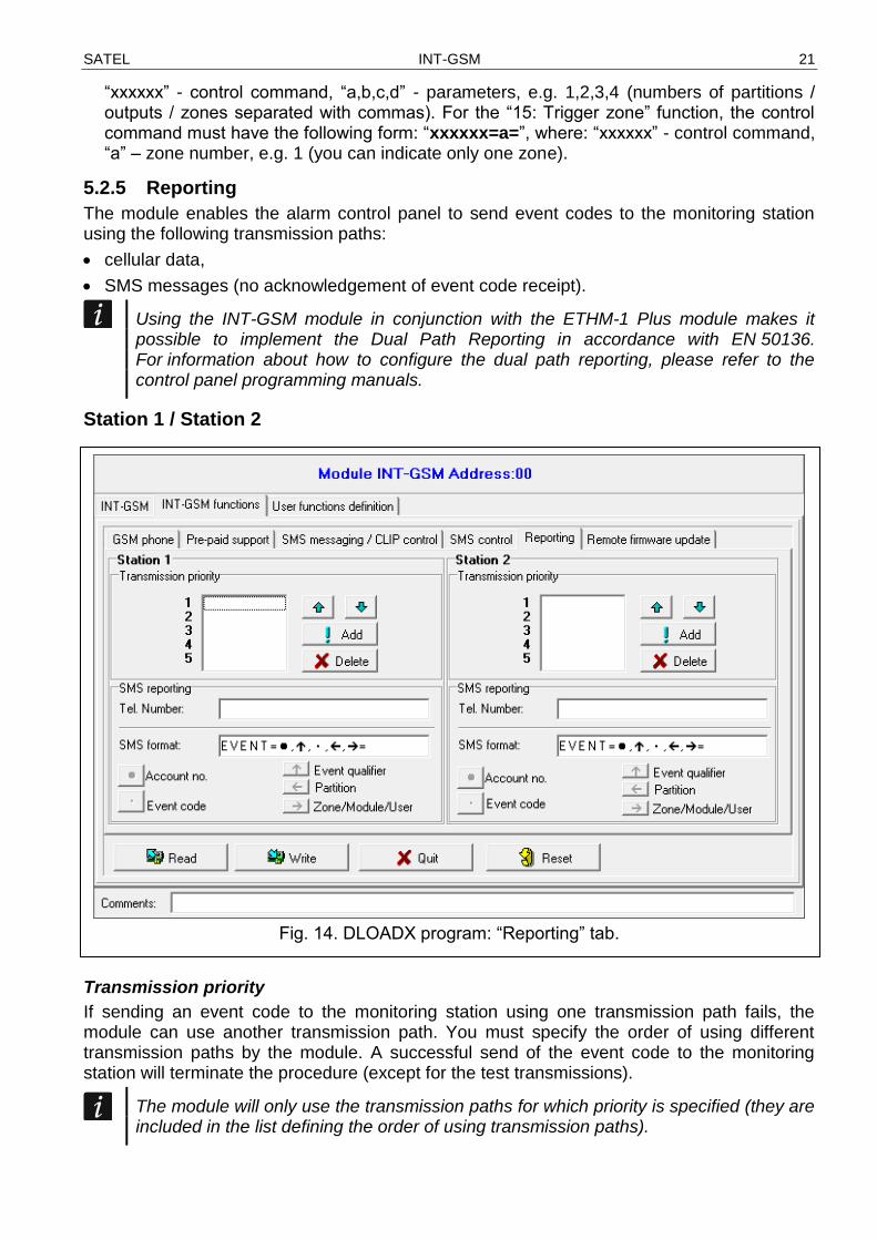
5.2.5 Reporting
The module enables the alarm control panel to send event codes to the monitoring station using the following transmission paths:
cellular data,
SMS messages (no acknowledgement of event code receipt).
Using the INT-GSM module in conjunction with the ETHM-1 Plus module makes it possible to implement the Dual Path Reporting in accordance with EN 50136. For information about how to configure the dual path reporting, please refer to the control panel programming manuals.
Station 1 / Station 2
Fig. 14. DLOADX program: “Reporting” tab.
Transmission priority
If sending an event code to the monitoring station using one transmission path fails, the module can use another transmission path. You must specify the order of using different transmission paths by the module. A successful send of the event code to the monitoring station will terminate the procedure (except for the test transmissions).
The module will only use the transmission paths for which priority is specified (they are included in the list defining the order of using transmission paths).
22 INT-GSM SATEL
If the INT-GSM module is connected to the ETHM-1 Plus module, priority must also be specified for the Ethernet transmission (ETHM).
In the case of SMS reporting, the module gets no acknowledgement of receiving the event codes by the monitoring station, hence this transmission path should be used as the last one.
The switch-over from one SIM card to the other one requires time (for example, to log onto the network), so it is better to use up all the transmission paths available for one SIM card.
The switch-over from one SIM card to the other is affected by the “Lock time” and “Return time” (see “GSM phone” p. 13).
SMS reporting
Tel. Number – phone number of the monitoring station for SMS reporting.
SMS format – SMS format for SMS reporting. It must be defined as required by the monitoring station. The SMS message format, preset by default in the module, corresponds to the default settings of the STAM-2 monitoring station (firmware version 1.2.0 or newer) for the Contact ID format.
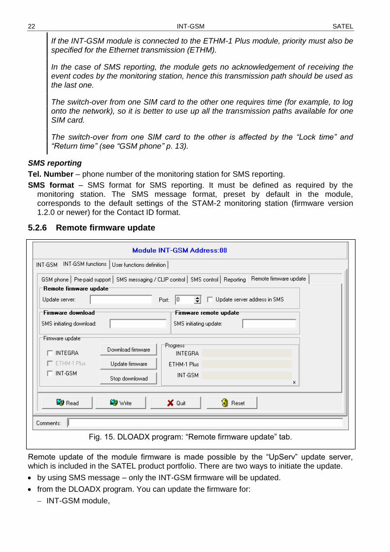
5.2.6 Remote firmware update
Fig. 15. DLOADX program: “Remote firmware update” tab.
Remote update of the module firmware is made possible by the “UpServ” update server, which is included in the SATEL product portfolio. There are two ways to initiate the update.
by using SMS message – only the INT-GSM firmware will be updated.
from the DLOADX program. You can update the firmware for:
INT-GSM module,
SATEL INT-GSM 23
INTEGRA control panel – only if the DLOADX program and the control panel are connected via the ETHM-1 Plus or INT-GSM module,
ETHM-1 Plus module – only if the INT-GSM module is connected to the ETHM-1 Plus module (module identified as “ETHM+GSM”).
Update server – address of the “UpServ” update server. You can enter the IP address or domain name.
Port – number of the TCP port used for communication with the “UpServ” update server. You can enter values from 0 to 65535 (0=disabled).
Update server address in SMS – if this option is enabled, you can enter server address and port number in the SMS message initiating the firmware download from the update server. If this option is enabled and the message contains no address or port number, the module will use the preprogrammed settings.
SMS messages which initiate download of new firmware and/or update of module firmware can only be sent from the telephone whose number is saved in the module (see “SMS messaging / CLIP control” p. 17).
Firmware download
When downloading new firmware, the module performs its normal functions.
SMS initiating download – the control command which, if sent in the SMS message, will start downloading of the new firmware from the server. You can enter up to 8 alphanumeric characters (digits, letters and special characters).
The command content must be different from that of the other control commands preprogrammed in the control panel.
If the „Update server address in SMS” option is enabled and you want the module to connect to an update server other than that indicated in the module settings, the message should look like this: xxxx=aaaa:pp= (“xxxx” – control command; “aaaa” – server address (IP address or domain name); “pp” – port number).
The module sends out an SMS notification on how the new firmware download has proceeded. The notification is sent to the telephone from which the SMS message initiating the firmware download was received.
If an SMS message containing the firmware download initiating command is re-sent when the new firmware downloading is in progress, the module will indicate in reply the download progress (percentage value).
Firmware remote update
During update of its firmware, the module does not perform its normal functions.
Before updating the module firmware, enter the “Service mode” in the alarm control panel. Otherwise, starting the update will make the control panel report that the INT-GSM module is not available.
SMS initiating update – the control command which, if sent in the SMS message, will start the firmware update. You can enter up to 8 alphanumeric characters (digits, letters and special characters).
The command content must be different from that of the other control commands preprogrammed in the control panel.
24 INT-GSM SATEL
The module sends out an SMS notification on how the firmware update has proceeded. The notification is sent to the telephone from which the SMS message initiating the firmware download was received.
Firmware update using DLOADX
INTEGRA – if this option is enabled, the INTEGRA Plus / INTEGRA control panel firmware will be updated (the DLOADX program has to be connected to the control panel via the ETHM-1 Plus or the INT-GSM module).
ETHM-1 Plus – if this option is enabled, the ETHM-1 Plus module firmware will be updated (the INT-GSM module has to be connected to the ETHM-1 Plus module).
INT-GSM – if this option is enabled, the INT-GSM module firmware will be updated.
Download firmware – click to download new version of firmware.
Update firmware – click to update firmware for the selected device(s) to the latest version. If you have not downloaded the firmware yourself, it will be downloaded automatically now. The update will begin after the download is complete.
Stop download – click to stop the process of updating the firmware for the selected device(s).
Progress – progress bars show the process of downloading the firmware.
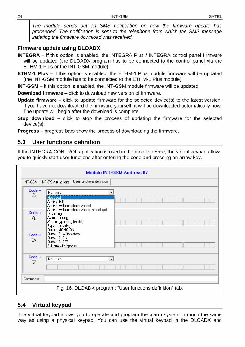
5.3 User functions definition
If the INTEGRA CONTROL application is used in the mobile device, the virtual keypad allows you to quickly start user functions after entering the code and pressing an arrow key.
Fig. 16. DLOADX program: “User functions definition” tab.
5.4 Virtual keypad
The virtual keypad allows you to operate and program the alarm system in much the same way as using a physical keypad. You can use the virtual keypad in the DLOADX and
SATEL INT-GSM 25
GUARDX programs and in the mobile device (after installation of the INTEGRA CONTROL application).
Parameters and options of the virtual keypad available in the DLOADX program can be programmed using:
DLOADX program: “Structure” window “Hardware” tab “Keypads” branch “DLOADX (RS-232)” item,
LCD keypad: SERVICE MODE STRUCTURE HARDWARE LCD KEYPADS SETTINGS DLOADX RS.
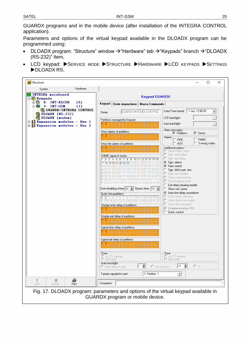
Fig. 17. DLOADX program: parameters and options of the virtual keypad available in GUARDX program or mobile device.
26 INT-GSM SATEL
Settings of the virtual keypad available in the GUARDX program or mobile device can be programmed using:
DLOADX program: “Structure” window “Hardware” tab “Keypads” branch [module name] “GUARDX/ INTEGRA CONTROL” item (Fig. 17),
LCD keypad: SERVICE MODE STRUCTURE HARDWARE LCD KEYPADS SETTINGS GUARDX ADDR. n [n = module address].
For description of the keypad parameters and options, please refer to the programming manual for INTEGRA / INTEGRA Plus control panel (only some of these parameters and options are available for the virtual keypad).
5.5 Macro commands
The INTEGRA CONTROL application allows to control the alarm system by means of macro commands, thus making it possible to quickly and easily run a number of different functions by touching just a few keys. The macro commands can be defined in the DLOADX program (“Structure” window “Hardware” tab “Keypads” branch [module name] branch “GUARDX/ INTEGRA CONTROL” item “Macro Commands” tab).
Defined macro commands can be automatically downloaded by the INTEGRA CONTROL application after establishing connection with the INT-GSM module.
Macro commands can be loaded into the application without establishing connection with the module. The file containing macro commands can be exported, and then saved to the mobile device memory (to transfer the file, you can use a memory card or other solutions available for the given device). This method allows you to use macro commands defined for the e.g. INT-TSG keypad in the INTEGRA CONTROL application. Instead of a file with macro commands defined for the INT-GSM module, you can load a file with macro commands defined for the keypad.
The data related to macro commands are stored in the module memory. Before you start defining the macro commands, click on the “Read” button in the “Macro commands” tab to read the data from the module. Having defined the macro commands, click on the “Write” button in the “Macro commands” tab to write the data to the module. The macro command related data are not read / written when you click
on the button in the main menu of DLOADX program.
Buttons
Read – click to read the macro command related data from the module.
Write – click to write the macro command related data to the module.
Quit – click to cancel reading or writing the macro command related data.
Reset – click to delete all the defined macro commands (and restore factory default settings).
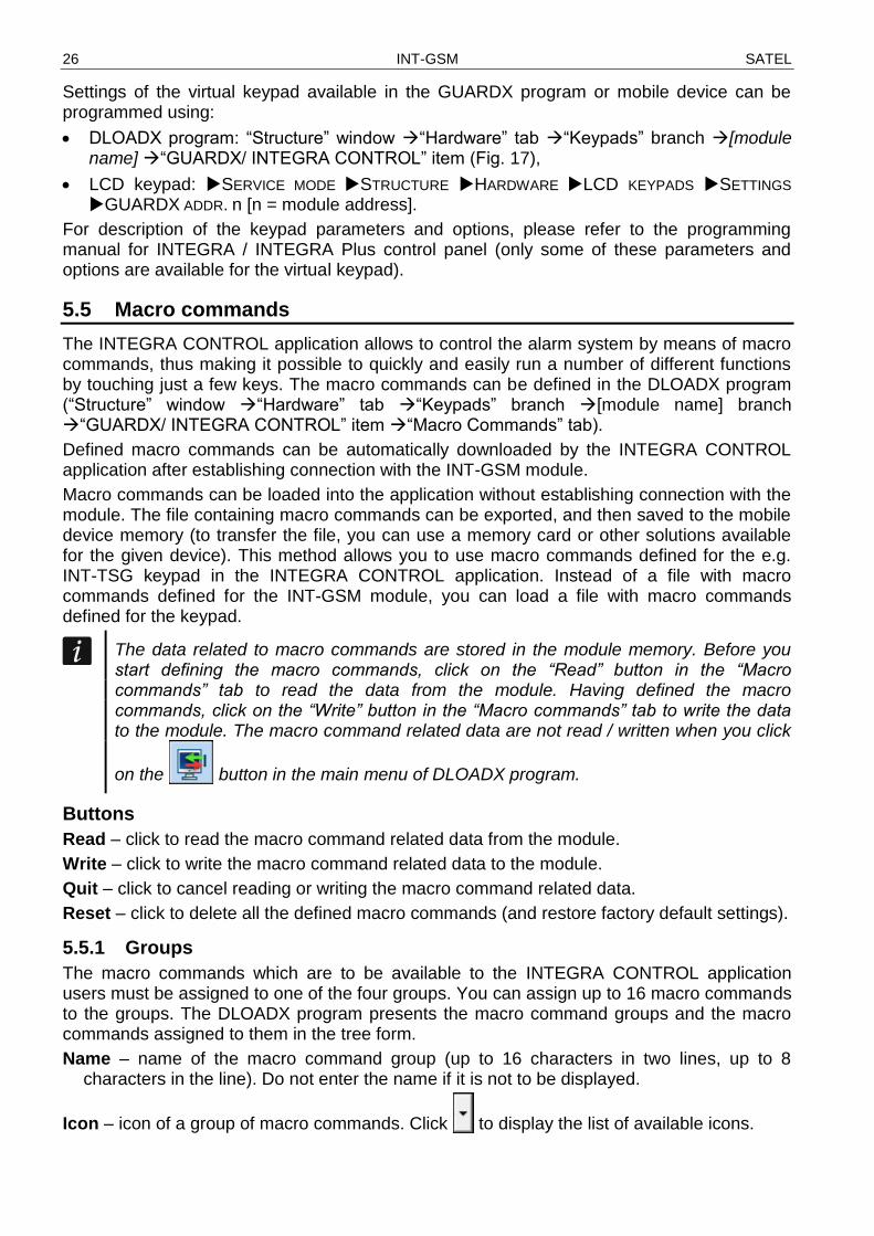
5.5.1 Groups
The macro commands which are to be available to the INTEGRA CONTROL application users must be assigned to one of the four groups. You can assign up to 16 macro commands to the groups. The DLOADX program presents the macro command groups and the macro commands assigned to them in the tree form.
Name – name of the macro command group (up to 16 characters in two lines, up to 8 characters in the line). Do not enter the name if it is not to be displayed.
Icon – icon of a group of macro commands. Click to display the list of available icons.
SATEL INT-GSM 27
Add macro – button available after you click on a macro command group. Clicking on the button will display a list of defined macro commands. Click on the name to add the macro command to the group.
Remove macro – the button is available after you click on any macro command. It removes that macro command from the group.
– click to move the highlighted macro command down within the group.
– click to move the highlighted macro command up within the group.
Export to file – click on the button to export defined macro commands to a file. The file with macro commands can be loaded into the INTEGRA CONTROL application or imported to another device that support macro commands.
Import from file – click to import macro commands from a file.
Fig. 18. DLOADX program: “Groups” tab.
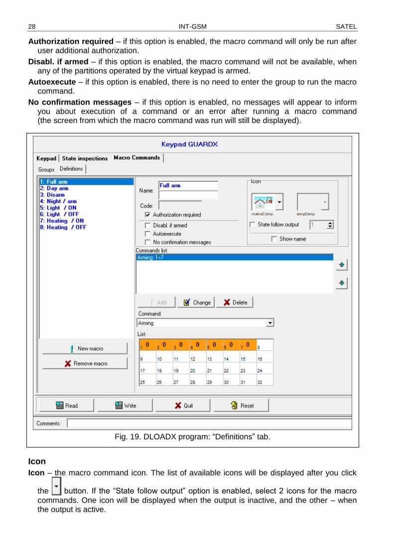
5.5.2 Definitions
You can create and configure macro commands in the “Definitions” tab. The macro command is a sequence of actions, composed of single commands, which are to be done by the control panel when running the macro command.
New macro – click to create a new macro command.
Remove macro – click to delete selected macro command.
Name – individual name of the macro command (up to 16 characters in two lines, up to 8 characters in the line).
28 INT-GSM SATEL
Authorization required – if this option is enabled, the macro command will only be run after user additional authorization.
Disabl. if armed – if this option is enabled, the macro command will not be available, when any of the partitions operated by the virtual keypad is armed.
Autoexecute – if this option is enabled, there is no need to enter the group to run the macro command.
No confirmation messages – if this option is enabled, no messages will appear to inform you about execution of a command or an error after running a macro command (the screen from which the macro command was run will still be displayed).
Fig. 19. DLOADX program: “Definitions” tab.
Icon
Icon – the macro command icon. The list of available icons will be displayed after you click
the button. If the “State follow output” option is enabled, select 2 icons for the macro
commands. One icon will be displayed when the output is inactive, and the other – when the output is active.
SATEL INT-GSM 29
State follow output – if this option is enabled, the icon of macro command will change depending on the status of output whose number should be selected in the field on the right side. Select an output, the status of which depends on the actions taken by the control panel after running the macro command. Thus it will be possible to inform the user by means of macro command icons about, for example, the status of outputs controlled by using macro commands or the status of partitions which are armed by a macro command.
Show name – if this option is enabled, the macro command name will be displayed.
Commands
Commands list – commands assigned to the currently highlighted macro command. The
and buttons allow you to change the order of commands (moving the selected
command up and down).
Add – click to add to the list a new command, selected in the “Command” field.
Change – click to save the changes to the command parameters which were made after adding the command to the list (otherwise, the changes made will not be saved).
Delete – click to remove the highlighted command from the list.
Command – the control panel executed function which can be assigned to the macro
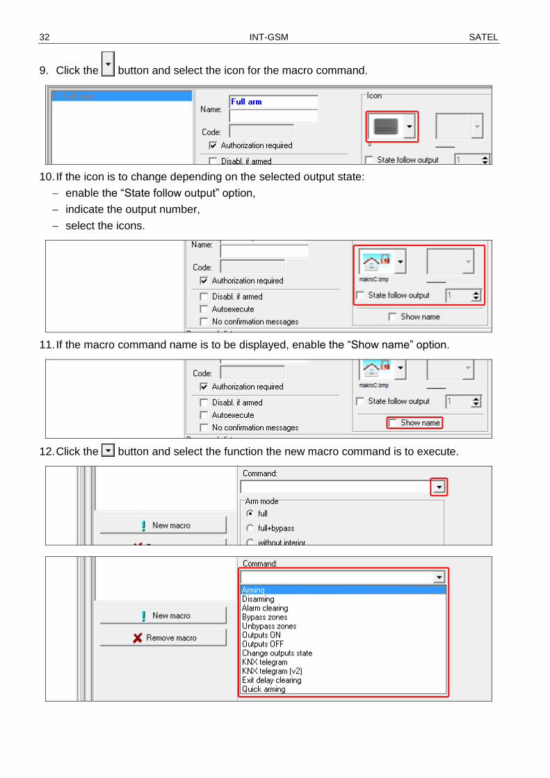
command. The list of all available functions will be displayed after you click the button. Depending on which function you choose:
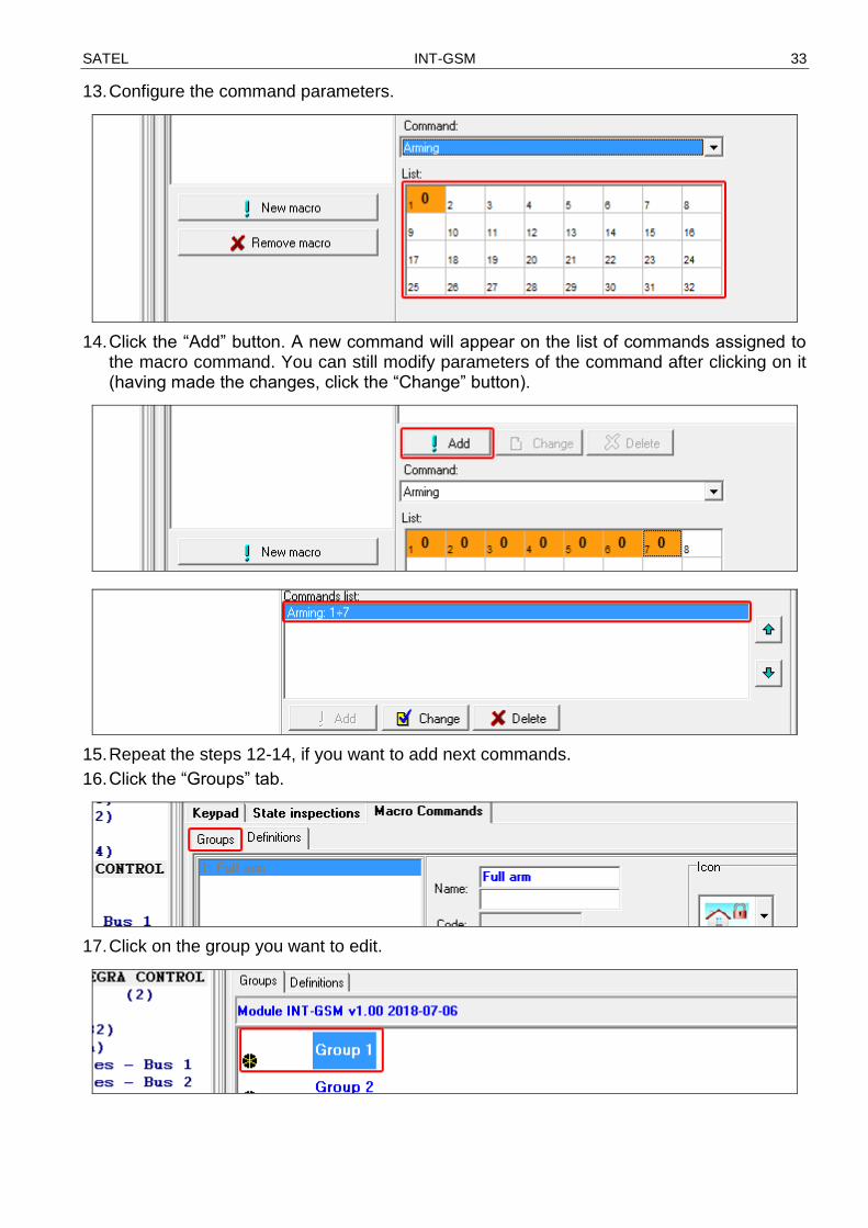
Arming – select the partitions which are to be armed (double-click on the field designated by the partition number) and define the arming mode (next clicks on the field designated by the partition number; the digit inside the field has the following meaning: 0 - full arming; 1 – full arming + bypasses; 2 – arming without interior; 3 - arming without interior and without entry delay).
Disarming – highlight the partitions which are to be disarmed (double-click on the field designated by the partition number).
Alarm clearing – select the partitions in which alarm is to be cleared (double-click on the field designated by the partition number).
Bypass zones – select the zones which are to be inhibited (double-click on the field designated by the zone number).
Unbypass zones – select the zones which are to be unbypassed (double-click on the field designated by the zone number).
Outputs ON – select the outputs which are to be activated (double-click on the field designated by the output number).
Outputs OFF – select the outputs which are to be deactivated (double-click on the field designated by the output number).
Change outputs state – select the outputs whose status is to be changed (double-click on the field designated by the output number).
KNX telegram – program the following parameters of KNX telegram for the INT-KNX module:
INT-KNX module – INT-KNX module which is to send the telegram.
Group address – the group address which will be inserted in the telegram.
Type – the telegram type.
Value – the value that will be inserted in the telegram (parameter available for some types of the telegram).
Priority – telegram priority (if two elements of the bus start transmitting simultaneously, the telegram with higher priority will be sent first).
30 INT-GSM SATEL
KNX telegram (v2) – program the following parameters related to setting the value of KNX communication object:
Module INT-KNX – INT-KNX-2 module in which the value is to be set.
Macro Command – name of the “Virtual (macro)” type object, defined in INT-KNX-2 module.
Data type – size and meaning of the communication object data defined in INT-KNX-2 module for selected object.
Value – value to be set (if the type of data provides for sending a sequence of characters, you can enter up to 13 characters).
Exit delay clearing (no additional parameters to configure).
Quick arm – select the arming mode which is to be activated.
The partitions must be controlled by user code.
The zones must not have the “Bypass disabled” option enabled.
The outputs must be the 24. MONO SWITCH, 25. BI SWITCH, 105. SHUTTER UP, 106. SHUTTER DOWN or REMOTE SWITCH type.
The INTEGRA CONTROL application can control the KNX system, if the INT-KNX or INT-KNX-2 module is connected to the control panel.
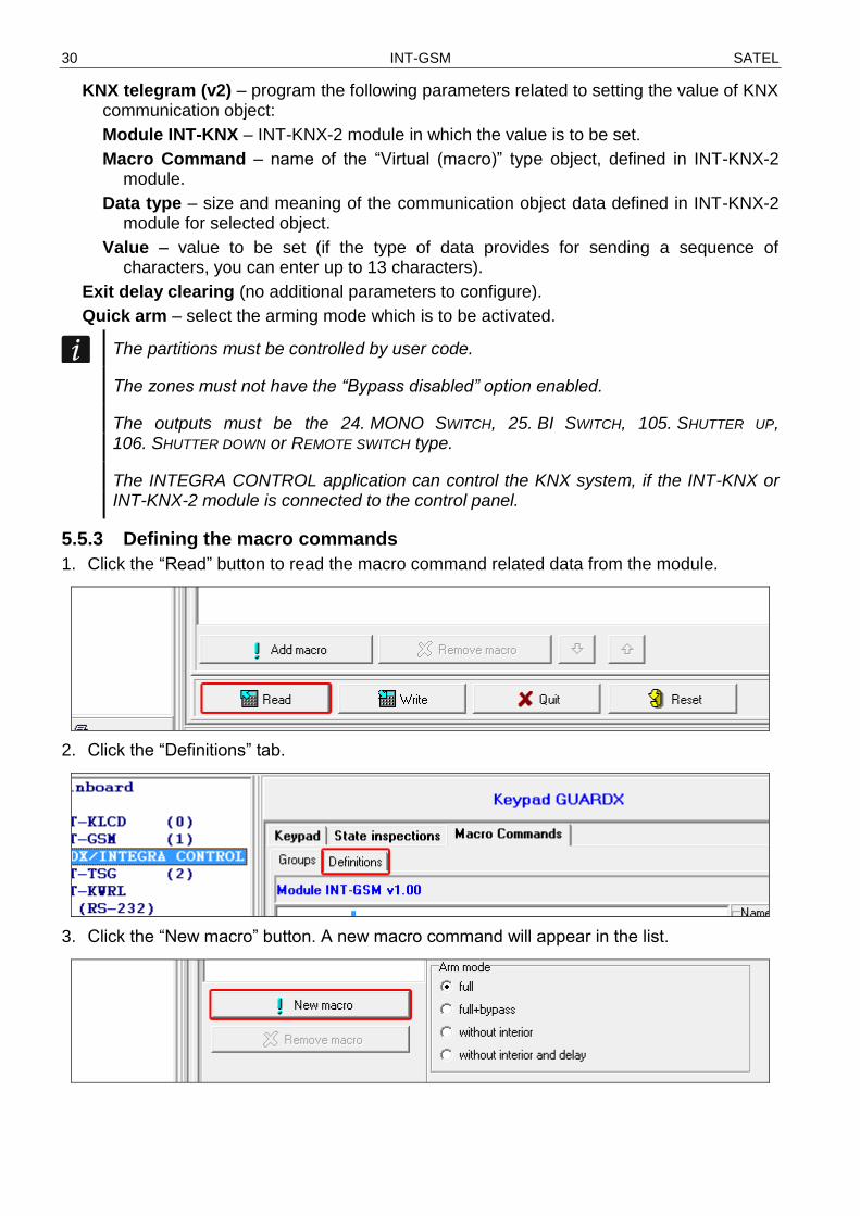
5.5.3 Defining the macro commands
1. Click the “Read” button to read the macro command related data from the module.
2. Click the “Definitions” tab.
3. Click the “New macro” button. A new macro command will appear in the list.
SATEL INT-GSM 31
4. Enter a name for the new macro command.
5. If running a macro command is to be each time preceded by user authorization, enable the “Authorization required” option.
6. If the macro command is to be unavailable when any of the partitions managed by the application is armed, enable the “Disabl. if armed” option.
7. If the macro command is to be available without entering the group, enable the “Autoexecute“ option.
8. If the confirmation messages are not to be displayed after running the macro command, enable the “No confirmation messages” option.
32 INT-GSM SATEL
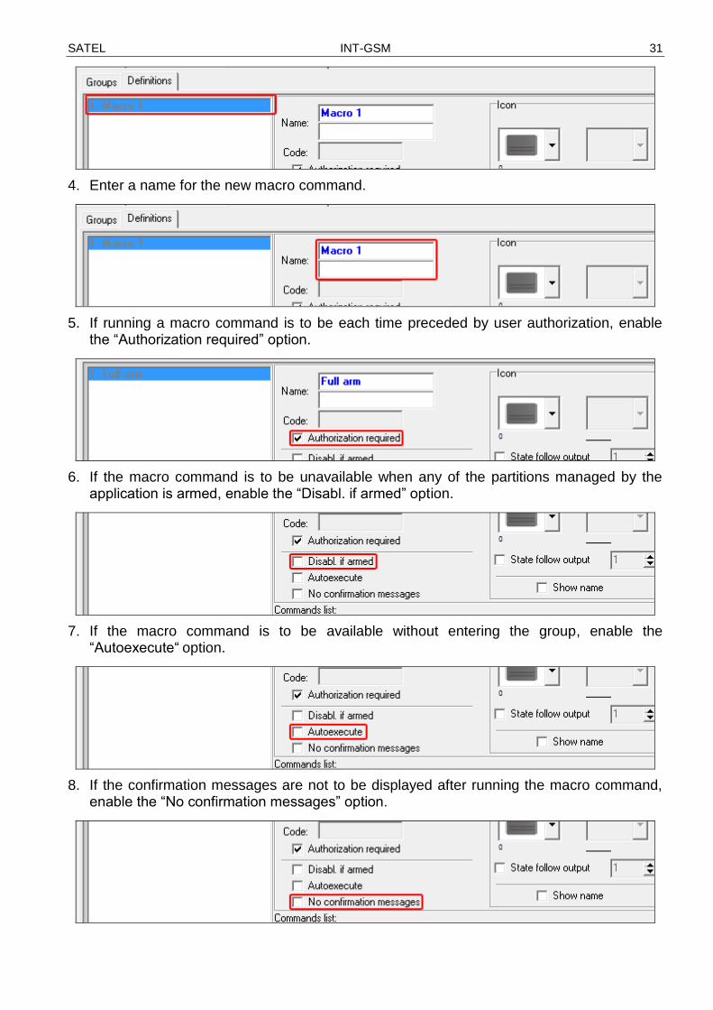
9. Click the button and select the icon for the macro command.
10. If the icon is to change depending on the selected output state:
enable the “State follow output” option,
indicate the output number,
select the icons.
11. If the macro command name is to be displayed, enable the “Show name” option.
12. Click the button and select the function the new macro command is to execute.
SATEL INT-GSM 33
13. Configure the command parameters.
14. Click the “Add” button. A new command will appear on the list of commands assigned to the macro command. You can still modify parameters of the command after clicking on it (having made the changes, click the “Change” button).
15. Repeat the steps 12-14, if you want to add next commands.
16. Click the “Groups” tab.
17. Click on the group you want to edit.
34 INT-GSM SATEL
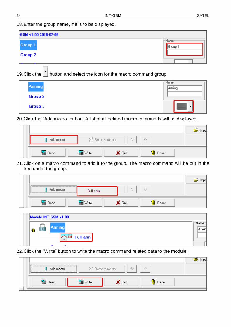
18. Enter the group name, if it is to be displayed.
19. Click the button and select the icon for the macro command group.
20. Click the “Add macro” button. A list of all defined macro commands will be displayed.
21. Click on a macro command to add it to the group. The macro command will be put in the tree under the group.
22. Click the “Write” button to write the macro command related data to the module.
SATEL INT-GSM 35
6. Remote programming / operating of control panel via module
For information related to configuring the control panel by means of the DLOADX program, please refer to the control panel programming manuals.
6.1 GUARDX program
If the INT-GSM module is connected to the ETHM-1 Plus module, communication via the INT-GSM module (via cellular network) will only be used if connection via Ethernet cannot be established (see the ETHM-1 Plus module manual).
Connection between the GUARDX program and the control panel via the INT-GSM module can be established using one of the following ways:
1. Initiating connection from the keypad (by the control panel). The alarm system can be managed only from specified location. This method is recommended when the alarm system owner does not want the system to be managed without its knowledge. The computer with GUARDX program must have a public IP address.
2. Initiating connection by SMS message. The computer with GUARDX program must have a public IP address.
3. Establishing connection via the SATEL server. The alarm system can be managed from any location. No public IP address is required for the computer with GUARDX program.
Connection can be established if the identifiers programmed in the control panel and the GUARDX program are identical (“INTEGRA identifier” and “GUARDX identifier”).
Required settings of the INT-GSM module for all methods of establishing connection:
enabled “GUARDX” option (p. 12),
programmed data encryption key (“GUARDX key” p. 12).
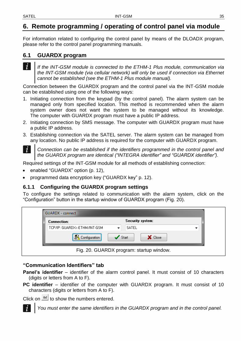
6.1.1 Configuring the GUARDX program settings
To configure the settings related to communication with the alarm system, click on the “Configuration” button in the startup window of GUARDX program (Fig. 20).
Fig. 20. GUARDX program: startup window.
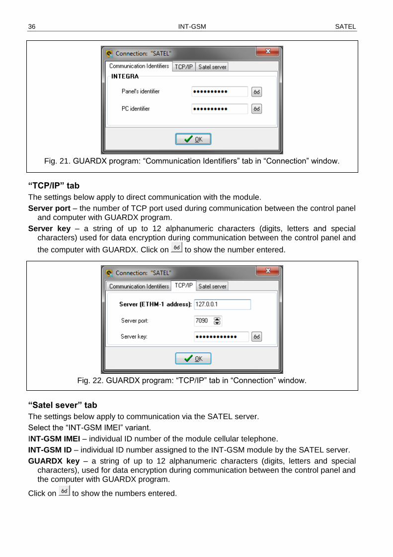
“Communication Identifiers” tab
Panel’s identifier – identifier of the alarm control panel. It must consist of 10 characters (digits or letters from A to F).
PC identifier – identifier of the computer with GUARDX program. It must consist of 10 characters (digits or letters from A to F).
Click on to show the numbers entered.
You must enter the same identifiers in the GUARDX program and in the control panel.
36 INT-GSM SATEL
Fig. 21. GUARDX program: “Communication Identifiers” tab in “Connection” window.
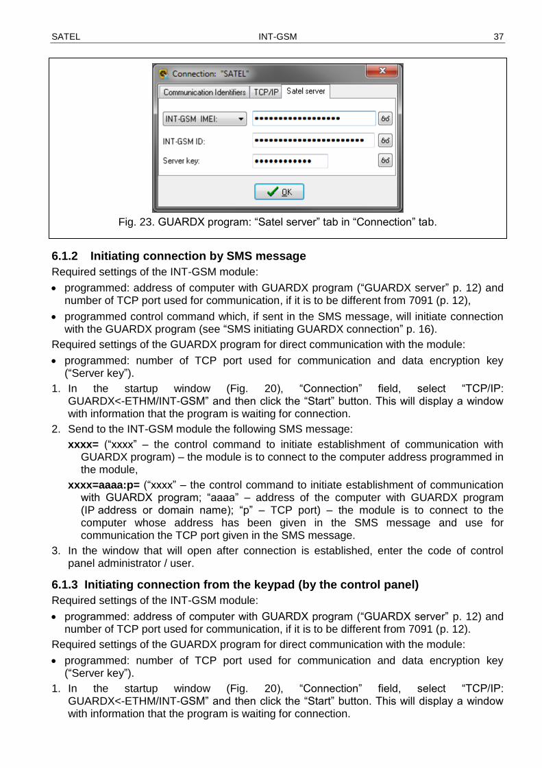
“TCP/IP” tab
The settings below apply to direct communication with the module.
Server port – the number of TCP port used during communication between the control panel and computer with GUARDX program.
Server key – a string of up to 12 alphanumeric characters (digits, letters and special characters) used for data encryption during communication between the control panel and
the computer with GUARDX. Click on to show the number entered.
Fig. 22. GUARDX program: “TCP/IP” tab in “Connection” window.
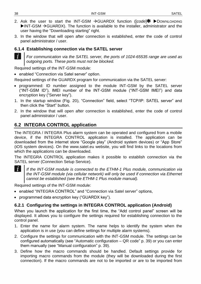
“Satel sever” tab
The settings below apply to communication via the SATEL server.
Select the “INT-GSM IMEI” variant.
INT-GSM IMEI – individual ID number of the module cellular telephone.
INT-GSM ID – individual ID number assigned to the INT-GSM module by the SATEL server.
GUARDX key – a string of up to 12 alphanumeric characters (digits, letters and special characters), used for data encryption during communication between the control panel and the computer with GUARDX program.
Click on to show the numbers entered.
SATEL INT-GSM 37
Fig. 23. GUARDX program: “Satel server” tab in “Connection” tab.
6.1.2 Initiating connection by SMS message
Required settings of the INT-GSM module:
programmed: address of computer with GUARDX program (“GUARDX server” p. 12) and number of TCP port used for communication, if it is to be different from 7091 (p. 12),
programmed control command which, if sent in the SMS message, will initiate connection with the GUARDX program (see “SMS initiating GUARDX connection” p. 16).
Required settings of the GUARDX program for direct communication with the module:
programmed: number of TCP port used for communication and data encryption key (“Server key”).
1. In the startup window (Fig. 20), “Connection” field, select “TCP/IP: GUARDX<-ETHM/INT-GSM” and then click the “Start” button. This will display a window with information that the program is waiting for connection.
2. Send to the INT-GSM module the following SMS message:
xxxx= (“xxxx” – the control command to initiate establishment of communication with GUARDX program) – the module is to connect to the computer address programmed in the module,
xxxx=aaaa:p= (“xxxx” – the control command to initiate establishment of communication with GUARDX program; “aaaa” – address of the computer with GUARDX program (IP address or domain name); “p” – TCP port) – the module is to connect to the computer whose address has been given in the SMS message and use for communication the TCP port given in the SMS message.
3. In the window that will open after connection is established, enter the code of control panel administrator / user.
6.1.3 Initiating connection from the keypad (by the control panel)
Required settings of the INT-GSM module:
programmed: address of computer with GUARDX program (“GUARDX server” p. 12) and number of TCP port used for communication, if it is to be different from 7091 (p. 12).
Required settings of the GUARDX program for direct communication with the module:
programmed: number of TCP port used for communication and data encryption key (“Server key”).
1. In the startup window (Fig. 20), “Connection” field, select “TCP/IP: GUARDX<-ETHM/INT-GSM” and then click the “Start” button. This will display a window with information that the program is waiting for connection.
38 INT-GSM SATEL
2. Ask the user to start the INT-GSM GUARDX function ([code] DOWNLOADING INT-GSM GUARDX). The function is available to the installer, administrator and the user having the “Downloading starting” right.
3. In the window that will open after connection is established, enter the code of control panel administrator / user.
6.1.4 Establishing connection via the SATEL server
For communication via the SATEL server, the ports of 1024-65535 range are used as outgoing ports. These ports must not be blocked.
Required settings of the INT-GSM module:
enabled “Connection via Satel server” option.
Required settings of the GUARDX program for communication via the SATEL server:
programmed: ID number assigned to the module INT-GSM by the SATEL server (“INT-GSM ID”), IMEI number of the INT-GSM module (“INT-GSM IMEI”) and data encryption key (“Server key”).
1. In the startup window (Fig. 20), “Connection” field, select “TCP/IP: SATEL server” and then click the “Start” button.
2. In the window that will open after connection is established, enter the code of control panel administrator / user.
6.2 INTEGRA CONTROL application
The INTEGRA / INTEGRA Plus alarm system can be operated and configured from a mobile device, if the INTEGRA CONTROL application is installed. The application can be downloaded from the internet store “Google play” (Android system devices) or “App Store” (iOS system devices). On the www.satel.eu website, you will find links to the locations from which the applications can be downloaded.
The INTEGRA CONTROL application makes it possible to establish connection via the SATEL server (Connection Setup Service).
If the INT-GSM module is connected to the ETHM-1 Plus module, communication via the INT-GSM module (via cellular network) will only be used if connection via Ethernet cannot be established (see the ETHM-1 Plus module manual).
Required settings of the INT-GSM module:
enabled “INTEGRA CONTROL” and “Connection via Satel server” options,
programmed data encryption key (“GUARDX key”).
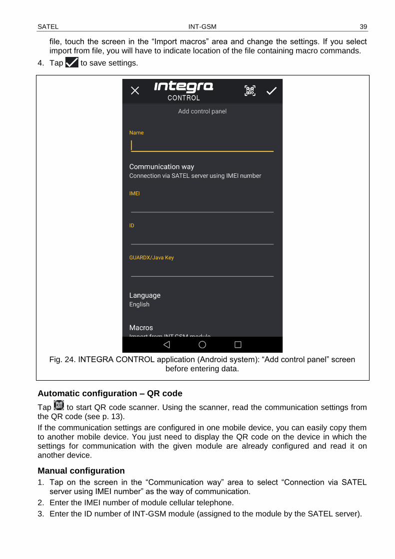
6.2.1 Configuring the settings in INTEGRA CONTROL application (Android)
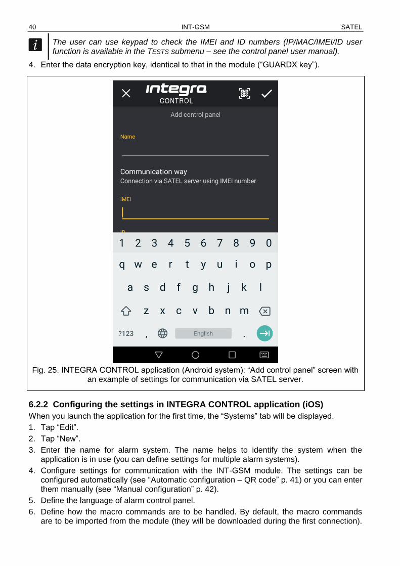
When you launch the application for the first time, the “Add control panel” screen will be displayed. It allows you to configure the settings required for establishing connection to the control panel.
1. Enter the name for alarm system. The name helps to identify the system when the application is in use (you can define settings for multiple alarm systems).
2. Configure the settings for communication with the INT-GSM module. The settings can be configured automatically (see “Automatic configuration – QR code” p. 39) or you can enter them manually (see “Manual configuration” p. 39).
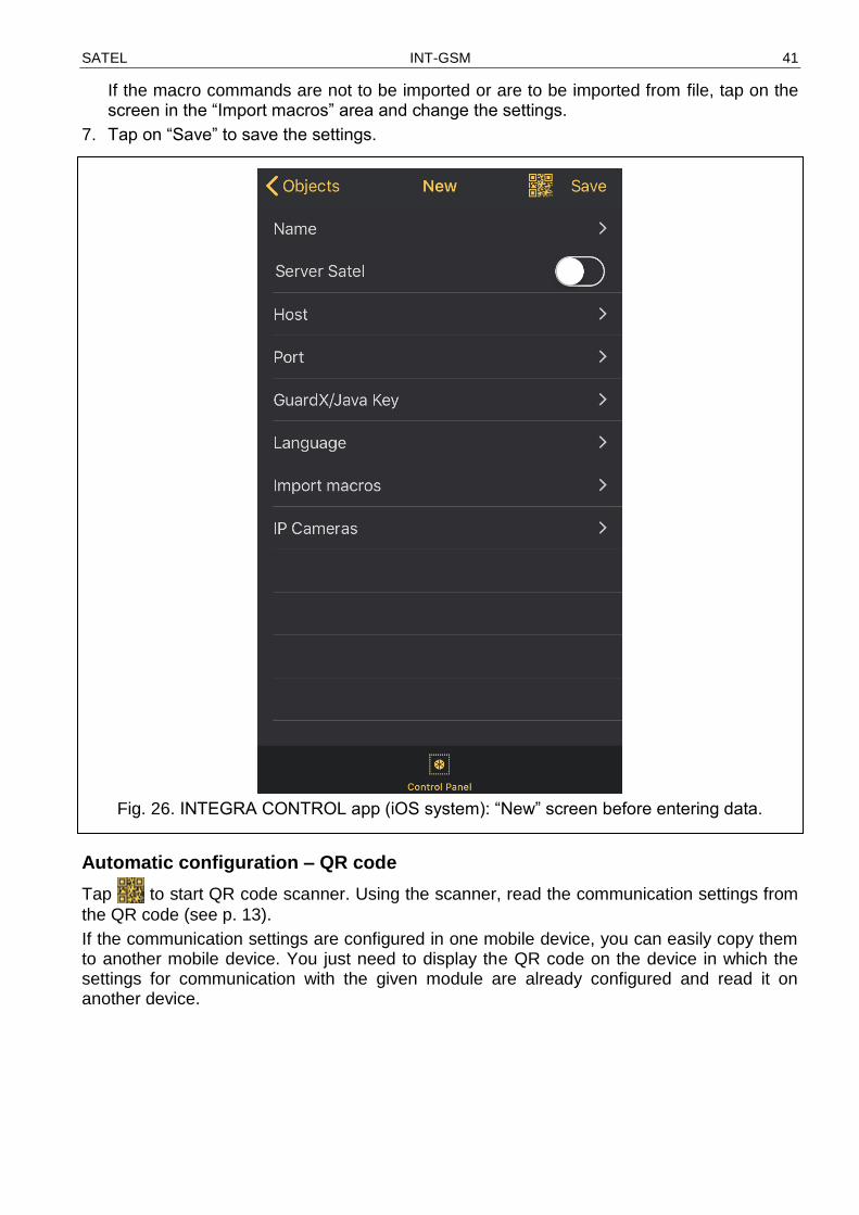
3. Define how the macro commands should be handled. Default settings provide for importing macro commands from the module (they will be downloaded during the first connection). If the macro commands are not to be imported or are to be imported from
SATEL INT-GSM 39
file, touch the screen in the “Import macros” area and change the settings. If you select import from file, you will have to indicate location of the file containing macro commands.
4. Tap to save settings.
Fig. 24. INTEGRA CONTROL application (Android system): “Add control panel” screen before entering data.
Automatic configuration – QR code
Tap to start QR code scanner. Using the scanner, read the communication settings from the QR code (see p. 13).
If the communication settings are configured in one mobile device, you can easily copy them to another mobile device. You just need to display the QR code on the device in which the settings for communication with the given module are already configured and read it on another device.
Manual configuration
1. Tap on the screen in the “Communication way” area to select “Connection via SATEL server using IMEI number” as the way of communication.
2. Enter the IMEI number of module cellular telephone.
3. Enter the ID number of INT-GSM module (assigned to the module by the SATEL server).
40 INT-GSM SATEL
The user can use keypad to check the IMEI and ID numbers (IP/MAC/IMEI/ID user function is available in the TESTS submenu – see the control panel user manual).
4. Enter the data encryption key, identical to that in the module (“GUARDX key”).
Fig. 25. INTEGRA CONTROL application (Android system): “Add control panel” screen with an example of settings for communication via SATEL server.
6.2.2 Configuring the settings in INTEGRA CONTROL application (iOS)
When you launch the application for the first time, the “Systems” tab will be displayed.
1. Tap “Edit”.
2. Tap “New”.
3. Enter the name for alarm system. The name helps to identify the system when the application is in use (you can define settings for multiple alarm systems).
4. Configure settings for communication with the INT-GSM module. The settings can be configured automatically (see “Automatic configuration – QR code” p. 41) or you can enter them manually (see “Manual configuration” p. 42).
5. Define the language of alarm control panel.
6. Define how the macro commands are to be handled. By default, the macro commands are to be imported from the module (they will be downloaded during the first connection).
SATEL INT-GSM 41
If the macro commands are not to be imported or are to be imported from file, tap on the screen in the “Import macros” area and change the settings.
7. Tap on “Save” to save the settings.
Fig. 26. INTEGRA CONTROL app (iOS system): “New” screen before entering data.
Automatic configuration – QR code
Tap to start QR code scanner. Using the scanner, read the communication settings from
the QR code (see p. 13).
If the communication settings are configured in one mobile device, you can easily copy them to another mobile device. You just need to display the QR code on the device in which the settings for communication with the given module are already configured and read it on another device.
42 INT-GSM SATEL
Manual configuration
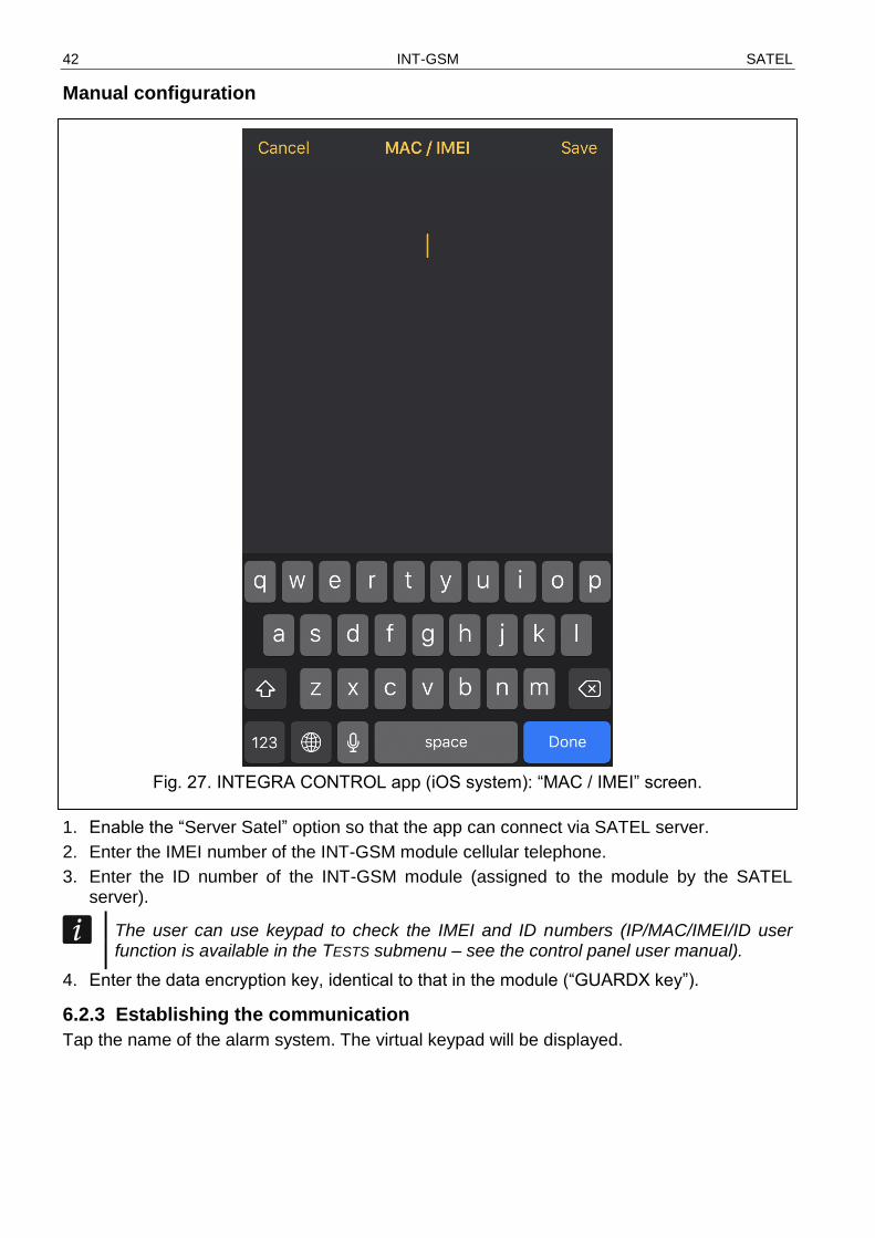
Fig. 27. INTEGRA CONTROL app (iOS system): “MAC / IMEI” screen.
1. Enable the “Server Satel” option so that the app can connect via SATEL server.
2. Enter the IMEI number of the INT-GSM module cellular telephone.
3. Enter the ID number of the INT-GSM module (assigned to the module by the SATEL server).
The user can use keypad to check the IMEI and ID numbers (IP/MAC/IMEI/ID user function is available in the TESTS submenu – see the control panel user manual).
4. Enter the data encryption key, identical to that in the module (“GUARDX key”).
6.2.3 Establishing the communication
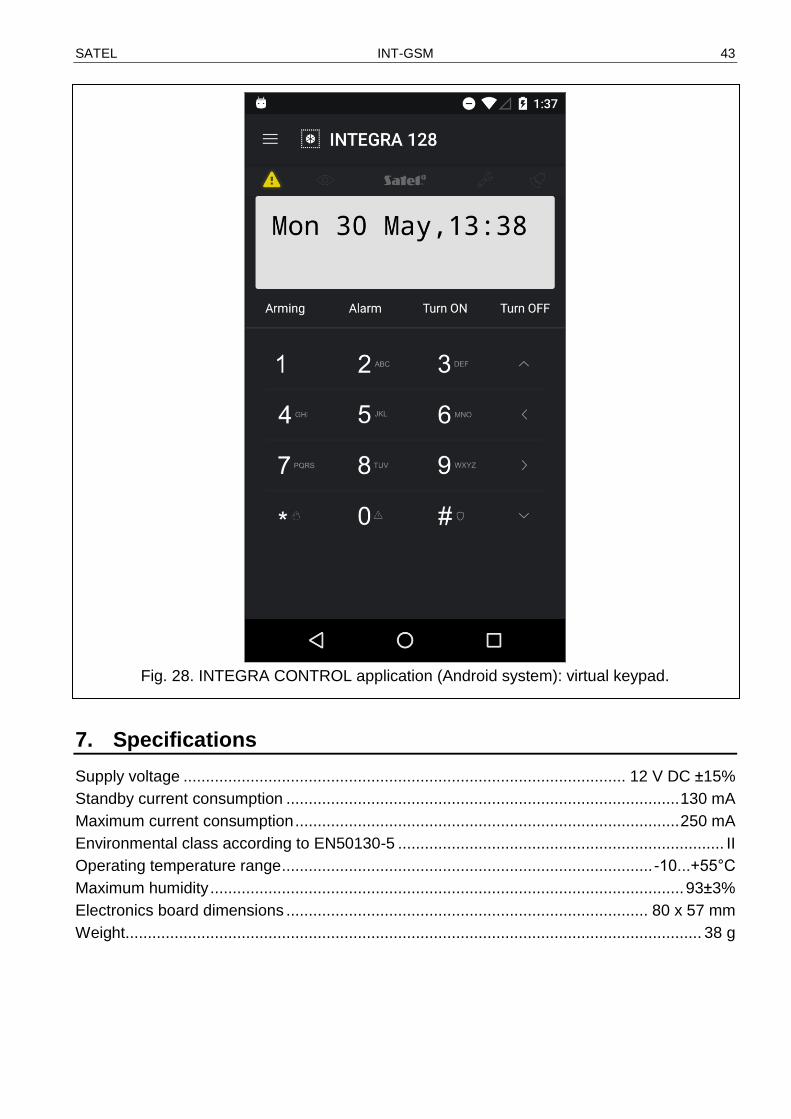
Tap the name of the alarm system. The virtual keypad will be displayed.
SATEL INT-GSM 43
Fig. 28. INTEGRA CONTROL application (Android system): virtual keypad.
7. Specifications
Supply voltage ................................................................................................... 12 V DC ±15%
Standby current consumption ........................................................................................ 130 mA
Maximum current consumption ...................................................................................... 250 mA
Environmental class according to EN50130-5 ......................................................................... II
Operating temperature range ................................................................................... -10...+55°C
Maximum humidity .......................................................................................................... 93±3%
Electronics board dimensions ................................................................................. 80 x 57 mm
Weight ................................................................................................................................. 38 g
44 INT-GSM SATEL
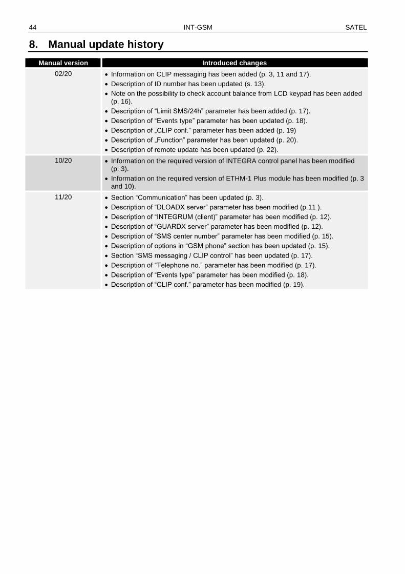
8. Manual update history
Manual version Introduced changes
02/20 Information on CLIP messaging has been added (p. 3, 11 and 17).
Description of ID number has been updated (s. 13).
Note on the possibility to check account balance from LCD keypad has been added (p. 16).
Description of “Limit SMS/24h” parameter has been added (p. 17).
Description of “Events type” parameter has been updated (p. 18).
Description of „CLIP conf.” parameter has been added (p. 19)
Description of „Function” parameter has been updated (p. 20).
Description of remote update has been updated (p. 22).
10/20 Information on the required version of INTEGRA control panel has been modified (p. 3).
Information on the required version of ETHM-1 Plus module has been modified (p. 3 and 10).
11/20 Section “Communication” has been updated (p. 3).
Description of “DLOADX server” parameter has been modified (p.11 ).
Description of “INTEGRUM (client)” parameter has been modified (p. 12).
Description of “GUARDX server” parameter has been modified (p. 12).
Description of “SMS center number” parameter has been modified (p. 15).
Description of options in “GSM phone” section has been updated (p. 15).
Section “SMS messaging / CLIP control” has been updated (p. 17).
Description of “Telephone no.” parameter has been modified (p. 17).
Description of “Events type” parameter has been modified (p. 18).
Description of “CLIP conf.” parameter has been modified (p. 19).