basicgsm 2 - gsm notification and control module, gsm
TRANSCRIPT

BasicGSM 2 - GSM notification and control module, GSM terminal.
Ropam Elektronik
Tel. +48 12 272 39 71 Faks +48 12 379 34 10
Polanka 301 32-400 Myślenice, Polska
www.ropam.com.pl [email protected]
Wersja dokumentu : 1.0 2017-10-06
Installation Manual (DTR).

© 2017 Ropam Elektronik
WARNINGS
For safety reasons, this equipment should be installed only by qualified personnel.
Before proceeding with the installation, refer to the above instruction, the connection
must be performed without the power supply.
Do not power on the unit without connecting an external antenna (starting the device
without the antenna connected may damage the phone transmissions and void the
warranty!).
Do not interfere with construction or carry out repairs yourself.
Protect your electronics against electrostatic discharges.
In order to meet LVD and EMC requirements, the following must be observed: power,
installation, shielding - according to application. The device is a source of
electromagnetic waves, so it may interfere with other radio devices in specific
configurations.
Ropam Elektronik is not responsible for any malfunction of the GSM network and any
possible technical problems.
.
WEEE LABELING
Waste electrical and electronic equipment must not be disposed of with household
waste. According to the WEEE directive (EU Directive 2002/96 / EC), electrical and
electronic equipment used should be used separately. In Poland, it is prohibited to place
together with other wastes of worn equipment marked with a crossed-out wheeled bin
symbol in accordance with the regulations on waste electrical and electronic equipment.
The user who intends to dispose of this product is obliged to give the above mentioned.
to the point of collection of used equipment. Collection points are conducted, among
others. by the wholesale and retail sellers of this equipment and the municipal
organizational units engaged in waste collection activities. The correct implementation
of these obligations is particularly important in the case of hazardous equipment that has
a negative impact on the environment and human health.
The power supply unit is compatible with a 12V DC lead acid battery (SLA, VRL). It
should not be discarded after use, but must be disposed of in accordance with the
applicable regulations.
(European Union Directives 91/157 / EEC and 93/86 / EEC).
© 2017 Ropam Elektronik
Spis treści
1. Introduction ................................................................................................................................. 1
Introduction ..................................................................................................................................... 1
Properties ........................................................................................................................................ 1
Appliance ........................................................................................................................................ 2
Warrnings ........................................................................................................................................ 2
Requirements for SMS control and mobile applications. ................................................................ 3
Device version ................................................................................................................................ 3
2. System description ..................................................................................................................... 5
Description of connectors and components. ................................................................................... 5
Optical status indication. ................................................................................................................. 8
Additional modules and extensions. ............................................................................................... 9
3. Installation and commissioning ................................................................................................. 10
Basic requirements. ...................................................................................................................... 10
Power requirements in accordance with PN-EN 50131-6. ........................................................... 10
Wiring system................................................................................................................................ 12
Installation and commissioning procedure. ................................................................................... 12
Connection of devices to the inputs. ............................................................................................. 13
Connecting devices to the outputs. ............................................................................................... 14
Connection of speech synthesizer, audio module. ....................................................................... 16
4. System configuration ................................................................................................................ 18
System configuration: BasicGSM Manager. ................................................................................. 18
Description of the program toolbar. ........................................................................... 18
Local configuration via USB port............................................................................... 18
Connection to the module via GPRS. ....................................................................... 19
Functional description. .............................................................................................. 20
Tab: SIM card settings. ................................................................................................................. 20
Tab: Phone numbers nad e-mail addresses. ................................................................................ 24
Tab: Inputs .................................................................................................................................... 24
Input settings - binary I1-I6. .......................................................................................................... 24
Input settings - Analog I7, I8. ........................................................................................................ 26
Inputs - Notifications. .................................................................................................................... 28
Tab: Outputs ................................................................................................................................. 29
Tab: Outputs - Notifications. ......................................................................................................... 32
© 2017 Ropam Elektronik
Tab: Timers. .................................................................................................................................. 33
Tab: Communication, Tests, Counters ......................................................................................... 34
Tab: System options. .................................................................................................................... 36
Tab: Temperature. ........................................................................................................................ 37
Tab: LogicProcessor ..................................................................................................................... 40
Logical functions. .......................................................................................................................... 42
Time / counter functions. ............................................................................................................... 48
Tab: Events Memory. .................................................................................................................... 51
Tab: Online view. .......................................................................................................................... 51
Netmonitor GSM (BTS) ................................................................................................................. 56
Upgrade to a newer version. ..................................................................................... 57
Module software update. .......................................................................................... 57
System configuration: SMS commands. ....................................................................................... 58
Remote configuration: TELEPHONE NUMBERS / SMS CENTER. ............................................. 59
Remote configuration: TEMPERATURE. ..................................................................................... 59
Remote configuration: OTHER SETTINGS. ................................................................................. 60
Ropam Basic mobile Application. ................................................................................................. 61
Set access to the application. ................................................................................... 61
Description of application windows. .......................................................................... 62
Descriptions and features of application icons. ......................................................... 63
Pre-set the application. ............................................................................................. 66
RopamDroid mobile application .................................................................................................... 68
RopamDroid application description. ........................................................................ 69
Installation and configuration of RopamDroid. .......................................................... 71
View application windows. ........................................................................................ 73
5. Reset the device to factory settings.......................................................................................... 75
6. System maintenance. ............................................................................................................... 76
7. Technical parameters. .............................................................................................................. 77
8. Version history. ......................................................................................................................... 79
Page 01
Introduction
© 2017 Ropam Elektronik
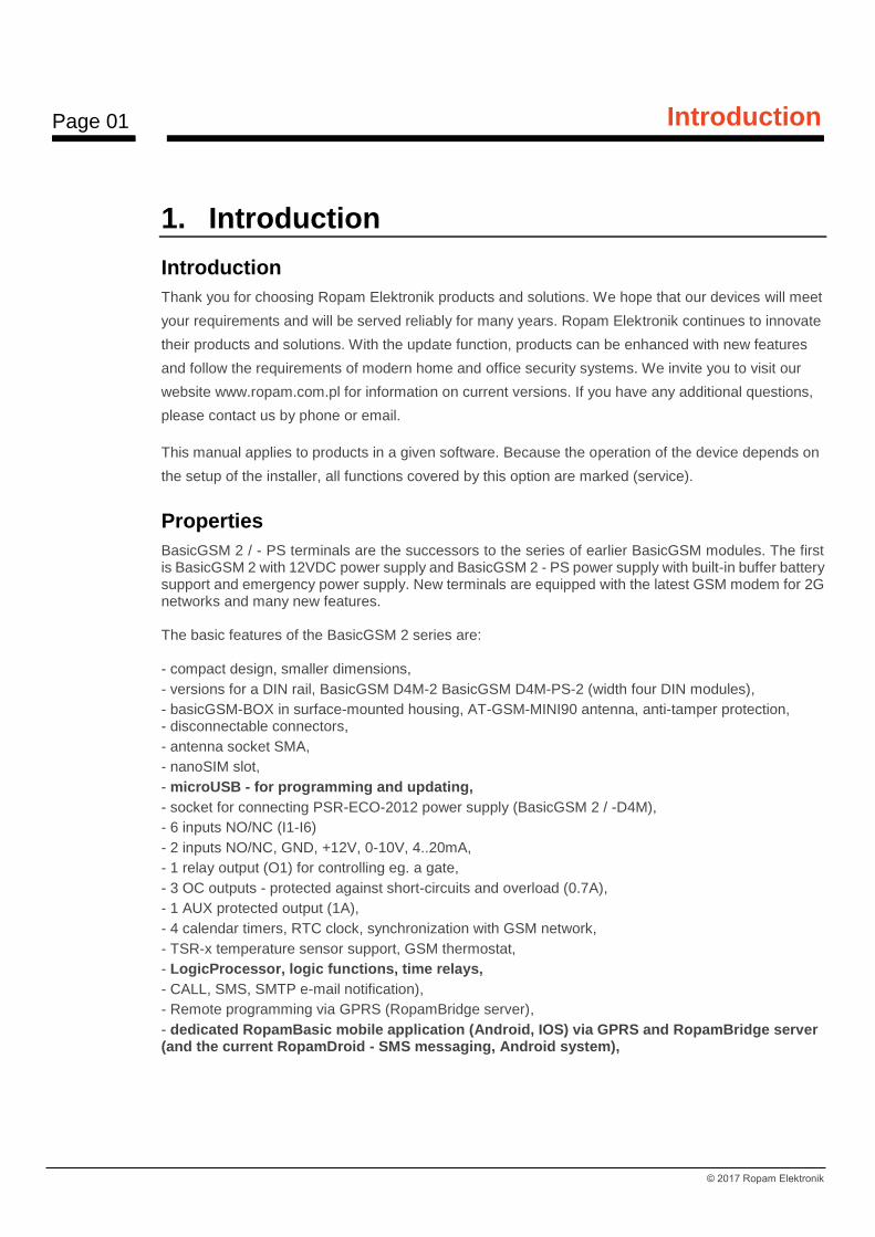
1. Introduction
Introduction
Thank you for choosing Ropam Elektronik products and solutions. We hope that our devices will meet
your requirements and will be served reliably for many years. Ropam Elektronik continues to innovate
their products and solutions. With the update function, products can be enhanced with new features
and follow the requirements of modern home and office security systems. We invite you to visit our
website www.ropam.com.pl for information on current versions. If you have any additional questions,
please contact us by phone or email.
This manual applies to products in a given software. Because the operation of the device depends on
the setup of the installer, all functions covered by this option are marked (service).
Properties
BasicGSM 2 / - PS terminals are the successors to the series of earlier BasicGSM modules. The first is BasicGSM 2 with 12VDC power supply and BasicGSM 2 - PS power supply with built-in buffer battery support and emergency power supply. New terminals are equipped with the latest GSM modem for 2G networks and many new features. The basic features of the BasicGSM 2 series are: - compact design, smaller dimensions,
- versions for a DIN rail, BasicGSM D4M-2 BasicGSM D4M-PS-2 (width four DIN modules),
- basicGSM-BOX in surface-mounted housing, AT-GSM-MINI90 antenna, anti-tamper protection, - disconnectable connectors,
- antenna socket SMA,
- nanoSIM slot,
- microUSB - for programming and updating,
- socket for connecting PSR-ECO-2012 power supply (BasicGSM 2 / -D4M),
- 6 inputs NO/NC (I1-I6)
- 2 inputs NO/NC, GND, +12V, 0-10V, 4..20mA,
- 1 relay output (O1) for controlling eg. a gate,
- 3 OC outputs - protected against short-circuits and overload (0.7A),
- 1 AUX protected output (1A),
- 4 calendar timers, RTC clock, synchronization with GSM network,
- TSR-x temperature sensor support, GSM thermostat,
- LogicProcessor, logic functions, time relays,
- CALL, SMS, SMTP e-mail notification),
- Remote programming via GPRS (RopamBridge server),
- dedicated RopamBasic mobile application (Android, IOS) via GPRS and RopamBridge server (and the current RopamDroid - SMS messaging, Android system),
Page 02
Introduction
© 2017 Ropam Elektronik
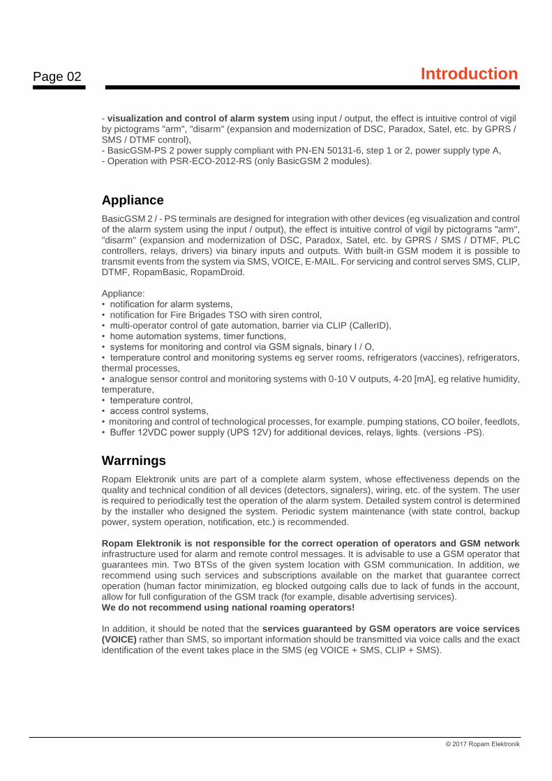
- visualization and control of alarm system using input / output, the effect is intuitive control of vigil by pictograms "arm", "disarm" (expansion and modernization of DSC, Paradox, Satel, etc. by GPRS / SMS / DTMF control), - BasicGSM-PS 2 power supply compliant with PN-EN 50131-6, step 1 or 2, power supply type A, - Operation with PSR-ECO-2012-RS (only BasicGSM 2 modules).
Appliance
BasicGSM 2 / - PS terminals are designed for integration with other devices (eg visualization and control of the alarm system using the input / output), the effect is intuitive control of vigil by pictograms "arm", "disarm" (expansion and modernization of DSC, Paradox, Satel, etc. by GPRS / SMS / DTMF, PLC controllers, relays, drivers) via binary inputs and outputs. With built-in GSM modem it is possible to transmit events from the system via SMS, VOICE, E-MAIL. For servicing and control serves SMS, CLIP, DTMF, RopamBasic, RopamDroid. Appliance: • notification for alarm systems, • notification for Fire Brigades TSO with siren control, • multi-operator control of gate automation, barrier via CLIP (CallerID), • home automation systems, timer functions, • systems for monitoring and control via GSM signals, binary I / O, • temperature control and monitoring systems eg server rooms, refrigerators (vaccines), refrigerators, thermal processes, • analogue sensor control and monitoring systems with 0-10 V outputs, 4-20 [mA], eg relative humidity, temperature, • temperature control, • access control systems, • monitoring and control of technological processes, for example. pumping stations, CO boiler, feedlots, • Buffer 12VDC power supply (UPS 12V) for additional devices, relays, lights. (versions -PS).
Warrnings
Ropam Elektronik units are part of a complete alarm system, whose effectiveness depends on the quality and technical condition of all devices (detectors, signalers), wiring, etc. of the system. The user is required to periodically test the operation of the alarm system. Detailed system control is determined by the installer who designed the system. Periodic system maintenance (with state control, backup power, system operation, notification, etc.) is recommended. Ropam Elektronik is not responsible for the correct operation of operators and GSM network infrastructure used for alarm and remote control messages. It is advisable to use a GSM operator that guarantees min. Two BTSs of the given system location with GSM communication. In addition, we recommend using such services and subscriptions available on the market that guarantee correct operation (human factor minimization, eg blocked outgoing calls due to lack of funds in the account, allow for full configuration of the GSM track (for example, disable advertising services). We do not recommend using national roaming operators! In addition, it should be noted that the services guaranteed by GSM operators are voice services (VOICE) rather than SMS, so important information should be transmitted via voice calls and the exact identification of the event takes place in the SMS (eg VOICE + SMS, CLIP + SMS).
Page 03
Introduction
© 2017 Ropam Elektronik
For service like e-mail transmission it is recommended to create a independent e-mail account (eg.
[email protected]) in a proven provider e-mail accounts. Sharing of data to an SMTP server from a
private account can result in unauthorized access to these accounts.
Requirements for SMS control and mobile applications.
For the service via SMS and RopamDroid mobile phone, the smartphone must encode the SMS: GSM or UNICODE alphabet other formats are not supported! For RopamDroid applications, your smartphone must have compatible SMS support from the Android API, and do not have overlays, other SMS intercept apps that have priority for inbox or outbox. For proper configuration and operation of RopamDroid you need the proper configuration of the system and knowledge of the data (service): - knowledge of the phone number of the SIM card installed in the system, - knowledge of "SMS code / login password for application" and active option: "Possible change of configuration via SMS", "SMS active control", "send confirmation of SMS command execution" - to control outputs via RopamDroid, the control setting via SMS for the output is required, - to control TermostatemGSM is required to run a function of temperature measurements and the thermostat. For proper setup and operation of RopamBasic it is required to have adequate knowledge of system configuration and data (service): - knowledge of the phone number of the SIM card installed in the system, - knowledge of "SMS password / application login password" and active option: "Possible remote programming via GPRS", - knowledge of the encryption key TCP / IP. - control via the RopamBasic requires the setting triggered by the "Mobile Application" for the output, - for controlling the GSM thermostat, it is necessary to start the function of temperature measurement and thermostat.
Device version
BasicGSM 2 is available in several versions, below is the name and options of the device.
BasicGSM - BOX 2, module equipped with tamper cover:

Page 04
Introduction
© 2017 Ropam Elektronik
BasicGSM 2: BasicGSM - PS 2:
BasicGSM - D4M 2: BasicGSM-D4M-PS 2:
Page 05
System description
© 2017 Ropam Elektronik
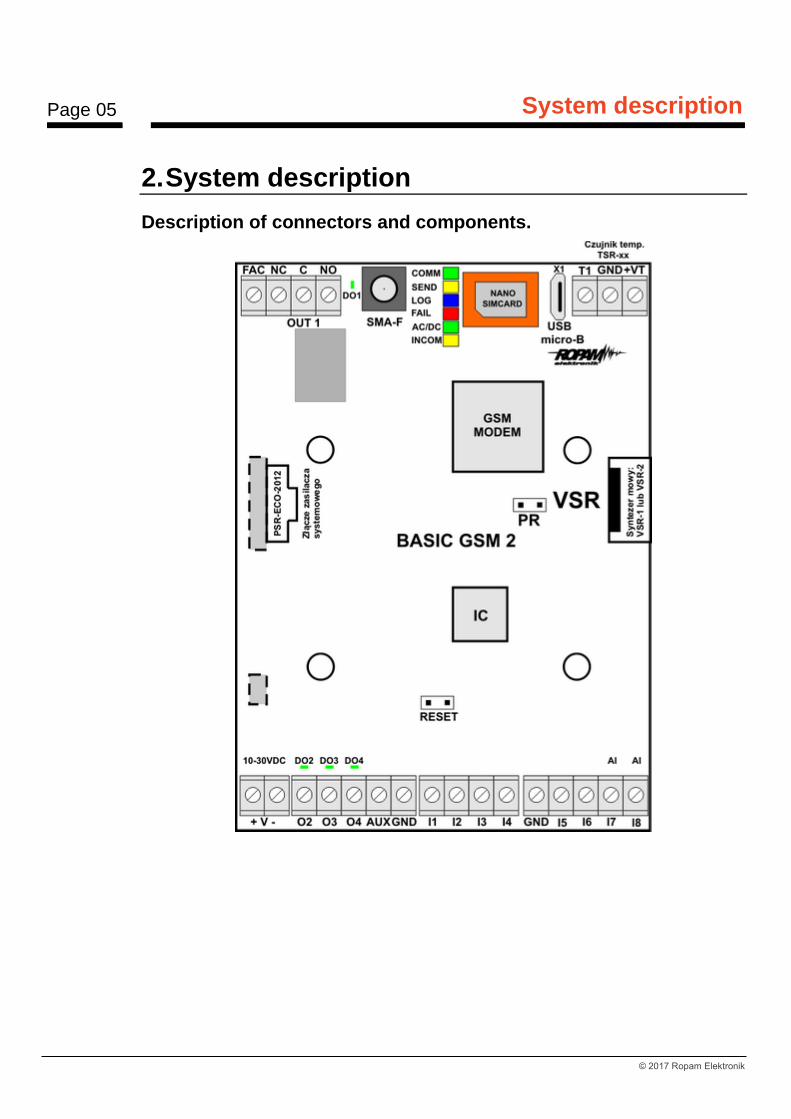
2. System description
Description of connectors and components.
Page 06
System description
© 2017 Ropam Elektronik
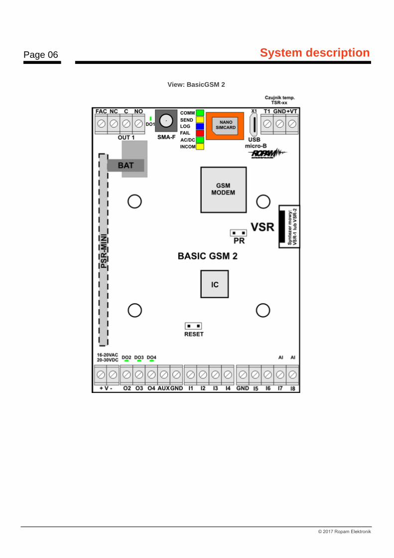
View: BasicGSM 2
Page 07
System description
© 2017 Ropam Elektronik
Connector / element
Description / Function
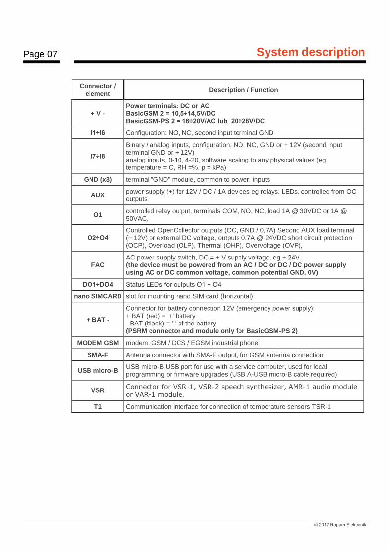
+ V -
Power terminals: DC or AC BasicGSM 2 = 10,5÷14,5V/DC BasicGSM-PS 2 = 16÷20V/AC lub 20÷28V/DC
I1÷I6 Configuration: NO, NC, second input terminal GND
I7÷I8
Binary / analog inputs, configuration: NO, NC, GND or + 12V (second input terminal GND or + 12V) analog inputs, 0-10, 4-20, software scaling to any physical values (eg. temperature = C, RH =%, p = kPa)
GND (x3) terminal "GND" module, common to power, inputs
AUX power supply (+) for 12V / DC / 1A devices eg relays, LEDs, controlled from OC outputs
O1 controlled relay output, terminals COM, NO, NC, load 1A @ 30VDC or 1A @ 50VAC,
O2÷O4 Controlled OpenCollector outputs (OC, GND / 0,7A) Second AUX load terminal (+ 12V) or external DC voltage, outputs 0.7A @ 24VDC short circuit protection (OCP), Overload (OLP), Thermal (OHP), Overvoltage (OVP),
FAC AC power supply switch, DC = + V supply voltage, eg + 24V, (the device must be powered from an AC / DC or DC / DC power supply using AC or DC common voltage, common potential GND, 0V)
DO1÷DO4 Status LEDs for outputs O1 ÷ O4
nano SIMCARD slot for mounting nano SIM card (horizontal)
+ BAT -
Connector for battery connection 12V (emergency power supply): + BAT (red) = '+' battery - BAT (black) = '-' of the battery (PSRM connector and module only for BasicGSM-PS 2)
MODEM GSM modem, GSM / DCS / EGSM industrial phone
SMA-F Antenna connector with SMA-F output, for GSM antenna connection
USB micro-B USB micro-B USB port for use with a service computer, used for local programming or firmware upgrades (USB A-USB micro-B cable required)
VSR Connector for VSR-1, VSR-2 speech synthesizer, AMR-1 audio module
or VAR-1 module.
T1 Communication interface for connection of temperature sensors TSR-1
Page 08
System description
© 2017 Ropam Elektronik
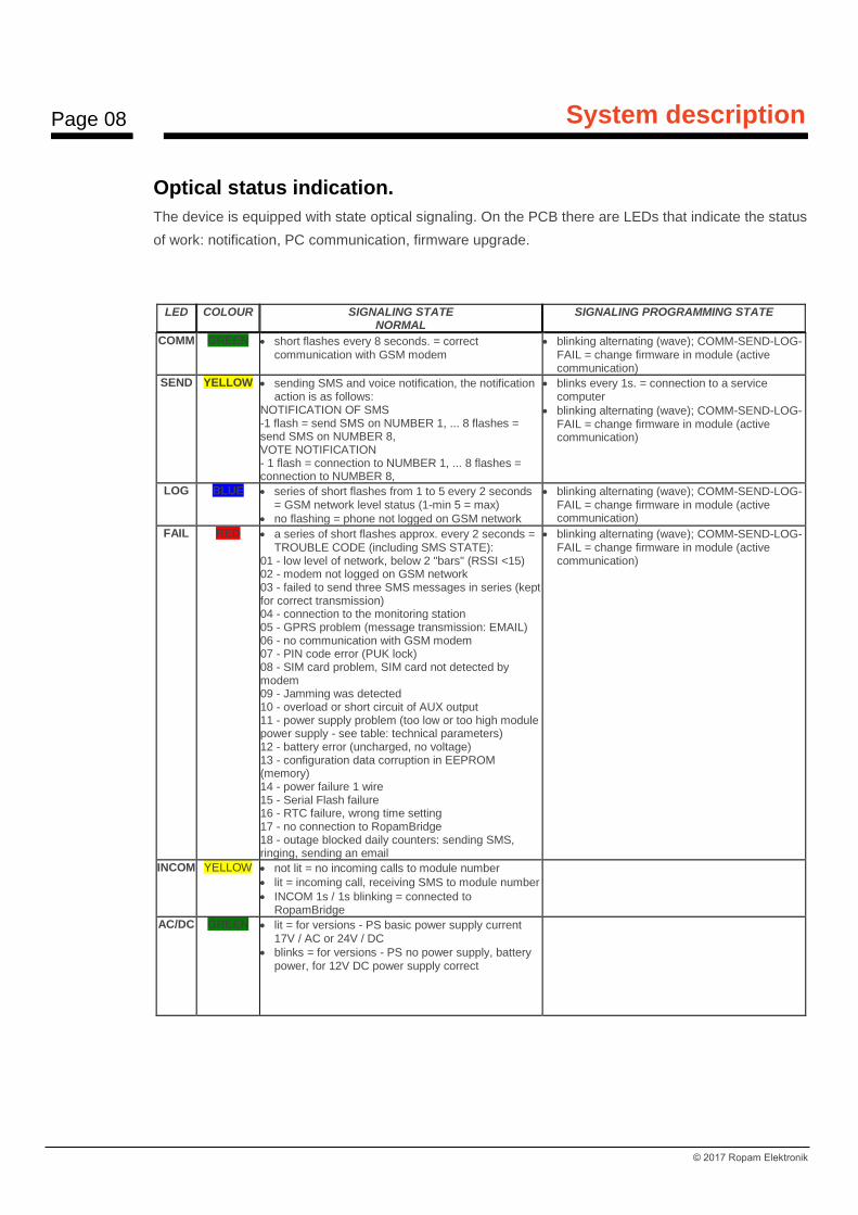
Optical status indication.
The device is equipped with state optical signaling. On the PCB there are LEDs that indicate the status
of work: notification, PC communication, firmware upgrade.
LED COLOUR SIGNALING STATE NORMAL
SIGNALING PROGRAMMING STATE
COMM GREEN • short flashes every 8 seconds. = correct communication with GSM modem
• blinking alternating (wave); COMM-SEND-LOG-FAIL = change firmware in module (active communication)
SEND YELLOW • sending SMS and voice notification, the notification action is as follows:
NOTIFICATION OF SMS -1 flash = send SMS on NUMBER 1, ... 8 flashes = send SMS on NUMBER 8, VOTE NOTIFICATION - 1 flash = connection to NUMBER 1, ... 8 flashes = connection to NUMBER 8,
• blinks every 1s. = connection to a service computer
• blinking alternating (wave); COMM-SEND-LOG-FAIL = change firmware in module (active communication)
LOG BLUE • series of short flashes from 1 to 5 every 2 seconds = GSM network level status (1-min 5 = max)
• no flashing = phone not logged on GSM network
• blinking alternating (wave); COMM-SEND-LOG-FAIL = change firmware in module (active communication)
FAIL RED • a series of short flashes approx. every 2 seconds = TROUBLE CODE (including SMS STATE):
01 - low level of network, below 2 "bars" (RSSI <15) 02 - modem not logged on GSM network 03 - failed to send three SMS messages in series (kept for correct transmission) 04 - connection to the monitoring station 05 - GPRS problem (message transmission: EMAIL) 06 - no communication with GSM modem 07 - PIN code error (PUK lock) 08 - SIM card problem, SIM card not detected by modem 09 - Jamming was detected 10 - overload or short circuit of AUX output 11 - power supply problem (too low or too high module power supply - see table: technical parameters) 12 - battery error (uncharged, no voltage) 13 - configuration data corruption in EEPROM (memory) 14 - power failure 1 wire 15 - Serial Flash failure 16 - RTC failure, wrong time setting 17 - no connection to RopamBridge 18 - outage blocked daily counters: sending SMS, ringing, sending an email
• blinking alternating (wave); COMM-SEND-LOG-FAIL = change firmware in module (active communication)
INCOM YELLOW • not lit = no incoming calls to module number
• lit = incoming call, receiving SMS to module number
• INCOM 1s / 1s blinking = connected to RopamBridge
AC/DC GREEN • lit = for versions - PS basic power supply current 17V / AC or 24V / DC
• blinks = for versions - PS no power supply, battery power, for 12V DC power supply correct

Page 09
System description
© 2017 Ropam Elektronik
Additional modules and extensions.
TSR-xx: TEMPERATURE SENSOR
TSR-1, TSR1HT, TSR-1TEL, TSR-2 temperature range as for TSR1-HT.
Digital temperature sensor with measuring range -55 ° C to + 125 ° C (resolution 0.5 ° C, reading
every 60s).
VSR-2: Speech Synthesizer:
Module for recording and playback of 16 audio messages (8 x 16sec. + 8 x 8sec), additionally allows
to connect audio module for listening to the object. Terminal functions allow you to add independent
messages from several (5) recordings in case of violation, temperature thresholds, AI thresholds.
VSR-1: Speech Synthesizer
Remembers 20 second voice prompt.
AMR-1: AUDIO MODULE
The audio module allows you to listen to an audio object: during an alarm or after a voice call. The
module is connected to the VSR input.
PSR-2012 ECO:
High-efficiency AC / DC pulse generator. P = 20 [W], Iout = 1.6A, U = 13.8 [V]

Page 10
Installation and commissioning
© 2017 Ropam Elektronik
3. Installation and commissioning
Basic requirements.
The system is based on BasicGSM 2 and the other required components are for installation by a
qualified installer with appropriate (required and required by country) permits and permissions to
connect (interference) to 230V / AC systems and low voltage installations. The units should be
installed indoors, with normal humidity (RH = 20% - 90% max non-condensing) and temperatures in
the range -10 ° C ... + 55 ° C. Before installing, make a load balancing of the power supply. Because
the system power supply is designed for continuous operation and does not have a power switch,
proper overload protection in the power supply circuit must be provided. Also tell the user how to
disconnect the power supply from the power supply (usually by splitting and marking the appropriate
fuse in the fuse box). Electrical installation should be carried out in accordance with applicable
standards and regulations.
When selecting the module mounting location, the communication module should be guided by the
following criteria:
- GSM network coverage (SIM card operator used for the module)
- the GSM antenna and other system components (eg power supply) must be in the protected area,
- availability and distance from alarm / triggering sources (eg control panel);
- availability or possibility of installation in the immediate vicinity of the power source:
- availability of facilities for third parties and sabotage tests,
- keep a safe distance from sources of possible interference (eg 230Vac power lines - buildings, radio
transmitters, etc.).
Power requirements in accordance with PN-EN 50131-6.
The PS * type A ** power supply should supply electrical power to I & HAS *** components without
interruption. To meet the appropriate degree 1,2 or 3 acc. EN 50131-6, the emergency power supply
must run at a minimum of Td (implemented by limiting the power consumption from the power supply:
Id + Iz) and the battery charging time to 80% of the rated capacity can not exceed the time: TQ0,8C.
Page 11
Installation and commissioning
© 2017 Ropam Elektronik
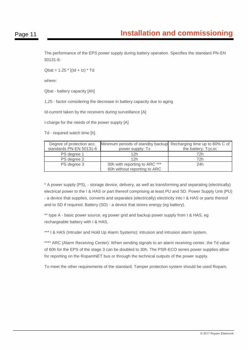
The performance of the EPS power supply during battery operation. Specifies the standard PN-EN
50131-6:
Qbat = 1.25 * [(Id + Iz) * Td
where:
Qbat - battery capacity [Ah]
1,25 - factor considering the decrease in battery capacity due to aging
Id-current taken by the receivers during surveillance [A]
I-charge for the needs of the power supply [A]
Td - required watch time [h].
Degree of protection acc. standards PN-EN 50131-6
Minimum periods of standby backup power supply: Td
Recharging time up to 80% C of the battery: TQ0,8C
PS degree 1 12h 72h
PS degree 2 12h 72h
PS degree 3 30h with reporting to ARC *** 60h without reporting to ARC
24h
* A power supply (PS), - storage device, delivery, as well as transforming and separating (electrically)
electrical power to the I & HAS or part thereof comprising at least PU and SD. Power Supply Unit (PU)
- a device that supplies, converts and separates (electrically) electricity into I & HAS or parts thereof
and to SD if required. Battery (SD) - a device that stores energy (eg battery).
** type A - basic power source, eg power grid and backup power supply from I & HAS, eg
rechargeable battery with I & HAS,
*** I & HAS (Intruder and Hold Up Alarm Systems): intrusion and intrusion alarm system.
**** ARC (Alarm Receiving Center): When sending signals to an alarm receiving center, the Td value
of 60h for the EPS of the stage 3 can be doubled to 30h. The PSR-ECO series power supplies allow
for reporting on the RopamNET bus or through the technical outputs of the power supply.
To meet the other requirements of the standard. Tamper protection system should be used Ropam.

Page 12
Installation and commissioning
© 2017 Ropam Elektronik
Wiring system.
System cabling should be made using low voltage cables. In addition, it should comply with the
regulations and standards in particular: cable type selection and cross-section, 230V / AC wiring
distance,
Other connections should be made according to the manufacturer's instructions and if not, you can
use the following cables:
• YTDY, YTLZ,
• UTP, STP, FTP,
• YTSKY,
• Other low current compliant with regulations and standards.
Installation and commissioning procedure.
1. Make complete wiring: signal and power supply,
2. Install the enclosure and insert the wiring through the cable glands,
3. Install the SIM card in the module (the card must not be installed while the power is on!),
- insert horizontally into the SIMCARD connector, the gold-plated SIM card towards the PCB, the SIM
card (notch) must be pointing at the slot in the SIM card slot on the module board.
Below is a view of the SIM card installation process in BasicGSM 2 / BasicGSM - PS 2 - Profile view.
4. Install the board and modules in the enclosure:
a) in the system housings (Ropam) on the pins included,
b) in the enclosures of the control panel transmitters on the self-adhesive pins supplied with the
module,
c) in the control cabinets with the latch fixing the DIN housing on the mounting rail.
5. Optional additional modules:
- for VSR connectors: VSR-2, VSR-2 + AMR-1 or VSR-1 or AMR-1,
- to the T1 connector: TSR-xx,
Page 13
Installation and commissioning
© 2017 Ropam Elektronik
6. Connect the wires to the appropriate terminals, eg signaling devices, relays
7. Connect the external antenna to the SMA-F connector (in the system casing, move the SMA
connector from the SMA-F connector to the casing hole).
8. Turn on the module power.
9. Connect the cable connecting the service computer to the USB-Micro jack.
10. Configure the system as needed.
11. Make tests and tests.
12. Disconnect the cable from the USB-microphone connector.
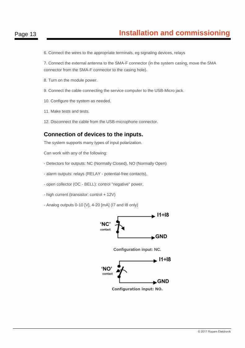
Connection of devices to the inputs.
The system supports many types of input polarization.
Can work with any of the following:
- Detectors for outputs: NC (Normally Closed), NO (Normally Open)
- alarm outputs: relays (RELAY - potential-free contacts),
- open collector (OC - BELL): control "negative" power,
- high current (transistor: control + 12V)
- Analog outputs 0-10 [V], 4-20 [mA] (I7 and I8 only)
Configuration input: NC.
Configuration input: NO.

Page 14
Installation and commissioning
© 2017 Ropam Elektronik
Input (I7, I8) in the configuration NC, software configurable (BasicGSM Manager).
Input (I7, I8) in the configuration: NO, configurable software (BasicGSM Manager).
Input I7 / I8 to connect a voltage or current source.
FAC input for AC voltage control (on isolation transformer).
Connecting devices to the outputs.
The module has outputs allowing control and signaling.
O1 - relay output - 1A @ 30VDC

Page 15
Installation and commissioning
© 2017 Ropam Elektronik
-
Output O1: Connection of the 12V DC (acoustic and / or optical).
Output O1: connection of 12V DC load.
- O2-O4 in the active state can supply (NO) or disconnect (NC) 0V power supply (GND).
(open collector transistor output OC, control "supply ground", 700mA max.)
O2-O4 output: connection of 12VDC / 700mA siren max. (acoustic and / or optical).

Page 16
Installation and commissioning
© 2017 Ropam Elektronik
Output O2-O4: connection of 12V DC, power supply + 12V = AUX.
O2-O4 output: connecting a LED, power supply + 12V = AUX.
- AUX, power output + 12V / 1A (second terminal, ground = GND) for powering detectors, relays. The output has stand-alone overload protection, overload and temperature protection (return to
normal operation if the problem is resolved).
Connection of speech synthesizer, audio module.
The system is equipped with a VSR socket for connecting VSR-2 speech synthesizer, VSR-1 or AMR-
1 audio module for listening / listening.
The speech synthesizer allows you to record and transmit a voice message in the event of a system
event. Playback occurs automatically when a voice call is made. The message is played back to the
end of the call. The message is played back to the end of the call.
Page 17
Installation and commissioning
© 2017 Ropam Elektronik
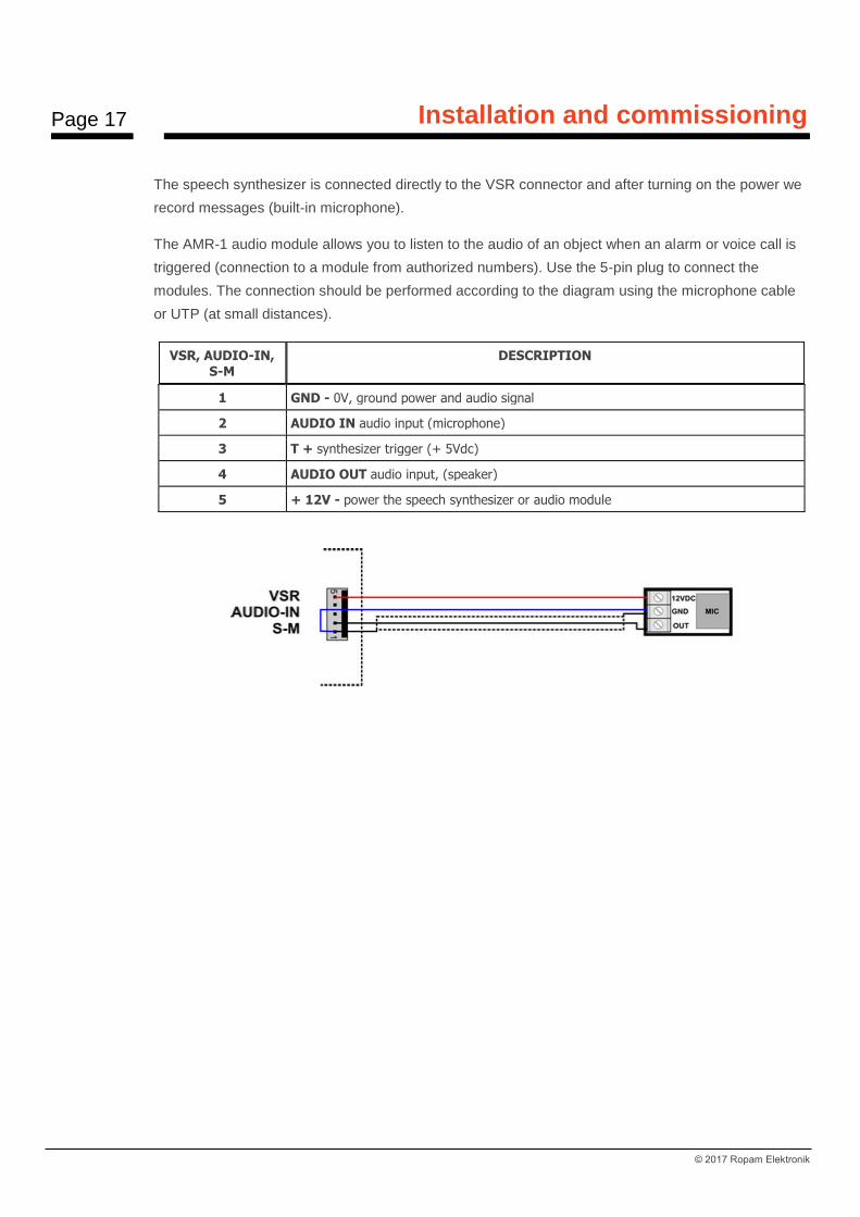
The speech synthesizer is connected directly to the VSR connector and after turning on the power we
record messages (built-in microphone).
The AMR-1 audio module allows you to listen to the audio of an object when an alarm or voice call is
triggered (connection to a module from authorized numbers). Use the 5-pin plug to connect the
modules. The connection should be performed according to the diagram using the microphone cable
or UTP (at small distances).
VSR, AUDIO-IN, S-M
DESCRIPTION
1 GND - 0V, ground power and audio signal
2 AUDIO IN audio input (microphone)
3 T + synthesizer trigger (+ 5Vdc)
4 AUDIO OUT audio input, (speaker)
5 + 12V - power the speech synthesizer or audio module

Page 18
System configuration
© 2017 Ropam Elektronik
4. System configuration Programming and configuration of the system (module) can be performed:
• from the BasicGSM Manager; local connection the whole system and functions,
• from the BasicGSM Manager; GPRS connection - the whole system and functions,
• from the SMS command level; selected functions.
System configuration: BasicGSM Manager.
BasicGSM Manager is designed for use on PCs running WINDOWS XP / VISTA / 7/8/10.
Communication between BasicGSM Manager and Ropam devices is via a USB port using
communication cables. BasicGSM Manager allows you to configure devices and update firmware
versions (firmware upgrade).
Description of the program toolbar.
The program has a text-graphic menu. Unauthorized operations or features for this type of device are
displayed as inactive (gray: icons or captions). Communication functions are only available after the
USB port is properly configured and communication with the module is started.
Local configuration via USB port.
The module is configured via USB. In order to obtain the configuration process, follow these steps.
1. Turn off the module power. 2. Connect the communication cable to the micro USB connector on the module board. 3. Connect the cable to the port on the service computer (USB). 4. Start the service computer and BasicGSM Manager. 5. Turn on the module power. 6. In BasicGSM Manager: - enter the PASSWORD in the COMMUNICATION OPTIONS (factory 111111), if no password or its incompatibility is possible, only SAVE to the module and update the firmware

Page 19
System configuration
© 2017 Ropam Elektronik
7. USB connection icon with module , signaling status of waiting for connection with module, message in program's foot: WAIT FOR APPLICATION OF MODULE. When the module is detected
(ready to connect to the module) the icon has a dark color . 8. The module should start communication, the communication options will be activated in the program. In addition, correct communication is signaled by an animation alongside the Ropam Elektronik logo in the upper bar of the program, and the message "MODULE CONNECTION" and "hardware, firmware version, disc ID" appear in the BasicGSM Manager footer. 9. Configure the module, perform tests (ON-LINE), etc. Reading / writing etc. is signaled by the corresponding message in the program footer and the progress of execution is indicated by the percent pointer at the top of the program menu - next to the Ropam Elektronik log.
10. To exit the communication, press the USB icon (the yellow LED SEND 4-5 times). 11. Disconnect the cable from the micro USB connector. 12. Perform tests, user training.
Connection to the module via GPRS.
The BasicGSM 2 module provides an option for remote connection to the user via GPRS data via the
RopamBridge server.
To set up a remote connection to a module using BasicGSM Manager:
- provide access to the internet for a computer that will make a remote connection to the BasicGSM 2 module - read the configuration (load the configuration file) of the module with which we want to connect - Verify GPRS connection data - APN:
Example settings operator Orange:
- select the option of remote connection to the module from the BasicGSM Manager status bar:
- the module must be disarmed during this procedure, - send to SMS module with remote connection request: SMS code / login to connect application (eg 2222 connect), - connection set up (40 attempts), - after a successful remote connection procedure statement on the status bar icon appears antenna index next to data synchronization indicator between the module and the program BasicGSM Manager:

Page 20
System configuration
© 2017 Ropam Elektronik
- to end the remote connection to the module, press the icon:
Functional description.
The description of the function and configuration is presented with the windows, descriptions and
messages from BasicGSM Manager.
Tab: SIM card settings.
SIM CARD PIN
In the field "SIM PIN" enter the digits of the SIM card PIN installed in the module phone. If you are
using a non-PIN (disabled) card, do not enter PIN code.
COMMENTS:
- in the factory settings of the module is not transmitted PIN. This allows you to install the SIM card and start the module without worrying about locking the SIM card by entering the wrong PIN code by the module. - no PIN code is required to disable the PIN code request only for non-PIN cards TELEPHONE NUMBER OF THE OBJECT
This is the SIM card number in the module. The field is saved to the module memory. Do not monitor the jamming GSM Jamming: This option disables GSM modem jamming detection. Do not signal low GSM network failure: Low GSM signaling off Restart modem every 24h: Modem restart function every 24 hours since the last restart of BasicGSM module 2. This function is useful in cases where there are problems with network login, unstable connection with BTS operator, virtual operators. The module resets only the GSM modem, the

Page 21
System configuration
© 2017 Ropam Elektronik
remaining module functions are available, the events generated on the inputs and outputs are written to the module memory. Sending SMS active: SMS of system event notification enabled. Unchecking this option will cause the module to miss sending SMS messages. Active ringing: The system event notification function is activated as a ringing tone for the user. In addition to the notification in the form of rings, they are also sent messages from the voice synthesizer: VSR-1, VSR-2 module AMR-1. When the function is inactive - no possibility to send notifications CLIP and voice module BasicGSM 2. When there is a need to use the module as a stand-alone BasicGSM 2 control unit - then turn off the options for sending SMS and dzwonienia- module will not turn on GSM modem and thus the system will not appear on the failure of GSM / calling / sending SMS. SMS CENTER The number of the SMS center, select on the operator tab from the list (the number will be displayed automatically) or edit the field. The number should be entered in international format.
COMMENTS: The module has the option to automatically retrieve the SMS center number from the SIM card inserted into the nano SIMCARD connector. If there is no possibility of automatic identification of the SMS center by module - select operator manually and save to the module.SMS CENTER must be the SMS center number of the GSM network operator of the SIM card in the module phone! No number or incorrect number will block SMS sending!
APN SETTINGS:
APN settings: Access point settings (internet via GPRS). Required to control the module from the RopamBasic application, GPRS monitoring, sending email notifications from the module.
Page 22
System configuration
© 2017 Ropam Elektronik
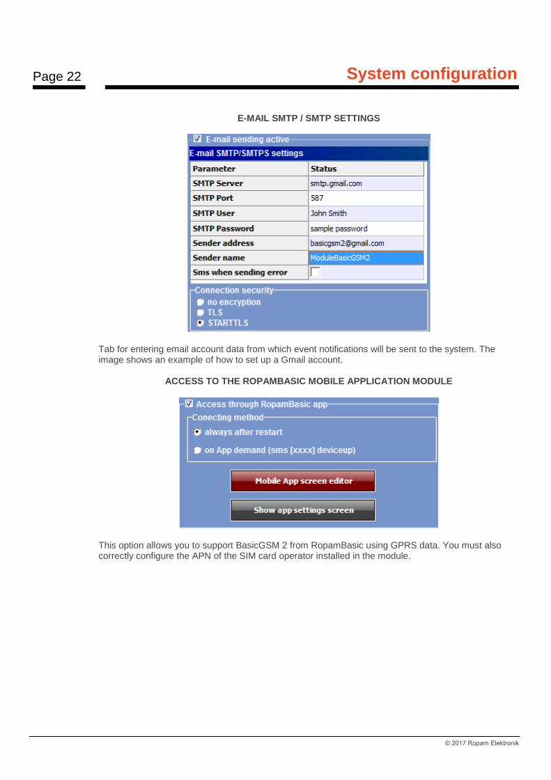
E-MAIL SMTP / SMTP SETTINGS
Tab for entering email account data from which event notifications will be sent to the system. The image shows an example of how to set up a Gmail account.
ACCESS TO THE ROPAMBASIC MOBILE APPLICATION MODULE
This option allows you to support BasicGSM 2 from RopamBasic using GPRS data. You must also correctly configure the APN of the SIM card operator installed in the module.
Page 23
System configuration
© 2017 Ropam Elektronik
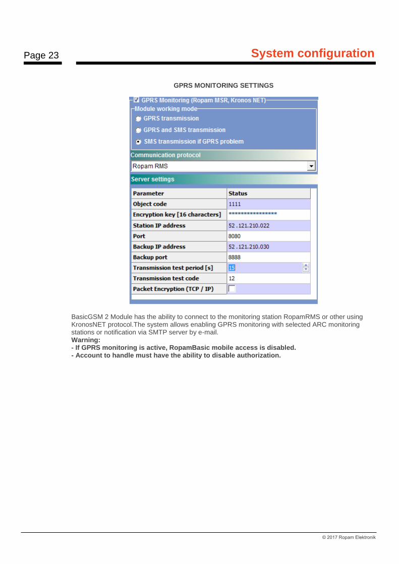
GPRS MONITORING SETTINGS
BasicGSM 2 Module has the ability to connect to the monitoring station RopamRMS or other using KronosNET protocol.The system allows enabling GPRS monitoring with selected ARC monitoring stations or notification via SMTP server by e-mail. Warning: - If GPRS monitoring is active, RopamBasic mobile access is disabled. - Account to handle must have the ability to disable authorization.
Page 24
System configuration
© 2017 Ropam Elektronik
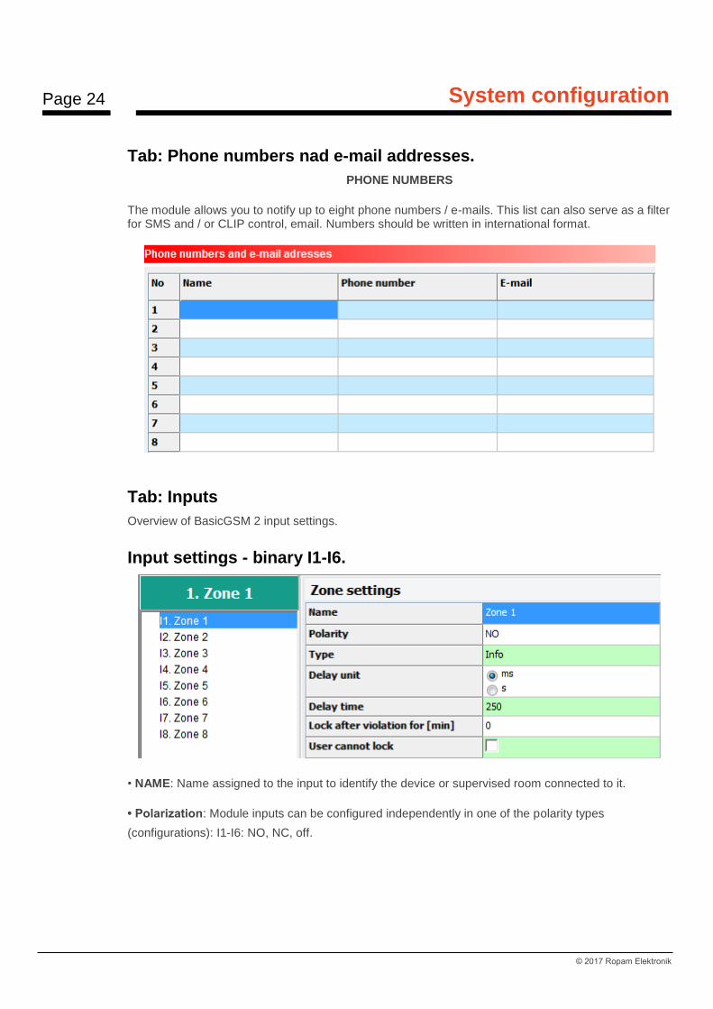
Tab: Phone numbers nad e-mail addresses.
PHONE NUMBERS
The module allows you to notify up to eight phone numbers / e-mails. This list can also serve as a filter for SMS and / or CLIP control, email. Numbers should be written in international format.
Tab: Inputs
Overview of BasicGSM 2 input settings.
Input settings - binary I1-I6.
• NAME: Name assigned to the input to identify the device or supervised room connected to it.
• Polarization: Module inputs can be configured independently in one of the polarity types
(configurations): I1-I6: NO, NC, off.

Page 25
System configuration
© 2017 Ropam Elektronik
NO - means the input is NORMALLY OPEN, triggered by "ground" (GND). In case of inputs I7, I8 can be triggered by "ground" (GND) or "plus" (+ VDC). NC - means the input is NORMALLY CLOSED, triggered by disconnection from "ground" (GND). In case of inputs I7, I8 can be triggered by "ground" (GND) or "plus" (+ VDC). OFF - disables the input regardless of other input settings.
• TYPE: INFO - the input trigger does not trigger an alarm action but initiates the sending of SMS and VOICE voice calls according to the settings. 24h - the input generates an alarm in each module state and generates the process of sending SMS and VOICE voice calls according to the settings. NORMAL - the line triggers an alarm (noisy) if the system is in standby mode and generates the process of sending SMS and VOICE voice calls according to the settings. ON / OFF - zone for arming / disarming system. The input can operate in the bistable mode (switch): the violation arises armed, the end of the violation turns off or monostable (the button when enabled option: LINE OF PULSE) the action is then: the first violation will arm the module, the second violation disarms, alternate. NORMAL SILENT - the input only works in standby mode, it does not generate a loud alarm, it only generates the process of sending SMS and VOICE voice calls according to the settings. • DELAY: input delay time unit: [ms], [s], • TIME DELAY: value of time after which input violation is detected: units [ms] - milliseconds (1s = 1000ms), [s] - seconds.
Example:
• Lock to [min]: Lock time of input (response) after first violation. This option works for TYPE input: INFO, NORMAL, NORMAL. For each input you can set the lock time independently (default set to 0s). Min / max = 1min./360min Warning: - This option is used to limit the number of notifications and motion detectors connected to the inputs. limiting the number of transmissions from a given source, readability of transmitted messages, - for a motion detector such as PIR, the parameter should be a loud alarm or a minimum of 1 minute. User can not block: The user can not block input from the application: RopamBasic, RopamDroid or SMS command.

Page 26
System configuration
© 2017 Ropam Elektronik
Input settings - Analog I7, I8.
In addition, two inputs I7, I8 are binary / analog inputs that can be configured from BasicGSM Manager. These inputs can, in addition to the binary states (0,1), recognize the values of analog signals: 0-10 [V]
and 4-20 [mA].
When selecting I7 or I8 input mode as analog:
you must configure its parameters:
- name - easier identification of the measured value - Alarm when higher / lower than allowed (SMS, CLIP, e-mail notification) of required content. It is also possible to set the voice prompts of the VSR-2 module connected to the module or to use audio messages recorded to the files and uploaded to the module memory (Tab "Communications, Tests, Counters" option: Audio voice announcements). - Input hysteresis: set to delay the input to change input parameters. - Delay [ms]: delay in response to change of measured value.

Page 27
System configuration
© 2017 Ropam Elektronik
Sample setting of I7 input to which a liquid level sensor with output 4-20 [mA] is connected.
Input principle:
Page 28
System configuration
© 2017 Ropam Elektronik
For a liquid level of 0m, the signal output at the transmitter output is 4 [mA], which is 20 [mA] for the
maximum level (10m).
COMMENTS: In SMS "STAN" are displayed values from inputs I7 / I8 in units set in the program.
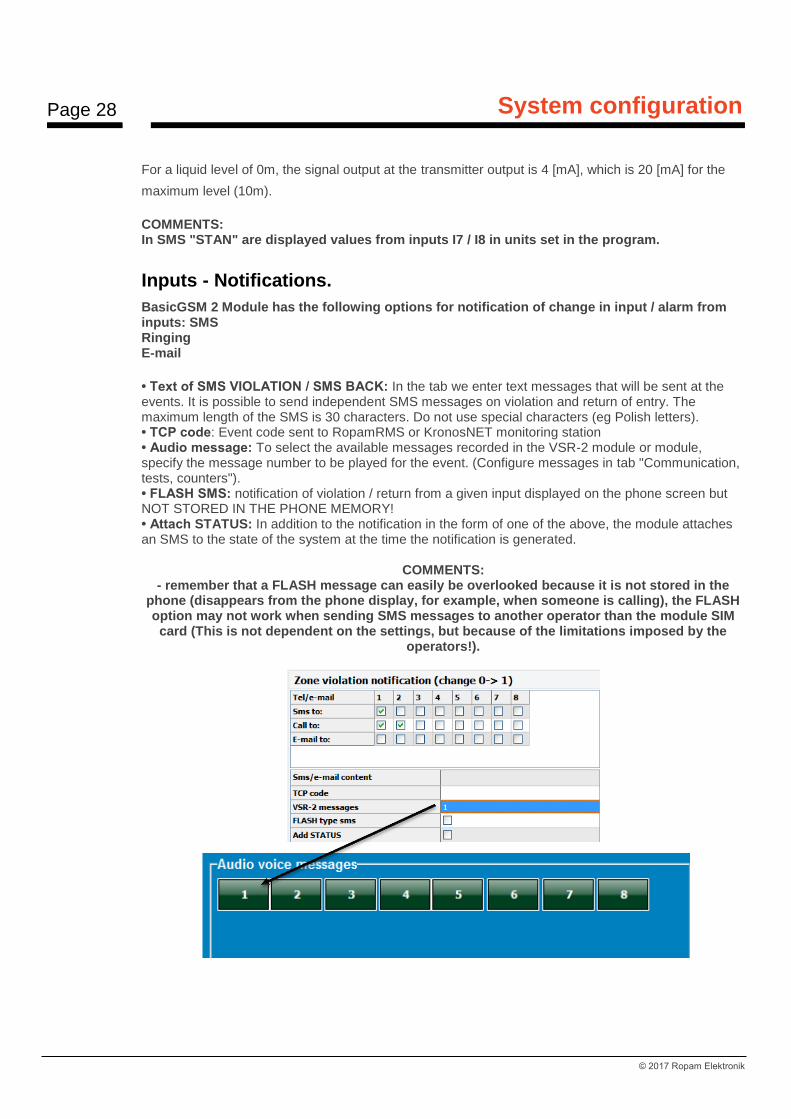
Inputs - Notifications.
BasicGSM 2 Module has the following options for notification of change in input / alarm from inputs: SMS Ringing E-mail
• Text of SMS VIOLATION / SMS BACK: In the tab we enter text messages that will be sent at the events. It is possible to send independent SMS messages on violation and return of entry. The maximum length of the SMS is 30 characters. Do not use special characters (eg Polish letters). • TCP code: Event code sent to RopamRMS or KronosNET monitoring station • Audio message: To select the available messages recorded in the VSR-2 module or module, specify the message number to be played for the event. (Configure messages in tab "Communication, tests, counters"). • FLASH SMS: notification of violation / return from a given input displayed on the phone screen but NOT STORED IN THE PHONE MEMORY! • Attach STATUS: In addition to the notification in the form of one of the above, the module attaches an SMS to the state of the system at the time the notification is generated.
COMMENTS: - remember that a FLASH message can easily be overlooked because it is not stored in the
phone (disappears from the phone display, for example, when someone is calling), the FLASH option may not work when sending SMS messages to another operator than the module SIM
card (This is not dependent on the settings, but because of the limitations imposed by the operators!).
Page 29
System configuration
© 2017 Ropam Elektronik
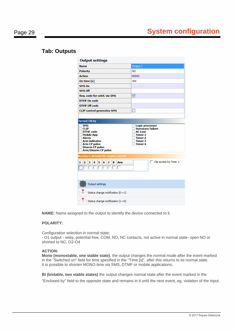
Tab: Outputs
NAME: Name assigned to the output to identify the device connected to it.
POLARITY:
Configuration selection in normal state: - O1 output - relay, potential free, COM, NO, NC contacts, not active in normal state- open NO or shorted to NC, O2-O4 ACTION: Mono (monostable, one stable state), the output changes the normal mode after the event marked in the "Switched on" field for time specified in the "Time [s]", after this returns to its normal state. It is possible to shorten MONO time via SMS, DTMF or mobile applications.
BI (bistable, two stable states) the output changes normal state after the event marked in the
"Enclosed by" field to the opposite state and remains in it until the next event, eg, violation of the input.
Page 30
System configuration
© 2017 Ropam Elektronik
BI (bistable, two stable states) the output changes normal state after the event marked in the
"Enclosed by" field to the opposite state and remains in it until the next event, eg, violation of the input.
Output in BI mode for triggering as ALARM acts as a latch, to clear the alarm.
TIME [s] Specifies the operating time [s] of the output in MONO mode, parameter 1-9000 s.
SMS ON In the tab we enter the text of the SMS which will activate the given output (default OnX where X =
output number). The maximum length of the SMS is 20 characters. Do not use special characters (eg
Polish letters).
SMS OFF In the tab we enter text SMS which will disable the given output (default OffX where X = output
number). The maximum length of the SMS is 20 characters. Do not use special characters (eg Polish
letters).
REQUIRE THE CODE Selecting the option will result control of the given output via SMS will require to place in the content
except SMS ON / SMS OFF, SMS CODE (tab: Communication, tests, counters).
DTMF On OnIn the tab we enter the DTMF code, which will turn on output (DTMFOn *). recommended lengths of
2-4 characters (numbers).
DTMF Off In the tab we enter the DTMF code, which will turn off the output (DTMFOff *). recommended lengths
of 2-4 characters (numbers).
EXCLUDED BY Defining what events control the output, selecting several options creates the LOGIC SUM (OR) of
these events (ie the output is active when at least one event has been fulfilled), it allows to combine eg
control: simultaneous SMS and CLIP.
SMS tick option allows you to control output via SMS (command or access code + command
depending on configuration) or RopamDroid application.
CLIP option allows output control by a short connection with the module telephone number. The
function is available if the control is enabled in the "NUMERICALLY CONTROLLED NUMBERS FOR
CLIP CONTROL" option by the numbers entered in the PHONE NUMBERS fields.
DTMF allows you to control the output via DTMF during a voice call (DTMFOn * or DTMFOff *).
Page 31
System configuration
© 2017 Ropam Elektronik
MOBILE APPLICATION: control of output from RopamBasic mobile application and RopamDroid.
ALARM: output active when an alarm occurs. (def. normal input).
INDICATOR: active output (indicator) when the module goes into standby mode, if this option is
enabled, the time settings in the "TIME [s]" field are ignored.
ARM CA Pulse: turn on the output to a short pulse (0,7s), eg. The purpose of arming external alarm
central.
DISARM CA Pulse: turn on the output to a short pulse (0,7s), for example to disarmam external alarm
central.
ARM/DISARM CA IMPULS: switch on / off output fot short pulse (0.7s), eg to arming / disarming the
external alarm panel.
LOGIC PROCESSOR - the output activated by LogicProcessor, the process of overrid actions for
module outputs. If the LP control option is selected, then other triggering changes functions of output
state are overwritten by the LogicProcessor loop! The output operation based on the LP allows to
achieve a result based on many of system resources which greatly facilitates advanced use of module
and reduces the quantity of external peripherals needed to carry out more complex operations using
the module BasicGSM 2.
FAILURE SUMMARY output is active when a failure occurs.
AC NO - active when AC power failure occurs, AC failure delay time (0s-165mins configured in
COMMUNICATIONS, TESTS, COUNTERS)
TIMER 1, TIMER 2, TIMER 3, TIMER 4: output on / off by timers available in the system.
NUMBERS AUTHORIZED TO CLIP CONTROL OUTPUT The option, after selecting, entitles phone numbers entered in the NUMERS tab to control the output
with the option CLICK ON: CLIP Bell.
COMMENTS: - Please note that the phone number from which you want to control the output can not be "reserved". - responses to incoming calls are configured in the SYSTEM OPTIONS tab.

Page 32
System configuration
© 2017 Ropam Elektronik
Tab: Outputs - Notifications.
The tab allows you to configure notifications when the modules output state changes. The window and
its configuration is analogous to the notification option from inputs.
Logical state '0' = output inactive: - polarity 'NO' O2-O4 = hiZ (high impedance) - polaritz 'NC' O2-O4 = GND (ground) Logical state '1' = active output - polarity 'NO' O2-O4 = GND (ground) - polaritz 'NC' O2-O4 = hiZ (high impedance) Information: OUT1-OUT4: list of outputs to which the settings apply. SMS 0-> 1: column to enter the text of the SMS sent when the output change to the state '1' active. SMS 1-> 0: column to enter the text of the SMS sent when the output change to state '0' is inactive. CALL 0-> 1: column to activate a voice call (CLIP or voice message) when you change the output state to '1' active. E-mail to: column to mark the recipient's number from the list to send when changing the output to status '1' active. VSR 0-> 1: column to enter the message numbers played during a voice call from the VSR-2 synthesizer or from the unit's memory when the output is changed to '1' active. CALL 1 -> 0: Voice call activation column (CLIP or voice message) when switching to a '0' state inactive. VSR 1-> 0: column to enter the message numbers played during a voice call from the VSR-2 synthesizer or from the unit's memory when the output is changed to '0' inactive. Tel / Email: Columns to mark recipients of SMS / CALL / E-MAIL messages. - no SMS content = no SMS transmission at the given event.
Page 33
System configuration
© 2017 Ropam Elektronik
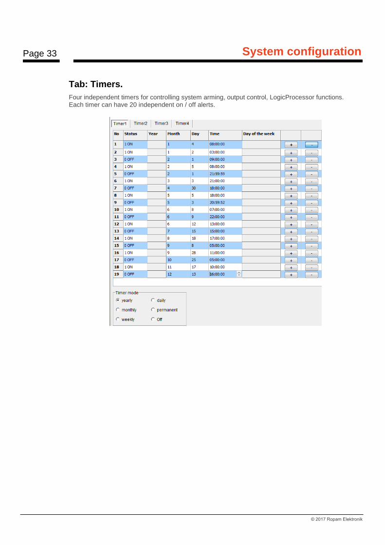
Tab: Timers.
Four independent timers for controlling system arming, output control, LogicProcessor functions. Each timer can have 20 independent on / off alerts.
Page 34
System configuration
© 2017 Ropam Elektronik
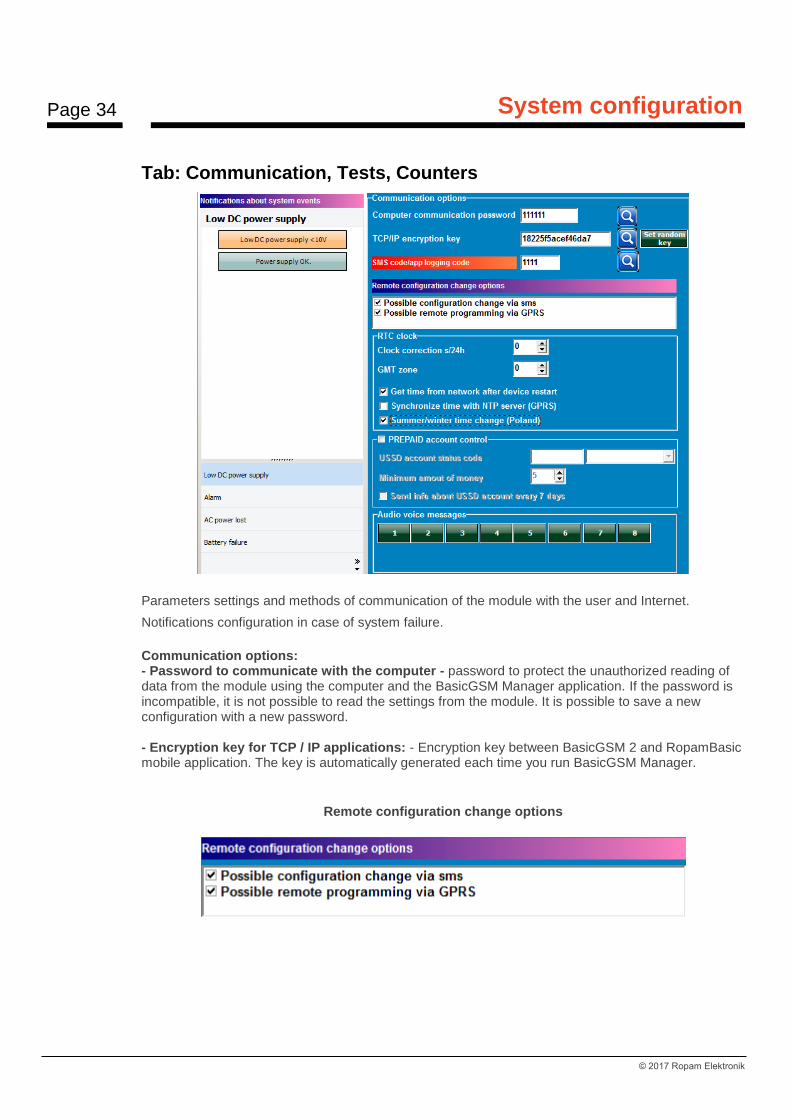
Tab: Communication, Tests, Counters
Parameters settings and methods of communication of the module with the user and Internet.
Notifications configuration in case of system failure.
Communication options: - Password to communicate with the computer - password to protect the unauthorized reading of data from the module using the computer and the BasicGSM Manager application. If the password is incompatible, it is not possible to read the settings from the module. It is possible to save a new configuration with a new password. - Encryption key for TCP / IP applications: - Encryption key between BasicGSM 2 and RopamBasic mobile application. The key is automatically generated each time you run BasicGSM Manager.
Remote configuration change options
Page 35
System configuration
© 2017 Ropam Elektronik
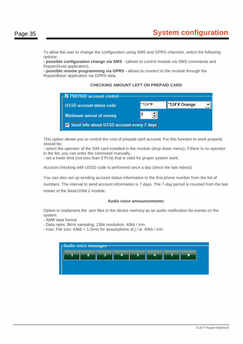
To allow the user to change the configuration using SMS and GPRS channels, select the following options: - possible configuration change via SMS - (allows to control module via SMS commands and RopamDroid application), - possible remote programming via GPRS - allows to connect to the module through the RopamBasic application via GPRS data.
CHECKING AMOUNT LEFT ON PREPAID CARD
This option allows you to control the cost of prepaid card account. For this function to work properly should be: - select the operator of the SIM card installed in the module (drop down menu), if there is no operator in the list, you can enter the command manually, - set a lower limit (not less than 5 PLN) that is valid for proper system work. Account checking with USSD code is performed once a day (since the last reboot).
You can also set up sending account status information to the first phone number from the list of
numbers. The interval to send account information is 7 days. The 7-day period is counted from the last
restart of the BasicGSM 2 module.
Audio voice announcements:
Option to implement the .amr files in the device memory as an audio notification for events on the system. - AMR data format - Data rates: 8kHz sampling, 13bit resolution, 40kb / min - max. File size: 64kb = 1.5min for assumptions of j / w: 40kb / min

Page 36
System configuration
© 2017 Ropam Elektronik
Tab: System options.
The tab allows you to set options related to: - transmission test (type, transmission interval, content, to whom, content), - notification counters (daily) - time of notification, - response to incoming calls, - SMS control options - other options (DTMF control).
SMS control: - SMS active control: enabled if: The system is supported by RopamDroid and single SMS commands, - send confirmation of SMS command execution: turn on if the system is supported by the application RopamDroid (needed for the visualization of system operations / module BasicGSM 2). Optionally disable if you do not use the module control from the RopamDroid application and / or SMS, - control only possible for numbers from the list: option selected - control by SMS commands / applications RopamDroid will only be possible for the phone numbers listed in the numbers list in the tab: Phone numbers, email addresses, - send unrecognized SMS to the first number (Echo): the option selected - the module sends unrecognized messages (eg ads, offers, other non-command messages to the module) to the first phone number listed in the tab: Phone numbers, email addresses,
Page 37
System configuration
© 2017 Ropam Elektronik
- do not confirm by the SMS the inclusion of the outputs: option selected - if the control of the outputs is made by SMS commands then the module does not send confirmation of the activation / change of the output status in the form of SMS. OTHER OPTIONS - Pressing (#DTMF) aborts the voice call: Pressing # on the telephone keypad during an ongoing voice call with the module terminates the voice prompt (played from VSR-1, VSR-2 or audio message from BasicGSM 2 memory).
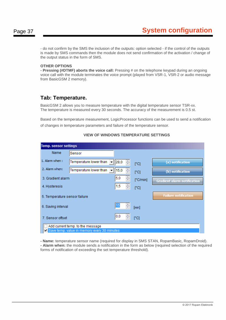
Tab: Temperature.
BasicGSM 2 allows you to measure temperature with the digital temperature sensor TSR-xx. The temperature is measured every 30 seconds. The accuracy of the measurement is 0.5 st.
Based on the temperature measurement, LogicProcessor functions can be used to send a notification
of changes in temperature parameters and failure of the temperature sensor.
VIEW OF WINDOWS TEMPERATURE SETTINGS
- Name: temperature sensor name (required for display in SMS STAN, RopamBasic, RopamDroid). - Alarm when: the module sends a notification in the form as below (required selection of the required forms of notification of exceeding the set temperature threshold).

Page 38
System configuration
© 2017 Ropam Elektronik
- Gradient Alarm: The module sends a notification of exceeding the specified gradient (change rate) of the temperature outside the specified value defined in the field .... [° C / min]. - Hysteresis: Temperature difference for lower and upper switching thresholds. Example: if the setpoint a = 30 [ºC] and b = 20 [ºC] and the hysteresis is set to 2 [ºC], the module switches on when the temperature falls below 18 [ºC] and switches off the heat when the temperature rises above 32 [° C].
COMMENTS: The "Thermostat" control must be based on the functions available in "LogicProcessor". - Temperature sensor failure: Notification of failure / defect of the temperature sensor sent to the system user. Possible notification options: Same as for alarms over temperature. - Memory save value interval: time period between recording of subsequent temperature values to event memory in the module. Minimum time: 1 [min], max interval: 1440 [min]
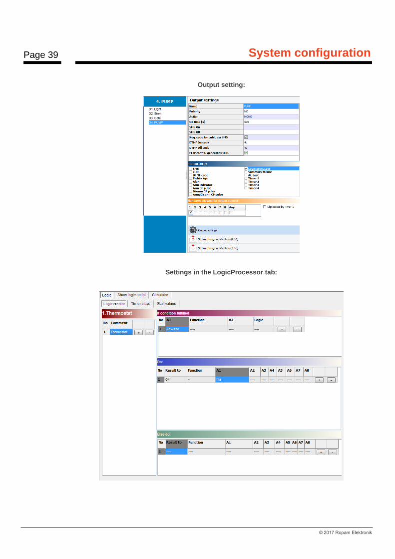
Example in LogicProcessor: The application allows the module to switch on when the temperature rises above 28 ° C. It switches off when the temperature falls below 15 ° C. C. TSR-xx sensor is connected to T1 input, output O4 controls pump via RM85 relay.
Page 39
System configuration
© 2017 Ropam Elektronik
Output setting:
Settings in the LogicProcessor tab:

Page 40
System configuration
© 2017 Ropam Elektronik
Listing logic script: int O4; int tha; main(){ gbenv(); O4=geto(4); while(1){ gbenv(); O4=geto(4); O4=tha; seto(4,O4); }; };
Tab: LogicProcessor
LogicProcessor: Advanced logic functions and time-logic functions, such as programmable time relays, the ability to
create free home automation features with GSM control.
The maximum size of the LogicProcessor script can be 2048 bytes. Maximum number of rows: 10 (comments).
Available resources: - logical function for the arguments: inputs, outputs, markers (0/1 binary value), temperature thresholds, thresholds for analog inputs (I7, I8), failures, timers, binary values, - time-logic functions like programmable time relays, triggers and reset timers (blocks) identical as arguments in logic functions and results are written to outputs or markers, - four clock timers (annual format) with 20 entries each to the LogicProcessor time option.

Page 41
System configuration
© 2017 Ropam Elektronik
WARNING: Functions are performed in the loop according to the scheme. Used physical outputs (results of functions) in LogicProcessor can`t be triggered by other events than the LP in the 'outputs' tab bacause they will be overwritten by logic functions. All logic and time functions for physical outputs must be implemented in LogicProcessor, the result of the function is not considered as output trigger.
Page 42
System configuration
© 2017 Ropam Elektronik
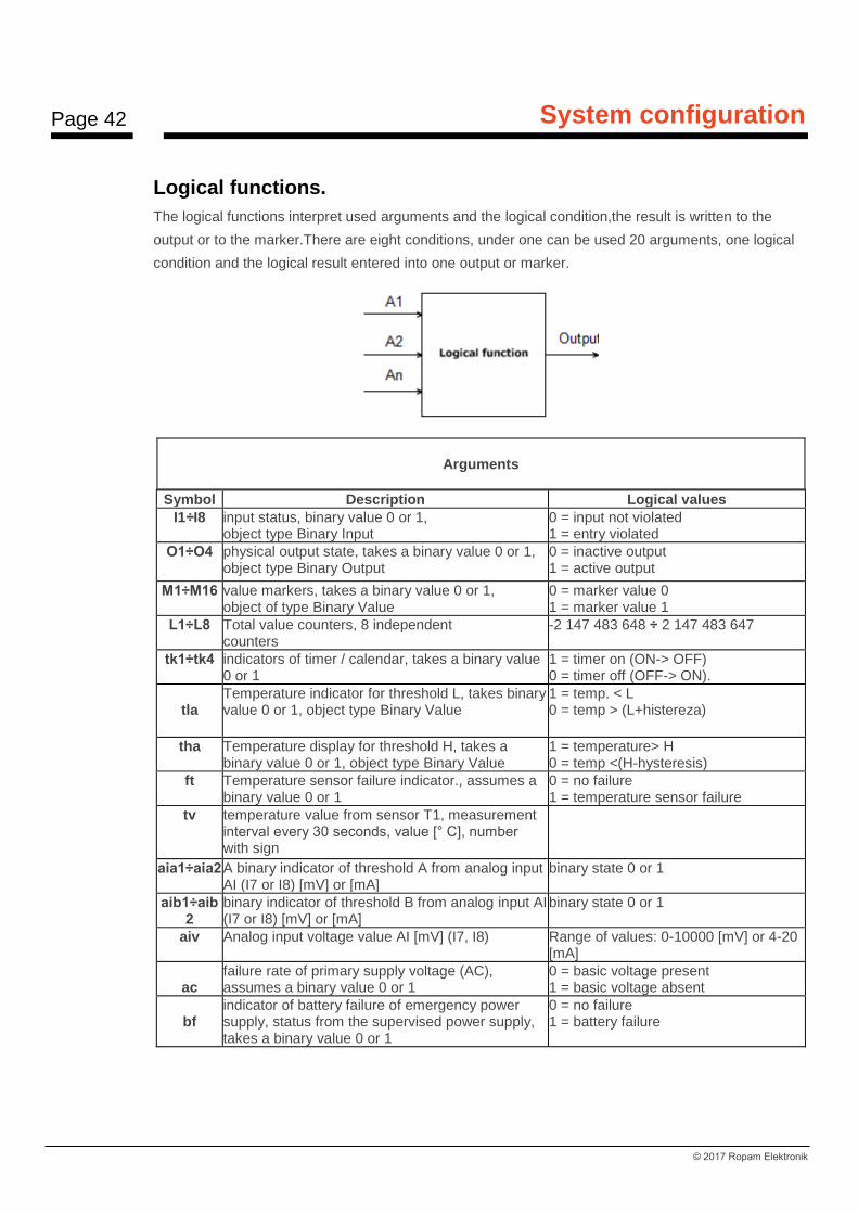
Logical functions.
The logical functions interpret used arguments and the logical condition,the result is written to the
output or to the marker.There are eight conditions, under one can be used 20 arguments, one logical
condition and the logical result entered into one output or marker.
Arguments
Symbol Description Logical values
I1÷I8 input status, binary value 0 or 1, object type Binary Input
0 = input not violated 1 = entry violated
O1÷O4 physical output state, takes a binary value 0 or 1, object type Binary Output
0 = inactive output 1 = active output
M1÷M16 value markers, takes a binary value 0 or 1, object of type Binary Value
0 = marker value 0 1 = marker value 1
L1÷L8 Total value counters, 8 independent counters
-2 147 483 648 ÷ 2 147 483 647
tk1÷tk4 indicators of timer / calendar, takes a binary value 0 or 1
1 = timer on (ON-> OFF) 0 = timer off (OFF-> ON).
tla
Temperature indicator for threshold L, takes binary value 0 or 1, object type Binary Value
1 = temp. < L 0 = temp > (L+histereza)
tha Temperature display for threshold H, takes a binary value 0 or 1, object type Binary Value
1 = temperature> H 0 = temp <(H-hysteresis)
ft Temperature sensor failure indicator., assumes a binary value 0 or 1
0 = no failure 1 = temperature sensor failure
tv temperature value from sensor T1, measurement interval every 30 seconds, value [° C], number with sign
aia1÷aia2 A binary indicator of threshold A from analog input AI (I7 or I8) [mV] or [mA]
binary state 0 or 1
aib1÷aib2
binary indicator of threshold B from analog input AI (I7 or I8) [mV] or [mA]
binary state 0 or 1
aiv Analog input voltage value AI [mV] (I7, I8) Range of values: 0-10000 [mV] or 4-20 [mA]
ac
failure rate of primary supply voltage (AC), assumes a binary value 0 or 1
0 = basic voltage present 1 = basic voltage absent
bf
indicator of battery failure of emergency power supply, status from the supervised power supply, takes a binary value 0 or 1
0 = no failure 1 = battery failure

Page 43
System configuration
© 2017 Ropam Elektronik
log indicator of signing modem to the GSM network, assumes a binary value 0 or 1
0 = not connected to GSM network 1 = modem connected to GSM network
jmg GSM jamming indicator, takes a binary value 0 or 1
0 = no GSM jamming 1 = GSM jamming
as Full system standby, takes a binary value 0 or 1, 0 = no full standby(supervision) 1 = full standby (supervision)
al alarm rate in the system, takes a binary value0 or 1,
0 = no alarm 1 = alarm status
sec operating time unit [s] from the time of restarting, accuracy 1%
sec= xx
uzv supply voltage value DC [mV] xxxx (eg: 13800[mV])
nlv GSM network level 1-4, called. 'dashes' 1÷4
fcd failure code xx (see SMS STAN) 00 = no failure xx = failure
0 Binary Value 0, object type Binary Value 0 - description of result in table "Logical function"
1 Binary Value 1, object type Binary Value 1 - description of result in table "Logical function"
Logical function (If)
Symbol Description Name
== returns true, if both arguments are the same value. equality
!= returns true if both arguments have different values inequality
_| returns true if the argument has a rising edge equality; rising edge
--| returns true if the argument has a falling edge equality; falling edge
> returns true if the left argument has a bigger value than the right
bigger than
< returns true if the left argument has a smaller value than the right
smaller than
>= returns true if the left argument is bigger or equal to the right value
bigger or equal
<= returns true if the left argument is smaller than or equal to the right value
smaller or equal
Result (Output)
Symbol Description Logical values
O1÷O4 physical output state, takes a binary value 0 or 1, object type Binary Output
0 = inactive output 1 = active output
M1÷M16 markers value, takes a binary value 0 or 1, object type Binary Value
0 = marker value 0 1 = marker value 1

Page 44
System configuration
© 2017 Ropam Elektronik
L1÷L8 total value counters, 8 independent counters
-2 147 483 648 ÷ 2 147 483 647
Logical function
Symbol Description Table of truths
AND logical product: A1÷A8 This is a logic system that performs the following functions: on the output appears signal '1' if and only if, when all n input signals have a logical value of '1'.
A1 An
0 0
0 1
1 0
1 1
OR logical sum: A1÷A8 this is a logical sum circuit, which outputs a signal '1' if this value has at least one of the signals. This means that '0' only appears if and only if both signals are '0'.
A1 An
0 0
0 1
1 0
1 1
NAND negated logical product (NOT AND): A1÷A8 This is a logical sum circuit which outputs a signal '1', if this value has n-1 input signals. This means that '0' appears only then, when all the signals are '1'.
A1 An
0 0
0 1
1 0
1 1
NOR negated logical sum (NOT OR); A1÷A8 this is a logic system that performs the following functions: on the output appears signal '1' if and only if, when all n input signals have a logical value of '0'.
A1 An
0 0
0 1
1 0
1 1
XOR alternative exclusion: A1÷A8 is a circuit on which output appears signal '1', if and only if one of the input signals will be '1'. When the signals are equal to '0' or more than one has a value of '1' at the output signal will be '0'.
A1 An
0 0
0 1
1 0
1 1
NOT negation: A1 This is circuit on which output appears signal '1', if and only if the input has a '0' signal, if on the input will appear '1' then the output is '0'
A1
0
1
= assignment; A1 is the circuit which rewrites the value of the input signal to the output
A1
0
1
+ addition: A1÷A2 function adds arguments and writes the result to the Lx counter
Page 45
System configuration
© 2017 Ropam Elektronik
- subtraction: A1÷A2 function subtracts the arguments and writes the result to the Lx counter
/ division: A1÷A2 the function divides two arguments and writes the result to the Lx counter
* increase: A1÷A2 the function increases two arguments and writes the result to the Lx counter
% the rest of the division of integers (modulo) function returns the remainder of dividing two integers, and writes the value to the counter Lx
WAIT wait: A1 function stops loop for time of the argument [ms] or a given value
SMS send SMS: A1÷A2 the function generates the SMS to the indicated numbers, as the argument A1, you can give the text and phone numbers in the form '$ 1,2,3,4,5,6,7,8' and A2 argument another system argument, eg power, function will combine A1 and A2
ARM this function will arm the module in full armed mode
DISARM function disarms the module
Example
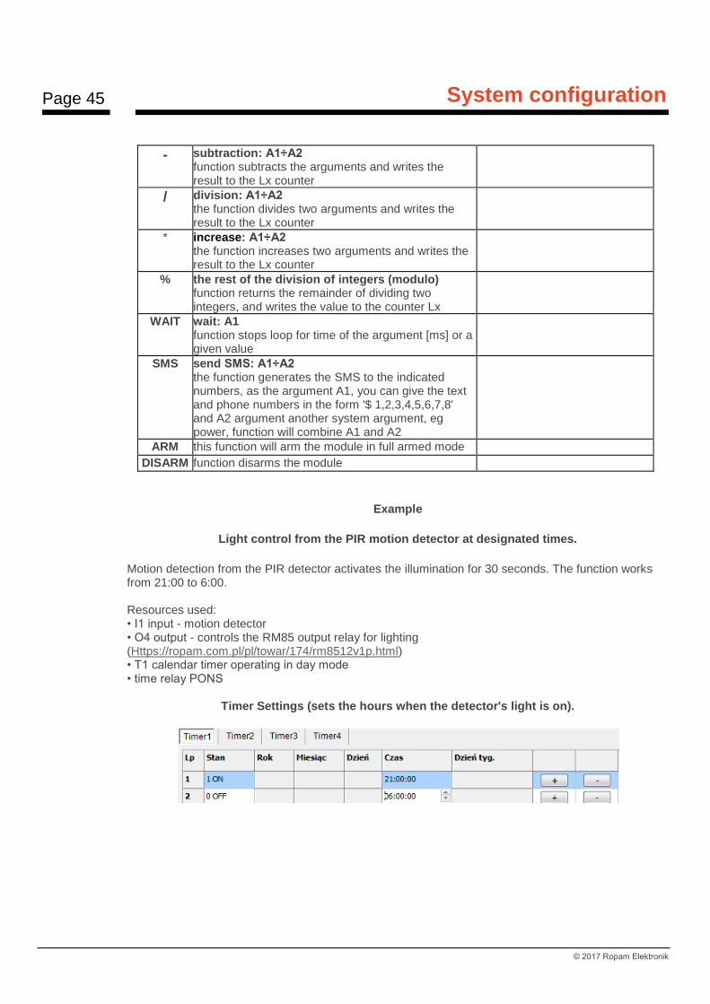
Light control from the PIR motion detector at designated times.
Motion detection from the PIR detector activates the illumination for 30 seconds. The function works from 21:00 to 6:00. Resources used: • I1 input - motion detector • O4 output - controls the RM85 output relay for lighting (Https://ropam.com.pl/pl/towar/174/rm8512v1p.html) • T1 calendar timer operating in day mode • time relay PONS
Timer Settings (sets the hours when the detector's light is on).
Page 46
System configuration
© 2017 Ropam Elektronik
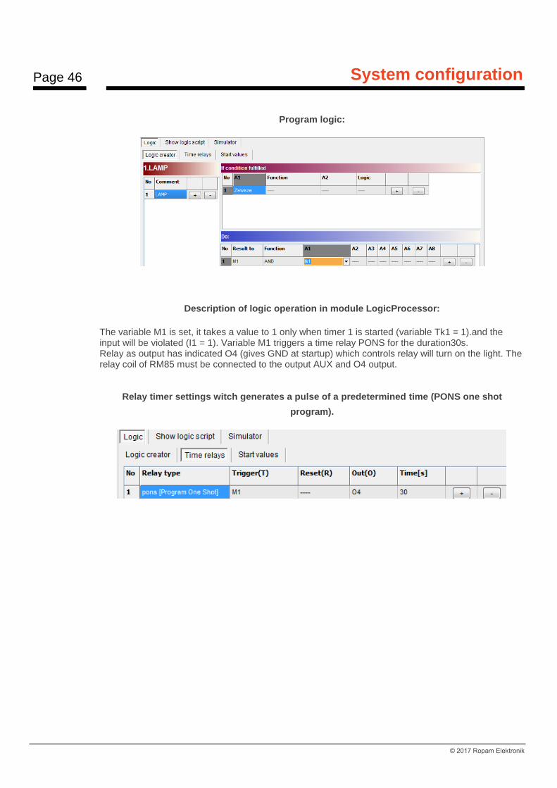
Program logic:
Description of logic operation in module LogicProcessor:
The variable M1 is set, it takes a value to 1 only when timer 1 is started (variable Tk1 = 1).and the input will be violated (I1 = 1). Variable M1 triggers a time relay PONS for the duration30s. Relay as output has indicated O4 (gives GND at startup) which controls relay will turn on the light. The relay coil of RM85 must be connected to the output AUX and O4 output.
Relay timer settings witch generates a pulse of a predetermined time (PONS one shot
program).
Page 47
System configuration
© 2017 Ropam Elektronik
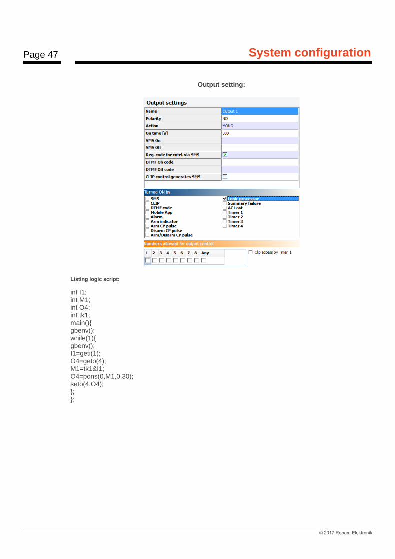
Output setting:
Listing logic script:
int I1; int M1; int O4; int tk1; main(){ gbenv(); while(1){ gbenv(); I1=geti(1); O4=geto(4); M1=tk1&I1; O4=pons(0,M1,0,30); seto(4,O4); }; };
Page 48
System configuration
© 2017 Ropam Elektronik
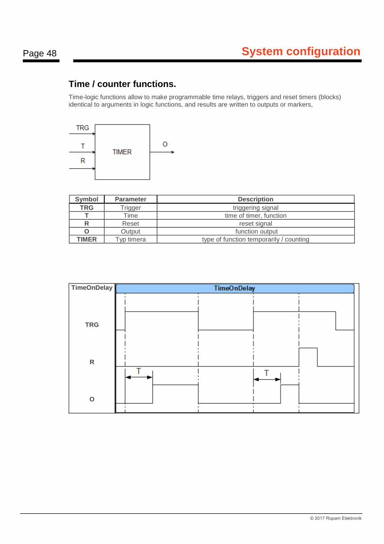
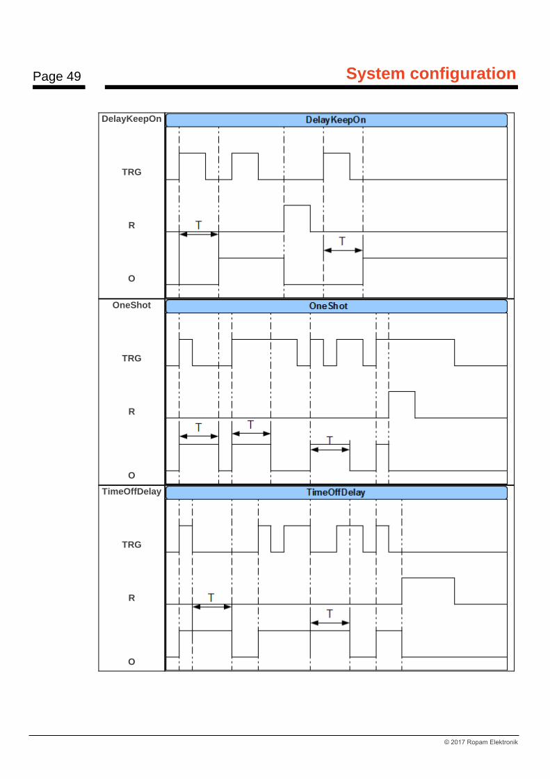
Time / counter functions.
Time-logic functions allow to make programmable time relays, triggers and reset timers (blocks) identical to arguments in logic functions, and results are written to outputs or markers,
Symbol Parameter Description
TRG Trigger triggering signal
T Time time of timer, function
R Reset reset signal
O Output function output
TIMER Typ timera type of function temporarily / counting
TimeOnDelay
TRG
R
O
Page 49
System configuration
© 2017 Ropam Elektronik
DelayKeepOn
TRG
R
O
OneShot
TRG
R
O
TimeOffDelay
TRG
R
O

Page 50
System configuration
© 2017 Ropam Elektronik
Blinker
TRG
R
O
MonoBi
TRG
R
O
Delay Alter
TRG
R
O
Page 51
System configuration
© 2017 Ropam Elektronik
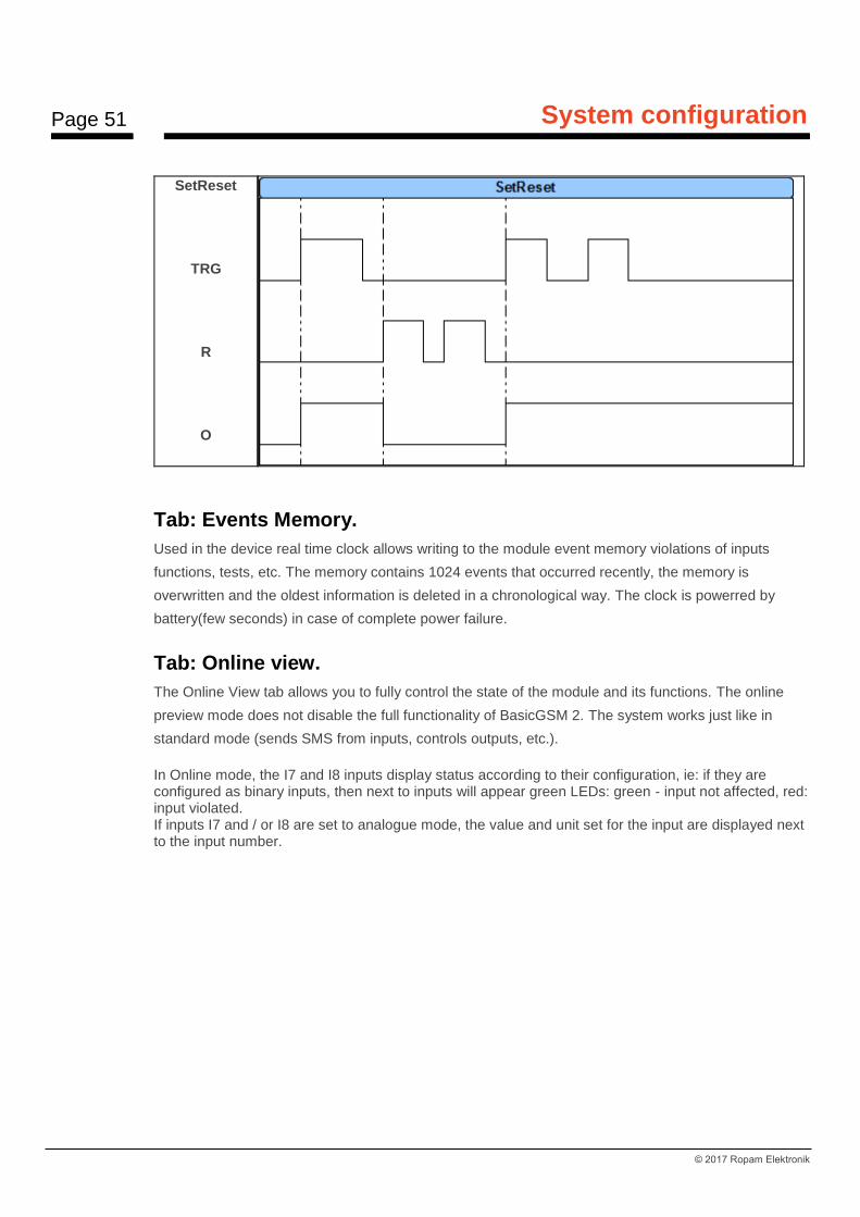
SetReset
TRG
R
O
Tab: Events Memory.
Used in the device real time clock allows writing to the module event memory violations of inputs
functions, tests, etc. The memory contains 1024 events that occurred recently, the memory is
overwritten and the oldest information is deleted in a chronological way. The clock is powerred by
battery(few seconds) in case of complete power failure.
Tab: Online view.
The Online View tab allows you to fully control the state of the module and its functions. The online
preview mode does not disable the full functionality of BasicGSM 2. The system works just like in
standard mode (sends SMS from inputs, controls outputs, etc.).
In Online mode, the I7 and I8 inputs display status according to their configuration, ie: if they are configured as binary inputs, then next to inputs will appear green LEDs: green - input not affected, red: input violated. If inputs I7 and / or I8 are set to analogue mode, the value and unit set for the input are displayed next to the input number.

Page 52
System configuration
© 2017 Ropam Elektronik
PREVIEW OF INPUT STATE The status of the inputs is signaled by circular indicators located at the screw terminals of the module connectors. The state of the input is determined by the color of the indicator: RED - input violated GREEN - input intact COMMENTS - ON-LINE view requires active connection via USB or GPRS connection, - In the ON-LINE mode, the module performs its standard functions, eg sends SMS messages when zones are violated, etc. CONTROL OF OUTPUT STATE This option allows you to activate module outputs. It is possible, for example, to pre-test the siren without having to start the alarm procedure. In order to trigger a given output (according to the polarity
set in the OUTPUT tab), click on the icon with the mouse . Clicking on the icon
ends the activation of the output.
Page 53
System configuration
© 2017 Ropam Elektronik
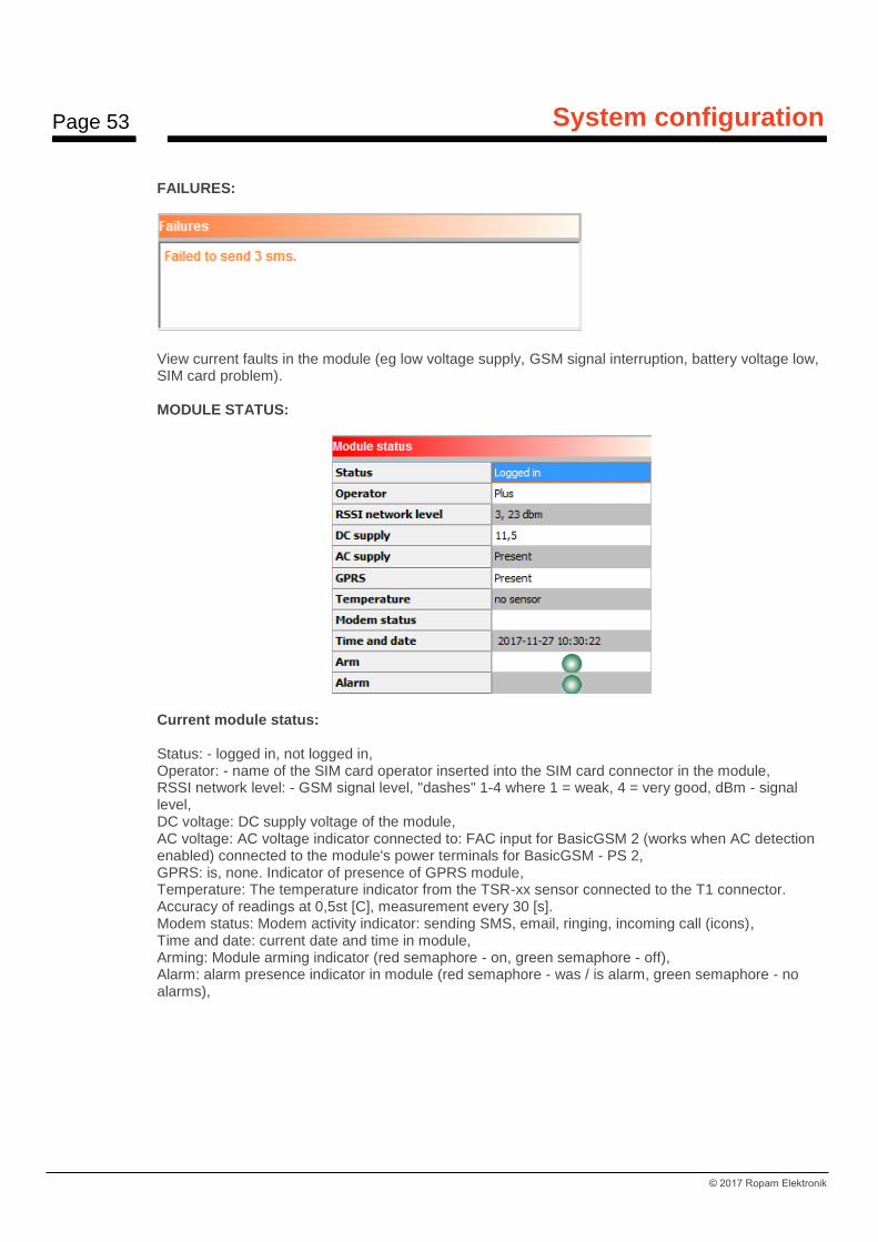
FAILURES:
View current faults in the module (eg low voltage supply, GSM signal interruption, battery voltage low, SIM card problem). MODULE STATUS:
Current module status: Status: - logged in, not logged in, Operator: - name of the SIM card operator inserted into the SIM card connector in the module, RSSI network level: - GSM signal level, "dashes" 1-4 where 1 = weak, 4 = very good, dBm - signal level, DC voltage: DC supply voltage of the module, AC voltage: AC voltage indicator connected to: FAC input for BasicGSM 2 (works when AC detection enabled) connected to the module's power terminals for BasicGSM - PS 2, GPRS: is, none. Indicator of presence of GPRS module, Temperature: The temperature indicator from the TSR-xx sensor connected to the T1 connector. Accuracy of readings at 0,5st [C], measurement every 30 [s]. Modem status: Modem activity indicator: sending SMS, email, ringing, incoming call (icons), Time and date: current date and time in module, Arming: Module arming indicator (red semaphore - on, green semaphore - off), Alarm: alarm presence indicator in module (red semaphore - was / is alarm, green semaphore - no alarms),
Page 54
System configuration
© 2017 Ropam Elektronik
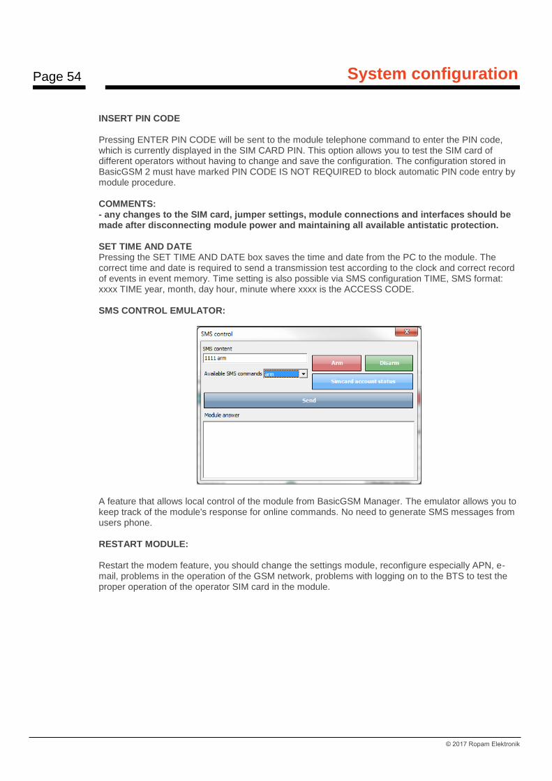
INSERT PIN CODE Pressing ENTER PIN CODE will be sent to the module telephone command to enter the PIN code, which is currently displayed in the SIM CARD PIN. This option allows you to test the SIM card of different operators without having to change and save the configuration. The configuration stored in BasicGSM 2 must have marked PIN CODE IS NOT REQUIRED to block automatic PIN code entry by module procedure. COMMENTS: - any changes to the SIM card, jumper settings, module connections and interfaces should be made after disconnecting module power and maintaining all available antistatic protection. SET TIME AND DATE Pressing the SET TIME AND DATE box saves the time and date from the PC to the module. The correct time and date is required to send a transmission test according to the clock and correct record of events in event memory. Time setting is also possible via SMS configuration TIME, SMS format: xxxx TIME year, month, day hour, minute where xxxx is the ACCESS CODE. SMS CONTROL EMULATOR:
A feature that allows local control of the module from BasicGSM Manager. The emulator allows you to keep track of the module's response for online commands. No need to generate SMS messages from users phone. RESTART MODULE: Restart the modem feature, you should change the settings module, reconfigure especially APN, e-mail, problems in the operation of the GSM network, problems with logging on to the BTS to test the proper operation of the operator SIM card in the module.
Page 55
System configuration
© 2017 Ropam Elektronik
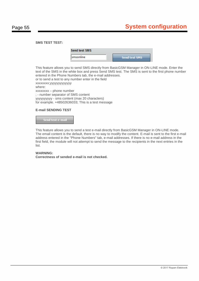
SMS TEST TEST:
This feature allows you to send SMS directly from BasicGSM Manager in ON-LINE mode. Enter the text of the SMS in the white box and press Send SMS test. The SMS is sent to the first phone number entered in the Phone Numbers tab, the e-mail addresses. or to send a test to any number enter in the field xxxxxxxx;yyyyyyyyyyyyy where: xxxxxxxx – phone number ; - number separator of SMS content yyyyyyyyyy - sms content (max 20 characters) for example. +48502636033; This is a test message E-mail SENDING TEST
This feature allows you to send a test e-mail directly from BasicGSM Manager in ON-LINE mode. The email content is the default, there is no way to modify the content. E-mail is sent to the first e-mail address entered in the "Phone Numbers" tab, e-mail addresses. If there is no e-mail address in the first field, the module will not attempt to send the message to the recipients in the next entries in the list. WARNING: Correctness of sended e-mail is not checked.
Page 56
System configuration
© 2017 Ropam Elektronik
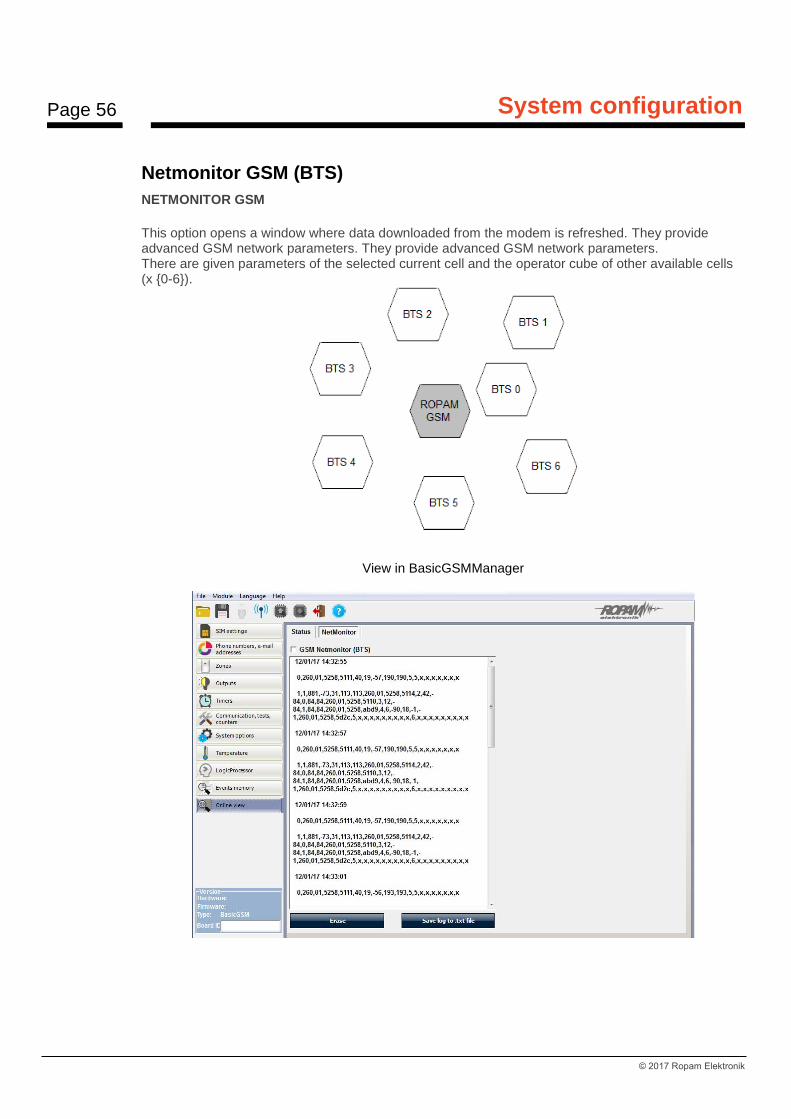
Netmonitor GSM (BTS)
NETMONITOR GSM
This option opens a window where data downloaded from the modem is refreshed. They provide advanced GSM network parameters. They provide advanced GSM network parameters. There are given parameters of the selected current cell and the operator cube of other available cells (x {0-6}).
View in BasicGSMManager
Page 57
System configuration
© 2017 Ropam Elektronik
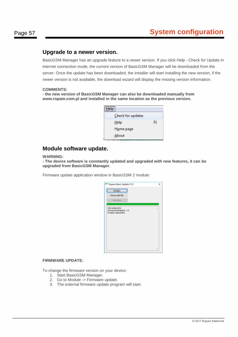
Upgrade to a newer version.
BasicGSM Manager has an upgrade feature to a newer version. If you click Help - Check for Update in
internet connection mode, the current version of BasicGSM Manager will be downloaded from the
server. Once the update has been downloaded, the installer will start installing the new version, if the
newer version is not available, the download wizard will display the missing version information.
COMMENTS: - the new version of BasicGSM Manager can also be downloaded manually from www.ropam.com.pl and installed in the same location as the previous version.
Module software update.
WARNING: - The device software is constantly updated and upgraded with new features, it can be upgraded from BasicGSM Manager. Firmware update application window in BasicGSM 2 module:
FIRMWARE UPDATE:
To change the firmware version on your device: 1. Start BasicGSM Manager. 2. Go to Module -> Firmware update. 3. The external firmware update program will start.
Page 58
System configuration
© 2017 Ropam Elektronik
4. Connect with the module. 5. Load the file with the new firmware version. 6. Press UPDATE.
a. The machine will start the firmware update procedure in the module "BOOT LOADER", the procedure should not be interrupted until the message UPDATE COMPLETED.
b. if the above procedure ends with an error, repeat the procedure from step 1. COMMENTS: - during the procedure can be displayed: Error: BasicGSM was not found, Run the bootloader, then repeat the procedure in point 2 and follow the prompts in the BasicGSM Manager. Ropam Elektronik devices are constantly being developed and expanded with their capabilities and functionality. With the new versions of devices, a new version of the configuration program is also created. As part of the completion should be provided / compatibility version, or update the software (firmware) of all components to the latest version, and use the latest configuration program. Device updates are available through: • BasicGSM Manager → Module → Firmware update (Internet connection required) • current CD included with the latest versions, • On request, we send any archive file for devices that require compliance. Updating of BasicGSM Manager is available through: • BasicGSM Manager → Help → Check for update (requires internet connection, installer overrides old BasicGSM Manager) • current CD included with the latest versions. Updating the USB cable driver is available through: • BasicGSM Manager (option for installing software: install USB drivers), • FTDI manufacturer's website → http://www.ftdichip.com/Drivers/VCP.htm.
System configuration: SMS commands.
Functionality of the module allows to change the selected configuration parameters remotely. This is done by sending an SMS with the appropriate command (command) with the access code. After the correct programming procedure, the module will reply to the SMS: "Configuration changed" in the case of configuration error, the reply is: "Error in configuration message, send correct again!" check the format of the SMS, then correct the content and resubmit. The factory set parameters: SMS code / application login: 1111 Sending SMS control confirmation PIN code request disabled
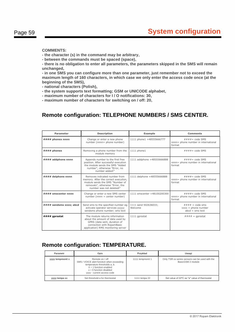
Page 59
System configuration
© 2017 Ropam Elektronik
COMMENTS: - the character (s) in the command may be arbitrary, - between the commands must be spaced (space), - there is no obligation to enter all parameters, the parameters skipped in the SMS will remain unchanged, - in one SMS you can configure more than one parameter, just remember not to exceed the maximum length of 160 characters, in which case we only enter the access code once (at the beginning of the SMS), - national characters (Polish), - the system supports text formatting; GSM or UNICODE alphabet, - maximum number of characters for I / O notifications: 30, - maximum number of characters for switching on / off: 20,
Remote configuration: TELEPHONE NUMBERS / SMS CENTER.
Parameter Description Example Comments
#### phonex nnnn Change or enter a new phone
number (nnnn= phone number)
1111 phone1 +48555666777 ####= code SMS
nnnn= phone number in international
format
#### phonex Removing a phone number from the
module memory
1111 phone1 ####= code SMS
#### addphone nnnn Appends number to the first free
position. After successful execution
the module sends the SMS "Added
number", otherwise "Error, no number added!"
1111 addphone +48555666888 ####= code SMS
nnnn= phone number in international
format
#### delphone nnnn Removes indicated number from
memory. After the correct execution,
module sends the SMS "Number of
removals", otherwise "Error, the
number was not deleted!"
1111 delphone +48555666888 ####= code SMS
nnnn= phone number in international
format
#### smscenter nnnn Change or enter a new SMS center number (nnnn = center number)
1111 smscenter +48100200300 ####= code SMS nnnn= phone number in international
format
#### sendsms xxxx; abcd Send sms to the specified number eg
activate operator services yyyyy
sendsms phone number; sms text
1111 send 502636033;
Welcome
#### = code sms
xxxx = phone number
abcd = sms text
#### gprsstat
The module returns information about the amount of data used by
GPRS (data sent, duration of
connection with RopamBasic
application) RMS monitoring server
1111 gprsstat #### = gprsstat
Remote configuration: TEMPERATURE.
Parametr Opis Przykład Uwagi
yyyy tempmonit x Remote on / off SMS / VOICE alert function when exceeding
temperature thresholds a, b. X = 1 function enabled x = 0 function disabled
yyyy - current access code
1111 tempmonit 1 Only TSR-xx series sensors can be used with the BasicGSM 2 module
yyyy tempa xx Set threshold a for thermostat 1111 tempa 22 Set value of 22ºC as "a" value of thermostat

Page 60
System configuration
© 2017 Ropam Elektronik
yyyy tempb xx Set threshold b for thermostat 1111 tempb 25 Set the value of 25ºC as the "b" value of the thermostat
Remote configuration: OTHER SETTINGS.
Parametr Opis Przykład Uwagi
yyyy lock x Lock inputs (enter input no.) 1111 lock 2 X – number of input
yyyy unlock x Unlock inputs (enter input no.) 1111 unlock 5 X – number of input
yyyy zones Returns the state of the module inputs. 1111 zones
yyyy downloading x Remote on / off of the GPRS programming function
1111 downloading X = 1 – ON X = 2 – OFF
yyyy code zzzz Change of SMS code (zzzz = new access code)
1111 code 1234 yyyy - current SMS code zzzz = new SMS code
yyyy time yy, mm, dd, hh, mm
Setting, changing date and time (Yy, mm, dd, hh, mm = year, month, day,
hour, minute)
1111 time 02, 01, 01, 12, 05
After commas, required spacing (space)
yyyy restart Restart of BasicGSM 2 1111 restart
yyyy status System status inquiry 1111 status The device sends a message containing data according to configuration (eg date, supply status, input state, other
information configured in BasicGSM Manager)
yyyy replysms Remote on / off SMS text message confirmation function
1111 replysms 1 X = 1 function enabled x = 0 function disabled
yyyy ai1a Analog input ai1 treshold a setting 1111 ai1a 1000 If the input is set to voltage mode - the setting range is 0-10000mV,
If the input is set to current loop mode - the setting range is 4-20mA
yyyy ai1b Analog input ai1 treshold b setting 1111 ai1b 1500 If the input is set to voltage mode - the setting range is 0-10000mV,
If the input is set to current loop mode - the setting range is 4-20mA
yyyy ai2a Analog input ai2 treshold a setting 1111 ai2a 1800 If the input is set to voltage mode - the setting range is 0-10000mV,
If the input is set to current loop mode - the setting range is 4-20mA
yyyy ai2b Analog input ai2 treshold b setting 1111 ai2a 5670 If the input is set to voltage mode - the setting range is 0-10000mV,
If the input is set to current loop mode - the setting range is 4-20mA
yyyy events Request to retrieve the history of the last 7 events from the module
1111 events
yyyy arm Arming the module 1111 arm
yyyy disarm Disarming the module 1111 disarm
yyyy echo Remote on / off The function of sending unrecognized
SMS messages from the ECHO network, eg www account passwords, network
information
1111 echo 1 X = 1 function enabled x = 0 function disabled
yyyy email Adding an email address to the first free spot in the user list.
1111 email [email protected] Provide a valid e-mail account to receive notifications from the module.
yyyy ussd Request to use the USSD code to verify the SIM card account in the module
yyyy USSD *124*# 1111 ussd (code ussd - eg Check account status , e.t.c.)
yyyy outs Enable binary outputs yyyy outs 0101 0 = disable, 1 = enabled
yyyy connect Request a service connection with the Ropam Bridge server and the BasicGSM
Manager
1111 connect Yyyy – sms code
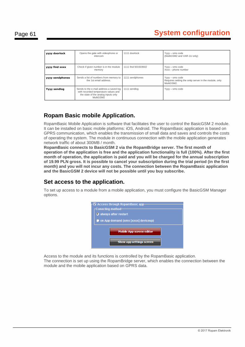
Page 61
System configuration
© 2017 Ropam Elektronik
yyyy doorlock
Opens the gate with videophone or intercom
1111 doorlock Yyyy – sms code (MultiGSM2 and VAR-1U only)
yyyy find xxxx Check if given number is in the module memory
1111 find 501503502 Yyyy – sms code Xxxx – phone number
yyyy sendphones Sends a list of numbers from memory to the 1st email address.
1111 sendphones Yyyy – sms code Requires setting the smtp server in the module, only MulitGSM2.
Yyyy sendlog Sends to the e-mail address a saved log with recorded temperature values and
the state of the analog inputs only MultiGSM2
1111 sendlog Yyyy – sms code
Ropam Basic mobile Application.
RopamBasic Mobile Application is software that facilitates the user to control the BasicGSM 2 module. It can be installed on basic mobile platforms: iOS, Android. The RopamBasic application is based on GPRS communication, which enables the transmission of small data and saves and controls the costs of operating the system. The module in continuous connection with the mobile application generates network traffic of about 300MB / month. RopamBasic connects to BasicGSM 2 via the RopamBridge server. The first month of operation of the application is free and the application functionality is full (100%). After the first month of operation, the application is paid and you will be charged for the annual subscription of 19.99 PLN gross. It is possible to cancel your subscription during the trial period (in the first month) and you will not incur any costs. The connection between the RopamBasic application and the BasicGSM 2 device will not be possible until you buy subscribe.
Set access to the application.
To set up access to a module from a mobile application, you must configure the BasicGSM Manager options.
Access to the module and its functions is controlled by the RopamBasic application. The connection is set up using the RopamBridge server, which enables the connection between the module and the mobile application based on GPRS data.

Page 62
System configuration
© 2017 Ropam Elektronik
There are 2 ways to connect an application to a BasicGSM 2 module: - Always after reboot (module) - the module sends to RopamBridge server data that is ready to connect to the mobile application, the server stores that data until the connection is established between the user and the module. - On request of application (mobile) - user after application activation is asked to send an SMS request to set up the connection to the module (recommended due to accidental module control from the application).
Description of application windows.
RopamBasic has the ability to define a main window with icons that are defined in BasicGSM Manager.
Main application window: Features available from the application:
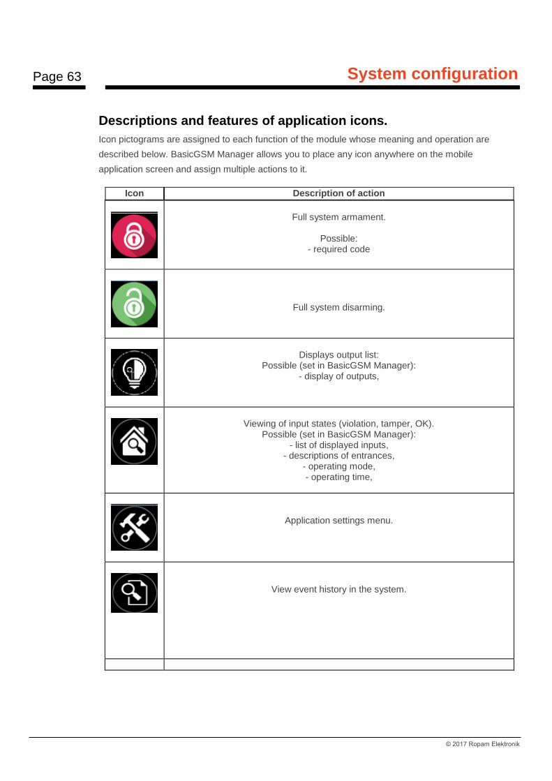
Page 63
System configuration
© 2017 Ropam Elektronik
Descriptions and features of application icons.
Icon pictograms are assigned to each function of the module whose meaning and operation are
described below. BasicGSM Manager allows you to place any icon anywhere on the mobile
application screen and assign multiple actions to it.
Icon Description of action
Full system armament.
Possible:
- required code
Full system disarming.
Displays output list:
Possible (set in BasicGSM Manager): - display of outputs,
Viewing of input states (violation, tamper, OK).
Possible (set in BasicGSM Manager): - list of displayed inputs,
- descriptions of entrances, - operating mode, - operating time,
Application settings menu.
View event history in the system.
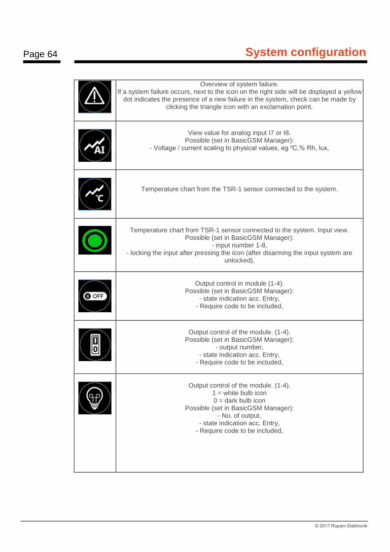
Page 64
System configuration
© 2017 Ropam Elektronik
Overview of system failure. If a system failure occurs, next to the icon on the right side will be displayed a yellow
dot indicates the presence of a new failure in the system, check can be made by clicking the triangle icon with an exclamation point.
View value for analog input I7 or I8.
Possible (set in BasicGSM Manager): - Voltage / current scaling to physical values, eg ºC,% Rh, lux,
Temperature chart from the TSR-1 sensor connected to the system.
Temperature chart from TSR-1 sensor connected to the system. Input view.
Possible (set in BasicGSM Manager): - input number 1-8,
- locking the input after pressing the icon (after disarming the input system are unlocked),
Output control in module (1-4).
Possible (set in BasicGSM Manager): - state indication acc. Entry,
- Require code to be included,
Output control of the module. (1-4).
Possible (set in BasicGSM Manager): - output number,
- state indication acc. Entry, - Require code to be included,
Output control of the module. (1-4).
1 = white bulb icon 0 = dark bulb icon
Possible (set in BasicGSM Manager): - No. of output,
- state indication acc. Entry, - Require code to be included,

Page 65
System configuration
© 2017 Ropam Elektronik
Output control of the module (1-4). eg roller blinds.
Possible (set in BasicGSM Manager) - No. of output,
- state indication acc. Entry, - Require code to be included,
Output control of the module (1-4). eg roller blinds.
Possible (set in BasicGSM Manager) - No. of output,
- state indication acc. Entry, - Require code to be included,
Output control of the module (1-4). eg entrance gate.
Possible (set in BasicGSM Manager) - No. of output,
- state indication acc. Entry, - Require code to be included,
Output control of the module (1-4). eg garage gate.
Possible (set in BasicGSM Manager) - No. of output,
- state indication acc. Entry, - Require code to be included,
Output control of the module (1-4). eg garage gate. Possible (set in BasicGSM Manager)
- No. of output, - state indication acc. Entry,
- Require code to be included,
Enabling the output group.
Possible (set in BasicGSM Manager): - no output / outputs,
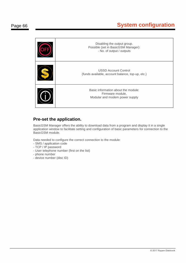
Page 66
System configuration
© 2017 Ropam Elektronik
Disabling the output group.
Possible (set in BasicGSM Manager): - No. of output / outputs
USSD Account Control (funds available, account balance, top-up, etc.)
Basic information about the module:
Firmware module, Modular and modem power supply
Pre-set the application.
BasicGSM Manager offers the ability to download data from a program and display it in a single application window to facilitate setting and configuration of basic parameters for connection to the BasicGSM module. Data needed to configure the correct connection to the module: - SMS / application code - TCP / IP password - User telephone number (first on the list) - phone number - device number (disc ID)

Page 67
System configuration
© 2017 Ropam Elektronik
Below the parameter download window from BasicGSM Manager and the view of where data is downloaded:
Description of individual fields in the program: User code and TCP / IP Password: - tab: "Communication, tests, counters" - SMS code / application log:
Phone number: - tab: "Phone numbers and email addresses":
Device phone number: - tab: "GSM modem options/Simcard options":

Page 68
System configuration
© 2017 Ropam Elektronik
Device Number (Board ID): - bottom left corner in BasicGSM Manager:
RopamDroid mobile application
RopamDroid mobile application is software that facilitates user control of series modules: BasicGSM, BasicGSM 2, MultiGSM, NEO, NeoGSM, OptimaGSM. It can be installed on the Android platform. The RopamDroid application is based on SMS communication, which allows the transmission of small amounts of data and thus saves and controls the costs of operating the system. RopamDroid is a free application for controlling your system. RopamDroid is supported by smartphones running Android. Basic application properties: - support Android version 2.1 ÷ 6, - clear graphical interface and status bar, - application and service filtering messages from the phone number of the system, - two-way communication via system SMS, - password protection for applications, - access to functions: control of armed status, current status and failures, blocking the view and control inputs, outputs control group, view and change the temperature thresholds for TermostatGSM, a preview of the I7, I8 and change the set thresholds, - Reduce control costs via SMS by consolidating information into single messages for applications. - RopamDroid Pro version supports multiple systems, objects.

Page 69
System configuration
© 2017 Ropam Elektronik
RopamDroid application description.
Application main window:
Description of the buttons and functions of the main window:
PIKTOGRAM FUNKTION
Disarming the module
Arming of the module
View status of zones (detectors) and the possibility of block grouping
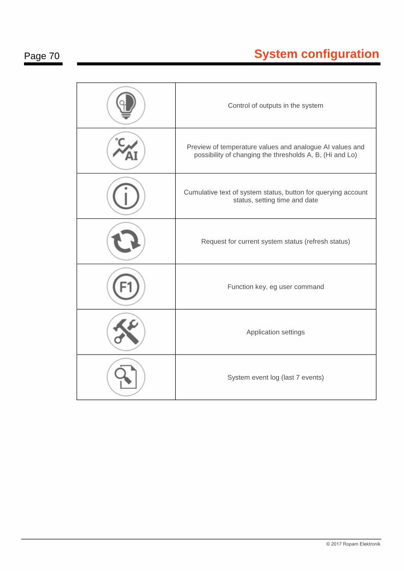
Page 70
System configuration
© 2017 Ropam Elektronik
Control of outputs in the system
Preview of temperature values and analogue AI values and possibility of changing the thresholds A, B, (Hi and Lo)
Cumulative text of system status, button for querying account status, setting time and date
Request for current system status (refresh status)
Function key, eg user command
Application settings
System event log (last 7 events)
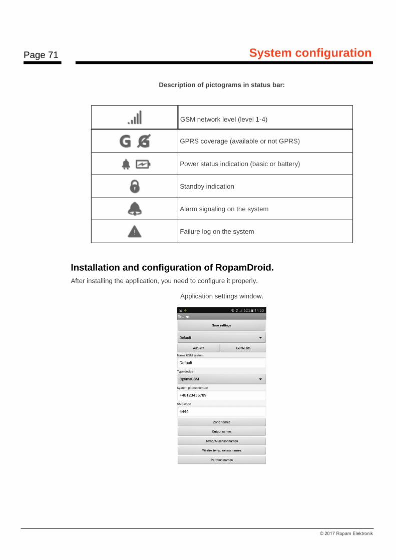
Page 71
System configuration
© 2017 Ropam Elektronik
Description of pictograms in status bar:
GSM network level (level 1-4)
GPRS coverage (available or not GPRS)
Power status indication (basic or battery)
Standby indication
Alarm signaling on the system
Failure log on the system
Installation and configuration of RopamDroid.
After installing the application, you need to configure it properly.
Application settings window.

Page 72
System configuration
© 2017 Ropam Elektronik
Add / Remove: function add, object recall (RopamDroid PRO version only). Object name: User's own name eg House. Module Type: Select the appropriate device type. Phone number of the facility: Enter the number of the SIM card installed in the system (International (recommended) or abbreviated). SMS password: enter the user code of the system (same as BasicGSM Manager - SMS code / application login)
BasicGSM Manager / Communication, tests, counters:
PartnerGSM / Options:
OptimaGSM Manager / System Options:
Notes: In the central OptimaGSM SMS password is the same as user code set in the touch panel working in the system for a user or set SMS command. Input names: input names in the system, Output names: outputs names in the system, Temperature sensor names: Temperature sensor name T1, for example, Temp CO, Temp. outside, Temp. ground floor., Temp. DHW. Zone names: zone names in the system, may be the same as in TPR-xx panels eg Ground floor, Garage. Require the password for the program: the option enables access to the application after authorization (recommended).

Page 73
System configuration
© 2017 Ropam Elektronik
Ask for sending SMS: option allows you to disable the confirmation control from applications eg. control of outputs. Arming control acknowledgments are always displayed. Change program password: This option allows you to set or change an application access authorization password. USSD account status: a field to enter a USSD short code for checking account status (eg Orange * 124 * #), the code will be automatically sent by pressing the USSD Account Status button. For this function must be selected in the service program "send confirmation". F1 user command: field for other another SMS command, eg MMS request, the code will be automatically sent when the F1 button is pressed. Keep settings: the button confirms and remembers all changes made in the settings! Export: function to export settings to file (without codes). Import: function to import settings into a file, after import, you have to complete the settings with SMS codes.
View application windows.
To control the outputs of the modules from application RopamDroid, select the utility appropriate for the device during setup that they will be controlled via SMS!
Inputs Outputs

Page 74
System configuration
© 2017 Ropam Elektronik
About the module:
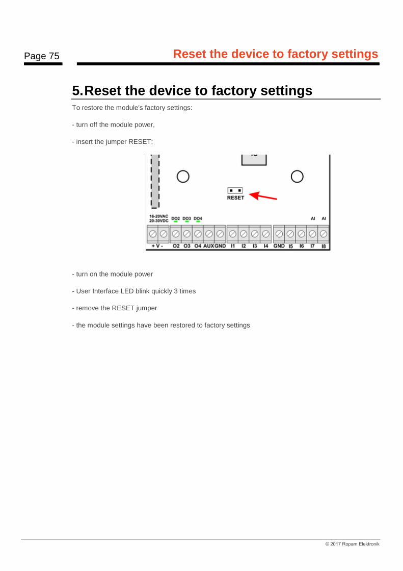
Page 75
Reset the device to factory settings
© 2017 Ropam Elektronik
5. Reset the device to factory settings To restore the module's factory settings:
- turn off the module power,
- insert the jumper RESET:
- turn on the module power
- User Interface LED blink quickly 3 times
- remove the RESET jumper
- the module settings have been restored to factory settings
Page 76
System maintenance.
© 2017 Ropam Elektronik
6. System maintenance. No special maintenance is required. During periodical technical inspections, check the condition of the
screw connections, emergency power supply, clean the PCB with compressed air. The system should
be periodically tested for proper operation and communication.

Page 77
Technical parameters.
© 2017 Ropam Elektronik
7. Technical parameters.
PARAMETER VALUE
Power supply BasicGSM 2,
U = 10,5V÷14,5V/DC min/max @ 1,5A min.
Power supply BasicGSM-PS 2,
U = 16V÷20V/AC min/max @ 30VA min. U = 20V÷28V/DC min/max @ 0,7A min.
Output voltage of the power supply BasicGSM-PS 2,
Un= 13,8V/DC (+/- 2%) U=10,5V-13,8V/DC**.
Power adapter power BasicGSM-PS 2,
(current efficiency)* 20W (1,5A)
DC power failure signaling U<11V
Output load O1 In=1,0A @30VDC/50VAC
Output load AUX In=1,0A (ciągła) Ipeak=1,3A (chwilowe)
Short-circuit and thermal output AUX protection Ilim=1,0A÷1,7A, Tj, Tc= 125 °C (Status: short-circuit current limitation or output overload)
Outputs load O2-O4 700mA @30Vdc max. (no short-circuit protection)
Current consumption by module circuits (without outputs)
40mA/50mA/300mA min/mid/max
Battery compatible with BasicGSM 2 -PS, 12V, 1,2Ah - 12Ah (VRL/SLA)
Battery charging current BasicGSM-PS 2, MultiGSM-PS 2
Ibat= 0,3A max. (Charging constant: voltage and current)
Output protection +BAT- BasicGSM 2-PS, undervoltage: Ubat<10,0V (+/-5%) reverse polarity protection and short-circuit protection:1.6A PTC
fuse (reversible)
Modem GSM Quectel M66 (Quad-Band, GPRS class 10) detection of jamming GSM
GSM modem working frequency 850/ 900/ 1800/ 1900 MHz (switched automatically)
Data transmission type SMS, VOICE, GPRS, E-MAIL (protocol SMTP)
Signal audio AUDIO IN, AUDIO OUT (connector VSR)
2Vrms.
Binary inputs (programmable)
NO, NC, hi-Z/~200Ω, ~320Ω/hi-Z,
Line impedance for type: no violation / violation
Analog inputs (programmable) I7, I8
Uin= 0-10V/DC (max.) (impedance Z=270KΏ , resolution 10mV,
accuracy 1% of the whole range)
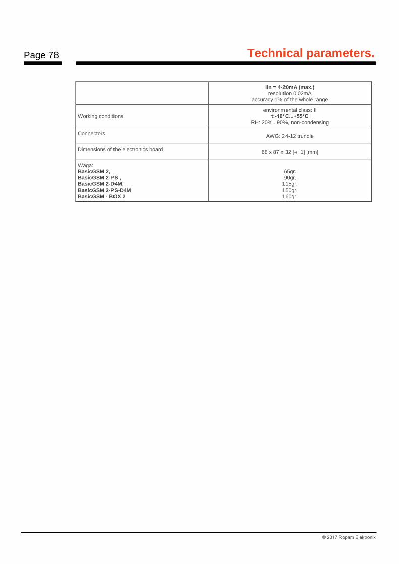
Page 78
Technical parameters.
© 2017 Ropam Elektronik
Iin = 4-20mA (max.) resolution 0,02mA
accuracy 1% of the whole range
Working conditions
environmental class: II t:-10°C...+55°C
RH: 20%...90%, non-condensing
Connectors AWG: 24-12 trundle
Dimensions of the electronics board 68 x 87 x 32 [-/+1] [mm]
Waga: BasicGSM 2, BasicGSM 2-PS , BasicGSM 2-D4M, BasicGSM 2-PS-D4M BasicGSM - BOX 2
65gr. 90gr.
115gr. 150gr. 160gr.

Page 79
Version history.
© 2017 Ropam Elektronik
8. Version history.
BasicGSM 2 Date Description
1.0 2017.03.27 - first version