tech briefs - nasa technical reports server
TRANSCRIPT
September 1999 www.nasatech.com Vol. 23 No. 9
D
c
B
A
TECH BRIEFS ENGINEERING UTIONS FOR DESIGN & MANUFACTURING
Advances in CAD/CAE/PDM
Automotive Technology
New! NASA Business Forum
4
4
It''''tO' ~ U P DATE "L 0 N LV 10\\" f. t.IUSU.I'f ,
. ~ s,~ct. C:~ ot.'~ll"t.tt1 Photonics Briefs -TA I N P ~cu"t. 11llCl con - AST ISSUE~ IUt. _ ,~pICl Product Development
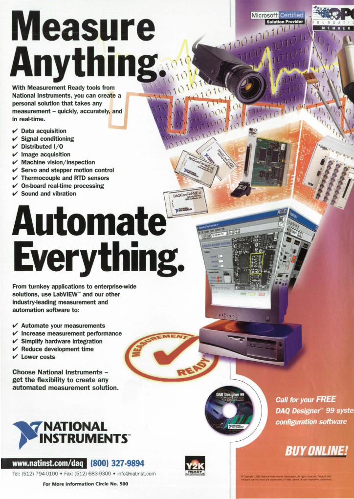
Measure Anything~\_-' \ With Measurement Ready tools from National Instruments, you can create a personal solution that takes any measurement - quickly, accurately, and in rea~time.
V' Data acquisition V' Signal conditioning V' Distributed I/O V' Image acquisition V' Machine vision/inspection V' Servo and stepper motion control V' Thermocouple and RTD sensors V' On-board rea~time processing V' Sound and vibration
Automate Everything. From turnkey applications to enterprise-wide solutions, use LabVIEW'" and our other industry-leading measurement and automation software to:
V' Automate your measurements V' Increase measurement performance V' Simplify hardware integration V' Reduce development time V' Lower costs
Choose National Instruments -get the flexibility to create any automated measurement solution.
NATIONAL INSTRUMENTS<M
www.natinst.com/daq (800) 327·9894 Tel : (512) 794-0100 • Fax: (512) 683-9300 • [email protected]
For More Information Circle No. 500
.QaIIfC ...... ~~M ................ ... ..... - .... -............ - ........ ~

. .
21 sf CenfurYATM t ccess 0
omega.com™
THE PRESSURE STRAIN FORCE
~No. 592
www.omega.com VISIT OUR WEBSITE! e-mail: [email protected]
o OOPYRIGHT 1999 OMEGA ENGII'EEANl. INC. All RIGHTS RESERVED.
NOW SHIPPING !
Introducing a
ew Gene • lion asf • ume",s
wit" dependability and integration t"at only Mat"emati(a (an pro ride
WOLFRAM RESEARCH
Check out Mathematica 4 and see the beginning of gigaNumerics'" www.wolfram.com/ma.hema.ica4/n.b or 1·800· W 0 L F RAM
Researchers and engineers worldwide use Molhematico lor modeling, analysis, numeric and symbolic compu'atian, visualization, and as a .uhnical dacumen. sys.em.
WoIfnun rt-rch, Inc.: wwwwolfram.com; inloCtwolfram.com; +1 - 217--39B-{)700 Wolfram Research Europe 1Jd.: www.woIfram.co.uI<; [email protected]; +~O) 1993-a83400 Wolfram Research Asia lid.: www.woIfram.co.jp;[email protected]; +81-(013-5276-0506 o '''' ...... r-o. .. .-...-. •• _01 ....... _....-.. ......... " ___ ,, ... -. ... _ ... -."..,-" ...... "" ...
For More Information Circle No. 505
StlI •• lallalrl •• "'lid. ,h. U.S. aad Caaada: www.wolfram.com/senice.lia.d .. le •• AI~,...bB ......... forlliao!olt""MaciIIo!It. ...... twx ......


There are a ton of reasons
to use Vespele just about anywhere.
The reasons to use Vesper polyimide parts and hapes
keep piling up. And not just because they stand up to heat,
friction, pressure and aggressive environments - with
minimal or no lubrication. Manufacturers are finding that
Vesper parts in a wide range of applications can really
trim the bottom line. That's because the reliability and
long life of Vesper parts can make them the most cost
effective choice for general appljcations in the long term.
If your applications require parts that can withstand
extreme temperatures (cryogenic to 550 F), Vesper should
be your first choice. Vesper should also be considered
for parts that rub together, if metal parts are too noisy,
or if fluid flow needs to be controlled.
Superior performance and reliability aren't the only
ways Vesper can save you money. Often, you can con
solidate two or more existing parts in one Vesper piece.
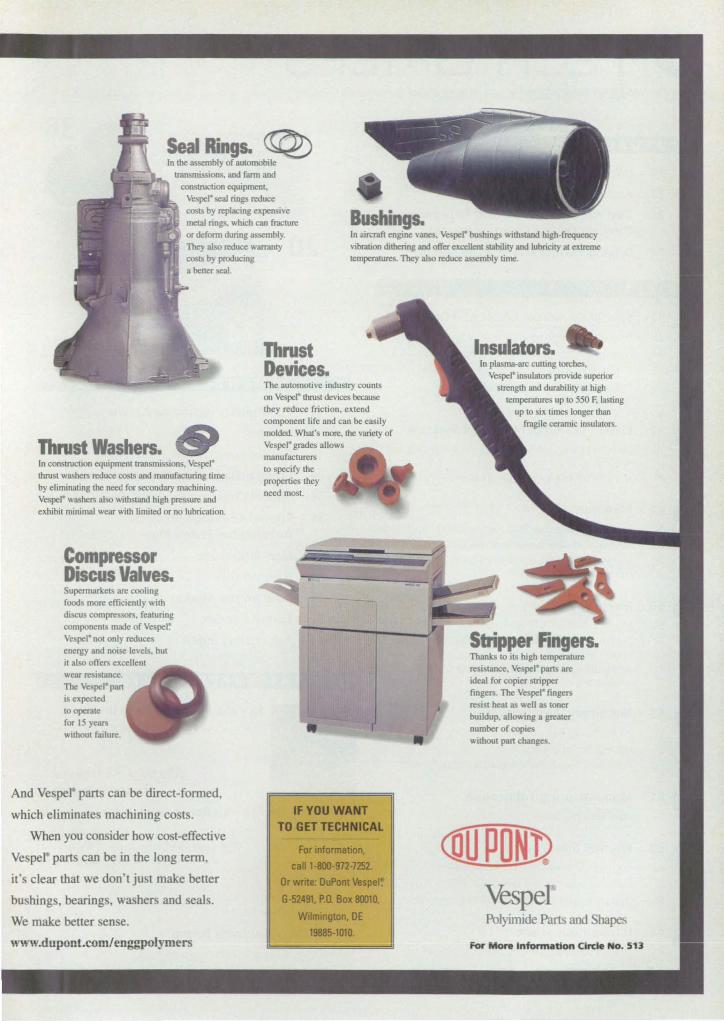
Sea Rings. ~ In the assembly of automobile
consll'llClion equipmeOl. Vespel' sea1 rings reduce
Bus· gs. costs by replacing expensive metal rings, which can fracrure or defonn during assembly. They also ""'uce warranty COSIs by producing
In aircraft engine vanes, Vespel' bushing withstand lrigh·f.requency vibration dithering and offer excelJerll stability and lubricity at extreme temperatures. They also ""'uce assembly Lime.
a beuer-seaL
Thrust Washers. In construction equipmeOllr.lJlsmissions. Vespel thrust washers reduce costs and manufacturing time by eliminating the need for secondary machining. Vespel' washers also wilhstand lrigh pressure and exhibit minimal wear wilh limited or no lubrication.
Compressor Discus Valves. Supennarkets are cooling food more efficiently with discus compressors. featuring componeOls made of Vespel~ Vespel' not only reduces energy and noise levels. but it also otTers excellent wear resi lance. The Vespel' pan is expected to operate for 15 ye:m without failure .
And Vespel parts can be direct-fonned,
which eliminate machining costs.
When you consider how cost-effective
Vespel part can be in the long term,
it's clear that we don't just make better
bu rung , bearings, washers and eaJ .
We make better sen e,
www.dupont.com/enggpolymers
Thrust Devices. The automotive indusuy counts on Vespel' thrust devices because they reduce friction, extend componeOl life and can be easily molded. What's more, the variety of Vespel' grades allows manufacturers to specify the properties they need most.
IF YOU WANT TO GET TECHNICAL
For information,
call 1-800-972-7252.
Or write: DuPont Vespe~
6-52491, P.O. Box 80010,
Wilmmgton, DE 19885-1010.
Insulators. In plasma·arc cutting torches,
Vespel' insulators provide superior strength and durability at high
temperatures up to 550 F, lasting up to six times longer than
fragile ceramic insulators.
Stripper Fingers. Thanks to its high temperature re istance, Vespel pans are ideal for copier stripper fingers. The Vespel' fingers "" i ,t beat as well as toner buildup. allowing a greater number of copies without pan changes.
<[(JPON] Vespel Polyimide p.arts and Shapes
For More (nformatlon C rele No. 13
TECH BRIEFS September 1999 • Vol. 23 No.9
ENGINEERING SOLUTIONS FOR DESIGN & MANUFACTURING
FEATURES
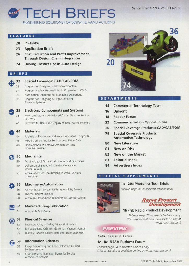
20 InReview
23 Application Briefs
26 Cost Reduction and Profit Improvement Through Design Chain Integration
74 Driving Plastics Use in Auto Design
BRIEFS
$ 32 32 34 35 35
0 38
38
41
44
44
46 48
0 50 50 50
52
0. 56 56 58 60
a 61
61
(@ ,9, 62
62 62 65
tj 68 68
70
Special Coverage: CAD/CAE/PDM
Program for Designing a Mechanical System
Program Predicts Uncertainties in Properties of C MCs
Automation Language for Managing Operations
Program for Designing Multiple-Reflector Antenna Systems
Electronic Components and Systems
MAP- and Laurent-AMP-Based Carrier Synchronization in GMSK
Software for Real-Time Display of Data via the Internet
Materials Analysis of Progressive Failure in Laminated Composites
Mixed-Carbon Anodes for Improved Li-Ion Cells
Electrodialysis To Remove Ammonium Ions From Wastewater
Mechanics Making Liquid Air in Small. Economical Quantities
Deflection of Stretched Circular Membrane Under Pressure
Accelerations of One Airplane in Wake Vortices of Another
Machinery/ Automation Air-Purification System Utilizing Humidity Swings
Hybrisol Rocket Engines
A Precise Closed-Loop Temperature-Control System
Manufacturing/Fabrication
Adaptable Drill GUide
Physical Sciences
Improved Array of X-Ray MlCrocalorimeters
Miniature Rlng-Orbitron Getter Ion Vacuum Pumps
Digitally Tunable Color Filters and Beam Scanners
Information Sciences
Image Smoothing and Edge Detection Guided by Stereoscopy
Characterizing Nonlinear DynamiCs by Use of Wavelet AnalYSIS
DEPARTMENTS
14 Commercial Technology Team
16 UpFront
18 Reader Forum
22 Commercialization Opportunities
36 Special Coverage Products: CAD/CAE/PDM
79 Special Coverage Products: Automotive Technology
80 New Literature
81 New on Disk
82 New on the Market
83 Editorial Index
84 Advertisers Index
SPECIAL SUPPLEMENTS
1a - 20a Photonics Tech Briefs
Follows page 48 in selected editions only.
Ra~/d Product - Dtzvtilopmtznt
1 b - 8b Rapid Product Development
Follows page 72 in selected editions only. (This supplement also is available on-line at
www.nasatech.com)
NASA Business Forum
1c - 8c NASA Business Forum
Follows page 84 in selected editions only. (This article also is available on-line at www.nasatech.com)
6 www.nasatech.com ASA Tech Briefs. plember 1999
Expand the Scope of Customer Service
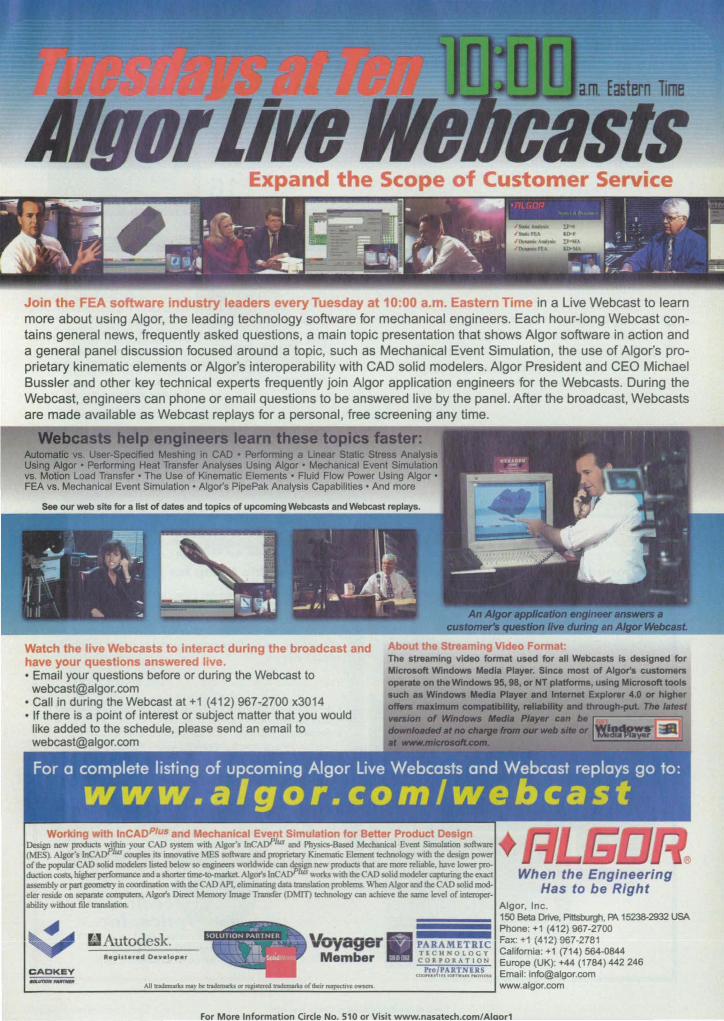
a e in us leaders every Tuesday at 10:00 a.m. Eastern Time in a Live Webcast to learn more about using Algor, the leading technology software for mechanical engineers. Each hour-long Webcast contains general news, frequently asked questions, a main topic presentation that shows Algor software in action and a general panel discussion focused around a topic, such as Mechanical Event Simulation, the use of Algor's proprietary kinematic elements or Algor's interoperability with CAD solid modelers. Algor President and CEO Michael Bussler and other key technical experts frequently join Algor application engineers for the Webcasts. During the Webcast, engineers can phone or email questions to be answered live by the panel. After the broadcast, Webcasts are made available as Webcast replays for a personal, free screening any time.
~i!!I'I!!lZl!"':
engineers learn these topics faster: Automatic vs. User-Specified Meshing in CAD • Performing a Linear Static Stress AnalYSIS Using Algor· Performing Heat Transfer Analyses USing Algor • Mechanical Event Simulation vs. Motion Load Transfer· The Use of Kinematic Elements· Fluid Flow Power Using Algor· FEA vs. Mechanical Event Simulation' Algor's PipePak Analysis Capabilities' And more
Watch the live Webcasts to interact during the broadcast and have your questions answered live. • Email your questions before or during the Webcast to
[email protected] • Call in during the Webcast at +1 (412) 967-2700 x3014 • If there is a pOint of interest or subject matter that you would
like added to the schedule, please send an email to [email protected]
Autodesk. Voyager Rev h te ,-ed Deye loper Member
The streaming video format used for all Webcasts Is designed for Microsoft Windows Media Player. Since most of Algor's customers operate on the Windows 95, 98, or NT platforms, using Microsoft tools such as Windows Media Player and Internet Explorer 4.0 or higher offws muImum c:ompaIIbUlty ..... 1MIIIity and thnIugh-put. 11Ie ",fast
-.Ion 01 WIndowa .... PIIIyw can be ...... lfIrlIIf,.. ...... IW~III!!~
PARAMETRIC TECHNOLOCY CORPOllATION
~/1~1!!!!~,
For More Information Circle No. 510 or Visit www.nasatech.com/Alaor1
Contents continued
72 Books and Reports 72
72
72
72
72
72
73
73
76
77
Conservatism in DeterministIC Structural Analysis
Evaporation of Isolated and Collections of Fluid Drops Under Supercritical Conditions
Gimbaled Injectors for Testing Spacecraft Thrusters
Experiments on Vibration and Noise in Fuselages
Lithium-Based Primary Cells for Low-Temperature Operation
Development of Fl ight Software for Small Explorer Spacecraft
Using Rayleigh Scattering To Measure Spacecraft Attitude
Diagnosing Gas-Turbine-Like Combustion by Use of PLiF
Special Coverage: Automotive Technology Optimization of Vehicle Interior Noise Treatment
Software for Analyzing Performance of a Gas Turbine Engine
This document was prepared under the sponsorship of the National Aeronautics and Space Administration. NeiLher Associated Business Publications Co., Lld~ nor the United Stales Government nor any person acting on behalf of the United StaLes Government assumes any liability resulting from the use of the information contained in this document, or warrants that such use will be free from privately owned rights. The U.S. Government does not endorse any commercial product, process. or activity identified in this publication.
PRODUCT OF THE MONTH
Gage Applied Sciences introduces CompuScope
, 602. a '6-bit AID and Scope card for the
PCI bus.
16
ON THE COVER
Badger Meter of Tulsa. OK. designed the valve positioner in this image with Solid Edge CAD software from Unigraphics Solutions. Huntsville. AL. The breakthrough of 3D design from 20 drawings is the concept behind Unigraphics' new Solid Edge Origin 3D software. which is designed to move 20 users to the 3D design world. For more information on Origin and other advances in the CAD/CAE/PDM area. see the Special Coverage beginning on page 26.
(Image courtesy of Unigraphics Solutions)
Permissions: Authorization to photocopy item for internal or personal use, or the internal or personal use of specific clients, is granted by Associated Business Publications, provided that th< flat fee of 3.00 per copy be paid directly to the Copyright Clearanc< Center (222 Rose Wood Dr .. Danvers. MA 01923). For those organizations that have been granted a photocopy license by ace, a separate system ofpaymenl has been arranged. The fee code for users of the Transactional Reporting Servi« is: ISSN 014:;'319X194 3.00+.00
Introducing the World's First Miniature NIST·traceable Lamp for Optical Fibers
8
The LS-I-CAL NIST-traceable Fiber Optic Light Source is your (calibrated!) light at the end of the tunnel -- or fiber, to be correct. This low-cost, calibrated VIS-Shortwave N1R light source provides the user with absolute spectral intensity values vs. wavelengths -- at the fiber entrance port. Imagine ... a calibrated source forjibers!
That's just one of the benefits the LS-J-CAL offers. Consider:
• Low cost At $549, the LS-J-CAL is thousands of dollars less than conventional radiometric standards.
• Small size. "Portable" best describes the LS-J-CAL. It will operate from any well-regulated 12VDC power source, and it's small enough to fit into a shirt pocket.
• NIST-traceable calibratioD. Included is calibration data for the lamp's spectral output from 300-1050 om.
• SMA 90S connector. The lamp couples to optical fibers, accessories and our low-cost IRRAD2000 Spectroradiometers.
See the Light ... the LS-J-CAL Fiber Optic Light Source
Fax: E-mail: Web:
For More Information Circle No. 405
(727) 733-3962 [email protected] www.OceanOptlcs.com
NASA Tech Briefs. September 1999
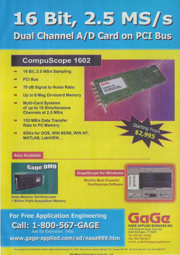
16 Bit, 2.5 MSls Sampling
III. PCI Bus
ill. 75 dB Signal to Noise Ratio
III Up to 8 Meg On-board Memory I. Multi-Card Systems of up to 16 Simultaneous Channels at 2.5 MSls
il l 100 MBls Data Transfer Rate to PC Memory
SDKs for DOS, WIN 95/98, WIN NT, MATLAB, LabVIEW, ..
Also Available
Deep Memory Oscilloscopes 1 Billion Point Acquisition Memory
GageScope for Windows
World's Most Powerful Oscilloscope Software
GAGE APPLIED SCIENCES INC. 1233 Shelbume Road, Suite 400 South Burlington, VT 05403
Tel: SDO-S67·GAGE Fax: 800-760·8411 e·mail: [email protected]
From outside the Unrted Stales contact Gage Appfied Sciences Inc., 2000, 32M Avenue lachine, Montreal ae, Canada H8T 3H7 Tel: (514) 633-7447 Fax: (514) 633-0770
pentiumxeonnt
Shorten the distance between thinking it and seeing it.
The Intel· Pentium· III Xeon™ processor. Powerful, robust performance for workstations.
Your workstation should be an extension of you. When deadlines are looming, and
you need to complete a 3-D model, a stress analysis and a motion study on a
design, you don't need a workstation that slows you down. Thoughts and
commands should pass uninterrupted from your brain to your fingertips to your
screen. That's the thinking behind the Intel· Pentium-III XeonTU processor, our most
powerful processor specifically designed for workstations. It supplies the kind of
muscle you need to get the most out of apps like Mechanical Desktop,
DesignSpace. Solid Edge and CATIA V5. And in dual-processor configurations it
delivers massive performance gains through multitasking and multithreaded
applications. Integrating seamlessly into your current network, the Pentium III Xeon
processor enables easy collaboration via the Web. It also runs everything including
your basic office applications on a Single machine-saving time, desk space and
dollars. All without skipping a beat. To see what a Pentium III Xeon processor-powered
workstation can do for you, go to: I 'Nwvv.intel,com/go/workstations
For More Information Circle No. 556 inteJ·
12 For More Information Circle No. 406
TECH BRIEFS www.nasatech.com
Published by .Associated Business Publications
Publisher..... ............ .... .............. . ....................... .Joseph T. Pramberger
ChIef Editor ....... ... .... .. . ..... ... .. .................................... Linda L Bell
AssocIate Publisher. Photonics Tech Briefs .............................................. Linda Silver
EdItor. Market Focus EditJons . ................................ . . ..... Robert aark
Internet Editor ............................................................................. Suzanne Bilyeu
ProducIJon Manager .......................................................................... Margery Koen
Assistant ProductIon Manager ............. .............................. .. . .John Iwandw
Art Director ...................... ...... ....................................................... lois Erlacher
ProductIon ArtIst .............................................................. Christopher Coleman
ClrculatJon Manager ................................................................... ... Hugh J. Dowling
BRIEFS & SUPPORnNG LITERATURE: Wrttten and produced for NASA by Advanced Testing Technologies, Inc., Hauppauge, NY 11788
TechnlcaVManaglng Editor .................................................................... Ted Selinsky
Sr. TechnICal Analyst................. . ............................................ Dr. Larry Grunberger
Art Manager .................................................................................. Eric Starstrom
Staff WriterslEditors ........................................... Dr. Theron Cole, George Watson
Graphics ............ .. ..... . .. ............................................................ Robert Simons
Ed,tOrial & ProductIon ..................................... .Joan Schmiemann, Becky D. Bentley
NASA:
NASA Tech ertefs are provided by the National Aeronautics and Space
AdministratIon, Technology Transfer DIvision, Washington, DC:
AdmInistrator .................................................................................. Daniel S. Goldin
Director, Commercial Technology .............................. ............... Dr. Robert Norwood
Publications Director ........................................................ ............................ Carl Ray
AssoaATED BUSINESS PUBLICAnONS INTERNATIONAL 317 Madison Avenue, New York, NY 10017-5391 (212) 49()"3999 FAX (212) 986-7864
Chairman/ChIef Executive Officer ............................... Bili Schnirring ([email protected])
President/Chief Operating OffICer ..................... ..................... Domenic A . Mucchetti
MIS Manager ...................................................................................... Ted Morawski
Webmaster ........... ....................... ............................................ .... ....... Albert Sunseri
CredIt/Collection ................................................. ................................. Feleda Lahey
AccountIng Manager ....................................................... ......................... Larry Duze
Trade Show Manager ........................................................................ Melissa Hinnen
Human Resources Manager ........................................................... lourdes Del Valle
Office Services Manager ............................ .. ............ ........ ......................... Sylvia Ruiz
NASA TECH BRIEFS ADVERTISING ACCOUNT EXECUTIVES
Headquarters .............. ....................................................................... (212) 490-3999
MA. NH, ME, VT, RI, Eastern Canada ...................................................... Ed Marecki
NY, CT .......... .......... .......... ................................. .
NJ, PA, DE. VA, DC, MD ...................................... ..
at (401) 351-0274
........... Mike Venezia
at (860) 871 -7491
............. Ryan Kraven
at (212) 490-3999
NC, SC, GA, FL, AL, TN, MS. LA, AR. OK ............................................ Christa Collins
at (954) 966-3939
MN, ND. SD, WI ........................................................................................ Bob Casey
at (847) 223-5225
IL, MO, lA, KS, NE .................................................................................. .Jeff Casey
at (847) 223-5225
IL, MI ............................................ ............................................ Colleen Bresnahan
at (847) 223-5225
IN, KY, OH, Western PA & NY, Central Canada ..... .. ................................. Chris Casey
at (847) 223-5225
N. Caltf ., CO ............................................... ........................................ ....... BiII Hague
at (408) 492-9292
WA. OR, ID, MT, WY, UT, Western Canada ............................................ Bill Madden
at (253) 858-1192
S. Calif .• NY. TX ............................................................................. Blake Dahlgren
at (310) 860-0172
A2, NM .... ......................................................................... Linda Silver
at (310) 247-0317
International Sales ............................................................................ Rachel Di Santo
at (0144) 01932-564999
Internet AdvertIsIng .................................................................... . .. Luke Schnirring
at (212) 49().3999
TechDeck Postcard Advertising ............ .............................................. Erving Dockery
at (212) 490-3999
Trade Show Sales ........................................................................... Carolyn Lighty
at (727) 796-5550. ext. t 35
For a complete list of staff e-mail addresses, visit www.nasatech.com
ASA Tech Briefs, September 1999
__ CfC*t~ ___
0(11 011 a 6UJ) 018 0.," D 'HD O. I.. D RaJ UI 0.11 • 11/X1 .e 0'21 D.tIl oa 0.11 D.([I O. III 0" 1maJ .'" 02 G.lI 75111 •• Q.21 IU 1~ tD
OS 0%1 0." "QjIJ
'. OJ! ac. C1Jl Itt G.lI 003 .. m t.zt D.12 a.as.m.(D 12 1l]2 0 ·1GUIl
10 all 0 111m ,m 03 o.om 0.1] 0)1 0 tsm De I.l! D Iil ID on IS D &' .00
• . en
More recorder and data acquisition products from Astro-Med
--
As' 0- . System Ce,""ed 0' -gOO Astro-Med Industrial Park. West Warwick. Rhode Island 02893 Phone: (401) 828-4000 ' Toll Free: 1-877-867-9783 ' Fax: (401) 822-2430 In Canada Telephone 1-800-565-2216 E-mail: [email protected] · Web Site: www.astro-med.com
For More information Circle No. 560
NASA Commercial Technology Team
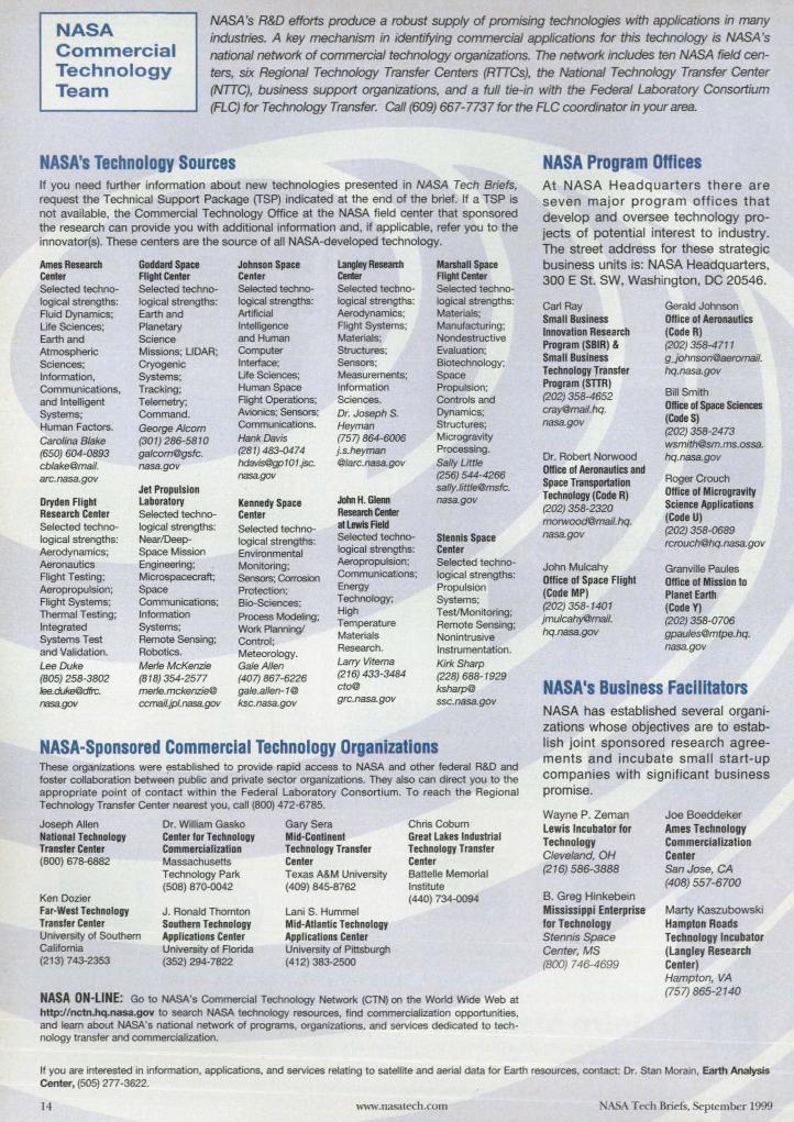
NASA's R&D efforts produce a robust supply of promising technologies with applications in many industries. A key mechanism in identifying commercial applications for this technology is NASA's national network of commercial technology organizations. The network includes ten NASA field centers, six Regional Technology Transfer Centers (RITCs), the National Technology Transfer Center (NTTC), business support organizations, and a full tie-in with the Federal Laboratory Consortium (FLC) for Technology Transfer. Call (609) 667-7737 for the FLC coordinator in your area.
NASA's Technology Sources If you need further information about new technologies presented in NASA Tech Briefs, request the Technical Support Package (TSP) indicated at the end of the brief. If a TSP is not available, the Commercial Technology Office at the NASA field center that sponsored
the research can provide you with additional information and, if applicable, refer you to the innovator(s). These centers are the source of all NASA-developed technology.
Ames Researdl Goddard Space Johnson Space Langley Research Marshall Space Center Flight Center Center CenIar Alght Center Selected techno- Selected techno- Selected techno- Selected techno- Selected techno-logical strengths: logical strengths: logical strengths: logical strengths: logical strengths: Ruid Dynamics; Earth and ArtifICial Aerodynamics; Materials; Ufe Sciences; Planetary Intelligence Flight Systems; Manufacturing; Earth and Science and Human Materials; Nondestructive Atmospheric Missions; LlDAR; Computer Structures; Evaluation; Sciences; Cryogenic Interface; Sensors; Biotechnology;
Information, Systems; Ufe Sciences; Measurements; Space Communications, Tracking; Human Space Information Propulsion;
and Intelligent Telemetry; Flight Operations; Sciences. Controls and
Systems; Command. Avionics; Sensors; Dr. Joseph S. Dynamics;
Human Factors. George Alcom Communications. Heyman Structures;
Carolina Blake (301) 286-5810 Hank Davis (757) 864-6006 Microgravity
(650) 604-0893 galcom@gsfc. (281) 483-0474 j.s.heyman Processing.
cblake@mail. nasa.gov [email protected]. @/arc.nasa.gov Sally Uttle
arc.nasagov nasagav (256) 544-4266
Jet Propulsion sally.litt/e@msfc.
Dryden Flight Laboratory Kennedy Space JohnH. Glem nasa.gov
Research Center Selected techno- Center Researd1 CenIar Selected techno- logical strengthS: Selected techno- at I.8wis field
logical strengths: NearlDeep- logical strengths: Selected techno- Stennis Space Aerodynamics; Space Mission Environmental logical strengths: Center
Aeronautics Engineering; Monitoring; Aeropropulsion; Selected techno-
Flight Testing; Microspacecraft; Sensors; Corrosion Communications; logical strengths:
Aeropropulsion; Space Protection; Energy Propulsion
Right Systems; Communications; Bio-Sciences; Technology; Systems;
Thermal Testing; Information Process Modeling; High Test/Monitoring;
Integrated Systems; Work Planning! Temperature Remote Sensing;
Systems Test Remote Sensing; Control; Materials Nonintrusive
and Validation. Robotics. Meteorology. Research. Instrumentation.
Lee Duke Merfe McKenzie Gale Allen LanyVitema Kirk Sharp
(805) 258-3802 (818) 354-2577 (407) 867-6226 (216) 433-3484 (228) 688-1929
/ee.duke@dfrc. merle.mckenzie@ gaJe.allen- 1@ cto@ ksharp@
nasagav ccmail.jpl.nasagav ksc.nasa.gov grc.nasa.gov ssc.nasa.gov
NASA-Sponsored Commercial Technology Organizations These organizations were established to provide rapid access to NASA and other federal R&D and foster collaboration between public and private sector organizations. They also can direct you to the appropriate point of contact w ithin the Federal Laboratory Consortium. To reach the Regional Technology Transfer Center nearest you, call (800) 472-6785.
Joseph Allen National Technology T ranster Center (BOO) 678-6882
Ken Dozier Far-West Technology Transler Center University 01 Southem Califomia (213) 743-2353
Dr. William Gasko Center lor Technology Commercialization Massachusetts Technology Park (508) 870-D042
J. Ronald Thomton Southern Technology Applications Center University 01 Florida (352) 294-7822
Gary Sera Mid-Continent Technology Transfer Center Texas A&M University (409) 845-8762
Lani S. Hummel Mid-Atlantic Technology Applications Center University of Pittsburgh (412) 383-2500
Chris Cobum Great Lakes Industrial Technology Transler Center Battelle Memorial Institute (440) 734-0094
NASA ON-LINE: Go to NASA's Commercial Technology Network (CTN) on the World Wide Web at http://nctn.hq.nasa.gOY to search NASA technology resources, find commercialization opportunities, and leam about NASA's national network of programs, organizations, and services dedicated to technology transfer and commercialization.
NASA Program Offices At NASA Headquarters there are seven major program offices that develop and oversee technology projects of potential interest to industry. The street address for these strategic business units is: NASA Headquarters, 300 E St. SW, Washington, DC 20546.
Carl Ray Small Business Innovation Research Program (SBIR) &, Small Business Technology Transfer Program (STTR) (202) 358-4652 [email protected]. nasa.gov
Dr. Robert Norwood Office 01 Aeronautics and Space Transportation Technology (Code R) (202) 358-2320 [email protected]. nasa.gov
John Mulcahy Office 01 Space Flight (Code MP) (202) 358-140 1 jmulcahy@mail. hq.nasa.gov
Gerald Johnson Office of Aeronautics (Code R) (202) 358-,m 1 gjohnson@aeromail. hq.nasa.gov
Bill Smith Office 01 Space Sciences (Code S) (202) 358-2473 [email protected]. hq.nasa.gov
Roger Crouch Office 01 Microgravity Science Applications (Code U) (202) 358-D689 [email protected]
Granville Paules Office 01 Mission to Planet Earth (Code Y) (202) 358-0706 [email protected]. nasa.gov
NASAls Business Facilitators NASA has established several organizations whose objectives are to establish joint sponsored research agreements and incubate small start-up companies with significant business promise.
Wayne P. Zeman Lewis Incubator for Technology Cleveland, OH (216) 586-3888
B. Greg Hinkebein Mississippi Enterprise for Technology Stennis Space Center, MS (BOO) 746-4699
Joe Boeddeker Ames Technology Commercialization Center San Jose, CA (408) 557-6700
Marty Kaszubowski Hampton Roads Technology Incubator (Langley Research Center) Hampton, VA (757) 865-2140
If you are interested in information, applications, and services relating to satellite and aerial data for Earth resources, contact: Dr. Stan Morain, Earth Analysis Center, (505) 277-3622.
14 www.nasatech.com NASA Tech Briefs, Seplember]999

WAllU Lorporauon: U:>A • Mlcroson Imernet txplOrer
ca r!J-r Search FaVOlites
Links ~ Best at the Web ~ T oday's Links
etoWAGO
WAGO has more than 8.£XX) connection and industrial automation products available. To find the ones that are best tor your needs, you now
have several options for finding them: • Fully interactive CD-ROM catalog
Assemble ralts and export to DXF flies Marklng script software Included Multiple search facilities
• Intemel sHe - www.wago.com Find the sales person In your area
• TradHionalllterature and Brochures Keep them on your bookshelf tor easy reference
• Call 1-800 DIN RAIL Speak with a service professional
http://www.wago.com
WAGO CORPORA11OH 9085 N. DEERBROOK TRAIL BROWN DEER. WI 53223 TEl..; 800 346-7245
feN' More Information Circle No. 519
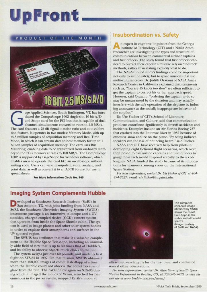
PRODUCT OF THE MONTH
Gage Applied Science, South Burlington, VT, has introduced the CompuScope 1602 ingle- lot l&-bit A/D and Scope card for the PCl bus that is capable of dualchannel, simultaneous conversion rate to 2.5 MS/s.
The card features a 75-dB signal-to-noise ratio and auto-calibration feature. It operates in two modes: Memory Mode, with up to 8 million samples of acquisition memory; and Real Time Mode, in which it can stream data to host memory for up to 1 billion samples of acquisition memory. The card uses Bus Mastering, enabling data to be transferred from on-board memory to the PC's memory at rates to 100 MB/s. The CompuScope 1602 is supported by CageScope for Windows oftware, which enables users to operate the card like an oscillo cope without writing code. Users can view, manipulate, store, analyze, and print data, as well as convert it to an ASCII format for use in spreadsheets.
For More Information Ci rcle No. 745
Imaging System Complements Hubble
Developed at outhwest Re earch In titute (SwRI) in an Antonio, TX, with joint funding from ASA and
SwRI, the outhwest Ultraviolet Imaging ystem (SWUIS) instrument package is an innovative tele cope and a UVsensitive, charged-coupled device (CCD) camera y tem that operates from inside the Space huttle cabin. The system is u ed to image planets and other olar s tern bodies in order to explore their atmospheres and urfaces in the UV pectral region.
The WUIS has attribute that make it a valuable complement to the Hubble pace Tele cope, including an unu ualIy wide field of view that i up to 30 times that of Hubble' , and its ability to ob erve objects much clo er to the Sun.
The system weighs just over 60 pounds, and made its first flight on ST~5 in 1997. On that mi ion, WUI obtained more than 400,000 images of comet Hale-Bopp at a time when the Hubble could not ob erve the comet because of glare from the Sun. The SWUIS flew again on STS-93 during which it imaged the clouds of Venus, earched for faint emissions in thejovian ystem, mapped Earth's moon at
nsubordina ·on vs. Safe
n expert in cognitive lingui tics from the Georgia In titute of Technology (CIT) and a ASA Arne
re earcher are inve tigating the type and structure of communication between commercial airliner captain and first officers. The tudy found that first officers who need to correct their captain' mistake rely on "indirect" methods, rather than tating explicity what to do.
The ASA-funded tudy' findings could be important not only to airline safety, but to pace mission that use multi-cultural crews. Dr. Judith Orasanu of ASA Ames Re earch Center in California explained that statements uch as, "You are 15 knots too slow" are often ufficient to
get the captain to correct hi or her approach peed. However, aid Orasanu, "ordering the captain to do so may be unwarranted by the ituation and may actually interfere with the afe operation of the airplane by inducing annoyance at the ociaUy inappropriate behavior of the co-pilot."
Dr. Ute Fi cher of CIT's School of Literature, Communication, and Culture, aid that communication problem contribute significantly in aircraft accidents and incidents. Examples include an Air Florida Boeing 737 that crashed into the Potomac River in 1982 because of exce ive snow and ice on the plane. "By being indirect, speakers run the risk of not being heard," said Fischer.
ASA and CIT have received help from pilots in developing eight fictional flight cenarios, which were then po ed to 576 airline captain and first officers to gauge how each would re pond verbally to their colleague . ASA funded the study because of its implications for teamwork among crews on the International Space Station.
For 17l(m information, contact Dr. Ute Fischer of crr at 404-894-7627; e-mail: [email protected].
This computerenhanced image obtained by SWUIS shows the comet Hale-Bopp in the visible and ultraviolet spectra. (Image courtesy of SwRI and NASA)
ultraviolet wavelengths for the first time, and conducted everal other ob ervation .
For more information, contact Dr. Alan Stem of SwRI's Space Studies Departmmt in Boulder, CO, at 303-546-9670; or visit the web site at www.boulder.swri. edu/swuis/
16 www.nasatech.com ASA ech Briefs, September 1999
Now see what you think. Now WITH
VOLUME
VISUALIZATION
New MATLAB 5.3, now with advanced visualization and a complete language for application development.
New VISualization Power
Now you can quickly create more
informative and revealing 2-D and
}D graphics directly in MATLAB 5.3.
Gain insights into complex systems
using capabilities like lighting and
shading, camera control, and texture
mapping. Efficient new algorithms
make even irregularly-sampled data
display faster and easier.
Multidimensional Arrays
and Structures
Now the MATLAB technical
computing language supports
multidimensional arrays and user
definable data structures. MATLAB
5.3 includes a full set of functions
for manipulating and analyzing
multidimensional data, including
volume visualization routines such
as isosurface and streamlines.
Application Development
A host oflanguage and data
management enhancements in
new MATLAB 5.3 make algorithm
and application development fast
and intuitive.
We added
• visual debugger/editor
• function performance pro filer
• point-and-click GUI builder
• object-oriented programming
New Toolboxes
Companion toolboxes offer
application-specific graph types,
analysis functions, and interactive
interfaces. New and updated
toolboxes include:
• Mapping Toolbox
• Image Processing Toolbox
• Signal Processing Toolbox Control System Toolbox
See how MATLAB 5.3 can work for you. Act now.
Get a free technical information kit on visualization
and application development in MATLAB.
Call 508-647-7000 V"l5it www athw rks.c m/ntbv
We have a ~ n~ of intamtior.a! rrpraaitima...
V"ui, our w.b ,i1t at -...mathworb.c:oml ..... for mo .. information. 0 1999 Th. MatbWo,ks, Inc.
For More Information Circle No. 537
Reader Forum Reader Forum is devoted to the thoughts, concerns, questions, and comments of our readers. If you have a comment, a
question regarding a specifu; technical problem, or an answer to a question that appeared in a recent issue, send your letter to the address below.
I would like to obtain any available information on service-life problems with bearings - roller, spherical- and bushings. Since aircraft and helicopter structural failures are many, this is an area of concern for aircraft safety, cost, and weight problems. Thanks for any information.
Eugene R. Speakman Fullerton, CA 714-529-2012 [email protected]
I am looking for a good source -book or technical paper - on step-bystep procedures to insure clean
assembly of parts for an assembly with bearings. I have information on building a cleanroom, but I can find nothing on the small details of getting clean parts to the cleanroom. Thanks for any assistance.
Robert Crader [email protected]
(Editor's Note: We've received comments from many of you regarding the Editor's Note in our May Reader Forum concerning aerogel, the "solid smoke" material developed by NASA. We stated that aerogel, which is made of silica, alumina, carbon, and other
materials, "weighs less than the same volume of air. n Our readers brought to our attention that this statement is not accurate. Terrance Mason of NASA's Jet Propulsion Laboratory, explains further: "The density of the silica network that makes up the aerogel is that of bulk glass; i.e., 2 glcc. The denSity of air is 0.001255 glcc. Therefore, there can be no combination of silica and air that has a density less than air. The miniscule pores in aerogel could be filled with helium or hydrogen and thus be made 'lighter than air,' but that is short-lived. The gas will leak out to the point where it would be heavier than air and fall." Thanks to Terrance for his clarification, and to our readers for pointing out this error.)
Post your letters to Reader Forum on-line at: www.nasatech.com or send to: Editor, NASA Tech Briefs, 317 Madison Ave., New York, NY 10017; Fax: 212-986-7864. Please include your name, company (if applicable), address, and phone number or e-mail address.
--_. -.,.
SYNRAD
18 For More Information Circle No. 407 NASA Tech Briefs, September 1999
ADVERTISEMENT
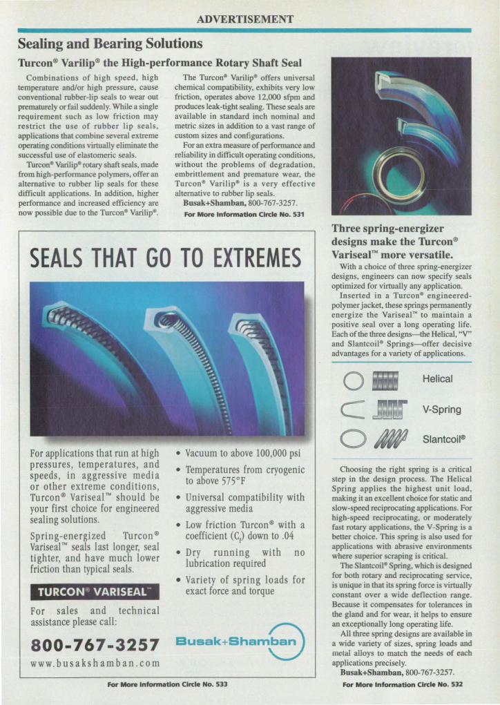
Sealing and Bearing Solutions Torcon® Varilip® the High-performance Rotary Shaft Seal
Combinations of high speed, high temperature andlor high pressure, cause conventional rubber-lip seals to wear out prematurely or fail suddenly. While a single requirement such as low friction may restrict the use of rubber lip seals, applications that combine everal extreme operating conditions virtually eliminate the successful use of elastomeric seals.
Thrconll Varilipll rotary shaft seals, made from high-perfonnance polymers, offer an alternative to rubber lip seals for these difficult application . In addition, higher performance and increased efficiency are now possible due to the Thrcon· Varilipll.
The TurconliJ VarilipliJ offers universal chemical compatibility, exhibits very low friction, operates above 12,000 sfpm and produces leak-tight sealing. These seals are available in standard inch nominal and metric sizes in addition to a vast range of custom sizes and configurations.
For an extra measure of perfonnance and reliability in difficult operating conditions, without the problems of degradation, embrittlement and premature wear, the Turconll VarilipliJ is a very effective alternative to rubber lip seals.
Busak+Sbamban, 800-767-3257. For More Information Circle No. 531
SEALS THAT GO TO EXTREMES
For applications that run at high pressures, temperatures, and speeds, in aggressive media or other extreme conditions, Tu rcon ® Variseal'" should be your first choice for engineered sealing solutions.
Spring-energized Turcon® Variseal"" seals last longer, seal tighter, and have much lower friction than typical seals.
TURCON ~ VARISEAL··
For sales and technical assistance please call:
800-767-3257 www.busakshamban.com
• Vacuum to above 100,000 psi
• Temperatures from cryogenic to above 575°F
• Universal compatibility with aggressive media
• Low friction Turcon® with a coefficient (e() down to .04
• Dry running with no lubrication required
• Variety of spring loads for exact force and torque
BUSBk+Shan8 For More Information Circle No. 533
Three spring-energizer designs make the Torcon® Varisear" more versatile.
With a choice of three spring-energizer designs, engineers can now specify seals optimized for virtually any application.
Inserted in a Turcon· engineeredpolymer jacket, these springs permanently energize the Variseal'" to maintain a positive seal over a long operating life. Each of the three designs-the Helical, "V" and Slantcoil* Springs-offer decisive advantages for a variety of applications.
o Helical
C V-Spring
o ~ Siantcoill!l
Choosing the right spring is a critical step in the design proce s. The Helical Spring applies the highest unit load, making it an excellent choice for static and slow-speed reciprocating applications. For high-speed reciprocating, or moderately fast rotary applications, the V-Spring is a better choice. This spring is also used for application with abrasive environments where superior scraping is critical.
The Slantcoilll Spring, which is designed for both rotary and reciprocating service, is unique in thatlts pring force is virtually constant over a wide deflection range. Because it compensates for tolerances in the gland and for wear, it helps to ensure an exceptionally long operating life.
All three spring designs are available in a wide variety of sizes, spring loads and metal alloys to match the needs of each applications precisely.
Busak+Sbamban, 800-767-3257.
For More Information CIrcle No. 532
Autodesk Inventor: A New Look at MeAD Steven S. Ross
Autode k i taking fre h aim at MCAD, the mechanical de ign CAD market, with an entirely new oftware package, Autode k Inventor. nlike the popular AutoCAD Mechanical De ktop, Inventor i not based on Auto CAD itself. In fact, files created with the two package are not completely compatible. Autodesk tarred development on Inventor in February 1996, two month before Mechanical Desktop first shipped.
The existing Mechanical De ktop is certainly a ucces fuI product. In fact, with a half-million copies sold, Autodesk claims market leadership in MCAD. But Autode k has never claimed it i as robu t as many of its competitors, e pecially for big as emblies of 300 to 3,000 components or more. Inventor, known to insiders by its code name "Rubicon" during its three-year development cycle, is aimed squarely at that market.
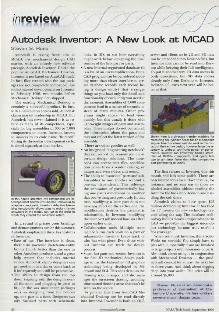
In this nozzle assembly, the components are in· terdependent and the cross handle is shown as an adaptive component. Inventor's Adaptive Assem· blies functionality allows users to make changes anywhere in the model, not just in the order in which they created the constraint system.
In a round 'of private pre briefings and demon trations earlier this summer, Autode k emphasized three key feature of Inventor: • Ease of use. The interface is clean,
there's an awe orne sketch-into-entity facility (much better than the one in other Autode k products), and a great help y tern that include tutorial video . Autode k claims designers can get used to it in a day or come back to it infrequently and till be productive.
• The ability to de ign from the top down (starting with the design's overall function, and plugging in parts to fit), or the way mo t other packages work - designing from the bottom up, one part at a time. Designers can mix finished parts with schematic
20
links, in 3D, to ee how everything might work before de igning the final version of the link part or parts.
• A new internal egmented datab e (it i a bit of an oversimplification, but a CAD program can be con idered nothing more than clever interface to create database records, each record being a de ign entity) that arrange things 0 you load only the detail and functionality of each entity you need at the moment. Assemblies of 3,000 components load in a matter of econd in-tead of many minutes. Other pro
gram might appear to load views quickly, but thi usually is done with lightweight image of parts and assemblie . These image do not contain all the information about the parts and may not reflect the late t version of the assembly. There are other goodies as well:
• An integrated "engineering notebook" that can record the reasons you cho e certain design olutions. The notebook can accept data files, pecification tables from a vendor catalog, or images and even videos and sound.
• The ability to "as ociate" parts and sulr as emblies to one another without a one-way dependency. This side tep the annoyance of parametrically basing one part's dimensions on another that you've designed previously. In that case, modifying a later part doe not have any effect on the earlier one; the modification de troys the parametric relation hip. In Inventor, modifying the later part will indeed have an effect upon earlier ones.
• Collaboration tools. Multiple team members can each work on a part or ubas embly. Inventor keep track of
who has what piece. Even tho e without Inventor can track the design proce .
• uper-fast pans and zooms. Inventor is the first 3D mechanical de ign package to use the Fahrenheit 3D graphics technology being developed by Micro oft and GI. Thi adds detail as the drawing scale change, and also manage the on-screen drawing, avoiding time wasted drawing areas that can't be seen on the creen. In general, file from AutoCAD Me
chanical De ktop can be read directly into Inventor. Inventor i both an OLE
www.nasatech.com
erver and client, 0 its 2D and 3D data can be embedded into De ktop file . But Inventor file cannot be read into De ktop while keeping their full intelligence. To put it another way, 2D data move in both direction, but 3D data move cleanly only from De ktop to Inventor. De ktop 4.0, early next year, will be better at that.
Shown here is a six·stage transfer machine for machining the cylinder heads for an automobile engine. Inventor allows users to work in the context of their entire design, however large the as· sembly is, without sacrificing power or performance. Inventor can effectively handle assemblies of 10,000+ components, and opens files two to ten times faster than other competitive best·performing solutions.
The first release of Inventor, due this month, will lack some polish. There are only limited tools for surface texture, for in tance, and no easy way to show exploded as emblie without reading the Inventor file back into Desktop and handling the task there.
Autodesk claims to have spent 25 million developing Inventor. It has filed for 17 patents on new technology created along the way. The database technology itself is clearly a major advance in CAD - probably the biggest since olr ject technology became truly useful a few years ago.
When you think Inventor, think SolidWorks on teroids. You simply have to play with it, e pecially if you are involved in large projects with thousands of parts. Also think about using it in conjunction with Mechanical De ktop - the products will co-exist for at least the next two or three years. And think about digging deep into your wallet. The price will be around 5,000.
Steven Ross is an associate professor of Journalism at Columbia University. He has written several major deSign texts .
ASA Tech Briefs, September 1999
HP
rJJP'I HEWLETT S
a!"~ PACKARD
Hewlett-Packard is unique in offering engineers a complete design toolbox.
First, our technology Leadership in both UNIXs and Windows NT® systems means the ultimate in performance
at the best price. With HP, you also receive a smooth road to compatibility with IA-64 architecture, the next generation
of computing that the HP-Intel® partnership is developing.
Adding to the mix are the immersive environments of HP's V1SUAUZE Center and Workgroup products, enabling teams of engineers to see
the design job in 3D and to collaborate early in the process when flaws are easier and Less costly to remedy.
Then, HP's DesignJet Large-format printer enables you to output your design with the highest quality available. From amazingly crisp, 600-dpi,
D-size drawings in less than a minute, to stunning, photo-quality, solid modeling color images up to 54 inches wide, you have the ultimate
control over your printed output
It aU adds up to a complete toolbox of unbeatable solutions from the Leader in the design marketplace.
Register to win a FREE telescope or binoculars and well send you HP's new Mechanical Design Power To V1SUAUZE CD-ROM. To register and
receive your FREE CD,just go to www.hp.comlinfolvis2ntb
VlSUALI?E WORKSTATIONS for Mo,. Information CIrcle No. 541
~MATE DESIGN MACHINE
I WnbNs NT Is. us registered _ Ii MoousoIt Coqxnncn UNIX IS a registered _.,!he U1ItBd S"" .. on! _ au!D1eS. Iitensed e>dJsM!Iy 1IrotqI)(JIJpen ~ I.Jnitsd.
(.., Commercialization Opportunities
Electrodialysis To Remove Ammonium Ions From Wastewater
The proce s removes ammonium from wastewater without the u e of consumable chemicals and without adding other ubstances to the treated water. (See page 48.)
Making Li uid Air in Small, Economic~ Quantities
A mixing apparatus combines liquid oxygen with liquid nitrogen to make liquid air in mall, convenient quantities. Both gases are readily available in liquid form, and the proce can produce batches as small as 100 liters. (See page 50.)
22 For More Information Circle No. 408
Air-Purification System Utilizing Humidity Swings
This ystem would remove toxic gases from solid-waste incinerator exhaust and remove trace contaminants from breathable air. Conceived originally as part of a life- upport s tern, the y tern can be adapted to the treatment of indu trial and municipal exhau t streams. (See page 56.)
Hybrisol Rocket Engines This is a combination of a hybrid and
a solid-propellant rocket engine. Estimates show that this de ign could be produced at half the co t of conventional rocket engines. (See page 58.)
A Precise Closed.Looe Temperature-Control System
This system is designed to use a single thermal ource to control the temperature of a dosed-loop system. Precise temperature control is important to a number of industries, including photographic, pharmaceutical, food-processing, heating-ventilationand-air-conditioning, and many others. Predicted temperature accuracy is ±D.5 OF (±0.3°C). (See page 60.)
Adaptable Drill Guide This drill guide can be adapted to a
curved or flat surface. The main function is to keep the axis of a drill perpendicular to the surface being drilled. The tool can also be used to guide a reamer and other tool and to control the depth of drilling. (See page 61.)
Improved Ax ay of X-Ray Microcalorimeters
This array of microcalorimeters is proposed for x-ray spectrometers for astrophysical research. The spectrometer will be used to measure the x-ray spectra of celestial olr jects at unprecedentedly high resolutions. (See page 62.)
Miniature Ring-Orbitron Getter Ion Vacuum Pumps
Miniature pumps are proposed for supplying high vacuums to advanced scientific instruments expected in the next few years. Examples of such instruments are electron micro copes, ion mass spectrometers, and instruments based on electronic probes. (See page 62)
ASA Tech BriefS, Se tember 1999
igh-Speed Card Enables Remote Communications for Shuttle Projects
Syn / Async 4111 calev: 1 S
Liberty, SC 864-843-434
22 communicatio card
The (;l'mh na III ie, Branch of • 't\. :\', C,ocidard 'pace Flight ,enler's Labor LOf) for Tt'rre tI j,11
Ph) il has bel'll r earching dircct me<lSUrCITlClll clrh.lIlce and t('chniques je)1 more than a dec'lIk. Recentl), Goddard t'ngiueer, dccided LO adapt .til airborne lasel .tILinH'ter fin lise 01\ the Span' hutlle.·j he m('asuremenl 1.\ (:1' and iL' ('01 repollding C()l11putel~ had 10 he operated remotd .
T he projce t required ,m RS--t22 oml with du,d channeb. '\ASA cho'e the high-speed' 11('/ \S\llC Cal d, "hich was
oftware Helps Manage Changes for Space Station Team
PVCS Dimensions configuration management oftware
Merant Mountain View, CA 650-938-3700 www.meranLcom
. 'AS \', International Spacl talion (1 S) i~ Ihe largest ricn
lific ('ooperali, e program ill hi LO
r\', {II awing on the resources and scienlific expenisl' of 16 nalion . Tht' Boeing C OIlIP;U1\, 1 'AS,\' prime conlr.iClOr, ha as 1I1lled the ta k of manllfactlll ing. te Ling. and delht.·ring thl'l. ,module of the I'> .
Thl' building 01 Cnin, the fil\t L'.s. module, i>eg,m with Boeing ulilizing the prohlem-tracklllg portion of lht' ryeS Dimen~ion ofl\\are to track bugs ,md authorize chauge to
integrated producl! across the pace tation program. The proce -ba cd configuration managemem ( :'\1) sy,t'm i~
hosted on a LIn ,el vel'; Boeing plan to expand ib u~e on a Windows _ T platform.
"The Boeing F-22 personnel in callie were achienng top qualil\ le\el. and gaining a competitive edge \'ia (heir succe, ful impl<."menuuion of P" Dimen 'ions.~ all.ording to }lon3 L:~rsen. Boning" ISS ~ofm'arc conliguration manager. "We ob~er\'ed firl-hand the major ,ucce ,e, Ihe, e highl\' c mplex development emironmellb experienced via this
\\orked intu b th the i.bCI t tup on the hUlllc, .:Ind the control module 011 the ground l() facilItate ommullication all a min O\\'<lVC link, The cOlllmllllicauoll fune cion \\'3 e,'en more important dill" to the fact lhat lhe huttle' re-('nm and land-
ing could dJIll,lge thl' hard dm{'~ • nd information collc( ted. \.." much data a po,~ihk
41' needed to he Id.1 '-<1 to alld 't,1l cd on lhe gmlllld. In additIOn. condilion, in orbit llH'31ll th,1t til(' lugh p,-eel data chann!'! would bt' open onl '20 min lite 3 da\'_
The card facilitatcd chlla lJ ,tJIsmission. nlclnding nll'a uJ'ements , f the heights 01 ground ulfaC(' and \'('ITelatlon canopies gathered tWill three million her ~hot., The ~\sl(,Jll 'hi controlled I emote!) from lile ground woon using ~igllals transmitted by the canl. "The Seale\e1 card ,,'as dlO,ell Iwc.IlI, e it fit Ihe sp 'cificatiolls \\t'
needed. ,\Ild aln, bccau,e \\e Irtlstccl its I eliabtlil)," ,aid David Rahine, an aero paCt' engincer ilt 1 'AS,\ Goddard. "'\'e plan to
lI~C it. in ,cn:ralmorc projen~ and in de\;ce\ that arc going to h( ll'cd in two ll10re upcoming ~hlltlle flights."
For More Information Circle No. 743
ach-anced ,olullon, and this \\,1 a m,~or factor iJlfluencing OUI deci ion to purchase th('\tem.-
The program prO\;c!ed an aeul't' ,;cw of dC\'l'lopmcnt efforts and aIJO\\cc! management of oln'"are changes in complex, heterogeneous elwironmellb \i .. [he seamle illtl'gration of change. \crsion, and proce m;Ulagement. The de\elopment t('am can acee ~ the Ylem in parallel and concurrently b) a \'ariety 01 meall , IIlcluding the 1l1lemet., P clients. and the.' Window lnlerfan' TIti~ i- important. ,luce the ,'[em upports [he Ilceru. of many Boeing team 111 building software collabol'arivcly,
For More Information Circle No, 744
'AS'-\' Tech Briefs. plember l!l999:gJL _________ ~\,~L.Q.iil.Sil~b.J;.Q(I:I_ __________________ ~ __ ~'_ __
'> The Volkswagen New Beetle is dashing outside and in. Not surprismg Its award-winning instrument panel is made of high-impact. heat-resistant. dimensionally stable NORYle resin from GE. Flower power. indeed
Everyone want what nobody aw coming_
That' why you can'tju t break the mold_
You have to shatter it-with fre h idea that
drive out costs, that ignite colo sal process
improvements, that boldly move new products
to market fa ter than ever before_ Thi is the
curve that can become your edge_ And with
more resources and re ins than any pIa tic
upp)ier on Earth , we can't wait to help 'ou
harp n our. E-mai) web.feedba [email protected].
i it, vw.gepla tic .com/ newbeetle. Or call u
for more inf rmation at 1-800- 45-0600.
,**-II1II _ .. ~_ oI __ AG
'/l·Is.--,_oI __ ~
GE Plastics We bring good things to life.
For MOft Information CIrcle No. 575
-$ Special Coverage: CADlCAElPDM
Cost Reduction and Profit Improvement Through Design
Chain Integration e-Engineering i the
reation of a dynamic, integrat d product develop-ment and realization proc , one widl me necessary agility and defme to re pond to the demand of an e-commerce world. e-Engineedng stem from a recognition that for companie to reap maxi-mum benefit from the large inve tments and Mar~.ting con iderable pain in im-plementing Enterpri e Re ource Planning (ERP) , the product pr ce s that feed into the upply chain must be optimized. Thi product proces is the Design hain, the in- The Design Chain
terlinked contributor to m e creation and realization of a product. The Design Chain i not only R&D, but cu tomer , marketing, upplier, and production.
Design hain costs can have a greater impact on earning than any other area of the organization. In the typical enterpd e, by the time a product reaches the upply chain , nearly 80% of product
costs have been predetermined by the De ign hain. attractive as earning improvement i, the option to implement Design Chain integration rapidly ,~;ll cease to be an elective choice. The emergence of the Internet will make it a competitive nece ity.
e- ngineering require three fundam ntal : pen'asive use of 3D for product data, gaining acce to that product infonnation, and the use of fit clients to leverage that data throughout the Design
hain. Companie that achieve De ign hain integration through e-Engineer
ing not onl improve product proce efficiency, but also the bottom line.
3D: The Universal language The fir t fundamental of De ign
hain integration through e-Engineer-
26
Conceptual Design
Training & Customer
Service
Engine.ring Manufacturing & Production Engine.ring
~
~
Field Engin •• ring & Service
ing is the use of 3D data for product development. There are many links in the De ign Chain, and without hared information, integration is impo ible. Engineering data has to be under tood by all contributors, and 20 engineering drawing do not facilitate communication of product feature and atmbute to tho e outside of engineedng.
Two-dimen ional repre entation of real-world objects is hard for many participants in the enterprise to under-tand. To emphasize this, put a human
face to ome of the vadou links in the De ign Chain: cu tomer, purcha ing agent, alesper on, factory worker, dealer, manager, and field ervice technician. A eemingly imple part, uch as an automotive wheel, might require a dozen or mOI'e 2D drawing to communicate all the nece ary details, ver us a ingle 3D file. Globalization make 3D
even more imperative. The ability to use animation and visualization technologies of 3D data can eliminate thou ands of page of text. orne companie literally have even different language poken on the factory floor, and 3D i the universal language.
www.nasalech.com
Suppliers
Technical Documentation
& Publications
e-Engineering require a core technology architecture that upports the entire flow of de ign -ever thing from concept through cu tomer delivery. Thi new architecture, De ign Flow, i the backbone of e-Engineering, providing the foundation for improving product proce es while allowing for integnttion of the De ign Chain into upply chain manage
ment and ERP. Design Flow i the first new 3D development architecture in more than a decade, and unlike exi ting CAD architecture, it can be used outside engi-
neering and in the De ign Chain. Corporations that have deployed olid
modeling into product development already have reaped enormou productivity gains of 3D. However, these traditional olid modeling technologies require a great deal of inve tment before tho e gain are realized. Just as companie are beginning to ee light at the end of the tunnel, mat light rna be me proverbial oncoming train. That train i e-bu ine , and it i quickJ rendedng traditional olid modeling ob olete.
Current Technology Falls Short The traditional CAD/ CAM/ CAE/
PDM system are point olution focused departmentally, not as enterpri e tools. The complex proprietary data tructure of these sy tern are barrier
to communication, not enabler . Furthermore, engineer utilizing identical ystem find it difficult to collaborate
effectively. The reasons are two-fold. Fir t, i the i ue of feature and hi tory data, or how each model wa con-tructed . Commonly referred to a deign intent, it is a fundamental require
ment of the e ystems for building
ASA Tech BriefS, September 1999

INTRODUCING RHINOjR. J
A NEW ADDITION TOTHE
KINGSTON STORAGE FAMILY. i
WHEN IT COMES TO
strength and durability. the
new Kingston- Rhino-JR is
a chip off the old block_ Like the popular Data Silo-. pan
or Kingston's rugged "Rhino· product Ime. the RhinojR
one-bay. desktop enclosure IS constructed from quality
steel and supports today's fastest 3.5" drives_ And or
course. It's just as good looking_ ThIS cost-effective. space
saVIng storage enclosure is a welcome addItion to
Kingston's family or storage productS_
CE A ... -
• Supports 3.5" SCSI 1,2,3, Ultra & Ultra2(LVO) Oevlces
• 40 Watt Power Supply
• 22.1 CFM Cooling Fan
• Drive Activity and Power-on LEOs
• Platform Independent
• Includes All Drive Mounting Hardware
Call Kingston today at (800) 259-9370 to find out bow
you can adopt your very own RhinoJR
KJnll&~QU STO'U,G& "~ODUCT. DIVISION
• SOLWJ.
~ lI':' S" 0: o ::t ................. .
n o
~ o ... II>
OQ n>
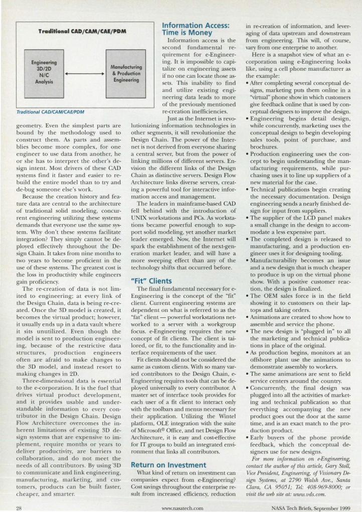
Information Access: TracliHonal CAD/ CAM/ CAI/ PDM Time is Money
Information acce i the
Engineering 30120 Manufacturing
second fundamental requirement for e-Engineering. It i impo ible to capitalize on engineering ets if no one can locate tho e as-N/C • I & Production
Analysis Engineering ets. Thi inability to find
and utilize exi ting engineering data lead to more of the previousl mentioned re-creation inefficiencie . Traditional CADICAMlCAElPDM
geometry. Even the implest parts are bound by the methodology u ed to construct them. parts and as emblie become more complex, for one engineer to u e data from another, he or she ha to interpret the other' design intent. Mo t drivers of the e CAD y terns find it fa ter and easier to re
build the entire model than to try and de-bug someone el e' work.
Because the creation history and feature data are cenu-al to the architecture of traditional olid modeling, concurrent engineering utilizing the e y terns demands that everyone u e the arne ystern. Why don't the e system facilitate integration? They simply cannot be deployed effectively throughout the De-ign Chain. It take from nine month to
two years to become proficient in the u e of these ys tem . The greate t cost i the 10 s in productivity while engineers gain proficiency.
The re-creation of data is not limited to engineering; at every link of the Design Chain, data is being re-created. Once the 3D model is created, it become the virtual product; however, it usually end up in a data vault where it its unutilized. Even though the model i sent to production engineering, becau e of the re trictive data tructure, production engineer
often are afraid to make change to the 3D model , and instead resort to making changes in 2D.
Three-dimensional data is e ential to the e-corporation. It i the fuel that drive virtual product development, and it provides u able and under-tandable information to every con
tributor in the De ign Chain. De ign Flow Architecture overcome the inherent limitation of exi ting 3D de-ign )' tern that are expen ive to im
plement, require month or ear to deliver productivi ty, are barrier to collaboration, and do not meet the need of all contributor. By u ing ·3D to communicate and link engineering, manufacturing, marketing, and cutomers, products can be built fa ter, heaper, and smarter.
28
Just as the Internet i revolutionizing information technologie in other egments, it will revolutionize the De ign Chain. The power of the Internet i not derived from everyone haring a cenu-al erver, but from the power of linking million of different server. Envi ion the different links of the De ign Chain as distinctive ervers. De ign Flow Architecture links diver e erver, creating a powerful tool for interactive information acce and management.
The leader in mainframe-based CAD fell behind with the introduction of
NIX workstation and PCS. As workstation became powerful enough to upport olid modeling, yet another market leader emerged. ow, the Internet will park the establishment of the next-gen-
eration market I ader, and will have a more sweeping effect than any of the technology shifts that occurred before.
"Fit" Clients The final fundamental neces ary for e
Engineering i the concept of the "fit" client. Current engineering sy tern are dependent on what i referred to as the "fat" client - powerful workstation networked to a server with a workgroup focus. e-Engineering requires the new concept of fit clients. The client is tailored, or fit, to the functionality and interface requirements of the user.
Fit clients should not be considered the same as custom clients. With so many varied contributors to the De ign Chain, eEngineering require tools that can be d~ ployed universally to every contributor. A master t of interface tools provide for each user of a fit client to interact only with the toolbars and menus necessary for their application. tiliring the Wintel platfornl, OLE integration with the uite of Micro oft® Office, and net De ign Flow Architecture, it is easy and co t-effective for IT group to build an integrated environment that links all contributors.
Return on Investment What kind of return on investment can
companie expect from e-Engineering? Co t savings throughout the enterpri e reult from increased efficiency, reduction
www.nasalech.com
in re-creation of information, and leveraging of data up tream and down tream from engineering. This will, of course, vary from one enterpri e to another.
Here i a nap hot view of what an ecorporation u ing ~Engineering looks like, using a cell phone manufacturer as the e ample: • After completing everal conceptual d~
signs, marketing puts them online in a "virtual" phone how in which customers give feedback online that is used b conceptual d igners to improve the de ign.
• Engineering begin detail de ign, while concurrently, marketing use the conceptual de ign to begin developing ale tool , point of purcha e, and
brochure . • Production engineering use the con
cept to begin understanding the manufacturing requirements, while purchasing u e it to line up uppliers of a new material for the case.
• Technical publication begin creating the nece sary documentation . De ign engineering sends a nearly fini hed deign for input from upplier.
• The upplier of the LCD panel makes a mall change in the de ign to accommodate a Ie s expen ive part.
• The completed de ign is released to
manufacturing, and a production engineer use it for de igning tooling.
• Manufacturability become an i ue and a new design that i much cheaper to produce i up on the virtual phone show. Witll a po itive cu tomer reaction, the de ign i finalized.
• The OEM ale force is in the field howing it to customers on their lap
top and taking orders. • Animations are created to show how to
as emble and service the phone. • The new design is "plugged in" to all
the marketing and technical publications in place of the original.
• As production begin , monitors at an off: hore plant u e the animations to demon trate assembly to workers.
• The same animation are sent to field ervice centers around the country.
• Concurrently, the final design was plugged into all the activities of marketing and technical publication so that everytl1ing accompanying the new product goes out the door at the same time, and is an exact match to the production product.
• Early bu ers of the phone provide feedback, which the conceptual designers use for new de ign . For more information on e-Engineering,
contact the author of this article, Gary toll, Vice President, Engineering, of VISionary Design Systems, at 2790 Walsh Ave., anta Clara, CA 95051; Tel: 408-969-8000; or visit the web itt at: www.vds.com.
ASA Tech Briefs, September 1999
V I SUA LI Z E the power and performance of our new machines for UNIX®, Windows NT® and Linux"'.
where's the power?
www.hp.com/i n fo/vis n tb Sign up at 0 • s· e·o 01 "VISUALIZE the Power" and
get an in-depth look at the hot, new ultimate design machines.
HP VISUALI?F
WORKSTATIONS
1HX"'~_"II1II.InnIdSlltes""'_CIlIIIIries._-""'" """""J(IOpao~lm1l!d _NT~.US rogosond_oI"..""... Corpomm l>uis.~ '-oItnos T_


tj Program for Designing a Mechanical System This program offers advantages of ease of use, accuracy, efficiency, and speed. John H. Glenn Research Center; Cleveland, Ohio
Mechanical System Design/ Analysis Tool (MSAT) is a user-friendly software system that facilitates and accelerates the processes of synthesizing and analyzing designs of mechanical systems. MSAT is particularly well suited for designing aircraft engines. MSAT can be used in the preliminary-design stage as well as in the detailed-design stage of a product-development process.
MSAT is a multi component, multidisciplinary program with a modular architecture that organizes designanalysis tasks around object-oriented representations of (1) components of the engine or other system that one seeks to design, (2) analysis programs, and (3) data-transfer links among the constructs listed in (l) and (2). The modular architecture enables the rapid generation of input data streams for trade-off studies of various configurations of the system to be designed. Once the user has set up a sequence of computations, the data-transfer links automatically transport output from one analysis/ design program for use as input in the next analysis/design program in the sequence. The computations are managed via constraint prop-
agation - that is, by reference to constraints provided by the user as part of the design definition.
MSAT provides a global perspective on system design. Building from subcomponents and components, the user sets detailed requirements for performances of components and of the system to be designed. The plug-and-play software framework of MSAT enables the user to add new analysis/ design programs and/ or components of the system to be designed and to perform trade-off studies rapidly; this capability helps to increase the quality of the ultimate design.
The plug-and-play feature of MSAT can also be utilized to make MSAT itself more versatile: New optimization and robust design software modules can be plugged in without extensive effort. As advanced computer programs are developed, the user can plug them in quickly, without having to delete older programs. This building-block application to the extension and improvement of MSAT is expected to reduce both the cost of further development of MSAT itself and cost of designing engineering systems by use of MSAT.
MSAT offers advantages of accuracy, efficiency, and speed. MSAT promotes accuracy by detecting errors in data entered by the user. A mathematical model of an engineering system can be built quickly and easily (see figure), and once the model has been built, the user does not have to rebuild the model for subsequent analysis. MSAT manages an optimization program and other analysis/ design programs in performing multiple iterations without interaction with the user. In a typical case in which five iterations would be needed to arrive at a reasonable product design by conventional means, MSAT can perform the same analysis in one run, thereby saving about 80 percent in time and cost.
MSAT is expected to be integrated with NASA's Numerical Propulsion System Simulation (NPSS) computer program, which is used for coupling computer codes for the design and analysis of propulsion and propulsion/ airframe systems.
MSAT has already been integrated with Monte Carlo, design-of-experiments, response-surfaces, and optimization software modules to provide a
r-r----------------.,;;-c-,,...-:-;--;,...-, ;-:;;::--r;OT,:;-o:-.• -:-:--:-------------- -y--y--. capability for robust
,----- Categories -----,
Exarrple
Frame GenerlcSeam
GETS
MaterlaProperties
MSo\T
!~:sSecti:ln ft91e F1owpal11
Performance
T~
NonIe
Roto-!Jyna"1ics
I YmIoW I
r--------------------~ay -------------------, Category: I'kNIpaIII
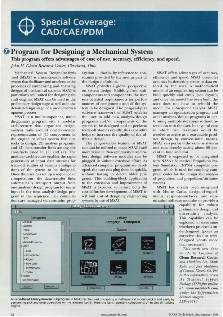
An Icon-Based library-Browser subprogram in MSAT can be used in creating a mathematical model quickly and easily by performing pick-and-drop operations on the relevant icon(s). Here the icons represent components of an aircraft turbine engine.
preliminary design and uncertainty analysis. This capability can be exploited to determine whether a product is underdesigned (poses an excessive risk) or overdesigned (costs more than necessary).
This work was done by Charles Lawrence of Glenn Research Center and HuaHua Lee, Mark Kolb, and Jack Madelone of General Electric Co. For further information, access the Technical Support Package (TSP) free on-line at www.nasatech.com under the Information Sciences category. LEW-1671O
32 www.nasatech.com NASA Tech Briefs, September 1999
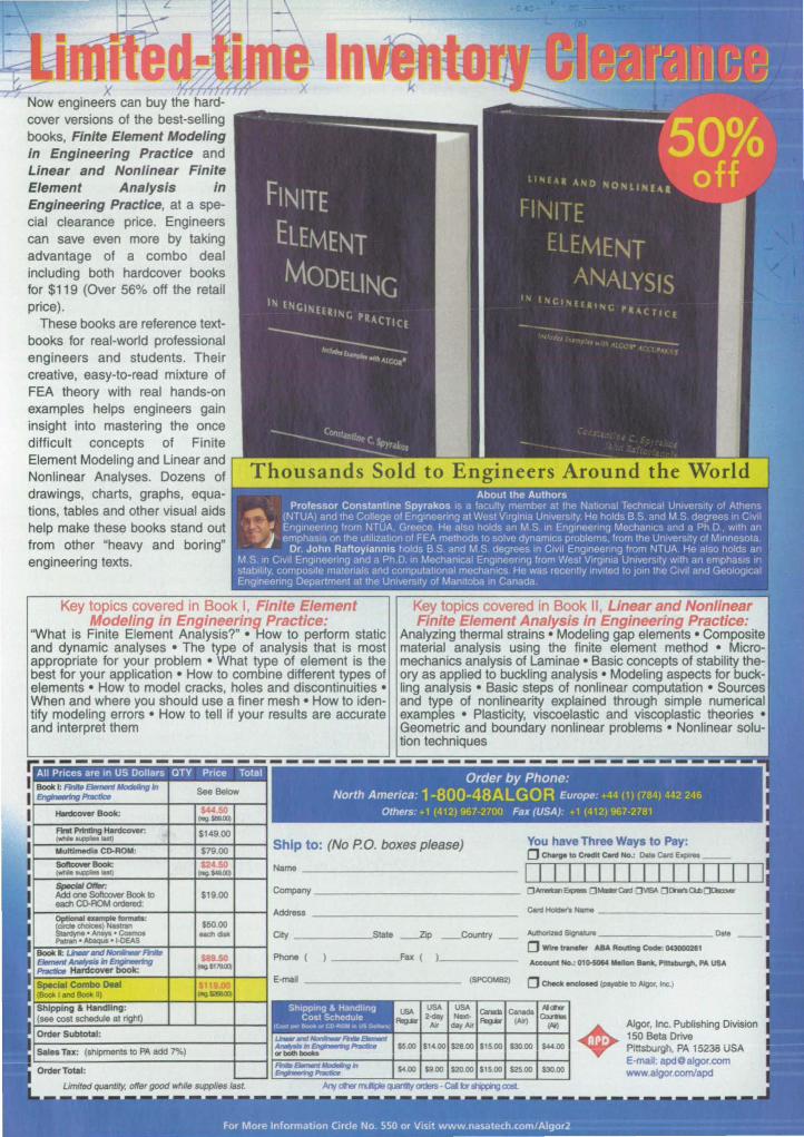
x r, Now engineers can buy the hard-cover versions of the best-selling books, Finite Element Modeling in Engineering Practice and Linear and Nonlinear Finite Element Analysis in Engineering Practice, at a special clearance price. Engineers can save even more by taking advantage of a combo deal including both hardcover books for $119 (Over 56% off the retail price).
These books are reference textbooks for real-world professional engineers and students. Their creative, easy-to-read mixture of FEA theory with real hands-on examples helps engineers gain insight into mastering the once difficult concepts of Finite Element Modeling and Linear and Nonlinear Analyses. Dozens of drawings, charts, graphs, equations, tables and other visual aids help make these books stand out from other "heavy and boring" engineering texts.
Key topics covered in Book I, Finite Element Modeling in Engineering Practice;
'What is Finite Element Analysis?" • l-iow to perform static and dynamic analyses • The type of analysis that is most appropriate for your problem • What type of element is the best for your application • How to combine different types of elements • How to model cracks, holes and discontinuities • When and where you should use a finer mesh • How to identify modeling errors • How to tell if your results are accurate and interpret them
Key topics covered in Book II, Linear and Nonlinear Finite Element Analysis in Engineering Practice:
Analyzing thermal strains • Modeling gap elements • Composite material analysis using the finite element method • Micromechanics analysis of Laminae • Basic concepts of stability theory as applied to buckling analysis • Modeling aspects for buckling analysis • Basic steps of nonlinear computation • Sources and type of nonlinearity explained through simple numerical examples • Plasticity, viscoelastic and viscoplastic theories • Geometric and boundary nonlinear problems • Nonlinear solution techniques
r.-------------- -----------------------Order by Phone:
North America: 1-BOO-4BALGOR Europe: +44 (1) (784) 442 246
Others: +1 (412) 967·2700 Fax (USA): +1 (412) 967·2781
I--~:::_'_'"::_:=_=::::_-_t_-t_:::::_:::::+____I Ship to: (No P.O. boxes please) You have Three Ways to Pay: (j Chorgo 10 Credit c.nt No.: DaIa CMl "-__
~~~~~~~--+-~----+-~ ~~ -------------------------CMl_. Name __________________ _
Crty ______ s,tate _Zip _Countty _ .........- sq,un Date
ra;~TI;"~nh~~t--j--~t-~ (j~~~ ~R~~~ Phone ( ____ --'Fax ( ), _____ _
F="';';';;'~~-:-----+-~----+-~ E-maIl ___________________ (SPCOMB2)
•
Algor, Inc. Publishing Division . , • 150 Beta Drive
Pittsburgh, PA 15238 USA
~;;~~~;;~f~~m~~~~~~~ E-mail: [email protected] I! www.algor.com/apd
Program Predicts Uncertainties in Properties of CMCs This program can help engineers design reliable, long-lived structural components. John H. Glenn Research Center, Cleveland, Ohio
Probabili tic Ceramic Matrix Composite Analyzer (PCEMCAN) i a u erfriendly computer program that predicts uncertainties in the mechanical and thermal propertie of ceramic-matrix compo ite (CMC) materials. The e materials are candidates for fabrication of tructural components that will be required to withstand loads at high temperatures in advanced aircraft engines. PCEMCAN i
intended to help re earchers develop improved CMCs for aircraft-engine components and to help engineers asse reliability and assW'e long operational lifetimes for tho e components.
PCEMCAN is an integrated computer code that embodie a combination of: • the formal probabilistic methodology
of CEMCAN [reported in "CEMCAN - Ceramic Matrix omposite Ana-
34
made your way! For over 35 years. Tescom has provided a diverse range of quality pressure control solutions that meet or exceed customer expectations. Whether it's one of our 60+ standard models. a simple modification or a one-of-a-kind custom control. well build 4 regulator. valve or system that meets your unique requirements.
CoDtrolltyles: pressure reducing and back pressure. hydraulic or pneumatlc, electrOnic. miniature. cartridge. tracking, vaporizing. vacuum or changeover.
~ loading and sensing styles. venting options. materials of seals. porting configurations and more. Pressure ranges:
1II.~I'ilIUXlIO PSJG. Flow: Cv = 0.00005 to 8.0.
~.,iIdl"ts will find or create a control solution for
For More Information Circle No. 409
Iyzer" (LEW-16327), J1SA Tech Briefs, Vol. 21 , o. 5 (Ma 1997), page 32] ; and
• dle fast probability integration (FPI) technique [reported in "Probabili tic Anal is of Composite-Material StructW'es" (LEW-l 6092) , i1SA Tech BriRfs, VoL 21, 0. 2 (February 1997) page 5 ] . Micromechanical and macrome
chanical theories as implemented in CEMCA are used to predict the trength and other properties of
CMC . Uncertainties in primitive variables are provided as input to PCEMCAN in the form of means, standard deviations, and type of probability distributions that characterize those uncertain tie . The type of probability di tributions avai lable in PCEMCA include normal , Weibull , and log-normal.
The probabilistic integration of random primitive variables is performed by u e of the FPI technique. Fewer computational simulations are needed to determine the scatter in response variables (e.g., properties of plies and laminates) when using the FPI technique than when using the Monte Carlo technique. PCEMCAN expresses the scatter in the response variables in the form of cumulative probability distribution functions (CDFs), which are useful for probabilistic analyse of tructures and as essments of degrees of reliability of components. PCEMCAN also quantifies the ensitivities of dle response variables to the random primitive variables.
More specifically, for given scatter of properties of fibers, properties of matrix and interphase materials, fiber volume ratio, ply thickness, and odler primitive variable , the response variables (properties of the composite material) for which CDF can be computed include the modulus of elasticity, Poisson's ratio, coefficients of thermal expansion, thermal conductivity, and laminate failure strength. PCEMCAN also compute the means, medians, and standard deviations of response variable .
These results can be used in probabilis tic structural analys is to compute the reliability of a component or to asses the life of the component for a desired reliability. Sensitivity information can be u ed to increa e reliability and to improve manufacturing processes and quality control. Finally, the probabilistic approach of PCEMCA is beneficia l in reduc-
ASA Tech Briefs , September 1999
ing the number of experiments needed , reducing (relative to the deterministic approach) the degree of conservatism in the design of a component, and making material-development and design processes more cost-effective.
This work was dun~ by Pappu L. N. Murthy of Glenn Research Center, Ashwin R. Sh~h ofSesL, Inc., and Suhodh K Mitalof the Uniuersil)1 of Toledo. For further information, access the Technical upport Package (TSP) free on.line at www.naatech.com under the Materials category.
Inquiries conceming rights for the commercial use of this invention should be addressed to NASA Glenn Research Center, Commercial Technology Office, Alln: Steve Fedor; Mail Stop 4-8, 21000 Brookpark Road, CLeveland, Ohio 44135. Refer Lo LEW-16653.
@ Automation Language for Managing Operations This software provides a facility for capturing expertise and procedure. NASA'sJet Propulsion Laboratory, Pasadena, California
Automation Language for Managing Operations (ALMO) i a computer program that assists a human operator at a central control station in monitoring and controlling a complex equipment system that includes multiple subsystems connected in a digital communication network. Still undergoing development, ALMO is designed specifically fO!' automating the operations of ASA's Deep Space Network (DS ). ALMO could be modified for use as control software in other applications that involve monitoring and control; examples include assembly lines, chemical-processing plants, and environmental management systems.
ALMO assists in the automation of operations by providing a facility for expressing procedure and operators' knowledge in the form of instructions executed by software. These instructions interact with the subsystems via a transport layer.
ALMO comprises two main components: the ALMO language and the ALMO engine/interpreter. The ALMO Language is an interpreted programming language that is used to write blocks in the control software of the
DSN. As used here, "block" denotes a software construct equivalent to a subroutine that performs a specific function. A block contains preconditions, one or more directive(s) to subsystems, and post-conditions. A block is executed either from a command line or from a graphical user interface for a subprogram associated with a temporal-dependency network (TDN) , which is a directed graph of interconnected node that represents an end-to-end sequence of operations. The TDN subprogram is equivalent to a main program that calls a subroutine at the appropriate time.
ALMO contributes to automation in several ways: • It provides visibility for information
about subsystems. • It affords an extensive facility for exe
cuting logistics involved in ystem operations.
• The ALMO language can be characterized as a scripting language that can represent most, if not all of a human operator's actions in operation of a subsystem. ALMO retrieves monitor data and event mes ages and enables a block to react to them. In this respect,
ALMO reduces the operator's workload, enabling the operator to monitor and control multiple subsy terns, and thereby reduces the cost of operation.
• ALMO provide mean to detect anomalies via subsystem monitor data, event me sages, and directive responses, and alerts the operator when it detects an anomaly.
• ALMO reinforces the concept of modular programming, in that blocks are written as modules. Modules can be reused for different subsy tern and in different applications; the number of blocks that must be written for a given application is thus smaller than it would otherwi e have to be; the co t of maintaining the software is also correspondingly lower.
• ALMO can be used as a means for knowledge engineering and acquisition of knowledge. This work was done by Paul Pechkam and
PaLricia Santos of Calleck for NASA's Jet Propulsion Laboratory. For further informalion, access Lhe Technical Support Package (TSP) free orvline at www.nasatech.com under the InformaLion Sciences category. NP0-20587
Program for Designing Multiple-Reflector Antenna Systems NASA s Jet Propulsion Laboratory, Pasadena, California
Millimeter-Wave Optics Design Tool (MOD Tool) is a computer program for analyzing and de igning multiple-reflector antenna system that operate at microwave and millimeter wavelengths. MOD Tool is intended for use in conjunction with a computer-aided-design (CAD) program along with other specialized programs that focus, variously, on thermal, mechanical, and other aspects of design. MOD Tool is a distributed client/ erver application program that includes a data base of design infUl'mation residing on a server computer, plus oftware components that perform
ASA Tech Briefs, September 1999
physical-optics analyses on a vaJiety of supercomputers. The client portion of MOD Tool include graphical-user-interface software components that reside on a de klOP computer. In addition to enabling an antenna designer to obtain computation for analysi and design of antennas, the client portion of MOD Tool serve as a data interface between (1) the antenna de ign and (2) the CAD and the structural and thermal designs. MOD Tool createS one standard data type for both ph} ICal optics and geometric optics and translation meclIanisms for each. It can utilize parallel su-
www.nasatech.com
percomputing to speed time-con uming physical-optics calculations. The graphical user interface relieves the antenna designer of many details, thereby simplifying the designer' taSk.
This program was written by Daniel Katz., Andrea Borgioli, Thomas Cwik, Chuigang Fu William Imbriale, Vahra.t Jamnejad, and Paul pringer of CaUech for NASA's J et Propulsion Laboratory. For further informaLion, access the Technical Support Package (TSP) free on-lille at www.1UlSatech.com under the Software category. NPO-20628
35

I -$ Special Coverage: CADICAE/PDM
nigraphics Hunt ville, AL, has introduced olid Edge Origin and olid Edge Origin 3D solid modeling software. olid Edge Origin is available free of charge to anyone desiring to te t the productivity increases in Solid Edge. Capabilities include evaluation of
basic 3D part creation, Solid Edge's drafting component, importing and exporting capabilities for 2D data, and the ability to impon 2D drawings and convert them to 3D models.
At the company' web site, users can order the Solid Edge Origin CD for testing, or may purchase the Solid Edge Origin 3D program for 495. The latter program adds the capability to save 3D model drawings to disk, and provides production-ready basic part modeling and 2D drafting, enabling users to create drawings via 3D models.
For More Information Circle No. 736
SolidWorks Corp., Concord, MA, has introduced SolidWorks" 99 3D mechanical design software with more than 150 major enhancements and innovations in the areas of modeling, assembly design, detailing, visua l communications, ease-of-use, data sharing, piping, and heet metal. The Wmdows
native software generates complete, production-level
engineering drawings that meet international standards. Enhancements include SolidWorks Property Manager, a graphical
user interface that enables editing of properties in drawings; AutoCAD· Command Line Emulator that recognizes frequently used AutoCAD commands; Real·Time Collision Detection that spots design problem with moving parts; and new translation tools that enable easy exchange of data with other CAD packages.
For More Information Circle No. 741
Framework Technologies Corp., Burlington, MA, has introduced ActiveProjecf" 5.0 project management soft· ware that allows project teams to design, publish, and manage collaborative Project Web Site without knowledge of HTML or other web program
ming languages. Project members can use a standard web browser to find, review, di cus , track. and collaborate on information in real time.
Documents, CAD drawings, schedule, preadsheets, photos, and other applications can be drag-and-<irop published and maintained as part of a Project Web Site. The software integrates Microsoft's
etMeeting web conferencing technOlogy, and contains web ite templates for users to create project sites.
For More Information Circle No. 739
CO MO /Works~
5.0 design analysi and simulation software from Structural Research & Analysis Corp., Lo Angeles, CA, i embedded in SolidWorks 99 solid modeling software. COSMOS / Work analyzes assemblie with contact and
gaps, allowing de igners to analyze press fits and bearing surfaces. The new version also offer fully iterative shape optimization.
A new transitional mesher, AccuStress", provides tress accuracy results and u er controls. It automatically detects small areas of geometry and places small elements at those positions, th.en transitions the mesh smoothly to the global size. Several manual controls allow users to apply the mesh size of their choice to edges, corners, face, and individual components within assemblies.
For More Information Circle No. 737
Autodesk, San Rafael, CA, offers Actrix~ Technical diagramming software that provides an automated drawing environment for creating schematics, electrical engineering diagrams, factory layouts, fluid power diagrams, and piping and instnlmentation layouts. The program
features interoperabili ty with AutoCAD", allowing users to import DWG files as backgrounds for space plans, layouts, and diagrams.
Features include the ability to drag and drop ActiveShapes'" objects from task-specific templates. The objects automatically snap, align, and rotate into position. A variety of objects can be drawn and edited; the objects can be completed u ing formatting and annotation features. Drawings may be organized by layers, and may be viewed with real-time pan and zoom capabilities.
For More Information Circle No. 738
NuGraI- 2.2 3D rendering and visualization software from Okino Computer Graphics, Mississauga, 0 , Canada, imports, simulates, photo-realistically renders, and translates all major 3D file fonnats. An intuitive graphical user interface allows objects to be elected,
transformed, materials assigned, and camera and lights interactively moved to create a photo-realistic rendering.
Rendering features include fast shadow generation, automatic reflection mapping, analytic texture filtering, and color, bump, and transparency texrure mapping. Data can be transferred from CAD package such as Solid Edge, SolidWorks, Au to CAD , Pro/ ENGI-
EER, and CADKEY as IGES, STL, or SAT files. Other features are a multi-threaded ray tracer and automatic 2D bitmap conversion.
For More Information Circle No. 740
36 www.nasatech.com ASA Tech Briefs, September 1999
• lewel
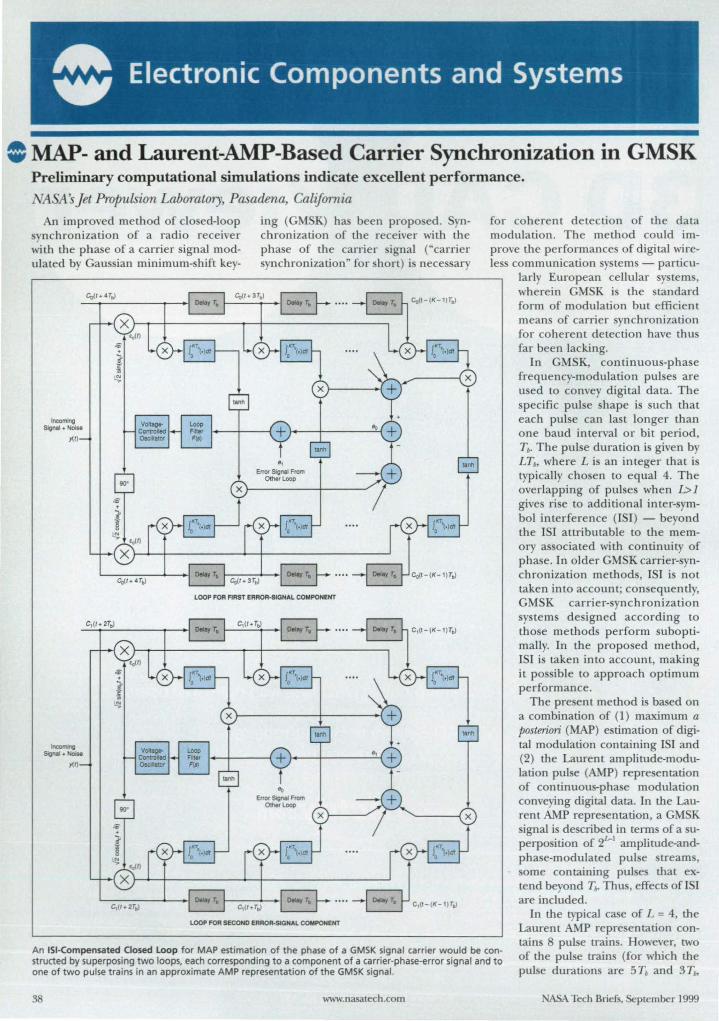
• Electronic Components and Systems
= MAP- and Laurent-AMP-Based Carrier Synchronization in GMSK Preliminary computational simulations indicate excellent performance.
'ASA s Jet Propulsion Laboratory, Pasadena, California
An improved method of closed-loop ynchronization of a radio receiver
with the phase of a carrier signal modulated by Gau ian minimum-shift key-
ing (GMSK) ha been propo ed. Synchronization of the receiver with the phase of the carrier ignal (" carrier synchronization" for short) is necessary
Incoming Sgnal + Notse
y(1)
Incoming Signal + Noise
y(1)
)--r-+ _____ -..,._t-_I_OeI_._Y_T._~ __ ._ .. _. ~ <,0-<'-""
LOOP FOR FIRST ERROR·SIGNAL COMPONENT
C,(t.T.l r=:::-l __ f---"----.:.,-~I~ ....
1----1--.-1'-0- .. ----:,. 1,,(t_(K_,)T.jJ C,(I.T.,l ~ -8
LOOP FOR SECOND ERROR·SlGNAL COMPONENT
for coherent detection of the data modulation. The method could improve the performances of digital wireless communication sy terns - particu-
larly European cellular system , wherein GMSK i the standard form of modulation but efficient means of carrier synchronization for coherent detection have thus far been laclting.
In GMSK, continuous-phase frequency-modulation pulses are u ed to con ey digital data. The specific pulse shape is such that each pulse can last longer than one baud interval or bit period, Tb• The pulse duration is given by LTb, where L is an integer that is typically chosen to equal 4. The overlapping of pulses when l;;> 1 gives rise to additional inter-symbol interference (lSI) - beyond the lSI attributable to the memory associated with continuity of phase. In older GMSK carrier-synchronization methods, lSI is not taken into account; consequently, GMSK carrier-synchronization system designed according to those methods perform suboptimally. In the proposed method, lSI is taken into account, malting it possible to approach optimum performance.
The present method is based on a combination of (1) maximum a posteriori (MAP) estimation of digital modulation containing lSI and (2) the Laurent amplitude-modulation pulse (AMP) repre entation of continuous-pha e modulation conveying digital data. In the Laurent AMP representation, a GMSK ignal is described in terms of a su-
perposition of 2~1 amplirude-andphase-modulated pulse streams, some containing pulses that extend beyond Til- Thus, effects ofISI are included.
In the typical case of L = 4, the
An lSI-Compensated Closed loop for MAP estimation of the phase of a GMSK Signal carrier would be constructed by superposing two loops. each corresponding to a component of a carrier-phase-error signal and to one of two pulse trains in an approximate AMP representation of the GMSK signal.
Laurent AMP representation contains 8 pulse train . However, two of the pulse trains (for whkh the pulse duration are 5 Tb and 3 Tb,
38 www.nasalech.com ASA Tech Briefs, September 1999
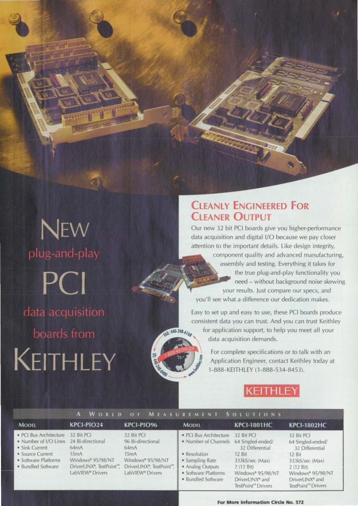
• Source Current • Software Platforms • Bundled Software
24 Bi-directional 64mA 15mA Window 95/9B/ T DriverLl X·, TestPoint": LabVlE'A!- Drivers
CLEANLY ENGINEERED FOR CLEANER OUTPUT Our new 32 bit PC! boards give you higher-performance
data acquisition and digital I/O because we pay closer
attention to the important details. Like design integrity,
component quality and advanced manufacturing,
assembly and testing. Everything it takes for
the true plug-and-play functionality you
need - without background noise skewing
your results. Just compare our specs, and
you'll see what a difference our dedication makes.
Easy to set up and easy to use, these PCI boards produce
consistent data you can trust. And you can trust Keithley
.. f(V- ~O-24'-6/y ' . for application support, to help you meet all your data acquisition demands.
15mA Window 95/98/ T DriverLl X·, TestPoint"', LabVIE'A!- Drivers
For complete specifications or to talk with an
Application Engineer, contact Keithley today at
1-888-KEITHLEY (1-888-534-8453).
• Resolution • Sampling Rate • Analog Outputs • Software Platforms • Bundled Software
KEITHLEY
32 Bit PO 64 Singled-endedl
32 Differential 12 Bit 333kS/sec (Max) 2 (12 Bit) WindowS- 95/9B/ NT DriverLlNX· and TestPoint'" Drivers
32 Bit PCI 64 Singled-endedl
32 Differential 12 Bit 333kS/sec (Max) 2 (12 Bit) WindowS- 95/981 T DriverLi X· and TestPoint'" Drivers
For More Information Clrde No, 572

40
• Market Leader: Hardigg manufactures more than one half of all rotationally molded shipping cases sold in the US
• Over 295 commercial off the shelf standard sizes • Quick as a Jack Rabbit delivery capability • Custom design service • Full cushioning design and manufacturing service
EGSA*) ---Contract No. GS-t4F-6140A
Hardigg Cases 147 North Main Street • South Deerfield, MA 01373 USA
Tel: 1-800-542-7344 or 413-665-2163 • Fax: 413-665-8061 www.hardigg.com • www.militarycases.com • Email: [email protected]
For More Information Circle No. 410
Series 3700 Capacitive have low-amplitude. low-frequency vibrations and provide
·Performlng ride quality assessments on automobiles, elevators and amusement park rides. • Monitoring tbe low frequency behavior of civil structures such as buildings and bridges . • Providing tilt and orientation measurements for marine platform and ship stabilization.
Packaged in rugged titanium housings. single axis and triaxial models are
available to measure events as low as 20 micro-g up to 200 g's over a bandwidth from 0 to 800 Hz. Various powering configurations allow operation from 24 vdc laboratory supplies, automotive { marine 12vdc batteries or 5 vdc digital power sources. Rely on PCB for quality instrumentation. unmatched 24-Hour customer service and a Total Customer Satisfaction guarantee.
DC SENSD S DIVISION ' 3m WAlDEN AVE' DEPEW, NEW YORK 14043 DCS TOll fREE 111·611-1111 ' PCBII6-6IHIDI • fAX 116-611·0911 ' EMAil dcssalestptb.cDI · WEB SITE m.pc~ . cOl
'SO!llICEIIlfI ED
For More Information Circle No_ 411
re p ctivel ) contain mo t of the ignal energy (the fraction of ignal energy in the other ix pul e train i onl 2.63 X
10-6). Therefore, the ignal can be approximated do el b the 5 T. and 3 T. pul e train . Thi is advantageous becau e the de ign of a do ed carrier- ynchronization loop based on the e two puis train onl can be impler than a de ign b ed on all eight pulse train .
The loop de ign i derived from a combination of (1) the foregoing twopul e-train repre entation and (2) an equation for an error ignal as a function of th e timated carrier phase for the GM K ignal ob erved (along with noi e) during a given number of baud interval _ The zero-error condition is an e timated carrier phase equal to the open-loop MAP phase estimate. One would do e the loop by updating the phase estimate in the effort to null the error ignal.
It tum out that the right ide of the equation for the error ignal as a function of the e timated carrier phase can be decompo ed into two components, each corre ponding to one of the two pul e tream in the approximate AMP repre entation. Thu , a do ed-loop GM K carrier synchronizer could be constructed as a uperpo ition of two loop , each contributin g one of the components of the error signal (see figure).
At the time of reporting the information for this article, the method had been te ted in some computational simulation , with promising results; imulated carrier-pha e ynchronizers designed according to the propo ed method exhibited excellent performance. Moreover, inasmuch as the second pulse tream contain significantly le energy than the first one does, it might be possible to reduce the complexity of the basic ynchronizer design by use of a single-pul e- tream AMP representation of GM K.
This work was done by Maroin K. imon of Caltech for ~ 1\ s J et Propulsion Laboratory. For further information, access the Technical Support Package (TSP) free on-line at www.nasatech.rom under the Electronic Components and ystems category.
In accordance with Public Law 96-517, the rontractor has elected to retain title to this invention. Inquiries concerning rights for its romm.ercial use slwuld be addressed to
Technology Reporting OffICe JPL Mail top 122-116 4800 Oak Grove Drive Pasadena, CA 911 09 (818) 354-2240 Refer to NP0-20482, volume and number
of this ASA Tech Brief: i ue, and the page number.
ASA'Ii ch Briefs, September 1999
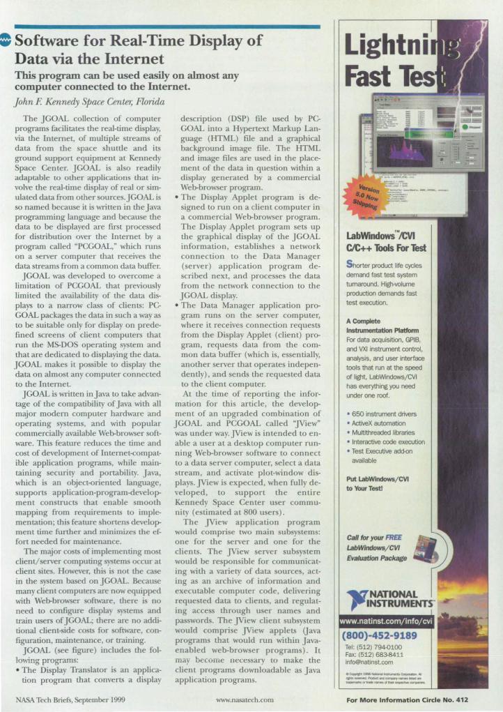
: Software for Real-Time Display of Data via the Internet This p rogram can be used easily on almost any computer connected to the Internet.
John F. Kennedy Space Center, Florida
The JGOAL collection of computer program facilitate the real-time di play, via the Intemet, of multiple streams of data from the space shuttle and its ground suppon equipment at Kennedy Space Center. jGOAL is aL 0 readily adapLable to other applications that involve the real-time display of real or imulated data from other sources.JGOAL is so named because it is written in theJava programming language and becau e the data to be displayed are first processed for distribution over the Intemet by a program called "PCGOAL," which runs on a server computer that receives the data streams from a common data buffer.
JGOAL was developed to overcome a limitation of PCGOAL that previously limited the availability of the data displays to a narrow class of clients: PCGOAL package the data in uch a way as to be suitable only for display on predefined screens of client computers that run the MS-DOS operating system and that are dedicated to displaying the data. JGOAL make it po ible to display the data on almost any computer connected to the Internet.
J GOAL is written in Java to take advantage of the compatibility of java with all major modem computer hardware and operating sy tern, and with popular commercially available Web-browser software. Thi feature reduces the time and cost of development of InterneH:ompatible application program, while maintaining security and portability. Java, which i an object-oriented language, supports application-program-development con tructs that enable smooth mapping from requirements to implementation; thi feature honen development time funher and minimize the effon needed for maintenance.
The major co ts of implementing mo t c1iem/ erver computing terns occur at client ite. However, this is not the case in the tern based on JGOAL. Because many client computers are now equipped with Web-bro~ er oftware, there is no need LO configure displa tems and train users of JGOAL; there are no additional client-side co ts for software, configuration, maintenance, or training.
JGOAL ( ee figure) includes the following programs: • The Displa Tran lator is an applica
tion program that converts a display
ASA Tech Briefs, September 1999
description (DSP) file used by PCGOAL into a Hypertext Markup Language (HTML) file and a graphical background image file. The HTML and image files are used in the placement of the data in que tion within a display generated by a commercial Web-browser program.
• The Display Applet program is designed to run on a client computer in a commercial Web-brow er program. The Display Applet program sets up the graphical di play of the JGOAL information, establishes a network connection to the Data Manager (server) application program decribed next, and proces e the data
from the network connection to the jGOAL display.
• The Data Manager application program runs on the server computer, where it receives connection reque ts from the Display Applet (c1iem) program, requests data from the common data buffer (which is, es entially, another server that operates independently), and sends the requested data to the client computer. At the time of reporting the infor
mation for thi article, the development of an upgraded combination of JGOAL and PCGOAL called "]View" was under way. ]View is intended to enable a u er at a desktop computer running Web-browser software to connect to a data erver computer, elect a data stream, and activate plot-window diplay. ]View is expected, when fully developed, to support the entire Kennedy pace Cenler u er community (e timated at 800 u ers).
The ]View application program would comprise two main ubsy tern : one for the server and one for the clients. The ]View server ub y tern would be responsible for communicating with a variety of data ources, acting as an archive of information and executable computer code, delivering reque led data to clients, and regulating acce through user name and pa word. The ]View client ub tern would compri e ]View applets Uava programs that would run within Javaenabled web-browser programs). It may become lJeces 'ary to make the client programs downloadable as Java application programs.
www.nasatech.com
Lightni Fast
labWindows"'/CVI CIC++ Tools For Test
S horter product life cycles demand fast test system turnaround. Hig)wolume production demands fast test execution.
A Complete
InstnlmentatIon Platfonn
For data acquisition, GPIB, and VXI Instrument control, analysis, and user interface tools that run at the speed of light, LabWindows/CVl has everything you need
under one roof.
• 650 instrument drivers • ActiveX automation • Mu1tithreaded libraries • Interactive code execution • Test Executive add-<>n
available
Put LabWlndowsj CVI
to Your Testl
Call for your FREE LabWindows/ CVl
Evaluation Package
www.natinst.com/info/cvi
(800)-452-9189 Tel: (512) 7940100 Fax: (512) 683-8411 [email protected]
O~15ia~.,.,...~ . ... ...--.FIocLclrdCltlrl1*'t',.,....., .. ..,.,...ot ... .,..at ........ ~
For More Information Circle No. 412
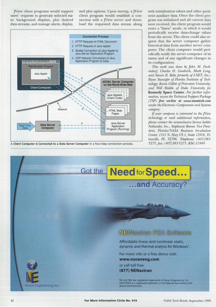
]View client program would upport u er ' reque ts to generate elected tatic background di pIa , plot de ired data streams, and manage alarm, di pia,
and plot option. Upon tartup, aJView client program would e tabli h a connection with a ]View erver and download the reque ted data tream along
with initialization values and other pertinent auxiliary data. O nce the client pnr gram was initialized and all current data were received, the client progranl would enter a "listen" mode, in, hich it would periodically receive data<hange values from the erver. The client could also reque t that the server computer gather historical data from another erver computer. The client computer would peliodically notify the erver computer of its statu and of any ignificant changes in its configuration .
Data Server Computer
Connection Process
1. HITP Request of HTML Document
2. HITP Request of Java Applet
3. Socket Connection of Java Applet to Java Server Application Program
4. UDP Network Connection of Java Application Program to Data.
, 1
" , ", " " " " " " ", '" 3' , ,
4
, , , , " , ,
_ C~=-==:;-, - '- -- - --, I '
Java Applets I I 1 (Client Code) I r _~ ___ r
,, ' Java Server Application
-II Program (Running)
This work was done by J ohn M. Dockendorf, Charles H. Goodrich, Mark Long, and teven R Beltz fOT71Uffly of I-NET, Inc.; Ryan Stansifer of Florida Institute of Technology; Kevin Gillett of Princeton University; and Will Riddle of Duke University for Kennedy Space Center. For further information, access the Technical Support Package (TSP) free o*linB at www.llasatech.co11l under the Electronic Components and Systems category.
A Client Computer Is Connected to a Data Server Computer in a four-step connection process.
If your company is interested in the ]View technology or need additional information, please contact the nonexclusive license holder Netlander; Inc., Stephanie Beever, Vice President, Florida/NASA Business Incubation Center, 1311 N. Hwy US 1, Suite 129-N, Titusville, FL 32796. Telephone: (407)383-5275,fax: (407)383-5273. KSC-11949
42
Need for Speed ... ... and Accuracy?
Affordable linear and nonlinear static, dynamic and thermal analysis for Windows' .
For more info or a free demo visit:
www.noraneng.com or call toll free (877) NENastran
NE and NEt are raglstered trademarks or Noran Engineering, Inc. NASTRAN is a reglstefed trademark of the National AeronauticS and Space Admirnstration.
For More Information Circle No. 419 NASA Tech Briefs, September 1999
YOU SAY YOU NEED TO QU CKLY OBTAIN FORCE, TORQUE, INDUCTANCE OR SATURATION EFFECTS FOR YOUR 3D ELECTROMECHANICAL DEVICE
? •
Well, here you go.
Ansoft Corporation provides easy-to-use software for electromechanical design problems requiring the representation of the electric or magnetic field behavior. The simple flow of the software along with extensive status monitoring and error checking features provide a structured analysis environment with a minimal learning curve and a minimal chance of error. Plus, analyzing a magnetic component's perfonnance before prototyping greatly enhances the chance of producing a timely, under-budget design. Ansoft's magnetic field simulation software for electromechanical appfications. Software that can see what you can'l
412.261.3200 ww.ansoft.com
For MoN Information Circle No. 541

., Analysis of Progressive Failure in Laminated Composites The progression of damage from initial loading to final failUl"e can be predicted. Langley Research Center, Hampton, Virginia
A computational methodology for predicting the initiation and propagation of failures in laminated matrix/ fiber composite-material structures has been developed. The methodology follow the progressive-failure approach, in which it is recognized that a laminated compo -ite structure can develop local failures or exhibit such local damage as matrix cracks, fiber breakage, fiber/ matrix debonds, and delaminations under normal operating conditions, and that such damage can contribute to the eventual failure of the structure. The ability to predict the initiation and growth of such damage is essential for predicting the performances of composite structures and developing reliable, safe designs that exploit the advantages offered by composite materials.
In this and other progressive-failureanalysis methodologies, a typical analysis involves a multistep iterative procedure in which the load on a mathematically modeled structure is increased in small steps. At each load step, a nonlinear analysis is performed until a converged solution (representing an equilibrium state) is obtained, assuming no changes in the mathematical submodels of the component materials of the structure. Then using the equilibrium state, the stre ses within each lamina are determined from the nonlinear-analysis solu-tion. These stresses are com-pared with allowable stresses for the affected materials and used to determine failure according to certain failure criteria.
If a failure criterion indicates failure of a lamina, then the mathematically modeled proper-ties of the lamina are changed according to a mathematical sub-model of degradation of the af-fected material properties. When this happens, the initial nonlin-ear olution no longer corre-sponds to an equilibrium tate, and it becomes necessary to re-
ing the current load level. This iterative process of obtaining nonlinear equilibrium olutions each time a local material submodel is changed is continued until no additional lamina failures are detected. However, in this progressive failure methodology, small load step sizes were used instead of the iterative process of obtaining equilibrium solutions to minimize the effect of not establishing equilibrium at the same load level. The load step is then incremented and the foregoing analysis repeated until catastrophic failure of the tructure is detected.
The present progressive-failure-analysis methodology includes the use of C I
(slope-continuou) shell finite elements from classical lamination theory for calculation of in-plane stresses. The failure criteria used in this methodology include the maximum- train criterion, Hashin's criterion (a stress-based criterion that predicts failures in ten ile and compressive fiber and matrix modes), and Christensen's criterion (a strain-based criterion that distinguishes between fiber failures and fiber/ matrixinteraction failures) . The materialdegradation model used in this methodology includes several options; the best option in each case depends
on the choice of failure criterion and on the nature of the compo ite material (e.g., unidirectional composite . fabric composite).
The methodology i implemented by computer code that has been incorporated into the Computational Mechanics Testbed (COMET) program, which is a general-purpose finite-element-analysis program. As thus augmented, COMET can predict the damage and response of a laminated composite structures from initial loading to final fai lure.
The methodology and its various fai lure criteria and material-degradation submodels were compared and assessed by performing analyses of several laminated compo ite structures. The results from these computations were found to be well correlated wi th available test data (see figure), except in structures in which interlaminar stresses are suspected of being large enough to cause certain failure mechanisms (such as debonding or delaminations) that are not modeled in this methodology.
This work W0.5 done by David W Sleight of Langley Research Center. Ffff further information, access the Technical Support Package (TSP) free on-line at www.nasatech.com under the Materials category. L-17660
~ I'----____ O ____ -.JI :t Load Specimen Load
Failure Criterion First Ply Failure Load, Final Failure Load, Dominant Failure lb. lb. Mode
Hashin's Criterion 1,520 3,212 Matrix Tension
Christensen's 1,520 3,261
Fiber/Matrix Criterion Interaction
Experimental Unavailable 3,523 Unavailable Results
e tablish equilibrium, using the modified lamina properties for the failed lamina while maintain-
The Final Failure load of a tension-loaded 20-ply laminate plate as computed by two Variants of the present methodology, is compared with the experimentally determined value.
44 www.nasatech.com NASA Tech Briefs, September 1999
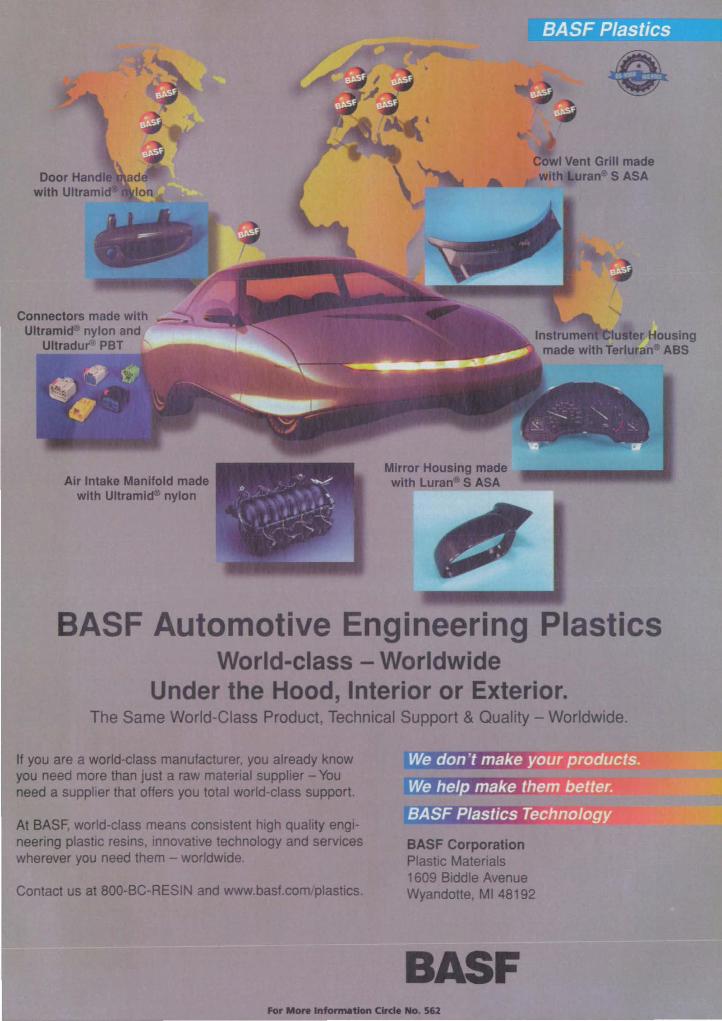
Air Intake ManHoid made with Ultramlc:fD nylon
Mirror Housing made with Lura'" S ASA
BASF Automotive Engineering Plastics World-class - Worldwide
Under the Hood, Interior or Exterior. The Same World-Class Product, Technical Support & auarrty - Worldwide.
If you are a wortd-elas$ manufacturer, you already know you need more than just a raw matenal supplier - You need a supplier that offers you total woI1d-cIass support.
At BASF, world-class means consistent high quartty eng .. nearing plastic resins, innovative technology and serviCes wherever you need them - worldwide.
Contact us at 800-BC-AESIN and www.basf.comlplast1cs.
BASF CorporatIon Plastic Matenals 1609 Biddle Avenue Wyandotte, MI 48192
BASF ... __ ............ CIIde No. sa
Origin is faster. more flexible, and
easier-to-use! '-_ ___ ...
" .w Pmj&t I . _._\ I Explorer: a tool .~:~ that helps navigate -: ~:: through the .,1 - .. ~\ hundreds of graphs ': '. '''. :- ' . and worksheets in
a project file ~ • New Data } J
Masking tool: point and click to exclude data points , - ..- ' from curve fitting
• OLE2 Server, export graphs in EPS, CGM, JPEG, TIFF, PDF, DXF, and more!
Open and run Excel, drag and drop to create Origin graphs from Excel workbooks and Origin worksheets
Toolbar customization: add your own tool bar buttons that run your own scripts or DLL
• Faster redraw: a graph ics caching scheme makes it easy to manipulate complex 3D graphs
"Microcal 's Orig in 6.0 has the most comprehensive graphing engine of this collection; it supports the most graph types, the most data types, and the most customizat ions." - Dr. Barry Simon, Ph. D., Desktop
Engineering Magazine, April, 1999
Call today! 69-7720
MlcrocallM
Microcal Software, In~. 2 One Roundhouse Plaza ~ Northampton. MA 01060 USA Tel. US & Canada 1·800-969-7720 Infl: 1·413-586-2013 Fax: 1-413-585-0126 Email: Infc>@microcal.com
(;1999. OrigIn and LabTalk are trademarks of Microcal Software. Inc. All other brand and prC>duct names are trademarks of their respective owners.
For More Information Circle No. 413
e Mixed-Carbon Anodes for Improved Li-Ion Cells A small amount of carbon black increases retention of charge capacity. NASA's Jet Propulsion Laboratory, Pasadena, California
Rechargeable lithium-ion electrochemical cells that contain anode made from a mixture of graphite and carbon black have been found to perform better than do similar cells that contain anode made of graphite alone. As explained in more detail below, the addition of carbon black improve performance by increasing effective electrical conductivity.
Typically, the anodes in tate-of-the-art lithium-ion cells are made of amorphous carbon (coke) or graphite. Heretofore, the e forms of carbon have been considered to have excellent electrical conductivity; therefore, Wltil now, no attempt was made to incorporate carbon black or other conductive diluents into the anodes. ow, however, it has been ob erved that when a carbon black (more specifically, Shawanigan black) is incorporated into graphite electrodes, cycle-life performance is significantly improved.
Four lithium-ion cell were fabricated for experiments to determine the effects of incorporating carbon black into graphite anodes. In each cell, the cathode was made of LiCo02 and the electrolyte was made ofa 1.0 M solution ofLiPF6 in a solvent that consisted of equal volume parts of ethylene carbonate (EC), diethyl carbonate (DEC), and dimethyl carbonate (DMC). The anodes of the four cells had the following compositions: 1. A commercial graphite (10-28
MCMB);
0.22
020
~ 0.18 <{
;E-o '" 0.16 c-Ol U .,
0.14 e> '" .J:: g
0.12 0 ~
2. A mixture of 95 weight percent 10-28 MCMB and 5 weight percent carbon black;
3. A mixture of 90 weight percent 10-2 MCMB and 10 weight percent carbon black; and
4. A mixture of 50 weight percent 10-2 MCMB and 50 weight percent of another commercial graphite (KS-44) . In cyclic charge/ discharge measure-
ments, all three cells containing mixedcarbon anodes (cells 2, 3, and 4) retained greater proportions of their initial discharge capacities than did the cell containing the ingle-carbon anode (cell 1) . Moreover, at about 15 cycles, the abolute di charge capacity of the single-
carbon cell fe ll ignificantly below that of all three mixed-carbon cells (see figure) .
The tentative explanation for orne of these experimental results is the following: • The carbon black particles are signifi
cantly smaller than tho e of 10-28 MCMB. Th erefore, in the 10-28 MCMB/ carbon-black electrode , the carbon black particles are conjectured to occupy the voids between the larger 10-28 MCMB particles. In so doing, the carbon black particles increase the effective electrical conductivity of the anode by contributing to overall electrical contact among the anode particle throughout the anode.
• The 10-28 MCMB and KS-44 graphites have different particle izes; consequently, electrical contact and electri-
0 ~ en
010 o 95% MCMB GrapMe + 5% Carbon Black 6. 50% MCMB Graphne + 50% KS44 Graphite
0.08 o 90% MCMB Graphite + 10% Carbon Black o 1000/. MCMB Graphne
30 40 so Cycle Number
Specific Discharge Capacities of four celis were measured in cyclic charging at a current of 30 mA and discharging at a current of 60 mA.
www.nasatech.com NASA Tech Briefs, September 1999

Drag-and-Drop measurements
LAN connectivity
Familiar
Wind ows· interface
New Features Histograms
CoLor-graded pershtence
Eye diagram measurements
Steve Montgomery went looking for a
new high-performance oscilloscope. What
he found changed the way he thought about
scopes-and the way he does his job.
"With Infiniium, the engineering
process becomes a lot
smoother."
Infiniium fits into
Steve's thinking process, letting
him concentrate on his work. not his
scope. We started from scratch and
designed everything with this in mind.
From simple things Uke having a green
knob that controls the green trace on the
screen. To the more complex. like basing
the interface on Windows· 98 for drag
and-drop ease, even when it comes to
advanced measurements. Adding LAN
connectivity was an obvious choice
-now Steve can document and
share his work more easily than ever. In
short, Infiniium lets him spend less time
fighting his scope. And that means he gets
his job done faster.
500 MHz to 15 GHz
bandwidth
Up to 8 GSa/s
sample rate
Advanced triggerin9
~--.;;;;:. It's not easy to get
scope users to change their
loyalties. So we changed the scope
instead, with Infiniium.
Infiniium is changing a lot of people's
minds about oscilloscopes. For more
mformation about why. call HP DIRECT
at 1-800-452-4844;· Ext. 6463.
Or check out our Web site:
www.hp.com/info/lnfi niium15
rh~ HEWLETT& .. r... PACKARD
hSI prm.. In Canada. <aU 1·877-8911 14. Ext. 6447 1999 Ht!1ClrU-Pack4rr1 c: TMEAfD9IIYNTB I Expanding Possibilities I Kloutmr .. is a I' ~ Yr'fIlSrtmzd 1Tad"",arkofMwrosoJl Corp
For More InfornNttion Circle No. 555 __ _
cal conductivity in the mixed-graphite anode are increased in the arne manner as in the 10-2 MCMB/ carbonblack electrode . While carbon black contribute to
electrical conductivity, it al 0 irreversibly con urnes ome lithium and the reb contribute to a partial irre ersible 10 of capacity. Apparently, the 5-weight-percent carbon black content provided uf-
ficient electrical contact for increased retention of capacity while conuibuting little irrever ible 10 during initial charging. The anode containing 10 weight percent of carbon black exhibited approximately the arne retention of capacity, but the initial irrever ible 10 was considerably greater than in the anode containing 5 weight percent of carbon black. From the e ob ervation ,
one can conclude that 5 weight percent is the optimum amount of carbon black.
This work was done by Chen-Kuo Huang and Jeffrey akaTTWw of Caltech far NASA's J et Propulsion Laboratory. Far further infonnation, access the TechnicaL upport Packagt (TSP) free on-line at www.nasatech.com under the Materials category. NP0-20603
Electrodialysis To Remove Ammonium Ions From Wastewater A simple treatment removes most of the ammonium content.
Lyndon B. Johnson Space Center; Houston, Texas
Electrodialysis has been shown to be an effective means for removing ammonium ions from wastewater without u e of consumable chemicals and without adding other substances to the treated water. Provided that continuing efforts to develop efficient electrodialy i equipment prove ucces ful , it hould be possible to apply this treauoent principle to wastewater streams to be recycled in life-support ystems for spacecraft and other clo ed habitats. Effluents from some industrial processes that generate high concentration of ammonium ion may also be treatable by thi principle.
In e lectrodialysis (see figure), an electric potential is applied across a membrane that is selectively permeable by the ions of interest - in this case, ammonium (NH:). Typ ically, a membrane suitable for this purpose comprises a polymer matrix, within which ionophores are immobil ized. Membranes based on perfluorosulfo nic acid and membranes in which nonactin ser ves as the ionophore have been fou nd to function efficiently as selective transporters of ammon ium ions from effluen t to concentratedwaste streams.
Process from Mars? ACR SmartReader Plus 7 features:
48
Sensors from '\enus?
Data Logger from Earth. Downloading information is simple: Connect an ACR interface cable to the logger and the Com port of a PC and run the ACR software. View data graphically or statistically. Loggers are accessible remotely by
modem and can be networked.
Without data, it's just an opinion For more information on the complete ACR family of data logging instruments, please contact us. Telephone: 604.591.1128 · Toll free rCOA & USA): 1.800.663.7845 Fax: 604.591.2252 · Web: www.acrsystems.com • [·mail· acr€!acrsystems.com Bldg 210- 12960 84th Avenue Surrey BC V3W IK7 Canada
1698
For More Information Circle No. 415
• 7 voltage and current channels
• +/-05% FS accuracy
• Up to 1 MB memory
• 12·bit resolution • Sample rates as
fast as L Hz
• Weighs less than 4 oz
• 1 O·year battery life (guaranteed)
• Free technical support on our 800 number
• 3·year warranty
• Year L compliant
>:z < "":E
8
InCR SYSTfMS INC.
In an experiment, electrodialysis in an electrolytic cell containing such a membrane reduced the ammonium concentration of a simulated effluent stream from 290 to 2 parts per million. The rate of flow of the stream was 1.152 liters/ day. The area of the membrane was 10 cm2
• With a potential of 10 V applied, the electric-curre .. t density in the cell was 2 mA/cm2
• With these parameters, the specific energy consumption amounted to 1.5 x 10· joules per liter of treated water. Because the minimum ammonium concentration was sti ll above the maximum allowable (0.5 parts per million) for potability in a lifesupport system, further effort would be necessary to develop a practical electrodialysis unit for incorporation into such a system.
This wark was done by Ella F. Spiegel of Eltron Research, Inc., far Johnson Space Center. No further documentation is available. MSC-22818
Treated Effluent Concentrated-Waste
Stream .. o"..ut.,-T""7"T7""-r-,....."St ... 7"'
I Effluent
Stream In
, r NH.
t \
Concentrated-Waste Stream In
An Electrolytic Cell containing a su itable membrane can be used to transfer ammonium ions from one stream to another.
ASA Tech Briefs, September 1999

Modular Photonics Test Systems Model 8800 and 8200 mainframe controllers house a variety of plug-and-play
instrumentation modules which enable users to test and characterize components and systems used in DWDM, datacom, sensor and other applications.
Hip-Density LD Control Control up to 16 laser diodes with our Model 8016 High-Density LD Controller. When used with the
Model 708 eight-channel butterfly telecom LD Mount, pump lasers or DFB lasers can be controlled
In a convenient. rack-mountable configuration.
The new kids on the bench. ewport is now into fiber optic test and mea
surement instrumentation in a big way. Our presence in the fi ber optic market is greater than ever. And with the introduction of this new line, so is your choice of test equipment.
Our instruments offer all the features and functions you need to perform DWDM-related tests with speed, precision and accuracy. So now you can concentrate on the quality of your testing without wondering about the quality of your equipment.
ewport. Your new, one-stop shop for fiber optic testing. For your free 1999/2000 catalog that features our entire product line, visit www.newport.comlwdm or call us today at 800-222-6440.
Laser Diode systems which cover the 630
Stabilized Light locking
light source of <100 kHz
USA: 800-222-6440, 949-863-3144 • Belgium : 016-402927 • Canada: 905-567-0390 · France: 01 -60916868 · Germany: 06151-3621-0 Italy: 02-924-5518 • Netherlands: 030-6592111 • Switzerland : 01-744-5070 • Ta iwan R.O.C.: 886-2-2769-9796 • UK: 01635-521757
COME VISIT US AT PHOTONICS EAST - BOOTH #1205 C"p u ...... . "fo"""tlon Circle No. 4 75
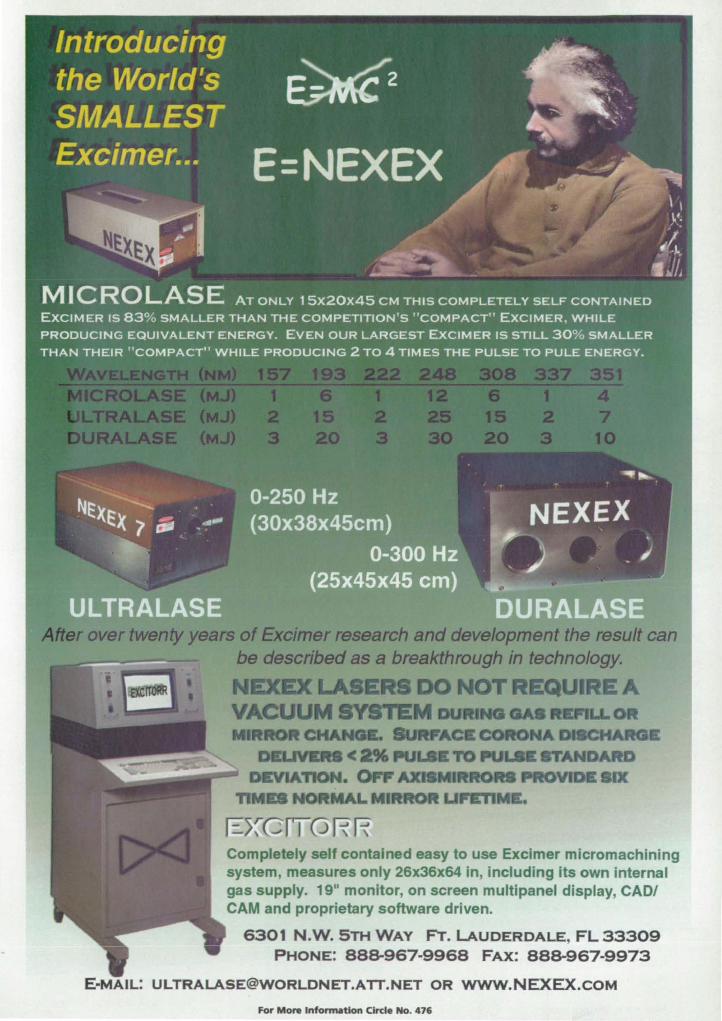
& "W1_ ..... 1tRO
UFEnM •
Completely self contained easy to use Excimer micromachining system, measures only 26x36x64 in, including its own internal gas supply. 19" monitor, on screen multipanel display, CADI CAM and proprietary software driven.
6301 N.W. 5TH WAY FT. LAUDERDALE, FL 33309 PHONE: 88&967-9968 FAX: 88&967·9973
E .. MAIL: [email protected] OR www.NEXEX.cOM
For More InfonnatJon Circle No. 476
Measure the IVI2 of all lass'S I
• Any Wavelength • Pulsed or CW · Easily & Quickly • Accurately & Reliably
dvanced PC Beam Propagation
Analyzer M2-200
· Measure M2 on your PC
· Automatic Optical Train for Visible & Near IR Lasers
· Manual Mode Operation for UV & Far IR Lasers
Knowing the M2 of your laser is the only way for you to accurately predict the focused spot size and beam divergence for critical laser applications. Now you can presicely measure M2 at a new lower cost.
For More Information Circle No. 460
S-=r=e_Inc~® laser Beam Diagnostics Phone: (435) 753-3729 E-mail: [email protected]
Visit www.spiricon.com
PHOTONICS Tech BrieFs
Supplement to NASA Tech Briefs' September 1999 Issue Published by Associated Business Publications International
Feature
6a Getting the Right CCD
Tech Briefs
14a High-Quantum-Efficiency Photocathode for Photomultiplier Tubes
16a Hybrid Imaging Technology
18a High-Speed Image Detectors With Subelectron Noise Floors
19a Prismatic Phase Shifter
Departments
4a The Power of Light-from SPIE, the International Society of Optical Engineering
20a New Products
Editorial Advisory Board
Bob Breault. President. Breault Research Organization
Dr. Geoffrey Burnham. President. Semiconductor Laser International
Dr. Jack D. Gaskill. Professor of Optics. Optical Sciences Center. University of Arizona
Dr. Arthur Guenther. Professor of Electrical Engineering and Physics & Astronomy. Center for High Technology Materials. University of New Mexico
R. Brian Hooker. Associate Research Professor. Dept. of Electrical and Computer Engineering. University of Colorado at Boulder
Heather Tooker. General Manager. Meadowlark Optics
www.nasatech.com
Cover photo courtesy Cutting Edge Optronics Inc. See "New Products, H page 20a.
Photonics Tech Briefs, September 1999
Wait a Minute ... Who's Kobayashi?
OPtOSigma'S Mitsuo Kobayashi is a dreamer. He didn't discover gravity or a new moon, but awoke early one morning with a revolutionary new concept in opta-mechanical positiOning. After a few quick sketches, he rushed to work It didn't take long for us to realize that his extended contact bearing stage was an astronomical leap forward . The re t is history.
Now available from OproSlgma in a wide range of models, Kobayashi's "Dream Stage" combines crossed-roller and ball-bearing concepts for eye-opening load capadties and laser-straight travel accurades. And because it u es only two
pieces with an integrated bearing design, conventional bearing ways are eliminated. So there are no preload screws to adjust, nothing to loosen up.
The great minds at OptoSigma are always searching for better ways to make your job easier. It often begins
with a dream. And continues with the best selection, prices and service in the industry.
Call (949) 851·5881 today for your Free c0p'y of the
OptoSigma Catalog and a complete listing of Our
Stages, Opti & Mounts.
v~~ W)IIW.edmUndSClent~
Don 't miss the premier issue. Call for your copy today.
When you manufacture and design imaging systems for as long as we have, there's plenty to write about. So we did. For the very first time, Edmund Industrial Optics presents a catalog and resource guide devoted entirely to electronic imaging. It features a wide range of off-tha-shelf imaging components, along with helpful technical background and application information. With solutions for all your imaging needs, n's not just a catalog. It's a must read.
_~·Edmund Industrial Optics __ Enviston the POSSlblllttes
USA HQ Phone 609-573-6250 ' Fax 609-573-6295 ' E-mail B991N9540edscl com UK D""81OO Phone 01904-691469 ' Fax 01904-691569 ' E-mail: edsclukOaol com
Japan DIVISIOO Phone 81·3-58Q()...4751 • Fw(' 81..J...5800-4733 • E-mall-saJesOedmund co·JP
0 1aae E~ SciIndc InC Edrruw:I ........ c:;:Ipjcs •• CIMIkJn of EIi'YLnd ScIWId: Inc.
4a
For More Information Circle No. 461
TELECOM M U N ICATIONS
LASER TUNING
ASTRONOMY
SPECTROPHOTOMETERS
RESEARCH
PULSE COMPRESSION
For More Information Circle No. 462
The Power of Liuht Continuing Education
PIE is dedicated to providing effective continuing education for the optics and photoni indu try. As a re ult, PIE offers a range of education opportunitie , from basic optics course for tudents, management, and sale ra.ff to in-<iepth technical training for the engineers and cienti ts who are at the cutting edge of re earch and development.
hort cour e - held in conjunction with PIE international symposia - are the core of SPIE' education program . Half- to two-day course offered at PIE symposia focus on emerging tech nologie , engineering technique , and applications and are taught by leading experts from industry, academia, and government. Among many others, topics include: • aero pace cience and sen ing • automation and product engineering • biomedical optics • electronic imaging • fiber optics • laser I ource technologies • microelectronic and optoelectronic
devices • optical physics, chemistry, and biology • optical cience and engineering, and • ignal and image processing.
For those who have other training needs, PIE has option . Customized incompany training programs bring worldrenowned instructors to your site to eliminate travel expen es and maximize training budgets. You get courses molded directly to your needs.
A different approach that still nets you great training is SPIE's line of video and CD-ROM . Popular and timeless course are put together in effective multimedia package 0 that you can train at your ite, at your pace.
Education never ends for those in the cience . Let SPIE help you continue
your learning. As for all its products and service , SPIE
offers a guarantee of complete satisfaction. Also, PIE offers Continuing Education nits, a nationally recognized unit of measure for continuing education and training programs that meet certain criteria, to tho e who complete course .
Far more information, amtact SPIE's EdIJ.C(V tion Department. Web:www.spie_arg; e-mail: [email protected]; plum.e: (360) 676-3290; fax: (360) 647-1445.
PhOlonics Tech Briefs, September 1999
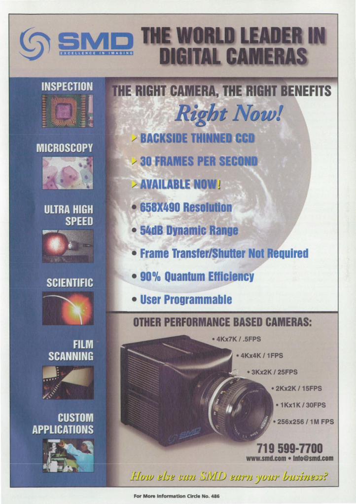
• Frame Transferl huHer Not quired
• 90% Quantum Enlci
• User Programmable
OTHER PERFORMANCE BASED CAMERAS:
• 4Kx4K 11 FPS
• 2Kx2K 1 15FPS
• 1 Kx1 K 1 30FPS
• 256x256 11 M FPS
719 599·7700 www.smd.com·[email protected]
For More InfonnatJon CIKI. No. 486
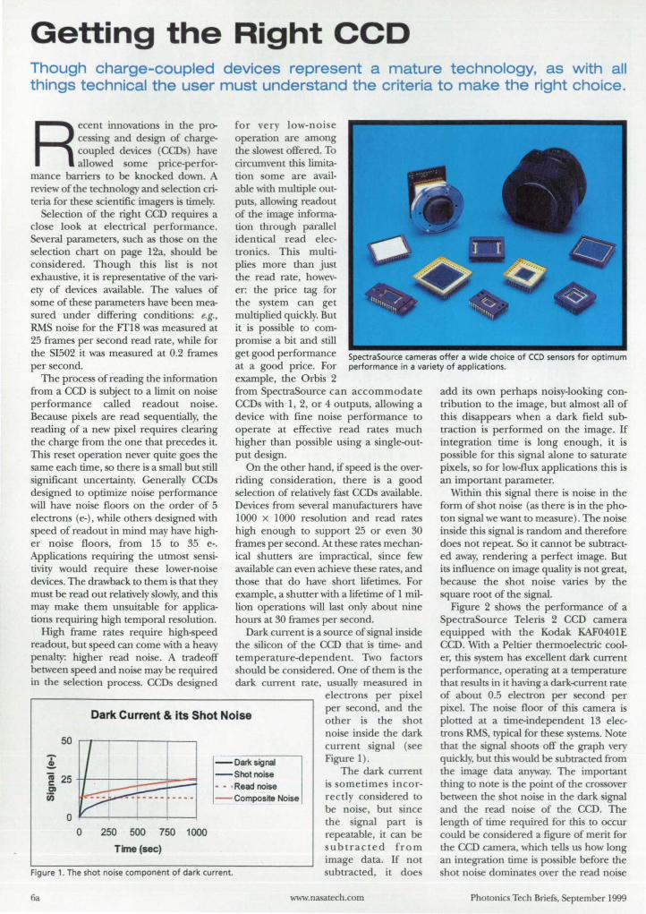
Getting the Right CCO Though charge-coupled devices represent a mature technology, as with all things technical the user must understand the criteria to make the right choice.
Recent innovations in the proce ing and design of chargecoupled device (CCD) have allowed orne price-perfor-
mance barriers to be knocked down. A review of the technology and election criteria for the e cientific imagers is timel .
Selection of the right CCD require a clo e look at electrical performance. Several parameters, such as tho e on the selection chart on page I2a, hould be con ide red. Though thi li t i not exhaustive, it i representative of the variety of device available. The value of orne of these parameters have been mea-ured under differing condition: e.g.,
RMS noise for the ¥fIB was measured at 25 frames per second read rate, while for the SI502 it was measured at 0.2 frames per second.
for very low-noi e operation are among the lowe t offered. To circumvent thi limitation orne are available with multiple outputs, allowing readout of the image information through parallel identical read electronic. Thi multiplie more than just the read rate, however: the price tag for the sy tem can get multiplied quickly. But it is po ible to compromise a bit and till get good performance at a good price. For example, the Orbis 2
SpectraSource cameras offer a wide choice of CCD sensors for optimum performance in a variety of applications.
The proce of reading the information from a CCD is subject to a limit on noise performance called readout noi e. Because pixels are read sequentially, the reading of a new pixel requires clearing the charge from the one that precede it. This reset operation never quite goes the same each time, so there is a mall but till ignificant uncertainty. Generally CCDs
de igned to optimize noise performance ,viil have noi e floors on the order of 5 electrons (e-). while others de igned with peed of readout in mind may have high
er noise floors, from 15 to 35 e-. Applications requiring the utmost en itivity would require these lower-noi e devices. The drawback to them is that they must be read out relatively slowly, and this may make them unsuitable for applications requiring high temporal re olution.
High frame rates require high-<'lpeed readout, but peed can come with a heavy penalty: higher read noise. A tradeoff between speed and noise may be required in the selection proce . CCDs designed
from pectraSource can accommodate CCD with 1, 2, or 4 outputs, allowing a device with fine noi e performance to operate at effective read rate much higher than pos ible using a single-output de ign.
On the other hand, if peed is the overriding consideration, there i a good selection of relatively fast CCDs available. Device from several manufacturers have 1000 x 1000 resolution and read rates high enough to support 25 or even 30 frames per econd. At the e rates mechanical hutters are impractical, ince few available can even achieve the e rate , and tho e that do have short lifetimes. For example, a shutter with a lifetime of 1 million operations will last only about nine hours at 30 frame per econd.
Dark current is a source of signal in ide the silicon of the CCD that is time- and temperature-dependent. Two factors should be considered. One of them is the dark current rate, usually measured in
electrons per pixel
Dark Current & its Shot Noise per second, and the other is the hot noise inside the dark current signal (ee
"'i' .!.
50
~ 25tt--~---L-=~~~ 01 en
250 500 750 1000
Time (sec)
- OaJ1csignai -Shot noise - - • Read noise - Composite Noise
Figure 1). The dark current
is ometime incorrectly considered to be noise, but since the ignal part is repeatable, it can be
Figure 1. The shot noise component of dark current.
ubtracted from image data. If not ubtracted, it doe
6a www.nasalech.com
add its own perhap noisy-looking contribution to the image, but almo t all of this di appears when a dark field subtraction is performed on the image. If integration time i long enough, it is po ible for thi signal alone to aturate pixel , so for low-flux application this is an important parameter.
Within this ignal there i noise in the form of hot noise (as there i in the photon ignal we want to measure) . The noise inside this signal is random and therefore doe not repeat. So it cannot be subtracted away, rendering a perfect image. But its influence on image quality is not great, because the shot noise varies by the quare root of the ignal.
Figure 2 shows the performance of a SpectraSource Teleri 2 CCD camera equipped with the Kodak KAF0401E CCD. With a Peltier thermoelectric cooler, this system has excellent dark current performance, operating at a temperature that re ults in it having a dark-current rate of about 0.5 electron per econd per pixel. The noise floor of this camera is plotted at a time-independent 13 electron RMS, typical for the e systems. Note that the ignal hoots off the graph very quickly, but this would be ubtracted from the image data anyway. The important thing to note is the point of the cro over between the shot noise in the dark signal and the read noise of the CCD. The length of time required for this to occur could be considered a figure of merit for the CCD camera, which tells us how long an integration time is po ible before the shot noise dominate over the read noise
Pho tonics Tech Briefs. September 1999
Knowing that the right tool makes a
difference, MelLes Griot provides a useful
selection of optics cleaning supplies, lab
accessories, tools, and laser safety eyewear.
An entire section in our catalog (pp.565-584)
fully describes these products -
all in stock and ready to deliver.
For more information on lab accessories look online I
• I www.mellesgriot.com/mg112.htm I
Canada (613) 226-5880 Denmark 5761 5049 France (01) 3012-0680 Germany (06251) 84060 Japan (03) 3407-3614 Netherlands (0316) 333041 Singapore 392-5368 Sweden (08) 630-8950 United Kingdom (01223) 203300
or Call, FAX, or E-mail for your catalog today!
Photonics Components 16542 Millikan Avenue • Irvine, CA 92606 1 (800) 835-2626 • (949) 261-5600 • FAX: (949) 261-7790 E-mail: [email protected]
www.mellesgriot.com For Mon Intonn.tlon ClrcI. No. 47.
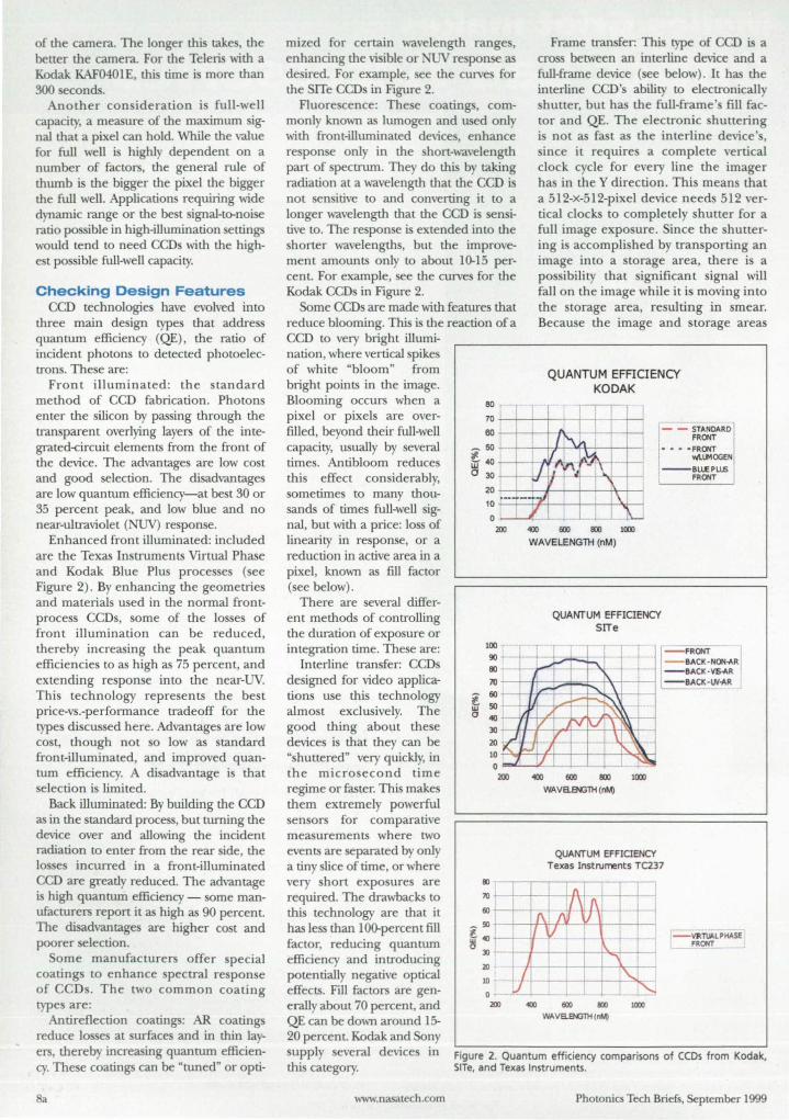
of the camera. The longer this takes, the better the camera. For the TeJeris with a Kodak KAF0401E, this time is more than 300 econds.
Another con ideration i full-well capacity, a measure of the maximum signal that a pixel can hold. While the value for full well is highly dependent on a number of factors, the general rule of thumb is the bigger the pixel the bigger the full well. Applications requiring wide dynamic range or the best signal-to-noise ratio possible in high-illumination settings would tend to need CCD with the highest possible full-well capacity.
Checking DeSign Features CCD technologies have evolved into
three main design types that address quantum efficiency (QE) , the ratio of incident photons to detected photoelectrons. These are:
Front illuminated: the standard method of CCD fabrication. Photons enter the silicon by passing through the transparent. overlying layers of the integrated-<:ircuit elements from the front of the device. The advantages are low cost and good selection. The disadvantages are low quantum efficiency-at best 30 or 35 percent peak, and low blue and no near-ultraviolet (NUV) response.
Enhanced front illuminated: included are the Texas Instruments Virtual Phase and Kodak Blue Plus processes (see Figure 2). By enhancing the geometries and materials used in the normal frontprocess CCDs, some of the losses of front illumination can be reduced, thereby increasing the peak quantum efficiencies to as high as 75 percent, and extending response into the near-UV. This technology represents the best price-vs.-performance tradeoff for the types discussed here. Advantages are low cost, though not so low as standard front-illuminated, and improved quantum efficiency. A disadvantage is that selection is limited.
Back illuminated: By building the CCD as in the standard process, but turning the device over and allowing the incident radiation to enter from the rear side, the losses incurred in a front-illuminated CCD are greatly reduced. The advantage is high quantum efficiency - some manufacturers report it as high as 90 percent. The disadvantages are higher co t and poorer selection.
Some manufacturers offer special coatings to enhance spectral response of CCDs. The two common coating types are:
Antireflection coatings: AR coatings reduce losses at surfaces and in thin layers, thereby increasing quantum efficiency. These coatings can be "tuned" or opti-
8a
mized for certain wavelength ranges, enhancing the vi ible or NUV re ponse as desired. For example, see the curves for the SITe CCDs in Figure 2.
Fluorescence: The e coatings, commonly known as ltunogen and used only with front-illuminated devices, enhance response only in the short-wavelength part of spectrum. They do this by taking radiation at a wavelength that the cm is not sensitive to and converting it to a longer wavelength that the CCD is sensitive to. The response is extended into the shorter wavelength, but the improvement amounts only to about 10-15 percent. For example, see the curve for the Kodak CCDs in Figure 2.
Some CCDs are made with features that reduce blooming. This is the reaction of a CCD to very bright illmni-nation, where vertical spikes of white "bloom" from bright points in the image. Blooming occurs when a pixel or pixels are overfilled, beyond their full-well capacity, usually by several times. Antibloom reduces this effect considerably, sometimes to many thousands of times full-well signal, but with a price: loss of linearity in response, or a reduction in active area in a pixel, known as fill factor (see below).
There are several different methods of controlling the duration of exposure or integration time. These are:
~ a
100 -
90 00
7Il
: t---. '10
30 I ,I 20 lO ~ 0
200
II:)
)O J-
Frame transfer: This type of CCD i a cro between an interline device and a full-frame device (see below). It has the interline CCD's ability to electronically shutter, but has the full-frame's fill factor and QE. The electronic shuttering is not as fast as the interline device's, ince it requires a complete vertical
clock cycle for every line the imager has in the Y direction. This means that a 512-x-512-pixel device needs 512 vertical clocks to completely hutter for a full image exposure. Since the shuttering is accomplished by transporting an image into a storage area, there is a possibility that significan t signal will fallon the image while it is moving into the storage area, resulting in smear. Because the image and storage areas
QUANTUM EFFICIENCY KODAK
[- - STANDARD
FRONT
1
- - - -FRONT wIJ-"'OGEN
--BU£ PLLIS I FRONT
«Xl6OO~1(xx)
WAVELENGTH (nM)
QUANTUM EFFICIENCY SITe
I' - FRONT 1
-~- - -- BACK-NON-AR
" - BACK-VE-AR
/.,- -BACK-W-AR
" I. -- ~ _ ••• 4_
", I V v V ~
" -' / ~ J -+~
«Xl 600 8Xl l(xx)
WAVaENGni(nMj
QUANTUM EFFIOENCY Texas Instruments TC237
! 11'1
--- - -.-
Interline transfer: CCDs designed for video applications use this technology almost exclusively. The good thing about these devices is that they can be "shuttered" very quickly, in the microsecond time regime or faster. This makes them extremely powerful sensors for comparative measurements where two events are separated by only a tiny slice of time, or where very short exposures are required. The drawbacks to this technology are that it has less than I OO-percen t fill factor, reducing quantum efficiency and introducing potentially negative optical effects. Fill factors are generally about 70 percent, and QE can be down around 15-20 percent. Kodak and Sony supply several devices in this category.
f\J;J\ (/) 1
~:I-1--V
: ~ V-
fJ\ I ' - VJl:ii __ i pHotSE r+ 1 -.fR~_
www.nasatech.com
I
I "-0 - - ~
200 «Xl 600 IIXl 1000 WAVaeGTH (oM)
Figure 2. Quantum efficiency comparisons of (CDs from Kodak. SITe. and Texas Instruments.
Photonics Tech Brief. September 1999
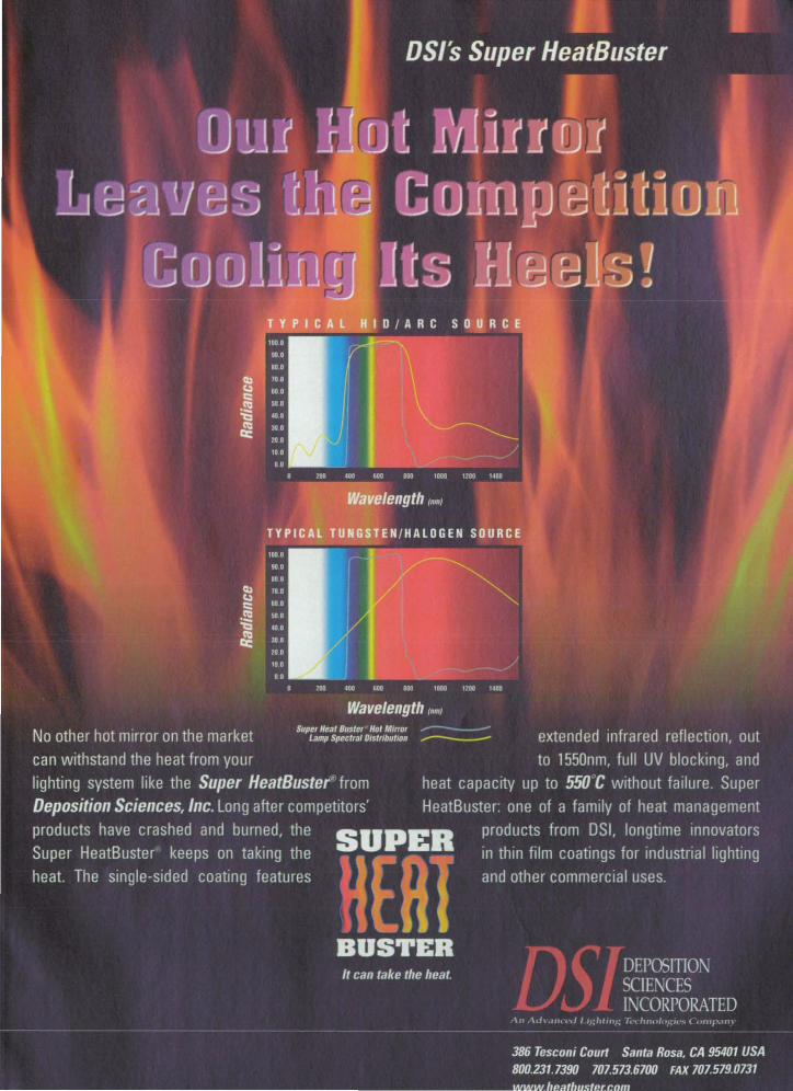
are controlled eparatel, orne intere ting control method can be u ed to achieve high frame rate along with low noi e . Pipe lining ubarra image through the torage area can re ult in rate of 200 per econd or higher, while holding the noi e floor down to 10 e- RM , making po ible application in adaptive optic or imilar areas. Manufacturer that up pi the e type of device are Texa In truments , Thorn on C F, and Philip, among other.
Full-frame: Thi technology ha no intrin ic huttering . feature , which means that unle orne mean are u ed
to block the incident flux, photon will fall on the image area during the entire readout period. Thi u uall re ults in unacceptable level of mear, and 0
nece itate the u e of an electromechanical hutter. ince no feature of the architecture are u ed for expo-ure control, the e device have high
QE and fill factor. The are al 0 Ie expen ive than their frame-tran fer equivalent, ince there i no doubling of the number of pixel for the torage array. Many manufacturer offer fullframe CCO , among them Kodak, Texa In trument , Thorn on C F, Philip , EEV, EG&G, and other.
Hitachi Denshi America, Ltd .
www.hdal.com
• Adanta nO-242-3636 • Dallas 8 17-488-4528 • New York 516-921·7200 • Chicago 630·250·8050 • Los Angeles 310-328-61 16 • Canada 416-299-5900
lOa For More Information Circle No. 463
Optical Considerations Among optical con ideration i fill
factor, the ratio of the actual collecting area of a pixel to its overall geometric area. Though at fir t it might eem that these would be equal, ome technologie uch a the interline tran fer CCD reduce thi ratio from unity. Typically, fill factor of 70 percent are about the be t currently available with interline CCO . Be ide the 10 of efficiency, reduced fill factor cau e other deleteriou effects: alia ing of patial frequencie and reduction of contra t at high patial frequencie are typical problems.
Antibloom features can al 0 reduce fill factor. Typically, CCDs with antibloom will use a drain electrode that mu t be po itioned next to each pixel to sweep off the excess charge created by high illumination level. This drain blocks or reflects light, and hence lessens fill factor. Some specialized proce e , uch as that used by Texas In truments, eliminate or greatly reduce these los e through the u e of transparent material for the overflow drain, so that not all CCO witll antibloom will suffer from reduced ftll factor.
The an wer to the que tion of what pixel size is right depends on several things unique to an application . The primary con ideration is usually spatial re olution, but to select a pixel size several things need to be nailed down. In determining the required patial re olution, the u er should be mindful of the deleterious effects of too large a pixel (patial re olution too low) , such as aliasing, reduced modulation tran fer function (MTF) , etc. It is better to err on tlle small side.
If the focal length of the optics to be used can be adjusted as required, then electing based on pixel ize i easier. A
12-pm pixel u ed with a 100-mm focal length achieve the same patial resolution as a 24-pm pixel and a 200-mm focal length, but at a lower cost, since bigger pixel u ually implie higher prices.
If the optical configuration is fixed, however, then the pixel size must be adjusted to achieve the target resolution. This mayor may not result in a practical olution . If, when all is considered, a 3-pm pixel i needed , there will be a very mall list of potential devices to choo e from. Conversely, if a 50-pm pixel i needed, there are few device 0 big. But in thi case, a technique known as binning can ynthe ize big pixels from small. The camera elected mu t upport binned opera
tion for this to be po sible , so the camera spec hould be checked.
Photoni Tech Briefs, September 1999
ITEM jj
ASM808-2OCS
ASM808-20W2
ASM808-4OCS
ASM8Q8-40W2
I ASM980-2OCS
ASM98G-20W2
I_m
_
m
_
ASM98G-4OCS
ASM98G-40W2
~
Plus 5,000 other products I www.thorlabs.com
ASE·FL7D01
One year warranty Available from stock
Demo units available
/ CS Mounting Style
W2 Mounting Style
980nm Laser shown with 20 Watt Laser bar. Shown with 40 Watt laser bar.
Water cooled heat-sinks available
PRICE DESCRIPTION
$750.00 808nm 20 Watt Laser. Mounting Style CS
$750.00 808nm 20 Watt Laser, Mounting Style W2 Shown with 20 Watt laser bar. $1043.00 808nm 40 Watt Laser. Mounting Style CS
$1043.00 808nm 40 Watt Laser. Mounting Style W2
$865.00 980nm 20 Watt Laser, Mounting Style CS
$865.00 980nm 20 Watt Laser. Mounting Style W2
$1199.00 980nm 40 Watt Laser, Mounting Style CS
$1199.00 980nm 40 Watt Laser, Mounting Style W2
Please see our website for the complete descriptions of aU our new products!
www.thorlabs.com For More Information Circle No. 479
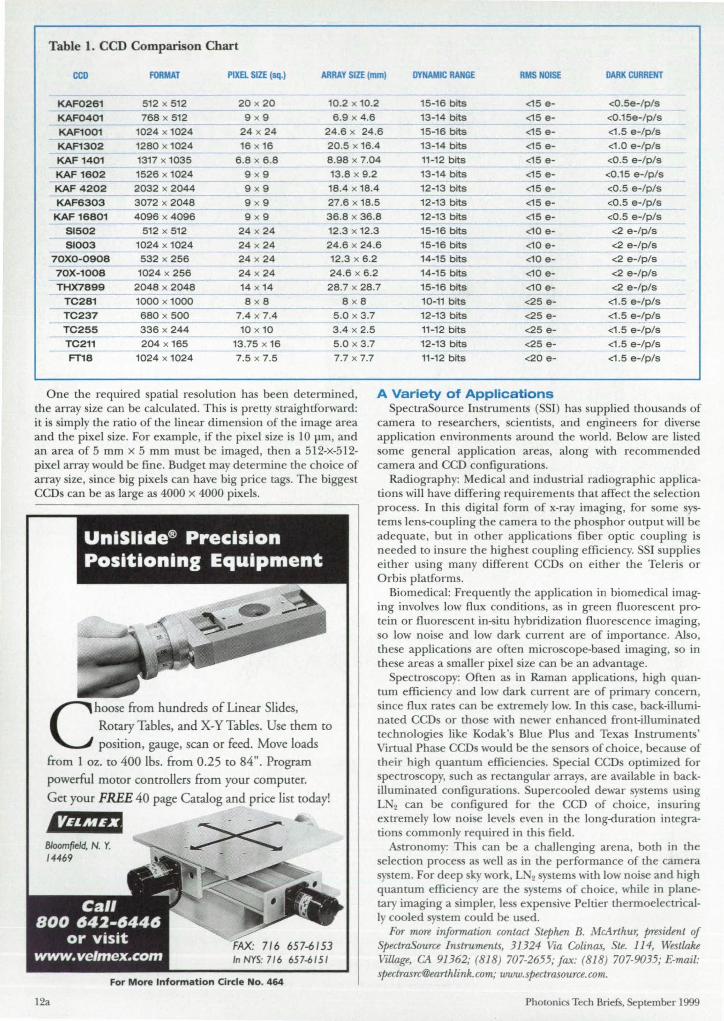
Table 1. CCD Comparison Chart
CCO FORMAT PIXel SIZE (sq.) ARRAY SIZE (mm) DYNAMIC RANGE RMS NOISE DARK CURRENT
KAF0261 512 x 512 20 x 20 10.2 x 10.2 15-16 bits <15 e- <0.5e-/p/s
KAF0401 768 x 512 9 x 9 6 .9 x 4.6 13-14 bits <15 e- <0.15e-/p/s
KAF1001 1024 x 1024 24 x 24 24.6 x 24.6 15-16 bits <15 e- <1 .5 e-/p/s
KAF1302 1280 x 1024 16 x 16 20.5 x 16.4 13-14 bits <15 e- <1 .0 e-/p/s
KAF 1401 1317 x 1035 6.8 x 6 .8 8 .98 x 7.04 11-12 bits <15 e- <0.5 e-/p/s
KAF1602 1526 x 1024 9 x 9 13.8 x 9.2 13-14 bits <15 e- <0.15 e-/p/s
KAF 4202 2032 x 2044 9 x 9 18.4 x 18.4 12-13 bits <15 e- <0.5 e-/p/s
KAF6303 3072 x 2048 9 x 9 27.6 x 18.5 12-13 bits <15 e- <0.5 e-/p/s
KAF 16801 4096 x 4096 9 x 9 36.8 x 36.8 12-13 bits <15 e- <0.5 e-/p/s
51502 512 x 512 24 x 24 12.3 x 12.3 15-16 bits <10 e- <2 e-/p/s
51003 1024 x 1024 24 x 24 24.6 x 24.6 15-16 bits <10 e- <2 e-/p/s
70XO-0908 532 x 256 24 x 24 12.3 x 6.2 14-15 bits <10 e- <2 e-/p/s
70X-1008 1024 x 256 24 x 24 24.6 x 6.2 14-15 bits <10 e- <2 e-/p/s
THX7899 2048 x 2048 14 x 14 28.7 x 28.7 15-16 bits <10 e- <2 e-/p/s
TC281 1000 x 1000 8 x 8 8 x 8
TC237 680 x 500 7.4 x 7.4 5.0 x 3.7
TC255 336 x 244 10 x 10 3.4 x 2.5
TC211 204 x 165 13.75 x 16 5.0 x 3.7
FT18 1024 x 1024 7.5 x 7.5 7.7 x 7.7
One the required patial resolution has been determined, the array size can be calculated. This is pretty straightforward: it is imply the ratio of the linear dimension of the image area and the pixel ize. For example, if the pixel size is 10 pm, and an area of 5 mm x 5 mm must be imaged, then a 512-x-512-pixel array would be fine . Budget may determine the choice of array size, ince big pixels can have big price tags. The bigge t CCD can be as large as 4000 x 4000 pixel .
Choose from hundreds of Linear Slides,
Rotary Tables, and X-YTables. Use them to
posicion, gauge, scan or feed. Move loads
from 1 oz. to 400 Ibs. from 0.25 to 84". Program
powerful motor controllers from your computer.
Get your FREE 40 page Catalog and price list today!
'22M,! , Bloomfield, N. Y. 14469
12a
For More Information Circle No. 464
10-11 bits <25 e- <1 .5 e-/p/s
12-13 bits <25 e- <1 .5 e-/p/s
11-12 bits <25 e- <1 .5 e-/p/s
12-13 bits <25 e- <1 .5 e-/p/s
11-12 bits <20 e- <1 .5 e-/p/s
A Variety of Applications SpectraSource Instruments (SSI) has supplied thousands of
camera to researchers, cientists, and engineers for diverse application environments around the world. Below are listed orne general application areas, along with recommended
camera and CCD configurations. Radiography: Medical and indu trial radiographic applica
tions will have differing requirements that affect the selection process. In thi digital form of x-ray imaging, for orne yterns len -coupling the camera to the pho phor output will be adequate, but in other applications fiber optic coupling i needed to insure the highe t coupling efficiency. SSI upplies either u ing many different CCDs on either the Teleris or Orbis platforms.
Biomedical: Frequently the application in biomedical imaging involves low flux conditions, as in green fluorescent protein or fluorescent in-situ hybridization fluorescence imaging, so low noise and low dark current are of importance. Also, these application are often micro cope-based imaging, 0 in these areas a smaller pixel size can be an advantage.
Spectro copy: Often as in Raman application , high quantum efficiency and low dark current are of primary concern, since flux rate can be extremely low. In this case, back-illuminated CCD or those with newer enhanced front-illuminated technologie like Kodak's Blue Plus and Texas Instruments' Virtual Phase CCDs would be the en or of choice, because of their high quantum efficiencie . pecial CCDs optimized for spectroscopy, such as rectangular arrays, are available in backilluminated configurations. upercooled dewar sy terns using LN2 can be configured for the CCD of choice, in uring extremely low noise levels even in the long-duration integration commonly required in thi field .
Astronomy: Thi can be a challenging arena, both in the selection proce as well as in the performance of the camera sy tern. For deep ky work, L 2 ystems with low noise and high quantum efficiency are the y tern of choice, while in planetary imaging a impler, Ie expen ive Peltier thermoelectrically cooled system could be used.
For maTe inJOT7TUltwn contact Stephen B. McArthur, presidmt of SpectraSource Instruments, 31324 Via Colinas, Su. 114, Westlake Village, CA 91362; (818) 707-2655; f ax: (818) 707-9035; E-mail: [email protected]; www.spectrasource.com.
Photonics Tech Briefs, September 1999

Everything you need to know about the photonics industry is right on your desktop!
• late-breaking industry news, updated daily to keep you current • original articles from experts, to help improve job performance • instant links to thousands of vendors, for product knowledge and buying access • classifieds and career information, to keep you aware of job opportunities • daily and weekly auction opportunities, to help you buy and sell at
great prices (including overruns and overstocks) • one-of-a-kind online industry newsletter
Register now on www.photonicsonline.com/win and get FREE access to complete industry information and solutions ... and you'll be automatically registered for a chance to win a FREE state-of-the-art, blazingly fast IBM ThinkPad, too! We'll include a FREE laptop carrying case when you enter Prize Code A0803PTE in the appropriate box.
It's e Business to Business
vvvvw. hotonicsonline.com/win Another VerticalNet Community
A0803PTE
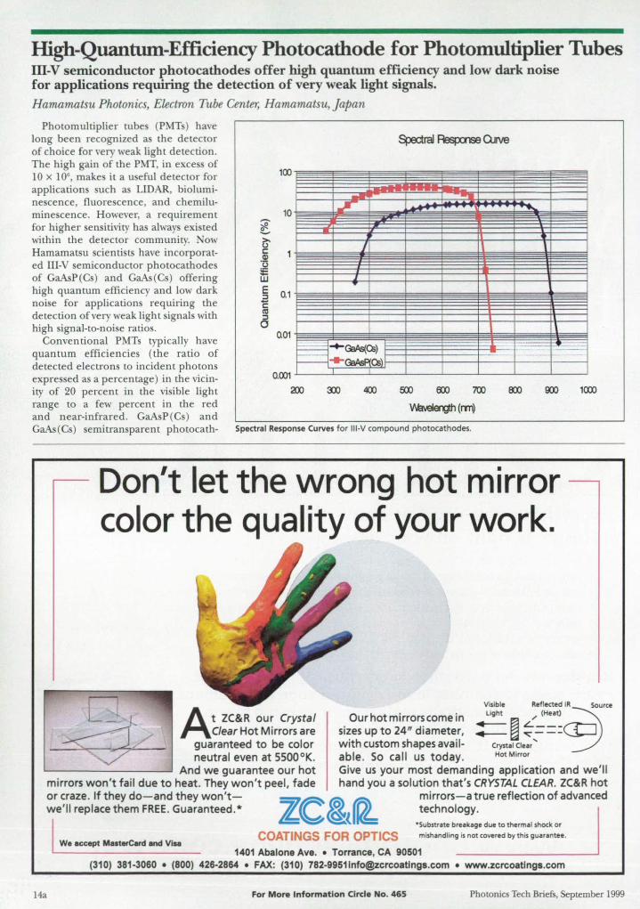
High-Quantum-Efficiency Photocathode for Photomultiplier Tubes ill-V semiconductor photocathodes offer high quantum efficiency and low dark noise for applications requiring the detection of very weak light signals. Hamamatsu Photonics, Electron Tube Center, Hamamatsu, Japan
Photomultiplier rube (PMTs) have long been recognized a the detector of choice for very weak light detection. The high gain of the PMT, in exce of 10 x 106
, makes it a useful detector for applications such as LIDAR, bioluminescence, fluorescence , and chemilumine cence. However, a requirement for higher sen itivity ha alway exi ted within the detector community. ow Hamamatsu scientists have incorporated III-V semiconductor photocathodes of GaAsP(Cs) and GaAs(Cs) offering high quantum efficiency and low dark noi e for applications requiring the detection of very weak light signals with high signal-to-noi e ratios.
~ ~ >-u c: Q)
'u :e w E ::::J 'E (II ::::J 0
100
10
0.1
0.01
... .. /
~ ....
= ==-= -+-~CS) - ..... G:IAsP(CS
400
--
700
WlveIergth (rm)
Conventional PMTs typically have quantum efficiencies (the ratio of detected electrons to incident photons expre sed a a percentage) in the vicinity of 20 percent in the visible light range to a few percent in the red and near-infrared. GaAsP(Cs) and GaAs(Cs) emitransparent photocath- Spectral Response Curves for III-V compound photocathodes.
~ I
U
~
1
1\
T I
Don't let the wrong hot mirror color the quality of your work.
J
J
I
I
~ I
1(0)
At ZC&R our Crystal Clear Hot Mirrors are
guaranteed to be color
Visible Reflected IR Source
Our hot mirrors come in Light / (Heat) 3 neutral even at 5500 oK.
And we guarantee our hot mirrors won't fail due to heat. They won't peel, fade
sizes up to 24" diameter, ~ ~ ~==:CP with custom shapes avail- Crystal Clear '"
able. So call us today. Hot Mirror
Give us your most demanding application and we'll hand you a solution that's CRYSTAL CLEAR. ZC&R hot
or craze. If they do-and they won'twe'll replace them FREE. Guaranteed. *
mirrors-a true reflection of advanced technology.
14a
w. accept MoterCard and Vi .. COATINGS FOR OPTICS
·Substr.te breakage due to thermal shock or
mishandling is not covered by this guarantee.
1401 Abalone Ave . • Torrance, CA 90501 (310) 381-3060 • (800) 426-2864 • FAX: (310) [email protected] • www.zcrcoatlngs.com
For More Information Circle No. 465 Photonics Tech Briefs, September 1999
odes have been used in other devices, such as image intensifiers, and the Electron Tube Center felt that incorporating them into PMTs would represent a significant improvement in the performance. Photomultiplier tubes employing these cathodes have quantum efficiencies in the visible of up to 50 percent and over 15 percent in the near infrared.
Photocathode work by the proce s called the photoelectric effect, de cribed by Ein tein in the early part of the century:
E=lli;-Eb A.
where E = energy imparted to the electron, h = Planck's constant, c = the speed of ligh t, A. = wavelength of ligh t, and Eb = binding energy of the electron to the atom.
When a photon enters the photocathode material and the energy (hc/A) of the photon exceeds the binding energy of the electron, the latter will be excited from the valence band to the conduction band of the photocathode. The electron must then be emitted from the photocathode into the vacuum of the PMT. In conventional photocathodes, the process of emission is hampered by a characteristic known as electron affinity (EA), which represents an energy barrier to the vacuum level. Therefore, to excite an electron into the vacuum, the incident photon must have an energy of Eb + EA' The advantage of III-V photocathodes over conventional cathodes is that it is possible to produce materials with negative electron affinity, when they are properly activated with cesium. With negative electron affinity materials, the barrier to the vacuum is completely removed. In fact, the negative electron affinity actually improves the probability that the electron will e cape to the vacuum.
In the past, Ill-V compound cathodes were available for PMTs only in a reflective mode, when the electron is emitted from the arne side of the cathode on which light is incident. This configuration makes electron collection difficult, resulting in reflective-mode PM'U that are large and bulky. The late t IlI-V compound cathode u e tran mission-mode photocathodes. In this configuration, the electron i emitted from the ide opposite to the light input, allowing the production of a very compact PMT. This compactness makes for very small cooled photon-counting PMT module . ContintUld
Photonics Tech Briefs, September 1m
• Focusable • ESO'protected • Unbeatable lifetime • Rugged shock resistant design • Many patterns available
LC SERIES
• OEM ready fixed focus design • Uniform intensity profile • ESO protected • Rugged shock resistant design • Many patterns available
DL~----, SERIES
Palnt ....... m Rugged industrial-grade design
• Focusable • Unbeatable lifetime
power hungry applications • Uniform intensity profile • Visible red up to 750 mW @ 670 nm • Infrared up to 4 W
For U.S. customers, FOB West Chazy, NY
A STOCKER & YALE COMPANY ·80 ·814·9552 www.lasiris.com E-mail: [email protected]
3549 Ashby Street St·Laurent, Quebec. Canada H4R 2K3 Tel.: (514)335·1005 Fax: (514) 335457E
Melles Griot makes
Internal Mirror Ion Lasers Analyzing • Measuring • Testing • Inspecting
16a
Melles Griot ion lasers have an integrated, hard-sealed
mirror design that is maintenance free for long-term,
repeatable results. Choose from violet, blue, green,
multiline, and all-line versions with stable output as
high as 200 mW. All of our laser heads are air cooled
and housed in compact, cylindrical or rectangular
casings. CE versions are available. The full line of ion
lasers, power supplies with power-factor correction,
and replacement tubes is available through our
worldwide distribution network.
Improve your analysis, inspection, and recording results - call us now!
Find out more: 1-800-645-2737 www.mellesgriot.com/mg113.htm
mELLES GillOT LASER GROUP
2051 Palomar Airport Road, 200 • Carlsbad, CA 92009 1 (800) 645-2737 • (760) 438-2131 • FAX: (760) 438-5208
E-mail : [email protected] • www.mellesgriot.com
Canada (613) 226-5880 Denmark 57615049 France (01 ) 3012-0680 Gennany (06251) 84060 Japan (03) 3407-3614 Netherlands (0316) 333041
Singapore 392-5368 Sweden (08)630-8950 United Kingdom (01223) 203300
For More Information Circle No. 467
In photon counting, a photon enters the tube and i converted to an electron that is amplified by the tube's gain. The result is a pul e with a specific amplitude. All pulses coming from the tube with this amplitude are counted as photons. The photocathode can also, however, emit "dark pUl es" because of thermionic emis-ion from the photocathode, The
number of dark pulse depends on the Eb of the photocathode. The GaAsP(Cs) has about 5,000 per econd, while the GaAs(Cs) has about 15,000 per second at room temperature. Therefore , for most applications, cooling is required to reduce these dark pulse , The dark counts are then reduced to 80 per econd for GaAsP(Cs) and 100 for GaAs(Cs) at o · C.
The limiting factor in using these PMTs in all current applications is the maximum allowable photocathode current of 2 picoamps. To get long operating life from the tubes, it is prudent to use them only for photon counting or very weak analog signal detection .
Future improvements will include increasing the sensitivity, further reducing the dark pulses, and increasing the maximum photocathode current. The Hamamatsu Electron Tube Center is constantly working to raise photomultiplier technology. The incorporation of III-V compound photocathodes into very compact PMTs is a significant step forward.
This work was done at the Hamamatsu Photonics Electron Tube Center. For further infamlation, contact Hamamatsu at 800-524-0504 or visit usa.hamamatsu. com. The author of this brief is Earl Hergert, Hamamatsu engineer.
Hybrid Imaging Technology Devices are made from CCD and CMOS components, which can be independently optimized. NASA ~ Jet Propulsion Laboratory, Pasadena, California
"Hybrid imaging technology" (HIT) is the name of a di cipline in which the advancement of electronic image sensors is pursued via hy-
Photonics Tech BriefS, Seplember 1999

bridization of charge-coupled-device (CCD) and complementary metal oxide/ semiconductor (CMOS) circuitry. The guiding principle of HIT is to combine CCD and CMOS components into units that afford capabilities that neither CCD nor Cl'vfOS circuitry can provide by itself. HIT can be applied to advantage in almost any situation in which there are requirements for very high imaging quality and low power dissipation. Applications can include portable video and portable digital still cameras, remote surveillance cameras, and low-power cameras in space borne and terrestrial cientific instrumentation.
HIT merges the exceptional quantum efficiencies, fill factors, broad spectral responses, and very low noise levels of CCDs with the low power levels, system-integration capabilities. and low costs of CMOS-based activepixel sensor (APS) circuits to create the next generation of high-performance image sensors. Some of the related research outside HIT has included attempts to merge CCD and CMOS components at the device-fabrication-process level. Although these attempts have yielded working image sensors, the devices have exhibited poor image quality and high noise because of lack of optimization of CMOS processes. In turn, the lack of optimization has been due to a basic incompatibility between CCD and CMOS processes as they relate to processing temperatures and to required oxide thicknesses for CMOS tran istors.
An essential element of the HIT approach is that no attempt is made to unite CCD and CMOS devices at the device-fabrication-process level; instead, the CCD and CMOS components of a given device are fabricated in eparate CCD and CMOS proces e and then joined mechanically and electrically (hybridized) by bump bonding. This element of HIT makes it po ible to avoid co tly proce development. Thi approach al 0 makes it po ible to optimize the CCD and the CMO parts independently, in uch a way a to maximize the overall performance of the resulting image sen or in a highly miniaturized format.
Another advantage of HIT i that it enables the reuse of CCD imaging device and CMOS readout circuitry without need for costly refabrication. A supply of un hybridized components can be maintained 0 that combinations of components can be elected to atisfy requirements in pecific applications.
Photonics Tech Briefs, September 1999
The imager integrated-circuit chip of an HIT image sensor is essentially a CCD chip, except that the on-chip amplifier usually found in such a device has been replaced by either a floating diffusion or a floating gate output node. The companion CMOS chip must contain a charge-to-voltage conversion amplifier similar to an operational amplifier configured as a charge integrator. Depending on the application, the CMOS chip could also contain additional circuitry to perform such functions as correlated double sampling and analog-to-digital conver-
sion. Matching bump-bond pads are formed on tbe CCD imager and CMOS chips during their respective fabrication processe. Indium bumps are deposited on the pads. and the chips are joined by standard bump-bonding techniques.
This work was done by MaTk V. Wadsworth of Caltech for NASA's Jet Propulsion Laboratory. For further information, access the Technical Support Package (TSP) free on-line at www. nasatech.com under the Electronic Components and Systems category. NP0-20542 Continued
Things Moving 100 FaSllor YouP
MoUonScope· PC Can Help You. Redlake Imaging Corporation offers a family of affordable high-speed computer based digital imaging
products deSigned to meet your motion analysis needs.
• Easy to Use "Point & Click" Application Software
• Up to 8,000 Digital Frames per Second
• Plug & Play PC Peripheral
• Up to 4 Cameras per PC
1-800-453·1223 Phone' 1·408-779-6464 FAX: 1·408-778'6256 E-Mlil: soleS@redlo e.com
Ii!IrEcLRKE ImRGlnG
For More Information Circle No. 468 17a
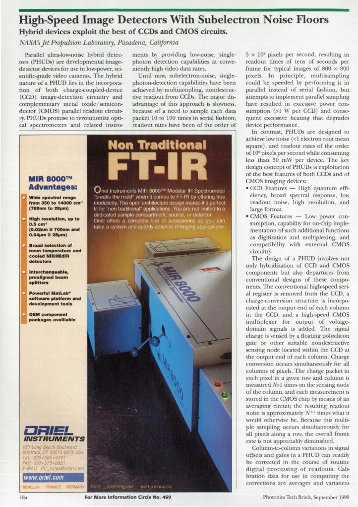
High-Speed Image Detectors With Subelectron Noise Floors Hybrid devices exploit the best of CCDs and CMOS circuits. NASA's Jet Propulsion Laboratory, Pasadena, Califamia
Parallel ultra-low-noise hybrid detectors (PHUD ) are developmental imagedetector device for use in low-pm er, cientific-grade video cameras. The hybrid nature of a PHUD lie in the incorporation of both charge-coupled-device (CCD) image-detection circuitry and complementary metal oxide/ emiconductor (CMO ) parallel readout circuitry. PHUD promi e to revolutionize optical pectrometers and related in tru-
MIR aooo™ Advantages: Wid •• pectr.1 r.ng. from 350 to 14000 em" (700nm to HilmI
High ,..olutlon, up to 0 .5 em" (O.02nm 0 700nm .nd O.04l1m 0 2811ml
Bro.d .electlon of room temper.tu,. .nd cooled NIR/MldIA detecto ...
Interch.nge.bl., p,..lIgn.d be.m .plltt ....
Pow.rful M. tLebe .ottw.,. pl. ltorm .nd dev.lopment tool.
OEM component p.ck.ge •• v.lII.bl.
ORIEL INSTRUMENTS
o # _ ru S raiford CT 066150872 USA TEL 203·380·439' FAX 203·315-0851 EMAIL ttlr
www.oriel.com
ments b providing low-noi e, inglephoton detection capabilitie at conveniently high video data rate.
ntil now, ubelectron-noi e, inglephoton-detection capabilitie have been achieved b multi ampling, non de tructive readout from CCD . The major disadvantage of thi approach i lowne , because of a need to ample each data packet 10 to 100 times in erial fashion; readout rate have been of the order of
18a For More Information Circle No. 469
5 X 10' pixel per econd, resulting in readout time of tens of econds per frame for typical image of 00 x 00 pixel . In principle, multi ampling could be peeded b performing it in parallel in tead of erial fashion , but attempts to implement parallel ampling have re ulted in exce ive power con-umption (>1 W per CCD) and con e
quent exce ive heating that degrade device performance.
In contrast, PHUD are de igned to achieve low noise (<1 electron root mean quare), and readout rate of the order
of 10· pixels per econd while con uming Ie than 50 mW per device. The key design concept ofPHUD is exploitation of the be t feature of both CCD and of CMOS imaging device : • CCD Features - High quantum effi
ciency, broad spectral re pon e, low readout noise, high re olution, and large format.
e CMOS Features - Low power consumption, capability for on-chip implementation of uch additional function as digitization and multiplexing, and compatibility with external CMO circuitry. The de ign of a PHUD involves not
only hybridization of CCD and CMO components but also departure from conventional designs of the e components. The conventional high- peed erial regi ter is removed from the CCD, a charge-conversion tructure is incorporated at the output end of each column in the CCD, and a high-speed CMO multiplexer for output of voltagedomain signals is added. The signal charge i sensed by a floating polysilicon gate or other suitable nonde tructive sen ing node located within the CCD at the output end of each column. Charge conver ion occurs imultaneously for all columns of pixels. The charge packet in each pixel in a given row and column is measured N>1 time on the en ing node of the column, and each measurement i stored in the CMO chip by mean of an averaging circuit; the re ulting readout noise i approximately I I ! times what it would otherwise be. Becau e this multiple ampling occurs imultaneously for all pixels along a row, the overall frame rate is not appreciably diminished.
Column-to-column variations in ignal otE ets and gains in a PHUD can readily be corrected in the course of routine digital proces ing of readout . Calibration data for use in computing the corrections are averages and variances
Photonics Tech Briefs, September 1999

of readouts from uniform images. This work was done by Mark V.
Wadsworth oj Caltech Jor NASA's Jet Propulsion Laboratory. For Jurther infor-
malion, access the Technical Support Package (TSP) free on-line at www.nasatech.com under the Electronic Components and Systems ca~~. }lP~20576
Prismatic Phase Shifter Small phase changes can be obtained with relatively coarse mechanical adjustments. Langley Research Center, Hampton, Virginia
The prismatic phase shifter is a novel device that can be used to control the phase ofa coherent beam of light. Phase hifting is becoming an integral function
of most modem interferometric systems. Phase shifting can be accomplished by use of any of a variety of older devices including moving mirrors, rotating quarter-wave plates, moving gratings, and Bragg cells, all of which have disadvantages. Surface losses and/ or changes in polarization are
N
n
After
Beam of Ught
Phase Shift Is Introduced into the beam of light when the prism is moved along its plane of symmetry.
induced by these various devices. In the case of a moving mirror, subwavelength translation can be difficult. Some of the other older devices produce lateral shifts of the beam.
The prismatic phase shifter introduces an easily controlled change of phase to a beam of light without the disadvantages of the older devices. This device consists of a prism mounted on a translation stage. The prism is placed in the beam oriented at the angle of minimum deviation. The orientation of the stage is chosen so that translation cause the prism to move along its plane of symmetry.
The figure shows the prism before (dashed) and after (solid) translation. Because of the symmetry of the configuration, the beam is nO[ deviated or translated, and a phase shift is introduced to
the beam. For decreasing apex angle, increased translation is needed to obtain
Photonics Tech Briefs, September 1999
a given phase shift. This effect is termed "optical leverage" and makes it possible to obtain small phase changes with relatively coarse mechanical adjustments.
The change in effective optical-path distance, t10PD, is given by
t1 OPD = 2 (nf - NL)
where nand N are the indices of refraction of the prism and the surrounding medium, respectively; , is half the difference between the old and new distances along the optical path inside the prism; and L is half the difference between the new and old distances along the optical path outside the prism. By the law of sines,
L Y ---=--sin a/ 2 cos ()
where Y is the translation distance, a is the apex angle of the prism, and 9 is the angle of incidence for minimum deviation. This angle is given by
n - n
[ 2 ] 9 = arcsin ---sin a/ 2
n - N
Furthermore, P. is given by
, Ysin (a/ 2) cos «(}-a/ 2) cos ()
Therefore, t10PD is given by
t10PD = 2Ysin (a/ 2) cos ()
[N - n cos (9 - a/2)]
When this device i operated at Brewster's angle, it imposes no surface losses. The only requirement the prism material must satisfy is that it be transparent at the wavelength of interest and be of reasonable optical quality. Because translation of the prism to produce change of phase does not cause deviation or translation of the beam, the device can be used in a system in which strict alignment must be maintained.
This worlt UW' dqne fly B'T'OOIcs A. Ch.iIdm oj Langley Research Center. For further information, acass tr.e Technical SUf1JUrl P~ (TSP) free on~ at WWUlna.saIa:h.com under 1M Physical Sciences CIJ~ LAR-14637
www.nasatech.com
With Exciton, you get a specialized team of professionals knowledgeable in the field of laser dyes. Since more than one dye may cover a given spectral region, we prmide the latest information concerning the best dye selection for a specific laser system and application. Exciton Inc., PO Box 31126, Dayton. OH 45437; Tel: 937·252·2989.
1999 PRECISION OPTICS CATALOG Edmund Scientific's new 1999 Catalog features hundreds of technical solutions from our extensive inventory of precision optiu, machine vision products, and optical compo
nents. All off-the-shelf precision optics and optical instruments are available in prototype and OEM manufacturing production quantities. Edmund Scientific Co., Industrial Optics Division, 101 Ean Gloucester Pike, Dept. B991N954, Barrington, NJ 08007; (609) 573-6250; fax: (609) 573-6295; web site: www.edsci.com.
Edmund Scientific For More Information Circle No. 491
~ That's why Ferson Optics makes sure ~~ your coatings are designed for easy ffif repeatability. We'll work with you to ~o provide the best solution for your III application. Bar none. And we hit the
mark In team work, too. So don't walt ~ until your coating becomes a ~~ problem. Call us first. ~~ ~~ COATINGS INCLUDE: (.) • Antlrellectlon • Beamsplltters
~ III
~ III
~
• Fillers· Laser Mirrors • Metallic Mirrors· HoVCoid Mirrors
Fast Turn Around 1 large Capacity UV to IR Range lOver 30 Years Experience
FERSON OPTICS, INC. An Systems, Inc. Company
2006 Government St Ocean Springs, MS 39564
(228) 875-8146 1 FAX (228) 875-5947 www.ferson.com
For More Information Circle No. 470
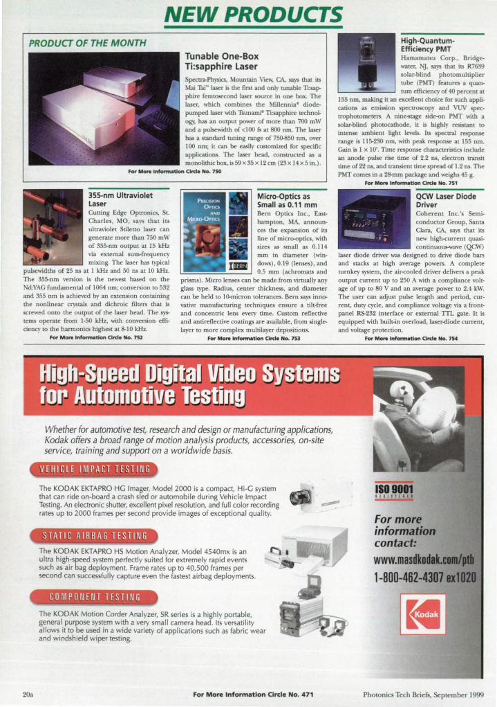
NEW PRODUCTS PRODUCT OF THE MONTH
355-nm Ultraviolet
Cutting Edge Optronics. St. Charles. MO . says that its ultraviolet Stiletto laser can generate more than 750 mW of 355-nm output at 15 kHz via external sum-frequency mixing. The laser has typical
Tunable One-Box Ti:sapphire Laser
pectra-Physics. Mountain View. CA. says that its Mai Tai~ laser is the first and only runable n:sapphire femtosecond laser source in one box. The laser. which combines the Millennja" diodepumped laser with Tsunami" n :sapphire technology, has an output power of more than 700 mW and a pulsewidth of <100 fs at 800 nm. The laser has a standard tuning range of 75(}.850 nm. over 100 nm; it can be easily custOlrnzed for specific appHcations. The laser head. constructed as a monolithkbox, is59x!l5x 12 em (2!1x 14x5 in.) .
pulsewidth of 25 ns at 1 kHz and 50 ns at 10kHz. The 355-nrn version is the newe t based on the Nd:YAG fundamental of 1064 nm; conversion to 532 and 355 nm is achieved by an extension containing the nonlinear crystals and dichroic filters that is screwed onto the output of the laser head. The systems operate from 1-50 kHz. with conversion efficiency to the harmonics highest at 8-10 kHz.
MicrO-Optics as Small as 0.11 mm Bern Optics Inc., Easthampton. MA. announces the expansion of its Hne of micro-optics. with sizes as small as 0.114 mm in diameter (windows), 0.19 (lenses). and 0.5 mm (achromats and
prisms) . Micro lenses can be made from virtually any glass type. Radius. center thickness. and diameter can be held to 10-micron tolerances. Bern says innovative manufacturing techniques ensure a tilt-free and concentric lens every time. Custom reflective and antireflective coatings are available. from singlelayer to more complex multilayer depositions.
For More Infonn.tlon Clrde No. 752 For More Infonn.tlon Clrcl. No. 753
Whether for automotive test, research and design or manufacturing applications, Kodak offers a broad range of motion analysis products, accessories, on-site service, training and support on a worldwide basis.
-I,V E Hie l E ·~ IMP ACT TE S TIN G -
20a
_~ -~J • • ~ - ~ •
The KODAK EKTAPRO HG Imager, Model 2000 is a compact, H i-G system that can ride on-board a crash sled or automobile during Vehicle Impact Testing. An electronic shutter, excellent pixel resolution, and full color recording rates up to 2000 frames per second provide images of exceptional quality.
The KODAK EKTAPRO HS Motion Analyzer, Model 4540mx is an ultra high-speed system perfectly suited for extremely rapid events such as air bag deployment. Frame rates up to 40,500 frames per second can successfully capture even the fastest airbag deployments.
The KODAK Motion Corder Analyzer, SR series is a highly portable. general purpose system with a very small camera head. Its versatility allows it to be used in a wide variety of applications such as fabric wear and windshield wiper testing.
For More Information Circle No. 471
-.-¥. - ••
La High-QuantllmEfficiency PMT Hamamatsu corp.. Bridgewater. JI{j. says that its R7639 solar-bifid photomuItipHer tube (PMT) features a quantum efficiency of 40 percenl at
155 nm, making it an excellent choice for such appHcations as emission spectroscopy and VUV speclTopholomerers, A nine-stage ide-on PMT with a solar-blind photocathode. it is highly resistant to intense ambient light levels. Its spectral response range is 115-230 nm. with peak response at 155 nm. Gain is 1 X 10'. Time response characteristics include an anode pulse rise time of 2.2 ns. eIeClTon tTansit time of22 ns. and tTansient time spread of 1.2 ns. The PMT comes in a 28-mm package and weighs 45 g.
For More Infann.tion Clrd. No. 751
QCW iLaser Diode Driver Coherent Inc.'s Semiconductor Group. Santa Clara. CA. says that its new high-current quasicontinuous-wave (QCWJ
laser diode driver was designed to drive diode bars and stacks at high average powers. A complete turnkey system. the air-cooled driver deHvers a peak output current up to 250 A with a compHance voltage of up to 80 V and an average power to 2.4 kW. The user can acljust pulse length and period, CUT
rent. duty cycle. and compliance voltage via a frontpanel RS-232 interface or external TTL gate. It is equipped with built-in overload. laser-diode current, and voltage protection.
For More Infonnation Circle No. 754
ISO 9001 IEtlS JEl f I
For more information contact:
www.masdkodalCtmt/' • . :1 1-800-462-4307u
Photonics Tech Briefs. September 1999

, , , , I I I I
• I
• I I , , I I I
•
)j
Vol. 23, No. 9 September 1999 This fonn expires: February 29. 2000
Fast Fax Information Form Fax: (413) 637-4343
Fax this form for quickest processing of your inquiry, or use the on-line LeadNet Service at www.nasatech.com.
Name:
Company:
Address: __________________________________________________________________________________ __
CHy/SVZIp: ______________________________________________________________________ ___
Phone: Fax:
e-m~l: ____________________________________________________________________________________ __
Circle the numbers be/ow to receive more information about products and services featured in this issue.
401
421 441 461 481 501 521 541 561
581
601 621 641 661 681 701 721 741 761 781 801 821
402 403 404 405 406 407 422 423 424 425 426 427 442 443 444 445 446 447 462 463 464 465 466 467 482 483 484 485 486 487 502 503 504 505 506 507 522 523 524 525 526 527 542 543 544 545 546 547 562 563 564 565 566 567 582 583 584 585 586 587 602 603 604 605 606 607 622 623 624 625 626 627 642 643 644 645 646 647 662 663 664 665 666 667 682 683 684 685 686 687 702 703 704 705 706 707 722 723 724 725 726 727 742 743 744 745 746 747 762 763 764 765 766 767 782 783 784 785 786 787 802 803 804 805 806 807 822 823 824 825 826 827
408 428 448 468 488 508 528 548 568 588 608 628 648 668 688 708 728 748 768 788 808 828
409 429 449 469 489 509 529 549 569 589 609 629 649 669 689 709 729 749 769 789 809 829
410 411 430 431 450 451 470 471 490 491 510 511 530 531 550 551 570 571 590 591 610 611 630 631 650 651 670 671 690 691 710 711 730 731 750 751 770 771
790 791 810 811 830 831
WIN A FREE SUBSCRIPTION ...
412 413 432 433 452 453 472 473 492 493 512 513 532 533 552 553 572 573 592 593 612 613 632 633 652 653 672 673 692 693 712 713 732 733 752 753 772 773 792 793 812 813 832 833
414 415 434 435 454 455 474 475 494 495 514 515 534 535 554 555 574 575 594 595 614 615 634 635 654 655 674 675 694 695 714 715 734 735 754 755 774 775 794 795 814 815 834 835
416 436 456 476 496 516 536 556 576 596
616 636 656 676 696 716 736 756 776 796
816 836
417 418 437 438 457 458 477 478 497 498 517 518 537 538 557 558 577 578 597 598 617 618 637 638 657 658 677 678 697 698 717 718 737 738 757 758 777 778 797 798 817 818 837 838
419 420 439 440 459 460 479 480 499 500 519 520 539 540 559 560 579 580 599 600 619 620 639 640 659 660 679 680 699 700 719 720 739 740 759 760 779 780 799 800 819 820 839 840
to a new e-mail new sletter from NASA Tech Briefs, featuring exclusive technology and business news as w ell as previews of upcoming Issues. To qualify, simply complete the survey below and fax this page to (413) 637-4343. Your response will be kept completely confidential and will be used for statistical purposes only. This survey is optional and not required to order product information above.
1a. Are you involved in advising, recommending, specifying. or approving the purchase of computer-aided design (CAD) software for your company? 0 Yes 0 No
1b. If yes, do you plan to increase your purchase of CAD software in the next 12 months? 0 Yes 0 No
2. Which of the follOwing types of CAD software do you now use? (check one) 0 2D 0 3D 0 Both
3. Please list the names of CAD packages you (or your department) currently use.
4. Please list any additional CAD packages you are considering purchasing in the next 12 months.
o Check here to receive your free subscription to the new NASA Tech Briefs e-mail newsletter. (Please be sure to fill in your e-mail address at the top of this page.)
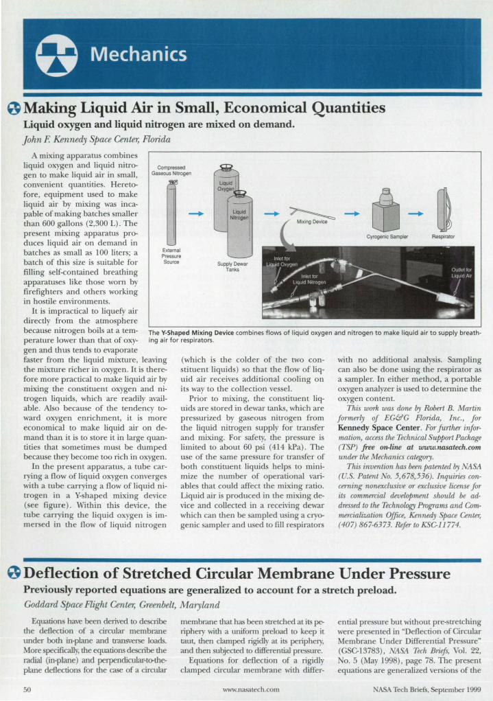
o Making Liquid Air in Small, Economical Quantities Liquid oxygen and liquid nitrogen are mixed on demand. John F. Kennedy pace Center, Florida
A mixing apparatus combine liquid oxygen and liquid nitrogen to make liquid air in small, convenient quantities. Hereto-fore, equipment used to make liquid air by mixing was inca-pable of making batches smaller than 600 gallons (2,300 L). The present mixing apparatus pro-duces liquid air on demand in batches as small as 100 liters; a batch of this size is suitable for filling self-contained breathing apparatuse like those worn by firefighters and others working in hostile environments.
It is impractical to liquefy air directly from the atmosphere
Compressed Gaseous Nitrogen
External Pressure Source
liquid Nitrogen
Supply Dewar Tanks
because nitrogen boils at a temperature lower than that of oxygen and thus tends to evaporate
The V-Shaped Mixing Device combines flows of liquid oxygen and nitrogen to make liquid air to supply breathing air for respirators.
faster from the liquid mixture, leaving the mixture richer in oxygen. It is therefore more practical to make liquid air by mixing the constituent oxygen and nitrogen liquids, which are readily available. Also because of the tendency toward oxygen enrichment, it is more economical to make liquid air on demand than it is to store it in large quantities that sometimes must be dumped because they become too rich in oxygen.
In the present apparatus, a tube carrying a flow of liquid oxygen converges with a tube carrying a flow of liquid nitrogen in a Y-shaped mixing device (see figure). Within this device, the tube carrying the liquid oxygen is immersed in the flow of liquid nitrogen
(which is the colder of the two constituent liquids) so that the flow of liquid air receives additional cooling on its way to the collection vessel.
Prior to mixing, the constituent liquids are stored in dewar tanks, which are pressurized by gaseous nitrogen from the liquid nitrogen supply for transfer and mixing. For safety, the pressure is limited to about 60 psi (414 kPa). The use of the same pressure for transfer of both constituent liquids helps to minimize the number of operational variables that could affect the mixing ratio. Liquid air i produced in the mixing device and collected in a receiving dewar which can then be ampled using a cryogenic sampler and used to fill respirators
with no additional analy is. Sampling can also be done using the respirator as a sampler. In either method, a portable oxygen analyzer is used to determine the oxygen content.
This work was done by Robert B. Martin formerly of EG&G Florida, Inc., for Kennedy Space Center. For further information, access the Technical Support Package (TSP) free on-line at www_nasatech.com under the Mechanics category.
This invention has been patented by NASA (U.s. Patent 0. 5,678,536). Inquiries concerning nonexclusive or exclusive License for its commercial development should be addressed to the Technology Programs and Commercialization Office, Kennedy Space Center; (407) 867-6373. Refer to KSG-11774.
o Deflection of Stretched Circular Membrane Under Pressure Previously reported equations are generalized to account for a stretch preload. Goddard Space Flight Center, Greenbelt, Maryland
Equations have been derived to describe the deflection of a circular membrane under both in-plane and transverse loads. More specifically, the equations describe the radial (in-plane) and perpendicular-to-theplane deflections for the case of a circular
50
membrane that has been stretched at its periphery with a uniform preload to keep it taut, then clamped rigidly at its periphery, and then subjected to differential pressure.
Equations for deflection of a rigidly clamped circular membrane with differ-
www.nasatech.com
ential pressure but without pre-stretching were presented in "Deflection of Circular Membrane Under Differential Pressure" (GSC-13783), jiSA Tech Briefs, Vol. 22, No. 5 (May 1998), page 78. The present equations are generalized versions of the
ASA Tech Briefs, September 1999

Stahl utilizes as-9000 procedures to transform your design concepts into a finished machined aluminum casting including sub-assembly when required. We are a fully integrated engineering, tooling, foundry and production machining facility using the latest technological tools Stahl Specialty is capable of meeting all your critical needs while satisfying your demands as a single source supplier. Give us a call or check out our web site at the communications below. Find out how our expertise can improve your quality.
Kingsville , Missouri USA 64061 • (816)597-3322 • (800)821-7852· Fax (816)597-3485 • hHp:/twww.slahlspecialty.com For More Information Circle No. 588
BUILDING BLOCKS FOR POSITIONING
www.velmex.com Fax: 716 657·6153
Get your free Catalog G todayl
Call: 800 641-6446 or 7t6 6S7·6Utln NY
For More Information Circle No. 416
The Leader in &@]WfflOU@@w Composite
Training • Composite laminate Design • Design and Analysis of
Composite Structural Joints • Structural Analysis and
Repair De.lgn
• Advanced CompoSite Drawing Interpretation
• Ultrasonic Inspection of Advanced Composite.
Training at our facility or yours. Call for our complete 13-course catalog.
Abarls TraInIng Resources, Inc. 5401 Longley Lane, Suite 49
Reno, NV 8951.1 USA (775) 827~568 • Fax: (775) 827~599
www.abarls.com • e-mail: [email protected]
(800) 638-8441
ABARIS 1 1 , •••• "-'" Ii-
For More Information Circle No. 417
previously reported equation . As before, the derivation follm a train-energy/ virtual deflection approach, which is common in tress-and-strain problems of this kind. The departure from the previously reported equation involve the incorporation of additional term to account for the change in train energy associated with work done by the preload.
The displacements of the membrane under load are de cribed by the equation
(1 )
and (2)
p(l- v) u=r(a-r)(cl + c2r)+--r,
2naEh
where r is the radial coordinate, a is the radius of the clamping edge, w is the transverse displacement (that i , the deflection perpendicular to the nominal membrane plane) at radius r, ~ is the maximum tran ver e di placement, u is the radial displacement at radius r, CI
and ~ are constants, p is the preload force , v is Pois on's ratio of the membrane material, Eis the Young's modulus of the membrane material, and h is the thicknes of the membrane. The term p(1- v)r/ 21taEh in equation 2 de cribes the component of radial displacement attributable to the preload.
The radial and transverse strains are given, respectively, by
Er = du + .!.[dW]2 dr 2 dr
and
u Et =
r
(3)
(4)
The strain energy as ociated with stretching of the membrane is given by
a
V = 1~E:2 f (E; + E? + 2VErEt )rdr (5)
o
To calculate the deflection of the membrane, one must olve the foregoing equation to find Ch ~, and ~. First, one ubtitute the right ide of equation (1)
through (4) for the corre ponding terms in equation 5. ing the re ulting form of equation (5), one finds CI and ~ by impo ing the requirements that
av =0 (6)
del and
(]V =0 de2
(7)
ext, one impo e the requirement that the change in work done by the differential pre ure acting through a virtual displacement equal the change in train energy associated with the virtual
displacement. If the virtual displacement is cho en to be Ow oc 0%. then this requirement is expressed by the equation
a [ 2]2 :~ oWo =2nqowo f 1-( ~) rdr
o
(8)
where q i the differential pressure on the membrane. Eventually, one obtain the following equations:
nEhw6 + 2aa3pwo - na4a3q = 0 (9)
where
(10)
Equation 9 can readily be olved to obtain the maximum deflection, ~, at the center of the membrane.
This work was done f7y Alfonso Hmnidn. of Goddard Space Flight Center. For further information, access the Technical Support Package (TSP) free cm-line at www.nasatech.com under the Mechanics category. GSC-14223
0 Accelerations of One Airplane in Wake Vortices of Another Results of a study could guide the development of valid simplified mathematical models.
Langley Research Center, Hampton, Virginia
Acceleration of one airplane encountering a vortex or pair of vortices in the wake of another airplane were computed in a parametric study. The approach taken in the tudy was to systematically investigate the effects of progressively more nearly complete de criptions of the interaction of an airplane with a wake-vortex system, in order to compare the theoreti-
www.nasatech.com
cal effects of some of the major simplifying assumptions that are commonly made in fonnulating mathematical models to represent this interaction. Despite their theoretical nature, this study and other related studies have practical significance: For example, mathematical models of airplane/ vortex interaction are needed for pilot-training flight simula-
ABA Tech Briefs, September 1999
When it comes to
sharpness, no one can top us.
How sharp is our image? On average,
20% sharper. ow do we do it? Big monitors are all we make. We understand
the specific challenges involved with J,. •. c .... ,H"in5'truly crisp focus on large screens.
Every monitor we sell meets the most rigorous standards for quality and performance. Plus, we back every
monitor with Cornerstone's industry-leading 5-year warranty.
It's not just bi talk-we have the numbers to prove it. To compare
Cornerstone's spees for yo elf, call (800) 562-2383 or visit our web site
t-oday. And discover how vast the
di erences really are.
ant proof? Visit IgMonitors.c:om/sharpest/ntbt
and see for yourself.
AND THE BIG P RE.
Try This F E WINDAQ Data Acquisition
..........,=;;;;.;;.;.-~
System
Before You Buy An A ani Inning
WINDAQ System
."" ... , ~"
-' Il. l.' ... " "' ..
• 8 differential inputs with ± 1 OOOV channelto-channel and input-to-output isolation
• ± 10mV to ±800VDC (or peak AC) full scale measurement range per channel
• 6 software selectable ranges per channel • 14-bit, 250kHz NO • Printer port, USB, or Ethernet interface
Get Your F WINDAQ
System at www.dataq.com/52.htm
DATAQ-INSTRUMENTS
For More Informat ion Circle No. 420
to . The models must repre ent the dominant vortex-encounter effects, yet must be imple enough to be adaptable to a variety of airplan and imulators .
In thi tudy, the axis of the vortice was parallel to the x axi of a Carte ian coordinate tem fixed with re pect to the Earth. The y and z axe were the lateral horizontal and vertical axe re pecuvel . In the case of a pair of voruce , the origin of the coorclinate S} tern was located between the vortice . U ing a previousl developed mathematical model of wake vortice, the y and z components of the vortex velocity at a given y,z location were taken to be (1) proportional to the weight and inversel proportional to the velocity and wing pan of the wake-generating airplane and (2) proportional to function of y and z that decrease with distance from the vortex core and that include the radii and the y and z po ition of the vortex core as parameters.
In adclition to the vortex coordinate y tern de cribed above, there was a co
ordinate ystem fixed to the airplane body axes and five aerodynamic- urface axi systems, to model the right and left wing panel, the right and left horizontal tail panels, and the vertical tail panel. The body-axi system could be located at an arbitrary po ition and orientation relative to the vortex axis ystem. The orientation was pecified b the standard airplane yaw, pitch, and roll Euler angles. The five aerodynamic- urface axi systems were placed at arbitrary positions and orientations relative to the airplane body-axis ystem. The equation for the wing and tail surface were written in general terms for planar aerodynamic urface with weep, taper, and dihedral. o fuselage was modeled, and the aero
dynamic surfaces were treated as originating at the center line of the airplane.
Each urface was broken up into panwise incremental areas. The angle of
attack and side lip at the three-quarterchord point of each incremental area was calculated independentl of tho e of its neighbors. The vortex and encountering-airplane velocitie were tran formed into the aerodynamic-surface axi ysterns and u ed to compute aerodynamic forces, which were assumed to act at the quarter~hord point of each incremental area. The aerodynamic forces were then tran formed back into the body axis system and used to compute the acceleration of the encountering airplane.
an example case, the vortex flow field modeled in the tudy had the nominal characteri tics of the wake of a Boeing 767 airplane, while the encountering airplane had the nominal characteri tics ofa Boeing 757 airplane. The majority of case considered in this rudy involved
www.nasalech.com
roll-dominant encounters, in which the longituclinal axi of the encountering airplane was nearly parallel to the vortex x axis. The fi t case con idered was that of a drag-Ie rectangular wing in the flow field of a ingle vortex. Then in a equence of increasingl comple case , the tudy progre ed to the case of a complete airplane with (1) aerodynamic urface characterized b taper, weep,
and dihedral; (2) aerodynamic behavior that included stalling; and (3) the vortex pair in ground effect. The effects of the pitch, roll , and yaw attitude of the airplane on the calculated acceleration were al 0 inve tigated.
The numerical re ults of the calculations were plotted as contours of constant acceleration in a 300-by-300-ft (91-by-91-m) area centered on vortex pairs. The following conclusions were drawn from the re ults: • The effects of the single vortex field ex
tended to larger distances from the vortex core than clid the effects of a coun terrotating vortex pair. However, near the cores, the effects of the vortex pair were greater and covered a larger area. In addition, the acceleration contours for the vortex pair were more complicated with more sign reversals. Thus, it appears that a vortex pair po es a potential hazard greater than that of a single vortex.
• The dominant accelerations were in roll and the z body axi ,although sigrtificant yawing, pitching, and lateral acceleration were calculated when the vertical and horizontal tail surface were added to the mathematical model. Longitudinal acceleration was not a major factor.
• A nonzero lift coefficient, drag, wing clihedral, and localized talling had negligible effects on the accelerations relative the effects of taper ratio and weep.
• Significan t distortion of all the acceleration contour occurred when the attitude of tile encountering airplane was changed b 20· about any axi .
• In the case of an encounter with vortex perpendicular to the longitudinal airplane axi , the z and pitch acceleration were generally comparable to tho e for a parallel encounter, except for small ar as of much larger acceleration around the vortex cores. However, the roIJing, yawing, and lateral acceleration were zero because of the ymmetry of the airplane.
• The effect of a ground plane at 150 ft (45.7 m ) below the vortex ystem was minimal except when the encountering airplane was near the ground. This work was done by Eric C. Stewart oj
Langley Research Center. For JUrlher inJormation, access the Technical Support Package (TSP) free on-line at www.nasatech.co7n under the Mechanics category. L-17831
A Tech Briefs, September 1999
Watlow Introduces A Better Way To Heat.
New Thick Film Technology Gives You The Kind Of Heat You Want.
Now you can achieve greater control of your heating applications with this breakthrough technology from Watlow. You get temperature capabilities to 500°C; temperature uniformity of ±2°C over the heated surface; fast response with low thermal mass, and greater heat transfer efficiency and heat-up due to thick film's intimate surface contact.
Tests in a specific application confirm increased yields of 30% and a reduction of 1.5 hours of production losses at start-up.
Layered resistor circuit on stainless steel allows uniform
heating while occonYTlodating mounting holes and notches.
Precision resistor circuit on 9uarlz for oppliootions like aggressIve chemical fluid heating.
Exactly Where You Want It.
Cuslom-con~gured reshtor circuit on 96% purity block alumino. This process allows romping rates of up to lSOoC per second while maintaining a uniform temperol1Jte
The low profile of thick film heating technology lets you put the watts preci ely where they're needed. You can apply heat directly to a variety of hape and sub trates -including 300 and 400 series stainle teel, quartz and ceramic - customizing your application to fit previously inacces ible areas or carro ive environments.
To find out how Watlow' new thick film technology can work for your application, access our web site or contact us at 1~800~4WATLOW (800·492.8569).
For More Information Cln:le No. 523
WATLOW www.wadow.com/thickfilm
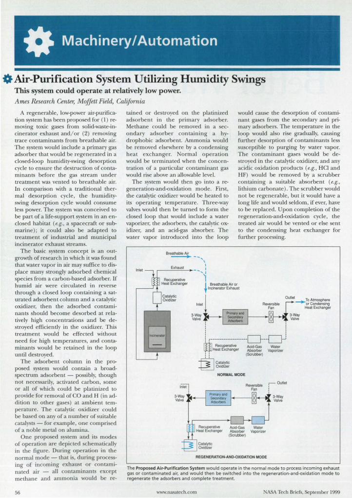
O Air-Purification System Utilizing Humidity Swings This system could operate at relatively low power. Ames Research Center, Moffett Field, California
A regenerable, low-power air-purification system has been propo ed for (l) removing toxic gases from olid-waste-incinerator exhaust and! or (2) removing trace contaminants from breathable air. The system would include a primary gas adsorber that would be regenerated in a clo ed-loop humidity-swing desorption cycle to ensure the de truction of contaminants before the gas stream under treatment was vented to breathable air. In comparison with a traditional thermal de orption cycle, the humidityswing desorption cycle would con ume Ie s power. The system was conceived to be part of a life-support system in an enclo ed habitat (e.g., a spacecraft or submarine); it could aI 0 be adapted to treatment of industrial and municipal incinerator exhaust streams.
The basic y tern concept i an outgrowth of research in which it was found that water vapor in air may suffice to di -place many trongly adsorbed chemical specie from a carbon-based adsorber. If humid air were circulated in reverse through a clo ed loop containing a saturated adsorbent column and a catalytic oxidizer, then the adsorbed contaminants hould become desorbed at relatively high concentrations and be destroyed efficiently in the oxidizer. This treatment would be effected without need for high temperatures, and contaminants would be retained in the loop until de troyed.
The adsorbent column in the proposed ystem would contain a broadpectrum adsorbent - pos ibly, though
not nece arily, activated carbon, some or all of which could be platinized to provide for removal of 0 and H (in addition to other gases) at ambient temperature. The catalytic oxidizer could be based on any of a number of uitable catalysts - for example, one comprised of a noble metal on alumina.
One propo ed y tern and its mode of operation are depicted chematically in the figure . During operation in the normal mode - that is, during proce -ing of incoming exhaust or contaminated air - all contaminants except methane and ammonia would be re-
56
tained or de troyed on the platinized ad orbent in the primary ad orber. Methane could be removed in a econdary ad orb r containing a hydrophobic ad orbent. Ammonia would be removed elsewhere by a conden ing heat exchanger. Normal operation would be terminated when the concentration of a particular contaminant gas would rise above an allowable level.
The y tern would then go into a regeneration-and-oxidation mode. First, the catalytic oxidizer would be heated to
its operating temperature. Three-way valve would then be turned to form the clo ed loop that would include a water vaporizer, the adsorbers, the catalytic oxidizer, and an acid-gas ab orber. The water vapor introduced into the loop
Breathable A~ --, \ ,
r---=-';;';:':''--~- -, :
'I
would cause tlle de orption of contaminant gase from the econdary and primary adsorbers. The temperature in the loop would aI 0 rise gradually, causing further de orption of contaminants Ie su ceptible to purging by water vapor. The contaminant gases would be destroyed in the catalytic oxidizer, and any acidic oxidation products (e.g., Hel and HF) would be removed by a scrubber containing a uitable absorbent (e.g., lithium carbonate). The scrubber would not be regenerable, but it would have a long life and would eldom, if ever, have to be replaced. Upon completion of the regeneration-and-oxidation cycle, the treated air would be vented or else sent to the condensing heat exchanger for further proce ing.
I Breathable Air or 'f Incinerator Exhaust
8 Inlet
Outlet ~To Atmosphere or Condensing
Heat Exchanger
3·Way Valve
o o o o
i .--------------------D---Oj ~ RectJperative Acid-Gas Water ~ Heat Exchanger AbsoIber Vaporizer : : (Scrubber)
fil Catalytic ~Oxidizer
NORMAL MODE
REGENERATION·AND-OXIDATION MODE
r--- Outlet
3·W~ Valve
The Proposed Air-Purification System would operate in the normal mode to process incoming exhaust gas or contaminated air, and would then be switched into the regeneration-and-oxidation mode to regenerate the adsorbers and complete treatment.
www.nasatech.com ASA Tech Briefs, September 1999


Enhance Microwave Perlonnance
Registered 1509001
E<r.OSORB', Fmerson & Onning Microwave Product's complete range of microwave absorbing materials, effective in controlling electromagnetic interlerences from 0.8 through 40 GHz. Products Include:
• Ca\oity damping-surface current absorbing elastomers & foams
• Broadband & tuned specular absorbing elastomers & foams
• Lossy magnetic machinable rod & sheet series for terminations & loads
We specialize in providing custom shaped ECCOSORB' absorbing materials, ECCOSf<Xr, dielectrics and ECCO HIELD shielding products.
EMERSON &CUMINC
rCROWAVE PRODUCTS
tbe recognized global leader in microU.'(Il~ absorbing materials.
800-650-5740 2 York Avenue, Randolph, MA 02368
7811%1-9600 • fax 811%1-2845 email: [email protected]
www.emersoncumingmp.com
For More Information Circle No. 421
This work was done fry John E. Finn and Cary K. Finn of Ames Research Center, M. Douglas LeVan of Vanderbilt University, and W Swt Appel of tlu UniVl!TSity of Virginia. For further infannation, access tlu Technical Support Package (TSP) free on-line at
WU/W.l1asatech.com under tlu Machinery'/ Automation category.
Inquiries concenting rights for tlu commercial use of this invention should be addressed to tlu Patent Counsel, Ames Research Center; (650) 604-5104. RefertoARC-14262.
o Hybrisol Rocket Engines These engines offer potential safety and cost advantages over solid-fuel engines. NASA:S Jet Propulsion Laboratory, Pasadena, California
"Hybri 01" denotes a propo ed rocket engine that would contain h brid and solid-propellant parts within a ingle combustion chamber. ["Hybrid" as u ed here denote a type of rocket engine in which a olid fuel is burned by use of a liquid or gaseous oxidizer and the flow of the oxidizer can be throttled to control the engine. Unlike conventional solid rocket propellants, a solid fuel for a hybrid rocket engine can be made relatively inert in the ab ence of the oxidizer and therefore presents little hazard of explosion or inadvertent ignition.] Inside a hybri 01 rocket engine, there would be two concentric tubular energy-storage layers: an outer layer of conventional olid rocket propellant and an inner layer of solid hybrid fuel ( ee figure) .
In operation, the olid hybrid fuel would be consumed first. As the hybrid fuel approached burnout, the burning would ignite the outer layer of solid propellant. The hybrisol concept would thus confer the following advantages: • The u e of the burning of the hybrid
fuel [0 ignite the olid propellant would increase reliability. It would also enable a reduction in overall rocket mass becau e there would be no need [0 carry a device to ignite the solid propellant.
• The rocket would operate initially in the hybrid mode, which would afford the inherent safety of that mode plus the controllability that i typically needed during the early phase of ascent. The later burning of solid propellant would provide the high thrust typically needed in the thinner upper atmosphere.
• During ascent, mass could be reduced harpl by jettison of the empty oxi
dizer tank immediately after burnout of the hybrid fuel. Detailed calculations have shown that
a hybrisol design could be executed at about half the co t of its nearest competitor. In addition to the advantage
www.nasatech.com
Oxidizer
So~id Fuel f~r Conventional Hybrid OperatIOn II Solid Propellant
:' .. ',' / :~: ~ ~ ; t , .' "0 !: : ,,', " 11 . ~. ~ ~ ~ ~~ .. .
A Hybrisol Rocket Engine is a combination of a hybrid and a solid-propellant rocket engine. As the hybrid fuel nears burnout, its burning ignites the solid propellant.
mentioned above, during the hybrid phase of operation, the hybrisol concept offers the advantage of lower (in compari on with other rocket-engine concepts) pollution from its exhaust and lower temperatures. The lower temperature make it easier [0 solve heat-transfer and heat-related material problems.
Potential applications for hybrisol rocket engine range beyond the spacecraft launching market to such terrestrial application as ounding rockets for cience, distress markers, and rockets for
triggering small avalanche to prevent larger one . To the degree to which there is a toy and/ or amateur rocket market, the hybrisol rockets could be attractive as safer alternatives to conventional olid-propellant rockets.
This work was done fry Kumar Ramohalli of Caltech fOT NASA's Jet Propulsion Laboratory, For further infannation, access tlu Technical Support Package (TSP) free on-line at www.nasatech.com under tlu Machinery/ Automation category. NP0-20387
ASA Tech Briefs, Seplember 1999
ADVERTISEMENT
MICRO AY DELIVERS SUPERCOMPUTER PERFO MANCE T l NUX AND U IX WORKSTAT ONS
ince 1982, Microway's products and technical suppon have helped users get more done for Ie money.
taning with the concept that PCS could u e more numeric power, we built a product line and cu tomer ba e that i now worldwide. The motherboard and workstations we de ign today u e Pentiumand Alpha-based processor that deliver 20,000 times the throughput of the 8087s we started with in 1982.
Microway h~ been building Linux Beowulf cluster since 1997. Our u ers employ either PVM or MPI to manage communications between processor in c1u ters fTom 8 to 200 Pentium or Alpha CP s. We de ign ystems
transputers. Following thi , Microway built mall upercomputer that featured up to 20 Intel i 60 RISC proce -ors. The 667-MHz dual
Alpha motherboard, which
we currently feature in our high-end work tations, delivers 2.6 gigaflops of throughput. If you have an application that is a big-time number-cruncher or a DSP appl1-cation that needs 64 bits of precision, you should consider our solutions.
667MHZ Alpha 21264 Daughtercard
Du I Alph 21264DP Moth rboard
u ing 21264 dual Alpha motherboard , UP2000 dual motherboards, 21164-LX single Alpha motherboards, or Pentium proce or for all price points.
Our expertise in parallel proce sing date back to the mid-80s when we were lnmos's largest customer for
Microwa i known for giving excellent en;ce. When you call us, you talk to a competent per on. Because we appreciate the critical nature of your work, every one of our products com ,,;th free tech upport for two years. Our leg
endary tech upport makes it possible for us to configure
your favorite True 64 UNIX, and OpenVM systems, yet also deliver NT and Linux. And we know how [Q take care of special situations, including rack-mounted industrial-
grade ystem, RAID-controlled hard rusk farms, and high bandwidth interprocessor communications
Microway' current software product line i anchored by DP Fortran, which is available for Pentiums and generates Alpha code for Linux. Compaq and Intel's ten-year agreement in ures that the Alpha 21264 and 21364 will continue to be performance leader in the high- peed numerics market for years to come. Intel and Samsung wi.1l manufacture the Alpha, which Compaq engineers will design and market. This means that you can count on Microway to continue our tradition of designing stateof-the-art cJu ter, motherboards, and workstations.
Microway hardware products have always been popuLar with government, indutry, and univer ity researchers. Our i860 powered card were used to search for oil, improve MRI re olution, do air flow studie on jet engines, and help the NASA SET! project earch for eXLTaterre trial life. Micro\\'a highend Alpha and Pentium workstation are currently in u e throughout the in major universitie and re earch organizations like A A, I T,
ill, Lincoln Labora-tory, mith onian, and CDC.
Company History Microway wa
founded in 1982 to help scienti ts and
NASA Tech Briefs, September 1999 For More Information Circle No. 568
engineer take advantage of the IBM PC. Our first product was a library, which made it po ib1e [Q use an 0 7 in a PC. We bundled our librarie with 8087 and became one of Intel's largest cu tomers.
Our hardware products included PC accelerator, coproce or cards, and motherboards. In 19 6, we introduced the first 32-bit Fortran to run on an Intel PC. The fir t PC to hit a megaflop used a Microway/Weitek coproce or driven by DP Fortran. Over the years, DP Fortran has been used to pon hundreds of popular mainframe applications, including MATLAB and ASPEN, to Intel-based PCs.
Microway's workstation have been purchased by university and ASA laboratories since 1989. PC Computing Magazine named our Alpha y tern "the faste t Windows T workstation on the planet
... the performance leader.»
For more information, contact Microway, Inc., Research Park, Box 79, Kingston, MA 02364; Tel: 508-746-7341; Fax: 508-7464678; e-mail: info@micruway. com; urww.mieroway. com
Microway 24 Node linux Beowulf Custer
59
(fA Precise Closed-Loop Temperature-Control System Flow from one thermal source at a time is varied to actively control temperature.
Lyndon B. Johnson Space Center, Houston, Texas
A control ystem that include a ingle thermal source ha been de igned to afford precise control of the temperature of a fluid flowing in a clo edloop sy tern. Similar control systems could make it po ible to increase production level and to reduce ri ks in industrial ituation in which temperature mu t be trictly maintained -especially situations that involve aggre sive or hazardous materials that exhibit safety-related, temperature-dependent properties. For example, in the photographic and other chemical industries, control of temperature is vital for manufacturing products and for safety of manufacturing processes; for another example, the ability to control temperature is a major concern for manufacturers of heating and cooling equipment. Overall, preci e temperature-control systems like the present one can serve as valuable tools that will insure both production and safety in affected industries, in the armed ser-
vice , and in the U . . space program. The operation of thi y tern in
cludes monitoring of tlle flow() of thermal (heating and! or cooling) fluid( ). Control of mas flows of thermal fluid is basic to heat-exchange ystems. In traditional heating and
cooling system, con tant-thermalfluid-flow source (e.g., pumps) and on/ off valves are u ed to maintain temperatures at acceptable level; thi practice is expensive and i fraught with production irregularitie and safety risks.
In other temperature-control systems, hot and cold fluids are constantly mixed to keep temperatures within optimum bands. In tlle present ystem, a variable flow from a single thermal source (a circulation heater or a circulation chiller, depending on whether heating or cooling is needed at the time) is u ed to effect preci e control of the temperature of a fluid circulating in a closed-loop system. AltllOugh the sys-
To learn more about MOC's line of high and ultrahigh vacuum, stainless steel gate, angle and inline valves ... cal/l-800-443-8817 and request our latest catalog!
60 For More Information Circle No. 422
tern i rated to maintain the temperature within ±1 OF (-=0.6 0c) of the set point, the de igner' specification predicts a range of ±0.5 OF (",,0.3 0c).
The sy tern has been in tailed in a pace- tation simulator in St. Loui ,
Mi souri. The pecification for the imulator require that temperature be
maintained within ±0.5 OF (",,0.3 0c) . Becau e the temperature tolerance for this imulator i almost as restrictive a are the temperature tolerance in other indu tries (including the photographic and chemical indu tries, heating-equipment manufacturers , and branches of the U.S. armed services), this system could also be put to good u e in those industrie .
This work was done by Thomas J. Poteat of McDonnell Douglas for Johnson Space Center. For further information, access the Technical Support Package (TSP) free online at www.nasatech.com under the Machinery/ Automation category. MSG-22774
Phone 510-265-3500 TolI·Free 800-443-8817
~ 510-887-<1626 e-mail [email protected] Web www.mdc-vacuum.com
ASA Tech Briefs, September 1999
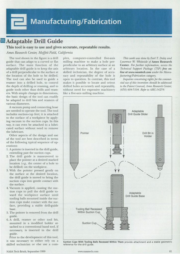
ElAdaptable Drill Guide This tool is easy to use and gives accurate, repeatable results.
Ames Research Center, Moffett Field, California
The tool shown in the figure is a drill guide that can adapt to a curved or flat surface. The main function of the adaptable drill guide is to keep the axis of a drill perpendicular to the surface at the location of the hole to be drilled. The tool can also be used to guide a reamer into a drilled hole, to control the depth of drilling or reaming, and to guide tools other than drills and reamers. With simple changes in dimensions, the basic design of the tool can readily be adapted to drill bits and reamers of various diameters.
A vacuum pump and connecting hose are needed to operate the tool. The tool includes suction-cup feet; it is attached to the surface of a workpiece by applying vacuum to the suction cups. In this way, it can even be attached to a lubricated surface without need to remove the lubricant.
Other aspects of the design and use of the tool are best described in terms of the following typical sequence of operations: 1. A pointer is inserted in the drill guide,
extending past the suction cups. 2. The drill guide is maneuvered to
place the pointer at a desired marked location (e.g., the center of a hole to be drilled) on the workpiece.
3. With the pointer pre sed gently on the surface at the desired location. the drill guide is moved to bring the suction cups into gentle contact with the surface.
4. Vacuum is applied, causing the suction cup to pull the drill guide toward the workpiece surface until tooling balls mounted inside the suction cups make contact with the surface, providing a stable drill-guide base.
5. The pointer is removed from the drill guide.
6. A drill, reamer or other tool bit. mounted in a modified holder attached to a conventional hand tool. if necessary. i in erted in the drill guide. Prior to the development of this tool.
it was necessary to either rely on a skilled technician or else use a com-
NASA Tech Briefs. September 1999
plex, computer-controlled five-axis milling machine to make a hole perpendicular to an arbitrary surface at an arbitrary location. In the case of a skilled technician. the degree of accuracy and repeatability of the hole is open to question. In contrast, this tool makes it possible to locate and orient drilled holes accurately and repeatably. without need for expensive machinery like a five-axis mi\ljng machine.
Tooling Ball Recessed Within Suction Cup'
Suction Cup
This work was done by Earl T. Daley and Lawrence W. Whiteside of Ames Research Center. For further information, access the Technical Support Package (TSP) free 07)
line at www.nasatech.com under the Manufacturing/Fabrication category.
Inquiries concerning rights for the commercial use oj this invention should be addressed to the Patent Counsel, Ames Research Center; (650) 604-5104. Refer to ARC-14259.
Adaptable Drill Guide Slider
Drill Bit in Holder
Adaptable Drill Guide Base
o
Suction Cups With Tooling Balls Recessed Within Them provide attachment and a stable geometric reference for the drill guide.
www.nasatech.com 61
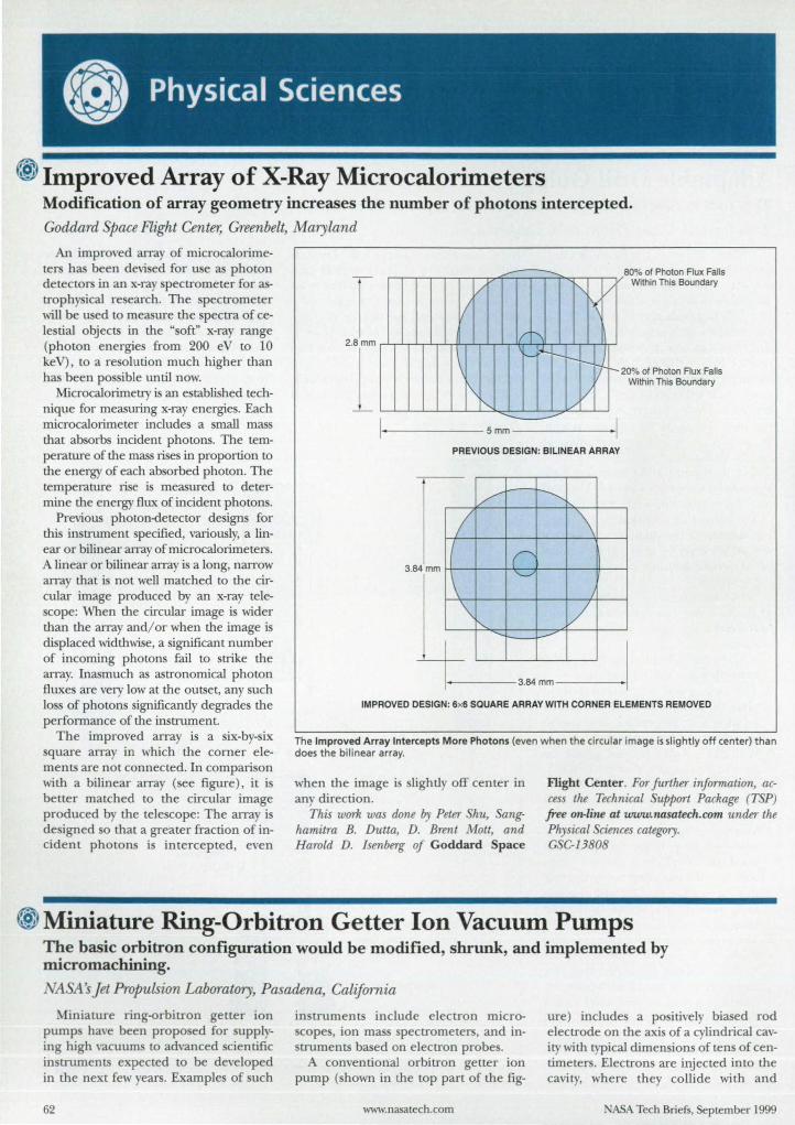
® Improved Array of X-Ray Microcalorimeters Modification of array geometry increases the number of photons intercepted. Goddanl pace Flight Center, Greenbelt, Maryland
An improved array of microcalOlimeters has been devi ed for use as photon detectors in an x-ray pectrometer for astroph ical re earch. The pectrometer will be us d to measure the spectra of ceIe tial objects in the " oft" x-ray range (photon energies from 200 eV to 10 keV), to a re olution much higher than has been po ible until now.
Microcalorimetry is an established technique for measuring x-ray energies. Each rnicrocalorimeter includes a mall mass that absorbs incident photons. The temperature of the mass rises in proportion to the energy of each ab orbed photon. The temperature rise is measured to determine the energy flux of incident photon .
Previous photon-detector de igns for this in trument specified, variously, a linear or bilinear array of rnicrocalorimeters. A linear or bilinear array is a long, narrow array that i not well matched to the circular image produced by an x-ray telecope: When the circular image is wider
than the array and/ or when the image is displaced widthwise, a ignificant number of incoming photons fail to strike the array. Inasmuch as astronomical photon fluxe are very low at the outset, any uch loss of photon significantly degrades the performance of the in trument.
The improved array is a six-by-six quare array in which the comer ele
ments are not connected. In comparison with a bilinear array (see figure), it i better matched to the circular image produced by the tele cope: The array is de igned 0 that a greater fraction of incident photons i intercepted, even
/ "-V ~
V 800
{, of Photon Flux Falls Within This Boundary
2.8mm 1"1\ '-
\
I\!,--.........
I Smm
I--r-r-
/v --
1-: 20"10 of Photon Flux Falls Within This Boundary
I I
PREVIOUS DESIGN: BILINEAR ARRAY
v ...........
I \ r '-.../ 3.B4mm
\ /
\ I'.... /
........ -IMPROVED DESIGN: 6x6 SQUARE ARRAY WITH CORNER ELEMENTS REMOVED
The Improved Array Intercepts More Photons (even when the circular image is slightly off center) than does the bilinear array.
when the image i lightly off center in any direction.
This work was done by Peter Shu, anghamitra B. Dutta, D. Brent Matt, and Harold D. Isenberg of Goddard Space
Flight Center . For further information, access the Technical Support Package (TSP) free On-lille at www.nasatech.com under the Physical ciences category. GSC-13808
@ Miniature Ring-Orbitron Getter Ion Vacuum Pumps The basic orbitron configuration would be modified, shrunk, and implemented by micromachining. NA :A's Jet Propulsion Laboratory, Pasadena, California
Miniature ring-orbitron getter ion pump ha\'e been propo ed for supplying high vacuums to advanced scientific instruments expected to be developed in the next few years. Examples of uch
62
in truments include electron microcope , ion mas spectrometers, and in
struments based on electron probe. A conventional orbitron getter ion
pump ( hown in the top part of the fig-
www.nasatech.com
ure) include a po itively biased rod electrode on the axis of a cylindrical cavity with typical dimen ion of tens of centimeter . Electron are injected into the cavity, where they collide with and
ASA Tech Briefs, September 1999

? • It
We hink We Kl!1ow~. Your job requires solvmg problems. Some days that's the easy part. You're tasked not only with identifying and stating problems correctly, but developing optimum solutions and products while saving time and money. If you only had more time, better software tools, and access to the technical Information you really need ...
Invention Machine's Knowledge-Based Innovation solutions provide tools specifically deSigned to look and act like you think. Our latest breakthrough reduces the hours of drudgery you spend locating and reading through hundreds of documents before you can even begin to solve your problem.
Introducing Knowledgist™ The new knowledge analysis tool dramatically Increases your knowledge capture and problem-solving productivity. Knowledgist semantically processes and structures technical information In a problemsolution format uniquely applicable to finding, answers. not more questions. It then creates an easy-to-use index of functional categories -reduce power, increase Viscosity, remove particle - with hyperlinks to your source documents. In short. Knowledgist raises your 'knowledge quotient" - allOWing you to innovate at an unparalleled rate!
SAO .\lap Function Structure Wi"dol<'
Highlighted example and result,~ with
diagram. source ~iiii~:M document, I: I n._ .. _ ... ...-.-....
and analysis =:..":".::..";:' .;:....-::;...-::.::::.. summary
.. ......,~ ... ,.".,., ...... n ...... ". cmt'''&rr '?!7jf2.
Results Display Wmdow with Summary
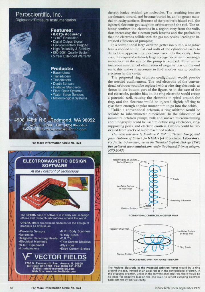
64
ELECTROMAGNETIC DESIGN SOFTWARE
For More Information Circle No. 424
thereby ionize re idual gas molecule . The re ulting ions are accelerated toward, and become buried in, an ion-getter material on cavity urface . Because of the po itively biased rod, the injected electron get caught in orbits around the rod. The orbiting confme the electron in a region away from the walls, thus increasing the electron path length and the probability that the electron collide with the gas molecule , leading to increased efficiency of pumping.
In a conventional large orbitron getter ion pump, a negative bias i applied to the flat end walls of the cylindrical cavity to deflect the approaching electrons back into the cavity. However, the required relatively large voltage becomes increasingly impractical a the ize of the pump i reduced. Thus, miniaturization must entail elimination of negative bias on the end walls; this make it nece sary to find another way to confine electrons in the cavity.
The propo ed ring orbitron configuration would provide the needed confinement. The rod electrode of the conventional orbitron would be replaced with a wire ring electrode, as shown in the bottom part of the figure. As in the case of the rod electrode, po itive bias on the ring electrode would create a potential well, causing the electrons to spiral around the ring, and the electrons would be injected slightly off-ring to give them enough angular momentum to go into the orbits.
Unlike a conventional orbitron, a ring orbitron would be calable to ubcentimeter dimensions. In the fabrication of
miniature orbitron pumps, bulk and surface micromachining and lithography cou ld be used to define ring electrodes, ringsupporting po ts, and electron emitters. Cavities could be fabricated from tacks of micromachined wafer.
This work was done by Jaroslava Z. Wilcox, Thomas George, and Jason Feldman of Caltech for NASA's Jet Propulsion Laboratory. For further information, access the Technical Support Package (TSP) free on-line at www.nasatech.com under the Physical Sciences category. NPO-20436
lon·Getter Surface on Inside Wall
Electron Emitter
Anode
Trajectory of Electron
CONVENTIONAL ORBITRON ION-GETTER PUMP
Trajectory of Electron
Electron Emitter
lon-Getter Surface on Inside Wall
Ring Anode
PROPOSEO RING.oRBITRON ION·GETTER PUMP
The Positive Electrode in the Proposed Orbit ron Pump would be a ring around the axis, instead of an axial rod as in the conventional orbitron. In the proposed orbitron, unl ike in the conventional orbitron, there would be no need for negative bias on the end walls to reflect escaping electrons back into the cylindrical cavity.
NASA Tech Briefs, September 1999
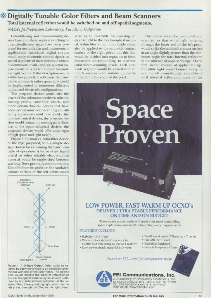
® Digitally Tunable Color Filters and Beam Scanners Total internal reflection would be switched on and off spatial segments.
11 it s Jet Propulsion Laboratory, Pasadena, California
Color-filtering and beam-scanning devices based on electro-optical switching of internal-reflection tate have been proposed for use in display and measurement applications. Associated digital circuits would apply electronic control ignals to spatial segments of the e devices to obtain discontinuous spatial and/ or spectral displacements of reflected and/ or transmitted light beams. If this description seems a little too general, it is because the basic device concept is rather general; it could be implemented in numerous different optical and electronic configurations.
The proposed devices would take the places of the galvanometer-<hiven mirrors, rotating prisms, color-filter wheels, and other optomechanical devices that have been used in orne beam-scanning and -filtering apparatuses until now. Unlike the optomechanical devices, the proposed device would contain no moving parts. Relative to the optomechanical devices, the proposed device would offer advantages of high speed and light weight
Figure 1 illustrates a color-filter device of the type proposed, with a simple design chosen for explaining the basic principle of operation. A ferroelectric liquid cry tal or other suitable electro-optical material would be sandwiched between two long Dove prisms. A continuou thin film of indium tin oxide on the sandwich contact surface of the left pri m would
SublraclJVe (Complementary)
Color Out Color Out
Figure 1. A Unique Output Color could be selected by applying voltage to an electrode coterminous with one of the color filters . The electric field would increase the index of refraction of the electro-optical material by an amount sufficient to stop total internal reflection at the selected filter, thereby making light pass from the left prism, through the filter. to the right prism.
ASA Tech Briefs, September 1999
erve as an electrode for applying an electric field to the electro-optical material. A thin film of indium tin oxide would also be applied to the andwich contact surface of the right prism, but this fUm would be divided into egments to form electrodes corre ponding to discrete color/ beam-scanning pixels. Each electrode segment would be coated with an interference or other suitable optical filter to define the color of the pixel.
The device would be po itioned and oriented 0 that white light entering through the lower end of the left prism would trike the sandwich contact surface at an angle slightly greater than the minimum angle for total internal reflection in the ab ence of applied voltage. Therefore, in the ab ence of applied voltage, the white light ,,,ould bounce along inside the left prism through a number of total internal reflections; none of the
LOW POWER, FAST WARM UP OCXO'S DELIVER ULTRA STABLE PERFORMANCE
ON TIME AND ON BUDGET These space proven units will meet your most demanding
space exploration and satellite time / frequency requirements.
FEATURES INCLUDE:
• Stability: 1x10 " / day • Small size &. mass: 200 grams; < 7 ro. in . • Warm up to stabilized frequency in • Full MIL or '5' level
as little as 2 min. using as low as 1 watt-hr. • Radiation hardened • Low power steady state: 0.6 to 3 watts • Remote Frequency ~vu~ •• "'_ . .........
FEI Communications, Inc. A Subsidiary of Frequency Electronics. Inc. ""'IIi_.'" 55 Qlarles lindbergh Blvd .• Mitchel Reid. NY 11553
.... TEL: 516-794-4500 ' FAX: 516-7944340 Visit us at: www.freqelec .com
For More Information Circle No. 425 65
light would be coupled to the right pri m and the Ii ht would be refle led out, till white, at the top of the left pri m.
If a ufficient voltage were applied between the ingle large electrode on the sandwich contact urface of the left prism and one of the pixel electrode on the sandwich contact urface of the right pli m, then the index of refraction of the electr~ptical material in that pixel would increase ufficiend to raise the minimum angle of incidence for total internal reflection above the actual angle of incidence. In that case, the incident light would trike the color filter in the affected pixel, 0 that ligh t of one color would p
through the filt r into th right pri m, while the complementary color would be reflected back into the left prism. The end re ult would be that light of the color p ed b the filter would travel along the right prism b total internal reflection and would leave dle right pri m at its top end, while light of the compl mental ' color would behave similarly in the left pri m and would leave that prism at its top end. If the pixels contained filters of different colors, then one could elect a unique output color b applying voltage to the pixel of that color.
Figure 2 illustrates a imple non-colordi criminating beam- canning device.
Still Positioning With Hydraulic Cylinders?
Finally, an all -electric actuator with the power of hydraulics and the speed of pneumatics
• Up to 20,000 Ibs force • Up to 40 in/sec travel speed • 100 million inches of travel life • High tolerance to shock • Compact package • Electronic servo control • Completely sealed
(IP65 std; IP67 optional)
Exlar's IRS actuators are true electric replacements for hydraulic and pneumatic cylinders, permitting the conversion of applications previously beyond the capabilities of electro-mechanical actuators.
The patented IRS design employs a planetary arrangement of helically threaded rolling members, which convert electric motor power into high force linear motion. The large contact area of the rollers allows high thrust load ratings and guarantees long life even in the most demanding
applications. ~..LA'~"i'7'-:-- . IRS
actuators are available in
a variety of standard load ratings, stroke lengths,
speeds, and mounting configur-ations. Alternatively, Exlar welcomes
the opportunity to supply custom designs tailored to your exact requirements.
To find out how you can achieve fluid power performance with clean , quiet, and smooth servo electric actuation, contact:
EXLAR Corporation Tel (612) 470-9020 1450 Pork Court Fax (612)474-7861 Chanhassen MN 55317
66 For More Information Circle No. 426
Thi de\; e would be imilar to the de\;ce of Figure 1 except that there would be no color filte and in tead of one long prism on the right ide, there would be multiple mall prisms - one prism for each pixel.
in the eXaTIlple of Figure I, in the air ence of applied m ltage, light would
travel along the left prism by total internal reflection and would emerge from the top of the left pri m. In this case, however, the left prism would be configured 0 that the light emerging from the top would be tra\'eling rightward in tead of leftward. If a ufficient voltage were applied to one of the pixel electrode, then the light would pass through to the right ide and would emerge through the upper right face of the pixel for that pri m. Thus, one could di continuously can (digitally switch) a beam of light among discrete para1lel path by applying voltage equentially to different pixel electrodes.
This work was done by Yu Wang of Caltech for NASA' Jet Propulsion Laboratory. For further infannation, access the Technical Support Package (T. 'P) free on-line at www.nasatech.com under the Physical ciences category.
In accordance with Public Law 96-517, the contractor has elected to retain title to this invention. Inquiries concerning rights for its commercial use should be addressed to
Technology Reporting Office JPL Mail top 122-116 4800 Oak Grove Drive Pasadena, CA 91109 (818) 354-2240 Refer to NP0-20240 volume and number
of this ASA Tech Briefs issue, and the page number.
Figure 2. A Unique Output Path could be selected by applying voltage to an electrode coterminous with one of the small prisms on the right side. Except for the prism configuration and the lack of filters. this device would function similarly to that of Figure 1.
A Tech Briefs. plember]999
RGA for the Masses Systems from $3750 (U.S. list)
" , Pdrtiol pres~,ure 10
of, ' •
• ~~ orders of magnitude dynamic range in a single scan
• Real-time WindowS® software
..... "f!'J'msidual gas analyzers from SRS offer uncompromised performance at half the price of the competition. Our systems provide mass ranges to 300 amu, detectable partial pressures to 10-14 Torr and better than 1 amu resolution. With our interac-tive Windows® software package you can fully control the RGA sensor, acquire data and analyze your vacuum system In real-time. The simple , rugged quadrupole mass spectrometer attaches directly to a 2 3/4" CF flange. A dual Th021r filament
• Mass spectra, leak detection and pressure VS. time modes
and a unique continuous dynode electron multiplier provide Increased stability and longer life than other designs. Both are field replaceable in a matter of minutes - a first for RGAs! If your application involves residual gas analysis, leak detection or vacuum processing, contact us for a copy of our RGA systems brochure and demo software package.
• Multi-head operation
• Optional Electron Multiplier
I~r-------------------------~ 1- -,...... ....... . 7~
.......
....,.. --
The RGA is an Invaluable vacuum diagnostic tool. Shown above Is the mass spectrum of a vacuum chamber contaminated with 011.
Stanford Research Systems
-.~------~~--------------~ .....
With d yna mic range tha t spans 6 o rders of magnitude. three Isotopes of Nitrogen (14N2• 14N 15N. 15N2) are clearly detected in a single scan.
1290-D Reamwood Avenue. Sunnyvale , CA 94089 Telephone (408)744-9040 . FAX (408)744-9049 Email: [email protected] • WWW: http://www.thinkSRS.com
Windows Is a registered trademark of Microsoft Corporation
For More Information Circle No. 552
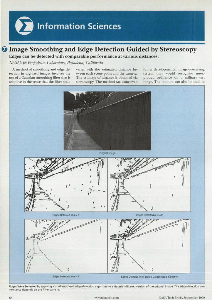
~ Image Smoothing and Edge Detection Guided by Stereoscopy Edges can be detected with comparable performance at various distances.
Ij\ :A Jet Propulsion Laboratory, Pasadena, California
A method of moothing and edge detection in digitized image involve the u e of a Gau ian moo thing filter that i adaptive in the en e that the filter cale
varies with the e timated di tance ben; een each cene point and the camera. The e timate of dj tance i obtained via
Original Image
for a developmental image-proce ing y tern that would recognize unex
ploded ordnance on a military te t range. The method can al 0 be used to
Edges Detected at " = 1 Edges Detected at " = 2
Edges Detected at " = 4 Edges Detected With Stereo-Guided Scale Selecllon
Edges Were Detected by applying a gradient-based edge-detection algorithm to a Gaussian-filtered version of the original image. The edge-detection performance depends on the filter scale, 0 .
68 www.nasatech.com A Tech Briefs, September 1999
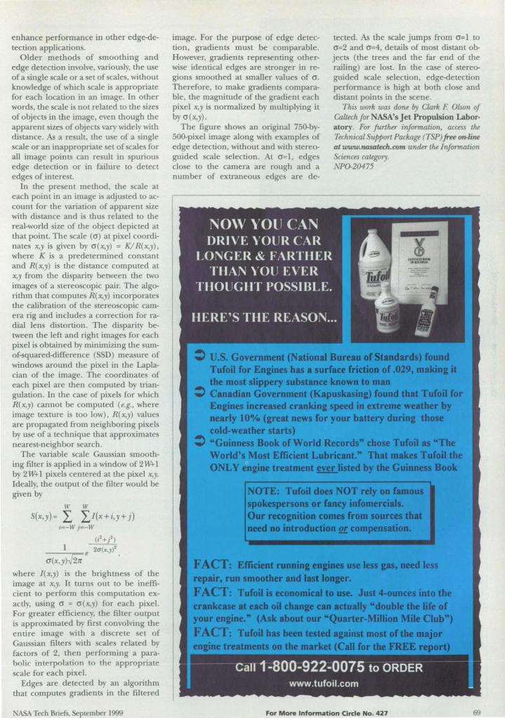
enhance performance in other edge-detection applications.
Older methods of smoothing and edge detection involve, variously, the use of a ingle scale or a set of scales, without knowledge of which scale is appropriate for each location in an image. In other word , the scale is not related to the ize of objects in the image, even though the apparent ize of objects vary widely with distance. As a re ult, the use of a single cale or an inappropriate set of scales for
all image points can re ult in spurious edge detection or in failure to detect edge of intere t.
In the pre ent method, the scale at each point in an image is adjusted to account for the variation of apparent size with distance and i thus related to the real-world size of the object depicted at that point. The cale (0) at pixel coordinates x,y is given by o(x,y) = K/ R(x,y)' where K is a predetermined con tant and R(x,y) is the di tance computed at x,y from the disparity between the two images of a stereoscopic pair. The algorithm that computes R(x,y) incorporates the calibration of the stereoscopic camera rig and include a correction for radial lens distortion. The disparity between the left and right images for each pixel is obtained by minimizing the sumof-squared-difference (SSD) measure of windows around the pixel in the Laplacian of the image. The coordinates of each pixel are then computed by triangulation. In the case of pixels for which R(x,y) cannot be computed (e.g., where image texture is too low) , R(x,y) value are propagated from neighboring pixels by use of a technique that approximate neare t-neighbor earch.
The variable cale Gaussian smoothing filter is applied in a window of2W+l by 2 W+ 1 pixels centered at the pixel x,y. Ideally, the output of the filter would be given by
w w (x'Y)= L L 1(x+i,),+ j)
i=-W j=-w
(i t +/) 1 t 2a(x.,)2
a(x,y)$ .
where /(x,y) i the brightne s of the image at x,y. It turn out to be inefficient to perform thi computation exactly, using 0 = a(x,y) for each pixel. For greater efficiency, the filler output i approximated by fir t convolving the entire image with a di crete et of Gau ian filters with cale related by factor of 2, then performing a parabolic interpolation to the appropriate scale for each pixel.
Edge are detected by an algorithm that compute gradients in the filtered
ASA Tech Briefs, September 1999
image. For the purpose of edge detection, gradients must be comparable. However. gradients representing otherwise identical edge are tronger in region smoothed at maller values of o . Therefore, to make gradients comparable, the magnitude of the gradient each pixel x,y is normalized by multiplying it by o(x,y).
The figure shows an original 750-b -500-pixel image along with examples of edge detection. without and with stereoguided cale election. At 0=1, edge close to the camera are rough and a number of extraneous edge are de-
tected. As the cale jumps from 0=1 to 0=2 and 0=4, details of most di tam objects (the trees and the far end of the railing) are lost. In the case of stereoguided cale selection, edge-detection performance is high at both close and distant points in the cene.
This work was done by Cltlm F Olson of Caltech for NASA's Jet Propulsion Laboratory. For further infonnation, access the Technical Support Package (TSP) free on-line at wr.uw.nasatech.com under the Information Sciences category. NPO-20475
For More Information Circle No. 427 69
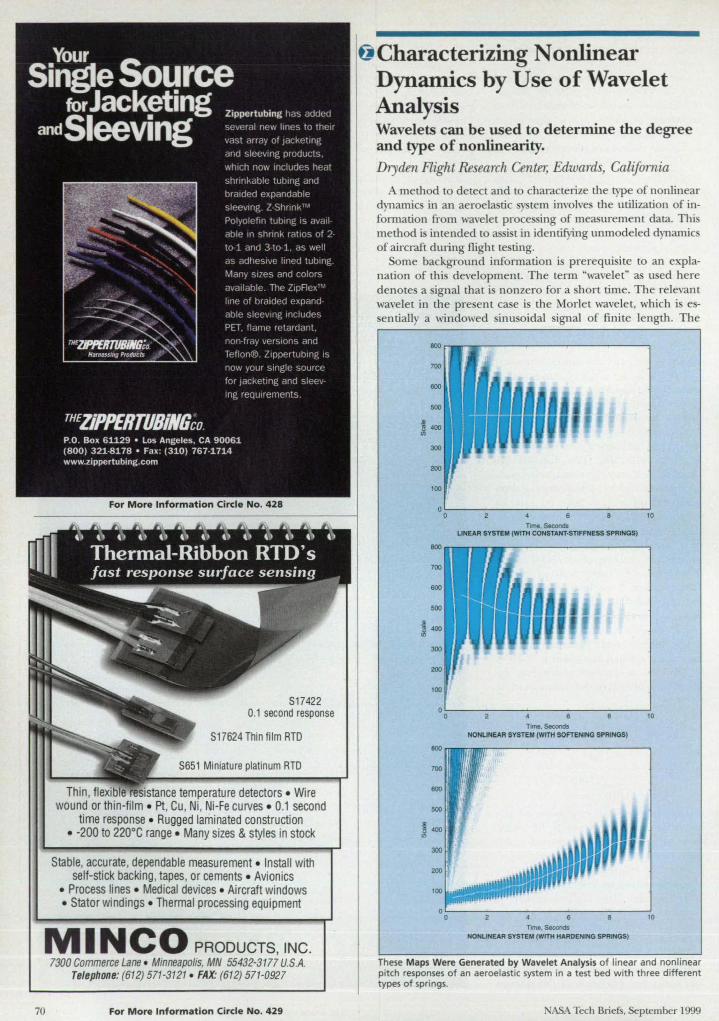
S17422 0.1 second response
S17624 Thin film RTD
S651 Miniatu re platinum RTD
Thin, flexible temperature detectors . Wire wound or thin-film . Pt , Cu, Ni, Ni-Fe CUNes • 0.1 second
time response . Rugged laminated construction • -200 to 220°C range . Many sizes & styles in stock
Stable, accurate, dependable measurement . Install with self-stick backing, tapes, or cements . Avion ics
• Process lines • Medical devices . Aircraft windows • Stator windings • Thermal processing equipment
MIN CO PRODUCTS, INC. 7300 Commerce Lane . Minneapolis, MN 55432-3177 U.S.A.
Telephone: (612) 571-3121 - FAX: (612) 571-0927
70 For M ore Information Circle No. 429
I.., Characterizing Nonlinear Dynamics by Use of Wavelet Analysis Wavelets can be used to determine the degree and type of nonlinearity.
Dryden Flight Research Center, Edwards, California
method to detect and to characterize the type of nonlinear dynamic in an aeroelastic tern involve the utilization of information from wavelet proce ing of measurement data. This method i intended lO assist in identifying unmodeled dynamics of aircraft during flight testing.
orne background information is prerequisite to an explanation of th i development. The tenn "wavelet" a used here denote a ignaI that i nonzero for a hort time. The relevant wavelet in the pre em case i the Morlet wavelet, which i es-entiaIly a windowed sinu oidaI ignaI of finite length. The
200
100
o L-----------------------------~ o 4 6 10 Time. Seconds
LINEAR SYSTEM (WITH CONSTANT·STIFFNESS SPRINGS)
~~~n.~------------l
700
600
500
~ 400
300
200
100
°OL----~----~----------------~10
TIme. Seconds NONUNEAR SYSTEM (WITH SOFTENING SPRINGS)
10 TIme, Seconds
NONUNEAR SYSTEM (WITH HARDENING SPRINGS)
These Maps Were Generated by Wavelet Analysis of linear and nonlinear pitch responses of an aeroelastic system in a test bed with three different types of springs.
ASA Tech Briefs, September 1999
Morlet wavelet is a function of parameters, called "scale" and "position," that affect, re pectively, the period of the sinu oida! component and the time when the nonzero component is centered. Wavelet proce ing involves computation of the magnitudes of correlation between a measured signal and wavelets of different scales and positions. The wavelets with the highest correlation magnitudes repre ent dominant features in the measurement data.
Wavelet analysis inherently extracts time-varying feature of a signal because of the short duration of the nonzero portion of the wavelet. The wavelets at a position in time determine only the features of the signal near that position. Thus, the changes in wavelets that correlate highly with the signal at different times indicate the changes in features of the signal as time progresses.
In the present method, responses from several configurations of an aeroelastic test bed are analyzed to determine the nature of the nonlinear dynamics that affect an aeroelastic system. The various configurations include various springs associated with pitch movement of a wing assembly. The forces generated by these springs can vary linearly with pitch angle or can vary nonlinearly, as in the cases of hardening or softening springs. Pitch angles are measured during free decay of oscillations of the system in response to an initial pitch placement.
The figure presents maps that resuJt from wavelet processing of pitch responses for different system configurations. These maps can be regarded as three-dimensional in the sense that they depict magnitude of correlation as functions of wavelet cales and positions: The color at each point in a map indicates the magnitude of correlation; specifically, white repre ents low correlation , the color changes gradually to darket· levels of gray as the correlation increases, and the color becomes blue for particularly high correlation.
The dominant features of each map are extracted by identifying correlation peaks. Because the e peaks are sometime difficuJt to identify vi uall from the colored two-dimen ional repre entations of the three-dimensional maps, a curve is drawn in each map to indicate the cale as ociated with the dominant feature at each po ition in time.
The dominant features extracted from the wa\'elet map clearly indicate the pre ence of a nonlinearity in the aeroelastic dynamics. The curve is level and hm\' no change in scale for the domi
nant feature of tlle re ponse from a linear system, but the curves vary, howing change in scale for the dominant fea-
ASA Tech Briefs, September 1999
tures of the responses from the nonlinear systems. This resuJt is expected because (a) the response from a linear system shouJd be a decaying sinusoid that has a constant frequency, while (b) the response from a nonlinear system should be a decaying sinusoid with a changing frequency. Thus, it is straightforward to detect the pre ence of nonlinearity from the variation in scale shown by me curve through the correlation peaks in a map.
The type of nonlinearity can be characterized by the type of change in me curve. The response from a hardening spring features a decreasing frequency, so its map houJd show an increasing scale.
Conversely, the response from a oftening spring features an increasing frequency, o its map shouJd show a decreasing scale.
The curves indicate these behaviors, demonstrating that \\'avelet anal} is provide means for both detection and characterization of nonlinear dynamics.
This work was done by Rick Lind and Martin Brenner ofDryden Flight Research Center and Kyle Snyder of the University of Tennessee Space Institute. For further information, access Ihe Technical Support Package (TSP) free O1Vline at www.nasatech.com
under the Information Sciences categury. DRG98-42
PRECISION MACHINING C OMPLEX MU LTI-FACETED PARTS
THE W AY You W ANT THEM
... E XA CT To PRINT.
RIGID ADHERENCE TO SPEcmCATIONS TOI.ERENCES TO ±O.DOOO40"
PROT01YPE TO P RODUcnON ••• VERY SMALL TO L.4.R.GE PARTS EXTENSIVE ExPERlENCE WlfH HIGH STRENGm Au.oYs & TrrANIUM
STATE-OF-THE-ART EQWPMENT 8-AXlS SWISS, 5-AXls MACHINING CENTERS, LARGE TURNING WlfH C&Y AXIS, FUll C-AXIS CNC GRJNDING
MlL-I-45208A, GMP, ISO 9002 & 150-10012-1 GoVERN MANtlFAClURJNG SYSTEMS, PROCWURES & Ql1ALlTY COIm(OL TO mE; L£VEL OF ZERO DUECT
OVER 90 Y EARS OF ExPEJUI:NCE AND ExCEllENCE MANuFACTURJNG IN A MODERN 50,000 SQ IT FAOUTY
FAST QUOTE ON YOUR PRINTS & SPECS . .. E-MAIl lpi@/llvezzi.com OR FAX 630-582-1238 RELY ON ACCURATE ESTIMATES & AsslmNCE WITH INNOVATIVE ENGINEfRlNG S£RVICfS & Pl/IOSIO, ' MANUFACTURING
DLAVEZZI QUAlln •. ABOVE AU ELSE.
LaVezzi Pm:ision, Inc. 999 Regency Drive Glendale Heights, IL 60139-2281 630-582-1230 Fax: 630-582-1238 E-mail: [email protected] 800-323-1772
o Conservatism in Deterministic Structural Analysis
A paper di cu e the exce ive con-ervati m that ha long been u pected
to exi t, becau e of the u e of conventional (determini tic) afety factor, in the analy is and de ign of quasi- tatic tructure . The origin of thi con er
vati m i identified a a violation of tati tical error-propagation law that occur when statistical data on load and stres es are reduced to determini tic values and then combined through several computational proce e. The e finding are ugge ted to indicate a need to replace determini tic method with probabili tic method to prevent violations of error-propagation laws. It i also uggested that, as an alternative to adoption of fully probabilistic methods, it may be more expedient to partially convert determini tic methods to probabilistic one to retain familiarity, confidence, and correlation with experience.
This work was Mne by V. Verderaime of Marshall Space Flight Center. To obtain a copy of the report, "Inherent Conservatism in Deterministic Quasi-Structural Analysis, n access the Technical Support Package (TSP) free on-line at www.nasatech.com under the Mechanics category. MFS-27333
Evaporation of Isolated and Collections of Fluid Drops Under Supercritical Conditions
A report pre ents a computational study of heat and rna tran fer for i 0-
lated and in teracting drop of one fluid (liquid O2 ) immer ed in another fluid (H2 ) in finite, quie cent surrounding under upercritical condition. The mathematical model u ed in thi tudy were de cribed in three previous article in A A Tech Briefs; namely, "Model of a Drop of O2 urrounded by H2 at High Pre ure" ( PO-20220), ~The Lewi umber Under upercritical Condition" ( PO-20256), and "Model of Interacting O2 Drop urrounded by H2 at High Pre ure" ( PO-20257), Vol. 23, o. 3 (March 1999), page 70.
This work was done by Josette Bellan and Kenneth Harstad of Caltech for NASA's Jet Propulsion Laboratory. To obtain a copy
72
of the report, "Heat and Mass Transfer for Isolated and Interacting Fluid Drops Under
upercritical Conditions, " access the Technical upport Package (To :P) free on-line at www.nasatech.com under the Physical
ciences category. NP0-20404
0. Gimbaled Injectors for Testing Spacecraft Thrusters
A report propo e an a embly of gimbaled valve/ nozzle suba semblies for u e in injecting either a propellant fluid (e.g., monomethyl hydrazine) or a propellant- imulating fluid (e.g., water) into the combu tion chamber of a pace craft thru ter during hot-fire or
cold te ting, respectively. The propo al i a re pon e to the problem of how to find the angle of impingement of injected fluid that results in the best thru ter performance.
This work was done by Marlin Klatte of Caltech for NASA's Jet Propulsion Laboratory. To obtain a copy of the report, "Gimbal Injector, " access the Technical Support Package (TSP) free on-line at www.nasatech.com under the Machinery/ A utomation category.
This invention is owned by NASA, and a patent application has been filed. Inquiries concerning nonexclusive or exclusive license for its commercial development should be addressed to the Patent Counsel, NASA Resident Office-JPL; (818)354-5179. &fer to NPO-20520.
o Experiments on Vibration and Noise in Fuselages
A paper ummarize a continuing program of vibro-acoustic testing of two aircraft fuselage trucrure: (1) a 12-ft (3.7-m)-long generic aluminum te tbed cyUnder that contains tiffening ring and stringers and (2) the 40-ft (l2.2-m)-long fu elage of a 10-pas enger turboprop airplane, made of honeycomb core and graphite/ epoxy face heets. Each tructure i mounted on
compliant supports that permit approximately free vibration and i in trumen ted with more than 200 accelerometer , which are po itioned according to prediction of the fir t 100 vibrational mode. ub equent acou tic tests will focus on measurement of interior noise fields created by exterior mechanical and acoustic ources.
www.nasatech.com
This work was done by Richard . Pappa and Rolph D. Buehrle of Langley Re earch Center and Jocelyn 1. Pritchard of the ~hicle Technology Directorate of the U. . Army Research Laboratory. To obtain a copy of the paper, "Vibro-Acoustics Modal Testing at
I1SA Langley &search Center," access the Technical upport Package (TSP) free on-line at www.nasatech.com under the Mechanics caLegory. L-17851
@l Lithium-Based Primary Cells for Low-Temperature Operation
A repon de cribe an experimental tudy of the low-temperature electrical
characteri tic of commercial Li/ Mn02, Li/CF .. Li/ O2, Li/SO 12, and Li/B X primary electrochemical cell . The e high-energy-den ity cell are under con ide ration for u e as lightweight, compact electric-power ource for cientific instruments in terre trial polar region and on Mars, where they could be called upon to operate at temperature a low as -85 ·C. The experiments, performed at temperatures down to -100 ·C, included steady- tate current-vs.-voltage mea urements during discharges with various increments of load resi tance from 105 down to 10 n, complete di charge tests, and ac-impedance mea urements.
This work was done by Frank Deligiannis, Harvey Frank, Evan Davies, and Rotnakumar Bugga of CalLech for NASA's Jet Propulsion Laboratory. To obtain a copy of the report, "Batteries for Ultra-low-Temperatum Applications," access the Technical upport Package (To P) free on-line at
www.nasatech.com under the Physical ciences category. NP0-20352
@ Development of Flight Software for Small Explorer Spacecraft
A report de cribe a continuing program of development of flight oftware for the attitude-control system (A ) and the command-and-data-handling (C&DH) tern of a prototype tandard pacecraft of the Small Explorer
(SMEX)-Lite c1as . Both the C&DH and ACS parts of the oftware are de igned to run on a single reduced-in truction-set computer (RJ C) with a peripheral com-
ASA Tech Briefs, Seplember 1999
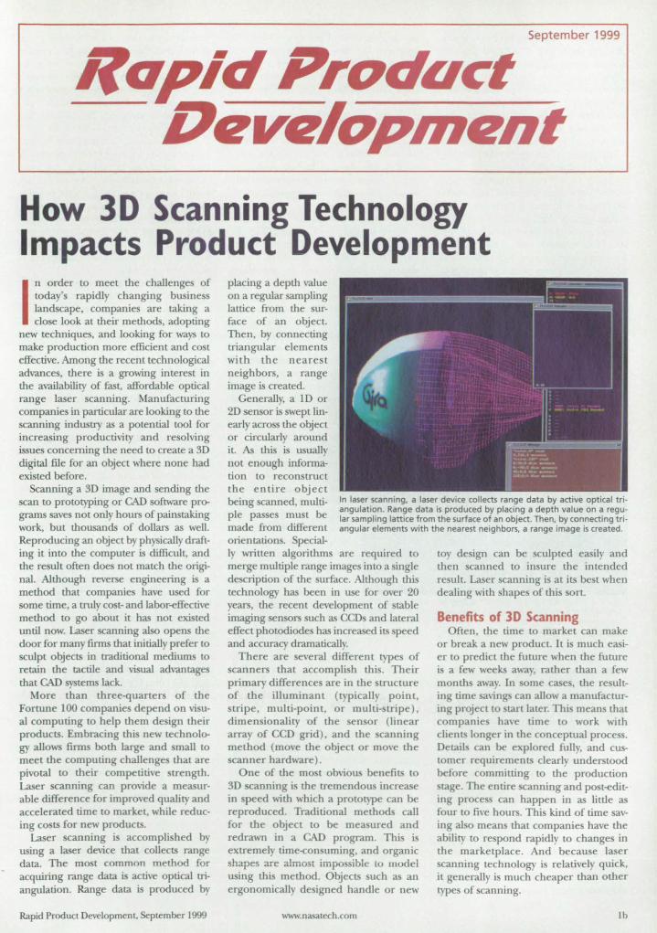
September 1999
RClR..id PrDduct Drlv~/DPhJrlnt
How 3D Scanning Technology Impacts Product Development
In order to meet the challenges of todar's rapidly changing business landscape, companies are taking a close look at their methods, adopting
new techniques, and looking for ways to make production more efficient and cost effective. Among the recent technological advances, there is a growing interest in the availability of fast., affordable optical range laser scanning. Manufacturing companies in particular are looking to the scanning industry as a potential tool for increasing productivity and resolving issues concerning the need to create a 3D digital file for an object where none had existed before.
Scanning a 3D image and sending the scan to prototyping or CAD software pn:r grams saves not only hours of painstaking work, but thousands of dollars as welL Reproducing an object by physically drafting it into the computer is difficult, and the result often does not match the original. Although reverse engineering is a method that companies have used for some time, a truly cost- and labor-effective method to go about it has not existed until now. Laser scanning also opens the door for many firms thal initially prefer to sculpt objects in traditional mediums to retain the tactile and visual advantage that CAD systems lack.
More than three-quarters of the Fortune 100 companies depend on visual computing to help them design their products. Embracing this new technology allows firms both large and smalJ to meet the computing challenges that are pivotal to their competitive strength. Laser scanning can provide a measurable difference for improved quality and accelerated time to market., while reducing costs for new products.
Laser scanning is accomplished by using a laser device that collects range data. TIle mo t common method for acquiring range data is active optical triangulation, Range data is produced by
Rapid Product Development., September 1999
placing a depth value on a regular sampling lattice from the surface of an object. Then, by connecting triangular elements with the nearest neighbors, a range image is created.
Generally, a ID or 2D sensor is swept linearly across the object or circularly around it As this is usually not enough information to reconstruct the entire object being canned, multiple passes must be made from different
In laser scanning, a laser device collects range data by active optical triangulation. Range data is produced by placing a depth value on a regular sampling lattice from the surface of an object. Then, by connecting triangular elements with the nearest neighbors, a range imag:e is created.
orientations. Special-ly written algorithms are required to merge multiple range images into a single description of the surface. Although this technology has been in use for over 20 years, the recent development of stable imaging sensors such as CCDs and lateral effect photodiodes has increased its peed and accuracy dramatically.
There are everal different types of scanners that accomplish thi . Their primary differences are in the structure of the illuminant (typically point, stripe, multi-point, or multi-stripe) , dimensionality 'Of the sensor (linear array of CCD grid) , and the scanning method (move the object or move the scanner hardware).
One of the most obvious benefits to 3D scanning is the tremendous increase in speed with which a prolOtype can be reproduced. Traditional methods call for the object to be measured and redrawn in a CAD program. This i extremely time-consuming, and organic shapes are almost impossible tu model using this method. Objects such as an ergonomically designed handle or new
www.nasarech.com
toy design can be sculpted easily and then scanned to in ure the intended result. Laser scanning is at its best when dealing with hapes of this sorL
Benefits of 3D Scanning Often, the time to market can make
or break a new product It is much easier to predict the future when the future is a few weeks away, rather than a few months away. In some cases, the resulting time savings can allow a manufacturing project to start later. This means that companies have time to work with clients longer in the conceptual process. Detail can be explored fully, and customer requirements clearly understood before committing to the production stage. The entire scanning and post-editing proce s can happen in as little as four to five hours. TIlls kind of time saving also means that companies have the ability to re pond rapidly to changes ill the marketplace. And because laser scanning technology is relatively quick, it generally is much cheaper than other types of scanning.
1b
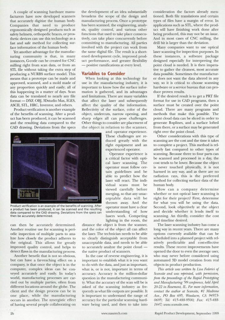
A couple of canning hardware manufacturers have now developed canners that accurately digitize the human body. Companie that need to produce ergonomicall d igned products uch as safety helmets, orthopedic brace ,or prosthetic device can use thi technology as a fast and safe method for collecting surface information of the human bod .
Yet another advantage for the manufacturing community i that, in man in tance , G-code can be created for C C milling right from can data, or from an STL file without taking the extra tep of producing a NURBS surface model. This means that a prototype can be made and approved, canned, and a mold made of any proportion quickly and easily; all of this happening in a matter of days. Scan data can be translated to nearly any file format-DXF, OBJ, 3D tudio Max, ICES, ASCII, STL, HRC, Inventor, and others.
Product verification is another example of the benefits of scanning. After a product has been produced, it can be canned and the resulting data compared to the CAD drawing. Deviation from the pec
the development of an idea ub tantiall broaden the cope of the de ign and manufacturing proce . Once a prototype has been canned, the engineering, anal ,-is, quality control, and various other
function that used to take place con ecutivel , can take place concurrently before committing to manufacturing. All parties involved with the project can work from the same digital file. The re ult is a hortened development cycle, improved product performance, and greater flexibility - po itive ramifications at every level.
Variables to Consider When looking at this technology for
use in the manufacturing indu try, it i important to know how the urface information is gathered, and its advantages and limitations. There are many variable that affect the laser and subsequently affect the quality of the information. Reflectivity of the urface, color of the object, undercuts, narrow opening, and sharp edges all can pose challenge. Other things to consider are placement of the object in relation to the scanner,
and operator experience. The e challenges are reduced greatly with the right equipment and an experienced operator.
Product verification is an example of the benefits of scanning. After a product has been produced, it can be scanned and the resulting data compared to the CAD drawing. Deviations from the specs can then be accurately determined.
Operator experience is a critical factor with optical laser scanning. The operator must follow certain guidelines and be able to predict how the laser will react. The individual scans must be viewed carefully before merging, so that any unacceptable data will be thrown away. And the operator must have a clear understanding of how la er work. Competing
can then be accurately determined. Another routine use for scanning is periodic inspection of multiple parts to analyze how closely the product adheres to the original. This allows for greatly improved quality control, and helps to detect flaws in the manufacturing process.
Another benefit that i not so obvious, but can have a far-reaching effect on a company, is that once the object is in the computer, complex ideas can be conveyed accurately and easily. In today' world, manufacturing proce e are carried oUl by multiple partie, often from different locations around the globe. The client and the de ign process can be in one place, while the manufacturing occurs in another. The synergistic effect of having several people collaborating on
2b
lighting in the room, the distance the object is from the canner, and the color of the object all can affect the laser. The technician needs to be able to clearly distinguish acceptable from unacceptable data, and needs to be able to accurately analyze the point cloud -the native product of scanners.
In the case of reverse engineering, it is important to establish what it is you want to do with the data, and just as important, what is, or is not, important in terms of accuracy. Accuracy is the million-dollar que tion in the manufacturing community. What the accuracy of the can will be is asked of the scanning industry as frequentlyas what file outputs are po ible. It is important to understand the range of accuracy for the particular canning hardware being used, and then to take into
www.nasatech.com
con ideration the factors alread mentioned. Both file translation and certain type of files have a margin of error. In application uch as STL, where the product will have finishing work done after being produced, this rna not be an issue. And in mo t case of C C milling, the drill bit is larger than the deviation.
Many companie want to use optical laser canning for inspection purpo es. In the e instance , a software package de igned e pecially for interpreting the point cloud is needed. It is then imperative to gather the cleane t, most accurate data po ible. Sometime the manufacturer doe not want the data altered in any way, so it is critical to choo e canning hardware or a service bureau that can produce proven results.
If the de ired re ult is to get a PRT file format for use in CAD programs, then a urface mu t be created over the point
cloud. There are many programs and methods that make this possible. The point cloud data can be sliced in order to generate B-splines, and a urface lofted from there, or a urface may be generated right over the point cloud.
Other consideration with thi type of scanning are the co t and the time it takes to complete a project. This method is relatively fast compared to other types of scanning. Because three to four parts can be scanned and proce ed in a day, the cost tends to be lower. Because the object is never touched physically, it is not harmed in any way, and as there are no radiation rays, this i the preferred method for collecting surface data of the human body.
How can a company determine whether or not optical laser scanning i right for their project? First, determine for what you will be using the data. Second, look objectively at the object and decide whether it lends itself to scanning. An thirdly, consider the cost and timeline desired.
The laser scanning industry has come a long way in recent years. There are many options currently available that can be scheduled into a planned project with relatively predictable and co t-effective results. These recent improvements have opened the door to even the average user, who may never before con idered using automated 3D model creation from real objects in product production.
This article was written by Lisa Federici of &ansite and was reprinted, with permission, from tM proceedings of tM Rapid Protolyping and Manufacturing '99 conference, Mld April 20-22 in Rosemont, IL. Fqr 1'IlOTe infMmation, contact tM author at Scansite, #1 Madrone Ave., PO Box 695, Woodacre, CA 94973-0695; Tel: 415-488-9500; Fax: 415-488-1647; www.scansite.com.
Rapid ProducL Development, ptember 1999

Roll over to 3D solid modeling with Solid Edge.
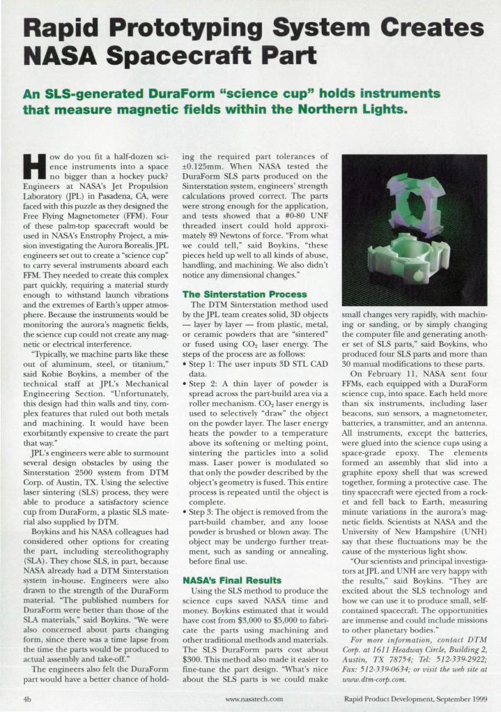
Rapid Prototyping System Creates NASA Spacecraft Part An SLS-generated DuraForrn "science cup" holds instruments that measure magnetic fields within the orthern Lights.
HOW do you fit a half-dozen cience in truments into a pace no bigger than a hockey puck?
Engineers at ASA' Jet Propul ion Laboratory (JPL) in Pasadena, CA, were faced with this puzzle as they de igned the Free Flying Magnetometer (FFM). Four of the e palm-top spacecraft would be used in ASA's Enstrophy Project, a mis-ion inve tigating the Aurora Borealis. JPL
engineers et out to create a "science cup" to carry everal instruments aboard each FFM. They needed to create thi complex part quickly, requiring a material turdy enough to with tand launch vibration and the extreme of Earth 's upper atmosphere. Because the instruments would be monitoring the aurora's magnetic fields, the cience cup could not create any magnetic or electrical interference.
"Typically, we machine parts like these out of aluminum, steel, or titanium," aid Kobie Boykin, a member of the
technical taff at JPL's Mechanical Engineering ection. "Unfortunately, this de ign had thin walls and tiny, complex feature that ruled out both metals and machining. It would have been exorbitantly expensive to create the part that way."
JPL's engineer were able to surmount everal de ign obstacle by using the interstation 2500 system from DTM orp. of Au tin, TX. sing the selective
laser intering (SLS) process, they were able to produce a ati factory cience cup from DuraForm, a plastic SLS material al 0 supplied by DTM.
Boykin and hi NASA colleague had con ide red other option for creating the part, including stereolithography ( LA). They chose SLS, in part, because
ASA already had a DTM Sinterstation system in-house. Engineers were al 0
drawn to the trength of the DuraForm material. "The published numbers for DuraForm were better than tho e of the
LA material ," aid Boykin . "We were also concerned about parts changing form, ince there was a time lap e from the time the parts would be produced to actual as embly and take-off."
The engineers also felt the DuraForm part would have a better chance of hold-
4b
ing the required part tolerance of ±0.125mm. When A te ted the DuraForm LS parts produced on the
interstation tem, engineers' trength calculation proved correct. The parts were trong enough for the application, and tests showed that a #0-80 UNF threaded in ert could hold approximately 89 ewton of force. "From what we could tell ," aid Boykins , "these pieces held up well to all kind of abuse, handling, and machining. We al 0 didn't notice any dimensional change ."
The Sinterstation Process The DTM Sinterstation method used
by the JPL team create olid, 3D objects - layer by layer - from plastic, metal, or ceramic powders that are "sintered" or fused using CO2 laser energy. The teps of the process are as follow :
• Step 1: The u er inputs 3D TL CAD data.
• tep 2: A thin layer of powder is spread across the part-build area via a roller mechanism. CO2 la er energy is u ed to selectively "draw" the object on the powder layer. The laser energy heats the powder to a temperature above its oftening or melting point, intering the particles into a solid
mas. La er power is modulated so that only the powder de cribed by the object'S geometry i fused. Thi entire proce i repeated until the object is complete.
• Step 3: The object i removed from the part-build chamber, and any 100 e powder i bru hed or blown away. The object may be undergo further treatment, such as sanding or annealing, before final use.
NASA's Final Results Using the SLS method to produce the
cience cup aved ASA time and money. Boykins e timated that it would have co t from 3,000 to 5,000 to fabricate the parts using machining and other traditional methods and materials. The DuraForm parts co t about
300. Thi method al 0 made it easier to fine-tune the part de ign. "What's nice about the SLS parts i we could make
www.nasatech.com
mall change very rapidly, with machining or anding, or by imply changing the computer file and generating another set of LS parts," aid Boykin , who produced four SLS parts and more than 30 manual modification to these parts.
On February 11 , A A sent four FFMs, each equipped with a DuraForm science cup, into pace. Each held more than ix in truments, including laser beacons, sun en ors, a magnetometer, batterie , a transmitter, and an antenna. All instruments, except the batterie, were glued into the science cup using a space-grade epoxy. The elements formed an assembly that slid into a graphite epoxy hell that was crewed together, forming a protective case. The tiny pacecraft were ejected from a rocket and fell back to Earth, measuring minute variation in the aurora' magnetic fields. cientists at ASA and the Unjversity of ew Hamp hire (UNH ) say that the e fluctuations may be the cau e of the mysterious light show.
"Our cienti ts and principal investigators atJPL and UNH are very happy with the re ults," said Boykin . "They are excited about the SLS technology and how we can u e it to produce small, elfcontained pacecraft. The opportunities are immen e and could include mis ion to other planetary bodie ."
For more information, contact DTM Corp. at 1611 Headway Circle, Building 2, Austin, TX 78754; Tel: 512-339-2922; Fax: 512-339-0634; or visit the web site at www.dtm-corp.com.
Rapid Product Development, ptember 1999

Granted, almost every road from concept to finished design has its unexpected bumps,
detours and dead ends. But that's no reason to head back to square one when you make a mistake
• :1 t:0 ,." .1
or need to change direction. Especially after having invested hours
designing a model. Unfortunately, with Mechanical Desktop,
thatJs exactly what you have to do. Not so with SolidWorks ·. With
SolidWorks you can explore options and change features to your
heart's content. Without losing anything-time, money, or your
sanity. All of which you risk losing with Mechanical Desktop. Still,
it would be unfair to say that Mechanical Desktop makes all changes hard. After all, many
rormer M~chanicai Desktop users have told us it made switching to SolidWorks very easy indeed.
FOR YET ANOTHER EXCELLENT
INCENTIVE TO SWITCH FROM
AUTOCAD OR MECHANICAL
DESKTOP TO SOUDWORKS, CALL
1-800·693-9000 EXT.3248 OR VISIT
WWW.SOUDWORKS.COM(3248
MORE POWER. lESS SWEAT.
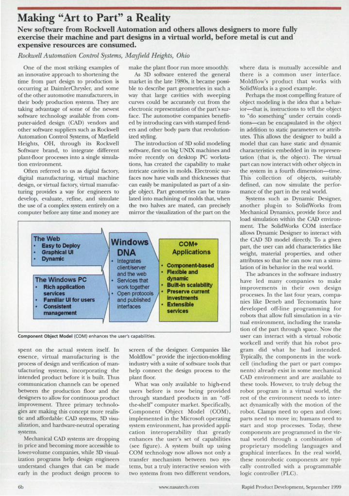
Making "Art to Part" a Reality New software from Rockwell Automation and others allows designers to more fully exercise their machine and part designs in a virtual world, before metal is cut and expensive resources are consumed. Rockwell Automation Control Systems, Mayfield Heights, Ohio
One of the most rriking examples of an innovative approach to shortening the time from part design to production is occurring at DainllerChrysler, and some of the other automotive manufacturers, in their body production systems. They are taking advantage of some of the newe t software technology available from computer-aided design (CAD) vendors and other software suppliers such as Rockwell Automation Control Systems, of Mayfield Heights, OH, through its Rockwell Software brand, to integrate different plant-floor processes into a single simulation environment.
Often referred to us as digital factory, digital manufacturing, virtual machine de ign, or virtual factory, virtual manufacturing provides a way for engineers to develop, evaluate, refine, and simulate the use of a complex system entirely on a computer before any time and money are
The Web
make the plant floor run more moothly. As 3D software entered the general
market in the late 1980s, it became po i· ble to describe part geometries in such a way that large cavitie with weeping curves could be accurately cut from the electronic repre entation of the part' surface. The automotive companies benefited by introducing cars with tamped fenders and other body parts that revolutionized styling.
The introduction of 3D solid modeling software, first on big UNIX machines and more recently on desktop PC workstations, has created the capability to make intricate cavities in molds. Electronic surfaces now have walls and thicknesses that can easily be manipulated as part of a single object. Part geometries can be translated into machining of molds th.at, when the two halves are mated, can precisely mirror the visualization of the part on the
COM+ Applications
Easy to Deploy Graphical UI Dynarrk • Integrates
client/server and the web
• CoR1)OMnt-baHd • flexible and
dynamic The Windows PC Rich application services
• ServIces that work together • Bull-ln scalability
• Pres.rv. currant Investments Familiar UI for UHf'S
Consistent Jnlnagement
• Open prcxooois and published Interfaces • ExNnslbl.
services
Component Object Model (COM) enhances the user's capabilities.
spent on the actual system itself. In es ence, virtual manufacturing is the process of design and verification of manufacturing systems, incorporating the intended product before it is built. Thus communication channels can be opened between the production floor and the designers to allow for continuous product improvement. Three primary technologie are making this concept more realistic and affordable: CAD systems, 3D visualization, and hardware-neutral operating systems.
Mechanical CAD systems are dropping in price and becoming more accessible to lower-volume companies, while 3D visualization programs help design engineers understand changes that can be made early in the product design process to
6b
screen of the designer. Companies like Moldflow" provide the injection-molding industry with a suite of software tools that help connect the design process to the plant floor.
What was only available to high-end users before is now being provided through standard products in an "offthe-shelf' computer market. Specifically, Component Object Model (COM) . implemented in the Microsoft operating system environment, has provided application interoperability that greatly enhances the user's set of capabilities (see figure ). A system built up using COM technology now allows not only a transfer mechanism between two sys~ems, but a truly interactive session with two systems from two different vendors,
www.nasatech .com
where data is mutually accessible and there is a common user interface. Moldflow's product that works with SolidWorks is a good example.
Perhaps the most compelling feature of object modeling is the idea that a behavior-that is, in tructions to tell the object to "do something" under certain conditions-can be encap ulated in the object in addition to tatic parameters or attributes. This allows the designer to build a model that can have static and dynamic characteristics embedded in its representation (that is, the object) . The virtual part can now interact with other objects in the system in a fOllrtll dimension-time. This collection of objects, suitably defined, can now simulate tlle performance of the part in the real world.
Sy terns such as Dynamic Designer, another plug-in to SolidWorks from Mechanical Dynamics, provide force and load simulation within the CAD environment. The SolidWorks COM interface allows Dynamic Designer to interact with the CAD 3D model directly. To a given part, the user can add characteristics like weight, material properties, and other attributes 0 that he can now run a simulation of its behavior in the real world.
The advances in the oftware industry have led many companies to make improvements in their own design processes. In the last four years, companies like Deneb and Tecnomatix have developed off-line programming for robots that allow full simulation in a virtual environment, including the translation of the part through space. Now the user can interact with a virtual robotic workcell and verify that his robot program did what he had intended. Typically, the components in the workcell (including the part or part components) already exist in some mechanical CAD environment and are available to these tools. However, to truly debug the robot program in a virtual world, the rest of the environment needs to interact dynamically with the motion of the robot. Clamp need to open and close; parts need to move in ; humans need to start and top processes. Today, the e components are programmed in the virtual world through a combination of proprietary modeling languages and graphical interfaces. In the real world, these nonrobotic components are typically controlled with a programmable logic controller (PLC) .
Rapid Product Development, September 1999
Other applications like material handling have similar oft ware technologies. AutoSimulation provide throughput and decision modeling capability with their AutoMod product, which features 3D animated graphics with interactive modeling and expert system-based material handling with tatistical Output reports and graphs. The product runs on both UNIX and PC stems.
PLCs execute relay ladder logic programs that are input/output-specific and are usually written as the last step before stanup. The mechanical designer at the machinery builder generates a timing chart, which diagramatically displays the sequence of the mechanical components of the machine, for the control engineer. And the de igner, in tum, works from a proce chart and floor plan that the enduser's process engineer has provided based on his unique knowledge of how to build the product -"
DaimlerChrysler sponsored a demonstration of these two items at the lAM show a year ago. CATIA V5, in beta release at the time, was used to plan the workcell that was et up in the company's booth. A processing-planning tool, developed as an add-in to the CATIA architecture, was used to specify the behavior sequences of the nonrobotic components such as clamps and fixtures. The
equence also identified the interlocks with the robots in the workcell.
Because the object model was built up from the physical resources of the workceli, all items in the sequence were referenced by their name as objects in the CATIA S) tern. Rockwell Automation, using newly developed Rockwell oftware technology, was able to read in
the timing diagram and convert it to PLC code. Finally, Deneb used the PLC code, executing in a soft controller, to drh'e the virtual workcell contained in their IGRIP product
Rockwell Software Enterprise Controls~, currendy still under deyelopment by Rockwell Automation, is intended to provide new capability to the machine and controls design customer. It will take the output of a mechanical design task-the development of the object model and its associated behavior (sometimes expressed as a timing chart)-and bring it into the controls development environment. Rather than convert the timing chart immediately to ladder logic, the system will allow the controls engineer to elaborate on the original intention of the upstream designer. The engineer can add mode behavior (manual, automatic, etc.), emergency responses, interlocks and safeties, exceptions such as bypass, and
Advanced rapid prototyping and manufacturing solutions , .y', ~,·.C2f?i';;.·-1S":..J,"-' .. ,.".."._ .. : .. , ..... :,.,1'4
'"-_ .• _'.:rt5 .... 1'J.!j.~~~~~
erthe • ne Machine
that gives you
Multi Ie 5 LUTIO
Functional Models Plastic Injection Molding Metal Casting _DuraForm~ PA: and DuraForm-"'Copper Polyamide: composite
GF (glass· filled) durable short run mold inserts • SandForm- Si and Zr: foundry
sand cores and molds engineering plastic models ...,RapidSteel"2.o: steel.bronze
• SOMOS· 201: TPE flexible, long run mold inserts • Castform- PS: expendable
investment casting patterns thennoplastlc elastomer models
.... MefIcI OYM CDrpcr.ltion Austtn. Texas. USA phone: +L5U.339.2922 fax: +L5t2.832.6753
Rapid Product Development, SepLember 1999
• RapidSteel-2.o: limited run pressure die casting mold inserts
EInpe DTMGrrobH Hilden. Germany phone: +49.2103.95nO Fax: +49.2103.52265
For More Information Circle No. 602
other control-specific information. The engineer can also link data reporting to
the machine tate information-production counts, utilization, rejects, and other management information.
As a next step in the code development process, the specific devices that are available to do the necessary tasks can be elected. Embedded in the device descrip
tions is the I/O behavior of that device. Only the last step is concerned with I/O. The controls engineer then can create all the names and device-specific detail. Part of the use of object-<>riented design permits the encap ulation of device behavior; these entities are called control assemblies. Also contained in a control assembly is information that can be used for generating wiring diagrams, diagnostics, and HMI. Finally, the system can generate code for several different controllers, based on some unique compiler technology embedded in Enterprise Controls.
Fur more information on RockweU Software Enterprise Controls, contact the authur of this brief, directur Jim Coburn, at Rockwell Automation Control Systems, 1 Allen Bradley Drive, Mayfield Heights, OH 44124; (440) 646-7977; fax (440) 603-9031. This brief is adapted from a paper of the same title in the 1999 Proceedings of the National Manufacturing Week Conference. Copyright © 1999 Reed Exhibition Companies.
DTM All this. Only with DTM".
call us today. _ .dtm-corp.com
E-mail: marketingOdtm-corp.com
AlIa ..... OTM Corporatlon Sinppore phone: +65-434-5nO Fax: ~~
7b
NEW PRODUCTS
CNC Software DP Technology, Cama
rillo, CA, has introduced E PRIT 99 CAM software for all type of CNC programming. The software features a Windows-compatible interface, support for seven languages, and enhanced support for mill and lathe operations. t=~-========:::~~iCE:;i!:= The new automatic milling feature allows users to immediately generate an area profile for re t material. The program create machinable features for uncut material and determine the tools needed for the finishing operation. Users can automate the creation of machinable features from a solid model. The software includes over 800 postproces or and the ability to connect to any machine on a shop floor. Circle No. 761
Injection Molding Material ClearTex~ single-component synthetic latex from Zeller
International, Winter Park, FL, is a clear, stretchy rubber material that i non-allergenic, dries fast at room tempreature, is available in a variety of color, and can be used to produce tear-re i tant parts. It can be used for coating, casting, film-forming, injection molding, and extrusion of parts such as gaskets, seals, O-rings, handles, and grips. The waterproof material can be used for dielectric/ conformal encapsulation coatings and liquid tapes. It is compatible with urethanes, fiberglas, metal, glass, ceramic, and polymer fortified gypsum, and is available in liquid or bead forms. Circle No. 763
Simulation & Modeling Software SimCad Series 3.1 process simulation and modeling oftware from CreateASoft,
Naperville , IL, enables users to recreate curren t operating environments, identify problem areas, and simulate real-time solutions. It can be used in any
business proce ,from manufacturing to business ervices. The software incorporates animation, real-time feedback, and what-if cenarios to treamline process modeling flows. Enhancements include improved model-building, support for resource monitoring, real-time graphing and reporting, and time distribution. Circle No. 765
Prototyping Services Planex SA, Fort Worth, TX, offers ProtoDuction~ services, includ
ing near-production-quality injection molded prototypes. The company use a proprietary E-System process for producing epoxy composite tools. It offers a choice of production materials, low cost, and 200 to 1,000 parts off of each tool. Other services include short hots for mold flow evaluation, functional nap fits , production tolerance, insert molding, and aluminum tooling. Circle No. 767
Parts Printer The Geni 3D parts
printer from tratasys, Eden Prairie, MN, allow users to build parts up to 12 x 8 x 8 inches. The tern operates in a footprint of 36.5 x 32 inche , and can be et on a de k top. It prints in a polyester material; prints can be sanded, drilled, or painted. The sy tern features a built-in clock that tracks cumulative build hours. When the system needs routine ervice, a user alert i di played on the LCD panel. The printer u es the Linux O/ S operating sy tern and runs on an industrial-grade embedded controller within the machine. It is compatible with intranets and can be networked. All networked users can view the entire print queue to check the status of their parts. Circle No. 762
20 CAD Software ViaGrafix Corp., Pryor, OK, has introduced ViaCAD, a 2D, entry
level CA system for engineering and drawing. De igned for the nonCAD professional, the software allows users to draw a line or other object, and displays the length of the line with the cursor in real time, along with the horizontal and vertical dimen ions. The Autodimension command automatically adds dimensions for all selected items in a drawing. The four types of dimensions supported are linear, angular, radius/ diameter, and coordinate. A library of3,000 symbols is standard, and Internet compatibility is provided with JPEG and VRML file support. Other file formats supported for drawing import and export include AutoCAD's DWG and DXF. Circle No. 764
Prototyping Kits Designer's Kits for engineer provide sample quantities of magnet
ic components made by].W. Miller Magnetics, Gardena, CA. The samples are for use by engineers in design and prototyping projects. Two kits are available: one for PMH Series high current EMI beads, and one for PMC Series EMI up pression beads. Each kit offers ten pieces each of 12 popular size/ impedance combinations. Applications include witching power supplies, computers and peripherals, telecommunications equipment, and audio equipment. They are designed to reduce high-frequency noise interference and are available tape-and-reel packaged in standard ElA chip sizes with soldercoated terminals for wave and reflow soldering. Circle No. 766
Infiltration Material DTM corp., Austin, TX, offers a polymer infiltration material that allows users to create functional, flexible prototypes such as tubing, hoses, and gaskets from DSM Desotech's Somos· 201 material . Somos 201 is a thermoplastic elastomer powder. Laser-sintered Somos 201 parts infiltrated with the new polymer material are watertight, have enhanced sur
face finish, and have high burst strength , wear re istance, and tear resi rance. Parts can be made in any color. Circle No. 768
8b www.nasatech.com Rapid Product Development, September 1999
ponent interface (PCI) bus architecture. The oftware consists of xWorks tasks written in C++. Various components of the software have either been developed anew or redesigned from heritage code written for prior pacecraft mi sion .
TIllS work was dolU by tephan R. Hammers of Ihe Hammers Co. for Goddard Space Flight Center. To obtain a copy of the report, ·S.fI,lEX-Lite ACS and C&DH Flight Software, " access the Technical upport Package (TSP)free on-line at www.nasatech.rom under the Information Sciences categor),. GSC-14214
® Using Rayleigh Scattering To Measure Spacecraft Attitude
Two reports describe a Rayleigh- cattering attitude sensor (RSAS) - an optoelectronic instrument for determining the orientation of a spacecraft. An RSAS compri es a telescope/ video-camera/ image-digitizer combination that is mounted on the spacecraft and that captures images of the limb of the Earth in 355-nm-wavelength unlight that has been Rayleigh-scattered from the atmosphere. (At 355 nm, the atmo phere catters trongly but does not absorb significantly.) A computational model of the 355-nm radiance of the atmo phere as a function of altitude, lighting conditions, and viewing angle is then used to extract, from the image data, an estimate of the angle between the line of sight of the RSAS and the nadir.
This work was done by Pawan K Bhartia and Ernest Hilsenrath of Goddard Space Flight Center. To obtain copies of the reports, "Rayleigh Scattering Sensor for Spacecraft Attitude Sensing (RSAS)" and "Design Deuelopment, and Test-Flight of the Rayleigh ScatWing Altitude Sensor, n acces the Technical Support Package (TSP) free on-line at www.1UlSatech.com under the Physical Sciences category.
This invention is owned 11), NA Ii, and a patent application has been filed. Inquiries concerning nonexclusive or exclusive licensl! for its commerciallkvelopment should be addressed to the Patent Counsel, Goddard :pace Right Center; (301) 286-7351. Refer
to G C-13858.
Diagnosing Gas-TurbineLike Combustion by Use ofPLIF
A report de cribes experiments in which planar laser-induced fluorecence (PUF) of h droxyl radical was used to tudy the u-tlCrure of flame in burner te t rigs (a flame-tube combu -tor and a ector combus[Or) under condition like tho e in combus[Ors of avia-
NASA Tech Briefs, September 1999
lion gas-turbine engine . The PUF image from the sector-combu tor experiments generally confirmed that the combustor functioned a de igned. The PUF images from the flame-tube experiments revealed previously unknown nonuniformitie in flame tructures; the e images provided guidance for selection of an optimum number of fuel-injection points and for modification of the fuel-injector de ign to improve combustion characteri tics.
This work was done by Yolanda R. Hicks and Robert C. Anderson of Glenn Research
-==Gapman ELECTRONIC GAP GAGE
• Assembled pam • Extruders • Cooters • Lomino1ing presses • Composite strudures • Automotive alignmenl'; ,-... """.~~"
• Printing press roller gaps • Plastic injection molds, cold gap deorances
=Capacifec tel: 978.772.6033 fax: 978.772.f:iJ36
Tooling Source 1
Find us at www.carrlane.com
• Distributor locator ISO 9001 • Product catalog CERT IF EO • New rtems
Center and Randy J Locke of .NY1\JA, 11Ie. To obtain a cop)' of the report, "Multi-Dimensional Measurements of Combustion :pedes in Flame Tube and ector Gas Turbine ComhusUm, " access the Technical Support Package (TSP)free on-line at www.nasatech.com under the Physical ciences category.
Inquiries concerning rights for the commercial use of this invention should be addressed to J liSA Glenn Research Center, Commercial Technology OffICe, Attn: Tech Brief Patent Slatus, Attn: leue Fedor, Mail top 4-8, 21000 Brookpark Road, Cleveland, Ohio 44135. Refer to LEW-16565.
• BLADDER TANKS & AIR CELLS • DIAPHRAGMS & ACUATO • BELLOWS & FUEL CELLS • STRESS TEST BLADDERS • CUSTOM INFLATABLES • PNEUMATIC / HYDRAULIC PRESSES
...AI-' .. -~ 800·526·5330 AERO TEC LABORATORIES INC. RAMSEY, NJ 07446-1251 USA TEL; 201 -825-1400 · FAX: 201-825·1962 .. Mail a8 , otec@cy b .rnu. ne t h tt p :// ww w .a t in c.c o m
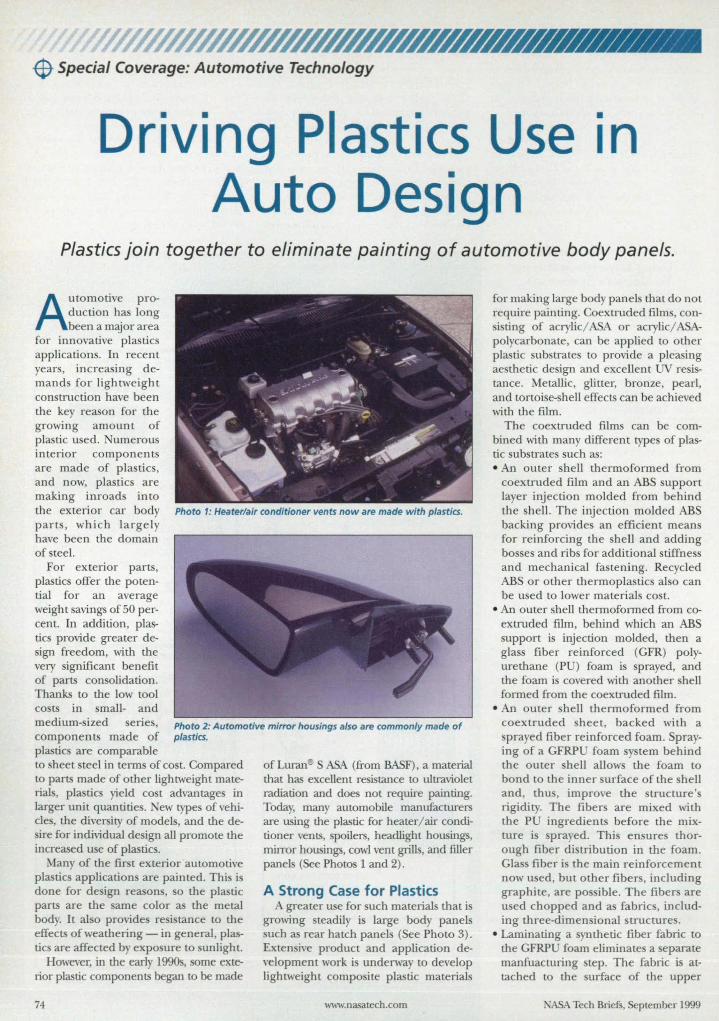
-$ Special Coverage: Automotive Technology
Driving Plastics Use in Auto Design
Plastics join together to eliminate painting of automotive body panels.
Automotive production has long been a major area
for innovative pIa tics applications. In recent years, increasing demand for lightweight construction have been the key reason for the growing amount of plastic u ed. 'umerous interior components are made of plastics, and now, pIa tics are making inroads into the exterior car body Photo 1: Heater/air conditioner vents now are made with plastics. parts, which largely have been the domain of steel.
For exterior parts, plastics offer the potential for an average weight savings of 50 percent. In addition, plastics provide greater design freedom, with the very significant benefit of parts consolidation. Thanks to the low tool costs in small- and medium- ized eries, components made of plastics are comparable
Photo 2: Automotive mirror housings also are commonly made of plastics.
to sheet steel in terms of COSL Compared to parts made of other lightweight materials, plastics yield cost advantages in larger unit quantities. ew type of vehicle , the diversity of model, and the desire for individual de ign all promote the increased use of plastics.
Many of the first exterior automotive plastics application are painted. This is done for design reason, 0 the plastic parts are the ame color as the metal body. It also provide re i tance to the effects of weathering - in general, plastics are affected by exposure to sunlight.
However, in the early 1990s, some exterior plastic components began to be made
74
of Luran~ S ASA (from BASF), a material that has excellent re istance to ultraviolet radiation and does not require painting. Today, many automobile manufacturers are using the plastic for heater/ air conditioner vents, poilers, headlight housings, mirror housings, cowl vent grills, and filler panels (See Photos 1 and 2).
A Strong Case for Plastics A greater u e for uch materials that is
growing steadily is large body panels such as rear hatch panels (See Photo 3) . Extensive product and application development work i underway to develop lightweight composite plastic materials
www.nasatech.com
for making large body panels that do not require painting. Coextmded film ,con-i ting of acrylic/ ASA or acrylic/ ASA
polycarbonate, can be applied to other pIa tic substrates to provide a pleasing ae thetic design and excellent resistance. Metallic, glitter, bronze, pearl, and tortoi e- hell effects can be achieved with the film.
The coextruded films can be combined with many different types of plastic substrates such as: • An outer shell thermoformed from
coextruded film and an ASS support layer injection molded from behind the hell. The injection molded ASS backing provides an efficient means for reinforcing the shell and adding bosses and ribs for additional stiffness and mechanical fastening. Recycled ASS or other thermoplastics also can be u ed to lower materials cost.
• An outer shell thermoformed from coextruded film, behind which an ASS support is injection molded, then a glas fiber reinforced (GFR) polyurethane (PU) foam is sprayed, and the foam is covered with another shell formed from the coextruded film.
• An outer shell thermoformed from coextruded heet, backed with a sprayed fiber reinforced foam. Spraying of a GFRP foam system behind the outer shell allows the foam to bond to the inner urface of the shell and, thus, improve the tructure' rigidity. The fibers are mixed with the PU ingredients before the mixture is prayed. This ensure thorough fiber distribution in the foam. Gla fiber is the main reinforcement now u ed, but other fibers, including graphite, are pos ible. The fiber are u ed chopped and as fabric, including three-dimensional structures.
• Laminating a ynthetic fiber fabric to the GFRP foam eliminates a eparate manfuacturing step. The fabric is attached to the surface of the upper
ASA Tech Briefs, September 1999
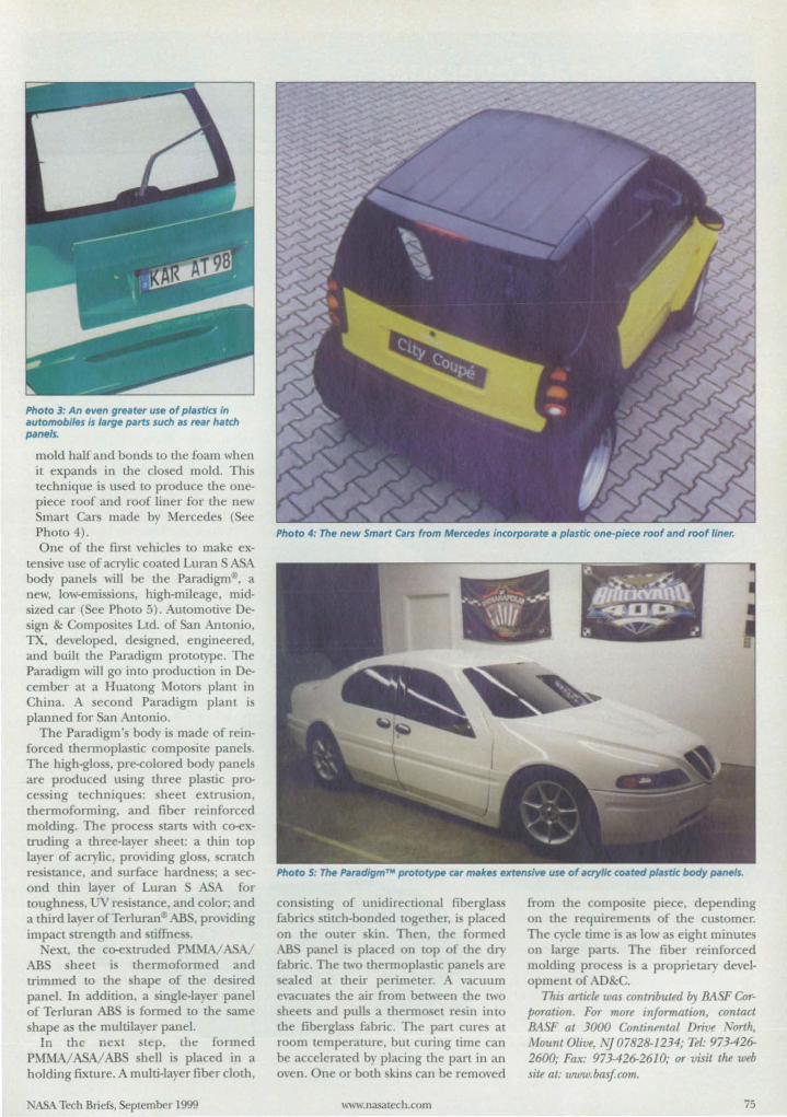
Photo 3: An even greater use of plastla In automobiles Is large parts such as rear hatch panels.
mold half and bonds to the foam when it expands in the closed mold. This technique is used to produce the onepiece roof and roof liner for the new Smart Cars made by Mercedes (See Photo 4). Photo 4: The new Smart Cars from Mercedes Incorporate a plastic one-piece roof and roof liner. One of the first vehicles to make ex-
tensive use of acrylic coated Luran S ASA body panels will be the Paradigm®, a new, low-emissions, high-mileage, mjdsized car (See Photo 5). Automotive Design & Composite Ltd. of San Antonio, TX, developed, de igned, engineered, and built the Paradigm prototype. The Paradigm will go into production in December at a Huatong Motors plant in China. A econd Paradigm plant is planned for San Antonio.
The Paradigm 's body is made of reinforced thermoplastic compo ite panels. The high-gloss pre-colored body panels are produced u ing three plastic proces ing technique; sheet extrusion. thermoforming, and fiber reinforced molding. The proces starts with co-extruding a three-layer heet: a thin LOp layer of acrylic, providing glo ,scratch resi tance, and urface hardness; a sec- Photo 5: The ParadlgmT .. prototype CII' makes extensive use of acrylic co.ted plastic body panels.
ond thin la er of Luran S ASA for toughne ,LJ resistance. and color; and a third layer of TerluranJ) ABS, providing impact trength and tifIness.
ext, the co-extruded P?\.L.\1A/ ASA/ AB sheet is thermoformed and trimmed to the shape of the de ired panel. In addition, a single-layer panel of Terluran AB is formed to the arne hape as the multilayer panel.
In the next tep. tht: formed P fMAI ASAI AB shell is placed in a holding fixture. A multi-layer fiber cloth,
ASA Tech Briefs, September 1999
con i ring of unidirectional fiberglas fabrics ritch-bonded together, i placed on the outer kin. Then, the formed AB panel is placed on LOp of the dry fabric. The [\\,0 thermoplastic panels are ealed at their perimeter. A vacuum
evacuate the air from between the [Wo heets and pulls a thermo el resin into
the fiberglas fabric. The part cure at room temperature, but curing time can be accelerated by placing the part in an oven. One or both skins can be removed
www.nasalech.com
from the compo ite piece, depending on the requirements of the customer. The cycle time is as low as eight minute on large parts. The fiber reinforced molding proce i a proprietary development of AD&C.
This artick was contributed fly BASF Corporation. For more infannation, contact BASF at 3000 Conti7lPrl11l/ Drive _ orth, Mount Olive, NJ07828-1234; Tel: 973-426-2600; Fax: 973-426-2610; or visit the web site at: www.bas!com.
75
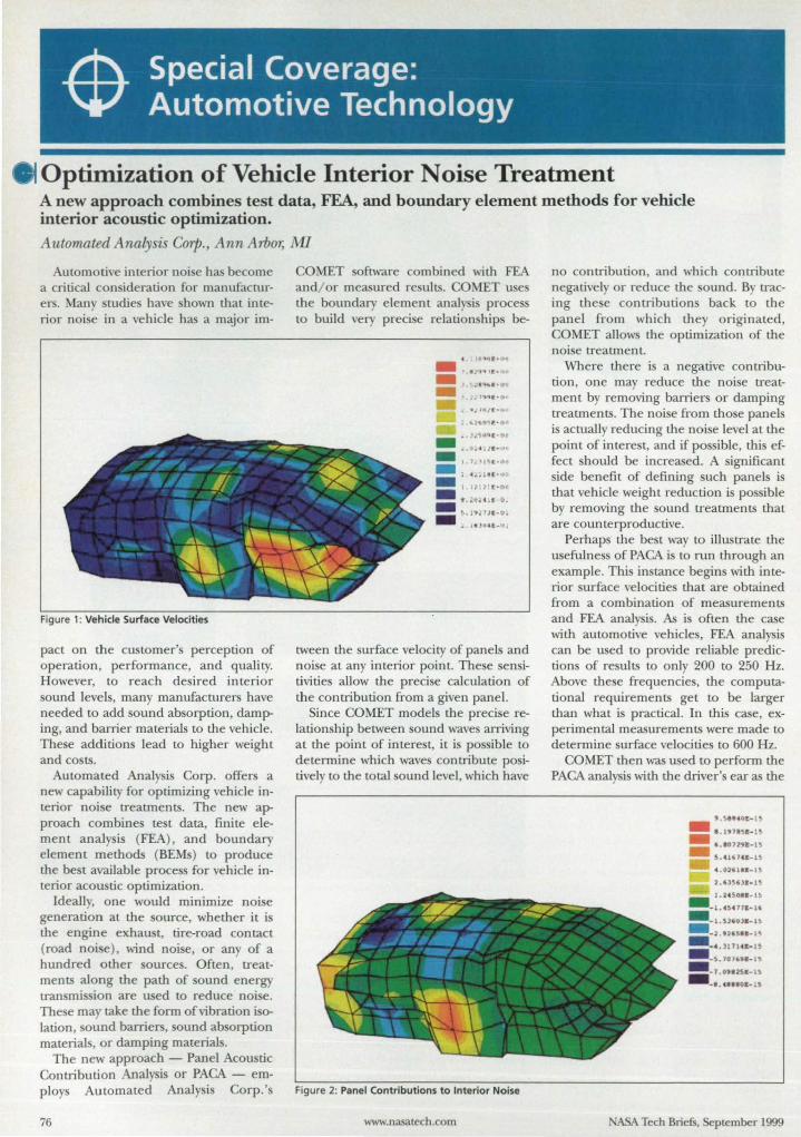
Optimization of Vehicle Interior Noise Treatment A new approach combines test data, FEA, and boundary element methods for vehicle interior acoustic optimization. Automated Analysis Corp., Ann Arbor, M1
Automotive interior noise has become a critical consideration for manufacturers. Many tudies have shown that interior noise in a vehicle has a major im-
Figure 1: Vehicle Surface Velocities
pact on the customer's perception of operation, performance, and quality. However, to reach desired interior sound levels, many manufacturers have needed to add sound absorption, damping, and barrier materials to the vehicle. These additions lead to higher weight and costs.
Automated Analysis Corp. offers a new capability for optimizing vehicle interior noise treatments. The new approach combines test data, finite element analysis (FEA) , and boundary element methods (BEMs) to produce the best available process for vehicle interior acoustic optimization.
Ideally, one would minimize noise generation at the source, whether it is the engine exhaust, tire-road contact (road noise), wind noise, or any of a hundred other sources. Often, treatments along the path of sound energy transmission are used to reduce noise. These may take the form of vibration isolation, sound barriers, sound absorption materials, or damping materials.
The new approach - Panel Acoustic Contribution Analysis or PAGA - employs Automated Analysis Corp. 's
76
OMET oftware combined with FEA and/ or measured results. COMET u es the boundary element analysis proces to build very precise relation hips be-
•• tI2'f"~I:'1)
.. . J..:~",qE·9~
.. ...... .. lJ l ... u .. = ,.1.''' •. 1 . ... ~1.tHJ
.. I. I' ~: t -O ~ 5 ::~:::;:-:: J.. "J04E_lI.
tween the surface velocity of panels and noise at any interior point. These sensitivities allow the precise calculation of the contribution from a given panel.
Since COMET models the precise relationship between sound waves arriving at the point of interest, it is possible to determine which waves contribute positively to the total sound level, which have
F,igure 2: Panel Contributions to Interior Noise
www.nasatech.com
no contribution, and which contribute negatively or reduce the sound. By tracing the e contributions back to the panel from which they originated, COMET allow the optimization of the noise treatment.
Where there is a negative contribution, one may reduce the noise treatment by removing barriers or damping treatments. The noise from those panels is actually reducing the noise level at the point of interest, and if possible, this effect should be increased. A ignifi can t side benefit of defining uch panels is that vehicle weight reduction is possible by removing the sound treatments that are counterproductive.
Perhaps the best way to illustrate the usefulness of PAGA is to run through an example. This instance begins with interior surface velocities that are obtained from a combination of measurements and FEA analysis. As is often the case with automotive vehicles, FEA analysis can be used to provide reliable predictions of results to only 200 to 250 Hz. Above these frequencies, the computational requirements get to be larger than what is practical. In this case, experimental measurements were made to determine surface velocities to 600 Hz.
COMET then was used to perform the PAGA analysis with the driver's ear as the
9 .5 . ... 0C-U
- I .""~a-u = '.1'7>9t-15 S. 41 U U -l
4 .0)'1 .... 1~
l.U '11-1
1. 24So" -1~
- -1. 45.,11-10
.... l.Sl'Ol&- l~ --> .. 2& " -15 .... _ ' .)11141-'
-s~ lal" ....
= -,.091251-" - . . .... 0&--1
ASA Tech Briefs, September 1999
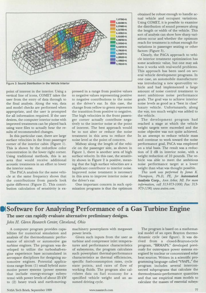
Figure 3: Sound Distribution in the VehIcle InterIor
point of interest in the interior. Using a vertical line of icons, COMET takes the user from the entry of data through to the final analysis. Along the way, data and model checks are performed when appropriate, and the user is prompted for all information required. If the user desires, the computer interior noise with improved treatments can be played back using wave files to actually hear the results of recommended changes.
In this particular case, there are large surface velocities in the front passenger comer of the interior cabin (Figure 1). This is shown by the red-yellow color concentration in the lower right comer. Using traditional methods, this is an area that would receive additional acoustic treatments in an effort to lower the interior noise.
The PACA analysis for the same vehicle at the same frequency shows that the contributions from panels look quite different (Figure 2). This contribution calculation of sensitivity is ex-
7.07l9IE001
6.8Kl8Eo01
S.5lOIIIEtQl
6.!ImE<01 5.01lJII.E<01 5.810211£<01
5.~
- U0324E<01
- 5.04S72£<01 4.79Q9E<01
4.~
- 4.211S1!E<01
•- 4.OB2.E<01
3.l'IZlOE<01
pressed in a range from positive values to negative values representing positive to negative contributions to the noise at the driver's ear. In this case, the change from yellow to green represents the transition from positive to negative. The high velocities in the front passenger comer actually contribute negatively to the interior noise at the point of interest. The best approach would be to not alter or reduce the noise treatment in this area to reduce the noise level at the point of concern.
Midway along the length of the vehicle on the passenger side, as shown in Figure 1, there is another area of high surface velocity. In this case, the sensitivity shown in Figure 2 is positive, meaning that the high surface velocities are a significant contributor to interior noise. Improved noise treatment is necessary in this area to improve interior noise at the driver's ear.
One important concern in such optimization programs is that the optimum
obtained be robust enough to handle actual vehicle and occupant variations. Using COMET, it is possible to examine the distribution of sound pressure along the length or width of the vehicle. This sort of analysis can how how sharp variations occur and whether the optimum reach for treatment is robust enough for variations in passenger seating or other factors (Figure 3).
Clearly, the PACA approach to vehicle interior treatment optimization has some academic value, but one may ask how it works with real-world problems. This approach has been used on several vehicle development programs. In one case, an automobile manufacturer was introducing a new sport-utility vehicle and had implemented a large amount of noise control treatment to meet ambitious noise performance goals. The goal was to achieve interior noise levels as good as a "best in classH
luxury vehicle. Unfortunately, along the way, too much weight was added to the vehicle.
The development program had reached a stage at which the vehicle weight targets were exceeded and the noise objective was not quite achieved. In an attempt to reduce vehicle mass and continue to work toward the noise performance goal, PACA was employed on a trial basis. The result was a reduction of 2 dB in interior noise, with a weight reduction of 10 pounds. The vehicle was able to meet the ambitious noise performance target at a lower weight than what was thought possible.
This work was performed by James K. Thompson, Ph.D, PE, for Automated Analysis Corp., Ann Arbor, MI. For more information, call 313-973-1000; Fax: 313-973-1190; www.autoa.com.
Software for Analyzing Performance of a Gas Turbine Engine The user can rapidly evaluate alternative preliminary designs. John H. Glenn Research Center, Cleveland, Ohio
A computer program provides capabilities for numerical simulation and analysis of the thermodynamic performance of aircraft or automotive gas turbine engines. The program was developed to utilize the turboshaft-engine experience base accumulated in aerospace di ciplines for designing automotive engines. Potential application range from (1) small hybrid automotive power systems (power systems that include energy-storage subsystems) with power levels of about 25 kW to (2) heavy truck and earth-moving-
NASA Tech Briefs. September 1999
machinery powerplants with megawatt power levels.
Given such inputs from the user as turbine and compressor inlet temperatures and performance characteristics of sub ystems. the program calculates such powerplant thermal-performance characteristics as thermal efficiencies, specific fuel-consumption rates, cycle state points, and rates of flow of working fluids. The program also calculates data on fuel economy for a specified vehicle weight and an assumed driving cycle.
www.nasatech.com
The program is based on a mathematical model of an open Brayton thermodynamic cycle (ee figure). It was derived from a closed-Brayton-cycle program. "BRMAPS, n developed previously for outer-space power systems energized by nuclear or concentrated solar heat sources. Written in a scientific programming language called "VSAPL,H the program includes several interconnected subprograms that calculate the thermodynamic-performance quantities and that use empirical mass models to
calculate the masses of essential subsys-
77
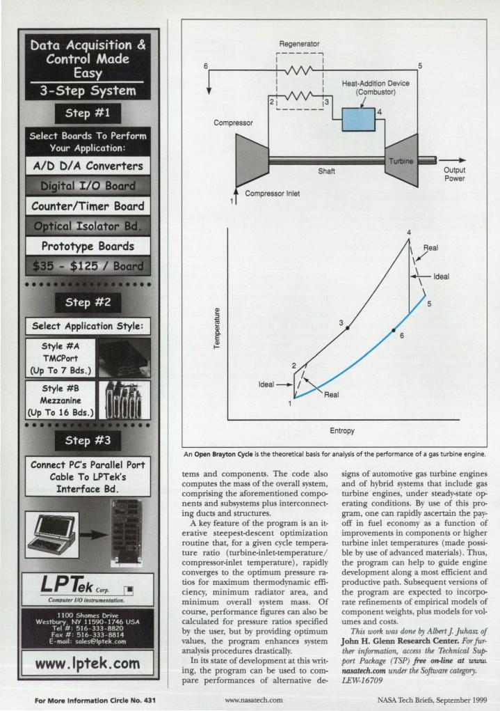
Connect PC's Parallel Port Cable To LPTek's
Interface Bd.
Computer I/O instrununtaJion.
1100 Shames DrIve Westbury . NY 11590- 1746 USA
Tel # 516 - 333 -8820 Fax # 516 - 333 - 8814
E-mall.sales@lptek cam
www.lptek.com
For More Information Circle No. 431
Regenerator ,------, I I
1~~----------------,5
Compressor
Shaft
Compressor Inlet
Heat-Addition Device (Combustor)
'-
4
--.. Output Power
Entropy
An Open Brayton Cycle is the theoretical basis for analysis of the performance of a gas turbine engine.
terns and components. The code also computes the mass of the overall system, comprising the aforementioned components and subsystems plus interconnecting ducts and structures.
A key feature of the program is an iterative steepest-descent optimization routine that, for a given cycle temperature ratio (turbine-inlet-temperature/ compressor-inlet temperature), rapidly converges to the optimum pressure ratios for maximum thermodynamic efficiency, minimum radiator area, and minimum overall system mass. Of course, performance figures can also be calculated for pressure ratios specified by the user, but by providing optimum values, the program enhances system analysis procedures drastically.
In its state of development at this writing, the program can be used to compare performances of alternative de-
www.nasatech.com
signs of automotive gas turbine engines and of hybrid systems that include gas turbine engines, under steady-state operating conditions. By use of this program, one can rapidly ascertain the payoff in fuel economy as a function of improvements in components or higher turbine inlet temperatures (made possible by use of advanced materials). Thus, the program can help to guide engine development along a most efficient and productive path. Subsequent versions of the program are expected to incorporate refinements of empirical models of component weights, plus models for volumes and costs.
This work was done by Alhert J Juhasz of John H. Glenn Research Center. For further information, access the Technical Support Package (TSP) free on-line at www. no.satech.rom unMr the Software category. LEW-16709
ASA Tech Briefs, September 1999
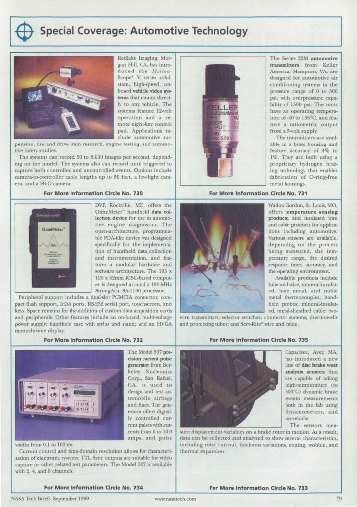
$- Special Coverage: Automotive Technology
Redlake Imaging, Morgan Hill, CA, has intr~ duced the MotionScope- V series solidstate, high- peed, onboard vehicle video systems that mount directly to any vehicle. The systems feature 12-volt operation and a remote eight-key control pad. Applications include automotive sus
pension. tire and drive train research, engine testing, and autom~ tive afety studies.
The systems can record SO [0 8,000 images per second, depending on the model. The systems also can record until triggered to capture both controlled and uncontrolled events. Options include camera-to-controller cable lengths up [0 SO feet, a low-Light camera, and a Hi-G camera.
For More Information Circle No. 730
OVP, Rockville, MD. offers the OmniMeter'" handheld data collection device for use in autom~ tive engine diagnostics. The open-architecture, programmable POA-like device was designed specifically for the implementation of handheld data collection and instrumentation, and features a modular hardware and software architecture. The 19S x 120 x 42mm RISCbased computer is designed around a I90-MHz StrongArm SA-I 100 processor.
Peripheral support includes a dual-slot PCMCIA connector, compact flash support, IrOA ports, RS-232 serial port, touchscreen. and keys. Space remain for the addition of custom data acquisition cards and peripherals. Other features include an on-board, multi-voltage power supply; handheld case with stylus and stand; and an HVGA monochrome display.
For More Information Circle No. 732
~idths from 0.1 to 100 ms.
The Model S07 precision current pulse generator from Berkeley , ucleonics Corp., San Rafael, CA, i u ed to de ign and test automobile airbags and fuse . The generator offers digitally controlled current pulses ~ith currents from 0 to 10.0 amp, and pul e
Current control and time..<fomain resolution allows for characterization of electronic systems. TIL Sync outputS are uitable for ~ideo capture or other related te t parameters. The Model 507 is available "ith 2, 4, and 8 channels.
For More Information Circle No. 734
The Series 22M automotive transmitters from Keller America, Hampton, VA, are designed for automotive air conditioning systems in the pressure range of 0 to SOO psi, with overpres ure capability of ISOO psi. The units have an operating temperature of -40 to ISS·C, and feature a ratiometric output from a 5-volt supply.
The transmitters are available in a brass housing and feature accuracy of 4% to 1 %. They are built using a proprietary hydrogen brazing technology that enables fabrication of O-ring-free metal hOUSings.
For More Information Circle No. 731
Watlow Gordon, St. Louis, MO, offers temperature sensing products, and insulated wire and cable products for applications including automotive. Various sensors are available, depending on the process being measured, the temperature range, the desired response time, accuracy, and the operating environmenL
Available products include lube and wire, mineral-insulated, base metal, and noble metal thermocouples; handheld probes; mineral-insulated, metal-sheathed cable; tw~
wire transmitter; selector switche ; connector systems; thermowells and protecting tubes; and Serv-Ritee wire and cable.
For More Information Circle No. 735
Capacitec. Ayer, MA, has introduced a new line of disc brake wear analysis sensors that are capable of taking high-temperature (to 500·C) dynamic brake system measurements both in the lab using dynamometer, and on-vehicle.
The sensors meaure displacement variables on a brake rotor in motion. As a result,
data can be collected and analyzed to show several characteristic , including rOlor run-out, thicknes variations, coning, wobble. and thermal expan ion.
For More Information Circle No. 733
NASA Tech Briefs. September 1999 www.nasatech.com 79
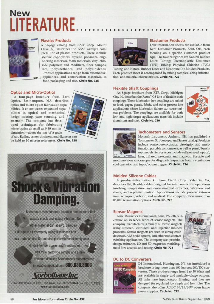
New
LITERATURE Plastics Products A 51-page catalog from BASF Corp., Mount Olive, IT, de cribe the BASF Group's complete line of plastic products. The e include tyrene copolymers, styrene polymers, engi
neering material , foam materials, vinyl chloride polymer and modifier , fiber compo -ites, polyurethanes, and polyethylenes. Product applications range from automotive, appliance , and con truction materials, to food packaging and toys. Circle No. 72S
Optics and Micro-Optics A four-page brochure from Bern
Optic, Easthampton, MA, de cribe optic and micro-optics fabrication capa-bilities. It encompasses expanded capabilities in optical and mechanical design, coating, parts ourcing, and assembly. The company has developed techniques for fabricating micro-optics as small as 0.19 mm in dimension-about the size of a grain of salL Radius, center thickne ,and diameter can be held to 10 micron tolerance. Circle No. 728
80 For More Information Circle No. 432
Elastomer Products Four information heets are available from Kent Elastomer Products, Kent, OH, each focusing on a pecific elastomer product type. The four categories are atural Rubber Latex Thbing; Thermoplastic Elastomer (TPE) Tubing; Polyvinyl Chloride (PVC)
Tubing; and atural Rubber Latex and eoprene Dip-Molded Products. Each product heet is accompanied by tubing sample, iring information, and material characteristic . Circle No. 723
Flexible Shaft Couplings An S-page brochure from KTR Corp., Michigan
City, IN, describe the Rotex- GS line of flexible shaft couplings. These lubrication-free couplings are suited to food, paper, plastic, fabric, and other proce line applications where lubrication failure can cause serious problems. The couplings are available for both low- and high-torque applications; materials include aluminum and steel. Circle No. 720
Tachometers and Sensors Monarch Instrument, Amherst, NH, has published a Tachometer, Stroboscope, and Sensor catalog. Products include contact/ non-<:ontact, pistol-grip, and multifunction portable tachometers, as well as panel/benchtop models. Sensor types include self-powered, optical, laser, infrared, proximity, and magnetic. Portable and
machine-vision troboscopes for diagno tic inspection feature continuous cool operation and input/ output triggers. Circle No. 724
Molded Silicone Cables A product-information kit from Cicoil Corp., Valencia, CA,
describes flat. flexible cables de igned for interconnection operations involving temperature and environmental extremes, vibration and shock, and repetitive motion . Applications include process automation, aerospace, robotic, and medical. The company offers more than 85,000 termination options. Circle No. 726
Sensor Magnets Kane Magnetics International, Kane, PA, offers lit
erature on its K-Sen series of sensor magnets. The company manufactures a variety of ferrite magnets using sintered, extruded. and injection-molded processes. Sensor magnets are used in airbag crash detectors, ABS brake systems, and other non-<:ontact switching applications. The company also provides design assistance. 2D and 3D magnetics modeling, mold-flowanalysis, and testing. Circle No. 721
DC to DC Converters D1 International, Huntington. NY, has introduced a brochure listing more than 490 low<ost DC/ DC converters. These products range from 1 to 30 Watts and are available in ingle- and multiple-voltage outputs. All units have input/output filtering, and they are designed for regulated low ripple and low noise. The company also offers ACDC 1O/ 15/ 20W open frame power supplies. Circle No. 722
ASA Tech Briefs, September 1999
Newon
DIS Inspection Software
CCI, Minneapolis. MN. offers pec.CbeckTM software that measures points, lines. arcs, circles, and roundness anal es through proprietary algorithm . It creates a dimensional template for the first pan; this template is then used to dimension subsequent parts aUlomatically. Each 2D cro s-sectional measurement is put into standard SPC ( tatistical Process Control) or PPAP (Pmduction Pan Approval Process) formaL Three methods of part registration are available: manual, best-fit, and feature-based. Other fearures include color-coded pass/fail print reports and automatic 3D views. Circle No. 710
Toolkit Qualifies Semiconductors The Wafer Level Reliability (WLR)
Toolkit from Keithley Instruments, Cleveland, OH, is designed to provide semiconductor fabs with a foundation for implementing a WLR monitoring program. The toolkit can be used with Keithley's Automated
Parametric Test (APT) systems to perform JEDEC standard tests. The test library offers isothermal electromigration, time-dependent dialectric breakdown, hot carrier i~ection, and mobile ion tests. The oftware is compatible with all Keithley parametric testers, including the
600, S900NT, and 400 UNIX-based APT systems. Circle No. 711
20 to 3D Conversion Auto-Z 2.0 from EMT Software, Bellingham, WA, is the late t version
of Auto-Z for AutoCAD R2000 and Rl4, as well as MDT versions 3.0 and 4.0. Using existing 2D multi-view drawings as a reference, Auto-Z builds an AutoCAD solid model. In some cases, Auto-Z builds a complete 3D model with no user input. In other cases, the program generates 30 to 99 percent of the 3D model, allowing the user to complete it in an AutoCAD 2D environment. Users can edit solid models by changing geometry in the 2D drawing. The software is network-ready. Circle No. 712
Data Visualization for Linux The Numerical Algorithms Group ( AG), Downers Grove, IL, has
announced IRIS Explorer Release 4.0 visual programming tern for data visualization for the Linux platform. It is designed for creating customized applications for displaying and analyzing complex data interactively. RedHat 5.1 eIVes as the distribution of the operating system, together with the leading-edge compiler for the port. The program enables c.ollaboration on data analysis. Circle No. 713
Automation Package ational In truments, Au tin, TX, has
introduced Lookout 4.0 automation software that features advanced multiserver, multi-cliem networking; imegrated. interactive ,,\'eb uppon; OPC sen-er and client capabilities; and seamless connectivity with the company' BridgeVIEWTM - UlbVIE\\TfM for indus
trial automation. A new pricing structure gives developers the opportunity to provide easy access to Lookout client tems withom paying for software on a per-installation basis. To access info anel <creens from the sen:el machines remotely, run-time client software provides users with full, interactive access to the Lookout system. Circle No. 715
ASA Tech Briefs, September 1999
Data Acquisition and Logging LoveLink™ II data acquisition and r-=========~
logging oftware from Love Controls Division, Dwyer Instruments, Michigan City, I ,features connection of up to 40 controls on a single computer port; I;' data logging at indilidually adjustable :=-rate , and user-friendly operator interface. It supports the Love ontrol Serle of 1/4, 1/8, 1/16. and 1/32 DIN microprocessor-based temperature/process controls. It runs on Windows 95/98 and Wmdows NT Workstation 4.0. An RS-232 or R.S485 converter is available for communication with temperature controls. Circle No. 717
Welding Software AW Welding from Computer Engineering, Blue Springs. MO, is
designed for writing accurate AWS welding-procedure specifications in compliance with AWS tructural WeJding Code. The oftware creates Welding Procedure Specifications (WPSs) for AWS Section D1.3 and D9.1; prequalified WPSS for D1.1. D1.3, and D9.1; and Procedure Qualifications Records (PQRs) for D1.3 and D9.1. It also provides a welder-management program, and creates and maintains AWs.compliant Welder Performance Qualification Records (WPQRs). weldercontinuity logs, and inspection logs. The program can generate lists of all welders qualified for a pecific WPS. Circle No. 714
ADHESIVE BONDS POLYETHYLENE & POLVPROpnENE
BOND POLYMER SYSTEM X17
• No surface preparation needed. Room temperature or heat cure. One component system. Easy to apply - brushable • High bond strength - shear and peel. Excellent moisture resistance • Convenient packaging
For information, call or write:
Master Bond Inc. 154 Hobart Street
Hackensack, NJ 07601 201-343-8983 www.muterboncl.com
Master Bond Inc. AdheSives, Sealants & Coatings
For More Information Circle No. 433 81
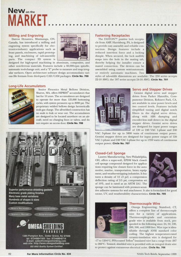
NeWonthe
MARKET. Milling and Engraving
Datron Dynamics, Missis auga, 0 , Canada, has introduced a milling and engraving s tern specifically for electronics-irldustry applications such as front panels, enclosures, rapid prototyping, and machining of sub-assembly parts. The compact 3D system is designed for high-speed machining in alumirlum , composites, and other non-ferrous materials. Features irlclude a 60,OOO-rpm spindle, automatic tookhange unit, and a "Z" probe to measure and map irregular surfaces. Open architecture software design accommodate various file formats from third-party CAD/ CAM packages. Circle No. 700
Long-Life Accumulators
82
Senior Flexonics Metal Bellows Division, Sharon, MA, offers HIPRESII accumulators that last for 10 years. The accumulators are designed to operate for more than 125,000 bottoming cycles, with system pressures up to 8000 psi. The proprietary welded bellows design hermetically eaJs gas charge. The all-welded construction has
no seals to leak or wear out. The accumulators are designed to be located anywhere on an aircraft; need no charging lirles or valves, and do not require an access door. Circle No. 708
For More Information Circle No. 434
Fastening Receptacles The FASTO M positive lock recepta
cle from AMP, Harrisburg, PA, i de igned to provide easy assembly and reliable connection. Design features include a reduced in ertion force and a locking dimple. When secured, the lock audibly snaps into the hole in the mating tab, thereby helping the installer ensure a mated connection. The devices can be assembled using custom semi-automatic or entirely automatic machines. Two styles of tab-width dimensions are available: The 250 series accepts 22-10 AWG; the 187 series accepts 24-16 AWG. Circle No. 701
Servo and Stepper Drives Gemini digital servo and stepper
drives from Parker Hannifin, Compumotor Division, Rohnert Park, CA, are available in nine power levels and two control levels. Features include simplified tuning and digital notch fil ters in the digi tal servo drive , along with ABS damping and encoder-less stall detect in the digital stepper drives. Gemini servo drives are designed for input power ranges of 120 or 240 VAC I-phase and 240
VAC 3-phase for up to 5800 watts of continuous output power. Gemini stepper drives are designed for irlput power ranges of 120 VAC I-phase and 240 VAC I-phase for up to 1350 watts of continuous output power. Circle No. 707
Closed-Cell Sponge Lauren Manufacturing, ew Philadelphia,
OH, offers a super-soft, EPDM black closedcell sponge compound designed for applications requiring low closure force in the automotive, marme, transportation, heavy equipment, and weather-strippirlg irldustries. It features a density of 12 ±3 pcf, a compression deflection rating of 2-5 psi, com pression set of 10%, and is rated as an ASTM 2Al. The sponge can be lamirlated with pre sure-sensitive adhesive systems for seal attachment. It also is formulated for good ozone, UV, and weatherability characteristics. Circle N·o. 705
Thermocouple Wire Omega Engineering, Stamford, CT,
offers a complete line of thermocouple wire for a variety of applications. Thermocouple-grade and extensiongrade wire is available from stock, prespooled irl the following sizes: 24, 50, 100, 200, 500, and 1000 feet. Wire type is identifiable through ANSI standard color coding. The highest temperature-rated ceramic-insulation wire is designed for
-17 to 1204°C; PFA-coated Teflonll-insulated wire has a range from -267 to 260· C. Twisted, shielded wire i provided with an integral drain \\~re to protect against extraneous electrical noise. Circle No. 706
NASA Tech Briefs, September 1999
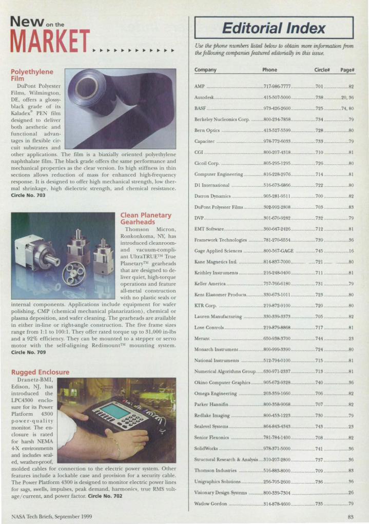
New onthe
MARKET. Polyethylene Film
DuPont Polyester Films, WilminglOn , DE, offers agIo yblack grade of its Kaladex· PE. film designed to deliver both aesthetk and functional advantage in flexible circuit sub lrales and other applications. The film i a biaxially oriented polyethylene naphthalate film. The black grade offers the ame performance and mechanical properties as the clear version. Its high stiffness in t.hin sections allow reduction o[ mass [or enhanced high-frequenc re ponse. It is designed to offer high mechanical trength , low thermal shrinkage, high dielectric trength, and chemical resi lance. Circle No. 703
Clean Planetary Gearheads
Thomson Micron, Ronkonkoma, NY, has introduced clean roomand vacuum-compliant UltraTRUETM True PlanetaryTM gearheads that are designed to deliver quiet, high-tOrque operations and feature all-metal con LrUction with no plastic seals or
internal components. Applications include equipment for wafer polishing, CMF (chemical mechanical planarization), chemical or plasma deposition, and wafer cleaning. The gearheads are available in either in-line or right-angle con LrUction . The five frame izes range from 1:1 to 100:1. They offer rated torque up to 31.000 in-lbs and a 92% efficiency. They can be mounted to a stepper or servo motOr with the self-aligning Redimount™ mounting system. Circle No. 709
Rugged Enclosure Dranetz-B:'U,
Edi on, G. has introduced the LPC4300 enclosure [or its Power Platform 4300 power-quali ty monitor. The enclosure is raled for harsh 'EMA 4-X emironments and includes sealed, weather-proof. molded cable for connection to the electric power } tern. Other features include a lockable case and provision for a ecurity cable. The Power Platform 4300 is de igned to monitor electric power lines for sags, swells. impul es. peak demand. harmonics, true It\,!S voltage/ current. and power factor. Circle No. 702
, ASA Tech Briefs, September 1999
Editorial Index Use the plume numbers ilsted beJnw w obtain ~ iriformatitm from the following companies featured edUorialIy in this issue.
Company Phone Circle# Page#
A.r-.tP .............................................. 717-986-7777 .................... 701 .................... 82
Autodesk ............. ........................... 415-507-5000 ........... ......... 738 ... ........... 20. 36
BASF ............................................ . 973-426-2600 ........... ......... 725 .............. 74 . 80
Berkeley Nucleonics Corp ........... 800-234-7858 .................... 734 .... ................ 79
Bern Optics .................................. 41g..527-5599 ......... .......... 728 .................... 80
Capacitec ...................................... 97S-772-6033 .................... 733 .................... 79
CGI .................................. .............. 800-207-4318 .................... 710 .................... 81
Cicoil Corp ................................... 805-295-1295 .................... 726 .................... 80
Computer Engineering ....... ......... 8 I 6-22S-2976 .................... 714 ...... .............. 81
Dllmernational ........... .. ............. 516-673-6866 ................ .... 722 .................... 80
Datron Dynamics .......................... 905-281-9511 .................... 700 .............. ..... . 82
DuPont Polyester FillIl5 ................ 302-992-2808 .................... 703 ................... . 83
DVP .............................. .................. 30 1-670-9282 .......... .. ........ 732 ......... ...... ..... 79
EMT SOftware ................................ 360-647-2426 ....... ............. 712 .................... 81
Framework Technologies ............ 781-270-6554 ............... ..... 739 ................ .. .. 36
Cage Applied Sciences ................ 800-567-CACE ................ 745 ........ ............ 16
Kane Magnetics Inti . .. .................. 81~37-7000.. ........ . .... 721 ...... . ......... 80
Keithley InstrumenLS .................... 216-24S-0400 ...... .. ...... ... .. 711 .... ............. ... 81
Keller America ....................... ....... 757-766-6180 ................. ... 7!l1 .................... 79
Kent Elastomer ProducLS .............. 330-67g..1011 .................... 723 .................... 80
KTR Corp ........................ ............. 219-872-9100 .................... 720 .................... 80
Lauren Manufacturing ................ 330-339-3373 .................... 705 .................... 82
Love COntrols ............... .. ............... 219-879-8868 .................... 717 .................... 81
Merant ............................. .......... ... 650-93S-3700 ............ ........ 744 .............. ...... 23
Monarch Instrument .................... 800-999-3390 ........ .. .......... 724 .................... 80
National Instruments .................. 512-794-0100 .................... 715 .................... 81
,'umerical Algorithlll5 Croup ...... 630-971-23l17 .................... 715 .................... 81
Olr.ino Computer Craphics .. ....... 905-672-9328 .................... 740 .................... 36
Omega Engineering .................... 20g..359-1660 ............... .. ... 706 .................... 82
Parker Hannifin ............................ 800-35S-9068 ................... 707 .................... 82
Redlake Imaging .......................... 800-45g..1223 .................. .. 7~ .................... 79
Sealevel SyStelll5 ........................... 864-84g..<t!l43 .................... 74.'1 ................... . 23
Senior Flexonia ............... ........... 781-7 4-1400 .................... 708 ................. ... 82
SolidWorks ................................... 97S-371-5000 .................... 741 .................... 36
Structural Research & Analym .... lI10-207-2800 .................... 7!l7 .................... 36
Thonuon lndtauies .................... 516-883-8000 ........ ........... . 709 .... .... ............ 83
Unigraphics SOlutions .......... ........ 256-705-2600 .... ................ 736 ............. 313
Visionary Design Sy&tems ............ 800-339-7301 .... .. ................................. ....... 26
Watlow Gordon .. ... ....................... lIl ~7S-4600 .................... 735 .................... 79
83
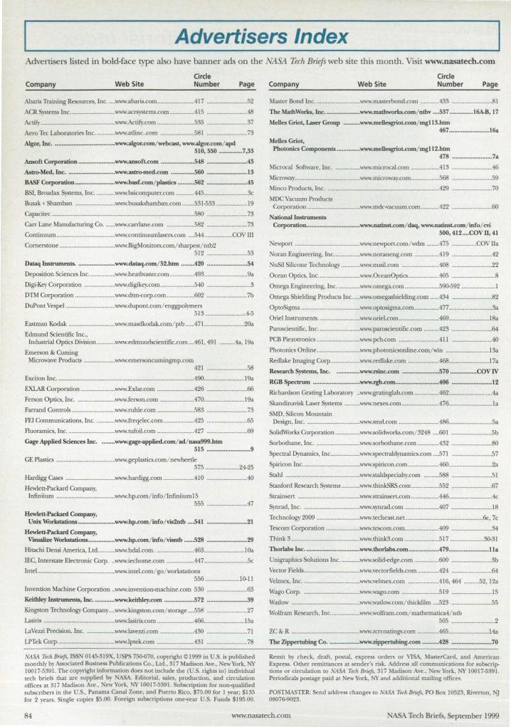
Advertisers Index dverti ers listed in bold-face type also have banner ads on the 'ltSA Tech Briefs web site tllls month. Visit www.nasatech.com
Company Web Site Circle Number Page
Aba.ris Training Resources, Inc. .... """w.abaris.com ...................•... .4l7 .......................... 52
ACR. )'Sterns Inc . ............................ www.acrsy tems.com ............ .... 415 .......................... 48
Actify ... ............................................. ,,"'" ctifY.com ........................ 535 .......................... 37
Aero Tee Laboratories lnc ............. www.allinc..com ...................... 581 .......................... 73
Algor, Inc. .................................... www.aIgor.com/ webcast. _w.algor.com/ ap<! 510,550 .............. 7,33
Ansofl Corporation ...................... WIIow.ansoft.com .............. ...... 548 ....................... .43
Astro-Med, Inc ............................. www.ast:ro-med.com ............. .560 ...........•............ 13
BASF COrporation ........................ \\oww.basf.com/ plastics .......... 562 ....................... .45
BS1, Broadax S terns, Inc ............. www.bsicomputer.com ............ 445 ............................ &
Busak + Shamban .......................... www.busakshamban.com ........ 531·533 .................... 19
Capacitec ..... ............................................ ........................................... 580 .......................... 73
Carr Lane Manufltcturing Co ....... www.carrlane.com .................. 582 ......................... . 73
COntinuum ...................... .. .............. www.continuumlasers.com .... 544 .................. COV III
Cornerstone ................... ................. www.BigMonitors.com/ sharpest/ntb2 512 .......................... 53
Dataq Instruments ................. ...... www.dataq.com/ 52.htm ....... .420 ........................ 54
Deposition Sciences Inc ....... .......... www.heatbuster.com ................ 493 ............................ 9a
Digi·Key Corporation .................... www.digikey.com ..................... . 540 ............................ 3
DTM Corporation ........... .............. . www.drm<orp.com ........ .......... 602 .......................... 7b
DuPont Vespel ................................ ,"", •. dupom.com/ enggpolymers 513 .......................... 4-5
Easunan Kodak ............................. . \\ww.masdkodak.com/ ptb ...... 471 .......................... 20a
Edmund &ientific Inc .• Industrial Optics Division ............ www.edmundscientific.com .... 461.491 .......... 4a.19a
Emerson & Cuming Microwave Products ... .. ............... w"w.emersoncumingmp.com
421 .......................... 58
Exciton Inc .................................................................. ................ ....... 490 ........ .................. 19a
EXlAR Corporation ...................... www.Exlar.com ........................ 426 .......................... 66
Ferson Optics. Inc ......................... www.ferson.com ...................... 470 .......................... 19a
Farrand Controls ............................ www.ruhle.com ........................ 583 ................. ......... 73
FEI Communications, Inc ............. www.freqelec.com .................... 425 .......................... 65
Fluoramics. Inc ............................... www.tufoil.com ........................ 427 .......................... 69
Gage Applied Sciences Inc. • ....... www.gage-applied.com/ ad/ nasa999.htm 515 .......................... 9
GE Plastics ...................................... www.geplastics.com/ newbeetle 575 ...................... 24-25
Hardigg Cases ................................ W\" •. hardigg.com .................... 410 .......................... 40
Hewlett-Packard Company. lnfiniium ...................................... www.hp.com/ info/ lnfiniiumI5
555 ......................... .47
H",,1ett·Packard Company, Unix Workstations ...................... www.hp.com/ info/ vis2ntb .... 541 ........................ 21
Hewlett·Packard Company. VtsUalize Workstations ................ www.hp.com/ info/ visnlb ...... 528 ........................ 29
Hitachi Densi America. LL<i ........... www.hdal.com ......................... 463 .......................... 1Oa
lEC. Interstate Electronic Corp ... www.iechome.com .... .. ............ 447 ............................ &
Intel... ............................................... www.intel.com/ go/ workstations 556 ...................... 10-11
Invention Machine Corporation .. W\.w.invention·machine.com 530 .......................... 63
Keithley Instruments, Inc. ............ \\oww.keithley.com .................. 572 ........................ 39
Kingston Technology COmpany .... ''''''''.kingston.com/ storage .... 558 .......................... 27
Lasiris .............................................. www.lasiris.com ....................... .466 .......................... 15a
LaVezzi Precision, Inc ..................... ww.\avezzi.com ...................... 430 .......................... 71
LPTek Corp ..................................... wwwJplek.com ........................ 431 .......................... 78
\'ISA Tech BrUifs, ISSN 014!)'319X. USPS 75~70. copyright ©1999 in U.S. is published monthly by Associated Business Publications Co .• Ltd .• 317 Macfuon Ave.. ew York, NY 10017·5391 . The copyright information does nnt include the (U.S. rights to) individual tech briefs that are supplied by NASA. EditOrial, sales. production, and circulation offices at 317 Macfuon A,-e.. ew York, NY 10017-5391. Subscription for non-<tuaJified subscribers in the U.S., Panama Canal Zone, and Pueno Rico, $75.00 for 1 year; $135 for 2 years. Single copies $5.00. Foreign subscriptions one·year U.S. Funds $195.00.
Company Web Site Circle Number Page
Master Bond Inc. ............................ \\'.w.maslerbond.com ............ 433 .......................... 81
The MathWorks, Inc. .................... www.matbworks.com/ ntbv .... 537 .............. 16A·B, 17
Melles Griot, Laser Group .......... www.mellesgriot.com/ mg1l3.hbn 467 ........................ 16a
Melles Griot, Pbotonics Components .............. www.mellesgriot.oom/ mgI12.htm
478 ........................ 7a
Microcal Software. Inc ................. W\" •. microcal.com .................. 413 .......................... 46
Microway ....................... ................... '"""".microway.com .................. 568 .......................... 59
Minco Products, Inc ......................................................................... 429 .......................... 70
MDC Vacuum Products COrporation .................................. ""',..mdc-vacuum.com ............ 422 .................... ..... . 60
National Instruments Corporation ................................ ,,"ww.llatinst.com/ daq, \\oww.natinst.com/ info/ cvi
500,412 .... COV II, 41
Newpon .......................................... www.newpon.com/ wdm ........ 475 ................ COV 11.
Noran Engineering. lnc ................. '"""".noraneng.com ................ 419 .......................... 42
NuSil Silicone TeclUlology ............ www.nusil.com ...................... ..408 .......................... 22
Ocean Optic. Inc ...... .. ................... ""'''".OceanOptics .................... 405 ............................ 8
Omega Engineering. Inc ............... "'.w.omega.com .. .................... 590-592 ..................... 1
Omega Shielding Products Inc . .... \\ww.omegashielding.com ...... 434 .......................... 82
OptoSigma ................ ........... ........... www.opto igma.com ................ 477 ............................ 3a
Oriel Instrumen ts ........................... www.oriel.com .......................... 469 .......................... 1Sa
Paroscientific, Inc ........................... www.paroscientific.com .......... 423 .......................... 64
PCB Piezotronics ...... ................ ...... \\ww.pcb.com ......................... .411 ............... ........... 40
Photonics Online ............................ "".w.photonicsonline.com/win ............................ 13a
Redlake Imaging COrp ................... www.redlake.com ................ .... 468 .......................... 17a
Research Systems, Inc. .............. www.rsinc.com ...................... 570 ................ COV]V
RGB Spectnun ............................ www.rgb.com ........ .................. 406 ........ ....... ......... 12
Richardson Grating Laboratory .. ,,,,,, •. gratinglab.com ................ 462 ............................ 4a
Skandinavisk Laser Systems .......... ""~ •. nexes.com ........ ................ 476 ............................ 1a
SMD. Silicon Mountain Design. Inc ................................... www.smd.com .......................... 486 .. .......................... 5a
SolidWorks Corporation ................ www.solidworks.com/ 3248 .... 601 .......................... 5b
Sorbothane.Inc ............................. '''"'''.sorbothane.com .............. 432 .......................... 80
Spectral Dynamics. Inc ................... '.ww.speetraldynamics.com .... 571 ...... .. .................. 57
Spiricon Inc ..................................... w"",.spiricon.com .................... 46O ............................ 2a
Stahl ................................................ ,"" •. stahlspecialty.com .......... 588 .............. ............ 51
Stanford Research Systems ............ WIIow.thinkSRS.com .................. 552 .......................... 67
Strainsen ........................................ '"""".strainsen.com .................. 446 ............................ 4c
Synrad. Inc ..................................... '''.w.synrad.com ...................... 407 .......................... 18
Technology 2009 ......... .. ................. '''''w.techeastnet .................................................. 6c. 7c
Tescom Corporation ...................... W\'w.lescom.com ...................... 409 .......................... 34
Think 3 ............................................ ,"" •. think3.com ...................... 517 ...................... 30-31
Thorlahs Inc ................................. www.thorlabs.com ................. .479 ........................ lla
Unigraphics Solutions Inc ............. www.solid-edge.com .............. .. 600 .......................... 3b
Vector Fields .................................... ,""".''eclorfields.com .............. 424 .................... ...... 64
Velme:x. Inc. .................................... '""" •. velmex.com .................... 416.464 .......... 52. 12a
Wago Corp ..................................... "".w.wago.com ........................ 519 .......................... 15
Watlow ............................................ www.watlow.com/ lhickfilm .... 523 ......................... . 55
Wolfrarn Research, Inc .............. ... .. W\,w.wolfram.com/ mathernatica4/ ntb 505 ............................ 2
ZC & R ............................................ '''"'''.zcrcoatings.com .............. 465 .......................... 14a
The Zippertubing Co ................... www.zippertubing.com .......... 428 ........................ 70
Remit by check. draft. postal, express orders or VISA, MasterCard, and American Express. Other remittances at sender's risk. Address alJ communications for subsaiptions or circulation to "'ASA Tuh BrU!ft. 317 Madison Ave .• New York, NY 10017-5391. Periodicals postage paid at New York. l\'Yand additional mailing offices.
POSTMASTER; Send address changes to .vASA T«h Bmfs. PO Box 10523. Riverton, r-u 08076-9023.
84 www.nasalech.com ASA Tech Briefs, September 1999
NASA Business Forum
Vision S ace ort: Space Development in the New Millennium
NASA Tech Briefs, September 1999
rI ASA's Kennedy Space Center is leading a major
initiative to identify the technologies that will enable
revolutionary "spaceports" of the future. The Vision
Spaceport program partners NASA and industry to develop the
infrastructure to support the next generation of space planes.
The initiative will be one of the featured tracks in the first -ever
NASA Business Forum, focused on emerging commercial
opportunities in aerospace and aviation. The forum is part of the
NASA-sponsored Technology 2009 national technology transfer
conference at the Fontainebleau Hilton in Miami on November 1-3.
(For more information on the workshop, visit www.techeast.net.)
Leading up to this event, NASA Tech Briefs presents a special
two-part article describing the major areas in which NASA is
looking to partner with industry on technology development into
the new millennium. This month's Part I features the technological
and economic challenges of realizing Vision Spaoeport, as well as
models of industry participation. The October issue will conclude
with space-based manufacturing capabilities and advanced
propulsion and engine technologies.
www.nasateeh.eom Ie
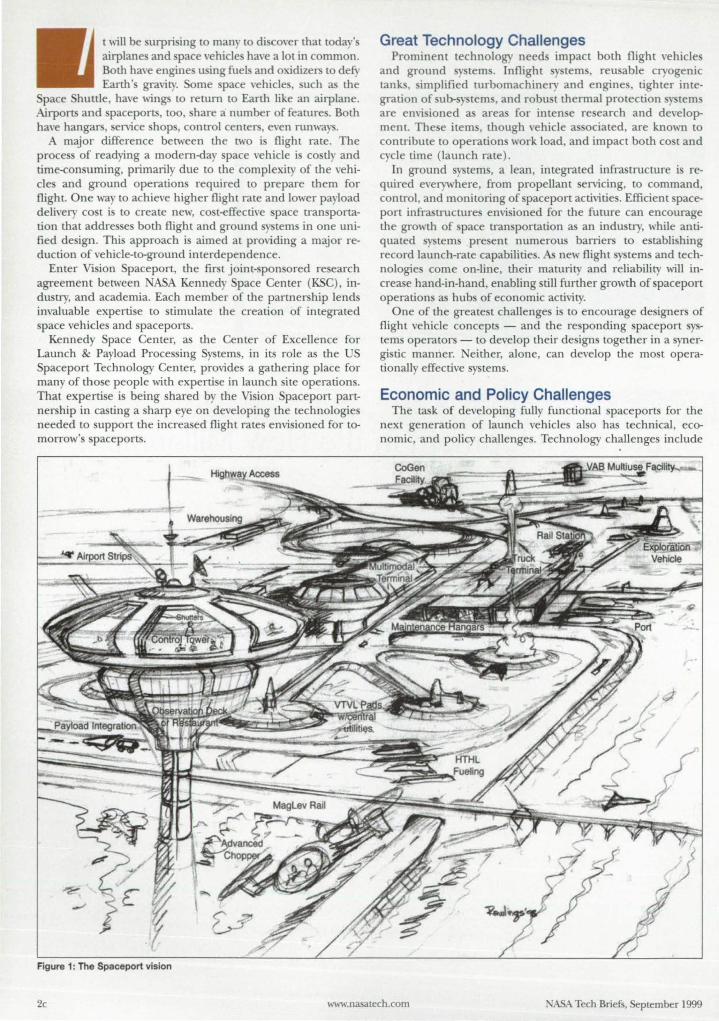
t will be surprising to many to di cover that today' airplane and pace vehicle have a lot in common. Both have engine u ing fuels and oxidizers to defy Earth 's gravity. Some pace vehicles, such as the
pace hurtle, have wings to return to Earth like an airplane. Airports and paceports, too, hare a number of features. Both have hangars, service shop , control centers, even runways.
A major difference between the two i flight rate. The proces of readying a modern-<iay space vehicle i costly and time-consuming, primarily due to the complexity of the vehicles and ground operation required to prepare them for flight. One way to achieve higher flight rate and lower payload delivery cost is to create new, cost-effective pace transportation that addres es both flight and ground terns in one unified de ign. Thi approach is aimed at providing a major reduction of vehicle-to-growld interdependence.
Enter Vision Spaceport, the first joint- ponsored research agreement between NASA Kennedy Space Center (KSC), industry, and academia. Each member of the partnerslup lends invaluable expertise to stimulate the creation of integrated space vehicles and spaceports.
Kennedy Space Center, as the Center of Excellence for Launch & Payload Processing Systems, in its role as the US Spaceport Technology Center, provides a gathering place for many of those people with expertise in launch site operations. That expertise is being shared by the Vision Spaceport partnership in casting a sharp eye on developing the technologies needed to support the increased flight rates envisioned for tomorrow's spaceports.
Figure 1: The Spaceport vision
Great Technology Challenges Prominent technology need impact both flight vehicles
and ground y tern. Inflight terns, reu able cryogenic tank , simplified turbomachinery and engine, tighter integration of ub- ystems, and robust thermal protection systems are envi ioned as areas for inten e re earch and development. The e item , though vehicle associated, are known to contribute to operations work load, and impact both co t and cycle time (launch rate).
In ground systems, a lean, integrated infrastructure is required everywhere, from propellant servicing, to command, control, and monitoring of pace port activities. Efficient spaceport infrastructures envi ioned for the future can encourage the growth of space transportation as an industry, while antiquated ystems present numerou barriers to establi hing record launch-rate capabilitie . As new flight systems and technologies come on-line, their maturity and reliability will increase hand-in-hand, enabling still further growth of spaceport operations as hubs of economic activit)'.
One of the greate t challenges is to encourage designers of flight vehicle concepts - and tlle responding spaceport systems operators - to develop their designs together in a synergistic manner. either, alone, can develop tlle most operationally effective systems.
Economic and Policy Challenges The task of developing fully functional spaceports for the
next generation of launch vehicles also has technical, economic, and policy challenges. Technology challenges include
2c www.nasalech .com NASA Tech BriefS, September 1999

POVVERFUL&SCALABLE CQ)QJJ(fl ~@(flW@(fl~ @)Ol)@ ~@(fl~~cQ:@)cQ:~@o=u~
~(fl@ @]@~[]l)~ ~D@)~@~
~"m @Ii" ~~OiIDm iID~~!1"§ multiple slots
llfil~ A Vi. " <f ~ ~
dual processor support
asI Broadax Systems, Inc.
'" 15.1" 10241068 resolution
Providing Industrial and MobilE Computing Solutions sincE 1986
rugged conslrudlon
4 accessible drivEs
1-800-872-4547 www.bsicomputer.com ~
For More Infonnatlon CIn:I. No. 445
PLAT LCMD CllLU .. acnncy.~ and -. _ and aynamoc IoIId tIf"'"9 frcm 250 pounOs 10 2 ....", p<U1ds One bIoon C)ICIt fabguo raIrd load colis aI!o~
CUVU ..... SI3>darII elMs pons fer ust ln~mpr_SOC1<eIS.
shactIes. IhocI< imSIen.
~ cyhIen. 01( 5p«JaIs 10 ftt edIIlng SIIIIC1IftS
LCMD ..oICATOIII C~c:allbraledload __ S)'SIfIIlS available
LCMD_ .. MG .....-n.ITUDi Sl3>darll1inos a vanous t}'Pe' 14'10 I·IIT ella Ar~ to a fraction II 1% FS I~ 10 IDfqUt and Dondong.
ftIIIICNI UMKJ Sl3>darll1inos 10 400.000 pounds capacity and OYer
1Inodod onds; immaI. _ tmads f'IIIoI ends
For More Information Circle No. 446
Are You an INSIDER?
Subscribe today to NTB INSIDER, the FREE e-mail newsletter for NASA Tech Briefs readers.
Twice each month, the INSIDER will bring you exclu ive previews of upcoming briefs and articles in NASA Tech Briefs, advance notice of online and trade show opportunities, and NASA/industry news you
won't find elsewhere. In a recent edition, for example, the INSIDER had the scoop on NASA's Inventions of
the Year ... weeks ahead of any other source.
Subscribe online at www.nasatech.com
integrating a ho t of 21 t century tern, from operators, through electronic networks, to end item uch as en ors and valve . Economic challenge include how to boot trap financing the development of uch tern , e pecially in the near term, while contemporary flight rates are not likely to quickly amortize uch inve tments. Policy challenge include que tion uch as who will pay for uch inve tments. Are user fee on a
pa -as-you-go approach - uch as with airports - useful guide for paceport developments? What are the role of private indu try, and which befall government?
Integrated ground and flight tern, when developed, will lead to a global proliferation of pace ports. In the near term, because pace vehicle reliabilitie are not yet aircraft-like, public afety will drive developers to the national ranges as mandated paceports. Even though propo ed ingle- tage-to-orbit ystems have no components to drop enroute to orbit, the in
gle tage require maturity and reliability far beyond current ystems before flights over populated areas are envi ioned.
When the e hurdle are cleared, the "spaceport as airport" will become a reality, perhap eeing space plane departing from a host of new terminal . State uch as Alaska, California, Florida, ew Mexico, and Virginia already are investing re-ources to be ready and able to meet these challenges.
Routine Space Flight: Payload Cost Economic tudies have indicated that cost reduction of two
orders of magnitude from today' markets are required before fully elastic markets develop in pace transportation. Thi means getting "cost" down to about 100 per delivered payload pound, with "price" perhap only twice as high. For comparison, thi means getting the cost of a trip down to about that of a round-the-world ticket (with amenities) on the Concorde. Studie show that mall, efficient space fleets of about 14 vehicles, with high utilization factors (launch rate) , conceivably
Figure 2: Technology Development - Paving the road to fulfillment of the vision
may enable such ventures as public space transportation, or large-scale energy enterpri es such as the constrUction of Space Solar Power energy tran mi sion station in the kyo Fascinating challenge await the space tran port industry. Many difficult que tion must be examined and answered.
Vision Spaceport Partners To lift the project off the ground, Kennedy Space Center
gathered a circle of indu try and academia partners to examine launch site operations and their cost-driving factor. Their goal i to identify technologies that will support the effective, affordable space transportation essential to opening
4c www.nasatech.com ASA Tech Briefs, September 1999
space for commercial enterprise. The parmers have formed a consortium of
launch site analysts and engineers, known as the Spaceport ynergy Team. The members are: • NASAJohn F. Kennedy Space Center • ASAAmes Research Center • The Boeing Company • Command and Control Technologies • Lockheed Martin • Quantum Technoiogies Sernces, Inc. • Science Applications International
Corporation • The niversity of Central Florida
The ESC partnership also is working closely with .farshall Space Flight Center, Johnson
pace Center, Langley Research Center, and industry partner vehicle designers to assure the model provides the best available operational assessment for future vehicle concepts.
Together, they are developing a co [and performance modeling tool for integrated vehicle and spaceport concepts. This innovative, com
Figure 3: Vision Realized - When the application of vision and technology coincide
puter-based model, when complete, will use information from the world's launch systems to estimate the cost and throughput performance of near-future design. The model thereby can be used to assist designers of future Space Transportation Systems in focusing on achieving affordable operating cost.
The prototype "core" model has been completed and currently is undergoing extensive validation and calibration using historical data in cooperation with the other ASA centers. A validated Version 1.0 beta model i expected to be available for use late this year.
I give up ...
Based on the launch vehicle designer's input, the model is being developed to provide system design information in various categories, including, but not limited to, estimates of: • Identity of required spacepon facilities • Facility and support equipment acquisition cost • Work force size • Operations cost summary • Vehicle and spacecraft processing time • System £light rate
Displays
_.Iechome.com
Tired of all the monkey business from the "other guys?" If you're looking for a true, ruggedized display that can
withstand harsh environments. get serious and visit our web site or
call 714.758.4241
ASA Tech Briefs. September 1999 For More Information Circle No. 447 5c

-Announcing Two Special Conference Tracks at
I E.
November 1·3, 1999
Miami Beach Fontainebleau Hilton
www.techeast.net
• MSA Business Forum First-ever government-industry forum on emerging commercial opportunities in aerospace and aviation, Spotlighting major areas in which NASA is looking to partner with Industry into the new millennium - including spaceports to launch the next generation of space vehicles, advanced medical technologies, space-based manufacturing, and more, Plus, learn how to do business successfully with NASA and meet the key players In technology transfer, licensing, contracting, and grants,
• S8m Southeast Conference The Small Business Innovation Research (SBIR) Program is the largest source of early-stage technology financing In the U,S" with 11 federal agencies awarding $1 ,2 billion annually to thousands of companies (500 or fewer employees), Hands-on workshops and Interactive sessions will show you how to effectively compete for and manage SBIR grants, and how to use SBIR to strategically grow your business, Plus, learn about STIR, an innovative program partnering small and larger companies and universities in cutting-edge R&D projects,
Register by October 15 and Save up to 30% •
Your conference registration Includes admission to hundreds of exhibits in three concurrent Tech East events:
Technology 2009 TECHNOLOGY See the best new inventions from America's premier R&D laboratories .. ,
an incredible wealth of new business ideas and ready-made engineering solutions,
Small Business Tech Expo Meet the experts who can help you turn Innovative ideas into profitable products, Find financing and marketing resources, Investment opportunities, and partners to launch your next venture.
Southeast Design & Manufacturing Expo Discover the latest tools to help your engineering team meet its design, prototyplng, testing, and production challenges,
Sponsored by
TECH BRIEFS
It's going to be hot in Miami this November!
I'-E S~ REGISTRATION
November 1-3, 1999 • Fontainebleau Hilton • Miami Beach, Florida
Please submit one form per person.
Name ________________________________________________________________________________ __
Tide __________________________________________________________________________________ _
Company ______________________________________________________________________________ __
Address City/StlZip _________________________________________________________________________ _
Phone ------------------------------------------ ~ E-Mail ________________________________________________________________________________ __
Conference Registration (check one)
A 0 Passport Registration (includes "S" and "c" below)
S 0 NASA Susiness Forum
C C SSIR Conference
By 10/1 5/99
$275 $175
$175
After 1011 5/99
$325
$225 $225
Conference registration includes conference sessions and materials, one ticket to the Networking Reception, and admission to the exhibit hall.
Short Courses Courses are numbered and priced individually. Write the number(s) and price(s) of the courses you will attend. SC __ @$_SC_@$_SC_@$_SC_@$_ShortCoursesTotal:$, __ __
Exhibits Only o Check here to register for free admission to Tech East '99 exhibits.
Payment Method (Full payment must accompany registration.)
o Purchase order attached
o Check enclosed (payable to Associated Susiness Publications Inti.) Payment Total: $
o Credit Card: 0 VISA 0 MasterCard 0 AmEx Card Number ___________________________________________________ expiration Date Signature ______________________________________________________________________________ __
Registrations are transferable when requested in writing. Cancellations must be received by 10/15/99 and are subject to a $30 processing fee.
THREE WAYS TO REGISTER Preregistration Deadline:
Fu: MajJ: October 15, 1999 (212) 986-7864 Tech East '99 - Miami
Online wvvw.techeast.net
do Associated Business Publications Inti. 317 Madison Avenue. # 1900
Questions? Call (212) 490-3999. New York. NY 10017
Sharpen Your Technical Edge Ii Business Skills - Attend These Short Courses During Tech East '99:
SC201 Elltrepreneurship & Intrepreneurship: How to Develop a Successful Business or Product (Mon., I III, 9:00 am - 12:30 pm, $150 pre-reg! $195 on-site)
SC202 Intellectual Property: Protection. Licensing, and Government Tech Transfer Issues (Mon .• II II, 12:30 - 4:00 pm, $150/$195)
SC203 New Venture Planning and Development for Scientists and Engineers (Tues., I 112. 9:00 am - 12:30 pm, $150/$195)
SC204 Introduction to Rapid Prototyping and Tooling Technologies (Tues., I I f2, 9:00 am - 1:00 pm, $175/$225)
SC20S Successful Proposal Strategies for Small Businesses (Tues .• 1112, 1:30 - 5:00 pm. $150/$195)
SC206 Tribological Materials and Manufacturing Processes for Wear Resistance (Wed., 1113,9:00 am - I :00 pm, $1751$225)
Visit www.tecbeast.net for more information.
Scope of the Model cope of the model covers three major areas of pace port
functionality: Launch 'Yst~m OpI!Yations. Thi will include module for:
• Pa load preflight proce ing • Launch operation • Flight control • Vehicle landing and recovery
The econd major functional area is Optional Facilities, including accommodation for: • ehicle as embly and integration, if needed • Vehicle ervicing for return to flight • Expendable elemen ts, if any
The third functional area addre ed by the model i upport Infrastructure Facilities, uch as: • Tran portation tern management and planning • Concept-unique logistic • paceport operation upport • Vehicle depot maintenance upport
The model, erving as a deci ion- upporting tool, will enable de igner to as e the new launch system concept and evaluate its co t-effectivene .
The first step in u ing the model is to acce the data input tabs. This i where designers define their flight sy tern . E -
Figure 4: The three-dimensional Virtual Spaceport artist's concept
ential characteristics of the vehicle are input, a well a cargo-carrying capabilities, identity of sub y terns, and other pertinent data. Thi step is key because vehicle characteristic influence the paceport architecture, contributing to overall cost of the system and the re ulting flight rate.
After flight vehicle design data are input, the model will generate simple data heets howing required paceport facilities, vehicle and spaceport operational costs, proce ing cycle times, and numerou other cost-affecting parameter. In a imple tabular format, the de igner easily can ee how different vehicle design impact launch ite infrastructure, and the as ociated costs and cycle time .
Graphical Output: The Virtual Spaceport Another more intuitive output of the model will be a "virtual
pace port" - a real-time, three-dimen ional ample rendering of facilitie required b the } tern concept. The Virtual Spaceport uses three-dimen ional launch ite infra tructure model po itioned on a two-dimen ional ground reference. Thi will make the output data easier to interpret, and thu acce ible to a broader audience.
orne launch ite facilitie commonl as ociated with pre-enHia pace ports rna not be e ential for future concepts.
For in tance, a horizontal rake-off pace-vehicle rna not require vertical proce ing infrastructure. Other type of pacecraft might rely on a magnetic-levitation rail for rake-off. An airport Ie control tower might be used in place of a bunkerlike launch control center. The ani t' concept in Figure 4 hows how future-generation proce ing and launch control
equipment dramaticall may reduce the required work force and accommodate increa ed flight rate.
The three-dimen ional Virtual paceport will allow the user to fly through the model and examine the infrastructure from different perspective . Many areas of the 3D model are being hyperlin ked to data heets for the particular facility in que tion.
Benefits of the Project Kennedy pace Center, through its goal to become a Space
port Technology Center, i a leading developer of pace port technologie . The tool being developed there will provide an in ight into paceport de ign of the future. As KSC move into the future with greater emphasis on re earch and development, it i trengthening plan to be both a provider of paceport technology, and a paceport-of-choice for many cu tomers of the future .
As the payload delivery and operation co ts continue to go down, more and more commercial cargo will be launched into Earth orbit and beyond. ASA's vision i of a day when human space flight become routine and affordable for anyone. The new technologie to upport thi vi-ion already are being developed. Vision Space
port is about our future. The Vi ion Spaceport partnership welcomes
participation of organizations with a vi ion for achieving affordable pace acce . The partnership particularly eeks collaboration and experti e in key areas such as space operations performance benchmarking, technology roadmapping, cost modeling, facility visualization , and related fie lds. Spaceport operators also are particularly welcome to contribute their unique perspective on reducing spaceport operations costs.
Potential participants hould recognize that they are expected to contribute funding or inkind re ources to the partner hip. All products become property of the Vi ion paceport Project
and are available publicly to all interested organization within limitation of applicable export control regulation.
Those interested further may contact Carey McCleskey, Government Co-chairj e-mail: carey.mccleskey- [email protected]. gov, or Ray Byrd, Industry Co-chairj e-mail: byrdr@pgocM5. ksc.nasa.gov. For further information, visit the Vision Spaceport website at: www.visionspaceport.org.
A lO-minute video describing the Project and the modeling effort is available to qualified pace indu try applicants.
This article was written by Raymond J. Byrd, Industry Co-Chair, Vision Spaceport Project, and was co-written by SI!Ygei Kossenko, Dynacs Digital Media Lab, Kennedy pace Center. Byrd has worked at Kennedy pace CentI!Y most of the past 34 yeaTS since becoming an S-1 C mechanical systems engineI!Y on the Saturn-Apollo program in 1965. His longtime expmence in launch site activities is representative of the people and expI!Ytise now gathi!Yed in the paceport >]nI!Ygy Team, with the goal of stimulating development of affordable space transportation. I!Ygei Kossenko is an award-winning producI!Y of digital media products at the Kennedy Space Center. Artwork is by Pat Rawlings, SAlC Houston, Cafryright 1999 Vision Spaceport Project.
Bc www.nasatech.com 'ASA Tech Briefs, September 1999
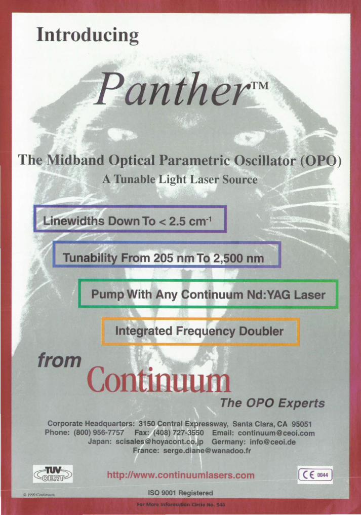
Introducing
The Midband Optical Parametric Oscillator (OP ) A Tunable Light Laser Source
From 205 nm To 2,500 nm
Integrated Frequency Doubler
The OPO Experts
Corporate Headquarters: 3150 Central Expressway, Santa Clara, CA 95051 Phone: (800) 956-n57 Fax: (408) 727-3550 Email: continuumOceol.com
Japan: [email protected] Germany: infoOceoi.de France: [email protected]
http://www.continuumlasers.com
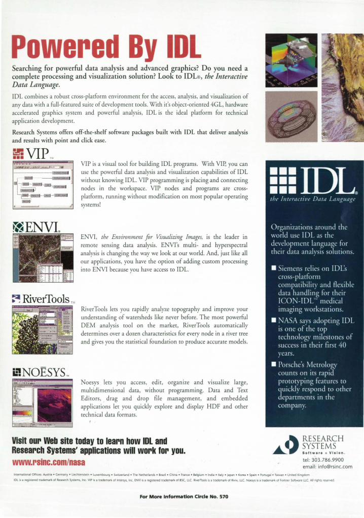
Powered By IOL Searching for powerful data analysis and advanced graphics? Do you need a complece processing and visualization solution? Look Co ID , the Interactive Data Language.
lOL combines a robust cross-platform environment for the access, analysis, and visualization of
any data with a full-featured suite of development tools. With it's object-oriented 4GL, hardware accelerated graphics system and powerful analysis, rOL is the ideal platform for technical
application development.
Research Systems offers off-the-shelf software packages built with IDL that deliver analysis and results with point and click ease.
Er: VIP TM
=~I II .... ~ ....... ,,' i 1,;..:, ... 1"-I . ~ >
I .' I
f ... j .. :·.,,. •. , .... ... . i : . ' . -. -
L...J: .. f.= I tB 1.,\ -. - !:_~
~ RiverTools TM
i:'NOESYS ~
VlP is a visual tool for building IDL programs. With Vlp, you can
use the powerful data analysis and visualization capabilities of rOL without knowing rOL. VlP programming is placing and connecting nodes in the workspace. VlP nodes and programs are crossplatform, running without modification on most popular operating
systems!
ENVI, the Environment for Visualizing Images, is the leader in remote sensing data analysis. ENVI's multi- and hyperspectral analysis is changing the way we look at our world. And, just like all
our applications, you have the option of adding custom processing into ENVI because you have access to IOL.
RiverTools lets you rapidly analyze topography and improve your understanding of watersheds like never before. The most powerful OEM analysis tool on the market, RiverTools automatically determines over a dozen characteristics for every node in a river tree and gives you the statistical foundation to produce accurate models.
oesys lets you access, edit, organize and visualize large, multidimensional data, without programming. Oata and Text Editors, drag and dtop file management, and embedded
applications let you quickly explore and display HOF and other technical data formatS.
Visit our Web site today to learn how IOL and Research Systems' applications will work lor you. www.rslnc.comlnasa
A RESEARCH
~y ~~~:'~~I~IO"' tel : 303.786.9900 email: [email protected]
IntffNtJONl OffICeS Austni • <Annlny • Uechterule1n .. lu-embourg .. SWluemnd .. Tht NetM~nc:b .. &raziI .. ChIN .. France .. Be'glUm .. Ind .. .. Imly .. J.lJ»" .. Kor", • Spain .. PonugM .. T.~n .. United KIngdom
10l IS. teg.lStered ~ 01 Research Syu.etm. Inc. \1P is • tt~n: of Intmys. Inc. ENVIn. reglSt~ ~ 01 sse. llC. Rr.tiToob ts • u.demIrt 01 RMx. llC. Noes)"l tS • ~rt 01 Fortnl'f SdtwiIre llC All nghts r~
For More Information Circle No. 570