table of contents of special provisions - biznet
TRANSCRIPT

TABLE OF CONTENTS OF SPECIAL PROVISIONS Note: This Table of Contents has been prepared for the convenience of those using this contract with the sole express purpose of locating quickly the information contained herein; and no claims shall arise due to omissions, additions, deletions, etc., as this Table of Contents shall not be considered part of the contract.

Table of ContentsCONTRACT TIME AND LIQUIDATED DAMAGES....................................................................................NOTICE TO CONTRACTOR – FEDERAL WAGE DETERMINATIONS....................................................(Davis Bacon Act) .....................................................................................................................................NOTICE TO CONTRACTOR – PREBID QUESTIONS AND ANSWERS..................................................NOTICE TO CONTRACTOR – HAZARDOUS MATERIALS .....................................................................INVESTIGATIONS .....................................................................................................................................NOTICE TO CONTRACTOR - CONSTRUCTION CONTRACTOR...........................................................DIGITAL SUBMISSIONS ...........................................................................................................................NOTICE TO CONTRACTOR – EXISTING IMS .........................................................................................NOTICE TO CONTRACTOR – MINIMUM CONCRETE COMPRESSIVE.................................................STRENGTH................................................................................................................................................NOTICE TO CONTRACTOR - SALVAGE .................................................................................................NOTICE TO CONTRACTOR – SIGN STRUCTURES AND ......................................................................FOUNDATIONS .........................................................................................................................................NOTICE TO CONTRACTOR – GLOBAL POSITIONING SYSTEM (GPS) ..............................................COORDINATES FOR SIGNS ....................................................................................................................NOTICE TO CONTRACTOR - ARCHITECTURAL AND INDUSTRIAL .....................................................MAINTENANCE COATINGS .....................................................................................................................NOTICE TO CONTRACTOR – USE OF STATE POLICE OFFICERS......................................................SECTION 1.02 – PROPOSAL REQUIREMENTS AND CONDITIONS .....................................................SECTION 1.05 - CONTROL OF THE WORK ............................................................................................SECTION 1.07 - LEGAL RELATIONS AND RESPONSIBILITIES.............................................................SECTION 1.08 - PROSECUTION AND PROGRESS................................................................................SECTION 4.06 - BITUMINOUS CONCRETE ............................................................................................SECTION 6.03 - STRUCTURAL STEEL....................................................................................................SECTION 12.00 – GENERAL CLAUSES FOR HIGHWAY SIGNING .......................................................SECTION 18.03 – IMPACT ATTENUATION SYSTEM, TEMPORARY.....................................................IMPACT ATTENUATION SYSTEM............................................................................................................SECTION M.04 BITUMINOUS CONCRETE MATERIALS ........................................................................SECTION M.06 - METALS.........................................................................................................................SECTION M.10 – RAILING AND FENCE ..................................................................................................ON-THE-JOB TRAINING (OJT) WORKFORCE DEVELOPMENT PILOT ...............................................SMALL CONTRACTOR AND SMALL CONTRACTOR MINORITY...........................................................BUSINESS ENTERPRISES (SET-ASIDE) ..............................................................................................ITEM #0020903A – LEAD COMPLIANCE FOR MISCELLANEOUS.........................................................EXTERIOR TASKS ....................................................................................................................................ITEM #0910189A – R-B 350 BRIDGE ATTACHMENT – JERSEY SHAPE...............................................PARAPET 10 GA .......................................................................................................................................ITEM #0917010A – REPAIR GUIDERAIL..................................................................................................ITEM #0952001A – SELECTIVE CLEARING AND THINNING .................................................................ITEM #0969060A - CONSTRUCTION FIELD OFFICE, SMALL................................................................ITEM #0971001A – MAINTENANCE AND PROTECTION OF TRAFFIC..................................................ITEM #1201801A – MONOTUBE BRIDGE SIGN STRUCTURE...............................................................ITEM #1201802A – 4 CHORD TRUSS BRIDGE SIGN STRUCTURE ......................................................ITEM #1201804A – 4 CHORD TRUSS CANTILEVER SIGN STRUCTURE .............................................ITEM #1202239A – OVERHEAD TRUSS SIGN SUPPORT FOUNDATION.............................................ITEM #1202999A – DRILLED SHAFT TRAFFIC STRUCTURE................................................................FOUNDATION............................................................................................................................................ITEM #1206025A - REMOVAL AND RELOCATION OF EXISTING..........................................................OVERHEAD SIGNS...................................................................................................................................ITEM #1207039A – SIGN FACE - EXTRUDED ALUMINUM (TYPE IX ....................................................RETROREFLECTIVE SHEETING) ...........................................................................................................
322222425252727282929303131323233333637384147598384868690
113117118122122134134153153155157158166204222240259275275289289291291
Table of Contents10170-3447/0148-0210
ITEM #1208931A – SIGN FACE - SHEET ALUMINUM \(TYPE IX ..........................................................RETROREFLECTIVE SHEETING) ...........................................................................................................ITEM #1806226A – PRE-WARNING VEHICLE.........................................................................................PERMITS AND/OR REQUIRED PROVISIONS: ........................................................................................
317317319321
Table of Contents20170-3447/0148-0210
Rev. Date 06-09-17
GENERAL
AUGUST 15, 2018
FEDERAL AID PROJECT NO. N/A STATE PROJECT NOS. 0170-3447 & 0148-0210
Statewide Replacement of Overhead Sign Supports On Various Routes
Replace Sign Support on I-91
Town/City of Greenwich, Westport, Bridgeport, Waterbury, Meriden, Berlin, Rocky Hill, Farmington, East Hartford, Enfield, Colchester and Wallingford
The State of Connecticut, Department of Transportation, Standard Specifications for Roads, Bridges, Facilities and Incidental Construction, Form 817, 2016, as revised by the Supplemental Specifications dated January 2018 (otherwise referred to collectively as "ConnDOT Form 817") is hereby made part of this contract, as modified by the Special Provisions contained herein. Form 817 is available at the following DOT website link http://www.ct.gov/dot/cwp/view.asp?a=3609&q=430362. The current edition of the State of Connecticut Department of Transportation's "Construction Contract Bidding and Award Manual" ("Manual"), is hereby made part of this contract. If the provisions of this Manual conflict with provisions of other Department documents (not including statutes or regulations), the provisions of the Manual will govern. The Manual is available at the following DOT website link http://www.ct.gov/dot/cwp/view.asp?a=2288&q=259258. The Special Provisions relate in particular to State Project Nos. 0170-3447 and 0148-0210 for the Statewide Replacement of Overhead Sign Supports On Various Routes and Replace Sign Support on I-91 in the Town(s)/City of Greenwich, Westport, Bridgeport, Waterbury, Meriden, Berlin, Rocky Hill, Farmington, East Hartford, Enfield, Colchester and Wallingford
COMBINED PROJECTS
There will be but one Contract for State Project No. 0170-3447 and State Project No. 0148-0210. The two projects will be considered as a single contract in all respects.
CONTRACT TIME AND LIQUIDATED DAMAGES In order to minimize the hazard, cost and inconvenience to the traveling public and pollution of the environment, it is necessary to limit the time of construction work, which interferes with traffic as specified in Article 1.08.04 of the Special Provisions. There will be two assessments for liquidated damages and they will be addressed in the following manner:
30170-3447/0148-0210
Rev. Date 06-09-17
GENERAL
1. For this contract, an assessment per day for liquidated damages, at a rate of Two
Thousand Five Hundred ($2,500) Dollars per day shall be applied to each calendar day the work runs in excess of the Four Hundred Seventy-Four (474) allowed calendar days for the contract.
2. For this contract, an assessment per hour for liquidated damages shall be applied to
each hour, or any portion thereof, in which the Contractor interferes with normal traffic operations during the restricted hours given in Article 1.08.04 of the Special Provisions. The liquidated damages shall be as shown in the following tables entitled “Liquidated Damages Per Hour” for each hour, or any portion thereof, in which the Contractor interferes with normal traffic operations during the restricted hours.
For the purpose of administering this contract, normal traffic operations are considered interfered with when: 1. Any portion of the travel lanes or shoulders is occupied by any personnel, equipment,
materials, or supplies including signs. 2. The transition between the planes of pavement surfaces is at a rate of one inch in less
than fifteen feet longitudinally.
40170-3447/0148-0210
Rev. Date 06-09-17
GENERAL
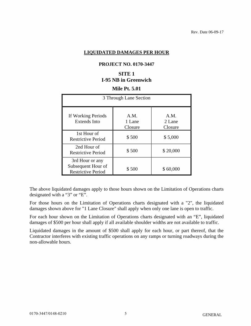
LIQUIDATED DAMAGES PER HOUR
PROJECT NO. 0170-3447
SITE 1 I-95 NB in Greenwich
Mile Pt. 5.01
3 Through Lane Section
If Working Periods
Extends Into
A.M.
1 Lane Closure
A.M.
2 Lane Closure
1st Hour of Restrictive Period $ 500 $ 5,000
2nd Hour of Restrictive Period $ 500 $ 20,000
3rd Hour or any Subsequent Hour of Restrictive Period
$ 500
$ 60,000
The above liquidated damages apply to those hours shown on the Limitation of Operations charts designated with a “3” or “E”.
For those hours on the Limitation of Operations charts designated with a "2", the liquidated damages shown above for "1 Lane Closure" shall apply when only one lane is open to traffic.
For each hour shown on the Limitation of Operations charts designated with an “E”, liquidated damages of $500 per hour shall apply if all available shoulder widths are not available to traffic.
Liquidated damages in the amount of $500 shall apply for each hour, or part thereof, that the Contractor interferes with existing traffic operations on any ramps or turning roadways during the non-allowable hours.
50170-3447/0148-0210
Rev. Date 06-09-17
GENERAL
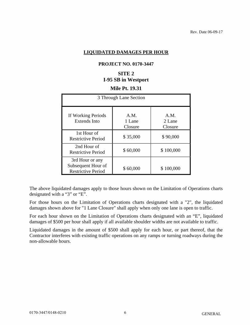
LIQUIDATED DAMAGES PER HOUR
PROJECT NO. 0170-3447
SITE 2 I-95 SB in Westport
Mile Pt. 19.31
3 Through Lane Section
If Working Periods
Extends Into
A.M.
1 Lane Closure
A.M.
2 Lane Closure
1st Hour of Restrictive Period $ 35,000 $ 90,000
2nd Hour of Restrictive Period $ 60,000 $ 100,000
3rd Hour or any Subsequent Hour of Restrictive Period
$ 60,000
$ 100,000
The above liquidated damages apply to those hours shown on the Limitation of Operations charts designated with a “3” or “E”.
For those hours on the Limitation of Operations charts designated with a "2", the liquidated damages shown above for "1 Lane Closure" shall apply when only one lane is open to traffic.
For each hour shown on the Limitation of Operations charts designated with an “E”, liquidated damages of $500 per hour shall apply if all available shoulder widths are not available to traffic.
Liquidated damages in the amount of $500 shall apply for each hour, or part thereof, that the Contractor interferes with existing traffic operations on any ramps or turning roadways during the non-allowable hours.
60170-3447/0148-0210
Rev. Date 06-09-17
GENERAL
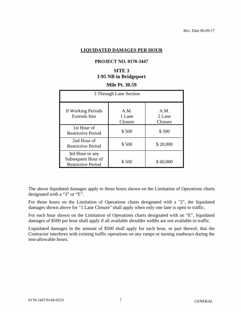
LIQUIDATED DAMAGES PER HOUR
PROJECT NO. 0170-3447
SITE 3 I-95 NB in Bridgeport
Mile Pt. 30.59
3 Through Lane Section
If Working Periods
Extends Into
A.M.
1 Lane Closure
A.M.
2 Lane Closure
1st Hour of Restrictive Period $ 500 $ 500
2nd Hour of Restrictive Period $ 500 $ 20,000
3rd Hour or any Subsequent Hour of Restrictive Period
$ 500
$ 60,000
The above liquidated damages apply to those hours shown on the Limitation of Operations charts designated with a “3” or “E”.
For those hours on the Limitation of Operations charts designated with a "2", the liquidated damages shown above for "1 Lane Closure" shall apply when only one lane is open to traffic.
For each hour shown on the Limitation of Operations charts designated with an “E”, liquidated damages of $500 per hour shall apply if all available shoulder widths are not available to traffic.
Liquidated damages in the amount of $500 shall apply for each hour, or part thereof, that the Contractor interferes with existing traffic operations on any ramps or turning roadways during the non-allowable hours.
70170-3447/0148-0210
Rev. Date 06-09-17
GENERAL
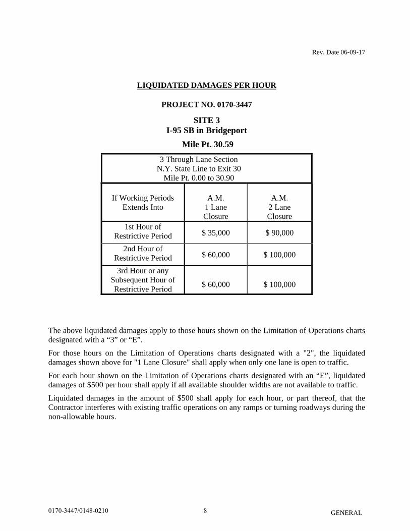
LIQUIDATED DAMAGES PER HOUR
PROJECT NO. 0170-3447
SITE 3 I-95 SB in Bridgeport
Mile Pt. 30.59
3 Through Lane Section N.Y. State Line to Exit 30
Mile Pt. 0.00 to 30.90
If Working Periods
Extends Into
A.M.
1 Lane Closure
A.M.
2 Lane Closure
1st Hour of Restrictive Period $ 35,000 $ 90,000
2nd Hour of Restrictive Period $ 60,000 $ 100,000
3rd Hour or any Subsequent Hour of Restrictive Period
$ 60,000
$ 100,000
The above liquidated damages apply to those hours shown on the Limitation of Operations charts designated with a “3” or “E”.
For those hours on the Limitation of Operations charts designated with a "2", the liquidated damages shown above for "1 Lane Closure" shall apply when only one lane is open to traffic.
For each hour shown on the Limitation of Operations charts designated with an “E”, liquidated damages of $500 per hour shall apply if all available shoulder widths are not available to traffic.
Liquidated damages in the amount of $500 shall apply for each hour, or part thereof, that the Contractor interferes with existing traffic operations on any ramps or turning roadways during the non-allowable hours.
80170-3447/0148-0210

Rev. Date 06-09-17
GENERAL
LIQUIDATED DAMAGES PER HOUR
PROJECT NO. 0170-3447
SITE 5 I-691EB in Meriden
Mile Pt. 1.65
2 Through Lane Section Mile Pt. 2.15 to 8.38
If Working Periods
Extends Into
A.M.
1 Lane Closure
P.M.
1 Lane Closure
1st Hour of Restrictive Period $ 500 $ 1,000
2nd Hour of Restrictive Period $ 9,000 $ 2,000
3rd Hour or any Subsequent Hour of Restrictive Period
$ 15,000
$ 4,000
The above liquidated damages apply to those hours shown on the Limitation of Operations charts designated with a “2” or “E”.
For each hour shown on the Limitation of Operations charts designated with an “E”, liquidated damages of $500 per hour shall apply if all available shoulder widths are not available to traffic.
Liquidated damages in the amount of $500 shall apply for each hour, or part thereof, that the Contractor interferes with existing traffic operations on any ramps or turning roadways during the non-allowable hours.
90170-3447/0148-0210
Rev. Date 06-09-17
GENERAL
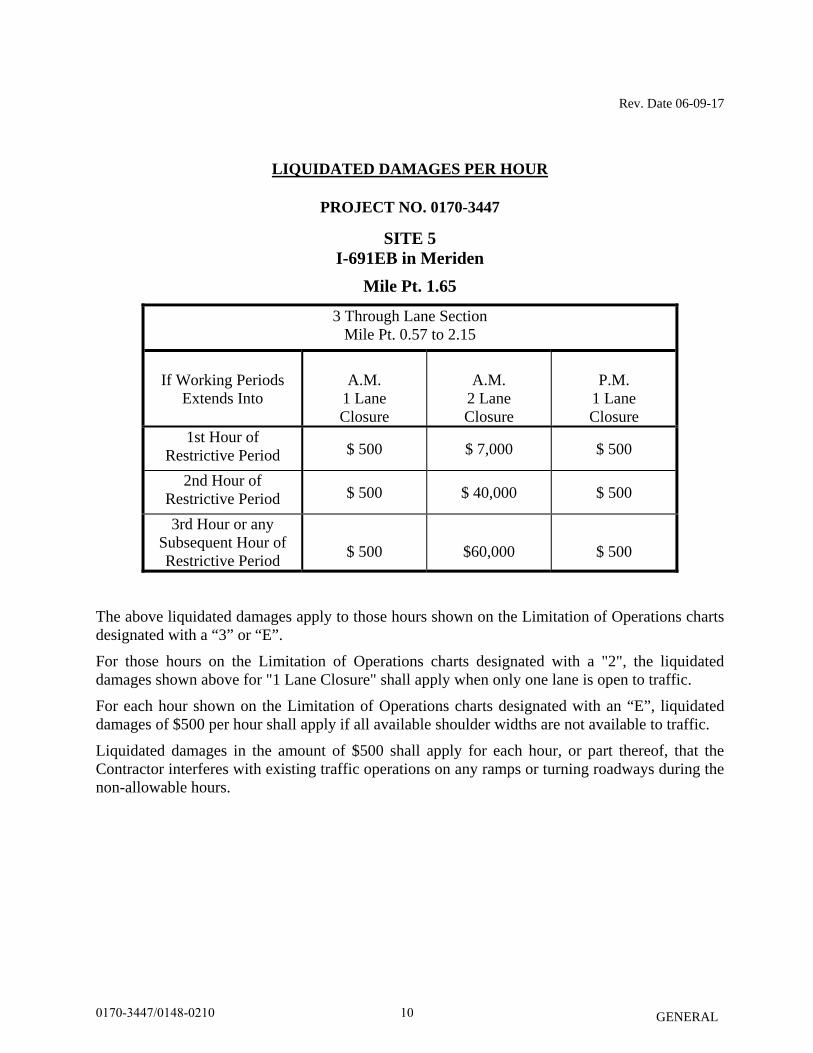
LIQUIDATED DAMAGES PER HOUR
PROJECT NO. 0170-3447
SITE 5 I-691EB in Meriden
Mile Pt. 1.65
3 Through Lane Section Mile Pt. 0.57 to 2.15
If Working Periods
Extends Into
A.M.
1 Lane Closure
A.M.
2 Lane Closure
P.M.
1 Lane Closure
1st Hour of Restrictive Period $ 500 $ 7,000 $ 500
2nd Hour of Restrictive Period $ 500 $ 40,000 $ 500
3rd Hour or any Subsequent Hour of Restrictive Period
$ 500
$60,000
$ 500
The above liquidated damages apply to those hours shown on the Limitation of Operations charts designated with a “3” or “E”.
For those hours on the Limitation of Operations charts designated with a "2", the liquidated damages shown above for "1 Lane Closure" shall apply when only one lane is open to traffic.
For each hour shown on the Limitation of Operations charts designated with an “E”, liquidated damages of $500 per hour shall apply if all available shoulder widths are not available to traffic.
Liquidated damages in the amount of $500 shall apply for each hour, or part thereof, that the Contractor interferes with existing traffic operations on any ramps or turning roadways during the non-allowable hours.
100170-3447/0148-0210
Rev. Date 06-09-17
GENERAL
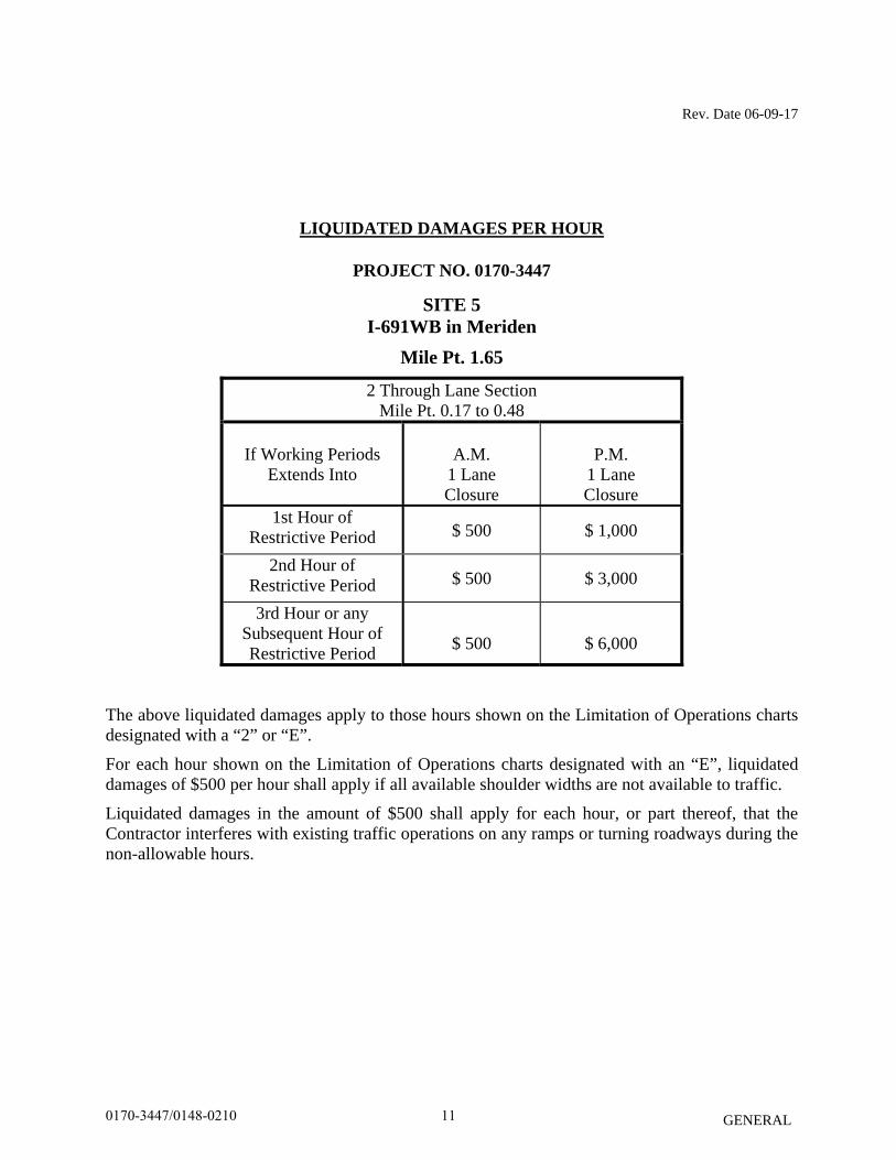
LIQUIDATED DAMAGES PER HOUR
PROJECT NO. 0170-3447
SITE 5 I-691WB in Meriden
Mile Pt. 1.65
2 Through Lane Section Mile Pt. 0.17 to 0.48
If Working Periods
Extends Into
A.M.
1 Lane Closure
P.M.
1 Lane Closure
1st Hour of Restrictive Period $ 500 $ 1,000
2nd Hour of Restrictive Period $ 500 $ 3,000
3rd Hour or any Subsequent Hour of Restrictive Period
$ 500
$ 6,000
The above liquidated damages apply to those hours shown on the Limitation of Operations charts designated with a “2” or “E”.
For each hour shown on the Limitation of Operations charts designated with an “E”, liquidated damages of $500 per hour shall apply if all available shoulder widths are not available to traffic.
Liquidated damages in the amount of $500 shall apply for each hour, or part thereof, that the Contractor interferes with existing traffic operations on any ramps or turning roadways during the non-allowable hours.
110170-3447/0148-0210
Rev. Date 06-09-17
GENERAL
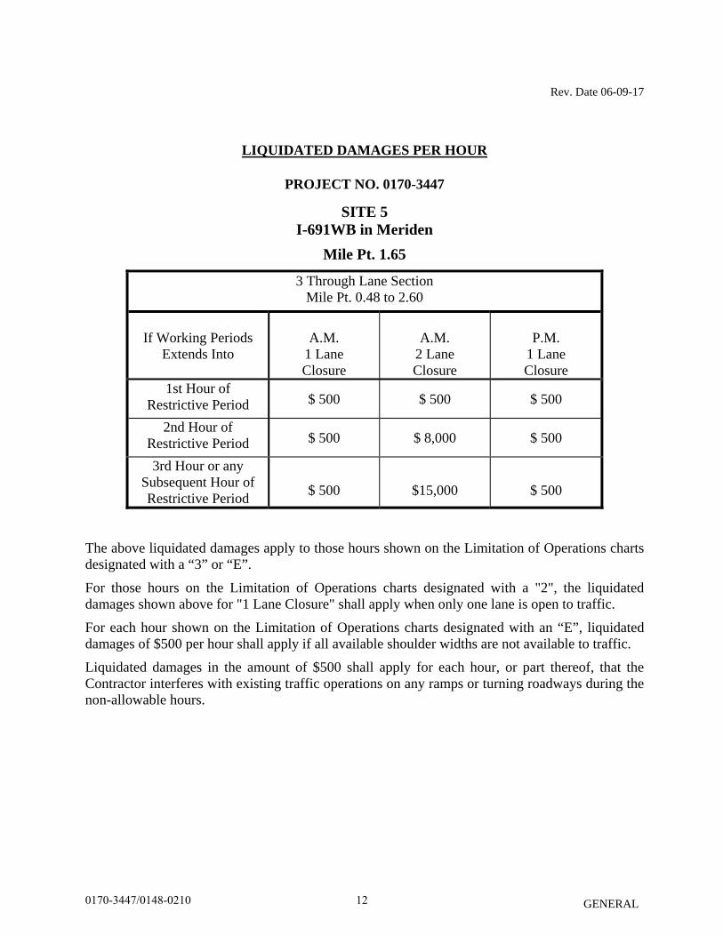
LIQUIDATED DAMAGES PER HOUR
PROJECT NO. 0170-3447
SITE 5 I-691WB in Meriden
Mile Pt. 1.65
3 Through Lane Section Mile Pt. 0.48 to 2.60
If Working Periods
Extends Into
A.M.
1 Lane Closure
A.M.
2 Lane Closure
P.M.
1 Lane Closure
1st Hour of Restrictive Period $ 500 $ 500 $ 500
2nd Hour of Restrictive Period $ 500 $ 8,000 $ 500
3rd Hour or any Subsequent Hour of Restrictive Period
$ 500
$15,000
$ 500
The above liquidated damages apply to those hours shown on the Limitation of Operations charts designated with a “3” or “E”.
For those hours on the Limitation of Operations charts designated with a "2", the liquidated damages shown above for "1 Lane Closure" shall apply when only one lane is open to traffic.
For each hour shown on the Limitation of Operations charts designated with an “E”, liquidated damages of $500 per hour shall apply if all available shoulder widths are not available to traffic.
Liquidated damages in the amount of $500 shall apply for each hour, or part thereof, that the Contractor interferes with existing traffic operations on any ramps or turning roadways during the non-allowable hours.
120170-3447/0148-0210
Rev. Date 06-09-17
GENERAL
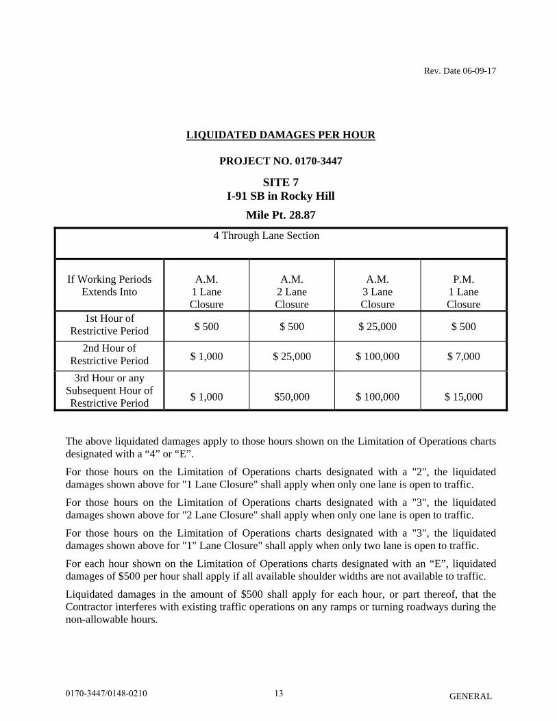
LIQUIDATED DAMAGES PER HOUR
PROJECT NO. 0170-3447
SITE 7 I-91 SB in Rocky Hill
Mile Pt. 28.87
4 Through Lane Section
If Working Periods
Extends Into
A.M.
1 Lane Closure
A.M.
2 Lane Closure
A.M.
3 Lane Closure
P.M.
1 Lane Closure
1st Hour of Restrictive Period $ 500 $ 500 $ 25,000 $ 500
2nd Hour of Restrictive Period $ 1,000 $ 25,000 $ 100,000 $ 7,000
3rd Hour or any Subsequent Hour of Restrictive Period
$ 1,000
$50,000
$ 100,000
$ 15,000
The above liquidated damages apply to those hours shown on the Limitation of Operations charts designated with a “4” or “E”.
For those hours on the Limitation of Operations charts designated with a "2", the liquidated damages shown above for "1 Lane Closure" shall apply when only one lane is open to traffic.
For those hours on the Limitation of Operations charts designated with a "3", the liquidated damages shown above for "2 Lane Closure" shall apply when only one lane is open to traffic.
For those hours on the Limitation of Operations charts designated with a "3", the liquidated damages shown above for "1" Lane Closure" shall apply when only two lane is open to traffic.
For each hour shown on the Limitation of Operations charts designated with an “E”, liquidated damages of $500 per hour shall apply if all available shoulder widths are not available to traffic.
Liquidated damages in the amount of $500 shall apply for each hour, or part thereof, that the Contractor interferes with existing traffic operations on any ramps or turning roadways during the non-allowable hours.
130170-3447/0148-0210
Rev. Date 06-09-17
GENERAL
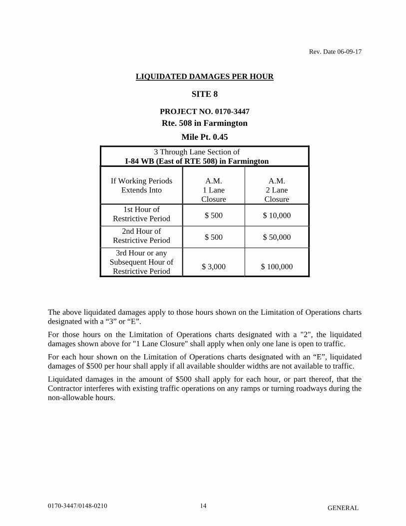
LIQUIDATED DAMAGES PER HOUR
SITE 8
PROJECT NO. 0170-3447 Rte. 508 in Farmington
Mile Pt. 0.45
3 Through Lane Section of I-84 WB (East of RTE 508) in Farmington
If Working Periods
Extends Into
A.M.
1 Lane Closure
A.M.
2 Lane Closure
1st Hour of Restrictive Period $ 500 $ 10,000
2nd Hour of Restrictive Period $ 500 $ 50,000
3rd Hour or any Subsequent Hour of Restrictive Period
$ 3,000
$ 100,000
The above liquidated damages apply to those hours shown on the Limitation of Operations charts designated with a “3” or “E”.
For those hours on the Limitation of Operations charts designated with a "2", the liquidated damages shown above for "1 Lane Closure" shall apply when only one lane is open to traffic.
For each hour shown on the Limitation of Operations charts designated with an “E”, liquidated damages of $500 per hour shall apply if all available shoulder widths are not available to traffic.
Liquidated damages in the amount of $500 shall apply for each hour, or part thereof, that the Contractor interferes with existing traffic operations on any ramps or turning roadways during the non-allowable hours.
140170-3447/0148-0210

Rev. Date 06-09-17
GENERAL
LIQUIDATED DAMAGES PER HOUR
SITE 9 I-84 EB in East Hartford
Mile Pt. 64.94
5 Through Lane Section (East of Rte. 15 NB On Ramp)
If Working Periods
Extends Into
A.M.
1 Lane Closure
A.M.
2 Lane Closure
A.M.
3 Lane Closure
P.M.
1 Lane Closure
P.M.
2 Lane Closure
1st Hour of Restrictive Period $ 500 $ 500 $ 500 $ 500 $ 1,000
2nd Hour of Restrictive Period $ 500 $ 500 $ 500 $ 7,000 $ 35,000
3rd Hour or any Subsequent Hour of Restrictive Period
$ 500
$ 500
$ 500
$ 7,000
$ 70,000
The above liquidated damages apply to those hours shown on the Limitation of Operations charts designated with a “5” or “E”.
For those hours on the Limitation of Operations charts designated with a "2", the liquidated damages shown above for "1 Lane Closure" shall apply when only one lane is open to traffic.
For those hours on the Limitation of Operations charts designated with a "3", the liquidated damages shown above for "2 Lane Closure" shall apply when only one lane is open to traffic.
For those hours on the Limitation of Operations charts designated with a "3", the liquidated damages shown above for "1 Lane Closure" shall apply when only two lanes are open to traffic.
For those hours on the Limitation of Operations charts designated with a "4", the liquidated damages shown above for "3 Lane Closure" shall apply when only one lane is open to traffic.
For those hours on the Limitation of Operations charts designated with a "4", the liquidated damages shown above for "2 Lane Closure" shall apply when only two lanes are open to traffic.
For those hours on the Limitation of Operations charts designated with a "4", the liquidated damages shown above for "1 Lane Closure" shall apply when only three lanes are open to traffic.
For each hour shown on the Limitation of Operations charts designated with an “E”, liquidated damages of $500 shall apply for each hour, or part thereof, if all available shoulder widths are not available to traffic.
Liquidated damages in the amount of $500 shall apply for each hour, or part thereof, that the Contractor interferes with existing traffic operations on any ramps or turning roadways during the non-allowable hours.
150170-3447/0148-0210
Rev. Date 06-09-17
GENERAL
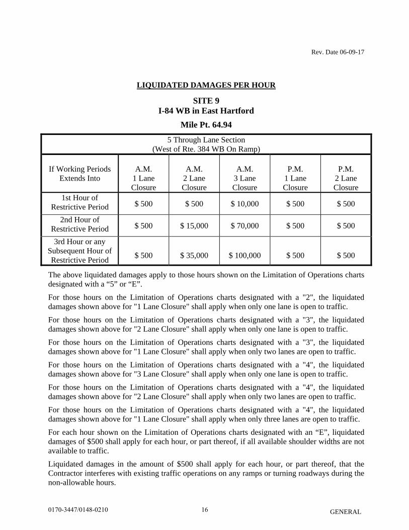
LIQUIDATED DAMAGES PER HOUR
SITE 9 I-84 WB in East Hartford
Mile Pt. 64.94
5 Through Lane Section (West of Rte. 384 WB On Ramp)
If Working Periods
Extends Into
A.M.
1 Lane Closure
A.M.
2 Lane Closure
A.M.
3 Lane Closure
P.M.
1 Lane Closure
P.M.
2 Lane Closure
1st Hour of Restrictive Period $ 500 $ 500 $ 10,000 $ 500 $ 500
2nd Hour of Restrictive Period $ 500 $ 15,000 $ 70,000 $ 500 $ 500
3rd Hour or any Subsequent Hour of Restrictive Period
$ 500
$ 35,000
$ 100,000
$ 500
$ 500
The above liquidated damages apply to those hours shown on the Limitation of Operations charts designated with a “5” or “E”.
For those hours on the Limitation of Operations charts designated with a "2", the liquidated damages shown above for "1 Lane Closure" shall apply when only one lane is open to traffic.
For those hours on the Limitation of Operations charts designated with a "3", the liquidated damages shown above for "2 Lane Closure" shall apply when only one lane is open to traffic.
For those hours on the Limitation of Operations charts designated with a "3", the liquidated damages shown above for "1 Lane Closure" shall apply when only two lanes are open to traffic.
For those hours on the Limitation of Operations charts designated with a "4", the liquidated damages shown above for "3 Lane Closure" shall apply when only one lane is open to traffic.
For those hours on the Limitation of Operations charts designated with a "4", the liquidated damages shown above for "2 Lane Closure" shall apply when only two lanes are open to traffic.
For those hours on the Limitation of Operations charts designated with a "4", the liquidated damages shown above for "1 Lane Closure" shall apply when only three lanes are open to traffic.
For each hour shown on the Limitation of Operations charts designated with an “E”, liquidated damages of $500 shall apply for each hour, or part thereof, if all available shoulder widths are not available to traffic.
Liquidated damages in the amount of $500 shall apply for each hour, or part thereof, that the Contractor interferes with existing traffic operations on any ramps or turning roadways during the non-allowable hours.
160170-3447/0148-0210
Rev. Date 06-09-17
GENERAL
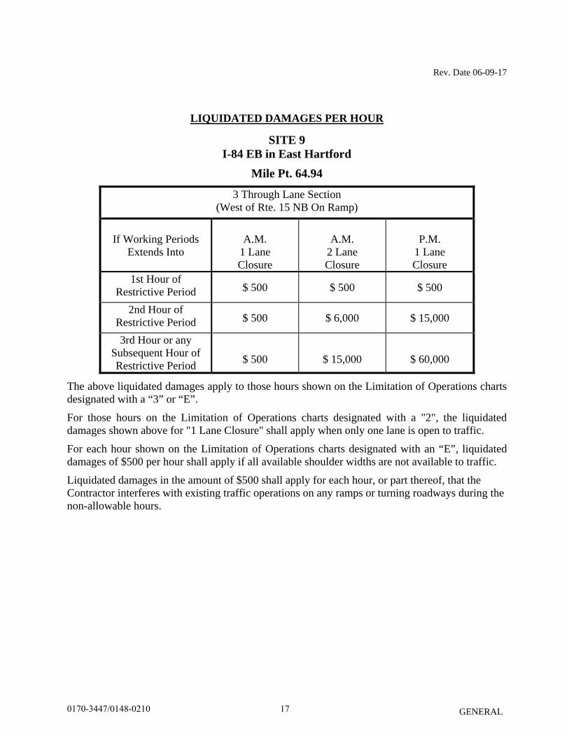
LIQUIDATED DAMAGES PER HOUR
SITE 9 I-84 EB in East Hartford
Mile Pt. 64.94
3 Through Lane Section (West of Rte. 15 NB On Ramp)
If Working Periods
Extends Into
A.M.
1 Lane Closure
A.M.
2 Lane Closure
P.M.
1 Lane Closure
1st Hour of Restrictive Period $ 500 $ 500 $ 500
2nd Hour of Restrictive Period $ 500 $ 6,000 $ 15,000
3rd Hour or any Subsequent Hour of Restrictive Period
$ 500
$ 15,000
$ 60,000
The above liquidated damages apply to those hours shown on the Limitation of Operations charts designated with a “3” or “E”.
For those hours on the Limitation of Operations charts designated with a "2", the liquidated damages shown above for "1 Lane Closure" shall apply when only one lane is open to traffic.
For each hour shown on the Limitation of Operations charts designated with an “E”, liquidated damages of $500 per hour shall apply if all available shoulder widths are not available to traffic.
Liquidated damages in the amount of $500 shall apply for each hour, or part thereof, that the Contractor interferes with existing traffic operations on any ramps or turning roadways during the non-allowable hours.
170170-3447/0148-0210
Rev. Date 06-09-17
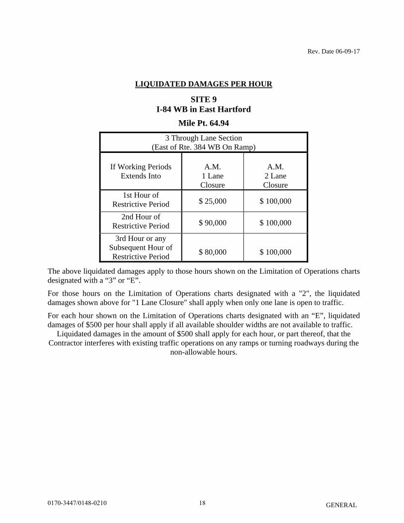
GENERAL
LIQUIDATED DAMAGES PER HOUR
SITE 9 I-84 WB in East Hartford
Mile Pt. 64.94
3 Through Lane Section (East of Rte. 384 WB On Ramp)
If Working Periods
Extends Into
A.M.
1 Lane Closure
A.M.
2 Lane Closure
1st Hour of Restrictive Period $ 25,000 $ 100,000
2nd Hour of Restrictive Period $ 90,000 $ 100,000
3rd Hour or any Subsequent Hour of Restrictive Period
$ 80,000
$ 100,000
The above liquidated damages apply to those hours shown on the Limitation of Operations charts designated with a “3” or “E”.
For those hours on the Limitation of Operations charts designated with a "2", the liquidated damages shown above for "1 Lane Closure" shall apply when only one lane is open to traffic.
For each hour shown on the Limitation of Operations charts designated with an “E”, liquidated damages of $500 per hour shall apply if all available shoulder widths are not available to traffic.
Liquidated damages in the amount of $500 shall apply for each hour, or part thereof, that the Contractor interferes with existing traffic operations on any ramps or turning roadways during the
non-allowable hours.
180170-3447/0148-0210
Rev. Date 06-09-17
GENERAL
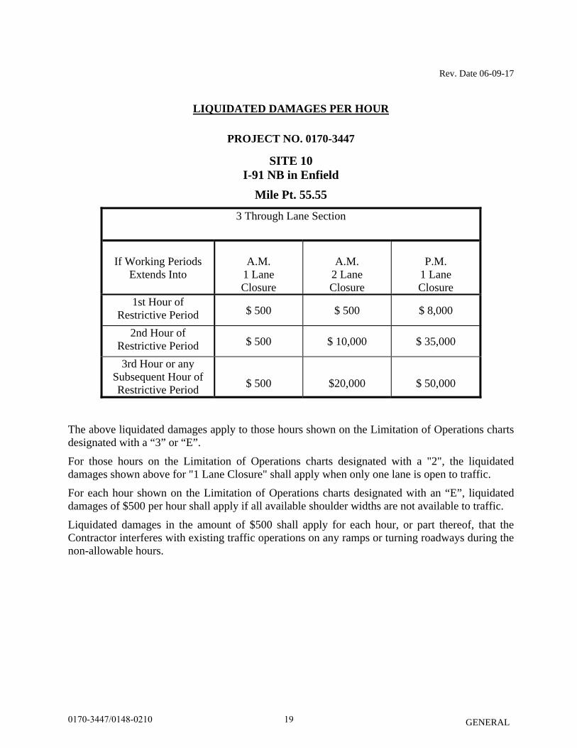
LIQUIDATED DAMAGES PER HOUR
PROJECT NO. 0170-3447
SITE 10 I-91 NB in Enfield
Mile Pt. 55.55
3 Through Lane Section
If Working Periods
Extends Into
A.M.
1 Lane Closure
A.M.
2 Lane Closure
P.M.
1 Lane Closure
1st Hour of Restrictive Period $ 500 $ 500 $ 8,000
2nd Hour of Restrictive Period $ 500 $ 10,000 $ 35,000
3rd Hour or any Subsequent Hour of Restrictive Period
$ 500
$20,000
$ 50,000
The above liquidated damages apply to those hours shown on the Limitation of Operations charts designated with a “3” or “E”.
For those hours on the Limitation of Operations charts designated with a "2", the liquidated damages shown above for "1 Lane Closure" shall apply when only one lane is open to traffic.
For each hour shown on the Limitation of Operations charts designated with an “E”, liquidated damages of $500 per hour shall apply if all available shoulder widths are not available to traffic.
Liquidated damages in the amount of $500 shall apply for each hour, or part thereof, that the Contractor interferes with existing traffic operations on any ramps or turning roadways during the non-allowable hours.
190170-3447/0148-0210
Rev. Date 06-09-17
GENERAL
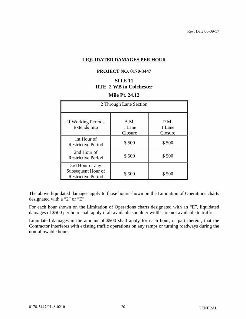
LIQUIDATED DAMAGES PER HOUR
PROJECT NO. 0170-3447
SITE 11 RTE. 2 WB in Colchester
Mile Pt. 24.12
2 Through Lane Section
If Working Periods
Extends Into
A.M.
1 Lane Closure
P.M.
1 Lane Closure
1st Hour of Restrictive Period $ 500 $ 500
2nd Hour of Restrictive Period $ 500 $ 500
3rd Hour or any Subsequent Hour of Restrictive Period
$ 500
$ 500
The above liquidated damages apply to those hours shown on the Limitation of Operations charts designated with a “2” or “E”.
For each hour shown on the Limitation of Operations charts designated with an “E”, liquidated damages of $500 per hour shall apply if all available shoulder widths are not available to traffic.
Liquidated damages in the amount of $500 shall apply for each hour, or part thereof, that the Contractor interferes with existing traffic operations on any ramps or turning roadways during the non-allowable hours.
200170-3447/0148-0210
Rev. Date 06-09-17
GENERAL
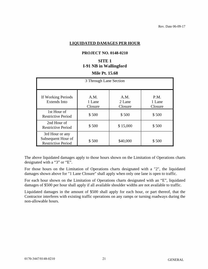
LIQUIDATED DAMAGES PER HOUR
PROJECT NO. 0148-0210
SITE 1 I-91 NB in Wallingford
Mile Pt. 15.68
3 Through Lane Section
If Working Periods
Extends Into
A.M.
1 Lane Closure
A.M.
2 Lane Closure
P.M.
1 Lane Closure
1st Hour of Restrictive Period $ 500 $ 500 $ 500
2nd Hour of Restrictive Period $ 500 $ 15,000 $ 500
3rd Hour or any Subsequent Hour of Restrictive Period
$ 500
$40,000
$ 500
The above liquidated damages apply to those hours shown on the Limitation of Operations charts designated with a “3” or “E”.
For those hours on the Limitation of Operations charts designated with a "2", the liquidated damages shown above for "1 Lane Closure" shall apply when only one lane is open to traffic.
For each hour shown on the Limitation of Operations charts designated with an “E”, liquidated damages of $500 per hour shall apply if all available shoulder widths are not available to traffic.
Liquidated damages in the amount of $500 shall apply for each hour, or part thereof, that the Contractor interferes with existing traffic operations on any ramps or turning roadways during the non-allowable hours.
210170-3447/0148-0210
GENERAL
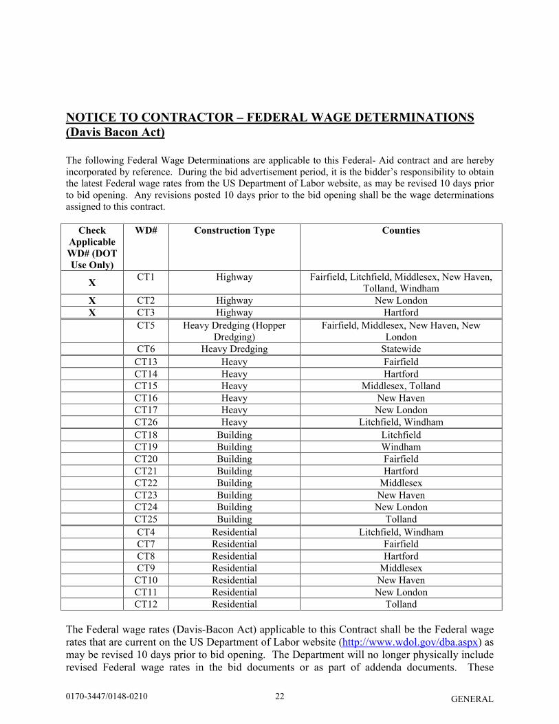
NOTICE TO CONTRACTOR – FEDERAL WAGE DETERMINATIONS
(Davis Bacon Act)
The following Federal Wage Determinations are applicable to this Federal- Aid contract and are hereby incorporated by reference. During the bid advertisement period, it is the bidder’s responsibility to obtain the latest Federal wage rates from the US Department of Labor website, as may be revised 10 days prior to bid opening. Any revisions posted 10 days prior to the bid opening shall be the wage determinations assigned to this contract.
Check
Applicable
WD# (DOT
Use Only)
WD# Construction Type Counties
X CT1 Highway Fairfield, Litchfield, Middlesex, New Haven,
Tolland, Windham X CT2 Highway New London X CT3 Highway Hartford
CT5 Heavy Dredging (Hopper
Dredging) Fairfield, Middlesex, New Haven, New
London CT6 Heavy Dredging Statewide CT13 Heavy Fairfield CT14 Heavy Hartford CT15 Heavy Middlesex, Tolland CT16 Heavy New Haven CT17 Heavy New London CT26 Heavy Litchfield, Windham CT18 Building Litchfield CT19 Building Windham CT20 Building Fairfield CT21 Building Hartford CT22 Building Middlesex CT23 Building New Haven CT24 Building New London CT25 Building Tolland CT4 Residential Litchfield, Windham CT7 Residential Fairfield CT8 Residential Hartford CT9 Residential Middlesex CT10 Residential New Haven CT11 Residential New London CT12 Residential Tolland
The Federal wage rates (Davis-Bacon Act) applicable to this Contract shall be the Federal wage rates that are current on the US Department of Labor website (http://www.wdol.gov/dba.aspx) as may be revised 10 days prior to bid opening. The Department will no longer physically include revised Federal wage rates in the bid documents or as part of addenda documents. These
220170-3447/0148-0210

GENERAL
applicable Federal wage rates will be incorporated in the final contract document executed by both parties. If a conflict exists between the Federal and State wage rates, the higher rate shall govern. To obtain the latest Federal wage rates, go to the US Department of Labor website (link above). Under Davis-Bacon Act, choose “Selecting DBA WDs” and follow the instruction to search the latest wage rates for the State, County and Construction Type.
230170-3447/0148-0210
GENERAL
NOTICE TO CONTRACTOR – PREBID QUESTIONS AND ANSWERS
Questions pertaining to DOT advertised construction projects must be presented through the CTDOT Pre-Bid Q and A Website. The Department cannot guarantee that all questions will be answered prior to the bid date. PLEASE NOTE - at 12:01 am, the day before the bid, the
subject project(s) being bid will be removed from the Q and A Website, Projects
Advertised Section, at which time questions can no longer be submitted through the
Q and A Website. At this time, the Q and A for those projects will be considered final,
unless otherwise stated and/or the bid is postponed to a future date and time to allow for
further questions and answers to be posted.
If a question needs to be asked the day before the bid date, please contact the Contracts Unit staff and email your question to [email protected] immediately. Contractors must identify their company name, contact person, contact email address and phone number when asking a question. The email address and phone number will not be made public. The questions and answers (if any) located on the Q and A Website are hereby made part of the bid/contract solicitation documents (located on the State Contracting Portal), and resulting contract for the subject project(s). It is the bidder’s responsibility to monitor, review, and become familiar with the questions and answers, as with all bid requirements and contract documents, prior to bidding. By signing the bid proposal and resulting contract, the bidder acknowledges receipt of, and agrees to the incorporation of the final list of Q and A, into the contract document. Contractors will not be permitted to file a future claim based on lack of receipt, or knowledge of the questions and answers associated with a project. All bidding requirements and project information, including but not limited to contract plans, specifications, addenda, Q and A, Notice to Contractors, etc., are made public on the State Contracting Portal and/or the CTDOT website.
240170-3447/0148-0210
Rev. Date 06/11/18
GENERAL
NOTICE TO CONTRACTOR – HAZARDOUS MATERIALS
INVESTIGATIONS
A limited hazardous materials site investigation has been conducted for Sign Supports at eleven (11) Sites, Statewide, & Sign Support No. 20343 in Wallingford, Connecticut. The scope of inspection was limited to the representative components projected for impact. All side-mounted panel signs had galvanized legs that were unpainted, therefore no lead paint was identified. Detectable amounts of lead in paint were confirmed and/or presumed present at Site No. 1, Site No. 2 (bridge & sign support), Site No. 3B, Site 6 (bridge), Site No. 10 (sign support) and Site 11. No detectable amounts of lead were identified at Site No. 5, Site No. 7 (bridge), Site No. 8, Site No. 10 (bridge) and Sign Support No. 20343. Sign supports at Site No. 3A, Site No. 4, Site No. 6, Site No, 7A, Site No. 7B, Site No. 7C and Site No. 9A, Site No. 9B and Site No. 9C were galvanized (unpainted). Projected paint waste debris was characterized and/or presumed as CTDEEP/RCRA hazardous waste at Site No. 1, Site No. 2 (bridge & sign support), Site No. 6 (bridge), Site No. 10 (sign support) and Site No. 11. Projected paint waste debris was characterized as non-hazardous, non-RCRA waste at Site No. 3B, Site No. 5, Site No. 8 and Sign Support No. 20343. All steel and metal generated from work tasks (painted or not) shall be segregated and recycled as scrap metal at a scrap metal recycling facility. The recycling of scrap metal (regardless of lead paint concentration) is exempt from USEPA RCRA and CTDEEP Hazardous Waste Regulation. Grey caulking at Site No. 3A and a black gasket material at Sign Support No. 20343 were sampled and found to contain no asbestos. No pigeon/bird guano accumulations were identified at any of the Sites. The Contractor is hereby notified that these hazardous materials requiring special management or disposal procedures will be encountered during various construction activities conducted within the project limits. The Contractor will be required to implement appropriate health and safety measures for all construction activities impacting these materials. These measures shall include, but are not limited to, air monitoring, engineering controls, personal protective equipment and decontamination, equipment decontamination and personnel training. WORKER HEALTH AND SAFETY PROTOCOLS WHICH ADDRESS POTENTIAL AND/OR ACTUAL RISK OF EXPOSURE TO SITE SPECIFIC HAZARDS ARE SOLELY THE RESPONSIBILITY OF THE CONTRACTOR.
250170-3447/0148-0210
Rev. Date 06/11/18
GENERAL
The Department, as Generator, will provide an authorized representative to sign all manifests and waste profile documentation required by disposal facilities for disposal of hazardous materials. The Sections which shall be reviewed by the Contractor include, but are not limited to, the following:
• Item No. 0020903A – Lead Compliance for Miscellaneous Exterior Tasks The Contractor is alerted to the fact that a Department environmental consultant may be on site for abatement and related activities, to collect environmental samples (if necessary), and to observe site conditions for the State. Information pertaining to the results of the limited hazardous materials investigation discussed can be found in the document listed below. This document shall be available for review electronically.
• HazMat Inspection Letter, Sign Supports at Eleven (11) Sites, Statewide, & Sign Support No. 20343, Wallingford, CT, TRC Environmental Corporation, June 07, 2018.
260170-3447/0148-0210
Rev. 2/6/18
GENERAL
NOTICE TO CONTRACTOR - CONSTRUCTION CONTRACTOR
DIGITAL SUBMISSIONS Upon execution of the Contract, the Contractor acknowledges and agrees that contractual submittals for this Project shall be submitted and handled through a system of paperless electronic means as outlined in the special provision for Section 1.05 herein. Shop drawings, working drawings, and product data shall be created, digitally signed and delivered by the Contractor in accordance with the Department’s Contractor Digital Submission Manual (CDSM). Other deliverables that are required by other special provisions shall be similarly submitted. Access credentials will be provided to the Contractor by the Department. The Department will provide the Contractor with a list of email addresses that are to be used for each submittal type. The Department shall not be held responsible for delays, lack of processing or response to submittals that do not follow the specified guidelines in the CDSM.
270170-3447/0148-0210
Rev. Date 08/14
GENERAL
NOTICE TO CONTRACTOR – EXISTING IMS
The Contractor is herein made aware of existing Incident Management System (IMS) conduit and appurtenances located on I-95, I-691, I-91, and I-84 in the vicinity of the project area. The Contractor will be responsible for locating, verifying the location of and protecting all IMS below and above the ground. Prior to the start of construction, the Contractor shall contact “Call Before You Dig” and all utility within the towns along the project corridor. The Contractor shall also contact Robert Kennedy (860-594-3458) of ConnDOT Highway Operations at to mark out IMS conduit and appurtenances. In areas adjacent to existing incident management system equipment, the Contractor is required to hand excavate. Any damage caused to the IMS conduit/equipment will be the responsibility of the Contractor, and will be replaced by the Contractor at the Contractor’s expense, as directed by the Engineer. Mark out of the IMS will not relieve the Contractor of responsibility for repair of damage caused by the Contractor or the Contractor’s sub-contractors.
280170-3447/0148-0210
4/20/2018
GENERAL
NOTICE TO CONTRACTOR – MINIMUM CONCRETE COMPRESSIVE
STRENGTH
The concrete strength or allowable design stress specified in the General Notes is for design purposes only. The minimum compressive strength of concrete in constructed components shall comply with the requirements of Section 6.01 Concrete for Structures.
290170-3447/0148-0210
Rev. Date 06/20/18
GENERAL
NOTICE TO CONTRACTOR - SALVAGE
The salvage items shall be delivered by the Contractor to the closest Maintenance Garage specified below. Deliveries may be made between 7:00 AM to 4:00 PM except during lunch hour, 12:00 noon to 1:00 PM, Monday through Friday, excluding holidays. The Contractor shall contact the General Supervisor, at least 24 hours prior to delivery. The salvage material shall be loaded, transported and unloaded by the Contractor. All material shall be stacked and stored by the Contractor according to the direction of the Storage Manager or his representative The Contractor shall salvage the following items for the State: District 1:
600’ of MBR, Type R-I at Site 5 (Project #0170-3447) in Meriden
Sent to: Meriden Maintenance Garage Contact: Rico D’Appollonio, General Supervisor Phone: 203-238-6240
130’ of MBR, Type R-B 350 at Site 7 (Project #0170-3447) in Rocky Hill
Sent to: Wethersfield Maintenance Garage Contact: John Wells, General Supervisor Phone: 860-529-7411 District 3:
610’ of Three-Cable Guide railing (Posts only) at Site 1 (Project #0148-0210) in Wallingford
Sent to: Wallingford Maintenance Garage Contact: Dave Astarita, General Supervisor Phone: 203-265-0106
875’ of MBR, Type R-I at Site 3 (Project #0170-3447) in Bridgeport
Sent to: Stratford Maintenance Garage Contact: Joseph Hunihan, General Supervisor Phone: 203-579-6207
The State Inspector responsible for this project shall determine the condition of the materials. Before delivery to the store area the Office of Construction’s project inspector should have a Salvage Materials Return to Stores Form issued on the Inventory Management Information System (IMIS), for each item or type to be delivered to the store. The Salvage Materials Return to Stores Form will be forwarded to the Material Store Supervisor. The Contractor shall not receive direct payment for this work. The cost for loading, transporting and unloading the salvage items shall be included in the general work for the project.
300170-3447/0148-0210
GENERAL
NOTICE TO CONTRACTOR – SIGN STRUCTURES AND
FOUNDATIONS
The Contractor is notified that the Contract includes special provisions that require the design of sign structures and foundations in accordance with the latest edition of the AASHTO LRFD Specifications for Structural Supports for Highway Signs, Luminaries and Traffic Signals, including the latest interim specifications, available prior to the advertising date of the contract. The AASHTO LRFD specifications incorporate a design methodology that differs from previous design specifications resulting in new design requirements. For additional information, refer to the special provisions for the sign structures and foundations.
310170-3447/0148-0210
Rev. Date 3/9/18
GENERAL
NOTICE TO CONTRACTOR – GLOBAL POSITIONING SYSTEM (GPS)
COORDINATES FOR SIGNS
The Contractor shall obtain and provide to the Engineer sign installation data, including Global Positioning System (GPS) latitude and longitude coordinates, for all new State owned and maintained signs. The Engineer shall forward the sign data to the Division of Traffic Engineering for upload into the Highway Sign Inventory and Maintenance Management Program (SIMS). Sign data submissions or questions relating to SIMS or GPS shall be sent to [email protected]. Refer to the special provision for Section 12.00 General Clauses For Highway Signing.
320170-3447/0148-0210
6/26/18
GENERAL
NOTICE TO CONTRACTOR - ARCHITECTURAL AND INDUSTRIAL
MAINTENANCE COATINGS
This Contract includes the application of materials subject to the Volatile Organic Compounds (VOC) content limits stated in the Regulations of Connecticut State Agencies (RCSA) Sections 22a-174-41 and -41a. All architectural and industrial maintenance (AIM) coatings and applications of such coatings must comply with these regulations. The Contractor shall submit a Material Safety Data Sheet/Safety Data Sheet or Product Technical Data Sheet developed by the manufacturer of each material that may be subject to the Regulations. The submittal must verify both the type of AIM and its VOC Content. VOC content shall be determined based on the formulation data supplied by the materials manufacturer. The Contractor may only use AIM coatings that contain VOCs below the respective coating category Phase II limits specified in Table 1 if either:
a) the coating was manufactured on or after May 1, 2018, or b) the coating is being applied after April 30, 2021.
The Contractor may use AIM coatings that contain VOCs exceeding the respective coating category Phase II limits specified in Table 1 only if all of the following four conditions are met:
a) the coating is being applied on or before April 30, 2021, b) the coating contains VOCs below the applicable Phase I limits specified in Table 1, c) the coating was manufactured prior to May 1, 2018, and d) the coating container(s) are dated (or date coded) as such.
For any coating that is not categorized within Table 1, the Contractor shall classify the coating as follows and apply corresponding limits in Table 1.
• Registers gloss <15 on an 85-degree meter or <5 on a 60-degree meter) – Flat Coating, • Registers gloss of ≥15 on an 85-degree meter and ≥5on a 60-degree meter) - Nonflat
Coating, • Registers gloss of ≥70 on a 60-degree meter - Nonflat-High Gloss Coating.
The Contractor must close all containers of coating and solvent when not in use. Coating container labels must display the date the coating was manufactured, the manufacturer’s recommendation regarding thinning with solvent, and the coating’s VOC content in grams per liter (g/L) of coating. Certain coating categories as noted in Table 1 have additional labeling requirements. The Contractor may add additional solvent to a coating only if such addition does not cause the coating to exceed the applicable VOC limit specified Table 1. The Contractor must adhere to type(s) of solvent and maximum amount of solvent recommended by coating manufacturer.
330170-3447/0148-0210
6/26/18
GENERAL
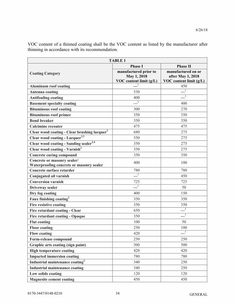
VOC content of a thinned coating shall be the VOC content as listed by the manufacturer after thinning in accordance with its recommendation.
TABLE 1
Coating Category
Phase I Phase II
manufactured prior to
May 1, 2018
VOC content limit (g/L)
manufactured on or
after May 1, 2018
VOC content limit (g/L)
Aluminum roof coating ---1 450 Antenna coating 530 ---1 Antifouling coating 400 ---1 Basement specialty coating ---1 400 Bituminous roof coating 300 270 Bituminous roof primer 350 350 Bond breaker 350 350 Calcimine recoater 475 475 Clear wood coating - Clear brushing lacquer
2 680 275
Clear wood coating - Lacquer2,3
550 275 Clear wood coating - Sanding sealer
2,4 350 275
Clear wood coating - Varnish2 350 275
Concrete curing compound 350 350 Concrete or masonry sealer/
Waterproofing concrete or masonry sealer 400 100
Concrete surface retarder 780 780 Conjugated oil varnish ---1 450 Conversion varnish 725 725 Driveway sealer ---1 50 Dry fog coating 400 150 Faux finishing coating
2 350 350
Fire resistive coating 350 350 Fire retardant coating - Clear 650 ---1 Fire retardant coating - Opaque 350 ---1 Flat coating 100 50 Floor coating 250 100 Flow coating 420 ---1 Form-release compound 250 250 Graphic arts coating (sign paint) 500 500 High temperature coating 420 420 Impacted immersion coating 780 780 Industrial maintenance coating
2 340 250
Industrial maintenance coating 340 250 Low solids coating 120 120 Magnesite cement coating 450 450
340170-3447/0148-0210
6/26/18
GENERAL
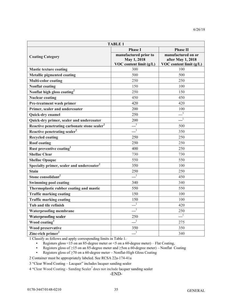
TABLE 1
Coating Category
Phase I Phase II
manufactured prior to
May 1, 2018
VOC content limit (g/L)
manufactured on or
after May 1, 2018
VOC content limit (g/L)
Mastic texture coating 300 100 Metallic pigmented coating 500 500 Multi-color coating 250 250 Nonflat coating 150 100 Nonflat high gloss coating
2 250 150
Nuclear coating 450 450 Pre-treatment wash primer 420 420 Primer, sealer and undercoater 200 100 Quick-dry enamel 250 ---1 Quick-dry primer, sealer and undercoater 200 ---1 Reactive penetrating carbonate stone sealer
2 ---1 500
Reactive penetrating sealer2 ---1 350
Recycled coating 250 250 Roof coating 250 250 Rust preventive coating
2 400 250
Shellac Clear 730 730 Shellac Opaque 550 550 Specialty primer, sealer and undercoater
2 350 100
Stain 250 250 Stone consolidant
2 ---1 450
Swimming pool coating 340 340 Thermoplastic rubber coating and mastic 550 550 Traffic marking coating 150 100 Traffic marking coating 150 100 Tub and tile refinish ---1 420 Waterproofing membrane ---1 250 Waterproofing sealer 250 ---1 Wood coating
2 ---1 275
Wood preservative 350 350 Zinc-rich primer
2 ---1 340
1 Classify as follows and apply corresponding limits in Table 1. • Registers gloss <15 on an 85-degree meter or <5 on a 60-degree meter) – Flat Coating, • Registers gloss of ≥15 on an 85-degree meter and ≥5on a 60-degree meter) – Nonflat Coating • Registers gloss of ≥70 on a 60-degree meter – Nonflat-High Gloss Coating
2 Container must be appropriately labeled. See RCSA 22a-174-41a 3 “Clear Wood Coating – Lacquer” includes lacquer sanding sealer 4 “Clear Wood Coating - Sanding Sealer” does not include lacquer sanding sealer
-END-
350170-3447/0148-0210
Rev. Date 6/21/17
GENERAL
NOTICE TO CONTRACTOR – USE OF STATE POLICE OFFICERS
The Department will reimburse services of State Police Officers as a direct payment to the Department of Emergency Services and Public Protection. Payment for State Police Officers must be approved by the Engineer. Any State Police Officers used by the Contractor for its convenience is the responsibility of the Contractor. A separate payment item for State Police Officers is not included in this Contract. Any costs associated with coordination and scheduling of State Police Officers shall be included in the lump sum bid price for Item No. 0971001A – Maintenance and Protection of Traffic.
360170-3447/0148-0210
Rev. Date 03/25/08
GENERAL
SECTION 1.02 – PROPOSAL REQUIREMENTS AND CONDITIONS
Article 1.02.04 – Examination of Plans, Specifications, Special Provisions and Site of Work:
Replace the third sentence of the last paragraph with:
The Department cannot ensure a response to inquiries received later than ten (10) days prior to the original scheduled opening of the related bid.
370170-3447/0148-0210
Rev. 2/6/18
GENERAL
SECTION 1.05 - CONTROL OF THE WORK
Replace Article 1.05.02 with the following:
1.05.02—Contractor Submittals, Working Drawings, Shop Drawings, Product Data,
Submittal Preparation and Processing - Review Timeframes, Department’s Action: 1. Contractor Submittals: The plans provided by the Department show the details necessary to give a comprehensive idea of the construction contemplated under the Contract. The plans will generally show the location, character, dimensions, and details necessary to complete the Project. If the plans do not show complete details, they will show the necessary dimensions and details, which when used along with the other Contract documents, will enable the Contractor to prepare working drawings, shop drawings or product data necessary to complete the Project. The Contractor shall prepare submittals as Portable Document Format (PDF) files. The Contractor is also required to acquire, maintain access and use the Department’s document management system for delivery of submittals. The format, digital signing requirements, delivery processes and document tracking procedures shall be performed in accordance with this specification and the Contractor’s Digital Submission Manual (CDSM). The submittals shall be sent to the Department’s reviewer(s), sufficiently in advance of the work detailed, to allow for their review in accordance with the review periods as specified herein (including any necessary revisions, resubmittal, and final review), and acquisition of materials, without causing a delay of the Project. 2. Working Drawings: When required by the Contract or when ordered to do so by the Engineer, the Contractor shall prepare and submit the working drawings, signed, sealed and dated by a qualified Professional Engineer licensed to practice in the State of Connecticut, for review. The drawings shall be delivered sufficiently in advance of the work detailed, to allow for their review in accordance with the review periods specified herein (including any necessary revisions, resubmittal, and final review). There will be no direct payment for furnishing any working drawings, procedures or supporting calculations, but the cost thereof shall be considered as included in the general cost of the work. a. Working Drawings for Permanent Construction: The Contractor shall supply to the Assistant District Engineer a certificate of insurance in accordance with 1.03.07 at the time that the working drawings for the Project are submitted. The Contractor’s designer, who prepares the working drawings, shall secure and maintain at no direct cost to the State a Professional Liability Insurance Policy for errors and omissions in the minimum amount of $2,000,000 per error or omission. The Contractor’s designer may elect to obtain a policy containing a maximum $250,000 deductible clause, but if the Contractor’s designer should obtain a policy containing such a clause, they shall be liable to the extent of at
380170-3447/0148-0210
Rev. 2/6/18
GENERAL
least the deductible amount. The Contractor’s designer shall obtain the appropriate and proper endorsement of its Professional Liability Policy to cover the indemnification clause in this Contract, as the same relates to negligent acts, errors or omissions in the Project work performed by them. The Contractor’s designer shall continue this liability insurance coverage for a period of
(i) 3 years from the date of acceptance of the work by the Engineer, as evidenced by a State of Connecticut, Department of Transportation form entitled "Certificate of Acceptance of Work," issued to the Contractor; or
(ii) 3 years after the termination of the Contract, whichever is earlier, subject to the continued commercial availability of such insurance.
b. Working Drawings for Temporary Construction: The Contractor shall submit drawings,
calculations, procedures and other supporting data to the Assistant District Engineer.
3. Shop Drawings: When required by the Contract, or when ordered to do so by the Engineer, the Contractor shall prepare and deliver shop drawings to the Designer for review. Review timeframes and submission locations are as specified herein. There will be no direct payment for furnishing any shop drawings, but the cost thereof shall be considered as included in the general cost of the work. 4. Product Data: When required by the Contract, or when ordered to do so by the Engineer, the Contractor shall prepare and deliver product data. The Contractor shall submit the product data in a single submittal for each element or group of elements of construction. The Contractor shall mark each copy of the product data submittal to show applicable choices and options. Where product data includes information on several products that are not required, copies shall be marked to indicate the applicable information. Product data shall include the following information and confirmation of conformance with the Contract to the extent applicable: manufacturer’s printed recommendations, compliance with recognized trade association standards, compliance with recognized testing agency standards, application of testing agency labels and seals, notation of coordination requirements, Contract item number, and any other information required by the individual Contract provisions. There will be no direct payment for furnishing any product data, but the cost thereof shall be considered as included in the general cost of the work. 5. Submittal Preparation and Processing – Review Timeframes: The Contractor shall allow 30 calendar days for submittal review by the Department, from the date receipt is acknowledged by the Department’s reviewer. For any submittals marked with “Revise and Resubmit” or “Rejected,” the Department is allowed an additional 20 calendar days for review of any resubmissions.
390170-3447/0148-0210
Rev. 2/6/18
GENERAL
An extension of Contract time will not be authorized due to the Contractor’s failure to transmit submittals sufficiently in advance of the work to permit processing. The furnishing of shop drawings, working drawings or product data, or any comments or suggestions by the Designer or Engineer concerning shop drawings, working drawings or product data, shall not relieve the Contractor of any of its responsibility for claims by the State or by third parties, as per 1.07.10. The furnishing of the shop drawings, working drawings and product data shall not serve to relieve the Contractor of any part of its responsibility for the safety or the successful completion of the Project construction. 6. Department’s Action: The Designer or Engineer will review each submittal, mark each with a self-explanatory action stamp, and return the stamped submittal promptly to the Contractor. The Contractor shall not proceed with the part of the Project covered by the submittal until the submittal is marked “No Exceptions Noted” or “Exceptions as Noted” by the Designer or Engineer. The Contractor shall retain sole responsibility for compliance with all Contract requirements. The stamp will be marked as follows to indicate the action taken: a. If submittals are marked “No Exceptions Noted,” the Designer or Engineer has not observed
any statement or feature that appears to deviate from the Contract requirements. This disposition is contingent on being able to execute any manufacturer’s written warranty in compliance with the Contract provisions.
b. If submittals are marked “Exceptions as Noted” the considerations or changes noted by the Department’s Action are necessary for the submittal to comply with Contract requirements. The Contractor shall review the required changes and inform the Designer or Engineer if they feel the changes violate a provision of the Contract or would lessen the warranty coverage.
c. If submittals are marked “Revise and Resubmit,” the Contractor shall revise the submittals
to address the deficiencies or provide additional information as noted by the Designer or Engineer. The Contractor shall allow an additional review period as specified in 1.05.02-5.
d. If submittals are marked “Rejected,” the Contractor shall prepare and submit a new
submittal in accordance with the Designer’s or Engineer’s notations. The resubmissions require an additional review and determination by the Designer or Engineer. The Contractor shall allow an additional review period as specified in 1.05.02-5.
400170-3447/0148-0210
Rev. Date 9-16
GENERAL
SECTION 1.07 - LEGAL RELATIONS AND RESPONSIBILITIES
Delete Article 1.07.07 in its entirety and replace it with the following:
1.07.07—Safety and Public Convenience: The Contractor shall conduct the Project work at all times in such a manner as to ensure the least possible obstruction to traffic. In a manner acceptable to the Engineer, the Contractor shall provide for the convenience and interests of the general public; the traveling public; parties residing along or adjacent to the highway or Project Site; and parties owning, occupying or using property adjacent to the Project Site, such as commuters, workers, tenants, lessors and operating agencies. Notwithstanding any other Contract provision, the Contractor shall not close to normal pedestrian or vehicular traffic any section of road, access drive, parking lot, sidewalk, station platform, railroad track, bus stop, runway, taxiway, occupied space within a Site, or occupied space within a building, except with the written permission of the Engineer. All equipment, materials, equipment or material storage areas, and work areas must be placed, located, and used in ways that do not create a hazard to people or property, especially in areas open to public pedestrian or vehicular traffic. All equipment and materials shall be placed or stored in such a way and in such locations as will not create a hazard to the traveling public or reduce sight lines. In an area unprotected by barriers or other means, equipment and materials must not be stored within 30 feet of any traveled way. The Contractor must always erect barriers and warning signs between any of its work or storage areas and any area open to public, pedestrian, or vehicular traffic. Such barriers and signs must comply with all laws and regulations, including any applicable codes. The Contractor must arrange for temporary lighting, snow and ice removal, security against vandalism and theft, and protection against excessive precipitation runoff within its Project work and storage areas, and within other areas specifically designated in the Contract. In addition to meeting the requirements of Section 9.71, the Contractor shall take all precautions necessary and reasonable for the protection of all persons, including, but not limited to, employees of the Contractor or the Department, and for the protection of property, until the Engineer notifies the Contractor in writing that the Project or the pertinent portion of the Project has been completed to the Engineer’s satisfaction. The Contractor shall comply with the safety provisions of applicable laws, including building and construction codes and the latest edition of the CFR. The Contractor must make available for reference in its field office, throughout the duration of the Project, a copy of the latest edition and all supplements of the CFR pertaining to OSHA. The Contractor shall make available to the Contractor’s employees, subcontractors, the Engineer, and the public, all information pursuant to OSHA 29 CFR Part 1926.59 and The
410170-3447/0148-0210

Rev. Date 9-16
GENERAL
Hazard Communication Standard 29 CFR 1910.1200, and shall also maintain a file on each job site containing all MSDS for products in use at the Project. These MSDS shall be made available to the Engineer upon request. The Contractor shall observe all rules and regulations of the Federal, State, and local health officials. Attention is directed to Federal, State, and local laws, rules, and regulations concerning construction safety and health standards. The Contractor shall not require any worker to work in surroundings or under conditions that are unsanitary, hazardous, or dangerous to the worker’s health or safety. Safety Plan: Before starting work on the Project, the Contractor shall submit to the Engineer a written Safety and Health Plan (hereinafter referred to as the “Plan”). The Plan shall meet or exceed the minimum requirements of this Subsection and any applicable State or Federal regulations. The Plan shall apply to any work under the Contract whether such work is performed, by way of example and not limitation, by the Contractor’s forces, subcontractors, suppliers, or fabricators. The Plan shall be prepared by the Contractor and submitted to the Engineer for review before the actual start of work on the Project. Within ten (10) calendar days of receipt, the Engineer will determine whether or not the Plan meets the requirements of this Specification. If the Plan does not meet the requirements of this Specification, it will be returned for revision. Work on the Project may not proceed until the Engineer has accepted the Plan. Nothing herein shall be construed, however, to relieve the Contractor from responsibility for the prosecution of the Project. The Plan shall conform to the following general format:
1. General Introduction. a. Description. The general introduction of the Plan shall include a statement by the
Contractor describing its commitment to maintain a safe work environment for its employees, Department representatives, and the public. Implementation procedures and company policies relative to safety shall be summarized or referenced in the Plan. i. The Plan shall include the names, addresses, and telephone numbers of the
Contractor’s Project Manager, Project superintendent and/or its designee for safety oversight, all competent persons, and the traffic control coordinator. Any changes to the safety management and oversight for the Project shall be promptly communicated to all concerned.
ii. The Plan shall provide guidelines for protecting all personnel from hazards associated with Project operations and activities.
iii. The Plan shall establish the policies and procedures that are necessary for the Project to be in compliance with the requirements of OSHA and other State and Federal regulatory agencies with jurisdiction, rules, regulations, standards, or guidelines in effect at the time the work is in progress.
420170-3447/0148-0210
Rev. Date 9-16
GENERAL
b. Responsibility, Identification of Personnel, and Certifications. The Contractor is solely responsible for creating, implementing, and monitoring the Plan. i. The Contractor shall identify and designate on-site supervisory level personnel
who shall be responsible for implementing and monitoring the Plan at all times throughout the duration of the Project and shall have authority to take prompt corrective measures to eliminate hazards including the ability to stop work activities.
ii. Documentation of training provided to the on-site supervisory level personnel shall be included as part of the Plan.
iii. For any work activities wherein the Contractor has identified a competent person as defined by OSHA, that person shall be capable of identifying existing and predictable hazards and have the authority to take prompt corrective measures to eliminate the hazards, including the ability to stop work activities.
iv. Documentation of the qualifications of such competent persons identified, including any certifications received, shall be included as part of the Plan.
v. The Contractor shall further identify the qualified safety professional responsible for developing the Plan and shall provide that person’s qualifications for developing the Plan which shall include, but not be limited to, education, training, certifications, and experience in developing this type of Plan.
vi. The Plan shall contain a certification executed by the qualified safety professional that developed the Plan, stating that the Plan complies with OSHA and other applicable State and Federal regulatory agencies with jurisdiction, rules, regulations, standards, or guidelines in effect at the time the work is in progress.
2. Elements of the Plan. The Plan shall address, but not be limited to, the following
elements: a. Management Safety Policy and Implementation Statement.
i. The Plan shall describe in detail the means by which the Contractor shall implement and monitor the Plan. Implementation and monitoring shall also mean that the Plan shall be a document with provision for change to update the Plan with new information on a yearly basis at a minimum and shall include new practices or procedures, changing site and environmental conditions, or other situations that could adversely affect site personnel. The Plan shall provide guidelines for protecting all personnel from hazards associated with Project operations and activities.
b. Emergency Telephone Numbers.
c. Personnel Responsibilities.
i. Management responsibilities ii. Responsibilities of Supervisor(s)
iii. Site safety officer(s) responsibilities iv. Employee responsibilities v. Competent person(s) as defined by OSHA responsibilities
d. Training.
i. Regulatory ii. Documentation
430170-3447/0148-0210
Rev. Date 9-16
GENERAL
iii. Site hazard assessment -Daily employee awareness of site operations e. Safety Rules.
i. General safety rules ii. Personal protective equipment
iii. Housekeeping f. Safety Checklists.
i. Project safety-planning checklist ii. Emergency plans and procedures checklist
iii. Documentation checklist iv. Protective materials and equipment checklist
g. Traffic Control Coordinator Inspections.
i. Responsible person ii. Frequency
iii. Documentation of actions taken h. Record Keeping.
i. OSHA 200 log i. Reporting.
i. Accident(s) ii. On site
iii. Legal notice requirement iv. Public liability v. Property damage
vi. Department of Labor vii. Hazard Communications
j. Additional Procedures for Project Specific Situations as Applicable.
i. Compressed gas cylinders ii. Confined spaces
iii. Cranes iv. Crystalline silica (stone, masonry, concrete, and brick dust) v. Electrical
vi. Equipment operators vii. Fall protection
viii. Hand and power tools ix. Hearing conservation x. Highway safety
xi. Lead health and safety plan xii. Lock out/tag out
xiii. Materials handling, storage, use, and disposal xiv. Areas of environmental concern xv. Night work
xvi. Personal protective equipment xvii. Project entry and exit
xviii. Respiratory protection xix. Sanitation xx. Signs, signals, and barricades
440170-3447/0148-0210
Rev. Date 9-16
GENERAL
xxi. Subcontractors xxii. Trenching
3. Appendix for Environmental Health and Safety Plan (HASP). If environmental
hazards are identified in the Contract, an Environmental HASP shall be included in an appendix to the Plan, or in a separate document. References to any Environmental HASP shall be included within the Plan, where appropriate.
The Plan shall be kept on the site and shall apply and be available to all workers and all other authorized persons entering the work site. Copies of all updates to the Plan shall be promptly supplied to the Engineer. If at any time during the Project the Engineer determines that the Contractor is not complying with the requirements of this provision or the updated Plan, the Contractor shall correct such deficiencies immediately. Failure to remediate such deficiencies may result in suspension of the Contractor’s operations until the deficiencies have been corrected. Suspensions ordered due to safety deficiencies will not be considered compensable or excusable delays. The Contractor is responsible for implementation of the Plan. Pursuant to Article 1.07.10, the Contractor shall indemnify, and save harmless the State from any and all liability related to the Plan in proportion to the extent that the Contractor is held liable for same by an arbiter of competent jurisdiction. The Contractor shall allow onto the Project site any inspector of OSHA or other legally responsible agency involved in safety and health administration upon presentation of proper credentials, without delay and without the presentation of an inspection warrant. Article 1.07.10 - Contractor’s Duty to Indemnify the State against Claims for Injury or
Damage:
Add the following after the only paragraph:
“It is further understood and agreed by the parties hereto, that the Contractor shall not use
the defense of Sovereign Immunity in the adjustment of claims or in the defense of any suit, including any suit between the State and the Contractor, unless requested to do so by the State.”
Article 1.07.11 Opening of Section of project to Traffic or Occupancy:
Add the following sentence to the last paragraph;
“In cases in which guiderail is damaged by the traveling public, repair or replacement
will be reimbursable as contained elsewhere herein.”
450170-3447/0148-0210
Rev. Date 9-16
GENERAL
Article 1.07.13 – Contractor’s Responsibility for Adjacent Property, Facilities and Services
is supplemented as follows: The following company and representative shall be contacted by the Contractor to coordinate the protection of their utilities on this project 30 days prior to the start of any work on this project involving their utilities: Mr. Augusto Grazuna District 1 Electrical Supervisor Department of Transportation Hartford, Connecticut (860) 566-3156/3157 Mr. Richard Russo District 2 Electrical Supervisor Department of Transportation Colchester, Connecticut (860) 537-8942/8943 Mr. Gerard McDonald District 3 Electrical Supervisor Department of Transportation Milford, Connecticut (203) 882-2033 Mr. David Moriarty District 4 Electrical Supervisor Department of Transportation Southbury, Connecticut 06488 (203) 264-9590
460170-3447/0148-0210
Rev. Date 6/27/18
GENERAL
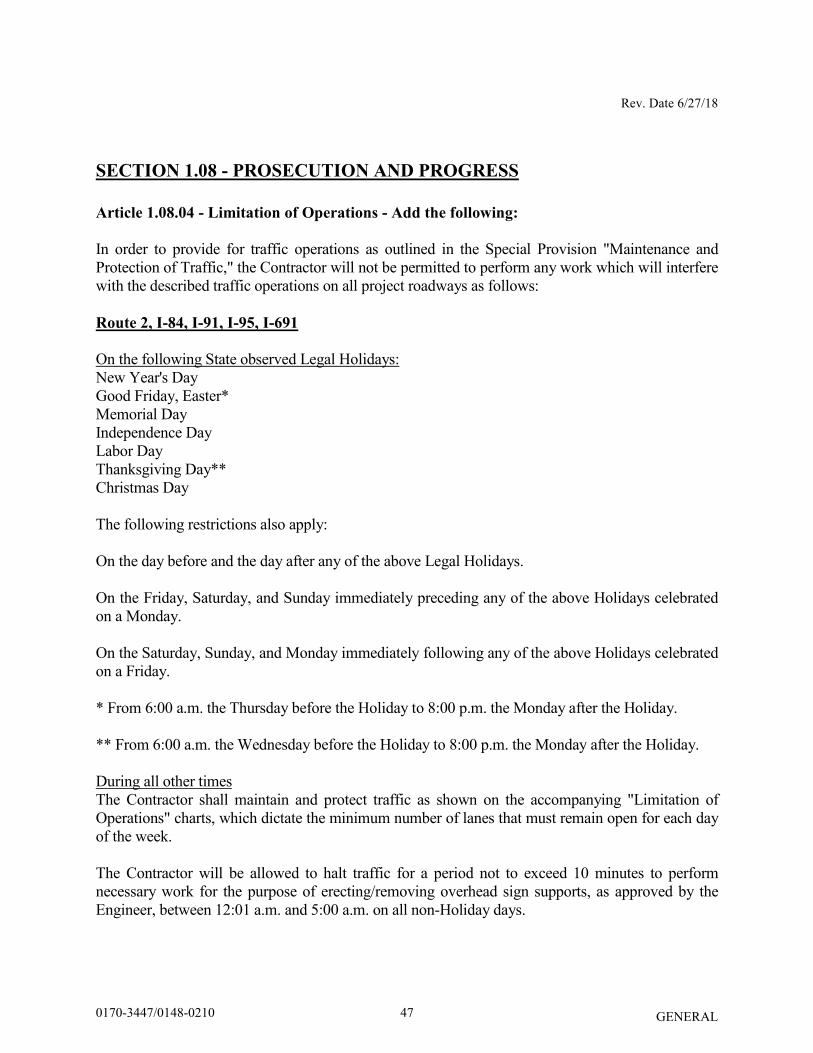
SECTION 1.08 - PROSECUTION AND PROGRESS
Article 1.08.04 - Limitation of Operations - Add the following:
In order to provide for traffic operations as outlined in the Special Provision "Maintenance and Protection of Traffic," the Contractor will not be permitted to perform any work which will interfere with the described traffic operations on all project roadways as follows:
Route 2, I-84, I-91, I-95, I-691
On the following State observed Legal Holidays: New Year's Day Good Friday, Easter* Memorial Day Independence Day Labor Day Thanksgiving Day** Christmas Day The following restrictions also apply: On the day before and the day after any of the above Legal Holidays. On the Friday, Saturday, and Sunday immediately preceding any of the above Holidays celebrated on a Monday. On the Saturday, Sunday, and Monday immediately following any of the above Holidays celebrated on a Friday. * From 6:00 a.m. the Thursday before the Holiday to 8:00 p.m. the Monday after the Holiday. ** From 6:00 a.m. the Wednesday before the Holiday to 8:00 p.m. the Monday after the Holiday. During all other times The Contractor shall maintain and protect traffic as shown on the accompanying "Limitation of Operations" charts, which dictate the minimum number of lanes that must remain open for each day of the week. The Contractor will be allowed to halt traffic for a period not to exceed 10 minutes to perform necessary work for the purpose of erecting/removing overhead sign supports, as approved by the Engineer, between 12:01 a.m. and 5:00 a.m. on all non-Holiday days.
470170-3447/0148-0210

Rev. Date 6/27/18
GENERAL
RAMPS, TURNING ROADWAYS AND HOV LANES:
Site 8 in Farmington (Ramp from I-84 W.B. to S.R. 508)
Monday through Friday between 6:00 a.m. and 7:00 p.m.
The Contractor will be allowed to halt traffic for a period not to exceed 10 minutes for the purpose of erecting/removing overhead sign supports, as approved by the Engineer, between 12:01 a.m. and 5:00 a.m. on all non-Holiday days.
Site 9 in East Hartford (On-Ramps 312 to I-84 EB & 118 to I-84 WB)
Monday through Friday between 6:00 a.m. and 9:00 a.m. & between 3:00 p.m. and 6:00 p.m.
The Contractor will be allowed to close On-Ramps 312 to I-84 EB & 118 to I-84 WB and detour traffic for a duration that shall not exceed 60 calendar days. The detours shall not be during the University of Connecticut Football season at Rentschler Field (August through December). The Contractor shall notify the Engineer at least 14 days in advance of the start of the On-Ramp closures. The Contractor will be allowed to halt traffic for a period not to exceed 10 minutes for the purpose of erecting/removing overhead sign supports, as approved by the Engineer, between 12:01 a.m. and 5:00 a.m. on all non-Holiday days.
Site 9 in East Hartford (Rte 15 NB On-Ramp to I-84 EB) and
(I-384 WB On-Ramp to I-84 WB)
Monday through Friday between 6:00 a.m. and 7:00 p.m. Saturday and Sunday between 8:00 a.m. and 8:00 p.m.
The Contractor will be allowed to halt traffic for a period not to exceed 10 minutes for the purpose of erecting/removing overhead sign supports, as approved by the Engineer, between 12:01 a.m. and 5:00 a.m. on all non-Holiday days.
480170-3447/0148-0210

Rev. Date 6/27/18
GENERAL
Site 9 in East Hartford (I-84 Restricted Lanes (HOV Lanes) including Entrance Ramps
from I-84 EB and Silver Lane)
Monday through Friday between 6:00 a.m. and 9:00 a.m. & between 2:00 p.m. and 6:00 p.m. Saturday and Sunday between 10:00 a.m. and 6:00 p.m. All other Ramps and Turning Roadways
Monday through Friday between 6:00 a.m. and 9:00 a.m. & between 3:00 p.m. and 6:00 p.m.
The Contractor will be allowed to halt traffic for a period not to exceed 10 minutes for the purpose of erecting/removing overhead sign supports, as approved by the Engineer, between 12:01 a.m. and 5:00 a.m. on all non-Holiday days. OTHER ROADWAYS: 4 LANE ROADWAYS:
Site 4 in Waterbury
Union Street & Washington Street
Monday through Friday between 6:00 a.m. and 9:00 a.m. & between 3:00 p.m. and 6:00 p.m. Saturday and Sunday between 10:00 a.m. and 6:00 p.m.
Route 69 (Silver Street\Hamilton Ave.)
Monday through Friday between 6:00 a.m. and 9:00 a.m. & between 1:00 p.m. and 7:00 p.m. Saturday and Sunday between 10:00 a.m. and 6:00 p.m. The Contractor will be allowed to halt traffic for a period not to exceed 10 minutes for the purpose of erecting/removing overhead sign supports, as approved by the Engineer, between 12:01 a.m. and 5:00 a.m. on all non-Holiday days.
Site 6 in Berlin
U.S. Route 5& Route 15 (Berlin Turnpike)
Monday through Friday between 6:00 a.m. and 9:00 a.m. & between 2:00 p.m. and 7:00 p.m. Saturday and Sunday between 10:00 a.m. and 6:00 p.m.
Route 372 (Mill Street)
Monday through Friday between 6:00 a.m. and 9:00 a.m. & between 3:00 p.m. and 6:00 p.m. Saturday and Sunday between 10:00 a.m. and 6:00 p.m. The Contractor will be allowed to halt traffic for a period not to exceed 10 minutes for the purpose of erecting/removing overhead sign supports, as approved by the Engineer, between 12:01 a.m. and 5:00 a.m. on all non-Holiday days.
490170-3447/0148-0210

Rev. Date 6/27/18
GENERAL
Site 7 in Rocky Hill
Route 3 (Cromwell Avenue)
Monday through Friday between 6:00 a.m. and 9:00 a.m. & between 3:00 p.m. and 6:00 p.m. Saturday and Sunday between 10:00 a.m. and 6:00 p.m.
Site 8 in Farmington (S.R. 508 West of the Signalized Intersection with Route 4)
Monday through Friday between 6:00 a.m. and 8:00 p.m. Saturday and Sunday between 10:00 a.m. and 6:00 p.m.
Site 8 in Farmington (S.R. 508 East of the Signalized Intersection with Route 4)
Monday through Friday between 6:00 a.m. and 9:00 a.m. & between 3:00 p.m. and 6:00 p.m. Saturday and Sunday between 10:00 a.m. and 6:00 p.m.
The Contractor will be allowed to halt traffic for a period not to exceed 10 minutes for the purpose of erecting/removing overhead sign supports, as approved by the Engineer, between 12:01 a.m. and 5:00 a.m. on all non-Holiday days.
Site 10 in Enfield
Route 190 (Hazard Avenue)
Monday through Friday between 6:00 a.m. 6:00 p.m. Saturday and Sunday between 10:00 a.m. and 6:00 p.m.
All Other Roadways
Monday through Friday between 6:00 a.m. and 9:00 a.m. & between 3:00 p.m. and 6:00 p.m. Saturday and Sunday between 10:00 a.m. and 6:00 p.m.
Additional Lane Closure Restrictions
It is anticipated that work on adjacent projects will be ongoing simultaneously with this project. The Contractor shall be aware of those projects and anticipate that coordination will be required to maintain proper traffic flow at all times on all project roadways, in a manner consistent with these specifications and acceptable to the Engineer. The Contractor will not be allowed to perform any work that will interfere with traffic operations on a roadway when traffic operations are being restricted on that same roadway, unless there is at least a one mile clear area length where the entire roadway is open to traffic or the closures have been coordinated and are acceptable to the Engineer. The one mile clear area length shall be measured from the end of the first work area to the beginning of the signing pattern for the next work area.
500170-3447/0148-0210
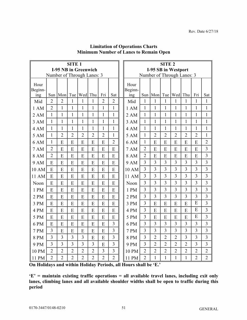
Rev. Date 6/27/18
GENERAL
Limitation of Operations Charts
Minimum Number of Lanes to Remain Open
SITE 1
I-95 NB in Greenwich
Number of Through Lanes: 3
SITE 2
I-95 SB in Westport
Number of Through Lanes: 3
Hour Beginn-
ing Sun Mon Tue Wed Thu Fri Sat
Hour Beginn-
ing Sun Mon Tue Wed Thu Fri Sat Mid 2 2 1 1 1 2 2 Mid 1 1 1 1 1 1 1
1 AM 2 1 1 1 1 1 1 1 AM 1 1 1 1 1 1 1 2 AM 1 1 1 1 1 1 1 2 AM 1 1 1 1 1 1 1 3 AM 1 1 1 1 1 1 1 3 AM 1 1 1 1 1 1 1 4 AM 1 1 1 1 1 1 1 4 AM 1 1 1 1 1 1 1 5 AM 1 2 2 2 2 2 1 5 AM 1 2 2 2 2 2 1 6 AM 1 E E E E E 2 6 AM 1 E E E E E 2 7 AM 2 E E E E E E 7 AM 2 E E E E E 3 8 AM 2 E E E E E E 8 AM 2 E E E E E 3 9 AM E E E E E E E 9 AM 3 3 3 3 3 3 3
10 AM E E E E E E E 10 AM 3 3 3 3 3 3 3 11 AM E E E E E E E 11 AM 3 3 3 3 3 3 3 Noon E E E E E E E Noon 3 3 3 3 3 3 3 1 PM E E E E E E E 1 PM 3 3 3 3 3 3 3 2 PM E E E E E E E 2 PM 3 3 3 3 3 3 3 3 PM E E E E E E E 3 PM 3 E E E E E 3 4 PM E E E E E E E 4 PM 3 E E E E E 3 5 PM E E E E E E E 5 PM 3 E E E E E 3 6 PM E E E E E E 3 6 PM 3 3 3 3 3 3 3 7 PM 3 E E E E E 3 7 PM 3 3 3 3 3 3 3 8 PM 3 3 3 3 E E 3 8 PM 3 2 2 2 3 3 3 9 PM 3 3 3 3 3 E 3 9 PM 3 2 2 2 2 3 3
10 PM 2 2 2 2 2 3 3 10 PM 2 2 2 2 2 2 2 11 PM 2 2 2 2 2 2 2 11 PM 2 1 1 1 1 2 2
On Holidays and within Holiday Periods, all Hours shall be ‘E.’
‘E’ = maintain existing traffic operations = all available travel lanes, including exit only
lanes, climbing lanes and all available shoulder widths shall be open to traffic during this
period
510170-3447/0148-0210
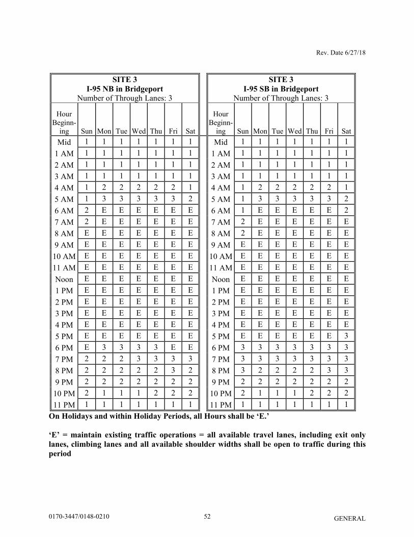
Rev. Date 6/27/18
GENERAL
SITE 3
I-95 NB in Bridgeport
Number of Through Lanes: 3
SITE 3
I-95 SB in Bridgeport
Number of Through Lanes: 3
Hour Beginn-
ing Sun Mon Tue Wed Thu Fri Sat
Hour Beginn-
ing Sun Mon Tue Wed Thu Fri Sat Mid 1 1 1 1 1 1 1 Mid 1 1 1 1 1 1 1
1 AM 1 1 1 1 1 1 1 1 AM 1 1 1 1 1 1 1 2 AM 1 1 1 1 1 1 1 2 AM 1 1 1 1 1 1 1 3 AM 1 1 1 1 1 1 1 3 AM 1 1 1 1 1 1 1 4 AM 1 2 2 2 2 2 1 4 AM 1 2 2 2 2 2 1 5 AM 1 3 3 3 3 3 2 5 AM 1 3 3 3 3 3 2 6 AM 2 E E E E E E 6 AM 1 E E E E E 2 7 AM 2 E E E E E E 7 AM 2 E E E E E E 8 AM E E E E E E E 8 AM 2 E E E E E E 9 AM E E E E E E E 9 AM E E E E E E E
10 AM E E E E E E E 10 AM E E E E E E E 11 AM E E E E E E E 11 AM E E E E E E E Noon E E E E E E E Noon E E E E E E E 1 PM E E E E E E E 1 PM E E E E E E E 2 PM E E E E E E E 2 PM E E E E E E E 3 PM E E E E E E E 3 PM E E E E E E E 4 PM E E E E E E E 4 PM E E E E E E E 5 PM E E E E E E E 5 PM E E E E E E 3 6 PM E 3 3 3 3 E E 6 PM 3 3 3 3 3 3 3 7 PM 2 2 2 3 3 3 3 7 PM 3 3 3 3 3 3 3 8 PM 2 2 2 2 2 3 2 8 PM 3 2 2 2 2 3 3 9 PM 2 2 2 2 2 2 2 9 PM 2 2 2 2 2 2 2
10 PM 2 1 1 1 2 2 2 10 PM 2 1 1 1 2 2 2 11 PM 1 1 1 1 1 1 1 11 PM 1 1 1 1 1 1 1
On Holidays and within Holiday Periods, all Hours shall be ‘E.’
‘E’ = maintain existing traffic operations = all available travel lanes, including exit only
lanes, climbing lanes and all available shoulder widths shall be open to traffic during this
period
520170-3447/0148-0210
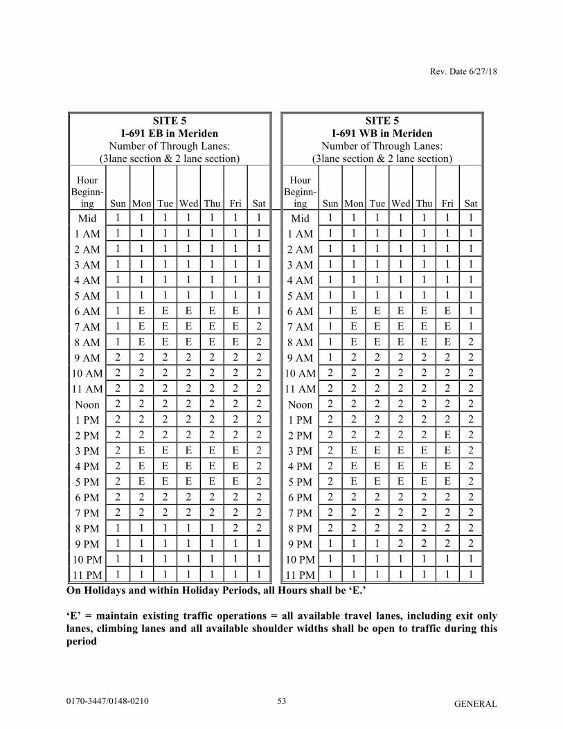
Rev. Date 6/27/18
GENERAL
SITE 5
I-691 EB in Meriden
Number of Through Lanes: (3lane section & 2 lane section)
SITE 5
I-691 WB in Meriden
Number of Through Lanes: (3lane section & 2 lane section)
Hour Beginn-
ing Sun Mon Tue Wed Thu Fri Sat
Hour Beginn-
ing Sun Mon Tue Wed Thu Fri Sat Mid 1 1 1 1 1 1 1 Mid 1 1 1 1 1 1 1
1 AM 1 1 1 1 1 1 1 1 AM 1 1 1 1 1 1 1 2 AM 1 1 1 1 1 1 1 2 AM 1 1 1 1 1 1 1 3 AM 1 1 1 1 1 1 1 3 AM 1 1 1 1 1 1 1 4 AM 1 1 1 1 1 1 1 4 AM 1 1 1 1 1 1 1 5 AM 1 1 1 1 1 1 1 5 AM 1 1 1 1 1 1 1 6 AM 1 E E E E E 1 6 AM 1 E E E E E 1 7 AM 1 E E E E E 2 7 AM 1 E E E E E 1 8 AM 1 E E E E E 2 8 AM 1 E E E E E 2 9 AM 2 2 2 2 2 2 2 9 AM 1 2 2 2 2 2 2
10 AM 2 2 2 2 2 2 2 10 AM 2 2 2 2 2 2 2 11 AM 2 2 2 2 2 2 2 11 AM 2 2 2 2 2 2 2 Noon 2 2 2 2 2 2 2 Noon 2 2 2 2 2 2 2 1 PM 2 2 2 2 2 2 2 1 PM 2 2 2 2 2 2 2 2 PM 2 2 2 2 2 2 2 2 PM 2 2 2 2 2 E 2 3 PM 2 E E E E E 2 3 PM 2 E E E E E 2 4 PM 2 E E E E E 2 4 PM 2 E E E E E 2 5 PM 2 E E E E E 2 5 PM 2 E E E E E 2 6 PM 2 2 2 2 2 2 2 6 PM 2 2 2 2 2 2 2 7 PM 2 2 2 2 2 2 2 7 PM 2 2 2 2 2 2 2 8 PM 1 1 1 1 1 2 2 8 PM 2 2 2 2 2 2 2 9 PM 1 1 1 1 1 1 1 9 PM 1 1 1 2 2 2 2
10 PM 1 1 1 1 1 1 1 10 PM 1 1 1 1 1 1 1 11 PM 1 1 1 1 1 1 1 11 PM 1 1 1 1 1 1 1
On Holidays and within Holiday Periods, all Hours shall be ‘E.’
‘E’ = maintain existing traffic operations = all available travel lanes, including exit only
lanes, climbing lanes and all available shoulder widths shall be open to traffic during this
period
530170-3447/0148-0210
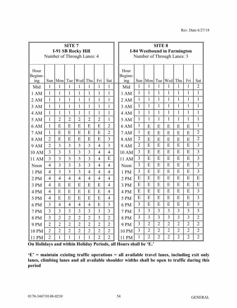
Rev. Date 6/27/18
GENERAL
SITE 7
I-91 SB Rocky Hill
Number of Through Lanes: 4
SITE 8
I-84 Westbound in Farmington
Number of Through Lanes: 3
Hour Beginn-
ing Sun Mon Tue Wed Thu Fri Sat
Hour Beginn-
ing Sun Mon Tue Wed Thu Fri Sat Mid 1 1 1 1 1 1 1 Mid 1 1 1 1 1 1 2
1 AM 1 1 1 1 1 1 1 1 AM 1 1 1 1 1 1 1 2 AM 1 1 1 1 1 1 1 2 AM 1 1 1 1 1 1 1 3 AM 1 1 1 1 1 1 1 3 AM 1 1 1 1 1 1 1 4 AM 1 1 1 1 1 1 1 4 AM 1 1 1 1 1 1 1 5 AM 1 2 2 2 2 2 1 5 AM 1 1 1 1 1 1 1 6 AM 1 E E E E E 2 6 AM 1 E E E E E 1 7 AM 1 E E E E E 2 7 AM 1 E E E E E 2 8 AM 2 E E E E E 3 8 AM 2 E E E E E 2 9 AM 2 3 3 3 3 4 3 9 AM 2 E E E E E 3
10 AM 3 3 3 3 3 4 4 10 AM 3 E E E E E 3 11 AM 3 3 3 3 3 4 E 11 AM 3 E E E E E 3 Noon 4 3 3 3 3 4 4 Noon 3 E E E E E 3 1 PM 4 3 3 3 4 4 4 1 PM 3 E E E E E 3 2 PM 4 4 4 4 4 4 4 2 PM E E E E E E E 3 PM 4 E E E E E 4 3 PM E E E E E E E 4 PM 4 E E E E E 4 4 PM E E E E E E 3 5 PM 4 E E E E E 4 5 PM E E E E E E 3 6 PM 3 4 4 4 4 E 3 6 PM 3 E E E E E 3 7 PM 3 3 3 3 3 3 3 7 PM 3 3 3 3 3 3 3 8 PM 3 2 2 2 2 3 2 8 PM 3 3 3 3 3 3 2 9 PM 2 2 2 2 2 2 2 9 PM 3 2 2 2 2 2 2
10 PM 2 2 2 2 2 2 2 10 PM 3 2 2 2 2 2 2 11 PM 2 1 1 1 1 2 2 11 PM 1 2 2 2 2 2 2
On Holidays and within Holiday Periods, all Hours shall be ‘E.’
‘E’ = maintain existing traffic operations = all available travel lanes, including exit only
lanes, climbing lanes and all available shoulder widths shall be open to traffic during this
period
540170-3447/0148-0210
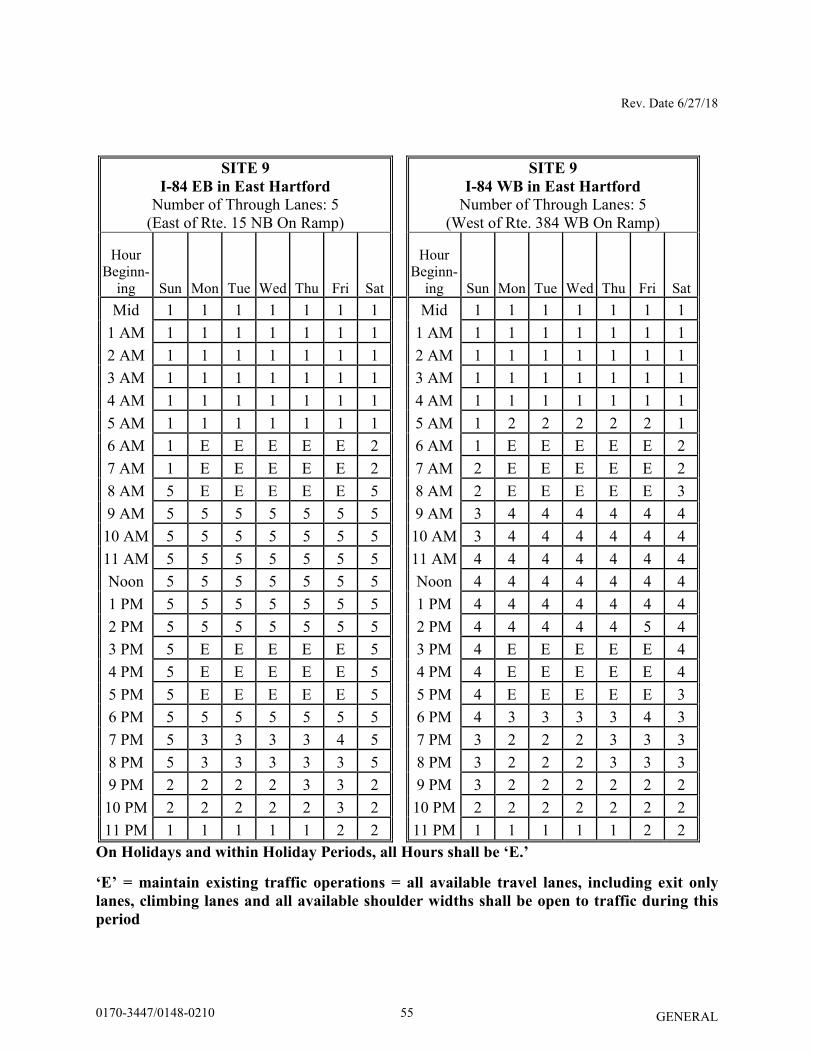
Rev. Date 6/27/18
GENERAL
SITE 9
I-84 EB in East Hartford
Number of Through Lanes: 5 (East of Rte. 15 NB On Ramp)
SITE 9
I-84 WB in East Hartford
Number of Through Lanes: 5 (West of Rte. 384 WB On Ramp)
Hour Beginn-
ing Sun Mon Tue Wed Thu Fri Sat
Hour Beginn-
ing Sun Mon Tue Wed Thu Fri Sat Mid 1 1 1 1 1 1 1 Mid 1 1 1 1 1 1 1
1 AM 1 1 1 1 1 1 1 1 AM 1 1 1 1 1 1 1 2 AM 1 1 1 1 1 1 1 2 AM 1 1 1 1 1 1 1 3 AM 1 1 1 1 1 1 1 3 AM 1 1 1 1 1 1 1 4 AM 1 1 1 1 1 1 1 4 AM 1 1 1 1 1 1 1 5 AM 1 1 1 1 1 1 1 5 AM 1 2 2 2 2 2 1 6 AM 1 E E E E E 2 6 AM 1 E E E E E 2 7 AM 1 E E E E E 2 7 AM 2 E E E E E 2 8 AM 5 E E E E E 5 8 AM 2 E E E E E 3 9 AM 5 5 5 5 5 5 5 9 AM 3 4 4 4 4 4 4
10 AM 5 5 5 5 5 5 5 10 AM 3 4 4 4 4 4 4 11 AM 5 5 5 5 5 5 5 11 AM 4 4 4 4 4 4 4 Noon 5 5 5 5 5 5 5 Noon 4 4 4 4 4 4 4 1 PM 5 5 5 5 5 5 5 1 PM 4 4 4 4 4 4 4 2 PM 5 5 5 5 5 5 5 2 PM 4 4 4 4 4 5 4 3 PM 5 E E E E E 5 3 PM 4 E E E E E 4 4 PM 5 E E E E E 5 4 PM 4 E E E E E 4 5 PM 5 E E E E E 5 5 PM 4 E E E E E 3 6 PM 5 5 5 5 5 5 5 6 PM 4 3 3 3 3 4 3 7 PM 5 3 3 3 3 4 5 7 PM 3 2 2 2 3 3 3 8 PM 5 3 3 3 3 3 5 8 PM 3 2 2 2 3 3 3 9 PM 2 2 2 2 3 3 2 9 PM 3 2 2 2 2 2 2
10 PM 2 2 2 2 2 3 2 10 PM 2 2 2 2 2 2 2 11 PM 1 1 1 1 1 2 2 11 PM 1 1 1 1 1 2 2
On Holidays and within Holiday Periods, all Hours shall be ‘E.’
‘E’ = maintain existing traffic operations = all available travel lanes, including exit only
lanes, climbing lanes and all available shoulder widths shall be open to traffic during this
period
550170-3447/0148-0210
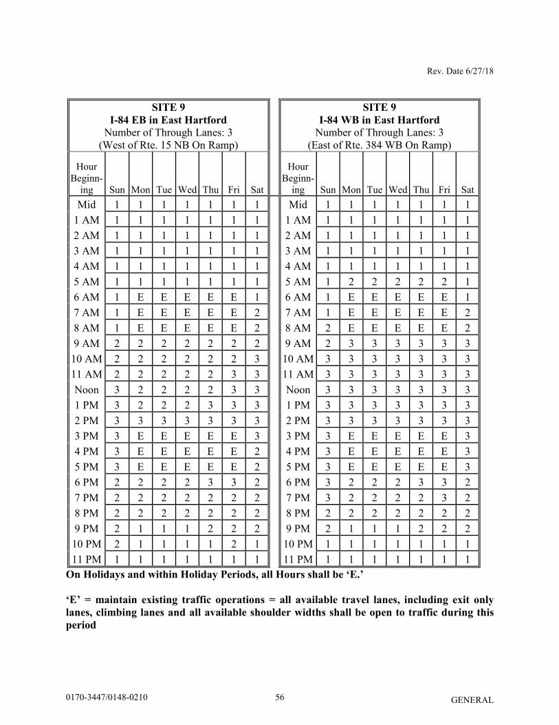
Rev. Date 6/27/18
GENERAL
SITE 9
I-84 EB in East Hartford
Number of Through Lanes: 3 (West of Rte. 15 NB On Ramp)
SITE 9
I-84 WB in East Hartford
Number of Through Lanes: 3 (East of Rte. 384 WB On Ramp)
Hour Beginn-
ing Sun Mon Tue Wed Thu Fri Sat
Hour Beginn-
ing Sun Mon Tue Wed Thu Fri Sat Mid 1 1 1 1 1 1 1 Mid 1 1 1 1 1 1 1
1 AM 1 1 1 1 1 1 1 1 AM 1 1 1 1 1 1 1 2 AM 1 1 1 1 1 1 1 2 AM 1 1 1 1 1 1 1 3 AM 1 1 1 1 1 1 1 3 AM 1 1 1 1 1 1 1 4 AM 1 1 1 1 1 1 1 4 AM 1 1 1 1 1 1 1 5 AM 1 1 1 1 1 1 1 5 AM 1 2 2 2 2 2 1 6 AM 1 E E E E E 1 6 AM 1 E E E E E 1 7 AM 1 E E E E E 2 7 AM 1 E E E E E 2 8 AM 1 E E E E E 2 8 AM 2 E E E E E 2 9 AM 2 2 2 2 2 2 2 9 AM 2 3 3 3 3 3 3
10 AM 2 2 2 2 2 2 3 10 AM 3 3 3 3 3 3 3 11 AM 2 2 2 2 2 3 3 11 AM 3 3 3 3 3 3 3 Noon 3 2 2 2 2 3 3 Noon 3 3 3 3 3 3 3 1 PM 3 2 2 2 3 3 3 1 PM 3 3 3 3 3 3 3 2 PM 3 3 3 3 3 3 3 2 PM 3 3 3 3 3 3 3 3 PM 3 E E E E E 3 3 PM 3 E E E E E 3 4 PM 3 E E E E E 2 4 PM 3 E E E E E 3 5 PM 3 E E E E E 2 5 PM 3 E E E E E 3 6 PM 2 2 2 2 3 3 2 6 PM 3 2 2 2 3 3 2 7 PM 2 2 2 2 2 2 2 7 PM 3 2 2 2 2 3 2 8 PM 2 2 2 2 2 2 2 8 PM 2 2 2 2 2 2 2 9 PM 2 1 1 1 2 2 2 9 PM 2 1 1 1 2 2 2
10 PM 2 1 1 1 1 2 1 10 PM 1 1 1 1 1 1 1 11 PM 1 1 1 1 1 1 1 11 PM 1 1 1 1 1 1 1
On Holidays and within Holiday Periods, all Hours shall be ‘E.’
‘E’ = maintain existing traffic operations = all available travel lanes, including exit only
lanes, climbing lanes and all available shoulder widths shall be open to traffic during this
period
560170-3447/0148-0210
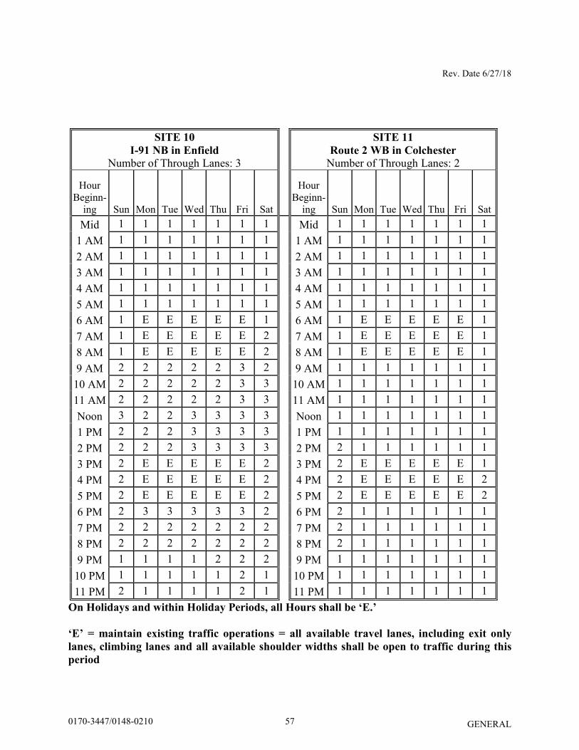
Rev. Date 6/27/18
GENERAL
SITE 10
I-91 NB in Enfield
Number of Through Lanes: 3
SITE 11
Route 2 WB in Colchester
Number of Through Lanes: 2
Hour Beginn-
ing Sun Mon Tue Wed Thu Fri Sat
Hour Beginn-
ing Sun Mon Tue Wed Thu Fri Sat Mid 1 1 1 1 1 1 1 Mid 1 1 1 1 1 1 1
1 AM 1 1 1 1 1 1 1 1 AM 1 1 1 1 1 1 1 2 AM 1 1 1 1 1 1 1 2 AM 1 1 1 1 1 1 1 3 AM 1 1 1 1 1 1 1 3 AM 1 1 1 1 1 1 1 4 AM 1 1 1 1 1 1 1 4 AM 1 1 1 1 1 1 1 5 AM 1 1 1 1 1 1 1 5 AM 1 1 1 1 1 1 1 6 AM 1 E E E E E 1 6 AM 1 E E E E E 1 7 AM 1 E E E E E 2 7 AM 1 E E E E E 1 8 AM 1 E E E E E 2 8 AM 1 E E E E E 1 9 AM 2 2 2 2 2 3 2 9 AM 1 1 1 1 1 1 1
10 AM 2 2 2 2 2 3 3 10 AM 1 1 1 1 1 1 1 11 AM 2 2 2 2 2 3 3 11 AM 1 1 1 1 1 1 1 Noon 3 2 2 3 3 3 3 Noon 1 1 1 1 1 1 1 1 PM 2 2 2 3 3 3 3 1 PM 1 1 1 1 1 1 1 2 PM 2 2 2 3 3 3 3 2 PM 2 1 1 1 1 1 1 3 PM 2 E E E E E 2 3 PM 2 E E E E E 1 4 PM 2 E E E E E 2 4 PM 2 E E E E E 2 5 PM 2 E E E E E 2 5 PM 2 E E E E E 2 6 PM 2 3 3 3 3 3 2 6 PM 2 1 1 1 1 1 1 7 PM 2 2 2 2 2 2 2 7 PM 2 1 1 1 1 1 1 8 PM 2 2 2 2 2 2 2 8 PM 2 1 1 1 1 1 1 9 PM 1 1 1 1 2 2 2 9 PM 1 1 1 1 1 1 1
10 PM 1 1 1 1 1 2 1 10 PM 1 1 1 1 1 1 1 11 PM 2 1 1 1 1 2 1 11 PM 1 1 1 1 1 1 1
On Holidays and within Holiday Periods, all Hours shall be ‘E.’
‘E’ = maintain existing traffic operations = all available travel lanes, including exit only
lanes, climbing lanes and all available shoulder widths shall be open to traffic during this
period
570170-3447/0148-0210
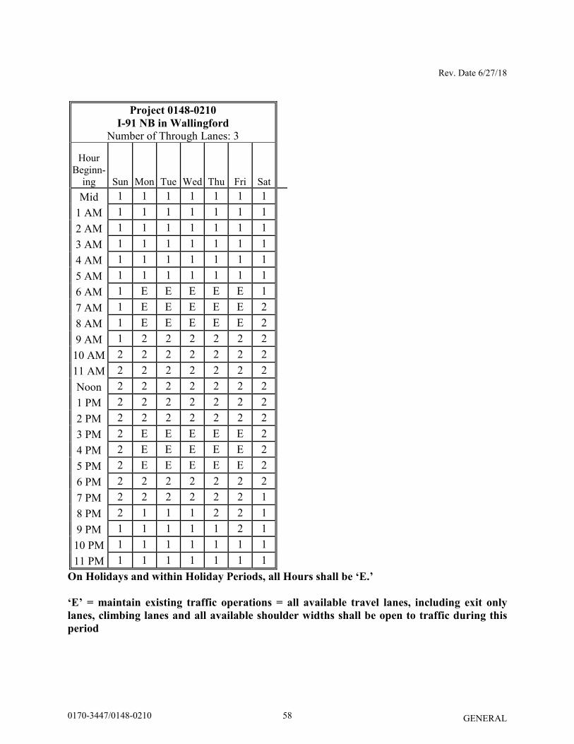
Rev. Date 6/27/18
GENERAL
Project 0148-0210
I-91 NB in Wallingford
Number of Through Lanes: 3
Hour Beginn-
ing Sun Mon Tue Wed Thu Fri Sat
Mid 1 1 1 1 1 1 1 1 AM 1 1 1 1 1 1 1 2 AM 1 1 1 1 1 1 1 3 AM 1 1 1 1 1 1 1 4 AM 1 1 1 1 1 1 1 5 AM 1 1 1 1 1 1 1 6 AM 1 E E E E E 1 7 AM 1 E E E E E 2 8 AM 1 E E E E E 2 9 AM 1 2 2 2 2 2 2
10 AM 2 2 2 2 2 2 2 11 AM 2 2 2 2 2 2 2 Noon 2 2 2 2 2 2 2 1 PM 2 2 2 2 2 2 2 2 PM 2 2 2 2 2 2 2 3 PM 2 E E E E E 2 4 PM 2 E E E E E 2 5 PM 2 E E E E E 2 6 PM 2 2 2 2 2 2 2 7 PM 2 2 2 2 2 2 1 8 PM 2 1 1 1 2 2 1 9 PM 1 1 1 1 1 2 1
10 PM 1 1 1 1 1 1 1 11 PM 1 1 1 1 1 1 1
On Holidays and within Holiday Periods, all Hours shall be ‘E.’
‘E’ = maintain existing traffic operations = all available travel lanes, including exit only
lanes, climbing lanes and all available shoulder widths shall be open to traffic during this
period
580170-3447/0148-0210
Rev. Date 9/30/2016 English
GENERAL
SECTION 4.06 - BITUMINOUS CONCRETE
Section 4.06 is being deleted in its entirety and replaced with the following: 4.06.01—Description
4.06.02—Materials
4.06.03—Construction Methods
4.06.04—Method of Measurement
4.06.05—Basis of Payment
4.06.01—Description: Work under this section shall include the production, delivery, placement, and compaction of an uniform textured, non-segregated, smooth bituminous concrete pavement to the grade and cross section shown on the plans. The terms listed below as used in this specification are defined as: Bituminous Concrete: A composite material consisting of prescribed amounts of asphalt binder, and aggregates. Asphalt binder may also contain additives engineered to modify specific properties and/or behavior of the composite material. References to bituminous concrete apply to all of its forms, such as those identified as hot-mix asphalt (HMA),or polymer-modified asphalt (PMA). Bituminous Concrete Plant (Plant): A structure where aggregates and asphalt binder are combined in a controlled fashion into a bituminous concrete mixture suitable for forming pavements and other paved surfaces. Course: A continuous layer (a lift or multiple lifts) of the same bituminous concrete mixture placed as part of the pavement structure. Density Lot: The total tonnage of all bituminous concrete placed in a single lift and as defined in Article 4.06.03. Disintegration: Erosion or fragmentation of the pavement surface which can be described as polishing, weathering-oxidizing, scaling, spalling, raveling, or formation of potholes. Dispute Resolution: A procedure used to resolve conflicts between the Engineer and the Contractor’s test results that may affect payment. Hot Mix Asphalt (HMA): A bituminous concrete mixture typically produced at 325°F. Job Mix Formula (JMF): A recommended aggregate gradation and asphalt binder content to achieve the required mixture properties.
590170-3447/0148-0210
Rev. Date 9/30/2016 English
GENERAL
Lift: An application of a bituminous concrete mixture placed and compacted to a specified thickness in a single paver pass. Percent Within Limits (PWL): The percentage of the lot falling between the Upper Specification Limit (USL) and the Lower Specification Limit (LSL). Polymer-Modified Asphalt (PMA): A bituminous concrete mixture containing a polymer modified asphalt binder and using a qualified warm mix technology. Production Lot: The total tonnage of a bituminous concrete mixture from a single source that may receive an adjustment. Production Sub Lot: Portion of the production lot typically represented by a single sample. Quality Assurance (QA): All those planned and systematic actions necessary to provide ConnDOT the confidence that a Contractor will perform the work as specified in the Contract. Quality Control (QC): The sum total of activities performed by the vendor (Producer, Manufacturer, and Contractor) to ensure that a product meets contract specification requirements. Superpave: A bituminous concrete mix design used in mixtures designated as “S*” Where “S” indicates Superpave and * indicates the sieve related to the nominal maximum aggregate size of the mix. Segregation: A non-uniform distribution of a bituminous concrete mixture in terms of gradation, temperature, or volumetric properties. Warm Mix Asphalt (WMA) Technology: A qualified additive or technology that may be used to produce a bituminous concrete at reduced temperatures and/or increase workability of the mixture. 4.06.02—Materials: All materials shall conform to the requirements of Section M.04.
1. Materials Supply: The bituminous concrete mixture must be from one source of supply and originate from one Plant unless authorized by the Engineer. 2. Recycled Materials: Reclaimed Asphalt Pavement (RAP), Crushed Recycled Container Glass (CRCG), Recycled Asphalt Shingles (RAS), or crumb rubber (CR) from recycled tires may be incorporated in bituminous concrete mixtures in accordance with Project Specifications.
4.06.03—Construction Methods:
600170-3447/0148-0210
Rev. Date 9/30/2016 English
GENERAL
1. Material Documentation: All vendors producing bituminous concrete must have Plants with automated vehicle-weighing scales, storage scales, and material feeds capable of producing a delivery ticket containing the information below.
a. “State of Connecticut” printed on ticket. b. Name of producer, identification of Plant, and specific storage silo if used. c. Date and time. d. Mixture Designation; Mix type and level Curb mixtures for machine-placed curbing
must state "curb mix only". e. If WMA Technology is used, the additive name and dosage rate or water injection rate
must be listed. f. Net weight of mixture loaded into the vehicle (When RAP and/or RAS is used the
moisture content shall be excluded from mixture net weight). g. Gross weight (equal to the net weight plus the tare weight or the loaded scale weight). h. Tare weight of vehicle (Daily scale weight of the empty vehicle). i. Project number, purchase order number, name of Contractor (if Contractor other than
Producer). j. Vehicle number - unique means of identification vehicle. k. For Batch Plants, individual aggregate, recycled materials, and virgin asphalt
max/target/min weights when silos are not used. l. For every mixture designation the running daily total delivered and sequential load
number.
The net weight of mixture loaded into the vehicle must be equal to the cumulative measured weights of its components. The Contractor must notify the Engineer immediately if, during production, there is a malfunction of the weight recording system in the automated Plant. Manually written tickets containing all required information will be allowed for no more than one hour. The State reserves the right to have an inspector present to monitor batching and /or weighing operations.
2. Transportation of Mixture: The mixture shall be transported in vehicles that are clean of all foreign material, excessive coating or cleaning agents, and, that have no gaps through which mixture might spill. Any material spilled during the loading or transportation process shall be quantified by re-weighing the vehicle. The Contractor shall load vehicles uniformly so that segregation is minimized. Loaded vehicles shall be tightly covered with waterproof covers acceptable to the Engineer. Mesh covers are prohibited. The cover must minimize air infiltration. Vehicles found not to be in conformance shall not be loaded. Vehicles with loads of bituminous concrete being delivered to State projects must not exceed the statutory or permitted load limits referred to as gross vehicle weight (GVW). The Contractor shall furnish a list and allowable weights of all vehicles transporting mixture.
610170-3447/0148-0210
Rev. Date 9/30/2016 English
GENERAL
The State reserves the right to check the gross and tare weight of any vehicle. If the gross or tare weight varies from that shown on the delivery ticket by more than 0.4 percent, the Engineer will recalculate the net weight. The Contractor shall correct the discrepancy to the satisfaction of the Engineer.
If a vehicle delivers mixture to the project and the delivery ticket indicates that the vehicle is overweight, the load may not be rejected but a “Measured Weight Adjustment” will be taken in accordance with Article 4.06.04. Vehicle body coating and cleaning agents must not have a deleterious effect on the mixture. The use of solvents or fuel oil, in any concentration, is prohibited for the coating of vehicle bodies. For each delivery, the Engineer shall be provided a clear, legible copy of the delivery ticket. 3. Paving Equipment: The Contractor shall have the necessary paving and compaction equipment at the project site to perform the work. All equipment shall be in good working order and any equipment that is worn, defective or inadequate for performance of the work shall be repaired or replaced by the Contractor to the satisfaction of the Engineer. During the paving operation, the use of solvents or fuel oil, in any concentration, is prohibited as a release agent or cleaner on any paving equipment (i.e., rollers, pavers, transfer devices, etc.). Refueling or cleaning of equipment is prohibited in any location on the project where fuel or solvents might come in contact with paved areas or areas to be paved. Solvents used in cleaning mechanical equipment or hand tools shall be stored off of areas paved or to be paved. Pavers: Each paver shall have a receiving hopper with sufficient capacity to provide for a uniform spreading operation and a distribution system that places the mix uniformly, without segregation. The paver shall be equipped with and use a vibratory screed system with heaters or burners. The screed system shall be capable of producing a finished surface of the required evenness and texture without tearing, shoving, or gouging the mixture. Pavers with extendible screed units as part of the system shall have auger extensions and tunnel extenders as necessary. Automatic screed controls for grade and slope shall be used at all times unless otherwise authorized by the Engineer. The controls shall automatically adjust the screed to compensate for irregularities in the preceding course or existing base. The controls shall maintain the proper transverse slope and be readily adjustable, and shall operate from a fixed or moving reference such as a grade wire or floating beam. Rollers: All rollers shall be self-propelled and designed for compaction of bituminous concrete. Rollers types shall include steel-wheeled, pneumatic or a combination thereof. Rollers that operate in a dynamic mode shall have drums that use a vibratory or oscillatory system or combination of. Vibratory rollers shall be equipped with indicators for amplitude, frequency and speed settings/readouts to measure the impacts per foot during the compaction process. Oscillatory rollers shall be equipped with frequency indicators. Rollers can operate in the dynamic mode using the oscillatory system on concrete structures such as bridges and catch basins if at the lowest frequency setting.
620170-3447/0148-0210

Rev. Date 9/30/2016 English
GENERAL
Pneumatic tire rollers shall be equipped with wide-tread compaction tires capable of exerting an average contact pressure from 60 to 90 pounds per square inch uniformly over the surface, The Contractor shall furnish documentation to the Engineer regarding tire size; pressure and loading to confirm that the proper contact pressure is being developed and that the loading and contact pressure is uniform for all wheels. Lighting: For paving operations, which will be performed during hours of darkness, the paving equipment shall be equipped with lighting fixtures as described below, or with an approved equal. Lighting shall minimize glare to passing traffic. The lighting options and minimum number of fixtures are listed in Tables 4.06-1 and 4.06-2:
TABLE 4.06-1: Minimum Paver Lighting
Option Fixture Configuration Fixture
Quantity Requirement
1
Type A 3 Mount over screed area Type B (narrow) or Type C (spot) 2 Aim to auger and guideline
Type B (wide) or Type C (flood) 2 Aim 25 feet behind paving machine
2 Type D Balloon 2 Mount over screed area
TABLE 4.06-2: Minimum Roller Lighting
Option Fixture
Configuration*
Fixture
Quantity Requirement
1 Type B (wide) 2 Aim 50 feet in front of and behind roller Type B (narrow) 2 Aim 100 feet in front of and behind roller
2 Type C (flood) 2 Aim 50 feet in front of and behind roller Type C (spot) 2 Aim 100 feet in front of and behind roller
3 Type D Balloon 1 Mount above the roller *All fixtures shall be mounted above the roller.
Type A: Fluorescent fixture shall be heavy-duty industrial type. Each fixture shall have a minimum output of 8,000 lumens. The fixtures shall be mounted horizontally, and be designed for continuous row installation. Type B: Each floodlight fixture shall have a minimum output of 18,000 lumens. Type C: Each fixture shall have a minimum output of 19,000 lumens. Type D: Balloon light: Each balloon light fixture shall have a minimum output of 50,000 lumens, and emit light equally in all directions.
Material Transfer Vehicle (MTV): A MTV shall be used when placing a bituminous concrete surface course as indicated in the contract documents.
630170-3447/0148-0210
Rev. Date 9/30/2016 English
GENERAL
The MTV must be a vehicle specifically designed for the purpose of delivering the bituminous
concrete mixture from the delivery vehicle to the paver. The MTV must continuously remix the bituminous concrete mixture throughout the placement process. The use of a MTV will be subject to the requirements stated in Article 1.07.05- Load Restrictions. The Engineer may limit the use of the vehicle if it is determined that the use of the MTV may damage highway components, utilities, or bridges. The Contractor shall submit to the Engineer at time of pre-construction the following information:
- The make and model of the MTV. - The individual axle weights and axle spacing for each piece of paving equipment (haul
vehicle, MTV and paver). - A working drawing showing the axle spacing in combination with all pieces of
equipment that will comprise the paving echelon.
4. Test Section: The Engineer may require the Contractor to place a test section whenever the requirements of this specification or Section M.04 are not met.
The Contractor shall submit the quantity of mixture to be placed and the location of the test section for review and approval by the Engineer. The same equipment used in the construction of a passing test section shall be used throughout production. If a test section fails to meet specifications, the Contractor shall stop production, make necessary adjustments to the job mix formula, Plant operations, or procedures for placement and compaction. The Contractor shall construct test sections, as allowed by the Engineer, until all the required specifications are met. All test sections shall also be subject to removal as set forth in Article 1.06.04. 5. Transitions for Roadway Surface: Transitions shall be formed at any point on the roadway where the pavement surface deviates, vertically, from the uniform longitudinal profile as specified on the plans. Whether formed by milling or by bituminous concrete mixture, all transition lengths shall conform to the criteria below unless otherwise specified. Permanent Transitions: Defined as any gradual change in pavement elevation that remains as a permanent part of the work. A transition shall be constructed no closer than 75 feet from either side of a bridge expansion joint or parapet. All permanent transitions, leading and trailing, shall meet the following length requirements:
a) Posted speed limit is greater than 35 MPH: 30 feet per inch of elevation change.
b) Posted speed limit is 35 MPH or less: 15 feet per inch of elevation change.
640170-3447/0148-0210
Rev. Date 9/30/2016 English
GENERAL
In areas where it is impractical to use the above described permanent transition lengths the use of a shorter permanent transition length may be permitted when approved by the Engineer.
Temporary Transitions: A temporary transition is defined as a transition that does not remain a permanent part of the work. All temporary transitions shall meet the following length requirements:
a) Posted speed limit is greater than 50 MPH (1) Leading Transitions = 15 feet per inch of vertical change (thickness)
(2) Trailing Transitions = 6 feet per inch of vertical change (thickness) b) Posted speed limit is 40, 45, or 50 MPH (1) Leading and Trailing = 4 feet per inch of vertical change (thickness)
c) Posted speed limit is 35 MPH or less (1) Leading and Trailing = 3 feet per inch of vertical change (thickness)
Note: Any temporary transition to be in-place over the winter shutdown period or during extended periods of inactivity (more than 14 calendar days) shall conform to the greater than 50 MPH requirements shown above. 6. Spreading and Finishing of Mixture: Prior to the placement of the mixture, the underlying base course shall be brought to the plan grade and cross section within the allowable tolerance. Immediately before placing a bituminous concrete lift, a uniform coating of tack coat shall be applied to all existing underlying pavement surfaces and on the exposed surface of a wedge joint. Such surfaces shall be clean and dry. Sweeping or other means acceptable to the Engineer shall be used. The mixture shall not be placed whenever the surface is wet or frozen. The Engineer may verify the mixture temperature by means of a probe or infrared type of thermometer. The Engineer may reject the load based on readings from a probe type thermometer and the specify temperature in the quality control plan (QCP) for placement. Tack Coat Application: The tack coat shall be applied by a pressurized spray system that results in uniform overlapping coverage at an application rate of 0.03 to 0.05 gallons per square yard for a non-milled surface and an application rate of 0.05 to 0.07 gallons per square yard for a milled surface. For areas where both milled and un-milled surfaces occur, the tack coat shall be an application rate of 0.03 to 0.05 gallons per square yard. The Engineer must approve the equipment and the method of measurement prior to use. The material for tack coat shall not be heated in excess of 160°F and shall not be further diluted. Tack coat shall be allowed sufficient time to break prior to any paving equipment or haul vehicles driving on it.
650170-3447/0148-0210
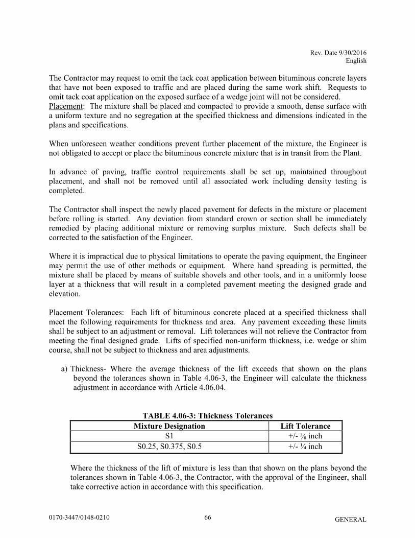
Rev. Date 9/30/2016 English
GENERAL
The Contractor may request to omit the tack coat application between bituminous concrete layers that have not been exposed to traffic and are placed during the same work shift. Requests to omit tack coat application on the exposed surface of a wedge joint will not be considered. Placement: The mixture shall be placed and compacted to provide a smooth, dense surface with a uniform texture and no segregation at the specified thickness and dimensions indicated in the plans and specifications. When unforeseen weather conditions prevent further placement of the mixture, the Engineer is not obligated to accept or place the bituminous concrete mixture that is in transit from the Plant. In advance of paving, traffic control requirements shall be set up, maintained throughout placement, and shall not be removed until all associated work including density testing is completed.
The Contractor shall inspect the newly placed pavement for defects in the mixture or placement before rolling is started. Any deviation from standard crown or section shall be immediately remedied by placing additional mixture or removing surplus mixture. Such defects shall be corrected to the satisfaction of the Engineer. Where it is impractical due to physical limitations to operate the paving equipment, the Engineer may permit the use of other methods or equipment. Where hand spreading is permitted, the mixture shall be placed by means of suitable shovels and other tools, and in a uniformly loose layer at a thickness that will result in a completed pavement meeting the designed grade and elevation. Placement Tolerances: Each lift of bituminous concrete placed at a specified thickness shall meet the following requirements for thickness and area. Any pavement exceeding these limits shall be subject to an adjustment or removal. Lift tolerances will not relieve the Contractor from meeting the final designed grade. Lifts of specified non-uniform thickness, i.e. wedge or shim course, shall not be subject to thickness and area adjustments.
a) Thickness- Where the average thickness of the lift exceeds that shown on the plans beyond the tolerances shown in Table 4.06-3, the Engineer will calculate the thickness adjustment in accordance with Article 4.06.04.
TABLE 4.06-3: Thickness Tolerances
Mixture Designation Lift Tolerance
S1 +/- ⅜ inch S0.25, S0.375, S0.5 +/- ¼ inch
Where the thickness of the lift of mixture is less than that shown on the plans beyond the tolerances shown in Table 4.06-3, the Contractor, with the approval of the Engineer, shall take corrective action in accordance with this specification.
660170-3447/0148-0210
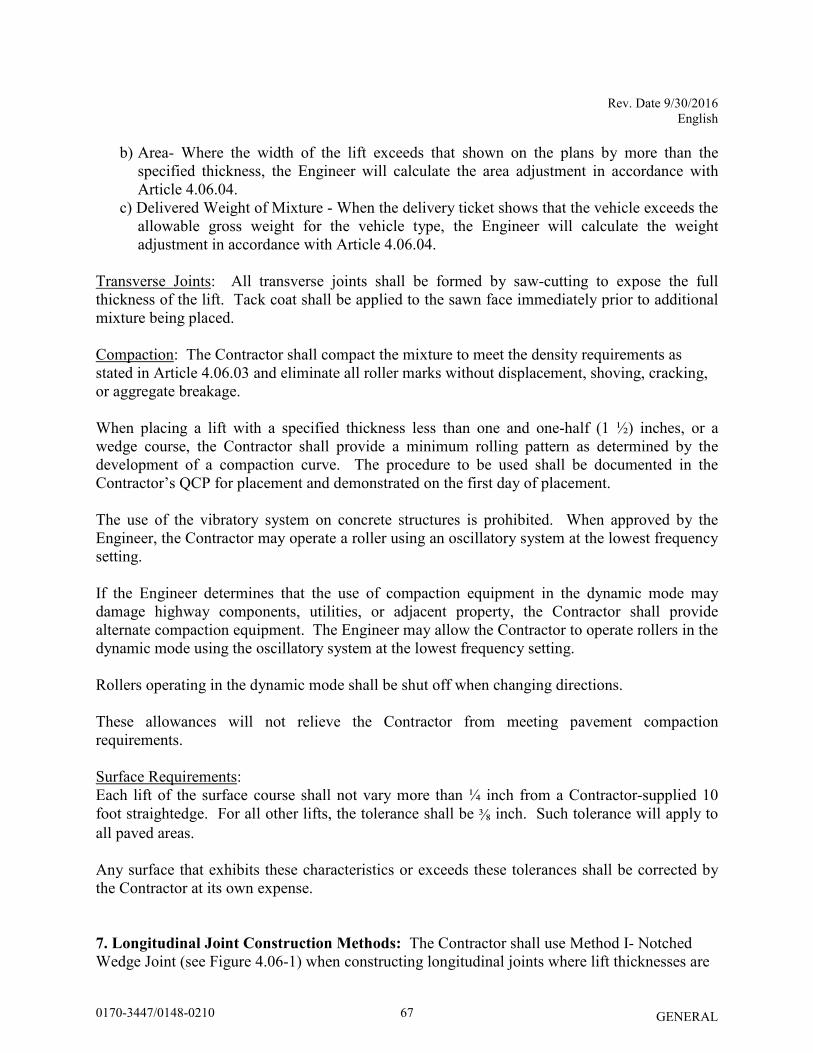
Rev. Date 9/30/2016 English
GENERAL
b) Area- Where the width of the lift exceeds that shown on the plans by more than the specified thickness, the Engineer will calculate the area adjustment in accordance with Article 4.06.04.
c) Delivered Weight of Mixture - When the delivery ticket shows that the vehicle exceeds the allowable gross weight for the vehicle type, the Engineer will calculate the weight adjustment in accordance with Article 4.06.04.
Transverse Joints: All transverse joints shall be formed by saw-cutting to expose the full thickness of the lift. Tack coat shall be applied to the sawn face immediately prior to additional mixture being placed. Compaction: The Contractor shall compact the mixture to meet the density requirements as stated in Article 4.06.03 and eliminate all roller marks without displacement, shoving, cracking, or aggregate breakage. When placing a lift with a specified thickness less than one and one-half (1 ½) inches, or a wedge course, the Contractor shall provide a minimum rolling pattern as determined by the development of a compaction curve. The procedure to be used shall be documented in the Contractor’s QCP for placement and demonstrated on the first day of placement. The use of the vibratory system on concrete structures is prohibited. When approved by the Engineer, the Contractor may operate a roller using an oscillatory system at the lowest frequency setting. If the Engineer determines that the use of compaction equipment in the dynamic mode may damage highway components, utilities, or adjacent property, the Contractor shall provide alternate compaction equipment. The Engineer may allow the Contractor to operate rollers in the dynamic mode using the oscillatory system at the lowest frequency setting. Rollers operating in the dynamic mode shall be shut off when changing directions. These allowances will not relieve the Contractor from meeting pavement compaction requirements.
Surface Requirements: Each lift of the surface course shall not vary more than ¼ inch from a Contractor-supplied 10 foot straightedge. For all other lifts, the tolerance shall be ⅜ inch. Such tolerance will apply to all paved areas. Any surface that exhibits these characteristics or exceeds these tolerances shall be corrected by the Contractor at its own expense. 7. Longitudinal Joint Construction Methods: The Contractor shall use Method I- Notched Wedge Joint (see Figure 4.06-1) when constructing longitudinal joints where lift thicknesses are
670170-3447/0148-0210
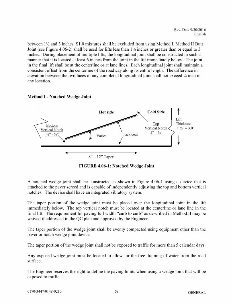
Rev. Date 9/30/2016 English
GENERAL
between 1½ and 3 inches. S1.0 mixtures shall be excluded from using Method I. Method II Butt Joint (see Figure 4.06-2) shall be used for lifts less than 1½ inches or greater than or equal to 3 inches. During placement of multiple lifts, the longitudinal joint shall be constructed in such a manner that it is located at least 6 inches from the joint in the lift immediately below. The joint in the final lift shall be at the centerline or at lane lines. Each longitudinal joint shall maintain a consistent offset from the centerline of the roadway along its entire length. The difference in elevation between the two faces of any completed longitudinal joint shall not exceed ¼ inch in any location.
Method I - Notched Wedge Joint:
FIGURE 4.06-1: Notched Wedge Joint
A notched wedge joint shall be constructed as shown in Figure 4.06-1 using a device that is attached to the paver screed and is capable of independently adjusting the top and bottom vertical notches. The device shall have an integrated vibratory system. The taper portion of the wedge joint must be placed over the longitudinal joint in the lift immediately below. The top vertical notch must be located at the centerline or lane line in the final lift. The requirement for paving full width “curb to curb” as described in Method II may be waived if addressed in the QC plan and approved by the Engineer. The taper portion of the wedge joint shall be evenly compacted using equipment other than the paver or notch wedge joint device. The taper portion of the wedge joint shall not be exposed to traffic for more than 5 calendar days. Any exposed wedge joint must be located to allow for the free draining of water from the road surface. The Engineer reserves the right to define the paving limits when using a wedge joint that will be exposed to traffic.
Hot side Cold Side
8” – 12” Taper
Top Vertical Notch
½” – ¾” Tack coat
Bottom Vertical Notch
¼” - ½”
Lift Thickness 1 ½” – 3.0”
Varies
680170-3447/0148-0210
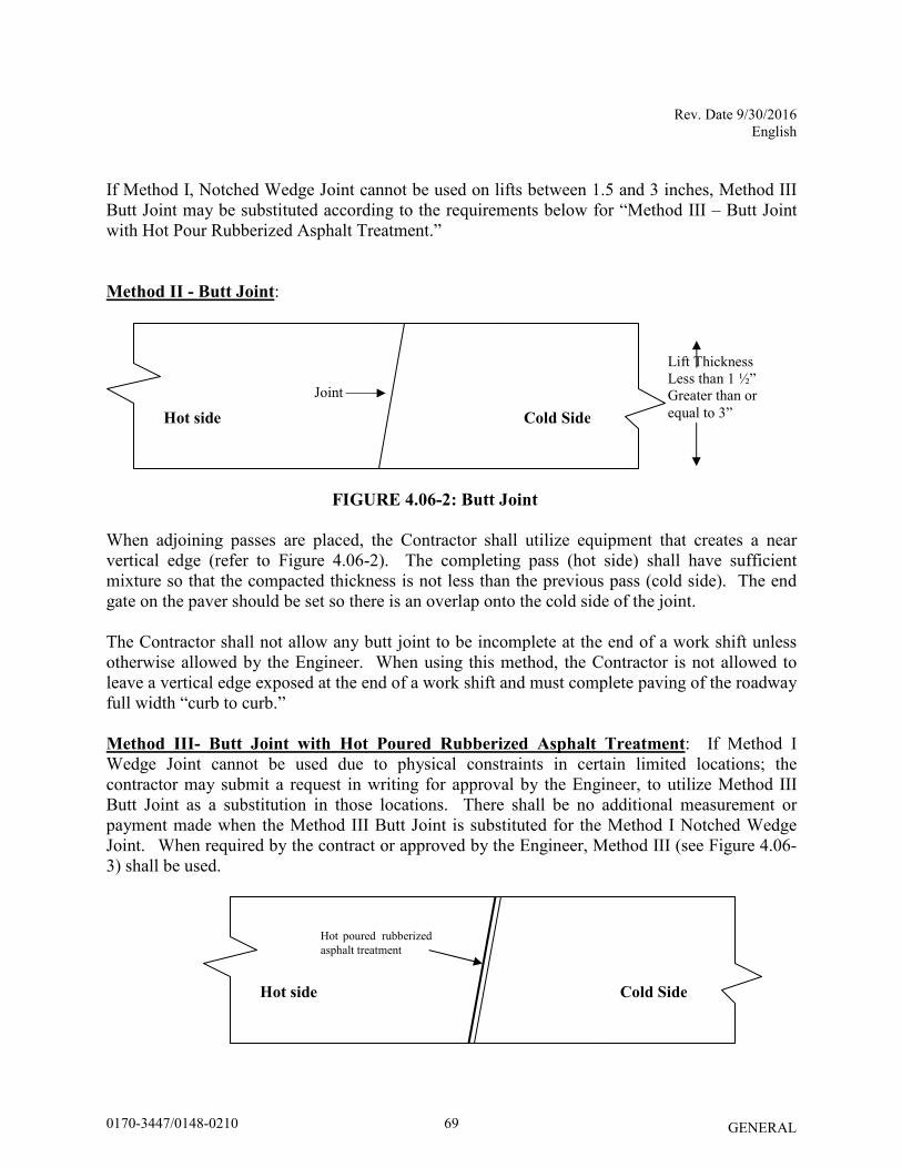
Rev. Date 9/30/2016 English
GENERAL
If Method I, Notched Wedge Joint cannot be used on lifts between 1.5 and 3 inches, Method III Butt Joint may be substituted according to the requirements below for “Method III – Butt Joint with Hot Pour Rubberized Asphalt Treatment.” Method II - Butt Joint:
FIGURE 4.06-2: Butt Joint
When adjoining passes are placed, the Contractor shall utilize equipment that creates a near vertical edge (refer to Figure 4.06-2). The completing pass (hot side) shall have sufficient mixture so that the compacted thickness is not less than the previous pass (cold side). The end gate on the paver should be set so there is an overlap onto the cold side of the joint. The Contractor shall not allow any butt joint to be incomplete at the end of a work shift unless otherwise allowed by the Engineer. When using this method, the Contractor is not allowed to leave a vertical edge exposed at the end of a work shift and must complete paving of the roadway full width “curb to curb.” Method III- Butt Joint with Hot Poured Rubberized Asphalt Treatment: If Method I Wedge Joint cannot be used due to physical constraints in certain limited locations; the contractor may submit a request in writing for approval by the Engineer, to utilize Method III Butt Joint as a substitution in those locations. There shall be no additional measurement or payment made when the Method III Butt Joint is substituted for the Method I Notched Wedge Joint. When required by the contract or approved by the Engineer, Method III (see Figure 4.06-3) shall be used.
Hot side Cold Side
Hot poured rubberized asphalt treatment
Hot side Cold Side
Joint
Lift Thickness Less than 1 ½” Greater than or equal to 3”
690170-3447/0148-0210

Rev. Date 9/30/2016 English
GENERAL
FIGURE 4.06-3: Butt Joint with Hot Poured Rubberized Asphalt Treatment
All of the requirements of Method II must be met with Method III. In addition, the longitudinal vertical edge must be treated with a rubberized joint seal material meeting the requirements of ASTM D 6690, Type 2. The joint sealant shall be placed on the face of the “cold side” of the butt joint as shown above prior to placing the “hot side” of the butt joint. The joint seal material shall be applied in accordance with the manufacturer’s recommendation so as to provide a uniform coverage and avoid excess bleeding onto the newly placed pavement. 8. Contractor Quality Control (QC) Requirements: The Contractor shall be responsible for maintaining adequate quality control procedures throughout the production and placement operations. Therefore, the Contractor must ensure that the materials, mixture and work provided by Subcontractors, Suppliers and Producers also meet contract specification requirements. This effort must be documented in Quality Control Plans and address the actions, inspection, or sampling and testing necessary to keep the production and placement operations in control, to determine when an operation has gone out of control and to respond to correct the situation in a timely fashion. The Standard QCP for production shall consist of the quality control program specific to the production facility. There are three components to the QCP for placement: a Standard QCP, a Project Summary Sheet that details project specific information, and if applicable a separate Extended Season Paving Plan as required in Section 9 “Temperature and Seasonal Requirements”. The Standard QCP for both production and placement shall be submitted to the Department for approval each calendar year and.at a minimum of 30 days prior to production or placement. Production or placement shall not occur until all QCP components have been approved by the Engineer. Each QCP shall include the name and qualifications of a Quality Control Manager (QCM). The QCM shall be responsible for the administration of the QCP, and any modifications that may become necessary. The QCM shall have the ability to direct all Contractor personnel on the project during paving operations. All Contractor sampling, inspection and test reports shall be reviewed and signed by the QCM prior to submittal to the Engineer. The QCPs shall also include the name and qualifications of any outside testing laboratory performing any QC functions on behalf of the Contractor. Approval of the QCP does not relieve the Contractor of its responsibility to comply with the project specifications. The Contractor may modify the QCPs as work progresses and must document the changes in writing prior to resuming operations. These changes include but are not limited to changes in quality control procedures or personnel. The Department reserves the right to deny significant changes to the QCPs.
700170-3447/0148-0210
Rev. Date 9/30/2016 English
GENERAL
QCP for Production: Refer to Section M.04.03-1. QCP for Placement: The Standard QCP, Project Summary Sheet, and Extended Season Paving Plan shall conform to the format provided by the Engineer. The format is available at http://www.ct.gov/dot/lib/dot/documents/dconstruction/pat/qcp_outline_hma_plac
ement.pdf. The Contractor shall perform all quality control sampling and testing, provide inspection, and exercise management control to ensure that placement conforms to the requirements as outlined in its QCP during all phases of the work. The Contractor shall document these activities for each day of placement.
The Contractor shall submit complete field density testing and inspection records to the Engineer within 48 hours in a manner acceptable to the Engineer.
The Contractor may obtain one (1) mat core and one (1) joint core per day for process control, provided this process is detailed in the QCP. The results of these process control cores shall not be used to dispute the Department determinations from the acceptance cores. The Contractor shall submit the location of each process control core to the Engineer for approval prior to taking the core. The core holes shall be filled to the same requirements described in sub-article 4.06.03-10. 9. Temperature and Seasonal Requirements: Paving, including placement of temporary pavements, shall be divided into two seasons, “In-Season” and “Extended-Season”. In-Season paving occurs from May 1 – October 14, and Extended Season paving occurs from October 15- April 30. The following requirements shall apply unless otherwise authorized or directed by the Engineer:
• Mixtures shall not be placed when the air or sub base temperature is less than 40°F regardless of the season.
• Should paving operations be scheduled during the Extended Season, the Contractor must submit an Extended Season Paving Plan for the project that addresses minimum delivered mix temperature considering WMA, PMA or other additives, maximum paver speed, enhanced rolling patterns and the method to balance mixture delivery and placement operations. Paving during Extended Season shall not commence until the Engineer has approved the plan.
10. Obtaining Bituminous Concrete Cores: This Section describes the methodology and sampling frequency the Contractor shall use to obtain pavement cores. Coring shall be performed on each lift specified to a thickness of one and one-half (1 ½) inches or more within 5 days of placement. The Contractor shall extract cores (4 or 6 inch diameter for S0.25, S0.375 and S0.5 mixtures 6 inch diameter for S1.0 mixtures) from locations determined
710170-3447/0148-0210
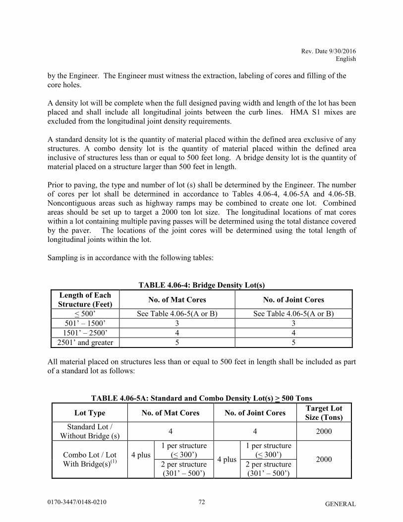
Rev. Date 9/30/2016 English
GENERAL
by the Engineer. The Engineer must witness the extraction, labeling of cores and filling of the core holes. A density lot will be complete when the full designed paving width and length of the lot has been placed and shall include all longitudinal joints between the curb lines. HMA S1 mixes are excluded from the longitudinal joint density requirements. A standard density lot is the quantity of material placed within the defined area exclusive of any structures. A combo density lot is the quantity of material placed within the defined area inclusive of structures less than or equal to 500 feet long. A bridge density lot is the quantity of material placed on a structure larger than 500 feet in length. Prior to paving, the type and number of lot (s) shall be determined by the Engineer. The number of cores per lot shall be determined in accordance to Tables 4.06-4, 4.06-5A and 4.06-5B. Noncontiguous areas such as highway ramps may be combined to create one lot. Combined areas should be set up to target a 2000 ton lot size. The longitudinal locations of mat cores within a lot containing multiple paving passes will be determined using the total distance covered by the paver. The locations of the joint cores will be determined using the total length of longitudinal joints within the lot. Sampling is in accordance with the following tables:
TABLE 4.06-4: Bridge Density Lot(s)
Length of Each
Structure (Feet) No. of Mat Cores No. of Joint Cores
< 500’ See Table 4.06-5(A or B) See Table 4.06-5(A or B) 501’ – 1500’ 3 3
1501’ – 2500’ 4 4 2501’ and greater 5 5
All material placed on structures less than or equal to 500 feet in length shall be included as part of a standard lot as follows:
TABLE 4.06-5A: Standard and Combo Density Lot(s) > 500 Tons
Lot Type No. of Mat Cores No. of Joint Cores Target Lot
Size (Tons)
Standard Lot / Without Bridge (s) 4 4 2000
Combo Lot / Lot With Bridge(s)(1)
4 plus
1 per structure (< 300’) 4 plus
1 per structure (< 300’) 2000 2 per structure
(301’ – 500’) 2 per structure (301’ – 500’)
720170-3447/0148-0210
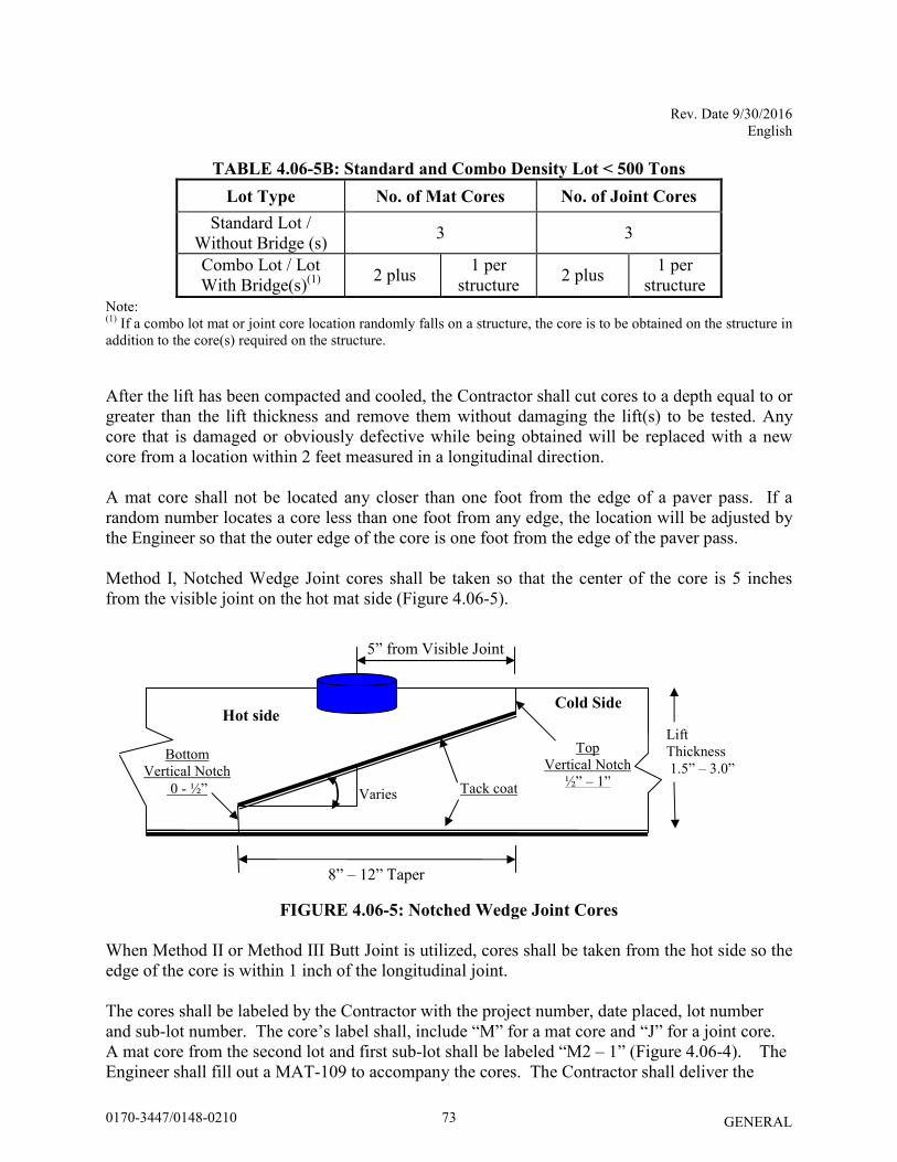
Rev. Date 9/30/2016 English
GENERAL
TABLE 4.06-5B: Standard and Combo Density Lot < 500 Tons
Lot Type No. of Mat Cores No. of Joint Cores
Standard Lot / Without Bridge (s) 3 3
Combo Lot / Lot With Bridge(s)(1) 2 plus 1 per
structure 2 plus 1 per structure
Note: (1) If a combo lot mat or joint core location randomly falls on a structure, the core is to be obtained on the structure in addition to the core(s) required on the structure. After the lift has been compacted and cooled, the Contractor shall cut cores to a depth equal to or greater than the lift thickness and remove them without damaging the lift(s) to be tested. Any core that is damaged or obviously defective while being obtained will be replaced with a new core from a location within 2 feet measured in a longitudinal direction. A mat core shall not be located any closer than one foot from the edge of a paver pass. If a random number locates a core less than one foot from any edge, the location will be adjusted by the Engineer so that the outer edge of the core is one foot from the edge of the paver pass. Method I, Notched Wedge Joint cores shall be taken so that the center of the core is 5 inches from the visible joint on the hot mat side (Figure 4.06-5).
FIGURE 4.06-5: Notched Wedge Joint Cores
When Method II or Method III Butt Joint is utilized, cores shall be taken from the hot side so the edge of the core is within 1 inch of the longitudinal joint. The cores shall be labeled by the Contractor with the project number, date placed, lot number and sub-lot number. The core’s label shall, include “M” for a mat core and “J” for a joint core. A mat core from the second lot and first sub-lot shall be labeled “M2 – 1” (Figure 4.06-4). The Engineer shall fill out a MAT-109 to accompany the cores. The Contractor shall deliver the
Hot side Cold Side
8” – 12” Taper
Top Vertical Notch
½” – 1” Tack coat
Bottom Vertical Notch
0 - ½”
Lift Thickness 1.5” – 3.0”
Varies
5” from Visible Joint
730170-3447/0148-0210
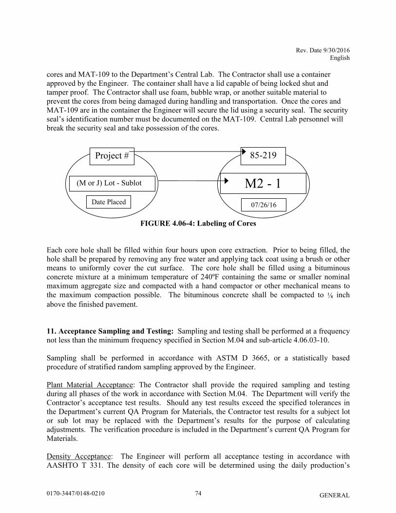
Rev. Date 9/30/2016 English
GENERAL
cores and MAT-109 to the Department’s Central Lab. The Contractor shall use a container approved by the Engineer. The container shall have a lid capable of being locked shut and tamper proof. The Contractor shall use foam, bubble wrap, or another suitable material to prevent the cores from being damaged during handling and transportation. Once the cores and MAT-109 are in the container the Engineer will secure the lid using a security seal. The security seal’s identification number must be documented on the MAT-109. Central Lab personnel will break the security seal and take possession of the cores.
FIGURE 4.06-4: Labeling of Cores
Each core hole shall be filled within four hours upon core extraction. Prior to being filled, the hole shall be prepared by removing any free water and applying tack coat using a brush or other means to uniformly cover the cut surface. The core hole shall be filled using a bituminous concrete mixture at a minimum temperature of 240ºF containing the same or smaller nominal maximum aggregate size and compacted with a hand compactor or other mechanical means to the maximum compaction possible. The bituminous concrete shall be compacted to ⅛ inch above the finished pavement. 11. Acceptance Sampling and Testing: Sampling and testing shall be performed at a frequency not less than the minimum frequency specified in Section M.04 and sub-article 4.06.03-10. Sampling shall be performed in accordance with ASTM D 3665, or a statistically based procedure of stratified random sampling approved by the Engineer. Plant Material Acceptance: The Contractor shall provide the required sampling and testing during all phases of the work in accordance with Section M.04. The Department will verify the Contractor’s acceptance test results. Should any test results exceed the specified tolerances in the Department’s current QA Program for Materials, the Contractor test results for a subject lot or sub lot may be replaced with the Department’s results for the purpose of calculating adjustments. The verification procedure is included in the Department’s current QA Program for Materials. Density Acceptance: The Engineer will perform all acceptance testing in accordance with AASHTO T 331. The density of each core will be determined using the daily production’s
Project #
(M or J) Lot - Sublot
85-219
M2 - 1
Date Placed
07/26/16
740170-3447/0148-0210
Rev. Date 9/30/2016 English
GENERAL
average maximum theoretical specific gravity (Gmm) established during the testing of the parent material at the Plant. When there was no testing of the parent material or any Gmm exceeds the specified tolerances in the Department’s current QA Program for Materials, the Engineer will determine the maximum theoretical density value to be used for density calculations.
12. Density Dispute Resolution Process: The Contractor and Engineer will work in partnership to avoid potential conflicts and to resolve any differences that may arise during quality control or acceptance testing for density. Both parties will review their sampling and testing procedures and results and share their findings. If the Contractor disputes the Engineer’s test results, the Contractor must submit in writing a request to initiate the Dispute Resolution Process within 7 calendar days of the notification of the test results. No request for dispute resolution will be allowed unless the Contractor provides quality control results within the timeframe described in sub-article 4.06.03-9 supporting its position. No request for Dispute Resolution will be allowed for a Density Lot in which any core was not taken within the required 5 calendar days of placement. Should the dispute not be resolved through evaluation of existing testing data or procedures, the Engineer may authorize the Contractor to obtain a new set of core samples per disputed lot. The core samples must be extracted no later than 14 calendar days from the date of Engineer’s authorization. The number and location (mat, joint, or structure) of the cores taken for dispute resolution must reflect the number and location of the original cores. The location of each core shall be randomly located within the respective original sub lot. All such cores shall be extracted and the core hole filled using the procedure outlined in Article 4.06.03. The dispute resolution results shall be added to the original results and averaged for determining the final in-place density value.
13. Corrective Work Procedure: If pavement placed by the Contractor does not meet the specifications, and the Engineer requires its replacement or correction, the Contractor shall:
a) Propose a corrective procedure to the Engineer for review and approval prior to any
corrective work commencing. The proposal shall include: - Limits of pavement to be replaced or corrected, indicating stationing or other
landmarks that are readily distinguishable. - Proposed work schedule. - Construction method and sequence of operations. - Methods of maintenance and protection of traffic. - Material sources. - Names and telephone numbers of supervising personnel.
b) Any corrective courses placed as the final wearing surface shall match the specified lift
thickness after compaction.
750170-3447/0148-0210
Rev. Date 9/30/2016 English
GENERAL
14. Protection of the Work: The Contractor shall protect all sections of the newly finished pavement from damage that may occur as a result of the Contractor’s operations for the duration of the Project.
15. Cut Bituminous Concrete Pavement: Work under this item shall consist of making a straight-line cut in the pavement to the lines delineated on the plans or as directed by the Engineer. The cut shall provide a straight, clean, vertical face with no cracking, tearing or breakage along the cut edge.
4.06.04—Method of Measurement:
1. HMA S* or PMA S*: The quantity of bituminous concrete measured for payment will be determined by the documented net weight in tons accepted by the Engineer in accordance with this specification and Section M.04. 2. Adjustments: Adjustments may be applied to bituminous concrete quantities and will be measured for payment using the following formulas:
Yield Factor for Adjustment Calculation = 0.0575 Tons/SY/inch
Actual Area = [(Measured Length (ft)) x (Avg. of width measurements (ft))]
Actual Thickness (t) = Total tons delivered / [Actual Area (SY) x 0.0575 Tons/SY/inch]
a) Area: If the average width exceeds the allowable tolerance, an adjustment will be made using the following formula. The tolerance for width is equal to the specified thickness (in.) of the lift being placed.
Tons Adjusted for Area (TA) = [(L x Wadj)/9] x (t) x 0.0575 Tons/SY/inch = (-) Tons
Where: L = Length (ft) (t) = Actual thickness (inches)
Wadj = (Designed width (ft) + tolerance /12) - Measured Width)
b) Thickness: If the actual average thickness is less than the allowable tolerance, the Contractor shall submit a repair procedure to the Engineer for approval. If the actual thickness exceeds the allowable tolerance, an adjustment will be made using the following formula:
Tons Adjusted for Thickness (TT) = A x tadj x 0.0575 = (-) Tons
Where: A = Area = {[L x (Designed width + tolerance (lift thickness)/12)] / 9} tadj = Adjusted thickness = [(Dt + tolerance) - Actual thickness] Dt = Designed thickness (inches)
760170-3447/0148-0210
Rev. Date 9/30/2016 English
GENERAL
c) Weight: If the quantity of bituminous concrete representing the mixture delivered to the project is in excess of the allowable gross vehicle weight (GVW) for each vehicle, an adjustment will be made using the following formula:
Tons Adjusted for Weight (TW) = GVW – DGW= (-) Tons
Where: DGW = Delivered gross weight as shown on the delivery ticket or
measured on a certified scale.
d) Mixture Adjustment: The quantity of bituminous concrete representing the production lot at the Plant will be adjusted as follow: i. Non-PWL Production Lot (less than 3500 tons):
The adjustment values in Table 4.06-6 and 4.06-7 shall be calculated for each sub lot based on the Air Void (AV) and Asphalt Binder Content (PB) test results for that sub lot. The total adjustment for each day’s production (lot) will be computed using tables and the following formulas:
Tons Adjusted for Superpave Design (TSD) = [(AdjAVt + AdjPBt) / 100] X Tons
Percent Adjustment for Air Voids = AdjAVt = [AdjAV1 + AdjAV2 + AdjAVi + … + AdjAVn)] /n
Where: AdjAVt = Total percent air void adjustment value for the lot
AdjAVi = Adjustment value from Table 4.06-7 resulting from each sub lot or the average of the adjustment values resulting from multiple tests within a sub lot, as approved by the Engineer.
n = number of sub lots based on Table M.04.03-2
TABLE 4.06-6: Adjustment Values for Air Voids
Percent Adjustment for Asphalt Binder = AdjPBt = [(AdjPB1 + AdjPB2 + AdjPBi + … + AdjPBn)] / n
Where: AdjPBt= Total percent asphalt binder adjustment value for the lot AdjPBi = Adjustment value from Table 4.06-7 resulting from each sub lot
n = number of binder tests in a production lot
Adjustment Value
(AdjAVi) (%) S0.25, S0.375, S0.5, S1
Air Voids (AV) +2.5 3.8 - 4.2
+3.125*(AV-3) 3.0 - 3.7 -3.125*(AV-5) 4.3 – 5.0
20*(AV-3) 2.3 – 2.9 -20*(AV-5) 5.1 – 5.7
-20.0 < 2.2 or > 5.8
770170-3447/0148-0210
Rev. Date 9/30/2016 English
GENERAL
TABLE 4.06-7: Adjustment Values for Binder Content
Adjustment Value
(AdjAVi) (%)
S0.25, S0.375, S0.5, S1
Pb
0.0 JMF Pb ± 0.3 - 10.0 ≤ JMF Pb - 0.4 or ≥ JMF Pb + 0.4
ii. PWL Production Lot (3500 tons or more): For each lot, the adjustment values shall be calculated based on PWL for AV, VMA and PB test results. The lot will be considered as being normally distributed and all applicable equations in AASHTO R9 and AASHTO R42 Appendix X4 will apply. Only one test result will be considered for each sub lot. The specification limits are listed in Section M.04.
For AV, PB and voids in mineral aggregate (VMA), the individual material quality characteristic adjustment (Adj) will be calculated as follow: For PWL between 50 and 90%: Adj(AVt or PBt or VMAt)= (55 + 0.5 PWL) - 100 For PWL at and above 90%: Adj(AVt or PBt or VMAt)= (77.5 + 0.25 PWL) - 100 Where: AdjAVt = Total percent AV adjustment value for the lot AdjPBt= Total percent PB adjustment value for the lot AdjVMAt= Total percent VMA adjustment value for the lot Lots with PWL less than 50% in any of the three individual material quality characteristics will be evaluated under 1.06.04. The total adjustment for each production lot will be computed using the following formula:
Tons Adjusted for Superpave Design (TSD) = [(0.5AdjAVt + 0.25AdjPBt + 0.25 AdjVMAt) / 100] X Tons
iii. Partial Lots:
Lots with less than 4 sublots will be combined with the prior lot. If there is no prior lot with equivalent material or if the last test result of the prior lot is over 30 calendar days old, the adjustment will be calculated as indicated in 4.06.04-2.d.i. Lots with 4 or more sublots will be calculated as indicated in 4.06.04-2.d.ii.
780170-3447/0148-0210
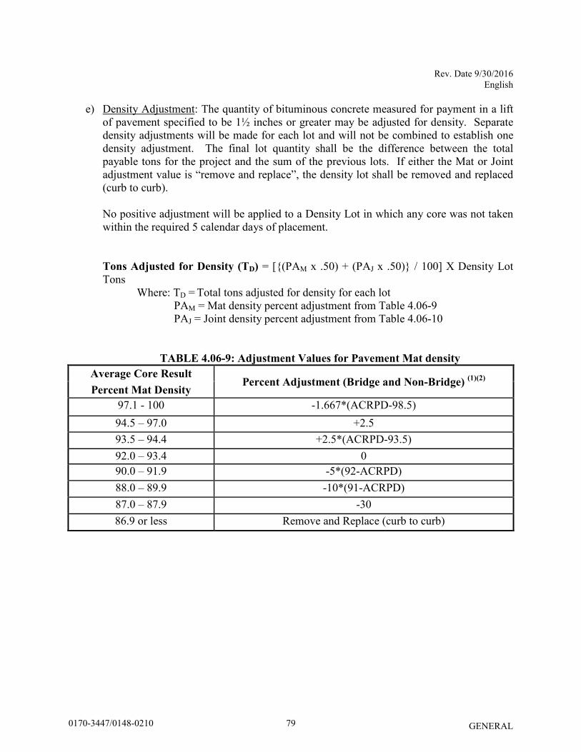
Rev. Date 9/30/2016 English
GENERAL
e) Density Adjustment: The quantity of bituminous concrete measured for payment in a lift of pavement specified to be 1½ inches or greater may be adjusted for density. Separate density adjustments will be made for each lot and will not be combined to establish one density adjustment. The final lot quantity shall be the difference between the total payable tons for the project and the sum of the previous lots. If either the Mat or Joint adjustment value is “remove and replace”, the density lot shall be removed and replaced (curb to curb).
No positive adjustment will be applied to a Density Lot in which any core was not taken within the required 5 calendar days of placement. Tons Adjusted for Density (TD) = [{(PAM x .50) + (PAJ x .50)} / 100] X Density Lot Tons Where: TD = Total tons adjusted for density for each lot
PAM = Mat density percent adjustment from Table 4.06-9 PAJ = Joint density percent adjustment from Table 4.06-10
TABLE 4.06-9: Adjustment Values for Pavement Mat density
Average Core Result Percent Adjustment (Bridge and Non-Bridge)
(1)(2)
Percent Mat Density
97.1 - 100 -1.667*(ACRPD-98.5) 94.5 – 97.0 +2.5 93.5 – 94.4 +2.5*(ACRPD-93.5) 92.0 – 93.4 0 90.0 – 91.9 -5*(92-ACRPD) 88.0 – 89.9 -10*(91-ACRPD) 87.0 – 87.9 -30 86.9 or less Remove and Replace (curb to curb)
790170-3447/0148-0210
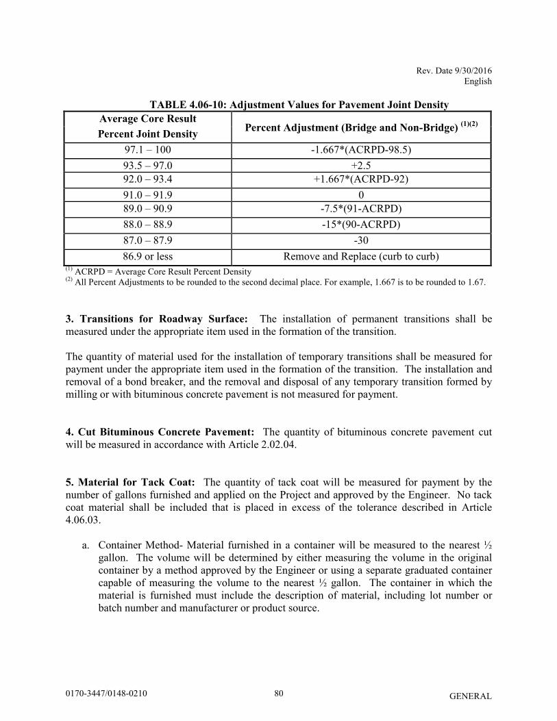
Rev. Date 9/30/2016 English
GENERAL
TABLE 4.06-10: Adjustment Values for Pavement Joint Density
Average Core Result Percent Adjustment (Bridge and Non-Bridge)
(1)(2)
Percent Joint Density
97.1 – 100 -1.667*(ACRPD-98.5) 93.5 – 97.0 +2.5 92.0 – 93.4 +1.667*(ACRPD-92) 91.0 – 91.9 0 89.0 – 90.9 -7.5*(91-ACRPD) 88.0 – 88.9 -15*(90-ACRPD) 87.0 – 87.9 -30 86.9 or less Remove and Replace (curb to curb)
(1) ACRPD = Average Core Result Percent Density (2) All Percent Adjustments to be rounded to the second decimal place. For example, 1.667 is to be rounded to 1.67. 3. Transitions for Roadway Surface: The installation of permanent transitions shall be measured under the appropriate item used in the formation of the transition. The quantity of material used for the installation of temporary transitions shall be measured for payment under the appropriate item used in the formation of the transition. The installation and removal of a bond breaker, and the removal and disposal of any temporary transition formed by milling or with bituminous concrete pavement is not measured for payment. 4. Cut Bituminous Concrete Pavement: The quantity of bituminous concrete pavement cut will be measured in accordance with Article 2.02.04. 5. Material for Tack Coat: The quantity of tack coat will be measured for payment by the number of gallons furnished and applied on the Project and approved by the Engineer. No tack coat material shall be included that is placed in excess of the tolerance described in Article 4.06.03.
a. Container Method- Material furnished in a container will be measured to the nearest ½ gallon. The volume will be determined by either measuring the volume in the original container by a method approved by the Engineer or using a separate graduated container capable of measuring the volume to the nearest ½ gallon. The container in which the material is furnished must include the description of material, including lot number or batch number and manufacturer or product source.
800170-3447/0148-0210
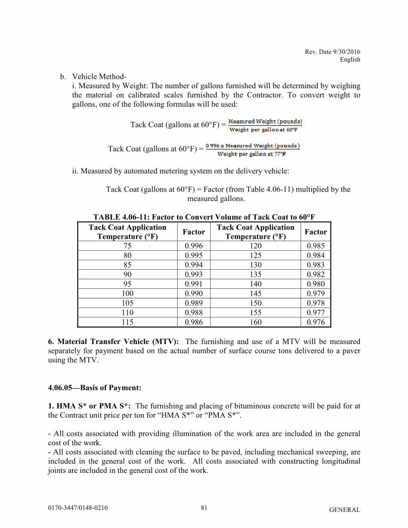
Rev. Date 9/30/2016 English
GENERAL
b. Vehicle Method- i. Measured by Weight: The number of gallons furnished will be determined by weighing the material on calibrated scales furnished by the Contractor. To convert weight to gallons, one of the following formulas will be used:
Tack Coat (gallons at 60°F) =
Tack Coat (gallons at 60°F) =
ii. Measured by automated metering system on the delivery vehicle:
Tack Coat (gallons at 60°F) = Factor (from Table 4.06-11) multiplied by the measured gallons.
TABLE 4.06-11: Factor to Convert Volume of Tack Coat to 60°F
Tack Coat Application
Temperature (°F) Factor
Tack Coat Application
Temperature (°F) Factor
75 0.996 120 0.985 80 0.995 125 0.984 85 0.994 130 0.983 90 0.993 135 0.982 95 0.991 140 0.980
100 0.990 145 0.979 105 0.989 150 0.978 110 0.988 155 0.977 115 0.986 160 0.976
6. Material Transfer Vehicle (MTV): The furnishing and use of a MTV will be measured separately for payment based on the actual number of surface course tons delivered to a paver using the MTV. 4.06.05—Basis of Payment:
1. HMA S* or PMA S*: The furnishing and placing of bituminous concrete will be paid for at the Contract unit price per ton for “HMA S*” or “PMA S*”.
- All costs associated with providing illumination of the work area are included in the general cost of the work. - All costs associated with cleaning the surface to be paved, including mechanical sweeping, are included in the general cost of the work. All costs associated with constructing longitudinal joints are included in the general cost of the work.
810170-3447/0148-0210
Rev. Date 9/30/2016 English
GENERAL
- All costs associated with obtaining cores for acceptance testing and dispute resolution are included in the general cost of the work. 2. Bituminous Concrete Adjustment Costs: The adjustment will be calculated using the formulas shown below if all of the measured adjustments in Article 4.06.04 are not equal to zero. A positive or negative adjustment will be applied to monies due the Contractor. Production Lot: [TT + TA + TW + TSD] x Unit Price = Est. (P)
Density Lot: TD x Unit Price = Est. (D)
Where: Unit Price = Contract unit price per ton per type of mixture T* = Total tons of each adjustment calculated in Article 4.06.04
Est. ( ) = Pay Unit represented in dollars representing incentive or disincentive.
The Bituminous Concrete Adjustment Cost item if included in the bid proposal or estimate is not to be altered by the Contractor.
3. Transitions for Roadway Surface: The installation of permanent transitions shall be paid under the appropriate item used in the formation of the transition. The quantity of material used for the installation of temporary transitions shall be paid under the appropriate pay item used in the formation of the transition. The installation and removal of a bond breaker, and the removal and disposal of any temporary transition formed by milling or with bituminous concrete pavement is included in the general cost of the work.
4. The cutting of bituminous concrete pavement will be paid in accordance with Article 2.02.05. 5. Material for tack coat will be paid for at the Contract unit price per gallon at 60°F for "Material for Tack Coat". 6. The Material Transfer Vehicle (MTV) will be paid at the Contract unit price per ton for a "Material Transfer Vehicle”. Pay Item* Pay Unit* HMA S* ton PMA S* ton Bituminous Concrete Adjustment Cost est. Material for Tack Coat gal. Material Transfer Vehicle ton *For contracts administered by the State of Connecticut, Department of Administrative Services, the pay items and pay units are as shown in contract award price schedule.
820170-3447/0148-0210
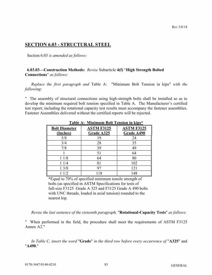
Rev 3/8/18
GENERAL
SECTION 6.03 - STRUCTURAL STEEL
Section 6.03 is amended as follows: 6.03.03—Construction Methods: Revise Subarticle 4(f) “High Strength Bolted
Connections” as follows:
Replace the first paragraph and Table A: "Minimum Bolt Tension in kips" with the
following:
" The assembly of structural connections using high-strength bolts shall be installed so as to develop the minimum required bolt tension specified in Table A. The Manufacturer’s certified test report; including the rotational capacity test results must accompany the fastener assemblies. Fastener Assemblies delivered without the certified reports will be rejected.
Table A: Minimum Bolt Tension in kips*
Bolt Diameter
(Inches) ASTM F3125
Grade A325 ASTM F3125
Grade A490 5/8 19 24 3/4 28 35 7/8 39 49 1 51 64
1 1/8 64 80 1 1/4 81 102 1 3/8 97 121 1 1/2 118 148
*Equal to 70% of specified minimum tensile strength of bolts (as specified in ASTM Specifications for tests of full-size F3125 Grade A 325 and F3125 Grade A 490 bolts with UNC threads, loaded in axial tension) rounded to the nearest kip.
Revise the last sentence of the sixteenth paragraph, "Rotational-Capacity Tests" as follows:
" When performed in the field, the procedure shall meet the requirements of ASTM F3125 Annex A2."
In Table C, insert the word "Grade" in the third row before every occurrence of "A325" and "A490."
830170-3447/0148-0210
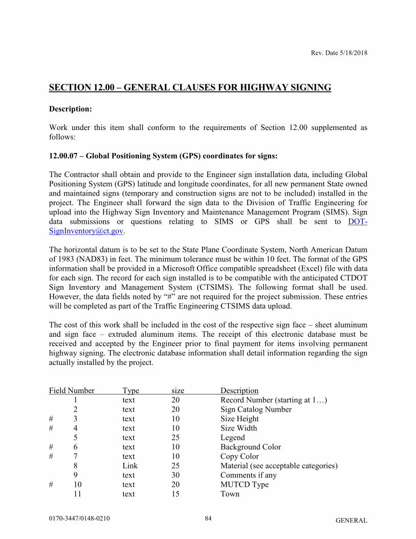
Rev. Date 5/18/2018
GENERAL
SECTION 12.00 – GENERAL CLAUSES FOR HIGHWAY SIGNING
Description:
Work under this item shall conform to the requirements of Section 12.00 supplemented as follows: 12.00.07 – Global Positioning System (GPS) coordinates for signs:
The Contractor shall obtain and provide to the Engineer sign installation data, including Global Positioning System (GPS) latitude and longitude coordinates, for all new permanent State owned and maintained signs (temporary and construction signs are not to be included) installed in the project. The Engineer shall forward the sign data to the Division of Traffic Engineering for upload into the Highway Sign Inventory and Maintenance Management Program (SIMS). Sign data submissions or questions relating to SIMS or GPS shall be sent to [email protected]. The horizontal datum is to be set to the State Plane Coordinate System, North American Datum of 1983 (NAD83) in feet. The minimum tolerance must be within 10 feet. The format of the GPS information shall be provided in a Microsoft Office compatible spreadsheet (Excel) file with data for each sign. The record for each sign installed is to be compatible with the anticipated CTDOT Sign Inventory and Management System (CTSIMS). The following format shall be used. However, the data fields noted by “#” are not required for the project submission. These entries will be completed as part of the Traffic Engineering CTSIMS data upload. The cost of this work shall be included in the cost of the respective sign face – sheet aluminum and sign face – extruded aluminum items. The receipt of this electronic database must be received and accepted by the Engineer prior to final payment for items involving permanent highway signing. The electronic database information shall detail information regarding the sign actually installed by the project. Field Number Type size Description 1 text 20 Record Number (starting at 1…) 2 text 20 Sign Catalog Number # 3 text 10 Size Height # 4 text 10 Size Width 5 text 25 Legend # 6 text 10 Background Color # 7 text 10 Copy Color 8 Link 25 Material (see acceptable categories) 9 text 30 Comments if any # 10 text 20 MUTCD Type 11 text 15 Town
840170-3447/0148-0210
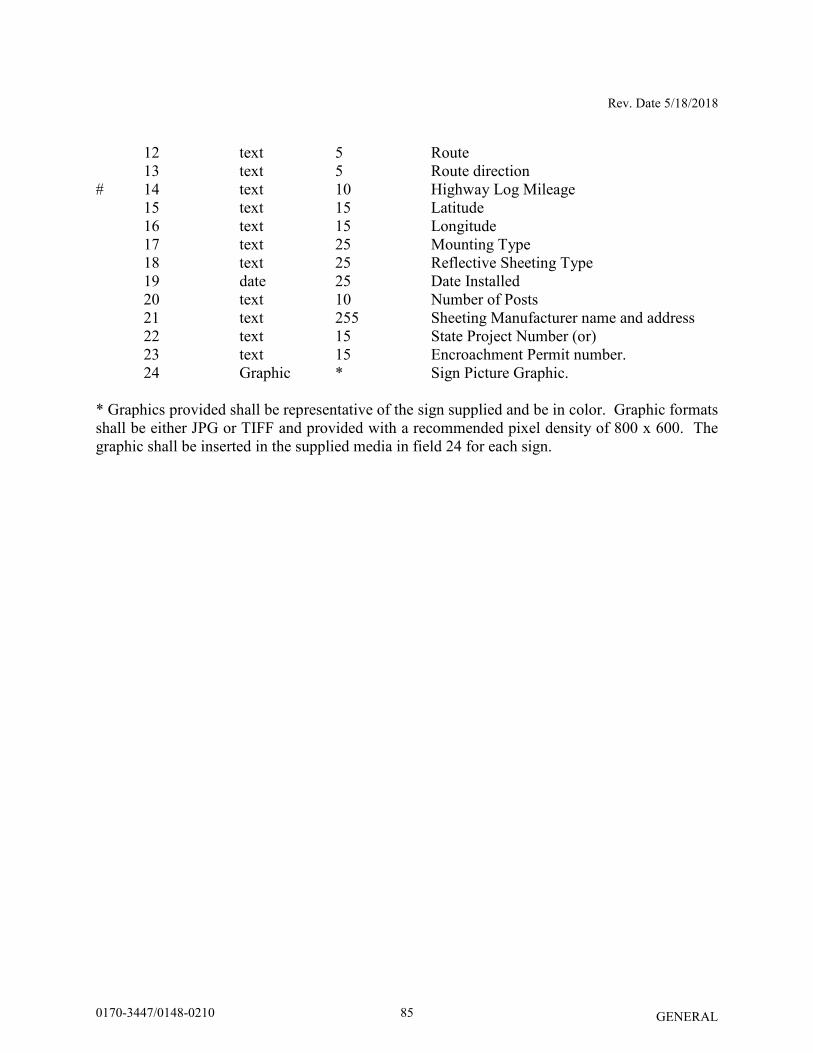
Rev. Date 5/18/2018
GENERAL
12 text 5 Route 13 text 5 Route direction # 14 text 10 Highway Log Mileage 15 text 15 Latitude 16 text 15 Longitude 17 text 25 Mounting Type 18 text 25 Reflective Sheeting Type 19 date 25 Date Installed 20 text 10 Number of Posts 21 text 255 Sheeting Manufacturer name and address 22 text 15 State Project Number (or) 23 text 15 Encroachment Permit number. 24 Graphic * Sign Picture Graphic. * Graphics provided shall be representative of the sign supplied and be in color. Graphic formats shall be either JPG or TIFF and provided with a recommended pixel density of 800 x 600. The graphic shall be inserted in the supplied media in field 24 for each sign.
850170-3447/0148-0210
Date 07/19/18
GENERAL
SECTION 18.03 – IMPACT ATTENUATION SYSTEM, TEMPORARY
IMPACT ATTENUATION SYSTEM
Article 18.03.03 – Construction Methods:
Add the following:
“The impact attenuation system shall be constructed in accordance with the attached
drawings and based on the system type being installed.”
860170-3447/0148-0210
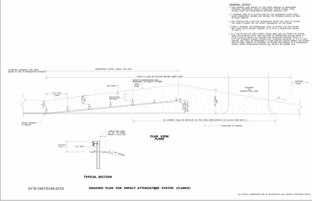
EXISTING
SLOPE
SLOPE 4:1 MAX. OR FLATTER BEYOND HINGE POINT
2'
HINGE
POINT
10:1 S
LO
PE
MA
X
BEGIN CURBING
IF NEEDEDDIRECTION OF TRAFFIC
(610)
(1905)
3'-3"MIN
(991)
PLAN VIEWFLARE
GENERAL NOTES:
DRIVEWAY
OR
INTERSECTING ROAD
ALL METRIC DIMENSIONS ARE IN MILLIMETERS (mm) UNLESS OTHERWISE NOTED.
NO CURBING SHALL BE INSTALLED IN THIS AREA APPROXIMATELY 50' (15.24m) (SEE NOTE 4)
6'-3" (TYP)
SEE NOTE 5
OR STEEPER
41
TYPICAL SECTION
15
1
PROPRIETARY SYSTEM LENGTH MAY VARY
POINT OF REDIRECTION AND
BEGINNING OF LENGTH OF NEED
DEFLECTION
DISTANCE
10:1 MAX.29"(TYP.)
(737)
WIDTH MAY VARY
@ 10:1 TO HINGE
POIONT 3' (914) MAX.
STANDARD GUIDERAIL TYPE SHALL
BEGIN AT END OF PROPRIETARY SYSTEM
1. THIS GRADING PLAN APPLIES TO THE LATEST VERSION OF DEPARTMENT
APPROVED PROPRIETARY IMPACT ATTENUATION SYSTEM FLARED TYPES
CHOSEN FROM THE DEPARTMENT'S QUALIFIED PRODUCTS LIST.
2. A MINIMUM AREA OF 75' (22.9m) LONG BY THE DESIGNATED CLEAR ZONE
WIDTH IMMEDIATELY BEHIND AND BEYOND THE TERMINAL SHOULD BE FREE
OF FIXED OBJECTS.
3. SEE CONSTRUCTION PLANS FOR APPROPRIATE OFFSET FOR NOSE OF SYSTEM.
THE FLARE IS BASED ON THE OFFSET DESIGNATED ON THE PLANS.
4. WHEN A DRIVEWAY OR INTERSECTING ROAD IS WITHIN 5' OF THE SYSTEM,
AND CURB EXISTS REMOVE CURBING UP TO POST 3. REDIRECTION BEGINS
AT POST 3.
5. IF A UTILITY POLE OR FIXED OBJECT EXISTS NEAR END OF SYSTEM, THE SYSTEM
SHALL BE INSTALLED SUCH THAT THE POINT OF REDIRECTION OCCURS PRIOR TO
UTILITY POLE OR OBJECT. IN ADDITION, THE DEFLECTION DISTANCE NOTED IS
4'-3" FOR STANDARD W-BEAM STRONG POST GUIDERAIL INSTALLED @ A 6'-3" POST
SPACING AND SHALL BE MAINTAINED. A CLEAR RUN-OUT LENGTH BEHIND THE SYSTEM
FREE OF FIXED OBJECTS IS ESSENTIAL TO PROPER FUNCTIONING OF A PROPRIETARY
GATING IMPACT ATTENUATION SYSTEM AND SHOULD BE STRIVED FOR.
4'(1219)
FLA
RE
MA
X.
SE
E
NO
TE 3
GRADING PLAN FOR IMPACT ATTENUATION SYSTEM (FLARED)870170-3447/0148-0210
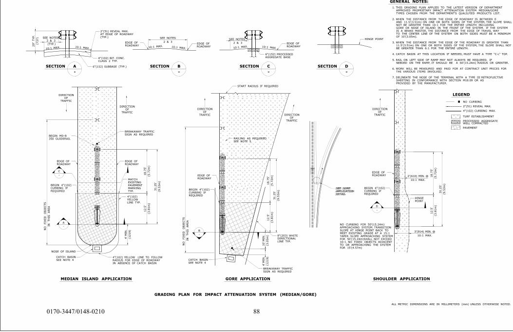
DETAIL
APPLICATION
SEE GORE
NO CURBING
10:1 MAX. 10:1 MAX.10:1 MAX.10:1 MAX.10:1 MAX.10:1 MAX.
WELL COMPACTEDPROCESSED AGGREGATE
PAVEMENT
TURF ESTABLISHMENT
SEE NOTES
2 & 3
2"(51) REVEAL MAX.
4"(102) CURBING MAX.
SEE NOTES
DIRECTION
OF
TRAFFICDIRECTION
OF
TRAFFIC
DIRECTION
OF
TRAFFIC
DIRECTION
OF
TRAFFIC
DIRECTION
OF
TRAFFIC
SEE GORE
APPLICATION
DETAIL
NO CURBING FOR 50'(15.24m)
APPROACHING SYSTEM. TRANSITION
SLOPE AT HINGE POINT BACK TO
MEET EXISTING GRADE AT A 15:1
TAPER. SLOPE APPROACHING SYSTEM
FOR 50'(15.24m)SHALL NOT EXCEED
10:1. NO FIXED OBJECTS ADJACENT
TO OR APPROACHING THE SYSTEM
FOR 15'(4.57m)
MEDIAN ISLAND APPLICATION
GORE APPLICATION
SHOULDER APPLICATION
GENERAL NOTES:
LEGEND
A
-
C
-
B
-
SECTION A
-
SECTION B
-
SECTION C
-
SECTION D
-
D
-
ALL METRIC DIMENSIONS ARE IN MILLIMETERS (mm) UNLESS OTHERWISE NOTED.
1. THIS GRADING PLAN APPLIES TO THE LATEST VERSION OF DEPARTMENT
APPROVED PROPRIETARY IMPACT ATTENUATION SYSTEM MEDIAN/GORE
TYPES CHOSEN FROM THE DEPARTMENT'S QUALILFIED PRODUCTS LIST.
2. WHEN THE DISTANCE FROM THE EDGE OF ROADWAY IS BETWEEN 0
AND 11.5'(3.51m) ON ONE OR BOTH SIDES OF THE SYSTEM, THE SLOPE SHALL
NOT BE GREATER THAN 10:1 FOR THE ENTIRE LENGTH INCLUDING
GORE OR NOSE OF ISLAND IN THE FRONT OF THE SYSTEM. IF THE SYSTEM
IS A BRAKE MASTER, THE DISTANCE FROM THE EDGE OF TRAVEL WAY
TO THE CENTER LINE OF THE SYSTEM ON BOTH SIDES MUST BE A MINIMUM
OF 10'(3.05m).
3. WHEN THE DISTANCE FROM THE EDGE OF THE ROADWAY IS GREATER THAN
11.5'(3.51m) ON ONE OR BOTH SIDES OF THE SYSTEM, THE SLOPE SHALL NOT
BE GREATER THAN 6:1 FOR THE ENTIRE LENGTH.
4. CATCH BASIN AT THIS LOCATION IF NEEDED, MUST HAVE A TYPE "C-L" TOP.
5. RAIL ON LEFT SIDE OF RAMP MAY NOT ALWAYS BE REQUIRED. IF
NEEDED ON THE RAMP, IT SHOULD BE A 50'(15.24m) RADIUS OR GREATER.
6. WORK WILL BE MEASURED AND PAID FOR AT CONTRACT UNIT PRICES FOR
THE VARIOUS ITEMS INVOLVED.
7. DELINEATE THE NOSE OF THE TERMINAL WITH A TYPE III RETROFLECTIVE
SHEETING IN CONFORMANCE WITH SECTION M18.09 OR AS
PROVIDED BY THE MANUFACTURER.
GRADING PLAN FOR IMPACT ATTENUATION SYSTEM (MEDIAN/GORE)
SEE NOTES
2 & 3
2 & 3
NO
FIX
ED
OBJE
CTS
IN
THIS
AR
EA
NO
FIX
ED
OBJE
CTS
IN
THIS
AR
EA
4'
MIN.
(1219)
12.5'
(3.8
1m)
18.7
5'
(5.7
2m)
31.2
5'
(9.5
3m)
18.7
5'
(5.7
2m)
31.2
5'
(9.5
3m)
12.5'
(3.8
1m)
10'
MIN.
(3.0
5m)
4'
MIN.
(1219)
2'(610) MIN. @
10:1 MAX.
18.7
5'
(5.7
2m)
31.2
5'
(9.5
3m)
12.5'
(3.8
1m)
3'(914) MIN. @
10:1 MAX.
IN ABSENCE OF CATCH BASIN
RADIUS FOR EDGE OF ROADWAY
4"(102) YELLOW LINE TO FOLLOW
ROADWAY
EDGE OF
REQUIRED
CURBING IF
BEGIN 4"(102)
POINT
HINGE
REQUIRED
CURBING IF
BEGIN 4"(102)
CLASS 2 TYP.
4"(102) BIT. CONC.
ROADWAY
EDGE OF
ROADWAY
EDGE OF
AGGREGATE BASE
6"(152) PROCESSED
ROADWAY
EDGE OF
HINGE POINT
START RADIUS IF REQUIRED
SEE NOTE 5
RAILING AS REQUIRED
ROADWAY
EDGE OF
REQUIRED
CURBING IF
BEGIN 4"(102)
ROADWAY
EDGE OF
350 GUIDERAIL
BEGIN MD-BSIGN AS REQUIRED
BREAKAWAY TRAFFIC
ROADWAY
EDGE OF
TYP.
MARKING
PAVEMENT
EXISTING
MATCH
LINE TYP.
YELLOW
4"(102)
NOSE OF ISLAND
SEE NOTE 4
CATCH BASIN
SIGN AS REQUIRED
BREAKAWAY TRAFFIC
LINE TYP.
DIRECTIONAL
8"(203) WHITE
SEE NOTE 4
CATCH BASIN
29" T
YP.
(737) (TYP.)
AT EDGE OF ROADWAY
2"(51) REVEAL MAX.
(TYP.)
6"(152) SUBBASE (TYP.)
880170-3447/0148-0210
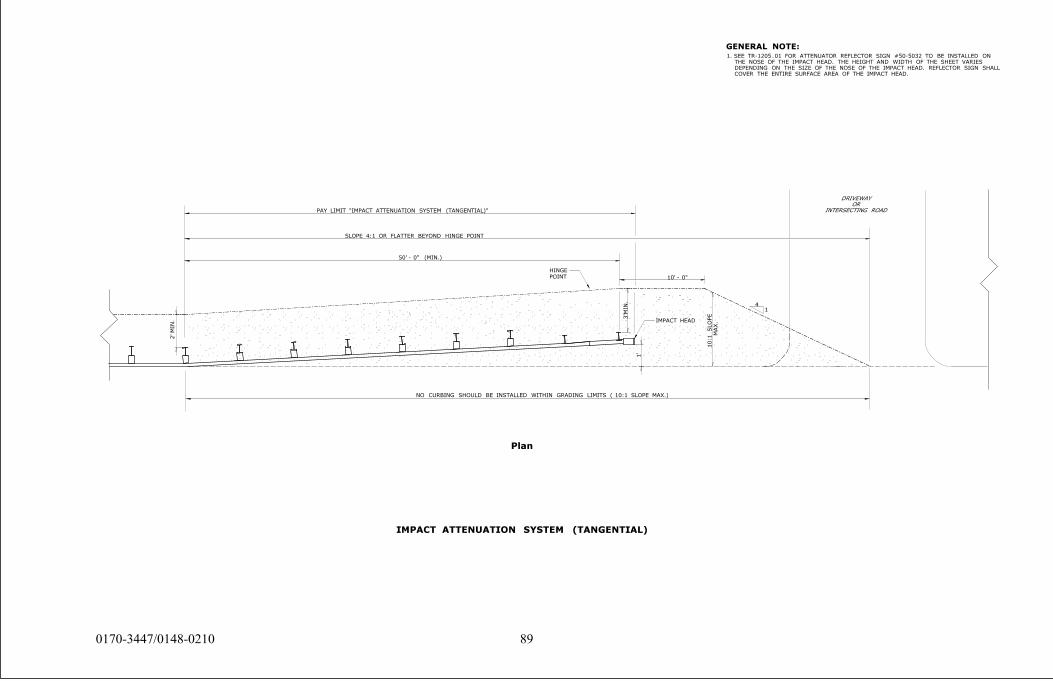
DRIVEWAY
OR
INTERSECTING ROAD
SLOPE 4:1 OR FLATTER BEYOND HINGE POINT
2'
MIN.
3'MIN.
1'
1. SEE TR-1205_01 FOR ATTENUATOR REFLECTOR SIGN #50-5032 TO BE INSTALLED ON
THE NOSE OF THE IMPACT HEAD. THE HEIGHT AND WIDTH OF THE SHEET VARIES
DEPENDING ON THE SIZE OF THE NOSE OF THE IMPACT HEAD. REFLECTOR SIGN SHALL
COVER THE ENTIRE SURFACE AREA OF THE IMPACT HEAD.
GENERAL NOTE:
41
NO CURBING SHOULD BE INSTALLED WITHIN GRADING LIMITS ( 10:1 SLOPE MAX.)
10' - 0"
50' - 0" (MIN.)
10:1 S
LO
PE
MA
X.
PAY LIMIT "IMPACT ATTENUATION SYSTEM (TANGENTIAL)"
Plan
IMPACT ATTENUATION SYSTEM (TANGENTIAL)
POINT
HINGE
IMPACT HEAD
890170-3447/0148-0210
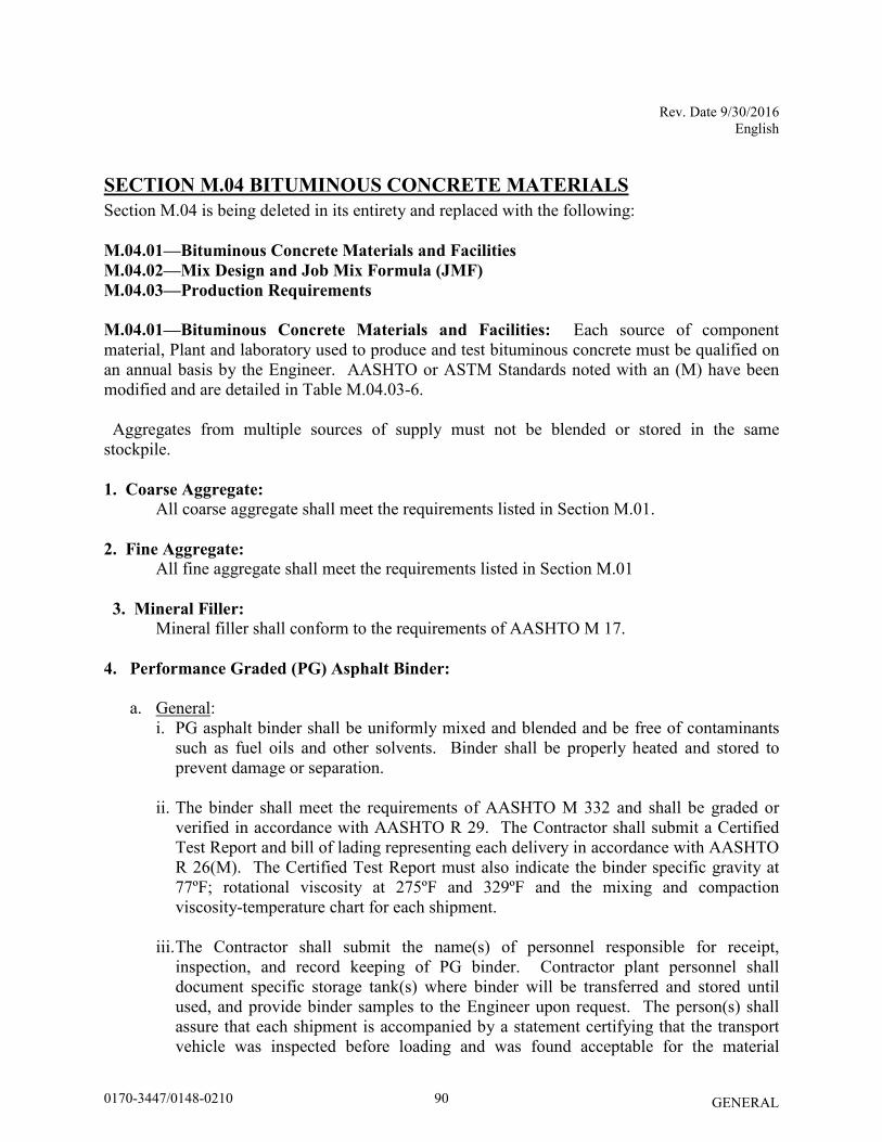
Rev. Date 9/30/2016 English
GENERAL
SECTION M.04 BITUMINOUS CONCRETE MATERIALS
Section M.04 is being deleted in its entirety and replaced with the following:
M.04.01—Bituminous Concrete Materials and Facilities
M.04.02—Mix Design and Job Mix Formula (JMF)
M.04.03—Production Requirements
M.04.01—Bituminous Concrete Materials and Facilities: Each source of component material, Plant and laboratory used to produce and test bituminous concrete must be qualified on an annual basis by the Engineer. AASHTO or ASTM Standards noted with an (M) have been modified and are detailed in Table M.04.03-6. Aggregates from multiple sources of supply must not be blended or stored in the same stockpile. 1. Coarse Aggregate:
All coarse aggregate shall meet the requirements listed in Section M.01.
2. Fine Aggregate:
All fine aggregate shall meet the requirements listed in Section M.01
3. Mineral Filler: Mineral filler shall conform to the requirements of AASHTO M 17.
4. Performance Graded (PG) Asphalt Binder:
a. General:
i. PG asphalt binder shall be uniformly mixed and blended and be free of contaminants such as fuel oils and other solvents. Binder shall be properly heated and stored to prevent damage or separation.
ii. The binder shall meet the requirements of AASHTO M 332 and shall be graded or verified in accordance with AASHTO R 29. The Contractor shall submit a Certified Test Report and bill of lading representing each delivery in accordance with AASHTO R 26(M). The Certified Test Report must also indicate the binder specific gravity at 77ºF; rotational viscosity at 275ºF and 329ºF and the mixing and compaction viscosity-temperature chart for each shipment.
iii. The Contractor shall submit the name(s) of personnel responsible for receipt, inspection, and record keeping of PG binder. Contractor plant personnel shall document specific storage tank(s) where binder will be transferred and stored until used, and provide binder samples to the Engineer upon request. The person(s) shall assure that each shipment is accompanied by a statement certifying that the transport vehicle was inspected before loading and was found acceptable for the material
900170-3447/0148-0210
Rev. Date 9/30/2016 English
GENERAL
shipped, and, that the binder is free of contamination from any residual material, along with two (2) copies of the bill of lading.
iv. The blending or combining of PG binders in one storage tank at the Plant from
different suppliers, grades, or additive percentages is prohibited.
b. Basis of Approval: The request for approval of the source of supply shall list the location where the material will be manufactured, and the handling and storage methods, along with necessary certification in accordance with AASHTO R 26(M). Only suppliers/refineries that have an approved “Quality Control Plan for Performance Graded Binders” formatted in accordance with AASHTO R 26(M) may supply PG binders to Department projects.
c. Standard Performance Grade (PG) Binder: i. Standard PG binder shall be defined as “Neat”. Neat PG binders shall be free from
modification with: fillers, extenders, reinforcing agents, adhesion promoters, thermoplastic polymers, acid modification and other additives such as re-refined motor oil, and shall indicate such information on each bill of lading and certified test report.
ii. The standard asphalt binder grade shall be PG 64S-22.
d. Modified Performance Grade (PG) Binder: The modified asphalt binder shall be Performance Grade PG 64E-22 asphalt modified solely with a Styrene-Butadiene-Styrene (SBS) polymer. The polymer modifier shall be added at either the refinery or terminal and delivered to the bituminous concrete production facility as homogenous blend. The stability of the modified binder shall be verified in accordance with ASTM D7173 using the Dynamic Shear Rheometer (DSR). The DSR G*/sin(δ) results from the top and bottom sections of the ASTM D7173 test shall not differ by more than 10%. The results of ASTM D7173 shall be included on the Certified Test Report. The binder shall meet the requirements of AASHTO M 332 (including Appendix X1) and AASHTO R 29.
e. Warm Mix Additive or Technology:
i. The warm mix additive or technology must be listed on the North East Asphalt User Producer Group (NEAUPG) Qualified Warm Mix Asphalt (WMA) Technologies List at the time of bid, which may be accessed online at http://www.neaupg.uconn.edu.
ii. The warm mix additive shall be blended with the asphalt binder in accordance with the manufacturer’s recommendations.
iii. The blended binder shall meet the requirements of AASHTO M 332 and shall be
graded or verified in accordance with AASHTO R 29 for the specified binder grade. The Contractor shall submit a Certified Test Report showing the results of the testing demonstrating the binder grade. In addition, it must include the grade of the virgin
910170-3447/0148-0210
Rev. Date 9/30/2016 English
GENERAL
binder, the brand name of the warm mix additive, the manufacturer’s suggested rate for the WMA additive, the water injection rate (when applicable) and the WMA Technology manufacturer’s recommended mixing and compaction temperature ranges.
5. Emulsified Asphalts:
a. General:
i. The emulsified asphalt shall meet the requirements of AASHTO M 140 or AASHTO M 208 as applicable.
ii. The emulsified asphalts shall be free of contaminants such as fuel oils and other solvents.
iii. The blending at mixing plants of emulsified asphalts from different suppliers is
prohibited. .
b. Basis of Approval i. The request for approval of the source of supply shall list the location where the
material is manufactured, the handling and storage methods, and certifications in accordance with AASHTO PP 71. Only suppliers that have an approved “Quality Control Plan for Emulsified Asphalt” formatted in accordance with AASHTO PP 71 and submit monthly split samples per grade to the Engineer may supply emulsified asphalt to Department projects.
ii. Each shipment of emulsified asphalt delivered to the project site shall be accompanied with the corresponding Certified Test Report listing Saybolt viscosity, residue by evaporation, penetration of residue, and weight per gallon at 77°F and Material Certificate.
iii. Anionic emulsified asphalts shall conform to the requirements of AASHTO M-140. Materials used for tack coat shall not be diluted and meet grade RS-1 or RS-1H. When ambient temperatures are 80˚F and rising, grade SS-1 or SS-lH may be substituted if permitted by the Engineer.
iv. Cationic emulsified asphalt shall conform to the requirements of AASHTO M-208. Materials used for tack coat shall not be diluted and meet grade CRS-1. The settlement and demulsibility test will not be performed unless deemed necessary by the Engineer. When ambient temperatures are 80˚F and rising, grade CSS-1 or CSS-lh may be substituted if permitted by the Engineer.
6. Reclaimed Asphalt Pavement (RAP):
920170-3447/0148-0210
Rev. Date 9/30/2016 English
GENERAL
a. General: RAP is a material obtained from the cold milling or removal and processing of bituminous concrete pavement. RAP material shall be crushed to 100% passing the ½ inch sieve and free from contaminants such as joint compound, wood, plastic, and metals.
b. Basis of Approval: The RAP material will be accepted on the basis of one of the following criteria: i. When the source of all RAP material is from pavements previously constructed on
Department projects, the Contractor shall provide a Materials Certificate listing the detailed locations and lengths of those pavements and that the RAP is only from those locations listed.
ii. When the RAP material source or quality is not known, the Contractor shall request for approval to the Engineer at least 30 calendar days prior to the start of the paving operation. The request shall include a Material Certificate and applicable test results stating that the RAP consists of aggregates that meet the specification requirements of sub articles M.04.01-1 through 3, and, that the binder in the RAP is substantially free of solvents, tars and other contaminants. The Contractor is prohibited from using unapproved material on Department projects and shall take necessary action to prevent contamination of approved RAP stockpiles. Stockpiles of unapproved material shall remain separate from all other RAP materials at all times. The request for approval shall include the following: 1. A 50-pound sample of the RAP to be incorporated into the recycled mixture. 2. A 25-pound sample of the extracted aggregate from the RAP.
7. Crushed Recycled Container Glass (CRCG):
a. Requirements: The Contractor may propose to use clean and environmentally-acceptable CRCG in an amount not greater than 5% by weight of total aggregate.
b. Basis of Approval: The Contractor shall submit to the Engineer a request to use CRCG.
The request shall state that the CRCG contains no more than 1% by weight of contaminants such as paper, plastic and metal and conform to the following gradation:
CRCG Grading Requirements Sieve Size Percent Passing 3/8-inch 100
No. 4 35-100 No. 200 0.0-10.0
The Contractor shall submit a Materials Certificate to the Engineer stating that the CRCG complies with all the applicable requirements in this specification.
930170-3447/0148-0210
Rev. Date 9/30/2016 English
GENERAL
8. Joint Seal Material:
a. Requirements: Joint seal material must meet the requirements of ASTM D 6690 – Type
2. The Contractor shall submit a Material Certificate in accordance with Article 1.06.07 certifying that the joint seal material meets the requirements of this specification.
9. Recycled Asphalt Shingles (RAS)
a. Requirements: RAS shall consist of processed asphalt roofing shingles from post-
consumer asphalt shingles or from manufactured shingle waste. The RAS material under consideration for use in bituminous concrete mixtures must be certified as being asbestos free and shall be entirely free of whole, intact nails. The RAS material shall meet the requirements of AASHTO MP 23.
The producer shall test the RAS material to determine the asphalt content and the gradation of the RAS material. The producer shall take necessary action to prevent contamination of RAS stockpiles. The Contractor shall submit a Materials Certificate to the Engineer stating that the RAS complies with all the applicable requirements in this specification.
10. Plant Requirements:
a. General: The Plant producing bituminous concrete shall comply with AASHTO M 156.
b. Storage Silos: The Contractor may use silos for short-term storage with the approval of
the Engineer. A silo must have heated cones and an unheated silo cylinder if it does not contain a separate internal heating system. When multiple silos are filled, the Contractor shall discharge one silo at a time. Simultaneous discharge of multiple silos for the same Project is not permitted.
Type of silo cylinder Maximum storage time for all classes (hr) HMA WMA/PMA Open Surge 4 Mfg Recommendations* Unheated – Non-insulated 8 Mfg Recommendations* Unheated – Insulated 18 Mfg Recommendations* Heated – No inert gas TBD by the Engineer
*Not to exceed HMA limits
c. Documentation System: The mixing plant documentation system shall include equipment for accurately proportioning the components of the mixture by weight and in the proper order, controlling the cycle sequence and timing the mixing operations. Recording equipment shall monitor the batching sequence of each component of the
940170-3447/0148-0210
Rev. Date 9/30/2016 English
GENERAL
mixture and produce a printed record of these operations on each Plant ticket, as specified herein. If recycled materials are used, the Plant tickets shall include their dry weight, percentage and daily moisture content. If a WMA Technology is added at the Plant, the Plant tickets shall include the actual dosage rate. For drum Plants, the Plant ticket shall be produced at 5 minute intervals and maintained by the vendor for a period of three years after the completion of the project. For batch Plants, the Plant ticket shall be produced for each batch and maintained by the vendor for a period of three years after the completion of the project. In addition, an asterisk (*) shall be automatically printed next to any individual batch weight(s) exceeding the following tolerances: Each Aggregate Component ±1.5% of individual or cumulative target weight for each bin Mineral Filler ±0.5% of the total batch Bituminous Material ±0.1% of the total batch Zero Return (Aggregate) ±0.5% of the total batch Zero Return (Bituminous Material) ±0.1% of the total batch The entire batching and mixing interlock cut-off circuits shall interrupt and stop the automatic batching operations when an error exceeding the acceptable tolerance occurs in proportioning. The scales shall not be manually adjusted during the printing process. In addition, the system shall be interlocked to allow printing only when the scale has come to a complete rest. A unique printed character (m) shall automatically be printed on the ticket when the automatic batching sequence is interrupted or switched to auto-manual or full manual during proportioning.
d. Aggregates: Aggregate stockpiles shall be managed to prevent segregation and cross contamination. For drum plants only, the percent moisture content at a minimum prior to production and half way through production shall be determined.
e. Mixture: The dry and wet mix times shall be sufficient to provide a uniform mixture and
a minimum particle coating of 95% as determined by AASHTO T 195(M) . Bituminous concrete mixtures shall contain no more than 0.5% moisture when tested in accordance with AASHTO T 329.
950170-3447/0148-0210
Rev. Date 9/30/2016 English
GENERAL
f. RAP: RAP moisture content shall be determined a minimum of twice daily (prior to production and halfway through production).
g. Asphalt Binder: A binder log shall be submitted to the Department’s Central Lab on a monthly basis.
h. Warm mix additive: For mechanically foamed WMA, the water injection rate shall be monitored during production and not exceed 2.0% by total weight of binder. For additive added at the Plant, the dosage rate shall be monitored during production.
i. Plant Laboratory: The Contractor shall maintain a laboratory at the production facility to
test bituminous concrete mixtures during production. The laboratory shall have a minimum of 300 square feet, have a potable water source and drainage in accordance with the CT Department of Public Health Drinking Water Division, and be equipped with all necessary testing equipment as well as with a PC, printer, and telephone with a dedicated hard-wired phone line. In addition, the PC shall have internet connection and a functioning web browser with unrestricted access to https://ctmail.ct.gov. This equipment shall be maintained in working order at all times and be made available for use by the Engineer.
The laboratory shall be equipped with a heating system capable of maintaining a
minimum temperature of 65°F. It shall be clean and free of all materials and equipment not associated with the laboratory. Sufficient light and ventilation must be provided. During summer months, adequate cooling or ventilation must be provided so the indoor air temperature shall not exceed the ambient outdoor temperature.
The laboratory testing apparatus, supplies, and safety equipment shall be capable of performing all tests in their entirety that are referenced in AASHTO R 35and AASHTO M 323. The Contractor shall ensure that the Laboratory is adequately supplied at all times during the course of the project with all necessary testing supplies and equipment.
The Contractor shall maintain a list of laboratory equipment used in the acceptance testing processes including but not limited to, balances, scales, manometer/vacuum gauge, thermometers, gyratory compactor, clearly showing calibration and/or inspection dates, in accordance with AASHTO R 18. The Contractor shall notify the Engineer if any modifications are made to the equipment within the laboratory. The Contractor shall take immediate action to replace, repair, and/or recalibrate any piece of equipment that is out of calibration, malfunctioning, or not in operation.
M.04.02—Mix Design and Job Mix Formula (JMF)
1. Curb Mix:
a. Requirements: The Contractor shall use bituminous concrete that meets the requirements
of Table M.04.02-1. RAP may be used in 5% increments by weight up to 30%.
960170-3447/0148-0210
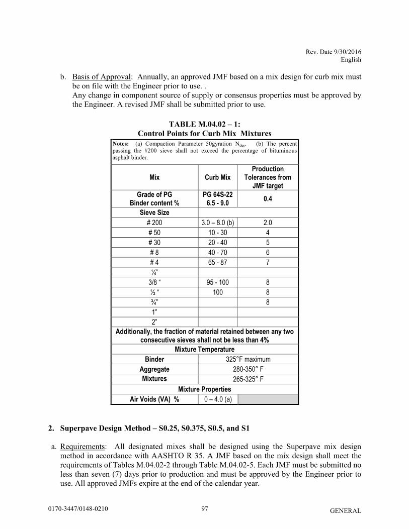
Rev. Date 9/30/2016 English
GENERAL
b. Basis of Approval: Annually, an approved JMF based on a mix design for curb mix must be on file with the Engineer prior to use. . Any change in component source of supply or consensus properties must be approved by the Engineer. A revised JMF shall be submitted prior to use.
TABLE M.04.02 – 1: Control Points for Curb Mix Mixtures
Notes: (a) Compaction Parameter 50gyration Ndes. (b) The percent passing the #200 sieve shall not exceed the percentage of bituminous asphalt binder.
Mix Curb Mix Production
Tolerances from JMF target
Grade of PG Binder content %
PG 64S-22 6.5 - 9.0
0.4
Sieve Size
# 200 3.0 – 8.0 (b) 2.0
# 50 10 - 30 4
# 30 20 - 40 5
# 8 40 - 70 6
# 4 65 - 87 7
¼”
3/8 “ 95 - 100 8
½ “ 100 8
¾” 8
1”
2”
Additionally, the fraction of material retained between any two consecutive sieves shall not be less than 4%
Mixture Temperature
Binder 325°F maximum
Aggregate 280-350° F
Mixtures 265-325° F
Mixture Properties
Air Voids (VA) % 0 – 4.0 (a)
2. Superpave Design Method – S0.25, S0.375, S0.5, and S1
a. Requirements: All designated mixes shall be designed using the Superpave mix design method in accordance with AASHTO R 35. A JMF based on the mix design shall meet the requirements of Tables M.04.02-2 through Table M.04.02-5. Each JMF must be submitted no less than seven (7) days prior to production and must be approved by the Engineer prior to use. All approved JMFs expire at the end of the calendar year.
970170-3447/0148-0210
Rev. Date 9/30/2016 English
GENERAL
All aggregate component consensus properties and tensile strength ratio (TSR) specimens shall be tested at an AASHTO Materials Reference Laboratory (AMRL) by NETTCP certified technicians. All bituminous concrete mixes shall be tested for stripping susceptibility by performing the tensile strength ratio (TSR) test procedure in accordance with AASHTO T 283(M) at a minimum every 36 months. The compacted specimens may be fabricated at the Plant and then tested at an AMRL accredited facility. TSR specimens, and corresponding JMF shall be submitted with each test report.
i. Superpave Mixtures with RAP: RAP may be used with the following conditions: • RAP amounts up to 15% may be used with no binder grade modification. • RAP amounts up to 20% may be used provided a new JMF is approved by the Engineer.
The JMF submittal shall include the grade of virgin binder added. The JMF shall be accompanied by a blending chart and supporting test results in accordance with AASHTO M 323 Appendix X1, or by testing that shows the combined binder (recovered binder from the RAP, virgin binder at the mix design proportions, warm mix asphalt additive and any other modifier if used) meets the requirements of the specified binder grade.
• Two representative samples of RAP shall be obtained. Each sample shall be split and one split sample shall be tested for binder content in accordance with AASHTO T 164 and the other in accordance AASHTO T 308.
• RAP material shall not be used with any other recycling option.
ii. Superpave Mixtures with RAS: RAS may be used solely in HMA S1 mixtures with the following conditions:
• RAS amounts up to 3% may be used. • RAS total binder replacement up to 15% may be used with no binder grade modification. • RAS total binder replacement up to 20% may be used provided a new JMF is approved
by the Engineer. The JMF submittal shall include the grade of virgin binder added. The JMF shall be accompanied by a blending chart and supporting test results in accordance to AASHTO M 323 appendix X1 or by testing that shows the combined binder (recovered binder from the RAP, virgin binder at the mix design proportions, warm mix asphalt additive and any other modifier if used) meets the requirements of the specified binder grade.
• Superpave Mixtures with RAS shall meet AASHTO PP 78 design considerations. The RAS asphalt binder availability factor (F) used in AASHTO PP 78 shall be 0.85.
iii. Superpave Mixtures with CRCG: CRCG may be used solely in HMA S1 mixtures. One
percent of hydrated lime, or other accepted non-stripping agent, shall be added to all mixtures containing CRCG. CRCG material shall not be used with any other recycling option.
980170-3447/0148-0210
Rev. Date 9/30/2016 English
GENERAL
b. Basis of Approval: The following information must be included with the JMF submittal:
• Gradation, consensus properties and specific gravities of the aggregate, RAP or RAS. • Average asphalt content of the RAP or RAS by AASHTO T 164. • Source of RAP or RAS, and percentage to be used. • Warm mix Technology, manufacturer’s recommended additive rate and tolerances and
manufacturer recommended mixing and compaction temperatures. • TSR test report and anti-strip manufacturer and recommended dosage rate if applicable. • Mixing and compaction temperature ranges for the mix with and without the warm-mix
technology incorporated. • JMF ignition oven correction factor by AASHTO T 308.
With each JMF submittal, the following samples shall be submitted to the Division of Materials Testing: • 4 - one quart cans of PG binder, with corresponding Safety Data Sheet (SDS) • 1 - 50 lbs bag of RAP • 2 – 50 lbs bag of plant blended virgin aggregate
A JMF may not be approved if any of the properties of the aggregate components or mix do not meet the verification tolerances as described in the Department’s current QA Program for Materials, Acceptance and Assurance Testing Policies and Procedures. Any material based on a JMF, once approved, shall only be acceptable for use when it is produced by the designated plant, it utilizes the same components, and the production of material continues to meet all criteria as specified herein, and component aggregates are maintained within the tolerances shown in Table M.04.02-2. A new JMF must be submitted to the Engineer for approval whenever a new component source is proposed.
Only one mix with one JMF will be approved for production at any one time. Switching between approved JMF mixes with different component percentages or sources of supply is prohibited.
c. Mix Status: Each facility will have each type of mixture rated based on the results of the previous year’s production. Mix Status will be provided to each bituminous concrete producer annually prior to the beginning of the paving season.
The rating criteria are based on compliance with Air Voids and Voids in Mineral Aggregate (VMA) as indicated in Table M.04.03-4 and are calculated as follows:
Criteria A: Percentage of acceptance test results with compliant air voids. Criteria B: The average of the percentage of acceptance test results with compliant VMA,
and percentage of acceptance test results with compliant air voids. The final rating assigned will be the lower of the rating obtained with Criteria A or B.
990170-3447/0148-0210
Rev. Date 9/30/2016 English
GENERAL
Mix status is defined as: “A” – Approved: Assigned to each mixture type from a production facility with a current rating of 70% or greater, or to each mixture type completing a successful PPT. “PPT” – Pre-Production Trial: Temporarily assigned to each mixture type from a production facility when:
1. there are no compliant acceptance production test results submitted to the Department from the previous year;
2. there is a source change in one or more aggregate components 3. there is a component percentage change of more than 5% by weight; 4. there is a change in RAP percentage; 5. the mixture has a rating of less than 70% from the previous season; 6. a new JMF not previously submitted.
Bituminous concrete mixtures with a “PPT” status cannot be used on Department projects. Testing shall be performed by the Producer with NETTCP certified personnel on material under this status. Test results must confirm that specifications requirements in Table M.04.02-2 and Table M.04.02-5 are met before material can be used. One of the following methods must be used to verify the test results:
Option A: Schedule a day when a Department Inspector can be at the facility to witness testing or, Option B: When the Contractor or their representative performs testing without being witnessed by an Inspector, the Contractor shall submit the test results and a split sample including 2 gyratory molds, 5,000 grams of boxed bituminous concrete, and 5,000 grams of cooled loose bituminous concrete for verification testing and approval. Option C: When the Contractor or their representative performs testing without being witnessed by a Department Inspector, the Engineer may verify the mix in the Contractor’s laboratory.
Witnessing or verifying by the Department of compliant test results will change the mix’s status to an “A”.
The differences between the Department’s test results and the Contractor’s must be within the “C” tolerances included in the Department’s QA Program for Materials, Acceptance and Assurance Testing Policies and Procedures in order to be verified.
“U” – Not Approved: Status assigned to a type of mixture that does not have an approved JMF. . Bituminous concrete mixtures with a “U” status cannot be used on Department projects.
1000170-3447/0148-0210
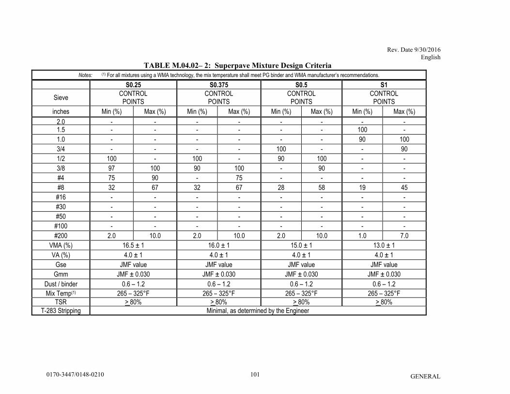
Rev. Date 9/30/2016 English
GENERAL
TABLE M.04.02– 2: Superpave Mixture Design Criteria
Notes: (1) For all mixtures using a WMA technology, the mix temperature shall meet PG binder and WMA manufacturer’s recommendations.
S0.25 S0.375 S0.5 S1
Sieve CONTROL
POINTS CONTROL
POINTS CONTROL
POINTS CONTROL
POINTS
inches Min (%) Max (%) Min (%) Max (%) Min (%) Max (%) Min (%) Max (%)
2.0 - - - - - - - - 1.5 - - - - - - 100 -
1.0 - - - - - - 90 100
3/4 - - - - 100 - - 90
1/2 100 - 100 - 90 100 - -
3/8 97 100 90 100 - 90 - -
#4 75 90 - 75 - - - -
#8 32 67 32 67 28 58 19 45
#16 - - - - - - - -
#30 - - - - - - - -
#50 - - - - - - - -
#100 - - - - - - - -
#200 2.0 10.0 2.0 10.0 2.0 10.0 1.0 7.0
VMA (%) 16.5 ± 1 16.0 ± 1 15.0 ± 1 13.0 ± 1
VA (%) 4.0 ± 1 4.0 ± 1 4.0 ± 1 4.0 ± 1
Gse JMF value JMF value JMF value JMF value
Gmm JMF ± 0.030 JMF ± 0.030 JMF ± 0.030 JMF ± 0.030
Dust / binder 0.6 – 1.2 0.6 – 1.2 0.6 – 1.2 0.6 – 1.2
Mix Temp(1) 265 – 325°F 265 – 325°F 265 – 325°F 265 – 325°F
TSR > 80%
> 80% > 80% > 80%
T-283 Stripping Minimal, as determined by the Engineer
1010170-3447/0148-0210
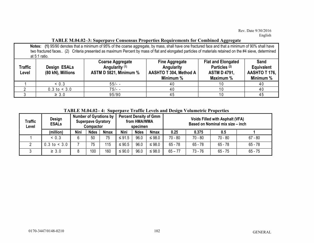
Rev. Date 9/30/2016 English
GENERAL
TABLE M.04.02–3: Superpave Consensus Properties Requirements for Combined Aggregate
Notes: (1) 95/90 denotes that a minimum of 95% of the coarse aggregate, by mass, shall have one fractured face and that a minimum of 90% shall have two fractured faces.. (2) Criteria presented as maximum Percent by mass of flat and elongated particles of materials retained on the #4 sieve, determined at 5:1 ratio.
Traffic Level
Design ESALs (80 kN), Millions
Coarse Aggregate Angularity (1)
ASTM D 5821, Minimum %
Fine Aggregate Angularity
AASHTO T 304, Method A Minimum %
Flat and Elongated Particles (2)
ASTM D 4791, Maximum %
Sand Equivalent
AASHTO T 176, Minimum %
1 < 0 .3 55 / - - 40 10 40
2 0 .3 to < 3 .0 75 / - - 40 10 40
3 ≥ 3 .0 95 /90 45 10 45
TABLE M.04.02– 4: Superpave Traffic Levels and Design Volumetric Properties
Traffic Level
Design ESALs
Number of Gyrations by Superpave Gyratory
Compactor
Percent Density of Gmm from HMA/WMA
specimen
Voids Filled with Asphalt (VFA) Based on Nominal mix size – inch
(million) Nini Ndes Nmax Nini Ndes Nmax 0.25 0.375 0.5 1
1 < 0 .3 6 50 75 ≤ 91.5 96.0 ≤ 98.0 70 - 80 70 - 80 70 - 80 67 - 80
2 0 .3 to < 3 .0 7 75 115 ≤ 90.5 96.0 ≤ 98.0 65 - 78 65 - 78 65 - 78 65 - 78
3 ≥ 3 .0 8 100 160 ≤ 90.0 96.0 ≤ 98.0 65 – 77 73 - 76 65 - 75 65 - 75
1020170-3447/0148-0210
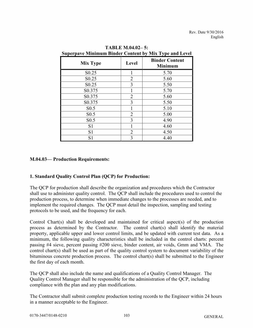
Rev. Date 9/30/2016 English
GENERAL
TABLE M.04.02– 5:
Superpave Minimum Binder Content by Mix Type and Level
Mix Type Level Binder Content
Minimum
S0.25 1 5.70 S0.25 2 5.60 S0.25 3 5.50
S0.375 1 5.70 S0.375 2 5.60 S0.375 3 5.50
S0.5 1 5.10 S0.5 2 5.00 S0.5 3 4.90 S1 1 4.60 S1 2 4.50 S1 3 4.40
M.04.03— Production Requirements:
1. Standard Quality Control Plan (QCP) for Production: The QCP for production shall describe the organization and procedures which the Contractor shall use to administer quality control. The QCP shall include the procedures used to control the production process, to determine when immediate changes to the processes are needed, and to implement the required changes. The QCP must detail the inspection, sampling and testing protocols to be used, and the frequency for each. Control Chart(s) shall be developed and maintained for critical aspect(s) of the production process as determined by the Contractor. The control chart(s) shall identify the material property, applicable upper and lower control limits, and be updated with current test data. As a minimum, the following quality characteristics shall be included in the control charts: percent passing #4 sieve, percent passing #200 sieve, binder content, air voids, Gmm and VMA. The control chart(s) shall be used as part of the quality control system to document variability of the bituminous concrete production process. The control chart(s) shall be submitted to the Engineer the first day of each month. The QCP shall also include the name and qualifications of a Quality Control Manager. The Quality Control Manager shall be responsible for the administration of the QCP, including compliance with the plan and any plan modifications. The Contractor shall submit complete production testing records to the Engineer within 24 hours in a manner acceptable to the Engineer.
1030170-3447/0148-0210
Rev. Date 9/30/2016 English
GENERAL
The QCP shall also include the name and qualifications of any outside testing laboratory performing any QC functions on behalf of the Contractor. The QCP must also include a list of sampling & testing methods and frequencies used during production, and the names of all Quality Control personnel and their duties. Approval of the QCP does not imply any warranty by the Engineer that adherence to the plan will result in production of bituminous concrete that complies with these specifications. The Contractor shall submit any changes to the QCP as work progresses.
2. Acceptance Requirements:
i. General:
Acceptance samples shall be obtained from the hauling vehicles and tested by the Contractor at the Plant.
The Contractor shall submit all acceptance tests results to the Engineer within 24 hours or prior to the next day’s production. All acceptance test specimens and supporting documentation must be retained by the Contractor and may be disposed of with the approval of the Engineer. All quality control specimens shall be clearly labeled and separated from the acceptance specimens. Contractor personnel performing acceptance sampling and testing must be present at the facility prior to, during, and until completion of production, and be certified as a NETTCP HMA Plant Technician or Interim HMA Plant Technician and be in good standing. Production of material for use on State projects must be suspended by the Contractor if such personnel are not present. Technicians found by the Engineer to be non-compliant with NETTCP policies and procedures or Department policies may be removed by the Engineer from participating in the acceptance testing process for Department projects until their actions can be reviewed. Anytime during production that testing equipment becomes defective or inoperable, production can continue for a maximum of 1 hour. The Contractor shall obtain box sample(s) in accordance with Table M.04.03-2 to satisfy the daily acceptance testing requirement for the quantity shipped to the project. The box sample(s) shall be tested once the equipment issue has been resolved to the satisfaction of the Engineer. Production beyond 1 hour may be considered by the Engineer. Production will not be permitted beyond that day until the subject equipment issue has been resolved. Verification testing will be performed by the Engineer in accordance with the Department’s QA Program for Materials. Should the Department be unable to verify the Contractor’s acceptance test result(s) due to a failure of the Contractor to retain acceptance test specimens or supporting documentation, the Contractor shall review its quality control plan, determine the cause of the nonconformance and
1040170-3447/0148-0210
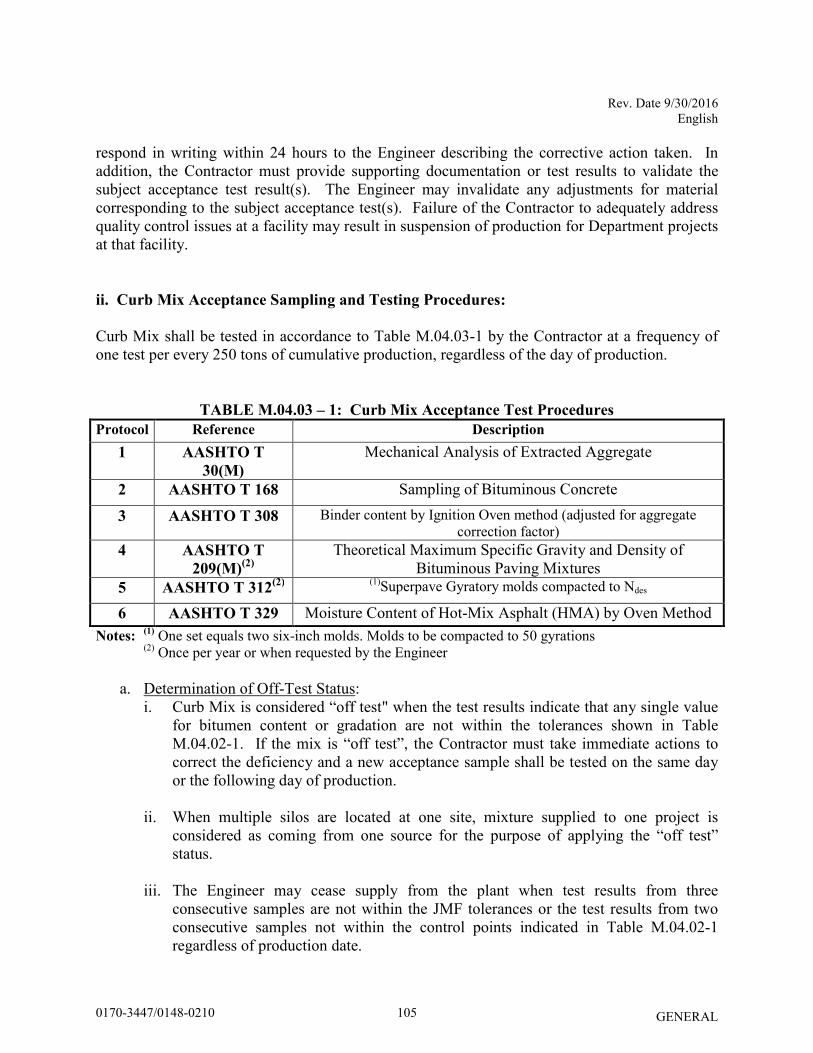
Rev. Date 9/30/2016 English
GENERAL
respond in writing within 24 hours to the Engineer describing the corrective action taken. In addition, the Contractor must provide supporting documentation or test results to validate the subject acceptance test result(s). The Engineer may invalidate any adjustments for material corresponding to the subject acceptance test(s). Failure of the Contractor to adequately address quality control issues at a facility may result in suspension of production for Department projects at that facility. ii. Curb Mix Acceptance Sampling and Testing Procedures:
Curb Mix shall be tested in accordance to Table M.04.03-1 by the Contractor at a frequency of one test per every 250 tons of cumulative production, regardless of the day of production.
TABLE M.04.03 – 1: Curb Mix Acceptance Test Procedures
Protocol Reference Description 1 AASHTO T
30(M)
Mechanical Analysis of Extracted Aggregate
2 AASHTO T 168 Sampling of Bituminous Concrete
3 AASHTO T 308 Binder content by Ignition Oven method (adjusted for aggregate correction factor)
4 AASHTO T
209(M)(2)
Theoretical Maximum Specific Gravity and Density of Bituminous Paving Mixtures
5 AASHTO T 312(2)
(1)Superpave Gyratory molds compacted to Ndes
6 AASHTO T 329 Moisture Content of Hot-Mix Asphalt (HMA) by Oven Method Notes:
(1) One set equals two six-inch molds. Molds to be compacted to 50 gyrations
(2) Once per year or when requested by the Engineer
a. Determination of Off-Test Status: i. Curb Mix is considered “off test" when the test results indicate that any single value
for bitumen content or gradation are not within the tolerances shown in Table M.04.02-1. If the mix is “off test”, the Contractor must take immediate actions to correct the deficiency and a new acceptance sample shall be tested on the same day or the following day of production.
ii. When multiple silos are located at one site, mixture supplied to one project is
considered as coming from one source for the purpose of applying the “off test” status.
iii. The Engineer may cease supply from the plant when test results from three
consecutive samples are not within the JMF tolerances or the test results from two consecutive samples not within the control points indicated in Table M.04.02-1 regardless of production date.
1050170-3447/0148-0210
Rev. Date 9/30/2016 English
GENERAL
b. JMF revisions i. If a test indicates that the bitumen content or gradation are outside the tolerances, the
Contractor may make a single JMF revision as allowed by the Engineer prior to any additional testing. Consecutive test results outside the requirements of Table M.04.02-1 JMF tolerances may result in rejection of the mixture.
ii. Any modification to the JMF shall not exceed 50% of the JMF tolerances indicated in Table M.04.02-1 for any given component of the mixture without approval of the Engineer. When such an adjustment is made to the bitumen, the corresponding production percentage of bitumen shall be revised accordingly.
iii. Superpave Mix Acceptance:
a. Sampling and Testing Procedures
Production Lot: The Lot will be defined as one of the following types: - Non-PWL Production Lot for total estimated project quantities per mixture less
than 3500 tons: All mixture placed during a single continuous paving operation. - PWL Production Lot for total estimated project quantities per mixture of 3500
tons or more: Each 3500 tons of mixture produced within 30 calendar days. Production Sub Lot: - For Non-PWL: As defined in Table M.04.03 – 2 - For PWL: 500 tons (the last Sub Lot may be less than 500 tons) Partial Production Lots (For PWL only): A Lot with less than 3500 tons due to: - completion of the Course - a Job Mix Formula revision due to changes in:
o cold feed percentages over 5% o target combined gradation over 5% o target binder over 0.15% o any component specific gravity
- a Lot spanning 30 calendar days
The acceptance sample(s) location(s) shall be selected using stratified – random sampling in accordance with ASTM D 3665 based on:
- the total daily estimated tons of production for non-PWL lots, or - the total lot size for PWL lots.
One acceptance sample shall be obtained and tested per Sub Lot. The Engineer may direct that additional acceptance samples be obtained. For non-PWL lots, one acceptance test shall always be performed in the last sub-lot based on actual tons of material produced.
1060170-3447/0148-0210
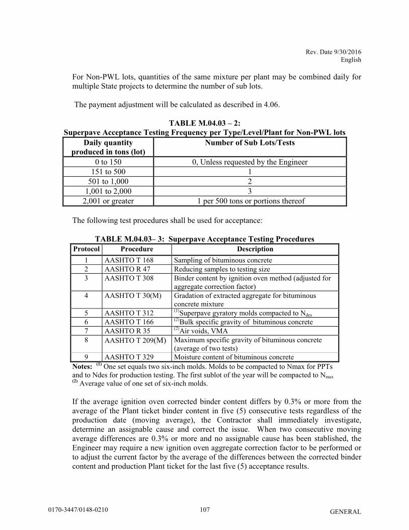
Rev. Date 9/30/2016 English
GENERAL
For Non-PWL lots, quantities of the same mixture per plant may be combined daily for multiple State projects to determine the number of sub lots. The payment adjustment will be calculated as described in 4.06.
TABLE M.04.03 – 2:
Superpave Acceptance Testing Frequency per Type/Level/Plant for Non-PWL lots
Daily quantity
produced in tons (lot)
Number of Sub Lots/Tests
0 to 150 0, Unless requested by the Engineer 151 to 500 1
501 to 1,000 2 1,001 to 2,000 3
2,001 or greater 1 per 500 tons or portions thereof
The following test procedures shall be used for acceptance:
TABLE M.04.03– 3: Superpave Acceptance Testing Procedures
Protocol Procedure Description
1 AASHTO T 168 Sampling of bituminous concrete 2 AASHTO R 47 Reducing samples to testing size 3 AASHTO T 308 Binder content by ignition oven method (adjusted for
aggregate correction factor) 4 AASHTO T 30(M) Gradation of extracted aggregate for bituminous
concrete mixture 5 AASHTO T 312 (1)Superpave gyratory molds compacted to Ndes 6 AASHTO T 166 (2)Bulk specific gravity of bituminous concrete 7 AASHTO R 35 (2)Air voids, VMA 8 AASHTO T 209(M) Maximum specific gravity of bituminous concrete
(average of two tests) 9 AASHTO T 329 Moisture content of bituminous concrete
Notes: (1)
One set equals two six-inch molds. Molds to be compacted to Nmax for PPTs and to Ndes for production testing. The first sublot of the year will be compacted to Nmax (2)
Average value of one set of six-inch molds. If the average ignition oven corrected binder content differs by 0.3% or more from the average of the Plant ticket binder content in five (5) consecutive tests regardless of the production date (moving average), the Contractor shall immediately investigate, determine an assignable cause and correct the issue. When two consecutive moving average differences are 0.3% or more and no assignable cause has been stablished, the Engineer may require a new ignition oven aggregate correction factor to be performed or to adjust the current factor by the average of the differences between the corrected binder content and production Plant ticket for the last five (5) acceptance results.
1070170-3447/0148-0210
Rev. Date 9/30/2016 English
GENERAL
The test specimen must be placed in an ignition oven for testing in accordance with AASHTO T 308 within thirty minutes of being obtained from the hauling vehicle and the test shall start immediately after.
The Contractor shall perform TSR testing within 30 days after the start of production for all design levels of HMA- and PMA- S0.5 plant-produced mixtures, in accordance with AASHTO T 283(M). The TSR test shall be performed at an AMRL certified laboratory by NETTCP certified technicians. The compacted specimens may be fabricated at the Plant and then tested at an AMRL accredited facility. The test results and specimens shall be submitted to the Engineer for review. Superpave mixtures that require anti-strip additives (either liquid or mineral) shall continue to meet all requirements specified herein for binder and bituminous concrete. The Contractor shall submit the name, manufacturer, percent used, technical datasheet and SDS for the anti-strip additive (if applicable) to the Engineer.
b. Determination of Off-Test Status:
i. Superpave mixes shall be considered “off test” when any Control Point Sieve, binder content, VA, VMA, or Gmm value is outside of the limits specified in Table M.04.03-4 or the target binder content at the Plant is below the minimum binder content stated in Table M.04.02-5. Note that further testing of samples or portions of samples not initially tested for this purpose cannot be used to change the status.
ii. Any time the bituminous concrete mixture is considered Off-test: 1. The Contractor shall notify the Engineer when the Plant is "off test" for any mix
design that is delivered to the project in any production day. When multiple silos are located at one site, mixture supplied to one project is considered as coming from one source for the purpose of applying the “off test” determination.
2. The Contractor must take immediate actions to correct the deficiency, minimize
“off test” production to the project, and obtain an additional Process Control (PC) test after any corrective action to verify production is in conformance to the specifications. A PC test will not be used for acceptance and is solely for the use of the Contractor in its quality control process.
c. Cessation of Supply for Superpave Mixtures in non-PWL lots:
A mixture shall not be used on Department’s projects when it is “off test” for: i. four (4) consecutive tests in any combination of VA, VMA or Gmm, regardless
of date of production, or, ii. two (2) consecutive tests in the Control Point sieves in one production shift.
As a result of cessation of supply, the mix status will be changed to PPT.
1080170-3447/0148-0210
Rev. Date 9/30/2016 English
GENERAL
d. JMF revisions:
JMF revisions are only permitted prior to or after a production shift. A JMF revision is effective from the time it was submitted and is not retroactive to the previous test(s).
JMF revisions shall be justified by a documented trend of test results.
Revisions to aggregate and RAP specific gravities are only permitted when testing is performed at an AMRL certified laboratory by NETTCP certified technicians.
A JMF revision is required when the Plant target RAP and/or bin percentage deviates by more than 5% and/or the Plant target binder content deviates by more than 0.15% from the active JMF.
1090170-3447/0148-0210
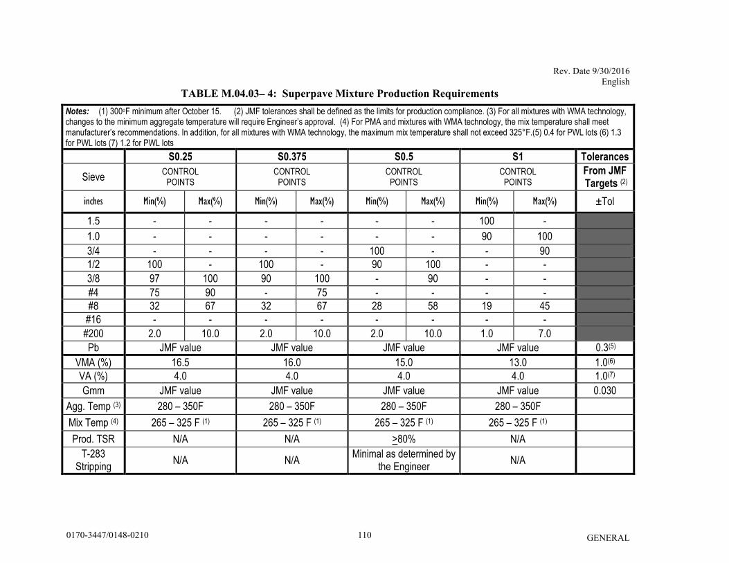
Rev. Date 9/30/2016 English
GENERAL
TABLE M.04.03– 4: Superpave Mixture Production Requirements
Notes: (1) 300oF minimum after October 15. (2) JMF tolerances shall be defined as the limits for production compliance. (3) For all mixtures with WMA technology, changes to the minimum aggregate temperature will require Engineer’s approval. (4) For PMA and mixtures with WMA technology, the mix temperature shall meet manufacturer’s recommendations. In addition, for all mixtures with WMA technology, the maximum mix temperature shall not exceed 325°F.(5) 0.4 for PWL lots (6) 1.3 for PWL lots (7) 1.2 for PWL lots
S0.25 S0.375 S0.5 S1 Tolerances
Sieve CONTROL
POINTS CONTROL
POINTS CONTROL
POINTS CONTROL
POINTS
From JMF Targets (2)
inches Min(%) Max(%) Min(%) Max(%) Min(%) Max(%) Min(%) Max(%) ±Tol
1.5 - - - - - - 100 -
1.0 - - - - - - 90 100
3/4 - - - - 100 - - 90
1/2 100 - 100 - 90 100 - -
3/8 97 100 90 100 - 90 - -
#4 75 90 - 75 - - - -
#8 32 67 32 67 28 58 19 45
#16 - - - - - - - -
#200 2.0 10.0 2.0 10.0 2.0 10.0 1.0 7.0
Pb JMF value JMF value JMF value JMF value 0.3(5)
VMA (%) 16.5 16.0 15.0 13.0 1.0(6)
VA (%) 4.0 4.0 4.0 4.0 1.0(7)
Gmm JMF value JMF value JMF value JMF value 0.030
Agg. Temp (3) 280 – 350F 280 – 350F 280 – 350F 280 – 350F
Mix Temp (4) 265 – 325 F (1) 265 – 325 F (1) 265 – 325 F (1) 265 – 325 F (1)
Prod. TSR N/A N/A >80% N/A
T-283 Stripping
N/A N/A Minimal as determined by
the Engineer N/A
1100170-3447/0148-0210
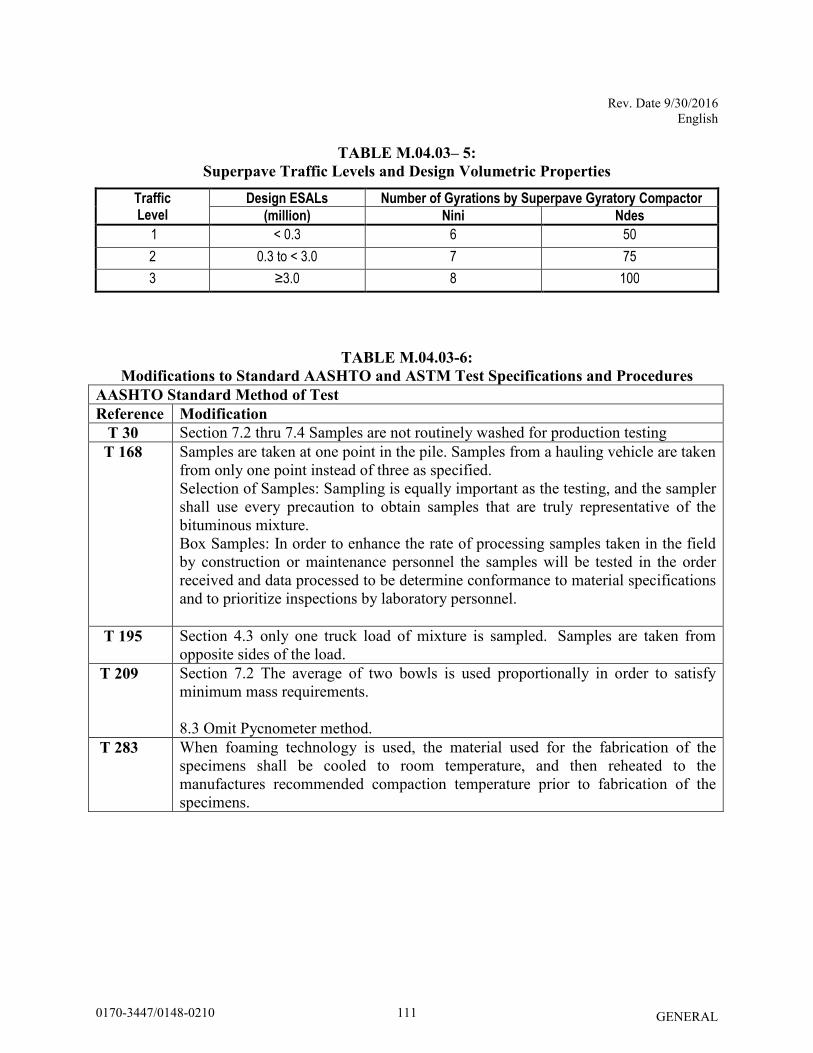
Rev. Date 9/30/2016 English
GENERAL
TABLE M.04.03– 5:
Superpave Traffic Levels and Design Volumetric Properties
TABLE M.04.03-6:
Modifications to Standard AASHTO and ASTM Test Specifications and Procedures
AASHTO Standard Method of Test
Reference Modification
T 30 Section 7.2 thru 7.4 Samples are not routinely washed for production testing T 168
Samples are taken at one point in the pile. Samples from a hauling vehicle are taken from only one point instead of three as specified. Selection of Samples: Sampling is equally important as the testing, and the sampler shall use every precaution to obtain samples that are truly representative of the bituminous mixture. Box Samples: In order to enhance the rate of processing samples taken in the field by construction or maintenance personnel the samples will be tested in the order received and data processed to be determine conformance to material specifications and to prioritize inspections by laboratory personnel.
T 195 Section 4.3 only one truck load of mixture is sampled. Samples are taken from opposite sides of the load.
T 209 Section 7.2 The average of two bowls is used proportionally in order to satisfy minimum mass requirements. 8.3 Omit Pycnometer method.
T 283 When foaming technology is used, the material used for the fabrication of the specimens shall be cooled to room temperature, and then reheated to the manufactures recommended compaction temperature prior to fabrication of the specimens.
Traffic Level
Design ESALs Number of Gyrations by Superpave Gyratory Compactor
(million) Nini Ndes
1 < 0.3 6 50
2 0.3 to < 3.0 7 75
3 ≥3.0 8 100
1110170-3447/0148-0210
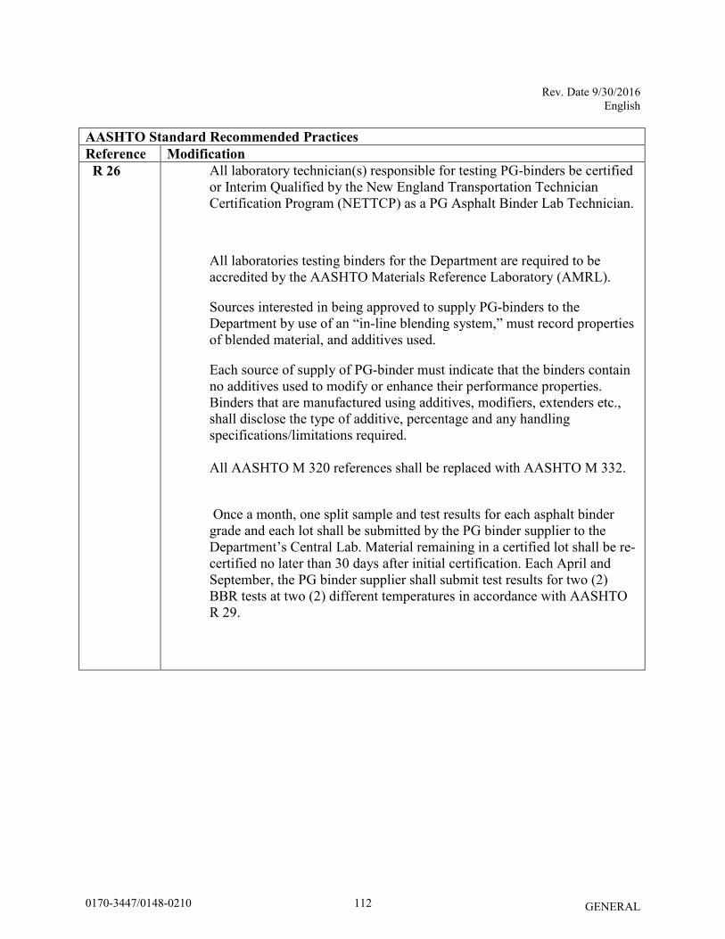
Rev. Date 9/30/2016 English
GENERAL
AASHTO Standard Recommended Practices
Reference Modification
R 26 All laboratory technician(s) responsible for testing PG-binders be certified or Interim Qualified by the New England Transportation Technician Certification Program (NETTCP) as a PG Asphalt Binder Lab Technician.
All laboratories testing binders for the Department are required to be accredited by the AASHTO Materials Reference Laboratory (AMRL).
Sources interested in being approved to supply PG-binders to the Department by use of an “in-line blending system,” must record properties of blended material, and additives used.
Each source of supply of PG-binder must indicate that the binders contain no additives used to modify or enhance their performance properties. Binders that are manufactured using additives, modifiers, extenders etc., shall disclose the type of additive, percentage and any handling specifications/limitations required. All AASHTO M 320 references shall be replaced with AASHTO M 332. Once a month, one split sample and test results for each asphalt binder grade and each lot shall be submitted by the PG binder supplier to the Department’s Central Lab. Material remaining in a certified lot shall be re-certified no later than 30 days after initial certification. Each April and September, the PG binder supplier shall submit test results for two (2) BBR tests at two (2) different temperatures in accordance with AASHTO R 29.
1120170-3447/0148-0210
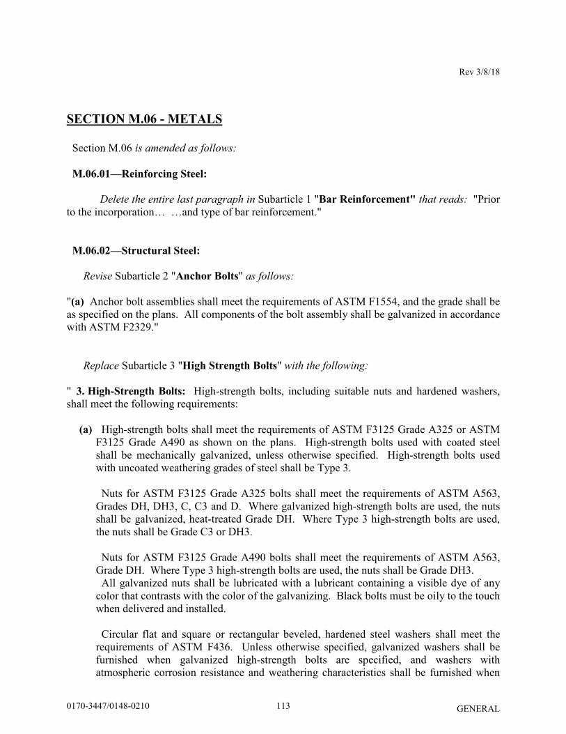
Rev 3/8/18
GENERAL
SECTION M.06 - METALS
Section M.06 is amended as follows:
M.06.01—Reinforcing Steel: Delete the entire last paragraph in Subarticle 1 "Bar Reinforcement" that reads: "Prior to the incorporation… …and type of bar reinforcement." M.06.02—Structural Steel:
Revise Subarticle 2 "Anchor Bolts" as follows: "(a) Anchor bolt assemblies shall meet the requirements of ASTM F1554, and the grade shall be as specified on the plans. All components of the bolt assembly shall be galvanized in accordance with ASTM F2329."
Replace Subarticle 3 "High Strength Bolts" with the following:
" 3. High-Strength Bolts: High-strength bolts, including suitable nuts and hardened washers, shall meet the following requirements:
(a) High-strength bolts shall meet the requirements of ASTM F3125 Grade A325 or ASTM F3125 Grade A490 as shown on the plans. High-strength bolts used with coated steel shall be mechanically galvanized, unless otherwise specified. High-strength bolts used with uncoated weathering grades of steel shall be Type 3. Nuts for ASTM F3125 Grade A325 bolts shall meet the requirements of ASTM A563, Grades DH, DH3, C, C3 and D. Where galvanized high-strength bolts are used, the nuts shall be galvanized, heat-treated Grade DH. Where Type 3 high-strength bolts are used, the nuts shall be Grade C3 or DH3. Nuts for ASTM F3125 Grade A490 bolts shall meet the requirements of ASTM A563, Grade DH. Where Type 3 high-strength bolts are used, the nuts shall be Grade DH3. All galvanized nuts shall be lubricated with a lubricant containing a visible dye of any color that contrasts with the color of the galvanizing. Black bolts must be oily to the touch when delivered and installed. Circular flat and square or rectangular beveled, hardened steel washers shall meet the requirements of ASTM F436. Unless otherwise specified, galvanized washers shall be furnished when galvanized high-strength bolts are specified, and washers with atmospheric corrosion resistance and weathering characteristics shall be furnished when
1130170-3447/0148-0210
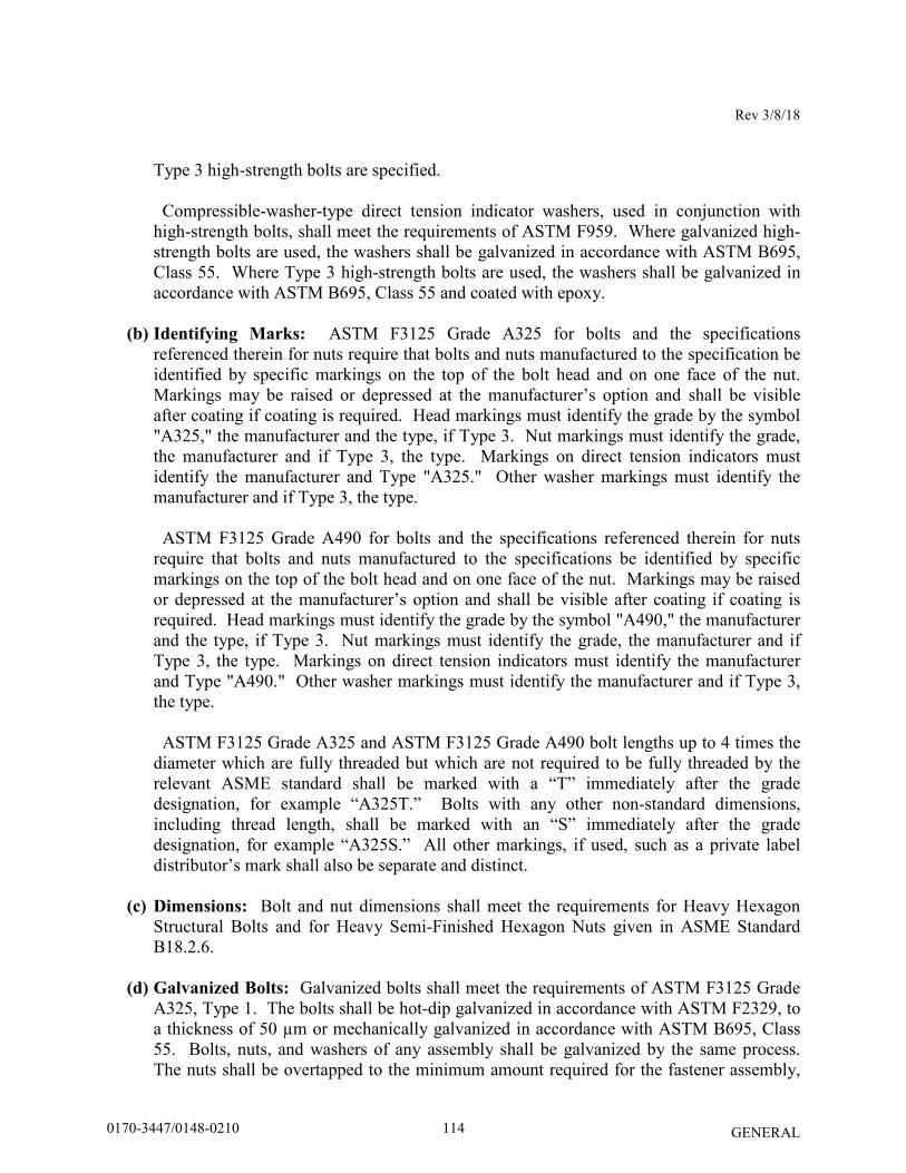
Rev 3/8/18
GENERAL
Type 3 high-strength bolts are specified. Compressible-washer-type direct tension indicator washers, used in conjunction with high-strength bolts, shall meet the requirements of ASTM F959. Where galvanized high-strength bolts are used, the washers shall be galvanized in accordance with ASTM B695, Class 55. Where Type 3 high-strength bolts are used, the washers shall be galvanized in accordance with ASTM B695, Class 55 and coated with epoxy.
(b) Identifying Marks: ASTM F3125 Grade A325 for bolts and the specifications referenced therein for nuts require that bolts and nuts manufactured to the specification be identified by specific markings on the top of the bolt head and on one face of the nut. Markings may be raised or depressed at the manufacturer’s option and shall be visible after coating if coating is required. Head markings must identify the grade by the symbol "A325," the manufacturer and the type, if Type 3. Nut markings must identify the grade, the manufacturer and if Type 3, the type. Markings on direct tension indicators must identify the manufacturer and Type "A325." Other washer markings must identify the manufacturer and if Type 3, the type. ASTM F3125 Grade A490 for bolts and the specifications referenced therein for nuts require that bolts and nuts manufactured to the specifications be identified by specific markings on the top of the bolt head and on one face of the nut. Markings may be raised or depressed at the manufacturer’s option and shall be visible after coating if coating is required. Head markings must identify the grade by the symbol "A490," the manufacturer and the type, if Type 3. Nut markings must identify the grade, the manufacturer and if Type 3, the type. Markings on direct tension indicators must identify the manufacturer and Type "A490." Other washer markings must identify the manufacturer and if Type 3, the type. ASTM F3125 Grade A325 and ASTM F3125 Grade A490 bolt lengths up to 4 times the diameter which are fully threaded but which are not required to be fully threaded by the relevant ASME standard shall be marked with a “T” immediately after the grade designation, for example “A325T.” Bolts with any other non-standard dimensions, including thread length, shall be marked with an “S” immediately after the grade designation, for example “A325S.” All other markings, if used, such as a private label distributor’s mark shall also be separate and distinct.
(c) Dimensions: Bolt and nut dimensions shall meet the requirements for Heavy Hexagon Structural Bolts and for Heavy Semi-Finished Hexagon Nuts given in ASME Standard B18.2.6.
(d) Galvanized Bolts: Galvanized bolts shall meet the requirements of ASTM F3125 Grade A325, Type 1. The bolts shall be hot-dip galvanized in accordance with ASTM F2329, to a thickness of 50 µm or mechanically galvanized in accordance with ASTM B695, Class 55. Bolts, nuts, and washers of any assembly shall be galvanized by the same process. The nuts shall be overtapped to the minimum amount required for the fastener assembly,
1140170-3447/0148-0210
Rev 3/8/18
GENERAL
and shall be lubricated with a lubricant containing a visible dye so a visual check can be made for the lubricant at the time of field installation. Galvanized bolts shall be tension tested after galvanizing. ASTM F3125 Grade A490 bolts shall be uncoated or shall be coated in accordance with either ASTM F1136 Grade 3 or ASTM F2833 Grade 1.
(e) Test Requirements: The maximum hardness of ASTM F3125 Grade A325 bolts shall be
34 HRC. The maximum hardness of ASTM F3125 Grade A490 bolts shall be 38 HRC. Plain, ungalvanized nuts shall have a minimum hardness of 89 HRB. Proof load tests, in accordance with the requirements of ASTM F606 Method 1, shall be required for the bolts. Wedge tests of full-size bolts are required in accordance with Section 10.1 of ASTM F3125. Galvanized bolts shall be wedge tested after galvanizing. Proof load tests of ASTM A563 are required for nuts. Proof load tests for nuts used with galvanized bolts shall be performed after galvanizing, overtapping and lubricating. Rotational-capacity tests are required and shall be performed on all plain or galvanized (after galvanizing) bolt, nut and washer assemblies by the manufacturer or distributor prior to shipping and by the Contractor at the Site. The thickness of galvanizing on bolts, nuts and washers shall be measured. On bolts, it shall be measured on the wrench flats or on top of the bolt head, and on nuts it shall be measured on the wrench flats.
(f) Certified Test Reports and Materials Certificates: The Contractor shall submit notarized copies of Certified Test Reports and Materials Certificates in accordance with Article 1.06.07 for fastener assemblies. In addition the Certified Test Reports and Materials Certificates shall include the following: 1. Mill test reports shall indicate the place where the material was melted and
manufactured. 2. Test reports for proof load tests, wedge tests, and rotational-capacity tests shall indicate
where the tests were performed, date of tests, location of where the components were manufactured and lot numbers.
3. The test report for galvanized components shall indicate the thickness of the galvanizing.
(g) Material Samples: Prior to incorporation into the work, the Contractor shall submit samples of the bolt assemblies to the Engineer for testing in accordance with the latest edition of the “Materials Testing Manual (Chapter 8, Minimum Schedule for Acceptance Testing).” Samples shall be submitted for each diameter, length, material designation, grade, coating and manufacturer of bolt assembly."
1150170-3447/0148-0210
Rev 3/8/18
GENERAL
M.06.03—Galvanizing:
Replace the entire subarticle with the following:
" M.06.03—Galvanizing: Unless otherwise specified on the plans or in the special provisions, the zinc coating on all iron and steel materials, other than wire, shall meet the requirements of ASTM A123, A153 or F2329, whichever shall apply. When mechanical galvanizing is used it shall meet the requirements of ASTM B695 Class 55."
1160170-3447/0148-0210
08/28/2017
GENERAL
SECTION M.10 – RAILING AND FENCE
M.10.02 – Metal Beam-Type Rail and Anchorages:
9. Plastic Blockouts: Amend as follows:
Replace NCHRP Report 350 with MASH
1170170-3447/0148-0210
Rev. Date 08/02/11
GENERAL
ON-THE-JOB TRAINING (OJT) WORKFORCE DEVELOPMENT PILOT
Description
To provide construction industry related job opportunities to minorities, women and economically disadvantaged individuals; and to increase the likelihood of a diverse and inclusive workforce on Connecticut Department of Transportation (ConnDOT) projects. All contractors (existing and newcomers) will be automatically placed in the Workforce Development Pilot. Standard OJT requirements typically associated with individual projects will no longer be applied at the project level for new projects. Instead, these requirements will be applicable on an annual basis for each contractor performing work on ConnDOT projects. The OJT Workforce Development Pilot will allow a contractor to train employees on Federal, State and privately funded projects located in Connecticut. However, contractors should give priority to training employees on ConnDOT Federal-Aid funded projects. Funding
The Department will establish an OJT fund annually from which contractors may bill the Department directly for eligible trainee hours. The funds for payment of trainee hours on federal-aid projects will be allocated from the ½ of 1% provided for OJT funding, and will be based on hours trained, not to exceed a maximum of $25,000.00 per year; per contractor.
Minorities and Women
Developing, training and upgrading of minorities, women and economically disadvantaged individuals toward journeyperson level status is the primary objective of this special training provision. Accordingly, the Contractor shall make every effort to enroll minority, women and economically disadvantaged individuals as trainees to the extent that such persons are available within a reasonable area of recruitment. This training commitment is not intended, and shall not be used, to discriminate against any applicant for training whether a member of a minority group or not. Assigning Training Goals
The Department, through the OJT Program Coordinator, will assign training goals for a calendar year based on the contractor’s past two year’s activities and the contractor’s anticipated upcoming year’s activity with the Department. At the beginning of each year, all contractors eligible will be contacted by the Department to determine the number of trainees that will be assigned for the upcoming calendar year. At that time, the Contractor shall enter into an agreement with the Department to provide a self-imposed on-the-job training program for the calendar year. This agreement will include a specific number of annual training goals agreed to by both parties. The number of training assignments may range from one (1) to six (6) per
1180170-3447/0148-0210
Rev. Date 08/02/11
GENERAL
contractor per calendar year. Each January, a summary of the trainees required and the OJT Workforce Development Pilot package will be sent to participating contractors. The number of trainees assigned to each contractor in the summary will increase proportionately not to exceed 6, as shown in the following table. This package will also be provided to contractors as they become newly eligible for the OJT Workforce Development Pilot throughout the remainder of the year. Projects awarded after September 30 will be included in the following year’s Program. The dollar thresholds for training assignments are as follows: $4.5 – 8 million= 1 trainee $ 9 – 15 million= 2 trainees $16 – 23 million= 3 trainees $24 – 30 million= 4 trainees $31 – 40 million= 5 trainees $41 – and above= 6 trainees Training Classifications
Preference shall be given to providing training in the following skilled work classifications. However, the classifications established are not all-inclusive:
Equipment Operators Electricians Laborers Painters Carpenters Iron / Reinforcing Steel Workers Concrete Finishers Mechanics Pipe Layers Welders
The Department has on file common training classifications and their respective training requirements; that may be used by the contractors. Contractors shall submit new classifications for specific job functions that their employees are performing. The Department will review and recommend for acceptance the new classifications proposed by contractors, if applicable. New classifications shall meet the following requirements: Proposed training classifications are reasonable and realistic based on the job skill classification needs, and the number of training hours specified in the training classification is consistent with common practices and provides enough time for the trainee to obtain journeyman level status. Where feasible, 25% percent of apprentices or trainees in each occupation shall be in their first year of apprenticeship or training. The number of trainees shall be distributed among the work classifications on the basis of the contractor’s needs and the availability of journeymen in the various classifications within a reasonable area of recruitment. No employee shall be employed as a trainee in any classification in which they have successfully completed a training course leading to journeyman level status or in which they have been employed as a journeyman.
1190170-3447/0148-0210
Rev. Date 08/02/11
GENERAL
Records and Reports
The Contractor shall maintain enrollment in the program and submit all required reports documenting company compliance under these contract requirements. These documents and any other information shall be submitted to the OJT Program Coordinator as requested. Upon the trainee’s completion and graduation from the program, the Contractor shall provide each trainee with a certification Certificate showing the type and length of training satisfactorily completed. Trainee Interviews
In order to determine the continued effectiveness of the OJT Program in Connecticut, the department will periodically conduct personal interviews with current trainees and may survey recent graduates of the program. This enables the OJT Program Coordinator to modify and improve the program as necessary. Trainee interviews are generally conducted at the job site to ensure that the trainees’ work and training is consistent with the approved training program. Trainee Wages
Contractors shall compensate trainees on a graduating pay scale based upon a percentage of the prevailing minimum journeyman wages (Davis-Bacon Act). Minimum pay shall be as follows:
60 percent of the journeyman wage for the first half of the training period 75 percent of the journeyman wage for the third quarter of the training period 90 percent of the journeyman wage for the last quarter of the training period
In no case, will the trainee be paid less than the prevailing rate for general laborer as shown in
the contract wage decision (must be approved by the Department of Labor).
Achieving or Failing to Meet Training Goals
The Contractor will be credited for each trainee currently enrolled or who becomes enrolled in the approved training program and providing they receive the required training under the specific training program. Trainees will be allowed to be transferred between projects if required by the Contractor’s schedule and workload. The OJT Program Coordinator must be notified of transfers within five (5) days of the transfer or reassignments by e-mail ([email protected]). Where a contractor does not or cannot achieve its annual training goal with female or minority trainees, they must produce adequate Good Faith Efforts documentation. Good Faith Efforts are those designed to achieve equal opportunity through positive, aggressive, and continuous result-oriented measures. 23 CFR § 230.409(g) (4). Contractors should request minorities and females from unions when minorities and females are under-represented in the contractor’s workforce.
1200170-3447/0148-0210
Rev. Date 08/02/11
GENERAL
Whenever a contractor requests ConnDOT approval of someone other than a minority or female, the contractor must submit documented evidence of its Good Faith Efforts to fill that position with a minority or female. When a non-minority male is accepted, a contractor must continue to attempt to meet its remaining annual training goals with females and minorities. Where a contractor has neither attained its goal nor submitted adequate Good Faith Efforts documentation, ConnDOT will issue a letter of non-compliance. Within thirty (30) days of receiving the letter of non-compliance, the contractor must submit a written Corrective Action Plan (CAP) outlining the steps that it will take to remedy the non-compliance. The CAP must be approved by ConnDOT. Failure to comply with the CAP may result in your firm being found non-responsive for future projects. Measurement and Payment
Optional reimbursement will be made to the contractor for providing the required training under this special provision on ConnDOT Federal-Aid funded projects only. Contractor will be reimbursed at $0.80 for each hour of training given to an employee in accordance with an approved training or apprenticeship program. This reimbursement will be made even though the Contractor receives additional training program funds from other sources, provided such other source does not specifically prohibit the contractor from receiving other reimbursement.
Reimbursement for training is made annually or upon the trainees completion and not on a monthly basis. No payment shall be made to the Contractor if either the failure to provide the required training, or the failure to hire the trainee as a journeyperson, is caused by the Contractor. Program reimbursements will be made directly to the prime contractor on an annual basis. To request reimbursement, prime contractors must complete the Voucher for OJT Workforce Development Pilot Hourly Reimbursement for each trainee in the OJT Program. This form is included in the OJT Workforce Development Pilot package and is available on the Department’s web site at: www.ct.gov/dot The completed form must be submitted to the Office of Contract Compliance for approval. The form is due on the 15th day of January for each trainee currently enrolled and for hours worked on ConnDOT Federal-Aid funded projects only.
1210170-3447/0148-0210
GENERAL
SMALL CONTRACTOR AND SMALL CONTRACTOR MINORITY
BUSINESS ENTERPRISES (SET-ASIDE)
March, 2001
NOTE: Certain requirements and procedures stated in this "Special Provision" are applicable prior to the execution of the Contract. I. GENERAL
A. The Contractor shall cooperate with the Connecticut Department of Transportation (CONNDOT) in implementing the required contract obligations concerning "Small Contractor" and "Small Contractor Minority Business Enterprise" use on this Contract in accordance with Section 4a-60g of the Connecticut General Statutes as revised. References, throughout this "Special Provision", to "Small Contractors" are also implied references to "Small Contractor Minority Business Enterprises" as both relate to Section IIA of these provisions. The Contractor shall also cooperate with CONNDOT in reviewing the Contractor's activities relating to this provision. This "Special Provision" is in addition to all other equal opportunity employment requirements of this Contract.
B. For the purpose of this "Special Provision", the "Small Contractor(s)" and
"Minority Business Enterprise(s)" named to satisfy the set-aside requirement must be certified by the Department of Administrative Services, Business Connections/ Set-Aside Unit [(860) 713-5236 www.das.state.ct.us/busopp.htm] as a "Small Contractor" and "Minority Business Enterprises" as defined by Section 4a-60g Subsections (1) and (3) of the Connecticut General Statutes as revised and is subject to approval by CONNDOT to do the work for which it is nominated pursuant to the criteria stipulated in Section IIC-3.
C. Contractors who allow work which they have designated for "Small Contractor"
participation in the preaward submission required under Section IIC to be performed by other than the approved "Small Contractor" organization and prior to concurrence by CONNDOT, will not be paid for the value of the work performed by organizations other than the "Small Contractor" designated.
D. If the Contractor is unable to achieve the specified contract goals for "Small
Contractor" participation, the Contractor shall submit written documentation to CONNDOT's Manager of Construction Operations indicating his/her good faith efforts to satisfy goal requirements. Documentation is to include but not be limited to the following:
1220170-3447/0148-0210
GENERAL
1. A detailed statement of the efforts made to select additional subcontract opportunities for work to be performed by each "Small Contractor" in order to increase the likelihood of achieving the stated goal.
2. A detailed statement, including documentation of the efforts made to
contact and solicit contracts with each "Small Contractor", including the names, addresses, dates and telephone numbers of each "Small Contractor" contacted, and a description of the information provided to each "Small Contractor" regarding the scope of services and anticipated time schedule of items proposed to be subcontracted and the nature of response from firms contacted.
3. For each "Small Contractor" that placed a subcontract quotation which the
Contractor considered not to be acceptable, provide a detailed statement of the reasons for this conclusion.
4. Documents to support contacts made with CONNDOT requesting
assistance in satisfying the contract specified or adjusted "Small Contractor" dollar requirements.
5. Document other special efforts undertaken by the Contractor to meet the
defined goal.
E. Failure of the Contractor to have at least the specified dollar amount of this contract performed by "Small Contractor" as required in Section IIA of this "Special Provision" will result in the reduction in contract payment to the Contractor by an amount equivalent to that determined by subtracting from the specific dollar amount required in Section IIA, the dollar payments for the work actually performed by each "Small Contractor". The deficiency in "Small Contractor" achievement, will therefore, be deducted from the final contract payment. However, in instances where the Contractor can adequately document or substantiate its good faith efforts made to meet the specified or adjusted dollar amount to the satisfaction of CONNDOT, no reduction in payments will be imposed.
F. All records must be retained for a period of three (3) years following completion
of the contract and shall be available at reasonable times and places for inspection by authorized representatives of CONNDOT.
G. Nothing contained herein, is intended to relieve any contractor or subcontractor or
material supplier or manufacturer from compliance with all applicable Federal and State legislation or provisions concerning equal employment opportunity, affirmative action, nondiscrimination and related subjects during the term of this Contract.
1230170-3447/0148-0210
GENERAL
II. SPECIFIC REQUIREMENTS In order to increase the participation of "Small Contractors", CONNDOT requires the following:
A. Not less than ten (10%) percent of the final value of this Contract shall be subcontracted to and performed by, and/or supplied by, manufactured by and paid to "Small Contractors" and/or "Small Contractors Minority Business Enterprises".
If the above percentage is zero (0%) AND an asterisk (*) has been entered in the
adjacent brackets [ ], this Contract is 100% solely set-aside for participation by "Small
Contractors" and/or "Small Contractors Minority Business Enterprises".
B. The Contractor shall assure that each "Small Contractor" will have an equitable opportunity to compete under this "Special Provision", particularly by arranging solicitations, time for the preparation of Quotes, Scope of Work, and Delivery Schedules so as to facilitate the participation of each "Small Contractor".
C. The Contractor shall provide to CONNDOT's Manager of Contracts within Seven
(7) days after the bid opening the following items:
1. An affidavit (Exhibit I) completed by each named "Small Contractor" subcontractor listing a description of the work and indicating the dollar amount of all contract(s) and/or subcontract(s) that have been awarded to him/her for the current State Fiscal Year (July 1 - June 30) does not exceed the Fiscal Year limit of $10,000,000.00.
2. A certification of work to be subcontracted (Exhibit II) signed by both the
Contractor and the "Small Contractor" listing the work items and the dollar value of the items that the nominated "Small Contractor" is to perform on the project to achieve the minimum percentage indicated in Section IIA above.
3. A certification of past experience (Exhibit III) indicating the scope of
work the nominated "Small Contractor" has performed on all projects, public and private, for the past two (2) years.
4. In instances where a change from the originally approved named "Small
Contractor" (see Section IB) is proposed, the Contractor is required to submit, in a reasonable and expeditious manner, a revised submission, comprised of the documentation required in Section IIC, Paragraphs 1, 2 and 3 and Section E together with documentation to substantiate and
1240170-3447/0148-0210
GENERAL
justify the change, (i.e., documentation to provide a basis for the change) to CONNDOT's Manager of Construction Operations for its review and approval prior to the implementation of the change. The Contractor must demonstrate that the originally named "Small Contractor" is unable to per-form in conformity to specifications, or unwilling to perform, or is in default of its contract, or is overextended on other jobs. The Contractor's ability to negotiate a more advantageous contract with another "Small Contractor" is not a valid basis for change. Documentation shall include a letter of release from the originally named "Small Contractor" indicating the reason(s) for the release.
D. After the Contractor signs the Contract, the Contractor will be required to meet
with CONNDOT's Manager of Construction Operations or his/her designee to review the following:
1. What is expected with respect to the "Small Contractor" set aside
requirements.
2. Failure to comply with and meet the requirement can and will result in monetary deductions from payment.
3. Each quarter after the start of the "Small Contractor" the Contractor shall
submit a report to CONNDOT's Manager of Construction Operations indicating the work done by, and the dollars paid to each "Small Contractor" to date.
4. What is required when a request to sublet to a "Small Contractor" is
submitted.
E. The Contractor shall submit to CONNDOT's Manager of Construction Operations all requests for subcontractor approvals on standard forms provided by the Department.
If the request for approval is for a "Small Contractor" subcontractor for the purpose of meeting the contract required "Small Contractor" percentage stipulated in Section IIA, a copy of the legal contract between the Contractor and the "Small Contractor" subcontractor must also be submitted at the same time. Any subsequent amendments or modifications of the contract between the Contractor and the "Small Contractor" subcontractor must also be submitted to CONNDOT's Manager of Construction Operations with an explanation of the change(s). The contract must show items of work to be performed, unit prices and, if a partial item, the work involved by both parties.
In addition, the following documents are to be attached:
1250170-3447/0148-0210
GENERAL
(1) A statement explaining any method or arrangement for renting equipment. If rental is from a Contractor, a copy of Rental Agreement must be submitted.
(2) A statement addressing any special arrangements for manpower.
(3) A statement addressing who will purchase material.
F. Contractors subcontracting with a "Small Contractor" to perform work or services as required by this "Special Provision" shall not terminate such firms without advising CONNDOT, in writing, and providing adequate documentation to substantiate the reasons for termination if the designated "Small Contractor" firm has not started or completed the work or the services for which it has been con-tracted to perform.
G. Material Suppliers or Manufacturers
If the Contractor elects to utilize a "Small Contractor" supplier or manufacturer to satisfy a portion or all of the specified dollar requirements, the Contractor must provide the Department with:
1. An executed Affidavit Small Contractor (Set-Aside) Connecticut Department of Transportation Affidavit Supplier or Manufacturer (sample attached), and
2. Substantiation of payments made to the supplier or manufacturer for
materials used on the project.
Brokers and packagers shall not be regarded as material Suppliers or manufacturer.
H. Non-Manufacturing or Non-Supplier "Small Contractor" Credit
Contractors may count towards its "Small Contractor" goals the following expenditures with "Small Contractor" firms that are not manufacturers or suppliers:
1. Reasonable fees or commissions charged for providing a bona fide service
such as professional, technical, consultant or managerial services and assistance in the procurement of essential personnel, facilities, equipment, material or supplies necessary for the performance of the contract provided that the fee or commission is determined by the Department of Transportation to be reasonable and consistent with fees customarily allowed for similar services.
1260170-3447/0148-0210
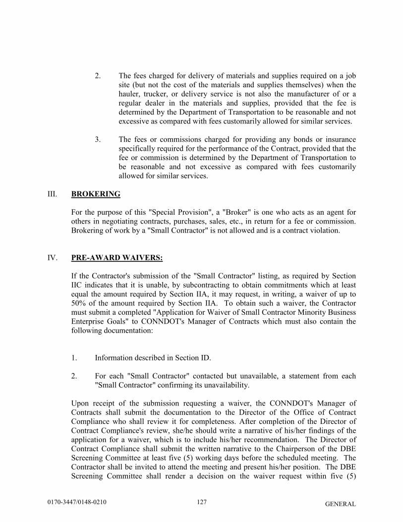
GENERAL
2. The fees charged for delivery of materials and supplies required on a job site (but not the cost of the materials and supplies themselves) when the hauler, trucker, or delivery service is not also the manufacturer of or a regular dealer in the materials and supplies, provided that the fee is determined by the Department of Transportation to be reasonable and not excessive as compared with fees customarily allowed for similar services.
3. The fees or commissions charged for providing any bonds or insurance
specifically required for the performance of the Contract, provided that the fee or commission is determined by the Department of Transportation to be reasonable and not excessive as compared with fees customarily allowed for similar services.
III. BROKERING
For the purpose of this "Special Provision", a "Broker" is one who acts as an agent for others in negotiating contracts, purchases, sales, etc., in return for a fee or commission. Brokering of work by a "Small Contractor" is not allowed and is a contract violation.
IV. PRE-AWARD WAIVERS:
If the Contractor's submission of the "Small Contractor" listing, as required by Section IIC indicates that it is unable, by subcontracting to obtain commitments which at least equal the amount required by Section IIA, it may request, in writing, a waiver of up to 50% of the amount required by Section IIA. To obtain such a waiver, the Contractor must submit a completed "Application for Waiver of Small Contractor Minority Business Enterprise Goals" to CONNDOT's Manager of Contracts which must also contain the following documentation:
1. Information described in Section ID.
2. For each "Small Contractor" contacted but unavailable, a statement from each "Small Contractor" confirming its unavailability.
Upon receipt of the submission requesting a waiver, the CONNDOT's Manager of Contracts shall submit the documentation to the Director of the Office of Contract Compliance who shall review it for completeness. After completion of the Director of Contract Compliance's review, she/he should write a narrative of his/her findings of the application for a waiver, which is to include his/her recommendation. The Director of Contract Compliance shall submit the written narrative to the Chairperson of the DBE Screening Committee at least five (5) working days before the scheduled meeting. The Contractor shall be invited to attend the meeting and present his/her position. The DBE Screening Committee shall render a decision on the waiver request within five (5)
1270170-3447/0148-0210
GENERAL
working days after the meeting. The DBE Screening Committee's decision shall be final. Waiver applications are available from the CONNDOT Manager of Contracts.
1280170-3447/0148-0210
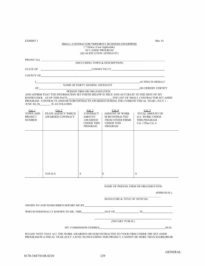
GENERAL
1290170-3447/0148-0210
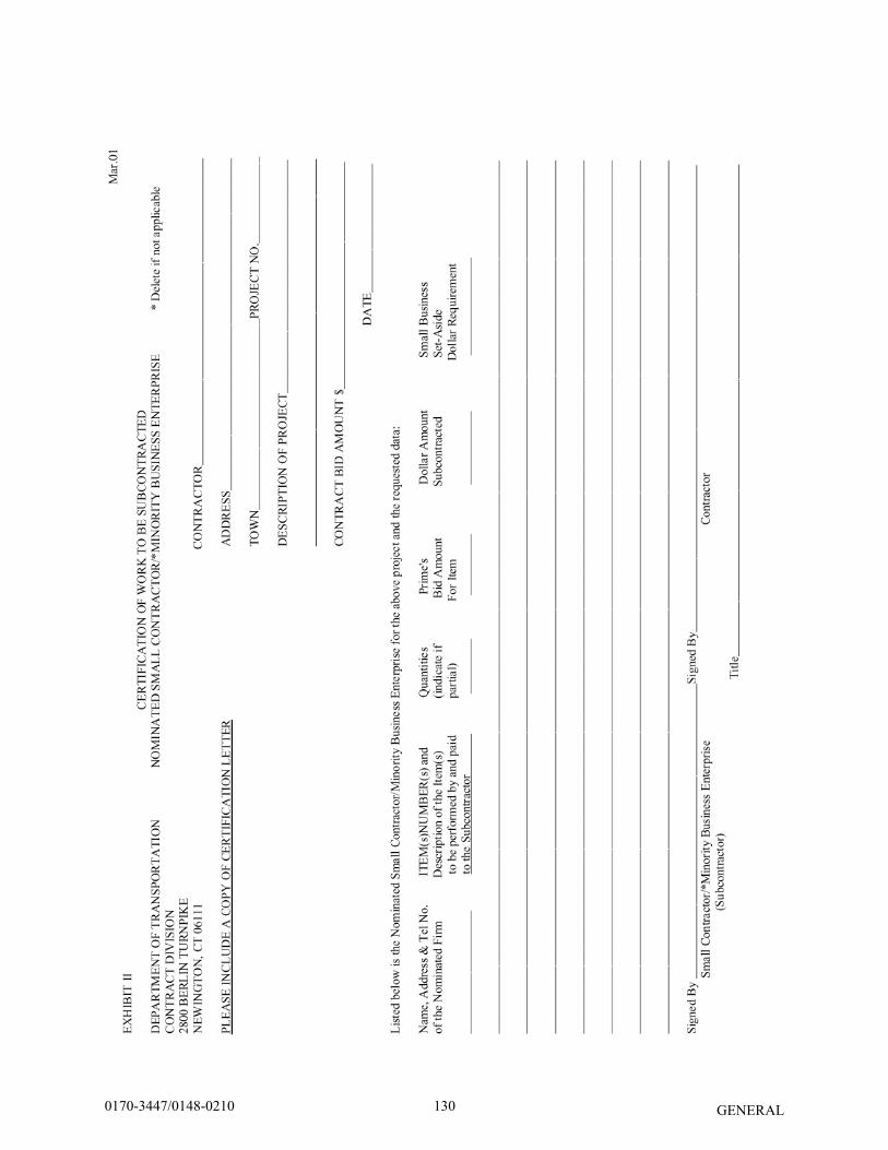
GENERAL
1300170-3447/0148-0210
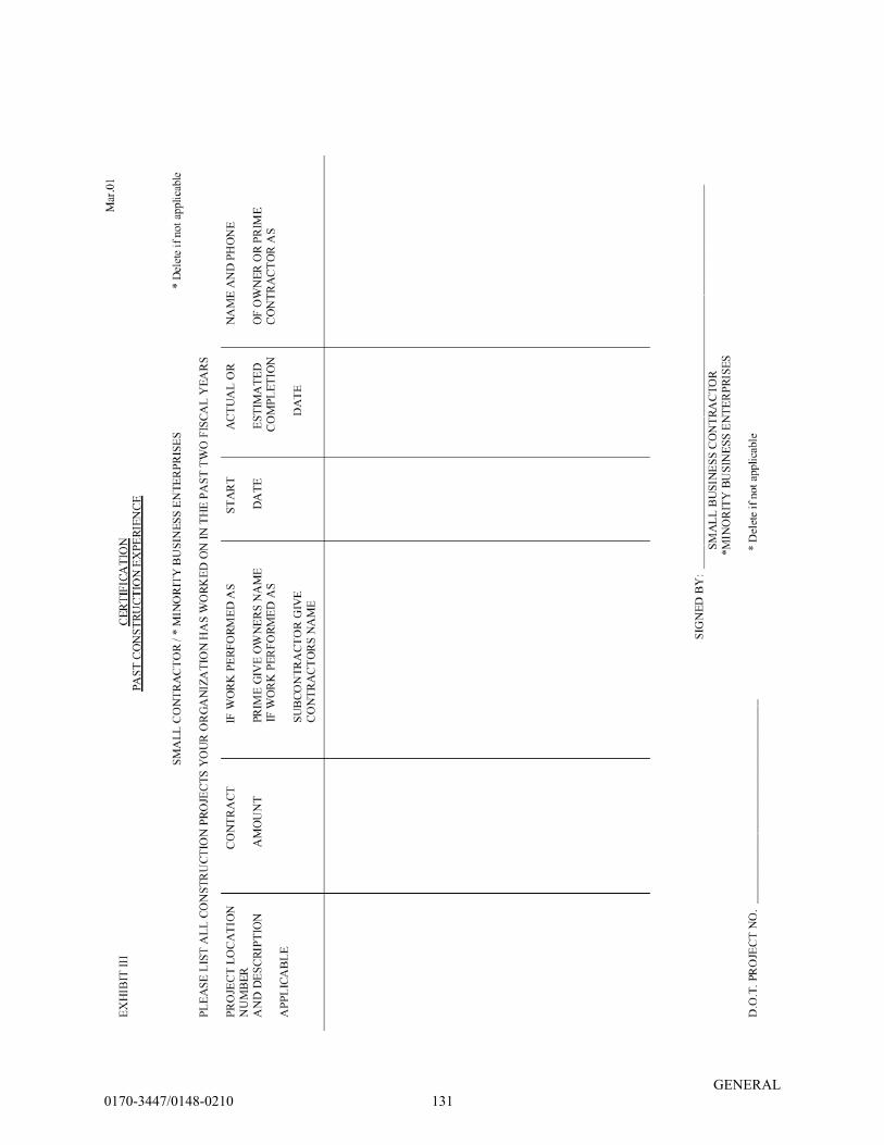
GENERAL
1310170-3447/0148-0210
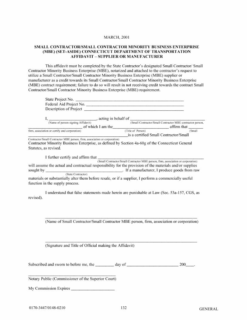
GENERAL 1320170-3447/0148-0210
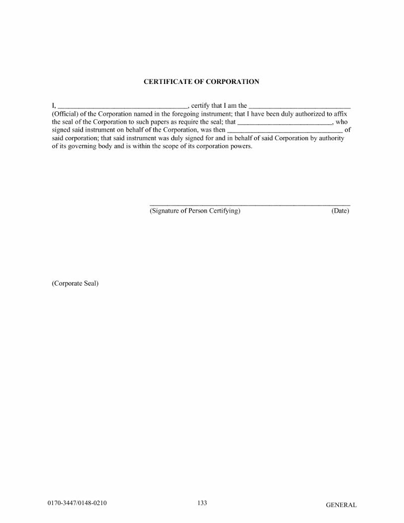
GENERAL
1330170-3447/0148-0210
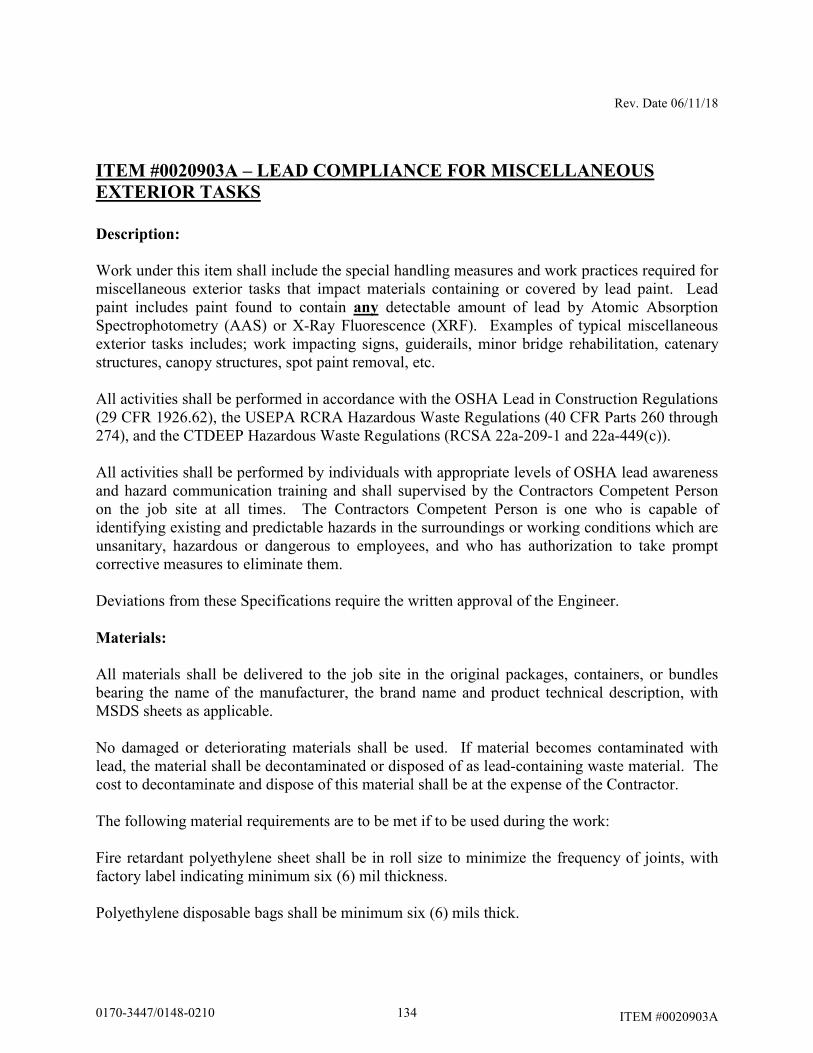
Rev. Date 06/11/18
ITEM #0020903A
ITEM #0020903A – LEAD COMPLIANCE FOR MISCELLANEOUS
EXTERIOR TASKS
Description:
Work under this item shall include the special handling measures and work practices required for miscellaneous exterior tasks that impact materials containing or covered by lead paint. Lead paint includes paint found to contain any detectable amount of lead by Atomic Absorption Spectrophotometry (AAS) or X-Ray Fluorescence (XRF). Examples of typical miscellaneous exterior tasks includes; work impacting signs, guiderails, minor bridge rehabilitation, catenary structures, canopy structures, spot paint removal, etc. All activities shall be performed in accordance with the OSHA Lead in Construction Regulations (29 CFR 1926.62), the USEPA RCRA Hazardous Waste Regulations (40 CFR Parts 260 through 274), and the CTDEEP Hazardous Waste Regulations (RCSA 22a-209-1 and 22a-449(c)). All activities shall be performed by individuals with appropriate levels of OSHA lead awareness and hazard communication training and shall supervised by the Contractors Competent Person on the job site at all times. The Contractors Competent Person is one who is capable of identifying existing and predictable hazards in the surroundings or working conditions which are unsanitary, hazardous or dangerous to employees, and who has authorization to take prompt corrective measures to eliminate them. Deviations from these Specifications require the written approval of the Engineer.
Materials:
All materials shall be delivered to the job site in the original packages, containers, or bundles bearing the name of the manufacturer, the brand name and product technical description, with MSDS sheets as applicable. No damaged or deteriorating materials shall be used. If material becomes contaminated with lead, the material shall be decontaminated or disposed of as lead-containing waste material. The cost to decontaminate and dispose of this material shall be at the expense of the Contractor. The following material requirements are to be met if to be used during the work: Fire retardant polyethylene sheet shall be in roll size to minimize the frequency of joints, with factory label indicating minimum six (6) mil thickness. Polyethylene disposable bags shall be minimum six (6) mils thick.
1340170-3447/0148-0210
Rev. Date 06/11/18
ITEM #0020903A
Tape (or equivalent) product capable of sealing joints in adjacent polyethylene sheets and for the attachment of polyethylene sheets to finished or unfinished surfaces must be capable of adhering under both dry and wet conditions. Cleaning Agents and detergent shall be lead specific, such as TriSodium Phosphate (TSP). Chemical strippers and chemical neutralizers shall be compatible with the substrate as well as with each other. Such chemical stripper shall contain less than 50% Volatile Organic Compounds (VOCs) by weight in accordance with RCSA 22a-174-40 Table 40-1. Labels and warning signs shall conform to 29 CFR 1926.62, 40 CFR 260 through 274 and 49 CFR 172 as appropriate. Air filtration devices and vacuum units shall be equipped with High-Efficiency Particulate Air (HEPA) filters. Construction Methods:
(1) Pre-Abatement Submittals and Notices
A. Prior to the start of any work on a contiguous per site basis that will generate hazardous lead waste above conditionally exempt small quantities (greater than 100 kg/month or greater than 1000 kg at any time), the Contractor shall obtain from the Engineer on a contiguous per site basis a temporary EPA Hazardous Waste Generators ID number, unless otherwise directed by the Engineer. B. Fifteen (15) working days prior to beginning work that impacts lead paint, the Contractor shall submit the following to the Engineer:
1. Work plan for work impacting lead paint including engineering controls, methods of containment of debris and work practices to be employed, as needed, to minimize employee exposure and prevent the spread of lead contamination outside the Regulated Area.
2. Copies of all employee certificates, dated within the previous twelve (12) months, relating to OSHA lead awareness and hazard communication training and training in the use of lead-safe work practices. SSPC training programs may be accepted as meeting these requirements if it can be demonstrated that such training addressed all required topics.
This information shall be updated and resubmitted annually, or as information changes, for the duration of the activities impacting lead to verify continued compliance.
1350170-3447/0148-0210
Rev. Date 06/11/18
ITEM #0020903A
3. Name and qualifications of Contractor’s OSHA Competent Person under 29 CFR 1926.62.
4. Documentation from the Contractor, typed on company letterhead and signed by the Contractor, certifying that all employees listed therein have received the following:
a. medical monitoring within the previous twelve (12) months, as required in 29
CFR 1926.62; b. biological monitoring within the previous six (6) months, as required in 29 CFR
1926.62; c. respirator fit testing within the previous twelve (12) months, as required in 29
CFR 1910.134 (for those who don a tight-fitting face piece respirator)
This information shall be updated and resubmitted annually, or as information changes, for the duration of the activities impacting lead to verify continued compliance.
5. Names of the proposed non-hazardous construction and demolition (C&D) lead
debris bulky waste disposal facility (CTDEEP-permitted Solid Waste landfill). 6. Names of the proposed scrap metal recycling facilities. The Contractor shall submit to
the Engineer all documentation necessary to demonstrate the selected facility is able to accept lead-painted scrap metal.
7. Names of the proposed hazardous waste disposal facility (selected from the
Department approved list provided herein), and copies of each facilities acceptance criteria and sampling frequency requirements.
8. Copies of the proposed hazardous waste transporters current USDOT Certificate of
Registration for Hazardous Materials Transport, and the proposed transporters current Hazardous Waste Transporter Permits for the State of Connecticut and the waste destination State.
9. Negative exposure assessments conducted within the previous 12 months documenting that employee exposure to lead for each task is below the OSHA Action Level of 30 µg/m3. If a negative exposure assessment has not been conducted, the Contractor shall submit its air monitoring program for the work tasks as part of the Work Plan. Until a negative exposure assessment is developed for each task impacting lead paint, the Contractor shall ensure that all workers and authorized persons entering the Regulated Area wear protective clothing and respirators in accordance with OSHA 29 CFR 1926.62.
No activity shall commence until all required submittals have been received and found acceptable to the Engineer. Those employees added to the Contractor's original list will be
1360170-3447/0148-0210
Rev. Date 06/11/18
ITEM #0020903A
allowed to perform work only upon submittal of acceptable documentation to, and review by, the Engineer. Contractor shall provide the Engineer with a minimum of 48 hours notice in advance of scheduling, changing or canceling work activities.
(2) Lead Abatement Provisions
A. General Requirements:
All employees of the Contractor who perform work impacting lead paint shall be properly trained to perform such duties. In addition, the Contractor shall instruct all workers in all aspects of personnel protection, work procedures, emergency evacuation procedures and use of equipment including procedures unique to this project. Contractor shall provide all labor, materials, tools, equipment, services, testing, and incidentals which are necessary or required to perform the work in accordance with applicable governmental regulations, industry standards and codes, and these Specifications. Prior to beginning work, the Engineer and Contractor shall perform a visual survey of each work area and review conditions. As necessary, the Contractor shall:
Shut down and lock out electrical power, including all receptacles and light fixtures, where feasible. The use or isolation of electrical power will be coordinated with all other ongoing uses of electrical power at the site.
If adequate electrical supply is not available at the site, the Contractor shall supply temporary power. Such temporary power shall be sufficient to provide adequate lighting and power the Contractor’s equipment. The Contractor is responsible for proper connection and installation of electrical wiring and shall ensure safe installation of electrical equipment in compliance with applicable electrical codes and OSHA requirements. If water is not available at the site for the Contractor’s use, the Contractor shall supply sufficient water for each shift to operate the wash facility/decontamination shower units in addition to the water needed at the work area. The Engineer may provide a Project Monitor to monitor compliance of the Contractor and protect the interests of the Department. In such cases, no activity impacting lead paint shall be performed until the Project Monitor is on-site. Where no Project Monitor will be provided, Contractor shall proceed at the direction of the Engineer. Environmental sampling, including ambient air sampling, TCLP waste stream sampling, and dust wipe sampling, will be conducted by the State as it deems necessary throughout the project. Air monitoring to comply with the Contractor’s obligations under OSHA remains solely responsibility of the Contractor.
1370170-3447/0148-0210
Rev. Date 06/11/18
ITEM #0020903A
If at any time, procedures for engineering, work practice, administrative controls or other topics are anticipated to deviate from those documented in the submitted and accepted Lead Work Plan, the Contractor shall submit a modification of its existing plan for review and acceptance by the Engineer prior to implementing the change.
If air samples collected outside of the Regulated Area during activities impacting lead paint indicate airborne lead concentrations greater than original background levels or 30 ug/m3, whichever is larger, or if at any time visible emissions of lead paint extend out from the Regulated Area, an examination of the Regulated Area shall be conducted and the cause of such emissions corrected. Cleanup of surfaces outside the Regulated Area using HEPA vacuum equipment or wet cleaning techniques shall be done prior to resuming work. Work outside the initial designated area(s) will not be paid for by the Engineer. The Contractor will be responsible for all costs incurred from these activities including repair of any damage. B. Regulated Area The Contractor shall establish a Regulated Area through the use of appropriate barrier tape or other means to control unauthorized access into the area where activities impacting lead paint are occurring. Warning signs meeting the requirements of 29 CFR 1926.62 shall be posted at all approaches to Regulated Areas. These signs shall read:
DANGER
LEAD WORK AREA MAY DAMAGE FERTILITY OR THE UNBORN CHILD
CAUSES DAMAGE TO THE CENTRAL NERVOUS SYSTEM DO NOT EAT, DRINK, OR SMOKE IN THIS AREA
The Contractor shall implement appropriate engineering controls such as poly drop cloths, local exhaust ventilation, wet dust suppression methods, etc. as necessary, and as approved by the Engineer, to prevent the spread of lead contamination beyond the Regulated Area in accordance with the Contractor’s approved work plan. Should the previously submitted work plan prove to be insufficient to contain the contamination, the Contractor shall modify its plan and submit it for review by the Engineer. C. Wash Facilities: The Contractor shall provide handwash facilities in compliance with 29 CFR 1926.51(f) and 29 CFR 1926.62 regardless of airborne lead exposure. If employee exposure to airborne lead exceeds the OSHA Permissible Exposure Limit of 50 micrograms per cubic meter (µg/m3), shower rooms must be provided. The Shower Room shall be of sufficient capacity to accommodate the number of workers. One shower stall shall be
1380170-3447/0148-0210
Rev. Date 06/11/18
ITEM #0020903A
provided for each eight (8) workers. Showers shall be equipped with hot and cold or warm running water. Shower water shall be collected and filtered using best available technology and disposed of in accordance with all Federal, State and local laws, regulations and ordinances. D. Personal Protection: The Contractor shall initially determine if any employee performing construction tasks impacting lead paint may be exposed to lead at or above the OSHA Action Level of 30 µg/m3. Assessments shall be based on initial air monitoring results as well as other relevant information. The Contractor may rely on historical air monitoring data obtained within the past 12 months under workplace conditions closely resembling the process, type of material, control methods, work practices and environmental conditions used and prevailing in the Contractors current operations to satisfy the exposure assessment requirements. Monitoring shall continue as specified in the OSHA standard until a negative exposure assessment is developed. Until a negative exposure assessment is developed for each task impacting lead paint, the Contractor shall ensure that all workers and authorized person entering the Regulated Area wear protective clothing and respirators in accordance with OSHA 29 CFR 1926.62. Protective clothing shall include impervious coveralls with elastic wrists and ankles, head covering, gloves and foot coverings. Sufficient quantities shall be provided to last throughout the duration of the project. Protective clothing provided by the Contractor and used during chemical removal operations shall be impervious to caustic materials. Gloves provided by the Contractor and used during chemical removal shall be of neoprene composition with glove extenders. Respiratory protective equipment shall be provided and selection shall conform to 42 CFR Part 84, 29 CFR Part 1910.134, and 29 CFR Part 1926.62. A formal respiratory protection program must be implemented in accordance with 29 CFR Part 1926.62 and Part 1910.134. E. Air Monitoring Requirements The Contractor shall:
1. Provide air monitoring equipment including sample filter cassettes of the type and
quantity required to properly monitor operations and personnel exposure surveillance throughout the duration of the project.
2. Conduct initial exposure monitoring to determine if any employee performing
construction tasks impacting lead paint may be exposed to lead at or above the OSHA Action Level of 30 micrograms per cubic meter. Monitoring shall continue as specified in the OSHA standard until a negative exposure assessment is developed.
3. Conduct personnel exposure assessment air sampling, as necessary, to assure that
workers are using appropriate respiratory protection in accordance with OSHA
1390170-3447/0148-0210

Rev. Date 06/11/18
ITEM #0020903A
Standard 1926.62. Documentation of air sampling results must be recorded at the work site within twenty-four (24) hours and shall be available for review until the job is complete.
F. Lead Abatement Procedures The Contractor’s Competent Person shall be at the job site at all times during work impacting lead.
Work impacting lead paint shall not begin until authorized by the Engineer, following a pre-work visual inspection by the Project Monitor or Engineer to verify existing conditions. Any activity impacting lead painted surfaces shall be performed in a manner which minimizes the spread of lead dust contamination and generation of airborne lead.
The Contractor shall conduct exposure assessments for all tasks which impact lead paint in
accordance with 29 CFR 1926.62(d) and shall implement appropriate personal protective
equipment until negative exposure assessments are developed.
All work impacting the materials identified below shall be conducted within an established
Regulated Area with a remote wash facility/decontamination system in accordance with
“C. Wash Facilities” and the OSHA Lead in Construction Standard. In accordance with
29 CFR 1926.62, engineering controls and work practices shall be utilized to prevent the
spread of lead dust and debris beyond the Regulated Area and limit the generation of
airborne lead. All wastes containing lead paint shall be properly contained and secured for
storage, transportation and disposal. The Contractor shall ensure proper entry and exit procedures for workers and authorized persons who enter and leave the Regulated Area. All workers and authorized persons shall leave the Regulated Area and proceed directly to the wash or shower facilities where they will HEPA vacuum gross debris from work suit, remove and dispose of work suit, wash and dry face and hands, and vacuum clothes. Lead chips and dust must not be removed by blowing or shaking of clothing. Wash water shall be collected, filtered, and disposed of in accordance with Federal, State and local water discharge standards. Any permit required for such discharge shall be the responsibility of the Contractor. No one shall eat, drink, smoke, chew gum or tobacco, or apply cosmetics while in the Regulated Area. Data from the limited lead testing performed by the Engineer is documented in the reports listed in the “Notice to Contractor – Hazardous Materials Investigations” or is presented herein. Under no circumstances shall this information be the sole means used by the Contractor for determining the extent of lead painted materials. The Contractor shall be responsible for verification of all field conditions affecting performance of the work as described in these Specifications in
1400170-3447/0148-0210
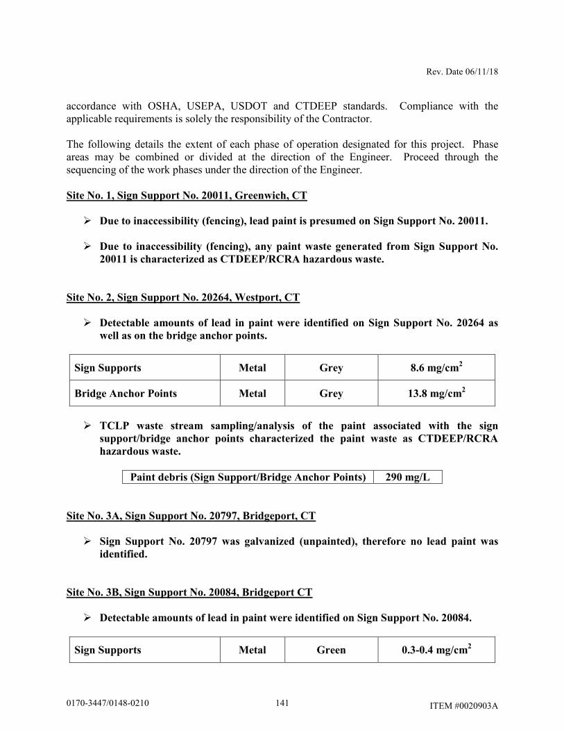
Rev. Date 06/11/18
ITEM #0020903A
accordance with OSHA, USEPA, USDOT and CTDEEP standards. Compliance with the applicable requirements is solely the responsibility of the Contractor. The following details the extent of each phase of operation designated for this project. Phase areas may be combined or divided at the direction of the Engineer. Proceed through the sequencing of the work phases under the direction of the Engineer.
Site No. 1, Sign Support No. 20011, Greenwich, CT
� Due to inaccessibility (fencing), lead paint is presumed on Sign Support No. 20011.
� Due to inaccessibility (fencing), any paint waste generated from Sign Support No.
20011 is characterized as CTDEEP/RCRA hazardous waste.
Site No. 2, Sign Support No. 20264, Westport, CT
� Detectable amounts of lead in paint were identified on Sign Support No. 20264 as
well as on the bridge anchor points.
Sign Supports Metal Grey 8.6 mg/cm2
Bridge Anchor Points Metal Grey 13.8 mg/cm2
� TCLP waste stream sampling/analysis of the paint associated with the sign
support/bridge anchor points characterized the paint waste as CTDEEP/RCRA
hazardous waste.
Paint debris (Sign Support/Bridge Anchor Points) 290 mg/L
Site No. 3A, Sign Support No. 20797, Bridgeport, CT
� Sign Support No. 20797 was galvanized (unpainted), therefore no lead paint was
identified.
Site No. 3B, Sign Support No. 20084, Bridgeport CT
� Detectable amounts of lead in paint were identified on Sign Support No. 20084.
Sign Supports Metal Green 0.3-0.4 mg/cm2
1410170-3447/0148-0210
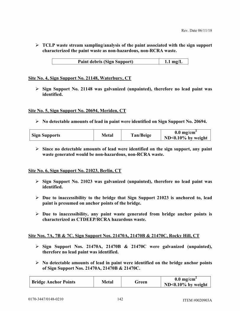
Rev. Date 06/11/18
ITEM #0020903A
� TCLP waste stream sampling/analysis of the paint associated with the sign support
characterized the paint waste as non-hazardous, non-RCRA waste.
Paint debris (Sign Support) 1.1 mg/L
Site No. 4, Sign Support No. 21148, Waterbury, CT
� Sign Support No. 21148 was galvanized (unpainted), therefore no lead paint was
identified.
Site No. 5, Sign Support No. 20694, Meriden, CT
� No detectable amounts of lead in paint were identified on Sign Support No. 20694.
Sign Supports Metal Tan/Beige 0.0 mg/cm
2
ND<0.10% by weight
� Since no detectable amounts of lead were identified on the sign support, any paint
waste generated would be non-hazardous, non-RCRA waste.
Site No. 6, Sign Support No. 21023, Berlin, CT
� Sign Support No. 21023 was galvanized (unpainted), therefore no lead paint was
identified.
� Due to inaccessibility to the bridge that Sign Support 21023 is anchored to, lead
paint is presumed on anchor points of the bridge.
� Due to inaccessibility, any paint waste generated from bridge anchor points is
characterized as CTDEEP/RCRA hazardous waste.
Site Nos. 7A, 7B & 7C, Sign Support Nos. 21470A, 21470B & 21470C, Rocky Hill, CT
� Sign Support Nos. 21470A, 21470B & 21470C were galvanized (unpainted),
therefore no lead paint was identified.
� No detectable amounts of lead in paint were identified on the bridge anchor points
of Sign Support Nos. 21470A, 21470B & 21470C.
Bridge Anchor Points Metal Green 0.0 mg/cm
2
ND<0.10% by weight
1420170-3447/0148-0210
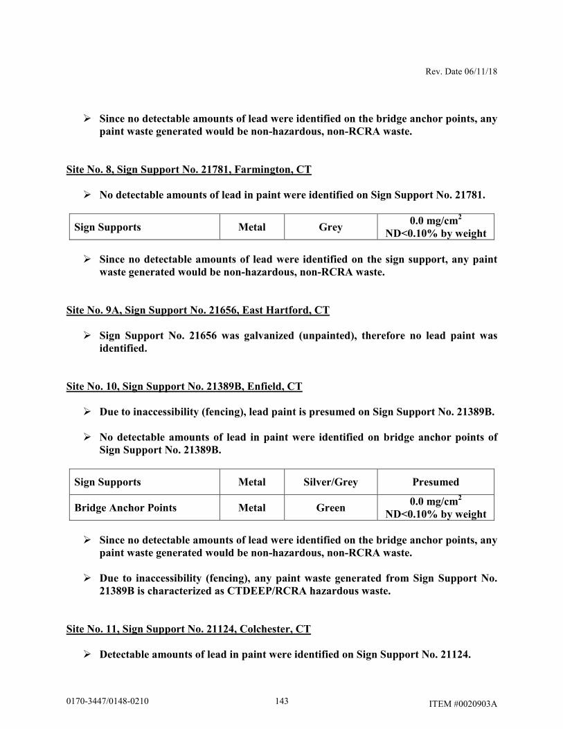
Rev. Date 06/11/18
ITEM #0020903A
� Since no detectable amounts of lead were identified on the bridge anchor points, any
paint waste generated would be non-hazardous, non-RCRA waste.
Site No. 8, Sign Support No. 21781, Farmington, CT
� No detectable amounts of lead in paint were identified on Sign Support No. 21781.
Sign Supports Metal Grey 0.0 mg/cm
2
ND<0.10% by weight
� Since no detectable amounts of lead were identified on the sign support, any paint
waste generated would be non-hazardous, non-RCRA waste.
Site No. 9A, Sign Support No. 21656, East Hartford, CT
� Sign Support No. 21656 was galvanized (unpainted), therefore no lead paint was
identified.
Site No. 10, Sign Support No. 21389B, Enfield, CT
� Due to inaccessibility (fencing), lead paint is presumed on Sign Support No. 21389B.
� No detectable amounts of lead in paint were identified on bridge anchor points of
Sign Support No. 21389B.
Sign Supports Metal Silver/Grey Presumed
Bridge Anchor Points Metal Green 0.0 mg/cm
2
ND<0.10% by weight
� Since no detectable amounts of lead were identified on the bridge anchor points, any
paint waste generated would be non-hazardous, non-RCRA waste.
� Due to inaccessibility (fencing), any paint waste generated from Sign Support No.
21389B is characterized as CTDEEP/RCRA hazardous waste.
Site No. 11, Sign Support No. 21124, Colchester, CT
� Detectable amounts of lead in paint were identified on Sign Support No. 21124.
1430170-3447/0148-0210
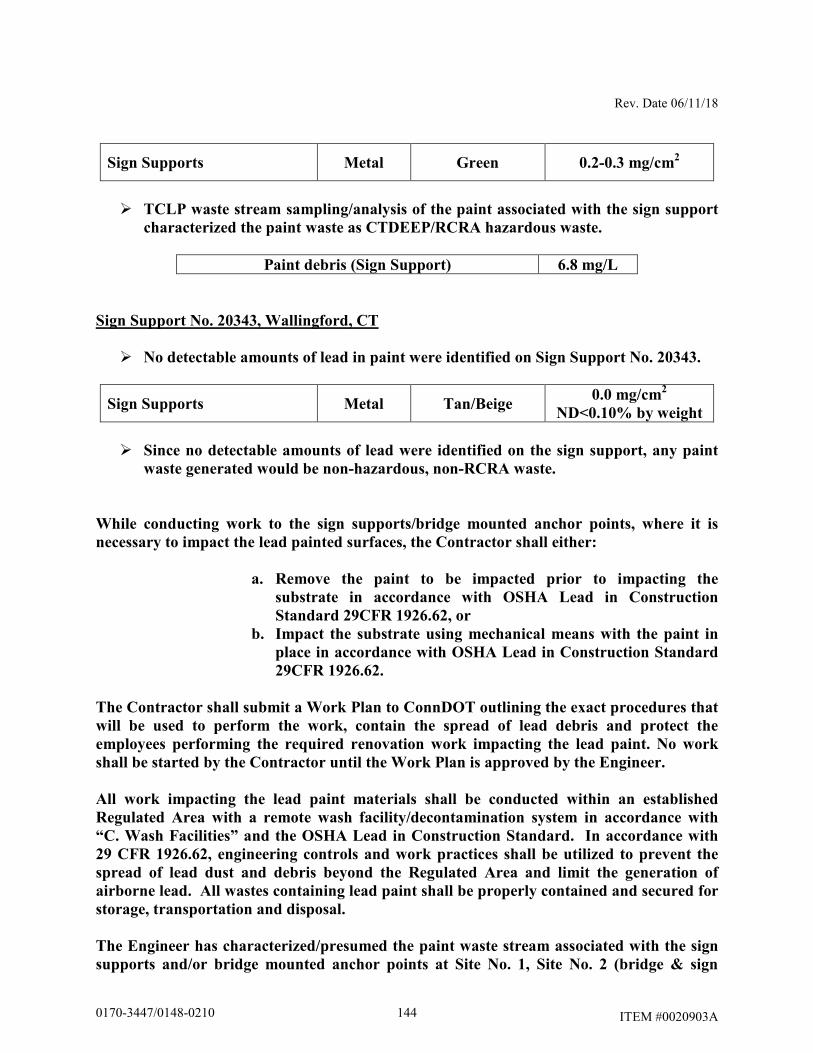
Rev. Date 06/11/18
ITEM #0020903A
Sign Supports Metal Green 0.2-0.3 mg/cm2
� TCLP waste stream sampling/analysis of the paint associated with the sign support
characterized the paint waste as CTDEEP/RCRA hazardous waste.
Paint debris (Sign Support) 6.8 mg/L
Sign Support No. 20343, Wallingford, CT
� No detectable amounts of lead in paint were identified on Sign Support No. 20343.
Sign Supports Metal Tan/Beige 0.0 mg/cm
2
ND<0.10% by weight
� Since no detectable amounts of lead were identified on the sign support, any paint
waste generated would be non-hazardous, non-RCRA waste.
While conducting work to the sign supports/bridge mounted anchor points, where it is
necessary to impact the lead painted surfaces, the Contractor shall either:
a. Remove the paint to be impacted prior to impacting the
substrate in accordance with OSHA Lead in Construction
Standard 29CFR 1926.62, or
b. Impact the substrate using mechanical means with the paint in
place in accordance with OSHA Lead in Construction Standard
29CFR 1926.62.
The Contractor shall submit a Work Plan to ConnDOT outlining the exact procedures that
will be used to perform the work, contain the spread of lead debris and protect the
employees performing the required renovation work impacting the lead paint. No work
shall be started by the Contractor until the Work Plan is approved by the Engineer.
All work impacting the lead paint materials shall be conducted within an established
Regulated Area with a remote wash facility/decontamination system in accordance with
“C. Wash Facilities” and the OSHA Lead in Construction Standard. In accordance with
29 CFR 1926.62, engineering controls and work practices shall be utilized to prevent the
spread of lead dust and debris beyond the Regulated Area and limit the generation of
airborne lead. All wastes containing lead paint shall be properly contained and secured for
storage, transportation and disposal.
The Engineer has characterized/presumed the paint waste stream associated with the sign
supports and/or bridge mounted anchor points at Site No. 1, Site No. 2 (bridge & sign
1440170-3447/0148-0210
Rev. Date 06/11/18
ITEM #0020903A
support), Site No. 10 (sign support) and Site No. 11 as RCRA hazardous waste. If the paint
is removed from the sign support/bridge surfaces, the paint shall be handled and disposed
of in accordance with USEPA/CTDEEP Hazardous Waste Regulations as described under
this Item 0020903A.
At Site No. 3B, Site No. 5, Site No. 8 and Sign Support No. 20343, the Engineer has
characterized the paint waste stream associated with the sign support components and/or
bridge anchor points as non-hazardous. If the paint is required to be removed from the
metal surfaces of the sign supports/bridge surfaces, the paint shall be handled and disposed
of as non-hazardous, non-RCRA waste as described under this Item 0020903A.
All steel and metal components generated from the miscellaneous exterior work tasks
(painted or not) shall be segregated and recycled as scrap metal. The recycling of scrap
metal (regardless of lead paint concentration) is exempt from USEPA RCRA and CTDEEP
Hazardous Waste Regulation.
Should lead contamination be discovered outside of the Regulated Area, the Contractor shall immediately stop all work in the Regulated Area, eliminate causes of such contamination and take steps to decontaminate non-work areas. Special Requirements:
1. Demolition/Renovation:
a. Demolish/renovate in a manner which minimizes the spread of lead contamination
and generation of lead dust. b. Implement dust suppression controls, such as misters, local exhaust ventilation,
etc. to minimize the generation of airborne lead dust. c. Segregate work areas from non-work areas through the use or barrier tape, drop
cloths, etc. d. Clean up immediately after renovation/demolition has been completed
2. Chemical Removal:
a. Apply chemical stripper in quantities and for durations specified by manufacturer. b. Where necessary, scrape lead paint from surface down to required level of
removal (i.e. stabilized surface, bare substrate with no trace of residual pigment, etc.). Use sanding, hand scraping, and dental picks to supplement chemical methods as necessary.
1450170-3447/0148-0210
Rev. Date 06/11/18
ITEM #0020903A
c. Apply neutralizer compatible with substrate and chemical agent to substrate following removal in accordance with manufacturer's instructions.
d. Protect adjacent surfaces from damage from chemical removal. e. Maintain a portable eyewash station in the work area. f. Wear respirators that will protect workers from chemical vapors. g. Do not apply caustic agents to aluminum surfaces.
3. Mechanical Paint Removal:
a. Provide sanders, grinders, rotary wire brushes, or needle gun removers equipped
with a HEPA filtered vacuum dust collection system. Cowling on the dust collection system for orbital-type tools must be capable of maintaining a continuous tight seal with the surface being abated. Cowling on the dust collection system for reciprocating-type tools shall promote an effective vacuum flow of loosened dust and debris. Inflexible cowlings may be used on flat surfaces only. Flexible contoured cowlings are required for curved or irregular surfaces.
b. Provide HEPA vacuums that are high performance designed to provide maximum
static lift and maximum vacuum system flow at the actual operating vacuum condition with the shroud in use. The HEPA vacuum shall be equipped with a pivoting vacuum head.
c. Remove lead paint from surface down to required level of removal (i.e. stabilized
surface, bare substrate with no trace of residual pigment, etc.). Use chemical methods, hand scraping, and dental picks to supplement abrasive removal methods as necessary.
d. Protect adjacent surfaces from damage from abrasive removal techniques. e. “Sandblasting” type removal techniques shall not be allowed.
4. Component Removal/Replacement:
a. Wet down components which are to be removed to reduce the amount of dust
generated during the removal process. b. Remove components utilizing hand tools, and follow appropriate safety
procedures during removal. Remove the components by approved methods which will provide the least disturbance to the substrate material. Do not damage adjacent surfaces.
1460170-3447/0148-0210
Rev. Date 06/11/18
ITEM #0020903A
c. Clean up immediately after component removals have been completed. Remove
any dust located behind the component removed.
G. Prohibited Removal Methods: The use of heat guns in excess of 700 degrees Fahrenheit to remove lead paint is prohibited. The use of sand, steel grit, air, CO2, baking soda, or any other blasting media to remove lead or lead paint without the use of a HEPA ventilated contained negative pressure enclosure is prohibited. Power/pressure washing shall not be used to remove lead paint. Compressed air shall not be utilized to remove lead paint. Chemical strippers containing Methylene Chloride are prohibited. Any chemical stripping may be prohibited on a project by project basis. Power tool assisted grinding, sanding, cutting, or wire brushing of lead paint without the use of cowled HEPA vacuum dust collection systems is prohibited. Lead paint burning, busting of rivets painted with lead paint, welding of materials painted with lead paint, and torch cutting of materials painted with lead paint is prohibited. Where cutting, welding, busting, or torch cutting of materials is required, lead paint in the affected area must be removed first. Chemical stripping of coatings from bridge components is generally prohibited unless specifically allowed on a project by project basis. H. Clean-up and Visual Inspection: The Contractor shall remove and containerize all lead waste material and visible accumulations of debris, paint chips and associated items. During clean-up the Contractor shall utilize rags and sponges wetted with lead-specific detergent and water as well as HEPA filtered vacuum equipment. The Engineer will conduct a visual inspection of the work areas in order to document that all surfaces have been maintained as free as practicable of accumulations of lead in accordance with 29 CFR 1926.62(h). If visible accumulations of waste, debris, lead paint chips or dust are found in the work area, the Contractor shall repeat the cleaning, at the Contractor's expense, until the area is in compliance. The visual inspection will detect incomplete work, damage caused by the abatement activity, and inadequate clean up of the work site.
1470170-3447/0148-0210
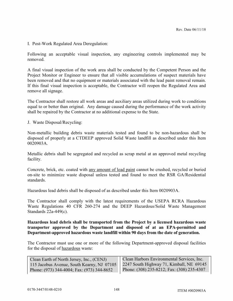
Rev. Date 06/11/18
ITEM #0020903A
I. Post-Work Regulated Area Deregulation: Following an acceptable visual inspection, any engineering controls implemented may be removed. A final visual inspection of the work area shall be conducted by the Competent Person and the Project Monitor or Engineer to ensure that all visible accumulations of suspect materials have been removed and that no equipment or materials associated with the lead paint removal remain. If this final visual inspection is acceptable, the Contractor will reopen the Regulated Area and remove all signage. The Contractor shall restore all work areas and auxiliary areas utilized during work to conditions equal to or better than original. Any damage caused during the performance of the work activity shall be repaired by the Contractor at no additional expense to the State. J. Waste Disposal/Recycling: Non-metallic building debris waste materials tested and found to be non-hazardous shall be disposed of properly at a CTDEEP approved Solid Waste landfill as described under this Item 0020903A. Metallic debris shall be segregated and recycled as scrap metal at an approved metal recycling facility. Concrete, brick, etc. coated with any amount of lead paint cannot be crushed, recycled or buried on-site to minimize waste disposal unless tested and found to meet the RSR GA/Residential standards. Hazardous lead debris shall be disposed of as described under this Item 0020903A. The Contractor shall comply with the latest requirements of the USEPA RCRA Hazardous Waste Regulations 40 CFR 260-274 and the DEEP Hazardous/Solid Waste Management Standards 22a-449(c). Hazardous lead debris shall be transported from the Project by a licensed hazardous waste
transporter approved by the Department and disposed of at an EPA-permitted and
Department-approved hazardous waste landfill within 90 days from the date of generation.
The Contractor must use one or more of the following Department-approved disposal facilities for the disposal of hazardous waste:
Clean Earth of North Jersey, Inc., (CENJ) 115 Jacobus Avenue, South Kearny, NJ 07105 Phone: (973) 344-4004; Fax: (973) 344-8652
Clean Harbors Environmental Services, Inc. 2247 South Highway 71, Kimball, NE 69145 Phone: (308) 235-8212; Fax: (308) 235-4307
1480170-3447/0148-0210
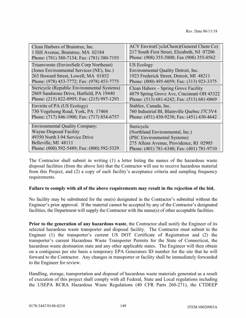
Rev. Date 06/11/18
ITEM #0020903A
Clean Harbors of Braintree, Inc. 1 Hill Avenue, Braintree, MA 02184 Phone: (781) 380-7134; Fax: (781) 380-7193
ACV Enviro(CycleChem)(General Chem Co) 217 South First Street, Elizabeth, NJ 07206 Phone: (908) 355-5800; Fax (908) 355-0562
Triumverate (EnviroSafe Corp Northeast) (Jones Environmental Services (NE), Inc.) 263 Howard Street, Lowell, MA 01852 Phone: (978) 453-7772; Fax: (978) 453-7775
US Ecology Environmental Quality Detroit, Inc. 1923 Frederick Street, Detroit, MI 48211 Phone: (800) 495-6059; Fax: (313) 923-3375
Stericycle (Republic Environmental Systems) 2869 Sandstone Drive, Hatfield, PA 19440 Phone: (215) 822-8995; Fax: (215) 997-1293
Clean Habors – Spring Grove Facility 4879 Spring Grove Ave, Cincinnati OH 45322 Phone: (513) 681-6242; Fax: (513) 681-0869
Envirite of PA (US Ecology) 730 Vogelsong Road, York, PA 17404 Phone: (717) 846-1900; Fax: (717) 854-6757
Stablex, Canada, Inc. 760 Industrial Bl, Blainville Quebec J7C3V4 Phone: (451) 430-9230; Fax: (451) 430-4642
Environmental Quality Company: Wayne Disposal Facility 49350 North I-94 Service Drive Belleville, MI 48111 Phone: (800) 592-5489; Fax: (800) 592-5329
Stericycle (Northland Environmental, Inc.) (PSC Environmental Systems) 275 Allens Avenue, Providence, RI 02905 Phone: (401) 781-6340; Fax: (401) 781-9710
The Contractor shall submit in writing (1) a letter listing the names of the hazardous waste disposal facilities (from the above list) that the Contractor will use to receive hazardous material from this Project, and (2) a copy of each facility’s acceptance criteria and sampling frequency requirements.
Failure to comply with all of the above requirements may result in the rejection of the bid. No facility may be substituted for the one(s) designated in the Contractor’s submittal without the Engineer’s prior approval. If the material cannot be accepted by any of the Contractor’s designated facilities, the Department will supply the Contractor with the name(s) of other acceptable facilities.
Prior to the generation of any hazardous waste, the Contractor shall notify the Engineer of its selected hazardous waste transporter and disposal facility. The Contractor must submit to the Engineer (1) the transporter’s current US DOT Certificate of Registration and (2) the transporter’s current Hazardous Waste Transporter Permits for the State of Connecticut, the hazardous waste destination state and any other applicable states. The Engineer will then obtain on a contiguous per site basis a temporary EPA Generators ID number for the site that he will forward to the Contractor. Any changes in transporter or facility shall be immediately forwarded to the Engineer for review. Handling, storage, transportation and disposal of hazardous waste materials generated as a result of execution of this project shall comply with all Federal, State and Local regulations including the USEPA RCRA Hazardous Waste Regulations (40 CFR Parts 260-271), the CTDEEP
1490170-3447/0148-0210
Rev. Date 06/11/18
ITEM #0020903A
Hazardous Waste Regulations (22a-209 and 22a-449(c)), and the USDOT Hazardous Materials Regulations (49 CFR Part 171-180). All debris shall be contained and collected daily or more frequently as directed by the Engineer, due to debris buildup. Debris shall be removed by HEPA vacuum collection. Such debris and paint chips shall be stored in leak-proof storage containers in the secured storage site, or as directed by the Engineer. The storage containers and storage locations shall be reviewed by the Engineer and shall be located in areas not subject to ponding. Storage containers shall be placed on pallets and closed and covered with tarps at all times except during placement, sampling and disposal of the debris. Hazardous waste materials are to be properly packed and labeled for transport by the Contractor is accordance with EPA, CTDEEP and USDOT regulations. The disposal of debris characterized as hazardous waste shall be completed within 90 calendar days of the date on which it began to be accumulated in the lined containers. Storage of containers shall be in accordance with current DEEP/EPA procedures. The Contractor shall label hazardous waste storage containers with a 6-inch square, yellow, weatherproof, Hazardous Waste sticker in accordance with USDOT regulations. Materials other than direct paint related debris which are incidental to the paint removal work activities (tarps, poly, plywood, PPE, gloves, decontamination materials, etc.) which may be contaminated with lead, shall be stored separately from the direct paint debris, and shall be sampled by the Engineer for waste disposal characterization testing. Such materials characterized as hazardous shall be handled/disposed of as described herein, while materials characterized as non-hazardous shall be disposed of as non-hazardous CTDEEP Solid Waste. Direct paint related debris materials not previously sampled and characterized for disposal, which may be originally presumed to be hazardous waste, shall also be stored separately and sampled by the Engineer for ultimate waste disposal characterization testing and handled/disposed of based on that testing. Project construction waste materials unrelated to the paint removal operations shall NOT be combined/stored with paint debris waste and/or incidental paint removal materials as they are not lead contaminated and shall NOT be disposed of as hazardous waste. The Engineer’s on-site Inspectors shall conduct inspections to verify materials remain segregated. The Contractor shall obtain and complete all paperwork necessary to arrange for material disposal, including disposal facility waste profile sheets. It is solely the Contractor’s responsibility to co-ordinate the disposal of hazardous materials with its selected treatment/recycling/disposal facility(s). Upon receipt of the final approval from the facility, the Contractor shall arrange for the loading, transport and treatment/recycling/disposal of the materials in accordance with all Federal and State regulations. No claim will be considered
based on the failure of the Contractor’s disposal facility(s) to meet the Contractor’s
1500170-3447/0148-0210
Rev. Date 06/11/18
ITEM #0020903A
production rate or for the Contractor’s failure to select sufficient facilities to meet its
production rate. The Contractor shall process the hazardous waste such that the material conforms with the requirements of the selected treatment/disposal facility, including but not limited to specified size and dimension. Refusal on the part of the treatment/disposal facility to accept said material solely on the basis of non-conformance of the material to the facility’s physical requirements is the responsibility of the Contractor and no claim for extra work shall be accepted for reprocessing of said materials to meet these requirements. All DOT shipping documents, including the Uniform Hazardous Waste Manifests utilized to accompany the transportation of the hazardous waste material shall be prepared by the Contractor and reviewed/signed by an authorized agent representing ConnDOT, as Generator, for each load of hazardous material that is packed to leave the site. The Contractor shall not sign manifests on behalf of the State as Generator. The Contractor shall forward the appropriate original copies of all manifests to the Engineer the same day the material leaves the Project site. Materials not related to lead paint removal and/or characterized as non-hazardous waste shall NOT be shipped for hazardous waste disposal in accordance with USEPA RCRA hazardous waste minimization requirements. A load-specific certificate of disposal, signed by the authorized agent representing the waste disposal facility, shall be obtained by the Contractor and promptly delivered to the Engineer for each load. In addition to all pertinent Federal, State and local laws or regulatory agency polices, the Contractor shall adhere to the following precautions during the transport of hazardous materials off-site:
• All vehicles departing the site are to be properly logged to show the vehicle identification, driver’s name, time of departure, destination, and approximate volume, and contents of materials carried. Vehicles shall display the proper USDOT placards for the type and quantity of waste;
• No materials shall leave the site unless a disposal facility willing to accept all of the material being transported has agreed to accept the type and quantity of waste;
• Documentation must be maintained indicating that all applicable laws have been satisfied and that the materials have been successfully transported and received at the disposal facility; and,
• The Contractor shall segregate the waste streams (i.e. concrete, wood, etc.) as directed by the receiving disposal facility.
1510170-3447/0148-0210
Rev. Date 06/11/18
ITEM #0020903A
Any spillage of debris during disposal operations during loading, transport and unloading shall be cleaned up in accordance with EPA 40 CFR 265 Subparts C & D, at the Contractor’s expense. The Contractor is liable for any fines, costs or remediation costs incurred as a result of their failure to be in compliance with this Item and all Federal, State and Local laws. K. Project Closeout Data:
Provide the Engineer, within thirty (30) days of completion of the project site work, a compliance package; which shall include, but not be limited to, the following:
1. Competent persons (supervisor) job log; 2. OSHA-compliant personnel air sampling data; 3. Completed waste shipment papers for non-hazardous lead construction and
demolition (C&D) waste disposal or recycling and scrap metal recycling. 4. Copies of completed Hazardous Waste Manifests (signed by authorized disposal
facility representative). Method of Measurement:
The completed work shall be paid as a lump sum. This item will include all noted services, equipment, facilities, testing and other associated work for up to three (3) ConnDOT project representatives. Services provided to any ConnDOT project representatives in excess of three (3) representatives will be measured for payment in accordance with Article 1.09.04 – “Extra and Cost-Plus Work.” Basis of Payment:
The lump sum price bid for this item shall include: services, materials, equipment, all permits, notifications, submittals, personal air sampling, personal protection equipment, temporary enclosures, incidentals, fees and labor incidental to activities impacting lead removal, treatment and handling of lead contaminated materials, and the transport and disposal of any hazardous and/or non-hazardous lead construction and demolition (C&D) bulky waste. Final payment will not be made until all project closeout data submittals have been completed and provided to the Engineer. Once the completed package has been received in its entirety and accepted by the Engineer, final payment will be made to the Contractor.
Pay Item Pay Unit Lead Compliance for Miscellaneous Exterior Tasks Lump Sum
1520170-3447/0148-0210
ITEM #0910189A
ITEM #0910189A – R-B 350 BRIDGE ATTACHMENT – JERSEY SHAPE
PARAPET 10 GA
Work under this section shall conform to the requirements of Section 9.10 of Form 817,
amended as follows:
9.10.01 - Description: Add the following:
Work under this item shall also consist of the installation and removal of temporary metal beam rail attachment at leading ends of concrete median barrier in accordance with the plans and specifications.
9.10.03 - Construction Methods: Add the following:
For the installation of temporary metal beam rail attachment at the leading ends of concrete median barrier, the Contractor shall remove a section of concrete median cap and excavate the granular fill between the median barriers as shown on the plans or as directed by the Engineer prior to the installation of the terminal connector. The attachment of the temporary concrete half-section barrier shall attach to temporary pre-cast concrete barrier curb as shown on the highway standard details provided. The barrier’s traffic-side face shall be flush at the connection of the two shapes to ensure no snagging of vehicles will occur.
When the temporary metal beam rail attachment is removed, the bolt holes on the
existing barrier shall be filled with non-shrink grout. The Contractor shall take the necessary precautions to prevent any damage to the existing concrete barrier during the removal process of the attachment. Any damage shall be repaired by the Contractor, as directed by the Engineer, and at no cost to the State.
9.10.04 - Method of Measurement:
3. (Type) Attachment: Add the following:
Temporary metal beam rail attachments will be measured once for payment by the actual number of installed and accepted attachments following their removal to the satisfaction of the Engineer. Payment will only be made once for each temporary metal beam attachment shown on the plans.
9.10.05 - Basis of Payment:
3. (Type) Attachment: Add the following:
Payment for temporary metal beam rail attachment at leading ends of concrete barrier will be made at the contract unit price for “R-B 350 Bridge Attachment – Jersey Shape Parapet 10 GA.” The price shall include all materials, drilling & grouting including anchor bolts, anchor plates, removal and disposal of surplus material, bituminous concrete park curbing, local removal of concrete median barrier cap, excavation, temporary pre-cast concrete half-section barrier, removal of temporary metal beam rail attachment, reconstruction of the median barrier to
1530170-3447/0148-0210
ITEM #0910189A
original conditions (granular fill, Class “A” Concrete, rebar), equipment, tools and labor incidental thereto.
Pay Item Pay Unit R-B 350 Bridge Attachment – Jersey Shape Parapet 10 GA EA.
1540170-3447/0148-0210
Rev. Date 7/16/18
ITEM #0917010A
ITEM #0917010A – REPAIR GUIDERAIL
Description: Work under this item shall consist of the repair of newly installed guiderail. It shall be repaired in the locations originally installed and fabricated in conformity with the lines, designations, dimensions, and details shown on the plans or as ordered by the Engineer. Materials: The material for guiderail shall meet the requirements as specified within the original applicable contract items.
When repairing guiderail, the Contractor shall reuse any undamaged existing guiderail elements, timber rail, wire rope, appropriate posts, delineators, lap bolts, and other hardware within the project limits as approved by the Engineer to repair the guiderail. The Contractor shall use new materials when any components of the existing railing are damaged or missing and cannot be obtained from other guiderail systems being removed or converted within the Project limits.
Construction Methods: The repair of guiderail shall be in accordance with contraction methods as specified within the original applicable contract items.
Guiderail, including end anchors, which has been installed in final condition and accepted by the Engineer, shall be eligible for reimbursement for repairs subject to the conditions described below. If multiple runs are to be installed in a single stage as indicated in the contract documents, determination for reimbursement shall be made when all runs within the stage are complete and accepted as previously described. On projects without designated stages, guiderail installations must be complete and serving the intended function as determined by the Engineer.
When newly installed guiderail is damaged by public traffic, the following conditions
must be satisfied prior to reimbursement for payment; 1. The damage must have been caused solely by the traveling public. 2. The Contractor shall provide satisfactory evidence that such damage was caused by
public traffic. Such as accident reports obtained from the Connecticut Department of Public Safety, police agencies or insurance companies; statements by reliable, unbiased eyewitnesses; or identification of the vehicle involved in the accident.
3. The Contractor shall attempt to collect the costs from the person or persons
responsible for the damage and provide documentation of those efforts to the satisfaction of the Engineer.
4. If such evidence cannot be obtained, the Engineer may determine that the damage
was not caused by the Contractor and reimbursement for payment is warranted.
1550170-3447/0148-0210
Rev. Date 7/16/18
ITEM #0917010A
This repair provision does not relieve the Contractor of the requirements of Section 1.07, any other contractual requirements for maintenance and protection of traffic and final acceptance and relief of responsibility for the project.
The Contractor shall remain responsible for the safety and integrity of the guiderail
system for the duration of the project. In the event the guiderail is damaged, the Contractor shall provide sufficient cones, drums and other traffic control devices to provide safe passage by the public. When ordered by the Engineer, the Contractor shall furnish replacement parts and immediately repair the guiderail, but in no case more than 24 hours after notification from the Engineer. In non-emergency situations, the guiderail shall be repaired within 72 hours. The repaired guiderail or anchorages, when completed, shall conform to these specifications for a new system. The Contractor shall be responsible for the removal and the proper disposal of all damaged material and debris.
Method of Measurement: Guiderail damaged solely by the traveling public will be measured for payment. Damage caused by the Contractor’s equipment or operations will not be measured for payment.
The sum of money shown on the estimate and in the itemized proposal as "Estimated
Cost" for repair of guiderail will be considered the price bid even though payment will be made only for actual work performed. The estimated cost figure is not to be altered in any manner by the bidder. Should the bidder alter the amount shown, the altered figures will be disregarded and the original price will be used to determine the total amount bid for the contract.
Basis of Payment: Repair of guiderail will be paid for in accordance with Article 1.09.04 as required to restore the rail to its full working condition in conformance with these specifications for a new system. There will be no payment for maintenance and protection of traffic for work associated with this item unless, in the opinion of the Engineer, the sole purpose of the maintenance and protection of traffic is for repair of the guiderail.
Pay Item Pay Unit Repair Guiderail est. (est.)
1560170-3447/0148-0210
Rev. Date 6/15/05
ITEM #0952001A
ITEM #0952001A – SELECTIVE CLEARING AND THINNING
Section 9.52 is amended as follows: Article 9.52.03 – Construction Methods is supplemented as follows:
Where directed by the Engineer, materials to be cut, trimmed or removed shall be those items that restrict visibility to an extruded aluminum sign to less than 800 ft (244 m). The entire sign will be visible for 800 ft (244 m) measured from the center of the right-travel lane approaching the sign, as viewed from a 3.5 ft (1.1 m) height above the roadway. All trees scheduled to be removed shall be visibly marked or flagged by the Contractor at least seven days prior to the cutting of such trees. The Engineer will inspect the identified trees and verify the limits of clearing and thinning prior to the Contractor proceeding with his cutting operation.
1570170-3447/0148-0210
Rev. Date 09/14/2016
ITEM #0969060A
ITEM #0969060A - CONSTRUCTION FIELD OFFICE, SMALL
Description: Under the item included in the bid document, adequate weatherproof office quarters with related furnishings, materials, equipment and other services, shall be provided by the Contractor for the duration of the work, and if necessary, for a close-out period determined by the Engineer. The office, furnishings, materials, equipment, and services are for the exclusive use of CTDOT forces and others who may be engaged to augment CTDOT forces with relation to the Contract. The office quarters shall be located convenient to the work site and installed in accordance with Article 1.08.02. This office shall be separated from any office occupied by the Contractor. Ownership and liability of the office quarters shall remain with the Contractor. Furnishings/Materials/Supplies/Equipment: All furnishings, materials, equipment and supplies shall be in like new condition for the purpose intended and require approval of the Engineer. Office Requirements: The Contractor shall furnish the office quarters and equipment as described below: Description \ Office Size Small Med. Large Extra
Large Minimum Sq. Ft. of floor space with a minimum ceiling height of 7 ft. 400 400 1000 2000
Minimum number of exterior entrances. 2 2 2 2 Minimum number of parking spaces. 7 7 10 15
Office Layout: The office shall have a minimum square footage as indicated in the table above, and shall be partitioned as shown on the building floor plan as provided by the Engineer. Tie-downs and Skirting: Modular offices shall be tied-down and fully skirted to ground level. Lavatory Facilities: For field offices sizes Small and Medium the Contractor shall furnish a toilet facility at a location convenient to the field office for use by CTDOT personnel and such assistants as they may engage; and for field offices sizes Large and Extra Large the Contractor shall furnish two (2) separate lavatories with toilet (men and women), in separately enclosed rooms that are properly ventilated and comply with applicable sanitary codes. Each lavatory shall have hot and cold running water and flush-type toilets. For all facilities the Contractor shall supply lavatory and sanitary supplies as required. Windows and Entrances: The windows shall be of a type that will open and close conveniently, shall be sufficient in number and size to provide adequate light and ventilation, and shall be fitted with locking devices, blinds and screens. The entrances shall be secure, screened, and fitted with a lock for which four keys shall be furnished. All keys to the construction field office shall be furnished to the CTDOT and will be kept in their possession while State personnel are using the office. Any access to the entrance ways shall meet applicable building codes, with appropriate handrails. Stairways shall be ADA/ABA compliant and have non-skid tread surfaces. An
1580170-3447/0148-0210
Rev. Date 09/14/2016
ITEM #0969060A
ADA/ABA compliant ramp with non-skid surface shall be provided with the Extra-Large field office. Lighting: The Contractor shall equip the office interior with electric lighting that provides a minimum illumination level of 100 foot-candles at desk level height, and electric outlets for each desk and drafting table. The Contractor shall also provide exterior lighting that provides a minimum illumination level of 2 foot-candles throughout the parking area and for a minimum distance of 10 ft. on each side of the field office. Parking Facility: The Contractor shall provide a parking area, adjacent to the field office, of sufficient size to accommodate the number of vehicles indicated in the table above. If a paved parking area is not readily available, the Contractor shall construct a parking area and driveway consisting of a minimum of 6 inches of processed aggregate base graded to drain. The base material will be extended to the office entrance. Field Office Security: Physical Barrier Devices - This shall consist of physical means to prevent entry, such as: 1) All windows shall be barred or security screens installed; 2) All field office doors shall be equipped with dead bolt locks and regular day operated door locks; and 3) Other devices as directed by the Engineer to suit existing conditions. Electric Service: The field office shall be equipped with an electric service panel, wiring, outlets, etc., to serve the electrical requirements of the field office, including: lighting, general outlets, computer outlets, calculators etc., and meet the following minimum specifications:
A. 120/240 volt, 1 phase, 3 wire B. Ampacity necessary to serve all equipment. Service shall be a minimum 100 amp
dedicated to the construction field office. C. The electrical panel shall include a main circuit breaker and branch circuit breakers of the
size and quantity required. D. Additional 120 volt, single phase, 20 amp, isolated ground dedicated power circuit with
dual NEMA 5-20 receptacles will be installed at each desk and personal computer table (workstation) location.
E. Additional 120 volt, single phase, 20 amp, isolated ground dedicated power circuit with dual NEMA 5-20 receptacles will be installed, for use by the Telephone Company.
F. Additional 120-volt circuits and duplex outlets as required meeting National Electric Code requirements.
G. One exterior (outside) wall mounted GFI receptacle, duplex, isolated ground, 120 volt, straight blade.
H. After work is complete and prior to energizing, the State’s CTDOT electrical inspector, must be contacted at 860-594-2240. (Do Not Call Local Town Officials)
I. Prior to field office removal, the CTDOT Office of Information Systems (CTDOT OIS) must be notified to deactivate the communications equipment.
1590170-3447/0148-0210
Rev. Date 09/14/2016
ITEM #0969060A
Heating, Ventilation and Air Conditioning (HVAC): The field office shall be equipped with sufficient heating, air conditioning and ventilation equipment to maintain a temperature range of 68o-80o Fahrenheit within the field office. Telephone Service: The Contractor shall provide telephone service with unlimited nation-wide calling plan. For a Small, Medium and Large field office this shall consist of the installation of two (2) telephone lines: one (1) line for phone/voice service and one (1) line dedicated for the facsimile machine. For an Extra-Large field office this shall consist of four (4) telephone lines: three (3) lines for phone/voice service and one (1) line dedicated for facsimile machine. The Contractor shall pay all charges. Data Communications Facility Wiring: Contractor shall install a Category 6 568B patch panel in a central wiring location and Cat 6 cable from the patch panel to each PC station, Smart Board location, Multifunction Laser Printer/Copier/Scanner/Fax, terminating in a (Category 6 568B) wall or surface mount data jack. The central wiring location shall also house either the data circuit with appropriate power requirements or a category 5 cable run to the location of the installed data circuit. The central wiring location will be determined by the CTDOT OIS staff in coordination with the designated field office personnel as soon as the facility is in place. For Small, Medium and Large field offices the Contractor shall run a CAT 6 LAN cable a minimum length of 25 feet for each CTDOT networked device (including but not limited to: smartboards and Multi-Function Laser Printer/Copier/Scanner/Fax) to LAN switch area leaving an additional 10 feet of cable length on each side with terminated RJ45 connectors. For an Extra-Large field office the Contractor shall run CAT 6 LAN cables from workstations, install patch panel in data circuit demark area and terminate runs with RJ45 jacks at each device location. Terminate runs to patch panel in LAN switch area. Each run / jack shall be clearly labeled with an identifying Jack Number. The Contractor shall supply cables to connect the Wi-Fi printer to the Contractor supplied internet router and to workstations/devices as needed. These cables shall be separate from the LAN cables and data Jacks detailed above for the CTDOT network. The number of networked devices anticipated shall be at least equal to the number of personal computer tables, Multi-Function Laser Printer/Copier/Scanner/Fax, and smartboards listed below. The installation of a data communication circuit between the field office and the CTDOT OIS in Newington will be coordinated between the CTDOT District staff, CTDOT OIS staff and the local utility company once the Contractor supplies the field office phone numbers and anticipated installation date. The Contractor shall provide the field office telephone number(s) to the CTDOT Project Engineer within 10 calendar days after the signing of the Contract as required by Article 1.08.02. This is required to facilitate data line and computer installations.
1600170-3447/0148-0210
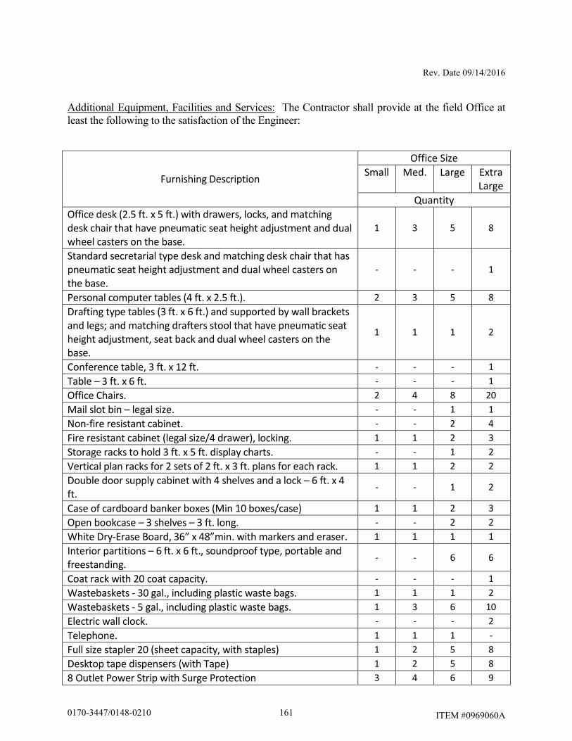
Rev. Date 09/14/2016
ITEM #0969060A
Additional Equipment, Facilities and Services: The Contractor shall provide at the field Office at least the following to the satisfaction of the Engineer:
Furnishing Description
Office Size
Small Med. Large Extra
Large
Quantity
Office desk (2.5 ft. x 5 ft.) with drawers, locks, and matching
desk chair that have pneumatic seat height adjustment and dual
wheel casters on the base.
1 3 5 8
Standard secretarial type desk and matching desk chair that has
pneumatic seat height adjustment and dual wheel casters on
the base.
- - - 1
Personal computer tables (4 ft. x 2.5 ft.). 2 3 5 8
Drafting type tables (3 ft. x 6 ft.) and supported by wall brackets
and legs; and matching drafters stool that have pneumatic seat
height adjustment, seat back and dual wheel casters on the
base.
1 1 1 2
Conference table, 3 ft. x 12 ft. - - - 1
Table – 3 ft. x 6 ft. - - - 1
Office Chairs. 2 4 8 20
Mail slot bin – legal size. - - 1 1
Non-fire resistant cabinet. - - 2 4
Fire resistant cabinet (legal size/4 drawer), locking. 1 1 2 3
Storage racks to hold 3 ft. x 5 ft. display charts. - - 1 2
Vertical plan racks for 2 sets of 2 ft. x 3 ft. plans for each rack. 1 1 2 2
Double door supply cabinet with 4 shelves and a lock – 6 ft. x 4
ft. - - 1 2
Case of cardboard banker boxes (Min 10 boxes/case) 1 1 2 3
Open bookcase – 3 shelves – 3 ft. long. - - 2 2
White Dry-Erase Board, 36” x 48”min. with markers and eraser. 1 1 1 1
Interior partitions – 6 ft. x 6 ft., soundproof type, portable and
freestanding. - - 6 6
Coat rack with 20 coat capacity. - - - 1
Wastebaskets - 30 gal., including plastic waste bags. 1 1 1 2
Wastebaskets - 5 gal., including plastic waste bags. 1 3 6 10
Electric wall clock. - - - 2
Telephone. 1 1 1 -
Full size stapler 20 (sheet capacity, with staples) 1 2 5 8
Desktop tape dispensers (with Tape) 1 2 5 8
8 Outlet Power Strip with Surge Protection 3 4 6 9
1610170-3447/0148-0210
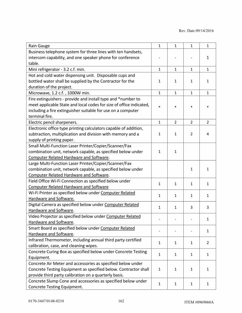
Rev. Date 09/14/2016
ITEM #0969060A
Rain Gauge 1 1 1 1
Business telephone system for three lines with ten handsets,
intercom capability, and one speaker phone for conference
table.
- - - 1
Mini refrigerator - 3.2 c.f. min. 1 1 1 1
Hot and cold water dispensing unit. Disposable cups and
bottled water shall be supplied by the Contractor for the
duration of the project.
1 1 1 1
Microwave, 1.2 c.f. , 1000W min. 1 1 1 1
Fire extinguishers - provide and install type and *number to
meet applicable State and local codes for size of office indicated,
including a fire extinguisher suitable for use on a computer
terminal fire.
* * * *
Electric pencil sharpeners. 1 2 2 2
Electronic office type printing calculators capable of addition,
subtraction, multiplication and division with memory and a
supply of printing paper.
1 1 2 4
Small Multi-Function Laser Printer/Copier/Scanner/Fax
combination unit, network capable, as specified below under
Computer Related Hardware and Software.
1 1
Large Multi-Function Laser Printer/Copier/Scanner/Fax
combination unit, network capable, as specified below under
Computer Related Hardware and Software.
1 1
Field Office Wi-Fi Connection as specified below under
Computer Related Hardware and Software 1 1 1 1
Wi-Fi Printer as specified below under Computer Related
Hardware and Software. 1 1 1 1
Digital Camera as specified below under Computer Related
Hardware and Software. 1 1 3 3
Video Projector as specified below under Computer Related
Hardware and Software. - - - 1
Smart Board as specified below under Computer Related
Hardware and Software. - - - 1
Infrared Thermometer, including annual third party certified
calibration, case, and cleaning wipes. 1 1 1 2
Concrete Curing Box as specified below under Concrete Testing
Equipment. 1 1 1 1
Concrete Air Meter and accessories as specified below under
Concrete Testing Equipment as specified below. Contractor shall
provide third party calibration on a quarterly basis.
1 1 1 1
Concrete Slump Cone and accessories as specified below under
Concrete Testing Equipment. 1 1 1 1
1620170-3447/0148-0210
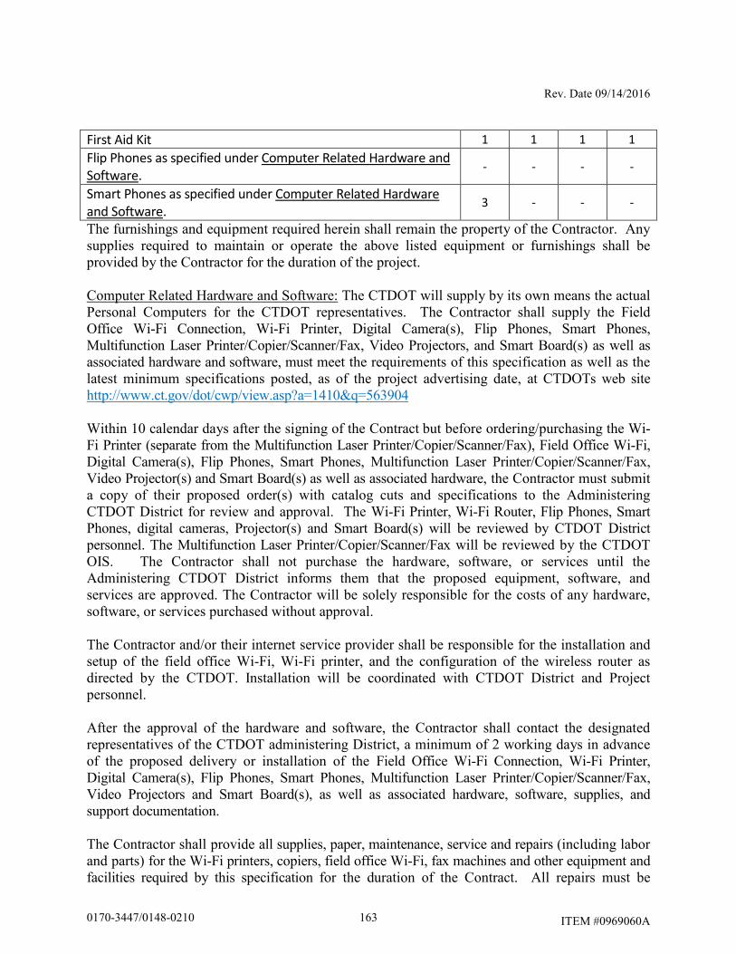
Rev. Date 09/14/2016
ITEM #0969060A
First Aid Kit 1 1 1 1
Flip Phones as specified under Computer Related Hardware and
Software. - - - -
Smart Phones as specified under Computer Related Hardware
and Software. 3 - - -
The furnishings and equipment required herein shall remain the property of the Contractor. Any supplies required to maintain or operate the above listed equipment or furnishings shall be provided by the Contractor for the duration of the project.
Computer Related Hardware and Software: The CTDOT will supply by its own means the actual Personal Computers for the CTDOT representatives. The Contractor shall supply the Field Office Wi-Fi Connection, Wi-Fi Printer, Digital Camera(s), Flip Phones, Smart Phones, Multifunction Laser Printer/Copier/Scanner/Fax, Video Projectors, and Smart Board(s) as well as associated hardware and software, must meet the requirements of this specification as well as the latest minimum specifications posted, as of the project advertising date, at CTDOTs web site http://www.ct.gov/dot/cwp/view.asp?a=1410&q=563904 Within 10 calendar days after the signing of the Contract but before ordering/purchasing the Wi-Fi Printer (separate from the Multifunction Laser Printer/Copier/Scanner/Fax), Field Office Wi-Fi, Digital Camera(s), Flip Phones, Smart Phones, Multifunction Laser Printer/Copier/Scanner/Fax, Video Projector(s) and Smart Board(s) as well as associated hardware, the Contractor must submit a copy of their proposed order(s) with catalog cuts and specifications to the Administering CTDOT District for review and approval. The Wi-Fi Printer, Wi-Fi Router, Flip Phones, Smart Phones, digital cameras, Projector(s) and Smart Board(s) will be reviewed by CTDOT District personnel. The Multifunction Laser Printer/Copier/Scanner/Fax will be reviewed by the CTDOT OIS. The Contractor shall not purchase the hardware, software, or services until the Administering CTDOT District informs them that the proposed equipment, software, and services are approved. The Contractor will be solely responsible for the costs of any hardware, software, or services purchased without approval. The Contractor and/or their internet service provider shall be responsible for the installation and setup of the field office Wi-Fi, Wi-Fi printer, and the configuration of the wireless router as directed by the CTDOT. Installation will be coordinated with CTDOT District and Project personnel. After the approval of the hardware and software, the Contractor shall contact the designated representatives of the CTDOT administering District, a minimum of 2 working days in advance of the proposed delivery or installation of the Field Office Wi-Fi Connection, Wi-Fi Printer, Digital Camera(s), Flip Phones, Smart Phones, Multifunction Laser Printer/Copier/Scanner/Fax, Video Projectors and Smart Board(s), as well as associated hardware, software, supplies, and support documentation. The Contractor shall provide all supplies, paper, maintenance, service and repairs (including labor and parts) for the Wi-Fi printers, copiers, field office Wi-Fi, fax machines and other equipment and facilities required by this specification for the duration of the Contract. All repairs must be
1630170-3447/0148-0210
Rev. Date 09/14/2016
ITEM #0969060A
performed with-in 48 hours. If the repairs require more than a 48 hours then an equal or better replacement must be provided. Once the Contract has been completed, the hardware and software will remain the property of the Contractor. First Aid Kit: The Contractor shall supply a first aid kit adequate for the number of personnel expected based on the size of the field office specified and shall keep the first aid kit stocked for the duration that the field office is in service. Rain Gauge: The Contractor shall supply install and maintain a rain gauge for the duration of the project, meeting these minimum requirements. The rain gauge shall be installed on the top of a post such that the opening of the rain gauge is above the top of the post an adequate distance to avoid splashing of rain water from the top of the post into the rain gauge. The Location of the rain gauge and post shall be approved by the Engineer. The rain gauge shall be made of a durable material and have graduations of 0.1 inches or less with a minimum total column height of 5 inches. If the rain gauge is damaged the Contractor shall replace it prior to the next forecasted storm event at no additional cost. Concrete Testing Equipment: If the Contract includes items that require compressive strength cylinders for concrete, in accordance with the Schedule of Minimum Testing Requirements for Sampling Materials for Test, the Contractor shall provide the following equipment. A) Concrete Cylinder Curing Box – meeting the requirements of Section 6.12 of the
Standard Specifications. B) Air Meter – The air meter provided shall be in good working order and meet the
requirements of AASHTO T 152. C) Slump Cone Mold – Slump cone, base plate, and tamping rod shall be provided in
like-new condition and meet the requirements of AASHTO T119, Standard Test Method for Slump of Hydraulic-Cement Concrete.
All testing equipment will remain the property of the Contractor at the completion of the project. Insurance Policy: The Contractor shall provide a separate insurance policy, with no deductible, in the minimum amount of five thousand dollars ($5,000) in order to insure all State-owned data equipment and supplies used in the office against all losses. The Contractor shall be named insured on that policy, and the CTDOT shall be an additional named insured on the policy. These losses shall include, but not be limited to: theft, fire, and physical damage. The CTDOT will be responsible for all maintenance costs of CTDOT owned computer hardware. In the event of loss, the Contractor shall provide replacement equipment in accordance with current CTDOT equipment specifications, within seven days of notice of the loss. If the Contractor is unable to provide the required replacement equipment within seven days, the CTDOT may provide replacement equipment and deduct the cost of the equipment from monies due or which may become due the
1640170-3447/0148-0210
Rev. Date 09/14/2016
ITEM #0969060A
Contractor under the Contract or under any other contract. The Contractor's financial liability under this paragraph shall be limited to the amount of the insurance coverage required by this paragraph. If the cost of equipment replacement required by this paragraph should exceed the required amount of the insurance coverage, the CTDOT will reimburse the Contractor for replacement costs exceeding the amount of the required coverage. Maintenance: During the occupancy by the CTDOT, the Contractor shall maintain all facilities and furnishings provided under the above requirements, and shall maintain and keep the office quarters clean through the use of weekly professional cleaning to include, but not limited to, washing & waxing floors, cleaning restrooms, removal of trash, etc. Exterior areas shall be mowed and clean of debris. A trash receptacle (dumpster) with weekly pickup (trash removal) shall be provided. Snow removal, sanding and salting of all parking, walkway, and entrance ways areas shall be accomplished during a storm if on a workday during work hours, immediately after a storm and prior to the start of a workday. If snow removal, salting and sanding are not completed by the specified time, the State will provide the service and all costs incurred will be deducted from the next payment estimate. Method of Measurement: The furnishing and maintenance of the construction field office will be measured for payment by the number of calendar months that the office is in place and in operation, rounded up to the nearest month. There will not be any price adjustment due to any change in the minimum computer related hardware and software requirements. Basis of Payment: The furnishing and maintenance of the Construction Field Office will be paid for at the Contract unit price per month for “Construction Field Office, (Small),” which price shall include all material, equipment, labor, service contracts, licenses, software, repair or replacement of hardware and software, related supplies, utility services, parking area, external illumination, trash removal, snow and ice removal, and work incidental thereto, as well as any other costs to provide requirements of this specified this specification. Pay Item Pay Unit Construction Field Office, (Small) Month
1650170-3447/0148-0210
Rev. Date 6/27/18
ITEM #0971001A
ITEM #0971001A – MAINTENANCE AND PROTECTION OF TRAFFIC
Article 9.71.01 – Description is supplemented by the following:
The Contractor shall maintain and protect traffic as described by the following and as limited in the Special Provision "Prosecution and Progress": Route 2, I-84, I-91, I-95, I-691
The Contractor shall maintain and protect the minimum number of through lanes and shoulders as dictated in the Special Provision for Section 1.08 - Prosecution and Progress “Limitation of Operations - Minimum Number of Lanes to Remain Open” Chart, on a paved travel path not less than 12 feet in width per lane. The Contractor shall be allowed to halt traffic for a period of time not to exceed 10 minutes for the purpose of erecting / removing overhead sign supports. If more than one 10-minute period is required, the Contractor shall allow all stored vehicles to proceed through the work area prior to the next stoppage. RAMPS, TURNING ROADWAYS AND HOV LANES:
Ramps and Turning Roadways (Site 9 – East Hartford)
The Contractor shall maintain and protect existing traffic operations. Excepted therefrom will be those periods, during the allowable periods, when the Contractor is actively working, at which time the Contractor shall be allowed to maintain and protect a minimum of one lane of traffic, on a paved travel path not less than 12 feet in width. The Contractor shall be allowed to halt traffic for a period of time not to exceed 10 minutes for the purpose of erecting / removing overhead sign supports. If more than one 10-minute period is required, the Contractor shall allow all stored vehicles to proceed through the work area prior to the next stoppage. The Contractor will be allowed to close Ramp 118 & Ramp 312 within the project limits and detour traffic for 60 days in accordance with the Detour Plans contained in the project plans.
1660170-3447/0148-0210
Rev. Date 6/27/18
ITEM #0971001A
Site 9 in East Hartford (I-84 Restricted Lanes (HOV Lanes) including Entrance Ramps
from I-84 EB and Silver Lane)
The Contractor shall maintain and protect existing traffic operations.
The Contractor will be allowed to close the I-84 Eastbound & Westbound Restricted Lanes (HOV Lanes) including Entrance Ramps from I-84 EB and Silver Lane during the allowable periods in accordance with the MPT plans in the Contract Plans. All Other Ramps and Turning Roadways
The Contractor shall maintain and protect existing traffic operations. Excepted therefrom will be those periods, during the allowable periods, when the Contractor is actively working, at which time the Contractor shall be allowed to maintain and protect a minimum of one lane of traffic, on a paved travel path not less than 12 feet in width. The Contractor shall be allowed to halt traffic for a period of time not to exceed 10 minutes for the purpose of erecting / removing overhead sign supports. If more than one 10-minute period is required, the Contractor shall allow all stored vehicles to proceed through the work area prior to the next stoppage.
ALL OTHER ROADWAYS:
All 4 Lane Roadways:
The Contractor shall maintain and protect a minimum of two lanes of traffic in each direction, each lane on a paved travel path not less than 11 feet in width. Where turn lanes exist, the Contractor shall provide an additional 10 feet of paved travel path to be used for turning vehicles only. This additional 10 feet of travel path shall be a minimum length of 150 feet. It shall be implemented so that sufficient storage, taper length, and turning radius are provided.
Excepted therefrom will be those periods, during the allowable periods, when the Contractor is actively working, at which time the Contractor shall maintain and protect at least one lane of traffic in each direction on a paved travel path not less than 11 feet in width.
1670170-3447/0148-0210
Rev. Date 6/27/18
ITEM #0971001A
All 2 Lane Roadways
The Contractor shall maintain and protect a minimum of one lane of traffic in each direction, each lane on a paved travel path not less than 11 feet in width. Excepted therefrom will be those periods, during the allowable periods, when the Contractor is actively working, at which time the Contractor shall maintain and protect at least an alternating one-way traffic operation, on a paved travel path not less than 11 feet in width. The length of the alternating one-way traffic operation shall not exceed 300 feet and there shall be no more than one alternating one-way traffic operation within the project limits without prior approval of the Engineer. Commercial and Residential Driveways
The Contractor shall maintain access to and egress from all commercial and residential driveways throughout the project limits. The Contractor will be allowed to close said driveways to perform the required work during those periods when the businesses are closed, unless permission is granted from the business owner to close the driveway during business hours. If a temporary closure of a residential driveway is necessary, the Contractor shall coordinate with the owner to determine the time period of the closure. Article 9.71.03 - Construction Method is supplemented as follows:
General
Unpaved travel paths will only be permitted for areas requiring full depth and full width reconstruction, in which case, the Contractor will be allowed to maintain traffic on processed aggregate for a duration not to exceed 10 calendar days. The unpaved section shall be the full width of the road and perpendicular to the travel lanes. Opposing traffic lane dividers shall be used as a centerline. The Contractor is required to delineate any raised structures within the travel lanes, so that the structures are visible day and night, unless there are specific contract plans and provisions to temporarily lower these structures prior to the completion of work. When the Contractor is excavating adjacent to the roadway, the Contractor shall provide a 3-foot shoulder between the work area and travel lanes, with traffic drums spaced every 50 feet. At the end of the workday, if the vertical drop-off exceeds 3 inches, the Contractor shall provide a temporary traversable slope of 4:1 or flatter that is acceptable to the Engineer. The Contractor, during the course of active construction work on overhead signs and structures, shall close the lanes directly below the work area for the entire length of time overhead work is being undertaken. At no time shall an overhead sign be left partially removed or installed.
1680170-3447/0148-0210
Rev. Date 6/27/18
ITEM #0971001A
If applicable, when an existing sign is removed, it shall be either relocated or replaced by a new sign during the same working day. The Contractor shall not store any material on-site which would present a safety hazard to motorists or pedestrians (e.g. fixed object or obstruct sight lines). The field installation of a signing pattern shall constitute interference with existing traffic operations and shall not be allowed, except during the allowable periods. Construction vehicles entering travel lanes at speeds less than the posted speed are interfering with traffic, and shall not be allowed without a lane closure. The lane closure shall be of sufficient length to allow vehicles to enter or exit the work area at posted speeds, in order to merge with existing traffic. Existing Signing
The Contractor shall maintain all existing overhead and side-mounted signs throughout the project limits during the duration of the project. The Contractor shall temporarily relocate signs and sign supports as many times as deemed necessary, and install temporary sign supports if necessary and as directed by the Engineer. Requirements for Winter The Contractor shall schedule a meeting with representatives from the Department including the offices of Maintenance and Traffic, and the Town/City to determine what interim traffic control measures the Contractor shall accomplish for the winter to provide safety to the motorists and permit adequate snow removal procedures. This meeting shall be held prior to October 31 of each year and will include, but not be limited to, discussion of the status and schedule of the following items: lane and shoulder widths, pavement restoration, traffic signal work, pavement markings, and signing. Signing Patterns
The Contractor shall erect and maintain all signing patterns in accordance with the traffic control plans contained herein. Proper distances between advance warning signs and proper taper lengths are mandatory.
Pavement Markings - Limited Access Highways, Turning Roadways and Ramps During construction, the Contractor shall maintain all pavement markings throughout the limits of the project. Interim Pavement Markings The Contractor shall install painted pavement markings, which shall include lane lines (broken lines), edge lines, stop bars, lane-use arrows and gore markings, on each intermediate course of
1690170-3447/0148-0210
Rev. Date 6/27/18
ITEM #0971001A
bituminous concrete pavement and on any milled surface by the end of the work day/night. All painted pavement markings will be paid under the appropriate items. If the Contractor does not install permanent Epoxy Resin Pavement Markings by the end of the work day/night on exit ramps where the final course of bituminous concrete pavement has been installed, the Contractor shall install temporary 12 inch wide white stop bars. The temporary stop bars shall consist of Temporary Plastic Pavement Marking Tape and shall be installed by the end of the work day/night. Stop bars may consist of two 6 inch wide white markings or three 4 inch wide white markings placed side by side. The Contractor shall remove and dispose of these markings when the permanent Epoxy Resin Pavement Markings are installed. The cost of furnishing, installing and removing the Temporary Plastic Pavement Marking Tape shall be at the Contractor’s expense. If an intermediate course of bituminous concrete pavement will be exposed throughout the winter, then Epoxy Resin Pavement Markings should be installed unless directed otherwise by the Engineer. Final Pavement Markings The Contractor should install painted pavement markings on the final course of bituminous concrete pavement by the end of the work day/night. If the painted pavement markings are not installed by the end of the work day/night, then Temporary Plastic Pavement Marking Tape shall be installed as described above and the painted pavement markings shall be installed by the end of the work day/night on Friday of that week. If Temporary Plastic Pavement Marking Tape is installed, the Contractor shall remove and dispose of these markings when the painted pavement markings are installed. The cost of furnishing, installing and removing the Temporary Plastic Pavement Marking Tape shall be at the Contractor’s expense. The Contractor shall install permanent Epoxy Resin Pavement Markings in accordance with Section 12.10 entitled “Epoxy Resin Pavement Markings” after such time as determined by the Engineer. TRAFFIC CONTROL DURING CONSTRUCTION OPERATIONS
The following guidelines shall assist field personnel in determining when and what type of traffic control patterns to use for various situations. These guidelines shall provide for the safe and efficient movement of traffic through work zones and enhance the safety of work forces in the work area.
1700170-3447/0148-0210
Rev. Date 6/27/18
ITEM #0971001A
TRAFFIC CONTROL PATTERNS
Traffic control patterns shall be used when a work operation requires that all or part of any vehicle or work area protrudes onto any part of a travel lane or shoulder. For each situation, the installation of traffic control devices shall be based on the following:
Speed and volume of traffic Duration of operation Exposure to hazards
Traffic control patterns shall be uniform, neat and orderly so as to command respect from the motorist. In the case of a horizontal or vertical sight restriction in advance of the work area, the traffic control pattern shall be extended to provide adequate sight distance for approaching traffic. If a lane reduction taper is required to shift traffic, the entire length of the taper should be installed on a tangent section of roadway so that the entire taper area can be seen by the motorist. Any existing signs that are in conflict with the traffic control patterns shall be removed, covered, or turned so that they are not readable by oncoming traffic. When installing a traffic control pattern, a Buffer Area should be provided and this area shall be free of equipment, workers, materials and parked vehicles. Typical traffic control plans 19 through 25 may be used for moving operations such as line striping, pot hole patching, mowing, or sweeping when it is necessary for equipment to occupy a travel lane. Traffic control patterns will not be required when vehicles are on an emergency patrol type activity or when a short duration stop is made and the equipment can be contained within the shoulder. Flashing lights and appropriate trafficperson shall be used when required. Although each situation must be dealt with individually, conformity with the typical traffic control plans contained herein is required. In a situation not adequately covered by the typical traffic control plans, the Contractor must contact the Engineer for assistance prior to setting up a traffic control pattern.
PLACEMENT OF SIGNS
Signs must be placed in such a position to allow motorists the opportunity to reduce their speed prior to the work area. Signs shall be installed on the same side of the roadway as the work area. On multi-lane divided highways, advance warning signs shall be installed on both sides of the highway. On directional roadways (on-ramps, off-ramps, one-way roads), where the sight distance to signs is restricted, these signs should be installed on both sides of the roadway.
1710170-3447/0148-0210
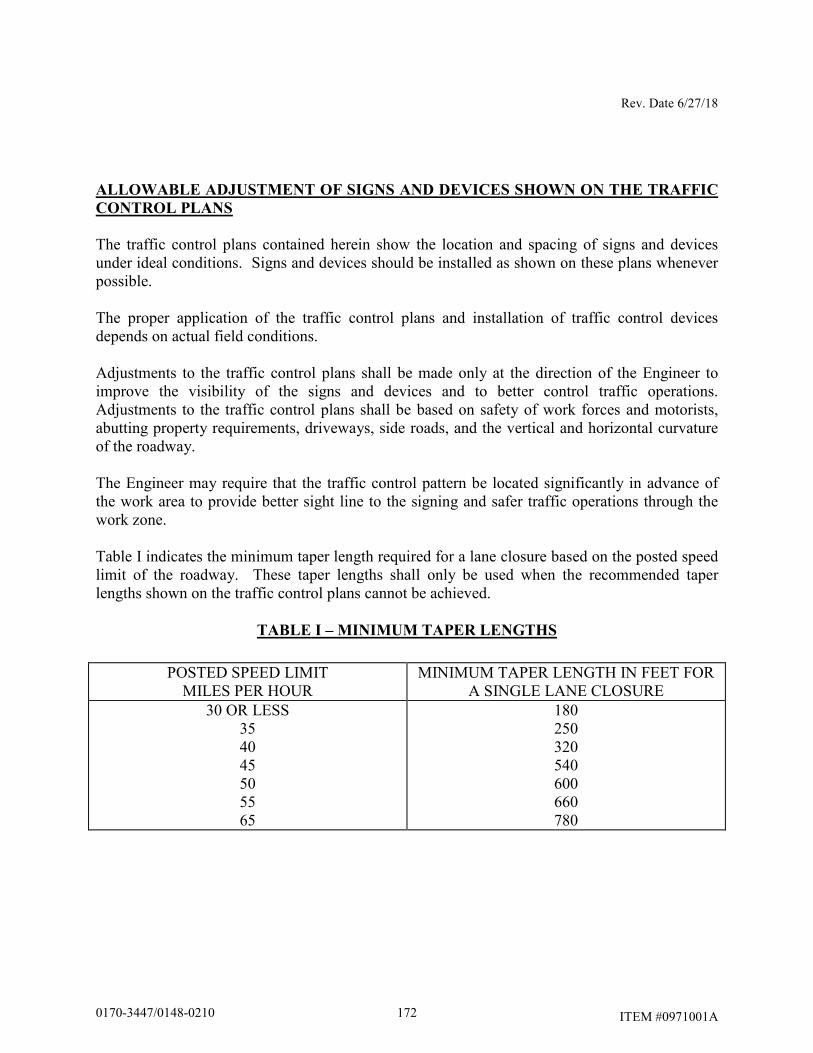
Rev. Date 6/27/18
ITEM #0971001A
ALLOWABLE ADJUSTMENT OF SIGNS AND DEVICES SHOWN ON THE TRAFFIC
CONTROL PLANS
The traffic control plans contained herein show the location and spacing of signs and devices under ideal conditions. Signs and devices should be installed as shown on these plans whenever possible. The proper application of the traffic control plans and installation of traffic control devices depends on actual field conditions. Adjustments to the traffic control plans shall be made only at the direction of the Engineer to improve the visibility of the signs and devices and to better control traffic operations. Adjustments to the traffic control plans shall be based on safety of work forces and motorists, abutting property requirements, driveways, side roads, and the vertical and horizontal curvature of the roadway. The Engineer may require that the traffic control pattern be located significantly in advance of the work area to provide better sight line to the signing and safer traffic operations through the work zone. Table I indicates the minimum taper length required for a lane closure based on the posted speed limit of the roadway. These taper lengths shall only be used when the recommended taper lengths shown on the traffic control plans cannot be achieved.
TABLE I – MINIMUM TAPER LENGTHS
POSTED SPEED LIMIT MILES PER HOUR
MINIMUM TAPER LENGTH IN FEET FOR A SINGLE LANE CLOSURE
30 OR LESS 35 40 45 50 55 65
180 250 320 540 600 660 780
1720170-3447/0148-0210
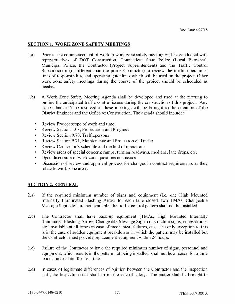
Rev. Date 6/27/18
ITEM #0971001A
SECTION 1. WORK ZONE SAFETY MEETINGS
1.a) Prior to the commencement of work, a work zone safety meeting will be conducted with representatives of DOT Construction, Connecticut State Police (Local Barracks), Municipal Police, the Contractor (Project Superintendent) and the Traffic Control Subcontractor (if different than the prime Contractor) to review the traffic operations, lines of responsibility, and operating guidelines which will be used on the project. Other work zone safety meetings during the course of the project should be scheduled as needed.
1.b) A Work Zone Safety Meeting Agenda shall be developed and used at the meeting to
outline the anticipated traffic control issues during the construction of this project. Any issues that can’t be resolved at these meetings will be brought to the attention of the District Engineer and the Office of Construction. The agenda should include:
• Review Project scope of work and time • Review Section 1.08, Prosecution and Progress • Review Section 9.70, Trafficpersons • Review Section 9.71, Maintenance and Protection of Traffic • Review Contractor’s schedule and method of operations. • Review areas of special concern: ramps, turning roadways, medians, lane drops, etc. • Open discussion of work zone questions and issues • Discussion of review and approval process for changes in contract requirements as they
relate to work zone areas SECTION 2. GENERAL
2.a) If the required minimum number of signs and equipment (i.e. one High Mounted Internally Illuminated Flashing Arrow for each lane closed, two TMAs, Changeable Message Sign, etc.) are not available; the traffic control pattern shall not be installed.
2.b) The Contractor shall have back-up equipment (TMAs, High Mounted Internally
Illuminated Flashing Arrow, Changeable Message Sign, construction signs, cones/drums, etc.) available at all times in case of mechanical failures, etc. The only exception to this is in the case of sudden equipment breakdowns in which the pattern may be installed but the Contractor must provide replacement equipment within 24 hours.
2.c) Failure of the Contractor to have the required minimum number of signs, personnel and
equipment, which results in the pattern not being installed, shall not be a reason for a time extension or claim for loss time.
2.d) In cases of legitimate differences of opinion between the Contractor and the Inspection
staff, the Inspection staff shall err on the side of safety. The matter shall be brought to
1730170-3447/0148-0210
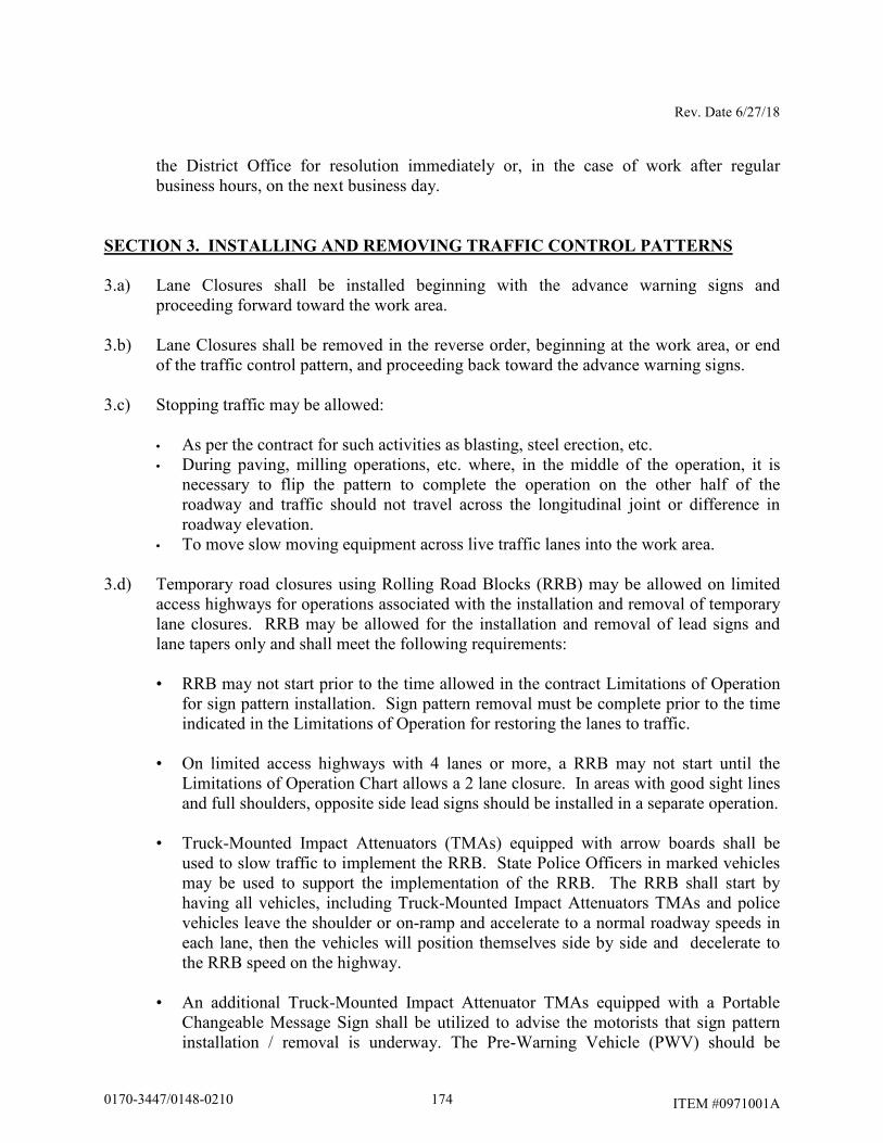
Rev. Date 6/27/18
ITEM #0971001A
the District Office for resolution immediately or, in the case of work after regular business hours, on the next business day.
SECTION 3. INSTALLING AND REMOVING TRAFFIC CONTROL PATTERNS
3.a) Lane Closures shall be installed beginning with the advance warning signs and proceeding forward toward the work area.
3.b) Lane Closures shall be removed in the reverse order, beginning at the work area, or end
of the traffic control pattern, and proceeding back toward the advance warning signs. 3.c) Stopping traffic may be allowed:
• As per the contract for such activities as blasting, steel erection, etc. • During paving, milling operations, etc. where, in the middle of the operation, it is
necessary to flip the pattern to complete the operation on the other half of the roadway and traffic should not travel across the longitudinal joint or difference in roadway elevation.
• To move slow moving equipment across live traffic lanes into the work area.
3.d) Temporary road closures using Rolling Road Blocks (RRB) may be allowed on limited access highways for operations associated with the installation and removal of temporary lane closures. RRB may be allowed for the installation and removal of lead signs and lane tapers only and shall meet the following requirements:
• RRB may not start prior to the time allowed in the contract Limitations of Operation
for sign pattern installation. Sign pattern removal must be complete prior to the time indicated in the Limitations of Operation for restoring the lanes to traffic.
• On limited access highways with 4 lanes or more, a RRB may not start until the Limitations of Operation Chart allows a 2 lane closure. In areas with good sight lines and full shoulders, opposite side lead signs should be installed in a separate operation.
• Truck-Mounted Impact Attenuators (TMAs) equipped with arrow boards shall be used to slow traffic to implement the RRB. State Police Officers in marked vehicles may be used to support the implementation of the RRB. The RRB shall start by having all vehicles, including Truck-Mounted Impact Attenuators TMAs and police vehicles leave the shoulder or on-ramp and accelerate to a normal roadway speeds in each lane, then the vehicles will position themselves side by side and decelerate to the RRB speed on the highway.
• An additional Truck-Mounted Impact Attenuator TMAs equipped with a Portable Changeable Message Sign shall be utilized to advise the motorists that sign pattern installation / removal is underway. The Pre-Warning Vehicle (PWV) should be
1740170-3447/0148-0210
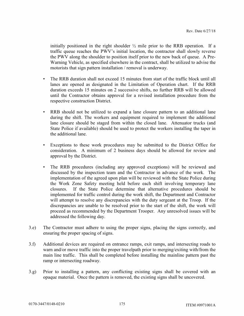
Rev. Date 6/27/18
ITEM #0971001A
initially positioned in the right shoulder ½ mile prior to the RRB operation. If a traffic queue reaches the PWV’s initial location, the contractor shall slowly reverse the PWV along the shoulder to position itself prior to the new back of queue. A Pre-Warning Vehicle, as specified elsewhere in the contract, shall be utilized to advise the motorists that sign pattern installation / removal is underway.
• The RRB duration shall not exceed 15 minutes from start of the traffic block until all lanes are opened as designated in the Limitation of Operation chart. If the RRB duration exceeds 15 minutes on 2 successive shifts, no further RRB will be allowed until the Contractor obtains approval for a revised installation procedure from the respective construction District.
• RRB should not be utilized to expand a lane closure pattern to an additional lane during the shift. The workers and equipment required to implement the additional lane closure should be staged from within the closed lane. Attenuator trucks (and State Police if available) should be used to protect the workers installing the taper in the additional lane.
• Exceptions to these work procedures may be submitted to the District Office for consideration. A minimum of 2 business days should be allowed for review and approval by the District.
• The RRB procedures (including any approved exceptions) will be reviewed and discussed by the inspection team and the Contractor in advance of the work. The implementation of the agreed upon plan will be reviewed with the State Police during the Work Zone Safety meeting held before each shift involving temporary lane closures. If the State Police determine that alternative procedures should be implemented for traffic control during the work shift, the Department and Contractor will attempt to resolve any discrepancies with the duty sergeant at the Troop. If the discrepancies are unable to be resolved prior to the start of the shift, the work will proceed as recommended by the Department Trooper. Any unresolved issues will be addressed the following day.
3.e) The Contractor must adhere to using the proper signs, placing the signs correctly, and
ensuring the proper spacing of signs. 3.f) Additional devices are required on entrance ramps, exit ramps, and intersecting roads to
warn and/or move traffic into the proper travelpath prior to merging/exiting with/from the main line traffic. This shall be completed before installing the mainline pattern past the ramp or intersecting roadway.
3.g) Prior to installing a pattern, any conflicting existing signs shall be covered with an
opaque material. Once the pattern is removed, the existing signs shall be uncovered.
1750170-3447/0148-0210
Rev. Date 6/27/18
ITEM #0971001A
3.h) On limited access roadways, workers are prohibited from crossing the travel lanes to install and remove signs or other devices on the opposite side of the roadway. Any signs or devices on the opposite side of the roadway shall be installed and removed separately.
SECTION 4. USE OF HIGH MOUNTED INTERNALLY ILLUMINATED FLASHING
ARROW
4.a) On limited access roadways, one Flashing Arrow shall be used for each lane that is closed. The Flashing Arrow shall be installed concurrently with the installation of the traffic control pattern and its placement shall be as shown on the traffic control plan. For multiple lane closures, one Flashing Arrow is required for each lane closed. If conditions warrant, additional Flashing Arrows should be employed (i.e.: curves, major ramps, etc.).
4.b) On non-limited access roadways, the use of a Flashing Arrow for lane closures is
optional. The roadway geometry, sight line distance, and traffic volume should be considered in the decision to use the Flashing Arrow.
4.c) The Flashing Arrow shall not be used on two lane, two-way roadways for temporary
alternating one-way traffic operations. 4.d) The Flashing Arrow board display shall be in the “arrow” mode for lane closure tapers
and in the “caution” mode (four corners) for shoulder work, blocking the shoulder, or roadside work near the shoulder. The Flashing Arrow shall be in the “caution” mode when it is positioned in the closed lane.
4.e) The Flashing Arrow shall not be used on a multi-lane roadway to laterally shift all lanes
of traffic, because unnecessary lane changing may result. SECTION 5. USE OF TRUCK MOUNTED OR TRAILER MOUNTED IMPACT
ATTENUATOR VEHICLES (TMAs)
5.a) For lane closures on limited access roadways, a minimum of two TMAs shall be used to install and remove traffic control patterns. If two TMAs are not available, the pattern shall not be installed.
5.b) On non-limited access roadways, the use of TMAs to install and remove patterns closing
a lane(s) is optional. The roadway geometry, sight line distance, and traffic volume should be considered in the decision to utilize the TMAs.
5.c) Generally, to establish the advance and transition signing, one TMA shall be placed on
the shoulder and the second TMA shall be approximately 1,000 feet ahead blocking the lane. The flashing arrow board mounted on the TMA should be in the “flashing arrow” mode when taking the lane. The sign truck and workers should be immediately ahead of
1760170-3447/0148-0210
Rev. Date 6/27/18
ITEM #0971001A
the second TMA. In no case shall the TMA be used as the sign truck or a work truck. Once the transition is in place, the TMAs shall travel in the closed lane until all Changeable Message Signs, signs, Flashing Arrows, and cones/drums are installed. The flashing arrow board mounted on the TMA should be in the “caution” mode when traveling in the closed lane.
5.d) A TMA shall be placed prior to the first work area in the pattern. If there are multiple
work areas within the same pattern, then additional TMAs shall be positioned at each additional work area as needed. The flashing arrow board mounted on the TMA should be in the “caution” mode when in the closed lane.
5.e) TMAs shall be positioned a sufficient distance prior to the workers or equipment being
protected to allow for appropriate vehicle roll-ahead in the event that the TMA is hit, but not so far that an errant vehicle could travel around the TMA and into the work area. For additional placement and use details, refer to the specification entitled “Truck-Mounted or Trailer-Mounted Impact Attenuator”. Some operations, such as paving and concrete repairs, do not allow for placement of the TMA(s) within the specified distances. In these situations, the TMA(s) should be placed at the beginning of the work area and shall be advanced as the paving or concrete operations proceed.
5.f) TMAs should be paid in accordance with how the unit is utilized. If it is used as a TMA
and is in the proper location as specified, then it should be paid at the specified hourly rate for “Truck-Mounted or Trailer-Mounted Impact Attenuator”. When the TMA is used as a Flashing Arrow, it should be paid at the daily rate for “High Mounted Internally Illuminated Flashing Arrow”. If a TMA is used to install and remove a pattern and is also used as a Flashing Arrow in the same day, then the unit should be paid as a “Truck-Mounted or Trailer-Mounted Impact Attenuator” for the hours used to install and remove the pattern, typically 2 hours (1 hour to install and 1 hour to remove). If the TMA is also used as a Flashing Arrow during the same day, then the unit should be paid at the daily rate as a “High Mounted Internally Illuminated Flashing Arrow”.
SECTION 6. USE OF TRAFFIC DRUMS AND TRAFFIC CONES
6.a) Traffic drums shall be used for taper channelization on limited-access roadways, ramps, and turning roadways and to delineate raised catch basins and other hazards.
6.b) Traffic drums shall be used in place of traffic cones in traffic control patterns that are in
effect for more than a 36-hour duration. 6.c) Traffic Cones less than 42 inches in height shall not be used on limited-access roadways
or on non-limited access roadways with a posted speed limit of 45 mph and above.
1770170-3447/0148-0210
Rev. Date 6/27/18
ITEM #0971001A
6.d) Typical spacing of traffic drums and/or cones shown on the Traffic Control Plans in the Contract are maximum spacings and may be reduced to meet actual field conditions as required.
SECTION 7. USE OF (REMOTE CONTROLLED) CHANGEABLE MESSAGE SIGNS
(CMS)
7.a) For lane closures on limited access roadways, one CMS shall be used in advance of the traffic control pattern. Prior to installing the pattern, the CMS shall be installed and in operation, displaying the appropriate lane closure information (i.e.: Left Lane Closed - Merge Right). The CMS shall be positioned ½ - 1 mile ahead of the lane closure taper. If the nearest Exit ramp is greater than the specified ½ - 1 mile distance, than an additional CMS shall be positioned a sufficient distance ahead of the Exit ramp to alert motorists to the work and therefore offer them an opportunity to take the exit.
7.b) CMS should not be installed within 1000 feet of an existing CMS. 7.c) On non-limited access roadways, the use of CMS for lane closures is optional. The
roadway geometry, sight line distance, and traffic volume should be considered in the decision to use the CMS.
7.d) The advance CMS is typically placed off the right shoulder, 5 feet from the edge of
pavement. In areas where the CMS cannot be placed beyond the edge of pavement, it may be placed on the paved shoulder with a minimum of five (5) traffic drums placed in a taper in front of it to delineate its position. The advance CMS shall be adequately protected if it is used for a continuous duration of 36 hours or more.
7.e) When the CMS are no longer required, they should be removed from the clear zone and
have the display screen cleared and turned 90° away from the roadway. 7.f) The CMS generally should not be used for generic messages (ex: Road Work Ahead,
Bump Ahead, Gravel Road, etc.). 7.g) The CMS should be used for specific situations that need to command the motorist’s
attention which cannot be conveyed with standard construction signs (Examples include: Exit 34 Closed Sat/Sun - Use Exit 35, All Lanes Closed - Use Shoulder, Workers on Road - Slow Down).
7.h) Messages that need to be displayed for long periods of time, such as during stage
construction, should be displayed with construction signs. For special signs, please coordinate with the Office of Construction and the Division of Traffic Engineering for the proper layout/dimensions required.
1780170-3447/0148-0210
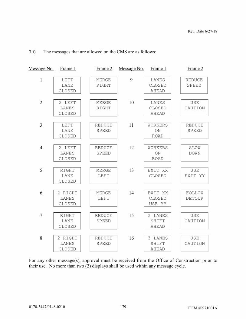
Rev. Date 6/27/18
ITEM #0971001A
7.i) The messages that are allowed on the CMS are as follows:
Message No. Frame 1 Frame 2 Message No. Frame 1 Frame 2
1 LEFT LANE
CLOSED
MERGE RIGHT
9 LANES CLOSED AHEAD
REDUCE SPEED
2 2 LEFT
LANES CLOSED
MERGE RIGHT
10 LANES CLOSED AHEAD
USE CAUTION
3 LEFT
LANE CLOSED
REDUCE SPEED
11 WORKERS ON
ROAD
REDUCE SPEED
4 2 LEFT
LANES CLOSED
REDUCE SPEED
12 WORKERS ON
ROAD
SLOW DOWN
5 RIGHT
LANE CLOSED
MERGE LEFT
13 EXIT XX CLOSED
USE EXIT YY
6 2 RIGHT
LANES CLOSED
MERGE LEFT
14 EXIT XX CLOSED USE YY
FOLLOW DETOUR
7 RIGHT LANE
CLOSED
REDUCE SPEED
15 2 LANES SHIFT AHEAD
USE CAUTION
8 2 RIGHT
LANES CLOSED
REDUCE SPEED
16 3 LANES SHIFT AHEAD
USE CAUTION
For any other message(s), approval must be received from the Office of Construction prior to their use. No more than two (2) displays shall be used within any message cycle.
1790170-3447/0148-0210
Rev. Date 6/27/18
ITEM #0971001A
SECTION 8. USE OF STATE POLICE OFFICERS
8.a) State Police may be utilized only on limited access highways and secondary roadways under their primary jurisdiction. One Officer may be used per critical sign pattern. Shoulder closures and right lane closures can generally be implemented without the presence of a State Police Officer. Likewise in areas with moderate traffic and wide, unobstructed medians, left lane closures can be implemented without State Police presence. Under some situations it may be desirable to have State Police presence, when one is available. Examples of this include: nighttime lane closures; left lane closures with minimal width for setting up advance signs and staging; lane and shoulder closures on turning roadways/ramps or mainline where sight distance is minimal; and closures where extensive turning movements or traffic congestion regularly occur, however they are not required.
8.b) Once the pattern is in place, the State Police Officer should be positioned in a non- hazardous location in advance of the pattern If traffic backs up beyond the beginning of the pattern, then the State Police Officer shall be repositioned prior to the backup to give warning to the oncoming motorists. The State Police Officer and TMA should not be in proximity to each other.
8.c) Other functions of the State Police Officer(s) may include:
• Assisting entering/exiting construction vehicles within the work area.
• Enforcement of speed and other motor vehicle laws within the work area, if specifically requested by the project.
8.d) State Police Officers assigned to a work site are to only take direction from the Engineer.
1800170-3447/0148-0210
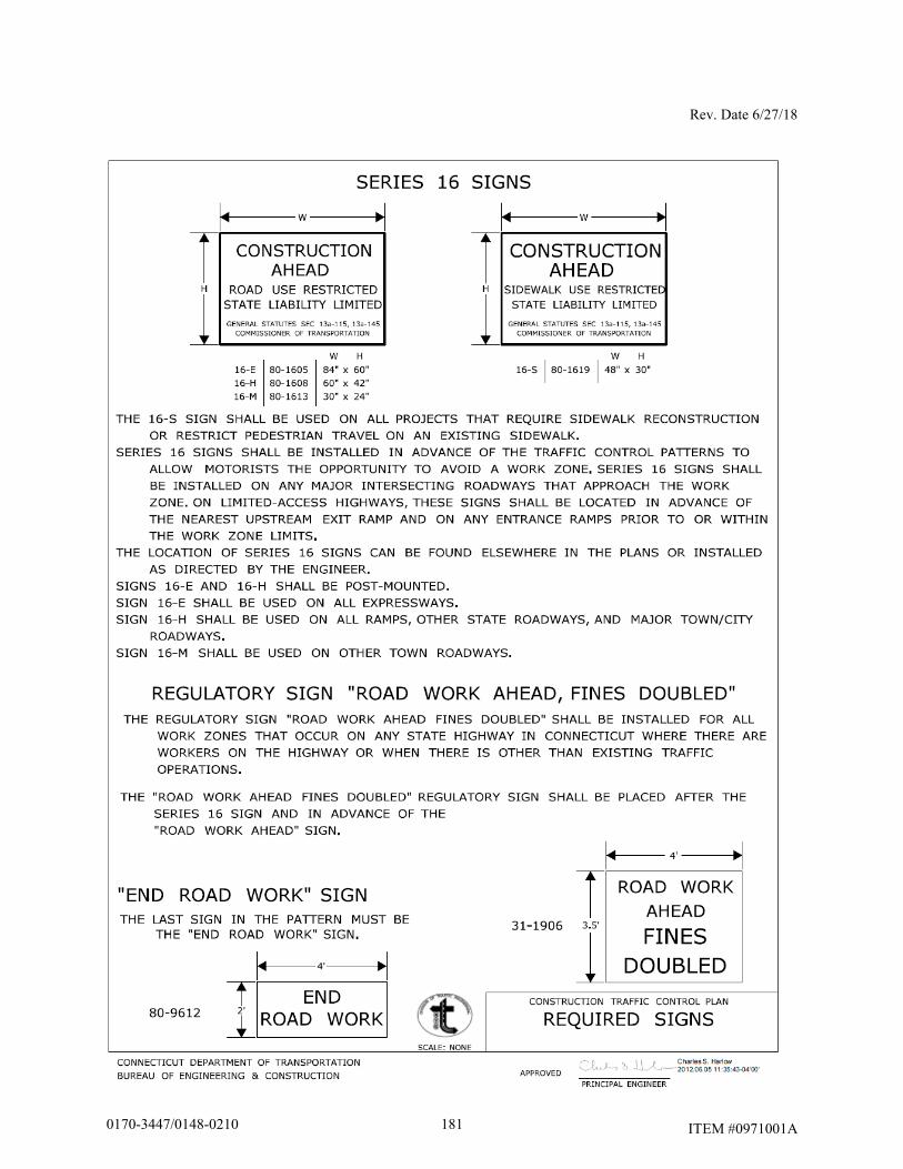
Rev. Date 6/27/18
ITEM #0971001A
1810170-3447/0148-0210
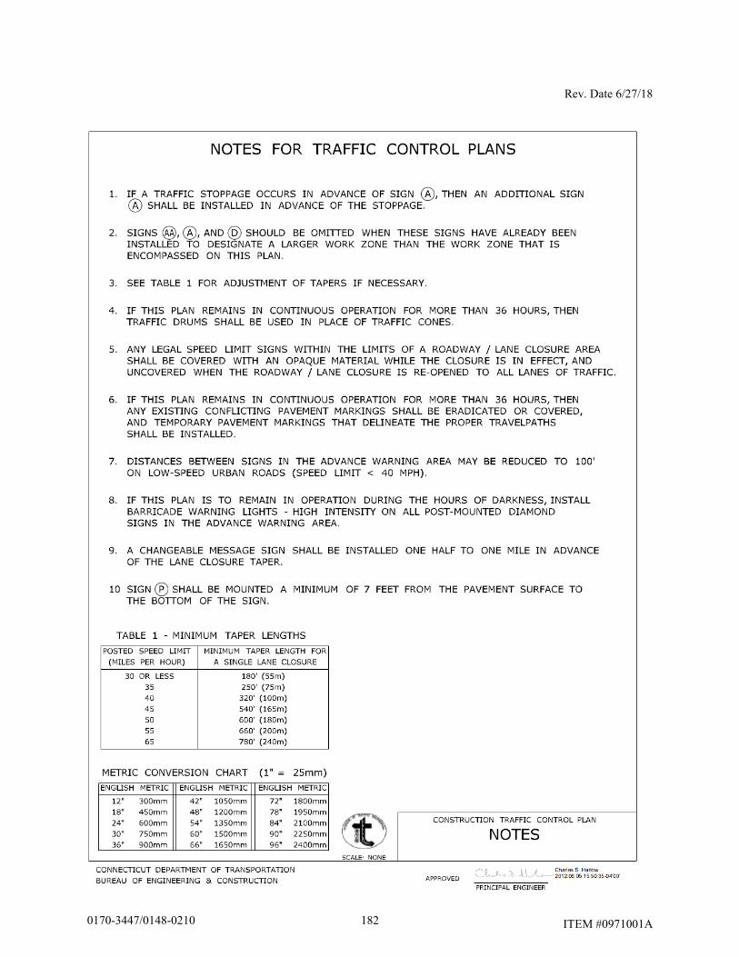
Rev. Date 6/27/18
ITEM #0971001A
1820170-3447/0148-0210
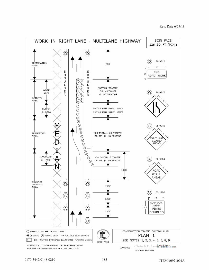
Rev. Date 6/27/18
ITEM #0971001A
1830170-3447/0148-0210
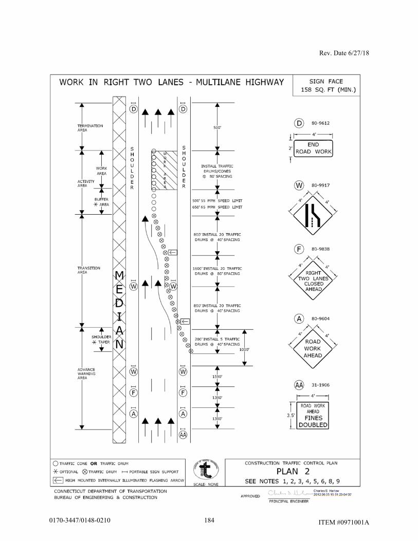
Rev. Date 6/27/18
ITEM #0971001A
1840170-3447/0148-0210
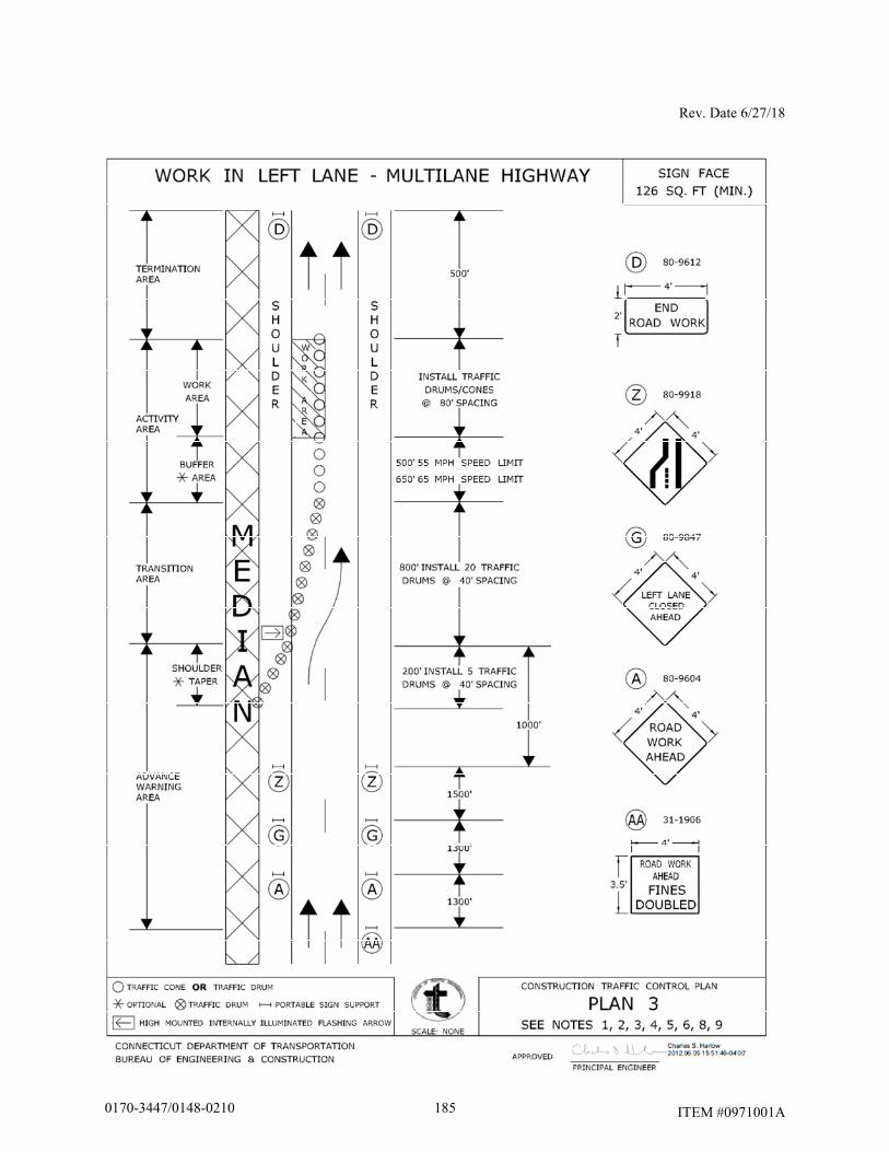
Rev. Date 6/27/18
ITEM #0971001A 1850170-3447/0148-0210
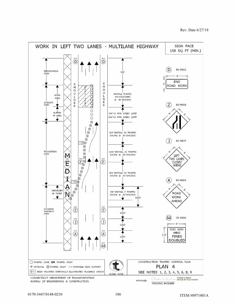
Rev. Date 6/27/18
ITEM #0971001A 1860170-3447/0148-0210
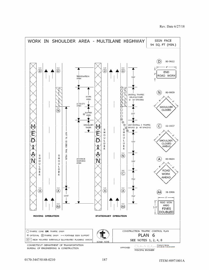
Rev. Date 6/27/18
ITEM #0971001A 1870170-3447/0148-0210
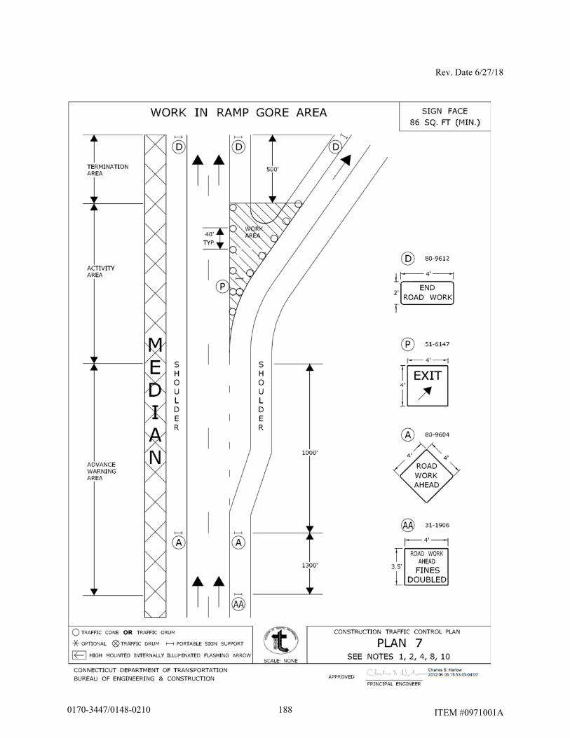
Rev. Date 6/27/18
ITEM #0971001A 1880170-3447/0148-0210
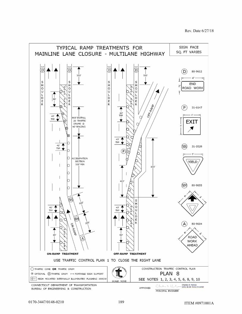
Rev. Date 6/27/18
ITEM #0971001A 1890170-3447/0148-0210
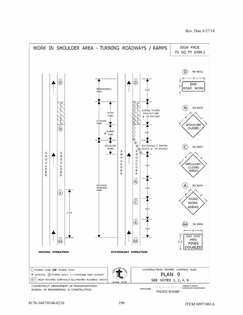
Rev. Date 6/27/18
ITEM #0971001A
1900170-3447/0148-0210
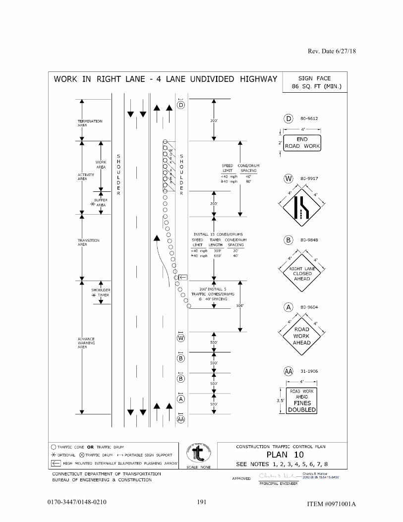
Rev. Date 6/27/18
ITEM #0971001A
1910170-3447/0148-0210
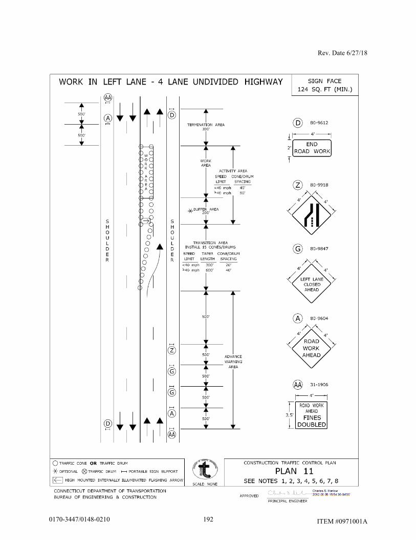
Rev. Date 6/27/18
ITEM #0971001A
1920170-3447/0148-0210
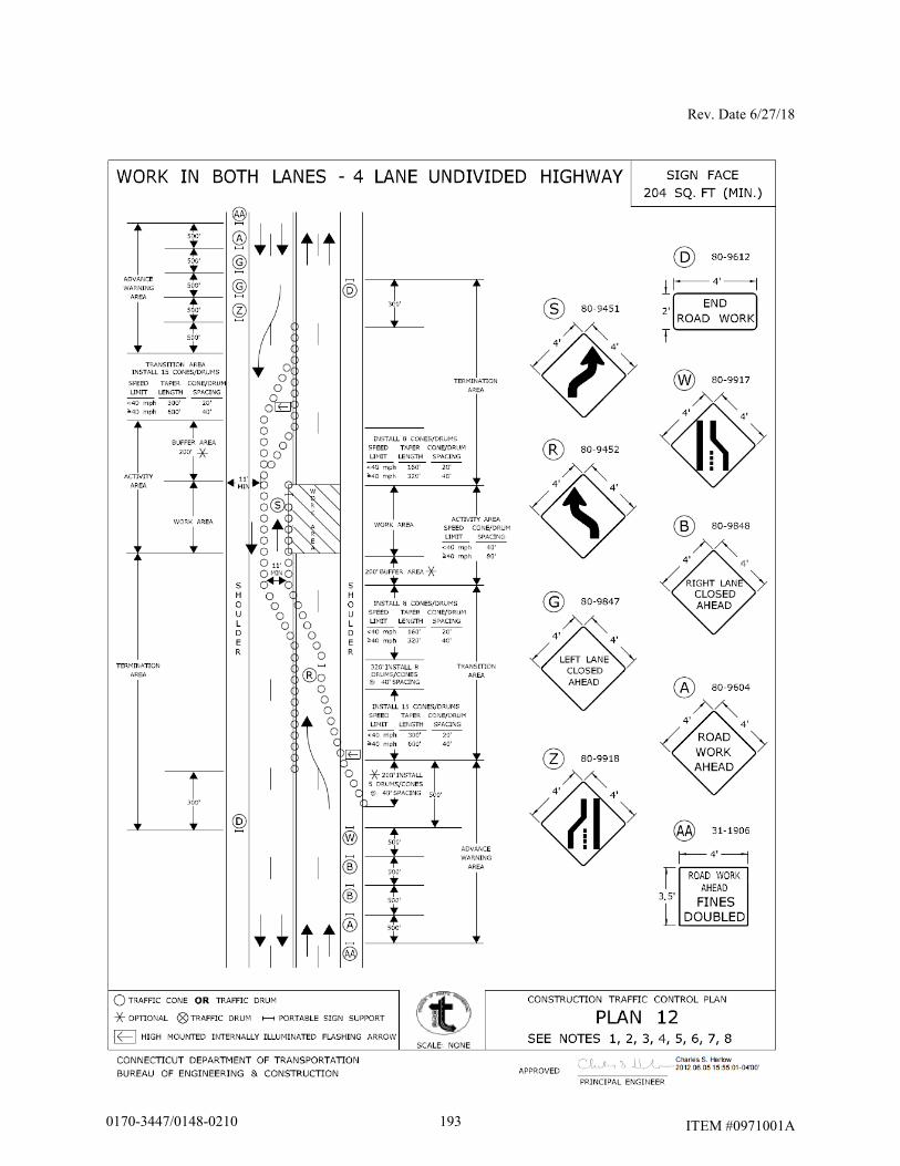
Rev. Date 6/27/18
ITEM #0971001A
1930170-3447/0148-0210
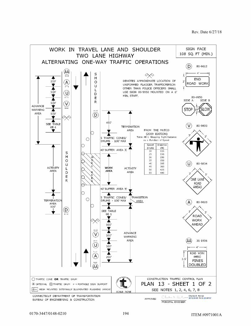
Rev. Date 6/27/18
ITEM #0971001A
1940170-3447/0148-0210
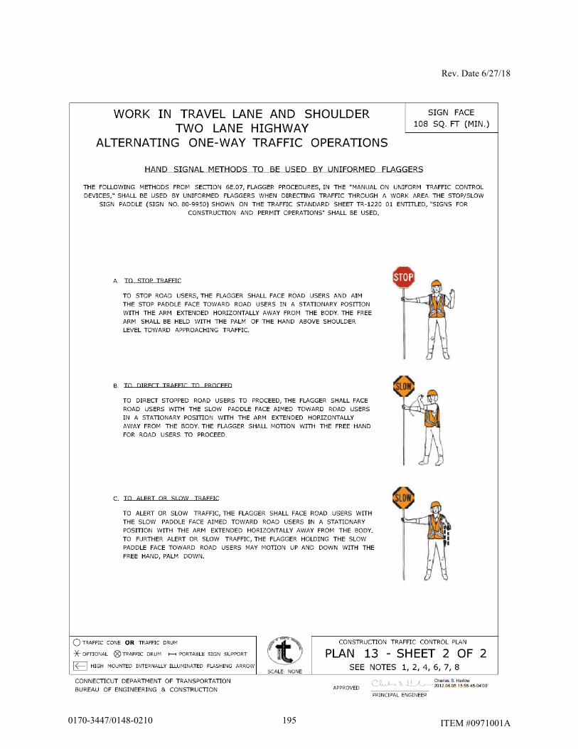
Rev. Date 6/27/18
ITEM #0971001A
1950170-3447/0148-0210
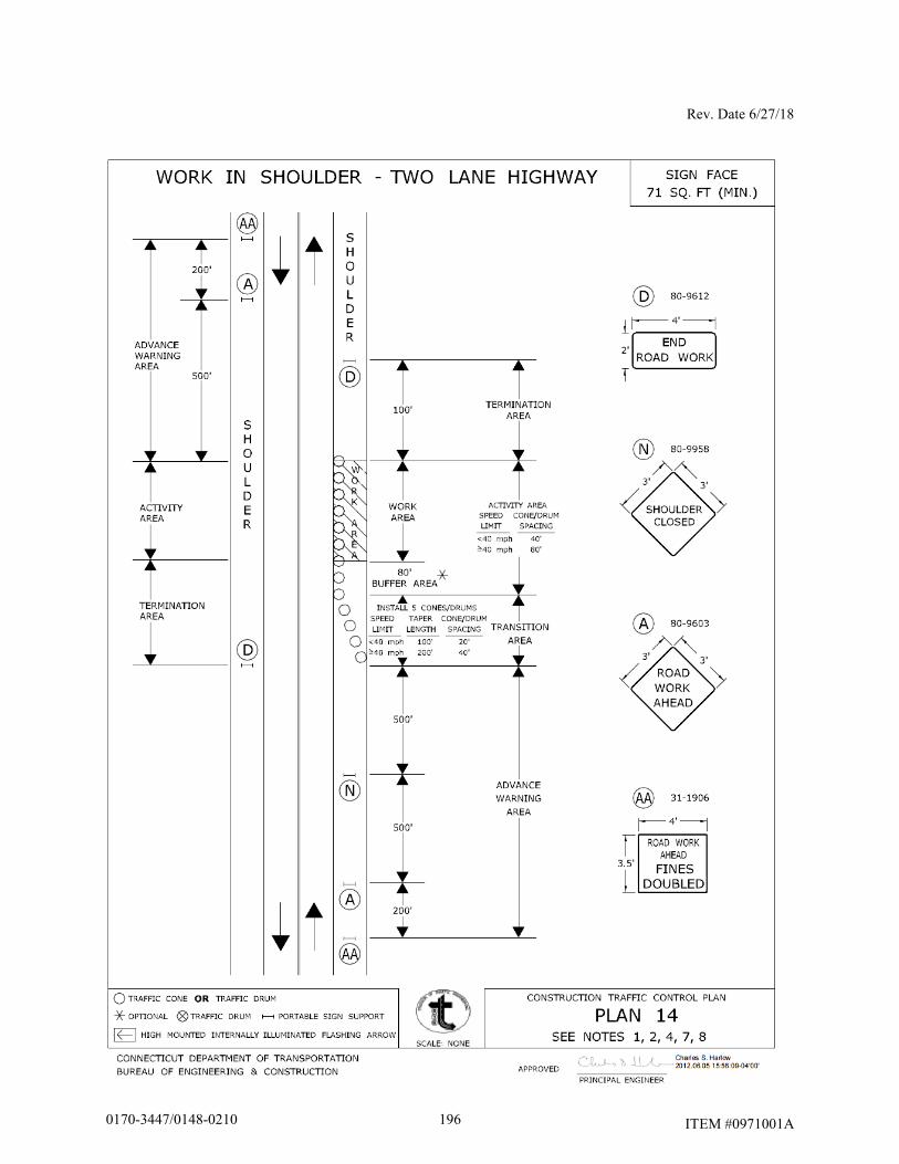
Rev. Date 6/27/18
ITEM #0971001A
1960170-3447/0148-0210
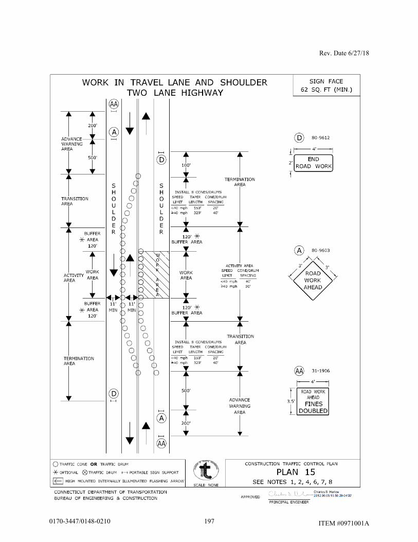
Rev. Date 6/27/18
ITEM #0971001A
1970170-3447/0148-0210
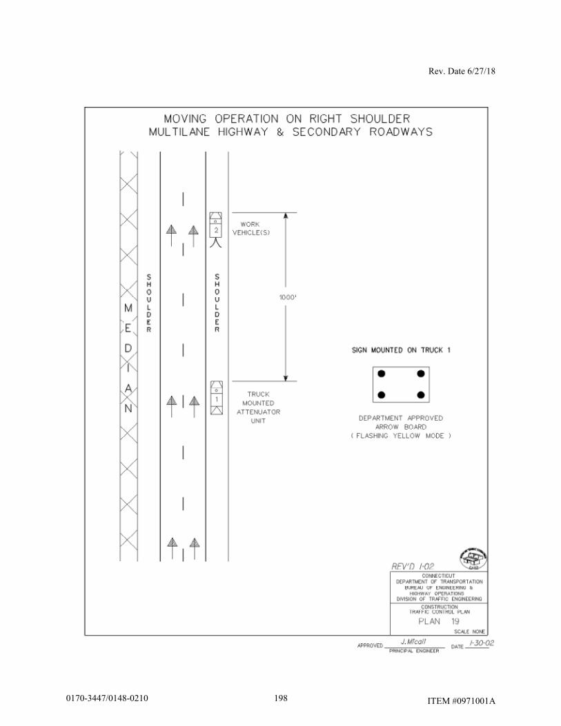
Rev. Date 6/27/18
ITEM #0971001A 1980170-3447/0148-0210
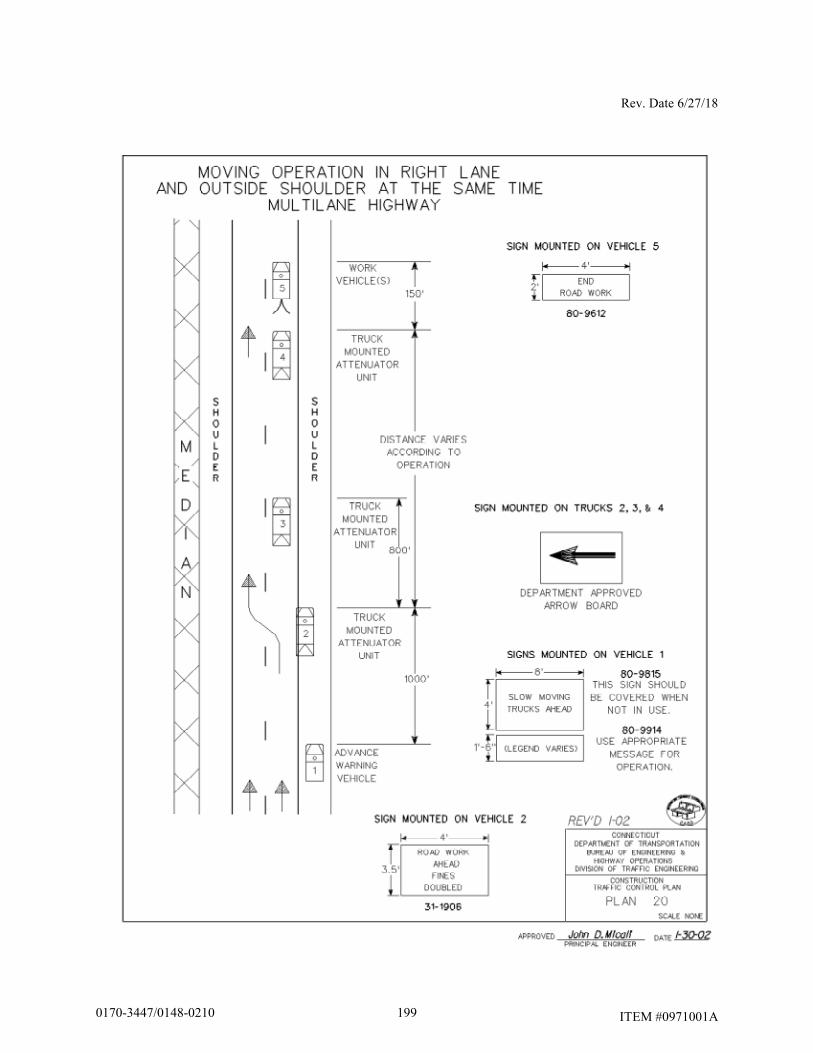
Rev. Date 6/27/18
ITEM #0971001A 1990170-3447/0148-0210
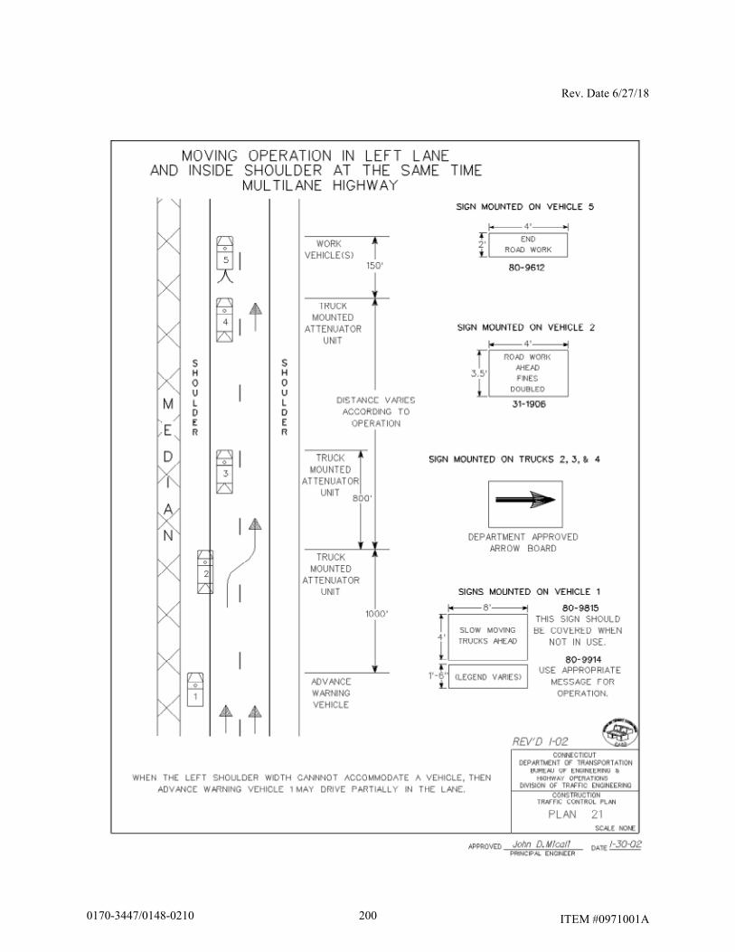
Rev. Date 6/27/18
ITEM #0971001A 2000170-3447/0148-0210
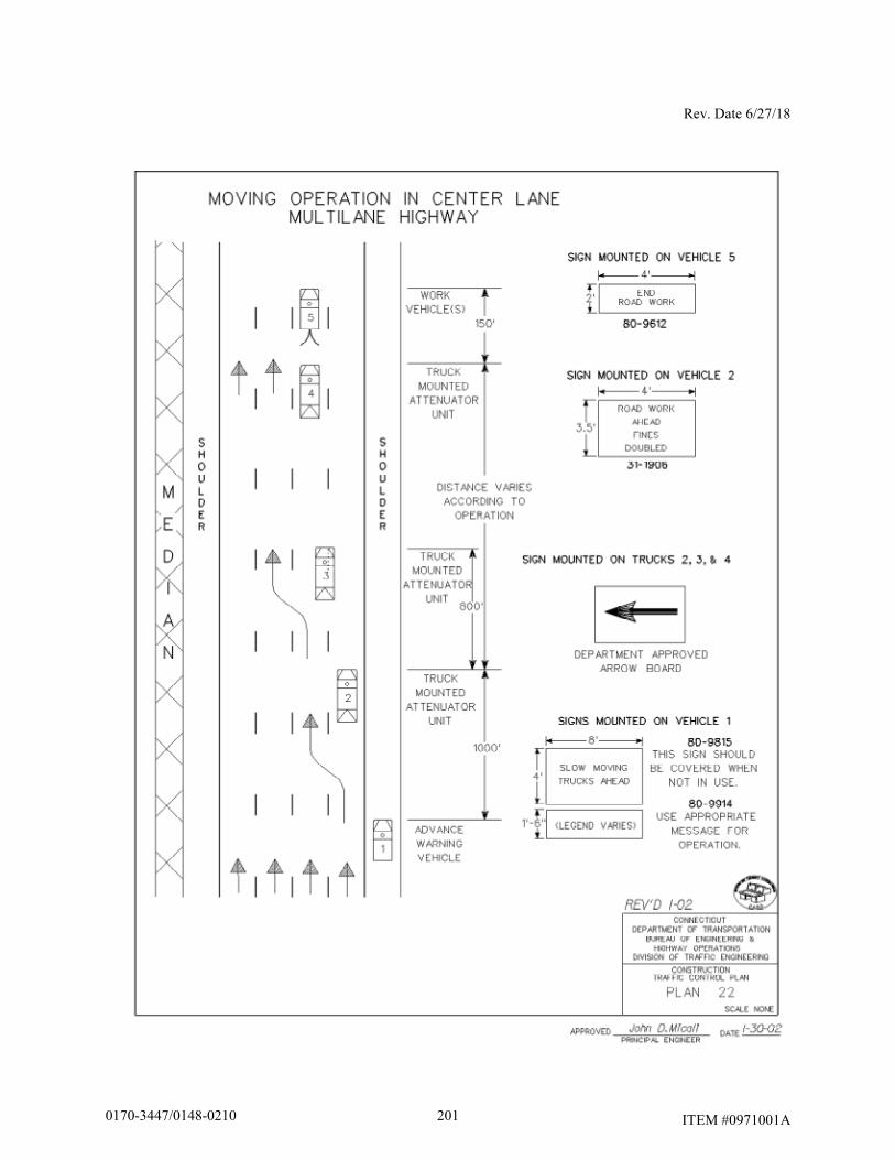
Rev. Date 6/27/18
ITEM #0971001A 2010170-3447/0148-0210
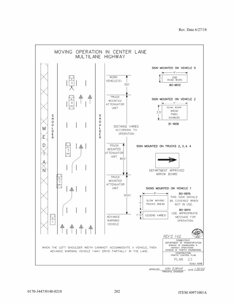
Rev. Date 6/27/18
ITEM #0971001A
2020170-3447/0148-0210
Rev. Date 6/27/18
ITEM #0971001A
Article 9.71.05 – Basis of Payment is supplemented by the following:
The temporary relocation of signs and supports, and the furnishing, installation and removal of any temporary supports shall be paid for under the item “Maintenance and Protection of Traffic”. Temporary overhead sign supports and foundations shall be paid for under the appropriate item(s). The cost of furnishing, installing, and removing the material for the 4H:1V traversable slope shall be paid for under the item “Maintenance and Protection of Traffic.”
2030170-3447/0148-0210
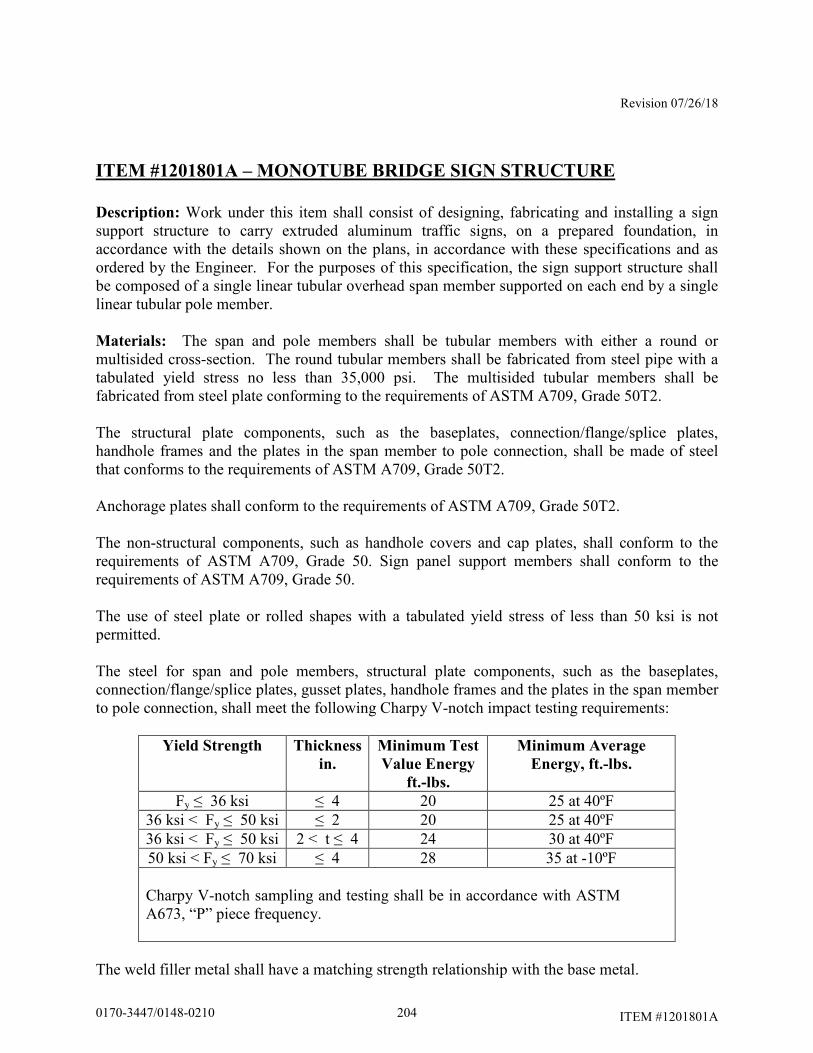
Revision 07/26/18
ITEM #1201801A
ITEM #1201801A – MONOTUBE BRIDGE SIGN STRUCTURE
Description: Work under this item shall consist of designing, fabricating and installing a sign support structure to carry extruded aluminum traffic signs, on a prepared foundation, in accordance with the details shown on the plans, in accordance with these specifications and as ordered by the Engineer. For the purposes of this specification, the sign support structure shall be composed of a single linear tubular overhead span member supported on each end by a single linear tubular pole member. Materials: The span and pole members shall be tubular members with either a round or multisided cross-section. The round tubular members shall be fabricated from steel pipe with a tabulated yield stress no less than 35,000 psi. The multisided tubular members shall be fabricated from steel plate conforming to the requirements of ASTM A709, Grade 50T2. The structural plate components, such as the baseplates, connection/flange/splice plates, handhole frames and the plates in the span member to pole connection, shall be made of steel that conforms to the requirements of ASTM A709, Grade 50T2. Anchorage plates shall conform to the requirements of ASTM A709, Grade 50T2. The non-structural components, such as handhole covers and cap plates, shall conform to the requirements of ASTM A709, Grade 50. Sign panel support members shall conform to the requirements of ASTM A709, Grade 50. The use of steel plate or rolled shapes with a tabulated yield stress of less than 50 ksi is not permitted. The steel for span and pole members, structural plate components, such as the baseplates, connection/flange/splice plates, gusset plates, handhole frames and the plates in the span member to pole connection, shall meet the following Charpy V-notch impact testing requirements:
Yield Strength Thickness
in.
Minimum Test
Value Energy
ft.-lbs.
Minimum Average
Energy, ft.-lbs.
Fy ≤ 36 ksi ≤ 4 20 25 at 40ºF 36 ksi < Fy ≤ 50 ksi ≤ 2 20 25 at 40ºF 36 ksi < Fy ≤ 50 ksi 2 < t ≤ 4 24 30 at 40ºF 50 ksi < Fy ≤ 70 ksi ≤ 4 28 35 at -10ºF Charpy V-notch sampling and testing shall be in accordance with ASTM A673, “P” piece frequency.
The weld filler metal shall have a matching strength relationship with the base metal.
2040170-3447/0148-0210
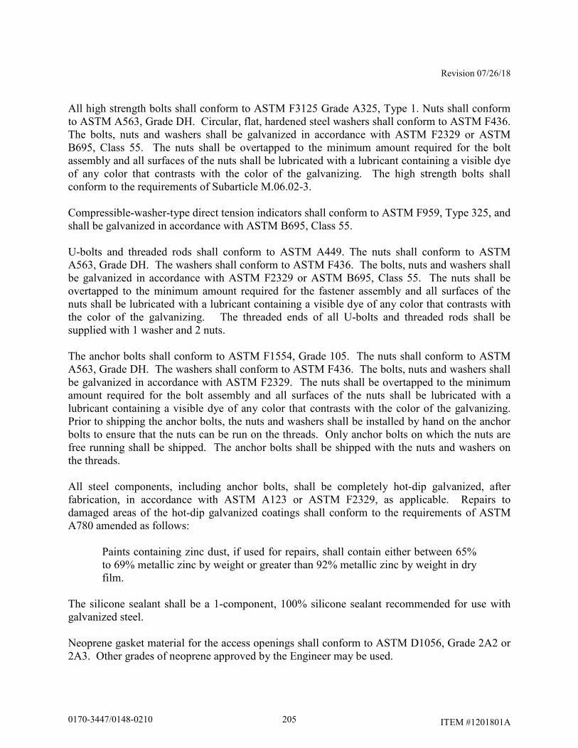
Revision 07/26/18
ITEM #1201801A
All high strength bolts shall conform to ASTM F3125 Grade A325, Type 1. Nuts shall conform to ASTM A563, Grade DH. Circular, flat, hardened steel washers shall conform to ASTM F436. The bolts, nuts and washers shall be galvanized in accordance with ASTM F2329 or ASTM B695, Class 55. The nuts shall be overtapped to the minimum amount required for the bolt assembly and all surfaces of the nuts shall be lubricated with a lubricant containing a visible dye of any color that contrasts with the color of the galvanizing. The high strength bolts shall conform to the requirements of Subarticle M.06.02-3. Compressible-washer-type direct tension indicators shall conform to ASTM F959, Type 325, and shall be galvanized in accordance with ASTM B695, Class 55. U-bolts and threaded rods shall conform to ASTM A449. The nuts shall conform to ASTM A563, Grade DH. The washers shall conform to ASTM F436. The bolts, nuts and washers shall be galvanized in accordance with ASTM F2329 or ASTM B695, Class 55. The nuts shall be overtapped to the minimum amount required for the fastener assembly and all surfaces of the nuts shall be lubricated with a lubricant containing a visible dye of any color that contrasts with the color of the galvanizing. The threaded ends of all U-bolts and threaded rods shall be supplied with 1 washer and 2 nuts. The anchor bolts shall conform to ASTM F1554, Grade 105. The nuts shall conform to ASTM A563, Grade DH. The washers shall conform to ASTM F436. The bolts, nuts and washers shall be galvanized in accordance with ASTM F2329. The nuts shall be overtapped to the minimum amount required for the bolt assembly and all surfaces of the nuts shall be lubricated with a lubricant containing a visible dye of any color that contrasts with the color of the galvanizing. Prior to shipping the anchor bolts, the nuts and washers shall be installed by hand on the anchor bolts to ensure that the nuts can be run on the threads. Only anchor bolts on which the nuts are free running shall be shipped. The anchor bolts shall be shipped with the nuts and washers on the threads. All steel components, including anchor bolts, shall be completely hot-dip galvanized, after fabrication, in accordance with ASTM A123 or ASTM F2329, as applicable. Repairs to damaged areas of the hot-dip galvanized coatings shall conform to the requirements of ASTM A780 amended as follows:
Paints containing zinc dust, if used for repairs, shall contain either between 65% to 69% metallic zinc by weight or greater than 92% metallic zinc by weight in dry film.
The silicone sealant shall be a 1-component, 100% silicone sealant recommended for use with galvanized steel. Neoprene gasket material for the access openings shall conform to ASTM D1056, Grade 2A2 or 2A3. Other grades of neoprene approved by the Engineer may be used.
2050170-3447/0148-0210
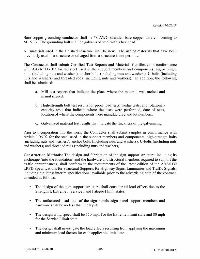
Revision 07/26/18
ITEM #1201801A
Bare copper grounding conductor shall be #8 AWG stranded bare copper wire conforming to M.15.13. The grounding bolt shall be galvanized steel with a hex head. All materials used in the finished structure shall be new. The use of materials that have been previously used in a structure or salvaged from a structure is not permitted. The Contractor shall submit Certified Test Reports and Materials Certificates in conformance with Article 1.06.07 for the steel used in the support members and components, high-strength bolts (including nuts and washers), anchor bolts (including nuts and washers), U-bolts (including nuts and washers) and threaded rods (including nuts and washers). In addition, the following shall be submitted:
a. Mill test reports that indicate the place where the material was melted and manufactured.
b. High-strength bolt test results for proof load tests, wedge tests, and rotational-
capacity tests that indicate where the tests were performed, date of tests, location of where the components were manufactured and lot numbers.
c. Galvanized material test results that indicate the thickness of the galvanizing.
Prior to incorporation into the work, the Contractor shall submit samples in conformance with Article 1.06.02 for the steel used in the support members and components, high-strength bolts (including nuts and washers), anchor bolts (including nuts and washers), U-bolts (including nuts and washers) and threaded rods (including nuts and washers). Construction Methods: The design and fabrication of the sign support structure, including its anchorage (into the foundation) and the hardware and structural members required to support the traffic appurtenances, shall conform to the requirements of the latest edition of the AASHTO LRFD Specifications for Structural Supports for Highway Signs, Luminaries and Traffic Signals, including the latest interim specifications, available prior to the advertising date of the contract, amended as follows:
• The design of the sign support structure shall consider all load effects due to the Strength I, Extreme I, Service I and Fatigue I limit states.
• The unfactored dead load of the sign panels, sign panel support members and
hardware shall be no less than the 8 psf.
• The design wind speed shall be 150 mph For the Extreme I limit state and 80 mph for the Service I limit state.
• The design shall investigate the load effects resulting from applying the maximum and minimum load factors for each applicable limit state.
2060170-3447/0148-0210
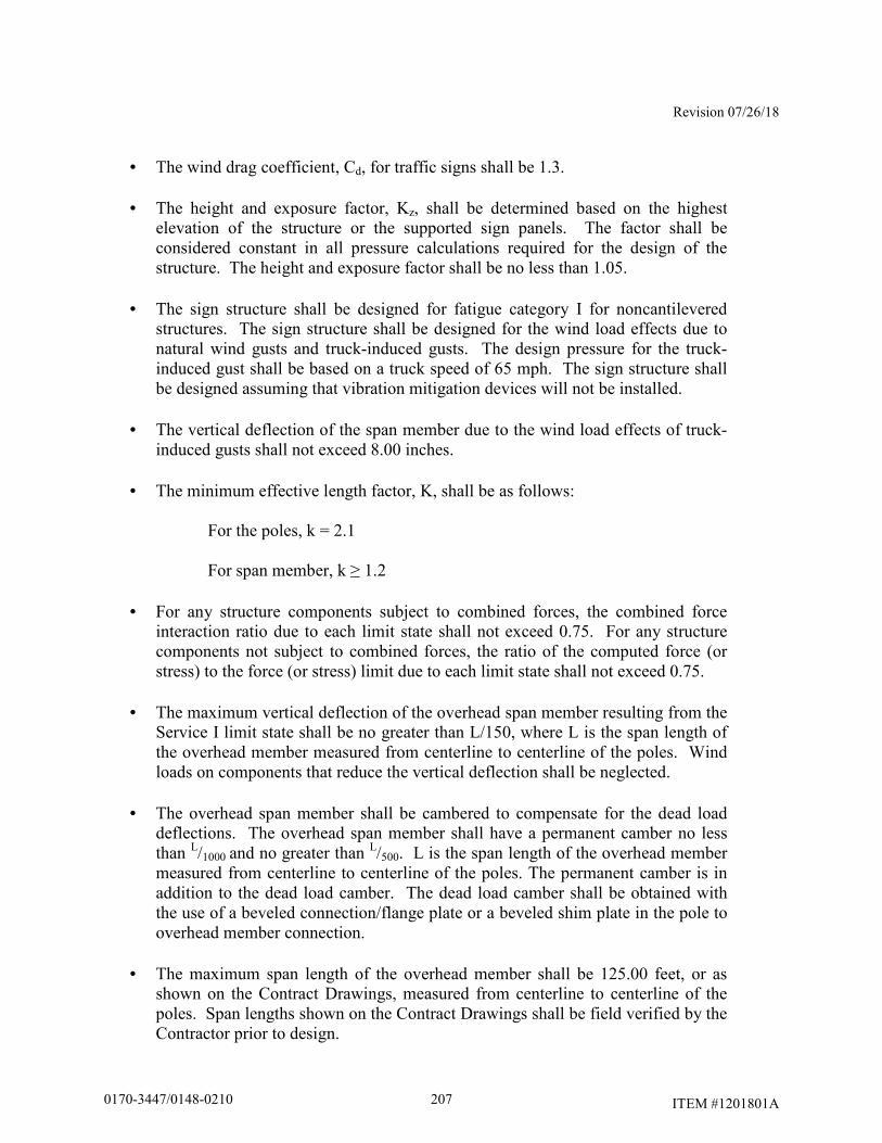
Revision 07/26/18
ITEM #1201801A
• The wind drag coefficient, Cd, for traffic signs shall be 1.3.
• The height and exposure factor, Kz, shall be determined based on the highest elevation of the structure or the supported sign panels. The factor shall be considered constant in all pressure calculations required for the design of the structure. The height and exposure factor shall be no less than 1.05.
• The sign structure shall be designed for fatigue category I for noncantilevered
structures. The sign structure shall be designed for the wind load effects due to natural wind gusts and truck-induced gusts. The design pressure for the truck-induced gust shall be based on a truck speed of 65 mph. The sign structure shall be designed assuming that vibration mitigation devices will not be installed.
• The vertical deflection of the span member due to the wind load effects of truck-
induced gusts shall not exceed 8.00 inches.
• The minimum effective length factor, K, shall be as follows:
For the poles, k = 2.1 For span member, k ≥ 1.2
• For any structure components subject to combined forces, the combined force
interaction ratio due to each limit state shall not exceed 0.75. For any structure components not subject to combined forces, the ratio of the computed force (or stress) to the force (or stress) limit due to each limit state shall not exceed 0.75.
• The maximum vertical deflection of the overhead span member resulting from the
Service I limit state shall be no greater than L/150, where L is the span length of the overhead member measured from centerline to centerline of the poles. Wind loads on components that reduce the vertical deflection shall be neglected.
• The overhead span member shall be cambered to compensate for the dead load
deflections. The overhead span member shall have a permanent camber no less than L/1000 and no greater than L/500. L is the span length of the overhead member measured from centerline to centerline of the poles. The permanent camber is in addition to the dead load camber. The dead load camber shall be obtained with the use of a beveled connection/flange plate or a beveled shim plate in the pole to overhead member connection.
• The maximum span length of the overhead member shall be 125.00 feet, or as
shown on the Contract Drawings, measured from centerline to centerline of the poles. Span lengths shown on the Contract Drawings shall be field verified by the Contractor prior to design.
2070170-3447/0148-0210
Revision 07/26/18
ITEM #1201801A
• The maximum diameter of the span and pole members shall be 2.50 feet.
• All tubular members on a structure shall have the same material designation.
• The span and pole members shall be tubular members with either round or multisided cross-sections. Span member components shall have the same cross-sectional shape. Multisided tubular members with other than 16 sides are not permitted. Multisided tubular members with fluted sides are not permitted.
• The minimum wall thickness of the tubular members shall be 0.3125 inches. The
wall thickness of the component members shall be uniform throughout their lengths. The use of multiple plies (laminations) to obtain the required member thickness is not permitted. The use of shop-fabricated stepped members is not permitted.
• The tubular members may be fabricated from multiple pieces. The pieces shall be
joined using a complete joint penetration groove weld with a backing ring. The complete joint penetration groove weld shall be ground smooth and flush with the adjacent base metal. 100% of the complete joint penetration groove weld shall be non-destructively tested by the ultrasonic method.
• Slip-type field splices are not permitted in any member.
• The tubular members may be fabricated with no more than 2 longitudinal seam
welds. The seam welds shall be ground smooth and flush with the adjacent base metal. The use of external longitudinal reinforcement bars at longitudinal seam welds is not permitted. The use of spiral seam welds is not permitted.
• The longitudinal seam welds within 6.00 inches of the member ends shall be
complete joint penetration groove welds.
• 100% of partial joint penetration longitudinal seam welds shall be non-destructively tested in accordance with the magnetic particle method. 100 % of complete joint penetration seam welds shall be non-destructively tested in accordance with the ultrasonic method.
• All tubular member to transverse plate connections shall be made with a complete
joint penetration groove weld with a backing ring attached to the plate with a continuous fillet weld. 100% of the complete joint penetration groove welds shall be non-destructively tested by the ultrasonic method after fabrication and prior to galvanizing. 100% of the complete joint penetration groove welds shall also be non-destructively tested by the ultrasonic method for toe cracks after galvanizing. 100% of backing ring fillet welds shall be non-destructively tested by the magnetic particle method after fabrication prior to galvanizing. After galvanizing,
2080170-3447/0148-0210
Revision 07/26/18
ITEM #1201801A
the joint between the backing ring and tubular member shall be sealed with silicone sealant to prevent the ingress of moisture.
• The use of stiffeners at tubular member to transverse plate connections is not
permitted.
• The strength of a connection made with a complete joint penetration groove weld shall be no greater than the strength of the base metal. In connections joining base metal with different yield strengths, the base metal with the lower yield strength shall govern the design.
• The minimum connection/flange/splice thickness shall be 2.00 inches. The
determination of the plate thickness in the tubular member to transverse plate connections shall consider the potential for the plate to warp due to the heat from welding. Consideration should be given to the use of thicker plates to allow for subsequent machining of warped plates to a flat surface so that removal of material will not compromise the required strength of the plate.
• All high-strength bolted connections shall be designed as slip critical connections
with standard holes, unless otherwise noted. The high-strength bolts shall conform to the maximum spacing requirements for sealing and stitch fasteners. The high-strength bolts shall conform to the edge distance requirement for fasteners. Consideration should be given to the use of smaller diameter bolts since they require lower specified minimum bolt tensions.
• The minimum number of high-strength bolts in flange splices shall be 8.
• The minimum thickness of the ring plates and gusset plates in the ring stiffened,
built-up box connection shall be 0.50 inches.
• The minimum size fillet weld shall be 0.25 inches, except the minimum size fillet welds in the ring stiffened, built-up box connection shall be 0.3125 inches. The use of seal and tack welds is not permitted. No welding shall be performed after galvanizing.
• The minimum base plate thickness shall no less than 2.50 inches, or at least as
thick as the anchor bolt diameter, whichever is greater. The determination of the plate thickness in the tubular member to transverse plate connections shall consider the potential for the plate to warp due to the heat from welding. Consideration should be given to the use of thicker plates to allow for subsequent machining of warped plates to a flat surface so that removal of material will not compromise the required strength of the plate.
2090170-3447/0148-0210
Revision 07/26/18
ITEM #1201801A
• The opening in the base plate shall be sized to allow for proper galvanizing and allow conduits projecting from the foundation to pass through it. The size of the opening shall be kept to a minimum to reduce the flexibility of the baseplate.
• The anchor bolt to base plate connection shall be designed as a double-nut
connection with shear holes. The minimum distance from the center of the anchor bolt hole to the edge of the base plate shall be no less than 2 times the diameter of the anchor bolt. The anchor bolts shall use an embedded anchorage plate, 0.75 inch minimum thickness, to transmit loads from the pole base to the concrete foundation. The use of hooked anchor bolts is not permitted. For poles less than 24.00 inches in diameter, the minimum number of anchor bolts shall be 8. For poles greater than or equal to 24.00 inches in diameter, the minimum number of anchor bolts shall be 12. The minimum anchor bolt diameter shall be 2.00 inches. The minimum anchor bolt embedment, the distance from the top of the foundation to the top of the embedded anchorage plate, shall be 3.50 feet or the tension development length of the vertical foundation reinforcement plus the end concrete cover, whichever is greater. Each anchor bolt shall be supplied with 5 nuts and 4 washers. Washers shall be placed on the top and bottom surfaces of the pole base plate and anchorage plate. Welding to the anchor bolts is not permitted. The use of lock washers with the anchor bolt assembly is not permitted.
The approximate dimensions of the overhead span member and the pole heights are shown in plan and elevation on the traffic sheets. The actual sign support dimensions shall be determined by the Contractor based on a the horizontal and vertical clearances shown on the plans, a field survey of the finished grade at the site, the elevation of the top of the finished foundation, the locations of overhead and subsurface utilities, the location of the drainage facilities and noise barrier wall locations. The minimum vertical clearance from the top of the finished road to the bottom of the sign panels and the centerline of the span member shall be a minimum of 18.00 feet unless shown otherwise on the plans. If shown on the plans, the minimum vertical clearance from the top of the finished road to the bottom of the sign panels shall be as shown on the sign structure drawings as amended by the sign structure elevation on the traffic sheets. Sign panels shall be installed symmetrically about the centerline of the overhead member. The bottom of all signs shall be level. Sign panels shall be installed at an angle of 5° from the vertical, with the top edge tilting toward oncoming traffic. The sign panels and crown panels, if applicable, shall be connected to sign panel support members. The support members shall extend full height of the sign and crown panels. The number and spacing of support members shall be determined by the Contractor based on the width of the sign and crown panels and the support member spacing parameters shown on the plans. Sign panels shall be supported by no less than 3 support members. Crown panels shall be supported by no less than 2 support members. The faying surface between the sign panel support member and the rear face of the sign panel shall be a flange so that panel clips may be placed on
2100170-3447/0148-0210
Revision 07/26/18
ITEM #1201801A
both sides of the flange to connect the panel. The outside support members for each sign panel shall include a sign stop at the bottom of the member and a sign hook at the top of the member to support and carry the sign panels. The sign panel support members shall be designed to be vertically adjustable to compensate for the overhead member camber. The supports members shall be designed to be installed at any location along the overhead member. The use of fixed connection plates welded transversely to the longitudinal axis of the overhead member is not permitted. The use of U-bolts and clamps with threaded fasteners is permitted provided the fasteners are not subject to shear forces. No less than 2 U-bolts or 4 threaded rods shall be used at each overhead member connection. The threaded ends of these fasteners shall have double nuts. The drilling of holes into the overhead member to prevent the panel support members from rotating is not permitted. The minimum thickness of the sign panel support members and the plate and rolled shape components used in the connection to the sign support shall be 0.25 inches. The sign support shall be designed for the load effects due to the actual sign panels, including crown panels, as well as any future sign and crown panels that it will carry, as shown on the plans. The sign supports shall also be designed for the load effects of sign and crown panels during all stages of construction which may exist during the project under which the supports are installed. The load effects on the sign support from the sign and crown panels shall include forces and moments due to the eccentricity of the sign and crown panels and the unbalanced lateral loads on the crown panel. The sign support and its component parts shall also be designed for the load effects resulting from the transportation and erection of the support. The sign support shall be designed so that the span member extends over and is connected to the top of the poles with a high-strength bolted, ring stiffened, built-up box connection. A minimum of 8 high-strength bolts shall be used to connect the pole connection plate to the built-up box connection plate. All bolts, nuts and washers used in the connection shall be visible. The use of tapped holes in the plates of the connection is not permitted. The use of a pin to connect the span member to the top of the poles is not permitted. The sign support and its component parts shall be designed for the governing load effects assuming the structure is rigidly connected at the span to pole connection and assuming the structure is free to rotate at the span to pole connection. Vent and drain holes shall be provided for galvanizing. The number, size and location of vent and drain holes should be coordinated with the galvanizer prior to the submission of the sign support design. The area of vent and drain holes at each end of a member shall be at least 30% of the inside area of the member for members 3.00 inches in diameter and greater and 45% of the inside area of the member for members smaller than 3.00 inches in diameter. The vent and drain holes shall be strategically located for reducing stress and for proper galvanizing. The holes shall be made by drilling. Flame cut holes are not permitted. The edges of all holes shall be rounded by grinding. After galvanizing, exposed holes placed in the sign support components for galvanizing shall be sealed with neoprene plugs.
2110170-3447/0148-0210
Revision 07/26/18
ITEM #1201801A
Each pole shall have a handhole located adjacent to base of the pole. One handhole shall be installed adjacent to each span member flange splice. All handholes shall be reinforced with a frame. The pole handholes shall be located with a normal direction that is 90° to the plane formed by the pole and overhead member. Handholes in the span member shall be oriented so that the opening faces down. In poles and in span members, the clear distance from the top of the baseplate or flange splice plate to the outside face of the bottom of the handhole frame shall be no less than the diameter of the tubular member plus 2 inches and no greater than the diameter of the tubular member plus 4 inches. The handhole frame shall be fabricated from steel plate and bent to form a closed shape and joined with a complete joint penetration groove weld. All surfaces of the groove weld shall be ground smooth and flush with the adjacent base metal. The handhole frame shall have a minimum 4.00 inch wide by minimum 6.00 inch high clear opening. The maximum width of the handhole opening, the clear opening plus twice the frame thickness, shall not be greater than 40% of the tubular member diameter at that section. The inside corners of the handhole frame shall be rounded to a radius of 30% to 50% of the width of the clear opening. The minimum thickness of the handhole frame shall be no less than the thickness of the pole or 0.3125 inches, whichever is greater. The handhole frame shall be connected to the tubular member with a partial joint penetration groove weld reinforced with a fillet weld. The handhole weld shall start and end at the point that is coincident with the longitudinal axis of symmetry of the tubular member and the longitudinal axis of symmetry of the handhole frame. 100% of the weld shall be non-destructively tested in accordance with the magnetic particle method. The handhole shall be provided with a cover connected to the frame with no less than 4 stainless steel screws. The cover shall be installed with a neoprene gasket matching the dimensions of the cover. The cover and the gasket and the handhole frame shall be in firm and continuous contact after tightening the fasteners. The cover shall also be attached to the frame with a 1.50 foot long stainless steel chain. The stainless steel chain shall be bolted to the inside face of the cover with a stainless steel bolt with a lock nut and also bolted to the inside side face of the handhole frame with a stainless steel bolt. On pole handhole frames, the side face of the handhole opposite of the stainless steel chain connection shall have a hole with a nut welded to outside face for a galvanized steel grounding bolt. The ends of each span member shall be sealed with a removable end cap plate attached to the member with no less than 3 threaded fasteners. The joint between the member and cap plate shall be sealed with a neoprene gasket. The design of the sign support and the anchorage shall be coordinated with the design of the foundation to ensure that the foundation is adequate for the support reactions and to avoid conflicts between the embedded anchorage and the foundation reinforcement. Prior to performing a field survey for each sign support, the Contractor shall coordinate with the Engineer to locate and stake each support foundation. The foundations shall be located to avoid conflicts with both subsurface and overhead utilities and subsurface drainage structures. In accordance with Article 1.05.15, the Contractor shall contact “Call Before You Dig” to identify the subsurface utilities that are located in the vicinity of each foundation. Once the location of
2120170-3447/0148-0210
Revision 07/26/18
ITEM #1201801A
each foundation has been found acceptable to the Engineer, the Contractor shall perform a field survey to obtain the information necessary to prepare a roadway cross-section with details of each sign support and supporting foundation(s). Prior to designing each sign support, the Contractor shall prepare and submit a cross-section (elevation) drawing based on a field survey for each sign support to the Engineer for review in accordance with 1.05.02. A cross-section drawing is a working drawing for permanent construction. Only one sign support cross-section shall be shown on each drawing. The cross-sections shall include, but not be limited to the following:
• Project number, town, location (route number, direction, mileage), station, structure number, sign location number, and site number
• Location and dimensions of travel lanes and shoulders
• Location and elevation of the high point of the road
• Top and bottom of slope elevations. Slope of finished grade at foundations
• Locations of utilities (both overhead and subsurface)
• Locations of drainage facilities
• Locations of noise barriers, including elevation of top of wall
• Type of protection (metal beam rail/barrier), and the dimension from the front face of
metal beam rail /barrier to the edge of the foundation and centerline of the foundation
• Elevation of the top of the foundation(s). The top of the foundation(s) shall project 6.00 inches to 12.00 inches above the level ground or 6.00 inches to 12.00 inches above the finished grade at the high side of a sloping grade.
• Dimension from top foundation to finish grade (existing or proposed as applicable).
• Span, dimension from centerline to centerline of foundations
• Dimensions of sign panel(s)
• Location of sign panel(s) relative to the centerline of the foundations/poles
• Location of sign panel(s) relative to the roadway travel lanes
• Dimension from top of foundation to centerline of overhead member
2130170-3447/0148-0210

Revision 07/26/18
ITEM #1201801A
• Minimum dimensions from high point of the road to the centerline of the overhead
member and the bottom of the sign panel(s)
• Elevation of centerline of overhead member If there are any changes to the proposed location of the sign support and foundations prior to the construction of the foundations, the cross-section shall be re-submitted for review. Prior to fabrication, the Contractor shall submit working drawings and design computations for each sign support, based on the reviewed cross-section, to the Engineer for review in accordance with Article 1.05.02. The working drawings and design computations for sign supports shall conform to working drawing requirements for permanent construction. An individual, independently packaged set of working drawings and computations, with all details and documents necessary for fabrication and erection of the structure and its components shall be prepared and submitted for each support. A single set of drawings with tabulated data for
multiple sign support locations is not permitted. Combining working drawing submittals for sign structures with submittals for structure foundations is not permitted. Working drawings for the erection of the structure shall conform to Subarticle 6.03.03-2(d). The packaged set of working drawings and computations for each support shall include the following:
• title sheet
• table of contents
• contact information for designer, fabricator and galvanizer – contact information should include name and address of each firm and the name of contact person with phone number and email address
• copy of fabricator’s AISC certification
• copy of the reviewed cross-section
• sign support working drawings
• sign support design computations
• welding procedures
• working drawings and supporting calculations for the erection of the structure
• sign support installation procedure, including the method to plumb the poles
2140170-3447/0148-0210
Revision 07/26/18
ITEM #1201801A
The sign support working drawings shall include complete details of all sign support components. The drawings shall include, but not be limited to the following:
• the project number, town and alpha-numeric support identification number
• reference to the design specifications, including interim specifications
• reference to the design specifications design criteria, such as design wind speed, minimum design life, etc.
• material specifications/designations for all components
• non-destructive weld testing requirements
• details of the location of the longitudinal seam weld in the span and pole members
• vent and drain holes for galvanizing
• dead load and permanent camber
• a plan view of the anchor bolt layout relative to the orientation of the span
• anchor bolt dimensions, including embedment and projection
• support installation procedure, including the method to plumb the poles
The sign support design computations shall include, but not be limited to the following:
• the project number, town and alpha-numeric support identification number
• references to design specifications, including interim specifications, and the applicable code section and articles
• description/documentation for all computer programs used in the design
• drawings/models of the structure, components and connections, with dimensions,
loads and references to the local and global coordinate systems used (as applicable), to facilitate review of the results
• a tabulation of the section properties of the tubular members at each analyzed
section. The tabulated values should include the diameter, D (if round member); effective width, b (if multisided member, AASHTO 5.5.2); equivalent diameter (if multisided member, AASHTO 5.6), wall thickness, t; inside bend radius, rb (if
2150170-3447/0148-0210
Revision 07/26/18
ITEM #1201801A
multisided member, AASHTO 5.5.2), cross-sectional area, A; moment of inertia, I; section modulus, S; radius of gyration, r. AASHTO Table B.2-1 may be used to determine the section properties. If Table B.2-1 is used, the radius measured to the mid-thickness of the wall shall also be provided.
• coefficients and factors used in the design
• results of all applicable limit states
• combined force interaction ratios for all applicable limit states
• maximum vertical deflection resulting from the Service I limit state
• vertical deflection of the span member due to the wind load effects of truck-
induced gusts
• total camber and permanent camber The submitted design computations shall reflect the load effects due to the actual sign panels, including crown panels, to be installed on the sign structure in the final condition. If additional sign and crown panels are shown on the plans for temporary signing during stage construction or for future signing, separate design computations shall be submitted to reflect those loading conditions and document the adequacy of the sign structure design. The Contractor shall make printed copies of the stamped working drawings and calculations, of the size and number determined by the Engineer, and deliver the copies as directed by the Engineer. If the as-built condition of the foundation(s), such as the location or elevation, will impact the design, final erection or assembly of the sign support for conformance with the requirements herein, the cross-section shall be re-submitted for review. Subsequently, the working drawings and calculations shall be resubmitted to conform to the revised cross-section and the requirements herein. The support shall be fabricated in accordance with the latest edition of the AASHTO LRFD Bridge Construction Specifications, including the latest interim specifications, amended herein. The steel fabricator shall meet the requirements of the AISC Certification Program for Manufacturers of Bridge and Highway Components (CPT). Fabrication of the support may begin only after the working drawings and design computations have been reviewed and the Engineer has authorized fabrication to begin. The Contractor shall submit to the Engineer, no less than 2 weeks prior to the start of fabrication, the name and location of the fabrication shop where the work will be done so that arrangements can be made for an audit of the facility and the assignment of the Department Quality Assurance (QA)
2160170-3447/0148-0210

Revision 07/26/18
ITEM #1201801A
inspector. No fabrication will be accepted unless the QA inspector is present during fabrication. No changes may be made during fabrication without prior written approval by the Department. The Contractor shall furnish facilities for the inspection of material and workmanship in the shop by the Engineer. The Engineer and his representative shall be allowed free access to the necessary parts of the premises. The Engineer will provide QA inspection at the fabrication shop to assure that all applicable Quality Control plans and inspections are adequately adhered to and maintained by the Contractor during all phases of the fabrication. A thorough inspection of a random selection of elements at the fabrication shop may serve as the basis of this assurance. Prior to shipment to the project, each individual piece of steel shall be marked in a clear and permanent fashion by a representative of the fabricators’ Quality Control (QC) Department to indicate complete final inspection by the fabricator and conformance to the project specifications for that piece. The mark must be dated. A Materials Certificate in accordance with Article 1.06.07 may be used in lieu of individual stamps or markings, for all material in a single shipment. The Materials Certificate must list each piece within the shipment and accompany the shipment to the project site. Following the final inspection by the fabricator’s QC personnel, the Engineer may select pieces of steel for re-inspection by the Department’s QA inspector. Should non-conforming pieces be identified, all similar pieces must be re-inspected by the fabricator and repair procedure(s) submitted to the Engineer for approval. Repairs will be made at the Contractor’s expense. The pieces selected for re-inspection and found to be in conformance, or adequately repaired pieces, may be marked by the QA inspector. Such markings indicate the Engineer takes no exception to the pieces being sent to the project site. Such marking does not indicate acceptance or approval of the material by the Engineer. All welding details, procedures and nondestructive testing shall conform to the requirements of AWS D1.1 Structural Welding Code - Steel. Personnel performing the nondestructive testing shall be certified as a NDT Level II technician in accordance with the American Society for Non Destructive Testing (ASNT), Recommended Practice SNT-TC-1A and approved by the Engineer. All nondestructive testing shall be witnessed by Engineer. Certified reports of all tests shall be submitted to the Engineer for examination. Each certified report shall identify the structure, member, and location of weld or welds tested. Each report shall also list the length and location of any defective welds and include information on the corrective action taken and results of all retests of repaired welds. The Department reserves the right to perform additional testing as determined by the Engineer. Should the Engineer require nondestructive testing on welds not designated in the contract, the
2170170-3447/0148-0210
Revision 07/26/18
ITEM #1201801A
cost of such inspection shall be borne by the Contractor if the testing indicates that any weld(s) are defective. If the testing indicates the weld(s) to be satisfactory, the actual cost of such inspection will be paid by the Department. All members and components shall be hot-dip galvanized in a single dip. Double-dipping of members and components is not permitted. All exterior and interior surfaces of the sign support members and components, including the interior of the ring-stiffened built-up box connection, shall be completely galvanized. Galvanized members and components shall be free from uncoated areas, blisters, flux deposits, and gross inclusions. Lumps, projections, globules, or heavy deposits of zinc which will interfere with the intended use of the material will not be permitted. All damaged areas of the hot-dip galvanized surfaces shall be repaired in accordance with the requirements of ASTM A780. If paint containing zinc dust is used for repairs, the dry coating thickness shall be at least 50% greater than the thickness of the adjacent hot-dip galvanized coating, but no greater than 4.0 mils. The paint shall be brush applied. The use of aerosol spray cans shall not be permitted. The color of the finished repair area shall match the color of the adjacent hot-dip galvanized surface at the time of the repair to the satisfaction of the Engineer. Prior to shipping, all galvanized surfaces of the members and components shall be inspected, in the presence of the Engineer, to determine the acceptability of the galvanized coating. Galvanized coatings may be found acceptable by the Engineer if all surfaces of the members and components meet the galvanizing requirements herein. Only sign support members and components with acceptable galvanized coatings shall be shipped. If the galvanized coating on any member or component is found not acceptable, the Contractor shall submit a repair procedure to the Engineer for review. Unless provisions for the sign support structure number are otherwise included in the contract, the sign support structure number shall be stenciled in black paint on the right side pole (as determined by the direction of traffic traveling below the structure) centered approximately 5.00 feet off the ground and visible from the roadway. The numeric characters shall be 3.00 inches to 4.00 inches high and placed vertically so that they may be read from top to bottom. After fabrication, the sign support components shall be assembled in the fabricator's shop, in the presence of the Engineer, to determine the acceptability of the bolted connections and to confirm the permanent camber. The faying surfaces of the connections shall be free of dirt, loose scale, burrs, other foreign material and other defects that would prevent solid seating of the parts. Prior to assembly, the galvanized faying surfaces shall be scored by wire brushing. The faying surfaces of the connection plates shall be checked with a straight edge to ensure that the surfaces are not distorted and the entire faying surface of each plate will be in contact when assembled. The high-strength bolts, including nuts and washers, shall be installed and tensioned in accordance with Subarticle 6.03.03-4(f). A connection may be found acceptable by the Engineer if the faying surfaces of the connection plates are in firm, continuous contact after properly tensioning the bolts. Only sign supports with acceptable connections shall be shipped. If a bolted
2180170-3447/0148-0210
Revision 07/26/18
ITEM #1201801A
connection is found not acceptable, the Contractor shall submit a procedure to repair the connection to the Engineer for review. Galvanized surfaces damaged by the repair procedure shall be hot dip galvanized. Repair of the damaged galvanized surfaces in accordance with the requirements of ASTM A780 or with a galvanizing repair stick is not permitted. Bolts, nuts and washers used for the trial shop fit-up shall not be reused in the final field assembly. With the overhead member supported at the ends, the permanent camber shall be measured at mid-span and the structure shall be rejected if the camber does not meet the following:
L/1000 ≤ Permanent Camber ≤ L/500 where L is the span length of the overhead member measured from centerline to centerline of the poles. The finished members and components shall be protected with sufficient dunnage and padding to protect them from damage and distortion during transportation. Damage to any material during transportation, improper storage, faulty erection, or undocumented fabrication errors may be cause for rejection of said material at the project site. All costs associated with any corrective action will be borne by the Contractor. Following delivery to the project site, the Engineer will perform a visual inspection of all material to verify shipping documents, fabricator markings, and that there was no damage to the material or coatings during transportation and handling. The Engineer is not responsible for approving or accepting any fabricated materials prior to final erection and assembly at the project site. High-strength bolts, nuts and washers shall be stored in accordance with Subarticle 6.03.03-4(f). The support shall be erected, assembled and installed in accordance with these specifications and the procedures and methods submitted with the working drawings. The Contractor and the support designer are responsible to ensure that the erection and assembly procedures and methods in this specification are acceptable for use with the support. Changes to these methods and procedures shall be submitted with the working drawings and computations. Prior to installation of the support, the exposed threads of all the embedded anchor bolts shall be cleaned of accumulated dirt and concrete and lubricated. The threads and bearing surfaces of all the anchor bolt nuts shall be cleaned and lubricated. The anchor bolts and nuts are properly lubricated if the nuts can be turned by hand on the anchor bolt threads. The lubricant shall contain a visible dye of any color that contrasts with the color of the galvanizing. Re-lubricate the threads of the anchor bolts and nuts if more than 24 hours have elapsed since earlier lubrication, or if the anchor bolts and nuts have become wet since they were first lubricated. The space between the bottom of the baseplate and the top of the foundation shall not be sealed with closed cell elastomer or filled with grout, unless otherwise noted.
2190170-3447/0148-0210
Revision 07/26/18
ITEM #1201801A
Install (turn) the leveling nuts onto the anchor bolts and align the nuts to the same elevation or plane. The distance from the bottom of the leveling nuts to the top of the foundation shall not exceed 1.00 inch. Place a structural hardened washer on top of each leveling nut, 1 washer on each anchor bolt. The pole shall be erected so that the centerline of the pole will be plumb after the application of all the dead loads. Install the pole base plate atop the washers resting on the leveling nuts, place a structural hardened washer on each anchor bolt resting it on the top of the base plate, and install (turn) a top nut on each anchor bolt until the nut contacts the washer. The leveling nuts and washers shall be inspected, and if necessary the nuts (turned), so that the washers are in full contact with the bottom surface of the base plate. Tighten the top nuts to a snug tight condition in a star pattern. Snug tight is defined as the maximum rotation resulting from the full effort of one person using a 12.00 inch long wrench or equivalent. A star tightening pattern is one in which the nuts on opposite or near-opposite sides of the bolt circle are successively tightened in a pattern resembling a star (e.g., For an 8-bolt circle with bolt sequentially numbered 1 to 8, tighten nuts in the following bolt order: 1, 5, 7, 3, 8, 4, 6, 2.). Tighten leveling nuts to a snug tight condition in a star pattern. Before final tightening of the top nuts, mark the reference position of each top nut in a snug-tight condition with a suitable marking on 1 flat with a corresponding reference mark on the base plate at each bolt. Then incrementally turn the top nuts using a star pattern one-sixth of a turn beyond snug tight. Turn the nuts in at least two full tightening cycles (passes). After tightening, verify the top nut rotation. The top nuts shall have full thread engagement. The distance from the bottom of the leveling nuts to the top of the foundation shall not exceed 1.00 inch. High-strength bolts, including nuts and washers, shall be installed and tensioned in accordance with Subarticle 6.03.03-4(f). The overhead member shall be temporarily and fully supported while all the high-strength bolts are installed and tensioned. The temporary support of the overhead member shall not be removed until the Engineer has confirmed that the faying surfaces of the connection/flange plates are in firm, continuous contact and the high-strength bolts were properly installed and tensioned. All high-strength bolts in the bolted connections shall be inspected (in accordance with Subarticle 6.03.03-4(f)) to confirm the high-strength bolts were properly tensioned. The use or installation of galvanized hardened steel washers between the faying surfaces of the connection is not permitted. After erecting the support, the support shall be electrically grounded by attaching the bare copper grounding conductor to the inside of the handhole frame with a galvanized steel bolt and to the ground rod with a ground clamp. The rigid metal conduit shall be electrically grounded by attaching the bare copper grounding conductor to the insulated bonding bushing and to the ground rod with a ground clamp.
2200170-3447/0148-0210
Revision 07/26/18
ITEM #1201801A
After erection of the support and before the installation of the sign panels, if the structure exhibits excessive vibration, oscillations or deflections as determined by the Engineer, the Contractor shall immediately stabilize the structure to the satisfaction of the Engineer. Stabilizing the structure may require the removal of a portion of the structure or the entire structure. The sign panels shall be located and mounted on the span member as shown in the working drawings. After installation of the sign panels, the anchor bolts nuts (leveling and top anchor nut) and washers shall be in full contact with the top and bottom surfaces of the pole baseplate and the centerline of the pole shall be plumb. After erection of the support and after the installation of the sign panels, if the structure exhibits excessive vibration, oscillations or deflections as determined by the Engineer, the Contractor shall design and construct devices to mitigate the movements. The Contractor is responsible for immediately stabilizing the structure to the satisfaction of the Engineer. Stabilizing the structure may require the removal of the sign panels or the entire structure. Prior to installation of any mitigation device, the Contractor shall submit drawings, design computations and other documentation to the Engineer for review in accordance with Article 1.05.02. Method of Measurement: This work will be measured for payment by the number of monotube bridge sign structures, completed and accepted in place. Basis of Payment: This work will be paid for at the contract unit price each for "Monotube Bridge Sign Structure", complete in place, which price shall include field survey, equipment, materials, tools and labor incidental to the design, fabrication, quality control, transportation, erection and installation, including anchorage materials, sign panel support members and mitigation devices, if required, of the supports at the locations specified on the plans.
2210170-3447/0148-0210
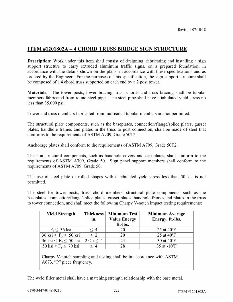
Revision 07/10/18
ITEM #1201802A
ITEM #1201802A – 4 CHORD TRUSS BRIDGE SIGN STRUCTURE
Description: Work under this item shall consist of designing, fabricating and installing a sign support structure to carry extruded aluminum traffic signs, on a prepared foundation, in accordance with the details shown on the plans, in accordance with these specifications and as ordered by the Engineer. For the purposes of this specification, the sign support structure shall be composed of a 4 chord truss supported on each end by a 2 post tower. Materials: The tower posts, tower bracing, truss chords and truss bracing shall be tubular members fabricated from round steel pipe. The steel pipe shall have a tabulated yield stress no less than 35,000 psi. Tower and truss members fabricated from multisided tubular members are not permitted. The structural plate components, such as the baseplates, connection/flange/splice plates, gusset plates, handhole frames and plates in the truss to post connection, shall be made of steel that conforms to the requirements of ASTM A709, Grade 50T2. Anchorage plates shall conform to the requirements of ASTM A709, Grade 50T2. The non-structural components, such as handhole covers and cap plates, shall conform to the requirements of ASTM A709, Grade 50. Sign panel support members shall conform to the requirements of ASTM A709, Grade 50. The use of steel plate or rolled shapes with a tabulated yield stress less than 50 ksi is not permitted. The steel for tower posts, truss chord members, structural plate components, such as the baseplates, connection/flange/splice plates, gusset plates, handhole frames and plates in the truss to tower connection, and shall meet the following Charpy V-notch impact testing requirements:
Yield Strength Thickness
in.
Minimum Test
Value Energy
ft.-lbs.
Minimum Average
Energy, ft.-lbs.
Fy ≤ 36 ksi ≤ 4 20 25 at 40ºF 36 ksi < Fy ≤ 50 ksi ≤ 2 20 25 at 40ºF 36 ksi < Fy ≤ 50 ksi 2 < t ≤ 4 24 30 at 40ºF 50 ksi < Fy ≤ 70 ksi ≤ 4 28 35 at -10ºF Charpy V-notch sampling and testing shall be in accordance with ASTM A673, “P” piece frequency.
The weld filler metal shall have a matching strength relationship with the base metal.
2220170-3447/0148-0210
Revision 07/10/18
ITEM #1201802A
All high strength bolts shall conform to ASTM F3125 Grade A325, Type 1. Nuts shall conform to ASTM A563, Grade DH. Circular, flat, hardened steel washers shall conform to ASTM F436. The bolts, nuts and washers shall be galvanized in accordance with ASTM F2329 or ASTM B695, Class 55. The nuts shall be overtapped to the minimum amount required for the bolt assembly and all surfaces of the nuts shall be lubricated with a lubricant containing a visible dye of any color that contrasts with the color of the galvanizing. The high strength bolts shall conform to the requirements of Subarticle M.06.02-3. Compressible-washer-type direct tension indicators shall conform to ASTM F959, Type 325, and shall be galvanized in accordance with ASTM B695, Class 55. U-bolts and threaded rods shall conform to ASTM A449. The nuts shall conform to ASTM A563, Grade DH. The washers shall conform to ASTM F436. The bolts, nuts and washers shall be galvanized in accordance with ASTM F2329 or ASTM B695, Class 55. The nuts shall be overtapped to the minimum amount required for the fastener assembly and all surfaces of the nuts shall be lubricated with a lubricant containing a visible dye of any color that contrasts with the color of the galvanizing. The threaded ends of all U-bolts and threaded rods shall be supplied with 1 washer and 2 nuts. The anchor bolts shall conform to ASTM F1554, Grade 105. The nuts shall conform to ASTM A563, Grade DH. The washers shall conform to ASTM F436. The bolts, nuts and washers shall be galvanized in accordance with ASTM F2329. The nuts shall be overtapped to the minimum amount required for the bolt assembly and all surfaces of the nuts shall be lubricated with a lubricant containing a visible dye of any color that contrasts with the color of the galvanizing. Prior to shipping the anchor bolts, the nuts and washers shall be installed by hand on the anchor bolts to ensure that the nuts can be run on the threads. Only anchor bolts on which the nuts are free running shall be shipped. The anchor bolts shall be shipped with the nuts and washers on the threads. All steel components, including anchor bolts, shall be completely hot-dip galvanized, after fabrication, in accordance with ASTM A123 or ASTM F2329, as applicable. Repairs to damaged areas of the hot-dip galvanized coatings shall conform to the requirements of ASTM A780 amended as follows:
Paints containing zinc dust, if used for repairs, shall contain either between 65% to 69% metallic zinc by weight or greater than 92% metallic zinc by weight in dry film.
The silicone sealant shall be a 1-component, 100% silicone sealant recommended for use with galvanized steel. Neoprene gasket material for the access openings shall conform to ASTM D1056, Grade 2A2 or 2A3. Other grades of neoprene approved by the Engineer may be used.
2230170-3447/0148-0210

Revision 07/10/18
ITEM #1201802A
Bare copper grounding conductor shall be #8 AWG stranded bare copper wire conforming to M.15.13. The grounding bolt shall be galvanized steel with a hex head. All materials used in the finished structure shall be new. The use of materials that have been previously used in a structure or salvaged from a structure is not permitted. The Contractor shall submit Certified Test Reports and Materials Certificates in conformance with Article 1.06.07 for the steel used in the tower and truss members and components, high-strength bolts (including nuts and washers), anchor bolts (including nuts and washers), U-bolts (including nuts and washers) and threaded rods (including nuts and washers). In addition, the following shall be submitted:
a. Mill test reports that indicate the place where the material was melted and manufactured.
b. High-strength bolt test results for proof load tests, wedge tests, and rotational-
capacity tests that indicate where the tests were performed, date of tests, location of where the components were manufactured and lot numbers.
c. Galvanized material test results that indicate the thickness of the galvanizing.
Prior to incorporation into the work, the Contractor shall submit samples in conformance with Article 1.06.02 for the steel used in the support members and components, high-strength bolts (including nuts and washers), anchor bolts (including nuts and washers), U-bolts (including nuts and washers) and threaded rods (including nuts and washers). Construction Methods: The design and fabrication of the sign support structure, including its anchorage (into the foundation) and the hardware and structural members required to support the traffic appurtenances, shall conform to the requirements of the latest edition of the AASHTO LRFD Specifications for Structural Supports for Highway Signs, Luminaries and Traffic Signals, including the latest interim specifications, available prior to the advertising date of the contract, amended as follows:
• The design of the sign support structure shall consider all load effects due to the Strength I, Extreme I, Service I and Fatigue I limit states.
• The unfactored dead load of the sign panels, sign panel support members and
hardware shall be no less than the 8 psf.
• The design wind speed shall be 150 mph for the Extreme I limit state and 80 mph for the Service I limit state.
• The design shall investigate the load effects resulting from applying the maximum
and minimum load factors for each applicable limit state.
2240170-3447/0148-0210
Revision 07/10/18
ITEM #1201802A
• The wind drag coefficient, Cd, for traffic signs shall be 1.3.
• The height and exposure factor, Kz, shall be determined based on the highest elevation of the structure or the supported sign panels. The factor shall be considered constant in all pressure calculations required for the design of the structure. The height and exposure factor shall be no less than 1.05.
• The sign structure shall be designed for fatigue category I for noncantilevered
structures. The sign structure shall be designed for the wind load effects due to natural wind gusts and truck-induced gusts. The design pressure for the truck-induced gust shall be based on a truck speed of 65 mph. The sign structure shall be designed assuming that vibration mitigation devices will not be installed.
• The vertical deflection of the truss due to the wind load effects of truck-induced
gusts shall not exceed 8 inches.
• The fixity of the structure connections shall be as follows:
Welded gusset plate, bracing member to chord connections shall be considered rigid in the plane of the gusset plate and pinned perpendicular to the plane of the gusset plate.
Flange plate chord to chord connections shall be considered rigid with respect to both axes.
Baseplate to anchor bolt connection shall be considered rigid with respect to both axes.
• The minimum effective length factor, K, shall be as follows:
For the tower posts, k = 2.1
For truss chord and bracing, and tower bracing, k ≥ 1.0
• For any structure components subject to combined forces, the combined force
interaction ratio due to each limit state shall not exceed 0.75. For any structure components not subject to combined forces, the ratio of the computed force (or stress) to the force (or stress) limit due to each limit state shall not exceed 0.75.
• The maximum vertical deflection of the overhead truss resulting from the Service
I limit state shall be no greater than L/150, where L is the span length of the truss measured from centerline to centerline of the tower posts. Wind loads on components that reduce the vertical deflection shall be neglected.
2250170-3447/0148-0210
Revision 07/10/18
ITEM #1201802A
• The truss shall be cambered to compensate for the dead load deflections. The truss shall have a permanent camber no less than L/1000 and no greater than L/500. L is the span length of the truss measured from centerline to centerline of the tower posts. The permanent camber is in addition to the dead load camber.
• The maximum span length of the truss shall be 200.00 feet or as shown on the
Contract Drawings, measured from the centerline to centerline of the towers. Span lengths shown on the Contract Drawings shall be field verified by the Contractor prior to design.
• The truss chords shall be fabricated in 1 or more sections and connected with
chord flange splices. The chords within the sections shall be fabricated from a single piece of pipe. Chord sections fabricated from multiple pieces of pipe are not permitted. All truss chords shall have the same cross-sectional properties and material designations. The minimum wall thickness of the truss chord members shall be 0.3125 inches.
• Tower posts shall be fabricated from a single piece of pipe. Posts fabricated from
multiple pieces of pipe are not permitted. All tower posts shall have the same cross-sectional properties and material designations. The minimum wall thickness of the tower posts shall be 0.3125 inches. The maximum outer diameter of the tower posts shall not exceed 2.00 feet.
• Tower and truss bracing shall be fabricated from steel pipe. All tower bracing
shall have the same cross-sectional properties. All truss bracing shall have the same cross-sectional properties. The cross-sectional properties of the tower and truss bracing may differ. All bracing shall have the same material designations. The bracing shall have a minimum nominal diameter of 2.50 inches. The bracing shall have a minimum thickness of 0.203 inches. The bracing shall be connected to tower post and truss chord gusset plates with slotted tube connections. The bracing slot shall have a coped hole at the end of the slot. In a minimum of 25% of the bracing gusset plate to tower post connections, 100% of the fillet welds on each side of the connection, shall be non-destructively tested in accordance with the magnetic particle method. In a minimum of 25% of the bracing gusset plate to truss chord connections, 100% of the fillet welds on each side of the connection, shall be non-destructively tested in accordance with the magnetic particle method.
• At a minimum, internal diagonal bracing shall be provided at each end of each
truss section to maintain the shape and stability the truss sections during shipping and handling of the sections and the erection of the completed truss. At a minimum, additional internal diagonal bracing shall be placed at a panel point at the midspan of the truss sections greater than 25.00 feet in length. The internal diagonal bracing may be provided using either a single member or multiple members.
2260170-3447/0148-0210
Revision 07/10/18
ITEM #1201802A
• All tubular member to transverse plate connections shall be made with a complete joint penetration groove weld with a backing ring attached to the plate with a continuous fillet weld. 100% of the complete joint penetration groove welds shall be non-destructively tested by the ultrasonic method after fabrication and prior to galvanizing. 100% of the complete joint penetration groove welds shall also be non-destructively tested by the ultrasonic method for toe cracks after galvanizing. 100% of backing ring fillet welds shall be non-destructively tested by the magnetic particle method after fabrication prior to galvanizing. After galvanizing, the joint between the backing ring and tubular member shall be sealed with silicone sealant to prevent the ingress of moisture.
• The use of stiffeners at tubular member to transverse plate connections is not
permitted.
• The strength of a connection made with a complete joint penetration groove weld shall be no greater than the strength of the base metal. In connections joining base metal with different yield strengths, the base metal with the lower yield strength shall govern the design.
• The minimum flange splice plate thickness shall be 2.00 inches. The
determination of the plate thickness in the tubular member to transverse plate connections shall consider the potential for the plate to warp due to the heat from welding. Consideration should be given to the use of thicker plates to allow for subsequent machining of warped plates to a flat surface so that removal of material will not compromise the required strength of the plate.
• All high-strength bolted connections shall be designed as slip critical connections
with standard holes, unless otherwise noted. The high-strength bolts shall conform to the maximum spacing requirements for sealing and stitch fasteners. The high-strength bolts shall conform to the edge distance requirement for fasteners. Consideration should be given to the use of smaller diameter bolts since they require lower specified minimum bolt tensions.
• The minimum number of high-strength bolts in flange splices in the truss chords
shall be 6.
• The minimum thickness of the tower and truss bracing gusset plates shall be 0.50 inches.
• The minimum size fillet weld shall be 0.25 inches, unless noted otherwise. The
use of seal and tack welds is not permitted. No welding shall be performed after galvanizing.
• The minimum base plate thickness shall no less than 2.00 inches or at least as
thick as the anchor bolt diameter, whichever is greater. The determination of the
2270170-3447/0148-0210
Revision 07/10/18
ITEM #1201802A
plate thickness in the tubular member to transverse plate connections shall consider the potential for the plate to warp due to the heat from welding. Consideration should be given to the use of thicker plates to allow for subsequent machining of warped plates to a flat surface so that removal of material will not compromise the required strength of the plate.
• The opening in the base plate shall be sized to allow for proper galvanizing and
allow conduits projecting from the foundation to pass through it. The size of the opening shall be kept to a minimum to reduce the flexibility of the baseplate.
• The anchor bolt to base plate connection shall be designed as a double-nut
connection with shear holes. The minimum distance from the center of the anchor bolt hole to the edge of the base plate shall be no less than 2 times the diameter of the anchor bolt. The anchor bolts shall use an embedded anchorage plate, 0.75 inch minimum thickness, to transmit loads from the post base to the concrete foundation. The use of hooked anchor bolts is not permitted. The minimum number of anchor bolts shall be 4. The minimum anchor bolt diameter shall be 1.50 inches. The minimum anchor bolt embedment, the distance from the top of the foundation to the top of the embedded anchorage plate, shall be 3.50 feet or the tension development length of the vertical foundation reinforcement plus the end concrete cover, whichever is greater, unless otherwise shown on the plans. Each anchor bolt shall be supplied with 5 nuts and 4 washers. Washers shall be placed on the top and bottom surfaces of the post base plate and anchorage plate. Welding to the anchor bolts is not permitted. The use of lock washers with the anchor bolt assembly is not permitted.
The approximate dimensions of the truss and the tower post heights are shown in plan and elevation on the traffic sheets. The actual sign support dimensions shall be determined by the Contractor based on a the horizontal and vertical clearances shown on the plans, a field survey of the finished grade at the site, the elevation of the top of the finished foundation, the locations of overhead and subsurface utilities, the location of the drainage facilities and noise barrier wall locations. The minimum vertical clearance from the top of the finished road to the bottom of the sign panels and the centerline of the truss shall be a minimum of 18.00 feet unless shown otherwise on the plans. If shown on the plans, the minimum vertical clearance from the top of the finished road to the bottom of the sign panels and the centerline of the truss shall be as shown on the sign support drawings as amended by the sign support elevation on the traffic sheets. The minimum vertical clearance from the top of the finished road to the lowest point of the bottom chords of the truss system shall be no less than 20.00 feet. Sign panels shall be installed symmetrically about the centerline of the truss. The bottom of all signs shall be level. Sign panels shall be installed at an angle of 5° from the vertical, with the top edge tilting toward oncoming traffic.
2280170-3447/0148-0210
Revision 07/10/18
ITEM #1201802A
The sign panels and crown panels, if applicable, shall be connected to sign panel support members. The support members shall extend full height of the sign and crown panels. The number and spacing of support members shall be determined by the Contractor based on the width of the sign and crown panels and the support member spacing parameters shown on the plans. Sign panels shall be supported by no less than 3 support members. Crown panels shall be supported by no less than 2 support members. The faying surface between the sign panel support member and the rear face of the sign panel shall be a flange so that panel clips may be placed on both sides of the flange to connect the panel. The outside support members for each sign panel shall include a sign stop at the bottom of the member and a sign hook at the top of the member to support and carry the sign panels. The sign panel support members shall be designed to be vertically adjustable to compensate for the truss camber. The supports members shall be designed to be installed at any location along the truss. The use of U-bolts and threaded rods is permitted. No less than 2 U-bolts or 4 threaded rods shall be used at each chord connection. The threaded ends of these fasteners shall have double nuts. The minimum thickness of the sign panel support members and the plate and rolled shape components used in the connection to the sign support shall be 0.25 inches. The sign support shall be designed for the load effects due to the actual sign panels, including crown panels, as well as any future sign and crown panels that it will carry, as shown on the plans. The sign supports shall also be designed for the load effects of sign and crown panels during all stages of construction which may exist during the project under which the supports are installed. The load effects on the sign support from the sign and crown panels shall include forces and moments due to the eccentricity of the sign and crown panels and the unbalanced lateral loads on the crown panel. The sign support and its component parts shall also be designed for the load effects resulting from the transportation and erection of the support. The sign support shall be designed so that the 4 chords of the truss fit within the tower posts. Each truss chord shall be connected to a tower post. 100% of the fillet welds used in the truss to post connection shall be non-destructively tested in accordance with the magnetic particle method. All bolts, nuts and washers used in the connection shall be visible. The use of tapped holes in the plates of the connection is not permitted. Vent and drain holes shall be provided for galvanizing. The number, size and location of vent and drain holes should be coordinated with the galvanizer prior to the submission of the sign support design. The area of vent and drain holes at each end of a member shall be at least 30% of the inside area of the member for members 3.00 inches in diameter and greater and 45% of the inside area of the member for members smaller than 3.00 inches in diameter. The vent and drain holes shall be strategically located for reducing stress and for proper galvanizing. The holes shall be made by drilling. Flame cut holes are not permitted. The edges of all holes shall be rounded by grinding. After galvanizing, exposed holes placed in the sign support components for galvanizing shall be sealed with neoprene plugs.
2290170-3447/0148-0210
Revision 07/10/18
ITEM #1201802A
One post in each tower shall have a handhole located adjacent to base of the post. The handhole shall be reinforced with a frame. The handhole shall be located with a normal direction that is 90° to the plane formed by the post and overhead truss. The clear distance from the top of the baseplate to the outside face of the bottom of the handhole frame shall be no less than the diameter of the tubular member plus 2 inches and no greater than the diameter of the tubular member plus 4 inches. The handhole frame shall be fabricated from steel plate and bent to form a closed shape and joined with a complete joint penetration groove weld. All surfaces of the groove weld shall be ground smooth and flush with the adjacent base metal. The handhole frame shall have a minimum 4.00 inch wide by minimum 6.00 inch high clear opening. The maximum width of the handhole opening, the clear opening plus twice the frame thickness, shall not be greater than 40% of the post diameter at that section. The inside corners of the handhole frame shall be rounded to a radius of 30% to 50% of the width of the clear opening. The minimum thickness of the handhole frame shall be no less than the thickness of the post or 0.3125 inches, whichever is greater. The handhole frame shall be connected to the post with a partial joint penetration groove weld reinforced with a fillet weld. The handhole weld shall start and end at the point that is coincident with the longitudinal axis of symmetry of the post and the longitudinal axis of symmetry of the handhole frame. 100% of the weld shall be non-destructively tested in accordance with the magnetic particle method. The handhole shall be provided with a cover connected to the frame with no less than 4 stainless steel screws. The cover shall be installed with a neoprene gasket matching the dimensions of the cover. The cover and the gasket and the handhole frame shall be in firm and continuous contact after tightening the fasteners. The cover shall also be attached to the frame with a 1.50 foot long stainless steel chain. The stainless steel chain shall be bolted to the inside face of the cover with a stainless steel bolt with a lock nut and also bolted to the inside side face of the handhole frame with a stainless steel bolt. On post handhole frames, the side face of the handhole opposite of the stainless steel chain connection shall have a hole with a nut welded to outside face for a galvanized steel grounding bolt. The ends of each chord member shall be sealed with a removable end cap plate attached to the member with a threaded fastener. The joint between the member and cap plate shall be sealed with a neoprene gasket. The design of the sign support and the anchorage shall be coordinated with the design of the foundation to ensure that the foundation is adequate for the support reactions and to avoid conflicts between the embedded anchorage and the foundation reinforcement. Prior to performing a field survey for each sign support, the Contractor shall coordinate with the Engineer to locate and stake each support foundation. The foundations shall be located to avoid conflicts with both subsurface and overhead utilities and subsurface drainage structures. In accordance with Article 1.05.15, the Contractor shall contact “Call Before You Dig” to identify the subsurface utilities that are located in the vicinity of each foundation. Once the location of each foundation has been found acceptable to the Engineer, the Contractor shall perform a field survey to obtain the information necessary to prepare a roadway cross-section with details of each sign support and supporting foundation(s).
2300170-3447/0148-0210
Revision 07/10/18
ITEM #1201802A
Prior to designing each sign support, the Contractor shall prepare and submit a cross-section (elevation) drawing based on a field survey for each sign support to the Engineer for review in accordance with 1.05.02. A cross-section drawing is a working drawing for permanent construction. Only one sign support cross-section shall be shown on each drawing. The cross-sections shall include, but not be limited to the following:
• Project number, town, location (route number, direction, mileage), station, structure number, sign location number, and site number
• Location and dimensions of travel lanes and shoulders
• Location and elevation of the high point of the road
• Top and bottom of slope elevations. Slope of finished grade at foundations
• Locations of utilities (both overhead and subsurface)
• Locations of drainage facilities
• Locations of noise barriers, including elevation of top of wall
• Type of protection (metal beam rail/barrier), and the dimension from the front
face of metal beam rail /barrier to the edge of the foundation and centerline of the foundation
• Elevation of the top of the foundation(s). The top of the foundation(s) shall
project 6.00 inches to 12.00 inches above the level ground or 6.00 inches to 12.00 inches above the finished grade at the high side of a sloping grade.
• Dimension from top foundation to finish grade (existing or proposed as
applicable).
• Span, dimension from centerline to centerline of foundations
• Dimensions of sign panel(s)
• Location of sign panel(s) relative to the centerline of the foundations/posts
• Location of sign panel(s) relative to the roadway travel lanes
• Dimension from top of foundation to centerline of truss
2310170-3447/0148-0210
Revision 07/10/18
ITEM #1201802A
• Minimum dimensions from high point of the road to the centerline of the truss and the bottom of the sign panel(s)
• Elevation of centerline of truss
If there are any changes to the proposed location of the sign support and foundations prior to the construction of the foundations, the cross-section shall be re-submitted for review. Prior to fabrication, the Contractor shall submit working drawings and design computations for each sign support, based on the reviewed cross-section, to the Engineer for review in accordance with Article 1.05.02. The working drawings and design computations for sign supports shall conform to working drawings for permanent construction. An individual, independently packaged set of working drawings and computations, with all details and documents necessary for fabrication and erection of the structure and its components shall be prepared and submitted for each support. A single set of drawings with tabulated data for
multiple sign support locations is not permitted. Combining working drawing submittals for sign structures with submittals for structure foundations is not permitted. Working drawings for the erection of the structure shall conform to Subarticle 6.03.03-2(d). The packaged set of working drawings and computations for each support shall include the following:
• title sheet
• table of contents
• contact information for designer, fabricator and galvanizer – contact information should include name and address of each firm and the name of contact person with phone number and email address
• copy of fabricator’s AISC certification
• copy of the reviewed cross-section
• sign support working drawings
• sign support design computations
• welding procedures
• working drawings and supporting calculations for the erection of the structure
• sign support installation procedure, including the method to plumb the tower
posts
2320170-3447/0148-0210
Revision 07/10/18
ITEM #1201802A
The sign support working drawings shall include complete details of all sign support components. The drawings shall include, but not be limited to the following:
• the project number, town and alpha-numeric support identification number
• reference to the design specifications, including interim specifications
• reference to the design specifications design criteria, such as design wind speed, minimum design life, etc.
• material specifications/designations for all components
• non-destructive weld testing requirements
• vent and drain holes for galvanizing
• dead load and permanent camber
• a plan view of the anchor bolt layout relative to the orientation of the span
• anchor bolt dimensions, including embedment and projection
• support installation procedure, including the method to plumb the tower posts
The sign support design computations shall include, but not be limited to the following:
• the project number, town and alpha-numeric support identification number
• references to design specifications, including interim specifications, and the applicable code section and articles
• description/documentation for all computer programs used in the design
• drawings/models of the structure, components and connections, with
dimensions, loads and references to the local and global coordinate systems used (as applicable), to facilitate review of the results
• Tabulation of the section properties of the tubular members at each analyzed
section. The tabulated values should include the diameter, D; wall thickness, t; cross-sectional area, A; moment of inertia, I; section modulus, S; radius of gyration, r. AASHTO Table B.2-1 may be used to determine the section properties. If Table B.2-1 is used, the radius measured to the mid-thickness of the wall shall also be provided.
2330170-3447/0148-0210
Revision 07/10/18
ITEM #1201802A
• coefficients and factors used in the design
• results of all applicable limit states
• combined force interaction ratios for all applicable limit states
• maximum vertical deflection resulting from the Service I limit state
• vertical deflection of the truss due to the wind load effects of truck-induced gusts
• total camber and permanent camber
The submitted design computations shall reflect the load effects due to the actual sign panels, including crown panels, to be installed on the sign structure in the final condition. If additional sign and crown panels are shown on the plans for temporary signing during stage construction or for future signing, separate design computations shall be submitted to reflect those loading conditions and document the adequacy of the sign structure design. The Contractor shall make printed copies of the stamped working drawings and calculations, of the size and number determined by the Engineer, and deliver the copies as directed by the Engineer. If the as-built condition of the foundation(s), such as the location or elevation, will impact the design, final erection or assembly of the sign support for conformance with the requirements herein, the cross-section shall be re-submitted for review. Subsequently, the working drawings and calculations shall be resubmitted to conform to the revised cross-section and the requirements herein. If the as-built condition of the foundation(s), such as the location or elevation, will impact the design, final erection or assembly of the sign support for conformance with the requirements herein, the cross-section shall be re-submitted for review. Subsequently, the working drawings and calculations shall be resubmitted to conform to the revised cross-section and the requirements herein. The support shall be fabricated in accordance with the latest edition of the AASHTO LRFD Bridge Construction Specifications, including the latest interim specifications, amended herein. The steel fabricator shall meet the requirements of the AISC Certification Program for Manufacturers of Bridge and Highway Components (CPT). Fabrication of the support may begin only after the working drawings and design computations have been reviewed and the Engineer has authorized fabrication to begin. The Contractor shall submit to the Engineer, no less than 2 weeks prior to the start of fabrication, the name and location of the fabrication shop where the work will be done so that arrangements can be made
2340170-3447/0148-0210

Revision 07/10/18
ITEM #1201802A
for an audit of the facility and the assignment of the Department Quality Assurance (QA) inspector. No fabrication will be accepted unless the QA inspector is present during fabrication. No changes may be made during fabrication without prior written approval by the Department. The Contractor shall furnish facilities for the inspection of material and workmanship in the shop by the Engineer. The Engineer and his representative shall be allowed free access to the necessary parts of the premises. The Engineer will provide QA inspection at the fabrication shop to assure that all applicable Quality Control plans and inspections are adequately adhered to and maintained by the Contractor during all phases of the fabrication. A thorough inspection of a random selection of elements at the fabrication shop may serve as the basis of this assurance. Prior to shipment to the project, each individual piece of steel shall be marked in a clear and permanent fashion by a representative of the fabricators’ Quality Control (QC) Department to indicate complete final inspection by the fabricator and conformance to the project specifications for that piece. The mark must be dated. A Materials Certificate in accordance with Article 1.06.07 may be used in lieu of individual stamps or markings, for all material in a single shipment. The Materials Certificate must list each piece within the shipment and accompany the shipment to the project site. Following the final inspection by the fabricator’s QC personnel, the Engineer may select pieces of steel for re-inspection by the Department’s QA inspector. Should non-conforming pieces be identified, all similar pieces must be re-inspected by the fabricator and repair procedure(s) submitted to the Engineer for approval. Repairs will be made at the Contractor’s expense. The pieces selected for re-inspection and found to be in conformance, or adequately repaired pieces, may be marked by the QA inspector. Such markings indicate the Engineer takes no exception to the pieces being sent to the project site. Such marking does not indicate acceptance or approval of the material by the Engineer. All welding details, procedures and nondestructive testing shall conform to the requirements of AWS D1.1 Structural Welding Code - Steel. Personnel performing the nondestructive testing shall be certified as a NDT Level II technician in accordance with the American Society for Non Destructive Testing (ASNT), Recommended Practice SNT-TC-1A and approved by the Engineer. All nondestructive testing shall be witnessed by Engineer. Certified reports of all tests shall be submitted to the Engineer for examination. Each certified report shall identify the structure, member, and location of weld or welds tested. Each report shall also list the length and location of any defective welds and include information on the corrective action taken and results of all retests of repaired welds.
2350170-3447/0148-0210
Revision 07/10/18
ITEM #1201802A
The Department reserves the right to perform additional testing as determined by the Engineer. Should the Engineer require nondestructive testing on welds not designated in the contract, the cost of such inspection shall be borne by the Contractor if the testing indicates that any weld(s) are defective. If the testing indicates the weld(s) to be satisfactory, the actual cost of such inspection will be paid by the Department. All members and components shall be hot-dip galvanized in a single dip. Double-dipping of members and components is not permitted. All exterior and interior surfaces of the sign support members and components shall be completely galvanized. Galvanized members and components shall be free from uncoated areas, blisters, flux deposits, and gross inclusions. Lumps, projections, globules, or heavy deposits of zinc which will interfere with the intended use of the material will not be permitted. All damaged areas of the hot-dip galvanized surfaces shall be repaired in accordance with the requirements of ASTM A780. If paint containing zinc dust is used for repairs, the dry coating thickness shall be at least 50% greater than the thickness of the adjacent hot-dip galvanized coating, but no greater than 4.0 mils. The paint shall be brush applied. The use of aerosol spray cans shall not be permitted. The color of the finished repair area shall match the color of the adjacent hot-dip galvanized surface at the time of the repair to the satisfaction of the Engineer. Prior to shipping, all galvanized surfaces of the members and components shall be inspected, in the presence of the Engineer, to determine the acceptability of the galvanized coating. Galvanized coatings may be found acceptable by the Engineer if all surfaces of the members and components meet the galvanizing requirements herein. Only sign support members and components with acceptable galvanized coatings shall be shipped. If the galvanized coating on any member or component is found not acceptable, the Contractor shall submit a repair procedure to the Engineer for review. Unless provisions for the sign support structure number are otherwise included in the contract, the sign support structure number shall be stenciled in black paint on the right side pole (as determined by the direction of traffic traveling below the structure) centered approximately 5.00 feet off the ground and visible from the roadway. The numeric characters shall be 3.00 inches to 4.00 inches high and placed vertically so that they may be read from top to bottom. After fabrication, the sign support components shall be assembled in the fabricator's shop, in the presence of the Engineer, to determine the acceptability of the bolted connections and to confirm the permanent camber. The faying surfaces of the connections shall be free of dirt, loose scale, burrs, other foreign material and other defects that would prevent solid seating of the parts. Prior to assembly, the galvanized faying surfaces shall be scored by wire brushing. The faying surfaces of the connection plates shall be checked with a straight edge to ensure that the surfaces are not distorted and the entire faying surface of each plate will be in contact when assembled. The high-strength bolts, including nuts and washers, shall be installed and tensioned in accordance with Subarticle 6.03.03-4(f). A connection may be found acceptable by the Engineer if the faying surfaces of the connection plates are in firm, continuous contact after properly tensioning
2360170-3447/0148-0210
Revision 07/10/18
ITEM #1201802A
the bolts. Only sign supports with acceptable connections shall be shipped. If a bolted connection is found not acceptable, the Contractor shall submit a procedure to repair the connection to the Engineer for review. Galvanized surfaces damaged by the repair procedure shall be hot dip galvanized. Repair of the damaged galvanized surfaces in accordance with the requirements of ASTM A780 or with a galvanizing repair stick is not permitted. Bolts, nuts and washers used for the trial shop fit-up shall not be reused in the final field assembly. The permanent camber shall be measured at mid-span and the member shall be rejected if the camber does not meet the following:
L/1000 ≤ Permanent Camber ≤ L/500 where L is the span length of the overhead member measured from centerline to centerline of the tower posts. The finished members and components shall be protected with sufficient dunnage and padding to protect them from damage and distortion during transportation. Damage to any material during transportation, improper storage, faulty erection, or undocumented fabrication errors may be cause for rejection of said material at the project site. All costs associated with any corrective action will be borne by the Contractor. Following delivery to the project site, the Engineer will perform a visual inspection of all material to verify shipping documents, fabricator markings, and that there was no damage to the material or coatings during transportation and handling. The Engineer is not responsible for approving or accepting any fabricated materials prior to final erection and assembly at the project site. High-strength bolts, nuts and washers shall be stored in accordance with Subarticle 6.03.03-4(f). The support shall be erected, assembled and installed in accordance with these specifications and the procedures and methods submitted with the working drawings. The Contractor and the support designer are responsible to ensure that the erection and assembly procedures and methods in this specification are acceptable for use with the support. Changes to these methods and procedures shall be submitted with the working drawings and computations. Prior to installation of the support, the exposed threads of all the embedded anchor bolts shall be cleaned of accumulated dirt and concrete and lubricated. The threads and bearing surfaces of all the anchor bolt nuts shall be cleaned and lubricated. The anchor bolts and nuts are properly lubricated if the nuts can be turned by hand on the anchor bolt threads. The lubricant shall contain a visible dye of any color that contrasts with the color of the galvanizing. Re-lubricate the threads of the anchor bolts and nuts if more than 24 hours has elapsed since earlier lubrication, or if the anchor bolts and nuts have become wet since they were first lubricated. The space between the bottom of the baseplate and the top of the foundation shall not be sealed with closed cell elastomer or filled with grout, unless otherwise noted.
2370170-3447/0148-0210
Revision 07/10/18
ITEM #1201802A
Install (turn) the leveling nuts onto the anchor bolts and align the nuts to the same elevation or plane. The distance from the bottom of the leveling nuts to the top of the foundation shall not exceed 1.00 inch. Place a structural hardened washer on top of each leveling nut, 1 washer on each anchor bolt. The tower shall be erected so that the centerline of the tower will be plumb after the application of all the dead loads. Install the post base plate atop the washers resting on the leveling nuts, place a structural hardened washer on each anchor bolt resting it on the top of the base plate, and install (turn) a top nut on each anchor bolt until the nut contacts the washer. The leveling nuts and washers shall be inspected, and if necessary the nuts (turned), so that the washers are in full contact with the bottom surface of the base plate. Tighten the top nuts to a snug tight condition in a star pattern. Snug tight is defined as the maximum rotation resulting from the full effort of one person using a 12.00 inch long wrench or equivalent. A star tightening pattern is one in which the nuts on opposite or near-opposite sides of the bolt circle are successively tightened in a pattern resembling a star (e.g., For an 8-bolt circle with bolt sequentially numbered 1 to 8, tighten nuts in the following bolt order: 1, 5, 7, 3, 8, 4, 6, 2.). Tighten leveling nuts to a snug tight condition in a star pattern. Before final tightening of the top nuts, mark the reference position of each top nut in a snug-tight condition with a suitable marking on 1 flat with a corresponding reference mark on the base plate at each bolt. Then incrementally turn the top nuts using a star pattern one-sixth of a turn beyond snug tight. Turn the nuts in at least two full tightening cycles (passes). After tightening, verify the top nut rotation. The top nuts shall have full thread engagement. The distance from the bottom of the leveling nuts to the top of the foundation shall not exceed 1.00 inch. High-strength bolts, including nuts and washers, shall be installed and tensioned in accordance with Subarticle 6.03.03-4(f). The truss shall be temporarily and fully supported while all the high-strength bolts are installed and tensioned. The temporary support of the truss shall not be removed until the Engineer has confirmed that the faying surfaces of the connection/flange plates are in firm, continuous contact and the high-strength bolts were properly installed and tensioned. All high-strength bolts in the bolted connections shall be inspected (in accordance with Subarticle 6.03.03-4(f)) to confirm the high-strength bolts were properly tensioned. After erecting the support, the support shall be electrically grounded by attaching the bare copper grounding conductor to the inside of the handhole frame with a galvanized steel bolt and to the ground rod with a ground clamp. The rigid metal conduit shall be electrically grounded by attaching the bare copper grounding conductor to the insulated bonding bushing and to the ground rod with a ground clamp.
2380170-3447/0148-0210
Revision 07/10/18
ITEM #1201802A
After erection of the support and before the installation of the sign panels, if the structure exhibits excessive vibration, oscillations or deflections as determined by the Engineer, the Contractor shall immediately stabilize the structure to the satisfaction of the Engineer. Stabilizing the structure may require the removal of a portion of the structure or the entire structure. The sign panels shall be located and mounted on the truss as shown in the working drawings. After installation of the sign panels, the anchor bolts nuts (leveling and top anchor nut) and washers shall be in full contact with the top and bottom surfaces of the post baseplate and the centerline of the post shall be plumb. After erection of the support and after the installation of the sign panels, if the structure exhibits excessive vibration, oscillations or deflections as determined by the Engineer, the Contractor shall design and construct devices to mitigate the movements. The Contractor is responsible for immediately stabilizing the structure to the satisfaction of the Engineer. Stabilizing the structure may require the removal of the sign panels or the entire structure. Prior to installation of any mitigation device, the Contractor shall submit drawings, design computations other documentation to the Engineer for review in accordance with Article 1.05.02. Method of Measurement: This work will be measured for payment by the number of bridge sign structures, completed and accepted in place. Basis of Payment: This work will be paid for at the contract unit price each for "4 Chord Truss Bridge Sign Structure", complete in place, which price shall include the field survey, equipment, materials, tools and labor incidental to the design, fabrication, quality control, transportation, erection and installation, including anchorage materials, sign panel support members and mitigation devices, if required, of the supports at the locations specified on the plans.
2390170-3447/0148-0210
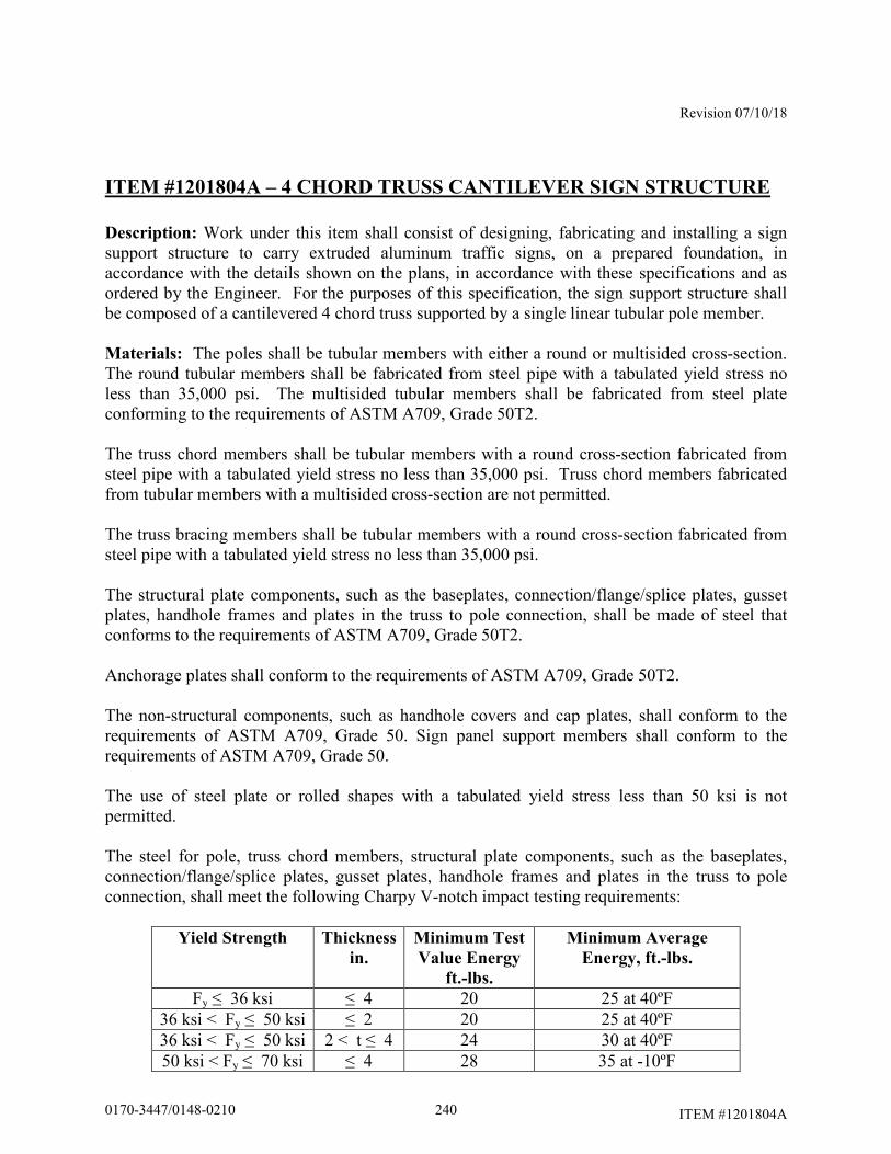
Revision 07/10/18
ITEM #1201804A
ITEM #1201804A – 4 CHORD TRUSS CANTILEVER SIGN STRUCTURE
Description: Work under this item shall consist of designing, fabricating and installing a sign support structure to carry extruded aluminum traffic signs, on a prepared foundation, in accordance with the details shown on the plans, in accordance with these specifications and as ordered by the Engineer. For the purposes of this specification, the sign support structure shall be composed of a cantilevered 4 chord truss supported by a single linear tubular pole member.
Materials: The poles shall be tubular members with either a round or multisided cross-section. The round tubular members shall be fabricated from steel pipe with a tabulated yield stress no less than 35,000 psi. The multisided tubular members shall be fabricated from steel plate conforming to the requirements of ASTM A709, Grade 50T2. The truss chord members shall be tubular members with a round cross-section fabricated from steel pipe with a tabulated yield stress no less than 35,000 psi. Truss chord members fabricated from tubular members with a multisided cross-section are not permitted. The truss bracing members shall be tubular members with a round cross-section fabricated from steel pipe with a tabulated yield stress no less than 35,000 psi. The structural plate components, such as the baseplates, connection/flange/splice plates, gusset plates, handhole frames and plates in the truss to pole connection, shall be made of steel that conforms to the requirements of ASTM A709, Grade 50T2. Anchorage plates shall conform to the requirements of ASTM A709, Grade 50T2. The non-structural components, such as handhole covers and cap plates, shall conform to the requirements of ASTM A709, Grade 50. Sign panel support members shall conform to the requirements of ASTM A709, Grade 50. The use of steel plate or rolled shapes with a tabulated yield stress less than 50 ksi is not permitted. The steel for pole, truss chord members, structural plate components, such as the baseplates, connection/flange/splice plates, gusset plates, handhole frames and plates in the truss to pole connection, shall meet the following Charpy V-notch impact testing requirements:
Yield Strength Thickness
in.
Minimum Test
Value Energy
ft.-lbs.
Minimum Average
Energy, ft.-lbs.
Fy ≤ 36 ksi ≤ 4 20 25 at 40ºF 36 ksi < Fy ≤ 50 ksi ≤ 2 20 25 at 40ºF 36 ksi < Fy ≤ 50 ksi 2 < t ≤ 4 24 30 at 40ºF 50 ksi < Fy ≤ 70 ksi ≤ 4 28 35 at -10ºF
2400170-3447/0148-0210
Revision 07/10/18
ITEM #1201804A
Charpy V-notch sampling and testing shall be in accordance with ASTM A673, “P” piece frequency.
The weld filler metal shall have a matching strength relationship with the base metal. All high strength bolts shall conform to ASTM F3125 Grade A325, Type 1. Nuts shall conform to ASTM A563, Grade DH. Circular, flat, hardened steel washers shall conform to ASTM F436. The bolts, nuts and washers shall be galvanized in accordance with ASTM F2329 or ASTM B695, Class 55. The nuts shall be overtapped to the minimum amount required for the bolt assembly and all surfaces of the nuts shall be lubricated with a lubricant containing a visible dye of any color that contrasts with the color of the galvanizing. The high strength bolts shall conform to the requirements of Subarticle M.06.02-3. Compressible-washer-type direct tension indicators shall conform to ASTM F959, Type 325, and shall be galvanized in accordance with ASTM B695, Class 55. U-bolts and threaded rods shall conform to ASTM A449. The nuts shall conform to ASTM A563, Grade DH. The washers shall conform to ASTM F436. The bolts, nuts and washers shall be galvanized in accordance with ASTM F2329 or ASTM B695, Class 55. The nuts shall be overtapped to the minimum amount required for the fastener assembly and all surfaces of the nuts shall be lubricated with a lubricant containing a visible dye of any color that contrasts with the color of the galvanizing. The threaded ends of all U-bolts and threaded rods shall be supplied with 1 washer and 2 nuts. The anchor bolts shall conform to ASTM F1554, Grade 105. The nuts shall conform to ASTM A563, Grade DH. The washers shall conform to ASTM F436. The bolts, nuts and washers shall be galvanized in accordance with ASTM F2329. The nuts shall be overtapped to the minimum amount required for the bolt assembly and all surfaces of the nuts shall be lubricated with a lubricant containing a visible dye of any color that contrasts with the color of the galvanizing. Prior to shipping the anchor bolts, the nuts and washers shall be installed by hand on the anchor bolts to ensure that the nuts can be run on the threads. Only anchor bolts on which the nuts are free running shall be shipped. The anchor bolts shall be shipped with the nuts and washers on the threads. All steel components, including anchor bolts, shall be completely hot-dip galvanized, after fabrication, in accordance with ASTM A123 or ASTM F2329, as applicable. Repairs to damaged areas of the hot-dip galvanized coatings shall conform to the requirements of ASTM A780 amended as follows:
Paints containing zinc dust, if used for repairs, shall contain either between 65% to 69% metallic zinc by weight or greater than 92% metallic zinc by weight in dry film.
2410170-3447/0148-0210
Revision 07/10/18
ITEM #1201804A
The silicone sealant shall be a 1-component, 100% silicone sealant recommended for use with galvanized steel. Neoprene gasket material for the access openings shall conform to ASTM D1056, Grade 2A2 or 2A3. Other grades of neoprene approved by the Engineer may be used. Bare copper grounding conductor shall be #8 AWG stranded bare copper wire conforming to M.15.13. The grounding bolt shall be galvanized steel with a hex head. All materials used in the finished structure shall be new. The use of materials that have been previously used in a structure or salvaged from a structure is not permitted. The Contractor shall submit Certified Test Reports and Materials Certificates in conformance with Article 1.06.07 for the steel used in the support members and components, high-strength bolts (including nuts and washers), anchor bolts (including nuts and washers), U-bolts (including nuts and washers) and threaded rods (including nuts and washers). In addition, the following shall be submitted:
a. Mill test reports that indicate the place where the material was melted and manufactured.
b. High-strength bolt test results for proof load tests, wedge tests, and rotational-
capacity tests that indicate where the tests were performed, date of tests, location of where the components were manufactured and lot numbers.
c. Galvanized material test results that indicate the thickness of the galvanizing.
Prior to incorporation into the work, the Contractor shall submit samples in conformance with Article 1.06.02 for the steel used in the support members and components, high-strength bolts (including nuts and washers), anchor bolts (including nuts and washers), U-bolts (including nuts and washers) and threaded rods (including nuts and washers). Construction Methods: The design and fabrication of the sign support structure, including its anchorage (into the foundation) and the hardware and structural members required to support the traffic appurtenances, shall conform to the requirements of the latest edition of the AASHTO LRFD Specifications for Structural Supports for Highway Signs, Luminaries and Traffic Signals, including the latest interim specifications, available prior to the advertising date of the contract, amended as follows:
• The design of the sign support structure shall consider all load effects due to the Strength I, Extreme I, Service I and Fatigue I limit states.
• The unfactored dead load of the sign panels, sign panel support members and
hardware shall be no less than the 8 psf.
2420170-3447/0148-0210
Revision 07/10/18
ITEM #1201804A
• The design wind speed shall be 150 mph for the Extreme I limit state and 80 mph for the Service I limit state.
• The design shall investigate the load effects resulting from applying the maximum
and minimum load factors for each applicable limit state.
• The wind drag coefficient, Cd, for traffic signs shall be 1.3.
• The height and exposure factor, Kz, shall be determined based on the highest elevation of the structure or the supported sign panels. The factor shall be considered constant in all pressure calculations required for the design of the structure. The height and exposure factor shall be no less than 1.05.
• The sign structure shall be designed for fatigue category I for cantilevered
structures. The sign structure shall be designed for the wind load effects due to natural wind gusts and truck-induced gusts. The design pressure for the truck-induced gust shall be based on a truck speed of 65 mph. The sign structure shall be designed assuming that vibration mitigation devices will not be installed.
• The vertical deflection of the free end of the truss due to the wind load effects of
truck-induced gusts shall not exceed 8.00 inches.
• The fixity of the structure connections shall be as follows:
Welded gusset plate, bracing member to chord connections shall be considered rigid in the plane of the gusset plate and pinned perpendicular to the plane of the gusset plate.
Flange plate chord to chord connections shall be considered rigid with respect to both axes.
Baseplate to anchor bolt connection shall be considered rigid with respect to both axes.
• The minimum effective length factor, K, shall be as follows:
For the pole, k = 2.1
For truss chord and bracing, k ≥ 1.0
• For any structure components subject to combined forces, the combined force
interaction ratio due to each limit state shall not exceed 0.75. For any structure components not subject to combined forces, the ratio of the computed force (or stress) to the force (or stress) limit due to each limit state shall not exceed 0.75.
2430170-3447/0148-0210
Revision 07/10/18
ITEM #1201804A
• The truss shall be cambered to compensate for the dead load deflections. The truss shall have a permanent camber no less than L/1000 and no greater than L/500. L is the span length of the cantilever truss measured from centerline of the pole to the end of the truss. The permanent camber is in addition to the dead load camber. The total camber shall be obtained with the use of through chord connection plates installed at an angle.
• The maximum span length of the truss shall be 45.00 feet, measured from the
centerline of the pole to the end of the truss.
• The truss chords shall be fabricated in 1 or more sections and connected with chord flange splices. The chords within the sections shall be fabricated from single pieces of pipe. Chord sections fabricated from multiple pieces of pipe are not permitted. All truss chords shall have the same cross-sectional properties and material designations. The minimum wall thickness of the truss chord members shall be 0.3125 inches.
• The truss bracing shall be fabricated from steel pipe. All truss bracing shall have
the same cross-sectional properties and material designations. The bracing shall have a minimum nominal diameter of 2.50 inches. The bracing shall have a minimum thickness of 0.203 inches. The bracing shall be connected to truss chord gusset plates with slotted tube connections. The bracing slot shall have a coped hole at the end of the slot. In a minimum of 25% of the bracing gusset plate to truss chord connections, 100% of the fillet welds on each side of the connection, shall be non-destructively tested in accordance with the magnetic particle method.
• At a minimum, internal diagonal bracing shall be provided at each end of each
truss section to maintain the shape and stability the truss sections during shipping and handling of the sections and the erection of the completed truss. At a minimum, additional internal diagonal bracing shall be placed at a panel point at the midspan of the truss sections greater than 25.00 feet in length. The internal diagonal bracing may be provided using either a single member or multiple members.
• The minimum diameter of the pole shall be 2.00 feet. The maximum diameter of
the pole shall be 2.50 feet.
• The pole shall be a tubular member with either a round or multisided cross-section. Multisided tubular members with other than 16 sides are not permitted. Multisided tubular member with fluted sides are not permitted.
• The minimum wall thickness of the pole shall be 0.3125 inches. The wall
thickness of the pole shall be uniform throughout its length. The use of multiple
2440170-3447/0148-0210
Revision 07/10/18
ITEM #1201804A
plies (laminations) to obtain the required member thickness is not permitted. The use of shop-fabricated stepped members is not permitted.
• Joining 2 tubular members together with a circumferential weld to fabricate a pole
is not permitted.
• Slip-type field splices are not permitted in any member.
• The poles may be fabricated with no more than 2 longitudinal seam welds. The seam welds shall be ground smooth and flush with the adjacent base metal. The use of external longitudinal reinforcement bars at longitudinal seam welds is not permitted. The use of spiral seam welds is not permitted.
• The longitudinal seam welds within 6.00 inches of the member ends shall be
complete joint penetration groove welds.
• 100% of partial joint penetration longitudinal seam welds shall be non-destructively tested in accordance with the magnetic particle method. 100 % of complete joint penetration seam welds shall be non-destructively tested in accordance with the ultrasonic method.
• All tubular member to transverse plate connections shall be made with a complete
joint penetration groove weld with a backing ring attached to the plate with a continuous fillet weld. 100% of the complete joint penetration groove welds shall be non-destructively tested by the ultrasonic method after fabrication and prior to galvanizing. 100% of the complete joint penetration groove welds shall also be non-destructively tested by the ultrasonic method for toe cracks after galvanizing. 100% of backing ring fillet welds shall be non-destructively tested by the magnetic particle method after fabrication prior to galvanizing. After galvanizing, the joint between the backing ring and tubular member shall be sealed with silicone sealant to prevent the ingress of moisture.
• The use of stiffeners at tubular member to base plate connection is not permitted.
• The strength of a connection made with a complete joint penetration groove weld
shall be no greater than the strength of the base metal. In connections joining base metal with different yield strengths, the base metal with the lower yield strength shall govern the design.
• The minimum flange splice plate thickness shall be 2.00 inches. The
determination of the plate thickness in the tubular member to transverse plate connections shall consider the potential for the plate to warp due to the heat from welding. Consideration should be given to the use of thicker plates to allow for subsequent machining of warped plates to a flat surface so that removal of material will not compromise the required strength of the plate.
2450170-3447/0148-0210
Revision 07/10/18
ITEM #1201804A
• All high-strength bolted connections shall be designed as slip critical connections with standard holes, unless otherwise noted. The high-strength bolts shall conform to the maximum spacing requirements for sealing and stitch fasteners. The high-strength bolts shall conform to the edge distance requirement for fasteners. Consideration should be given to the use of smaller diameter bolts since they require lower specified minimum bolt tensions.
• The minimum number of high-strength bolts in flange splices in the truss chords
shall be 6.
• The minimum thickness of the truss to pole connection plates shall be 0.75 inches. The minimum thickness of the truss bracing gusset plates and the stiffener plates shall be 0.50 inches.
• The minimum size fillet weld shall be 0.25 inches, unless noted otherwise. The
use of seal and tack welds is not permitted. No welding shall be performed after galvanizing.
• The minimum base plate thickness shall be no less than 2.50 inches, or at least as
thick as the anchor bolt diameter, whichever is greater. The determination of the plate thickness in the tubular member to transverse plate connections shall consider the potential for the plate to warp due to the heat from welding. Consideration should be given to the use of thicker plates to allow for subsequent machining of warped plates to a flat surface so that removal of material will not compromise the required strength of the plate.
• The opening in the base plate shall be sized to allow for proper galvanizing and
allow conduits projecting from the foundation to pass through it. The size of the opening shall be kept to a minimum to reduce the flexibility of the baseplate.
• The anchor bolt to base plate connection shall be designed as a double-nut
connection with shear holes. The minimum distance from the center of the anchor bolt hole to the edge of the base plate shall be no less than 2 times the diameter of the anchor bolt. The anchor bolts shall use an embedded anchorage plate, 0.75 inch minimum thickness, to transmit loads from the pole base to the concrete foundation. The use of hooked anchor bolts is not permitted. The minimum number of anchor bolts shall be 12. The minimum anchor bolt diameter shall be 2.00 inches. The minimum anchor bolt embedment, the distance from the top of the foundation to the top of the embedded anchorage plate, shall be 3.50 feet or the tension development length of the vertical foundation reinforcement plus the end concrete cover, whichever is greater. Each anchor bolt shall be supplied with 5 nuts and 4 washers. Washers shall be placed on the top and bottom surfaces of the pole base plate and anchorage plate. Welding to the anchor bolts is not permitted. The use of lock washers with the anchor bolt assembly is not permitted.
2460170-3447/0148-0210
Revision 07/10/18
ITEM #1201804A
The approximate dimensions of the truss and the pole heights are shown in plan and elevation on the traffic sheets. The actual sign support dimensions shall be determined by the Contractor based on a the horizontal and vertical clearances shown on the plans, a field survey of the finished grade at the site, the elevation of the top of the finished foundation, the locations of overhead and subsurface utilities, the location of the drainage facilities and noise barrier wall locations. The minimum vertical clearance from the top of the finished road to the bottom of the sign panels and the centerline of the truss shall be a minimum of 18.00 feet unless shown otherwise on the plans. If shown on the plans, the minimum vertical clearance from the top of the finished road to the bottom of the sign panels and the centerline of the truss shall be as shown on the sign support drawings as amended by the sign support elevation on the traffic sheets. The minimum vertical clearance from the top of the finished road to the lowest point of the bottom chords of the truss system shall be no less than 20.00 feet. Sign panels shall be installed symmetrically about the centerline of the truss. The bottom of all signs shall be level. Sign panels shall be installed at an angle of 5° from the vertical, with the top edge tilting toward oncoming traffic. The sign panels and crown panels, if applicable, shall be connected to sign panel support members. The support members shall extend full height of the sign and crown panels. The number and spacing of support members shall be determined by the Contractor based on the width of the sign and crown panels and the support member spacing parameters shown on the plans. Sign panels shall be supported by no less than 3 support members. Crown panels shall be supported by no less than 2 support members. The faying surface between the sign panel support member and the rear face of the sign panel shall be a flange so that panel clips may be placed on both sides of the flange to connect the panel. The outside support members for each sign panel shall include a sign stop at the bottom of the member and a sign hook at the top of the member to support and carry the sign panels. The sign panel support members shall be designed to be vertically adjustable to compensate for the truss camber. The supports members shall be designed to be installed at any location along the truss. The use of U-bolts and threaded rods is permitted. No less than 2 U-bolts or 4 threaded rods shall be used at each chord connection. The threaded ends of these fasteners shall have double nuts. The minimum thickness of the sign panel support members and the plate and rolled shape components used in the connection to the sign support shall be 0.25 inches. The sign support shall be designed for the load effects due to the actual sign panels, including crown panels, as well as any future sign and crown panels that it will carry, as shown on the plans. The sign supports shall also be designed for the load effects of sign and crown panels during all stages of construction which may exist during the project under which the supports are installed. The load effects on the sign support from the sign and crown panels shall include forces and moments due to the eccentricity of the sign and crown panels and the unbalanced
2470170-3447/0148-0210
Revision 07/10/18
ITEM #1201804A
lateral loads on the crown panel. The sign support and its component parts shall also be designed for the load effects resulting from the transportation and erection of the support. The sign support shall be designed so that the pole extends into the truss and is connected at each chord. Connection plates, through each chord, shall be fastened with high-strength bolts to stiffened connection plates fillet welded to the pole. 100% of the fillet welds used in the truss to pole connection shall be non-destructively tested in accordance with the magnetic particle method. All bolts, nuts and washers used in the connection shall be visible. The use of tapped holes in the plates of the connection is not permitted. Vent and drain holes shall be provided for galvanizing. The number, size and location of vent and drain holes should be coordinated with the galvanizer prior to the submission of the sign support design. The area of vent and drain holes at each end of a member shall be at least 30% of the inside area of the member for members 3.00 inches in diameter and greater and 45% of the inside area of the member for members smaller than 3.00 inches in diameter. The vent and drain holes shall be strategically located for reducing stress and for proper galvanizing. The holes shall be made by drilling. Flame cut holes are not permitted. The edges of all holes shall be rounded by grinding. After galvanizing, exposed holes placed in the sign support components for galvanizing shall be sealed with neoprene plugs. The pole shall have a handhole located adjacent to base of the pole. The handhole shall be reinforced with a frame. The handhole shall be located with a normal direction that is 90° to the plane formed by the pole and overhead truss. The clear distance from the top of the baseplate to the outside face of the bottom of the handhole frame shall be no less than the diameter of the tubular member plus 2 inches and no greater than the diameter of the tubular member plus 4 inches. The handhole frame shall be fabricated from steel plate and bent to form a closed shape and joined with a complete joint penetration groove weld. All surfaces of the groove weld shall be ground smooth and flush with the adjacent base metal. The handhole frame shall have a minimum 4.00 inches wide by minimum 6.00 inches high clear opening. The maximum width of the handhole opening, the clear opening plus twice the frame thickness, shall not be greater than 40% of the pole diameter at that section. The inside corners of the handhole frame shall be rounded to a radius of 30% to 50% of the width of the clear opening. The minimum thickness of the handhole frame shall be no less than the thickness of the pole or 0.3125 inches, whichever is greater. The handhole frame shall be connected to the pole with a partial joint penetration groove weld reinforced with a fillet weld. The handhole weld shall start and end at the point that is coincident with the longitudinal axis of symmetry of the pole and the longitudinal axis of symmetry of the handhole frame. 100% of the weld shall be non-destructively tested in accordance with the magnetic particle method. The handhole shall be provided with a cover connected to the frame with no less than 4 stainless steel screws. The cover shall be installed with a neoprene gasket matching the dimensions of the cover. The cover and the gasket and the handhole frame shall be in firm and continuous contact after tightening the fasteners. The cover shall also be attached to the frame with a 1.50 inch long stainless steel chain. The stainless steel chain shall be bolted to the inside face of the cover with a stainless steel bolt with a lock nut and
2480170-3447/0148-0210
Revision 07/10/18
ITEM #1201804A
also bolted to the inside side face of the handhole frame with a stainless steel bolt. On pole handhole frames, the side face of the handhole opposite of the stainless steel chain connection shall have a hole with a nut welded to outside face for a galvanized steel grounding bolt. The ends of each chord member shall be sealed with a removable end cap plate attached to the member with a threaded fastener. The joint between the member and cap plate shall be sealed with a neoprene gasket. The design of the sign support and the anchorage shall be coordinated with the design of the foundation to ensure that the foundation is adequate for the support reactions and to avoid conflicts between the embedded anchorage and the foundation reinforcement. Prior to performing a field survey for each sign support, the Contractor shall coordinate with the Engineer to locate and stake each support foundation. The foundations shall be located to avoid conflicts with both subsurface and overhead utilities and subsurface drainage structures. In accordance with Article 1.05.15, the Contractor shall contact “Call Before You Dig” to identify the subsurface utilities that are located in the vicinity of each foundation. Once the location of each foundation has been found acceptable to the Engineer, the Contractor shall perform a field survey to obtain the information necessary to prepare a roadway cross-section with details of each sign support and supporting foundation(s). Prior to designing each sign support, the Contractor shall prepare and submit a cross-section (elevation) drawing based on a field survey for each sign support to the Engineer for review in accordance with 1.05.02. A cross-section drawing is a working drawing for permanent construction. Only one sign support cross-section shall be shown on each drawing. The cross-sections shall include, but not be limited to the following:
• Project number, town, location (route number, direction, mileage), station, structure number, sign location number, and site number
• Location and dimensions of travel lanes and shoulders
• Location and elevation of the high point of the road
• Top and bottom of slope elevations. Slope of finished grade at foundations
• Locations of utilities (both overhead and subsurface)
• Locations of drainage facilities
• Locations of noise barriers, including elevation of top of wall
2490170-3447/0148-0210
Revision 07/10/18
ITEM #1201804A
• Type of protection (metal beam rail/barrier), and the dimension from the front face of metal beam rail /barrier to the edge of the foundation and centerline of the foundation
• Elevation of the top of the foundation(s). The top of the foundation(s) shall
project 6.00 inches to 12.00 inches above the level ground or 6.00 inches to 12.00 inches above the finished grade at the high side of a sloping grade.
• Dimension from top foundation to finish grade (existing or proposed as
applicable).
• Span, dimension from centerline to centerline of foundations
• Dimensions of sign panel(s)
• Location of sign panel(s) relative to the centerline of the foundations/poles
• Location of sign panel(s) relative to the roadway travel lanes
• Dimension from top of foundation to centerline of truss
• Minimum dimensions from high point of the road to the centerline of the truss and the bottom of the sign panel(s)
• Elevation of centerline of truss
If there are any changes to the proposed location of the sign support and foundations prior to the construction of the foundations, the cross-section shall be re-submitted for review. Prior to fabrication, the Contractor shall submit working drawings and design computations for each sign support, based on the reviewed cross-section, to the engineer for review in accordance with Article 1.05.02. The working drawings and design computations for sign supports shall conform to the requirements of working drawings for permanent construction. An individual, independently packaged set of working drawings and computations, with all details and documents necessary for fabrication and erection of the structure and its components shall be prepared and submitted for each support. A single set of drawings with tabulated data for
multiple sign support locations is not permitted. Combining working drawing submittals for sign structures with submittals for structure foundations is not permitted. Working drawings for the erection of the structure shall conform to Subarticle 6.03.03-2(d). The packaged set of working drawings and computations for each support shall include the following:
• title sheet
2500170-3447/0148-0210
Revision 07/10/18
ITEM #1201804A
• table of contents
• contact information for designer, fabricator and galvanizer – contact information should include name and address of each firm and the name of contact person with phone number and email address
• copy of fabricator’s AISC certification
• copy of the reviewed cross-section
• sign support working drawings
• sign support design computations
• welding procedures
• working drawings and supporting calculations for the erection of the structure
• sign support installation procedure, including the method to plumb the poles The sign support working drawings shall include complete details of all sign support components. The drawings shall include, but not be limited to the following:
• the project number, town and alpha-numeric support identification number
• reference to the design specifications, including interim specifications
• reference to the design specifications design criteria, such as design wind speed, minimum design life, etc.
• material specifications/designations for all components
• non-destructive weld testing requirements
• details of the location of the longitudinal seam weld in the pole
• vent and drain holes for galvanizing
• dead load and permanent camber
• a plan view of the anchor bolt layout relative to the orientation of the span
• anchor bolt dimensions, including embedment and projection
2510170-3447/0148-0210
Revision 07/10/18
ITEM #1201804A
• support installation procedure, including the method to plumb the pole The sign support design computations shall include, but not be limited to the following:
• the project number, town and alpha-numeric support identification number
• references to design specifications, including interim specifications, and the applicable code section and articles
• description/documentation for all computer programs used in the design
• drawings/models of the structure, components and connections, with
dimensions, loads and references to the local and global coordinate systems used (as applicable), to facilitate review of the results
• Tabulation of the section properties of the tubular members at each analyzed
section. The tabulated values should include the diameter, D (if round member); effective width, b (if multisided member, AASHTO 5.5.2); equivalent diameter (if multisided member, AASHTO 5.6), wall thickness, t; inside bend radius, rb (if multisided member, AASHTO 5.5.2), cross-sectional area, A; moment of inertia, I; section modulus, S; radius of gyration, r. AASHTO Table B.2-1 may be used to determine the section properties. If Table B.2-1 is used, the radius measured to the mid-thickness of the wall shall also be provided.
• coefficients and factors used in the design
• results of all applicable limit states
• combined force interaction ratios for all applicable limit states
• maximum vertical deflection resulting from the Service I limit state
• vertical deflection of the free end of the truss due to the wind load effects of
truck-induced gusts
• total camber and permanent camber The submitted design computations shall reflect the load effects due to the actual sign panels, including crown panels, to be installed on the sign structure in the final condition. If additional sign and crown panels are shown on the plans for temporary signing during stage construction or for future signing, separate design computations shall be submitted to reflect those loading conditions and document the adequacy of the sign structure design.
2520170-3447/0148-0210

Revision 07/10/18
ITEM #1201804A
The Contractor shall make printed copies of the stamped working drawings and calculations, of the size and number determined by the Engineer, and deliver the copies as directed by the Engineer. If the as-built condition of the foundation(s), such as the location or elevation, will impact the design, final erection or assembly of the sign support for conformance with the requirements herein, the cross-section shall be re-submitted for review. Subsequently, the working drawings and calculations shall be resubmitted to conform to the revised cross-section and the requirements herein. The support shall be fabricated in accordance with the latest edition of the AASHTO LRFD Bridge Construction Specifications, including the latest interim specifications, amended herein. The steel fabricator shall meet the requirements of the AISC Certification Program for Manufacturers of Bridge and Highway Components (CPT). Fabrication of the support may begin only after the working drawings and design computations have been reviewed and the Engineer has authorized fabrication to begin. The Contractor shall submit to the Engineer, no less than 2 weeks prior to the start of fabrication, the name and location of the fabrication shop where the work will be done so that arrangements can be made for an audit of the facility and the assignment of the Department Quality Assurance (QA) inspector. No fabrication will be accepted unless the QA inspector is present during fabrication. No changes may be made during fabrication without prior written approval by the Department. The Contractor shall furnish facilities for the inspection of material and workmanship in the shop by the Engineer. The Engineer and his representative shall be allowed free access to the necessary parts of the premises. The Engineer will provide QA inspection at the fabrication shop to assure that all applicable Quality Control plans and inspections are adequately adhered to and maintained by the Contractor during all phases of the fabrication. A thorough inspection of a random selection of elements at the fabrication shop may serve as the basis of this assurance. Prior to shipment to the project, each individual piece of steel shall be marked in a clear and permanent fashion by a representative of the fabricators’ Quality Control (QC) Department to indicate complete final inspection by the fabricator and conformance to the project specifications for that piece. The mark must be dated. A Materials Certificate in accordance with Article 1.06.07 may be used in lieu of individual stamps or markings, for all material in a single shipment. The Materials Certificate must list each piece within the shipment and accompany the shipment to the project site. Following the final inspection by the fabricator’s QC personnel, the Engineer may select pieces of steel for re-inspection by the Department’s QA inspector. Should non-conforming pieces be identified, all similar pieces must be re-inspected by the fabricator and repair procedure(s) submitted to the Engineer for approval. Repairs will be made at the Contractor’s expense.
2530170-3447/0148-0210
Revision 07/10/18
ITEM #1201804A
The pieces selected for re-inspection and found to be in conformance, or adequately repaired pieces, may be marked by the QA inspector. Such markings indicate the Engineer takes no exception to the pieces being sent to the project site. Such marking does not indicate acceptance or approval of the material by the Engineer. All welding details, procedures and nondestructive testing shall conform to the requirements of AWS D1.1 Structural Welding Code - Steel. Personnel performing the nondestructive testing shall be certified as a NDT Level II technician in accordance with the American Society for Non Destructive Testing (ASNT), Recommended Practice SNT-TC-1A and approved by the Engineer. All nondestructive testing shall be witnessed by Engineer. Certified reports of all tests shall be submitted to the Engineer for examination. Each certified report shall identify the structure, member, and location of weld or welds tested. Each report shall also list the length and location of any defective welds and include information on the corrective action taken and results of all retests of repaired welds. The Department reserves the right to perform additional testing as determined by the Engineer. Should the Engineer require nondestructive testing on welds not designated in the contract, the cost of such inspection shall be borne by the Contractor if the testing indicates that any weld(s) are defective. If the testing indicates the weld(s) to be satisfactory, the actual cost of such inspection will be paid by the Department. All members and components shall be hot-dip galvanized in a single dip. Double-dipping of members and components is not permitted. All exterior and interior surfaces of the sign support members and components shall be completely galvanized. Galvanized members and components shall be free from uncoated areas, blisters, flux deposits, and gross inclusions. Lumps, projections, globules, or heavy deposits of zinc which will interfere with the intended use of the material will not be permitted. All damaged areas of the hot-dip galvanized surfaces shall be repaired in accordance with the requirements of ASTM A780. If paint containing zinc dust is used for repairs, the dry coating thickness shall be at least 50% greater than the thickness of the adjacent hot-dip galvanized coating, but no greater than 4.0 mils. The paint shall be brush applied. The use of aerosol spray cans shall not be permitted. The color of the finished repair area shall match the color of the adjacent hot-dip galvanized surface at the time of the repair to the satisfaction of the Engineer. Prior to shipping, all galvanized surfaces of the members and components shall be inspected, in the presence of the Engineer, to determine the acceptability of the galvanized coating. Galvanized coatings may be found acceptable by the Engineer if all surfaces of the members and components meet the galvanizing requirements herein. Only sign support members and components with acceptable galvanized coatings shall be shipped. If the galvanized coating on
2540170-3447/0148-0210
Revision 07/10/18
ITEM #1201804A
any member or component is found not acceptable, the Contractor shall submit a repair procedure to the Engineer for review. Unless provisions for the sign support structure number are otherwise included in the contract, the sign support structure number shall be stenciled in black paint on the right side pole (as determined by the direction of traffic traveling below the structure) centered approximately 5.00 feet off the ground and visible from the roadway. The numeric characters shall be 3.00 inches to 4.00 inches high and placed vertically so that they may be read from top to bottom. After fabrication, the sign support components shall be assembled in the fabricator's shop, in the presence of the Engineer, to determine the acceptability of the bolted connections and to confirm the permanent camber. The faying surfaces of the connections shall be free of dirt, loose scale, burrs, other foreign material and other defects that would prevent solid seating of the parts. Prior to assembly, the galvanized faying surfaces shall be scored by wire brushing. The faying surfaces of the connection plates shall be checked with a straight edge to ensure that the surfaces are not distorted and the entire faying surface of each plate will be in contact when assembled. The high-strength bolts, including nuts and washes, shall be installed and tensioned in accordance with Subarticle 6.03.03-4(f). A connection may be found acceptable by the Engineer if the faying surfaces of the connection plates are in firm, continuous contact after properly tensioning the bolts. Only sign supports with acceptable connections shall be shipped. If a bolted connection is found not acceptable, the Contractor shall submit a procedure to repair the connection to the Engineer for review. Galvanized surfaces damaged by the repair procedure shall be hot dip galvanized. Repair of the damaged galvanized surfaces in accordance with the requirements of ASTM A780 or with a galvanizing repair stick is not permitted. Bolts, nuts and washers used for the trial shop fit-up shall not be reused in the final field assembly. The permanent camber shall be measured at the end of the truss and the structure shall be rejected if the camber does not meet the following:
L/1000 ≤ Permanent Camber ≤ L/500 where L is the span length of the overhead member measured from centerline to the end of the truss. The finished members and components shall be protected with sufficient dunnage and padding to protect them from damage and distortion during transportation. Damage to any material during transportation, improper storage, faulty erection, or undocumented fabrication errors may be cause for rejection of said material at the project site. All costs associated with any corrective action will be borne by the Contractor. Following delivery to the project site, the Engineer will perform a visual inspection of all material to verify shipping documents, fabricator markings, and that there was no damage to the material or coatings during transportation and handling. The Engineer is not responsible for approving or accepting any fabricated materials prior to final erection and assembly at the project site.
2550170-3447/0148-0210
Revision 07/10/18
ITEM #1201804A
High-strength bolts, nuts and washers shall be stored in accordance with Subarticle 6.03.03-4(f). The support shall be erected, assembled and installed in accordance with these specifications and the procedures and methods submitted with the working drawings. The Contractor and the support designer are responsible to ensure that the erection and assembly procedures and methods in this specification are acceptable for use with the support. Changes to these methods and procedures shall be submitted with the working drawings and computations. Prior to installation of the support, the exposed threads of all the embedded anchor bolts shall be cleaned of accumulated dirt and concrete and lubricated. The threads and bearing surfaces of all the anchor bolt nuts shall be cleaned and lubricated. The anchor bolts and nuts are properly lubricated if the nuts can be turned by hand on the anchor bolt threads. The lubricant shall contain a visible dye of any color that contrasts with the color of the galvanizing. Re-lubricate the threads of the anchor bolts and nuts if more than 24 hours has elapsed since earlier lubrication, or if the anchor bolts and nuts have become wet since they were first lubricated. The space between the bottom of the baseplate and the top of the foundation shall not be sealed with closed cell elastomer or filled with grout, unless otherwise noted. Install (turn) the leveling nuts onto the anchor bolts and align the nuts to the same elevation or plane. The distance from the bottom of the leveling nuts to the top of the foundation shall not exceed 1.00 inch. Place a structural hardened washer on top of each leveling nut, 1 washer on each anchor bolt. The pole shall be erected so that the centerline of the pole will be plumb after the application of all the dead loads. The pole may be initially installed raked in the opposite direction of the overhead member to obtain the plumb condition. Raking the pole may be accomplished by installing the leveling nuts in a plane other than level. Install the pole base plate atop the washers resting on the leveling nuts, place a structural hardened washer on each anchor bolt resting it on the top of the base plate, and install (turn) a top nut on each anchor bolt until the nut contacts the washer. The leveling nuts and washers shall be inspected, and if necessary the nuts (turned), so that the washers are in full contact with the bottom surface of the base plate. Tighten the top nuts to a snug tight condition in a star pattern. Snug tight is defined as the maximum rotation resulting from the full effort of one person using a 12.00 inch long wrench or equivalent. A star tightening pattern is one in which the nuts on opposite or near-opposite sides of the bolt circle are successively tightened in a pattern resembling a star (e.g., For an 8-bolt circle with bolt sequentially numbered 1 to 8, tighten nuts in the following bolt order: 1, 5, 7, 3, 8, 4, 6, 2.). Tighten leveling nuts to a snug tight condition in a star pattern.
2560170-3447/0148-0210
Revision 07/10/18
ITEM #1201804A
Before final tightening of the top nuts, mark the reference position of each top nut in a snug-tight condition with a suitable marking on 1 flat with a corresponding reference mark on the base plate at each bolt. Then incrementally turn the top nuts using a star pattern one-sixth of a turn beyond snug tight. Turn the nuts in at least two full tightening cycles (passes). After tightening, verify the top nut rotation. The top nuts shall have full thread engagement. The distance from the bottom of the leveling nuts to the top of the foundation shall not exceed 1.00 inch. High-strength bolts, including nuts and washers, shall be installed and tensioned in accordance with Subarticle 6.03.03-4(f). The truss shall be temporarily and fully supported while all the high-strength bolts are installed and tensioned. The temporary support of the truss shall not be removed until the Engineer has confirmed that the faying surfaces of the connection/flange plates are in firm, continuous contact and the high-strength bolts were properly installed and tensioned. All high-strength bolts in the bolted connections shall be inspected (in accordance with Subarticle 6.03.03-4(f)) to confirm the high-strength bolts were properly tensioned. After erecting the support, the support shall be electrically grounded by attaching the bare copper grounding conductor to the inside of the handhole frame with a galvanized steel bolt and to the ground rod with a ground clamp. The rigid metal conduit shall be electrically grounded by attaching the bare copper grounding conductor to the insulated bonding bushing and to the ground rod with a ground clamp. After erection of the support and before the installation of the sign panels, if the structure exhibits excessive vibration, oscillations or deflections as determined by the Engineer, the Contractor shall immediately stabilize the structure to the satisfaction of the Engineer. Stabilizing the structure may require the removal of a portion of the structure or the entire structure. The sign panels shall be located and mounted on the truss as shown in the working drawings. After installation of the sign panels, the anchor bolts nuts (leveling and top anchor nut) and washers shall be in full contact with the top and bottom surfaces of the pole baseplate and the centerline of the pole shall be plumb. After erection of the support and after the installation of the sign panels, if the structure exhibits excessive vibration, oscillations or deflections as determined by the Engineer, the Contractor shall design and construct devices to mitigate the movements. The Contractor is responsible for immediately stabilizing the structure to the satisfaction of the Engineer. Stabilizing the structure may require the removal of the sign panels or the entire structure. Prior to installation of any mitigation device, the Contractor shall submit drawings, design computations other documentation to the Engineer for review in accordance with Article 1.05.02. Method of Measurement: This work will be measured for payment by the number of cantilever sign structures, completed and accepted in place.
2570170-3447/0148-0210
Revision 07/10/18
ITEM #1201804A
Basis of Payment: This work will be paid for at the contract unit price each for "4 Chord Truss Cantilever Sign Structure", complete in place, which price shall include field survey, equipment, materials, tools and labor incidental to the design, fabrication, quality control, transportation, erection and installation, including anchorage materials, sign panel support members and mitigation devices, if required, of the supports at the locations specified on the plans.
2580170-3447/0148-0210
Revision 06/15/18
ITEM #1202239A
ITEM #1202239A – OVERHEAD TRUSS SIGN SUPPORT FOUNDATION
Description: Work under this item shall consist of the subsurface investigation, design and construction of foundations to support a 4 chord truss bridge sign structure, in accordance with the details shown on the plans, in accordance with these specifications and as ordered by the Engineer. The foundation may be either a spread footing foundation or a drilled shaft foundation as selected by the Contractor, unless a specific foundation type is required by the details shown on the plans. For the purpose of bidding this item, the Contractor shall assume that the subsurface conditions for each foundation location consists of cohesionless medium dense granular soil (AASHTO A-1 or A-2) with cobbles present and a high groundwater table which requires the use of wet construction/concreting methods.
Materials: The reinforcing steel shall be uncoated unless otherwise noted on the plans. The reinforcing steel shall be ASTM A615, Grade 60 reinforcement conforming to the requirements of Article M.06.01. Granular fill shall conform to M.02.01. Temporary Earth Retaining System: Materials of steel sheet piling shall conform to the requirements of ASTM A328. Timber sheet piling shall conform to the requirements of Subarticle M.09.01-1. Materials other than steel or timber, or a combination of these may be used provided they are properly designed for the purpose intended. Systems utilizing other material(s) shall conform to the manufacturer’s specifications and project specifications. The parts list shall be furnished for the proprietary system and the Contractor shall provide the material certificates for the parts. Concrete for the spread footing foundation, both footing and pedestal, and for the formed pedestals of the drilled shaft foundation shall conform to Article M.03 for Class ‘F’ Concrete. The 28 day minimum compressive strength of the concrete in the constructed components shall be 4,400 psi. The concrete mix design, including admixtures, shall be submitted to the Engineer for approval. The concrete for the drilled shaft shall be dense, homogeneous, fluid, resistant to segregation and shall consolidate under self-weight. The concrete for the drilled shaft shall be a Contractor designed Portland cement concrete with a 0.375 inches (No. 8) maximum coarse aggregate size and a minimum of 705 lbs/cubic yard of cementitious materials. The initial concrete slump shall be 7.00 inches + 1.00 inch. The concrete shall maintain a minimum 4.00 inch slump for the duration of the concrete placement. The concrete shall contain 1% - 7% air entrainment. The 28 day minimum compressive strength of the concrete in the constructed foundation shall be 4,000 psi. The concrete mix design, including admixtures, shall be submitted to the Engineer for approval.
2590170-3447/0148-0210
Revision 06/15/18
ITEM #1202239A
The slurry, if used, shall be Contractor designed mineral or polymer slurry that meets the range of values listed herein. The slurry mix design, including admixtures, shall be submitted to the Engineer for approval. Rigid metal conduit, ground rod sleeves and related hardware, and end caps shall be galvanized steel conduit, conforming to the Plans and Article M.15.09. Ground rods shall be 0.625 inches in diameter by 12.00 foot long copper clad steel. The copper cladding shall be a minimum thickness of 0.128 inches. The ground clamp shall be a square-head bolt type, approved for direct burial. Stainless steel mesh shall be comprised of either Grade T316 or Grade T304 stainless steel wire and shall have a minimum of 5 wires per inch in both directions. Hose clamps shall be stainless steel and shall be adjustable. Bare copper wire shall conform to Article M.15.13. Topsoil shall conform to Article M.13.01. Fertilizer shall conform to Article M.13.03. Seed mixture shall conform to Article M.13.04. Mulch shall conform to Article M.13.05. Erosion control matting shall conform to Article M.13.09.
Construction Methods:
Subsurface Conditions for Foundation Design: As early as possible and prior to preparation of the foundation design, the Contractor shall perform a subsurface investigation for each sign foundation location. The subsurface data obtained in the exploration program at each site shall be used in the design of the foundation at that site. Use of the assumed subsurface condition (that was provided for the purpose of bidding), an assumed conservative subsurface condition or any other assumed subsurface condition shall not be allowed for use in the foundation design nor shall any assumed subsurface condition relieve the Contractor from their responsibility of obtaining a test boring at each foundation site. The subsurface investigation program should be prepared and executed in accordance with the most recent editions of the AASHTO Manual on Subsurface Investigations and ConnDOT Geotechnical Engineering Manual. The Contractor shall provide a full-time inspector to oversee the subsurface exploration program. The subsurface investigations and all related cost will not be measured for payment and shall be included in the cost of the foundation.
2600170-3447/0148-0210
Revision 06/15/18
ITEM #1202239A
The Contractor shall review results of their subsurface investigation to determine if subsurface conditions for sign foundation locations differ materially from those assumed at the time of bid. Should the subsurface investigation(s) encounter conditions that differ materially, the Contractor shall notify the Engineer in writing prior to the submission of the working drawings and calculations. All matters regarding increased cost relating to an agreed upon change in subsurface conditions will be handled per Section 1.04.04 – Differing Site Conditions. Design Requirements for Spread Footing Foundations: The design of spread footing traffic structure foundations shall conform to the requirements of the latest edition of the AASHTO LRFD Specifications for Structural Supports for Highway Signs, Luminaries and Traffic Signals, including the latest interim specifications, available prior to the advertising date of the contract, amended as follows:
• The footing and pedestal shall be designed for the traffic structure support reactions of all applicable limit states.
• The minimum concrete cover for the reinforcement in the footing and pedestal
shall be 3.00 inches, unless otherwise indicated on the plans.
• The footing shall have a top and bottom mat of reinforcement. The reinforcement in each mat shall extend full length and width of the footing. Splicing of the footing reinforcement is not permitted. The minimum size and spacing of reinforcement in each direction of each mat shall be #5 @ 12.00 inches.
• The foundation shall have a single rectangular pedestal connected to the footing
with dowels cast into the footing. The minimum size and spacing of reinforcement in each face of the pedestal shall be #5 @ 12.00 inches.
• For eccentrically loaded footings, the location of the resultant factored eccentric
vertical load shall be located within the middle two thirds of the footing for footings bearing on soil, and within the middle nine-tenths of the footing for footings bearing on rock. This location requirement of the factored eccentric vertical load shall be investigated due to the effects of all applicable limit states.
• Footings under eccentric loads shall be designed to ensure that the factored
bearing resistance is not less than the effects of factored loads at all applicable limit states.
• Footings that are subjected to horizontal or inclined loads shall be designed to
ensure that the factored sliding resistance is not less than the effects of factored horizontal loads at all applicable limit states. The resistance factor for shear resistance between the underlying soil and the foundation, φτ, shall be taken as 0.80.
• The use of soil or rock anchors to increase stability is not permitted.
2610170-3447/0148-0210
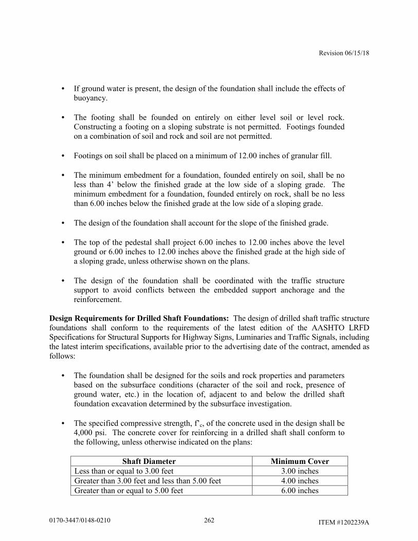
Revision 06/15/18
ITEM #1202239A
• If ground water is present, the design of the foundation shall include the effects of
buoyancy.
• The footing shall be founded on entirely on either level soil or level rock. Constructing a footing on a sloping substrate is not permitted. Footings founded on a combination of soil and rock and soil are not permitted.
• Footings on soil shall be placed on a minimum of 12.00 inches of granular fill.
• The minimum embedment for a foundation, founded entirely on soil, shall be no
less than 4’ below the finished grade at the low side of a sloping grade. The minimum embedment for a foundation, founded entirely on rock, shall be no less than 6.00 inches below the finished grade at the low side of a sloping grade.
• The design of the foundation shall account for the slope of the finished grade.
• The top of the pedestal shall project 6.00 inches to 12.00 inches above the level
ground or 6.00 inches to 12.00 inches above the finished grade at the high side of a sloping grade, unless otherwise shown on the plans.
• The design of the foundation shall be coordinated with the traffic structure
support to avoid conflicts between the embedded support anchorage and the reinforcement.
Design Requirements for Drilled Shaft Foundations: The design of drilled shaft traffic structure foundations shall conform to the requirements of the latest edition of the AASHTO LRFD Specifications for Structural Supports for Highway Signs, Luminaries and Traffic Signals, including the latest interim specifications, available prior to the advertising date of the contract, amended as follows:
• The foundation shall be designed for the soils and rock properties and parameters based on the subsurface conditions (character of the soil and rock, presence of ground water, etc.) in the location of, adjacent to and below the drilled shaft foundation excavation determined by the subsurface investigation.
• The specified compressive strength, f’c, of the concrete used in the design shall be
4,000 psi. The concrete cover for reinforcing in a drilled shaft shall conform to the following, unless otherwise indicated on the plans:
Shaft Diameter Minimum Cover
Less than or equal to 3.00 feet 3.00 inches Greater than 3.00 feet and less than 5.00 feet 4.00 inches Greater than or equal to 5.00 feet 6.00 inches
2620170-3447/0148-0210
Revision 06/15/18
ITEM #1202239A
• The reinforcement shall be uncoated and conform to ASTM A615, Grade 60.
• The foundation shall be designed for the traffic structure support reactions of all
applicable limit states. The reactions shall include axial, shear, flexural and torsional load effects.
• For sign support foundations, the minimum drilled shaft diameter shall be 3.00
feet, unless otherwise indicated on the plans.
• The design of the drilled shaft foundation shall include embedment of the foundation in soil, the embedment of the foundation in rock or the embedment of the foundation partially in soil and partially in rock, as applicable based on the findings of the required subsurface investigations at each foundation location.
• The design of the drilled shaft embedment depth shall account for the slope of the
finished grade.
• The minimum embedment for a drilled shaft foundation, excavated entirely in soil, shall be no less than 15.00 feet below the finished grade at the low side of a sloping grade. The minimum embedment for a drilled shaft foundation, excavated entirely in rock shall be no less than 10.00 feet below the finished grade at the low side of a sloping grade.
• For sign support foundations, the top of the drilled shaft pedestal shall project
6.00 inches to 12.00 inches above the level ground or 6.00 inches to 12.00 inches above the finished grade at the high side of a sloping grade, unless otherwise shown on the plans.
• The drilled shaft foundation shall be reinforced with longitudinal and transverse
reinforcement. The area of longitudinal reinforcement should be no less than the sum of the reinforcement required for flexure and the longitudinal reinforcement required for torsion. The area of transverse reinforcement should be no less than the sum of the reinforcement required for shear and the transverse reinforcement required for torsion. Additional transverse reinforcement may be required at the top of the drilled shaft within the limits of the pedestal due to the torsional load on the anchor bolt group.
• The minimum number of longitudinal reinforcing bars shall be 16. The minimum
size of longitudinal reinforcing bars shall be #8. The minimum area of longitudinal reinforcing bars shall be no less than 1% of the gross cross-sectional area of the shaft. The minimum clear distance between longitudinal reinforcing bars shall be no less than 5 times the maximum aggregate size or 5.00 inches, whichever is greater. The reinforcement shall extend full length of the drilled
2630170-3447/0148-0210
Revision 06/15/18
ITEM #1202239A
shaft foundation, including the pedestal, less cover requirements. Splicing of the longitudinal reinforcement is not permitted.
• The drilled shaft shall be transversely reinforced with spirals or circular, one
piece, enclosed ties. The minimum size of the reinforcement shall be #4. The maximum spacing/pitch of the reinforcement shall be no more than 6.00 inches. The spiral reinforcement shall be terminated at the top and the bottom with 1 ½ turns of the reinforcing and a 135° standard hook. Spirals may be spliced with lap splices or mechanical connectors. For spirals, the minimum lap splice length shall be 1.7 times the tension development length (including modification factors) of the bar or 48 bar diameters, whichever is greater. For spirals, the mechanical connectors shall develop both in tension and compression 125% of the specified yield strength of the bar and conform to the latest edition of the AASHTO LRFD Bridge Design Specifications, including the latest interim specifications. For ties, the minimum lap splice length shall be no less than 1.7 times the tension development length (including modification factors) of the bar. Tie lap splices shall be alternated. The ends of the bars in lap splices shall be anchored with a 135° standard hook around longitudinal reinforcement.
• For sign support foundations utilizing the drilled shaft option, the top of the
drilled shafts shall be designed with a rectangular pedestal to facilitate the installation of the anchor bolts and rigid metal conduits. Unless specific geometry is indicated on the plans, the dimensions of the pedestal shall be designed such that the pedestal sides match tangentially into the limits of the diameter of the drilled shaft. The top and sides of the pedestal shall be reinforced with a grillage of reinforcement. The minimum size reinforcement shall be #5. The minimum concrete cover shall be 3.00 inches, unless otherwise indicated on the plans.
• The design of the foundation shall be coordinated with the traffic structure
support to avoid conflicts between the embedded support anchorage and the foundation reinforcement.
Submittal Requirements for Foundations: Prior to excavating for the foundation, the Contractor shall submit working drawings and design computations for the foundation(s) at each sign support, based on the reviewed sign structure cross-section, to the Engineer for review in accordance with Article 1.05.02. The working drawings and design computations for foundations shall conform to working drawings for permanent construction. An individual, independently packaged set of working drawings and computations, with all details and documents necessary for fabrication and construction shall be prepared and submitted for the foundation(s) at each support. A single set of drawings with tabulated data for multiple
foundation locations is not permitted. Combining working drawing submittals for sign structures with submittals for structure foundations is not permitted.
2640170-3447/0148-0210

Revision 06/15/18
ITEM #1202239A
The packaged set of working drawings and computations for the foundations at each support shall be submitted in an individual file in electronic portable document format (.pdf) with appropriate bookmarks commenting enabled. The packaged set shall include the following:
• title sheet • table of contents • contact information for designer – contact information should include name and
address of design firm, name of contact person with phone number and email address
• copy of the reviewed cross-section • results of subsurface investigation, including boring logs and geotechnical design
recommendations • foundation working drawings • foundation design computations
The working drawings shall include complete details of all foundation components. The drawings shall include, but not be limited to the following:
• the project number, town and alpha-numeric support identification number
• selected type of foundation (spread footing or drilled shaft)
• reference to the design specifications, including interim specifications
• material specifications for all components
• embedment depths for foundation in soil, rock and a combination of soil and rock
• anchor bolt details, including dimensions, embedment and projection The design computations shall include, but not be limited to the following:
• the project number, town and alpha-numeric support identification number
• references to design specifications, including interim specifications, and the applicable code section and articles
• description/documentation for all computer programs used in the design
2650170-3447/0148-0210
Revision 06/15/18
ITEM #1202239A
• drawings/models of the foundation with dimensions, loads and references to the
local and global coordinate systems used (as applicable), to facilitate review of the results
• coefficients and factors used in the design
• sign support reactions of all applicable limit states
• soil and rock design parameters
• computations demonstrating the geotechnical and structural capacity of the foundation for
all applicable limit states The submitted foundation design computations shall reflect the load effects due to the actual sign panels, including crown panels, of the supported sign structure in the final condition. If additional sign and crown panels are shown on the plans for temporary signing during stage construction or for future signing, separate foundation design computations shall be submitted to reflect those loading conditions and document the adequacy of the foundation. The Contractor shall make printed copies of the stamped working drawings and calculations, of the size and number determined by the Engineer, and deliver the copies as directed by the Engineer. Prior to excavating for the foundation, the Contractor shall submit the following:
Reinforcing Steel Shop Drawings: Based on the accepted foundation design, reinforcing steel shop drawings shall be prepared for each foundation. A copy of the reviewed and stamped reinforcing steel shop drawings shall be submitted in accordance with Subarticle 1.05.02.
Concrete Mix Design: The Contractor shall submit the concrete mix design, including admixtures, for review in accordance with Subarticle 1.05.02. Slurry Mix Design: If the Foundation Construction Procedure involves the use of slurry, the Contractor shall submit the slurry mix design for review in accordance with Subarticle 1.05.02.
Drilled Shaft Foundation Construction Personnel: The Contractor performing the work described in this specification shall have installed drilled shafts of both diameter and length similar to those required for the traffic structures for a minimum of 3 years prior to the bid date for this project. The Contractor shall submit a list containing at least 3 projects completed in the last 3 years on which the Contractor has installed drilled shafts of a diameter and length similar to those shown on the plans. The list of projects shall contain names and phone numbers
2660170-3447/0148-0210
Revision 06/15/18
ITEM #1202239A
of owner's representatives who can verify the Contractors' participation on those projects. The Contractor shall provide a list identifying the on-site supervisor(s) and drill operator(s) for approval by the Engineer. The on-site supervisor(s) shall have a minimum 2 years of experience in supervising the construction of drilled shafts of a diameter and length similar to those shown on the plans. The drill operator(s) shall have a minimum 1 year experience in drilling for the construction of drilled shafts of a diameter and length similar to those shown on the plans. The list shall contain a summary of each individual’s experience. Should the Contractor elect to change personnel during construction of the shaft, the same approval process will need to be completed for the new personnel prior to them starting work on the project. The Contractor shall not be compensated for any delays resulting from their changing of personnel. All documentation for review shall be submitted in accordance with Subarticle 1.05.02
Drilled Shaft Foundation Construction Procedure: The Contractor shall submit a written foundation construction procedure outlining the equipment; drilling procedure for soil and rock, including how spoils will be handled; temporary casing placement and removal; slurry placement; reinforcement, anchor bolt and conduit placement; and concrete placement required for the drilled shaft foundation construction for review in accordance with Subarticle 1.05.02. The procedure should include contingencies for the various soil, rock and subsurface water conditions that may be encountered during the foundation construction. Also required in this submission are the following:
• list of proposed equipment to be used, including cranes, drills, augers,
bailing buckets, final cleaning equipment, desanding equipment, slurry pumps, core sampling equipment, tremies or concrete pumps, casing, etc.
• details of overall construction operation sequence and the sequence of
shaft construction in bents or groups
• details of shaft excavation methods
• when the use of slurry is anticipated, details of the mix design and its suitability for the subsurface conditions at the construction site, mixing and storage methods, maintenance methods, and disposal procedures
• details of methods to clean the shaft excavation
• details of reinforcement placement, including support and centralization
methods
• details of concrete mix design and test results of both a trial mix and a slump loss test. The tests shall be conducted by an approved testing
2670170-3447/0148-0210
Revision 06/15/18
ITEM #1202239A
laboratory using approved methods to demonstrate that the concrete meets slump loss requirements
• details of concrete placement, including proposed operational procedures
for free fall, tremie or pumping methods, proposed concreting log form and computations for time duration of shaft pour estimates
• details of casing installation and removal methods
• details of methods for removal of obstructions. Obstructions the
Contractor shall provide details of methods for removal include, but are not necessarily be limited to, boulders, concrete, riprap, steel, timber, etc.
The Engineer will evaluate the foundation construction procedure for conformance with the plans, specifications and special provisions and will then notify the Contractor of any additional information required and/or changes necessary to meet the contract requirements. All procedural approvals given by the Engineer shall be subject to trial in the field and shall not relieve the Contractor of the responsibility to satisfactorily complete the work as detailed in the plans and specifications. The Contractor shall not commence construction of the drilled shafts until the Engineer has accepted the foundation construction procedure.
A Foundation Construction Procedure may be accepted by the Engineer without inclusion of slurry if the Contractor chooses to use permanent or temporary casings in accordance with the permanent or temporary casing method, described below. However, a slurry procedure and slurry mix design shall be required if the Contractor chooses to advance excavation ahead of the casings or if the Engineer determines that application of slurry is required to maintain soil stability. The Contractor shall be responsible for any delays to the project resulting from slurry construction procedure and mix design reviews submitted after approval of a dry and permanent or temporary casing method. Construction of Drilled Shaft Foundations: Construction methods for drilled shaft foundations shall conform to the following: Excavations required for shafts shall be performed through whatever materials are encountered, to the dimensions and elevations in the working drawings or as ordered by the Engineer. The methods and equipment used shall be suitable for the intended purpose and materials encountered. Shaft excavation may be performed by combinations of augering, rotary drilling, down-the-hole hammer, reverse circulation drilling, clamming, scraping, or other means approved by the Engineer. Generally, either the dry method, wet method, or temporary casing method may be used, as necessary, to produce sound, durable concrete foundation shafts free of defects. The Contractor shall select and use the method that is needed to properly accomplish the work, as determined by site conditions and subject to the approval of the Engineer. The
2680170-3447/0148-0210
Revision 06/15/18
ITEM #1202239A
Contractor is responsible for maintaining the stability of the shaft excavation during all phases of construction. The dry method consists of drilling the shaft excavation, removing accumulated water and loose material from the excavation, and placing the shaft concrete in a relatively dry excavation. The dry construction method shall be used only at sites where the groundwater table and site conditions are suitable to permit construction of the shaft in a relatively dry excavation, and where the sides and bottom of the shaft are stable and may be visually inspected prior to placing the concrete. The use of the dry construction method is permitted if less than one foot of water accumulates in the bottom of a hole without pumping over a one hour period, the excavation remains stable and any loose material and water can be removed prior to placement of concrete. The wet construction method shall be used at sites where a dry excavation cannot be maintained for placement of the shaft concrete. Wet construction methods consist of using a mineral or polymer slurry to maintain stability of the hole’s perimeter while advancing the excavation to final depth, placing the reinforcing cage and shaft concrete. This procedure may require desanding and cleaning the slurry; final cleaning of the excavation by means of a bailing bucket, air lift, submersible pump or other devices; and placing the shaft concrete with a tremie. Unless it is demonstrated to the satisfaction of the Engineer that the surface casing is not required, temporary surface casings shall be provided to aid shaft alignment and position, and to prevent sloughing of the top of the shaft excavation. Surface casing is defined as the amount of casing required from the ground surface to a point in the shaft excavation where sloughing of the surrounding soil does not occur. The temporary or permanent casing construction methods may be used in lieu of the dry or wet construction methods or where the dry or wet construction methods are inappropriate. Temporary or permanent casing construction methods consist of advancing the excavation through caving material with or without slurry. Casings may be installed by driving or vibratory procedures in advance of excavation to the lower limits of the caving material. When a nearly impervious formation is reached, a casing is placed in the hole and sealed in the nearly impervious formation. After the drilling fluid is removed from the casing, drilling may proceed as with the dry method. The temporary casing is withdrawn when the shaft concrete is placed. If seepage conditions prevent use of the dry method, excavation is completed using the wet method. Slurry may be omitted if the casing is advanced ahead of drilling and only if minor caving of the hole is observed. Slurry shall be used in installation if drilling is to advance ahead of the casing or if the Engineer determines that the application of the slurry is required in order to maintain soil stability around the hole. If the Engineer determines that the foundation material encountered during excavation is unsuitable or differs from that anticipated in the design of the shaft, or if rock is encountered at an unanticipated elevation, the Contractor’s foundation designer shall determine if the foundation embedment should be revised from that shown on the working drawings. If rock is encountered, the Engineer shall be notified to inspect and determine the elevation of the top of competent rock. Any revisions to the foundation embedment during construction shall be reviewed by the Engineer.
2690170-3447/0148-0210
Revision 06/15/18
ITEM #1202239A
Excavated materials which are removed from the shaft excavation and any drilled fluids used shall be disposed of by the Contractor as directed by the Engineer and in accordance with Section 1.10. Permanent and temporary casings shall be metal, smooth, clean, watertight, and of ample strength to withstand both handling and driving stresses and the pressure of both concrete and the surrounding earth materials. The outside diameter of casing shall not be less than the specified size of the shaft. Temporary casings shall be removed while the concrete remains workable (i.e., a slump of 4.00 inches or greater). Before the casing is withdrawn and while the casing is being withdrawn, a 5.00 foot minimum head of fresh concrete in the casing shall be maintained so that all the fluid trapped behind the casing is displaced upward without contaminating the shaft concrete. The required minimum concrete head may have to be increased to counteract groundwater head outside the casing. Separation of the concrete by hammering or otherwise vibrating the casing, during withdrawal operations, shall be avoided. Casing extraction shall be at a slow, uniform rate with the pull in line with the shaft axis. Slurry used in the drilling process shall be a mineral or polymer slurry. The slurry shall have both a grain size that will remain in suspension and sufficient viscosity and gel characteristics to transport excavated material to a suitable screening system. The percentage and specific gravity of the material used to make the suspension shall be sufficient to maintain the stability of the excavation and to allow proper concrete placement. The level of the slurry shall be maintained at a height sufficient to prevent caving of the hole. The slurry shall be premixed thoroughly with clean fresh water at a temperature above 41° F and adequate time allotted for hydration prior to introduction into the shaft excavation. The elevation of the slurry within the shaft foundation shall be maintained within 24.00 inches of the top casing and at least 48.00 inches above the existing water level during drilling and until the concrete placement is essentially complete. The slurry properties shall be maintained at all times, including non-working periods and stoppages. The slurry shall be circulated and agitated, continuously if necessary, to maintain the slurry properties and to prevent it from setting up in the shaft. The Contractor, in the presence of the Engineer, shall perform control tests on the slurry to ensure that the density, viscosity, and pH fall within the acceptable limits tabulated below. The Contractor shall provide all equipment required to perform the tests. If desanding is required, sand content shall not exceed 4% (by volume) at any point in the shaft excavation as determined by the American Petroleum Institute sand content test.
2700170-3447/0148-0210
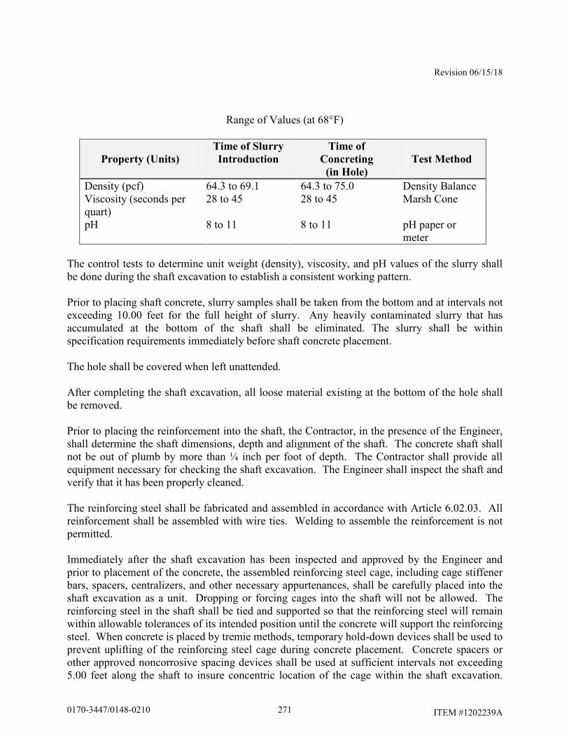
Revision 06/15/18
ITEM #1202239A
Range of Values (at 68°F)
Property (Units)
Time of Slurry
Introduction
Time of
Concreting
(in Hole)
Test Method
Density (pcf) 64.3 to 69.1 64.3 to 75.0 Density Balance Viscosity (seconds per quart)
28 to 45 28 to 45 Marsh Cone
pH 8 to 11 8 to 11 pH paper or meter
The control tests to determine unit weight (density), viscosity, and pH values of the slurry shall be done during the shaft excavation to establish a consistent working pattern. Prior to placing shaft concrete, slurry samples shall be taken from the bottom and at intervals not exceeding 10.00 feet for the full height of slurry. Any heavily contaminated slurry that has accumulated at the bottom of the shaft shall be eliminated. The slurry shall be within specification requirements immediately before shaft concrete placement. The hole shall be covered when left unattended. After completing the shaft excavation, all loose material existing at the bottom of the hole shall be removed. Prior to placing the reinforcement into the shaft, the Contractor, in the presence of the Engineer, shall determine the shaft dimensions, depth and alignment of the shaft. The concrete shaft shall not be out of plumb by more than ¼ inch per foot of depth. The Contractor shall provide all equipment necessary for checking the shaft excavation. The Engineer shall inspect the shaft and verify that it has been properly cleaned. The reinforcing steel shall be fabricated and assembled in accordance with Article 6.02.03. All reinforcement shall be assembled with wire ties. Welding to assemble the reinforcement is not permitted. Immediately after the shaft excavation has been inspected and approved by the Engineer and prior to placement of the concrete, the assembled reinforcing steel cage, including cage stiffener bars, spacers, centralizers, and other necessary appurtenances, shall be carefully placed into the shaft excavation as a unit. Dropping or forcing cages into the shaft will not be allowed. The reinforcing steel in the shaft shall be tied and supported so that the reinforcing steel will remain within allowable tolerances of its intended position until the concrete will support the reinforcing steel. When concrete is placed by tremie methods, temporary hold-down devices shall be used to prevent uplifting of the reinforcing steel cage during concrete placement. Concrete spacers or other approved noncorrosive spacing devices shall be used at sufficient intervals not exceeding 5.00 feet along the shaft to insure concentric location of the cage within the shaft excavation.
2710170-3447/0148-0210
Revision 06/15/18
ITEM #1202239A
When the size of the longitudinal reinforcing steel is larger than a #8 bar, such spacing shall not exceed 10.00 feet. After placement of the reinforcing cage, the Engineer shall inspect the shaft to ensure that it has remained clean. If the inspection indicates that loose material has accumulated at the bottom of shaft excavation, the Contractor shall remove the reinforcing cage and reclean the shaft. Concrete shall be placed in the shaft excavation as soon as possible, but no more than 4 hours after completion of excavation and cleaning of the bottom of the excavation, and no more than 2 hours after placement of the reinforcing steel cage. Concrete shall be placed in a continuous operation to the top of the shaft. The concrete level shall be horizontal during the pouring operations. Concrete placement shall continue after the shaft is full until good quality concrete is evident at the top of the shaft. The elapsed time from the beginning of concrete placement in the shaft to the completion of placement shall not exceed 2 hours. In dry construction, concrete shall be placed in a single continuous operation with the flow of concrete down the center of the shaft excavation so as to consolidate the concrete on impact. During placement operations, the concrete is not permitted to hit the reinforcing steel. A dropchute, consisting of a hopper and flexible hose, may be used to direct the concrete down the center of the foundation and prevent the concrete from hitting the reinforcing steel. Accumulated water shall be removed before placing the concrete. At the time of concrete placement, no more than 2.00 inches of water may exist at the bottom of the excavation and loose sediment no more than 0.50 inches over one-half the base is acceptable. In wet (slurry) construction, concrete to be placed by the tremie method, where the concrete displaces the slurry from bottom of the excavation to the top. The concrete shall be placed through a top metal hopper and into a rigid leak-proof elephant trunk tremie tube, sufficiently large enough to permit free flow of concrete. The tremie tube shall be positioned so that it can be removed without disturbing the reinforcing. Initially, the discharge end of the tremie tube shall be sealed closed (plugged) to prevent slurry from entering the tube after it is placed in the excavation and before the tube is filled with concrete. After concrete placement has started, the tremie tube shall be kept full of concrete to the bottom of the hopper to maintain a positive concrete head. The flow of concrete shall be induced by slightly raising the discharge end of the tube, always keeping the tube end in the deposited concrete. No horizontal movement of the tremie tube will be permitted. The shaft concrete shall be vibrated or rodded to a depth of 5.00 feet below the ground surface except where soft uncased soil or slurry remaining in the excavation will possibly mix with the concrete. Exposed concrete shall be cured and finished in accordance with Subarticle 6.01.03-7, 9 and 10. No construction operations that would cause soil movement adjacent to the shaft, other than mild vibration, shall be conducted for at least 48 hours after shaft concrete has been placed.
2720170-3447/0148-0210
Revision 06/15/18
ITEM #1202239A
The top of the foundations shall be backfilled and the adjacent disturbed ground surfaces restored to match the surrounding area after the concrete has cured and the forms are removed. Placement of topsoil shall conform to Articles 9.44.01 and 9.44.03. Turf establishment shall conform to Article 9.50.03. Construction of Spread Footing Foundations: Construction methods for spread footing foundations shall conform to the following: Temporary earth retaining system shall be safely designed and shall be carried to adequate depths and braced as necessary for proper performance of the work. Construction shall be such as to permit excavation or fill as required. Interior dimensions shall be such as to give sufficient clearance for construction of forms and their inspection and for battered pile clearance when necessary. Movements of the system or bracing which prevent the proper completion of the substructure shall be corrected at the sole expense of the Contractor. No part of the temporary earth retaining system or bracing shall be allowed to extend into the substructure without written permission of the Engineer. Working drawings and design calculations for temporary earth retaining system shall be submitted in accordance with the requirements of Article 1.05.02. Unless otherwise ordered by the Engineer, all parts of the temporary earth retaining system shall be removed upon completion of the work for which it was provided. The excavation shall be backfilled and properly compacted, prior to removal of the system unless otherwise permitted by the Engineer. Temporary earth retaining system may be left in place at the option of the Contractor if so permitted by the Engineer, provided that it is cut off at an elevation as directed by the Engineer and the cutoffs removed from the site. Excavation: Article 2.03.03. Granular Fill: Article 2.13.03. Class “F” Concrete: Article 6.01.03. Deformed Steel Bars: Subarticles 6.02.03-2,3,4,7, and 8. Additional construction provisions for all foundation types: Anchor bolt assemblies shall be embedded in the concrete as shown on the working drawings. A template plate shall be used to hold the anchor bolt assemblies, conduits and ground rod sleeve in the correct position until concrete has set. The anchor bolts shall be installed plumb. All conduit ends terminating below grade shall be capped with a malleable iron caps. All above-grade conduit ends shall be terminated with an insulated bonding bushing with tinned insert. The rigid metal conduit sweeps shall extend a minimum of 2.00 feet from the side of the foundation and shall be placed a minimum of 2.50 feet below finished grade.
2730170-3447/0148-0210

Revision 06/15/18
ITEM #1202239A
Stainless steel wire mesh shall be installed tight to the top of the foundations and attached to sign support structure baseplates to provide a barrier against possible entry of rodents, birds, insects, and reptiles. The mesh shall be attached to the baseplate with the use of an adjustable stainless steel hose clamp of a diameter that is compatible with the geometry of the baseplate. Ground rod and ground wire shall be installed as shown on the plans. After the foundation has cured, the Contractor shall submit the top of foundation elevations based on a field survey. The traffic structures shall not be erected on the foundation unit until all concrete has attained a compressive strength, f’c, greater than or equal to 4,000 psi based on physical testing. Method of Measurement: This work will be measured for payment by the number of foundation units, each completely installed and accepted. Two foundation units are required to support each overhead truss sign support. Basis of Payment: The work will be paid for at the contract unit price each for “Overhead Truss Sign Support Foundation,” completed and accepted in place, which price shall include all equipment, materials, tools and labor incidental to the design, fabrication, construction and disposal of drilling spoils, of the foundations at the locations specified on the plans. No additional payment will be made for the Contractor to test the slurry when it is used to construct a drilled shaft foundation. No additional payment will be made for subsurface investigations performed by the Contractor. The removal of existing roadside barrier systems, installation and removal of temporary roadside barrier systems and resetting existing roadside barrier systems will not be paid for separately, but will be included as part of the work. The support of excavation areas by temporary earth retaining system will not be paid for separately, but will be included as part of the work. The temporary support, protection and restoration of utilities (if necessary), including existing underground wiring, conduits, drainage structures, pipes and underdrain systems within the excavation limits will not be paid for separately, but will be included as part of the work. Backfilling and restoration of adjacent ground surfaces (pavement, slope protection, topsoil & seed, etc.) in all areas disturbed by the work will not be paid for separately, but will be included as part of the work. The Engineer will determine the type, thickness and horizontal limits of the surface treatments to be restored. The installation of new or upgraded permanent roadside barrier systems, if required, will not be paid for as part of this work, but will be paid for under separate items.
2740170-3447/0148-0210
Revision 06/15/18
ITEM #1202999A
ITEM #1202999A – DRILLED SHAFT TRAFFIC STRUCTURE
FOUNDATION
Description: Work under this item shall consist of the subsurface investigation, design and construction of drilled shaft foundations for traffic structures, in accordance with the details shown on the plans, in accordance with these specifications and as ordered by the Engineer. For the purposes of this specification, a traffic structure support may be an overhead cantilever or bridge type sign support structure. Materials: The reinforcing steel shall be uncoated unless otherwise noted on the plans. The reinforcing steel shall be ASTM A615, Grade 60 reinforcement conforming to the requirements of Article M.06.01.
The concrete for the drilled shaft shall be dense, homogeneous, fluid, resistant to segregation and consolidate under self-weight. The concrete for the drilled shaft shall be a Contractor designed Portland cement concrete with a 0.375 inch (No. 8) maximum coarse aggregate size and a minimum of 705 lbs/cubic yard of cementitious materials. The initial concrete slump shall be 7.00 inches + 1.00 inch. The concrete shall maintain a minimum 4.00 inch slump for the duration of the concrete placement. The concrete shall contain 1% - 7% air entrainment. The 28 day minimum compressive strength of the concrete in the constructed foundation shall be 4,000 psi. The concrete mix design, including admixtures, shall be submitted to the Engineer for approval. The concrete for the formed pedestal shall conform to Article M.03 for Class ‘F’ Concrete. The 28 day minimum compressive strength of the concrete in the constructed pedestal shall be 4,400 psi. The concrete mix design, including admixtures, shall be submitted to the Engineer for approval. The slurry, if used, shall be Contractor designed mineral or polymer slurry that meets the range of values listed herein. The slurry mix design, including admixtures, shall be submitted to the Engineer for approval. Rigid metal conduit, ground rod sleeves and related hardware, and end caps shall be galvanized steel conduit, and shall conform to Article M.15.09. Ground rods shall be 0.626 inches in diameter by 12.00 foot long copper clad steel. The copper cladding shall be a minimum thickness of 0.128 inches. The ground clamp shall be a square-head bolt type, approved for direct burial. Stainless steel mesh shall be comprised of either Grade T316 or Grade T304 stainless steel wire and shall have a minimum of 5 wires per inch in both directions. Hose clamps shall be stainless steel and shall be adjustable.
2750170-3447/0148-0210
Revision 06/15/18
ITEM #1202999A
Bare copper wire shall conform to Article M.15.13.
Topsoil shall conform to Article M.13.01. Fertilizer shall conform to Article M.13.03. Seed mixture shall conform to Article M.13.04. Mulch shall conform to Article M.13.05. Erosion control matting shall conform to Article M.13.09. Construction Methods:
Subsurface Conditions for Bidding: For the purpose of bidding this item, the Contractor shall assume that the subsurface conditions for each foundation location consists of cohesion less medium dense granular soil (AASHTO A-1 or A-2) with cobbles present and a high groundwater table which requires the use of wet construction/concreting methods. Subsurface Conditions for Foundation Design: As early as possible and prior to preparation of the foundation design, the Contractor shall perform a subsurface investigation for each sign foundation location. The subsurface data obtained in the exploration program at each site shall be used in the design of the foundation at that site. Use of the assumed subsurface condition (that was provided for the purpose of bidding), an assumed conservative subsurface condition or any other assumed subsurface condition shall not be allowed for use in the foundation design nor shall any assumed subsurface condition relieve the Contractor from their responsibility of obtaining a test boring at each foundation site. The subsurface investigation program should be prepared and executed in accordance with the most recent editions of the AASHTO Manual on Subsurface Investigations and ConnDOT Geotechnical Engineering Manual. The Contractor shall provide a full-time inspector to oversee the subsurface exploration program. The subsurface investigations and all related cost will not be measured for payment and shall be included in the cost of the foundation. The Contractor shall review results of their subsurface investigation to determine if subsurface conditions for sign foundation locations differ materially from those assumed at the time of bid. Should the subsurface investigation(s) encounter conditions that differ materially, the Contractor shall notify the Engineer in writing prior to the submission of the working drawings and calculations. All matters regarding increased cost relating to agreed upon change in subsurface conditions will be handled per Section 1.04.04 – Differing Site Conditions. Foundation Design Requirements: The design of drilled shaft traffic structure foundations shall conform to the requirements of the latest edition of AASHTO LRFD Specifications for Structural Supports for Highway Signs, Luminaries and Traffic Signals, including the latest interim specifications, available prior to the advertising date of the contract, amended as follows:
2760170-3447/0148-0210
Revision 06/15/18
ITEM #1202999A
• The foundation shall be designed for the soils and rock properties and parameters based on the subsurface conditions (character of the soil and rock, presence of ground water, etc.) in the location of, adjacent to and below the drilled shaft foundation excavation determined by the subsurface investigation.
• The specified compressive strength, f’c, of the concrete used in the design shall be 4,000 psi. The concrete cover for reinforcing in a drilled shaft shall conform to the following:
Shaft Diameter Minimum Cover
Less than or equal to 3.00 feet 3.00 inches Greater than 3.00 feet and less than 5.00 feet
4.00 inches
Greater than or equal to 5.00 feet 6.00 inches
• The reinforcement shall be uncoated and conform to ASTM A615, Grade 60.
• The foundation shall be designed for the traffic structure support reactions for all applicable limit states. The reactions shall include axial, shear, flexural and torsional load effects.
• For sign support foundations, the minimum drilled shaft diameter shall be 3.00
feet, unless otherwise noted on the plans.
• The design of the drilled shaft foundation shall include embedment of the foundation in soil, the embedment of the foundation in rock or the embedment of the foundation partially in soil and partially in rock, as applicable based on the findings of the required subsurface investigation at each foundation location.
• The design of the drilled shaft foundation embedment depth shall account for the
slope of the finished grade.
• The minimum embedment for a drilled shaft foundation, excavated entirely in soil, shall be no less than 15.00 feet below the finished grade at the low side of a sloping grade. The minimum embedment for a drilled shaft foundation, excavated entirely in rock shall be no less than 10.00 feet below the finished grade at the low side of a sloping grade.
• For sign support foundations, the top of the drilled shaft pedestal shall project
6.00 inches to 12.00 inches above the level ground or 6.00 inches to 12.00 inches above the finished grade at the high side of a sloping grade, unless otherwise shown on the plans.
2770170-3447/0148-0210
Revision 06/15/18
ITEM #1202999A
• The drilled shaft foundation shall be reinforced with longitudinal and transverse reinforcement. The area of longitudinal reinforcement should be no less than the sum of the reinforcement required for flexure and the longitudinal reinforcement required for torsion. The area of transverse reinforcement should be no less than the sum of the reinforcement required for shear and the transverse reinforcement required for torsion.
• In drilled shaft foundations for cantilever sign structures, the area of transverse
reinforcement provided shall prevent the concrete breakout at the edge of the foundation due to the torsional load on the anchor bolt group. The area of transverse reinforcement provided shall be considered adequate to prevent this condition if the nominal torsional strength of the foundation is greater than the concrete breakout strength. The concrete breakout strength shall be determined in accordance with the latest edition of the “Building Code Requirements for Reinforced Concrete”, ACI 318, Appendix D.
• The minimum number of longitudinal reinforcing bars shall be 16. The minimum
size of longitudinal reinforcing bars shall be #8. The minimum area of longitudinal reinforcing bars shall be no less than 1% of the gross cross-sectional area of the shaft. The minimum clear distance between longitudinal reinforcing bars shall be no less than 5 times the maximum aggregate size or 5.00 inches, whichever is greater. The reinforcement shall extend full length of the drilled shaft foundation, including the pedestal, less cover requirements. Splicing of the longitudinal reinforcement is not permitted.
• The drilled shaft foundation shall be transversely reinforced with spirals or
circular, one piece, enclosed ties. The minimum size of the transverse reinforcement shall be #4. The maximum spacing/pitch of the transverse reinforcement shall be no more than 6.00 inches. The minimum spacing/pitch of the transverse reinforcement shall be no more than 4.00 inches. The maximum spacing/pitch of the transverse reinforcement in the top 2.00 feet of the foundation shall be no more than 4.00 inches. The spiral reinforcement shall be terminated at the top and the bottom with 1 ½ turns of the reinforcing and a 135° standard hook. Spirals may be spliced with lap splices or mechanical connectors. For spirals, the minimum lap splice length shall be 1.7 times the tension development length (including modification factors) of the bar or 48 bar diameters, whichever is greater. For spirals, the mechanical connectors shall develop both in tension and compression 125% of the specified yield strength of the bar and conform to the latest edition of the AASHTO LRFD Bridge Design Specifications, including the latest interim specifications. For ties, the minimum lap splice length shall be no less than 1.7 times the tension development length (including modification factors) of the bar. Tie lap splices shall be alternated. The ends of the bars in lap splices shall be anchored with a 135° standard hook around longitudinal reinforcement.
2780170-3447/0148-0210
Revision 06/15/18
ITEM #1202999A
• For sign support foundations, the top of the drilled shaft shall be designed with a square pedestal to facilitate the installation of the anchor bolts and rigid metal conduits. The plan dimensions of the pedestal shall equal the diameter of the drilled shaft. The top and sides of the pedestal shall be reinforced with a grillage of reinforcement. The minimum size reinforcement shall be #5. The minimum concrete cover shall be 3.00 inches, unless otherwise indicated on the plans.
• The design of the foundation shall be coordinated with the traffic structure
support to avoid conflicts between the embedded support anchorage and the foundation reinforcement.
Submittal Requirements for Foundations: Prior to excavating for the foundation, the Contractor shall submit working drawings and design computations for the foundation(s) at each sign support, based on the reviewed sign structure cross-section, to the Engineer for review in accordance with Article 1.05.02. The working drawings and design computations for foundations shall conform to working drawings for permanent construction. An individual, independently packaged set of working drawings and computations, with all details and documents necessary for fabrication and construction shall be prepared and submitted for the foundation(s) at each support. A single set of drawings with tabulated data for multiple
foundation locations is not permitted. Combining working drawing submittals for sign structures with submittals for structure foundations is not permitted. The packaged set of working drawings and computations for the foundations at each support shall be submitted in an individual file in electronic portable document format (.pdf) with appropriate bookmarks commenting enabled. The packaged set shall include the following:
• title sheet
• table of contents
• contact information for designer – contact information should include name and address of design firm, name of contact person with phone number and email address
• copy of the reviewed cross-section
• results of subsurface investigation, including boring logs and geotechnical design
recommendations
• foundation working drawings
• foundation design computations The working drawings shall include complete details of all foundation components. The drawings shall include, but not be limited to the following:
2790170-3447/0148-0210

Revision 06/15/18
ITEM #1202999A
• the project number, town and alpha-numeric support identification number
• reference to the design specifications, including interim specifications
• material specifications for all components
• embedment depths for foundation in soil, rock and a combination of soil and rock
• anchor bolt details, including dimensions, embedment and projection
The design computations shall include, but not be limited to the following:
• the project number, town and alpha-numeric support identification number
• references to design specifications, including interim specifications, and the applicable code section and articles
• description/documentation for all computer programs used in the design
• drawings/models of the foundation with dimensions, loads and references to the
local and global coordinate systems used (as applicable), to facilitate review of the results
• coefficients and factors used in the design
• sign support reactions of all applicable limit states
• soil and rock design parameters
• computations demonstrating the geotechnical and structural capacity of the foundation for
all applicable limit states The submitted foundation design computations shall reflect the load effects due to the actual sign panels, including crown panels, of the supported sign structure in the final condition. If additional sign and crown panels are shown on the plans for temporary signing during stage construction or for future signing, separate foundation design computations shall be submitted to reflect those loading conditions and document the adequacy of the foundation. The Contractor shall make printed copies of the stamped working drawings and calculations, of the size and number determined by the Engineer, and deliver the copies as directed by the Engineer. Prior to excavating for the foundation, the Contractor shall submit the following:
2800170-3447/0148-0210
Revision 06/15/18
ITEM #1202999A
Reinforcing Steel Shop Drawings: Based on the accepted foundation design, reinforcing steel shop drawings shall be prepared for each foundation. A copy of the reviewed and stamped reinforcing steel shop drawings shall be submitted in accordance with Subarticle 1.05.02.
Concrete Mix Design: The Contractor shall submit the concrete mix design, including admixtures, for review in accordance with Subarticle 1.05.02. Slurry Mix Design: If the Foundation Construction Procedure involves the use of slurry, the Contractor shall submit the slurry mix design for review in accordance with Subarticle 1.05.02.
Drilled Shaft Foundation Construction Personnel: The Contractor performing the work described in this specification shall have installed drilled shafts of both diameter and length similar to those required for the traffic structures for a minimum of 3 years prior to the bid date for this project. The Contractor shall submit a list containing at least 3 projects completed in the last 3 years on which the Contractor has installed drilled shafts of a diameter and length similar to those shown on the plans. The list of projects shall contain names and phone numbers of owner's representatives who can verify the Contractors' participation on those projects. The Contractor shall provide a list identifying the on-site supervisor(s) and drill operator(s) for approval by the Engineer. The on-site supervisor(s) shall have a minimum 2 years of experience in supervising the construction of drilled shafts of a diameter and length similar to those shown on the plans. The drill operator(s) shall have a minimum 1 year experience in drilling for the construction of drilled shafts of a diameter and length similar to those shown on the plans. The list shall contain a summary of each individual’s experience. Should the Contractor elect to change personnel during construction of the shaft, the same approval process will need to be completed for the new personnel prior to them starting work on the project. The Contractor shall not be compensated for any delays resulting from their changing of personnel. All documentation for review shall be submitted in accordance with Subarticle 1.05.02
Drilled Shaft Foundation Construction Procedure: The Contractor shall submit a written foundation construction procedure outlining the equipment; drilling procedure for soil and rock, including how spoils will be handled; temporary casing placement and removal; slurry placement; reinforcement, anchor bolt and conduit placement; and concrete placement required for the drilled shaft foundation construction for review in accordance with Subarticle 1.05.02. The procedure should include contingencies for the various soil, rock and subsurface water conditions that may be encountered during the foundation construction. Also required in this submission are the following:
2810170-3447/0148-0210
Revision 06/15/18
ITEM #1202999A
• list of proposed equipment to be used, including cranes, drills, augers, bailing buckets, final cleaning equipment, desanding equipment, slurry pumps, core sampling equipment, tremies or concrete pumps, casing, etc.
• details of overall construction operation sequence and the sequence of
shaft construction in bents or groups
• details of shaft excavation methods
• when the use of slurry is anticipated, details of the mix design and its suitability for the subsurface conditions at the construction site, mixing and storage methods, maintenance methods, and disposal procedures
• details of methods to clean the shaft excavation
• details of reinforcement placement, including support and centralization
methods
• details of concrete mix design and test results of both a trial mix and a slump loss test. The tests shall be conducted by an approved testing laboratory using approved methods to demonstrate that the concrete meets slump loss requirements
• details of concrete placement, including proposed operational procedures
for free fall, tremie or pumping methods, proposed concreting log form and computations for time duration of shaft pour estimates
• details of casing installation and removal methods
• details of methods for removal of obstructions. Obstructions the
Contractor shall provide details of methods for removal include, but are not necessarily be limited to, boulders, concrete, riprap, steel, timber, etc.
The Engineer will evaluate the foundation construction procedure for conformance with the plans, specifications and special provisions and will then notify the Contractor of any additional information required and/or changes necessary to meet the contract requirements. All procedural approvals given by the Engineer shall be subject to trial in the field and shall not relieve the Contractor of the responsibility to satisfactorily complete the work as detailed in the plans and specifications. The Contractor shall not commence construction of the drilled shafts until the Engineer has accepted the foundation construction procedure.
A Foundation Construction Procedure may be accepted by the Engineer without inclusion of slurry if the Contractor chooses to use permanent or temporary casings in accordance with the
2820170-3447/0148-0210
Revision 06/15/18
ITEM #1202999A
permanent or temporary casing method, described below. However, a slurry procedure and slurry mix design shall be required if the Contractor chooses to advance excavation ahead of the casings or if the Engineer determines that application of slurry is required to maintain soil stability. The Contractor shall be responsible for any delays to the project resulting from slurry construction procedure and mix design reviews submitted after approval of a dry and permanent or temporary casing method. Excavations required for shafts shall be performed through whatever materials are encountered, to the dimensions and elevations in the working drawings or as ordered by the Engineer. The methods and equipment used shall be suitable for the intended purpose and materials encountered. Shaft excavation may be performed by combinations of augering, rotary drilling, down-the-hole hammer, reverse circulation drilling, clamming, scraping, or other means approved by the Engineer. Generally, either the dry method, wet method, or temporary casing method may be used, as necessary, to produce sound, durable concrete foundation shafts free of defects. The Contractor shall select and use the method that is needed to properly accomplish the work, as determined by site conditions and subject to the approval of the Engineer. The Contractor is responsible for maintaining the stability of the shaft excavation during all phases of construction. The dry method consists of drilling the shaft excavation, removing accumulated water and loose material from the excavation, and placing the shaft concrete in a relatively dry excavation. The dry construction method shall be used only at sites where the groundwater table and site conditions are suitable to permit construction of the shaft in a relatively dry excavation, and where the sides and bottom of the shaft are stable and may be visually inspected prior to placing the concrete. The use of the dry construction method is permitted if less than one foot of water accumulates in the bottom of a hole without pumping over a one hour period, the excavation remains stable and any loose material and water can be removed prior to placement of concrete. The wet construction method shall be used at sites where a dry excavation cannot be maintained for placement of the shaft concrete. Wet construction methods consist of using a mineral slurry to maintain stability of the hole perimeter while advancing the excavation to final depth, placing the reinforcing cage and shaft concrete. This procedure may require desanding and cleaning the slurry; final cleaning of the excavation by means of a bailing bucket, air lift, submersible pump or other devices; and placing the shaft concrete with a tremie. Unless it is demonstrated to the satisfaction of the Engineer that the surface casing is not required, temporary surface casings shall be provided to aid shaft alignment and position, and to prevent sloughing of the top of the shaft excavation. Surface casing is defined as the amount of casing required from the ground surface to a point in the shaft excavation where sloughing of the surrounding soil does not occur. The temporary or permanent casing construction methods may be used in lieu of the dry or wet construction methods or where the dry or wet construction methods are inappropriate. Temporary or permanent casing construction methods consist of advancing the excavation through caving material with or without slurry. Casings may be installed by driving or vibratory procedures in advance of excavation to the lower limits of the caving material. When a nearly impervious formation is reached, a casing is placed in the hole and sealed in the nearly
2830170-3447/0148-0210
Revision 06/15/18
ITEM #1202999A
impervious formation. After the drilling fluid is removed from the casing, drilling may proceed as with the dry method. The temporary casing is withdrawn when the shaft concrete is placed. If seepage conditions prevent use of the dry method, excavation is completed using the wet method. Slurry may be omitted if the casing is advanced ahead of drilling and only if minor caving of the hole is observed. Slurry shall be used in installation if drilling is to advance ahead of the casing or if the Engineer determines that the application of the slurry is required in order to maintain soil stability around the hole. If the Engineer determines that the foundation material encountered during excavation is unsuitable or differs from that anticipated in the design of the shaft, or if rock is encountered at an unanticipated elevation, the Contractor’s foundation designer shall determine if the foundation embedment should be revised from that shown on the working drawings. If rock is encountered, the Engineer shall be notified to inspect and determine the elevation of the top of competent rock. Any revisions to the foundation embedment during construction shall be reviewed by the Engineer. Excavated materials which are removed from the shaft excavation and any drilled fluids used shall be disposed of by the Contractor as directed by the Engineer and in accordance with Section 1.10. Permanent and temporary casings shall be metal, smooth, clean, watertight, and of ample strength to withstand both handling and driving stresses and the pressure of both concrete and the surrounding earth materials. The outside diameter of casing shall not be less than the specified size of the shaft. Temporary casings shall be removed while the concrete remains workable (i.e., a slump of 4.00 inches or greater). Before the casing is withdrawn and while the casing is being withdrawn, a 5.00 foot minimum head of fresh concrete in the casing shall be maintained so that all the fluid trapped behind the casing is displaced upward without contaminating the shaft concrete. The required minimum concrete head may have to be increased to counteract groundwater head outside the casing. Separation of the concrete by hammering or otherwise vibrating the casing, during withdrawal operations, shall be avoided. Casing extraction shall be at a slow, uniform rate with the pull in line with the shaft axis. Slurry used in the drilling process shall be a mineral or polymer slurry. The slurry shall have both a mineral grain size that will remain in suspension and sufficient viscosity and gel characteristics to transport excavated material to a suitable screening system. The percentage and specific gravity of the material used to make the suspension shall be sufficient to maintain the stability of the excavation and to allow proper concrete placement. The level of the slurry shall be maintained at a height sufficient to prevent caving of the hole. The mineral slurry shall be premixed thoroughly with clean fresh water at a temperature above 41° F and adequate time allotted for hydration prior to introduction into the shaft excavation. The elevation of the slurry within the shaft foundation shall be maintained within 24.00 inches of the top casing and at least 48.00 inches above the existing water level during drilling and until the concrete placement is essentially complete. The slurry properties shall be maintained at all times, including non-working periods and stoppages. The slurry shall be circulated and agitated,
2840170-3447/0148-0210
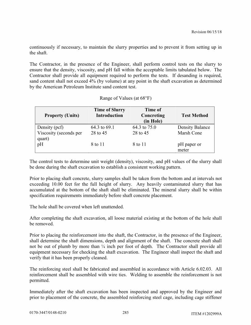
Revision 06/15/18
ITEM #1202999A
continuously if necessary, to maintain the slurry properties and to prevent it from setting up in the shaft. The Contractor, in the presence of the Engineer, shall perform control tests on the slurry to ensure that the density, viscosity, and pH fall within the acceptable limits tabulated below. The Contractor shall provide all equipment required to perform the tests. If desanding is required, sand content shall not exceed 4% (by volume) at any point in the shaft excavation as determined by the American Petroleum Institute sand content test.
Range of Values (at 68°F)
Property (Units)
Time of Slurry
Introduction
Time of
Concreting
(in Hole)
Test Method
Density (pcf) 64.3 to 69.1 64.3 to 75.0 Density Balance Viscosity (seconds per quart)
28 to 45 28 to 45 Marsh Cone
pH 8 to 11 8 to 11 pH paper or meter
The control tests to determine unit weight (density), viscosity, and pH values of the slurry shall be done during the shaft excavation to establish a consistent working pattern. Prior to placing shaft concrete, slurry samples shall be taken from the bottom and at intervals not exceeding 10.00 feet for the full height of slurry. Any heavily contaminated slurry that has accumulated at the bottom of the shaft shall be eliminated. The mineral slurry shall be within specification requirements immediately before shaft concrete placement. The hole shall be covered when left unattended. After completing the shaft excavation, all loose material existing at the bottom of the hole shall be removed. Prior to placing the reinforcement into the shaft, the Contractor, in the presence of the Engineer, shall determine the shaft dimensions, depth and alignment of the shaft. The concrete shaft shall not be out of plumb by more than ¼ inch per foot of depth. The Contractor shall provide all equipment necessary for checking the shaft excavation. The Engineer shall inspect the shaft and verify that it has been properly cleaned. The reinforcing steel shall be fabricated and assembled in accordance with Article 6.02.03. All reinforcement shall be assembled with wire ties. Welding to assemble the reinforcement is not permitted. Immediately after the shaft excavation has been inspected and approved by the Engineer and prior to placement of the concrete, the assembled reinforcing steel cage, including cage stiffener
2850170-3447/0148-0210
Revision 06/15/18
ITEM #1202999A
bars, spacers, centralizers, and other necessary appurtenances, shall be carefully placed into the shaft excavation as a unit. Dropping or forcing cages into the shaft will not be allowed. The reinforcing steel in the shaft shall be tied and supported so that the reinforcing steel will remain within allowable tolerances of its intended position until the concrete will support the reinforcing steel. When concrete is placed by tremie methods, temporary hold-down devices shall be used to prevent uplifting of the reinforcing steel cage during concrete placement. Concrete spacers or other approved noncorrosive spacing devices shall be used at sufficient intervals not exceeding 5.00 feet along the shaft to insure concentric location of the cage within the shaft excavation. When the size of the longitudinal reinforcing steel is larger than a #8 bar, such spacing shall not exceed 10.00 feet. After placement of the reinforcing cage, the Engineer shall inspect the shaft to ensure that it has remained clean. If the inspection indicates that loose material has accumulated at the bottom of shaft excavation, the Contractor shall remove the reinforcing cage and reclean the shaft. Concrete shall be placed in the shaft excavation as soon as possible, but no more than 4 hours after completion of excavation and cleaning of the bottom of the excavation, and no more than 2 hours after placement of the reinforcing steel cage. Concrete shall be placed in a continuous operation to the top of the shaft. The concrete level shall be horizontal during the pouring operations. Concrete placement shall continue after the shaft is full until good quality concrete is evident at the top of the shaft. The elapsed time from the beginning of concrete placement in the shaft to the completion of placement shall not exceed 2 hours. In dry construction, concrete shall be placed in a single continuous operation with the flow of concrete down the center of the shaft excavation so as to consolidate the concrete on impact. During placement operations, the concrete is not permitted to hit the reinforcing steel. A dropchute, consisting of a hopper and flexible hose, may be used to direct the concrete down the center of the foundation and prevent the concrete from hitting the reinforcing steel. Accumulated water shall be removed before placing the concrete. At the time of concrete placement, no more than 2.00 inches of water may exist at the bottom of the excavation and loose sediment no more than 0.50 inches over one-half the base is acceptable. In wet (slurry) construction, concrete to be placed by the tremie method, where the concrete displaces the slurry from bottom of the excavation to the top. The concrete shall be placed through a top metal hopper and into a rigid leak-proof elephant trunk tremie tube, sufficiently large enough to permit free flow of concrete. The tremie tube shall be positioned so that it can be removed without disturbing the reinforcing. Initially, the discharge end of the tremie tube shall be sealed closed (plugged) to prevent slurry from entering the tube after it is placed in the excavation and before the tube is filled with concrete. After concrete placement has started, the tremie tube shall be kept full of concrete to the bottom of the hopper to maintain a positive concrete head. The flow of concrete shall be induced by slightly raising the discharge end of the tube, always keeping the tube end in the deposited concrete. No horizontal movement of the tremie tube will be permitted.
2860170-3447/0148-0210

Revision 06/15/18
ITEM #1202999A
The shaft concrete shall be vibrated or rodded to a depth of 5.00 feet below the ground surface except where soft uncased soil or slurry remaining in the excavation will possibly mix with the concrete. Exposed concrete shall be cured and finished in accordance with Subarticle 6.01.03-7, 9 and 10. Anchor bolt assemblies shall be embedded in the concrete as shown on the working drawings. A template plate shall be used to hold the anchor bolt assemblies, conduits and ground rod sleeve in the correct position until the concrete has set. The anchor bolts shall be installed plumb. All conduit ends terminating below grade shall be capped with a malleable iron caps. All above-grade conduit ends shall be terminated with an insulated bonding bushing with tinned insert. The rigid metal conduit sweeps shall extend a minimum of 2.00 feet from the side of the foundation and shall be placed a minimum of 2.50 feet below finished grade. Stainless steel wire mesh shall be installed tight to the top of the foundations and attached to sign support structure baseplates to provide a barrier against possible entry of rodents, birds, insects, and reptiles. The mesh shall be attached to the baseplate with the use of an adjustable stainless steel hose clamp of a diameter that is compatible with the geometry of the baseplate. Ground rod and ground wire shall be installed as shown on the plans. No construction operations that would cause soil movement adjacent to the shaft, other than mild vibration, shall be conducted for at least 48 hours after shaft concrete has been placed. The top of the foundations shall be backfilled and the adjacent disturbed ground surfaces restored to match the surrounding area after the concrete has cured and the forms are removed. Placement of topsoil shall conform to Articles 9.44.01 and 9.44.03. Turf establishment shall conform to Article 9.50.03. After the foundation has cured, the Contractor shall obtain the as-built top of foundation elevations based on a field survey. The traffic structures shall not be erected on the foundation until both the pedestal concrete and the shaft concrete has attained a compressive strength, f’c, greater than or equal to 4,000 psi based on physical testing. Method of Measurement: This work will be measured for payment by the number of foundation units, each completely installed and accepted. One foundation unit is required to support each cantilever sign support. Two foundation units are required to support each bridge sign support.
Basis of Payment: The work will be paid for at the contract unit price each for “Drilled Shaft Traffic Structure Foundation,” completed and accepted in place, which price shall include all
2870170-3447/0148-0210

Revision 06/15/18
ITEM #1202999A
equipment, materials, tools and labor incidental to the design, fabrication, construction and disposal of drilling spoils, of the foundations at the locations specified on the plans. No additional payment will be made for the Contractor to test the slurry when it is used to construct a drilled shaft foundation. No additional payment will be made for subsurface investigations performed by the Contractor. The removal of existing roadside barrier systems, installation and removal of temporary roadside barrier systems and resetting existing roadside barrier systems will not be paid for separately, but will be included as part of the work. The temporary support, protection and restoration of utilities (if necessary), including existing underground wiring, conduits, drainage structures, pipes and underdrain systems within the excavation limits will not be paid for separately, but will be included as part of the work. Backfilling and restoration of adjacent ground surfaces (pavement, slope protection, topsoil & seed, etc.) in all areas disturbed by the work will not be paid for separately, but will be included as part of the work. The Engineer will determine the type, thickness and horizontal limits of the surface treatments to be restored. The installation of new or upgraded permanent roadside barrier systems, if required, will not be paid for as part of this work, but will be paid for under separate items.
2880170-3447/0148-0210
Rev. Date 6/27/18
ITEM #1206025A
ITEM #1206025A - REMOVAL AND RELOCATION OF EXISTING
OVERHEAD SIGNS
Section 12.06 is supplemented as follows: 12.06.01 – Description is supplemented with the following:
Work under this item shall consist of the removal and/or relocation of designated existing overhead signs, sign supports and foundations, where indicated on the plans or as directed by the Engineer. 12.06.03 - Construction Methods is supplemented with the following:
Overhead sign supports, foundations, and other materials designated for removal shall be removed and disposed of by the Contractor as directed by the Engineer and in accordance with existing standards for Removal of Existing Overhead Signing. For overhead signs designated for reinstallation and/or relocation, the Contractor shall accomplish the work in a manner so as not to cause twisting, bending or deforming of sign panels, or scratching of the sign face. Any sign panel damaged shall be repaired or replaced at the Contractor’s expense. The signs shall be level, correctly aligned as indicated on the plans and shall be properly fastened to the structure or supports with the necessary hardware as indicated on the plans. In cases where Existing Bridge Mounted Sign Supports are to be removed and existing attachments not re-used, the contractor shall remove the supports from the existing parapet and girders by unbolting or in the case of welded attachments, the weld shall be left intact and the horizontal members cut as close to the girder as possible without causing any damage to the girder. Where horizontal attachments are un-bolted from existing steel girders; the Contractor shall install new galvanized high strength bolts in any remaining holes in the girder where the support was removed. Existing through bolted attachments to concrete girders or parapets shall have the remaining holes filled with non-shrink grout. Where existing anchor bolts are cast into the concrete, the bolts shall be cut flush with the concrete and coated with zinc paint. Paints containing zinc dust, if used for repairs, shall contain either between 65% to 69% metallic zinc by weight or greater than 92% metallic zinc by weight in dry film. Repair procedures shall be in accordance with the requirements of ASTM A780. The paint shall be brush applied. The use of aerosol spray cans shall not be permitted. In cases where Existing Overhead Signs are mounted to bridge parapets or concrete median barriers, the bolts shall be cut flush with the concrete and coated with zinc paint. Paints containing zinc dust, if used for repairs, shall contain either between 65% to 69% metallic zinc by weight or greater than 92% metallic zinc by weight in dry film. Repair procedures shall be in accordance with the requirements of ASTM A780. The paint shall be brush applied. The use of aerosol spray cans shall not be permitted. Any voids remaining in the concrete shall be filled at the direction of the Engineer.
2890170-3447/0148-0210
Rev. Date 6/27/18
ITEM #1206025A
12.06.04 - Method of Measurement is supplemented with the following:
This work will be paid for at the contract lump sum price for “Removal and Relocation of Existing Overhead Signs” which price shall include overhead signs designated for relocation, overhead extruded aluminum signs, overhead sign supports, foundations, and other materials designated for removal, and all equipment, material, tools and labor incidental thereto. 12.06.05 - Basis of Payment is supplemented with the following:
This work will be paid for at the contract lump sum price for “Removal and Relocation of Existing Overhead Signs”. This price shall include the removal, relocation, and permanent installation of overhead signs. Also, the price shall include all necessary hardware required for the reinstallation of the existing sign panels onto existing or new sign supports, unless such hardware is paid for under separate pay items. The price shall include all equipment, material, labor and tools necessary to complete this work. This price shall also include removing, loading, transporting, and unloading of overhead extruded aluminum signs designated for removal and all equipment, material, tools and labor incidental thereto. This price shall also include removing and disposing of sign supports, foundations, and other materials, and all equipment, material, tools and labor incidental thereto. Pay Item Pay Unit Removal and Relocation of Existing Overhead Signs L.S.
2900170-3447/0148-0210
Rev. Date 7/6/18
ITEM #1207039A
ITEM #1207039A – SIGN FACE - EXTRUDED ALUMINUM (TYPE IX
RETROREFLECTIVE SHEETING)
Article 12.07.01 – Description is revised as follows: Sign Face – Extruded Aluminum is supplemented with the sign details that follow. Pay Item Pay Unit Sign Face - Extruded Aluminum (Type IX Retroreflective Sheeting) S.F.
2910170-3447/0148-0210
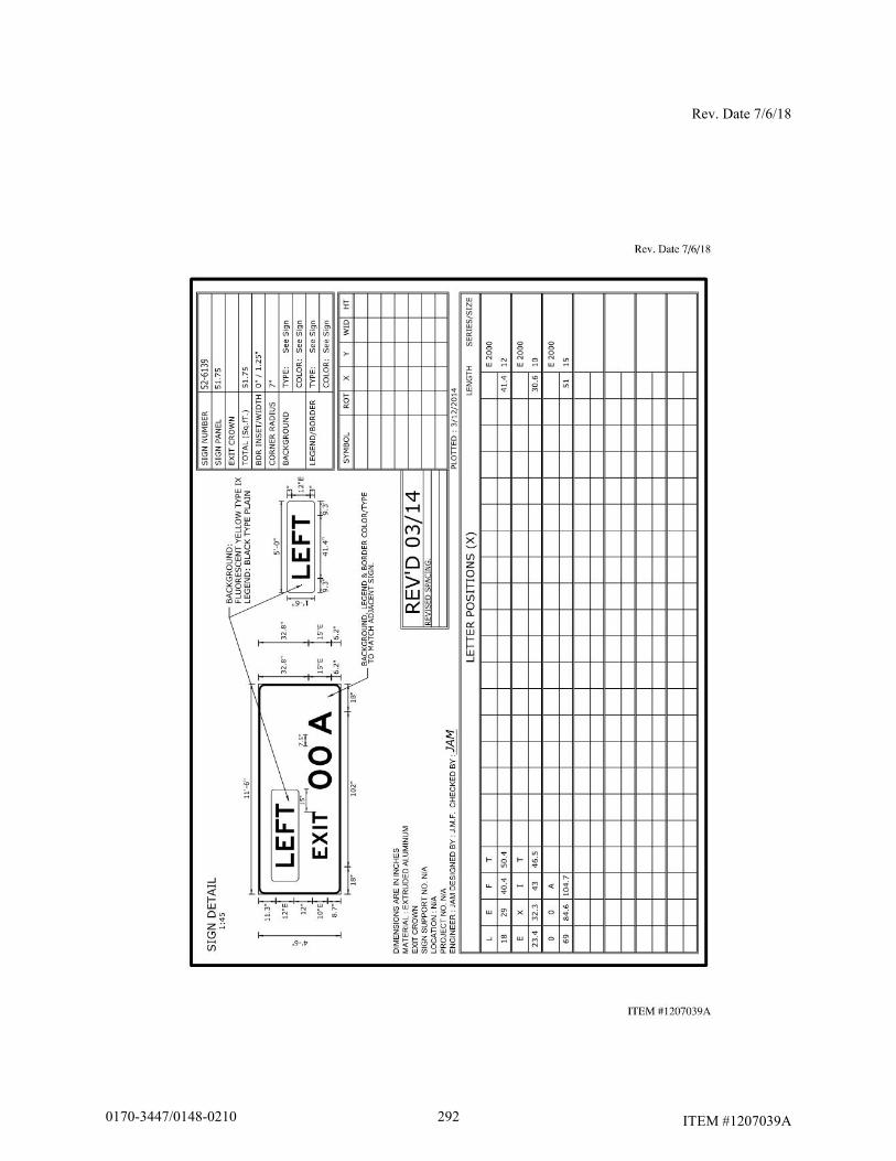
Rev. Date 7/6/18
ITEM #1207039A 2920170-3447/0148-0210
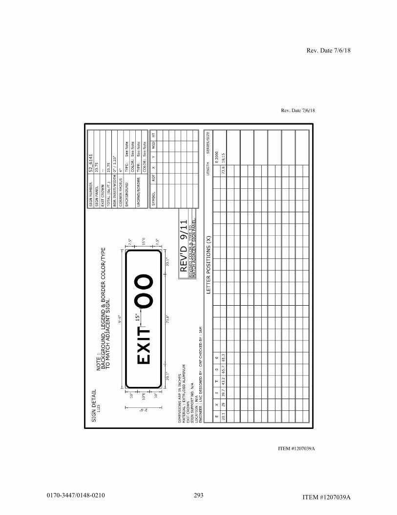
Rev. Date 7/6/18
ITEM #1207039A 2930170-3447/0148-0210
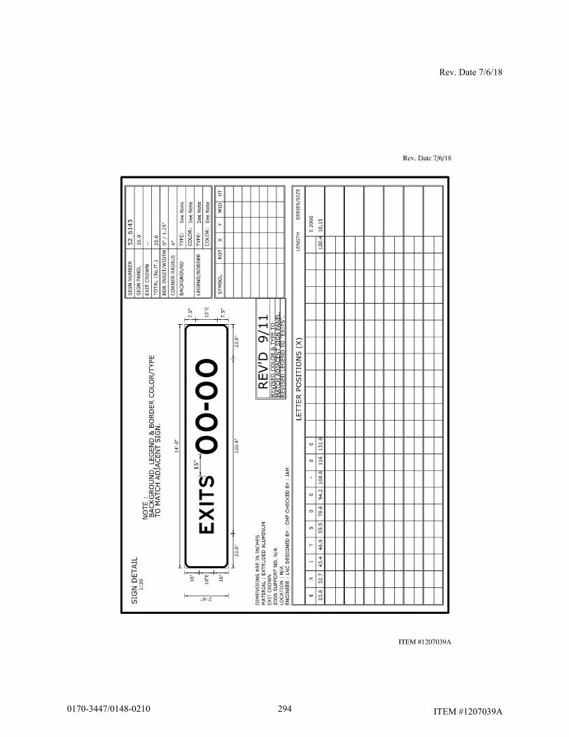
Rev. Date 7/6/18
ITEM #1207039A 2940170-3447/0148-0210
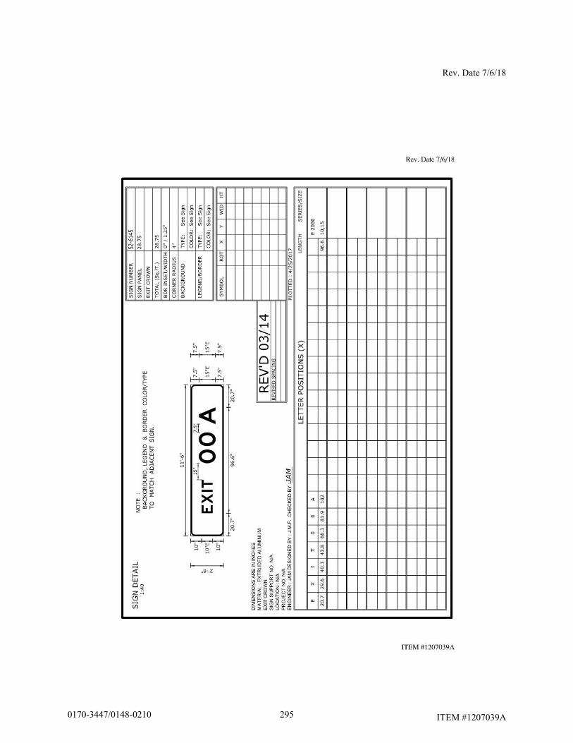
Rev. Date 7/6/18
ITEM #1207039A
2950170-3447/0148-0210
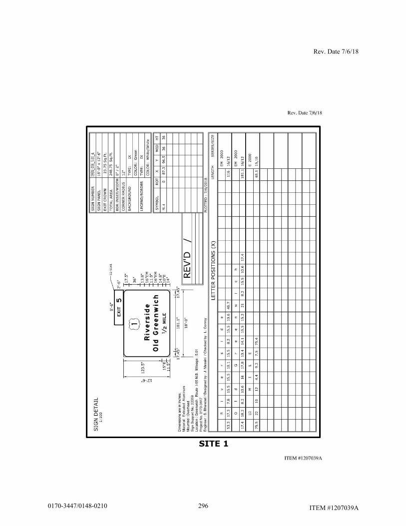
Rev. Date 7/6/18
ITEM #1207039A 2960170-3447/0148-0210

Rev. Date 7/6/18
ITEM #1207039A 2970170-3447/0148-0210
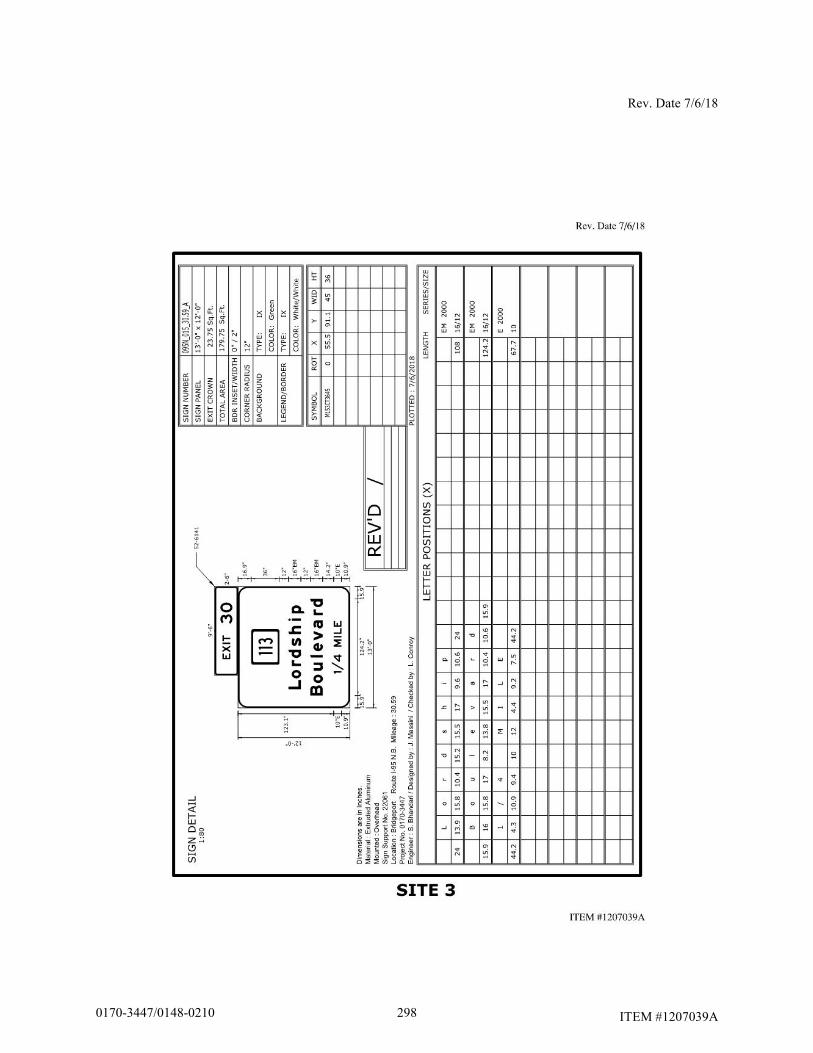
Rev. Date 7/6/18
ITEM #1207039A 2980170-3447/0148-0210
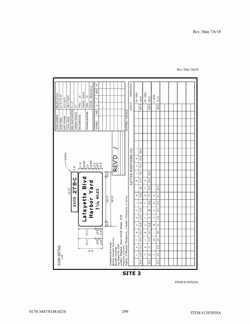
Rev. Date 7/6/18
ITEM #1207039A
2990170-3447/0148-0210
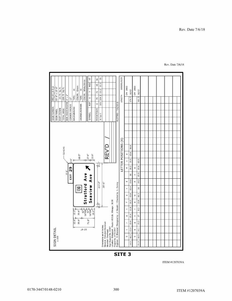
Rev. Date 7/6/18
ITEM #1207039A 3000170-3447/0148-0210
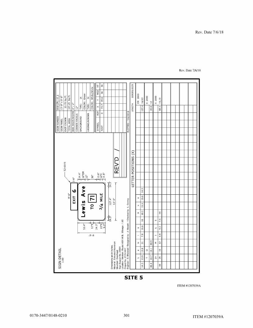
Rev. Date 7/6/18
ITEM #1207039A 3010170-3447/0148-0210
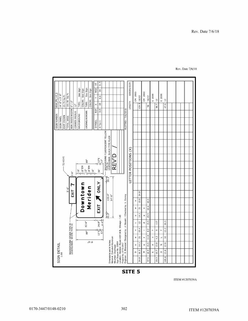
Rev. Date 7/6/18
ITEM #1207039A 3020170-3447/0148-0210
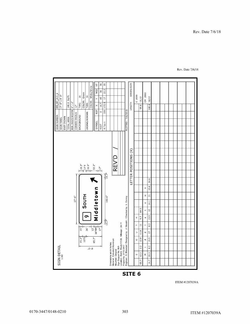
Rev. Date 7/6/18
ITEM #1207039A
3030170-3447/0148-0210
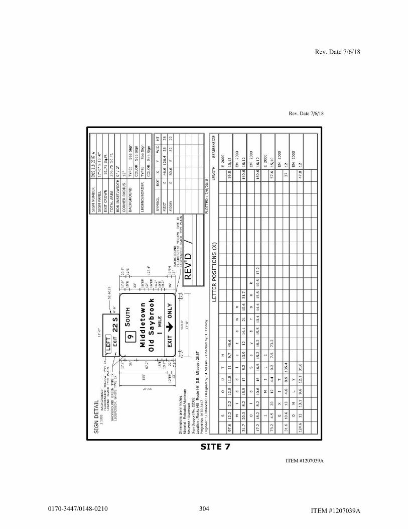
Rev. Date 7/6/18
ITEM #1207039A 3040170-3447/0148-0210
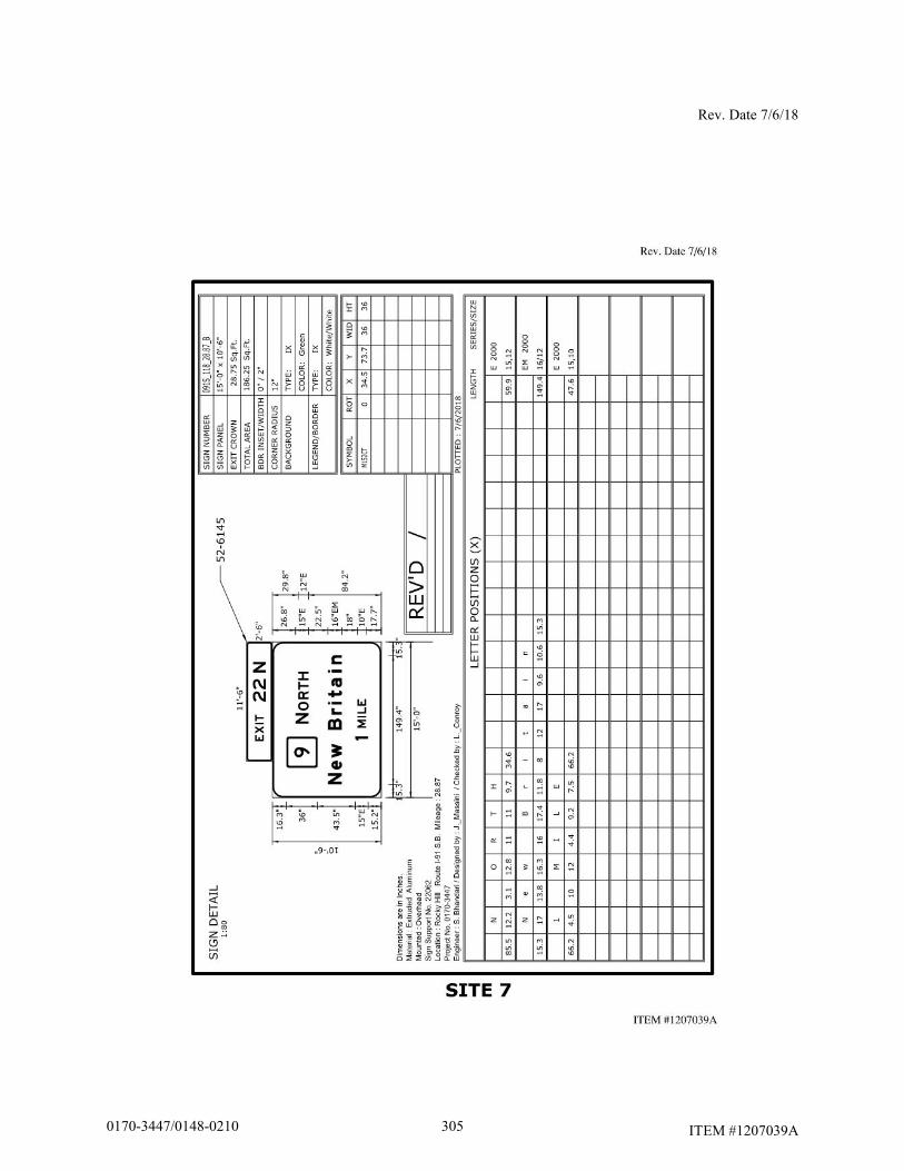
Rev. Date 7/6/18
ITEM #1207039A 3050170-3447/0148-0210

Rev. Date 7/6/18
ITEM #1207039A 3060170-3447/0148-0210
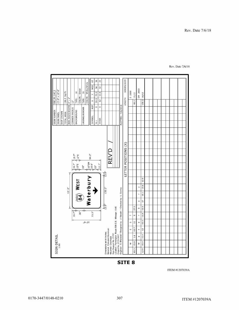
Rev. Date 7/6/18
ITEM #1207039A
3070170-3447/0148-0210

Rev. Date 7/6/18
ITEM #1207039A 3080170-3447/0148-0210
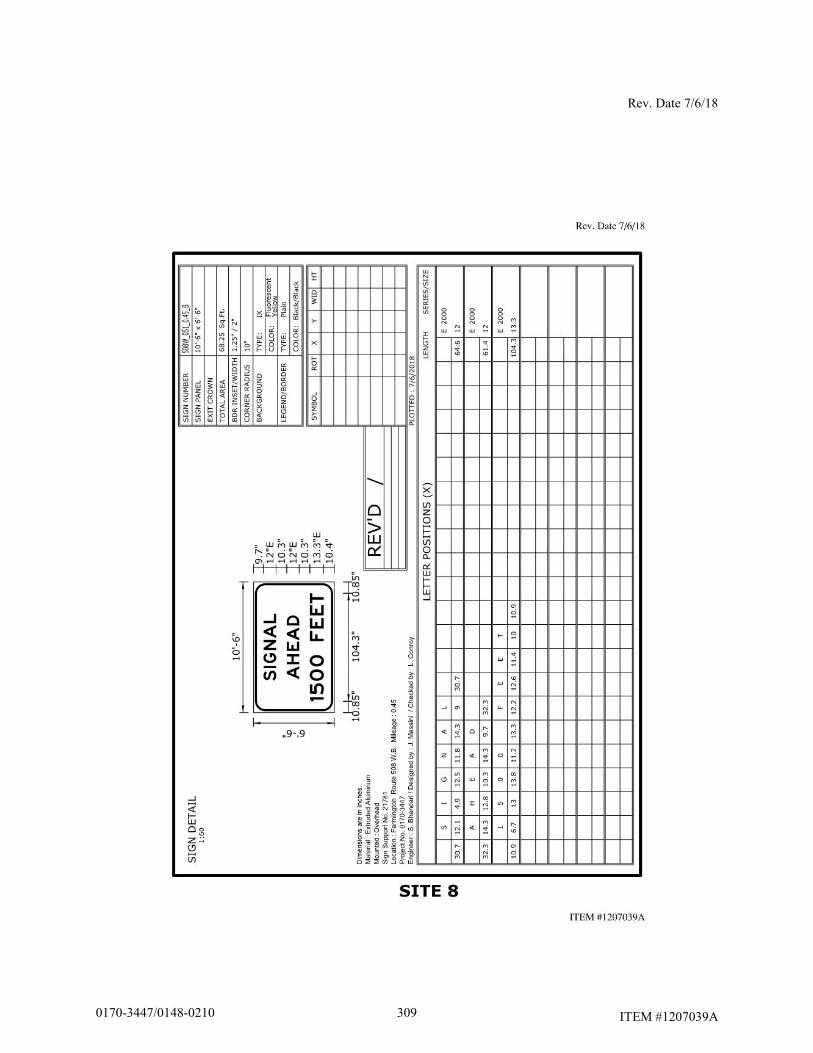
Rev. Date 7/6/18
ITEM #1207039A 3090170-3447/0148-0210
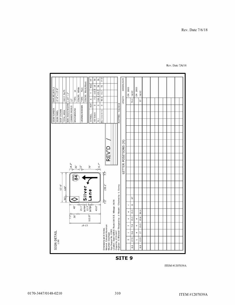
Rev. Date 7/6/18
ITEM #1207039A 3100170-3447/0148-0210

Rev. Date 7/6/18
ITEM #1207039A
3110170-3447/0148-0210
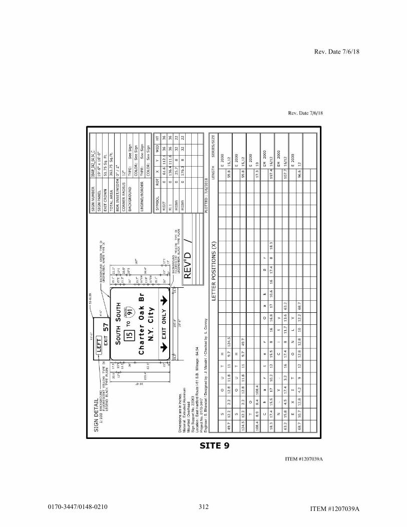
Rev. Date 7/6/18
ITEM #1207039A 3120170-3447/0148-0210
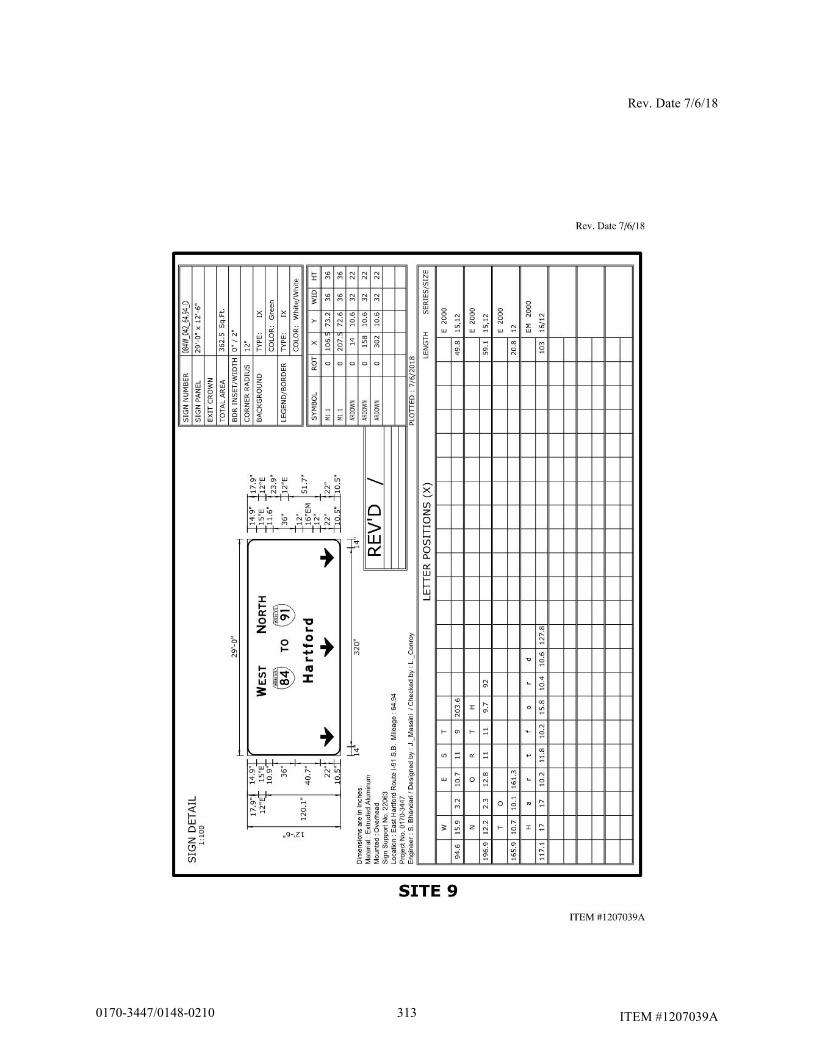
Rev. Date 7/6/18
ITEM #1207039A 3130170-3447/0148-0210
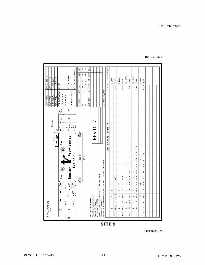
Rev. Date 7/6/18
ITEM #1207039A 3140170-3447/0148-0210
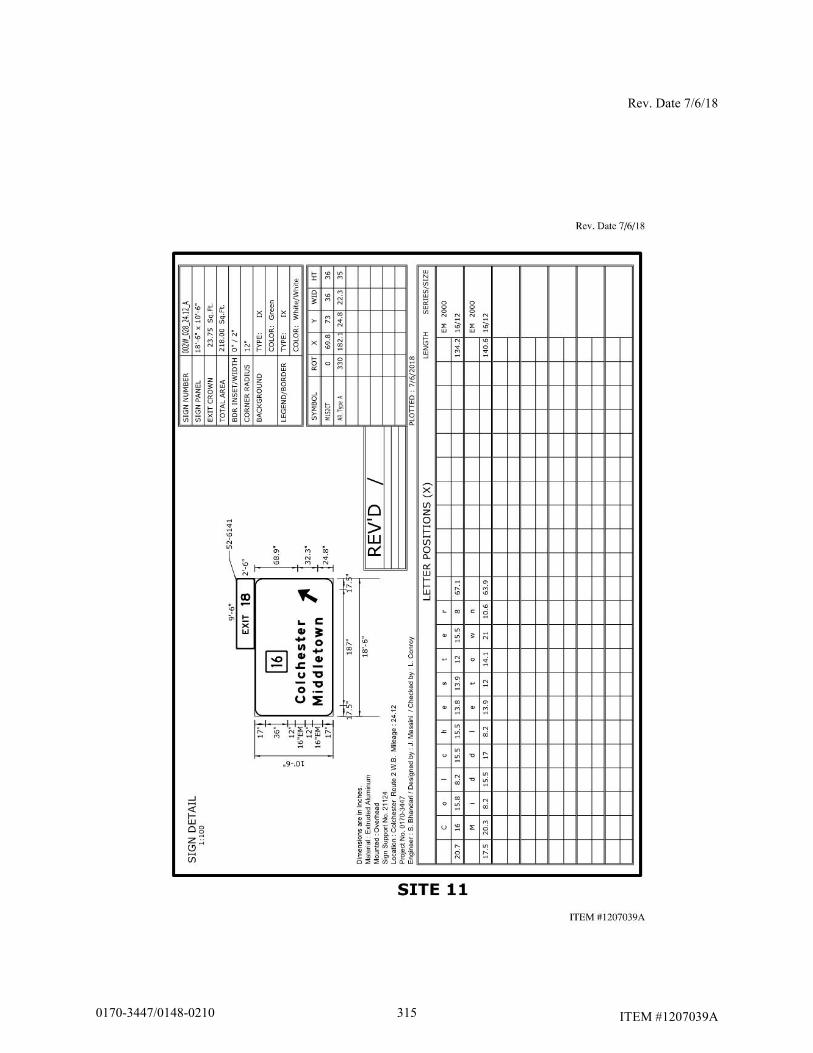
Rev. Date 7/6/18
ITEM #1207039A 3150170-3447/0148-0210

Rev. Date 7/6/18
ITEM #1207039A
3160170-3447/0148-0210
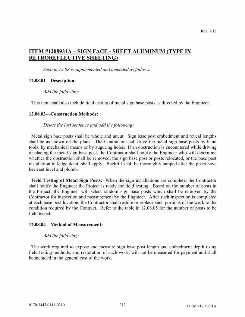
Rev. 7/18
ITEM #1208931A
ITEM #1208931A – SIGN FACE - SHEET ALUMINUM (TYPE IX
RETROREFLECTIVE SHEETING) Section 12.08 is supplemented and amended as follows: 12.08.01—Description:
Add the following:
This item shall also include field testing of metal sign base posts as directed by the Engineer.
12.08.03—Construction Methods:
Delete the last sentence and add the following:
Metal sign base posts shall be whole and uncut. Sign base post embedment and reveal lengths shall be as shown on the plans. The Contractor shall drive the metal sign base posts by hand tools, by mechanical means or by auguring holes. If an obstruction is encountered while driving or placing the metal sign base post, the Contractor shall notify the Engineer who will determine whether the obstruction shall be removed, the sign base post or posts relocated, or the base post installation in ledge detail shall apply. Backfill shall be thoroughly tamped after the posts have been set level and plumb. Field Testing of Metal Sign Posts: When the sign installations are complete, the Contractor shall notify the Engineer the Project is ready for field testing. Based on the number of posts in the Project, the Engineer will select random sign base posts which shall be removed by the Contractor for inspection and measurement by the Engineer. After such inspection is completed at each base post location, the Contractor shall restore or replace such portions of the work to the condition required by the Contract. Refer to the table in 12.08.05 for the number of posts to be field tested.
12.08.04—Method of Measurement:
Add the following:
The work required to expose and measure sign base post length and embedment depth using field testing methods, and restoration of such work, will not be measured for payment and shall be included in the general cost of the work.
3170170-3447/0148-0210
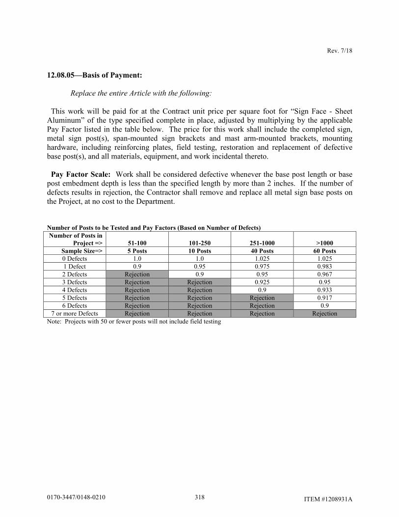
Rev. 7/18
ITEM #1208931A
12.08.05—Basis of Payment:
Replace the entire Article with the following:
This work will be paid for at the Contract unit price per square foot for “Sign Face - Sheet Aluminum” of the type specified complete in place, adjusted by multiplying by the applicable Pay Factor listed in the table below. The price for this work shall include the completed sign, metal sign post(s), span-mounted sign brackets and mast arm-mounted brackets, mounting hardware, including reinforcing plates, field testing, restoration and replacement of defective base post(s), and all materials, equipment, and work incidental thereto. Pay Factor Scale: Work shall be considered defective whenever the base post length or base post embedment depth is less than the specified length by more than 2 inches. If the number of defects results in rejection, the Contractor shall remove and replace all metal sign base posts on the Project, at no cost to the Department. Number of Posts to be Tested and Pay Factors (Based on Number of Defects)
Number of Posts in
Project => 51-100 101-250 251-1000 >1000
Sample Size=> 5 Posts 10 Posts 40 Posts 60 Posts
0 Defects 1.0 1.0 1.025 1.025 1 Defect 0.9 0.95 0.975 0.983 2 Defects Rejection 0.9 0.95 0.967 3 Defects Rejection Rejection 0.925 0.95 4 Defects Rejection Rejection 0.9 0.933 5 Defects Rejection Rejection Rejection 0.917 6 Defects Rejection Rejection Rejection 0.9
7 or more Defects Rejection Rejection Rejection Rejection Note: Projects with 50 or fewer posts will not include field testing
3180170-3447/0148-0210
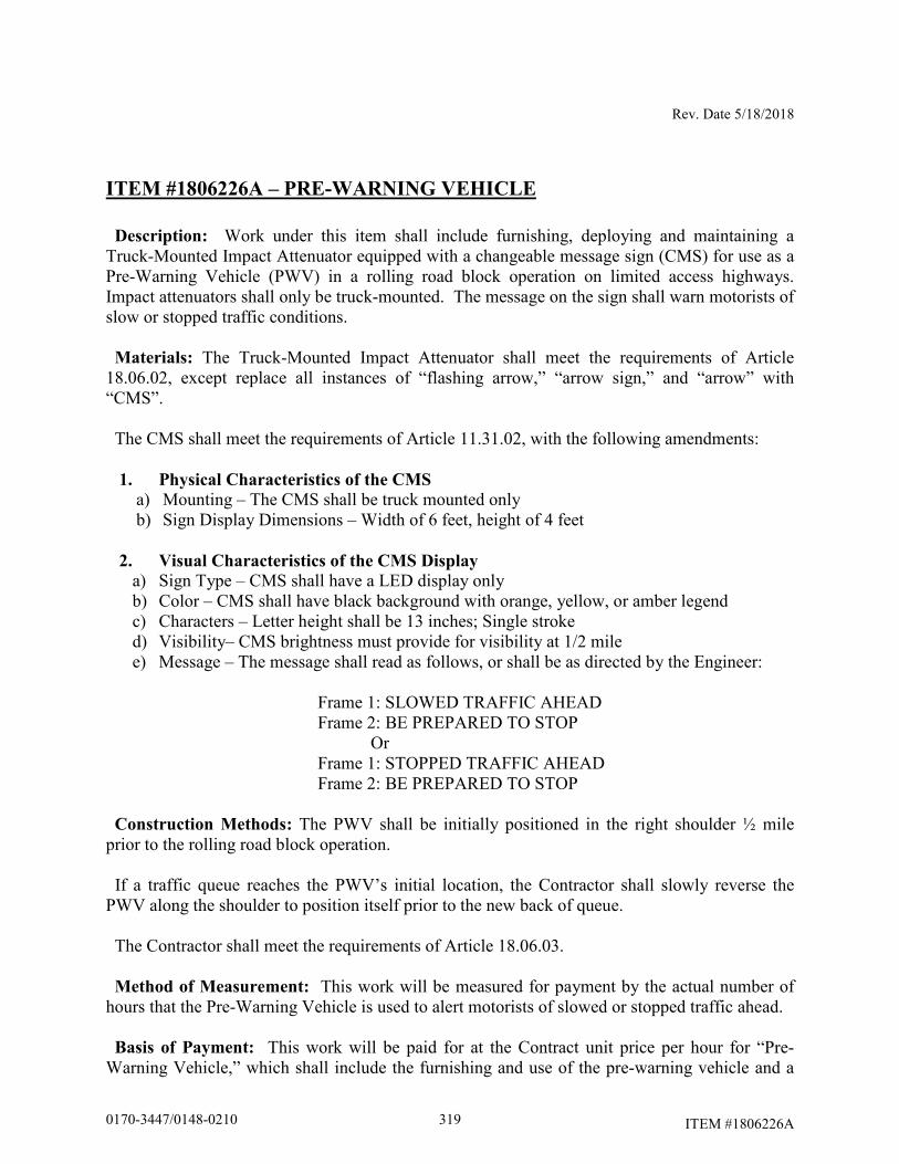
Rev. Date 5/18/2018
ITEM #1806226A
ITEM #1806226A – PRE-WARNING VEHICLE
Description: Work under this item shall include furnishing, deploying and maintaining a Truck-Mounted Impact Attenuator equipped with a changeable message sign (CMS) for use as a Pre-Warning Vehicle (PWV) in a rolling road block operation on limited access highways. Impact attenuators shall only be truck-mounted. The message on the sign shall warn motorists of slow or stopped traffic conditions. Materials: The Truck-Mounted Impact Attenuator shall meet the requirements of Article 18.06.02, except replace all instances of “flashing arrow,” “arrow sign,” and “arrow” with “CMS”. The CMS shall meet the requirements of Article 11.31.02, with the following amendments:
1. Physical Characteristics of the CMS
a) Mounting – The CMS shall be truck mounted only b) Sign Display Dimensions – Width of 6 feet, height of 4 feet
2. Visual Characteristics of the CMS Display
a) Sign Type – CMS shall have a LED display only b) Color – CMS shall have black background with orange, yellow, or amber legend c) Characters – Letter height shall be 13 inches; Single stroke d) Visibility– CMS brightness must provide for visibility at 1/2 mile e) Message – The message shall read as follows, or shall be as directed by the Engineer:
Frame 1: SLOWED TRAFFIC AHEAD Frame 2: BE PREPARED TO STOP Or Frame 1: STOPPED TRAFFIC AHEAD Frame 2: BE PREPARED TO STOP
Construction Methods: The PWV shall be initially positioned in the right shoulder ½ mile prior to the rolling road block operation. If a traffic queue reaches the PWV’s initial location, the Contractor shall slowly reverse the PWV along the shoulder to position itself prior to the new back of queue. The Contractor shall meet the requirements of Article 18.06.03. Method of Measurement: This work will be measured for payment by the actual number of hours that the Pre-Warning Vehicle is used to alert motorists of slowed or stopped traffic ahead. Basis of Payment: This work will be paid for at the Contract unit price per hour for “Pre-Warning Vehicle,” which shall include the furnishing and use of the pre-warning vehicle and a
3190170-3447/0148-0210
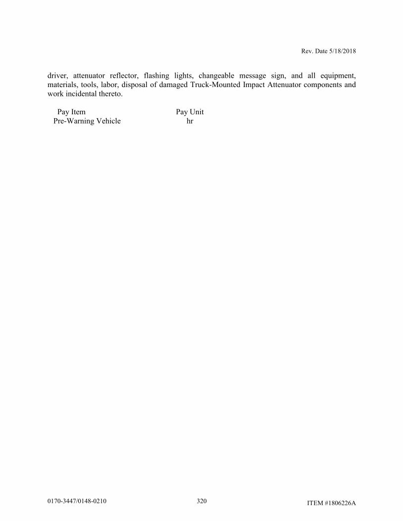
Rev. Date 5/18/2018
ITEM #1806226A
driver, attenuator reflector, flashing lights, changeable message sign, and all equipment, materials, tools, labor, disposal of damaged Truck-Mounted Impact Attenuator components and work incidental thereto.
Pay Item Pay Unit Pre-Warning Vehicle hr
3200170-3447/0148-0210
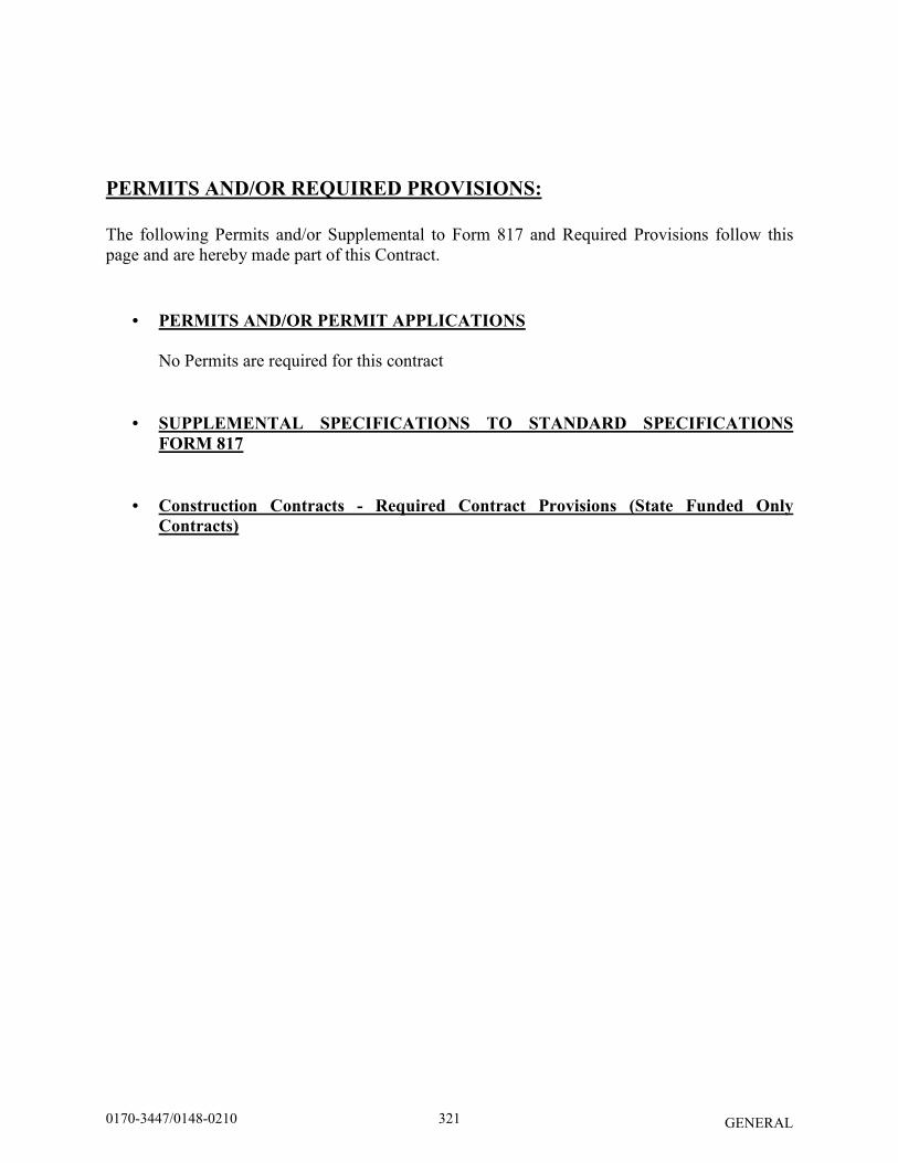
GENERAL
PERMITS AND/OR REQUIRED PROVISIONS:
The following Permits and/or Supplemental to Form 817 and Required Provisions follow this page and are hereby made part of this Contract.
• PERMITS AND/OR PERMIT APPLICATIONS
No Permits are required for this contract
• SUPPLEMENTAL SPECIFICATIONS TO STANDARD SPECIFICATIONS
FORM 817
• Construction Contracts - Required Contract Provisions (State Funded Only
Contracts)
3210170-3447/0148-0210
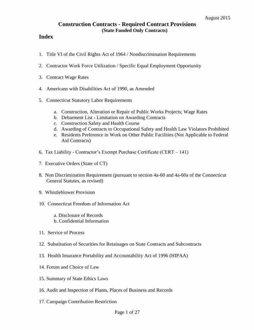
August 2015
Page 1 of 27
Construction Contracts - Required Contract Provisions (State Funded Only Contracts)
Index
1. Title VI of the Civil Rights Act of 1964 / Nondiscrimination Requirements
2. Contractor Work Force Utilization / Specific Equal Employment Opportunity
3. Contract Wage Rates
4. Americans with Disabilities Act of 1990, as Amended
5. Connecticut Statutory Labor Requirements
a. Construction, Alteration or Repair of Public Works Projects; Wage Rates
b. Debarment List - Limitation on Awarding Contracts
c. Construction Safety and Health Course
d. Awarding of Contracts to Occupational Safety and Health Law Violators Prohibited
e. Residents Preference in Work on Other Public Facilities (Not Applicable to Federal
Aid Contracts)
6. Tax Liability - Contractor’s Exempt Purchase Certificate (CERT – 141)
7. Executive Orders (State of CT)
8. Non Discrimination Requirement (pursuant to section 4a-60 and 4a-60a of the Connecticut
General Statutes, as revised)
9. Whistleblower Provision
10. Connecticut Freedom of Information Act
a. Disclosure of Records
b. Confidential Information
11. Service of Process
12. Substitution of Securities for Retainages on State Contracts and Subcontracts
13. Health Insurance Portability and Accountability Act of 1996 (HIPAA)
14. Forum and Choice of Law
15. Summary of State Ethics Laws
16. Audit and Inspection of Plants, Places of Business and Records
17. Campaign Contribution Restriction
August 2015
Page 2 of 27
18. Tangible Personal Property
19. Bid Rigging and/or Fraud – Notice to Contractor
20. Consulting Agreement Affidavit
Index of Exhibits
EXHIBIT A – Title VI Contractor Assurances (page 13)
EXHIBIT B – Contractor Work Force Utilization / Equal Employment Opportunity (page 14)
EXHIBIT C – Health Insurance Portability and Accountability Act of 1996 (HIPAA) (page 17)
EXHIBIT D - Campaign Contribution Restriction (page 25)
EXHIBIT E - State Wage Rates (Attached at the end)
August 2015
Page 3 of 27
1. Title VI of the Civil Rights Act of 1964 / Nondiscrimination Requirements
The Contractor shall comply with Title VI of the Civil Rights Act of 1964 as amended (42 U.S.C. 2000
et seq.), all requirements imposed by the regulations of the United States Department of Transportation
(49 CFR Part 21) issued in implementation thereof, and the Title VI Contractor Assurances attached
hereto at Exhibit A, all of which are hereby made a part of this Contract.
2. Contractor Work Force Utilization / Equal Employment Opportunity
(a) The Contractor shall comply with the Contractor Work Force Utilization / Equal
Employment Opportunity requirements attached at Exhibit B and hereby made part of this
Contract, whenever a contractor or subcontractor at any tier performs construction work in
excess of $10,000. These goals shall be included in each contract and subcontract. Goal
achievement is calculated for each trade using the hours worked under each trade.
(b) Companies with contracts, agreements or purchase orders valued at $10,000 or more will
develop and implement an Affirmative Action Plan utilizing the ConnDOT Affirmative
Action Plan Guideline. This Plan shall be designed to further the provision of equal
employment opportunity to all persons without regard to their race, color, religion, sex or
national origin, and to promote the full realization of equal employment opportunity
through a positive continuation program. Plans shall be updated as required by ConnDOT.
3. Contract Wage Rates
The Contractor shall comply with:
The State wage rate requirements indicated in Exhibit E hereof are hereby made part of this Contract.
Prevailing Wages for Work on State Highways; Annual Adjustments. With respect to contracts for
work on state highways and bridges on state highways, the Contractor shall comply with the provisions
of Section 31-54 and 31-55a of the Connecticut General Statutes, as revised.
As required by section 1.05.12 (Payrolls) of the State of Connecticut, Department of Transportation’s
Standard Specification for Roads, Bridges and Incidental Construction (FORM 816), as may be
revised, every Contractor or subcontractor performing project work on a federal aid project is required
to post the relevant prevailing wage rates as determined by the United States Secretary of Labor. The
wage rate determinations shall be posted in prominent and easily accessible places at the work site.
4. Americans with Disabilities Act of 1990, as Amended
This provision applies to those Contractors who are or will be responsible for compliance with the
terms of the Americans with Disabilities Act of 1990, as amended (42 U.S.C. 12101 et seq.), (Act),
during the term of the Contract. The Contractor represents that it is familiar with the terms of this Act
and that it is in compliance with the Act. Failure of the Contractor to satisfy this standard as the same
applies to performance under this Contract, either now or during the term of the Contract as it may be
amended, will render the Contract voidable at the option of the State upon notice to the contractor. The
Contractor warrants that it will hold the State harmless and indemnify the State from any liability
which may be imposed upon the State as a result of any failure of the Contractor to be in compliance
with this Act, as the same applies to performance under this Contract.
August 2015
Page 4 of 27
5. Connecticut Statutory Labor Requirements
(a) Construction, Alteration or Repair of Public Works Projects; Wage Rates. The
Contractor shall comply with Section 31-53 of the Connecticut General Statutes, as revised. The
wages paid on an hourly basis to any person performing the work of any mechanic, laborer or
worker on the work herein contracted to be done and the amount of payment or contribution paid
or payable on behalf of each such person to any employee welfare fund, as defined in subsection (i)
of section 31-53 of the Connecticut General Statutes, shall be at a rate equal to the rate customary
or prevailing for the same work in the same trade or occupation in the town in which such public
works project is being constructed. Any contractor who is not obligated by agreement to make
payment or contribution on behalf of such persons to any such employee welfare fund shall pay to
each mechanic, laborer or worker as part of such person’s wages the amount of payment or
contribution for such person’s classification on each pay day.
(b) Debarment List. Limitation on Awarding Contracts. The Contractor shall comply with
Section 3l-53a of the Connecticut General Statutes, as revised.
(c) Construction Safety and Health Course. The Contractor shall comply with section 31-53b
of the Connecticut General Statutes, as revised. The contractor shall furnish proof to the Labor
Commissioner with the weekly certified payroll form for the first week each employee begins work
on such project that any person performing the work of a mechanic, laborer or worker pursuant to
the classifications of labor under section 31-53 of the Connecticut General Statutes, as revised, on
such public works project, pursuant to such contract, has completed a course of at least ten hours in
duration in construction safety and health approved by the federal Occupational Safety and Health
Administration or, has completed a new miner training program approved by the Federal Mine
Safety and Health Administration in accordance with 30 CFR 48 or, in the case of
telecommunications employees, has completed at least ten hours of training in accordance with 29
CFR 1910.268.
Any employee required to complete a construction safety and health course as required that has not
completed the course, shall have a maximum of fourteen (14) days to complete the course. If the
employee has not been brought into compliance, they shall be removed from the project until such
time as they have completed the required training.
Any costs associated with this notice shall be included in the general cost of the contract. In
addition, there shall be no time granted to the contractor for compliance with this notice. The
contractor’s compliance with this notice and any associated regulations shall not be grounds for
claims as outlined in Section 1.11 – “Claims”.
(d) Awarding of Contracts to Occupational Safety and Health Law Violators Prohibited. The
Contract is subject to Section 31-57b of the Connecticut General Statutes, as revised.
(e) Residents Preference in Work on Other Public Facilities. NOT APPLICABLE TO
FEDERAL AID CONTRACTS. Pursuant to Section 31-52a of the Connecticut General Statutes,
as revised, in the employment of mechanics, laborers or workmen to perform the work specified
herein, preference shall be given to residents of the state who are, and continuously for at least six
months prior to the date hereof have been, residents of this state, and if no such person is available,
then to residents of other states
August 2015
Page 5 of 27
6. Tax Liability - Contractor’s Exempt Purchase Certificate (CERT – 141)
The Contractor shall comply with Chapter 219 of the Connecticut General Statutes pertaining to
tangible personal property or services rendered that is/are subject to sales tax. The Contractor is
responsible for determining its tax liability. If the Contractor purchases materials or supplies pursuant
to the Connecticut Department of Revenue Services’ "Contractor’s Exempt Purchase Certificate
(CERT-141)," as may be revised, the Contractor acknowledges and agrees that title to such materials
and supplies installed or placed in the project will vest in the State simultaneously with passage of title
from the retailers or vendors thereof, and the Contractor will have no property rights in the materials
and supplies purchased.
Forms and instructions are available anytime by:
Internet: Visit the DRS website at www.ct.gov/DRS to download and print Connecticut tax forms; or
Telephone: Call 1-800-382-9463 (Connecticut calls outside the Greater Hartford calling area only) and
select Option 2 or call 860-297-4753 (from anywhere).
7. Executive Orders This contract is subject to the provisions of Executive Order No. Three of Governor Thomas J. Meskill, promulgated June 16, 1971, concerning labor employment practices, Executive Order No. Seventeen of Governor Thomas J. Meskill, promulgated February 15, 1973, concerning the listing of employment openings and Executive Order No. Sixteen of Governor John G. Rowland promulgated August 4, 1999, concerning violence in the workplace, all of which are incorporated into and are made a part of the contract as if they had been fully set forth in it. The contract may also be subject to Executive Order No. 14 of Governor M. Jodi Rell, promulgated April 17, 2006, concerning procurement of cleaning products and services and to Executive Order No. 49 of Governor Dannel P. Malloy, promulgated May 22, 2015, mandating disclosure of certain gifts to public employees and contributions to certain candidates for office. If Executive Order No. 14 and/or Executive Order No. 49 are applicable, they are deemed to be incorporated into and are made a part of the contract as if they had been fully set forth in it. At the Contractor’s request, the Department shall provide a copy of these orders to the Contractor.
8. Non Discrimination Requirement (pursuant to section 4a-60 and 4a-60a of the Connecticut
General Statutes, as revised): References to “minority business enterprises” in this Section are
not applicable to Federal-aid projects/contracts. Federal-aid projects/contracts are instead
subject to the Federal Disadvantaged Business Enterprise Program.
(a) For purposes of this Section, the following terms are defined as follows:
i. "Commission" means the Commission on Human Rights and Opportunities;
ii. "Contract" and “contract” include any extension or modification of the Contract or
contract;
iii. "Contractor" and “contractor” include any successors or assigns of the Contractor or
contractor;
iv. “gender identity or expression" means a person's gender-related identity, appearance or
behavior, whether or not that gender-related identity, appearance or behavior is different
from that traditionally associated with the person's physiology or assigned sex at birth,
which gender-related identity can be shown by providing evidence including, but not
limited to, medical history, care or treatment of the gender-related identity, consistent and
uniform assertion of the gender-related identity or any other evidence that the gender-
related identity is sincerely held, part of a person's core identity or not being asserted for
an improper purpose.
August 2015
Page 6 of 27
v. “good faith" means that degree of diligence which a reasonable person would exercise in
the performance of legal duties and obligations;
vi. "good faith efforts" shall include, but not be limited to, those reasonable initial efforts
necessary to comply with statutory or regulatory requirements and additional or
substituted efforts when it is determined that such initial efforts will not be sufficient to
comply with such requirements;
vii. "marital status" means being single, married as recognized by the State of Connecticut,
widowed, separated or divorced;
viii. "mental disability" means one or more mental disorders, as defined in the most recent
edition of the American Psychiatric Association's "Diagnostic and Statistical Manual of
Mental Disorders", or a record of or regarding a person as having one or more such
disorders;
ix. "minority business enterprise" means any small contractor or supplier of materials fifty-
one percent or more of the capital stock, if any, or assets of which is owned by a person or
persons: (1) who are active in the daily affairs of the enterprise, (2) who have the power
to direct the management and policies of the enterprise, and (3) who are members of a
minority, as such term is defined in subsection (a) of Connecticut General Statutes § 32-
9n; and
x. “public works contract" means any agreement between any individual, firm or
corporation and the State or any political subdivision of the State other than a
municipality for construction, rehabilitation, conversion, extension, demolition or repair
of a public building, highway or other changes or improvements in real property, or
which is financed in whole or in part by the State, including, but not limited to, matching
expenditures, grants, loans, insurance or guarantees.
For purposes of this Section, the terms "Contract" and “contract” do not include a contract where
each contractor is (1) a political subdivision of the State, including, but not limited to, a
municipality, (2) a quasi-public agency, as defined in Conn. Gen. Stat. Section 1-120, (3) any
other state, including but not limited to any federally recognized Indian tribal governments, as
defined in Conn. Gen. Stat. Section 1-267, (4) the federal government, (5) a foreign government,
or (6) an agency of a subdivision, agency, state or government described in the immediately
preceding enumerated items (1), (2), (3), (4) or (5).
(b) (1) The Contractor agrees and warrants that in the performance of the Contract such Contractor
will not discriminate or permit discrimination against any person or group of persons on the
grounds of race, color, religious creed, age, marital status, national origin, ancestry, sex, gender
identity or expression, intellectual disability, mental disability or physical disability, including,
but not limited to, blindness, unless it is shown by such Contractor that such disability prevents
performance of the work involved, in any manner prohibited by the laws of the United States or
of the State of Connecticut; and the Contractor further agrees to take affirmative action to insure
that applicants with job-related qualifications are employed and that employees are treated when
employed without regard to their race, color, religious creed, age, marital status, national origin,
ancestry, sex, gender identity or expression, intellectual disability, mental disability or physical
disability, including, but not limited to, blindness, unless it is shown by the Contractor that such
disability prevents performance of the work involved; (2) the Contractor agrees, in all
solicitations or advertisements for employees placed by or on behalf of the Contractor, to state
that it is an "affirmative action-equal opportunity employer" in accordance with regulations
adopted by the Commission; (3) the Contractor agrees to provide each labor union or
representative of workers with which the Contractor has a collective bargaining Agreement or
other contract or understanding and each vendor with which the Contractor has a contract or
August 2015
Page 7 of 27
understanding, a notice to be provided by the Commission, advising the labor union or workers’
representative of the Contractor's commitments under this section and to post copies of the notice
in conspicuous places available to employees and applicants for employment; (4) the Contractor
agrees to comply with each provision of this Section and Connecticut General Statutes §§ 46a-
68e and 46a-68f and with each regulation or relevant order issued by said Commission pursuant
to Connecticut General Statutes §§ 46a-56, 46a-68e and 46a-68f; and (5) the Contractor agrees to
provide the Commission on Human Rights and Opportunities with such information requested by
the Commission, and permit access to pertinent books, records and accounts, concerning the
employment practices and procedures of the Contractor as relate to the provisions of this Section
and Connecticut General Statutes § 46a-56. If the contract is a public works contract, the
Contractor agrees and warrants that he will make good faith efforts to employ minority business
enterprises as subcontractors and suppliers of materials on such public works projects.
(c) Determination of the Contractor's good faith efforts shall include, but shall not be limited to, the
following factors: The Contractor's employment and subcontracting policies, patterns and
practices; affirmative advertising, recruitment and training; technical assistance activities and
such other reasonable activities or efforts as the Commission may prescribe that are designed to
ensure the participation of minority business enterprises in public works projects.
(d) The Contractor shall develop and maintain adequate documentation, in a manner prescribed by
the Commission, of its good faith efforts.
(e) The Contractor shall include the provisions of subsection (b) of this Section in every subcontract
or purchase order entered into in order to fulfill any obligation of a contract with the State and
such provisions shall be binding on a subcontractor, vendor or manufacturer unless exempted by
regulations or orders of the Commission. The Contractor shall take such action with respect to
any such subcontract or purchase order as the Commission may direct as a means of enforcing
such provisions including sanctions for noncompliance in accordance with Connecticut General
Statutes §46a-56; provided if such Contractor becomes involved in, or is threatened with,
litigation with a subcontractor or vendor as a result of such direction by the Commission, the
Contractor may request the State of Connecticut to enter into any such litigation or negotiation
prior thereto to protect the interests of the State and the State may so enter.
(f) The Contractor agrees to comply with the regulations referred to in this Section as they exist on
the date of this Contract and as they may be adopted or amended from time to time during the
term of this Contract and any amendments thereto.
(g) (1) The Contractor agrees and warrants that in the performance of the Contract such Contractor
will not discriminate or permit discrimination against any person or group of persons on the
grounds of sexual orientation, in any manner prohibited by the laws of the United States or the
State of Connecticut, and that employees are treated when employed without regard to their
sexual orientation; (2) the Contractor agrees to provide each labor union or representative of
workers with which such Contractor has a collective bargaining Agreement or other contract or
understanding and each vendor with which such Contractor has a contract or understanding, a
notice to be provided by the Commission on Human Rights and Opportunities advising the labor
union or workers' representative of the Contractor's commitments under this section, and to post
copies of the notice in conspicuous places available to employees and applicants for employment;
(3) the Contractor agrees to comply with each provision of this section and with each regulation
or relevant order issued by said Commission pursuant to Connecticut General Statutes § 46a-56;
August 2015
Page 8 of 27
and (4) the Contractor agrees to provide the Commission on Human Rights and Opportunities
with such information requested by the Commission, and permit access to pertinent books,
records and accounts, concerning the employment practices and procedures of the Contractor
which relate to the provisions of this Section and Connecticut General Statutes § 46a-56.
(h) The Contractor shall include the provisions of the foregoing paragraph in every subcontract or
purchase order entered into in order to fulfill any obligation of a contract with the State and such
provisions shall be binding on a subcontractor, vendor or manufacturer unless exempted by
regulations or orders of the Commission. The Contractor shall take such action with respect to
any such subcontract or purchase order as the Commission may direct as a means of enforcing
such provisions including sanctions for noncompliance in accordance with Connecticut General
Statutes § 46a-56; provided, if such Contractor becomes involved in, or is threatened with,
litigation with a subcontractor or vendor as a result of such direction by the Commission, the
Contractor may request the State of Connecticut to enter into any such litigation or negotiation
prior thereto to protect the interests of the State and the State may so enter.”
The Nondiscrimination Certifications can be found at the Office of Policy and Management website.
http://www.ct.gov/opm/cwp/view.asp?a=2982&Q=390928
9. Whistleblower Provision
The following clause is applicable if the Contract has a value of Five Million Dollars ($5,000,000) or
more.
Whistleblowing. This Contract may be subject to the provisions of Section 4-61dd of the Connecticut General Statutes. In accordance with this statute, if an officer, employee or appointing authority of the Contractor takes or threatens to take any personnel action against any employee of the Contractor in retaliation for such employee's disclosure of information to any employee of the contracting state or quasi-public agency or the Auditors of Public Accounts or the Attorney General under the provisions of subsection (a) of such statute, the Contractor shall be liable for a civil penalty of not more than five thousand dollars for each offense, up to a maximum of twenty per cent of the value of this Contract. Each violation shall be a separate and distinct offense and in the case of a continuing violation, each calendar day's continuance of the violation shall be deemed to be a separate and distinct offense. The State may request that the Attorney General bring a civil action in the Superior Court for the Judicial District of Hartford to seek imposition and recovery of such civil penalty. In accordance with subsection (f) of such statute, each large state contractor, as defined in the statute, shall post a notice of the provisions of the statute relating to large state contractors in a conspicuous place which is readily available for viewing by the employees of the Contractor. 10. Connecticut Freedom of Information Act
(a) Disclosure of Records. This Contract may be subject to the provisions of section 1-218 of
the Connecticut General Statutes. In accordance with this statute, each contract in excess of two million five hundred thousand dollars between a public agency and a person for the performance of a governmental function shall (a) provide that the public agency is entitled to receive a copy of records and files related to the performance of the governmental function, and (b) indicate that such records and files are subject to FOIA and may be disclosed by the public agency pursuant to FOIA. No request to inspect or copy such records or files shall be valid unless the request is made to the public agency in accordance with FOIA. Any complaint by a person who is denied the right to inspect or copy such records or files shall be brought to the Freedom of Information Commission in accordance with the provisions of sections 1-205 and 1-206 of the Connecticut General Statutes.
August 2015
Page 9 of 27
(b) Confidential Information. The State will afford due regard to the Contractor’s request
for the protection of proprietary or confidential information which the State receives from
the Contractor. However, all materials associated with the Contract are subject to the terms
of the FOIA and all corresponding rules, regulations and interpretations. In making such a
request, the Contractor may not merely state generally that the materials are proprietary or
confidential in nature and not, therefore, subject to release to third parties. Those particular
sentences, paragraphs, pages or sections that the Contractor believes are exempt from
disclosure under the FOIA must be specifically identified as such. Convincing explanation
and rationale sufficient to justify each exemption consistent with the FOIA must
accompany the request. The rationale and explanation must be stated in terms of the
prospective harm to the competitive position of the Contractor that would result if the
identified material were to be released and the reasons why the materials are legally exempt
from release pursuant to the FOIA. To the extent that any other provision or part of the
Contract conflicts or is in any way inconsistent with this section, this section controls and
shall apply and the conflicting provision or part shall not be given effect. If the Contractor
indicates that certain documentation is submitted in confidence, by specifically and clearly
marking the documentation as “CONFIDENTIAL,” DOT will first review the Contractor’s
claim for consistency with the FOIA (that is, review that the documentation is actually a
trade secret or commercial or financial information and not required by statute), and if
determined to be consistent, will endeavor to keep such information confidential to the
extent permitted by law. See, e.g., Conn. Gen. Stat. §1-210(b)(5)(A-B). The State,
however, has no obligation to initiate, prosecute or defend any legal proceeding or to seek a
protective order or other similar relief to prevent disclosure of any information that is
sought pursuant to a FOIA request. Should the State withhold such documentation from a
Freedom of Information requester and a complaint be brought to the Freedom of
Information Commission, the Contractor shall have the burden of cooperating with DOT in
defense of that action and in terms of establishing the availability of any FOIA exemption
in any proceeding where it is an issue. In no event shall the State have any liability for the
disclosure of any documents or information in its possession which the State believes are
required to be disclosed pursuant to the FOIA or other law.
11. Service of Process
The Contractor, if not a resident of the State of Connecticut, or, in the case of a partnership, the
partners, if not residents, hereby appoints the Secretary of State of the State of Connecticut, and his
successors in office, as agent for service of process for any action arising out of or as a result of this
Contract; such appointment to be in effect throughout the life of this Contract and six (6) years
thereafter.
12. Substitution of Securities for Retainages on State Contracts and Subcontracts
This Contract is subject to the provisions of Section 3-ll2a of the General Statutes of the State of
Connecticut, as revised.
13. Health Insurance Portability and Accountability Act of 1996 (HIPAA)
The Contractor shall comply, if applicable, with the Health Insurance Portability and Accountability
Act of 1996 and, pursuant thereto, the provisions attached at Exhibit C, and hereby made part of this
Contract.
August 2015
Page 10 of 27
14. Forum and Choice of Law
Forum and Choice of Law. The parties deem the Contract to have been made in the City of Hartford, State of Connecticut. Both parties agree that it is fair and reasonable for the validity and construction of the Contract to be, and it shall be, governed by the laws and court decisions of the State of Connecticut, without giving effect to its principles of conflicts of laws. To the extent that any immunities provided by Federal law or the laws of the State of Connecticut do not bar an action against the State, and to the extent that these courts are courts of competent jurisdiction, for the purpose of venue, the complaint shall be made returnable to the Judicial District of Hartford only or shall be brought in the United States District Court for the District of Connecticut only, and shall not be transferred to any other court, provided, however, that nothing here constitutes a waiver or compromise of the sovereign immunity of the State of Connecticut. The Contractor waives any objection which it may now have or will have to the laying of venue of any Claims in any forum and further irrevocably submits to such jurisdiction in any suit, action or proceeding.
15. Summary of State Ethics Laws Pursuant to the requirements of section 1-101qq of the Connecticut General Statutes, the summary of State ethics laws developed by the State Ethics Commission pursuant to section 1-81b of the Connecticut General Statutes is incorporated by reference into and made a part of the Contract as if the summary had been fully set forth in the Contract.
16. Audit and Inspection of Plants, Places of Business and Records
(a) The State and its agents, including, but not limited to, the Connecticut Auditors of Public
Accounts, Attorney General and State’s Attorney and their respective agents, may, at
reasonable hours, inspect and examine all of the parts of the Contractor’s and Contractor
Parties’ plants and places of business which, in any way, are related to, or involved in, the
performance of this Contract. For the purposes of this Section, “Contractor Parties” means the
Contractor’s members, directors, officers, shareholders, partners, managers, principal officers,
representatives, agents, servants, consultants, employees or any one of them or any other
person or entity with whom the Contractor is in privity of oral or written contract and the
Contractor intends for such other person or entity to Perform under the Contract in any
capacity. (b) The Contractor shall maintain, and shall require each of the Contractor Parties to maintain,
accurate and complete Records. The Contractor shall make all of its and the Contractor Parties’ Records available at all reasonable hours for audit and inspection by the State and its agents.
(c) The State shall make all requests for any audit or inspection in writing and shall provide the Contractor with at least twenty-four (24) hours’ notice prior to the requested audit and inspection date. If the State suspects fraud or other abuse, or in the event of an emergency, the State is not obligated to provide any prior notice.
(d) The Contractor shall keep and preserve or cause to be kept and preserved all of its and Contractor Parties’ Records until three (3) years after the latter of (i) final payment under this Agreement, or (ii) the expiration or earlier termination of this Agreement, as the same may be modified for any reason. The State may request an audit or inspection at any time during this period. If any Claim or audit is started before the expiration of this period, the Contractor shall retain or cause to be retained all Records until all Claims or audit findings have been resolved.
(e) The Contractor shall cooperate fully with the State and its agents in connection with an audit or inspection. Following any audit or inspection, the State may conduct and the Contractor shall cooperate with an exit conference.
(f) The Contractor shall incorporate this entire Section verbatim into any contract or other agreement that it enters into with any Contractor Party.
August 2015
Page 11 of 27
17.Campaign Contribution Restriction
For all State contracts, defined in Conn. Gen. Stat. §9-612(f)(1) as having a value in a calendar year of $50,000 or more, or a combination or series of such agreements or contracts having a value of $100,000 or more, the authorized signatory to this contract expressly acknowledges receipt of the State Elections Enforcement Commission’s notice advising state contractors of state campaign contribution and solicitation prohibitions, and will inform its principals of the contents of the notice, as set forth in "Notice to Executive Branch State Contractors and Prospective State Contractors of Campaign Contribution and Solicitation Limitations,” a copy of which is attached hereto and hereby made a part of
this contract, attached as Exhibit D. 18. Tangible Personal Property (a) The Contractor on its behalf and on behalf of its Affiliates, as defined below, shall comply with the
provisions of Conn. Gen. Stat. §12-411b, as follows:
(1) For the term of the Contract, the Contractor and its Affiliates shall collect and remit to the State of Connecticut, Department of Revenue Services, any Connecticut use tax due under the provisions of Chapter 219 of the Connecticut General Statutes for items of tangible personal property sold by the Contractor or by any of its Affiliates in the same manner as if the Contractor and such Affiliates were engaged in the business of selling tangible personal property for use in Connecticut and had sufficient nexus under the provisions of Chapter 219 to be required to collect Connecticut use tax;
(2) A customer’s payment of a use tax to the Contractor or its Affiliates relieves the customer of liability for the use tax;
(3) The Contractor and its Affiliates shall remit all use taxes they collect from customers on or before the due date specified in the Contract, which may not be later than the last day of the month next succeeding the end of a calendar quarter or other tax collection period during which the tax was collected;
(4) The Contractor and its Affiliates are not liable for use tax billed by them but not paid to them by a customer; and
(5) Any Contractor or Affiliate who fails to remit use taxes collected on behalf of its customers by the due date specified in the Contract shall be subject to the interest and penalties provided for persons required to collect sales tax under chapter 219 of the general statutes.
(b) For purposes of this section of the Contract, the word “Affiliate” means any person, as defined in
section 12-1 of the general statutes, that controls, is controlled by, or is under common control with another person. A person controls another person if the person owns, directly or indirectly, more than ten per cent of the voting securities of the other person. The word “voting security” means a security that confers upon the holder the right to vote for the election of members of the board of directors or similar governing body of the business, or that is convertible into, or entitles the holder to receive, upon its exercise, a security that confers such a right to vote. “Voting security” includes a general partnership interest.
(c) The Contractor represents and warrants that each of its Affiliates has vested in the Contractor plenary authority to so bind the Affiliates in any agreement with the State of Connecticut. The Contractor on its own behalf and on behalf of its Affiliates shall also provide, no later than 30 days after receiving a request by the State’s contracting authority, such information as the State may require to ensure, in the State’s sole determination, compliance with the provisions of Chapter 219 of the Connecticut General Statutes, including, but not limited to, §12-411b.
19. Bid Rigging and/or Fraud – Notice to Contractor The Connecticut Department of Transportation is cooperating with the U.S. Department of Transportation and the Justice Department in their investigation into highway construction contract bid rigging and/or fraud.
August 2015
Page 12 of 27
A toll-free “HOT LINE” telephone number 800-424-9071 has been established to receive information from contractors, subcontractors, manufacturers, suppliers or anyone with knowledge of bid rigging and/or fraud, either past or current. The “HOT LINE” telephone number will be available during normal working hours ( 8:00 am – 5:00 pm EST). Information will be treated confidentially and anonymity respected. 20. Consulting Agreement Affidavit The Contractor shall comply with Connecticut General Statutes Section 4a-81(a) and 4a-81(b), as revised. Pursuant to Public Act 11-229, after the initial submission of the form, if there is a change in the information contained in the form, a contractor shall submit the updated form, as applicable, either (i) not later than thirty (30) days after the effective date of such change or (ii) prior to execution of any new contract, whichever is earlier. The Affidavit/Form may be submitted in written format or electronic format through the Department of Administrative Services (DAS) website.
August 2015
Page 13 of 27
EXHIBIT A
TITLE VI CONTRACTOR ASSURANCES
During the performance of this Contract, the contractor, for itself, its assignees and successors in interest
(hereinafter referred to as the "Contractor") agrees as follows:
1. Compliance with Regulations: The Contractor shall comply with the regulations relative to nondiscrimination
in federally assisted programs of the United States Department of Transportation (hereinafter, "USDOT”), Title
49, Code of Federal Regulations, Part 21, as they may be amended from time to time (hereinafter referred to as
the "Regulations"), which are herein incorporated by reference and made a part of this contract.
2. Nondiscrimination: The Contractor, with regard to the work performed by it during the Contract, shall not
discriminate on the grounds of race, color, national origin, sex, age, or disability in the selection and retention of
subcontractors, including procurements of materials and leases of equipment. The Contractor shall not participate
either directly or indirectly in the discrimination prohibited by Subsection 5 of the Regulations, including
employment practices when the Contract covers a program set forth in Appendix B of the Regulations.
3. Solicitations for Subcontracts, Including Procurements of Materials and Equipment:
In all solicitations either by competitive bidding or negotiation made by the Contractor for work to be performed
under a subcontract, including procurements of materials or leases of equipment, each potential subcontractor or
supplier shall be notified by the Contractor of the Contractor’s obligations under this contract and the Regulations
relative to nondiscrimination on the grounds of race, color, national origin, sex, age, or disability.
4. Information and Reports: The Contractor shall provide all information and reports required by the
Regulations or directives issued pursuant thereto and shall permit access to its books, records, accounts, other
sources of information, and its facilities as may be determined by the Connecticut Department of Transportation
(ConnDOT) or the Funding Agency (FHWA, FTA and FAA) to be pertinent to ascertain compliance with such
Regulations, orders, and instructions. Where any information required of a Contractor is in the exclusive
possession of another who fails or refuses to furnish this information, the Contractor shall so certify to ConnDOT
or the Funding Agency, as appropriate, and shall set forth what efforts it has made to obtain the information.
5. Sanctions for Noncompliance: In the event of the Contractor’s noncompliance with the nondiscrimination
provisions of this Contract, the ConnDOT shall impose such sanctions as it or the Funding Agency may
determine to be appropriate, including, but not limited to:
A. Withholding contract payments until the Contractor is in-compliance; and/or
B. Cancellation, termination, or suspension of the Contract, in whole or in part.
6. Incorporation of Provisions: The Contractor shall include the provisions of paragraphs 1 through 5 in every
subcontract, including procurements of materials and leases of equipment, unless exempt by the Regulations or
directives issued pursuant thereto. The Contractor shall take such action with respect to any subcontract or
procurement as the ConnDOT or the Funding Agency may -direct as a means of enforcing such provisions
including sanctions for noncompliance. Provided, however, that in the event a Contractor becomes involved in, or
is threatened with, litigation with a subcontractor or supplier as a result of such direction, the Contractor may
request the ConnDOT to enter into such litigation to protect the interests of the Funding Agency, and, in addition,
the Contractor may request the United States to enter into such litigation to protect the interests of the United
States

August 2015
Page 14 of 27
EXHIBIT B
CONTRACTOR WORKFORCE UTILIZATION / EQUAL EMPLOYMENT OPPORTUNITY
1. Project Workforce Utilization Goals:
These goals are applicable to all the Contractor’s construction work (whether or not it is
Federal or Federally assisted or funded) performed in the covered area. If the contractor
performs construction work in a geographical area located outside of the covered area, it shall
apply the goals established for the geographical area where the work is actually performed.
Whenever the Contractor, or any Subcontractor at any tier, subcontracts a portion of the work
involving any construction trade, it shall physically include in each subcontract in excess of
$10,000 the provisions of these specifications which contain the applicable goals for minority
and female participation.
The goals for minority and female utilization are expressed in percentage terms for the contractor’s
aggregate work-force in each trade on all construction work in the covered area, are referenced in
the Appendix A below.
STATE FUNDED PROJECTS (only)
APPENDIX A
(Labor Market Goals)
LABOR MARKET AREA GOAL Minority
Female
Bridgeport 14%
6.9%
Ansonia Beacon Falls Bridgeport Derby
Easton Fairfield Milford Monroe
Oxford Seymour Shelton Stratford
Trumbull
Danbury 4%
6.9%
Bethel Bridgewater Brookfield Danbury
Kent New Fairfield New Milford Newtown
Redding Ridgefield Roxbury Sherman
Washington
Danielson 2%
6.9%
Brooklyn Eastford Hampton Killingly
Pomfret Putnam Scotland Sterling
Thompson Voluntown Union Woodstock
Hartford 15%
6.9%
August 2015
Page 15 of 27
Andover Ashford Avon Barkhamsted
Belin Bloomfield Bolton Bristol
Burlington Canton Chaplin Colchester
Columbia Coventry Cromwell Durham
East Granby East Haddam East Hampton East Hartford
East Windsor Ellington Enfield Farmington
Glastonbury Granby Haddam Hartford
Harwinton Hebron Lebanon Manchester
Mansfield Marlborough Middlefield Middletown
Newington Plainville Plymouth Portland
Rocky Hill Simsbury Somers South Windsor
Southington Stafford Suffield Tolland
Vernon West Hartford Wethersfield Willington
Winchester Windham Windsor Windsor Locks
Lower River 2%
6.9%
Chester Deep River Essex Old Lyme
Westbrook
New Haven 14%
6.9%
Bethany Branford Cheshire Clinton
East Haven Guilford Hamden Killingworth
Madison Meriden New Haven North Branford
North Haven Orange Wallingford West Haven
Woodbridge
New London 8%
6.9%
Bozrah Canterbury East Lyme Franklin
Griswold Groton Ledyard Lisbon
Montville New London North Stonington Norwich
Old Lyme Old Saybrook Plainfield Preston
Salem Sprague Stonington Waterford
Hopkinton RI – Westerly Rhode Island
Stamford 17%
6.9%
Darien Greenwich New Canaan Norwalk
Stamford Weston Westport Wilton
Torrington 2%
6.9%
Canaan Colebrook Cornwall Goshen
Hartland Kent Litchfield Morris
Norfolk North Canaan Salisbury Sharon
Torrington Warren

August 2015
Page 16 of 27
Waterbury 10%
6.9%
Bethlehem Middlebury Naugatuck Prospect
Southbury Thomaston Waterbury Watertown
Wolcott Woodbury
August 2015
Page 17 of 27
EXHIBIT C
Health Insurance Portability and Accountability Act of 1996 (“HIPAA”).
(a) If the Contactor is a Business Associate under the requirements of the Health Insurance
Portability and Accountability Act of 1996 (“HIPAA”), the Contractor must comply with
all terms and conditions of this Section of the Contract. If the Contractor is not a Business
Associate under HIPAA, this Section of the Contract does not apply to the Contractor for
this Contract.
(b) The Contractor is required to safeguard the use, publication and disclosure of information
on all applicants for, and all clients who receive, services under the Contract in accordance
with all applicable federal and state law regarding confidentiality, which includes but is not
limited to HIPAA, more specifically with the Privacy and Security Rules at 45 C.F.R. Part
160 and Part 164, subparts A, C, and E; and
(c) The State of Connecticut Agency named on page 1 of this Contract (hereinafter the
“Department”) is a “covered entity” as that term is defined in 45 C.F.R. § 160.103; and
(d) The Contractor, on behalf of the Department, performs functions that involve the use or
disclosure of “individually identifiable health information,” as that term is defined in 45
C.F.R. § 160.103; and
(e) The Contractor is a “business associate” of the Department, as that term is defined in 45
C.F.R. § 160.103; and
(f) The Contractor and the Department agree to the following in order to secure compliance
with the HIPAA, the requirements of Subtitle D of the Health Information Technology for
Economic and Clinical Health Act (hereinafter the HITECH Act), (Pub. L. 111-5, sections
13400 to 13423), and more specifically with the Privacy and Security Rules at 45 C.F.R.
Part 160 and Part 164, subparts A, C, and E.
(g) Definitions
(1) “Breach shall have the same meaning as the term is defined in section 13400 of the
HITECH Act (42 U.S.C. §17921(1))
(2) “Business Associate” shall mean the Contractor.
(3) “Covered Entity” shall mean the Department of the State of Connecticut named on page
1 of this Contract.
(4) “Designated Record Set” shall have the same meaning as the term “designated record
set” in 45 C.F.R. § 164.501.
(5) “Electronic Health Record” shall have the same meaning as the term is defined in
section 13400 of the HITECH Act (42 U.S.C. §17921(5))
August 2015
Page 18 of 27
(6) “Individual” shall have the same meaning as the term “individual”’ in 45 C.F.R. §
160.103 and shall include a person who qualifies as a personal representative as defined
in 45 C.F.R. § 164.502(g).
(7) “Privacy Rule” shall mean the Standards for Privacy of Individually Identifiable Health
Information at 45 C.F.R. part 160 and parts 164, subparts A and E.
(8) “Protected Health Information” or “PHI” shall have the same meaning as the term
“protected health information” in 45 C.F.R. § 160.103, limited to information created or
received by the Business Associate from or on behalf of the Covered Entity.
(9) “Required by Law”’ shall have the same meaning as the term “required by law” in 45
C.F.R. § 164.103.
(10) “Secretary” shall mean the Secretary of the Department of Health and Human Services
or his designee.
(11) “More stringent” shall have the same meaning as the term “more stringent” in 45
C.F.R. § 160.202.
(12) “This Section of the Contract” refers to the HIPAA Provisions stated herein, in their
entirety.
(13) “Security Incident” shall have the same meaning as the term “security incident” in
45 C.F.R.§ 164.304.
(14) “Security Rule” shall mean the Security Standards for the Protection of Electronic
Protected Health Information at 45 C.F.R. part 160 and parts 164, subpart A and C.
(15) “Unsecured protected health information” shall have the same meaning
as the term as defined in section 13402(h)(1)(A) of HITECH. Act. (42
U.S.C. §17932(h)(1)(A)).
(h) Obligations and Activities of Business Associates.
(1) Business Associate agrees not to use or disclose PHI other than as permitted or required
by this Section of the Contract or as Required by Law.
(2) Business Associate agrees to use appropriate safeguards to prevent use or disclosure of
PHI other than as provided for in this Section of the Contract.
(3) Business Associate agrees to use administrative, physical and technical safeguards that
reasonably and appropriately protect the confidentiality, integrity, and availability of
electronic protected health information that it creates, receives, maintains, or transmits
on behalf of the Covered Entity.
(4) Business Associate agrees to mitigate, to the extent practicable, any harmful effect that
is known to the Business Associate of a use or disclosure of PHI by Business Associate
in violation of this Section of the Contract.
August 2015
Page 19 of 27
(5) Business Associate agrees to report to Covered Entity any use or disclosure of PHI not
provided for by this Section of the Contract or any security incident of which it
becomes aware.
(6) Business Associate agrees to insure that any agent, including a subcontractor, to whom
it provides PHI received from, or created or received by Business Associate, on behalf
of the Covered Entity, agrees to the same restrictions and conditions that apply through
this Section of the Contract to Business Associate with respect to such information.
(7) Business Associate agrees to provide access, at the request of the Covered Entity, and in
the time and manner agreed to by the parties, to PHI in a Designated Record Set, to
Covered Entity or, as directed by Covered Entity, to an Individual in order to meet the
requirements under 45 C.F.R. § 164.524.
(8) Business Associate agrees to make any amendments to PHI in a Designated Record Set
that the Covered Entity directs or agrees to pursuant to 45 C.F.R. § 164.526 at the
request of the Covered Entity, and in the time and manner agreed to by the parties.
(9) Business Associate agrees to make internal practices, books, and records, including
policies and procedures and PHI, relating to the use and disclosure of PHI received
from, or created or received by, Business Associate on behalf of Covered Entity,
available to Covered Entity or to the Secretary in a time and manner agreed to by the
parties or designated by the Secretary, for purposes of the Secretary determining
Covered Entity’s compliance with the Privacy Rule.
(10)Business Associate agrees to document such disclosures of PHI and information related
to such disclosures as would be required for Covered Entity to respond to a request by
an Individual for an accounting of disclosures of PHI in accordance with 45 C.F.R.
§ 164.528 and section 13405 of the HITECH Act (42 U.S.C. § 17935) and any
regulations promulgated thereunder.
(11)Business Associate agrees to provide to Covered Entity, in a time and manner agreed to
by the parties, information collected in accordance with clause h. (10) of this Section of
the Contract, to permit Covered Entity to respond to a request by an Individual for an
accounting of disclosures of PHI in accordance with 45 C.F.R. § 164.528 and section
13405 of the HITECH Act (42 U.S.C. § 17935) and any regulations promulgated
thereunder. Business Associate agrees at the Covered Entity’s direction to provide an
accounting of disclosures of PHI directly to an individual in accordance with 45 C.F.R.
§ 164.528 and section 13405 of the HITECH Act (42 U.S.C. § 17935) and any
regulations promulgated thereunder.
(12)Business Associate agrees to comply with any state or federal law that is more stringent
than the Privacy Rule.
(13) Business Associate agrees to comply with the requirements of the HITECH Act
relating to privacy and security that are applicable to the Covered Entity and with the
requirements of 45 C.F.R. sections 164.504(e), 164.308, 164.310, 164.312, and
164.316.
August 2015
Page 20 of 27
(14) In the event that an individual requests that the Business Associate (a) restrict
disclosures of PHI; (b) provide an accounting of disclosures of the individual’s PHI; or
(c) provide a copy of the individual’s PHI in an electronic health record, the Business
Associate agrees to notify the covered entity, in writing, within two business days of the
request.
(15) Business Associate agrees that it shall not, directly or indirectly, receive any
remuneration in exchange for PHI of an individual without (1) the written approval of
the covered entity, unless receipt of remuneration in exchange for PHI is expressly
authorized by this Contract and (2) the valid authorization of the individual, except for
the purposes provided under section 13405(d)(2) of the HITECH Act,(42 U.S.C. §
17935(d)(2)) and in any accompanying regulations
(16) Obligations in the Event of a Breach
A. The Business Associate agrees that, following the discovery of a breach of
unsecured protected health information, it shall notify the Covered Entity of such
breach in accordance with the requirements of section 13402 of HITECH (42 U.S.C.
17932(b) and the provisions of this Section of the Contract.
B. Such notification shall be provided by the Business Associate to the Covered Entity
without unreasonable delay, and in no case later than 30 days after the breach is
discovered by the Business Associate, except as otherwise instructed in writing by a
law enforcement official pursuant to section 13402 (g) of HITECH (42 U.S.C.
17932(g)) . A breach is considered discovered as of the first day on which it is, or
reasonably should have been, known to the Business Associate. The notification
shall include the identification and last known address, phone number and email
address of each individual (or the next of kin of the individual if the individual is
deceased) whose unsecured protected health information has been, or is reasonably
believed by the Business Associate to have been, accessed, acquired, or disclosed
during such breach.
C. The Business Associate agrees to include in the notification to the Covered Entity at
least the following information:
1. A brief description of what happened, including the date of the breach and the
date of the discovery of the breach, if known.
2. A description of the types of unsecured protected health information that were
involved in the breach (such as full name, Social Security number, date of birth,
home address, account number, or disability code).
3. The steps the Business Associate recommends that individuals take to protect
themselves from potential harm resulting from the breach.
4. A detailed description of what the Business Associate is doing to investigate the
breach, to mitigate losses, and to protect against any further breaches.
5. Whether a law enforcement official has advised either verbally or in writing the
Business Associate that he or she has determined that notification or notice to
August 2015
Page 21 of 27
individuals or the posting required under section 13402 of the HITECH Act
would impede a criminal investigation or cause damage to national security and;
if so, include contact information for said official.
D. Business Associate agrees to provide appropriate staffing and have established
procedures to ensure that individuals informed by the Covered Entity of a breach by
the Business Associate have the opportunity to ask questions and contact the
Business Associate for additional information regarding the breach. Such
procedures shall include a toll-free telephone number, an e-mail address, a posting
on its Web site and a postal address. Business Associate agrees to include in the
notification of a breach by the Business Associate to the Covered Entity, a written
description of the procedures that have been established to meet these requirements.
Costs of such contact procedures will be borne by the Contractor.
E. Business Associate agrees that, in the event of a breach, it has the burden to
demonstrate that it has complied with all notifications requirements set forth above,
including evidence demonstrating the necessity of a delay in notification to the
Covered Entity.
(i) Permitted Uses and Disclosure by Business Associate.
(1) General Use and Disclosure Provisions Except as otherwise limited in this Section of
the Contract, Business Associate may use or disclose PHI to perform functions,
activities, or services for, or on behalf of, Covered Entity as specified in this Contract,
provided that such use or disclosure would not violate the Privacy Rule if done by
Covered Entity or the minimum necessary policies and procedures of the Covered
Entity.
(2) Specific Use and Disclosure Provisions
(A) Except as otherwise limited in this Section of the Contract, Business Associate may
use PHI for the proper management and administration of Business Associate or to
carry out the legal responsibilities of Business Associate.
(B) Except as otherwise limited in this Section of the Contract, Business Associate may
disclose PHI for the proper management and administration of Business Associate,
provided that disclosures are Required by Law, or Business Associate obtains
reasonable assurances from the person to whom the information is disclosed that it
will remain confidential and used or further disclosed only as Required by Law or
for the purpose for which it was disclosed to the person, and the person notifies
Business Associate of any instances of which it is aware in which the confidentiality
of the information has been breached.
(C) Except as otherwise limited in this Section of the Contract, Business Associate may
use PHI to provide Data Aggregation services to Covered Entity as permitted by 45
C.F.R. § 164.504(e)(2)(i)(B).
(j) Obligations of Covered Entity.
August 2015
Page 22 of 27
(1) Covered Entity shall notify Business Associate of any limitations in its notice of privacy
practices of Covered Entity, in accordance with 45 C.F.R. § 164.520, or to the extent
that such limitation may affect Business Associate’s use or disclosure of PHI.
(2) Covered Entity shall notify Business Associate of any changes in, or revocation of,
permission by Individual to use or disclose PHI, to the extent that such changes may
affect Business Associate’s use or disclosure of PHI.
(3) Covered Entity shall notify Business Associate of any restriction to the use or disclosure
of PHI that Covered Entity has agreed to in accordance with 45 C.F.R. § 164.522, to the
extent that such restriction may affect Business Associate’s use or disclosure of PHI.
(k) Permissible Requests by Covered Entity. Covered Entity shall not request Business
Associate to use or disclose PHI in any manner that would not be permissible under the
Privacy Rule if done by the Covered Entity, except that Business Associate may use and
disclose PHI for data aggregation, and management and administrative activities of
Business Associate, as permitted under this Section of the Contract.
(l) Term and Termination.
(1) Term. The Term of this Section of the Contract shall be effective as of the date the
Contract is effective and shall terminate when the information collected in accordance
with clause h. (10) of this Section of the Contract is provided to the Covered Entity and
all of the PHI provided by Covered Entity to Business Associate, or created or received
by Business Associate on behalf of Covered Entity, is destroyed or returned to
Covered Entity, or, if it is infeasible to return or destroy PHI, protections are extended
to such information, in accordance with the termination provisions in this Section.
(2) Termination for Cause Upon Covered Entity’s knowledge of a material breach by
Business Associate, Covered Entity shall either:
(A) Provide an opportunity for Business Associate to cure the breach or end the
violation and terminate the Contract if Business Associate does not cure the breach
or end the violation within the time specified by the Covered Entity; or
(B) Immediately terminate the Contract if Business Associate has breached a material
term of this Section of the Contract and cure is not possible; or
(C) If neither termination nor cure is feasible, Covered Entity shall report the violation
to the Secretary.
(3) Effect of Termination
(A) Except as provided in (l)(2) of this Section of the Contract, upon termination of this
Contract, for any reason, Business Associate shall return or destroy all PHI received
from Covered Entity, or created or received by Business Associate on behalf of
Covered Entity. Business Associate shall also provide the information collected in
accordance with clause h. (10) of this Section of the Contract to the Covered Entity
August 2015
Page 23 of 27
within ten business days of the notice of termination. This provision shall apply to
PHI that is in the possession of subcontractors or agents of Business Associate.
Business Associate shall retain no copies of the PHI.
(B) In the event that Business Associate determines that returning or destroying the PHI
is infeasible, Business Associate shall provide to Covered Entity notification of the
conditions that make return or destruction infeasible. Upon documentation by
Business Associate that return or destruction of PHI is infeasible, Business
Associate shall extend the protections of this Section of the Contract to such PHI
and limit further uses and disclosures of PHI to those purposes that make return or
destruction infeasible, for as long as Business Associate maintains such PHI.
Infeasibility of the return or destruction of PHI includes, but is not limited to,
requirements under state or federal law that the Business Associate maintains or
preserves the PHI or copies thereof.
(m) Miscellaneous Provisions.
(1) Regulatory References. A reference in this Section of the Contract to a section in the
Privacy Rule means the section as in effect or as amended.
(2) Amendment. The Parties agree to take such action as in necessary to amend this Section
of the Contract from time to time as is necessary for Covered Entity to comply with
requirements of the Privacy Rule and the Health Insurance Portability and
Accountability Act of 1996, Pub. L. No. 104-191.
(3) Survival. The respective rights and obligations of Business Associate shall survive the
termination of this Contract.
(4) Effect on Contract. Except as specifically required to implement the purposes of this
Section of the Contract, all other terms of the Contract shall remain in force and effect.
(5) Construction. This Section of the Contract shall be construed as broadly as necessary to
implement and comply with the Privacy Standard. Any ambiguity in this Section of the
Contract shall be resolved in favor of a meaning that complies, and is consistent with,
the Privacy Standard.
(6) Disclaimer. Covered Entity makes no warranty or representation that compliance with
this Section of the Contract will be adequate or satisfactory for Business Associate’s
own purposes. Covered Entity shall not be liable to Business Associate for any claim,
civil or criminal penalty, loss or damage related to or arising from the unauthorized use
or disclosure of PHI by Business Associate or any of its officers, directors, employees,
contractors or agents, or any third party to whom Business Associate has disclosed PHI
contrary to the provisions of this Contract or applicable law. Business Associate is
solely responsible for all decisions made, and actions taken, by Business Associate
regarding the safeguarding, use and disclosure of PHI within its possession, custody or
control.
(7) Indemnification. The Business Associate shall indemnify and hold the Covered Entity harmless
from and against any and all claims, liabilities, judgments, fines, assessments, penalties, awards and
any statutory damages that may be imposed or assessed pursuant to HIPAA, as amended or the

August 2015
Page 24 of 27
HITECH Act, including, without limitation, attorney’s fees, expert witness fees, costs of investigation,
litigation or dispute resolution, and costs awarded thereunder, relating to or arising out of any violation
by the Business Associate and its agents, including subcontractors, of any obligation of Business
Associate and its agents, including subcontractors, under this section of the contract, under HIPAA, the
HITECH Act, the Privacy Rule and the Security Rule.
August 2015
Page 25 of 27
CONNECTICUT STATE ELECTIONS ENFORCEMENT COMMISSION EXHIBIT D
Rev. 1/11
Page 1 of 2
Notice to Executive Branch State Contractors and Prospective State
Contractors of Campaign Contribution and Solicitation Limitations
This notice is provided under the authority of Connecticut General Statutes §9-612(g)(2), as amended by P.A.
10-1, and is for the purpose of informing state contractors and prospective state contractors of the following law
(italicized words are defined on the reverse side of this page).
CAMPAIGN CONTRIBUTION AND SOLICITATION LIMITATIONS
No state contractor, prospective state contractor, principal of a state contractor or principal of a prospective state contractor, with
regard to a state contract or state contract solicitation with or from a state agency in the executive branch or a quasi-public agency or a
holder, or principal of a holder of a valid prequalification certificate, shall make a contribution to (i) an exploratory committee or
candidate committee established by a candidate for nomination or election to the office of Governor, Lieutenant Governor, Attorney
General, State Comptroller, Secretary of the State or State Treasurer, (ii) a political committee authorized to make contributions or
expenditures to or for the benefit of such candidates, or (iii) a party committee (which includes town committees).
In addition, no holder or principal of a holder of a valid prequalification certificate, shall make a contribution to (i) an exploratory
committee or candidate committee established by a candidate for nomination or election to the office of State senator or State
representative, (ii) a political committee authorized to make contributions or expenditures to or for the benefit of such candidates, or (iii)
a party committee.
On and after January 1, 2011, no state contractor, prospective state contractor, principal of a state contractor or principal of a prospective
state contractor, with regard to a state contract or state contract solicitation with or from a state agency in the executive branch or a
quasi-public agency or a holder, or principal of a holder of a valid prequalification certificate, shall knowingly solicit contributions from
the state contractor's or prospective state contractor's employees or from a subcontractor or principals of the subcontractor on behalf of
(i) an exploratory committee or candidate committee established by a candidate for nomination or election to the office of Governor,
Lieutenant Governor, Attorney General, State Comptroller, Secretary of the State or State Treasurer, (ii) a political committee authorized
to make contributions or expenditures to or for the benefit of such candidates, or (iii) a party committee.
DUTY TO INFORM State contractors and prospective state contractors are required to inform their principals of the above prohibitions, as applicable, and the
possible penalties and other consequences of any violation thereof.
PENALTIES FOR VIOLATIONS
Contributions or solicitations of contributions made in violation of the above prohibitions may result in the following civil and criminal
penalties:
Civil penalties—Up to $2,000 or twice the amount of the prohibited contribution, whichever is greater, against a principal or a
contractor. Any state contractor or prospective state contractor which fails to make reasonable efforts to comply with the provisions
requiring notice to its principals of these prohibitions and the possible consequences of their violations may also be subject to civil
penalties of up to $2,000 or twice the amount of the prohibited contributions made by their principals.
Criminal penalties—Any knowing and willful violation of the prohibition is a Class D felony, which may subject the violator to
imprisonment of not more than 5 years, or not more than $5,000 in fines, or both.
CONTRACT CONSEQUENCES
In the case of a state contractor, contributions made or solicited in violation of the above prohibitions may resulting the contract being
voided.
In the case of a prospective state contractor, contributions made or solicited in violation of the above prohibitions shall result in the
contract described in the state contract solicitation not being awarded to the prospective state contractor, unless the State Elections
Enforcement Commission determines that mitigating circumstances exist concerning such violation.
The State shall not award any other state contract to anyone found in violation of the above prohibitions for a period of one year after the
election for which such contribution is made or solicited, unless the State Elections Enforcement Commission determines that mitigating
circumstances exist concerning such violation.
Additional information may be found on the website of the State Elections Enforcement Commission, www.ct.gov/seec. Click on the link
to “Lobbyist/Contractor Limitations.”
August 2015
Page 26 of 27
CONNECTICUT STATE ELECTIONS ENFORCEMENT COMMISSION
Rev. 1/11
Page 2 of 2
DEFINITIONS “State contractor” means a person, business entity or nonprofit organization that enters into a state contract. Such person, business entity or nonprofit
organization shall be deemed to be a state contractor until December thirty-first of the year in which such contract terminates. “State contractor” does not
include a municipality or any other political subdivision of the state, including any entities or associations duly created by the municipality or political subdivision exclusively amongst themselves to further any purpose authorized by statute or charter, or an employee in the executive or legislative branch
of state government or a quasi-public agency, whether in the classified or unclassified service and full or part-time, and only in such person's capacity as a
state or quasi-public agency employee.
“Prospective state contractor” means a person, business entity or nonprofit organization that (i) submits a response to a state contract solicitation by the
state, a state agency or a quasi-public agency, or a proposal in response to a request for proposals by the state, a state agency or a quasi-public agency, until the contract has been entered into, or (ii) holds a valid prequalification certificate issued by the Commissioner of Administrative Services under
section 4a-100. “Prospective state contractor” does not include a municipality or any other political subdivision of the state, including any entities or
associations duly created by the municipality or political subdivision exclusively amongst themselves to further any purpose authorized by statute or charter, or an employee in the executive or legislative branch of state government or a quasi-public agency, whether in the classified or unclassified
service and full or part-time, and only in such person's capacity as a state or quasi-public agency employee.
“Principal of a state contractor or prospective state contractor” means (i) any individual who is a member of the board of directors of, or has an ownership
interest of five per cent or more in, a state contractor or prospective state contractor, which is a business entity, except for an individual who is a member
of the board of directors of a nonprofit organization, (ii) an individual who is employed by a state contractor or prospective state contractor, which is a business entity, as president, treasurer or executive vice president, (iii) an individual who is the chief executive officer of a state contractor or prospective
state contractor, which is not a business entity, or if a state contractor or prospective state contractor has no such officer, then the officer who duly
possesses comparable powers and duties, (iv) an officer or an employee of any state contractor or prospective state contractor who has managerial or discretionary responsibilities with respect to a state contract, (v) the spouse or a dependent child who is eighteen years of age or older of an individual
described in this subparagraph, or (vi) a political committee established or controlled by an individual described in this subparagraph or the business entity
or nonprofit organization that is the state contractor or prospective state contractor.
“State contract” means an agreement or contract with the state or any state agency or any quasi-public agency, let through a procurement process or
otherwise, having a value of fifty thousand dollars or more, or a combination or series of such agreements or contracts having a value of one hundred
thousand dollars or more in a calendar year, for (i) the rendition of services, (ii) the furnishing of any goods, material, supplies, equipment or any items of any kind, (iii) the construction, alteration or repair of any public building or public work, (iv) the acquisition, sale or lease of any land or building, (v) a
licensing arrangement, or (vi) a grant, loan or loan guarantee. “State contract” does not include any agreement or contract with the state, any state agency
or any quasi-public agency that is exclusively federally funded, an education loan, a loan to an individual for other than commercial purposes or any agreement or contract between the state or any state agency and the United States Department of the Navy or the United States Department of Defense.
“State contract solicitation” means a request by a state agency or quasi-public agency, in whatever form issued, including, but not limited to, an invitation
to bid, request for proposals, request for information or request for quotes, inviting bids, quotes or other types of submittals, through a competitive
procurement process or another process authorized by law waiving competitive procurement.
“Managerial or discretionary responsibilities with respect to a state contract” means having direct, extensive and substantive responsibilities with respect
to the negotiation of the state contract and not peripheral, clerical or ministerial responsibilities.
“Dependent child” means a child residing in an individual’s household who may legally be claimed as a dependent on the federal income tax of such
individual.
“Solicit” means (A) requesting that a contribution be made, (B) participating in any fund-raising activities for a candidate committee, exploratory
committee, political committee or party committee, including, but not limited to, forwarding tickets to potential contributors, receiving contributions for transmission to any such committee or bundling contributions, (C) serving as chairperson, treasurer or deputy treasurer of any such committee, or (D)
establishing a political committee for the sole purpose of soliciting or receiving contributions for any committee. Solicit does not include: (i) making a
contribution that is otherwise permitted by Chapter 155 of the Connecticut General Statutes; (ii) informing any person of a position taken by a candidate for public office or a public official, (iii) notifying the person of any activities of, or contact information for, any candidate for public office; or (iv) serving
as a member in any party committee or as an officer of such committee that is not otherwise prohibited in this section.
“Subcontractor” means any person, business entity or nonprofit organization that contracts to perform part or all of the obligations of a state contractor's
state contract. Such person, business entity or nonprofit organization shall be deemed to be a subcontractor until December thirty first of the year in which
the subcontract terminates. “Subcontractor” does not include (i) a municipality or any other political subdivision of the state, including any entities or
associations duly created by the municipality or political subdivision exclusively amongst themselves to further any purpose authorized by statute or
charter, or (ii) an employee in the executive or legislative branch of state government or a quasi-public agency, whether in the classified or unclassified
service and full or part-time, and only in such person's capacity as a state or quasi-public agency employee.
“Principal of a subcontractor” means (i) any individual who is a member of the board of directors of, or has an ownership interest of five per cent or more
in, a subcontractor, which is a business entity, except for an individual who is a member of the board of directors of a nonprofit organization, (ii) an individual who is employed by a subcontractor, which is a business entity, as president, treasurer or executive vice president, (iii) an individual who is the
chief executive officer of a subcontractor, which is not a business entity, or if a subcontractor has no such officer, then the officer who duly possesses
comparable powers and duties, (iv) an officer or an employee of any subcontractor who has managerial or discretionary responsibilities with respect to a subcontract with a state contractor, (v) the spouse or a dependent child who is eighteen years of age or older of an individual described in this
subparagraph, or (vi) a political committee established or controlled by an individual described in this subparagraph or the business entity or nonprofit
organization that is the subcontractor.

August 2015
Page 27 of 27
EXHIBIT E
(state wages will be inserted here)
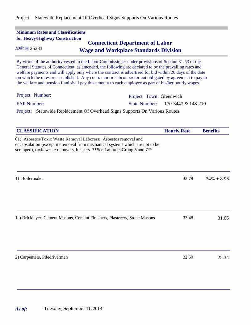
Project: Statewide Replacement Of Overhead Signs Supports On Various Routes
Project: Statewide Replacement Of Overhead Signs Supports On Various Routes
Project Project Greenwich
By virtue of the authority vested in the Labor Commissioner under provisions of Section 31-53 of the General Statutes of Connecticut, as amended, the following are declared to be the prevailing rates and welfare payments and will apply only where the contract is advertised for bid within 20 days of the date on which the rates are established. Any contractor or subcontractor not obligated by agreement to pay to the welfare and pension fund shall pay this amount to each employee as part of his/her hourly wages.
Minimum Rates and Classifications for Heavy/Highway Construction
Connecticut Department of LaborWage and Workplace Standards Division
FAP Number: State Number: 170-3447 & 148-210
Town:
H 25233
Number:
ID#:
Hourly Rate BenefitsCLASSIFICATION
01) Asbestos/Toxic Waste Removal Laborers: Asbestos removal and encapsulation (except its removal from mechanical systems which are not to be scrapped), toxic waste removers, blasters. **See Laborers Group 5 and 7**
1) Boilermaker 33.79 34% + 8.96
1a) Bricklayer, Cement Masons, Cement Finishers, Plasterers, Stone Masons 33.48 31.66
2) Carpenters, Piledrivermen 32.60 25.34
As of: Tuesday, September 11, 2018
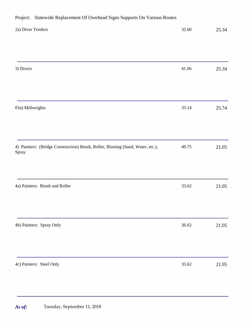
Project: Statewide Replacement Of Overhead Signs Supports On Various Routes
2a) Diver Tenders 32.60 25.34
3) Divers 41.06 25.34
03a) Millwrights 33.14 25.74
4) Painters: (Bridge Construction) Brush, Roller, Blasting (Sand, Water, etc.), Spray
49.75 21.05
4a) Painters: Brush and Roller 33.62 21.05
4b) Painters: Spray Only 36.62 21.05
4c) Painters: Steel Only 35.62 21.05
As of: Tuesday, September 11, 2018
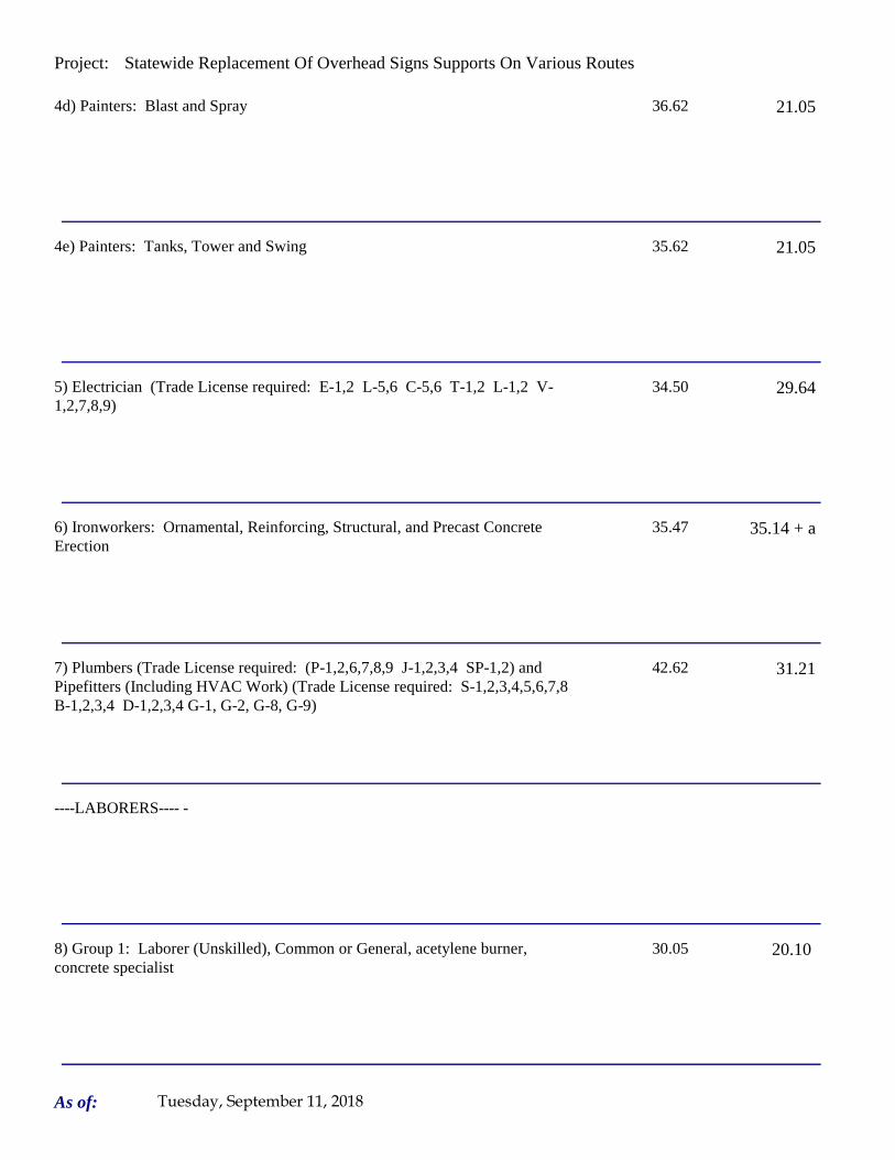
Project: Statewide Replacement Of Overhead Signs Supports On Various Routes
4d) Painters: Blast and Spray 36.62 21.05
4e) Painters: Tanks, Tower and Swing 35.62 21.05
5) Electrician (Trade License required: E-1,2 L-5,6 C-5,6 T-1,2 L-1,2 V-1,2,7,8,9)
34.50 29.64
6) Ironworkers: Ornamental, Reinforcing, Structural, and Precast Concrete Erection
35.47 35.14 + a
7) Plumbers (Trade License required: (P-1,2,6,7,8,9 J-1,2,3,4 SP-1,2) and Pipefitters (Including HVAC Work) (Trade License required: S-1,2,3,4,5,6,7,8 B-1,2,3,4 D-1,2,3,4 G-1, G-2, G-8, G-9)
42.62 31.21
----LABORERS---- -
8) Group 1: Laborer (Unskilled), Common or General, acetylene burner, concrete specialist
30.05 20.10
As of: Tuesday, September 11, 2018

Project: Statewide Replacement Of Overhead Signs Supports On Various Routes
9) Group 2: Chain saw operators, fence and guard rail erectors, pneumatic tool operators, powdermen
30.30 20.10
10) Group 3: Pipelayers 30.55 20.10
11) Group 4: Jackhammer/Pavement breaker (handheld); mason tenders (cement/concrete), catch basin builders, asphalt rakers, air track operators, block paver, curb setter and forklift operators
30.55 20.10
12) Group 5: Toxic waste removal (non-mechanical systems) 32.05 20.10
13) Group 6: Blasters 31.80 20.10
Group 7: Asbestos/lead removal, non-mechanical systems (does not include leaded joint pipe)
31.05 20.10
Group 8: Traffic control signalmen 16.00 20.10
As of: Tuesday, September 11, 2018

Project: Statewide Replacement Of Overhead Signs Supports On Various Routes
Group 9: Hydraulic Drills 29.30 18.90
----LABORERS (TUNNEL CONSTRUCTION, FREE AIR). Shield Drive and Liner Plate Tunnels in Free Air.----
13a) Miners, Motormen, Mucking Machine Operators, Nozzle Men, Grout Men, Shaft & Tunnel Steel & Rodmen, Shield & Erector, Arm Operator, Cable Tenders
32.22 20.10 + a
13b) Brakemen, Trackmen 31.28 20.10 + a
----CLEANING, CONCRETE AND CAULKING TUNNEL----
14) Concrete Workers, Form Movers, and Strippers 31.28 20.10 + a
15) Form Erectors 31.60 20.10 + a
As of: Tuesday, September 11, 2018

Project: Statewide Replacement Of Overhead Signs Supports On Various Routes
----ROCK SHAFT LINING, CONCRETE, LINING OF SAME AND TUNNEL IN FREE AIR:----
16) Brakemen, Trackmen, Tunnel Laborers, Shaft Laborers 31.28 20.10 + a
17) Laborers Topside, Cage Tenders, Bellman 31.17 20.10 + a
18) Miners 32.22 20.10 + a
----TUNNELS, CAISSON AND CYLINDER WORK IN COMPRESSED AIR: ----
18a) Blaster 38.53 20.10 + a
19) Brakemen, Trackmen, Groutman, Laborers, Outside Lock Tender, Gauge Tenders
38.34 20.10 + a
As of: Tuesday, September 11, 2018

Project: Statewide Replacement Of Overhead Signs Supports On Various Routes
20) Change House Attendants, Powder Watchmen, Top on Iron Bolts 36.41 20.10 + a
21) Mucking Machine Operator 39.11 20.10 + a
----TRUCK DRIVERS----(*see note below)
Two axle trucks 29.13 23.33 + a
Three axle trucks; two axle ready mix 29.23 23.33 + a
Three axle ready mix 29.28 23.33 + a
Four axle trucks, heavy duty trailer (up to 40 tons) 29.33 23.33 + a
As of: Tuesday, September 11, 2018

Project: Statewide Replacement Of Overhead Signs Supports On Various Routes
Four axle ready-mix 29.38 23.33 + a
Heavy duty trailer (40 tons and over) 29.58 23.33 + a
Specialized earth moving equipment other than conventional type on-the road trucks and semi-trailer (including Euclids)
29.38 23.33 + a
----POWER EQUIPMENT OPERATORS----
Group 1: Crane handling or erecting structural steel or stone, hoisting engineer (2 drums or over), front end loader (7 cubic yards or over), Work Boat 26 ft. & Over, Tunnel Boring Machines. (Trade License Required)
39.55 24.05 + a
Group 2: Cranes (100 ton rate capacity and over); Excavator over 2 cubic yards; Piledriver ($3.00 premium when operator controls hammer); Bauer Drill/Caisson. (Trade License Required)
39.23 24.05 + a
Group 3: Excavator/Backhoe under 2 cubic yards; Cranes (under 100 ton rated capacity), Gradall; Master Mechanic; Hoisting Engineer (all types of equipment where a drum and cable are used to hoist or drag material regardless of motive power of operation), Rubber Tire Excavator (Drott-1085 or similar);Grader Operator; Bulldozer Fine Grade (slopes, shaping, laser or GPS, etc.). (Trade License Required)
38.49 24.05 + a
As of: Tuesday, September 11, 2018

Project: Statewide Replacement Of Overhead Signs Supports On Various Routes
Group 4: Trenching Machines; Lighter Derrick; Concrete Finishing Machine; CMI Machine or Similar; Koehring Loader (Skooper)
38.10 24.05 + a
Group 5: Specialty Railroad Equipment; Asphalt Paver; Asphalt Spreader; Asphalt Reclaiming Machine; Line Grinder; Concrete Pumps; Drills with Self Contained Power Units; Boring Machine; Post Hole Digger; Auger; Pounder; Well Digger; Milling Machine (over 24" Mandrell)
37.51 24.05 + a
Group 5 continued: Side Boom; Combination Hoe and Loader; Directional Driller.
37.51 24.05 + a
Group 6: Front End Loader (3 up to 7 cubic yards); Bulldozer (rough grade dozer).
37.20 24.05 + a
Group 7: Asphalt Roller; Concrete Saws and Cutters (ride on types); Vermeer Concrete Cutter; Stump Grinder; Scraper; Snooper; Skidder; Milling Machine (24" and Under Mandrel).
36.86 24.05 + a
Group 8: Mechanic, Grease Truck Operator, Hydroblaster, Barrier Mover, Power Stone Spreader; Welder; Work Boat under 26 ft.; Transfer Machine.
36.46 24.05 + a
Group 9: Front End Loader (under 3 cubic yards), Skid Steer Loader regardless of attachments (Bobcat or Similar); Fork Lift, Power Chipper; Landscape Equipment (including hydroseeder).
36.03 24.05 + a
As of: Tuesday, September 11, 2018

Project: Statewide Replacement Of Overhead Signs Supports On Various Routes
Group 10: Vibratory Hammer, Ice Machine, Diesel and Air Hammer, etc. 33.99 24.05 + a
Group 11: Conveyor, Earth Roller; Power Pavement Breaker (whiphammer), Robot Demolition Equipment.
33.99 24.05 + a
Group 12: Wellpoint Operator. 33.93 24.05 + a
Group 13: Compressor Battery Operator. 33.35 24.05 + a
Group 14: Elevator Operator; Tow Motor Operator (Solid Tire No Rough Terrain).
32.21 24.05 + a
Group 15: Generator Operator; Compressor Operator; Pump Operator; Welding Machine Operator; Heater Operator.
31.80 24.05 + a
Group 16: Maintenance Engineer/Oiler 31.15 24.05 + a
As of: Tuesday, September 11, 2018

Project: Statewide Replacement Of Overhead Signs Supports On Various Routes
Group 17: Portable asphalt plant operator; portable crusher plant operator; portable concrete plant operator.
35.46 24.05 + a
Group 18: Power Safety Boat; Vacuum Truck; Zim Mixer; Sweeper; (minimum for any job requiring CDL license).
33.04 24.05 + a
**NOTE: SEE BELOW
----LINE CONSTRUCTION----(Railroad Construction and Maintenance)----
20) Lineman, Cable Splicer, Technician 48.19 6.5% + 22.00
21) Heavy Equipment Operator 42.26 6.5% + 19.88
22) Equipment Operator, Tractor Trailer Driver, Material Men 40.96 6.5% + 19.21
As of: Tuesday, September 11, 2018

Project: Statewide Replacement Of Overhead Signs Supports On Various Routes
23) Driver Groundmen 26.50 6.5% + 9.00
23a) Truck Driver 40.96 6.5% + 17.76
----LINE CONSTRUCTION----
24) Driver Groundmen 30.92 6.5% + 9.70
25) Groundmen 22.67 6.5% + 6.20
26) Heavy Equipment Operators 37.10 6.5% + 10.70
27) Linemen, Cable Splicers, Dynamite Men 41.22 6.5% + 12.20
As of: Tuesday, September 11, 2018

Project: Statewide Replacement Of Overhead Signs Supports On Various Routes
28) Material Men, Tractor Trailer Drivers, Equipment Operators 35.04 6.5% + 10.45
As of: Tuesday, September 11, 2018

Project: Statewide Replacement Of Overhead Signs Supports On Various Routes
Welders: Rate for craft to which welding is incidental.
*Note: Hazardous waste removal work receives additional $1.25 per hour for truck drivers.
**Note: Hazardous waste premium $3.00 per hour over classified rate
Crane with 150 ft. boom (including jib) - $1.50 extra Crane with 200 ft. boom (including jib) - $2.50 extraCrane with 250 ft. boom (including jib) - $5.00 extraCrane with 300 ft. boom (including jib) - $7.00 extra
All classifications that indicate a percentage of the fringe benefits must be calculated at the percentage rate times the "base hourly rate".
Apprentices duly registered under the Commissioner of Labor's regulations on "Work Training Standards for Apprenticeship and Training Programs" Section 31-51-d-1 to 12, are allowed to be paid the appropriate percentage of the prevailing journeymen hourly base and the full fringe benefit rate, providing the work site ratio shall not be less than one full-time journeyperson instructing and supervising the work of each apprentice in a specific trade.
Each contractor shall pay the annual adjusted prevailing wage rate that is in effect each July 1st, as posted by the Department of Labor.
It is the contractor's responsibility to obtain the annual adjusted prevailing wage rate increases directly from the Department of Labor's website. The annual adjustments will be posted on the Department of Labor's Web page:
www.ct.gov/dol. The Department of Labor will continue to issue the initial prevailing wage rate schedule
to the Contracting Agency for the project.
All subsequent annual adjustments will be posted on our Web Site for contractor access.
The Prevailing wage rates applicable to this project are subject to annual adjustments each July 1st for the duration of the project.
Crane with 400 ft. boom (including jib) - $10.00 extra
~~Connecticut General Statute Section 31-55a: Annual Adjustments to wage rates by contractors doing state work ~~
Contracting Agencies are under no obligation pursuant to State labor law to pay any increase due to the annual adjustment provision.
ALL Cranes: When crane operator is operating equipment that requires a fully licensed crane operator to operate he receives an extra $4.00 premium in addition to the hourly wage rate and benefit contributions:
1) Crane handling or erecting structural steel or stone; hoisting engineer (2 drums or over)
2) Cranes (100 ton rate capacity and over) Bauer Drill/Caisson
3) Cranes (under 100 ton rated capacity)
As of: Tuesday, September 11, 2018

Project: Statewide Replacement Of Overhead Signs Supports On Various Routes
Please direct any questions which you may have pertaining to classification of work and payment of prevailing wages to the Wage and Workplace Standards Division, telephone (860)263-6790.
Effective October 1, 2005 - Public Act 05-50: any person performing the work of any mechanic, laborer, or worker shall be paid prevailing wage
All Person who perform work ON SITE must be paid prevailing wage for the appropriate mechanic, laborer, or worker classification.
All certified payrolls must list the hours worked and wages paid to All Persons who perform work ON SITE regardless of their ownership i.e.: (Owners, Corporate Officers, LLC Members, Independent Contractors, et. al)
Reporting and payment of wages is required regardless of any contractual relationship alleged to exist between the contractor and such person.
~~Unlisted classifications needed for work not included within the scope of the classifications listed may be added after award only as provided in the labor standards contract clause (29 CFR 5.5 (a) (1) (ii)).
As of: Tuesday, September 11, 2018

Project: Statewide Replacement Of Overhead Signs Supports On Various Routes
Project: Statewide Replacement Of Overhead Signs Supports On Various Routes
Project Project Waterbury
By virtue of the authority vested in the Labor Commissioner under provisions of Section 31-53 of the General Statutes of Connecticut, as amended, the following are declared to be the prevailing rates and welfare payments and will apply only where the contract is advertised for bid within 20 days of the date on which the rates are established. Any contractor or subcontractor not obligated by agreement to pay to the welfare and pension fund shall pay this amount to each employee as part of his/her hourly wages.
Minimum Rates and Classifications for Heavy/Highway Construction
Connecticut Department of LaborWage and Workplace Standards Division
FAP Number: State Number: 170-3447 & 148-210
Town:
H 25237
Number:
ID#:
Hourly Rate BenefitsCLASSIFICATION
01) Asbestos/Toxic Waste Removal Laborers: Asbestos removal and encapsulation (except its removal from mechanical systems which are not to be scrapped), toxic waste removers, blasters. **See Laborers Group 5 and 7**
1) Boilermaker 33.79 34% + 8.96
1a) Bricklayer, Cement Masons, Cement Finishers, Plasterers, Stone Masons 33.48 31.66
2) Carpenters, Piledrivermen 32.60 25.34
As of: Tuesday, September 11, 2018

Project: Statewide Replacement Of Overhead Signs Supports On Various Routes
2a) Diver Tenders 32.60 25.34
3) Divers 41.06 25.34
03a) Millwrights 33.14 25.74
4) Painters: (Bridge Construction) Brush, Roller, Blasting (Sand, Water, etc.), Spray
49.75 21.05
4a) Painters: Brush and Roller 33.62 21.05
4b) Painters: Spray Only 36.62 21.05
4c) Painters: Steel Only 35.62 21.05
As of: Tuesday, September 11, 2018

Project: Statewide Replacement Of Overhead Signs Supports On Various Routes
4d) Painters: Blast and Spray 36.62 21.05
4e) Painters: Tanks, Tower and Swing 35.62 21.05
5) Electrician (Trade License required: E-1,2 L-5,6 C-5,6 T-1,2 L-1,2 V-1,2,7,8,9)
38.82 26.25+3% of gross wage
6) Ironworkers: Ornamental, Reinforcing, Structural, and Precast Concrete Erection
35.47 35.14 + a
7) Plumbers (Trade License required: (P-1,2,6,7,8,9 J-1,2,3,4 SP-1,2) and Pipefitters (Including HVAC Work) (Trade License required: S-1,2,3,4,5,6,7,8 B-1,2,3,4 D-1,2,3,4 G-1, G-2, G-8, G-9)
42.62 31.21
----LABORERS---- -
8) Group 1: Laborer (Unskilled), Common or General, acetylene burner, concrete specialist
30.05 20.10
As of: Tuesday, September 11, 2018

Project: Statewide Replacement Of Overhead Signs Supports On Various Routes
9) Group 2: Chain saw operators, fence and guard rail erectors, pneumatic tool operators, powdermen
30.30 20.10
10) Group 3: Pipelayers 30.55 20.10
11) Group 4: Jackhammer/Pavement breaker (handheld); mason tenders (cement/concrete), catch basin builders, asphalt rakers, air track operators, block paver, curb setter and forklift operators
30.55 20.10
12) Group 5: Toxic waste removal (non-mechanical systems) 32.05 20.10
13) Group 6: Blasters 31.80 20.10
Group 7: Asbestos/lead removal, non-mechanical systems (does not include leaded joint pipe)
31.05 20.10
Group 8: Traffic control signalmen 16.00 20.10
As of: Tuesday, September 11, 2018
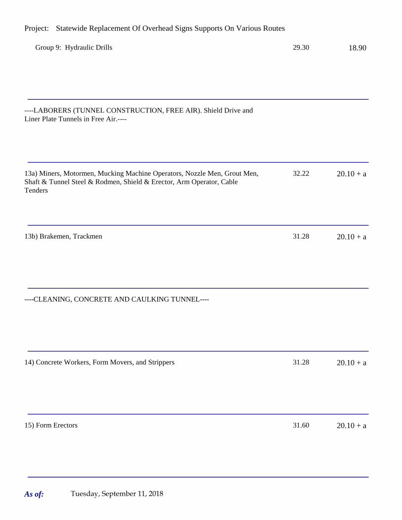
Project: Statewide Replacement Of Overhead Signs Supports On Various Routes
Group 9: Hydraulic Drills 29.30 18.90
----LABORERS (TUNNEL CONSTRUCTION, FREE AIR). Shield Drive and Liner Plate Tunnels in Free Air.----
13a) Miners, Motormen, Mucking Machine Operators, Nozzle Men, Grout Men, Shaft & Tunnel Steel & Rodmen, Shield & Erector, Arm Operator, Cable Tenders
32.22 20.10 + a
13b) Brakemen, Trackmen 31.28 20.10 + a
----CLEANING, CONCRETE AND CAULKING TUNNEL----
14) Concrete Workers, Form Movers, and Strippers 31.28 20.10 + a
15) Form Erectors 31.60 20.10 + a
As of: Tuesday, September 11, 2018

Project: Statewide Replacement Of Overhead Signs Supports On Various Routes
----ROCK SHAFT LINING, CONCRETE, LINING OF SAME AND TUNNEL IN FREE AIR:----
16) Brakemen, Trackmen, Tunnel Laborers, Shaft Laborers 31.28 20.10 + a
17) Laborers Topside, Cage Tenders, Bellman 31.17 20.10 + a
18) Miners 32.22 20.10 + a
----TUNNELS, CAISSON AND CYLINDER WORK IN COMPRESSED AIR: ----
18a) Blaster 38.53 20.10 + a
19) Brakemen, Trackmen, Groutman, Laborers, Outside Lock Tender, Gauge Tenders
38.34 20.10 + a
As of: Tuesday, September 11, 2018

Project: Statewide Replacement Of Overhead Signs Supports On Various Routes
20) Change House Attendants, Powder Watchmen, Top on Iron Bolts 36.41 20.10 + a
21) Mucking Machine Operator 39.11 20.10 + a
----TRUCK DRIVERS----(*see note below)
Two axle trucks 29.13 23.33 + a
Three axle trucks; two axle ready mix 29.23 23.33 + a
Three axle ready mix 29.28 23.33 + a
Four axle trucks, heavy duty trailer (up to 40 tons) 29.33 23.33 + a
As of: Tuesday, September 11, 2018

Project: Statewide Replacement Of Overhead Signs Supports On Various Routes
Four axle ready-mix 29.38 23.33 + a
Heavy duty trailer (40 tons and over) 29.58 23.33 + a
Specialized earth moving equipment other than conventional type on-the road trucks and semi-trailer (including Euclids)
29.38 23.33 + a
----POWER EQUIPMENT OPERATORS----
Group 1: Crane handling or erecting structural steel or stone, hoisting engineer (2 drums or over), front end loader (7 cubic yards or over), Work Boat 26 ft. & Over, Tunnel Boring Machines. (Trade License Required)
39.55 24.05 + a
Group 2: Cranes (100 ton rate capacity and over); Excavator over 2 cubic yards; Piledriver ($3.00 premium when operator controls hammer); Bauer Drill/Caisson. (Trade License Required)
39.23 24.05 + a
Group 3: Excavator/Backhoe under 2 cubic yards; Cranes (under 100 ton rated capacity), Gradall; Master Mechanic; Hoisting Engineer (all types of equipment where a drum and cable are used to hoist or drag material regardless of motive power of operation), Rubber Tire Excavator (Drott-1085 or similar);Grader Operator; Bulldozer Fine Grade (slopes, shaping, laser or GPS, etc.). (Trade License Required)
38.49 24.05 + a
As of: Tuesday, September 11, 2018
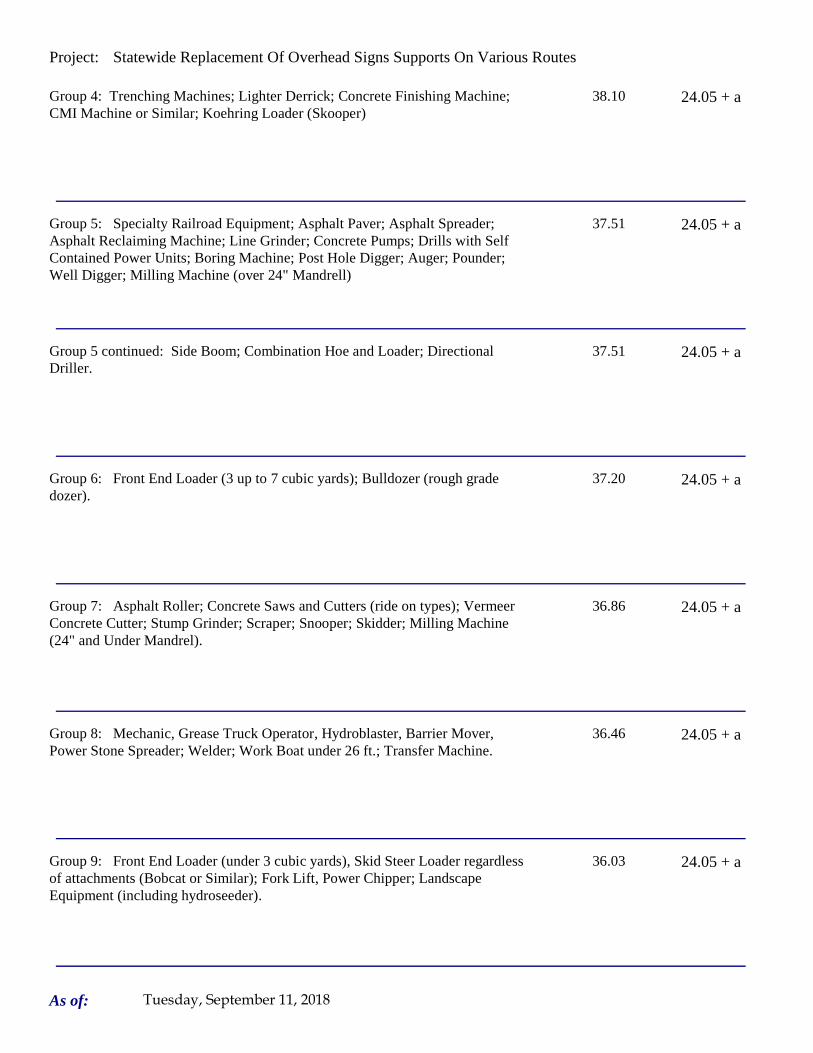
Project: Statewide Replacement Of Overhead Signs Supports On Various Routes
Group 4: Trenching Machines; Lighter Derrick; Concrete Finishing Machine; CMI Machine or Similar; Koehring Loader (Skooper)
38.10 24.05 + a
Group 5: Specialty Railroad Equipment; Asphalt Paver; Asphalt Spreader; Asphalt Reclaiming Machine; Line Grinder; Concrete Pumps; Drills with Self Contained Power Units; Boring Machine; Post Hole Digger; Auger; Pounder; Well Digger; Milling Machine (over 24" Mandrell)
37.51 24.05 + a
Group 5 continued: Side Boom; Combination Hoe and Loader; Directional Driller.
37.51 24.05 + a
Group 6: Front End Loader (3 up to 7 cubic yards); Bulldozer (rough grade dozer).
37.20 24.05 + a
Group 7: Asphalt Roller; Concrete Saws and Cutters (ride on types); Vermeer Concrete Cutter; Stump Grinder; Scraper; Snooper; Skidder; Milling Machine (24" and Under Mandrel).
36.86 24.05 + a
Group 8: Mechanic, Grease Truck Operator, Hydroblaster, Barrier Mover, Power Stone Spreader; Welder; Work Boat under 26 ft.; Transfer Machine.
36.46 24.05 + a
Group 9: Front End Loader (under 3 cubic yards), Skid Steer Loader regardless of attachments (Bobcat or Similar); Fork Lift, Power Chipper; Landscape Equipment (including hydroseeder).
36.03 24.05 + a
As of: Tuesday, September 11, 2018

Project: Statewide Replacement Of Overhead Signs Supports On Various Routes
Group 10: Vibratory Hammer, Ice Machine, Diesel and Air Hammer, etc. 33.99 24.05 + a
Group 11: Conveyor, Earth Roller; Power Pavement Breaker (whiphammer), Robot Demolition Equipment.
33.99 24.05 + a
Group 12: Wellpoint Operator. 33.93 24.05 + a
Group 13: Compressor Battery Operator. 33.35 24.05 + a
Group 14: Elevator Operator; Tow Motor Operator (Solid Tire No Rough Terrain).
32.21 24.05 + a
Group 15: Generator Operator; Compressor Operator; Pump Operator; Welding Machine Operator; Heater Operator.
31.80 24.05 + a
Group 16: Maintenance Engineer/Oiler 31.15 24.05 + a
As of: Tuesday, September 11, 2018

Project: Statewide Replacement Of Overhead Signs Supports On Various Routes
Group 17: Portable asphalt plant operator; portable crusher plant operator; portable concrete plant operator.
35.46 24.05 + a
Group 18: Power Safety Boat; Vacuum Truck; Zim Mixer; Sweeper; (minimum for any job requiring CDL license).
33.04 24.05 + a
**NOTE: SEE BELOW
----LINE CONSTRUCTION----(Railroad Construction and Maintenance)----
20) Lineman, Cable Splicer, Technician 48.19 6.5% + 22.00
21) Heavy Equipment Operator 42.26 6.5% + 19.88
22) Equipment Operator, Tractor Trailer Driver, Material Men 40.96 6.5% + 19.21
As of: Tuesday, September 11, 2018

Project: Statewide Replacement Of Overhead Signs Supports On Various Routes
23) Driver Groundmen 26.50 6.5% + 9.00
23a) Truck Driver 40.96 6.5% + 17.76
----LINE CONSTRUCTION----
24) Driver Groundmen 30.92 6.5% + 9.70
25) Groundmen 22.67 6.5% + 6.20
26) Heavy Equipment Operators 37.10 6.5% + 10.70
27) Linemen, Cable Splicers, Dynamite Men 41.22 6.5% + 12.20
As of: Tuesday, September 11, 2018

Project: Statewide Replacement Of Overhead Signs Supports On Various Routes
28) Material Men, Tractor Trailer Drivers, Equipment Operators 35.04 6.5% + 10.45
As of: Tuesday, September 11, 2018

Project: Statewide Replacement Of Overhead Signs Supports On Various Routes
Welders: Rate for craft to which welding is incidental.
*Note: Hazardous waste removal work receives additional $1.25 per hour for truck drivers.
**Note: Hazardous waste premium $3.00 per hour over classified rate
Crane with 150 ft. boom (including jib) - $1.50 extra Crane with 200 ft. boom (including jib) - $2.50 extraCrane with 250 ft. boom (including jib) - $5.00 extraCrane with 300 ft. boom (including jib) - $7.00 extra
All classifications that indicate a percentage of the fringe benefits must be calculated at the percentage rate times the "base hourly rate".
Apprentices duly registered under the Commissioner of Labor's regulations on "Work Training Standards for Apprenticeship and Training Programs" Section 31-51-d-1 to 12, are allowed to be paid the appropriate percentage of the prevailing journeymen hourly base and the full fringe benefit rate, providing the work site ratio shall not be less than one full-time journeyperson instructing and supervising the work of each apprentice in a specific trade.
Each contractor shall pay the annual adjusted prevailing wage rate that is in effect each July 1st, as posted by the Department of Labor.
It is the contractor's responsibility to obtain the annual adjusted prevailing wage rate increases directly from the Department of Labor's website. The annual adjustments will be posted on the Department of Labor's Web page:
www.ct.gov/dol. The Department of Labor will continue to issue the initial prevailing wage rate schedule
to the Contracting Agency for the project.
All subsequent annual adjustments will be posted on our Web Site for contractor access.
The Prevailing wage rates applicable to this project are subject to annual adjustments each July 1st for the duration of the project.
Crane with 400 ft. boom (including jib) - $10.00 extra
~~Connecticut General Statute Section 31-55a: Annual Adjustments to wage rates by contractors doing state work ~~
Contracting Agencies are under no obligation pursuant to State labor law to pay any increase due to the annual adjustment provision.
ALL Cranes: When crane operator is operating equipment that requires a fully licensed crane operator to operate he receives an extra $4.00 premium in addition to the hourly wage rate and benefit contributions:
1) Crane handling or erecting structural steel or stone; hoisting engineer (2 drums or over)
2) Cranes (100 ton rate capacity and over) Bauer Drill/Caisson
3) Cranes (under 100 ton rated capacity)
As of: Tuesday, September 11, 2018

Project: Statewide Replacement Of Overhead Signs Supports On Various Routes
Please direct any questions which you may have pertaining to classification of work and payment of prevailing wages to the Wage and Workplace Standards Division, telephone (860)263-6790.
Effective October 1, 2005 - Public Act 05-50: any person performing the work of any mechanic, laborer, or worker shall be paid prevailing wage
All Person who perform work ON SITE must be paid prevailing wage for the appropriate mechanic, laborer, or worker classification.
All certified payrolls must list the hours worked and wages paid to All Persons who perform work ON SITE regardless of their ownership i.e.: (Owners, Corporate Officers, LLC Members, Independent Contractors, et. al)
Reporting and payment of wages is required regardless of any contractual relationship alleged to exist between the contractor and such person.
~~Unlisted classifications needed for work not included within the scope of the classifications listed may be added after award only as provided in the labor standards contract clause (29 CFR 5.5 (a) (1) (ii)).
As of: Tuesday, September 11, 2018

Project: Statewide Replacement Of Overhead Signs Supports On Various Routes
Project: Statewide Replacement Of Overhead Signs Supports On Various Routes
Project Project Bridgeport
By virtue of the authority vested in the Labor Commissioner under provisions of Section 31-53 of the General Statutes of Connecticut, as amended, the following are declared to be the prevailing rates and welfare payments and will apply only where the contract is advertised for bid within 20 days of the date on which the rates are established. Any contractor or subcontractor not obligated by agreement to pay to the welfare and pension fund shall pay this amount to each employee as part of his/her hourly wages.
Minimum Rates and Classifications for Heavy/Highway Construction
Connecticut Department of LaborWage and Workplace Standards Division
FAP Number: State Number: 170-3447 & 148-210
Town:
H 25236
Number:
ID#:
Hourly Rate BenefitsCLASSIFICATION
01) Asbestos/Toxic Waste Removal Laborers: Asbestos removal and encapsulation (except its removal from mechanical systems which are not to be scrapped), toxic waste removers, blasters. **See Laborers Group 5 and 7**
1) Boilermaker 33.79 34% + 8.96
1a) Bricklayer, Cement Masons, Cement Finishers, Plasterers, Stone Masons 33.48 31.66
2) Carpenters, Piledrivermen 32.60 25.34
As of: Tuesday, September 11, 2018

Project: Statewide Replacement Of Overhead Signs Supports On Various Routes
2a) Diver Tenders 32.60 25.34
3) Divers 41.06 25.34
03a) Millwrights 33.14 25.74
4) Painters: (Bridge Construction) Brush, Roller, Blasting (Sand, Water, etc.), Spray
49.75 21.05
4a) Painters: Brush and Roller 33.62 21.05
4b) Painters: Spray Only 36.62 21.05
4c) Painters: Steel Only 35.62 21.05
As of: Tuesday, September 11, 2018

Project: Statewide Replacement Of Overhead Signs Supports On Various Routes
4d) Painters: Blast and Spray 36.62 21.05
4e) Painters: Tanks, Tower and Swing 35.62 21.05
5) Electrician (Trade License required: E-1,2 L-5,6 C-5,6 T-1,2 L-1,2 V-1,2,7,8,9)
38.82 26.25+3% of gross wage
6) Ironworkers: Ornamental, Reinforcing, Structural, and Precast Concrete Erection
35.47 35.14 + a
7) Plumbers (Trade License required: (P-1,2,6,7,8,9 J-1,2,3,4 SP-1,2) and Pipefitters (Including HVAC Work) (Trade License required: S-1,2,3,4,5,6,7,8 B-1,2,3,4 D-1,2,3,4 G-1, G-2, G-8, G-9)
42.62 31.21
----LABORERS---- -
8) Group 1: Laborer (Unskilled), Common or General, acetylene burner, concrete specialist
30.05 20.10
As of: Tuesday, September 11, 2018
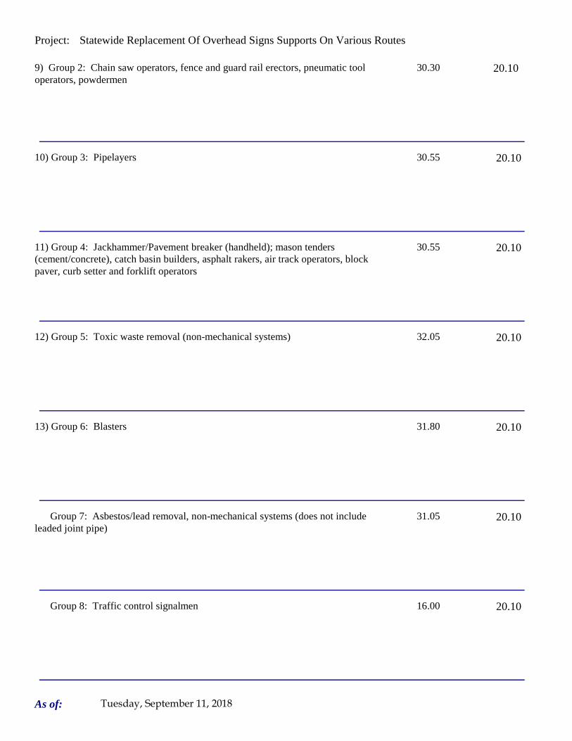
Project: Statewide Replacement Of Overhead Signs Supports On Various Routes
9) Group 2: Chain saw operators, fence and guard rail erectors, pneumatic tool operators, powdermen
30.30 20.10
10) Group 3: Pipelayers 30.55 20.10
11) Group 4: Jackhammer/Pavement breaker (handheld); mason tenders (cement/concrete), catch basin builders, asphalt rakers, air track operators, block paver, curb setter and forklift operators
30.55 20.10
12) Group 5: Toxic waste removal (non-mechanical systems) 32.05 20.10
13) Group 6: Blasters 31.80 20.10
Group 7: Asbestos/lead removal, non-mechanical systems (does not include leaded joint pipe)
31.05 20.10
Group 8: Traffic control signalmen 16.00 20.10
As of: Tuesday, September 11, 2018

Project: Statewide Replacement Of Overhead Signs Supports On Various Routes
Group 9: Hydraulic Drills 29.30 18.90
----LABORERS (TUNNEL CONSTRUCTION, FREE AIR). Shield Drive and Liner Plate Tunnels in Free Air.----
13a) Miners, Motormen, Mucking Machine Operators, Nozzle Men, Grout Men, Shaft & Tunnel Steel & Rodmen, Shield & Erector, Arm Operator, Cable Tenders
32.22 20.10 + a
13b) Brakemen, Trackmen 31.28 20.10 + a
----CLEANING, CONCRETE AND CAULKING TUNNEL----
14) Concrete Workers, Form Movers, and Strippers 31.28 20.10 + a
15) Form Erectors 31.60 20.10 + a
As of: Tuesday, September 11, 2018
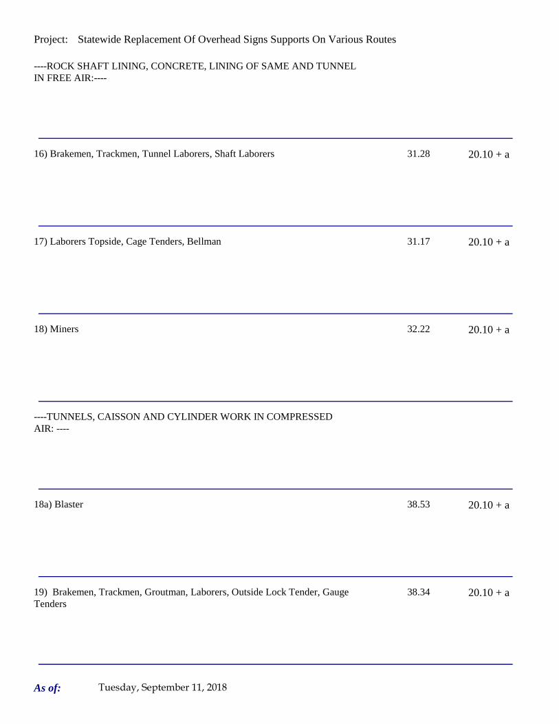
Project: Statewide Replacement Of Overhead Signs Supports On Various Routes
----ROCK SHAFT LINING, CONCRETE, LINING OF SAME AND TUNNEL IN FREE AIR:----
16) Brakemen, Trackmen, Tunnel Laborers, Shaft Laborers 31.28 20.10 + a
17) Laborers Topside, Cage Tenders, Bellman 31.17 20.10 + a
18) Miners 32.22 20.10 + a
----TUNNELS, CAISSON AND CYLINDER WORK IN COMPRESSED AIR: ----
18a) Blaster 38.53 20.10 + a
19) Brakemen, Trackmen, Groutman, Laborers, Outside Lock Tender, Gauge Tenders
38.34 20.10 + a
As of: Tuesday, September 11, 2018
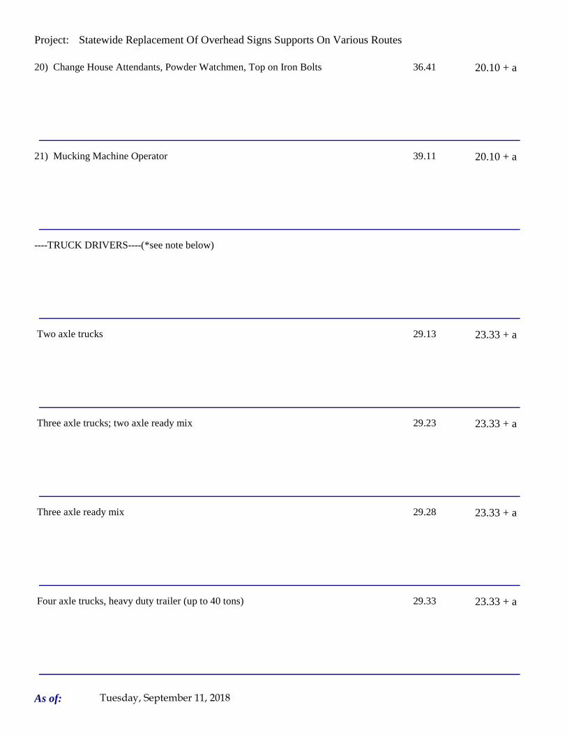
Project: Statewide Replacement Of Overhead Signs Supports On Various Routes
20) Change House Attendants, Powder Watchmen, Top on Iron Bolts 36.41 20.10 + a
21) Mucking Machine Operator 39.11 20.10 + a
----TRUCK DRIVERS----(*see note below)
Two axle trucks 29.13 23.33 + a
Three axle trucks; two axle ready mix 29.23 23.33 + a
Three axle ready mix 29.28 23.33 + a
Four axle trucks, heavy duty trailer (up to 40 tons) 29.33 23.33 + a
As of: Tuesday, September 11, 2018

Project: Statewide Replacement Of Overhead Signs Supports On Various Routes
Four axle ready-mix 29.38 23.33 + a
Heavy duty trailer (40 tons and over) 29.58 23.33 + a
Specialized earth moving equipment other than conventional type on-the road trucks and semi-trailer (including Euclids)
29.38 23.33 + a
----POWER EQUIPMENT OPERATORS----
Group 1: Crane handling or erecting structural steel or stone, hoisting engineer (2 drums or over), front end loader (7 cubic yards or over), Work Boat 26 ft. & Over, Tunnel Boring Machines. (Trade License Required)
39.55 24.05 + a
Group 2: Cranes (100 ton rate capacity and over); Excavator over 2 cubic yards; Piledriver ($3.00 premium when operator controls hammer); Bauer Drill/Caisson. (Trade License Required)
39.23 24.05 + a
Group 3: Excavator/Backhoe under 2 cubic yards; Cranes (under 100 ton rated capacity), Gradall; Master Mechanic; Hoisting Engineer (all types of equipment where a drum and cable are used to hoist or drag material regardless of motive power of operation), Rubber Tire Excavator (Drott-1085 or similar);Grader Operator; Bulldozer Fine Grade (slopes, shaping, laser or GPS, etc.). (Trade License Required)
38.49 24.05 + a
As of: Tuesday, September 11, 2018

Project: Statewide Replacement Of Overhead Signs Supports On Various Routes
Group 4: Trenching Machines; Lighter Derrick; Concrete Finishing Machine; CMI Machine or Similar; Koehring Loader (Skooper)
38.10 24.05 + a
Group 5: Specialty Railroad Equipment; Asphalt Paver; Asphalt Spreader; Asphalt Reclaiming Machine; Line Grinder; Concrete Pumps; Drills with Self Contained Power Units; Boring Machine; Post Hole Digger; Auger; Pounder; Well Digger; Milling Machine (over 24" Mandrell)
37.51 24.05 + a
Group 5 continued: Side Boom; Combination Hoe and Loader; Directional Driller.
37.51 24.05 + a
Group 6: Front End Loader (3 up to 7 cubic yards); Bulldozer (rough grade dozer).
37.20 24.05 + a
Group 7: Asphalt Roller; Concrete Saws and Cutters (ride on types); Vermeer Concrete Cutter; Stump Grinder; Scraper; Snooper; Skidder; Milling Machine (24" and Under Mandrel).
36.86 24.05 + a
Group 8: Mechanic, Grease Truck Operator, Hydroblaster, Barrier Mover, Power Stone Spreader; Welder; Work Boat under 26 ft.; Transfer Machine.
36.46 24.05 + a
Group 9: Front End Loader (under 3 cubic yards), Skid Steer Loader regardless of attachments (Bobcat or Similar); Fork Lift, Power Chipper; Landscape Equipment (including hydroseeder).
36.03 24.05 + a
As of: Tuesday, September 11, 2018

Project: Statewide Replacement Of Overhead Signs Supports On Various Routes
Group 10: Vibratory Hammer, Ice Machine, Diesel and Air Hammer, etc. 33.99 24.05 + a
Group 11: Conveyor, Earth Roller; Power Pavement Breaker (whiphammer), Robot Demolition Equipment.
33.99 24.05 + a
Group 12: Wellpoint Operator. 33.93 24.05 + a
Group 13: Compressor Battery Operator. 33.35 24.05 + a
Group 14: Elevator Operator; Tow Motor Operator (Solid Tire No Rough Terrain).
32.21 24.05 + a
Group 15: Generator Operator; Compressor Operator; Pump Operator; Welding Machine Operator; Heater Operator.
31.80 24.05 + a
Group 16: Maintenance Engineer/Oiler 31.15 24.05 + a
As of: Tuesday, September 11, 2018
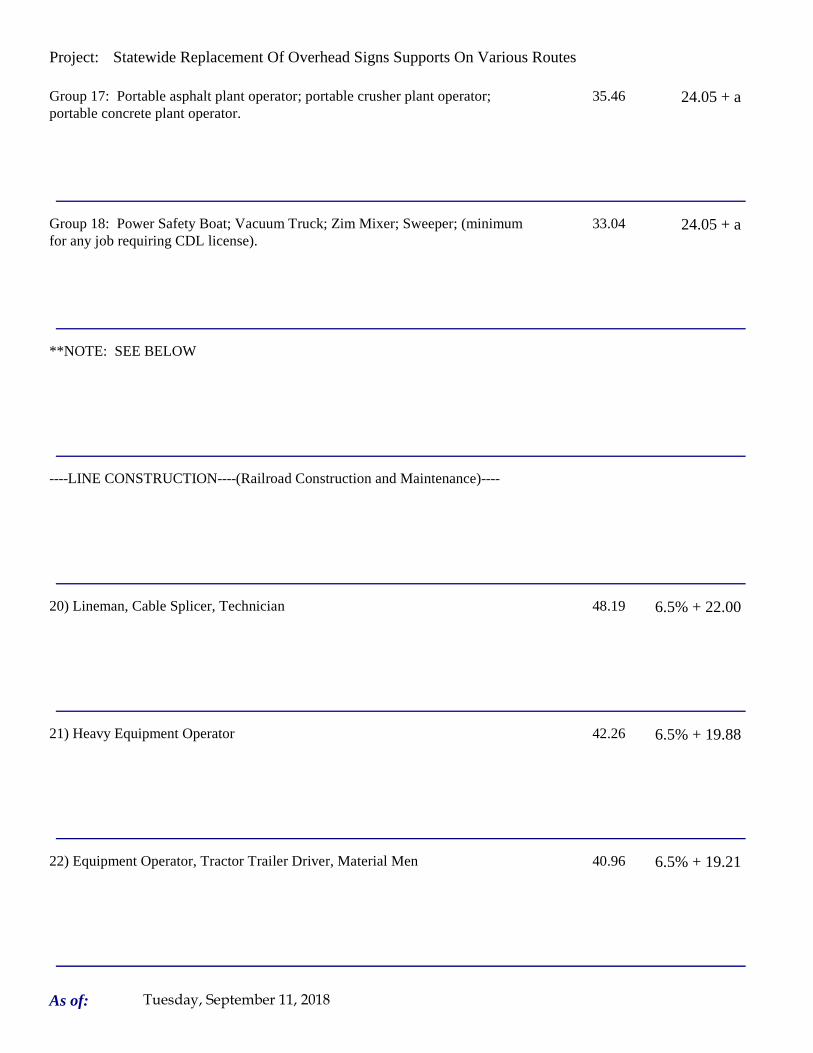
Project: Statewide Replacement Of Overhead Signs Supports On Various Routes
Group 17: Portable asphalt plant operator; portable crusher plant operator; portable concrete plant operator.
35.46 24.05 + a
Group 18: Power Safety Boat; Vacuum Truck; Zim Mixer; Sweeper; (minimum for any job requiring CDL license).
33.04 24.05 + a
**NOTE: SEE BELOW
----LINE CONSTRUCTION----(Railroad Construction and Maintenance)----
20) Lineman, Cable Splicer, Technician 48.19 6.5% + 22.00
21) Heavy Equipment Operator 42.26 6.5% + 19.88
22) Equipment Operator, Tractor Trailer Driver, Material Men 40.96 6.5% + 19.21
As of: Tuesday, September 11, 2018

Project: Statewide Replacement Of Overhead Signs Supports On Various Routes
23) Driver Groundmen 26.50 6.5% + 9.00
23a) Truck Driver 40.96 6.5% + 17.76
----LINE CONSTRUCTION----
24) Driver Groundmen 30.92 6.5% + 9.70
25) Groundmen 22.67 6.5% + 6.20
26) Heavy Equipment Operators 37.10 6.5% + 10.70
27) Linemen, Cable Splicers, Dynamite Men 41.22 6.5% + 12.20
As of: Tuesday, September 11, 2018

Project: Statewide Replacement Of Overhead Signs Supports On Various Routes
28) Material Men, Tractor Trailer Drivers, Equipment Operators 35.04 6.5% + 10.45
As of: Tuesday, September 11, 2018

Project: Statewide Replacement Of Overhead Signs Supports On Various Routes
Welders: Rate for craft to which welding is incidental.
*Note: Hazardous waste removal work receives additional $1.25 per hour for truck drivers.
**Note: Hazardous waste premium $3.00 per hour over classified rate
Crane with 150 ft. boom (including jib) - $1.50 extra Crane with 200 ft. boom (including jib) - $2.50 extraCrane with 250 ft. boom (including jib) - $5.00 extraCrane with 300 ft. boom (including jib) - $7.00 extra
All classifications that indicate a percentage of the fringe benefits must be calculated at the percentage rate times the "base hourly rate".
Apprentices duly registered under the Commissioner of Labor's regulations on "Work Training Standards for Apprenticeship and Training Programs" Section 31-51-d-1 to 12, are allowed to be paid the appropriate percentage of the prevailing journeymen hourly base and the full fringe benefit rate, providing the work site ratio shall not be less than one full-time journeyperson instructing and supervising the work of each apprentice in a specific trade.
Each contractor shall pay the annual adjusted prevailing wage rate that is in effect each July 1st, as posted by the Department of Labor.
It is the contractor's responsibility to obtain the annual adjusted prevailing wage rate increases directly from the Department of Labor's website. The annual adjustments will be posted on the Department of Labor's Web page:
www.ct.gov/dol. The Department of Labor will continue to issue the initial prevailing wage rate schedule
to the Contracting Agency for the project.
All subsequent annual adjustments will be posted on our Web Site for contractor access.
The Prevailing wage rates applicable to this project are subject to annual adjustments each July 1st for the duration of the project.
Crane with 400 ft. boom (including jib) - $10.00 extra
~~Connecticut General Statute Section 31-55a: Annual Adjustments to wage rates by contractors doing state work ~~
Contracting Agencies are under no obligation pursuant to State labor law to pay any increase due to the annual adjustment provision.
ALL Cranes: When crane operator is operating equipment that requires a fully licensed crane operator to operate he receives an extra $4.00 premium in addition to the hourly wage rate and benefit contributions:
1) Crane handling or erecting structural steel or stone; hoisting engineer (2 drums or over)
2) Cranes (100 ton rate capacity and over) Bauer Drill/Caisson
3) Cranes (under 100 ton rated capacity)
As of: Tuesday, September 11, 2018

Project: Statewide Replacement Of Overhead Signs Supports On Various Routes
Please direct any questions which you may have pertaining to classification of work and payment of prevailing wages to the Wage and Workplace Standards Division, telephone (860)263-6790.
Effective October 1, 2005 - Public Act 05-50: any person performing the work of any mechanic, laborer, or worker shall be paid prevailing wage
All Person who perform work ON SITE must be paid prevailing wage for the appropriate mechanic, laborer, or worker classification.
All certified payrolls must list the hours worked and wages paid to All Persons who perform work ON SITE regardless of their ownership i.e.: (Owners, Corporate Officers, LLC Members, Independent Contractors, et. al)
Reporting and payment of wages is required regardless of any contractual relationship alleged to exist between the contractor and such person.
~~Unlisted classifications needed for work not included within the scope of the classifications listed may be added after award only as provided in the labor standards contract clause (29 CFR 5.5 (a) (1) (ii)).
As of: Tuesday, September 11, 2018

Project: Statewide Replacement Of Overhead Signs Supports On Various Routes
Project: Statewide Replacement Of Overhead Signs Supports On Various Routes
Project Project Westport
By virtue of the authority vested in the Labor Commissioner under provisions of Section 31-53 of the General Statutes of Connecticut, as amended, the following are declared to be the prevailing rates and welfare payments and will apply only where the contract is advertised for bid within 20 days of the date on which the rates are established. Any contractor or subcontractor not obligated by agreement to pay to the welfare and pension fund shall pay this amount to each employee as part of his/her hourly wages.
Minimum Rates and Classifications for Heavy/Highway Construction
Connecticut Department of LaborWage and Workplace Standards Division
FAP Number: State Number: 170-3447 & 148-210
Town:
H 25235
Number:
ID#:
Hourly Rate BenefitsCLASSIFICATION
01) Asbestos/Toxic Waste Removal Laborers: Asbestos removal and encapsulation (except its removal from mechanical systems which are not to be scrapped), toxic waste removers, blasters. **See Laborers Group 5 and 7**
1) Boilermaker 33.79 34% + 8.96
1a) Bricklayer, Cement Masons, Cement Finishers, Plasterers, Stone Masons 33.48 31.66
2) Carpenters, Piledrivermen 32.60 25.34
As of: Tuesday, September 11, 2018

Project: Statewide Replacement Of Overhead Signs Supports On Various Routes
2a) Diver Tenders 32.60 25.34
3) Divers 41.06 25.34
03a) Millwrights 33.14 25.74
4) Painters: (Bridge Construction) Brush, Roller, Blasting (Sand, Water, etc.), Spray
49.75 21.05
4a) Painters: Brush and Roller 33.62 21.05
4b) Painters: Spray Only 36.62 21.05
4c) Painters: Steel Only 35.62 21.05
As of: Tuesday, September 11, 2018
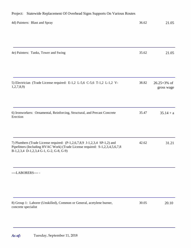
Project: Statewide Replacement Of Overhead Signs Supports On Various Routes
4d) Painters: Blast and Spray 36.62 21.05
4e) Painters: Tanks, Tower and Swing 35.62 21.05
5) Electrician (Trade License required: E-1,2 L-5,6 C-5,6 T-1,2 L-1,2 V-1,2,7,8,9)
38.82 26.25+3% of gross wage
6) Ironworkers: Ornamental, Reinforcing, Structural, and Precast Concrete Erection
35.47 35.14 + a
7) Plumbers (Trade License required: (P-1,2,6,7,8,9 J-1,2,3,4 SP-1,2) and Pipefitters (Including HVAC Work) (Trade License required: S-1,2,3,4,5,6,7,8 B-1,2,3,4 D-1,2,3,4 G-1, G-2, G-8, G-9)
42.62 31.21
----LABORERS---- -
8) Group 1: Laborer (Unskilled), Common or General, acetylene burner, concrete specialist
30.05 20.10
As of: Tuesday, September 11, 2018

Project: Statewide Replacement Of Overhead Signs Supports On Various Routes
9) Group 2: Chain saw operators, fence and guard rail erectors, pneumatic tool operators, powdermen
30.30 20.10
10) Group 3: Pipelayers 30.55 20.10
11) Group 4: Jackhammer/Pavement breaker (handheld); mason tenders (cement/concrete), catch basin builders, asphalt rakers, air track operators, block paver, curb setter and forklift operators
30.55 20.10
12) Group 5: Toxic waste removal (non-mechanical systems) 32.05 20.10
13) Group 6: Blasters 31.80 20.10
Group 7: Asbestos/lead removal, non-mechanical systems (does not include leaded joint pipe)
31.05 20.10
Group 8: Traffic control signalmen 16.00 20.10
As of: Tuesday, September 11, 2018

Project: Statewide Replacement Of Overhead Signs Supports On Various Routes
Group 9: Hydraulic Drills 29.30 18.90
----LABORERS (TUNNEL CONSTRUCTION, FREE AIR). Shield Drive and Liner Plate Tunnels in Free Air.----
13a) Miners, Motormen, Mucking Machine Operators, Nozzle Men, Grout Men, Shaft & Tunnel Steel & Rodmen, Shield & Erector, Arm Operator, Cable Tenders
32.22 20.10 + a
13b) Brakemen, Trackmen 31.28 20.10 + a
----CLEANING, CONCRETE AND CAULKING TUNNEL----
14) Concrete Workers, Form Movers, and Strippers 31.28 20.10 + a
15) Form Erectors 31.60 20.10 + a
As of: Tuesday, September 11, 2018

Project: Statewide Replacement Of Overhead Signs Supports On Various Routes
----ROCK SHAFT LINING, CONCRETE, LINING OF SAME AND TUNNEL IN FREE AIR:----
16) Brakemen, Trackmen, Tunnel Laborers, Shaft Laborers 31.28 20.10 + a
17) Laborers Topside, Cage Tenders, Bellman 31.17 20.10 + a
18) Miners 32.22 20.10 + a
----TUNNELS, CAISSON AND CYLINDER WORK IN COMPRESSED AIR: ----
18a) Blaster 38.53 20.10 + a
19) Brakemen, Trackmen, Groutman, Laborers, Outside Lock Tender, Gauge Tenders
38.34 20.10 + a
As of: Tuesday, September 11, 2018

Project: Statewide Replacement Of Overhead Signs Supports On Various Routes
20) Change House Attendants, Powder Watchmen, Top on Iron Bolts 36.41 20.10 + a
21) Mucking Machine Operator 39.11 20.10 + a
----TRUCK DRIVERS----(*see note below)
Two axle trucks 29.13 23.33 + a
Three axle trucks; two axle ready mix 29.23 23.33 + a
Three axle ready mix 29.28 23.33 + a
Four axle trucks, heavy duty trailer (up to 40 tons) 29.33 23.33 + a
As of: Tuesday, September 11, 2018

Project: Statewide Replacement Of Overhead Signs Supports On Various Routes
Four axle ready-mix 29.38 23.33 + a
Heavy duty trailer (40 tons and over) 29.58 23.33 + a
Specialized earth moving equipment other than conventional type on-the road trucks and semi-trailer (including Euclids)
29.38 23.33 + a
----POWER EQUIPMENT OPERATORS----
Group 1: Crane handling or erecting structural steel or stone, hoisting engineer (2 drums or over), front end loader (7 cubic yards or over), Work Boat 26 ft. & Over, Tunnel Boring Machines. (Trade License Required)
39.55 24.05 + a
Group 2: Cranes (100 ton rate capacity and over); Excavator over 2 cubic yards; Piledriver ($3.00 premium when operator controls hammer); Bauer Drill/Caisson. (Trade License Required)
39.23 24.05 + a
Group 3: Excavator/Backhoe under 2 cubic yards; Cranes (under 100 ton rated capacity), Gradall; Master Mechanic; Hoisting Engineer (all types of equipment where a drum and cable are used to hoist or drag material regardless of motive power of operation), Rubber Tire Excavator (Drott-1085 or similar);Grader Operator; Bulldozer Fine Grade (slopes, shaping, laser or GPS, etc.). (Trade License Required)
38.49 24.05 + a
As of: Tuesday, September 11, 2018

Project: Statewide Replacement Of Overhead Signs Supports On Various Routes
Group 4: Trenching Machines; Lighter Derrick; Concrete Finishing Machine; CMI Machine or Similar; Koehring Loader (Skooper)
38.10 24.05 + a
Group 5: Specialty Railroad Equipment; Asphalt Paver; Asphalt Spreader; Asphalt Reclaiming Machine; Line Grinder; Concrete Pumps; Drills with Self Contained Power Units; Boring Machine; Post Hole Digger; Auger; Pounder; Well Digger; Milling Machine (over 24" Mandrell)
37.51 24.05 + a
Group 5 continued: Side Boom; Combination Hoe and Loader; Directional Driller.
37.51 24.05 + a
Group 6: Front End Loader (3 up to 7 cubic yards); Bulldozer (rough grade dozer).
37.20 24.05 + a
Group 7: Asphalt Roller; Concrete Saws and Cutters (ride on types); Vermeer Concrete Cutter; Stump Grinder; Scraper; Snooper; Skidder; Milling Machine (24" and Under Mandrel).
36.86 24.05 + a
Group 8: Mechanic, Grease Truck Operator, Hydroblaster, Barrier Mover, Power Stone Spreader; Welder; Work Boat under 26 ft.; Transfer Machine.
36.46 24.05 + a
Group 9: Front End Loader (under 3 cubic yards), Skid Steer Loader regardless of attachments (Bobcat or Similar); Fork Lift, Power Chipper; Landscape Equipment (including hydroseeder).
36.03 24.05 + a
As of: Tuesday, September 11, 2018

Project: Statewide Replacement Of Overhead Signs Supports On Various Routes
Group 10: Vibratory Hammer, Ice Machine, Diesel and Air Hammer, etc. 33.99 24.05 + a
Group 11: Conveyor, Earth Roller; Power Pavement Breaker (whiphammer), Robot Demolition Equipment.
33.99 24.05 + a
Group 12: Wellpoint Operator. 33.93 24.05 + a
Group 13: Compressor Battery Operator. 33.35 24.05 + a
Group 14: Elevator Operator; Tow Motor Operator (Solid Tire No Rough Terrain).
32.21 24.05 + a
Group 15: Generator Operator; Compressor Operator; Pump Operator; Welding Machine Operator; Heater Operator.
31.80 24.05 + a
Group 16: Maintenance Engineer/Oiler 31.15 24.05 + a
As of: Tuesday, September 11, 2018

Project: Statewide Replacement Of Overhead Signs Supports On Various Routes
Group 17: Portable asphalt plant operator; portable crusher plant operator; portable concrete plant operator.
35.46 24.05 + a
Group 18: Power Safety Boat; Vacuum Truck; Zim Mixer; Sweeper; (minimum for any job requiring CDL license).
33.04 24.05 + a
**NOTE: SEE BELOW
----LINE CONSTRUCTION----(Railroad Construction and Maintenance)----
20) Lineman, Cable Splicer, Technician 48.19 6.5% + 22.00
21) Heavy Equipment Operator 42.26 6.5% + 19.88
22) Equipment Operator, Tractor Trailer Driver, Material Men 40.96 6.5% + 19.21
As of: Tuesday, September 11, 2018
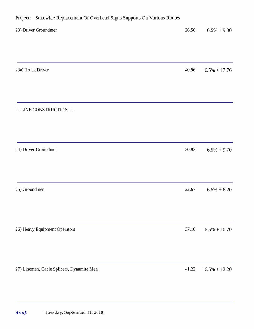
Project: Statewide Replacement Of Overhead Signs Supports On Various Routes
23) Driver Groundmen 26.50 6.5% + 9.00
23a) Truck Driver 40.96 6.5% + 17.76
----LINE CONSTRUCTION----
24) Driver Groundmen 30.92 6.5% + 9.70
25) Groundmen 22.67 6.5% + 6.20
26) Heavy Equipment Operators 37.10 6.5% + 10.70
27) Linemen, Cable Splicers, Dynamite Men 41.22 6.5% + 12.20
As of: Tuesday, September 11, 2018

Project: Statewide Replacement Of Overhead Signs Supports On Various Routes
28) Material Men, Tractor Trailer Drivers, Equipment Operators 35.04 6.5% + 10.45
As of: Tuesday, September 11, 2018
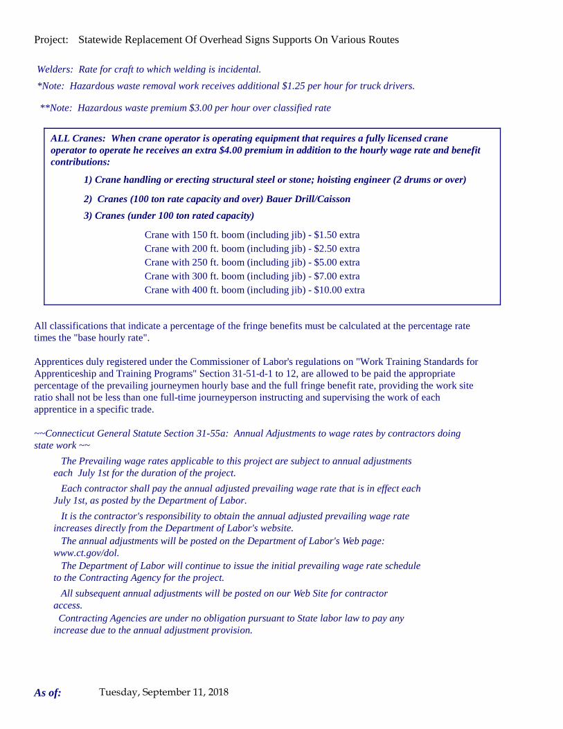
Project: Statewide Replacement Of Overhead Signs Supports On Various Routes
Welders: Rate for craft to which welding is incidental.
*Note: Hazardous waste removal work receives additional $1.25 per hour for truck drivers.
**Note: Hazardous waste premium $3.00 per hour over classified rate
Crane with 150 ft. boom (including jib) - $1.50 extra Crane with 200 ft. boom (including jib) - $2.50 extraCrane with 250 ft. boom (including jib) - $5.00 extraCrane with 300 ft. boom (including jib) - $7.00 extra
All classifications that indicate a percentage of the fringe benefits must be calculated at the percentage rate times the "base hourly rate".
Apprentices duly registered under the Commissioner of Labor's regulations on "Work Training Standards for Apprenticeship and Training Programs" Section 31-51-d-1 to 12, are allowed to be paid the appropriate percentage of the prevailing journeymen hourly base and the full fringe benefit rate, providing the work site ratio shall not be less than one full-time journeyperson instructing and supervising the work of each apprentice in a specific trade.
Each contractor shall pay the annual adjusted prevailing wage rate that is in effect each July 1st, as posted by the Department of Labor.
It is the contractor's responsibility to obtain the annual adjusted prevailing wage rate increases directly from the Department of Labor's website. The annual adjustments will be posted on the Department of Labor's Web page:
www.ct.gov/dol. The Department of Labor will continue to issue the initial prevailing wage rate schedule
to the Contracting Agency for the project.
All subsequent annual adjustments will be posted on our Web Site for contractor access.
The Prevailing wage rates applicable to this project are subject to annual adjustments each July 1st for the duration of the project.
Crane with 400 ft. boom (including jib) - $10.00 extra
~~Connecticut General Statute Section 31-55a: Annual Adjustments to wage rates by contractors doing state work ~~
Contracting Agencies are under no obligation pursuant to State labor law to pay any increase due to the annual adjustment provision.
ALL Cranes: When crane operator is operating equipment that requires a fully licensed crane operator to operate he receives an extra $4.00 premium in addition to the hourly wage rate and benefit contributions:
1) Crane handling or erecting structural steel or stone; hoisting engineer (2 drums or over)
2) Cranes (100 ton rate capacity and over) Bauer Drill/Caisson
3) Cranes (under 100 ton rated capacity)
As of: Tuesday, September 11, 2018

Project: Statewide Replacement Of Overhead Signs Supports On Various Routes
Please direct any questions which you may have pertaining to classification of work and payment of prevailing wages to the Wage and Workplace Standards Division, telephone (860)263-6790.
Effective October 1, 2005 - Public Act 05-50: any person performing the work of any mechanic, laborer, or worker shall be paid prevailing wage
All Person who perform work ON SITE must be paid prevailing wage for the appropriate mechanic, laborer, or worker classification.
All certified payrolls must list the hours worked and wages paid to All Persons who perform work ON SITE regardless of their ownership i.e.: (Owners, Corporate Officers, LLC Members, Independent Contractors, et. al)
Reporting and payment of wages is required regardless of any contractual relationship alleged to exist between the contractor and such person.
~~Unlisted classifications needed for work not included within the scope of the classifications listed may be added after award only as provided in the labor standards contract clause (29 CFR 5.5 (a) (1) (ii)).
As of: Tuesday, September 11, 2018

Project: Statewide Replacement Of Overhead Sign Supports On Various Routes
Project: Statewide Replacement Of Overhead Sign Supports On Various Routes
Project Project Meriden
By virtue of the authority vested in the Labor Commissioner under provisions of Section 31-53 of the General Statutes of Connecticut, as amended, the following are declared to be the prevailing rates and welfare payments and will apply only where the contract is advertised for bid within 20 days of the date on which the rates are established. Any contractor or subcontractor not obligated by agreement to pay to the welfare and pension fund shall pay this amount to each employee as part of his/her hourly wages.
Minimum Rates and Classifications for Heavy/Highway Construction
Connecticut Department of LaborWage and Workplace Standards Division
FAP Number: State Number: 170-3447 & 148-210
Town:
H 25242
Number:
ID#:
Hourly Rate BenefitsCLASSIFICATION
01) Asbestos/Toxic Waste Removal Laborers: Asbestos removal and encapsulation (except its removal from mechanical systems which are not to be scrapped), toxic waste removers, blasters. **See Laborers Group 5 and 7**
1) Boilermaker 33.79 34% + 8.96
1a) Bricklayer, Cement Masons, Cement Finishers, Plasterers, Stone Masons 33.48 31.66
2) Carpenters, Piledrivermen 32.60 25.34
As of: Wednesday, September 12, 2018

Project: Statewide Replacement Of Overhead Sign Supports On Various Routes
2a) Diver Tenders 32.60 25.34
3) Divers 41.06 25.34
03a) Millwrights 33.14 25.74
4) Painters: (Bridge Construction) Brush, Roller, Blasting (Sand, Water, etc.), Spray
49.75 21.05
4a) Painters: Brush and Roller 33.62 21.05
4b) Painters: Spray Only 36.62 21.05
4c) Painters: Steel Only 35.62 21.05
As of: Wednesday, September 12, 2018

Project: Statewide Replacement Of Overhead Sign Supports On Various Routes
4d) Painters: Blast and Spray 36.62 21.05
4e) Painters: Tanks, Tower and Swing 35.62 21.05
5) Electrician (Trade License required: E-1,2 L-5,6 C-5,6 T-1,2 L-1,2 V-1,2,7,8,9)
37.50 27.91+3% of gross wage
6) Ironworkers: Ornamental, Reinforcing, Structural, and Precast Concrete Erection
35.47 35.14 + a
7) Plumbers (Trade License required: (P-1,2,6,7,8,9 J-1,2,3,4 SP-1,2) and Pipefitters (Including HVAC Work) (Trade License required: S-1,2,3,4,5,6,7,8 B-1,2,3,4 D-1,2,3,4 G-1, G-2, G-8, G-9)
42.62 31.21
----LABORERS---- -
8) Group 1: Laborer (Unskilled), Common or General, acetylene burner, concrete specialist
30.05 20.10
As of: Wednesday, September 12, 2018

Project: Statewide Replacement Of Overhead Sign Supports On Various Routes
9) Group 2: Chain saw operators, fence and guard rail erectors, pneumatic tool operators, powdermen
30.30 20.10
10) Group 3: Pipelayers 30.55 20.10
11) Group 4: Jackhammer/Pavement breaker (handheld); mason tenders (cement/concrete), catch basin builders, asphalt rakers, air track operators, block paver, curb setter and forklift operators
30.55 20.10
12) Group 5: Toxic waste removal (non-mechanical systems) 32.05 20.10
13) Group 6: Blasters 31.80 20.10
Group 7: Asbestos/lead removal, non-mechanical systems (does not include leaded joint pipe)
31.05 20.10
Group 8: Traffic control signalmen 16.00 20.10
As of: Wednesday, September 12, 2018

Project: Statewide Replacement Of Overhead Sign Supports On Various Routes
Group 9: Hydraulic Drills 29.30 18.90
----LABORERS (TUNNEL CONSTRUCTION, FREE AIR). Shield Drive and Liner Plate Tunnels in Free Air.----
13a) Miners, Motormen, Mucking Machine Operators, Nozzle Men, Grout Men, Shaft & Tunnel Steel & Rodmen, Shield & Erector, Arm Operator, Cable Tenders
32.22 20.10 + a
13b) Brakemen, Trackmen 31.28 20.10 + a
----CLEANING, CONCRETE AND CAULKING TUNNEL----
14) Concrete Workers, Form Movers, and Strippers 31.28 20.10 + a
15) Form Erectors 31.60 20.10 + a
As of: Wednesday, September 12, 2018

Project: Statewide Replacement Of Overhead Sign Supports On Various Routes
----ROCK SHAFT LINING, CONCRETE, LINING OF SAME AND TUNNEL IN FREE AIR:----
16) Brakemen, Trackmen, Tunnel Laborers, Shaft Laborers 31.28 20.10 + a
17) Laborers Topside, Cage Tenders, Bellman 31.17 20.10 + a
18) Miners 32.22 20.10 + a
----TUNNELS, CAISSON AND CYLINDER WORK IN COMPRESSED AIR: ----
18a) Blaster 38.53 20.10 + a
19) Brakemen, Trackmen, Groutman, Laborers, Outside Lock Tender, Gauge Tenders
38.34 20.10 + a
As of: Wednesday, September 12, 2018

Project: Statewide Replacement Of Overhead Sign Supports On Various Routes
20) Change House Attendants, Powder Watchmen, Top on Iron Bolts 36.41 20.10 + a
21) Mucking Machine Operator 39.11 20.10 + a
----TRUCK DRIVERS----(*see note below)
Two axle trucks 29.13 23.33 + a
Three axle trucks; two axle ready mix 29.23 23.33 + a
Three axle ready mix 29.28 23.33 + a
Four axle trucks, heavy duty trailer (up to 40 tons) 29.33 23.33 + a
As of: Wednesday, September 12, 2018

Project: Statewide Replacement Of Overhead Sign Supports On Various Routes
Four axle ready-mix 29.38 23.33 + a
Heavy duty trailer (40 tons and over) 29.58 23.33 + a
Specialized earth moving equipment other than conventional type on-the road trucks and semi-trailer (including Euclids)
29.38 23.33 + a
----POWER EQUIPMENT OPERATORS----
Group 1: Crane handling or erecting structural steel or stone, hoisting engineer (2 drums or over), front end loader (7 cubic yards or over), Work Boat 26 ft. & Over, Tunnel Boring Machines. (Trade License Required)
39.55 24.05 + a
Group 2: Cranes (100 ton rate capacity and over); Excavator over 2 cubic yards; Piledriver ($3.00 premium when operator controls hammer); Bauer Drill/Caisson. (Trade License Required)
39.23 24.05 + a
Group 3: Excavator/Backhoe under 2 cubic yards; Cranes (under 100 ton rated capacity), Gradall; Master Mechanic; Hoisting Engineer (all types of equipment where a drum and cable are used to hoist or drag material regardless of motive power of operation), Rubber Tire Excavator (Drott-1085 or similar);Grader Operator; Bulldozer Fine Grade (slopes, shaping, laser or GPS, etc.). (Trade License Required)
38.49 24.05 + a
As of: Wednesday, September 12, 2018

Project: Statewide Replacement Of Overhead Sign Supports On Various Routes
Group 4: Trenching Machines; Lighter Derrick; Concrete Finishing Machine; CMI Machine or Similar; Koehring Loader (Skooper)
38.10 24.05 + a
Group 5: Specialty Railroad Equipment; Asphalt Paver; Asphalt Spreader; Asphalt Reclaiming Machine; Line Grinder; Concrete Pumps; Drills with Self Contained Power Units; Boring Machine; Post Hole Digger; Auger; Pounder; Well Digger; Milling Machine (over 24" Mandrell)
37.51 24.05 + a
Group 5 continued: Side Boom; Combination Hoe and Loader; Directional Driller.
37.51 24.05 + a
Group 6: Front End Loader (3 up to 7 cubic yards); Bulldozer (rough grade dozer).
37.20 24.05 + a
Group 7: Asphalt Roller; Concrete Saws and Cutters (ride on types); Vermeer Concrete Cutter; Stump Grinder; Scraper; Snooper; Skidder; Milling Machine (24" and Under Mandrel).
36.86 24.05 + a
Group 8: Mechanic, Grease Truck Operator, Hydroblaster, Barrier Mover, Power Stone Spreader; Welder; Work Boat under 26 ft.; Transfer Machine.
36.46 24.05 + a
Group 9: Front End Loader (under 3 cubic yards), Skid Steer Loader regardless of attachments (Bobcat or Similar); Fork Lift, Power Chipper; Landscape Equipment (including hydroseeder).
36.03 24.05 + a
As of: Wednesday, September 12, 2018

Project: Statewide Replacement Of Overhead Sign Supports On Various Routes
Group 10: Vibratory Hammer, Ice Machine, Diesel and Air Hammer, etc. 33.99 24.05 + a
Group 11: Conveyor, Earth Roller; Power Pavement Breaker (whiphammer), Robot Demolition Equipment.
33.99 24.05 + a
Group 12: Wellpoint Operator. 33.93 24.05 + a
Group 13: Compressor Battery Operator. 33.35 24.05 + a
Group 14: Elevator Operator; Tow Motor Operator (Solid Tire No Rough Terrain).
32.21 24.05 + a
Group 15: Generator Operator; Compressor Operator; Pump Operator; Welding Machine Operator; Heater Operator.
31.80 24.05 + a
Group 16: Maintenance Engineer/Oiler 31.15 24.05 + a
As of: Wednesday, September 12, 2018

Project: Statewide Replacement Of Overhead Sign Supports On Various Routes
Group 17: Portable asphalt plant operator; portable crusher plant operator; portable concrete plant operator.
35.46 24.05 + a
Group 18: Power Safety Boat; Vacuum Truck; Zim Mixer; Sweeper; (minimum for any job requiring CDL license).
33.04 24.05 + a
**NOTE: SEE BELOW
----LINE CONSTRUCTION----(Railroad Construction and Maintenance)----
20) Lineman, Cable Splicer, Technician 48.19 6.5% + 22.00
21) Heavy Equipment Operator 42.26 6.5% + 19.88
22) Equipment Operator, Tractor Trailer Driver, Material Men 40.96 6.5% + 19.21
As of: Wednesday, September 12, 2018

Project: Statewide Replacement Of Overhead Sign Supports On Various Routes
23) Driver Groundmen 26.50 6.5% + 9.00
23a) Truck Driver 40.96 6.5% + 17.76
----LINE CONSTRUCTION----
24) Driver Groundmen 30.92 6.5% + 9.70
25) Groundmen 22.67 6.5% + 6.20
26) Heavy Equipment Operators 37.10 6.5% + 10.70
27) Linemen, Cable Splicers, Dynamite Men 41.22 6.5% + 12.20
As of: Wednesday, September 12, 2018

Project: Statewide Replacement Of Overhead Sign Supports On Various Routes
28) Material Men, Tractor Trailer Drivers, Equipment Operators 35.04 6.5% + 10.45
As of: Wednesday, September 12, 2018

Project: Statewide Replacement Of Overhead Sign Supports On Various Routes
Welders: Rate for craft to which welding is incidental.
*Note: Hazardous waste removal work receives additional $1.25 per hour for truck drivers.
**Note: Hazardous waste premium $3.00 per hour over classified rate
Crane with 150 ft. boom (including jib) - $1.50 extra Crane with 200 ft. boom (including jib) - $2.50 extraCrane with 250 ft. boom (including jib) - $5.00 extraCrane with 300 ft. boom (including jib) - $7.00 extra
All classifications that indicate a percentage of the fringe benefits must be calculated at the percentage rate times the "base hourly rate".
Apprentices duly registered under the Commissioner of Labor's regulations on "Work Training Standards for Apprenticeship and Training Programs" Section 31-51-d-1 to 12, are allowed to be paid the appropriate percentage of the prevailing journeymen hourly base and the full fringe benefit rate, providing the work site ratio shall not be less than one full-time journeyperson instructing and supervising the work of each apprentice in a specific trade.
Each contractor shall pay the annual adjusted prevailing wage rate that is in effect each July 1st, as posted by the Department of Labor.
It is the contractor's responsibility to obtain the annual adjusted prevailing wage rate increases directly from the Department of Labor's website. The annual adjustments will be posted on the Department of Labor's Web page:
www.ct.gov/dol. The Department of Labor will continue to issue the initial prevailing wage rate schedule
to the Contracting Agency for the project.
All subsequent annual adjustments will be posted on our Web Site for contractor access.
The Prevailing wage rates applicable to this project are subject to annual adjustments each July 1st for the duration of the project.
Crane with 400 ft. boom (including jib) - $10.00 extra
~~Connecticut General Statute Section 31-55a: Annual Adjustments to wage rates by contractors doing state work ~~
Contracting Agencies are under no obligation pursuant to State labor law to pay any increase due to the annual adjustment provision.
ALL Cranes: When crane operator is operating equipment that requires a fully licensed crane operator to operate he receives an extra $4.00 premium in addition to the hourly wage rate and benefit contributions:
1) Crane handling or erecting structural steel or stone; hoisting engineer (2 drums or over)
2) Cranes (100 ton rate capacity and over) Bauer Drill/Caisson
3) Cranes (under 100 ton rated capacity)
As of: Wednesday, September 12, 2018

Project: Statewide Replacement Of Overhead Sign Supports On Various Routes
Please direct any questions which you may have pertaining to classification of work and payment of prevailing wages to the Wage and Workplace Standards Division, telephone (860)263-6790.
Effective October 1, 2005 - Public Act 05-50: any person performing the work of any mechanic, laborer, or worker shall be paid prevailing wage
All Person who perform work ON SITE must be paid prevailing wage for the appropriate mechanic, laborer, or worker classification.
All certified payrolls must list the hours worked and wages paid to All Persons who perform work ON SITE regardless of their ownership i.e.: (Owners, Corporate Officers, LLC Members, Independent Contractors, et. al)
Reporting and payment of wages is required regardless of any contractual relationship alleged to exist between the contractor and such person.
~~Unlisted classifications needed for work not included within the scope of the classifications listed may be added after award only as provided in the labor standards contract clause (29 CFR 5.5 (a) (1) (ii)).
As of: Wednesday, September 12, 2018
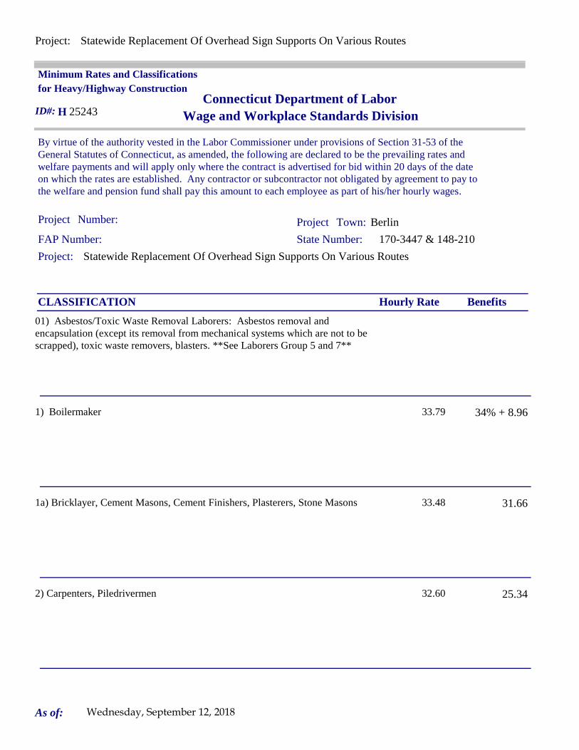
Project: Statewide Replacement Of Overhead Sign Supports On Various Routes
Project: Statewide Replacement Of Overhead Sign Supports On Various Routes
Project Project Berlin
By virtue of the authority vested in the Labor Commissioner under provisions of Section 31-53 of the General Statutes of Connecticut, as amended, the following are declared to be the prevailing rates and welfare payments and will apply only where the contract is advertised for bid within 20 days of the date on which the rates are established. Any contractor or subcontractor not obligated by agreement to pay to the welfare and pension fund shall pay this amount to each employee as part of his/her hourly wages.
Minimum Rates and Classifications for Heavy/Highway Construction
Connecticut Department of LaborWage and Workplace Standards Division
FAP Number: State Number: 170-3447 & 148-210
Town:
H 25243
Number:
ID#:
Hourly Rate BenefitsCLASSIFICATION
01) Asbestos/Toxic Waste Removal Laborers: Asbestos removal and encapsulation (except its removal from mechanical systems which are not to be scrapped), toxic waste removers, blasters. **See Laborers Group 5 and 7**
1) Boilermaker 33.79 34% + 8.96
1a) Bricklayer, Cement Masons, Cement Finishers, Plasterers, Stone Masons 33.48 31.66
2) Carpenters, Piledrivermen 32.60 25.34
As of: Wednesday, September 12, 2018
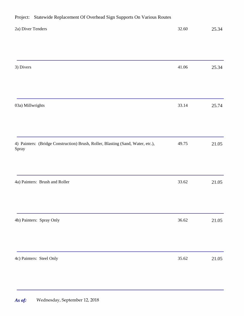
Project: Statewide Replacement Of Overhead Sign Supports On Various Routes
2a) Diver Tenders 32.60 25.34
3) Divers 41.06 25.34
03a) Millwrights 33.14 25.74
4) Painters: (Bridge Construction) Brush, Roller, Blasting (Sand, Water, etc.), Spray
49.75 21.05
4a) Painters: Brush and Roller 33.62 21.05
4b) Painters: Spray Only 36.62 21.05
4c) Painters: Steel Only 35.62 21.05
As of: Wednesday, September 12, 2018

Project: Statewide Replacement Of Overhead Sign Supports On Various Routes
4d) Painters: Blast and Spray 36.62 21.05
4e) Painters: Tanks, Tower and Swing 35.62 21.05
5) Electrician (Trade License required: E-1,2 L-5,6 C-5,6 T-1,2 L-1,2 V-1,2,7,8,9)
37.50 27.91+3% of gross wage
6) Ironworkers: Ornamental, Reinforcing, Structural, and Precast Concrete Erection
35.47 35.14 + a
7) Plumbers (Trade License required: (P-1,2,6,7,8,9 J-1,2,3,4 SP-1,2) and Pipefitters (Including HVAC Work) (Trade License required: S-1,2,3,4,5,6,7,8 B-1,2,3,4 D-1,2,3,4 G-1, G-2, G-8, G-9)
42.62 31.21
----LABORERS---- -
8) Group 1: Laborer (Unskilled), Common or General, acetylene burner, concrete specialist
30.05 20.10
As of: Wednesday, September 12, 2018
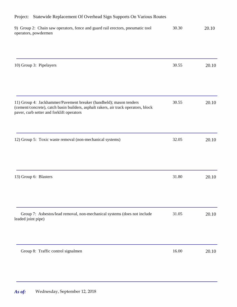
Project: Statewide Replacement Of Overhead Sign Supports On Various Routes
9) Group 2: Chain saw operators, fence and guard rail erectors, pneumatic tool operators, powdermen
30.30 20.10
10) Group 3: Pipelayers 30.55 20.10
11) Group 4: Jackhammer/Pavement breaker (handheld); mason tenders (cement/concrete), catch basin builders, asphalt rakers, air track operators, block paver, curb setter and forklift operators
30.55 20.10
12) Group 5: Toxic waste removal (non-mechanical systems) 32.05 20.10
13) Group 6: Blasters 31.80 20.10
Group 7: Asbestos/lead removal, non-mechanical systems (does not include leaded joint pipe)
31.05 20.10
Group 8: Traffic control signalmen 16.00 20.10
As of: Wednesday, September 12, 2018

Project: Statewide Replacement Of Overhead Sign Supports On Various Routes
Group 9: Hydraulic Drills 29.30 18.90
----LABORERS (TUNNEL CONSTRUCTION, FREE AIR). Shield Drive and Liner Plate Tunnels in Free Air.----
13a) Miners, Motormen, Mucking Machine Operators, Nozzle Men, Grout Men, Shaft & Tunnel Steel & Rodmen, Shield & Erector, Arm Operator, Cable Tenders
32.22 20.10 + a
13b) Brakemen, Trackmen 31.28 20.10 + a
----CLEANING, CONCRETE AND CAULKING TUNNEL----
14) Concrete Workers, Form Movers, and Strippers 31.28 20.10 + a
15) Form Erectors 31.60 20.10 + a
As of: Wednesday, September 12, 2018
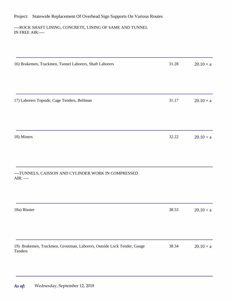
Project: Statewide Replacement Of Overhead Sign Supports On Various Routes
----ROCK SHAFT LINING, CONCRETE, LINING OF SAME AND TUNNEL IN FREE AIR:----
16) Brakemen, Trackmen, Tunnel Laborers, Shaft Laborers 31.28 20.10 + a
17) Laborers Topside, Cage Tenders, Bellman 31.17 20.10 + a
18) Miners 32.22 20.10 + a
----TUNNELS, CAISSON AND CYLINDER WORK IN COMPRESSED AIR: ----
18a) Blaster 38.53 20.10 + a
19) Brakemen, Trackmen, Groutman, Laborers, Outside Lock Tender, Gauge Tenders
38.34 20.10 + a
As of: Wednesday, September 12, 2018
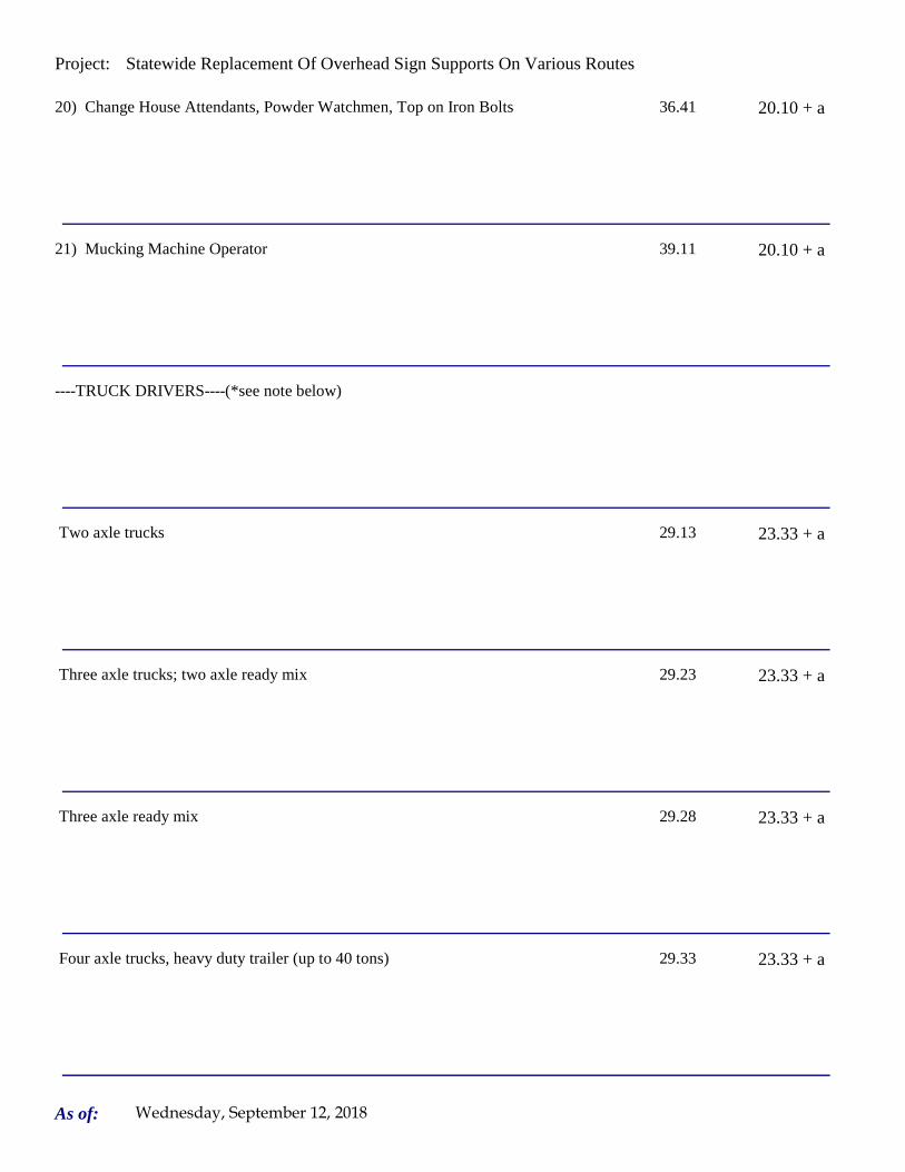
Project: Statewide Replacement Of Overhead Sign Supports On Various Routes
20) Change House Attendants, Powder Watchmen, Top on Iron Bolts 36.41 20.10 + a
21) Mucking Machine Operator 39.11 20.10 + a
----TRUCK DRIVERS----(*see note below)
Two axle trucks 29.13 23.33 + a
Three axle trucks; two axle ready mix 29.23 23.33 + a
Three axle ready mix 29.28 23.33 + a
Four axle trucks, heavy duty trailer (up to 40 tons) 29.33 23.33 + a
As of: Wednesday, September 12, 2018
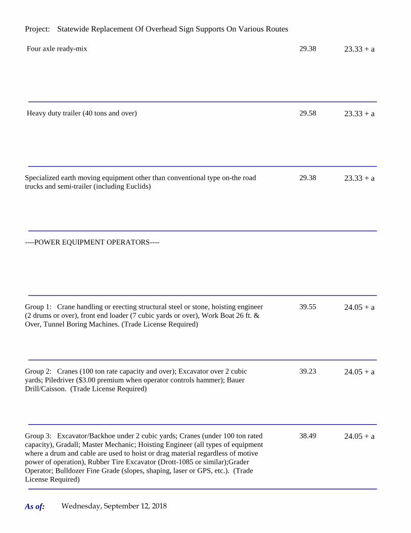
Project: Statewide Replacement Of Overhead Sign Supports On Various Routes
Four axle ready-mix 29.38 23.33 + a
Heavy duty trailer (40 tons and over) 29.58 23.33 + a
Specialized earth moving equipment other than conventional type on-the road trucks and semi-trailer (including Euclids)
29.38 23.33 + a
----POWER EQUIPMENT OPERATORS----
Group 1: Crane handling or erecting structural steel or stone, hoisting engineer (2 drums or over), front end loader (7 cubic yards or over), Work Boat 26 ft. & Over, Tunnel Boring Machines. (Trade License Required)
39.55 24.05 + a
Group 2: Cranes (100 ton rate capacity and over); Excavator over 2 cubic yards; Piledriver ($3.00 premium when operator controls hammer); Bauer Drill/Caisson. (Trade License Required)
39.23 24.05 + a
Group 3: Excavator/Backhoe under 2 cubic yards; Cranes (under 100 ton rated capacity), Gradall; Master Mechanic; Hoisting Engineer (all types of equipment where a drum and cable are used to hoist or drag material regardless of motive power of operation), Rubber Tire Excavator (Drott-1085 or similar);Grader Operator; Bulldozer Fine Grade (slopes, shaping, laser or GPS, etc.). (Trade License Required)
38.49 24.05 + a
As of: Wednesday, September 12, 2018

Project: Statewide Replacement Of Overhead Sign Supports On Various Routes
Group 4: Trenching Machines; Lighter Derrick; Concrete Finishing Machine; CMI Machine or Similar; Koehring Loader (Skooper)
38.10 24.05 + a
Group 5: Specialty Railroad Equipment; Asphalt Paver; Asphalt Spreader; Asphalt Reclaiming Machine; Line Grinder; Concrete Pumps; Drills with Self Contained Power Units; Boring Machine; Post Hole Digger; Auger; Pounder; Well Digger; Milling Machine (over 24" Mandrell)
37.51 24.05 + a
Group 5 continued: Side Boom; Combination Hoe and Loader; Directional Driller.
37.51 24.05 + a
Group 6: Front End Loader (3 up to 7 cubic yards); Bulldozer (rough grade dozer).
37.20 24.05 + a
Group 7: Asphalt Roller; Concrete Saws and Cutters (ride on types); Vermeer Concrete Cutter; Stump Grinder; Scraper; Snooper; Skidder; Milling Machine (24" and Under Mandrel).
36.86 24.05 + a
Group 8: Mechanic, Grease Truck Operator, Hydroblaster, Barrier Mover, Power Stone Spreader; Welder; Work Boat under 26 ft.; Transfer Machine.
36.46 24.05 + a
Group 9: Front End Loader (under 3 cubic yards), Skid Steer Loader regardless of attachments (Bobcat or Similar); Fork Lift, Power Chipper; Landscape Equipment (including hydroseeder).
36.03 24.05 + a
As of: Wednesday, September 12, 2018
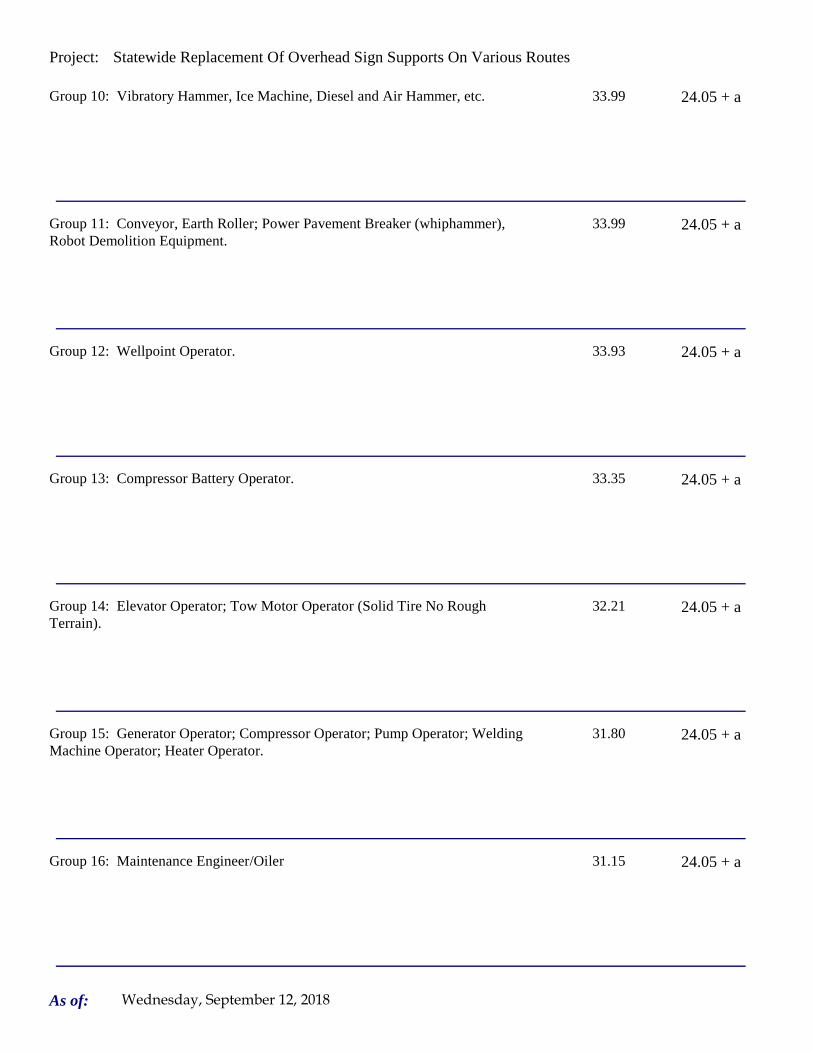
Project: Statewide Replacement Of Overhead Sign Supports On Various Routes
Group 10: Vibratory Hammer, Ice Machine, Diesel and Air Hammer, etc. 33.99 24.05 + a
Group 11: Conveyor, Earth Roller; Power Pavement Breaker (whiphammer), Robot Demolition Equipment.
33.99 24.05 + a
Group 12: Wellpoint Operator. 33.93 24.05 + a
Group 13: Compressor Battery Operator. 33.35 24.05 + a
Group 14: Elevator Operator; Tow Motor Operator (Solid Tire No Rough Terrain).
32.21 24.05 + a
Group 15: Generator Operator; Compressor Operator; Pump Operator; Welding Machine Operator; Heater Operator.
31.80 24.05 + a
Group 16: Maintenance Engineer/Oiler 31.15 24.05 + a
As of: Wednesday, September 12, 2018

Project: Statewide Replacement Of Overhead Sign Supports On Various Routes
Group 17: Portable asphalt plant operator; portable crusher plant operator; portable concrete plant operator.
35.46 24.05 + a
Group 18: Power Safety Boat; Vacuum Truck; Zim Mixer; Sweeper; (minimum for any job requiring CDL license).
33.04 24.05 + a
**NOTE: SEE BELOW
----LINE CONSTRUCTION----(Railroad Construction and Maintenance)----
20) Lineman, Cable Splicer, Technician 48.19 6.5% + 22.00
21) Heavy Equipment Operator 42.26 6.5% + 19.88
22) Equipment Operator, Tractor Trailer Driver, Material Men 40.96 6.5% + 19.21
As of: Wednesday, September 12, 2018

Project: Statewide Replacement Of Overhead Sign Supports On Various Routes
23) Driver Groundmen 26.50 6.5% + 9.00
23a) Truck Driver 40.96 6.5% + 17.76
----LINE CONSTRUCTION----
24) Driver Groundmen 30.92 6.5% + 9.70
25) Groundmen 22.67 6.5% + 6.20
26) Heavy Equipment Operators 37.10 6.5% + 10.70
27) Linemen, Cable Splicers, Dynamite Men 41.22 6.5% + 12.20
As of: Wednesday, September 12, 2018

Project: Statewide Replacement Of Overhead Sign Supports On Various Routes
28) Material Men, Tractor Trailer Drivers, Equipment Operators 35.04 6.5% + 10.45
As of: Wednesday, September 12, 2018

Project: Statewide Replacement Of Overhead Sign Supports On Various Routes
Welders: Rate for craft to which welding is incidental.
*Note: Hazardous waste removal work receives additional $1.25 per hour for truck drivers.
**Note: Hazardous waste premium $3.00 per hour over classified rate
Crane with 150 ft. boom (including jib) - $1.50 extra Crane with 200 ft. boom (including jib) - $2.50 extraCrane with 250 ft. boom (including jib) - $5.00 extraCrane with 300 ft. boom (including jib) - $7.00 extra
All classifications that indicate a percentage of the fringe benefits must be calculated at the percentage rate times the "base hourly rate".
Apprentices duly registered under the Commissioner of Labor's regulations on "Work Training Standards for Apprenticeship and Training Programs" Section 31-51-d-1 to 12, are allowed to be paid the appropriate percentage of the prevailing journeymen hourly base and the full fringe benefit rate, providing the work site ratio shall not be less than one full-time journeyperson instructing and supervising the work of each apprentice in a specific trade.
Each contractor shall pay the annual adjusted prevailing wage rate that is in effect each July 1st, as posted by the Department of Labor.
It is the contractor's responsibility to obtain the annual adjusted prevailing wage rate increases directly from the Department of Labor's website. The annual adjustments will be posted on the Department of Labor's Web page:
www.ct.gov/dol. The Department of Labor will continue to issue the initial prevailing wage rate schedule
to the Contracting Agency for the project.
All subsequent annual adjustments will be posted on our Web Site for contractor access.
The Prevailing wage rates applicable to this project are subject to annual adjustments each July 1st for the duration of the project.
Crane with 400 ft. boom (including jib) - $10.00 extra
~~Connecticut General Statute Section 31-55a: Annual Adjustments to wage rates by contractors doing state work ~~
Contracting Agencies are under no obligation pursuant to State labor law to pay any increase due to the annual adjustment provision.
ALL Cranes: When crane operator is operating equipment that requires a fully licensed crane operator to operate he receives an extra $4.00 premium in addition to the hourly wage rate and benefit contributions:
1) Crane handling or erecting structural steel or stone; hoisting engineer (2 drums or over)
2) Cranes (100 ton rate capacity and over) Bauer Drill/Caisson
3) Cranes (under 100 ton rated capacity)
As of: Wednesday, September 12, 2018

Project: Statewide Replacement Of Overhead Sign Supports On Various Routes
Please direct any questions which you may have pertaining to classification of work and payment of prevailing wages to the Wage and Workplace Standards Division, telephone (860)263-6790.
Effective October 1, 2005 - Public Act 05-50: any person performing the work of any mechanic, laborer, or worker shall be paid prevailing wage
All Person who perform work ON SITE must be paid prevailing wage for the appropriate mechanic, laborer, or worker classification.
All certified payrolls must list the hours worked and wages paid to All Persons who perform work ON SITE regardless of their ownership i.e.: (Owners, Corporate Officers, LLC Members, Independent Contractors, et. al)
Reporting and payment of wages is required regardless of any contractual relationship alleged to exist between the contractor and such person.
~~Unlisted classifications needed for work not included within the scope of the classifications listed may be added after award only as provided in the labor standards contract clause (29 CFR 5.5 (a) (1) (ii)).
As of: Wednesday, September 12, 2018

Project: Statewide Replacement Of Overhead Sign Supports On Various Routes
Project: Statewide Replacement Of Overhead Sign Supports On Various Routes
Project Project Rocky Hill
By virtue of the authority vested in the Labor Commissioner under provisions of Section 31-53 of the General Statutes of Connecticut, as amended, the following are declared to be the prevailing rates and welfare payments and will apply only where the contract is advertised for bid within 20 days of the date on which the rates are established. Any contractor or subcontractor not obligated by agreement to pay to the welfare and pension fund shall pay this amount to each employee as part of his/her hourly wages.
Minimum Rates and Classifications for Heavy/Highway Construction
Connecticut Department of LaborWage and Workplace Standards Division
FAP Number: State Number: 170-3447 & 148-210
Town:
H 25244
Number:
ID#:
Hourly Rate BenefitsCLASSIFICATION
01) Asbestos/Toxic Waste Removal Laborers: Asbestos removal and encapsulation (except its removal from mechanical systems which are not to be scrapped), toxic waste removers, blasters. **See Laborers Group 5 and 7**
1) Boilermaker 33.79 34% + 8.96
1a) Bricklayer, Cement Masons, Cement Finishers, Plasterers, Stone Masons 33.48 31.66
2) Carpenters, Piledrivermen 32.60 25.34
As of: Wednesday, September 12, 2018

Project: Statewide Replacement Of Overhead Sign Supports On Various Routes
2a) Diver Tenders 32.60 25.34
3) Divers 41.06 25.34
03a) Millwrights 33.14 25.74
4) Painters: (Bridge Construction) Brush, Roller, Blasting (Sand, Water, etc.), Spray
49.75 21.05
4a) Painters: Brush and Roller 33.62 21.05
4b) Painters: Spray Only 36.62 21.05
4c) Painters: Steel Only 35.62 21.05
As of: Wednesday, September 12, 2018

Project: Statewide Replacement Of Overhead Sign Supports On Various Routes
4d) Painters: Blast and Spray 36.62 21.05
4e) Painters: Tanks, Tower and Swing 35.62 21.05
5) Electrician (Trade License required: E-1,2 L-5,6 C-5,6 T-1,2 L-1,2 V-1,2,7,8,9)
40.00 25.97+3% of gross wage
6) Ironworkers: Ornamental, Reinforcing, Structural, and Precast Concrete Erection
35.47 35.14 + a
7) Plumbers (Trade License required: (P-1,2,6,7,8,9 J-1,2,3,4 SP-1,2) and Pipefitters (Including HVAC Work) (Trade License required: S-1,2,3,4,5,6,7,8 B-1,2,3,4 D-1,2,3,4 G-1, G-2, G-8, G-9)
42.62 31.21
----LABORERS---- -
8) Group 1: Laborer (Unskilled), Common or General, acetylene burner, concrete specialist
30.05 20.10
As of: Wednesday, September 12, 2018

Project: Statewide Replacement Of Overhead Sign Supports On Various Routes
9) Group 2: Chain saw operators, fence and guard rail erectors, pneumatic tool operators, powdermen
30.30 20.10
10) Group 3: Pipelayers 30.55 20.10
11) Group 4: Jackhammer/Pavement breaker (handheld); mason tenders (cement/concrete), catch basin builders, asphalt rakers, air track operators, block paver, curb setter and forklift operators
30.55 20.10
12) Group 5: Toxic waste removal (non-mechanical systems) 32.05 20.10
13) Group 6: Blasters 31.80 20.10
Group 7: Asbestos/lead removal, non-mechanical systems (does not include leaded joint pipe)
31.05 20.10
Group 8: Traffic control signalmen 16.00 20.10
As of: Wednesday, September 12, 2018

Project: Statewide Replacement Of Overhead Sign Supports On Various Routes
Group 9: Hydraulic Drills 29.30 18.90
----LABORERS (TUNNEL CONSTRUCTION, FREE AIR). Shield Drive and Liner Plate Tunnels in Free Air.----
13a) Miners, Motormen, Mucking Machine Operators, Nozzle Men, Grout Men, Shaft & Tunnel Steel & Rodmen, Shield & Erector, Arm Operator, Cable Tenders
32.22 20.10 + a
13b) Brakemen, Trackmen 31.28 20.10 + a
----CLEANING, CONCRETE AND CAULKING TUNNEL----
14) Concrete Workers, Form Movers, and Strippers 31.28 20.10 + a
15) Form Erectors 31.60 20.10 + a
As of: Wednesday, September 12, 2018

Project: Statewide Replacement Of Overhead Sign Supports On Various Routes
----ROCK SHAFT LINING, CONCRETE, LINING OF SAME AND TUNNEL IN FREE AIR:----
16) Brakemen, Trackmen, Tunnel Laborers, Shaft Laborers 31.28 20.10 + a
17) Laborers Topside, Cage Tenders, Bellman 31.17 20.10 + a
18) Miners 32.22 20.10 + a
----TUNNELS, CAISSON AND CYLINDER WORK IN COMPRESSED AIR: ----
18a) Blaster 38.53 20.10 + a
19) Brakemen, Trackmen, Groutman, Laborers, Outside Lock Tender, Gauge Tenders
38.34 20.10 + a
As of: Wednesday, September 12, 2018

Project: Statewide Replacement Of Overhead Sign Supports On Various Routes
20) Change House Attendants, Powder Watchmen, Top on Iron Bolts 36.41 20.10 + a
21) Mucking Machine Operator 39.11 20.10 + a
----TRUCK DRIVERS----(*see note below)
Two axle trucks 29.13 23.33 + a
Three axle trucks; two axle ready mix 29.23 23.33 + a
Three axle ready mix 29.28 23.33 + a
Four axle trucks, heavy duty trailer (up to 40 tons) 29.33 23.33 + a
As of: Wednesday, September 12, 2018

Project: Statewide Replacement Of Overhead Sign Supports On Various Routes
Four axle ready-mix 29.38 23.33 + a
Heavy duty trailer (40 tons and over) 29.58 23.33 + a
Specialized earth moving equipment other than conventional type on-the road trucks and semi-trailer (including Euclids)
29.38 23.33 + a
----POWER EQUIPMENT OPERATORS----
Group 1: Crane handling or erecting structural steel or stone, hoisting engineer (2 drums or over), front end loader (7 cubic yards or over), Work Boat 26 ft. & Over, Tunnel Boring Machines. (Trade License Required)
39.55 24.05 + a
Group 2: Cranes (100 ton rate capacity and over); Excavator over 2 cubic yards; Piledriver ($3.00 premium when operator controls hammer); Bauer Drill/Caisson. (Trade License Required)
39.23 24.05 + a
Group 3: Excavator/Backhoe under 2 cubic yards; Cranes (under 100 ton rated capacity), Gradall; Master Mechanic; Hoisting Engineer (all types of equipment where a drum and cable are used to hoist or drag material regardless of motive power of operation), Rubber Tire Excavator (Drott-1085 or similar);Grader Operator; Bulldozer Fine Grade (slopes, shaping, laser or GPS, etc.). (Trade License Required)
38.49 24.05 + a
As of: Wednesday, September 12, 2018

Project: Statewide Replacement Of Overhead Sign Supports On Various Routes
Group 4: Trenching Machines; Lighter Derrick; Concrete Finishing Machine; CMI Machine or Similar; Koehring Loader (Skooper)
38.10 24.05 + a
Group 5: Specialty Railroad Equipment; Asphalt Paver; Asphalt Spreader; Asphalt Reclaiming Machine; Line Grinder; Concrete Pumps; Drills with Self Contained Power Units; Boring Machine; Post Hole Digger; Auger; Pounder; Well Digger; Milling Machine (over 24" Mandrell)
37.51 24.05 + a
Group 5 continued: Side Boom; Combination Hoe and Loader; Directional Driller.
37.51 24.05 + a
Group 6: Front End Loader (3 up to 7 cubic yards); Bulldozer (rough grade dozer).
37.20 24.05 + a
Group 7: Asphalt Roller; Concrete Saws and Cutters (ride on types); Vermeer Concrete Cutter; Stump Grinder; Scraper; Snooper; Skidder; Milling Machine (24" and Under Mandrel).
36.86 24.05 + a
Group 8: Mechanic, Grease Truck Operator, Hydroblaster, Barrier Mover, Power Stone Spreader; Welder; Work Boat under 26 ft.; Transfer Machine.
36.46 24.05 + a
Group 9: Front End Loader (under 3 cubic yards), Skid Steer Loader regardless of attachments (Bobcat or Similar); Fork Lift, Power Chipper; Landscape Equipment (including hydroseeder).
36.03 24.05 + a
As of: Wednesday, September 12, 2018

Project: Statewide Replacement Of Overhead Sign Supports On Various Routes
Group 10: Vibratory Hammer, Ice Machine, Diesel and Air Hammer, etc. 33.99 24.05 + a
Group 11: Conveyor, Earth Roller; Power Pavement Breaker (whiphammer), Robot Demolition Equipment.
33.99 24.05 + a
Group 12: Wellpoint Operator. 33.93 24.05 + a
Group 13: Compressor Battery Operator. 33.35 24.05 + a
Group 14: Elevator Operator; Tow Motor Operator (Solid Tire No Rough Terrain).
32.21 24.05 + a
Group 15: Generator Operator; Compressor Operator; Pump Operator; Welding Machine Operator; Heater Operator.
31.80 24.05 + a
Group 16: Maintenance Engineer/Oiler 31.15 24.05 + a
As of: Wednesday, September 12, 2018

Project: Statewide Replacement Of Overhead Sign Supports On Various Routes
Group 17: Portable asphalt plant operator; portable crusher plant operator; portable concrete plant operator.
35.46 24.05 + a
Group 18: Power Safety Boat; Vacuum Truck; Zim Mixer; Sweeper; (minimum for any job requiring CDL license).
33.04 24.05 + a
**NOTE: SEE BELOW
----LINE CONSTRUCTION----(Railroad Construction and Maintenance)----
20) Lineman, Cable Splicer, Technician 48.19 6.5% + 22.00
21) Heavy Equipment Operator 42.26 6.5% + 19.88
22) Equipment Operator, Tractor Trailer Driver, Material Men 40.96 6.5% + 19.21
As of: Wednesday, September 12, 2018

Project: Statewide Replacement Of Overhead Sign Supports On Various Routes
23) Driver Groundmen 26.50 6.5% + 9.00
23a) Truck Driver 40.96 6.5% + 17.76
----LINE CONSTRUCTION----
24) Driver Groundmen 30.92 6.5% + 9.70
25) Groundmen 22.67 6.5% + 6.20
26) Heavy Equipment Operators 37.10 6.5% + 10.70
27) Linemen, Cable Splicers, Dynamite Men 41.22 6.5% + 12.20
As of: Wednesday, September 12, 2018

Project: Statewide Replacement Of Overhead Sign Supports On Various Routes
28) Material Men, Tractor Trailer Drivers, Equipment Operators 35.04 6.5% + 10.45
As of: Wednesday, September 12, 2018

Project: Statewide Replacement Of Overhead Sign Supports On Various Routes
Welders: Rate for craft to which welding is incidental.
*Note: Hazardous waste removal work receives additional $1.25 per hour for truck drivers.
**Note: Hazardous waste premium $3.00 per hour over classified rate
Crane with 150 ft. boom (including jib) - $1.50 extra Crane with 200 ft. boom (including jib) - $2.50 extraCrane with 250 ft. boom (including jib) - $5.00 extraCrane with 300 ft. boom (including jib) - $7.00 extra
All classifications that indicate a percentage of the fringe benefits must be calculated at the percentage rate times the "base hourly rate".
Apprentices duly registered under the Commissioner of Labor's regulations on "Work Training Standards for Apprenticeship and Training Programs" Section 31-51-d-1 to 12, are allowed to be paid the appropriate percentage of the prevailing journeymen hourly base and the full fringe benefit rate, providing the work site ratio shall not be less than one full-time journeyperson instructing and supervising the work of each apprentice in a specific trade.
Each contractor shall pay the annual adjusted prevailing wage rate that is in effect each July 1st, as posted by the Department of Labor.
It is the contractor's responsibility to obtain the annual adjusted prevailing wage rate increases directly from the Department of Labor's website. The annual adjustments will be posted on the Department of Labor's Web page:
www.ct.gov/dol. The Department of Labor will continue to issue the initial prevailing wage rate schedule
to the Contracting Agency for the project.
All subsequent annual adjustments will be posted on our Web Site for contractor access.
The Prevailing wage rates applicable to this project are subject to annual adjustments each July 1st for the duration of the project.
Crane with 400 ft. boom (including jib) - $10.00 extra
~~Connecticut General Statute Section 31-55a: Annual Adjustments to wage rates by contractors doing state work ~~
Contracting Agencies are under no obligation pursuant to State labor law to pay any increase due to the annual adjustment provision.
ALL Cranes: When crane operator is operating equipment that requires a fully licensed crane operator to operate he receives an extra $4.00 premium in addition to the hourly wage rate and benefit contributions:
1) Crane handling or erecting structural steel or stone; hoisting engineer (2 drums or over)
2) Cranes (100 ton rate capacity and over) Bauer Drill/Caisson
3) Cranes (under 100 ton rated capacity)
As of: Wednesday, September 12, 2018
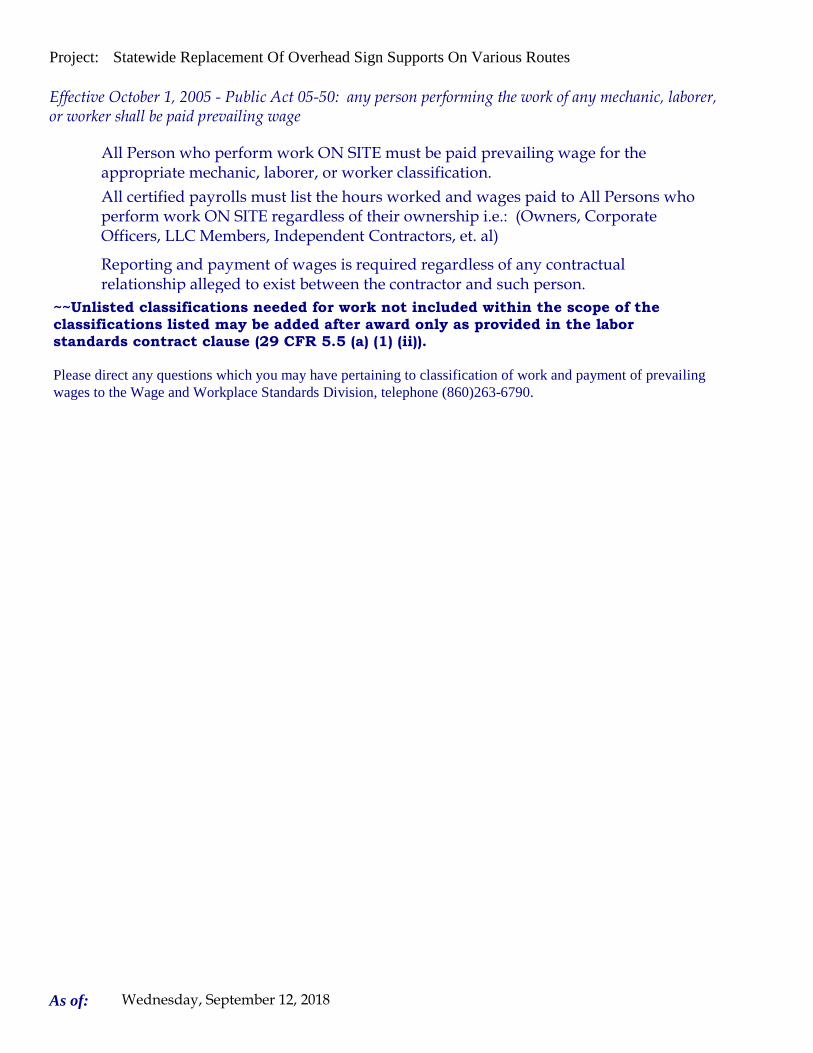
Project: Statewide Replacement Of Overhead Sign Supports On Various Routes
Please direct any questions which you may have pertaining to classification of work and payment of prevailing wages to the Wage and Workplace Standards Division, telephone (860)263-6790.
Effective October 1, 2005 - Public Act 05-50: any person performing the work of any mechanic, laborer, or worker shall be paid prevailing wage
All Person who perform work ON SITE must be paid prevailing wage for the appropriate mechanic, laborer, or worker classification.
All certified payrolls must list the hours worked and wages paid to All Persons who perform work ON SITE regardless of their ownership i.e.: (Owners, Corporate Officers, LLC Members, Independent Contractors, et. al)
Reporting and payment of wages is required regardless of any contractual relationship alleged to exist between the contractor and such person.
~~Unlisted classifications needed for work not included within the scope of the classifications listed may be added after award only as provided in the labor standards contract clause (29 CFR 5.5 (a) (1) (ii)).
As of: Wednesday, September 12, 2018

Project: Statewide Replacement Of Overhead Sign Supports On Various Routes
Project: Statewide Replacement Of Overhead Sign Supports On Various Routes
Project Project Farmington
By virtue of the authority vested in the Labor Commissioner under provisions of Section 31-53 of the General Statutes of Connecticut, as amended, the following are declared to be the prevailing rates and welfare payments and will apply only where the contract is advertised for bid within 20 days of the date on which the rates are established. Any contractor or subcontractor not obligated by agreement to pay to the welfare and pension fund shall pay this amount to each employee as part of his/her hourly wages.
Minimum Rates and Classifications for Heavy/Highway Construction
Connecticut Department of LaborWage and Workplace Standards Division
FAP Number: State Number: 170-3447 & 148-210
Town:
H 25245
Number:
ID#:
Hourly Rate BenefitsCLASSIFICATION
01) Asbestos/Toxic Waste Removal Laborers: Asbestos removal and encapsulation (except its removal from mechanical systems which are not to be scrapped), toxic waste removers, blasters. **See Laborers Group 5 and 7**
1) Boilermaker 33.79 34% + 8.96
1a) Bricklayer, Cement Masons, Cement Finishers, Plasterers, Stone Masons 33.48 31.66
2) Carpenters, Piledrivermen 32.60 25.34
As of: Wednesday, September 12, 2018

Project: Statewide Replacement Of Overhead Sign Supports On Various Routes
2a) Diver Tenders 32.60 25.34
3) Divers 41.06 25.34
03a) Millwrights 33.14 25.74
4) Painters: (Bridge Construction) Brush, Roller, Blasting (Sand, Water, etc.), Spray
49.75 21.05
4a) Painters: Brush and Roller 33.62 21.05
4b) Painters: Spray Only 36.62 21.05
4c) Painters: Steel Only 35.62 21.05
As of: Wednesday, September 12, 2018

Project: Statewide Replacement Of Overhead Sign Supports On Various Routes
4d) Painters: Blast and Spray 36.62 21.05
4e) Painters: Tanks, Tower and Swing 35.62 21.05
5) Electrician (Trade License required: E-1,2 L-5,6 C-5,6 T-1,2 L-1,2 V-1,2,7,8,9)
40.00 25.97+3% of gross wage
6) Ironworkers: Ornamental, Reinforcing, Structural, and Precast Concrete Erection
35.47 35.14 + a
7) Plumbers (Trade License required: (P-1,2,6,7,8,9 J-1,2,3,4 SP-1,2) and Pipefitters (Including HVAC Work) (Trade License required: S-1,2,3,4,5,6,7,8 B-1,2,3,4 D-1,2,3,4 G-1, G-2, G-8, G-9)
42.62 31.21
----LABORERS---- -
8) Group 1: Laborer (Unskilled), Common or General, acetylene burner, concrete specialist
30.05 20.10
As of: Wednesday, September 12, 2018

Project: Statewide Replacement Of Overhead Sign Supports On Various Routes
9) Group 2: Chain saw operators, fence and guard rail erectors, pneumatic tool operators, powdermen
30.30 20.10
10) Group 3: Pipelayers 30.55 20.10
11) Group 4: Jackhammer/Pavement breaker (handheld); mason tenders (cement/concrete), catch basin builders, asphalt rakers, air track operators, block paver, curb setter and forklift operators
30.55 20.10
12) Group 5: Toxic waste removal (non-mechanical systems) 32.05 20.10
13) Group 6: Blasters 31.80 20.10
Group 7: Asbestos/lead removal, non-mechanical systems (does not include leaded joint pipe)
31.05 20.10
Group 8: Traffic control signalmen 16.00 20.10
As of: Wednesday, September 12, 2018

Project: Statewide Replacement Of Overhead Sign Supports On Various Routes
Group 9: Hydraulic Drills 29.30 18.90
----LABORERS (TUNNEL CONSTRUCTION, FREE AIR). Shield Drive and Liner Plate Tunnels in Free Air.----
13a) Miners, Motormen, Mucking Machine Operators, Nozzle Men, Grout Men, Shaft & Tunnel Steel & Rodmen, Shield & Erector, Arm Operator, Cable Tenders
32.22 20.10 + a
13b) Brakemen, Trackmen 31.28 20.10 + a
----CLEANING, CONCRETE AND CAULKING TUNNEL----
14) Concrete Workers, Form Movers, and Strippers 31.28 20.10 + a
15) Form Erectors 31.60 20.10 + a
As of: Wednesday, September 12, 2018

Project: Statewide Replacement Of Overhead Sign Supports On Various Routes
----ROCK SHAFT LINING, CONCRETE, LINING OF SAME AND TUNNEL IN FREE AIR:----
16) Brakemen, Trackmen, Tunnel Laborers, Shaft Laborers 31.28 20.10 + a
17) Laborers Topside, Cage Tenders, Bellman 31.17 20.10 + a
18) Miners 32.22 20.10 + a
----TUNNELS, CAISSON AND CYLINDER WORK IN COMPRESSED AIR: ----
18a) Blaster 38.53 20.10 + a
19) Brakemen, Trackmen, Groutman, Laborers, Outside Lock Tender, Gauge Tenders
38.34 20.10 + a
As of: Wednesday, September 12, 2018

Project: Statewide Replacement Of Overhead Sign Supports On Various Routes
20) Change House Attendants, Powder Watchmen, Top on Iron Bolts 36.41 20.10 + a
21) Mucking Machine Operator 39.11 20.10 + a
----TRUCK DRIVERS----(*see note below)
Two axle trucks 29.13 23.33 + a
Three axle trucks; two axle ready mix 29.23 23.33 + a
Three axle ready mix 29.28 23.33 + a
Four axle trucks, heavy duty trailer (up to 40 tons) 29.33 23.33 + a
As of: Wednesday, September 12, 2018

Project: Statewide Replacement Of Overhead Sign Supports On Various Routes
Four axle ready-mix 29.38 23.33 + a
Heavy duty trailer (40 tons and over) 29.58 23.33 + a
Specialized earth moving equipment other than conventional type on-the road trucks and semi-trailer (including Euclids)
29.38 23.33 + a
----POWER EQUIPMENT OPERATORS----
Group 1: Crane handling or erecting structural steel or stone, hoisting engineer (2 drums or over), front end loader (7 cubic yards or over), Work Boat 26 ft. & Over, Tunnel Boring Machines. (Trade License Required)
39.55 24.05 + a
Group 2: Cranes (100 ton rate capacity and over); Excavator over 2 cubic yards; Piledriver ($3.00 premium when operator controls hammer); Bauer Drill/Caisson. (Trade License Required)
39.23 24.05 + a
Group 3: Excavator/Backhoe under 2 cubic yards; Cranes (under 100 ton rated capacity), Gradall; Master Mechanic; Hoisting Engineer (all types of equipment where a drum and cable are used to hoist or drag material regardless of motive power of operation), Rubber Tire Excavator (Drott-1085 or similar);Grader Operator; Bulldozer Fine Grade (slopes, shaping, laser or GPS, etc.). (Trade License Required)
38.49 24.05 + a
As of: Wednesday, September 12, 2018

Project: Statewide Replacement Of Overhead Sign Supports On Various Routes
Group 4: Trenching Machines; Lighter Derrick; Concrete Finishing Machine; CMI Machine or Similar; Koehring Loader (Skooper)
38.10 24.05 + a
Group 5: Specialty Railroad Equipment; Asphalt Paver; Asphalt Spreader; Asphalt Reclaiming Machine; Line Grinder; Concrete Pumps; Drills with Self Contained Power Units; Boring Machine; Post Hole Digger; Auger; Pounder; Well Digger; Milling Machine (over 24" Mandrell)
37.51 24.05 + a
Group 5 continued: Side Boom; Combination Hoe and Loader; Directional Driller.
37.51 24.05 + a
Group 6: Front End Loader (3 up to 7 cubic yards); Bulldozer (rough grade dozer).
37.20 24.05 + a
Group 7: Asphalt Roller; Concrete Saws and Cutters (ride on types); Vermeer Concrete Cutter; Stump Grinder; Scraper; Snooper; Skidder; Milling Machine (24" and Under Mandrel).
36.86 24.05 + a
Group 8: Mechanic, Grease Truck Operator, Hydroblaster, Barrier Mover, Power Stone Spreader; Welder; Work Boat under 26 ft.; Transfer Machine.
36.46 24.05 + a
Group 9: Front End Loader (under 3 cubic yards), Skid Steer Loader regardless of attachments (Bobcat or Similar); Fork Lift, Power Chipper; Landscape Equipment (including hydroseeder).
36.03 24.05 + a
As of: Wednesday, September 12, 2018

Project: Statewide Replacement Of Overhead Sign Supports On Various Routes
Group 10: Vibratory Hammer, Ice Machine, Diesel and Air Hammer, etc. 33.99 24.05 + a
Group 11: Conveyor, Earth Roller; Power Pavement Breaker (whiphammer), Robot Demolition Equipment.
33.99 24.05 + a
Group 12: Wellpoint Operator. 33.93 24.05 + a
Group 13: Compressor Battery Operator. 33.35 24.05 + a
Group 14: Elevator Operator; Tow Motor Operator (Solid Tire No Rough Terrain).
32.21 24.05 + a
Group 15: Generator Operator; Compressor Operator; Pump Operator; Welding Machine Operator; Heater Operator.
31.80 24.05 + a
Group 16: Maintenance Engineer/Oiler 31.15 24.05 + a
As of: Wednesday, September 12, 2018

Project: Statewide Replacement Of Overhead Sign Supports On Various Routes
Group 17: Portable asphalt plant operator; portable crusher plant operator; portable concrete plant operator.
35.46 24.05 + a
Group 18: Power Safety Boat; Vacuum Truck; Zim Mixer; Sweeper; (minimum for any job requiring CDL license).
33.04 24.05 + a
**NOTE: SEE BELOW
----LINE CONSTRUCTION----(Railroad Construction and Maintenance)----
20) Lineman, Cable Splicer, Technician 48.19 6.5% + 22.00
21) Heavy Equipment Operator 42.26 6.5% + 19.88
22) Equipment Operator, Tractor Trailer Driver, Material Men 40.96 6.5% + 19.21
As of: Wednesday, September 12, 2018

Project: Statewide Replacement Of Overhead Sign Supports On Various Routes
23) Driver Groundmen 26.50 6.5% + 9.00
23a) Truck Driver 40.96 6.5% + 17.76
----LINE CONSTRUCTION----
24) Driver Groundmen 30.92 6.5% + 9.70
25) Groundmen 22.67 6.5% + 6.20
26) Heavy Equipment Operators 37.10 6.5% + 10.70
27) Linemen, Cable Splicers, Dynamite Men 41.22 6.5% + 12.20
As of: Wednesday, September 12, 2018

Project: Statewide Replacement Of Overhead Sign Supports On Various Routes
28) Material Men, Tractor Trailer Drivers, Equipment Operators 35.04 6.5% + 10.45
As of: Wednesday, September 12, 2018

Project: Statewide Replacement Of Overhead Sign Supports On Various Routes
Welders: Rate for craft to which welding is incidental.
*Note: Hazardous waste removal work receives additional $1.25 per hour for truck drivers.
**Note: Hazardous waste premium $3.00 per hour over classified rate
Crane with 150 ft. boom (including jib) - $1.50 extra Crane with 200 ft. boom (including jib) - $2.50 extraCrane with 250 ft. boom (including jib) - $5.00 extraCrane with 300 ft. boom (including jib) - $7.00 extra
All classifications that indicate a percentage of the fringe benefits must be calculated at the percentage rate times the "base hourly rate".
Apprentices duly registered under the Commissioner of Labor's regulations on "Work Training Standards for Apprenticeship and Training Programs" Section 31-51-d-1 to 12, are allowed to be paid the appropriate percentage of the prevailing journeymen hourly base and the full fringe benefit rate, providing the work site ratio shall not be less than one full-time journeyperson instructing and supervising the work of each apprentice in a specific trade.
Each contractor shall pay the annual adjusted prevailing wage rate that is in effect each July 1st, as posted by the Department of Labor.
It is the contractor's responsibility to obtain the annual adjusted prevailing wage rate increases directly from the Department of Labor's website. The annual adjustments will be posted on the Department of Labor's Web page:
www.ct.gov/dol. The Department of Labor will continue to issue the initial prevailing wage rate schedule
to the Contracting Agency for the project.
All subsequent annual adjustments will be posted on our Web Site for contractor access.
The Prevailing wage rates applicable to this project are subject to annual adjustments each July 1st for the duration of the project.
Crane with 400 ft. boom (including jib) - $10.00 extra
~~Connecticut General Statute Section 31-55a: Annual Adjustments to wage rates by contractors doing state work ~~
Contracting Agencies are under no obligation pursuant to State labor law to pay any increase due to the annual adjustment provision.
ALL Cranes: When crane operator is operating equipment that requires a fully licensed crane operator to operate he receives an extra $4.00 premium in addition to the hourly wage rate and benefit contributions:
1) Crane handling or erecting structural steel or stone; hoisting engineer (2 drums or over)
2) Cranes (100 ton rate capacity and over) Bauer Drill/Caisson
3) Cranes (under 100 ton rated capacity)
As of: Wednesday, September 12, 2018

Project: Statewide Replacement Of Overhead Sign Supports On Various Routes
Please direct any questions which you may have pertaining to classification of work and payment of prevailing wages to the Wage and Workplace Standards Division, telephone (860)263-6790.
Effective October 1, 2005 - Public Act 05-50: any person performing the work of any mechanic, laborer, or worker shall be paid prevailing wage
All Person who perform work ON SITE must be paid prevailing wage for the appropriate mechanic, laborer, or worker classification.
All certified payrolls must list the hours worked and wages paid to All Persons who perform work ON SITE regardless of their ownership i.e.: (Owners, Corporate Officers, LLC Members, Independent Contractors, et. al)
Reporting and payment of wages is required regardless of any contractual relationship alleged to exist between the contractor and such person.
~~Unlisted classifications needed for work not included within the scope of the classifications listed may be added after award only as provided in the labor standards contract clause (29 CFR 5.5 (a) (1) (ii)).
As of: Wednesday, September 12, 2018

Project: Statewide Replacement Of Overhead Sign Supports On Various Routes
Project: Statewide Replacement Of Overhead Sign Supports On Various Routes
Project Project East Hartford
By virtue of the authority vested in the Labor Commissioner under provisions of Section 31-53 of the General Statutes of Connecticut, as amended, the following are declared to be the prevailing rates and welfare payments and will apply only where the contract is advertised for bid within 20 days of the date on which the rates are established. Any contractor or subcontractor not obligated by agreement to pay to the welfare and pension fund shall pay this amount to each employee as part of his/her hourly wages.
Minimum Rates and Classifications for Heavy/Highway Construction
Connecticut Department of LaborWage and Workplace Standards Division
FAP Number: State Number: 170-3447 & 148-210
Town:
H 25246
Number:
ID#:
Hourly Rate BenefitsCLASSIFICATION
01) Asbestos/Toxic Waste Removal Laborers: Asbestos removal and encapsulation (except its removal from mechanical systems which are not to be scrapped), toxic waste removers, blasters. **See Laborers Group 5 and 7**
1) Boilermaker 33.79 34% + 8.96
1a) Bricklayer, Cement Masons, Cement Finishers, Plasterers, Stone Masons 33.48 31.66
2) Carpenters, Piledrivermen 32.60 25.34
As of: Wednesday, September 12, 2018

Project: Statewide Replacement Of Overhead Sign Supports On Various Routes
2a) Diver Tenders 32.60 25.34
3) Divers 41.06 25.34
03a) Millwrights 33.14 25.74
4) Painters: (Bridge Construction) Brush, Roller, Blasting (Sand, Water, etc.), Spray
49.75 21.05
4a) Painters: Brush and Roller 33.62 21.05
4b) Painters: Spray Only 36.62 21.05
4c) Painters: Steel Only 35.62 21.05
As of: Wednesday, September 12, 2018
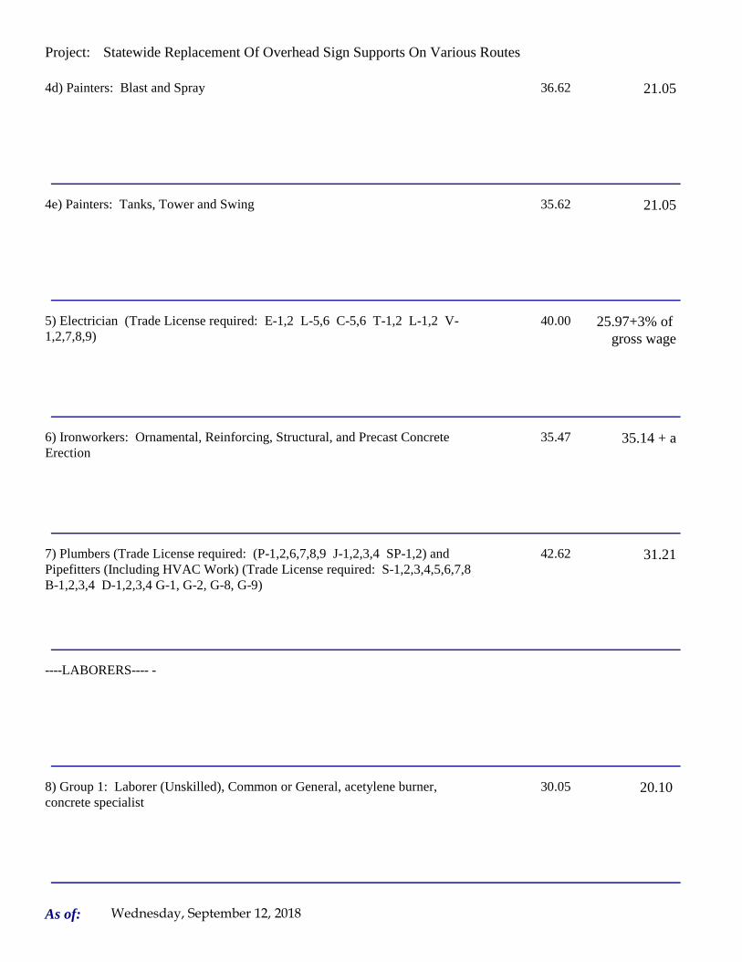
Project: Statewide Replacement Of Overhead Sign Supports On Various Routes
4d) Painters: Blast and Spray 36.62 21.05
4e) Painters: Tanks, Tower and Swing 35.62 21.05
5) Electrician (Trade License required: E-1,2 L-5,6 C-5,6 T-1,2 L-1,2 V-1,2,7,8,9)
40.00 25.97+3% of gross wage
6) Ironworkers: Ornamental, Reinforcing, Structural, and Precast Concrete Erection
35.47 35.14 + a
7) Plumbers (Trade License required: (P-1,2,6,7,8,9 J-1,2,3,4 SP-1,2) and Pipefitters (Including HVAC Work) (Trade License required: S-1,2,3,4,5,6,7,8 B-1,2,3,4 D-1,2,3,4 G-1, G-2, G-8, G-9)
42.62 31.21
----LABORERS---- -
8) Group 1: Laborer (Unskilled), Common or General, acetylene burner, concrete specialist
30.05 20.10
As of: Wednesday, September 12, 2018

Project: Statewide Replacement Of Overhead Sign Supports On Various Routes
9) Group 2: Chain saw operators, fence and guard rail erectors, pneumatic tool operators, powdermen
30.30 20.10
10) Group 3: Pipelayers 30.55 20.10
11) Group 4: Jackhammer/Pavement breaker (handheld); mason tenders (cement/concrete), catch basin builders, asphalt rakers, air track operators, block paver, curb setter and forklift operators
30.55 20.10
12) Group 5: Toxic waste removal (non-mechanical systems) 32.05 20.10
13) Group 6: Blasters 31.80 20.10
Group 7: Asbestos/lead removal, non-mechanical systems (does not include leaded joint pipe)
31.05 20.10
Group 8: Traffic control signalmen 16.00 20.10
As of: Wednesday, September 12, 2018

Project: Statewide Replacement Of Overhead Sign Supports On Various Routes
Group 9: Hydraulic Drills 29.30 18.90
----LABORERS (TUNNEL CONSTRUCTION, FREE AIR). Shield Drive and Liner Plate Tunnels in Free Air.----
13a) Miners, Motormen, Mucking Machine Operators, Nozzle Men, Grout Men, Shaft & Tunnel Steel & Rodmen, Shield & Erector, Arm Operator, Cable Tenders
32.22 20.10 + a
13b) Brakemen, Trackmen 31.28 20.10 + a
----CLEANING, CONCRETE AND CAULKING TUNNEL----
14) Concrete Workers, Form Movers, and Strippers 31.28 20.10 + a
15) Form Erectors 31.60 20.10 + a
As of: Wednesday, September 12, 2018

Project: Statewide Replacement Of Overhead Sign Supports On Various Routes
----ROCK SHAFT LINING, CONCRETE, LINING OF SAME AND TUNNEL IN FREE AIR:----
16) Brakemen, Trackmen, Tunnel Laborers, Shaft Laborers 31.28 20.10 + a
17) Laborers Topside, Cage Tenders, Bellman 31.17 20.10 + a
18) Miners 32.22 20.10 + a
----TUNNELS, CAISSON AND CYLINDER WORK IN COMPRESSED AIR: ----
18a) Blaster 38.53 20.10 + a
19) Brakemen, Trackmen, Groutman, Laborers, Outside Lock Tender, Gauge Tenders
38.34 20.10 + a
As of: Wednesday, September 12, 2018

Project: Statewide Replacement Of Overhead Sign Supports On Various Routes
20) Change House Attendants, Powder Watchmen, Top on Iron Bolts 36.41 20.10 + a
21) Mucking Machine Operator 39.11 20.10 + a
----TRUCK DRIVERS----(*see note below)
Two axle trucks 29.13 23.33 + a
Three axle trucks; two axle ready mix 29.23 23.33 + a
Three axle ready mix 29.28 23.33 + a
Four axle trucks, heavy duty trailer (up to 40 tons) 29.33 23.33 + a
As of: Wednesday, September 12, 2018

Project: Statewide Replacement Of Overhead Sign Supports On Various Routes
Four axle ready-mix 29.38 23.33 + a
Heavy duty trailer (40 tons and over) 29.58 23.33 + a
Specialized earth moving equipment other than conventional type on-the road trucks and semi-trailer (including Euclids)
29.38 23.33 + a
----POWER EQUIPMENT OPERATORS----
Group 1: Crane handling or erecting structural steel or stone, hoisting engineer (2 drums or over), front end loader (7 cubic yards or over), Work Boat 26 ft. & Over, Tunnel Boring Machines. (Trade License Required)
39.55 24.05 + a
Group 2: Cranes (100 ton rate capacity and over); Excavator over 2 cubic yards; Piledriver ($3.00 premium when operator controls hammer); Bauer Drill/Caisson. (Trade License Required)
39.23 24.05 + a
Group 3: Excavator/Backhoe under 2 cubic yards; Cranes (under 100 ton rated capacity), Gradall; Master Mechanic; Hoisting Engineer (all types of equipment where a drum and cable are used to hoist or drag material regardless of motive power of operation), Rubber Tire Excavator (Drott-1085 or similar);Grader Operator; Bulldozer Fine Grade (slopes, shaping, laser or GPS, etc.). (Trade License Required)
38.49 24.05 + a
As of: Wednesday, September 12, 2018

Project: Statewide Replacement Of Overhead Sign Supports On Various Routes
Group 4: Trenching Machines; Lighter Derrick; Concrete Finishing Machine; CMI Machine or Similar; Koehring Loader (Skooper)
38.10 24.05 + a
Group 5: Specialty Railroad Equipment; Asphalt Paver; Asphalt Spreader; Asphalt Reclaiming Machine; Line Grinder; Concrete Pumps; Drills with Self Contained Power Units; Boring Machine; Post Hole Digger; Auger; Pounder; Well Digger; Milling Machine (over 24" Mandrell)
37.51 24.05 + a
Group 5 continued: Side Boom; Combination Hoe and Loader; Directional Driller.
37.51 24.05 + a
Group 6: Front End Loader (3 up to 7 cubic yards); Bulldozer (rough grade dozer).
37.20 24.05 + a
Group 7: Asphalt Roller; Concrete Saws and Cutters (ride on types); Vermeer Concrete Cutter; Stump Grinder; Scraper; Snooper; Skidder; Milling Machine (24" and Under Mandrel).
36.86 24.05 + a
Group 8: Mechanic, Grease Truck Operator, Hydroblaster, Barrier Mover, Power Stone Spreader; Welder; Work Boat under 26 ft.; Transfer Machine.
36.46 24.05 + a
Group 9: Front End Loader (under 3 cubic yards), Skid Steer Loader regardless of attachments (Bobcat or Similar); Fork Lift, Power Chipper; Landscape Equipment (including hydroseeder).
36.03 24.05 + a
As of: Wednesday, September 12, 2018

Project: Statewide Replacement Of Overhead Sign Supports On Various Routes
Group 10: Vibratory Hammer, Ice Machine, Diesel and Air Hammer, etc. 33.99 24.05 + a
Group 11: Conveyor, Earth Roller; Power Pavement Breaker (whiphammer), Robot Demolition Equipment.
33.99 24.05 + a
Group 12: Wellpoint Operator. 33.93 24.05 + a
Group 13: Compressor Battery Operator. 33.35 24.05 + a
Group 14: Elevator Operator; Tow Motor Operator (Solid Tire No Rough Terrain).
32.21 24.05 + a
Group 15: Generator Operator; Compressor Operator; Pump Operator; Welding Machine Operator; Heater Operator.
31.80 24.05 + a
Group 16: Maintenance Engineer/Oiler 31.15 24.05 + a
As of: Wednesday, September 12, 2018

Project: Statewide Replacement Of Overhead Sign Supports On Various Routes
Group 17: Portable asphalt plant operator; portable crusher plant operator; portable concrete plant operator.
35.46 24.05 + a
Group 18: Power Safety Boat; Vacuum Truck; Zim Mixer; Sweeper; (minimum for any job requiring CDL license).
33.04 24.05 + a
**NOTE: SEE BELOW
----LINE CONSTRUCTION----(Railroad Construction and Maintenance)----
20) Lineman, Cable Splicer, Technician 48.19 6.5% + 22.00
21) Heavy Equipment Operator 42.26 6.5% + 19.88
22) Equipment Operator, Tractor Trailer Driver, Material Men 40.96 6.5% + 19.21
As of: Wednesday, September 12, 2018

Project: Statewide Replacement Of Overhead Sign Supports On Various Routes
23) Driver Groundmen 26.50 6.5% + 9.00
23a) Truck Driver 40.96 6.5% + 17.76
----LINE CONSTRUCTION----
24) Driver Groundmen 30.92 6.5% + 9.70
25) Groundmen 22.67 6.5% + 6.20
26) Heavy Equipment Operators 37.10 6.5% + 10.70
27) Linemen, Cable Splicers, Dynamite Men 41.22 6.5% + 12.20
As of: Wednesday, September 12, 2018

Project: Statewide Replacement Of Overhead Sign Supports On Various Routes
28) Material Men, Tractor Trailer Drivers, Equipment Operators 35.04 6.5% + 10.45
As of: Wednesday, September 12, 2018

Project: Statewide Replacement Of Overhead Sign Supports On Various Routes
Welders: Rate for craft to which welding is incidental.
*Note: Hazardous waste removal work receives additional $1.25 per hour for truck drivers.
**Note: Hazardous waste premium $3.00 per hour over classified rate
Crane with 150 ft. boom (including jib) - $1.50 extra Crane with 200 ft. boom (including jib) - $2.50 extraCrane with 250 ft. boom (including jib) - $5.00 extraCrane with 300 ft. boom (including jib) - $7.00 extra
All classifications that indicate a percentage of the fringe benefits must be calculated at the percentage rate times the "base hourly rate".
Apprentices duly registered under the Commissioner of Labor's regulations on "Work Training Standards for Apprenticeship and Training Programs" Section 31-51-d-1 to 12, are allowed to be paid the appropriate percentage of the prevailing journeymen hourly base and the full fringe benefit rate, providing the work site ratio shall not be less than one full-time journeyperson instructing and supervising the work of each apprentice in a specific trade.
Each contractor shall pay the annual adjusted prevailing wage rate that is in effect each July 1st, as posted by the Department of Labor.
It is the contractor's responsibility to obtain the annual adjusted prevailing wage rate increases directly from the Department of Labor's website. The annual adjustments will be posted on the Department of Labor's Web page:
www.ct.gov/dol. The Department of Labor will continue to issue the initial prevailing wage rate schedule
to the Contracting Agency for the project.
All subsequent annual adjustments will be posted on our Web Site for contractor access.
The Prevailing wage rates applicable to this project are subject to annual adjustments each July 1st for the duration of the project.
Crane with 400 ft. boom (including jib) - $10.00 extra
~~Connecticut General Statute Section 31-55a: Annual Adjustments to wage rates by contractors doing state work ~~
Contracting Agencies are under no obligation pursuant to State labor law to pay any increase due to the annual adjustment provision.
ALL Cranes: When crane operator is operating equipment that requires a fully licensed crane operator to operate he receives an extra $4.00 premium in addition to the hourly wage rate and benefit contributions:
1) Crane handling or erecting structural steel or stone; hoisting engineer (2 drums or over)
2) Cranes (100 ton rate capacity and over) Bauer Drill/Caisson
3) Cranes (under 100 ton rated capacity)
As of: Wednesday, September 12, 2018

Project: Statewide Replacement Of Overhead Sign Supports On Various Routes
Please direct any questions which you may have pertaining to classification of work and payment of prevailing wages to the Wage and Workplace Standards Division, telephone (860)263-6790.
Effective October 1, 2005 - Public Act 05-50: any person performing the work of any mechanic, laborer, or worker shall be paid prevailing wage
All Person who perform work ON SITE must be paid prevailing wage for the appropriate mechanic, laborer, or worker classification.
All certified payrolls must list the hours worked and wages paid to All Persons who perform work ON SITE regardless of their ownership i.e.: (Owners, Corporate Officers, LLC Members, Independent Contractors, et. al)
Reporting and payment of wages is required regardless of any contractual relationship alleged to exist between the contractor and such person.
~~Unlisted classifications needed for work not included within the scope of the classifications listed may be added after award only as provided in the labor standards contract clause (29 CFR 5.5 (a) (1) (ii)).
As of: Wednesday, September 12, 2018

Project: Statewide Replacement Of Overhead Sign Supports On Various Routes
Project: Statewide Replacement Of Overhead Sign Supports On Various Routes
Project Project Enfield
By virtue of the authority vested in the Labor Commissioner under provisions of Section 31-53 of the General Statutes of Connecticut, as amended, the following are declared to be the prevailing rates and welfare payments and will apply only where the contract is advertised for bid within 20 days of the date on which the rates are established. Any contractor or subcontractor not obligated by agreement to pay to the welfare and pension fund shall pay this amount to each employee as part of his/her hourly wages.
Minimum Rates and Classifications for Heavy/Highway Construction
Connecticut Department of LaborWage and Workplace Standards Division
FAP Number: State Number: 17-3447 & 148-210
Town:
H 25247
Number:
ID#:
Hourly Rate BenefitsCLASSIFICATION
01) Asbestos/Toxic Waste Removal Laborers: Asbestos removal and encapsulation (except its removal from mechanical systems which are not to be scrapped), toxic waste removers, blasters. **See Laborers Group 5 and 7**
1) Boilermaker 33.79 34% + 8.96
1a) Bricklayer, Cement Masons, Cement Finishers, Plasterers, Stone Masons 33.48 31.66
2) Carpenters, Piledrivermen 32.60 25.34
As of: Wednesday, September 12, 2018

Project: Statewide Replacement Of Overhead Sign Supports On Various Routes
2a) Diver Tenders 32.60 25.34
3) Divers 41.06 25.34
03a) Millwrights 33.14 25.74
4) Painters: (Bridge Construction) Brush, Roller, Blasting (Sand, Water, etc.), Spray
49.75 21.05
4a) Painters: Brush and Roller 33.62 21.05
4b) Painters: Spray Only 36.62 21.05
4c) Painters: Steel Only 35.62 21.05
As of: Wednesday, September 12, 2018

Project: Statewide Replacement Of Overhead Sign Supports On Various Routes
4d) Painters: Blast and Spray 36.62 21.05
4e) Painters: Tanks, Tower and Swing 35.62 21.05
5) Electrician (Trade License required: E-1,2 L-5,6 C-5,6 T-1,2 L-1,2 V-1,2,7,8,9)
40.00 25.97+3% of gross wage
6) Ironworkers: Ornamental, Reinforcing, Structural, and Precast Concrete Erection
35.47 35.14 + a
7) Plumbers (Trade License required: (P-1,2,6,7,8,9 J-1,2,3,4 SP-1,2) and Pipefitters (Including HVAC Work) (Trade License required: S-1,2,3,4,5,6,7,8 B-1,2,3,4 D-1,2,3,4 G-1, G-2, G-8, G-9)
42.62 31.21
----LABORERS---- -
8) Group 1: Laborer (Unskilled), Common or General, acetylene burner, concrete specialist
30.05 20.10
As of: Wednesday, September 12, 2018

Project: Statewide Replacement Of Overhead Sign Supports On Various Routes
9) Group 2: Chain saw operators, fence and guard rail erectors, pneumatic tool operators, powdermen
30.30 20.10
10) Group 3: Pipelayers 30.55 20.10
11) Group 4: Jackhammer/Pavement breaker (handheld); mason tenders (cement/concrete), catch basin builders, asphalt rakers, air track operators, block paver, curb setter and forklift operators
30.55 20.10
12) Group 5: Toxic waste removal (non-mechanical systems) 32.05 20.10
13) Group 6: Blasters 31.80 20.10
Group 7: Asbestos/lead removal, non-mechanical systems (does not include leaded joint pipe)
31.05 20.10
Group 8: Traffic control signalmen 16.00 20.10
As of: Wednesday, September 12, 2018
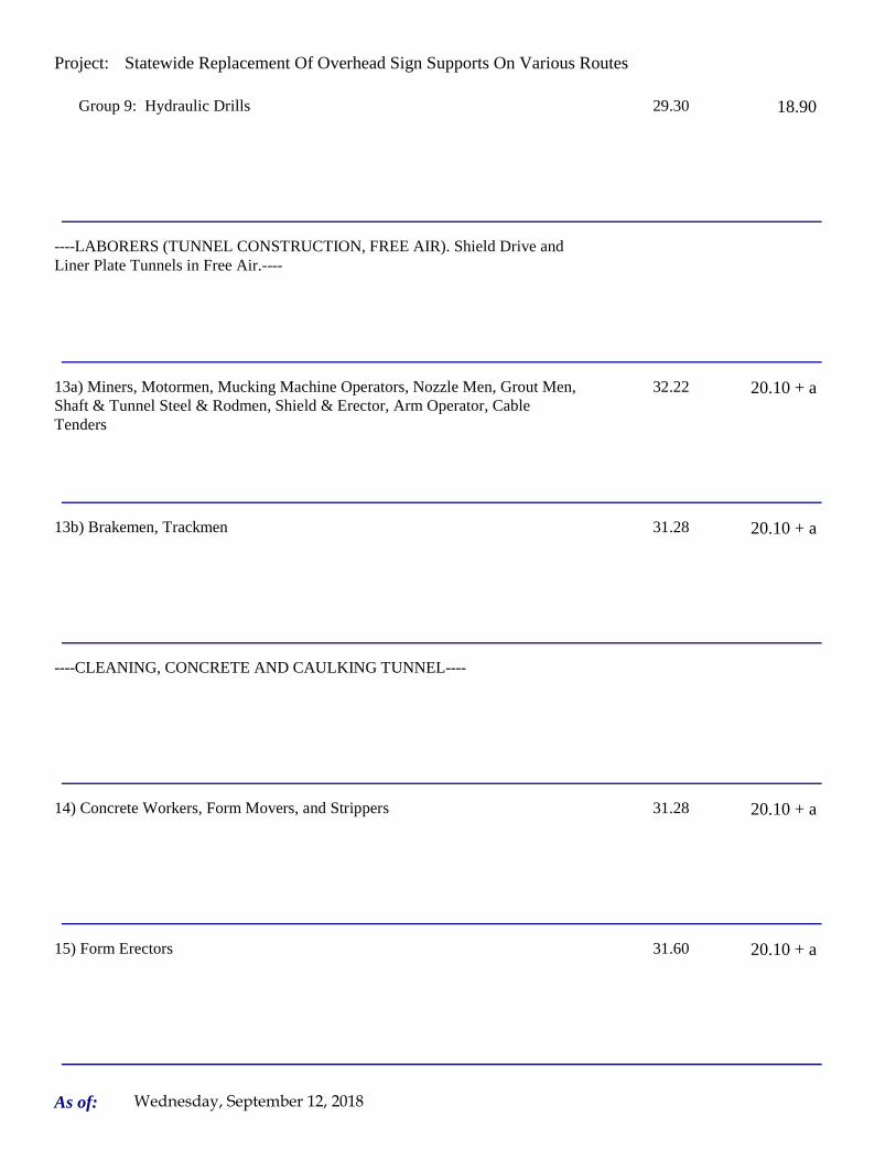
Project: Statewide Replacement Of Overhead Sign Supports On Various Routes
Group 9: Hydraulic Drills 29.30 18.90
----LABORERS (TUNNEL CONSTRUCTION, FREE AIR). Shield Drive and Liner Plate Tunnels in Free Air.----
13a) Miners, Motormen, Mucking Machine Operators, Nozzle Men, Grout Men, Shaft & Tunnel Steel & Rodmen, Shield & Erector, Arm Operator, Cable Tenders
32.22 20.10 + a
13b) Brakemen, Trackmen 31.28 20.10 + a
----CLEANING, CONCRETE AND CAULKING TUNNEL----
14) Concrete Workers, Form Movers, and Strippers 31.28 20.10 + a
15) Form Erectors 31.60 20.10 + a
As of: Wednesday, September 12, 2018

Project: Statewide Replacement Of Overhead Sign Supports On Various Routes
----ROCK SHAFT LINING, CONCRETE, LINING OF SAME AND TUNNEL IN FREE AIR:----
16) Brakemen, Trackmen, Tunnel Laborers, Shaft Laborers 31.28 20.10 + a
17) Laborers Topside, Cage Tenders, Bellman 31.17 20.10 + a
18) Miners 32.22 20.10 + a
----TUNNELS, CAISSON AND CYLINDER WORK IN COMPRESSED AIR: ----
18a) Blaster 38.53 20.10 + a
19) Brakemen, Trackmen, Groutman, Laborers, Outside Lock Tender, Gauge Tenders
38.34 20.10 + a
As of: Wednesday, September 12, 2018

Project: Statewide Replacement Of Overhead Sign Supports On Various Routes
20) Change House Attendants, Powder Watchmen, Top on Iron Bolts 36.41 20.10 + a
21) Mucking Machine Operator 39.11 20.10 + a
----TRUCK DRIVERS----(*see note below)
Two axle trucks 29.13 23.33 + a
Three axle trucks; two axle ready mix 29.23 23.33 + a
Three axle ready mix 29.28 23.33 + a
Four axle trucks, heavy duty trailer (up to 40 tons) 29.33 23.33 + a
As of: Wednesday, September 12, 2018

Project: Statewide Replacement Of Overhead Sign Supports On Various Routes
Four axle ready-mix 29.38 23.33 + a
Heavy duty trailer (40 tons and over) 29.58 23.33 + a
Specialized earth moving equipment other than conventional type on-the road trucks and semi-trailer (including Euclids)
29.38 23.33 + a
----POWER EQUIPMENT OPERATORS----
Group 1: Crane handling or erecting structural steel or stone, hoisting engineer (2 drums or over), front end loader (7 cubic yards or over), Work Boat 26 ft. & Over, Tunnel Boring Machines. (Trade License Required)
39.55 24.05 + a
Group 2: Cranes (100 ton rate capacity and over); Excavator over 2 cubic yards; Piledriver ($3.00 premium when operator controls hammer); Bauer Drill/Caisson. (Trade License Required)
39.23 24.05 + a
Group 3: Excavator/Backhoe under 2 cubic yards; Cranes (under 100 ton rated capacity), Gradall; Master Mechanic; Hoisting Engineer (all types of equipment where a drum and cable are used to hoist or drag material regardless of motive power of operation), Rubber Tire Excavator (Drott-1085 or similar);Grader Operator; Bulldozer Fine Grade (slopes, shaping, laser or GPS, etc.). (Trade License Required)
38.49 24.05 + a
As of: Wednesday, September 12, 2018

Project: Statewide Replacement Of Overhead Sign Supports On Various Routes
Group 4: Trenching Machines; Lighter Derrick; Concrete Finishing Machine; CMI Machine or Similar; Koehring Loader (Skooper)
38.10 24.05 + a
Group 5: Specialty Railroad Equipment; Asphalt Paver; Asphalt Spreader; Asphalt Reclaiming Machine; Line Grinder; Concrete Pumps; Drills with Self Contained Power Units; Boring Machine; Post Hole Digger; Auger; Pounder; Well Digger; Milling Machine (over 24" Mandrell)
37.51 24.05 + a
Group 5 continued: Side Boom; Combination Hoe and Loader; Directional Driller.
37.51 24.05 + a
Group 6: Front End Loader (3 up to 7 cubic yards); Bulldozer (rough grade dozer).
37.20 24.05 + a
Group 7: Asphalt Roller; Concrete Saws and Cutters (ride on types); Vermeer Concrete Cutter; Stump Grinder; Scraper; Snooper; Skidder; Milling Machine (24" and Under Mandrel).
36.86 24.05 + a
Group 8: Mechanic, Grease Truck Operator, Hydroblaster, Barrier Mover, Power Stone Spreader; Welder; Work Boat under 26 ft.; Transfer Machine.
36.46 24.05 + a
Group 9: Front End Loader (under 3 cubic yards), Skid Steer Loader regardless of attachments (Bobcat or Similar); Fork Lift, Power Chipper; Landscape Equipment (including hydroseeder).
36.03 24.05 + a
As of: Wednesday, September 12, 2018

Project: Statewide Replacement Of Overhead Sign Supports On Various Routes
Group 10: Vibratory Hammer, Ice Machine, Diesel and Air Hammer, etc. 33.99 24.05 + a
Group 11: Conveyor, Earth Roller; Power Pavement Breaker (whiphammer), Robot Demolition Equipment.
33.99 24.05 + a
Group 12: Wellpoint Operator. 33.93 24.05 + a
Group 13: Compressor Battery Operator. 33.35 24.05 + a
Group 14: Elevator Operator; Tow Motor Operator (Solid Tire No Rough Terrain).
32.21 24.05 + a
Group 15: Generator Operator; Compressor Operator; Pump Operator; Welding Machine Operator; Heater Operator.
31.80 24.05 + a
Group 16: Maintenance Engineer/Oiler 31.15 24.05 + a
As of: Wednesday, September 12, 2018
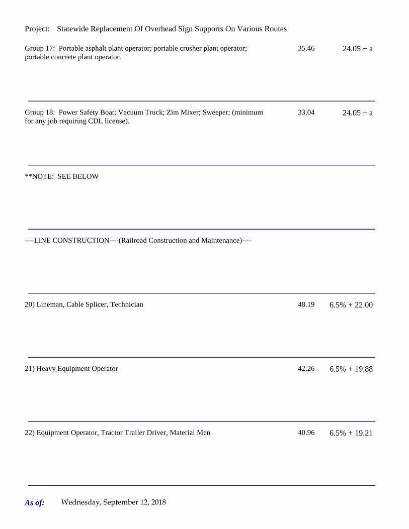
Project: Statewide Replacement Of Overhead Sign Supports On Various Routes
Group 17: Portable asphalt plant operator; portable crusher plant operator; portable concrete plant operator.
35.46 24.05 + a
Group 18: Power Safety Boat; Vacuum Truck; Zim Mixer; Sweeper; (minimum for any job requiring CDL license).
33.04 24.05 + a
**NOTE: SEE BELOW
----LINE CONSTRUCTION----(Railroad Construction and Maintenance)----
20) Lineman, Cable Splicer, Technician 48.19 6.5% + 22.00
21) Heavy Equipment Operator 42.26 6.5% + 19.88
22) Equipment Operator, Tractor Trailer Driver, Material Men 40.96 6.5% + 19.21
As of: Wednesday, September 12, 2018
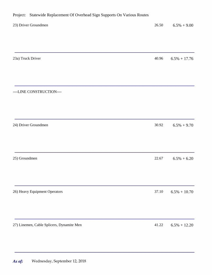
Project: Statewide Replacement Of Overhead Sign Supports On Various Routes
23) Driver Groundmen 26.50 6.5% + 9.00
23a) Truck Driver 40.96 6.5% + 17.76
----LINE CONSTRUCTION----
24) Driver Groundmen 30.92 6.5% + 9.70
25) Groundmen 22.67 6.5% + 6.20
26) Heavy Equipment Operators 37.10 6.5% + 10.70
27) Linemen, Cable Splicers, Dynamite Men 41.22 6.5% + 12.20
As of: Wednesday, September 12, 2018

Project: Statewide Replacement Of Overhead Sign Supports On Various Routes
28) Material Men, Tractor Trailer Drivers, Equipment Operators 35.04 6.5% + 10.45
As of: Wednesday, September 12, 2018

Project: Statewide Replacement Of Overhead Sign Supports On Various Routes
Welders: Rate for craft to which welding is incidental.
*Note: Hazardous waste removal work receives additional $1.25 per hour for truck drivers.
**Note: Hazardous waste premium $3.00 per hour over classified rate
Crane with 150 ft. boom (including jib) - $1.50 extra Crane with 200 ft. boom (including jib) - $2.50 extraCrane with 250 ft. boom (including jib) - $5.00 extraCrane with 300 ft. boom (including jib) - $7.00 extra
All classifications that indicate a percentage of the fringe benefits must be calculated at the percentage rate times the "base hourly rate".
Apprentices duly registered under the Commissioner of Labor's regulations on "Work Training Standards for Apprenticeship and Training Programs" Section 31-51-d-1 to 12, are allowed to be paid the appropriate percentage of the prevailing journeymen hourly base and the full fringe benefit rate, providing the work site ratio shall not be less than one full-time journeyperson instructing and supervising the work of each apprentice in a specific trade.
Each contractor shall pay the annual adjusted prevailing wage rate that is in effect each July 1st, as posted by the Department of Labor.
It is the contractor's responsibility to obtain the annual adjusted prevailing wage rate increases directly from the Department of Labor's website. The annual adjustments will be posted on the Department of Labor's Web page:
www.ct.gov/dol. The Department of Labor will continue to issue the initial prevailing wage rate schedule
to the Contracting Agency for the project.
All subsequent annual adjustments will be posted on our Web Site for contractor access.
The Prevailing wage rates applicable to this project are subject to annual adjustments each July 1st for the duration of the project.
Crane with 400 ft. boom (including jib) - $10.00 extra
~~Connecticut General Statute Section 31-55a: Annual Adjustments to wage rates by contractors doing state work ~~
Contracting Agencies are under no obligation pursuant to State labor law to pay any increase due to the annual adjustment provision.
ALL Cranes: When crane operator is operating equipment that requires a fully licensed crane operator to operate he receives an extra $4.00 premium in addition to the hourly wage rate and benefit contributions:
1) Crane handling or erecting structural steel or stone; hoisting engineer (2 drums or over)
2) Cranes (100 ton rate capacity and over) Bauer Drill/Caisson
3) Cranes (under 100 ton rated capacity)
As of: Wednesday, September 12, 2018

Project: Statewide Replacement Of Overhead Sign Supports On Various Routes
Please direct any questions which you may have pertaining to classification of work and payment of prevailing wages to the Wage and Workplace Standards Division, telephone (860)263-6790.
Effective October 1, 2005 - Public Act 05-50: any person performing the work of any mechanic, laborer, or worker shall be paid prevailing wage
All Person who perform work ON SITE must be paid prevailing wage for the appropriate mechanic, laborer, or worker classification.
All certified payrolls must list the hours worked and wages paid to All Persons who perform work ON SITE regardless of their ownership i.e.: (Owners, Corporate Officers, LLC Members, Independent Contractors, et. al)
Reporting and payment of wages is required regardless of any contractual relationship alleged to exist between the contractor and such person.
~~Unlisted classifications needed for work not included within the scope of the classifications listed may be added after award only as provided in the labor standards contract clause (29 CFR 5.5 (a) (1) (ii)).
As of: Wednesday, September 12, 2018

Project: Statewide Replacement Of Overhead Sign Supports On Various Routes
Project: Statewide Replacement Of Overhead Sign Supports On Various Routes
Project Project Colchester
By virtue of the authority vested in the Labor Commissioner under provisions of Section 31-53 of the General Statutes of Connecticut, as amended, the following are declared to be the prevailing rates and welfare payments and will apply only where the contract is advertised for bid within 20 days of the date on which the rates are established. Any contractor or subcontractor not obligated by agreement to pay to the welfare and pension fund shall pay this amount to each employee as part of his/her hourly wages.
Minimum Rates and Classifications for Heavy/Highway Construction
Connecticut Department of LaborWage and Workplace Standards Division
FAP Number: State Number: 170-3447 & 148-210
Town:
H 25248
Number:
ID#:
Hourly Rate BenefitsCLASSIFICATION
01) Asbestos/Toxic Waste Removal Laborers: Asbestos removal and encapsulation (except its removal from mechanical systems which are not to be scrapped), toxic waste removers, blasters. **See Laborers Group 5 and 7**
1) Boilermaker 33.79 34% + 8.96
1a) Bricklayer, Cement Masons, Cement Finishers, Plasterers, Stone Masons 33.48 31.66
2) Carpenters, Piledrivermen 32.60 25.34
As of: Wednesday, September 12, 2018

Project: Statewide Replacement Of Overhead Sign Supports On Various Routes
2a) Diver Tenders 32.60 25.34
3) Divers 41.06 25.34
03a) Millwrights 33.14 25.74
4) Painters: (Bridge Construction) Brush, Roller, Blasting (Sand, Water, etc.), Spray
49.75 21.05
4a) Painters: Brush and Roller 33.62 21.05
4b) Painters: Spray Only 36.62 21.05
4c) Painters: Steel Only 35.62 21.05
As of: Wednesday, September 12, 2018

Project: Statewide Replacement Of Overhead Sign Supports On Various Routes
4d) Painters: Blast and Spray 36.62 21.05
4e) Painters: Tanks, Tower and Swing 35.62 21.05
5) Electrician (Trade License required: E-1,2 L-5,6 C-5,6 T-1,2 L-1,2 V-1,2,7,8,9)
40.00 25.97+3% of gross wage
6) Ironworkers: Ornamental, Reinforcing, Structural, and Precast Concrete Erection
35.47 35.14 + a
7) Plumbers (Trade License required: (P-1,2,6,7,8,9 J-1,2,3,4 SP-1,2) and Pipefitters (Including HVAC Work) (Trade License required: S-1,2,3,4,5,6,7,8 B-1,2,3,4 D-1,2,3,4 G-1, G-2, G-8, G-9)
42.62 31.21
----LABORERS---- -
8) Group 1: Laborer (Unskilled), Common or General, acetylene burner, concrete specialist
30.05 20.10
As of: Wednesday, September 12, 2018

Project: Statewide Replacement Of Overhead Sign Supports On Various Routes
9) Group 2: Chain saw operators, fence and guard rail erectors, pneumatic tool operators, powdermen
30.30 20.10
10) Group 3: Pipelayers 30.55 20.10
11) Group 4: Jackhammer/Pavement breaker (handheld); mason tenders (cement/concrete), catch basin builders, asphalt rakers, air track operators, block paver, curb setter and forklift operators
30.55 20.10
12) Group 5: Toxic waste removal (non-mechanical systems) 32.05 20.10
13) Group 6: Blasters 31.80 20.10
Group 7: Asbestos/lead removal, non-mechanical systems (does not include leaded joint pipe)
31.05 20.10
Group 8: Traffic control signalmen 16.00 20.10
As of: Wednesday, September 12, 2018

Project: Statewide Replacement Of Overhead Sign Supports On Various Routes
Group 9: Hydraulic Drills 29.30 18.90
----LABORERS (TUNNEL CONSTRUCTION, FREE AIR). Shield Drive and Liner Plate Tunnels in Free Air.----
13a) Miners, Motormen, Mucking Machine Operators, Nozzle Men, Grout Men, Shaft & Tunnel Steel & Rodmen, Shield & Erector, Arm Operator, Cable Tenders
32.22 20.10 + a
13b) Brakemen, Trackmen 31.28 20.10 + a
----CLEANING, CONCRETE AND CAULKING TUNNEL----
14) Concrete Workers, Form Movers, and Strippers 31.28 20.10 + a
15) Form Erectors 31.60 20.10 + a
As of: Wednesday, September 12, 2018

Project: Statewide Replacement Of Overhead Sign Supports On Various Routes
----ROCK SHAFT LINING, CONCRETE, LINING OF SAME AND TUNNEL IN FREE AIR:----
16) Brakemen, Trackmen, Tunnel Laborers, Shaft Laborers 31.28 20.10 + a
17) Laborers Topside, Cage Tenders, Bellman 31.17 20.10 + a
18) Miners 32.22 20.10 + a
----TUNNELS, CAISSON AND CYLINDER WORK IN COMPRESSED AIR: ----
18a) Blaster 38.53 20.10 + a
19) Brakemen, Trackmen, Groutman, Laborers, Outside Lock Tender, Gauge Tenders
38.34 20.10 + a
As of: Wednesday, September 12, 2018

Project: Statewide Replacement Of Overhead Sign Supports On Various Routes
20) Change House Attendants, Powder Watchmen, Top on Iron Bolts 36.41 20.10 + a
21) Mucking Machine Operator 39.11 20.10 + a
----TRUCK DRIVERS----(*see note below)
Two axle trucks 29.13 23.33 + a
Three axle trucks; two axle ready mix 29.23 23.33 + a
Three axle ready mix 29.28 23.33 + a
Four axle trucks, heavy duty trailer (up to 40 tons) 29.33 23.33 + a
As of: Wednesday, September 12, 2018

Project: Statewide Replacement Of Overhead Sign Supports On Various Routes
Four axle ready-mix 29.38 23.33 + a
Heavy duty trailer (40 tons and over) 29.58 23.33 + a
Specialized earth moving equipment other than conventional type on-the road trucks and semi-trailer (including Euclids)
29.38 23.33 + a
----POWER EQUIPMENT OPERATORS----
Group 1: Crane handling or erecting structural steel or stone, hoisting engineer (2 drums or over), front end loader (7 cubic yards or over), Work Boat 26 ft. & Over, Tunnel Boring Machines. (Trade License Required)
39.55 24.05 + a
Group 2: Cranes (100 ton rate capacity and over); Excavator over 2 cubic yards; Piledriver ($3.00 premium when operator controls hammer); Bauer Drill/Caisson. (Trade License Required)
39.23 24.05 + a
Group 3: Excavator/Backhoe under 2 cubic yards; Cranes (under 100 ton rated capacity), Gradall; Master Mechanic; Hoisting Engineer (all types of equipment where a drum and cable are used to hoist or drag material regardless of motive power of operation), Rubber Tire Excavator (Drott-1085 or similar);Grader Operator; Bulldozer Fine Grade (slopes, shaping, laser or GPS, etc.). (Trade License Required)
38.49 24.05 + a
As of: Wednesday, September 12, 2018
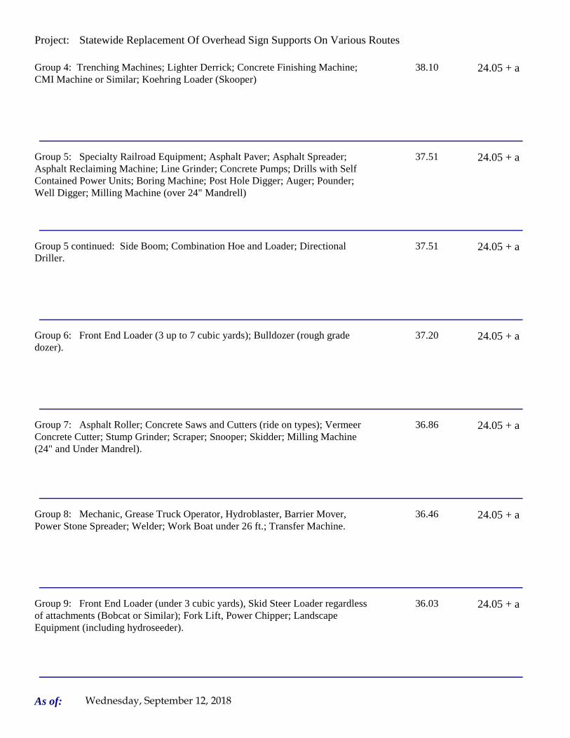
Project: Statewide Replacement Of Overhead Sign Supports On Various Routes
Group 4: Trenching Machines; Lighter Derrick; Concrete Finishing Machine; CMI Machine or Similar; Koehring Loader (Skooper)
38.10 24.05 + a
Group 5: Specialty Railroad Equipment; Asphalt Paver; Asphalt Spreader; Asphalt Reclaiming Machine; Line Grinder; Concrete Pumps; Drills with Self Contained Power Units; Boring Machine; Post Hole Digger; Auger; Pounder; Well Digger; Milling Machine (over 24" Mandrell)
37.51 24.05 + a
Group 5 continued: Side Boom; Combination Hoe and Loader; Directional Driller.
37.51 24.05 + a
Group 6: Front End Loader (3 up to 7 cubic yards); Bulldozer (rough grade dozer).
37.20 24.05 + a
Group 7: Asphalt Roller; Concrete Saws and Cutters (ride on types); Vermeer Concrete Cutter; Stump Grinder; Scraper; Snooper; Skidder; Milling Machine (24" and Under Mandrel).
36.86 24.05 + a
Group 8: Mechanic, Grease Truck Operator, Hydroblaster, Barrier Mover, Power Stone Spreader; Welder; Work Boat under 26 ft.; Transfer Machine.
36.46 24.05 + a
Group 9: Front End Loader (under 3 cubic yards), Skid Steer Loader regardless of attachments (Bobcat or Similar); Fork Lift, Power Chipper; Landscape Equipment (including hydroseeder).
36.03 24.05 + a
As of: Wednesday, September 12, 2018

Project: Statewide Replacement Of Overhead Sign Supports On Various Routes
Group 10: Vibratory Hammer, Ice Machine, Diesel and Air Hammer, etc. 33.99 24.05 + a
Group 11: Conveyor, Earth Roller; Power Pavement Breaker (whiphammer), Robot Demolition Equipment.
33.99 24.05 + a
Group 12: Wellpoint Operator. 33.93 24.05 + a
Group 13: Compressor Battery Operator. 33.35 24.05 + a
Group 14: Elevator Operator; Tow Motor Operator (Solid Tire No Rough Terrain).
32.21 24.05 + a
Group 15: Generator Operator; Compressor Operator; Pump Operator; Welding Machine Operator; Heater Operator.
31.80 24.05 + a
Group 16: Maintenance Engineer/Oiler 31.15 24.05 + a
As of: Wednesday, September 12, 2018

Project: Statewide Replacement Of Overhead Sign Supports On Various Routes
Group 17: Portable asphalt plant operator; portable crusher plant operator; portable concrete plant operator.
35.46 24.05 + a
Group 18: Power Safety Boat; Vacuum Truck; Zim Mixer; Sweeper; (minimum for any job requiring CDL license).
33.04 24.05 + a
**NOTE: SEE BELOW
----LINE CONSTRUCTION----(Railroad Construction and Maintenance)----
20) Lineman, Cable Splicer, Technician 48.19 6.5% + 22.00
21) Heavy Equipment Operator 42.26 6.5% + 19.88
22) Equipment Operator, Tractor Trailer Driver, Material Men 40.96 6.5% + 19.21
As of: Wednesday, September 12, 2018

Project: Statewide Replacement Of Overhead Sign Supports On Various Routes
23) Driver Groundmen 26.50 6.5% + 9.00
23a) Truck Driver 40.96 6.5% + 17.76
----LINE CONSTRUCTION----
24) Driver Groundmen 30.92 6.5% + 9.70
25) Groundmen 22.67 6.5% + 6.20
26) Heavy Equipment Operators 37.10 6.5% + 10.70
27) Linemen, Cable Splicers, Dynamite Men 41.22 6.5% + 12.20
As of: Wednesday, September 12, 2018

Project: Statewide Replacement Of Overhead Sign Supports On Various Routes
28) Material Men, Tractor Trailer Drivers, Equipment Operators 35.04 6.5% + 10.45
As of: Wednesday, September 12, 2018

Project: Statewide Replacement Of Overhead Sign Supports On Various Routes
Welders: Rate for craft to which welding is incidental.
*Note: Hazardous waste removal work receives additional $1.25 per hour for truck drivers.
**Note: Hazardous waste premium $3.00 per hour over classified rate
Crane with 150 ft. boom (including jib) - $1.50 extra Crane with 200 ft. boom (including jib) - $2.50 extraCrane with 250 ft. boom (including jib) - $5.00 extraCrane with 300 ft. boom (including jib) - $7.00 extra
All classifications that indicate a percentage of the fringe benefits must be calculated at the percentage rate times the "base hourly rate".
Apprentices duly registered under the Commissioner of Labor's regulations on "Work Training Standards for Apprenticeship and Training Programs" Section 31-51-d-1 to 12, are allowed to be paid the appropriate percentage of the prevailing journeymen hourly base and the full fringe benefit rate, providing the work site ratio shall not be less than one full-time journeyperson instructing and supervising the work of each apprentice in a specific trade.
Each contractor shall pay the annual adjusted prevailing wage rate that is in effect each July 1st, as posted by the Department of Labor.
It is the contractor's responsibility to obtain the annual adjusted prevailing wage rate increases directly from the Department of Labor's website. The annual adjustments will be posted on the Department of Labor's Web page:
www.ct.gov/dol. The Department of Labor will continue to issue the initial prevailing wage rate schedule
to the Contracting Agency for the project.
All subsequent annual adjustments will be posted on our Web Site for contractor access.
The Prevailing wage rates applicable to this project are subject to annual adjustments each July 1st for the duration of the project.
Crane with 400 ft. boom (including jib) - $10.00 extra
~~Connecticut General Statute Section 31-55a: Annual Adjustments to wage rates by contractors doing state work ~~
Contracting Agencies are under no obligation pursuant to State labor law to pay any increase due to the annual adjustment provision.
ALL Cranes: When crane operator is operating equipment that requires a fully licensed crane operator to operate he receives an extra $4.00 premium in addition to the hourly wage rate and benefit contributions:
1) Crane handling or erecting structural steel or stone; hoisting engineer (2 drums or over)
2) Cranes (100 ton rate capacity and over) Bauer Drill/Caisson
3) Cranes (under 100 ton rated capacity)
As of: Wednesday, September 12, 2018

Project: Statewide Replacement Of Overhead Sign Supports On Various Routes
Please direct any questions which you may have pertaining to classification of work and payment of prevailing wages to the Wage and Workplace Standards Division, telephone (860)263-6790.
Effective October 1, 2005 - Public Act 05-50: any person performing the work of any mechanic, laborer, or worker shall be paid prevailing wage
All Person who perform work ON SITE must be paid prevailing wage for the appropriate mechanic, laborer, or worker classification.
All certified payrolls must list the hours worked and wages paid to All Persons who perform work ON SITE regardless of their ownership i.e.: (Owners, Corporate Officers, LLC Members, Independent Contractors, et. al)
Reporting and payment of wages is required regardless of any contractual relationship alleged to exist between the contractor and such person.
~~Unlisted classifications needed for work not included within the scope of the classifications listed may be added after award only as provided in the labor standards contract clause (29 CFR 5.5 (a) (1) (ii)).
As of: Wednesday, September 12, 2018

Connecticut Department of Labor Wage and Workplace Standards Division
FOOTNOTES
Please Note: If the “Benefits” listed on the schedule for the following occupations includes a letter(s) (+ a or + a+b for instance), refer to the information below.
Benefits to be paid at the appropriate prevailing wage rate for the listed occupation. If the “Benefits” section for the occupation lists only a dollar amount, disregard the information below.
Bricklayers, Cement Masons, Cement Finishers, Concrete Finishers, Stone Masons (Building Construction) and
(Residential- Hartford, Middlesex, New Haven, New London and Tolland Counties)
a. Paid Holiday: Employees shall receive 4 hours for Christmas Eve holiday provided the employee works the regularly scheduled day before and after the holiday. Employers may schedule work on Christmas Eve and employees shall receive pay for actual hours worked in addition to holiday pay.
Elevator Constructors: Mechanics
a. Paid Holidays: New Year’s Day, Memorial Day, Independence Day, Labor Day,
Veterans’ Day, Thanksgiving Day, Christmas Day, plus the Friday after Thanksgiving.
b. Vacation: Employer contributes 8% of basic hourly rate for 5 years or more
of service or 6% of basic hourly rate for 6 months to 5 years of service as vacation pay credit.
Glaziers
a. Paid Holidays: Labor Day and Christmas Day.
Power Equipment Operators (Heavy and Highway Construction & Building Construction)
a. Paid Holidays: New Year’s Day, Good Friday, Memorial day, Independence Day,
Labor Day, Thanksgiving Day and Christmas Day, provided the employee works 3 days during the week in which the holiday falls, if scheduled, and if scheduled, the working day before and the working day after the holiday. Holidays falling on Saturday may be observed on Saturday, or if the employer so elects, on the preceding Friday.
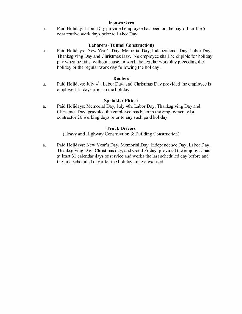
Ironworkers a. Paid Holiday: Labor Day provided employee has been on the payroll for the 5
consecutive work days prior to Labor Day.
Laborers (Tunnel Construction) a. Paid Holidays: New Year’s Day, Memorial Day, Independence Day, Labor Day,
Thanksgiving Day and Christmas Day. No employee shall be eligible for holiday pay when he fails, without cause, to work the regular work day preceding the holiday or the regular work day following the holiday.
Roofers
a. Paid Holidays: July 4th, Labor Day, and Christmas Day provided the employee is employed 15 days prior to the holiday.
Sprinkler Fitters
a. Paid Holidays: Memorial Day, July 4th, Labor Day, Thanksgiving Day and Christmas Day, provided the employee has been in the employment of a contractor 20 working days prior to any such paid holiday.
Truck Drivers
(Heavy and Highway Construction & Building Construction)
a. Paid Holidays: New Year’s Day, Memorial Day, Independence Day, Labor Day, Thanksgiving Day, Christmas day, and Good Friday, provided the employee has at least 31 calendar days of service and works the last scheduled day before and the first scheduled day after the holiday, unless excused.

Information Bulletin Occupational Classifications
The Connecticut Department of Labor has the responsibility to properly
determine "job classification" on prevailing wage projects covered under C.G.S. Section 31-53(d).
Note: This information is intended to provide a sample of some occupational classifications for guidance purposes only. It is not an all-inclusive list of each occupation's duties. This list is being provided only to highlight some areas where a contractor may be unclear regarding the proper classification. If unsure, the employer should seek guidelines for CTDOL.
Below are additional clarifications of specific job duties performed for certain classifications:
ASBESTOS WORKERS Applies all insulating materials, protective coverings, coatings and finishes to all types of mechanical systems.
ASBESTOS INSULATOR
Handle, install apply, fabricate, distribute, prepare, alter, repair, dismantle, heat and frost insulation, including penetration and fire stopping work on all penetration fire stop systems.
BOILERMAKERS
Erects hydro plants, incomplete vessels, steel stacks, storage tanks for water, fuel, etc. Builds incomplete boilers, repairs heat exchanges and steam generators.
BRICKLAYERS, CEMENT MASONS, CEMENT FINISHERS, MARBLE MASONS, PLASTERERS, STONE MASONS, PLASTERERS. STONE MASONS, TERRAZZO WORKERS, TILE SETTERS
Lays building materials such as brick, structural tile and concrete cinder, glass, gypsum, terra cotta block. Cuts, tools and sets marble, sets stone, finishes concrete, applies decorative steel, aluminum and plastic tile, applies cements, sand, pigment and marble chips to floors, stairways, etc.
CARPENTERS, MILLWRIGHTS. PILEDRIVERMEN. LATHERS. RESILEINT FLOOR LAYERS, DOCK BUILDERS, DIKERS, DIVER TENDERS
Constructs, erects, installs and repairs structures and fixtures of wood, plywood and wallboard. Installs, assembles, dismantles, moves industrial machinery. Drives piling into ground to provide foundations for structures such as buildings and bridges, retaining walls for earth embankments, such as cofferdams. Fastens wooden, metal or rockboard lath to walls, ceilings and partitions of buildings, acoustical tile layer, concrete form builder. Applies firestopping materials on fire resistive joint systems only. Installation of curtain/window walls only where attached to wood or metal studs. Installation of insulated material of all types whether blown, nailed or attached in other ways to walls, ceilings and floors of buildings. Assembly and installation of modular furniture/furniture systems. Free-standing furniture is not covered. This includes free standing: student chairs, study top desks, book box desks, computer furniture, dictionary stand, atlas stand, wood shelving, two-position information access station, file cabinets, storage cabinets, tables, etc.
LABORER, CLEANING
• The clean up of any construction debris and the general (heavy/light) cleaning, including sweeping, wash down, mopping, wiping of the construction facility and its furniture, washing, polishing, and dusting.
DELIVERY PERSONNEL
• If delivery of supplies/building materials is to one common point and stockpiled there, prevailing wages are not required. If the delivery personnel are involved in the distribution of the material to multiple locations within the construction site then they would have to be paid prevailing wages for the type of work performed: laborer, equipment operator, electrician, ironworker, plumber, etc.
• An example of this would be where delivery of drywall is made to a building and the delivery personnel distribute the drywall from one "stockpile" location to further sub‐locations on each floor. Distribution of material around a construction site is the job of a laborer or tradesman, and not a delivery personnel.
ELECTRICIANS
Install, erect, maintenance, alteration or repair of any wire, cable, conduit, etc., which generates, transforms, transmits or uses electrical energy for light, heat, power or other purposes, including the Installation or maintenance of telecommunication, LAN wiring or computer equipment, and low voltage wiring. *License required per Connecticut General Statutes: E-1,2 L-5,6 C-5,6 T-1,2 L-1,2 V-1,2,7,8,9.
ELEVATOR CONSTRUCTORS
Install, erect, maintenance and repair of all types of elevators, escalators, dumb waiters and moving walks. *License required by Connecticut General Statutes: R-1,2,5,6.
FORK LIFT OPERATOR
Laborers Group 4) Mason Tenders - operates forklift solely to assist a mason to a maximum height of nine (9) feet only.
Power Equipment Operator Group 9 ‐ operates forklift to assist any trade, and to assist a mason to a height over nine (9) feet.
GLAZIERS
Glazing wood and metal sash, doors, partitions, and 2 story aluminum storefronts. Installs glass windows, skylights, store fronts and display cases or surfaces such as building fronts, interior walls, ceilings and table tops and metal store fronts. Installation of aluminum window walls and curtain walls is the "joint" work of glaziers and ironworkers, which require equal composite workforce.
IRONWORKERS
Erection, installation and placement of structural steel, precast concrete, miscellaneous iron, ornamental iron, metal curtain wall, rigging and reinforcing steel. Handling, sorting, and installation of reinforcing steel (rebar). Metal bridge rail (traffic), metal bridge handrail, and decorative security fence installation. Installation of aluminum window walls and curtain walls is the "joint" work of glaziers and ironworkers which require equal composite workforce.
INSULATOR
• Installing fire stopping systems/materials for "Penetration Firestop Systems": transit to cables, electrical conduits, insulated pipes, sprinkler pipe penetrations, ductwork behind radiation, electrical cable trays, fire rated pipe penetrations, natural polypropylene, HVAC ducts, plumbing bare metal, telephone and communication wires, and boiler room ceilings.
LABORERS
Acetylene burners, asphalt rakers, chain saw operators, concrete and power buggy operator, concrete saw operator, fence and guard rail erector (except metal bridge rail (traffic), decorative security fence (non-metal).
installation.), hand operated concrete vibrator operator, mason tenders, pipelayers (installation of storm drainage or sewage lines on the street only), pneumatic drill operator, pneumatic gas and electric drill operator, powermen and wagon drill operator, air track operator, block paver, curb setters, blasters, concrete spreaders.
PAINTERS
Maintenance, preparation, cleaning, blasting (water and sand, etc.), painting or application of any protective coatings of every description on all bridges and appurtenances of highways, roadways, and railroads. Painting, decorating, hardwood finishing, paper hanging, sign writing, scenic art work and drywall hhg for any and all types of building and residential work.
LEAD PAINT REMOVAL
• Painter’s Rate 1. Removal of lead paint from bridges. 2. Removal of lead paint as preparation of any surface to be repainted. 3. Where removal is on a Demolition project prior to reconstruction.
• Laborer’s Rate 1. Removal of lead paint from any surface NOT to be repainted. 2. Where removal is on a TOTAL Demolition project only.
PLUMBERS AND PIPEFITTERS
Installation, repair, replacement, alteration or maintenance of all plumbing, heating, cooling and piping. *License required per Connecticut General Statutes: P-1,2,6,7,8,9 J-1,2,3,4 SP-1,2 S-1,2,3,4,5,6,7,8 B-1,2,3,4 D-1,2,3,4.
POWER EQUIPMENT OPERATORS
Operates several types of power construction equipment such as compressors, pumps, hoists, derricks, cranes, shovels, tractors, scrapers or motor graders, etc. Repairs and maintains equipment. *License required, crane operators only, per Connecticut General Statutes.
ROOFERS
Covers roofs with composition shingles or sheets, wood shingles, slate or asphalt and gravel to waterproof roofs, including preparation of surface. (demolition or removal of any type of roofing and or clean-up of any and all areas where a roof is to be relaid.)
SHEETMETAL WORKERS
Fabricate, assembles, installs and repairs sheetmetal products and equipment in such areas as ventilation, air-conditioning, warm air heating, restaurant equipment, architectural sheet metal work, sheetmetal roofing, and aluminum gutters. Fabrication, handling, assembling, erecting, altering, repairing, etc. of coated metal material panels and composite metal material panels when used on building exteriors and interiors as soffits, facia, louvers, partitions, canopies, cornice, column covers, awnings, beam covers, cladding, sun shades, lighting troughs, spires, ornamental roofing, metal ceilings, mansards, copings, ornamental and ventilation hoods, vertical and horizontal siding panels, trim, etc. The sheet metal classification also applies to the vast variety of coated metal material panels and composite metal material panels that have evolved over the years as an alternative to conventional ferrous and non-ferrous metals like steel, iron, tin, copper, brass, bronze, aluminum, etc. Fabrication, handling, assembling, erecting, altering, repairing, etc. of architectural metal roof, standing seam roof, composite metal roof, metal and composite bathroom/toilet partitions, aluminum gutters, metal and composite lockers and shelving, kitchen equipment, and walk‐in coolers. To include testing and air –balancing ancillary to installation and construction.
SPRINKLER FITTERS
Installation, alteration, maintenance and repair of fire protection sprinkler systems. *License required per Connecticut General Statutes: F-1,2,3,4.
TILE MARBLE AND TERRAZZO FINISHERS
Assists and tends the tile setter, marble mason and terrazzo worker in the performance of their duties.
TRUCK DRIVERS
~How to pay truck drivers delivering asphalt is under REVISION~
Truck Drivers are requires to be paid prevailing wage for time spent "working" directly on the site. These drivers remain covered by the prevailing wage for any time spent transporting between the actual construction location and facilities (such as fabrication, plants, mobile factories, batch plant, borrow pits, job headquarters, tool yards, etc.) dedicated exclusively, or nearly so, to performance of the contract or project, which are so located in proximity to the actual construction location that it is reasonable to include them. *License required, drivers only, per Connecticut General Statutes.
For example:
• Material men and deliverymen are not covered under prevailing wage as long as they are not directly involved in the construction process. If, they unload the material, they would then be covered by prevailing wage for the classification they are performing work in: laborer, equipment operator, etc. • Hauling material off site is not covered provided they are not dumping it at a location outlined above. • Driving a truck on site and moving equipment or materials on site would be considered covered work, as this is part of the construction process.
Any questions regarding the proper classification should be directed to: Public Contract Compliance Unit
Wage and Workplace Standards Division Connecticut Department of Labor
200 Folly Brook Blvd, Wethersfield, CT 06109 (860) 263-6543.
Sec. 31-55a
Statute 31-55a
Last Updated: June 02, 2008
You are here: DOL Web Site Wage and Workplace Issues Statute 31-55a
- Special Notice -
To All State and Political Subdivisions,Their Agents, and Contractors
Connecticut General Statute 31-55a - Annual adjustments to wage rates by contractors doing state work.
Each contractor that is awarded a contract on or after October 1, 2002, for (1) the construction of a state highway or bridge that falls under the provisions of section 31-54 of the general statutes, or (2) the construction, remodeling, refinishing, refurbishing, rehabilitation, alteration or repair of any public works project that falls under the provisions of section 31-53 of the general statutes shall contact the Labor Commissioner on or before July first of each year, for the duration of such contract, to ascertain the prevailing rate of wages on an hourly basis and the amount of payment or contributions paid or payable on behalf of each mechanic, laborer or worker employed upon the work contracted to be done, and shall make any necessary adjustments to such prevailing rate of wages and such payment or contributions paid or payable on behalf of each such employee, effective each July first.
● The prevailing wage rates applicable to any contract or subcontract awarded on or after October 1, 2002 are subject to annual adjustments each July 1st for the duration of any project which was originally advertised for bids on or after October 1, 2002.
● Each contractor affected by the above requirement shall pay the annual adjusted prevailing wage rate that is in effect each July 1st, as posted by the Department of Labor.
● It is the contractor’s responsibility to obtain the annual adjusted prevailing wage rate increases directly from the Department of Labor’s Web Site. The annual adjustments will be posted on the Department of Labor Web page: www.ctdol.state.ct.us. For those without internet access, please contact the division listed below.
● The Department of Labor will continue to issue the initial prevailing wage rate schedule to the Contracting Agency for the project. All subsequent annual adjustments will be posted on our Web Site for contractor access.
Any questions should be directed to the Contract Compliance Unit, Wage and Workplace
http://www.ctdol.state.ct.us/wgwkstnd/laws-regs/statute31-55a.htm (1 of 2) [6/20/2008 8:00:16 AM]

Sec. 31-55a
Standards Division, Connecticut Department of Labor, 200 Folly Brook Blvd., Wethersfield, CT 06109 at (860)263-6790.
Workplace Laws
Published by the Connecticut Department of Labor, Project Management Office
http://www.ctdol.state.ct.us/wgwkstnd/laws-regs/statute31-55a.htm (2 of 2) [6/20/2008 8:00:16 AM]

November 29, 2006
NoticeTo All Mason Contractors and Interested Parties
Regarding Construction Pursuant to Section 31-53 of theConnecticut General Statutes (Prevailing Wage)
The Connecticut Labor Department Wage and Workplace Standards Division is empowered toenforce the prevailing wage rates on projects covered by the above referenced statute.
Over the past few years the Division has withheld enforcement of the rate in effect for workerswho operate a forklift on a prevailing wage rate project due to a potential jurisdictional dispute.
The rate listed in the schedules and in our Occupational Bulletin (see enclosed) has been asfollows:
Forklift Operator:
- Laborers (Group 4) Mason Tenders - operates forklift solely to assist a mason to a maximumheight of nine feet only.
- Power Equipment Operator (Group 9) - operates forklift to assist any trade and to assist amason to a height over nine feet.
The U.S. Labor Department conducted a survey of rates in Connecticut but it has not beenpublished and the rate in effect remains as outlined in the above Occupational Bulletin.
Since this is a classification matter and not one of jurisdiction, effective January 1,2007 the Connecticut Labor Department will enforce the rate on each schedule inaccordance with our statutory authority.
Your cooperation in filing appropriate and accurate certified payrolls is appreciated.
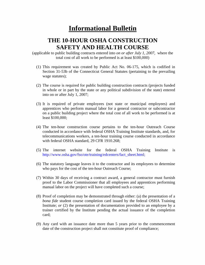
Informational Bulletin
THE 10-HOUR OSHA CONSTRUCTION SAFETY AND HEALTH COURSE
(applicable to public building contracts entered into on or after July 1, 2007, where the total cost of all work to be performed is at least $100,000)
(1) This requirement was created by Public Act No. 06-175, which is codified in
Section 31-53b of the Connecticut General Statutes (pertaining to the prevailing wage statutes);
(2) The course is required for public building construction contracts (projects funded
in whole or in part by the state or any political subdivision of the state) entered into on or after July 1, 2007;
(3) It is required of private employees (not state or municipal employees) and
apprentices who perform manual labor for a general contractor or subcontractor on a public building project where the total cost of all work to be performed is at least $100,000;
(4) The ten-hour construction course pertains to the ten-hour Outreach Course
conducted in accordance with federal OSHA Training Institute standards, and, for telecommunications workers, a ten-hour training course conducted in accordance with federal OSHA standard, 29 CFR 1910.268;
(5) The internet website for the federal OSHA Training Institute is
http://www.osha.gov/fso/ote/training/edcenters/fact_sheet.html;
(6) The statutory language leaves it to the contractor and its employees to determine who pays for the cost of the ten-hour Outreach Course;
(7) Within 30 days of receiving a contract award, a general contractor must furnish
proof to the Labor Commissioner that all employees and apprentices performing manual labor on the project will have completed such a course;
(8) Proof of completion may be demonstrated through either: (a) the presentation of a
bona fide student course completion card issued by the federal OSHA Training Institute; or (2) the presentation of documentation provided to an employee by a trainer certified by the Institute pending the actual issuance of the completion card;
(9) Any card with an issuance date more than 5 years prior to the commencement
date of the construction project shall not constitute proof of compliance;
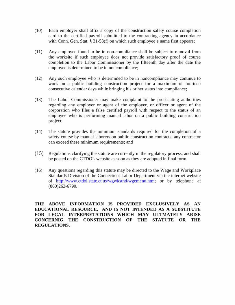
(10) Each employer shall affix a copy of the construction safety course completion card to the certified payroll submitted to the contracting agency in accordance with Conn. Gen. Stat. § 31-53(f) on which such employee’s name first appears;
(11) Any employee found to be in non-compliance shall be subject to removal from
the worksite if such employee does not provide satisfactory proof of course completion to the Labor Commissioner by the fifteenth day after the date the employee is determined to be in noncompliance;
(12) Any such employee who is determined to be in noncompliance may continue to
work on a public building construction project for a maximum of fourteen consecutive calendar days while bringing his or her status into compliance;
(13) The Labor Commissioner may make complaint to the prosecuting authorities
regarding any employer or agent of the employer, or officer or agent of the corporation who files a false certified payroll with respect to the status of an employee who is performing manual labor on a public building construction project;
(14) The statute provides the minimum standards required for the completion of a
safety course by manual laborers on public construction contracts; any contractor can exceed these minimum requirements; and
(15) Regulations clarifying the statute are currently in the regulatory process, and shall
be posted on the CTDOL website as soon as they are adopted in final form. (16) Any questions regarding this statute may be directed to the Wage and Workplace
Standards Division of the Connecticut Labor Department via the internet website of http://www.ctdol.state.ct.us/wgwkstnd/wgemenu.htm; or by telephone at (860)263-6790.
THE ABOVE INFORMATION IS PROVIDED EXCLUSIVELY AS AN EDUCATIONAL RESOURCE, AND IS NOT INTENDED AS A SUBSTITUTE FOR LEGAL INTERPRETATIONS WHICH MAY ULTMATELY ARISE CONCERNIG THE CONSTRUCTION OF THE STATUTE OR THE REGULATIONS.

Sec. 31-53b. Construction safety and health course. Proof of completion required for employees on public building projects. Enforcement. Regulations. (a) Each contract entered into on or after July 1, 2007, for the construction, remodeling, refinishing, refurbishing, rehabilitation, alteration or repair of any public building project by the state or any of its agents, or by an political subdivision of the state or any of its agents, where the total cost of all work to be performed by all contractors and subcontractors in connection with the contract is at least one hundred thousand dollars, shall contain a provision requiring that, not later than thirty days after the date such contract is awarded, each contractor furnish proof to the Labor Commissioner that all employees performing manual labor on or in such public building, pursuant to such contract, have completed a course of at least ten hours in duration in construction safety and health approved by the federal Occupational Safety and Health Administration or, in the case of telecommunications employees, have completed at least ten hours of training in accordance with 29 CFR 1910.268. (b) Any employee required to complete a construction safety and health course required under subsection (a) of this section who has not completed the course shall be subject to removal from the worksite if the employee does not provide documentation of having completed such course by the fifteenth day after the date the employee is found to be in noncompliance. The Labor Commissioner or said commissioner’s designee shall enforce this section. (c) Not later than January 1, 2007, the Labor Commissioner shall adopt regulations, in accordance with the provisions of chapter 54, to implement the provisions of subsections (a) and (b) of this section. Such regulations shall require that the ten-hour construction safety and health courses required under subsection (a) of this section be conducted in accordance with federal Occupational Safety and Health Administration Training Institute standards, or in accordance with 29 CFR 1910.268, as appropriate. The Labor Commissioner shall accept as sufficient proof of compliance with the provisions of subsection (a) or (b) of this section a student course completion card issued by the federal Occupational Safety and Health Administration Training Institute, or such other proof of compliance said commissioner deems appropriate, dated no earlier than five years before the commencement date of such public works project. (d) For the purposes of this section, “public building” means a structure, paid for in whole or in part with state funds, within a roof and within exterior walls or fire walls, designed for the housing, shelter, enclosure and support or employment of people, animals or property of any kind, including, but not limited to, sewage treatment plants and water treatment plants, “Public building” does not include site work, roads or bridges, rail lines, parking lots or underground water, sewer or drainage systems including pump houses or other utility systems.
CONNECTICUT DEPARTMENT OF LABOR WAGE AND WORKPLACE STANDARDS DIVISION
CONTRACTORS WAGE CERTIFICATION FORM
I, of Officer, Owner, Authorized Rep. Company Name
do hereby certify that the Company Name Street City and all of its subcontractors will pay all workers on the
Project Name and Number
Street and City
the wages as listed in the schedule of prevailing rates required for such project (a copy of which isattached hereto).
Signed
Subscribed and sworn to before me this day of , 2004.
Notary Public
L Return to: Connecticut Department of Labor
Wage & Workplace Standards Division 200 Folly Brook Blvd.
Wethersfield, CT 06109