synthesis of bulk feal nanostructured materials by hvof spray forming and spark plasma sintering
TRANSCRIPT
Intermetallics 14 (2006) 1208e1213www.elsevier.com/locate/intermet
Synthesis of bulk FeAl nanostructured materials by HVOFspray forming and Spark Plasma Sintering
Thierry Grosdidier a,*, Gang Ji a,b,c, Frederic Bernard c, Eric Gaffet d,Zuhair A. Munir e, Sebastien Launois f
a Laboratoire d’Etude des Textures et Application aux Materiaux (LETAM), UMR CNRS 7078, Universite de Metz,
Ile du Saulcy, 57045 Metz Cedex 01, Franceb Laboratoire d’Etude et Recherche en Materiaux, Plasmas et Surfaces (LERMPS), Universite de Technologie de Belfort-Montbeliard,
90010 Belfort Cedex, Francec Laboratoire de Recherche sur la Reactivite des Solides (LRRS), UMR CNRS 5613, Universite de Bourgogne, 9 avenue Alain Savary,
21078 Dijon Cedex, Franced Nanomaterials Research Group, UMR CNRS 5060, Universite de Technologie de Belfort-Montbeliard, 90010 Belfort Cedex, France
e Department of Chemical Engineering and Materials Science, University of California, Davis, CA 95616, USAf Departement de Technologie pour l’Energie et les Nanomateriaux, Commissariat a l’Energie Atomique, 17 rue des Martyrs,
38054 Grenoble, France
Received 15 September 2005; received in revised form 2 November 2005; accepted 8 November 2005
Available online 4 April 2006
Abstract
This paper examines the efficiency of two consolidation processing techniques: High Velocity Oxy-Fuel (HVOF) spray forming and SparkPlasma Sintering (SPS) to obtain bulk nanostructured materials from an Y2O3 reinforced Fee40Al (at.%) milled powder. The microstructures ofthe sintered end-products were characterized by Scanning Electron Microscopy (SEM) and Transmission Electron Microscopy (TEM) in order togain new insights in their microstructure formation mechanisms. HVOF spray forming is more effective to retain fine nanograins, in particularwithin retained unmelted powder particles. The drawbacks of this technique are that it inevitably leads to a high fraction of porosity and, becauseof lack of wetting, large areas (the melted zones) without any Y2O3 oxide. Comparatively, SPS has a much higher potential to create sub-micrometer microstructures within which the oxides are more homogeneously distributed.� 2006 Elsevier Ltd. All rights reserved.
Keywords: A. Iron aluminides based on FeAl; A. Nanostructured intermetallics; C. Plasma spraying; D. Microstructure; F. Electron microscopy, transmission
1. Introduction
FeAl intermetallic alloys are attractive materials for indus-trial applications at medium to high temperatures because theycombine good mechanical properties, low density, low costand availability of raw materials and excellent corrosion and ox-idation resistances [1e3]. However, their use has been limitedby their brittleness at room temperature and poor creep resis-tance. These drawbacks can be improved by grain boundary
* Corresponding author. Tel.: þ33 3 87 54 71 30; fax: þ33 3 87 31 53 77.
E-mail address: [email protected] (T. Grosdidier).
0966-9795/$ - see front matter � 2006 Elsevier Ltd. All rights reserved.
doi:10.1016/j.intermet.2005.11.033
and oxide dispersion strengthenings as well as grain sizereduction [4e6]. Taking all these factors into account, a Y2O3
strengthened Fee40Al (at.%)eZreB powder was designed byCEA (Commissariat a l’Energie Atomique) for consolidationvia extrusion or forging [7,8]. This powder is prepared by gas at-omization and subsequent ball milling during which the Y2O3
phase is introduced [4,7]. The standard consolidation techniquesusually result in materials having a grain size of the order of mi-crometers or slightly above [7e9]. The oxide particles are gen-erally several tens of nanometers and fairly well distributedthroughout the material. Using this milled powder as a precursor,two other consolidation processing techniques are being testedto synthesize bulk components with the goal of reaching even
1209T. Grosdidier et al. / Intermetallics 14 (2006) 1208e1213
finer grain sizes: the High Velocity Oxy-Fuel (HVOF) thermalspray technique and Spark Plasma Sintering (SPS).
Thermal spraying is a process in which a fine powder is car-ried in a gas stream and passed through an intense combustionflame, where it becomes molten. The gas stream, expandingrapidly because of the heating, then sprays the molten powderonto the substrate where it solidifies. A deposit thereforebuilds up by the successive impact of individual powder parti-cles. The resulting microstructure depends on the nature of thestarting feedstock of powder particles, on their interaction withthe flame in transit and, finally, on the interaction of each par-ticle with the substrate to form the individual splats that are the‘‘building blocks’’ of the deposit. HVOF thermal spraying ofmilled powder has already been successfully used for produc-ing metallic nanostructured coatings, for example Ni-based al-loys [10], Inconel 718 [11] or FeAl [12]. In addition, due to itshigh deposition rate, the technique has also been used to fab-ricate near net-shaped bulk nanostructured materials [13].
Spark Plasma Sintering has received increasing attention[14]. SPS shows similarities with conventional hot pressingin that the precursor is loaded in a die (typically made ofgraphite) and a uniaxial pressure is applied during synthesis.However, instead of using an external heating source, a pulseddirect current (DC) is allowed to pass through the sample andalso through the electrically conducting pressure die. Conse-quently, SPS is claimed to use microscopic electric dischargesbetween the particles under pressure [15] and to reduce signif-icantly the synthesis and densification temperatures, limitingthereby the grain growth. The combination of mechanical ac-tivation of the powder with the SPS technique, often referredto as the MASPS process, has also been shown to be suitablefor the production of materials having nanostructure and a con-trolled consolidation level [16]. It was proved to produce, frommilled powders, bulk nanostructured Fe3AleC [17] and(Alþ 12.5 at.% Cu)3Zr [18] intermetallics that showed supe-rior mechanical properties.
The aim of this paper is to give our first results concerningthe comparison of the microstructure of bulk nanostructuredmaterials obtained from milled oxide dispersion strengthened(ODS) Fee40Al (at.%) powder using the HVOF and SPStechniques.
2. Experimental
The feedstock milled powder was produced by CEA-DTEN(Departement de Technologie pour l’Energie et les Nanomater-iaux). Its nominal composition was Fee39.78Ale0.054Zre0.01Be0.2Y2O3 (mol%). Small amounts of Zr and B wereadded for fixing carbon impurities and improving grain bound-ary strength [5]. In addition, Y2O3 was introduced at the mill-ing stage to create a fine yttria dispersion in the consolidatedproducts [4,19,20]. This milled powder, which has a crystallitesize of about 20 nm [12,21], was then used for the synthesis ofbulk materials using the two different techniques.
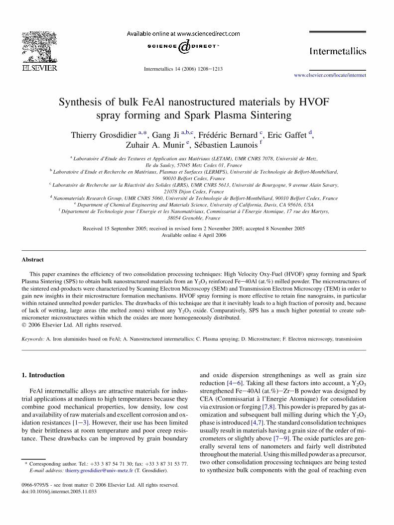
Fig. 1(a,b) shows the sketches of the HVOF spray formingand SPS experimental set-ups, respectively. A Plasma-TechnikCDS HVOF console and a CDS 100 torch were used to spray
form the sieved milled powder. A copper tube, cooled byinternal water circulation, was used as a substrate to deposita 5 mm thick deposit (see inset photo in Fig. 1(a)). TheHVOF flame was selected to guarantee a relatively lowtemperature and high velocity in order to retain unmeltednanostructured powder particles. The exact experimental con-ditions were detailed elsewhere [13]. A 1050 SPS apparatus,manufactured by the Sumitomo Coal and Mining Company[14], was used for the SPS sintering at the University ofCalifornia-Davis. This machine consists of a uniaxial 100 kNpress combined with a 15 V, 5000 A pulsed DC power supply.The pulse cycle used in this work consisted of 12 pulses onand 2 off. This means that there were 12 pulses of 3.2 mseach followed by a 6.4 ms (2 times 3.2 ms) off. An uniaxialload of 70 MPa was applied during the whole heating andcooling stages. The examples of microstructures shown herewere prepared either (i) within a ‘‘low temperature’’ regime rangewhere significant porosity was still present in the consolidatedproduct or (ii) at, comparatively, higher temperatures forwhich the consolidation regime provided fully dense products.An example of end-product is shown in the inset of Fig. 1(b).It has dimensions 18.8 mm in diameter and 5 mm in height.
The samples were investigated by Scanning ElectronMicroscopy (SEM) as well as by Transmission Electron Mi-croscopy (TEM) at the University of Metz with the goals of(i) asserting the presence of nanograins in the end-products
Fig. 1. Sketches of (a) the HVOF spray forming and (b) the SPS sintering ex-
perimental set-ups; insets are photos corresponding to the processed samples.
1210 T. Grosdidier et al. / Intermetallics 14 (2006) 1208e1213
and (ii) depicting interesting fine scale features in the consol-idated structures. SEM was done using a Jeol 6500F fieldemission gun microscope. TEM examinations were carriedout using a Philips CM200 microscope operating at 200 kV.The chemical compositions were determined in the TEM us-ing a PGT Spirit energy dispersive X-ray (EDX) spectrometrysystem. The analyses were carried out without the use of stan-dards for neither the determination of the CliffeLorimer fac-tors nor the measurements of local thin foil thicknesses. Theresults are therefore considered semi-quantitatively. All EDXspectra were displayed by plotting the intensity square rootas a function of the energy in order to reveal low intensitypeaks. This representation mode allows a better visibility ofsmall peaks. However, it has the drawback of enhancing theartifact peaks such as Cr-Ka from the microscope pole piece,Fe-escape and sum peaks related to high intensity peaks,Mo-Ka and Mo-L peaks stemming from ion-milling inducedcontamination and mineral contaminants (S, Cl,.). In addi-tion, the presence of the C and Cu peaks in the spectra is as-sociated with contaminations from the electron beam and thecopper sample holder, respectively. All these artifact peaksare indicated by stars in the EDX spectra given in this paper.
3. Results
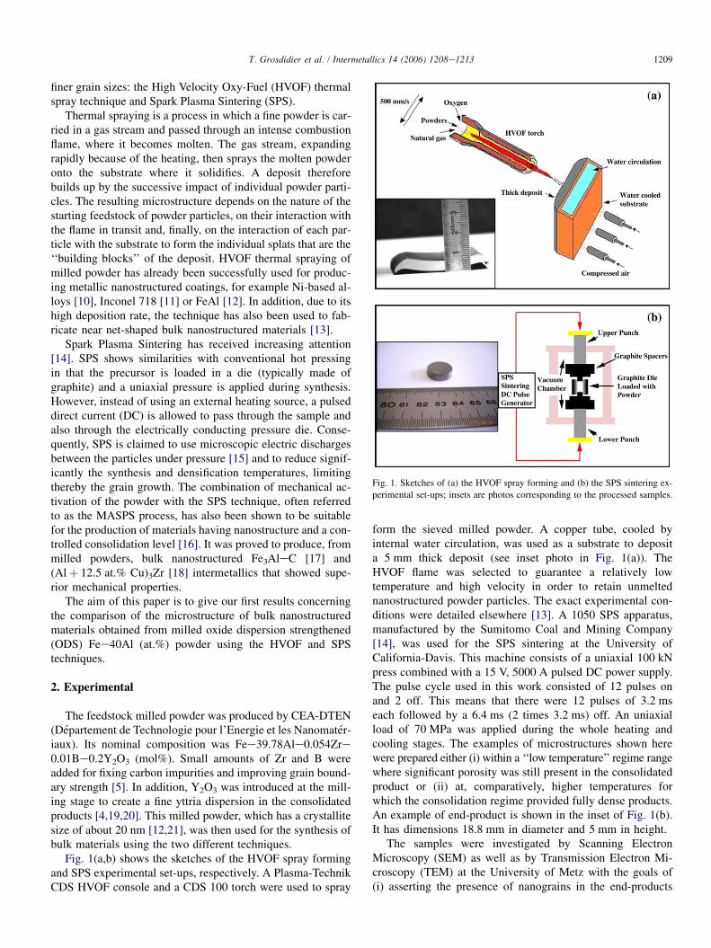
Fig. 2 gives typical examples of the main characteristics ofthe deposits obtained by the HVOF technique. The HVOFspray formed material displayed typical microstructural fea-tures that were very similar to those observed in the HVOFnanostructured thin coatings [21]. They consisted of unmeltedpowder particles, melted and flattened particles (i.e. splats)and porosity [12,13,21]. Fig. 2(a) is an SEM image of sucha structure. Contamination oxides, due to oxidation of thepowder particles during their transit in the flame as well as af-ter a subsequent passage of the spraying torch, are present atintersplat boundaries. A significant amount of porosity (about10%) is also retained in the deposit because of poor flatteningat the employed spraying conditions of the droplets under im-pact condition on the chilled surface [12,13]. TEM investiga-tion showed that a nanograin zone was retained in the core ofthe unmelted powder particles [13]. The grain size was in therange from 30 to 90 nm. The grains, embedded in a still de-formed matrix, resulted from a partial recrystallization of theoriginal deformed structure from the milled powder [13,21].The structure in the fully melted splats mainly consisted of
Al-Kα
Fe-Kα
Fe-Kβ
Cu-Kα*
Cr-Kα*
Mo-Kα*
Cu-Kβ*
0 5 10
Energy (keV)15 20
Fe-esc*
C-K*
Fe-L
Inte
nsity
squ
are
root
(a.
u.)
(c)
Fig. 2. (a) Backscattered electron SEM micrograph showing the details of the HVOF spray formed deposit, (b) TEM bright-field micrograph showing a columnar
grain zone in the fully melted splats and (c) EDX spectrum recorded in one of the columnar grains.
1211T. Grosdidier et al. / Intermetallics 14 (2006) 1208e1213
sub-micrometer columnar grains [13]. They resulted froma rapid directional growth due to the intense heat extractionby heat conduction between the splats and the substrate (orthe already deposited coating). An example of this type of co-lumnar structure is shown in the TEM bright-field micrographof Fig. 2(b). An interesting point revealed by the EDX analysisin the TEM was the fact that there was no yttrium left in themelted zones of the coatings. This is illustrated by the EDXspectra given in Fig. 2(c). Due to a lack of miscibility, yttriumwas washed away from the melt and became trapped in theamorphous Al2O3-based oxide present at intersplat boundarieswhere it substituted Al [22].
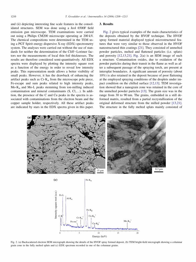
Fig. 3 shows two examples of SEM micrographs of the prod-ucts consolidated using the SPS technique. The first SEM mi-crograph (Fig. 3(a)) was taken from a sample consolidated inthe low temperature regime and a significant amount of porosityis clearly visible. Interestingly, the initial powder particles areclearly depicted in this image as they are all surrounded bya thin oxide layer that shows up with a very bright contrast.This oxide film must have been formed during the consolidationprocess by reacting with trapped gas under heating by the actionof the applied current. Comparatively, when the processing isdone in the high temperature regime that does not lead to
Fig. 3. Backscattered electron SEM micrographs of SPS samples consolidated
(a) in the low temperature and (b) high temperature regimes.
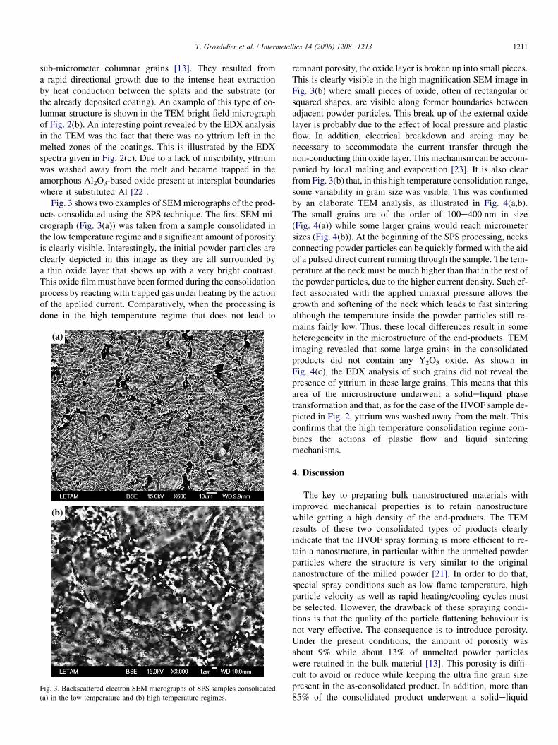
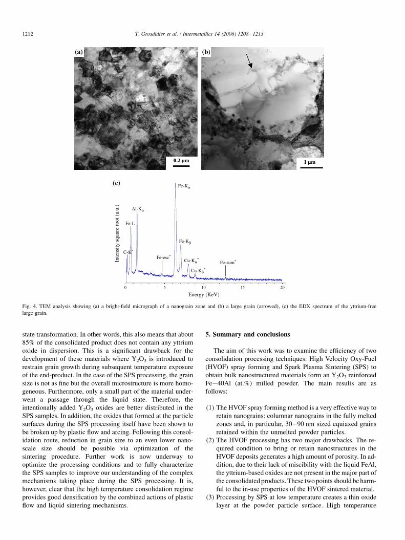
remnant porosity, the oxide layer is broken up into small pieces.This is clearly visible in the high magnification SEM image inFig. 3(b) where small pieces of oxide, often of rectangular orsquared shapes, are visible along former boundaries betweenadjacent powder particles. This break up of the external oxidelayer is probably due to the effect of local pressure and plasticflow. In addition, electrical breakdown and arcing may benecessary to accommodate the current transfer through thenon-conducting thin oxide layer. This mechanism can be accom-panied by local melting and evaporation [23]. It is also clearfrom Fig. 3(b) that, in this high temperature consolidation range,some variability in grain size was visible. This was confirmedby an elaborate TEM analysis, as illustrated in Fig. 4(a,b).The small grains are of the order of 100e400 nm in size(Fig. 4(a)) while some larger grains would reach micrometersizes (Fig. 4(b)). At the beginning of the SPS processing, necksconnecting powder particles can be quickly formed with the aidof a pulsed direct current running through the sample. The tem-perature at the neck must be much higher than that in the rest ofthe powder particles, due to the higher current density. Such ef-fect associated with the applied uniaxial pressure allows thegrowth and softening of the neck which leads to fast sinteringalthough the temperature inside the powder particles still re-mains fairly low. Thus, these local differences result in someheterogeneity in the microstructure of the end-products. TEMimaging revealed that some large grains in the consolidatedproducts did not contain any Y2O3 oxide. As shown inFig. 4(c), the EDX analysis of such grains did not reveal thepresence of yttrium in these large grains. This means that thisarea of the microstructure underwent a solideliquid phasetransformation and that, as for the case of the HVOF sample de-picted in Fig. 2, yttrium was washed away from the melt. Thisconfirms that the high temperature consolidation regime com-bines the actions of plastic flow and liquid sinteringmechanisms.
4. Discussion
The key to preparing bulk nanostructured materials withimproved mechanical properties is to retain nanostructurewhile getting a high density of the end-products. The TEMresults of these two consolidated types of products clearlyindicate that the HVOF spray forming is more efficient to re-tain a nanostructure, in particular within the unmelted powderparticles where the structure is very similar to the originalnanostructure of the milled powder [21]. In order to do that,special spray conditions such as low flame temperature, highparticle velocity as well as rapid heating/cooling cycles mustbe selected. However, the drawback of these spraying condi-tions is that the quality of the particle flattening behaviour isnot very effective. The consequence is to introduce porosity.Under the present conditions, the amount of porosity wasabout 9% while about 13% of unmelted powder particleswere retained in the bulk material [13]. This porosity is diffi-cult to avoid or reduce while keeping the ultra fine grain sizepresent in the as-consolidated product. In addition, more than85% of the consolidated product underwent a solideliquid
1212 T. Grosdidier et al. / Intermetallics 14 (2006) 1208e1213
Al-Kα
Fe-Kα
Fe-Kβ
Cu-Kα*
Cu-Kβ*
Fe-esc*
0 5 10 15 20
C-K*
Fe-sum*
Fe-L
Inte
nsity
squ
are
root
(a.
u.)
(c)
Energy (KeV)
Fig. 4. TEM analysis showing (a) a bright-field micrograph of a nanograin zone and (b) a large grain (arrowed), (c) the EDX spectrum of the yttrium-free
large grain.
state transformation. In other words, this also means that about85% of the consolidated product does not contain any yttriumoxide in dispersion. This is a significant drawback for thedevelopment of these materials where Y2O3 is introduced torestrain grain growth during subsequent temperature exposureof the end-product. In the case of the SPS processing, the grainsize is not as fine but the overall microstructure is more homo-geneous. Furthermore, only a small part of the material under-went a passage through the liquid state. Therefore, theintentionally added Y2O3 oxides are better distributed in theSPS samples. In addition, the oxides that formed at the particlesurfaces during the SPS processing itself have been shown tobe broken up by plastic flow and arcing. Following this consol-idation route, reduction in grain size to an even lower nano-scale size should be possible via optimization of thesintering procedure. Further work is now underway tooptimize the processing conditions and to fully characterizethe SPS samples to improve our understanding of the complexmechanisms taking place during the SPS processing. It is,however, clear that the high temperature consolidation regimeprovides good densification by the combined actions of plasticflow and liquid sintering mechanisms.
5. Summary and conclusions
The aim of this work was to examine the efficiency of twoconsolidation processing techniques: High Velocity Oxy-Fuel(HVOF) spray forming and Spark Plasma Sintering (SPS) toobtain bulk nanostructured materials form an Y2O3 reinforcedFee40Al (at.%) milled powder. The main results are asfollows:
(1) The HVOF spray forming method is a very effective way toretain nanograins: columnar nanograins in the fully meltedzones and, in particular, 30e90 nm sized equiaxed grainsretained within the unmelted powder particles.
(2) The HVOF processing has two major drawbacks. The re-quired condition to bring or retain nanostructures in theHVOF deposits generates a high amount of porosity. In ad-dition, due to their lack of miscibility with the liquid FeAl,the yttrium-based oxides are not present in the major part ofthe consolidated products. These two points should be harm-ful to the in-use properties of the HVOF sintered material.
(3) Processing by SPS at low temperature creates a thin oxidelayer at the powder particle surface. High temperature
1213T. Grosdidier et al. / Intermetallics 14 (2006) 1208e1213
processing causes a break up of this thin oxide layer byplastic deformation and arcing.
(4) A good densification can be obtained by SPS through thecombined mechanisms of plastic flow and local liquidsintering.
(5) Because a major part of the material remains in the solidstate, SPS has a much higher potential to create sub-micrometer microstructures within which the oxides aremore homogeneously distributed.
Acknowledgements
This work has partially been funded under a project of theministere francais de la recherche (convention n � 03K558).T.G. wishes to thank Prof. C. Coddet (LERMPS) for the pro-vision of the thermal spray facilities and Prof. H.L. Liao(LERMPS) for his help with the HVOF processing.
References
[1] Deevi SC, Sikka VK. Intermetallics 1996;4:357.
[2] Baker I, Munroe PR. Int Mater Rev 1997;42:181.
[3] Stoloff NS. Mater Sci Eng 1998;A258:1.
[4] Morris DG, Gunther S. Mater Sci Eng 1996;A208:7.
[5] Baccino R, Wolski K, Thevenot F, Lecoze J, Moret F. Ann Chim Sci Mat
1997;22:423.
[6] Schneibel JH, George EP, Anderson IM. Intermetallics 1997;5:185.
[7] Moret F, Baccino R, Martel P, Guetaz L. J Phys IV 1996;6:281.
[8] Revol S, Launois S, Baccino R, Sire P, Girard Y, Mao C, et al. In:
Proceedings of PM conference EURO PM2001, European conference
on powder metallurgy. Nice, France: European powder metallurgy asso-
ciation; October 2001. p. 22.
[9] Munoz-Morris MA, Garcia Oca C, Morris DG. Acta Mater 2003;51:
5187.
[10] Jiang HG, Lau ML, Lavernia EJ. Nanostruct Mater 1998;10:169.
[11] Tellkamp VL, Lau ML, Fabel A, Lavernia EJ. Nanostruct Mater
1997;9:489.
[12] Grosdidier T, Tidu A, Liao HL. Scripta Mater 2001;44:387.
[13] Ji G, Grosdidier T, Liao HL, Morniroli JP, Coddet C. Intermetallics
2005;13:596.
[14] Tokita M. J Soc Powder Technol Jpn 1993;30:790.
[15] Omori M. Mater Sci Eng 2000;A287:183.
[16] Munir ZA, Woolman JN, Petrovic JJ. US Patent no. 6,613,276;
September 2, 2003.
[17] Minamino Y, Koizumi Y, Tsuji N, Hirohata N, Mizuuchi K, Ohkanda Y.
Sci Technol Adv Mater 2004;5:133.
[18] Lee SH, Moon KI, Hong HS, Lee KS. Intermetallics 2003;11:1039.
[19] Morris DG, Gunther S, Briguet C. Scripta Metall Mater 1997;37:71.
[20] Grosdidier T, Suzon E, Wagner F. Intermetallics 2004;12:645.
[21] Ji G, Morniroli JP, Grosdidier T. Scripta Mater 2003;18:1599.
[22] Grosdidier T, Ji G, Bozzolo N. Intermetallics, in press.
[23] Groza JR, Zavaliangos A. Mater Sci Eng 2000;A287:171.