synthesis and characterization of polydiene-grafted
TRANSCRIPT

University of South Carolina University of South Carolina
Scholar Commons Scholar Commons
Theses and Dissertations
2018
Synthesis And Characterization Of Polydiene-Grafted Synthesis And Characterization Of Polydiene-Grafted
Nanoparticles Nanoparticles
Zaid Mohammed Abbas Alajeeli University of South Carolina
Follow this and additional works at: https://scholarcommons.sc.edu/etd
Part of the Chemistry Commons
Recommended Citation Recommended Citation Abbas Alajeeli, Z.(2018). Synthesis And Characterization Of Polydiene-Grafted Nanoparticles. (Doctoral dissertation). Retrieved from https://scholarcommons.sc.edu/etd/4952
This Open Access Dissertation is brought to you by Scholar Commons. It has been accepted for inclusion in Theses and Dissertations by an authorized administrator of Scholar Commons. For more information, please contact [email protected].

SYNTHESIS AND CHARACTERIZATION OF POLYDIENE-GRAFTED
NANOPARTICLES
by
Zaid Mohammed Abbas Alajeeli
Bachelor of Science
Al-Nahrain University, 2005
Master of Science
Al-Nahrain University, 2008
Submitted in Partial Fulfillment of the Requirements
For the Degree of Doctor of Philosophy in
Chemistry
College of Arts and Sciences
University of South Carolina
2018
Accepted by:
Brian Benicewicz, Major Professor
Chuanbing Tang, Committee Member
Thomas Vogt, Committee Member
Ehsan Jabbarzadeh, Committee Member
Cheryl L. Addy, Vice Provost and Dean of the Graduate School

ii
© Copyright by Zaid Mohammed Abbas Alajeeli, 2018
All Rights Reserved.

iii
DEDICATION
To the great homeland of Iraq, to my dad’s soul and the one who changed me.

iv
ACKNOWLEDGEMENTS
I would like to start with this quote by John Ruskin “A great thing can
only be done by a great person; and they do it without effort”. Many thanks to
the greatest person in my PhD path, my advisor, Prof. Brian Benicewicz. For the
last five years he was father, friend, leader and amazing teacher. Special thanks
and gratitude to my committee member Prof Chuanbing Tang for his great
personality, I always remember how many times he walked by my office to ask
about me and my country safety situation, that means a lot to me. I would also
thank my committee members Prof. Thomas Vogt, and Prof. Ehsan Jabbarzadeh
for their encouragement, helpful advice, and honest criticism throughout my
doctoral work.
I really like to express my gratitude to everyone I have worked with in the
Benicewicz group, I had great time to learn from everyone. Since I arrived, no
one called me Zaid because Dr. Tony Neely, Dr. Anand Viswanath, Dr Michel
Bell and Dr. Mohammad Mohammadkhani told everyone my name is “Shiekh”,
thanks for this name. Also, I would love to thank Dr. Kayley Hayat, Dr. Yang
Zheng, Dr. Yucheng Huang, Dr. Julia Pribyl, Laura Murdock, Maan Al Ali,
Andrew Pingitore, Susan Hipp, Warren Steckle, Dr. Quoqing Qian, Dr. Alex

v
Gulledge, Dr. Amin Daryaei, Dr. Fei Huang, Dr. Lihui Wang, Karl Golian, Kayla
Lantz, Dr. Amrita Sarkar, Md. Anisur Rahman, Meghan Lamm, and Dr. Mitra
Ganewatta. A great thanks to our collaborators in Stefik group, Dr. Morgan
Stefik and Zack Marsh for their giant efforts in this work.
What makes the Benicewicz group great is collaboration with great people
in particular the research groups of Prof. Sanat Kumar at Columbia University
and Prof. Linda Schadler at Rensselaer Polytechnic Institute. Therefore, I would
thank Andrew Jimenez, Connor Bilchak, Mayank Jhalaria, Marissa Giovino, and
Xin Ning. A great acknowledgement to my great friend Massimo Tawfilas at
University of Milano-Bicocca for his amazing collaboration in most of my work.
I would love to thank two American families who helped me all the way
through my PhD. The Gordners’ and Batemans’ for their kindness, help and
support. Especially, Trey Gordner and Stephen Bateman for every moment we
spent together.
Finally, I have to thank my family, without you all I will not be here. Your
love, support, encouragement and emotion were everyday with me. Our father
should be proud of every one of us.

vi
ABSTRACT
This dissertation presents the design, synthesis, and characterization of
polydiene grafted nanoparticles as a way to tailor nanocomposite interfaces and
properties via interface design. The polymerization of dienes was done via
reversible addition fragmentation chain transfer (RAFT) polymerization. The
grafting of polymer chains on the surface of silica nanoparticles can be controlled
through the molecular design of the RAFT agents attached to the nanoparticles
surface. The properties of the nanocomposites largely depended on the interface
between the particles and the polymer matrix.
In the first part of this work, the polymerization of diene monomers was
done on 15 nm diameter silica nanoparticles. SI-RAFT polymerization of isoprene
and chloroprene on silica NPs was studied in detail and revealed living character
for all these polymerizations. Composites of matrix-free grafted NPs were
prepared and analyzed to find the effects of chain length on the dispersibility
and organization of particles throughout the matrix. A wide range of grafted
polydiene brush molecular weights and graft densities were polymerized on SiO2
NPs to investigate mechanical properties of composites. Multiple

vii
characterizations such as DSC, WAXS, and SAXS were applied to study the
interaction of the polydiene brushes on the inorganic fillers. The surface
modified particles with diene polymer brushes were capable of creating a well-
dispersed state that resulted in improved mechanical properties of matrix-free
composites. High loadings of inorganic particles were attained while avoiding
particle aggregation and the improvement in mechanical properties correlated
with the loading of the core silica loading level.
In the second part, both free and SI-RAFT polymerization of 2,3-dimethyl
butadiene (DMB) was studied. The kinetic study of DMB monomer was studied
with free and SI-RAFT polymerization and compared to other diene monomers.
The SI-RAFT polymerization was done with two different graft densities to
represent both low and high-density graft regimes. The dispersion of particles
was investigated and showed that for both low and high graft density an
acceptable level of dispersion was observed throughout the final composite
which was confirmed with TEM and SAXS studies. The resulting polydimethyl
butadiene (PDMB) grafted silica nanoparticles were directly crosslinked to obtain
matrix-free nanocomposites that showed good nanoparticle dispersion and much
improved mechanical properties compared with the unfilled crosslinked matrix.

viii
The third part of this study examined the reversible addition-
fragmentation chain transfer polymerization of chloroprene on the surface of 15
nm diameter silica nanoparticles to obtain polychloroprene-grafted-silica
nanoparticles which were dispersed in an industrial matrix of polychloroprene to
obtain PCP nanocomposites with different silica core loadings. Two graft
densities and a wide range of molecular weights were studied to examine the
effects of these key parameters on the cured composite properties. The
dispersion of the grafted nanoparticles in a commercial PCP matrix were
excellent for both high and low graft densities. The mechanical properties were
enhanced for all composites compared to unfilled cured matrix and
proportionally improved with increasing silica loading and grafted polymer
chain length. Stress-strain properties were most improved in composites using
nanoparticles with low graft density and high molecular weight grafted chains.
Finally, polyisoprene (PIP) grafted nanoparticles were prepared and
studied for use in rubbery nanocomposites. Scale up approaches were successful
and detailed mechanical property studies were conducted to evaluate the
advantages of these new polymer grafted nanoparticle based rubbery
composites. These trans-PIP grafted particles were dispersed in commercial cis-
PIP and in-house prepared trans-PIP matrices to obtain PIP nanocomposites with
different silica loadings and a single graft density. Miscibility and dispersion of

ix
particles in both matrices were also studied to examine the compatibility of the
different isomers. The trans-PIP-g-NPs were relatively well-dispersed in the cis-
PIP matrix where the molecular weights of the grafted and matrix polymers were
nearly the same (35 kDa-grafted and 40 kDa matrix). However, the mechanical
properties of the trans-PIP-g-NPs in the trans-PIP matrix showed better
mechanical properties, likely due to the polymer compatibility even though the
molecular weights of the grafted and matrix chains (35 kDa-grafted and 52 kDa
matrix) were mis-matched and the particles were not dispersed as well in the
matrix.

x
TABLE OF CONTENTS
DEDICATION ................................................................................................................. iii
ACKNOWLEDGEMENTS ............................................................................................. iv
ABSTRACT ...................................................................................................................... vi
LIST OF TABLES ........................................................................................................... xiii
LIST OF FIGURES ......................................................................................................... xiv
LIST OF SCHEMES ....................................................................................................... xix
LIST OF ABBREVIATIONS .......................................................................................... xx
CHAPTER 1: INTRODUCTION .....................................................................................1
1.1 Introduction ......................................................................................................2
1.2 Grafted Surfaces ...............................................................................................5
1.3 Polymer Nanocomposite ................................................................................8
1.4 Polydienes .......................................................................................................10
1.5 Dissertation Outline .......................................................................................13
1.6 References .......................................................................................................16
CHAPTER 2: PREPARATION OF DIENE POLYMERS GRAFTED ON SILICA
NANOPARTICLES AND THEIR MATRIX-FREE NANOCOMPOSITES .............23

xi
2.1 Abstract............................................................................................................24
2.2 Introduction ....................................................................................................24
2.3 Materials and Methods..................................................................................27
2.4 Results and Discussion ..................................................................................40
2.5 Conclusions .....................................................................................................48
2.6 References .......................................................................................................49
CHAPTER 3: SI-RAFT POLYMERIZATION OF 2,3-DIMETHYL-1,3-
BUTADIENE ON SILICA NANOPARTICLES FOR MATRIX-FREE METHYL
RUBBER NANOCOMPOSITES ....................................................................................53
3.1 Abstract............................................................................................................54
3.2 Introduction ....................................................................................................54
3.3 Materials and Methods..................................................................................57
3.4 Results and Discussion ..................................................................................64
3.5 Conclusions .....................................................................................................81
3.6 References .......................................................................................................83
CHAPTER 4: REINFORCEMENT OF POLYCHLOROPRENE BY GRAFTED
SILICA NANOPARTICLES ...........................................................................................88
4.1 Abstract............................................................................................................89
4.2 Introduction ....................................................................................................89
4.3 Materials and Methods..................................................................................92
4.4 Results and Discussion ................................................................................101
4.5 Conclusions ...................................................................................................122

xii
4.6 References .....................................................................................................123
CHAPTER 5: POLYISOPRENE GRAFTED SILICA NANOPARTICLES FOR
RUBBER REINFORCEMENT OF CIS AND TRANS POLYISOPRENE
MATRICES .....................................................................................................................130
5.1 Abstract..........................................................................................................131
5.2 Introduction ..................................................................................................132
5.3 Materials and Methods................................................................................135
5.4 Results and Discussion ................................................................................141
5.5 Conclusions ...................................................................................................157
5.6 References .....................................................................................................158
CHAPTER 6: CONCLUSION AND FUTURE WORK ............................................163
6.1 Conclusions ...................................................................................................164
6.2 Future Work ..................................................................................................167

xiii
LIST OF TABLES
Table 2.1 Sample details of matrix-free polydiene grafted silica nanoparticle
composites ........................................................................................................................45
Table 3.1 RAFT Polymerization of DMB using free RAFT agents at 115o C and
identical conditions .........................................................................................................65
Table 3.2 RAFT Polymerization of DMB of free CDPA Using Different Initiators
at Various Temperatures and Conditions ...................................................................66
Table 3.3 Overall Microstructure of the Anionic and the RAFT Polymers, and
Distribution of Dyads and Triads .................................................................................67
Table 3.4 The kinetic results for the free RAFT polymerization of DMB
[monomer]:[CTA]:[initiator] 600:1:0.1 ..........................................................................69
Table 3.5 The kinetic results for the RAFT-g-NPs polymerization of DMB
[monomer]:[CTA]:[initiator] 600:1:0.1 ..........................................................................74
Table 3.6 Sample details of matrix-free PDMB-g-SiO2 NPs composites .................76
Table 4.1 Sample details and properties of cured PCP nanocomposites ..............102
Table 4.2 Absorption Peaks in FTIR Spectra .............................................................105
Table 4.3 Calculations of Modulus enhancement (Ec/Eo) of filled composites ...107
Table 5.1 Composition and mechanical properties of PIP-g-SiO2 NPs
nanocomposites .............................................................................................................141
Table 5.2 Overall configurational composition of the PIP polymer via RAFT
polymerization ..............................................................................................................143

xiv
LIST OF FIGURES
Figure 1.1 Mechanisms of CRPs ......................................................................................3
Figure 1.2 Chain Transfer Agents (CTA) dithioester and trithiocarbonate ..............4
Figure 1.3 Mechanism of RAFT polymerization ..........................................................5
Figure 1.4 Agglomeration of Non-grafted nanoparticles ............................................6
Figure 1.5 Grafting techniques: A) physisorption, B) grafting-to approach, C)
grafting-from approach ....................................................................................................7
Figure 1.6 Nanocomposite morphology map showing the different nanoparticle
dispersion states possible with a variation in graft density (y-axis) and the ratio
of matrix chain length to grafted chain length (x-axis). N is defined as the
number of repeat units in the polymer chain ...............................................................7
Figure 1.7 Synthesis and attachment of the activated RAFT agent to SiO2
nanoparticle ....................................................................................................................10
Figure 1.8 Synthesis and attachment of diene polymers to SiO2 nanoparticle ......13
Figure 2.1 1H NMR (400 MHz, CDCl3) spectrum of chloroprene monomer .........30
Figure 2.2 1H NMR (400 MHz, CDCl3) spectrum of activated-MDSS ....................32
Figure 2.3 1H NMR (400 MHz, CDCl3) spectrum of activated-DoPAT ..................33
Figure 2.4 a) Pseudo first-order kinetic plots b) dependence of molecular weight
(solid line, Mn, theory) on the conversion for the polymerization of isoprene with
ratio between species [CP]/[RAFT]/[AIBN] = 300:1:0.1 with free DoPAT; DoPAT
grafted particles with 0.14 ch/nm2 density; DoPAT grafted particles with 0.42
ch/nm2 density .................................................................................................................42

xv
Figure 2.5 a) Pseudo first-order kinetic plots and dependence of molecular
weight (solid line, Mn, theory) on the conversion for chloroprene with ratio
between species [CP]/[RAFT]/[AIBN] = 400:1:0.1 with: b) free MDSS; c) MDSS
grafted particles with 0.15 ch/nm2 density; d) MDSS grafted particles with 0.32
ch/nm2 density .................................................................................................................42
Figure 2.6. Stress-strain curves of crosslinked unfilled and filled composites a)
Polyisoprene, b) Polychloroprene ................................................................................44
Figure 2.7 Temperature dependence of storage modulus and tan delta of
crosslinked unfilled and matrix-free nanocomposites of a,c) Polyisoprene and
b,d) Polychloroprene ......................................................................................................46
Figure 2.8 TEM micrographs of (a) as prepared PIP-g-SiO2 NPs Mn 62 Kg/mol)
with chain density of 0.1 ch/nm2 nanocomposite filled with 5% loading NPs, (b)
PCP-g-SiO2 NPs (Mn100 kg/mol) with chain density of 0.1 ch/nm2 nanocomposite
filled with 30% loading NPs, (c) bare silica NPs in PIP matrix filled with 5%
loading NPs, (d) bare silica NPs in PCP matrix filled with 30% loading NPs.
(scale bars are 200 nm) ...................................................................................................47
Figure 2.9 Representative small-angle X-ray scattering (SAXS) intensity curves
for matrix-free grafted silica nanocomposites ............................................................48
Figure 3.1 Chain transfer agents used for DMB RAFT polymerization ..................56
Figure 3.2 400-MHz 1H NMR spectra of poly(2,3-dimethyl-1,3-butadiene) ...........68
Figure 3.3 (a) First-order kinetic plots and (b) dependence of molecular weight
(solid line, Mn, theory) on the conversion for the SI- RAFT polymerization of
DMB on silica nanoparticles; high surface density (triangle, 85 mmol/g, 0.36
ch/nm2); low surface density (star, 34 mmol/g, 0.15 ch/nm2); free DoPAT,
(square). All polymerization were under the same conditions
[monomer]:[CTA]:[initiator] 600:1:0.1 ..........................................................................69
Figure 3.4 GPC traces of PDMB prepared from free RAFT polymerization ..........69
Figure 3.5 GPC traces of PDMB prepared from free RAFT-g-NPs polymerization
a) 0.15 ch/nm2, b) 0.36 ch/nm2 ........................................................................................73

xvi
Figure 3.6 Rate of free RAFT polymerization and on 0.15 ch/nm2 SiO2 NPs of
Isoprene, Chloroprene, and Dimethyl butadiene monomers ...................................75
Figure 3.7 TEM image of a,c) 42k PDMB-g-SiO2 NPs 0.02 ch/nm2 60 silica wt%,
b,d) 46k PDMB-g-SiO2 NPs 0.15 ch/nm2 26 silica wt% (all images are 200 nm scale
bar) ....................................................................................................................................77
Figure 3.8 Representative small-angle X-ray scattering (SAXS) intensity curves
for matrix-free PCP grafted silica nanocomposites ....................................................78
Figure 3.9 Temperature dependence of storage modulus and Tan delta of
crosslinked unfilled and matrix-free PDMB silica nanocomposites........................79
Figure 3.10 a) Stress-strain curves of crosslinked unfilled and filled
nanocomposites, b) hardness of crosslinked unfilled and filled nanocomposites 81
Figure 4.1 FTIR spectra of the unfilled, C18 NPs, and PCP-g-SiO2 ........................105
Figure 4.2 TGA results for RAFT agent attached NPs (black line), 34.8k-g-NPs
0.022 ch/nm2 (red line) and 25 wt% cured composites (blue line) .........................106
Figure 4.3 Modulus enhancement (Ec/Eo) of filled composites (volume fraction,
𝜑) for both predicted () and experimental samples ●, C18-SiO2; ▲,38k-high
density; ▼,73k-high density; ◆,161k-high density; ⊲,34.8k-low density; ⊳,
134k-low density ...........................................................................................................108
Figure 4.4 Stress-strain diagram of unfilled and filled composites with increasing
in silica loading and grafted molecular weight (a), C18-SiO2; (b),34.8k-low
density; (c), 38k-high density; (d), 73k-high density; (e), 134k-low density;
(f),161k-high density .....................................................................................................110
Figure 4.5 a) Strain diagram of unfilled polymer and filled composites with
different silica loadings and grafted molecular weights of 0.21 ch/nm2 NPs, b)
strain diagram of unfilled polymer and filled composites with different silica
loadings and grafted molecular weights of 0.022 ch/nm2 NPs, c) stress diagram of
unfilled polymer and filled composites with different silica loadings and grafted
molecular weights of 0.21 ch/nm2 NPs, d) stress diagram of unfilled polymer and
filled composites with different silica loadings and grafted molecular weights of
0.022 ch/nm2 NPs ...........................................................................................................111

xvii
Figure 4.6 a, c, e, and g) Storage moduli of unfilled polymer and NP filled
composites with different silica loadings and grafted molecular weights at 0.022
and 0.21 ch/nm2. b, d, f, and h) tan δ of unfilled polymer and NP filled
composites with different silica loadings and grafted molecular weights at 0.022
and 0.21 ch/nm2 .............................................................................................................114
Figure 4.7 a) Storage modulus versus strain amplitude sweep of unfilled and 10%
SiO2 loading samples. b) Loss modulus versus strain amplitude sweep of unfilled
and 10% SiO2 loading samples. c) Storage modulus versus strain amplitude
sweep of unfilled, 10%, 25% SiO2 loading samples. d) Loss modulus versus strain
amplitude sweep of unfilled, 10%, and 25% SiO2 loading samples ......................116
Figure 4.8 a) TEM images of PCP nanocomposites with 10 wt% SiO2 loading, a)
C18 NPs, b) 34.8k-g-SiO2 at 0.022 ch/nm2, c) 38k-g-SiO2 at 0.21 ch/nm2, d) 73k-g-
SiO2 at 0.21 ch/nm2, e) 134k-g-SiO2 at 0.022 ch/nm2, f) 161k-g-SiO2 at 0.21 ch/nm2
(scale bar for all images is 200 nm) .............................................................................117
Figure 4.9 The 38, 73, 129, and 161kg/mol samples have a chain density of
0.2ch/nm2 while the 34.8 and 134kg/mol have a chain density of 0.022 ch/nm2. The
data were offset vertically for clarity .........................................................................120
Figure 4.10 (a) SEM-EDS image of 134k-10 (b) SEM-EDS image of 34.8k-25 .......122
Figure 5.1 400-MHz 1H NMR spectra of free PIP .....................................................144
Figure 5.2 400-MHz 1H NMR spectra of grafted PIP ...............................................144
Figure 5.3 a) DSC curve of uncured 75% trans-free PIP as a function of
temperature from -85 to 170 °C, b) DSC curve of uncured 75% trans-free PIP as a
function of temperature from -85 to 170 °C, c) DSC curve of matrix free as a
function of temperature from -85 to 170°C, d) X-ray diffraction spectra of 40-g-
Silica in 75% Trans (40T) composite ...........................................................................145
Figure 5.4 a) TEM images of PIP nanocomposites with 20 % wt SiO2 loading, a)
bare NPs in trans-PIP matrix, b) bare NPs in cis-PIP matrix, c) 35k-g-SiO2 (0.035
ch/nm2) in trans-PIP matrix, d) 35k-g-SiO2 (0.035 ch/nm2) in cis-PIP matrix, (scale
bar in all images 500 nm) .............................................................................................148
Figure 5.5 Representative small-angle X-ray scattering (SAXS) intensity curves
for matrix- free PIP and in matrix nanocomposites .................................................150

xviii
Figure 5.6 Plots of modulus enhancement (Ec/Eo) versus volume fraction (φ) for
both theoretical and experimental results for each sample ....................................151
Figure 5.7 a) Stress-strain curves of unfilled and filled composites with 20 wt%
silica loading. b) Stress-strain curves of unfilled and filled composites with 40
wt% silica loading. c) Stress-strain curves of unfilled and filled composites with
60 wt% silica loading. d) Elongation at break vs silica volume fraction for all the
samples. e) Tensile stress vs silica volume fraction for all the samples ................152
Figure 5.8 a) Hardness vs silica volume fraction for all the samples. b) hardness
of 20 wt% and 40 wt% samples after aging at 100∘C for 72h and 160h .................153
Figure 5.9 a, b) Storage modulus diagram of unfilled and filled composites with
increasing in silica loading in both cis and trans matrices. c) Storage modulus at
25oC .................................................................................................................................155
Figure 5.10 a, and b) Tan δ diagram of unfilled and filled composites with
increasing in silica loading in both cis and trans matrices ......................................156

xix
LIST OF SCHEMES
Scheme 2.1 Synthesis of chloroprene monomer .........................................................30
Scheme 2.2 Activation of 2-Methyl-2-[(dodecylsulfanylthiocarbonyl)
sulfanyl]propanoic acid (MDSS) ...................................................................................31
Scheme 2.3 Activation of 2-(((dodecylthio)carbonothioyl)thio)propanoic acid
(DoPAT) ............................................................................................................................33
Scheme 2.4 a) Polymerization of isoprene mediated by free DoPAT RAFT agent.
b) Polymerization of chloroprene mediated by free MDSS RAFT agent ................40
Scheme 2.5 Synthetic of polydiene grafted silica NPs ...............................................41
Scheme 3.1 Polymerization of Dimethyl butadiene by free DoPAT RAFT agent .65
Scheme 3.2 Preparation of PDMB-g-SiO2 NPs ............................................................71

xx
LIST OF ABBREVIATIONS
AIBN ............................................................................................. Azobisisobutyronitrile
AIBN ............................................................................................. Azobisisobutyronitrile
ATRP ................................................................ Atom Transfer Radical Polymerization
CDTPA ............. 4-Cyano-4-[(dodecylsulfanylthiocarbonyl) sulfanyl]pentanoic acid
CRP .......................................................................... Controlled Radical Polymerization
DCP ...................................................................................................... Dicumyl Peroxide
DLS .......................................................................................... Dynamic Light Scattering
DMA................................................................................. Dynamic mechanical analysis
DMAP .................................................................................... 4-Dimethylaminopyridine
DoPAT ....................................... 2-(((dodecylthio)carbonothioyl)thio)propanoic acid
DSC ............................................................................ Differential scanning calorimetry
dTBP .............................................................................................. Di-tert-butyl peroxide
EDS .................................................................... Energy-dispersive X-ray spectroscopy
GPC ............................................................................ Gel permeation chromatography
HF .......................................................................................................... Hydrofluoric acid
MDSS ............. 2-methyl-2[(dodecylsulfanylthiocarbonyl) sulfanyl] propanoic acid
NMP ...................................................................... Nitroxide-Mediated Polymerization
NMR .................................................................................. Nuclear Magnetic Resonance
NP .................................................................................................................. Nanoparticle

xxi
PCP .......................................................................................................... Polychloroprene
PDI .................................................................................................... Polydispersity Index
PDMB .......................................................................................... Polydimethylbutadiene
PIP ................................................................................................................. Polyisoprene
RAFT .............. Reversible Addition-Fragmentation Chain Transfer Polymerization
SAXS .................................................................................. Small-Angle X-ray Scattering
SI-RAFT ....................................................................................... Surface-Initiated RAFT
TEM .......................................................................... Transmission electron microscopy
Tg ...................................................................................... Glass Transition Temperature
TGA .................................................................................... Thermogravimetric Analysis
THF.......................................................................................................... Tetrahydrofuran
UV-vis ........................................................................... Ultraviolet visible spectroscopy

1
CHAPTER 1
INTRODUCTION

2
1.1 Introduction
Over the last 30 years processes of controlled radical polymerization
(CRP) have been improved and modified to meet the ambitions of research
groups. Better control is gained with these kinds of polymerizations due to the
ability to control free radical processes.1–3 CRP techniques allow precise control
over polymer molecular weight, polydispersity, molecular architecture, and end
group chemistry. The most studied CRP techniques are nitroxide-mediated
polymerization (NMP),4 atom transfer radical polymerization (ATRP),5 and
reversible addition-fragmentation chain transfer polymerization (RAFT) (Figure
1.1).6,7 ATRP requires a metal catalyst, and NMP requires a high reaction
temperature. RAFT is advantageous over the previously mentioned techniques
because it can work at low temperatures, without a metal catalyst, and is able to
polymerize a wide range of monomers.
For a long time, it has been a challenge to synthesize polymers with a
narrow polydispersity index (PDI) through free radical polymerization because
of chain transfer reactions and radical termination. Reversible addition-
fragmentation chain polymerization (RAFT) is one of the most successful
processes in CRP to obtain polymers with low PDIs (<1.1). The RAFT
polymerization process was invented in 1998 by a group of researchers in

3
Melbourne, Australia at the Commonwealth Scientific and Industrial Research
Organization (CSIRO). Compared to other CRPs, RAFT is characterized by its
simplicity, compatibility with many monomers, without the use of metal catalyst
or high temperature.8 With RAFT polymerization the key component is the chain
transfer agent (CTA), e.g., dithioester or trithiocarbonate (Figure 1.2). The CTA’s
utility comes from participating in equilibrium between active and dormant
states. The CTA commonly referred to as a RAFT agent contains Z and R groups
that are responsible for controlling the equilibrium of the polymerization.7
Figure 1.1 Mechanisms of CRPs.1
The RAFT general mechanism is shown for dithoester CTA in Figure 1.3.
Initiation starts with the homolysis (1) of a free radical initiator via traditional
initiation methods. The initiator reacts with monomer first (2), producing the
propagating radical species Pn●. Pn● then reacts with the RAFT CTA during

4
chain transfer (3), causing fragmentation of the dithioester, forming an
intermediate and subsequently the new radical species R●(4). R● is now a radical
species that will re-initiate free monomer and produce the propagating species
Pm● (5). Chain equilibrium is reached between Pn●, Pm● (6) and the intermediate
due to the addition of Pm● to a dithioester and subsequent fragmentation. The
RAFT CTA remains active at the chain end, allowing for further polymerization
as more monomer is added to the solution to create homo or block copolymers
and other advanced polymer architectures.9–15
Figure 1.2 Chain Transfer Agents (CTA) dithioester and trithiocarbonate.
The ratio of RAFT agent to initiator in the polymerization has to be high to
avoid having a high number of active species which leads to termination
between active radical species.16 A wide range of RAFT agents has been
synthesized to fulfill the requirement of different monomer radical stability. The
Z and R groups of the RAFT agent are responsible for controlling the equilibrium
and the rate of monomer addition to the propagating radical species CTA, and
also the rate of CTA fragmentation. The Z group controls the reactivity of CTA

5
by stabilizing the radical species. The R group has to be an excellent homolytic
leaving group with respect to Pn●.16
Figure 1.3 Mechanism of RAFT polymerization.14,15
1.2. Grafted Surfaces
Polymer grafted nanoparticles have been of interest for many research
groups because of their wide variety of applications in surface coatings,
separation membranes, insulation systems, drug delivery, organic light-emitting
devices, etc. Predominantly bare nanoparticles do not have favorable interactions
with the organic medium because of the tendency of agglomeration which is
caused by surface tension between nanoparticles and the organic medium
(Figure 1.4). Therefore, surface modification with polymer chains can enhance
particle dispersion in different matrices. RAFT polymerization is one of the

6
processes that is used to attach well-defined polymer chains to a substrate
surface.17–24
Figure 1.4 Agglomeration of Non-grafted nanoparticles.25
Surface modification can be achieved through attachment of polymer
chains to a substrate surface through covalent and non-covalent bonds. Non-
covalent attachment is called physisorption; covalent attachment is a stronger
attachment, so it is more favorable for nanocomposite applications.26 Covalent
attachment uses one of two ways to graft polymers to a surface. “Grafting-to”
attaches already prepared polymer chains to surfaces using active sites on those
chain ends. “Grafting-from” propagates polymerization from a substrate
surface.21 Grafting-to cannot accomplish high graft density substrates because of
the steric interactions that arise from bulky free polymer migrating to an already
grafted surface. Grafting-from attaches an initiator or RAFT agent to the surface

7
of the substrate. Subsequently, the monomer in solution is initiated, and the
polymer is grown from the surface.8 The grafting-from technique results in
particles with higher graft density because steric interactions are overcome
(Figure 1.5).
Figure 1.5 A) physisorption, B) grafting-to approach, C) grafting-from
approach.21
Figure 1.6 Nanocomposite morphology map showing the different nanoparticle
dispersion states possible with a variation in graft density (y-axis) and the ratio
of matrix chain length to grafted chain length (x-axis). N is defined as the
number of repeat units in the polymer chain.31

8
1.3. Polymer Nanocomposite
1.3.1 Nanocomposite
Polymer nanocomposites are used by addition of nanoparticles to
polymers and results in materials with improvements in different properties
such as physical, chemical, biological, optical, rheological, electrical, thermal, and
mechanical.12,27–30 Physical properties can be affected by nanoscale fillers and
change properties and behavior for the entire matrix which provides
opportunities in different fields in industry. As mentioned earlier an important
aspect of using grafted NPs is to disperse them in a matrix for better properties
and there are several ways to disperse them, and the most important way to
achieve this is by grafting them with polymer chains that can entangle and be
miscible with the matrix and avoid agglomeration.27 The interface between the
matrix and nanoparticles polymer chains depends primarily on the brush chain
length and chain density. Even though it is known the high graft density
particles are well-dispersed in polymer matrices, in higher grafted chain
length/matrix chain length ratios, particles with lower densities could also be
miscible. Overall, the miscibility of grafted chains with the matrix chains has
been a key challenge for making well-dispersed nanocomposites. Figure 1.6
shows the filler morphologies obtained by Kumar et al.31 Evenly dispersed

9
particles were obtained with sufficient polymer coverage. Different polymer
chemistries have been carried out on filler surfaces though most polymeric
species tend to be derived from chain growth monomers.
1.3.2 Nanocomposites via RAFT polymerization
One way of preparing polymer functionalized nanoparticles is by grafting
from the surface of nanomaterials through surface-initiated RAFT
polymerization. The grafting with this method could achieve higher graft density
and better control of obtaining specific graft densities. The first grafting using the
SI- RAFT technique was made by Benicewicz et al. by adding an aminosilane
coupling reagent followed by an activated RAFT agent to silica nanoparticle
surfaces.32 Figure 1.7 illustrates the functionalization of nanoparticles by using an
activated RAFT agent. Activated RAFT agents contain a modified carboxylic acid
that possesses excellent leaving group chemistry. The process proved to be a
versatile method for surface modification of silica nanoparticles with effective
graft densities of 0.01 – 0.7 ch/nm2 being achieved. One advantage of SI- RAFT
over other types of surface-initiated controlled radical polymerization is that the
graft density could be determined prior to polymerization by quantitively
measuring the characteristic UV-vis absorption of the RAFT-grafted
nanoparticles. The versatility of RAFT has allowed for nanocomposites to be

10
synthesized for many applications including hybrid materials, optical, electrical,
self-healing, and drug delivery.33–42
Figure 1.7 Synthesis and attachment of the activated RAFT agent to SiO2
nanoparticle.32
1.4. Polydienes
1.4.1 Polydiene Composites
The term polydiene refers to a general class of polymer materials that are
prepared from a 1,3-butadeine monomer core structure. Various substituents on
this core structure lead to variety of interesting monomers. Polydienes are
attractive materials as valuable elastomers, and its molecular chain contains
latent polyvalent functionality contained in their double-bond-rich composition
which exhibits interesting physical properties, e.g., low glass transitions (Tg), low
degradability, excellent flexibility and high mechanical strength.42–47 However,

11
the application of polydienes are limited because of degradation and
incompatibility of the rubber with other materials. Thus, polydienes have to be
mixed with crosslinkers, fillers and other polymers to overcome the limitations,
for example, double bonds in polydiene molecules are used as a functionality for
crosslinking. These processes lead to improvements in several properties of
rubber composites and to extend the usage of polydienes in many fields such as
composites and blends.48
Polymer blending has been studied extensively over the past decades in
order to achieve a set of desired properties and high performances for specific
applications. Inorganic fillers that are used in thermoplastic and rubber
industries are important to improve modulus, tensile strength, tear resistance,
abrasion resistance and dynamic mechanical properties.44,49–53 Recently,
developments in polydiene composites with improved characteristics are
attracting industrial attention, as these composites comprise most of the rubber
industry. Rubber composites typically contain a combination of inorganic fillers
like carbon black or silica and a flexible polymer to form a flexible rubbery
composite. This provides unique materials which exhibit high durability, low
degradability and good flexibility. Among different fillers, silica particles have
been extensively employed as a filler as they can produce large improvements in
composite films in addition to attaining reasonable particle dispersions in an

12
organic matrix. Meanwhile, the use of a filler such as carbon black can improve
toughness and durability.54
1.4.2 Polydiene Nanocomposites
Addition of filler into polymeric matrix and blending of the components is
a critical aspect to obtaining dispersed particles that result in properties which
cannot be achieved from the individual polymer components.54 Therefore, many
studies have been done to investigate the modification of the inorganic fillers
such as inorganic filler treatments or polymer grafting.32,39,56–59 Rubber
nanocomposites have already been synthesized through polymer-grafted
particles due to the easy attachment and accurate control over the polymer chain
attachments. Thus, building on previous work which demonstrated significant
improvements for thermoplastic polymers, surface-initiated reversible addition
fragmentation chain transfer radical polymerization (SI-RAFT) was proposed to
modify silica nanoparticles with butadiene derivative polymers for rubber
applications.8,19,60–62 This approach is designed to corporate specific chemistry to
the nanoparticles filler surface which is expected to alter the fundamental
interactions between the nanofiller and the matrix and lead to important
improvements in the nanocomposite properties. The basic outline for this
approach is shown in Figure 1.8.

13
Figure 1.8 Synthesis and attachment of activated RAFT agent to SiO2
nanoparticle.61
1.5 Dissertation Outline
This dissertation focuses on the synthesis, characterization, design and
development of polydiene nanocomposite materials and the enhancements of
properties afforded by them. To control the interface between the particles and
the polymer matrix reversible addition fragmentation chain transfer (RAFT)
polymerization was used for the grafting of polymer chains to the surface of
silica nanoparticles by attaching the RAFT agents covalently to the inorganic
filler. Surface modification was studied with the aim of understanding the
structure-property relationships of polymer grafted nanoparticles in
nanocomposites. The versatility of this design was demonstrated as it was
applied to several different monomers.

14
Chapter 2 focuses on the SI-RAFT polymerization of isoprene and
chloroprene on silica NPs. The kinetics of the free RAFT and SI-RAFT
polymerizations were studied. Composites of PIP-g-SiO2 and PIP-g-SiO2 NPs
were prepared and analyzed to examine the effects of grafted chains on the
dispersibility of particles throughout the matrix-free composites. The effects of
PIP and PCP brush molecular weight and chain density on the dispersion of
silica particles was investigated. The interaction and dispersion states of grafted
particles in matrix-free composites was also studied using TEM and SAXS.
Chapter 3 reports on the investigation of new a diene monomer i.e., 2,3-
dimethyl butadiene (DMB). To best of our knowledge, there is no report on
polymerization of this monomer via RAFT polymerization or nanocomposites
made with this polymer. The kinetic studies of DMB polymerization mediated by
silica anchored RAFT agent at different graft densities were investigated and
compared to the polymerization mediated by free RAFT agent. Comparisons
were made to the polymerization of other related dienes. Mechanical properties
were investigated for crosslinked samples to study the effect of grafted
nanoparticles on the final composite properties. TEM and SAXS were used to
investigate the dispersion of silica NPs in the nanocomposite.

15
Chapter 4 focuses on the reinforcement of industrial PCP by dispersing
the grafted PCP nanoparticles made via SI-RAFT polymerization. Two graft
densities were used and with a range of grafted molecular weights. Mechanical
properties were studied through tensile stress-strain, dynamic mechanical
analysis, and strain sweep amplitude DMA to investigate the entanglement of
grafted polymer with industrial PCP matrix. The degree of swelling and
crosslink density was also studied to compare it to untreated composites. The
dispersity of particles and the effect of grafted polymer chain length on the
dispersion and interaction with the matrix was investigated.
Finally, Chapter 5 entails a detailed study of grafted nanoparticle
dispersion, particularly the dispersion of grafted PIP nanoparticles in two
different matrices (cis and trans variation), and its influence on dispersion and
properties. One chain density and molecular weight was used with different
silica loadings in the matrix. SAXS and TEM studies clearly showed that
dispersion of nanoparticles was affected by the silica loading and miscibility of
the grafted polymer with the matrix polymer. The effect of these variables was
shown in mechanical properties.
Chapter 6 summarizes the conclusions from this work and suggests some
directions for future work.

16
1.6 References
(1) Ilgach, D. M.; Meleshko, T. K.; Yakimansky, A. V. Polym. Sci. Ser. C 2015,
57 (1), 3–19.
(2) Vazaios, A.; Lohse, D. J.; Hadjichristidis, N. Macromolecules 2005, 38 (13),
5468–5474.
(3) Ishizone, T.; Han, S.; Okuyama, S.; Nakahama, S. Macromolecules 2003, 36
(1), 42–49.
(4) Hawker, C. J.; Bosman, A. W.; Harth, E. Chem. Rev. 2001, 101 (12), 3661–
3688.
(5) Wang, J. S.; Matyjaszewski, K. J. Am. Chem. Soc. 1995, 117 (20), 5614–5615.
(6) Moad, G.; Rizzardo, E.; Thang, S. H. Aust. J. Chem. 2005, 58 (6), 379–410.
(7) Chiefari, J.; Chong, Y. K.; Ercole, F.; Krstina, J.; Jeffery, J.; Le, T. P. T.;
Mayadunne, R. T. A.; Meijs, G. F.; Moad, C. L.; Moad, G.; Rizzardo, E.; Thang, S.
H. Macromolecules 1998, 31 (16), 5559–5562.
(8) Li, C.; Benicewicz, B. C. Macromolecules 2005, 38 (14), 5929–5936.
(9) Keddie, D. J.; Moad, G.; Rizzardo, E.; Thang, S. H. Macromolecules 2012, 45
(13), 5321–5342.

17
(10) Harvison, M. A.; Roth, P. J.; Davis, T. P.; Lowe, A. B. Aust. J. Chem. 2011, 64
(8), 992–1006.
(11) Moad, G.; Rizzardo, E.; Thang, S. H. Polym. Int. 2011, 60 (1), 9–25.
(12) Gregory, A.; Stenzel, M. H. Prog. Polym. Sci. 2012, 37 (1), 38–105.
(13) Roth, P. J.; Boyer, C.; Lowe, A. B.; Davis, T. P. Macromol. Rapid Commun.
2011, 32 (15), 1123–1143.
(14) Moad, G.; Chong, Y. K.; Mulder, R.; Rizzardo, E.; Thang, S. H. ACS Symp.
Ser. 2009, 1024, 3–18.
(15) Moad, G. In ACS Symposium Series 1187; 2015; pp 211–246.
(16) Moad, G.; Rizzardo, E.; Thang, S. H. Aust. J. Chem. 2006, 59 (10), 669–692.
(17) Zhao, Y.; Perrier, S. Macromolecules 2007, 40 (25), 9116–9124.
(18) Wang, Y. Y.; Hsieh, T. E.; Chen, I. C.; Chen, C. H. IEEE Trans. Adv. Packag.
2007, 30 (3), 421–427.
(19) Moll, J. F.; Akcora, P.; Rungta, A.; Gong, S.; Colby, R. H.; Benicewicz, B. C.;
Kumar, S. K. Macromolecules 2011, 44 (18), 7473–7477.
(20) Zou, H.; Wu, S.; Shen, J. Chem. Rev. 2008, 108 (9), 3893–3957.

18
(21) Barbey, R.; Lavanant, L.; Paripovic, D.; Schuwer, N.; Sugnaux, C.; Tugulu,
S.; Klok, H.-A. Chem. Rev. 2009, 109, 5437–5527.
(22) Liu, C. H.; Pan, C. Y. Polymer (Guildf). 2007, 48 (13), 3679–3685.
(23) Wang, L.; Chen, Y. P.; Miller, K. P.; Cash, B. M.; Jones, S.; Glenn, S.;
Benicewicz, B. C.; Decho, A. W. Chem. Commun. 2014, 50 (81), 12030–12033.
(24) Li, C.; Han, J.; Ryu, C. Y.; Benicewicz, B. C. Macromolecules 2006, 39 (9),
3175–3183.
(25) Benicewicz, B.; Kumar, S.; Schadler, L. et al. J. Polym. Sci., Part B: Polym.
Phys. 2006, 44, 2944–2950
(26) Gläsel, H.-J.; Bauer, F.; Ernst, H. Macromol. Chem. Phys. 2000, 201 (18),
2765–2770.
(27) Schadler, L. S.; Kumar, S. K.; Benicewicz, B. C.; Lewis, S. L.; Harton, S. E.
MRS Bull. 2007, 32 (4), 335–340.
(28) Li, Y.; Tao, P.; Viswanath, A.; Benicewicz, B. C.; Schadler, L. S. Langmuir
2013, 29 (4), 1211–1220.
(29) Krishnamoorti, R. MRS Bull. 2007, 32 (4), 341–347.
(30) Winey, K. I.; Vaia, R. A. MRS Bull. 2007, 32 (04), 314–322.

19
(31) Kumar, S. K.; Jouault, N.; Benicewicz, B.; Neely, T. Macromolecules 2013, 46
(9), 3199–3214.
(32) Li, C.; Han, J.; Ryu, C. Y.; Benicewicz, B. C. Macromolecules 2006, 39, 3175–
3183.
(33) Viswanath, A.; Shen, Y.; Green, A. N.; Tan, R.; Greytak, A. B.; Benicewicz,
B. C. Macromolecules, 2014, 47, 8137–8144.
(34) Zheng, Y.; Wang, L.; Lu, L.; Wang, Q.; Benicewicz, B. C. ACS Omega 2017,
2 (7), 3399–3405.
(35) Zheng, Y.; Huang, Y.; Abbas, Z. M.; Benicewicz, B. C. Polym. Chem. 2017,
370–374.
(36) Khani, M. M.; Abbas, Z. M.; Benicewicz, B. C. J. Polym. Sci. Part A Polym.
Chem. 2017, 1–9.
(37) Zheng, Y.; Abbas, Z. M.; Sarkar, A.; Marsh, Z.; Stefik, M.; Benicewicz, B. C.
Polymer (Guildf). 2018, 135, 193–199.
(38) Huang, Y.; Zheng, Y.; Sarkar, A.; Xu, Y.; Stefik, M.; Benicewicz, B. C.
Macromolecules 2017, 50 (12), 4742–4753.
(39) Tao, P.; Viswanath, A.; Li, Y.; Siegel, R. W.; Benicewicz, B. C.; Schadler, L.
S. Polym. (United Kingdom) 2013, 54 (6), 1639–1646.

20
(40) Bell, M.; Krentz, T.; Nelson, J. K.; Schadler, L.; Wu, K.; Breneman, C.; Zhao,
S.; Hillborg, H.; Benicewicz, B. J. Colloid Interface Sci. 2017, 495, 130–139.
(41) Audouin, F.; Heise, A. Eur. Polym. J. 2013, 49 (5), 1073–1079.
(42) Saunders, K. J. Organic Polymer Chemistry; Springer: Dordrecht, 1973.
(43) Brosse, J. C.; Campistron, I.; Derouet, D.; Hamdaoui, A. E. L.; Houdayer,
S.; Reyx, D. J. Appl. Polym. Sci. 2000, 78, 1461–1477.
(44) Kumnuantip, C.; Sombatsompop, N. Mater. Lett. 2003, 57 (21), 3167–3174.
(45) Salaeh, S. Processing Of Natural Rubber Composites And Blends :
Relation Between Structure And Properties, Prince Of Songkla University And
University Claude Bernard Lyon, PhD thesis, 2014.
(46) Hosler, D.; Burkett, S. L.; Tarkanian, M. J. Science, 1999, 284 (5422), 1988–
1991.
(47) Heinrich, G.; Kluppel, M.; Vilgis, T. A. Curr. Opin. Solid State Mater. Sci.
2002, 6, 195–203.
(48) Moaddab, A.; Kalaee, M.; Mazinani, S.; Aghajani, A.; Rajab, M. M. Rubber
Chem. Technol. 2015, 88 (1), 53–64.
(49) Mutar, M. A. J. Al-Nahrain Univ. 2010, 13 (3), 1–6.

21
(50) Muter, M. A.; Mugar, Q. K. J. Nat. Sci. Res. 2014, 4 (24), 60–73.
(51) Datta, R. N. Rubber Curing Systems; Rapra Technology Limited:
Shropshire, 2002; Vol. 12.
(52) Handbook of Composites from Renewable Materials Volume 6: Polymeric
Composites; Vijay Kumar Thakur, Thakur, M. K., Kessler, M. R., Eds.; John Wiley
& Sons Inc, 2017.
(53) Dannenberg, E. M. Rubber Chem. Technol. 1986, 59 (3), 512–524.
(54) Roland C. M. Ref. Modul. Mater. Sci. Mater. Eng. 2016, 2475–2480.
(55) Kapgate, B. P.; Das, C.; Basu, D.; Das, A.; Heinrich, G. J. Elastomers Plast.
2015, 47 (3), 248–261.
(56) Bansod, N. D.; Kapgate, B. P.; Das, C.; Basu, D.; Debnath, S. C.; Roy, K.;
Wiessner, S. RSC Adv. 2015, 5 (66), 53559–53568.
(57) Kapgate, B. P.; Das, C.; Das, A.; Basu, D.; Wiessner, S.; Reuter, U.;
Heinrich, G. J. Appl. Polym. Sci. 2016, 133 (30), 1–10.
(58) Kumar, S. K.; Benicewicz, B. C.; Vaia, R. A.; Winey, K. I. Macromolecules
2017, 50 (3), 714–731.
(59) Moad, G. Polym. Int. 2017, 66 (1), 26–41.

22
(60) Benicewicz, B.; Wang, L.; Mohammadkhani, M. Butadiene-derived
polymers grafted nanoparticles and their methods of manufacture and use,
U.S. Patent 9, 249, 250, February 6, 2016.
(61) Akcora, P.; Liu, H.; Kumar, S. K.; Moll, J.; Li, Y.; Benicewicz, B. C.;
Schadler, L. S.; Acehan, D.; Panagiotopoulos, A. Z.; Pryamitsyn, V.; Ganesan, V.;
Ilavsky, J.; Thiyagarajan, P.; Colby, R. H.; Douglas, J. F. Nat. Mater. 2009, 8 (4),
354–359.

23
CHAPTER 2
PREPARATION OF DIENE POLYMERS GRAFTED ON SILICA
NANOPARTICLES AND THEIR MATRIX-FREE
NANOCOMPOSITES

24
2.1 Abstract
The grafting of polydienes to the surface of silica nanoparticles has been
studied and developed by the RAFT polymerization process. This process has
been shown to be applicable for preparing grafted polydienes to the inorganic
fillers that are important for the investigation of surface interactions between
fillers and rubber materials. The resulting polydiene-grafted silica nanoparticles
were directly crosslinked to obtain matrix-free nanocomposites which showed
acceptable nanoparticle dispersion and good mechanical properties compared
with unfilled crosslinked polydiene rubbers. The dispersion of particles was
investigated by transmission electron microscopy (TEM), and small-angle X-ray
scattering (SAXS).
2.2 Introduction
The grafting of polymers to inorganic surfaces is one of the most
interesting topics due to their applications in nanocomposites, sensors, coatings,
optoelectronics, and bio applications.1-4 Surface-initiated polymerization using
the RAFT technique has proven to be a powerful method for the preparation of
polymer-grafted particles due to the easy attachment and precise control over the
grafting densities of RAFT agents as well as the controlled molecular weights
and narrow molecular weight distribution of the grafted polymer chains.5,6

25
Many types of research have been done on polydienes and their
properties. The molecular chain consists of latent polyvalent functionality
contained in their double-bond-rich composition which exhibits interesting
physical properties, low glass transitions (Tg), low degradability, excellent
flexibility and high mechanical strength.7-10 The applications of polydienes are
limited due to degradation and phase separation between rubber and other
materials. For this reason, polydienes have to be mixed with crosslinkers, fillers
and other polymers to overcome this problem, for example, double bonds in
polydiene molecules are used as a site for crosslinking. These processes lead to
improved properties of rubber composites and extend the usage of polydienes in
many fields such as composites and blends.11,12
Polyisoprene (PIP) and Polychloroprene (PCP) are well-known polydienes
with good material characteristics that are used in industry. Polyisoprene is one
of the most important classes of rubber materials due to its value in the tire
industry.13-15 Polymerization of isoprene has been done by anionic, cationic, and
radical polymerizations.16-21 Anionic polymerization is the most widely used
technique in industry to produce a well-controlled polymer with narrow
polydispersity, but it is susceptible and not compatible with electrophilic and
acidic functional groups and is challenging in the presence of contaminants.

26
Moreover, polychloroprene exhibits excellent resistance to oil, grease and
wax, has a wide operating temperature range, and is resistant to ozone and harsh
weather conditions compared to other rubbery materials and was discovered by
Dupont (1931) and has been widely used in the rubber industry.22 The
applications of polychloroprene range from adhesives and sealants to hoses and
automotive parts. To synthesize PCPs, uncontrolled free radical emulsion
polymerization is commonly used with thio-based chain transfer agents to limit
molecular weight.23
There has been some work on controlled radical polymerization (CRP) of
isoprene by RAFT and nitroxide-mediated polymerization (NMP). Perrier et al.
and also Wooley et al. have independently reported RAFT polymerization of
isoprene in bulk using a high temperature stable trithiocarbonate RAFT agent.24,25
It is important to mention that CRP techniques have not been used for the
surface polymerization of dienes. Thus, we propose here an in-depth
investigation of the surface-initiated RAFT polymerization of isoprene and
chloroprene on silica nanoparticle surfaces and a careful study of the
polymerization kinetics at different graft densities. The improvement of
nanocomposite properties requires that nanoparticles be well dispersed in the
matrix instead of agglomerating. Grafting filler nanoparticles with the same
polymer chains as the matrix has been demonstrated to be an effective way to

27
improve nanoparticle dispersion. The resulting grafted silica nanoparticles were
directly crosslinked to create matrix-free nanocomposites that showed improved
mechanical properties as compared to unfilled crosslinked polydiene matrix.
2.3 Materials and Methods
Materials. 3,4-Dichloro-1-butene was purchased from TCI chemicals. The RAFT
agent 2- (((dodecylthio)carbonothioyl)thio)propanoic acid (DoPAT) (97%) and 2-
methyl-2-[(dodecylsulfanylthiocarbonyl) sulfanyl]propanoic acid (MDSS) (97%)
were purchased from Strem Chemicals and used as received. Spherical SiO2
nanoparticles dispersed in methyl ethyl ketone (MEK-ST) with a diameter of 14 ±
4 nm were purchased from Nissan Chemical Co. Tetrabutylammonium bromide
(PTC) was purchased from Chem-Impex International. Tetrahydrofuran (THF)
(HPLC grade) was purchased from Fisher, 2.2’-Azobisisobutyronitrile (AIBN)
was purified by recrystallization from methanol and dissolved in THF to make
10 mM solutions. dicumyl peroxide (Acros, 99%), Dimethylmethoxy-n-
octylsilane (Gelest, 95%), and 3-aminopropyldimethylethoxysilane (Gelest, 95%)
were used as received. All other reagents were used as received.
Characterization
1H NMR (Bruker Avance III-HD 400 MHz) were conducted using CDCl3
as a solvent. Molecular weights (Mn) and dispersities (Đ) were determined using

28
a Varian 290 LC gel permeation chromatography (GPC) with a 390 LC
multidetector unit, and three Styragel columns. The columns consisted of HR1,
HR3, and HR4 in the effective molecular weight ranges of 100-5000, 500-30000,
and 5000-500000, respectively. THF was used as eluent at 30°C and the flow rate
was adjusted to 1.0mL/min. Molecular weights were calibrated with
poly(styrene) standards obtained from Polymer Laboratories. The transmission
electron microscopy (TEM) was performed on a Hitachi H8000 TEM at an
accelerating voltage of 200 KV. The samples were prepared by cryo-sectioning of
crosslinked samples of the grafted nanoparticle and placed on copper grids.
Small angle X-ray scattering experiments were conducted using a SAXSLab
Ganesha instrument at the South Carolina SAXS Collaborative. A Xeons
GeniX3D microfocus source was used with a Cu target to generate a
monochromic beam with a 0.154 nm wavelength. The instrument was calibrated
using a silver behenate reference with the first order scattering vector q*=1.076
nm-1, where q=4πλ-1 sin q with a total scattering angle of 2q. Dynamic Light
Scattering (DLS) characterizations were conducted using Zetasizer Nano ZS90
from Malvern. Infrared spectra were obtained using a BioRad Excalibur FTS3000
spectrometer. Thermogravimetric analysis (TGA) measurements were carried
out on a TA Q5000 thermogravimetric analyzer (TA Instruments). All the
samples were preheated to 100o C and kept at this temperature for 10 min to

29
remove residual solvents. After cooling to 40o C, the samples were heated to 800o
C with a heating rate of 10o C/min in a nitrogen atmosphere. Dynamic
mechanical analysis (DMA) was performed with an Eplexor 2000N dynamic
measurement system (TA, ARES-RSA3) using a constant frequency of 10 Hz in a
temperature range -100o C to 100o C. The analysis was done in tension mode. For
the measurement of the complex modulus, E*, a static load of 1% pre-strain was
applied and the samples oscillated to a dynamic load of 0.5% strain.
Measurements were done with a heating rate of 3o C/min under nitrogen flow.
Tensile tests of samples were carried out using an Instron 5543A material testing
machine with crosshead speed 20 mm/min (ASTM D412, ISO 527). Samples were
cut into standard dumbbell shapes with neck cross-section dimensions of 5 x 22
mm with 0.4mm thickness. At least five measurements were recorded, and the
average values were reported.
Experimental
Synthesis of Chloroprene Monomer. For the synthesis of chloroprene monomer,
NaOH (16 g, 0.404 mol) and PTC (4.35 g, 0.0134 mol) in 65 ml of water were
charged to a 250 mL three-necked round bottom flask. A condenser was fitted,
and the mixture was stirred and heated. At 55o C, 3,4-dichloro-1-butene (25 g, 0.2
mol) was added dropwise over five minutes. Heating continued and at 62o C the

30
product distilled as a hazy liquid; 60–75o C was maintained for two hours.
Drying over MgSO4 yielded a clear, colorless liquid. Chloroprene monomer is
self-polymerizing under ambient conditions, so it is an unstable monomer.
Therefore, it was stabilized by adding 0.1% (w/w) phenothiazine stabilizer to the
dried product and the solution purged with nitrogen. Yield 74%. 1H NMR (400
MHz, CDCl3) δ 5.22-5.25 (2H, d, CH2=CH), 5.31-5.34 (2H, d, CH2=CCl), 6.31-6.40
(1H, q, CCl-CH,), (Figure 2.1) (Scheme 2.1). HRMS (EI) (m/z) calcd for C4H5Cl:
88.0080; found: 88.0110.26
Scheme 2.1 Synthesis of chloroprene monomer.
Figure 2.1 1H NMR (400 MHz, CDCl3) spectrum of chloroprene monomer
31
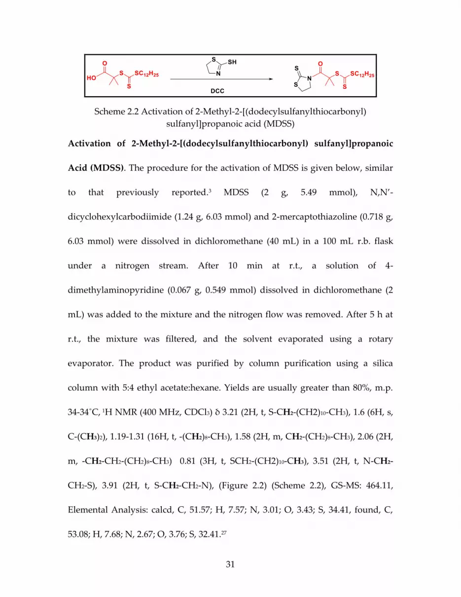
Scheme 2.2 Activation of 2-Methyl-2-[(dodecylsulfanylthiocarbonyl)
sulfanyl]propanoic acid (MDSS)
Activation of 2-Methyl-2-[(dodecylsulfanylthiocarbonyl) sulfanyl]propanoic
Acid (MDSS). The procedure for the activation of MDSS is given below, similar
to that previously reported.3 MDSS (2 g, 5.49 mmol), N,N’-
dicyclohexylcarbodiimide (1.24 g, 6.03 mmol) and 2-mercaptothiazoline (0.718 g,
6.03 mmol) were dissolved in dichloromethane (40 mL) in a 100 mL r.b. flask
under a nitrogen stream. After 10 min at r.t., a solution of 4-
dimethylaminopyridine (0.067 g, 0.549 mmol) dissolved in dichloromethane (2
mL) was added to the mixture and the nitrogen flow was removed. After 5 h at
r.t., the mixture was filtered, and the solvent evaporated using a rotary
evaporator. The product was purified by column purification using a silica
column with 5:4 ethyl acetate:hexane. Yields are usually greater than 80%, m.p.
34-34˚C, 1H NMR (400 MHz, CDCl3) δ 3.21 (2H, t, S-CH2-(CH2)10-CH3), 1.6 (6H, s,
C-(CH3)2), 1.19-1.31 (16H, t, -(CH2)8-CH3), 1.58 (2H, m, CH2-(CH2)8-CH3), 2.06 (2H,
m, -CH2-CH2-(CH2)8-CH3) 0.81 (3H, t, SCH2-(CH2)10-CH3), 3.51 (2H, t, N-CH2-
CH2-S), 3.91 (2H, t, S-CH2-CH2-N), (Figure 2.2) (Scheme 2.2), GS-MS: 464.11,
Elemental Analysis: calcd, C, 51.57; H, 7.57; N, 3.01; O, 3.43; S, 34.41, found, C,
53.08; H, 7.68; N, 2.67; O, 3.76; S, 32.41.27

32
Figure 2.2 1H NMR (400 MHz, CDCl3) spectrum of activated-MDSS
Activation of 2-(((dodecylthio)carbonothioyl)thio)propanoic Acid (DoPAT).
The procedure for the activation of DoPAT is given below. DoPAT (2 g, 5.72
mmol), N,N’-dicyclohexylcarbodiimide (1.30 g, 6.30 mmol) and 2-
mercaptothiazoline (0.751 g, 6.30 mmol) were dissolved in dichloromethane (40
mL) in a 100 mL round bottom flask under a nitrogen stream. After 10 min at r.t.,
a solution of 4-dimethylaminopyridine (0.0697 g, 0.572 mmol) dissolved in
dichloromethane (2 mL) was added to the mixture and the nitrogen flow was
removed. After 5 h at r.t., the mixture was filtered, and the solvent evaporated
using a rotary evaporator. The product was purified by column purification
using a silica column with 5:4 ethyl acetate:hexane. Yields were greater than 90%,
m.p. 52-54˚C. 1H NMR (400 MHz, CDCl3) δ 3.28 (2H, t, S-CH2-(CH2)10-CH3), 1.63
(3H, s, C-(CH3)2), 1.12-1.33 (16H, t, -(CH2)8-CH3), 1.58 (2H, m, -CH2-(CH2)8-CH3),

33
2.09 (2H, m, -CH2-CH2-(CH2)8-CH3) 0.82 (3H, t, SCH2-(CH2)10-CH3), 3.51 (3H, t, -
S-CH(CH3)-CO-N-CH2-CH2-S), 3.93 (2H, t, S-CH2-CH2-N), (Figure 2.3) (Scheme
2.3) GS-MS: 450.92, HRMS (EI) (m/z) calcd. for C4H5Cl: 451.1166; found:
451.1182. 28
Scheme 2.3 Activation of 2-(((dodecylthio)carbonothioyl)thio)propanoic acid
(DoPAT)
Figure 2.3 1H NMR (400 MHz, CDCl3) spectrum of activated-DoPAT
Free Polymerization of Isoprene Via RAFT Polymerization by DoPAT.
Isoprene (2g, 30 mmol), DoPAT (35 mg, 0.1 mmol), dicumyl peroxide (2.7 mg,
0.01mol) (from 10 mM stock solution of DCP), and THF (2.8 mL) with a
polymerization ratio [monomer]: [CTA]:[initiator] 300:1:0.1 were added to a

34
Schlenk tube. The mixture was degassed by three freeze-pump-thaw cycles, filled
with nitrogen, and then the Schlenk tube was placed in a 115o C oil bath (be sure
to fill the only a fifth of the tube due to high pressure). The polymerization was
stopped by quenching in ice water. Molecular weights were measured using gel
permeation chromatography (GPC) in THF which was calibrated with
polystyrene standards. A wide range of molecular weights can be polymerized
by varying the polymerization feed ratio.
Free Polymerization of Chloroprene Via RAFT Polymerization by MDSS.
Chloroprene (0.25 g), MDSS (5.16 mg), AIBN (141ml from 10 mM stock solution)
and THF (1 ml) with a polymerization ratio [monomer]: [CTA]:[initiator]
400:1:0.1 were added and mixed thoroughly in a Schlenk flask. The mixture was
degassed by three freeze-pump-thaw cycles, filled with nitrogen, and the Schlenk
flask was placed in an oil bath at 60o C. The polymerization was stopped by
quenching in ice water. Molecular weights were measured using gel permeation
chromatography (GPC) in THF which was calibrated with polystyrene
standards. Different molecular weights can be achieved by varying the
polymerization ratio.
Preparation of DoPAT-Functionalized Silica Nanoparticles. A solution (20 mL)
of colloidal silica particles (30 wt % in methyl isobutyl ketone) was added to a

35
two-neck round bottom flask and diluted with 110 mL of THF.
Dimethylmethoxy-n-octylsilane (0.1 mL) was added to improve dispersibility
along with 3-aminopropyldimethylethoxysilane (0.7 mL, 5 mmol) and the
mixture was refluxed for 5 h under nitrogen protection. The reaction was cooled
to room temperature and precipitated in a large amount of hexanes (300 mL).
The particles were recovered by centrifugation and dispersed in THF using
sonication, then precipitated in hexanes again. The amine-functionalized
particles were dispersed in 40 mL of THF for further reaction. Then 2.5 g (5.5
mmol) of activated DoPAT was prepared similarly to a procedure described
previously and added dropwise to a THF solution of the amine-functionalized
silica nanoparticles (40 mL, 6 g) at room temperature. After complete addition,
the solution was stirred overnight. The reaction mixture was precipitated into a
large amount of methanol (400 mL). The particles were recovered by
centrifugation at 3000 rpm for 5 min. The particles were redispersed in 30 mL
THF and precipitated in methanol. This dissolution-precipitation procedure was
repeated two more times until the supernatant layer after centrifugation was
colorless. The yellow DoPAT- functionalized silica nanoparticles were dried at
room temperature and analyzed using UV-Vis spectroscopy to determine the
chain density using a calibration curve constructed from standard solutions of
free DoPAT. The RAFT agent density of the particles was calculated to be 100

36
mmol/g of grafted NPs (0.42 chains/nm2). Different graft densities were achieved
by adding different amounts of 3-aminopropyldimethylethoxysilane in the first
step as described previously.
Preparation of MDSS-Functionalized Silica Nanoparticles. A solution (20 mL)
of colloidal silica particles (30 wt % in methyl isobutyl ketone) was added to a
two-neck round bottom flask and diluted with 110 mL of THF.
Dimethylmethoxy-n-octylsilane (0.1 mL) was added to improve dispersibility
along with 3-aminopropyldimethylethoxysilane (0.7 mL, 5mmol) and the
mixture was refluxed for 5h under nitrogen protection. The reaction was then
cooled to room temperature and precipitated in a large amount of hexanes (300
mL). The reaction was cooled to room temperature and precipitated in a large
amount of hexanes (500 mL). The particles were recovered by centrifugation and
dispersed in THF using sonication and precipitated in hexanes again. The amine-
functionalized particles were redispersed in 35 mL of THF for further reaction.
Then 0.2 g, (0.4 mmol) of activated MDSS was prepared as described above and
added dropwise to a THF solution of the amine functionalized silica
nanoparticles (40 mL, 6 g) at room temperature. After complete addition, the
solution was stirred overnight. The reaction mixture was precipitated into a large
amount of hexanes (400 mL). The nanoparticles were recovered by centrifugation
at 5000 rpm for 8 min. The particles were redispersed in 30 mL THF and

37
precipitated in hexanes. This dissolution-precipitation procedure was repeated
two more times until the supernatant layer after centrifugation was colorless. The
yellow MDSS-anchored silica nanoparticles were dried at room temperature and
analyzed using UV analysis to determine the chain density (ch/nm2) using a
calibration curve constructed from standard solutions of free MDSS. Different
graft densities were achieved by adding different amounts of 3-
aminopropyldimethylethoxysilane in the first step as described previously.
RAFT Polymerization of Isoprene from DoPAT- Functionalized Silica
Nanoparticles. In a typical polymerization, isoprene (1.42 g, 21 mmol), DoPAT-
g-silica NPs with surface density of 0.10 mmol/g (0.7g, 70 mmol), THF (2.2 mL),
and dicumyl peroxide initiator (7.0 mmol) with a ratio between species of
[monomer]: [CTA]:[initiator] 300:1:0.1 were added to a Schlenk tube. The
particles were dispersed into the solution via sonication for 1 min and
subsequently, the mixture was degassed by three freeze-pump-thaw cycles, filled
with nitrogen, and the sealed Schlenk tube was placed in a 115o C oil bath for the
desired time and temperature. The polymerization was stopped by quenching in
ice water. NMR spectroscopy was used to determine the conversion of monomer
comparing the monomer peak with the ones of internal standard (trioxane). The
resultant polymer grafted particles were precipitated into a large amount of

38
methanol and centrifuged at 8000 rpm for 5 min and the particles were dispersed
back into THF.
RAFT Polymerization of Chloroprene from MDSS-Functionalized Silica
Nanoparticles. In a typical polymerization, chloroprene (2g), MDSS-g-SiO2 (0.74
g 0.32 ch/nm2), AIBN (567ml from 10mMstock solution) and THF (4 ml) with a
ratio between species of [monomer]: [CTA]:[initiator] 400:1:0.1, were added and
mixed well in a Schlenk flask. The mixture was degassed by three freeze-pump-
thaw cycles, filled with nitrogen, and the sealed Schlenk flask was placed in an
oil bath at 60o C. Aliquots of the reaction solution were withdrawn from the flask
periodically throughout the polymerization. The resulting polychloroprene
grafted particles were purified by two rounds of centrifugation to remove excess
monomers and free polymers then redispersed in THF.
General Procedure for Cleaving Grafted Polymer from Particles. 20 mg of
polydiene grafted silica nanoparticles were dissolved in 2 mL of THF. Aqueous
HF (49%, 0.2 mL) was added, and the solution was allowed to stir at room
temperature overnight. The solution was poured into a PTFE Petri dish and
allowed to stand in a fume hood overnight to evaporate the volatiles. The
recovered polymer was subsequentlly used for GPC analyses.

39
Curing Process of Polydiene Grafted Nanoparticles. Thermogravimetric
analysis (TGA) was done before curing matrix-free samples to calculate the exact
amount of grafted polymer on the surface of NPs. Then two different ways were
used to cure PCP and PIP:
❖ Curing Process of Polychloroprene (PCP) Nanocomposites. A solvent
mixing technique was used for curing. All equivalents mentioned here are
mass equivalents. Chloroprene polymer (100eq), zinc oxide (5eq),
magnesium oxide (2eq), phenyl-a- naphthylamine (2eq), stearic acid
(0.5eq), 2-mercaptothiazoline (0.5eq) were mixed well in THF (15 mL for
each gram of polymer). The mixtures were then poured into Teflon petri
dishes for solvent evaporation under vacuum. The dried samples were hot
pressed at 160o for 25 min to obtain vulcanized rubber sheet of 0.2-0.4 mm
thickness.29,30
❖ Curing Process of Polyisoprene (PIP) Nanocomposites. A solvent mixing
technique was used to cure the PIP by adding curing agents. The isoprene
polymer (100eq) was cured using dicumyl peroxide (10eq) in THF; all
equivalents are PHR (Part per Hundred Rubber). After evaporating the
solvent samples were hot pressed at 160o for 25 minutes to obtain
vulcanized rubber sheet of 0.4 mm thickness.31,32

40
Scheme 2.4 a) Polymerization of isoprene mediated by free DoPAT RAFT
agent. b) Polymerization of chloroprene mediated by free MDSS RAFT agent.
2.4 Results and Discussion
Kinetic Study of Free RAFT and SI-RAFT of Isoprene and Chloroprene
We initially started the free RAFT polymerization of isoprene and
chloroprene. The ratio between species was kept at [Monomer]/[RAFT]/[Initiator]
= 300:1: 0.1 for isoprene and 400:1:0.1 for chloroprene. The reaction was carried
out in THF, at 115o C for isoprene and 60o C for chloroprene and the
polymerization was monitored over time. The kinetic study for isoprene and
chloroprene ln(M0/Mt) had a linear relationship versus time and the molecular
weight increased with monomer conversion. Both monomers showed some non-
linearity at low conversion, which has been referred to as “hybrid behavior”
(Figure 2.4, Scheme 2.4, Figure 2.5 and Scheme 2.5).27,28 This behavior is
characterized by an initial molecular weight that us higher than predicted but
approaches the calculated molecular weight as conversion increases and is

41
usually attributed to a low chain transfer constant at the initial stage of
polymerization.
The attachment of the RAFT agent onto NP surfaces and the subsequent
surface-initiated RAFT polymerization is illustrated in Scheme 2.4. The
attachment of the RAFT agent onto silica nanoparticles was measured by UV-vis
spectrometry. The RAFT agent used to anchor onto the modified silica
nanoparticles was determined quantitatively by comparing the absorption for
the RAFT agent anchored to silica nanoparticles to a standard absorption curve
made from known amounts of the free RAFT agent. NPs with a wide range of
graft densities were used throughout the study (0.005 ch/nm2 to 0.7 ch/nm2). In
this study, we did not target very high graft density to avoid low ratio of silica to
polymer content in the final nanocomposite, which is typically of less interest in
practical applications.
Scheme 2.5 Synthetic of polydiene grafted silica NPs.

42
Figure 2.4 a) Pseudo first-order kinetic plots b) dependence of molecular weight
(solid line, Mn, theory) on the conversion for the polymerization of isoprene with
ratio between species [CP]/[RAFT]/[AIBN] = 300:1:0.1 with free DoPAT; DoPAT
grafted particles with 0.14 ch/nm2 density; DoPAT grafted particles with 0.42
ch/nm2 density.
Figure 2.5 a) Pseudo first-order kinetic plots and dependence of molecular
weight (solid line, Mn, theory) on the conversion for chloroprene with ratio
between species [CP]/[RAFT]/[AIBN] = 400:1:0.1 with: b) free MDSS; c) MDSS
grafted particles with 0.15 ch/nm2 density; d) MDSS grafted particles with 0.32
ch/nm2 density.

43
Kinetic studies of the SI-RAFT polymerization of both monomers were
studied at two different graft densities as well as using free RAFT agent for
comparison. Figure 2.4 and Figure 2.5 show that there is a good linear
relationship between ln(M0/Mt) vs. time versus conversion for the SI-graft
polymerization, which indicates a constant radical concentration throughout the
reaction and the living character of the polymerizations. Moreover, it is obvious
that the free RAFT agent-mediated polymerization was much slower than SI-
RAFT polymerization for isoprene and increased with increasing graft density.
The results in Figure 2.5 show that these trends were reversed for chloroprene,
where the free polymerization kinetics were faster than the SI-RAFT
polymerization, and the polymerization become slower with increasing graft
density. At this time, the reasons for these trends is unclear, although this study
adds more data to understand these relationships as new monomers are
evaluated.
Mechanical properties of matrix-free PCP grafted silica nanoparticle
composites.
To investigate the mechanical properties of matrix-free polydiene grafted
silica nanoparticle composites, we prepared a series of nanocomposites with two
graft densities (0.25 and 0.035 ch/nm2) for polyisoprene composites and one graft

44
density (0.1 ch/nm2) for polychloroprene composites, with different molecular
weights of the grafted polymer (Table 2.1). The matrix-free nanocomposites were
crosslinked as films and cut into dog-bones for tensile testing. Figure 2.6 shows
the tensile stress-strain curves of cured nanocomposites, and it was found that
the properties of the composites were directly related to the silica content in the
nanocomposites. All the matrix-free composites showed improvement in tensile
strength for both polyisoprene and polychloroprene compared with unfilled
samples.29 Furthermore, the tensile stress at break increased with silica loading
with a corresponding decrease in elongation at break. For matrix-free
nanocomposite systems, the increase in molecular weight of the grafted
polymers cause a reduction in silica loading at a fixed graft density. This general
trend is consistent with previous literature that tensile strength generally
increases continuously with increasing silica loading.33,34 From experimental
0.0 0.5 1.0 1.5 2.0
0
2
4
6
8
10
Te
ns
ile
Str
en
gth
(M
Pa
)
Tensile Strain (mm/mm)
Unfilled PIP
PIP-1
PIP-2
PIP-3
PIP-4
a
0 2 4 6 8 10 12-2
0
2
4
6
8
10
12
14
Te
ns
ile
Str
es
s(M
Pa
)
Tensile Strain(mm/mm)
Unfilled-PCP
PCP-4
PCP-3
PCP-2
PCP-1
b
Figure 2.6. Stress-strain curves of crosslinked unfilled and filled composites a)
Polyisoprene, b) Polychloroprene.

45
results, increases in grafted molecular weight can lead to increase in the
elongation at break due to better entanglement between polymer chains, but
lower silica content can also cause a decrease in tensile strength.
Table 2.1 Sample details of matrix-free polydiene grafted silica nanoparticle
composites.
Sample
Name
Graft
Density
(ch/nm2)
Mn
(kDa)
Silica
content
(wt%)
Tensile
Strength
(MPa)
Elongation
at Break
(mm/mm)
Graft
Density
(ch/nm2)
Unfilled-
PIP
-- 43k -- 0.32 0.17 --
PIP-1 0.25 19k 34 1.89 0.96 0.25
PIP-2 0.25 41k 20 3.45 1.07 0.25
PIP-3 0.035 51k 48 5.20 1.82 0.035
PIP-4 0.035 38k 73 9.63 1.34 0.035
Unfilled-
PCP
-- 50k -- 1.8 10.3 --
PCP-1 0.1 47 50 12.9 3.9 0.1
PCP-2 0.1 55 45 11 5.3 0.1
PCP-3 0.1 70 40 11 7.7 0.1
PCP-4 0.1 100 30 6.1 10.9 0.1
The dynamic mechanical behavior was measured at constant strain and
frequency for the crosslinked silica nanocomposites. At low temperatures below
glass transition temperature, the effect of the silica on E’ is observed even though
the molecular chain segments are frozen in this region. In the rubbery plateau
region above Tg, matrix-free silica composites also had higher storage modulus

46
relative to the unfilled for both polymers. These data for matrix-free samples
showed that the storage modulus increased with increasing silica loading. The
glass transition temperature of the matrix-free composites was not affected by
silica loading and that is shown in tan delta figures where all the peaks appear at
the same temperature. Moreover, the reduction of tan delta peak height
increased with silica loading, which may, at least in part, suggest better
reinforcing effect and stronger rubber-filler interaction at high silica loading.9
Figure 2.7 Temperature dependence of storage modulus and tan delta of
crosslinked unfilled and matrix-free nanocomposites of a,c) Polyisoprene and
b,d) Polychloroprene.

47
Figure 2.8 TEM micrographs of (a) as prepared PIP-g-SiO2 NPs Mn 62 Kg/mol)
with chain density of 0.1 ch/nm2 nanocomposite filled with 5% loading NPs, (b)
PCP-g-SiO2 NPs (Mn100 kg/mol) with chain density of 0.1 ch/nm2 nanocomposite
filled with 30% loading NPs, (c) bare silica NPs in PIP matrix filled with 5%
loading NPs, (d) bare silica NPs in PCP matrix filled with 30% loading NPs.
(scale bars are 200 nm).
As shown in TEM photographs (Figure 2.8) particle dispersion was
suitable for both PIP and PCP nanocomposites. There was no significant
clustering of particles even at high silica loading of 30% in PCP. In addition, a
closer view exhibits no uniform pattern of particle distribution and interparticle
spacing, which is most likely due to the significant size disparity of the core silica
particles. Small-angle X-ray scattering (SAXS) was used to obtain more
information about the investigation of interparticle spacing and particle

48
dispersion. No agglomeration on was detected from the X-ray scattering pattern
at low q. The intensity of all the peaks was relatively weak, indicating a broad
distribution of interparticle spacing. The location of the peak did not change
much between the samples, which corresponded to a d spacing between 18-23
nm and seems reasonable considering the size of silica core (15 nm) plus the
grafted polymers (Figure 2.9).
Figure 2.9 Representative small-angle X-ray scattering (SAXS) intensity curves
for matrix-free grafted silica nanocomposites.
2.5 Conclusion
In this chapter, we studied the surface-initiated RAFT polymerization of
polydiene derivatives grafted onto silica NPs. Trithiocarbonate RAFT agents
were anchored onto the surface of silica NPs with controlled graft density, and
controlled radical polymerizations were conducted to produce surface grafted
polymer of predetermined molecular weight and relatively narrow PDI. The

49
polymerization kinetics were studied, and it was found that the grafting-from
polymerization rate was dependent on the graft density. The polymerization rate
of isoprene was faster on particles, but thus trend was reversed for the
polymerization rate of chloroprene. Grafted silica NPs were directly crosslinked
to form matrix-free nanocomposites that showed uniform particle dispersion and
improved mechanical properties compared to unfilled crosslinked films. These
durable, sturdy composite materials could be useful in many applications.
2.6 References
(1) R. Gangopadhyay, A. De, Chem. Mater. 2000, 12, 608–622.
(2) C. Sanchez, B. Lebeau, F. Chaput, J. P. Boilot, Adv. Mater. 2003, 15, 1969–1994
(3) G. Moad, E. Rizzardo, S. H. Thang, Aust. J. Chem. 2005, 58, 379–410.
(4) H. Zou, S. Wu, J. Shen, Chem. Rev. 2008, 108, 3893–3957.
(5) Li, C.; Han, J.; Ryu, C. Y.; Benicewicz, B. C. Macromolecules 2006, 39 (9), 3175–
3183.
(6) Li, C.; Benicewicz, B. C. Macromolecules 2005, 38 (14), 5929–5936.
(7) Saunders, K. J. Organic Polymer Chemistry; Springer: Dordrecht, 1973.

50
(8) Brosse, J. C.; Campistron, I.; Derouet, D.; Hamdaoui, A. E. L.; Houdayer, S.;
Reyx, D. J. Appl. Polym. Sci. 2000, 78, 1461–1477.
(9) Kumnuantip, C.; Sombatsompop, N. Mater. Lett. 2003, 57 (21), 3167–3174.
(10) Salaeh, S. Processing of Natural Rubber Composites And Blends: Relation
Between Structure And Properties, Prince Of Songkla University And
University Claude Bernard Lyon, 2014.
(11) Hosler, D.; Burkett, S. L.; Tarkanian, M. J. Science. 1999, 284 (5422), 1988–
1991.
(12) Heinrich, G.; Kluppel, M.; Vilgis, T. A. Curr. Opin. Solid State Mater. Sci.
2002, 6, 195–203.
(13) Nazhat, S. N.; Parker, S.; Patel, M. P.; Braden, M. Biomaterials 2001, 22 (17),
2411–2416.
(14) Nazhat, S. N.; Parker, S.; Riggs, P. D.; Braden, M. Biomaterials 2001, 22 (15),
2087–2093.
(15) Hou, S.; Chan, W. K. Preparation of Functionalized Polystyrene-block-
polyisoprene Copolymers and Their Luminescence Properties.
Macromolecules 2002, 35, 850-856.

51
(16) Lu, Z. J.; Huang, X. Y.; Huang, J. L.; Pan, G. Q. Macromol. Rapid Commun.
1998, 19, 527-531.
(17) Donderer, M.; Langstein, G.; Schafer, M.; Nuyken, O. Polym. Bull. (Berlin)
2002, 47, 509-516.
(18) Peng, Y.; Wang, J.; Liu, J.; Dai, H.; Cun, L. Polym. Int. 1996, 39, 63-68.
(19) Kongkaew, A.; Wootthikanokkhan, J. Polym. Bull. (Berlin) 1999, 43, 327-
332.
(20) Wootthikanokkhan, J.; Tongrubbai, B. J. Appl. Polym. Sci. 2003, 88, 921-927.
(21) Kir, O.; Binder, W. H.; European Polym. J. 2013, 49, 3078-3088.
(22) Carothers, W. H.; Williams, I.; Collins, A. M.; Kirby, J. E. J. Am. Chem. Soc.
1931, 53 (11), 4203–4225.
(23) Itoyama, K.; Hirashima, N.; Hirano, J.; Kadowaki, T. Polym. Journal 1991,
23 (7), 859–864.
(24) Germack, D. S.; Wooley, K. L.; J. Polym. Sci., Part A: Polym. Chem. 2007, 45,
4100-4108.
(25) Li, C.; Han, J.; Ryu, C. Y.; Benicewicz, B. C. Macromolecules 2006, 39, 3175–
3183.

52
(26) Koiry, B. P.; Moukwa, M.; Singha, N. K. J. Fluor. Chem. 2013, 153, 137–142.
(27) Zheng, Y.; Abbas, Z. M.; Sarkar, A.; Marsh, Z.; Stefik, M.; Benicewicz, B. C.
Polymer (Guildf). 2018, 135, 193–199.
(28) Khani, M. M.; Abbas, Z. M.; Benicewicz, B. C. J. Polym. Sci. Part A Polym.
Chem. 2017, 1–9.
(29) Kapgate, B. P.; Das, C.; Das, A.; Basu, D.; Wiessner, S.; Reuter, U.;
Heinrich, G. J. Appl. Polym. Sci. 2016, 133 (30), 1–10.
(30) Chokanandsombat, Y.; Sirisinha, C. J. Appl. Polym. Sci. 2013, 128 (4), 2533–
2540.
(31) Rajan, R.; Varghese, S.; George, K. E. Prog. Rubber, Plast. Recycl. Technol.
2012, 28 (4), 201–220.
(32) Boochathum, P.; Prajudtake, W. Eur. Polym. J. 2001, 37, 417–427.
(33) Sae-Oui, P.; Sirisinha, C.; Thepsuwan, U.; Hatthapanit, K. Eur. Polym. J.
2006, 42 (3), 479–486.
(34) Sae-oui, P.; Sirisinha, C.; Thepsuwan, U.; Hatthapanit, K. Eur. Polym. J.
2007, 43 (1), 185–193.

53
CHAPTER 3
SI-RAFT POLYMERIZATION OF 2,3-DIMETHYL-1,3-BUTADIENE
ON SILICA NANOPARTICLES FOR MATRIX-FREE METHYL
RUBBER NANOCOMPOSITES

54
3.1 Abstract
Reversible addition-fragmentation Chain transfer (RAFT) polymerization
of 2,3-dimethyl-1,3-butadiene (DMB) in solution and on the surface of silica
nanoparticles was investigated and PDMB-grafted silica nanoparticles (PDMB-g-
SiO2 NPs) with different chain densities and molecular weights were prepared.
The kinetic studies of DMB polymerization mediated by silica anchored RAFT
agents at different graft densities were investigated and compared to the
polymerization mediated by the corresponding free RAFT agent. The PDMB-g-
SiO2 NPs were cured to prepare rubbery films to obtain matrix-free
nanocomposites which exhibited a good dispersion of silica nanoparticles and
improved mechanical properties compared to the unfilled crosslinked rubber.
3.2 Introduction
Poly(2,3-dimethyl-1,3-butadiene) (PDMB) also known as methyl isoprene
or methyl rubber in industry, is a historically significant rubber which was used
by the Germans during WWI as a substitution for natural rubber.1–3 The early
synthesis of the monomer involved conversion of acetone to pinacol in the
presence of aluminum oxide as catalyst, then dehydrogenation of pinacol to form
the diene.4,5 The polymerization of DMB has not been widely studied because the
resulting rubber is softer than natural and synthetic rubber.6,7 DMB was the first

55
monomer to be converted into industrially synthesized rubber, referred to as
methyl rubber because it has one more methyl group than isoprene. The
industrial process to produce methyl rubber was developed by Hoffmann in
1910 and produced during 1914–1918, but it was not widely used after that due
to unfavorable properties like excessive hardness at low temperature and
susceptibility to oxidation.8,9
The synthesis of PDMB through free radical polymerization is commonly
used to produce very high molecular weight polymers with broad molecular
weight distribution.4,10–12 There are few reports on the controlled radical
polymerization of DMB which could be because of the lack of control due to
steric hindrance on this monomer and the rubber made out of is not suitable for
industrial applications.13,14 Polymerization of DMB by anionic polymerization
affords good control over molecular weight and narrow molecular weight
distribution, but this method is challenging because of the sensitivity of the
reaction towards the presence of contaminants.15 Thus, to the best of our
knowledge, there is no report on RAFT polymerization of DMB.
The most important factor when polymerizing a new monomer via RAFT
polymerization is to select the proper RAFT agent and the reaction conditions,
because the inappropriate RAFT agent can lead to a reduction control, severe

56
retardation or inhibition.16 Therefore, three different RAFT agents were explored
for the polymerization of DMB; 2-(((dodecylthio)carbonothioyl)thio)propanoic
acid (DoPAT), 2-methyl-2-[(dodecylsulfanylthiocarbonyl) sulfanyl]propanoic
acid (MDSS), and 4-cyano-4-[(dodecylsulfanylthiocarbonyl) sulfanyl]pentanoic
acid (CDTPA) (Figure 3.1). All three RAFT agents were used in the same
conditions, despite that some retardation and poor control was realized in
previous studies of RAFT polymerization of diene monomers which has been
related to RAFT agent reactivity. Furthermore, it is mentioned in the literature,
that the RAFT polymerization process does not affect the polymer
microstructure.17
Figure 3.1 Chain transfer agents used for DMB RAFT polymerization.
Nanoparticles have been synthesized and used in reinforcement of
different inorganic matrices.18–22 It is well known that the addition of inorganic
fillers into a polymer matrix can improve the thermomechanical properties
compared to the neat polymer.23,24 The formation of clusters (or agglomerates)
stemming from phase separation between the polymer matrix and nanofiller can
actually diminish property enhancement, so to obtain the targeted improvement,

57
it is necessary that the nanoparticles be well dispersed in the matrix.25–27
Nanoparticles which are covalently grafted with polymer chains that are the
same as or miscible with the matrix have been extensively studied and proven to
be an effective means of controlling the nanoparticle dispersion given that there
is sufficient control of the grafted chain molecular weight and graft density.28,29
In this work, we report the free and surface-initiated RAFT
polymerization of DMB from silica nanoparticles and careful studies of the
polymerization kinetics at different graft densities. These results were compared
to other dienes that had been studied under the same conditions. The resulting
PDMB, neat and grafted on silica nanoparticles, were crosslinked to create
matrix-free nanocomposites that showed improved mechanical properties
compared to neat DMB.
3.3 Materials and Methods
Materials. DMB monomer was purchased from Alfa Asear. The RAFT agent 4-
Cyano-4-(((dodecylthio)carbonothioyl)thio)pentanoic acid (CDPA, >97%) was
purchased from Strem Chemicals and used as received. Spherical SiO2
nanoparticles dispersed in methyl ethyl ketone (MEK-ST) with a diameter of 14 ±
4 nm were purchased from Nissan Chemical Co. Tetrahydrofuran (THF) (HPLC
grade, Fisher), dicumyl peroxide (Acros, 99%), n-octyldimethylmethoxysilane

58
(Gelest, 95%), and 3-aminopropyldimethylethoxysilane (Gelest, 95%) were used
as received. All other reagents were used as received.
Anionic polymerization of 2,3-dimethyl-1,3-butadiene. The anionic
polymerization of DMB was carried out by the syringe high vacuum technique
under dry nitrogen in baked glass.13 After baking the glasses at 125o C, DMB (60.9
mmol, 5g) was added into Schlenk flask with 5 mL of dry THF as a solvent. The
flask was subjected to three cycles of freeze-pump-thaw then filled with dry
nitrogen. Then n-Butyllithium in hexane (0.02 mmol, 1.3mg) was added as an
initiator by a syringe through the septum while stirring and the reaction was
heated at 60o C for 24 hours. The polymerization was terminated by rapidly
cooling the reaction mixture in a water bath to room temperature. The resulting
PDMB was precipitated into a large amount of methanol and centrifuged at 8,000
rpm for 10 min and redispersed in THF. Different molecular weights were
synthesized by varying [monomer: initiator] ratio and time.30
RAFT polymerization of 2,3-dimethyl-1,3-butadiene. A 25 mL Schlenk flask,
equipped with a magnetic stirrer, was charged with a mixture of DoPAT (10 mg,
28.6 mmol), dicumyl peroxide (DCP) (0.58 mg, 2.15 mmol), DMB (0.94 g, 11.44
mmol) and THF (2 ml). The mixture was degassed by three freeze-pump-thaw
cycles, filled with nitrogen, and the sealed Schlenk flask was placed in an oil bath

59
at 115°C for 20 hours. Termination proceeded by rapidly cooling the reaction
mixture in a water bath to room temperature. The resulting PDMB grafted
particles were precipitated into a large amount of methanol and centrifuged at
8,000 rpm for 10 min and re-dispersed in THF. The molecular weight of this
sample was 7K. Different molecular weights were synthesized by varying
[monomer: CTA: initiator] ratio and time.
Synthesis of CPDA-g-SiO2. A solution (20 mL) of colloidal silica particles (30 wt
% in methyl isobutyl ketone) was added to a two-neck round bottom flask and
diluted with 60 mL of THF. Then, n-octyldimethylmethoxysilane (ODMES) (0.4
mL, 1.61 mmol) was added and the mixture was refluxed in a 75°C in oil bath for
12 hours under nitrogen protection. The reaction was cooled to room
temperature and precipitated in an excess of hexanes (200 mL). The particles
were later recovered by centrifugation and dispersed in THF (50 mL) using
sonication and precipitated in hexanes again. 3-
Aminopropyldimethyethoxysilane (0.25 ml, 1.33 mmol) were added to ODMES-
functionalized particles in THF (50 ml) and the mixture was refluxed in a 75° C
oil bath for 3 hours under nitrogen protection. The reaction was cooled to room
temperature and precipitated in an excess of hexanes (200 mL). The particles
were recollected by centrifugation and dispersed in THF using sonication and
precipitated in hexanes again. The amine-functionalized particles were dispersed

60
in 50 mL of THF for further reaction. Then activated CPDA (0.511 g, 1.13mmol)
was prepared and added dropwise to a THF solution of the amine functionalized
silica nanoparticles (50 mL, 6 g) at room temperature.22 After complete addition,
the solution was stirred overnight. The reaction mixture was precipitated into an
excess of hexanes (400 mL). The particles were recollected by centrifugation at
3000 rpm for 8 min. The particles were redispersed in 30 mL THF and
precipitated in hexanes. This dissolution-precipitation procedure was repeated
two more times until the supernatant layer after centrifugation was colorless. The
yellow CPDA-anchored silica nanoparticles were dried at room temperature and
analyzed using UV analysis to determine the chain density using a calibration
curve constructed from standard solutions of free CPDA.
Polymerization Procedures of Surface-initiated RAFT of DMB. In a typical
polymerization, DMB (0.8g), CPDA-g-SiO2 (0.46g 0.15ch/nm2), DCP (161ul from
10mM stock solution), THF (2ml) and toluene (1ml) were added and mixed well
in a Schlenk tube. The mixture was degassed by three freeze-pump-thaw cycles,
filled with nitrogen, and the sealed Schlenk flask was placed in an oil bath at
115°C. The resulting PDMB grafted particles were precipitated into a large
amount of methanol and centrifuged at 8,000 rpm for 10 min and redispersed in
THF. Different molecular weights can be synthesized by varying the ratio of
[monomer: CTA: initiator] and time. After polymerization, grafted polymer

61
chains were cleaved from the nanoparticles, by the following procedure. PDMB
grafted silica particles (20 mg) were dissolved in 2mL of THF. Aqueous HF (49%,
0.2 mL) was added, and the solution was allowed to stir at room temperature
overnight. The solution was poured into a PTFE Petri dish and allowed to stand
in a fume hood overnight to evaporate the volatiles. The collected PDMB was
then subjected to GPC analysis.
Curing process of PDMB grafted particles. The solvent mixing technique was
used to cure the PDMB by adding curing agent in THF. PDMB (100 eq) with
dicumyl peroxide (10 eq) [all equivalents are PHR (Parts per Hundred Rubber)]
was used to cure the rubbery materials. After evaporating the solvent, samples
were hot pressed at 160o for 25 minutes to obtain a vulcanized rubber sheet of 0.4
mm thickness.
Characterization Techniques
Molecular weights. Molecular weights (Mn) and dispersities (Đ) were
determined using a Varian 290 LC gel permeation chromatography (GPC) with a
390 LC multidetector unit, and three Styragel columns. The columns consisted of
HR1, HR3, and HR4 in the effective molecular weight ranges of 100-5000, 500-
30000, and 5000-500000, respectively. THF was used as eluent at 30°C and the

62
flow rate was adjusted to 1.0mL/min. Molecular weights were calibrated with
poly(styrene) standards obtained from Polymer Laboratories.
Nuclear Magnetic Resonance Spectroscopy. 1H NMR (Bruker Avance III-HD
400 MHz) spectra were recorded using CDCl3 as a solvent.
Transmission Electron Microscopy. The transmission electron microscopy
(TEM) was performed on a Hitachi H8000 TEM at an accelerating voltage of 200
KV. The samples were prepared by cryosectioning of the crosslinked samples in
a solution of H2O: DMSO 30:70, then placed on copper grids.
X-ray Scattering (SAXS). X-ray experiments were conducted using a SAXS Lab
Ganesha at the South Carolina SAXS Collaborative. A Xenocs GeniX3D
microfocus source was used with a Cu target to generate a monochromic beam
with a 0.154 nm wavelength. The instrument was calibrated using National
Institute of Standards and Technology (NIST) reference material 640c silicon
powder with the peak position at 2θ=28.44˚ where 2θ is the total scattering angle.
A Pilatus 300 K detector (Dectris) was used to collect the two-dimensional (2D)
scattering patterns. All small-angle X-ray Scattering (SAXS) data were acquired
with an X-ray flux of ~4.1 M and ~21.4 M photons/s incident upon the samples.
All data were acquired by 10-15 minutes measurements. Transmission SAXS was
measured normal to sample substrates to observe the purely in-plane

63
morphology. These 2D images were azimuthally integrated to yield the
scattering vector and intensity.
Dynamic Mechanical Analysis. Dynamic mechanical analysis was performed
with an Eplexor 2000N dynamic measurement system (TA, ARES-RSA3) using a
constant frequency of 10 Hz and the gap is 10mm in a temperature range -50o C
to 60o C. The analysis was done in tension mode. For the measurement of the
complex modulus, E*, a static load of 1% pre-strain was applied and then the
samples oscillated to a dynamic load of 0.5% strain. Measurements were done at
a heating rate of 3o C/min under nitrogen flow. Samples were cut into rectangular
shapes with dimensions of 4.8*15 mm with 0.4mm thickness. At least two
measurements were recorded, and the average values were reported.
Stress-Strain Analysis. Tensile tests of samples were carried out using an Instron
5543A material testing machine with crosshead speed 20 mm/min (ASTM D412,
ISO 527). Samples were cut into standard dumbbell shapes with neck cross-
section dimensions of 5 x 22 mm with 0.4mm thickness. At least five
measurements were recorded, and the average values were reported.
Hardness Test. Hardness of PDMB cured specimens was measured using a
durometer with Shore A scale (Cogenix Wallace, Surrey) as per ASTM D2240.
Samples were cut into standard square shapes with dimensions of 5*5 mm, and

64
the sheets having a sufficient thickness of 6mmwere used. At least five
measurements were recorded, and the average values were reported.
3.4 Results and Discussion
Polymerization of free Dimethyl Butadiene via RAFT Polymerization
Before performing the SI-RAFT polymerization of DMB, detailed studies
of the polymerization of DMB controlled by free RAFT agents were conducted.
Three trithiocarbonate RAFT agents MDSS, CDTPA and DoPAT were tested to
study which would give the best control over the polymerization. All
polymerizations were set-up under the same conditions; 115o C and [600:1:0.1]
ratio of monomer to RAFT agent to initiator [M:CTA:Inti]. It was found that
CDPTA lacks good control as indicated by the broad dispersity (2.1), likely
because of the presence of electron-withdrawing groups on the RAFT agent
which lead to higher transfer coefficients. In the literature, multiple side reactions
have been identified, e.g., hydrolysis, cycloaddition reactions, and hetero
Diels−Alder reaction with diene monomers.16,31,32 The other two RAFT agents
showed good reasonably control, but DoPAT was found to have the best control
with the narrowest dispersity (1.21) (Table 3.1 and Scheme 3.1).
Several initiators were also tested in the DoPAT RAFT system at various
temperatures and conditions. As shown in (Table 3.2) polymerization was not

65
observed at temperatures of 70o C or lower. For example, polymerization using
2,2′-Azobis(2-methylpropionitrile) (AIBN) at 70o C did not show any monomer
consumption by NMR or polymer growth by GPC. The conversion using AIBN
at 95o C for 24 hours was the highest compared to the other initiators, but yielded
broad dispersities (1.42) and low molecular weight (6kg/mol) as detected by
GPC. Polymerization using di-tert-butyl peroxide (dTBP) at 135o C and benzoyl
peroxide (DBPO) at 95o C show similar dispersities and slightly higher molecular
weights but all with higher dispersities than DCP. Therefore, DCP used to
perform more extensive studies on DMB.
Scheme 3.1 Polymerization of Dimethyl butadiene by free DoPAT RAFT agent.
Table3.1 RAFT Polymerization of DMB using free RAFT agents at 115o C and
identical conditions.
Sampl
e
RAFT Initiato
r
[M:CAT:I
]
Tem
p oC
Tim
e hr
Conversio
n %
Mn
kg/mo
l
Đ
1 DoPAT DCP 600:1:0.1 115 3 8 3.6 1.2
1
2 MDSS DCP 600:1:0.1 115 3 6.1 2.1 1.3
8
3 CDTP
A
DCP 600:1:0.1 115 3 9.2 4.2 2.1

66
Table 3.2 RAFT Polymerization of DMB of free CDPA Using Different Initiators
at Various Temperatures and Conditions.
Sample Initiator [M:CAT:I] Temp oC
Time
hr
Conversion
%
Theoretical
Mn
Mn
kg/mol
Đ
1 DCP 600:1:0.1 115 24 20 9.8 7.2 1.26
2 AIBN 600:1:0.1 70 24 NR -- --- ---
3 AIBN 600:1:0.1 95 24 27 13.3 6 1.42
4 dTBP 600:1:0.1 135 24 17 8.4 11 1.43
5 DBPO 600:1:0.1 95 24 23 11.4 9.8 1.44
6 DCP 5000:1:0.1 115 40 --- --- 50 1.34
7 DCP 7000:1:0.1 115 40 --- --- 76.3 1.43
8 nBuLi 1500:1 40 24 --- --- 15.8 1.32
9 nBuLi 3000:1 40 24 --- --- 26.4 1.42
We studied the microstructure of PDMB polymerized via RAFT by NMR,
which has not been reported previously. It was found that the ratio between
microstructures was 97% 1,4 addition and 3% 1,2 addition, as shown in Table 3.3,
Figure 3.2. The ratio of each component was close to PDMB obtained from free
anionic polymerization and did not change across samples of different molecular
weights although significant differences were found in the cis/trans ratios. From
the NMR spectrum it was easy to determine not only the percent of 1,4 addition
cis and trans and 1,2 additions, but also the distribution of dyads and triads of
these structural units.13,15 Analysis of these peaks was made by using the
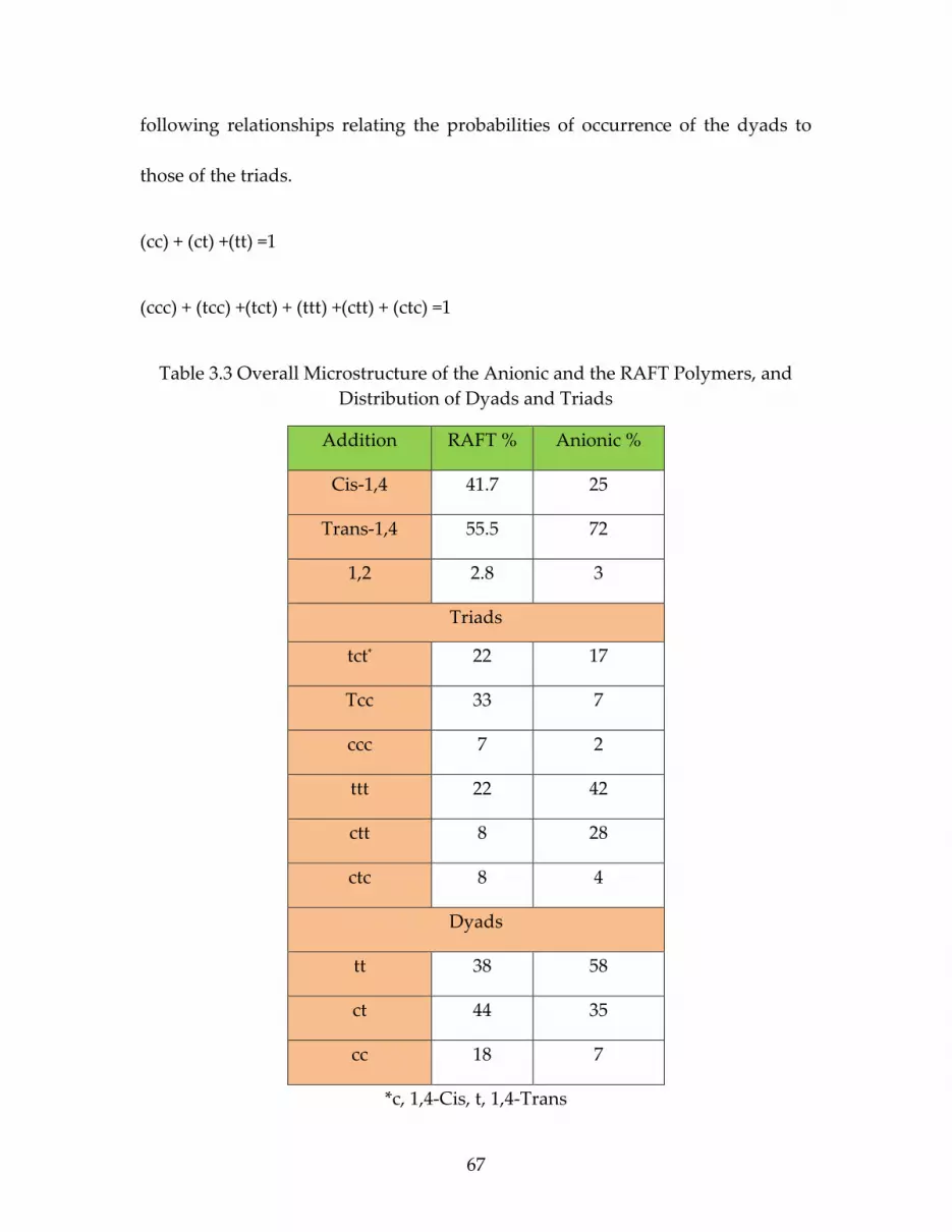
67
following relationships relating the probabilities of occurrence of the dyads to
those of the triads.
(cc) + (ct) +(tt) =1
(ccc) + (tcc) +(tct) + (ttt) +(ctt) + (ctc) =1
Table 3.3 Overall Microstructure of the Anionic and the RAFT Polymers, and
Distribution of Dyads and Triads
Addition RAFT % Anionic %
Cis-1,4 41.7 25
Trans-1,4 55.5 72
1,2 2.8 3
Triads
tct* 22 17
Tcc 33 7
ccc 7 2
ttt 22 42
ctt 8 28
ctc 8 4
Dyads
tt 38 58
ct 44 35
cc 18 7
*c, 1,4-Cis, t, 1,4-Trans

68
Figure 3.2 400-MHz 1H NMR spectra of poly(2,3-dimethyl-1,3-butadiene)
The free RAFT polymerization of DMB was done with a mole ratio of
[monomer]/[CTA]/[initiator] 600:1:0.1 at 115o C under nitrogen gas. The kinetic
results for the free RAFT polymerization of DMB are shown in Figure 3.3 (GPC
data shown in Figure 3.4 and Table 3.4). Monomer consumption was linear with
respect to time which indicates a constant radical concentration throughout the
polymerization. The controlled polymerization was evidenced by the linear
increase of Mn with respect to monomer conversion. Experimental molecular
weights generally agreed with theoretical molecular weights, and molecular
weight distributions were generally narrow (~1.21). The control of DoPAT
trithiocarbonate RAFT agents agrees with previous studies on diene monomers
reported by Benicewicz21,33 and confirmed that the selected RAFT for the current
studies was suitable for high-temperature RAFT polymerizations.

69
0 2 4 6 8 10 12 14 16 18 20 220.0
0.1
0.2
0.3
0.4
0.5 Free
on 0.15 ch/nm2
on 0.36 ch/nm2
Ln
(Mo
/Mt)
Time (hr)
a)
0 10 20 30 400
5
10
15
20
25
Free
0.15 ch/nm2
0.36 ch/nm2
Theoretical Mn
Free PDI
0.15 ch/nm2
0.36 ch/nm2
Conversion (%)
Mn
(K
g/m
ol)
1.0
1.5
2.0
2.5
3.0
3.5
4.0
4.5
5.0
b)
Ð
Figure 3.3 (a) First-order kinetic plots and (b) dependence of molecular weight
(solid line, Mn, theory) on the conversion for the SI- RAFT polymerization of
DMB on silica nanoparticles; high surface density (triangle, 85 mmol/g, 0.36
ch/nm2); low surface density (star, 34 mmol/g, 0.15 ch/nm2); free DoPAT,
(square). All polymerization were under the same conditions
[monomer]:[CTA]:[initiator] 600:1:0.1.
22 24 26 28
Retention time (min)
3 hr
6 hr
10 hr
15 hr
20 hr
Figure 3.4 GPC traces of PDMB prepared from free RAFT polymerization
Table 3.4 The kinetic results for the free RAFT polymerization of DMB
[monomer]:[CTA]:[initiator] 600:1:0.1.
Sample Ln(Mo/Mt) Theoretical
Mn
(kg/mol)
Mn
(kg/mol)
PDI Conversion
%
3hr 0.078 3.5 3.6 1.38 7
6hr 0.096 5.7 3.9 1.33 11.6
10hr 0.160 7.9 4.6 1.37 16.1
15hr 0.169 8.9 5.5 1.36 18
20hr 0.203 10 7.2 1.31 20.3

70
Polymerization of Dimethyl Butadiene via SI-RAFT
The investigation of polymerization kinetics for DMB on the surface of
silica nanoparticles, has not been previously reported. Therefore, activated
DoPAT chain transfer agent was grafted on the surface of nanoparticles by the
initial reaction with 3-aminopropyldimethymethoxysilane onto the particles’
surface, (DoPAT-g-SiO2) (Scheme 3.2) followed by the reaction of activated
DoPAT with the amino groups attached to the NP surface. The reaction of the
inert n-octyldimethylmethoxysilane was conducted to import a more soluble
interface to the NP surface via the n-octyl chains. The concentration of RAFT
agent on the surface of nanoparticles was determined quantitatively by
comparing the absorption at about 300 nm for the DoPAT anchored silica
nanoparticles to a standard absorption curve made from known amounts of the
free DoPAT. With this procedure the synthesis of DoPAT-g-SiO2 at two densities
of 85 mmol/g (0.35 chains/nm2) and 34 mmol/g (0.15 chains/nm2) was conducted,
and used to study the SI-RAFT polymerization of DMB.
For the surface polymerization of DMB, DoPAT-g-SiO2 particles need to
be dispersed in a solvent medium that should be a polar-nonpolar mixture to
simultaneously disperse the silica particles and later be able to dissolve the
nonpolar high methyl content PDMB chains and to avoid any possible gelation

71
that might occur. Therefore, a mixture of tetrahydrofuran (THF) was used as a
suitable polar solvent for the dispersion of silica particles combined with toluene
as nonpolar solvent and excess monomer that also acts as a solvent for the PDMB
chains. It was found that when the (THF:Toluene) ratio (v:v) was (1:1), gelation
of the polymerization did not occur.
Scheme 3.2 Preparation of PDMB-g-SiO2 NPs.
The SI-RAFT polymerizations of DMB were studied by using two
different grafted RAFT agent densities of 85 mmol/g (0.36 chains/nm2) and 34
mmol/g (0.15 chains/nm2) to investigate the effect of grafting densities on the
polymerization and were compared with the polymerization of free DoPAT. All

72
reactions were carried out under the same conditions using dicumyl peroxide as
the initiator at 115o C and with the ratio between species of
[monomer]:[CTA]:[initiator] of 600:1:0.1. The results of the kinetic studies for the
SI-RAFT polymerization of DMB controlled by surface grafted RAFT agents are
shown in Figure 3.3 (GPC data shown in Figure 3.5 and Table 3.5). The graphs
show a linear relationship between monomer consumption and time for all cases
over the range of conversion studied, which indicates a constant free radical
concentration during the polymerization. The results also show the molecular
weight increased linearly with monomer conversion for all polymerizations,
measured molecular weights were in general agreement with the theoretical
molecular weights, and molecular weight distributions were generally narrow
(generally < 1.3). Nevertheless, the rates of the polymerizations controlled by
surface grafted RAFT agents were apparently higher than the polymerization via
free RAFT agent under identical conditions. From these results, we also observed
that when grafted RAFT agents were present at higher graft density the
polymerization rate was faster than low grafted RAFT density. This general
trend is opposite that observed in the RAFT polymerization of chloroprene
where the rate of polymerization was decreased with increasing RAFT agent
density. In another comparison between the free and graft RAFT polymerization
rates, DMB behaved similarly to isoprene where the free RAFT polymerization

73
rates were lower than grafted polymerization rates (Figure 3.6).21,33 The
chloroprene behavior that showed much higher rates than isoprene and DMB
was ascribed to the differences in monomer reactivity because the chlorine atom
that is attached on the butadiene is electron withdrawing in nature and
destabilizes the radical, thus making it comparatively more reactive. On the
other hand, isoprene and DMB contain methyl groups that stabilize the radical
on butadiene and will result in slower rates.34–37 The second trend which is still
not resolved is the difference between free RAFT and SI-RAFT rates because
some monomers polymerize faster on particles and polymerization rates increase
with increasing of grafting density.29 Comparisons across many different
monomers systems have not shown a clear trend to explain the varied behavior.
20 22 24 26
Retention time (min)
3 hr
6 hr
10 hr
15 hr
20 hr
a)
20 22 24 26
b)
Retention time (min)
3 hr
6 hr
10 hr
15 hr
20 hr
Figure 3.5 GPC traces of PDMB prepared from free RAFT-g-NPs
polymerization a) 0.15 ch/nm2, b) 0.36 ch/nm2.

74
Table 3.5 The kinetic results for the RAFT-g-NPs polymerization of DMB
[monomer]:[CTA]:[initiator] 600:1:0.1.
0.15 ch/nm2
Sample Ln(Mo/Mt) Theoretical
Mn
(kg/mol)
Mn
(kg/mol)
PDI Conversion
%
3hr 0.087 3.5 7.3 1.36 8
6hr 0.14 5.7 8.9 1.31 13
10hr 0.17 7.9 11.1 1.31 16
15hr 0.21 8.9 12.7 1.36 19
20hr 0.24 10 16.5 1.43 20
0.36 ch/nm2
Sample Ln(Mo/Mt) Theoretical
Mn
(kg/mol)
Mn
(kg/mol)
PDI Conversion
%
3hr 0.21 3.5 8.5 1.3 18.6
6hr 0.26 5.7 13 1.23 22.7
10hr 0.31 7.9 13.7 1.27 26.8
15hr 0.45 8.9 17.5 1.23 36.3
20hr 0.53 10 20.4 1.31 41.4

75
0 2 4 6 8 10 12 14 16 18 20 22
0.0
0.2
0.4
0.6
0.8
1.0
1.2
1.4 PI-g-SiO20.15 ch/nm
2
PCP-g-SiO20.15 ch/nm
2
PDMB-g-SiO20.15 ch/nm
2
Free PI
Free PCP
Free PDMB
ln([
Mo
]/[M
t])
Time (hr)
Figure 3.6 Rate of free RAFT polymerization and on 0.15 ch/nm2 SiO2 NPs of
Isoprene, Chloroprene, and Dimethyl butadiene monomers.
Mechanical properties of matrix-free PDMB-g-SiO2 NPs composites
The investigation of the mechanical properties of matrix-free PDMB
grafted silica nanoparticle composites was done by preparing a series of
nanocomposites from NPs with the two graft densities (0.15 ch/nm2 and 0.02
ch/nm2), and varying molecular weights of grafted polymer. The details of the
samples are listed in Table 3.6. The PDMB-g-SiO2 NPs were crosslinked as
matrix-free composites by using dicumyl peroxide as crosslinking agent in
solution and then the solvent was allowed to evaporate under vacuum. Dried
samples were hot pressed at 160oC for 25 min to obtain vulcanized rubber sheet
of 0.4 mm thickness.

76
Table 3.6 Sample details of matrix-free PDMB-g-SiO2 NPs composites
Sample
name
Graft
density
(ch/nm2)
Mn
(kg/mol)
Silica
Wt%
Tensile
strength
(MPa)
Elongation
at break
(mm/mm)
Hardness
Shore oA
Unfilled N/A 50k 0 0.62±0.004 0.32±0.04 51±2
24k 0.02 24k 67 1.90±0.31 0.047±0.001 95.5±1.5
42k 0.02 42k 60 3.52±0.31 0.82±0.21 88±2.5
94k 0.02 94k 49.6 3.07±0.45 1.69±0.26 75±2
35k 0.15 35k 41 1.30±0.32 0.72±0.15 80±1.5
46k 0.15 46k 26 0.85±0.08 0.57±0.11 76±1.5
Matrix-free nanocomposites have a dispersion advantage compared to
traditional composites that are prepared by blending rubber directly with the
nanoparticle. Traditional composite synthesis procedures require the mixing of
particles with the polymer matrix, which introduces agglomeration of particles
particularly with high nanoparticle loadings due to undesirable interface
compatibility.38–40 The grafted nanoparticles are separated from each other by the
polymer brushes that were polymerized on the surface of these particles. Thus,
good dispersion can be created and maintained in these systems.28 As shown in
Figure 3.7, good particle dispersion was achieved with both 42k PDMB-g-SiO2
NPs 0.02 ch/nm2, 60 silica wt%, and 46k PDMB-g-SiO2 NPs 0.15 ch/nm2, 26 silica
wt%. There was no significant agglomeration of particles even at high silica
loading. However, there was no well-defined organization of the nanoparticles

77
and d-spacing was not uniform, which is most likely due to the large size
disparity of the core silica particles.21
Figure 3.7 TEM image of a,c) 42k PDMB-g-SiO2 NPs 0.02 ch/nm2 60 silica wt%,
b,d) 46k PDMB-g-SiO2 NPs 0.15 ch/nm2 26 silica wt% (all images are 200 nm scale
bar)
To confirm the dispersion state of nanoparticles in matrix-free of the
crosslinked samples, Small-angle X-ray scattering (SAXS) (Figure 3.8) was used
to obtain more information. No agglomeration was detected from the X-ray
scattering pattern at low q. The intensity of all the peaks was relatively weak,
indicating a broad distribution of interparticle spacing. The location of the peak
changed between the samples dependent upon the grafting density, for 0.02

78
ch/nm2 the q value was approximately 0.04 A-1 which corresponds to a d spacing
of ~15 nm, but for particles with 0.15 ch/nm2 the q value was approximately 0.02
A-1 which corresponds to a d spacing of ~31 nm. The difference in a d spacing
seems reasonable considering the low graft density particles have more space on
the surface for chains to collapse, while the higher graft density chains are more
extended would push the particles farther apart.
0.005 0.01 0.05 0.10.01 0.1
0.001
0.01
0.1
1
10
100
Inte
ns
ity
, a
.u.
q, A-1
24k
42k
35k
46k
Figure 3.8 Representative small-angle X-ray scattering (SAXS) intensity curves
for matrix-free PCP grafted silica nanocomposites.
At constant strain and frequency, dynamic mechanical behavior was
measured (Figure 3.9) for the crosslinked silica nanocomposites and the
crosslinked unfilled polymer. The glass transition temperature of the matrix-free
composites was not altered compared with unfilled PDMB as observed in Figure
3.9 a. It is apparent the reduction of tan delta peak height increased with silica

79
loading, which may suggest a better reinforcing effect and stronger rubber-filler
interaction at high silica loading.41,42 As shown in Figure 3.9 b at low
temperatures below the Tg, the effect of the silica on storage modulus is
distinctly observed although the molecular chain segments are frozen in this
region. In the rubbery plateau region above Tg, matrix-free silica composites also
had higher storage modulus relative to the unfilled polymer. For all matrix-free
composites, the storage modulus increasing silica loading.
-40 -20 0 20 40 60 80
0.0
0.5
1.0
1.5
2.0
2.5
Unfilled
24k
42k
35k
46k
Tan
Temp Co
a)
-40 -20 0 20 40 60 801
10
100
1000
Unfilled
24k
42k
35k
46k
Sto
rag
e M
od
ulu
s (
MP
a)
Temp (Co)
b)
Figure 3.9 Temperature dependence of storage modulus and Tan delta of
crosslinked unfilled and matrix-free PDMB silica nanocomposites.
The crosslinked matrix-free nanocomposite sheets were cut into dog-
bones for standard mechanical property tests. It was found that the properties of
the composites were directly related to the grafting density and silica loading of
the nanocomposites. All the matrix-free composites had significantly improved
tensile strength compared with unfilled PDMB (Figure 3.10). In addition to that,
the tensile stress at break increased with silica loading and this general trend is

80
consistent with previous literature that tensile strength generally increases
continuously with increasing inorganic filler loading. Matrix-free nanocomposite
systems were tested at two graft densities, and the increase in molecular weight
of the grafted polymers causes a decrease in silica loading at a fixed graft
density. At low graft density (0.02 ch/nm2), we observed a significant effect of
chain molecular weight on the stress-strain behavior. The composite with 24k
molecular weight chains was quite brittle and broke at ~4.7% elongation. At the
same graft density, the composite with 42k molecular weight chains displayed
clear yield behavior and failed at 82% elongation, indicating a much tougher
material. We believe this is due to almost solely to a chain entanglement.
At higher chain densities (0.15 ch/nm2), the 35k and 46k molecular weight
grafts may be too crowded and at these intermediate chain lengths, are limited in
their ability to entangle. Thus, lower tensile strengths were observed, although
they still were improved as compared to the unfilled crosslinked polymer.
The final example in this data set is a low graft density sample (0.02
ch/nm2) which had 94k molecular weight chains. This crosslinked sample
displayed yield behavior, a high elongation at break (and toughness), and a high
tensile stress at break. This is interpreted as a result maximizing chain

81
entanglement by the combination of high molecular weight chains and low graft
density. 24,39,43
Also, from Table 3.6 the results of hardness testing show good
improvement on the final composites (Figure 3.10 b). The increase in silica
loading led to an increase in the hardness of the surface, with a clear distinction
between filled and unfilled composites. Overall, with the data set obtained this
far, it appears that the hardness values appear to scale linearly with the silica
content of the composites. Additional work would be needed to the test for the
perhaps more subtle effects of chain density or chain length.
0.0 0.5 1.0 1.5 2.0
0.0
0.5
1.0
1.5
2.0
2.5
3.0
3.5
4.0
Ten
sil
e S
tre
ss (
MP
a)
Tensile Strain (mm/mm)
Unfilled
24k
42k
94k
35k
46k
a)
0 10 20 30 40 50 60 7040
50
60
70
80
90
100
b) Unfilled
24k
42k
94k
35k
46k
Ha
rdn
es
s S
ho
re o
A
Silica Loading (wt%)
Figure 3.10 a) Stress-strain curves of crosslinked unfilled and filled
nanocomposites, b) hardness of crosslinked unfilled and filled nanocomposites
3.5 Conclusion
A facile method was demonstrated for the polymerization of free dimethyl
butadiene and dimethyl butadiene grafted on silica NPs using free RAFT and
surface-initiated RAFT polymerization techniques, respectively. A high

82
temperature stable free chain transfer agent (DoPAT) was used to perform both
free polymerization and SI-RAFT polymerization on the surface of silica particles
with controllable graft densities. Controlled radical polymerizations were
conducted to produce polymers with low dispersities and predictable molecular
weights, and it was found that the surface anchored DoPAT showed excellent
control over the surface graft polymerization of DMB. The microstructure of
synthesized polymer was almost same ratios of (1,4) to (1,2) additions in both
free and SI-RAFT polymerizations. Interestingly, the cis/trans ratios were
different than the polymer prepared from anionic polymerization. The
polymerization kinetics were studied, and it was found that the SI-RAFT
polymerization rate was dependent on the graft density and generally faster than
free polymerization mediated by free RAFT agent. Furthermore, when compared
to previous studies DMB polymerization was found to have a similar rate as
isoprene and much slower than chloroprene both free RAFT and SI-RAFT
polymerizations. The PDMB-g-SiO2 NPs were directly crosslinked to form
matrix-free nanocomposites that showed good particle dispersion and improved
mechanical properties compared to unfilled PDMB. These strong, tough
composite materials could be useful in many applications that require these
improved properties.

83
3.6 References
(1) Wolf, H.; Ralph, W. Rubber - A Story of Glory and Greed; New York, 1936.
(2) Griesbaum, K.; Behr, A.; Biedenkapp, D.; Voges, H.-W.; Garbe, D.; Paetz,
C.; Collin, G.; Mayer, D.; Hoke, H. Ullmann’s Encycl. Ind. Chem. 1 2000, 18 (2),
133–189.
(3) Harp, S. L. A World History of Rubber: Empire, Industry, and the Everyday;
2016.
(4) Morton, M.; Gibbs, W. E. J. Polym. Sci. Part A Gen. Pap. 1963, 1 (8), 2679–
2695.
(5) Kyriakides, L. P. J. Am. Chem. Soc. 1914, 36 (5), 987–1005.
(6) YEN, T. F. J. Polym. Sci. 1958, 35 (129), 533–543.
(7) YEN, T. F. J. Polym. Sci. 1959, 38 (133), 652–656.
(8) Schrock, R.; McLain, S.; Sancho, J. Pure Appl. Chem. 1980, 52 (3), 729–732.
(9) Wreford, S. S.; Fischer, M. B.; Datta, S. J. Organometal. Chem. 1980, 188, 353–
366.
(10) Cataldo, F.; Ragni, P.; Ursini, O.; Angelini, G. Radiat. Phys. Chem. 2008, 77
(8), 941–948.

84
(11) Wendell, C. B. A study of 2,3-dimethyl butadiene-1,3 and related compounds,
University of Massachusetts Amherst, PhD Thesis, 1933.
(12) Ying, W. Bin; Jang, J. U.; Lee, M. W.; Yang, H. S.; Moon, D. S.; Lee, K. J.;
Lee, B. Polym. (United Kingdom) 2016, 101, 158–167.
(13) Blondin, D.; Regis, J.; Prud’homme, J. Macromolecules 1974, 7 (2), 187–189.
(14) Uemura, T.; Nakanishi, R.; Mochizuki, S.; Murata, Y.; Kitagawa, S. Chem.
Commun. 2015, 51 (48), 9892–9895.
(15) Cordoneanu, A.; Baird, M. C. Macromolecules 2004, 37 (18), 6744–6747.
(16) Moad, G. Macromol. Chem. Phys. 2014, 215 (1), 9–26.
(17) Wei, R.; Luo, Y.; Zeng, W.; Wang, F.; Xu, S. Ind. Eng. Chem. Res. 2012, 51,
15530–15535.
(18) Faraji, S.; Yardim, M. F.; Can, D. S.; Sarac, A. S. J. Appl. Polym. Sci. 2017,
134 (2), 1–10.
(19) Merza, K. S.; Al-Attabi, H. D.; Abbas, Z. M.; Yusr, H. A. Green Sustain.
Chem. 2012, 2 (February), 26–28.
(20) Natarajan, B.; Neely, T.; Rungta, A.; Benicewicz, B. C.; Schadler, L. S.
Macromolecules 2013, 46 (12), 4909–4918.

85
(21) Zheng, Y.; Abbas, Z. M.; Sarkar, A.; Marsh, Z.; Stefik, M.; Benicewicz, B. C.
Polymer (Guildf). 2018, 135, 193–199.
(22) Huang, Y.; Zheng, Y.; Sarkar, A.; Xu, Y.; Stefik, M.; Benicewicz, B. C.
Macromolecules 2017, 50 (12), 4742–4753.
(23) Kumar, S. K.; Benicewicz, B. C.; Vaia, R. A.; Winey, K. I. Macromolecules
2017, 50 (3), 714–731.
(24) Poochai, C.; Pae-on, P.; Pongpayoon, T. Int. Sch. Sci. Res. Innov. 2010, 4 (5),
969–973.
(25) Akcora, P.; Liu, H.; Kumar, S. K.; Moll, J.; Li, Y.; Benicewicz, B. C.;
Schadler, L. S.; Acehan, D.; Panagiotopoulos, A. Z.; Pryamitsyn, V.; Ganesan, V.;
Ilavsky, J.; Thiyagarajan, P.; Colby, R. H.; Douglas, J. F. Nat. Mater. 2009, 8 (4),
354–359.
(26) Stefik, M.; Guldin, S.; Vignolini, S.; Wiesner, U.; Steiner, U. Chem. Soc. Rev.
2015, 44 (15), 5076–5091.
(27) Zhao, D.; Di Nicola, M.; Khani, M. M.; Jestin, J.; Benicewicz, B. C.; Kumar,
S. K. ACS Macro Lett. 2016, 5 (7), 790–795.
(28) Li, Y.; Krentz, T. M.; Wang, L.; Benicewicz, B. C.; Schadler, L. S. Appl.
Mater. Sci. 2014, 6 (9), 6005–6021.

86
(29) Li, C.; Han, J.; Ryu, C. Y.; Benicewicz, B. C. Macromolecules 2006, 39 (9),
3175–3183.
(30) Chiang, W.-L.; Hsieh, H. C.-C.; Tsiang, R. C.-C. J. Polym. Res. 1998, 5 (4),
227–232.
(31) Moad, G. Polym. Int. 2017, 66 (1), 26–41.
(32) Keddie, D. J.; Moad, G.; Rizzardo, E.; Thang, S. H. Macromolecules 2012, 45
(13), 5321–5342.
(33) Khani, M. M.; Abbas, Z. M.; Benicewicz, B. C. J. Polym. Sci. Part A Polym.
Chem. 2017, 1–9.
(34) Poutsma, M. L. J. Org. Chem. 2011, 76 (1), 270–276.
(35) Fellows, C. M.; Senogles, E. Eur. Polym. J. 2003, 39 (7), 1509–1513.
(36) Bamford, C. H.; Jenkiins, A. D.; Johnston, R. Trans. Faraday Soc. 1958, 55,
418–432.
(37) Bamford, C. H.; Jenkins, a. D. Trans. Faraday Soc. 1963, 59 (2), 530.
(38) Kapgate, B. P.; Das, C.; Das, A.; Basu, D.; Wiessner, S.; Reuter, U.;
Heinrich, G. J. Appl. Polym. Sci. 2016, 133 (30), 1–10.

87
(39) Bansod, N. D.; Kapgate, B. P.; Das, C.; Basu, D.; Debnath, S. C.; Roy, K.;
Wiessner, S. RSC Adv. 2015, 5 (66), 53559–53568.
(40) Hooper, J. B.; Schweizer, K. S. Macromolecules 2006, 39 (15), 5133–5142.
(41) Stojanovic, D.; Orlovic, A.; Glisic, S. B.; Markovic, S.; Radmilovic, V.;
Uskokovic, P. S.; Aleksic, R. J. Supercrit. Fluids 2010, 52 (3), 276–284.
(42) Kumnuantip, C.; Sombatsompop, N. Mater. Lett. 2003, 57 (21), 3167–3174.
(43) Sae-oui, P.; Sirisinha, C.; Thepsuwan, U.; Hatthapanit, K. Eur. Polym. J.
2007, 43 (1), 185–193.

88
CHAPTER 4
REINFORCEMENT OF POLYCHLOROPRENE BY GRAFTED
SILICA NANOPARTICLES

89
4.1 Abstract
Reversible addition-fragmentation chain transfer polymerization of
chloroprene on the surface of silica nanoparticles was performed to obtain
polychloroprene-grafted-silica nanoparticles (PCP-g-SiO2 NPs). These particles
were dispersed in a commercial polychloroprene matrix to obtain PCP
nanocomposites with different silica core loadings (1, 5, 10, and 25 wt%). Two
different chain graft densities were studied (“low,” 0.022 ch/nm2 and “high,” 0.21
ch/nm2) as a function of the grafted polymer molecular mass. The cured samples
showed significant improvement in the mechanical properties of the PCP rubber
nanocomposites as compared to the unfilled PCP as measured by standard
tensile and dynamic mechanical analysis even with low silica content. The
mechanical properties of the nanocomposites were notably enhanced when the
graft density was low and molecular masses were high. The interaction between
the rubber and SiO2 NPs was explored by FTIR. The dispersion of nanoparticles
was investigated by transmission electron microscopy (TEM), and Small-Angle
X-ray Scattering (SAXS).
4.2 Introduction
Mechanical reinforcement of rubber materials by inorganic fillers has been
practiced for many years.1–5 Carbon black and metal oxides are the most popular

90
types of fillers that have been used in rubber nanocomposites.6–10 One of the most
common strategies employed for enhancing the dispersion of the inorganic fillers
particles in the polymer is to enhance their miscibility with the polymer matrix,
and these interactions between the inorganic fillers and polymeric matrix exert a
strong influence on the properties of the final composite.11 One of the leading
research areas in using inorganic fillers in rubbery matrices has been to lower the
phase separation of the inorganic particles.12 Many early attempts used modified
fillers containing some organic functional groups that were miscible or could
react with the matrix to minimize the agglomeration of the fillers. More recent
efforts have carefully examined many molecular variables such as graft chain
density, particle loading and ligand choice which can influence the composite
properties.13–15 The reinforcements of the rubber materials have been focused on
the improvement of stiffness, modulus, rupture energy, tear strength, tensile
strength, cracking resistance, fatigue resistance, and abrasion resistance.16
A critical aspect of the presence of a filler is the strength of interaction
between a chemically grafted filler particle and the matrix.17 The major factors
that control the reinforcing mechanism of inorganic fillers in rubber matrices are
the dispersion into the matrix and the interaction between rubber and fillers.18
Various functional groups have been used to passivate the surface of the
inorganic fillers including silanes, phosphonates, amines, hydroxides, and alkyl

91
groups. However, many of the previous studies still resulted in agglomeration
and aggregation of the fillers due to particle-matrix incompatibility.19,20
Polychloroprene (PCP) was discovered by Dupont (1931) and has been
widely used in the rubber industry.21 It can be vulcanized with sulfur, organic
peroxides and metal oxides to produce sheets and films with good elasticity,
perspiration, resistance to oil and various solvents, excellent weatherability, and
excellent thermal and thermoxidative stability.22 It is particularly noted for its
durability when exposed to multiple degradation modes.
In this work, silica nanoparticles with grafted PCP chains were used as
hybrid fillers in PCP matrices to improve the composite properties. Strong
rubber-filler interactions lead to increased strength in rubber composites. A
bound rubber model was suggested in several reports where tightly and loosely
bound rubber, surrounding the filler particles, had been shown to act as an
additional crosslink mechanism in the rubber matrix.19,23 Bound rubber
represents the bonds of rubber chains to the inorganic particles being strong
enough to persist in the final composite.7,23 However, most studies focus on the
use of small surface functional groups to enhance the interactions. Our previous
work has shown that the molecular weight and graft density of grafted chains
can also be used to control the dispersion of nanoparticles in polymer matrices,

92
as well as the strength of interactions.25-27 To expand on this concept in the
current study, we explored two different polymer graft densities, four silica
loading levels (1, 5, 10, 25 wt%) and a broad range of grafted molecular weights
(34.8-161 kg/mol). The use of these grafted nanoparticles in cured composites
showed improvements for filled samples even at low silica loadings (1 wt%).
Furthermore, the high grafted molecular weights (161 kg/mol and 134 kg/mol)
enhanced the final composite properties more than low grafted molecular
weights (38 kg/mol and 34.8 kg/mol), and the low graft densities (0.022 ch/nm2)
were better than the high graft densities (0.21 ch/nm2).
4.3 Materials and Methods:
Materials. Chloroprene monomer was prepared through dehydrochlorination of
3,4-dichloro-1-butene purchased from TCI America.16,28 The RAFT agent 2-
methyl-2-(dodecylsulfanylthiocarbonyl)sulfanyl] propanoic acid (MDSS) (97%)
was purchased from Strem Chemicals and used as received. Spherical silica
nanoparticles (SiO2) with a diameter of 14 ± 4 nm were purchased from Nissan
Chemical Co. Tetrahydrofuran (THF) (HPLC grade, Fisher),
aminopropyldimethylethoxysilane (APS), octyldimethylethoxysilane (ODMES)
and octadecyldimethylethoxysilane (C18) were purchased from Gelest (95%) and
used as received. 2.2’-Azobisisobutyronitrile (AIBN) was purified by

93
recrystallization from methanol and dissolved in THF to make a 10mM solution.
PCP 150K was purchased from Sp2 polymers. All other reagents were used as
received.
Synthesis of alkyl silane-grafted-SiO2 (C18 NPs). A solution (10 mL) of colloidal
silica particles (30 wt % in methyl isobutyl ketone) was added to a 250 mL round
bottom (r.b.) flask equipped with a condenser and diluted with 30 mL of THF.
Octadecyldimethylethoxysilane (C18) (1 g, 2.92 mmol) was added to the mixture
and refluxed in a 75 °C oil bath for 12 hours under flowing nitrogen. The reaction
was then cooled to room temperature (r.t.) and precipitated in methanol (120mL).
The particles were recollected by centrifugation (5000 rpm) and dispersed in THF
using sonication (5 min) and precipitated in methanol again. The C18-
functionalized particles were then dispersed in 40 mL of THF.
Synthesis of Chloroprene Monomer. For the synthesis of chloroprene monomer,
NaOH (16 g, 0.404 mol) and PTC (4.35 g, 0.0134 mol) in 65 ml of water were
charged to a 250 mL three-necked round bottom flask. A condenser was fitted,
and the mixture was stirred and heated. At 55o C, 3,4-dichloro-1-butene (25 g, 0.2
mol) was added dropwise over five minutes. Heating was continued at 60-75 oC
for two hours and the product distilled as a hazy liquid. Drying over MgSO4
yielded a clear, colorless liquid. Chloroprene monomer is self-polymerizing

94
under ambient conditions and was stabilized by adding 0.1% (w/w)
phenothiazine stabilizer to the dried product and the solution purged with
nitrogen. Yield 74%. 1H NMR (400 MHz, CDCl3) δ 5.04 (2H, m, CH2=CH), 5.34
(2H, dd, CH2=CCl), 6.32 (1H, t, CCl-CH,). HRMS (EI) (m/z) calcd. for C4H5Cl:
88.0080; found: 88.0091.
Activation of 2-Methyl-2-[(dodecylsulfanylthiocarbonyl) sulfanyl]propanoic
acid (MDSS). The procedure for the activation of MDSS is given below, similar
to that previously reported.3 MDSS (2 g, 5.49 mmol), N,N’-
dicyclohexylcarbodiimide (1.24 g, 6.03 mmol) and 2-mercaptothiazoline (0.718 g,
6.03 mmol) were dissolved in dichloromethane (40 mL) in a 100 mL r.b. flask
under a nitrogen stream. After 10 min at r.t., a solution of 4-
dimethylaminopyridine (0.067 g, 0.549 mmol) dissolved in dichloromethane (2
mL) was added to the mixture and the nitrogen flow was removed. After 5 h at
r.t., the mixture was filtered, and the solvent evaporated using a rotary
evaporator. The product was purified by column purification using a silica
column with 5:4 ethyl acetate:hexane. Yields are usually greater than 80%, m.p.
34-34˚C, 1H NMR (400 MHz, CDCl3) δ 3.21 (2H, t, S-CH2-(CH2)10-CH3), 1.6 (6H, s,
C-(CH3)2), 1.19-1.31 (16H, t, -(CH2)8-CH3), 1.58 (2H, m, CH2-(CH2)8-CH3), 2.06 (2H,
m, -CH2-CH2-(CH2)8-CH3) 0.81 (3H, t, SCH2-(CH2)10-CH3), 3.51 (2H, t, N-CH2-
CH2-S), 3.91 (2H, t, S-CH2-CH2-N) GS-MS: 464.11, Elemental Analysis: calcd: C,
95
51.57; H, 7.57; N, 3.01; O, 3.43; S, 34.41, found: C, 53.08; H, 7.68; N, 2.67; O, 3.76; S,
32.41.
Synthesis of MDSS-g-SiO2. A solution (10 mL) of silica nanoparticles (30 wt %
in methyl isobutyl ketone) was added to a 100 mL r.b. flask and diluted with 15
mL of THF. Octyldimethylethoxysilane (ODMES) (0.3 mL, 1.21 mmol) was
added to the mixture and refluxed in a 75°C oil bath for 12 hours under flowing
nitrogen. The reaction was cooled to r.t. and precipitated in hexanes (120mL).
The particles were recollected by centrifugation and dispersed in THF (20 ml)
using sonication and precipitated in hexanes again. The ODMES-functionalized
particles were dissolved in THF (20 mL), combined with 3-
aminopropyldimethylethoxysilane (0.3 mL, 1.59 mmol) and the mixture was
refluxed in a 75°C oil bath for 3 hours under flowing nitrogen. The reaction was
then cooled to r.t. and precipitated in hexanes (120mL). The particles were
recollected by centrifugation and dispersed in THF using sonication and
precipitated in hexanes again. The amine-functionalized particles were dispersed
in 40 mL of THF for further reaction. Then 0.2 g (0.4 mmol) of activated MDSS
was added dropwise to a THF solution of the amine functionalized silica
nanoparticles (40 mL, 6 g) at r.t. After complete addition, the solution was stirred
overnight. The reaction mixture was then precipitated into 400mL of hexanes.
The particles were recollected by centrifugation at 3000 rpm for 8 min. The

96
particles were redispersed in 30 mL THF and precipitated in hexanes. This
dissolution-precipitation procedure was repeated 2 more times until the
supernatant layer after centrifugation was colorless. The yellow MDSS-anchored
silica nanoparticles were dried under vacuum at r.t. and analyzed using UV
analysis to determine the chain density using a calibration curve constructed
from standard solutions of free MDSS.29–31
Procedures of surface-initiated RAFT polymerization of chloroprene. The
polymerization of chloroprene (1g) with MDSS-g-SiO2 as the RAFT agent (0.22g
0.21ch/nm2), AIBN (114ul from 10 mM stock solution) with reaction ratio
[1000:1:0.1, (monomer: CTA: initiator)] and THF (3ml) were added and mixed
well in a Schlenk tube. The mixture was degassed by three freeze-pump-thaw
cycles, filled with nitrogen, and the Schlenk flask was placed in an oil bath at
60°C for 48 hours. The resulting PCP grafted particles were precipitated into a
large amount of methanol and centrifuged at 8,000 rpm for 10 min and
redispersed in THF. After cleaving the chains from the silica NPs, the molecular
weight of the grafted chains was 38 kg/mol. Different molecular weights were
synthesized by varying the [monomer: CTA: initiator] ratio and time.32
Procedure for cleaving grafted polymer from particles. PCP-g-SiO2 particles (20
mg) were dissolved in 2mL of THF. Aqueous HF (49%, 0.2 mL) was added, and

97
the solution was stirred overnight at r.t. The solution was poured into a PTFE
Petri dish and allowed to stand in a fume hood overnight to evaporate the
volatiles. The recollected PCP was then subjected to GPC analyses.
Nanocomposite preparation. 1g of PCP matrix was dissolved in 30mL of THF
and mixed with different loadings of core SiO2 NP (1, 5, 10, and 25 wt%).
Thermogravimetric analysis was used to estimate the neat weight of grafted PCP
on SiO2 NP, then the needed free PCP weight of matrix was added to match
projected silica loadings.
Curing process of PCP nanocomposites. A solvent mixing technique was used
to cure the PCP by adding curing agents. The chloroprene polymer was cured
using zinc oxide (5phr), magnesium oxide (2phr), N-phenylnaphthalen-2-amine
(2phr), stearic acid (0.5phr), and 2-mercaptothiazoline (0.5phr) in THF. After
evaporating the solvent samples were hot pressed at 160o for 25 minutes to obtain
vulcanized rubber sheet of 0.4 mm thickness.33
Characterization Techniques
Molecular weights. Molecular weights (Mn) and dispersities (Đ) were
determined using a Varian 290 LC gel permeation chromatography (GPC) with a
390 LC multidetector unit, and three Styragel columns. The columns consisted of
HR1, HR3, and HR4 in the effective molecular weight ranges of 100-5000, 500-

98
30000, and 5000-500000, respectively. THF was used as eluent at 30°C and the
flow rate was adjusted to 1.0mL/min. Molecular weights were calibrated with
poly(styrene) standards obtained from Polymer Laboratories.
FTIR Spectroscopy. FTIR spectra of the prepared rubber samples were recorded
in attenuated total reflectance mode (ATR) using a BioRad Excalibur FTS3000
spectrometer. All measurements were recorded in the scan range of 400 cm-1 –
4000 cm-1.
Transmission Electron Microscopy. The Transmission Electron Microscopy
(TEM) was performed on a Hitachi H8000 TEM at an accelerating voltage of 200
kV. The samples were prepared by cryoultramicrotomy sectioning of crosslinked
samples in a solution of H2O:DMSO 30:70, then placed on copper grids. The
image was acquired in bright field mode using on objective aperture and a XYZ
detector.
Dynamic Mechanical Analysis. Dynamic mechanical analysis was performed
with an Eplexor 2000N dynamic measurement system (TA, ARES-RSA3) using a
constant frequency of 10 Hz in a temperature range -80 oC to 80 oC. The analysis
was done in tension mode. For the measurement of the complex modulus, E*, a
static load of 1% pre-strain was applied and the samples oscillated to a dynamic

99
load of 0.5% strain. Measurements were done with a heating rate of 3o C/min
under nitrogen flow.
Strain amplitude sweep test. In the strain sweep test, the frequency is set at a
constant 1 rad s−1 while the strain is swept from 0.01% to 100% at 25 oC. Samples
were cut into square shapes with dimensions of 16.5 x 8 mm with 0.4mm
thickness.
Stress-Strain Analysis. Tensile tests of samples were carried out using an Instron
5543A material testing machine with crosshead speed 20 mm/min (ASTM D412,
ISO 527). Samples were cut into standard dumbbell shapes with neck cross-
section dimensions of 5 x 22 mm with 0.4mm thickness. At least five
measurements were recorded, and the average values were reported.
Swelling Measurements. Swelling of the PCP composites was accomplished by
soaking the cured sheet of rubber in toluene for seven days at r.t. During the
seven days, the toluene was changed daily using fresh toluene. The rubber sheets
were removed after seven days and residual solvent on the surface was removed
using lab wipes. The weights of the sheets were measured using an analytical
balance directly after removal from the residual solvent. The degree of swelling
(Q) was determined by the following eq.34
𝑄 (%) =𝑊𝑠−𝑊𝑜
𝑊𝑜∗ 100 (1)

100
Where, Ws is the weight of the sample after swelling and Wo is the weight of
sample the before swelling.
Crosslink density. The crosslink density is the number of effectively elastic
chains per unit volume, and can be obtained using the Flory-Rehner eq.35,36
𝑣 = −[ln(1 − 𝑉𝑟) + 𝑉𝑟 + 𝜒𝑉𝑟2]/𝑉𝑡(𝑉𝑟1
3 − (𝑉𝑟
2)) (2)
Where Vr is the volume fraction of rubber in the swollen state, Vt is the molar
volume of toluene (106.2), 𝜒 is the effective interaction parameter (CR-toluene),
which is (0.342) for the CR-toluene system. All reported values were the average
of five test samples after immersion in toluene at 22 °C for one week, and the
solvent was replaced daily.
Small-Angle X-ray Scattering (SAXS). X-ray experiments were conducted using
a SAXS Lab Ganesha instrument at the South Carolina SAXS Collaborative. A
Xenocs GeniX3D microfocus source was used with a Cu target to generate a
monochromic beam with a 0.154 nm wavelength. The instrument was calibrated
using National Institute of Standards and Technology (NIST) reference material
640c silicon powder with the peak position at 2θ=28.44˚ where 2θ is the total
scattering angle. A Pilatus 300 K detector (Dectris) was used to collect the two-
dimensional (2D) scattering patterns. All SAXS data were acquired with an X-ray
flux of ~4.1 M and ~21.4 M photons/s incident upon the samples. All data were

101
acquired by 10-15 minutes measurements. Transmission SAXS was measured
normal to sample substrates to observe the purely in-plane morphology. These
2D images were azimuthally integrated to yield the scattering vector and
intensity.
Energy-dispersive X-ray spectroscopy. (EDS): EDS spectra were collected using
a FEI Talos F200X S-TEM Microscope operating at an accelerating voltage of 200
kV and equipped with a Bruker super-X EDS system with 4 symmetric silicon
drift detectors (SDD). Images were collected using STEM high-angle annular
dark field (HAADF) imaging on microtomed slices 60 nm thick. The
corresponding EDS data was collected in two steps – a spectral scan (3 minutes)
for determining the elements present by measuring the K𝛼 and L𝛼 electron
energies and mapping (7 minutes) to determine the distribution within the area
of interest. All scans were done with either a magnification of 28500x or 40000x.
4.4 Results and Discussion
Generally, all fillers that disperse in a rubber interact and play a a
significant role in the mechanical properties of the elastomeric composites. Our
previous work showed that we could controllably polymerize chloroprene from
the surface of silica NPs and preliminary mechanical properties were reported on
samples made at a single chain density using matrix free composites only.3 In

102
this work, a more detailed study was conducted using PCP-g-SiO2 NPs (PCP-g-
NPs) in an industrial rubber to prepare silica-filled rubber composites to study
the effect of SiO2 NPs on the reinforcement of the rubber composites. This was
done at four different loadings and dispersing SiO2 NPs grafted with different
PCP molecular weight brushes into a commercial PCP matrix. A series of
composites were prepared using SiO2 NPs grafted only with short octadecyl
chains (C18), ODDMMS-g-SiO2, to avoid self-agglomeration, and PCP grafted
SiO2 NPs using two different graft densities of (0.21 ch/nm2) and (0.022 ch/nm2)
with a broad range of molecular weights (34.8-161 kg/mol) of grafted PCP. All
samples were dispersed in a fixed weight ratio of the industrial matrix with a 150
kg/mol molecular weight. The details of the samples are listed in Table 4.1.
Table 4.1 Sample details and properties of cured PCP nanocomposites
Sample
name
Mn
(kg/mol)
*
Graft
density
(ch/nm2)
Silica**
loading
(Wt %)
Tensile
strength
(MPa)
Elongation
at Break
Degree of
Swelling
(%)
Crosslink
Density
(ѵ*104
mol/cc)
PCP
Unfilled
150 --- 0 2.25 ± 1.10 5.27 ± 1.11 491 ± 5 0.518 ±
0.008
C18 -1 0 --- 1 2.60 ± 0.73 4.90 ± 1.02 486 ± 9 0.579 ±
0.019
38k-1 38 0.21 1 2.61 ± 0.05 5.81 ± 1.07 481 ± 11 0.590 ±
0.023
73k-1 73 0.21 1 3.37 ±1.05 6.26 ±0.53 461 ± 7 0.634 ±
0.017
161k-1 161 0.21 1 4.74 ±0.73 8.76 ±0.8 442 ± 12 0.683 ±
0.033
C18-5 0 --- 5 3.21 ± 0.85 6.30 ± 0.31 462 ± 3 0.585 ±
0.007
38k-5 38 0.21 5 4.62 ±0.77 7.50 ±1.17 445 ± 4 0.627 ±
0.006
73k-5 73 0.21 5 4.27 ±1.67 7.52 ±1.89 429 ± 15 0.693 ±
0.025
161k-5 161 0.21 5 5.96 ±0.51 10.78 ±0.3 411 ± 2 0.717 ±
0.006

103
34.8k-5 34.8 0.022 5 7.35 ±1.54 7.21 ±0.57 438 ± 15 0.643 ±
0.039
134k-5 134 0.022 5 7.45 ±2.81 7.35 ±1.97 407 ± 5 0.737 ±
0.008
C18-10 0 --- 10 4.36 ± 1.01 6.90 ± 0.97 429 ± 12 0.613 ±
0.046
38k-10 38 0.21 10 4.68 ±0.44 8.29 ±0.39 400 ± 3 0.678 ±
0.009
73k-10 73 0.21 10 5.57 ±1.07 10.26 ±1.01 389 ± 11 0.724 ±
0.051
161k-10 161 0.21 10 6.94 ±1.01 12.86 ±1.3 341 ± 6 0.914 ±
0.015
34.8k-10 34.8 0.022 10 6.68 ±1.05 6.75 ±1.0 381 ± 4 0.739 ±
0.013
134k-10 134 0.022 10 7.83 ±1.15 8.80 ± 0.83 361 ± 11 0.812 ±
0.042
C18-25 0 --- 25 4.95 ± 1.95 9.23 ± 0.43 311 ± 6 0.665 ±
0.021
34.8k-25 34.8 0.022 25 7.92 ± 1.40 9.40 ± 0.64 225 ± 7 1.149 ±
0.063
134k-25 134 0.022 25 8.90 ± 1.25 9.51 ± 0.38 166 ± 10 1.912 ±
0.188
* All composites dispersed in 150 kg/mol PCP
** Silica loading calculated to total polymer plus silica
The PCP grafted silica NPs were prepared by the surface-initiated RAFT
polymerization of chloroprene. After polymerization, the particles were purified
using centrifugation to remove small amounts of free PCP chains.3 NMR analysis
showed that the polymer contained 71% 1,4-trans, 23% cis, 1.3% 1,2-additions
and 4.7% 3,4-additions, similar to that found in normal free radical
polymerization.37,38 Chloroprene rubbers are often vulcanized using a mixture of
metal oxides. In this work, a common recipe was used comprising zinc oxide,
magnesium oxide, 2-mercaptothiazoline (accelerator), stearic acid (stabilizer),
and N-phenylnaphthalen-2-amine. The rubber can be vulcanized in the presence
of only zinc oxide, but the use of magnesium oxide is necessary to avoid burning
or charring originating from the dehydrochlorination reaction. Under such

104
conditions, the dehydrochlorination reaction of the tertiary allylic positions will
occur first, and once the tertiary allylic chlorines (1,2-units) are consumed, the
less reactive 3,4- and 1,4-units that will undergo dehydrochlorination.36 Overall,
this method has been reported to produce cured rubbers with high flexibility
and dimensional stability. 19,33,40
FT-IR spectroscopy was performed to analyze the unfilled and filled
rubber. The spectrum of the filled sample shows additional peaks in the range
1100-1000 cm-1 (Si-O-Si) derived from the silica nanoparticles.41 In addition to
this, peaks are observed at 1120 cm-1 (C-N) and 1570 cm-1 (N-H) which are related
to the APS grafted on the SiO2 NPs.42 Specifically, bands at 640 cm-1 and 820 cm-1
correspond to carbon to chlorine bond (C-Cl) of the PCP. The remainder of the
bands can be attributed to the PCP rubber; at 1300-1433 cm-1 for (CH2) bands, the
asymmetric (CH) appears at 2750-2900 cm-1, the alkene band is observed at 1660
cm-1 (C=C), and a band at 3010 cm-1 for (=CH). Finally, the wide-stretching band
at 3200-3500 cm-1 is due to silanol (-OH)(Figure 4.1)(Table 4.2).37
Thermal gravimetric analysis (TGA) was used to confirm the RAFT agent
attachment and graft polymerization of chloroprene from the surface of the NPs
(Figure 4.2). The small weight loss observed for the RAFT agent grafted NPs is
representative of

105
Figure 4.1 FTIR spectra of the unfilled, C18 NPs, and PCP-g-SiO2
Table 4.2 Absorption Peaks in FTIR Spectra
Peaks Wavenumber cm-1
C-Cl ms* 640-820
Si-O-Si ms 1100
C-N w 1120
-CH2- m, vs 1300-1433
-NH- ms 1570
C=C s 1660
-CH asymmetric vs 2750-2900
=CH w 3010
-OH ms 3200-3500
* vs., very strong; s, strong; ms, medium strong; m, medium; w, weak.
the weight loss for the grafted RAFT agent and the nanoparticles surfactant
stabilizer. The TGA weight loss result (red line) for a 34.8k-g-NP sample is also
consistent with the calculated value for this chain density. Finally, weight loss

106
for the composite (blue line) containing dispersed grafted PCP in commercial
PCP matrix for the 25 wt % silica core is in agreement with the calculations when
considering the additional metal oxide curing agents.
0 200 400 600 8000
10
20
30
40
50
60
70
80
90
100
110
Temperature oC
Weig
ht
loss %
RAFT grafted NPs
34.8k-g-NPs
34.8k-g-NPs, 25% wt NPs (cured)
Figure 4.2 TGA results for RAFT agent attached NPs (black line), 34.8k-g-NPs
0.022 ch/nm2 (red line) and 25 wt% cured composites (blue line).
Mechanical properties of the cured composites were evaluated using
conventional stress-strain measurements (Figure 4.3). The increase in modulus
for silica reinforced elastomers can be predicted using the Guth-Gold equation,43
𝐸𝑐
𝐸𝑜= 1 + 2.5𝜑 + 14.1𝜑2 (3)
Where, Ec and Eo are the tensile moduli of the filled and unfilled composites,
respectively. Ec/Eo is termed as the modulus enhancement and 𝜑 is the
calculated volume fraction of silica in the filled composite.

107
Table 4.3 Calculations of modulus enhancement (Ec/Eo) of filled composites
Sample
name
1st 2nd 3rd 4th 5th Average St.Dev. Modulus
improvement
PCP
Unfilled
0.97785 0.90203 0.7774 0.78524 0.82254 0.853 0.09 1.00
C18 -1 1.053 0.753 0.6987 0.954 0.987 0.889 0.15 1.04
38k-1 0.89252 1.254 0.70088 1.19434 0.678 0.944 0.27 1.11
73k-1 0.70205 1.108 1.104 0.9672 0.820116 0.940 0.178 1.10
161k-1 0.876541 0.8965 1.29874 1.3547 0.9543 1.076 0.231 1.26
C18-5 0.88697 1.3002 0.89654 1.099434 0.80235 0.997 0.202 1.17
38k-5 0.89976 1.03956 0.97882 1.19956 1.06956 1.037 0.111 1.22
73k-5 0.98871 0.98707 1.014616 1.26616 1.17616 1.087 0.127 1.27
161k-5 1.19568 1.27988 1.142558 1.23363 1.32563 1.235 0.071 1.45
34.8k-5 1.27533 1.0268 1.9582 1.0024 1.30063 1.313 0.386 1.54
134k-5 1.785 1.563 1.245 1.346 1.109 1.410 0.267 1.65
C18-10 1.120 1.154 0.965 0.855 1.095 1.038 0.125 1.22
38k-10 1.437 1.024 1.065 1.755 0.875 1.231 0.359 1.44
73k-10 1.456 1.366 1.205 1.154 0.987 1.234 0.184 1.45
161k-10 1.207 1.094 1.423 1.279 1.506 1.302 0.165 1.53
34.8k-10 1.52364 1.5485 1.1025 1.8452 1.025 1.409 0.341 1.65
134k-10 1.62974 1.20567 1.6541 1.3068 1.7023 1.500 0.227 1.76
C18-25 1.1984 0.9564 0.83124 1.2795 1.16785 1.087 0.186 1.27
34.8k-25 1.86432 2.3454 1.396 1.1139 1.03286 1.550 0.551 1.82
134k-25 1.703265 1.806547 2.05124 1.30454 1.2345 1.620 0.345 1.90

108
Figure 4.3 Modulus enhancement (Ec/Eo) of filled composites (volume fraction,
𝜑) for both predicted () and experimental samples ●, C18-SiO2; ▲,38k-high
density; ▼,73k-high density; ◆,161k-high density; ⊲,34.8k-low density; ⊳,
134k-low density.
The experimental data for the modulus enhancement (Ec/Eo) were higher
than those predicted by the Guth-Gold equation for all of the polymer grafted
nanocomposite films. The C18 composite films showed little or minor modulus
enhancement, or in the case of the highest loading level tested, a decrease as
compared to the theoretical prediction. This suggests that the treatment of silica
with grafted chains that can entangle with matrix chains significantly contribute
to composite modulus enhancements, beyond the simple creation of a
hydrophobic surface layer. Interestingly, samples with lower graft density
(unfilled symbols) and high molecular weights of the grafted polymer (e.g., 134k-
g-0.022 ch/nm2) showed much greater improvements in the tensile modulus

109
compared to the unfilled composite and the high graft density filled composites
(filled symbols).44 This also supports the chain entanglement hypothesis as a
major contributory factor in improving composite mechanical properties as the
long low-density chains will be more efficient in entangling with matrix chains
than densely grafted chains . Generally, the strength of the rubber filler
interaction appears enhanced by the grafted polymer chains on the silica surface,
which results in effectively increasing the filler volume fraction.6,7,18
Figure 4.4 shows the stress-strain data for the unfilled polymer and filled
composites with different molecular weights of grafted PCP and loading of Silica
nanoparticles.

110
Figure 4.4 Stress-strain diagram of unfilled and filled composites with increasing
in silica loading and grafted molecular weight (a), C18-SiO2; (b),34.8k-low
density; (c), 38k-high density; (d), 73k-high density; (e), 134k-low density;
(f),161k-high density.
A more comprehensive analysis of the stress-strain data for the
composites is shown in Figure 4.5. For reference, the unfilled, crosslinked PCP
properties are plotted as the 0% silica loading using the molecular weight of the
resin before crosslinking and the C18-SiO2 grafted particle composites are plotted
as the zero value Mn data. The results show the general expected trend of higher
mechanical properties with higher loading levels of silica nanoparticles.
The comparison between the C18-SiO2 grafted nanocomposite properties
and the polymer grafted nanocomposite properties is valuable in pointing to the
importance of chain entanglement effects. The C18 grafted chains are effective in
creating a hydrophobic layer on the NPs and assisting in dispersing the NPs in
the matrix but do not contribute to chain entanglement effects with the matrix
polymer. The data for long-chain grafted NPs shows that the mechanical
properties were improved across all experimental graft variables and specifically

111
when chain entanglement was most enhanced. These results agree with previous
results of NP grafted composites for glassy polymers and general concepts that
address the bound layer effect in filled rubbers.19,22–25,45
Figure 4.5 a) Strain diagram of unfilled polymer and filled composites with
different silica loadings and grafted molecular weights of 0.21 ch/nm2 NPs, b)
strain diagram of unfilled polymer and filled composites with different silica
loadings and grafted molecular weights of 0.022 ch/nm2 NPs, c) stress diagram of
unfilled polymer and filled composites with different silica loadings and grafted
molecular weights of 0.21 ch/nm2 NPs, d) stress diagram of unfilled polymer and
filled composites with different silica loadings and grafted molecular weights of
0.022 ch/nm2 NPs.
The importance of graft density and its effects on chain entanglement are
also evident from the current study. For example, we can compare the data for 10
wt% silica loaded composites at graft densities of 0.21 ch/nm2 and 0.022 ch/nm2

112
with similar molecular weights of grafted chains (161k and 134k, respectively).
The stress-at-break for these samples is 6.94 MPa and 7.83 MPa, suggesting that
the difference in graft density and its effect on chain entanglement are an
important variable of the grafting architecture. For NPs with low graft densities,
higher particle loading levels can be attained since the weight percent of grafted
chains is smaller than with high graft densities. Thus, further increases in
mechanical properties (both tensile strength and modulus, e.g., Figure 4.5) were
observed at higher silica loading levels for the low graft density NP filled
composites.
The effect of PCP-g-NPs on the dynamic mechanical properties of 1, 5, 10,
and 25 wt% silica filled nanocomposites is shown in Figure 4.6. The storage
moduli (E’) in the rubbery plateau region showed a continual increase with
increasing silica loading. However, the molecular weight of the grafted chains
also played an important role in the storage modulus. At each of the different
chain densities, the storage modulus showed an increase with increasing graft
molecular weight. For both chain densities, the highest grafted molecular
weights (134k and 161k) yielded the highest values for the storage modulus, as
well as the highest values for effective crosslink density. The effects of graft
density were also observed at lower molecular weights. Comparison of the
samples with 38k grafted chains (high graft density) and 34.8k (low graft density)

113
show that the composites using the 34.8k grafted PCP grafted nanoparticles gave
higher room temperature storage moduli at all loading levels. We attribute this
to the enhanced chain entanglement of the matrix chains with the low graft
density grafted chains that have more space for the matrix chains to penetrate
between grafted chains.2 It should be mentioned that the C18 NP composite
samples showed a significant drop in E’, particularly noticeable at the higher
loading levels. This decrease is likely due to the C18 chains, which have a
melting point ~18-20 oC. Thus, the grafted short ligands would not be expected to
contribute to a stable entangled state and rubber-silica interaction with the
matrix chains at these temperatures. 44-46 A single loss peak was observed for all
of the polymer grafted NP composites which were approximately the same as
the unfilled crosslinked rubber, also indicating a fairly continuous interface-
matrix region. 47
-50 0 50
1
10
100
1000
0 5 10 15 20 25 30
2
4
Sto
rag
e M
od
ulu
s (
MP
a)
Unfilled
C18-1
38k-1
73k-1
161k-1
Temperature oC
a)
-80 -60 -40 -20 0 20 40 60
0.0
0.5
1.0
1.5
2.0
2.5
Unfilled
C18-1
38k-1
73k-1
161k-1
Tan
Temp Co
b)

114
-60 -40 -20 0 20 40 60
1
10
100
1000
0 20
2
4
Unfilled
C18-5
38k-5
73k-5
161k-5
34.8k-5
134k-5
Sto
rag
e M
od
ulu
s (
MP
a)
Temp (Co)
c)
-60 -40 -20 0 20 40 60
0.0
0.5
1.0
1.5
2.0
2.5
Unfilled
C18-5
38k-5
73k-5
161k-5
34.8k-5
134k-5
Tan
Temp Co
d)
-60 -40 -20 0 20 40 60
1
10
100
1000
0 20 40
2
4
6
Unfilled
C18-10
38k-10
73k-10
161k-10
34.8k-10
134k-10
Sto
rag
e M
od
ulu
s (
MP
a)
Temp (Co)
e)
-60 -40 -20 0 20 40 60
0.0
0.5
1.0
1.5
2.0
2.5
Temp
Tan
Unfilled
C18-10
38k-10
73k-10
161k-10
34.8k-10
134k-10
f)
-60 -40 -20 0 20 40 601
10
100
1000 Unfilled
C18-25
34.8k-25
134k-25
Sto
rag
e M
od
ulu
s (
MP
a)
Temp (Co)
g)
-60 -40 -20 0 20 40 60
0.0
0.5
1.0
1.5
2.0
2.5
Temp
Ta
n
Unfilled
C18-25
34.8k-25
134k-25
h)
Figure 4.6 a, c, e, and g) Storage moduli of unfilled polymer and NP filled
composites with different silica loadings and grafted molecular weights at 0.022
and 0.21 ch/nm2. b, d, f, and h) tan δ of unfilled polymer and NP filled
composites with different silica loadings and grafted molecular weights at 0.022
and 0.21 ch/nm2.
The effect of PCP-g-NPs on the dynamic mechanical properties of storage
modulus of 1, 5, 10, and 25 wt% silica filled nanocomposites is shown in Figure

115
4.6 (a, c, e, and g). The graphs show an increase in storage modulus with
increasing silica loading. However, the graft density is also playing a significant
role. The low graft density samples show a larger increase in storage modulus
compared to the high graft density samples, because in low graft density the
matrix chains have more space to penetrate between grafted chains and this will
increase the crosslinking between the matrix and grafted polymer.2 This
conclusion is consistent with the stress-strain data that was plotted in Figure 4.3.
It should be mentioned that the C18 NPs samples show two peaks of (Tg) in the
DMA analysis and it is apparent in the 25 wt% sample. This second peak is due
to the C18 chains, which have a melting point approximately 18-20o C. Therefore,
this grafted ligand will not maintain chain entanglement with the matrix chains.48
Consequently, raising the percent of grafted PCP will also lead to an
increase in the crosslink density for the nanocomposites, which in turn
contributes to storage modulus enhancement. This result agreed with the highest
tensile modulus (25 wt%) and shown in the stress-strain study. Previously, (Das
et al. 2015) worked on controlling the growth of silica in a natural
rubber/chloroprene rubber blend by a solution sol-gel method, and the DMA
analysis had two observed Tg peaks that relate to both rubber blends. For all
composites in this work, the Tg was not altered from the Tg of the unfilled
nanocomposites, as observed in the tan δ vs. temperature plot in Figure 4.6 (b, d,

116
h, and f). However, the reduction of the tan δ peak height increased with silica
loading, which suggests a better reinforcing effect and stronger rubber-filler
interaction at high silica loading.49
0.01 0.1 1 10 100
0
5
10
15
20
25
G' (M
Pa
)
Strain(%)
Unfilled
C18-10
38k-10
73k-10
161k-10
34.8k-10
134k-10
a)
0.001 0.01 0.1 1 10 100
0
2
4
6
b)
G" (
MP
a)
Strain (%)
Unfilled
C18-10
38k-10
73k-10
161k-10
34.8k-10
134k-10
0.01 0.1 1 10 100
0
10
20
30
40c)
G' (M
Pa
)
Strain (%)
Unfilled
C18-10
C18-25
34.8k-10
34.8k-25
134k-10
134k-25
0.01 0.1 1 10 100
0
2
4
6
8
10
d)
G" (
MP
a)
Strasin (%)
Unfilled
C18-10
C18-25
34.8k-10
34.8k-25
134k-10
134k-25
Figure 4.7 a) Storage modulus versus strain amplitude sweep of unfilled and 10%
SiO2 loading samples. b) Loss modulus versus strain amplitude sweep of unfilled
and 10% SiO2 loading samples. c) Storage modulus versus strain amplitude
sweep of unfilled, 10%, 25% SiO2 loading samples. d) Loss modulus versus strain
amplitude sweep of unfilled, 10%, and 25% SiO2 loading samples.
The Payne effect is known as a filler network disruption by deformation;
displacement of the particles with increasing dynamic strain amplitude causes a
substantial decrease in the storage modulus and a peak in the loss modulus. This

117
behavior is shown in Figure 4.7 for polychloroprene rubber containing various
levels of silica loading. Unfilled matrix does not show this strain dependence of
their dynamic properties as much as filled matrices.45
Figure 4.8 a) TEM images of PCP nanocomposites with 10 wt% SiO2 loading, a)
C18 NPs, b) 34.8k-g-SiO2 at 0.022 ch/nm2, c) 38k-g-SiO2 at 0.21 ch/nm2, d) 73k-g-
SiO2 at 0.21 ch/nm2, e) 134k-g-SiO2 at 0.022 ch/nm2, f) 161k-g-SiO2 at 0.21 ch/nm2
(scale bar for all images is 200 nm).

118
TEM micrographs were acquired to study the dispersion state of the silica
NPs in the PCP nanocomposites. Figure 4.8 shows the results for 10% silica
loading levels of the grafted NPs for all the molecular weights and graft
densities. The short C18 grafted NPs (Figure 4.8 a) showed the highest level of
agglomeration. At the low polymer molecular weights, clustering was observed
in both the 34.8k (0.022 ch/nm2) and 38k (0.21 ch/nm2) grafted NP samples
(Figure 4.8 b and c) due to the incompatibility between the short chains of
grafted polymer and longer matrix chains. At the next higher molecular weight,
the 73k-g-SiO2 filled sample (Figure 4.8 d) showed improved dispersion with just
a moderate amount of clustering. At the highest graft molecular weights, the
134k and 161k grafted NPs (Figure 4.8 e and f)were dispersed much more
effectively due to the improved compatibility and entanglement with matrix
chains, consistent with the increase in mechanical properties.12,34
Small-angle X-ray scattering (SAXS) measurements were performed to
compare ensemble measurements with localized TEM observations. Kratky plots
were used to highlight subtle changes to the scattering patterns (Figure 4.9). As
expected, the SAXS profile of the purely PCP film was monotonic without
features corresponding to different material phases. The SAXS profile for PCP
with 10 wt% of C18 SiO2-NP loaded films (10 wt% C18 NPs) were like pure PCP
with a distinct peak near q= 1.96 nm-1, corresponding to a 3.2 nm correlation. The

119
correlation length is consistent with the interparticle separation for agglomerates
observed in Figure 4.8a. For all nanocomposites examined, the addition of
grafted PCP chains expanded the interparticle separation. Going from the 34.8K
to the 38K-g-SiO2-NP films led to a shifted peak/inflection point, consistent with
the longer chains enhancing the interparticle separation. Subsequent samples
with longer grafted chains and higher chain density (73, 126, 161 kg/mol at
0.2ch/nm2) exhibited similar inflection points, attributed to similar interparticle
correlations, albeit within an inherently polydisperse system. As the molecular
weight of the grafted PCP was increased, the scattering intensity slightly
decreased, suggestive of reduced extent of nanoparticle aggregation as also
observed by TEM. This reduced intensity of the scattering feature paired and
minor shifts to lower-q suggest a reduced extent of aggregation with an
expanding interparticle spacing within aggregates. These observations are
consistent with TEM imaging in Figure 4.8.50 Trends were also noted for the
effect of chain density on the state of dispersion: a sample with a high molar
mass of 134kg/mol and low chain density (0.022 ch/nm2) exhibited a more
pronounced peak of scattering intensity, suggestive of particle aggregation and
consistent with TEM data in Figure 4.8e. These findings highlight the important
roles of having both sufficiently high grafted chain density and high molar mass
grafted chains to promote particle dispersion.

120
Figure 4.9 The 38, 73, 129, and 161kg/mol samples have a chain density of
0.2ch/nm2 while the 34.8 and 134kg/mol have a chain density of 0.022 ch/nm2. The
data were offset vertically for clarity.
To establish the existence of bound rubber over silica surface and the
study the unexpected behavior of Payne effect, scanning electron microscopy
equipped with energy dispersive X-ray spectroscopy (SEM-EDS) was performed
for a selected sample and the results are shown in Figure 4.10. It is evident here
that the silica NPs were distributed through the rubber matrix. It can also be seen
that the silica particles appear to be brighter compared to zinc oxide which
appears agglomerated in the TEM images. This indicates the presence of

121
individual silica particles and suggests that the PCP chains are entangled to the
matrix.

122
Figure 4.10 (a) SEM-EDS image of 134k-10 (b) SEM-EDS image of 34.8k-25
4.5 Conclusion
A study on the reinforcement of polychloroprene (PCP) was performed
using PCP grafted silica nanoparticles, prepared by the polymerization of
chloroprene from the surface of silica via surface-initiated RAFT polymerization.
The results were compared to short C18 grafted NPs, which was used to create a

123
hydrophobic layer on the silica. Comparatively, the cured composites with the
C18 grafted NPs showed lower mechanical properties and poor dispersion in the
PCP matrix. Samples with grafted PCP showed higher mechanical properties
and better dispersion due to the improved interactions and chain entanglement
of the matrix with the grafted polymer chains. Two different graft densities were
studied representing the low and high graft density regimes. The cured
composites with low graft density NPs exhibited greater enhancement and at
lower grafted molecular weights due to the penetration of matrix chains into the
polymer brushes. The mechanical properties generally improved by increasing
the silica loading from 1 to 25 wt%. The modified rubber produces a strong
nanocomposite which will be useful in many applications. The control and
variation of grafted molecular weight and chain density of grafted polymer
could be a very effective technique to convey improved nanocomposite
properties for practical applications.
4.6 References
(1) Faraji, S.; Yardim, M. F.; Can, D. S.; Sarac, A. S. J. Appl. Polym. Sci. 2017,
134 (2), 1–10.
(2) Huang, Y.; Zheng, Y.; Sarkar, A.; Xu, Y.; Stefik, M.; Benicewicz, B. C.
Macromolecules 2017, 50 (12), 4742–4753.

124
(3) Zheng, Y.; Abbas, Z. M.; Sarkar, A.; Marsh, Z.; Stefik, M.; Benicewicz, B. C.
Polymer (Guildf). 2018, 135, 193–199.
(4) Zhao, D.; Di Nicola, M.; Khani, M. M.; Jestin, J.; Benicewicz, B. C.; Kumar,
S. K. ACS Macro Lett. 2016, 5 (7), 790–795.
(5) Hosler, D.; Burkett, S. L.; Tarkanian, M. J. Science. 1999, 284 (5422), 1988–
1991.
(6) Othman, A. bin; Gregory, M. J. J Nat Rubb Res 1988, 3 (1), 7–20.
(7) Qu, M.; Deng, F.; Kalkhoran, S. M.; Gouldstone, A.; Robisson, A.; Van
Vliet, K. J. Soft Matter 2011, 7 (3), 1066.
(8) MUTER, M. A.; MUGAR, Q. K. J. Nat. Sci. Res. 2014, 4 (24), 60–73.
(9) Merza, K. S.; Al-Attabi, H. D.; Abbas, Z. M.; Yusr, H. A. Green Sustain.
Chem. 2012, 2 (February), 26–28.
(10) Mao, Y.; Li, S.; Ploehn, H. J. J. Appl. Polym. Sci. 2017, 134 (27), 1–11.
(11) Bhattacharya, S. N.; Kamal, M. R.; Gupta, R. K. Polymeric Nanocomposites
Theory and Practice; Carl Hanser Publishers: Munich, 2007. p 53
(12) Hooper, J. B.; Schweizer, K. S. Macromolecules 2006, 39 (15), 5133–5142.

125
(13) Moll, J. F.; Akcora, P.; Rungta, A.; Gong, S.; Colby, R. H.; Benicewicz, B. C.;
Kumar, S. K. Macromolecules 2011, 44 (18), 7473–7477.
(14) Li, C.; Benicewicz, B. C. Macromolecules 2005, 38 (14), 5929–5936.
(15) Li, C.; Han, J.; Ryu, C. Y.; Benicewicz, B. C. Macromolecules 2006, 39, 3175–
3183.
(16) Polmanteer, K. E. Rubber Chemistry and Technology. 1975, pp 795–809.
(17) Heinrich, G.; Kluppel, M.; Vilgis, T. A. Curr. Opin. Solid State Mater. Sci.
2002, 6, 195–203.
(18) Maillard, D.; Kumar, S. K.; Fragneaud, B.; Kysar, J. W.; Rungta, A.;
Benicewicz, B. C.; Deng, H.; Brinson, L. C.; Douglas, J. F. Nano Lett. 2012, 12 (8),
3909–3914.
(19) Kapgate, B. P.; Das, C.; Das, A.; Basu, D.; Wiessner, S.; Reuter, U.;
Heinrich, G. J. Appl. Polym. Sci. 2016, 133 (30), 1–10.
(20) Tunnicliffe, L. B.; Busfiel, J. J. C. Adv. Polym. Sci. 2016, 275, 71–102.
(21) Carothers, W. H.; Williams, I.; Collins, A. M.; Kirby, J. E. J. Am. Chem. Soc.
1931, 53 (11), 4203–4225.

126
(22) Scagliusi, S. R.; Araújo, S. G.; Landini, L.; Lugão, A. B. Int. Nucl. Atl. Conf.
Rio Janeiro, RJ, Brazil 2009, 41 (35).
(23) Dannenberg, E. M. Rubber Chem. Technol. 1986, 59 (3), 512–524.
(24) Xu, H.; Song, Y.; Jia, E.; Zheng, Q. J. Appl. Polym. Sci. 2018, 135 (22), 63–67.
(25) Kumar, S. K.; Jouault, N.; Benicewicz, B.; Neely, T. Macromolecules 2013, 46
(9), 3199–3214.
(26) Natarajan, B.; Neely, T.; Rungta, A.; Benicewicz, B. C.; Schadler, L. S.
Macromolecules 2013, 46 (12), 4909–4918.
(27) Akcora, P.; Liu, H.; Kumar, S. K.; Moll, J.; Li, Y.; Benicewicz, B. C.;
Schadler, L. S.; Acehan, D.; Panagiotopoulos, A. Z.; Pryamitsyn, V.; Ganesan, V.;
Ilavsky, J.; Thiyagarajan, P.; Colby, R. H.; Douglas, J. F. Nat. Mater. 2009, 8 (4),
354–359.
(28) Koiry, B. P.; Moukwa, M.; Singha, N. K. J. Fluor. Chem. 2013, 153, 137–142.
(29) Khani, M. M.; Abbas, Z. M.; Benicewicz, B. C. J. Polym. Sci. Part A Polym.
Chem. 2017, 1–9.
(30) Kumar, S. K.; Benicewicz, B. C.; Vaia, R. A.; Winey, K. I. Macromolecules
2017, 50 (3), 714–731.

127
(31) Li, C.; Han, J.; Ryu, C. Y.; Benicewicz, B. C. Macromolecules 2006, 39 (9),
3175–3183.
(32) Benicewicz, B.; Wang, L.; Mohammadkhani, M. Butadiene-derived
polymers grafted nanoparticles and their methods of manufacture and use,
U.S. Patent 9, 249, 250, February 6, 2016.
(33) Datta, R. N. Rubber Curing Systems; Rapra Technology Limited:
Shropshire, 2002; Vol. 12.
(34) Sperling, L. H.; Sperling, L. H. Introduction to Physical Polymer Science.,
4th Edditi.; A JOHN WILEY & SONS, INC. PUBLICATION: New Jersey, 2015.
(35) Ibarra, L.; Chamorro, C. J. Appl. Polym. Sci. 1991, 43 (10), 1805–1819.
(36) Valentín, J. L.; Carretero-González, J.; Mora-Barrantes, I.; Chassé, W.;
Saalwächter, K. Macromolecules 2008, 41 (13), 4717–4729.
(37) Arjunan, V.; Subramanian, S.; Mohan, S. Turkish J. Chem. 2003, 27 (4), 423–
431.
(38) Moad, G. Polym. Int. 2017, 66 (1), 26–41.
(39) Desai, H.; Hendrikse, K. G.; Woolard, C. D. J. Applied Polym. Sci. 2007, 105,
865–876.

128
(40) Chokanandsombat, Y.; Sirisinha, C. J. Appl. Polym. Sci. 2013, 128 (4), 2533–
2540.
(41) Lippincott, E. R.; Vanvalkenburg, a.; Weir, C. E.; Bunting, E. N. J. Res. Natl.
Bur. Stand. (1934). 1958, 61 (1), 61.
(42) Parida, K. M.; Mallick, S.; Sahoo, P. C.; Rana, S. K. Appl. Catal. A Gen. 2010,
381 (1–2), 226–232.
(43) Guth, E. J. Appl. Phys. 1945, 16 (1), 20–25.
(44) Tao, P.; Li, Y.; Rungta, A.; Viswanath, A.; Gao, J.; Benicewicz, B. C.; Siegel,
R. W.; Schadler, L. S. J. Mater. Chem. 2011, 21 (46), 18623.
(45) Roland C. M. Ref. Modul. Mater. Sci. Mater. Eng. 2016, 2475–2480.
(46) Torres, J. M.; Stafford, C. M.; Vogt, B. D. Polymer (Guildf). 2010, 51 (18),
4211–4217.
(47) Robertson, C. G.; Lin, C. J.; Bogoslovov, R. B.; Rackaitis, M.; Sadhukhan,
P.; Quinn, J. D.; Roland, C. M. Rubber Chem. Technol. 2011, 84 (4), 507–519.
(48) Das, A.; Costa, F. R.; Wagenknecht, U.; Heinrich, G. Eur. Polym. J. 2008, 44
(11), 3456–3465.

129
(49) Bansod, N. D.; Kapgate, B. P.; Das, C.; Basu, D.; Debnath, S. C.; Roy, K.;
Wiessner, S. RSC Adv. 2015, 5 (66), 53559–53568.
(50) Baeza, G. P.; Genix, A. C.; Degrandcourt, C.; Petitjean, L.; Gummel, J.;
Couty, M.; Oberdisse, J. Macromolecules 2013, 46 (1), 317–329.

130
CHAPTER 5
POLYISOPRENE GRAFTED SILICA NANOPARTICLES FOR
RUBBER REINFORCEMENT OF CIS AND TRANS POLYISOPRENE
MATRICES

131
5.1 Abstract
Silica-polyisoprene nanocomposites (PIP-g-SiO2) have been synthesized by
surface-initiated reversible addition-fragmentation chain transfer polymerization
(SI-RAFT) and the properties of these materials were studied. The PIP-g-SiO2
were used to be prepare rubbery nanocomposites that are useful for exploring
new surface interactions between silica nanofillers and rubbery materials.
Attempts to scale-up the SI-RAFT reaction have been successful and detailed
mechanical property studies have been conducted to estimate the possibility of
these new grafted polymers on improving rubbery composite properties. These
grafted particles were dispersed in a commercial polyisoprene matrix to obtain
PIP nanocomposites with different silica loadings (20, 40, and 60 wt %). The
cured samples showed superior mechanical properties compared to PIP rubber
nanocomposites measured by hardness, tensile and dynamic mechanical analysis
even with low silica content. Mechanical studies demonstrated that the
nanocomposites exhibited notable enhancements when low graft density was
combined with high molecular mass. The interactions between rubber and SiO2
NPs were explored by FTIR. The dispersion of particles was investigated by
transmission electron microscopy (TEM), and Small-Angle X-ray Scattering
(SAXS).

132
5.2 Introduction
The process of polymer composites blending have been developed to
produce products that result from mixing two or more components with
polymer to enhance properties.1 Rubber nanocomposites are one example of
these materials that has very important applications in industry.2,3 Tremendous
efforts have been made to investigate the effect of inorganic fillers in rubbery
materials and how they interact with functionalized polymers such as grafted
polymers or grafted functional groups.4 The reinforcements of the rubber have
been studied with regards to improvements in stiffness, modulus, rupture
energy, tear strength, tensile strength, hardness, fatigue resistance, and abrasion
resistance for the final rubber film.5 The elongation at break (%) gradually
decreases with increasing filler loading and this reduction of elongation at break
is due to stiffening of the polymer matrix by the filler.6 Dynamic mechanical
analysis (DMA) of the storage modulus is often used to probe the reinforcement
effect from the inorganic fillers, as the interaction between rubber and fillers may
decrease the chain mobility and result in an increase in storage modulus.7,8 In
addition to that, surface hardness plays one of the most important roles in
evaluating the improvement of mechanical properties of any materials especially
by increasing the inorganic filler content.9

133
Rubber nanocomposites have already been synthesized through polymer-
grafted particles due to the easy attachment and precise control over the grafting
techniques.10–12 Since the first report on the application of surface-initiated
reversible addition fragmentation chain transfer radical polymerization (SI-
RAFT) to modify silica nanoparticles using a surface-anchored RAFT agent by
Benicewicz et al., this SI-RAFT technique has been used in the modification of
nanoparticles with a wide range of polymers.13–16
One of the important classes of rubbery materials is polyisoprene, which
has been widely used in industry with different kinds of blends for
reinforcement purposes.5,17 Anionic, cationic, and radical polymerizations have
prepared isoprene polymers with both cis and trans configurations.18–20 Anionic
polymerization produces polymer with narrow dispersity (Đ); however, it is not
compatible with electrophilic and acidic functional groups and is very sensitive
to moisture and contamination.21 Cis-1,4-polyisoprene is the most popular form
of isoprene rubber due to its importance in tire industry and is also known as
natural rubber (NR). In addition, trans-1,4-polyisoprene (TPI) is also used for
many applications different from NR products. It can be semi-crystalline, so the
properties and structure of TPI crystals were studied very well individually or in
blends with NR.22 There has been some work on controlled radical
polymerization (CRP) of isoprene by RAFT and nitroxide-mediated

134
polymerization (NMP). Perrier et al. and Wooly et al. have independently
reported RAFT polymerization of isoprene in bulk using a stable trithiocarbonate
RAFT agent in high temperatures.23,24 Isoprene polymer contains double bonds in
the polymer backbone which allows for further functionalization or chemical
modifications, especially vulcanization.22,25
Surface polymerization of isoprene by free radical polymerization and
from the surface of silica nanoparticles via RAFT was reported by Benicewicz et
al.10 The polymer produced from this process is a mixture of 23% cis and 75%
trans for both free and grafted polymerizations. To the best of our knowledge,
mechanical properties of surface-tethered polyisoprene have not been
investigated. In this work, we report an in-depth investigation of the surface-
initiated RAFT polymerization of isoprene on silica nanoparticles and their
dispersion and properties in polyisoprene matrices. The polyisoprene grafted
nanoparticles are dispersed and cured to produce composites using both cis and
trans PIP (it’s important to mention the trans used here is also polymerized via
RAFT, so it will have %75 trans content). The final composites showed
improvements for filled silica samples (up to 60 wt %). Moreover, this work
showed good enhancement of final mechanical properties even with low
molecular weights of grafted polymer.

135
5.3 Materials and Methods
Materials. Isoprene was obtained from TCI America and was purified by
passage over a neutral alumina prior to use. Cis-polyisoprene was purchased
from Sigma Aldrich. The RAFT agent 4-cyano-4-(dodecylsulfanylthiocarbonyl)
sulfanylpentanoic acid (DOPAT) (97%) and 2-methyl-
2[(dodecylsulfanylthiocarbonyl) sulfanyl] propanoic acid (MDSS) (97%) were
purchased from Strem Chemicals and used as received. Spherical SiO2
nanoparticles with a diameter of 14 ± 4 nm were purchased from Nissan
Chemical Co. Tetrahydrofuran (THF) (HPLC grade, Fisher), dicumyl peroxide
(Acros, 99%), and 3-aminopropyldimethylethoxysilane (Gelest, 95%) were used
as received.
Free polymerization of isoprene. Isoprene (5 g, 73 mmol), DOPAT (30 mg, 74
µmol) and dicumyl peroxide initiator (4 mg, 14.3 µmol) with a ratio between
species of [monomer]:[CTA]:[initiator] = 1000:1:0.2 were added to a Schlenk tube.
The mixture was degassed by three freeze-pump-thaw cycles, filled with
nitrogen, and then the sealed Schlenk tube was placed in an oil bath set at 120 °C.
The polymerization was stopped by quenching in ice water. Molecular weights
were measured using gel permeation chromatography (GPC) in THF which was
calibrated with poly(methyl methacrylate) standards.

136
Synthesis of DOPAT-g-SiO2. A solution (20 mL) of colloidal silica particles (30
wt % in methyl isobutyl ketone) was added to a two-necked round bottom flask
and diluted with 110 mL of THF. Dimethylmethoxy-n-octylsilane (0.16 mL) was
added to improve dispersibility along with 3-aminopropyldimethylethoxysilane
(0.06 mL, 0.32 mmol) and the mixture was heated at reflux in a 75 °C oil bath for
5 hours under nitrogen protection. The reaction was then cooled to room
temperature and precipitated in a large amount of hexanes (500 mL). The
particles were recovered by centrifugation and dispersed in THF using
sonication, then precipitated in hexanes again. The amine-functionalized
particles were dispersed in 40 mL of THF for further reaction. Then 0.2 g (0.5
mmol, 1.5 eq) of activated DOPAT was prepared and added dropwise to a THF
solution of the amine functionalized silica nanoparticles (40 mL, 6 g) at room
temperature.26 After complete addition, the solution was stirred overnight. The
reaction mixture was precipitated into a large amount of hexanes (400 mL). The
particles were recovered by centrifugation at 3000 rpm for 8 min. The particles
were redispersed in 30 mL THF and precipitated in hexanes. This
dissolution−precipitation procedure was repeated 2 more times until the
supernatant layer after centrifugation was colorless. The yellow DOPAT-
anchored silica nanoparticles were dried at room temperature and analyzed

137
using UV analysis to determine the chain density using a calibration curve
constructed from standard solutions of free DOPAT.
Surface-initiated RAFT polymerization of isoprene. Isoprene (1.22 g, 17.8
mmol), DOPAT-g-silica NPs with surface density of 41.9 µmol/g (0.17 chs/nm2)
(80 mg, 3.27 µmol), THF (2 ml) and dicumyl peroxide initiator (0.67 mmol) with a
ratio between species of [monomer]:[CTA]:[initiator] = 5000:1:0.2 were added to a
Schlenk tube. The particles were dispersed into the solution via sonication for 1
min and subsequently the mixture was degassed by three freeze-pump-thaw
cycles, filled with nitrogen, and then the sealed Schlenk tube was placed in an oil
bath set at 120 °C for various intervals. The polymerization was stopped by
quenching in ice water. The resultant polymer grafted particles were then
precipitated into a large amount of isopropanol and centrifuged at 8,000 rpm for
12 min and the particles were dispersed back into THF.
Nanocomposite preparation. Thermogravimetric analysis was used to determine
the weight of grafted PIP on SiO2 NP. Then the needed free PIP weight of matrix
was calculated to match silica loadings desired in the final nanocomposite. The
calculated PIP matrix was dissolved in 30mL of THF and mixed with different
loadings of grafted NPs to obtain the final content of core SiO2 NP (20, 40, and 60
wt %).

138
Curing process of PIP nanocomposites. A solvent mixing technique was used to
prepare the PIP and curing agents in THF. The isoprene polymer (100eq) was
cured using dicumyl peroxide (10eq), all equivalents are PHR (Parts per
Hundred Rubber). After evaporating the solvent samples were hot pressed at
160o for 25 minutes to obtain vulcanized rubber sheet of 0.4 mm thickness.27,28
Characterization Techniques
Molecular weights. Molecular weights (Mn) and dispersities (Đ) were
determined using a Varian 290 LC gel permeation chromatography (GPC) with a
390 LC multidetector unit, and three Styragel columns. The columns consisted of
HR1, HR3, and HR4 in the effective molecular weight ranges of 100-5000, 500-
30000, and 5000-500000, respectively. THF was used as eluent at 30°C and the
flow rate was adjusted to 1.0mL/min. Molecular weights were calibrated with
poly(styrene) standards obtained from Polymer Laboratories.
Nuclear Magnetic Resonance Spectroscopy. 1H NMR (Bruker Avance III-HD
400 MHz) were conducted using CDCl3 as solvent.
Differential scanning calorimetry (DSC). DSC was conducted using a TA Q2000
DSC (TA Instruments) under a nitrogen atmosphere at a heating rate of 10 °C/
min from −85 to 180° C.

139
Transmission Electron Microscopy. The Transmission Electron Microscopy
(TEM) was performed on a FEI Talos 120C TEM at an accelerating voltage of 80
kV at NYU Langone’s Microscopy Laboratory. The samples were prepared by
cryo-ultramicrotomy sectioning of crosslinked samples with a Leica EM FCS
cryo-ultramicrotome. Sections were cut at -80 °C with thicknesses of 100 nm at 2
mm/s and placed on a formvar coated copper grid. The grids were transferred
and stored under LN2 prior to imaging. Images were acquired in bright field
mode using an objective aperture with a Gatan OneView digital camera at a
variety of magnifications across the samples.
Dynamic Mechanical Analysis. Dynamic mechanical analysis was performed
with an Eplexor 2000N dynamic measurement system (TA, ARES-RSA3) using a
constant frequency of 10 Hz in a temperature range -80o C to 50o C. The analysis
was done in the tension mode. For the measurement of the complex modulus, E*,
a static load of 1% pre-strain was applied and then the samples oscillated to a
dynamic load of 0.5% strain. Measurements were done at a heating rate of 3
oC/min under nitrogen flow.
Stress-Strain Analysis. Tensile tests of dumbbell-shaped samples were carried
out using the material testing machine (Instron 5543A) with crosshead speed 40
mm/min (ISO 527).

140
Hardness Test. Hardness of PIP cured specimens was measured using a
durometer with Shore A scale (Cogenix Wallace, Surrey) as per ASTM D2240.
Thermal Aging: Thermal aging was conducted on the obtained reinforced
elastomeric materials, and was performed in an air circulating oven operated at
100 ∘C for 72 h and 168 h.
Small-Angle X-ray Scattering (SAXS). Scattering experiments were conducted
using a SAXS Lab Ganesha at the South Carolina SAXS Collaborative. A Xenocs
GeniX3D microfocus source was used with a Cu target to generate a
monochromic beam with a 0.154 nm wavelength. The instrument was calibrated
using National Institute of Standards and Technology (NIST) reference material
640c silicon powder with the peak position at 2θ=28.44˚ where 2θ is the total
scattering angle. A Pilatus 300K detector (Dectris) was used to collect the two-
dimensional (2D) scattering patterns. All SAXS data were acquired with an X-ray
flux of 4.1 M photons/s incident upon the samples with a sample detector
distance of 1502.1 mm. All WAXS measurements were acquired with an X-ray
flux of 36.3 M photons/s with a sample detector distance of 112.1 mm. SAXS
measurements were conducted for 1200 s while WAXS measurements were
conducted for 600 s, both were with a transmission geometry. The resulting 2D

141
images were azimuthally integrated and transmission-corrected to yield the
scattering vector and absolute scattering intensity
5.4 Results and Discussion
The process of adding fillers to polymeric materials often improves the
mechanical properties of the polymer matrix. This reinforcement is correlated to
the properties of the interphase and depends on the nature of the interactions
between polymer and reinforcing filler.6 In this work, PIP is grafted to silica
nanoparticles (PIP-g-SiO2 NPs) and mixed with an industrial rubber to prepare
silica-filled rubber composites to study the effect of SiO2 NPs on the
reinforcement of the rubber composites. Cis and trans PIP matrices were used to
mix with the grafted PIP NPs at different loadings of SiO2 NPs. A series of
composites were prepared, and the NPs were dispersed in a fixed weight ratio of
polymer matrices. The details of the samples are listed in Table 5.1
Table 5.1 Composition and mechanical properties of PIP-g-SiO2 NPs
nanocomposites
Sample
name
Mn
kg/mol
Graft
density
ch/nm2
Silica
wt %
Grafted
PIP %*
Free
PIP%
**
Tensile
strength
(MPa)
Elongation
at break
(mm/mm)
Hardness
Shore A
Young’s
Modulu
s (MPa)
Free PIP
Cis (FC)
40k --- 0 00 100 0.32±0.03 0.11±0.081 43±2 3.32±0.02

142
Free PIP
75%
Trans
(FT)
52k --- 0 00 100 0.41±0.06 0.13±0.012 47±1.5 4.01±0.01
20 g-Silica
in Cis
(20C)
35k 0.035 20 8.75 91.25 1.03±0.02
4
0.42±0.012 76±3 4.19±0.90
20 Bare
Silica in
Cis
(20BC)
--- --- 20 00 100 0.54±0.13 0.19±0.06 72±2.5 3.79±0.66
20 g-Silica
in 75%
Trans
(20T)
35k 0.035 20 8.75 91.25 1.13±0.28 0.80±0.31 79.5±1 3.51±0.41
20 Bare
Silica in
75%
Trans
(20BT)
--- --- 20 00 100 0.35±0.24 1.10±0.17 72.5±1 0.49±0.05
40 g-Silica
in Cis
(40C)
35k 0.035 40 26.67 73.33 1.30±0.34 2.47±0.04 86.5±2 6.54±0.89
40 g-Silica
in 75%
Trans
(40T)
35k 0.035 40 26.67 73.33 1.64±0.21 3.13±0.45 88±3 4.59±1.82
60 g-Silica
in Cis
(60C)
35k 0.035 60 45 55 4.48±0.73 2.79±0.53 90±1 6.51±0.31
60 Bare
Silica in
Cis
(60BC)
--- --- 60 00 100 2.95±1.36 1.59±0.62 86±1.5 3.54±1.12
60 g-Silica
in 75%
Trans
(60T)
35k 0.035 60 45 55 9.07±1.67 3.76±0.28 90.5±1.5 3.55±0.07
60 Bare
Silica in
75%
Trans
(60BT)
--- 60 00 100 5.10±0.81 2.18±0.72 90±1.5 3.22±0.24
Matrix
Free (MF)
75%
Trans
35k 0.035 75 100 00 8.84±0.13 1.25±0.21 96±2 124.7±12.
8
* The percent of grafted polymer to the total weight of polymer in composite

143
**The percent of free polymer to the total weight of polymer in composite
NMR characterization of PIP free and grafted on silica NPs was conducted
using 400 1H NMR to study the configurational composition of the final polymer
chain. The total content of 1,4 addition was around 95% between cis and trans
and the remaining 5% was 1,2 and 3,4 addition.29 To recognize the difference
between the 1,4 cis and trans content the chemical shift of two methyl groups are
not completely equivalent and the total percent of cis and trans are shown in
Figures 5.1, 5.2, and Table 5.2.30 The chemical shift of methyl group of 1,4 cis PIP
is 1.6 ppm, but it is 1.5 ppm for 1,4 trans PIP.
Table 5.2 Overall configurational composition of the PIP polymer via RAFT
polymerization.
Linkage %
1,4 trans addition 75
1,4 cis addition 20
1,2 addition 1.3
3,4 addition 3.7

144
Figure 5.1 400-MHz 1H NMR spectra of free PIP
Figure 5.2 400-MHz 1H NMR spectra of grafted PIP

145
-100 -50 0 50 100 150 200-2.0
-1.5
-1.0
-0.5
0.0
0.5
1.0
1.5
He
at
Flo
w (
mW
) (e
xo
up
)
Temperature oC
c)Cooling
Heating
-100 -50 0 50 100 150 200-6
-4
-2
0
2
4
6
8
10
12a)
He
at
Flo
w (
mW
, ex
o u
p)
Temperature oC
Cooling
Heating
-100 -50 0 50 100 150 200-4
-3
-2
-1
0
1
2
3
4
5b)
He
at
Flo
w (
mW
, ex
o u
p)
Temperature oC
Cooling
Heating
20 30 40 50
0.01
0.02
0.03
0.04
0.05
0.06
0.07
Inte
ns
ity
(A
.u)
2
d)
Figure 5.3 a) DSC curve of uncured 75% trans-free PIP as a function of
temperature from -85 to 170 °C, b) DSC curve of uncured 75% trans-free PIP as a
function of temperature from -85 to 170 °C, c) DSC curve of matrix free as a
function of temperature from -85 to 170°C, d) X-ray diffraction spectra of 40-g-
Silica in 75% Trans (40T) composite.
Trans -1,4-polyisoprene (TPI) is a semi-crystalline polymer. Previous work
done by Boochathum et al. showed that carbon-carbon crosslinks were observed
to reduce the crystallinity of NR and TPI.22 For the present work, dicumyl
peroxide was used as the curing agent. It’s well known crystallinity is one of the
most important parameters that affect many physical and chemical properties of
polymers, including 75% trans-PIP.31 Figures 5.3-a and b, show the DSC’s of both
uncured and cured free 75% trans-PIP, and Figure 5.3-c shows cured trans PIP-g-

146
NPs’ of 40% wt of silica. All showed no evidence of crystallization in either the
heating or cooling cycles even with a high content of TPI.32 Furthermore, the
WAXS data were plotted using Bragg’s law between (2Ө) and intensity and are
shown in Figure 5.3-d, for a sample of mixed TPI grafted NPs and free TPI. There
was no evidence of crystallinity in the composite similar to that expected for NR
and its composites.33–35
In general, the state of inorganic filler dispersion and interactions with
rubber matrix is the influence that contributes to improving the mechanical
properties of the elastomeric composites. Therefore, the morphology of the PIP
composites at 20 % wt silica loading was studied by TEM. Figure 5.4 shows the
presence of large spherically shaped silica particle aggregates in the PIP matrix
filled with untreated silica. Some particles with spherical structure with a
dimension of few nm can be found. The size of the individual SiO2 particles is 15
nm, whereas the large silica aggregates are of 200–1000 nm size in the trans-PIP
matrix. However, a reduction in the agglomeration as well as in the size of
clusters is observed in the cis-PIP matrix. Contrary to this finding, the grafted
silica NPs showed a huge reduction in the agglomeration in both matrices. In
grafted NP nanocomposites, smaller clusters were observed (100-200 nm) in the
trans-PIP matrix. Remarkably, a reduction in cluster size and agglomeration
much more noticeable in the cis-PIP matrix system, where the distribution of

147
silica particles was found to be more uniform. We believe that the better
dispersion of the trans-PIP grafted NPs in the cis-PIP matrix was affected by the
relative molecular weights of the grafted polymer (35k g/mol) and cis-PIP matrix
(40k g/mol), despite the different in polymer configurations. The larger
agglomerations observed in the trans-PIP grafted NPs in the trans-PIP matrix can
be ascribed to the larger mis-match in molecular weights (35k g/mol vs. 52k
g/mol, respectively). We have shown previously that the ratio of grafted chain
length to matrix chain length plays a major role in determining the dispersion
state in polymer nanocomposites, and thus their properties.16
Small-angle X-ray scattering (SAXS) was used to obtain more information
on the particle dispersion state of the crosslinked samples (Figure 5.5). No
agglomeration was detected from the X-ray scattering pattern at low q.11 The
intensity of all the peaks were relatively weak, indicating a broad distribution of
interparticle spacing. The location of the peak did not change much between the
crosslinked samples, which corresponded to a d spacing approximately between
16-19 nm, which seems reasonable considering the grafted PIP molecular weight
of 35k with low grafting density. However, the bare particles tested with 20 % wt
did not show any agglomeration below 200 nm, but the d-spacing curve was
lower than grafted samples. 20BT sample showed severe agglomeration under
TEM while 20CB showed severe clusters under TEM with sizes more than 100nm

148
and neither could be detected by SAXS. The 40, 60 % wt, and matrix free samples
all showed the same peak position. It was also observed that all grafted and bare
particles did not show the agglomeration.
Figure 5.4 a) TEM images of PIP nanocomposites with 20 % wt SiO2 loading, a)
bare NPs in trans-PIP matrix, b) bare NPs in cis-PIP matrix, c) 35k-g-SiO2 (0.035
ch/nm2) in trans-PIP matrix, d) 35k-g-SiO2 (0.035 ch/nm2) in cis-PIP matrix, (scale
bar in all images 500 nm).
The reinforcement effect expected by silica in rubber nanocomposites was
investigated through the application of the modified Guth-Gold equation, which
describes the enhancement in Young’s modulus of the composites and is shown
in Figure 5.6.37

149
𝐸𝑐
𝐸𝑜= 1 + 2.5𝜑 + 14.1𝜑2…………(1)
Where Ec and Eo are the tensile modulus of the filled and unfilled
composites respectively. Ec/Eo is termed as the modulus enhancement and φ is
the calculated volume fraction of silica in the filled composite. The mechanical
properties of all nanocomposites were improved by increasing the silica loading
in both matrices compared to unfilled and bare NPs samples. By using the
calculations of volume fraction of silica in the nanocomposite the expected
plotted data for every composite was obtained using the calculated values in
modified Guth-Gold equation. Next, experimental data was taken from the
stress-strain curve and divided by the Young’s modulus of the unfilled rubber
individually for cis-PIP and trans-PIP. The values for each set are plotted against
the corresponding volume fraction of silica. The experimental data of modulus
enhancement (Ec/Eo) were close to the expected data for cis-PIP nanocomposites,
while the trans-PIP matrix was all lower than that of theoretical expectations.
Consequently, the silica volume fraction φ is about 0.076, 0.18, and 0.33 for each
set of samples (20, 40, 60 % wt), respectively, and 0.5 for the matrix free sample.
This shows that the treatment of silica enhances the Young’s modulus of the cis-
PIP composites only, while the influence of PIP-g-SiO2 samples are much greater
than that of bare NPs in both matrices. Surprisingly, the modulus of matrix free

150
sample was 6 times greater than expected due to the high entanglement of the
grafted polymer in addition to the high silica loading.
0.01 0.1
0.01
0.1
1
10
100
1000
Inte
ns
ity
, a
.u.
q, A-1
Matrix-Free
20C
20T
20BC
20BT
a)
0.01 0.1
0.1
1
10
100
1000b)
Inte
nsit
y,
a.u
.
q, A-1
Matrix-Free
40C
40T
0.01 0.1
0.1
1
10
100
1000c)
Inte
nsit
y,
a.u
.
q, A-1
Matrix-Free
60C
60T
60BC
60BT
Figure 5.5 Representative small-angle X-ray scattering (SAXS) intensity curves
for matrix- free PIP and in matrix nanocomposites.

151
0.0 0.1 0.2 0.3 0.4
-0.5
0.0
0.5
1.0
1.5
2.0
2.5
3.0
3.5
4.0
PIP-g-NPs in Cis
PIP-g-NPs in Trans
Bare NPs in Cis
Bare NPs in Trans
Theoretical
Ec/E
o
Volume Fraction of Silica
a)
Figure 5.6 Plots of modulus enhancement (Ec/Eo) versus volume fraction (φ) for
both theoretical and experimental results for each sample.
The tensile strength and elongation at break of the inorganic fillers effect
on different PIP properties of the NP filled systems were analyzed for the matrix
free, cis-PIP and trans-PIP matrix blends. Figure 5 (a, b, and c) shows that the
tensile strength of the matrix free sample was severed times greater than the free
polymers. This outcome was expected since higher silica loading usually leads to
higher tensile strength.26 In addition, the nanoparticle grafted polymer with no
free matrix should be highly entangled. The addition of the PIP-g-SiO2 to the cis-
PIP and trans-PIP matrices improves the properties proportionally with the
increase in silica loading as compared to the free polymer.17 The grafted NP filled
composites also showed improved properties as compared to the filled
composites using ungrafted base silica, even at identical core silica loading levels
of 20, 40 and 60 wt%. In addition to the individual stress-strain curves shown in
Figure 5.7 (a,b and c), the comparisons for elongation-at break and tensile stress
for all samples are analyzed in Figure 5.7 (d and e).38 One more characteristic

152
important to mention is the matrix compatibility to the grafted polymer. For the
trans-PIP matrix, the grafted PIP and matrix PIP were both made via RAFT
polymerization, and the microstructure of chains was almost identical. When this
0.0 0.2 0.4 0.6 0.8 1.0
0.0
0.2
0.4
0.6
0.8
1.0
1.2
1.4
Str
es
s (
MP
a)
Strain (mm/mm)
Free Cis
Free Trans
20BC
20C
20BT
20T
a)
0.0 0.2 0.4 0.6 0.8 1.0 1.2 1.4 1.6 1.8
0
2
4
6
8a)
Str
es
s (
MP
a)
Strain (mm/mm)
Free Cis
Free Trans
40C
40T
MF
-0.5 0.0 0.5 1.0 1.5 2.0 2.5 3.0 3.5 4.0
0
2
4
6
8
10
c)
Str
es
s (
MP
a)
Strain (mm/mm)
Free cis
Free trans
60BC
60C
60BT
60T
MF
0.0 0.1 0.2 0.3 0.4 0.5
0.0
0.5
1.0
1.5
2.0
2.5
3.0
3.5
4.0
d)
PIP-g-SiO2 in Cis
PIP-g-SiO2 in Trans
Bare SiO2 in Cis
Bare SiO2 in Trans
Matrix Free
Elo
ng
ati
on
(m
m/m
m)
Volume Fraction of Silica ()
0.0 0.1 0.2 0.3 0.4 0.5
0
2
4
6
8
10
e)
Str
es
s (
MP
a)
PIP-g-SiO2 in Cis
PIP-g-SiO2 in Trans
Bare SiO2 in Cis
Bare SiO2 in Trans
Matrix Free
Volume Fraction of Silica ()
Figure 5.7 a) Stress-strain curves of unfilled and filled composites with 20 wt%
silica loading. b) Stress-strain curves of unfilled and filled composites with 40
wt% silica loading. c) Stress-strain curves of unfilled and filled composites
with 60 wt% silica loading. d) Elongation at break vs silica volume fraction for
all the samples. e) Tensile stress vs silica volume fraction for all the samples.

153
characteristic is selectively compared at all the loadings levels, the grafted trans-
PIP NPs in trans-PIP matrix always produced high elongation at break and
tensile stress than the grafted trans-PIP in cis-PIP matrices. An unexpected
property was observed in the behavior of the matrix free composite which
exhibited a very high yield point and stress at break. In contrast, the samples
containing free polymer matrix showed higher elasticity and lower yield points.
Only the 60 % g silica in trans sample showed higher stress at break than the
matrix free sample.
Figure 5.8 (a) shows the results of hardness testing, which generally show
an increase in surface hardness with an increase of silica loading in the
composites.39 The improvement was expected due to the presence of the silica
nanoparticles. However, the trans-PIP samples showed higher values than the
cis-PIP matrix samples. Two sets of samples (20 and 40 wt%) were tested for the
0.0 0.1 0.2 0.3 0.4 0.5
40
50
60
70
80
90
100
a)
PIP-g-SiO2 in Cis
PIP-g-SiO2 in Trans
Bare SiO2 in Cis
Bare SiO2 in Trans
Matrix Free
Ha
rdn
ess
(S
ho
re A
o)
Silica Volume Fraction ()
0.06 0.08 0.10 0.12 0.14 0.16 0.1870
75
80
85
90
95
100
Cis
Trans
Cis 72h
Trans 72h
Cis 160h
Trans 160h
Ha
rdn
ess
(S
ho
re A
o)
Volume Fraction of Silica ()
b)
Figure 5.8 a) Hardness vs silica volume fraction for all the samples. b)
hardness of 20 wt% and 40 wt% samples after aging at 100∘C for 72 h and 160h

154
effects of thermal aging shown in Figure 5.8(b). A change in the hardness values
increased with increasing silica loading, which can be attributed the loss of the
crosslinking network upon thermal aging. The reversion process led to make the
rubber physically weaker and losing the mechanical performance of the rubbery
material.40
Dynamic mechanical behavior (DMA) of the PIP nanocomposites were
studied from (-80 to 50o C) at constant strain and frequency. The DMA results
support the general reinforcement character of the NPs filled systems, as
observed in the stress–strain study. Figure 5.9 (a, b) show the temperature
dependence of storage modulus (E’) and exhibit an increase in storage modulus
in both the glassy and the rubbery plateau regions of the filled composites
relative to the unfilled matrices which scaled with the filler loading level.17,39 A
comparison has can be made between storage modulus of both matrices at 25o C.
Figure 5.9 (c) shows the general trends in the storage modulus with increasing
silica volume fraction. This effect was enhanced by compatibility of the grafted
trans-PIP chains with the trans-PIP matrix as compared to the grafted trans-PIP
chains with cis-PIP matrix.

155
-80 -60 -40 -20 0 20 401
10
100
1000
a)
Free Trans
Matrix Free
20T
40T
60T
E' (M
Pa
)
Temp oC
-80 -60 -40 -20 0 20 401
10
100
1000
Free Cis
Matrix Free
20C
40C
60C
E' (M
Pa
)
Temp oC
b)
0.0 0.1 0.2 0.3 0.4 0.5
0
100
200
300
400
500
600
700
PIP-g-SiO2 in Cis
PIP-g-SiO2 in Trans
Matrix Free
Silica Volume Fraction ()
E' (M
Pa
)
c)
Figure 5.9 a, b) Storage modulus diagram of unfilled and filled composites with
increasing in silica loading in both cis and trans matrices. c) Storage modulus at
25oC.
It’s well known that the more free volume of polymer, the more easily
polymer chains can move and with different physical conformations.41 Therefore,
damping properties of the materials which are related to the free volume change
are investigated also for PIP samples through examination of both matrices by
dynamic mechanical analysis to calculate the height and width of tan δ curves.
The tan δ values decrease when the free volume change becomes smaller. In the
transition region from glassy to rubbery phase, the increase of particle volume
fraction will reduce the height of tan δ peaks which is observed for both sets of

156
samples shown in Figure 5.10 (a and b). Additionally, it could be expected that
confining the rubber segment movement by anchoring them to rigid particle
surfaces through the grafted polymer will decrease the free volume of the final
composite. Thus, in the extreme limit where all chains are anchored to the NPs,
the matrix free sample showed the smallest tan δ peak due to high entanglement
with high loading and very low free volume.39 The shifting of Tg to lower
temperature and broader peak width could be attributed to the different
dispersion state of the inorganic particles, could create many different
environments and mobilities for the chain segments. Thus, the energy needed to
mobilize the polymer chains will be broader, resulting in a broader distribution
of tan δ values.42
-80 -60 -40 -20 0 20 40-0.2
0.0
0.2
0.4
0.6
0.8
1.0
1.2
1.4
1.6a) Free Trans
Matrix Free
20T
40T
60T
Tan
Temparuture oC
-80 -60 -40 -20 0 20 40-0.2
0.0
0.2
0.4
0.6
0.8
1.0
1.2
1.4
1.6
1.8
Free Cis
Matrix Free
20C
40C
60C
Ta
n
Temparuture oC
b)
Figure 5.10 a, and b) Tan δ diagram of unfilled and filled composites with
increasing in silica loading in both cis and trans matrices.

157
5.5 Conclusion
The present study was designed to investigate the influence of PIP grafted
silica nanoparticles as inorganic fillers on the properties of elastomer based on
cis-PIP and trans-PIP matrices. Even though TPI is reported as a semi crystalline
polymer, no evidence of crystallinity was detected in the cured samples and we
concluded that the crosslinking destroyed any crystallinity that might have been
present prior crosslinking. NMR studies showed the PIP produced by the RAFT
polymerization of isoprene was 95% 1,4 addition with approximately 75% trans
content. The dispersion state of the grafted NPs in both cis-PIP and trans-PIP was
controlled by two main factors, the ratio of grafted chain length to the matrix
chain length and the compatibility of the grafted trans-PIP isomer with the trans-
PIP matrix. Generally, the mechanical properties increased with the silica loading
level and showed the largest increases when particles were well dispersed, and
the two factors mentioned above were optimized for compatibility and chain
entanglement. In all cases, the grafted NP composites were improved compared
to the ungrafted bare silica composites, even when compared an identical core
silica loading levels. The matrix free grafted NP composites showed exceptional
mechanical properties and could be useful in specialty applications. These
strong, tough composite materials could be useful in many applications that
require improved properties over conventional silica rubbers.

158
5.6 References
(1) Handbook of Composites from Renewable Materials Volume 8: Nanocomposites:
Advanced Applications; Thakur, V. K., Thakur, M. K., Kessler, M. R., Eds.; John
Wiley & Sons, Incorporated, 2017.
(2) Wolf, H.; Ralph, W. Rubber - A Story of Glory and Greed; New York, 1936.
(3) Harp, S. L. A World History of Rubber: Empire, Industry, and the Everyday;
2016.
(4) Heinrich, G.; Kluppel, M.; Vilgis, T. A. Curr. Opin. Solid State Mater. Sci.
2002, 6, 195–203.
(5) Polmanteer, K. E. Rubber Chemistry and Technology. 1975, pp 795–809.
(6) Samaržija-Jovanović, S.; Jovanović, V.; Marković, G.; Zeković, I.;
Marinović-Cincović, M. Sci. World J. 2014, 2014, 9.
(7) Liu, X.; Wang, T.; Chow, L. C.; Yang, M.; Mitchell, J. W. Int. J. Polym. Sci.
2014, 2014, 1–8.
(8) Baboo, M.; Dixit, M.; Sharma, K.; Saxena, N. S. Int. J. Polym. Mater. 2009, 58
(12), 636–646.

159
(9) Handbook of Composites from Renewable Materials Volume 7: Nanocomposites:
Science and Fundamentals; Thakur, V. K., Thakur, M. K., Kessler, M. R., Eds.; John
Wiley & Sons, Incorporated, 2017.
(10) Khani, M. M.; Abbas, Z. M.; Benicewicz, B. C. J. Polym. Sci. Part A Polym.
Chem. 2017, 1–9.
(11) Zheng, Y.; Abbas, Z. M.; Sarkar, A.; Marsh, Z.; Stefik, M.; Benicewicz, B. C.
Polymer (Guildf). 2018, 135, 193–199.
(12) Perrier, S.; Takolpuckdee, P.; Mars, C. A. Macromolecules 2005, 38 (6), 2033–
2036.
(13) Benicewicz, B.; Wang, L.; Mohammadkhani, M. Butadiene-derived polymers
grafted nanoparticles and their methods of manufacture and use, U.S. Patent 9,
249, 250, February 6, 2016.
(14) Li, C.; Benicewicz, B. C. Macromolecules 2005, 38 (14), 5929–5936.
(15) Moad, G. Polym. Int. 2017, 66 (1), 26–41.
(16) Akcora, P.; Liu, H.; Kumar, S. K.; Moll, J.; Li, Y.; Benicewicz, B. C.;
Schadler, L. S.; Acehan, D.; Panagiotopoulos, A. Z.; Pryamitsyn, V.; Ganesan, V.;
Ilavsky, J.; Thiyagarajan, P.; Colby, R. H.; Douglas, J. F. Nat. Mater. 2009, 8 (4),
354–359.

160
(17) Kumar, V.; Hanel, T.; Giannini, L.; Galimberti, M.; Giese, U. KGK
Kautschuk Gummi Kunststoffe 2014, 67 (10), 38–46.
(18) Janeczek, H. J. Polym. Sci. Part A Polym. Chem. 2006, 44 (3), 1086–1092.
(19) Nazhat, S. N.; Parker, S.; Riggs, P. D.; Braden, M. Biomaterials 2001, 22 (15),
2087–2093.
(20) Nazhat, S. N.; Parker, S.; Patel, M. P.; Braden, M. Biomaterials 2001, 22 (17),
2411–2416.
(21) Fetters, L. J. J. Res. Notional Bur. Stand. - A. Phys. Chem. 1966, 70A (5), 421–
433.
(22) Boochathum, P.; Chiewnawin, S. Eur. Polym. J. 2001, 37 (3), 429–434.
(23) GERMACK, D. S.; WOOLEY, K. L. J. Polym. Sci. Part a-Polymer Chem. 2007,
45, 4100–4108.
(24) Jitchum, V.; Perrier, S. Macromolecules 2007, 40 (5), 1408–1412.
(25) Tutorsky, I. A.; Shumanov, L. A.; Dogadkin, B. A. Polymer (Guildf). 1968, 9,
413–418.
(26) Huang, Y.; Zheng, Y.; Sarkar, A.; Xu, Y.; Stefik, M.; Benicewicz, B. C.
Macromolecules 2017, 50 (12), 4742–4753.

161
(27) Rajan, R.; Varghese, S.; George, K. E. Prog. Rubber, Plast. Recycl. Technol.
2012, 28 (4), 201–220.
(28) Boochathum, P.; Prajudtake, W. Eur. Polym. J. 2001, 37, 417–427.
(29) Sato, H.; Tanaka, Y. J. Polym. Sci. Polym. Chem. Ed. 1979, 17 (11), 3551–3558.
(30) Chen, H. Y. Anal. Chem. 1962, 34 (13), 1793–1795.
(31) Kavesh, S.; Schultz, J. M. Polym. Eng. Sci. 1969, 9 (6).
(32) Anandakumaran, K.; Kuo, C. C.; Mukherji, S.; Woodward, A. E. J. Polym.
Sci. 1982, 20, 1669–1676.
(33) Zhou, W.; Meng, L.; Lu, J.; Wang, Z.; Zhang, W.; Huang, N.; Chen, L.; Li,
L. Soft Matter 2015, 11 (25), 5044–5052.
(34) Rabiej, S.; Wlochowicz, A. Die Angew. Makromol. Chemie 1990, 175 (1), 81–
97.
(35) Venkatanarasimhan, S.; Dhamodharan, R. Polym. Bull. 2015, 72 (9), 2311–
2330.
(36) Rahman, I. A.; Jafarzadeh, M.; Sipaut, C. S. Ceram. Int. 2009, 35 (5), 1883–
1888.
(37) Guth, E. J. Appl. Phys. 1945, 16 (1), 20–25.

162
(38) Maillard, D.; Kumar, S. K.; Fragneaud, B.; Kysar, J. W.; Rungta, A.;
Benicewicz, B. C.; Deng, H.; Brinson, L. C.; Douglas, J. F. Nano Lett. 2012, 12 (8),
3909–3914.
(39) Kapgate, B. P.; Das, C.; Basu, D.; Das, A.; Heinrich, G. J. Elastomers Plast.
2015, 47 (3), 248–261.
(40) Sathi, S. G.; Jang, J. Y.; Jeong, K. U.; Nah, C. J. Appl. Polym. Sci. 2016, 133
(42), 1–14.
(41) Vallée, R. A. L.; Cotlet, M.; Van Der Auweraer, M.; Hofkens, J.; Müllen, K.;
De Schryver, F. C. J. Am. Chem. Soc. 2004, 126 (8), 2296–2297.
(42) Jovanović, V.; Budinski-Simendić, J.; Milić, J.; Aroguz, A.; Ristić, I.;
Prendzov, S.; Korugic-Karasz, L. ACS Symp. Ser. 2010, 1061, 167–193.

163
CHAPTER 6
CONCLUSION AND FUTURE WORK

164
6.1 Conclusion
Reversible addition-fragmentation chain transfer (RAFT) polymerization
was used for the grafting of polydienes chains to the surface of silica
nanoparticles to allow for the control over the nanoparticle dispersion, grafted
brush entanglement, brush graft density, and brush molecular weight, thus
controlling the interface between the particles and the polymer matrix. The
interface between silica and a rubber matrix was controlled via the development
the grafted rubbery polymeric chains on 15 nm silica surfaces to obtain dispersed
NPs in polymer nanocomposites. We studied the chemistry of surface-initiated
RAFT polymerization of several 1,3-diene monomers derivatives grafted from
silica NPs. Trithiocarbonate RAFT agents were used to be attached to the surface
of silica NPs with controlled graft density, and controlled radical
polymerizations were conducted to produce a surface grafted polymer of
predetermined molecular weight and relatively narrow PDI. The polymerization
kinetics were studied, and it was found that the grafting-from polymerization
rate was dependent on the graft density. The experiments revealed that the SI-
RAFT polymerization of isoprene from particles proceeded with a higher rate
when compared to polymerization mediated by free RAFT agent and proceeded
at higher rates as the surface density of the RAFT agent increased. However, this
behavior was reversed for chloroprene, i.e., the polymerization was slower on

165
particles than free RAFT agent mediate polymerization and proceeded at slower
rates as the surface density of the RAFT agent increased. Polymer grafted silica
NPs were directly crosslinked to form matrix-free nanocomposites that showed
uniform particle dispersion and improved mechanical properties than unfilled
crosslinked polymer. These strong, sturdy composite materials could be useful in
many applications. The molecular weight of polymer chains was also shown to
be crucial in the dispersion of particles throughout the matrix-free
nanocomposite. Also, the matrix-free composite SAXS data showed that as the
molecular weight of the grafted chains on silica particles was increased the d-
spacing between particles also increased. Nanocomposites with high silica
loading exhibit higher tensile stress and storage modulus but occurred with a
decrease in the final composite elongation. Also, the dispersion of particles was
analyzed by TEM and displayed a good state of dispersion for the particles.
The polymerization of 2,3-dimethyl butadiene, DMB, was also done as
part of investigations of diene-type monomers, and its behavior was similar to
isoprene as the polymerization rate mediated by free RAFT agent was higher
than the polymerization rate on silica nanoparticles. Matrix-free nanocomposites
were prepared by curing the grafted chains and showed good improvement as
compared to the unfilled crosslinked matrix. The dispersion of nanoparticles was

166
also studied by TEM and SAXS which was influenced by polymer molecular
weight and chain density of the grafted polymer.
The PCP-g- SiO2 NPs were disperse a in commercially available PCP
matrix. Significant improvements were revealed from mechanical studies on the
crosslinked composites. Dynamic mechanical analysis showed increases in the
storage modulus in the rubbery state for the silica filled samples compared with
the unfilled crosslinked matrix. In addition to the mechanical testing results,
TEM and SAXS results suggested that excellent nanoparticle dispersion could be
achieved with the proper grafting characteristics. Partial nanoparticle
aggregation existed with low molecular weight grafted chains due to phase
separation. Also, the low graft density particles showed a lower level of
dispersion due to core-core attractions, which could be potentially improved by
using a bimodal polymer grafting architecture.
PIP-g-SiO2 NPs were also dispersed in commercially available cis-PIP,
and a PIP matrix synthesized by free RAFT polymerization (75% trans). The
difference in the mechanical properties was apparent due to miscibility of grafted
polymer with the trans-PIP matrix because of the similarity of the macrostructure
of grafted and matrix polymeric chains. Thus, the tensile stress, strength and
storage modulus were all higher in composites made using the trans-PIP matrix.

167
The particle dispersion was shown by TEM and SAXS to be approximately
equivalent for both the cis-PIP and trans-PIP matrices.
6.2 Future Work
Publications concerned with the mechanism of surface-initiated RAFT
polymerization of diene monomers is limited. The behavior of polymerizations
mediated by free RAFT and SI-RAFT with different densities could be further
studied and compared with RAFT polymerizations of styrenic and acrylic
monomers to investigate the widely varying polymerization rates between free
RAFT and SI-RAFT polymerizations. One suggestion for the future work is to
investigate the RAFT polymerization of other substituted diene monomers to
understand the mechanism of their RAFT polymerization. A more detailed study
of the effects of electron donating and withdrawing groups of dienes on the
polymerization rate and the radical stability of the RAFT agent could be
valuable.
In addition to that, the grafted polydiene have a lot of potential in
reinforced rubber nanocomposites where the dispersion and the compatibility of
nanoparticles are essential factors in achieving targeted properties. However,
most of the industrial rubber materials are high molecular weight polymers.
Different molecular weights should be synthesized by varying the
polymerization conditions to accomplish the desired matching between the

168
grafted polymer, and these matrices, since based on previous findings brush
molecular weight needs to be matched with the matrix molecular weight. This is
a challenge that can be addressed in the future for more practical applications.
The silica surface influences particle agglomeration due to the particle-
particle interaction. Moreover, due to enhanced chain entanglement and better
mechanical properties when using low graft density brushes, bimodal
architectures with short brushes and high graft density should be explored as
this could eliminate particle-particle interaction to achieve better dispersion.
However, the mechanical properties of PCP showed an unexpected behavior of
the Payne effect due to multiple factors that influence the nanocomposite
entanglement but were complicated by the particulates present in the curing
additives. For future direction, Payne effect studies could be repeated with a
non-metal oxide curing process to investigate the real effects of grafted NPs on
rubber nanocomposites.
Post-modification of the diene polymers, via hydrogenation of the grafted
polymers can produce polyolefin grafted nanoparticles. The hydrogenation of
substituted diene polymers will provide a variety of substituted olefins grafted
onto NPs. The controlled radical polymerization of different monomers in
sequence could lead to AB block copolymers with mono and disubstituted

169
dienes. Such rubbery block copolymers (both olefinic and hydrogenated) appear
to be almost completely unexpected in the literature