synchronization, toa and position estimation for low-complexity ldr uwb devices
TRANSCRIPT

Seediscussions,stats,andauthorprofilesforthispublicationat:https://www.researchgate.net/publication/4209917
Synchronization,TOAandpositionestimationforlow-complexityLDRUWBdevices
CONFERENCEPAPER·OCTOBER2005
DOI:10.1109/ICU.2005.1570035·Source:IEEEXplore
CITATIONS
27
READS
79
5AUTHORS,INCLUDING:
AlbertoRabbachin
EuropeanCommission
70PUBLICATIONS1,209CITATIONS
SEEPROFILE
Jean-PhilippeMontillet
ÉcolePolytechniqueFédéraledeLausanne
39PUBLICATIONS206CITATIONS
SEEPROFILE
KegenYu
UniversityofNewSouthWales
67PUBLICATIONS982CITATIONS
SEEPROFILE
IanJamesOppermann
SIRCATechnology
127PUBLICATIONS1,942CITATIONS
SEEPROFILE
Availablefrom:KegenYu
Retrievedon:04February2016
Synchronization, TOA and Position Estimationfor Low-complexity LDR UWB Devices
Paul Cheong, Alberto Rabbachin, Jean-Philippe Montillet, Kegen Yu and Ian Oppermann
Centrefor Wireless Communications, University of Oulu, Finland.paul. cheonggee. oulufi
Abstract- The paper provides an evaluation of a non-coherent tWB system, which is suitable for low complexity,cost and data rate tWB wireless sensor networks withpositioning capability. Synchronization and time of arrival(TOA) estimation is performed using a non-coherent energycollection method. Coarse and fine synchronization areperformed to identify the energy clusters and refine the energycollection window respectively. The effect of the integrationwindow size is evaluated for both TOA estimation and positionestimation. Direct method (DM) and Davidon-Fletcher-Powell(DFP) algorithms are implemented for position estimation. Theresult shows the possibility of attaining sub-meter performanceusing a low complexity and cost device.
I. INTRODUCTION
T here are various methods of synchronization in thecontext of UWB systems. Wireless communication
devices need to be synchronized to be able to communicate.The process of synchronization between two or morewireless communication devices is therefore an essential andimportant procedure to ensure a reliable signal acquisitionand link. In the context of IR-UWB system, much emphasishas to be put on the issue of synchronization due to the timesensitive nature of UWB pulse. In order to keep thecomplexity and cost low, we concentrate our efforts on non-coherent receivers.Time of arrival (TOA) estimation is together with
received signal strength intensity (RSSI) and angle of arrivalestimation (AOA), among the most common positionsensing techniques. TOA estimation gives to the receiver theestimation of the delay of the signal due to the propagation.This delay defines the distance between the transmitter andthe receiver. TOA estimation technique seems to be the mostcapable to exploit the high time resolution, given by thelarge bandwidth of UWB signal. TOA estimation is usuallyperformed by a cross-correlation procedure that correlatesthe received signal with a local generated replica of thereceived signal. The very short impulse duration and thedistorted received waveform make correlation receiverdifficult and costly to implement. Especially for UWBwireless sensor networks, a non-coherent receiver solutionsuch as transmitted reference and energy collection seem tobe more appealing than coherent solution.
Non-coherent receivers such as energy collection [3]-[5]and transmitted reference [6]-[8] have been recentlyproposed for low complexity and low cost UWB solutions.
Various position estimation algorithms exist and arecategorized into iterative and non-iterative. The selection ofalgorithm depends partly on the computational budget pertag and the accuracy requirement. The accuracy of theposition estimation in turn depends on the number andquality of the TOA estimates, which can be utilized in thecalculation for a given node. Our analysis in this paper willfocus on a lower complexity, non-iterative technique, directmethod (DM) [9][10], and a higher complexity iterativetechnique, Davidon-Fletcher-Powell (DFP) [9]-[12]. Thesetechniques are implemented in a centralized network withfixed access nodes.
The paper is structured as follow: Section II gives adescription of the synchronization process, section IIIdescribes the TOA estimation process, section IV brieflydefines the two position estimation algorithms, section Vprovides the results for TOA and position estimation andfinally the conclusion is given in section VI.
II. SYNCHRONIZATION
Synchronization can be divided into a few differentphases, such as receiver synchronization, clock tracking, etc.In the context of IR-UWB system, much emphasis has to beput on the issue of synchronization due to the time sensitivenature of UWB pulse. These pulses are placed in differentprecise location to convey different information andtherefore are time crucial.A system based on non-coherent receiver is defined as a
system where the signal phase (in the case of IR-UWB, thisreduces to the polarity of the signal) is not necessary fordemodulation. That means that non-coherent systems cannothandle any form of Phase Shift Keying (PSK) modulation.
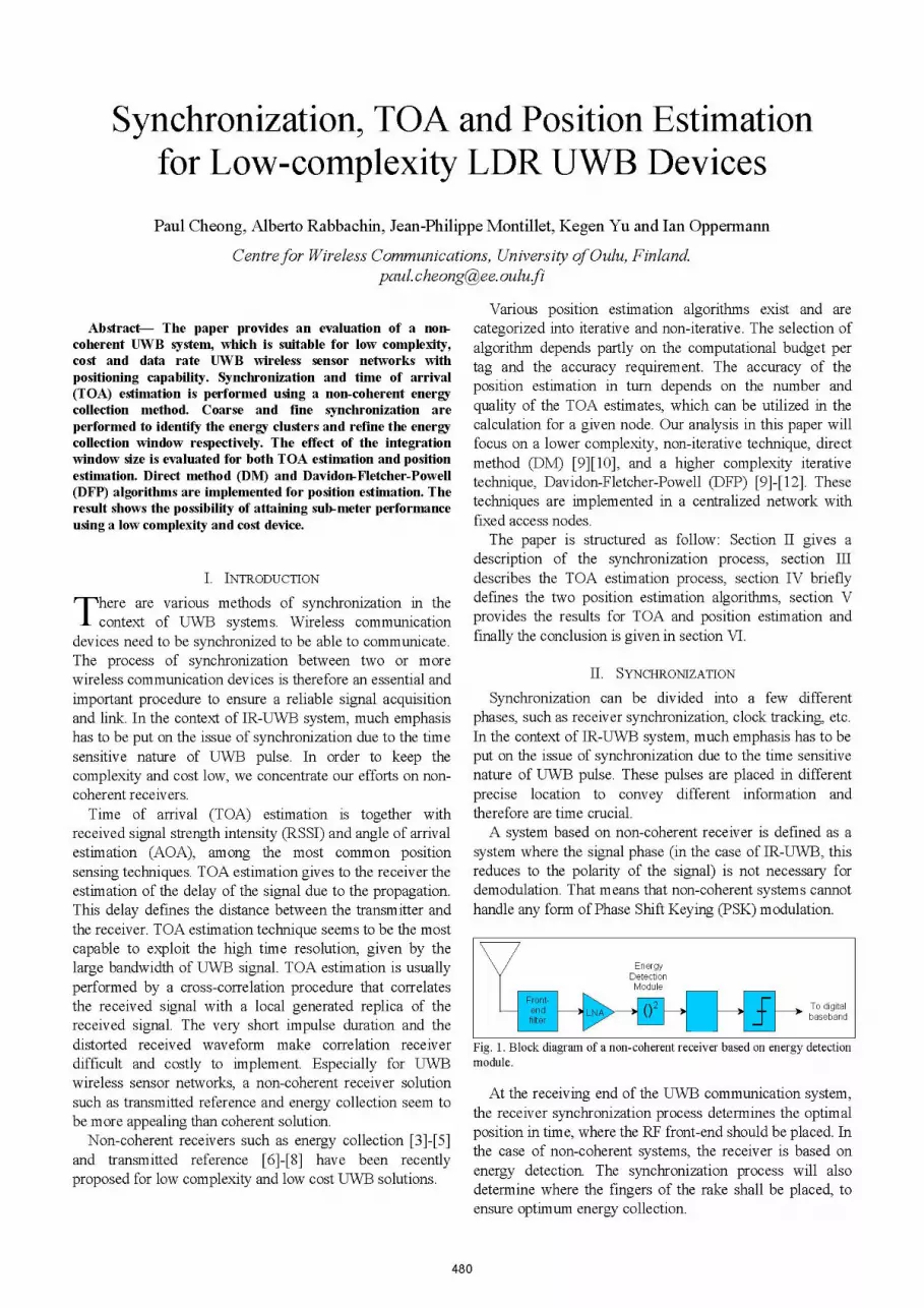
EnergyDetectionModule
\WA 2. 1+ T > To digitalt...... Dbaseband
Fig. 1. Block diagram of a non-coherent receiver based on energy detectionmodule.
At the receiving end of the UWB communication system,the receiver synchronization process determines the optimalposition in time, where the RF front-end should be placed. Inthe case of non-coherent systems, the receiver is based onenergy detection. The synchronization process will alsodetermine where the fingers of the rake shall be placed, toensure optimum energy collection.
480
Synchronization is also important for ranging where delayestimation is done. The precision of the synchronization ofthe first path will enable a more accurate delay estimation.This synchronization proposal will address receiversynchronization for both data and ranging scenarios. Thereceiver synchronization process can be divided into twosub-processes:
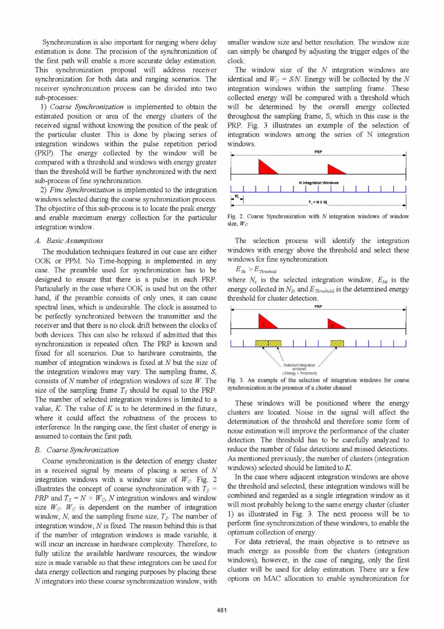
1) Coarse Synchronization is implemented to obtain theestimated position or area of the energy clusters of thereceived signal without knowing the position of the peak ofthe particular cluster. This is done by placing series ofintegration windows within the pulse repetition period(PRP). The energy collected by the window will becompared with a threshold and windows with energy greaterthan the threshold will be further synchronized with the nextsub-process of fine synchronization.2) Fine Synchronization is implemented to the integration
windows selected during the coarse synchronization process.The objective of this sub-process is to locate the peak energyand enable maximum energy collection for the particularintegration window.
A. Basic AssumptionsThe modulation techniques featured in our case are either
OOK or PPM. No Time-hopping is implemented in anycase. The preamble used for synchronization has to bedesigned to ensure that there is a pulse in each PRP.Particularly in the case where OOK is used but on the otherhand, if the preamble consists of only ones, it can causespectral lines, which is undesirable. The clock is assumed tobe perfectly synchronized between the transmitter and thereceiver and that there is no clock drift between the clocks ofboth devices. This can also be relaxed if admitted that thissynchronization is repeated often. The PRP is known andfixed for all scenarios. Due to hardware constraints, thenumber of integration windows is fixed at N but the size ofthe integration windows may vary. The sampling frame, S,consists ofN number of integration windows of size W. Thesize of the sampling frame Ts should be equal to the PRP.The number of selected integration windows is limited to avalue, K. The value of K is to be determined in the future,where it could affect the robustness of the process tointerference. In the ranging case, the first cluster of energy isassumed to contain the first path.
B. Coarse SynchronizationCoarse synchronization is the detection of energy cluster
in a received signal by means of placing a series of Nintegration windows with a window size of Wc. Fig. 2illustrates the concept of coarse synchronization with Ts =
PRP and Ts = N x WC, N integration windows and windowsize Wc. Wc is dependent on the number of integrationwindow, N, and the sampling frame size, Ts. The number ofintegration window, N is fixed. The reason behind this is thatif the number of integration windows is made variable, itwill incur an increase in hardware complexity. Therefore, tofully utilize the available hardware resources, the windowsize is made variable so that these integrators can be used fordata energy collection and ranging purposes by placing theseN integrators into these coarse synchronization window, with
smaller window size and better resolution. The window sizecan simply be changed by adjusting the trigger edges of theclock.
The window size of the N integration windows areidentical and Wc = SIN. Energy will be collected by the Nintegration windows within the sampling frame. Thesecollected energy will be compared with a threshold whichwill be determined by the overall energy collectedthroughout the sampling frame, S, which in this case is thePRP. Fig. 3 illustrates an example of the selection ofintegration windows among the series of N integrationwindows.
PRP
N Integration Windows
Ts= N X Wr
Fig. 2. Coarse Synchronization with N integration windows of windowsize, Wc
The selection process will identify the integrationwindows with energy above the threshold and select thesewindows for fine synchronization.
ENS > EThresholdwhere NS is the selected integration window, ENS is theenergy collected in NS, and EThreshold is the determined energythreshold for cluster detection.
PRP
_ _
Selected Integrationwindows
( Energy > Threshold)
Fig. 3. An example of the selection of integrationsynchronization in the presence of a cluster channel
windows for coarse
These windows will be positioned where the energyclusters are located. Noise in the signal will affect thedetermination of the threshold and therefore some form ofnoise estimation will improve the performance of the clusterdetection. The threshold has to be carefully analyzed toreduce the number of false detections and missed detections.As mentioned previously, the number of clusters (integrationwindows) selected should be limited to K.
In the case where adjacent integration windows are abovethe threshold and selected, these integration windows will becombined and regarded as a single integration window as itwill most probably belong to the same energy cluster (cluster1) as illustrated in Fig. 3. The next process will be toperform fine synchronization of these windows, to enable theoptimum collection of energy.
For data retrieval, the main objective is to retrieve asmuch energy as possible from the clusters (integrationwindows), however, in the case of ranging, only the firstcluster will be used for delay estimation. There are a fewoptions on MAC allocation to enable synchronization for
481
.*W..1-

data retrieval purpose and for ranging purpose. Nevertheless,the concept of coarse synchronization remains identicalregardless of the purpose.
C. Fine SynchronizationThe method proposed in this section can be used for fine
synchronization as well as for ranging. The differencesbetween using this concept for synchronization and rangingare as follow:* Ranging only require the knowledge of the first cluster,
which is assumed to contain the first path required fordelay estimation.
* Synchronization requires the knowledge of as manyclusters as possible, as maximum energy collection ispreferred.
Fine synchronization is performed by placing N windowswithin the coarsely synchronized windows. The process willrefine the search for the starting point of the cluster. Thehardware constraint affecting the synchronization accuracyand performance of this approach is the integration windowsize, which is dependent on the number of windows used aswell as the clock resolution. Ranging and finesynchronization can be implemented at the same time,reducing the processing time.
The explanation of this approach will be based on rangingbut the concept can simply be implemented in the case ofsynchronization.
III. TOA ESTIMATION
The main objective of ranging is to perform delayestimation of the first path. This process will be done afterthe coarse synchronization process. Coarse synchronization,as described previously, selects K number of windows,which represents the energy clusters. For ranging purpose,only the first cluster is essential where the assumed first pathis located.
PRP
\Selected Integration\window for Delay Est.(Energy1 > Threshold &Energy 1 > Energy 2 &assumed first path)
Fig. 4. Coarse Synchronization for ranging purpose
Fig. 4 illustrates the integration window with the firstenergy cluster used for delay estimation. The integrationwindow is selected on conditions that the energy collected isabove the threshold and is larger than that of the otherintegration windows. The selected integration window willthen proceed to the fine synchronization. Delay estimation isdone with the same set of integrators that are used in thesynchronization process. This will therefore reduce the needto incur further hardware complexity. The integrationwindow with window size Wc is further sub-divided into Nwindows of size Wd as illustrated in Fig. 5(a).
The ranging process is done with the assumption that thefirst path is in the first cluster. There will be imperfect
synchronization, which contributes to a synchronizationerror region of e,. This error region can also be interpretedinto scenarios where only coarse synchronization is done.The energy collected by each integration window will becompared with a threshold, EdThre,hold, and the window withenergy above the threshold (ENd> EdThreshold) will be selectedas illustrated in Fig. 5(b). ENd is the energy collected inwindow Nd. The selected integration window will bedeclared the first path of the signal and will be used fordelay estimation.
WC= NX W,
(a)
I~ ~~~~~~Assumed First path(Estimated TOA)
(b)
Fig. 5. (a) Fine Synchronization sub-process using N integration windows(b) Delay estimation by selecting the first window with energy greater thanthe threshold.
The precision of the delay estimation for ranging isdependent on the size and the number of integrationwindows and the degree of precision will affect theestimation of the time of arrival which will determine theaccuracy of ranging and in turn affect the position estimationaccuracy.
1217 1217tdela 2rtdaVVdI VV d
2dla delay tde/ay +where tdelay is the optimal delay estimation and t' is thedelay
estimated delay.
IV. POSITION ESTIMATION
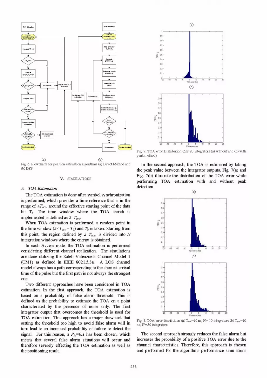
Two algorithms are emphasized in this section for theposition estimation within a centralized network, wherereference points are available in the form of base stationsand fixed access nodes. One of the algorithms is the directmethod (DM) [9]-[10], which directly solves a set ofsimultaneous equations based on the TOA/TDOAmeasurements. Therefore, exact solutions can be obtainedfor 2-D positioning with two fixed nodes using two TOAmeasurements (with known transmit time) or with three fixednodes using three TDOA measurements. For 3-Dpositioning, four fixed nodes are needed to obtain exactsolutions using TDOA measurements. This method has thelowest complexity compared to other algorithms and thus itis well suited for the scenarios where very low complexity isrequired. The other algorithm is the optimization-basedquasi-Newton Davidon-Fletcher-Powell (DFP) algorithm[9]-[12], which is an iterative method. Since it is iterativeand needs to determine the search direction during eachiterate, this algorithm has much higher complexity comparedto the non-iterative algorithms including the direct method.The position calculation processes for the two algorithms arebriefly described in the flowcharts (Fig. 6). It is assumed thatthe positions of the anchor nodes are known and the anchornodes are perfectly synchronized. The positions of sensornodes of interest are to be estimated.
482
I
(a)
Initial Estimatesp, and B,
'gradient g,
Determine searchdirection Sk
Determine stepsize or
timato Compute Updat p,;
i i i ~~~~~~Position increment hk+,
Gradient increment g,,,
N o F 1
No
Computeao bi, ci,gji=1,2
a ? M 8tYes d DN * bJHestiat
No~~~~~~~~~~~~~~~~A
No
Compute Aostion
coordinates
No- . Reecetimated\olutione ~~~~position
Sp.pL A Posibon Acquired
(a) (b)Fig. 6. Flowcharts for position estimation algorithms (a) Direct Method and(b) DFP
V. SIMULATIONS
A. TOA Estimation
The TOA estimation is done after symbol synchronizationis performed, which provides a time reference that is in therange of ±Tacc, around the effective starting point of the databit Tb. The time window where the TOA search isimplemented is defined as 2 Ta,cWhen TOA estimation is performed, a random point in
the time window (2 x Tac - Tb) and Tb is taken. Starting fromthis point, the region defined by 2 Ta,c, is divided into Nintegration windows where the energy is obtained.
In each Access node, the TOA estimation is performedconsidering different channel realization. The simulationsare done utilizing the Saleh Valenzuela Channel Model 1(CM1) as defined in IEEE 802.15.3a. A LOS channelmodel always has a path corresponding to the shortest arrivaltime of the pulse but the first path is not always the strongestone.Two different approaches have been considered in TOA
estimation. In the first approach, the TOA estimation isbased on a probability of false alarm threshold. This isdefined as the probability to estimate the TOA on a pointcharacterized by the presence of noise only. The firstintegrator output that overcomes the threshold is used forTOA estimation. This approach has a major drawback thatsetting the threshold too high to avoid false alarm will inturn lead to an increased probability of failure to detect thesignal. For this reason, a Pfa=O.1 has been chosen, whichmeans that several false alarm situations will occur andtherefore severely effecting the TOA estimation as well asthe positioning result.
(b)
Fig. 7. TOA error Distribution (5ns 20 integrators (a) without and (b) withpeak method)
In the second approach, the TOA is estimated by takingthe peak value between the integrator outputs. Fig. 7(a) andFig. 7(b) illustrate the distribution of the TOA error whileperforming TOA estimation with and without peakdetection.
(a)
(b)
Fig. 8. TOA error distribution (a) TaCc 10 ns, N= 10 integrators (b) TaCc 10ns, N= 20 integrators
The second approach strongly reduces the false alarm butincreases the probability of a positive TOA error due to thechannel characteristics. Therefore, this approach is chosenand performed for the algorithms performance simulations
483
TOA Estimation
due to the above-mentioned reasons.The use of 10 or 20 integrators performed leads to a small
TOA error. Fig. 8(a) and Fig. 8(b) illustrate the distributionfor both cases and by simple observation, the distributionsare similar.
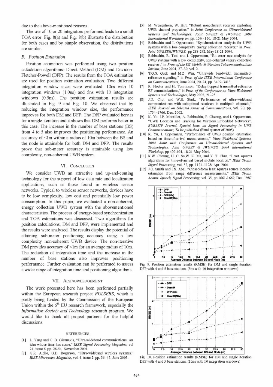
B. Position EstimationPosition estimation was performed using two position
calculation algorithms: Direct Method (DM) and Davidon-Fletcher-Powell (DFP). The results from the TOA estimationare used for position estimation evaluation. Two differentintegration window sizes were evaluated: iOns with 10integration windows (1.Ons) and 5ns with 10 integrationwindows (0.5ns). The position estimation results areillustrated in Fig. 9 and Fig. 10. We observed that byreducing the integration window size, the performanceimproves for both DM and DFP. The DFP evaluated here isfor a single iteration and it shows that DM performs better inthis case. The increase in the number of base stations (BS)from 4 to 5 also improves the positioning performance. Anaccuracy of <lm within a radius of 10m between the BS andthe node is attainable for both DM and DFP. The resultsprove that sub-meter accuracy is attainable using lowcomplexity, non-coherent UWB system.
VI. CONCLUSION
We consider UWB an attractive and up-and-comingtechnology for the support of low data rate and localizationapplications, such as those found in wireless sensornetworks. Typical to wireless sensor networks, devices haveto be low complexity, low cost and potentially low powerconsumption. In this paper, we evaluated a non-coherent,energy collection UWB system with the abovementionedcharacteristics. The process of energy-based synchronizationand TOA estimations was discussed. Two algorithms forposition calculations, DM and DFP, were implemented andthe results were analyzed. The results display the potential ofattaining sub-meter positioning accuracy using a lowcomplexity non-coherent UWB device. The non-iterativeDM provides accuracy of <lm for an average radius of 10m.The reduction of integration time and the increase in thenumber of base stations also improves positioningperformance. Further evaluation can be performed to assessa wider range of integration time and positioning algorithms.
VII. ACKNOWLEDGEMENT
The work presented here has been performed partiallywithin the European research project PULSERS, which ispartly being funded by the Commission of the EuropeanUnion within the 6th EU research framework, especially theInformation Society and Technology research program. Wewould like to thank all project partners for the helpfuldiscussions.
REFERENCES[1] L. Yang and G. B. Giannakis, "Ultra-wideband communications: An
idea whose time has come," IEEE Signal Processing Magazine, vol21, issue 6, pp. 26-54, November 2004.
[2] G.R. Aiello, G.D. Rogerson, "Ultra-wideband wireless systems,"IEEE Microwave Magazine, vol. 4, issue 2, pp. 36- 47, June 2003.
[3] M. Weisenhorn, W. Hirt, "Robust noncoherent receiver exploitingUWB channel properties," in Joint Conference on UltrawidebandSystems and Technologies. Joint UWBST & IWUWBS. 2004International Workshop on, pp. 156 - 160, 18-21 May 2004.
[4] Rabbachin and I. Oppermann, "Synchronization analysis for UWBsystems with a low-complexity energy collection receiver," in Proc.Joint UWBST&IWUWBS, pp 288-292, May 18-21 2004.
[5] Rabbachin, R. Tesi, and I. Oppermann, "Bit error rate analysis forUWB systems with a low complexity, non-coherent energy collectionreceiver," in Proc. ofthe ISTMobile & Wireless TelecommunicationsSummit, June 2004, 27-30, vol. 2.
[6] T.Q.S. Quek and M.Z. Win, "Ultrawide bandwidth transmitted-reference signaling," in Proc. of the IEEE International Conferenceon Communications, June 2004, 20-24, pp. 3409-3413.
[7] R. Hoctor and H. Tomlinson, "Delay-hopped transmitted-referenceRF communications," in Proc. of the Conference on Ultra WidebandSystems and Technologies, May 2002, 21-23.
[8] J.D. Choi and W.E. Stark, "Performance of ultra-widebandcommunications with suboptimal receivers in multipath channels,"IEEE Journal on Selected Areas of Communications, vol. 20, pp.1754-1766, Dec. 2002.
[9] K. Yu, J.P. Montillet, A. Rabbachin, P. Cheong, and I. Oppermann,"UWB Location and Tracking for Wireless Embedded Networks",EURASIP Journal, Special Issue on Signal Processing in UWBCommunications, To be published (Final quarter of 2005).
[10] K. Yu, I. Oppermann, "Performance of UWB position estimationbased on time-of-arrival measurements," Ultra Wideband Systems,2004. Joint with Conference on Ultrawideband Systems andTechnologies. Joint UWBST & IWUWBS. 2004 InternationalWorkshop, pp 400-404, 18-21 May 2004.
[11] K.W. Cheung, H. C. So,W. K. Ma, and Y. T. Chan, "Least squaresalgorithms for time-of-arrival based mobile location," IEEE Trans.Signal Processing, vol. 52, pp. 1121-1128, Apr. 2004.
[12] J.O. Smith and J.S. Abel, "Closed-form least squares source locationestimation from range difference measurements," IEEE Trans.Acoust. Speech, Signal Processing, vol. 35, pp.1661-1669, Dec. 1987
Fig. 9. Position estimation results (RMSE) for DM and single iterationDFP with 4 and 5 base stations. (5ns with 10 integration windows)
5 7.5 10 12.5 15 17.5 20 22.5 25Average Distance between BS and Node (m)
27.5 30
Fig. 10. Position estimation results (RMSE) for DM and single iterationDFP with 4 and 5 base stations. (IOns with 10 integration windows)
484
-* -DFP* DirectM* DFP(5Bs)
DirectM(5Bs)
w
C',~~~~~~~~~~~~~~~~~~~~~~~~~~~~~~~~~,
5 7.5 10 12.5 15 17.5 302.52 2.Average Distance between BS and Node (in)
3
- DFP
-U- DirectM , ,,
-*- DFP(5Bs)
DirectM(5Bs)2
w Al'ci,~~~~~~~~~~~~~~
,z - ,'- ,B __-D _
1 _ ,S _
_-4
n