switchgear for driver's desks, toggle switches f, l, p series
TRANSCRIPT
Connect - Contact - ControlConnect - Contact - Control
30°
15°
0°
15°
30°
OBEN
UNTEN
MITTE
35°
17,5°
0°
17,5°
35°
OBEN
UNTEN
MITTE
35°
17,5°
0°
17,5°
35°
OBEN
UNTEN
MITTE
Switchgear for driver‘s desks Toggle switches F, L, P Series Timetable holder BFH
F 110.en
IndexSwitchgear for driver‘s desks Toggle switchesF, L, P SeriesTimetable holder BFH 1Toggle switch assemblies for driver‘s desks 2
Features 2
Applications 2
Ordering code F, L, P Series 3
Switch function 4
Contact positions 4
Switching elements 5
Dimension diagrams 5
Switch function 6
Contact positions 6
Switching elements 7
Dimension diagrams 7
Special features and accessories 8
Handle styles 8
Nameplates 8
Switch guard S608 9
Cutouts, Clearance, Mounting 9
Timetable holder BFH 10
Ordering code BFH 10
Dimension diagrams, Mounting 10
Notes 11
Electrical Components and Systems forRailway Engineering and Industrial Applications 12
2
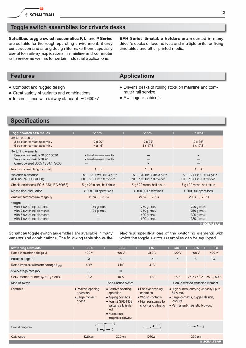
Toggle switch assemblies for driver‘s desks
Toggle switch assemblies Series F Series L Series PSwitch positions 3-position contact assembly 5-position contact assembly
2 x 30° 4 x 15°
2 x 35°
4 x 17.5°
2 x 35°
4 x 17.5°
Switching elements Snap-action switch S800 / S826 Snap-action switch S870 Cam-operated S005 / S007 / S008
● 3-position contact assembly
● 5-position contact assembly
---
------●
●------
Number of switching elements 1 ... 2 1 ... 4 1 ... 4
Vibration resistance (IEC 61373, IEC 60068)
5 ... 20 Hz: 0.0193 g/Hz 20 ... 150 Hz: 7.9 m/sec²
5 ... 20 Hz: 0.0193 g/Hz 20 ... 150 Hz: 7.9 m/sec²
5 ... 20 Hz: 0.0193 g/Hz 20 ... 150 Hz: 7.9 m/sec²
Shock resistance (IEC 61373, IEC 60068) 5 g / 22 msec, half sinus 5 g / 22 msec, half sinus 5 g / 22 msec, half sinus
Mechanical endurance > 300,000 operations > 100,000 operations > 300,000 operations
Ambient temperature range Ta -20°C ... +70°C -20°C ... +70°C -20°C ... +70°C
Weight with 1 switching element with 2 switching elements with 3 switching elements with 4 switching elements
170 g max. 190 g max.
--- ---
230 g max. 350 g max.400 g max. 600 g max.
200 g max. 250 g max. 300 g max. 360 g max.
Features
● Compact and rugged design● Great variety of variants and combinations● In compliance with railway standard IEC 60077
Applications
● Driver‘s desks of rolling stock on mainline and com-muter rail service
● Switchgear cabinets
Switching elements S800 S826 S870 S005 S007 S008Rated insulation voltage Ui 400 V 400 V 250 V 400 V 400 V 400 V
Pollution degree 3 3 3 3 3 3
Rated impulse withstand voltage Uimp 4 kV 4 kV 4 kV
Overvoltage category III III
Conv. thermal current Ith at Ta = 85°C 10 A 10 A 10 A 15 A 25 A / 60 A 25 A / 60 A
Kind of switch Snap-action switch Cam-operated switching element
Features ● Positive opening operation
● Large contact bridge
● Positive opening operation
● Wiping contacts● Form Z SPDT-DB,
galvanically isola-ted
● Permanent-magnetic blowout
● Positive opening operation
● Wiping contacts● High resistance to
shock and vibration
● High current-carrying capacity up to 60 A max.
● Large contacts, rugged design,long life
● Permanent-magnetic blowout
Circuit diagram3
1
4
2 1 42 1 2
Catalogue D20.en D26.en D70.en D30.en
Schaltbau toggle switch assemblies F, L, and P Series are suitable for the rough operating environment. Sturdy construction and a long design life make them especially useful for railway applications in mainline and commuter rail service as well as for certain industrial applications.
BFH Series timetable holders are mounted in many driver‘s desks of locomotives and multiple units for fixing timetables and other printed media.
Specifications
Schaltbau toggle switch assemblies are available in many variants and combinations. The following table shows the
electrical specifications of the switching elements with which the toggle switch assemblies can be equipped.
3
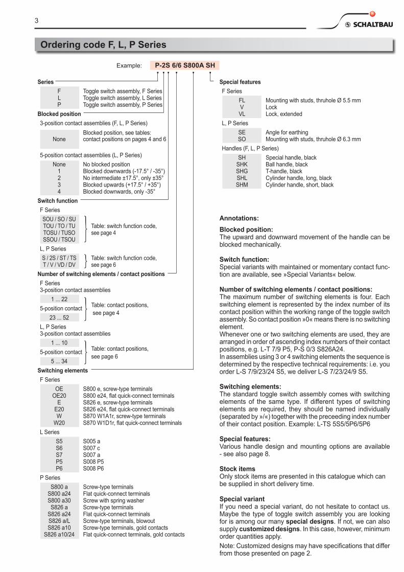
Ordering code F, L, P Series
Series F Toggle switch assembly, F Series L Toggle switch assembly, L Series P Toggle switch assembly, P SeriesBlocked position3-position contact assemblies (F, L, P Series) Blocked position, see tables: None contact positions on pages 4 and 6 5-position contact assemblies (L, P Series) None No blocked position 1 Blocked downwards (-17.5° / -35°) 2 No intermediate ±17.5°, only ±35° 3 Blocked upwards (+17.5° / +35°) 4 Blocked downwards, only -35°
Switch functionF Series SOU / SO / SU TOU / TO / TU Table: switch function code, TOSU / TUSO see page 4 SSOU / TSOUL, P Series S / 2S / ST / TS Table: switch function code, T / V / VD / DV see page 6
Number of switching elements / contact positionsF Series 3-position contact assemblies 1 ... 22 5-position contact Table: contact positions,
23 ... 52 see page 4
L, P Series 3-position contact assemblies 1 ... 10 5-position contact Table: contact positions,
5 ... 34 see page 6
Switching elementsF Series OE S800 e, screw-type terminals OE20 S800 e24, flat quick-connect terminals E S826 e, screw-type terminals E20 S826 e24, flat quick-connect terminals W S870 W1A1r, screw-type terminals W20 S870 W1D1r, flat quick-connect terminalsL Series S5 S005 a S6 S007 c S7 S007 a P5 S008 P5 P6 S008 P6P Series S800 a Screw-type terminals S800 a24 Flat quick-connect terminals S800 a30 Screw with spring washer S826 a Screw-type terminals S826 a24 Flat quick-connect terminals S826 a/L Screw-type terminals, blowout S826 a10 Screw-type terminals, gold contacts S826 a10/24 Flat quick-connect terminals, gold contacts
Annotations:Blocked position:The upward and downward movement of the handle can be blocked mechanically.
Switch function:Special variants with maintained or momentary contact func-tion are available, see »Special Variants« below.
Number of switching elements / contact positions:The maximum number of switching elements is four. Each switching element is represented by the index number of its contact position within the working range of the toggle switch assembly. So contact position »0« means there is no switching element. Whenever one or two switching elements are used, they are arranged in order of ascending index numbers of their contact positions, e.g. L-T 7/9 P5, P-S 0/3 S826A24. In assemblies using 3 or 4 switching elements the sequence is determined by the respective technical requirements: i.e. you order L-S 7/9/23/24 S5, we deliver L-S 7/23/24/9 S5.
Switching elements:The standard toggle switch assembly comes with switching elements of the same type. If different types of switching elements are required, they should be named individually (separated by »/«) together with the preceeding index number of their contact position. Example: L-TS 5S5/5P6/5P6
Special features:Various handle design and mounting options are available - see also page 8.
Stock itemsOnly stock items are presented in this catalogue which can be supplied in short delivery time.
Special variantIf you need a special variant, do not hesitate to contact us. Maybe the type of toggle switch assembly you are looking for is among our many special designs. If not, we can also supply customized designs. In this case, however, minimum order quantities apply.Note: Customized designs may have specifications that differ from those presented on page 2.
Special featuresF Series FL Mounting with studs, thruhole Ø 5.5 mm V Lock VL Lock, extendedL, P Series SE Angle for earthing SO Mounting with studs, thruhole Ø 6.3 mmHandles (F, L, P Series) SH Special handle, black SHK Ball handle, black SHG T-handle, black SHL Cylinder handle, long, black SHM Cylinder handle, short, black
Example: P-2S 6/6 S800A SH
4
30°
15°
0°
15°
30°
UP
DOWN
CENTRE
30°
15°
0°
15°
30°
UP
DOWN
CENTRE
35°
17.5°
0°
17.5°
35°
UP
DOWN
CENTRE
35°
17.5°
0°
17.5°
35°
UP
DOWN
CENTRE
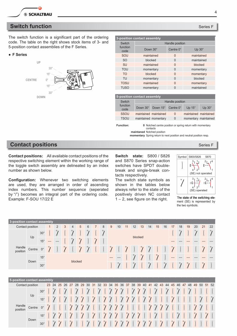
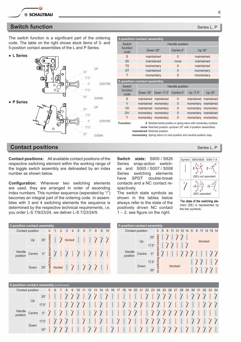
Switch function
The switch function is a significant part of the ordering code. The table on the right shows stock items of 3- and 5-position contact assemblies of the F Series.
3-position contact assemblySwitch function
code
Handle position
Down 30° Centre 0° Up 30°
SOU maintained 0 maintainedSO blocked 0 maintainedSU maintained 0 blocked
TOU momentary 0 momentaryTO blocked 0 momentaryTU momentary 0 blocked
TOSU maintained 0 momentaryTUSO momentary 0 maintained
5-position contact assemblySwitch function
code
Handle position
Down 30° Down 15° Centre 0° Up 15° Up 30°
SSOU maintained maintained 0 maintained maintainedTSOU maintained momentary 0 momentary maintained
Series F
Contact positions Series F
5-position contact assemblyContact position 23 24 25 26 27 28 29 30 31 32 33 34 35 36 37 38 39 40 41 42 43 44 45 46 47 48 49 50 51 52
Handle position
Up30°
15°
Centre 0°
Down15°
30°
3-position contact assemblyContact position 1 2 3 4 5 6 7 8 9 10 11 12 13 14 15 16 17 18 19 20 21 22
Handle position
Up30°
blocked15° --- --- --- --- --- --- --- ---
Centre 0°
Down15°
blocked--- --- --- --- --- --- --- ---
30°
Function: 0
maintanedmomentary
Notched centre position or spring return with momentary contactsNotched positionSpring return to next position and neutral position resp.
● F Series
Contact positions: All available contact positions of the respective switching element within the working range of the toggle switch assembly are delineated by an index number as shown below.
Configuration: Whenever two switching elements are used, they are arranged in order of ascending index numbers. This number sequence (seperated by “/”) becomes an integral part of the ordering code. Example: F-SOU 17/22 E
Switch state: S800 / S826 and S870 Series snap-action switches have SPDT double-break and single-break con-tacts respectively. The switch state symbols as shown in the tables below always refer to the state of the positively driven NC contact 1 – 2, see figure on the right.
Symbol S800/S826 S870
1
1
2
3
4
2 4
1
1
2
3
4
2 4(SE) not operated
1
1
2
3
4
2 4
1
1
2
3
4
2 4
(SE) operated
The state of the switching ele-he state of the switching ele-ment (SE) is represented by the two symbols.
5
2 1 123 4 3 2 1
42
13
12.5 16 12.51612.516
* Ground terminal** Switching element with flat quick-connect terminals
** Switching element with flat quick-connect
terminals
Sequential switch numbers (not shown on switching element itself)
88**
80
35
32
80 70
M5
14
10
32
70808110
6 +1
35
M5=67 / M6=71
81
28
up to 25A= M5over 25A= M6
8.5 17
Terminal designation (shown on nameplate of toggle switch assembly) 21
43
21
65 3
4 21 7
834
56
12
M5
14
Ø2
10
12 1.5-
2.0
max
.
6.5
28.5
M4
44
10
189
65
14
53
3570
+1
30
24.5
5.5 18
8070
53
4453
85**
55**
12
M4*
36.5+0.5 36.5+0.5 36+0,5 36+0,5 59+0,5 59+0,5 53.5+0.5 70.5+0.5
Groundterminal M4
Groundterminal M4
1 1 1 1
Groundterminal M5
Ø2
Ø2
28.5
44
10
189
14
3577
.5 +1
30
M5*
6.5
Position and designation of switch terminals
Ø2
Ø3.5
Ø5,5
4453
M4
Special design FL for mounting with stud and thruhole Ø5.5 ( see Ordering code, page 3).
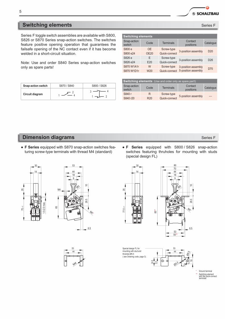
Switching elements Series F
Switching elementsSnap-action switch Code Terminals Contact
positions Catalogue
S800 e OE Screw-type3-position assembly D20
S800 e24 OE20 Quick-connectS826 e E Screw-type
3-position assembly D26S826 e24 E20 Quick-connectS870 W1A1r W Screw-type 3-position assembly
5-position assembly D70S870 W1D1r W20 Quick-connect
Series F toggle switch assemblies are available with S800, S826 or S870 Series snap-action switches. The switches feature positive opening operation that guarantees the failsafe opening of the NC contact even if it has become welded in a short-circuit situation.
Note: Use and order S840 Series snap-action switches only as spare parts!
Dimension diagrams Series F
Switching elements (Use and order only as spare part!)
Snap-action switch Code Terminals Contact
positions Catalogue
S840 r R Screw-type5-position assembly ---
S840 r20 R20 Quick-connect
● F Series equipped with S870 snap-action switches fea-turing screw-type terminals with thread M4 (standard)
● F Series equipped with S800 / S826 snap-actionswitches featuring thruholes for mounting with studs (special design FL)
Snap-action switch S870 / S840 S800 / S826
Circuit diagram 1 42 3
1
4
2
630°
15°
0°
15°
30°
UP
DOWN
CENTRE
30°
15°
0°
15°
30°
UP
DOWN
CENTRE
35°
17.5°
0°
17.5°
35°
UP
DOWN
CENTRE
35°
17.5°
0°
17.5°
35°
UP
DOWN
CENTRE
Switch function
The switch function is a significant part of the ordering code. The table on the right shows stock items of 3- and5-position contact assemblies of the L and P Series.
3-position contact assemblySwitch function
code
Handle position
Down 35° Centre 0° Up 35°
S maintained 0 maintained2S maintained none maintainedTS momentary 0 maintainedST maintained 0 momentaryT momentary 0 momentary
5-position contact assemblySwitch function
code
Handle position
Down 35° Down 17.5° Centre 0° Up 17.5° Up 35°
S maintained maintained 0 maintained maintainedV maintained momentary 0 momentary maintained
VD maintained momentary 0 momentary momentaryDV momentary momentary 0 momentary maintainedT momentary momentary 0 momentary momentary
Series L, P
Contact positions Series L, P
Function: 0none
maintainedmomentary
Notched centre position or spring return with momentary contactsNotched position up/down 35° with 3-position assembliesNotched positionSpring return to next position and neutral position resp.
5-position contact assembly (continued)
Contact position 5 6 7 8 9 10 11 12 13 14 15 16 17 18 19 20 21 22 23 24 25 26 27 28 29 30 31 32 33 34
Handle position
Up35°
17.5°
Centre 0°
Down17.5°
35°
3-position contact assemblyContact position 0 1 2 3 4 5 6 7 8 9 10
Handle position
Up 35°
no s
witc
hing
ele
men
t mou
nted
blocked
Centre 0°
Down 35° blocked
Contact positions: All available contact positions of the respective switching element within the working range of the toggle switch assembly are delineated by an index number as shown below.
Configuration: Whenever two switching elements are used, they are arranged in order of ascending index numbers. This number sequence (seperated by “/”) becomes an integral part of the ordering code. In assem-blies with 3 and 4 switching elements the sequence is determined by the respective technical requirements, i.e. you order L-S 7/9/23/24, we deliver L-S 7/23/24/9.
Symbol S800/S826 S005 -7 -8
1
1
2
3
4
2
1
1
2
3
4
2(SE) not operated
1
1
2
3
4
2
1
1
2
3
4
2
(SE) operated
The state of the switching ele-he state of the switching ele-ment (SE) is represented by the two symbols.
Switch state: S800 / S826 Series snap-action switch-es and S005 / S007 / S008 Series switching elements have SPDT double-break contacts and a NC contact re-spectively.The switch state symbols as shown in the tables below always refer to the state of the positively driven NC contact 1 – 2, see figure on the right.
5-position contact assemblyContact position 0 5 8 11 12 13 14 5 8 11 12 13 14
Handle position
Up35°
no s
witc
hing
ele
men
t mou
nted
blocked17.5°
Centre 0°
Down17.5°
blocked35°
● L Series
● P Series
7
2 1 123 4 3 2 1
42
13
12.5 16 12.51612.516
* Ground terminal** Switching element with flat quick-connect terminals
** Switching element with flat quick-connect
terminals
Sequential switch numbers (not shown on switching element itself)
88**
80
3532
80 70
M5
14
10
32
70808110
6 +1
35
M5=67 / M6=71
81
28
up to 25A= M5over 25A= M6
8.5 17
Terminal designation (shown on nameplate of toggle switch assembly) 21
43
21
65 3
4 21 7
834
56
12
M5
14
Ø2
10
12 1.5-
2.0
max
.
6.5
28.5
M4
44
10
189
65
14
53
3570
+1
30
24.5
5.5 18
8070
53
4453
85**
55**
12
M4*
36.5+0.5 36.5+0.5 36+0,5 36+0,5 59+0,5 59+0,5 53.5+0.5 70.5+0.5
Groundterminal M4
Groundterminal M4
1 1 1 1
Groundterminal M5
Ø2
Ø2
28.5
44
10
189
14
3577
.5 +1
30
M5*
6.5
Position and designation of switch terminals
Ø2
Ø3.5
Ø5,5
4453
M4
Special design FL for mounting with stud and thruhole Ø5.5 ( see Ordering code, page 3).
2 1 123 4 3 2 1
42
13
12.5 16 12.51612.516
* Ground terminal** Switching element with flat quick-connect terminals
** Switching element with flat quick-connect
terminals
Sequential switch numbers (not shown on switching element itself)
88**
80
35
32
80 70
M5
14
10
32
70808110
6 +1
35
M5=67 / M6=71
81
28
up to 25A= M5over 25A= M6
8.5 17
Terminal designation (shown on nameplate of toggle switch assembly) 21
43
21
65 3
4 21 7
834
56
12
M5
14
Ø2
10
12 1.5-
2.0
max
.
6.5
28.5
M4
44
10
189
65
14
53
3570
+1
30
24.5
5.5 18
8070
53
4453
85**
55**
12
M4*
36.5+0.5 36.5+0.5 36+0,5 36+0,5 59+0,5 59+0,5 53.5+0.5 70.5+0.5
Groundterminal M4
Groundterminal M4
1 1 1 1
Groundterminal M5
Ø2
Ø2
28.5
44
10
189
14
3577
.5 +1
30
M5*
6.5
Position and designation of switch terminals
Ø2
Ø3.5
Ø5,5
4453
M4
Special design FL for mounting with stud and thruhole Ø5.5 ( see Ordering code, page 3).
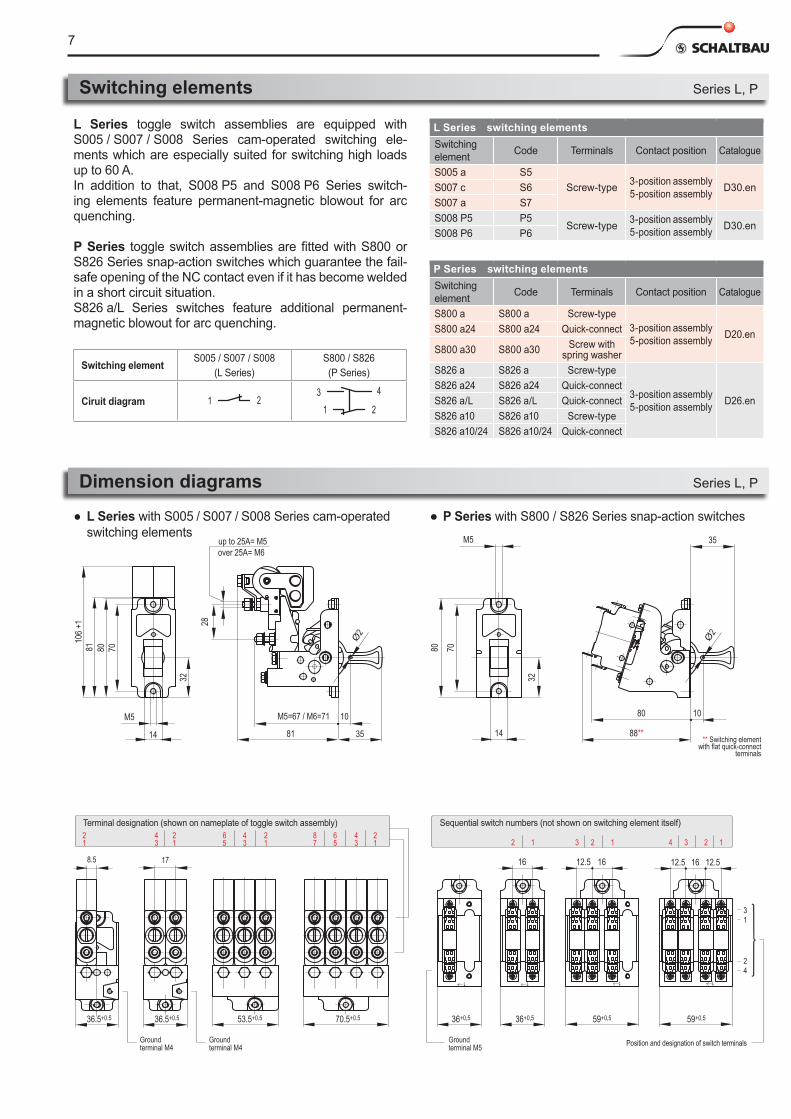
Switching elements Series L, P
P Series switching elementsSwitching element Code Terminals Contact position Catalogue
S800 a S800 a Screw-type3-position assembly5-position assembly D20.enS800 a24 S800 a24 Quick-connect
S800 a30 S800 a30 Screw with spring washer
S826 a S826 a Screw-type
3-position assembly5-position assembly D26.en
S826 a24 S826 a24 Quick-connectS826 a/L S826 a/L Quick-connectS826 a10 S826 a10 Screw-typeS826 a10/24 S826 a10/24 Quick-connect
L Series toggle switch assemblies are equipped with S005 / S007 / S008 Series cam-operated switching ele-ments which are especially suited for switching high loads up to 60 A.In addition to that, S008 P5 and S008 P6 Series switch-ing elements feature permanent-magnetic blowout for arc quenching.
P Series toggle switch assemblies are fitted with S800 or S826 Series snap-action switches which guarantee the fail-safe opening of the NC contact even if it has become welded in a short circuit situation. S826 a/L Series switches feature additional permanent- magnetic blowout for arc quenching.
Switching element S005 / S007 / S008(L Series)
S800 / S826(P Series)
Ciruit diagram 1 23
1
4
2
Dimension diagrams Series L, P
L Series switching elementsSwitching element Code Terminals Contact position Catalogue
S005 a S5Screw-type 3-position assembly
5-position assembly D30.enS007 c S6S007 a S7S008 P5 P5
Screw-type 3-position assembly5-position assembly D30.en
S008 P6 P6
● L Series with S005 / S007 / S008 Series cam-operated switching elements
● P Series with S800 / S826 Series snap-action switches
8
14.5
Ø3.
5
32
36-0.5
367080
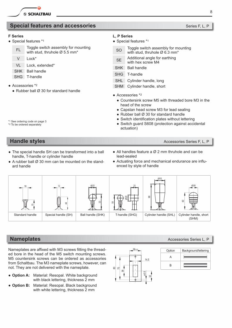
Special features and accessories Series F, L, P
Handle styles Accessories Series F, L, P
● All handles feature a Ø 2 mm thruhole and can be lead-sealed
● Actuating force and mechanical endurance are influ-enced by style of handle
● The special handle SH can be transformed into a ball handle, T-handle or cylinder handle
● A rubber ball Ø 30 mm can be mounted on the stand-ard handle
18
35
12
44
Ø25
53
Ø20
25
5088
Ø35
Ø30
60
18
35
12
44
Ø25
53
Ø20
25
5088
Ø35
Ø30
60
18
35
12
44
Ø25
53
Ø20
25
5088
Ø35
Ø30
60
18
35
12
44
Ø25
53
Ø20
25
5088
Ø35
Ø30
60
18
35
12
44
Ø25
53
Ø20
2550
88
Ø35
Ø30
60
18
35
12
44
Ø25
53
Ø20
25
5088
Ø35
Ø3060
Standard handle Special handle (SH) Ball handle (SHK) T-handle (SHG) Cylinder handle (SHL) Cylinder handle, short (SHM)
Nameplates Accessories Series L, P
Nameplates are affixed with M3 screws fitting the thread-ed bore in the head of the M5 switch mounting screws. M5 countersink screws can be ordered as accessories from Schaltbau. The M3 nameplate screws, however, can not. They are not delivered with the nameplate.
● Option A: Material: Resopal. White background with black lettering, thickness 2 mm
● Option B: Material: Resopal. Black background with white lettering, thickness 2 mm
Option Background/lettering
A
B
F Series● Special features *1
FL Toggle switch assembly for mounting with stud, thruhole Ø 5.5 mm*
V Lock*
VL Lock, extended*SHK Ball handleSHG T-handle
● Accessories *2
● Rubber ball Ø 30 for standard handle
*1 See ordering code on page 3*2 To be ordered separately
L, P Series● Special features *1
SO Toggle switch assembly for mounting with stud, thruhole Ø 6.3 mm*
SE Additional angle for earthing with hex screw M4
SHK Ball handleSHG T-handleSHL Cylinder handle, longSHM Cylinder handle, short
● Accessories *2
● Countersink screw M5 with threaded bore M3 in the head of the screw ● Capstan head screw M3 for lead sealing ● Rubber ball Ø 30 for standard handle ● Switch identification plates without lettering ● Switch guard S608 (protection against accidental actuation)
9
70 +0
.1
27
80
39.5
Ø3.2
L1544(S
tand
ard)
70 (S
tehb
olzen
befe
stigu
ng)
70
2743
15 LL1544
(Sta
ndar
d)
70 (M
ount
ing w
ith st
uds)
70
2743
15 LB
A
44
32
M4
70
M5
x*
Switch guard S608 Accessories Series L, P
Cutouts, Clearance, Mounting Series F, L, P
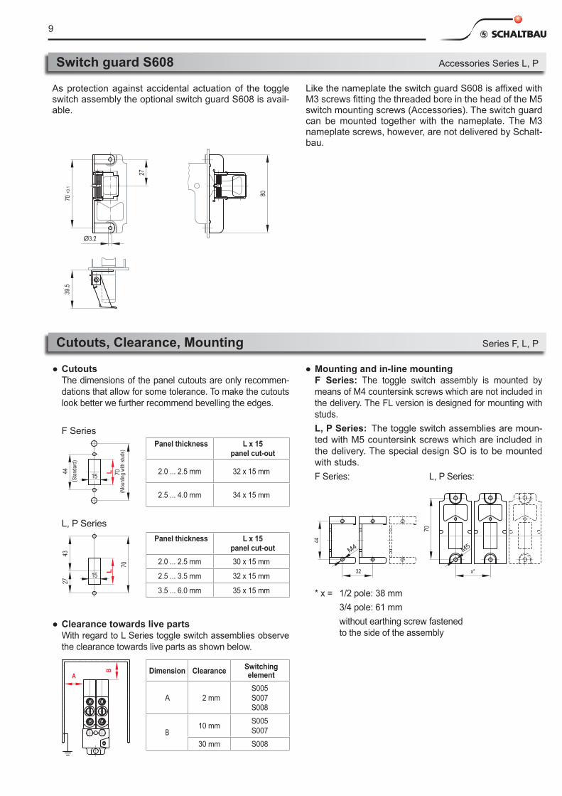
As protection against accidental actuation of the toggle switch assembly the optional switch guard S608 is avail-able.
L, P SeriesPanel thickness L x 15
panel cut-out2.0 ... 2.5 mm 30 x 15 mm
2.5 ... 3.5 mm 32 x 15 mm
3.5 ... 6.0 mm 35 x 15 mm
● Cutouts The dimensions of the panel cutouts are only recommen-
dations that allow for some tolerance. To make the cutouts look better we further recommend bevelling the edges.
Panel thickness L x 15 panel cut-out
2.0 ... 2.5 mm 32 x 15 mm
2.5 ... 4.0 mm 34 x 15 mm
F Series
● Clearance towards live parts With regard to L Series toggle switch assemblies observe
the clearance towards live parts as shown below.
Dimension Clearance Switching element
A 2 mmS005 S007 S008
B10 mm S005
S007
30 mm S008
● Mounting and in-line mounting F Series: The toggle switch assembly is mounted by
means of M4 countersink screws which are not included in the delivery. The FL version is designed for mounting with studs.
L, P Series: The toggle switch assemblies are moun-ted with M5 countersink screws which are included in the delivery. The special design SO is to be mounted with studs.
F Series: L, P Series:
Like the nameplate the switch guard S608 is affixed with M3 screws fitting the threaded bore in the head of the M5 switch mounting screws (Accessories). The switch guard can be mounted together with the nameplate. The M3 nameplate screws, however, are not delivered by Schalt-bau.
* x = 1/2 pole: 38 mm 3/4 pole: 61 mm without earthing screw fastened
to the side of the assembly
10
18,7540
40
25
90A
X
18,75
31,75
18,75
X in mmA in mm
25
BFH-40-SO
BFH-40-M5
BFH-25-M5-L
BFH-25-SO
Typenbezeichnung
80 70
32
14
36 +0.5
Timetable holder BFH Series BFH
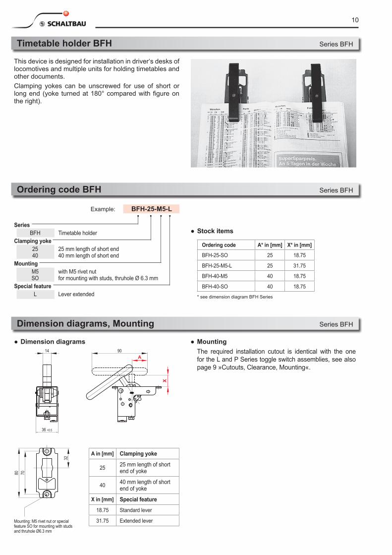
This device is designed for installation in driver‘s desks of locomotives and multiple units for holding timetables and other documents.Clamping yokes can be unscrewed for use of short or long end (yoke turned at 180° compared with figure on the right).
Series BFH Timetable holderClamping yoke 25 25 mm length of short end 40 40 mm length of short end
Mounting M5 with M5 rivet nut SO for mounting with studs, thruhole Ø 6.3 mm
Special feature L Lever extended
Example: BFH-25-M5-L
Ordering code BFH Series BFH
Dimension diagrams, Mounting Series BFH
● Mounting The required installation cutout is identical with the one
for the L and P Series toggle switch assemblies, see also page 9 »Cutouts, Clearance, Mounting«.
● Dimension diagrams
● Stock items
Ordering code A* in [mm] X* in [mm]
BFH-25-SO 25 18.75
BFH-25-M5-L 25 31.75
BFH-40-M5 40 18.75
BFH-40-SO 40 18.75
* see dimension diagram BFH Series
A in [mm] Clamping yoke
25 25 mm length of short end of yoke
40 40 mm length of short end of yoke
X in [mm] Special feature
18.75 Standard lever
31.75 Extended leverMounting: M5 rivet nut or special feature SO for mounting with studs and thruhole Ø6.3 mm

11
Notes
12
RoHS2002/95/EC
Schaltbau GmbHHollerithstrasse 581829 MunichGermanyPhone +49 89 9 30 05-0Fax +49 89 9 30 05-350e-Mail [email protected] www.schaltbau.de
with compliments:
We reserve the right to make technical alterations without prior notice.
For updated product information visit www.schaltbau-gmbh.com. Issued 05-2012F1843/0606/1.0 Printed in Germany
Electrical Components and Systems for Railway Engineering and Industrial Applications
Connectors Connectors manufactured to industry standards Connectors to suit the special requirements of communications
engineering (MIL connectors) Charging connectors for battery-powered machines and systems Connectors for railway engineering, including UIC connectors Special connectors to suit customer requirements
Snap-action switches Snap-action switches with positive opening operation Snap-action switches with self-cleaning contacts Enabling switches Special switches to suit customer requirements
Contactors Single and multi-pole DC contactors High-voltage AC/DC contactors Contactors for battery powered vehicles and power supplies Contactors for railway applications Terminal bolts and fuse holders DC emergency stop switches Special contactors to suit customer requirements
Control devices Master controllers and reversers for railway applications Toggle switch devices Handles and foot switches for railway applications
(dead-man equipment) Switching elements with high breaking capacity Emergency brake handles Signal devices
Transportation system equipment Power supplies for passenger coaches (electric equipment) Battery chargers for locomotives and passenger coaches High-voltage equipment for single and multi-phase operation Heating devices and heating controls Design and engineering services for high-voltage equipment Special equipment to suit customer requirements
Schaltbau GmbHhas a quality manage-ment system that has been certified since 1994.
Schaltbau GmbHmanufac tures in com-pl iance with RoHS. The LV Series connectors are RoHS compliant.
Schaltbau GmbHhas an environment management system that has been certified since 1994.