svar high response valve closed loop electronic control for
TRANSCRIPT
© 2003by Bosch Rexroth AG, Industrial Hydraulics, D-97813 Lohr am Main
All rights reserved. No part of this document may be reproduced or stored, processed, duplicated or circulated usingelectronic systems, in any form or by any means, without the prior written authorisation of Bosch Rexroth AG.In the event of contravention of the above provisions, the contravening party is obliged to pay compensation.
VTS 0940; VTS 0941; VTS 0942 1/26 RE 29 799/08.95
Summary of contents
Contents PageSVAR closed loop electronic control
• General 1• Technical data 2• Project planning/maintenance notes 2• Ordering code 3• "Axis ready" signal 4
SVAR closed loop electronic control, type VTS 0940-2X/...• Functional description 5• Connection diagram, unit dimensions 6
SVAR closed loop electronic control, type VTS 0941-2X/...• Functional description 5• Connection diagram, unit dimensions 8
SVAR closed loop electronic control, type VTS 0942-2X/...• Functional description 5• Connection diagram, unit dimensions 10
Interfaces• Control, analogue position measuring system,
pressure sensor 11• Input/output cards, valves 12
Individual cards• NT 3 power supply 13-14• NT 4 power supply 15-16• AR 1 analogue closed loop position control 17-19• XPL 1 closed loop pressure control card 20-22• Input/outputs cards EA1 and EA2 23-26
RE 29 799/08.03Replaces: 08.95
SVAR high response valve closed loopelectronic control for analogue closedloop position and pressure control ofservo hydraulic systemsTypes VTS 0940, VTS 0941 and VTS 0942
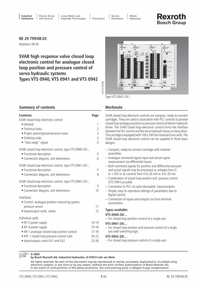
Type VTS 0941-2X/...
H/A
4153
/94
Merkmale
SVAR closed loop electronic controls are compact, ready-to-connectcartridges. They are used in association with PLC controls to provideclosed loop analogue position or pressure control of electro-hydraulicdrives. The SVAR closed loop electronic control forms the interfacebetween the PLC control and the servo hydraulic linear or rotary drive.The cartridge is equipped with 100 x 160 mm modular Euro cards. TheSVAR closed loop electronic control can be supplied in three basicdesigns.
– Compact, ready-to-connect cartridge with modularassemblies
– Analogue command signal input and actual signalmeasurement via differential inputs
– Both command signals for position and differential pressureand actual signals may be processed as voltages from 0to +10V or as currents from 0 to 20 mA or 4 to 20 mA.
– Combination of closed loop position and pressure control(VTS 0941) possible
– Connection to PLC via opto-decoupled inputs/outputs– Simple, easy to reproduce settings of parameters due to
digital control– Connection of inputs and outputs via front terminal
connections
Types available:VTS 0940-2X/...– For closed loop position control of a single axis
VTS 0941-2X/...– For closed loop position and pressure control of a single
axis with switching logic
VTS 0942-2X/...– For closed loop pressure control of a single axis
RE 29 799/08.95 2/26 VTS 0940; VTS 0941; VTS 0942
Technical data (For applications outside these parameters please consult us!)
Supply voltage
– External operating voltage UB 115/230 VAC; 50 to 60 Hz; 60 VAor UB + 24 VDC ± 10 %; 2 to 4 A
– Internal operating voltages UM ± 15 V and + 5 V
Valve command signal ucom ± 10 V; 5 mAor icom ± 10 mA; load 1 kΩ (optional)
Inputs/outputs
– Input resistance Ri 10 kΩ– Differential inputs ui ± 10 V
or ii 0 to 20 mA or 4 to 20 mA; load 500 Ω– Control signal inputs (fan in) +15 to 24 V; 3,3 kΩ; opto-decoupled
– Control signal outputs (fan out) +15 to 24 V; max. 8 mA total; opto-decoupled
"Axis ready" signal Potential free relay contact
– Contact loading I 2 ADC; Ieff = 2 A
– Switching power P 30 W / 60 VA
Permissible ambient temperature t 0 to + 50 °C
Storage temperature t – 20 to + 70 °C
Dimensions (B x H x T) – VTS 0940-2X 145 x 183 x 285 mm– VTS 0941-2X 186 x 183 x 285 mm– VTS 0942-2X 145 x 183 x 285 mm
Weight – VTS 0940-2X m 3,0 kg– VTS 0941-2X m 3,5 kg– VTS 0942-2X m 3,0 kg
– The cards may only be plugged or unplugged with the power switched off.
– Measurements should only be taken using instruments with Ri > 100 kΩ.
– Command signals may only be switched via relays with gold contacts (small voltages, small currents).
– Always screen command signal cables for valves with integral electronics or external valve amplifiers. Leave one end of screenopen. Connect card end to 0V supply voltage (GND).
– Signals to be screened should not be routed through a common cable.
– Connect command signal line screens on control side.
– Radio transmitters may not be used within 1 m of this card.
– Supply and return lines must not be installed in the vicinity of power lines.
Note!
Electrical signals (e.g. actual signals) generated by control electronics may not be used to switch off safety dependent machine functions. (c.f.European standard "Safety requirements of fluid technological systems and components", issue prEN 982)
Project planning / maintenance notes

VTS 0940; VTS 0941; VTS 0942 3/26 RE 29 799/08.95
Further details in clear text
E = Input/output card EA1 withvalve amplifier output stage for
servo valve 4WS2EM6-1X/…F12…with mechanical feedback
F = Input/output card EA1 withvalve amplifier output stage for
servo valve 4WS2EM10-4X/…B2…with mechanical feedback
G = Input/output card EA1 withvalve amplifier output stage for
servo valve 4WS2EM16-2X/…B12…with mechanical feedback
D = Input/output card EA2 withoutvalve amplifier output stage forvalves with integral electronics
e.g. 4WRDE...24V4WRTE...4WRS6... + module amplifier4WSE2... or 4WSE3E
Analogue closed loop position control = 0Analogue closed loop position control andclosed loop pressure control = 1Analogue closed loop pressure control = 2
Series 20 to 29 = 2X(20 to 29: externally interchangeable)
External supply voltages:115 VAC; 50 or 60 Hz (only for 4WS2EM, Size 6 to 16) = W115230 VAC; 50 or 60 Hz (only for 4WS2EM, Size 6 to 16) = W230+ 24 VDC (only for valves with integral electronics) = G24
e.g. 4WRDE…24V4WRTE…4WRS6… + module amplifier4WSE2… or 4WSE3E
Ordering code
*VTS 094_ – 2X / /

RE 29 799/08.95 4/26 VTS 0940; VTS 0941; VTS 0942
15
14
15c
15a
15a
15c
15a
15c
X1
15
14
15c
15a
15a
15c
15a
15c
X1
15
14
15c
15a
15a
15c
X1
15a
15c
15a
15c
All cards plugged in and internal supply voltages available.
SVAR closed loop electronic control ("Axis ready" signal)
VTS 0940-2X/...
VTS 0941-2X/...
VTS 0942-2X/...
EA1or
EA2
BUS
Axisready
AR1
Power supplyNT3/NT4
Voltagemonitor
Power supplyNT3/NT4
Voltagemonitor
AR1
XPL1
Axisready
EA1or
EA2
XPL1
Axisready
BUS
BUS
EA1or
EA2
Power supplyNT3/NT4
Voltagemonitor

VTS 0940; VTS 0941; VTS 0942 5/26 RE 29 799/08.95
SPS
I/O 24 V
D
A
NT3/NT4
=
AR1 VTS 0225 EA1/EA2
p / Q
su,i
I/O
PDT1
PLC
NT3 power supply
– Voltages for the closed loop electronic control aregenerated from 115 V or 230 V mains supply.• + 5 V• ± 15 V• ± 24 V
– All voltages are monitored (relay contact)
NT4 power supply
– Voltages for the closed loop electronic control aregenerated from + 24 V ± 10 % supply voltage.• + 5 V• ± 15 V
– All voltages are monitored (relay contact)
Input/output cards EA1 or EA2
– Direction dependent gain matching– Signal to PLC: "Axis ready"– EA1: Valve output stage for servo valves with mechanical
feedback– EA2: Interface for integral valve electronics
Command position
PLC control Closed loop electronic control Hydraulic drive
Application: Closed loop position control of a single axis with anlogue control AR1
AR1 analogue control
– P controller– D term or T1 term– Two ramp generators for each drive direction– Open loop/closed loop control switch– Cable break monitoring of command and actual signals
(at 4 to 20 mA)– Following error monitoring– Communication with PLC via opto-decoupled 24V inputs and
outputs– All parameter and function settings reproducible by means of
encoded and DIL switches
Actual position
Faultmonitor
Functional description for SVAR closed loop electronic control, type VTS 0940-2X
Valve I, U

RE 29 799/08.95 6/26 VTS 0940; VTS 0941; VTS 0942
1 23 4
FGGest.
NPa2
a1+
a2+
a1–
a2–
135
24
123456789
10
11121314151617181920
VTS0225 AR1
VF
VG
D
Fehler
EA
VTS06xx
NP
6789
10
12345
16171819202122
2324252627
282930
1112131415
VTS090x
NT
Betriebsspannung
34
SPS
I/O24 V
DA
p / Q
su,i
p / Q
12
222 50
1,5
235
145
8132
5
133
163
183
10
25
10TE 8TE 8TE
1 23 4
FGGest.
NPa2
a1+
a2+
a1–
a2–
135
24
123456789
10
11121314151617181920
VTS0225 AR1
VF
VG
D
Fehler
EA2
VTS0610
NP
6789
10
12345
16171819202122
2324252627
282930
1112131415
VTS090x
NT
Betriebsspannung
34
1TE = 5,08 mm
Unit dimensions: SVAR closed loop electronic control, type VTS 0940-2X (Dimensions in mm)
Connection diagram: PLC control, SVAR closed loop electronic control type VTS 0940-2X,valve and position measuring system
Command position
Actual position
Valve command signal andvoltage supply forintegral electronics
Valve current in servo valveswith mechanical feedback
FaultsRelease
Stop
Operating voltage
Valve with integral electronics
PLC
Forplug-inconnections
FaultsRelease
Stop
Operating voltage
VTS 0940; VTS 0941; VTS 0942 7/26 RE 29 799/08.95
SPS
I/O 24 V
D
A
NT3/NT4
=
AR1 VTS 0225
su,i
I/O
PDT1
PIDT1
XPL1 VTS 0223 EA1/EA2
pu,i
p / Q
A Bp
u,i
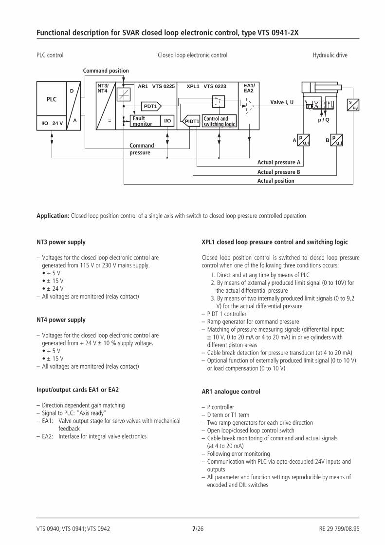
Functional description for SVAR closed loop electronic control, type VTS 0941-2X
NT3 power supply
– Voltages for the closed loop electronic control aregenerated from 115 V or 230 V mains supply.• + 5 V• ± 15 V• ± 24 V
– All voltages are monitored (relay contact)
NT4 power supply
– Voltages for the closed loop electronic control aregenerated from + 24 V ± 10 % supply voltage.• + 5 V• ± 15 V
– All voltages are monitored (relay contact)
Input/output cards EA1 or EA2
– Direction dependent gain matching– Signal to PLC: "Axis ready"– EA1: Valve output stage for servo valves with mechanical
feedback– EA2: Interface for integral valve electronics
XPL1 closed loop pressure control and switching logic
Closed loop position control is switched to closed loop pressurecontrol when one of the following three conditions occurs:
1. Direct and at any time by means of PLC2. By means of externally produced limit signal (0 to 10V) for
the actual differential pressure3. By means of two internally produced limit signals (0 to 9,2
V) for the actual differential pressure– PIDT 1 controller– Ramp generator for command pressure– Matching of pressure measuring signals (differential input:
± 10 V, 0 to 20 mA or 4 to 20 mA) in drive cylinders withdifferent piston areas
– Cable break detection for pressure transducer (at 4 to 20 mA)– Optional function of externally produced limit signal (0 to 10 V)
or load compensation (0 to 10 V)
AR1 analogue control
– P controller– D term or T1 term– Two ramp generators for each drive direction– Open loop/closed loop control switch– Cable break monitoring of command and actual signals
(at 4 to 20 mA)– Following error monitoring– Communication with PLC via opto-decoupled 24V inputs and
outputs– All parameter and function settings reproducible by means of
encoded and DIL switches
Application: Closed loop position control of a single axis with switch to closed loop pressure controlled operation
PLC control Closed loop electronic control Hydraulic drive
Control andswitching logic
Valve I, U
Commandpressure
Faultmonitor
Command position
PLC
Actual pressure A
Actual pressure B
Actual position
RE 29 799/08.95 8/26 VTS 0940; VTS 0941; VTS 0942
SPS
I/O24 V
DA
p / Q
su,i
p / Q
1 23 4
FGGest.
NPa2
a1+
a2+
a1–
a2–
135
24
123456789
10
11121314151617181920
VTS0225
AR1
VF
VG
D
Fehler NP
6789
10
12345
16171819202122
2324252627
282930
1112131415
VTS090x
NT
Betriebsspannung
34
135
24
VTS0223
XPL1
NP-Ist NP-Soll
Perr.PR
P1 P2
pu,i
A pu,i
B
123456789
101112
131415161718192021222324
EA
VTS06xx 1
2
222 50
1,5
235
186
11432
5
133
163
183
10
25
10TE 8TE 8TE
1 23 4
FGGest.
NPa2
a1+
a2+
a1–
a2–
135
24
123456789
10
11121314151617181920
VTS0225
AR1
VF
VG
D
Fehler
EA2VTS0610
NP
6789
10
12345
16171819202122
2324252627
282930
1112131415
VTS090x
NT
Betriebsspannung
34
8TE
135
24
123456789
101112
131415161718192021222324
VTS0223
XPL1
1TE = 5,08 mm
NP-Ist NP-Soll
Perr.PR
P1 P2
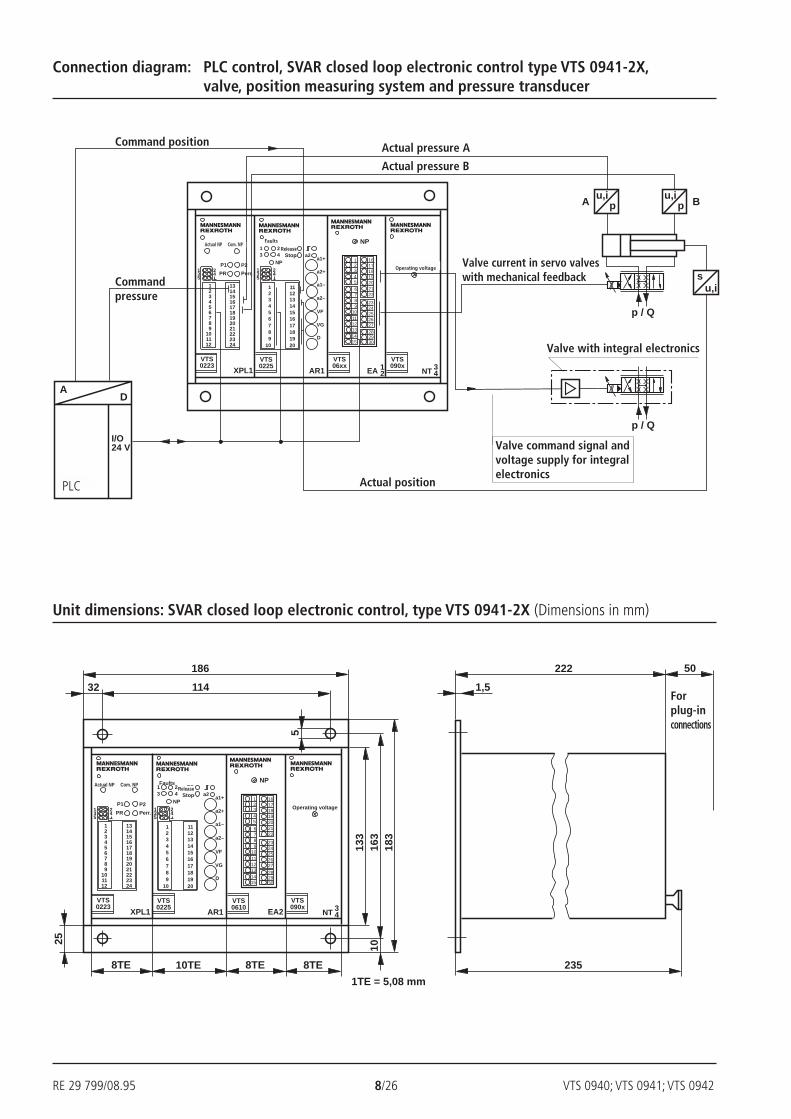
Unit dimensions: SVAR closed loop electronic control, type VTS 0941-2X (Dimensions in mm)
Connection diagram: PLC control, SVAR closed loop electronic control type VTS 0941-2X,valve, position measuring system and pressure transducer
Valve with integral electronics
Command position
Actual position
Valve current in servo valveswith mechanical feedback
Valve command signal andvoltage supply for integralelectronics
Actual pressure A
Actual pressure B
Operating voltage
ReleaseStop
FaultsActual NP Com. NP
Commandpressure
PLC
Forplug-inconnections
Operating voltage
ReleaseStop
FaultsActual NP Com. NP
VTS 0940; VTS 0941; VTS 0942 9/26 RE 29 799/08.95
SPS
I/O 24 V
D
A
NT3/NT4
= PIDT1
XPL1 VTS 0223 EA1/EA2
p
p / Q
A Bp
u,i u,i
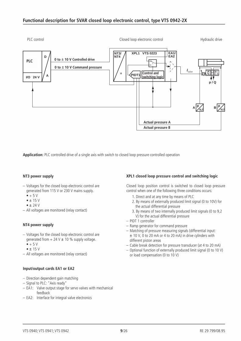
NT3 power supply
– Voltages for the closed loop electronic control aregenerated from 115 V or 230 V mains supply.• + 5 V• ± 15 V• ± 24 V
– All voltages are monitored (relay contact)
NT4 power supply
– Voltages for the closed loop electronic control aregenerated from + 24 V ± 10 % supply voltage.• + 5 V• ± 15 V
– All voltages are monitored (relay contact)
Input/output cards EA1 or EA2
– Direction dependent gain matching– Signal to PLC: "Axis ready"– EA1: Valve output stage for servo valves with mechanical
feedback– EA2: Interface for integral valve electronics
XPL1 closed loop pressure control and switching logic
Closed loop position control is switched to closed loop pressurecontrol when one of the following three conditions occurs:
1. Direct and at any time by means of PLC2. By means of externally produced limit signal (0 to 10V) for
the actual differential pressure3. By means of two internally produced limit signals (0 to 9,2
V) for the actual differential pressure– PIDT 1 controller– Ramp generator for command pressure– Matching of pressure measuring signals (differential input:
± 10 V, 0 to 20 mA or 4 to 20 mA) in drive cylinders withdifferent piston areas
– Cable break detection for pressure transducer (at 4 to 20 mA)– Optional function of externally produced limit signal (0 to 10 V)
or load compensation (0 to 10 V)
Application: PLC controlled drive of a single axis with switch to closed loop pressure controlled operation
Functional description for SVAR closed loop electronic control, type VTS 0942-2X
PLC control Closed loop electronic control Hydraulic drive
0 to ± 10 V Controlled drive
0 to ± 10 V Command pressureIValve
PLC
Control andswitching logic
Actual pressure AActual pressure B

RE 29 799/08.95 10/26 VTS 0940; VTS 0941; VTS 0942
SPS
I/O24 V
DA
p / Q
p / Q
EA
VTS06xx
NP
6789
10
12345
16171819202122
2324252627
282930
1112131415
VTS090x
NT
Betriebsspannung
34
135
24
VTS0223
XPL1
pu,i
A pu,i
B
123456789
101112
131415161718192021222324
Perr.
12
NP-Ist NP-Soll
PR
P1 P2
222 50
1,5
235
145
8132
5
133
163
183
10
25
8TE 8TE 8TE
EA2
VTS0610
NP
6789
10
12345
16171819202122
2324252627
282930
1112131415
VTS090x
NT
Betriebsspannung
34
135
24
VTS0223
XPL1
2TE
1TE = 5,08 mm
123456789
101112
131415161718192021222324
NP-Ist NP-Soll
PR
P1 P2
Unit dimensions: SVAR closed loop electronic control, type VTS 0942-2X (Dimensions in mm)
Connection diagram: PLC control, SVAR closed loop electronic control type VTS 0942-2X,valve and pressure transducer
Forplug-inconnections
Valve command signal andvoltage supply for integralelecronics
Actual pressure AControlled drive command signal
Actual NP Com. NP
Operating voltage
Actual NP Com. NP
Operating voltage
Actual pressure B
Valve command signal
Valve with integral electronics
Commandpressure
PLC
VTS 0940; VTS 0941; VTS 0942 11/26 RE 29 799/08.95
1 23 4
FGGest.
NP
a2a1+
a2+
a1–
a2–
123456789
10
11121314151617181920
VTS0225
AR1
VF
VG
D
135
24
Fehler
135
24
123456789
101112
131415161718192021222324
VTS0223
XPL1
NP-Ist NP-Soll
Perr.PR
P1 P2
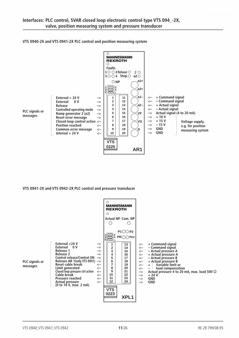
VTS 0940-2X and VTS 0941-2X PLC control and position measuring system
Interfaces: PLC control, SVAR closed loop electronic control type VTS 094_-2X,valve, position measuring system and pressure transducer
VTS 0941-2X and VTS 0942-2X PLC control and pressure transducer
<– + Command signal<– – Command signal<– + Actual signal<– – Actual signal–> Actual signal (4 to 20 mA)–> + 10 V–> + 15 V–> – 15 V–> GND–> GND
Voltage supply,e.g. for positionmeasuring system
<– + Command signal<– – Command signal<– – Actual pressure A<– + Actual pressure A<– – Actual pressure B<– + Actual pressure B<– + Variable limit or<– – load compensation–> Actual pressure 4 to 20 mA, max. load 500 Ω–> + 24 V–> GND–> GND
PLC signals ormessages
External + 24 V –>External 0 V –>Release –>Controlled operating mode –>Ramp generator 2 (a2) –>Reset error message –>Closed loop control active <–Position reached <–Common error message <–Internal + 24 V <–
External +24 V –>External 0 V –>Release 1 –>Release 2 –>Control release/Control ON –>Release AR 1(only VTS 0941) –>Reset cable break <–Limit generated <–Closed loop pressure ctrl active <–Cable break <–Pressure reached <–Actual pressure <–(0 to 10 V, max. 2 mA)
PLC signals ormessages
FaultsRelease
Stop
Actual NP Com. NP
RE 29 799/08.95 12/26 VTS 0940; VTS 0941; VTS 0942
EA2
VTS0610
NP
6789
10
12345
16171819202122
2324252627282930
1112131415
321
6
54
987
1211
10
1514
13
181716
212019
2423
22
272625
2928
30
15 … 24 V
0 V0…±10 V
+ 24 V0 V
+ 24 V0 V
0…±10 V0 V
0…±10 V
+ 15 V– 15 V
0 V0 …±10 V
0 V
EA1
VTS0609
NP~
6789
10
12345
16171819202122
2324252627282930
1112131415
BACD
321
6
54
987
1211
10
1514
13
181716
212019
2423
22
272625
2928
30
15 … 24 V
0 V0…±10 V
+ 5 V– 15 V+ 15 V
AC
b
1342
B
D a
12; 3
45; 6
12354
+ 24 V
0 V
EA2
VTS0610
NP
6789
10
12345
16171819202122
2324252627282930
1112131415
+ 24 V
0 V
VT 11073-1X
VT 11080-2X
4WRS6
78910
61211
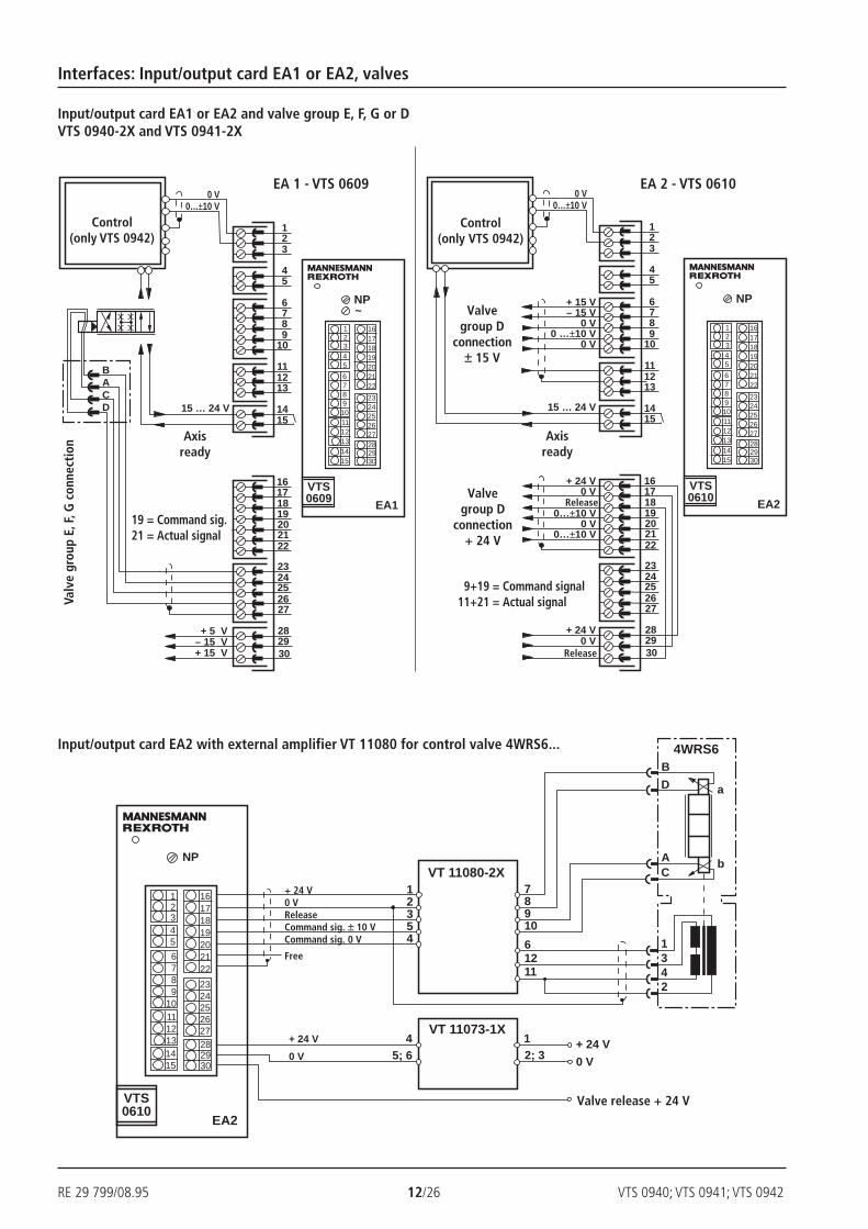
Control(only VTS 0942)
EA 1 - VTS 0609
Control(only VTS 0942)
EA 2 - VTS 0610
Release
Release
Input/output card EA1 or EA2 and valve group E, F, G or DVTS 0940-2X and VTS 0941-2X
Input/output card EA2 with external amplifier VT 11080 for control valve 4WRS6...
Interfaces: Input/output card EA1 or EA2, valves
Valve release + 24 V
Valvegroup D
connection± 15 V
Valvegroup D
connection+ 24 V
Axisready
Axisready
9+19 = Command signal11+21 = Actual signal
19 = Command sig.21 = Actual signal
+ 24 V0 VReleaseCommand sig. ± 10 VCommand sig. 0 V
Free
Valv
e gr
oup
E, F
, G c
onne
ctio
n

VTS 0940; VTS 0941; VTS 0942 13/26 RE 29 799/08.95
27
31
29
L1
NPE
15a
15c
4ac
20ac
24ac
6ac
22ac
2ac
+ 24 V
~
– 15 V
M0
+ 5 V
– 24 V
+ 15 V
NT3 power supply cards were developed for use in SVAR closed loopelectronic control cartridge assemblies. They meet the qualityrequirements with respect to the supply voltages. The card is a Eurocard and provides the five output voltages required.Power supply and voltage stabilisation form one unit on the card.
Features:
– Regulator for all voltages
– All output voltages are short-circuit protected by fold-backcharacteristic
– Monitoring of all voltages and fault signals by means of arelay contact
H/A 2848NT3 power supply, type VTS 0908
Technical data:
Supply voltage U 230/115 VAC ± 10 %(Excess voltage protectionto VDE 0160)
Power consumption P 60 W
Cut-out mechanism IS Thermister 110 °Cin primary circuit
Output voltages UA ± 15 VDC ± 5 %; 0,4 A± 24 VDC ± 5 %; 0,2 A+ 5 VDC ± 5 %; 0,6 A
Relay data– Max. contact load I 2 A– Max. switching power P 30 W / 60 VA
Type of connection 50 + 3 pin terminal connector,DIN 41 612, standardised,form C
Card dimensions Euro card100 x 160 mm, DIN 41 494
Front plate dimensions– Height 3 HE (128,4 mm)– Width on conductor side 1 TE (5,08 mm)– Width on component side 7 TE
Permiss. ambient temp. t 0 to + 50 °C
Storage temperature t – 20 to + 70°C
Weight m 1,4 kg
For applications outside these parameters please consult us.
Voltagemonitor
Contact closed =voltages OK
Terminal connections:
NT3 power supply card, type VTS 0908

RE 29 799/08.95 14/26 VTS 0940; VTS 0941; VTS 0942
Betriebsspannung
715
2
100
165
186
8TE (40,3)
3HE
(12
8,4)
89
VTS0908
NT3
7
Operating voltage
Further details in clear text
1 = Supply voltage 230 VAC (50 to 60 Hz)2 = Supply voltage 115 VAC (50 to 60 Hz)
50 + 3 pin terminal connector DIN 41 612 = Sstandardised, form C(with leading safety contact)
Series 10 to 19 = 1X(10 to 19: externally interchangeable)
VTS 0908 S 1X / *
Unit dimensions (Dimensions in mm)
Ordering code
NT3 power supply card, type VTS 0908

VTS 0940; VTS 0941; VTS 0942 15/26 RE 29 799/08.95
15a
15c
4ac
20ac
24ac
6ac
2ac
+ 24 V
+ 15 V
– 15 V
+ 5 V
M0
+ 24 V
+ 24 V
0 V
0 V
NT4 power supply cards were developed for use in SVAR closed loopelectronic control cartridge assemblies. They meet the qualityrequirements with respect to the supply voltages. The card is a Eurocard and provides the three output voltages required.NT4 power supply cards are not suitable for use with amplifier outputstages B for servo valves with mechanical feedback.
Features:
– DC/DC converter
– Monitoring of all voltages and fault signals by means of arelay contact
H/A 4158/94NT4 power supply, type VTS 0909
Terminal connections:
ScreenScreen
Voltagemonitor
Contact closed =voltages OK
Technical data:
Supply voltage U + 24 VDC ± 10 %
Power consumption P 35 W
Cut-out mechanism IS T 400 mA in primary circuit
Output voltages UA ± 15 VDC ± 5 %; 0,35 A+5 VDC ± 5 %; 1 A
Relay data– Max. contact load I 2 ADC / 2 AAC– Max. switching power P 30 W / 60 VA
Type of connection: 50 + 3 pin terminal connector,DIN 41 612, standardised,form C
Card dimensions Euro card100 x 160 mm, DIN 41 494
Front plate dimensions– Height 3 HE (128,4 mm)– Width on conductor side 1 TE (5,08 mm)– Width on component side 7 TE
Permiss. ambient temp. t 0 to + 50 °C
Storage temperature t – 20 to + 70°C
Weight m 1,4 kg
For applications outside these parameters please consult us.
NT4 power supply card, type VTS 0909

RE 29 799/08.95 16/26 VTS 0940; VTS 0941; VTS 0942
715
2
100
165
186
8TE (40,3)
3HE
(12
8,4)
89
VTS0909
NT4
7
+ 24 V
0 V
F1/T400 mA
Series 10 to 19 = 1X(10 to 19: externally interchangeable)
Further details in clear text
*VTS 0909 –1X /
Unit dimensions (Dimensions in mm)
Ordering code
NT4 power supply, type VTS 0909
Operating voltage
VTS 0940; VTS 0941; VTS 0942 17/26 RE 29 799/08.95
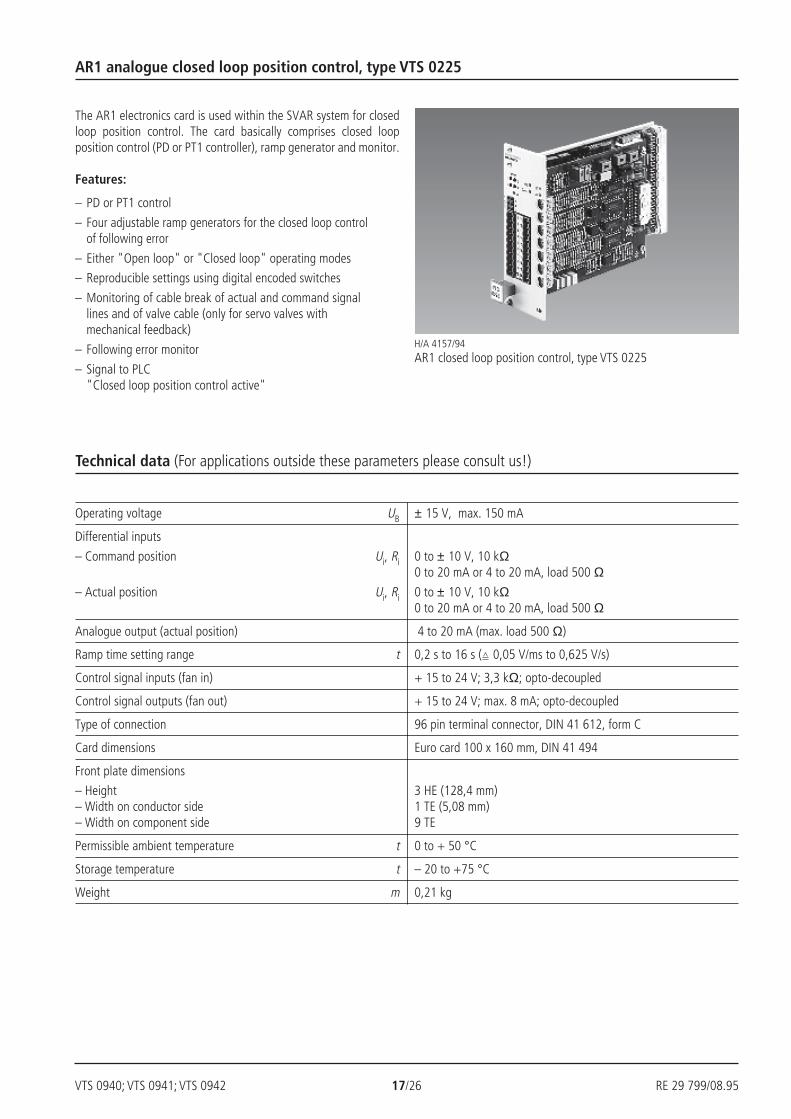
Operating voltage UB ± 15 V, max. 150 mA
Differential inputs
– Command position Ui, Ri 0 to ± 10 V, 10 kΩ0 to 20 mA or 4 to 20 mA, load 500 Ω
– Actual position Ui, Ri 0 to ± 10 V, 10 kΩ0 to 20 mA or 4 to 20 mA, load 500 Ω
Analogue output (actual position) 4 to 20 mA (max. load 500 Ω)
Ramp time setting range t 0,2 s to 16 s ( 0,05 V/ms to 0,625 V/s)
Control signal inputs (fan in) + 15 to 24 V; 3,3 kΩ; opto-decoupled
Control signal outputs (fan out) + 15 to 24 V; max. 8 mA; opto-decoupled
Type of connection 96 pin terminal connector, DIN 41 612, form C
Card dimensions Euro card 100 x 160 mm, DIN 41 494
Front plate dimensions
– Height 3 HE (128,4 mm)– Width on conductor side 1 TE (5,08 mm)– Width on component side 9 TE
Permissible ambient temperature t 0 to + 50 °C
Storage temperature t – 20 to +75 °C
Weight m 0,21 kg
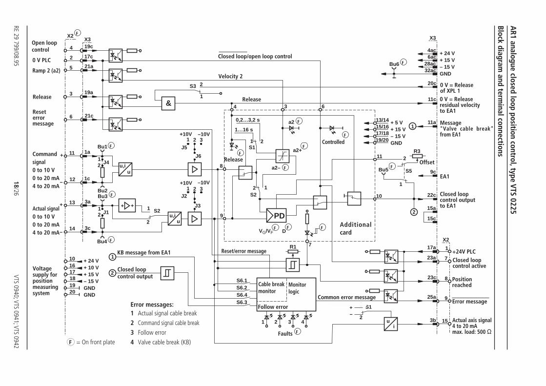
The AR1 electronics card is used within the SVAR system for closedloop position control. The card basically comprises closed loopposition control (PD or PT1 controller), ramp generator and monitor.
Features:
– PD or PT1 control
– Four adjustable ramp generators for the closed loop controlof following error
– Either "Open loop" or "Closed loop" operating modes
– Reproducible settings using digital encoded switches
– Monitoring of cable break of actual and command signallines and of valve cable (only for servo valves withmechanical feedback)
– Following error monitor
– Signal to PLC"Closed loop position control active"
H/A 4157/94AR1 closed loop position control, type VTS 0225
Technical data (For applications outside these parameters please consult us!)
AR1 analogue closed loop position control, type VTS 0225
RE 29 799/08.9518/26
VTS 0940; VTS 0941; VTS 0942
u,iu
++
u,iu
&
PD
ui
4
2
5
3
6
11
12
13
14
101617181920
+ 24 V+ 10 V+ 15 V– 15 VGNDGND
Bu4
1
2
Bu2Bu3
J112
3c
3a
1c
J421
Bu11a
21c
19a
21a
17c
19cX3
+
–
+
–
1
2
S2
J2
J3
1 2 3–10V+10V
J5
J6
1 2 3–10V+10V
1
2S3
4
1S1
8
2
2
1S2
9
S6.1
S6.3S6.4S6.2
1 2 3 4
R1 7
a2–
a2+
a2
3 6
13/1415/1617/1819/20
11
S5
2
10
Bu5
1
R3
1
Bu6
X3
4ac6ac
28ac32ac
20c
11c
11a
9c
22c
15a
15c2
X2
1
7
8
9
17a
23a
23c
25a
153b
S11
2
+–
0,2…3,2 s
1…16 s
DVG/VF
X2
+ 24 V+ 15 V– 15 VGND
+ 5 V+ 15 V– 15 VGND
Block diagram and term
inal connections
AR1 analogue closed loop position control, type VTS 0225
F = On front plate
Additionalcard
Cable breakmonitor
Monitorlogic
Follow error
Faults F
0 V = Releaseof XPL 1
+24V PLC
Positionreached
Error message
Actual axis signal4 to 20 mAmax. load: 500 Ω
Offset
F
F
ControlledF
F
F
F
Velocity 2
Release
ReleaseF
F F
KB message from EA1
Closed loopcontrol output
F
F
Voltagesupply forpositionmeasuringsystem
Actual signal0 to 10 V0 to 20 mA4 to 20 mA
Reseterrormessage
0 V PLC
0 V = Releaseresidual velocityto EA1
Message"Valve cable break"from EA1
EA1
Common error message
Ramp 2 (a2)
F
Release
F
F
Reset/error message
Closed loopcontrol outputto EA1
Closed loopcontrol active
Closed loop/open loop control
Error messages:1 Actual signal cable break
2 Command signal cable break
3 Follow error
4 Valve cable break (KB)
Open loopcontrol
Commandsignal0 to 10 V0 to 20 mA4 to 20 mA
VTS 0940; VTS 0941; VTS 0942 19/26 RE 29 799/08.95
3HE
(12
8,4)
715
2
100
165
186
89
7
10TE (50,5)
1 23 4
FGGest.
NP
a2a1+
a2+
a1–
a2–
123456789
10
11121314151617181920
VTS0225
AR1
VF
VG
D
135
24
Fehler
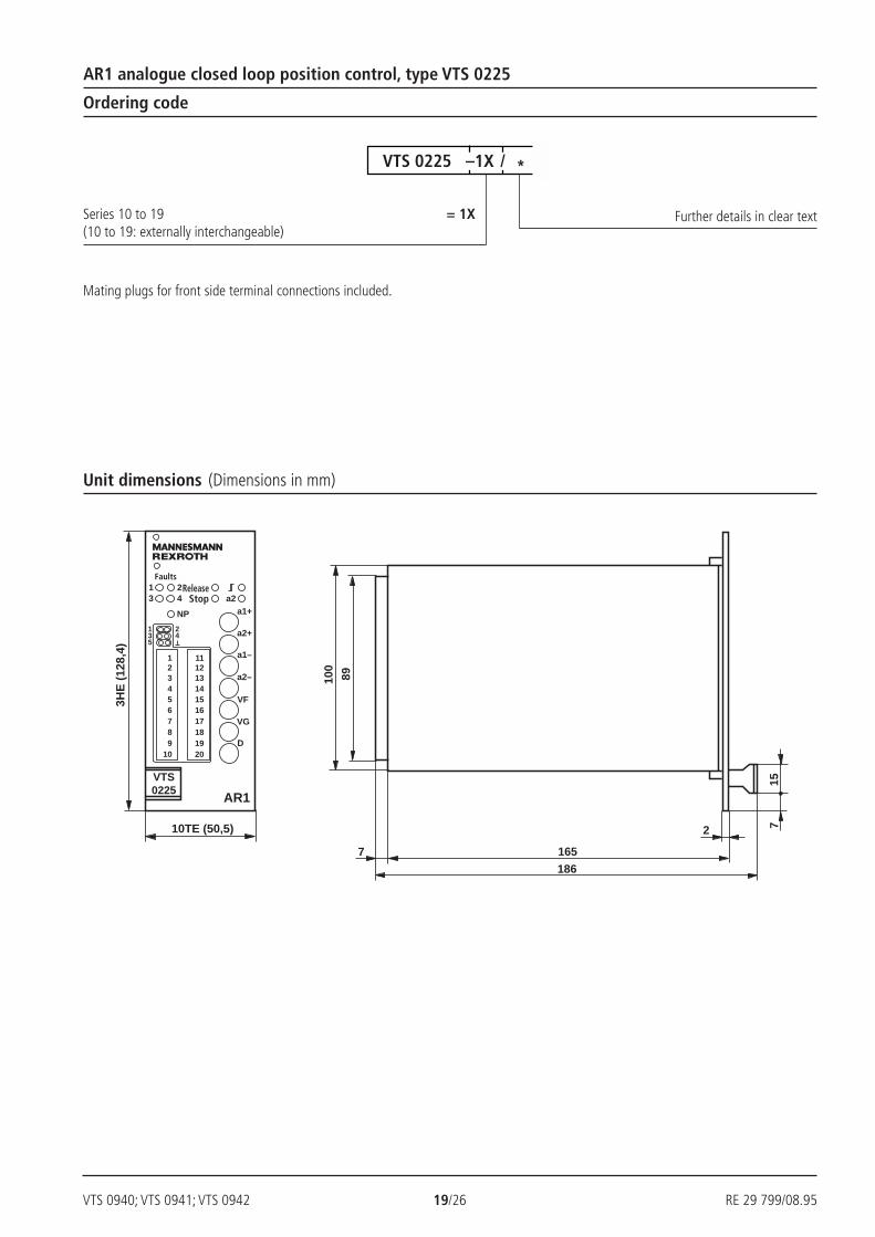
Series 10 to 19 = 1X(10 to 19: externally interchangeable)
*VTS 0225 –1X /
Mating plugs for front side terminal connections included.
Ordering code
Unit dimensions (Dimensions in mm)
AR1 analogue closed loop position control, type VTS 0225
Further details in clear text
ReleaseStop
Faults
RE 29 799/08.95 20/26 VTS 0940; VTS 0941; VTS 0942
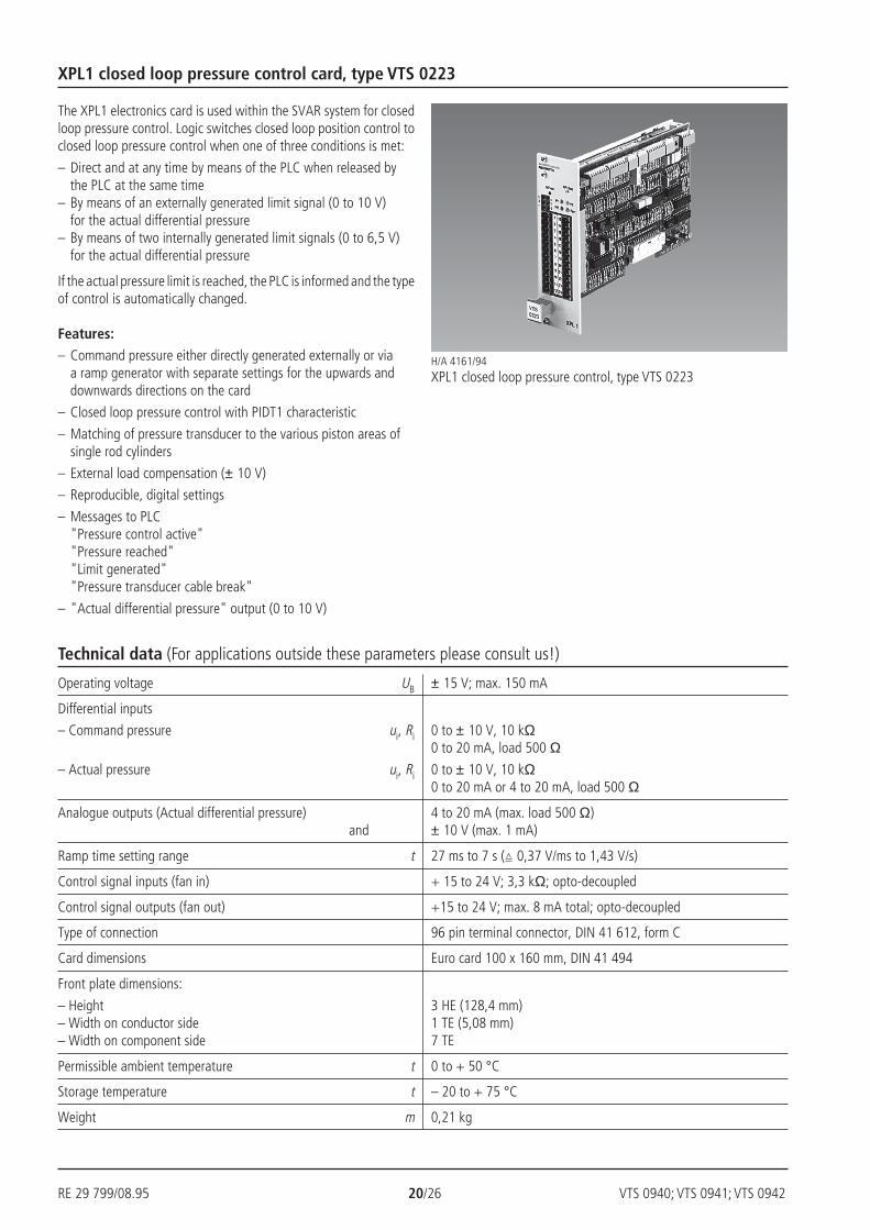
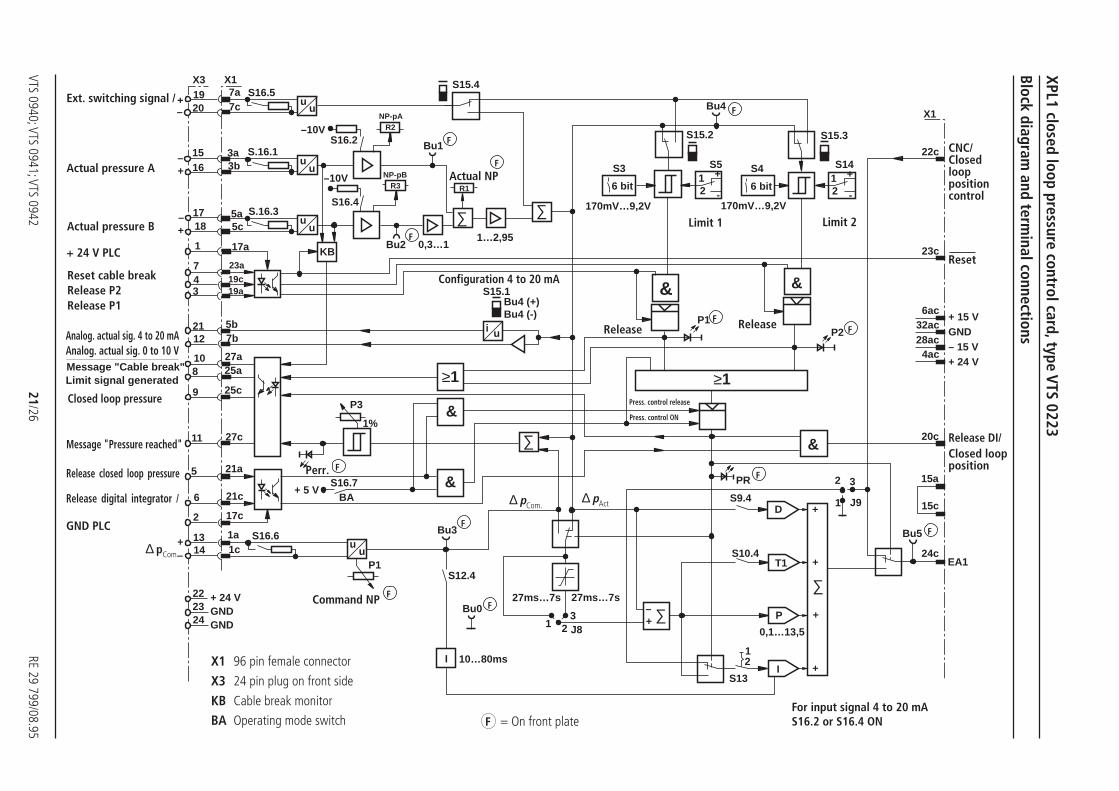
The XPL1 electronics card is used within the SVAR system for closedloop pressure control. Logic switches closed loop position control toclosed loop pressure control when one of three conditions is met:
– Direct and at any time by means of the PLC when released bythe PLC at the same time
– By means of an externally generated limit signal (0 to 10 V)for the actual differential pressure
– By means of two internally generated limit signals (0 to 6,5 V)for the actual differential pressure
If the actual pressure limit is reached, the PLC is informed and the typeof control is automatically changed.
Features:– Command pressure either directly generated externally or via
a ramp generator with separate settings for the upwards anddownwards directions on the card
– Closed loop pressure control with PIDT1 characteristic
– Matching of pressure transducer to the various piston areas ofsingle rod cylinders
– External load compensation (± 10 V)
– Reproducible, digital settings
– Messages to PLC"Pressure control active""Pressure reached""Limit generated""Pressure transducer cable break"
– "Actual differential pressure" output (0 to 10 V)
H/A 4161/94XPL1 closed loop pressure control, type VTS 0223
Operating voltage UB ± 15 V; max. 150 mA
Differential inputs
– Command pressure ui, Ri 0 to ± 10 V, 10 kΩ0 to 20 mA, load 500 Ω
– Actual pressure ui, Ri 0 to ± 10 V, 10 kΩ0 to 20 mA or 4 to 20 mA, load 500 Ω
Analogue outputs (Actual differential pressure) 4 to 20 mA (max. load 500 Ω)and ± 10 V (max. 1 mA)
Ramp time setting range t 27 ms to 7 s ( 0,37 V/ms to 1,43 V/s)
Control signal inputs (fan in) + 15 to 24 V; 3,3 kΩ; opto-decoupled
Control signal outputs (fan out) +15 to 24 V; max. 8 mA total; opto-decoupled
Type of connection 96 pin terminal connector, DIN 41 612, form C
Card dimensions Euro card 100 x 160 mm, DIN 41 494
Front plate dimensions:
– Height 3 HE (128,4 mm)– Width on conductor side 1 TE (5,08 mm)– Width on component side 7 TE
Permissible ambient temperature t 0 to + 50 °C
Storage temperature t – 20 to + 75 °C
Weight m 0,21 kg
Technical data (For applications outside these parameters please consult us!)
XPL1 closed loop pressure control card, type VTS 0223
VTS 0940; VTS 0941; VTS 094221/26
RE 29 799/08.95
uu
&
uu
uu
i u
uu
+ 24 VGNDGND
222324
1c1a
17c
21c
1413
2
6
S16.6+–
5 21a
27c11
9 25c
25a827a10
12 7b21 5b
347
19a19c
23a
1 17a
5c5a
1817–
+
S.16.3
–+
–+
16 3b3a15
7c20
7a19
S.16.1
S16.5X1X3
–10VS16.2
–10V
S16.4
NP-pB
NP-pAR2
R3
KBBu2
P3
1%
S16.7+ 5 V
BA&
Bu3
P1S12.4
I
Bu0
&
&
Bu1
Bu4 (+)Bu4 (-)
R1
S15.4
S15.1
≥1
0,3…11…2,95
27ms…7s 27ms…7s
13
2 J8
S13
21
S9.4
S10.4
0,1…13,5
I
P
T1
D
++
++
Bu5
1
2 3
J9
&
PR
P1P2
6 bit
S4 S14
S15.3
S5
S15.2
170mV…9,2V
S3
6 bit
170mV…9,2V
12
+
-
12
+
-
≥1
Bu4
24c
15c
15a
20c
4ac
32ac28ac
6ac
23c
22c
X1
10…80ms
+ 15 VGND– 15 V+ 24 V
EA1
∑
+– ∑
∑∑
∑
Block diagram and term
inal connections
XPL1 closed loop pressure control card, type VTS 0223
X1 96 pin female connector
X3 24 pin plug on front side
KB Cable break monitor
BA Operating mode switch F = On front plateFor input signal 4 to 20 mAS16.2 or S16.4 ON
Release Release
Limit 2Limit 1
Release DI/Closed loopposition
F
Perr. F
Actual NP
F
Ext. switching signal /
+ 24 V PLC
Reset cable breakRelease P2Release P1
Analog. actual sig. 4 to 20 mAAnalog. actual sig. 0 to 10 VMessage "Cable break"Limit signal generated
F
F
Press. control ON
Press. control release
F
F
F
Configuration 4 to 20 mA
Actual pressure A
Message "Pressure reached"
Release closed loop pressure
GND PLC
Release digital integrator /
∆ pCom.
CNC/Closedlooppositioncontrol
Reset
Command NP
Closed loop pressure
Actual pressure B
F
F
F
∆ pAct ∆ pCom.
F

RE 29 799/08.95 22/26 VTS 0940; VTS 0941; VTS 0942
3HE
(12
8,4)
715
2
100
165
186
89
7
8TE (40,3)
135
24
123456789
101112
131415161718192021222324
VTS0223
XPL1
NP-Ist NP-Soll
Perr.PR
P1 P2
Series 20 to 29 = 2X(20 to 29: externally interchangeable)
Further details in clear text
*VTS 0223 –2X /
Mating plugs for front side terminal connections included.
Unit dimensions (Dimensions in mm)
Ordering code
XPL1 closed loop pressure control card, type VTS 0223
Actual NP Comm. NP

VTS 0940; VTS 0941; VTS 0942 23/26 RE 29 799/08.95
Technical data for EA1:
Supply voltage U ± 24 V / to 200 mA± 15 V / 25 mA;regulated ± 5 %
Dither voltage USS ≤ 10 mV
Output stage output current Imax ± 60 mA / ±100 mA
Dither f 330 to 700 Hz
Differential input U 0 to ± 10 V
Ri 10 kΩ
Connections– Front side 30 pin/2 row
with screw connection– Connection side 64 pin terminal connector,
DIN 41 612, form C
Card dimensions Euro card100 x 160 mmDIN 41 494
Front plate dimensions– Height 3 HE (128,4 mm)– Width on conductor side 1 TE (5,08 mm)– Width on component side 7 TE
Permiss. ambient temp. t 0 to 50 °C
Storage temperature – 20 to + 75 °C
Weight m Up to 0,35 kg (with plug),depending on type
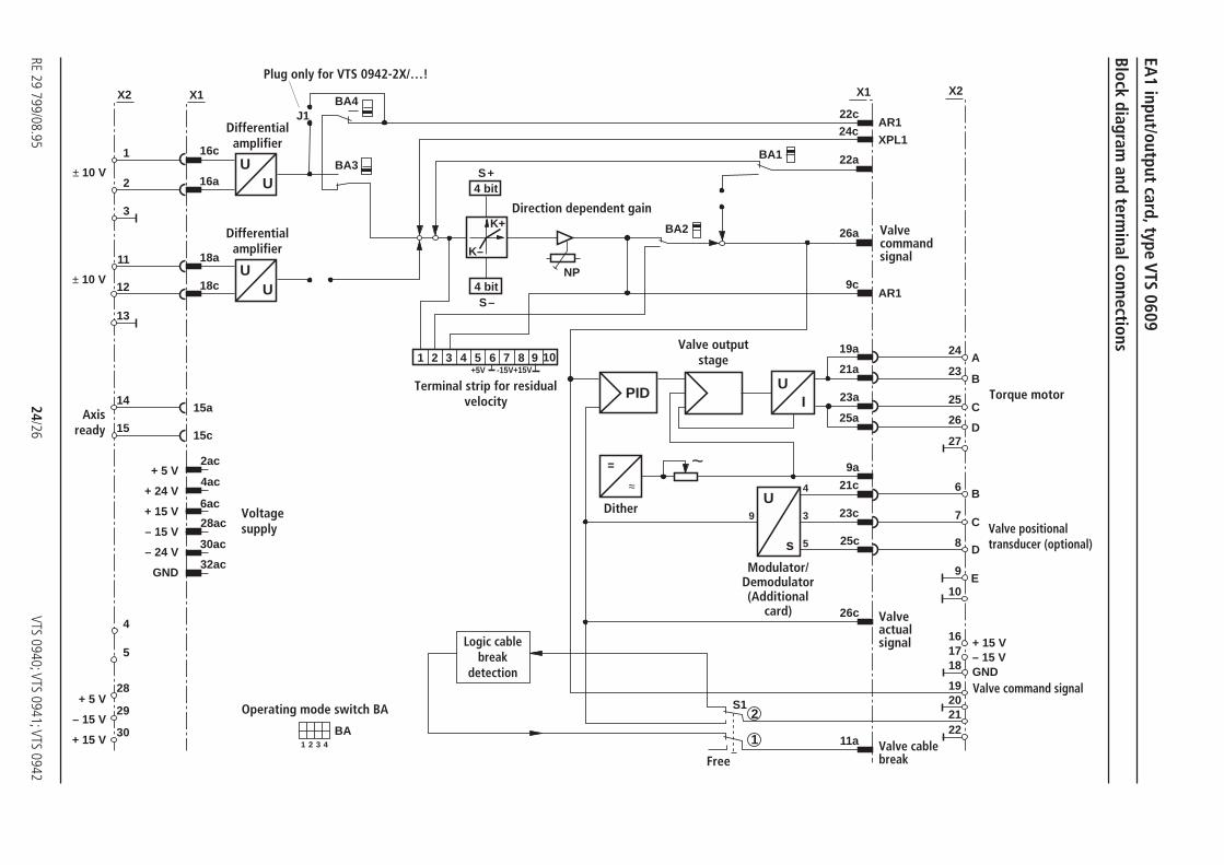
Input/output cards EA1 and EA2 are used in the SVAR closed loopelectronic control for front panel signal line connection of inputs andoutputs.
The EA1 card is equipped with a valve output stage. The EA2 card isonly supplied without valve output stage.
In addition the following functions are featured:
– Direction dependent gain matching of the command signalwhen using a single rod cylinder with a differential arearatio
– Zero point setting (NP) of valve command signal
H/A 2850Input/output card EA1, type VTS 0609
Technical data EA2:
Supply voltage U + 24 V / 2 to 4 A(valve dependent)± 15 V / 25 mA
Differential input U 0 to ± 10 VRi 10 kΩ
Connections– Front side 30 pin/2 row
with screw connection– Connection side 64 pin terminal connector,
DIN 41 612, form C
Card dimensions Euro card100 x 160 mmDIN 41 494
Front plate dimensions– Height 3 HE (128,4 mm)– Width on conductor side 1 TE (5,08 mm)– Width on component side 7 TE
Permiss. ambient temp. t 0 to 50 °C
Storage temperature – 20 to + 75 °C
Weight m Up to 0,35 kg (with plug),depending on connection
For applications outside these parameters please consult us.
Input/output cards EA1 (type VTS 0609) and EA2 (type VTS 0610)
RE 29 799/08.9524/26
VTS 0940; VTS 0941; VTS 0942
+ 5 V
+ 24 V
+ 15 V
– 15 V
– 24 V
GND
14
15
BA4
BA3S+
S–
X1
UU
12
11
3
2
1
NP
16c
16a
18a
18c
26a
22a
24c22c
BA1
X1
BA2
4
5
1 2 3 4 5 6 7 8 9 10+15V-15V+5V
X2 X2
13
28
29
30
PIDU
I
=
≈U
s
4
3
5
9
19a
21a
23a
25a
9a
21c
23c
25c
26c
2ac
4ac
6ac
28ac
30ac
32ac
22212019
181716
10
9
8
7
6
27
23
24
25
26
A
B
C
D
B
C
D
E
~
J1
S1
1 2 3 4
BA
UU
4 bit
4 bit
2
1
K+
K–
9c
11a
AR1
XPL1
+ 5 V
– 15 V
+ 15 V
± 10 V
± 10 V
+ 15 V– 15 VGND
AR1
15c
15a
Block diagram and term
inal connections
EA1 input/output card, type VTS 0609
Free
Dither
Terminal strip for residualvelocity
Operating mode switch BA
Axisready
Direction dependent gain
Voltagesupply
Logic cablebreak
detection
Modulator/Demodulator(Additional
card)
Valve positionaltransducer (optional)
Torque motor
Valve command signal
Valvecommandsignal
Valveactualsignal
Valve cablebreak
Differentialamplifier
Differentialamplifier
Valve outputstage
Plug only for VTS 0942-2X/…!

VTS 0940; VTS 0941; VTS 094225/26
RE 29 799/08.95
678910111224252627
15
14
UU
BA4
BA3
4 bit
4 bit
S+
S–
X1
K+
K–
UU
UU
24
23
3
2
1
NP
16 A
B17
D19
C18
E20
F21
22
28
29
30
16c
16a
18a
18c
26a
22a
24c
22c
BA1
X1
26c
BA2
1 2 3 4 5 6 7 8 9 0+15V-15V+5V
X2 X2
1 2 3 4
BA2ac
6ac
28ac
32ac
J1
AR1
XPL1
+ 5 V
+ 15 V
– 15 V
GND
+ 24 V
0 V
± 10 V
± 10 V
+ 15 V A– 15 V B
0 V CDEF
15c
15a
EA2 input/output card, type VTS 0610
Block diagram and term
inal connections
Valve release+ 24 V
Actualvalvesignal
Voltage supply
Differentialamplfier
Terminal strip for specialfunctions
Operating mode switch BA
Direction dependentgain
Axisready
FreeFreeFreeFree
Valve connectionInternal electronics± 15 V
Valvecommandsignal
Differentialamplifier
Differentialamplifier
Valve connectionInternal electronics+ 24 V
RE 29 799/08.95 26/26 VTS 0940; VTS 0941; VTS 0942
Bosch Rexroth AGIndustrial Hydraulics
D-97813 Lohr am MainZum Eisengießer 1 • D-97816 Lohr am MainTelefon 0 93 52 / 18-0Telefax 0 93 52 / 18-23 58 • Telex 6 89 418-0eMail [email protected] www.boschrexroth.de
The data specified above only serves to describethe product. No statements concerning a certaincondition or suitability for a certain applicationcan be derived from our information.The detailsstated do not release you from the responsibilityfor carrying out your own assessment andverification. It must be remembered that ourproducts are subject to a natural process ofwear and ageing.
715
2
100
165186
8TE (40,3)
3HE
(12
8,4)
89
7
EA1
VTS0609
NP~
6789
10
12345
16171819202122
2324252627282930
1112131415
8TE (40,3)
3HE
(12
8,4)
EA2VTS0610
NP
6789
10
12345
16171819202122
2324252627282930
1112131415
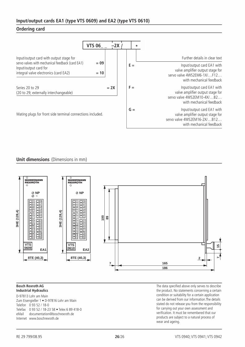
Further details in clear text
E = Input/output card EA1 withvalve amplifier output stage for
servo valve 4WS2EM6-1X/…F12…with mechanical feedback
F = Input/output card EA1 withvalve amplifier output stage for
servo valve 4WS2EM10-4X/…B2…with mechanical feedback
G = Input/output card EA1 withvalve amplifier output stage for
servo valve 4WS2EM16-2X/…B12…with mechanical feedback
Input/output card with output stage forservo valves with mechanical feedback (card EA1) = 09Input/output card forintegral valve electronics (card EA2) = 10
Series 20 to 29 = 2X(20 to 29; externally interchangeable)
*VTS 06_ _ –2X /
Mating plugs for front side terminal connections included.
Unit dimensions (Dimensions in mm)
Ordering card
Input/output cards EA1 (type VTS 0609) and EA2 (type VTS 0610)
VTS 0940; VTS 0941; VTS 0942 27/26 RE 29 799/08.95
Bosch Rexroth AGIndustrial Hydraulics
D-97813 Lohr am MainZum Eisengießer 1 • D-97816 Lohr am MainTelefon 0 93 52 / 18-0Telefax 0 93 52 / 18-23 58 • Telex 6 89 418-0eMail [email protected] www.boschrexroth.de
The data specified above only serves to describethe product. No statements concerning a certaincondition or suitability for a certain applicationcan be derived from our information.The detailsstated do not release you from the responsibilityfor carrying out your own assessment andverification. It must be remembered that ourproducts are subject to a natural process ofwear and ageing.
Notes
RE 29 799/08.95 28/26 VTS 0940; VTS 0941; VTS 0942
Bosch Rexroth AGIndustrial Hydraulics
D-97813 Lohr am MainZum Eisengießer 1 • D-97816 Lohr am MainTelefon 0 93 52 / 18-0Telefax 0 93 52 / 18-23 58 • Telex 6 89 418-0eMail [email protected] www.boschrexroth.de
The data specified above only serves to describethe product. No statements concerning a certaincondition or suitability for a certain applicationcan be derived from our information.The detailsstated do not release you from the responsibilityfor carrying out your own assessment andverification. It must be remembered that ourproducts are subject to a natural process ofwear and ageing.
Notes