superflow® regulator contents - amron international
TRANSCRIPT
SuperFlow® RegulatorContents
SF-1 1.1 SuperFlow® Demand Regulator
SF-1 1.1.1 General Regulator Information
SF-2 1.1.2 SuperFlow® Demand Regulator Test for Correct Adjustment, Fully Assembled
SF-2 1.1.3 Inspection of SuperFlow® Regulator Body Interior
SF-4 1.1.4 SuperFlow® Demand Regulator Bias Adjustment Servicing, Demand Regulator on the Helmet
SF-5 1.1.5 Reassembly of the SuperFlow® Regulator Adjustment System
SF-5 1.1.6 SuperFlow® Demand Regulator Removal from Helmet
SF-6 1.1.7 Disassembly of the SuperFlow® Demand Regulator
SF-8 1.1.8 Inspection of SuperFlow® Demand Regulator Parts
SF-10 1.1.9 Reassembly of the
SuperFlow® Demand Regulator
SF-14 1.1.10 Tuning the SuperFlow® Regulator
SF-15 1.1.11 Important Notes on Regulator Adjustment
SF-16 1.1.12 SuperFlow® Regulator Steady Flows When Pressured Up: Special Tools Used
SF-18 1.1.13 Regulator Steady Flows When Pressured Up
SF-18 1.1.14 Regulator has Low or No Flow When Pressurized
SF-19 1.1.15 Unexplained Demand Regulator Free Flow
SF-19 1.2 Water Dump Exhaust Body
SF-19 1.2.1 Water Dump Valve Removal
SF-20 1.2.2 Water Dump Valve Replacement
SF-20 1.2.3 Water Dump Valve Body Removal
SF-20 1.2.4 Water Dump Valve Body Remounting
1.1 SuperFlow® Demand Regulator1.1.1 General Regulator InformationWhile the regulator systems on all Kirby Mor-gan helmets are simple and highly reliable, the breathing resistance will increase if the demand regulator on your helmet is not maintained or adjusted properly. The demand regulator must receive regular maintenance to assure the best performance possible. However, in the event the demand regulator is damaged, there is always a backup supply of steady flow gas available from the defogger valve.
For the gas inlet valve and adjustment system to operate properly, the components in the demand regulator MUST be in good condition and MUST be periodically inspected and adjusted.
Five special tools, the inlet valve holder (P/N 525-616), the regulator adjustment wrench (P/N 525-611), the socket wrench (P/N 525-612), the
castle wrench (P/N 525-618), and the regulator mount nut socket wrench (P/N 525-625) should be used to work on the SuperFlow® regulator whenever possible.
Disassembly, assembly, and adjustment can be done without these tools, but the work is much easier and the adjustment is better if these tools are used. The above five tools are available to-gether along with a tool case. The “Tool Kit with Pouch” is Part #525-620. This kit is included with each new Kirby Morgan helmet that is equipped with the SuperFlow® regulator.
© MMXIV Kirby Morgan Dive Systems, Inc. All rights reserved. Document # 140130014 SF-1
SuperFlow® Regulator SuperFlow® Demand Regulator
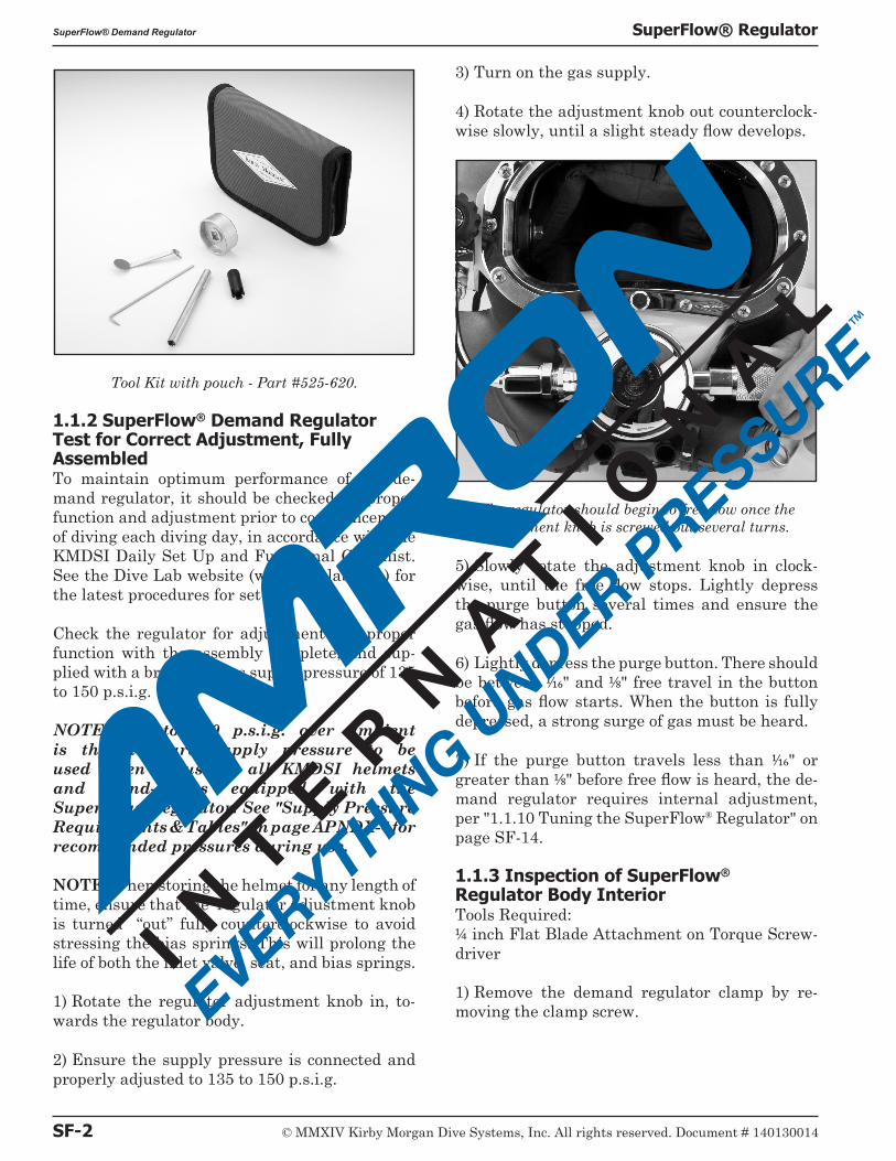
Tool Kit with pouch - Part #525-620.
1.1.2 SuperFlow® Demand Regulator Test for Correct Adjustment, Fully AssembledTo maintain optimum performance of the de-mand regulator, it should be checked for proper function and adjustment prior to commencement of diving each diving day, in accordance with the KMDSI Daily Set Up and Functional Checklist. See the Dive Lab website (www.divelab.com) for the latest procedures for set-up.
Check the regulator for adjustment and proper function with the assembly complete, and sup-plied with a breathing gas supply pressure of 135 to 150 p.s.i.g.
NOTE: 135 to 150 p.s.i.g. over ambient is the standard supply pressure to be used when adjusting all KMDSI helmets and band-masks equipped with the SuperFlow® regulator. See "Supply Pressure Requirements & Tables" on page APNDX-4 for recommended pressures during use.
NOTE: When storing the helmet for any length of time, ensure that the regulator adjustment knob is turned “out” fully counterclockwise to avoid stressing the bias springs. This will prolong the life of both the inlet valve, seat, and bias springs.
1) Rotate the regulator adjustment knob in, to-wards the regulator body.
2) Ensure the supply pressure is connected and properly adjusted to 135 to 150 p.s.i.g.
3) Turn on the gas supply.
4) Rotate the adjustment knob out counterclock-wise slowly, until a slight steady flow develops.
The regulator should begin to free flow once the adjustment knob is screwed out several turns.
5) Slowly rotate the adjustment knob in clock-wise, until the free flow stops. Lightly depress the purge button several times and ensure the gas flow has stopped.
6) Lightly depress the purge button. There should be between 1/16" and 1/8" free travel in the button before gas flow starts. When the button is fully depressed, a strong surge of gas must be heard.
7) If the purge button travels less than 1/16" or greater than 1/8" before free flow is heard, the de-mand regulator requires internal adjustment, per "1.1.10 Tuning the SuperFlow® Regulator" on page SF-14.
1.1.3 Inspection of SuperFlow® Regulator Body Interior Tools Required:1/4 inch Flat Blade Attachment on Torque Screw-driver
1) Remove the demand regulator clamp by re-moving the clamp screw.
SF-2 © MMXIV Kirby Morgan Dive Systems, Inc. All rights reserved. Document # 140130014
SuperFlow® Demand Regulator SuperFlow® Regulator
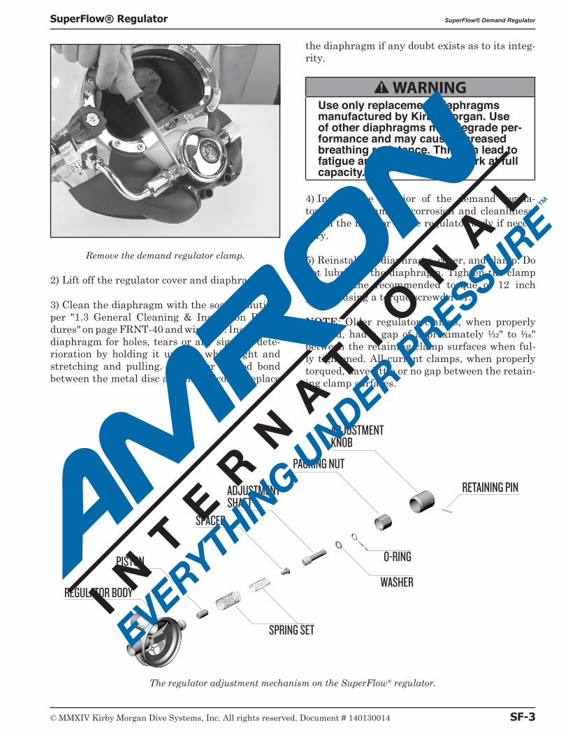
Remove the demand regulator clamp.
2) Lift off the regulator cover and diaphragm.
3) Clean the diaphragm with the soapy solution, per "1.3 General Cleaning & Inspection Proce-dures" on page FRNT-40 and wipe dry. Inspect the diaphragm for holes, tears or any signs of dete-rioration by holding it up to a white light and stretching and pulling. Check for a good bond between the metal disc and the silicone. Replace
the diaphragm if any doubt exists as to its integ-rity.
B WARNINGUse only replacement diaphragms manufactured by Kirby Morgan. Use of other diaphragms may degrade per-formance and may cause increased breathing resistance. This can lead to fatigue and the inability to work at full capacity.
4) Inspect the interior of the demand regula-tor body for damage, corrosion and cleanliness. Clean the interior of the regulator body if neces-sary.
5) Reinstall the diaphragm, cover, and clamp. Do not lubricate the diaphragm. Tighten the clamp screw to the recommended torque of 12 inch pounds using a torque screwdriver.
NOTE: Older regulator clamps, when properly torqued, had a gap of approximately 1/32" to 1/16" between the retaining clamp surfaces when ful-ly tightened. All current clamps, when properly torqued, have little or no gap between the retain-ing clamp surfaces.
The regulator adjustment mechanism on the SuperFlow® regulator.
REGULATOR BODY
PISTON
SPACER
ADJUSTMENT SHAFT
ADJUSTMENT KNOB
PACKING NUT
SPRING SET
O-RING
RETAINING PIN
WASHER
© MMXIV Kirby Morgan Dive Systems, Inc. All rights reserved. Document # 140130014 SF-3
SuperFlow® Regulator SuperFlow® Demand Regulator
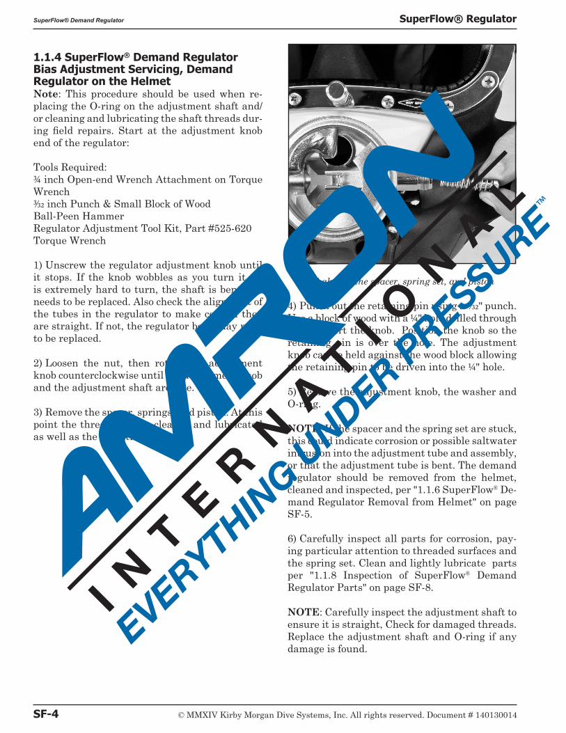
1.1.4 SuperFlow® Demand Regulator Bias Adjustment Servicing, Demand Regulator on the HelmetNote: This procedure should be used when re-placing the O-ring on the adjustment shaft and/or cleaning and lubricating the shaft threads dur-ing field repairs. Start at the adjustment knob end of the regulator:
Tools Required:3/4 inch Open-end Wrench Attachment on Torque Wrench3/32 inch Punch & Small Block of Wood Ball-Peen Hammer Regulator Adjustment Tool Kit, Part #525-620Torque Wrench
1) Unscrew the regulator adjustment knob until it stops. If the knob wobbles as you turn it, or is extremely hard to turn, the shaft is bent and needs to be replaced. Also check the alignment of the tubes in the regulator to make certain they are straight. If not, the regulator body may need to be replaced.
2) Loosen the nut, then rotate the adjustment knob counterclockwise until the adjustment knob and the adjustment shaft are free.
3) Remove the spacer, springs, and piston. At this point the threads can be cleaned and lubricated as well as the adjustment shaft.
Shake out the spacer, spring set, and piston
4) Punch out the retaining pin using a 3/32" punch. Use a block of wood with a 1/4" hole drilled through it to support the knob. Position the knob so the retaining pin is over the hole. The adjustment knob can be held against the wood block allowing the retaining pin to be driven into the 1/4" hole.
5) Remove the adjustment knob, the washer and O-ring.
NOTE: If the spacer and the spring set are stuck, this could indicate corrosion or possible saltwater intrusion into the adjustment tube and assembly, or that the adjustment tube is bent. The demand regulator should be removed from the helmet, cleaned and inspected, per "1.1.6 SuperFlow® De-mand Regulator Removal from Helmet" on page SF-5.
6) Carefully inspect all parts for corrosion, pay-ing particular attention to threaded surfaces and the spring set. Clean and lightly lubricate parts per "1.1.8 Inspection of SuperFlow® Demand Regulator Parts" on page SF-8.
NOTE: Carefully inspect the adjustment shaft to ensure it is straight, Check for damaged threads. Replace the adjustment shaft and O-ring if any damage is found.
SF-4 © MMXIV Kirby Morgan Dive Systems, Inc. All rights reserved. Document # 140130014
SuperFlow® Demand Regulator SuperFlow® Regulator
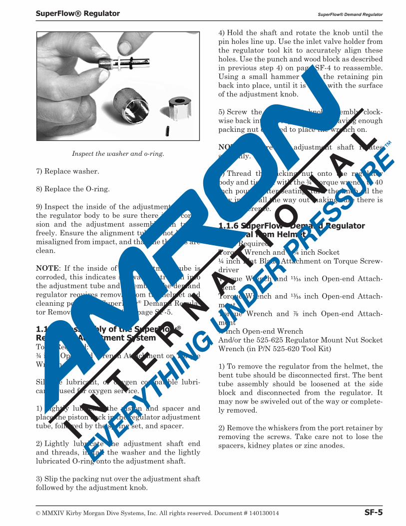
Inspect the washer and o-ring.
7) Replace washer.
8) Replace the O-ring.
9) Inspect the inside of the adjustment tube on the regulator body to be sure there is no corro-sion and the adjustment assembly can travel freely. Ensure the alignment tube is not bent or misaligned from impact, and that the threads are clean.
NOTE: If the inside of the adjustment tube is corroded, this indicates saltwater intrusion into the adjustment tube and assembly. The demand regulator requires removal from the helmet and cleaning per "1.1.6 SuperFlow® Demand Regula-tor Removal from Helmet" on page SF-5.
1.1.5 Reassembly of the SuperFlow® Regulator Adjustment SystemTools Required:3/4 inch Open-end Wrench Attachment on Torque Wrench
Silicone lubricant, or oxygen compatible lubri-cant if used for oxygen service.
1) Lightly lubricate the piston and spacer and place the piston back in the regulator adjustment tube, followed by the spring set, and spacer.
2) Lightly lubricate the adjustment shaft end and threads, install the washer and the lightly lubricated O-ring onto the adjustment shaft.
3) Slip the packing nut over the adjustment shaft followed by the adjustment knob.
4) Hold the shaft and rotate the knob until the pin holes line up. Use the inlet valve holder from the regulator tool kit to accurately align these holes. Use the punch and wood block as described in previous step 4) on page SF-4 to reassemble. Using a small hammer drive the retaining pin back into place, until it is flush with the surface of the adjustment knob.
5) Screw the adjustment knob assembly clock-wise back into the regulator body leaving enough packing nut exposed to place the wrench on.
NOTE: Ensure the adjustment shaft rotates smoothly.
6) Thread the packing nut onto the regulator body and tighten with the 3/4" torque wrench to 40 inch pounds after seating, turn the knob all the way in and all the way out making sure there is no interference.
1.1.6 SuperFlow® Demand Regulator Removal from HelmetTools Required:Torque Wrench and 1 1/4 inch Socket1/4 inch Flat Blade Attachment on Torque Screw-driverTorque Wrench and 11/16 inch Open-end Attach-mentTorque Wrench and 13/16 inch Open-end Attach-mentTorque Wrench and 7/8 inch Open-end Attach-ment7/8 inch Open-end WrenchAnd/or the 525-625 Regulator Mount Nut Socket Wrench (in P/N 525-620 Tool Kit)
1) To remove the regulator from the helmet, the bent tube should be disconnected first. The bent tube assembly should be loosened at the side block and disconnected from the regulator. It may now be swiveled out of the way or complete-ly removed.
2) Remove the whiskers from the port retainer by removing the screws. Take care not to lose the spacers, kidney plates or zinc anodes.
© MMXIV Kirby Morgan Dive Systems, Inc. All rights reserved. Document # 140130014 SF-5
SuperFlow® Regulator SuperFlow® Demand Regulator
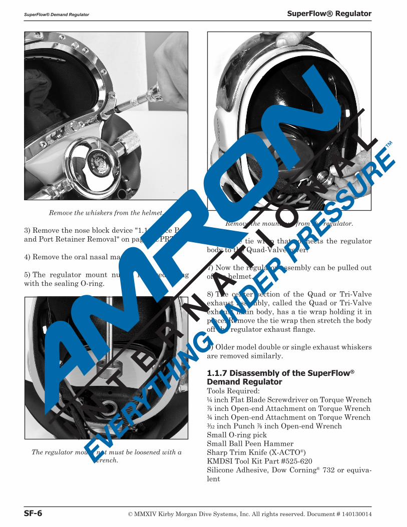
Remove the whiskers from the helmet.
3) Remove the nose block device "1.1.3 Face Port and Port Retainer Removal" on page FCPRT-1.
4) Remove the oral nasal mask.
5) The regulator mount nut is removed along with the sealing O-ring.
The regulator mount nut must be loosened with a wrench.
Remove the mount nut from the regulator.
6) Cut the tie wrap that connects the regulator body to the Quad-Valve cover.
7) Now the regulator assembly can be pulled out of the helmet.
8) The center section of the Quad or Tri-Valve exhaust assembly, called the Quad or Tri-Valve exhaust main body, has a tie wrap holding it in place. Remove the tie wrap then stretch the body off the regulator exhaust flange.
9) Older model double or single exhaust whiskers are removed similarly.
1.1.7 Disassembly of the SuperFlow® Demand RegulatorTools Required:1/4 inch Flat Blade Screwdriver on Torque Wrench 7/8 inch Open-end Attachment on Torque Wrench3/4 inch Open-end Attachment on Torque Wrench 3/32 inch Punch 7/8 inch Open-end WrenchSmall O-ring pickSmall Ball Peen HammerSharp Trim Knife (X-ACTO®)KMDSI Tool Kit Part #525-620Silicone Adhesive, Dow Corning® 732 or equiva-lent
SF-6 © MMXIV Kirby Morgan Dive Systems, Inc. All rights reserved. Document # 140130014
SuperFlow® Demand Regulator SuperFlow® Regulator
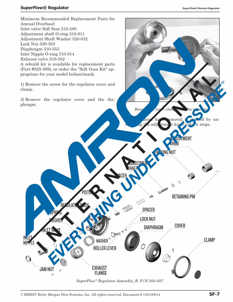
Minimum Recommended Replacement Parts for Annual Overhaul:Inlet valve Soft Seat 510-580Adjustment shaft O-ring 510-011Adjustment Shaft Washer 520-032Lock Nut 530-303Diaphragm 510-553Inlet Nipple O-ring 510-014Exhaust valve 510-552A rebuild kit is available for replacement parts (Part #525-309), or order the "Soft Goos Kit" ap-propriate for your model helmet/mask.
1) Remove the screw for the regulator cover and clamp.
2) Remove the regulator cover and the dia-phragm.
Remove the cover clamp from the regulator.
3) Adjustment knob removal is started by un-screwing the adjustment knob until it stops.
SuperFlow® Regulator Assembly, B. P/N 505-027.
COVER
CLAMP
INLET VALVE
WASHER
SPRING
INLET NIPPLE
REGULATOR BODY
PISTON
SPACER
ADJUSTMENT SHAFT
ADJUSTMENT KNOB
PACKING NUT
JAM NUT EXHAUST FLANGE
RETAINING PIN
ROLLER LEVERWASHER
DIAPHRAGM
LOCK NUT
SPACER
© MMXIV Kirby Morgan Dive Systems, Inc. All rights reserved. Document # 140130014 SF-7
SuperFlow® Regulator SuperFlow® Demand Regulator
4) The packing nut is now exposed enough to use a wrench on it for removal. As the nut is backed off, also unscrew the knob.
5) The O-ring and washer will remain on the ad-justment shaft.
6) Tilt the regulator so that the spacer, spring set, and piston fall out of the adjustment tube of the regulator.
NOTE: If the spacer and the spring set are stuck, this indicates possible corrosion or saltwater in-trusion into the adjustment tube or the adjust-ment tube may be bent. The demand regulator requires removal from the helmet and cleaning per "1.1.6 SuperFlow® Demand Regulator Re-moval from Helmet" on page SF-5. This occurs if the helmet is dropped on the adjustment knob or the adjustment knob otherwise impacts against a rigid object. Repairs must be made by a trained KMDSI technician.
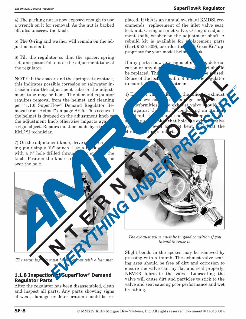
7) On the adjustment knob, drive out the retain-ing pin using a 3/32" punch. Use a block of wood with a 1/4" hole drilled through it to support the knob. Position the knob so the retaining pin is over the hole.
The retaining pin must be driven out with a hammer and punch.
1.1.8 Inspection of SuperFlow® Demand Regulator PartsAfter the regulator has been disassembled, clean and inspect all parts. Any parts showing signs of wear, damage or deterioration should be re-
placed. If this is an annual overhaul KMDSI rec-ommends replacement of the inlet valve seat, lock nut, O-ring on inlet valve, O-ring on adjust-ment shaft, washer on the adjustment shaft. A rebuild kit is available for replacement parts (Part #525-309), or order the "Soft Goos Kit" ap-propriate for your model helmet/mask.
If any parts show any signs of damage, deterio-ration or any damaged threads, the part should be replaced. The lock nut must never be reused. Reuse of the lock nut will not allow the regulator to maintain proper adjustment.
1) Exhaust valve: Ensure the silicone exhaust valve shows no signs of damage, brittleness or any deformities. The exhaust valve should lay flat against the seat. If conducting an Annual Overhaul, the exhaust should be replaced. En-sure the seat spokes that hold the exhaust valve are smooth, even and not bent, and that the chrome plating is intact.
The exhaust valve must be in good condition if you intend to reuse it.
Slight bends in the spokes may be removed by pressing with a thumb. The exhaust valve seat-ing area should be free of dirt and corrosion to ensure the valve can lay flat and seal properly. NEVER lubricate the valve. Lubricating the valve will cause dirt and particles to stick to the valve and seat causing poor performance and wet breathing.
SF-8 © MMXIV Kirby Morgan Dive Systems, Inc. All rights reserved. Document # 140130014
SuperFlow® Demand Regulator SuperFlow® Regulator
2) Inlet valve: Check the condition of the rubber seat for wear and/or deep grooves. If the orange silicone seat surface is stained to a dark color, this is an indication the air supply that was be-ing used was dirty,
Check the condition of the inlet nipple. The in-let nipple sealing edge must be in good condition, free of nicks, chipped chrome or any damage. If the inlet nipple sealing edge has nicks or missing chrome, the inlet nipple as well as the soft seat will require replacement. During annual over-haul the inlet valve soft seat should be replaced.
3) Inlet Valve Soft Seat Replacement: To replace the soft seat use a small screwdriver or O-ring pick to pry the soft seat from the chrome plated brass valve body. Using a sewing needle clean all old silicone sealant from the vent hole in the bot-tom of the cup area, and from the cupped area itself.
NOTE: Replace the entire inlet valve if any chrome is missing or if the shaft is bent or thread damage is present.
4) Dab a small amount of silicone adhesive Dow Corning® 732 or equivalent on one side of the new soft seat then press the seat into the cup area of
the inlet valve assembly then using a clean cloth, wipe all excess silicone from the valve assembly.
B WARNINGUse silicone seal-ant in a well venti-lated area. Do not breathe the fumes from uncured sili-cone sealant. These fumes are danger-ous and can cause unconsciousness. They can also cause long term damage to body tissue. Read and follow all pre-cautions listed on the silicone sealant tube and Material Safety Data Sheet.
5) Diaphragm: Check to determine if rubber has separated from the metal disc. Hold the di-aphragm to a bright white light, while aggres-sively pulling and stretching to reveal damage, deterioration, or holes.
Diaphragms showing any indication of damage should be replaced. The diaphragm should al-
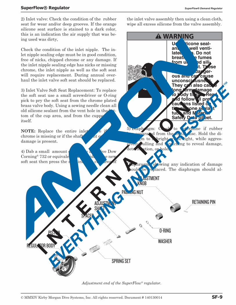
Adjustment end of the SuperFlow® regulator.
REGULATOR BODY
PISTON
SPACER
ADJUSTMENT SHAFT
ADJUSTMENT KNOB
PACKING NUT
SPRING SET
O-RING
RETAINING PIN
WASHER
© MMXIV Kirby Morgan Dive Systems, Inc. All rights reserved. Document # 140130014 SF-9
SuperFlow® Regulator SuperFlow® Demand Regulator
ways be replaced during scheduled annual over-hauls.
6) Inspect the whisker wings. Replace the whis-ker wings if they show signs of wear, aging or any damage.
The current whiskers used in the Quad-Valve and Tri-Valve exhaust systems are much more rugged than the early latex double exhaust sys-tem, and will give a much longer service life and provide better breathing performance at depth. Early double exhaust systems should be replaced with the current Quad-Valve exhaust system, or Tri-Valve for the SL 27®.
1.1.9 Reassembly of the SuperFlow® Demand RegulatorNOTE: Use the blow-apart in the back of the manual to help ensure correct assembly.
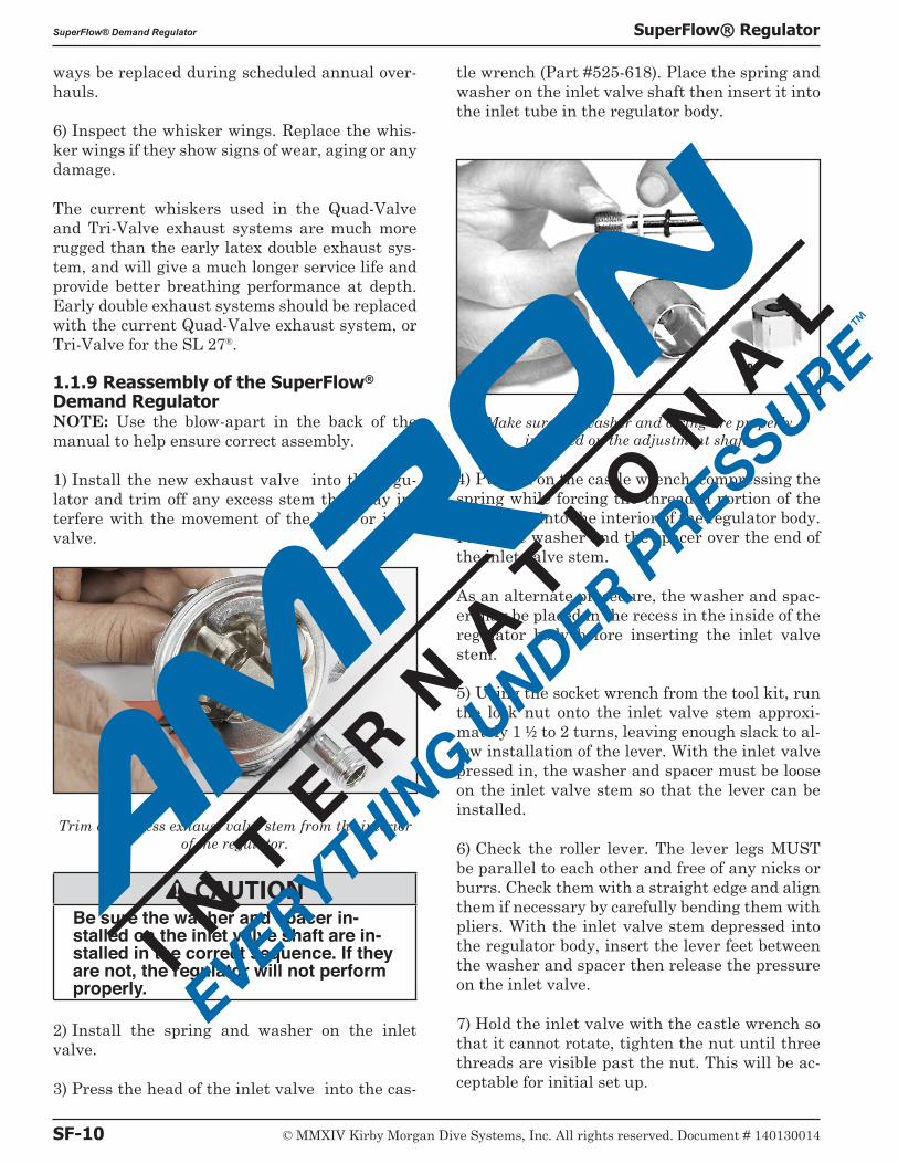
1) Install the new exhaust valve into the regu-lator and trim off any excess stem that may in-terfere with the movement of the lever or inlet valve.
Trim any excess exhaust valve stem from the interior of the regulator.
B CAUTIONBe sure the washer and spacer in-stalled on the inlet valve shaft are in-stalled in the correct sequence. If they are not, the regulator will not perform properly.
2) Install the spring and washer on the inlet valve.
3) Press the head of the inlet valve into the cas-
tle wrench (Part #525-618). Place the spring and washer on the inlet valve shaft then insert it into the inlet tube in the regulator body.
Make sure the washer and o-ring are properly installed on the adjustment shaft.
4) Push in on the castle wrench, compressing the spring while forcing the threaded portion of the shaft stem into the interior of the regulator body. Place the washer and the spacer over the end of the inlet valve stem.
As an alternate procedure, the washer and spac-er may be placed in the recess in the inside of the regulator body before inserting the inlet valve stem.
5) Using the socket wrench from the tool kit, run the lock nut onto the inlet valve stem approxi-mately 1 1/2 to 2 turns, leaving enough slack to al-low installation of the lever. With the inlet valve pressed in, the washer and spacer must be loose on the inlet valve stem so that the lever can be installed.
6) Check the roller lever. The lever legs MUST be parallel to each other and free of any nicks or burrs. Check them with a straight edge and align them if necessary by carefully bending them with pliers. With the inlet valve stem depressed into the regulator body, insert the lever feet between the washer and spacer then release the pressure on the inlet valve.
7) Hold the inlet valve with the castle wrench so that it cannot rotate, tighten the nut until three threads are visible past the nut. This will be ac-ceptable for initial set up.
SF-10 © MMXIV Kirby Morgan Dive Systems, Inc. All rights reserved. Document # 140130014
SuperFlow® Demand Regulator SuperFlow® Regulator
8) While holding the lever down, install the inlet nipple with its O-ring on into the regulator body. Using the torque wrench, tighten the inlet nipple to 40 inch pounds.
9) Lightly lubricate the piston and spacer. In-stall the piston, spring set and spacer into the adjustment tube of the regulator body, sequence as shown in the blow-apart drawing.
10) Reassemble the adjustment knob assembly; lightly lubricate the new O-ring then install the new washer and O-ring on the adjustment shaft.
11) Slide the packing nut onto the adjustment shaft, then slip the knob onto the end of the shaft. Hold the shaft and rotate the knob until the pinholes line up.
Use the inlet valve holder from the regulator tool kit to accurately align these holes.
12) Install the retaining pin by tapping it in with a small hammer until it is flush with the outer surface of the knob.
13) Lightly lubricate the shaft end and the threads with the appropriate lubricant. Thread the adjustment shaft clockwise, using the adjust-ment knob, into the tube until the packing nut can be started.
Back out the adjustment knob once the packing nut is engaged on the demand regulator body to access the packing nut with the torque wrench. Using a torque wrench, tighten the packing nut to 40 inch pounds after seating.
14) Rotate the adjustment knob in i.e, clock-wise, several turns, then recheck the torque one more time. Ensure the adjustment shaft rotates smoothly and there is no binding.
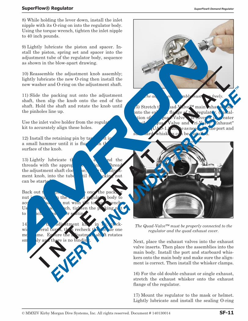
The adjustment assembly must turn freely.
15) Stretch the Quad-Valve™ main exhaust body onto the exhaust flange of the regulator. (Instal-lation of the Quad-Valve™ is covered in greater detail in "Quad Valve and Tri-Valve® Exhaust" on page QUAD-1.) Rotate as needed so the port and starboard whiskers can be installed.
The Quad-Valve™ must be properly connected to the regulator and the quad exhaust cover.
Next, place the exhaust valves into the exhaust valve inserts. Then place the assemblies into the main body. Install the port and starboard whis-kers onto the main body and make sure the align-ment is correct. Then install the whisker clamps.
16) For the old double exhaust or single exhaust, stretch the exhaust whisker onto the exhaust flange of the regulator.
17) Mount the regulator to the mask or helmet. Lightly lubricate and install the sealing O-ring
© MMXIV Kirby Morgan Dive Systems, Inc. All rights reserved. Document # 140130014 SF-11
SuperFlow® Regulator SuperFlow® Demand Regulator
and thread on the regulator mount nut, hand tight.
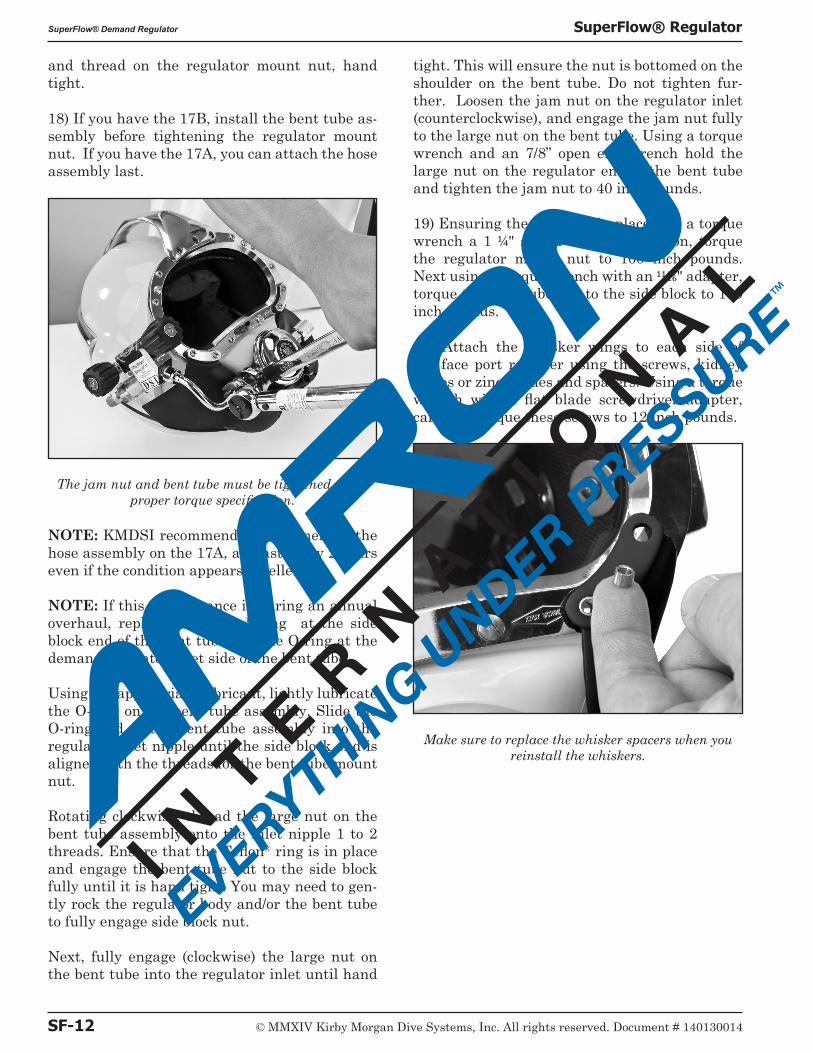
18) If you have the 17B, install the bent tube as-sembly before tightening the regulator mount nut. If you have the 17A, you can attach the hose assembly last.
The jam nut and bent tube must be tightened to the proper torque specification.
NOTE: KMDSI recommends replacement of the hose assembly on the 17A, at least every 2 years even if the condition appears excellent.
NOTE: If this maintenance is during an annual overhaul, replace the Teflon® ring at the side block end of the bent tube and the O-ring at the demand regulator inlet side of the bent tube.
Using the appropriate lubricant, lightly lubricate the O-ring on the bent tube assembly. Slide the O-ring end of the bent tube assembly into the regulator inlet nipple until the side block end is aligned with the threads for the bent tube mount nut.
Rotating clockwise, thread the large nut on the bent tube assembly onto the inlet nipple 1 to 2 threads. Ensure that the Teflon® ring is in place and engage the bent tube nut to the side block fully until it is hand tight. You may need to gen-tly rock the regulator body and/or the bent tube to fully engage side block nut.
Next, fully engage (clockwise) the large nut on the bent tube into the regulator inlet until hand
tight. This will ensure the nut is bottomed on the shoulder on the bent tube. Do not tighten fur-ther. Loosen the jam nut on the regulator inlet (counterclockwise), and engage the jam nut fully to the large nut on the bent tube. Using a torque wrench and an 7/8” open end wrench hold the large nut on the regulator end of the bent tube and tighten the jam nut to 40 inch pounds.
19) Ensuring the O-ring is in place, use a torque wrench a 1 1/4" socket and an extension, torque the regulator mount nut to 100 inch pounds. Next using a torque wrench with an 11/16" adapter, torque the bent tube nut to the side block to 100 inch pounds.
19) Attach the whisker wings to each side of the face port retainer using the screws, kidney plates or zinc anodes and spacers. Using a torque wrench with a flat blade screwdriver adapter, carefully torque these screws to 12 inch pounds.
Make sure to replace the whisker spacers when you reinstall the whiskers.
SF-12 © MMXIV Kirby Morgan Dive Systems, Inc. All rights reserved. Document # 140130014
SuperFlow® Demand Regulator SuperFlow® Regulator
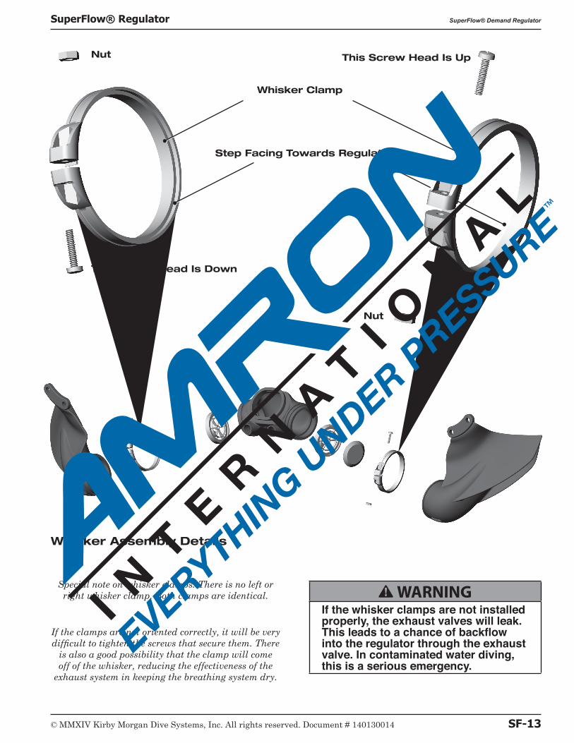
Special note on whisker clamps: There is no left or right whisker clamp. Both clamps are identical.
If the clamps are not oriented correctly, it will be very difficult to tighten the screws that secure them. There
is also a good possibility that the clamp will come off of the whisker, reducing the effectiveness of the
exhaust system in keeping the breathing system dry.
Whisker Assembly Details
This Screw Head Is Down
Whisker Clamp
Step Facing Towards Regulator
Nut
Nut
This Screw Head Is Up
B WARNINGIf the whisker clamps are not installed properly, the exhaust valves will leak. This leads to a chance of backflow into the regulator through the exhaust valve. In contaminated water diving, this is a serious emergency.
© MMXIV Kirby Morgan Dive Systems, Inc. All rights reserved. Document # 140130014 SF-13
SuperFlow® Regulator SuperFlow® Demand Regulator
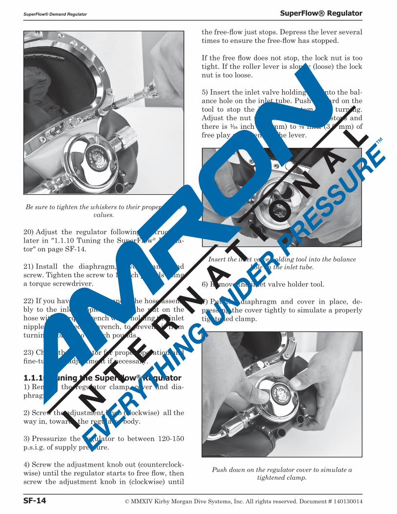
Be sure to tighten the whiskers to their proper torque values.
20) Adjust the regulator following instructions later in "1.1.10 Tuning the SuperFlow® Regula-tor" on page SF-14.
21) Install the diaphragm, cover, clamp and screw. Tighten the screw to 12 inch pounds using a torque screwdriver.
22) If you have the 17A, connect the hose assem-bly to the inlet nipple. Tighten the nut on the hose with a torque wrench while holding the inlet nipple with a second wrench, to prevent it from turning. Torque to 40 inch pounds.
23) Check the regulator for proper operation and fine-tune the adjustment if necessary.
1.1.10 Tuning the SuperFlow® Regulator1) Remove the regulator clamp, cover and dia-phragm.
2) Screw the adjustment knob (clockwise) all the way in, towards the regulator body.
3) Pressurize the regulator to between 120-150 p.s.i.g. of supply pressure.
4) Screw the adjustment knob out (counterclock-wise) until the regulator starts to free flow, then screw the adjustment knob in (clockwise) until
the free-flow just stops. Depress the lever several times to ensure the free-flow has stopped.
If the free flow does not stop, the lock nut is too tight. If the roller lever is sloppy (loose) the lock nut is too loose.
5) Insert the inlet valve holding tool into the bal-ance hole on the inlet tube. Push forward on the tool to stop the inlet valve stem from turning. Adjust the nut until the freeflow just stops and there is 1/16 inch (1.5 mm) to 1/8 inch (3.0 mm) of free play at the end of the lever.
Insert the inlet valve holding tool into the balance hole on the inlet tube.
6) Remove the inlet valve holder tool.
7) Put the diaphragm and cover in place, de-pressing the cover tightly to simulate a properly tightened clamp.
Push down on the regulator cover to simulate a tightened clamp.
SF-14 © MMXIV Kirby Morgan Dive Systems, Inc. All rights reserved. Document # 140130014
SuperFlow® Demand Regulator SuperFlow® Regulator
8) Depress the purge button in the center of the cover.
NOTE: (Reference, instructions following) Before bending the lever,double check the adjustments. The lever rarely requires bending. Usually levers require bending only when improperly serviced, or if damaged during disassembly.
9) There must be 1/16 inch (1.5 mm) to 1/8 inch (3.0 mm) of free travel before the purge button actu-ates, resulting in a slight flow of gas. If a slight flow of gas develops with the purge button de-pressed less than 1/16 inch (1.5 mm), the lever will require bending down.
If the purge button travels further than a 1/8” (3.0 mm) before gas flow starts, the lever will re-quire bending upward.
10) To bend the lever up, remove the lever and carefully place it in a vice. Grip the lever from the side with a pair of long nosed pliers and bend the roller end up with your finger. Bend it only a small amount at a time.
NOTE: Be very careful to not place undue stress on the lower legs of the lever as this will disfigure the feet and cause spongy operation.
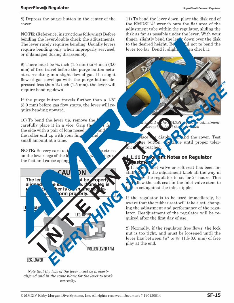
B CAUTIONThe legs of the lever must be properly aligned in the same plane. If one leg is up and the other is down, the regula-tor will not perform properly.
LEG, LOWER
LEG, LOWER
FEET
LEG, UPPER
ROLLER LEVER ARM
Note that the legs of the lever must be properly aligned and in the same plane for the lever to work
correctly.
11) To bend the lever down, place the disk end of the KMDSI 1/4" wrench onto the flat area of the adjustment tube within the regulator, sliding the disk as far as possible under the lever. With your finger, slightly bend the lever down over the disk to the desired height. Be careful not to bend the lever too far! Bend it slightly, then check it.
Use the disk end of the KMDSI regulator adjustment wrench to bend the lever down.
12) Replace the diaphragm and the cover. Test the purge button. Continue until proper toler-ances are reached.
1.1.11 Important Notes on Regulator Adjustment1) If a new inlet valve or soft seat has been in-stalled, turn the adjustment knob all the way in and allow the regulator to sit for 24 hours. This will allow the soft seat in the inlet valve stem to take a set against the inlet nipple.
If the regulator is to be used immediately, be aware that the rubber seat will take a set, chang-ing the adjustment and performance of the regu-lator. Readjustment of the regulator will be re-quired after the first day of use.
2) Normally, if the regulator free flows, the lock nut is too tight, and must be loosened until the lever has between 1/16" to 1/8" (1.5-3.0 mm) of free play at the end.
© MMXIV Kirby Morgan Dive Systems, Inc. All rights reserved. Document # 140130014 SF-15
SuperFlow® Regulator SuperFlow® Demand Regulator
B WARNINGThe lock nut must always be replaced if removed from the inlet valve. The plastic material that locks the nut is not designed for multiple reuse. If the nut comes loose during a dive the regulator would free flow heavily. In the situation where the diver is using bottled breathing gas this would result in a rapid consumption of breathing gas.
B CAUTIONThe lock nut must not be loosened more than 1/8 turn to lower the height of the lever. If more adjustment is nec-essary the lever should be bent down-ward. If the nut is loosened more than 1/8 turn the lever will not have enough travel for proper flow rates.
3) If the regulator continues to free flow after proper adjustment using the correct supply pres-sure of 135-150 p.s.i.g. (9.3-10.1 bar), both the inlet valve soft seat and/or the inlet nipple must be inspected for damage. Generally, if the inlet nipple has missing chrome or a bent or damaged sealing edge, the soft seat may not make a proper seal and may also be damaged. Replacement of both the inlet nipple and the soft seat is strongly recommended under these conditions.
1.1.12 SuperFlow® Regulator Steady Flows When Pressured Up: Special Tools UsedTools Required:Small flat blade screw driver.Small jewelers screw driver or metal scribe.Needle nose pliers.KMDSI regulator tool kit P/N 525-620 if avail-able.
The demand regulator is rugged and reliable. However, to maintain optimum performance it should be checked prior to each diving day in accordance with the brief procedure "1.1.2 SuperFlow® Demand Regulator Test for Correct Adjustment, Fully Assembled" on page SF-2.
If after completing the demand regulator test as outlined in "1.1.10 Tuning the SuperFlow® Regu-lator" on page SF-14, adjustment is necessary and
the KMDSI P/N 525-620 tool kit is not available proceed as follows:
1) Remove the regulator clamp, cover and dia-phragm.
2) Adjust the regulator adjustment knob all the way in. Finger tight only.
3) Pressurize the regulator to between 120-150 p.s.i.g. (8.5-10 bar).
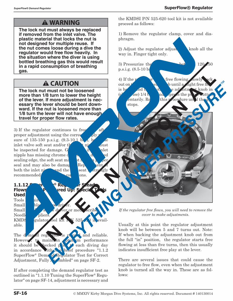
4) If the regulator is not free flowing, slowly back out on the adjustment knob until a slight free flow is heard and then rotate the adjustment knob in (clockwise) 1/4 turn and depress the purge button momentarily. Repeat this procedure until the gas flow stops.
If the regulator free flows, you will need to remove the cover to make adjustments.
Usually at this point the regulator adjustment knob will be between 5 and 7 turns out. Note: If when backing the adjustment knob out from the full “in” position, the regulator starts free flowing at less than five turns, then this usually indicates insufficient free play at the lever.
There are several issues that could cause the regulator to free flow, even when the adjustment knob is turned all the way in. These are as fol-lows:
SF-16 © MMXIV Kirby Morgan Dive Systems, Inc. All rights reserved. Document # 140130014
SuperFlow® Demand Regulator SuperFlow® Regulator
D) The regulator was rebuilt and the lock nut is too tight. If this is the case, the nut must be loos-ened.
E) The washer was never removed from the reg-ulator and a second one has accidentally been installed. If this is the case, the second washer must be removed.
F) The regulator body has never been properly serviced and there is corrosion inside the body, making proper inlet valve travel impossible.
5) Check the free play at the lever. The lever should have between 1/16-1/8 inch (1.5-3.0 mm) play. If adjustment is necessary, adjust using the KMDSI tools.
6) KMDSI tools: Using the inlet valve holding tool, (L shaped rod), insert the end of the tool into the balance hole. Lightly apply force by pushing on the tool making it act as a lever to put fric-tion against the inlet valve shaft. At this point, the KMDSI regulator adjustment wrench can be used to rotate the lock nut . Rotate the nut “In” (clockwise) to reduce lever play or “Out” (counter clockwise) to increase lever play.
Only rotate the nut 1/8 turn at a time. Remove the tools and depress the lever several times after adjusting to ensure the correct play is achieved. It may be necessary to repeat this procedure sev-eral times, as the method requires estimating the correct position of the nut.
NOTE: if there is little (less than 1/16 inch /1.5 mm) or no lever play, the regulator will free flow. If there is too much free play, (more than 1/8 inch / 3.0 mm) the regulator will not be capable of full demand flow potential.
7) If the free flow does not stop after this proce-dure, refer to regulator disassembly and cleaning procedures.
Alternate method: If a KMDSI tool kit is not available, a small jeweler’s screwdriver or metal scribe can be inserted in the slot on the end of the inlet valve to keep it from rotating, and nee-dle nose pliers may be used to rotate the lever nut. Holding the slot of the inlet valve to prevent its rotation, carefully rotate the nut “In” (clock-wise to remove lever play and “Out” (counter-clockwise) to increase lever play.
Only turn the adjustment nut 1/8 turn at a time.
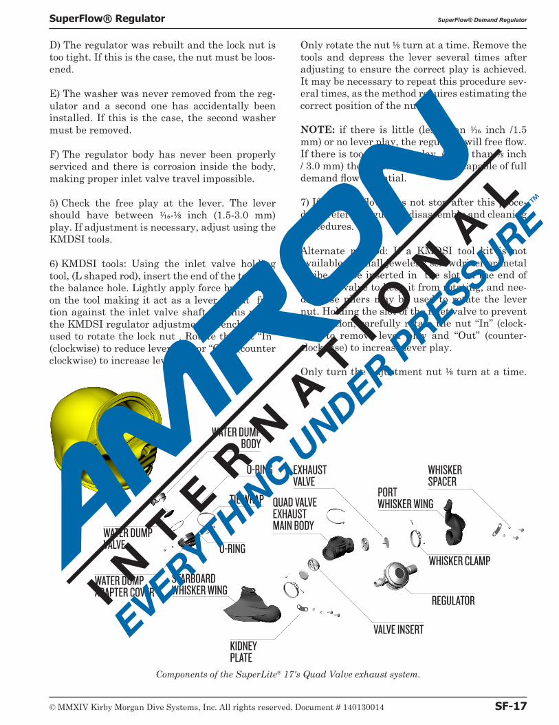
Components of the SuperLite® 17's Quad Valve exhaust system.
O-RING
TIE WRAP
WATER DUMP BODY
VALVE INSERT
REGULATOR
WHISKER CLAMPO-RING
WATER DUMPVALVE
KIDNEYPLATE
WATER DUMP ADAPTER COVER
WHISKERSPACER
QUAD VALVE EXHAUST MAIN BODY
EXHAUSTVALVE
PORT WHISKER WING
STARBOARDWHISKER WING
© MMXIV Kirby Morgan Dive Systems, Inc. All rights reserved. Document # 140130014 SF-17
SuperFlow® Regulator SuperFlow® Demand Regulator
Depress the lever momentarily after each adjust-ment and observe the lever play. It may be neces-sary to complete this procedure several times, as the procedure requires estimating the proper po-sition of the nut. If the regulator free flow did not stop after this procedure, refer to regulator disas-sembly and cleaning sections of this manual.
8) When adjustment is complete, place the dia-phragm and cover in place, and press tightly down on the cover to simulate the action of the clamp.
9) With the cover pressed tight against the dia-phragm, if the regulator starts to free flow, the lever may need to be bent down slightly. If the regulator does not free flow, slowly depress the purge button until a slight free flow develops. The purge button should depress no further than 1/8 inch (3.0 mm) before the regulator develops a flow.
If the regulator does not develop a slight free flow when the purge button is depressed in 1/8 inch (3.0 mm), then the lever will require slight upward bending.
Before bending the lever, double check the adjust-ments. It is rare that the lever requires bending in a regulator that has been in service. Usually levers only require bending in new installations or because of damage during disassembly.
10) Install the clamp and clamp screw. Tighten the screw to the correct torque (see appendix for torque specifications).
11) Again, press on the purge button in the cover. It must have 1/16 inch (1.5 mm) minimum and 1/8 inch (3.0 mm) maximum free travel before it contacts the diaphragm. If there is more than 1/8 inch (3.0 mm) travel, the lever must be bent up-ward, per "1.1.10 Tuning the SuperFlow® Regu-lator" on page SF-14. If the button has only slight or no free travel, the lever must be bent down.
12) If the purge button travel is correct, the ad-justment is complete.
1.1.13 Regulator Steady Flows When Pressured Up 1) Ensure supply pressure is adjusted between 135-150 p.s.i.g. (9.3-10.3bar).
2) Adjust demand regulator bias adjustment knob clockwise (in) until the free flow stops.
NOTE: If demand regulator bias adjustment knob is turned fully “in” and gas continues to flow, the demand regulator requires adjustment.
3) Recheck lever play at the purge button ensur-ing 1/16 inch (1.5 mm) to 1/8 inch (3.0 mm) of free travel before the purge button comes in contact with the diaphragm actuating a slight flow of gas. If a slight flow of gas develops with the purge button depressed less than 1/16 inch (1.5 mm) or greater than 1/8 inch (3.0 mm) the lever will re-quire adjusting.
1.1.14 Regulator has Low or No Flow When PressurizedTools Required:Regulator Adjustment Tools, (Part #525-620)1/4 inch Flat Blade Attachment on Torque Screw-driver
NOTE: If there is low or no flow when the regu-lator is pressurized, and the lever is very loose (travels more than 1/8 inch at the roller end), the nut must be tightened.
1) Adjust demand regulator bias adjustment knob “in”, i.e., clockwise.
2) Ensure supply pressure is adjusted between 135-150 p.s.i.g. (9.3-10.3bar).
3) Back the demand regulator bias adjustment knob out counterclockwise until a slight steady flow develops. Then adjust the knob in clockwise until the free-flow just stops. Depress the lever several times to ensure the regulator is stabi-lized.
4) Recheck the lever play at the purge button en-suring 1/16 inch (1.5 mm) to 1/8 inch (3.0 mm) of free travel before the purge button comes in contact with the diaphragm actuating a slight flow of gas. If a slight flow of gas develops with the purge button depressed less than 1/16 inch (1.5 mm), the lever will require slightly more play.
If the purge button travels greater than 1/8 inch (3.0 mm), the lever will require a reduction of play by adjusting.
SF-18 © MMXIV Kirby Morgan Dive Systems, Inc. All rights reserved. Document # 140130014
SuperFlow® Demand Regulator SuperFlow® Regulator
5) Recheck that the gas source pressure is set between 135-150 p.s.i.g. The gas source must be capable of supplying 4.5 a.c.f.m. (127.4 BL/min per diver) at the required over bottom pressures for the depth of the dive.
6) If the preceding steps were satisfactory, check the following helmet/mask parts for foreign de-bris in the air/gas passages:
a. One-way valveb. Side block assembly 1. Steady Flow Valve 2. Emergency Valve Assembly 3. Bent Tube Assembly
1.1.15 Unexplained Demand Regulator Free FlowAny leak in the neck dam when the diver is face down will cause gas to vent out into the water from the inside of the helmet. This causes the demand regulator to steady flow, making up for the vented gas. Even if the adjustment knob is turned in, the leak may continue.
1) One method to check for this is for the diver to place the demand regulator above the neck dam by looking up. Free flow from a leaky neck dam should cease as long as the helmet is in the up-right position.
2) Ensure the demand regulator bias adjustment knob is properly adjusted for the supply pressure.
3) During ascent the regulator will free flow if the supply pressure to the helmet is not backed off (topside) or, the diver does not adjust “in” (clockwise), the demand regulator adjustment knob as the diver’s depth and the ambient pres-sure decreases.
4) If the preceding steps were checked and the demand regulator still steady flows the regulator requires adjustment.
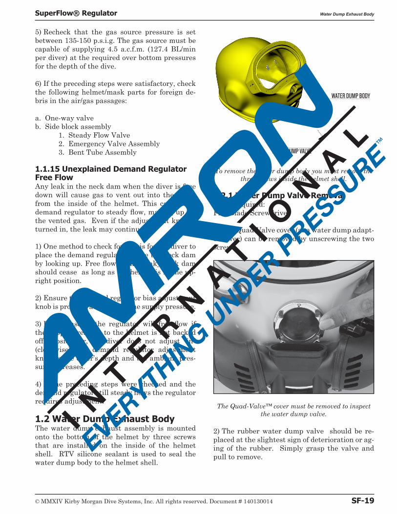
1.2 Water Dump Exhaust BodyThe water dump exhaust assembly is mounted onto the bottom of the helmet by three screws that are installed on the inside of the helmet shell. RTV silicone sealant is used to seal the water dump body to the helmet shell.
WATER DUMP VALVE
WATER DUMP BODY
To remove the water dump body you must remove the three screws inside the helmet shell.
1.2.1 Water Dump Valve RemovalTools Required:Flat Blade Screwdriver
1) The Quad-Valve cover (aka water dump adapt-er cover) can be removed by unscrewing the two screws.
The Quad-Valve™ cover must be removed to inspect the water dump valve.
2) The rubber water dump valve should be re-placed at the slightest sign of deterioration or ag-ing of the rubber. Simply grasp the valve and pull to remove.
© MMXIV Kirby Morgan Dive Systems, Inc. All rights reserved. Document # 140130014 SF-19
SuperFlow® Regulator Water Dump Exhaust Body
1.2.2 Water Dump Valve Replacement1) The rubber water dump valve is installed by inserting the center stem through the water dump body then pulling from the inside of the helmet shell until it snaps into place.
2) When installing the Quad Valve exhaust/wa-ter dump adapter cover, be sure NEVER to use longer screws. These would protrude into the in-terior of the exhaust body as this would interfere with the operation of the rubber exhaust valve .
1.2.3 Water Dump Valve Body Removal 1) The water dump body should never need ser-vicing. If it is to be removed, you must first re-move the three screws inside the helmet shell.
After this is done, gently twist the valve body off of the helmet shell. A wooden wedge may be used to slide between the valve body and the shell to break the RTV sealant.
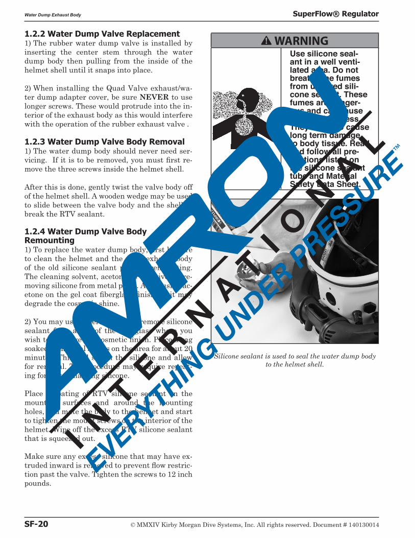
1.2.4 Water Dump Valve Body Remounting1) To replace the water dump body, first be sure to clean the helmet and the main exhaust body of the old silicone sealant prior to remounting. The cleaning solvent, acetone, is effective for re-moving silicone from metal parts. Avoid using ac-etone on the gel coat fiberglass finish, as it may degrade the cosmetic shine.
2) You may use mineral spirits to remove silicone sealant from areas of the fiberglass where you wish to preserve the cosmetic finish. Place a rag soaked in mineral spirits on the area for about 20 minutes. This will soften the silicone and allow for removal. The procedure may require repeat-ing for any remaining silicone.
Place a coating of RTV silicone sealant on the mounting surfaces and around the mounting holes, and mate the body to the helmet and start to tighten the mount screws on the interior of the helmet. Wipe off the excess RTV silicone sealant that is squeezed out.
Make sure any excess silicone that may have ex-truded inward is removed to prevent flow restric-tion past the valve. Tighten the screws to 12 inch pounds.
B WARNINGUse silicone seal-ant in a well venti-lated area. Do not breathe the fumes from uncured sili-cone sealant. These fumes are danger-ous and can cause unconsciousness. They can also cause long term damage to body tissue. Read and follow all pre-cautions listed on the silicone sealant tube and Material Safety Data Sheet.
Silicone sealant is used to seal the water dump body to the helmet shell.
SF-20 © MMXIV Kirby Morgan Dive Systems, Inc. All rights reserved. Document # 140130014
Water Dump Exhaust Body SuperFlow® Regulator