submission of supplemental projects for inclusion in the local
TRANSCRIPT
1
Submission of Supplemental Projects for
Inclusion in the Local Plan
SRRTEP – Western ATSI Local Plan
2
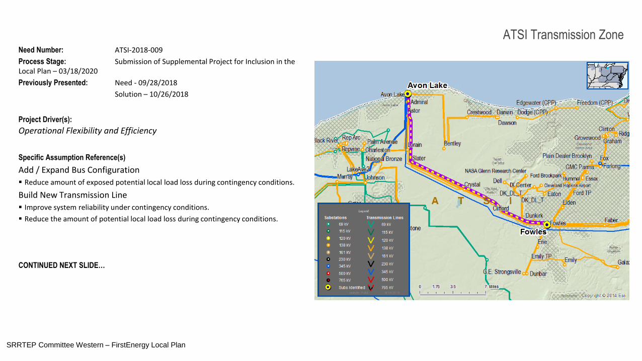
Need Number: ATSI-2018-009
Process Stage: Submission of Supplemental Project for Inclusion in the Local Plan – 03/18/2020
Previously Presented: Need - 09/28/2018
Solution – 10/26/2018
Project Driver(s):
Operational Flexibility and Efficiency
Specific Assumption Reference(s)
Add / Expand Bus Configuration
Reduce amount of exposed potential local load loss during contingency conditions.
Build New Transmission Line
Improve system reliability under contingency conditions.
Reduce the amount of potential local load loss during contingency conditions.
CONTINUED NEXT SLIDE…
PJM SRRTEP – Western 10/26/2018
SRRTEP Committee Western – FirstEnergy Local Plan
ATSI Transmission Zone
3
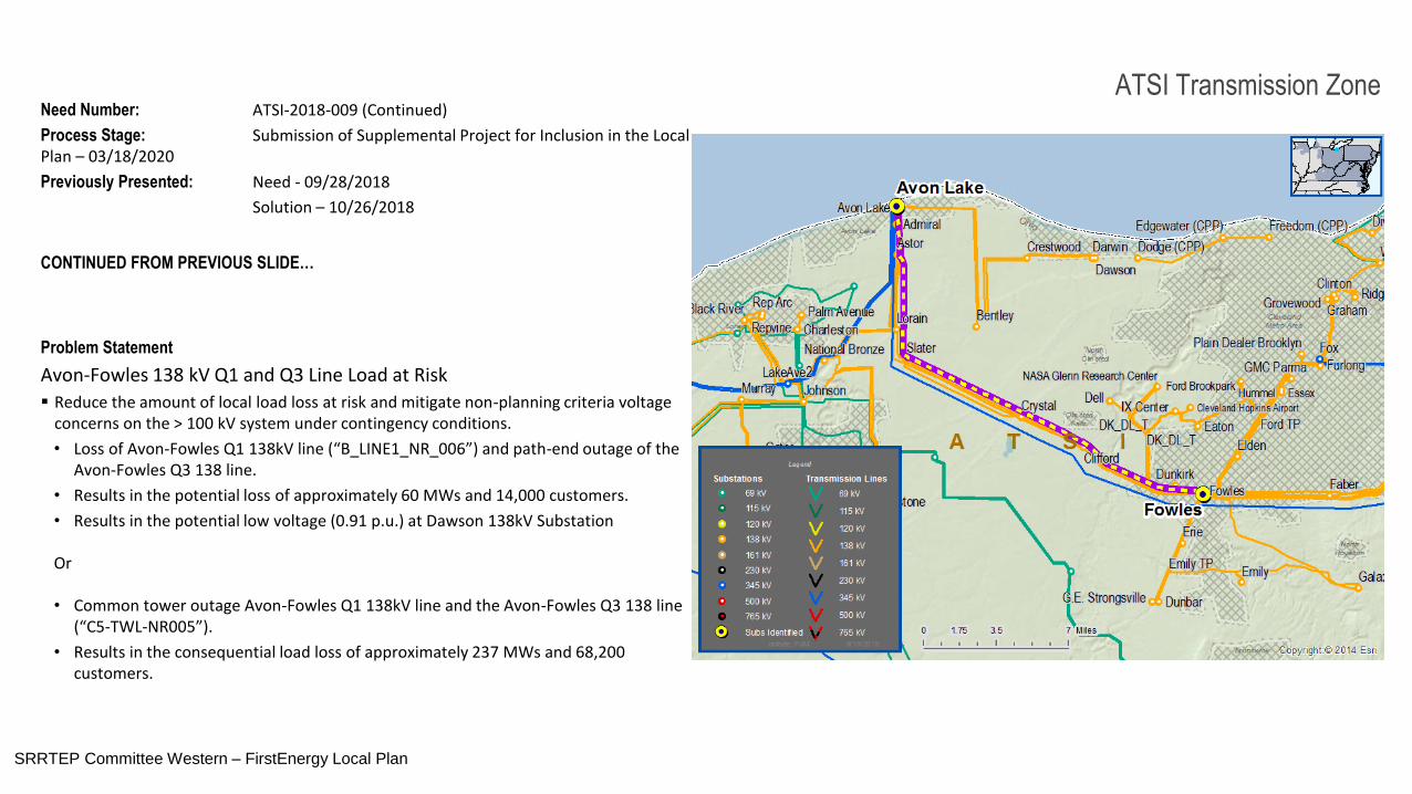
ATSI Transmission ZoneNeed Number: ATSI-2018-009 (Continued)
Process Stage: Submission of Supplemental Project for Inclusion in the Local Plan – 03/18/2020
Previously Presented: Need - 09/28/2018
Solution – 10/26/2018
CONTINUED FROM PREVIOUS SLIDE…
Problem Statement
Avon-Fowles 138 kV Q1 and Q3 Line Load at Risk
Reduce the amount of local load loss at risk and mitigate non-planning criteria voltage concerns on the > 100 kV system under contingency conditions.
• Loss of Avon-Fowles Q1 138kV line (“B_LINE1_NR_006”) and path-end outage of the Avon-Fowles Q3 138 line.
• Results in the potential loss of approximately 60 MWs and 14,000 customers.
• Results in the potential low voltage (0.91 p.u.) at Dawson 138kV Substation
Or
• Common tower outage Avon-Fowles Q1 138kV line and the Avon-Fowles Q3 138 line (“C5-TWL-NR005”).
• Results in the consequential load loss of approximately 237 MWs and 68,200 customers.
PJM SRRTEP – Western 10/26/2018
SRRTEP Committee Western – FirstEnergy Local Plan
4
ATSI Transmission ZoneNeed Number: ATSI-2018-009 (Continued)
Process Stage: Submission of Supplemental Project for Inclusion in the Local Plan – 03/18/2020
Previously Presented: Need - 09/28/2018
Solution – 10/26/2018
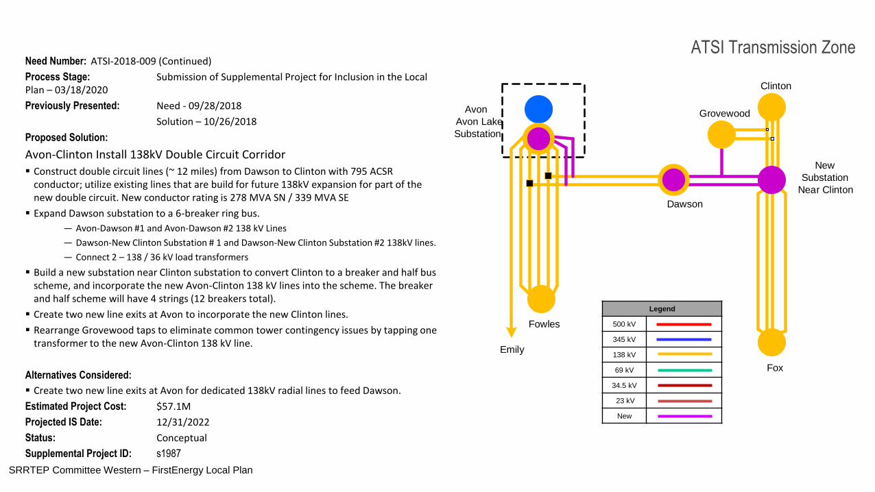
Proposed Solution:
Avon-Clinton Install 138kV Double Circuit Corridor
Construct double circuit lines (~ 12 miles) from Dawson to Clinton with 795 ACSR conductor; utilize existing lines that are build for future 138kV expansion for part of the new double circuit. New conductor rating is 278 MVA SN / 339 MVA SE
Expand Dawson substation to a 6-breaker ring bus.
― Avon-Dawson #1 and Avon-Dawson #2 138 kV Lines
― Dawson-New Clinton Substation # 1 and Dawson-New Clinton Substation #2 138kV lines.
― Connect 2 – 138 / 36 kV load transformers
Build a new substation near Clinton substation to convert Clinton to a breaker and half bus scheme, and incorporate the new Avon-Clinton 138 kV lines into the scheme. The breaker and half scheme will have 4 strings (12 breakers total).
Create two new line exits at Avon to incorporate the new Clinton lines.
Rearrange Grovewood taps to eliminate common tower contingency issues by tapping one transformer to the new Avon-Clinton 138 kV line.
Alternatives Considered:
Create two new line exits at Avon for dedicated 138kV radial lines to feed Dawson.
Estimated Project Cost: $57.1M
Projected IS Date: 12/31/2022
Status: Conceptual
Supplemental Project ID: s1987
Legend
500 kV
345 kV
138 kV
69 kV
34.5 kV
23 kV
New
Avon
Avon Lake
Substation
Dawson
Fowles
Emily
New
Substation
Near Clinton
Grovewood
Clinton
Fox
SRRTEP Committee Western – FirstEnergy Local Plan
5
ATSI Transmission Zone
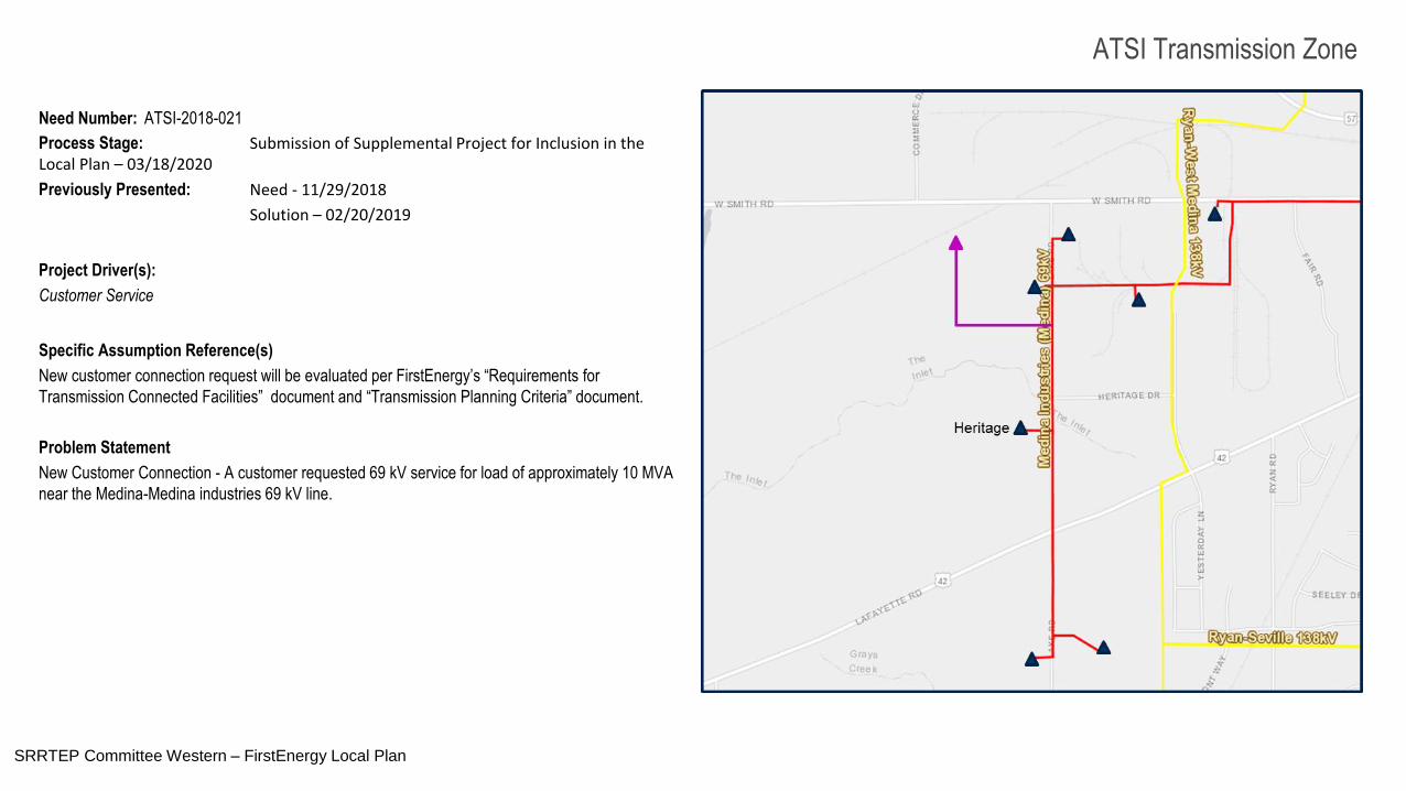
Need Number: ATSI-2018-021
Process Stage: Submission of Supplemental Project for Inclusion in the Local Plan – 03/18/2020
Previously Presented: Need - 11/29/2018
Solution – 02/20/2019
Project Driver(s):
Customer Service
Specific Assumption Reference(s)
New customer connection request will be evaluated per FirstEnergy’s “Requirements for
Transmission Connected Facilities” document and “Transmission Planning Criteria” document.
Problem Statement
New Customer Connection - A customer requested 69 kV service for load of approximately 10 MVA
near the Medina-Medina industries 69 kV line.
SRRTEP Committee Western – FirstEnergy Local Plan
6
ATSI Transmission Zone
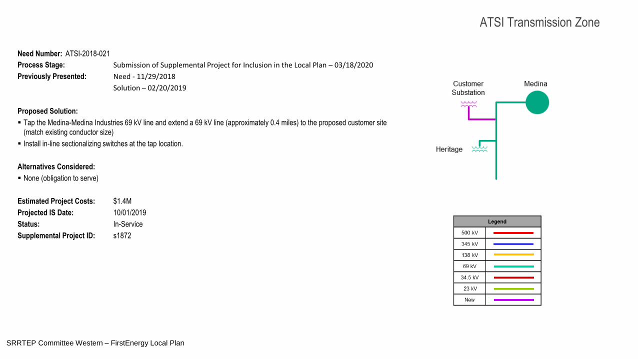
Need Number: ATSI-2018-021
Process Stage: Submission of Supplemental Project for Inclusion in the Local Plan – 03/18/2020
Previously Presented: Need - 11/29/2018
Solution – 02/20/2019
Proposed Solution:
Tap the Medina-Medina Industries 69 kV line and extend a 69 kV line (approximately 0.4 miles) to the proposed customer site
(match existing conductor size)
Install in-line sectionalizing switches at the tap location.
Alternatives Considered:
None (obligation to serve)
Estimated Project Costs: $1.4M
Projected IS Date: 10/01/2019
Status: In-Service
Supplemental Project ID: s1872
SRRTEP Committee Western – FirstEnergy Local Plan
7
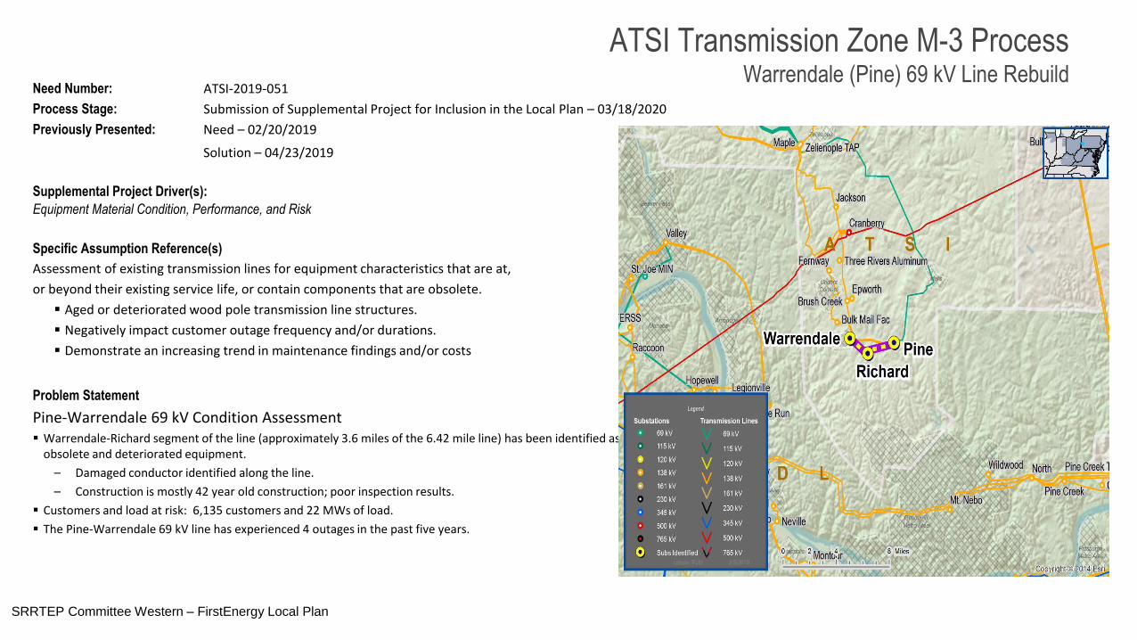
ATSI Transmission Zone M-3 ProcessWarrendale (Pine) 69 kV Line Rebuild
Need Number: ATSI-2019-051
Process Stage: Submission of Supplemental Project for Inclusion in the Local Plan – 03/18/2020
Previously Presented: Need – 02/20/2019
Solution – 04/23/2019
Supplemental Project Driver(s):
Equipment Material Condition, Performance, and Risk
Specific Assumption Reference(s)
Assessment of existing transmission lines for equipment characteristics that are at,
or beyond their existing service life, or contain components that are obsolete.
Aged or deteriorated wood pole transmission line structures.
Negatively impact customer outage frequency and/or durations.
Demonstrate an increasing trend in maintenance findings and/or costs
Problem Statement
Pine-Warrendale 69 kV Condition Assessment Warrendale-Richard segment of the line (approximately 3.6 miles of the 6.42 mile line) has been identified as having
obsolete and deteriorated equipment.
– Damaged conductor identified along the line.
– Construction is mostly 42 year old construction; poor inspection results.
Customers and load at risk: 6,135 customers and 22 MWs of load.
The Pine-Warrendale 69 kV line has experienced 4 outages in the past five years.
SRRTEP Committee Western – FirstEnergy Local Plan
8
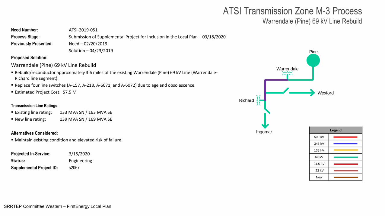
Need Number: ATSI-2019-051
Process Stage: Submission of Supplemental Project for Inclusion in the Local Plan – 03/18/2020
Previously Presented: Need – 02/20/2019
Solution – 04/23/2019
Proposed Solution:
Warrendale (Pine) 69 kV Line Rebuild
Rebuild/reconductor approximately 3.6 miles of the existing Warrendale (Pine) 69 kV Line (Warrendale-Richard line segment).
Replace four line switches (A-157, A-218, A-6071, and A-6072) due to age and obsolescence.
Estimated Project Cost: $7.5 M
Transmission Line Ratings:
Existing line rating: 133 MVA SN / 163 MVA SE
New line rating: 139 MVA SN / 169 MVA SE
Alternatives Considered:
Maintain existing condition and elevated risk of failure
Projected In-Service: 3/15/2020
Status: Engineering
Supplemental Project ID: s2067
Legend
500 kV
345 kV
138 kV
69 kV
34.5 kV
23 kV
New
Pine
Warrendale
Richard
Ingomar
Wexford
ATSI Transmission Zone M-3 ProcessWarrendale (Pine) 69 kV Line Rebuild
SRRTEP Committee Western – FirstEnergy Local Plan
9
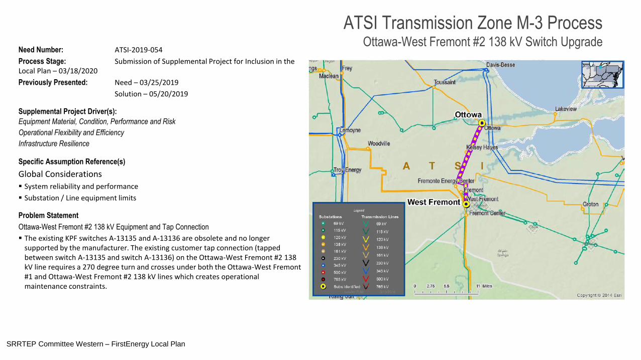
Need Number: ATSI-2019-054
Process Stage: Submission of Supplemental Project for Inclusion in the Local Plan – 03/18/2020
Previously Presented: Need – 03/25/2019
Solution – 05/20/2019
Supplemental Project Driver(s):
Equipment Material, Condition, Performance and Risk
Operational Flexibility and Efficiency
Infrastructure Resilience
Specific Assumption Reference(s)
Global Considerations
System reliability and performance
Substation / Line equipment limits
Problem Statement
Ottawa-West Fremont #2 138 kV Equipment and Tap Connection
The existing KPF switches A-13135 and A-13136 are obsolete and no longer supported by the manufacturer. The existing customer tap connection (tapped between switch A-13135 and switch A-13136) on the Ottawa-West Fremont #2 138 kV line requires a 270 degree turn and crosses under both the Ottawa-West Fremont #1 and Ottawa-West Fremont #2 138 kV lines which creates operational maintenance constraints.
ATSI Transmission Zone M-3 ProcessOttawa-West Fremont #2 138 kV Switch Upgrade
SRRTEP Committee Western – FirstEnergy Local Plan
10
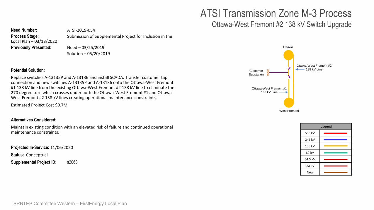
Need Number: ATSI-2019-054
Process Stage: Submission of Supplemental Project for Inclusion in the Local Plan – 03/18/2020
Previously Presented: Need – 03/25/2019
Solution – 05/20/2019
Potential Solution:
Replace switches A-13135P and A-13136 and install SCADA. Transfer customer tap connection and new switches A-13135P and A-13136 onto the Ottawa-West Fremont #1 138 kV line from the existing Ottawa-West Fremont #2 138 kV line to eliminate the 270 degree turn which crosses under both the Ottawa-West Fremont #1 and Ottawa-West Fremont #2 138 kV lines creating operational maintenance constraints.
Estimated Project Cost $0.7M
Alternatives Considered:
Maintain existing condition with an elevated risk of failure and continued operational maintenance constraints.
Projected In-Service: 11/06/2020
Status: Conceptual
Supplemental Project ID: s2068
PJM SRRTEP – Western ATSI Supplemental 05/20/2019
Legend
500 kV
345 kV
138 kV
69 kV
34.5 kV
23 kV
New
Ottawa
Customer
Substation
West Fremont
ATSI Transmission Zone M-3 ProcessOttawa-West Fremont #2 138 kV Switch Upgrade
Ottawa-West Fremont #2
138 kV Line
Ottawa-West Fremont #1
138 kV Line
SRRTEP Committee Western – FirstEnergy Local Plan
1111
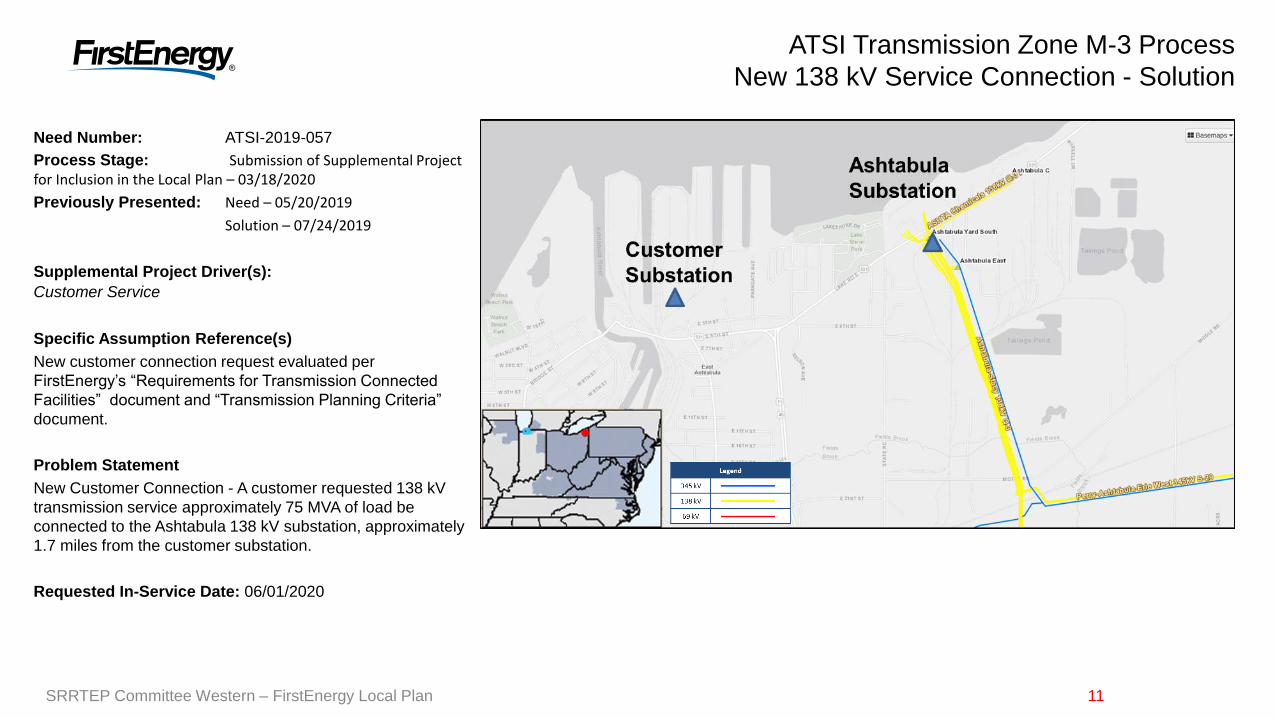
Need Number: ATSI-2019-057
Process Stage: Submission of Supplemental Project for Inclusion in the Local Plan – 03/18/2020
Previously Presented: Need – 05/20/2019
Solution – 07/24/2019
Supplemental Project Driver(s):
Customer Service
Specific Assumption Reference(s)
New customer connection request evaluated per
FirstEnergy’s “Requirements for Transmission Connected
Facilities” document and “Transmission Planning Criteria”
document.
Problem Statement
New Customer Connection - A customer requested 138 kV
transmission service approximately 75 MVA of load be
connected to the Ashtabula 138 kV substation, approximately
1.7 miles from the customer substation.
Requested In-Service Date: 06/01/2020
ATSI Transmission Zone M-3 Process
New 138 kV Service Connection - Solution
SRRTEP Committee Western – FirstEnergy Local Plan
12
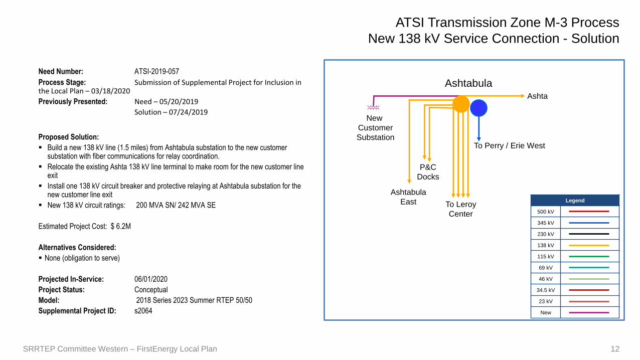
Need Number: ATSI-2019-057
Process Stage: Submission of Supplemental Project for Inclusion in the Local Plan – 03/18/2020
Previously Presented: Need – 05/20/2019
Solution – 07/24/2019
Proposed Solution:
Build a new 138 kV line (1.5 miles) from Ashtabula substation to the new customer substation with fiber communications for relay coordination.
Relocate the existing Ashta 138 kV line terminal to make room for the new customer line exit
Install one 138 kV circuit breaker and protective relaying at Ashtabula substation for the new customer line exit
New 138 kV circuit ratings: 200 MVA SN/ 242 MVA SE
Estimated Project Cost: $ 6.2M
Alternatives Considered:
None (obligation to serve)
Projected In-Service: 06/01/2020
Project Status: Conceptual
Model: 2018 Series 2023 Summer RTEP 50/50
Supplemental Project ID: s2064
Legend
500 kV
345 kV
230 kV
138 kV
115 kV
69 kV
46 kV
34.5 kV
23 kV
New
12
To Leroy
Center
New
Customer
SubstationTo Perry / Erie West
Ashta
Ashtabula
East
P&C
Docks
Ashtabula
ATSI Transmission Zone M-3 Process
New 138 kV Service Connection - Solution
SRRTEP Committee Western – FirstEnergy Local Plan
1313
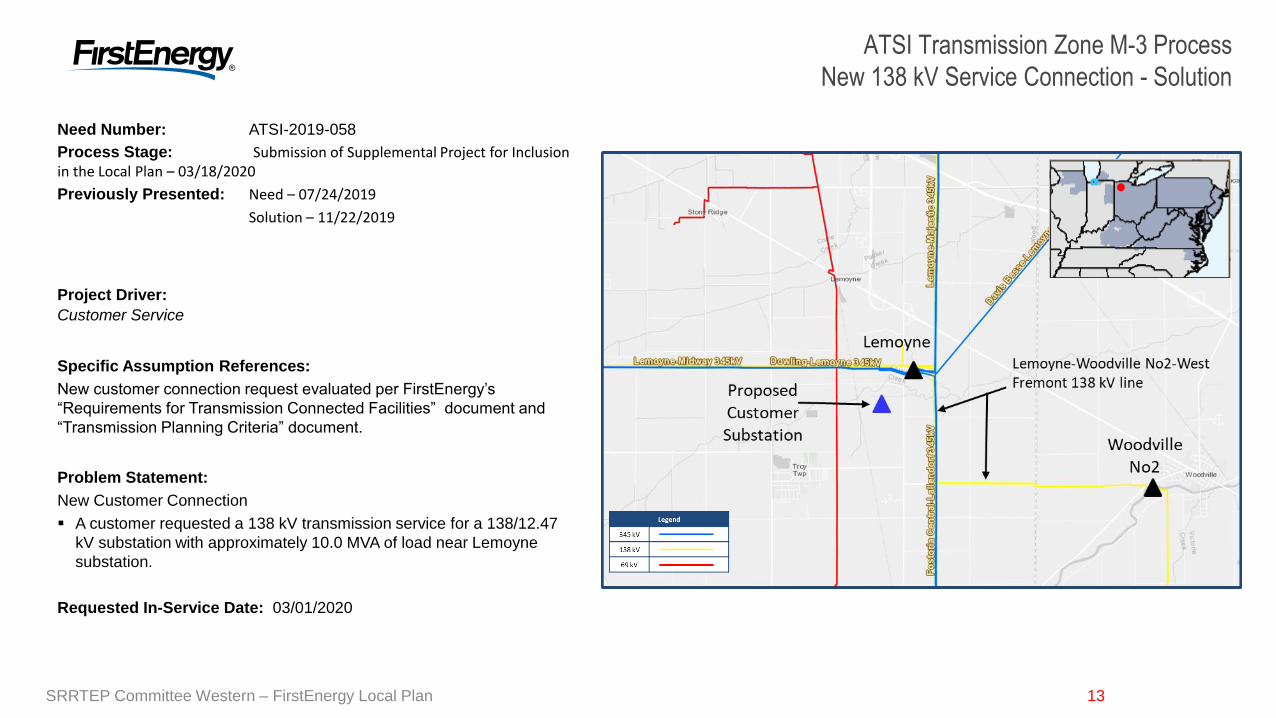
Need Number: ATSI-2019-058
Process Stage: Submission of Supplemental Project for Inclusion in the Local Plan – 03/18/2020
Previously Presented: Need – 07/24/2019
Solution – 11/22/2019
Project Driver:
Customer Service
Specific Assumption References:
New customer connection request evaluated per FirstEnergy’s
“Requirements for Transmission Connected Facilities” document and
“Transmission Planning Criteria” document.
Problem Statement:
New Customer Connection
A customer requested a 138 kV transmission service for a 138/12.47
kV substation with approximately 10.0 MVA of load near Lemoyne
substation.
Requested In-Service Date: 03/01/2020
ATSI Transmission Zone M-3 Process
New 138 kV Service Connection - Solution
SRRTEP Committee Western – FirstEnergy Local Plan
14
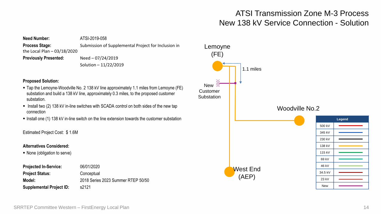
Need Number: ATSI-2019-058
Process Stage: Submission of Supplemental Project for Inclusion in the Local Plan – 03/18/2020
Previously Presented: Need – 07/24/2019
Solution – 11/22/2019
Proposed Solution:
Tap the Lemoyne-Woodville No. 2 138 kV line approximately 1.1 miles from Lemoyne (FE)
substation and build a 138 kV line, approximately 0.3 miles, to the proposed customer
substation.
Install two (2) 138 kV in-line switches with SCADA control on both sides of the new tap
connection
Install one (1) 138 kV in-line switch on the line extension towards the customer substation
Estimated Project Cost: $ 1.6M
Alternatives Considered:
None (obligation to serve)
Projected In-Service: 06/01/2020
Project Status: Conceptual
Model: 2018 Series 2023 Summer RTEP 50/50
Supplemental Project ID: s2121
Legend
500 kV
345 kV
230 kV
138 kV
115 kV
69 kV
46 kV
34.5 kV
23 kV
New
14
New
Customer
Substation
Lemoyne
(FE)
Woodville No.2
1.1 miles
ATSI Transmission Zone M-3 Process
New 138 kV Service Connection - Solution
West End
(AEP)
SRRTEP Committee Western – FirstEnergy Local Plan
1515
Need Number: ATSI-2019-Mutiple (See next slide)
Process Stage: Submission of Supplemental Project for Inclusion in the Local Plan – 03/18/2020
Previously Presented: Need – 07/24/2019
Solution – 11/22/2019
Project Driver:
Equipment Material Condition, Performance and Risk
Specific Assumption References:
Line Condition Rebuild/Replacement
Age/condition of wood pole transmission line structures
Age/condition of steel tower or steel pole transmission line
structures
Age/condition of transmission line conductors
System Performance Projects
Substation/line equipment limits
Problem Statement:
Line sections are exhibiting deterioration, increasing maintenance
needs.
Transmission line is approaching end of life
Transmission line ratings are limited by terminal equipment.
Map Not Shown
Multiple Locations
ATSI Transmission Zone M-3 Process
Multiple Line Rehab / Rebuild Solution
Continued on next page…
SRRTEP Committee Western – FirstEnergy Local Plan
16
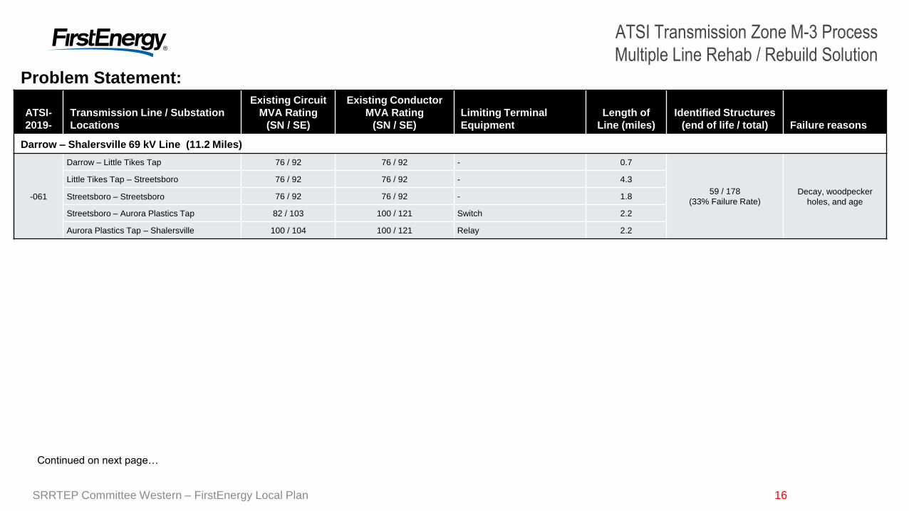
ATSI Transmission Zone M-3 Process
Multiple Line Rehab / Rebuild Solution
ATSI-
2019-
Transmission Line / Substation
Locations
Existing Circuit
MVA Rating
(SN / SE)
Existing Conductor
MVA Rating
(SN / SE)
Limiting Terminal
Equipment
Length of
Line (miles)
Identified Structures
(end of life / total) Failure reasons
Darrow – Shalersville 69 kV Line (11.2 Miles)
-061
Darrow – Little Tikes Tap 76 / 92 76 / 92 - 0.7
59 / 178
(33% Failure Rate)
Decay, woodpecker
holes, and age
Little Tikes Tap – Streetsboro 76 / 92 76 / 92 - 4.3
Streetsboro – Streetsboro 76 / 92 76 / 92 - 1.8
Streetsboro – Aurora Plastics Tap 82 / 103 100 / 121 Switch 2.2
Aurora Plastics Tap – Shalersville 100 / 104 100 / 121 Relay 2.2
Continued on next page…
16
Problem Statement:
SRRTEP Committee Western – FirstEnergy Local Plan
17
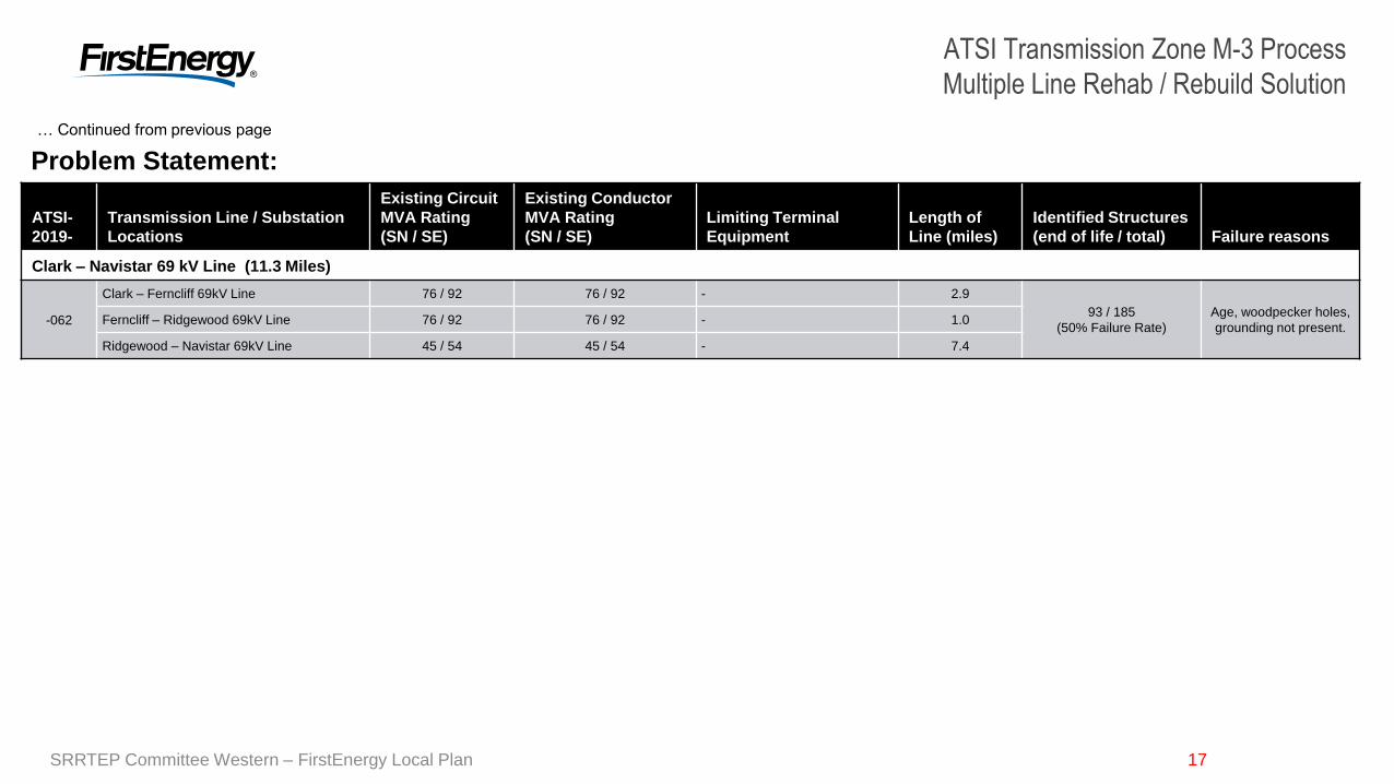
ATSI Transmission Zone M-3 Process
Multiple Line Rehab / Rebuild Solution
ATSI-
2019-
Transmission Line / Substation
Locations
Existing Circuit
MVA Rating
(SN / SE)
Existing Conductor
MVA Rating
(SN / SE)
Limiting Terminal
Equipment
Length of
Line (miles)
Identified Structures
(end of life / total) Failure reasons
Clark – Navistar 69 kV Line (11.3 Miles)
-062
Clark – Ferncliff 69kV Line 76 / 92 76 / 92 - 2.9
93 / 185
(50% Failure Rate)
Age, woodpecker holes,
grounding not present.Ferncliff – Ridgewood 69kV Line 76 / 92 76 / 92 - 1.0
Ridgewood – Navistar 69kV Line 45 / 54 45 / 54 - 7.4
… Continued from previous page
17
Problem Statement:
SRRTEP Committee Western – FirstEnergy Local Plan
18
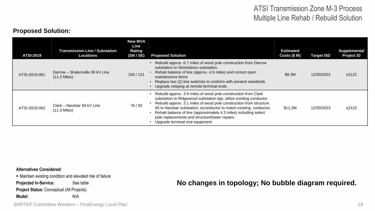
ATSI Transmission Zone M-3 Process
Multiple Line Rehab / Rebuild Solution
18
Proposed Solution:
ATSI-2019
Transmission Line / Substation
Locations
New MVA
Line
Rating
(SN / SE) Proposed Solution
Estimated
Costs ($ M) Target ISD
Supplemental
Project ID
ATSI-2019-061Darrow – Shalersville 69 kV Line
(11.2 Miles)100 / 121
• Rebuild approx. 6.7 miles of wood pole construction from Darrow
substation to Streetsboro substation.
• Rehab balance of line (approx. 4.5 miles) and correct open
maintenance items
• Replace two (2) line switches to conform with present standards
• Upgrade relaying at remote terminal ends.
$9.3M 12/30/2023 s2122
ATSI-2019-062Clark – Navistar 69 kV Line
(11.3 Miles)
76 / 92
• Rebuild approx. 3.9 miles of wood pole construction from Clark
substation to Ridgewood substation tap; utilize existing conductor.
• Rebuild approx. 3.1 miles of wood pole construction from structure
65 to Navistar substation; reconductor to match existing conductor.
• Rehab balance of line (approximately 4.3 miles) including select
pole replacements and structure/tower repairs.
• Upgrade terminal end equipment
$11.2M 12/30/2023 s2123
Alternatives Considered:
Maintain existing condition and elevated risk of failure
Projected In-Service: See table
Project Status: Conceptual (All Projects)
Model: N/A
No changes in topology; No bubble diagram required.
SRRTEP Committee Western – FirstEnergy Local Plan
1919
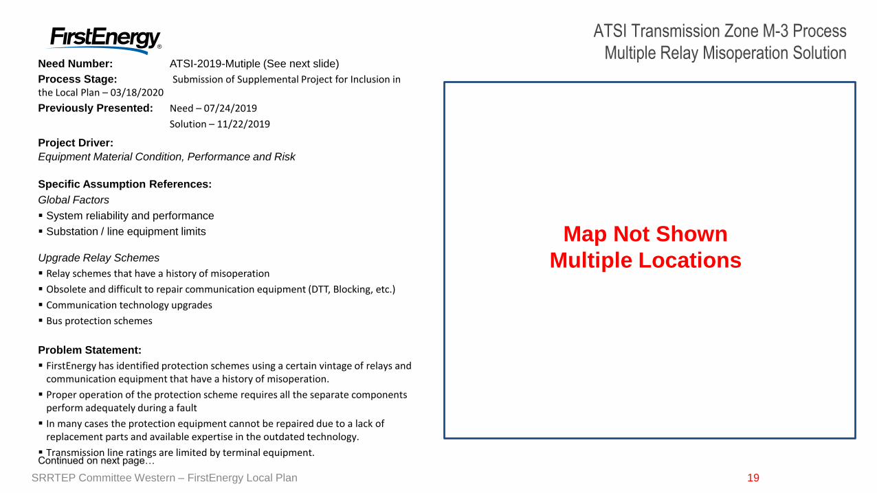
Need Number: ATSI-2019-Mutiple (See next slide)
Process Stage: Submission of Supplemental Project for Inclusion in the Local Plan – 03/18/2020
Previously Presented: Need – 07/24/2019
Solution – 11/22/2019
Project Driver:
Equipment Material Condition, Performance and Risk
Specific Assumption References:
Global Factors
System reliability and performance
Substation / line equipment limits
Upgrade Relay Schemes
Relay schemes that have a history of misoperation
Obsolete and difficult to repair communication equipment (DTT, Blocking, etc.)
Communication technology upgrades
Bus protection schemes
Problem Statement:
FirstEnergy has identified protection schemes using a certain vintage of relays and communication equipment that have a history of misoperation.
Proper operation of the protection scheme requires all the separate components perform adequately during a fault
In many cases the protection equipment cannot be repaired due to a lack of replacement parts and available expertise in the outdated technology.
Transmission line ratings are limited by terminal equipment.
Map Not Shown
Multiple Locations
ATSI Transmission Zone M-3 Process
Multiple Relay Misoperation Solution
Continued on next page…
SRRTEP Committee Western – FirstEnergy Local Plan
20
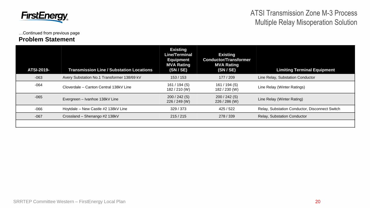
ATSI Transmission Zone M-3 Process
Multiple Relay Misoperation Solution
20
ATSI-2019- Transmission Line / Substation Locations
Existing
Line/Terminal
Equipment
MVA Rating
(SN / SE)
Existing
Conductor/Transformer
MVA Rating
(SN / SE) Limiting Terminal Equipment
-063 Avery Substation No.1 Transformer 138/69 kV 153 / 153 177 / 209 Line Relay, Substation Conductor
-064Cloverdale – Canton Central 138kV Line
161 / 194 (S)
182 / 210 (W)
161 / 194 (S)
182 / 230 (W)Line Relay (Winter Ratings)
-065Evergreen – Ivanhoe 138kV Line
200 / 242 (S)
226 / 249 (W)
200 / 242 (S)
226 / 286 (W)Line Relay (Winter Rating)
-066 Hoytdale – New Castle #2 138kV Line 329 / 373 425 / 522 Relay, Substation Conductor, Disconnect Switch
-067 Crossland – Shenango #2 138kV 215 / 215 278 / 339 Relay, Substation Conductor
…Continued from previous page
Problem Statement
SRRTEP Committee Western – FirstEnergy Local Plan
21
ATSI Transmission Zone M-3 Process
Multiple Relay Misoperation Solution
21
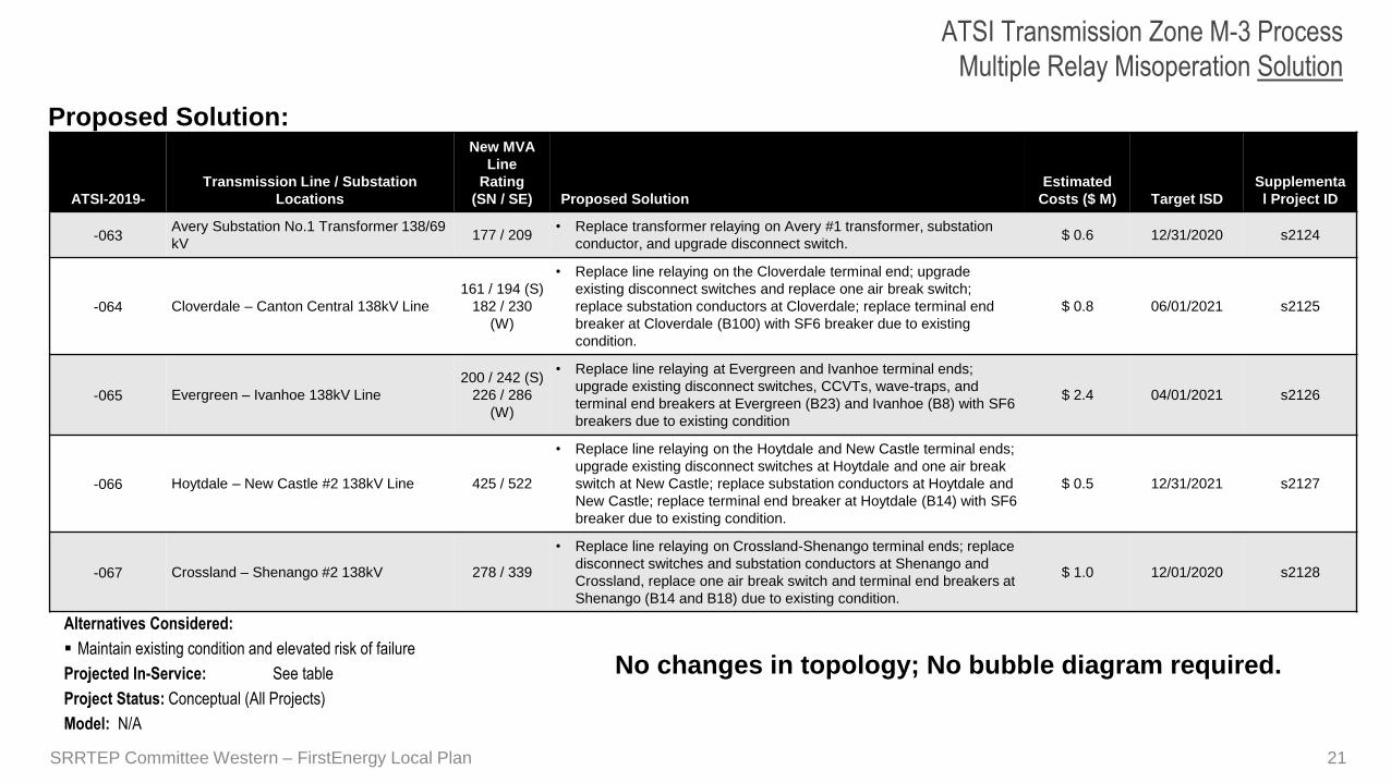
Proposed Solution:
ATSI-2019-
Transmission Line / Substation
Locations
New MVA
Line
Rating
(SN / SE) Proposed Solution
Estimated
Costs ($ M) Target ISD
Supplementa
l Project ID
-063Avery Substation No.1 Transformer 138/69
kV 177 / 209
• Replace transformer relaying on Avery #1 transformer, substation
conductor, and upgrade disconnect switch.$ 0.6 12/31/2020 s2124
-064 Cloverdale – Canton Central 138kV Line
161 / 194 (S)
182 / 230
(W)
• Replace line relaying on the Cloverdale terminal end; upgrade
existing disconnect switches and replace one air break switch;
replace substation conductors at Cloverdale; replace terminal end
breaker at Cloverdale (B100) with SF6 breaker due to existing
condition.
$ 0.8 06/01/2021 s2125
-065 Evergreen – Ivanhoe 138kV Line
200 / 242 (S)
226 / 286
(W)
• Replace line relaying at Evergreen and Ivanhoe terminal ends;
upgrade existing disconnect switches, CCVTs, wave-traps, and
terminal end breakers at Evergreen (B23) and Ivanhoe (B8) with SF6
breakers due to existing condition
$ 2.4 04/01/2021 s2126
-066 Hoytdale – New Castle #2 138kV Line 425 / 522
• Replace line relaying on the Hoytdale and New Castle terminal ends;
upgrade existing disconnect switches at Hoytdale and one air break
switch at New Castle; replace substation conductors at Hoytdale and
New Castle; replace terminal end breaker at Hoytdale (B14) with SF6
breaker due to existing condition.
$ 0.5 12/31/2021 s2127
-067 Crossland – Shenango #2 138kV 278 / 339
• Replace line relaying on Crossland-Shenango terminal ends; replace
disconnect switches and substation conductors at Shenango and
Crossland, replace one air break switch and terminal end breakers at
Shenango (B14 and B18) due to existing condition.
$ 1.0 12/01/2020 s2128
Alternatives Considered:
Maintain existing condition and elevated risk of failure
Projected In-Service: See table
Project Status: Conceptual (All Projects)
Model: N/A
No changes in topology; No bubble diagram required.
SRRTEP Committee Western – FirstEnergy Local Plan
22SRRTEP Committee Western – FirstEnergy Local Plan22
Need Number: ATSI-2019-Mutiple (See next slide)
Process Stage: Submission of Supplemental Project for Inclusion in the Local Plan – 06/08/2020
Previously Presented: Need Meeting – 11/22/2019Solution Meeting – 03/19/2020
Project Driver:
Equipment Material Condition, Performance and Risk
Specific Assumption References:
Global Factors
System reliability and performance
Substation / line equipment limits
Upgrade Relay Schemes
Relay schemes that have a history of misoperation
Obsolete and difficult to repair communication equipment (DTT, Blocking, etc.)
Communication technology upgrades
Bus protection schemes
Problem Statement:
FirstEnergy has identified protection schemes using a certain vintage of relays and communication equipment that have a history of misoperation.
Proper operation of the protection scheme requires all the separate components perform adequately during a fault
In many cases the protection equipment cannot be repaired due to a lack of replacement parts and available expertise in the outdated technology.
Transmission line ratings are limited by terminal equipment.
Map Not ShownMultiple Locations
ATSI Transmission Zone M-3 Process
Multiple Relay Misoperation - Solution
Continued on next page…
23
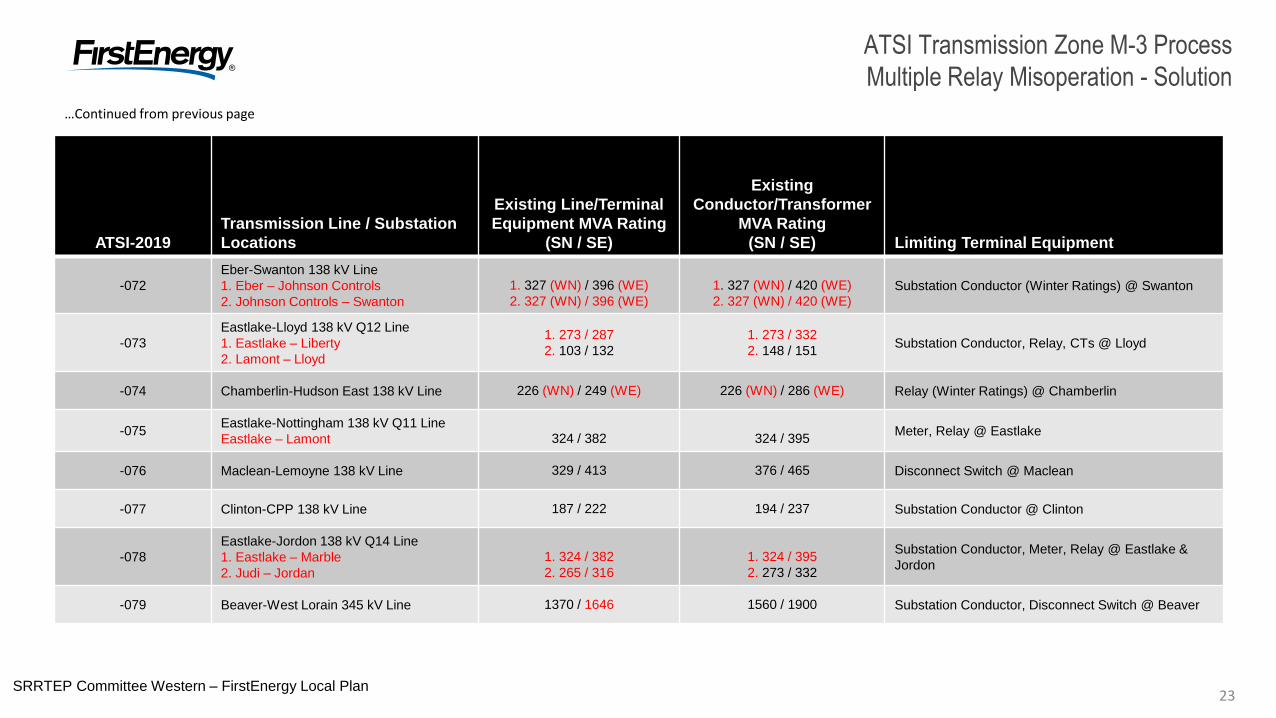
ATSI Transmission Zone M-3 Process
Multiple Relay Misoperation - Solution
23SRRTEP Committee Western – FirstEnergy Local Plan
ATSI-2019
Transmission Line / Substation
Locations
Existing Line/Terminal
Equipment MVA Rating
(SN / SE)
Existing
Conductor/Transformer
MVA Rating
(SN / SE) Limiting Terminal Equipment
-072
Eber-Swanton 138 kV Line
1. Eber – Johnson Controls
2. Johnson Controls – Swanton
1. 327 (WN) / 396 (WE)
2. 327 (WN) / 396 (WE)
1. 327 (WN) / 420 (WE)
2. 327 (WN) / 420 (WE)Substation Conductor (Winter Ratings) @ Swanton
-073
Eastlake-Lloyd 138 kV Q12 Line
1. Eastlake – Liberty
2. Lamont – Lloyd
1. 273 / 287
2. 103 / 132
1. 273 / 332
2. 148 / 151Substation Conductor, Relay, CTs @ Lloyd
-074 Chamberlin-Hudson East 138 kV Line 226 (WN) / 249 (WE) 226 (WN) / 286 (WE) Relay (Winter Ratings) @ Chamberlin
-075Eastlake-Nottingham 138 kV Q11 Line
Eastlake – Lamont 324 / 382 324 / 395Meter, Relay @ Eastlake
-076 Maclean-Lemoyne 138 kV Line 329 / 413 376 / 465 Disconnect Switch @ Maclean
-077 Clinton-CPP 138 kV Line 187 / 222 194 / 237 Substation Conductor @ Clinton
-078
Eastlake-Jordon 138 kV Q14 Line
1. Eastlake – Marble
2. Judi – Jordan
1. 324 / 382
2. 265 / 316
1. 324 / 395
2. 273 / 332
Substation Conductor, Meter, Relay @ Eastlake &
Jordon
-079 Beaver-West Lorain 345 kV Line 1370 / 1646 1560 / 1900 Substation Conductor, Disconnect Switch @ Beaver
…Continued from previous page
24
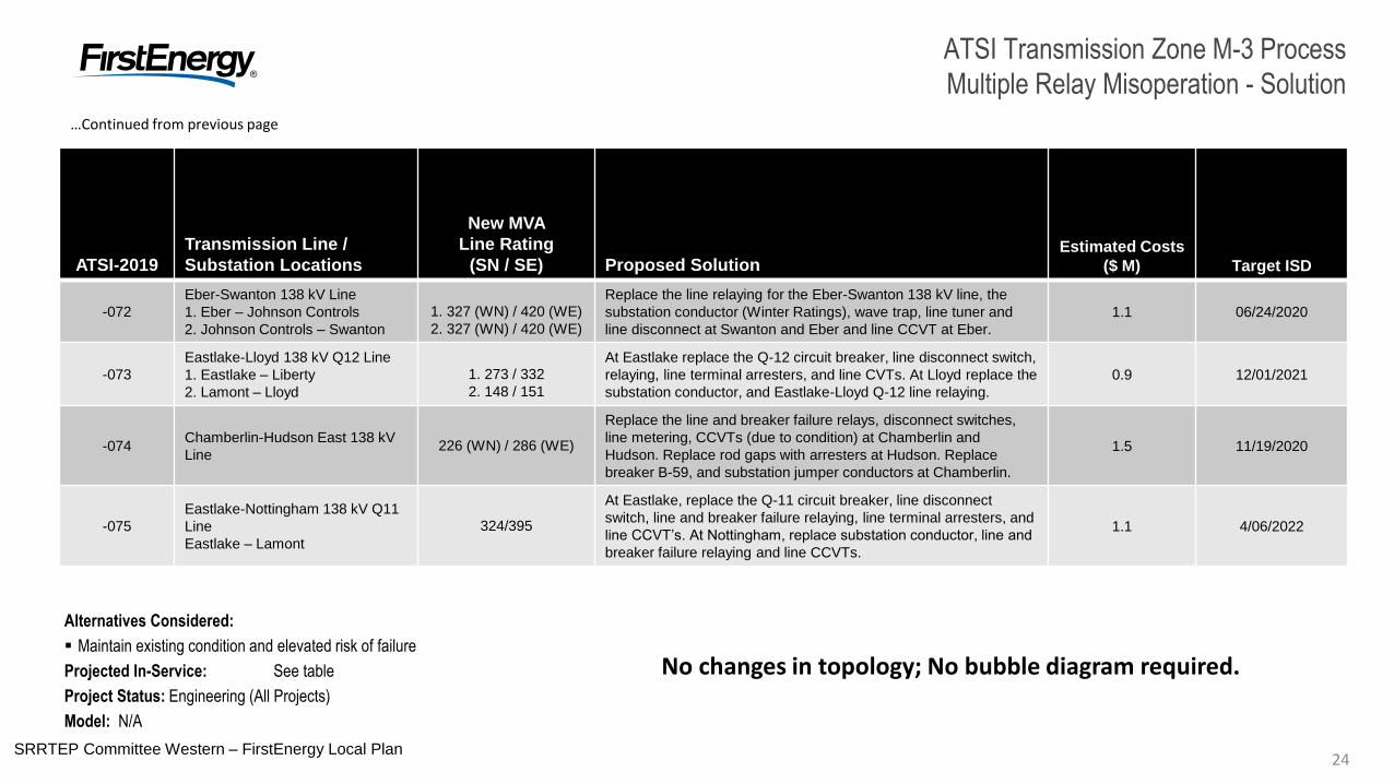
ATSI Transmission Zone M-3 Process
Multiple Relay Misoperation - Solution
24SRRTEP Committee Western – FirstEnergy Local Plan
ATSI-2019
Transmission Line /
Substation Locations
New MVA
Line Rating
(SN / SE) Proposed SolutionEstimated Costs
($ M) Target ISD
-072
Eber-Swanton 138 kV Line
1. Eber – Johnson Controls
2. Johnson Controls – Swanton
1. 327 (WN) / 420 (WE)
2. 327 (WN) / 420 (WE)
Replace the line relaying for the Eber-Swanton 138 kV line, the
substation conductor (Winter Ratings), wave trap, line tuner and
line disconnect at Swanton and Eber and line CCVT at Eber.
1.1 06/24/2020
-073
Eastlake-Lloyd 138 kV Q12 Line
1. Eastlake – Liberty
2. Lamont – Lloyd
1. 273 / 332
2. 148 / 151
At Eastlake replace the Q-12 circuit breaker, line disconnect switch,
relaying, line terminal arresters, and line CVTs. At Lloyd replace the
substation conductor, and Eastlake-Lloyd Q-12 line relaying.
0.9 12/01/2021
-074Chamberlin-Hudson East 138 kV
Line226 (WN) / 286 (WE)
Replace the line and breaker failure relays, disconnect switches,
line metering, CCVTs (due to condition) at Chamberlin and
Hudson. Replace rod gaps with arresters at Hudson. Replace
breaker B-59, and substation jumper conductors at Chamberlin.
1.5 11/19/2020
-075
Eastlake-Nottingham 138 kV Q11
Line
Eastlake – Lamont
324/395
At Eastlake, replace the Q-11 circuit breaker, line disconnect
switch, line and breaker failure relaying, line terminal arresters, and
line CCVT’s. At Nottingham, replace substation conductor, line and
breaker failure relaying and line CCVTs.
1.1 4/06/2022
…Continued from previous page
Alternatives Considered:
Maintain existing condition and elevated risk of failure
Projected In-Service: See table
Project Status: Engineering (All Projects)
Model: N/A
No changes in topology; No bubble diagram required.
25
ATSI Transmission Zone M-3 Process
Multiple Relay Misoperation - Solution
25SRRTEP Committee Western – FirstEnergy Local Plan
ATSI-2019
Transmission Line /
Substation Locations
New MVA
Line Rating
(SN / SE) Proposed SolutionEstimated Costs
($ M) Target ISD
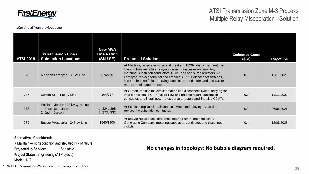
-076 Maclean-Lemoyne 138 kV Line 376/465
At Maclean, replace terminal end breaker B13202, disconnect switches,
line and breaker failure relaying, carrier transceiver and monitor,
metering, substation conductors, CCVT and add surge arresters. At
Lemoyne, replace terminal end breaker B13219, disconnect switches,
line and breaker failure relaying, substation conductors and add carrier
monitor, and surge arresters.
0.9 12/15/2020
-077 Clinton-CPP 138 kV Line 194/237At Clinton, replace the circuit breaker, line disconnect switch, relaying for
interconnection to CPP (Ridge Rd.) and breaker failure, substation
conductor, and install new meter, surge arresters and line side CCVTs.
0.9 11/13/2020
-078
Eastlake-Jordon 138 kV Q14 Line
1. Eastlake – Marble
2. Judi – Jordan
1. 324 / 395
2. 273 / 332
At Eastlake replace line disconnect switch and relaying. At Jordan
replace the substation conductor.0.2 06/01/2021
-079 Beaver-West Lorain 345 kV Line 1560/1900At Beaver replace bus differential relaying for Interconnection to
Generating Company, metering, substation conductor, and disconnect
switch.
0.4 12/01/2023
…Continued from previous page
Alternatives Considered:
Maintain existing condition and elevated risk of failure
Projected In-Service: See table
Project Status: Engineering (All Projects)
Model: N/A
No changes in topology; No bubble diagram required.
26SRRTEP Committee Western – FirstEnergy Local Plan26
Need Number: ATSI-2019-Mutiple (See next slide)
Process Stage: Submission of Supplemental Project for Inclusion in the Local Plan – 06/08/2020
Previously Presented: Need Meeting – 11/22/2019
Solution Meeting – 03/19/2020
Project Driver:
Equipment Material Condition, Performance and Risk
Specific Assumption References:
Global Factors
System reliability and performance
Substation / line equipment limits
Upgrade Relay Schemes
Bus protection schemes which rely on remote clearing.
Protection system with single point of failure.
Relay schemes that have a history of misoperation.
Obsolete firmware or software.
Problem Statement:
FirstEnergy has identified protection schemes on networked lines and buses using a certain vintage of relays that have a history of misoperation.
Schemes protecting these facilities have no local backup so failures impact a larger portion of the system.
In many cases the protection equipment cannot be repaired due to a lack of replacement parts and available expertise in the outdated technology.
Transmission line ratings are limited by terminal equipment.
Map Not ShownMultiple Locations
ATSI Transmission Zone M-3 Process
Relay Single Point of Failure - Solution
Continued on next page…
27
ATSI Transmission Zone M-3 Process
Relay Single Point of Failure - Solution
27SRRTEP Committee Western – FirstEnergy Local Plan
ATSI-2019 Transmission Line / Substation Locations
Existing
Line/Terminal
Equipment
MVA Rating
(SN / SE)
Existing
Conductor/Transformer
MVA Rating
(SN / SE) Limiting Terminal Equipment
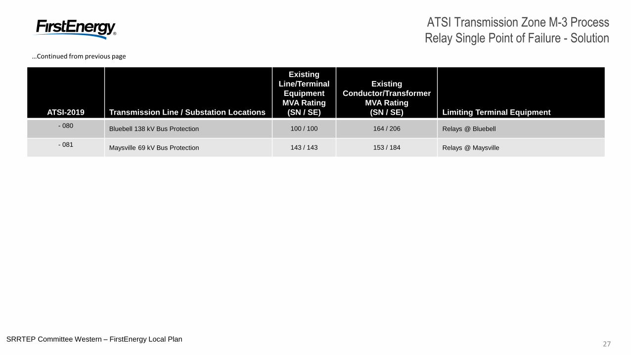
- 080Bluebell 138 kV Bus Protection 100 / 100 164 / 206 Relays @ Bluebell
- 081Maysville 69 kV Bus Protection 143 / 143 153 / 184 Relays @ Maysville
…Continued from previous page
28SRRTEP Committee Western – FirstEnergy Local Plan28
ATSI Transmission Zone M-3 ProcessBluebell Replace 138 kV Bus Protection - Solution
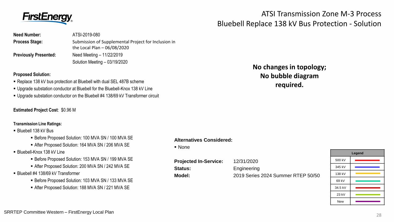
Need Number: ATSI-2019-080
Process Stage: Submission of Supplemental Project for Inclusion in the Local Plan – 06/08/2020
Previously Presented: Need Meeting – 11/22/2019
Solution Meeting – 03/19/2020
Proposed Solution:
Replace 138 kV bus protection at Bluebell with dual SEL 487B scheme
Upgrade substation conductor at Bluebell for the Bluebell-Knox 138 kV Line
Upgrade substation conductor on the Bluebell #4 138/69 kV Transformer circuit
Estimated Project Cost: $0.96 M
Transmission Line Ratings:
Bluebell 138 kV Bus
Before Proposed Solution: 100 MVA SN / 100 MVA SE
After Proposed Solution: 164 MVA SN / 206 MVA SE
Bluebell-Knox 138 kV Line
Before Proposed Solution: 153 MVA SN / 199 MVA SE
After Proposed Solution: 200 MVA SN / 242 MVA SE
Bluebell #4 138/69 kV Transformer
Before Proposed Solution: 103 MVA SN / 133 MVA SE
After Proposed Solution: 188 MVA SN / 221 MVA SE
Legend
500 kV
345 kV
138 kV
69 kV
34.5 kV
23 kV
New
No changes in topology; No bubble diagram
required.
Alternatives Considered:
None
Projected In-Service: 12/31/2020
Status: Engineering
Model: 2019 Series 2024 Summer RTEP 50/50
29SRRTEP Committee Western – FirstEnergy Local Plan29
ATSI Transmission Zone M-3 ProcessMaysville Replace 69 kV Bus Protection - Solution
Need Number: ATSI-2019-081
Process Stage: Submission of Supplemental Project for Inclusion in the Local Plan – 06/08/2020
Previously Presented: Need Meeting – 11/22/2019
Solution Meeting – 03/19/2020
Proposed Solution:
Replace 69 kV bus protection with primary and backup differential
Add CT to 69 kV breaker B46 for use with new bus protection relaying
Upgrade substation conductor at Maysville for the Canal (Maysville) 69 kV Line
Estimated Project Cost: $0.22 M
Transmission Line Ratings:
Maysville 69 kV Bus
Before Proposed Solution: 143 MVA SN / 143 MVA SE
After Proposed Solution: 153 MVA SN / 184 MVA SE
Maysville-Greenville 69 kV Line segment
Before Proposed Solution: 64 MVA SN / 83 MVA SE
After Proposed Solution: 80 MVA SN / 96 MVA SE
Alternatives Considered:
None
Projected In-Service: 12/31/2020
Status: Engineering
Model: 2019 Series 2024 Summer RTEP 50/50
Legend
500 kV
345 kV
138 kV
69 kV
34.5 kV
23 kV
New
No changes in topology; No bubble diagram
required.
30
Customer
Substation
Harding – Jennings
Q13 138 kV Line
LTV East
SRRTEP Committee Western – FirstEnergy Local Plan30
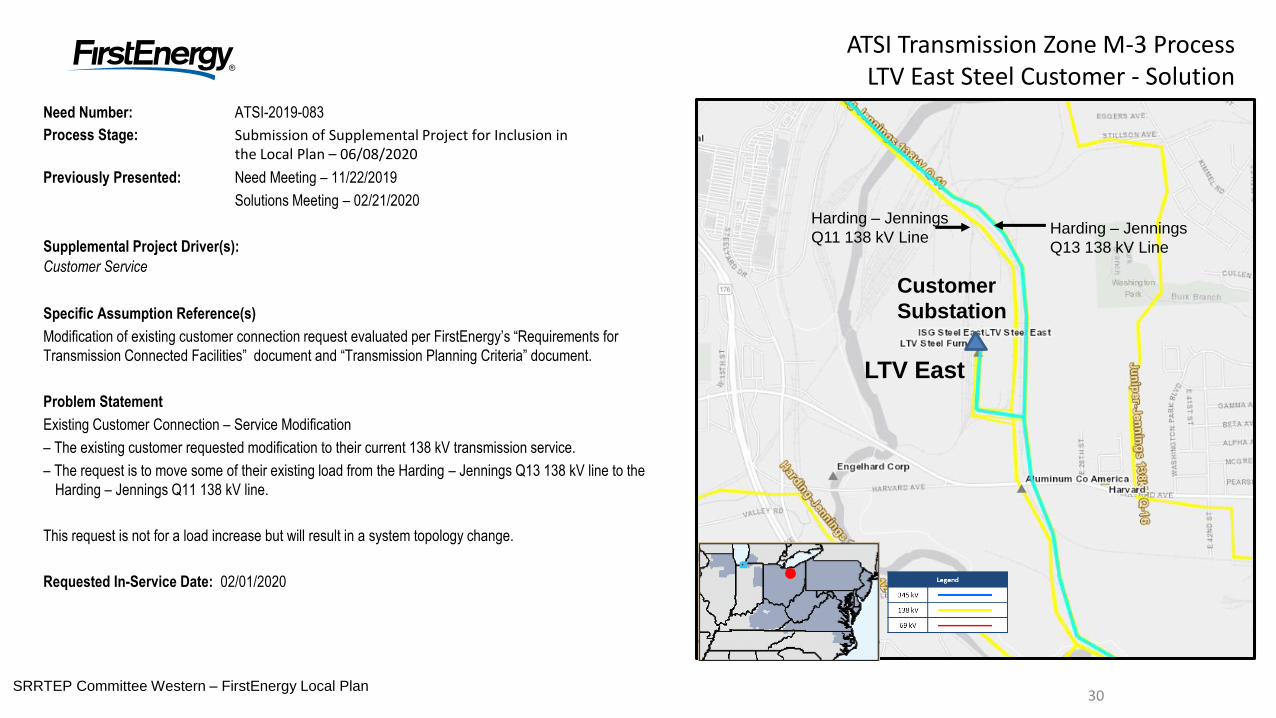
ATSI Transmission Zone M-3 ProcessLTV East Steel Customer - Solution
Need Number: ATSI-2019-083
Process Stage: Submission of Supplemental Project for Inclusion in the Local Plan – 06/08/2020
Previously Presented: Need Meeting – 11/22/2019
Solutions Meeting – 02/21/2020
Supplemental Project Driver(s):
Customer Service
Specific Assumption Reference(s)
Modification of existing customer connection request evaluated per FirstEnergy’s “Requirements for
Transmission Connected Facilities” document and “Transmission Planning Criteria” document.
Problem Statement
Existing Customer Connection – Service Modification
– The existing customer requested modification to their current 138 kV transmission service.
– The request is to move some of their existing load from the Harding – Jennings Q13 138 kV line to the
Harding – Jennings Q11 138 kV line.
This request is not for a load increase but will result in a system topology change.
Requested In-Service Date: 02/01/2020
Harding – Jennings
Q11 138 kV Line
31SRRTEP Committee Western – FirstEnergy Local Plan31
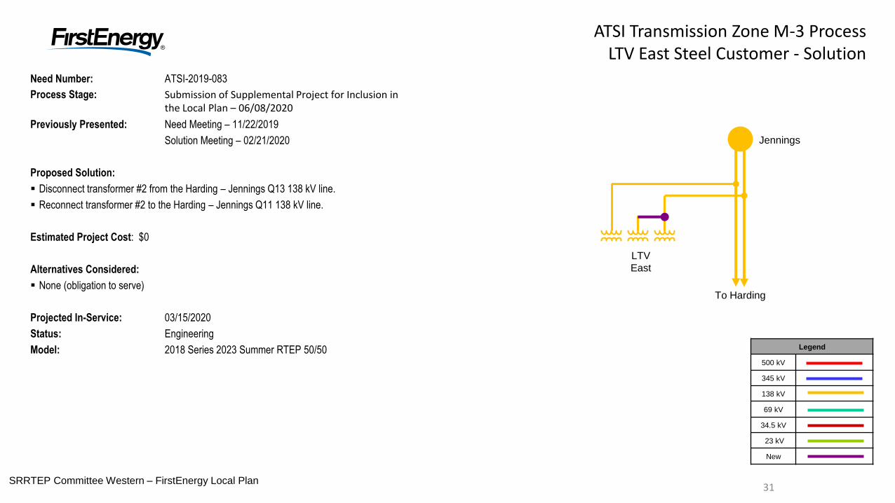
ATSI Transmission Zone M-3 ProcessLTV East Steel Customer - Solution
Need Number: ATSI-2019-083
Process Stage: Submission of Supplemental Project for Inclusion in the Local Plan – 06/08/2020
Previously Presented: Need Meeting – 11/22/2019
Solution Meeting – 02/21/2020
Proposed Solution:
Disconnect transformer #2 from the Harding – Jennings Q13 138 kV line.
Reconnect transformer #2 to the Harding – Jennings Q11 138 kV line.
Estimated Project Cost: $0
Alternatives Considered:
None (obligation to serve)
Projected In-Service: 03/15/2020
Status: Engineering
Model: 2018 Series 2023 Summer RTEP 50/50 Legend
500 kV
345 kV
138 kV
69 kV
34.5 kV
23 kV
New
Jennings
To Harding
LTV
East
32SRRTEP Committee Western – FirstEnergy Local Plan32
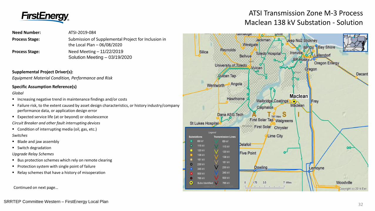
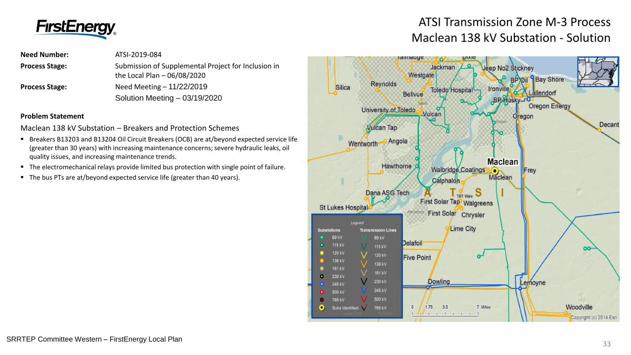
Need Number: ATSI-2019-084
Process Stage: Submission of Supplemental Project for Inclusion in the Local Plan – 06/08/2020
Process Stage: Need Meeting – 11/22/2019
Solution Meeting – 03/19/2020
Supplemental Project Driver(s):
Equipment Material Condition, Performance and Risk
Specific Assumption Reference(s)
Global
Increasing negative trend in maintenance findings and/or costs
Failure risk, to the extent caused by asset design characteristics, or history industry/company performance data, or application design error
Expected service life (at or beyond) or obsolescence
Circuit Breaker and other fault interrupting devices
Condition of interrupting media (oil, gas, etc.)
Switches
Blade and jaw assembly
Switch degradation
Upgrade Relay Schemes
Bus protection schemes which rely on remote clearing
Protection system with single point of failure
Relay schemes that have a history of misoperation
ATSI Transmission Zone M-3 ProcessMaclean 138 kV Substation - Solution
Continued on next page…
33SRRTEP Committee Western – FirstEnergy Local Plan33
Need Number: ATSI-2019-084
Process Stage: Submission of Supplemental Project for Inclusion in the Local Plan – 06/08/2020
Process Stage: Need Meeting – 11/22/2019
Solution Meeting – 03/19/2020
Problem Statement
Maclean 138 kV Substation – Breakers and Protection Schemes
Breakers B13203 and B13204 Oil Circuit Breakers (OCB) are at/beyond expected service life (greater than 30 years) with increasing maintenance concerns; severe hydraulic leaks, oil quality issues, and increasing maintenance trends.
The electromechanical relays provide limited bus protection with single point of failure.
The bus PTs are at/beyond expected service life (greater than 40 years).
ATSI Transmission Zone M-3 ProcessMaclean 138 kV Substation - Solution
34SRRTEP Committee Western – FirstEnergy Local Plan34
ATSI Transmission Zone M-3 ProcessMaclean 138 kV Substation - Solution
Need Number: ATSI-2019-084
Process Stage: Submission of Supplemental Project for Inclusion in the Local Plan – 06/08/2020
Previously Presented: Need Meeting – 11/22/2019
Solution Meeting – 03/19/2020
Proposed Solution:
Replace 138kV breaker B13204
Replace 138kV breaker B13203
Replace disconnect switches for Breaker B13204
Replace disconnect switches for Breaker B13203
Replace one (1) disconnect switch for 138-69 kV Transformer No1
Upgrade substation conductor at Maclean for the Maclean-Chrysler 138 kV Line
Estimated Project Cost: $1.2 M
Transmission Line Ratings:
Maclean-Chrysler 138 kV Line
Before Proposed Solution: 327 MVA WN / 394 MVA WE
After Proposed Solution: 327 MVA WN / 394 MVA WE
Maclean-Walbridge Coatings 138 kV Line section of the (Maclean-Chrysler 138 kV Line)
Before Proposed Solution: 327 MVA WN / 394 MVA WE
After Proposed Solution: 327 MVA WN / 420 MVA WE
Alternatives Considered:
Maintain existing equipment and risk of failure.
Projected In-Service: 11/11/2021
Status: Conceptual
Model: N/A
Legend
500 kV
345 kV
138 kV
69 kV
34.5 kV
23 kV
New
No changes in topology; No bubble diagram
required.
35SRRTEP Committee Western – FirstEnergy Local Plan35
Need Number: ATSI-2019-085
Process Stage: Submission of Supplemental Project for Inclusion in the Local Plan – 06/08/2020
Previously Presented: Need Meeting – 11/22/2019
Solution Meeting – 03/19/2020
Supplemental Project Driver(s):
Equipment Material Condition, Performance and Risk
Specific Assumption Reference(s)
Global
System reliability and performance
Substation/line equipment limits
Failure risk, to the extent caused by asset design characteristics, or history industry/company performance data, or application design error
Expected service life (at or beyond) or obsolescence
Circuit Breaker and other fault interrupting devices
Operating Mechanism
Switches
Blade and jaw assembly
Operating mechanism
Station Protection and Control
Electromechanical relays
Devices used for panel, telemetry, and revenue metering
Potential Transformers (PTs)
ATSI Transmission Zone M-3 ProcessCedar Street 138 / 69 kV Substation - Solution
PJM to Provide Map
36SRRTEP Committee Western – FirstEnergy Local Plan36
Need Number: ATSI-2019-085
Process Stage: Submission of Supplemental Project for Inclusion in the Local Plan – 06/08/2020
Previously Presented: Need Meeting – 11/22/2019
Solution Meeting – 03/19/2020
Problem Statement
Cedar 138/69 kV Street Substation – Breakers, Relays, and Control Building
Breaker B-26 69 kV Bus Tie Breaker and disconnect switches are at/beyond expected service life (greater than 52 years) with increasing maintenance concerns; deteriorated operating mechanism, spare part availability, and increasing maintenance trends.
North and South bus PTs are deteriorating and at/beyond expected service life (greater than 40 years).
Transformer 138/69 kV #1, bus protection, and line exit relays are electromechanical and prone to misoperation.
o Cedar Street – Shenango 138 kV Line
o Cedar Street – New Castle 138 kV Line
o Cedar Street – New Castle #1, #2 and #3 69 kV Lines
o Cedar Street – Frisco #1 and #2 69 kV Lines
o Cedar Street – McDowell 69 kV Line
o Cedar Street – Grant Street 69 kV Line
o Cedar Street – New Wilmington 69 kV Line
o Cedar Street – Lowellville North 69 kV Line
o Cedar Street – Lowellville South 69 kV Line
o Cedar Street – Columbiana 69 kV Line
ATSI Transmission Zone M-3 ProcessCedar Street 138 / 69 kV Substation - Solution
PJM to Provide Map
37SRRTEP Committee Western – FirstEnergy Local Plan37
Need Number: ATSI-2019-086
ATSI-2019-091
Process Stage: Submission of Supplemental Project for Inclusion in the Local Plan – 06/08/2020
Previously Presented: Need Meeting – 11/22/2019Solution Meeting – 03/19/2020
Supplemental Project Driver(s):
Equipment Material Condition, Performance and Risk
Specific Assumption Reference(s)
Global
System reliability and performance
Substation/line equipment limits
Failure risk, to the extent caused by asset design characteristics, or history industry/company performance data, or application design error
Expected service life (at or beyond) or obsolescence
Circuit Breaker and other fault interrupting devices
Condition of interrupting media (oil, gas, etc.)
Station Protection and Control
Electromechanical relays
ATSI Transmission Zone M-3 ProcessFowles and Pleasant Valley 138 kV Substation - Solution
PJM to Provide Map
38SRRTEP Committee Western – FirstEnergy Local Plan38
Need Number: ATSI-2019-086
ATSI-2019-091
Process Stage: Submission of Supplemental Project for Inclusion in the Local Plan – 06/08/2020
Previously Presented: Need Meeting – 11/22/2019
Solution Meeting – 03/19/2020
Problem Statement
ATSI-2019-086
Fowles Breaker Replacement
Breaker B-8 Oil Circuit Breaker (OCB) is at/beyond expected service life (greater than 30 years) with increasing Maintenance concerns; Deteriorated bushing potential device and mechanism, Obsolete replacement parts, hot spots, and deteriorated oil within the tank.
ATSI-2019-091
Fowles 138 kV Substation – Breaker and substation equipment
Breaker B-2 Oil Circuit Breaker (OCB) is at/beyond expected service life (greater than 30years) with increasing maintenance concerns; hot spots, oil leaks, and increasing maintenance trends.
CTs and disconnect switches are at/beyond expected service life.
Relays are electromechanical and prone to misoperation.
Pleasant Valley 138 kV Substation – Breakers and Substation Equipment
Breaker B-1 Oil Circuit Breaker (OCB) is at/beyond expected service life (greater than 30 years) with increasing maintenance concerns; hot spots and deteriorated oil within the tank, deterioration of terminal block wiring in the cabinet.
CTs and disconnect switches are at/beyond expected service life.
PJM to Provide Map
ATSI Transmission Zone M-3 ProcessFowles and Pleasant Valley 138 kV Substation - Solution
39SRRTEP Committee Western – FirstEnergy Local Plan39
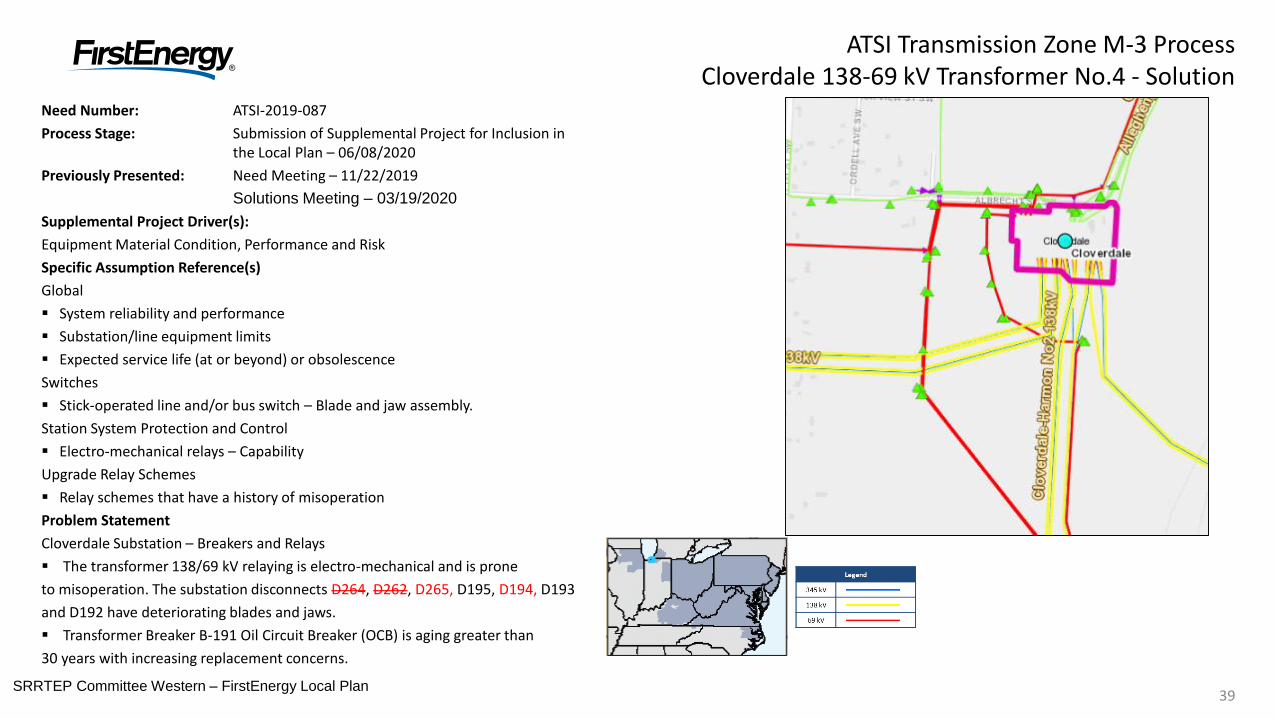
Need Number: ATSI-2019-087
Process Stage: Submission of Supplemental Project for Inclusion in the Local Plan – 06/08/2020
Previously Presented: Need Meeting – 11/22/2019
Solutions Meeting – 03/19/2020
Supplemental Project Driver(s):
Equipment Material Condition, Performance and Risk
Specific Assumption Reference(s)
Global
System reliability and performance
Substation/line equipment limits
Expected service life (at or beyond) or obsolescence
Switches
Stick-operated line and/or bus switch – Blade and jaw assembly.
Station System Protection and Control
Electro-mechanical relays – Capability
Upgrade Relay Schemes
Relay schemes that have a history of misoperation
Problem Statement
Cloverdale Substation – Breakers and Relays
The transformer 138/69 kV relaying is electro-mechanical and is prone
to misoperation. The substation disconnects D264, D262, D265, D195, D194, D193
and D192 have deteriorating blades and jaws.
Transformer Breaker B-191 Oil Circuit Breaker (OCB) is aging greater than
30 years with increasing replacement concerns.
ATSI Transmission Zone M-3 ProcessCloverdale 138-69 kV Transformer No.4 - Solution
40
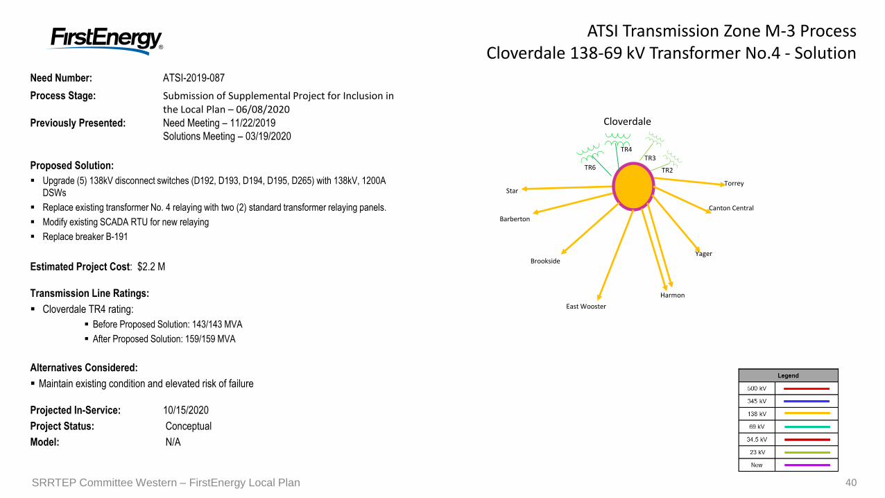
Need Number: ATSI-2019-087
Process Stage: Submission of Supplemental Project for Inclusion in the Local Plan – 06/08/2020
Previously Presented: Need Meeting – 11/22/2019
Solutions Meeting – 03/19/2020
Proposed Solution:
Upgrade (5) 138kV disconnect switches (D192, D193, D194, D195, D265) with 138kV, 1200A
DSWs
Replace existing transformer No. 4 relaying with two (2) standard transformer relaying panels.
Modify existing SCADA RTU for new relaying
Replace breaker B-191
Estimated Project Cost: $2.2 M
Transmission Line Ratings:
Cloverdale TR4 rating:
Before Proposed Solution: 143/143 MVA
After Proposed Solution: 159/159 MVA
Alternatives Considered:
Maintain existing condition and elevated risk of failure
Projected In-Service: 10/15/2020
Project Status: Conceptual
Model: N/A
SRRTEP Committee Western – FirstEnergy Local Plan 40
ATSI Transmission Zone M-3 ProcessCloverdale 138-69 kV Transformer No.4 - Solution
Cloverdale
Star
Brookside
Barberton
East Wooster
Harmon
Yager
Canton Central
Torrey
TR4
TR6 TR2
TR3
41
Pine
Maple
Mars
Adams Ridge
Callery
Evans City
Warrendale
ConcastCranberry
SRRTEP Committee Western – FirstEnergy Local Plan41
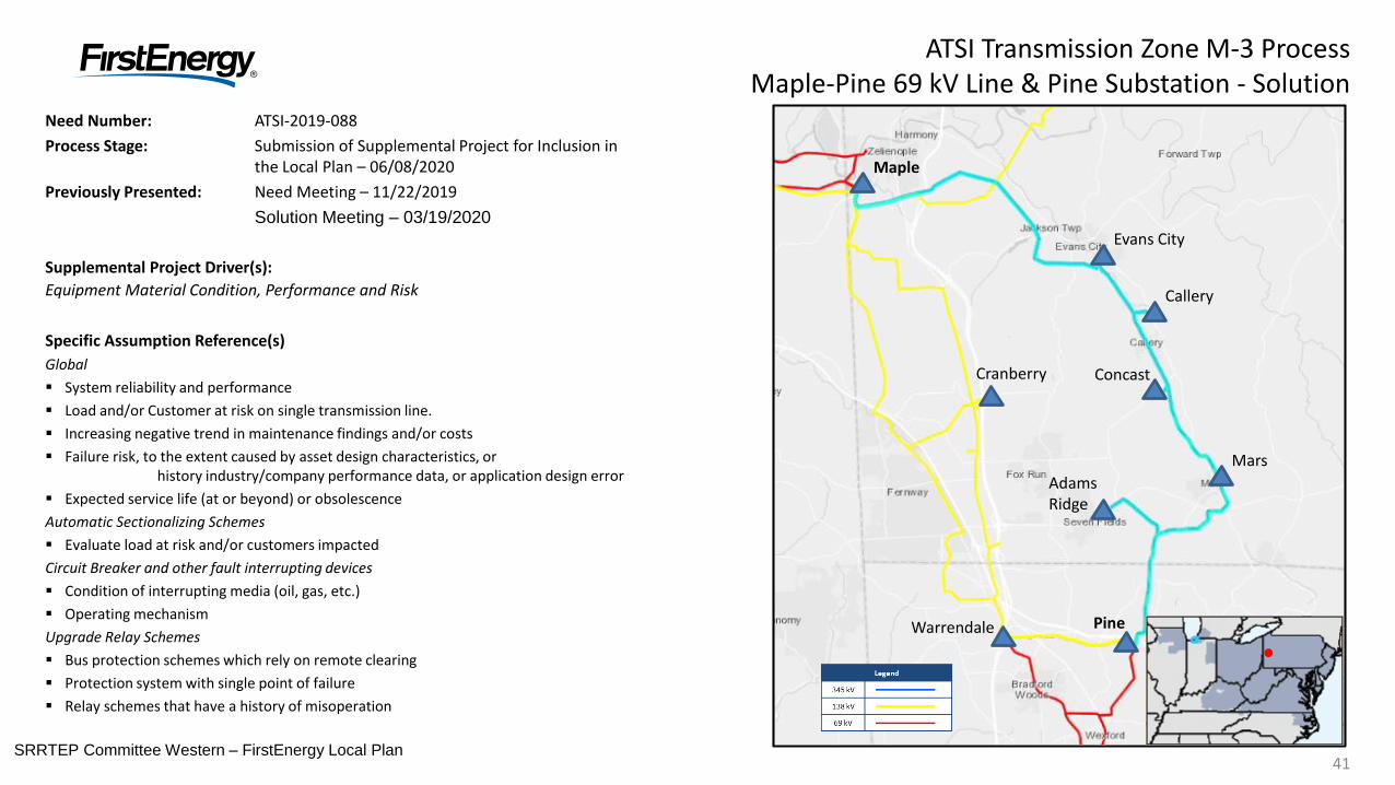
Need Number: ATSI-2019-088
Process Stage: Submission of Supplemental Project for Inclusion in the Local Plan – 06/08/2020
Previously Presented: Need Meeting – 11/22/2019
Solution Meeting – 03/19/2020
Supplemental Project Driver(s):
Equipment Material Condition, Performance and Risk
Specific Assumption Reference(s)
Global
System reliability and performance
Load and/or Customer at risk on single transmission line.
Increasing negative trend in maintenance findings and/or costs
Failure risk, to the extent caused by asset design characteristics, or history industry/company performance data, or application design error
Expected service life (at or beyond) or obsolescence
Automatic Sectionalizing Schemes
Evaluate load at risk and/or customers impacted
Circuit Breaker and other fault interrupting devices
Condition of interrupting media (oil, gas, etc.)
Operating mechanism
Upgrade Relay Schemes
Bus protection schemes which rely on remote clearing
Protection system with single point of failure
Relay schemes that have a history of misoperation
ATSI Transmission Zone M-3 ProcessMaple-Pine 69 kV Line & Pine Substation - Solution

42
Pine
Maple
Mars
Adams Ridge
Callery
Evans City
Warrendale
ConcastCranberry
SRRTEP Committee Western – FirstEnergy Local Plan42
Need Number: ATSI-2019-088
Process Stage: Submission of Supplemental Project for Inclusion in the Local Plan – 06/08/2020
Previously Presented: Need Meeting – 11/22/2019
Solution Meeting – 03/19/2020
Problem Statement
Maple-Pine 69 kV Line
The existing 69 kV transmission line is approximately 18 miles long with approximately 45 MWs of load and 11,500 customers at risk. The largest customer and load base at risk is located at Mars substation (22 MWs / 5,300 Customers).
Overall line condition is adequate based on recent line inspection results.
System performance over the past five years: 5 momentary / 6 sustained
Pine 69 kV Substation – Breakers and Protection Schemes
Several SF6 breakers at Pine substation at/beyond expected service life with increasing maintenance concerns;
– Breaker B-18 has history of SF6 leaks
– Breaker B-14 has history of SF6 leaks and has had air tank issues
– Breaker B-22 has experienced a bushing failure and repairs
– Breaker B-26 has had a bushing, air receiver, pilot valve and a lower pressure cut-off valve issues
The transfer line and bus protection electro-mechanical relays are prone to mis-operate due to components failing without warning.
ATSI Transmission Zone M-3 ProcessMaple-Pine 69 kV Line & Pine Substation - Solution
43SRRTEP Committee Western – FirstEnergy Local Plan43
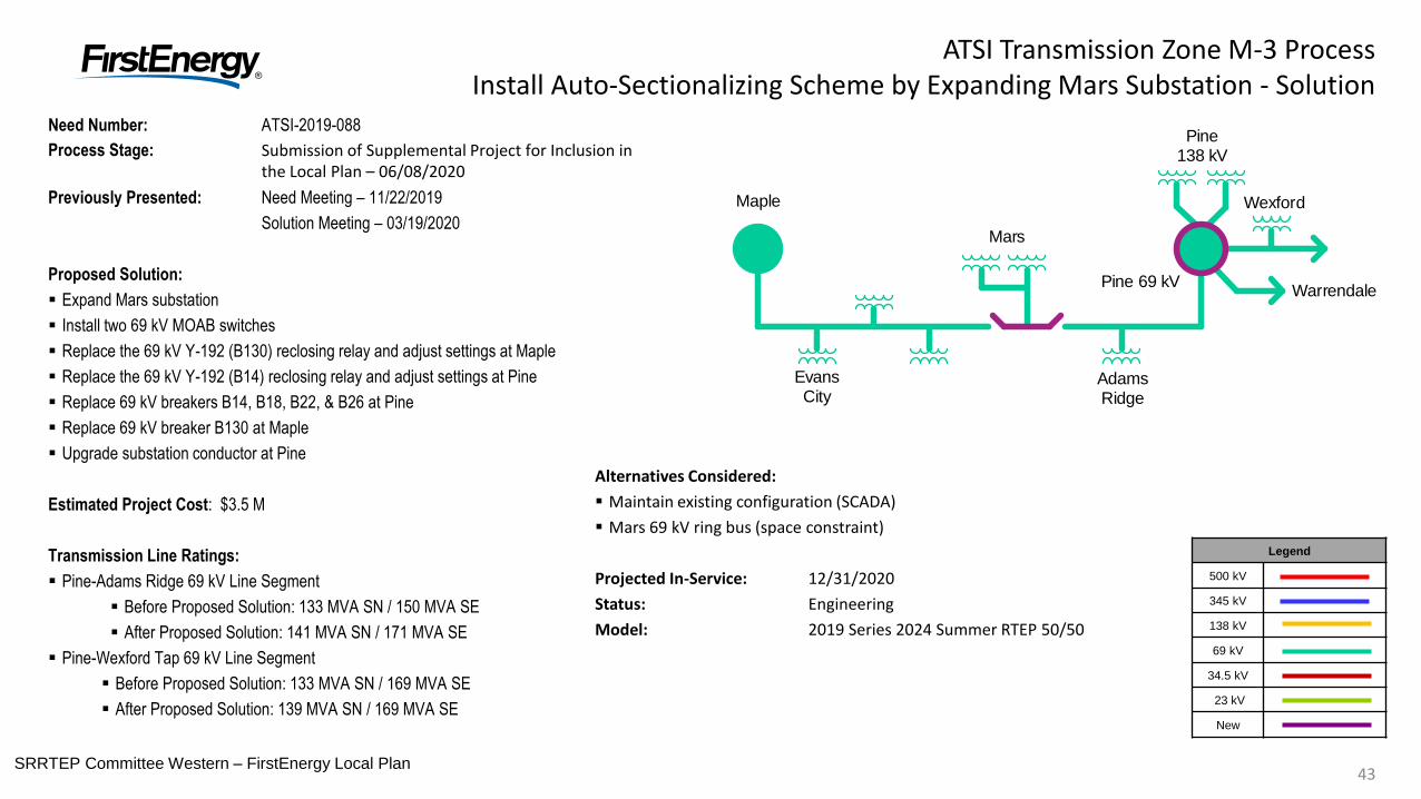
ATSI Transmission Zone M-3 ProcessInstall Auto-Sectionalizing Scheme by Expanding Mars Substation - Solution
Need Number: ATSI-2019-088
Process Stage: Submission of Supplemental Project for Inclusion in the Local Plan – 06/08/2020
Previously Presented: Need Meeting – 11/22/2019
Solution Meeting – 03/19/2020
Proposed Solution:
Expand Mars substation
Install two 69 kV MOAB switches
Replace the 69 kV Y-192 (B130) reclosing relay and adjust settings at Maple
Replace the 69 kV Y-192 (B14) reclosing relay and adjust settings at Pine
Replace 69 kV breakers B14, B18, B22, & B26 at Pine
Replace 69 kV breaker B130 at Maple
Upgrade substation conductor at Pine
Estimated Project Cost: $3.5 M
Transmission Line Ratings:
Pine-Adams Ridge 69 kV Line Segment
Before Proposed Solution: 133 MVA SN / 150 MVA SE
After Proposed Solution: 141 MVA SN / 171 MVA SE
Pine-Wexford Tap 69 kV Line Segment
Before Proposed Solution: 133 MVA SN / 169 MVA SE
After Proposed Solution: 139 MVA SN / 169 MVA SE
Legend
500 kV
345 kV
138 kV
69 kV
34.5 kV
23 kV
New
Alternatives Considered:
Maintain existing configuration (SCADA)
Mars 69 kV ring bus (space constraint)
Projected In-Service: 12/31/2020
Status: Engineering
Model: 2019 Series 2024 Summer RTEP 50/50
Maple
Evans City
Mars
Adams Ridge
Pine 69 kV
Pine138 kV
Warrendale
Wexford
44
ATSI Transmission Zone
PJM SRRTEP – Western 03/25/2019
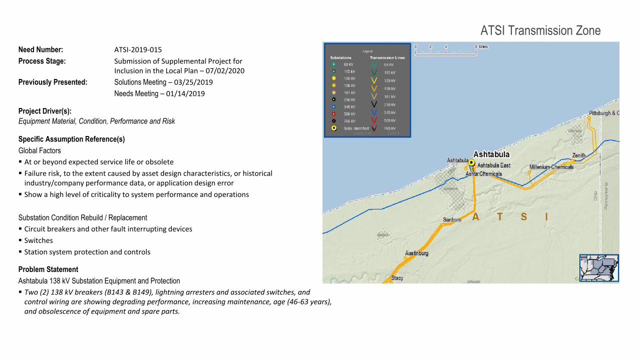
Need Number: ATSI-2019-015
Process Stage: Submission of Supplemental Project for Inclusion in the Local Plan – 07/02/2020
Previously Presented: Solutions Meeting – 03/25/2019
Needs Meeting – 01/14/2019
Project Driver(s):
Equipment Material, Condition, Performance and Risk
Specific Assumption Reference(s)
Global Factors
At or beyond expected service life or obsolete
Failure risk, to the extent caused by asset design characteristics, or historical industry/company performance data, or application design error
Show a high level of criticality to system performance and operations
Substation Condition Rebuild / Replacement
Circuit breakers and other fault interrupting devices
Switches
Station system protection and controls
Problem Statement
Ashtabula 138 kV Substation Equipment and Protection
Two (2) 138 kV breakers (B143 & B149), lightning arresters and associated switches, and control wiring are showing degrading performance, increasing maintenance, age (46-63 years), and obsolescence of equipment and spare parts.
45
ATSI Transmission Zone
Need Number: ATSI-2019-015
Process Stage: Submission of Supplemental Project for Inclusion in the Local Plan – 07/02/2020
Previously Presented: Solutions Meeting – 03/25/2019
Needs Meeting – 01/14/2019
Proposed Solution (S2259):
Ashtabula 138 kV Breakers and Relay Upgrades
Replace two (2) 138 kV breakers (B143 & B149), associated switches, and substation conductor.
Transmission Line Ratings:
Ashtabula-Pitts Conn Dock Q15 138 kV Line
Before Proposed Solution: 329 MVA SN / 399 MVA SE
After Proposed Solution: 347 MVA SN / 423 MVA SE
Alternatives Considered:
Maintain existing condition and risk of failure.
Estimated Project Cost: $5.2M
Projected IS Date: 12/31/2019
Status: Conceptual
PJM SRRTEP – Western 03/25/2019
No diagram required.
All work is within the substation
4646
ATSI Transmission Zone M-3 ProcessChamberlin 138 kV Substation - Solution
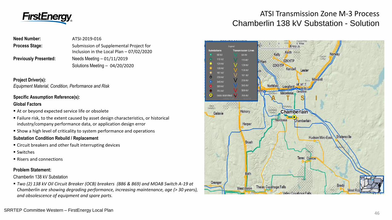
Need Number: ATSI-2019-016
Process Stage: Submission of Supplemental Project for Inclusion in the Local Plan – 07/02/2020
Previously Presented: Needs Meeting – 01/11/2019
Solutions Meeting – 04/20/2020
Project Driver(s):
Equipment Material, Condition, Performance and Risk
Specific Assumption Reference(s):
Global Factors
At or beyond expected service life or obsolete
Failure risk, to the extent caused by asset design characteristics, or historical industry/company performance data, or application design error
Show a high level of criticality to system performance and operations
Substation Condition Rebuild / Replacement
Circuit breakers and other fault interrupting devices
Switches
Risers and connections
Problem Statement:
Chamberlin 138 kV Substation
Two (2) 138 kV Oil Circuit Breaker (OCB) breakers (B86 & B69) and MOAB Switch A-19 at Chamberlin are showing degrading performance, increasing maintenance, age (> 30 years), and obsolescence of equipment and spare parts.
SRRTEP Committee Western – FirstEnergy Local Plan
4747
ATSI Transmission Zone M-3 ProcessChamberlin 138 kV Substation - Solution
Need Number: ATSI-2019-016
Process Stage: Submission of Supplemental Project for Inclusion in the Local Plan – 07/02/2020
Previously Presented: Needs Meeting – 01/11/2019
Solutions Meeting – 04/20/2020
Proposed Solution(S2245):
Chamberlin 138 kV Breaker and Switch Upgrades
Replace two (2) 138 kV Oil Circuit Breaker (OCB) breakers () B86 & B69 that are part of the protection scheme for the two 138 / 69 kV transformers at Chamberlin substation, upgrade the transformer #2 relay, and replace MOAB Switch A-19.
Transmission Line Ratings:
Chamberlin 138 / 69 kV Transformer #2
Before Proposed Solution: 163 MVA SN / 163 MVA SE
After Proposed Solution: 164 MVA SN / 174 MVA SE
Alternatives Considered:
Maintain existing condition and risk of failure.
Estimated Project Cost: $0.5M
Projected IS Date: 03/31/2021
Status: Engineering
No diagram required.
All work is within the substation
SRRTEP Committee Western – FirstEnergy Local Plan
48
ATSI Transmission Zone
Need Number: ATSI-2019-050
Process Stage: Submission of Supplemental Project for Inclusion in the Local Plan – 07/02/2020
Previously Presented: Solutions Meeting – 03/07/2019
Needs Meeting – 02/07/2019
Project Driver(s):
Equipment Material, Condition, Performance and Risk
Operational Flexibility and Efficiency
Infrastructure Resilience
Specific Assumption Reference(s)
Global Factors
System reliability and performance
Load at risk in planning and operational scenarios
Reconductor / Rebuild Transmission Lines
Three or more terminal transmission lines
Upgrade Relay Schemes
Relay schemes that have a history of misoperation
Obsolete and difficult to repair communication equipment
Continued on next slide…
PJM RTEP – 03/07/2019
49
ATSI Transmission Zone
Need Number: ATSI-2019-050
Process Stage: Submission of Supplemental Project for Inclusion in the Local Plan – 07/02/2020
Previously Presented: Solutions Meeting – 03/07/2019
Needs Meeting – 02/07/2019
…Continued from previous slide.
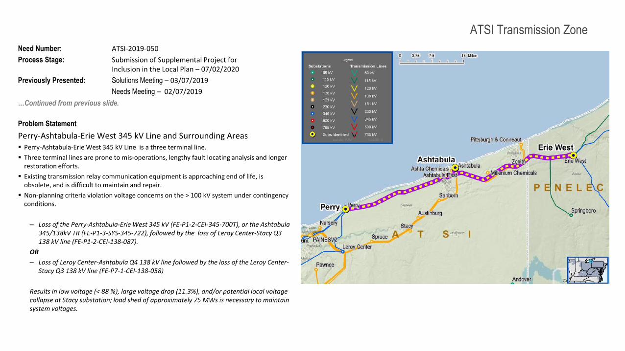
Problem Statement
Perry-Ashtabula-Erie West 345 kV Line and Surrounding Areas Perry-Ashtabula-Erie West 345 kV Line is a three terminal line.
Three terminal lines are prone to mis-operations, lengthy fault locating analysis and longer restoration efforts.
Existing transmission relay communication equipment is approaching end of life, is obsolete, and is difficult to maintain and repair.
Non-planning criteria violation voltage concerns on the > 100 kV system under contingency conditions.
– Loss of the Perry-Ashtabula-Erie West 345 kV (FE-P1-2-CEI-345-700T), or the Ashtabula 345/138kV TR (FE-P1-3-SYS-345-722), followed by the loss of Leroy Center-Stacy Q3 138 kV line (FE-P1-2-CEI-138-087).
OR
– Loss of Leroy Center-Ashtabula Q4 138 kV line followed by the loss of the Leroy Center-Stacy Q3 138 kV line (FE-P7-1-CEI-138-058)
Results in low voltage (< 88 %), large voltage drop (11.3%), and/or potential local voltage collapse at Stacy substation; load shed of approximately 75 MWs is necessary to maintain system voltages.
PJM RTEP – 03/07/2019
50
ATSI Transmission Zone
Need Number: ATSI-2019-050
Process Stage: Submission of Supplemental Project for Inclusion in the Local Plan – 07/02/2020
Previously Presented: Solutions Meeting – 03/07/2019
Needs Meeting – 02/07/2019
Continued from previous slide…
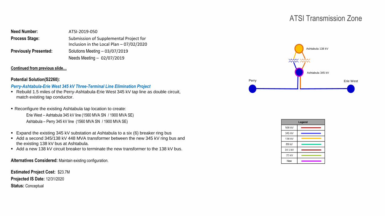
Potential Solution(S2260):
Perry-Ashtabula-Erie West 345 kV Three-Terminal Line Elimination Project Rebuild 1.5 miles of the Perry-Ashtabula-Erie West 345 kV tap line as double circuit,
match existing tap conductor.
Reconfigure the existing Ashtabula tap location to create:
Erie West – Ashtabula 345 kV line (1560 MVA SN / 1900 MVA SE)
Ashtabula – Perry 345 kV line (1560 MVA SN / 1900 MVA SE)
Expand the existing 345 kV substation at Ashtabula to a six (6) breaker ring bus
Add a second 345/138 kV 448 MVA transformer between the new 345 kV ring bus and
the existing 138 kV bus at Ashtabula.
Add a new 138 kV circuit breaker to terminate the new transformer to the 138 kV bus.
Alternatives Considered: Maintain existing configuration.
Estimated Project Cost: $23.7M
Projected IS Date: 12/31/2020
Status: Conceptual
Perry Erie West
Ashtabula 345 kV
Ashtabula 138 kV
PJM RTEP – 03/07/2019
5151
ATSI Transmission Zone M-3 ProcessRichland-East Leipsic 138 kV Line - Solution
Need Number: ATSI-2020-002
Process Stage: Submission of Supplemental Project for Inclusion in the Local Plan – 07/02/2020
Previously Presented: Needs Meeting – 02/21/2020
Solutions Meeting – 04/20/2020
Supplemental Project Driver(s):
Equipment Material Condition, Performance and Risk
Specific Assumption Reference(s):
Line Condition Rebuild / Replacement
Aged or deteriorated wood pole transmission line structures
Negatively impact customer outage frequency and/or durations
Demonstrate an increasing trend in maintenance findings and/or costs
Transmission line ratings are limited by terminal equipment.
Problem Statement:Richland-East Leipsic 138 kV (~15.8 miles) Transmission Line:
• The Richland-East Leipsic 138 kV Transmission Line was built in the 1960s. The average age of the structures on this line are 54 years old. FirstEnergy has historically experienced an average age of reject for wood poles to be 48.7 years.
• Line was surveyed in 2018 and showed a structure reject rate of 100% (126/126). The primary reasons for reject were structure age, woodpecker holes, pole top decay, and phase raised structures.
• There has been a growing trend in unscheduled interruptions on this line. There have been 11 total outages since 2011 for lightning, equipment failures, and other issues.
• There has been an increase in unplanned maintenance on this line. A recent aerial patrol found 90 active maintenance conditions requiring repair for wood pole rot, broken static wire and attachment hardware, and bent braces.
SRRTEP Committee Western – FirstEnergy Local Plan
5252
ATSI Transmission Zone M-3 ProcessRichland-East Leipsic 138 kV Line - Solution
Need Number: ATSI-2020-002
Process Stage: Submission of Supplemental Project for Inclusion in the Local Plan – 07/02/2020
Previously Presented: Needs Meeting – 02/21/2020
Solutions Meeting – 04/20/2020
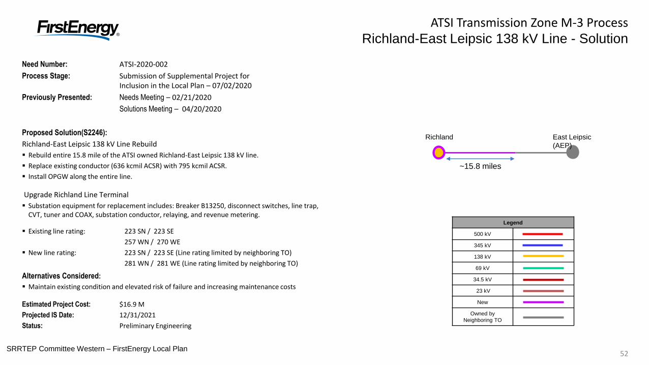
Proposed Solution(S2246):
Richland-East Leipsic 138 kV Line Rebuild
Rebuild entire 15.8 mile of the ATSI owned Richland-East Leipsic 138 kV line.
Replace existing conductor (636 kcmil ACSR) with 795 kcmil ACSR.
Install OPGW along the entire line.
Upgrade Richland Line Terminal
Substation equipment for replacement includes: Breaker B13250, disconnect switches, line trap, CVT, tuner and COAX, substation conductor, relaying, and revenue metering.
Existing line rating: 223 SN / 223 SE
257 WN / 270 WE
New line rating: 223 SN / 223 SE (Line rating limited by neighboring TO)
281 WN / 281 WE (Line rating limited by neighboring TO)
Alternatives Considered:
Maintain existing condition and elevated risk of failure and increasing maintenance costs
Estimated Project Cost: $16.9 M
Projected IS Date: 12/31/2021
Status: Preliminary Engineering
Richland East Leipsic
(AEP)
~15.8 miles
Legend
500 kV
345 kV
138 kV
69 kV
34.5 kV
23 kV
New
Owned by
Neighboring TO
SRRTEP Committee Western – FirstEnergy Local Plan
53SRRTEP Committee: Western – FirstEnergy Local Plan53
Need Number: ATSI-2020-006 (s2261)
Process Stage: Submission of Supplemental Project for Inclusion in the Local Plan – 09/25/2020
Previously Presented: Need Meeting – 04/20/2020
Solution Meeting – 05/22/2020
Project Driver:
Equipment Material Condition, Performance and Risk
Operational Flexibility and Efficiency
Infrastructure Resilience
Specific Assumption References:
Global Factors
System reliability and performance
Substation / line equipment limits
Problem Statement
Abbe – Johnson #1 69 kV switch (A-47)
Switch originally installed in 1982
Corrosion on operating mechanism
Existing KPF switch is obsolete and no longer supported by the manufacturer
Undesirable design with vertical operating rod
Transmission line ratings are limited by the existing switch rating
Map Not Shown
Multiple Locations
ATSI Transmission Zone M-3 Process
Abbe-Johnson # 1 69 kV Switch Solution
Continued on next slide…
54
ATSI Transmission Zone M-3 Process
Abbe-Johnson # 1 69 kV Switch Solution
54SRRTEP Committee: Western – FirstEnergy Local Plan
ATSI-2020 Transmission Line / Substation Locations
Existing
Line/Terminal
Equipment
MVA Rating
(SN / SE)
Existing
Conductor/Transformer
MVA Rating
(SN / SE) Limiting Terminal Equipment
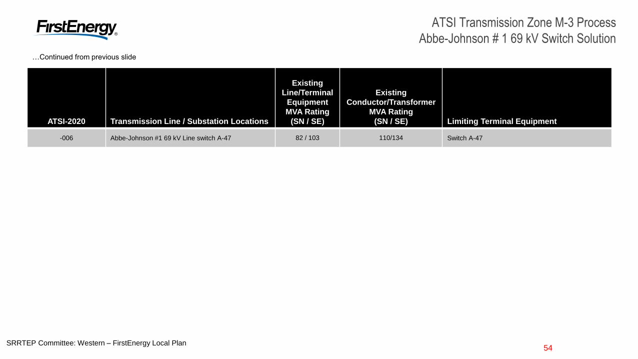
-006 Abbe-Johnson #1 69 kV Line switch A-47 82 / 103 110/134 Switch A-47
…Continued from previous slide
55SRRTEP Committee: Western – FirstEnergy Local Plan55
ATSI Transmission Zone M-3 ProcessAbbe-Johnson # 1 69 kV Switch Solution
Need Number: ATSI-2020-006 (s2261)
Process Stage: Submission of Supplemental Project for Inclusion in the Local Plan – 09/25/2020
Previously Presented: Need Meeting – 04/20/2020
Solution Meeting – 05/22/2020
Proposed Solution:
Abbe – Johnson #1 69 kV switch (A-47)
Replace switch A-47 on the Abbe – Johnson #1 69 kV Line with a 1200 A quick break switch with whip
Transmission Line Ratings:
Abbe – Johnson #1 69 kV Line
Before Proposed Solution: 82 MVA SN / 103 MVA SE
After Proposed Solution: 110 MVA SN / 134 MVA SE
Alternatives Considered:
Maintain existing condition and risk of failure.
Estimated Project Cost: $0.32M
Projected IS Date: 06/29/2020
Status: Engineering
No changes in topology;No bubble diagram required.

56SRRTEP Committee: Western – FirstEnergy Local Plan56
Need Number: ATSI-2019-068 (s2262)
Process Stage: Submission of Supplemental Project for Inclusion in the Local Plan – 09/25/2020
Previously Presented: Need Meeting – 07/24/2019
Solution Meeting – 05/22/2020
Project Driver:
Operational Flexibility and Efficiency
Equipment Material Condition, Performance and Risk
Infrastructure Resilience
Specific Assumption References:
Global Factors
System reliability and performance
Substation / line equipment limits
Load at risk in planning and operational scenarios
Substation Condition Rebuild/Replacement
Circuit breakers and other fault interrupting devices
Add/Expand Bus Configuration
Loss of substation bus adversely impacts transmission system
performance.
Eliminate simultaneous outages to multiple networked elements
Capability to perform system maintenance
Upgrade Relay Schemes
Bus protection schemes
Relay schemes that have a history of misoperation
ATSI Transmission Zone M-3 Process
Salt Springs 138 kV Substation Solution
Salt Springs
Continued on next slide…
57SRRTEP Committee: Western – FirstEnergy Local Plan57
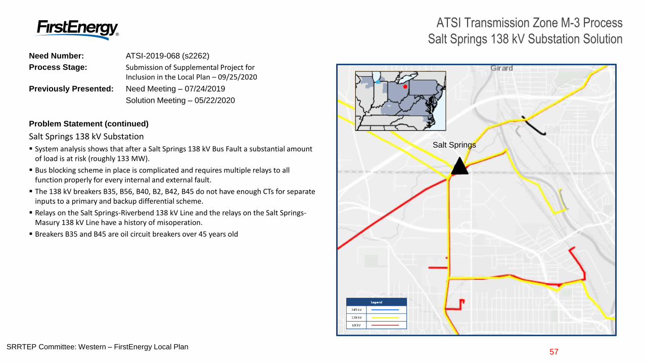
Need Number: ATSI-2019-068 (s2262)
Process Stage: Submission of Supplemental Project for Inclusion in the Local Plan – 09/25/2020
Previously Presented: Need Meeting – 07/24/2019
Solution Meeting – 05/22/2020
Problem Statement (continued)
Salt Springs 138 kV Substation
System analysis shows that after a Salt Springs 138 kV Bus Fault a substantial amount of load is at risk (roughly 133 MW).
Bus blocking scheme in place is complicated and requires multiple relays to all function properly for every internal and external fault.
The 138 kV breakers B35, B56, B40, B2, B42, B45 do not have enough CTs for separate inputs to a primary and backup differential scheme.
Relays on the Salt Springs-Riverbend 138 kV Line and the relays on the Salt Springs-Masury 138 kV Line have a history of misoperation.
Breakers B35 and B45 are oil circuit breakers over 45 years old
ATSI Transmission Zone M-3 Process
Salt Springs 138 kV Substation Solution
Salt Springs
58SRRTEP Committee: Western – FirstEnergy Local Plan58
ATSI Transmission Zone M-3 ProcessSalt Springs 138 kV Substation Solution
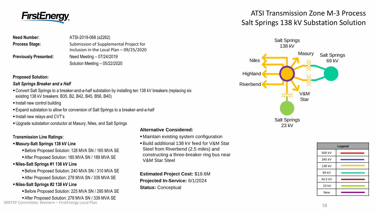
Need Number: ATSI-2019-068 (s2262)
Process Stage: Submission of Supplemental Project for Inclusion in the Local Plan – 09/25/2020
Previously Presented: Need Meeting – 07/24/2019
Solution Meeting – 05/22/2020
Proposed Solution:
Salt Springs Breaker and a Half
Convert Salt Springs to a breaker-and-a-half substation by installing ten 138 kV breakers (replacing six
existing 138 kV breakers: B35, B2, B42, B45, B56, B40)
Install new control building
Expand substation to allow for conversion of Salt Springs to a breaker-and-a-half
Install new relays and CVT’s
Upgrade substation conductor at Masury, Niles, and Salt Springs
Transmission Line Ratings:
Masury-Salt Springs 138 kV Line
Before Proposed Solution: 128 MVA SN / 165 MVA SE
After Proposed Solution: 185 MVA SN / 189 MVA SE
Niles-Salt Springs #1 138 kV Line
Before Proposed Solution: 240 MVA SN / 310 MVA SE
After Proposed Solution: 278 MVA SN / 339 MVA SE
Niles-Salt Springs #2 138 kV Line
Before Proposed Solution: 225 MVA SN / 295 MVA SE
After Proposed Solution: 278 MVA SN / 339 MVA SE
Legend
500 kV
345 kV
138 kV
69 kV
34.5 kV
23 kV
New
Salt Springs138 kV
Salt Springs69 kV
Salt Springs23 kV
Niles
Highland
Riverbend
Masury
V&M Star
Alternative Considered:
Maintain existing system configuration
Build additional 138 kV feed for V&M Star
Steel from Riverbend (2.5 miles) and
constructing a three-breaker ring bus near
V&M Star Steel
Estimated Project Cost: $19.6M
Projected In-Service: 6/1/2024
Status: Conceptual
59SRRTEP Committee: Western – FirstEnergy Local Plan59
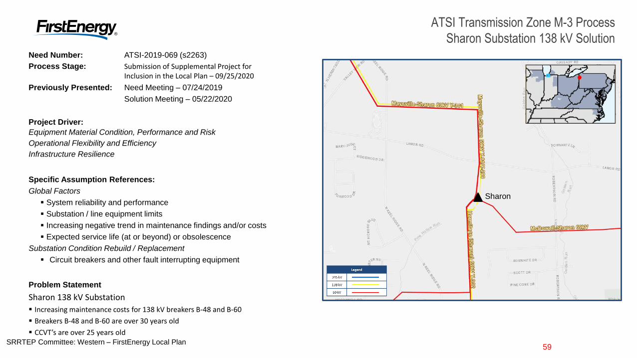
Need Number: ATSI-2019-069 (s2263)
Process Stage: Submission of Supplemental Project for Inclusion in the Local Plan – 09/25/2020
Previously Presented: Need Meeting – 07/24/2019
Solution Meeting – 05/22/2020
Project Driver:
Equipment Material Condition, Performance and Risk
Operational Flexibility and Efficiency
Infrastructure Resilience
Specific Assumption References:
Global Factors
System reliability and performance
Substation / line equipment limits
Increasing negative trend in maintenance findings and/or costs
Expected service life (at or beyond) or obsolescence
Substation Condition Rebuild / Replacement
Circuit breakers and other fault interrupting equipment
Problem Statement
Sharon 138 kV Substation
Increasing maintenance costs for 138 kV breakers B-48 and B-60
Breakers B-48 and B-60 are over 30 years old
CCVT’s are over 25 years old
ATSI Transmission Zone M-3 Process
Sharon Substation 138 kV Solution
Sharon
60SRRTEP Committee: Western – FirstEnergy Local Plan60
ATSI Transmission Zone M-3 ProcessSharon Substation 138 kV Solution
Need Number: ATSI-2019-069 (s2263)
Process Stage: Submission of Supplemental Project for Inclusion in the Local Plan – 09/25/2020
Previously Presented: Need Meeting – 07/24/2019
Solution Meeting – 05/22/2020
Proposed Solution:
Sharon Substation 138 kV Breakers
Upgrade Sharon 138 kV breaker B48 and B60, and associated disconnect
switches
Upgrade relays associated with B48
Replace the B48 CCVT and the Sharon-Shenango 138 kV Line CCVT
Upgrade substation conductor to exceed transmission line ratings
Transmission Line Ratings:
Sharon 138 kV North Bus-South Bus
Before Proposed Solution: 191 MVA SN / 191 MVA SE
After Proposed Solution: 278 MVA SN / 339 MVA SE
Sharon-Shenango 138 kV Line
Before Proposed Solution: 176 MVA SN / 229 MVA SE
After Proposed Solution: 265 MVA SN / 316 MVA SE
Alternative Considered:
Maintain existing equipment and risk of failure
Estimated Project Cost: $1.3 M
Legend
500 kV
345 kV
138 kV
69 kV
34.5 kV
23 kV
New
No changes in topology;No bubble diagram required.
Projected In-Service: 12/31/2021
Status: Conceptual
61SRRTEP Committee: Western – FirstEnergy Local Plan61
ATSI Transmission Zone M-3 ProcessMagellan New Customer Solution
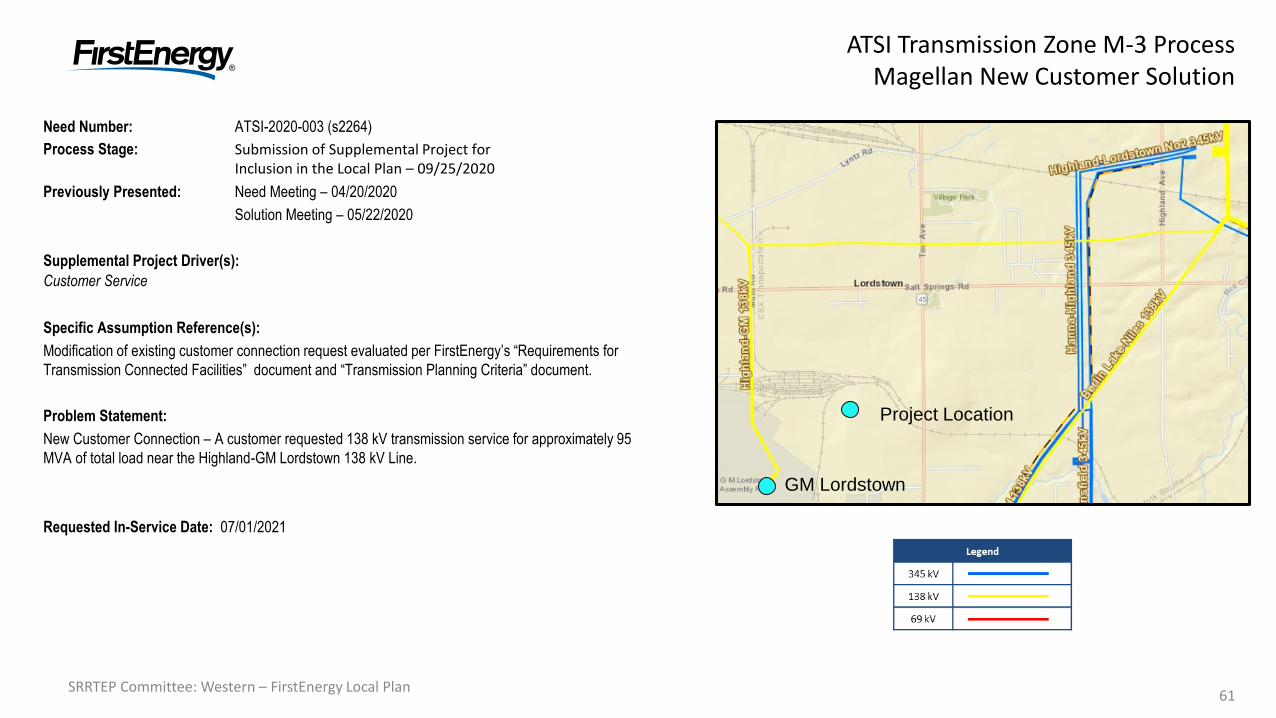
Need Number: ATSI-2020-003 (s2264)
Process Stage: Submission of Supplemental Project for Inclusion in the Local Plan – 09/25/2020
Previously Presented: Need Meeting – 04/20/2020
Solution Meeting – 05/22/2020
Supplemental Project Driver(s):
Customer Service
Specific Assumption Reference(s):
Modification of existing customer connection request evaluated per FirstEnergy’s “Requirements for
Transmission Connected Facilities” document and “Transmission Planning Criteria” document.
Problem Statement:
New Customer Connection – A customer requested 138 kV transmission service for approximately 95
MVA of total load near the Highland-GM Lordstown 138 kV Line.
Requested In-Service Date: 07/01/2021
GM Lordstown
Project Location
62SRRTEP Committee: Western – FirstEnergy Local Plan62
ATSI Transmission Zone M-3 ProcessMagellan New Customer Solution
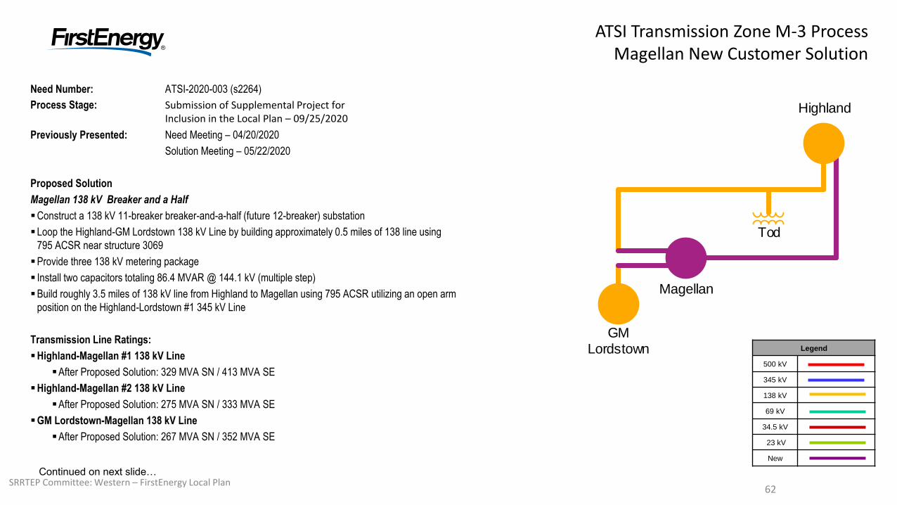
Need Number: ATSI-2020-003 (s2264)
Process Stage: Submission of Supplemental Project for Inclusion in the Local Plan – 09/25/2020
Previously Presented: Need Meeting – 04/20/2020
Solution Meeting – 05/22/2020
Proposed Solution
Magellan 138 kV Breaker and a Half
Construct a 138 kV 11-breaker breaker-and-a-half (future 12-breaker) substation
Loop the Highland-GM Lordstown 138 kV Line by building approximately 0.5 miles of 138 line using
795 ACSR near structure 3069
Provide three 138 kV metering package
Install two capacitors totaling 86.4 MVAR @ 144.1 kV (multiple step)
Build roughly 3.5 miles of 138 kV line from Highland to Magellan using 795 ACSR utilizing an open arm
position on the Highland-Lordstown #1 345 kV Line
Transmission Line Ratings:
Highland-Magellan #1 138 kV Line
After Proposed Solution: 329 MVA SN / 413 MVA SE
Highland-Magellan #2 138 kV Line
After Proposed Solution: 275 MVA SN / 333 MVA SE
GM Lordstown-Magellan 138 kV Line
After Proposed Solution: 267 MVA SN / 352 MVA SE
Legend
500 kV
345 kV
138 kV
69 kV
34.5 kV
23 kV
New
Highland
Tod
GM Lordstown
Magellan
Continued on next slide…

63SRRTEP Committee: Western – FirstEnergy Local Plan63
ATSI Transmission Zone M-3 ProcessMagellan New Customer Solution
Need Number: ATSI-2020-003 (s2264)
Process Stage: Submission of Supplemental Project for Inclusion in the Local Plan – 09/25/2020
Previously Presented: Need Meeting – 04/20/2020
Solution Meeting – 05/22/2020
Alternatives Considered:
Provide service via 5-breaker ring bus (criteria violations identified)
Provide service via a 345/138 kV substation (not needed for studied load level)
Estimated Project Cost: $31.8 M
Projected In-Service: 07/01/2021
Status: Engineering
Model: 2019 Series 2024 Summer RTEP 50/50
Legend
500 kV
345 kV
138 kV
69 kV
34.5 kV
23 kV
New
Highland
Tod
GM Lordstown
Magellan
64SRRTEP Committee: Western – FirstEnergy Local Plan64
ATSI Transmission Zone M-3 Process
Streetsboro 69 kV Area Solution
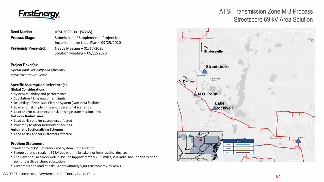
Need Number: ATSI-2020-001 (s2265)
Process Stage: Submission of Supplemental Project for Inclusion in the Local Plan – 09/25/2020
Previously Presented: Needs Meeting – 01/17/2020Solution Meeting – 05/22/2020
Project Driver(s): Operational Flexibility and Efficiency
Infrastructure Resilience
Specific Assumption Reference(s)Global Considerations System reliability and performance Substation / Line equipment limits Reliability of Non-Bulk Electric System (Non-BES) facilities Load and risk in planning and operational scenarios Load and/or customers at risk on single transmission linesNetwork Radial Lines Load at risk and/or customers affected Proximity to other networked facilitiesAutomatic Sectionalizing Schemes Load at risk and/or customers affected
Problem StatementStreetsboro 69 kV Substation and System Configuration Streetsboro is a straight 69 kV bus with no breakers or interrupting devices. The Ravenna-Lake Rockwell 69 kV line (approximately 7.59 miles) is a radial line; normally open
point near Streetsboro substation. Customers and load at risk: Approximately 5,000 customers / 25 MWs
Lake
Rockwell
Streetsboro
N.O. Point
To
Shalersville
To
Darrow
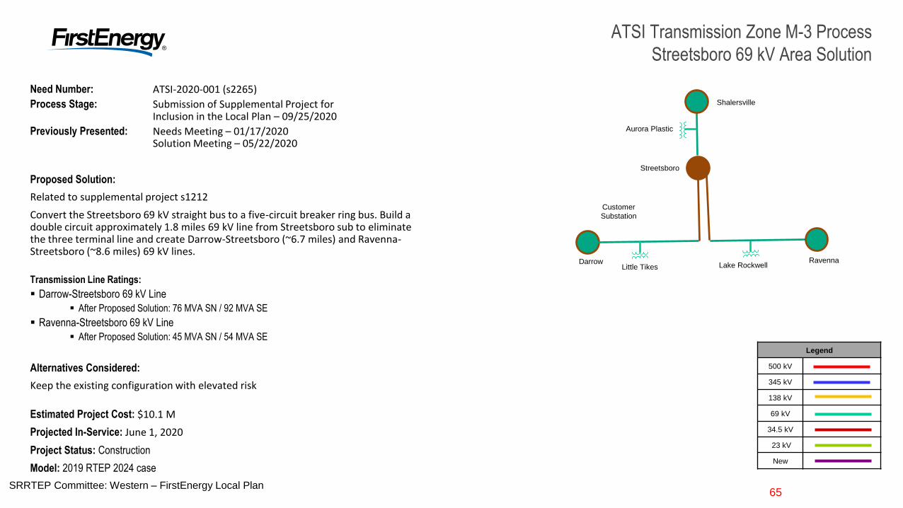
65SRRTEP Committee: Western – FirstEnergy Local Plan65
ATSI Transmission Zone M-3 Process
Streetsboro 69 kV Area Solution
Need Number: ATSI-2020-001 (s2265)
Process Stage: Submission of Supplemental Project for Inclusion in the Local Plan – 09/25/2020
Previously Presented: Needs Meeting – 01/17/2020Solution Meeting – 05/22/2020
Proposed Solution:
Related to supplemental project s1212
Convert the Streetsboro 69 kV straight bus to a five-circuit breaker ring bus. Build a double circuit approximately 1.8 miles 69 kV line from Streetsboro sub to eliminate the three terminal line and create Darrow-Streetsboro (~6.7 miles) and Ravenna-Streetsboro (~8.6 miles) 69 kV lines.
Transmission Line Ratings:
Darrow-Streetsboro 69 kV Line
After Proposed Solution: 76 MVA SN / 92 MVA SE
Ravenna-Streetsboro 69 kV Line
After Proposed Solution: 45 MVA SN / 54 MVA SE
Alternatives Considered:
Keep the existing configuration with elevated risk
Estimated Project Cost: $10.1 M
Projected In-Service: June 1, 2020
Project Status: Construction
Model: 2019 RTEP 2024 case
Streetsboro
Customer
Substation
RavennaDarrowLake RockwellLittle Tikes
Shalersville
Aurora Plastic
Legend
500 kV
345 kV
138 kV
69 kV
34.5 kV
23 kV
New
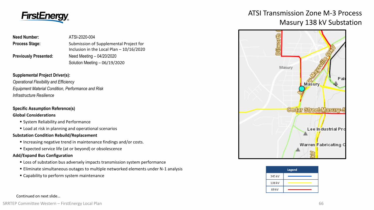
6666
ATSI Transmission Zone M-3 ProcessMasury 138 kV Substation
Need Number: ATSI-2020-004
Process Stage: Submission of Supplemental Project for Inclusion in the Local Plan – 10/16/2020
Previously Presented: Need Meeting – 04/20/2020
Solution Meeting – 06/19/2020
Supplemental Project Driver(s):
Operational Flexibility and Efficiency
Equipment Material Condition, Performance and Risk
Infrastructure Resilience
Specific Assumption Reference(s)
Global Considerations
System Reliability and Performance
Load at risk in planning and operational scenarios
Substation Condition Rebuild/Replacement
Increasing negative trend in maintenance findings and/or costs.
Expected service life (at or beyond) or obsolescence
Add/Expand Bus Configuration
Loss of substation bus adversely impacts transmission system performance
Eliminate simultaneous outages to multiple networked elements under N-1 analysis
Capability to perform system maintenance
Continued on next slide…
SRRTEP Committee Western – FirstEnergy Local Plan
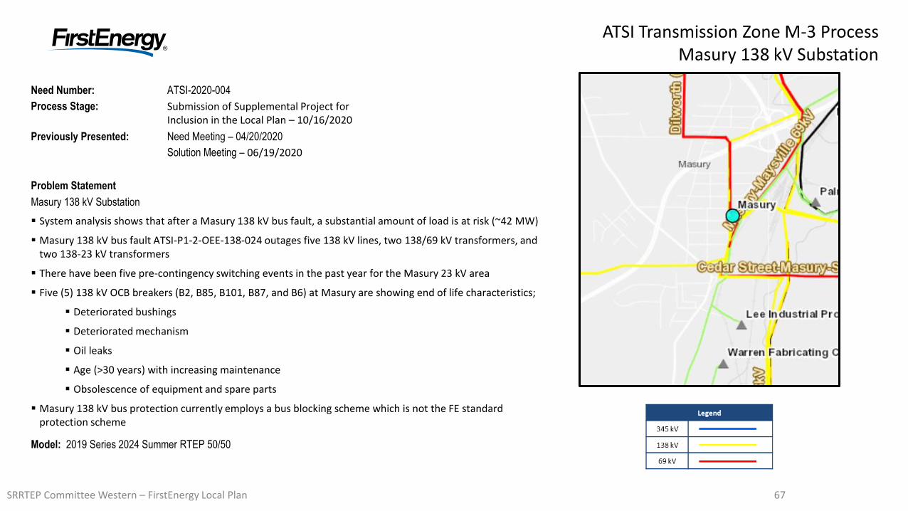
6767
ATSI Transmission Zone M-3 ProcessMasury 138 kV Substation
Need Number: ATSI-2020-004
Process Stage: Submission of Supplemental Project for Inclusion in the Local Plan – 10/16/2020
Previously Presented: Need Meeting – 04/20/2020
Solution Meeting – 06/19/2020
Problem Statement
Masury 138 kV Substation
System analysis shows that after a Masury 138 kV bus fault, a substantial amount of load is at risk (~42 MW)
Masury 138 kV bus fault ATSI-P1-2-OEE-138-024 outages five 138 kV lines, two 138/69 kV transformers, and two 138-23 kV transformers
There have been five pre-contingency switching events in the past year for the Masury 23 kV area
Five (5) 138 kV OCB breakers (B2, B85, B101, B87, and B6) at Masury are showing end of life characteristics;
Deteriorated bushings
Deteriorated mechanism
Oil leaks
Age (>30 years) with increasing maintenance
Obsolescence of equipment and spare parts
Masury 138 kV bus protection currently employs a bus blocking scheme which is not the FE standard protection scheme
Model: 2019 Series 2024 Summer RTEP 50/50
SRRTEP Committee Western – FirstEnergy Local Plan
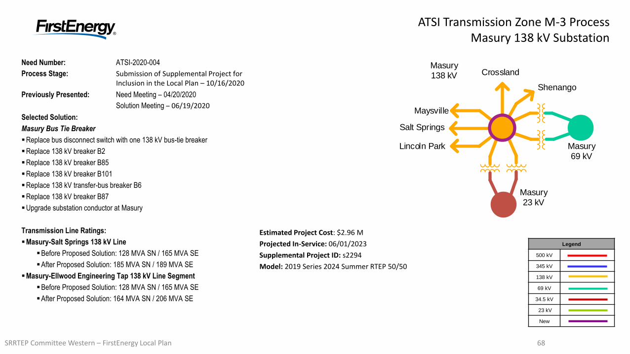
6868
ATSI Transmission Zone M-3 ProcessMasury 138 kV Substation
Need Number: ATSI-2020-004
Process Stage: Submission of Supplemental Project for Inclusion in the Local Plan – 10/16/2020
Previously Presented: Need Meeting – 04/20/2020
Solution Meeting – 06/19/2020
Selected Solution:
Masury Bus Tie Breaker
Replace bus disconnect switch with one 138 kV bus-tie breaker
Replace 138 kV breaker B2
Replace 138 kV breaker B85
Replace 138 kV breaker B101
Replace 138 kV transfer-bus breaker B6
Replace 138 kV breaker B87
Upgrade substation conductor at Masury
Transmission Line Ratings:
Masury-Salt Springs 138 kV Line
Before Proposed Solution: 128 MVA SN / 165 MVA SE
After Proposed Solution: 185 MVA SN / 189 MVA SE
Masury-Ellwood Engineering Tap 138 kV Line Segment
Before Proposed Solution: 128 MVA SN / 165 MVA SE
After Proposed Solution: 164 MVA SN / 206 MVA SE
Legend
500 kV
345 kV
138 kV
69 kV
34.5 kV
23 kV
New
Masury138 kV
Masury69 kV
Masury23 kV
Lincoln Park
Salt Springs
Maysville
Crossland
Shenango
Estimated Project Cost: $2.96 M
Projected In-Service: 06/01/2023
Supplemental Project ID: s2294
Model: 2019 Series 2024 Summer RTEP 50/50
SRRTEP Committee Western – FirstEnergy Local Plan
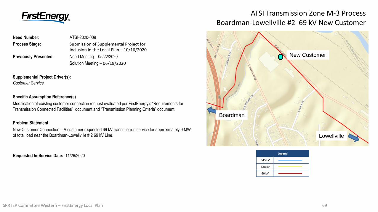
6969
ATSI Transmission Zone M-3 ProcessBoardman-Lowellville #2 69 kV New Customer
Need Number: ATSI-2020-009
Process Stage: Submission of Supplemental Project for Inclusion in the Local Plan – 10/16/2020
Previously Presented: Need Meeting – 05/22/2020
Solution Meeting – 06/19/2020
Supplemental Project Driver(s):
Customer Service
Specific Assumption Reference(s)
Modification of existing customer connection request evaluated per FirstEnergy’s “Requirements for
Transmission Connected Facilities” document and “Transmission Planning Criteria” document.
Problem Statement
New Customer Connection – A customer requested 69 kV transmission service for approximately 9 MW
of total load near the Boardman-Lowellville # 2 69 kV Line.
Requested In-Service Date: 11/26/2020
New Customer
Boardman
Lowellville
SRRTEP Committee Western – FirstEnergy Local Plan
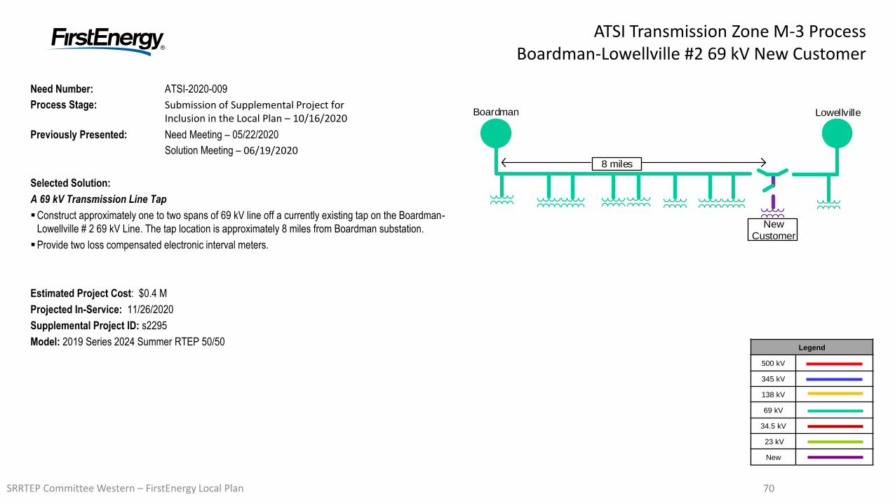
7070
ATSI Transmission Zone M-3 ProcessBoardman-Lowellville #2 69 kV New Customer
Need Number: ATSI-2020-009
Process Stage: Submission of Supplemental Project for Inclusion in the Local Plan – 10/16/2020
Previously Presented: Need Meeting – 05/22/2020
Solution Meeting – 06/19/2020
Selected Solution:
A 69 kV Transmission Line Tap
Construct approximately one to two spans of 69 kV line off a currently existing tap on the Boardman-
Lowellville # 2 69 kV Line. The tap location is approximately 8 miles from Boardman substation.
Provide two loss compensated electronic interval meters.
Estimated Project Cost: $0.4 M
Projected In-Service: 11/26/2020
Supplemental Project ID: s2295
Model: 2019 Series 2024 Summer RTEP 50/50Legend
500 kV
345 kV
138 kV
69 kV
34.5 kV
23 kV
New
Boardman Lowellville
8 miles
NewCustomer
SRRTEP Committee Western – FirstEnergy Local Plan
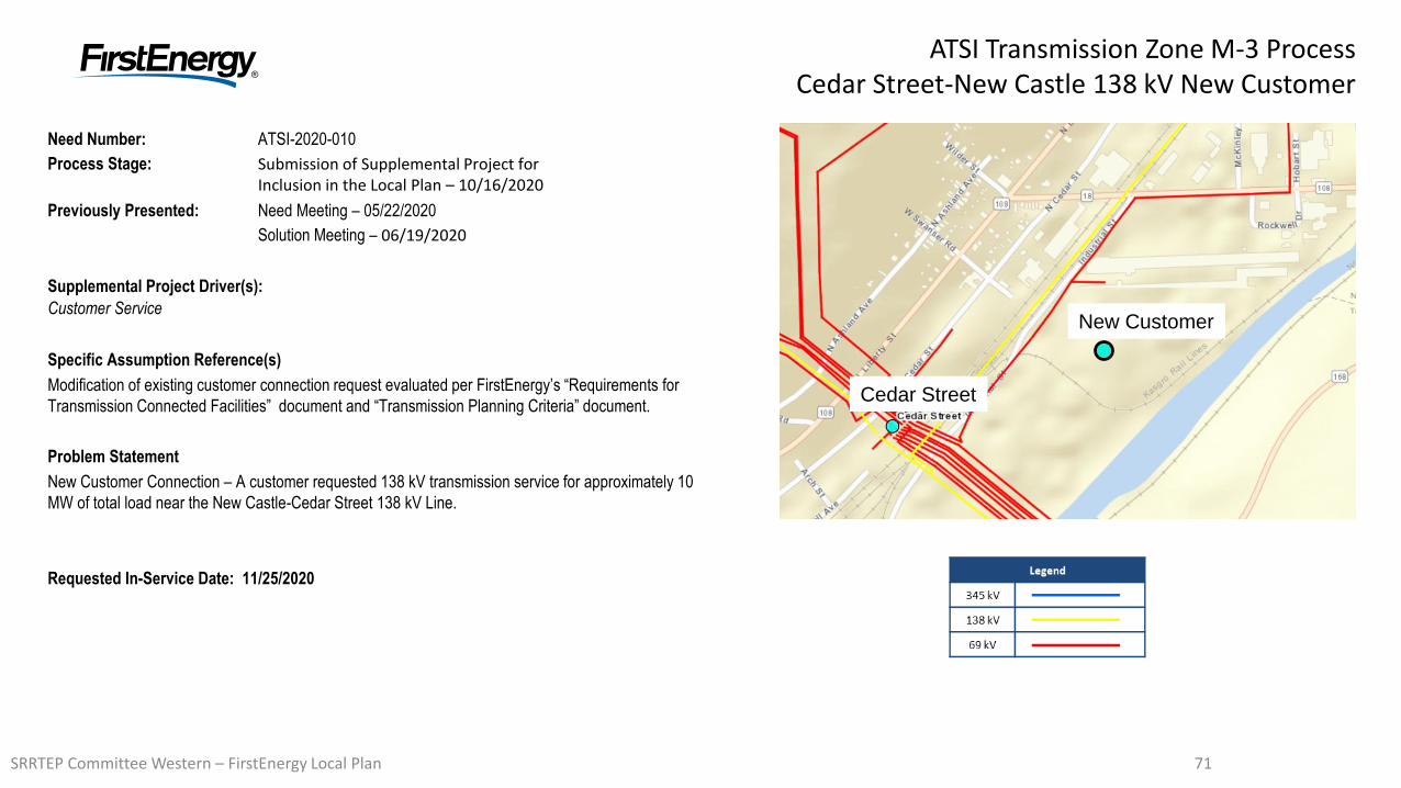
7171
ATSI Transmission Zone M-3 ProcessCedar Street-New Castle 138 kV New Customer
Need Number: ATSI-2020-010
Process Stage: Submission of Supplemental Project for Inclusion in the Local Plan – 10/16/2020
Previously Presented: Need Meeting – 05/22/2020
Solution Meeting – 06/19/2020
Supplemental Project Driver(s):
Customer Service
Specific Assumption Reference(s)
Modification of existing customer connection request evaluated per FirstEnergy’s “Requirements for
Transmission Connected Facilities” document and “Transmission Planning Criteria” document.
Problem Statement
New Customer Connection – A customer requested 138 kV transmission service for approximately 10
MW of total load near the New Castle-Cedar Street 138 kV Line.
Requested In-Service Date: 11/25/2020
Cedar Street
New Customer
SRRTEP Committee Western – FirstEnergy Local Plan
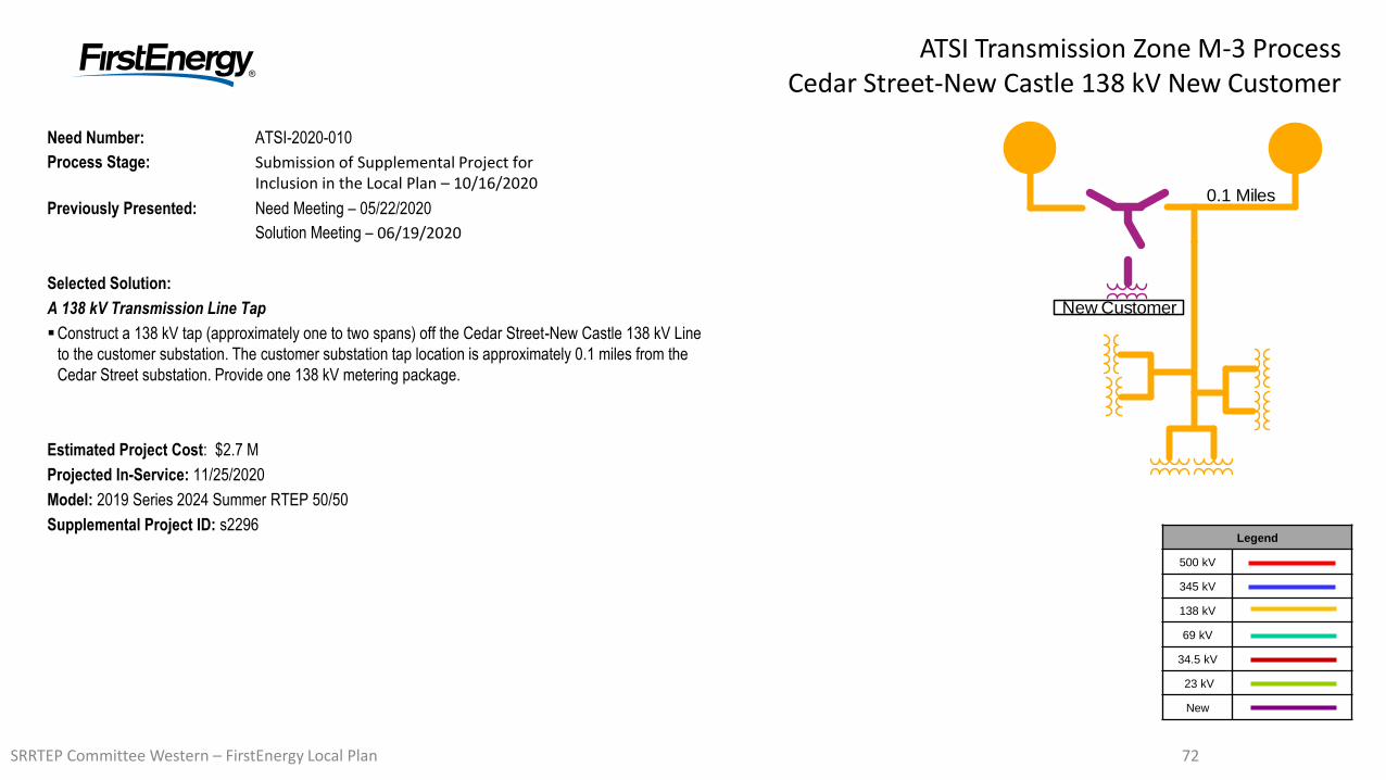
7272
ATSI Transmission Zone M-3 ProcessCedar Street-New Castle 138 kV New Customer
Need Number: ATSI-2020-010
Process Stage: Submission of Supplemental Project for Inclusion in the Local Plan – 10/16/2020
Previously Presented: Need Meeting – 05/22/2020
Solution Meeting – 06/19/2020
Selected Solution:
A 138 kV Transmission Line Tap
Construct a 138 kV tap (approximately one to two spans) off the Cedar Street-New Castle 138 kV Line
to the customer substation. The customer substation tap location is approximately 0.1 miles from the
Cedar Street substation. Provide one 138 kV metering package.
Estimated Project Cost: $2.7 M
Projected In-Service: 11/25/2020
Model: 2019 Series 2024 Summer RTEP 50/50
Supplemental Project ID: s2296Legend
500 kV
345 kV
138 kV
69 kV
34.5 kV
23 kV
New
0.1 Miles
New Customer
SRRTEP Committee Western – FirstEnergy Local Plan
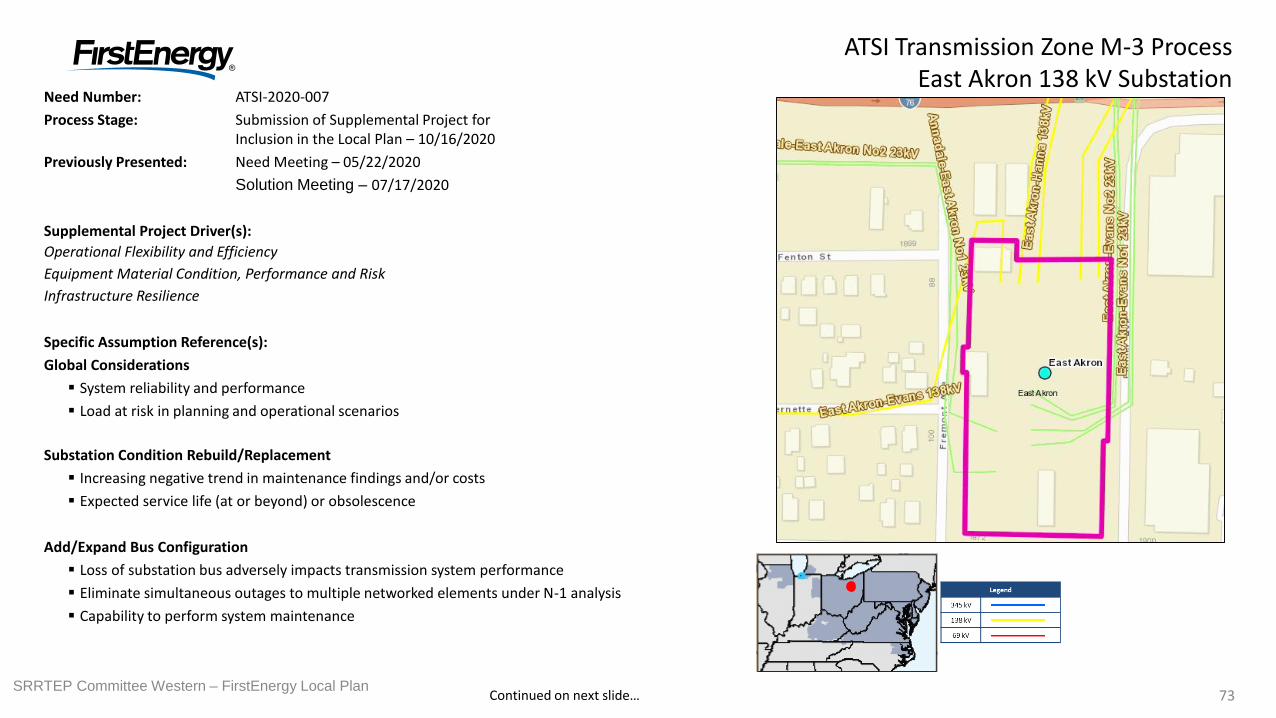
7373
Need Number: ATSI-2020-007
Process Stage: Submission of Supplemental Project for Inclusion in the Local Plan – 10/16/2020
Previously Presented: Need Meeting – 05/22/2020
Solution Meeting – 07/17/2020
Supplemental Project Driver(s):
Operational Flexibility and Efficiency
Equipment Material Condition, Performance and Risk
Infrastructure Resilience
Specific Assumption Reference(s):
Global Considerations
System reliability and performance
Load at risk in planning and operational scenarios
Substation Condition Rebuild/Replacement
Increasing negative trend in maintenance findings and/or costs
Expected service life (at or beyond) or obsolescence
Add/Expand Bus Configuration
Loss of substation bus adversely impacts transmission system performance
Eliminate simultaneous outages to multiple networked elements under N-1 analysis
Capability to perform system maintenance
ATSI Transmission Zone M-3 ProcessEast Akron 138 kV Substation
Continued on next slide…SRRTEP Committee Western – FirstEnergy Local Plan
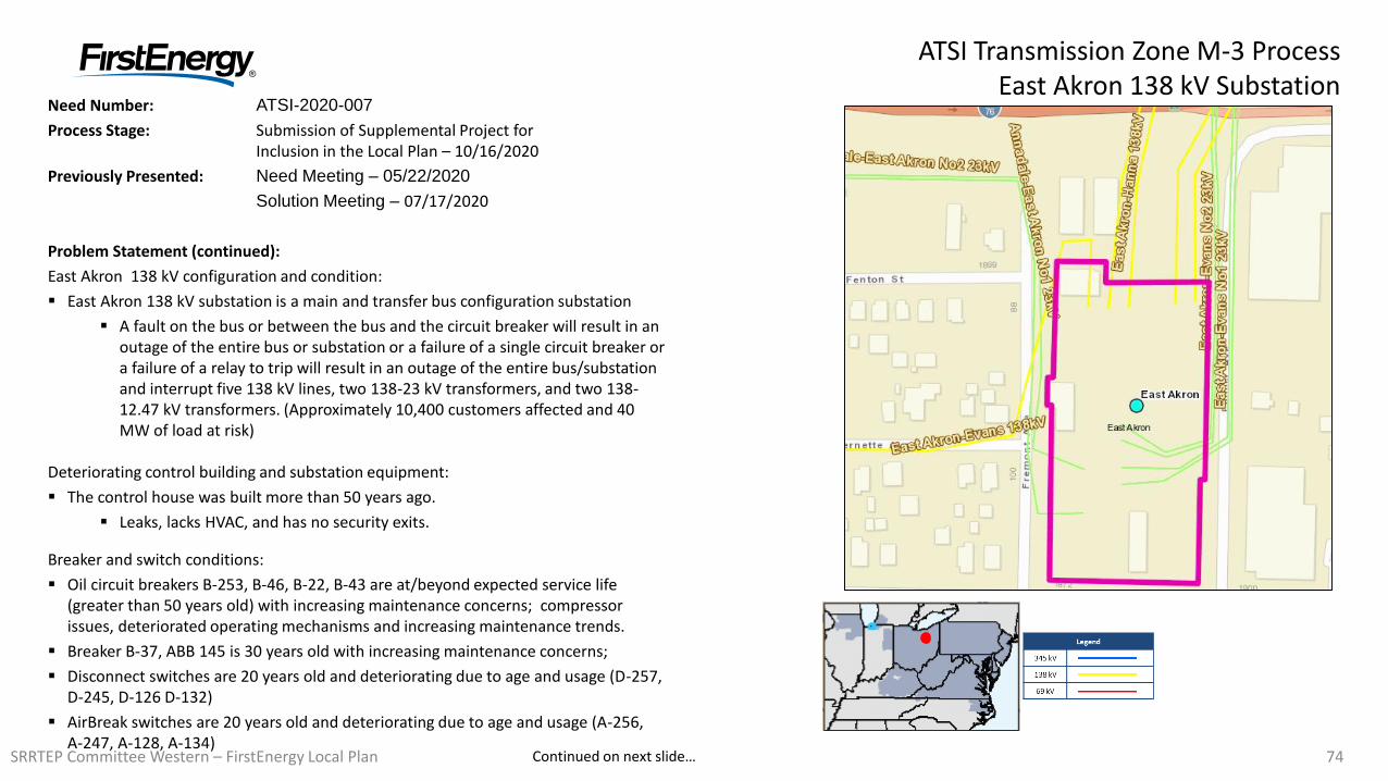
7474
Need Number: ATSI-2020-007
Process Stage: Submission of Supplemental Project for Inclusion in the Local Plan – 10/16/2020
Previously Presented: Need Meeting – 05/22/2020
Solution Meeting – 07/17/2020
Problem Statement (continued):
East Akron 138 kV configuration and condition:
East Akron 138 kV substation is a main and transfer bus configuration substation
A fault on the bus or between the bus and the circuit breaker will result in an outage of the entire bus or substation or a failure of a single circuit breaker or a failure of a relay to trip will result in an outage of the entire bus/substation and interrupt five 138 kV lines, two 138-23 kV transformers, and two 138-12.47 kV transformers. (Approximately 10,400 customers affected and 40 MW of load at risk)
Deteriorating control building and substation equipment:
The control house was built more than 50 years ago.
Leaks, lacks HVAC, and has no security exits.
Breaker and switch conditions:
Oil circuit breakers B-253, B-46, B-22, B-43 are at/beyond expected service life (greater than 50 years old) with increasing maintenance concerns; compressor issues, deteriorated operating mechanisms and increasing maintenance trends.
Breaker B-37, ABB 145 is 30 years old with increasing maintenance concerns;
Disconnect switches are 20 years old and deteriorating due to age and usage (D-257, D-245, D-126 D-132)
AirBreak switches are 20 years old and deteriorating due to age and usage (A-256, A-247, A-128, A-134)
ATSI Transmission Zone M-3 ProcessEast Akron 138 kV Substation
Continued on next slide…SRRTEP Committee Western – FirstEnergy Local Plan
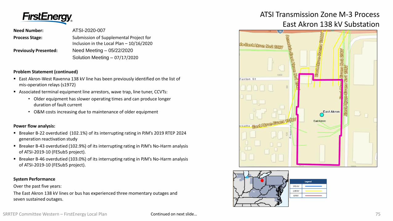
7575
Need Number: ATSI-2020-007
Process Stage: Submission of Supplemental Project for Inclusion in the Local Plan – 10/16/2020
Previously Presented: Need Meeting – 05/22/2020
Solution Meeting – 07/17/2020
Problem Statement (continued)
East Akron-West Ravenna 138 kV line has been previously identified on the list of mis-operation relays (s1972)
Associated terminal equipment line arrestors, wave trap, line tuner, CCVTs:
• Older equipment has slower operating times and can produce longer duration of fault current
• O&M costs increasing due to maintenance of older equipment
Power flow analysis:
Breaker B-22 overdutied (102.1%) of its interrupting rating in PJM’s 2019 RTEP 2024 generation reactivation study
Breaker B-43 overdutied (102.9%) of its interrupting rating in PJM’s No-Harm analysis of ATSI-2019-10 (FESub5 project).
Breaker B-46 overdutied (103.0%) of its interrupting rating in PJM’s No-Harm analysis of ATSI-2019-10 (FESub5 project).
System Performance
Over the past five years:
The East Akron 138 kV lines or bus has experienced three momentary outages and seven sustained outages.
ATSI Transmission Zone M-3 ProcessEast Akron 138 kV Substation
Continued on next slide…SRRTEP Committee Western – FirstEnergy Local Plan
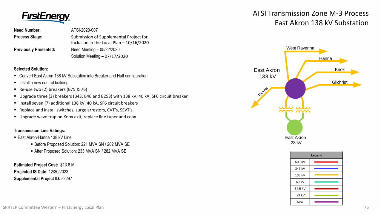
7676
ATSI Transmission Zone M-3 ProcessEast Akron 138 kV Substation
Need Number: ATSI-2020-007
Process Stage: Submission of Supplemental Project for Inclusion in the Local Plan – 10/16/2020
Previously Presented: Need Meeting – 05/22/2020
Solution Meeting – 07/17/2020
Selected Solution:
Convert East Akron 138 kV Substation into Breaker and Half configuration
Install a new control building.
Re-use two (2) breakers (B75 & 76)
Upgrade three (3) breakers (B43, B46 and B253) with 138 kV, 40 kA, SF6 circuit breaker
Install seven (7) additional 138 kV, 40 kA, SF6 circuit breakers
Replace and install switches, surge arrestors, CVT’s, SSVT’s
Upgrade wave trap on Knox exit, replace line tuner and coax
Transmission Line Ratings:
East Akron-Hanna 138 kV Line
Before Proposed Solution: 221 MVA SN / 262 MVA SE
After Proposed Solution: 233 MVA SN / 282 MVA SE
Estimated Project Cost: $13.8 M
Projected IS Date: 12/30/2023
Supplemental Project ID: s2297
Legend
500 kV
345 kV
138 kV
69 kV
34.5 kV
23 kV
New
East Akron 23 kV
Gilchrist
Knox
Hanna
West Ravenna
East Akron
138 kV
SRRTEP Committee Western – FirstEnergy Local Plan
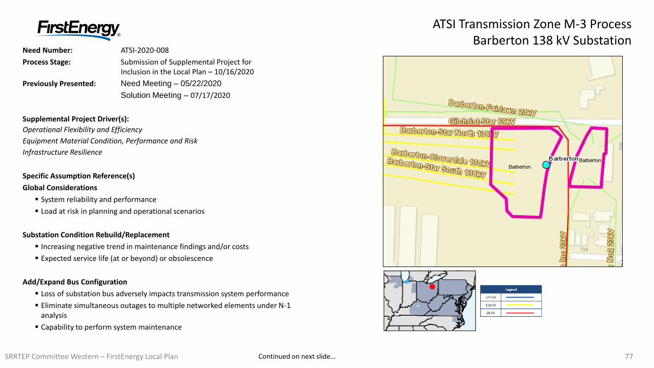
7777
Need Number: ATSI-2020-008
Process Stage: Submission of Supplemental Project for Inclusion in the Local Plan – 10/16/2020
Previously Presented: Need Meeting – 05/22/2020
Solution Meeting – 07/17/2020
Supplemental Project Driver(s):
Operational Flexibility and Efficiency
Equipment Material Condition, Performance and Risk
Infrastructure Resilience
Specific Assumption Reference(s)
Global Considerations
System reliability and performance
Load at risk in planning and operational scenarios
Substation Condition Rebuild/Replacement
Increasing negative trend in maintenance findings and/or costs
Expected service life (at or beyond) or obsolescence
Add/Expand Bus Configuration
Loss of substation bus adversely impacts transmission system performance
Eliminate simultaneous outages to multiple networked elements under N-1 analysis
Capability to perform system maintenance
ATSI Transmission Zone M-3 ProcessBarberton 138 kV Substation
Continued on next slide…SRRTEP Committee Western – FirstEnergy Local Plan
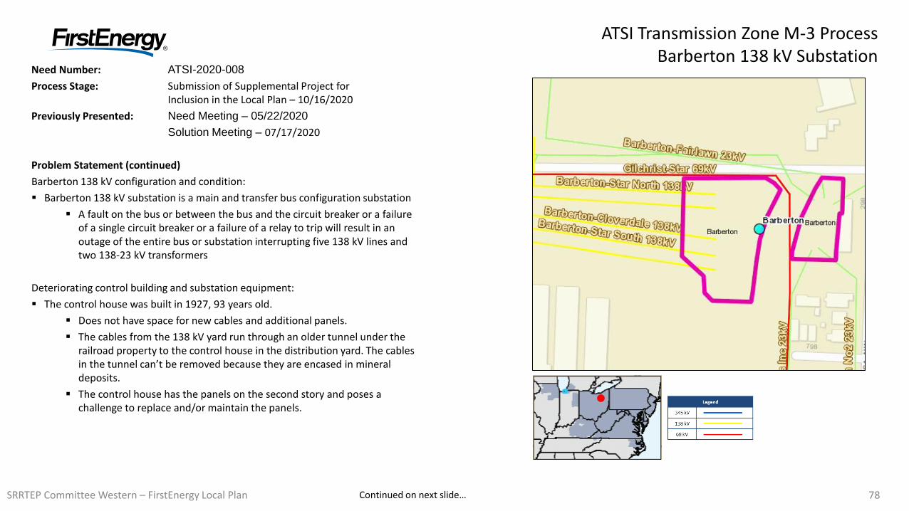
7878
Need Number: ATSI-2020-008
Process Stage: Submission of Supplemental Project for Inclusion in the Local Plan – 10/16/2020
Previously Presented: Need Meeting – 05/22/2020
Solution Meeting – 07/17/2020
Problem Statement (continued)
Barberton 138 kV configuration and condition:
Barberton 138 kV substation is a main and transfer bus configuration substation
A fault on the bus or between the bus and the circuit breaker or a failure of a single circuit breaker or a failure of a relay to trip will result in an outage of the entire bus or substation interrupting five 138 kV lines and two 138-23 kV transformers
Deteriorating control building and substation equipment:
The control house was built in 1927, 93 years old.
Does not have space for new cables and additional panels.
The cables from the 138 kV yard run through an older tunnel under the railroad property to the control house in the distribution yard. The cables in the tunnel can’t be removed because they are encased in mineral deposits.
The control house has the panels on the second story and poses a challenge to replace and/or maintain the panels.
ATSI Transmission Zone M-3 ProcessBarberton 138 kV Substation
Continued on next slide…SRRTEP Committee Western – FirstEnergy Local Plan
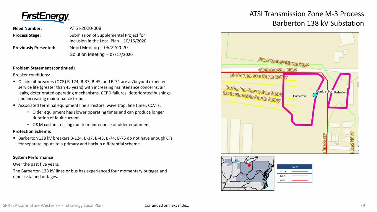
7979
Need Number: ATSI-2020-008
Process Stage: Submission of Supplemental Project for Inclusion in the Local Plan – 10/16/2020
Previously Presented: Need Meeting – 05/22/2020
Solution Meeting – 07/17/2020
Problem Statement (continued)
Breaker conditions:
Oil circuit breakers (OCB) B-124, B-37, B-45, and B-74 are at/beyond expected service life (greater than 45 years) with increasing maintenance concerns; air leaks, deteriorated operating mechanisms, CCPD failures, deteriorated bushings, and increasing maintenance trends
Associated terminal equipment line arrestors, wave trap, line tuner, CCVTs:
• Older equipment has slower operating times and can produce longer duration of fault current
• O&M cost increasing due to maintenance of older equipment
Protection Scheme:
Barberton 138 kV breakers B-124, B-37, B-45, B-74, B-75 do not have enough CTs for separate inputs to a primary and backup differential scheme.
System Performance
Over the past five years:
The Barberton 138 kV lines or bus has experienced four momentary outages and nine sustained outages.
ATSI Transmission Zone M-3 ProcessBarberton 138 kV Substation
Continued on next slide…SRRTEP Committee Western – FirstEnergy Local Plan
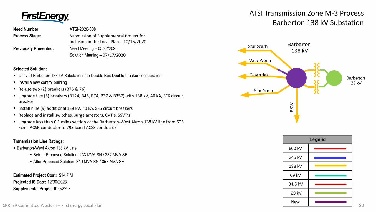
8080
ATSI Transmission Zone M-3 ProcessBarberton 138 kV Substation
Need Number: ATSI-2020-008
Process Stage: Submission of Supplemental Project for Inclusion in the Local Plan – 10/16/2020
Previously Presented: Need Meeting – 05/22/2020
Solution Meeting – 07/17/2020
Selected Solution:
Convert Barberton 138 kV Substation into Double Bus Double breaker configuration
Install a new control building
Re-use two (2) breakers (B75 & 76)
Upgrade five (5) breakers (B124, B45, B74, B37 & B357) with 138 kV, 40 kA, SF6 circuit breaker
Install nine (9) additional 138 kV, 40 kA, SF6 circuit breakers
Replace and install switches, surge arrestors, CVT’s, SSVT’s
Upgrade less than 0.1 miles section of the Barberton-West Akron 138 kV line from 605 kcmil ACSR conductor to 795 kcmil ACSS conductor
Transmission Line Ratings:
Barberton-West Akron 138 kV Line
Before Proposed Solution: 233 MVA SN / 282 MVA SE
After Proposed Solution: 310 MVA SN / 357 MVA SE
Estimated Project Cost: $14.7 M
Projected IS Date: 12/30/2023
Supplemental Project ID: s2298
Legend
500 kV
345 kV
138 kV
69 kV
34.5 kV
23 kV
New
Barberton 23 kV
Star North
West Akron
Cloverdale
B&
W
Barberton
138 kVStar South
SRRTEP Committee Western – FirstEnergy Local Plan
81
Revision History3/18/2020 – V1 – Local Plan posted to pjm.com
6/8/2020 – V2 – Added: S2227-S2243
7/2/2020 – V3 – Added: S2245, S2246, S2259, S2260
10/1/2020 – V4 – Added: S2261 – S2265
10/16/2020 – V5 – Added: S2294-S2298
SRRTEP Committee Western – FirstEnergy Local Plan