study of rail transit system communication network (bcn
TRANSCRIPT
CAPSTONE PROJECT REPORT
MINT PROGRAM
Study of Rail Transit System Communication Network (BCN/TCN) and Related Sub-
Systems
STUDENT NAME: SALMAN RATHOR

ii
Rail transit system communication network (BCN/TCN)
Acknowledgement
I would like to thank my mentors Mr. Shahnawaz Mir, Dr. Mike MacGregor for
supporting and encouraging me during my Master’s Degree. The completion
of my Degree could not have been possible without the continuous support
and guidance from them. My sincere thanks to Mr. Juned Noonari who helped
me to get all the resources and essential details during the project research.
iii
Rail transit system communication network (BCN/TCN)
Table of Content
1.0 Introduction ......................................................................................................... 1
1.1 Background ........................................................................................................ 1
1.2 Evolution of Train Control/ train Signaling Systems ........................................... 2
1.3 Communication Network .................................................................................... 5
2.0 Train Control Systems Around the World ......................................................... 7
2.1 Positive Train Control systems ........................................................................... 7
2.1.1 PTC System ................................................................................................ 8
2.1.1.1 PTC System Operation ......................................................................... 9
2.1.1.2 PTC high-level architecture ................................................................. 10
2.1.1.3 IEEE 802.15 Positive Train Control Group .......................................... 12
2.2 Enhanced Train Control (ETC) ......................................................................... 13
2.3 European Train Control System (ETCS) .......................................................... 15
2.3.1 ETCS Trackside Equipment ...................................................................... 15
2.3.2 ETCS Onboard Equipment ........................................................................ 17
2.4 Chinese Train Control System (CTCS) ............................................................ 18
3.0 Communications Based Train Control (CBTC) ............................................... 21
3.1 Fixed block vs. moving block............................................................................ 21
3.2 Characteristics of CBTC System ...................................................................... 22
3.3 CBTC System Architecture .............................................................................. 25
3.4 CBTC subsystems ........................................................................................... 26
3.4.1 Components and Networks ....................................................................... 26
3.4.2 Vehicle Onboard components ................................................................... 27
3.4.2.1 Onboard Control Unit (OBCU) ............................................................ 27
3.4.3 Wayside components ................................................................................ 28
3.4.4 Automatic Train Supervision ...................................................................... 29
3.4.4.1 Data Communication System .............................................................. 30
3.5 The Evolution of Communication Technologies for Railway Signaling ............. 32
3.5.1 Early CBTC systems.................................................................................. 33
3.5.2 Radio-based CBTC: .................................................................................. 34
3.5.2.1 Custom and Commercial-off-the-shelf (COTS) radio: ......................... 34
3.5.2.2 Leaky waveguide ................................................................................ 34
4.0 Rail Communication Network and Technologies ........................................... 36
iv
Rail transit system communication network (BCN/TCN)
4.1 General Requirements ..................................................................................... 37
4.1.1 Train Control .............................................................................................. 38
4.1.2 Redundancy of network and coverage ...................................................... 38
4.1.3 Video surveillance ..................................................................................... 38
4.1.4 Exclusive voice call function for railway ..................................................... 39
4.2 Train Communication Network (TCN) .............................................................. 40
4.2.1 Multi-function Vehicle Bus ......................................................................... 41
4.2.2 Wired Train Bus ......................................................................................... 42
4.2.3 Common Real-time Protocols (RTP) ......................................................... 43
4.2.4 TCN Gateway ............................................................................................ 44
4.2.5 UIC Communication .................................................................................. 44
4.2.6 ERRI test train ........................................................................................... 45
4.2.7 Ethernet Train Backbone ........................................................................... 45
4.2.7.1 Redundancy in Ethernet for TCN ........................................................ 47
4.2.7.2 TCN using Switched Ethernet ............................................................. 48
4.3 Wireless Technologies for rail communication. ................................................ 51
4.3.1 WLAN System for Rail Communication ..................................................... 52
4.3.1.2 WLAN Standards ................................................................................ 54
4.3.1.3 Wireless LAN Topology/Configurations ............................................... 56
4.3.1.4 WLAN Performance ............................................................................ 58
4.3.1.5 Advantages of WiFi ............................................................................. 59
4.3.1.6 Wi-Fi Drawbacks ................................................................................. 59
4.3.1.7 Improvements Proposed in WLAN for CBTC system .......................... 60
4.3.1.8 Handling roaming in Wi-Fi ................................................................... 61
4.3.1.9 DCS RF Coverage .............................................................................. 63
4.3.2 Terrestrial Trunked Radio (TETRA) System for Rail Communication ........ 64
4.3.2.1 TETRA systems technical characteristics ........................................... 64
4.3.2.2 TETRA Network Architecture .............................................................. 66
4.3.3 Cellular Technology for Rail Communications ........................................... 67
4.3.3.1 GSM-R Standard................................................................................. 67
4.3.3.2 GSM-R Architecture ............................................................................ 70
4.3.3.3 GSM-R Network Hierarchical Structure ............................................... 76
4.3.4 A Comparison of TETRA Vs GSM-R ......................................................... 78
4.3.5 Long term Evolution-Railway (LTE-R) ....................................................... 80
v
Rail transit system communication network (BCN/TCN)
4.3.5.1 LTE-R Architecture .............................................................................. 80
4.3.5.2 Railway specific functions in LTE-R .................................................... 84
4.3.6 Future Railway Mobile Communication System ........................................ 87
4.3.6.1 The use of FRMCS based on 5G ........................................................ 89
4.4 Supervisory/SCADA system for train control .................................................... 93
4.4.1 Typical SCADA System ............................................................................. 93
4.4.1.1 Remote Terminal Units ....................................................................... 93
4.4.1.1 Master Terminal Unit ........................................................................... 93
4.4.1.2 Communications System .................................................................... 95
4.4.1.3 SCADA System in Train control .......................................................... 95
5.0 Security of Train Communication System ...................................................... 97
5.1 Attacks on ICS/SCADA Systems ..................................................................... 97
5.1.1 Intentional Attacks ..................................................................................... 98
5.1.2 Unintentional Consequences ..................................................................... 99
5.1.3 Unintentional Internal Security Consequences .......................................... 99
5.2 SCADA System Vulnerabilities....................................................................... 100
5.2.1 Cyber Attacks on SCADA Systems ......................................................... 101
5.2.1.1 Attacks on Hardware ......................................................................... 101
5.2.1.2 Attacks on Software .......................................................................... 101
5.2.1.3 Attacks on Communication Stack ..................................................... 102
5.3 Security of Wireless Networks........................................................................ 103
5.3.1 Vulnerabilities and Threats to Wireless Networks .................................... 103
5.3.1.1 Eavesdropping or Sniffing ................................................................. 103
5.3.1.2 Physically insecure locations ............................................................ 104
5.3.1.3 Rogue access points ......................................................................... 104
5.3.1.4 MAC address spoofing ...................................................................... 104
5.3.1.5 Wardriving ......................................................................................... 104
5.3.1.6 Denial-Of-Service (DOS) attacks ...................................................... 104
5.3.1.7 Disassociation and De-authentication Attacks .................................. 105
5.3.1.8 Exploiting security protocol loopholes ............................................... 105
5.3.2 Security Mechanisms in IEEE 802.11 protocols ...................................... 105
5.3.2.1 Wired Equivalent Privacy .................................................................. 105
5.3.2.2 WEP Weaknesses ............................................................................ 107
5.3.2.3 Wireless Protected Access ............................................................... 108
vi
Rail transit system communication network (BCN/TCN)
5.3.2.4 Wireless Protected Access 2 (WPA2) ............................................... 109
5.3.2.1 IEEE 802.11i ..................................................................................... 110
5.3.2.2 WPA 3 ............................................................................................... 111
5.3.3 Security of Cellular Network .................................................................... 112
5.3.3.1 Security in GSM mobile network ....................................................... 113
5.3.3.2 GPRS Network Security .................................................................... 116
5.3.3.3 Vulnerabilities in GSM Network ......................................................... 118
5.3.3.4 Vulnerabilities detected in use of GSM for railway applications ........ 119
5.3.3.5 LTE Network Security ....................................................................... 120
5.4 Defense-in-Depth for Rail communication Network ........................................ 123
5.4.1 SCADA Security Strategy and Risk Mitigation ......................................... 123
5.4.2 Network Architecture for ICS security ...................................................... 125
5.4.3 Recommendation for Defense in Depth Strategy .................................... 127
6.0 Train Control System Vendors ....................................................................... 128
7.0 Conclusion ....................................................................................................... 131
8.0 References ....................................................................................................... 133
vii
Rail transit system communication network (BCN/TCN)
Table of Figures
Figure 1. Schematic of signal block section (“Signalling,” 2019) ................................ 2
Figure 2 Track Circuit - Block Unoccupied (“Signalling,” 2019) ....................................... 3
Figure 3. Track Circuit - Block Occupied. (“Signalling,” 2019) ......................................... 4
Figure 4. A profile-based train control system (F. R. Yu, 2018) ....................................... 4
Figure 5. technical architecture of PTC (Baker, 2012) .................................................... 9
Figure 6 PTC System operation (Baker, 2012) ............................................................. 10
Figure 7 The High-Level Architecture of an End-to-End PTC Infrastructure (CISCO,
2013) ............................................................................................................................. 11
Figure 8. Approved PTC Systems (Burkhardt, n.d.) ...................................................... 12
Figure 9 Diagram of the proposed ETC Level 1 system (Scanlan et al., 2018) ............. 13
Figure 10 ETC Level 3 system with a full buildout into the wayside segment (Scanlan et
al., 2018) ....................................................................................................................... 14
Figure 11 Level 1 (with infill balise group) (RSSB, 2010) .............................................. 16
Figure 12 Level 2 without lineside signals (RSSB, 2010) .............................................. 17
Figure 13 ETCS onboard equipment (RSSB, 2010) ...................................................... 18
Figure 14. The system structure of ITCS based on GSM-R (Hann, 2010) .................... 20
Figure 15 Fixed vs. moving block (Farooq & Soler, 2017) ............................................. 22
Figure 16 Positioning Basics in CBTC (Ali, 2015) ......................................................... 23
Figure 17 CBTC Positioning Characteristics ................................................................. 23
Figure 18 CBTC Positioning Characteristics (Ali, 2015) ................................................ 24
Figure 19. Communication-based train control (CBTC) system (L. Zhu, Yu, Ning, &
Tang, 2014) ................................................................................................................... 25
Figure 20 Major CBTC Subsystems (IEEE Std 1474.3-2008) ....................................... 26
Figure 21 System Architecture of Onboard components (Lam, 2017) .......................... 27
Figure 22 CBTC wayside components (Farooq & Soler, 2017) ..................................... 29
Figure 23 System Architecture of Operational Control Center (Lam, 2017) .................. 30
Figure 24 DCS SYSTEM (CBTC Overview Wayside Equipment, 2019) ....................... 30
Figure 25 Wired Network (Kuun & Canada, n.d.) .......................................................... 31
Figure 26 Simplified CBTC Architecture (Wen et al., 2018) .......................................... 32
viii
Rail transit system communication network (BCN/TCN)
Figure 27 Conventional signaling systems vs CBTC (Ali, 2016) ................................... 33
Figure 28 Train monitoring, control and supervision system (Moxa, 2019) ................... 36
Figure 29 Railway specific call processing features (Choi et al., 2013) ......................... 39
Figure 30 Train Communication Network. IEC 61375-1 (Holmberg, 2015) ................... 41
Figure 31 Open train with the Multifunction Vehicle Bus as vehicle bus (in some
vehicles) and ................................................................................................................. 42
Figure 32 Wire Train Bus (Hubert Kirrmann & Pierre A. Zuber, 2001) .......................... 43
Figure 33 Alternating periodic and sporadic data transmissions (Hubert Kirrmann &
Pierre A. Zuber, 2001) ................................................................................................... 44
Figure 34. Ethernet Train Backbone. (Holmberg, 2015) ................................................ 46
Figure 35 HSR based TCN (Aitzol Zuloaga et al., 2013) ............................................... 48
Figure 36 The TCN topology structure based on switched Ethernet (Ma et al., 2014) .. 49
Figure 37 Improvement of the communication protocol stack. (Ma et al., 2014) ........... 50
Figure 38 Ethernet based train control and supervision system (Moxa, 2019) .............. 51
Figure 39 Comparison Between IEEE 802.11a,b,g,n and ac (Abdelrahman et al., 2015)
...................................................................................................................................... 56
Figure 40 Ad hoc mode(Dhanalakshmi & Sathiya, 2015) .............................................. 57
Figure 41 Basic Service Set (BSS) and Extended Service Set (ESS) (Dhanalakshmi &
Sathiya, 2015) ............................................................................................................... 58
Figure 42 The proposed cooperative and cognitive CBTC system (Li et al., 2015) ....... 62
Figure 43 TETRA network architecture diagram (Donner et al., 2014).......................... 66
Figure 44 GSM-R system structure (Z.-D. Zhong et al., 2018) ...................................... 72
Figure 45 The GSM-R network structure of the whole railway (Z.-D. Zhong et al., 2018)
...................................................................................................................................... 76
Figure 46 The GSM-R intelligent network structure (Z.-D. Zhong et al., 2018) ............. 77
Figure 47 GSM-R GPRS backbone Network (Z.-D. Zhong et al., 2018) ...................... 77
Figure 48 Comparison of TDMA digital communications systems (Cesar Briso & J.I.
Alonso, 2007) ................................................................................................................ 79
Figure 49 The LTE -R architecture for HSR communication (He et al., 2016) ............... 81
Figure 50. System parameters of GSM-R, LTE, and LTE-R (He et al., 2016) ............... 84
Figure 51 MBMS Based Group Messaging Architecture (5G Americas, 2016) ............. 85
ix
Rail transit system communication network (BCN/TCN)
Figure 52 LTE-R services (He et al., 2016) ................................................................... 86
Figure 53 LTE throughput performance versus train speed (Choi et al., 2013) ............. 87
Figure 54 Application Layer Relationship Diagram (FRMCS Functional Working Group,
2019) ............................................................................................................................. 88
Figure 55 Urban rail requirements,(Mottier, 2016) ........................................................ 89
Figure 56 Five communication scenarios of smart rail transportation (Briso-Rodríguez,
Guan, Xuefeng, & Kürner, 2017) ................................................................................... 90
Figure 57 Broadband network for HST noncritical communications. (Briso-Rodríguez et
al., 2017) ....................................................................................................................... 92
Figure 58 Example of different wireless communications systems customized for critical
and noncritical communications (Briso-Rodríguez et al., 2017) .................................... 92
Figure 59. Typical Components of a Control System (GAO-04-354, 2004) ................... 94
Figure 60. SCADA System Implementation Example (Rail Monitoring and Control)
(Stouffer, Falco, & Kent, 2006) ...................................................................................... 96
Figure 61 Keyed stream cipher operation (Gast, 2009)............................................... 106
Figure 62 WEP operations (Gast, 2009) ..................................................................... 106
Figure 63 Protection by Michael (Gast, 2009) ............................................................. 108
Figure 64 TKIP Key mixing (Gast, 2009) ..................................................................... 109
Figure 65 CCMP frame processing encryption (Gast, 2009) ....................................... 110
Figure 66 Evolving Security Architecture (Wierenga, 2019) ........................................ 113
Figure 67 Authentication and Encryption in GSM (RF Telecom, 2009) ....................... 114
Figure 68 Ciphertext generation (Yasir Korkusuz, 2012) ............................................. 115
Figure 69 Comp128: SRES Session Key (Yasir Korkusuz, 2012) ............................... 116
Figure 70 Basic GPRS ciphering environment (ETSI TS 101 106 V7.0.0, 2001) ........ 117
Figure 71 SAE/LTE security requirements (Prasad & So, 2011) ................................ 120
Figure 72 Security Architecture of LTE (Ahmed et al., 2016) ...................................... 121
Figure 73 Relationship Between Corporate and SCADA Networks (NCS, 2004) ................ 124
Figure 74. CSSP Recommended Defense-In-Depth Architecture (Stouffer et al., 2015)
.................................................................................................................................... 126
1.0 Introduction
The signaling and train control system is like lifeblood for any rail transit system. The
train control system requires continuous information on the location of the trains on the
track and based on this information use signaling to control the movement of the train.
This requires a reliable communication system to transfer information related to train
location and signaling between train, wayside controls, and signaling system. The
system needs to transfer information between various equipment without delay and to
keep its integrity intact. The communication network deployed for train control system
plays a key role in the safe and secure operation of the train system.
1.1 Background
The development of the steam engine led to the expansion of railways worldwide. The
19th century saw the rapid development of railways all over the world including Canada,
and it virtually brought a revolution in the transportation industry (Marsh, 2009). The
invention of diesel and electric locomotives which could pull much large load enhanced
the efficiency and capacity of the network many folds. The railways played a major role
in industrialization, development of new markets and integrating them to create a
demand for resources and technology. However, the railway's infrastructure required
major investments, land requirements and right of way. This requirement of funds was
met by massive public expenditures in various forms, but the results were a substantial
contribution to the employment, business development and general economic growth of
the far-flung regions.
With the rapid expansion of the railroad system for transportation of human resources,
the railroad system became complex infrastructure requiring special techniques and
technologies to manage it. Railroad-Based transportation has become a lifeline for
metro cities to carry a large number of people from their home to workplaces without the
hassle of getting into traffic jams. With the introduction of the electric locomotive, it is a
most environmentally friendly system for mass movement of men and material across
the nation. The railroad system has come under pressure to increase its capacity and
speed to ease pressure from busy roads and everyday traffic snarls.
Introduction 2
Rail transit system communication network (BCN/TCN)
The complexities of the system have led to many disasters due to technical problems as
well as human errors. February 26th, 2012, saw a major VIA train derailment at
Burlington in Canada when a Via train ran at 56 MPH over 15 MPH crossover killing
three crew in the engine and injuring 46 persons (Wightman, 2018).
Managing complex railroad infrastructure requires timely information on rail stock using
an automated, reliable and failsafe system for train management. Train Communication
Network (TCN) is an effort in this direction. The train signaling and communication
system plays a key role to meet increased demand and safety (F. R. Yu, 2018).
1.2 Evolution of Train Control/ train signaling Systems
Rails provide low friction path for the trains, but this feature leaves the train system with
poor braking capabilities. In the beginning, only one train used to ply over the rail track.
The increase in rail traffic demanded the use of the same track for multiple trains
operating close to each other. The signaling system is used for basically avoiding
collision and derailment of trains plying on the same track (Morar, 2012). This required
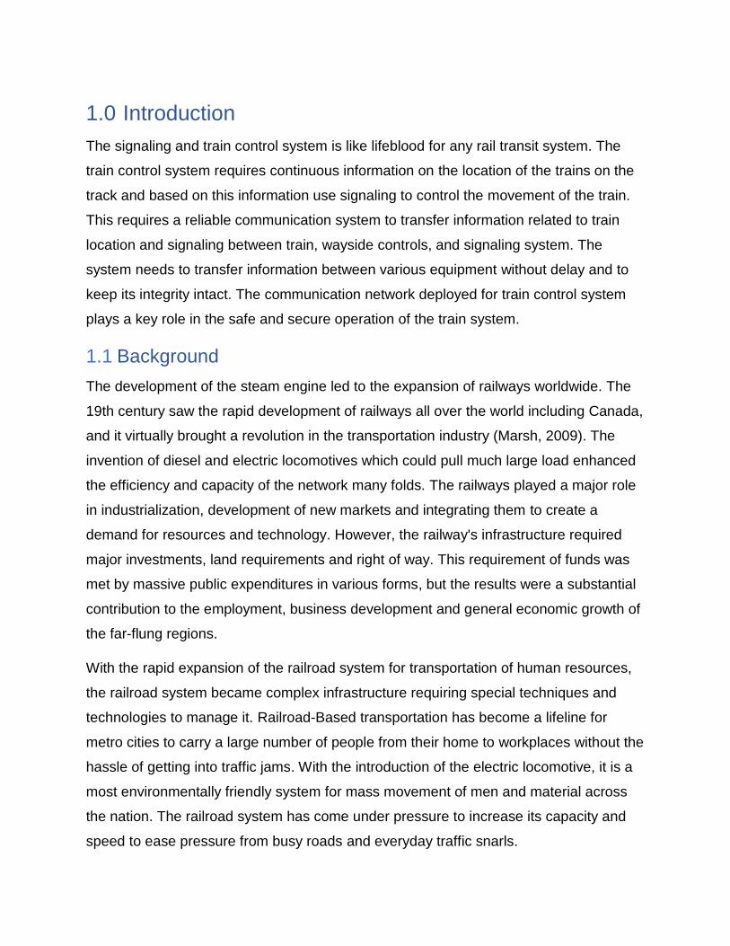
stringent traffic control and led to the development of a block system where rail track
was divided into blocks or sections, and only one train was allowed to be in the block to
avoid a collision. Each block was protected by a mechanical signal placed at the
beginning of the block to provide information to the driver of the train about the
availability of the block or section as shown in Figure 1 (Railway Technical, 2019). The
signal shows green when the block is unoccupied and red when the block is occupied.
Figure 1. Schematic of signal block section (Railway Technical, 2019)
Introduction 3
Rail transit system communication network (BCN/TCN)
The train signaling and control systems were developed with the basic objective to
prevent collisions of two trains traveling on the same track. This requires a control
system to have the knowledge of the location of the train on the track. (F. R. Yu, 2018)
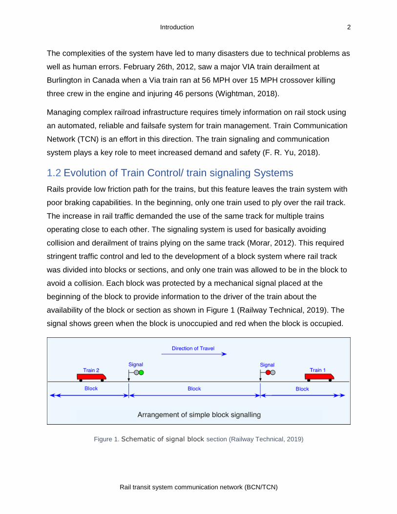
The first signaling control system using Track Circuit was developed in late 1800 by
William Robinson (Mansour, 2017). The track circuit was used to detect the train’s
presence or absence on the track and provided tracks status on trackside signals to
provide information about track condition ahead to the drivers. The track circuit consists
of a low voltage generator that energizes a relay though rails and activates the go signal
as shown in Figure 2 (Railway Technical, 2019).
Figure 2 Track Circuit - Block Unoccupied (Railway Technical, 2019)
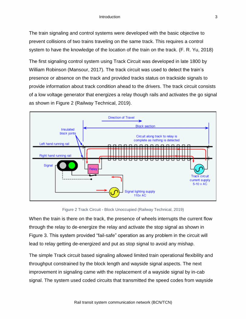
When the train is there on the track, the presence of wheels interrupts the current flow
through the relay to de-energize the relay and activate the stop signal as shown in
Figure 3. This system provided “fail-safe” operation as any problem in the circuit will
lead to relay getting de-energized and put as stop signal to avoid any mishap.
The simple Track circuit based signaling allowed limited train operational flexibility and
throughput constrained by the block length and wayside signal aspects. The next
improvement in signaling came with the replacement of a wayside signal by in-cab
signal. The system used coded circuits that transmitted the speed codes from wayside
Introduction 4
Rail transit system communication network (BCN/TCN)
over the rails. The speed codes were picked up by the equipment in the train, and this
provided continuous information about the track condition to the driver on the train. The
system allowed automatic operations but again was limited by the layout of the track
circuit and number of speed codes used. This technology was used in the latter half of
the 20th century by many railroad systems including Washington (WMATA), Victoria line
of London underground, lines in Hongkong and many more (F. R. Yu, 2018).
Figure 3. Track Circuit - Block Occupied. (Railway Technical, 2019)
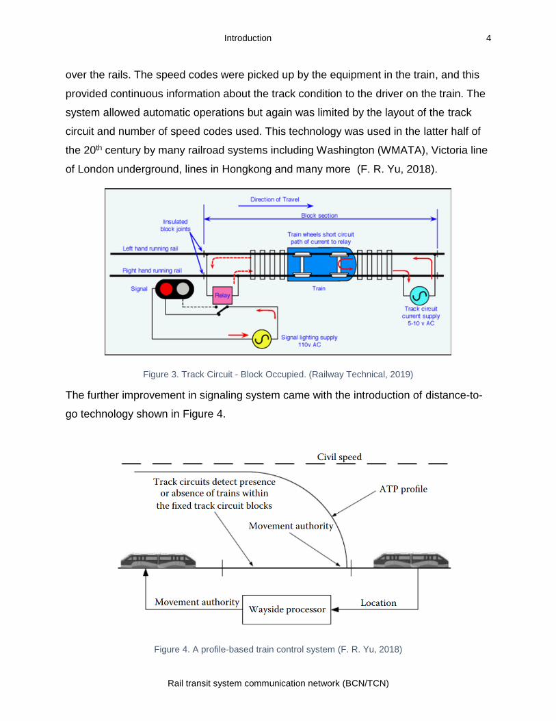
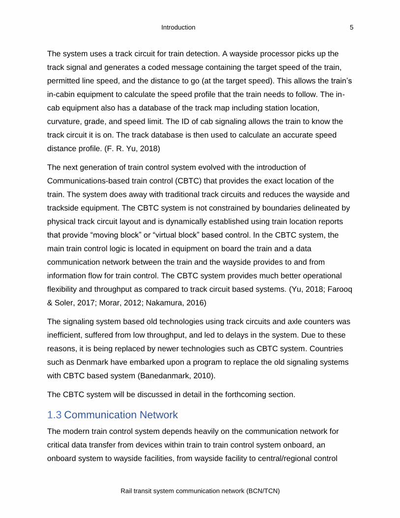
The further improvement in signaling system came with the introduction of distance-to-
go technology shown in Figure 4.
Figure 4. A profile-based train control system (F. R. Yu, 2018)
Introduction 5
Rail transit system communication network (BCN/TCN)
The system uses a track circuit for train detection. A wayside processor picks up the
track signal and generates a coded message containing the target speed of the train,
permitted line speed, and the distance to go (at the target speed). This allows the train’s
in-cabin equipment to calculate the speed profile that the train needs to follow. The in-
cab equipment also has a database of the track map including station location,
curvature, grade, and speed limit. The ID of cab signaling allows the train to know the
track circuit it is on. The track database is then used to calculate an accurate speed
distance profile. (F. R. Yu, 2018)
The next generation of train control system evolved with the introduction of
Communications-based train control (CBTC) that provides the exact location of the
train. The system does away with traditional track circuits and reduces the wayside and
trackside equipment. The CBTC system is not constrained by boundaries delineated by
physical track circuit layout and is dynamically established using train location reports
that provide “moving block” or “virtual block” based control. In the CBTC system, the
main train control logic is located in equipment on board the train and a data
communication network between the train and the wayside provides to and from
information flow for train control. The CBTC system provides much better operational
flexibility and throughput as compared to track circuit based systems. (Yu, 2018; Farooq
& Soler, 2017; Morar, 2012; Nakamura, 2016)
The signaling system based old technologies using track circuits and axle counters was
inefficient, suffered from low throughput, and led to delays in the system. Due to these
reasons, it is being replaced by newer technologies such as CBTC system. Countries
such as Denmark have embarked upon a program to replace the old signaling systems
with CBTC based system (Banedanmark, 2010).
The CBTC system will be discussed in detail in the forthcoming section.
1.3 Communication Network
The modern train control system depends heavily on the communication network for
critical data transfer from devices within train to train control system onboard, an
onboard system to wayside facilities, from wayside facility to central/regional control
Introduction 6
Rail transit system communication network (BCN/TCN)
centers, and links to the corporate network. The communication network includes wired
as well as wireless networks. With the vast type of communication requirement, rail
system uses many communication technologies for the transfer of information. The
communication system plays a critical role in the safe and secure operation of the train
system. (Craven, 2004)
The use of electronics and IT system has revolutionized the way we work and do
business. The industrial sector including railways has benefited from the use of
technology to run operations of the railway system efficiently and safely. The use of IT
has increased many folds in the last decade. However, the IT and communication
network has brought with them the associated risk. These vulnerabilities have caused
large scale damages with an attacker taking advantage of the same to disrupt the
system. The SCADA (supervisory control and data acquisition) system used by industry
including railways has also been targeted (Shaw, 2004). The SCADA system is based
on IT and communication technologies. This requires that security aspects of IT and
communication network used for train control system should be taken seriously and
necessary steps are taken to mitigate the associated risks. (Vane, 2010) (Craven,
2004)(Chen et al., 2014)
The rest of the report is organized as follows. The second section looks into the train
control systems used around the world. The third section discusses the CBTC system in
details along with its various components. The fourth section reviews the
communication technologies used in rail communication including Ethernet, Wi-Fi,
GSM-R, Tetra, LTE-R, etc. and SCADA system for train control. The fifth section looks
into the security aspect of communication in the train control system including security
aspects of SCADA and communication system used. The sixth section list the main
train control system manufacturers followed by conclusion and bibliography.
2.0 Train Control Systems Around the World
A large number of accidents due to train collisions and derailment has led to the loss of
many lives and money. This prompted rail organizations around the world to adopt a
train control network for its safe and secure operation. This section describes the two
key train control systems Positive train control and European Train Control system
adopted by major railway setups around the world.
2.1 Positive Train Control systems
The U.S. brought legislation and adopted Positive train control (PTC) after the collision
of a Union Pacific freight train and a Metrolink Commuter train in California on
September 12, 2008. In the accident, 25 persons died, and 135 passengers were
injured. The accident occurred when the red signal was ignored by the train driver while
texting on his mobile. The existing Automatic Train Stop (ATS) and Automatic Train
Control (ATC) operating at that time in many U.S. rail network were reactive in nature
and could not have prevented the accident due to the driver not acknowledging the
signal. It prompted enacting of Rail Safety Improvement Act (RSIA) law mandating the
use of a PTC system in time bound manner. PTC system provides “functional
requirements for monitoring and controlling train movements as an attempt to provide
increased safety” (Wightman, 2018).
The federal law defines PTC system as a “system designed to prevent train-to-train
collisions, over speed derailments, incursions into established work zone limits, and the
movement of a train through a switch left in the wrong position” (Peters, 2018).
In the U.S. all Class I railroad systems are mandated to install a PTC system positively
by 2020. By the end of 2018, PTC was made operational in 83% or 44,695 miles (AAR,
2019).
As per The American Railway Engineering and Maintenance-of-Way Association
(AREMA), the main characteristics of PTC are (Lanham, 2009):
• Avoidance of train to train collisions
• Enforcement of line speed to prevent derailments due to excessive speed
Train control systems around the world 8
Rail transit system communication network (BCN/TCN)
• Safety of wayside rail workers, by preventing intrusions into the working zone
• Prevention of movement due to a switch accidentally left in the wrong position.
In addition to the above, the system must be interoperable so that the train can also
operate on any track using existing signaling and control systems.
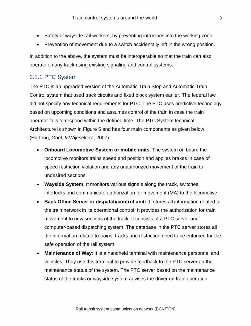
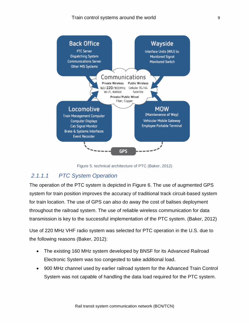
2.1.1 PTC System
The PTC is an upgraded version of the Automatic Train Stop and Automatic Train
Control system that used track circuits and fixed block system earlier. The federal law
did not specify any technical requirements for PTC. The PTC uses predictive technology
based on upcoming conditions and assumes control of the train in case the train
operator fails to respond within the defined time. The PTC System technical
Architecture is shown in Figure 5 and has four main components as given below
(Hartong, Goel, & Wijesekera, 2007):
• Onboard Locomotive System or mobile units: The system on board the
locomotive monitors trains speed and position and applies brakes in case of
speed restriction violation and any unauthorized movement of the train to
undesired sections.
• Wayside System: It monitors various signals along the track, switches,
interlocks and communicate authorization for movement (MA) to the locomotive.
• Back Office Server or dispatch/control unit: It stores all information related to
the train network in its operational control. It provides the authorization for train
movement to new sections of the track. It consists of a PTC server and
computer-based dispatching system. The database in the PTC server stores all
the information related to trains, tracks and restriction need to be enforced for the
safe operation of the rail system.
• Maintenance of Way: It is a handheld terminal with maintenance personnel and
vehicles. They use this terminal to provide feedback to the PTC server on the
maintenance status of the system. The PTC server based on the maintenance
status of the tracks or wayside system advises the driver on train operation.
Train control systems around the world 9
Rail transit system communication network (BCN/TCN)
Figure 5. technical architecture of PTC (Baker, 2012)
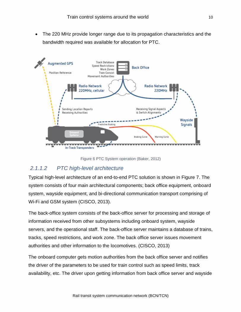
2.1.1.1 PTC System Operation
The operation of the PTC system is depicted in Figure 6. The use of augmented GPS
system for train position improves the accuracy of traditional track circuit-based system
for train location. The use of GPS can also do away the cost of balises deployment
throughout the railroad system. The use of reliable wireless communication for data
transmission is key to the successful implementation of the PTC system. (Baker, 2012)
Use of 220 MHz VHF radio system was selected for PTC operation in the U.S. due to
the following reasons (Baker, 2012):
• The existing 160 MHz system developed by BNSF for its Advanced Railroad
Electronic System was too congested to take additional load.
• 900 MHz channel used by earlier railroad system for the Advanced Train Control
System was not capable of handling the data load required for the PTC system.
Train control systems around the world 10
Rail transit system communication network (BCN/TCN)
• The 220 MHz provide longer range due to its propagation characteristics and the
bandwidth required was available for allocation for PTC.
Figure 6 PTC System operation (Baker, 2012)
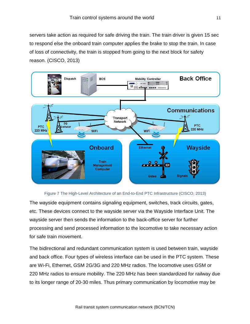
2.1.1.2 PTC high-level architecture
Typical high-level architecture of an end-to-end PTC solution is shown in Figure 7. The
system consists of four main architectural components; back office equipment, onboard
system, wayside equipment, and bi-directional communication transport comprising of
Wi-Fi and GSM system (CISCO, 2013).
The back-office system consists of the back-office server for processing and storage of
information received from other subsystems including onboard system, wayside
servers, and the operational staff. The back-office server maintains a database of trains,
tracks, speed restrictions, and work zone. The back office server issues movement
authorities and other information to the locomotives. (CISCO, 2013)
The onboard computer gets motion authorities from the back office server and notifies
the driver of the parameters to be used for train control such as speed limits, track
availability, etc. The driver upon getting information from back office server and wayside
Train control systems around the world 11
Rail transit system communication network (BCN/TCN)
servers take action as required for safe driving the train. The train driver is given 15 sec
to respond else the onboard train computer applies the brake to stop the train. In case
of loss of connectivity, the train is stopped from going to the next block for safety
reason. (CISCO, 2013)
Figure 7 The High-Level Architecture of an End-to-End PTC Infrastructure (CISCO, 2013)
The wayside equipment contains signaling equipment, switches, track circuits, gates,
etc. These devices connect to the wayside server via the Wayside Interface Unit. The
wayside server then sends the information to the back-office server for further
processing and send processed information to the locomotive to take necessary action
for safe train movement.
The bidirectional and redundant communication system is used between train, wayside
and back office. Four types of wireless interface can be used in the PTC system. These
are Wi-Fi, Ethernet, GSM 2G/3G and 220 MHz radios. The locomotive uses GSM or
220 MHz radios to ensure mobility. The 220 MHz has been standardized for railway due
to its longer range of 20-30 miles. Thus primary communication by locomotive may be
Train control systems around the world 12
Rail transit system communication network (BCN/TCN)
220 MHz with a backup using 3G, and in the yard or at the station it may use Wi-Fi.
(CISCO, 2013)
The transport network provides a resilient communication path between back-office
systems and field devices. It consists of industrial Ethernet switches at the edge and a
multipath backbone system. (CISCO, 2013)
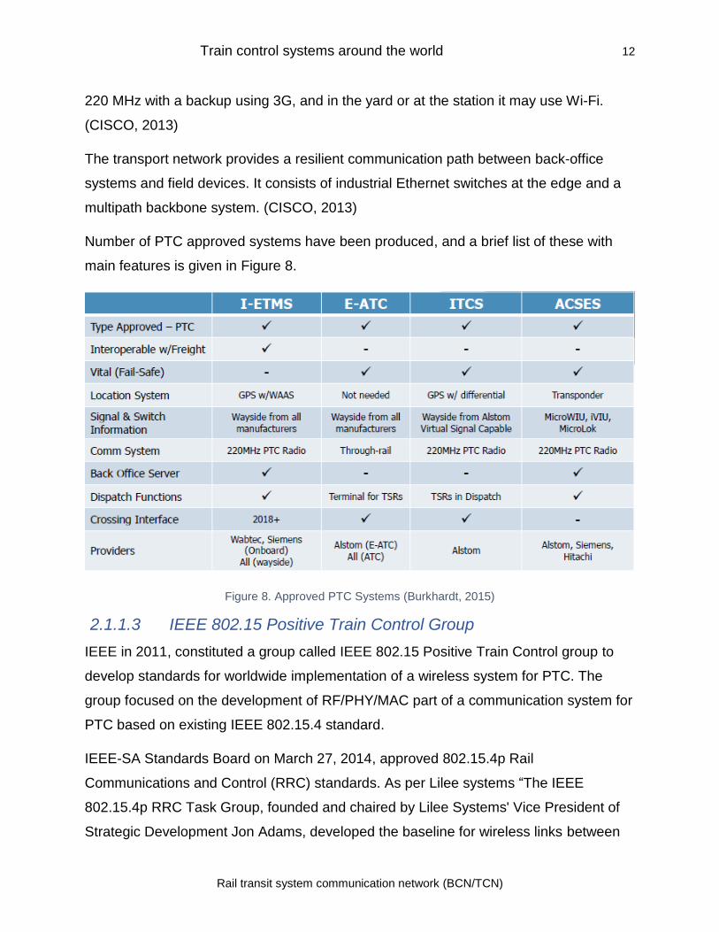
Number of PTC approved systems have been produced, and a brief list of these with
main features is given in Figure 8.
Figure 8. Approved PTC Systems (Burkhardt, 2015)
2.1.1.3 IEEE 802.15 Positive Train Control Group
IEEE in 2011, constituted a group called IEEE 802.15 Positive Train Control group to
develop standards for worldwide implementation of a wireless system for PTC. The
group focused on the development of RF/PHY/MAC part of a communication system for
PTC based on existing IEEE 802.15.4 standard.
IEEE-SA Standards Board on March 27, 2014, approved 802.15.4p Rail
Communications and Control (RRC) standards. As per Lilee systems “The IEEE
802.15.4p RRC Task Group, founded and chaired by Lilee Systems' Vice President of
Strategic Development Jon Adams, developed the baseline for wireless links between
Train control systems around the world 13
Rail transit system communication network (BCN/TCN)
trains or locomotives and track infrastructure, creating the framework for locomotive and
transit communication standards” (Lilee Systems, 2014). It extends the IEEE 802.15.4p
to “include a sensor, control, and information transfer applications for rail transit entities”
(Lilee Systems, 2014).
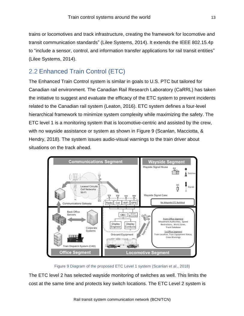
2.2 Enhanced Train Control (ETC)
The Enhanced Train Control system is similar in goals to U.S. PTC but tailored for
Canadian rail environment. The Canadian Rail Research Laboratory (CaRRL) has taken
the initiative to suggest and evaluate the efficacy of the ETC system to prevent incidents
related to the Canadian rail system (Leaton, 2016). ETC system defines a four-level
hierarchical framework to minimize system complexity while maximizing the safety. The
ETC level 1 is a monitoring system that is locomotive-centric and assisted by the crew,
with no wayside assistance or system as shown in Figure 9 (Scanlan, Macciotta, &
Hendry, 2018). The system issues audio-visual warnings to the train driver about
situations on the track ahead.
Figure 9 Diagram of the proposed ETC Level 1 system (Scanlan et al., 2018)
The ETC level 2 has selected wayside monitoring of switches as well. This limits the
cost at the same time and protects key switch locations. The ETC Level 2 system is
Train control systems around the world 14
Rail transit system communication network (BCN/TCN)
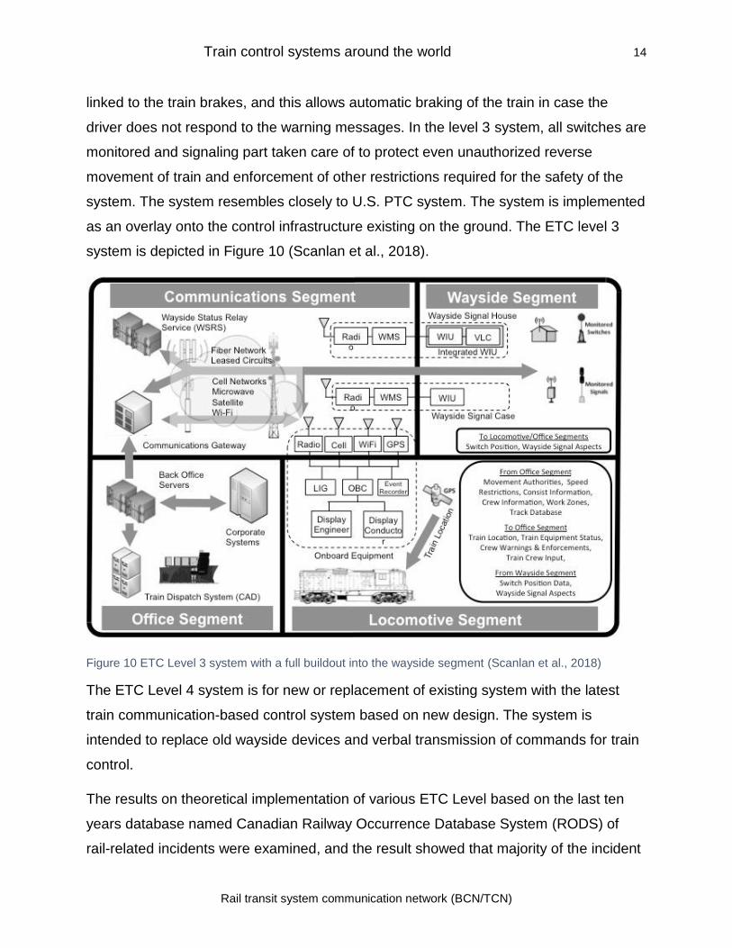
linked to the train brakes, and this allows automatic braking of the train in case the
driver does not respond to the warning messages. In the level 3 system, all switches are
monitored and signaling part taken care of to protect even unauthorized reverse
movement of train and enforcement of other restrictions required for the safety of the
system. The system resembles closely to U.S. PTC system. The system is implemented
as an overlay onto the control infrastructure existing on the ground. The ETC level 3
system is depicted in Figure 10 (Scanlan et al., 2018).
Figure 10 ETC Level 3 system with a full buildout into the wayside segment (Scanlan et al., 2018)
The ETC Level 4 system is for new or replacement of existing system with the latest
train communication-based control system based on new design. The system is
intended to replace old wayside devices and verbal transmission of commands for train
control.
The results on theoretical implementation of various ETC Level based on the last ten
years database named Canadian Railway Occurrence Database System (RODS) of
rail-related incidents were examined, and the result showed that majority of the incident
Train control systems around the world 15
Rail transit system communication network (BCN/TCN)
preventable would have prevented just with the implementation of basic ETC 1 level
system. As per the report, “The results of the ETC preventability analysis demonstrated
that between 3.55 and 5.96% of the 14,036 incidents would have been preventable at
ETC Levels 1 through 4 (leaving at a minimum, 94.04% of incidents non-ETC
preventable)” (Scanlan et al., 2018). The report provides the way forward to take a
decision on the implementation of Level of ETC system taking into account various
considerations.
2.3 European Train Control System (ETCS)
The European Train Control System is an automatic train protection system designed
for the protection of rail systems around Europe. ETCS is the signaling and control part
of the European Rail Traffic Management System (ERTMS) which handles the total
train operation and control of the rail system. The ETCS technology can be
implemented in four levels of signaling depending on the train traffic. The ETCS L0 (LS)
is for trains on non-ETCS route. The ETCS L1 (FS) can be overlaid on an existing
system to enable trains to move to cross border areas where the ETCS system supplied
by other operators are in use. The ETCS L2 is the most advanced version using a
digital wireless system for the exact location of the train and providing movement
authority directly to the train driver using an onboard computer. It is also designed to
reduce the overall maintenance cost, provide better safety, operational flexibility, and
reliability. ETCS is intended to replace incompatible safety systems used in the
European rail system.
The ETCS system consists of two parts; onboard equipment and trackside equipment.
2.3.1 ETCS Trackside Equipment
The ETCS trackside equipment includes balises, Euroloops, Radio Block Centers
(RBC), and Radio In-fill Units. The balise is a configurable transponder which is
mounted in four ft. Area. It does not require any external power supply as it gets
energized by a train passing over it. Once activated by passing train, it sends the
telegram or data back to the train as per its configuration. The balise is used in a group
of 8 balises with each balise in the group having a unique identity. Each group also has
Train control systems around the world 16
Rail transit system communication network (BCN/TCN)
a unique identity. The balise group provides direction of train movement as well as
redundancy when one balise in the group fails. (RSSB, 2010)
The Radio Block Centre (RBC) communicates with onboard ETCS equipment and is
located with other signaling and controlling equipment in the system. The transmission
uses GSM-R (Global System for Mobile Communications – Railway) radio. The data
packets have the same structure as that of balise. The Radio Block Centre is used for
monitoring interlocking and generating movement authority messages. The Radio Block
Centre messages contain restrictions and route speed. The Radio Block Centre also
provides an interface to another signaling system regarding train location etc. (RSSB,
2010)
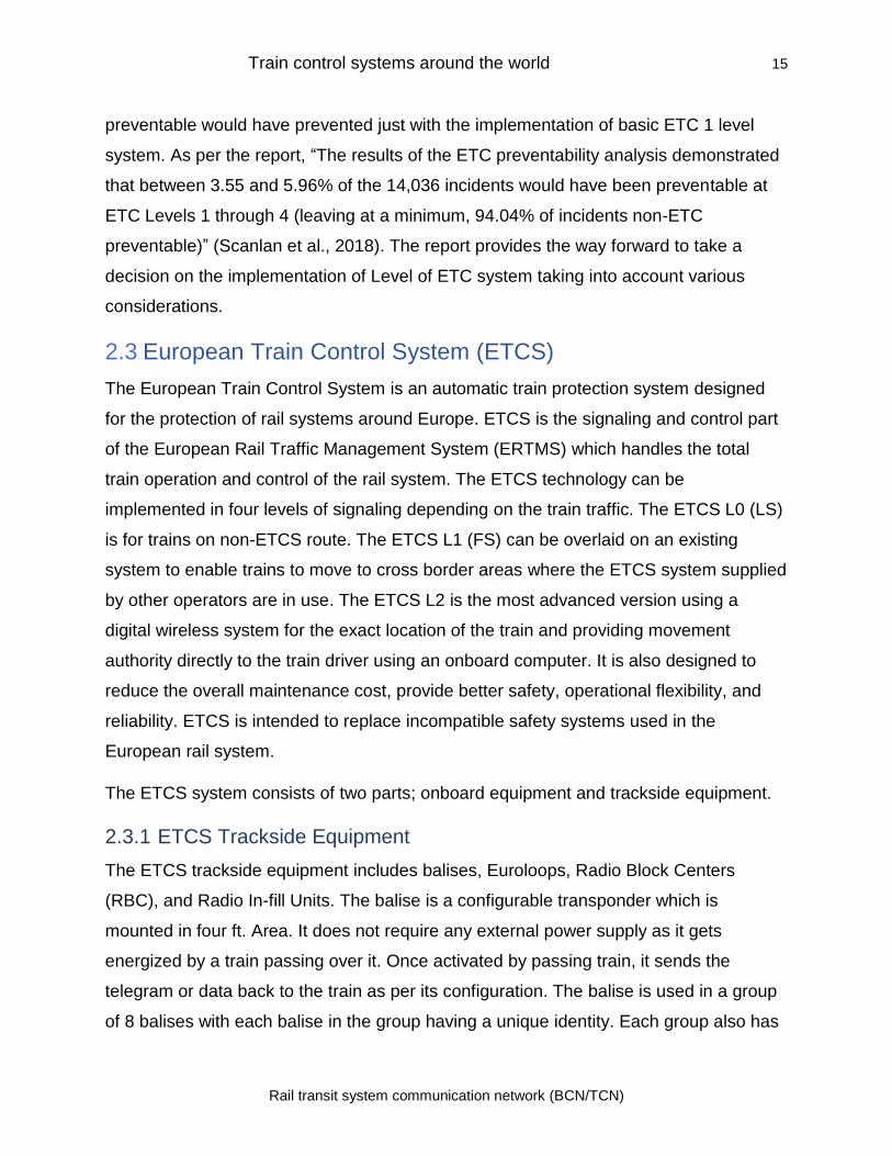
The Euroloop is a track mounted loop, used only in ETCS L1 system, to transfer
electronic messages to the train. The Radio In-fill Unit has the same function as
Euroloop but uses GSM-R radio for data transmission (RSSB, 2010). The ETCS L1
basic system using radio in-fill unit is shown in Figure 11. The ETCS system is overlaid
on top of the existing signaling system. The in-fill balise groups are located at some
distance on the approach to the signal to which it applies. It is also connected
electrically to the signal. This enables the early update to the train system. (RSSB,
2010)
Figure 11 Level 1 (with infill balise group) (RSSB, 2010)
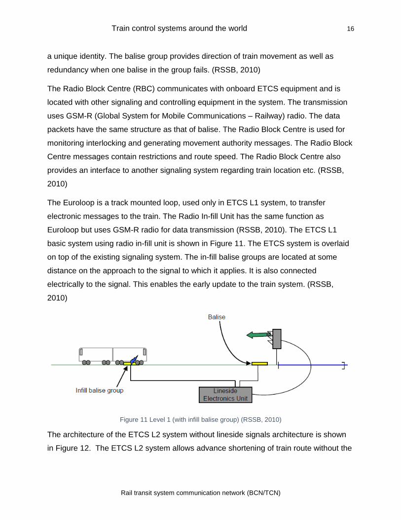
The architecture of the ETCS L2 system without lineside signals architecture is shown
in Figure 12. The ETCS L2 system allows advance shortening of train route without the
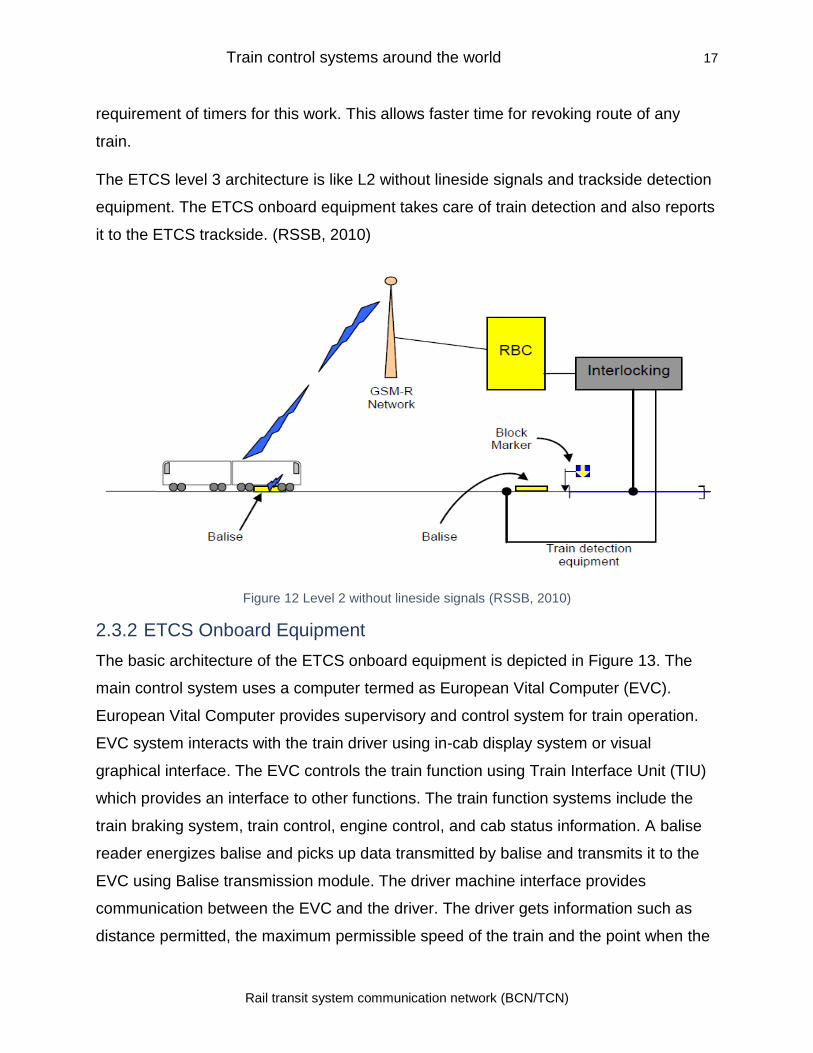
Train control systems around the world 17
Rail transit system communication network (BCN/TCN)
requirement of timers for this work. This allows faster time for revoking route of any
train.
The ETCS level 3 architecture is like L2 without lineside signals and trackside detection
equipment. The ETCS onboard equipment takes care of train detection and also reports
it to the ETCS trackside. (RSSB, 2010)
Figure 12 Level 2 without lineside signals (RSSB, 2010)
2.3.2 ETCS Onboard Equipment
The basic architecture of the ETCS onboard equipment is depicted in Figure 13. The
main control system uses a computer termed as European Vital Computer (EVC).
European Vital Computer provides supervisory and control system for train operation.
EVC system interacts with the train driver using in-cab display system or visual
graphical interface. The EVC controls the train function using Train Interface Unit (TIU)
which provides an interface to other functions. The train function systems include the
train braking system, train control, engine control, and cab status information. A balise
reader energizes balise and picks up data transmitted by balise and transmits it to the
EVC using Balise transmission module. The driver machine interface provides
communication between the EVC and the driver. The driver gets information such as
distance permitted, the maximum permissible speed of the train and the point when the
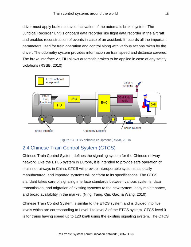
Train control systems around the world 18
Rail transit system communication network (BCN/TCN)
driver must apply brakes to avoid activation of the automatic brake system. The
Juridical Recorder Unit is onboard data recorder like flight data recorder in the aircraft
and enables reconstruction of events in case of an accident. It records all the important
parameters used for train operation and control along with various actions taken by the
driver. The odometry system provides information on train speed and distance covered.
The brake interface via TIU allows automatic brakes to be applied in case of any safety
violations (RSSB, 2010)
Figure 13 ETCS onboard equipment (RSSB, 2010)
2.4 Chinese Train Control System (CTCS)
Chinese Train Control System defines the signaling system for the Chinese railway
network. Like the ETCS system in Europe, it is intended to provide safe operation of
mainline railways in China. CTCS will provide interoperable systems as locally
manufactured, and imported systems will conform to its specifications. The CTCS
standard takes care of signaling interface standards between various systems, data
transmission, and migration of existing systems to the new system, easy maintenance,
and broad availability in the market. (Ning, Tang, Qiu, Gao, & Wang, 2010)
Chinese Train Control System is similar to the ETCS system and is divided into five
levels which are corresponding to Level 1 to level 3 of the ETCS system. CTCS level 0
is for trains having speed up to 120 km/h using the existing signaling system. The CTCS
Train control systems around the world 19
Rail transit system communication network (BCN/TCN)
level 1 trains with speed between 120 km/s to 160 km/h. The train operation in this
mode uses the onboard system without using block signals and requires the installation
of transponders on track for train location detection. Level 2 system can be radio-based
or transponder based. CTCS level 2, a points and continuous system, is continuous
control for the train with speeds of more than 200km/h but less than 250 km/h that
require automatic protection circuits on board the train. CTCS level 3 uses GSM-R for
communication and is compatible with Level 2 with the downgrade and is intended for
trains with speed between 300-350 km/h. The last level CTCS level 4 is next generation
system using long-term evolution for railway (LTE-R) for communication, train interval
control using moving block function, and train positioning system using global navigation
satellite systems (GNSSs). The Level 4 system reduces the maintenance cost as the
use of wayside is minimized. The system also allows for flexible train density on the
same line. (Junting, Jianwu, & Yongzhi, 2016)(Ning et al., 2010)
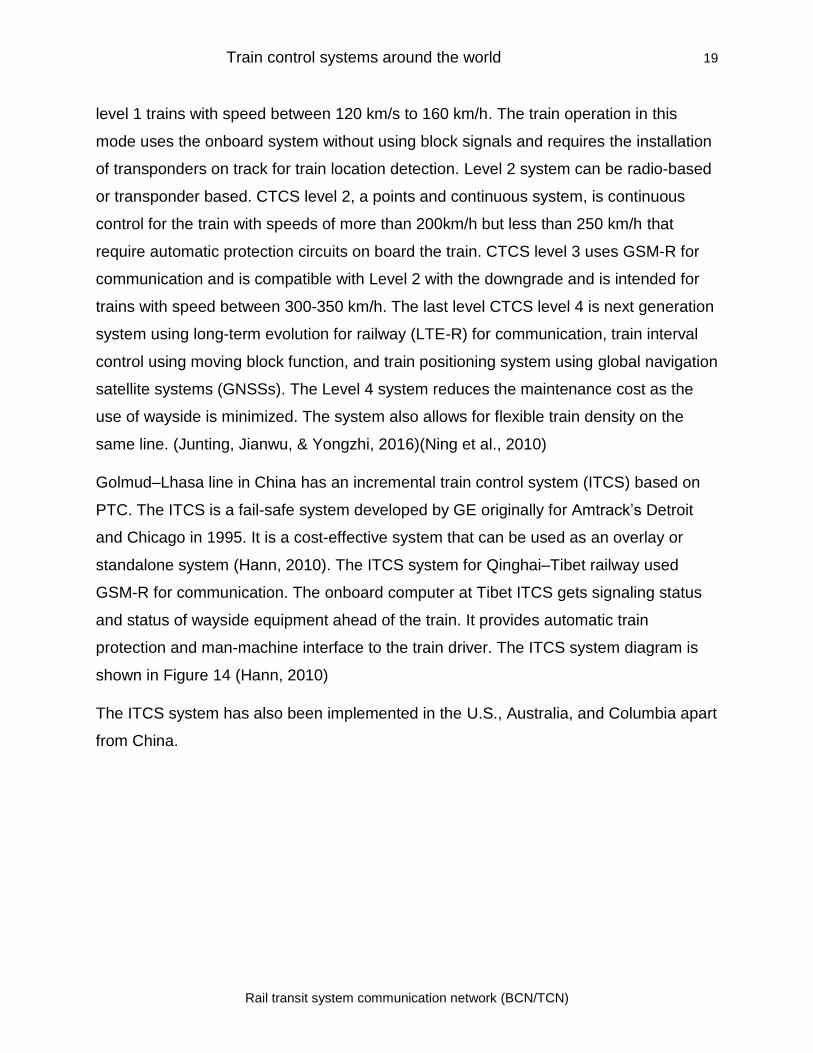
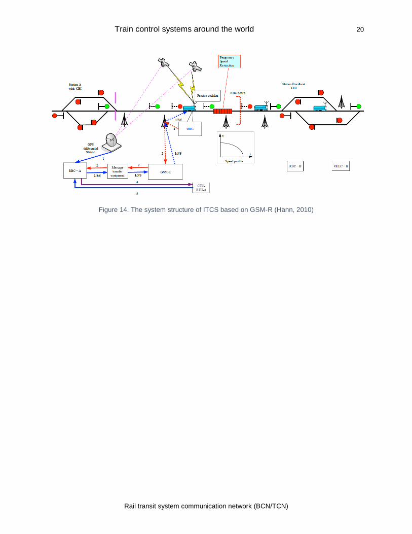
Golmud–Lhasa line in China has an incremental train control system (ITCS) based on
PTC. The ITCS is a fail-safe system developed by GE originally for Amtrack’s Detroit
and Chicago in 1995. It is a cost-effective system that can be used as an overlay or
standalone system (Hann, 2010). The ITCS system for Qinghai–Tibet railway used
GSM-R for communication. The onboard computer at Tibet ITCS gets signaling status
and status of wayside equipment ahead of the train. It provides automatic train
protection and man-machine interface to the train driver. The ITCS system diagram is
shown in Figure 14 (Hann, 2010)
The ITCS system has also been implemented in the U.S., Australia, and Columbia apart
from China.
Train control systems around the world 20
Rail transit system communication network (BCN/TCN)
Figure 14. The system structure of ITCS based on GSM-R (Hann, 2010)
3.0 Communications Based Train Control (CBTC)
Communications Based Train Control is considered as a direction of a next-generation
rail control system in the world. The system can be used in all types of railway systems
including, metro, light rail and main rail systems (Bin, Tao, Min, & Hai, 2006).
The use of a CBTC system allows trains with much closer headways than the traditional
track circuit-based systems. The ability of the CBTC system to determine the exact
location and direction of movement of trains allows safe and secure operation of the rail
system. (Pochet, Sandou, & Baro, 2017)
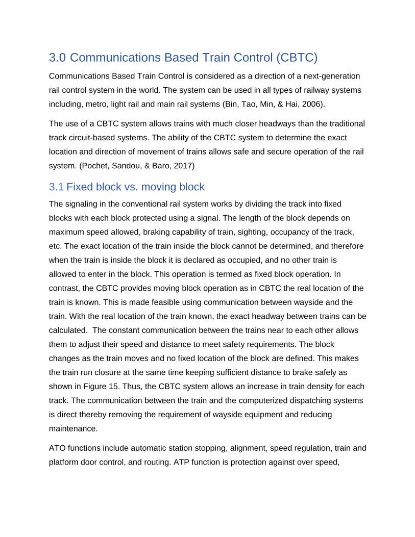
3.1 Fixed block vs. moving block
The signaling in the conventional rail system works by dividing the track into fixed
blocks with each block protected using a signal. The length of the block depends on
maximum speed allowed, braking capability of train, sighting, occupancy of the track,
etc. The exact location of the train inside the block cannot be determined, and therefore
when the train is inside the block it is declared as occupied, and no other train is
allowed to enter in the block. This operation is termed as fixed block operation. In
contrast, the CBTC provides moving block operation as in CBTC the real location of the
train is known. This is made feasible using communication between wayside and the
train. With the real location of the train known, the exact headway between trains can be
calculated. The constant communication between the trains near to each other allows
them to adjust their speed and distance to meet safety requirements. The block
changes as the train moves and no fixed location of the block are defined. This makes
the train run closure at the same time keeping sufficient distance to brake safely as
shown in Figure 15. Thus, the CBTC system allows an increase in train density for each
track. The communication between the train and the computerized dispatching systems
is direct thereby removing the requirement of wayside equipment and reducing
maintenance.
ATO functions include automatic station stopping, alignment, speed regulation, train and
platform door control, and routing. ATP function is protection against over speed,
Communications-Based Train Control 22
Rail transit system communication network (BCN/TCN)
collision, and avoiding other dangerous conditions. The ATS monitors and controls the
movements of trains for the entire system. (Ali, 2017)
Figure 15 Fixed vs. moving block (Farooq & Soler, 2017)
The CBTC system can provide various levels of automation termed as Grades of
Automation (GOA), and these grades are defined in IEC 62290-1. The grades of
operation are (F. R. Yu, 2018):
• GOA1: Manual protected operation
• GOA2: Semi-automated operation
• GOA3: Driverless operation
• GOA4: Fully automated operation
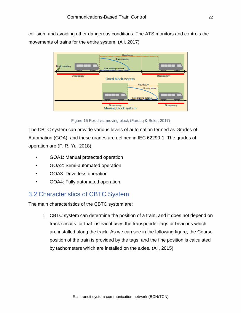
3.2 Characteristics of CBTC System
The main characteristics of the CBTC system are:
1. CBTC system can determine the position of a train, and it does not depend on
track circuits for that instead it uses the transponder tags or beacons which
are installed along the track. As we can see in the following figure, the Course
position of the train is provided by the tags, and the fine position is calculated
by tachometers which are installed on the axles. (Ali, 2015)
Communications-Based Train Control 23
Rail transit system communication network (BCN/TCN)
Figure 16 Positioning Basics in CBTC (Ali, 2015)
Figure 17 CBTC Positioning Characteristics
(Ali, 2015)
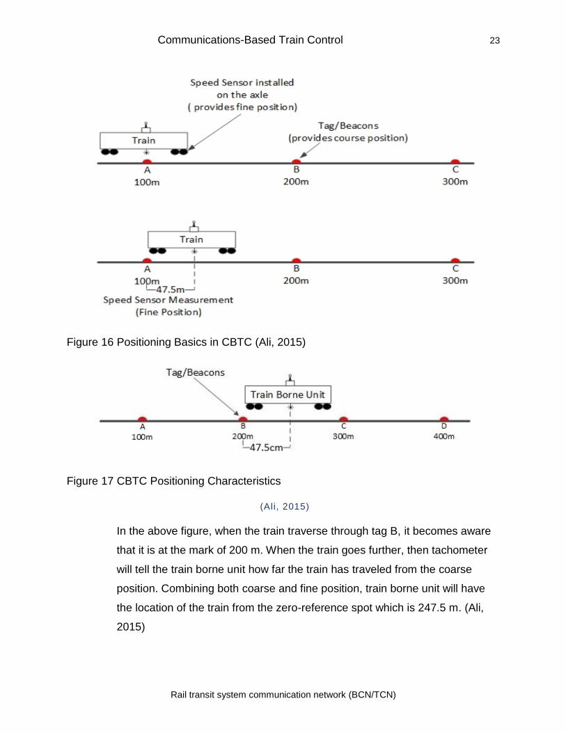
In the above figure, when the train traverse through tag B, it becomes aware
that it is at the mark of 200 m. When the train goes further, then tachometer
will tell the train borne unit how far the train has traveled from the coarse
position. Combining both coarse and fine position, train borne unit will have
the location of the train from the zero-reference spot which is 247.5 m. (Ali,
2015)
Communications-Based Train Control 24
Rail transit system communication network (BCN/TCN)
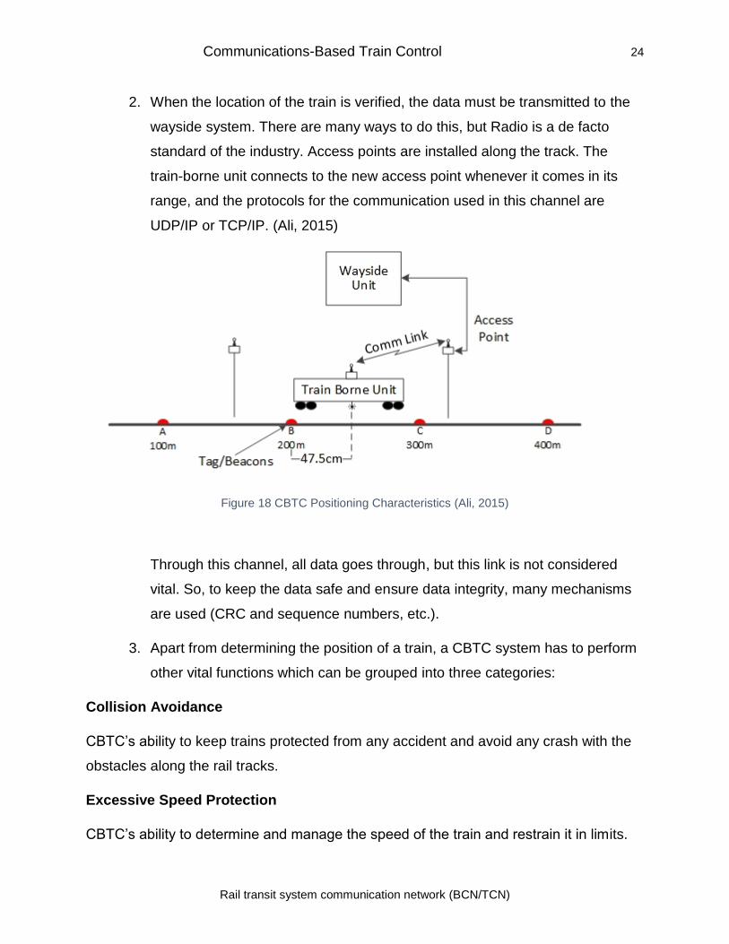
2. When the location of the train is verified, the data must be transmitted to the
wayside system. There are many ways to do this, but Radio is a de facto
standard of the industry. Access points are installed along the track. The
train-borne unit connects to the new access point whenever it comes in its
range, and the protocols for the communication used in this channel are
UDP/IP or TCP/IP. (Ali, 2015)
Figure 18 CBTC Positioning Characteristics (Ali, 2015)
Through this channel, all data goes through, but this link is not considered
vital. So, to keep the data safe and ensure data integrity, many mechanisms
are used (CRC and sequence numbers, etc.).
3. Apart from determining the position of a train, a CBTC system has to perform
other vital functions which can be grouped into three categories:
Collision Avoidance
CBTC’s ability to keep trains protected from any accident and avoid any crash with the
obstacles along the rail tracks.
Excessive Speed Protection
CBTC’s ability to determine and manage the speed of the train and restrain it in limits.
Communications-Based Train Control 25
Rail transit system communication network (BCN/TCN)
Other Protections
It is important for CBTC to access all the subsystems present in whole CBTC
architecture to execute its functions properly. So, network consistency and data
accessibility must be established. All the processors and subsystems in CBTC are
tightly integrated.
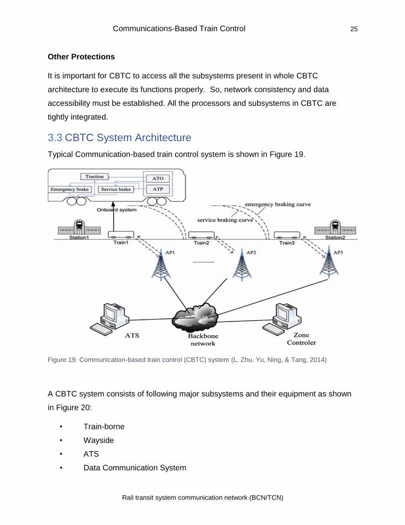
3.3 CBTC System Architecture
Typical Communication-based train control system is shown in Figure 19.
Figure 19. Communication-based train control (CBTC) system (L. Zhu, Yu, Ning, & Tang, 2014)
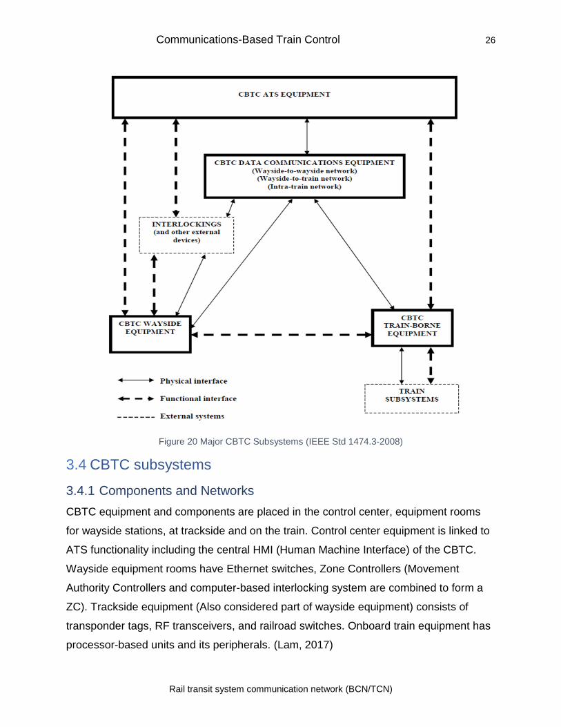
A CBTC system consists of following major subsystems and their equipment as shown
in Figure 20:
• Train-borne
• Wayside
• ATS
• Data Communication System
Communications-Based Train Control 26
Rail transit system communication network (BCN/TCN)
Figure 20 Major CBTC Subsystems (IEEE Std 1474.3-2008)
3.4 CBTC subsystems
3.4.1 Components and Networks
CBTC equipment and components are placed in the control center, equipment rooms
for wayside stations, at trackside and on the train. Control center equipment is linked to
ATS functionality including the central HMI (Human Machine Interface) of the CBTC.
Wayside equipment rooms have Ethernet switches, Zone Controllers (Movement
Authority Controllers and computer-based interlocking system are combined to form a
ZC). Trackside equipment (Also considered part of wayside equipment) consists of
transponder tags, RF transceivers, and railroad switches. Onboard train equipment has
processor-based units and its peripherals. (Lam, 2017)
Communications-Based Train Control 27
Rail transit system communication network (BCN/TCN)
3.4.2 Vehicle Onboard components
The onboard apparatus consists of Onboard Control Unit (OBCU). This system
transmits train control info to the wayside system. On-board ATP and ATO subsystems
are segments of aboard ATC functionalities. The ATO subsystem provides the
functionality of automation in the train operation. These operations include starting,
accelerating, braking and stopping the train. ATP system supervises the speed and
takes control in case of any failure or mistake by the driver.
Data Communication System components (DCS) are also present. It consists of both
hardware and software. Radios and antennas are part of this. Communication between
wayside and train system is dependent on this subsystem. It will be discussed in detail
in the Data communication section.
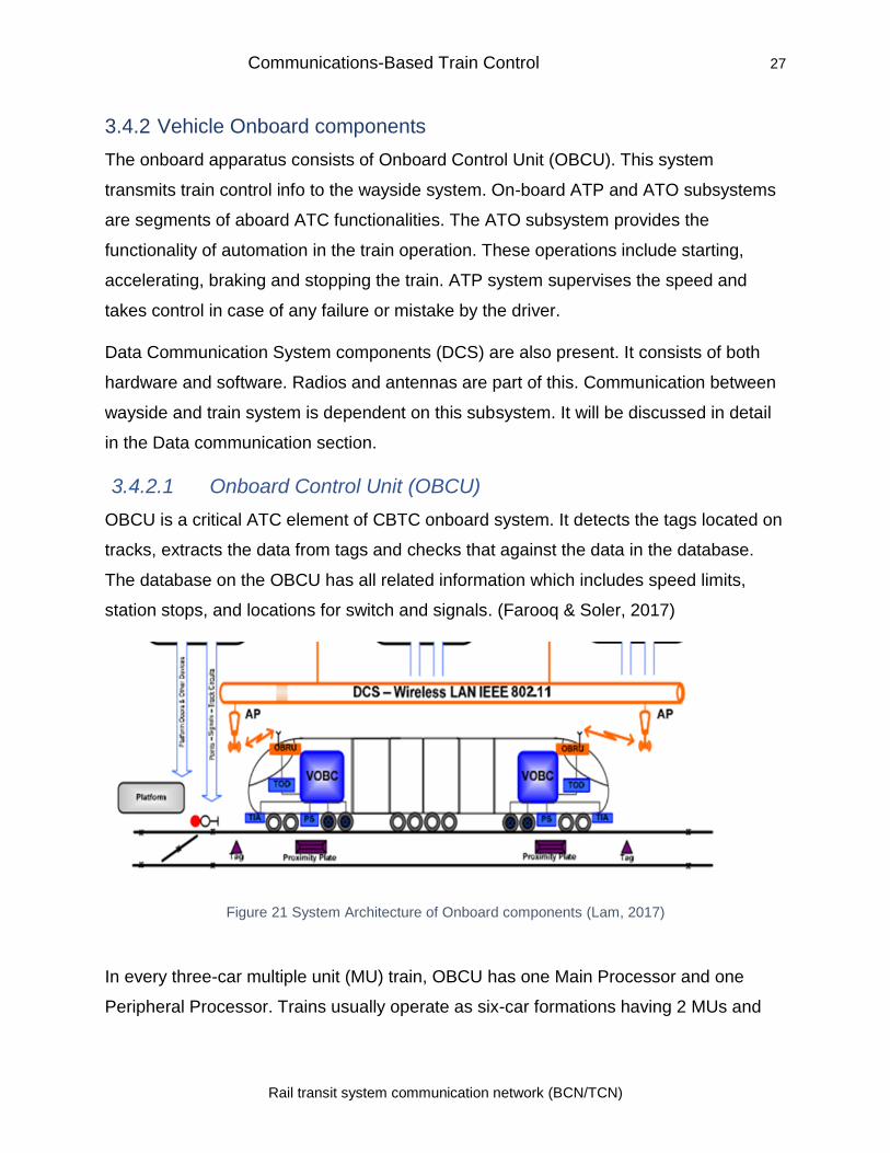
3.4.2.1 Onboard Control Unit (OBCU)
OBCU is a critical ATC element of CBTC onboard system. It detects the tags located on
tracks, extracts the data from tags and checks that against the data in the database.
The database on the OBCU has all related information which includes speed limits,
station stops, and locations for switch and signals. (Farooq & Soler, 2017)
Figure 21 System Architecture of Onboard components (Lam, 2017)
In every three-car multiple unit (MU) train, OBCU has one Main Processor and one
Peripheral Processor. Trains usually operate as six-car formations having 2 MUs and
Communications-Based Train Control 28
Rail transit system communication network (BCN/TCN)
therefore having OBCU (also called VOBC) at each end. Having redundant VOBCs
provide high availability. (Lam, 2017)
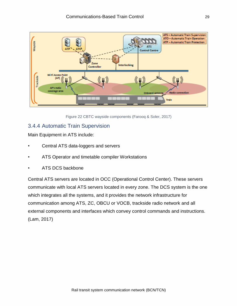
3.4.3 Wayside components
Figure 22 shows typical wayside elements of CBTC system. Zone Controller (ZC) is a
critical part of the wayside system. A zone controller controls a specific area in rail
networks. The Zone controller divides the track into multiple zones where each zone
has an independent zone controller. ZC is the receiver for all location information sent
from the trains in its area. The main operation of the zone controller is to set route by
commands delivered from the Central control system. So, ZC maintains safe separation
of the train. Wayside ATO and ATP subsystems are also typically present in ZC. ATP is
the subsystem which determines the movement of Authority of the train. Computer-
based interlocking (CI) system is responsible for interlocking functions such as route
setting, point movement, locking and releasing. Mostly, CI is embedded in the ATP
subsystem. (Farooq & Soler, 2017)
As we can see in the above figure, trackside has many Wi-Fi access points (APs). Each
unit has 1 AP. Trains communicate with the APs via a radio connection. APs are then
able to connect with the wayside system. Movement Authority Controller is located at
Control center office and wayside stations. It is a computer-based controller, and it
performs the following functions (Keevill, 2013)::
• Movement Authority Controller monitors the data collected by the Interlocking
systems like route setting and locking and switch point.
• Check the location of all the train operating in its control area.
• Send Movement Authority Limit on the basis of the above information to all
the trains in its area.
Communications-Based Train Control 29
Rail transit system communication network (BCN/TCN)
Figure 22 CBTC wayside components (Farooq & Soler, 2017)
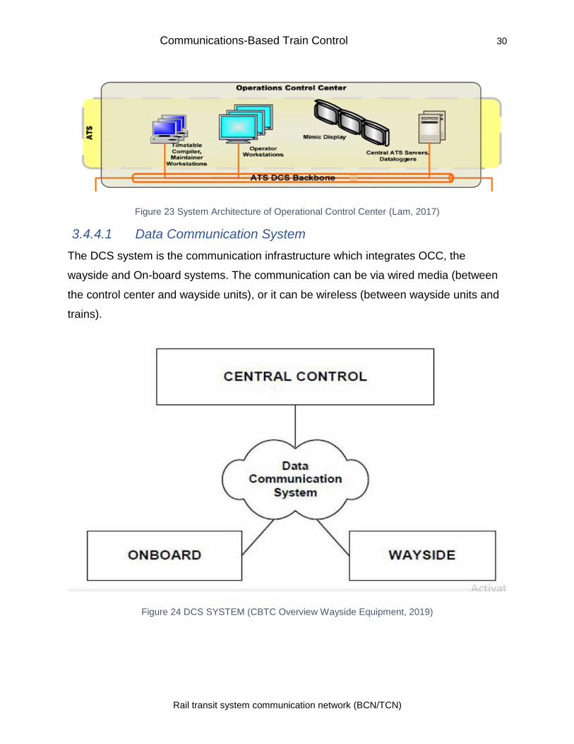
3.4.4 Automatic Train Supervision
Main Equipment in ATS include:
• Central ATS data-loggers and servers
• ATS Operator and timetable compiler Workstations
• ATS DCS backbone
Central ATS servers are located in OCC (Operational Control Center). These servers
communicate with local ATS servers located in every zone. The DCS system is the one
which integrates all the systems, and it provides the network infrastructure for
communication among ATS, ZC, OBCU or VOCB, trackside radio network and all
external components and interfaces which convey control commands and instructions.
(Lam, 2017)
Communications-Based Train Control 30
Rail transit system communication network (BCN/TCN)
Figure 23 System Architecture of Operational Control Center (Lam, 2017)
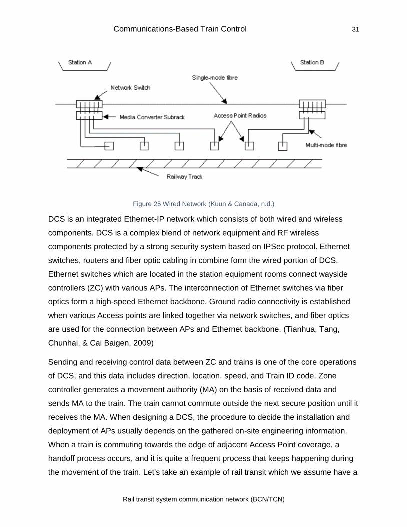
3.4.4.1 Data Communication System
The DCS system is the communication infrastructure which integrates OCC, the
wayside and On-board systems. The communication can be via wired media (between
the control center and wayside units), or it can be wireless (between wayside units and
trains).
Figure 24 DCS SYSTEM (CBTC Overview Wayside Equipment, 2019)
Communications-Based Train Control 31
Rail transit system communication network (BCN/TCN)
Figure 25 Wired Network (Kuun & Canada, n.d.)
DCS is an integrated Ethernet-IP network which consists of both wired and wireless
components. DCS is a complex blend of network equipment and RF wireless
components protected by a strong security system based on IPSec protocol. Ethernet
switches, routers and fiber optic cabling in combine form the wired portion of DCS.
Ethernet switches which are located in the station equipment rooms connect wayside
controllers (ZC) with various APs. The interconnection of Ethernet switches via fiber
optics form a high-speed Ethernet backbone. Ground radio connectivity is established
when various Access points are linked together via network switches, and fiber optics
are used for the connection between APs and Ethernet backbone. (Tianhua, Tang,
Chunhai, & Cai Baigen, 2009)
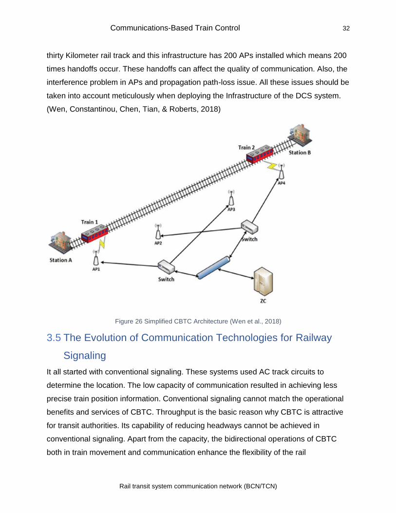
Sending and receiving control data between ZC and trains is one of the core operations
of DCS, and this data includes direction, location, speed, and Train ID code. Zone
controller generates a movement authority (MA) on the basis of received data and
sends MA to the train. The train cannot commute outside the next secure position until it
receives the MA. When designing a DCS, the procedure to decide the installation and
deployment of APs usually depends on the gathered on-site engineering information.
When a train is commuting towards the edge of adjacent Access Point coverage, a
handoff process occurs, and it is quite a frequent process that keeps happening during
the movement of the train. Let's take an example of rail transit which we assume have a
Communications-Based Train Control 32
Rail transit system communication network (BCN/TCN)
thirty Kilometer rail track and this infrastructure has 200 APs installed which means 200
times handoffs occur. These handoffs can affect the quality of communication. Also, the
interference problem in APs and propagation path-loss issue. All these issues should be
taken into account meticulously when deploying the Infrastructure of the DCS system.
(Wen, Constantinou, Chen, Tian, & Roberts, 2018)
Figure 26 Simplified CBTC Architecture (Wen et al., 2018)
3.5 The Evolution of Communication Technologies for Railway
Signaling
It all started with conventional signaling. These systems used AC track circuits to
determine the location. The low capacity of communication resulted in achieving less
precise train position information. Conventional signaling cannot match the operational
benefits and services of CBTC. Throughput is the basic reason why CBTC is attractive
for transit authorities. Its capability of reducing headways cannot be achieved in
conventional signaling. Apart from the capacity, the bidirectional operations of CBTC
both in train movement and communication enhance the flexibility of the rail
Communications-Based Train Control 33
Rail transit system communication network (BCN/TCN)
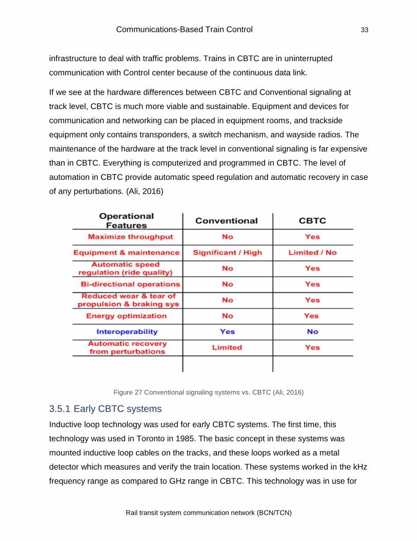
infrastructure to deal with traffic problems. Trains in CBTC are in uninterrupted
communication with Control center because of the continuous data link.
If we see at the hardware differences between CBTC and Conventional signaling at
track level, CBTC is much more viable and sustainable. Equipment and devices for
communication and networking can be placed in equipment rooms, and trackside
equipment only contains transponders, a switch mechanism, and wayside radios. The
maintenance of the hardware at the track level in conventional signaling is far expensive
than in CBTC. Everything is computerized and programmed in CBTC. The level of
automation in CBTC provide automatic speed regulation and automatic recovery in case
of any perturbations. (Ali, 2016)
Figure 27 Conventional signaling systems vs. CBTC (Ali, 2016)
3.5.1 Early CBTC systems
Inductive loop technology was used for early CBTC systems. The first time, this
technology was used in Toronto in 1985. The basic concept in these systems was
mounted inductive loop cables on the tracks, and these loops worked as a metal
detector which measures and verify the train location. These systems worked in the kHz
frequency range as compared to GHz range in CBTC. This technology was in use for
Communications-Based Train Control 34
Rail transit system communication network (BCN/TCN)
railways for almost three decades, but the difficulty in establishing such infrastructure
and its vulnerability with regards to security were some of the many drawbacks because
of which there was a need to switch to more efficient technology.
3.5.2 Radio-based CBTC:
Bombardier was the first supplier for CBTC system. They implemented it in Francisco
Airport in 2003. Radio-based CBTC systems can be split into two groups. Those which
are based on older technology, i.e., leaky waveguide and those which are based on
COTS technologies.
3.5.2.1 Custom and Commercial-off-the-shelf (COTS) radio:
Early CBTC systems were custom solutions and developed for specific requirements for
a particular project. One problem with CBTC systems is that they are weak in
interoperability. Once a supplier is selected, then the transit agency depends completely
on the supplier. Later on, no other controller can be used. Although, this trend is now
changing gradually as transit agencies are making the suppliers follow the IEEE, APTA,
AREMA and other defined standards. An early CBTC example is Model 2400 solution
which was developed and installed by Bombardier. It was leaky waveguide based. It
was one hundred times expensive than Wi-Fi-based solution. Later on, Bombardier
switched to spread-spectrum technology, but it was still ten times costly than Wi-Fi
solution. (Farooq & Soler, 2017)
3.5.2.2 Leaky waveguide
The leaky waveguide is also called leaky cable or feeder. Leaky coaxial cables are used
as a continuous radiating structure, and it allows radio signals to leak in or out. It has
been used and deployed in the past for decades. It offers certain benefits. In Leaky
waveguide, open-air communication is quite limited because it occurs between a small
distance around 0.3-0.6 m and the equipment include aboard receiver antenna and
leaky cable. Therefore, less interference and less propagation loss. Some rail transits
have applied it in combination with radio communication. At such rail transits, the leaky
waveguide is applied where there are chances of more interference like in open air and
radio communication in tunnels. Combining the two technologies and switching
Communications-Based Train Control 35
Rail transit system communication network (BCN/TCN)
between them is a big task. The drawback of leaky cable technology is that it is
expensive and its deployment and maintenance is quite difficult. Moreover, the leaky
waveguide is susceptible to environmental factors like snow and signal degradation can
occur. For these issues, it has not been very reasonable for the CBTC. (Farooq & Soler,
2017)
.
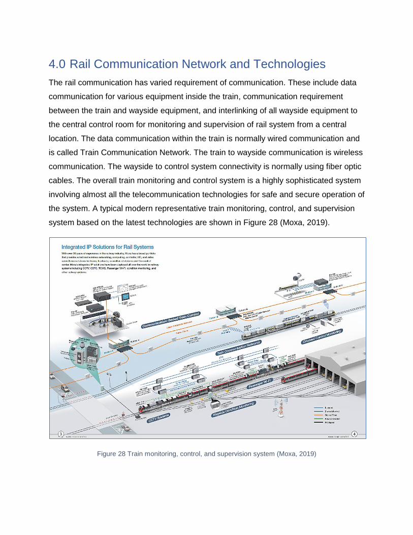
4.0 Rail Communication Network and Technologies
The rail communication has varied requirement of communication. These include data
communication for various equipment inside the train, communication requirement
between the train and wayside equipment, and interlinking of all wayside equipment to
the central control room for monitoring and supervision of rail system from a central
location. The data communication within the train is normally wired communication and
is called Train Communication Network. The train to wayside communication is wireless
communication. The wayside to control system connectivity is normally using fiber optic
cables. The overall train monitoring and control system is a highly sophisticated system
involving almost all the telecommunication technologies for safe and secure operation of
the system. A typical modern representative train monitoring, control, and supervision
system based on the latest technologies are shown in Figure 28 (Moxa, 2019).
Figure 28 Train monitoring, control, and supervision system (Moxa, 2019)
Rail Communication Network and Technologies 37
Rail transit system communication network (BCN/TCN)
The modern train system requires broadband access for passengers to view videos, TV,
latest news and Internet access. This requires large bandwidth as well as high data
speed which is a challenge especially the high-speed trains moving at speeds greater
than 350 Kmph. (Masson & Berbineau, 2017a)
This section will look into the various technologies used for TCN and wireless
communication.
4.1 General Requirements
Reliable voice and data communication are prerequisites to the safe operation of the
train system. The data communication needs to be error-free and delivered on time else
the automated brakes mechanism brings automotive to halt for safety.
This requires low latency and error-free performance from wireless system deployed
(Cortes Alcala, Lin, He, & Briso-Rodriguez, 2011). Also, the system needs to facilitate
Video transmission, Emergency group communications and security (Masson &
Berbineau, 2017b). To provide reliable and low latency communication over wireless
system mandates the use of a dedicated frequency band for rail communication.
Europe, Asia, Australia, and North Africa all use GSM-R (Global System for Mobile
Communications – Railway) frequencies in 900 MHz band. U.S uses 220 MHz for its
PTC system. (DIGI, 2018)
The basic requirements of a rail communication system for TCN are (DIGI, 2018):
• Network Performance and Resilience: The cellular system with dedicated
frequency band can provide this.
• Rugged Devices – Trains and rail wayside are challenging environments for
deployment of communications systems. This requires ruggedized housing
and the system that can withstand extremes of vibration, shock, temperature,
and humidity.
• Long Life: The equipment in the rail environment are distributed over a large
area and therefore repairing them is a costly affair, and this requires reliable
operation and long life with minimum failures from the equipment side.
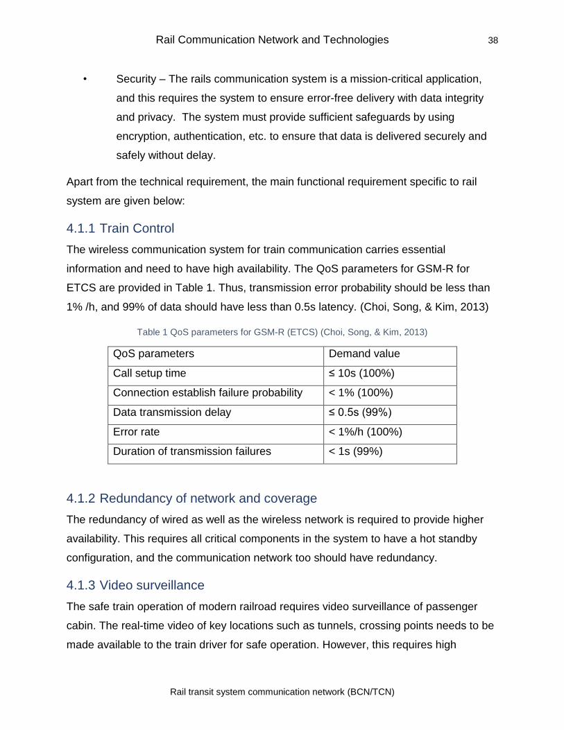
Rail Communication Network and Technologies 38
Rail transit system communication network (BCN/TCN)
• Security – The rails communication system is a mission-critical application,
and this requires the system to ensure error-free delivery with data integrity
and privacy. The system must provide sufficient safeguards by using
encryption, authentication, etc. to ensure that data is delivered securely and
safely without delay.
Apart from the technical requirement, the main functional requirement specific to rail
system are given below:
4.1.1 Train Control
The wireless communication system for train communication carries essential
information and need to have high availability. The QoS parameters for GSM-R for
ETCS are provided in Table 1. Thus, transmission error probability should be less than
1% /h, and 99% of data should have less than 0.5s latency. (Choi, Song, & Kim, 2013)
Table 1 QoS parameters for GSM-R (ETCS) (Choi, Song, & Kim, 2013)
QoS parameters Demand value
Call setup time ≤ 10s (100%)
Connection establish failure probability < 1% (100%)
Data transmission delay ≤ 0.5s (99%)
Error rate < 1%/h (100%)
Duration of transmission failures < 1s (99%)
4.1.2 Redundancy of network and coverage
The redundancy of wired as well as the wireless network is required to provide higher
availability. This requires all critical components in the system to have a hot standby
configuration, and the communication network too should have redundancy.
4.1.3 Video surveillance
The safe train operation of modern railroad requires video surveillance of passenger
cabin. The real-time video of key locations such as tunnels, crossing points needs to be
made available to the train driver for safe operation. However, this requires high
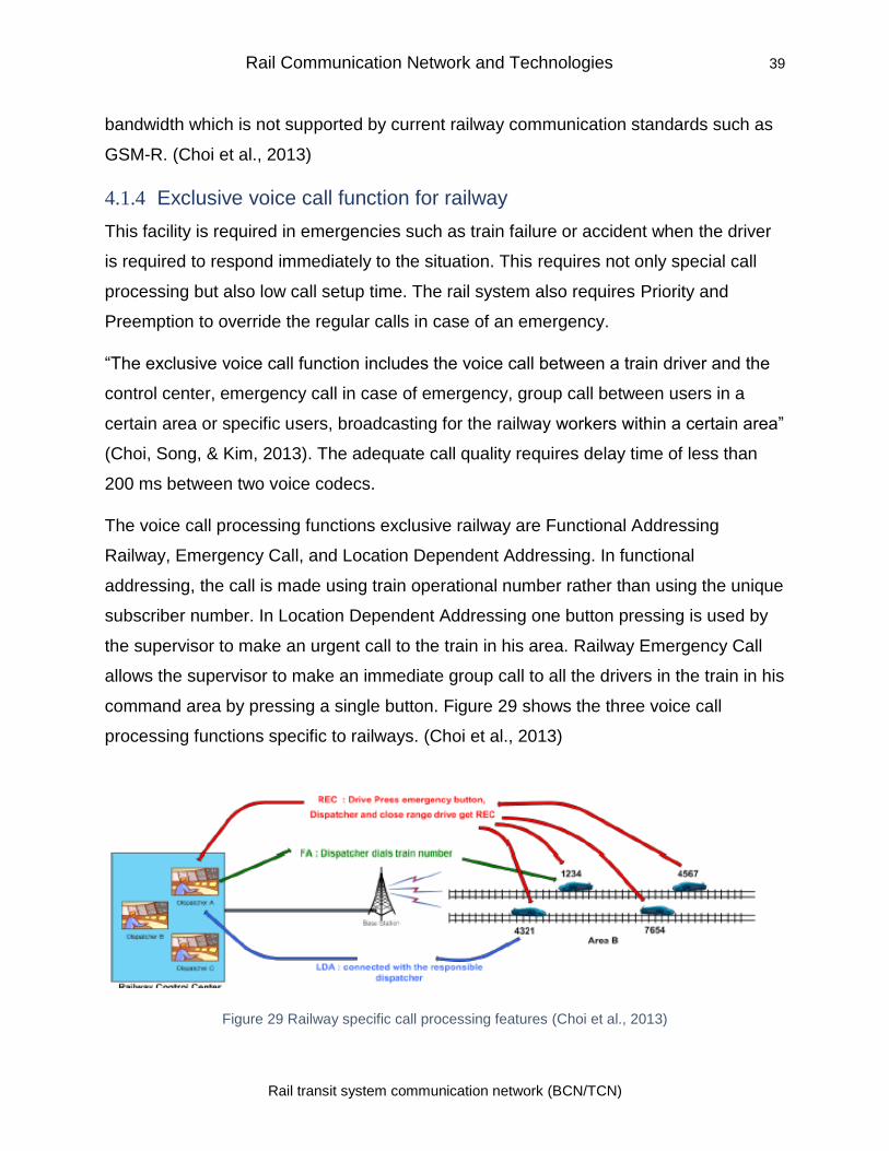
Rail Communication Network and Technologies 39
Rail transit system communication network (BCN/TCN)
bandwidth which is not supported by current railway communication standards such as
GSM-R. (Choi et al., 2013)
4.1.4 Exclusive voice call function for railway
This facility is required in emergencies such as train failure or accident when the driver
is required to respond immediately to the situation. This requires not only special call
processing but also low call setup time. The rail system also requires Priority and
Preemption to override the regular calls in case of an emergency.
“The exclusive voice call function includes the voice call between a train driver and the
control center, emergency call in case of emergency, group call between users in a
certain area or specific users, broadcasting for the railway workers within a certain area”
(Choi, Song, & Kim, 2013). The adequate call quality requires delay time of less than
200 ms between two voice codecs.
The voice call processing functions exclusive railway are Functional Addressing
Railway, Emergency Call, and Location Dependent Addressing. In functional
addressing, the call is made using train operational number rather than using the unique
subscriber number. In Location Dependent Addressing one button pressing is used by
the supervisor to make an urgent call to the train in his area. Railway Emergency Call
allows the supervisor to make an immediate group call to all the drivers in the train in his
command area by pressing a single button. Figure 29 shows the three voice call
processing functions specific to railways. (Choi et al., 2013)
Figure 29 Railway specific call processing features (Choi et al., 2013)
Rail Communication Network and Technologies 40
Rail transit system communication network (BCN/TCN)
4.2 Train Communication Network (TCN)
The Train Communication Network consists of a system to connect various electronic
devices on board the trains and communicating the data collected to Train Control and
Management System (TCMS). When the first electronic monitoring and control systems
were introduced for train monitoring and control, the individual system was hardwired
directly to the control system using dedicated wiring (Neil, 2012). As the number of
systems increased the cost of wiring went up, and the approach was not scalable. The
serial communication provided a solution to the problem by reducing the number of
wires and allowing all the systems to transmit data on a single bus which led to a
reduction in the cost and complexity of cabling in rail communication. (Holmberg, 2016)
However, the use of proprietary serial technologies did not allow equipment
interoperability and to sort out this issue standardization was undertaken by
International Electrical Commission (IEC). The standard for Train Communication
Network (IEC 61375-1) was published by the IEC in collaboration with the International
Railway Union(UIC) along with UIC CODE 556 leaflet (Information transmission in the
train) (Schafers & Hans, 2000). Train Communication Network standard IEC 61375-1
specifies the standard for exchange of data between various systems in the network
with the aim of interoperability between various equipment (Park & Lee, 1998). As per
Schafers & Hans (2000) “UIC 556 and the accompanying UIC codes define the
operator's view on the train, the framework for the coordination of the different
applications and the operational handling to ensure interoperability between vehicles
from different manufacture” (Schafers & Hans, 2000).
The IEC 61375-1 TCN standard provides hardware specifications, MAC and Link layer
protocols and defines a protocol for inter-link communication. The standard also
provides higher level real-time protocols for a node to node data exchange. Thus TCN
provides a methodology of data exchange between equipment and control systems for
Train Control and Management. (Holmberg, 2016)
TCN standard (IEC 61375-1) specifies two network buses, Wired Train Bus (WTB) (IEC
61375-2-1:2012, 2012a) and a Multi-function Vehicle Bus (MVB) (IEC 61375-2-1:2012,
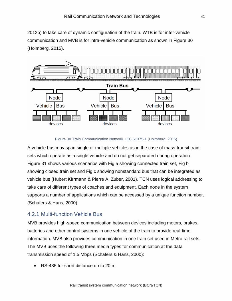
Rail Communication Network and Technologies 41
Rail transit system communication network (BCN/TCN)
2012b) to take care of dynamic configuration of the train. WTB is for inter-vehicle
communication and MVB is for intra-vehicle communication as shown in Figure 30
(Holmberg, 2015).
Figure 30 Train Communication Network. IEC 61375-1 (Holmberg, 2015)
A vehicle bus may span single or multiple vehicles as in the case of mass-transit train-
sets which operate as a single vehicle and do not get separated during operation.
Figure 31 shows various scenarios with Fig a showing connected train set, Fig b
showing closed train set and Fig c showing nonstandard bus that can be integrated as
vehicle bus (Hubert Kirrmann & Pierre A. Zuber, 2001). TCN uses logical addressing to
take care of different types of coaches and equipment. Each node in the system
supports a number of applications which can be accessed by a unique function number.
(Schafers & Hans, 2000)
4.2.1 Multi-function Vehicle Bus
MVB provides high-speed communication between devices including motors, brakes,
batteries and other control systems in one vehicle of the train to provide real-time
information. MVB also provides communication in one train set used in Metro rail sets.
The MVB uses the following three media types for communication at the data
transmission speed of 1.5 Mbps (Schafers & Hans, 2000):
• RS-485 for short distance up to 20 m.
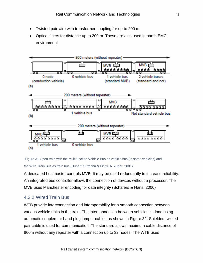
Rail Communication Network and Technologies 42
Rail transit system communication network (BCN/TCN)
• Twisted pair wire with transformer coupling for up to 200 m
• Optical fibers for distance up to 200 m. These are also used in harsh EMC
environment
Figure 31 Open train with the Multifunction Vehicle Bus as vehicle bus (in some vehicles) and
the Wire Train Bus as train bus (Hubert Kirrmann & Pierre A. Zuber, 2001)
A dedicated bus master controls MVB. It may be used redundantly to increase reliability.
An integrated bus controller allows the connection of devices without a processor. The
MVB uses Manchester encoding for data integrity (Schafers & Hans, 2000)
4.2.2 Wired Train Bus
WTB provide interconnection and interoperability for a smooth connection between
various vehicle units in the train. The interconnection between vehicles is done using
automatic couplers or hand plug jumper cables as shown in Figure 32. Shielded twisted
pair cable is used for communication. The standard allows maximum cable distance of
860m without any repeater with a connection up to 32 nodes. The WTB uses
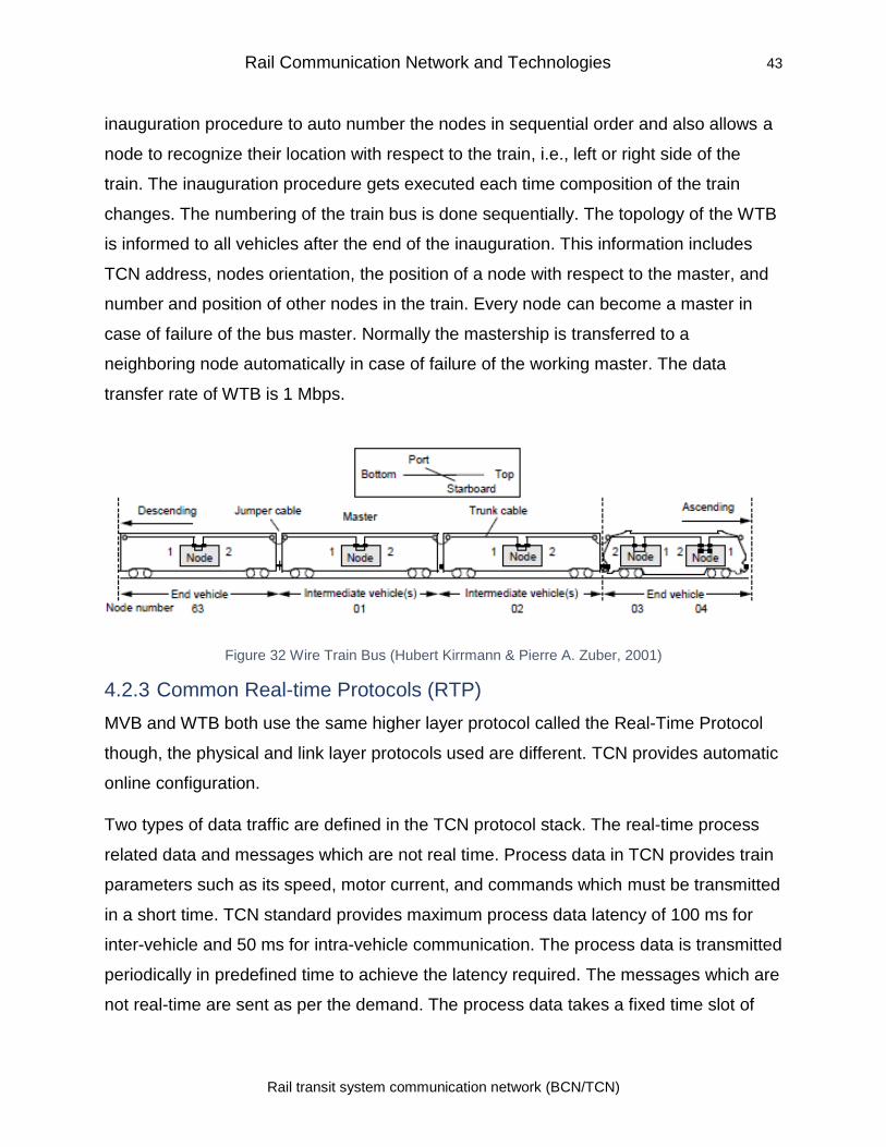
Rail Communication Network and Technologies 43
Rail transit system communication network (BCN/TCN)
inauguration procedure to auto number the nodes in sequential order and also allows a
node to recognize their location with respect to the train, i.e., left or right side of the
train. The inauguration procedure gets executed each time composition of the train
changes. The numbering of the train bus is done sequentially. The topology of the WTB
is informed to all vehicles after the end of the inauguration. This information includes
TCN address, nodes orientation, the position of a node with respect to the master, and
number and position of other nodes in the train. Every node can become a master in
case of failure of the bus master. Normally the mastership is transferred to a
neighboring node automatically in case of failure of the working master. The data
transfer rate of WTB is 1 Mbps.
Figure 32 Wire Train Bus (Hubert Kirrmann & Pierre A. Zuber, 2001)
4.2.3 Common Real-time Protocols (RTP)
MVB and WTB both use the same higher layer protocol called the Real-Time Protocol
though, the physical and link layer protocols used are different. TCN provides automatic
online configuration.
Two types of data traffic are defined in the TCN protocol stack. The real-time process
related data and messages which are not real time. Process data in TCN provides train
parameters such as its speed, motor current, and commands which must be transmitted
in a short time. TCN standard provides maximum process data latency of 100 ms for
inter-vehicle and 50 ms for intra-vehicle communication. The process data is transmitted
periodically in predefined time to achieve the latency required. The messages which are
not real-time are sent as per the demand. The process data takes a fixed time slot of
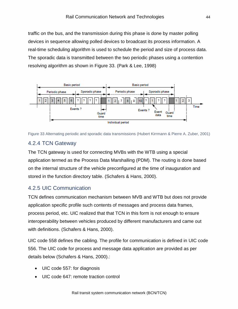
Rail Communication Network and Technologies 44
Rail transit system communication network (BCN/TCN)
traffic on the bus, and the transmission during this phase is done by master polling
devices in sequence allowing polled devices to broadcast its process information. A
real-time scheduling algorithm is used to schedule the period and size of process data.
The sporadic data is transmitted between the two periodic phases using a contention
resolving algorithm as shown in Figure 33. (Park & Lee, 1998)
Figure 33 Alternating periodic and sporadic data transmissions (Hubert Kirrmann & Pierre A. Zuber, 2001)
4.2.4 TCN Gateway
The TCN gateway is used for connecting MVBs with the WTB using a special
application termed as the Process Data Marshalling (PDM). The routing is done based
on the internal structure of the vehicle preconfigured at the time of inauguration and
stored in the function directory table. (Schafers & Hans, 2000).
4.2.5 UIC Communication
TCN defines communication mechanism between MVB and WTB but does not provide
application specific profile such contents of messages and process data frames,
process period, etc. UIC realized that that TCN in this form is not enough to ensure
interoperability between vehicles produced by different manufacturers and came out
with definitions. (Schafers & Hans, 2000).
UIC code 558 defines the cabling. The profile for communication is defined in UIC code
556. The UIC code for process and message data application are provided as per
details below (Schafers & Hans, 2000).:
• UIC code 557: for diagnosis
• UIC code 647: remote traction control
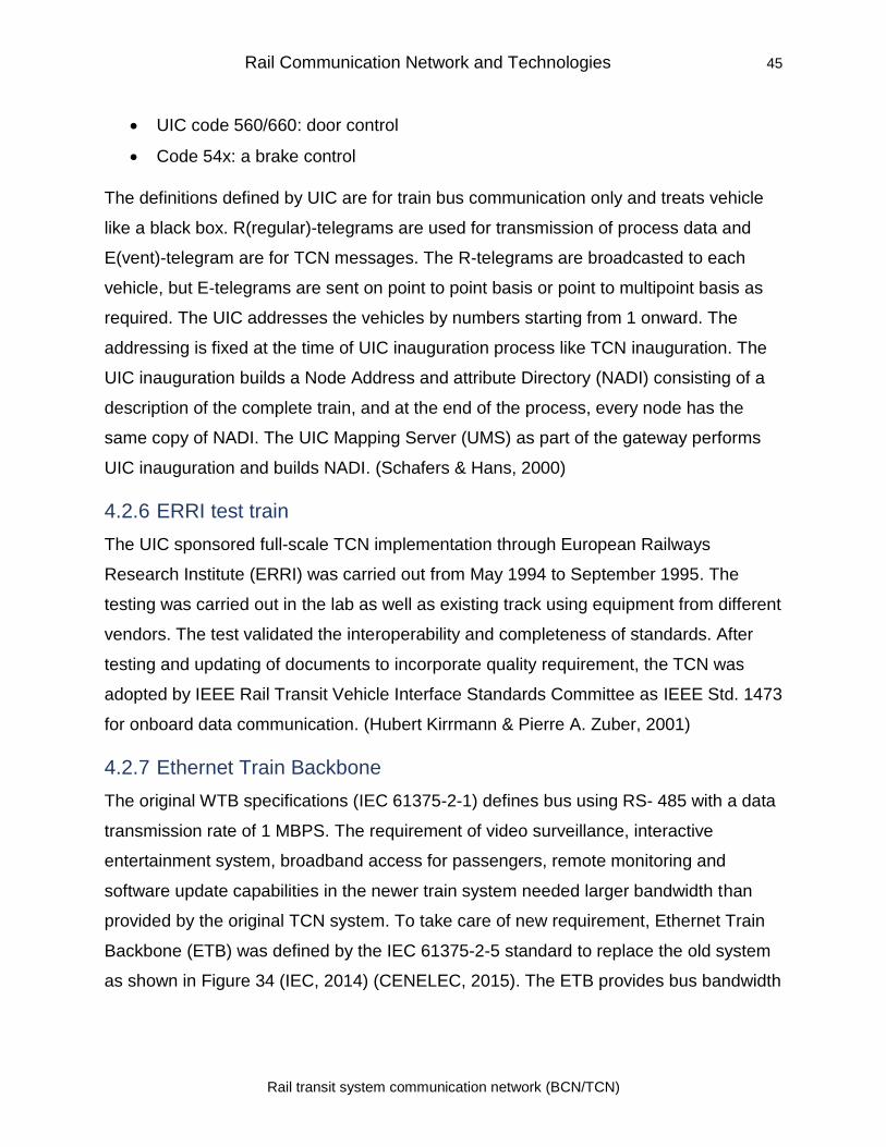
Rail Communication Network and Technologies 45
Rail transit system communication network (BCN/TCN)
• UIC code 560/660: door control
• Code 54x: a brake control
The definitions defined by UIC are for train bus communication only and treats vehicle
like a black box. R(regular)-telegrams are used for transmission of process data and
E(vent)-telegram are for TCN messages. The R-telegrams are broadcasted to each
vehicle, but E-telegrams are sent on point to point basis or point to multipoint basis as
required. The UIC addresses the vehicles by numbers starting from 1 onward. The
addressing is fixed at the time of UIC inauguration process like TCN inauguration. The
UIC inauguration builds a Node Address and attribute Directory (NADI) consisting of a
description of the complete train, and at the end of the process, every node has the
same copy of NADI. The UIC Mapping Server (UMS) as part of the gateway performs
UIC inauguration and builds NADI. (Schafers & Hans, 2000)
4.2.6 ERRI test train
The UIC sponsored full-scale TCN implementation through European Railways
Research Institute (ERRI) was carried out from May 1994 to September 1995. The
testing was carried out in the lab as well as existing track using equipment from different
vendors. The test validated the interoperability and completeness of standards. After
testing and updating of documents to incorporate quality requirement, the TCN was
adopted by IEEE Rail Transit Vehicle Interface Standards Committee as IEEE Std. 1473
for onboard data communication. (Hubert Kirrmann & Pierre A. Zuber, 2001)
4.2.7 Ethernet Train Backbone
The original WTB specifications (IEC 61375-2-1) defines bus using RS- 485 with a data
transmission rate of 1 MBPS. The requirement of video surveillance, interactive
entertainment system, broadband access for passengers, remote monitoring and
software update capabilities in the newer train system needed larger bandwidth than
provided by the original TCN system. To take care of new requirement, Ethernet Train
Backbone (ETB) was defined by the IEC 61375-2-5 standard to replace the old system
as shown in Figure 34 (IEC, 2014) (CENELEC, 2015). The ETB provides bus bandwidth
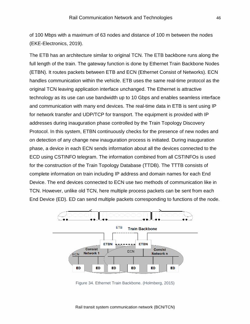
Rail Communication Network and Technologies 46
Rail transit system communication network (BCN/TCN)
of 100 Mbps with a maximum of 63 nodes and distance of 100 m between the nodes
(EKE-Electronics, 2019).
The ETB has an architecture similar to original TCN. The ETB backbone runs along the
full length of the train. The gateway function is done by Ethernet Train Backbone Nodes
(ETBN). It routes packets between ETB and ECN (Ethernet Consist of Networks). ECN
handles communication within the vehicle. ETB uses the same real-time protocol as the
original TCN leaving application interface unchanged. The Ethernet is attractive
technology as its use can use bandwidth up to 10 Gbps and enables seamless interface
and communication with many end devices. The real-time data in ETB is sent using IP
for network transfer and UDP/TCP for transport. The equipment is provided with IP
addresses during inauguration phase controlled by the Train Topology Discovery
Protocol. In this system, ETBN continuously checks for the presence of new nodes and
on detection of any change new inauguration process is initiated. During inauguration
phase, a device in each ECN sends information about all the devices connected to the
ECD using CSTINFO telegram. The information combined from all CSTINFOs is used
for the construction of the Train Topology Database (TTDB). The TTTB consists of
complete information on train including IP address and domain names for each End
Device. The end devices connected to ECN use two methods of communication like in
TCN. However, unlike old TCN, here multiple process packets can be sent from each
End Device (ED). ED can send multiple packets corresponding to functions of the node.
Figure 34. Ethernet Train Backbone. (Holmberg, 2015)
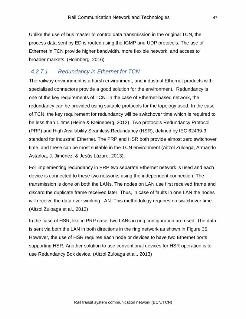
Rail Communication Network and Technologies 47
Rail transit system communication network (BCN/TCN)
Unlike the use of bus master to control data transmission in the original TCN, the
process data sent by ED is routed using the IGMP and UDP protocols. The use of
Ethernet in TCN provide higher bandwidth, more flexible network, and access to
broader markets. (Holmberg, 2016)
4.2.7.1 Redundancy in Ethernet for TCN
The railway environment is a harsh environment, and industrial Ethernet products with
specialized connectors provide a good solution for the environment. Redundancy is
one of the key requirements of TCN. In the case of Ethernet-based network, the
redundancy can be provided using suitable protocols for the topology used. In the case
of TCN, the key requirement for redundancy will be switchover time which is required to
be less than 1.4ms (Heine & Kleineberg, 2012). Two protocols Redundancy Protocol
(PRP) and High Availability Seamless Redundancy (HSR), defined by IEC 62439-3
standard for industrial Ethernet. The PRP and HSR both provide almost zero switchover
time, and these can be most suitable in the TCN environment (Aitzol Zuloaga, Armando
Astarloa, J. Jiménez, & Jesús Lázaro, 2013).
For implementing redundancy in PRP two separate Ethernet network is used and each
device is connected to these two networks using the independent connection. The
transmission is done on both the LANs. The nodes on LAN use first received frame and
discard the duplicate frame received later. Thus, in case of faults in one LAN the nodes
will receive the data over working LAN. This methodology requires no switchover time.
(Aitzol Zuloaga et al., 2013)
In the case of HSR, like in PRP case, two LANs in ring configuration are used. The data
is sent via both the LAN in both directions in the ring network as shown in Figure 35.
However, the use of HSR requires each node or devices to have two Ethernet ports
supporting HSR. Another solution to use conventional devices for HSR operation is to
use Redundancy Box device. (Aitzol Zuloaga et al., 2013)
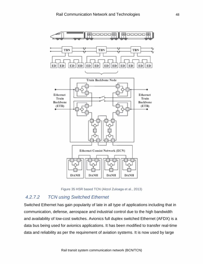
Rail Communication Network and Technologies 48
Rail transit system communication network (BCN/TCN)
Figure 35 HSR based TCN (Aitzol Zuloaga et al., 2013)
4.2.7.2 TCN using Switched Ethernet
Switched Ethernet has gain popularity of late in all type of applications including that in
communication, defense, aerospace and industrial control due to the high bandwidth
and availability of low-cost switches. Avionics full duplex switched Ethernet (AFDX) is a
data bus being used for avionics applications. It has been modified to transfer real-time
data and reliability as per the requirement of aviation systems. It is now used by large
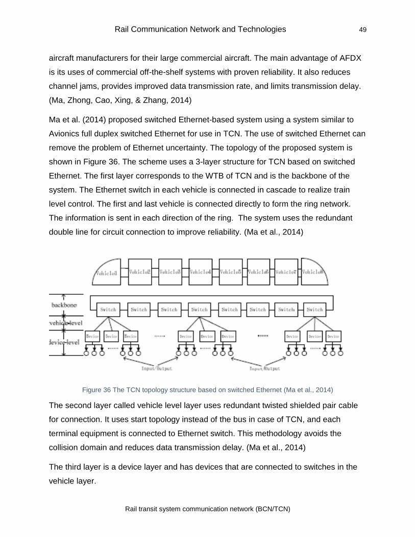
Rail Communication Network and Technologies 49
Rail transit system communication network (BCN/TCN)
aircraft manufacturers for their large commercial aircraft. The main advantage of AFDX
is its uses of commercial off-the-shelf systems with proven reliability. It also reduces
channel jams, provides improved data transmission rate, and limits transmission delay.
(Ma, Zhong, Cao, Xing, & Zhang, 2014)
Ma et al. (2014) proposed switched Ethernet-based system using a system similar to
Avionics full duplex switched Ethernet for use in TCN. The use of switched Ethernet can
remove the problem of Ethernet uncertainty. The topology of the proposed system is
shown in Figure 36. The scheme uses a 3-layer structure for TCN based on switched
Ethernet. The first layer corresponds to the WTB of TCN and is the backbone of the
system. The Ethernet switch in each vehicle is connected in cascade to realize train
level control. The first and last vehicle is connected directly to form the ring network.
The information is sent in each direction of the ring. The system uses the redundant
double line for circuit connection to improve reliability. (Ma et al., 2014)
Figure 36 The TCN topology structure based on switched Ethernet (Ma et al., 2014)
The second layer called vehicle level layer uses redundant twisted shielded pair cable
for connection. It uses start topology instead of the bus in case of TCN, and each
terminal equipment is connected to Ethernet switch. This methodology avoids the
collision domain and reduces data transmission delay. (Ma et al., 2014)
The third layer is a device layer and has devices that are connected to switches in the
vehicle layer.
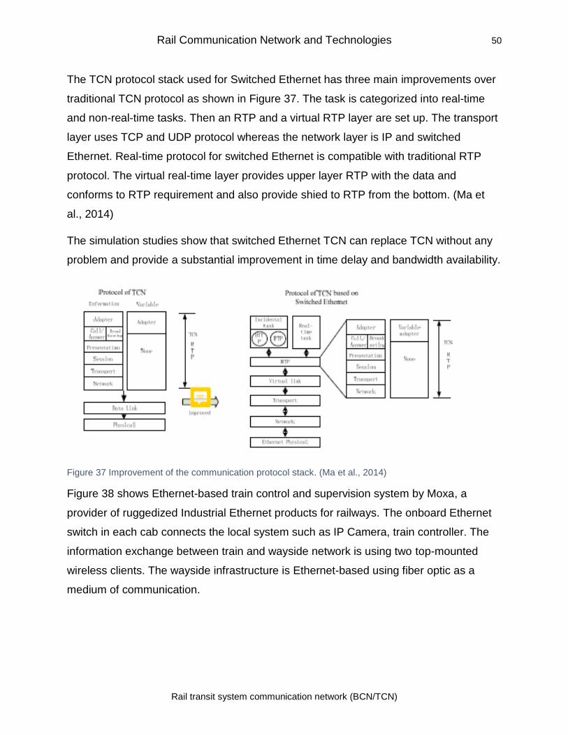
Rail Communication Network and Technologies 50
Rail transit system communication network (BCN/TCN)
The TCN protocol stack used for Switched Ethernet has three main improvements over
traditional TCN protocol as shown in Figure 37. The task is categorized into real-time
and non-real-time tasks. Then an RTP and a virtual RTP layer are set up. The transport
layer uses TCP and UDP protocol whereas the network layer is IP and switched
Ethernet. Real-time protocol for switched Ethernet is compatible with traditional RTP
protocol. The virtual real-time layer provides upper layer RTP with the data and
conforms to RTP requirement and also provide shied to RTP from the bottom. (Ma et
al., 2014)
The simulation studies show that switched Ethernet TCN can replace TCN without any
problem and provide a substantial improvement in time delay and bandwidth availability.
Figure 37 Improvement of the communication protocol stack. (Ma et al., 2014)
Figure 38 shows Ethernet-based train control and supervision system by Moxa, a
provider of ruggedized Industrial Ethernet products for railways. The onboard Ethernet
switch in each cab connects the local system such as IP Camera, train controller. The
information exchange between train and wayside network is using two top-mounted
wireless clients. The wayside infrastructure is Ethernet-based using fiber optic as a
medium of communication.
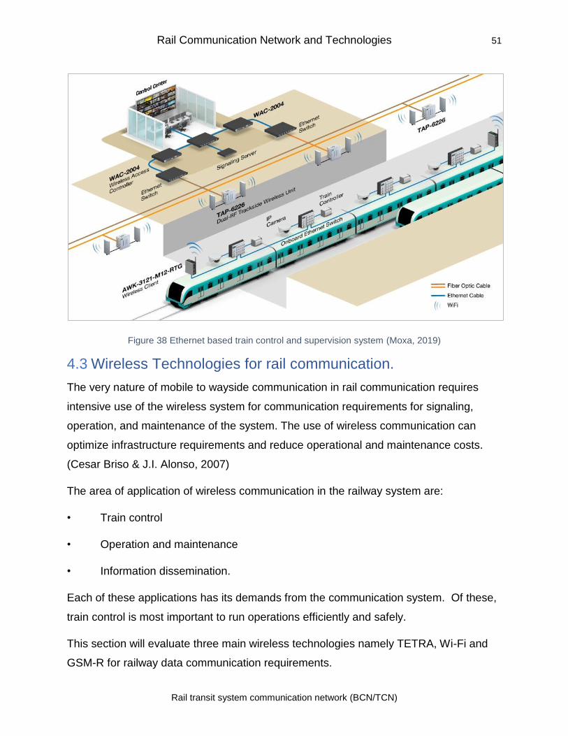
Rail Communication Network and Technologies 51
Rail transit system communication network (BCN/TCN)
Figure 38 Ethernet based train control and supervision system (Moxa, 2019)
4.3 Wireless Technologies for rail communication.
The very nature of mobile to wayside communication in rail communication requires
intensive use of the wireless system for communication requirements for signaling,
operation, and maintenance of the system. The use of wireless communication can
optimize infrastructure requirements and reduce operational and maintenance costs.
(Cesar Briso & J.I. Alonso, 2007)
The area of application of wireless communication in the railway system are:
• Train control
• Operation and maintenance
• Information dissemination.
Each of these applications has its demands from the communication system. Of these,
train control is most important to run operations efficiently and safely.
This section will evaluate three main wireless technologies namely TETRA, Wi-Fi and
GSM-R for railway data communication requirements.
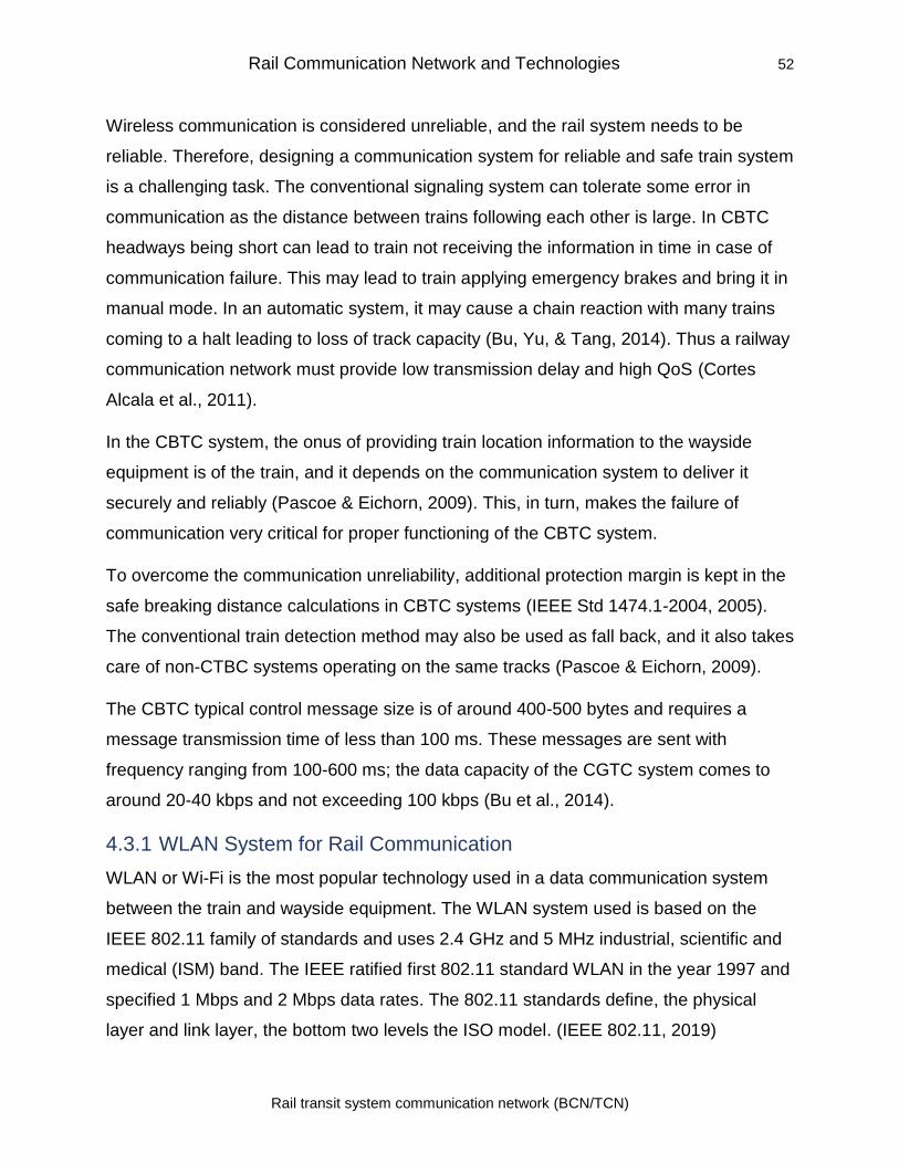
Rail Communication Network and Technologies 52
Rail transit system communication network (BCN/TCN)
Wireless communication is considered unreliable, and the rail system needs to be
reliable. Therefore, designing a communication system for reliable and safe train system
is a challenging task. The conventional signaling system can tolerate some error in
communication as the distance between trains following each other is large. In CBTC
headways being short can lead to train not receiving the information in time in case of
communication failure. This may lead to train applying emergency brakes and bring it in
manual mode. In an automatic system, it may cause a chain reaction with many trains
coming to a halt leading to loss of track capacity (Bu, Yu, & Tang, 2014). Thus a railway
communication network must provide low transmission delay and high QoS (Cortes
Alcala et al., 2011).
In the CBTC system, the onus of providing train location information to the wayside
equipment is of the train, and it depends on the communication system to deliver it
securely and reliably (Pascoe & Eichorn, 2009). This, in turn, makes the failure of
communication very critical for proper functioning of the CBTC system.
To overcome the communication unreliability, additional protection margin is kept in the
safe breaking distance calculations in CBTC systems (IEEE Std 1474.1-2004, 2005).
The conventional train detection method may also be used as fall back, and it also takes
care of non-CTBC systems operating on the same tracks (Pascoe & Eichorn, 2009).
The CBTC typical control message size is of around 400-500 bytes and requires a
message transmission time of less than 100 ms. These messages are sent with
frequency ranging from 100-600 ms; the data capacity of the CGTC system comes to
around 20-40 kbps and not exceeding 100 kbps (Bu et al., 2014).
4.3.1 WLAN System for Rail Communication
WLAN or Wi-Fi is the most popular technology used in a data communication system
between the train and wayside equipment. The WLAN system used is based on the
IEEE 802.11 family of standards and uses 2.4 GHz and 5 MHz industrial, scientific and
medical (ISM) band. The IEEE ratified first 802.11 standard WLAN in the year 1997 and
specified 1 Mbps and 2 Mbps data rates. The 802.11 standards define, the physical
layer and link layer, the bottom two levels the ISO model. (IEEE 802.11, 2019)
Rail Communication Network and Technologies 53
Rail transit system communication network (BCN/TCN)
4.3.1.1.1 IEEE 802.11 Architecture
Each wireless node is referred to as a station in 802.11. The portable station can be
mobile or move from point to point but is only used at a fixed point. Mobile stations can
access the WLAN during movement. The two or more stations can come together to
communicate with each other, and in this situation, they form a Basic Service Set
(BSS). 802.11. WLANs use the BSS as the standard building block. (Crow, Widjaja,
Kim, & Sakai, 1997)
IEEE 802.11 Data Link Layer
The 802.11 divides the data link layer into two sublayers: Logical Link Control (LLC) and
Media Access Control (MAC). 802.11 uses the same Logical Link Control layer and 48-
bit addressing as wired 802 LANs. The common LLC allows for simple bridging between
wireless and wired networks. (Crow et al., 1997)
The wireless medium is a shared medium, and the 802.11 MAC is designed to support
multiple users in the wireless medium by making the sender senses the medium before
transmission. 802.11 uses Carrier Sense Multiple Access with Collision Avoidance
(CSMA/CA) or the Distributed Coordination Function (DCF) for accessing the shared
medium. Explicit packet acknowledgment (ACK) is used in CSMA/CA to prevent
collisions. In this method, the receiving station confirms the proper receipt of the packet
to the sender before next transmission by the sender. In case of non-receipt of ACK
message the transmission station assumes collision and it retransmits the packet after a
random amount of time. This method of avoiding collision leads to the lower
performance of WLAN as compared to the wired LAN. The data integrity of the packet is
maintained by using CRC checksum. (Pathak, 2017)
IEEE 802.11 Physical Layer
The original 802.11 standard specified two types of physical layers one radio operating
in the 2.4 – 2.4835 GHz band and the other in the infrared band. The power output is
limited to 1 watt. The radio uses two spread spectrum techniques; Frequency Hopping
Spread Spectrum and Direct Sequence Spread Spectrum. With the publication of more
Rail Communication Network and Technologies 54
Rail transit system communication network (BCN/TCN)
standards number of physical layer, supplements have been introduced as depicted in
Figure 39.
4.3.1.2 WLAN Standards
The 802.11 series of standards offer a number of standards developed over a period
using various technologies and frequency bands (IEEE 802.11, 2019). The standards
applicable for railway network shall be discussed below.
IEEE802.11a: It was ratified in September 1997 using 5 GHz band. It uses Orthogonal
Frequency Division Multiplexing (OFDM) with support to speed up to 54 Mbps. Due to
its higher frequency band, 802.11a is not compatible with 802.11b, the most popular
system in 2.4 GHz band. In OFDM the data carrier is divided into a number of low-
speed carriers which are located apart at precise frequencies that are orthogonal to
each other. These frequencies are then transmitted simultaneously on a single
transmission path. The precise spacing of frequencies allows the demodulators to see
their own frequencies only. The use of frequencies close to each other provides OFDM
with high spectral efficiency, resiliency to RF interference, and lower multi-path
distortion.
IEEE802.11b
The IEEE802.11b standard was ratified in 1999. It supports the data rate up to 11 Mbps
and uses ISM Band from 2.402 GHz – 2.479 GHz. It uses Direct Sequence Spread
Spectrum and bandwidth of each channel is 22 MHz. (Pathak, 2017)
In the direct sequence spread spectrum, the signal to be transmitted is spread over a
full band by modulating it by a random binary string (called the spreading code). The
data bits get mapped to into a pattern of "chips" and these chips are mapped back into
a bit at the destination. This requires the transmitter and the receiver to be synchronized
using the same spreading code.
The range of operation is 30 meters indoor and 100 meters outdoor. The data rate
achieved goes down as the distance of communication increases. The data rate is
dynamically adjusted depending on the quality of the link. As the standard shares the
Rail Communication Network and Technologies 55
Rail transit system communication network (BCN/TCN)
same band as for Bluetooth, cordless mobile and other gadgets it is prone to
interference. (Abdelrahman, Mustafa, & Osman, 2015)
IEEE802.11g
The IEEE802.11g, ratified in 2003, uses 2.4 GHz ISM band for communication. It uses
Orthogonal Frequency Division Multiplexing and supports bandwidth up to 54 Mbps. It is
backward compatible with 802.11b and in this mode, it uses DSSS modulation.
However, like 802.11b it is also prone to interference from other devices using the ISM
band. It provides a higher range as compared to 802.11b. (Abdelrahman et al., 2015)
IEEE802.11n
The 802.11n standard, ratified in 2009, uses Orthogonal Frequency Division
Multiplexing. It uses multiple antennas for data transmission and reception. It also uses
Multiple Input, Multiple Output (MIMO) for increasing the range and throughput. The
maximum bandwidth supported by the standard is 300 Mbps. The outdoor range of
IEEE802.11n is 250 meters, and the indoor range is 75 meters. The MIMO technology
also called smart antenna systems divides the original signal into multiple streams, and
each steam is then transmitted using a separate antenna simultaneously on the same
channel. At the receiver end, the signals are received by multiple antennas and
combined to provide an output signal. The use of multiple antennae provides path
diversity which is an important point in an urban environment where lots of reflections
take place due to the topology of the urban environment. This process allows the use of
the spectrum efficiently and provides better reliability.
IEEE802.11ac
The IEEE802.11ac, released in December 2013, uses 5 GHz band for operation. The
data rates depend on the bandwidth used and are as follows (Abdelrahman et al.,
2015):
• 7.2 - 96.3Mbps for 20MHz,
• 15 – 200Mbps for 40MHz
• 32.5 - 433.3Mbps for 80MHz
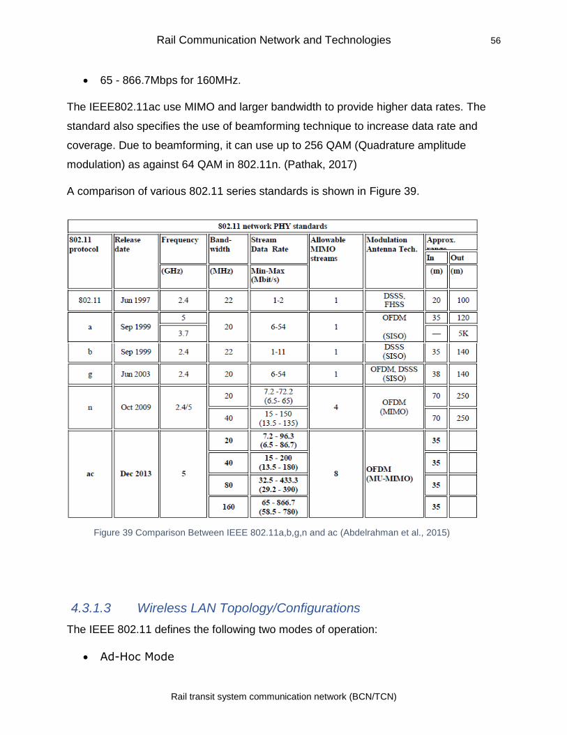
Rail Communication Network and Technologies 56
Rail transit system communication network (BCN/TCN)
• 65 - 866.7Mbps for 160MHz.
The IEEE802.11ac use MIMO and larger bandwidth to provide higher data rates. The
standard also specifies the use of beamforming technique to increase data rate and
coverage. Due to beamforming, it can use up to 256 QAM (Quadrature amplitude
modulation) as against 64 QAM in 802.11n. (Pathak, 2017)
A comparison of various 802.11 series standards is shown in Figure 39.
4.3.1.3 Wireless LAN Topology/Configurations
The IEEE 802.11 defines the following two modes of operation:
• Ad-Hoc Mode
Figure 39 Comparison Between IEEE 802.11a,b,g,n and ac (Abdelrahman et al., 2015)
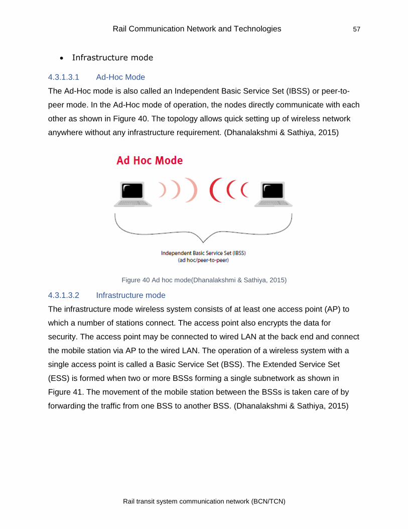
Rail Communication Network and Technologies 57
Rail transit system communication network (BCN/TCN)
• Infrastructure mode
4.3.1.3.1 Ad-Hoc Mode
The Ad-Hoc mode is also called an Independent Basic Service Set (IBSS) or peer-to-
peer mode. In the Ad-Hoc mode of operation, the nodes directly communicate with each
other as shown in Figure 40. The topology allows quick setting up of wireless network
anywhere without any infrastructure requirement. (Dhanalakshmi & Sathiya, 2015)
Figure 40 Ad hoc mode(Dhanalakshmi & Sathiya, 2015)
4.3.1.3.2 Infrastructure mode
The infrastructure mode wireless system consists of at least one access point (AP) to
which a number of stations connect. The access point also encrypts the data for
security. The access point may be connected to wired LAN at the back end and connect
the mobile station via AP to the wired LAN. The operation of a wireless system with a
single access point is called a Basic Service Set (BSS). The Extended Service Set
(ESS) is formed when two or more BSSs forming a single subnetwork as shown in
Figure 41. The movement of the mobile station between the BSSs is taken care of by
forwarding the traffic from one BSS to another BSS. (Dhanalakshmi & Sathiya, 2015)
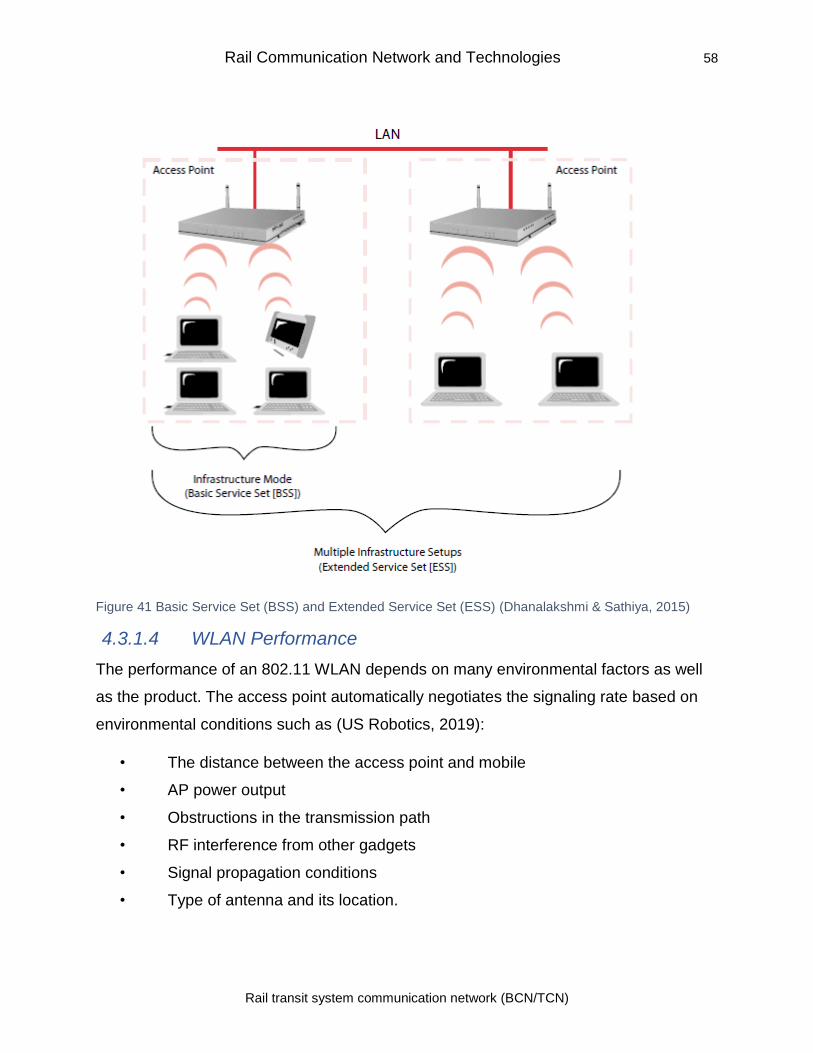
Rail Communication Network and Technologies 58
Rail transit system communication network (BCN/TCN)
Figure 41 Basic Service Set (BSS) and Extended Service Set (ESS) (Dhanalakshmi & Sathiya, 2015)
4.3.1.4 WLAN Performance
The performance of an 802.11 WLAN depends on many environmental factors as well
as the product. The access point automatically negotiates the signaling rate based on
environmental conditions such as (US Robotics, 2019):
• The distance between the access point and mobile
• AP power output
• Obstructions in the transmission path
• RF interference from other gadgets
• Signal propagation conditions
• Type of antenna and its location.
Rail Communication Network and Technologies 59
Rail transit system communication network (BCN/TCN)
Thus, the mobile node data access speed changes depending on the environmental
conditions prevailing
4.3.1.5 Advantages of Wi-Fi
The WLAN systems are very popular as these are low cost, do not require licensing;
these are easy to deploy, maintain, and shift. (Cesar Briso & J.I. Alonso, 2007)
From the point of view of rail communication, the advantages of using WLAN are
(Farooq & Soler, 2017):
• They provide High data throughput
• WLANs are easy to deploy and maintain
• WLANs use reduces the requirement of trackside equipment
• These are Cost-effective
• Provide Redundancy
• They use open standard Protocols
• WLANs have large Industry support and market
Modern applications or systems in CBTC such as CCTV, PIDs, Aboard Internet, remote
analysis and broadcast redundancy require high data rates. Wi-Fi supports the
infrastructure to meet this requirement. Wi-fi equipment for COTS is cheaper.
The biggest advantage of using Wi-Fi is the non-requirement of taking permission from
regulatory authorities for frequency use and licensing.
4.3.1.6 Wi-Fi Drawbacks
The Wi-Fi system has some inherent drawbacks such as (Farooq & Soler, 2017):
• Prone to interference
• The requirement of strict security measures
• No support for mobility
• Limited range
• Network congestion
Rail Communication Network and Technologies 60
Rail transit system communication network (BCN/TCN)
Susceptibility of Wi-Fi system from interference is known issue due to the shared nature
of frequency band used by it. The failure of CTBC systems has also been reported due
to interference in the Wi-Fi system. A case in point is the Shenzhen Metro where
interference was due to Wi-Fi user in the surrounding area (Huifeng, 2012). However,
an environment such as an underground railway system, the probability of interference
becomes much less (Alvarez & Roman, 2013). The interference can be mitigated to a
certain extent during deployment by using measures such as using alternating
frequency channels.
4.3.1.7 Improvements Proposed in WLAN for CBTC system
The frequent handoff in wayside communication in train system along with packet loss
and delays in communication requires optimization of performance. Sun, Yu, Tang, &
Bu (2016) modeled a networked control system (NCS) consisting of a multi-train CBTC
system and proposed a new train control scheme to improve the QoS of CBTC
systems. The energy consumption was minimized using MAC layer retry limit and the
trip time track errors were mitigated using guidance trajectory update. The simulation of
this system showed substantial improvement in energy consumption and a reduction in
trip time errors. (Sun, Yu, Tang, & Bu, 2016)
Another train performance approach based on deep reinforcement learning was
proposed. The approach uses linear quadratic as the metrics for performance control.
The optimal train control policy and handoff policy is obtained by optimizing the train
control action and handoff decision. The optimization minimizes the energy
consumption and travels profile tracking error which in turn control train safety and
control accuracy. For this purpose, the proposal models the dynamic transition
characteristics and the time-varying channel using the finite state Markov channel
(FSMC) model. The simulation results showed that the optimization method could
improve train control performance of the CBTC system at the same time system safety
requires some sacrifice in performance. (Cesar Briso & J.I. Alonso, 2007)
Rail Communication Network and Technologies 61
Rail transit system communication network (BCN/TCN)
4.3.1.8 Handling roaming in Wi-Fi
The Wi-Fi network in CTBC is built by locating the Wireless access points (APs) closely
together along the railway track in such a way that their coverage areas overlap.
However, this requires the moving train to look for suitable AP continuously and connect
to it as the train moves along. This requires smooth switching over of communication
from AP to another within an acceptable delay. The high speed of trains requires a rapid
change of channels as the train moves and the handover algorithms used in stationary
Wi-Fi environments are not suitable in railroad system (Jiang, Zhao, & Zhao, 2011).
The packet loss in the rail system due to handover is more than due to radio wave
propagation (Jiang et al., 2011). A study showed that the packet loss of 10% was
observed at a train speed of 200 km/h, overlap area of 20 meters and a maximum
handover time of 180 ms. The typical handover time in CBTC is 70-120 ms and a
maximum of 1 sec. If the handover time is less than a control message interval in
CBTC, the loss will not matter much (Bu et al., 2014).
To have a smooth transition, two radios, one at each end is installed in the train so that
at least one of the two radio is all the time connected to an AP. As handover mechanism
is not specified in IEEE 802.11 standard, the CBTC system manufacturers develop their
own roaming algorithm.
A proposal to use cooperative relaying cognitive CBTC system was given enhancing the
wireless system reliability (Li, Yu, Zhu, Tang, & Ning, 2015). The proposed system is
shown in Figure 42. In the normal system the access system is placed at both ends of
the train, but in case of the proposed system, the end communication point in the train
can also work as relay nodes for other trains. This is called cooperative relaying as
shown in Figure 42. The use of cooperative relaying enhances communication between
the access point and the train. The packet collision is avoided by using request-to-send
(RTS)/clear-to-send (CTS) message exchange between the receiver and sender
(Bletsas, Lippman, & Reed, 2005). This message exchange also enables the sender
and receiver to estimate the current state of the channel. In case of failure of an AP the
communication gets disrupted, but with the use of the direct train to train communication
the front rail can provide information about train position directly to the train behind it. In
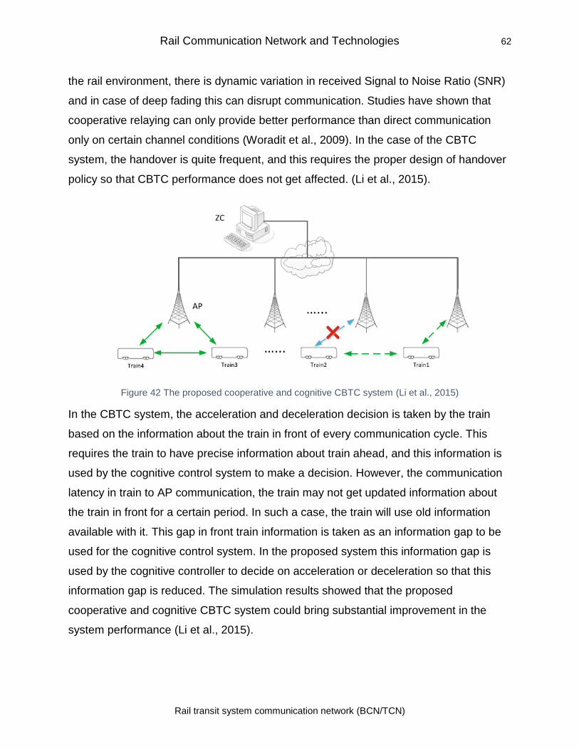
Rail Communication Network and Technologies 62
Rail transit system communication network (BCN/TCN)
the rail environment, there is dynamic variation in received Signal to Noise Ratio (SNR)
and in case of deep fading this can disrupt communication. Studies have shown that
cooperative relaying can only provide better performance than direct communication
only on certain channel conditions (Woradit et al., 2009). In the case of the CBTC
system, the handover is quite frequent, and this requires the proper design of handover
policy so that CBTC performance does not get affected. (Li et al., 2015).
Figure 42 The proposed cooperative and cognitive CBTC system (Li et al., 2015)
In the CBTC system, the acceleration and deceleration decision is taken by the train
based on the information about the train in front of every communication cycle. This
requires the train to have precise information about train ahead, and this information is
used by the cognitive control system to make a decision. However, the communication
latency in train to AP communication, the train may not get updated information about
the train in front for a certain period. In such a case, the train will use old information
available with it. This gap in front train information is taken as an information gap to be
used for the cognitive control system. In the proposed system this information gap is
used by the cognitive controller to decide on acceleration or deceleration so that this
information gap is reduced. The simulation results showed that the proposed
cooperative and cognitive CBTC system could bring substantial improvement in the
system performance (Li et al., 2015).
Rail Communication Network and Technologies 63
Rail transit system communication network (BCN/TCN)
4.3.1.9 DCS RF Coverage
CBTC systems are used all around the world. DCS of all these systems is based on
radio frequency to transport data between wayside components and commuting trains.
Even though the DCSs of these different CBTC systems are not the same, but they
have similar functions and characteristics.
The very rudimentary requirement for DCS is to give RF coverage to make sure that the
communication between wayside components and CBTC onboard train goes
uninterrupted on any place or location on the track even in storage areas. Proper RF
coverage is usually attained by using antennas which are attached to the apparatus
normally known as Wayside radio unit (WRU) located in the wayside infrastructure. The
number of WRUs and distance between them depends on many considerations like the
existence or absence of portals or tunnels and propagation losses at the current radio
frequency. A very important factor as we said is to provide communication without
interruption between Train and wayside equipment. This is done when the Radio units
are installed in the train on both front and back side. So, the train connects with WRUs
from both front and back of the train as it commutes. When the train comes close to
WRU, communication occurs through the front radio unit of the train and rear radio unit
keeps searching for the other WRUs. As the train passes the first WRU and is about to
lose the communication, the back radio has already found another WRU and connect to
it to avoid any interruption in the communication with wayside. This is possible because
of the overall arrangement of WRUs. If the WRUs are placed closely then such
arrangement will improve the reliability. (Fitzmaurice, 2013)
A very crucial part in RF coverage is the frequency of the DCS operation. Mostly CBTC
systems operate at 900 MHz or 2.4 GHz or 5.8 GHz. Most of the CBTC systems which
we can see in the above figure work at 2.4 GHz frequency. The choice of the frequency
band in CBTC can be decided on the basis of low-cost and verified equipment. In case
of such hardware, mostly 2.4 GHz is chosen because of the large industry support and
the market for Wi-Fi compatibility. CBTC vendors usually use already in market COTS
radios instead of developing their own. The selection of the frequency of DCS also
Rail Communication Network and Technologies 64
Rail transit system communication network (BCN/TCN)
depends on RF interference. The decision of operating frequency does not depend on
one factor, but it decided in consideration with CBTC system overall.
There are two kinds of antennas used for wayside:
• Continuous antenna
• Discrete antenna
Continuous antennas are leaky coaxial cables having holes in their outer walls used as
a continuous radiating structure, and it allows radio signals to leak in or out. Discrete
antennas are usually lightweight and cheaper in installation and maintenance. Other
than fulfilling the data transfer requirements of CBTC, this type of antenna can carry
signals from CCTV cameras on trains. The RF interference is an issue in every DCS
which should be considered carefully. There could be many reasons for RF
interference. Therefore, many mitigation strategies can be applied to overcome the
issue. A crucial characteristic that every DCS should have is to warn the system if there
is any excessive RF interference so that the suitable measure can be taken before
Excessive RF interference affects the operation of DCS.
4.3.2 Terrestrial Trunked Radio (TETRA) System for Rail Communication
TETRA is a digital Trunked Radio system standardized by ETSI (ETSI EN 300 392-2 -
V3.7.2, 2016). It has been extensively used by public utilities such as police, medical
services, sports, commercial organization, emergency communication, etc. The ETSI
standard defines network interfaces, air interfaces, service, and facilities so that
infrastructure and products developed by different manufacturers are fully interoperable
with each other. The railways across Europe, Asia, and Latin America use TETRA
system in mass rapid transit, metros and railways. The TETRA service generally
operates in 300-400 MHz band. (Tsogtbayar, Kang, Lee, & Boldbaatar, 2016a)
4.3.2.1 TETRA systems technical characteristics
TETRA provides a number of services which are characterized as bearer service and
teleservices. The bearer services are the same as general networks. The teleservices
are similar to mobile communication included bearer services. The TETRA is a private
Rail Communication Network and Technologies 65
Rail transit system communication network (BCN/TCN)
mobile radio (PMR) where the dispatcher distributes calls according to a priority list.
(Cesar Briso & J.I. Alonso, 2007)
TETRA uses encrypted data communication for providing (Tsogtbayar, Kang, Lee, &
Boldbaatar, 2016b):
• Point to point voice communication
• Group voice call
• Acknowledged voice group call
• Broadcast voice call
TETRA allows data communication at the speeds of less than 10 Kbps. The call setup
time in TETRA is less than 1 sec which meets the requirement of emergency services.
The group calling facility of TETRA is suitable for its use in risk situations where the
speed of communication is important. (Esteban & Solanas, 2016)
TETRA uses Time Division Multiple Access (TDMA) with a carrier spacing of 25 kHz. It
uses 4 TDMA timeslots and π/4 QPSK modulation. The data rate per time slot is 7.2kb/s
per time slot, and the aggregate data rate is 28.8Kbps. The mobile radios in TETRA can
communicate using direct-mode operation (DMO) as well as using trunked-mode
operation (TMO). This facility is availed using switching and management infrastructure
in TETRA base stations. The system allows direct communication if network coverage is
not available and this mode is called DMO mode. DMO can also use one of more
TETRA terminals in series for establishing communication, and this method is called
DMO gateway or repeater as per the usage. This facility can be used for direct
communications in underground or bad coverage areas. (ITU-R M.2418-0, 2017)
The TETRA system provides a number of types of data communication. It provides
short data services and status messages using the main control channel of the TETRA
system. The specifically assigned channels are used for circuit-switched data or packet-
switched data communication. End to end encryption allows protection against
eavesdropping. The terminals are authenticated using infrastructure. Using a single
button user can make a call to a predefined group of mobiles. The studies show that the
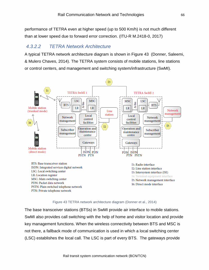
Rail Communication Network and Technologies 66
Rail transit system communication network (BCN/TCN)
performance of TETRA even at higher speed (up to 500 Km/h) is not much different
than at lower speed due to forward error correction. (ITU-R M.2418-0, 2017)
4.3.2.2 TETRA Network Architecture
A typical TETRA network architecture diagram is shown in Figure 43 (Donner, Saleemi,
& Mulero Chaves, 2014). The TETRA system consists of mobile stations, line stations
or control centers, and management and switching system/infrastructure (SwMI).
Figure 43 TETRA network architecture diagram (Donner et al., 2014)
The base transceiver stations (BTSs) in SwMI provide air interface to mobile stations.
SwMI also provides call switching with the help of home and visitor location and provide
key management functions. When the wireless connectivity between BTS and MSC is
not there, a fallback mode of communication is used in which a local switching center
(LSC) establishes the local call. The LSC is part of every BTS. The gateways provide
Rail Communication Network and Technologies 67
Rail transit system communication network (BCN/TCN)
an interface to voice and data network of other systems such as PSTN, PDN, GSM, etc.
(Donner et al., 2014)
Intersystem interface (ISI) is used for connecting two different TETRA systems. The
systems may be from the same operator or another operator.
4.3.3 Cellular Technology for Rail Communications
Cellular technology has emerged as the main technology for voice and data
communications for safe and efficient rail operations. With the adoption of GSM-R
standard, many incompatible analog systems used in Europe were replaced by systems
based on GSM-R. The use of GSM-R provides much-needed interoperability among
various systems.
4.3.3.1 GSM-R Standard
Secure and safe operation of rail system needed a reliable, proven, and off the shelf
communication system. Studies were undertaken, and discussion resulted in the
acceptance of GSM as the main system which could be used with minimum
modifications. It required the addition of Advanced Speech Call Items (ASCI) features to
the existing GSM system. After discussions, European Conference of Postal and
Telecommunications Administrations (CEPT) was approached to add 4 MHz to the
GSM band and provide it for the exclusive use of railways. In 1992 International Union
of Railways or Union Internationale des Chemins de Fer (UIC) along with railways and
EC formed a group called EIRENE (European Integrated Radio Enhanced Network) to
work out functional specifications that will fulfill the needs of railways and provide
interoperability across borders. After finalization of specifications by EIRENE, another
project named MORANE (MObile radio for RAilway Networks in Europe) was set up by
the consortium of GSM suppliers, railways and laboratories. The equipment developed
under MORANE were installed and tested at three pilot line at (ETSI, 2019):
• Florence - Arezzo
• Stuttgart - Mannheim
• Paris
Rail Communication Network and Technologies 68
Rail transit system communication network (BCN/TCN)
After the completion of pilot project and preparation of a final report incorporating the
field trail details, UIC and railways signed Memorandum of Understanding for
implementation of GSM-R for its communication requirements in 1997. Within Europe,
32 railways are signatories of the MOU (UIC, 2019).
GSM-R is based on the GSM standard with some enhancement for railways. The
enhancements include (ETSI, 2019) :
• Dedicated frequency bands in Europe: 873-880 MHz (Uplink) and 918-925 MHz
(Down Link). Germany allocated its earlier trunked radio mobile band 873–876
MHz and 918–921 MHz for GSM-R use (“Frequenznutzungsplan [Frequency Use
Plan] (PDF) (in German),” 2008).
• Functional addressing for call handling
• Private Mobile Radio (PMR) features including "Voice Broadcast Service," "Voice
Group Call Service, and Priority and Pre-emption
• Location dependent addressing
The GSM-R frequency band allocation in various countries is as follows (GSMR-Info,
2009):
In China and South Africa the band allocated for GSM-R is:
• 885–889 MHz (Uplink)
• 930–934 MHz (Downlink)
In Australia, the band allocated for GSM-R is in DCS band (Railway Safety Regulator,
2012)
• 1,727.5–1,732.5 MHz and 1,772.5–1,785 MHz (Uplink)
• 1,822.5–1,827.5 MHz and 1,867.5–1,880 MHz (Downlink)
In India, the band allocated uses P-GSM band with 1.6 MHz range
• 907.8–909.4 MHz (Uplink)
• 952.8–954.4 MHz (Downlink)
Rail Communication Network and Technologies 69
Rail transit system communication network (BCN/TCN)
The GSM-R uses GMSK modulation. GSM-R like GSM is a Time Division Multiple
Access (TDMA) system, with each frame, has 8-time slots or logical channels and carry
148-bit data. The data is transmitted in frames of 4.615 ms. (GSMR-Info, 2009)
ETSI Technical Committee "Railway Telecommunications" (TC RT) is responsible for
maintenance and further development of the GSM-R system. TC RT is also
collaborating with railways world over to take care of railways evolving requirements
including provision for global roaming in GSM-R environment. All changes request for
GSM-R are submitted by TC RT as Change Requests to the 3GPP (3rd Generation
Partnership Project). (ETSI, 2019)
A new project called ERTMS/GSM-R was started by UIC to complement work done by
EIRENE and MORANE. The ERTMS/GSM-R project combines the knowledge from
various groups and trails for enhancement of the system. (UIC, 2019)
The three permanent GSM-R working groups are (UIC, 2019):
• European Radio Implementers Group (ERIG)
• Functional Group (FG)
• Operators Group (OG)
ERIG group consists of railway members who have signed the MoU and the AoI. This
group exchanges information about lessons learned from projects already implemented,
gaps in specifications, and other reports related to implementation. The group acts as a
dissemination platform for all information related to GSM-R. (UIC, 2019)
Functional Group maintains the FRS and reviews the implementation reports related to
functional requirements and create change request based on the reviews. The group in
collaboration with other groups such as OG and the GSM-R industry Group (IG) works
out requirement and solutions. IG is a group of GSM-R suppliers that works for the
promotion of GSM-R worldwide and also interfaces with railway groups FG and OG.
(UIC, 2019)
UIC works with ETSI Technical Committee on Rail Telecommunications for protection of
feature specific to railways and improvement of GSM standard. GSM-R improves on the
Rail Communication Network and Technologies 70
Rail transit system communication network (BCN/TCN)
call setup time over the normal GSM to meet low call setup time required for railway
operations.
A study of communication failures dues to the stochastic nature of GSM-R was carried
out to assess the capacity reduction with ETCS level 3. It was found that the framework
of ETCS is good enough to take care of errors in GSM-R that are more than the
traditional system. (Jansen, Klabes, & Wendler, 2010)
4.3.3.1.1 Railway Specific Function in GSM-R
The functions specific to GSM-R are as follows (He et al., 2016):
Voice group call service (VGCS): VGCS provides establishing group calls between
drivers, wayside workers, railway staff or any other groups.
Voice broadcast service (VBS): VBS is used for a broadcasting message to a group. It
is one-way facilities where group member can only listen. It can also be used for
broadcasting recorded messages for announcements as well.
Enhanced multilevel precedence and preemption (MLPP): eMLPP defines a multilevel
priority for users and is used for making emergency group calls.
Shunting mode: Shunting mode is for communication with shunting personnel, and it
provides group communication facility.
Functional addressing: In this mode, the call is made by a number that identifies the
function rather than the permanent subscriber number.
Location-dependent addressing: This enables making calls from the train to numbers
allocated for certain functions based on the train’s location.
4.3.3.2 GSM-R Architecture
GSM-R network consists of a trunk transmission circuit and GSM-R digital mobile
communication system. The four parts of the GSM-R system are:
• Network subsystem (NSS): includes mobile switching subsystem (SSS), mobile
intelligent network (IN) subsystem, and GPRS subsystem
• base station subsystem (BSS),
Rail Communication Network and Technologies 71
Rail transit system communication network (BCN/TCN)
• operation and support subsystem (OSS)
• Terminal device.
GSM-R system structure and main interfaces are shown in Figure 44.
4.3.3.2.1 Mobile Switching Subsystem
Mobile Switching Subsystem or depicted as SSS in Figure 44 consists of many
subsystems such as MSC, HLR, and VLR. The functions of SSS are user call switching,
mobility management, user database, and security management. The signaling system
for communication is No.7 signaling protocol. The functions of various subsystems are
as follows (Z.-D. Zhong et al., 2018):
Mobile Service Switching Center (MSC)
Mobile Service Switching Center is the core of the network and provides call control and
mobility management. Gateway MSC provides an interface between GSM-R and other
communication networks.
Visitor Location Register (VLR)
VLR is a dynamic database and stores all information related to mobile users which are
in its control area. It along with HLR provides facilitates mobile roaming. At the time of
mobile station (MS) goes to a new area Home location register (HLR) registers it with
VLR obtains data about MS form VLR. When the user moves out of roaming area, the
data is deleted.
Home Location Register (HLR)
HLR is a database for mobile user management and stores the mobile user data in its
area. The information includes the location information, the identification sign, etc. HLR
updated location information in its database when MS goes roaming and also provides
call routing information for the user.
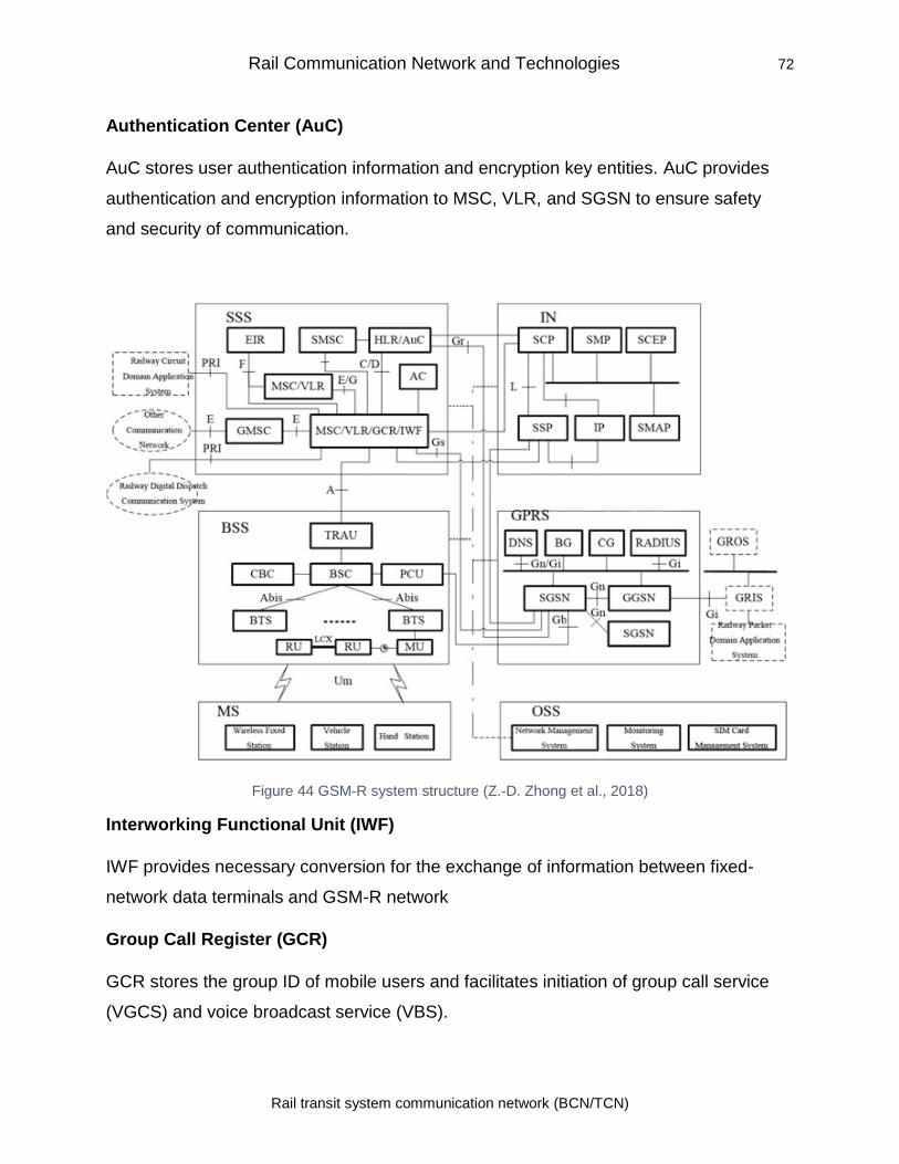
Rail Communication Network and Technologies 72
Rail transit system communication network (BCN/TCN)
Authentication Center (AuC)
AuC stores user authentication information and encryption key entities. AuC provides
authentication and encryption information to MSC, VLR, and SGSN to ensure safety
and security of communication.
Figure 44 GSM-R system structure (Z.-D. Zhong et al., 2018)
Interworking Functional Unit (IWF)
IWF provides necessary conversion for the exchange of information between fixed-
network data terminals and GSM-R network
Group Call Register (GCR)
GCR stores the group ID of mobile users and facilitates initiation of group call service
(VGCS) and voice broadcast service (VBS).
Rail Communication Network and Technologies 73
Rail transit system communication network (BCN/TCN)
Short Message Service Center (SMSC)
SMSC facilitate transmission of SMS to MSC.
Acknowledge Center (AC)
Acknowledge Center records information about railway emergency calls.
Equipment Identity Register (EIR)
EIR stores the mobile International Mobile Equipment Identity (IMEI) database. Based
on the category of IMEI list the system decides about the service to be provided.
4.3.3.2.2 Mobile Intelligent Network Subsystem
IN subsystem provides intelligent control of the call by separating the network switching
function and the service control function. GSM-R intelligent network consists of GSM
many subsystems described below (Z.-D. Zhong et al., 2018).
• GSM Service Switching Point (gsmSSP) acts as an interface between SCP and
MSC. It detects the service request and communicates with the SCP for
processing the call.
• GPRS Service Switching Point (gprsSSP) acts as an interface between SCP and
SGSN. It detects the service request and communicates with the SCP for
processing the call.
• Service Control Point (SCP) provides service logic of IN and in collaboration with
SSP controls the intelligent service connection and charging.
• Intelligent Peripheral (IP) along with SCP provides resources such as receiving
DTMF, generating signals, recording of notices, etc.
• Service Management Point (SMP) manages SCP and user service data.
• Service Management Access Point (SMAP) manages access to the services
provided by SMP and manages users data related to services.
• Service Context Entering Point (SCEP) is responsible for IN service
development, testing, and verification.
Rail Communication Network and Technologies 74
Rail transit system communication network (BCN/TCN)
4.3.3.2.3 General Packet Radio Service (GPRS) Subsystem
GPRS provides packet-based data communication for mobile users. It includes a core
layer and a wireless access layer.
The core layer consists of several units such as Service GPRS Support Node (SGSN),
Gateway GPRS Support Node (GGSN), DNS(Domain Name Server), RADIUS Service,
etc. as per details below (Z.-D. Zhong et al., 2018).
• Service GPRS Support Node (SGSN) provides mobility management and route
searching.
• Gateway GPRS Support Node (GGSN) acts as a gateway between the GPRS
network and external data network and provides necessary protocols etc.
required data exchange.
• Domain Name Server (DNS) provides domain name resolution for SGSN,
GGSN, and other network nodes.
• RADIUS Service stores user identity information, and provides user
authentication services.
The wireless access layer consists of a Packet Control Unit, base station, and terminal
(Z.-D. Zhong et al., 2018).
• Packet Control Unit (PCU) manages packet transmission including channel
management, error detection, and automatic data retransmission.
• Border Gateway (BG) provides an interface between different GPRS networks
including security, routing protocol, etc.
• Charge Gateway (CG) takes care of billing by managing the ticket record of all
GPRS support nodes and transferring the information to the charge center.
• GPRS Network Interface Equipment consists of GPRS home server (GROS),
GSM-R terminal, and GPRS interface server (GRIS). GRIS provides protocol
conversion for data exchange between a railway application system and GPRS
terminal.
Rail Communication Network and Technologies 75
Rail transit system communication network (BCN/TCN)
4.3.3.2.4 Base Station Subsystem
The mobile station connects with the base station over a wireless interface. BSS
provides radio resource management, and transfers call data including signaling
information between mobile and MSC for call connection. The brief on various
subsystems is given below (Z.-D. Zhong et al., 2018):
• BSS consists of a base station controller, the transcoder/rate adaptor unit
(TRAU), the cell broadcast center, the base transceiver station, etc.
• Base Station Controller (BSC) manages all interfaces, wireless parameters, radio
resources, channel assignment, and signal processing for call establishment.
• Transcoder/Rate Adaptor Unit (TRAU) provides voice coding and rate adaptation
between BSC and MSC.
• Cell Broadcast Center (CBC) manages the cell broadcasting message service.
• Base Transceiver Station (BTS) is an interface between the mobile station at one
end and BSC at another end. BTS provides functions such as air interface,
channel coding/decoding, and modulation/demodulation.
• Relay Transmission Equipment is used to extend wireless coverage of GSM-R in
the weak signal are using repeater station and associated equipment.
4.3.3.2.5 Operation and Support Subsystem (OSS)
Operation and Support Subsystem provides user management and network
management. (Z.-D. Zhong et al., 2018)
Network Management System
The network management system monitors configure and control all the network
devices. It provides network reports and helps in the planning and maintenance of the
system.
Monitoring system
An interface monitoring system monitors various network interfaces, analyses network
subsystems, data processing equipment, server, and other systems.
SIM Card Management System
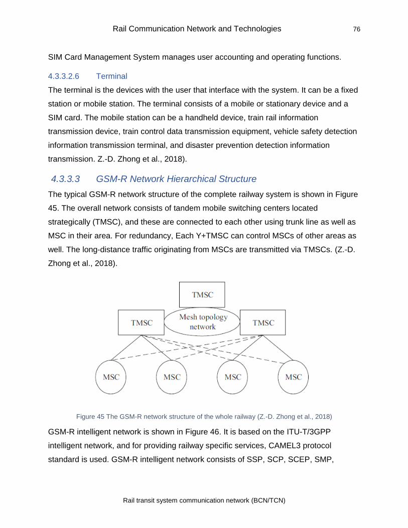
Rail Communication Network and Technologies 76
Rail transit system communication network (BCN/TCN)
SIM Card Management System manages user accounting and operating functions.
4.3.3.2.6 Terminal
The terminal is the devices with the user that interface with the system. It can be a fixed
station or mobile station. The terminal consists of a mobile or stationary device and a
SIM card. The mobile station can be a handheld device, train rail information
transmission device, train control data transmission equipment, vehicle safety detection
information transmission terminal, and disaster prevention detection information
transmission. Z.-D. Zhong et al., 2018).
4.3.3.3 GSM-R Network Hierarchical Structure
The typical GSM-R network structure of the complete railway system is shown in Figure
45. The overall network consists of tandem mobile switching centers located
strategically (TMSC), and these are connected to each other using trunk line as well as
MSC in their area. For redundancy, Each Y+TMSC can control MSCs of other areas as
well. The long-distance traffic originating from MSCs are transmitted via TMSCs. (Z.-D.
Zhong et al., 2018).
Figure 45 The GSM-R network structure of the whole railway (Z.-D. Zhong et al., 2018)
GSM-R intelligent network is shown in Figure 46. It is based on the ITU-T/3GPP
intelligent network, and for providing railway specific services, CAMEL3 protocol
standard is used. GSM-R intelligent network consists of SSP, SCP, SCEP, SMP,
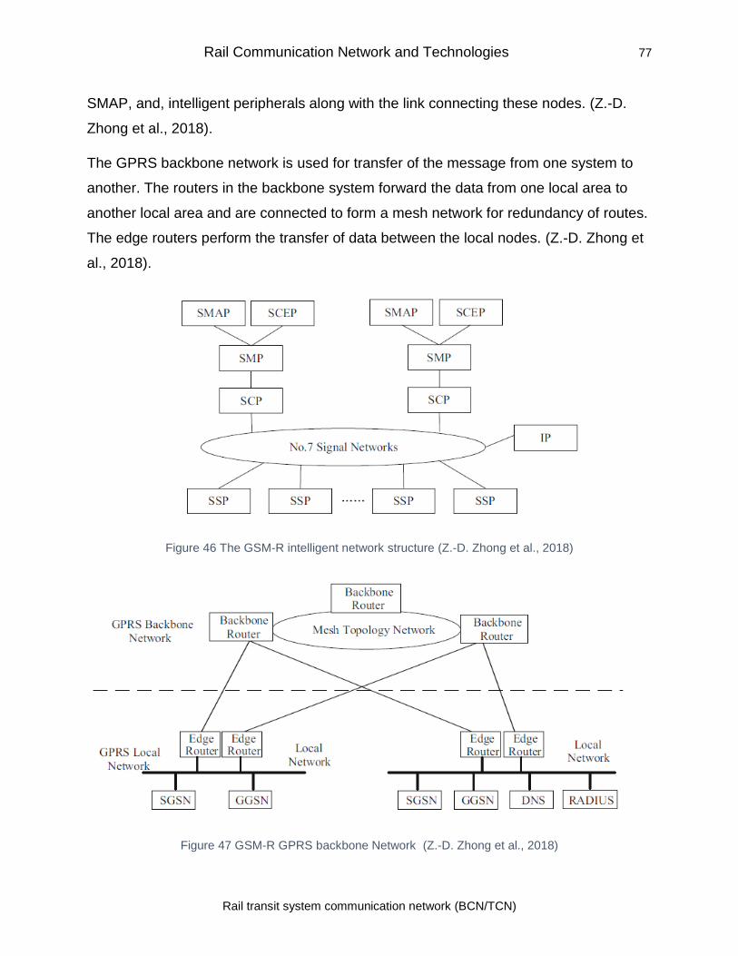
Rail Communication Network and Technologies 77
Rail transit system communication network (BCN/TCN)
SMAP, and, intelligent peripherals along with the link connecting these nodes. (Z.-D.
Zhong et al., 2018).
The GPRS backbone network is used for transfer of the message from one system to
another. The routers in the backbone system forward the data from one local area to
another local area and are connected to form a mesh network for redundancy of routes.
The edge routers perform the transfer of data between the local nodes. (Z.-D. Zhong et
al., 2018).
Figure 46 The GSM-R intelligent network structure (Z.-D. Zhong et al., 2018)
Figure 47 GSM-R GPRS backbone Network (Z.-D. Zhong et al., 2018)
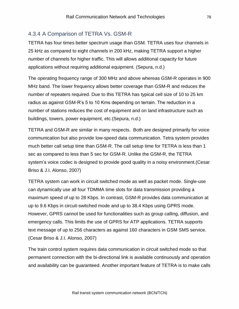
Rail Communication Network and Technologies 78
Rail transit system communication network (BCN/TCN)
4.3.4 A Comparison of TETRA Vs. GSM-R
TETRA has four times better spectrum usage than GSM. TETRA uses four channels in
25 kHz as compared to eight channels in 200 kHz, making TETRA support a higher
number of channels for higher traffic. This will allows additional capacity for future
applications without requiring additional equipment. (Sepura, n.d.)
The operating frequency range of 300 MHz and above whereas GSM-R operates in 900
MHz band. The lower frequency allows better coverage than GSM-R and reduces the
number of repeaters required. Due to this TETRA has typical cell size of 10 to 25 km
radius as against GSM-R’s 5 to 10 Kms depending on terrain. The reduction in a
number of stations reduces the cost of equipment and on land infrastructure such as
buildings, towers, power equipment, etc.(Sepura, n.d.)
TETRA and GSM-R are similar in many respects. Both are designed primarily for voice
communication but also provide low-speed data communication. Tetra system provides
much better call setup time than GSM-R. The call setup time for TETRA is less than 1
sec as compared to less than 5 sec for GSM-R. Unlike the GSM-R, the TETRA
system’s voice codec is designed to provide good quality in a noisy environment.(Cesar
Briso & J.I. Alonso, 2007)
TETRA system can work in circuit switched mode as well as packet mode. Single-use
can dynamically use all four TDMMA time slots for data transmission providing a
maximum speed of up to 28 Kbps. In contrast, GSM-R provides data communication at
up to 9.6 Kbps in circuit-switched mode and up to 38.4 Kbps using GPRS mode.
However, GPRS cannot be used for functionalities such as group calling, diffusion, and
emergency calls. This limits the use of GPRS for ATP applications. TETRA supports
text message of up to 256 characters as against 160 characters in GSM SMS service.
(Cesar Briso & J.I. Alonso, 2007)
The train control system requires data communication in circuit switched mode so that
permanent connection with the bi-directional link is available continuously and operation
and availability can be guaranteed. Another important feature of TETRA is to make calls
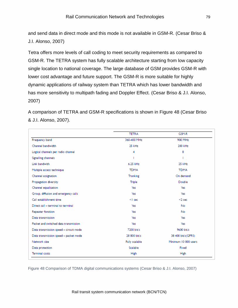
Rail Communication Network and Technologies 79
Rail transit system communication network (BCN/TCN)
and send data in direct mode and this mode is not available in GSM-R. (Cesar Briso &
J.I. Alonso, 2007)
Tetra offers more levels of call coding to meet security requirements as compared to
GSM-R. The TETRA system has fully scalable architecture starting from low capacity
single location to national coverage. The large database of GSM provides GSM-R with
lower cost advantage and future support. The GSM-R is more suitable for highly
dynamic applications of railway system than TETRA which has lower bandwidth and
has more sensitivity to multipath fading and Doppler Effect. (Cesar Briso & J.I. Alonso,
2007)
A comparison of TETRA and GSM-R specifications is shown in Figure 48 (Cesar Briso
& J.I. Alonso, 2007).
Figure 48 Comparison of TDMA digital communications systems (Cesar Briso & J.I. Alonso, 2007)
Rail Communication Network and Technologies 80
Rail transit system communication network (BCN/TCN)
4.3.5 Long term Evolution-Railway (LTE-R)
The Long term Evolution (LTE) is the successor of GSM G3 technology. The LTE needs
to be tailored for railway requirement and is termed as LTE-R on lines of GSM-R. First
LTE-R based system was claimed to have been implemented by Samsung and KT for
Wonju-Gangneung high-speed railway line. The line has a maximum speed of 250 km/h
and key railway specific features include availability Mission-Critical Push-to-talk
(MCPTT) button as per specifications are given in 3GPP standards Release 13. To be
compatible with the high-speed line the LTE-R based system must be able to operate at
speeds up to 500 km/r to match the speed of high-speed trains (Netmanias, 2017)
4.3.5.1 LTE-R Architecture
3GPP via its Rel8 specifications ratified new technology called Long Term Evolution
(LTE) or Evolved UTRAN (E-UTRAN). It uses Evolved Packet System (EPS) which in
turn uses Evolved Packet Core (EPC). EPC is based on a flat IP structure and uses
Orthogonal Frequency Division Multiplexing for downlink. The uplink uses
Synchronization Channel-Frequency Division Multiple Access (SC-FDMA) using carrier
bandwidth from 1.4 MHz up to 20 MHz. It can use frequency division duplexing as well
as time division duplexing. The interference using co-ordination techniques are avoided
by using SC-FDMA’s Inter-Cell Interference Coordination (ICIC) function. The base
station of GSM or Node B of UMTS is termed as evolved-Node B (eNode-B) in LTE.
eNode-B does radio resource management. The LTE supports peak theoretical data
rate of up to 150 Mbps on the downlink (using two x2 MIMO and 20 MHz BW) and 75
Mbps for uplink using 10 MHz BW. (4G Americas, 2012)
Figure 49 shows the projected architecture for LTE-R (He et al., 2016). The LTE-R
inherits main features of LTE and additional radio access system is provided to
communicate with onboard units as per requirement of high-speed rail (HSR). The
difference between LTE and LTE-R include network layout services, system
parameters, architecture, and QoS. The LTE-R network similar to LTE uses evolved
packet core (EPC) as a core network and Evolved Universal Terrestrial Radio Access
Network (E-UTRAN) as a radio access network. The EPC is based on Internet protocol
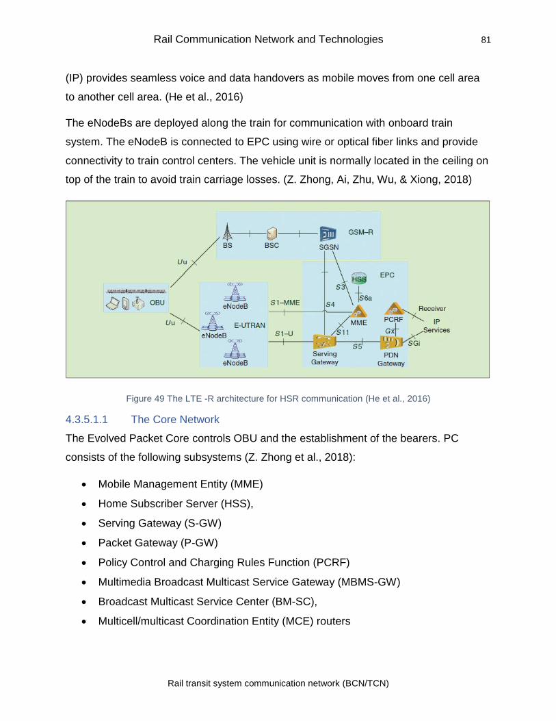
Rail Communication Network and Technologies 81
Rail transit system communication network (BCN/TCN)
(IP) provides seamless voice and data handovers as mobile moves from one cell area
to another cell area. (He et al., 2016)
The eNodeBs are deployed along the train for communication with onboard train
system. The eNodeB is connected to EPC using wire or optical fiber links and provide
connectivity to train control centers. The vehicle unit is normally located in the ceiling on
top of the train to avoid train carriage losses. (Z. Zhong, Ai, Zhu, Wu, & Xiong, 2018)
Figure 49 The LTE -R architecture for HSR communication (He et al., 2016)
4.3.5.1.1 The Core Network
The Evolved Packet Core controls OBU and the establishment of the bearers. PC
consists of the following subsystems (Z. Zhong et al., 2018):
• Mobile Management Entity (MME)
• Home Subscriber Server (HSS),
• Serving Gateway (S-GW)
• Packet Gateway (P-GW)
• Policy Control and Charging Rules Function (PCRF)
• Multimedia Broadcast Multicast Service Gateway (MBMS-GW)
• Broadcast Multicast Service Center (BM-SC),
• Multicell/multicast Coordination Entity (MCE) routers
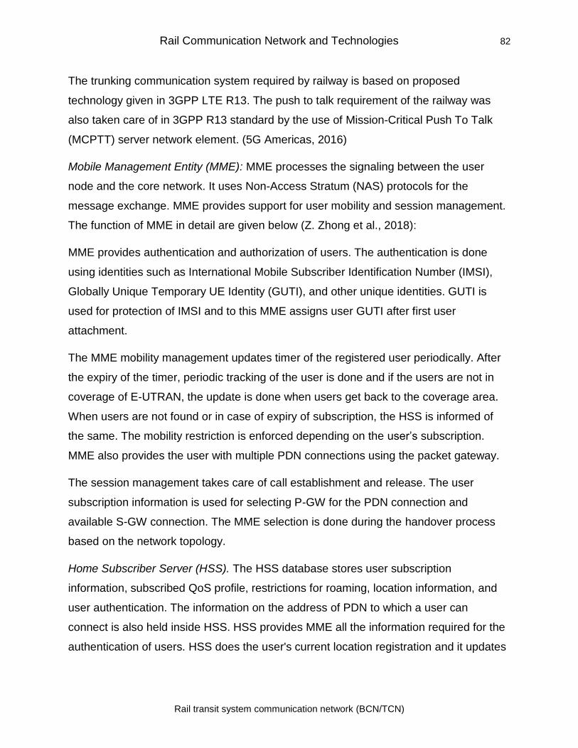
Rail Communication Network and Technologies 82
Rail transit system communication network (BCN/TCN)
The trunking communication system required by railway is based on proposed
technology given in 3GPP LTE R13. The push to talk requirement of the railway was
also taken care of in 3GPP R13 standard by the use of Mission-Critical Push To Talk
(MCPTT) server network element. (5G Americas, 2016)
Mobile Management Entity (MME): MME processes the signaling between the user
node and the core network. It uses Non-Access Stratum (NAS) protocols for the
message exchange. MME provides support for user mobility and session management.
The function of MME in detail are given below (Z. Zhong et al., 2018):
MME provides authentication and authorization of users. The authentication is done
using identities such as International Mobile Subscriber Identification Number (IMSI),
Globally Unique Temporary UE Identity (GUTI), and other unique identities. GUTI is
used for protection of IMSI and to this MME assigns user GUTI after first user
attachment.
The MME mobility management updates timer of the registered user periodically. After
the expiry of the timer, periodic tracking of the user is done and if the users are not in
coverage of E-UTRAN, the update is done when users get back to the coverage area.
When users are not found or in case of expiry of subscription, the HSS is informed of
the same. The mobility restriction is enforced depending on the user’s subscription.
MME also provides the user with multiple PDN connections using the packet gateway.
The session management takes care of call establishment and release. The user
subscription information is used for selecting P-GW for the PDN connection and
available S-GW connection. The MME selection is done during the handover process
based on the network topology.
Home Subscriber Server (HSS). The HSS database stores user subscription
information, subscribed QoS profile, restrictions for roaming, location information, and
user authentication. The information on the address of PDN to which a user can
connect is also held inside HSS. HSS provides MME all the information required for the
authentication of users. HSS does the user's current location registration and it updates
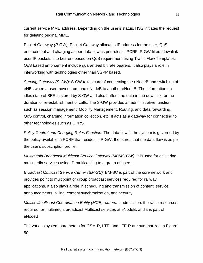
Rail Communication Network and Technologies 83
Rail transit system communication network (BCN/TCN)
current service MME address. Depending on the user’s status, HSS initiates the request
for deleting original MME.
Packet Gateway (P-GW): Packet Gateway allocates IP address for the user, QoS
enforcement and charging as per data flow as per rules in PCRF. P-GW filters downlink
user IP packets into bearers based on QoS requirement using Traffic Flow Templates.
QoS based enforcement include guaranteed bit rate bearers. It also plays a role in
interworking with technologies other than 3GPP based.
Serving Gateway (S-GW): S-GW takes care of connecting the eNodeB and switching of
eNBs when a user moves from one eNodeB to another eNodeB. The information on
idles state of SER is stored by S-GW and also buffers the data in the downlink for the
duration of re-establishment of calls. The S-GW provides an administrative function
such as session management, Mobility Management, Routing, and data forwarding,
QoS control, charging information collection, etc. It acts as a gateway for connecting to
other technologies such as GPRS.
Policy Control and Charging Rules Function: The data flow in the system is governed by
the policy available in PCRF that resides in P-GW. It ensures that the data flow is as per
the user’s subscription profile.
Multimedia Broadcast Multicast Service Gateway (MBMS-GW): It is used for delivering
multimedia services using IP-multicasting to a group of users.
Broadcast Multicast Service Center (BM-SC): BM-SC is part of the core network and
provides point to multipoint or group broadcast services required for railway
applications. It also plays a role in scheduling and transmission of content, service
announcements, billing, content synchronization, and security.
Multicell/multicast Coordination Entity (MCE) routers: It administers the radio resources
required for multimedia broadcast Multicast services at eNodeB, and it is part of
eNodeB.
The various system parameters for GSM-R, LTE, and LTE-R are summarized in Figure
50.
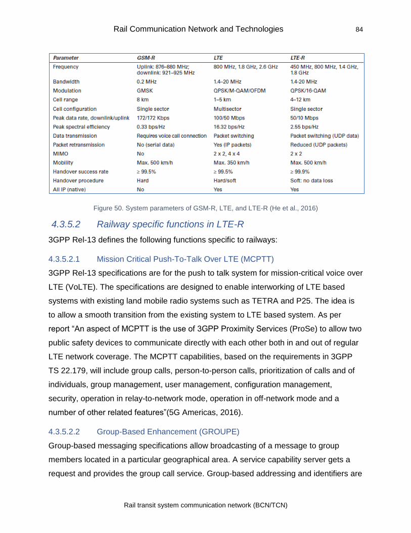
Rail Communication Network and Technologies 84
Rail transit system communication network (BCN/TCN)
Figure 50. System parameters of GSM-R, LTE, and LTE-R (He et al., 2016)
4.3.5.2 Railway specific functions in LTE-R
3GPP Rel-13 defines the following functions specific to railways:
4.3.5.2.1 Mission Critical Push-To-Talk Over LTE (MCPTT)
3GPP Rel-13 specifications are for the push to talk system for mission-critical voice over
LTE (VoLTE). The specifications are designed to enable interworking of LTE based
systems with existing land mobile radio systems such as TETRA and P25. The idea is
to allow a smooth transition from the existing system to LTE based system. As per
report “An aspect of MCPTT is the use of 3GPP Proximity Services (ProSe) to allow two
public safety devices to communicate directly with each other both in and out of regular
LTE network coverage. The MCPTT capabilities, based on the requirements in 3GPP
TS 22.179, will include group calls, person-to-person calls, prioritization of calls and of
individuals, group management, user management, configuration management,
security, operation in relay-to-network mode, operation in off-network mode and a
number of other related features”(5G Americas, 2016).
4.3.5.2.2 Group-Based Enhancement (GROUPE)
Group-based messaging specifications allow broadcasting of a message to group
members located in a particular geographical area. A service capability server gets a
request and provides the group call service. Group-based addressing and identifiers are
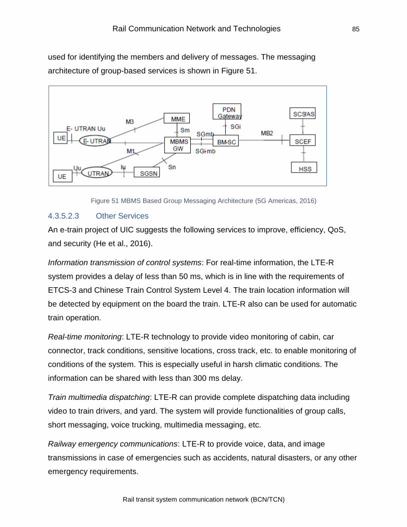
Rail Communication Network and Technologies 85
Rail transit system communication network (BCN/TCN)
used for identifying the members and delivery of messages. The messaging
architecture of group-based services is shown in Figure 51.
Figure 51 MBMS Based Group Messaging Architecture (5G Americas, 2016)
4.3.5.2.3 Other Services
An e-train project of UIC suggests the following services to improve, efficiency, QoS,
and security (He et al., 2016).
Information transmission of control systems: For real-time information, the LTE-R
system provides a delay of less than 50 ms, which is in line with the requirements of
ETCS-3 and Chinese Train Control System Level 4. The train location information will
be detected by equipment on the board the train. LTE-R also can be used for automatic
train operation.
Real-time monitoring: LTE-R technology to provide video monitoring of cabin, car
connector, track conditions, sensitive locations, cross track, etc. to enable monitoring of
conditions of the system. This is especially useful in harsh climatic conditions. The
information can be shared with less than 300 ms delay.
Train multimedia dispatching: LTE-R can provide complete dispatching data including
video to train drivers, and yard. The system will provide functionalities of group calls,
short messaging, voice trucking, multimedia messaging, etc.
Railway emergency communications: LTE-R to provide voice, data, and image
transmissions in case of emergencies such as accidents, natural disasters, or any other
emergency requirements.
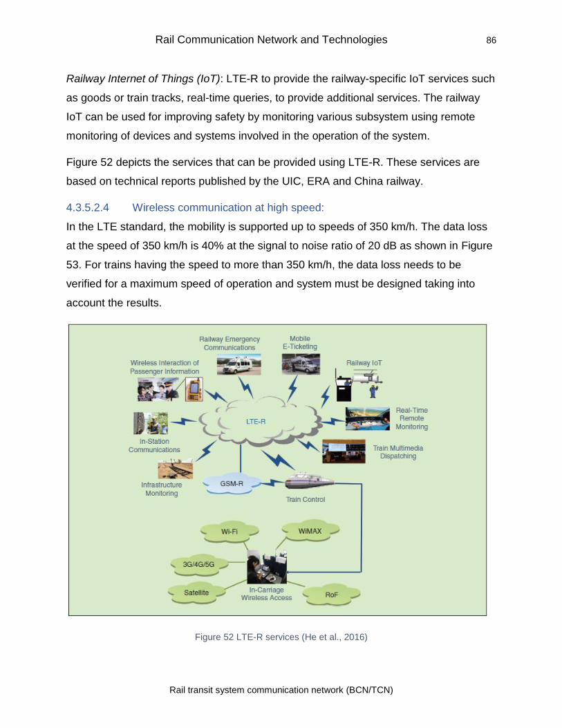
Rail Communication Network and Technologies 86
Rail transit system communication network (BCN/TCN)
Railway Internet of Things (IoT): LTE-R to provide the railway-specific IoT services such
as goods or train tracks, real-time queries, to provide additional services. The railway
IoT can be used for improving safety by monitoring various subsystem using remote
monitoring of devices and systems involved in the operation of the system.
Figure 52 depicts the services that can be provided using LTE-R. These services are
based on technical reports published by the UIC, ERA and China railway.
4.3.5.2.4 Wireless communication at high speed:
In the LTE standard, the mobility is supported up to speeds of 350 km/h. The data loss
at the speed of 350 km/h is 40% at the signal to noise ratio of 20 dB as shown in Figure
53. For trains having the speed to more than 350 km/h, the data loss needs to be
verified for a maximum speed of operation and system must be designed taking into
account the results.
Figure 52 LTE-R services (He et al., 2016)
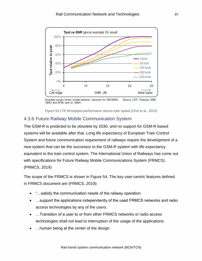
Rail Communication Network and Technologies 87
Rail transit system communication network (BCN/TCN)
Figure 53 LTE throughput performance versus train speed (Choi et al., 2013)
4.3.6 Future Railway Mobile Communication System
The GSM-R is predicted to be obsolete by 2030, and no support for GSM-R based
systems will be available after that. Long life expectancy of European Train Control
System and future communication requirement of railways require the development of a
new system that can be the successor to the GSM-R system with life expectancy
equivalent to the train control system. The International Union of Railways has come out
with specifications for Future Railway Mobile Communications System (FRMCS).
(FRMCS, 2019)
The scope of the FRMCS is shown in Figure 54. The key user-centric features defined
in FRMCS document are (FRMCS, 2019):
• “…satisfy the communication needs of the railway operation
• …support the applications independently of the used FRMCS networks and radio
access technologies by any of the users.
• …Transition of a user to or from other FRMCS networks or radio access
technologies shall not lead to interruption of the usage of the applications
• …human being at the center of the design
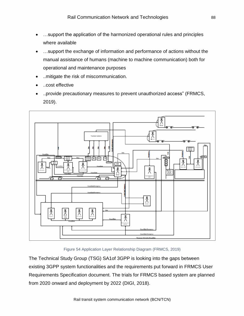
Rail Communication Network and Technologies 88
Rail transit system communication network (BCN/TCN)
• …support the application of the harmonized operational rules and principles
where available
• …support the exchange of information and performance of actions without the
manual assistance of humans (machine to machine communication) both for
operational and maintenance purposes
• ..mitigate the risk of miscommunication.
• ..cost effective
• ..provide precautionary measures to prevent unauthorized access” (FRMCS,
2019).
Figure 54 Application Layer Relationship Diagram (FRMCS, 2019)
The Technical Study Group (TSG) SA1of 3GPP is looking into the gaps between
existing 3GPP system functionalities and the requirements put forward in FRMCS User
Requirements Specification document. The trials for FRMCS based system are planned
from 2020 onward and deployment by 2022 (DIGI, 2018).
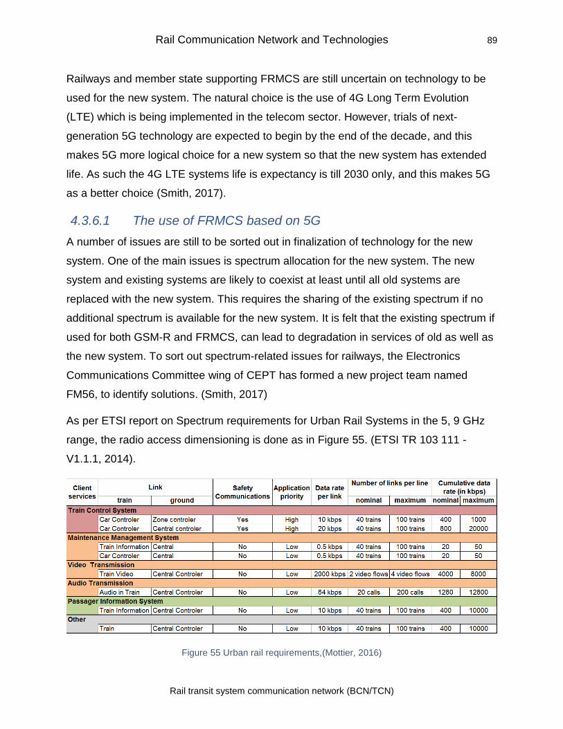
Rail Communication Network and Technologies 89
Rail transit system communication network (BCN/TCN)
Railways and member state supporting FRMCS are still uncertain on technology to be
used for the new system. The natural choice is the use of 4G Long Term Evolution
(LTE) which is being implemented in the telecom sector. However, trials of next-
generation 5G technology are expected to begin by the end of the decade, and this
makes 5G more logical choice for a new system so that the new system has extended
life. As such the 4G LTE systems life is expectancy is till 2030 only, and this makes 5G
as a better choice (Smith, 2017).
4.3.6.1 The use of FRMCS based on 5G
A number of issues are still to be sorted out in finalization of technology for the new
system. One of the main issues is spectrum allocation for the new system. The new
system and existing systems are likely to coexist at least until all old systems are
replaced with the new system. This requires the sharing of the existing spectrum if no
additional spectrum is available for the new system. It is felt that the existing spectrum if
used for both GSM-R and FRMCS, can lead to degradation in services of old as well as
the new system. To sort out spectrum-related issues for railways, the Electronics
Communications Committee wing of CEPT has formed a new project team named
FM56, to identify solutions. (Smith, 2017)
As per ETSI report on Spectrum requirements for Urban Rail Systems in the 5, 9 GHz
range, the radio access dimensioning is done as in Figure 55. (ETSI TR 103 111 -
V1.1.1, 2014).
Figure 55 Urban rail requirements,(Mottier, 2016)
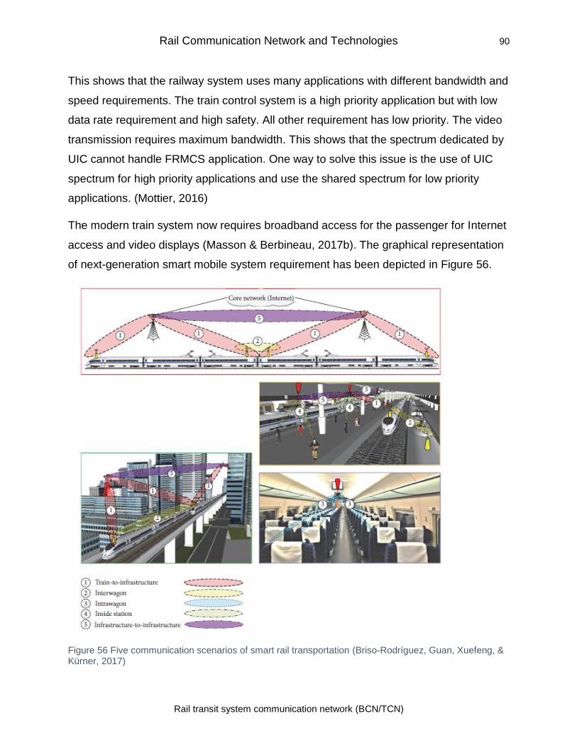
Rail Communication Network and Technologies 90
Rail transit system communication network (BCN/TCN)
This shows that the railway system uses many applications with different bandwidth and
speed requirements. The train control system is a high priority application but with low
data rate requirement and high safety. All other requirement has low priority. The video
transmission requires maximum bandwidth. This shows that the spectrum dedicated by
UIC cannot handle FRMCS application. One way to solve this issue is the use of UIC
spectrum for high priority applications and use the shared spectrum for low priority
applications. (Mottier, 2016)
The modern train system now requires broadband access for the passenger for Internet
access and video displays (Masson & Berbineau, 2017b). The graphical representation
of next-generation smart mobile system requirement has been depicted in Figure 56.
Figure 56 Five communication scenarios of smart rail transportation (Briso-Rodríguez, Guan, Xuefeng, & Kürner, 2017)
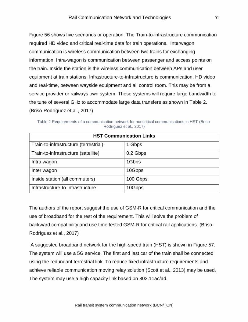
Rail Communication Network and Technologies 91
Rail transit system communication network (BCN/TCN)
Figure 56 shows five scenarios or operation. The Train-to-infrastructure communication
required HD video and critical real-time data for train operations. Interwagon
communication is wireless communication between two trains for exchanging
information. Intra-wagon is communication between passenger and access points on
the train. Inside the station is the wireless communication between APs and user
equipment at train stations. Infrastructure-to-infrastructure is communication, HD video
and real-time, between wayside equipment and ail control room. This may be from a
service provider or railways own system. These systems will require large bandwidth to
the tune of several GHz to accommodate large data transfers as shown in Table 2.
(Briso-Rodríguez et al., 2017)
Table 2 Requirements of a communication network for noncritical communications in HST (Briso-Rodríguez et al., 2017)
HST Communication Links
Train-to-infrastructure (terrestrial) 1 Gbps
Train-to-infrastructure (satellite) 0.2 Gbps
Intra wagon 1Gbps
Inter wagon 10Gbps
Inside station (all commuters) 100 Gbps
Infrastructure-to-infrastructure 10Gbps
The authors of the report suggest the use of GSM-R for critical communication and the
use of broadband for the rest of the requirement. This will solve the problem of
backward compatibility and use time tested GSM-R for critical rail applications. (Briso-
Rodríguez et al., 2017)
A suggested broadband network for the high-speed train (HST) is shown in Figure 57.
The system will use a 5G service. The first and last car of the train shall be connected
using the redundant terrestrial link. To reduce fixed infrastructure requirements and
achieve reliable communication moving relay solution (Scott et al., 2013) may be used.
The system may use a high capacity link based on 802.11ac/ad.
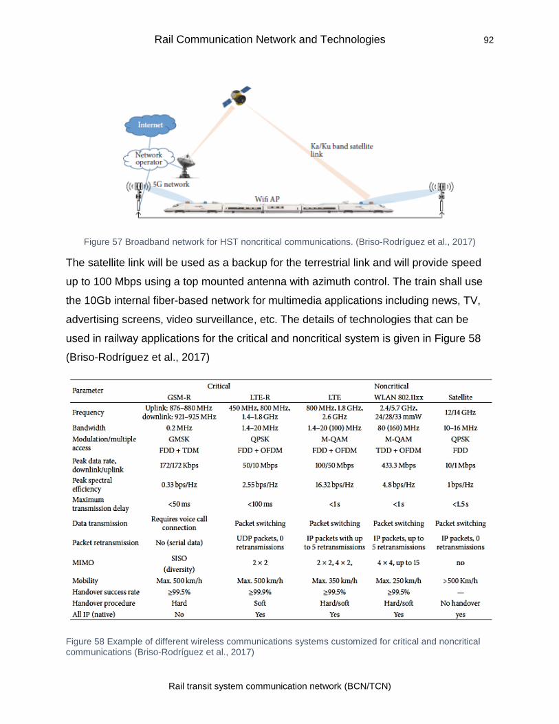
Rail Communication Network and Technologies 92
Rail transit system communication network (BCN/TCN)
Figure 57 Broadband network for HST noncritical communications. (Briso-Rodríguez et al., 2017)
The satellite link will be used as a backup for the terrestrial link and will provide speed
up to 100 Mbps using a top mounted antenna with azimuth control. The train shall use
the 10Gb internal fiber-based network for multimedia applications including news, TV,
advertising screens, video surveillance, etc. The details of technologies that can be
used in railway applications for the critical and noncritical system is given in Figure 58
(Briso-Rodríguez et al., 2017)
Figure 58 Example of different wireless communications systems customized for critical and noncritical communications (Briso-Rodríguez et al., 2017)
Rail Communication Network and Technologies 93
Rail transit system communication network (BCN/TCN)
4.4 Supervisory/SCADA system for train control
As the railway grew, the operations of the railway system have become more
sophisticated. The central monitoring and control of the system play a key role in the
safe operations of the railway system. In general, for each railway system, there is an
Operation and control center which is linked to smaller control centers at stations and
wayside using high-speed links. Supervisory Control and Data Acquisition (SCADA)
system are used for monitoring of various equipment and subsystems distributed over
various locations along the rail tracks. The SCADA system collects the data from
various remote sites and sends it to central monitoring and controls system to carry out
necessary monitoring and control of the system. (Belmonte, Boulanger, Schön, &
Berkani, 2006)
4.4.1 Typical SCADA System
A typical SCADA system integrated with the corporate enterprise network is shown in
Figure 59. The three key functional units of SCADA system are the master terminal unit
(MTU), the remote terminal unit (RTU), and communication system.
4.4.1.1 Remote Terminal Units
The remote terminal units are connected to the field sensors, switches, controls, etc.
and collect data from these devices. The remote terminal units are installed at various
locations for collecting the data to be monitored. SCADA system can use RTU or
Programmable Logic Controller (PLC) as per the system configuration. PLCs are small
industrial computers that can collect the data as well as perform complex processes for
onsite data processing. PLCs, traditionally, have been used for process control systems
in plants and manufacturing units. These automate many controllers and logic systems
earlier used by the industry. PLC nowadays is also used in place of RTUs where local
processing and control of the system is required. Due to their flexibility and lowering of
cost, these have replaced RTUs in many systems. (Stouffer, Falco, & Kent, 2006)
4.4.1.1 Master Terminal Unit
The master terminal unit consists of servers running SCADA and other application
software, engineering work stations, and Human-Machine Interface or Man Machine
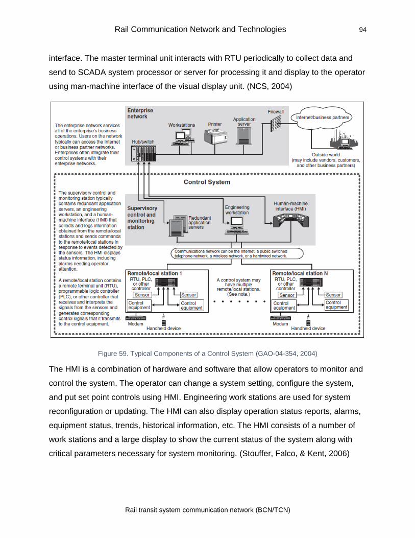
Rail Communication Network and Technologies 94
Rail transit system communication network (BCN/TCN)
interface. The master terminal unit interacts with RTU periodically to collect data and
send to SCADA system processor or server for processing it and display to the operator
using man-machine interface of the visual display unit. (NCS, 2004)
Figure 59. Typical Components of a Control System (GAO-04-354, 2004)
The HMI is a combination of hardware and software that allow operators to monitor and
control the system. The operator can change a system setting, configure the system,
and put set point controls using HMI. Engineering work stations are used for system
reconfiguration or updating. The HMI can also display operation status reports, alarms,
equipment status, trends, historical information, etc. The HMI consists of a number of
work stations and a large display to show the current status of the system along with
critical parameters necessary for system monitoring. (Stouffer, Falco, & Kent, 2006)
Rail Communication Network and Technologies 95
Rail transit system communication network (BCN/TCN)
4.4.1.2 Communications System
The communication system is used for data collection from sensors to the RTUs,
transfer data from RTU’s to the master control units. The communication network can
be wired, wireless, Ethernet, satellite or combination of one or more of these
technologies as required. The remote sites not accessible using wired systems use
wireless systems to transfer data from RTU’s. For difficult to access remote locations,
the satellite terminals are used for collection of data from RTU (Stouffer, Falco, & Kent,
2006)
4.4.1.3 SCADA System in Train control
A typical example of train control and operations system using SCADA is shown in
Figure 60. The system consists of a primary control center and three field
stations/subsystems. The main control center is connected to the three centers using
ring topology-based WAN. The field RTUs and PLCs collect data from wayside
equipment and transmit it to the rail control center over the WAN. (Stouffer, Falco, &
Kent, 2006)
The monitoring and control are done using Man/human-machine interface (MMI) or
operator console and associated input devices such as keyboard and trackball for
navigation. Large video displays are used or displaying the system status for monitoring
the rail network. The system generates an audio-visual alarm in case of any problem to
alert the operator.
Railway supervision can be divided into three hierarchical levels (Belmonte et al., 2006):
i. Route control: Include train control, route setting, ending commands, and
protection functions
ii. Traffic flow control: Real-time monitoring of the system, conflict solving, etc.
iii. System management and planning
The key functions of the train supervisory system are:
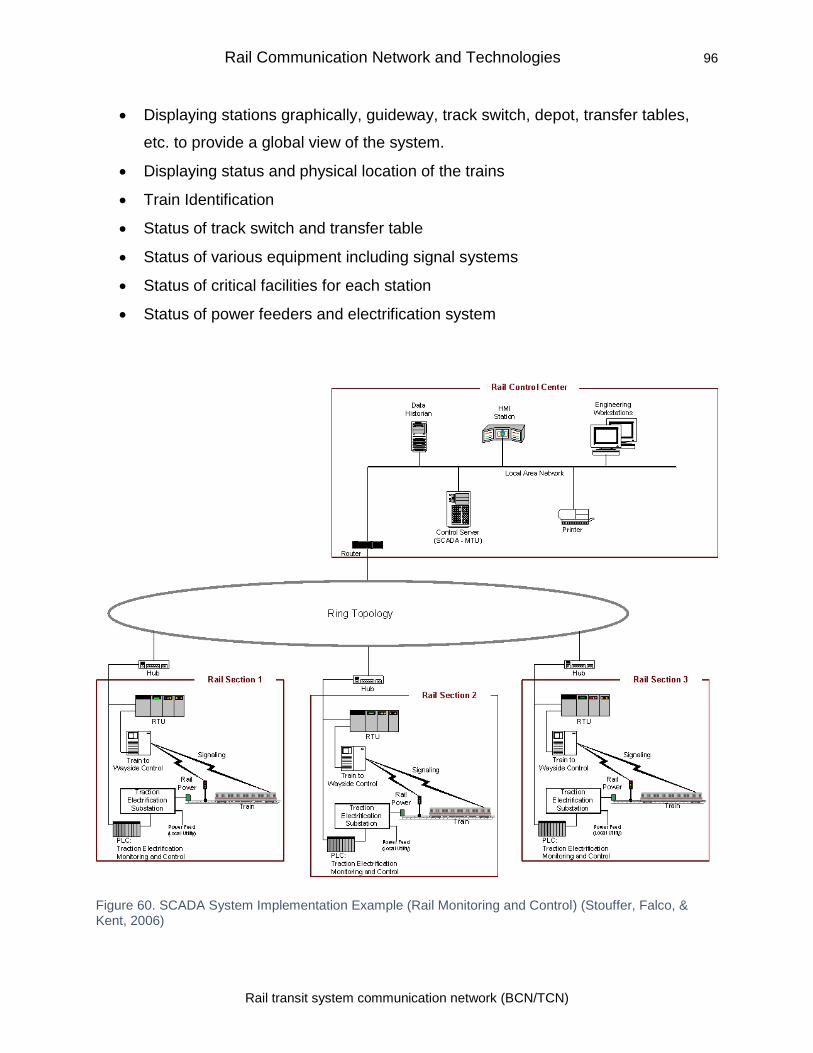
Rail Communication Network and Technologies 96
Rail transit system communication network (BCN/TCN)
• Displaying stations graphically, guideway, track switch, depot, transfer tables,
etc. to provide a global view of the system.
• Displaying status and physical location of the trains
• Train Identification
• Status of track switch and transfer table
• Status of various equipment including signal systems
• Status of critical facilities for each station
• Status of power feeders and electrification system
Figure 60. SCADA System Implementation Example (Rail Monitoring and Control) (Stouffer, Falco, & Kent, 2006)
5.0 Security of Train Communication System
The rapid automation of railway system has brought many new technologies including
internet for use in train control systems. Earlier, the use of proprietary hardware and
software systems and protocols were difficult to understand and this made hacking into
these systems difficult unless some insider with system knowledge was involved. With
standardization and interoperability of equipment, the use of commercial off-the-shelf
(COTS) especially IT related system has grown many folds and brought down the
system costs and their maintenance substantially (GAO-04-354, 2004). The
standardized technologies including operating systems, protocols are widely used and
also have commonly known vulnerabilities such as virus, worms and other attacks. The
availability sophisticated and of easy to use exploitation tools for these vulnerabilities
allow exploitation of these simple resulting in substantial increase in attacks using the
common vulnerabilities. The transit industry has also used these technologies and
COTs extensively to lower the system cost, cost of training and maintenance over
proprietary systems. This has led to many attacks on ICS and SCADA system by
exploiting the known vulnerabilities. (Stouffer, Pillitteri, Lightman, Abrams, & Hahn,
2015) (APTA SS-CCS-RP-001-10, 2010)
The use of wireless technology to provide mobility and use of modern techniques in the
train control system has opened the system to vulnerabilities of the wireless system.
With the use of a wireless system, the network and trains no longer function as a closed
system that leads to vulnerabilities and threats. (DHS, 2012) (Chen et al., 2014)
This section looks into the security aspect of the SCADA system and various
communication technologies used in modern train control systems such as Wi-Fi, GSM,
LTE, etc.
5.1 Attacks on ICS/SCADA Systems
A large number of attacks on rail systems, Industrial control system (ICS) and SCADA
have been reported. (Sayegh, Chehab, Elhajj, & Kayssi, 2013) (APTA SS-CCS-RP-001-
10, 2010)
Security of Train Communication System 98
Rail transit system communication network (BCN/TCN)
NIST classifies the ICS/SCADA security-related incidents in three categories:
intentionally targeted attacks, unintentional threats, and unintentional internal security
consequences. The unintentional threats are damages due to worms, virus, system
failure etc. The unintentional internal security consequences are related to the changes
or configuration carried out without proper authorization. The intentionally targeted
attacks are most damaging of the three as the attacker is normally a skilled person and
has knowledge about the system. The threat agents to a control system include ex-
employees, contractors, and other dissatisfied individuals working for the organization.
(Stouffer et al., 2015)(Sayegh, Chehab, Elhajj, & Kayssi, 2013)(Shaw, 2004)
5.1.1 Intentional Attacks
• Salt River Project: In 1994, a breach in the computer system of the Salt River
Project, supplying water and electricity to Phoenix, Arizona was detected. The
attackers accessed the computer system by dialing into a backup computer using
the modem. (GAO-04-354, 2004)
• Worcester Air Traffic Communications: The air traffic at the airport of
Worcester, Massachusetts was disrupted for many hours when a teenager was
able to disable part of the phone system. The attacker used a simple modem to
get into the Bell Atlantic computer system. (Thomas, 1998)
• Maroochy Shire Sewage Spill: Vitek Boden, an Australian employed by the
company who has installed the sewage control system, attacked the system
leading spill of millions of liter of raw sewage into local parks at Maroochy Shire,
Queensland. He did so after his application for employment in the company was
turned down. (Thomas, 1998)
• The other incident occurred when a Polish teenager modified his TV remote and
used it to hack into the tram system in the city of Lodz (Leyden, 2008). He used
the remote to change the track point, and this led to the derailment of trams and
spreading chaos. The device he used was able to maneuver the trams and the
tracks.
• Siemen’s S-7 SCADA was attacked using a malware called Stuxnet in Iran in
2010. The system was infected using a USN drive, and the worm was installed
Security of Train Communication System 99
Rail transit system communication network (BCN/TCN)
on a PLC to inject malware code into the system. The Stuxnet malware exploits
Windows LNK-files security loopholes. The malware looks for certain specific
information and then send it to the external servers. (McMillan, 2010)
5.1.2 Unintentional Consequences
• CSX Train Signaling System: The rail system has also been the victim of these
attacks. The virus attack on CSX railway in 2003 and hacking of polish tram in
2007 have been well documented. A virus, called “Sobig,” infected CSX
Corporation’s computers at their headquarter in Jacksonville, Fla and thus led to
disruption in dispatching, signaling, and other systems (DAVID HANCOCK,
2003). This outage affected complete CSX system covering 23 states and led to
delays and cancellation of many trains.
• Northeast Power Blackout: A failure of the alarm processor of the First
Energy’s SCADA system led to tripping of 345 kV transmission lines in Northern
Ohio as the operators could not get the information about alarms. This lead to the
failure of the grid and tripping of 256 power plants. (Stouffer et al., 2006)
5.1.3 Unintentional Internal Security Consequences
• Vulnerability Scanner Incidents: This incident happened at Sandia National
Laboratories a facility created for the U.S. Department of Energy’s National
Nuclear Security Administration. During testing of 9 ft, robotic arm of SCADA
system using ping sweep made the arm “active” and it swung 180 degree and
damaged wafers worth $50,000. (Stouffer et al., 2006)
• Bellingham, Washington Gasoline Pipeline Failure: The SCADA system
failure at Bellingham, Washington Gasoline Pipeline led to a leak of 237,000
gallons of gasoline in 1999. The pipeline later caught fire and led to the death of
3 persons, injuring eight and caused extensive damage to the property. (Stouffer
et al., 2006)
The consequences of a security breach in the SCADA system are many and include
physical, economic, and social impacts. The attacks can lead to loss of production,
death, injuries, damage to equipment and property, damage to the environment, theft of
Security of Train Communication System 100
Rail transit system communication network (BCN/TCN)
materials, contamination of natural resources, loss of confidential data, loss of
company’s brand image in public and many more. (Stouffer et al., 2006)
5.2 SCADA System Vulnerabilities
The modern SCADA systems use communication technologies such as Ethernet,
TCP/IP, and other Internet technologies for seamless networking and interconnection
among the equipment from different vendors. The use of web-based technologies such
as ActiveX, Java, etc. opens more possibilities of cyber-attacks (Hentea, 2008). This
has resulted in vulnerabilities associated with these communication and networking
technologies to get passed on to SCADA systems using these technologies. (NCS,
2004)
The General Accounting Office (GAO) report on Information Security Issues also
validates above and indicates that the risk to industrial control systems have escalated
due to the use of standard systems with known vulnerabilities, use of insecure remote
connections, interconnection of SCADA system to other systems, and availability of
network infrastructure and control system details in public domain. The GAO report also
gave a typical diagram of a SCADA system depicting the interconnection to remote
units and outside systems. The communication can be using wired or wireless
connections. The connection to the outside world is using the Internet. (GAO-04-354,
2004)
Security of SCADA system can be compromised in many ways in the system, and the
easiest place is from the control room or host level. The connection to the corporate
network is another area where SCADA systems can be accessed. In case of the
corporate network getting compromised the SCADA system also become vulnerable.
(NCS, 2004)
From a security point of view, the linkages between different networks are the weak
points in the network as an attacker can exploit these to get into the system. The
SCADA system host is vulnerable to following attacks from the weak linkage (NCS,
2004):
Security of Train Communication System 101
Rail transit system communication network (BCN/TCN)
• The launch of Denial of Service (DoS) attack to bring down the SCADA server
and shutting down the server
• Deleting SCADA server system files
• Insert trojan into the system to take control of the system
• Steal username and password by logging operator’s keystrokes.
• Steal sensitive data about operations to get a competitive advantage
• Modifying data set points to deceive system and operators to make them shut
down the system
• Hack remote database and modify the same
• Use the SCADA server to launch an attack on the corporate network.
The NCS report has detailed these vulnerabilities in a tabular form. An important
observation in reports says “SCADA Administrators and Industrial Systems Analysts are
often deceived into thinking that since their industrial networks are on separate systems
from the corporate network, they are safe from outside attacks” (NCS, 2004)
Another report by American researchers found twenty fine zero-day vulnerabilities in
SCADA software for critical infrastructure systems from 20 leading suppliers. The
vulnerabilities were found in the communication equipment between servers and remote
stations. These vulnerabilities are the cause of concern as in this area there is no
firewall to protect the network. (Ashford, 2013)
5.2.1 Cyber Attacks on SCADA Systems
5.2.1.1 Attacks on Hardware
The attacks on hardware can happen due to unauthorized physical access to the
system or remote access.
5.2.1.2 Attacks on Software
The software attacks include holes in the operating system used. The absence of any
privilege of protection in embedded operating systems used. The buffer overflow can
create a problem for servers, work stations, as well as field devices as these systems,
run for a very long time without rebooting leading to accumulated memory fragmentation
Security of Train Communication System 102
Rail transit system communication network (BCN/TCN)
and program stalling. Many SCADA applications use SQL (Structured Query Language)
for accessing the database. The SQL is susceptible to cyber-attack. In SQL injection
attack the attacker manipulates web application data by inserting a number of
unexpected SQL statements into a query. (B. Zhu, Joseph, & Sastry, 2011)
5.2.1.3 Attacks on Communication Stack
TCP/IP protocol is vulnerable to many attacks, and some of the attacks that can harm
the SCADA system are given below (B. Zhu et al., 2011):
Network Layer attacks
Diagnostic Server Attacks through UDP port: The UDP port can be used by an attacker
to get system details by using debugging tools used by the developers.
Idle Scan: It is used to blind a port scan so that attacks such as dumb “zombie” host or
another attack cannot take place. The scanning functionality of two popular protocols
MODBUS and DNP3 used by SCADA systems when used over TCP/IP is vulnerable to
this attack.
Smurf: In this continuous stream of ICMP (Internet Control Message Protocol) is sent to
the host to overload it with requests leading to crash. The PLC can crash or issue
dangerous command if PLC acts on any modified message. (B. Zhu et al., 2011):
Address Resolution Protocol (ARP) Spoofing/Poisoning: ARP is used to port IP address
to Ethernet MAC address for transfer of data over LAN. The ARP spoofing attack
changes Ethernet MAC address to attacker’s address and so that it gets associated with
the IP address and all the traffic gets diverted to attacker’s computer. In case of a
SCADA system, this will make network devices send a packet to attackers or an
unreachable host. (B. Zhu et al., 2011):
Transport Layer attacks
SYN flood attack host is flooded with TCP message more than it can process leading to
a system crash.
Security of Train Communication System 103
Rail transit system communication network (BCN/TCN)
Application Layer attacks
The SCADA protocol does not have any mechanism to find out the source of data, and
hence anyone with access to the devices using these protocols can attack the system.
DNS forgery is one such attack when fake DNS reply with matching attributes but the
attacker’s information inside is sent for processing by the client before a real DNS reply
is received. (Hansman & Hunt, 2005)
Attacks on SCADA protocols
The MODBUS/TCP is an application layer protocol used by SCADA system access
server from the client end. Since there is no encryption involved, the system is prone to
attacks. DNP3 protocol is used for communication between master control stations and
remote stations mainly in power and water companies. The DNP3 based remote
stations can be reset or reconfigured by sending code 0x0D. The attacker can use this
facility to manipulate or delay response from the remote station. (B. Zhu et al., 2011)
The Factory Intelligent Network Services (FINS) Protocol used by many PLCs does not
use any encryption, and any eavesdropper can extract the password and hack into the
system. The other attacks that can be launched using FINS are replay attack,
fragmentation attacks, DoS attacks, etc. (Sayegh et al., 2013)
5.3 Security of Wireless Networks
The wireless network’s vulnerabilities include those in traditional wired network plus the
vulnerability due to the easy interception of wireless signals using appropriate device or
equipment.
5.3.1 Vulnerabilities and Threats to Wireless Networks
The vulnerability of wireless networks can be due to the following (Lane, 2019):
5.3.1.1 Eavesdropping or Sniffing
The wireless signals can be easily intercepted even outside the premises using a proper
receiver. In the case of the rail network, the access point is located by wayside making it
easy anyone near to eavesdrop on the signals. The attacker after intercepting the data
Security of Train Communication System 104
Rail transit system communication network (BCN/TCN)
can modify or insert another data the network. A number of free wireless sniffing tools
such as tcpdump and Ethereal are available for free on websites for capturing data.
Tcpdump uses the text-based command to capture data while Ethereal provides a
graphical interface for capturing and analyzing the data. AiroPeek from WildPackets and
Sniffer Wireless from Network Associates are two of many commercial tools available
for sniffing and analyzing the captured data. (Sankar, Sundaralingam, Balinsky, & Miller,
2004)
5.3.1.2 Physically insecure locations
The installation of wireless equipment in an insecure location can allow an attacker to
access the system by using its administrative port. (Lane, 2019)
5.3.1.3 Rogue access points
The rogue access points are access point installed by an attacker to trick users into
accessing their system so that they can sniff into the data and steal information. (Lane,
2019)
5.3.1.4 MAC address spoofing
Wireless access points can be configured to allow only devices whose MAC address
has been registered with the WAP. However, an attacker may get around this by
spoofing the MAC address, and therefore some additional mechanism is needed to
restrict access.
5.3.1.5 Wardriving
The wardriving is normally used to check the coverage area of a mobile system. The
vehicle with wardriving equipment goes around the places to check the access.
However, this can be used by a hacker to map the system. A number of wardriving tools
are available in the market such as Kismet, Network Stumbler, MacStumbler for MAC,
bsd-airtools for FreeBSD OS and Wellenreiter for BSD and Linux. (Sankar et al., 2004)
5.3.1.6 Denial-Of-Service (DOS) attacks
The wireless system can be kept out of service by launching a signal of higher power
than the normal signal. The radio-jamming system is used for this. The attacker can
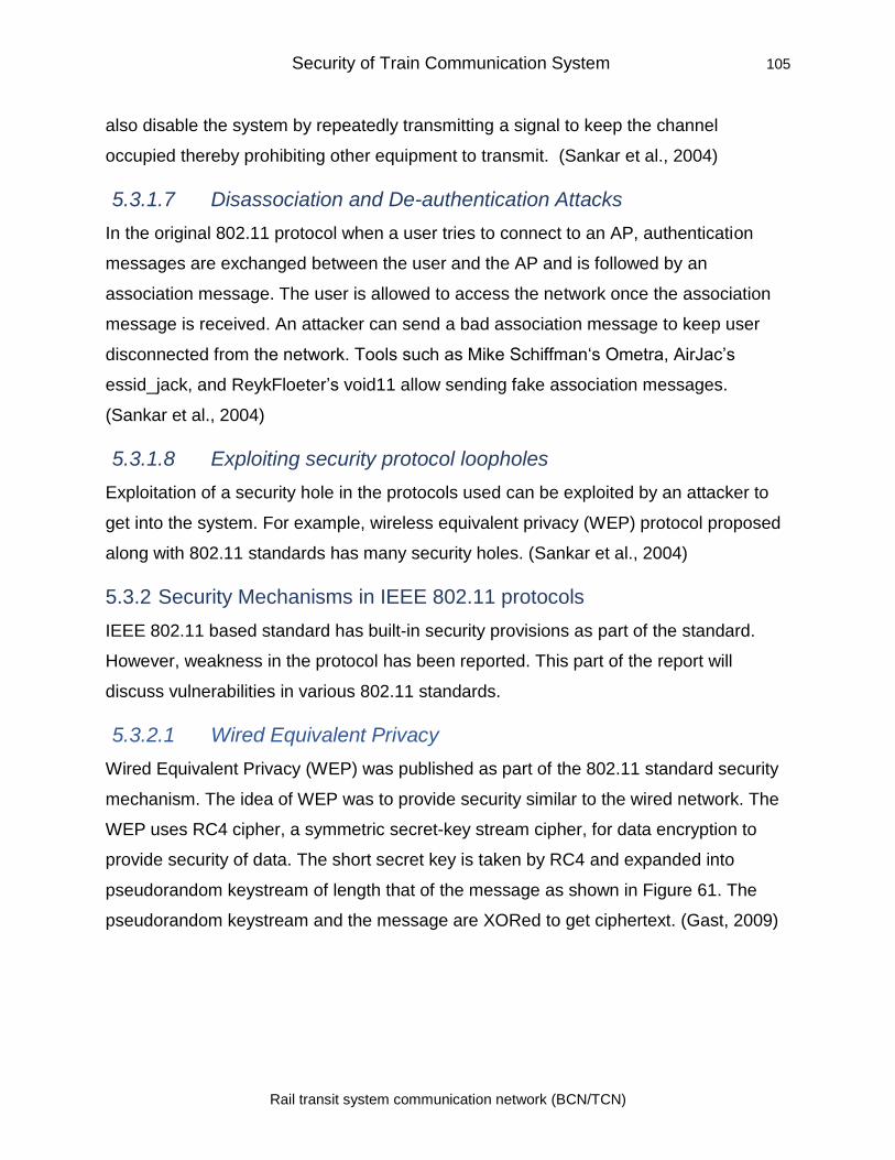
Security of Train Communication System 105
Rail transit system communication network (BCN/TCN)
also disable the system by repeatedly transmitting a signal to keep the channel
occupied thereby prohibiting other equipment to transmit. (Sankar et al., 2004)
5.3.1.7 Disassociation and De-authentication Attacks
In the original 802.11 protocol when a user tries to connect to an AP, authentication
messages are exchanged between the user and the AP and is followed by an
association message. The user is allowed to access the network once the association
message is received. An attacker can send a bad association message to keep user
disconnected from the network. Tools such as Mike Schiffman‘s Ometra, AirJac’s
essid_jack, and ReykFloeter’s void11 allow sending fake association messages.
(Sankar et al., 2004)
5.3.1.8 Exploiting security protocol loopholes
Exploitation of a security hole in the protocols used can be exploited by an attacker to
get into the system. For example, wireless equivalent privacy (WEP) protocol proposed
along with 802.11 standards has many security holes. (Sankar et al., 2004)
5.3.2 Security Mechanisms in IEEE 802.11 protocols
IEEE 802.11 based standard has built-in security provisions as part of the standard.
However, weakness in the protocol has been reported. This part of the report will
discuss vulnerabilities in various 802.11 standards.
5.3.2.1 Wired Equivalent Privacy
Wired Equivalent Privacy (WEP) was published as part of the 802.11 standard security
mechanism. The idea of WEP was to provide security similar to the wired network. The
WEP uses RC4 cipher, a symmetric secret-key stream cipher, for data encryption to
provide security of data. The short secret key is taken by RC4 and expanded into
pseudorandom keystream of length that of the message as shown in Figure 61. The
pseudorandom keystream and the message are XORed to get ciphertext. (Gast, 2009)
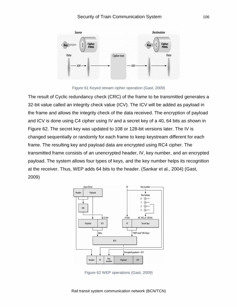
Security of Train Communication System 106
Rail transit system communication network (BCN/TCN)
Figure 61 Keyed stream cipher operation (Gast, 2009)
The result of Cyclic redundancy check (CRC) of the frame to be transmitted generates a
32-bit value called an integrity check value (ICV). The ICV will be added as payload in
the frame and allows the integrity check of the data received. The encryption of payload
and ICV is done using C4 cipher using IV and a secret key of a 40, 64 bits as shown in
Figure 62. The secret key was updated to 108 or 128-bit versions later. The IV is
changed sequentially or randomly for each frame to keep keystream different for each
frame. The resulting key and payload data are encrypted using RC4 cipher. The
transmitted frame consists of an unencrypted header, IV, key number, and an encrypted
payload. The system allows four types of keys, and the key number helps its recognition
at the receiver. Thus, WEP adds 64 bits to the header. (Sankar et al., 2004) (Gast,
2009)
Figure 62 WEP operations (Gast, 2009)
Security of Train Communication System 107
Rail transit system communication network (BCN/TCN)
5.3.2.2 WEP Weaknesses
The WEP provides reasonable security, but many flaws were found in it and are
described below:
• One set of keys for the entire network: WEP uses a key pair which is shared
among all users of the entire network. The key leakage by any user can
compromise the whole network. The manual key distribution is also a big risk as
any widely distributed item is likely to come in the public domain at some point.
(Gast, 2009)
• Key size: The key size of 40 or 64 bit proposed by WEP is considered weak as
minimum acceptable key size from a security point of view needs to be at least
128 bit long. However, it was extended to 108 and then to 128 bit later.
• WEP deployment: Fluhrer et al. (2001) showed that the deployment of WEP
was found be errored, making RC4 used unsecured and used passive “ciphertext
only” attack to show the discovery of secret key. The attack collects network
packets over a period and then identifies the packet with a weak key structure.
After sorting out these weak packets, the byte value with the highest number
reveals the key. (Fluhrer, Mantin, & Shamir, 2001).
• Initialization Vector: Another weakness in WEP is the reuse of keystream in
RC4 encryption. It was observed that the XORed value of two RC4 encrypted
packets is the same as the XORed value of two plain text frames. The analysis of
the difference between two streams can lead to the content of the frame. To
overcome this IV was inserted to make keystream different in every frame. As IV
is sent after encryption, the encryption of two packets with the same IV will have
the same key. Due to the 24-bit length of IV, the number of available keys is
limited and will get exhausted after some time, and then old IV shall be used
again. The attacker can accumulate the packets with the same IV over a long
period and then break the key to compromise security. Tools such as AirSnort
which are commonly available can be used for breaking the key. (Borisov,
Goldberg, & Wagner, 2001)
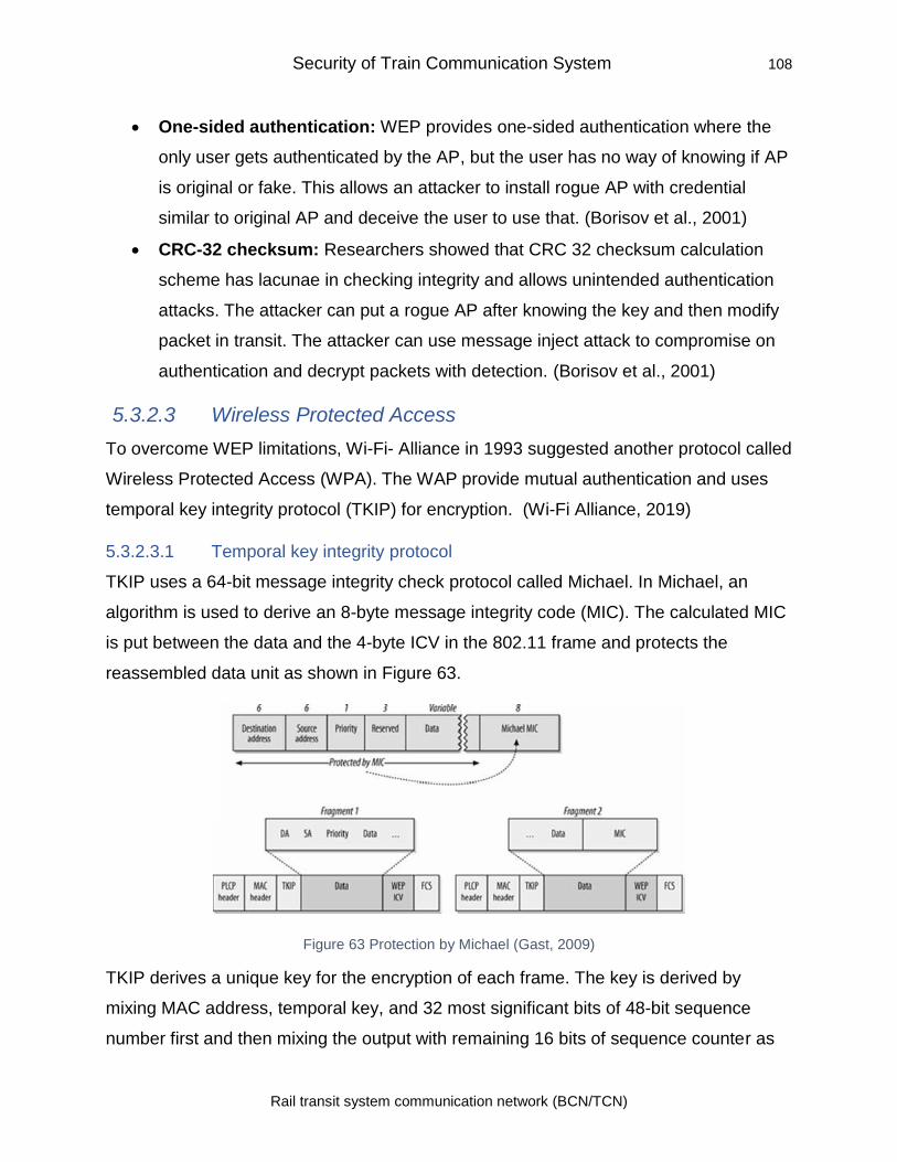
Security of Train Communication System 108
Rail transit system communication network (BCN/TCN)
• One-sided authentication: WEP provides one-sided authentication where the
only user gets authenticated by the AP, but the user has no way of knowing if AP
is original or fake. This allows an attacker to install rogue AP with credential
similar to original AP and deceive the user to use that. (Borisov et al., 2001)
• CRC-32 checksum: Researchers showed that CRC 32 checksum calculation
scheme has lacunae in checking integrity and allows unintended authentication
attacks. The attacker can put a rogue AP after knowing the key and then modify
packet in transit. The attacker can use message inject attack to compromise on
authentication and decrypt packets with detection. (Borisov et al., 2001)
5.3.2.3 Wireless Protected Access
To overcome WEP limitations, Wi-Fi- Alliance in 1993 suggested another protocol called
Wireless Protected Access (WPA). The WAP provide mutual authentication and uses
temporal key integrity protocol (TKIP) for encryption. (Wi-Fi Alliance, 2019)
5.3.2.3.1 Temporal key integrity protocol
TKIP uses a 64-bit message integrity check protocol called Michael. In Michael, an
algorithm is used to derive an 8-byte message integrity code (MIC). The calculated MIC
is put between the data and the 4-byte ICV in the 802.11 frame and protects the
reassembled data unit as shown in Figure 63.
Figure 63 Protection by Michael (Gast, 2009)
TKIP derives a unique key for the encryption of each frame. The key is derived by
mixing MAC address, temporal key, and 32 most significant bits of 48-bit sequence
number first and then mixing the output with remaining 16 bits of sequence counter as
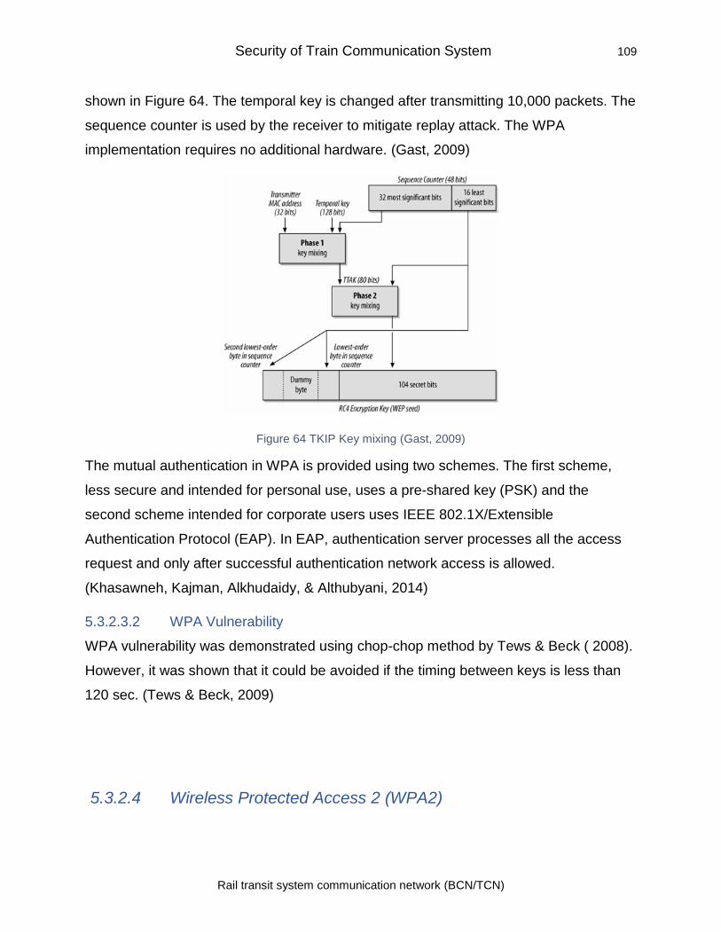
Security of Train Communication System 109
Rail transit system communication network (BCN/TCN)
shown in Figure 64. The temporal key is changed after transmitting 10,000 packets. The
sequence counter is used by the receiver to mitigate replay attack. The WPA
implementation requires no additional hardware. (Gast, 2009)
Figure 64 TKIP Key mixing (Gast, 2009)
The mutual authentication in WPA is provided using two schemes. The first scheme,
less secure and intended for personal use, uses a pre-shared key (PSK) and the
second scheme intended for corporate users uses IEEE 802.1X/Extensible
Authentication Protocol (EAP). In EAP, authentication server processes all the access
request and only after successful authentication network access is allowed.
(Khasawneh, Kajman, Alkhudaidy, & Althubyani, 2014)
5.3.2.3.2 WPA Vulnerability
WPA vulnerability was demonstrated using chop-chop method by Tews & Beck ( 2008).
However, it was shown that it could be avoided if the timing between keys is less than
120 sec. (Tews & Beck, 2009)
5.3.2.4 Wireless Protected Access 2 (WPA2)
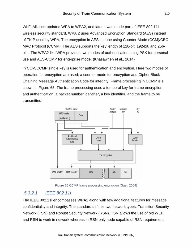
Security of Train Communication System 110
Rail transit system communication network (BCN/TCN)
Wi-Fi Alliance updated WPA to WPA2, and later it was made part of IEEE 802.11i
wireless security standard. WPA 2 uses Advanced Encryption Standard (AES) instead
of TKIP used by WPA. The encryption in AES is done using Counter-Mode (CCM)/CBC-
MAC Protocol (CCMP). The AES supports the key length of 128-bit, 192-bit, and 256-
bits. The WPA2 like WPA provides two modes of authentication using PSK for personal
use and AES-CCMP for enterprise mode. (Khasawneh et al., 2014)
In CCM/CCMP single key is used for authentication and encryption. Here two modes of
operation for encryption are used; a counter mode for encryption and Cipher Block
Chaining Message Authentication Code for integrity. Frame processing in CCMP is s
shown in Figure 65. The frame processing uses a temporal key for frame encryption
and authentication, a packet number identifier, a key identifier, and the frame to be
transmitted.
Figure 65 CCMP frame processing encryption (Gast, 2009)
5.3.2.1 IEEE 802.11i
The IEEE 802.11i encompasses WPA2 along with few additional features for message
confidentiality and integrity. The standard defines two network types; Transition Security
Network (TSN) and Robust Security Network (RSN). TSN allows the use of old WEP
and RSN to work in network whereas in RSN only node capable of RSN requirement
Security of Train Communication System 111
Rail transit system communication network (BCN/TCN)
can work. Strong security associations are used by RSA for its APs and IEEE 802.1x
protocol is used for authentication. (Aruba, 2018)
5.3.2.1.1 The vulnerability of WPA2/ IEEE 802.11i
Proper implementation of WPA2/ IEEE 802.11i provides good data confidentiality and
integrity, but it does not provide any protection against DoS attacks.
Airtight Networks detected a Hole 196 vulnerability in WPA2 that exposes it to insider
attacks. The WPA2 shares a group temporal key (GTK) that is used for broadcast data,
among all authorized clients. The AP encrypts data broadcasted to the group using GTK
and is decrypted by the client using GTK. A client can inject spoofed GTK and used it to
sniff data from other users. However, this can be exploited by an insider with access to
the network. (Wexler, 2010)
The main issue in WPA2 was susceptibility of PSK mode to dictionary attacks as it uses
predefines a key and lightweight authentication handshake. The 802.1X/EAP mode of
operation for enterprise required proper implementation due to complex configuration
requirements. Moreover, it was too complex for small enterprises such as café who
provide public Wi-Fi hot spots.
5.3.2.2 WPA 3
To address problems with WPA2, a new protocol called WPA3 was introduced to
simplify the security. As per Wi-Fi Alliance, “WPA3 adds new features to simplify Wi-Fi
security, enable more robust authentication, deliver increased cryptographic strength for
highly sensitive data markets, and maintain resiliency of mission-critical networks” (Wi-
Fi Alliance, 2019).
WPA3 Personal uses Simultaneous Authentication of Equals (SAE) instead of PSK in
WPA2. It provides robust authentication using a password that may not be very
complex. It protects from dictionary attacks. The system protects data even after the
password is compromised. (Wi-Fi Alliance, 2019)
To secure an open public network, Opportunistic Wireless Encryption (OWE) was
introduced (Harkins & Kumari, 2017). When the user gets associated with an AP, the
Security of Train Communication System 112
Rail transit system communication network (BCN/TCN)
OWE performs an unauthenticated Diffie-Hellman resulting in a key that is known to
only user and AP. This key is then used for encryption and management for the link.
This methodology provides much better security than WPA2- PSK. (Aruba, 2018)
The key tools used in WPA3 are (Wi-Fi Alliance, 2019):
• “Authenticated encryption: 256-bit Galois/Counter Mode Protocol (GCMP-256)
• Key derivation and confirmation: 384-bit Hashed Message Authentication
Mode (HMAC) with Secure Hash Algorithm (HMAC-SHA384)
• Key establishment and authentication: Elliptic Curve Diffie-Hellman (ECDH)
exchange and Elliptic Curve Digital Signature Algorithm (ECDSA) using a 384-bit
elliptic curve
• Robust management frame protection: 256-bit Broadcast/Multicast Integrity
Protocol Galois Message Authentication Code (BIP-GMAC-256)” (Wi-Fi Alliance,
2019).
The use of CNSA (Commercial National Security Algorithms) for 802.1X/EAP
configuration ensures that no misconfiguration is done and mix and match of the
algorithm in an insecure manner cannot be done as in case of WAP2. (Aruba, 2018)
5.3.3 Security of Cellular Network
The security of cellular communication has kept pace with technology. The evolving
security architecture from GSM to LTE is shown in Figure 66. The risk in earlier versions
has been addressed in a later version to make the system more secure. However, as
the communication mode shifted from voice-centric to data-centric and flatter
architecture, the system is now more prone to attacks making it challenging work to
maintain security in cellular networks.
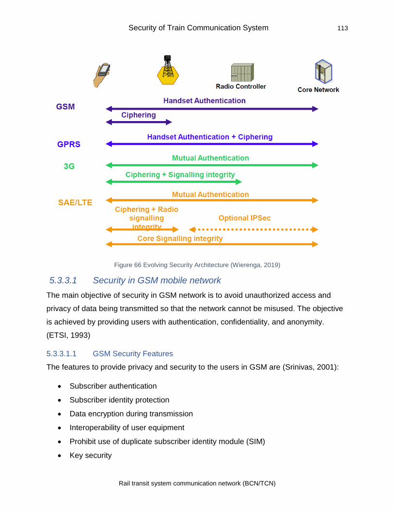
Security of Train Communication System 113
Rail transit system communication network (BCN/TCN)
Figure 66 Evolving Security Architecture (Wierenga, 2019)
5.3.3.1 Security in GSM mobile network
The main objective of security in GSM network is to avoid unauthorized access and
privacy of data being transmitted so that the network cannot be misused. The objective
is achieved by providing users with authentication, confidentiality, and anonymity.
(ETSI, 1993)
5.3.3.1.1 GSM Security Features
The features to provide privacy and security to the users in GSM are (Srinivas, 2001):
• Subscriber authentication
• Subscriber identity protection
• Data encryption during transmission
• Interoperability of user equipment
• Prohibit use of duplicate subscriber identity module (SIM)
• Key security
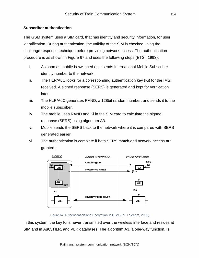
Security of Train Communication System 114
Rail transit system communication network (BCN/TCN)
Subscriber authentication
The GSM system uses a SIM card, that has identity and security information, for user
identification. During authentication, the validity of the SIM is checked using the
challenge-response technique before providing network access. The authentication
procedure is as shown in Figure 67 and uses the following steps (ETSI, 1993):
i. As soon as mobile is switched on it sends International Mobile Subscriber
identity number to the network.
ii. The HLR/AuC looks for a corresponding authentication key (Ki) for the IMSI
received. A signed response (SERS) is generated and kept for verification
later.
iii. The HLR/AuC generates RAND, a 128bit random number, and sends it to the
mobile subscriber.
iv. The mobile uses RAND and Ki in the SIM card to calculate the signed
response (SERS) using algorithm A3.
v. Mobile sends the SERS back to the network where it is compared with SERS
generated earlier.
vi. The authentication is complete if both SERS match and network access are
granted.
Figure 67 Authentication and Encryption in GSM (RF Telecom, 2009)
In this system, the key Ki is never transmitted over the wireless interface and resides at
SIM and in AuC, HLR, and VLR databases. The algorithm A3, a one-way function, is
MOBILE RADIO INTERFACE FIXED NETWORK
Challenge R
Response SRESA3
Ki
A3
Ki
A5 A5
ENCRYPTED DATA
A8
Kc
A8
Kc
Key
SIM
?
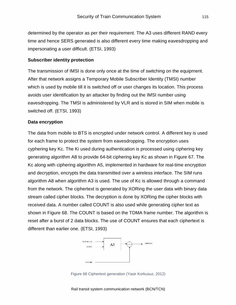
Security of Train Communication System 115
Rail transit system communication network (BCN/TCN)
determined by the operator as per their requirement. The A3 uses different RAND every
time and hence SERS generated is also different every time making eavesdropping and
impersonating a user difficult. (ETSI, 1993)
Subscriber identity protection
The transmission of IMSI is done only once at the time of switching on the equipment.
After that network assigns a Temporary Mobile Subscriber Identity (TMSI) number
which is used by mobile till it is switched off or user changes its location. This process
avoids user identification by an attacker by finding out the IMSI number using
eavesdropping. The TMSI is administered by VLR and is stored in SIM when mobile is
switched off. (ETSI, 1993)
Data encryption
The data from mobile to BTS is encrypted under network control. A different key is used
for each frame to protect the system from eavesdropping. The encryption uses
cyphering key Kc. The Ki used during authentication is processed using ciphering key
generating algorithm A8 to provide 64-bit ciphering key Kc as shown in Figure 67. The
Kc along with ciphering algorithm A5, implemented in hardware for real-time encryption
and decryption, encrypts the data transmitted over a wireless interface. The SIM runs
algorithm A8 when algorithm A3 is used. The use of Kc is allowed through a command
from the network. The ciphertext is generated by XORing the user data with binary data
stream called cipher blocks. The decryption is done by XORing the cipher blocks with
received data. A number called COUNT is also used while generating cipher text as
shown in Figure 68. The COUNT is based on the TDMA frame number. The algorithm is
reset after a burst of 2 data blocks. The use of COUNT ensures that each ciphertext is
different than earlier one. (ETSI, 1993)
Figure 68 Ciphertext generation (Yasir Korkusuz, 2012)
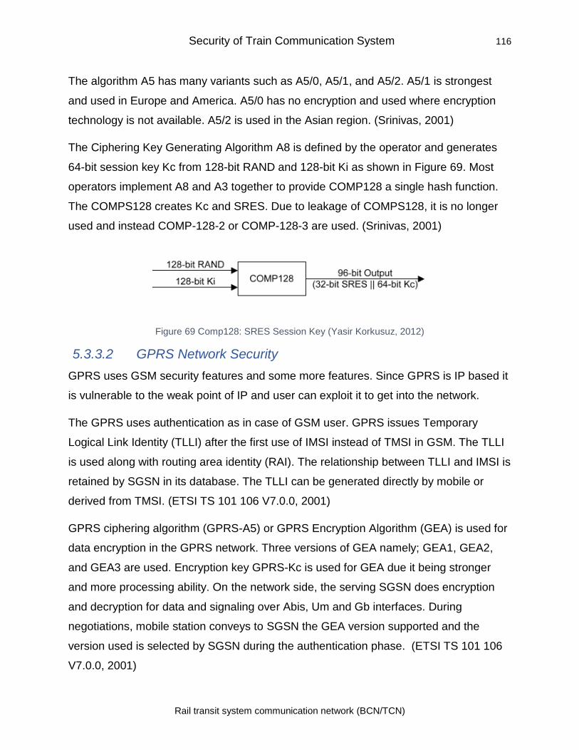
Security of Train Communication System 116
Rail transit system communication network (BCN/TCN)
The algorithm A5 has many variants such as A5/0, A5/1, and A5/2. A5/1 is strongest
and used in Europe and America. A5/0 has no encryption and used where encryption
technology is not available. A5/2 is used in the Asian region. (Srinivas, 2001)
The Ciphering Key Generating Algorithm A8 is defined by the operator and generates
64-bit session key Kc from 128-bit RAND and 128-bit Ki as shown in Figure 69. Most
operators implement A8 and A3 together to provide COMP128 a single hash function.
The COMPS128 creates Kc and SRES. Due to leakage of COMPS128, it is no longer
used and instead COMP-128-2 or COMP-128-3 are used. (Srinivas, 2001)
Figure 69 Comp128: SRES Session Key (Yasir Korkusuz, 2012)
5.3.3.2 GPRS Network Security
GPRS uses GSM security features and some more features. Since GPRS is IP based it
is vulnerable to the weak point of IP and user can exploit it to get into the network.
The GPRS uses authentication as in case of GSM user. GPRS issues Temporary
Logical Link Identity (TLLI) after the first use of IMSI instead of TMSI in GSM. The TLLI
is used along with routing area identity (RAI). The relationship between TLLI and IMSI is
retained by SGSN in its database. The TLLI can be generated directly by mobile or
derived from TMSI. (ETSI TS 101 106 V7.0.0, 2001)
GPRS ciphering algorithm (GPRS-A5) or GPRS Encryption Algorithm (GEA) is used for
data encryption in the GPRS network. Three versions of GEA namely; GEA1, GEA2,
and GEA3 are used. Encryption key GPRS-Kc is used for GEA due it being stronger
and more processing ability. On the network side, the serving SGSN does encryption
and decryption for data and signaling over Abis, Um and Gb interfaces. During
negotiations, mobile station conveys to SGSN the GEA version supported and the
version used is selected by SGSN during the authentication phase. (ETSI TS 101 106
V7.0.0, 2001)
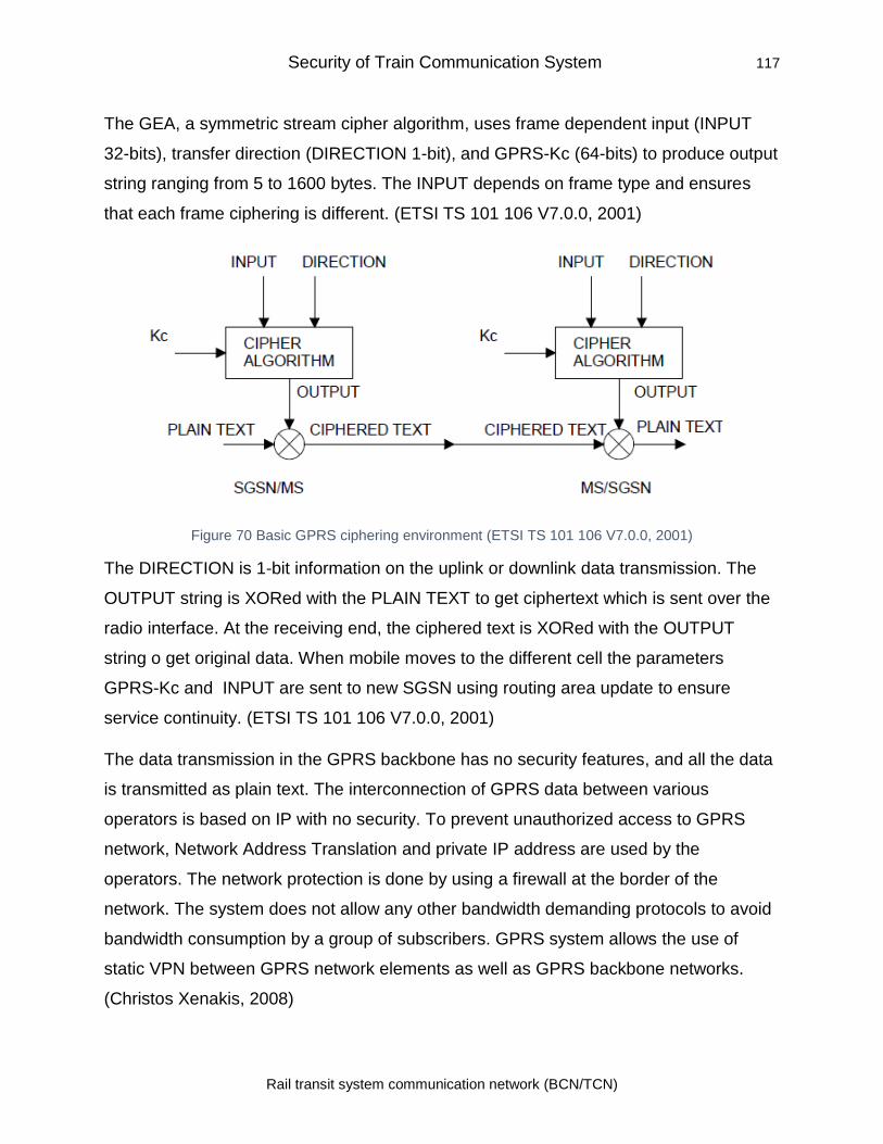
Security of Train Communication System 117
Rail transit system communication network (BCN/TCN)
The GEA, a symmetric stream cipher algorithm, uses frame dependent input (INPUT
32-bits), transfer direction (DIRECTION 1-bit), and GPRS-Kc (64-bits) to produce output
string ranging from 5 to 1600 bytes. The INPUT depends on frame type and ensures
that each frame ciphering is different. (ETSI TS 101 106 V7.0.0, 2001)
Figure 70 Basic GPRS ciphering environment (ETSI TS 101 106 V7.0.0, 2001)
The DIRECTION is 1-bit information on the uplink or downlink data transmission. The
OUTPUT string is XORed with the PLAIN TEXT to get ciphertext which is sent over the
radio interface. At the receiving end, the ciphered text is XORed with the OUTPUT
string o get original data. When mobile moves to the different cell the parameters
GPRS-Kc and INPUT are sent to new SGSN using routing area update to ensure
service continuity. (ETSI TS 101 106 V7.0.0, 2001)
The data transmission in the GPRS backbone has no security features, and all the data
is transmitted as plain text. The interconnection of GPRS data between various
operators is based on IP with no security. To prevent unauthorized access to GPRS
network, Network Address Translation and private IP address are used by the
operators. The network protection is done by using a firewall at the border of the
network. The system does not allow any other bandwidth demanding protocols to avoid
bandwidth consumption by a group of subscribers. GPRS system allows the use of
static VPN between GPRS network elements as well as GPRS backbone networks.
(Christos Xenakis, 2008)
Security of Train Communication System 118
Rail transit system communication network (BCN/TCN)
5.3.3.3 Vulnerabilities in GSM Network
In spite of various security measures adopted the GSM network was found to be
vulnerable to various attacks as per details below (Toorani & Beheshti, 2008):
Unilateral authentication
The GSM system provides only one-way authentication with the user getting
authenticated but no authentication for BTS. This can allow an attacker to install a rogue
BTS identical to the subscriber’s network and launch a man in middle attack or steal
information. The cloning of BTS was not considered earlier due to the high cost of the
equipment, but with prices dropping substantially the cloning is a reality. (Toorani &
Beheshti, 2008)
Flaws in the implementation of A3/A8 algorithms
The selection of A3 and A8 algorithms are left to the operators. Most operators use
COMP128-1 which was developed by GSM association. It was shown that COMP128-1
could be broken using reverse engineering. The analysis of around 150,000 RAND-
SRES pairs can reveal Ki and also make Kc weaker. A similar problem was found with
COMP128-2 and this lead to the introduction of a new version called COMP128-3 with
the 64-bit session key. (Toorani & Beheshti, 2008)
SIM card cloning
The use of COMP128-1 allows derivation of Ki in SIM card using an attack called
partitioning provider attacker can access SIM card for a min. The knowledge of Ki
allows cloning of the SIM card. Unfortunately, software is available for cloning SIM. For
cloning, a card reader scans the SIM card on its serial port and the software reveals the
key. Another software can be used for creating a SIM.
Flaws in cryptographic algorithms
Algorithms A5/1 and A5/2 are weak, and both can be broken in 2 min after capturing
data. (Becher et al., 2011)
Security of Train Communication System 119
Rail transit system communication network (BCN/TCN)
Lack of user visibility
The ciphering of data can be disabled by a BTS without the user knowing about it. This
allows a rogue BTS to disable ciphering and transmit mobile data in plain text.
Leaking the user anonymity
The user is required to send IMSI when entering the network for the first time. This can
be exploited by a rogue BTS by sending a request for identity and in turn, get user’s
IMSI number.
Other Vulnerabilities
GSM does not provide message integrity to the user, and the user cannot verify the
integrity of the message. The use of forwarding error correction (FEC) before cyphering
makes algorithms used vulnerable.
Research showed that using Botnets on mobile devices DoS attack can be launched on
the network and the HLR is the weakest link in the system. By sending a large amount
of traffic to HLR, the system output can be reduced by 93% (Traynor et al., 2009).
The attack on the SMS infrastructure of GSM was shown by (Becher et al., 2011)
The GPRS network was found to have vulnerability at many points including SIM card,
the interface between the SGSN and the mobile, backbone network and connectivity
with outside network or operators. (Christos Xenakis, 2008)
5.3.3.4 Vulnerabilities detected in use of GSM for railway applications
A cryptographic analysis of the European Rail Traffic Management System (ERTMS)
protocols showed that an attacker can forge train control messages (Chothia, Ordean,
De Ruiter, & Thomas, 2017). The system uses three protocol stacks with GSM-R at the
bottom provides encryption, above this, the authentication and integrity are provided by
EuroRadio protocol and on top is application layer protocol for ETCS that provide a
timestamp and message acknowledgments for preventing a replay attack. Since MAC
(Message Authentication Code) algorithm used in EuroRadio is only 64-bit, there is a
possibility of it getting repeated, and if an attacker can wait for enough time, the
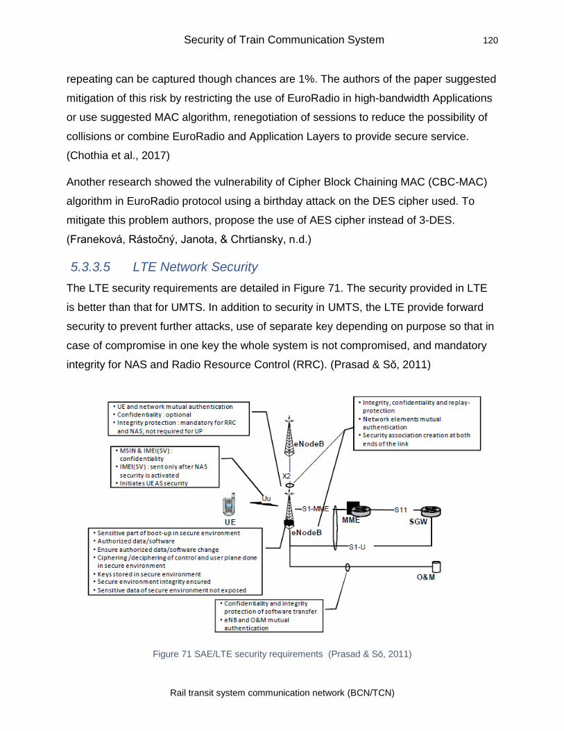
Security of Train Communication System 120
Rail transit system communication network (BCN/TCN)
repeating can be captured though chances are 1%. The authors of the paper suggested
mitigation of this risk by restricting the use of EuroRadio in high-bandwidth Applications
or use suggested MAC algorithm, renegotiation of sessions to reduce the possibility of
collisions or combine EuroRadio and Application Layers to provide secure service.
(Chothia et al., 2017)
Another research showed the vulnerability of Cipher Block Chaining MAC (CBC-MAC)
algorithm in EuroRadio protocol using a birthday attack on the DES cipher used. To
mitigate this problem authors, propose the use of AES cipher instead of 3-DES.
(Franeková, Rástočný, Janota, & Chrtiansky, n.d.)
5.3.3.5 LTE Network Security
The LTE security requirements are detailed in Figure 71. The security provided in LTE
is better than that for UMTS. In addition to security in UMTS, the LTE provide forward
security to prevent further attacks, use of separate key depending on purpose so that in
case of compromise in one key the whole system is not compromised, and mandatory
integrity for NAS and Radio Resource Control (RRC). (Prasad & So, 2011)
Figure 71 SAE/LTE security requirements (Prasad & So, 2011)
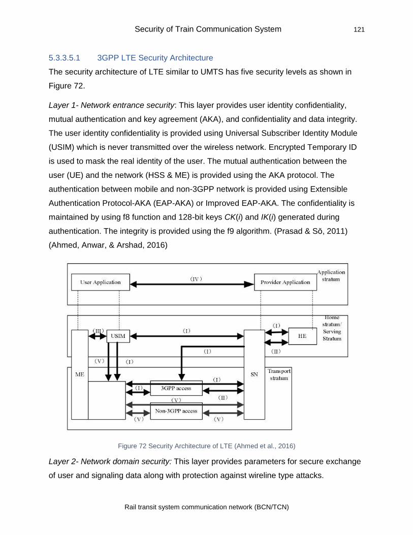
Security of Train Communication System 121
Rail transit system communication network (BCN/TCN)
5.3.3.5.1 3GPP LTE Security Architecture
The security architecture of LTE similar to UMTS has five security levels as shown in
Figure 72.
Layer 1- Network entrance security: This layer provides user identity confidentiality,
mutual authentication and key agreement (AKA), and confidentiality and data integrity.
The user identity confidentiality is provided using Universal Subscriber Identity Module
(USIM) which is never transmitted over the wireless network. Encrypted Temporary ID
is used to mask the real identity of the user. The mutual authentication between the
user (UE) and the network (HSS & ME) is provided using the AKA protocol. The
authentication between mobile and non-3GPP network is provided using Extensible
Authentication Protocol-AKA (EAP-AKA) or Improved EAP-AKA. The confidentiality is
maintained by using f8 function and 128-bit keys CK(i) and IK(i) generated during
authentication. The integrity is provided using the f9 algorithm. (Prasad & So, 2011)
(Ahmed, Anwar, & Arshad, 2016)
Figure 72 Security Architecture of LTE (Ahmed et al., 2016)
Layer 2- Network domain security: This layer provides parameters for secure exchange
of user and signaling data along with protection against wireline type attacks.
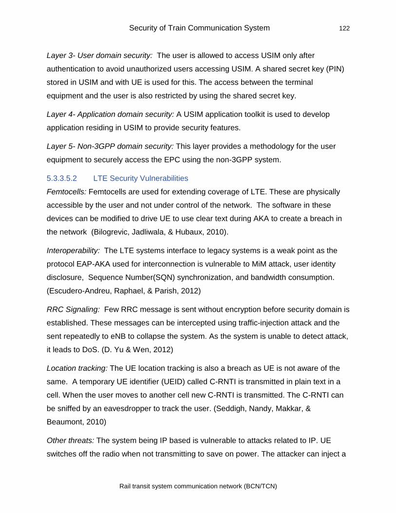
Security of Train Communication System 122
Rail transit system communication network (BCN/TCN)
Layer 3- User domain security: The user is allowed to access USIM only after
authentication to avoid unauthorized users accessing USIM. A shared secret key (PIN)
stored in USIM and with UE is used for this. The access between the terminal
equipment and the user is also restricted by using the shared secret key.
Layer 4- Application domain security: A USIM application toolkit is used to develop
application residing in USIM to provide security features.
Layer 5- Non-3GPP domain security: This layer provides a methodology for the user
equipment to securely access the EPC using the non-3GPP system.
5.3.3.5.2 LTE Security Vulnerabilities
Femtocells: Femtocells are used for extending coverage of LTE. These are physically
accessible by the user and not under control of the network. The software in these
devices can be modified to drive UE to use clear text during AKA to create a breach in
the network (Bilogrevic, Jadliwala, & Hubaux, 2010).
Interoperability: The LTE systems interface to legacy systems is a weak point as the
protocol EAP-AKA used for interconnection is vulnerable to MiM attack, user identity
disclosure, Sequence Number(SQN) synchronization, and bandwidth consumption.
(Escudero-Andreu, Raphael, & Parish, 2012)
RRC Signaling: Few RRC message is sent without encryption before security domain is
established. These messages can be intercepted using traffic-injection attack and the
sent repeatedly to eNB to collapse the system. As the system is unable to detect attack,
it leads to DoS. (D. Yu & Wen, 2012)
Location tracking: The UE location tracking is also a breach as UE is not aware of the
same. A temporary UE identifier (UEID) called C-RNTI is transmitted in plain text in a
cell. When the user moves to another cell new C-RNTI is transmitted. The C-RNTI can
be sniffed by an eavesdropper to track the user. (Seddigh, Nandy, Makkar, &
Beaumont, 2010)
Other threats: The system being IP based is vulnerable to attacks related to IP. UE
switches off the radio when not transmitting to save on power. The attacker can inject a
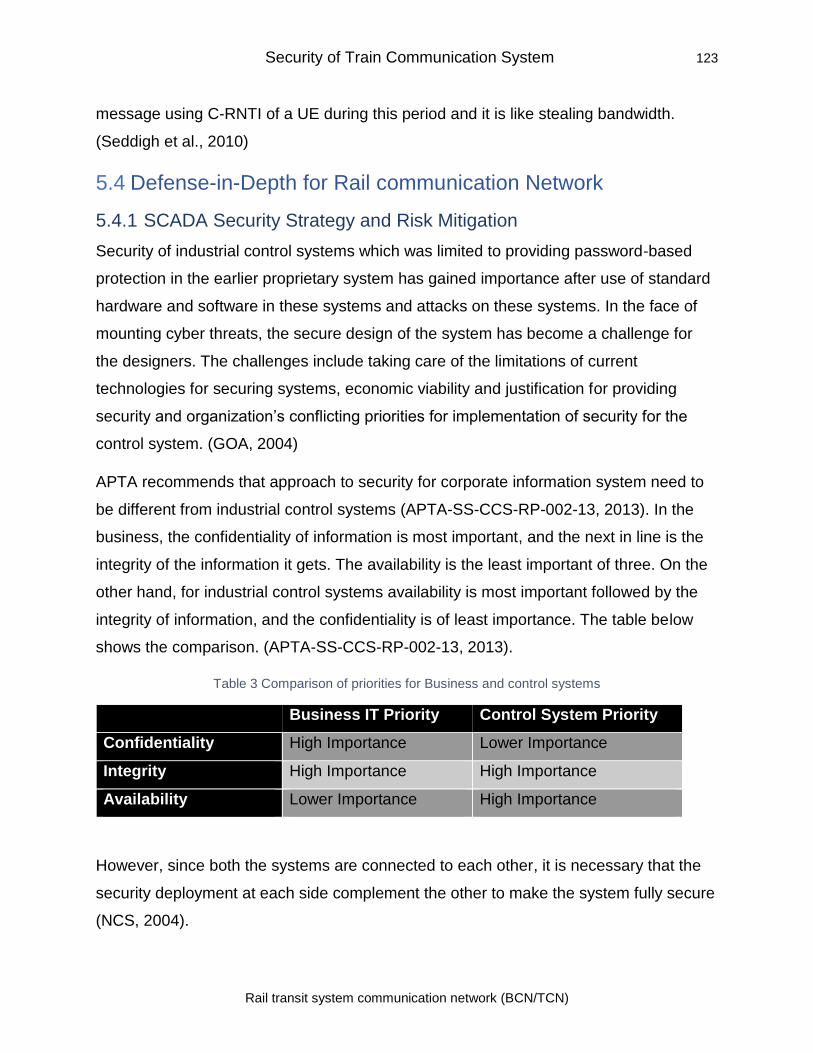
Security of Train Communication System 123
Rail transit system communication network (BCN/TCN)
message using C-RNTI of a UE during this period and it is like stealing bandwidth.
(Seddigh et al., 2010)
5.4 Defense-in-Depth for Rail communication Network
5.4.1 SCADA Security Strategy and Risk Mitigation
Security of industrial control systems which was limited to providing password-based
protection in the earlier proprietary system has gained importance after use of standard
hardware and software in these systems and attacks on these systems. In the face of
mounting cyber threats, the secure design of the system has become a challenge for
the designers. The challenges include taking care of the limitations of current
technologies for securing systems, economic viability and justification for providing
security and organization’s conflicting priorities for implementation of security for the
control system. (GOA, 2004)
APTA recommends that approach to security for corporate information system need to
be different from industrial control systems (APTA-SS-CCS-RP-002-13, 2013). In the
business, the confidentiality of information is most important, and the next in line is the
integrity of the information it gets. The availability is the least important of three. On the
other hand, for industrial control systems availability is most important followed by the
integrity of information, and the confidentiality is of least importance. The table below
shows the comparison. (APTA-SS-CCS-RP-002-13, 2013).
Table 3 Comparison of priorities for Business and control systems
Business IT Priority Control System Priority
Confidentiality High Importance Lower Importance
Integrity High Importance High Importance
Availability Lower Importance High Importance
However, since both the systems are connected to each other, it is necessary that the
security deployment at each side complement the other to make the system fully secure
(NCS, 2004).
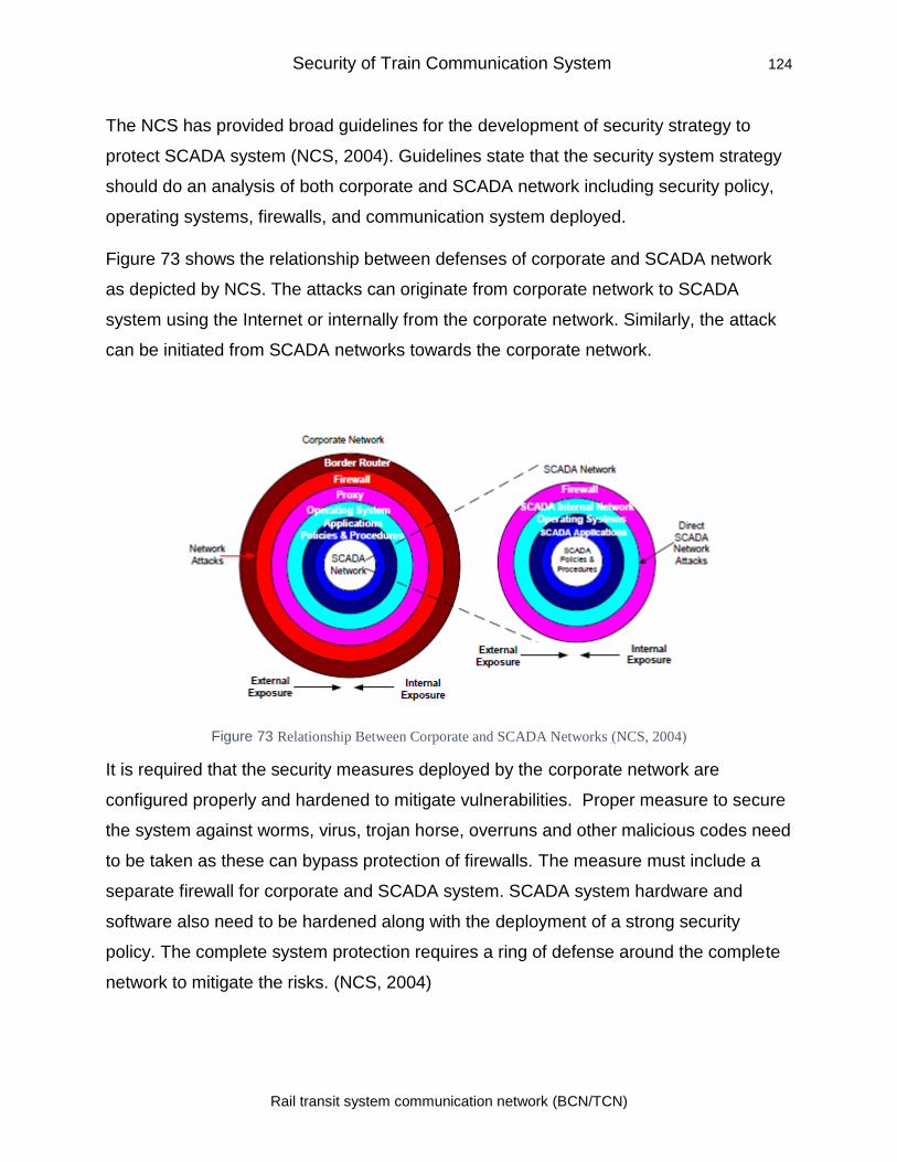
Security of Train Communication System 124
Rail transit system communication network (BCN/TCN)
The NCS has provided broad guidelines for the development of security strategy to
protect SCADA system (NCS, 2004). Guidelines state that the security system strategy
should do an analysis of both corporate and SCADA network including security policy,
operating systems, firewalls, and communication system deployed.
Figure 73 shows the relationship between defenses of corporate and SCADA network
as depicted by NCS. The attacks can originate from corporate network to SCADA
system using the Internet or internally from the corporate network. Similarly, the attack
can be initiated from SCADA networks towards the corporate network.
Figure 73 Relationship Between Corporate and SCADA Networks (NCS, 2004)
It is required that the security measures deployed by the corporate network are
configured properly and hardened to mitigate vulnerabilities. Proper measure to secure
the system against worms, virus, trojan horse, overruns and other malicious codes need
to be taken as these can bypass protection of firewalls. The measure must include a
separate firewall for corporate and SCADA system. SCADA system hardware and
software also need to be hardened along with the deployment of a strong security
policy. The complete system protection requires a ring of defense around the complete
network to mitigate the risks. (NCS, 2004)
Security of Train Communication System 125
Rail transit system communication network (BCN/TCN)
The National Institute of Standards and Technology (NIST) has published Guide to
Industrial Control Systems (ICS) Security vide it's Special Publication 800-82 (Stouffer
et al., 2015). The guideline is given in the report for the security of SCADA systems as
well as for distributed control systems, and Programmable Logic Controllers (PLC).
As per NIST guidelines, development of security strategy should use the following steps
(Stouffer et al., 2015):
• Business Case for Security: The preparation of the business case for security is
required to address concerns of management, impact on business, and financial
justification. The business case must include benefits of improvement in control
system reliability and availability, the repercussion of non-implementation of ICS
security measures, resources required and cost of implementation.
• Program development: The security implementation program needs to be
comprehensive and include all aspects of security. It is important that program
includes scope, charter, inventory of assets, vulnerability and risk assessment, risk
mitigation, senior management’s approval and support, security awareness
program and training.
5.4.2 Network Architecture for ICS security
The NIST report for ICS security recommends that the ICS network should be logically
as well as physically separate than the corporate network as both have different
requirements. Both the network should use Defense-in-Depth Architecture by using
multilayer protection. There should be an only single interconnection between the two
networks and a properly configured firewall should be deployed to deny all traffic other
than required. The firewall needs to be configured to provide source and destination
filtering in addition to normal filtering. The use of DMZ between two networks can make
all communication via the DMZ zone to isolate two networks.
The use of intrusion detection system and implementation of strong security policy is
primary requirements. The workable incident response mechanisms, regular and
comprehensive training programs must be part of the security management. The NIST
report provides a representative architecture for providing defense in depth as shown in
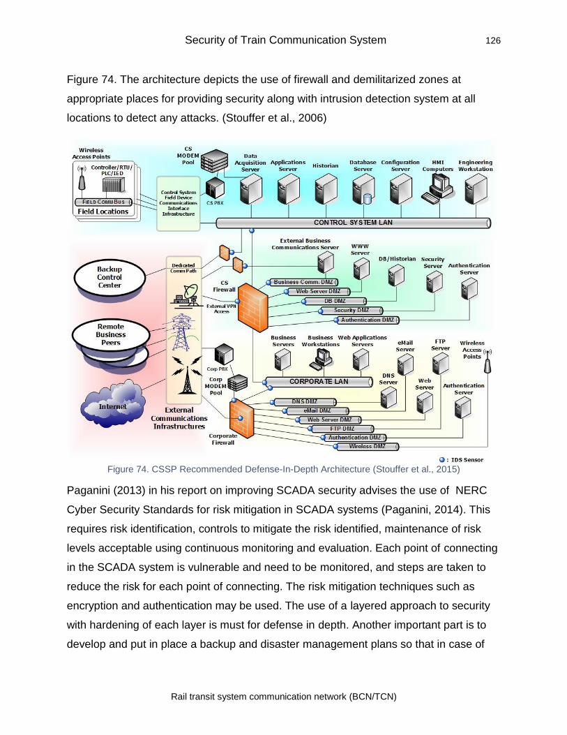
Security of Train Communication System 126
Rail transit system communication network (BCN/TCN)
Figure 74. The architecture depicts the use of firewall and demilitarized zones at
appropriate places for providing security along with intrusion detection system at all
locations to detect any attacks. (Stouffer et al., 2006)
Figure 74. CSSP Recommended Defense-In-Depth Architecture (Stouffer et al., 2015)
Paganini (2013) in his report on improving SCADA security advises the use of NERC
Cyber Security Standards for risk mitigation in SCADA systems (Paganini, 2014). This
requires risk identification, controls to mitigate the risk identified, maintenance of risk
levels acceptable using continuous monitoring and evaluation. Each point of connecting
in the SCADA system is vulnerable and need to be monitored, and steps are taken to
reduce the risk for each point of connecting. The risk mitigation techniques such as
encryption and authentication may be used. The use of a layered approach to security
with hardening of each layer is must for defense in depth. Another important part is to
develop and put in place a backup and disaster management plans so that in case of
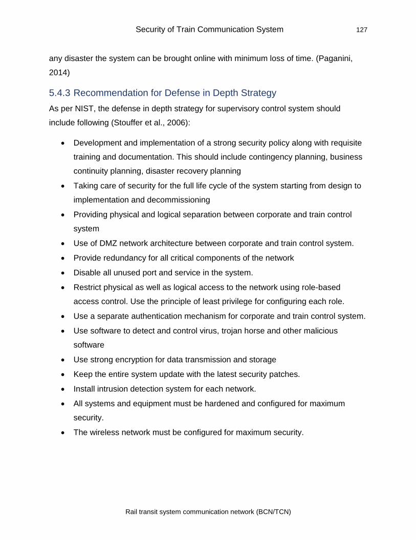
Security of Train Communication System 127
Rail transit system communication network (BCN/TCN)
any disaster the system can be brought online with minimum loss of time. (Paganini,
2014)
5.4.3 Recommendation for Defense in Depth Strategy
As per NIST, the defense in depth strategy for supervisory control system should
include following (Stouffer et al., 2006):
• Development and implementation of a strong security policy along with requisite
training and documentation. This should include contingency planning, business
continuity planning, disaster recovery planning
• Taking care of security for the full life cycle of the system starting from design to
implementation and decommissioning
• Providing physical and logical separation between corporate and train control
system
• Use of DMZ network architecture between corporate and train control system.
• Provide redundancy for all critical components of the network
• Disable all unused port and service in the system.
• Restrict physical as well as logical access to the network using role-based
access control. Use the principle of least privilege for configuring each role.
• Use a separate authentication mechanism for corporate and train control system.
• Use software to detect and control virus, trojan horse and other malicious
software
• Use strong encryption for data transmission and storage
• Keep the entire system update with the latest security patches.
• Install intrusion detection system for each network.
• All systems and equipment must be hardened and configured for maximum
security.
• The wireless network must be configured for maximum security.
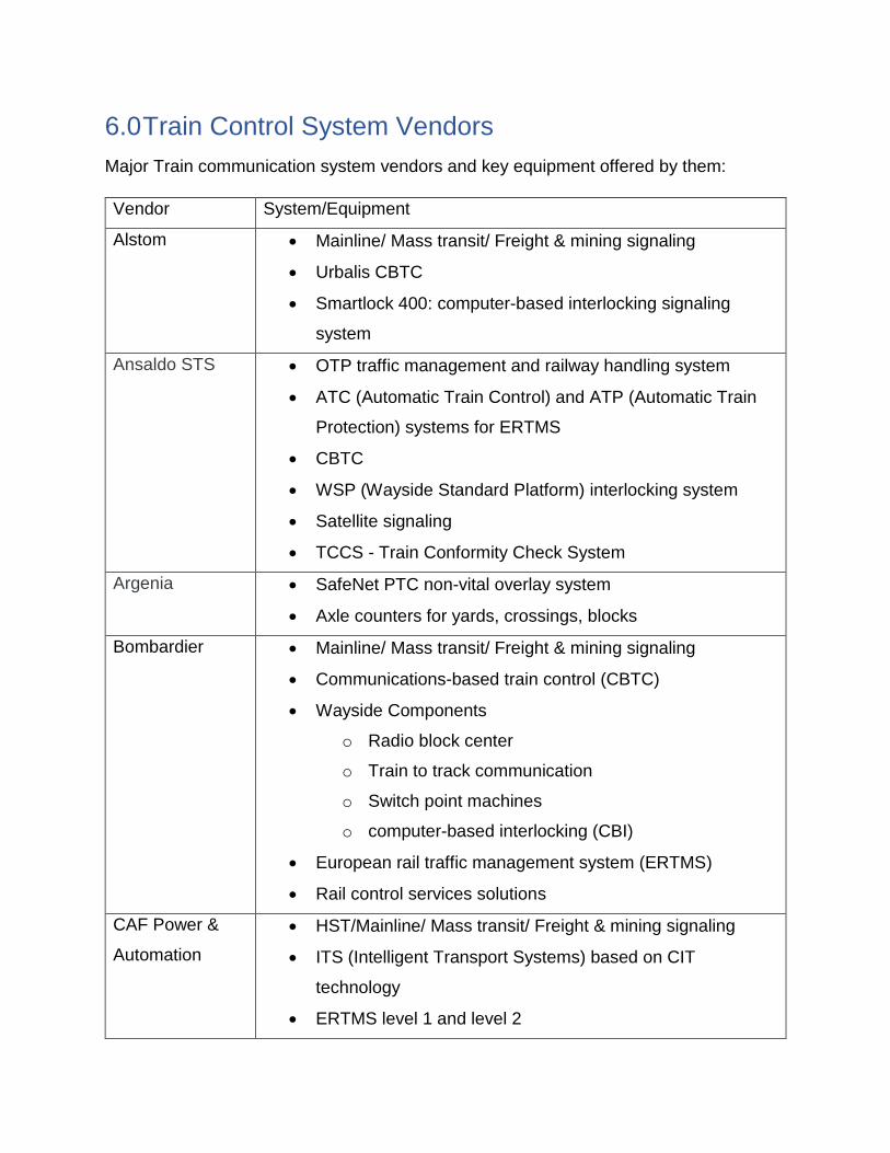
6.0 Train Control System Vendors
Major Train communication system vendors and key equipment offered by them:
Vendor System/Equipment
Alstom • Mainline/ Mass transit/ Freight & mining signaling
• Urbalis CBTC
• Smartlock 400: computer-based interlocking signaling
system
Ansaldo STS • OTP traffic management and railway handling system
• ATC (Automatic Train Control) and ATP (Automatic Train
Protection) systems for ERTMS
• CBTC
• WSP (Wayside Standard Platform) interlocking system
• Satellite signaling
• TCCS - Train Conformity Check System
Argenia • SafeNet PTC non-vital overlay system
• Axle counters for yards, crossings, blocks
Bombardier • Mainline/ Mass transit/ Freight & mining signaling
• Communications-based train control (CBTC)
• Wayside Components
o Radio block center
o Train to track communication
o Switch point machines
o computer-based interlocking (CBI)
• European rail traffic management system (ERTMS)
• Rail control services solutions
CAF Power &
Automation
• HST/Mainline/ Mass transit/ Freight & mining signaling
• ITS (Intelligent Transport Systems) based on CIT
technology
• ERTMS level 1 and level 2
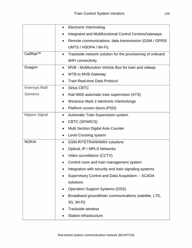
Train Control System Vendors 129
Rail transit system communication network (BCN/TCN)
• Electronic Interlocking
• Integrated and Multifunctional Control CentresGateways.
• Remote communications: data transmission (GSM / GPRS/
UMTS / HSDPA / Wi-Fi).
CellRail™ • Trackside network solution for the provisioning of onboard
WIFI connectivity
Duagon • MVB - Multifunction Vehicle Bus for train and railway
• WTB to MVB Gateway
• Train Real-time Data Protocol
Invensys Rail/
Siemens
• Sirius CBTC
• Rail 9000 automatic train supervision (ATS)
• Westrace Mark 2 electronic interlockings
• Platform screen doors (PSD)
Nippon Signal • Automatic Train Supervision system
• CBTC (SPARCS)
• Multi Section Digital Axle Counter
• Level Crossing system
NOKIA • GSM-R/TETRA/WiMAX solutions
• Optical, IP / MPLS Networks
• Video surveillance (CCTV)
• Control room and train management system
• Integration with security and train signaling systems
• Supervisory Control and Data Acquisition -- SCADA
solutions
• Operation Support Systems (OSS)
• Broadband ground/train communications (satellite, LTE,
3G, Wi-Fi)
• Trackside wireless
• Station infrastructure
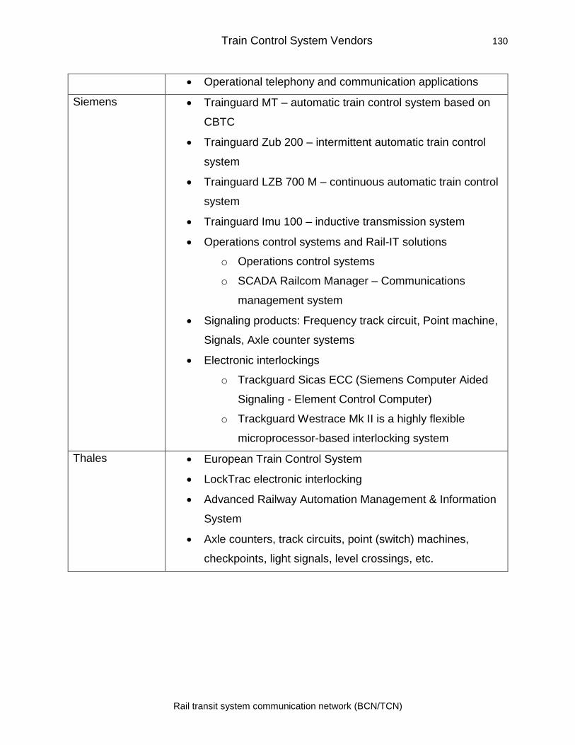
Train Control System Vendors 130
Rail transit system communication network (BCN/TCN)
• Operational telephony and communication applications
Siemens • Trainguard MT – automatic train control system based on
CBTC
• Trainguard Zub 200 – intermittent automatic train control
system
• Trainguard LZB 700 M – continuous automatic train control
system
• Trainguard Imu 100 – inductive transmission system
• Operations control systems and Rail-IT solutions
o Operations control systems
o SCADA Railcom Manager – Communications
management system
• Signaling products: Frequency track circuit, Point machine,
Signals, Axle counter systems
• Electronic interlockings
o Trackguard Sicas ECC (Siemens Computer Aided
Signaling - Element Control Computer)
o Trackguard Westrace Mk II is a highly flexible
microprocessor-based interlocking system
Thales • European Train Control System
• LockTrac electronic interlocking
• Advanced Railway Automation Management & Information
System
• Axle counters, track circuits, point (switch) machines,
checkpoints, light signals, level crossings, etc.
7.0 Conclusion
The rail communication and control system has evolved over the period in order to
prevent accidents, increase density and provide safe operation of the system. Many
initiatives have been taken by the governments, standard bodies, train operators,
associations and manufacturers. The U.S. has mandated the use of a PTC system and
Europe has gone for ETCS. The standard bodies such as ETSI, IEEE, etc. have
published standards suitable for rail TCN and communication systems.
The modern train control system depends heavily on the communication network for
critical data transfer from devices within train to train control system onboard, an
onboard system to wayside facilities, from wayside facility to central/regional control
centers, and links to the corporate network. The communication network includes wired
as well as wireless networks. The SCADA and IT systems are used extensively to
monitor and control rail operations. The communication and IT system play a critical role
in the safe and secure operation of the train system. In order to improve the system,
reduce wayside equipment and provide increased density and safety, the rail operations
are using technologies such as communication-based train control system along with
communication systems such as TETRA, Wi-Fi, GSM-R, and LTE-R. The CBTC system
provides exact train location and allows the system to shift to moving the block from
fixed block thereby increasing system capacity and safety. The communication systems
provide quick transfer of information on track conditions ahead and also allow automatic
application of brakes in case of laxity on the part of the driver in acknowledging the
status to control system. In order to provide more information to the driver about
conditions ahead using CCTV feed at strategic locations and amenities such as TV,
News, Internet access to passengers in train and stations new high-speed technologies
are needed. The UIC has come out with requirements of Future Railway Mobile
Communications System and is looking at various options and technologies to be used
for the next generation of systems. Use of operational technologies such as LTE-R and
upcoming technology such as 5G is being explored. Security is another important
aspect as the IT-based technologies using Cots are vulnerable to known attacks. To
address security concerns, the implementation of security using defense in depth is
References 132
Rail transit system communication network (BCN/TCN)
most important and includes the use of strong security policy, updated system patches,
use of firewalls, use of antivirus and anti-malware software, provide adequate training
and security awareness, and hardening the system for maximum security. The use of
new technologies and the implementation of security control can provide safe and
secure operation of the rail system and provide modern facilities to the passengers.
8.0 References
4G Americas. (2012). 4G Mobile Broadband Evolution 3GPP Release 11 and Beyond,
HSPA+, SAE/LTE and LTE-Advanced. Retrieved from www.4gamericas.org
5G Americas. (2016). Inside 3GPP Release 13: Understanding the Standards for LTE-
Advanced Enhancements 2016 Update. Retrieved from
http://www.5gamericas.org/files/4314/7700/6698/Inside_3GPP_Release_13_Under
standing_the_Standards_for_LTE_Advanced_Enhancements_Final.pdf
AAR. (2019). Positive Train Control (PTC). Retrieved from https://www.aar.org/wp-
content/uploads/2018/04/AAR-Positive-Train-Control.pdf
Abdelrahman, R. B. M., Mustafa, A. B. A., & Osman, A. A. (2015). A Comparison
between IEEE 802.11a, b, g, n and ac Standards. IOSR Journal of Computer
Engineering, 17(5), 26–29. https://doi.org/10.9790/0661-17532629
Ahmed, W., Anwar, S., & Arshad, M. J. (2016). Security Architecture of 3GPP LTE and
LTE-A Network: A Review. INTERNATIONAL JOURNAL OF MULTIDISCIPLINARY
SCIENCES AND ENGINEERING, 7(1). Retrieved from www.ijmse.org
Aitzol Zuloaga, Armando Astarloa, J. Jiménez, & Jesús Lázaro. (2013). High-availability
Seamless Redundancy for Train Ethernet Consist Network. In Proceedings of the
XVIII Conference on the Design of Circuits and Integrated Systems. Donosti-San
Sebastian, Spain. Retrieved from
https://www.researchgate.net/publication/259849047_High-
availability_Seamless_Redundancy_for_Train_Ethernet_Consist_Network
Ali, N. (2015). What is CBTC? (IEEE 1474.1). Retrieved March 8, 2019, from
https://www.cbtcsolutions.ca/blog/2017/1/30/what-is-cbtc-ieee-14741
Ali, N. (2016). CBTC vs Conventional Signalling - Which is Safer? Retrieved March 10,
2019, from https://www.cbtcsolutions.ca/blog/2017/4/26/cbtc-vs-conventional-
signalling-which-is-safer
Ali, N. (2017). 7 Key CBTC Functions Transit Operators Must Understand. Retrieved
References 134
Rail transit system communication network (BCN/TCN)
from www.CBTCSolutions.ca
Alvarez, R., & Roman, J. (2013). ETCS L2 and CBTC over LTE: Convergence of the
radio layer in advanced Train Control Systems. Retrieved from
https://www.titanict.com.au/index.php/news-articles/white-papers/58-etcs-l2-and-
cbtc-over-lte-convergence-of-the-radio-layer-in-advanced-train-control-systems
APTA-SS-CCS-RP-002-13. (2013). Securing Control and Communications Systems in
Rail Transit Environments, Part II: Defining a Security Zone Architecture for Rail
Transit and Protecting Critical Zones.
APTA SS-CCS-RP-001-10. (2010). Securing Control and Communications Systems in
Transit Environments Part 1: Elements, Organization and Risk
Assessment/Management. Retrieved from
https://www.apta.com/resources/standards/Documents/APTA-SS-CCS-RP-001-
10.pdf
Aruba. (2018). WPA3 AND ENHANCED OPEN: NEXT GENERATION WI-FI
SECURITY. Retrieved from https://www.arubanetworks.com/assets/wp/WP_WPA3-
Enhanced-Open.pdf
Ashford, W. (2013). US researchers find 25 security vulnerabilities in SCADA systems.
Retrieved March 7, 2019, from
https://www.computerweekly.com/news/2240207488/US-researchers-find-25-
security-vulnerabilities-in-SCADA-systems
Baker, J. (2012). White Paper - Positive Train Control. Retrieved from
www.transitwireless.org
Banedanmark. (2010). The Signalling Programme A total renewal of the Danish
signalling infrastructure - PDF (2nd ed.). Banedanmark. Retrieved from
https://docplayer.net/1622113-The-signalling-programme-a-total-renewal-of-the-
danish-signalling-infrastructure.html
Becher, M., Freiling, F. C., Hoffmann, J., Holz, T., Uellenbeck, S., & Wolf, C. (2011).
Mobile Security Catching Up? Revealing the Nuts and Bolts of the Security of

References 135
Rail transit system communication network (BCN/TCN)
Mobile Devices. In 2011 IEEE Symposium on Security and Privacy (pp. 96–111).
IEEE. https://doi.org/10.1109/SP.2011.29
Belmonte, F., Boulanger, J.-L., Schön, W., & Berkani, K. (2006). Role of supervision
systems in railway safety. In Computers in Railways X (Vol. 1, pp. 129–138).
Southampton, UK: WIT Press. https://doi.org/10.2495/CR060131
Bilogrevic, I., Jadliwala, M., & Hubaux, J. (2010). Security Issues in Next Generation
Mobile Networks: LTE and Femtocells. In 2nd International Femtocell Workshop.
Luton. Retrieved from
http://citeseerx.ist.psu.edu/viewdoc/summary?doi=10.1.1.167.223
Bin, N., Tao, T., Min, Q. K., & Hai, G. C. (2006). CBTC (Communication Based Train
Control): system and development. WIT Transactions on The Built Environment,
88. https://doi.org/10.2495/CR060411
Bletsas, A., Lippman, A., & Reed, D. P. (2005). A Simple Distributed Method for Relay
Selection in Cooperative Diversity Wireless Networks, based on Reciprocity and
Channel Measurements. In 2005 IEEE 61st Vehicular Technology Conference (Vol.
3, pp. 1484–1488). IEEE. https://doi.org/10.1109/VETECS.2005.1543566
Borisov, N., Goldberg, I., & Wagner, D. (2001). Intercepting mobile communications. In
Proceedings of the 7th annual international conference on Mobile computing and
networking - MobiCom ’01 (pp. 180–189). New York, New York, USA: ACM Press.
https://doi.org/10.1145/381677.381695
Briso-Rodríguez, C., Guan, K., Xuefeng, Y., & Kürner, T. (2017). Wireless
Communications in Smart Rail Transportation Systems. Wireless Communications
and Mobile Computing, 2017, 1–10. https://doi.org/10.1155/2017/6802027
Bu, B., Yu, F. R., & Tang, T. (2014). Performance Improved Methods for
Communication-Based Train Control Systems With Random Packet Drops. IEEE
Transactions on Intelligent Transportation Systems, 15(3), 1179–1192.
https://doi.org/10.1109/TITS.2013.2294719
Burkhardt, R. (2015). Positive Train Control (PTC) in the United States ITC Signaling
References 136
Rail transit system communication network (BCN/TCN)
Seminar. Retrieved from http://www.irse.org/knowledge/publicdocuments/2-3
Positive Train Control in the United States_ITC Presentation.pdf
CBTC Overview Wayside Equipment. (2019). CBTC Overview Wayside Equipment -
Railway Signalling Concepts.
CENELEC. (2015). CENELEC - EN 61375-2-5 - Electronic railway equipment - Train
communication network (TCN) - Part 2-5: Ethernet train backbone |
Engineering360. Retrieved February 27, 2019, from
https://standards.globalspec.com/std/9903928/EN 61375-2-5
Cesar Briso, & J.I. Alonso. (2007). Requirements of wireless communications for control
and operation of railway systems. The Journal of The Institute of
Telecommunications Professionals, 1. Retrieved from
https://www.researchgate.net/publication/298904575_Requirements_of_wireless_c
ommunications_for_control_and_operation_of_railway_systems
Chen, B., Schmittner, C., Ma, Z., Temple, W. G., Dong, X., Jones, D. L., & Sanders, W.
H. (2014). Security Analysis of Urban Railway Systems: The Need for a Cyber-
Physical Perspective. Retrieved from
https://www.perform.illinois.edu/Papers/USAN_papers/15CHE01.pdf
Choi, H. Y., Song, Y., & Kim, Y.-K. (2013). Standards of Future Railway Wireless
Communication in Korea. In Recent Advances in Computer Engineering,
Communications and Information Technology (pp. 360–367). Retrieved from
https://pdfs.semanticscholar.org/136d/a426a745adbc28471a8c6851e0183a429013
Chothia, T., Ordean, M., De Ruiter, J., & Thomas, R. J. (2017). An Attack Against
Message Authentication in the ERTMS Train to Trackside Communication
Protocols. In Proceedings of the 2017 ACM on Asia Conference on Computer and
Communications Security. Abu Dhabi, United Arab Emirates: ACM.
https://doi.org/10.1145/3052973.3053027
Christos Xenakis. (2008). (PDF) Security Measures and Weaknesses of the GPRS
References 137
Rail transit system communication network (BCN/TCN)
Security Architecture. International Journal of Network Security, 6(2). Retrieved
from
https://www.researchgate.net/publication/46055883_Security_Measures_and_Wea
knesses_of_the_GPRS_Security_Architecture
CISCO. (2013). Cisco Connected Transportation System. Retrieved from
https://www.cisco.com/c/en/us/td/docs/solutions/Enterprise/CTS/1-0/CTS.pdf
Cortes Alcala, C., Lin, S., He, R., & Briso-Rodriguez, C. (2011). Design and Test of a
High QoS Radio Network for CBTC Systems in Subway Tunnels. In 2011 IEEE
73rd Vehicular Technology Conference (VTC Spring) (pp. 1–5). IEEE.
https://doi.org/10.1109/VETECS.2011.5956646
Craven, P. V. (2004). A brief look at railroad communication vulnerabilities. In
Proceedings. The 7th International IEEE Conference on Intelligent Transportation
Systems (IEEE Cat. No.04TH8749) (pp. 245–249). IEEE.
https://doi.org/10.1109/ITSC.2004.1398905
Crow, B. P., Widjaja, I., Kim, J. G., & Sakai, P. T. (1997). IEEE 802.11 Wireless Local
Area Networks. IEEE Communications Magazine, 35(9), 116–126.
https://doi.org/10.1109/35.620533
DAVID HANCOCK. (2003). Virus Disrupts Train Signals - CBS News. Retrieved March
6, 2019, from https://www.cbsnews.com/news/virus-disrupts-train-signals/
Dhanalakshmi, S., & Sathiya, M. (2015). An Overview of IEEE802.11 Wireless LAN
Technologies. International Journal of Computer Science and Mobile Computing
(Vol. 4). Retrieved from
https://www.ijcsmc.com/docs/papers/January2015/V4I1201511.pdf
DHS. (2012). Roadmap to Secure Control Systems in the Transportation Sector The
Roadmap to Secure Control Systems in the Transportation Sector Working Group.
Retrieved from https://ics-cert.us-
cert.gov/sites/default/files/documents/TransportationRoadmap20120831.pdf
DIGI. (2018). THE FAST TRACK TO POSITIVE TRAIN CONTROL COMPLIANCE.
References 138
Rail transit system communication network (BCN/TCN)
Retrieved from https://www.mouser.com/pdfDocs/digi-any-g-to-ltepositive-train-
control-compliance-white-paper.pdf
Donner, A., Saleemi, J. A., & Mulero Chaves, J. (2014). TETRA Backhauling via
Satellite: Improving Call Setup Times and Saving Bandwidth. Journal of Computer
Networks and Communications, 2014, 1–16. https://doi.org/10.1155/2014/562546
EKE-Electronics. (2019). Train Communication Network (TCN). Retrieved February 24,
2019, from https://www.eke-electronics.com/train-communication-network-tcn
Escudero-Andreu, G., Raphael, C. P., & Parish, D. J. (2012). Analysis and Design of
Security for Next Generation 4G Cellular Networks. In 13th Annual Post Graduate
Symposium on the Convergence of Telecommunications, Networking and
Broadcasting (PGNET). Leicestershire, UK: PGNET. Retrieved from
http://www.academia.edu/2670566/Analysis_and_Design_of_Security_for_Next_G
eneration_4G_Cellular_Networks
Esteban, A., & Solanas, S. (2016). The Viability of TETRA for ETCS Railway Signalling
System. In 10th International Workshop on Communication Technologies for
Vehicles (pp. 15–26). https://doi.org/10.1007/978-3-319-38921-9_3
ETSI. (1993). Recommendation GSM 02.09 "Security Aspects" Retrieved
from
https://www.etsi.org/deliver/etsi_gts/02/0209/03.01.00_60/gsmts_0209sv030100p.p
df
ETSI. (2019). GSM for Railways. Retrieved from www.etsi.org
ETSI EN 300 392-2 - V3.7.2. (2016). Terrestrial Trunked Radio (TETRA); Voice plus
Data (V+D); Part 2: Air Interface (AI). Retrieved from
https://portal.etsi.org/TB/ETSIDeliverableStatus.aspx
ETSI TR 103 111 - V1.1.1. (2014). Electromagnetic compatibility and Radio spectrum
Matters (ERM); System Reference document (SRdoc); Spectrum requirements for
Urban Rail Systems in the 5,9 GHz range. Retrieved from
https://www.etsi.org/deliver/etsi_tr/103100_103199/103111/01.01.01_60/tr_103111
References 139
Rail transit system communication network (BCN/TCN)
v010101p.pdf
ETSI TS 101 106 V7.0.0. (2001). Digital cellular telecommunications system (Phase
2+); General Packet Radio Service (GPRS); GPRS ciphering algorithm
requirements (3GPP TS 01.61 version 7.0.0 Release 1998) GLOBAL SYSTEM
FOR MOBILE COMMUNICATIONS. Retrieved from
http://portal.etsi.org/tb/status/status.htm
Farooq, J., & Soler, J. (2017). Radio Communication for Communications-Based Train
Control (CBTC): A Tutorial and Survey. IEEE Communications Surveys & Tutorials,
19(3), 1377–1402. https://doi.org/10.1109/COMST.2017.2661384
Fitzmaurice, M. (2013). Wayside Communications: CBTC Data Communications
Subsystems. IEEE Vehicular Technology Magazine, 8(3), 73–80.
https://doi.org/10.1109/MVT.2013.2269191
Fluhrer, S., Mantin, I., & Shamir, A. (2001). Weaknesses in the Key Scheduling
Algorithm of RC4. In International Workshop on Selected Areas in Cryptography
(pp. 1–24). Springer, Berlin, Heidelberg. https://doi.org/10.1007/3-540-45537-X_1
Franeková, M., Rástočný, K., Janota, A., & Chrtiansky, P. (n.d.). SAFETY ANALYSIS
OF CRYPTOGRAPHY MECHANISMS USED IN GSM FOR RAILWAY. Retrieved
from http://annals.fih.upt.ro/pdf-full/2011/ANNALS-2011-1-34.pdf
Frequenznutzungsplan [Frequency Use Plan] (PDF) (in German). (2008). Retrieved
February 26, 2019, from
http://www.bundesnetzagentur.de/media/archive/17448.pdf
FRMCS. (2019). Future Railway Mobile Communication System User Requirements
Specification. Retrieved from
https://uic.org/IMG/pdf/frmcs_user_requirements_specification_version_4.0.0.pdf
GAO-04-354. (2004). Report to Congressional Requesters CRITICAL
INFRASTRUCTURE PROTECTION Challenges and Efforts to Secure Control
Systems. Washington, D.C. Retrieved from www.gao.gov/cgi-bin/getrpt?GAO-04-
354.
References 140
Rail transit system communication network (BCN/TCN)
Gast, M. (2009). 802.11 Wireless Networks: The Definitive Guide, 2nd Edition - O’Reilly
Media. California: O’Reilly Media. Retrieved from
http://shop.oreilly.com/product/9780596100520.do
GSMR-Info. (2009). GSM-R Technology At A Glance. Retrieved February 26, 2019,
from http://gsmr-info.com/gsm-r_history.cfm
Hann, G. (2010). Incremental Train Control System. IEEE Vehicular Technology
Magazine, 5(4), 50–55. https://doi.org/10.1109/MVT.2010.939108
Hansman, S., & Hunt, R. (2005). A taxonomy of network and computer attacks.
Computers & Security, 24(1), 31–43. https://doi.org/10.1016/j.cose.2004.06.011
Harkins, D., & Kumari, W. (2017). Opportunistic Wireless Encryption.
Hartong, M., Goel, R., & Wijesekera, D. (2007). Securing Positive Train Control
Systems. In Critical Infrastructure Protection (pp. 57–72). Boston, MA: Springer US.
https://doi.org/10.1007/978-0-387-75462-8_5
He, R., Ai, B., Wang, G., Guan, K., Zhong, Z., Molisch, A. F., … Oestges, C. P. (2016).
High-Speed Railway Communications: From GSM-R to LTE-R. IEEE Vehicular
Technology Magazine, 11(3), 49–58. https://doi.org/10.1109/MVT.2016.2564446
Heine, H., & Kleineberg, O. (2012). The High-Availability Seamless redundancy protocol
(HSR): Robust fault-tolerant networking and loop prevention through duplicate
discard. In 2012 9th IEEE International Workshop on Factory Communication
Systems (pp. 213–222). IEEE. https://doi.org/10.1109/WFCS.2012.6242569
Hentea, M. (2008). Improving Security for SCADA Control Systems. Interdisciplinary
Journal of Information, Knowledge, and Management, 3.
https://doi.org/10.28945/3185
Holmberg, J. (2015). Train Communication Networks. Retrieved from
https://mycourses.aalto.fi/pluginfile.php/91683/course/section/43034/Johan_Holmb
erg-Train_Communication_Networks.pdf
Holmberg, J. (2016). Threat Modeling for Train Control and Management Systems
References 141
Rail transit system communication network (BCN/TCN)
based on the Ethernet Train Backbone. Aalto university. Retrieved from
https://pdfs.semanticscholar.org/b11f/d44ca547550b6a09ec16e6772ed94ac4008c.
pdf?_ga=2.192960877.135929645.1551249135-642747640.1551249135
Hubert Kirrmann, & Pierre A. Zuber. (2001). THE IEC/IEEE TRAIN COMMUNICATION
NETWORK. Retrieved from
https://www.dca.ufrn.br/~affonso/DCA_STR/trabalhos/rt-diversos/The IEC-IEEE
train communication network.pdf
Huifeng, H. (2012). Public Wi-fi signal may have caused Shenzhen subway train
stoppage. Retrieved February 25, 2019, from
https://www.scmp.com/news/china/article/1076596/public-wi-fi-signal-may-have-
caused-shenzhen-subway-train-stoppage
IEC. (2014). Electronic railway equipment-Train communication network (TCN)-Part 3-4:
Ethernet Consist Network (ECN). IEC. Retrieved from www.iec.ch
IEC 61375-2-1:2012. (2012a). Electronic railway equipment - Train communication
network (TCN) - Part 2-1: Wire Train Bus (WTB). Retrieved February 24, 2019,
from https://webstore.iec.ch/publication/5402
IEC 61375-2-1:2012. (2012b). Electronic railway equipment - Train communication
network (TCN) - Part 3-1: Multifunction Vehicle Bus (MVB). Retrieved February 24,
2019, from https://webstore.iec.ch/publication/5398
IEEE 802.11. (2019). IEEE 802.11, The Working Group Setting the Standards for
Wireless LANs. Retrieved March 2, 2019, from http://www.ieee802.org/11/
IEEE Std 1474.1-2004. (2005). IEEE standard for communications-based train control
(CBTC) performance and functional requirements. Institute of Electrical and
Electronics Engineers. Retrieved from
https://ieeexplore.ieee.org/document/1405808
ITU-R M.2418-0. (2017). Description of Railway Radiocommunication Systems between
Trainand Trackside (RSTT) M Series Mobile, radiodetermination, amateur and
related satellite services. Retrieved from http://www.itu.int/ITU-R/go/patents/en
References 142
Rail transit system communication network (BCN/TCN)
Jansen, D. N., Klabes, S. G., & Wendler, E. (2010). The impact of GSM-R on railway
capacity. In B. Ning (Ed.), Advanced Train Control Systems. Southampton, SO40
7AA, UK: WIT Press.
Jiang, H., Zhao, H., & Zhao, B. (2011). A novel handover scheme in wireless LAN in
CBTC system. In Proceedings of 2011 IEEE International Conference on Service
Operations, Logistics and Informatics (pp. 473–477). IEEE.
https://doi.org/10.1109/SOLI.2011.5986607
Junting, L., Jianwu, D., & Yongzhi, M. (2016). NGCTCS: Next-generation Chinese Train
Control System. Journal of Engineering Science and Technology Review (Vol. 9).
Retrieved from www.jestr.org
Keevill, D. (2013). CBTC Upgrade Scope Definition and Implementation.
Khasawneh, M., Kajman, I., Alkhudaidy, R., & Althubyani, A. (2014). A Survey on Wi-Fi
Protocols: WPA and WPA2. In Recent Trends in Computer Networks and
Distributed Systems Security: Second International Conference, SNDS 2014, (pp.
496–511). Trivandrum, India,: Springer-Verlag Berlin Heidelberg .
https://doi.org/10.1007/978-3-642-54525-2_44
Kuun, E., & Canada, A. (n.d.). 5-Technical Forums II Communications-Based Train
Control 1.
Lam, L. Y. (2017). METRO PERFORMANCE The quest for system performance in
Singapore re-signalling project (Vol. 229).
Lane, H. (2019). SANS Institute Information Security Reading Room Security
Vulnerabilities and Wireless LAN Technology. Retrieved from
https://www.sans.org/reading-room/whitepapers/wireless/security-vulnerabilities-
wireless-lan-technology-1629
Lanham, M. (2009). Meeting t he Communication Challenges for Positive Train Control.
In AREMA 2009 Annual Conference & Exposition. Chicago, IL: American Railway
Engineering and Maintenance-of-Way Association (AREMA). Retrieved from
https://www.arema.org/files/library/2009_Conference_Proceedings/Meeting_the_C
References 143
Rail transit system communication network (BCN/TCN)
ommunication_Challenges_for_Positive_Train_Control.pdf
Leaton, P. (2016). Train Control Working Group Final Report. Retrieved from
https://www.tc.gc.ca/media/documents/railsafety/train-control-working-group-final-
report.pdf
Leyden, J. (2008). Polish teen derails tram after hacking train network. Retrieved March
6, 2019, from https://www.theregister.co.uk/2008/01/11/tram_hack/
Li, K., Yu, F. R., Zhu, L., Tang, T., & Ning, B. (2015). Cooperative and cognitive wireless
networks for train control systems. Wireless Networks, 21(8), 2545–2559.
https://doi.org/10.1007/s11276-015-0932-1
Lilee Systems. (2014). Lilee Systems Announces IEEE Approval of 802.15.4p Rail
Communications and Control Standard. Retrieved February 27, 2019, from
http://www.marketwired.com/press-release/lilee-systems-announces-ieee-approval-
802154p-rail-communications-control-standard-1900212.htm
Ma, L.-C., Zhong, C.-C., Cao, Y., Xing, Z., & Zhang, Y.-Z. (2014). Research on train
communication network based on switched Ethernet. In C.-C. Zhong, Y. Cao, Z.
Xing, & Y.-Z. Zhang (Eds.), WIT Transactions on The Built Environment (Vol. 135,
pp. 109–121). WIT Press. https://doi.org/10.2495/CR140091
Mansour, B. (2017). Towards Digital Railways - Signalling and Train Control System -
HSS Engineering. Retrieved February 22, 2019, from
http://www.hssgroup.com.my/2017/12/towards-digital-railways-signalling-and-train-
control-system/
Marsh, J. H. (2009). Railway History. Retrieved February 22, 2019, from
https://www.thecanadianencyclopedia.ca/en/article/railway-history
Masson, É., & Berbineau, M. (2017a). Broadband Wireless Communications for Railway
Applications (Vol. 82). Cham: Springer International Publishing.
https://doi.org/10.1007/978-3-319-47202-7
Masson, É., & Berbineau, M. (2017b). Studies in Systems, Decision and Control 82
References 144
Rail transit system communication network (BCN/TCN)
Broadband Wireless Communications for Railway Applications For Onboard
Internet Access and Other Applications. (Janusz Kacprzyk, Ed.). Springer
International Publishing. Retrieved from http://www.springer.com/series/13304
McMillan, R. (2010). Was Stuxnet Built to Attack Iran’s Nuclear Program? | PCWorld.
Retrieved March 7, 2019, from
https://www.pcworld.com/article/205827/was_stuxnet_built_to_attack_irans_nuclea
r_program.html
Morar, S. (2012). Evolution of communication based train control worldwide. In IET
Professional Development Course on Railway Signalling and Control Systems
(RSCS 2012) (pp. 218–226). IET. https://doi.org/10.1049/ic.2012.0054
Mottier, D. (2016). How 5G technologies could benefit to the railway sector: challenges
and opportunities. Retrieved from
https://docbox.etsi.org/Workshop/2016/201611_MANAGING_RAIL_MOBILE_COM
MS/S03_ATTRACTIVENESS_FUTURE_OTHER_TECHNO/BENEFITS_5G_TECH
NO_RAILWAY_SECTOR_MOTTIER_MERCE.pdf
Moxa. (2019). Full Ethernet Connectivity for Railway Automation. Retrieved March 5,
2019, from https://www.moxanederland.nl/railway-ethernet/index.php
Nakamura, H. (2016). How to Deal with Revolutions in Train Control Systems.
Engineering, 2(3), 380–386. https://doi.org/10.1016/J.ENG.2016.03.015
NCS. (2004). TECHNICAL INFORMATION BULLETIN 04-1: Supervisory Control and
Data Acquisition (SCADA) Systems. Arlington, VA. Retrieved from
https://docplayer.net/16998386-Supervisory-control-and-data-acquisition-scada-
systems.html
Neil, G. (2012). On board train control and monitoring systems. In IET Professional
Development Course on Electric Traction Systems (pp. 223–246). Institution of
Engineering and Technology. https://doi.org/10.1049/ic.2012.0082
Netmanias. (2017). World’s First LTE-Railway Service on High-speed Train Goes Live
in Korea, Supplied by Samsung and KT | NETMANIAS. Retrieved March 3, 2019,
References 145
Rail transit system communication network (BCN/TCN)
from https://netmanias.com/en/post/korea_ict_news/13050/kt-lte-lte-r-
samsung/world-s-first-lte-railway-service-on-high-speed-train-goes-live-in-korea-
supplied-by-samsung-and-kt
Ning, B., Tang, T., Qiu, K., Gao, C., & Wang, Q. (2010). CTCS-Chinese Train Control
System. WIT Transactions on State of the Art in Science and Engineering, 46.
https://doi.org/10.2495/978-1-84564
Paganini, P. (2014). Improving SCADA System Security. Retrieved March 7, 2019, from
https://resources.infosecinstitute.com/improving-scada-system-security/
Park, J., & Lee, S. (1998). Performance Evaluation of the Train Communication
Network. IFAC Proceedings Volumes, 31(32), 155–160.
https://doi.org/10.1016/S1474-6670(17)36350-4
Pascoe, R., & Eichorn, T. (2009). What is communication-based train control? IEEE
Vehicular Technology Magazine, 4(4), 16–21.
https://doi.org/10.1109/MVT.2009.934665
Pathak, P. (2017). A Comparison between WLAN (IEEE 802.11a, b, g, n and ac)
Standards | Publish your master’s thesis, bachelor’s thesis, essay or term paper.
Munich: GRIN Verlag. Retrieved from https://www.grin.com/document/368284
Peters, J. (2018). Positive Train Control (PTC): Overview and Policy Issues. Retrieved
from https://crsreports.congress.gov
Pochet, J., Sandou, G., & Baro, S. (2017). Automatic Train Supervision for a CBTC
Suburban Railway Line Using Multiobjective Optimization. Retrieved from
https://hal-centralesupelec.archives-ouvertes.fr/hal-01667907
Prasad, A. R., & So, S. (2011). Security in next generation mobile networks : SAE/LTE
and WiMAX. River Publishers. Retrieved from
https://www.riverpublishers.com/book_details.php?book_id=89
Railway Safety Regulator. (2012). Representation to Draft Radio Frequency Spectrum
Allocation. Retrieved from http://www.ellipsis.co.za/wp-
References 146
Rail transit system communication network (BCN/TCN)
content/uploads/2012/10/RSR-Comments_1012.pdf
Railway Technical. (2019). Signalling. Retrieved February 22, 2019, from
http://www.railway-technical.com/signalling/
RF Telecom. (2009). RF Telecom Association: GSM (and PCN ) Security and
Encryption. Retrieved March 10, 2019, from
http://rftelecom.blogspot.com/2009/06/gsm-and-pcn-security-and-encryption.html
RSSB. (2010). ETCS System Description. Retrieved from www.rgsonline.co.uk.
Sankar, K., Sundaralingam, S., Balinsky, A., & Miller, D. (2004). Cisco wireless lan
security (paperback). Cisco Press. Retrieved from
https://books.google.co.in/books/about/Cisco_Wireless_LAN_Security.html?id=T_T
KAgAAQBAJ&printsec=frontcover&source=kp_read_button&redir_esc=y#v=onepa
ge&q&f=false
Sayegh, N., Chehab, A., Elhajj, I. H., & Kayssi, A. (2013). Internal security attacks on
SCADA systems. In 2013 Third International Conference on Communications and
Information Technology (ICCIT) (pp. 22–27). IEEE.
https://doi.org/10.1109/ICCITechnology.2013.6579516
Scanlan, K. M., Macciotta, R., & Hendry, M. T. (2018). Developing a Fail-Safe Train
Control System-A Canadian Perspective. In AREMA annual Conference 2018.
Chicago, IL, USA: AREMA. Retrieved from
https://www.researchgate.net/publication/327894421_Developing_a_Fail-
Safe_Train_Control_System-A_Canadian_Perspective
Schafers, C., & Hans, G. (2000). IEC 61375-1 and UIC 556-International Standards for
Train Communication. Retrieved from
https://pdfs.semanticscholar.org/26ad/0d5b33f01ad09b7fccf4b4cd9b899524f9ef.pd
f
Scott, S., Leinonen, J., Pirinen, P., Vihriala, J., Van Phan, V., & Latva-aho, M. (2013). A
Cooperative Moving Relay Node System Deployment in a High Speed Train. In
2013 IEEE 77th Vehicular Technology Conference (VTC Spring) (pp. 1–5). IEEE.
References 147
Rail transit system communication network (BCN/TCN)
https://doi.org/10.1109/VTCSpring.2013.6691818
Seddigh, N., Nandy, B., Makkar, R., & Beaumont, J. F. (2010). Security advances and
challenges in 4G wireless networks. In 2010 Eighth International Conference on
Privacy, Security and Trust (pp. 62–71). IEEE.
https://doi.org/10.1109/PST.2010.5593244
Sepura. (n.d.). A comparison of TETRA and GSM-R for railway communications.
Retrieved from https://www.teltronic.es/wp-
content/uploads/2017/06/MKT170418_eng_1.2_A-comparison-of-TETRA-and-
GSM-R-for-railway-communication.pdf
Shaw, W. T. (2004). SCADA System Vulnerabilities to Cyber Attack. Retrieved March 7,
2019, from https://electricenergyonline.com/energy/magazine/181/article/SCADA-
System-Vulnerabilities-to-Cyber-Attack.htm
Smith, K. (2017). Beyond GSM-R: the future of railway radio. Retrieved February 26,
2019, from https://www.railjournal.com/in_depth/beyond-gsm-r-the-future-of-
railway-radio
Srinivas, S. (2001). The GSM Standard (An overview of its security). Retrieved from
https://www.sans.org/reading-room/whitepapers/telephone/gsm-standard-an-
overview-security-317
Stouffer, K., Falco, J., & Kent, K. (2006). Guide to Supervisory Control and Data
Acquisition (SCADA) and Industrial Control Systems Security. Retrieved from
https://www.dhs.gov/sites/default/files/publications/csd-nist-
guidetosupervisoryanddataccquisition-scadaandindustrialcontrolsystemssecurity-
2007.pdf
Stouffer, K., Pillitteri, V., Lightman, S., Abrams, M., & Hahn, A. (2015). Guide to
Industrial Control Systems (ICS) Security. Gaithersburg, MD.
https://doi.org/10.6028/NIST.SP.800-82r2
Tews, E., & Beck, M. (2009). Practical attacks against WEP and WPA. In Proceedings
of the second ACM conference on Wireless network security - WiSec ’09 (p. 79).
References 148
Rail transit system communication network (BCN/TCN)
New York, New York, USA: ACM Press. https://doi.org/10.1145/1514274.1514286
Thomas, P. (1998). Teen hacker faces federal charges. Retrieved March 7, 2019, from
http://edition.cnn.com/TECH/computing/9803/18/juvenile.hacker/index.html
Tianhua, X. U., Tang, T., Chunhai, G., & Cai Baigen, &. (2009). Dependability analysis
of the data communication system in train control system. Control System. Sci
China Ser E-Tech Sci, 52(9), 2605–2618. https://doi.org/10.1007/s11431-009-
0183-4
Toorani, M., & Beheshti, A. (2008). Solutions to the GSM Security Weaknesses. In 2008
The Second International Conference on Next Generation Mobile Applications,
Services, and Technologies (pp. 576–581). IEEE.
https://doi.org/10.1109/NGMAST.2008.88
Traynor, P., Lin, M., Ongtang, M., Rao, V., Jaeger, T., McDaniel, P., & La Porta, T.
(2009). On cellular botnets. In Proceedings of the 16th ACM conference on
Computer and communications security - CCS ’09 (p. 223). New York, New York,
USA: ACM Press. https://doi.org/10.1145/1653662.1653690
Tsogtbayar, C., Kang, H., Lee, J., & Boldbaatar, T. (2016a). A Feasibility Study on
TETRA System Application for Train Control Systems. IJR International Journal of
Railway, 9(2), 36–40. https://doi.org/10.7782/IJR.2016.9.2.036
Tsogtbayar, C., Kang, H., Lee, J., & Boldbaatar, T. (2016b). A Feasibility Study on
TETRA System Application for Train Control Systems. International Journal of
Railway, 9(2), 36–40. https://doi.org/10.7782/IJR.2016.9.2.036
UIC. (2019). GSM-R. Retrieved February 26, 2019, from https://uic.org/gsm-r
US Robotics. (2019). Wireless LAN Networking. Retrieved from
https://support.usr.com/download/whitepapers/wireless-wp.pdf
Vane, A. M. (2010). The U.S. Army Concept Capability Plan for Cyberspace Operations
2016-2028.
Vehicular Technology Society. Rail Transit Vehicle Interface Standards Committee.,
References 149
Rail transit system communication network (BCN/TCN)
Institute of Electrical and Electronics Engineers., & IEEE-SA Standards Board.
(2008). IEEE recommended practice for communications-based train control
(CBTC) system design and functional allocations. Institute of Electrical and
Electronics Engineers.
Wen, T., Constantinou, C., Chen, L., Tian, Z., & Roberts, C. (2018). Access Point
Deployment Optimization in CBTC Data Communication System. IEEE
Transactions on Intelligent Transportation Systems, 19(6), 1985–1995.
https://doi.org/10.1109/TITS.2017.2747759
Wexler, J. (2010). WPA2 vulnerability found. Retrieved March 9, 2019, from
https://www.networkworld.com/article/2214616/wpa2-vulnerability-found.html
Wi-Fi Alliance. (2019). Discover Wi-Fi Security. Retrieved March 9, 2019, from
https://www.wi-fi.org/discover-wi-fi/security
Wierenga, K. (2019). 3GPP/LTE Security Session #2: LTE Security Architecture
Fundamentals. Retrieved March 10, 2019, from
https://www.slideserve.com/carney/3gpp-lte-security-session-2-lte-security-
architecture-fundamentals
Wightman, R. (2018). Positive Train Control – Transport Action Canada. Retrieved
February 22, 2019, from https://www.transportaction.ca/national-news/positive-
train-control/
Woradit, K., Quek, T. Q. S., Suwansantisuk, W., Win, M. Z., Wuttisittikulkij, L., &
Wymeersch, H. (2009). Outage behavior of selective relaying schemes. IEEE
Transactions on Wireless Communications, 8(8), 3890–3895.
https://doi.org/10.1109/TWC.2009.080504
Yasir Korkusuz, A. (2012). Security in the GSM Network. Retrieved from
https://web.itu.edu.tr/~korkusuza/Security in the GSM Network.pdf?kategori=php
Yu, D., & Wen, W. (2012). Non-access-stratum request attack in E-UTRAN. In 2012
Computing, Communications and Applications Conference (pp. 48–53). IEEE.
https://doi.org/10.1109/ComComAp.2012.6154001
References 150
Rail transit system communication network (BCN/TCN)
Yu, F. R. (2018). Advances in communications-based train control systems. CRC Press
.
Zhong, Z.-D., Ai, B., Zhu, G., Wu, H., Xiong, L., Wang, F.-G., … He, R.-S. (2018).
Dedicated Mobile Communications for High-speed Railway. Berlin, Heidelberg:
Springer Berlin Heidelberg. https://doi.org/10.1007/978-3-662-54860-8
Zhong, Z., Ai, B., Zhu, G., Wu, H., & Xiong, L. (2018). Dedicated mobile
communications for high-speed railway. Springer. Retrieved from
https://books.google.co.in/books?id=6fwwDwAAQBAJ&pg=PA270&lpg=PA270&dq
=lte-r+architecture&source=bl&ots=LXwS2fX7sU&sig=ACfU3U0-
xrN3KgSzuUyhGq-qM4rv_80ZwA&hl=en&sa=X&ved=2ahUKEwiAqfuE-
ufgAhXGF3IKHS9WDmYQ6AEwC3oECAEQAQ#v=onepage&q=lte-r
architecture&f=false
Zhu, B., Joseph, A., & Sastry, S. (2011). A Taxonomy of Cyber Attacks on SCADA
Systems. In 2011 International Conference on Internet of Things and 4th
International Conference on Cyber, Physical and Social Computing (pp. 380–388).
IEEE. https://doi.org/10.1109/iThings/CPSCom.2011.34
Zhu, L., Yu, F. R., Ning, B., & Tang, T. (2014). Communication-Based Train Control
(CBTC) Systems With Cooperative Relaying: Design and Performance Analysis.
IEEE Transactions on Vehicular Technology, 63(5), 2162–2172.
https://doi.org/10.1109/TVT.2013.2291533