study of an optimization design and analysis for stair
TRANSCRIPT
i
Study of an Optimization Design and Analysis for Stair
Climbing Lift
A THESIS SUBMITTED TO THE DEPARTMENT OF “MECHANICAL ENGINEERING” IN PARTIAL
FULFILMENT OF THE REQUIREMENTS FOR THE DEGREE OF BACHELOR OF SCIENCE IN
MECHANICAL ENGINEERING
Submitted By
Md. Arman Omar Student No. 201418052
Arif Quadir Ayon Student No. 201418102
Md. Ashraf Hossain Bhuiyan Student No. 201418105
Supervised By
Lt Col A K M Khabirul Islam Instructor Class-A
Faculty of Mechanical Engineering, MIST
Department of Mechanical Engineering
Military Institute of Science & Technology (MIST)
Mirpur Cantonment, Dhaka
December 2017
MILITARY INSTITUTE OF SCIENCE & TECHNOLOGY
(MIST)
ii
STUDENT DECLARATION
This is to certify that the thesis entitled, “Study of an Optimization Design and Analysis for
Stair Climbing Lift” is an outcome of the investigation carried out by the author under the
supervision of Lt Col A K M Khabirul Islam, Instructor class-A, Faculty of Mechanical
Engineering, MIST. This thesis or any part of it has not been submitted to elsewhere for the
award of any other degree or diploma or other similar title or prize.
SUBMITTED BY
Md. Arman Omar
Roll: 201418052
Arif Quadir Ayon
Roll: 201418102
Md. Ashraf Hossain Bhuiyan
Roll: 201418105
iii
SUPERVISOR CERTIFICATION
This is to certify that Md. Arman Omar, Student no: 201418052; Arif Quadir Ayon, Student
no: 201418102; Md. Ashraf Hossain Bhuiyan, Student no: 201418105 have completed their
undergraduate thesis report on “Study of an Optimization Design and Analysis for Stair
Climbing Lift” under my supervision. To the best of my knowledge, the report is their original
work and was not submitted elsewhere for other purpose.
I wish their ever success in life.
APPROVED BY
________________ Lt Col A K M Khabirul Islam
Instructor Class-A
Department of Industrial and Production Engineering,
Faculty of Mechanical Engineering,
Military Institute of Science & Technology (MIST)
Mirpur Cantonment, Dhaka.
iv
ACKNOWLEDGEMENT
First of all, we are grateful to Allah, the Almighty for giving us the courage and enthusiasm to
complete the thesis work.
The authors express their profound gratitude to Lt Col A K M Khabirul Islam, faculty of
mechanical engineering for his constant & meticulous supervision, valuable suggestion and
encouragement to carry out this work. For all this, the authors express their sincere
acknowledgement and gratitude.
We are also grateful to all the staffs and lab assistants of applied fluid mechanics lab and
machine tool lab of MIST for their help in completion of the project work.
We feel that the contribution and support of our parents has enabled us to reach this stage and
pursue this thesis work and we are thankful to them.
Finally we would like to thank everybody who supported us in any respect for the completion
of the thesis.
The Authors
Department of Mechanical Engineering
Military Institute of Science and Technology
Mirpur Cantonment, Dhaka-1216
December, 2017
v
ABSTRACT
A stairlift is a mechanical device for lifting man and material up and down on the stairs, who
may find difficulty in doing so themselves. A stairlift can be used as Material Handling System.
For sufficiently wide stairs, a rail is mounted to the treads of the stairs. A chair or lifting
platform is attached to the rail. Stairlift can be mounted on the stair without altering civil
structure. This lift runs on electric power and consists of a motor, reduction gear box, chain
drive, a saddle/carriage sliding on the rail.
In this system, we use DC motor for changing the polarity of the power supply which will make
the motor run in reverse direction. The carriage run towards upward or downward direction
with the help of Toggle switches and push buttons. As guide wheel roller bearings are attached
with carriage, the movement of the carriage is like a linear tracking system. In compared with
the conventional hydraulic lift, there are some advantages like no civil structure and alteration
is required, low cost, less bulkiness, less power, less maintenance requires, easy design, easy
installations. Though some drawbacks due to weight carrying capacity which completely
depend upon the capacity of motor, there is lot of scope for further modification in the project
as using monorail, use of belt drive or chain drive instead of chain drive. Rack and pinion
arrangement can also be used for stairlift.
vi
Contents Introduction ................................................................................................................................ 1
1.1 Introduction ...................................................................................................................... 1
1.2 Motivation ........................................................................................................................ 2
1.3 Objectives ......................................................................................................................... 3
1.4 Evolution of Stairlift......................................................................................................... 3
1.5 Popular Types ................................................................................................................... 5
1.6 Advantages of a Stairlift ................................................................................................... 9
Literature Review..................................................................................................................... 10
Design Consideration ............................................................................................................... 13
3.1 General Considerations .................................................................................................. 13
3.2 Considerations for Lift parts .......................................................................................... 14
3.3 Travelling Position ......................................................................................................... 15
3.4 Power and cost considerations ....................................................................................... 16
3.5 Guideline for measuring Stair lift................................................................................... 16
Design and Fabrication of Stairlift ........................................................................................... 20
4.1 General Aspect ............................................................................................................... 20
4.2 View of experimental setup............................................................................................ 21
4.3 Main components ........................................................................................................... 23
4.3.1 Track ........................................................................................................................ 23
4.3.2 Carriage ................................................................................................................... 24
4.3.3 Motor ....................................................................................................................... 25
4.3.4 Toggle Switches ...................................................................................................... 27
4.3.5 Seat and Foot rest .................................................................................................... 28
4.3.6 Controller ................................................................................................................. 29
4.3.7 Motor Speed Control ............................................................................................... 32
4.3.8 Sprocket ................................................................................................................... 33
4.3.9 Chain ........................................................................................................................ 34
4.3.10 Worm gearbox ....................................................................................................... 36
4.3.11 Battery ................................................................................................................... 37
4.3.12 Battery charger ...................................................................................................... 37
Design Parameters ................................................................................................................... 38
5.1 Maximum load that can be carried by motor ................................................................. 38
vii
5.2 Power required for average load carrying: ..................................................................... 39
5.3 Axial load and Radial load on bearing: .......................................................................... 40
5.4 Chain specification ......................................................................................................... 41
5.5 Ansys Analysis ............................................................................................................... 43
Result and Discussion .............................................................................................................. 56
Conclusion and Recommendation ........................................................................................... 59
Reference ................................................................................................................................. 60
List of Figures
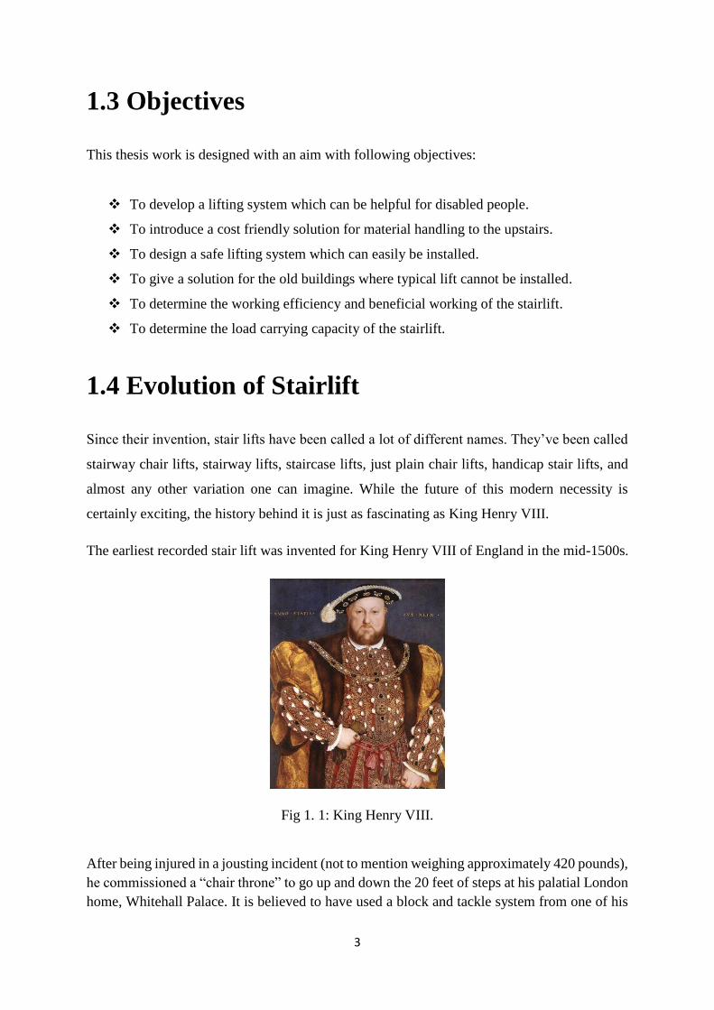
Fig 1. 1: King Henry VIII. ......................................................................................................... 3
Fig 1. 2: Modern Stairlift ........................................................................................................... 4
Fig 1. 3: Straight rail stairlift...................................................................................................... 5
Fig 1. 4: Curved rail stairlift ...................................................................................................... 6
Fig 1. 5: Wheelchair platform stairlift ....................................................................................... 7
Fig 1. 6: Outdoor stairlift ........................................................................................................... 7
Fig 3. 1 ..................................................................................................................................... 17
Fig 3. 2 ..................................................................................................................................... 17
Fig 3. 3 ..................................................................................................................................... 18
Fig 3. 4 ..................................................................................................................................... 18
Fig 3. 5 ..................................................................................................................................... 19
Fig 3. 6 ..................................................................................................................................... 19
Fig 4. 1: View of the stairlift for right side .............................................................................. 21
Fig 4. 2: Transmission from motor to gearbox ........................................................................ 21
Fig 4. 3: Transmission from gearbox to Chain drive ............................................................... 22
Fig 4. 4: Rail and carriage assembly ........................................................................................ 22
Fig 4. 5: Track in solidworks ................................................................................................... 23
Fig 4. 6: Track for this experiment .......................................................................................... 24
Fig 4. 7: Carriage in solidworks ............................................................................................... 24
Fig 4. 8: Carriage ..................................................................................................................... 25
Fig 4. 9: Dimension of the BLDC motor ................................................................................. 26
Fig 4. 10: DC motor used in the experiment ............................................................................ 27
Fig 4. 11: Toggle switches ....................................................................................................... 28
viii
Fig 4. 12: Seat .......................................................................................................................... 29
Fig 4. 13: Controller ................................................................................................................. 30
Fig 4. 14: Sprocket ................................................................................................................... 33
Fig 4. 15: Chain no 420............................................................................................................ 35
Fig 4. 16: Worm gear-set ......................................................................................................... 36
Fig 4. 17: Battery ..................................................................................................................... 37
Fig 4. 18: Battery Charger ....................................................................................................... 37
Fig 5. 1: ANSYS model of the sprocket .................................................................................. 44
Fig 5.2: Finite element mesh .................................................................................................... 44
Fig 5. 3: Deformation of sprocket under 2000N load .............................................................. 45
Fig 5. 4: Von mises stress developed on sprocket teeth under 2000N load............................. 45
Fig 5. 5: First pricipal stress on sprocket teeth ........................................................................ 46
Fig 5. 6: Direction of largest tensile stress happened to the sprocket ...................................... 46
Fig 5. 7: Finite element mesh of rail ........................................................................................ 47
Fig 5. 8: Deformation of rail for 115 kg load .......................................................................... 47
Fig 5. 9: Time Vs Max and Min deformation .......................................................................... 49
Fig 5. 10: Equivalent stress on rail........................................................................................... 49
Fig 5. 11: Time Vs Equivalent stress on rail ............................................................................ 51
Fig 5. 12: Force reaction at the bottom .................................................................................... 51
Fig 5. 13: Time Vs Reaction force ........................................................................................... 53
Fig 5. 14: Reaction force at the top .......................................................................................... 53
Fig 5. 15: Time Vs Reaction force at top ................................................................................. 55
Fig 6. 1: Speed Vs Time Graph ............................................................................................... 56
Fig 6. 2: Angle Vs Required Force Graph ............................................................................... 57
Fig 6. 3:Weight Vs Time required Graph ................................................................................ 58
List of Tables
Table 4. 1: Specifications of the Motor Used .......................................................................... 26
Table 4. 2: Specifications of the Sprocket used ....................................................................... 33
Table 5. 1: Change of max and min deformation with Time ................................................... 48
Table 5. 2: Change of equivalent stress with time ................................................................... 50
Table 5. 3: Reaction force at the bottom of rail at different directions .................................... 52
Table 5. 4: Reaction force at the top of the rail ....................................................................... 54
ix
NOMENCLATURE
D Pitch Diameter
𝐻𝑎 Allowable horse Power
L Length of chain between two sprockets
M Mass of the carriage
𝐹𝑎 Axial Load on bearing
𝐹𝑟 Radial Load on bearing
𝐹𝑠 Factor of safety
P Power
p Pitch
W Total weight
𝜂𝑔 Efficiency of the gearbox
𝜂𝑚 Efficiency of the motor
𝜇 Coefficient of friction
1
1.1 Introduction Stair into buildings is one of the most challenging barriers for users of wheeled mobility devices
and those with mobility limitations associated with ageing. The significance of this problem
should not be underestimated. In Bangladesh, thousands of people aged 65 and older face
difficulty climbing steps without resting and many of them uses wheelchair. Traditional
solutions for this inaccessibility have typically involved either installation a lift if possible or
moving to alternate housing includes a lift. These solutions are costly and sometimes
installation of lift is not possible.
A stairlift can be a good solution that allow users to safely move up and down through the
stairs. Lifts can be categorized into three broad groups:
1) vertical platform lifts—designed to transport the user vertically between two or three floor
levels
2) inclined platform lifts (also referred to as wheelchair platform lifts)—designed to
transport the user in his or her own wheelchair between levels on an incline such as along a
stairway; and
3) stair glides (also referred to as stair lifts, stair-chair lifts, and stair climbers)—designed to
transport the user on an integrated seat between floor levels while traveling on an incline such
as along a stairway.
Elevators have been identified as effective solutions in terms of speed, capacity, rise and
usability; however, the need for adequate space, and the high costs associated with their
purchase, installation, and maintenance are significant drawbacks, thus limiting their use in
typical home settings. Platform lifts and stair glides remain the ‘devices of choice’ for small
elevation changes in existing homes; however, these also have their limitations. For platform
lifts, limitations relating to use, size, speed, capacity, and rise have been identified.
Chapter-1 Introduction
2
The stairlift found in online and market is much expensive. This work aimed to develop a
stairlift for the disabled persons at low cost which is easier to install and does not affect the
aesthetics of the home much.
This paper explores the development of a stairlift which run by chain drive and also design
process of the lift.
1.2 Motivation
The motivation for this research comes basically from the need of a lifting system which is cost
friendly and easy for installation. Typical lifts are very expensive and also the maintenance
cost is high. In old buildings where there is no required space for installation a lift or two/three
storeyed building, it is much hazardous for a person who is physically disabled to use the stairs.
Also, it is difficult to handle heavy weight materials and equipment for lifting. .
Stair Lifts can assist people by doing the following:
• Decrease the need for excessive remodeling of a multi-story home
• Avoid a move to an entirely new, single-story house
• Make a multi-story home more fully and completely accessible
• Assist people who have just suffered an injury or undergone surgery and are
temporarily unable to use the stairs unassisted
• Rentable models of stair lifts can act as a solution for short-term elderly
visitors who have difficulty using the stairs
• Modify a multi-story house in a situation where elderly parents may be
moving back in with their kids for assistance and support
• Allowing wheelchair access to multiple levels of a home
• Increasing the safety of those who live alone and have decreased mobility
3
1.3 Objectives
This thesis work is designed with an aim with following objectives:
❖ To develop a lifting system which can be helpful for disabled people.
❖ To introduce a cost friendly solution for material handling to the upstairs.
❖ To design a safe lifting system which can easily be installed.
❖ To give a solution for the old buildings where typical lift cannot be installed.
❖ To determine the working efficiency and beneficial working of the stairlift.
❖ To determine the load carrying capacity of the stairlift.
1.4 Evolution of Stairlift
Since their invention, stair lifts have been called a lot of different names. They’ve been called
stairway chair lifts, stairway lifts, staircase lifts, just plain chair lifts, handicap stair lifts, and
almost any other variation one can imagine. While the future of this modern necessity is
certainly exciting, the history behind it is just as fascinating as King Henry VIII.
The earliest recorded stair lift was invented for King Henry VIII of England in the mid-1500s.
Fig 1. 1: King Henry VIII.
After being injured in a jousting incident (not to mention weighing approximately 420 pounds),
he commissioned a “chair throne” to go up and down the 20 feet of steps at his palatial London
home, Whitehall Palace. It is believed to have used a block and tackle system from one of his
4
warships, and was operated by a staff of servants.In 1923, the precrsor to the modern stair lift
was invented by C.C. Crispen, a Pennsylvania entrepreneur. A friend of his who was
immobilized due to polio was having trouble getting between two floors in his house, so
Crispen, a self-taught engineer, created a seat capable of traveling up and down stairs. It was a
basic chair connected to a rail that went the length of the staircase. It ran on small wheels or
rollers and was moved by a chain or a cable. Crispen built his first prototype and named it “the
Inclin-ator”.
The first widely used stair lift was introduced by the Inclinator Company of America shortly
after. Early users were largely comprised of those affected by polio, who could not easily climb
or descend stairs. The product increased in use and the technology advanced as more companies
began producing them.
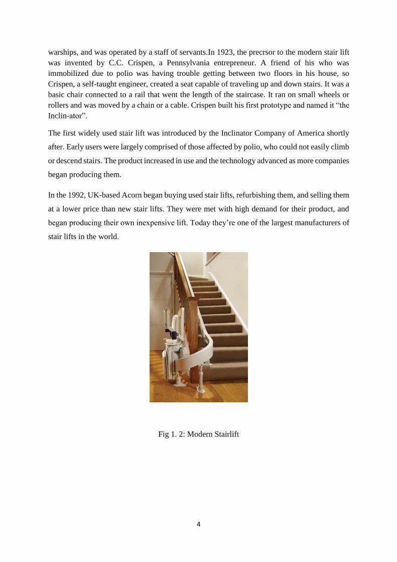
In the 1992, UK-based Acorn began buying used stair lifts, refurbishing them, and selling them
at a lower price than new stair lifts. They were met with high demand for their product, and
began producing their own inexpensive lift. Today they’re one of the largest manufacturers of
stair lifts in the world.
Fig 1. 2: Modern Stairlift
5
1.5 Popular Types
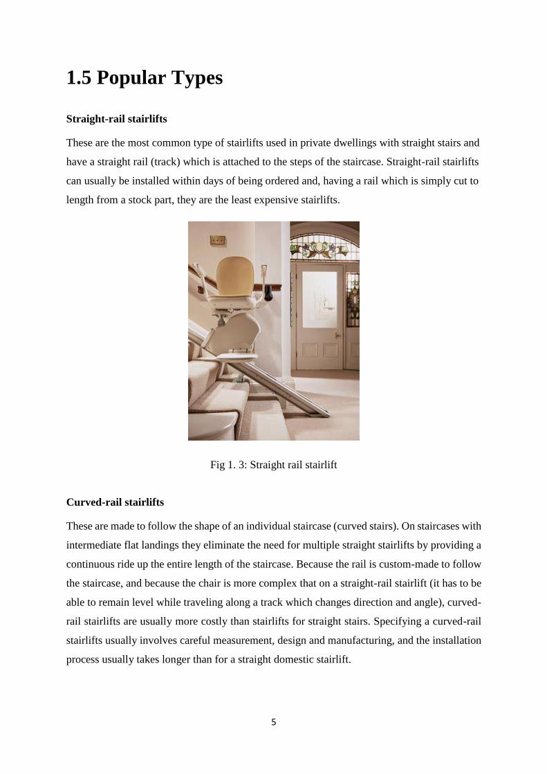
Straight-rail stairlifts
These are the most common type of stairlifts used in private dwellings with straight stairs and
have a straight rail (track) which is attached to the steps of the staircase. Straight-rail stairlifts
can usually be installed within days of being ordered and, having a rail which is simply cut to
length from a stock part, they are the least expensive stairlifts.
Fig 1. 3: Straight rail stairlift
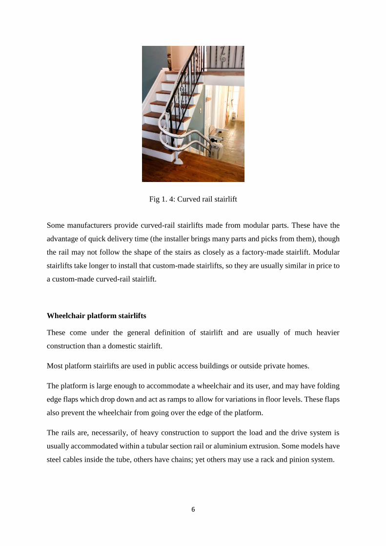
Curved-rail stairlifts
These are made to follow the shape of an individual staircase (curved stairs). On staircases with
intermediate flat landings they eliminate the need for multiple straight stairlifts by providing a
continuous ride up the entire length of the staircase. Because the rail is custom-made to follow
the staircase, and because the chair is more complex that on a straight-rail stairlift (it has to be
able to remain level while traveling along a track which changes direction and angle), curved-
rail stairlifts are usually more costly than stairlifts for straight stairs. Specifying a curved-rail
stairlifts usually involves careful measurement, design and manufacturing, and the installation
process usually takes longer than for a straight domestic stairlift.
6
Fig 1. 4: Curved rail stairlift
Some manufacturers provide curved-rail stairlifts made from modular parts. These have the
advantage of quick delivery time (the installer brings many parts and picks from them), though
the rail may not follow the shape of the stairs as closely as a factory-made stairlift. Modular
stairlifts take longer to install that custom-made stairlifts, so they are usually similar in price to
a custom-made curved-rail stairlift.
Wheelchair platform stairlifts
These come under the general definition of stairlift and are usually of much heavier
construction than a domestic stairlift.
Most platform stairlifts are used in public access buildings or outside private homes.
The platform is large enough to accommodate a wheelchair and its user, and may have folding
edge flaps which drop down and act as ramps to allow for variations in floor levels. These flaps
also prevent the wheelchair from going over the edge of the platform.
The rails are, necessarily, of heavy construction to support the load and the drive system is
usually accommodated within a tubular section rail or aluminium extrusion. Some models have
steel cables inside the tube, others have chains; yet others may use a rack and pinion system.
7
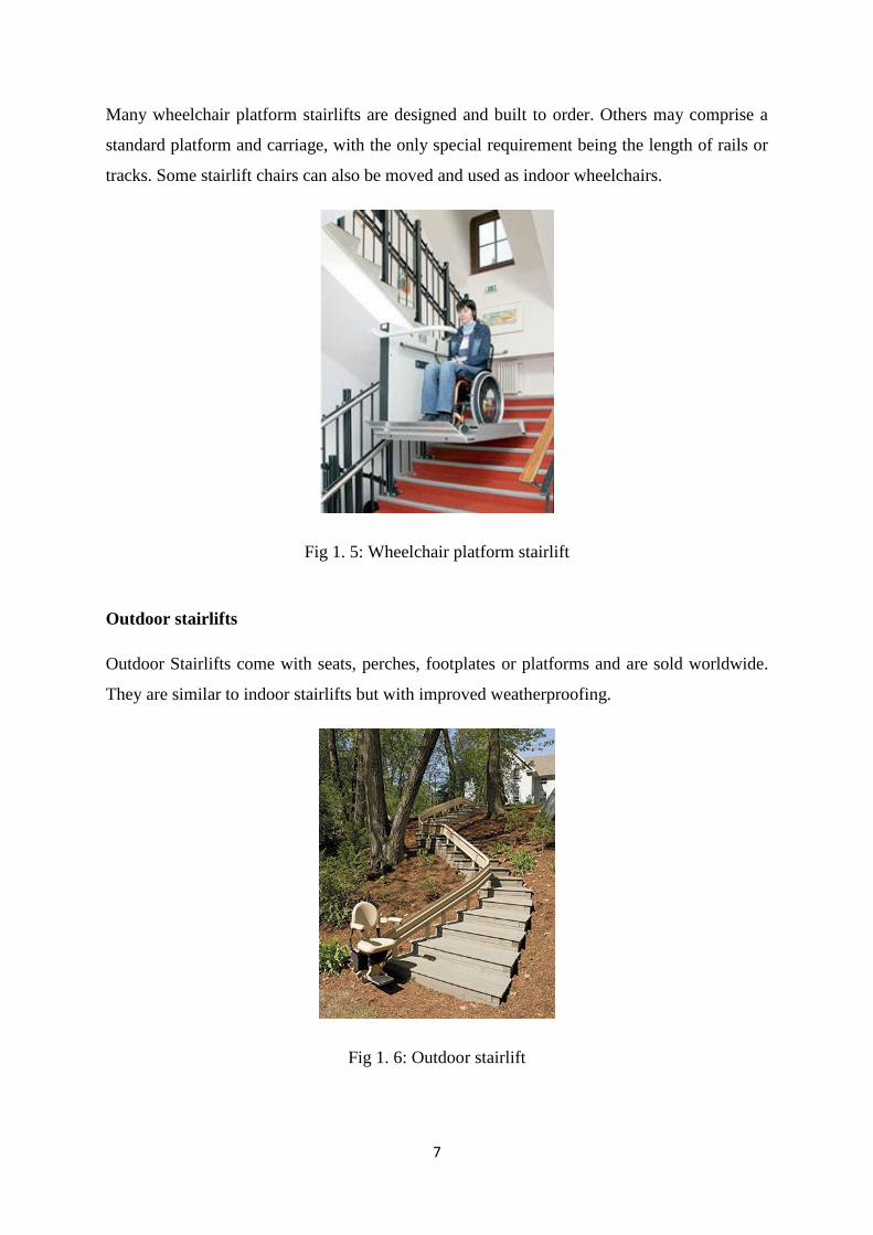
Many wheelchair platform stairlifts are designed and built to order. Others may comprise a
standard platform and carriage, with the only special requirement being the length of rails or
tracks. Some stairlift chairs can also be moved and used as indoor wheelchairs.
Fig 1. 5: Wheelchair platform stairlift
Outdoor stairlifts
Outdoor Stairlifts come with seats, perches, footplates or platforms and are sold worldwide.
They are similar to indoor stairlifts but with improved weatherproofing.
Fig 1. 6: Outdoor stairlift
8
Pre-owned stairlifts
There is a second-user market for some types of stairlift. This is most common with straight
rail domestic types. The rails can be cut to length if too long, or extended with a "joining kit".
Most models allow the carriage to be "re-handed" so it can be used on the left or right side of
the staircase.
During the early days of curved rail stairlifts there was no second user market because of the
difficulty of matching rails to a different layout. Even staircases built to the same design
specification in neighbouring houses have variations, but in most attempted "transplants" there
are too many differences to make it practicable. Many owners have had to pay to have
unwanted curved stairlifts removed.
More recently, some curved rails have been produced to a modular design so components can
be unbolted and used elsewhere, subject to design and safety considerations. In some cases,
tubular section rails which are welded during manufacture, are produced by specialist rail
companies so they can be used with a pre-owned carriage, controls, and other components.
This is, perhaps, like putting an old locomotive on new railway lines. It provides a lower cost
solution than buying a totally new system.
Manufacturers and installers have offered an extended warranty, rather like those available for
domestic white goods and brown goods.
Goods stairlifts
Some manufacturers produce stairlifts with trays instead of seats for moving goods between
different levels, usually in commercial or industrial buildings. Some businesses have purchased
normal domestic stairlifts purely as goods transporters and put items such as boxes of stationery
on the seat.
9
1.6 Advantages of a Stairlift
The main advantages of a stairlift are:
• Stairlifts are not much expensive.
• There’s very small amount of cost for maintenance
• It can easily be installed and any change in the stairs is not needed.
• Stairlifts is suitable for any kind of building old or new.
• No extra space is required for installation.
• It can easily be operated
10
Chapter-2 Literature Review
An elevator or lift is a vertical transport equipment that efficiently moves people or goods
between floors (levels) of a building, or of other structure. Elevators are generally powered by
electric motors that either drive traction cables or counterweight systems like a hoist or pump
hydraulic fluid to raise a cylindrical piston like a jack. Because of wheelchair access laws,
elevators are often a legal requirement in new multi-storey buildings, especially where
wheelchair ramps would be impractical. A stairlift is a mechanical device for lifting people and
wheelchairs up and down stairs. For sufficiently wide stairs, a rail is mounted to the treads of
the stairs. A chair or lifting platform is attached to the rail. A person on the chair or platform is
lifted as the chair or platform moves along the rail.
Stairlifts are know variously as stair lifts, stair-lifts, chair lifts, stair gliders and by other names.
This type of chair lift should not be confused with the chairlift used by skiers. As the name
suggests stair case lift is a type of lift that can be mounted on the stock stair case without
altering civil structure. This lift of course runs on electric power and consists of a motor two
rails a sliding chair. This stair case lift can be mounted stock stair case where the civil structure
is not be altered; and still handicapped old age and goods are to be carried across the stair case.
These actual size stair case lift will be on could with at which can be assembly, and mounted
and wheel as disassembled and mounted.
In the middle 1800s, there were many types of crude elevators that carried freight. Most of
them ran hydraulically. The first hydraulic elevators used a plunger below the car to raise or
lower the elevator. A pump applied water pressure to a plunger, or steel column, inside a
vertical cylinder. Increasing the pressure caused the elevator to ascend. The elevator also used
a system of counter-balancing so that the plunger did not have to lift the entire weight of the
elevator and its load. The plunger, however, was not practical for tall buildings, because it
required a pit as deep below the building as the building was tall. Later a rope-geared elevator
with multiple pulleys was developed.
11
The development of elevators was led by the need for movement of raw materials including
coal and lumber from hillsides. The technology developed by these industries and the
introduction of steel beam construction worked together to provide the passenger and freight
elevators in use today. Lifts are invented long back ago. But installation of lift involves ample
amount of cost intenous of rails, motor honk, civil structures. If lifts to be installed in the stalk
structure then it be alteration cost is too much. To overcome all these factors and to civil
construction cost the concept of stair case lift come with being which reduced extra costing
associated with the lift mechanism, the benchmark of the system is that this concept is
associated with simplifying as well. Some people argue that lifts began as simple rope or chain
hoist. A lift is a essential platform that is either pulled or pushed up by a mechanical means. A
modern day lift when consists of a cab (also called a "cage" or "car") mounted on a platform
within an enclosed space called a shaft or sometimes a "hoistway". In the past, lift drive
mechanisms were powered by steam and water hydraulic pistons or by hand. In a "traction"
lift, cars are pulled up by means of rolling steel ropes over a deeply grooved pulley commonly
called a sheave in the industry. The weight of the car is balanced by counterweight. Sometimes
two lifts always move synchronously in opposite directions, and they are each other's
counterweight. The friction between the ropes and the pulley furnishes the traction which gives
this type of lift its name.
Hydraulic lifts use the principles of hydraulics (in the sense of hydraulic power) to pressurize
an above ground or in-ground piston to raise and lower the car. Roped hydraulics use a
combination of both ropes and hydraulic power to raise and lower cars. Recent innovations
include permanent magnet motors, machine room-less rail mounted gearless machines, and
microprocessor controls. The technology used in new installations depends on a variety of
factors. Hydraulic lifts are cheaper, but installing cylinders greater than a certain length
becomes impractical for very high lift hoist ways. For buildings of much over seven storey’s,
traction lifts must be employed instead. Hydraulic lifts are usually slower than traction lifts.
Lifts are a candidate for mass customization.
There are economies to be made from mass production of the components, but each building
comes with its own requirements like different number of floors, dimensions of the well and
usage patterns.
In the year of 2000, a group of researchers [1] introduced a rover type of vehicle to run over
stepped path. Using a rhombus configuration the rover had one wheel mounted on a fork in the
12
front, one wheel in the rear and two bogieson each side. Researchers around the world are
thinking seriously to redesign such vehicle, which will be economical and affordable. Chang
Hsueh-Er [2] developed a five wheeler trolley, which was driven by manual power. Anastasios
et al. [3] and D. Helmick et al. [4] designed a robotic carrier with belt driven. No wheel was
introduced in his robotic carrier. However, none of them think about automatic vehicle that can
carry loads through stairs. In various research projects all over the world the different
locomotion concepts for mobile robots have been analyzed and new concepts have been
proposed [5, 6]. Good general surveys are provided in [5-12]. In [8] over 300 mobility concepts
and more than 400 navigation concepts have been generated and discussed, yielding to three
candidate systems, a symmetrical walker with six identical legs, a four-wheeled vehicle and a
so called attached scout concept with six wheels.
In this article the design and manufacturing of a stair climbing vehicle has been presented. The
vehicle is designed in such a way that it can climb a stepped path (like stairs) with its modified
wheel structure. Not only on the stairs, can it also move with load over flat or rocky surface.
This is the individuality of this vehicle. Different speed combinations are incorporated
depending on the working condition through simple gear arrangement, powered by the local
motor drive. Speed reduction at any desired rate, is possible to establish over the existing ratio.
Wheeled rovers are the optimal solutions for well structured environment like roads or
habitations. But off-the road, their efficiency is very dependent on the typical size of
encountered obstacles that have to be overcome in a standard motion mode. This is the case for
[13-15], which can typically overcome obstacles of their wheel size, if friction is high enough.
Adding real climbing abilities to a wheeled rover requires the use of a special strategy and often
implies dedicated actuators like [16, 17] or complex control procedure like [18, 19].
A group of Indian students designed and fabricated [20] a stairlift for material handling system
using rope drive. Some Japanese students did a project on stairlift [21] and the aim of this
project was to supply a new, cost-effective stair lift for wheelchair users. For this purpose, a
new mechanism, known as "crawl type," has been developed. This system was composed of
three parts: traction guides, drive guides, and a hoist carrier.
13
Chapter-3 Design Consideration
3.1 General Considerations
Before deciding on the most suitable form of lift consider the following:
Progressive conditions
Someone with a disability who has a condition that could deteriorate should consider what the
best long term solution will be. Although he/she may be able to use a seated stair lift now, it
may be wise to consider installing a through-floor lift so that in future the option to travel in a
wheelchair is available.
It is advisable that the stair lift covers the whole staircase. Some people will attempt to save
costs by installing a straight stair lift on a curved staircase and attempt to manage the first or
last few steps. However, if their condition deteriorates, they will no longer be able to manage
this.
Bending knees
Is the user able to bend his/her knees sufficiently to travel in a seated position?
Who will operate the stair lift?
Does the lift need to be operated by the user, their career or both? Controls are available to
allow users and careers to operate the lift but it will be easier to have these fitted during the
initial installation.
The environment including doors or thresholds near the staircase, bulkheads or banister rails,
and radiators near the staircase.
Other users of the stairs, e.g. children, pets, elderly visitors.
14
Other members of the household Can other members of the household easily use the stairway
when the lift is folded against the wall?
3.2 Considerations for Lift parts
Rails
Straight rails for use on domestic staircases are usually made from extruded aluminium or steel
and come in various cross-sectional shapes. These rails may, typically, weigh over 30 kg,
depending on the length. In most applications they are attached to the steps with metal brackets.
If a rail crosses a doorway at the bottom of the stairs or causes an obstruction a hinge can be
fitted so the end of the rail can be folded back out of the way when not in use.
Curved rails are made from materials such as steel or aluminium and come in various cross-
sectional shapes according to the designer. Individual designs vary a lot and probably the key
criterion is to make the curves with the smallest radius possible so they will wrap tightly around
objects such as newel posts.
The sections of curved rails usually packaged well to prevent damage in transit and are
unwrapped and assembled on site.
Rails for wheelchair platform stairlifts may be secured to walls in addition to the step fixings
Carriage
The chair portion of a stair lift is generally referred to as the “carriage,” according to Wikipedia.
Consideration should be taken as to the carriage design, such as height of the seat, manual
versus power swivel of the seat, and safety hitches to ensure that the lift won’t start moving
until the carriage has been securely locked.
15
Swivel Seats
A seat that swivels is very important to the safety of the user. The majority of stair lift seats
face away from the wall or banister, towards the stairwell. If the seat does not swivel, the user
may need to get in and out of the carriage from either the top or bottom stair step. Entry and
exit into the carriage from the steps as opposed to the landings poses an increased risk of falling.
Seats that swivel allow the user to turn the carriage away from the stairs, towards the landing,
so that they may safely sit down and stand up on a flat, level and wide surface. Since the seats
swivel upon arrival to the top and bottom of the stairwell, there are safety locks that ensure the
seat will not twist and turn as the carriage is traveling up and down the track.
Chair Height
The height of the chair must be low enough so that the user can sit down and stand up easily.
If the chair height is either too high or too low, a disabled user may have trouble getting in and
out. Sometimes there are options to adjust the seat at the time of installation to the user’s height
specifications.
Seat Belts
Most, if not all, stair lift carriages come equipped with a seat belt as a safety precaution. It is
important for the user to fasten the seat belt during any time of use to prevent falls from the
chair, and wait for the carriage to come to a complete stop.
3.3 Travelling Position
Stand, sit or use a wheelchair? Will the user want to stand, sit on a seat or use a wheelchair?
If a standing stairlift is preferred, is there sufficient headroom?
Which direction will the user need to face? Most seats face sideways, but if the user has a
stiff knee he/she may need to face forwards to give them more room.
16
3.4 Power and cost considerations
If the track for the stairlift cannot continue beyond the bottom or top step of the staircase
because it will obstruct a door, some companies can provide a foldup, hinged rail to overcome
this problem. This rail may be manually or electrically operated.
Power source
Stair lift can be operated by both DC or AC power source. Stair lifts are available with a battery
backup option in case of power failures. We choose DC motor instead of AC motor, it is easier
to change the direction of rotation or, polarity in DC motor.
Budget and financial consideration
The cost of a stair lift is based on factors including the staircase type, the features required and
the custom specification you choose.
Maintenance costs to the user tend to vary depending on the amount of usage the stair lift gets.
3.5 Guideline for measuring Stair lift
Measuring your staircase can be an essential easy step process to determine which type of stair
lift you may require in your home. As a guide, please follow our guide to finding your staircase
type to ensure we give you the right stair lift advice.
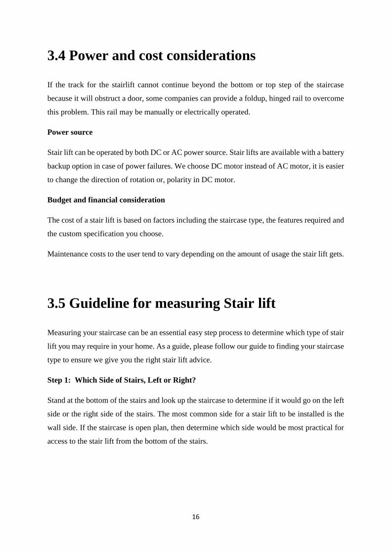
Step 1: Which Side of Stairs, Left or Right?
Stand at the bottom of the stairs and look up the staircase to determine if it would go on the left
side or the right side of the stairs. The most common side for a stair lift to be installed is the
wall side. If the staircase is open plan, then determine which side would be most practical for
access to the stair lift from the bottom of the stairs.
17
Fig 3. 1
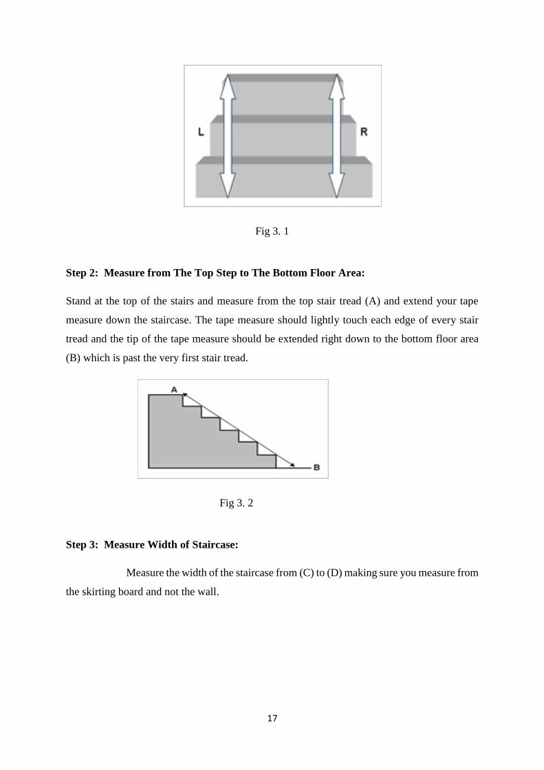
Step 2: Measure from The Top Step to The Bottom Floor Area:
Stand at the top of the stairs and measure from the top stair tread (A) and extend your tape
measure down the staircase. The tape measure should lightly touch each edge of every stair
tread and the tip of the tape measure should be extended right down to the bottom floor area
(B) which is past the very first stair tread.
Fig 3. 2
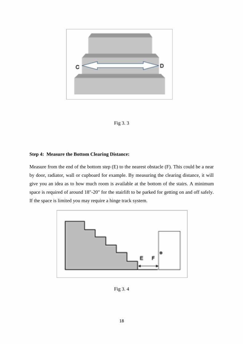
Step 3: Measure Width of Staircase:
Measure the width of the staircase from (C) to (D) making sure you measure from
the skirting board and not the wall.
18
Fig 3. 3
Step 4: Measure the Bottom Clearing Distance:
Measure from the end of the bottom step (E) to the nearest obstacle (F). This could be a near
by door, radiator, wall or cupboard for example. By measuring the clearing distance, it will
give you an idea as to how much room is available at the bottom of the stairs. A minimum
space is required of around 18"-20" for the stairlift to be parked for getting on and off safely.
If the space is limited you may require a hinge track system.
Fig 3. 4
19
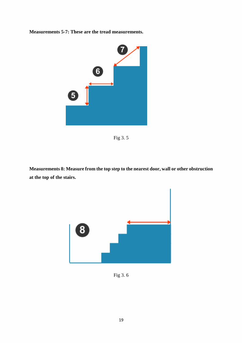
Measurements 5-7: These are the tread measurements.
Fig 3. 5
Measurements 8: Measure from the top step to the nearest door, wall or other obstruction
at the top of the stairs.
Fig 3. 6

20
Chapter-4 Design and Fabrication of Stairlift
4.1 General Aspect
An experimental facility has been designed, fabricated and installed to collected data for this
research. The detailed description of experimental apparatus and experimental procedure are
presented in this chapter.
Thus, components used in this experiment are-
▪ Track or Rail
▪ Carriage
▪ Motor
▪ Toggle switches
▪ Seat
▪ Foot Rest
▪ Controller
▪ Transmission
▪ Battery Charger
▪ Battery
Measuring apparatus are:
• Measuring Tape
• Vernier calipers
• Tachometer
Auxiliary components used:
• Rivet Gun
• Soldering Iron
• Filler Metal
21
4.2 View of experimental setup
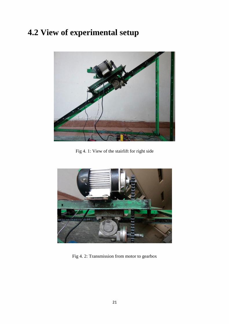
Fig 4. 1: View of the stairlift for right side
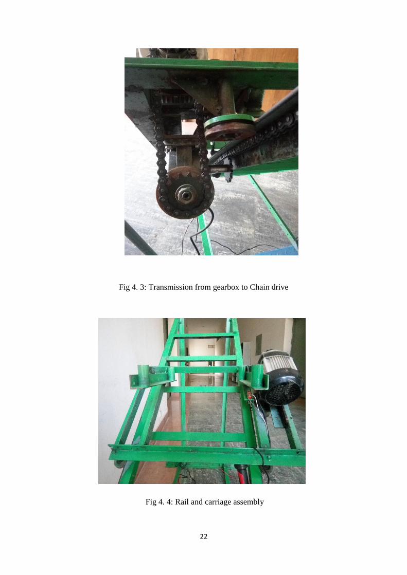
Fig 4. 2: Transmission from motor to gearbox
22
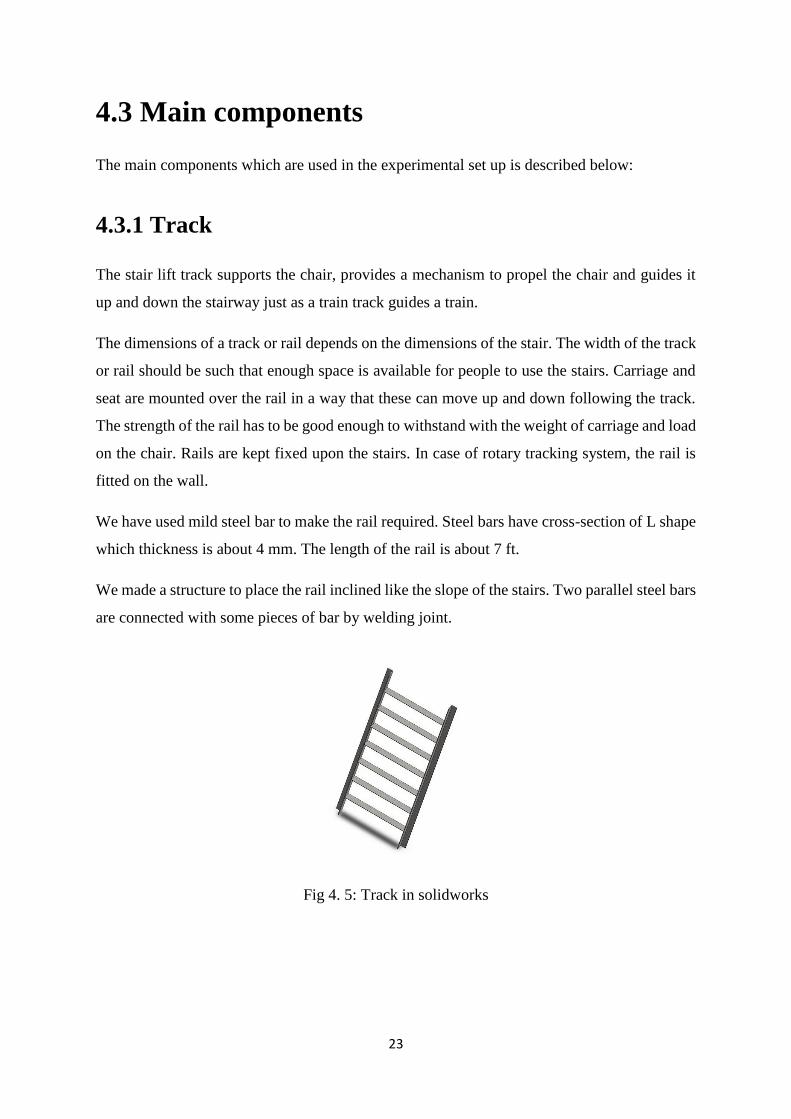
Fig 4. 3: Transmission from gearbox to Chain drive
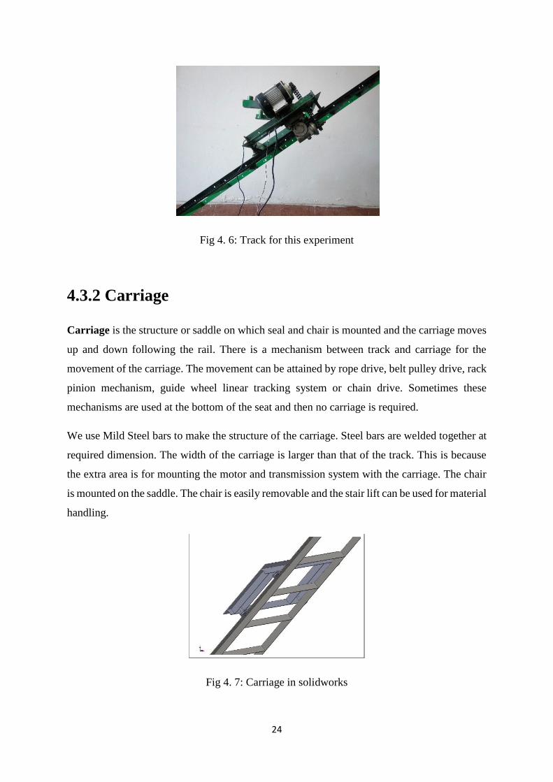
Fig 4. 4: Rail and carriage assembly
23
4.3 Main components
The main components which are used in the experimental set up is described below:
4.3.1 Track
The stair lift track supports the chair, provides a mechanism to propel the chair and guides it
up and down the stairway just as a train track guides a train.
The dimensions of a track or rail depends on the dimensions of the stair. The width of the track
or rail should be such that enough space is available for people to use the stairs. Carriage and
seat are mounted over the rail in a way that these can move up and down following the track.
The strength of the rail has to be good enough to withstand with the weight of carriage and load
on the chair. Rails are kept fixed upon the stairs. In case of rotary tracking system, the rail is
fitted on the wall.
We have used mild steel bar to make the rail required. Steel bars have cross-section of L shape
which thickness is about 4 mm. The length of the rail is about 7 ft.
We made a structure to place the rail inclined like the slope of the stairs. Two parallel steel bars
are connected with some pieces of bar by welding joint.
Fig 4. 5: Track in solidworks
24
Fig 4. 6: Track for this experiment
4.3.2 Carriage
Carriage is the structure or saddle on which seal and chair is mounted and the carriage moves
up and down following the rail. There is a mechanism between track and carriage for the
movement of the carriage. The movement can be attained by rope drive, belt pulley drive, rack
pinion mechanism, guide wheel linear tracking system or chain drive. Sometimes these
mechanisms are used at the bottom of the seat and then no carriage is required.
We use Mild Steel bars to make the structure of the carriage. Steel bars are welded together at
required dimension. The width of the carriage is larger than that of the track. This is because
the extra area is for mounting the motor and transmission system with the carriage. The chair
is mounted on the saddle. The chair is easily removable and the stair lift can be used for material
handling.
Fig 4. 7: Carriage in solidworks
25
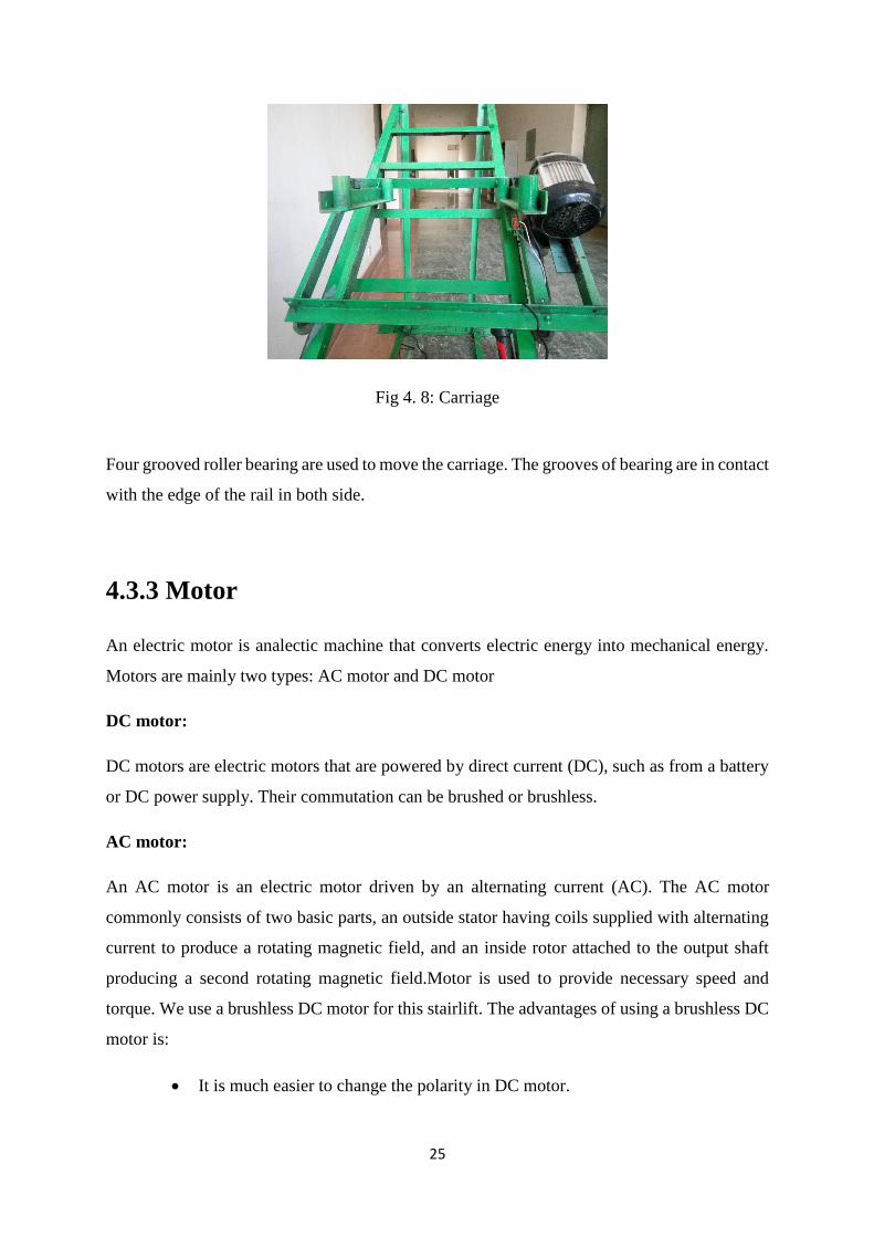
Fig 4. 8: Carriage
Four grooved roller bearing are used to move the carriage. The grooves of bearing are in contact
with the edge of the rail in both side.
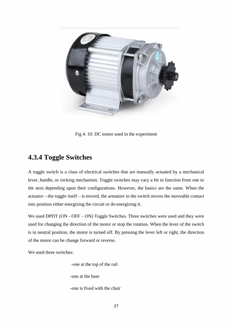
4.3.3 Motor
An electric motor is analectic machine that converts electric energy into mechanical energy.
Motors are mainly two types: AC motor and DC motor
DC motor:
DC motors are electric motors that are powered by direct current (DC), such as from a battery
or DC power supply. Their commutation can be brushed or brushless.
AC motor:
An AC motor is an electric motor driven by an alternating current (AC). The AC motor
commonly consists of two basic parts, an outside stator having coils supplied with alternating
current to produce a rotating magnetic field, and an inside rotor attached to the output shaft
producing a second rotating magnetic field.Motor is used to provide necessary speed and
torque. We use a brushless DC motor for this stairlift. The advantages of using a brushless DC
motor is:
• It is much easier to change the polarity in DC motor.
26
• DC motors with control box kit are available in market. It is very simple to set the
controller with the motor.
• Brushless motor has high power to weight ratio.
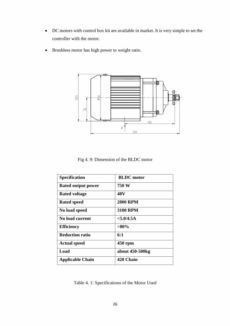
Fig 4. 9: Dimension of the BLDC motor
Specification BLDC motor
Rated output power 750 W
Rated voltage 48V
Rated speed 2800 RPM
No load speed 3100 RPM
No load current <5.0/4.5A
Efficiency >80%
Reduction ratio 6:1
Actual speed 450 rpm
Load about 450-500kg
Applicable Chain 420 Chain
Table 4. 1: Specifications of the Motor Used
27
Fig 4. 10: DC motor used in the experiment
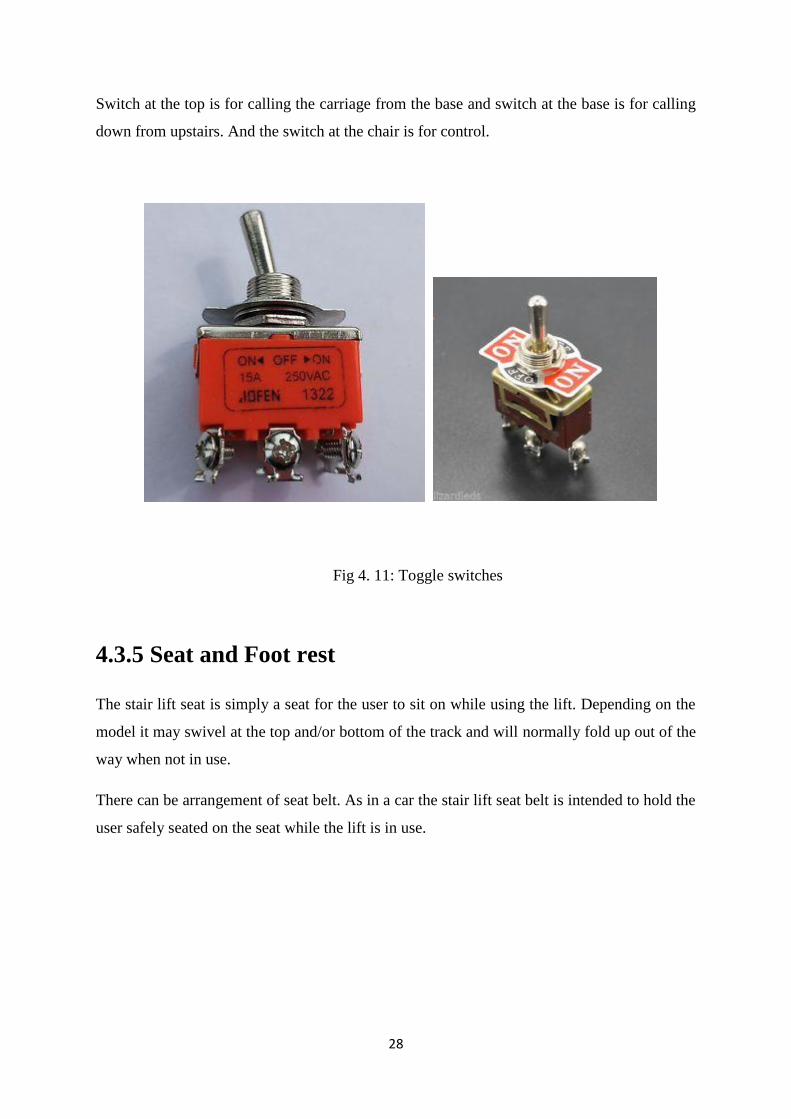
4.3.4 Toggle Switches
A toggle switch is a class of electrical switches that are manually actuated by a mechanical
lever, handle, or rocking mechanism. Toggle switches may vary a bit in function from one to
the next depending upon their configurations. However, the basics are the same. When the
actuator—the toggle itself—is moved, the armature in the switch moves the moveable contact
into position either energizing the circuit or de-energizing it.
We used DPDT (ON - OFF – ON) Toggle Switches. Three switches were used and they were
used for changing the direction of the motor or stop the rotation. When the lever of the switch
is in neutral position, the motor is turned off. By pressing the lever left or right, the direction
of the motor can be change forward or reverse.
We used three switches:
-one at the top of the rail
-one at the base
-one is fixed with the chair
28
Switch at the top is for calling the carriage from the base and switch at the base is for calling
down from upstairs. And the switch at the chair is for control.
Fig 4. 11: Toggle switches
4.3.5 Seat and Foot rest
The stair lift seat is simply a seat for the user to sit on while using the lift. Depending on the
model it may swivel at the top and/or bottom of the track and will normally fold up out of the
way when not in use.
There can be arrangement of seat belt. As in a car the stair lift seat belt is intended to hold the
user safely seated on the seat while the lift is in use.
29
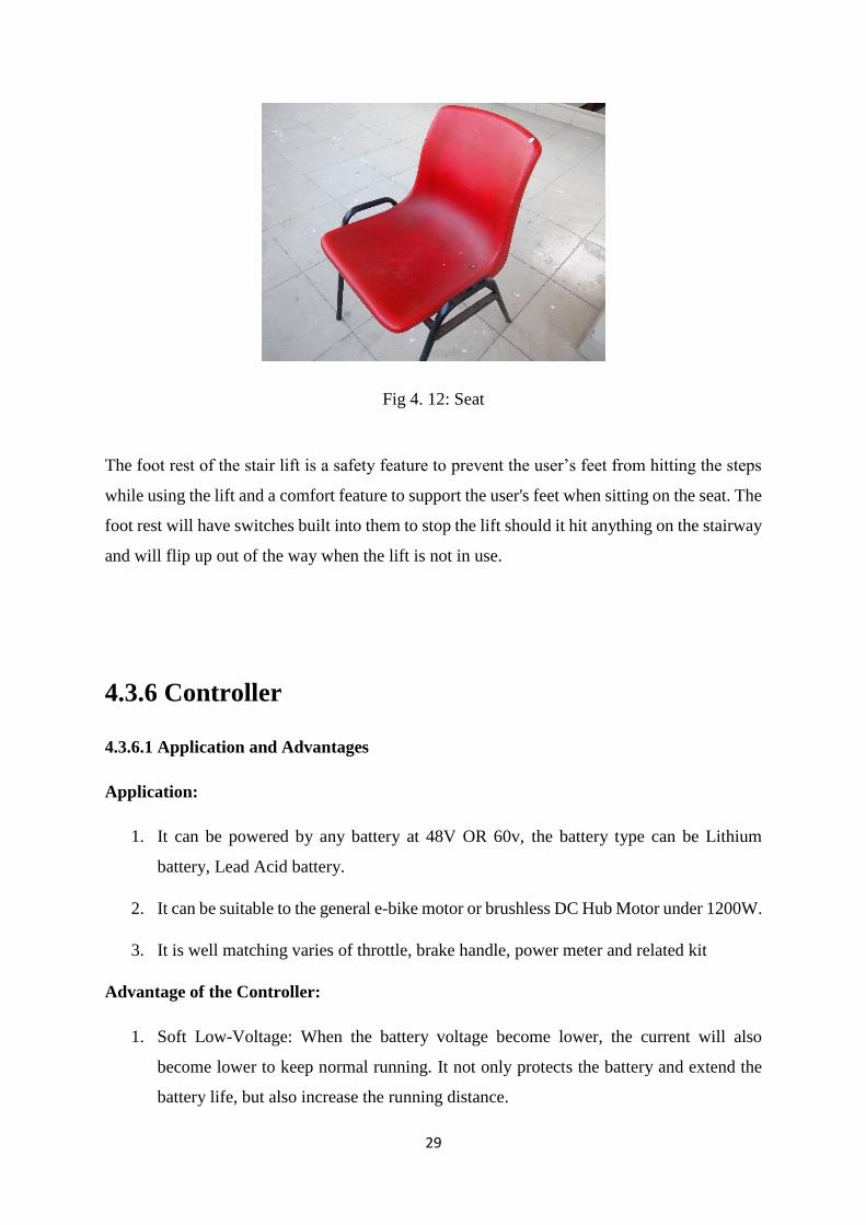
Fig 4. 12: Seat
The foot rest of the stair lift is a safety feature to prevent the user’s feet from hitting the steps
while using the lift and a comfort feature to support the user's feet when sitting on the seat. The
foot rest will have switches built into them to stop the lift should it hit anything on the stairway
and will flip up out of the way when the lift is not in use.
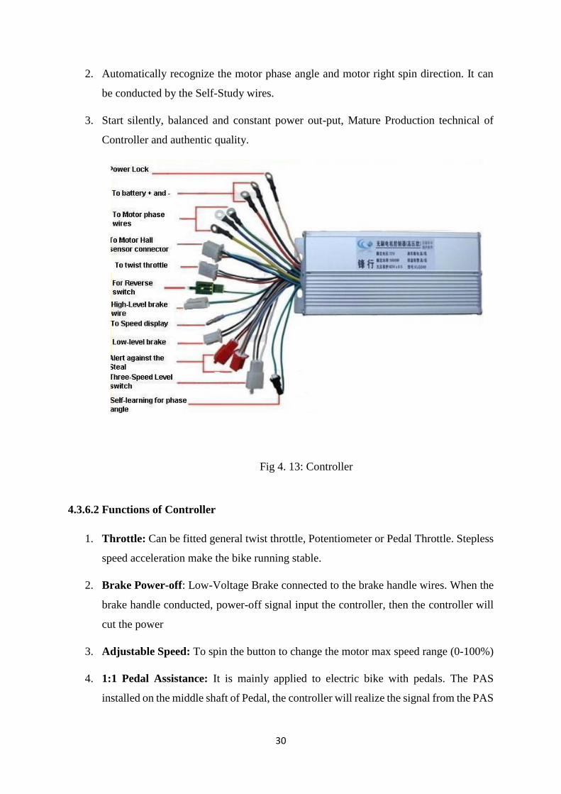
4.3.6 Controller
4.3.6.1 Application and Advantages
Application:
1. It can be powered by any battery at 48V OR 60v, the battery type can be Lithium
battery, Lead Acid battery.
2. It can be suitable to the general e-bike motor or brushless DC Hub Motor under 1200W.
3. It is well matching varies of throttle, brake handle, power meter and related kit
Advantage of the Controller:
1. Soft Low-Voltage: When the battery voltage become lower, the current will also
become lower to keep normal running. It not only protects the battery and extend the
battery life, but also increase the running distance.
30
2. Automatically recognize the motor phase angle and motor right spin direction. It can
be conducted by the Self-Study wires.
3. Start silently, balanced and constant power out-put, Mature Production technical of
Controller and authentic quality.
Fig 4. 13: Controller
4.3.6.2 Functions of Controller
1. Throttle: Can be fitted general twist throttle, Potentiometer or Pedal Throttle. Stepless
speed acceleration make the bike running stable.
2. Brake Power-off: Low-Voltage Brake connected to the brake handle wires. When the
brake handle conducted, power-off signal input the controller, then the controller will
cut the power
3. Adjustable Speed: To spin the button to change the motor max speed range (0-100%)
4. 1:1 Pedal Assistance: It is mainly applied to electric bike with pedals. The PAS
installed on the middle shaft of Pedal, the controller will realize the signal from the PAS
31
sensor, then out-put the current. So, the pedal driving will be much more easily and
smooth
5. LCD Meter: The meter displays Battery power Level, Out-put power, Speed, PAS
Grades, Single trip distance, Cruise, Failure indication, Total Trip Distance, Trip Time,
Motor RPM.
6. Forward/Reverse rotation
If the motor spin direction is reverse, firstly Self-study wires should be disconnected, but
connect them again at once, then the motor will spin on other direction. When the direction is
right, only the Self-Study wires should be disconnected.
4.3.6.3 Controller Software Functions
1. It can be fitted various of motors, like brushless DC motor, Geared Motor, Hub motor
or PM Motor, or fitted two wheel, three wheel or four wheel motor.
2. Over-heat protection, the controller will cut the power when the temperature is overtop,
and restart if the temperature is normal.
3. Intelligent management of battery system, the controller will reasonable control the
battery discharge, low-voltage protection function to extend the battery life.
4. Over-load protection. When overload of the bike to make the motor stall more than 2
seconds, the controller will cut off the current out-put to protect the motor and battery.
5. Timely control the motor phase current, and protect the MOS.
6. Over voltage and low voltage protection.
7. Double-Mode, controller can check the motor hall sensor condition automatically. If
the motor sensors are broken, controller will operate to None-Hall mode.
8. When the motor phase is failure, controller will protect it, avoid motor burned, and
protect the battery at the same time.
32
We used a 48V 800W Brushless DC Motor Controller. The specifications of this controller
are:
Voltage: 48V
Low Voltage Cut off: 41.5V +-0.5V
Rated Power: 800-1000W
Limit current: 35A
Dimension of the controller box: 180*88*45mm (this size not included the base)
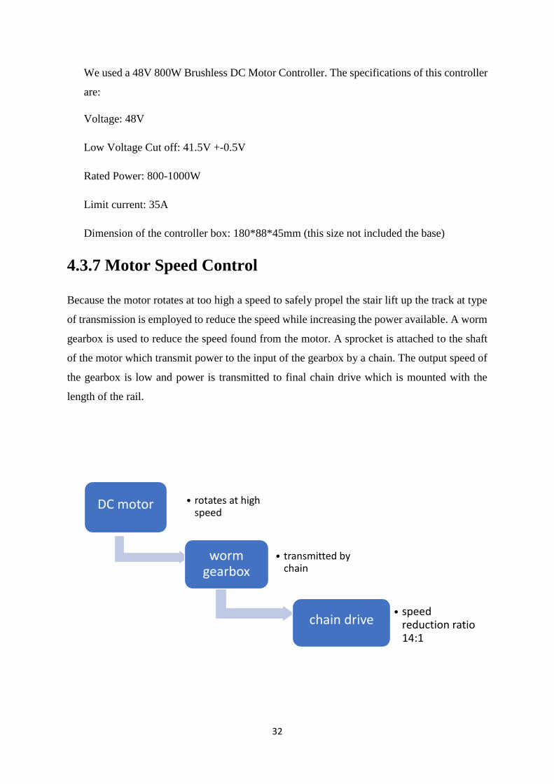
4.3.7 Motor Speed Control
Because the motor rotates at too high a speed to safely propel the stair lift up the track at type
of transmission is employed to reduce the speed while increasing the power available. A worm
gearbox is used to reduce the speed found from the motor. A sprocket is attached to the shaft
of the motor which transmit power to the input of the gearbox by a chain. The output speed of
the gearbox is low and power is transmitted to final chain drive which is mounted with the
length of the rail.
DC motor • rotates at high speed
worm gearbox
• transmitted by chain
chain drive • speed
reduction ratio 14:1
33
4.3.8 Sprocket
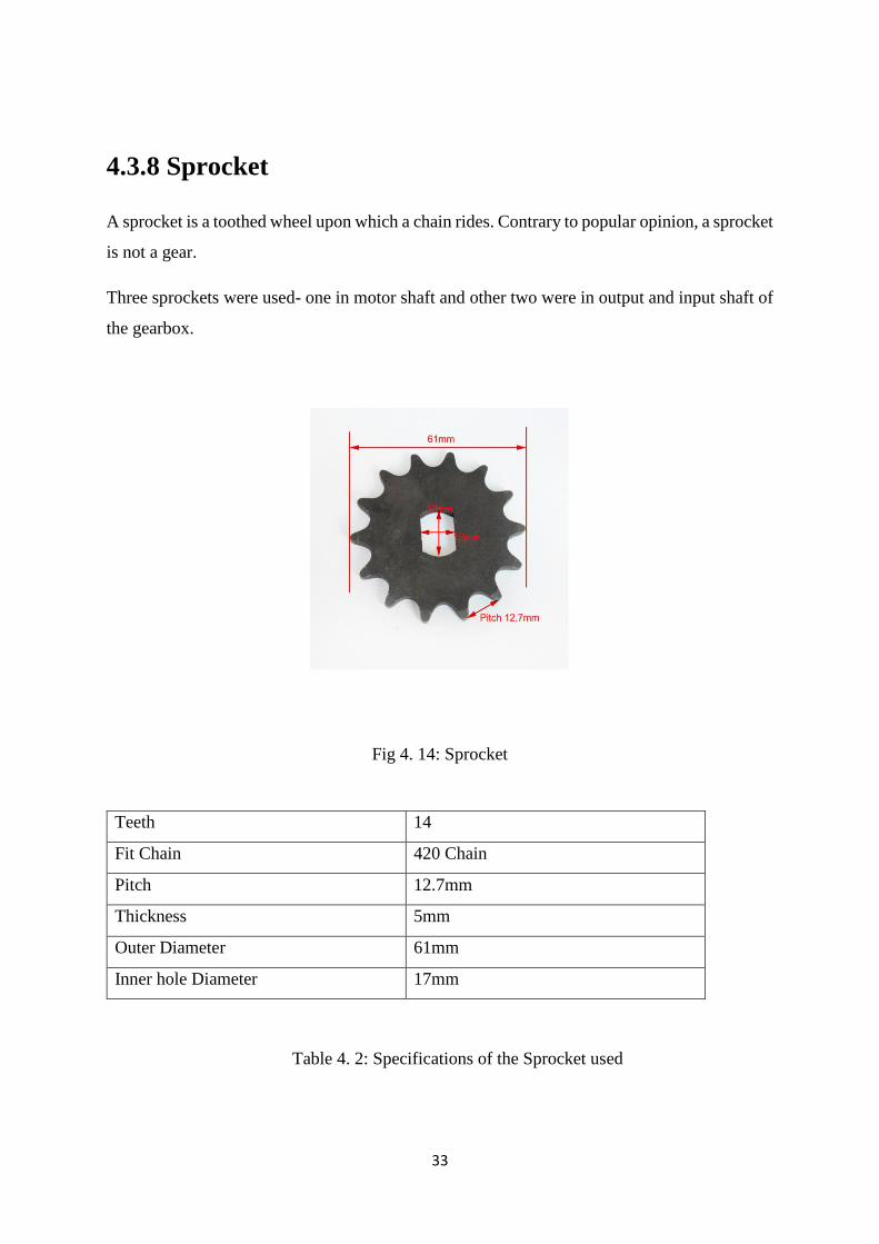
A sprocket is a toothed wheel upon which a chain rides. Contrary to popular opinion, a sprocket
is not a gear.
Three sprockets were used- one in motor shaft and other two were in output and input shaft of
the gearbox.
Fig 4. 14: Sprocket
Teeth 14
Fit Chain 420 Chain
Pitch 12.7mm
Thickness 5mm
Outer Diameter 61mm
Inner hole Diameter 17mm
Table 4. 2: Specifications of the Sprocket used
34
4.3.9 Chain
A chain is a series of connected links which are typically made of metal. A chain may consist
of two or more links. The main functions of chain are:
• Transmit power.
• Convey objects or materials.
• Convert rotary motion to linear motion, or linear motion to
rotary motion.
Chains have the following general advantages over the rope drive and other equipment intended
to do the same functions:
• Have controlled flexibility in only one plane.
• Have a positive action over sprockets, no slippage takes place.
• Carry very heavy loads with little stretch.
• Efficiency of a chain joint passing around a sprocket approaches 100 %
because of the large internal mechanical advantages of links in flexure.
• Provide extended wear life because flexure takes place between bearing
surfaces with high hardness designed specifically to resist wear.
• Can be operated satisfactorily in adverse environments, such as under
high temperatures or where they are subject to moisture or foreign
materials.
• Can be manufactured from special steels to resist specific environments.
• Have an unlimited shelf life. They do not deteriorate with age or with
sun, oil, or grease.
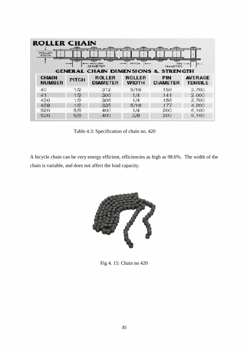
We used chain no 420 which is widely used for rickshaw and motorcycle.
35
Table 4.3: Specification of chain no. 420
A bicycle chain can be very energy efficient, efficiencies as high as 98.6%. The width of the
chain is variable, and does not affect the load capacity.
Fig 4. 15: Chain no 420
36
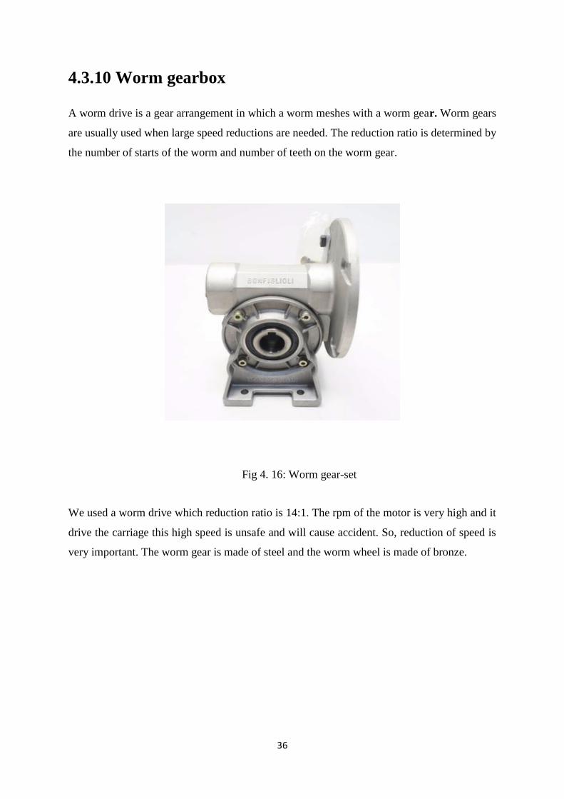
4.3.10 Worm gearbox
A worm drive is a gear arrangement in which a worm meshes with a worm gear. Worm gears
are usually used when large speed reductions are needed. The reduction ratio is determined by
the number of starts of the worm and number of teeth on the worm gear.
Fig 4. 16: Worm gear-set
We used a worm drive which reduction ratio is 14:1. The rpm of the motor is very high and it
drive the carriage this high speed is unsafe and will cause accident. So, reduction of speed is
very important. The worm gear is made of steel and the worm wheel is made of bronze.

37
4.3.11 Battery
We use four 12V battery for power supply. These batteries can be recharged.
Fig 4. 17: Battery
4.3.12 Battery charger
The batteries are charged by a charger which converts 220V AC input in DC output. The
batteries are connected among themselves and two junctions are connected to the controller
box. There is a charging port in the controller box by which batteries get charged.
Fig 4. 18: Battery Charger
38
Chapter-5 Design Parameters
5.1 Maximum load that can be carried by motor
Efficiency of the motor 𝜂𝑚 =78%
Maximum Speed =3100 rpm
Gear Ratio = 1:6
Actual Speed = 3100/6
=516.67 rpm
Gear reduction ratio by worm = 14:1
Speed at carriage = 516.67/14
=36.9 rpm
Now,
Maximum load that can be carried by motor:
P*𝜂𝑚*ηg= F*v
750 W *.78*.934 = F *π∗d∗N
60
546.39 =F * 𝜋∗61∗10−3∗36.9
60
F*0.1178 = 346.39
F=4638.285 N
F=mg
mg=4638.285 N
39
m = 4638.285
9.81
=472.91 Kg
5.2 Power required for average load carrying:
Mass of the carriage, motor, gearbox, and chair is about =15 kg
Average mass to be lifted =100Kg
Total mass, m = (Mass of the carriage, motor, gearbox, and chair
+Average: mass to be lifted)
= (100+15) Kg
=115 Kg
Total Weight W=mg
= (115*9.81)
=1128.15 N
Co-efficient of Friction for ball bearing 𝜇=0.002
Force required,
F=Wsin 𝜃+𝜇 cos 𝜃
F=1128.15 sin 40°+ (0.002*1128.15cos 40°)
F= 725.16 +1.7284
=726.89 N
Velocity, V=𝜋∗𝐷∗𝑁
60
=3.1416∗61∗10−3∗36.9
60
=7.0714
60
=0.11785 m/s
40
Power, P = 𝐹∗𝑣
𝜂𝑚∗η𝑔
=726.89∗0.11785
0.78∗0.934
=117.586 W
5.3 Axial load and Radial load on bearing:
Bore diameter=17mm
For deep groove ball bearing [22],
C=9.56
𝐶𝑜=4.50
Basic Load Bearing C=Fe (𝐿)1
𝑎
Here, a=3 for ball bearing
Now,
L=20000*60*369*10−6 mr
Recommended Bearing Life =20 Kh
L=44.28 mr
9.56=Fe (44.28)1
3
Fe=2.70 KN
Let,
Factor of Safety 𝐹𝑠 =1.2 [22]
𝐹𝑒′=1.2*2.70
=3.24 KN
Now,
𝐹𝑒′=XV𝐹𝑟+Y𝐹𝑎
41
=XV*F Cos (𝜃) + Y*F sin(𝜃)
=0.56*1.2*F Cos (50°)+1.55*F Sin (50°)
3.24 = 0.4319F +1.1873 F
F= 3.24
1.6192
=2 KN
𝐹𝑟= F cos 50°
=2 cos 50°
= 1.29 KN
𝐹𝑎 = F sin 50°
=2 sin 50°
= 1.53 KN
5.4 Chain specification
Pitch Diameter of Sprocket D=12.7 𝑚𝑚
sin(180 14)⁄
=57 mm
Chordal Speed Variation,
∆𝑉
𝑉=100 [Sec (
180
𝑁) − 1] cos(
180
𝑁)
=100[Sec (180
14)-1] cos(
180
14)
=2.50%
Length of Chain between two Sprocket
𝐿
𝑝=
2𝑐
𝑝+
𝑁1+𝑁2
2+
(𝑁2−𝑁1)2
4𝜋2(𝐶𝑝)⁄
Pitch p= 0.5 in
42
Centre to Core Distance =10.1 in
𝑁1=𝑁2=14
𝐿
𝑃=
2∗10.1
0.5 +
14+14
2
=54.4 ≈ 55 pitches
L= (55*.5) =27.5 Inch
Allowable Horse Power, 𝐻𝑎 = 𝐾1 𝐾2 𝐻𝑡𝑎𝑏
Tooth correction Factor,
𝐾1=0.78
Multiple Stand Factor,
𝐾2=1.0
𝐻𝑡𝑎𝑏= 2.38 hp
𝐻𝑎 = 0.78*1.0*2.38 hp
= 1.8564 hp
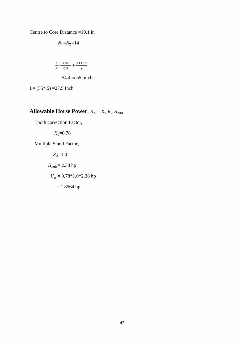
43
5.5 Ansys Analysis
In this project, the final design was an outcome of a sequential analysis and modification of
stages. Stair lifts can easily installed into any situation where the condition of the stair tread is
good. A chair lift for stairs can be both battery operated and AC power operated. Stairs present
a mobility challenge and often danger for the elderly who are struggling with mobility issues.
Falling down stairs are a leading cause of serious injury among the elderly and purchasing a
chair lift for stairs can significantly reduce concerns about falls. A chair lift will not only be a
safer method for movement up and down stairs by those with mobility issues but they will also
be securing an important degree of independence. The concept of stair case lift is mead for
transportation of human, goods across stair case hence it needs something like transported.
This system involves a motor, a gearbox, sprocket and a chain drive. Bearings are attached to
the edge of the rail and the bearing shafts are connected to the staircase.
Now, on these staircase a motor is mounted which is associated with the gearbox.On the output
of the gearbox is mounted a chain drive. This output shaft of the gearbox is also used to rotate
the sprocket with the help of which these stair case lift can move upward and downward. As
motor and gearbox along with the platform, chair are mounted on the suitable platform which
can be slide on the rails the entire unit starts moving upwards then human / goods can be
motivated very easily. Reversing the supply to the DC motor on changing the polarity of the
power supply will make the motor run in reverse direction connected with the earlier, while the
later will form the entire assembly run to in downward direction then by making the entire
/single must be use for the future purposes.
The direction of the motor of stair case lift can be changed with the help of button mounted on
the chair.
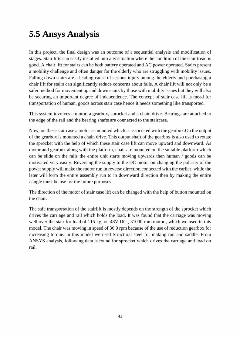
The safe transportation of the stairlift is mostly depends on the strength of the sprocket which
drives the carriage and rail which holds the load. It was found that the carriage was moving
well over the stair for load of 115 kg, on 48V DC , 31000 rpm motor , which we used in this
model. The chair was moving in speed of 36.9 rpm because of the use of reduction gearbox for
increasing torque. In this model we used Structural steel for making rail and saddle. From
ANSYS analysis, following data is found for sprocket which drives the carriage and load on
rail.

44
Fig 5. 1: ANSYS model of the sprocket
Fig 5.2: Finite element mesh
45
Fig 5. 3: Deformation of sprocket under 2000N load
Fig 5. 4: Von mises stress developed on sprocket teeth under 2000N load
46
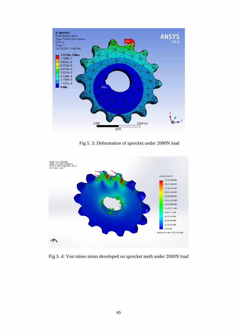
Fig 5. 5: First pricipal stress on sprocket teeth
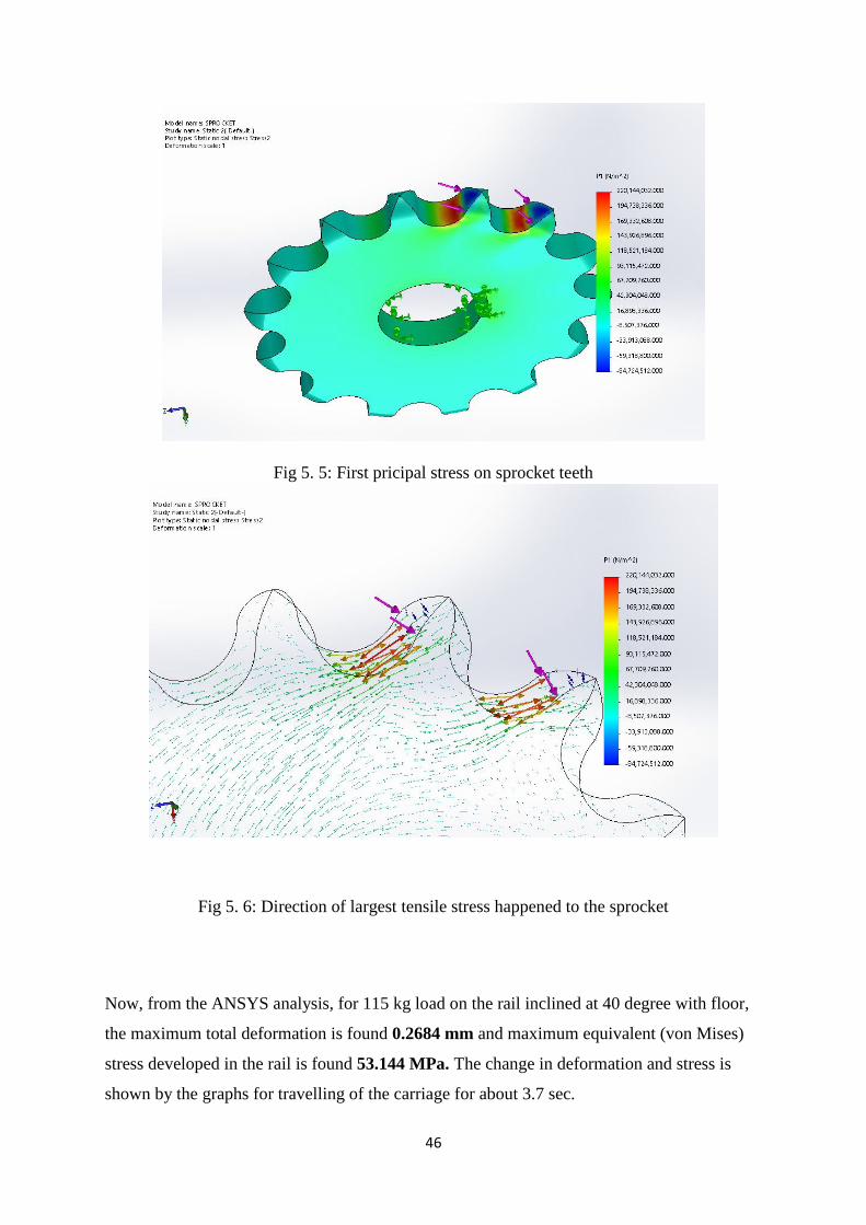
Fig 5. 6: Direction of largest tensile stress happened to the sprocket
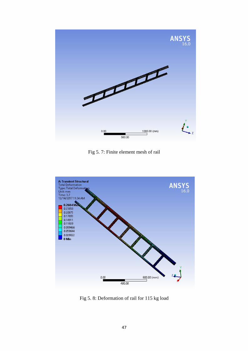
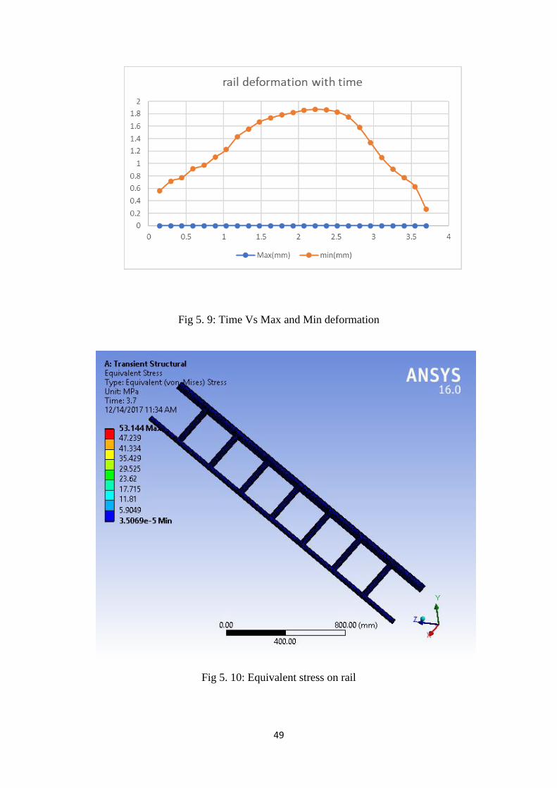
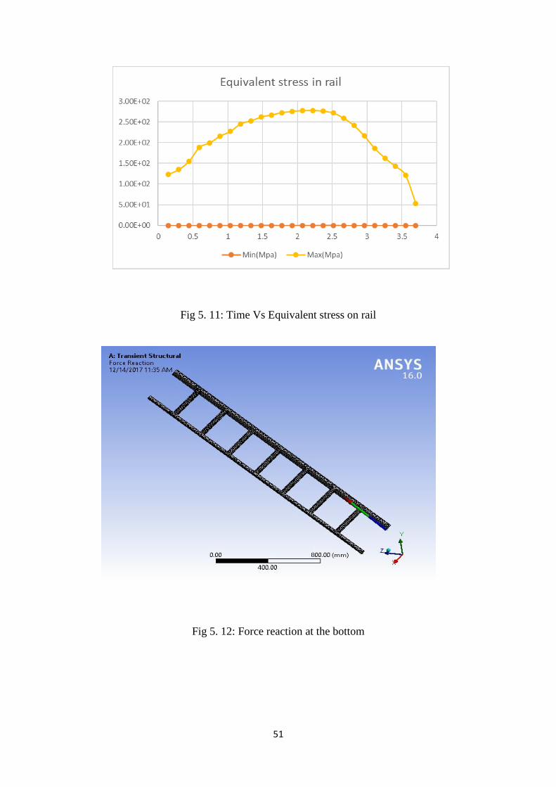
Now, from the ANSYS analysis, for 115 kg load on the rail inclined at 40 degree with floor,
the maximum total deformation is found 0.2684 mm and maximum equivalent (von Mises)
stress developed in the rail is found 53.144 MPa. The change in deformation and stress is
shown by the graphs for travelling of the carriage for about 3.7 sec.
47
Fig 5. 7: Finite element mesh of rail
Fig 5. 8: Deformation of rail for 115 kg load
48
Time (s) Max(mm) min(mm)
0.148 0 0.5625
0.296 0 0.71567
0.444 0 0.77398
0.592 0 0.91261
0.74 0 0.9707
0.888 0 1.1029
1.036 0 1.2229
1.184 0 1.4309
1.332 0 1.5536
1.48 0 1.6694
1.628 0 1.7337
1.776 0 1.7804
1.924 0 1.8156
2.072 0 1.8549
2.22 0 1.8716
2.368 0 1.8624
2.516 0 1.8284
2.664 0 1.7466
2.812 0 1.5771
2.96 0 1.3375
3.108 0 1.0983
3.256 0 0.91019
3.404 0 0.76956
3.552 0 0.62824
3.7 0 0.2684
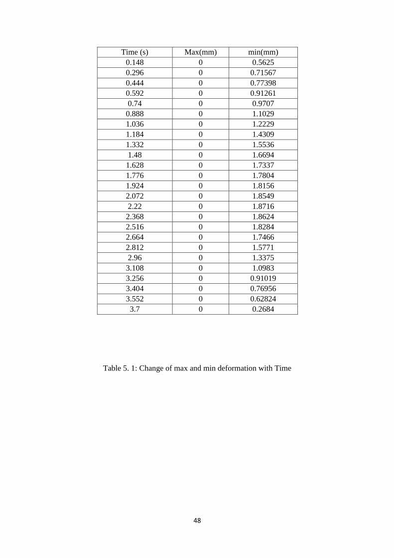
Table 5. 1: Change of max and min deformation with Time
49
Fig 5. 9: Time Vs Max and Min deformation
Fig 5. 10: Equivalent stress on rail
50
Time(s) Min(MPa) Max(MPa)
0.148 8.04E-05 123
0.296 1.81E-04 134.77
0.444 1.94E-04 154.93
0.592 2.07E-04 188.44
0.74 1.94E-04 199.1
0.888 3.39E-04 215.54
1.036 6.86E-04 226.84
1.184 1.57E-04 245.2
1.332 3.79E-04 252.6
1.48 1.29E-03 261.54
1.628 1.27E-03 266.79
1.776 3.94E-04 272.21
1.924 5.10E-04 275.25
2.072 1.03E-03 277.24
2.22 5.84E-04 277.61
2.368 1.48E-03 276.14
2.516 1.22E-03 271.23
2.664 4.52E-04 258.92
2.812 1.03E-04 241.01
2.96 2.06E-04 216.12
3.108 3.68E-04 186.23
3.256 1.23E-04 162.58
3.404 3.76E-05 142.89
3.552 3.44E-05 120.91
3.7 3.51E-05 53.144
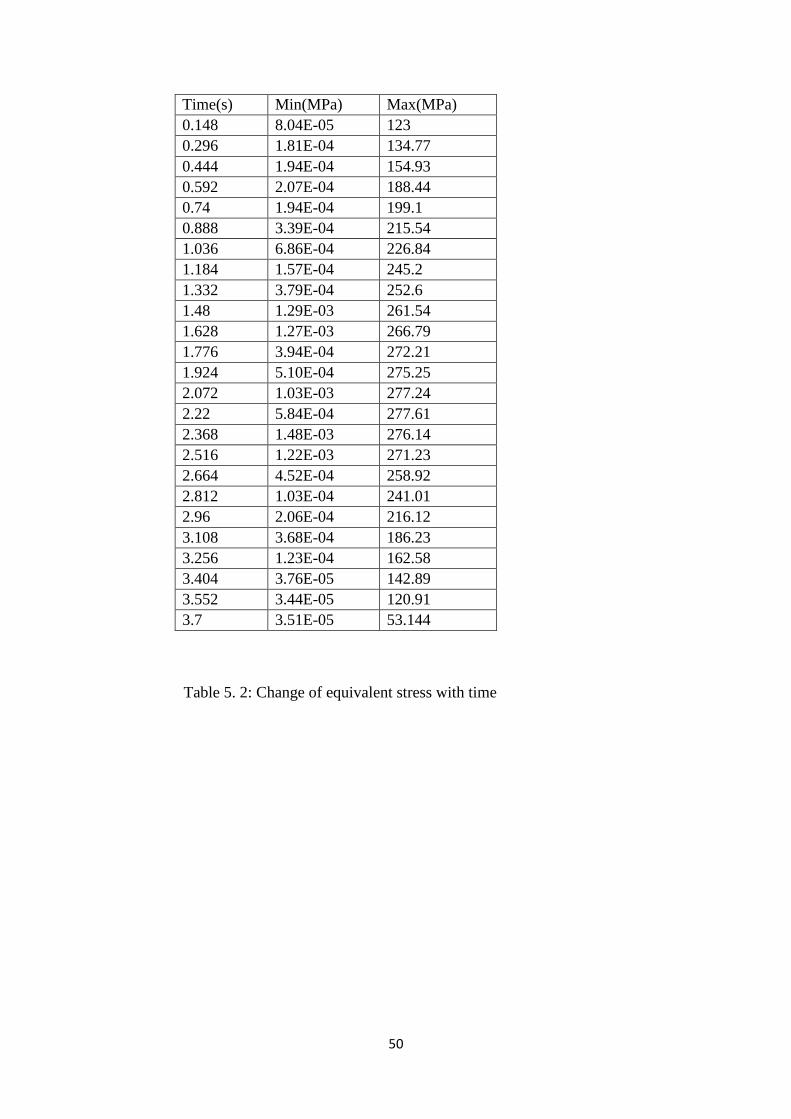
Table 5. 2: Change of equivalent stress with time
51
Fig 5. 11: Time Vs Equivalent stress on rail
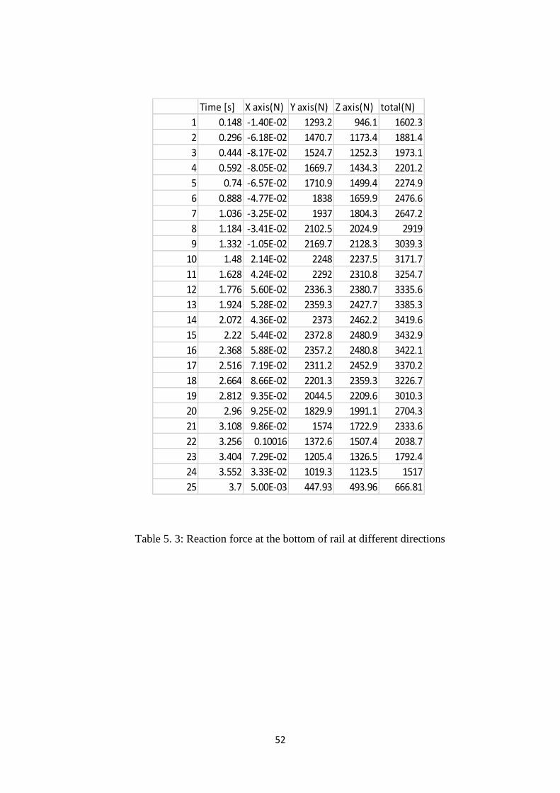
Fig 5. 12: Force reaction at the bottom
52
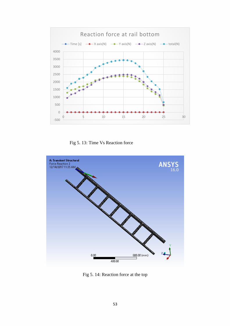
Table 5. 3: Reaction force at the bottom of rail at different directions
Time [s] X axis(N) Y axis(N) Z axis(N) total(N)
1 0.148 -1.40E-02 1293.2 946.1 1602.3
2 0.296 -6.18E-02 1470.7 1173.4 1881.4
3 0.444 -8.17E-02 1524.7 1252.3 1973.1
4 0.592 -8.05E-02 1669.7 1434.3 2201.2
5 0.74 -6.57E-02 1710.9 1499.4 2274.9
6 0.888 -4.77E-02 1838 1659.9 2476.6
7 1.036 -3.25E-02 1937 1804.3 2647.2
8 1.184 -3.41E-02 2102.5 2024.9 2919
9 1.332 -1.05E-02 2169.7 2128.3 3039.3
10 1.48 2.14E-02 2248 2237.5 3171.7
11 1.628 4.24E-02 2292 2310.8 3254.7
12 1.776 5.60E-02 2336.3 2380.7 3335.6
13 1.924 5.28E-02 2359.3 2427.7 3385.3
14 2.072 4.36E-02 2373 2462.2 3419.6
15 2.22 5.44E-02 2372.8 2480.9 3432.9
16 2.368 5.88E-02 2357.2 2480.8 3422.1
17 2.516 7.19E-02 2311.2 2452.9 3370.2
18 2.664 8.66E-02 2201.3 2359.3 3226.7
19 2.812 9.35E-02 2044.5 2209.6 3010.3
20 2.96 9.25E-02 1829.9 1991.1 2704.3
21 3.108 9.86E-02 1574 1722.9 2333.6
22 3.256 0.10016 1372.6 1507.4 2038.7
23 3.404 7.29E-02 1205.4 1326.5 1792.4
24 3.552 3.33E-02 1019.3 1123.5 1517
25 3.7 5.00E-03 447.93 493.96 666.81
53
Fig 5. 13: Time Vs Reaction force
Fig 5. 14: Reaction force at the top
-500
0
500
1000
1500
2000
2500
3000
3500
4000
0 5 10 15 20 25 30
Reaction force at rail bottom
Time [s] X axis(N) Y axis(N) Z axis(N) total(N)
54
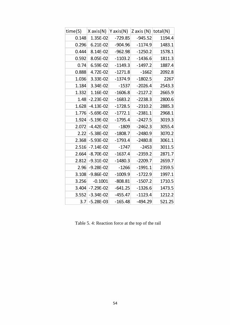
Table 5. 4: Reaction force at the top of the rail
time(S) X axis(N) Y axis(N) Z axis (N) total(N)
0.148 1.35E-02 -729.85 -945.52 1194.4
0.296 6.21E-02 -904.96 -1174.9 1483.1
0.444 8.14E-02 -962.98 -1250.2 1578.1
0.592 8.05E-02 -1103.2 -1436.6 1811.3
0.74 6.59E-02 -1149.3 -1497.2 1887.4
0.888 4.72E-02 -1271.8 -1662 2092.8
1.036 3.33E-02 -1374.9 -1802.5 2267
1.184 3.34E-02 -1537 -2026.4 2543.3
1.332 1.16E-02 -1606.8 -2127.2 2665.9
1.48 -2.23E-02 -1683.2 -2238.3 2800.6
1.628 -4.13E-02 -1728.5 -2310.2 2885.3
1.776 -5.69E-02 -1772.1 -2381.1 2968.1
1.924 -5.19E-02 -1795.4 -2427.5 3019.3
2.072 -4.42E-02 -1809 -2462.3 3055.4
2.22 -5.38E-02 -1808.7 -2480.9 3070.2
2.368 -5.93E-02 -1793.4 -2480.8 3061.1
2.516 -7.14E-02 -1747 -2453 3011.5
2.664 -8.70E-02 -1637.4 -2359.2 2871.7
2.812 -9.31E-02 -1480.3 -2209.7 2659.7
2.96 -9.28E-02 -1266 -1991.1 2359.5
3.108 -9.86E-02 -1009.9 -1722.9 1997.1
3.256 -0.1001 -808.81 -1507.2 1710.5
3.404 -7.29E-02 -641.25 -1326.6 1473.5
3.552 -3.34E-02 -455.47 -1123.4 1212.2
3.7 -5.28E-03 -165.48 -494.29 521.25
55
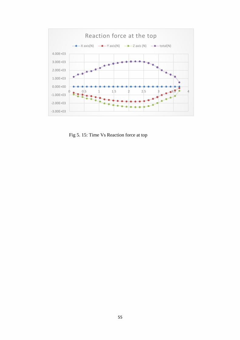
Fig 5. 15: Time Vs Reaction force at top
-3.00E+03
-2.00E+03
-1.00E+03
0.00E+00
1.00E+03
2.00E+03
3.00E+03
4.00E+03
0 0.5 1 1.5 2 2.5 3 3.5 4
Reaction force at the top
X axis(N) Y axis(N) Z axis (N) total(N)
56
Chapter-6 Result and Discussion
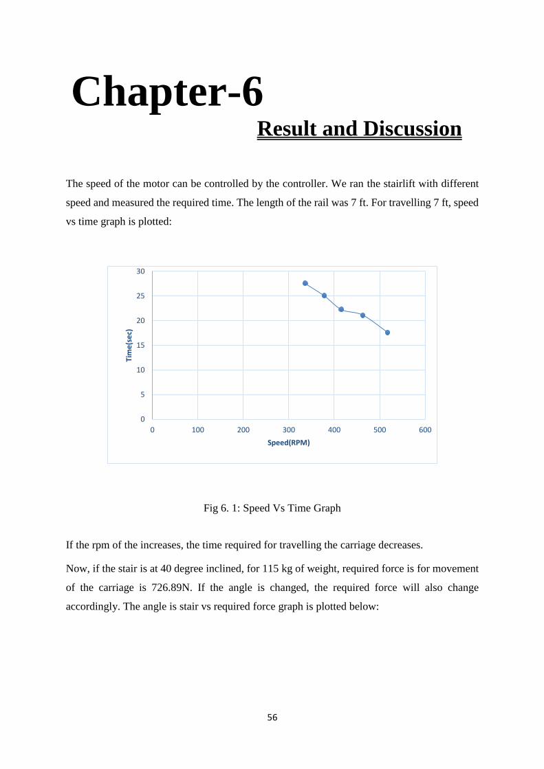
The speed of the motor can be controlled by the controller. We ran the stairlift with different
speed and measured the required time. The length of the rail was 7 ft. For travelling 7 ft, speed
vs time graph is plotted:
Fig 6. 1: Speed Vs Time Graph
If the rpm of the increases, the time required for travelling the carriage decreases.
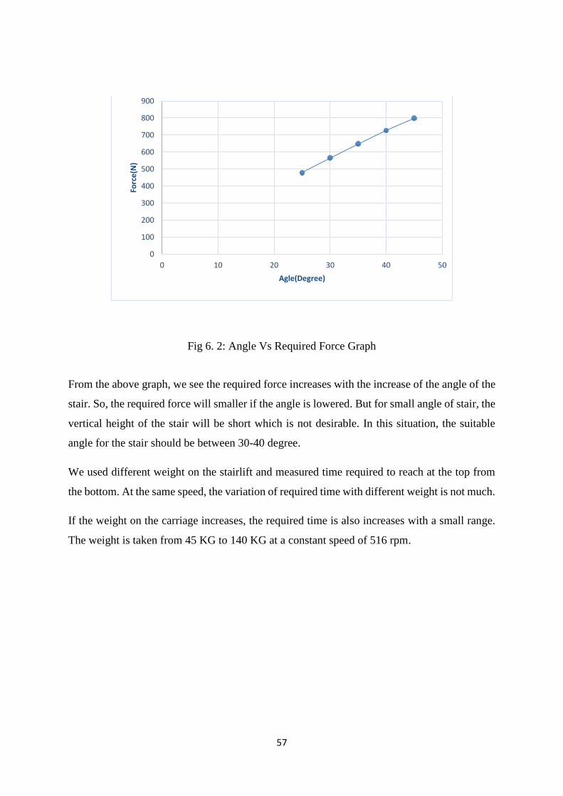
Now, if the stair is at 40 degree inclined, for 115 kg of weight, required force is for movement
of the carriage is 726.89N. If the angle is changed, the required force will also change
accordingly. The angle is stair vs required force graph is plotted below:
0
5
10
15
20
25
30
0 100 200 300 400 500 600
Time(sec)
Speed(RPM)
57
Fig 6. 2: Angle Vs Required Force Graph
From the above graph, we see the required force increases with the increase of the angle of the
stair. So, the required force will smaller if the angle is lowered. But for small angle of stair, the
vertical height of the stair will be short which is not desirable. In this situation, the suitable
angle for the stair should be between 30-40 degree.
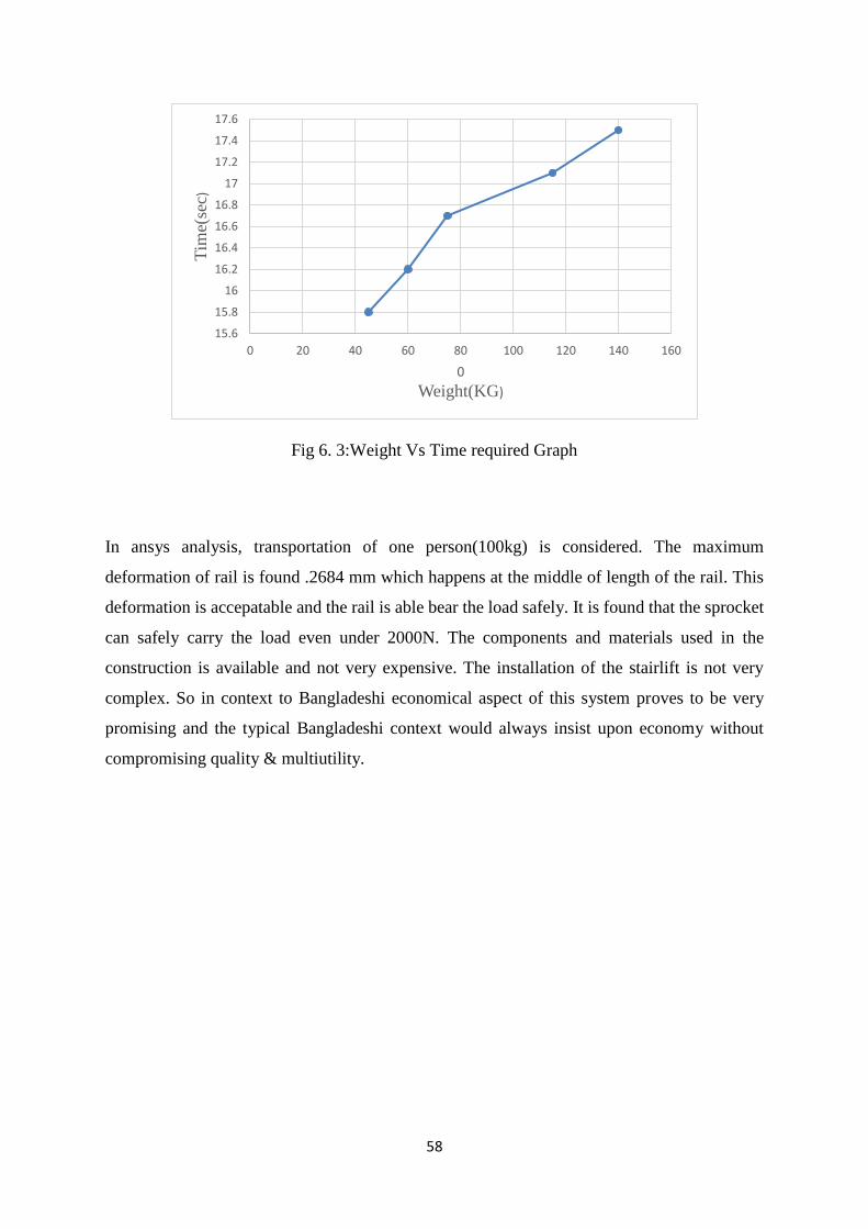
We used different weight on the stairlift and measured time required to reach at the top from
the bottom. At the same speed, the variation of required time with different weight is not much.
If the weight on the carriage increases, the required time is also increases with a small range.
The weight is taken from 45 KG to 140 KG at a constant speed of 516 rpm.
0
100
200
300
400
500
600
700
800
900
0 10 20 30 40 50
Force(N)
Agle(Degree)
58
Fig 6. 3:Weight Vs Time required Graph
In ansys analysis, transportation of one person(100kg) is considered. The maximum
deformation of rail is found .2684 mm which happens at the middle of length of the rail. This
deformation is accepatable and the rail is able bear the load safely. It is found that the sprocket
can safely carry the load even under 2000N. The components and materials used in the
construction is available and not very expensive. The installation of the stairlift is not very
complex. So in context to Bangladeshi economical aspect of this system proves to be very
promising and the typical Bangladeshi context would always insist upon economy without
compromising quality & multiutility.
15.6
15.8
16
16.2
16.4
16.6
16.8
17
17.2
17.4
17.6
0 20 40 60 80 100 120 140 160
Tim
e(se
c)
0
Weight(KG)
59
Chapter-7 Conclusion and Recommendation
Conclusion
Though making a cost friendly Stairlift had some limitations, it was a good and challenging
project for us. Making a stairlift with roller bearing is not a complicated process and all the
components are widely available in market. DC motors with control box are now being
manufactured for auto rickshaw and this can be directly used in the stairlift. During the test run
of this project, it was realized that it would capable of carrying heavy load without suffering
any deformation or local fractures if it would go into real world production at an ideal scale.
Though the initial cost of the project seemed to be a little bit higher but more accurate
manufacturing would shorten this.
Recommendations
Stairlift has distinguished advantages and benefits. In this case no one has alter the civil
structure for installation thereafter shortest cost for installation procedure as compared to that
of lift.
So, future of such lifting system seems to be very bright. There is lot of scope for further
modification in the project as follows.
• Using monorail instead of two.
• Incorporation and automation / timer unit which will ease the use of device.
• Push button ON/OFF using timer circuit can also be used.
• A swivel seating arrangement and Seatbelt for future safety can be included.
• Rack and carrier arrangement, Pulley drive, Hoisting rope system can also be used for
stairlift system.
• Use of work & roller reduction gear assembly.
• Folding seat arrangement.
60
[1] Siegwart, R., Lauria, M., Mäusli, P., Winnendael, M., 1998, “Design and
Implementation of an Innovative Micro-Rover,” Proceedings of Robotics 98, the 3rd
Conference and Exposition on Robotics in Challenging Environments, April 26-30,
Albuquerque, New Mexico.
[2] Hsueh-Er, C., “Stair-climbing vehicle, 2008, “ Patent No. US2008164665(A1)”, Jan
24.
[3] Mourikis, A.I., Trawny, N., Roumeliotis, S.I., Helmick, D.M., and Matthies, L., 2007,
“Autonomous Stair Climbing for Tracked Vehicles,” International Journal of Computer
Vision & International Journal of Robotics Research - Joint Special Issue on Vision and
Robotics, 26(7), 737-758.
[4] Helmick, D., Roumeliotis, S., McHenry, M., Matthies, L., 2002, “Multi-sensor, high
speed autonomous stair climbing”, IEEE/RSJ Conference on Intelligent Robots and
Systems (IROS), September.
[5] Schilling, K., Jungius, C., 1996. “Mobile Robots for Planetary Exploration,” Control
Engineering Practice, Vol. 4, No. 4.
[6] Burdick, J.W., Radford, J., and Chirikjian, G.S., 1993, “A ‘Sidewinding’ Locomotion
Gait for Hyper Redundant Robots,” Proc. IEEE International Conference on Robotics
and Automation.
[7] Desai, R.S., Wilcox, B., Bedard, R., 1992, “JPL Robotic Vehicle Overview,” in AUVS.
[8] McTamaney, L.S., Douglas, B.D., Harmon, S.Y., 1989, “Mars Rover concept
development,” Proc. SPIE Conf. 1007, Mobile Robots III.
[9] Spiessbach, A., Clark, B., Larimer, S., Tobey, B., Lindauer, B., Koenig, R., Lisec, T.,
1987, “Issues and Options for a Mars Rover”, Proc. SPIE Conf. 852, Mobile Robots II.
[10] Wilcox, B., Matthies, L., Gennery, D., Cooper, B., Nguyen, T., 1992, “Robotic
Vehicles for Planetary Exploration”, Proc. of the 1992 IEEE International Conf. on
Robotics and Automation.
[11] Wright, D.D., Watson R.E., 1987, “Comparison of Mobility System Concepts for a
Mars Rover”, Proc.SPIE Conf. 852, Mobile Robots II.
[12] Lee, G.K., 1993, “System Requirements for Planetary Rovers”, Proc. SPIE Conf. 1956,
Sensor Fusion and Aerospace Applications.
[13] Stone, H. W., 1996, “Mars Pathfinder Microrover: A Low-Cost, Low-Power
Spacecraft,” Proceedings of he 1996 AIAA Forum on Advanced Developments in
Space Robotics, Madison WI.
[14] Volpe, R., Balaram, J., Ohm, T., Ivlev, R., 1997, “Rocky 7: A Next Generation Mars
Rover Prototype."Journal of Advanced Robotics, 11(4).
[15] Kubota, T., Kuroda, Y., Kunii, Y., Natakani, I., 1999, “Micro Planetary Rover
‘Micro5”, Proceedings of Fifth International Symposium on Artificial Intelligence,
Robotics and Automation in Space (ESA SP-440),Noordwijk, 373-378.
[16] Kemurdjian, L., Gromov, V., Mishkinyuk, V., Kucherenko, V., Sologub, P., 1992,
“Small Marsokhod Configuration,” International Conference on Robotics &
Automation, Nice.
Reference
61
[17] Leppänen, S. Salmi, Halme, A., 1998, “WorkPartner HUT Automation’s new hybrid
walking machine”, CLAWAR’98 First international symposium, Brussels. Hossain,
Chowdhury, Islam, and Akhtar
[18] Lauria, M., Conti, F., Maeusli, P.-A., Van Winnendael, M., Bertrand, R., Siegwart R,
1998, “Design and Control of an Innovative Micro-Rover”, Proceedings of 5th ESA
Workshop on Advanced Space Technologies for Robotics and Automation, The
Netherlands.
[19] Tunstel, E., 1999, “Evolution of Autonomous Self-Righting Behaviors for Articulated
Nanrovers,” Proceedings of Fifth International Symposium on Artificial Intelligence,
Robotics and Automation in Space (ESA SP-440), Noordwijk, 341-346.
[20] http://ci.nii.ac.jp/naid/110004695617
[21] http://en.cnki.com.cn/Article_en/CJFDTOTAL-HEBX200604008.htm
[22] Shigley's Mechanical Engineering Design - McGraw-Hill Education