structural behaviour of expanded metal sheets
TRANSCRIPT
1
Abstract
In engineering, there is a need for light materials able to withstand different load conditions. Expanded metal sheets have been employed in the construction industry mainly as furniture, safety fences and sidewalks among other uses. More recently, expanded metal has been used as part of energy absorbers as can be observed in several international patents. However, the structural behavior of the expanded metal structures has not been explained to this date. In this paper, the structural behavior of expanded metal tubes is investigated using computational modeling. Expanded metal tubes are subjected to axial compression; thereafter the influence of the orientation of the cells is also analyzed. The results show that structures made of expanded metal are imperfection sensitive structures able to absorb energy by a predictable plastic deformation pattern.
Keywords: Expanded Metal, Finite Element Methods, Energy Absorption.
1 Introduction
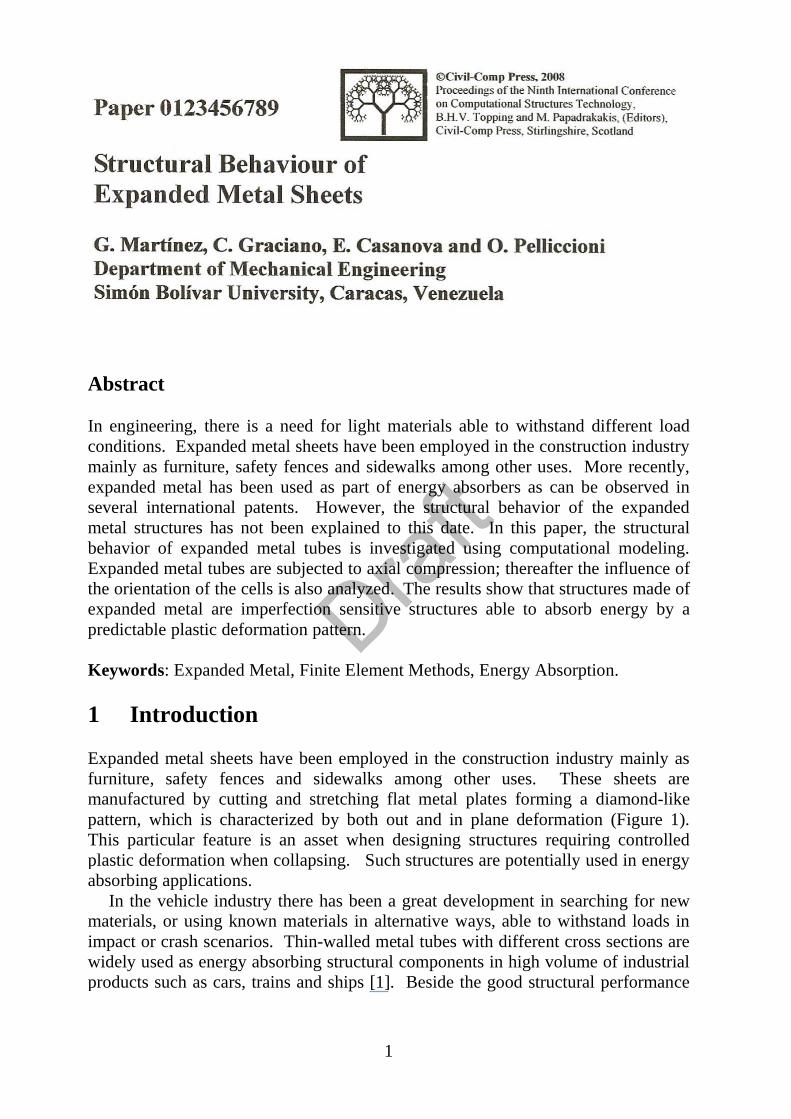
Expanded metal sheets have been employed in the construction industry mainly as furniture, safety fences and sidewalks among other uses. These sheets are manufactured by cutting and stretching flat metal plates forming a diamond-like pattern, which is characterized by both out and in plane deformation (Figure 1). This particular feature is an asset when designing structures requiring controlled plastic deformation when collapsing. Such structures are potentially used in energy absorbing applications.
In the vehicle industry there has been a great development in searching for new materials, or using known materials in alternative ways, able to withstand loads in impact or crash scenarios. Thin-walled metal tubes with different cross sections are widely used as energy absorbing structural components in high volume of industrial products such as cars, trains and ships [1]. Beside the good structural performance
2
of thin-walled members as energy absorbers, they are relatively cheap and weight efficient.
Energy absorbers are devices designed to absorb/dissipate the impact energy in a controlled manner and hence protect the structure under consideration [3]. Consequently, an energy absorber should be capable of absorbing kinetic energy upon impact and dissipate it in some other energy form, ideally in an irreversible manner. Inelastic energy can exist in various forms such a plastic deformation, viscous energy and friction or fracture energy [4].
Many efforts have been made in the past decades to understand and improve the structural behavior of energy absorber under various load conditions: axial crushing, bending and oblique impact. Alexander [5] shows an approximate theoretical model to predict the mean crushing force and energy absorbing properties of circular tubes under axial crush loading.
In [6,7], Wierzbicki and Abramowicz proposed a novel crushing theoretical mechanism. Later on, Abramowicz and Jones [8,9] as well as Jones and Abramowicz [10] extended and validated experimentally their theory. Hanssen et al. [11] shows the performance in axial compression of square aluminum columns filled with aluminum foam. Reyes et al. [12] investigated the behavior of square aluminum columns subjected to oblique loading. Nagel and Thambiratnam [3,13,14] conducted numerical studies on the impact response and energy absorption of tapered thin walled tubes under axial and oblique loading. Zhang et al. [15] studied the influence of the patterns to the surface of conventional thin walled square tubes to improve the energy absorption capacity under axial and compressive loads.
Figure 1. Geometry of a diamond mesh (cells): (a) frontal view, (b) lateral view, (c) nomenclature and dimensions
In the search for new developments for energy dissipation in crash scenarios, expanded metal sheets have found a place [2]. Ayestaran et al. [2] performed a preliminary investigation on the energy absorption capacity of a crush zone of a car made of expanded metal sheets.
In this paper, the structural behavior of the expanded metal tubes is investigated using computational modeling. Expanded metal tubes are subjected to axial compression; thereafter the influence of the orientation of the cells is also analyzed.
(a) (c)(b)
n
ea
dv
dh
Dimensions (mm) n 8 dv 42 dh 89 a 3 e 3.2

3
The explicit FE code ANSYS-LS-DYNA is used to simulate the axial compression of expanded metal tubes of cylindrical cross sections. This code has been developed for large deformation structural dynamics. Special attention is paid when analyzing transient dynamics response of 3D solids and structures, employing, as an explicit code, the central difference method in order to solve the equations of motion and possessing simultaneously many advantages that are critical for efficient and accurate analysis of crashes [16].
Finally, numerical results are compared with experimental results obtained by Smith [17]. A very good agreement is found between both results and useful concluding remarks are presented.
2 Finite Element modeling
This section describes the numerical model used for the analysis. A cuasi-staticnumerical analysis, using the finite element method, of cylindrical expanded metal tubes was conducted. Geometries and boundary conditions are similarly to those used by Smith [17], i.e. the tube is clamped at both ends. This similarity remained in order to compare numerical and experimental results.
For the numerical analysis the following geometries were developed:
Cylindrical geometry, horizontal orientation of the pattern (G_00) Cylindrical geometry, vertical orientation of the pattern (G_90)
Figures 2 and 3 show a schematic view of the two geometries, G_00 and G_90 respectively.
Figure 2. Cylindrical geometry, horizontal orientation of the pattern (G_00):(a) lateral view, (b) frontal view.
A finite element model of these two geometries was built using ANSYS LS-DYNA. An explicit analysis code was used to model both material and geometric
401mm
129 mm

4
nonlinearity, and it is well suited for simulating problems where complex contact interactions occur within the structure, such as for axially crushed of expanded metal tubes.
Figure 3. Cylindrical geometry, vertical orientation of the pattern (G_90): (a) lateral view, (b) frontal view.
Figure 4 shows the mesh and boundary conditions used for model G_90. The base of each tube was fully fixed (clamped) at the top end, while the other end was moved only in the axial direction with a prescribed velocity of 10 mm/s.
Figure 4. Boundary conditions for model G_90.
Each geometry was modeled using solid elements of designation Solid 164, from the ANSYS element library. This is an eight nodes element suitable for large strain analyses. In order to avoid hourglassing effect, fully integrated element formulations
XY
Z
408 mm
116 mm
X
Y
Z
X
Y
Z
Fully fixed constraints
Axial direction with prescribed velocity, only axial direction is free

5
were used. However, these options are more costly (in CPU time) than other element formulations [18]. The boundary conditions are similar in both models. Contact within each geometry is modeled by using Automatic General Contact [18].This contact type is used when a surface of one body contacts itself or the surface of another body.
Table 1 shows the material properties taken from [19] used in the numerical analysis herein. In the FE model, the material was modeled via a classical bilinear isotropic hardening model (strain rate independent) that uses two slopes (elastic and plastic) to represent the stress-strain behavior of the material.
Elastic Modulus (E) 235 MPa Poisson ratio ( ) 0.3
Density ( ) 7835 kg/m3
Yield Strenght ( y) 470 MPa Tangent Slope Modulus (Et) 660 MPa
Table 1. Material properties of Finite Element Model
3 Results and Discussion
3.1 Cylindrical geometry, Model G_90
Figure 5. Deformation process for model G_90: (a) initial shape, (b) 50 mm, (c) 100 mm, (d) 150 mm, (e) 210 mm
MN
MX
X
Y
Z
MN
MX
X
Y
Z
MN
MX
X
Y
Z
MN
MX
X
Y
Z
MN
MX
X
Y
Z
(a) (b) (c)
(d) (e)
6
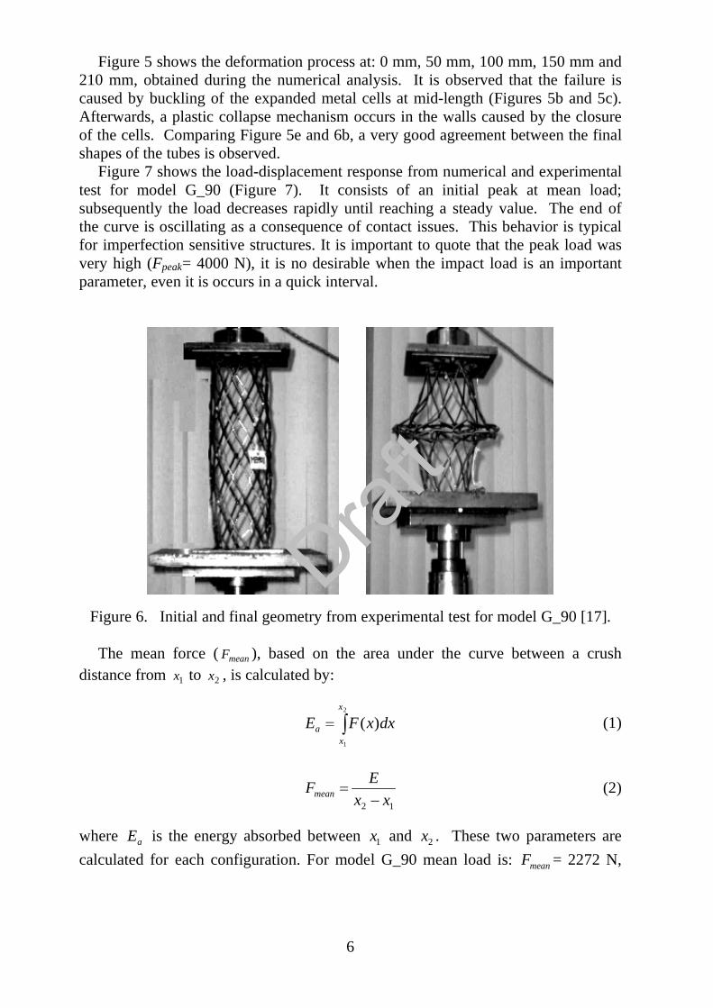
Figure 5 shows the deformation process at: 0 mm, 50 mm, 100 mm, 150 mm and 210 mm, obtained during the numerical analysis. It is observed that the failure is caused by buckling of the expanded metal cells at mid-length (Figures 5b and 5c). Afterwards, a plastic collapse mechanism occurs in the walls caused by the closure of the cells. Comparing Figure 5e and 6b, a very good agreement between the final shapes of the tubes is observed.
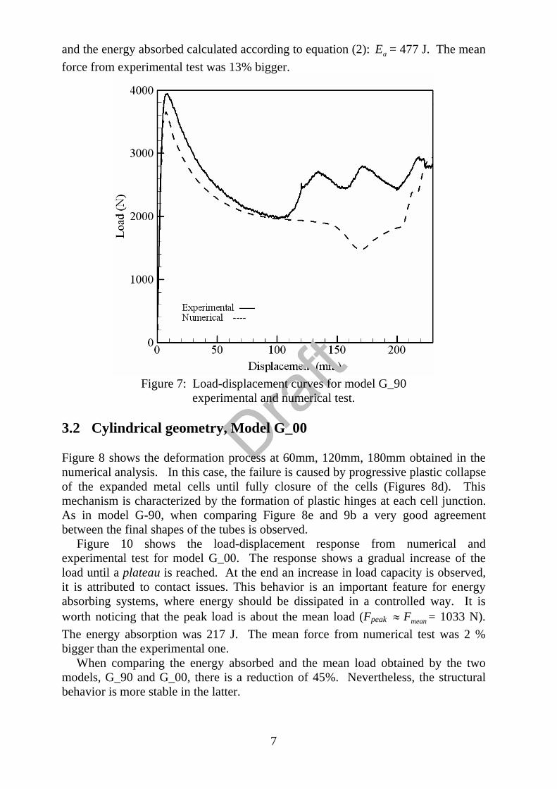
Figure 7 shows the load-displacement response from numerical and experimental test for model G_90 (Figure 7). It consists of an initial peak at mean load; subsequently the load decreases rapidly until reaching a steady value. The end of the curve is oscillating as a consequence of contact issues. This behavior is typical for imperfection sensitive structures. It is important to quote that the peak load was very high (Fpeak= 4000 N), it is no desirable when the impact load is an important parameter, even it is occurs in a quick interval.
Figure 6. Initial and final geometry from experimental test for model G_90 [17].
The mean force ( meanF ), based on the area under the curve between a crush distance from 1x to 2x , is calculated by:
2
1
)(x
xa dxxFE (1)
12 xxEFmean (2)
where aE is the energy absorbed between 1x and 2x . These two parameters are calculated for each configuration. For model G_90 mean load is: meanF = 2272 N,
7
and the energy absorbed calculated according to equation (2): aE = 477 J. The mean force from experimental test was 13% bigger.
Figure 7: Load-displacement curves for model G_90 experimental and numerical test.
3.2 Cylindrical geometry, Model G_00
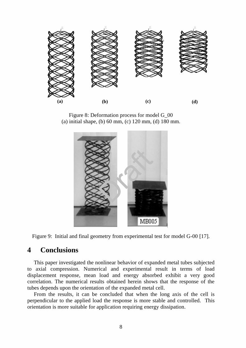
Figure 8 shows the deformation process at 60mm, 120mm, 180mm obtained in the numerical analysis. In this case, the failure is caused by progressive plastic collapse of the expanded metal cells until fully closure of the cells (Figures 8d). This mechanism is characterized by the formation of plastic hinges at each cell junction. As in model G-90, when comparing Figure 8e and 9b a very good agreement between the final shapes of the tubes is observed.
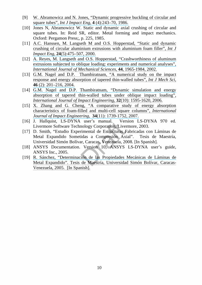
Figure 10 shows the load-displacement response from numerical and experimental test for model G_00. The response shows a gradual increase of the load until a plateau is reached. At the end an increase in load capacity is observed, it is attributed to contact issues. This behavior is an important feature for energy absorbing systems, where energy should be dissipated in a controlled way. It is worth noticing that the peak load is about the mean load (Fpeak meanF = 1033 N). The energy absorption was 217 J. The mean force from numerical test was 2 % bigger than the experimental one. When comparing the energy absorbed and the mean load obtained by the two models, G_90 and G_00, there is a reduction of 45%. Nevertheless, the structural behavior is more stable in the latter.
8
Figure 8: Deformation process for model G_00
(a) initial shape, (b) 60 mm, (c) 120 mm, (d) 180 mm.
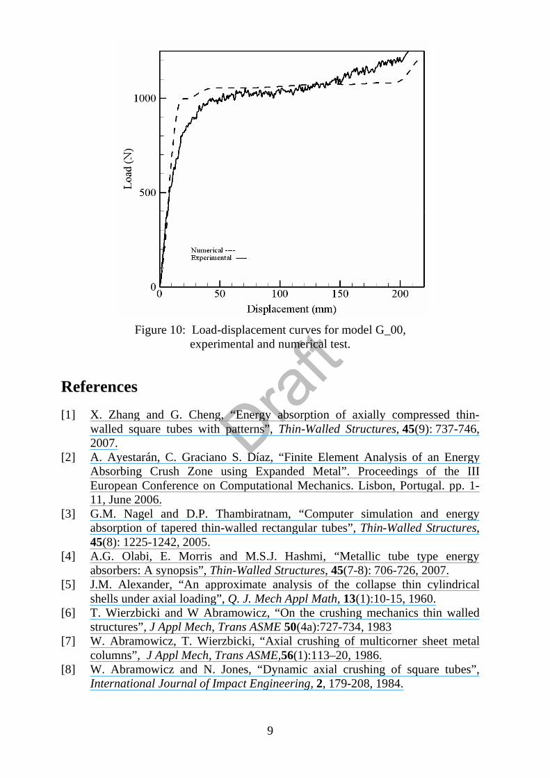
Figure 9: Initial and final geometry from experimental test for model G-00 [17].
4 ConclusionsThis paper investigated the nonlinear behavior of expanded metal tubes subjected
to axial compression. Numerical and experimental result in terms of load displacement response, mean load and energy absorbed exhibit a very good correlation. The numerical results obtained herein shows that the response of the tubes depends upon the orientation of the expanded metal cell.
From the results, it can be concluded that when the long axis of the cell is perpendicular to the applied load the response is more stable and controlled. This orientation is more suitable for application requiring energy dissipation.
MNMXXY
Z
MN
MX
XY
Z
MNMX
XY
Z
M
MX
XY
Z
(a) (b) (c) (d)
9
Figure 10: Load-displacement curves for model G_00, experimental and numerical test.
References [1] X. Zhang and G. Cheng, “Energy absorption of axially compressed thin-
walled square tubes with patterns”, Thin-Walled Structures, 45(9): 737-746, 2007.
[2] A. Ayestarán, C. Graciano S. Díaz, “Finite Element Analysis of an Energy Absorbing Crush Zone using Expanded Metal”. Proceedings of the III European Conference on Computational Mechanics. Lisbon, Portugal. pp. 1-11, June 2006.
[3] G.M. Nagel and D.P. Thambiratnam, “Computer simulation and energy absorption of tapered thin-walled rectangular tubes”, Thin-Walled Structures,45(8): 1225-1242, 2005.
[4] A.G. Olabi, E. Morris and M.S.J. Hashmi, “Metallic tube type energy absorbers: A synopsis”, Thin-Walled Structures, 45(7-8): 706-726, 2007.
[5] J.M. Alexander, “An approximate analysis of the collapse thin cylindrical shells under axial loading”, Q. J. Mech Appl Math, 13(1):10-15, 1960.
[6] T. Wierzbicki and W Abramowicz, “On the crushing mechanics thin walled structures”, J Appl Mech, Trans ASME 50(4a):727-734, 1983
[7] W. Abramowicz, T. Wierzbicki, “Axial crushing of multicorner sheet metal columns”, J Appl Mech, Trans ASME,56(1):113–20, 1986.
[8] W. Abramowicz and N. Jones, “Dynamic axial crushing of square tubes”, International Journal of Impact Engineering, 2, 179-208, 1984.
10
[9] W. Abramowicz and N. Jones, “Dynamic progressive buckling of circular and square tubes”, Int J Impact Eng, 4 (4):243–70, 1986.
[10] Jones N, Abramowicz W. Static and dynamic axial crushing of circular and square tubes. In: Reid SR, editor. Metal forming and impact mechanics. Oxford: Pergamon Press;, p. 225, 1985.
[11] A.C. Hanssen, M. Langseth M and O.S. Hopperstad, “Static and dynamic crushing of circular aluminium extrusions with aluminium foam filler”, Int J Impact Eng, 24(5):475–507, 2000.
[12] A. Reyes, M. Langseth and O.S. Hopperstad, “Crashworthiness of aluminum extrusions subjected to oblique loading: experiments and numerical analyses”, International Journal of Mechanical Sciences, 44, 1965-1984, 2002.
[13] G.M. Nagel and D.P. Thambiratnam, “A numerical study on the impact response and energy absorption of tapered thin-walled tubes”, Int J Mech Sci,46 (2): 201–216, 2004.
[14] G.M. Nagel and D.P. Thambiratnam, “Dynamic simulation and energy absorption of tapered thin-walled tubes under oblique impact loading”, International Journal of Impact Engineering, 32(10): 1595-1620, 2006.
[15] X. Zhang and G. Cheng, “A comparative study of energy absorption characteristics of foam-filled and multi-cell square columns”, InternationalJournal of Impact Engineering, 34(11): 1739-1752, 2007.
[16] J. Hallquist, LS-DYNA user’s manual. Version LS-DYNA 970 ed. Livermore Software Technology Corporation, Livermore, 2003.
[17] D. Smith, “Estudio Experimental de Estructuras Fabricadas con Láminas de Metal Expandido Sometidas a Compresión Axial”. Tesis de Maestría, Universidad Simón Bolívar, Caracas, Venezuela, 2008. [In Spanish].
[18] ANSYS Documentation. Version 10, ANSYS LS-DYNA user’s guide, ANSYS Inc., 2005.
[19] R. Sánchez, “Determinación de las Propiedades Mecánicas de Láminas de Metal Expandido”. Tesis de Maestría, Universidad Simón Bolívar, Caracas-Venezuela, 2005. [In Spanish].