prelub specification sheets - trysome
TRANSCRIPT

Prelub Specification Sheets
www.trysome.co.za | +27 (0)11 823 5650
Issu
e 1
2
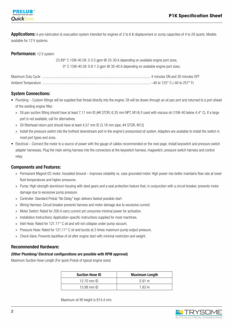
Applications: A pre-lubrication & evacuation system intended for engines of 2 to 6 ℓ displacement or sump capacities of 4 to 28 quarts. Models
available for 12 V systems.
Performance: 12 V system
23.89° C 15W-40 Oil: 3-3.5 gpm @ 25-30 A depending on available engine port sizes.
0° C 15W-40 Oil: 0.8-1.3 gpm @ 30-40 A depending on available engine port sizes.
Maximum Duty Cycle ................................................................................................................... 4 minutes ON and 30 minutes OFF
Ambient Temperature . .................................................................................................................. –40 to 125° C (-40 to 257° F)
System Connections:• Plumbing – Custom fittings will be supplied that thread directly into the engine. Oil will be drawn through an oil pan port and returned to a port ahead
of the existing engine filter.
» Oil pan suction fitting should have at least 7.11 mm ID (#6 STOR, 6.35 mm NPT, M14) if used with viscous oil (15W-40 below 4.4° C). If a large
port is not available, call for alternatives.
» Oil filterhead return port should have at least 4.57 mm ID (3.18 mm pipe, #4 STOR, M12)
» Install the pressure switch into the furthest downstream port in the engine’s pressurised oil system. Adapters are available to install the switch in
most port types and sizes.
• Electrical – Connect the motor to a source of power with the gauge of cables recommended on the next page. Install keyswitch and pressure switch
adapter harnesses. Plug the main wiring harness into the connectors at the keyswitch harness, magswitch, pressure switch harness and control
relay.
Components and Features: » Permanent Magnet DC motor: Insulated Ground – improves reliability vs. case grounded motor. High power rise better maintains flow rate at lower
fluid temperatures and higher pressures.
» Pump: High-strength aluminium housing with steel gears and a seal protection feature that, in conjunction with a circuit breaker, prevents motor
damage due to excessive pump pressure.
» Controller: Standard Prelub “No Delay” logic delivers fastest possible start.
» Wiring Harness: Circuit breaker prevents harness and motor damage due to excessive current.
» Motor Switch: Rated for 200 A carry current yet consumes minimal power for activation.
» Installation Instructions: Application-specific instructions supplied for most machines.
» Inlet Hose: Rated for 121.11° C oil and will not collapse under pump vacuum.
» Pressure Hose: Rated for 121.11° C oil and bursts at 3 times maximum pump output pressure.
» Check Valve: Prevents backflow of oil after engine start with minimal restriction and weight.
Recommended Hardware:
(Other Plumbing/ Electrical configurations are possible with RPM approval)
Maximum Suction Hose Length (For quick Prelub of typical engine sizes)
Maximum oil lift height is 914.4 mm.
Suction Hose ID Maximum Length
12.70 mm ID 0.91 m
15.88 mm ID 1.83 m
P1K Specification Sheet
3
P1K Specification Sheet
Maximum Pressure Hose Length (Limits pressure or motor current)
Electrical Connections (Total Length = Battery Cable + Motor Cable + Ground Cable)
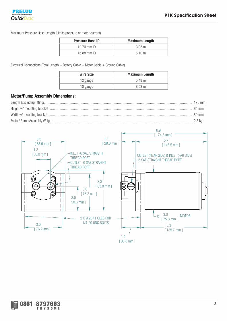
Motor/Pump Assembly Dimensions:Length (Excluding fittings) ............................................................................................................................................................... 175 mm
Height w/ mounting bracket ............................................................................................................................................................ 84 mm
Width w/ mounting bracket ............................................................................................................................................................. 89 mm
Motor/ Pump Assembly Weight ....................................................................................................................................................... 2.3 kg
Wire Size Maximum Length
12 gauge 5.49 m
10 gauge 8.53 m
Pressure Hose ID Maximum Length
12.70 mm ID 3.05 m
15.88 mm ID 6.10 m
MOTORØ
6.9[ 174.5 mm ]
5.7[ 145.5 mm ]
1.5[ 38.8 mm ]
3.0[ 76.2 mm ]
5.3[ 135.7 mm ]
1.1[ 29.0 mm ]
3.3[ 83.8 mm ]
2.0[ 50.6 mm ]
INLET -6 SAE STRAIGHTTHREAD PORTOUTLET -6 SAE STRAIGHTTHREAD PORT
OUTLET (NEAR SIDE) & INLET (FAR SIDE)-6 SAE STRAIGHT THREAD PORT
3.0[ 75.3 mm ]2 X Ø.257 HOLES FOR
1/4-20 UNC BOLTS
1.2[ 30.0 mm ]
3.5[ 88.9 mm ]
3.0[ 76.2 mm ]
4
P2K Specification Sheet
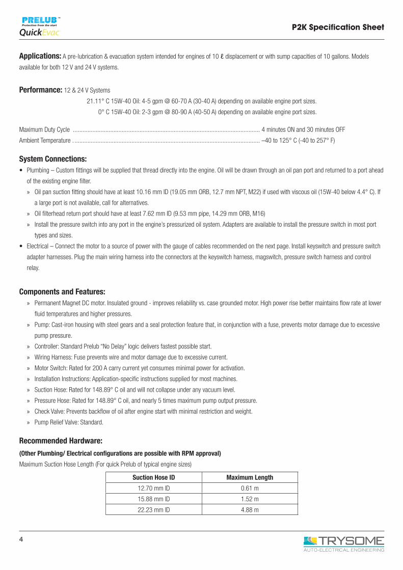
Applications: A pre-lubrication & evacuation system intended for engines of 10 ℓ displacement or with sump capacities of 10 gallons. Models
available for both 12 V and 24 V systems.
Performance: 12 & 24 V Systems
21.11° C 15W-40 Oil: 4-5 gpm @ 60-70 A (30-40 A) depending on available engine port sizes.
0° C 15W-40 Oil: 2-3 gpm @ 80-90 A (40-50 A) depending on available engine port sizes.
Maximum Duty Cycle ................................................................................................................... 4 minutes ON and 30 minutes OFF
Ambient Temperature . .................................................................................................................. –40 to 125° C (-40 to 257° F)
System Connections:• Plumbing – Custom fittings will be supplied that thread directly into the engine. Oil will be drawn through an oil pan port and returned to a port ahead
of the existing engine filter.
» Oil pan suction fitting should have at least 10.16 mm ID (19.05 mm ORB, 12.7 mm NPT, M22) if used with viscous oil (15W-40 below 4.4° C). If
a large port is not available, call for alternatives.
» Oil filterhead return port should have at least 7.62 mm ID (9.53 mm pipe, 14.29 mm ORB, M16)
» Install the pressure switch into any port in the engine’s pressurized oil system. Adapters are available to install the pressure switch in most port
types and sizes.
• Electrical – Connect the motor to a source of power with the gauge of cables recommended on the next page. Install keyswitch and pressure switch
adapter harnesses. Plug the main wiring harness into the connectors at the keyswitch harness, magswitch, pressure switch harness and control
relay.
Components and Features: » Permanent Magnet DC motor. Insulated ground - improves reliability vs. case grounded motor. High power rise better maintains flow rate at lower
fluid temperatures and higher pressures.
» Pump: Cast-iron housing with steel gears and a seal protection feature that, in conjunction with a fuse, prevents motor damage due to excessive
pump pressure.
» Controller: Standard Prelub “No Delay” logic delivers fastest possible start.
» Wiring Harness: Fuse prevents wire and motor damage due to excessive current.
» Motor Switch: Rated for 200 A carry current yet consumes minimal power for activation.
» Installation Instructions: Application-specific instructions supplied for most machines.
» Suction Hose: Rated for 148.89° C oil and will not collapse under any vacuum level.
» Pressure Hose: Rated for 148.89° C oil, and nearly 5 times maximum pump output pressure.
» Check Valve: Prevents backflow of oil after engine start with minimal restriction and weight.
» Pump Relief Valve: Standard.
Recommended Hardware:
(Other Plumbing/ Electrical configurations are possible with RPM approval)
Maximum Suction Hose Length (For quick Prelub of typical engine sizes)
Suction Hose ID Maximum Length
12.70 mm ID 0.61 m
15.88 mm ID 1.52 m
22.23 mm ID 4.88 m
5
P2K Specification Sheet
Maximum Pressure Hose Length (limits pressure or motor current)
IF Suction Hose Length is > ½ Maximum Length above,
Then Use Max Permitted Ratio of Pressure Hose Length: Suction Hose Length
If Suction Hose Length is < ½ Maximum Length above,
Then Use Max Permitted Pressure Hose Length
Electrical Connections (Total Length = Battery Cable + Motor Cable + Ground Cable)
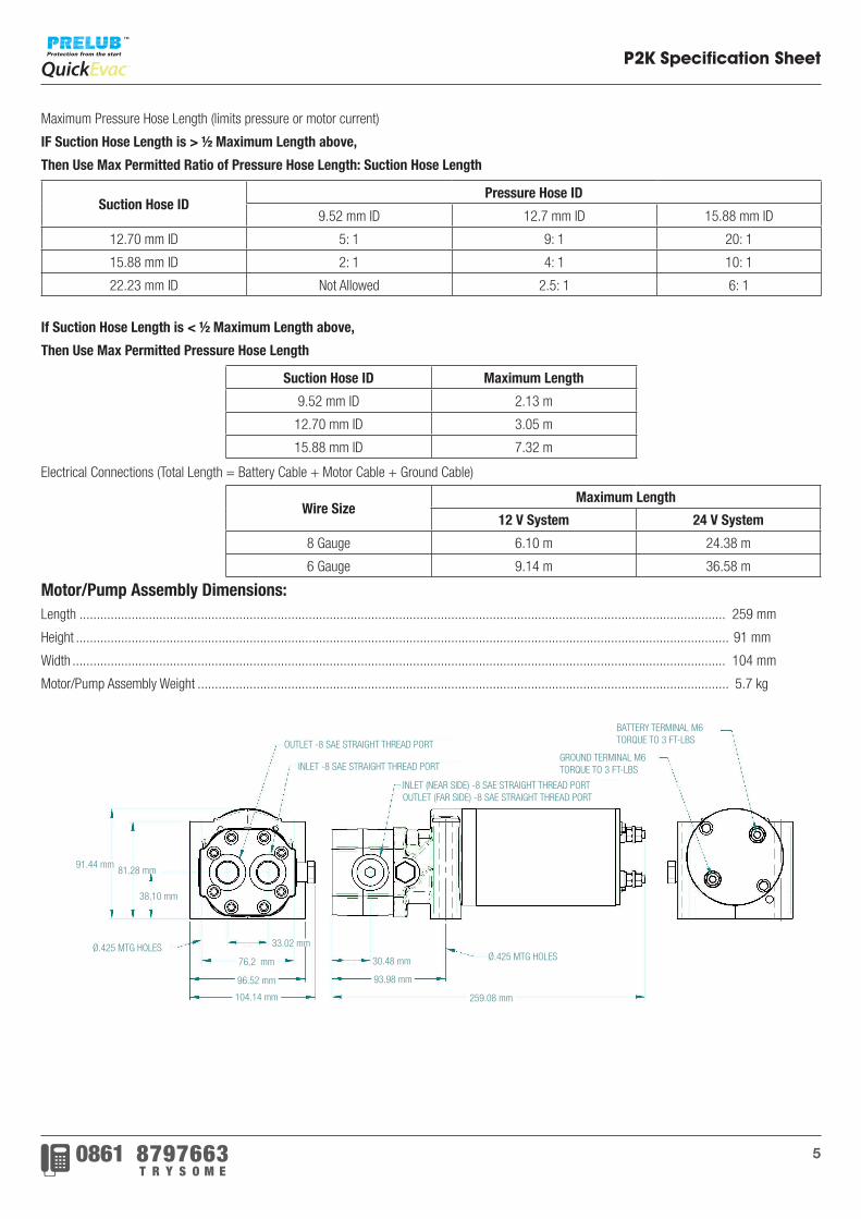
Motor/Pump Assembly Dimensions:Length .......................................................................................................................................................................................... 259 mm
Height ............................................................................................................................................................................................ 91 mm
Width ............................................................................................................................................................................................ 104 mm
Motor/Pump Assembly Weight ......................................................................................................................................................... 5.7 kg
Suction Hose IDPressure Hose ID
9.52 mm ID 12.7 mm ID 15.88 mm ID
12.70 mm ID 5: 1 9: 1 20: 1
15.88 mm ID 2: 1 4: 1 10: 1
22.23 mm ID Not Allowed 2.5: 1 6: 1
Suction Hose ID Maximum Length
9.52 mm ID 2.13 m
12.70 mm ID 3.05 m
15.88 mm ID 7.32 m
Wire SizeMaximum Length
12 V System 24 V System
8 Gauge 6.10 m 24.38 m
6 Gauge 9.14 m 36.58 m
91.44 mm
104.14 mm
96.52 mm
76.2 mm 30.48 mm
93.98 mm
259.08 mm
Ø.425 MTG HOLESØ.425 MTG HOLES
BATTERY TERMINAL M6TORQUE TO 3 FT-LBS
GROUND TERMINAL M6TORQUE TO 3 FT-LBS
OUTLET -8 SAE STRAIGHT THREAD PORT
INLET -8 SAE STRAIGHT THREAD PORT
INLET (NEAR SIDE) -8 SAE STRAIGHT THREAD PORTOUTLET (FAR SIDE) -8 SAE STRAIGHT THREAD PORT
38.10 mm
33.02 mm
81.28 mm
6
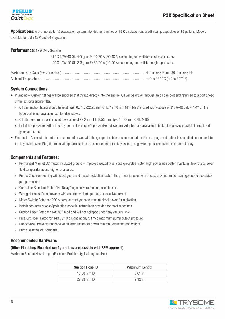
Applications: A pre-lubrication & evacuation system intended for engines of 15 ℓ displacement or with sump capacities of 16 gallons. Models
available for both 12 V and 24 V systems.
Performance: 12 & 24 V Systems
21° C 15W-40 Oil: 4-5 gpm @ 60-70 A (30-40 A) depending on available engine port sizes.
0° C 15W-40 Oil: 2-3 gpm @ 80-90 A (40-50 A) depending on available engine port sizes.
Maximum Duty Cycle (Evac operation) ........................................................................................... 4 minutes ON and 30 minutes OFF
Ambient Temperature ................................................................................................................... –40 to 125° C (-40 to 257° F)
System Connections:• Plumbing – Custom fittings will be supplied that thread directly into the engine. Oil will be drawn through an oil pan port and returned to a port ahead
of the existing engine filter.
» Oil pan suction fitting should have at least 0.5” ID (22.23 mm ORB, 12.70 mm NPT, M22) if used with viscous oil (15W-40 below 4.4° C). If a
large port is not available, call for alternatives.
» Oil filterhead return port should have at least 7.62 mm ID. (9.53 mm pipe, 14.29 mm ORB, M16)
» Install the pressure switch into any port in the engine’s pressurized oil system. Adapters are available to install the pressure switch in most port
types and sizes.
• Electrical – Connect the motor to a source of power with the gauge of cables recommended on the next page and splice the supplied connector into
the key switch wire. Plug the main wiring harness into the connectors at the key switch, magswitch, pressure switch and control relay.
Components and Features: » Permanent Magnet DC motor. Insulated ground – improves reliability vs. case grounded motor. High power rise better maintains flow rate at lower
fluid temperatures and higher pressures.
» Pump: Cast iron housing with steel gears and a seal protection feature that, in conjunction with a fuse, prevents motor damage due to excessive
pump pressure.
» Controller: Standard Prelub “No Delay” logic delivers fastest possible start.
» Wiring Harness: Fuse prevents wire and motor damage due to excessive current.
» Motor Switch: Rated for 200 A carry current yet consumes minimal power for activation.
» Installation Instructions: Application-specific instructions provided for most machines.
» Suction Hose: Rated for 148.89° C oil and will not collapse under any vacuum level.
» Pressure Hose: Rated for 148.89° C oil, and nearly 5 times maximum pump output pressure.
» Check Valve: Prevents backflow of oil after engine start with minimal restriction and weight.
» Pump Relief Valve: Standard.
Recommended Hardware:
(Other Plumbing/ Electrical configurations are possible with RPM approval)
Maximum Suction Hose Length (For quick Prelub of typical engine sizes)
P3K Specification Sheet
Suction Hose ID Maximum Length
15.88 mm ID 0.61 m
22.23 mm ID 2.13 m
7
P3K Specification Sheet
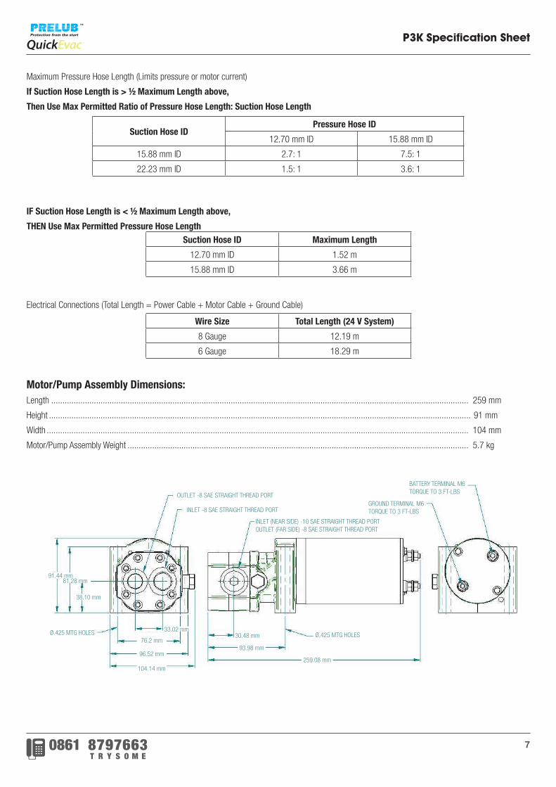
Maximum Pressure Hose Length (Limits pressure or motor current)
If Suction Hose Length is > ½ Maximum Length above,
Then Use Max Permitted Ratio of Pressure Hose Length: Suction Hose Length
IF Suction Hose Length is < ½ Maximum Length above,
THEN Use Max Permitted Pressure Hose Length
Electrical Connections (Total Length = Power Cable + Motor Cable + Ground Cable)
Motor/Pump Assembly Dimensions:Length .......................................................................................................................................................................................... 259 mm
Height ............................................................................................................................................................................................ 91 mm
Width ............................................................................................................................................................................................ 104 mm
Motor/Pump Assembly Weight ........................................................................................................................................................ 5.7 kg
Suction Hose IDPressure Hose ID
12.70 mm ID 15.88 mm ID
15.88 mm ID 2.7: 1 7.5: 1
22.23 mm ID 1.5: 1 3.6: 1
Suction Hose ID Maximum Length
12.70 mm ID 1.52 m
15.88 mm ID 3.66 m
Wire Size Total Length (24 V System)
8 Gauge 12.19 m
6 Gauge 18.29 m
BATTERY TERMINAL M6TORQUE TO 3 FT-LBS
GROUND TERMINAL M6TORQUE TO 3 FT-LBS
INLET (NEAR SIDE) -10 SAE STRAIGHT THREAD PORTOUTLET (FAR SIDE) -8 SAE STRAIGHT THREAD PORT
OUTLET -8 SAE STRAIGHT THREAD PORT
INLET -8 SAE STRAIGHT THREAD PORT
Ø.425 MTG HOLESØ.425 MTG HOLES
104.14 mm
96.52 mm
76.2 mm
91.44 mm
30.48 mm33.02 mm
93.98 mm
259.08 mm
38.10 mm
81.28 mm
8
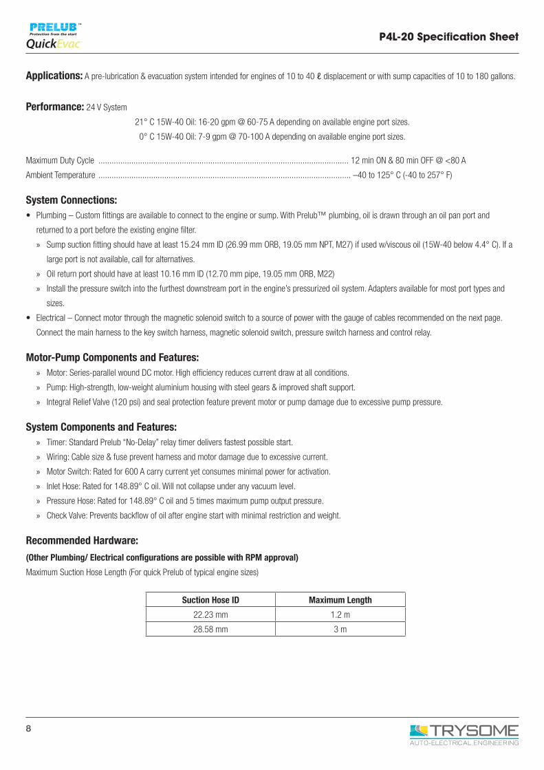
P4L-20 Specification Sheet
Applications: A pre-lubrication & evacuation system intended for engines of 10 to 40 ℓ displacement or with sump capacities of 10 to 180 gallons.
Performance: 24 V System
21° C 15W-40 Oil: 16-20 gpm @ 60-75 A depending on available engine port sizes.
0° C 15W-40 Oil: 7-9 gpm @ 70-100 A depending on available engine port sizes.
Maximum Duty Cycle .................................................................................................................. 12 min ON & 80 min OFF @ <80 A
Ambient Temperature ................................................................................................................... –40 to 125° C (-40 to 257° F)
System Connections:• Plumbing – Custom fittings are available to connect to the engine or sump. With Prelub™ plumbing, oil is drawn through an oil pan port and
returned to a port before the existing engine filter.
» Sump suction fitting should have at least 15.24 mm ID (26.99 mm ORB, 19.05 mm NPT, M27) if used w/viscous oil (15W-40 below 4.4° C). If a
large port is not available, call for alternatives.
» Oil return port should have at least 10.16 mm ID (12.70 mm pipe, 19.05 mm ORB, M22)
» Install the pressure switch into the furthest downstream port in the engine’s pressurized oil system. Adapters available for most port types and
sizes.
• Electrical – Connect motor through the magnetic solenoid switch to a source of power with the gauge of cables recommended on the next page.
Connect the main harness to the key switch harness, magnetic solenoid switch, pressure switch harness and control relay.
Motor-Pump Components and Features: » Motor: Series-parallel wound DC motor. High efficiency reduces current draw at all conditions.
» Pump: High-strength, low-weight aluminium housing with steel gears & improved shaft support.
» Integral Relief Valve (120 psi) and seal protection feature prevent motor or pump damage due to excessive pump pressure.
System Components and Features: » Timer: Standard Prelub “No-Delay” relay timer delivers fastest possible start.
» Wiring: Cable size & fuse prevent harness and motor damage due to excessive current.
» Motor Switch: Rated for 600 A carry current yet consumes minimal power for activation.
» Inlet Hose: Rated for 148.89° C oil. Will not collapse under any vacuum level.
» Pressure Hose: Rated for 148.89° C oil and 5 times maximum pump output pressure.
» Check Valve: Prevents backflow of oil after engine start with minimal restriction and weight.
Recommended Hardware:
(Other Plumbing/ Electrical configurations are possible with RPM approval)
Maximum Suction Hose Length (For quick Prelub of typical engine sizes)
Suction Hose ID Maximum Length
22.23 mm 1.2 m
28.58 mm 3 m
9
P4L-20 Specification Sheet
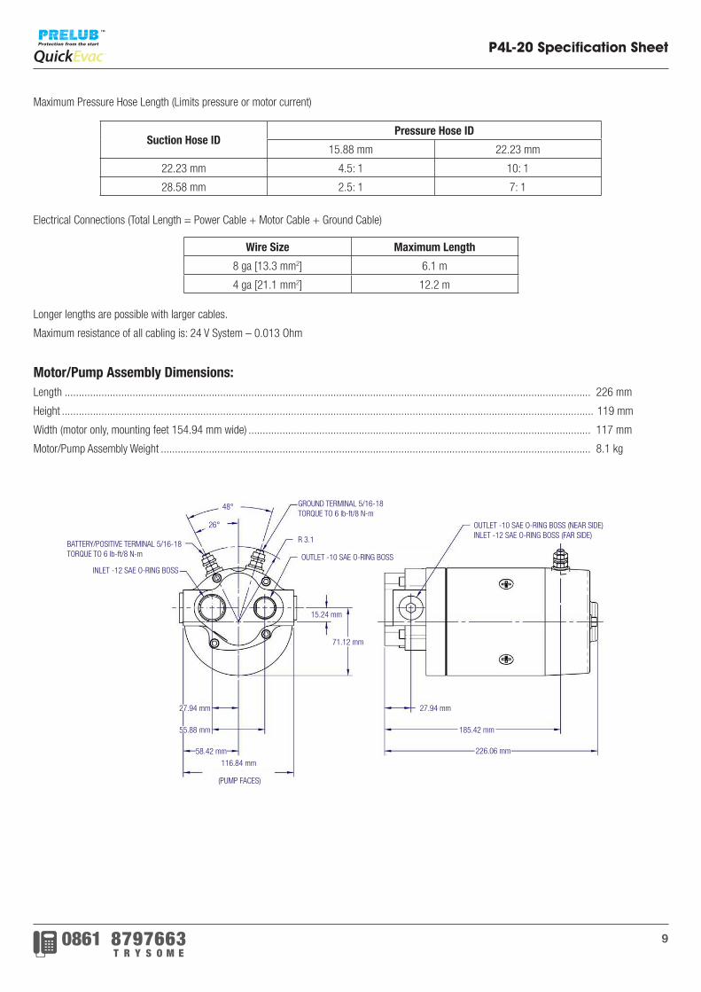
Maximum Pressure Hose Length (Limits pressure or motor current)
Electrical Connections (Total Length = Power Cable + Motor Cable + Ground Cable)
Longer lengths are possible with larger cables.
Maximum resistance of all cabling is: 24 V System – 0.013 Ohm
Motor/Pump Assembly Dimensions:Length .......................................................................................................................................................................................... 226 mm
Height ............................................................................................................................................................................................ 119 mm
Width (motor only, mounting feet 154.94 mm wide) ......................................................................................................................... 117 mm
Motor/Pump Assembly Weight ........................................................................................................................................................ 8.1 kg
Suction Hose IDPressure Hose ID
15.88 mm 22.23 mm
22.23 mm 4.5: 1 10: 1
28.58 mm 2.5: 1 7: 1
Wire Size Maximum Length
8 ga [13.3 mm2] 6.1 m
4 ga [21.1 mm2] 12.2 m
185.42 mm
GROUND TERMINAL 5/16-18TORQUE TO 6 lb-ft/8 N-m
BATTERY/POSITIVE TERMINAL 5/16-18TORQUE TO 6 lb-ft/8 N-m
R 3.1
(PUMP FACES)
OUTLET -10 SAE O-RING BOSS
OUTLET -10 SAE O-RING BOSS (NEAR SIDE)INLET -12 SAE O-RING BOSS (FAR SIDE)
INLET -12 SAE O-RING BOSS
55.88 mm
116.84 mm
58.42 mm
27.94 mm27.94 mm
226.06 mm
15.24 mm
48°
26°
71.12 mm
10
P4K-40 Specification Sheet
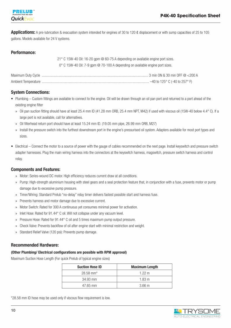
Applications: A pre-lubrication & evacuation system intended for engines of 30 to 120 ℓ displacement or with sump capacities of 25 to 105
gallons. Models available for 24 V systems.
Performance: 21° C 15W-40 Oil: 16-20 gpm @ 60-75 A depending on available engine port sizes.
0° C 15W-40 Oil: 7-9 gpm @ 70-100 A depending on available engine port sizes.
Maximum Duty Cycle .................................................................................................................. 3 min ON & 30 min OFF @ <200 A
Ambient Temperature ................................................................................................................... –40 to 125° C (-40 to 257° F)
System Connections:• Plumbing – Custom fittings are available to connect to the engine. Oil will be drawn through an oil pan port and returned to a port ahead of the
existing engine filter
» Oil pan suction fitting should have at least 25.4 mm ID (41.28 mm ORB, 25.4 mm NPT, M42) if used with viscous oil (15W-40 below 4.4° C). If a
large port is not available, call for alternatives.
» Oil filterhead return port should have at least 15.24 mm ID. (19.05 mm pipe, 26.99 mm ORB, M27)
» Install the pressure switch into the furthest downstream port in the engine’s pressurised oil system. Adapters available for most port types and
sizes.
• Electrical – Connect the motor to a source of power with the gauge of cables recommended on the next page. Install keyswitch and pressure switch
adapter harnesses. Plug the main wiring harness into the connectors at the keyswitch harness, magswitch, pressure switch harness and control
relay.
Components and Features: » Motor: Series-wound DC motor. High efficiency reduces current draw at all conditions.
» Pump: High-strength aluminium housing with steel gears and a seal protection feature that, in conjunction with a fuse, prevents motor or pump
damage due to excessive pump pressure.
» Timer/Wiring: Standard Prelub “no-delay” relay timer delivers fastest possible start and harness fuse.
» Prevents harness and motor damage due to excessive current.
» Motor Switch: Rated for 300 A continuous yet consumes minimal power for activation.
» Inlet Hose: Rated for 91.44° C oil. Will not collapse under any vacuum level.
» Pressure Hose: Rated for 91.44° C oil and 5 times maximum pump output pressure.
» Check Valve: Prevents backflow of oil after engine start with minimal restriction and weight.
» Standard Relief Valve (120 psi): Prevents pump damage.
Recommended Hardware:
(Other Plumbing/ Electrical configurations are possible with RPM approval)
Maximum Suction Hose Length (For quick Prelub of typical engine sizes)
*28.58 mm ID hose may be used only if viscous flow requirement is low.
Suction Hose ID Maximum Length
28.58 mm* 1.22 m
34.93 mm 1.83 m
47.65 mm 3.66 m
11
P4K-40 Specification Sheet
Maximum Pressure Hose Length (Limits pressure or motor current)
*22.23 ID hose may only be used with 28.58 mm ID Suction hose.
Electrical Connections (Total Length = Power Cable + Motor Cable + Ground Cable)
Longer lengths are possible with larger cables.
Maximum resistance of all cabling is: 24 V System – 0.005 Ohm
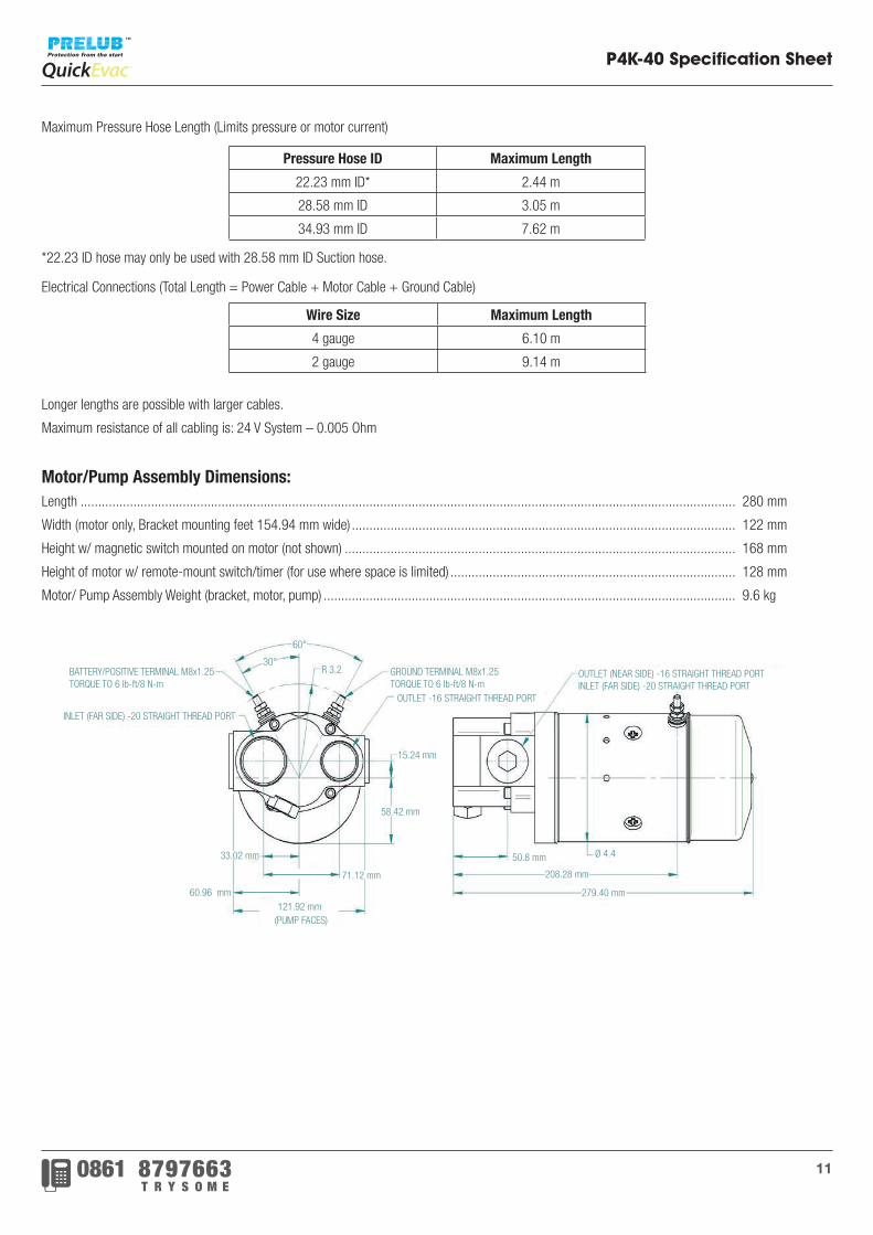
Motor/Pump Assembly Dimensions:Length .......................................................................................................................................................................................... 280 mm
Width (motor only, Bracket mounting feet 154.94 mm wide) ............................................................................................................. 122 mm
Height w/ magnetic switch mounted on motor (not shown) ............................................................................................................... 168 mm
Height of motor w/ remote-mount switch/timer (for use where space is limited) ................................................................................. 128 mm
Motor/ Pump Assembly Weight (bracket, motor, pump) ..................................................................................................................... 9.6 kg
Pressure Hose ID Maximum Length
22.23 mm ID* 2.44 m
28.58 mm ID 3.05 m
34.93 mm ID 7.62 m
Wire Size Maximum Length
4 gauge 6.10 m
2 gauge 9.14 m
GROUND TERMINAL M8x1.25TORQUE TO 6 lb-ft/8 N-m
(PUMP FACES)
OUTLET -16 STRAIGHT THREAD PORT
OUTLET (NEAR SIDE) -16 STRAIGHT THREAD PORTINLET (FAR SIDE) -20 STRAIGHT THREAD PORT
INLET (FAR SIDE) -20 STRAIGHT THREAD PORT
60°
30°R 3.2
121.92 mm
15.24 mm
58.42 mm
71.12 mm
50.8 mm
208.28 mm
279.40 mm
33.02 mm
60.96 mm
Ø 4.4
BATTERY/POSITIVE TERMINAL M8x1.25TORQUE TO 6 lb-ft/8 N-m
12
High-Volume Pump Specification Sheet
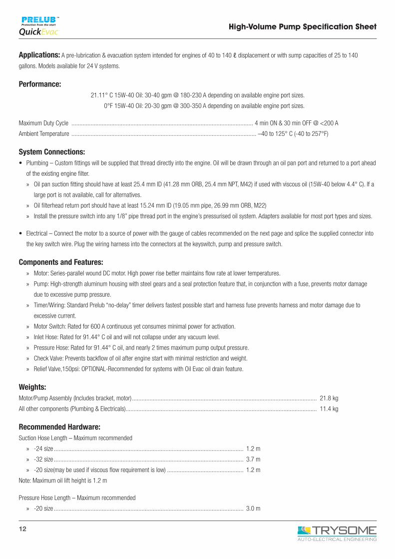
Applications: A pre-lubrication & evacuation system intended for engines of 40 to 140 ℓ displacement or with sump capacities of 25 to 140
gallons. Models available for 24 V systems.
Performance: 21.11° C 15W-40 Oil: 30-40 gpm @ 180-230 A depending on available engine port sizes.
0°F 15W-40 Oil: 20-30 gpm @ 300-350 A depending on available engine port sizes.
Maximum Duty Cycle .................................................................................................................. 4 min ON & 30 min OFF @ <200 A
Ambient Temperature .................................................................................................................... –40 to 125° C (-40 to 257°F)
System Connections:• Plumbing – Custom fittings will be supplied that thread directly into the engine. Oil will be drawn through an oil pan port and returned to a port ahead
of the existing engine filter.
» Oil pan suction fitting should have at least 25.4 mm ID (41.28 mm ORB, 25.4 mm NPT, M42) if used with viscous oil (15W-40 below 4.4° C). If a
large port is not available, call for alternatives.
» Oil filterhead return port should have at least 15.24 mm ID (19.05 mm pipe, 26.99 mm ORB, M22)
» Install the pressure switch into any 1/8” pipe thread port in the engine’s pressurised oil system. Adapters available for most port types and sizes.
• Electrical – Connect the motor to a source of power with the gauge of cables recommended on the next page and splice the supplied connector into
the key switch wire. Plug the wiring harness into the connectors at the keyswitch, pump and pressure switch.
Components and Features: » Motor: Series-parallel wound DC motor. High power rise better maintains flow rate at lower temperatures.
» Pump: High-strength aluminum housing with steel gears and a seal protection feature that, in conjunction with a fuse, prevents motor damage
due to excessive pump pressure.
» Timer/Wiring: Standard Prelub “no-delay” timer delivers fastest possible start and harness fuse prevents harness and motor damage due to
excessive current.
» Motor Switch: Rated for 600 A continuous yet consumes minimal power for activation.
» Inlet Hose: Rated for 91.44° C oil and will not collapse under any vacuum level.
» Pressure Hose: Rated for 91.44° C oil, and nearly 2 times maximum pump output pressure.
» Check Valve: Prevents backflow of oil after engine start with minimal restriction and weight.
» Relief Valve,150psi: OPTIONAL-Recommended for systems with Oil Evac oil drain feature.
Weights:Motor/Pump Assembly (Includes bracket, motor) .................................................................................................................... 21.8 kg
All other components (Plumbing & Electricals) ........................................................................................................................ 11.4 kg
Recommended Hardware:Suction Hose Length – Maximum recommended
» -24 size ....................................................................................................................... 1.2 m
» -32 size ....................................................................................................................... 3.7 m
» -20 size(may be used if viscous flow requirement is low) ................................................ 1.2 m
Note: Maximum oil lift height is 1.2 m
Pressure Hose Length – Maximum recommended
» -20 size ....................................................................................................................... 3.0 m
13
High-Volume Pump Specification Sheet
» -24 size ....................................................................................................................... 7.6 m
» -16 Size (w/-20 suction hose only) ................................................................................ 2.4 m
Motor Ground and Power Cables, Combined Length - Maximum w/24 V systems
» #2 gauge ..................................................................................................................... 6.0 m
» 0 gauge ....................................................................................................................... 9.2 m
Greater lengths are possible with larger cables. Max resistance of both cables is;
24 V system – 0.003 Ohm, 12 V system – Not available, 32 V system – Not available.
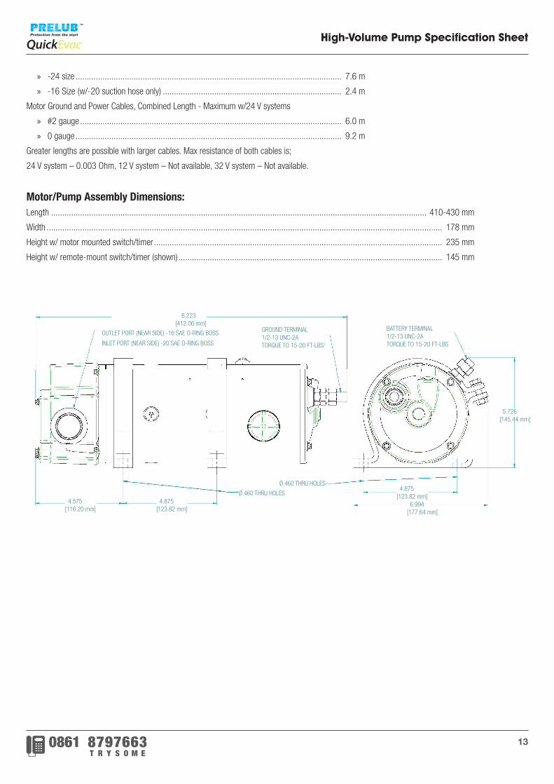
Motor/Pump Assembly Dimensions:Length ........................................................................................................................................................................ 410-430 mm
Width ................................................................................................................................................................................. 178 mm
Height w/ motor mounted switch/timer ................................................................................................................................. 235 mm
Height w/ remote-mount switch/timer (shown) ...................................................................................................................... 145 mm
4.875[123.82 mm]
4.875[123.82 mm]
5.726[145.44 mm]
16.223[412.06 mm]
BATTERY TERMINAL1/2-13 UNC-2ATORQUE TO 15-20 FT-LBS
GROUND TERMINAL1/2-13 UNC-2ATORQUE TO 15-20 FT-LBS
6.994[177.64 mm]
4.575[116.20 mm]
Ø.460 THRU HOLES
Ø.460 THRU HOLES
OUTLET PORT (NEAR SIDE) -16 SAE O-RING BOSS
INLET PORT (NEAR SIDE) -20 SAE O-RING BOSS
14
A.C. High-Volume Pump Specification Sheet
Applications: A pre-lubrication system intended for engines of 40 to 140 ℓ displacement or with sump capacities of 25 to 140 gallons. Ideally
suited for installation where high capacity batteries are unavailable for DC Prelub™ Systems such as air-start, power generation, and marine engines.
The AC-HVP pump is also suitable for the transfer of bulk fluids in both portable and stationary applications. Models available for 208 V, 230 V, and
460 V 60 Hz 3-Phase power supplies.
Performance: 460 V, 60 Hz, 3-Phase power (Current ~double on 208 V)
21.11° C 15W-40 Oil: 25-35 gpm @ 4-6.3 A depending on available engine port sizes.
0° C 15W-40 Oil: 10-25 gpm @ 5-7 A depending on available engine port sizes.
Maximum Duty Cycle .................................................................................................................. 4 min ON & 30 min OFF @ <200 A
Ambient Temperature .................................................................................................................... –40 to 125° C (-40 to 257°F)
*Pump can sustain extended duty when motor current < 12.6/6.3 Amps (warm oil, low pressure)
System Connections:• Plumbing – Custom fittings are available to mate directly into the engine. Oil will be drawn through an oil pan port and returned to a port ahead of the
existing engine filter.
» Oil pan suction fitting should have at least 25.4 mm ID (41.28 mm ORB, 25.4 mm NPT, M42) if used with viscous oil (15W-40 below 4.4° C). If a
large port is not available, call for alternatives.
» Oil filterhead return port should have at least 15.24 mm ID (19.05 mm pipe, 26.99 mm ORB, M22).
» Install the pressure switch into any port in the engine’s pressurized oil system. Adapters available for most port types and sizes.
• Electrical – Connect the Prelub™ Controller to a 3-phase power source and connect the AC Prelub™ Pump to the Controller in accordance with
all applicable electrical codes. Splice the supplied connector into the key switch wire. Plug the wiring harness into the connectors at the keyswitch,
controller and pressure switch.
Components and Features: » Motor: 5hp, IEEE 45 Certified, Totally Enclosed Fan-Cooled motor suitable for harsh environments.
» Pump: High-strength aluminium housing with steel gears and a seal protection feature that, in conjunction with customer supplied circuit
protection, prevents motor damage due to excessive pump pressure.
» System Controller: Standard Prelub “No-Delay” logic delivers fastest possible start.
» Design reduces extra electrical equipment needed for Code compliance when installing, saving the user installation time and money.
» Thermal-Overload, Phase-Loss, and Short-Circuit Protection for the Prelub™ Pump and control components.
» Rugged NEMA 12 Enclosure for installation in harsh environments.
» Inlet Hose: Rated for 91.44° C oil and will not collapse under any vacuum level.
» Pressure Hose: Rated for 91.44° C oil, and nearly 2 times maximum pump output pressure.
» Check Valve: Prevents backflow of oil after engine start with minimal restriction and weight.
» Pump Relief Valve: OPTIONAL-Recommended for applications that could dead-head pump.
15
10.75273mm
6.0152mm
8.1205mm
10.3262mm11.5292mm
8.3211mm
MOUNTING DIMENSIONS
CONTINUOUS HINGE
.317.8mm
(4 PLCS)
9.7247mm
AC-HVP CONTROLLER
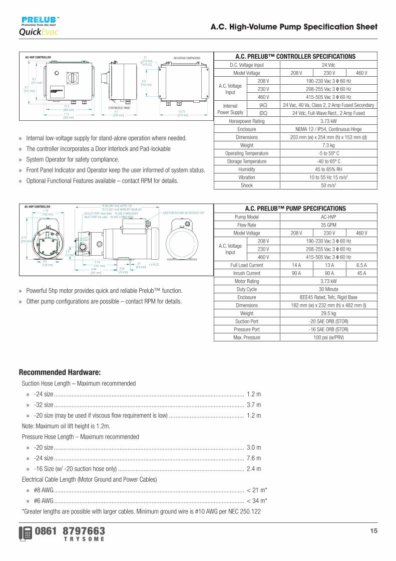
A.C. High-Volume Pump Specification Sheet
A.C. PRELUB™ CONTROLLER SPECIFICATIONSD.C. Voltage Input 24 Vdc
Model Voltage 208 V 230 V 460 V
A.C. Voltage Input
208 V 190-230 Vac 3 Φ 60 Hz
230 V 208-255 Vac 3 Φ 60 Hz
460 V 415-505 Vac 3 Φ 60 Hz
InternalPower Supply
(AC) 24 Vac, 40 Va, Class 2, 2 Amp Fused Secondary
(DC) 24 Vdc, Full-Wave Rect., 2 Amp Fused
Horsepower Rating 3.73 kW
Enclosure NEMA 12 / IP54, Continuous Hinge
Dimensions 203 mm (w) x 254 mm (h) x 153 mm (d)
Weight 7.3 kg
Operating Temperature -5 to 55º C
Storage Temperature -40 to 65º C
Humidity 45 to 85% RH
Vibration 10 to 55 Hz 15 m/s2
Shock 50 m/s2
A.C. PRELUB™ PUMP SPECIFICATIONSPump Model AC-HVP
Flow Rate 35 GPM
Model Voltage 208 V 230 V 460 V
A.C. Voltage Input
208 V 190-230 Vac 3 Φ 60 Hz
230 V 208-255 Vac 3 Φ 60 Hz
460 V 415-505 Vac 3 Φ 60 Hz
Full Load Current 14 A 13 A 6.5 A
Inrush Current 90 A 90 A 45 A
Motor Rating 3.73 kW
Duty Cycle 30 Minute
Enclosure IEEE45 Rated, Tefc, Rigid Base
Dimensions 182 mm (w) x 232 mm (h) x 482 mm (l)
Weight 29.5 kg
Suction Port -20 SAE ORB (STOR)
Pressure Port -16 SAE ORB (STOR)
Max. Pressure 100 psi (w/PRV)
» Internal low-voltage supply for stand-alone operation where needed.
» The controller incorporates a Door Interlock and Pad-lockable
» System Operator for safety compliance.
» Front Panel Indicator and Operator keep the user informed of system status.
» Optional Functional Features available – contact RPM for details.
» Powerful 5hp motor provides quick and reliable Prelub™ function.
» Other pump configurations are possible – contact RPM for details.
9.15232mm
7.16182mm
4.9124mm
3.0076mm
7.74197mm
9.49241mm
18.98 [482mm] w/ STD. LID19.73 [501] w/ RELIEF VALVE LID
.348.6mm x 4 PLCS.
2.872mm
OUTLET PORT (near side): -16 SAE O-RING BOSSINLET PORT (far side): -20 SAE O-RING BOSS
JUNCTION BOX MAY BE ROTATED 180º
AC-HVP PUMP
Recommended Hardware:Suction Hose Length – Maximum recommended
» -24 size ....................................................................................................................... 1.2 m
» -32 size ....................................................................................................................... 3.7 m
» -20 size (may be used if viscous flow requirement is low) ............................................... 1.2 m
Note: Maximum oil lift height is 1.2m.
Pressure Hose Length – Maximum recommended
» -20 size ....................................................................................................................... 3.0 m
» -24 size ....................................................................................................................... 7.6 m
» -16 Size (w/ -20 suction hose only) ............................................................................... 2.4 m
Electrical Cable Length (Motor Ground and Power Cables)
» #8 AWG ....................................................................................................................... < 21 m*
» #6 AWG ....................................................................................................................... < 34 m*
*Greater lengths are possible with larger cables. Minimum ground wire is #10 AWG per NEC 250.122
Ø
.31[7.8 mm] (4 PLCS)
6.0[152 mm]
10.75[273 mm]
8.1[205 mm]
10.3[262 mm]
7.16[182 mm]
4.9[124 mm]
9.15[232 mm]
2.8[72 mm]
18.98 [482 mm] w/STD. LID19.73 [501 mm] W/RELIEF VALVE LID
JUNCTION BOX MAY BE ROTATED 180°
.34[8.6 mm] 3.00
[76 mm]
7.74[197 mm]
9.49[241 mm]
4.9[124 mm] x 4 PLCS.
OUTLET PORT (near side): - 16 SAE O-RING BOSSINLET PORT (far side): - 20 SAE O-RING BOSS
8.3[211 mm]
9.7[247 mm]
11.5[292 mm]
MOUNTING DIMENSIONSAC-HVP CONTROLLER
AC-HVP CONTROLLER
CONTINUOUS HINGE
16
Self-Contained Evac Tool™ Specification Sheet
Applications: A remotely-powered, handheld, transfer pump for lubricating oils. Models available for 12 Vdc and 24 Vdc.
Performance: #10 Machine Upfit Kit (16 mm ID Suction Hose)
Current @ 24 Vdc ½ of Current @ 12Vdc
3.5 gpm: 60º C 15W-40 Oil @ 12-14 A & 12 Vdc
2.00 gpm: 23.88º C 15W-40 Oil @ 16-18 A & 12 Vdc
1.25 gpm: 10º C 15W-40 Oil @ 20-22 A & 12 Vdc
Maximum Duty Cycle .................................................................................................................... 50% (4 minute Max. ON Time)
Ambient Temperature Rating* ...................................................................................................... 0º F to 150º F (-18º C to 65º C)
Target Evac Duration ................................................................................................... 90 seconds (depends on machine upfit kit)
Maximum Oil Viscosity ..............................................................................................700 cSt (2700 SUS) 50º F 15W-40 or thinner
*Be sure fluids are adequately heated if using with ambient temperature below 23.88° C. Most efficient evac occurs with oil temperatures greater
than 23.88º C because engine manufacturers recommend that oil be drained warm so that contaminants are suspended in oil and drained rather than
settling and being left in the pan to re-circulate.
Tool is not rated for transfer of combustibles or coolants (e.g. gasoline, kerosene, antifreeze, etc.) modification of tool or machine upfit kit without
specific RPM approval will void warranty.
Components and Features: » Efficient, high-torque, permanent magnet DC motor.
» Built-in, automatic, reset circuit breaker to protect against motor abuse.
» Tool housing is a rugged, impact-modified, reinforced polymer.
» High-amperage, capable motor switch with silver contacts for long life.
» Remote Activation Switch (with 2.44 m lead) assembly available.
» Shoulder strap available for ease of transport or securing tool to machine.
» Polyethylene carrying case available to organise tool & accessories.
» SCET™ is supplied with an 457.2 mm long suction hose and 1.22 m long pressure hose.
» Various Tool Plumbing configurations are available.
Machine Upfit Kits: » Kits are machine-specific & contain all necessary hardware.
» Detailed installation instructions, including application photographs, are included.
» Plumbing and Electrical connectors are mounted on an easily accessible Evac Bracket.
» Plumbing connects sump drain to a no-spill Flush Face Quick Disconnect.
» Many specialty oil pan drain fittings available; custom fittings are possible.
» Harness connects machine battery to Deutsch connector (3.05 m of 12 ga. SXL wire supplied).
» Various Evac Bracket assemblies available for installation flexibility.
17
Self-Contained Evac Tool™ Specification Sheet
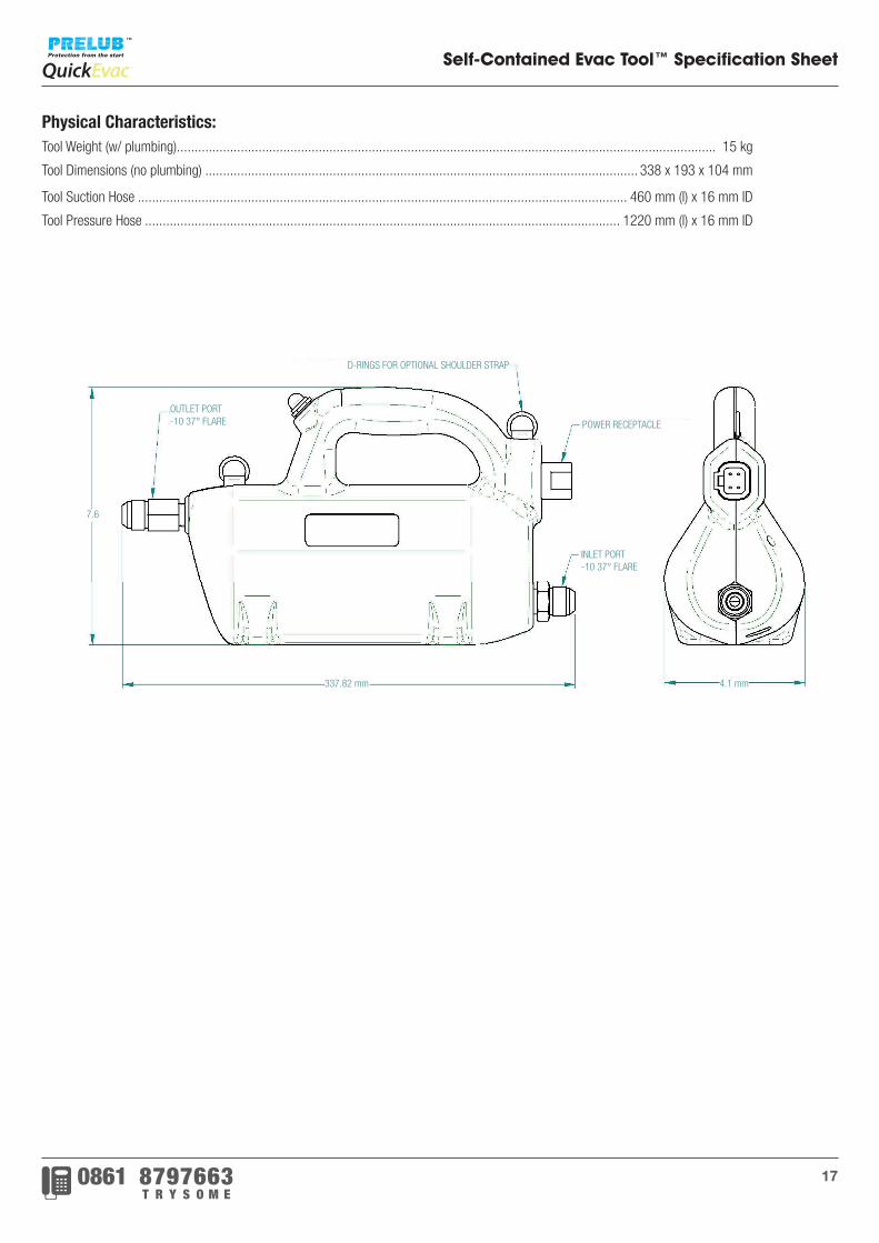
Physical Characteristics:Tool Weight (w/ plumbing)........................................................................................................................................................ 15 kg
Tool Dimensions (no plumbing) .......................................................................................................................... 338 x 193 x 104 mm
Tool Suction Hose .......................................................................................................................................... 460 mm (l) x 16 mm ID
Tool Pressure Hose ...................................................................................................................................... 1220 mm (l) x 16 mm ID
D-RINGS FOR OPTIONAL SHOULDER STRAP
POWER RECEPTACLE
INLET PORT-10 37° FLARE
4.1 mm337.82 mm
7.6
OUTLET PORT-10 37° FLARE
18
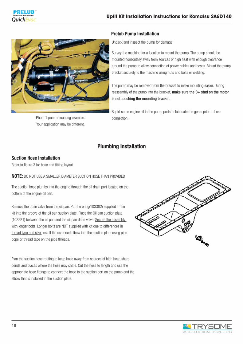
Prelub Pump Installation
Unpack and inspect the pump for damage.
Survey the machine for a location to mount the pump. The pump should be
mounted horizontally away from sources of high heat with enough clearance
around the pump to allow connection of power cables and hoses. Mount the pump
bracket securely to the machine using nuts and bolts or welding.
The pump may be removed from the bracket to make mounting easier. During
reassembly of the pump into the bracket, make sure the B+ stud on the motor
is not touching the mounting bracket.
Squirt some engine oil in the pump ports to lubricate the gears prior to hose
connection.
Plumbing Installation
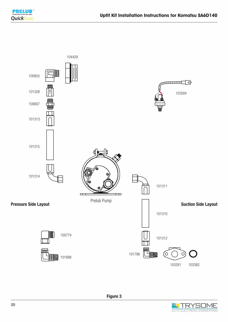
Suction Hose InstallationRefer to figure 3 for hose and fitting layout.
NOTE: DO NOT USE A SMALLER DIAMETER SUCTION HOSE THAN PROVIDED
The suction hose plumbs into the engine through the oil drain port located on the
bottom of the engine oil pan.
Remove the drain valve from the oil pan. Put the oring(103382) supplied in the
kit into the groove of the oil pan suction plate. Place the Oil pan suction plate
(103281) between the oil pan and the oil pan drain valve. Secure the assembly
with longer bolts. Longer bolts are NOT supplied with kit due to differences in
thread type and size. Install the screened elbow into the suction plate using pipe
dope or thread tape on the pipe threads.
Plan the suction hose routing to keep hose away from sources of high heat, sharp
bends and places where the hose may chafe. Cut the hose to length and use the
appropriate hose fittings to connect the hose to the suction port on the pump and the
elbow that is installed in the suction plate.
Upfit Kit Installation Instructions for Komatsu SA6D140
Photo 1 pump mounting example.
Your application may be different.
19
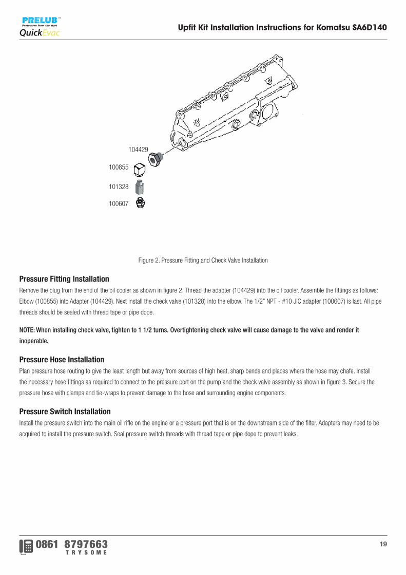
Figure 2. Pressure Fitting and Check Valve Installation
Pressure Fitting InstallationRemove the plug from the end of the oil cooler as shown in figure 2. Thread the adapter (104429) into the oil cooler. Assemble the fittings as follows:
Elbow (100855) into Adapter (104429). Next install the check valve (101328) into the elbow. The 1/2” NPT - #10 JIC adapter (100607) is last. All pipe
threads should be sealed with thread tape or pipe dope.
NOTE: When installing check valve, tighten to 1 1/2 turns. Overtightening check valve will cause damage to the valve and render it
inoperable.
Pressure Hose InstallationPlan pressure hose routing to give the least length but away from sources of high heat, sharp bends and places where the hose may chafe. Install
the necessary hose fittings as required to connect to the pressure port on the pump and the check valve assembly as shown in figure 3. Secure the
pressure hose with clamps and tie-wraps to prevent damage to the hose and surrounding engine components.
Pressure Switch InstallationInstall the pressure switch into the main oil rifle on the engine or a pressure port that is on the downstream side of the filter. Adapters may need to be
acquired to install the pressure switch. Seal pressure switch threads with thread tape or pipe dope to prevent leaks.
Upfit Kit Installation Instructions for Komatsu SA6D140
104429
100855
101328
100607
20
Upfit Kit Installation Instructions for Komatsu SA6D140
104429
103584
101311
101310
101312
101796
103281 103382
100855
101328
100607
101313
101315
101314
101688
100774
Pressure Side LayoutPrelub Pump
Suction Side Layout
Figure 3
21
Upfit Kit Installation Instructions for Komatsu SA6D140
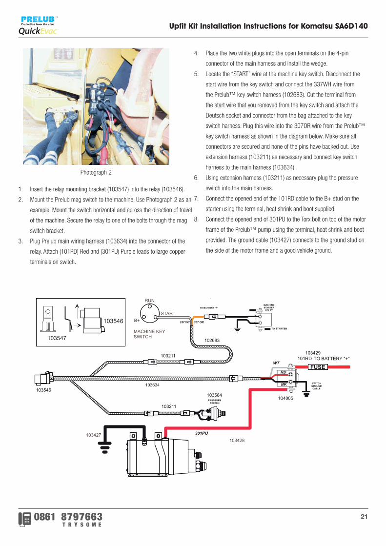
1. Insert the relay mounting bracket (103547) into the relay (103546).
2. Mount the Prelub mag switch to the machine. Use Photograph 2 as an
example. Mount the switch horizontal and across the direction of travel
of the machine. Secure the relay to one of the bolts through the mag
switch bracket.
3. Plug Prelub main wiring harness (103634) into the connector of the
relay. Attach (101RD) Red and (301PU) Purple leads to large copper
terminals on switch.
4. Place the two white plugs into the open terminals on the 4-pin
connector of the main harness and install the wedge.
5. Locate the “START” wire at the machine key switch. Disconnect the
start wire from the key switch and connect the 337WH wire from
the Prelub™ key switch harness (102683). Cut the terminal from
the start wire that you removed from the key switch and attach the
Deutsch socket and connector from the bag attached to the key
switch harness. Plug this wire into the 307OR wire from the Prelub™
key switch harness as shown in the diagram below. Make sure all
connectors are secured and none of the pins have backed out. Use
extension harness (103211) as necessary and connect key switch
harness to the main harness (103634).
6. Using extension harness (103211) as necessary plug the pressure
switch into the main harness.
7. Connect the opened end of the 101RD cable to the B+ stud on the
starter using the terminal, heat shrink and boot supplied.
8. Connect the opened end of 301PU to the Torx bolt on top of the motor
frame of the Prelub™ pump using the terminal, heat shrink and boot
provided. The ground cable (103427) connects to the ground stud on
the side of the motor frame and a good vehicle ground.
Photograph 2
10788FOR TECHNICAL ASSISTANCE CALL 1-800-255-2250
PRELUB is a trademark of RPM Industries, Inc.
PRELUB™ Upfit Kit Installation InstructionsFor Komatsu SA6D140
PRESSURESWITCH
MACHINESTARTER
RELAYTO BATTERY "+"
TO STARTER
307 OR337 WT
PHOTOGRAPH 2
Page 4 of 5
TO BATTERY "+"
FUSE
301PU
101RD
1. Insert the relay mounting bracket (103547) intothe relay (103546).
2. Mount the Prelub mag switch to the machine.Use Photograph 2 as an example. Mount theswitch horizontal and across the direction of travelof the machine. Secure the relay to one of thebolts through the magswitch bracket.
3. Plug Prelub main wiring harness (103634) intothe connector of the relay. Attach (101RD) Redand (301PU) Purple leads to large copperterminals on switch.
103547
103546
103546
103211
102683
103211
103584
103429
MACHINE KEYSWITCH
B+
RUN
START
103428
103427
4.Place the two white plugs into the open terminals on the 4 pinconnector of the main harness and install the wedge.
5. Locate the "START" wire at the machine key switch.Disconnect the start wire from the key switch and connect the337WH wire from the Prelub™ key switch harness(102683). Cutthe terminal from the start wire that you removed from the keyswitch and attach the Deutsch socket and connector from thebag attached to the key switch harness. Plug this wire into the307OR wire from the Prelub™ key switch harness as shown inthe diagram below. Make sure all connectors are secured andnone of the pins have backed out. Use extensionharness(103211) as necessary and connect key switch harnessto the main harness(103634).
6. Using extension harness(103211) as necessary plug thepressure switch into the main harness.
7. Connect the opened end of the 101RD cable to the B+ studon the starter using the terminal, heat shrink and boot supplied.
8. Connect the opened end of 301PU to the Torx bolt on top ofthe motor frame of the Prelub™ pump using the terminal, heatshrink and boot provided. The ground cable(103427) connects tothe ground stud on the side of the motor frame and a goodvehicle ground.
Plug themain wiring harness (103634) into the connector on themagnetic switch. Attach the free end of the ground wire frommagnetic switch to a confirmed good ground.
RD
WT
BK103634
104005
SWITCHGROUNDCABLE
� � � � � � � � � � � � � � � � � � �
� � � � � � � � � � � � � � � � � �
� � � � � � � �
� � � � � �
� � � � � � � � � � � � � �
� � � � �
7/27/06
3
21 Trysome Auto Electrical - www.trysome.cc - [email protected]
22
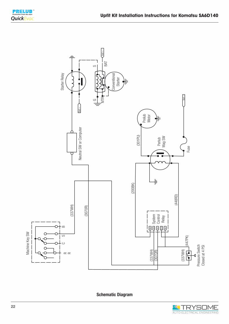
Upfit Kit Installation Instructions for Komatsu SA6D140
Star
ter R
elay
Conv
entio
nal
Star
ter
Prel
ubM
otor
(301
PU)
Fuse
(448
RD)(2
00BK
)
(307
0R)
(337
WH)
Mac
hine
Key
SW
R R
CS
B
Syst
emCo
ntro
lRe
lay
Pres
sure
Sw
itch
Clos
ed a
t 4 P
SI(447
PK)
(337
WH)
(307
OR)
(337
WH)
86 30 87 87A
85
Perlu
b M
ag S
W
SG MTR
BAT
Neut
ral S
W o
r Com
pute
rBa
tt +
Batt
+
Batt
+
Schematic Diagram
23
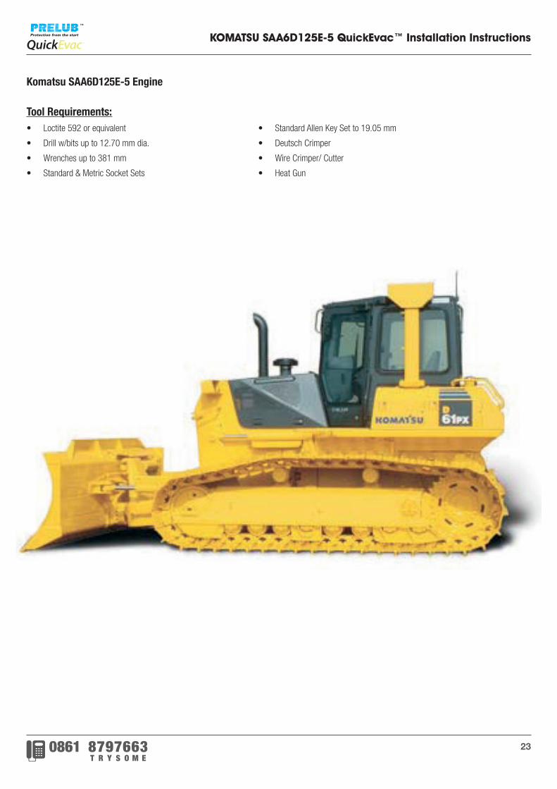
KOMATSU SAA6D125E-5 QuickEvac™ Installation Instructions
Komatsu SAA6D125E-5 Engine
Tool Requirements:• Loctite 592 or equivalent
• Drill w/bits up to 12.70 mm dia.
• Wrenches up to 381 mm
• Standard & Metric Socket Sets
• Standard Allen Key Set to 19.05 mm
• Deutsch Crimper
• Wire Crimper/ Cutter
• Heat Gun
24
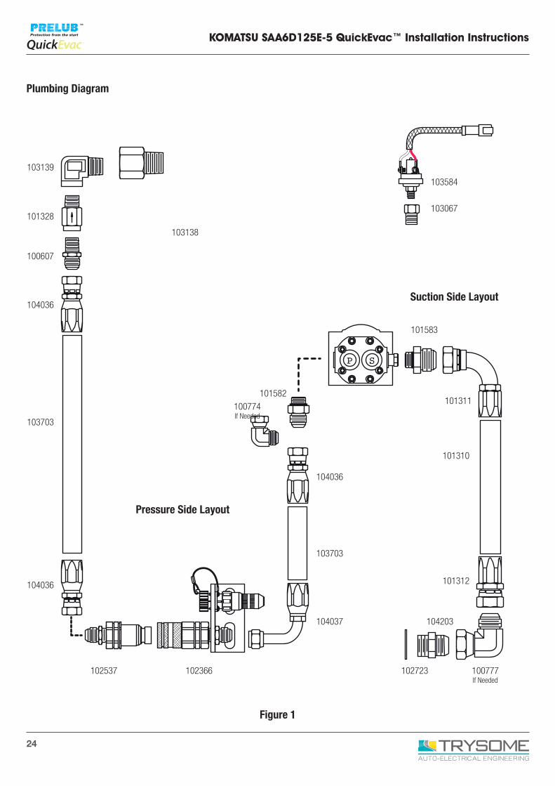
KOMATSU SAA6D125E-5 QuickEvac™ Installation Instructions
103139
103138
103584
103067
102537 102366
104037 104203
101310
101311
101583
101312
102723 100777If Needed
103703
104036
101582100774If Needed
101328
100607
104036
103703
104036
SP
Pressure Side Layout
Suction Side Layout
Figure 1
Plumbing Diagram
25
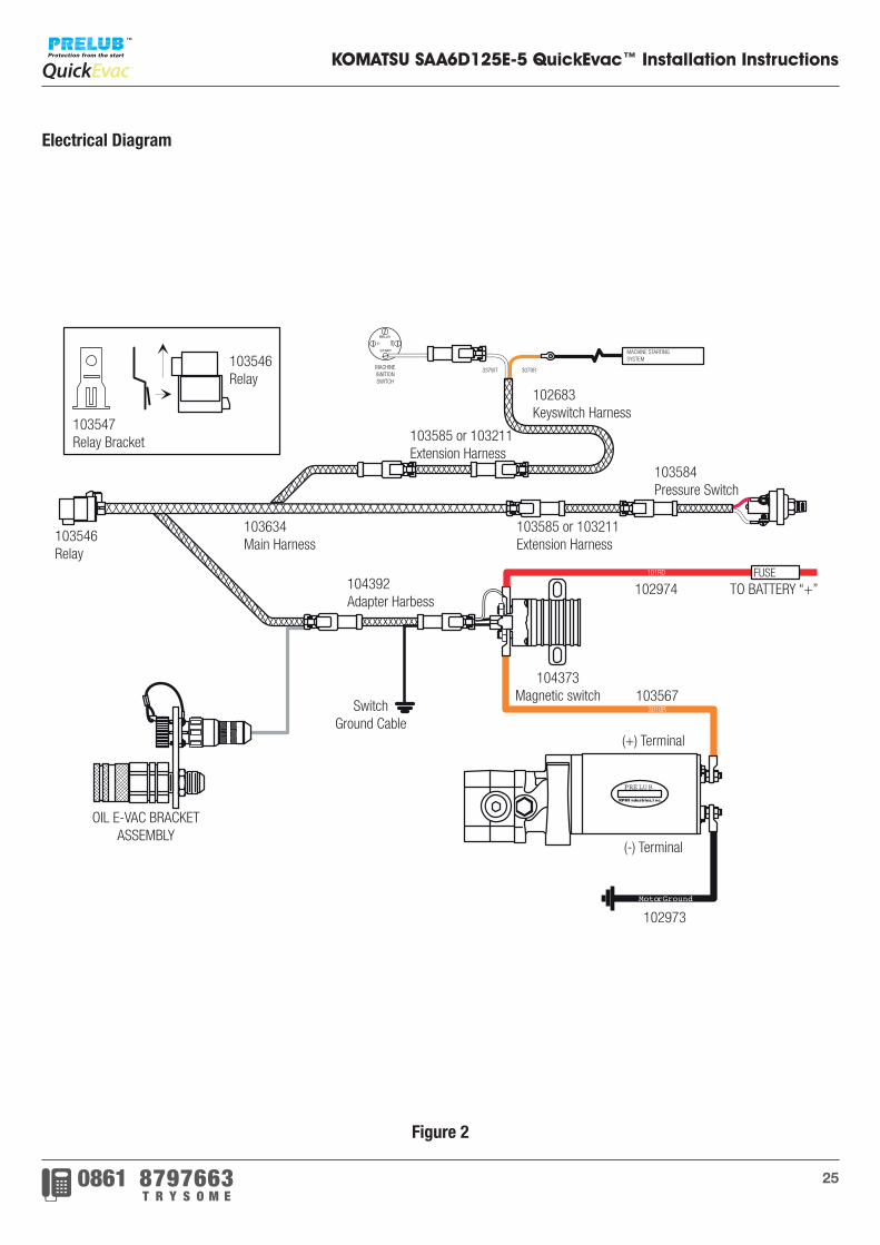
KOMATSU SAA6D125E-5 QuickEvac™ Installation Instructions
MotorGround
PRELUB
RPMI ndustries,I nc.
301OR
101RD
START
RELAYBAT
C
Figure 2
OIL E-VAC BRACKET ASSEMBLY
103546Relay
SwitchGround Cable
102973
(+) Terminal
(-) Terminal
104373Magnetic switch 103567
102974 TO BATTERY “+”104392Adapter Harbess
103634Main Harness
103585 or 103211Extension Harness
103584Pressure Switch
102683Keyswitch Harness
103585 or 103211Extension Harness
103546Relay
103547Relay Bracket
MACHINEIGNITIONSWITCH
337WT 3070R
MACHINE STARTINGSYSTEM
FUSE101RD
3010R
Electrical Diagram
26
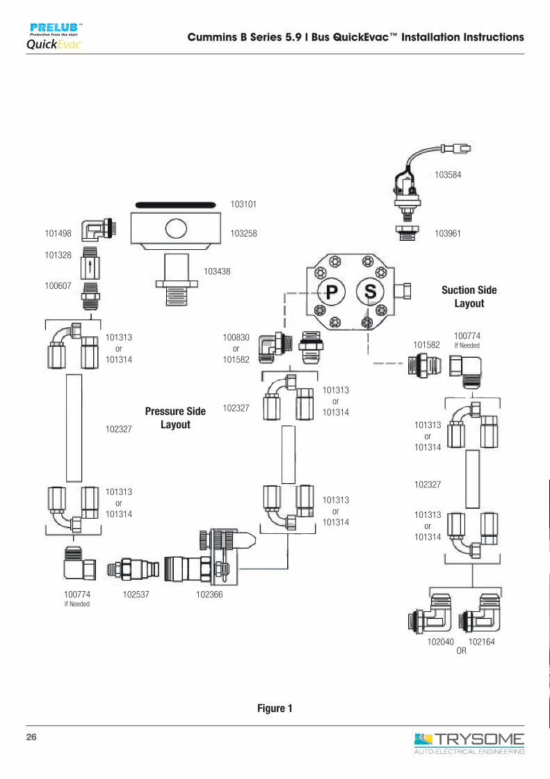
Cummins B Series 5.9 l Bus QuickEvac™ Installation Instructions
Figure 1
103584
103961
103101
103258
103438
100830or
101582
102327
102366
101313or
101314
101313or
101314
101313or
101314101313
or 101314
101313or
101314
101313or
101314
102327
101498
101328
100607
102327
101582
100774If Needed
100774If Needed
102040 102164OR
102537
Suction SideLayout
Pressure SideLayout
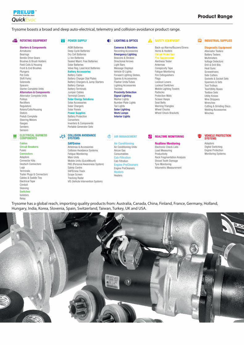
Product Range
Trysome boasts a broad and deep auto-electrical, telemetry and collision-avoidance product range.
Trysome has a global reach, importing quality products from: Australia, Canada, China, Finland, France, Germany, Holland,Hungary, India, Korea, Slovenia, Spain, Switzerland, Taiwan, Turkey, UK and USA.
CablesCircuit BreakersFusesConnectorsAdaptorsConnector KitsDeutsch ConnectorsLugsTerminalsTrailer Plugs & ConnectorsCables & Saddle TiesElectrical TapeConduitSleevingSwitchesIsolatorsRelay
ELECTRICAL HARNESS COMPONENTS
Starters & ComponentsArmatures BearingsBendix Drive GearsBrushes & Brush HoldersField Coils & Housing Front & End BrushesPlungersPot CoilsShift ForksSolenoidsSpacersStarter Complete UnitsAlternators & ComponentsAlternator Complete UnitsPulleysRectifiersRegulatorsRotors/Coils/HousingStatorsPrelub CompleteSteering MotorsGaugesSendersSensors
ROTATING EQUIPMENT
Cameras & MonitorsRecording AccessoriesEmergency LightingBeacons & StrobesDirectional ArrowsLight BarsMessage DisplaysVehicle ID LightsForward Lighting Globes, Spares & AccessoriesFlasher Units/TubesLighting AccessoriesTorchesProximity DetectionSignal LightingMarker LightsNumber Plate LightsTail LightsSolar LightingWork LampsInterior Lights
LIGHTING & OPTICS
Back-up Alarms/Buzzers/SirensHorns & HootersCircuit ProtectionFire SuppressionAlertness Tester AntennasConspicuity TapeFatigue MonitoringFire ExtinguishersFlagsLockout LeversLockout SwitchesMobile Lighting TowersPadlocksProtection MatsScissor HaspsSeat BeltsWarning TrianglesWheel ChocksWheel Chock Brackets
SAFETY EQUIPMENT
AGM BatteriesDeep Cycle BatteriesDry Cell BatteriesLi-Ion BatteriesSealed Maint. Free BatteriesSolar BatteriesValve Reg. Lead Acid BatteriesBattery AccessoriesBattery CableBattery Charger Dial PlatesBattery Chargers & Jump StartersBattery ClampsBattery Terminals Jumper CablesTerminal CoversSolar Energy SolutionsSolar AccessoriesSolar ChargersSolar PanelsPower SuppliesBattery ProtectionConvertersInverters & ComponentsPortable Generator Sets
POWER SUPPLY
Diagnostic EquipmentAlternator TestersBattery TestersMultimetersVoltage DetectorsDrill & Drill BitsHeat GunsScrewdriversSide CuttersSockets & Socket SetsSpanners & SetsTool TrolleysTool/Utility BoxesToolbox SetsUtility KnivesWire StrippersWrenchesCutting & Grinding DiscsWelding AccessoriesWinches
INDUSTRIAL SUPPLIES
SAFEmineAntennas & AccessoriesCollision Avoidance SystemsFatigue MonitoringMain UnitsMobile Units (QuickMount)PAS (Personal Awareness System)Safety CentreSAFEmine TrackScope ScreenTracking RadarVIS (Vehicle Intervention System)
COLLISION AVOIDANCE SYSTEMS
AdaptorsDigital Switching Engine ProtectionMonitoring Systems
VEHICLE PROTECTION SYSTEMS
Air ConditioningAir Conditioning UnitsAircon GasConsumablesCab FiltrationCab FiltrationEngine PreCleanersEngine PreCleanersHeatersHeaters
AIR MANAGEMENT
Realtime MonitoringElectronic Check Lists Load MeasuringProductivityRock Fragmentation AnalysisShovel Tooth DamageTyre Monitoring Volumetric Measurement
REALTIME MONITORING
0062
0
KwaZulu Natal:T: +27 (0)31 303 4129
Gauteng (HO):T: +27 (0)11 823 5650
Northern Cape:T: +27 (0)53 723 3415
Mpumalanga:T: +27 (0)13 692 8132
Free State:T: +27 (0)63 257 0505
North West:T: +27 (0)14 596 5257
Eastern Cape:T: +27 (0)81 036 9111
Western Cape:T: +27 (0)21 945 1453
Zambia:T: +26 (0)21 222 5338
Botswana, Jwaneng:T: +267 588 7617
Mozambique:T: +258 252 20666
Botswana, Letlhakane:T: +267 297 8568
[email protected] • www.trysome.co.za • P.O. Box 13677, Witfield, 1467
Call us today!