storagetek sl150 modular tape library guide - oracle help
TRANSCRIPT
[1]StorageTek SL150 Modular Tape LibraryGuide
E22579-16
December 2018

StorageTek SL150 Modular Tape Library Guide
E22579-16
Copyright © 2018, Oracle and/or its affiliates. All rights reserved.
This software and related documentation are provided under a license agreement containing restrictions onuse and disclosure and are protected by intellectual property laws. Except as expressly permitted in yourlicense agreement or allowed by law, you may not use, copy, reproduce, translate, broadcast, modify, license,transmit, distribute, exhibit, perform, publish, or display any part, in any form, or by any means. Reverseengineering, disassembly, or decompilation of this software, unless required by law for interoperability, isprohibited.
The information contained herein is subject to change without notice and is not warranted to be error-free. Ifyou find any errors, please report them to us in writing.
If this is software or related documentation that is delivered to the U.S. Government or anyone licensing iton behalf of the U.S. Government, then the following notice is applicable:
U.S. GOVERNMENT END USERS: Oracle programs, including any operating system, integrated software,any programs installed on the hardware, and/or documentation, delivered to U.S. Government end usersare "commercial computer software" pursuant to the applicable Federal Acquisition Regulation andagency-specific supplemental regulations. As such, use, duplication, disclosure, modification, andadaptation of the programs, including any operating system, integrated software, any programs installed onthe hardware, and/or documentation, shall be subject to license terms and license restrictions applicable tothe programs. No other rights are granted to the U.S. Government.
This software or hardware is developed for general use in a variety of information managementapplications. It is not developed or intended for use in any inherently dangerous applications, includingapplications that may create a risk of personal injury. If you use this software or hardware in dangerousapplications, then you shall be responsible to take all appropriate fail-safe, backup, redundancy, and othermeasures to ensure its safe use. Oracle Corporation and its affiliates disclaim any liability for any damagescaused by use of this software or hardware in dangerous applications.
Oracle and Java are registered trademarks of Oracle and/or its affiliates. Other names may be trademarks oftheir respective owners.
Intel and Intel Xeon are trademarks or registered trademarks of Intel Corporation. All SPARC trademarksare used under license and are trademarks or registered trademarks of SPARC International, Inc. AMD,Opteron, the AMD logo, and the AMD Opteron logo are trademarks or registered trademarks of AdvancedMicro Devices. UNIX is a registered trademark of The Open Group.
This software or hardware and documentation may provide access to or information about content,products, and services from third parties. Oracle Corporation and its affiliates are not responsible for andexpressly disclaim all warranties of any kind with respect to third-party content, products, and servicesunless otherwise set forth in an applicable agreement between you and Oracle. Oracle Corporation and itsaffiliates will not be responsible for any loss, costs, or damages incurred due to your access to or use ofthird-party content, products, or services, except as set forth in an applicable agreement between you andOracle.
iii
Contents
Preface ............................................................................................................................................................... xiii
Documentation Accessibility ................................................................................................................... xiiiClass 1 Laser Product Notice ................................................................................................................... xiii
1 About the SL150 Library
About the Base Module........................................................................................................................... 1-2About the Expansion Module ................................................................................................................ 1-3About the Mailslot ................................................................................................................................... 1-3About the Robot ....................................................................................................................................... 1-3About Tape Drives ................................................................................................................................... 1-3
About M8 Compatibility ................................................................................................................... 1-4About Library Managed Encryption (LME)................................................................................... 1-4
Behavior of Port 1 and Port 2 .................................................................................................... 1-4About Tape Drives With Two Ports ................................................................................................ 1-5About Bridged Tape Drives.............................................................................................................. 1-5
Library Weights and Dimensions ......................................................................................................... 1-6Library Power Requirements ................................................................................................................. 1-7Library Cartridge Capacity ..................................................................................................................... 1-7Networking and Host Communication................................................................................................ 1-8
SAS-2 and SAS-3 Configuration Issues........................................................................................... 1-8Power Over Ethernet (POE).............................................................................................................. 1-9IPv6 Network Address Support....................................................................................................... 1-9SAN Connection Zoning................................................................................................................... 1-9
Software that Supports the SL150 ......................................................................................................... 1-9About ACSLS (Automated Cartridge System Library Software) ............................................... 1-9About StorageTek Tape Analytics ................................................................................................ 1-10About Service Delivery Platform 2............................................................................................... 1-11
SL150 Part Numbers for Ordering ..................................................................................................... 1-11Configuration and Ordering Examples ....................................................................................... 1-13Ordering Media and Labels .......................................................................................................... 1-13
2 Installing the Library
Verify the Site Meets Environmental Requirements ........................................................................ 2-1Airborne Contaminants Limits ........................................................................................................ 2-1Positive Pressurization and Ventilation - Hot Aisle Containment System (HACS) ................ 2-2
iv
Electrostatic Discharge ...................................................................................................................... 2-3Prepare the Rack ....................................................................................................................................... 2-3Unpack and Acclimate the Library ....................................................................................................... 2-4Install the Base Module .......................................................................................................................... 2-5
Unpack the Base Module Accessory Kit ......................................................................................... 2-5Install the Base Module Back Rails .................................................................................................. 2-6Install the Base Module Front Rails................................................................................................. 2-8
Install Base Module Front Rails Task 1: Connect the Front Rail to the Back Rail.............. 2-8Install Base Module Front Rails Task 2: Secure the Front Rail ............................................. 2-9Install Base Module Front Rails Task 3: Verify Proper Front Rail Installation ............... 2-10Install Base Module Front Rails Task 4: Install the Clip Nuts (square hole racks only) 2-10
Mount the Base Module ................................................................................................................. 2-11Mount the Base Module Task 1: Engage the Base Module with the Rail ........................ 2-12Mount the Base Module Task 2: Remove the Cartridge Magazine with the Hex Key .. 2-12Mount the Base Module Task 3: Remove the Cable Clip................................................... 2-13Mount the Base Module Task 4: Secure the Base Module to the Rack............................. 2-13
Install the Expansion Module............................................................................................................. 2-13Unpack the Expansion Module Accessory Kit ........................................................................... 2-14Remove the Library Floor ............................................................................................................. 2-15Install Clip Nuts for the Expansion Module (for square hole racks only).............................. 2-16Prepare the Expansion Module by Removing the Cartridge Magazines ............................... 2-17Install the Floor in the Bottom Expansion Module .................................................................... 2-18Mount the Expansion Module....................................................................................................... 2-19Install the Rear Rails for the Expansion Module ........................................................................ 2-21Secure the Expansion Module to the Front Rack Stile ............................................................... 2-22Replace the Cartridge Magazines ................................................................................................. 2-22Label the Modules........................................................................................................................... 2-22Install the Hook and Loop Strap................................................................................................... 2-23
Install Power Supplies and Tape Drives .......................................................................................... 2-24Remove the Power Supply Filler .................................................................................................. 2-25Insert a Power Supply into the Slot .............................................................................................. 2-26Remove a Tape Drive Filler ........................................................................................................... 2-26Insert a Tape Drive Tray into the Slot .......................................................................................... 2-26
Cable the Library ................................................................................................................................... 2-27Cable the Library Task 1: Cable the Expansion Modules.......................................................... 2-27Cable the Library Task 2: Connect Cables to the Drive Assembly and Power Supply ........ 2-28Cable the Library Task 3: Connect the Network Port................................................................ 2-28Cable the Library Task 4: Align and Dress the Cables and Cords........................................... 2-29
Unlock the Robot................................................................................................................................... 2-29Unlock the Knob-type Robot Lock (newer version)................................................................... 2-29Unlock the Thumbscrew-type Robot Lock (older version)....................................................... 2-29
Apply Power to the Library ................................................................................................................. 2-30Configure the Library After Powering-on for the First Time ....................................................... 2-30
Configure the Library: Login with the Default Admin ............................................................. 2-30Configure the Library Step 1 of 6: Change the Default Administrator Password................. 2-31Configure the Library Step 2 of 6: Configure the Network Port 1........................................... 2-32Configure the Library Step 3 of 6: Set the Library Date and Time........................................... 2-33
v
Configure the Library Step 4 of 6: Set the Drive Element Addressing Mode) ....................... 2-34Configure the Library Step 5 of 6: Configure the Mailslot, Reserved Slots and Volume LabelFormat 2-34Configure the Library Step 6 of 6: Review and Apply Initialization Settings........................ 2-35Configure the Library: Finish the New Configuration.............................................................. 2-36
Run a Self-Test....................................................................................................................................... 2-36Stopping a Self-test.......................................................................................................................... 2-37
3 Basic User Interface Operations
Using the Remote Interface .................................................................................................................... 3-1Using the Front Touch Screen................................................................................................................ 3-2Log In to the Remote Interface .............................................................................................................. 3-2Configure Accessibility Settings........................................................................................................... 3-3Log Out of the Remote Interface ........................................................................................................... 3-3Change Your Password ........................................................................................................................... 3-3Interpret the Graphical Library Display.............................................................................................. 3-3Show, Hide, and Reorder Table Columns........................................................................................... 3-4Export a Table ........................................................................................................................................... 3-4Print a Table .............................................................................................................................................. 3-4Set Automatic Screen Refresh................................................................................................................ 3-5
4 Configuring the Library
Set the Time, Network Address, Library Settings, and Encryption ............................................... 4-1Run the Configuration Wizard......................................................................................................... 4-1Configure the Network Interfaces ................................................................................................... 4-2
Configure Network Interfaces Task 1: Verify Job Activity and Launch the Wizard ........ 4-2Configure Network Interfaces Task 2: Configure Network Port 1...................................... 4-2Configure Network Interfaces Task 3: Configure Network Port 2 (optional) ................... 4-3
Set the Library Date and Time ......................................................................................................... 4-3Configure Library Settings ............................................................................................................... 4-3
Selecting a Drive Element Addressing Mode ......................................................................... 4-4Partition the Library........................................................................................................................... 4-5
Partition the Library Task 1: Create a New Partition ............................................................ 4-5Partition the Library Task 2: Assign Resources to the Partition .......................................... 4-5Partition the Library Task 3: Delete an Existing Partition .................................................... 4-5Partition the Library Task 4: Verify the Partitioning Configuration Changes................... 4-6
Configure Library Managed Encryption (LME)............................................................................ 4-6Configure LME Task 1: Obtain Information from OKM....................................................... 4-6Configure LME Task 2: Configure the SL150 to Manage Encryption................................. 4-6Configure LME Task 3: Verify the SL150 Agent is Enrolled ................................................ 4-7
Review and Apply Configuration Changes ................................................................................... 4-7Update Library and Drive Firmware .................................................................................................... 4-7
Identify Current Firmware Versions............................................................................................... 4-7Download Firmware from My Oracle Support ............................................................................. 4-7
Verify the Download .................................................................................................................. 4-8Upgrade the Library Firmware........................................................................................................ 4-8
vi
Upgrade the Drive Firmware ........................................................................................................... 4-9Revert to the Previous Library Firmware....................................................................................... 4-9
Manage the Library’s SSL/TLS Certificate for HTTPS .................................................................. 4-10Generate a Self-Signed Certificate ................................................................................................ 4-10Install a Third-Party Signed Certificate ....................................................................................... 4-10
Install a Certificate Task 1: Verify the Library Has a Self-Signed Certificate.................. 4-10Install a Certificate Task 2: Export Certificate Signing Request (CSR) File ..................... 4-10Install a Certificate Task 3: Obtain Required Certificates .................................................. 4-10Install a Certificate Task 4: Import the Certificate File ....................................................... 4-11
5 Managing Users
User Roles and Access ............................................................................................................................. 5-1Add a User and Assign a Role ............................................................................................................... 5-1Remove a User........................................................................................................................................... 5-2Change an Assigned Role ....................................................................................................................... 5-2Reset Another User's Password ............................................................................................................. 5-2
6 Importing and Exporting Cartridges
Viewing Tape Cartridge (Media) Health............................................................................................. 6-1Guidelines for Handling Tape Cartridges .......................................................................................... 6-1
Inspect a Tape Cartridge ................................................................................................................... 6-2Clean the Tape Cartridge Exterior................................................................................................... 6-3Store Tape Cartridges ........................................................................................................................ 6-3
Labeling Cartridges.................................................................................................................................. 6-3Tape Media ID .................................................................................................................................... 6-3Tape Cartridge Types ........................................................................................................................ 6-4Label Format Types ........................................................................................................................... 6-4Non-Standard Label Formats ........................................................................................................... 6-5
Translating Between Physical and Logical Labels ................................................................. 6-5Managing Unidentifiable, Unsupported, or Missing Labels................................................ 6-5
Determine the Required Number of Reserved System Slots .......................................................... 6-5Determine the Number of Cleaning Cartridges................................................................................. 6-6Apply a Label to a Tape Cartridge ........................................................................................................ 6-6Prepare Diagnostic, Cleaning, and Data Tape Cartridges................................................................ 6-7Load the Magazines (Bulk Loading)..................................................................................................... 6-7
Load the Magazines Task 1: Unlock and Remove the Magazines.............................................. 6-7Load the Magazines Task 2: Load the Left Magazine in the Base Module................................ 6-8Load the Magazines Task 3: Load the Remaining Magazines..................................................... 6-9Load the Magazines Task 4: Locking the Magazines and Auditing the Library...................... 6-9Updating Media Health After a Bulk Load.................................................................................... 6-9
Import and Export Cartridges Using the Mailslot ............................................................................. 6-9Assign the Mailslot to a Partition.................................................................................................. 6-10
Assign the Mailslot Using the Remote User Interface........................................................ 6-10Assign the Mailslot Using the Local Operator Panel.......................................................... 6-10
Import Tape Cartridges.................................................................................................................. 6-10Export Tape Cartridges .................................................................................................................. 6-10Open the Mailslot ............................................................................................................................ 6-10

vii
Close the Mailslot ........................................................................................................................... 6-11Unassign the Mailslot ..................................................................................................................... 6-11
Unassign the Mailslot Using the Remote User Interface.................................................... 6-11Unassign the Mailslot Using the Local Operator Panel ..................................................... 6-11
Move Tape Cartridges with the Remote Interface.......................................................................... 6-11
7 Monitoring the Library
View User and Host Activity ................................................................................................................. 7-1View the Library State............................................................................................................................. 7-1
Library LED Status Indicators.......................................................................................................... 7-1Determine the Possible Cause of a Degraded or Failed Library State ....................................... 7-2
Configure Simple Network Management Protocol (SNMP) ........................................................... 7-2SNMP Versions................................................................................................................................... 7-3SNMP Traps........................................................................................................................................ 7-3Enable or Disable SNMP................................................................................................................... 7-4Configure an SNMP User ................................................................................................................. 7-4Configure an SNMP Trap Recipient................................................................................................ 7-4Send a Test Trap ................................................................................................................................. 7-5Download the Management Information Base (MIB)................................................................... 7-5
Enable or Disable the Service Delivery Platform (SDP2) ................................................................ 7-5Configure Email Notifications............................................................................................................... 7-5
Enable or Disable Email Notifications ............................................................................................ 7-6Configure Email Recipients .............................................................................................................. 7-6Send a Test Email Alert ..................................................................................................................... 7-6
8 Managing Tape Drives
Viewing Current Drive State ................................................................................................................. 8-1Configure Drive Cleaning ...................................................................................................................... 8-1
Enable Library-Managed Drive Auto Cleaning ............................................................................ 8-2Configure Host-Managed Drive Cleaning ..................................................................................... 8-2
Configure Automatic Cleaning in Oracle Secure Backup During Drive Setup................. 8-2Set Up NetBackup for Reactive Cleaning Using the Administration Console..................... 8-3Set Up NetBackup for Reactive Cleaning Using the Commandline ...................................... 8-3Set Up Symantec Backup Exec Drive Cleaning ...................................................................... 8-3Set Up Reactive Cleaning for HP StorageWorks Enterprise Backup Solution with HP DataProtector 8-3Set Up As-Needed Cleaning in IBM Tivoli Storage Manager (TSM)...................................... 8-4Set Up Tape-Alert Cleaning in EMC Networker....................................................................... 8-4Set Up CommVault Drive Cleaning......................................................................................... 8-4
Manually Clean a Drive .................................................................................................................... 8-4Check for Drives that Require Cleaning.................................................................................. 8-4Use the Remote Interface to Clean a Degraded Drive........................................................... 8-5
Manage Expired Cleaning Cartridges .................................................................................................. 8-5Monitor Cleaning Cartridges Using the Remote Interface ......................................................... 8-5Replace Expired Cleaning Media Using the Remote Interface ................................................... 8-5Replace Expired Cleaning Media Using the Host Application ................................................... 8-6
viii
Restart a Drive........................................................................................................................................... 8-6Update Drive Firmware........................................................................................................................... 8-6
9 Servicing the Library
Place the Library Online and Offline................................................................................................... 9-1Power On the Library .............................................................................................................................. 9-2
Library Startup Sequence.................................................................................................................. 9-2Power Off the Library.............................................................................................................................. 9-2
Controlled Power-Down from the Interface .................................................................................. 9-2Forced Power-Down ......................................................................................................................... 9-3Lock the Robot .................................................................................................................................... 9-3
Lock the Knob-type Robot Lock (new version) ...................................................................... 9-3Lock the Thumbscrew-type Robot Lock (older version)....................................................... 9-4
Restart the Library.................................................................................................................................... 9-4Restarting the Library Following a Power Outage ....................................................................... 9-4
Audit the Library ...................................................................................................................................... 9-4Move the Library Rack ............................................................................................................................ 9-5Enable the Locate Light ........................................................................................................................... 9-6Troubleshoot the Library ........................................................................................................................ 9-6
Diagnose a Browser-Based User Interface Problem...................................................................... 9-6Diagnose a Library Problem............................................................................................................. 9-6
Diagnose a Problem if You Cannot Login to the Remote Interface..................................... 9-6Use the Health Table to Diagnose the Issue............................................................................ 9-7Check if Fault is Closed in the Health Log.............................................................................. 9-8Locate and Remove a Cartridge Stuck in a Magazine Slot ................................................... 9-8Locate and Clear Obstructions, Such as Loose or Protruding Cartridges.......................... 9-9Save the Health Log to a File..................................................................................................... 9-9Run a Self-Test............................................................................................................................. 9-9
Restore the Factory Default Configuration ................................................................................. 9-10Get Parts and Technical Support........................................................................................................ 9-11
Check for Relevant Knowledge Articles...................................................................................... 9-11Get Firmware Updates ................................................................................................................... 9-11Create a Service Request ................................................................................................................ 9-11
10 Replacing Components (CRUs & FRUs)
CRU Locations ....................................................................................................................................... 10-1Drive Tray Removal and Replacement ............................................................................................. 10-2
Remove the Drive Tray .................................................................................................................. 10-2Replace the Drive Tray ................................................................................................................... 10-3
Replace the Drive Tray Task 1: Remove New Drive Tray from Package........................ 10-3Replace the Drive Tray Task 2: Replace the Drive Tray..................................................... 10-3Replace the Drive Tray Task 3: Verify the Library Recognized the New Drive Tray.... 10-3
Remove a Drive Filler ..................................................................................................................... 10-4Install a Drive Filler ........................................................................................................................ 10-4
Power Supply Removal and Replacement ....................................................................................... 10-4Remove the Power Supply............................................................................................................. 10-4Replace the Power Supply ............................................................................................................. 10-4
ix
Remove a Power Supply Filler...................................................................................................... 10-5Install a Power Supply Filler ......................................................................................................... 10-5
Front Control Panel Removal and Replacement ............................................................................. 10-5Remove the Front Control Panel................................................................................................... 10-6Replace the Front Control Panel ................................................................................................... 10-6
Module Controller Removal and Replacement............................................................................... 10-7Remove the Module Controller..................................................................................................... 10-7Replace the Module Controller ..................................................................................................... 10-8
Robot Module Removal and Replacement ...................................................................................... 10-8Remove the Robot ........................................................................................................................... 10-9
Remove the Robot Task 1: Park and Lock the Robot.......................................................... 10-9Remove the Robot Task 2: Slide Robot CRU Out of Base Module ................................... 10-9
Manually Retract the Robot ........................................................................................................ 10-10Manually Disengage the Robot ................................................................................................... 10-11
Manually Disengage the Robot Task 1: Cut Cables .......................................................... 10-11Manually Disengage the Robot Task 2: Remove the Robot CRU ................................... 10-11Manually Disengage the Robot Task 3: Remove the Z Platform .................................... 10-12Manually Disengage the Robot Task 4: Clean Up............................................................. 10-12
Replace the Robot.......................................................................................................................... 10-12Replace the Robot Task 1: Reinsert the Robot CRU and Unlock the Robot .................. 10-12Replace the Robot Task 2: Cabling ...................................................................................... 10-12
Expansion Module Chassis Removal and Replacement (FRU).................................................. 10-13Remove an Expansion Module ................................................................................................... 10-13
Remove Expansion Task 1: Power Down, Lock the Robot, and Remove Magazines.. 10-13Remove Expansion Task 2: Remove the Floor, Cables, and Cords ................................ 10-14Remove Expansion Task 3: Remove Operational Expansion Modules Below the DefectiveModule 10-14Remove Expansion Task 4: Remove Components from the Defective Module ........... 10-15
Replace the Expansion FRU Chassis .......................................................................................... 10-15Replace Expansion Task 1: Install the Chassis................................................................... 10-15Replace Expansion Task 2: Install CRUs, Fillers, and Magazines in Replaced Module...........10-16Replace Expansion Task 3: Install the Remaining Expansion Modules......................... 10-16Replace Expansion Task 4: Finishing Touches .................................................................. 10-16
Base Module (Module 1) Chassis Removal and Replacement ................................................... 10-16Remove the Base Module Chassis .............................................................................................. 10-17
Remove Base Task 1: Lock the Robot and Remove Expansion Modules ...................... 10-17Remove Base Task 2: Remove Module and Remove Parts for Reuse ............................ 10-17
Replace the Base Module Chassis ............................................................................................... 10-18Replace Base Task 1: Install the Base Module FRU........................................................... 10-18Replace Base Task 2: Install the Base Module CRUs and Expansion Modules ............ 10-18Replace Base Task 3: Reinstall Magazines and Dress the Cables.................................... 10-18
Validate the Component Installation .............................................................................................. 10-19Return CRU Components to Oracle ................................................................................................ 10-20Lock the Robot for Reshipment within Rack ................................................................................ 10-20
Power Down the Library and Verify Robot Position............................................................... 10-20Install the Shipping Clip .............................................................................................................. 10-20

x
A Slot Mapping and Cartridge Locations
Cartridge Slot Addressing ..................................................................................................................... A-1Reserved Slots.................................................................................................................................... A-1
Drive, Mailslot, Power Supply, and Robot Addressing .................................................................. A-1SCSI Element Addressing ..................................................................................................................... A-2Example Library Configurations and Slot Maps ............................................................................. A-2
Glossary

xi
List of Figures
1–1 Base Module and Two Expansion Modules (Front View) ................................................... 1-11–2 Base Module and Expansion Modules (Rear View) .............................................................. 1-22–1 Rear View of Sun Rack II (PDU on Right Side) ...................................................................... 2-42–2 Base Module Accessory Package Mounting Hardware ........................................................ 2-62–3 Back Rail Position........................................................................................................................ 2-72–4 Back Rails Installed ..................................................................................................................... 2-72–5 Front Rail Installation (Left Rail Shown) ................................................................................. 2-92–6 Mounting Block for Front Rail (Right Rail Shown)................................................................ 2-92–7 Rails Installed - Front View ................................................................................................... 2-102–8 Clip Nut Location for the Base Module................................................................................ 2-112–9 Tab and Rail Engagement....................................................................................................... 2-112–10 Cable Clip Removal ................................................................................................................. 2-132–11 Expansion Module ................................................................................................................... 2-142–12 Expansion Module Accessory Package Hardware ............................................................. 2-152–13 Library Floor Removal from the Base Module .................................................................... 2-162–14 Expansion Module Installation .............................................................................................. 2-172–15 Magazine Latches.................................................................................................................... 2-182–16 Library Floor ............................................................................................................................. 2-192–17 Floor Secured ............................................................................................................................ 2-192–18 Scratch Avoidance ................................................................................................................... 2-202–19 Alignment Tab Seated ............................................................................................................. 2-212–20 Expansion Module Back Rail and Clip Nut ......................................................................... 2-212–21 Expansion Module ID Label................................................................................................... 2-232–22 Hook and Loop Strap .............................................................................................................. 2-232–23 SL150 Library Rear View ........................................................................................................ 2-242–24 Power Supply ........................................................................................................................... 2-252–25 Tape Drive Tray ....................................................................................................................... 2-252–26 Base Module Output Ports (ports 2 through 10) ................................................................. 2-272–27 Module Controller Ports (Output port shown with dust cover) ...................................... 2-282–28 Initial Cabling ........................................................................................................................... 2-283–1 Front Control Panel Home Screen............................................................................................ 3-26–1 Correct Label Orientation .......................................................................................................... 6-610–1 Tape Drive Tray CRU (HP LTO-5) ........................................................................................ 10-210–2 Power Supply CRU.................................................................................................................. 10-410–3 Rear View of the Front Control Panel ................................................................................... 10-510–4 Bullwheel Gear and Robot Lock .......................................................................................... 10-1110–5 Expansion Module FRU........................................................................................................ 10-1310–6 Module Rear Rail Removal................................................................................................... 10-1510–7 Base Module FRU................................................................................................................... 10-1710–8 Cable Attachment .................................................................................................................. 10-19A–1 Non-Partitioned One Module Library, Standard Mailslot, and No Reserved Cells ....... A-2A–2 Non-Partitioned Two Module Library, Expanded Mailslot, and No Reserved Cells ..... A-3A–3 Non-Partitioned 15 Module Library, Standard Mailslot, and Three Reserved Cells....... A-4

xii
List of Tables
1–1 Port Configuration Options...................................................................................................... 1-41–2 Shipping (Packaged) Weights and Dimensions .................................................................... 1-61–3 Component (Unpackaged) Weights and Dimensions.......................................................... 1-61–4 Storage Slot, Mailslot, and Drive Counts for Different Configurations............................. 1-72–1 Gas Limit Recommendations ................................................................................................... 2-27–1 SNMP Trap Levels ..................................................................................................................... 7-3A–1 Starting Element Address and Maximum Number of Elements ....................................... A-2
xiii
Preface
This guide is intended for anyone involved with installation planning or the orderingof Oracle’s StorageTek SL150 Modular Tape Library.
Documentation AccessibilityFor information about Oracle's commitment to accessibility, visit the OracleAccessibility Program website athttp://www.oracle.com/pls/topic/lookup?ctx=acc&id=docacc.
Access to Oracle SupportOracle customers that have purchased support have access to electronic supportthrough My Oracle Support. For information, visithttp://www.oracle.com/pls/topic/lookup?ctx=acc&id=info or visithttp://www.oracle.com/pls/topic/lookup?ctx=acc&id=trs if you are hearingimpaired.
Class 1 Laser Product NoticeThe StorageTek SL150 Modular Tape Library contains a class-1 laser as defined by IEC60825-1 Ed. 3 (2014) and EN 60825-1:2014.
Warning: Use of controls or adjustments or performance ofprocedures other than those specified may result in hazardousradiation exposure.

xiv
1
About the SL150 Library 1-1
1About the SL150 Library
[2]This chapter provides an overview of Oracle’s StorageTek SL150 Modular TapeLibrary, which is a scalable, rack-mounted, modular automated tape library.
■ About the Base Module
■ About the Expansion Module
■ About the Mailslot
■ About the Robot
■ About Tape Drives
■ Library Weights and Dimensions
■ Library Power Requirements
■ Library Cartridge Capacity
■ Networking and Host Communication
■ Software that Supports the SL150
■ SL150 Part Numbers for Ordering
The SL150 library has two module types: the Base Module and Expansion. Eachmodule has two drive slots and stores up to 30 tapes in two 15-slot magazine (one onthe left side and the other on the right side). Additionally, a four slot Mailslots residesin the base module for entering or ejecting tapes.
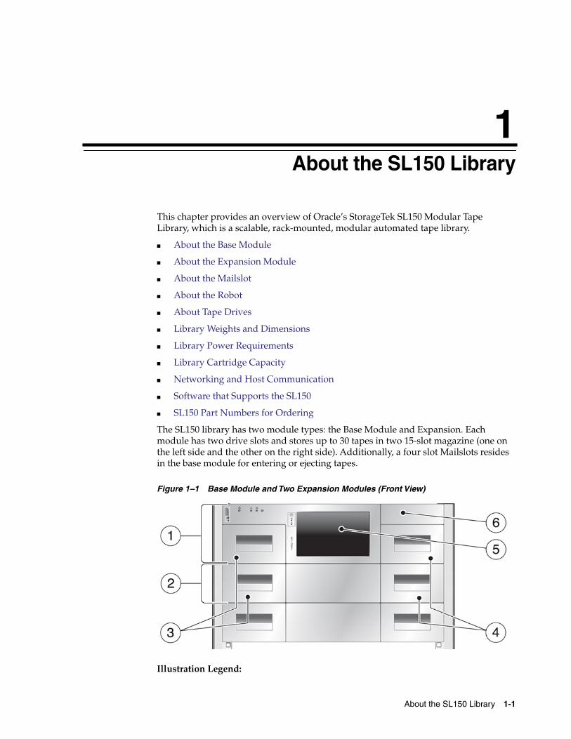
Figure 1–1 Base Module and Two Expansion Modules (Front View)
Illustration Legend:
About the Base Module
1-2 StorageTek SL150 Modular Tape Library Guide
1 - Base module (Module 1)2 - Expansion module (Module 2)3 - Left cartridge magazines4 - Right cartridge magazines5 - Front control panel6 - Mailslot
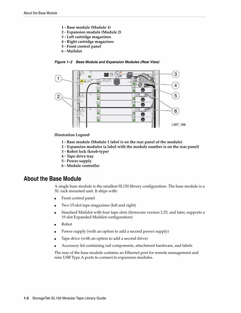
Figure 1–2 Base Module and Expansion Modules (Rear View)
Illustration Legend:
1 - Base module (Module 1 label is on the rear panel of the module)2 - Expansion modules (a label with the module number is on the rear panel)3 - Robot lock (knob-type)4 - Tape drive tray5 - Power supply6 - Module controller
About the Base ModuleA single base module is the smallest SL150 library configuration. The base module is a3U rack mounted unit. It ships with:
■ Front control panel
■ Two 15-slot tape magazines (left and right)
■ Standard Mailslot with four tape slots (firmware version 2.25, and later, supports a19 slot Expanded Mailslot configuration)
■ Robot
■ Power supply (with an option to add a second power supply)
■ Tape drive (with an option to add a second drive)
■ Accessory kit containing rail components, attachment hardware, and labels
The rear of the base module contains an Ethernet port for remote management andnine USB Type A ports to connect to expansion modules.
About Tape Drives
About the SL150 Library 1-3
About the Expansion ModuleAn expansion module provides additional cartridge storage and tape drive capacity.Expansion modules are installed below the base module. The base module connects toeach of the expansion modules using a USB Type A connector.
Expansion modules ship without tape drives or power supplies. The expansionmodule can contain up to two drives and two power supplies. If there is no tape drive,the expansion module can operate off of the power provided by the USB cable, it doesnot require a power supply. If you install a drive in the expansion module, you mustalso install at least one power supply. You can add a second power supply forredundancy, however one power supply can provide power for two drive.
Each expansion module requires 2U of rack space. An expansion module ships with:
■ Two 15-slot tape magazines (left and right)
■ Module controller
■ Expansion cable that has two USB Type A connectors
■ Mounting hardware to secure the module to the rack
■ Identification labels
About the MailslotThe four cartridge mailslot is located above the right magazine in the base module.The mailslot to imports and exports cartridges without interfering with robotoperations. See "Import and Export Cartridges Using the Mailslot" on page 6-9.
19-slot Expanded MailslotThe expanded mailslot configuration converts a 15-slot magazine into an additionalmailslot. Configuring the expanded mailslot requires library firmware versions 2.25and later.
About the RobotThe robot automatically retrieves and inserts cartridges into the mailslot, storage cells,and tape drives. Within the base module, a bull wheel and pulley rotate to raise andlower the robot hand, which contains a label barcode scanner and retractable grippersto grab and release cartridges.
See Also:
■ "Robot Module Removal and Replacement" on page 10-8
■ "Unlock the Robot" on page 2-29
■ "Lock the Robot" on page 9-3
About Tape DrivesThe SL150 library supports the following tape drives. You can install a mix of HP andIBM drives of various generations within the library.
■ HP LTO half-height generation 5 or 6 SAS or short wavelength FC interface
■ IBM LTO half-height generation 6, 7, or 8 SAS or short wavelength FC interface
About Tape Drives
1-4 StorageTek SL150 Modular Tape Library Guide
See Also
■ "Managing Tape Drives" on page 8-1
■ "Upgrade the Drive Firmware" on page 4-9
■ "Labeling Cartridges" on page 6-3
About M8 CompatibilityWith library code 3.50 and above, the library supports the M8 cartridge type, which isan LTO7 cartridge initialized to a 9TB capacity by an LTO8 drive (instead of thestandard 6TB capacity of a standard LTO7 cartridge).
For an LTO8 drive to initialize an LTO7 cartridge to M8, the cartridge must be new(unused) and contain an M8 label. Only LTO8 drives can read and write M8 cartridges.
About Library Managed Encryption (LME)With library code 3.50 and above, the library can manage the enrollment and keydelivery for IBM LTO-7 and higher drives. Each drive that you enroll still requires anencryption activation file. However, with LME, the library is the OKM agent instead ofindividual drives, meaning you only need to enroll the library with OKM rather thanindividual drives. You will still need to use VOP to enroll HP LTO-6 or lower drives.
For more information on configuring library managed encryption, see "ConfigureLibrary Managed Encryption (LME)" on page 4-6.
For more information on the behavior of the ports, see "Behavior of Port 1 and Port 2"on page 1-4.
Behavior of Port 1 and Port 2With library code 3.50 and above, you can configure Network Port 2 for librarymanaged encryption (LME). Enabling LME on Port 2 changes the behavior of theports. If you do not configure Port 2, the behavior of the ports continues to function asbefore (with Port 1 sending UI, SNMP, and email alerts (SMTP) traffic, and Port 2reserved for service use).
Note: LTO-5, 6, and 7 drives can read two generations back andwrite one generation back. LTO-8 drives can read and write onegeneration back. For best capacity and performance, always usecartridges of the same generation as your drives.
IMPORTANT: If you plan to configure Port 2, use a separate subnetand gateway than Port 1, otherwise all traffic will go through Port 1.
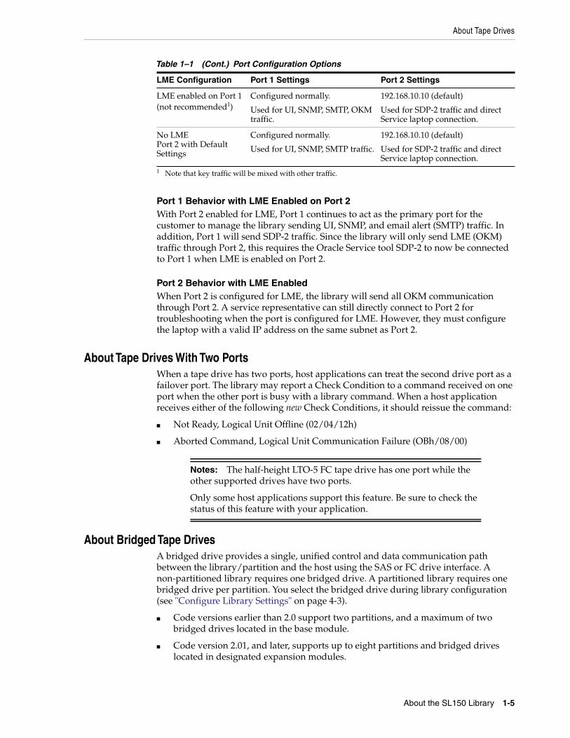
Table 1–1 Port Configuration Options
LME Configuration Port 1 Settings Port 2 Settings
LME enabled on Port 2 Configured normally.
Used for UI, SNMP, SMTP, SDP-2traffic.
New address with differentsubnet and gateway than Port 1.
Used for OKM traffic only.
About Tape Drives
About the SL150 Library 1-5
Port 1 Behavior with LME Enabled on Port 2With Port 2 enabled for LME, Port 1 continues to act as the primary port for thecustomer to manage the library sending UI, SNMP, and email alert (SMTP) traffic. Inaddition, Port 1 will send SDP-2 traffic. Since the library will only send LME (OKM)traffic through Port 2, this requires the Oracle Service tool SDP-2 to now be connectedto Port 1 when LME is enabled on Port 2.
Port 2 Behavior with LME EnabledWhen Port 2 is configured for LME, the library will send all OKM communicationthrough Port 2. A service representative can still directly connect to Port 2 fortroubleshooting when the port is configured for LME. However, they must configurethe laptop with a valid IP address on the same subnet as Port 2.
About Tape Drives With Two PortsWhen a tape drive has two ports, host applications can treat the second drive port as afailover port. The library may report a Check Condition to a command received on oneport when the other port is busy with a library command. When a host applicationreceives either of the following new Check Conditions, it should reissue the command:
■ Not Ready, Logical Unit Offline (02/04/12h)
■ Aborted Command, Logical Unit Communication Failure (OBh/08/00)
About Bridged Tape DrivesA bridged drive provides a single, unified control and data communication pathbetween the library/partition and the host using the SAS or FC drive interface. Anon-partitioned library requires one bridged drive. A partitioned library requires onebridged drive per partition. You select the bridged drive during library configuration(see "Configure Library Settings" on page 4-3).
■ Code versions earlier than 2.0 support two partitions, and a maximum of twobridged drives located in the base module.
■ Code version 2.01, and later, supports up to eight partitions and bridged driveslocated in designated expansion modules.
LME enabled on Port 1(not recommended1)
Configured normally.
Used for UI, SNMP, SMTP, OKMtraffic.
192.168.10.10 (default)
Used for SDP-2 traffic and directService laptop connection.
No LMEPort 2 with DefaultSettings
Configured normally.
Used for UI, SNMP, SMTP traffic.
192.168.10.10 (default)
Used for SDP-2 traffic and directService laptop connection.
1 Note that key traffic will be mixed with other traffic.
Notes: The half-height LTO-5 FC tape drive has one port while theother supported drives have two ports.
Only some host applications support this feature. Be sure to check thestatus of this feature with your application.
Table 1–1 (Cont.) Port Configuration Options
LME Configuration Port 1 Settings Port 2 Settings
Library Weights and Dimensions
1-6 StorageTek SL150 Modular Tape Library Guide
You must connect the bridged drive to an HBA supporting multiple LUNs (alsoreferred to as LUN scanning). The SL150 Library uses a single SCSI ID and two logicalunit numbers (LUN). LUN 0 controls the tape drive and LUN 1 which is configured asa SCSI medium changer device controls the robotics. Data is sent to the remainingLUN on the bridged drive or to LUNs on the other, unbridged drives in the partition,all of which are configured as SCSI sequential-access (tape) devices.
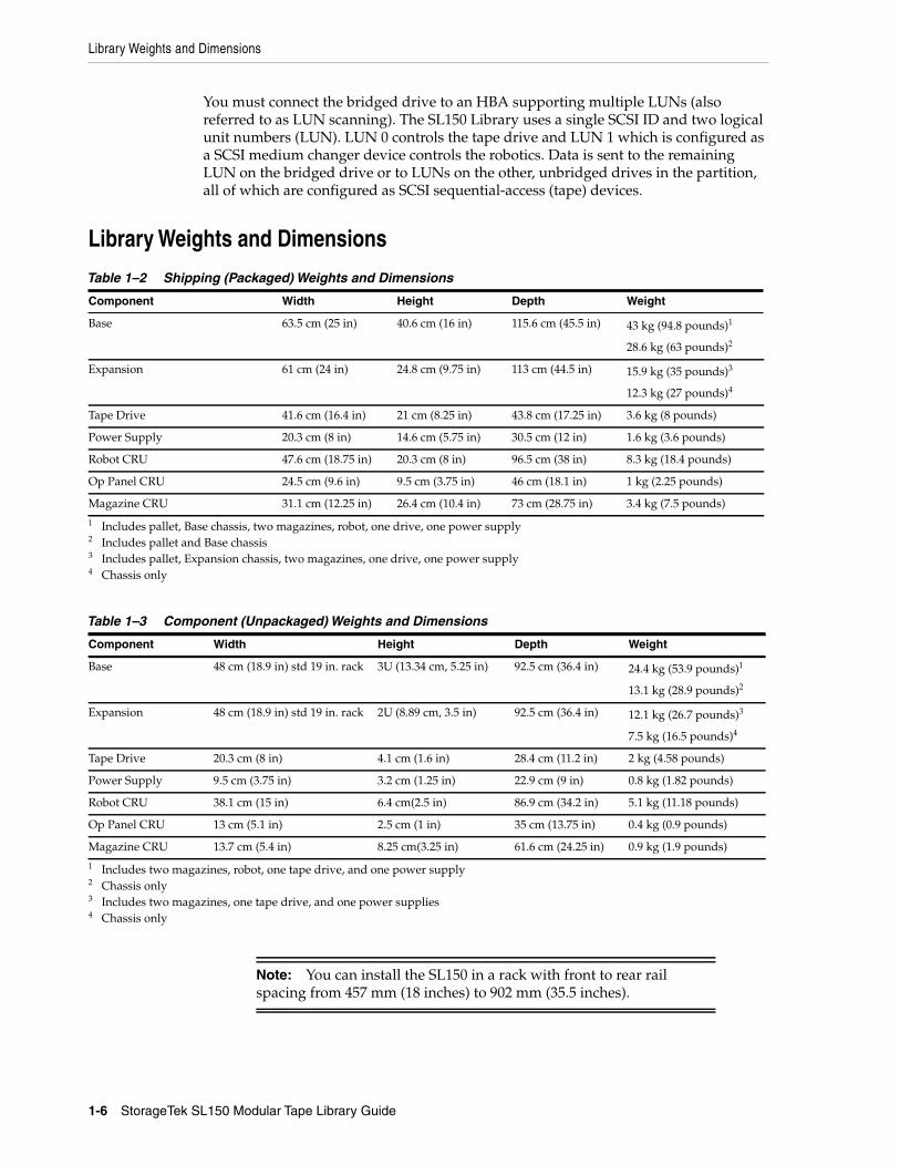
Library Weights and Dimensions
Table 1–2 Shipping (Packaged) Weights and Dimensions
Component Width Height Depth Weight
Base 63.5 cm (25 in) 40.6 cm (16 in) 115.6 cm (45.5 in) 43 kg (94.8 pounds)1
28.6 kg (63 pounds)2
1 Includes pallet, Base chassis, two magazines, robot, one drive, one power supply2 Includes pallet and Base chassis
Expansion 61 cm (24 in) 24.8 cm (9.75 in) 113 cm (44.5 in) 15.9 kg (35 pounds)3
12.3 kg (27 pounds)4
3 Includes pallet, Expansion chassis, two magazines, one drive, one power supply4 Chassis only
Tape Drive 41.6 cm (16.4 in) 21 cm (8.25 in) 43.8 cm (17.25 in) 3.6 kg (8 pounds)
Power Supply 20.3 cm (8 in) 14.6 cm (5.75 in) 30.5 cm (12 in) 1.6 kg (3.6 pounds)
Robot CRU 47.6 cm (18.75 in) 20.3 cm (8 in) 96.5 cm (38 in) 8.3 kg (18.4 pounds)
Op Panel CRU 24.5 cm (9.6 in) 9.5 cm (3.75 in) 46 cm (18.1 in) 1 kg (2.25 pounds)
Magazine CRU 31.1 cm (12.25 in) 26.4 cm (10.4 in) 73 cm (28.75 in) 3.4 kg (7.5 pounds)
Table 1–3 Component (Unpackaged) Weights and Dimensions
Component Width Height Depth Weight
Base 48 cm (18.9 in) std 19 in. rack 3U (13.34 cm, 5.25 in) 92.5 cm (36.4 in) 24.4 kg (53.9 pounds)1
13.1 kg (28.9 pounds)2
1 Includes two magazines, robot, one tape drive, and one power supply2 Chassis only
Expansion 48 cm (18.9 in) std 19 in. rack 2U (8.89 cm, 3.5 in) 92.5 cm (36.4 in) 12.1 kg (26.7 pounds)3
7.5 kg (16.5 pounds)4
3 Includes two magazines, one tape drive, and one power supplies4 Chassis only
Tape Drive 20.3 cm (8 in) 4.1 cm (1.6 in) 28.4 cm (11.2 in) 2 kg (4.58 pounds)
Power Supply 9.5 cm (3.75 in) 3.2 cm (1.25 in) 22.9 cm (9 in) 0.8 kg (1.82 pounds)
Robot CRU 38.1 cm (15 in) 6.4 cm(2.5 in) 86.9 cm (34.2 in) 5.1 kg (11.18 pounds)
Op Panel CRU 13 cm (5.1 in) 2.5 cm (1 in) 35 cm (13.75 in) 0.4 kg (0.9 pounds)
Magazine CRU 13.7 cm (5.4 in) 8.25 cm(3.25 in) 61.6 cm (24.25 in) 0.9 kg (1.9 pounds)
Note: You can install the SL150 in a rack with front to rear railspacing from 457 mm (18 inches) to 902 mm (35.5 inches).
Library Cartridge Capacity
About the SL150 Library 1-7
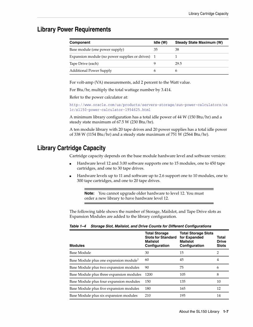
Library Power Requirements
For volt-amp (VA) measurements, add 2 percent to the Watt value.
For Btu/hr, multiply the total wattage number by 3.414.
Refer to the power calculator at:
http://www.oracle.com/us/products/servers-storage/sun-power-calculators/calc/sl150-power-calculator-1954625.html
A minimum library configuration has a total idle power of 44 W (150 Btu/hr) and asteady state maximum of 67.5 W (230 Btu/hr).
A ten module library with 20 tape drives and 20 power supplies has a total idle powerof 338 W (1154 Btu/hr) and a steady state maximum of 751 W (2564 Btu/hr).
Library Cartridge CapacityCartridge capacity depends on the base module hardware level and software version:
■ Hardware level 12 and 3.00 software supports one to 15 modules, one to 450 tapecartridges, and one to 30 tape drives.
■ Hardware levels up to 11 and software up to 2.6 support one to 10 modules, one to300 tape cartridges, and one to 20 tape drives.
The following table shows the number of Storage, Mailslot, and Tape Drive slots asExpansion Modules are added to the library configuration.
Component Idle (W) Steady State Maximum (W)
Base module (one power supply) 35 38
Expansion module (no power supplies or drives) 1 1
Tape Drive (each) 9 29.5
Additional Power Supply 6 6
Note: You cannot upgrade older hardware to level 12. You mustorder a new library to have hardware level 12.
Table 1–4 Storage Slot, Mailslot, and Drive Counts for Different Configurations
Modules
Total StorageSlots for StandardMailslotConfiguration
Total Storage Slotsfor ExpandedMailslotConfiguration
TotalDriveSlots
Base Module 30 15 2
Base Module plus one expansion module1 60 45 4
Base Module plus two expansion modules 90 75 6
Base Module plus three expansion modules 1200 105 8
Base Module plus four expansion modules 150 135 10
Base Module plus five expansion modules 180 165 12
Base Module plus six expansion modules 210 195 14
Networking and Host Communication
1-8 StorageTek SL150 Modular Tape Library Guide
Networking and Host CommunicationThe library uses Ethernet cables for network connections. Always use shieldedEthernet cables to connect to a drive installed in a library.
■ SAS-2 and SAS-3 Configuration Issues
■ Power Over Ethernet (POE)
■ IPv6 Network Address Support
■ SAN Connection Zoning
SAS-2 and SAS-3 Configuration Issues
The SAS driver only allows one device driver to attach per device (sg, sgen, st, and soforth). Users must have every component in the following list to be affected:
■ Oracle Solaris 10 (Update 8 or later) or Solaris 11 (11.1 and later)
■ Any SAS-2 or SAS-3 HBA
■ Tape drives or libraries using a SAS-2 or SAS-3 connection
■ A backup application that requires multiple SAS drivers. The most commonbackup applications that use multiple device drivers include:
– CA ARCserve
– HP Data Protector
– IBM Tivoli Storage Manager
A SAS tape drive attached through a SAS-2 or SAS-3 HBA will work on the Solarissystem using just the Solaris native commands such as dd or tar. However, thisconfiguration is recommended for a stand-alone drive only.
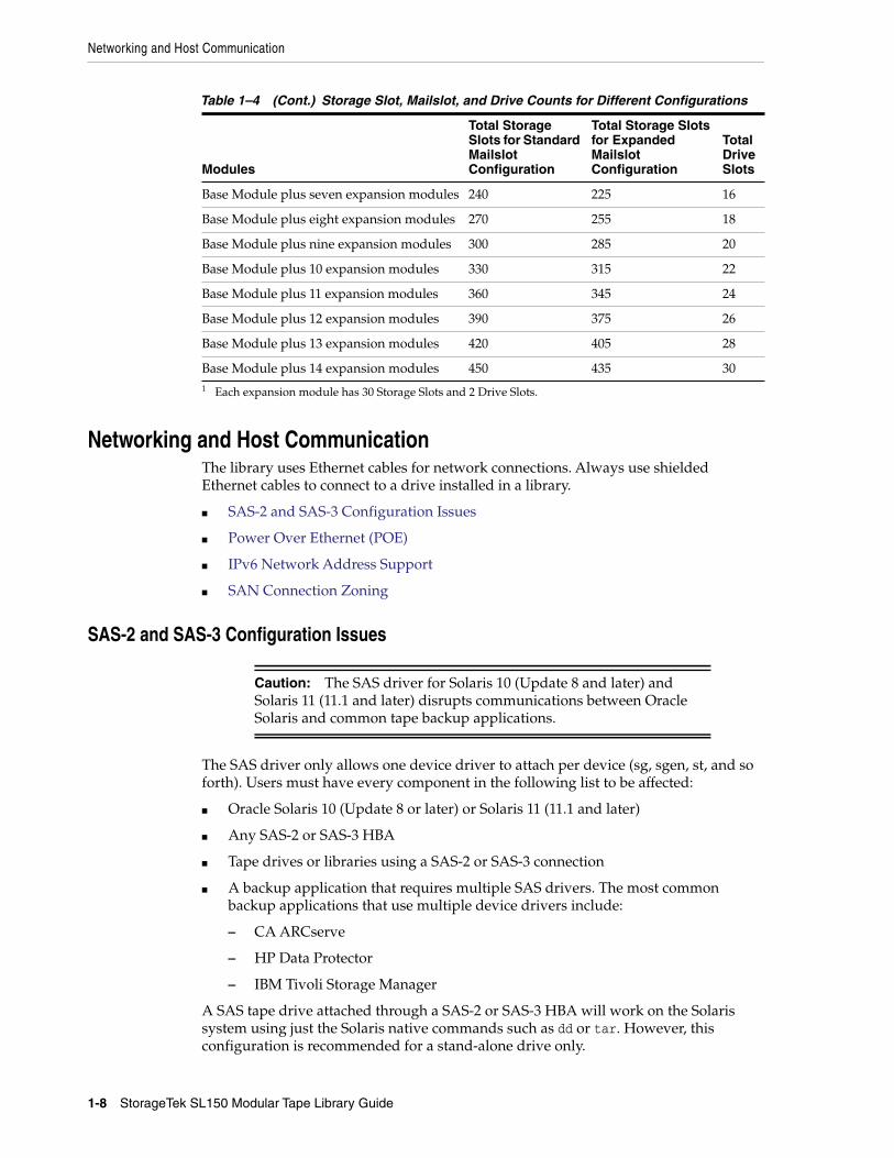
Base Module plus seven expansion modules 240 225 16
Base Module plus eight expansion modules 270 255 18
Base Module plus nine expansion modules 300 285 20
Base Module plus 10 expansion modules 330 315 22
Base Module plus 11 expansion modules 360 345 24
Base Module plus 12 expansion modules 390 375 26
Base Module plus 13 expansion modules 420 405 28
Base Module plus 14 expansion modules 450 435 301 Each expansion module has 30 Storage Slots and 2 Drive Slots.
Caution: The SAS driver for Solaris 10 (Update 8 and later) andSolaris 11 (11.1 and later) disrupts communications between OracleSolaris and common tape backup applications.
Table 1–4 (Cont.) Storage Slot, Mailslot, and Drive Counts for Different Configurations
Modules
Total StorageSlots for StandardMailslotConfiguration
Total Storage Slotsfor ExpandedMailslotConfiguration
TotalDriveSlots
Software that Supports the SL150
About the SL150 Library 1-9
If you want to use Oracle Solaris 10 (Update 8 and later) or Solaris 11 (11.1 and later)and a SAS-2 or SAS-3 HBA, you should use one of the following backup applications:
■ Oracle Secure Backup (OSB): 10.4.0.2 or later
■ EMC Networker: current release level with all patches applied
■ Symantec NetBackup: current release level with all patches applied
Power Over Ethernet (POE)Network switches providing power over Ethernet (POE) must be IEEE certified.
IPv6 Network Address SupportLibrary firmware versions 2.0 and later support a dual-stack network configurationthat uses both IPv4 and IPv6. In dual-stack mode, the library continues to recognizeIPv4 addresses while adding the use of IPv6 addresses. To configure the networkaddress, see "Configure the Network Interfaces" on page 4-2.
Always consult with the network administrator before configuring or changing IPv6addressing and to get the length of the network prefix for your location.
SAN Connection ZoningThe library can be connected to the host HBA through a storage area network (SAN).Configure zoning on the FC switch so only the backup servers access the library.
ZoningUse zoning to partition a SAN into logical groupings of devices so that each group isisolated from the other and can only access the devices in its own group. Two types ofzoning exist: Hardware zoning (based on physical fabric port number) and Softwarezoning (defined with the World Wide Node Name (WWNN) or World Wide PortName (WWPN)).
The dynamic World Wide Name (dWWN) feature assigns world wide names to thelibrary drive slots rather than the drives themselves, which allows you to swap orreplace a drive without bringing down the entire operating system.
Software that Supports the SL150■ About ACSLS (Automated Cartridge System Library Software)
■ About StorageTek Tape Analytics
■ About Service Delivery Platform 2
About ACSLS (Automated Cartridge System Library Software)ACSLS functions as the central service provider for all library operations, efficientlysharing library resources with any ACSLS-enabled application on any system, andallowing centralized library control across multiple StorageTek libraries.
Note: A switch that is not IEEE certified might provide too muchcurrent over the cable and overload the Ethernet connection on thelibrary. Results of an overload appear as the Ethernet port beingunresponsive and the remote management interface not working.
Software that Supports the SL150
1-10 StorageTek SL150 Modular Tape Library Guide
ACSLS version 8.2 or later is required for interfacing with the SL150 Library.
ACSLS version 8.3 (second patch) is required for library firmware version 2.25, andlater, which supports new ASC and ASCQ reporting.
Refer to the ACSLS documentation library for additional information regardingsupport for the SL150 Library and tape drives. See the Tape Storage section of OTN(http://docs.oracle.com/en/storage/#tab5).
Tape Drive support:
■ SL150 firmware version 2.60 and later:
– LTO-7 requires the minimum of ACSLS version 8.4 with patch 1
– LTO-5 and LTO-6 ACSLS version 8.4 or later
■ SL150 firmware version 2.50 with LTO-5 or LTO-6 requires a minimum of ACSLSversion 8.3 patch 3.
About StorageTek Tape AnalyticsStorageTek Tape Analytics (STA) is an intelligent monitoring application. It simplifiestape storage management and allows you to make informed decisions about futuretape storage investments based on the current health of the tape storage environment.
To set up communications between the STA server and the libraries, you must performsome configuration procedures on the libraries and some on the STA server. STA usesboth the v2c and v3 SNMP protocols to communicate with the library.
■ The initial communication handshake between a library and the STA server isdone through the v2c protocol.
■ The traps and get functions are done through the v3 protocol. The authentication,encryption, and message integrity features in SNMP v3 provide a securemechanism for sending library data.
For more information, refer to the STA documentation at:
http://docs.oracle.com/en/storage/#tab5
STA version 2.2.1 is the recommended minimum level to support the SL150 Library.
Note:
■ ACSLS versions 8.2, 8.3, and 8.4 do not support the ExpandedMailslot configuration (19 mailslots) available with libraryfirmware version 2.25 or later.
■ ACSLS requires the SL150 setting for Drive Element Addressingbe installed drives only.
Note: STA requires a dedicated server. Oracle recommends that youplace the STA server on the same subnet as the library to improveSNMP UDP reliability.
SL150 Part Numbers for Ordering
About the SL150 Library 1-11
About Service Delivery Platform 2The StorageTek Service Delivery Platform 2 (SDP-2) is a support enhancement solutionthat provides faster problem resolution, analysis and trending, and improveddiagnostic capabilities. SDP is a remote application that can be installed on a Linuxserver that connects to the library. SDP collects device events and alerts supportanalysts, providing remote diagnosis and automatic service requests (ASR).
For more information, contact an Oracle representative or visit:http://www.oracle.com/technetwork/systems/asr/documentation/oracle-installed-storage-330027.html
To configure the library for SDP-2, see "Enable or Disable the Service DeliveryPlatform (SDP2)" on page 7-5.
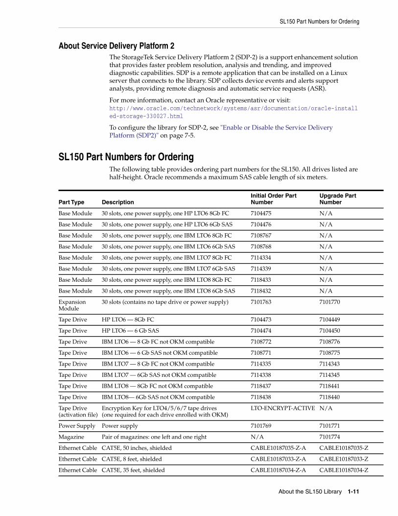
SL150 Part Numbers for OrderingThe following table provides ordering part numbers for the SL150. All drives listed arehalf-height. Oracle recommends a maximum SAS cable length of six meters.
Part Type DescriptionInitial Order PartNumber
Upgrade PartNumber
Base Module 30 slots, one power supply, one HP LTO6 8Gb FC 7104475 N/A
Base Module 30 slots, one power supply, one HP LTO6 6Gb SAS 7104476 N/A
Base Module 30 slots, one power supply, one IBM LTO6 8Gb FC 7108767 N/A
Base Module 30 slots, one power supply, one IBM LTO6 6Gb SAS 7108768 N/A
Base Module 30 slots, one power supply, one IBM LTO7 8Gb FC 7114334 N/A
Base Module 30 slots, one power supply, one IBM LTO7 6Gb SAS 7114339 N/A
Base Module 30 slots, one power supply, one IBM LTO8 8Gb FC 7118433 N/A
Base Module 30 slots, one power supply, one IBM LTO8 6Gb SAS 7118432 N/A
ExpansionModule
30 slots (contains no tape drive or power supply) 7101763 7101770
Tape Drive HP LTO6 — 8Gb FC 7104473 7104449
Tape Drive HP LTO6 — 6 Gb SAS 7104474 7104450
Tape Drive IBM LTO6 — 8 Gb FC not OKM compatible 7108772 7108776
Tape Drive IBM LTO6 — 6 Gb SAS not OKM compatible 7108771 7108775
Tape Drive IBM LTO7 — 8 Gb FC not OKM compatible 7114335 7114343
Tape Drive IBM LTO7 — 6Gb SAS not OKM compatible 7114338 7114345
Tape Drive IBM LTO8 — 8Gb FC not OKM compatible 7118437 7118441
Tape Drive IBM LTO8— 6Gb SAS not OKM compatible 7118438 7118440
Tape Drive(activation file)
Encryption Key for LTO4/5/6/7 tape drives(one required for each drive enrolled with OKM)
LTO-ENCRYPT-ACTIVE N/A
Power Supply Power supply 7101769 7101771
Magazine Pair of magazines: one left and one right N/A 7101774
Ethernet Cable CAT5E, 50 inches, shielded CABLE10187035-Z-A CABLE10187035-Z
Ethernet Cable CAT5E, 8 feet, shielded CABLE10187033-Z-A CABLE10187033-Z
Ethernet Cable CAT5E, 35 feet, shielded CABLE10187034-Z-A CABLE10187034-Z
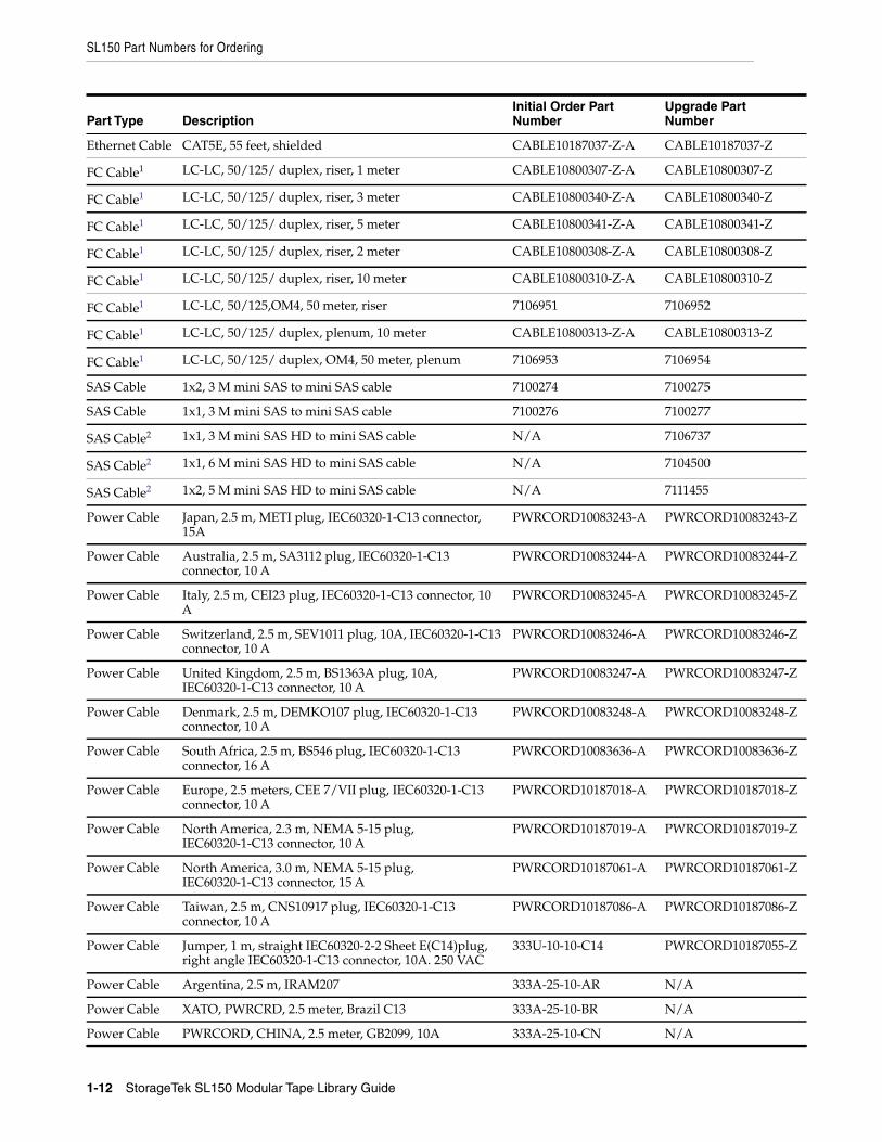
SL150 Part Numbers for Ordering
1-12 StorageTek SL150 Modular Tape Library Guide
Ethernet Cable CAT5E, 55 feet, shielded CABLE10187037-Z-A CABLE10187037-Z
FC Cable1 LC-LC, 50/125/ duplex, riser, 1 meter CABLE10800307-Z-A CABLE10800307-Z
FC Cable1 LC-LC, 50/125/ duplex, riser, 3 meter CABLE10800340-Z-A CABLE10800340-Z
FC Cable1 LC-LC, 50/125/ duplex, riser, 5 meter CABLE10800341-Z-A CABLE10800341-Z
FC Cable1 LC-LC, 50/125/ duplex, riser, 2 meter CABLE10800308-Z-A CABLE10800308-Z
FC Cable1 LC-LC, 50/125/ duplex, riser, 10 meter CABLE10800310-Z-A CABLE10800310-Z
FC Cable1 LC-LC, 50/125,OM4, 50 meter, riser 7106951 7106952
FC Cable1 LC-LC, 50/125/ duplex, plenum, 10 meter CABLE10800313-Z-A CABLE10800313-Z
FC Cable1 LC-LC, 50/125/ duplex, OM4, 50 meter, plenum 7106953 7106954
SAS Cable 1x2, 3 M mini SAS to mini SAS cable 7100274 7100275
SAS Cable 1x1, 3 M mini SAS to mini SAS cable 7100276 7100277
SAS Cable2 1x1, 3 M mini SAS HD to mini SAS cable N/A 7106737
SAS Cable2 1x1, 6 M mini SAS HD to mini SAS cable N/A 7104500
SAS Cable2 1x2, 5 M mini SAS HD to mini SAS cable N/A 7111455
Power Cable Japan, 2.5 m, METI plug, IEC60320-1-C13 connector,15A
PWRCORD10083243-A PWRCORD10083243-Z
Power Cable Australia, 2.5 m, SA3112 plug, IEC60320-1-C13connector, 10 A
PWRCORD10083244-A PWRCORD10083244-Z
Power Cable Italy, 2.5 m, CEI23 plug, IEC60320-1-C13 connector, 10A
PWRCORD10083245-A PWRCORD10083245-Z
Power Cable Switzerland, 2.5 m, SEV1011 plug, 10A, IEC60320-1-C13connector, 10 A
PWRCORD10083246-A PWRCORD10083246-Z
Power Cable United Kingdom, 2.5 m, BS1363A plug, 10A,IEC60320-1-C13 connector, 10 A
PWRCORD10083247-A PWRCORD10083247-Z
Power Cable Denmark, 2.5 m, DEMKO107 plug, IEC60320-1-C13connector, 10 A
PWRCORD10083248-A PWRCORD10083248-Z
Power Cable South Africa, 2.5 m, BS546 plug, IEC60320-1-C13connector, 16 A
PWRCORD10083636-A PWRCORD10083636-Z
Power Cable Europe, 2.5 meters, CEE 7/VII plug, IEC60320-1-C13connector, 10 A
PWRCORD10187018-A PWRCORD10187018-Z
Power Cable North America, 2.3 m, NEMA 5-15 plug,IEC60320-1-C13 connector, 10 A
PWRCORD10187019-A PWRCORD10187019-Z
Power Cable North America, 3.0 m, NEMA 5-15 plug,IEC60320-1-C13 connector, 15 A
PWRCORD10187061-A PWRCORD10187061-Z
Power Cable Taiwan, 2.5 m, CNS10917 plug, IEC60320-1-C13connector, 10 A
PWRCORD10187086-A PWRCORD10187086-Z
Power Cable Jumper, 1 m, straight IEC60320-2-2 Sheet E(C14)plug,right angle IEC60320-1-C13 connector, 10A. 250 VAC
333U-10-10-C14 PWRCORD10187055-Z
Power Cable Argentina, 2.5 m, IRAM207 333A-25-10-AR N/A
Power Cable XATO, PWRCRD, 2.5 meter, Brazil C13 333A-25-10-BR N/A
Power Cable PWRCORD, CHINA, 2.5 meter, GB2099, 10A 333A-25-10-CN N/A
Part Type DescriptionInitial Order PartNumber
Upgrade PartNumber
SL150 Part Numbers for Ordering
About the SL150 Library 1-13
Configuration and Ordering ExamplesExample 1: 30 cartridge library with an IBM LTO-7 FC drive, a second FC drive, and asecond power supply (redundant power):
■ 7114334 — Library, 30 slots with IBM LTO-7 half-height FC tape drive
■ 7114335 — Drive, IBM LTO-7, half-height FC
■ 7101769 — Power supply
Example 2: 60 cartridge library with two partitions, a total of four IBM LTO-6 drives (2SAS and 2 FC), and four power supplies:
■ 7108768 — Library, 30 slots with one IBM LTO-6 half-height SAS tape drive
■ 7101763 — Expansion module, 30 slots
■ 7108771 — Drive, IBM LTO-6, half-height SAS
■ 7108772 — Drive, IBM LTO-6, half-height FC (x2)
■ 7101769 — Power supply (x3)
Example 3: 90 cartridge library with one HP LTO-6 FC drive
■ 7108767 — Library, 30 slots with one HP LTO-6 half-height FC tape drive
■ 7101763 — Expansion module, 30 slots (x2).
Note that an expansion module receives power from the base module. Theexpansion module requires a power supply only when it contains a tape drive.
Example 4: Upgrade an existing library without partitions from 30 to 120 cartridgeswith a SAS drive in each module (power is not redundant):
■ 7101770 — Expansion module, 30 slots (x3)
■ 7104450 — Drive, HP LTO-6, half-height SAS (x3)
■ 7101771 — Power supply (x3)
Ordering Media and Labels■ Call 1.877.STK.TAPE to order media from your local reseller or to obtain media
pre-sales support.
■ E-mail: [email protected]
See the tape media area on the corporate website for additional information.
https://www.oracle.com/storage/products.html#tape
Power Cable PWRCORD, ISRAEL, 2.5 meter, SI-32, 10A 333A-25-10-IL N/A
Power Cable PWRCORD, INDIA, 2.5 meter, IS1293, 10A 333A-25-10-IN N/A
Power Cable PWRCORD, KOREA, 2.5 meter, KSC8305, 10A 333A-25-10-KR N/A1 This multimode (50-micron) fiber-optic cables connect Fibre Channel devices. These cables are orange with tan LC connectors. The tape
drive only supports LC connectors and short wavelength SFP modules. Riser cable materials are not classified according to flammability.Plenum cables meet UL standards for flammability.
2 This cable supports a 12 Gb/s transfer rate, and it must be used when the tape drive is connected to a SAS-3 HBA. Two LTO tape drivescan be connected to one SAS-3 HBA with this cable.
Part Type DescriptionInitial Order PartNumber
Upgrade PartNumber

SL150 Part Numbers for Ordering
1-14 StorageTek SL150 Modular Tape Library Guide
Click the Show all Tape Storage products link, and click the StorageTek LTO DataCartridges link.
2
Installing the Library 2-1
2Installing the Library
Library installation involves the following tasks:
■ Verify the Site Meets Environmental Requirements
■ Prepare the Rack
■ Unpack and Acclimate the Library
■ Install the Base Module
■ Install the Expansion Module
■ Install Power Supplies and Tape Drives
■ Cable the Library
■ Unlock the Robot
■ Apply Power to the Library
■ Configure the Library After Powering-on for the First Time
■ Run a Self-Test
Verify the Site Meets Environmental RequirementsFor optimal reliability, maintain the environment between the recommended ranges.
Temperature:
■ Operating: +10° to +40°C (+50° to +104°F)
■ Non-operating -40° to +60°C (-40° to +140°F)
Relative Humidity:
■ Operating: 20% to 80% (40% to 50% recommended) non-condensing
■ Non-operating: 10% to 95% non-condensing
Airborne Contaminants LimitsAirborne particulates can damage equipment. The operating environment for thelibrary must meet to the following requirements:
Note: These installation instructions use the Sun Rack II (astandard Oracle 19-inch rack). If your rack is different, use theinstructions as a basic guide but alter the steps accordingly.
Verify the Site Meets Environmental Requirements
2-2 StorageTek SL150 Modular Tape Library Guide
■ ISO 14644-1 Class 8 Environment
■ Total mass of airborne particulates must be less than or equal to 200 microgramsper cubic meter
■ Severity level G1 per ANSI/ISA 71.04-1985
Particles ten microns or smaller are particularly harmful to most data processinghardware. Gasses that are particularly dangerous to electronic components includechlorine compounds, ammonia and its derivatives, oxides of sulfur, and petrolhydrocarbons. In the absence of appropriate hardware exposure limits, healthexposure limits must be used.
Humidification with chlorinated water is a common source of airborne chlorine.Appropriately-designed carbon filters must be used to ensure safe levels of airbornechlorine when chlorinated water is used for humidification.
Some basic precautions to follow:
■ Do not allow food or drink into the data center.
■ Do not store cardboard, wood, or packing materials in the data center clean area.
■ Identify a separate area for unpacking new equipment from crates and boxes.
■ Do not allow construction or drilling in the data center without first isolatingsensitive equipment. Dry wall and gypsum are especially damaging to equipment.
Positive Pressurization and Ventilation - Hot Aisle Containment System (HACS)If you will be installing the SL150 in an HACS environment, the system must maintainadequate air flow from the cold to hot aisle. Ensure that there is no turbulent airdirected at the installed equipment which may reduce the cooling capability of thecold aisle supply air.
The HACS pressure differential should have neutral to negative pressure in the hotaisle. To achieve this, you may need to install rack doors on contributing or affectedracks. If this is ineffective to reduce air impediment, you may need to install asupplemental air removal unit to boost airflow through the equipment.
Table 2–1 Gas Limit Recommendations
Chemical ASHRAE OSHA (PEL) ACGIH NIOSH
Acetic Acid (CH3COOH) Not defined 10 ppm Not defined Not defined
Ammonia (NH) 3500 µg/m3 350 ppm 25 ppm Not defined
Chlorine (Cl) 2100 µg/m3 31 ppm (c) Not defined 0.5 ppm (c)
Hydrogen Chloride (HCl) Not defined 5 ppm (c) Not defined Not defined
Hydrogen Sulfide (H2S) 50 µg/m3 320 ppm (c) 10 ppm 10 ppm
Ozone (O3) 235 µg/m3 30.1 ppm Not defined Not defined
Petrol-hydrocarbons (CnHn) Not defined 500 ppm 75 ppm 300 ppm
Sulfur Dioxide (SO2) 80 µg/m3 35 ppm 2 ppm 0.5 ppm (c)
Sulfuric Acid (H2SO4) Not defined 1 ppm Not defined 1 ppm (c)
Prepare the Rack
Installing the Library 2-3
Electrostatic DischargeBe aware of the precautions needed when handling parts. A discharge of staticelectricity might damage static-sensitive devices which may reduce the life expectancyof the product.
Electrostatic Discharge Prevention
■ Avoid hand contact by transporting and storing products in static-safe containers.
■ Keep electrostatic-sensitive parts in their containers until they arrive at static-freework areas.
■ Place parts on a grounded surface before removing them from the container.
■ Avoid touching pins, leads, or circuitry.
■ Use proper grounding practices when touching a static-sensitive component orassembly.
Grounding Methods to Prevent Electrostatic Discharge
■ Use a wrist strap connected by a ground cord to a grounded chassis.
■ Use conductive field service tools.
■ Use a portable field service kit with a folding static-dissipating work mat.
Prepare the RackRack Requirements
■ Rack must contain four posts.
■ Front and rear service clearance must be at least 965 mm (38 inches).
■ Front of the rack must face the cool aisle and the rear face the warm aisle.
■ Rack must be level (left to right and front to back). The installed library mustremain level for proper operation.
■ Vertical rail spacing should be between 457 mm (18 in) and 902 mm (35.5 in.
■ Provide sufficient rack space to install the base module (3U) and any expansionmodules (2U each).
Rack Preparation
■ Position the power distribution unit (PDU) on the right side of the rack as viewedfrom the rear of the rack (see Figure 2–1). The power supply outlets are on theright side of the SL150 library. Refer to the rack and power distribution unitdocumentation for instructions to install the PDU
■ To provide access during installation of a library module, remove the front doorfrom the rack.
Note: If you do not have the suggested equipment for propergrounding, arrange for an authorized reseller to install the part.
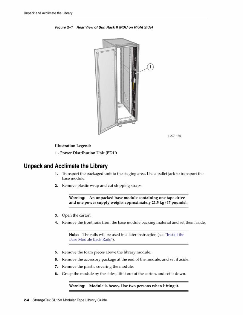
Unpack and Acclimate the Library
2-4 StorageTek SL150 Modular Tape Library Guide
Figure 2–1 Rear View of Sun Rack II (PDU on Right Side)
Illustration Legend:
1 - Power Distribution Unit (PDU)
Unpack and Acclimate the Library1. Transport the packaged unit to the staging area. Use a pallet jack to transport the
base module.
2. Remove plastic wrap and cut shipping straps.
3. Open the carton.
4. Remove the front rails from the base module packing material and set them aside.
5. Remove the foam pieces above the library module.
6. Remove the accessory package at the end of the module, and set it aside.
7. Remove the plastic covering the module.
8. Grasp the module by the sides, lift it out of the carton, and set it down.
Warning: An unpacked base module containing one tape driveand one power supply weighs approximately 21.5 kg (47 pounds).
Note: The rails will be used in a later instruction (see "Install theBase Module Back Rails").
Warning: Module is heavy. Use two persons when lifting it.
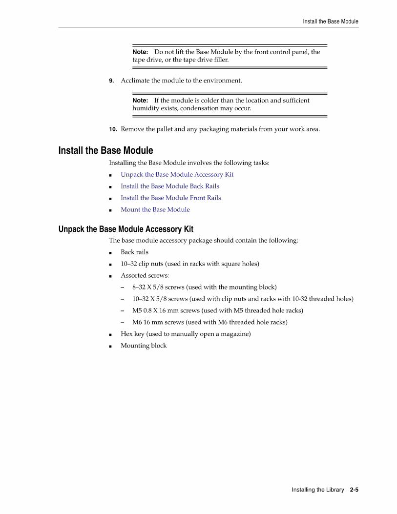
Install the Base Module
Installing the Library 2-5
9. Acclimate the module to the environment.
10. Remove the pallet and any packaging materials from your work area.
Install the Base ModuleInstalling the Base Module involves the following tasks:
■ Unpack the Base Module Accessory Kit
■ Install the Base Module Back Rails
■ Install the Base Module Front Rails
■ Mount the Base Module
Unpack the Base Module Accessory KitThe base module accessory package should contain the following:
■ Back rails
■ 10–32 clip nuts (used in racks with square holes)
■ Assorted screws:
– 8–32 X 5/8 screws (used with the mounting block)
– 10–32 X 5/8 screws (used with clip nuts and racks with 10-32 threaded holes)
– M5 0.8 X 16 mm screws (used with M5 threaded hole racks)
– M6 16 mm screws (used with M6 threaded hole racks)
■ Hex key (used to manually open a magazine)
■ Mounting block
Note: Do not lift the Base Module by the front control panel, thetape drive, or the tape drive filler.
Note: If the module is colder than the location and sufficienthumidity exists, condensation may occur.
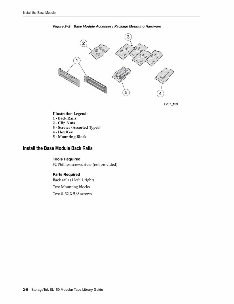
Install the Base Module
2-6 StorageTek SL150 Modular Tape Library Guide
Figure 2–2 Base Module Accessory Package Mounting Hardware
Illustration Legend:1 - Back Rails2 - Clip Nuts3 - Screws (Assorted Types)4 - Hex Key5 - Mounting Block
Install the Base Module Back Rails
Tools Required#2 Phillips screwdriver (not provided).
Parts RequiredBack rails (1 left, 1 right)
Two Mounting blocks
Two 8–32 X 5/8 screws
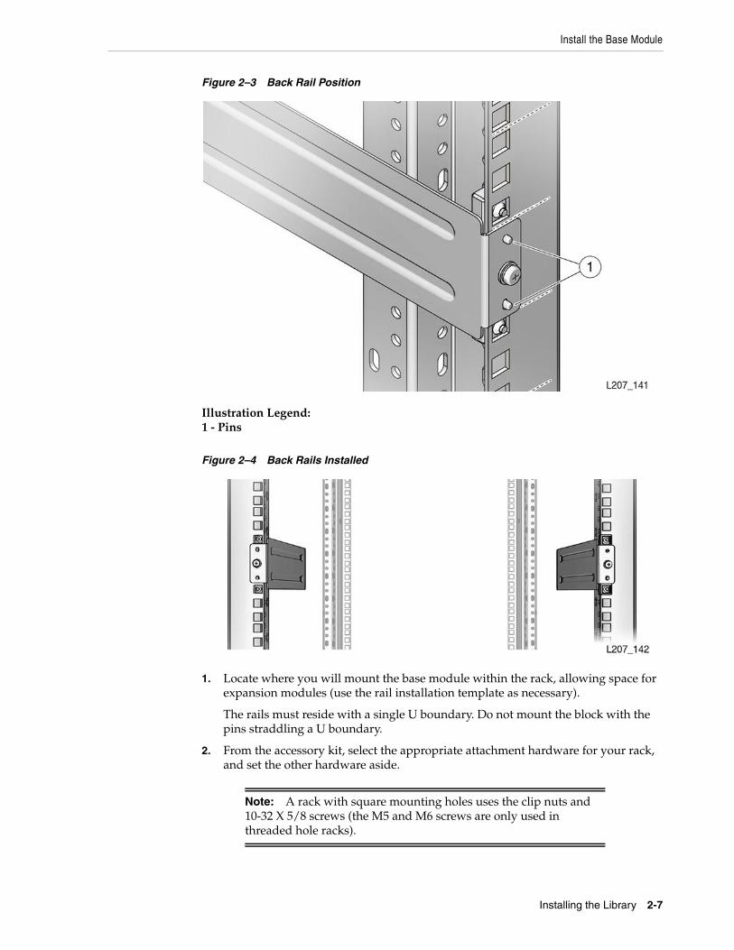
Install the Base Module
Installing the Library 2-7
Figure 2–3 Back Rail Position
Illustration Legend:1 - Pins
Figure 2–4 Back Rails Installed
1. Locate where you will mount the base module within the rack, allowing space forexpansion modules (use the rail installation template as necessary).
The rails must reside with a single U boundary. Do not mount the block with thepins straddling a U boundary.
2. From the accessory kit, select the appropriate attachment hardware for your rack,and set the other hardware aside.
Note: A rack with square mounting holes uses the clip nuts and10-32 X 5/8 screws (the M5 and M6 screws are only used inthreaded hole racks).
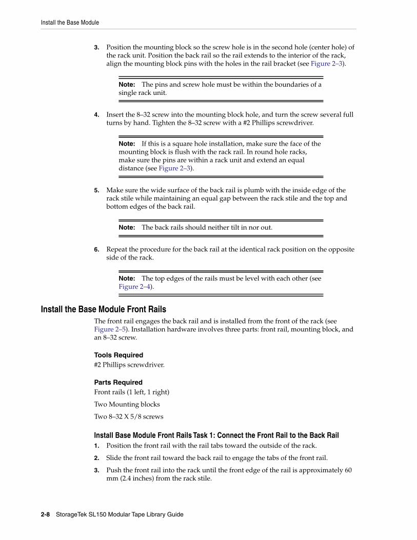
Install the Base Module
2-8 StorageTek SL150 Modular Tape Library Guide
3. Position the mounting block so the screw hole is in the second hole (center hole) ofthe rack unit. Position the back rail so the rail extends to the interior of the rack,align the mounting block pins with the holes in the rail bracket (see Figure 2–3).
4. Insert the 8–32 screw into the mounting block hole, and turn the screw several fullturns by hand. Tighten the 8–32 screw with a #2 Phillips screwdriver.
5. Make sure the wide surface of the back rail is plumb with the inside edge of therack stile while maintaining an equal gap between the rack stile and the top andbottom edges of the back rail.
6. Repeat the procedure for the back rail at the identical rack position on the oppositeside of the rack.
Install the Base Module Front RailsThe front rail engages the back rail and is installed from the front of the rack (seeFigure 2–5). Installation hardware involves three parts: front rail, mounting block, andan 8–32 screw.
Tools Required#2 Phillips screwdriver.
Parts RequiredFront rails (1 left, 1 right)
Two Mounting blocks
Two 8–32 X 5/8 screws
Install Base Module Front Rails Task 1: Connect the Front Rail to the Back Rail1. Position the front rail with the rail tabs toward the outside of the rack.
2. Slide the front rail toward the back rail to engage the tabs of the front rail.
3. Push the front rail into the rack until the front edge of the rail is approximately 60mm (2.4 inches) from the rack stile.
Note: The pins and screw hole must be within the boundaries of asingle rack unit.
Note: If this is a square hole installation, make sure the face of themounting block is flush with the rack rail. In round hole racks,make sure the pins are within a rack unit and extend an equaldistance (see Figure 2–3).
Note: The back rails should neither tilt in nor out.
Note: The top edges of the rails must be level with each other (seeFigure 2–4).
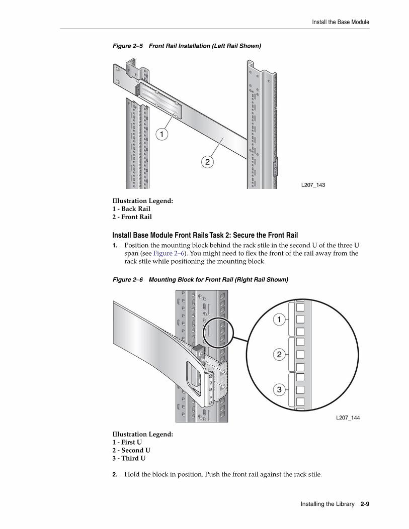
Install the Base Module
Installing the Library 2-9
Figure 2–5 Front Rail Installation (Left Rail Shown)
Illustration Legend:1 - Back Rail2 - Front Rail
Install Base Module Front Rails Task 2: Secure the Front Rail1. Position the mounting block behind the rack stile in the second U of the three U
span (see Figure 2–6). You might need to flex the front of the rail away from therack stile while positioning the mounting block.
Figure 2–6 Mounting Block for Front Rail (Right Rail Shown)
Illustration Legend:1 - First U2 - Second U3 - Third U
2. Hold the block in position. Push the front rail against the rack stile.
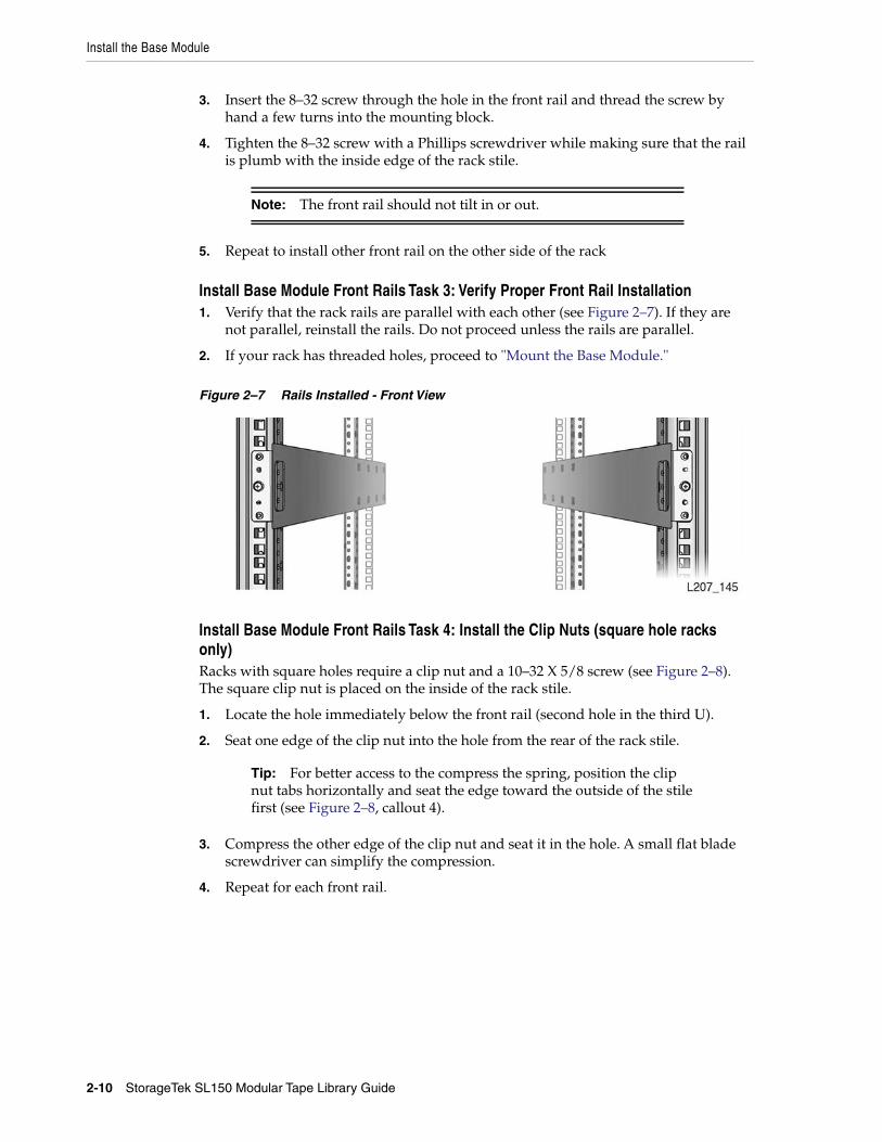
Install the Base Module
2-10 StorageTek SL150 Modular Tape Library Guide
3. Insert the 8–32 screw through the hole in the front rail and thread the screw byhand a few turns into the mounting block.
4. Tighten the 8–32 screw with a Phillips screwdriver while making sure that the railis plumb with the inside edge of the rack stile.
5. Repeat to install other front rail on the other side of the rack
Install Base Module Front Rails Task 3: Verify Proper Front Rail Installation1. Verify that the rack rails are parallel with each other (see Figure 2–7). If they are
not parallel, reinstall the rails. Do not proceed unless the rails are parallel.
2. If your rack has threaded holes, proceed to "Mount the Base Module."
Figure 2–7 Rails Installed - Front View
Install Base Module Front Rails Task 4: Install the Clip Nuts (square hole racksonly)Racks with square holes require a clip nut and a 10–32 X 5/8 screw (see Figure 2–8).The square clip nut is placed on the inside of the rack stile.
1. Locate the hole immediately below the front rail (second hole in the third U).
2. Seat one edge of the clip nut into the hole from the rear of the rack stile.
3. Compress the other edge of the clip nut and seat it in the hole. A small flat bladescrewdriver can simplify the compression.
4. Repeat for each front rail.
Note: The front rail should not tilt in or out.
Tip: For better access to the compress the spring, position the clipnut tabs horizontally and seat the edge toward the outside of the stilefirst (see Figure 2–8, callout 4).
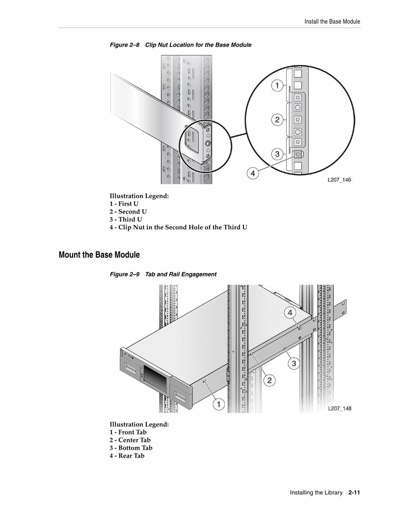
Install the Base Module
Installing the Library 2-11
Figure 2–8 Clip Nut Location for the Base Module
Illustration Legend:1 - First U2 - Second U3 - Third U4 - Clip Nut in the Second Hole of the Third U
Mount the Base Module
Figure 2–9 Tab and Rail Engagement
Illustration Legend:1 - Front Tab2 - Center Tab3 - Bottom Tab4 - Rear Tab
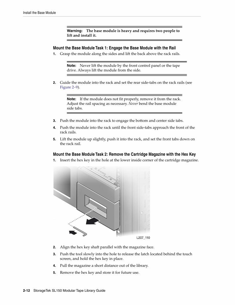
Install the Base Module
2-12 StorageTek SL150 Modular Tape Library Guide
Mount the Base Module Task 1: Engage the Base Module with the Rail1. Grasp the module along the sides and lift the back above the rack rails.
2. Guide the module into the rack and set the rear side-tabs on the rack rails (seeFigure 2–9).
3. Push the module into the rack to engage the bottom and center side tabs.
4. Push the module into the rack until the front side-tabs approach the front of therack rails.
5. Lift the module up slightly, push it into the rack, and set the front tabs down onthe rack rail.
Mount the Base Module Task 2: Remove the Cartridge Magazine with the Hex Key1. Insert the hex key in the hole at the lower inside corner of the cartridge magazine.
2. Align the hex key shaft parallel with the magazine face.
3. Push the tool slowly into the hole to release the latch located behind the touchscreen, and hold the hex key in place.
4. Pull the magazine a short distance out of the library.
5. Remove the hex key and store it for future use.
Warning: The base module is heavy and requires two people tolift and install it.
Note: Never lift the module by the front control panel or the tapedrive. Always lift the module from the side.
Note: If the module does not fit properly, remove it from the rack.Adjust the rail spacing as necessary. Never bend the base moduleside tabs.
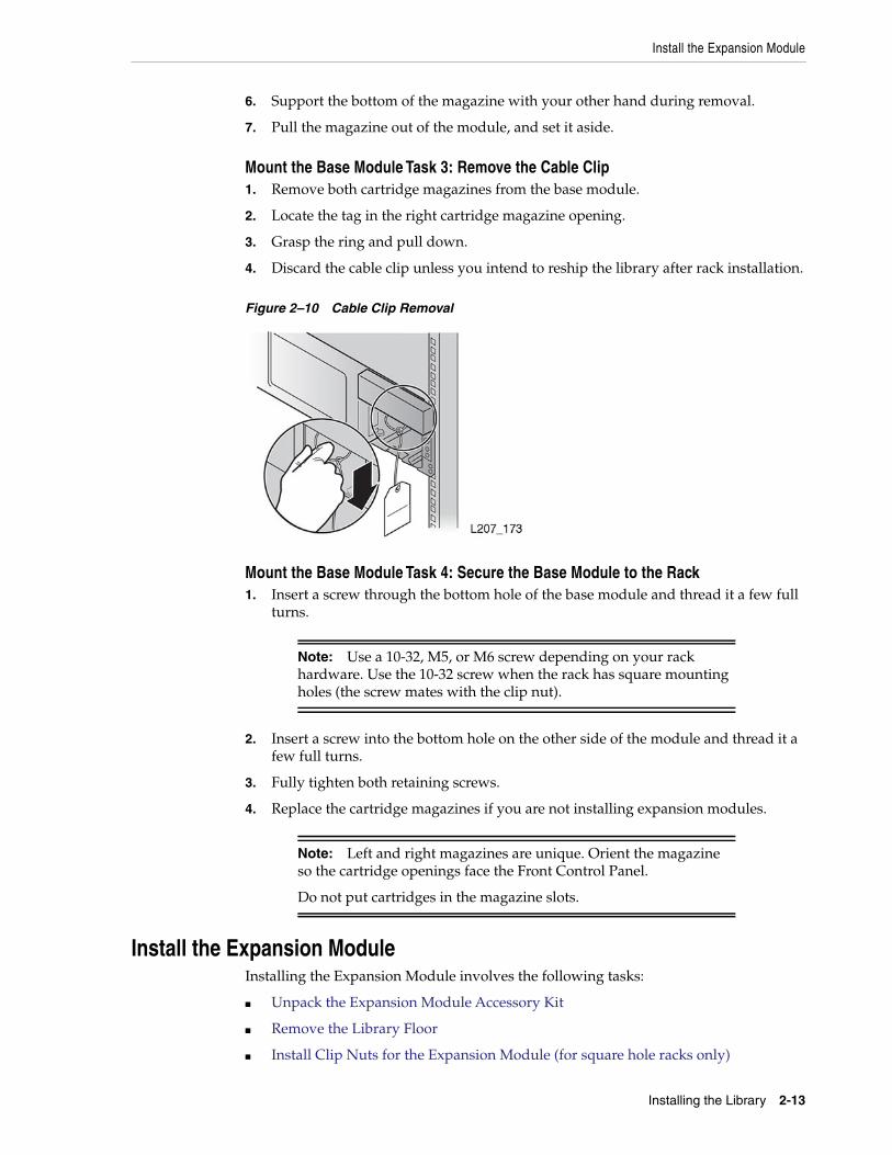
Install the Expansion Module
Installing the Library 2-13
6. Support the bottom of the magazine with your other hand during removal.
7. Pull the magazine out of the module, and set it aside.
Mount the Base Module Task 3: Remove the Cable Clip1. Remove both cartridge magazines from the base module.
2. Locate the tag in the right cartridge magazine opening.
3. Grasp the ring and pull down.
4. Discard the cable clip unless you intend to reship the library after rack installation.
Figure 2–10 Cable Clip Removal
Mount the Base Module Task 4: Secure the Base Module to the Rack1. Insert a screw through the bottom hole of the base module and thread it a few full
turns.
2. Insert a screw into the bottom hole on the other side of the module and thread it afew full turns.
3. Fully tighten both retaining screws.
4. Replace the cartridge magazines if you are not installing expansion modules.
Install the Expansion ModuleInstalling the Expansion Module involves the following tasks:
■ Unpack the Expansion Module Accessory Kit
■ Remove the Library Floor
■ Install Clip Nuts for the Expansion Module (for square hole racks only)
Note: Use a 10-32, M5, or M6 screw depending on your rackhardware. Use the 10-32 screw when the rack has square mountingholes (the screw mates with the clip nut).
Note: Left and right magazines are unique. Orient the magazineso the cartridge openings face the Front Control Panel.
Do not put cartridges in the magazine slots.
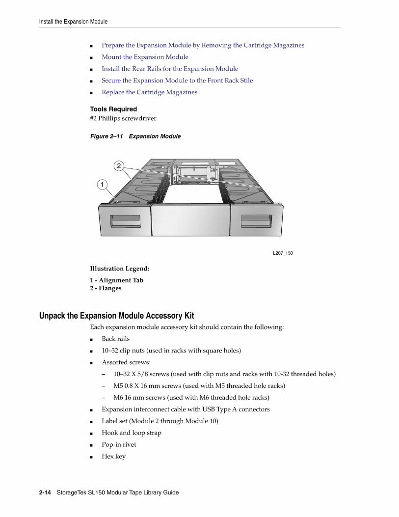
Install the Expansion Module
2-14 StorageTek SL150 Modular Tape Library Guide
■ Prepare the Expansion Module by Removing the Cartridge Magazines
■ Mount the Expansion Module
■ Install the Rear Rails for the Expansion Module
■ Secure the Expansion Module to the Front Rack Stile
■ Replace the Cartridge Magazines
Tools Required#2 Phillips screwdriver.
Figure 2–11 Expansion Module
Illustration Legend:
1 - Alignment Tab2 - Flanges
Unpack the Expansion Module Accessory KitEach expansion module accessory kit should contain the following:
■ Back rails
■ 10–32 clip nuts (used in racks with square holes)
■ Assorted screws:
– 10–32 X 5/8 screws (used with clip nuts and racks with 10-32 threaded holes)
– M5 0.8 X 16 mm screws (used with M5 threaded hole racks)
– M6 16 mm screws (used with M6 threaded hole racks)
■ Expansion interconnect cable with USB Type A connectors
■ Label set (Module 2 through Module 10)
■ Hook and loop strap
■ Pop-in rivet
■ Hex key
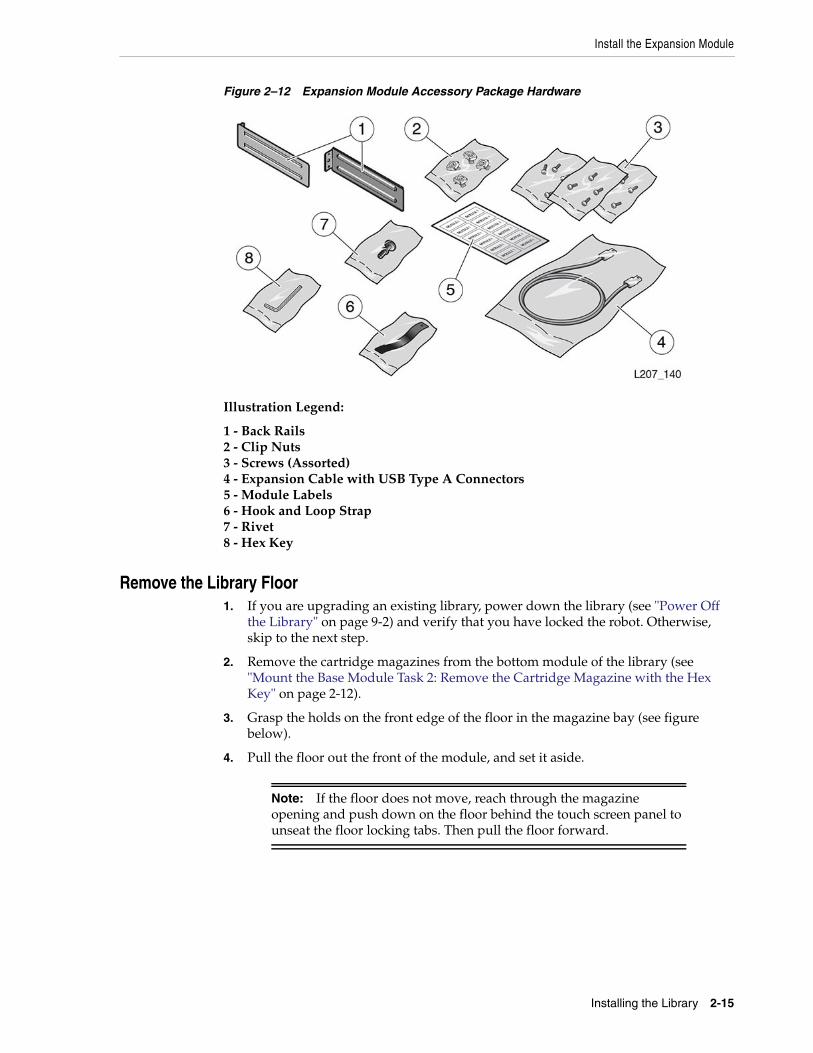
Install the Expansion Module
Installing the Library 2-15
Figure 2–12 Expansion Module Accessory Package Hardware
Illustration Legend:
1 - Back Rails2 - Clip Nuts3 - Screws (Assorted)4 - Expansion Cable with USB Type A Connectors5 - Module Labels6 - Hook and Loop Strap7 - Rivet8 - Hex Key
Remove the Library Floor1. If you are upgrading an existing library, power down the library (see "Power Off
the Library" on page 9-2) and verify that you have locked the robot. Otherwise,skip to the next step.
2. Remove the cartridge magazines from the bottom module of the library (see"Mount the Base Module Task 2: Remove the Cartridge Magazine with the HexKey" on page 2-12).
3. Grasp the holds on the front edge of the floor in the magazine bay (see figurebelow).
4. Pull the floor out the front of the module, and set it aside.
Note: If the floor does not move, reach through the magazineopening and push down on the floor behind the touch screen panel tounseat the floor locking tabs. Then pull the floor forward.
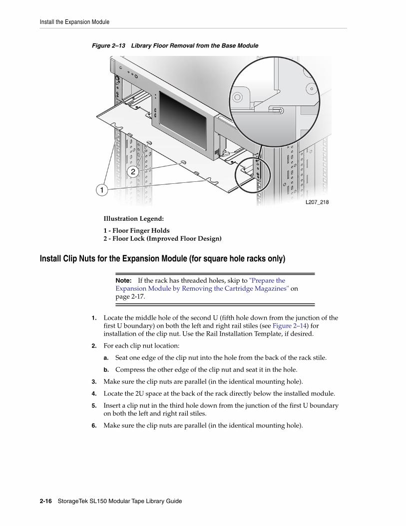
Install the Expansion Module
2-16 StorageTek SL150 Modular Tape Library Guide
Figure 2–13 Library Floor Removal from the Base Module
Illustration Legend:
1 - Floor Finger Holds2 - Floor Lock (Improved Floor Design)
Install Clip Nuts for the Expansion Module (for square hole racks only)
1. Locate the middle hole of the second U (fifth hole down from the junction of thefirst U boundary) on both the left and right rail stiles (see Figure 2–14) forinstallation of the clip nut. Use the Rail Installation Template, if desired.
2. For each clip nut location:
a. Seat one edge of the clip nut into the hole from the back of the rack stile.
b. Compress the other edge of the clip nut and seat it in the hole.
3. Make sure the clip nuts are parallel (in the identical mounting hole).
4. Locate the 2U space at the back of the rack directly below the installed module.
5. Insert a clip nut in the third hole down from the junction of the first U boundaryon both the left and right rail stiles.
6. Make sure the clip nuts are parallel (in the identical mounting hole).
Note: If the rack has threaded holes, skip to "Prepare theExpansion Module by Removing the Cartridge Magazines" onpage 2-17.
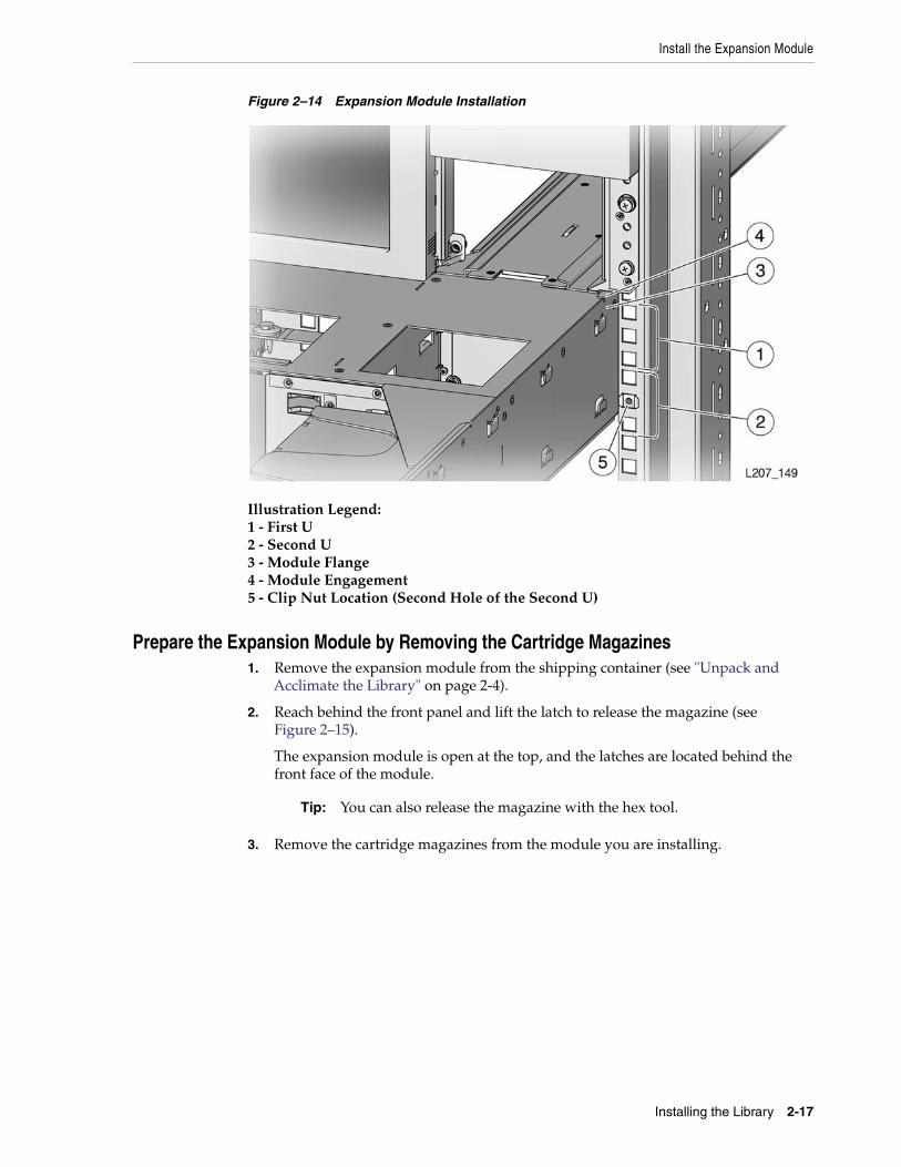
Install the Expansion Module
Installing the Library 2-17
Figure 2–14 Expansion Module Installation
Illustration Legend:1 - First U2 - Second U3 - Module Flange4 - Module Engagement5 - Clip Nut Location (Second Hole of the Second U)
Prepare the Expansion Module by Removing the Cartridge Magazines1. Remove the expansion module from the shipping container (see "Unpack and
Acclimate the Library" on page 2-4).
2. Reach behind the front panel and lift the latch to release the magazine (seeFigure 2–15).
The expansion module is open at the top, and the latches are located behind thefront face of the module.
3. Remove the cartridge magazines from the module you are installing.
Tip: You can also release the magazine with the hex tool.
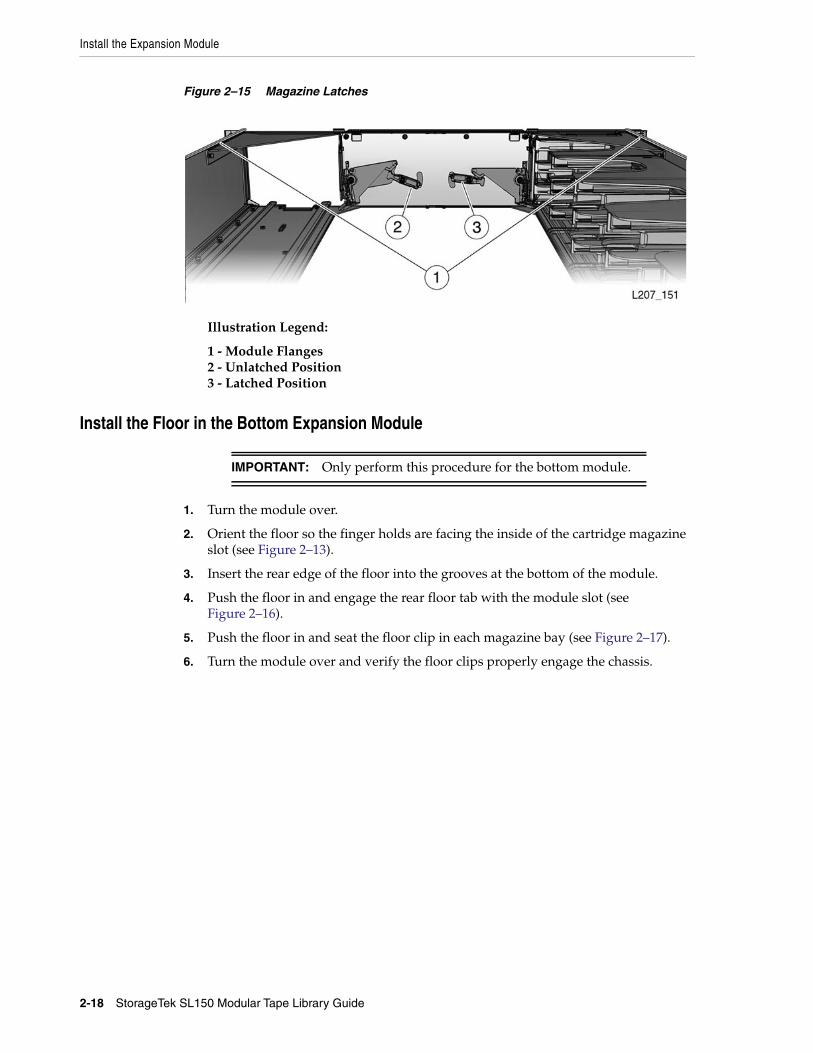
Install the Expansion Module
2-18 StorageTek SL150 Modular Tape Library Guide
Figure 2–15 Magazine Latches
Illustration Legend:
1 - Module Flanges2 - Unlatched Position3 - Latched Position
Install the Floor in the Bottom Expansion Module
1. Turn the module over.
2. Orient the floor so the finger holds are facing the inside of the cartridge magazineslot (see Figure 2–13).
3. Insert the rear edge of the floor into the grooves at the bottom of the module.
4. Push the floor in and engage the rear floor tab with the module slot (seeFigure 2–16).
5. Push the floor in and seat the floor clip in each magazine bay (see Figure 2–17).
6. Turn the module over and verify the floor clips properly engage the chassis.
IMPORTANT: Only perform this procedure for the bottom module.
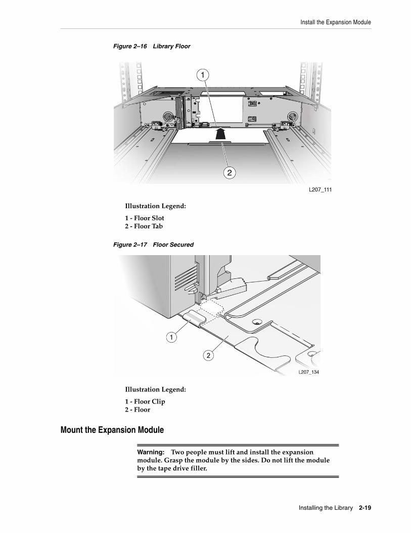
Install the Expansion Module
Installing the Library 2-19
Figure 2–16 Library Floor
Illustration Legend:
1 - Floor Slot2 - Floor Tab
Figure 2–17 Floor Secured
Illustration Legend:
1 - Floor Clip2 - Floor
Mount the Expansion Module
Warning: Two people must lift and install the expansionmodule. Grasp the module by the sides. Do not lift the moduleby the tape drive filler.
Install the Expansion Module
2-20 StorageTek SL150 Modular Tape Library Guide
1. Lift the module to the bottom of the installed module.
2. Insert the rear edge of the module flange into the grooves on the bottom edge ofthe installed module and push the 2U expansion module in approximately 75millimeters (3 inches).
3. Lower the front edge of the module approximately 10 mm (0.4 inch), guide anysharp metal edges away from the upper module front panel, and push the modulein until the sharp edges are past the front panel (see Figure 2–18).
4. Raise the front of the 2U module, push the module in, and engage the module leftand right side flanges with the grooves in the previous module.
5. Push the module in and seat the alignment tab in the slot of the left magazine bay(see Figure 2–19).
Figure 2–18 Scratch Avoidance
Illustration Legend:
1 - Flange (Short Section)2 - Tall Metal Part with Sharp Edges3 - Flange (Long Section)
Note: Do not scratch the front panel of the module above.
Install the Expansion Module
Installing the Library 2-21
Figure 2–19 Alignment Tab Seated
Illustration Legend:
1 - Tab Seated in Slot2 - Slot in Magazine Bay
Install the Rear Rails for the Expansion Module1. Slide the back rail under the expansion module tabs (see Figure 2–20).
2. Repeat for the rail on the other side of the module.
Figure 2–20 Expansion Module Back Rail and Clip Nut
Illustration Legend:
1 - Clip Nut
2 - Rear Rail
3. Push the back rail against the rack vertical rail.
4. Secure the back rail to the rack vertical rail with a screw.
Tip: Use a 10-32 screw when a rack has square holes (the screwmates with a clip nut).
Install the Expansion Module
2-22 StorageTek SL150 Modular Tape Library Guide
5. Repeat this task for the rail on the other side of the module.
Secure the Expansion Module to the Front Rack Stile
1. Insert a screw in the lower left side of the module and thread it a few turns.
2. Insert a screw in the lower right side of the module and thread it a few turns.
3. Fully tighten both screws.
4. Install another expansion module (see "Unpack the Expansion Module AccessoryKit").
Replace the Cartridge Magazines
1. Orient the magazine with the cartridge slots facing toward the center of themodule.
2. Lift the magazine and point the back toward the module slot.
3. Engage the magazine with the track in the magazine slot.
4. Push the magazine fully into the slot.
5. Repeat as necessary until each expansion modules has two magazines.
Label the Modules1. Locate the scribe lines in the upper left corner of the expansion module (as viewed
from the back of the rack).
2. Obtain the module label sheet from the accessory kit.
3. Peel the proper label from the label sheet.
4. Orient the label properly, align the label with the scribe lines, and adhere the labelto the chassis (see Figure 2–21).
Tip: Use a 10-32 screw when a rack has square holes (the screwmates with a clip nut).
Note: Left and right magazines are unique.
Note: Do not put cartridges in the magazine slots.
Note: The sheet has labels for Module 2 through Module 10.
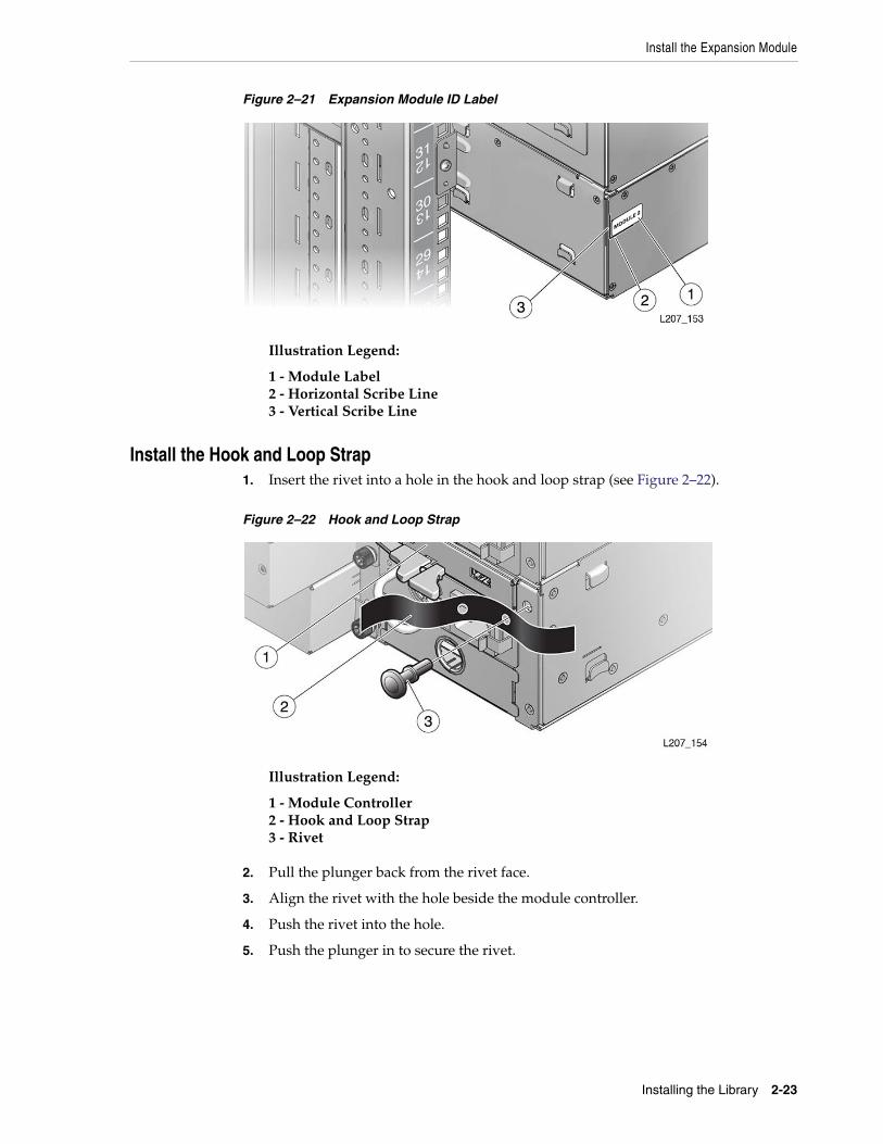
Install the Expansion Module
Installing the Library 2-23
Figure 2–21 Expansion Module ID Label
Illustration Legend:
1 - Module Label2 - Horizontal Scribe Line3 - Vertical Scribe Line
Install the Hook and Loop Strap1. Insert the rivet into a hole in the hook and loop strap (see Figure 2–22).
Figure 2–22 Hook and Loop Strap
Illustration Legend:
1 - Module Controller2 - Hook and Loop Strap3 - Rivet
2. Pull the plunger back from the rivet face.
3. Align the rivet with the hole beside the module controller.
4. Push the rivet into the hole.
5. Push the plunger in to secure the rivet.
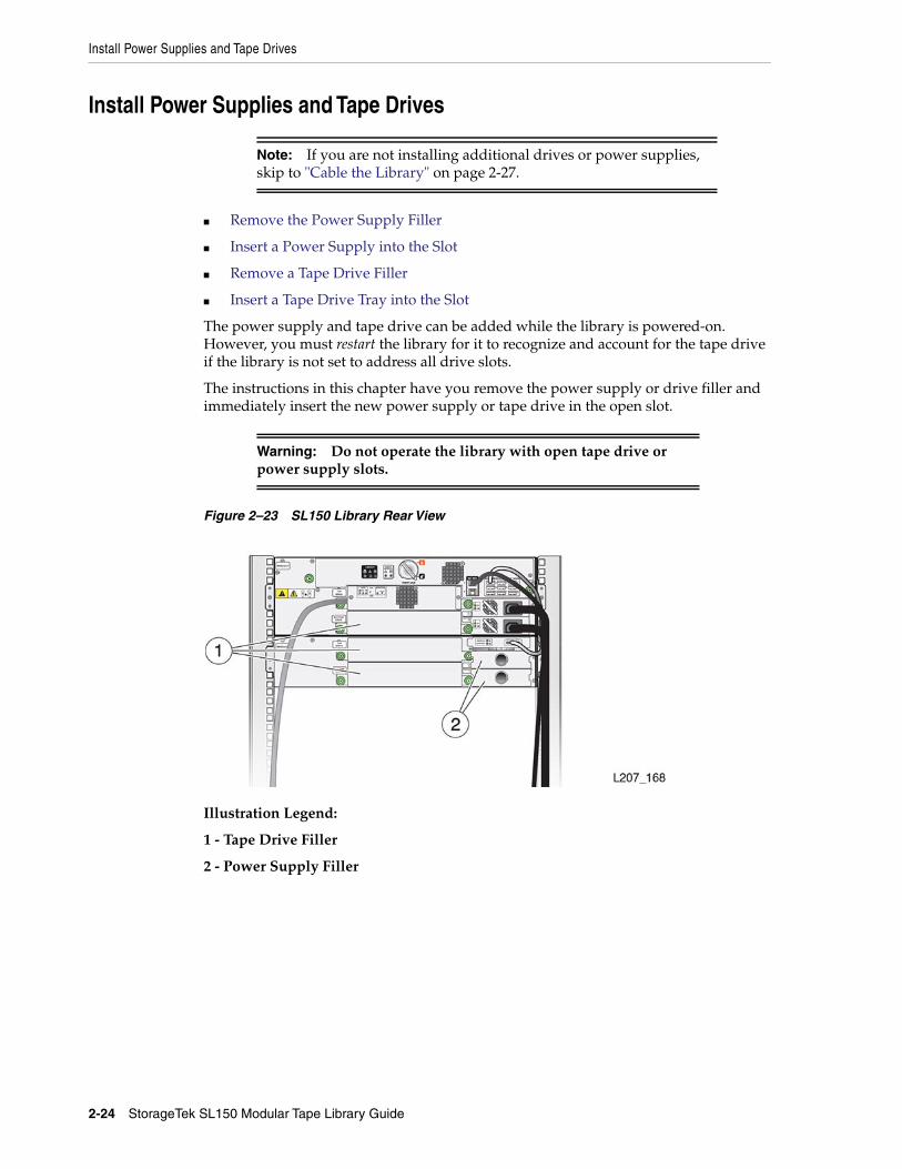
Install Power Supplies and Tape Drives
2-24 StorageTek SL150 Modular Tape Library Guide
Install Power Supplies and Tape Drives
■ Remove the Power Supply Filler
■ Insert a Power Supply into the Slot
■ Remove a Tape Drive Filler
■ Insert a Tape Drive Tray into the Slot
The power supply and tape drive can be added while the library is powered-on.However, you must restart the library for it to recognize and account for the tape driveif the library is not set to address all drive slots.
The instructions in this chapter have you remove the power supply or drive filler andimmediately insert the new power supply or tape drive in the open slot.
Figure 2–23 SL150 Library Rear View
Illustration Legend:
1 - Tape Drive Filler
2 - Power Supply Filler
Note: If you are not installing additional drives or power supplies,skip to "Cable the Library" on page 2-27.
Warning: Do not operate the library with open tape drive orpower supply slots.
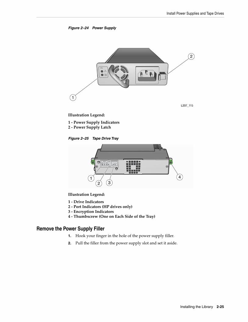
Install Power Supplies and Tape Drives
Installing the Library 2-25
Figure 2–24 Power Supply
Illustration Legend:
1 - Power Supply Indicators2 - Power Supply Latch
Figure 2–25 Tape Drive Tray
Illustration Legend:
1 - Drive Indicators2 - Port Indicators (HP drives only)3 - Encryption Indicators4 - Thumbscrew (One on Each Side of the Tray)
Remove the Power Supply Filler1. Hook your finger in the hole of the power supply filler.
2. Pull the filler from the power supply slot and set it aside.
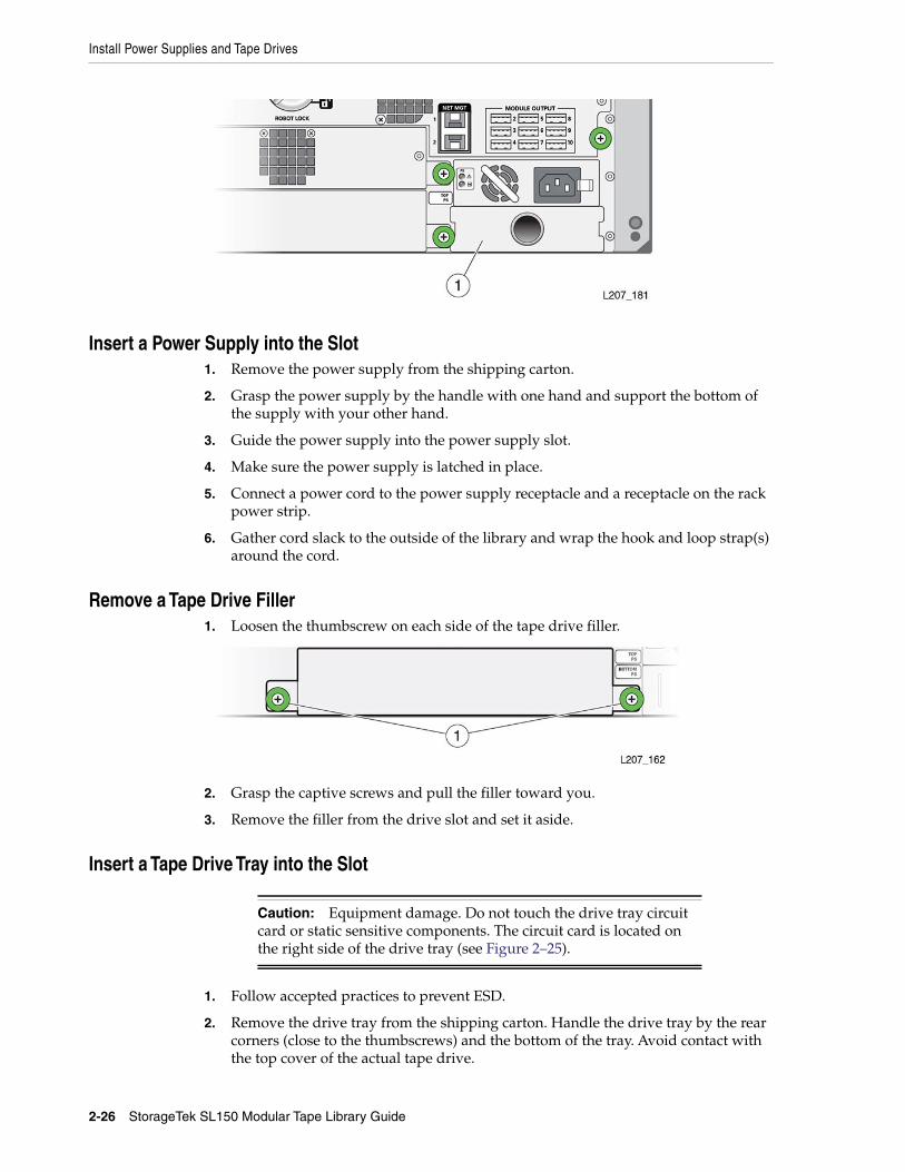
Install Power Supplies and Tape Drives
2-26 StorageTek SL150 Modular Tape Library Guide
Insert a Power Supply into the Slot1. Remove the power supply from the shipping carton.
2. Grasp the power supply by the handle with one hand and support the bottom ofthe supply with your other hand.
3. Guide the power supply into the power supply slot.
4. Make sure the power supply is latched in place.
5. Connect a power cord to the power supply receptacle and a receptacle on the rackpower strip.
6. Gather cord slack to the outside of the library and wrap the hook and loop strap(s)around the cord.
Remove a Tape Drive Filler1. Loosen the thumbscrew on each side of the tape drive filler.
2. Grasp the captive screws and pull the filler toward you.
3. Remove the filler from the drive slot and set it aside.
Insert a Tape Drive Tray into the Slot
1. Follow accepted practices to prevent ESD.
2. Remove the drive tray from the shipping carton. Handle the drive tray by the rearcorners (close to the thumbscrews) and the bottom of the tray. Avoid contact withthe top cover of the actual tape drive.
Caution: Equipment damage. Do not touch the drive tray circuitcard or static sensitive components. The circuit card is located onthe right side of the drive tray (see Figure 2–25).
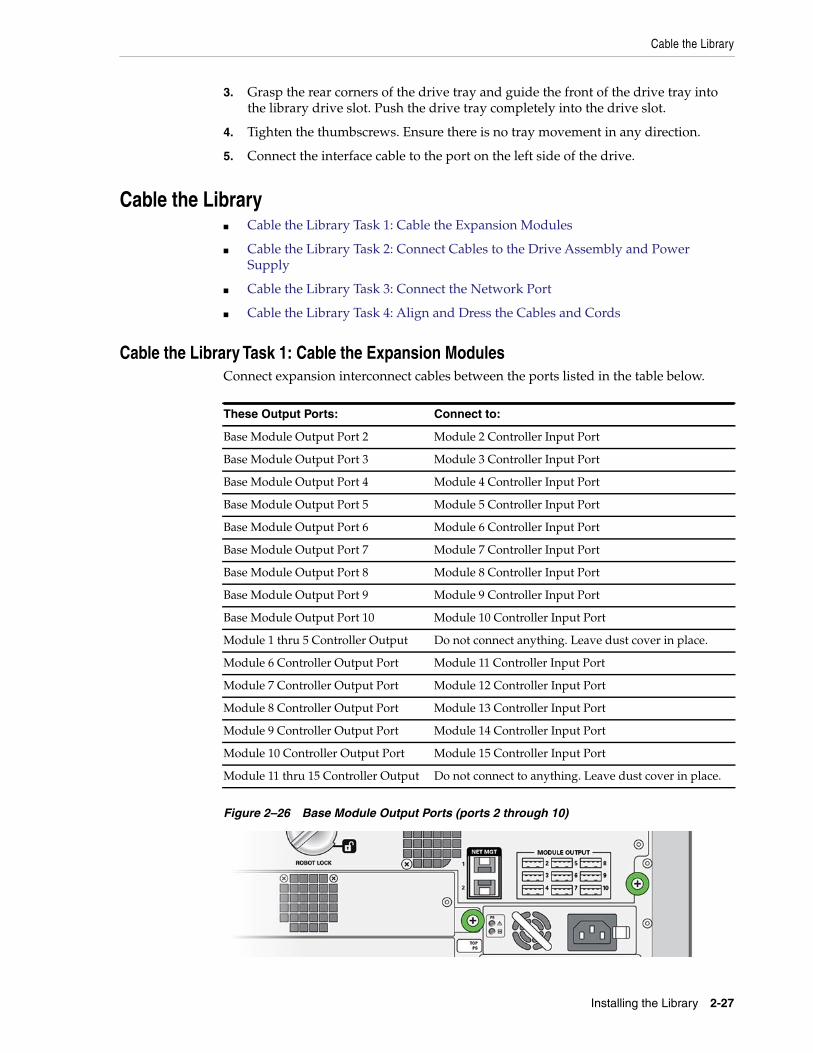
Cable the Library
Installing the Library 2-27
3. Grasp the rear corners of the drive tray and guide the front of the drive tray intothe library drive slot. Push the drive tray completely into the drive slot.
4. Tighten the thumbscrews. Ensure there is no tray movement in any direction.
5. Connect the interface cable to the port on the left side of the drive.
Cable the Library■ Cable the Library Task 1: Cable the Expansion Modules
■ Cable the Library Task 2: Connect Cables to the Drive Assembly and PowerSupply
■ Cable the Library Task 3: Connect the Network Port
■ Cable the Library Task 4: Align and Dress the Cables and Cords
Cable the Library Task 1: Cable the Expansion ModulesConnect expansion interconnect cables between the ports listed in the table below.
Figure 2–26 Base Module Output Ports (ports 2 through 10)
These Output Ports: Connect to:
Base Module Output Port 2 Module 2 Controller Input Port
Base Module Output Port 3 Module 3 Controller Input Port
Base Module Output Port 4 Module 4 Controller Input Port
Base Module Output Port 5 Module 5 Controller Input Port
Base Module Output Port 6 Module 6 Controller Input Port
Base Module Output Port 7 Module 7 Controller Input Port
Base Module Output Port 8 Module 8 Controller Input Port
Base Module Output Port 9 Module 9 Controller Input Port
Base Module Output Port 10 Module 10 Controller Input Port
Module 1 thru 5 Controller Output Do not connect anything. Leave dust cover in place.
Module 6 Controller Output Port Module 11 Controller Input Port
Module 7 Controller Output Port Module 12 Controller Input Port
Module 8 Controller Output Port Module 13 Controller Input Port
Module 9 Controller Output Port Module 14 Controller Input Port
Module 10 Controller Output Port Module 15 Controller Input Port
Module 11 thru 15 Controller Output Do not connect to anything. Leave dust cover in place.
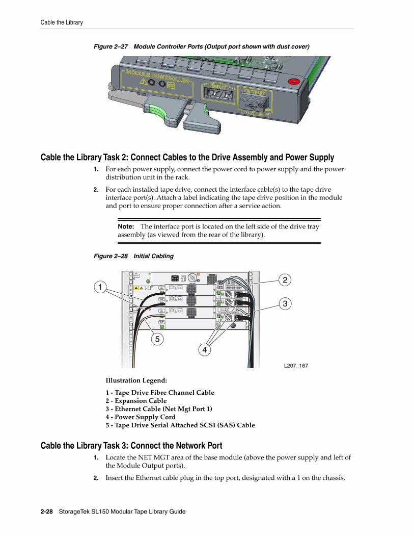
Cable the Library
2-28 StorageTek SL150 Modular Tape Library Guide
Figure 2–27 Module Controller Ports (Output port shown with dust cover)
Cable the Library Task 2: Connect Cables to the Drive Assembly and Power Supply1. For each power supply, connect the power cord to power supply and the power
distribution unit in the rack.
2. For each installed tape drive, connect the interface cable(s) to the tape driveinterface port(s). Attach a label indicating the tape drive position in the moduleand port to ensure proper connection after a service action.
Figure 2–28 Initial Cabling
Illustration Legend:
1 - Tape Drive Fibre Channel Cable2 - Expansion Cable3 - Ethernet Cable (Net Mgt Port 1)4 - Power Supply Cord5 - Tape Drive Serial Attached SCSI (SAS) Cable
Cable the Library Task 3: Connect the Network Port1. Locate the NET MGT area of the base module (above the power supply and left of
the Module Output ports).
2. Insert the Ethernet cable plug in the top port, designated with a 1 on the chassis.
Note: The interface port is located on the left side of the drive trayassembly (as viewed from the rear of the library).
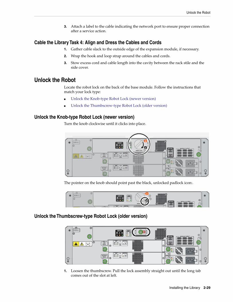
Unlock the Robot
Installing the Library 2-29
3. Attach a label to the cable indicating the network port to ensure proper connectionafter a service action.
Cable the Library Task 4: Align and Dress the Cables and Cords1. Gather cable slack to the outside edge of the expansion module, if necessary.
2. Wrap the hook and loop strap around the cables and cords.
3. Stow excess cord and cable length into the cavity between the rack stile and theside cover.
Unlock the RobotLocate the robot lock on the back of the base module. Follow the instructions thatmatch your lock type:
■ Unlock the Knob-type Robot Lock (newer version)
■ Unlock the Thumbscrew-type Robot Lock (older version)
Unlock the Knob-type Robot Lock (newer version)Turn the knob clockwise until it clicks into place.
The pointer on the knob should point past the black, unlocked padlock icon:.
Unlock the Thumbscrew-type Robot Lock (older version)
1. Loosen the thumbscrew. Pull the lock assembly straight out until the long tabcomes out of the slot at left.
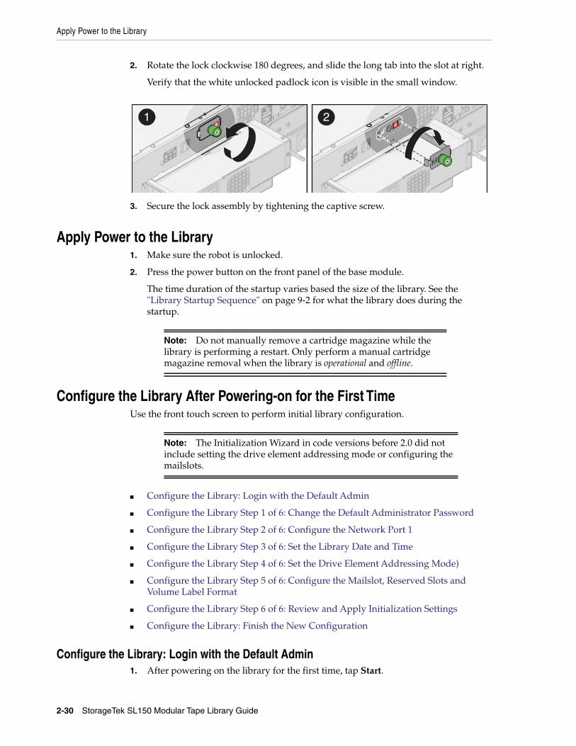
Apply Power to the Library
2-30 StorageTek SL150 Modular Tape Library Guide
2. Rotate the lock clockwise 180 degrees, and slide the long tab into the slot at right.
Verify that the white unlocked padlock icon is visible in the small window.
3. Secure the lock assembly by tightening the captive screw.
Apply Power to the Library1. Make sure the robot is unlocked.
2. Press the power button on the front panel of the base module.
The time duration of the startup varies based the size of the library. See the"Library Startup Sequence" on page 9-2 for what the library does during thestartup.
Configure the Library After Powering-on for the First TimeUse the front touch screen to perform initial library configuration.
■ Configure the Library: Login with the Default Admin
■ Configure the Library Step 1 of 6: Change the Default Administrator Password
■ Configure the Library Step 2 of 6: Configure the Network Port 1
■ Configure the Library Step 3 of 6: Set the Library Date and Time
■ Configure the Library Step 4 of 6: Set the Drive Element Addressing Mode)
■ Configure the Library Step 5 of 6: Configure the Mailslot, Reserved Slots andVolume Label Format
■ Configure the Library Step 6 of 6: Review and Apply Initialization Settings
■ Configure the Library: Finish the New Configuration
Configure the Library: Login with the Default Admin1. After powering on the library for the first time, tap Start.
Note: Do not manually remove a cartridge magazine while thelibrary is performing a restart. Only perform a manual cartridgemagazine removal when the library is operational and offline.
Note: The Initialization Wizard in code versions before 2.0 did notinclude setting the drive element addressing mode or configuring themailslots.
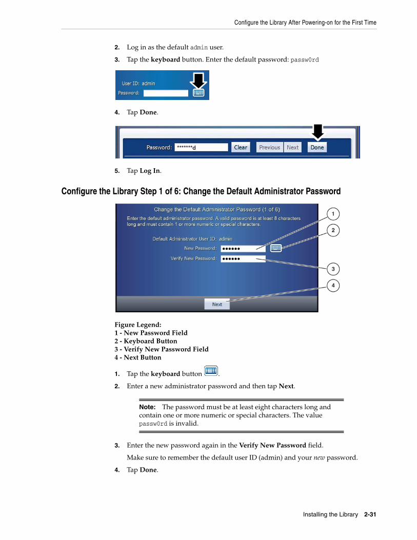
Configure the Library After Powering-on for the First Time
Installing the Library 2-31
2. Log in as the default admin user.
3. Tap the keyboard button. Enter the default password: passw0rd
4. Tap Done.
5. Tap Log In.
Configure the Library Step 1 of 6: Change the Default Administrator Password
Figure Legend:1 - New Password Field2 - Keyboard Button3 - Verify New Password Field4 - Next Button
1. Tap the keyboard button .
2. Enter a new administrator password and then tap Next.
3. Enter the new password again in the Verify New Password field.
Make sure to remember the default user ID (admin) and your new password.
4. Tap Done.
Note: The password must be at least eight characters long andcontain one or more numeric or special characters. The valuepassw0rd is invalid.
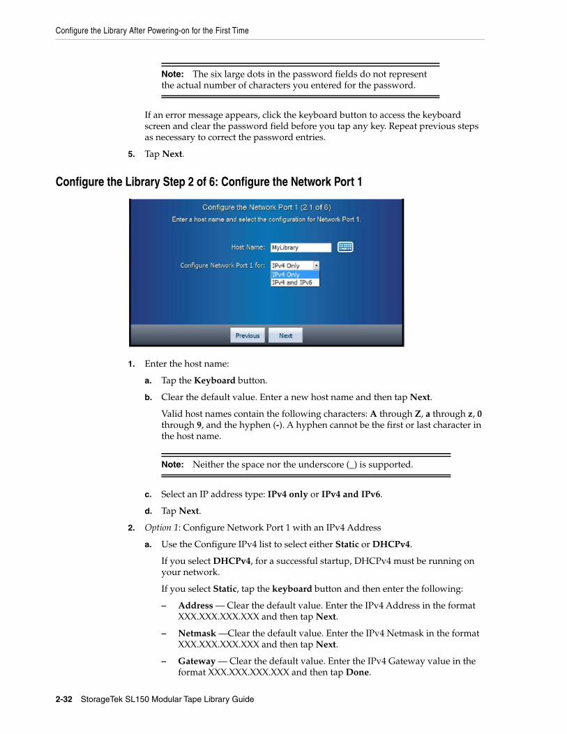
Configure the Library After Powering-on for the First Time
2-32 StorageTek SL150 Modular Tape Library Guide
If an error message appears, click the keyboard button to access the keyboardscreen and clear the password field before you tap any key. Repeat previous stepsas necessary to correct the password entries.
5. Tap Next.
Configure the Library Step 2 of 6: Configure the Network Port 1
1. Enter the host name:
a. Tap the Keyboard button.
b. Clear the default value. Enter a new host name and then tap Next.
Valid host names contain the following characters: A through Z, a through z, 0through 9, and the hyphen (-). A hyphen cannot be the first or last character inthe host name.
c. Select an IP address type: IPv4 only or IPv4 and IPv6.
d. Tap Next.
2. Option 1: Configure Network Port 1 with an IPv4 Address
a. Use the Configure IPv4 list to select either Static or DHCPv4.
If you select DHCPv4, for a successful startup, DHCPv4 must be running onyour network.
If you select Static, tap the keyboard button and then enter the following:
– Address — Clear the default value. Enter the IPv4 Address in the formatXXX.XXX.XXX.XXX and then tap Next.
– Netmask —Clear the default value. Enter the IPv4 Netmask in the formatXXX.XXX.XXX.XXX and then tap Next.
– Gateway — Clear the default value. Enter the IPv4 Gateway value in theformat XXX.XXX.XXX.XXX and then tap Done.
Note: The six large dots in the password fields do not representthe actual number of characters you entered for the password.
Note: Neither the space nor the underscore (_) is supported.
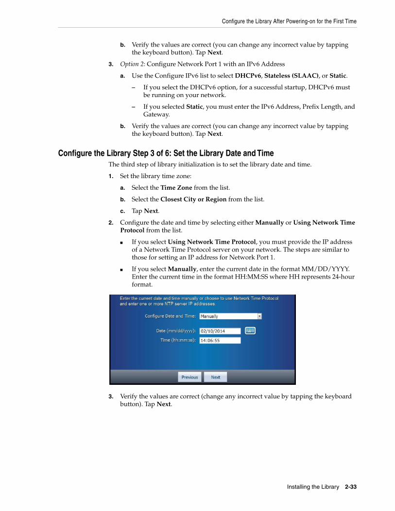
Configure the Library After Powering-on for the First Time
Installing the Library 2-33
b. Verify the values are correct (you can change any incorrect value by tappingthe keyboard button). Tap Next.
3. Option 2: Configure Network Port 1 with an IPv6 Address
a. Use the Configure IPv6 list to select DHCPv6, Stateless (SLAAC), or Static.
– If you select the DHCPv6 option, for a successful startup, DHCPv6 mustbe running on your network.
– If you selected Static, you must enter the IPv6 Address, Prefix Length, andGateway.
b. Verify the values are correct (you can change any incorrect value by tappingthe keyboard button). Tap Next.
Configure the Library Step 3 of 6: Set the Library Date and TimeThe third step of library initialization is to set the library date and time.
1. Set the library time zone:
a. Select the Time Zone from the list.
b. Select the Closest City or Region from the list.
c. Tap Next.
2. Configure the date and time by selecting either Manually or Using Network TimeProtocol from the list.
■ If you select Using Network Time Protocol, you must provide the IP addressof a Network Time Protocol server on your network. The steps are similar tothose for setting an IP address for Network Port 1.
■ If you select Manually, enter the current date in the format MM/DD/YYYY.Enter the current time in the format HH:MM:SS where HH represents 24-hourformat.
3. Verify the values are correct (change any incorrect value by tapping the keyboardbutton). Tap Next.
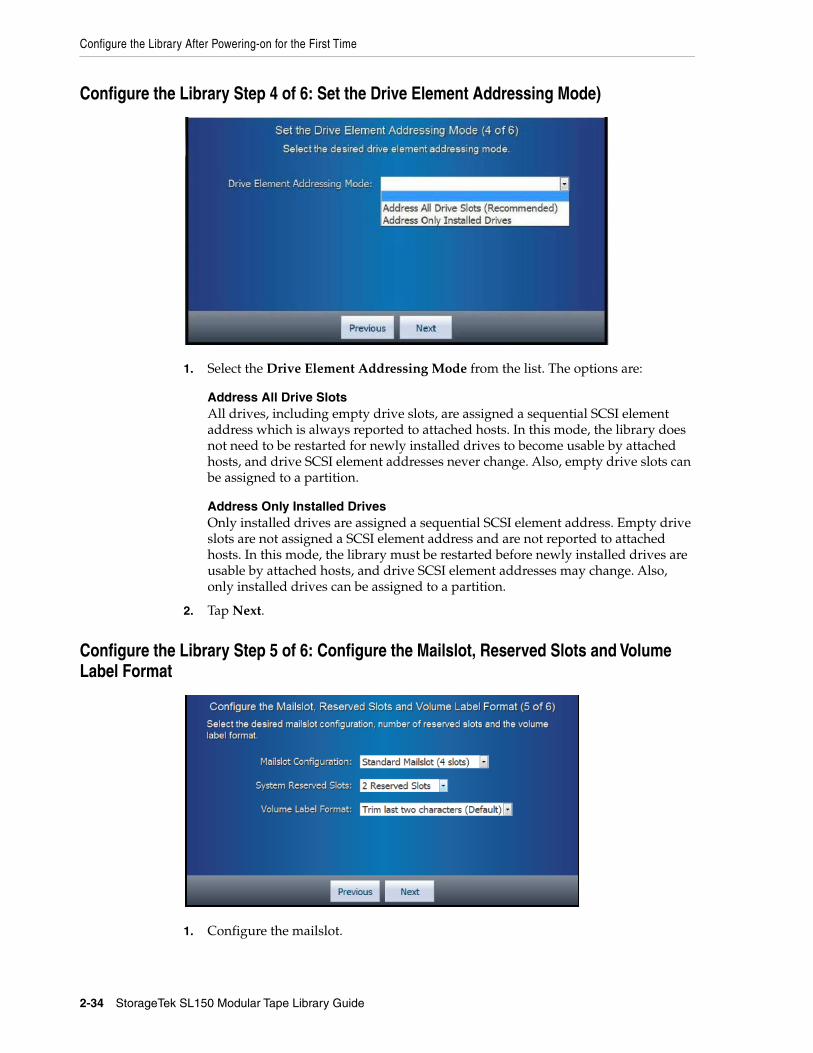
Configure the Library After Powering-on for the First Time
2-34 StorageTek SL150 Modular Tape Library Guide
Configure the Library Step 4 of 6: Set the Drive Element Addressing Mode)
1. Select the Drive Element Addressing Mode from the list. The options are:
Address All Drive SlotsAll drives, including empty drive slots, are assigned a sequential SCSI elementaddress which is always reported to attached hosts. In this mode, the library doesnot need to be restarted for newly installed drives to become usable by attachedhosts, and drive SCSI element addresses never change. Also, empty drive slots canbe assigned to a partition.
Address Only Installed DrivesOnly installed drives are assigned a sequential SCSI element address. Empty driveslots are not assigned a SCSI element address and are not reported to attachedhosts. In this mode, the library must be restarted before newly installed drives areusable by attached hosts, and drive SCSI element addresses may change. Also,only installed drives can be assigned to a partition.
2. Tap Next.
Configure the Library Step 5 of 6: Configure the Mailslot, Reserved Slots and VolumeLabel Format
1. Configure the mailslot.
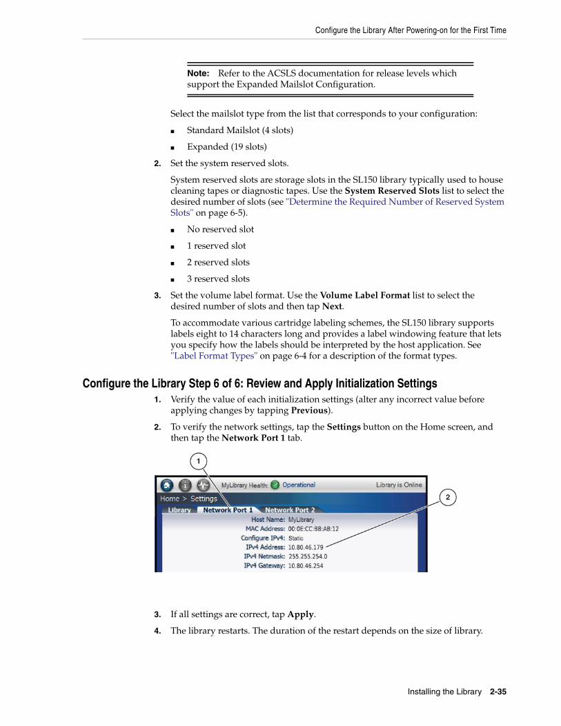
Configure the Library After Powering-on for the First Time
Installing the Library 2-35
Select the mailslot type from the list that corresponds to your configuration:
■ Standard Mailslot (4 slots)
■ Expanded (19 slots)
2. Set the system reserved slots.
System reserved slots are storage slots in the SL150 library typically used to housecleaning tapes or diagnostic tapes. Use the System Reserved Slots list to select thedesired number of slots (see "Determine the Required Number of Reserved SystemSlots" on page 6-5).
■ No reserved slot
■ 1 reserved slot
■ 2 reserved slots
■ 3 reserved slots
3. Set the volume label format. Use the Volume Label Format list to select thedesired number of slots and then tap Next.
To accommodate various cartridge labeling schemes, the SL150 library supportslabels eight to 14 characters long and provides a label windowing feature that letsyou specify how the labels should be interpreted by the host application. See"Label Format Types" on page 6-4 for a description of the format types.
Configure the Library Step 6 of 6: Review and Apply Initialization Settings1. Verify the value of each initialization settings (alter any incorrect value before
applying changes by tapping Previous).
2. To verify the network settings, tap the Settings button on the Home screen, andthen tap the Network Port 1 tab.
3. If all settings are correct, tap Apply.
4. The library restarts. The duration of the restart depends on the size of library.
Note: Refer to the ACSLS documentation for release levels whichsupport the Expanded Mailslot Configuration.
Run a Self-Test
2-36 StorageTek SL150 Modular Tape Library Guide
5. After the restart completes, the Home screen appears on the touch screen. LibraryHealth displays in the status bar at the top of the screen. If the library is notOperational, perform the troubleshooting procedures listed in "Servicing theLibrary" on page 9-1 before proceeding.
Configure the Library: Finish the New ConfigurationAt this point, the newly installed tape library should be operational. But to finish theconfiguration and fully integrate the equipment into your environment, you may needto carry out the following, additional tasks:
■ Upgrade library or drive firmware (see "Update Library and Drive Firmware" onpage 4-7).
■ Add any additional users that you require (see "Add a User and Assign a Role" onpage 5-1).
■ Set up system monitoring, if required (see "Configure Simple NetworkManagement Protocol (SNMP)" on page 7-2).
■ Configure system notifications, if required (see "Configure Email Notifications" onpage 7-5).
■ Load cartridge magazines (see "Importing and Exporting Cartridges" on page 6-1).
Run a Self-TestA self-test can be helpful for troubleshooting. Before placing a newly installed orreconfigured library into production, you should run a full self test.
1. Before running a self-test, verify the following:
■ There is at least one diagnostic tape ("DG" label) in the mailslot or reservedsystem slot. The diagnostic tape should be compatible with at least oneunoccupied drive.
■ The mailslot is closed and all magazines are securely latched.
■ At least one of the four slots in the standard mailslot is empty.
■ At least one slot in the library is empty.
2. From the remote interface, select Library in the left menu.
3. From the Library drop-down , select Run Self Test.
4. Select a test type:
■ Basic Self Test — a quick (6 move) test used to verify basic library function totest robot access to the corner locations of the library.
■ Full Self Test — a thorough test that moves a tape to every slot and to everyunoccupied drive compatible with the chosen diagnostic tape. A full test cantake significant time depending on the number of modules in the library, soplan accordingly.
Caution: Do not manually remove a cartridge magazine while thelibrary is performing the restart. Only perform a manual cartridgemagazine removal when the library is operational and offline.
Run a Self-Test
Installing the Library 2-37
5. Optionally, select Set the Library back Online to automatically bring the libraryonline after the test (the library goes offline to perform the self test)
6. Click OK to start the test.
7. If you did not check the Set the Library back Online checkbox, remember to bringthe library back online manually, once you are ready. See "Place the Library Onlineand Offline" on page 9-1.
Stopping a Self-testTo stop a test that is in progress, from the Library drop-down , select Stop thecurrent test. The test may take a few moments to stop. If the diagnostic cartridge wasnot returned to its reserved cell at the end of the test, move the diagnostic cartridgenow (see "Move Tape Cartridges with the Remote Interface" on page 6-11).
Note: If the test fails, click Degraded to open a health tableidentifying a failed or degraded component. See "Use the HealthTable to Diagnose the Issue" on page 9-7 more information.

Run a Self-Test
2-38 StorageTek SL150 Modular Tape Library Guide
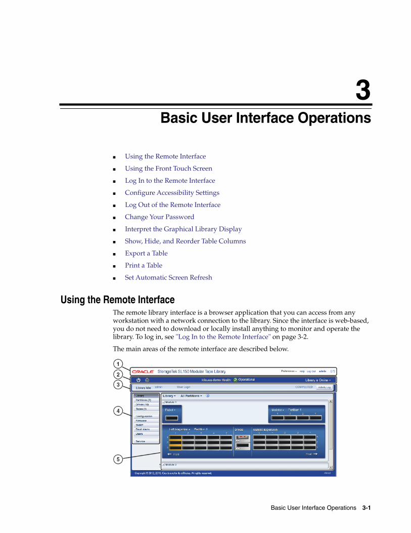
3
Basic User Interface Operations 3-1
3Basic User Interface Operations
■ Using the Remote Interface
■ Using the Front Touch Screen
■ Log In to the Remote Interface
■ Configure Accessibility Settings
■ Log Out of the Remote Interface
■ Change Your Password
■ Interpret the Graphical Library Display
■ Show, Hide, and Reorder Table Columns
■ Export a Table
■ Print a Table
■ Set Automatic Screen Refresh
Using the Remote InterfaceThe remote library interface is a browser application that you can access from anyworkstation with a network connection to the library. Since the interface is web-based,you do not need to download or locally install anything to monitor and operate thelibrary. To log in, see "Log In to the Remote Interface" on page 3-2.
The main areas of the remote interface are described below.
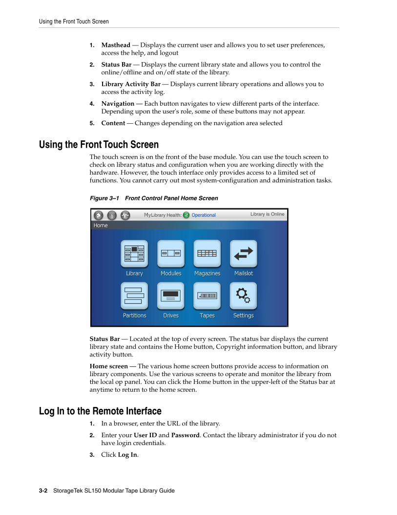
Using the Front Touch Screen
3-2 StorageTek SL150 Modular Tape Library Guide
1. Masthead — Displays the current user and allows you to set user preferences,access the help, and logout
2. Status Bar — Displays the current library state and allows you to control theonline/offline and on/off state of the library.
3. Library Activity Bar — Displays current library operations and allows you toaccess the activity log.
4. Navigation — Each button navigates to view different parts of the interface.Depending upon the user's role, some of these buttons may not appear.
5. Content — Changes depending on the navigation area selected
Using the Front Touch ScreenThe touch screen is on the front of the base module. You can use the touch screen tocheck on library status and configuration when you are working directly with thehardware. However, the touch interface only provides access to a limited set offunctions. You cannot carry out most system-configuration and administration tasks.
Figure 3–1 Front Control Panel Home Screen
Status Bar — Located at the top of every screen. The status bar displays the currentlibrary state and contains the Home button, Copyright information button, and libraryactivity button.
Home screen — The various home screen buttons provide access to information onlibrary components. Use the various screens to operate and monitor the library fromthe local op panel. You can click the Home button in the upper-left of the Status bar atanytime to return to the home screen.
Log In to the Remote Interface1. In a browser, enter the URL of the library.
2. Enter your User ID and Password. Contact the library administrator if you do nothave login credentials.
3. Click Log In.
Interpret the Graphical Library Display
Basic User Interface Operations 3-3
Configure Accessibility SettingsUsers with low vision, blindness, color blindness, or other visual impairments canadjust Accessibility Settings when logging into the remote interface:
1. From the login screen, select Set Accessibility Settings.
■ Screen reader - If you are using a screen reader, select this option. Theinterface generates components that have rich user interface interaction andare accessible through the keyboard.
■ High contrast - The interface generates high-contrast-friendly visual content.High-contrast mode is designed for use with operating systems or browsersthat have high-contrast features enabled.
■ Large-fonts - The interface generates browser zoom-friendly content.
2. Click Log In to close the property sheet and log in to the library.
Navigate the User Interface with a KeyboardYou can navigate between the different parts of an SL150 user interface screen, menu,or list using the tab and arrow keys on the keyboard. You select interface elements bypressing the Return key on the keyboard.
Log Out of the Remote InterfaceFor security reasons, always log out using the procedure below. While the interfacewill log out inactive users automatically, you should not rely on this. Never leave asession open and unattended.
1. Near the top right of the interface, click Log Out.
2. Wait until the "Logged Out" dialog indicates that you have successfully signed outbefore closing the browser window.
Change Your Password1. In the dashboard area at the top of the interface, click the Preferences control.
2. From the context menu, select Change Password.
3. In the Old Password field, enter your current password.
4. In the Password field, enter your new password.
5. In the Verify Password field, re-enter your new password.
See Also:
■ "Reset Another User's Password" on page 5-2
Interpret the Graphical Library DisplayThe Library screen of the SL150 user interface lets you view the locations andcharacteristics of library components at a glance. You can view the whole library or, ifpartitioned between hosts, a single partition at a time. When you place the cursor overone of these tape icons, the icon is highlighted and a fly-over tool tip displays thecorresponding slot address and label value.
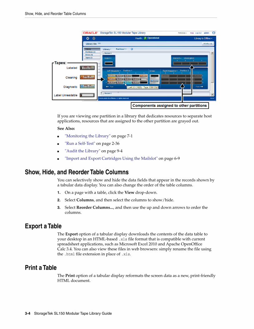
Show, Hide, and Reorder Table Columns
3-4 StorageTek SL150 Modular Tape Library Guide
If you are viewing one partition in a library that dedicates resources to separate hostapplications, resources that are assigned to the other partition are grayed out.
See Also:
■ "Monitoring the Library" on page 7-1
■ "Run a Self-Test" on page 2-36
■ "Audit the Library" on page 9-4
■ "Import and Export Cartridges Using the Mailslot" on page 6-9
Show, Hide, and Reorder Table ColumnsYou can selectively show and hide the data fields that appear in the records shown bya tabular data display. You can also change the order of the table columns.
1. On a page with a table, click the View drop-down.
2. Select Columns, and then select the columns to show/hide.
3. Select Reorder Columns..., and then use the up and down arrows to order thecolumns.
Export a TableThe Export option of a tabular display downloads the contents of the data table toyour desktop in an HTML-based .xls file format that is compatible with currentspreadsheet applications, such as Microsoft Excel 2010 and Apache OpenOfficeCalc 3.4. You can also view these files in web browsers: simply rename the file usingthe .html file extension in place of .xls.
Print a TableThe Print option of a tabular display reformats the screen data as a new, print-friendlyHTML document.
Set Automatic Screen Refresh
Basic User Interface Operations 3-5
Set Automatic Screen RefreshYou can pause and resume automatic refreshes of the browser-based user interface.
1. In the top-right of the remote interface, click Preferences.
2. Select Pause Automatic Refresh or Resume Automatic Refresh from thedrop-down menu.
When auto-refresh is paused, you must use your web browser's reload/refreshcontrol.

Set Automatic Screen Refresh
3-6 StorageTek SL150 Modular Tape Library Guide
4
Configuring the Library 4-1
4Configuring the Library
This this section covers how to change the library configuration at any time after theinitial installation configuration. For initial installation configuration, see "Configurethe Library After Powering-on for the First Time" on page 2-30.
■ Set the Time, Network Address, Library Settings, and Encryption
■ Update Library and Drive Firmware
■ Manage the Library’s SSL/TLS Certificate for HTTPS
Set the Time, Network Address, Library Settings, and EncryptionUse the configuration wizard to change the library time, network parameters, librarysettings (such as auto cleaning, mailslots, partitioning, and so on), and encryption.
■ "Run the Configuration Wizard" on page 4-1
■ "Configure the Network Interfaces" on page 4-2
■ "Set the Library Date and Time" on page 4-3
■ "Configure Library Settings" on page 4-3
■ "Partition the Library" on page 4-5
■ "Configure Library Managed Encryption (LME)" on page 4-6
■ "Review and Apply Configuration Changes" on page 4-7
Run the Configuration Wizard1. From the remote interface, select Configuration in the left menu.
2. Click Configure .
3. Within the Configuration Wizard, select each configuration task that you need toperform, and then click Next. Proceed to the relevant sections:
■ Configure the Network Interfaces
■ Set the Library Date and Time
■ Configure Library Settings
■ Configure Library Managed Encryption (LME)
Note: You cannot configure the network interfaces and encryptionsimultaneously.
Set the Time, Network Address, Library Settings, and Encryption
4-2 StorageTek SL150 Modular Tape Library Guide
Configure the Network InterfacesYou can configure the library's two local area network interfaces:
■ Network Port 1 — connects browser-based, remote user interface clients to theinterface server on the library.
■ Network Port 2 — a second network connection for service use or for librarymanaged encryption (LME) for OKM communication.
Before deciding on a configuration, review the "Behavior of Port 1 and Port 2" onpage 1-4 and consult with your network administrator. Support for IPv6 and localaddressing requirements can vary from site to site.
■ Configure Network Interfaces Task 1: Verify Job Activity and Launch the Wizard
■ Configure Network Interfaces Task 2: Configure Network Port 1
■ Configure Network Interfaces Task 3: Configure Network Port 2 (optional)
Configure Network Interfaces Task 1: Verify Job Activity and Launch the Wizard1. Check the activity log for active jobs, such as tape moves or mounts. Never change
the network configuration during active jobs, if at all possible.
2. If any tape jobs are active, wait for them to complete before continuing. You maywant to take the library offline before configuring to prevent host activity.
3. Run the Configuration Wizard. Select Configure Network Settings.
Configure Network Interfaces Task 2: Configure Network Port 1The library supports either both IPv6 and IPv4 (dual-stack mode) or IPv4-onlyconfiguration. In dual-stack mode, the library continues to recognize IPv4 addresseswhile adding the ability to use hexadecimal IPv6 addresses.
1. Enter the desired library name in the Host Name field.
Valid host names contain characters in the ranges [A-Z], [a-z], and [0-9], plus thehyphen (-). A hyphen cannot be the first or last character in the host name. Spacesand underscores (_) are not supported.
2. From the "Configure Network for" drop-down list select either:IPv4 only or IPv4 and IPv6
3. For IPv4 select either:
■ Static — You must enter the Address, Netmask, and Gateway. In most cases,you will want to choose Static so that library interface clients can always findthe server at a stable, well-known network location.
■ DHCP — A DHCP server must be running on your network to use thissetting.
4. For IPv6 select either:
■ Static — You must enter the Address, Prefix Length, and Gateway. In general,if your DNS (Domain Name Service) supports IPv6 addresses, select Static sothat library interface clients can always find the server at a stable, well-knownnetwork location.
■ Stateless (SLAAC) — If DNS does not support IPv6 addresses, select Stateless(SLAAC). With a stateless address, library interface clients can find the serverat an address based on the unique MAC (media access control) address of the
Set the Time, Network Address, Library Settings, and Encryption
Configuring the Library 4-3
network interface card in the robot/controller assembly. A stateless addresswill not change unless the robot has to be replaced
■ DHCPv6 — If a DHCPv6 server is available on your network, you can selectDHCPv6. Be aware the network address of the library user interface willchange.
5. Click Next.
Configure Network Interfaces Task 3: Configure Network Port 2 (optional)With library code 3.50 and above, you can configure Network Port 2 for librarymanaged encryption (LME). Configuring Port 2 will force LME through Port 2 only.Leaving the Port 2 configuration set to default will force LME through Port 1 only.
1. From the Network Port 2 list, select On or Off.
2. For IPv4 select either: Static or DHCP (see Configure Network Interfaces Task 2:Configure Network Port 1 for a description of these options).
The library supports Port 2 being on the same subnet as KMA IPv4 addresses.Entering a gateway is not required if Port 2 and the KMA are on the same subnet.You should enter a gateway that can reach all OKM cluster KMA’s.
3. Click Next.
Set the Library Date and Time1. Run the Configuration Wizard. Select Set the Library Date and Time.
2. Select the Time Zone and Closest City or Region from the drop-down lists. ClickNext.
3. Either set the time Manually or use NTP:
■ Manually — Enter the date using the format mm/dd/yyyy (month/day/year).Enter the time using the format hh:mm:ss (hour:minute:seconds).
■ Network Time Protocol — Enter the addresses of up to three NTP servers.
4. Click Next.
Configure Library Settings1. Run the Configuration Wizard. Select Configure Library Settings.
2. Select the Drive Element Addressing Mode. The correct setting for your systemdepends on your current configuration (for help deciding on a mode, see"Selecting a Drive Element Addressing Mode" on page 4-4).
IMPORTANT: Do not configure Port 2 for any other use than withLME, otherwise you may encounter issues. If you are not using LME,Oracle recommends that you leave Port 2 set to the defaults. See"Behavior of Port 1 and Port 2" on page 1-4 for more information.
Note: You should configure Port 2 to be on a different network thanPort 1 to create a secure and private connection to pass the encryptionkeys between the library and the OKM cluster.
Set the Time, Network Address, Library Settings, and Encryption
4-4 StorageTek SL150 Modular Tape Library Guide
■ Address All Drive Slots (Recommended) — Assigns new SCSI hardwareaddresses to all drive bays in the library, whether or not drives are actuallyinstalled.
■ Address Only Installed Drives — Assigns SCSI address to drive bays thatcontain an installed drive. Does not address empty drive bays.
3. Select a Drive Auto Clean mode:
■ On — Enables library auto cleaning. You must have one or two cleaningcartridges in reserve slots to enable this feature. See "Configure DriveCleaning" on page 8-1 for more information.
■ Off — Disables library auto cleaning. You must configure host-managedcleaning or manually clean. See "Configure Drive Cleaning" on page 8-1 formore information.
4. Select the Mailslot Configuration:
■ Standard (4 slots)
■ Expanded (19 slots) — Converts the right magazine of the base module intoan additional mailslot. The magazine must be empty before selecting thisconfiguration.
5. Select the number System Reserve Slots. If you are unsure on the number required,see "Determine the Required Number of Reserved System Slots" on page 6-5.
6. Select whether to partition the library:
■ Partitioning Off
■ Partitioning On — You will need to partition the library now (see "Partitionthe Library" on page 4-5).
7. Select a Library Bridged Drive. The default bridged drive is Module 1 Top Drive.For more information on bridge drives, see "About Bridged Tape Drives" onpage 1-5.
8. Select a Library Volume Label Format. For a description of each type, see"Labeling Cartridges" on page 6-3.
Selecting a Drive Element Addressing ModeUse the following guidelines to help decide which addressing mode to select.
Select Address All Drive Slots if:
■ If you control the library using a version of Oracle StorageTek ACSLS softwarethat supports the Drive Element Addressing option.
■ If you are installing a new library. This means host system drive assignments donot need to be remapped when drives are subsequently added or replaced.
Select Address Only Installed Drives if:
■ If you control the library using a version of Oracle StorageTek ACSLS softwarethat does not support the Drive Element Addressing option.
■ If you are upgrading an SL150 library that does not currently assign addresses toempty drive bays. Entering Address Only Installed Drives retains the currentaddresses and assigns the next address in sequence to the new drive.
Set the Time, Network Address, Library Settings, and Encryption
Configuring the Library 4-5
Partition the LibraryPartitioning lets multiple host systems access library resources. Each partition behavesas an independent library, but all partitions share the reserved cells, the single robot,and the four-cartridge mailslot.
Requirements:
■ Maximum of 8 partitions (code versions before 2.0 only support two partitions)
■ Each partition must have it’s own bridged drive
■ Each partition must have at least one magazine
Tasks:
■ Partition the Library Task 1: Create a New Partition
■ Partition the Library Task 2: Assign Resources to the Partition
■ Partition the Library Task 3: Delete an Existing Partition
■ Partition the Library Task 4: Verify the Partitioning Configuration Changes
Partition the Library Task 1: Create a New PartitionTo access the Configure Library Partitioning screen: Run the Configuration Wizard.Select Configure Library Settings. Select Partitioning On, and then click Next. Usethe tasks below to create the partitioning configuration.
If at any point you do not wish to proceed, click Previous or Cancel.
1. Click Add Partition.
2. Enter the Partition Name.
3. Select a Bridged Drive from the list. Each partition must have a bridged drive. Formore information on bridge drives, see "About Bridged Tape Drives" on page 1-5.
4. Select a Volume Label Format from the list (see "Labeling Cartridges" on page 6-3for more information).
5. Assign the partition resources, see .
Partition the Library Task 2: Assign Resources to the Partition1. In the left-hand manu, select the partition to modify.
2. To add resources to the partition, click on an unassigned resource (gray in color).For each partition that you need to add to the current library configuration, createa new partition.
3. To remove resources from the partition, click on a resource the partition owns.
Partition the Library Task 3: Delete an Existing Partition
1. In the left-hand manu, select the partition to delete.
2. Click Delete Partition, just below the list of partitions.
IMPORTANT: Before deleting a partition, make sure that it no longerholds tape volumes that contain valid data. When you reassign theslots, the host application that controls the partition may treat anyresident tape cartridges as scratch volumes.
Set the Time, Network Address, Library Settings, and Encryption
4-6 StorageTek SL150 Modular Tape Library Guide
3. Click OK. Reassign resources as needed (see Partition the Library Task 2: AssignResources to the Partition above).
4. Otherwise, if you are finished, review and apply the configuration changes.
Partition the Library Task 4: Verify the Partitioning Configuration ChangesOnce you are finished partitioning, review your changes and then click Next.
Configure Library Managed Encryption (LME)The library can manage the encryption enrollment and key delivery of all IBM LTO-7or higher drives. For HP LTO-6 drives and earlier, you must still use the Virtual OpPanel (VOP) software to enroll the drives.
■ Configure LME Task 1: Obtain Information from OKM
■ Configure LME Task 2: Configure the SL150 to Manage Encryption
■ Configure LME Task 3: Verify the SL150 Agent is Enrolled
Configure LME Task 1: Obtain Information from OKMHave the OKM administrator use the OKM GUI to create an SL150 library agent andthen record the following information to use in the SL150 configuration:
■ Agent Name
■ Passphrase
Configure LME Task 2: Configure the SL150 to Manage Encryption
1. In the SL150 GUI, Run the Configuration Wizard. Select Configure LibraryEncryption.
2. Set "Library Encryption Status" to Encrypting.
This globally enables library managed encryption for all IBM LTO-7+ driveswithin the library regardless of the partitioning configuration.
3. Enter the following information:
■ OKM Cluster IP address
■ Agent ID
■ Agent Passphrase
4. Note the port that will be used for OKM communication.
If you altered the Port 2 configuration, all LME traffic will go through Port 2. Ifyou left the Port 2 configuration set to default values, LME traffic will go throughPort 1.
5. Leave the OKM tuning parameters at their default setting unless instructed tochange them by your OKM administrator.
IMPORTANT: Library encryption must be configured separately andafter all other library configuration options. Make sure you havecompleted the network configuration and completed a library rebootbefore configuring encryption. If not, see "Configure the NetworkInterfaces" on page 4-2.
Update Library and Drive Firmware
Configuring the Library 4-7
6. Click Next, then review and apply the changes.
Configure LME Task 3: Verify the SL150 Agent is EnrolledAfter confirming the changes within the Configuration Wizard, have the OKMadministrator go to the OKM GUI and verify that the SL150 agent now shows"Enrolled: True".
See the OKM documentation for more information.
Review and Apply Configuration Changes1. Review the Summary of Configuration Changes screen. Altered settings are
indicated by "changed" in the changes column.
2. Note any alerts at the bottom of the screen.
3. If you see a problem, click Previous to return to an earlier screen or Cancel to quit.
4. Otherwise, select the Accept all changes check box, and then click Apply.
Update Library and Drive FirmwareYou should check and update firmware after you first install the library. Oraclerecommends that you regularly check for firmware updates.
■ Identify Current Firmware Versions
■ Download Firmware from My Oracle Support
■ Upgrade the Library Firmware
■ Upgrade the Drive Firmware
■ Revert to the Previous Library Firmware
Identify Current Firmware Versions1. From the remote interface, select Firmware in the left menu.
2. Click the Library Firmware tab. Note the Current Firmware Version field
3. Click the Drive Firmware tab. For each drive in the list, note the values:
■ Firmware Version — contains an alphanumeric string
■ Type — a vendor identifier plus an LTO Generation number
■ Interface Type — Fibre (for Fibre Channel) or SAS (for Serial Attached SmallComputer System Interface)
Download Firmware from My Oracle Support1. Log in to My Oracle Support: https://support.oracle.com.
2. Click the Patches & Updates tab.
3. Within the Patch Search area, click on the Product or Family (Advanced) link.
4. In the Product is field, enter:
■ For library firmware: Enter SL150, and then select StorageTek SL150 ModularTape Library from the list of results.
Update Library and Drive Firmware
4-8 StorageTek SL150 Modular Tape Library Guide
■ For drive firmware: Enter LTO, and then select the drive model (for example,IBM LTO7 Tape Drive).
5. From the Release drop-down list, select the release version you want to download(for example 3.20 for library firmware, or HH-FC or HH-SAS for drive firmware).
6. Click Search.
7. In the Patch Search Results table, click a row. A button bar displays.
8. Click Read Me to confirm the firmware version.
For drive firmware, make sure it is intended for the SL150 library. Note thefirmware release level. Scan the drive firmware Read Me file for lines like thefollowing:
Unbundled Product: StorageTek LTO-6hh FC Tape Drive for the SL150 libraryUnbundled Release: 23DS
9. Click Download, and then within the download dialog click the file name to beginthe download.
Library firmware is named p12345678_xyz0_Generic.zip, where p12345678represents a part number, x represents the major release number, and yz representsthe minor release number.
Drive firmware is named 123456_01.zip, where 123456_01 represents a partnumber.
Verify the Download1. At the bottom of the File Download dialog, click on the View Digest Details link.
2. Copy the MD5 and SHA checksums and paste them into a text file.
3. Verify the integrity of the downloaded ZIP file. Using a suitable checksum utility,calculate the MD5 or SHA-1 digest value of the downloaded file, and compare theresult to the corresponding MD5 or SHA-1 value saved in your text file.
You can use digest (Oracle Solaris) and dgst (Linux). Microsoft offers acommandline File Checksum Integrity Verifier utility (fciv.exe) as a freedownload from http://support.microsoft.com/kb/841290.
4. If the digest value that you calculated for the file does not match the valuedisplayed in the dialog, the file is corrupt and cannot be installed successfully.Stop here, and re-download the firmware zip.
Upgrade the Library Firmware1. Download the library firmware (see "Download Firmware from My Oracle
Support" on page 4-7).
2. Extract the firmware ZIP (the extracted file should contain a .tar file and releasenotes).
3. Log in to the remote interface as an administrator.
4. Select Firmware in the left menu.
5. Select the Library Firmware tab, and then click Upgrade .
6. Browse to the folder that contains the firmware, and select the SL150_xyz0.tarfile, where xyz0 is the four-digit form of the release number.
7. To install the new firmware and restart the library, click OK.
Update Library and Drive Firmware
Configuring the Library 4-9
The upgrade dialog displays a progress meter and the estimated time required forthe upgrade. Do not close this window until the installation process finishes.
8. If a library firmware upgrade fails, create a service request. For more information,see "Create a Service Request" on page 9-11.
Upgrade the Drive FirmwareIf possible, update drive firmware during periods when host applications are notmaking heavy use of the library. The library cannot respond to host commands duringthe updates, which may take up to 20 minutes per tape drive.
For each drive model and interface type that requires new firmware, proceed asfollows:
1. Download the drive firmware (see "Download Firmware from My Oracle Support"on page 4-7)
2. Extract the drive firmware ZIP (the extracted folder should contain HTML andtext release notes, a LEGAL_LICENSE.TXT file, a tload.tar file, and two versions ofthe firmware file).
3. Log in to the remote user interface as an administrator.
4. Take the library offline (see "Place the Library Online and Offline" on page 9-1).
5. Select Firmware in the left menu. Click the Drive Firmware tab.
6. Click Upgrade Drive Firmware .
7. Click on the table entries to select the drive(s) that you want to update (hold downthe Shift key to select multiple drives). Click Next.
8. Browse to the folder that contains the drive firmware, and select the file with the.E extension (such as Z5BD.E).
9. Verify you have selected the correct file, and then click Upgrade. The updatebegins immediately.
If you are updating multiple drives, you can click Cancel to skip the upgrade forany drives that have not yet been processed. However, the upgrade that iscurrently underway will continue.
10. If a firmware upgrade fails, make sure that the chosen firmware is correct for theLTO generation and interface specification of the drive. If it is not, repeat thisprocedure to download a copy of the correct firmware.
11. When all firmware is up to date, bring the library back online.
Revert to the Previous Library FirmwareIf you ever have problems with a library firmware update, you can roll the libraryback to the most recent, previously installed version using the following procedure.
1. Log in to the remote user interface as an administrator.
2. Click Firmware in the left menu.
3. To roll back the library firmware, click Revert .
4. If the library has been operating normally and if its contents have not changed,check the Bypass audit for a faster restart ... check box.
5. Click OK to restart the library and activate the old firmware.
Manage the Library’s SSL/TLS Certificate for HTTPS
4-10 StorageTek SL150 Modular Tape Library Guide
Manage the Library’s SSL/TLS Certificate for HTTPSA certificate encrypts SSL/TLS traffic to and from the library. At initial installation, thelibrary has a default certificate. At a minimum, you should replace the defaultcertificate with a new self-signed certificate. Then, optionally, you can installed acertificate signed by a certifying authority (CA).
■ Generate a Self-Signed Certificate
■ Install a Third-Party Signed Certificate
Generate a Self-Signed CertificateA self-signed certificate is secure, but will require you to manually tell the browser totrust the certificate before you can view the login screen. To eliminate this browsersecurity exception, you can install a certificate signed by a certifying authority (CA)(see "Install a Third-Party Signed Certificate" on page 4-10).
1. Click Configuration in the left navigation area of the GUI.
2. Click the Certificate tab, and then click New Certificate .
3. Enter in the certificate information.
Install a Third-Party Signed CertificateInstalling a third-party certificate is a multistep process of submitting a certificatesigning request (CSR) to the CA, obtaining the certificate from the CA, and thenimporting the certificate file to the library.
■ Install a Certificate Task 1: Verify the Library Has a Self-Signed Certificate
■ Install a Certificate Task 2: Export Certificate Signing Request (CSR) File
■ Install a Certificate Task 3: Obtain Required Certificates
■ Install a Certificate Task 4: Import the Certificate File
Install a Certificate Task 1: Verify the Library Has a Self-Signed CertificateThe library must have a self-signed certificate before installing a third-party signedcertificate. You cannot go directly from the default certificate to a third-partycertificate. To install the self-signed certificate, see "Generate a Self-Signed Certificate"on page 4-10.
Install a Certificate Task 2: Export Certificate Signing Request (CSR) File1. Click Configuration in the left navigation area of the GUI.
2. Click the Certificate tab, and then click Export CSR .
3. Click Download.
4. Submit the CSR to the third-party certifying authority (CA).
Install a Certificate Task 3: Obtain Required CertificatesVerify that you have obtained the following before importing:
■ Primary certificate of the trust anchor CA (such as VeriSign's public primary rootCA)
Manage the Library’s SSL/TLS Certificate for HTTPS
Configuring the Library 4-11
■ Intermediate certificate of the issuing SSL CA (optional). In cases where there is nointermediate issuer, you can omit the intermediate certificate. This is highlysite-specific, so check with your company’s security experts for requirements.
■ Your newly issued SSL certificate
Install a Certificate Task 4: Import the Certificate File1. Click Configuration in the left navigation area of the GUI.
2. Click the Certificate tab, and then click Import Certificate .
3. Copy and paste each certificate file (as noted above in task 3) into the text box andclick Next. To skip the intermediate certificate, leave the box blank and click Next.

Manage the Library’s SSL/TLS Certificate for HTTPS
4-12 StorageTek SL150 Modular Tape Library Guide
5
Managing Users 5-1
5Managing Users
The library manages user access to the system based on user and role. This sectionoutlines how to add and manage users.
■ User Roles and Access
■ Add a User and Assign a Role
■ Remove a User
■ Change an Assigned Role
■ Reset Another User's Password
User Roles and AccessA user’s role determines their access to library functions. The administrator can assigna user one of the following roles:
■ Viewer — a read-only role. Viewers can login, monitor library operations, andview component states and properties, but they cannot alter the configuration oroperation of the library.
■ Operator — limited control over the operation of the library, but cannot changethe configuration. Operators can take the library online/offline, power the libraryon/off, import and export cartridges, and run self-tests.
■ Administrator — has full control over the operation and configuration of thelibrary, and can manage other users. The administrator can grant or deny usersaccess, assign user roles, set and change library properties, configure the TCP/IPconnection and SNMP communication. Since the administrator role can alterconfiguration settings, you should limit the number of users with this role.
■ Service — a special role for service technicians. The service user has all theprivileges of an administrator except for managing users. When you require theassistance of an Oracle service representative, you can create a log-in account forthe service person and assign the account to the Service user.
See Also:
■ "Add a User and Assign a Role" on page 5-1
Add a User and Assign a Role1. Log into the remote interface with the administrator or service role.
2. Select Users in the left menu.
Remove a User
5-2 StorageTek SL150 Modular Tape Library Guide
3. Click Add User .
4. Enter a User ID and Password. Assign a role from the drop-down list.
See Also:
■ "User Roles and Access" on page 5-1
Remove a User1. Log into the remote interface with the administrator role.
2. Select Users in the left menu.
3. Select the user account by clicking on the corresponding table row.
4. Click Delete User .
Change an Assigned Role1. Log into the remote interface with the administrator role.
2. Select Users in the left menu.
3. Select the account by clicking on the corresponding table row.
4. Click Change Role .
5. Select a role from the drop-down list.
See "User Roles and Access" on page 5-1 for more information on each role.
Reset Another User's PasswordTo change your own password, use the Preferences drop-down at the top of the userinterface. See "Change Your Password" on page 3-3.
If you are an administrator, you can change another user's password:
1. Log into the remote interface with the administrator role.
2. Select Users in the left menu.
3. Select the user account by clicking on the corresponding table row.
4. Click Reset Password .
5. Enter a new password.
Note: Once the account is set up, users can choose their ownpasswords. See "Change Your Password" on page 3-3.

6
Importing and Exporting Cartridges 6-1
6Importing and Exporting Cartridges
■ Viewing Tape Cartridge (Media) Health
■ Guidelines for Handling Tape Cartridges
■ Labeling Cartridges
■ Determine the Required Number of Reserved System Slots
■ Determine the Number of Cleaning Cartridges
■ Apply a Label to a Tape Cartridge
■ Prepare Diagnostic, Cleaning, and Data Tape Cartridges
■ Load the Magazines (Bulk Loading)
■ Import and Export Cartridges Using the Mailslot
■ Move Tape Cartridges with the Remote Interface
Viewing Tape Cartridge (Media) HealthAfter a tape mounts to a drive, the drive will report on the health of the tape based oninformation from the tape’s previous use. You can view the health of the specific tapein the Tapes table.
1. From the remote interface, select Tapes in the left menu.
2. View the Media Health column. Possible states are:
■ Unknown — the tape has not yet been mounted in a drive, therefore thehealth of the tape is not known.
■ Operative — the tape is in good health.
■ Degraded — the tape is in moderate health and should be replaced.
■ Failed — the tape is in bad health or incompatible with a tape drive. Itshould not be used and should be replaced.
Guidelines for Handling Tape Cartridges
■ Keep tapes clean and inspect for damage before each use.
CAUTION: Improperly handling tape cartridges can cause loss ofdata or damage the library.
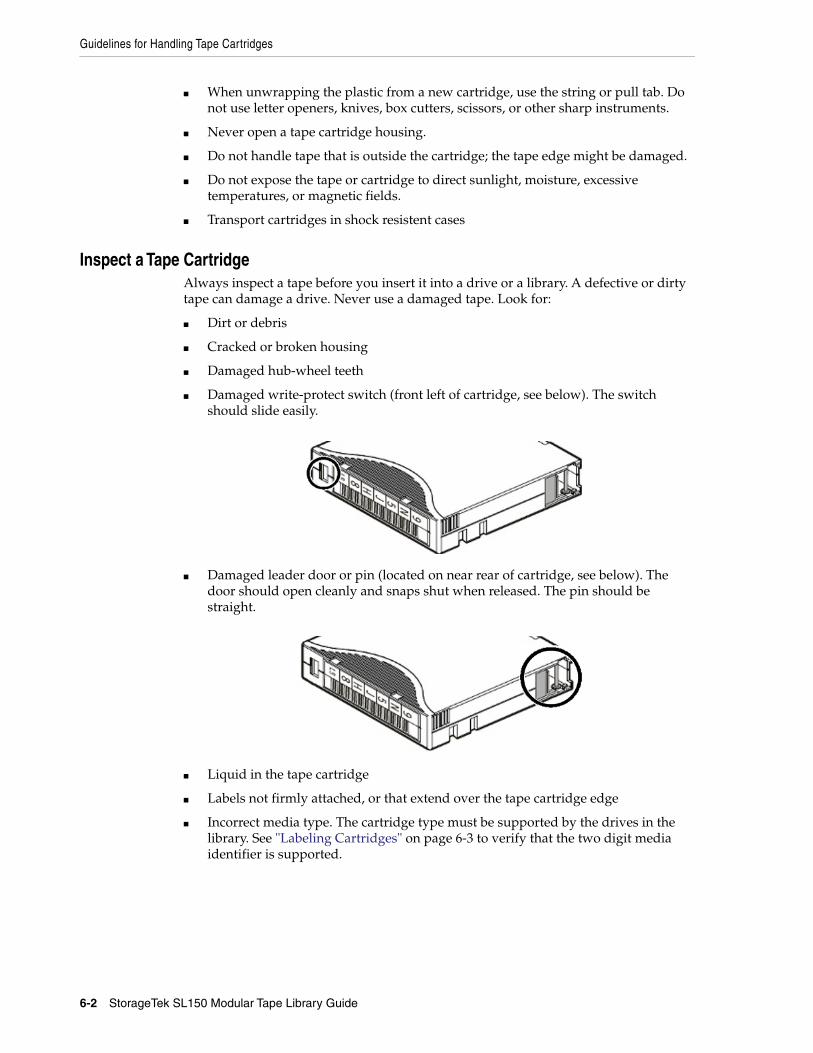
Guidelines for Handling Tape Cartridges
6-2 StorageTek SL150 Modular Tape Library Guide
■ When unwrapping the plastic from a new cartridge, use the string or pull tab. Donot use letter openers, knives, box cutters, scissors, or other sharp instruments.
■ Never open a tape cartridge housing.
■ Do not handle tape that is outside the cartridge; the tape edge might be damaged.
■ Do not expose the tape or cartridge to direct sunlight, moisture, excessivetemperatures, or magnetic fields.
■ Transport cartridges in shock resistent cases
Inspect a Tape CartridgeAlways inspect a tape before you insert it into a drive or a library. A defective or dirtytape can damage a drive. Never use a damaged tape. Look for:
■ Dirt or debris
■ Cracked or broken housing
■ Damaged hub-wheel teeth
■ Damaged write-protect switch (front left of cartridge, see below). The switchshould slide easily.
■ Damaged leader door or pin (located on near rear of cartridge, see below). Thedoor should open cleanly and snaps shut when released. The pin should bestraight.
■ Liquid in the tape cartridge
■ Labels not firmly attached, or that extend over the tape cartridge edge
■ Incorrect media type. The cartridge type must be supported by the drives in thelibrary. See "Labeling Cartridges" on page 6-3 to verify that the two digit mediaidentifier is supported.
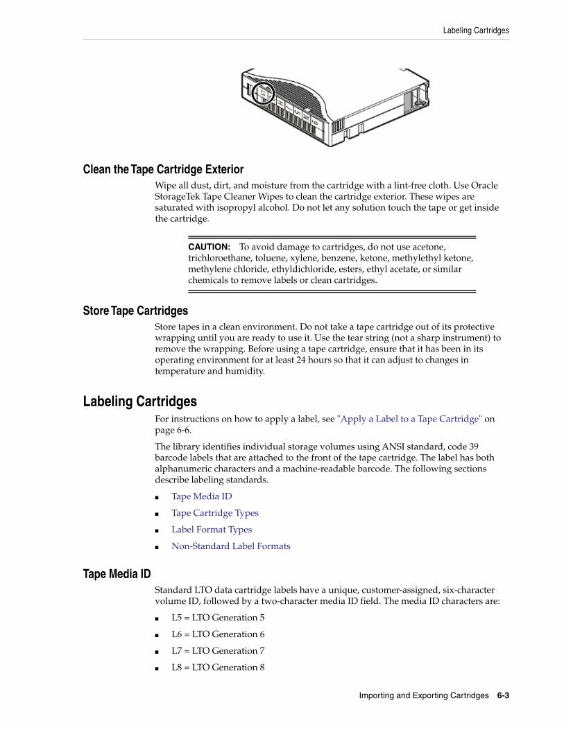
Labeling Cartridges
Importing and Exporting Cartridges 6-3
Clean the Tape Cartridge ExteriorWipe all dust, dirt, and moisture from the cartridge with a lint-free cloth. Use OracleStorageTek Tape Cleaner Wipes to clean the cartridge exterior. These wipes aresaturated with isopropyl alcohol. Do not let any solution touch the tape or get insidethe cartridge.
Store Tape CartridgesStore tapes in a clean environment. Do not take a tape cartridge out of its protectivewrapping until you are ready to use it. Use the tear string (not a sharp instrument) toremove the wrapping. Before using a tape cartridge, ensure that it has been in itsoperating environment for at least 24 hours so that it can adjust to changes intemperature and humidity.
Labeling CartridgesFor instructions on how to apply a label, see "Apply a Label to a Tape Cartridge" onpage 6-6.
The library identifies individual storage volumes using ANSI standard, code 39barcode labels that are attached to the front of the tape cartridge. The label has bothalphanumeric characters and a machine-readable barcode. The following sectionsdescribe labeling standards.
■ Tape Media ID
■ Tape Cartridge Types
■ Label Format Types
■ Non-Standard Label Formats
Tape Media IDStandard LTO data cartridge labels have a unique, customer-assigned, six-charactervolume ID, followed by a two-character media ID field. The media ID characters are:
■ L5 = LTO Generation 5
■ L6 = LTO Generation 6
■ L7 = LTO Generation 7
■ L8 = LTO Generation 8
CAUTION: To avoid damage to cartridges, do not use acetone,trichloroethane, toluene, xylene, benzene, ketone, methylethyl ketone,methylene chloride, ethyldichloride, esters, ethyl acetate, or similarchemicals to remove labels or clean cartridges.
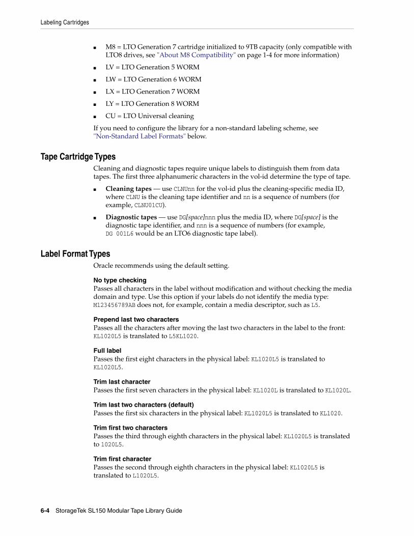
Labeling Cartridges
6-4 StorageTek SL150 Modular Tape Library Guide
■ M8 = LTO Generation 7 cartridge initialized to 9TB capacity (only compatible withLTO8 drives, see "About M8 Compatibility" on page 1-4 for more information)
■ LV = LTO Generation 5 WORM
■ LW = LTO Generation 6 WORM
■ LX = LTO Generation 7 WORM
■ LY = LTO Generation 8 WORM
■ CU = LTO Universal cleaning
If you need to configure the library for a non-standard labeling scheme, see"Non-Standard Label Formats" below.
Tape Cartridge TypesCleaning and diagnostic tapes require unique labels to distinguish them from datatapes. The first three alphanumeric characters in the vol-id determine the type of tape.
■ Cleaning tapes — use CLNUnn for the vol-id plus the cleaning-specific media ID,where CLNU is the cleaning tape identifier and nn is a sequence of numbers (forexample, CLNU01CU).
■ Diagnostic tapes — use DG[space]nnn plus the media ID, where DG[space] is thediagnostic tape identifier, and nnn is a sequence of numbers (for example,DG 001L6 would be an LTO6 diagnostic tape label).
Label Format TypesOracle recommends using the default setting.
No type checkingPasses all characters in the label without modification and without checking the mediadomain and type. Use this option if your labels do not identify the media type:M123456789AB does not, for example, contain a media descriptor, such as L5.
Prepend last two charactersPasses all the characters after moving the last two characters in the label to the front:KL1020L5 is translated to L5KL1020.
Full labelPasses the first eight characters in the physical label: KL1020L5 is translated toKL1020L5.
Trim last characterPasses the first seven characters in the physical label: KL1020L is translated to KL1020L.
Trim last two characters (default)Passes the first six characters in the physical label: KL1020L5 is translated to KL1020.
Trim first two charactersPasses the third through eighth characters in the physical label: KL1020L5 is translatedto 1020L5.
Trim first characterPasses the second through eighth characters in the physical label: KL1020L5 istranslated to L1020L5.
Determine the Required Number of Reserved System Slots
Importing and Exporting Cartridges 6-5
Non-Standard Label FormatsBy default, the library uses the eight-character label format that is standard for LTOcartridges. While most backup and storage management applications support thestandard LTO labeling format, a few use proprietary labeling schemes to trackvolumes. If you use such an application, you can, in most cases, configure the SL150 toautomatically translate between the physical labels on your cartridges and the logicallabel format that the application uses internally.
Translating Between Physical and Logical LabelsTo accommodate the fullest range of possible labeling schemes, the library supportslabels 8 to 14 characters long and provides a label windowing feature that lets youspecify how labels should be interpreted when communicating with the hostapplication.
So, for example, if the host application uses only a portion of the physical cartridgelabel to identify volumes, you can tell the library to construct a logical label using asubset of the characters. Alternatively, if the physical cartridge label is simply a stringof characters that does not identify the media domain (LTO) and generation, you cantell the library to skip domain and type checking and send all characters to the hostwithout any further processing (you should not use this option, if your labels include adomain and type).
Managing Unidentifiable, Unsupported, or Missing LabelsIf the physical label on a cartridge is missing, misapplied, damaged, or incorrectlyformatted, the cartridge can be loaded and stored in the library. Since the librarysoftware cannot identify the cartridge, it marks the Tape Label field of thecorresponding tape properties sheet [UNREADABLE].
Determine the Required Number of Reserved System SlotsYou can reserve up to a maximum of three slots. Based on your cleaning strategy andyour diagnostic needs, decide how many system reserved slots to configure:
■ Diagnostic Cartridge — may require 1 reserved slot.
If you are planning to use a diagnostic cartridge, Oracle recommends that youconfigure one reserved system slot to hold it. This insures that it is alwaysavailable when needed. But if storage space is at a premium, you can also importthe diagnostic cartridge from the mailslot as needed.
■ Cleaning Cartridge — may require 2 reserved slots.
If using library auto cleaning or manual cleaning: configure at least one,preferably two reserved slots. Two cleaning cartridges in reserved slots minimizesdowntime by insuring a usable cleaning cartridge is always available, so drives donot sit idle while awaiting cleaning.
If using host-managed cleaning: do not configure system reserved slots forcleaning cartridges. Host applications cannot access system reserved slots.Cleaning cartridges must reside in storage slots controlled by the host application.
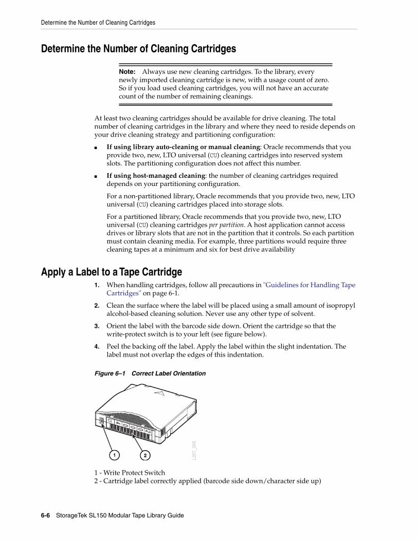
Determine the Number of Cleaning Cartridges
6-6 StorageTek SL150 Modular Tape Library Guide
Determine the Number of Cleaning Cartridges
At least two cleaning cartridges should be available for drive cleaning. The totalnumber of cleaning cartridges in the library and where they need to reside depends onyour drive cleaning strategy and partitioning configuration:
■ If using library auto-cleaning or manual cleaning: Oracle recommends that youprovide two, new, LTO universal (CU) cleaning cartridges into reserved systemslots. The partitioning configuration does not affect this number.
■ If using host-managed cleaning: the number of cleaning cartridges requireddepends on your partitioning configuration.
For a non-partitioned library, Oracle recommends that you provide two, new, LTOuniversal (CU) cleaning cartridges placed into storage slots.
For a partitioned library, Oracle recommends that you provide two, new, LTOuniversal (CU) cleaning cartridges per partition. A host application cannot accessdrives or library slots that are not in the partition that it controls. So each partitionmust contain cleaning media. For example, three partitions would require threecleaning tapes at a minimum and six for best drive availability
Apply a Label to a Tape Cartridge1. When handling cartridges, follow all precautions in "Guidelines for Handling Tape
Cartridges" on page 6-1.
2. Clean the surface where the label will be placed using a small amount of isopropylalcohol-based cleaning solution. Never use any other type of solvent.
3. Orient the label with the barcode side down. Orient the cartridge so that thewrite-protect switch is to your left (see figure below).
4. Peel the backing off the label. Apply the label within the slight indentation. Thelabel must not overlap the edges of this indentation.
Figure 6–1 Correct Label Orientation
1 - Write Protect Switch2 - Cartridge label correctly applied (barcode side down/character side up)
Note: Always use new cleaning cartridges. To the library, everynewly imported cleaning cartridge is new, with a usage count of zero.So if you load used cleaning cartridges, you will not have an accuratecount of the number of remaining cleanings.
Load the Magazines (Bulk Loading)
Importing and Exporting Cartridges 6-7
Prepare Diagnostic, Cleaning, and Data Tape CartridgesBefore loading cartridges into the library you need to prepare the various tapecartridge types: diagnostic, cleaning, and data.
Prepare a Diagnostic Tape CartridgeDiagnostic cartridges are specially labeled data cartridges used for testing libraryrobotics and drives. You can purchase diagnostic cartridges or you can create them byapplying an Oracle-supplied diagnostic label to any available, blank LTO tape. Oraclerecommends that you have a diagnostic tape on hand during system configurationand at all times thereafter, if possible.
To create a diagnostic cartridge, apply the DG label from the library’s accessory kit to ablank LTO data cartridge (see "Apply a Label to a Tape Cartridge" on page 6-6).
Prepare Cleaning Tape CartridgesUniversal cleaning cartridges carry the media descriptor CU. Note that Oracle stronglyrecommends universal cleaning tapes and requires their use with library-manageddrive cleaning. Apply the appropriate label to the cleaning cartridge (see "Apply aLabel to a Tape Cartridge" on page 6-6). Labels for universal cleaning cartridges takethe form CLNUxxCU, where CLNU is a descriptive prefix, xx is a sequence number, and CUis the media descriptor for universal cleaning media.
Prepare the Data Tape CartridgesLocate the correct label for the data tape (see "Labeling Cartridges") and apply thelabel (see "Apply a Label to a Tape Cartridge" on page 6-6). Make sure that the label’smedia ID matches the cartridge type.
If you need to configure the library for a non-standard labeling scheme, see"Non-Standard Label Formats" on page 6-5.
Load the Magazines (Bulk Loading)Each library module has two magazines that hold 15 cartridges each. Before puttingthe library into production, you can load the magazines to save time importingcartridges. Additionally, there may be times when it makes sense to bulk load thelibrary using the magazines. The library must always perform an audit after bulkloading.
■ Load the Magazines Task 1: Unlock and Remove the Magazines
■ Load the Magazines Task 2: Load the Left Magazine in the Base Module
■ Load the Magazines Task 3: Load the Remaining Magazines
■ Load the Magazines Task 4: Locking the Magazines and Auditing the Library
■ Updating Media Health After a Bulk Load
Load the Magazines Task 1: Unlock and Remove the MagazinesIf the magazines have already been inserted into the enclosures, proceed as follows.
1. From the remote interface, select Library in the left menu. For instructions onlogging in, see "Log In to the Remote Interface" on page 3-2.
2. From the Library drop-down menu , select Unlock Magazines.
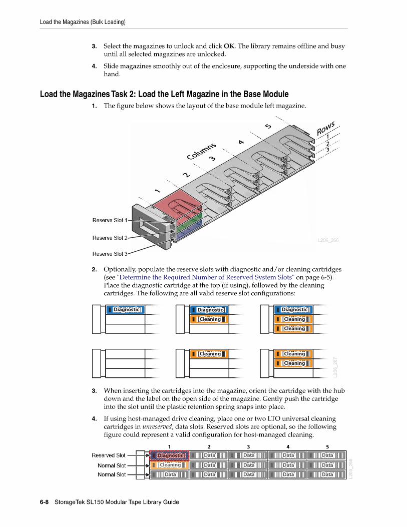
Load the Magazines (Bulk Loading)
6-8 StorageTek SL150 Modular Tape Library Guide
3. Select the magazines to unlock and click OK. The library remains offline and busyuntil all selected magazines are unlocked.
4. Slide magazines smoothly out of the enclosure, supporting the underside with onehand.
Load the Magazines Task 2: Load the Left Magazine in the Base Module1. The figure below shows the layout of the base module left magazine.
2. Optionally, populate the reserve slots with diagnostic and/or cleaning cartridges(see "Determine the Required Number of Reserved System Slots" on page 6-5).Place the diagnostic cartridge at the top (if using), followed by the cleaningcartridges. The following are all valid reserve slot configurations:
3. When inserting the cartridges into the magazine, orient the cartridge with the hubdown and the label on the open side of the magazine. Gently push the cartridgeinto the slot until the plastic retention spring snaps into place.
4. If using host-managed drive cleaning, place one or two LTO universal cleaningcartridges in unreserved, data slots. Reserved slots are optional, so the followingfigure could represent a valid configuration for host-managed cleaning.
Import and Export Cartridges Using the Mailslot
Importing and Exporting Cartridges 6-9
5. Load the remaining slots with data tapes.
6. Once loaded, reinstall the left magazine. Be careful to hold the magazine so thattapes do not fall out. Push the magazine into place until it latches with a click.
Load the Magazines Task 3: Load the Remaining Magazines
1. Slide each magazine out of the enclosure, supporting the underside with onehand.
2. Load data cartridges into the magazine slots.
REMINDER: If host-managed drive cleaning and partitioning the library, placeone, preferably two, LTO universal cleaning cartridges in each partition.
3. Once loaded, reinstall the magazines. Be careful to hold each magazine so thattapes do not fall. Push the magazine into place until it latches with a click.
Load the Magazines Task 4: Locking the Magazines and Auditing the Library1. Log in to the remote user interface.
2. From the Library drop-down menu , select Lock and Audit Magazines.
3. Optionally, select Set the Library back Online... to automatically bring the libraryonline after the audit.
4. Click OK to lock the magazines, take the library offline, and start the audit (see"Audit the Library" on page 9-4).
Updating Media Health After a Bulk LoadThe library assesses each tape and updates the Media Health state whenever thecartridge mounts a drive. After bulk loading tapes, Media Health for many cartridgeswill be listed as "Unknown". As the library mounts cartridges during the course ofroutine operations, the library progressively updates the Media Health property,replacing the "Unknown" values. However, you can force an immediate update of anindividual cartridge by taking the library offline and mounting the cartridge.
Import and Export Cartridges Using the MailslotWhen you need to import cartridges into a library or partition or export them from alibrary or partition, use the mailslot (also known as the cartridge access port or CAP inother StorageTek libraries). The standard mailslot holds up to four cartridges. Theoptional, expanded magazine holds up to nineteen.
To load or unload cartridges using the mailslot, carry out the following tasks:
■ Assign the Mailslot to a Partition (if the library is partitioned),
■ Open the Mailslot,
■ Import Tape Cartridges and Export Tape Cartridges,
■ Close the Mailslot,
IMPORTANT: If using the 19-slot mailslot configuration, leave theright base module magazine empty.
Import and Export Cartridges Using the Mailslot
6-10 StorageTek SL150 Modular Tape Library Guide
■ Unassign the Mailslot when finished.
Assign the Mailslot to a PartitionIf your library is partitioned and controlled by two separate host applications, youmust assign the mailslot to a partition before exporting or importing. For informationon how SCSI hosts handle a shared mailslot, see the SL150 SCSI Reference Guide.
Assign the Mailslot Using the Remote User Interface1. Select Library in the left menu.
2. From the Mailslot drop-down , select Assign.
3. Select a partition from the Assign Mailslot to Partition drop-down list.
Assign the Mailslot Using the Local Operator Panel1. On the Home screen, tap Mailslot.
2. Tap Assign to a Partition at the bottom of the screen.
3. Select a partition to assign.
Import Tape Cartridges1. If importing into a partitioned library, Assign the Mailslot to a Partition.
2. Open the Mailslot, and place the tapes in the mailslot. Close the Mailslot.
3. Use the host application to move the tapes from the mailslot to the storage slots.
If you cannot use the host application, you may Move Tape Cartridges with theRemote Interface. Then, update the host application database to account for thenew tapes.
4. Once you are finished importing tapes, Unassign the Mailslot.
Export Tape Cartridges1. If exporting from a partitioned library, Assign the Mailslot to a Partition.
2. Use the host application to move the tapes from the storage slots to the mailslot.
If you cannot use the host application, Move Tape Cartridges with the RemoteInterface. Then, after closing the mailslot update the host application database toaccount for the removed tapes.
3. Open the Mailslot, and remove the tapes. Close the Mailslot.
Open the Mailslot1. If using the remote interface:
Select Library in the left menu. From the Mailslot drop-down , selectOpen and then click OK.
If using the local touch panel:On the Home screen, tap Mailslot. Tap Open Mailslot. If you do not see an OpenMailslot button, the mailslot is incorrectly assigned, see "Assign the Mailslot Usingthe Local Operator Panel" on page 6-10.
2. Pull the standard mailslot out from the upper-right corner of the base module.
Move Tape Cartridges with the Remote Interface
Importing and Exporting Cartridges 6-11
If using the expanded mailslot, slide out the right magazine in the base module,supporting the weight with one hand. Be careful to hold it so that tape cartridgesdo not fall out of the slots
3. Add and/or remove cartridges, following the guidelines for "Guidelines forHandling Tape Cartridges" on page 6-1.
Close the Mailslot
■ Expanded mailslot (the right base module magazine):Grasp the front handle while supporting the magazine weight with the other.Carefully align the magazine with the right magazine bay of the base module, andgently push it into the bay until it latches into place with a noticeable click.
■ Standard mailslot:Push the mailslot into the bay using a single, steady motion, so that it latches intoplace with a noticeable click. If you do not insert the mailslot smoothly, you mayfail to engage the latch and may trigger needless, multiple re-audits of themailslot.
Unassign the MailslotYou should unassign the mailslot when you are finished importing/exporting so thatother partitions can access it.
Unassign the Mailslot Using the Remote User Interface1. Select Library from the left menu.
2. From the Mailslot drop-down , select Unassign.
3. Click OK.
Unassign the Mailslot Using the Local Operator Panel1. On the Home screen, tap Mailslot.
2. Tap the Unassign Mailslot button at the bottom of the interface.
3. Tap OK.
Move Tape Cartridges with the Remote InterfaceAlways use the host application to move tapes when possible. Moving cartridges withthe SL150 interface can cause host database inconsistencies that force audits.
1. If the library is partitioned and you will be moving a tape to/from the mailslot,Assign the Mailslot to a Partition.
2. Select Library in the left menu. Right-click on a tape, select Move Tape.
3. At the top of the screen. Optionally, check the Set the Library back Online ...checkbox (the library automatically goes offline when moving tapes with theremote interface). Click OK.
IMPORTANT: The library cannot access mailslots until the mailslot ispositively latched (you will hear a noticeable click).

Move Tape Cartridges with the Remote Interface
6-12 StorageTek SL150 Modular Tape Library Guide
4. The Source field is pre-populated. To select a Destination, click on where youwant to move the tape to within the graphical library map.
5. To move the tape, click OK.
6. If you did not check the Set the Library back Online ... checkbox, remember tobring the library back online once you are ready.
7
Monitoring the Library 7-1
7Monitoring the Library
You can monitor library operations for component failures and operational problems.Careful monitoring and prompt corrective action will minimize library downtime andmaximize the availability of your data.
■ View User and Host Activity
■ View the Library State
■ Configure Simple Network Management Protocol (SNMP)
■ Enable or Disable the Service Delivery Platform (SDP2)
■ Configure Email Notifications
View User and Host ActivityUse the activity log to display recent user and host activity.
1. Click Activity Log near the top-right of the screen.
2. Click either the User Activity tab or Host Activity tab to view the library activity.
View the Library StateThe status bar at the top of the interface displays the library Health, which representsthe combined state of every component in the system.
■ Operative — the library is fully operational.
■ Degraded — a device in the library has failed or is offline, but the library cancontinue to function (such as a faulty drive).
■ Failed — a device has failed and the library cannot function (such as a failedrobot).
Library LED Status IndicatorsLibrary status indicators are located on the front control panel above the left cartridgemagazine and at the rear of the library on the robot customer replaceable unit [CRU].
Note: Clicking the library state in the status bar displays the LibraryHealth pop-up which you can use to troubleshoot the library (see"Determine the Possible Cause of a Degraded or Failed Library State"on page 7-2).
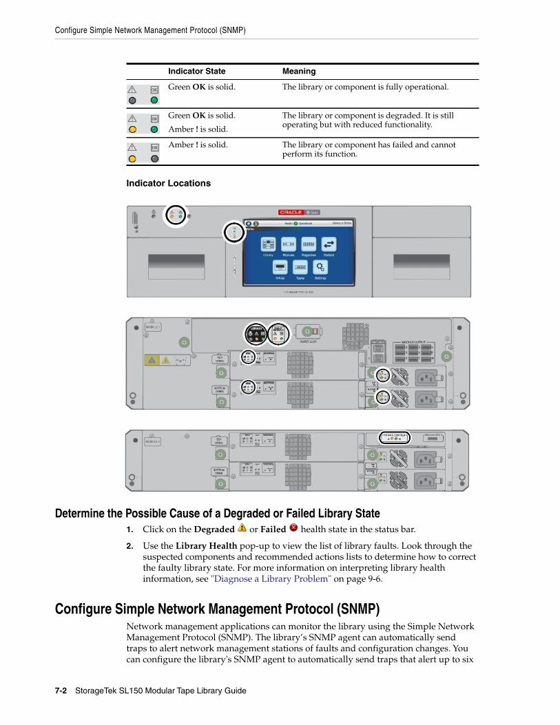
Configure Simple Network Management Protocol (SNMP)
7-2 StorageTek SL150 Modular Tape Library Guide
Indicator Locations
Determine the Possible Cause of a Degraded or Failed Library State1. Click on the Degraded or Failed health state in the status bar.
2. Use the Library Health pop-up to view the list of library faults. Look through thesuspected components and recommended actions lists to determine how to correctthe faulty library state. For more information on interpreting library healthinformation, see "Diagnose a Library Problem" on page 9-6.
Configure Simple Network Management Protocol (SNMP)Network management applications can monitor the library using the Simple NetworkManagement Protocol (SNMP). The library’s SNMP agent can automatically sendtraps to alert network management stations of faults and configuration changes. Youcan configure the library's SNMP agent to automatically send traps that alert up to six
Indicator State Meaning
Green OK is solid. The library or component is fully operational.
Green OK is solid.
Amber ! is solid.
The library or component is degraded. It is stilloperating but with reduced functionality.
Amber ! is solid. The library or component has failed and cannotperform its function.
Configure Simple Network Management Protocol (SNMP)
Monitoring the Library 7-3
network management stations about faults and configuration changes. The librarysupports both SNMP version 2c and version 3.
■ "SNMP Versions" on page 7-3
■ "SNMP Traps" on page 7-3
■ "Enable or Disable SNMP" on page 7-4
■ "Configure an SNMP User" on page 7-4
■ "Configure an SNMP Trap Recipient" on page 7-4
■ "Send a Test Trap" on page 7-5
■ "Download the Management Information Base (MIB)" on page 7-5
SNMP Versions■ v3 — Version 3 is not backward compatible, but it supports a more secure
authentication method and can encrypt management data. Always choose v3unless you need compatibility with older SNMP versions and have no securityconcerns. v3 requires the following information:
– User Name
– Authentication Protocol — Select SHA for best security or MD5 forcompatibility with systems that use MD5.
– Authentication Passphrase — Enter a strong user-authentication password.
– Privacy Protocol — Select AES (Advanced Encryption Standard) for bestsecurity or DES (Data Encryption Standard) for compatibility with systemsthat use DES.
– Privacy Passphrase — Enter a strong data-protection password.
– Engine ID — Only required when adding a trap recipient. In most casesaccept the default value. If you must override this value, enter a hexadecimalvalue that starts with 0x and does not contain either all zeroes (0) or allsixteens (F).
■ v2c — Backward compatible with earlier versions of the standard, but it is notsecure because authentication credentials (community strings) and managementdata are exchanged in clear text.
This is the less secure option. Only select this option if you need compatibilitywith older SNMP versions. v2c requires the following information:
– Community Name — A 31-character, alphanumeric password or phrase. Donot use factory-set default community names or obvious strings like public andprivate.
SNMP TrapsThe table below lists traps returned by the SL150.
Table 7–1 SNMP Trap Levels
Trap Level Description
1 error log entry
2 warning log entry
Configure Simple Network Management Protocol (SNMP)
7-4 StorageTek SL150 Modular Tape Library Guide
Enable or Disable SNMP1. From the remote interface, select SNMP in the left menu.
2. Click the SNMP is Enabled/Disabled drop-down.
3. Select either Enable SNMP or Disable SNMP.
4. Click OK to confirm the change.
Configure an SNMP UserSNMP users can access the library's SNMP agent. You can add, modify, or delete anSNMP user:
1. From the remote interface, select SNMP in the left menu.
2. Select the SNMP Users tab.
3. Click Add SNMP User , or select a user and then click Edit SNMP User orDelete SNMP User .
■ See "SNMP Versions" on page 7-3 for the required version information.
Configure an SNMP Trap RecipientAn SNMP trap recipient is a network management station that you designate toreceive notifications sent by the SNMP agent on the library. You can add up to six traprecipients. You can add, modify, or delete an SNMP trap recipient:
1. From the remote interface, select SNMP in the left menu.
2. Click the SNMP Trap Recipients tab.
3 info log entry
4 configuration
11 agent start
13 test
14 heartbeat A (2.5 minute period)
15 heartbeat B (24 hour period)
21 Library Status Good
25 Library Status Check
27 Environmental Hardware Check
41 Drive Status Good
45 Drive Status Check
61 CAP (mailslot) Status Good
63 CAP (mailslot) Status Open
65 CAP (mailslot) Status Check
100 Proprietary
102 Proprietary
Table 7–1 (Cont.) SNMP Trap Levels
Trap Level Description
Configure Email Notifications
Monitoring the Library 7-5
3. Click Add Trap Recipient , or select a recipient and then click Edit TrapRecipient or Delete Trap Recipient .
■ Host Address — IP address of the management host that will receive the traps
■ Trap Level — Comma-delimited list of the Trap Levels to send to thismanagement station. For a list of valid entries, see "SNMP Traps" on page 7-3.
■ Version — The SNMP version. See "SNMP Versions" on page 7-3 for details onadditional required information.
Send a Test TrapTo verify the configuration, you can sent a test trap (level 13) to all trap recipients.
1. From the remote interface, select SNMP in the left menu.
2. Click the SNMP Trap Recipients tab.
3. Click Send a Test Trap . If the icon is grayed-out, try clicking on a recipient inthe list. Make sure you have enabled SNMP.
Download the Management Information Base (MIB)1. From the remote interface, select SNMP in the left navigation menu.
2. Click Download Mib .
3. Save the file or view it in a text editor.
Enable or Disable the Service Delivery Platform (SDP2)1. From the remote interface, select SNMP in the left menu.
2. Click the SDP2 is Enabled/Disabled drop-down.
3. Select either Enable SDP2 or Disable SDP2.
4. To enable SDP2:
a. Enable SNMP (see "Enable or Disable SNMP" on page 7-4). You can configureSDP2 without enabling SNMP. But you cannot enable SDP2 until you enableSNMP.
b. Configure an SNMP trap recipient to receive trap levels: 13,14,15,102 (see"Configure an SNMP Trap Recipient" on page 7-4). To use SDP2, you mustconfigure at least one SNMP trap recipient to receive the specified traps.
c. The button should now read SDP2 is Enabled (Configured). If not, verify youhave enabled SNMP and have a recipient configured with the trap levels:13,14,15,102.
Configure Email NotificationsYou can configure the library to send automatic email alerts to specified addresseswhenever the library changes state (from online to offline, for example) and/orwhenever library health is degraded.
■ "Enable or Disable Email Notifications" on page 7-6
■ "Configure Email Recipients" on page 7-6
■ "Send a Test Email Alert" on page 7-6
Configure Email Notifications
7-6 StorageTek SL150 Modular Tape Library Guide
Enable or Disable Email Notifications1. From the remote interface, select Email Alerts in the left menu.
2. Click Configure .
3. Set Email Alerts to On (Enabled) or Off (Disabled).
4. If enabling email alerts, enter the following information:
■ SMTP Host Address — IP address of the Simple Mail Transport Protocolserver that will handle outgoing mail for the library.
■ SMTP Port — The network port used by your SMTP server. The default is 25,but you may choose any non-reserved port. Reserved ports include 0, 22, 80,67, 68, 123, 514, 546, 547, 161, 162, and all ports in the range 33200-33500.
■ From Name — The name that should appear in the sender field of the email.The default is "Library Alert".
■ From Email — The email address that should appear in the sender field of theemail.
■ Secure Connection — Select TLS unless the network does not support TLS.SSL is an older protocol that offers less protection. None provides nocryptographic protection.
■ If using TLS or SSL, enter a user name and password.
Configure Email Recipients1. From the remote interface, select Email Alerts in the left menu.
2. Click Add Recipient , or select a recipient and click Edit Recipient or DeleteEmail Recipient .
■ Alert on Health and/or Change — When selected, recipient will be notifiedwhen the library health changes.
Send a Test Email Alert1. From the remote interface, select Email Alerts in the left menu.
2. Select a recipient, and then click Send Test Email .
8
Managing Tape Drives 8-1
8Managing Tape Drives
■ Viewing Current Drive State
■ Configure Drive Cleaning
■ Manage Expired Cleaning Cartridges
■ Restart a Drive
■ Update Drive Firmware
See Also:
■ "Drive Tray Removal and Replacement" on page 10-2
Viewing Current Drive StateThe current state of the drive is reported to the library. The state is polledapproximately every 10 seconds. You can view the state in the Drives table.
1. From the remote interface, select Drives in the left menu.
2. View the States column. Possible values are:
■ Empty
■ Cleaning
■ Loading
■ Loaded
■ Reading
■ Writing
■ Rewinding
■ Unloading
Configure Drive CleaningLTO drives may require occasional cleaning with a compatible cleaning cartridge. Thedrive will notify the library or host application when it requires cleaning. You canmanage drive cleaning in one of three ways:
■ Enable Library-Managed Drive Auto Cleaning
■ Configure Host-Managed Drive Cleaning
■ Manually Clean a Drive.
Configure Drive Cleaning
8-2 StorageTek SL150 Modular Tape Library Guide
Enable Library-Managed Drive Auto CleaningLibrary-managed auto cleaning is the easiest and most flexible way to clean drives.When enabled, the library automatically performs a cleaning whenever a driverequests it.
1. Verify there is at least one universal LTO cleaning cartridge (media type CU) in areserved system slot. For best drive availability, place two cleaning cartridges inreserved slots.
2. From the remote interface, select Configuration in the left menu.
3. Click Configure .
4. Select Configure Library Settings, and then click Next.
5. Set Drive Auto Clean to On.
6. Set System Reserved Slots to 1 or 2. To use the auto cleaning, you must reserve atleast one system slot for a cleaning cartridge.
7. Click Next. If applicable, click Next again to bypass the partitioning configuration.
8. On the summary screen, select Accept all changes and then click Apply.
Configure Host-Managed Drive CleaningMany storage-management and backup applications can manage drive cleaning (suchas Oracle Secure Backup, Symantec NetBackup, IBM Tivoli Storage Manager, andothers). The host application can manage the cleaning of drives that it controls, if acleaning cartridge is available in a storage slot.
Advantage of host-managed cleaning:
■ The host remains in control of its assigned drives and storage slots at all times.
Disadvantage of host-managed cleaning:
■ In a partitioned library, each partition must contain compatible cleaningcartridges, meaning you must provide duplicate cleaning media across partitions.The extra cleaning tapes take up slots that could otherwise hold data tapes.
The sections below summarize the procedures for configuring host-managed cleaning.Always refer to the host documentation for full details.
■ Configure Automatic Cleaning in Oracle Secure Backup During Drive Setup
■ Set Up NetBackup for Reactive Cleaning Using the Administration Console
■ Set Up NetBackup for Reactive Cleaning Using the Commandline
■ Set Up Symantec Backup Exec Drive Cleaning
■ Set Up Reactive Cleaning for HP StorageWorks Enterprise Backup Solution withHP Data Protector
■ Set Up As-Needed Cleaning in IBM Tivoli Storage Manager (TSM)
■ Set Up Tape-Alert Cleaning in EMC Networker
■ Set Up CommVault Drive Cleaning
Configure Automatic Cleaning in Oracle Secure Backup During Drive SetupWhen you add tape drives to your Oracle Secure Backup configuration, select Yesfrom the Auto clean list. Enter the following information:
Configure Drive Cleaning
Managing Tape Drives 8-3
■ Clean interval (duration) — The desired interval between cleaning cycles.
■ Clean using emptiest — Select Yes to use cleaning cartridges in round-robinfashion, starting from the least-used cartridge. Select No to use each cleaningcartridge until it expires, starting from the cartridge with the fewest remainingcleaning cycles (the default).
Set Up NetBackup for Reactive Cleaning Using the Administration Console1. From the Administration Console, select Media and Device Management.
2. Select Device Monitor, and then select Drives.
3. In the Drive Status pane, select an SL150 drive and then open the Actions menu.
4. Select the Set Cleaning Frequency parameter, and set the value to 0 (zero). Thistells NetBackup to clean drives in response to Tape Alerts.
5. Repeat until you have configured all SL150 drives.
Set Up NetBackup for Reactive Cleaning Using the Commandline1. To add a drive to the NetBackup configuration, use the command tpconfig -add
-drive -type [hcart|hcart2|hcart3] path drivepath -cleanfreq 0, where:
■ hcart* is the generic NetBackup media identifier.
■ drivepath is the path to the device file for the drive. Stop here.
2. If you have already added the drives to your NetBackup configuration, run thecommand /usr/openv/volmgr/bin/tpclean/tpclean -F drive_name 0, where:
■ drive_name is the name that was assigned to the drive when it was added tothe NetBackup device configuration.
■ 0 is the value that turns off frequency-based cleaning in favor of reactivecleaning.
Set Up Symantec Backup Exec Drive Cleaning1. On the Backup Exec navigation bar, select Devices.
2. Select Robotic Libraries, and then select the robotic library for which you aresetting up the cleaning.
3. Click Slots to display the library's slots in the right pane.
4. Select the slot that contains the cleaning tape.
5. In the task bar, under General Tasks, select Properties.
6. Select the Cleaning Slot option, and click OK.
7. Make sure that the cleaning tape is located in the slot that you defined as thecleaning slot.
Set Up Reactive Cleaning for HP StorageWorks Enterprise Backup Solution with HPData ProtectorIf you provide correctly labeled cleaning cartridges, Data Protector detects thecartridges and automatically sets up reactive cleaning.
Configure Drive Cleaning
8-4 StorageTek SL150 Modular Tape Library Guide
Set Up As-Needed Cleaning in IBM Tivoli Storage Manager (TSM)1. To configure on-demand cleaning for a drive that has not yet been added to your
TSM configuration, use the DEFINE DRIVE command.
2. To configure on-demand cleaning for a drive that has already been added to yourTSM configuration, use the UPDATE DRIVE command.
3. Using the chosen command, set the drive parameter CLEANFREQuency to ASNEEDED.
Set Up Tape-Alert Cleaning in EMC NetworkerEMC Networker automatically cleans drives if it is configured to receive Tape Alertsfrom the drive. To enable Tape Alerts, set up the Networker Common Device Interface(CDI) as follows.
1. In the NetWorker Administration interface, click on Devices, and select View,Diagnostic Mode.
2. Select Devices from the navigation tree.
3. In the Devices table, right-click on one of the SL150 tape drives, and selectProperties from the context menu.
4. In the Properties window, select the Advanced tab.
5. In the Device Configuration area of the Advanced tab, under CDI settings, selectSCSI Commands: Sends explicit SCSI commands to tape devices.
6. Repeat steps 3-5 until the Common Device Interface has been configured for allSL150 tape drives.
Set Up CommVault Drive Cleaning1. In the ComCell interface, right-click on the SL150 library, and select Properties
from the context menu.
2. When the Library Properties sheet appears, select the Drives tab.
3. In the Enable Auto-Cleaning section of the tab, check the On sense code checkbox.
Manually Clean a DriveAlthough not recommended, you can manually manage drive cleaning by monitoringthe remote interface for cleaning messages and responding accordingly.
■ Check for Drives that Require Cleaning
■ Use the Remote Interface to Clean a Degraded Drive
Check for Drives that Require Cleaning1. Log in to the remote interface.
2. Check the Library Health indicator at the top of the screen. If it is in the Degradedstate, click on it, and examine the Health Table for code 9030, DRIVE_NEEDS_CLEANING.
Caution: Over-cleaning can damage drives. Clean only when thedrive indicates that it requires cleaning.
Manage Expired Cleaning Cartridges
Managing Tape Drives 8-5
3. If a drive needs cleaning, note the drive address (module number and either Topor Bottom). Use the library user interface to clean the drive (see below).
Use the Remote Interface to Clean a Degraded Drive1. Verify that a drive needs cleaning (see "Check for Drives that Require Cleaning" on
page 8-4).
2. Make sure that the library contains at least one unexpired LTO universal cleaningcartridge (media type CU).
3. Select Library in the left menu.
4. Locate the drive that needs cleaning. Hover over the drive and verify the driveaddress is correct.
5. Right-click on the drive, and then select Clean Drive.
6. Select a cleaning tape from the drop-down list.
7. Optionally, select Set the Library back Online ...
If you do not select this option, remember to bring the library back online once thecleaning finishes.
Manage Expired Cleaning CartridgesA cleaning cartridge expires when a drive determines the cartridge is no longer usable.When the drive identifies an expired cartridge, it notifies the library. The librarydismounts the cartridge, flags it as expired, and alerts the remote interface.
If you have configured your backup or storage management application toautomatically handle cleaning requests, the application may manage cleaning mediafor you. Consult the vendor's documentation for details.
■ Monitor Cleaning Cartridges Using the Remote Interface
■ Replace Expired Cleaning Media Using the Remote Interface
■ Replace Expired Cleaning Media Using the Host Application
Monitor Cleaning Cartridges Using the Remote Interface1. In the remote interface, select Library in the left menu.
2. Right-click a cleaning cartridge, and then select Properties.
3. Note the Cleaning Tape Status.
4. If the cartridge is expired, replace it:
■ If the cartridge is in a reserved system slot, see "Replace Expired CleaningMedia Using the Remote Interface" on page 8-5.
■ If the cartridge in a host application-managed storage slot, see "ReplaceExpired Cleaning Media Using the Host Application" on page 8-6.
Replace Expired Cleaning Media Using the Remote InterfaceUse this procedure to replace a cleaning cartridge in a reserved system cell.
1. From the remote interface, select Library in the left menu.
2. If the library is partitioned, Unassign the Mailslot before proceeding.
Restart a Drive
8-6 StorageTek SL150 Modular Tape Library Guide
3. Right-click on the expired cleaning cartridge, and move it to the mailslot (see"Move Tape Cartridges with the Remote Interface" on page 6-11).
4. Open the Mailslot, and remove the expired cleaning media.
5. Dispose of the expired media promptly, so that dirty cartridges are notinadvertently reimported and reused.
6. Place new cleaning media in the mailslot. Then Close the Mailslot.
7. Move the new cleaning media from the mailslot to the reserved system slot(s)
Replace Expired Cleaning Media Using the Host ApplicationUse this procedure to replace a cleaning cartridge in a host-managed storage slot.
1. If the library is partitioned, Assign the Mailslot to a Partition.
2. Move the expired cartridge into the library mailslot using the host application.Consult your application documentation for instructions.
3. Open the Mailslot, and remove the expired cleaning media.
4. Dispose of the expired cartridge promptly, so that dirty cartridges are notinadvertently reimported and reused.
5. Place new a cleaning cartridge in the mailslot. Then Close the Mailslot.
6. Import the new cleaning cartridge into the library using the host application.Consult your application documentation for instructions.
Restart a DriveRestarting a drive powers the drive off and then back on and performs initialization ofthe drive. This action may resolve some drive problems.
1. In the remote interface, select Library in the left menu.
2. Right-click the drive, and then select Restart Drive.
Update Drive FirmwareFor instructions on obtaining and installing updated drive firmware, see "UpdateLibrary and Drive Firmware" on page 4-7.
9
Servicing the Library 9-1
9Servicing the Library
[3]This section covers routine procedures you may need to perform when servicing ortroubleshooting the library. For details on removing or replacing specific components,see "Replacing Components (CRUs & FRUs)" on page 10-1.
■ Place the Library Online and Offline
■ Power On the Library
■ Power Off the Library
■ Restart the Library
■ Audit the Library
■ Move the Library Rack
■ Enable the Locate Light
■ Troubleshoot the Library
■ Get Parts and Technical Support
See Also:
■ "Run a Self-Test" on page 2-36
Place the Library Online and OfflineAlways take the library offline before performing any maintenance that might conflictwith host data operations. After you complete the disruptive activity, you can bringthe library back online and continue host operations.
1. If taking the library offline, stop any host activity before proceeding.
2. From the remote interface, click the Library is Online/Offline drop-down in theupper-right.
3. Select either Set Library Offline or Set Library Online.
WARNING: Oracle's StorageTek SL150 Modular Tape Librarycontains a Class-1 laser, as defined by IEC 60825-1 Ed. 2 (2007). Useof controls or adjustments or performance of procedures other thanthose specified herein may result in hazardous radiation exposure.
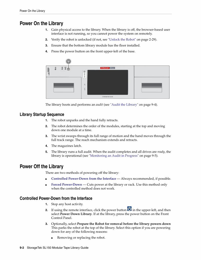
Power On the Library
9-2 StorageTek SL150 Modular Tape Library Guide
Power On the Library1. Gain physical access to the library. When the library is off, the browser-based user
interface is not running, so you cannot power the system on remotely.
2. Verify the robot is unlocked (if not, see "Unlock the Robot" on page 2-29).
3. Ensure that the bottom library module has the floor installed.
4. Press the power button on the front upper-left of the base.
The library boots and performs an audit (see "Audit the Library" on page 9-4).
Library Startup Sequence1. The robot unparks and the hand fully retracts.
2. The robot determines the order of the modules, starting at the top and movingdown one module at a time.
3. The wrist sweeps through its full range of motion and the hand moves through thefull track range. The reach mechanism extends and retracts.
4. The magazines latch.
5. The library runs a full audit. When the audit completes and all drives are ready, thelibrary is operational (see "Monitoring an Audit in Progress" on page 9-5).
Power Off the LibraryThere are two methods of powering off the library:
■ Controlled Power-Down from the Interface — Always recommended, if possible.
■ Forced Power-Down — Cuts power at the library or rack. Use this method onlywhen the controlled method does not work.
Controlled Power-Down from the Interface1. Stop any host activity.
2. If using the remote interface, click the power button in the upper-left, and thenselect Power Down Library. If at the library, press the power button on the FrontControl Panel.
3. Optionally, select Prepare the Robot for removal before the library powers downThis parks the robot at the top of the library. Select this option if you are poweringdown for any of the following reasons:
■ Removing or replacing the robot.
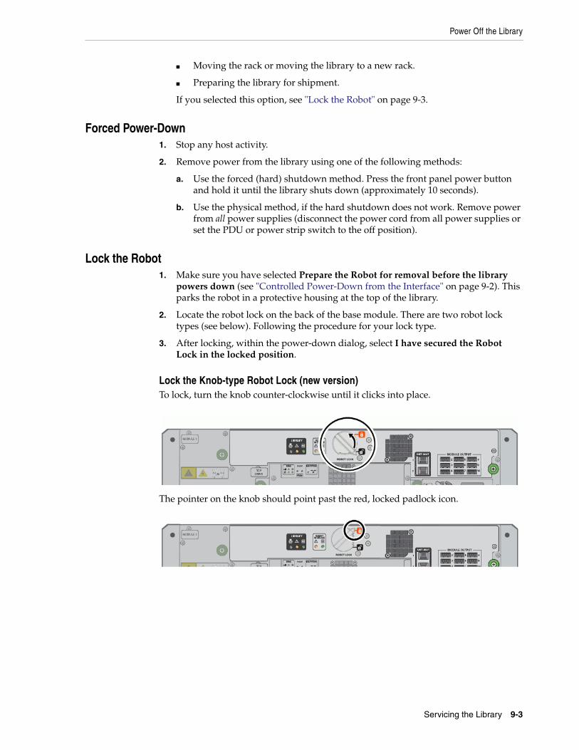
Power Off the Library
Servicing the Library 9-3
■ Moving the rack or moving the library to a new rack.
■ Preparing the library for shipment.
If you selected this option, see "Lock the Robot" on page 9-3.
Forced Power-Down1. Stop any host activity.
2. Remove power from the library using one of the following methods:
a. Use the forced (hard) shutdown method. Press the front panel power buttonand hold it until the library shuts down (approximately 10 seconds).
b. Use the physical method, if the hard shutdown does not work. Remove powerfrom all power supplies (disconnect the power cord from all power supplies orset the PDU or power strip switch to the off position).
Lock the Robot1. Make sure you have selected Prepare the Robot for removal before the library
powers down (see "Controlled Power-Down from the Interface" on page 9-2). Thisparks the robot in a protective housing at the top of the library.
2. Locate the robot lock on the back of the base module. There are two robot locktypes (see below). Following the procedure for your lock type.
3. After locking, within the power-down dialog, select I have secured the RobotLock in the locked position.
Lock the Knob-type Robot Lock (new version)To lock, turn the knob counter-clockwise until it clicks into place.
The pointer on the knob should point past the red, locked padlock icon.
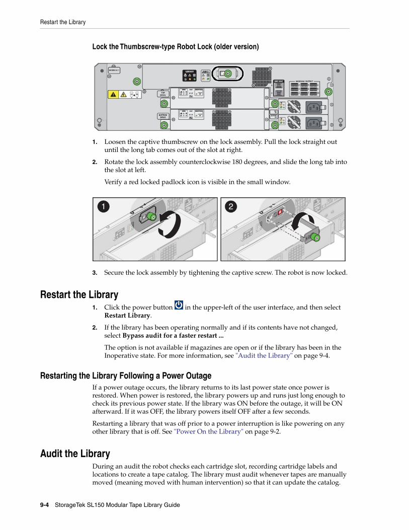
Restart the Library
9-4 StorageTek SL150 Modular Tape Library Guide
Lock the Thumbscrew-type Robot Lock (older version)
1. Loosen the captive thumbscrew on the lock assembly. Pull the lock straight outuntil the long tab comes out of the slot at right.
2. Rotate the lock assembly counterclockwise 180 degrees, and slide the long tab intothe slot at left.
Verify a red locked padlock icon is visible in the small window.
3. Secure the lock assembly by tightening the captive screw. The robot is now locked.
Restart the Library1. Click the power button in the upper-left of the user interface, and then select
Restart Library.
2. If the library has been operating normally and if its contents have not changed,select Bypass audit for a faster restart ...
The option is not available if magazines are open or if the library has been in theInoperative state. For more information, see "Audit the Library" on page 9-4.
Restarting the Library Following a Power OutageIf a power outage occurs, the library returns to its last power state once power isrestored. When power is restored, the library powers up and runs just long enough tocheck its previous power state. If the library was ON before the outage, it will be ONafterward. If it was OFF, the library powers itself OFF after a few seconds.
Restarting a library that was off prior to a power interruption is like powering on anyother library that is off. See "Power On the Library" on page 9-2.
Audit the LibraryDuring an audit the robot checks each cartridge slot, recording cartridge labels andlocations to create a tape catalog. The library must audit whenever tapes are manuallymoved (meaning moved with human intervention) so that it can update the catalog.
Move the Library Rack
Servicing the Library 9-5
The library automatically performs an audit whenever it powers up or whenever youreinsert magazines.
Normally, host applications request audits. However, you can audit the library fromthe remote interface, but you should avoid this, if possible, as it interrupts hostoperations.
To manually initiate an audit:
1. From the remote interface, select Library in the left menu.
2. From the Library drop-down menu , select Audit Library.
3. Optionally, select Set the Library back Online ...
4. To take the library offline, start the audit, and close the dialog, press OK.
5. If you did not check the Set the Library back Online ... checkbox, remember tobring the library back online once you are ready.
Monitoring an Audit in ProgressThe duration of an audit depends on the size of the library. For example, a 30-slotlibrary can take about 7 minutes to audit.
You can track the progress of the audit on the Library screen of the remote interface.Grayed-out cartridge icons represent unaudited slots. As the audit progresses, auditedslots return to their normal appearance. Hovering over a slot shows the currentcartridge label information (see "Labeling Cartridges" on page 6-3 for labelinformation).
Move the Library Rack1. Power the library off (see "Power Off the Library" on page 9-2).
2. Secure the robot (see "Lock the Robot" on page 9-3).
3. If the floor is uneven, remove all magazines from library as tape cartridges canshift and obstruct library robotics when the library is restarted.
a. Unlock all magazines using the remote interface or local operator panel. Pressthe Select All option on the Unlock Magazines dialog.
b. Remove all magazines.
4. Set the rack PDU circuit breakers to OFF and disconnect the PDU power cord(s)from the main circuit.
5. Label and disconnect any host connection or LAN cables.
6. Raise any leveling pads until the casters are supporting the rack. Release any rackanti-tip device(s), and remove any wheel chocks.
7. Move the library to its new location. Reset the leveling pads.
8. Reinstall the magazines.
9. Reconnect power, host-connections, and local area network (LAN) cables.
10. Unlock the robot.
11. Power the library on.
Enable the Locate Light
9-6 StorageTek SL150 Modular Tape Library Guide
Enable the Locate LightIf you have multiple SL150s in your data center, you an use the locate light tophysically identify a particular unit.
1. In the remote interface, click the locate icon in the upper left of the screen.
2. Select Switch Locate Light On.
3. The physical locate LEDs activate on the front control panel and in the blackrectangle on the robot CRU.
Troubleshoot the Library■ "Diagnose a Browser-Based User Interface Problem" on page 9-6
■ "Diagnose a Library Problem" on page 9-6
Diagnose a Browser-Based User Interface Problem1. If you have problems with a browser, try a different browser. Check the SL150
firmware release notes for known incompatibilities.
2. If you start to have problems with a browser that used to work, check for recentchanges to the browser configuration:
■ If scripting (Javascript) has been disabled, enable it.
■ If browser plug-ins or extensions have been installed or updated recently,disable or uninstall the add-on software.
■ If browser software has been recently updated, roll back the update and revertto the previous version.
3. If an update is available for the browser, install it.
4. If you still have problems after you have tried the latest versions of severalbrowsers, open a service request. See "Get Parts and Technical Support" onpage 9-11.
Diagnose a Library Problem■ Diagnose a Problem if You Cannot Login to the Remote Interface
■ Use the Health Table to Diagnose the Issue
■ Locate and Remove a Cartridge Stuck in a Magazine Slot
■ Locate and Clear Obstructions, Such as Loose or Protruding Cartridges
■ Save the Health Log to a File
■ Run a Self-Test
Diagnose a Problem if You Cannot Login to the Remote Interface1. Go to the library and check the local operator panel.
2. If the local operator panel is working and the remote user interface is not, checkthe Ethernet cable connected to NET MGT port 0 at the rear of the library. Checkfor network problems.
Troubleshoot the Library
Servicing the Library 9-7
3. If the local operator panel is also not working, make sure that the library haspower. Check the power cord connected to each power supply. Check thedata-center power outlet. Check breakers.
4. If the library is connected to power, check the LED Indicators on the library and itscomponents:
■ Power supplies — If an amber power supply LED is lit or if both powersupply LEDs are dark, replace the power supply. See "Power Supply Removaland Replacement" on page 10-4.
■ Robot Module — If an amber Robot Module LED is lit or if both robot LEDsare dark, replace the robot. See "Robot Module Removal and Replacement" onpage 10-8.
5. If the robot module is OK, restart the library, and repeat this procedure.
6. If problems persist after you have restarted the library and repeated the abovediagnostic steps, go to "Get Parts and Technical Support" on page 9-11, check forrelevant knowledge articles, and then, if necessary, open a service request.
Use the Health Table to Diagnose the Issue1. Log in to the remote interface, take the library offline, and use the health table.
2. To access the health table, click the Degraded or Failed indicator in the status bar.
3. Note the Fault Code listed in the health table. Suggested fixes are listed below:
■ Fault Code 903:
– If Drive Auto Clean is enabled — If the drive listed in the suspectedcomponent field is mounted, wait. The library will attempt a cleaningonce the tape dismounts.
If the fault persists after the tape dismounts, a cleaning cartridge isunavailable or expired. Load a new, LTO universal cleaning cartridge intoa reserved slot. Then clean the drive using the library user interface.
– If using host-managed drive cleaning — Consult the host applicationdocumentation and make sure that fresh cleaning media are available. Ifnecessary, clean the drive listed using the library user interface.
■ Fault Code 9108:
– If the Suspect Component is one or more magazines, see "Locate andRemove a Cartridge Stuck in a Magazine Slot" on page 9-8.
– If the Suspect Component is one or more drives, the cartridge may bestuck in the drive. Go to "Get Parts and Technical Support" on page 9-11,and check for relevant knowledge articles. If you cannot find a resolution,open a service request
■ Fault Code 9109 or 9102 thru 9107:
– See "Locate and Clear Obstructions, Such as Loose or ProtrudingCartridges" on page 9-9.
■ All other Fault Codes:
– Follow the Recommended Action listed in the health table one at a timeand in the order specified in the suspect components list. See "ReplacingComponents (CRUs & FRUs)" on page 10-1.
Troubleshoot the Library
9-8 StorageTek SL150 Modular Tape Library Guide
If you replace the robot, the operator panel, or the chassis of library module 1,power-cycle the library as soon as you finish. These three components main-tain records of the product serial number and configuration settings. Ifyou replace more than one of them at a time, without restarting the library,this information will be lost.
4. After attempting a fix, if the connection status indicator shows Library isInoperative, restart the library and then see "Check if Fault is Closed in the HealthLog" below.
Check if Fault is Closed in the Health LogAfter attempting a fix and restarting the library, you should see if the fault record hasbeen closed:
1. Select Service in the left menu. Select the Health Log tab
2. Locate the row for the fault and note the value of the Type field:
■ If the record is still Open, you have not yet isolated the problem. Note the nextSuspect Component and repeat "Use the Health Table to Diagnose the Issue"above.
■ If the record is Closed, but the library status is still Degraded, check forremaining faults in the health table and repeat "Use the Health Table toDiagnose the Issue" above.
■ If you Closed all fault records and still cannot get the library into Operationalcondition, go to "Get Parts and Technical Support" on page 9-11, check forrelevant knowledge articles, and, if you cannot find a resolution, open aservice request. Include fault codes and details of the actions that you havetaken.
Locate and Remove a Cartridge Stuck in a Magazine SlotUse this procedure to resolve Fault Code 9108 if the Suspect Components indicatesone or more magazines.
1. Identify the problem slot. Correlate the details of the failed move, as listed in theLibrary Activity Panel, with the Suspect Components field of the correspondingLibrary Health record.
2. Manually unlock the magazine that contains the problem (see "Mount the BaseModule Task 2: Remove the Cartridge Magazine with the Hex Key" on page 2-12).
If you feel any significant resistance when you try to remove the magazine, STOPand check for obstructions. Go to "Locate and Clear Obstructions, Such as Loose orProtruding Cartridges" on page 9-9.
3. Set the magazine on a flat surface, be careful to not spill cartridges.
4. Locate the slot with the stuck cartridge. Grasp the cartridge by the top and bottomgripping surfaces. Gently try to free the cartridge. Do not force it.
■ If you free the cartridge, check the storage slot for damage or defects.
If you find any damage to the magazine, request a replacement. Go to "GetParts and Technical Support" on page 9-11, and create a service request.
If you find no damage, reseat the cartridge in its slot and make sure that it ismoving freely. Reinstall the magazine in its bay and power up the library andsee "Check if Fault is Closed in the Health Log" on page 9-8.
Troubleshoot the Library
Servicing the Library 9-9
■ If you cannot free the cartridge, go to "Get Parts and Technical Support" onpage 9-11, and check for relevant knowledge articles. If you cannot find aresolution, open a service request.
Locate and Clear Obstructions, Such as Loose or Protruding CartridgesIf the Suspect Components and/or Recommended Action fields indicate that anobstruction is interfering with the robot or if the Fault Code is either 9109 or in therange 9102-9107, look for a mispositioned cartridge or obstruction in the library.
1. Remove the magazine that will give you the best view of the interior of the library.If you feel any significant resistance when attempting to remove the magazine, donot force it. Instead, remove a magazine on the opposite side of the library.
2. Using the empty magazine bay as a window, look inside the library. Try to locateobstructions, particularly loose or protruding cartridges. Look across, above, andbelow.
3. If you cannot see any obstructions, gain additional visibility by removingadditional magazines.
4. If you see a cartridge protruding from a storage slot in one of the magazines orlying on the bottom of the library, reach in through the open magazine bay and tryto remove it.
5. If you cannot reach the cartridge, remove additional magazines for additionalclearance.
6. If you cannot remove the problem cartridge, stop here. Go to "Get Parts andTechnical Support" on page 9-11, and check for relevant knowledge articles. If youcannot find a resolution, open a service request.
7. If you successfully removed the problem cartridge, remove the source magazineand check the source storage slot for defects.
8. If you find any damage to the source magazine, request a replacement. Go to "GetParts and Technical Support" on page 9-11, and open a service request.
9. Otherwise, reseat the errant cartridge in its storage cell.
10. Reinstall all removed magazines in their original bays.
11. Once you have reinserted the magazines, start the library and then see "Check ifFault is Closed in the Health Log" on page 9-8.
Save the Health Log to a FileIf you need to work on diagnostics off-line or if you need to open a service request,save the contents of the system health log to a file.
1. From the remote interface, select Service in the left menu and then select theHealth Log tab.
2. Click Export , and then save the file.
The HTML-based SL150_HealthLog.xls file is compatible with currentspreadsheet applications, such as Microsoft Excel and Apache OpenOffice Calc. Toview these files in web browsers, simply rename the file using the .html fileextension in place of .xsl.
Run a Self-TestOnce you have resolved an issue. You can make sure that the library is functioningnormally by running a self test. See "Run a Self-Test" on page 2-36.
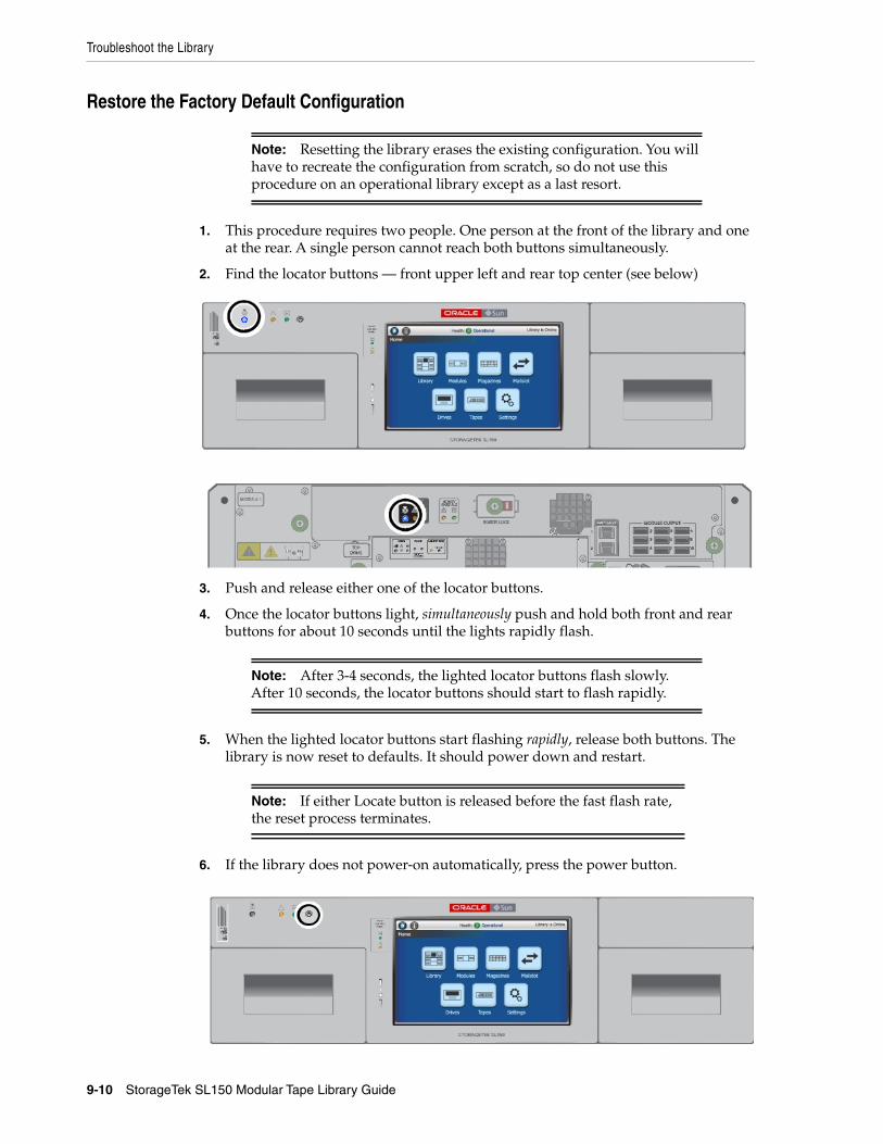
Troubleshoot the Library
9-10 StorageTek SL150 Modular Tape Library Guide
Restore the Factory Default Configuration
1. This procedure requires two people. One person at the front of the library and oneat the rear. A single person cannot reach both buttons simultaneously.
2. Find the locator buttons — front upper left and rear top center (see below)
3. Push and release either one of the locator buttons.
4. Once the locator buttons light, simultaneously push and hold both front and rearbuttons for about 10 seconds until the lights rapidly flash.
5. When the lighted locator buttons start flashing rapidly, release both buttons. Thelibrary is now reset to defaults. It should power down and restart.
6. If the library does not power-on automatically, press the power button.
Note: Resetting the library erases the existing configuration. You willhave to recreate the configuration from scratch, so do not use thisprocedure on an operational library except as a last resort.
Note: After 3-4 seconds, the lighted locator buttons flash slowly.After 10 seconds, the locator buttons should start to flash rapidly.
Note: If either Locate button is released before the fast flash rate,the reset process terminates.
Get Parts and Technical Support
Servicing the Library 9-11
7. Run the initial installation wizard and reconfigure the library as you would whensetting up a new unit (see "Configure the Library After Powering-on for the FirstTime" on page 2-30).
Get Parts and Technical Support■ Check for Relevant Knowledge Articles
■ Get Firmware Updates
■ Create a Service Request
Check for Relevant Knowledge Articles1. Log in to My Oracle Support at https://support.oracle.com.
2. Select the Knowledge tab.
3. In the Knowledge Base area, select the Search & Browse tab.
4. In the Select a product or product line field, enter StorageTek SL150 ModularTape Library.
5. In the Go directly to the best match area, click the Information Center:StorageTek SL150 ... link.
6. In the Information Center document, select the Resources tab, and browse thelinks on the page.
Get Firmware UpdatesSee "Update Library and Drive Firmware" on page 4-7.
Create a Service Request1. Save a library health log (see "Save the Health Log to a File" on page 9-9).
2. Log in to My Oracle Support at https://support.oracle.com.
3. Select the Service Requests tab.
4. Click the Help control in the upper right corner of the Oracle support page.
5. From the Help drop-down menu, select How do I create a new SR?
6. Follow the instructions provided.

Get Parts and Technical Support
9-12 StorageTek SL150 Modular Tape Library Guide
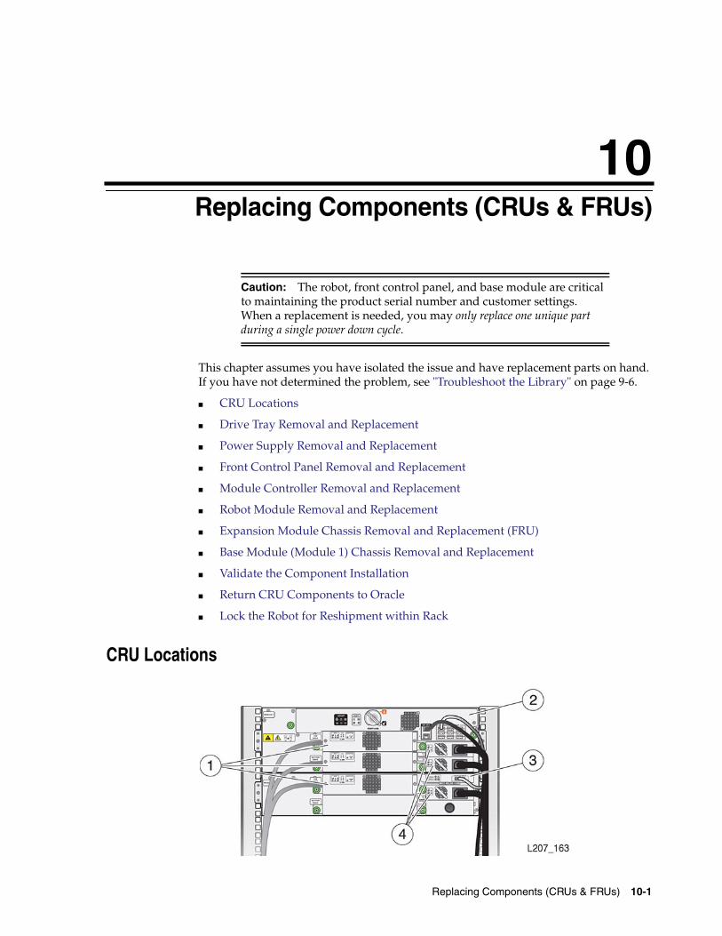
10
Replacing Components (CRUs & FRUs) 10-1
10Replacing Components (CRUs & FRUs)
This chapter assumes you have isolated the issue and have replacement parts on hand.If you have not determined the problem, see "Troubleshoot the Library" on page 9-6.
■ CRU Locations
■ Drive Tray Removal and Replacement
■ Power Supply Removal and Replacement
■ Front Control Panel Removal and Replacement
■ Module Controller Removal and Replacement
■ Robot Module Removal and Replacement
■ Expansion Module Chassis Removal and Replacement (FRU)
■ Base Module (Module 1) Chassis Removal and Replacement
■ Validate the Component Installation
■ Return CRU Components to Oracle
■ Lock the Robot for Reshipment within Rack
CRU Locations
Caution: The robot, front control panel, and base module are criticalto maintaining the product serial number and customer settings.When a replacement is needed, you may only replace one unique partduring a single power down cycle.
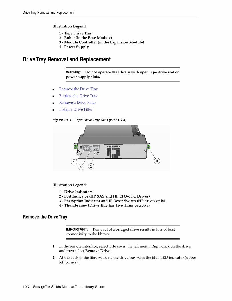
Drive Tray Removal and Replacement
10-2 StorageTek SL150 Modular Tape Library Guide
Illustration Legend:
1 - Tape Drive Tray2 - Robot (in the Base Module)3 - Module Controller (in the Expansion Module)4 - Power Supply
Drive Tray Removal and Replacement
■ Remove the Drive Tray
■ Replace the Drive Tray
■ Remove a Drive Filler
■ Install a Drive Filler
Figure 10–1 Tape Drive Tray CRU (HP LTO-5)
Illustration Legend:
1 - Drive Indicators2 - Port Indicator (HP SAS and HP LTO-6 FC Drives)3 - Encryption Indicator and IP Reset Switch (HP drives only)4 - Thumbscrew (Drive Tray has Two Thumbscrews)
Remove the Drive Tray
1. In the remote interface, select Library in the left menu. Right-click on the drive,and then select Remove Drive.
2. At the back of the library, locate the drive tray with the blue LED indicator (upperleft corner).
Warning: Do not operate the library with open tape drive slot orpower supply slots.
IMPORTANT: Removal of a bridged drive results in loss of hostconnectivity to the library.
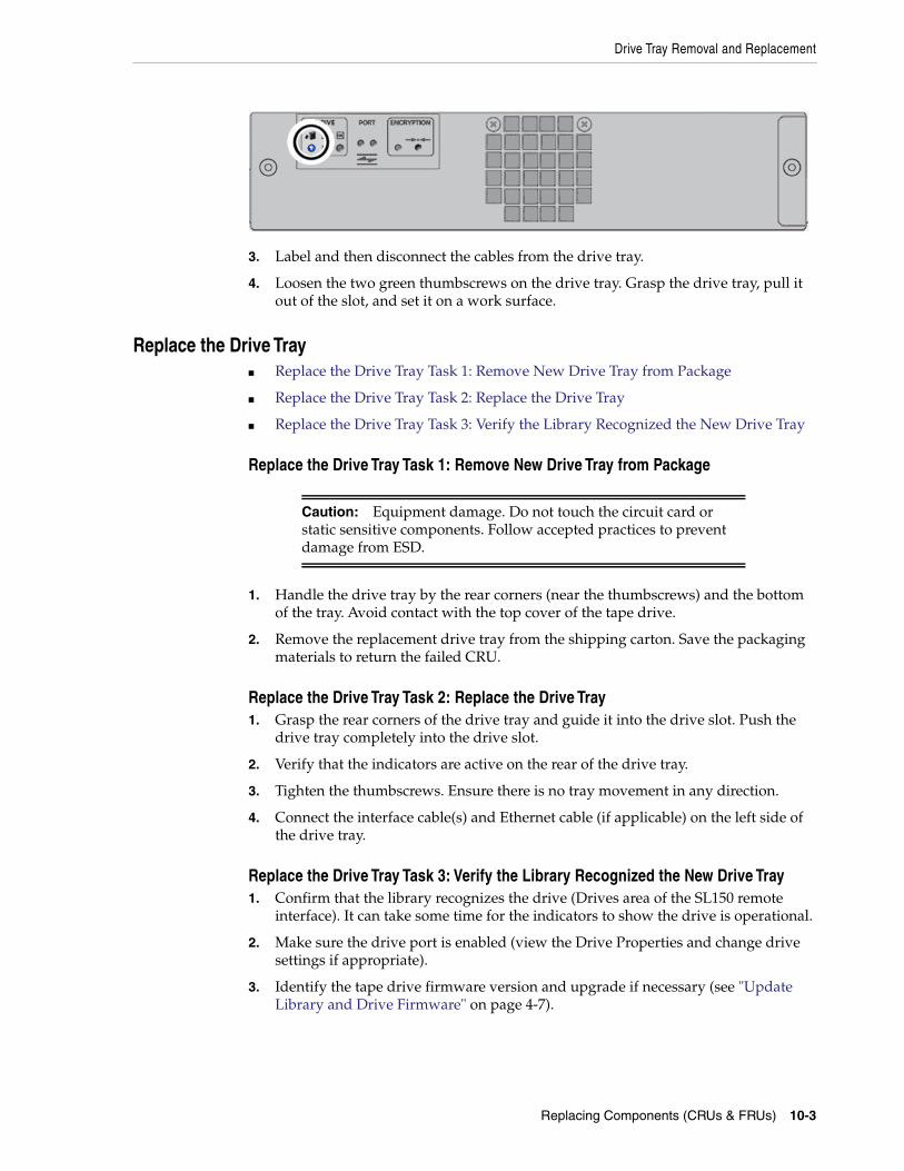
Drive Tray Removal and Replacement
Replacing Components (CRUs & FRUs) 10-3
3. Label and then disconnect the cables from the drive tray.
4. Loosen the two green thumbscrews on the drive tray. Grasp the drive tray, pull itout of the slot, and set it on a work surface.
Replace the Drive Tray■ Replace the Drive Tray Task 1: Remove New Drive Tray from Package
■ Replace the Drive Tray Task 2: Replace the Drive Tray
■ Replace the Drive Tray Task 3: Verify the Library Recognized the New Drive Tray
Replace the Drive Tray Task 1: Remove New Drive Tray from Package
1. Handle the drive tray by the rear corners (near the thumbscrews) and the bottomof the tray. Avoid contact with the top cover of the tape drive.
2. Remove the replacement drive tray from the shipping carton. Save the packagingmaterials to return the failed CRU.
Replace the Drive Tray Task 2: Replace the Drive Tray1. Grasp the rear corners of the drive tray and guide it into the drive slot. Push the
drive tray completely into the drive slot.
2. Verify that the indicators are active on the rear of the drive tray.
3. Tighten the thumbscrews. Ensure there is no tray movement in any direction.
4. Connect the interface cable(s) and Ethernet cable (if applicable) on the left side ofthe drive tray.
Replace the Drive Tray Task 3: Verify the Library Recognized the New Drive Tray1. Confirm that the library recognizes the drive (Drives area of the SL150 remote
interface). It can take some time for the indicators to show the drive is operational.
2. Make sure the drive port is enabled (view the Drive Properties and change drivesettings if appropriate).
3. Identify the tape drive firmware version and upgrade if necessary (see "UpdateLibrary and Drive Firmware" on page 4-7).
Caution: Equipment damage. Do not touch the circuit card orstatic sensitive components. Follow accepted practices to preventdamage from ESD.
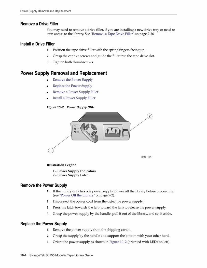
Power Supply Removal and Replacement
10-4 StorageTek SL150 Modular Tape Library Guide
Remove a Drive FillerYou may need to remove a drive filler, if you are installing a new drive tray or need togain access to the library. See "Remove a Tape Drive Filler" on page 2-26
Install a Drive Filler1. Position the tape drive filler with the spring fingers facing up.
2. Grasp the captive screws and guide the filler into the tape drive slot.
3. Tighten both thumbscrews.
Power Supply Removal and Replacement■ Remove the Power Supply
■ Replace the Power Supply
■ Remove a Power Supply Filler
■ Install a Power Supply Filler
Figure 10–2 Power Supply CRU
Illustration Legend:
1 - Power Supply Indicators2 - Power Supply Latch
Remove the Power Supply1. If the library only has one power supply, power off the library before proceeding
(see "Power Off the Library" on page 9-2).
2. Disconnect the power cord from the defective power supply.
3. Press the latch towards the left (toward the fan) to release the power supply.
4. Grasp the power supply by the handle, pull it out of the library, and set it aside.
Replace the Power Supply1. Remove the power supply from the shipping carton.
2. Grasp the supply by the handle and support the bottom with your other hand.
3. Orient the power supply as shown in Figure 10–2 (oriented with LEDs on left).
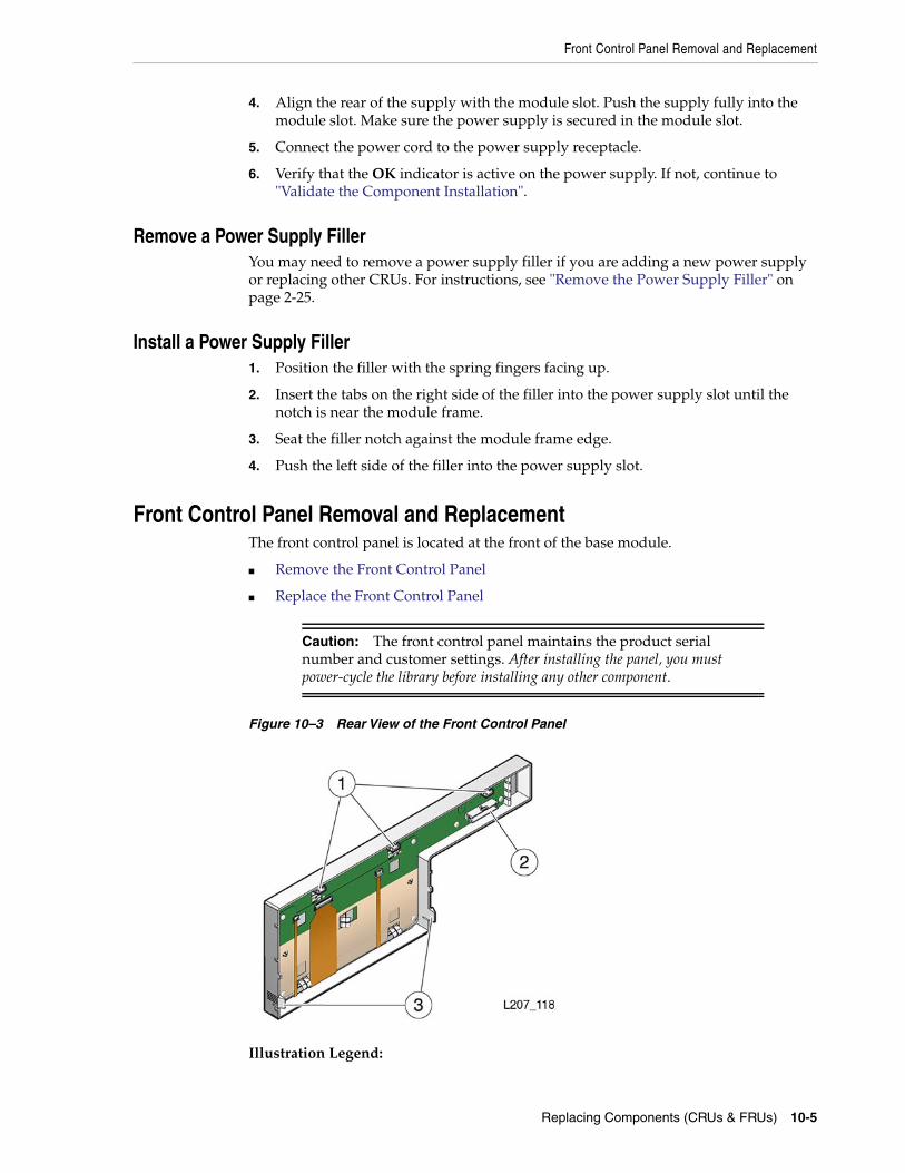
Front Control Panel Removal and Replacement
Replacing Components (CRUs & FRUs) 10-5
4. Align the rear of the supply with the module slot. Push the supply fully into themodule slot. Make sure the power supply is secured in the module slot.
5. Connect the power cord to the power supply receptacle.
6. Verify that the OK indicator is active on the power supply. If not, continue to"Validate the Component Installation".
Remove a Power Supply FillerYou may need to remove a power supply filler if you are adding a new power supplyor replacing other CRUs. For instructions, see "Remove the Power Supply Filler" onpage 2-25.
Install a Power Supply Filler1. Position the filler with the spring fingers facing up.
2. Insert the tabs on the right side of the filler into the power supply slot until thenotch is near the module frame.
3. Seat the filler notch against the module frame edge.
4. Push the left side of the filler into the power supply slot.
Front Control Panel Removal and ReplacementThe front control panel is located at the front of the base module.
■ Remove the Front Control Panel
■ Replace the Front Control Panel
Figure 10–3 Rear View of the Front Control Panel
Illustration Legend:
Caution: The front control panel maintains the product serialnumber and customer settings. After installing the panel, you mustpower-cycle the library before installing any other component.
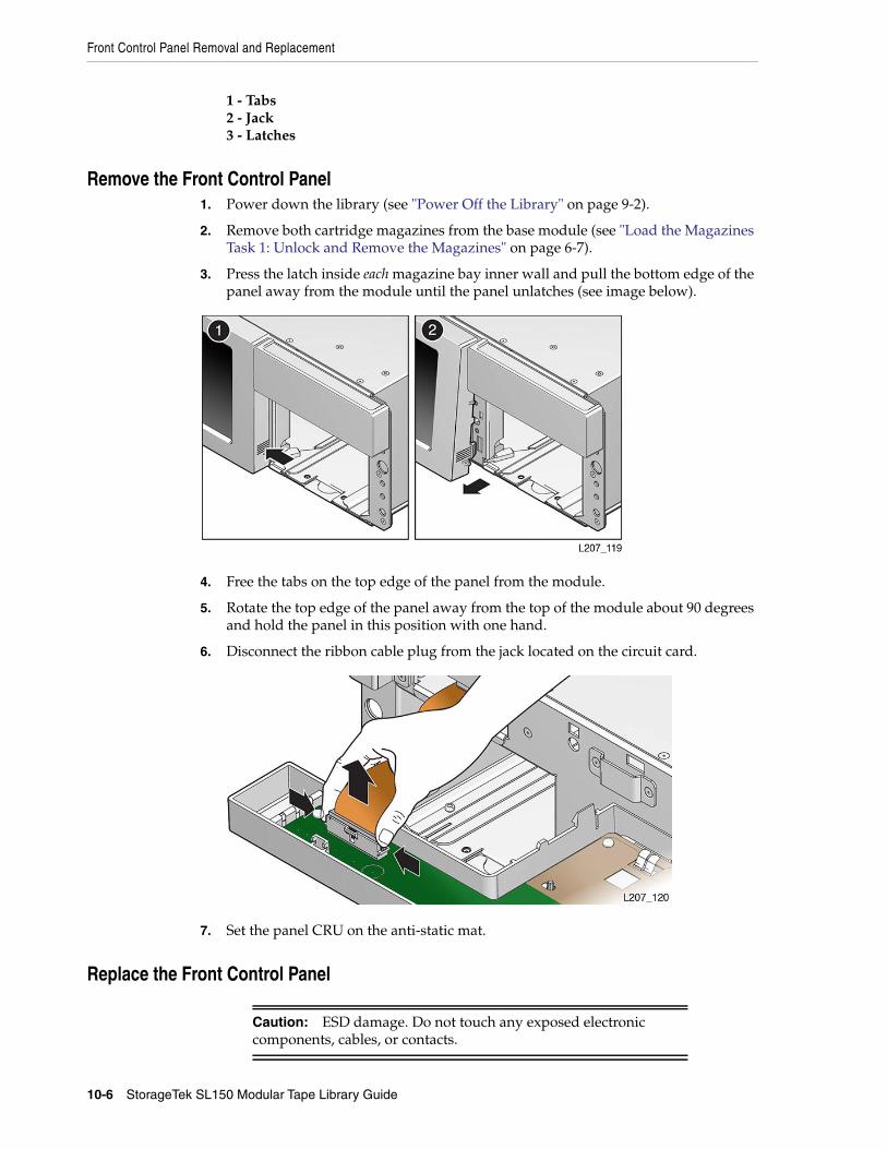
Front Control Panel Removal and Replacement
10-6 StorageTek SL150 Modular Tape Library Guide
1 - Tabs2 - Jack3 - Latches
Remove the Front Control Panel1. Power down the library (see "Power Off the Library" on page 9-2).
2. Remove both cartridge magazines from the base module (see "Load the MagazinesTask 1: Unlock and Remove the Magazines" on page 6-7).
3. Press the latch inside each magazine bay inner wall and pull the bottom edge of thepanel away from the module until the panel unlatches (see image below).
4. Free the tabs on the top edge of the panel from the module.
5. Rotate the top edge of the panel away from the top of the module about 90 degreesand hold the panel in this position with one hand.
6. Disconnect the ribbon cable plug from the jack located on the circuit card.
7. Set the panel CRU on the anti-static mat.
Replace the Front Control Panel
Caution: ESD damage. Do not touch any exposed electroniccomponents, cables, or contacts.
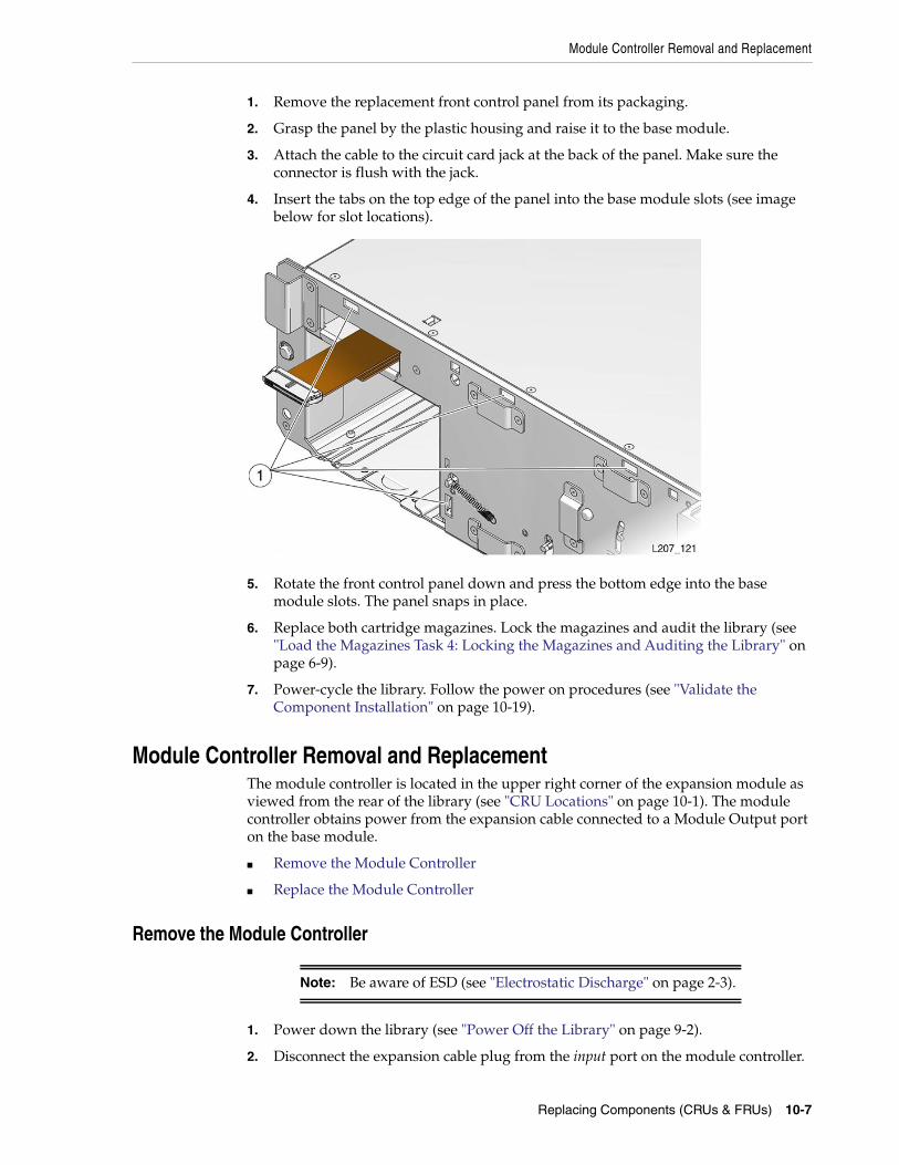
Module Controller Removal and Replacement
Replacing Components (CRUs & FRUs) 10-7
1. Remove the replacement front control panel from its packaging.
2. Grasp the panel by the plastic housing and raise it to the base module.
3. Attach the cable to the circuit card jack at the back of the panel. Make sure theconnector is flush with the jack.
4. Insert the tabs on the top edge of the panel into the base module slots (see imagebelow for slot locations).
5. Rotate the front control panel down and press the bottom edge into the basemodule slots. The panel snaps in place.
6. Replace both cartridge magazines. Lock the magazines and audit the library (see"Load the Magazines Task 4: Locking the Magazines and Auditing the Library" onpage 6-9).
7. Power-cycle the library. Follow the power on procedures (see "Validate theComponent Installation" on page 10-19).
Module Controller Removal and ReplacementThe module controller is located in the upper right corner of the expansion module asviewed from the rear of the library (see "CRU Locations" on page 10-1). The modulecontroller obtains power from the expansion cable connected to a Module Output porton the base module.
■ Remove the Module Controller
■ Replace the Module Controller
Remove the Module Controller
1. Power down the library (see "Power Off the Library" on page 9-2).
2. Disconnect the expansion cable plug from the input port on the module controller.
Note: Be aware of ESD (see "Electrostatic Discharge" on page 2-3).
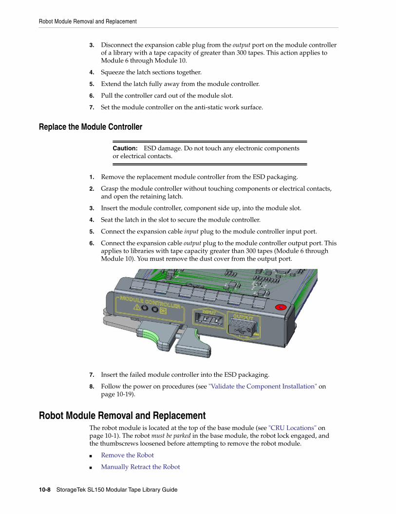
Robot Module Removal and Replacement
10-8 StorageTek SL150 Modular Tape Library Guide
3. Disconnect the expansion cable plug from the output port on the module controllerof a library with a tape capacity of greater than 300 tapes. This action applies toModule 6 through Module 10.
4. Squeeze the latch sections together.
5. Extend the latch fully away from the module controller.
6. Pull the controller card out of the module slot.
7. Set the module controller on the anti-static work surface.
Replace the Module Controller
1. Remove the replacement module controller from the ESD packaging.
2. Grasp the module controller without touching components or electrical contacts,and open the retaining latch.
3. Insert the module controller, component side up, into the module slot.
4. Seat the latch in the slot to secure the module controller.
5. Connect the expansion cable input plug to the module controller input port.
6. Connect the expansion cable output plug to the module controller output port. Thisapplies to libraries with tape capacity greater than 300 tapes (Module 6 throughModule 10). You must remove the dust cover from the output port.
7. Insert the failed module controller into the ESD packaging.
8. Follow the power on procedures (see "Validate the Component Installation" onpage 10-19).
Robot Module Removal and ReplacementThe robot module is located at the top of the base module (see "CRU Locations" onpage 10-1). The robot must be parked in the base module, the robot lock engaged, andthe thumbscrews loosened before attempting to remove the robot module.
■ Remove the Robot
■ Manually Retract the Robot
Caution: ESD damage. Do not touch any electronic componentsor electrical contacts.
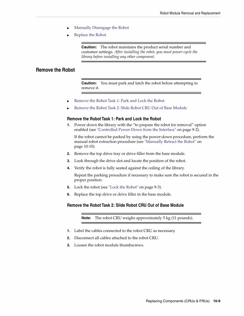
Robot Module Removal and Replacement
Replacing Components (CRUs & FRUs) 10-9
■ Manually Disengage the Robot
■ Replace the Robot
Remove the Robot
■ Remove the Robot Task 1: Park and Lock the Robot
■ Remove the Robot Task 2: Slide Robot CRU Out of Base Module
Remove the Robot Task 1: Park and Lock the Robot1. Power down the library with the “to prepare the robot for removal” option
enabled (see "Controlled Power-Down from the Interface" on page 9-2).
If the robot cannot be parked by using the power-down procedure, perform themanual robot extraction procedure (see "Manually Retract the Robot" onpage 10-10).
2. Remove the top drive tray or drive filler from the base module.
3. Look through the drive slot and locate the position of the robot.
4. Verify the robot is fully seated against the ceiling of the library.
Repeat the parking procedure if necessary to make sure the robot is secured in theproper position.
5. Lock the robot (see "Lock the Robot" on page 9-3).
6. Replace the top drive or drive filler in the base module.
Remove the Robot Task 2: Slide Robot CRU Out of Base Module
1. Label the cables connected to the robot CRU as necessary.
2. Disconnect all cables attached to the robot CRU.
3. Loosen the robot module thumbscrews.
Caution: The robot maintains the product serial number andcustomer settings. After installing the robot, you must power-cycle thelibrary before installing any other component.
Caution: You must park and latch the robot before attempting toremove it.
Note: The robot CRU weighs approximately 5 kg (11 pounds).
Robot Module Removal and Replacement
10-10 StorageTek SL150 Modular Tape Library Guide
4. Grasp the robot module thumbscrews and pull the robot approximately 25cm (10inches) out of the base module.
5. Reposition your hands near the center of the extended robot.
6. Pull the robot completely out of the base module, and set it on the anti-static worksurface.
7. Proceed to "Replace the Robot" on page 10-12.
Manually Retract the RobotOnly use this procedure if you could not park the robot by using the power-downprocedure.
1. Remove the top drive tray from the base module (see "Drive Tray Removal andReplacement" on page 10-2).
2. Locate the bullwheel gear inside the library and above the top drive slot (seeFigure 10–4).
3. Look through the drive slot and locate the position of the robot.
4. Turn the gear with your thumb to raise the robot, hold the gear in position with afinger, reposition your thumb, and turn the gear. Repeat as necessary until therobot is at the top of the base module.
If the robot does not retract, disengage it (see "Manually Disengage the Robot" onpage 10-11).
5. Hold the bullwheel gear with the robot fully raised until you lock the robot.
6. Return to Step 5 of , "Remove the Robot Task 1: Park and Lock the Robot" andcontinue through the last step of robot removal (see , "Remove the Robot Task 2:Slide Robot CRU Out of Base Module").
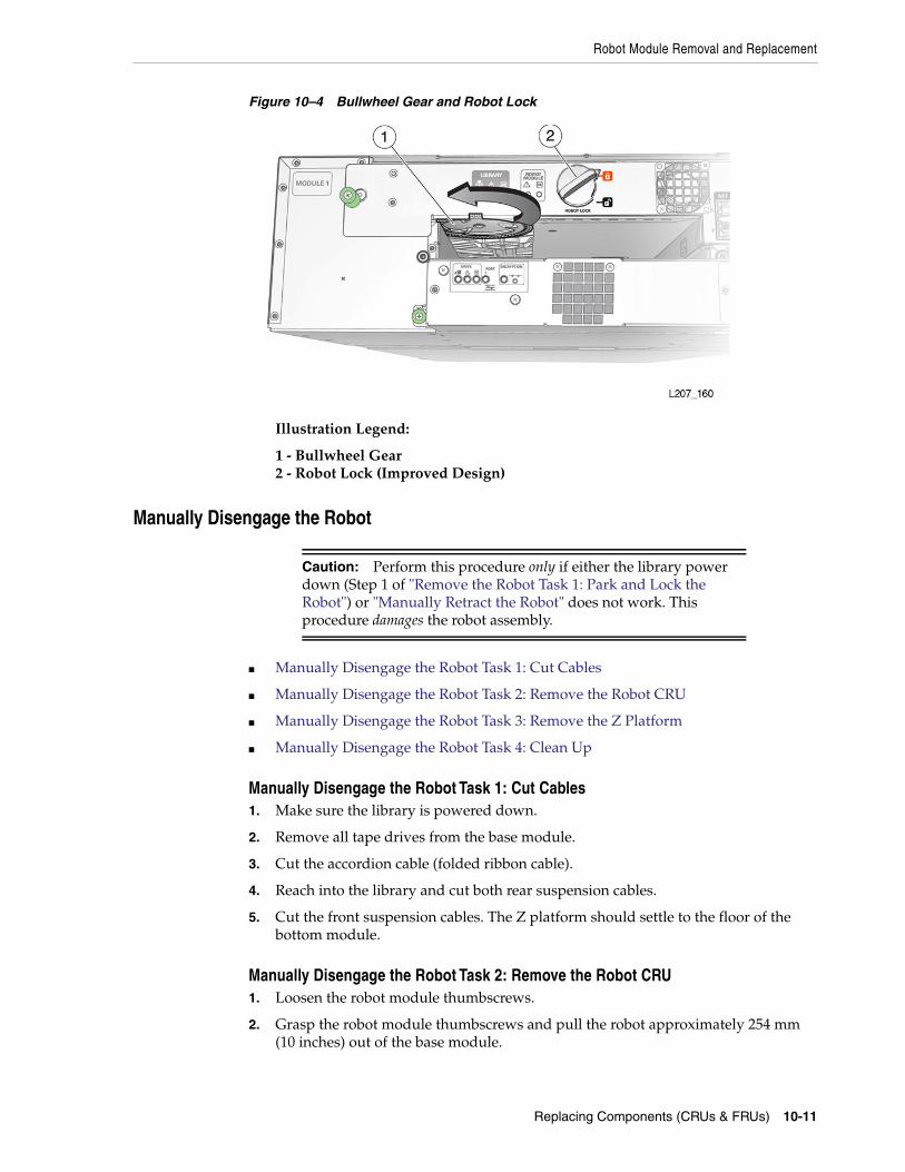
Robot Module Removal and Replacement
Replacing Components (CRUs & FRUs) 10-11
Figure 10–4 Bullwheel Gear and Robot Lock
Illustration Legend:
1 - Bullwheel Gear2 - Robot Lock (Improved Design)
Manually Disengage the Robot
■ Manually Disengage the Robot Task 1: Cut Cables
■ Manually Disengage the Robot Task 2: Remove the Robot CRU
■ Manually Disengage the Robot Task 3: Remove the Z Platform
■ Manually Disengage the Robot Task 4: Clean Up
Manually Disengage the Robot Task 1: Cut Cables1. Make sure the library is powered down.
2. Remove all tape drives from the base module.
3. Cut the accordion cable (folded ribbon cable).
4. Reach into the library and cut both rear suspension cables.
5. Cut the front suspension cables. The Z platform should settle to the floor of thebottom module.
Manually Disengage the Robot Task 2: Remove the Robot CRU1. Loosen the robot module thumbscrews.
2. Grasp the robot module thumbscrews and pull the robot approximately 254 mm(10 inches) out of the base module.
Caution: Perform this procedure only if either the library powerdown (Step 1 of "Remove the Robot Task 1: Park and Lock theRobot") or "Manually Retract the Robot" does not work. Thisprocedure damages the robot assembly.
Robot Module Removal and Replacement
10-12 StorageTek SL150 Modular Tape Library Guide
3. Reposition your hands along the sides of the extended robot and close to the basemodule.
4. Pull the robot completely out of the base module, and set it aside.
Manually Disengage the Robot Task 3: Remove the Z Platform1. Remove the cartridge magazines from the base module.
2. Remove cartridge magazines from expansion modules until you locate the Zplatform.
3. Grasp the platform by reaching through either the magazine or tape driveopenings.
4. Raise the platform by hand to the top of the base module.
5. Push the platform through the robot CRU opening at the rear of the base modulefar enough so that it does not slip back inside the library.
6. Go to the back of the library, grasp the robot CRU, and remove it from the library.
Manually Disengage the Robot Task 4: Clean Up1. Inspect the library floor and remove any debris resulting from the broken robot.
2. Replace all cartridge magazines and tape drives removed during this procedure.
3. Follow the replace robot procedures (see "Replace the Robot" on page 10-12).
Replace the Robot■ Replace the Robot Task 1: Reinsert the Robot CRU and Unlock the Robot
■ Replace the Robot Task 2: Cabling
Replace the Robot Task 1: Reinsert the Robot CRU and Unlock the Robot1. Remove the replacement robot from its shipping carton, and set it on the anti-static
mat. Save the packaging materials for the return of the failed CRU.
2. Grasp the robot near the center with the thumbscrews facing you.
3. Insert the robot into the base module.
4. Push the robot fully into the module.
5. Tighten the thumbscrews on each side of the robot CRU.
6. Unlock the robot (see "Unlock the Robot" on page 2-29).
Replace the Robot Task 2: Cabling1. Plug the expansion cable for Module 2 through Module 10 into the appropriate
base module connector.
For example, connect the output plug of the expansion cable to Port 2 on the robotCRU and the input plug of the cable to the Module 2 controller input port.
Note: You can also perform this procedure at the rear of the libraryby removing the tape drives or drive fillers from the modules, andreaching through the drive openings.
Expansion Module Chassis Removal and Replacement (FRU)
Replacing Components (CRUs & FRUs) 10-13
2. Plug the Ethernet cables into the appropriate Net Mgt ports.
3. Follow the power on procedures (see "Validate the Component Installation").
Expansion Module Chassis Removal and Replacement (FRU)
You must transfer cartridge magazines, tape drives, tape drive fillers, power supplies,power supply fillers, and the module controller from the failed module to the FRU, asapplicable. You might need to remove operational modules to access the defective one.
■ Remove an Expansion Module
■ Replace the Expansion FRU Chassis
Figure 10–5 Expansion Module FRU
Illustration Legend:
1 - Flange2 - Tab
Remove an Expansion Module■ Remove Expansion Task 1: Power Down, Lock the Robot, and Remove Magazines
■ Remove Expansion Task 2: Remove the Floor, Cables, and Cords
■ Remove Expansion Task 3: Remove Operational Expansion Modules Below theDefective Module
■ Remove Expansion Task 4: Remove Components from the Defective Module
Remove Expansion Task 1: Power Down, Lock the Robot, and Remove Magazines
Note: The initial design of the expansion cable did not have pluglabels.
Note: The expansion module is a field-replaceable unit (FRU) andmust be serviced by an Oracle service person.
Caution: You must park and lock the robot before attempting toremove an expansion module.
Expansion Module Chassis Removal and Replacement (FRU)
10-14 StorageTek SL150 Modular Tape Library Guide
1. Power down the library with the option enabled to prepare the robot for removal(see "Controlled Power-Down from the Interface" on page 9-2).
2. Perform the robot park and lock instructions (see "Remove the Robot Task 1: Parkand Lock the Robot" on page 10-9).
3. Remove the magazines from the defective module. Remove the magazines fromall modules below it, and remove the magazines from the module directly above it(see "Mount the Base Module Task 2: Remove the Cartridge Magazine with theHex Key" on page 2-12).
Remove Expansion Task 2: Remove the Floor, Cables, and Cords1. Grasp the library floor at the thumb-holds within the magazine openings.
2. Pull the floor out from the front of the module.
3. Disconnect the expansion cable plug(s) from the port(s) at each affected expansionmodule controller. Module 6 through Module 10 could have both ports connected.
4. Open the hook and loop strap, extract all cables and cords, then remove the hookand loop strap (open the plunger on the plastic rivet).
5. Disconnect the power supply cord.
6. Disconnect the drive interface and Ethernet cables, as applicable.
Remove Expansion Task 3: Remove Operational Expansion Modules Below theDefective Module
1. (Optional) Remove tape drives and power supplies to lighten the weight of theexpansion module (see, as necessary, "Drive Tray Removal and Replacement" onpage 10-2 and "Power Supply Removal and Replacement" on page 10-4).
2. Remove the Phillips screws securing the expansion module to the front of the rack.
3. Grasp the module, pull it forward until the break in the flange is visible, lower thefront of the module, pull it free from the module above it, and away from the rack.
4. Set the module down and away from the front of the rack.
5. Remove the Phillips screws and rear rails from the module. Leave the clip nut inplace (see Figure 10–6).
6. Repeat until you have removed all modules below the failed module.
Note: If the floor does not move, reach through the magazineopening and push down on the floor behind the touch screen panel tounseat the floor locks. Pull the floor forward with your other hand.
Note: The original design of the expansion controller had a singleport only.
Warning: Expansion modules weigh about 19.9 kg (43.9 pounds)with two cartridge magazines, 30 tape cartridges, two tape drives,and two power supplies.
Expansion Module Chassis Removal and Replacement (FRU)
Replacing Components (CRUs & FRUs) 10-15
Figure 10–6 Module Rear Rail Removal
Illustration Legend:
1 - Rear Rail2 - Clip Nut
Remove Expansion Task 4: Remove Components from the Defective Module1. Remove the functional components as applicable:
■ "Remove the Drive Tray" on page 10-2
■ "Remove a Drive Filler" on page 10-4
■ "Remove the Power Supply" on page 10-4
■ "Remove a Power Supply Filler" on page 10-5
■ "Remove the Module Controller" on page 10-7
2. Remove the failed expansion module.
Replace the Expansion FRU Chassis■ Replace Expansion Task 1: Install the Chassis
■ Replace Expansion Task 2: Install CRUs, Fillers, and Magazines in ReplacedModule
■ Replace Expansion Task 3: Install the Remaining Expansion Modules
■ Replace Expansion Task 4: Finishing Touches
Replace Expansion Task 1: Install the Chassis1. Grasp the expansion module chassis by the sides and remove it from the shipping
carton.
2. Remove the magazines from the expansion module (see "Prepare the ExpansionModule by Removing the Cartridge Magazines" on page 2-17).
3. If this will be the bottom module of the library, install the library floor now (see"Install the Floor in the Bottom Expansion Module" on page 2-18).
4. Mount the module (see "Mount the Expansion Module" on page 2-19).
5. Install the rails (see "Install the Rear Rails for the Expansion Module" onpage 2-21).
Base Module (Module 1) Chassis Removal and Replacement
10-16 StorageTek SL150 Modular Tape Library Guide
6. Secure the module (see "Secure the Expansion Module to the Front Rack Stile" onpage 2-22).
Replace Expansion Task 2: Install CRUs, Fillers, and Magazines in Replaced ModuleCables and cords are connected as part of CRU installation.
1. Install the module controller (see "Replace the Module Controller").
2. Install the tape drive assembly (see "Replace the Drive Tray").
3. Install the tape drive filler (see "Install a Drive Filler").
4. Install the power supply (see "Replace the Power Supply").
5. Install the power supply filler (see "Install a Power Supply Filler").
6. Insert the cartridge magazines.
Replace Expansion Task 3: Install the Remaining Expansion Modules1. Locate the next expansion module for installation (refer to the module number
label on the back of the module).
2. Repeat the installation tasks until all expansion modules and CRUs are installed(refer to and ).
3. Make sure you have installed the floor in the bottom module (see "Install the Floorin the Bottom Expansion Module" on page 2-18).
Replace Expansion Task 4: Finishing Touches1. Secure the hook and loop strap to the replaced expansion module (close the
plunger of the rivet).
2. Align, dress, and secure cables in the hook and loop straps.
3. Follow the power on procedures (see "Validate the Component Installation").
Base Module (Module 1) Chassis Removal and Replacement
You must transfer the cartridge magazines, front control panel, tape drive(s), tapedrive filler, power supply, power supply filler, and the robot from the defective basemodule to the FRU.
■ Remove the Base Module Chassis
■ Replace the Base Module Chassis
Tip: When the library capacity is more than 300 cartridges, you willnot connect the output port for Module 6 through Module 10 now.You connect the port when installing Module 11 through Module 15.
Note: The base module is a field-replaceable unit (FRU) and must beserviced by an Oracle service person.
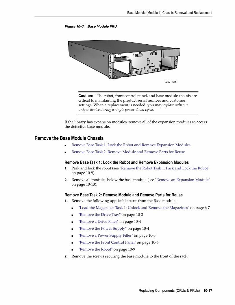
Base Module (Module 1) Chassis Removal and Replacement
Replacing Components (CRUs & FRUs) 10-17
Figure 10–7 Base Module FRU
If the library has expansion modules, remove all of the expansion modules to accessthe defective base module.
Remove the Base Module Chassis■ Remove Base Task 1: Lock the Robot and Remove Expansion Modules
■ Remove Base Task 2: Remove Module and Remove Parts for Reuse
Remove Base Task 1: Lock the Robot and Remove Expansion Modules1. Park and lock the robot (see "Remove the Robot Task 1: Park and Lock the Robot"
on page 10-9).
2. Remove all modules below the base module (see "Remove an Expansion Module"on page 10-13).
Remove Base Task 2: Remove Module and Remove Parts for Reuse1. Remove the following applicable parts from the Base module:
■ "Load the Magazines Task 1: Unlock and Remove the Magazines" on page 6-7
■ "Remove the Drive Tray" on page 10-2
■ "Remove a Drive Filler" on page 10-4
■ "Remove the Power Supply" on page 10-4
■ "Remove a Power Supply Filler" on page 10-5
■ "Remove the Front Control Panel" on page 10-6
■ "Remove the Robot" on page 10-9
2. Remove the screws securing the base module to the front of the rack.
Caution: The robot, front control panel, and base module chassis arecritical to maintaining the product serial number and customersettings. When a replacement is needed, you may replace only oneunique device during a single power-down cycle.
Base Module (Module 1) Chassis Removal and Replacement
10-18 StorageTek SL150 Modular Tape Library Guide
3. Extract the module from the rack.
Replace the Base Module Chassis■ Replace Base Task 1: Install the Base Module FRU
■ Replace Base Task 2: Install the Base Module CRUs and Expansion Modules
■ Replace Base Task 3: Reinstall Magazines and Dress the Cables
Replace Base Task 1: Install the Base Module FRU1. Grasp the base module chassis by the sides and remove it from the shipping
carton.
2. If there are no expansion modules for this library, install the floor in the basemodule (see "Install the Floor in the Bottom Expansion Module").
3. Mount the base module (see "Mount the Base Module" on page 2-11).
Replace Base Task 2: Install the Base Module CRUs and Expansion Modules1. Reinstall the base module components.
■ "Replace the Robot" on page 10-12
■ "Replace the Drive Tray" on page 10-3
■ "Install a Drive Filler" on page 10-4
■ "Replace the Power Supply" on page 10-4
■ "Install a Power Supply Filler" on page 10-5
■ "Replace the Front Control Panel" on page 10-6
2. Reinstall the expansion modules (see "Replace the Expansion FRU Chassis" onpage 10-15). Make sure to install the floor in the bottom module.
3. Re-cable the expansion modules. Connect the specific base module port to thecontroller card port of the associated expansion module. See "Cable the LibraryTask 1: Cable the Expansion Modules" on page 2-27 for details.
Replace Base Task 3: Reinstall Magazines and Dress the Cables1. Install cartridge magazines in all modules (see "Load the Magazines Task 4:
Locking the Magazines and Auditing the Library").
2. Align and dress the cables. Secure the cables in the hook and loop straps, ifapplicable.
Warning: The base module weighs approximately 12.8 kg (28.3pounds) without magazines, tape drives, power supplies, or therobot CRU. A best practice is to use two persons to lift the unit.
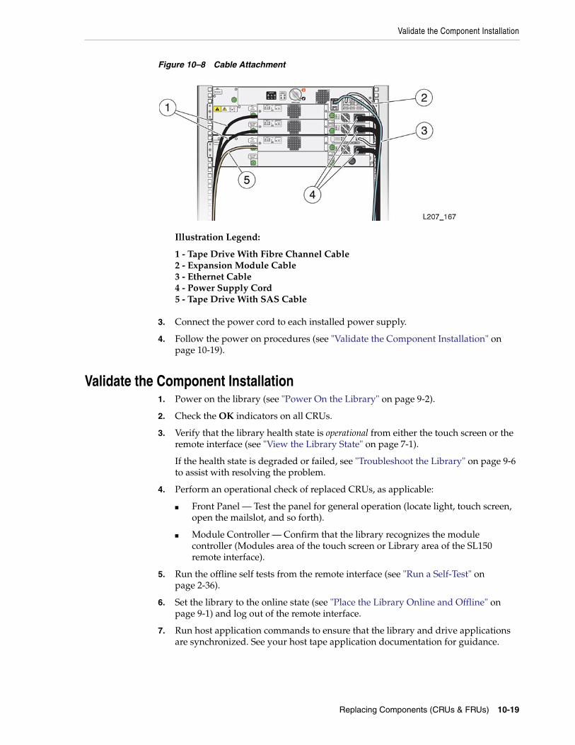
Validate the Component Installation
Replacing Components (CRUs & FRUs) 10-19
Figure 10–8 Cable Attachment
Illustration Legend:
1 - Tape Drive With Fibre Channel Cable2 - Expansion Module Cable3 - Ethernet Cable4 - Power Supply Cord5 - Tape Drive With SAS Cable
3. Connect the power cord to each installed power supply.
4. Follow the power on procedures (see "Validate the Component Installation" onpage 10-19).
Validate the Component Installation1. Power on the library (see "Power On the Library" on page 9-2).
2. Check the OK indicators on all CRUs.
3. Verify that the library health state is operational from either the touch screen or theremote interface (see "View the Library State" on page 7-1).
If the health state is degraded or failed, see "Troubleshoot the Library" on page 9-6to assist with resolving the problem.
4. Perform an operational check of replaced CRUs, as applicable:
■ Front Panel — Test the panel for general operation (locate light, touch screen,open the mailslot, and so forth).
■ Module Controller — Confirm that the library recognizes the modulecontroller (Modules area of the touch screen or Library area of the SL150remote interface).
5. Run the offline self tests from the remote interface (see "Run a Self-Test" onpage 2-36).
6. Set the library to the online state (see "Place the Library Online and Offline" onpage 9-1) and log out of the remote interface.
7. Run host application commands to ensure that the library and drive applicationsare synchronized. See your host tape application documentation for guidance.
Return CRU Components to Oracle
10-20 StorageTek SL150 Modular Tape Library Guide
Return CRU Components to OracleYou should only replace a single CRU at a time. Keep the original CRU until thecorrect CRU is identified as faulty.
Return the robot and tape drive tray CRUs to Oracle. Instructions should have beenprovided regarding the process to return the specific CRU.
Dispose of all other CRUs or recycle them, as appropriate.
Lock the Robot for Reshipment within RackUse the following instructions if you are shipping the SL150 after installing it into arack.
■ Power Down the Library and Verify Robot Position
■ Install the Shipping Clip
Power Down the Library and Verify Robot Position1. Power down the library with the “to prepare the robot for removal” option
enabled (see "Controlled Power-Down from the Interface" on page 9-2).
2. Lock the robot (see "Lock the Robot" on page 9-3).
3. Remove the right cartridge magazine from the base module (see "Mount the BaseModule Task 2: Remove the Cartridge Magazine with the Hex Key" on page 2-12 ifnecessary).
4. Make sure the robot has positioned the hand against the ceiling and front face ofthe library (see image below).
Install the Shipping Clip1. Verify the robot is in position (see Power Down the Library and Verify Robot
Position).
2. Grasp the shipping clip and reach through the cartridge magazine opening.
Caution: Improper installation of the lock could cause catastrophicfailure during shipment.
Lock the Robot for Reshipment within Rack
Replacing Components (CRUs & FRUs) 10-21
3. Open the shipping clip and install it over the 7 mm steel shaft behind the handassembly (see image below).
Illustration Legend:
1 - Opened Shipping Clip2 - Instruction Tag
4. Squeeze the clip to reduce the clamping force on the shaft and slide the cliptoward the hand assembly (see image below). The hand will be contained betweenthe front wall and the clip.
5. Guide the instruction tag out of the cartridge magazine slot. Route the string andinstruction tag between the mailslot and right side of the front control panel andset it on top of the base module (see image below).
Lock the Robot for Reshipment within Rack
10-22 StorageTek SL150 Modular Tape Library Guide
6. Replace the right magazine in the base module and verify the magazine is securelylatched.
A
Slot Mapping and Cartridge Locations A-1
ASlot Mapping and Cartridge Locations
■ Cartridge Slot Addressing
■ Drive, Mailslot, Power Supply, and Robot Addressing
■ SCSI Element Addressing
■ Example Library Configurations and Slot Maps
Cartridge Slot AddressingLibrary slots are identified by library-module, side, row, column, where:
■ library-module is the module that contains the slot. Modules are numbered bystarting from the base module (1) and counting down.
■ side identifies the magazine within the module either Left or Right.
■ row is the row of the slot with in the magazine, numbered starting from the top ofmagazine(1) and counting down.
■ column is the column of the slot within the magazine, numbered starting from thehandle side of the magazine, at the front of the library, and counting to the back.
Reserved SlotsThe library can have a maximum of three reserved slots. Only the following slotaddresses can be used as reserved slots (see "Determine the Required Number ofReserved System Slots" on page 6-5). Reserved slots do not have a SCSI elementaddress.
■ 1, Left, 1, 1
■ 1, Left, 2, 1
■ 1, Left, 3, 1
Drive, Mailslot, Power Supply, and Robot AddressingComponent locations are identified using the following addressing schemes:
Component SCSI Element Address Physical addressing
Drives Yes module,top|bottom
Mailslot Yes slot number
Expanded Mailslot Yes module,side,row,column
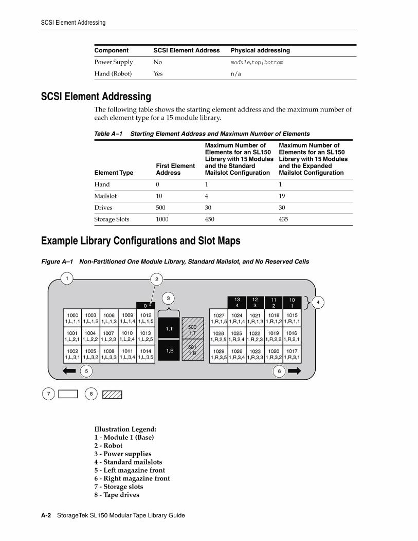
SCSI Element Addressing
A-2 StorageTek SL150 Modular Tape Library Guide
SCSI Element AddressingThe following table shows the starting element address and the maximum number ofeach element type for a 15 module library.
Example Library Configurations and Slot Maps
Figure A–1 Non-Partitioned One Module Library, Standard Mailslot, and No Reserved Cells
Illustration Legend:1 - Module 1 (Base)2 - Robot3 - Power supplies4 - Standard mailslots5 - Left magazine front6 - Right magazine front7 - Storage slots8 - Tape drives
Power Supply No module,top|bottom
Hand (Robot) Yes n/a
Table A–1 Starting Element Address and Maximum Number of Elements
Element TypeFirst ElementAddress
Maximum Number ofElements for an SL150Library with 15 Modulesand the StandardMailslot Configuration
Maximum Number ofElements for an SL150Library with 15 Modulesand the ExpandedMailslot Configuration
Hand 0 1 1
Mailslot 10 4 19
Drives 500 30 30
Storage Slots 1000 450 435
Component SCSI Element Address Physical addressing
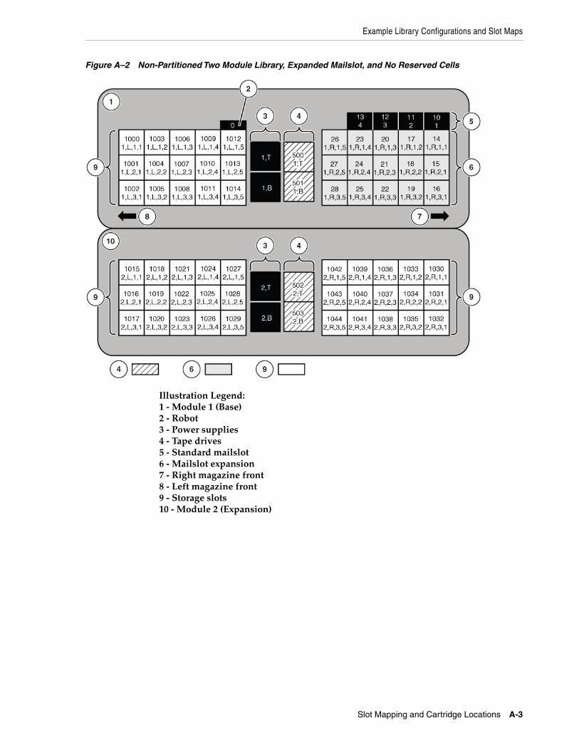
Example Library Configurations and Slot Maps
Slot Mapping and Cartridge Locations A-3
Figure A–2 Non-Partitioned Two Module Library, Expanded Mailslot, and No Reserved Cells
Illustration Legend:1 - Module 1 (Base)2 - Robot3 - Power supplies4 - Tape drives5 - Standard mailslot6 - Mailslot expansion7 - Right magazine front8 - Left magazine front9 - Storage slots10 - Module 2 (Expansion)
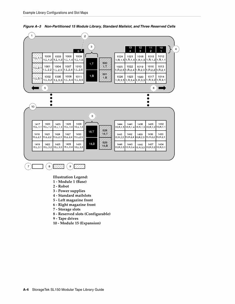
Example Library Configurations and Slot Maps
A-4 StorageTek SL150 Modular Tape Library Guide
Figure A–3 Non-Partitioned 15 Module Library, Standard Mailslot, and Three Reserved Cells
Illustration Legend:1 - Module 1 (Base)2 - Robot3 - Power supplies4 - Standard mailslots5 - Left magazine front6 - Right magazine front7 - Storage slots8 - Reserved slots (Configurable)9 - Tape drives10 - Module 15 (Expansion)
Glossary-1
Glossary
This glossary defines terms and abbreviations in this publication.
Some of the definitions are taken from other glossaries. The letters in the parenthesesthat follow some definitions indicate the source of the definition:
(A) The American National Standard Dictionary for Information Systems, ANSIX3.172-1990, copyright 1990 by the American National Standards Institute (ANSI).
(E) The ANSI/Electronic Industries Association (EIA) Standard-440-A, Fiber OpticTerminology.
(I) The Information Technology Vocabulary, developed by Subcommittee 1, JointTechnical Committee 1, of the International Organization for Standardization andInternational Electro-technical Commission (ISO/IEC/JTC1/SC1).
(IBM) The IBM Dictionary of Computing, copyright 1994 by IBM.
(T) Draft international standards committee drafts, and working papers beingdeveloped by the ISO/IEC/JTC1/SC1.
alphanumeric
A character or group of characters that identifies a register, a particular part of storage,or some other data source or destination. (A).
arm
The robotic assembly that is lowered between the columns of tapes. The arm hangs onfour wires from the Z mechanism. The arm includes the hand, the rails the hand rideson, the track motor that moves the hand along the rails, and the KLT card.
audit
The process of recording the location of all tapes in a library.
bar code
A code consisting of a series of bars of varying widths. This code appears on theexternal label attached to the spine of a tape cartridge and is equivalent to the volumeserial number (VOLSER). This code is read by the machine vision system of the library.
base chassis
The sheet metal and plastic chassis that makes up the framework of Module 1.
base module
The smallest, fully functional library consisting of the base chassis with the midplane,robot, front control panel, mailslot, one or two power supplies, up to two half-heightLTO Ultrium tape drives, left magazine, and right magazine.
cartridge
Glossary-2
cartridge
A storage device that consists of magnetic tape on a supply reel in a protectivehousing. The spine of the cartridge usually contains a label listing the volumeidentification number. Also called tape, tape cartridge, tape volume, or cassette.
cell
See slot.
cleaning cartridge
A tape cartridge that contains special material to clean the tape path in a transport ordrive. LTO Ultrium cleaning cartridge labels have a CLN prefix and a CU mediaidentifier.
configuration
The manner in which the hardware and software of an information processing systemis organized and interconnected. (T)
data cartridge
A term used to distinguish a cartridge onto which a tape drive may write data.
diagnostics
Pertaining to the detection and isolation of errors in programs and faults inequipment.
dismount
To remove a tape from a drive.
drive
A drive controls the movement of the tape and records or reads the data on the tape asdesired by the customer (see tape drive).
drive cleaning
The device feature that uses a cleaning cartridge to clean a tape drive.
drive slot
The space in the library where the tape drive resides.
drive tray
See tape drive.
dynamic host configuration protocol (DHCP)
A network protocol that enables a server to automatically assign an IP address todevices on a network. DHCP assigns a number dynamically from a defined range ofnumbers for a given network.
encryption
The process of changing data into a form that cannot be read until it is deciphered,protecting the data from unauthorized access and use.
Ethernet
A local-area, packet-switched bus topology that enables the connection of severalcomputer systems. The Ethernet architecture is similar to the IEEE 802.3 standard.
gripper
Glossary-3
expanded mailsot
An optional library configuration to increase the capacity of the Mailslot from four to19 cartridges. A logical entity containing four slots in the Standard Mailslot plus 15slots in the Base Module right magazine (the Mailslot Expansion).
expansion cable
A cable used to connect expansion modules to Module 1. Each end of the cable has aUSB A style connector.
expansion chassis
The sheet metal and plastic chassis that makes up the framework for Module 2–15.
expansion module
A module that can be added to the bottom of an existing library to increase its capacityfor drives and tape cartridges (tapes). The module consists of the expansion chassis, amodule controller, up to two power supplies, up to two half-height LTO Ultrium tapedrives, a left magazine, and a right magazine.
export
The action in which the device places a cartridge into the mailslot so that the operatorcan remove the cartridge. Also called eject.
FC
See Fibre Channel.
fiber optics
The branch of optical technology concerned with the transmission of radiant powerthrough fibers made of transparent materials such as glass, fused silica, and plastic. (E)
fiber-optic cable
A cable made of ultra-thin glass or silica fibers which can transmit data using pulses oflaser light. Fiber-optic cables have several advantages over copper cables: they havemuch less signal loss; they allow information to be transmitted at higher speeds andover longer distances; they are not affected by external electrical noise; and they arebetter for transmissions which require security.
Fibre Channel
The National Committee for Information Technology Standards standard that definesan ultrahigh-speed, content-independent, multilevel data transmission interface thatsupports multiple protocols simultaneously. Fibre Channel supports connectivity tomillions of devices over copper or fiber-optic physical media and provides the bestcharacteristics of both networks and channels over diverse topologies.
front control panel
An assembly mounted on the front of the base chassis. It includes the touch screenoperator panel, various LEDs and switches, and associated electronics.
get
An activity in which a robot obtains a cartridge from a slot or drive.
gripper
The portion of the hand assembly that grasps and holds a cartridge.
GUI
Glossary-4
GUI
Graphical user interface. Software that allows the user to control the device throughvisual screens.
hand
The robotic mechanism that grabs tape cartridges and moves them between slots andthe drive. It is a component of the arm. The hand has a reach mechanism that gets tapecartridges from slots or drives and puts them into slots or drives. The hand also has awrist mechanism that rotates the hand to allow it to reach cartridges on either side orthe drives at the back of the library.
hardware
All or part of the physical components of an information processing system, such ascomputers or peripheral devices. (T) (A)
HBA
See host bus adapter.
host bus adapter (HBA)
A circuit installed in a multi-platform host or device that interfaces between the deviceand the bus.
host computer
In a computer network, a computer that usually performs network control functionsand provides end users with services such as computation and database access. (T)
host interface
An interface between a network and host computer. (T)
import
The process of bringing a cartridge into the library from the mailslot. Also called enter.
indicator
A device that provides a visual or other indication of the existence of a defined state.(T)
initial program load (IPL)
A process that activates a device reset and loads system programs to prepare acomputer system for operation. Processors having diagnostic programs activate theseprograms at initial program load execution. Devices running firmware usually reloadthe functional firmware from a diskette or disk drive at initial program load execution.
initialization
The operations required for setting a device to a starting state, before the use of a datamedium, or before implementation of a process. (T)
interface
Hardware, software, or both, that links systems, programs, or devices. (IBM)
internet protocol (IP)
A protocol used to route data from its source to its destination in an Internetenvironment. (IBM)
magnetic tape drive
Glossary-5
inventory
The process of reading and storing in memory the bar code identification and locationof all tape cartridges in a library.
IP
See internet protocol.
IPL
See initial program load.
LC connector
A standard fiber-optic cable connector for Fibre Channel data transfer.
LED
Light emitting diode. An electronic device that lights up when electricity is passedthrough it.
left magazine
A plastic assembly containing 15 tape slots that can be inserted into the left side (asviewed from the front) of Modules 1–15. Left magazines and right magazines are notinterchangeable.
library
A robotic system that stores, moves, mounts, and dismounts tape cartridges that areused in data read or write operations.
LME
Library Managed Encryption. A feature introduced with library code 3.50 where thelibrary manages the enrollment and key delivery for IBM LTO-7 and higher drives foruse with OKM.
LTO
An acronym for Linear Tape-Open technology which is a set of data format standardscreated to enable data interchange among tape drives produced by a consortium ofmanufacturers. With LTO standards, the tape cartridges are interchangeable amongtape drive brands.
LUN
Logical Unit Number. An address for a component of a SCSI device. In this device, thehost computer sends the SCSI commands for the library to LUN 1 of the master tapedrive and sends SCSI commands for the tape drive itself to LUN 0.
MAC address
The media access control address is a unique identifier assigned to devices forcommunication on a physical network.
magnetic tape
A tape with a magnetizable layer on which data can be stored. (T)
magnetic tape drive
A mechanism for controlling the movement of magnetic tape, commonly used to movemagnetic tape past a read head or write head, or to allow automatic rewinding. (I) (A)
mailslot
Glossary-6
mailslot
The standard mailslot is a plastic and metal assembly located in the upper right cornerof the base chassis used to enter tapes into the library and to remove tapes from thelibrary. Previous StorageTek libraries called this a CAP (Cartridge Access Port).
mailslot expansion
A term describing the Base Module right magazine (the magazine immediately belowthe Standard Mailslot) when the library has the expanded mailslot configuration. Themailslot capacity expands from four cartridges (Standard Mailslot) to 19 cartridges.
management information base (MIB)
An ASCII text file organized hierarchically that describes the elements (configurationand statistical information) of a managed device. When a manager requestsinformation, or a managed device generates a trap, the MIB translates the numericstrings into readable text that identifies each data object within the message.
midplane
A card mounted in the base chassis or expansion chassis that is behind the tape slotsand in front of the tape drives. Other cards connect to it either by direct connection orby a cable.
Module 1
See base module.
module controller
A card inserted into the back of Modules 2–15 that controls the operation of themodule. It is connected to the robot by an expansion cable.
Module X (2 through 15)
See expansion module.
mount
To place a tape in a drive and make it accessible to the host system.
multimode fiber
An optical fiber designed to carry multiple signals, distinguished by frequency orphase, at the same time.
net mask
A 32-bit, or 4-byte number, in dotted decimal format (typically written as fournumbers separated by periods, such as 255.255.0.0 or 255.255.255.0) that is applied toan IP address to identify the network and node address of a host or router interface.(Synonymous with subnet mask.)
network
An arrangement of nodes and branches that connects data processing devices to oneanother through software and hardware links to facilitate information interchange.
offline
Neither controlled by, nor communicating with, a computer. (IBM)
OKM
Oracle Key Manager, which provides encryption keys to the tape drives.
SAS
Glossary-7
online
Pertaining to the operation of a functional unit when under the direct control of thecomputer. (T)
operator panel
A component of the front control panel consisting of a seven inch WVGA color touchscreen.
partition
A segmented part of the library that acts to hosts as a separate and independent tapelibrary. The partition must have one bridged drive and at least one magazine.Partitions share the mailslot and robot, but the tape drives and magazines within eachpartition are for use solely by that partition. Other partitions cannot use these tapedrives or magazine storage slots.
port
A specific communications end point within a host. A port is identified by a portnumber. (IBM) (2) In Fibre Channel, an access point in a device where a link attaches.
power supply
An AC to DC power supply that mounts into the rear of a module Module (1–15).Referred to as top power supply or bottom power supply when referring to a powersupply installed in a specific module.
power supply filler
A metal frame that slides into a power supply slot when a power supply will not beused in that slot.
put
An activity in which a robot places a cartridge into a slot or drive.
release
A distribution of a new product or new function and fixes for an existing product.(IBM)
right magazine
A plastic assembly containing 15 tape slots that can be inserted into the right side (asviewed from the front) of Modules 1–15. Right magazines and left magazines are notinterchangeable.
robot
An assembly that incorporates the bulk of the Module 1 electronics and the roboticcomponents. This assembly is a combination of mechanical components, electronics,and a sheet metal housing. It is located at the top of the base chassis and incorporatesthe arm, Z mechanism, a CPU board, plus the KLC and KLZ cards.
SAS
Serial Attached SCSI. A computer bus technology and serial communication protocolfor direct attached storage devices, including disk drives and high-performance tapedrives.
SCSI
Glossary-8
SCSI
Small Computer System Interface. A standard interface and command set fortransferring data between mass storage and other devices. The host computer usesSCSI commands to operate the device. Depending on the model, physical connectionbetween the host computer and the tape drive will use a parallel SCSI, SAS, or FibreChannel interface.
SLAAC
Stateless automatic address configuration. The process of a host generating its ownaddress by using a combination of locally available information, such as a MACaddress, and information that is advertised by routers.
slot
An empty location into which something else may be placed. Most commonly usedwhen referring to the locations in the magazine or mailslot where tape cartridges areplaced. Power supplies and drives are also placed in slots.
switch
In Fibre Channel technology, a device that connects Fibre Channel devices together ina fabric.
tape
Also known as cartridge, tape cartridge, tape volume, volume, or cassette.
tape cartridge
A container holding magnetic tape that can be processed without separating the tapefrom the container. The device uses data and cleaning cartridges. These cartridges arenot interchangeable. See cartridge.
tape drive
An electro-mechanical device that moves magnetic tape and includes mechanisms forwriting and reading data to and from the tape. The drive is mounted into a proprietarytray (sometimes called a sled).
tape drive filler
A metal frame that slides into a tape drive slot when a tape drive will not be used inthat slot.
Terabyte
A unit of storage, abbreviated T or TB, equal to 1,024 Gigabytes.
U
A measure of chassis height. 1U in rack measurement is 44.45 millimeters (1.75 inches).
Ultrium
An LTO tape format optimized for high capacity and performance. The Ultrium tapeformat uses a single reel cartridge to maximize capacity.
USB
Universal Serial Bus. A serial bus standard used to interface devices.
Z mechanism
Glossary-9
World Wide Name
A unique identifier in a Fibre Channel or SAS storage network. The first three bytesare derived from an IEEE Organizationally Unique Identifier (OUI), which defines themanufacturer or vendor. The remaining five bytes are assigned by the vendor.
WORM
An acronym for Write Once Read Many times, a class of recording systems that allowrecording and adding data, but not altering recorded data.
wrist
A component of the hand assembly that rotates the hand horizontally.
Z mechanism
The robotic assembly mounted at the back of the robot that raises and lowers the arm.The Z mechanism includes a motor, gears, the bullwheel, and the wires and pulleysthat hold the arm. As the motor turns, the bullwheel rotates and extends or retracts thewires to lower or raise the arm.

Z mechanism
Glossary-10