storagetek enterprise library software - oracle help center
TRANSCRIPT
Submit comments about this document to [email protected].
StorageTek Enterprise Library Software
Command, Control Statement, and Utility Reference
Version 7.1
Part Number: E35322-01November 2012
ELS 7.1 Command, Control Statement, and Utility Reference
E35322-01
Oracle welcomes your comments and suggestions for improving this book. Contact us at [email protected]. Please include the title, part number, issue date, and revision.
Copyright ©2009, 2012, Oracle and/or its affiliates. All rights reserved.
This software and related documentation are provided under a license agreement containing restrictions on use and disclosure and are protected by intellectual property laws. Except as expressly permitted in your license agreement or allowed by law, you may not use, copy, reproduce, translate, broadcast, modify, license, transmit, distribute, exhibit, perform, publish, or display any part, in any form, or by any means. Reverse engineering, disassembly, or decompilation of this software, unless required by law for interoperability, is prohibited.
The information contained herein is subject to change without notice and is not warranted to be error-free. If you find any errors, please report them to us in writing.
If this is software or related software documentation that is delivered to the U.S. Government or anyone licensing it on behalf of the U.S. Government, the following notice is applicable:
U.S. GOVERNMENT RIGHTS Programs, software, databases, and related documentation and technical data delivered to U.S. Government customers are "commercial computer software" or "commercial technical data" pursuant to the applicable Federal Acquisition Regulation and agency-specific supplemental regulations. As such, the use, duplication, disclosure, modification, and adaptation shall be subject to the restrictions and license terms set forth in the applicable Government contract, and, to the extent applicable by the terms of the Government contract, the additional rights set forth in FAR 52.227-19, Commercial Computer Software License (December 2007). Oracle USA, Inc., 500 Oracle Parkway, Redwood City, CA 94065.
This software or hardware is developed for general use in a variety of information management applications. It is not developed or intended for use in any inherently dangerous applications, including applications which may create a risk of personal injury. If you use this software or hardware in dangerous applications, then you shall be responsible to take all appropriate fail-safe, backup, redundancy, and other measures to ensure the safe use. Oracle Corporation and its affiliates disclaim any liability for any damages caused by use of this software or hardware in dangerous applications.
Oracle is a registered trademark of Oracle Corporation and/or its affiliates. Oracle and Java are registered trademarks of Oracle and/or its affiliates. Other names may be trademarks of their respective owners.
AMD, Opteron, the AMD logo, and the AMD Opteron logo are trademarks or registered trademarks of Advanced Micro Devices. Intel and Intel Xeon are trademarks or registered trademarks of Intel Corporation. All SPARC trademarks are used under license and are trademarks or registered trademarks of SPARC International, Inc. UNIX is a registered trademark licensed through X/Open Company, Ltd.
This software or hardware and documentation may provide access to or information on content, products, and services from third parties. Oracle Corporation and its affiliates are not responsible for and expressly disclaim all warranties of any kind with respect to third-party content, products, and services. Oracle Corporation and its affiliates will not be responsible for any loss, costs, or damages incurred due to your access to or use of third-party content, products, or services.
Revision 01 3
Contents
Preface 37
What’s New? 45
1. ELS Command Interfaces 49
Unified User Interface (UUI) Support 49
SMC Command Interfaces 50
Issuing SMC Commands from the Console 50
Specifying SMC Commands in the SMCCMDS or SMCPARMS Data Sets 52
SMC Commands that Specify JOBname, STEPname, and PROCstep 53
Issuing SMC Commands from a Utility 53
HSC and VTCS Command Interfaces 54
Issuing HSC and VTCS Commands from the Console 54
Issuing HSC and VTCS Commands from a Utility 56
Issuing HSC and VTCS Commands from PARMLIB 57
HSC Service Levels 59
2. SMC Commands and Control Statements 61
ALLOCDef 62
Description 62
Syntax 63
Parameters 64
ALLOCJob 69
Description 69
Syntax 69
Parameters 70
4 ELS 7.1 Command, Control Statement, and Utility Reference • November 2012 Revision 01
CMDDef 72
Description 72
Syntax 72
Parameters 72
COMMtest 74
Description 74
Syntax 74
Parameters 75
Display DRive 76
Description 76
Syntax 76
Parameters 77
Display RC 78
Description 78
Syntax 78
Parameters 79
Display Volume 80
Description 80
Syntax 80
Parameters 80
DRIVemap 81
Description 81
Syntax 81
Parameters 82
Help 83
Description 83
Syntax 83
Parameters 83
HTTP 85
Description 85
Syntax 85
Parameters 86
LIst 88
Revision 01 Contents 5
Description 88
Syntax 88
Parameters 89
LOG 90
Description 90
Syntax 91
Parameters 91
METAdata 94
Description 94
Syntax 94
Parameters 94
MONitor 96
Description 96
Syntax 96
Parameters 97
MOUNTDef 99
Description 99
Syntax 100
Parameters 101
MSGDef 105
Description 105
Syntax 105
Parameters 106
MSGJob 108
Description 108
Syntax 108
Parameters 109
POLicy 111
Description 111
Syntax 113
Parameters 114
READ 120
Description 120
6 ELS 7.1 Command, Control Statement, and Utility Reference • November 2012 Revision 01
Syntax 120
Parameters 120
RESYNChronize 123
Description 123
Syntax 123
Parameters 123
Route 124
Description 124
Syntax 124
Parameters 125
SERVer 126
Description 126
Syntax 127
Parameters 127
SIMulate 131
Description 131
Syntax 132
Parameters 132
Output 133
STORMNGR 135
Description 135
Syntax 135
Parameters 136
TAPEPlex 137
Description 137
Syntax 138
Parameters 139
TCPip 141
Description 141
Syntax 141
Parameters 142
TRace 144
Description 144
Revision 01 Contents 7
Syntax 145
Parameters 146
TREQDef 149
Description 149
Syntax 149
Parameters 150
TAPEREQ Control Statement 152
UEXit 159
Description 159
Syntax 160
Parameters 160
UNITAttr 162
Description 162
Syntax 163
Parameters 163
USERMsg 165
Description 165
Syntax 165
Parameters 165
3. HSC and VTCS Commands and Control Statements 167
ACTIvities 168
Description 168
Syntax 168
Parameters 169
Additional JCL Requirements 170
ACTMVCgn 171
Description 171
Syntax 171
Parameters 172
Additional JCL Requirements 172
ARCHive 173
Description 173
Syntax 173
8 ELS 7.1 Command, Control Statement, and Utility Reference • November 2012 Revision 01
Parameters 174
ARCHive Reports 175
MOVEVTV Report 178
AUDit 179
Description 179
Syntax 180
Parameters (Real Volume Audit) 181
Parameters (Virtual Volume Audit) 184
Audit Report 185
BACKup 189
Description 189
Syntax 189
Parameters 189
Additional JCL Requirements 190
CANcel 191
Description 191
Syntax 191
Parameters 191
CAPPref 192
Description 192
Syntax 192
Parameters 193
CDs 195
Description 195
Syntax 195
Parameters 196
CDSDAta 198
Description 198
Syntax 198
Parameters 199
CDSDEF 200
Description 200
Syntax 200
Revision 01 Contents 9
Parameters 201
CLean 202
Description 202
Syntax 202
Parameters 202
COMMPath 203
Description 203
Syntax 204
Parameters 204
CONFIg 207
Description 207
Syntax 207
Parameters 208
CONFIg GLOBAL Statement 210
CONFIg RECLAIM Statement 218
CONFIg VTVVOL Statement 221
CONFIg MVCVOL Statement 222
CONFIg VTSS Statement 223
CONFIg RTD Statement 226
CONFIg VTD Statement 228
CONFIg CLUSTER Statement 230
CONFIg CLINK Statement 231
CONFIg HOST Statement 234
CONFIg STORMNGR Statement 235
CONFIg TAPEPLEX Statement 236
CONSolid 238
Description 238
Syntax 238
Parameters 239
Consolidation Report 240
DEComp 241
Description 241
Syntax 241
10 ELS 7.1 Command, Control Statement, and Utility Reference • November 2012 Revision 01
Parameters 241
Output 242
DELETSCR 244
Description 244
Syntax 244
Parameters 245
DELETSCR Report 246
DIRBLD 247
Description 247
Syntax 247
Parameters 247
DISMount 248
Description 248
Syntax 248
Parameters 249
Display 250
Display Acs 252
Display ACTive 254
Display ALl 261
Display Cap 262
Display CDS 264
Display CLInk 265
Display CLUster 268
Display CMD 271
Display COMMPath 272
Display CONFIG 273
Display DRives 278
Display DRIVE_INFO 281
Display EXceptns 284
Display LMUPDEF 287
Display LOCKs 288
Display Lsm 290
Display Message 292
Revision 01 Contents 11
Display MGMTDEF 293
Display MIGrate 294
Display MNTD 299
Display MONitor 300
Display MVC 301
Display MVCPool 307
Display OPTion 311
Display PATH 312
Display Queue 315
Display REPlicat 316
Display Requests 318
Display RTD 319
Display SCRatch 323
Display SEN 328
Display SERVER 330
Display SRVlev 331
Display Status 332
Display STORCLas 333
Display STORMNgr 335
Display TASKs 338
Display THReshld 340
Display Volser 343
Display VOLume_Info 345
Display VSCRatch 346
Display VTD 348
Display VTSS 351
Display VTV 357
DRAin 361
Description 361
Syntax 361
Parameters 361
DRCHKPT 362
Description 362
12 ELS 7.1 Command, Control Statement, and Utility Reference • November 2012 Revision 01
Syntax 362
Parameters 362
DRMONitr 363
Description 363
Syntax 363
Parameters 364
DRTEST 366
DRTEST CREATE 367
DRTEST PRIMEprd 372
DRTEST RESET 375
DRTEST START 376
DRTEST STOP 377
EEXPORT 378
Description 378
Parameters 379
EJect 381
Description 381
Syntax 382
Parameters 383
ENter 386
Description 386
Syntax 386
Parameters 386
EXECParm 388
Description 388
Syntax 388
Parameters 388
EXPORT 390
Description 390
Syntax 390
Parameters 391
Additional JCL Requirements 391
FMTLOG 392
Revision 01 Contents 13
Description 392
Syntax 392
Parameters 392
Additional JCL Requirements 392
IMPORT 393
Description 393
Syntax 394
Parameters 394
Additional JCL Requirements 396
INITialize 397
Description 397
Syntax 398
Parameters 398
Additional JCL Requirements 400
INVENTRY 401
Description 401
Syntax 401
Parameters 402
Return Codes 403
Inventory Report 404
LIBGen 405
Description 405
Syntax 405
Parameters 405
Additional JCL Requirements 406
Output 407
LMUPDEF 408
Description 408
Syntax 408
Parameters 409
LMUPATH Control Statement 410
LOGUTIL 412
Description 412
14 ELS 7.1 Command, Control Statement, and Utility Reference • November 2012 Revision 01
Syntax 413
Parameters 413
LOGUTIL FOR_LOSTMVC Statement 415
LOGUTIL GENAUDIT Statement 417
LOGUTIL LOCATE_VTV Statement 418
LOGUTIL UNDELETE Statement 420
MERGEcds 421
Description 421
Syntax 421
Parameters 422
Additional JCL Requirements 423
SLSMERGE Control Statement 424
MERGMFST 427
Description 427
Syntax 427
Parameters 427
Additional JCL Requirements 428
METAdata 429
Description 429
Syntax 429
Parameters 430
MGMTDEF 431
Description 431
Syntax 431
Parameters 432
MGMTclas Control Statement 433
MIGRSEL Control Statement 444
MIGRVTV Control Statement 447
MVCATTR Control Statement 449
STORclas Control Statement 451
STORLST Control Statement 457
STORSEL Control Statement 458
VTSSLST Control Statement 460
Revision 01 Contents 15
VTSSSEL Control Statement 462
MIGrate 465
Description 465
Syntax (Format 1) 465
Parameters (Format 1) 466
Syntax (Format 2) 467
Parameters (Format 2) 467
MNTD 468
Description 468
Syntax 468
Parameters 469
MODify 474
Description 474
Syntax 475
Parameters 475
Mount 478
Description 478
Syntax 479
Parameters 480
MOVe 483
Description 483
Syntax 483
Parameters 484
MVCDRain 486
Description 486
Syntax 486
Parameters 487
MVCMAINT 489
Description 489
Syntax 489
Parameters 490
Additional JCL Requirements 492
Return Codes 493
16 ELS 7.1 Command, Control Statement, and Utility Reference • November 2012 Revision 01
MVCMAINT Reports 494
MVCPLRPT 495
Description 495
Syntax 495
Parameters 495
Output 497
MVCRPt 503
Description 503
Syntax 503
Parameters 504
MVC Reports 505
OFFload 512
OFFload LOGFILE 513
OPTION TITLE Control Statement 515
Syntax 515
Parameters 515
OPTion 516
Description 516
Syntax 517
Parameters 518
RECall 522
Description 522
Syntax 522
Parameters 523
RECLaim 524
Description 524
Syntax 524
Parameters 525
RECONcil 527
Description 527
Syntax 528
Parameters 528
RECONcil Reports 530
Revision 01 Contents 17
RECOVer 534
Description 534
Syntax 534
Parameters 534
RELease 535
Description 535
Syntax 535
Parameters 535
REPLaceall 536
Description 536
Syntax 536
Parameters 536
RESTore 537
Description 537
Syntax 537
Parameters 537
Additional JCL Requirements 538
SCRAtch 539
Description 539
Syntax 539
Parameters 539
SCREdist 540
Description 540
Syntax 541
Parameters 541
SCRPT 544
Description 544
Syntax 544
Parameters 544
SCRPT Report 545
SENter 547
Description 547
Syntax 547
18 ELS 7.1 Command, Control Statement, and Utility Reference • November 2012 Revision 01
Parameters 547
SET 548
SET CLNPRFX 549
SET COMPRFX 551
SET DRVHOST 553
SET EJCTPAS 554
SET FREEZE 555
SET HOSTID 557
SET HSCLEVel 558
SET LOGFILE 559
SET MAJNAME 561
SET MIGOPT 562
SET NEWHOST 564
SET SCRLABL 565
SET SLIDRIVS 566
SET SLISTATN 571
SET SMF 573
SET TAPEPlex 574
SET TCHNIQE 575
SET VAULT 577
SET VAULTVOL 579
SET VOLPARM 580
SRVlev 590
Description 590
Syntax 590
Parameters 590
STOPMN 591
Description 591
Syntax 591
Parameters 591
SWitch 592
Description 592
Syntax 593
Revision 01 Contents 19
Parameters 593
Examples 595
TRace 596
Description 596
Syntax 596
Parameters 597
TRACELKP 598
Description 598
Syntax 598
Parameters 598
UEXIT 600
Description 600
Syntax 601
Parameters 601
UNSCratch 603
Description 603
Syntax 603
Parameters 603
UNSElect 604
Description 604
Syntax 604
Parameters 605
Vary 606
Description 606
Syntax 607
Parameters 607
VIew 610
Description 610
Syntax 610
Parameters 611
VOLPCONV 615
Description 615
Syntax 615
20 ELS 7.1 Command, Control Statement, and Utility Reference • November 2012 Revision 01
Parameters 615
Additional JCL Requirements 616
VOLRpt 617
Description 617
Syntax 618
Parameters 619
Additional JCL Requirements 624
VTVMAINT 625
Description 625
Syntax 625
Parameters 626
Return Codes 628
VTVMAINT Report 629
VTVRPt 630
Description 630
VTVRPt BASIC 631
VTVRPt COPIES 635
VVAUDIT 638
Description 638
Syntax 638
Parameters 638
Warn 639
Description 639
Syntax 639
Parameters 640
4. SMC Utilities 641
SMC Utility Return Codes and Messages 642
Unified User Interface Utility (SMCUUUI) 643
Sample JCL 644
Parameters 644
Required Data Set Definition (DD) Statements 646
POLicy and TAPEREQ Batch Test Utility (SMCUTRQ) 652
Sample JCL 652
Revision 01 Contents 21
Control Cards 653
Sample Input 655
Sample Output 656
Tape Management Extract Utility (SMCUDBX) 657
Running the SMC Scratch Extract Utility 658
Using SMCUDBX with CA-1 Release 4.9 or Below 659
Using SMCUDBX with CA-DYNAM/TLMS Release 5.3 or Below 659
Syntax 660
Parameters 661
JCL Requirements 662
Output Description 663
SMC UUI Simulation Utility (SMCUSIM) 664
Phase 1 Processing 664
Phase 2 Processing 665
Sample JCL 666
Parameters 666
Required Data Set Definition (DD) Statements 669
SMCUSIM Utility Sample CSV 670
Trace Format Utility (SMCUGTF) 671
Sample JCL 671
5. HSC Stand-Alone Utilities 673
Utility Administrator (SLUADMIN) 674
Invoking SLUADMIN 674
Requesting SLUADMIN Output 679
SLUADMIN Program Return Codes 684
Reports Created By Utility Commands 684
SLICREAT 685
Creating Control Data Set Initialization JCL 686
Executing the SLICREAT Program 688
Verifying Successful Completion of the SLICREAT Program 688
Other Uses for SLICREAT 689
Scratch Conversion Utility (SLUCONDB) 690
Syntax 691
22 ELS 7.1 Command, Control Statement, and Utility Reference • November 2012 Revision 01
Parameters 692
JCL Requirements 694
JCL Examples 695
Output Description 697
6. VTCS Stand-Alone Utilities 699
RTV Utility 699
Syntax 699
Parameters 700
JCL Requirements 702
RTV Utility Report Messages 703
RTV LISTONLY Listing 707
RTV Decompress Listing 708
A. MEDia, RECtech, and MODel Values 709
Media Type (MEDia) 709
Recording Technique (RECtech) 713
MODel Type (MODel) 716
B. Library Identification 719
ACSid 719
LSMid 719
CAPid 720
CAP Numbers 720
Panels, Rows and Columns 721
Panels 721
Rows 722
Columns 723
C. Tape Management System Interface (SLUDR*) Routines 725
SLUDRCA1 725
SLUDRRMM 726
SLUDRSMC 726
SLUDRTLM 726
SLUDRZAR 727
Revision 01 Contents 23
Glossary 729
Index 751

24 ELS 7.1 Command, Control Statement, and Utility Reference • November 2012 Revision 01
Revision 01 25
Figures
FIGURE 1-1 Example JCL Defining Sequential PARMLIB Data Sets 57
FIGURE 1-2 Example JCL Defining Partitioned PARMLIB Data Sets 58
FIGURE 2-1 ALLOCDef syntax 63
FIGURE 2-2 ALLOCJob syntax 69
FIGURE 2-3 CMDDef syntax 72
FIGURE 2-4 COMMtest syntax 74
FIGURE 2-5 Display DRive syntax 76
FIGURE 2-6 Display RC syntax 78
FIGURE 2-7 Display Volume syntax 80
FIGURE 2-8 DRIVemap syntax 81
FIGURE 2-9 Help syntax 83
FIGURE 2-10 HTTP syntax 85
FIGURE 2-11 LIst syntax 88
FIGURE 2-12 LOG syntax 91
FIGURE 2-13 METAdata (SMC) syntax 94
FIGURE 2-14 MONitor syntax 96
FIGURE 2-15 MOUNTDef syntax 100
FIGURE 2-16 MSGDef syntax 105
FIGURE 2-17 MSGJob syntax 108
FIGURE 2-18 POLicy syntax 113
FIGURE 2-19 READ syntax 120
FIGURE 2-20 RESYNChronize syntax 123
FIGURE 2-21 Route syntax 124
FIGURE 2-22 SERVer syntax 127
FIGURE 2-23 SIMulate syntax 132
26 ELS 7.1 Command, Control Statement, and Utility Reference • November 2012 Revision 01
FIGURE 2-24 SIMulate output - No Tape Policies Applied 133
FIGURE 2-25 SIMulate output - Tape Policies Applied at IDAX 134
FIGURE 2-26 STORMNGR syntax 135
FIGURE 2-27 TAPEPlex syntax 138
FIGURE 2-28 TCPip syntax 141
FIGURE 2-29 TRace syntax 145
FIGURE 2-30 TREQDef syntax 149
FIGURE 2-31 TAPEREQ control statement syntax 153
FIGURE 2-32 UEXit syntax 160
FIGURE 2-33 UNITAttr syntax 163
FIGURE 2-34 USERMsg syntax 165
FIGURE 3-1 ACTIvities syntax 168
FIGURE 3-2 ACTMVCgn syntax 171
FIGURE 3-3 ARCHive syntax 173
FIGURE 3-4 Example output from ARCHive 175
FIGURE 3-5 Example output from ARCHive MOVEVTV 178
FIGURE 3-6 AUDit syntax 180
FIGURE 3-7 Example AUDIT utility report 185
FIGURE 3-8 BACKup syntax 189
FIGURE 3-9 CANcel syntax 191
FIGURE 3-10 CAPPref syntax 192
FIGURE 3-11 CDs syntax 195
FIGURE 3-12 CDSDAta syntax 198
FIGURE 3-13 CDSDEF syntax 200
FIGURE 3-14 CLean syntax 202
FIGURE 3-15 COMMPath syntax 204
FIGURE 3-16 CONFIg syntax 207
FIGURE 3-17 CONFIg GLOBAL statement syntax 210
FIGURE 3-18 CONFIg RECLAIM statement syntax 218
FIGURE 3-19 CONFIg VTSS statement syntax 223
FIGURE 3-20 CONFIg RTD statement syntax 226
FIGURE 3-21 CONFIg VTD statement syntax 228
FIGURE 3-22 CONFIg CLUSTER statement syntax 230
FIGURE 3-23 CONFIg CLINK statement syntax 231
FIGURE 3-24 CONFIg HOST statement syntax 234
Revision 01 Figures 27
FIGURE 3-25 CONFIg STORMNGR statement syntax 235
FIGURE 3-26 CONFIg TAPEPLEX statement syntax 236
FIGURE 3-27 CONSolid syntax 238
FIGURE 3-28 DEComp syntax 241
FIGURE 3-29 Example DEComp FLATDD output 242
FIGURE 3-30 Example DEComp SLSPRINT output 243
FIGURE 3-31 DELETSCR syntax 244
FIGURE 3-32 DELETSCR report 246
FIGURE 3-33 DIRBLD syntax 247
FIGURE 3-34 DISMount syntax 248
FIGURE 3-35 Display Acs syntax 252
FIGURE 3-36 Display ACTive syntax 254
FIGURE 3-37 Example Display Active and Display Queue output (no detail) 254
FIGURE 3-38 Example Display Active DETail output 255
FIGURE 3-39 Display ALl syntax 261
FIGURE 3-40 Display Cap syntax 262
FIGURE 3-41 Display CDS Syntax 264
FIGURE 3-42 Display CLInk syntax 265
FIGURE 3-43 Example Display CLInk output 265
FIGURE 3-44 Display CLUster syntax 268
FIGURE 3-45 Example Display CLUster output 268
FIGURE 3-46 Display CMD syntax 271
FIGURE 3-47 Display COMMPath syntax 272
FIGURE 3-48 Display CONFIG syntax 273
FIGURE 3-49 Example Display CONFIG output 274
FIGURE 3-50 Display DRives syntax 278
FIGURE 3-51 Display DRIVE_INFO syntax 281
FIGURE 3-52 Display EXceptns syntax 284
FIGURE 3-53 Display LMUPDEF syntax 287
FIGURE 3-54 Display LOCKs syntax 288
FIGURE 3-55 Example Display LOCKs output 288
FIGURE 3-56 Display Lsm syntax 290
FIGURE 3-57 Display Message syntax 292
FIGURE 3-58 Display MGMTDEF syntax 293
FIGURE 3-59 Display MIGrate syntax 294
28 ELS 7.1 Command, Control Statement, and Utility Reference • November 2012 Revision 01
FIGURE 3-60 Example Display MIGrate output 295
FIGURE 3-61 Example Display MIGrate DEtail output 296
FIGURE 3-62 Example Display MIGrate AUTO output 298
FIGURE 3-63 Example Display MIGrate DELAY output 298
FIGURE 3-64 Display MNTD syntax 299
FIGURE 3-65 Display MONitor syntax 300
FIGURE 3-66 Display MVC syntax 301
FIGURE 3-67 Example MVC summary report 302
FIGURE 3-68 Display MVCPool syntax 307
FIGURE 3-69 Example output from Display MVCPool (no pool name specified) 309
FIGURE 3-70 Display OPTion syntax 311
FIGURE 3-71 Display PATH syntax 312
FIGURE 3-72 Example Display PATH output 313
FIGURE 3-73 Display Queue syntax 315
FIGURE 3-74 Display REPlicat syntax 316
FIGURE 3-75 Example Display REPlicat output 317
FIGURE 3-76 Display Requests syntax 318
FIGURE 3-77 Display RTD syntax 319
FIGURE 3-78 Example Display RTD output 320
FIGURE 3-79 Example Display RTD Queued output 322
FIGURE 3-80 Display SCRatch syntax 323
FIGURE 3-81 Display SEN 328
FIGURE 3-82 Display SERVER syntax 330
FIGURE 3-83 Example Display SERVER command output 330
FIGURE 3-84 Display SRVlev syntax 331
FIGURE 3-85 Display Status syntax 332
FIGURE 3-86 Display STORCLas syntax 333
FIGURE 3-87 Example Display STORCLas output 334
FIGURE 3-88 Display STORMNgr syntax 335
FIGURE 3-89 Example Display STORMNgr output 336
FIGURE 3-90 Display TASKs syntax 338
FIGURE 3-91 Example Display TASKs output 338
FIGURE 3-92 Display THReshld syntax 340
FIGURE 3-93 Example Display THReshld output 342
FIGURE 3-94 Display Volser syntax 343
Revision 01 Figures 29
FIGURE 3-95 Display VOLUME_INFO syntax 345
FIGURE 3-96 Display VSCRatch syntax 346
FIGURE 3-97 Display VTD syntax 348
FIGURE 3-98 Example Display VTD output 349
FIGURE 3-99 Display VTSS syntax 351
FIGURE 3-100 Example Display VTSS output 352
FIGURE 3-101 Example Display VTSS Detail additional output 354
FIGURE 3-102 Display VTV syntax 357
FIGURE 3-103 Example Display VTV output 358
FIGURE 3-104 DRAin syntax 361
FIGURE 3-105 DRCHKPT Syntax 362
FIGURE 3-106 DRMONitr Syntax 363
FIGURE 3-107 DRTEST CREATE syntax 368
FIGURE 3-108 SLSSTATN File Example 370
FIGURE 3-109 SLSVTSS File Example 371
FIGURE 3-110 DRTEST PRIMEprd syntax 373
FIGURE 3-111 DRTEST RESET syntax 375
FIGURE 3-112 DRTEST START syntax 376
FIGURE 3-113 DRTEST STOP syntax 377
FIGURE 3-114 EEXPORT command syntax 378
FIGURE 3-115 EJect syntax 382
FIGURE 3-116 ENter syntax 386
FIGURE 3-117 EXECParm syntax 388
FIGURE 3-118 EXPORT syntax 390
FIGURE 3-119 FMTLOG syntax 392
FIGURE 3-120 IMPORT syntax 394
FIGURE 3-121 INITialize syntax 398
FIGURE 3-122 INVENTRY syntax 401
FIGURE 3-123 Example INVENTRY report 404
FIGURE 3-124 LIBGen utility syntax 405
FIGURE 3-125 LMUPDEF syntax 408
FIGURE 3-126 LMUPATH control statement syntax 410
FIGURE 3-127 LOGUTIL syntax 413
FIGURE 3-128 LOGUTIL FOR_LOSTMVC statement syntax 415
FIGURE 3-129 LOGUTIL GENAUDIT statement syntax 417
30 ELS 7.1 Command, Control Statement, and Utility Reference • November 2012 Revision 01
FIGURE 3-130 LOGUTIL LOCATE_VTV statement syntax 418
FIGURE 3-131 LOGUTIL UNDELETE statement syntax 420
FIGURE 3-132 MERGEcds syntax 421
FIGURE 3-133 SLSMERGE DD Statement syntax 424
FIGURE 3-134 MERGMFST syntax 427
FIGURE 3-135 MGMTDEF syntax 429
FIGURE 3-136 MGMTDEF syntax 431
FIGURE 3-137 MGMTclas control statement syntax 434
FIGURE 3-138 MIGRSEL control statement syntax 444
FIGURE 3-139 MIGRVTV control statement syntax 447
FIGURE 3-140 MVCATTR control statement syntax 449
FIGURE 3-141 STORclas control statement syntax 451
FIGURE 3-142 VLE to VLE Replication Versus VTSS to VLE 454
FIGURE 3-143 STORLST control statement syntax 457
FIGURE 3-144 STORSEL control statement syntax 458
FIGURE 3-145 VTSSLST control statement syntax 460
FIGURE 3-146 VTSSSEL control statement syntax 462
FIGURE 3-147 MIGrate syntax (Format 1) 465
FIGURE 3-148 MIGrate syntax (Format 2) 467
FIGURE 3-149 MNTD syntax 468
FIGURE 3-150 MODify syntax 475
FIGURE 3-151 Mount syntax 479
FIGURE 3-152 MOVe syntax 483
FIGURE 3-153 MVCDRain syntax 486
FIGURE 3-154 MVCMAINT syntax 489
FIGURE 3-155 Example MVCMAINT report 494
FIGURE 3-156 MVCPLRPT syntax 495
FIGURE 3-157 Example MVC summary report 497
FIGURE 3-158 Example MVCPLRPT report (Part 2) 501
FIGURE 3-159 MVCRPt syntax 503
FIGURE 3-160 Example MVC summary report 505
FIGURE 3-161 Example MVC detailed report (additional fields) 510
FIGURE 3-162 OFFload LOGFILE syntax 513
FIGURE 3-163 OPTION TITLE syntax 515
FIGURE 3-164 OPTion syntax 517
Revision 01 Figures 31
FIGURE 3-165 RECall syntax 522
FIGURE 3-166 RECLaim syntax 524
FIGURE 3-167 RECONcil syntax 528
FIGURE 3-168 Example output from RECONcil REPORT only 530
FIGURE 3-169 Example output from RECONcil MOVEVTV 533
FIGURE 3-170 RECOVer syntax 534
FIGURE 3-171 RELease syntax 535
FIGURE 3-172 REPLaceall syntax 536
FIGURE 3-173 RESTore syntax 537
FIGURE 3-174 SCRAtch syntax 539
FIGURE 3-175 SCREdist syntax 541
FIGURE 3-176 SENter syntax 547
FIGURE 3-177 SET CLNPRFX syntax 549
FIGURE 3-178 SET COMPRFX syntax 551
FIGURE 3-179 SET DRVHOST syntax 553
FIGURE 3-180 SET EJCTPAS syntax 554
FIGURE 3-181 SET FREEZE syntax 555
FIGURE 3-182 SET HOSTID syntax 557
FIGURE 3-183 SET HSCLEVel syntax 558
FIGURE 3-184 SET LOGFILE syntax 559
FIGURE 3-185 SET MAJNAME syntax 561
FIGURE 3-186 SET MIGOPT syntax 562
FIGURE 3-187 SET NEWHOST syntax 564
FIGURE 3-188 SET SCRLABL syntax 565
FIGURE 3-189 SET SLIDRIVS syntax 566
FIGURE 3-190 SET SLISTATN syntax 571
FIGURE 3-191 SET SMF syntax 573
FIGURE 3-192 SET TAPEPlex syntax 574
FIGURE 3-193 SET TCHNIQE syntax 575
FIGURE 3-194 SET VAULT syntax 577
FIGURE 3-195 SET VAULTVOL syntax 579
FIGURE 3-196 SET VOLPARM syntax 580
FIGURE 3-197 POOLPARM control statement syntax 582
FIGURE 3-198 VOLPARM syntax 588
FIGURE 3-199 SRVlev syntax 590
FIGURE 3-200 STOPMN syntax 591
FIGURE 3-201 SWitch syntax 593
FIGURE 3-202 TRace syntax 596
FIGURE 3-203 TRACELKP syntax 598
FIGURE 3-204 UEXIT syntax 601
FIGURE 3-205 UNSCratch syntax 603
FIGURE 3-206 UNSElect syntax 604
FIGURE 3-207 Vary syntax 607
FIGURE 3-208 VIew syntax 610
FIGURE 3-209 VOLPCONV Control Statement syntax 615
FIGURE 3-210 VOLRpt syntax 618
FIGURE 3-211 VTVMAINT syntax 625
FIGURE 3-212 VTVMAINT Report 629
FIGURE 3-213 VTVRPt BASIC syntax 631
FIGURE 3-214 Example VTVRPt BASIC output 632
FIGURE 3-215 VTVRPt COPIES syntax 635
FIGURE 3-216 Example VTVRPt COPIES output 636
FIGURE 3-217 VVAUDIT syntax 638
FIGURE 3-218 Warn syntax 639
FIGURE 4-1 JCL to Execute the SMCUUUI Utility 644
FIGURE 4-2 JCL to Execute the SMCUTRQ Utility 652
FIGURE 4-3 SMCUTRQ Utility Sample Output 656
FIGURE 4-4 Scratch Synchronization Between SMC Client Host and HSC CDS 657
FIGURE 4-5 SMCUDBX PARM parameter syntax 660
FIGURE 4-6 Sample JCL for Scratch Extraction Utility 662
FIGURE 4-7 Scratch Extraction Utility Sample Output Messages 663
FIGURE 4-8 JCL to Execute the SMCUSIM Utility 666
FIGURE 4-9 JCL to Execute the SMCUGTF Utility 671
FIGURE 5-1 CSV Command 680
FIGURE 5-2 JCL Example: CSV Output for the MVCRPT command. 683
FIGURE 5-3 SLICREAT JCL Example 686
FIGURE 5-4 SLUCONDB PARM parameter syntax 691
FIGURE 5-5 Scratch Conversion Utility Sample Output - Without LIBONLY or TAPEPLEX 697
FIGURE 5-6 Scratch Conversion Utility Output - With LIBONLY or TAPEPLEX 697
FIGURE 6-1 RTV utility syntax 699
Revision 01 Figures 33
FIGURE 6-2 Example RTV LISTONLY listing 707
FIGURE 6-3 Example RTV Decompress Listing 708

34 ELS 7.1 Command, Control Statement, and Utility Reference • November 2012 Revision 01
Revision 01 35
Tables
TABLE 3-1 Display options 250
TABLE 3-2 HSC SEN Events 329
TABLE 3-3 VTCS SEN Events 329
TABLE 3-4 Example Display VSCRatch output 347
TABLE 3-5 DRTEST options 366
TABLE 3-6 INVENTRY Return Codes 403
TABLE 3-7 Label Descriptions for Devices in Output LIBGen 407
TABLE 3-8 MGMTclas ACSlist/DUPlex Scenarios 438
TABLE 3-9 Valid MVC Media Names and Compatible SWAPTO RTD Device Types 449
TABLE 3-10 STORSEL Functions 458
TABLE 3-11 VTSSSEL Functions 463
TABLE 3-12 MVCMAINT Return Codes 493
TABLE 3-13 OFFload options 512
TABLE 3-14 SET options 548
TABLE 3-15 Mapping of Command Prefix Codes to Characters 552
TABLE 3-16 HSC State/SET SLIDRIVS Operation 569
TABLE 3-17 VTVMAINT Return Codes 628
TABLE 3-18 VTVRPt options 630
TABLE 5-1 SLUADMIN Return Codes 684
TABLE 6-1 RTV Label Types 701
TABLE A-1 Media Types 710
TABLE A-2 Media Type Defaults 712
TABLE A-3 Recording Techniques 713
TABLE A-4 Recording Technique Defaults 715
TABLE A-5 Model Types 716

36 ELS 7.1 Command, Control Statement, and Utility Reference • November 2012 Revision 01
Revision 01 37
Preface
Oracle’s StorageTek Enterprise Library Software (ELS) is a solution consisting of the following base software:
■ Oracle’s StorageTek Storage Management Component (SMC) (includes the product formerly known as StorageTek HTTP Server)
■ Oracle’s StorageTek Host Software Component (HSC)
■ Oracle’s StorageTek Virtual Tape Control Software (VTCS)
■ Oracle’s StorageTek Concurrent Disaster Recovery Test (CDRT)
This publication describes commands, control statements, and utilities provided by ELS base software products; SMC, HSC, VTCS and CDRT. It is intended for storage administrators, system programmers and operators responsible for configuring and maintaining ELS.
To perform the tasks described in this publication, you should already understand the following:
■ MSP/EX operating system■ JES■ Enterprise Library Software (ELS)
Related Documentation
StorageTek Enterprise Library Software (ELS)■ Introducing ELS ■ Installing ELS ■ ELS Syntax Quick Reference ■ ELS Messages and Codes ■ ELS Programming Reference ■ ELS Legacy Interfaces Reference ■ Configuring HSC and VTCS ■ Managing HSC and VTCS ■ Configuring and Managing SMC ■ ELS Disaster Recovery and Offsite Data Management Guide
38 ELS 7.1 Command, Control Statement, and Utility Reference • November 2012 Revision 01
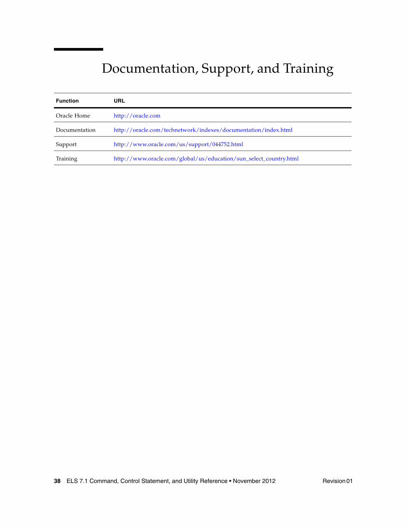
Documentation, Support, and Training
Function URL
Oracle Home http://oracle.com
Documentation http://oracle.com/technetwork/indexes/documentation/index.html
Support http://www.oracle.com/us/support/044752.html
Training http://www.oracle.com/global/us/education/sun_select_country.html
Revision 01 Preface 39
Additional Information
Conventions for Reader Usability
Typographic
Some JCL examples in this guide include italic type. Italic type is used to indicate a variable. You must substitute an actual value for these variables.
The use of mixed upper and lower case characters for commands, control statements, and parameters indicates that lower case letters may be omitted to form abbreviations. For example, you may simply enter POL when executing the POLicy command.
Syntax Flow Diagrams
Syntax flow diagramming conventions include the following:
Flow Lines
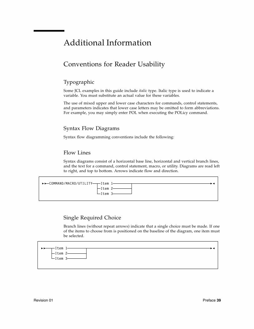
Syntax diagrams consist of a horizontal base line, horizontal and vertical branch lines, and the text for a command, control statement, macro, or utility. Diagrams are read left to right, and top to bottom. Arrows indicate flow and direction.
Single Required Choice
Branch lines (without repeat arrows) indicate that a single choice must be made. If one of the items to choose from is positioned on the baseline of the diagram, one item must be selected.
COMMAND/MACRO/UTILITY Item 1Item 2Item 3
Item 1Item 2Item 3
40 ELS 7.1 Command, Control Statement, and Utility Reference • November 2012 Revision 01
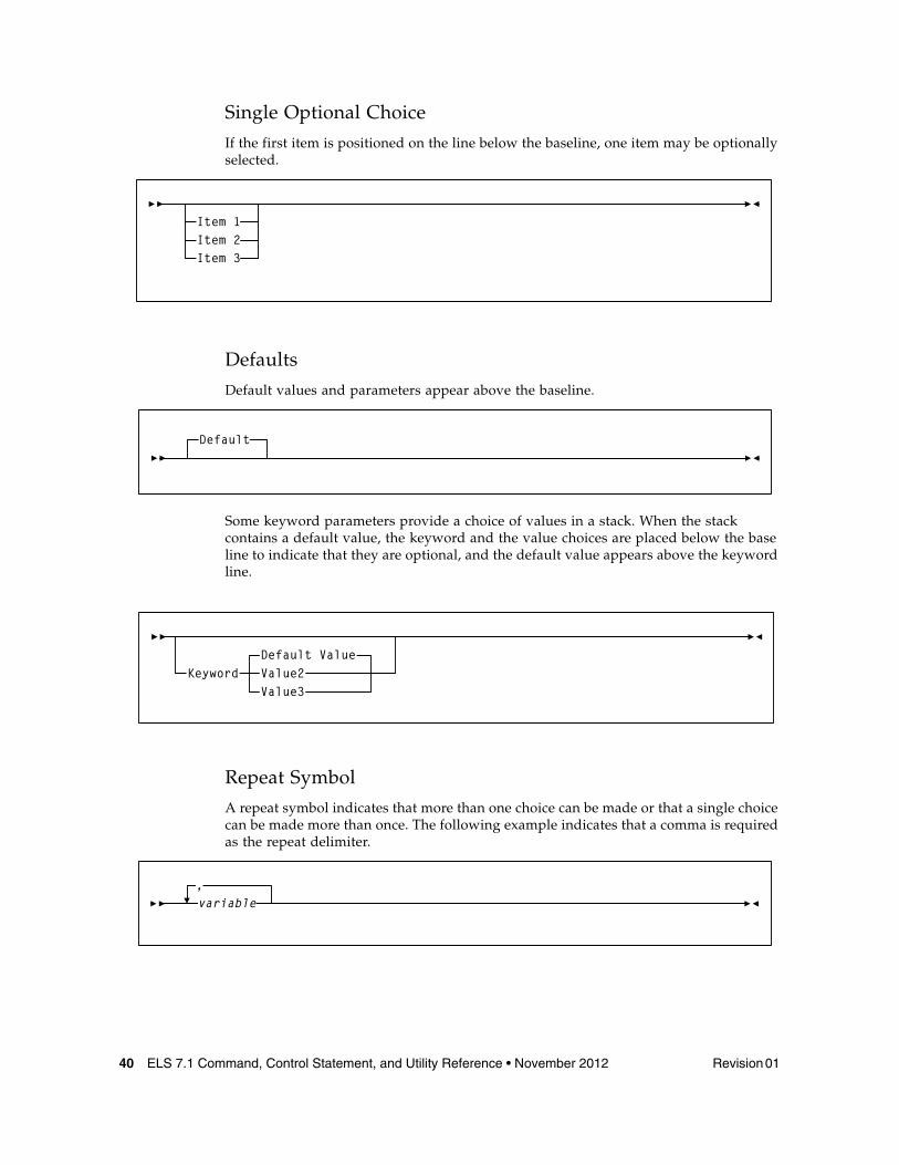
Single Optional Choice
If the first item is positioned on the line below the baseline, one item may be optionally selected.
Defaults
Default values and parameters appear above the baseline.
Some keyword parameters provide a choice of values in a stack. When the stack contains a default value, the keyword and the value choices are placed below the base line to indicate that they are optional, and the default value appears above the keyword line.
Repeat Symbol
A repeat symbol indicates that more than one choice can be made or that a single choice can be made more than once. The following example indicates that a comma is required as the repeat delimiter.
Item 1Item 2Item 3
Default
KeywordValue3
Default ValueValue2
,variable
Revision 01 Preface 41
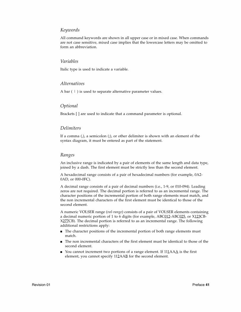
Keywords
All command keywords are shown in all upper case or in mixed case. When commands are not case sensitive, mixed case implies that the lowercase letters may be omitted to form an abbreviation.
Variables
Italic type is used to indicate a variable.
Alternatives
A bar ( | ) is used to separate alternative parameter values.
Optional
Brackets [ ] are used to indicate that a command parameter is optional.
Delimiters
If a comma (,), a semicolon (;), or other delimiter is shown with an element of the syntax diagram, it must be entered as part of the statement.
Ranges
An inclusive range is indicated by a pair of elements of the same length and data type, joined by a dash. The first element must be strictly less than the second element.
A hexadecimal range consists of a pair of hexadecimal numbers (for example, 0A2-0AD, or 000-0FC).
A decimal range consists of a pair of decimal numbers (i.e., 1-9, or 010-094). Leading zeros are not required. The decimal portion is referred to as an incremental range. The character positions of the incremental portion of both range elements must match, and the non incremental characters of the first element must be identical to those of the second element.
A numeric VOLSER range (vol-range) consists of a pair of VOLSER elements containing a decimal numeric portion of 1 to 6 digits (for example, ABC012-ABC025, or X123CB-X277CB). The decimal portion is referred to as an incremental range. The following additional restrictions apply:
■ The character positions of the incremental portion of both range elements must match.
■ The non incremental characters of the first element must be identical to those of the second element.
■ You cannot increment two portions of a range element. If 111AAA is the first element, you cannot specify 112AAB for the second element.
42 ELS 7.1 Command, Control Statement, and Utility Reference • November 2012 Revision 01
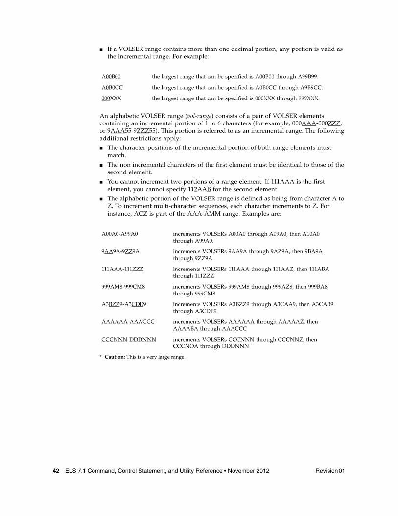
■ If a VOLSER range contains more than one decimal portion, any portion is valid as the incremental range. For example:
An alphabetic VOLSER range (vol-range) consists of a pair of VOLSER elements containing an incremental portion of 1 to 6 characters (for example, 000AAA-000ZZZ, or 9AAA55-9ZZZ55). This portion is referred to as an incremental range. The following additional restrictions apply:
■ The character positions of the incremental portion of both range elements must match.
■ The non incremental characters of the first element must be identical to those of the second element.
■ You cannot increment two portions of a range element. If 111AAA is the first element, you cannot specify 112AAB for the second element.
■ The alphabetic portion of the VOLSER range is defined as being from character A to Z. To increment multi-character sequences, each character increments to Z. For instance, ACZ is part of the AAA-AMM range. Examples are:
A00B00 the largest range that can be specified is A00B00 through A99B99.
A0B0CC the largest range that can be specified is A0B0CC through A9B9CC.
000XXX the largest range that can be specified is 000XXX through 999XXX.
A00A0-A99A0 increments VOLSERs A00A0 through A09A0, then A10A0 through A99A0.
9AA9A-9ZZ9A increments VOLSERs 9AA9A through 9AZ9A, then 9BA9A through 9ZZ9A.
111AAA-111ZZZ increments VOLSERs 111AAA through 111AAZ, then 111ABA through 111ZZZ
999AM8-999CM8 increments VOLSERs 999AM8 through 999AZ8, then 999BA8 through 999CM8
A3BZZ9-A3CDE9 increments VOLSERs A3BZZ9 through A3CAA9, then A3CAB9 through A3CDE9
AAAAAA-AAACCC increments VOLSERs AAAAAA through AAAAAZ, then AAAABA through AAACCC
CCCNNN-DDDNNN increments VOLSERs CCCNNN through CCCNNZ, then CCCNOA through DDDNNN *
* Caution: This is a very large range.
Revision 01 Preface 43
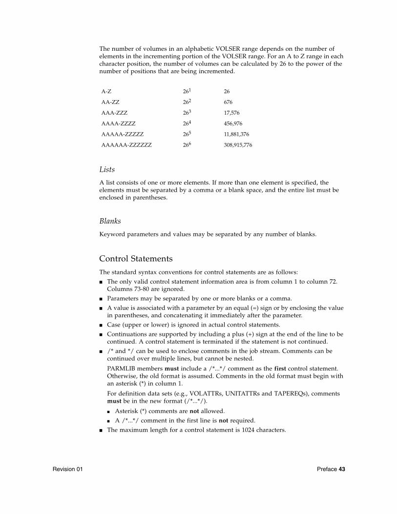
The number of volumes in an alphabetic VOLSER range depends on the number of elements in the incrementing portion of the VOLSER range. For an A to Z range in each character position, the number of volumes can be calculated by 26 to the power of the number of positions that are being incremented.
Lists
A list consists of one or more elements. If more than one element is specified, the elements must be separated by a comma or a blank space, and the entire list must be enclosed in parentheses.
Blanks
Keyword parameters and values may be separated by any number of blanks.
Control Statements
The standard syntax conventions for control statements are as follows:
■ The only valid control statement information area is from column 1 to column 72. Columns 73-80 are ignored.
■ Parameters may be separated by one or more blanks or a comma.
■ A value is associated with a parameter by an equal (=) sign or by enclosing the value in parentheses, and concatenating it immediately after the parameter.
■ Case (upper or lower) is ignored in actual control statements.
■ Continuations are supported by including a plus (+) sign at the end of the line to be continued. A control statement is terminated if the statement is not continued.
■ /* and */ can be used to enclose comments in the job stream. Comments can be continued over multiple lines, but cannot be nested.
PARMLIB members must include a /*...*/ comment as the first control statement. Otherwise, the old format is assumed. Comments in the old format must begin with an asterisk (*) in column 1.
For definition data sets (e.g., VOLATTRs, UNITATTRs and TAPEREQs), comments must be in the new format (/*...*/).
■ Asterisk (*) comments are not allowed.
■ A /*...*/ comment in the first line is not required.
■ The maximum length for a control statement is 1024 characters.
A-Z 261 26
AA-ZZ 262 676
AAA-ZZZ 263 17,576
AAAA-ZZZZ 264 456,976
AAAAA-ZZZZZ 265 11,881,376
AAAAAA-ZZZZZZ 266 308,915,776

44 ELS 7.1 Command, Control Statement, and Utility Reference • November 2012 Revision 01
Revision 01 45
What’s New?
Revision 01This publication includes information about the following ELS enhancements:
■ RECALWER (Recall with Error) parameter default behavior has changed.
The global default is RECALWER=NO. You cannot override this default at the global level. Instead, you must specify RECALWER=YES at the command level.
The RECALWER parameter default is changed to OFF for the CONSolid, EEXPORT, MVCDRain, and RECall commands.
See:
■ “CONSolid” on page 238■ “EEXPORT” on page 378■ “MVCDRain” on page 486■ “RECall” on page 522
■ New VTCS commands and parameters can be used to create a DR baseline for the VSM environment.
■ The CONFIg RECLAIM includes the PROTECT parameter, used to protect an MVC from being used after it is drained or reclaimed.
See “CONFIg RECLAIM Statement” on page 218.
■ The DRCHKPT command establishes the system recovery point (checkpoint).
See “DRCHKPT” on page 362.
■ The DRMONitr command stalls job stream processing to ensure that critical data reaches its target destination.
See “DRMONitr” on page 363.
■ The LMUPATH control statement LMUADDR parameter now allows a maximum of 40 IP addresses.
See “LMUPATH Control Statement” on page 410.
■ The SMC MOUNTDef command has added a IOS003Alimit parameter that specifies the maximum number of attempts to re-drive a mount request that has failed following a IOS003A message.
See “MOUNTDef” on page 99.
46 ELS 7.1 Command, Control Statement, and Utility Reference • November 2012 Revision 01
■ The SMC MONitor command LOWscratch parameter default value has changed from 0 to 60.
See “MONitor” on page 96.
■ The SMC READ command includes the REPlacepolicy parameter, which specifies that all SMC POLICY objects be replaced by any POLICY statements found in a specified data set.
See “READ” on page 120.
■ The SMC TCPIP command has added the RERESolve parameter that specifies whether SMC attempts to re-resolve the SERVER HOST name after a communication failure.
See “TCPip” on page 141.
■ The SMC TRace command includes the COMPact parameter, used to specify whether SMC trace output is produced in a "compact" format that conserves GTF dataset space.
See “TRace” on page 144.
■ The new SMC Trace Format utility (SMCUGTF) converts SMC GTF output in “compact” format into the original Trace format.
See “Trace Format Utility (SMCUGTF)” on page 671.
■ The new METAdata command is used to show XML tags associated with a function that produces XML output.
■ For information about the SMC METAdata command, see “METAdata” on page 94.
■ For information about the HSC/VTCS METAdata command, see “METAdata” on page 429.
■ The HSC/VTCS CONFIg GLOBAL Statement includes a FASTMIGR parameter that specifies whether the stacked/streamed migrates feature is enabled for all VTSSs that support this feature.
See “CONFIg GLOBAL Statement” on page 210.
■ The HSC/VTCS CONFIg STORMNGR statement includes the optional VLEDEV parameter, which allows you to specify the logical device IDs of a VLE.
See “CONFIg STORMNGR Statement” on page 235.
■ The HSC/VTCS Display SCRatch command includes the REFresh parameter, used to update VSM scratch counts prior to the display occurring.
See “SCRAtch” on page 539.
■ The HSC/VTCS MGMTDEF STORLST control statement has changed to allow a maximum of ten STORCLAS values to be specified.
See “STORLST Control Statement” on page 457.
■ The HSC/VTCS STORclas control statement has added two parameters: FROMLST, which provides VTCS with a list of VTSSs to source the VTV; and DEDUP, which specifies whether VTV data migrated to VMVCs in a VLE is deduplicated.
In addition, a Dynamic Reclaim Usage Notes section has been added.
See “STORclas Control Statement” on page 451 and “Dynamic Reclaim Usage Notes” on page 455.
Revision 01 What’s New? 47
■ The HSC/VTCS OPTion command includes a SUBtype parameter that specifies the SMF subtype records to be written.
See “OPTion” on page 516.
■ The HSC/VTCS SCRPT command reports on VLE usage by Storage Class.
See “SCRPT” on page 544.
■ The HSC/VTCS SWitch command has added a RESET parameter that resets the internal switch setting for an ACS so the NCO MODify CONFIG command can be invoked.
See “SWitch” on page 592.
■ Support for the concurrent tape recall/mount feature, which improves mount time for a VTV that is not resident in the VTSS.
■ The CONFIg GLOBAL statement includes the FASTRECL parameter, used to specify whether VTCS should perform concurrent tape recall/mount for all VTSSs that support the feature.
See “CONFIg GLOBAL Statement” on page 210.
■ The CONFIg VTSS statement includes the NOERLYMT parameter, used to disable Concurrent Tape Recall/Mount feature for a VTSS.
See “CONFIg VTSS Statement” on page 223.
■ Display CONFIG output includes a GLOBAL FASTRECL field.
See “Display CONFIG” on page 273.
■ Display VTSS DETail output includes concurrent tape recall/mount features.
See “Display VTSS DEtail Output” on page 354.
■ Display VTV output includes the AVOID EARLY MOUNT status field.
See “Display VTV” on page 357.
■ Support for Cross Tapeplex Autorecall (CTA), which allows automatic recall of electronically exported VTVs from a remote TapePlex to satisfy a mount request on the local TapePlex.
The EEXPORT command includes the TOVTSS parameter, used to specify the VTSS name to be preferenced as the receiving VTSS within the target TapePlex specified by the TOPlex parameter.
See “EEXPORT” on page 378.
Additionally, various Display command outputs are revised to include CTA information.
See “Unified User Interface Utility (SMCUUUI)” on page 643.
■ Support for Oracle’s StorageTek T10000C tape drive.
See Appendix A, “MEDia, RECtech, and MODel Values”.
■ Dynamic reclaim support for T10000B media
See:
■ “CONFIg” on page 207
■ “CONFIg RECLAIM Statement” on page 218
■ “STORclas Control Statement” on page 451
■ “RECLaim” on page 524
■ “POOLPARM Control Statement” on page 582
48 ELS 7.1 Command, Control Statement, and Utility Reference • November 2012 Revision 01
■ TAPEPlex commands required at SMC Startup
In SMC 7.1 the ability to derive TapePlex definitions based on locally defined subsystems is removed. Instead, all TapePlexes must be defined using the TAPEPlex command. If no TAPEPlex commands are found at SMC startup, the SMC subsystem terminates.
See “TAPEPlex” on page 137.
■ Advanced VSM management features
By default, advanced VSM management features are automatically enabled for ELS 7.1. The FEATures command, included in previous ELS releases, is no longer valid.
Revision 01 49
CHAPTER
1
ELS Command Interfaces
This chapter describes the various interfaces you can use to issue ELS commands. It is organized in the following sections:
■ Unified User Interface (UUI) Support■ SMC Command Interfaces■ HSC/VTCS Command Interfaces
Unified User Interface (UUI) SupportCertain SMC, HSC, and VTCS commands described in this publication are supported by the UUI (Unified User Interface).
The ELS UUI interface is designed to standardize both internal and external interfaces into SMC, HSC and VTCS functions. The UUI allows you to do the following:
■ Execute commands via a utility.■ Invoke commands from a programmatic interface.■ Request output in text, XML or Comma Separated Values (CSV) format.■ Invoke commands to an HSC server from a remote client.
ELS expands the commands available through the UUI interface to include all functions previously supported by the HSC PGMI and batch API interfaces. Although the existing interfaces will continue to be supported for an undetermined number of future releases, these interfaces will not be enhanced to add new data items.
Note – ■ Refer to the ELS Programming Reference for detailed information about the UUI.
■ See “Unified User Interface Utility (SMCUUUI)” on page 643 for information about the SMCUUUI utility, used to issue UUI supported SMC, HSC, and VTCS commands from a batch job.
SMC Command Interfaces
50 ELS 7.1 Command, Control Statement, and Utility Reference • November 2012 Revision 01
SMC Command InterfacesThis section includes the following topics:
■ Issuing SMC Commands from the Console■ Specifying SMC Commands in the SMCCMDS or SMCPARMS Data Sets■ SMC Commands that Specify JOBname, STEPname, and PROCstep■ Issuing SMC Commands from a Utility
Issuing SMC Commands from the Console
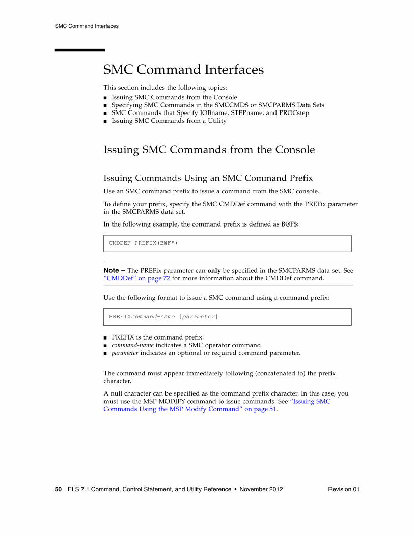
Issuing Commands Using an SMC Command PrefixUse an SMC command prefix to issue a command from the SMC console.
To define your prefix, specify the SMC CMDDef command with the PREFix parameter in the SMCPARMS data set.
In the following example, the command prefix is defined as B@F$:
Note – The PREFix parameter can only be specified in the SMCPARMS data set. See “CMDDef” on page 72 for more information about the CMDDef command.
Use the following format to issue a SMC command using a command prefix:
■ PREFIX is the command prefix.■ command-name indicates a SMC operator command. ■ parameter indicates an optional or required command parameter.
The command must appear immediately following (concatenated to) the prefix character.
A null character can be specified as the command prefix character. In this case, you must use the MSP MODIFY command to issue commands. See “Issuing SMC Commands Using the MSP Modify Command” on page 51.
CMDDEF PREFIX(B@F$)
PREFIXcommand-name [parameter]
SMC Command Interfaces
Revision 01 Chapter 1 ELS Command Interfaces 51
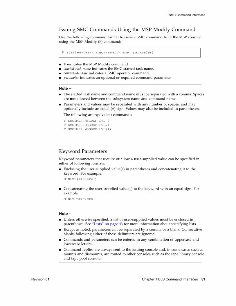
Issuing SMC Commands Using the MSP Modify CommandUse the following command format to issue a SMC command from the MSP console using the MSP Modify (F) command:
■ F indicates the MSP Modify command■ started-task-name indicates the SMC started task name.■ command-name indicates a SMC operator command.■ parameter indicates an optional or required command parameter.
Note – ■ The started task name and command name must be separated with a comma. Spaces
are not allowed between the subsystem name and command name.
■ Parameters and values may be separated with any number of spaces, and may optionally include an equal (=) sign. Values may also be included in parentheses.
The following are equivalent commands:
F SMC1MSP,MSGDEF LVL 4F SMC1MSP,MSGDEF LVL=4F SMC1MSP,MSGDEF LVL(4)
Keyword ParametersKeyword parameters that require or allow a user-supplied value can be specified in either of following formats:
■ Enclosing the user-supplied value(s) in parentheses and concatenating it to the keyword. For example,MINLVL(minlevel)
■ Concatenating the user-supplied value(s) to the keyword with an equal sign. For example,MINLVL=minlevel
Note – ■ Unless otherwise specified, a list of user-supplied values must be enclosed in
parentheses. See “Lists” on page 43 for more information about specifying lists.
■ Except as noted, parameters can be separated by a comma or a blank. Consecutive blanks following either of these delimiters are ignored.
■ Commands and parameters can be entered in any combination of uppercase and lowercase letters.
■ Command replies are always sent to the issuing console and, in some cases such as mounts and dismounts, are routed to other consoles such as the tape library console and tape pool console.
F started-task-name,command-name [parameter]
SMC Command Interfaces
52 ELS 7.1 Command, Control Statement, and Utility Reference • November 2012 Revision 01
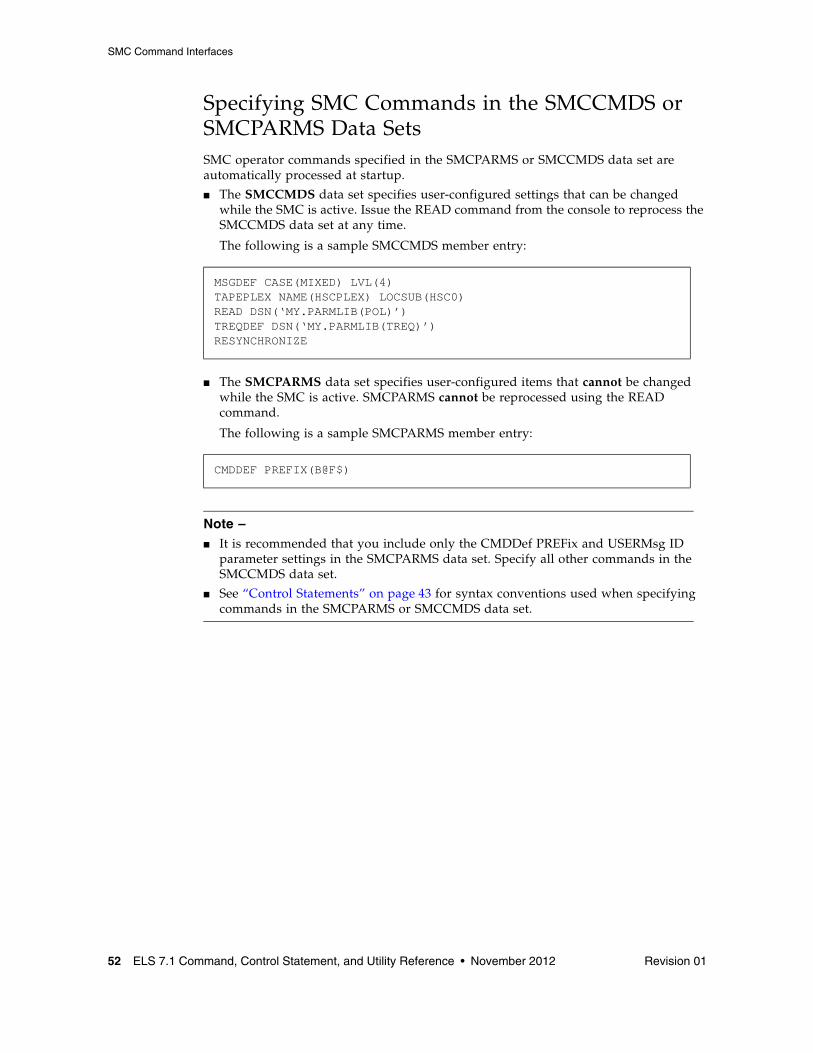
Specifying SMC Commands in the SMCCMDS or SMCPARMS Data SetsSMC operator commands specified in the SMCPARMS or SMCCMDS data set are automatically processed at startup.
■ The SMCCMDS data set specifies user-configured settings that can be changed while the SMC is active. Issue the READ command from the console to reprocess the SMCCMDS data set at any time.
The following is a sample SMCCMDS member entry:
■ The SMCPARMS data set specifies user-configured items that cannot be changed while the SMC is active. SMCPARMS cannot be reprocessed using the READ command.
The following is a sample SMCPARMS member entry:
Note – ■ It is recommended that you include only the CMDDef PREFix and USERMsg ID
parameter settings in the SMCPARMS data set. Specify all other commands in the SMCCMDS data set.
■ See “Control Statements” on page 43 for syntax conventions used when specifying commands in the SMCPARMS or SMCCMDS data set.
MSGDEF CASE(MIXED) LVL(4)TAPEPLEX NAME(HSCPLEX) LOCSUB(HSC0)READ DSN(‘MY.PARMLIB(POL)’)TREQDEF DSN(‘MY.PARMLIB(TREQ)’)RESYNCHRONIZE
CMDDEF PREFIX(B@F$)
SMC Command Interfaces
Revision 01 Chapter 1 ELS Command Interfaces 53
SMC Commands that Specify JOBname, STEPname, and PROCstepSMC ALLOCJOB, MSGJOB, and TRACE commands allow specification of JOBname, STEPname, or PROCstep. These commands are evaluated by the SMC in order of most specific to least specific job name specification. Therefore, commands can be entered in any order. Consider the following example:
Two ALLOCJob commands are entered:
Regardless of the order in which these commands are entered, job name NOALLOC1 is processed with MINLVL 3 because this command’s job name is more specific than job name NOALLOC*.
Note – ■ If an SMC ALLOCJOB or MSGJOB command is entered specifying only JOBname,
STEPname, or PROCstep, the command is interpreted as if LIST had also been specified.
■ The above behavior does not apply to TAPEREQ statements, which are always evaluated in the order in which they appear in the TREQDEF DD.
Issuing SMC Commands from a UtilityUse the SMCUUUI utility to issue UUI-supported SMC, HSC, and VTCS commands in a batch job. These commands can be routed to a local or remote HSC TapePlex.
The SMCUUUI utility can generate several types of output, including plain text, structured XML, and Comma Separated Values (CSV).
See “Unified User Interface Utility (SMCUUUI)” on page 643 for more information about the SMCUUUI utility.
Note – SMC commands cannot be issued from the utility administrator (SLUADMIN).
ALLOCJOB JOBNAME=NOALLOC* MINLVL=4ALLOCJOB JOBNAME=NOALLOC1 MINLVL=3
HSC and VTCS Command Interfaces
54 ELS 7.1 Command, Control Statement, and Utility Reference • November 2012 Revision 01
HSC and VTCS Command InterfacesThis section includes the following topics:
■ Issuing HSC and VTCS Commands from the Console■ Issuing HSC and VTCS Commands from a Utility■ Issuing HSC and VTCS Commands from PARMLIB■ HSC Service Levels
Issuing HSC and VTCS Commands from the ConsoleUse any of the following methods to issue HSC and VTCS operator commands:
■ Issue commands using the MSP Modify command■ Issue commands using a command prefix
Issuing HSC and VTCS Commands Using a Command PrefixUse a command prefix to issue a HSC or VTCS command from the console. This prefix is assigned during the LIBGEN process. Examples include ".," and "#".
Use the SET COMPRFX command to define a new prefix. This command specifies the 2-character hexadecimal code of the command prefix.
■ The command prefix is not valid until the HSC or VTCS system is recycled.
■ See TABLE 3-15 on page 552 for a list of characters associated with each code.
■ See “SET COMPRFX” on page 551 for more information about the SET COMPRFX command and prefix restrictions.
Use the following format to issue a command using a command prefix:
■ PREFIX is the command prefix.■ command-name indicates a HSC or VTCS operator command. ■ parameter indicates an optional or required command parameter.
The command must appear immediately following (concatenated to) the prefix character.
A null character can be specified as the command prefix character. In this case, you must use the MSP Modify command to issue commands.
Note – The VT command prefix is no longer required for VTCS commands. If entered, it is ignored.
PREFIXcommand-name [parameter]
HSC and VTCS Command Interfaces
Revision 01 Chapter 1 ELS Command Interfaces 55
Issuing HSC and VTCS Commands Using the MSP Modify CommandUse the following format to issue a command from the console using the MSP Modify (F) command:
■ F indicates the MSP Modify command■ started-task-name indicates the entry in the subsystem name table for the HSC.
A system programmer specifies this one- to four-character HSC subsystem name by adding an element to the IEFSSNxx entry in the SYS1.PARMLIB (e.g., SLS0).
■ command-name indicates a HSC or VTCS operator command.■ parameter indicates an optional or required command parameter.
Keyword ParametersKeyword parameters that require or allow a user-supplied value can be specified in either of following formats:
■ Enclosing the user-supplied value(s) in parentheses and concatenating it to the keyword. For example,HOSTID(host-id)
■ Concatenating the user-supplied value(s) to the keyword with an equal sign. For example,HOSTID=host-id
Note – ■ Unless otherwise specified, a list of user-supplied values must be enclosed in
parentheses. See “Lists” on page 43 for more information about specifying lists.
■ Except as noted, parameters can be separated by a comma or a blank. Consecutive blanks following either of these delimiters are ignored.
■ Commands and parameters can be entered in any combination of uppercase and lowercase letters.
■ Command replies are always sent to the issuing console and, in some cases such as mounts and dismounts, are routed to other consoles such as the tape library console and tape pool console.
F started-task-name,command-name [parameter]
HSC and VTCS Command Interfaces
56 ELS 7.1 Command, Control Statement, and Utility Reference • November 2012 Revision 01
Issuing HSC and VTCS Commands from a UtilityHSC and VTCS contain utility functions designed to help you manage library resources. Certain HSC and VTCS commands are used to initiate these utilities. These commands are specified using the utility administrator (SLUADMIN).
Additionally, you can use the SMCUUUI utility to issue UUI-supported SMC, HSC, and VTCS commands in a batch job. These commands can be routed to a local or remote HSC TapePlex.
Both SLUADMIN and SMCUUUI can generate several types of output, including plain text, structured XML, and Comma Separated Values (CSV).
Note – ■ SWSADMIN and SWUADMIN are alias names for SLUADMIN, and are still
honored.
■ See “Utility Administrator (SLUADMIN)” on page 674 for more information about the SLUADMIN utility.
■ See “Unified User Interface Utility (SMCUUUI)” on page 643 for more information about the SMCUUUI utility.
HSC and VTCS Command Interfaces
Revision 01 Chapter 1 ELS Command Interfaces 57
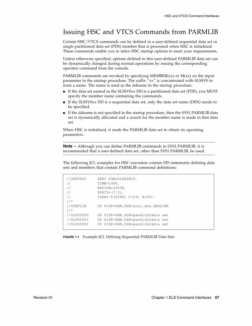
Issuing HSC and VTCS Commands from PARMLIBCertain HSC/VTCS commands can be defined in a user-defined sequential data set or single partitioned data set (PDS) member that is processed when HSC is initialized. These commands enable you to tailor HSC startup options to meet your requirements.
Unless otherwise specified, options defined in this user-defined PARMLIB data set can be dynamically changed during normal operations by issuing the corresponding operator command from the console.
PARMLIB commands are invoked by specifying MEMBER(xx) or M(xx) on the input parameter in the startup procedure. The suffix ‘‘xx’’ is concatenated with SLSSYS to form a name. The name is used as the ddname in the startup procedure.
■ If the data set named in the SLSSYSxx DD is a partitioned data set (PDS), you MUST specify the member name containing the commands.
■ If the SLSSYSxx DD is a sequential data set, only the data set name (DSN) needs to be specified.
■ If the ddname is not specified in the startup procedure, then the SYS1.PARMLIB data set is dynamically allocated and a search for the member name is made in that data set.
When HSC is initialized, it reads the PARMLIB data set to obtain its operating parameters.
Note – Although you can define PARMLIB commands in SYS1.PARMLIB, it is recommended that a user-defined data set, other than SYS1.PARMLIB, be used.
The following JCL examples for HSC execution contain DD statements defining data sets and members that contain PARMLIB command definitions:
FIGURE 1-1 Example JCL Defining Sequential PARMLIB Data Sets
//IEFPROC EXEC PGM=SLSBINIT,// TIME=1440,// REGION=2000K,// DPRTY=(7,5),// PARM=’E(E086) F(23) M(00)’//*//STEPLIB DD DISP=SHR,DSN=your.sea.SEALINK//*//SLSSYS00 DD DISP=SHR,DSN=parmlib0data set//SLSSYS01 DD DISP=SHR,DSN=parmlib1data set//SLSSYS02 DD DISP=SHR,DSN=parmlib2data set
HSC and VTCS Command Interfaces
58 ELS 7.1 Command, Control Statement, and Utility Reference • November 2012 Revision 01
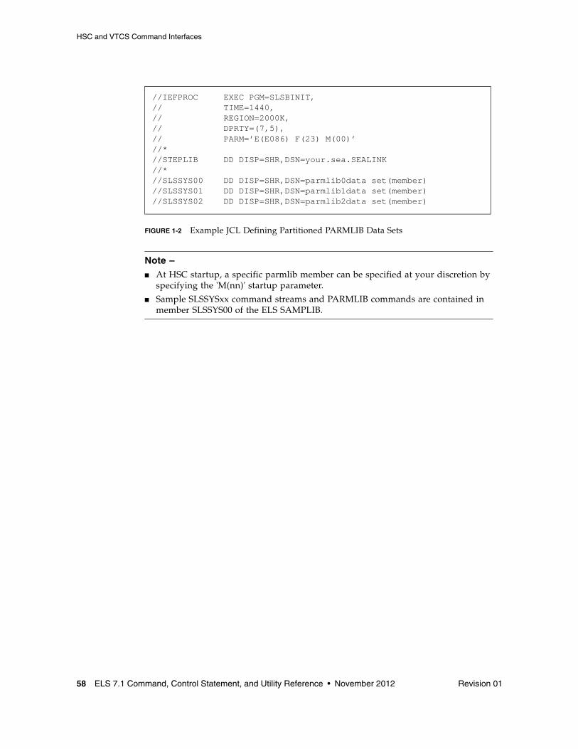
FIGURE 1-2 Example JCL Defining Partitioned PARMLIB Data Sets
Note – ■ At HSC startup, a specific parmlib member can be specified at your discretion by
specifying the 'M(nn)' startup parameter.
■ Sample SLSSYSxx command streams and PARMLIB commands are contained in member SLSSYS00 of the ELS SAMPLIB.
//IEFPROC EXEC PGM=SLSBINIT,// TIME=1440,// REGION=2000K,// DPRTY=(7,5),// PARM=’E(E086) F(23) M(00)’//*//STEPLIB DD DISP=SHR,DSN=your.sea.SEALINK//*//SLSSYS00 DD DISP=SHR,DSN=parmlib0data set(member)//SLSSYS01 DD DISP=SHR,DSN=parmlib1data set(member)//SLSSYS02 DD DISP=SHR,DSN=parmlib2data set(member)
HSC and VTCS Command Interfaces
Revision 01 Chapter 1 ELS Command Interfaces 59
HSC Service Levels The HSC subsystem can operate at either base or full service level.
Base Service Level FunctionsThe base service level is the nucleus of the HSC subsystem. It provides the functions necessary to execute as an extension of the operating system, and satisfies the requirements defined by the operating environment in place at the time of execution.
All HSC commands can be issued with the HSC executing at the base service level. However, commands that involve library hardware cannot perform their function completely.
VTCS commands cannot be issued with the HSC executing at the base service level.
Mount Requests Intercepted During Base Service Level Operations
Mount messages intercepted by the SMC while the HSC is operating at the base service level are not sent to the HSC, but are left pending until the HSC reaches the full service level.
When the SMC recognizes that the HSC has reached the full service level, the mounts are redriven. These mount messages that occur with SMC intervention, and that are subsequently redriven when the HSC reaches the full service level, have their subpool specification honored.
Full Service Level FunctionsThe full service level of operation for the HSC provides all of the functions available and necessary to invoke and sustain complete library operations. These functions include:
■ mount/dismount processing ■ CAP processing ■ cartridge and cell inventory management ■ LMU access ■ library resource recovery ■ support for all library utilities ■ support for all HSC and VTCS commands
Note – All VTCS commands require a HSC executing at FULL service level.

Revision 01 61
CHAPTER
2
SMC Commands and Control Statements
This chapter contains reference information about SMC commands and control statements.
See Chapter 4, “SMC Utilities” for information about SMC utilities.
ALLOCDef
62 ELS 7.1 Command, Control Statement, and Utility Reference • November 2012 Revision 01
ALLOCDefInterfaces:
Console, utility, or SMCCMDS/SMCPARMS data setUUI: Yes (No XML/CSV output)
Subsystem Requirements:
Active SMC required, or may be input to the SMCUSIM utility
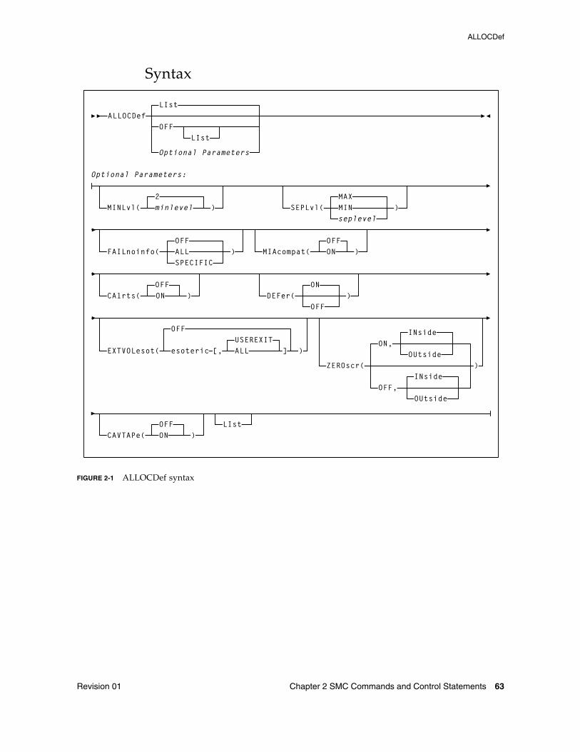
DescriptionThe ALLOCDef command is used to specify default allocation settings for the SMC subsystem.
ALLOCDef
Revision 01 Chapter 2 SMC Commands and Control Statements 63
Syntax
FIGURE 2-1 ALLOCDef syntax
ALLOCDef
SEPLvl(seplevel
MAXMIN
OFF
)MINLvl(2
)minlevel
MIAcompat( )OFFON
OFFFAILnoinfo( ALL )
SPECIFIC
CA1rts( )OFFON DEFer(
ON
OFF)
EXTVOLesot(
OFF
)esoteric [,
ZEROscr(
ALL ]USEREXIT
LIst
Optional Parameters
Optional Parameters:
LIst
LIst
OFF,OUtside
INside
ON,OUtside
INside
)
CAVTAPe(OFFON )
ALLOCDef
64 ELS 7.1 Command, Control Statement, and Utility Reference • November 2012 Revision 01
ParametersLIst
optionally, lists current default allocation settings.
■ LIst is the default when no parameters are specified on the ALLOCDef command.
■ LIst may be specified with other parameters. In this case, the LIst is generated after the other parameters are processed.
OFF
optionally, resets all default allocation values to original SMC default settings. Specify LIst with this parameter to list these settings.
MINLvl
optionally, specifies the minimum level of drive exclusion. If a job is not allocatable at the minimum exclusion level, the SMC still excludes drives to the minimum level and allows the job to fail.
minlevel
the minimum allocation exclusion level. Valid values are 0-8. 2 is the default value.
Note – ■ Setting MINLVL=0 indicates that the job will not be failed by the SMC even if the
device and specific volume are incompatible. MINLVL=0 may be used to force SMC to allow allocation to succeed when a “foreign” tape cartridge has the same volume serial number as an existing library or virtual volume.
■ Increasing minlevel has no effect unless message SMC0045 or SMC0091 has been issued for a specific job step.
■ Refer to the publication Configuring and Managing SMC for more information about SMC exclusion levels.
SEPLvl
optionally, specifies the exclusion level at which affinity and GDG chains are separated.
seplevel
an exclusion level between the minimum and maximum levels. When sufficient drives exist, the SMC attempts to separate chains at this level. This value cannot be less than the minlevel value.
MAX
Affinity and GDG chains for conflicting exclusion criteria are separated whenever sufficient drives are available. This is the default.
MIN
Affinity and GDG chains are not separated beyond the minimum level.
ALLOCDef
Revision 01 Chapter 2 SMC Commands and Control Statements 65
Note – ■ If HSC allocation previously specified UNITAFF(NOSEP) and GDGALL(NOSEP),
the default SMC exclusion tables can specify SEPLvl=3 in order to preserve existing behavior for scratch affinity chains with different media types.
■ Refer to the publication Configuring and Managing SMC for more information about SMC exclusion levels.
FAILnoinfo
optionally, specifies whether the SMC fails a job step during allocation when a communication failure prevents the retrieval of volume information from a TapePlex, or when no TapePlexes are available.
OFF
SMC does not fail the job step.
ALL
SMC marks all devices ineligible and fails the job step.
SPECIFIC
If a communication failure occurs during the volume lookup process for a specific volume, or if no TapePlexes are available and the step contains allocations for specific volumes, the SMC marks all devices ineligible and fails the job step.
If the job step contains only scratch allocations, then the job step is allowed to proceed and allocation is based solely on SMC tape policy specifications.
MIAcompat
optionally, specifies whether the EDL is updated at SSI24 time for compatibility with Computer Associates Unicenter CA-MIA Tape Sharing for MSP/EX and OS/390 product.
OFF
The EDL is not updated at SSI24 time. This is the default.
ON
The EDL is modified at SSI24 time. Specify this value if you use Unicenter CA-MIA.
CA1rts
optionally, specifies whether the DEFER processing is performed at SSI24 time for compatibility with Computer Associates Real Time Stacking feature of its CA-1 tape management system.
OFF
DEFER status is not updated at SSI24 time. This is the default.
ON
DEFER status is updated at SSI24 time. Specify this value if you use the Real Time Stacking feature of CA-1.
ALLOCDef
66 ELS 7.1 Command, Control Statement, and Utility Reference • November 2012 Revision 01
DEFer
optionally, enables or disables deferred mount processing for library mounts. With deferred mounting enabled, a library resident volume is mounted when the data set is opened. If the data set is not opened, the cartridge is not mounted, freeing the robot to perform other work If the data set is opened, however, the job waits until the cartridge is mounted.
ON
enables deferred mount processing. This parameter overrides the user’s JCL and defers all ACS mounts until the data set is opened. This is the default.
OFF
disables deferred mount processing and honors user JCL specifications.
EXTVOLesot
optionally, directs the SMC to use a specified esoteric to allocate a specific external volume (i.e., a volume that is not in a TapePlex). When this esoteric is used depends upon the setting of the modifier value specified after the esoteric, as well as whether the specified esoteric is valid (intersects with the original esoteric specification).
OFF
EXTVOLesot processing is disabled. Nonlibrary drives are selected, if possible, when a specific external volume is allocated. This is the default.
esoteric,USEREXIT
specifies an esoteric to be used to allocate a specific external volume when the “use specvol” (UX08) or “use library drives” (UX13) return code is specified. If the specific volume user exit returns the “use specvol” (UX08) or “use library drives” (UX13) return code for this DD, then any drives in the specified esoteric that intersect with the original esoteric will be selected for allocation. This is the default if esoteric is specified.
esoteric,ALL
Whenever an external volume is allocated, drives in the specified esoteric are selected.
ALLOCDef
Revision 01 Chapter 2 SMC Commands and Control Statements 67
ZEROscr
optionally, specifies the exclusion action when there are no scratch volumes in any TapePlex (ON or OFF), or in one or more ACSs within a TapePlex in a multiple ACS environment (INside or OUtside).
ON
This is the default. ON indicates one of the following:
■ If scratch subpools are not being used, and one or more ACSs contain zero scratch volumes, then drives in those ACSs are excluded from the list of eligible devices.
■ If a scratch subpool is being requested (either though TAPEREQ or User Exit 02/04), and one or more ACSs contain zero scratch volumes in the requested subpool, then drives in those ACSs are excluded from the list of eligible devices.
■ In JES3 with SETUP environments only, drives in the ACS with the largest number of available scratch volumes remain eligible. All other drives are excluded from selection.
INside
All nonlibrary drives are excluded when there are no scratch volumes in any ACS, and there are library drives eligible for allocation. This is the default.
OUtside
All library drives are excluded when there are no scratch volumes in any ACS, and there are nonlibrary drives eligible for allocation.
OFF
All drives in all ACSs are to remain eligible for selection.
INside
All nonlibrary drives are excluded when there are no scratch volumes in any ACS, and there are library drives eligible for allocation. This is the default.
OUtside
All library drives are excluded when there are no scratch volumes in any ACS, and there are nonlibrary drives eligible for allocation.
ALLOCDef
68 ELS 7.1 Command, Control Statement, and Utility Reference • November 2012 Revision 01
CAVTAPe
optionally, specifies whether scratch user exit 02 or specific user exit 08 are called when an SMC POLICY object is found that applies to the allocation event.
OFF
If an SMC POLICY object applies to an allocation event, then user exit 02 and user exit 08 are not called, even if active. The SMC POLICY object supplies all of the SMC tape policy is such instances. This is the default.
ON
If an SMC POLICY object applies to an allocation event, then the scratch user exit 02 or specific user exit 08 are called and any non-conflicting user exit policy is applied to the same allocation event.
Note – ■ This setting is recommended only for those customers with CA-Vtape installed who
are using a default SMC POLICY object but where CA-Vtape supplied user exits are required.
■ Only non-conflicting policies from the user exit are applied. Thus, if the SMC POLICY specifies an ESOTERIC, or a TAPEPLEX name, and user exit 02 or user exit 08 also specifies an ESOTERIC or TAPEPLEX name, the SMC POLICY specifications will apply. Refer to the publication Configuring and Managing SMC for more information about SMC interaction with CA-Vtape.
ALLOCJob
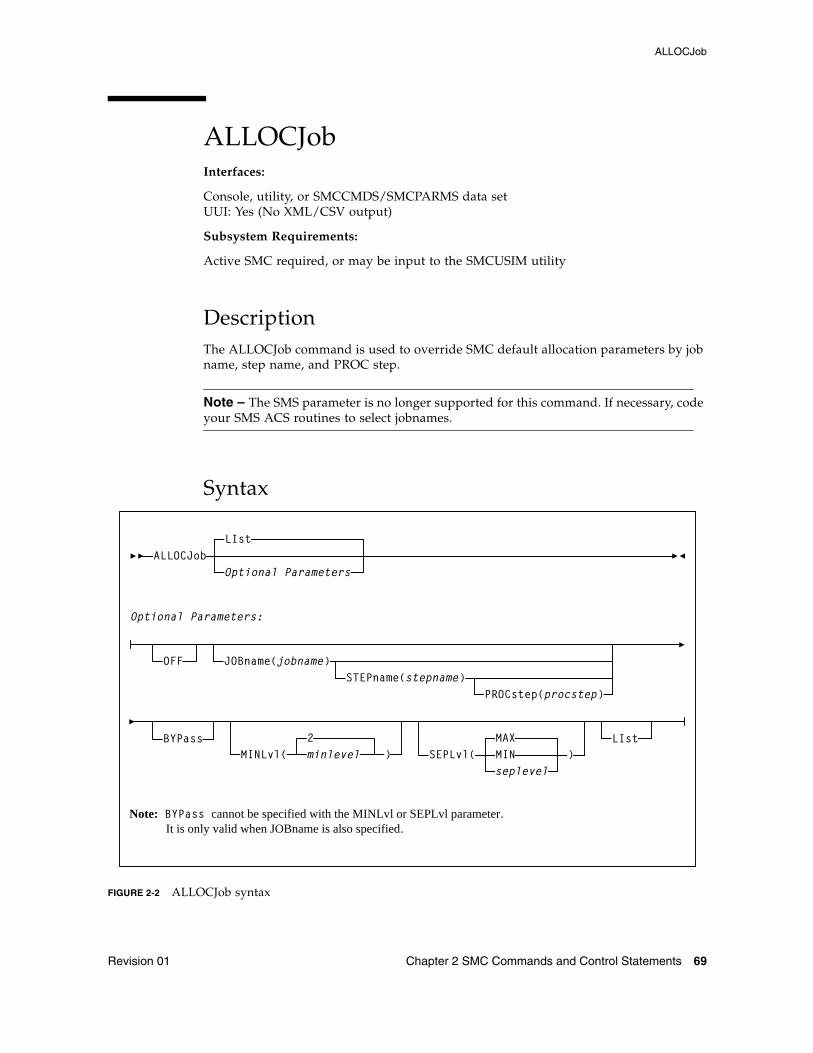
Revision 01 Chapter 2 SMC Commands and Control Statements 69
ALLOCJobInterfaces:
Console, utility, or SMCCMDS/SMCPARMS data setUUI: Yes (No XML/CSV output)
Subsystem Requirements:
Active SMC required, or may be input to the SMCUSIM utility
DescriptionThe ALLOCJob command is used to override SMC default allocation parameters by job name, step name, and PROC step.
Note – The SMS parameter is no longer supported for this command. If necessary, code your SMS ACS routines to select jobnames.
Syntax
FIGURE 2-2 ALLOCJob syntax
SEPLvl(seplevel
MAXMIN
JOBname(jobname)
BYPass)MINLvl(
2)minlevel
STEPname(stepname)PROCstep(procstep)
Note: BYPass cannot be specified with the MINLvl or SEPLvl parameter. It is only valid when JOBname is also specified.
ALLOCJobLIst
Optional Parameters
Optional Parameters:
LIst
OFF
ALLOCJob
70 ELS 7.1 Command, Control Statement, and Utility Reference • November 2012 Revision 01
ParametersLIst
optionally, lists current default allocation settings and override settings (in the order they are processed) by job name, step name, and PROC step.
■ LIst is the default when no parameters are specified on the ALLOCJob command.
■ LIst may be specified with other parameters. In this case, the LIst is generated after the other parameters are processed.
OFF
optionally, removes all job name, step name, and PROC step overrides for allocation
■ If no other parameters are specified, allocation overrides are removed for all jobs.
■ If only JOBname is specified, allocation overrides are removed for ALL ALLOCJob entries for that job name.
■ If JOBname, STEPname and PROCstep are specified, allocation overrides are removed only for the specified entry.
Global allocation settings are not affected by this parameter.
JOBname
optionally, specifies a job name.
This parameter is required unless LIst or OFF is specified.
jobname
the job name. The value entered must be one to eight characters in length. An asterisk (*) can be used as a wildcard when included as the last character. ALLOCJob is set for all jobs whose job names match the characters preceding the asterisk.
STEPname
optionally, specifies a step name. This parameter is only valid when JOBname is also specified. It is not valid in JES3 environments with TAPE SETUP processing.
stepname
the step name. The value entered must be one to eight characters in length. An asterisk (*) can be used as a wildcard when included as the last character.
PROCstep
optionally, specifies a PROC step. This parameter is only valid when JOBname and STEPname are also specified. It is not valid in JES3 environments with TAPE SETUP processing.
procstep
the PROC step.
The value entered must be one to eight characters in length. An asterisk (*) can be used as a wildcard when included as the last character.
ALLOCJob
Revision 01 Chapter 2 SMC Commands and Control Statements 71
BYPass
optionally, specifies that SMC allocation influencing is not performed for the indicated job (job step, step name, PROC step).
This parameter cannot be specified with the MINLvl, SEPLvl, or SMS parameter. It is only valid when JOBname is also specified.
Note – It is recommended that you use MINLV=0 instead of BYPASS, except when no mounts will be performed (i.e., IEFBR14 jobs).
MINLvl
optionally, specifies the desired minimum level of drive exclusion. If a job is not allocatable at the minimum exclusion level, the SMC still excludes drives to the minimum level and allows the job to fail.
This parameter cannot be specified with the BYPass parameter. It is only valid when JOBname is also specified.
minlevel
the desired minimum allocation exclusion level. Valid values are 0-8. 0 indicates that the SMC will not exclude any drives, even if all drives would be excluded during level 1 exclusion processing. The default is the current value of the ALLOCDEF MINLVL setting. Refer to the publication Configuring and Managing SMC for more information about SMC exclusion levels.
Note – ■ Setting MINLVL=0 indicates that the job will not be failed by the SMC even if the
device and specific volume are incompatible. MINLVL=0 may be used to force SMC to allow allocation to succeed when a “foreign” tape cartridge has the same volume serial number as an existing library or virtual volume.
■ Increasing minlevel has no effect unless message SMC0045 or SMC0091 has been issued for a specific job step.
SEPLvl
optionally, specifies the exclusion level at which affinity and GDG chains are separated. This parameter cannot be specified with the BYPass parameter. It is only valid when JOBname is also specified.
MIN
Affinity and GDG chains are not separated beyond the minimum level.
MAX
Affinity and GDG chains are separated for conflicting exclusion criteria whenever sufficient drives are available. This is the default.
seplevel
an exclusion level between the minimum and maximum levels. When sufficient drives exist, the SMC attempts to separate chains at this level. Refer to the publication Configuring and Managing SMC for more information about SMC exclusion levels.
Note – The seplevel value cannot be less than the minlevel value.
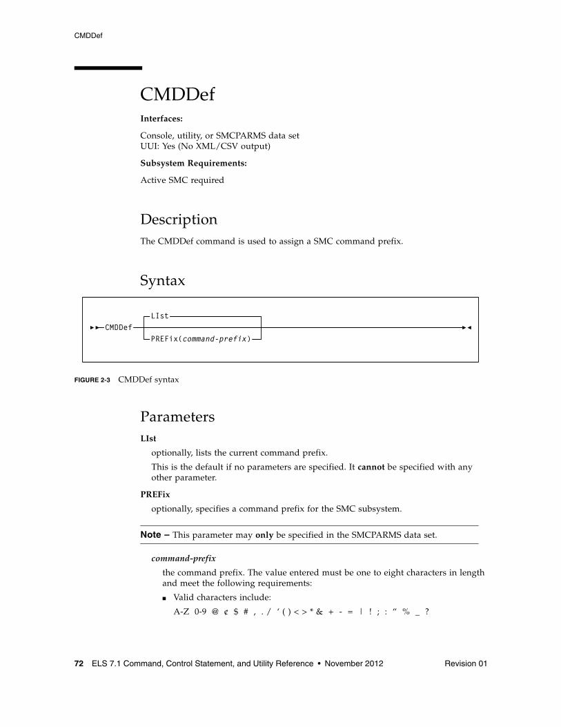
CMDDef
72 ELS 7.1 Command, Control Statement, and Utility Reference • November 2012 Revision 01
CMDDefInterfaces:
Console, utility, or SMCPARMS data setUUI: Yes (No XML/CSV output)
Subsystem Requirements:
Active SMC required
DescriptionThe CMDDef command is used to assign a SMC command prefix.
Syntax
FIGURE 2-3 CMDDef syntax
ParametersLIst
optionally, lists the current command prefix.
This is the default if no parameters are specified. It cannot be specified with any other parameter.
PREFix
optionally, specifies a command prefix for the SMC subsystem.
Note – This parameter may only be specified in the SMCPARMS data set.
command-prefix
the command prefix. The value entered must be one to eight characters in length and meet the following requirements:
■ Valid characters include:
A-Z 0-9 @ ¢ $ # , . / ‘ ( ) < > * & + - = | ! ; : “ % _ ?
CMDDefLIst
PREFix(command-prefix)
CMDDef
Revision 01 Chapter 2 SMC Commands and Control Statements 73
■ The command prefix cannot include a command string, a command abbreviation, or any string that invokes a command.
■ The command prefix cannot include a string that is a subset or superset of an existing prefix beginning with the same character.
Note – The MSP command, DISPLAY OPDATA, displays all active command prefixes and their corresponding subsystem name.
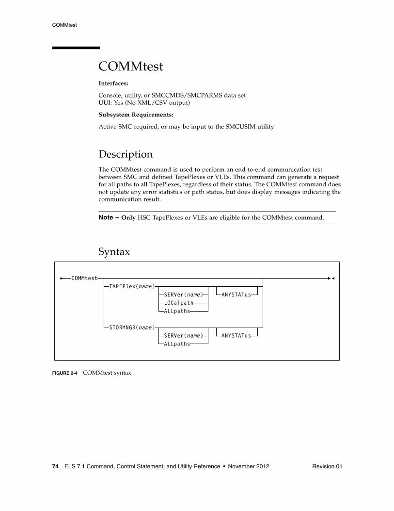
COMMtest
74 ELS 7.1 Command, Control Statement, and Utility Reference • November 2012 Revision 01
COMMtestInterfaces:
Console, utility, or SMCCMDS/SMCPARMS data setUUI: Yes (No XML/CSV output)
Subsystem Requirements:
Active SMC required, or may be input to the SMCUSIM utility
DescriptionThe COMMtest command is used to perform an end-to-end communication test between SMC and defined TapePlexes or VLEs. This command can generate a request for all paths to all TapePlexes, regardless of their status. The COMMtest command does not update any error statistics or path status, but does display messages indicating the communication result.
Note – Only HSC TapePlexes or VLEs are eligible for the COMMtest command.
Syntax
FIGURE 2-4 COMMtest syntax
LOCalpath
TAPEPlex(name)SERVer(name)
ALLpaths
ANYSTATus
STORMNGR(name)SERVer(name)ALLpaths
ANYSTATus
COMMtest
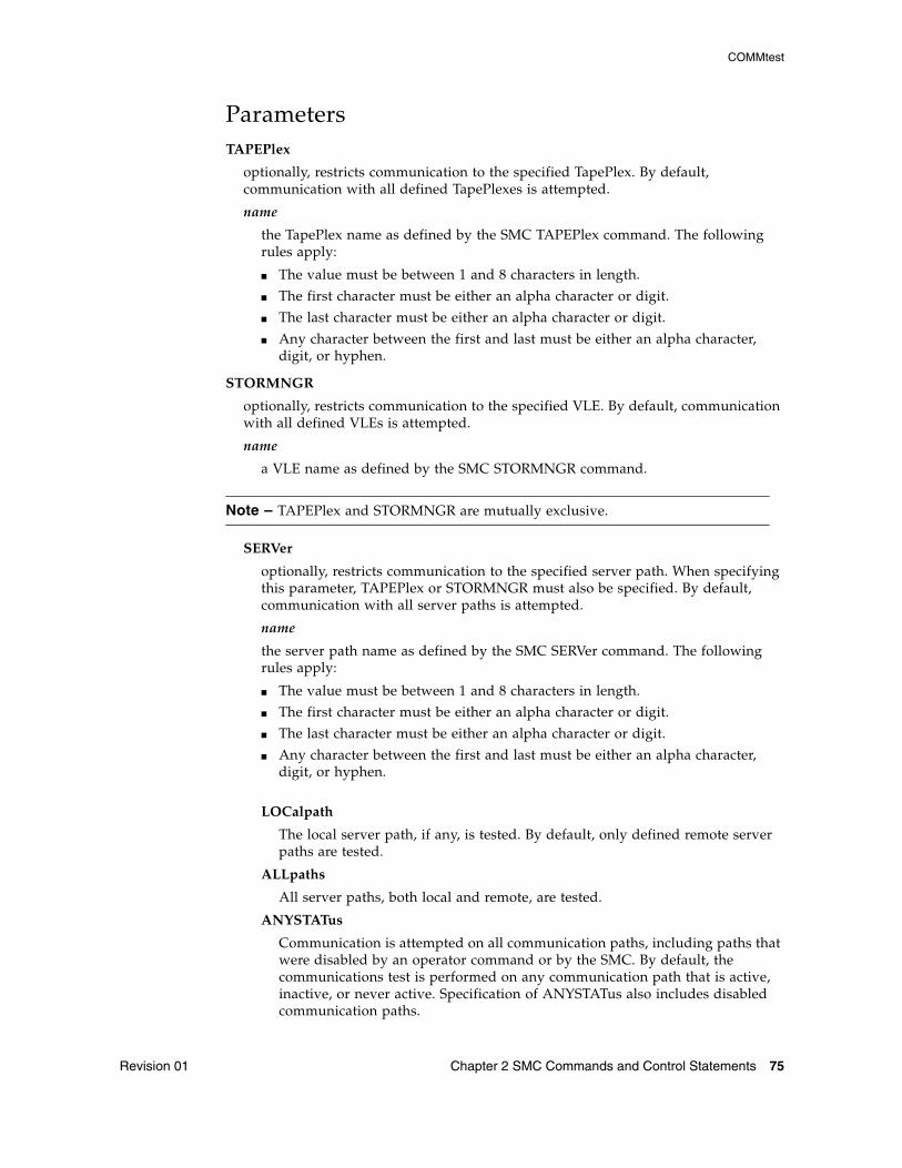
COMMtest
Revision 01 Chapter 2 SMC Commands and Control Statements 75
ParametersTAPEPlex
optionally, restricts communication to the specified TapePlex. By default, communication with all defined TapePlexes is attempted.
name
the TapePlex name as defined by the SMC TAPEPlex command. The following rules apply:
■ The value must be between 1 and 8 characters in length.
■ The first character must be either an alpha character or digit.
■ The last character must be either an alpha character or digit.
■ Any character between the first and last must be either an alpha character, digit, or hyphen.
STORMNGR
optionally, restricts communication to the specified VLE. By default, communication with all defined VLEs is attempted.
name
a VLE name as defined by the SMC STORMNGR command.
Note – TAPEPlex and STORMNGR are mutually exclusive.
SERVer
optionally, restricts communication to the specified server path. When specifying this parameter, TAPEPlex or STORMNGR must also be specified. By default, communication with all server paths is attempted.
name
the server path name as defined by the SMC SERVer command. The following rules apply:
■ The value must be between 1 and 8 characters in length.
■ The first character must be either an alpha character or digit.
■ The last character must be either an alpha character or digit.
■ Any character between the first and last must be either an alpha character, digit, or hyphen.
LOCalpath
The local server path, if any, is tested. By default, only defined remote server paths are tested.
ALLpaths
All server paths, both local and remote, are tested.
ANYSTATus
Communication is attempted on all communication paths, including paths that were disabled by an operator command or by the SMC. By default, the communications test is performed on any communication path that is active, inactive, or never active. Specification of ANYSTATus also includes disabled communication paths.
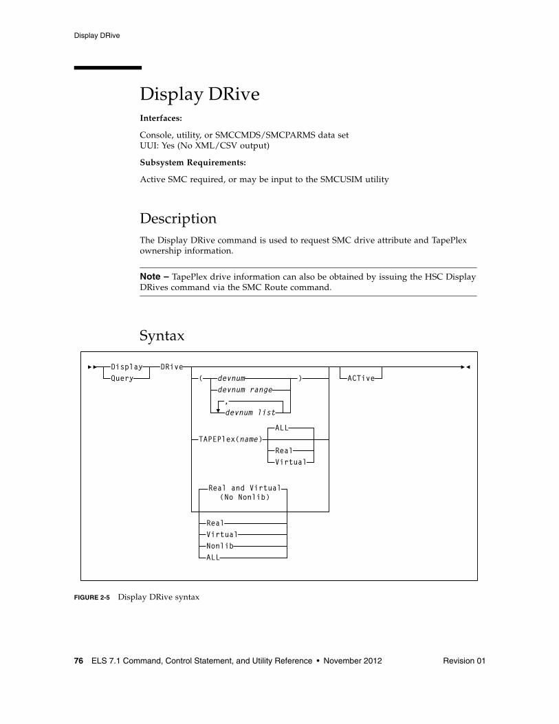
Display DRive
76 ELS 7.1 Command, Control Statement, and Utility Reference • November 2012 Revision 01
Display DRiveInterfaces:
Console, utility, or SMCCMDS/SMCPARMS data setUUI: Yes (No XML/CSV output)
Subsystem Requirements:
Active SMC required, or may be input to the SMCUSIM utility
DescriptionThe Display DRive command is used to request SMC drive attribute and TapePlex ownership information.
Note – TapePlex drive information can also be obtained by issuing the HSC Display DRives command via the SMC Route command.
Syntax
FIGURE 2-5 Display DRive syntax
( devnumdevnum range
)
,devnum list
TAPEPlex(name)ALL
Virtual
Real and Virtual(No Nonlib)
VirtualNonlib
DRiveACTive
Real
Real
ALL
DisplayQuery
Display DRive
Revision 01 Chapter 2 SMC Commands and Control Statements 77
Parametersdevnum, devnum-range, devnum-list
indicates the device number(s) to be processed. If specified, all device addresses specified are displayed. The devnum form of the Display DRive command is the only way that defined devices that are not TapePlex owned, or not defined by an SMC UNITAttr command, can be displayed.
TAPEPlex
optionally, lists only devices owned by the specified TapePlex.
name
the TapePlex name. The following rules apply:
■ The value must be between 1 and 8 characters in length.
■ The first character must be either an alpha character or digit.
■ The last character must be either an alpha character or digit.
■ Any character between the first and last must be either an alpha character, digit, or hyphen.
Real
optionally, lists only “real” (i.e. nonvirtual) devices owned by the specified TapePlex.
Virtual
optionally, lists only virtual devices owned by the specified TapePlex.
ALL
optionally, lists all devices owned by the specified TapePlex. This is the default if no parameters are specified.
Real
optionally, lists only “real” (i.e. nonvirtual) devices owned by SMC-defined TapePlexes.
Virtual
optionally, lists only virtual devices owned by SMC-defined TapePlexes.
Nonlib
optionally, lists only “real” devices that are not owned by any SMC-defined TapePlex, but have UNITATTR statements defined.
ALL
optionally, lists all devices owned by SMC-defined TapePlexes.
ACTive
optionally, lists only drives currently mounted or awaiting mounts according to SMC internal data.
Note – If a Display DRive command is issued without any parameters, by default, the SMC lists all real and virtual devices owned by SMC-defined TapePlexes.
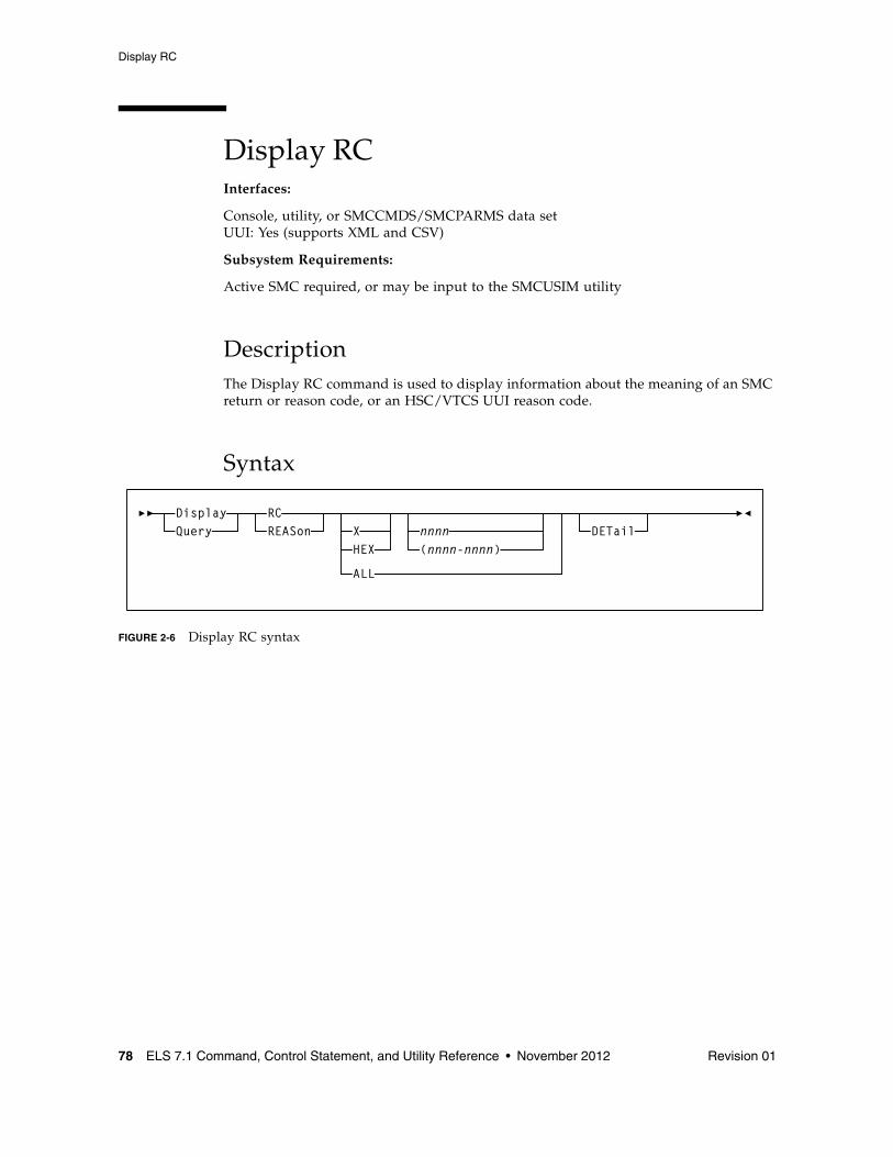
Display RC
78 ELS 7.1 Command, Control Statement, and Utility Reference • November 2012 Revision 01
Display RCInterfaces:
Console, utility, or SMCCMDS/SMCPARMS data setUUI: Yes (supports XML and CSV)
Subsystem Requirements:
Active SMC required, or may be input to the SMCUSIM utility
DescriptionThe Display RC command is used to display information about the meaning of an SMC return or reason code, or an HSC/VTCS UUI reason code.
Syntax
FIGURE 2-6 Display RC syntax
DisplayQuery
RCREASon X
HEX
ALL
DETailnnnn(nnnn-nnnn)
Display RC
Revision 01 Chapter 2 SMC Commands and Control Statements 79
ParametersX or HEX
optionally, specifies that the reason/return code value or range is specified as a hexadecimal number.
nnnn, nnnn-nnnn
optionally, lists the return codes for which the explanation is to be displayed.
■ If X or HEX is specified, the value may contain hexadecimal characters 0-9 andA-F.
■ If X or HEX is not specified, the value may contain only numeric characters.
A range specified from the console may contain a maximum of 16 values.
ALL
optionally, indicates that all defined return or reason codes are to be listed. ALL is permitted only from a utility.
Note – ALL and H/HEX are mutually exclusive.
DETail
optionally, indicates that detailed information about the requested codes is to be listed.
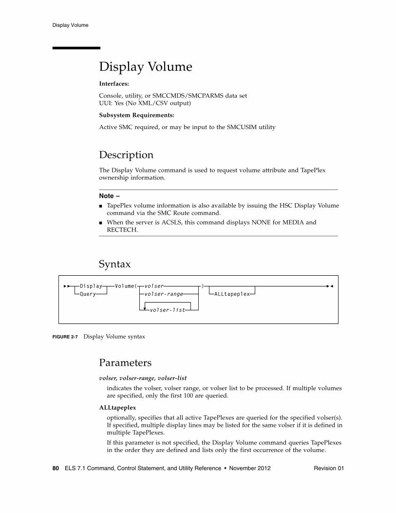
Display Volume
80 ELS 7.1 Command, Control Statement, and Utility Reference • November 2012 Revision 01
Display VolumeInterfaces:
Console, utility, or SMCCMDS/SMCPARMS data setUUI: Yes (No XML/CSV output)
Subsystem Requirements:
Active SMC required, or may be input to the SMCUSIM utility
DescriptionThe Display Volume command is used to request volume attribute and TapePlex ownership information.
Note – ■ TapePlex volume information is also available by issuing the HSC Display Volume
command via the SMC Route command.
■ When the server is ACSLS, this command displays NONE for MEDIA and RECTECH.
Syntax
FIGURE 2-7 Display Volume syntax
Parametersvolser, volser-range, volser-list
indicates the volser, volser range, or volser list to be processed. If multiple volumes are specified, only the first 100 are queried.
ALLtapeplex
optionally, specifies that all active TapePlexes are queried for the specified volser(s). If specified, multiple display lines may be listed for the same volser if it is defined in multiple TapePlexes.
If this parameter is not specified, the Display Volume command queries TapePlexes in the order they are defined and lists only the first occurrence of the volume.
volservolser-range
)ALLtapeplex
Volume(DisplayQuery
volser-list
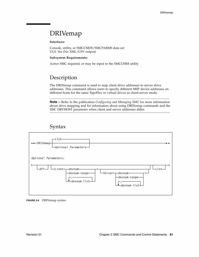
DRIVemap
Revision 01 Chapter 2 SMC Commands and Control Statements 81
DRIVemapInterfaces:
Console, utility, or SMCCMDS/SMCPARMS data setUUI: Yes (No XML/CSV output)
Subsystem Requirements:
Active SMC required, or may be input to the SMCUSIM utility
DescriptionThe DRIVemap command is used to map client drive addresses to server drive addresses. This command allows users to specify different MSP device addresses on different hosts for the same TapePlex or virtual drives in client-server mode.
Note – Refer to the publication Configuring and Managing SMC for more information about drive mapping and for information about using DRIVemap commands and the HSC DRVHOST parameter when client and server addresses differ.
Syntax
FIGURE 2-8 DRIVemap syntax
LIst
CLient( devnumdevnum-range
devnum-list
)SErver( devnum
devnum-range
devnum-list
,,
)
Optional ParametersDRIVemap
Optional Parameters:
LIstOFF
DRIVemap
82 ELS 7.1 Command, Control Statement, and Utility Reference • November 2012 Revision 01
ParametersLIst
optionally, lists all current DRIVemap mappings.
■ LIst is the default when no parameters are specified on the DRIVemap command. In this case, all DRIVemap entries are listed.
■ LIst may be specified with other parameters. In this case, the LIst is applied after the other parameters are processed.
OFF
optionally, removes all current DRIVemap mappings. When specified with CLient, this parameter removes DRIVemap ranges specified in the CLient parameter.
CLient
optionally, specifies the device numbers mapped by the DRIVemap command.
devnum, devnum-range, devnum-list
the device number, device number range, or device number list.
SErver
optionally, specifies the device numbers that are defined on the HSC server.
devnum, devnum-range, devnum-list
the device number, device number range, or device number list.
The ranges and lists must match those in the CLient parameter. For example:
CL(AA0-AA2) SE(BA0-BA2) is valid; CL(AA0-AA2) SE(BA0, BA1, BA2) is invalid.
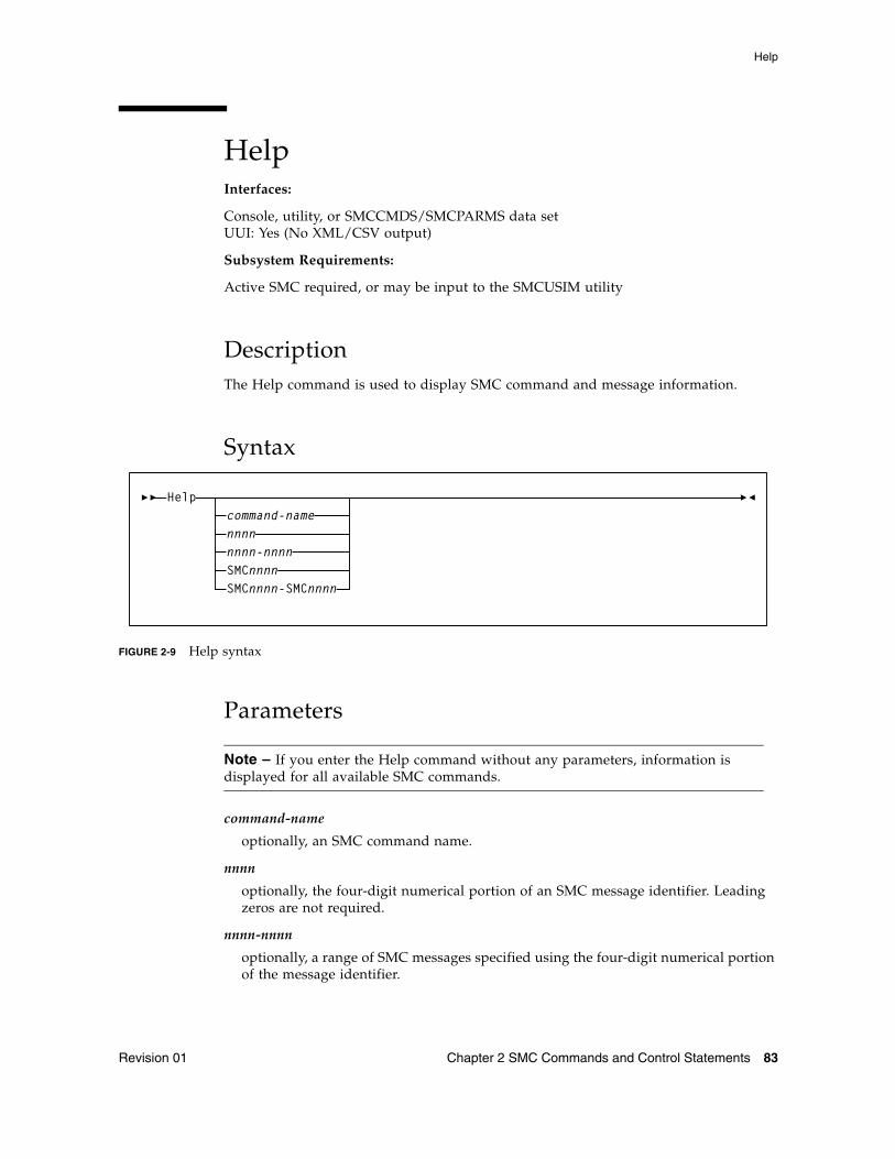
Help
Revision 01 Chapter 2 SMC Commands and Control Statements 83
HelpInterfaces:
Console, utility, or SMCCMDS/SMCPARMS data setUUI: Yes (No XML/CSV output)
Subsystem Requirements:
Active SMC required, or may be input to the SMCUSIM utility
DescriptionThe Help command is used to display SMC command and message information.
Syntax
FIGURE 2-9 Help syntax
Parameters
Note – If you enter the Help command without any parameters, information is displayed for all available SMC commands.
command-name
optionally, an SMC command name.
nnnn
optionally, the four-digit numerical portion of an SMC message identifier. Leading zeros are not required.
nnnn-nnnn
optionally, a range of SMC messages specified using the four-digit numerical portion of the message identifier.
Helpcommand-namennnnnnnn-nnnnSMCnnnnSMCnnnn-SMCnnnn
Help
84 ELS 7.1 Command, Control Statement, and Utility Reference • November 2012 Revision 01
SMCnnnn
optionally, a full SMC message identifier.
SMCnnnn-SMCnnnn
optionally, a range of SMC messages specified using full message identifiers.
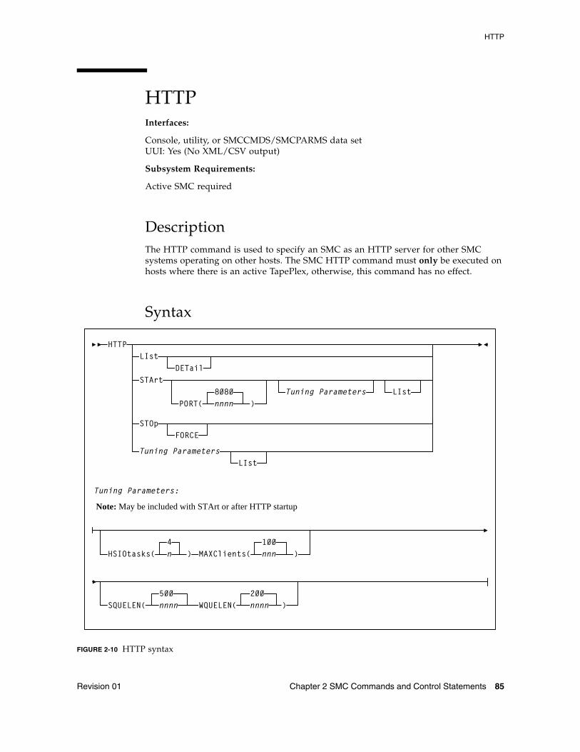
HTTP
Revision 01 Chapter 2 SMC Commands and Control Statements 85
HTTPInterfaces:
Console, utility, or SMCCMDS/SMCPARMS data setUUI: Yes (No XML/CSV output)
Subsystem Requirements:
Active SMC required
DescriptionThe HTTP command is used to specify an SMC as an HTTP server for other SMC systems operating on other hosts. The SMC HTTP command must only be executed on hosts where there is an active TapePlex, otherwise, this command has no effect.
Syntax
FIGURE 2-10 HTTP syntax
HTTPLIst
DETailSTArt
PORT(8080nnnn )
Tuning Parameters LIst
STOp
Tuning ParametersLIst
Tuning Parameters:
Note: May be included with STArt or after HTTP startup
100
WQUELEN(200nnnnSQUELEN(
500nnnn )
HSIOtasks(4n ) MAXClients( nnn )
FORCE
HTTP
86 ELS 7.1 Command, Control Statement, and Utility Reference • November 2012 Revision 01
ParametersLIst
optionally, displays HTTP Server status information and interval statistics.
DETail
optionally, lists I/O, error, accept and reject counts, and CGI module use count information in addition to information displayed in the LIst command.
STArt
optionally, starts the SMC HTTP server.
PORT
optionally, specifies the port number to be listened to for incoming requests.
nnnn
the TCP/IP port number. It is recommended that you do not specify well know TCP/IP port numbers. If not specified, The default is 8080.
STOp
optionally stops the SMC HTTP server.
FORCE
optionally, directs SMC to process the HTTP STOp command even if the status of the SMC HTTP Server is not active. Use this parameter only if there has been an unrecoverable HTTP service task termination and the normal SMC HTTP STOp command has been rejected.
Optional Tuning Parameters
Note – It is strongly recommended that you do not change the default values for these parameters unless directed by Oracle StorageTek Software Support.
HSIOtasks
optionally, specifies the maximum number of SMC HTTP socket I/O tasks to start.
n
the number of I/O tasks.
Note – The HSIOtasks parameter CANNOT be specified after HTTP server startup, it must be specified as part of the HTTP START command. However the remaining tuning parameters, MAXClients, SQUELEN, and WQUELEN may be changed after HTTP server startup has completed.
MAXClients
optionally, specifies the maximum number of connected requests that will be allowed at one time.
nnnn
the number of requests. This value must be between 1 and 300. The default value is 100.
HTTP
Revision 01 Chapter 2 SMC Commands and Control Statements 87
SQUELEN(nnn)
Optionally, specifies the maximum HTTP server I/O queue length before task balancing forces tasks into synchronous I/O mode.
nnnn
the queue length. The default value is 500.
Note – The current and highest I/O queue length can be determined by issuing an SMC HTTP LIST DETAIL command and looking to the line beginning with "Socket I/O reqs"; "quecurr" lists the current I/O queue length, and "high" lists the high I/O queue length.
WQUELEN(nnn)
Optionally, specifies the maximum HTTP server I/O queue length before task balancing is attempted by forcing selected tasks to wait after queueing an I/O request.
nnnn
the queue length. The default value is 200.
The current and highest I/O queue length can be determined by issuing an SMC HTTP LIST DETAIL command and looking to the line beginning with "Socket I/O reqs"; "quecurr" lists the current I/O queue length, and "high" lists the high I/O queue length.
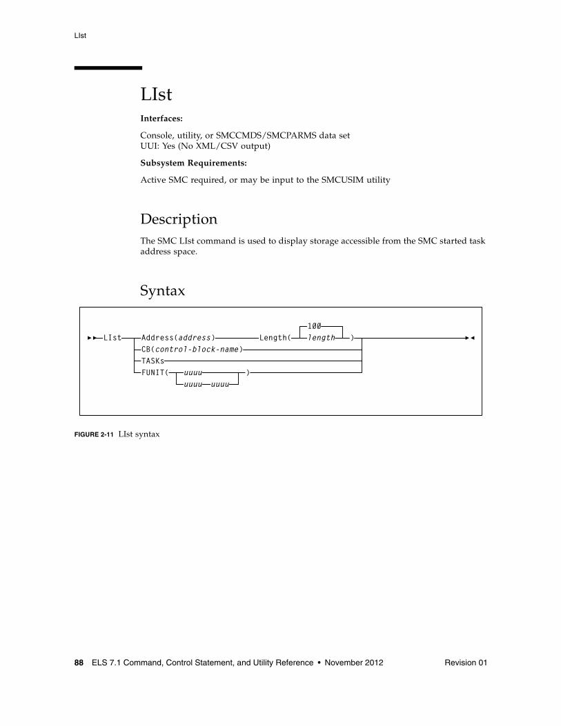
LIst
88 ELS 7.1 Command, Control Statement, and Utility Reference • November 2012 Revision 01
LIstInterfaces:
Console, utility, or SMCCMDS/SMCPARMS data setUUI: Yes (No XML/CSV output)
Subsystem Requirements:
Active SMC required, or may be input to the SMCUSIM utility
DescriptionThe SMC LIst command is used to display storage accessible from the SMC started task address space.
Syntax
FIGURE 2-11 LIst syntax
LIst Address(address) Length(CB(control-block-name)
100length )
TASKsFUNIT( uuuu
uuuu uuuu)
LIst
Revision 01 Chapter 2 SMC Commands and Control Statements 89
ParametersAddress
optionally, specifies the address at which to begin listing SMC memory contents.
address
the address. The value entered must be a valid hexadecimal address.
Length
optionally, specifies the length of SMC memory (bytes) to be listed. Length is required if Address is specified.
length
the length. The value entered must be a valid hexadecimal value between 1 and FFFF. Memory is listed beginning at the location specified in the Address parameter. The default value is 100 (decimal 256).
CB
optionally, specifies the internal SMC control block to be listed.
control-block-name
the control block name.
SMC control blocks are listed for diagnostic purposes. Specify control-block-name only as directed by Oracle StorageTek Software Support.
TASKs
optionally, lists the tasks in the SMC subsystem address space.
FUNIT
optionally, lists SMC control blocks associated with the specified unit address(es).
uuuu or uuuu-uuuu
the unit address(es).
LOG
90 ELS 7.1 Command, Control Statement, and Utility Reference • November 2012 Revision 01
LOG Interfaces:
Console, utility, or SMCCMDS/SMCPARMS data setUUI: Yes (No XML/CSV output)
Subsystem Requirements:
Active SMC required
DescriptionThe SMC LOG command logs data communications from either or all of the following:
■ SMC Library Interface Component■ SMC Client Configuration Component■ SMC HTTP Server Component■ SMC Operator Command Component
These communication transactions are logged to the SMC log file.
This command is intended to be used primarily as directed by Oracle StorageTek Software Support.
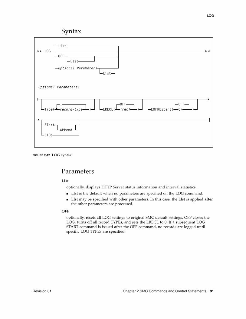
LOG
Revision 01 Chapter 2 SMC Commands and Control Statements 91
Syntax
FIGURE 2-12 LOG syntax
ParametersLIst
optionally, displays HTTP Server status information and interval statistics.
■ LIst is the default when no parameters are specified on the LOG command.
■ LIst may be specified with other parameters. In this case, the LIst is applied after the other parameters are processed.
OFF
optionally, resets all LOG settings to original SMC default settings. OFF closes the LOG, turns off all record TYPEs, and sets the LRECL to 0. If a subsequent LOG START command is issued after the OFF command, no records are logged until specific LOG TYPEs are specified.
LOGList
OFFLIst
Optional ParametersList
Optional Parameters:
TYpe( record-type ),
LRECL(OFFlrecl ) EOFREstart(
OFFON )
STart
STOpAPPend
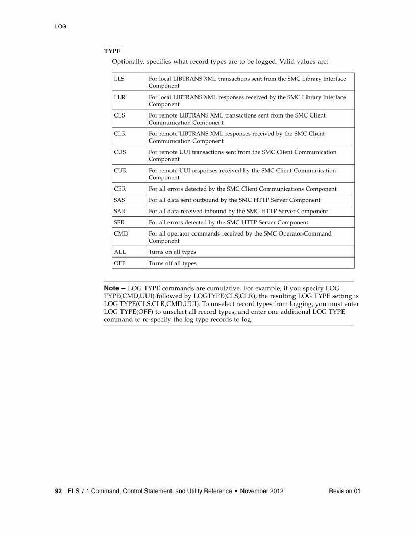
LOG
92 ELS 7.1 Command, Control Statement, and Utility Reference • November 2012 Revision 01
TYPE
Optionally, specifies what record types are to be logged. Valid values are:
Note – LOG TYPE commands are cumulative. For example, if you specify LOG TYPE(CMD,UUI) followed by LOGTYPE(CLS,CLR), the resulting LOG TYPE setting is LOG TYPE(CLS,CLR,CMD,UUI). To unselect record types from logging, you must enter LOG TYPE(OFF) to unselect all record types, and enter one additional LOG TYPE command to re-specify the log type records to log.
LLS For local LIBTRANS XML transactions sent from the SMC Library Interface Component
LLR For local LIBTRANS XML responses received by the SMC Library Interface Component
CLS For remote LIBTRANS XML transactions sent from the SMC Client Communication Component
CLR For remote LIBTRANS XML responses received by the SMC Client Communication Component
CUS For remote UUI transactions sent from the SMC Client Communication Component
CUR For remote UUI responses received by the SMC Client Communication Component
CER For all errors detected by the SMC Client Communications Component
SAS For all data sent outbound by the SMC HTTP Server Component
SAR For all data received inbound by the SMC HTTP Server Component
SER For all errors detected by the SMC HTTP Server Component
CMD For all operator commands received by the SMC Operator-Command Component
ALL Turns on all types
OFF Turns off all types
LOG
Revision 01 Chapter 2 SMC Commands and Control Statements 93
LRECL
optionally, specifies the line length written to the LOG file.
OFF
The maximum line length is controlled by the DCB LRECL. The LOG record is appended to the log date and time stamp. This is the default.
nnnnn
a value from 80 to 32767, used to limit the logical line length.
If the data sent or received exceeds the specified LRECL, then multiple lines are written. If LRECL is specified, then the log date and time stamp are written as separate LOG records. If this value exceeds the DCB LRECL, then the DCB LRECL is used.
EOFREstart
optionally, specifies the response when the LOG file reaches End of File (EOF).
OFF
Logging stops at EOF.
ON
The LOG file closes and re-opens at EOF, and logging continues.
STArt
optionally, starts logging.
APPend
optionally, specifies that data is appended to the current LOG file when logging is started. If not specified, then data is added to the LOG file from the beginning of the log file, and any data currently in the log file is lost. APPend can only be specified when STArt is also specified.
STOp
optionally, stops logging. Current LOG settings are preserved.
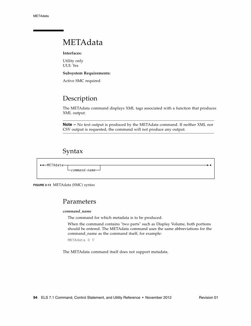
METAdata
94 ELS 7.1 Command, Control Statement, and Utility Reference • November 2012 Revision 01
METAdataInterfaces:
Utility onlyUUI: Yes
Subsystem Requirements:
Active SMC required
DescriptionThe METAdata command displays XML tags associated with a function that produces XML output.
Note – No text output is produced by the METAdata command. If neither XML nor CSV output is requested, the command will not produce any output.
Syntax
FIGURE 2-13 METAdata (SMC) syntax
Parameterscommand_name
The command for which metadata is to be produced.
When the command contains "two parts" such as Display Volume, both portions should be entered. The METAdata command uses the same abbreviations for the command_name as the command itself, for example:
METAdata D V
The METAdata command itself does not support metadata.
METAdatacommand-name
METAdata
Revision 01 Chapter 2 SMC Commands and Control Statements 95
The following tags are produced by the METAdata command:
<command_name>
The full name of the command.
<security_level>
Required security level if command authorization is in effect. Values are QUERY, SET, and ADMIN.
<command_tags>
Header tag for all XML tags.
The following tags are produced for each XML tag in the requested command:
<tag_data>
Header tag for each XML tag.
<tag_name>
The XML tag name, for example, volser.
<tag_type>
Values are header (header XML tag), data (XML data tag, normally associated with a value), and trailer (indicates the position of the trailer tag associated with a header tag).
<occurrences>
The maximum number of expected occurrences, for tags that may occur multiple times. This may be either a numeric value or "unlimited."
The following tags are produced only for data-type tags.
<data_type>
Indicates the type of data expected in the tag value. Produced only for data tags. Values include: char, numeric, flag, hex, date, time.
<maximum_size>
Indicates the maximum output data size.
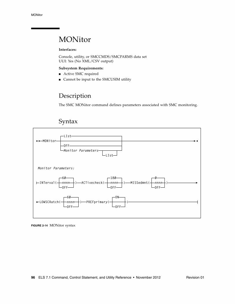
MONitor
96 ELS 7.1 Command, Control Statement, and Utility Reference • November 2012 Revision 01
MONitorInterfaces:
Console, utility, or SMCCMDS/SMCPARMS data setUUI: Yes (No XML/CSV output)
Subsystem Requirements:
■ Active SMC required
■ Cannot be input to the SMCUSIM utility
DescriptionThe SMC MONitor command defines parameters associated with SMC monitoring.
Syntax
FIGURE 2-14 MONitor syntax
MONitorLIst
OFFMonitor Parameters
LIst
Monitor Parameters:
INTerval( )60nnnnOFF
ACTivecheck( )180nnnnOFF
LOWSCRatch(60nnnnOFF
) PREFprimary(ON
OFF)
MISSedmnt(0
OFF)nnnn
MONitor
Revision 01 Chapter 2 SMC Commands and Control Statements 97
ParametersLIst
Optionally, lists the current MONitor command settings.
OFF
Optionally, resets all MONitor parameters to their default values.
INTerval
Optionally, specifies the base SMC monitor scan interval in seconds. The default value is 60.
At each monitor interval, SMC performs the following actions:
1. SMC attempts to find an active communication path for any inactive TapePlex or STORMNGR.
2. If PREFprimary(ON) is set, SMC attempts to change the communication path from a non-primary path to the primary server.
3. SMC checks to ensure that the SMC IEFJFRQ exit is active, so that SMC is influencing tape allocation.
4. SMC clears orphaned task tokens.
5. SMC attempts to redrive pending mounts.
Note – It is strongly recommended that you do not set the MONitor INTerval to 0 or OFF. With these values set, SMC is not able to re-drive pending mounts, honor the PREFprimary setting automatically, or verify that the IEFJFRQ exit is active.
ACTivecheck
Optionally, specifies the interval in seconds after which SMC should verify that communication is still accessible on an active communication path that has had no activity since the prior active check. The default value is 180, or 3 times the INTerval value.
If ACTivecheck is set to 0 or OFF, SMC does not monitor active communication paths. If the ACTivecheck interval is not a multiple of the base INTerval, it is rounded up to a number of seconds that is a multiple of the INTerval value.
MISSedmnt
Optionally, specifies the interval in seconds after which SMC should issue a message indicating that an outstanding mount is pending. The message is repeated after each interval as long as the mount remains unsatisfied. The default value is 0, meaning that the message does not appear.
If the MISSedmnt interval is not a multiple of the base INTerval, it is rounded up to a number of seconds that is a multiple of the INTerval value. It is recommended that the value of this parameter should be set to at least 600 (10 minutes) to allow the SMC mount monitor processing to attempt to redrive missing mounts before producing the periodic missed mount message.
MONitor
98 ELS 7.1 Command, Control Statement, and Utility Reference • November 2012 Revision 01
LOWscratch
Optionally, specifies the interval in seconds after which SMC should report on server scratch subpools that are below their threshold value. The default value is 60.
LOWSCRatch does not report on scratch shortages that are not associated with a subpool name, except for scratch subpool zero.
If LOWSCRatch is set to 0 or OFF, SMC does not perform scratch threshold checking. If the LOWSCRatch interval is not a multiple of the base INTerval, it is rounded up to a number of seconds that is a multiple of the INTerval value.
PREFprimary
Optionally, indicates whether SMC attempts to establish communication on a higher priority server path when communication is currently active on a server that is not the first defined server for a TapePlex. The default value of ON indicates that at each MONitor INTerval, SMC attempts to communicate on the first defined server path if that is not the current active path.
If PREFprimary is set to OFF, then SMC continues to communicate on an active path even if one defined earlier becomes available.
The PREFprimary setting also controls the behavior of the RESYNChronize command. When PREFprimary(ON) is set, a RESYNChronize attempts to communicate to the first defined server. When PREFprimary(OFF) is set, a RESYNChronize does not change the current active communication path, if one exists.
MOUNTDef
Revision 01 Chapter 2 SMC Commands and Control Statements 99
MOUNTDefInterfaces:
Console, utility, or SMCCMDS/SMCPARMS data setUUI: Yes (No XML/CSV output)
Subsystem Requirements:
Active SMC required, or may be input to the SMCUSIM utility
DescriptionThe SMC MOUNTDef command is used to control message processing (i.e., mount/dismount) options previously controlled by the HSC MNTD command and HSC input parameters and LIBGEN options. The MOUNTDef command also applies to VTVs.
These options control the following:
■ automation of pending mounts■ delete disposition at dismount time■ whether mount and dismount messages are issued■ when mount messages are rolled off of the console■ swap processing behavior
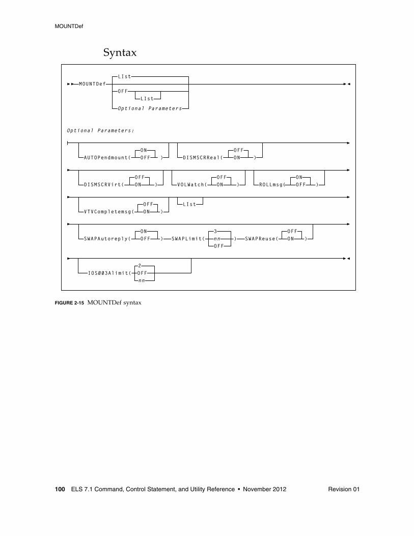
MOUNTDef
100 ELS 7.1 Command, Control Statement, and Utility Reference • November 2012 Revision 01
Syntax
FIGURE 2-15 MOUNTDef syntax
)OFFON
)ONOFFAUTOPendmount(
ROLLmsg( )ONOFFVOLWatch(
)OFFONDISMSCRReal(
)OFFONDISMSCRVirt(
LIst
MOUNTDefOFF
LIst
Optional Parameters
LIst
Optional Parameters:
OFFVTVCompletemsg( ON )
SWAPAutoreply(ONOFF ) SWAPLimit(
3nnOFF
) SWAPReuse(OFFON )
IOS003Alimit(2OFFnn
MOUNTDef
Revision 01 Chapter 2 SMC Commands and Control Statements 101
ParametersLIst
optionally, lists current SMC MOUNTDef settings.
■ LIst is the default when no parameters are specified on the MOUNTDef command.
■ LIst may be specified with other parameters. In this case, the LIst is generated after the other parameters are processed.
OFF
optionally, resets all MOUNTDef settings to original SMC default settings. Specify LIst with this parameter to list these settings.
AUTOPendmount
optionally, specifies whether the pending mounts are automated for library or virtual drives found when SMC is first initialized and the owning TapePlex is first activated.
ON
Pending mounts are automated. This is the default.
OFF
Pending mounts are not automated.
Note – If AUTOPendmount is OFF, you must issue an HSC MOUNT command to complete any pending mounts found when a TapePlex is first activated.
DISMSCRReal
optionally, specifies how the SMC interprets the delete disposition on a dismount message for real (nonvirtual) volumes.
Note – The DISMSCRReal and DISMSCRVirt parameters replace the DELDISP= parameter of the HSC LIBGEN SLILIBRY macro.
OFF
The real cartridge is retained as nonscratch when MSP indicates delete disposition in the dismount message. This is the default, and is recommended for CA-1 or CA-TLMS users to leave volumes in a consistent nonscratch status during the CA-1 and CA-TLMS grace period.
ON
The real cartridge is scratched when MSP indicates delete disposition in the dismount message.
MOUNTDef
102 ELS 7.1 Command, Control Statement, and Utility Reference • November 2012 Revision 01
DISMSCRVirt
optionally, specifies how the SMC interprets the delete disposition on a dismount message for VTVs.
Note – The DISMSCRReal and DISMSCRVirt parameters replace the DELDISP= parameter of the HSC LIBGEN SLILIBRY macro.
OFF
The VTV is retained as nonscratch when MSP indicates delete disposition in the dismount message. This is the default.
ON
The VTV is scratched when MSP indicates delete disposition in the dismount message.
VOLWatch
optionally, specifies whether an SMC message is issued when a library volume is to be mounted on a nonlibrary drive.
OFF
No message is issued when a library volume is to be mounted on a nonlibrary drive.
ON
A console message is issued when a library volume is to be mounted on a nonlibrary drive.
ROLLmsg
optionally, specifies whether mount messages handled by the SMC are allowed to roll off the operator console before mount requests are satisfied.
ON
Mount messages are allowed to roll off the console screen before mounts are satisfied. This is the default.
Note – You can limit the rolling of specific mount messages (e.g., TMS007) by presetting the messages xxxxRCDC (Request to Change Descriptor Codes) flag word xxxxRBFB1. The SAMPLIB includes a sample MPF USEREXIT to preset the xxxxRCDC flag.
OFF
Mount messages remain on the console screen until mount requests are satisfied.
VTVCompletemsg
optionally, specifies whether VTV mount and dismount messages are issued.
OFF
VTV mount (SLS5075I) and VTV dismount (SLS5076I) messages are not issued on the host where the server is running. This is the default.
ON
The VTV mount (SLS5075I) and VTV dismount (SLS5076I) messages are issued on the host where the server is running.
MOUNTDef
Revision 01 Chapter 2 SMC Commands and Control Statements 103
SWAPAutoreply
optionally, specifies whether the SMC enhanced swap process automatically responds "NO" to the Fujitsu "IGF500D - REPLY 'YES' DEVICE OR 'NO' message when no compatible swap-to device is found.
ON
SMC automatically replies "NO" to the Fujitsu "IGF500D - REPLY 'YES' DEVICE OR 'NO' message after the SMC fails to find compatible devices and issues its own "SMC0108 No compatible drive found for SWAP processing" message. This is the default.
OFF
SMC does not automatically reply to the Fujitsu "IGF500D - REPLY 'YES' DEVICE OR 'NO' message after the SMC fails to find compatible devices.
SWAPLimit
optionally, specifies the maximum number of system initiated swaps before the SMC gives up on the current jobstep + volser swap series and returns to MSP.
nn
a swap value of 0-99. If a non-zero value is specified then only that number of system initiated swaps are allowed before SMC gives up and returns to MSP.
Any operator initiated swaps do not count towards the specified number, however, their swap-to devices are recorded. Specifying a value of 0 is the equivalent to specifying "OFF" (see below). The default value is 3.
OFF
specifies that an unlimited number of system initiated swaps are possible, however, only the last 16 devices used are recorded to track possible swap-to device exclusion.
SWAPReuse
optionally, specifies whether previously used swap-to devices are to be excluded as possible swap-to devices for the current jobstep + volser swap series.
OFF
Previously used swap-to devices are excluded as possible swap-to devices for the current jobstep + volser swap series. If no eligible device is found then SMC issues its own "SMC0108 No compatible drive found for SWAP processing" message and return to MSP. This is the default.
ON
Previously used swap-to devices are eligible to be used for the current jobstep + volser swap series.
MOUNTDef
104 ELS 7.1 Command, Control Statement, and Utility Reference • November 2012 Revision 01
IOS003Alimit
optionally, specifies the maximum number of attempts to re-drive a mount request that has failed with a IOS003A message.
OFF
specifies that an unlimited number of attempts will occur to re-drive the mount request following a IOS003A message for a given drive.
nn
specifies a value between 1-99. The number specified is the maximum number of attempts to re-drive the mount request. The maximum allowed value is 99. The default value is 2.
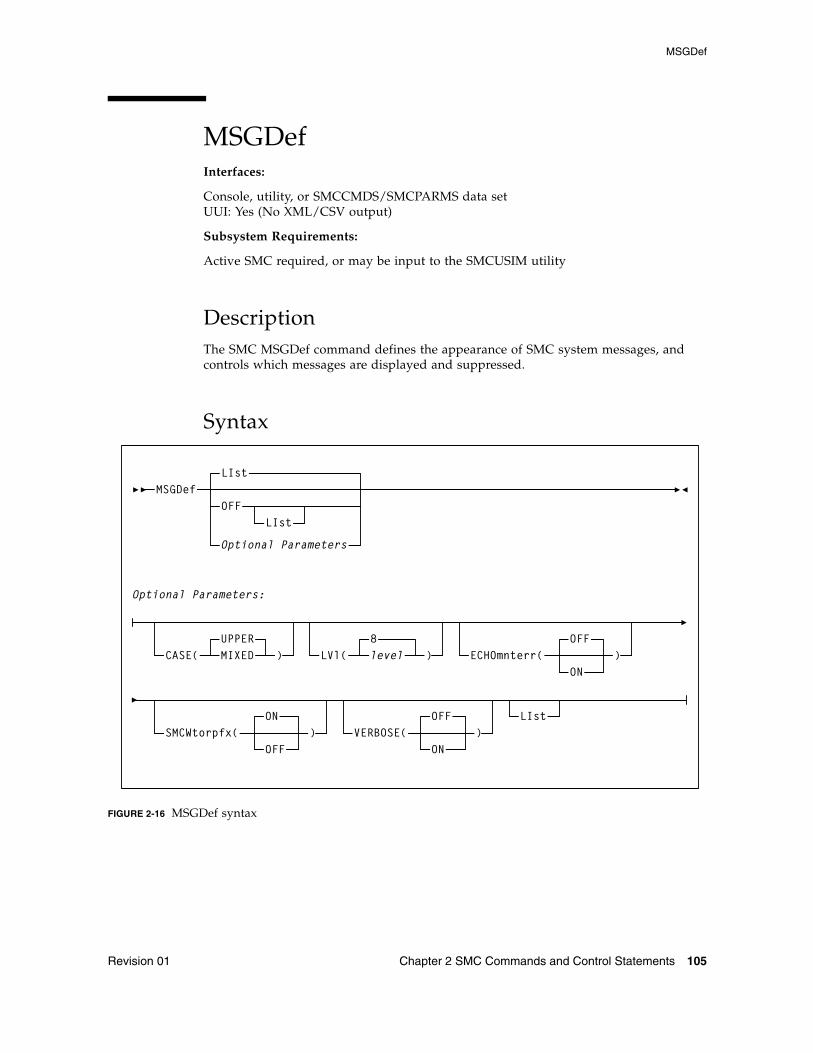
MSGDef
Revision 01 Chapter 2 SMC Commands and Control Statements 105
MSGDefInterfaces:
Console, utility, or SMCCMDS/SMCPARMS data setUUI: Yes (No XML/CSV output)
Subsystem Requirements:
Active SMC required, or may be input to the SMCUSIM utility
DescriptionThe SMC MSGDef command defines the appearance of SMC system messages, and controls which messages are displayed and suppressed.
Syntax
FIGURE 2-16 MSGDef syntax
CASE(UPPERMIXED ) LVl( level
8) ECHOmnterr(
OFF)
ON
SMCWtorpfx(ON
)OFF
VERBOSE( )OFF
ON
MSGDefOFF
LIst
Optional Parameters
LIst
Optional Parameters:
LIst
MSGDef
106 ELS 7.1 Command, Control Statement, and Utility Reference • November 2012 Revision 01
ParametersLIst
optionally, lists current default SMC message settings.
■ LIst is the default when no parameters are specified on the MSGDef command.
■ LIst may be specified with other parameters. In this case, the LIst is generated after the other parameters are processed.
OFF
optionally, resets all MSGDef values to original SMC default settings. Specify LIst with this parameter to list these settings. MSGDef cannot be specified with any other parameter.
CASE
optionally, specifies the message case. Valid values are UPPER or MIXED.
UPPER
specifies upper case. This is the default.
MIXED
specifies mixed case.
LVl
optionally, specifies the default level used to control which SMC messages are displayed and suppressed.
level
the default level. Valid values include the following:
If no value is specified, the default value of 8 is used.
Note – Levels higher than 8 are used for diagnostic purposes and should only be specified as directed by Oracle StorageTek Software Support.
0 Display error messages only.
4 Display error and warning messages from the SMC subsystem.
8 Display all SMC subsystem messages and allocation job log warning messages. This is the default if the MSGDef parameter is not specified.
MSGDef
Revision 01 Chapter 2 SMC Commands and Control Statements 107
ECHOmnterr
optionally, specifies whether mount errors generated by the HSC are echoed directly to the console for the SMC client.
ON
Mount errors generated by the HSC are echoed to the console for the SMC client.
Note – This parameter is valid for both local and remote servers.
OFF
Mount errors generated by the HSC are not to the console for the SMC client. This is the default.
SMCWtorpfx
optionally, specifies whether the SMC0137 prefix is displayed for HSC WTOR messages generated by WTORDEST(CLIENT) on the TAPEPlex command.
ON
The SMC0137 prefix is displayed. This is the default.
OFF
The SMC0137 prefix is not displayed.
VERBOSE
optionally, specifies whether SMC0190 and SMC0191 messages are displayed whenever any SMC settings are altered.
ON
SMC0190 and SMC0191 messages are displayed.
OFF
SMC0190 and SMC0191 messages are not displayed.
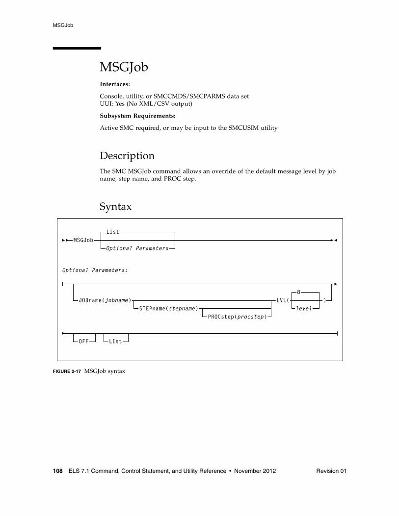
MSGJob
108 ELS 7.1 Command, Control Statement, and Utility Reference • November 2012 Revision 01
MSGJobInterfaces:
Console, utility, or SMCCMDS/SMCPARMS data setUUI: Yes (No XML/CSV output)
Subsystem Requirements:
Active SMC required, or may be input to the SMCUSIM utility
DescriptionThe SMC MSGJob command allows an override of the default message level by job name, step name, and PROC step.
Syntax
FIGURE 2-17 MSGJob syntax
MSGJobLIst
OFF
level
8JOBname(jobname)
STEPname(stepname)PROCstep(procstep)
LVL( )
LIst
Optional Parameters
Optional Parameters:
MSGJob
Revision 01 Chapter 2 SMC Commands and Control Statements 109
ParametersLIst
optionally, lists current default SMC message settings and job name, step name, and PROC step exceptions (in the order of evaluation).
■ LIst is the default when no parameters are specified on the MSGJob command.
■ LIst may be specified with other parameters. In this case, the LIst is generated after the other parameters are processed.
OFF
optionally, removes MSGJob overrides.
■ If no other parameters are specified, MSGJob overrides are removed for all jobs.
■ If only JOBname is specified, MSGJob overrides are removed for ALL MSGJob entries for that job name.
■ If JOBname, STEPname and PROCstep are specified, MSGJob overrides are removed only for the specified entry.
The global MSGDef is not affected by this parameter.
JOBname
optionally, specifies a job name.
jobname
the job name.
The value entered must be one to eight characters in length. An asterisk (*) can be used as a wildcard when included as the last character. In this case, the message level is set for all jobs whose job names match the characters preceding the asterisk.
STEPname
optionally, specifies a step name. It is only valid when JOBname is also specified (may be “JOB=*”).
stepname
the step name.
The value entered must be one to eight characters in length. This parameter is only valid if JOBname is also specified.
PROCstep
optionally, specifies a PROC step. It is only valid when JOBname and STEPname are also specified.
procstep
the PROC step.
The value entered must be one to eight characters in length. This parameter is only valid if JOBname and STEPname are also specified.
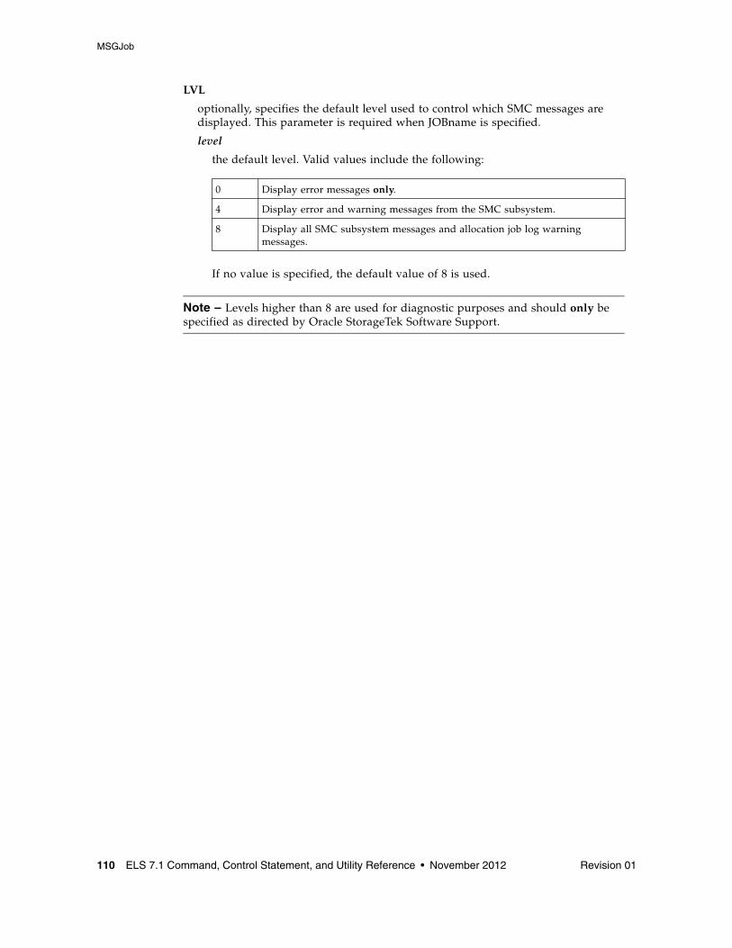
MSGJob
110 ELS 7.1 Command, Control Statement, and Utility Reference • November 2012 Revision 01
LVL
optionally, specifies the default level used to control which SMC messages are displayed. This parameter is required when JOBname is specified.
level
the default level. Valid values include the following:
If no value is specified, the default value of 8 is used.
Note – Levels higher than 8 are used for diagnostic purposes and should only be specified as directed by Oracle StorageTek Software Support.
0 Display error messages only.
4 Display error and warning messages from the SMC subsystem.
8 Display all SMC subsystem messages and allocation job log warning messages.
POLicy
Revision 01 Chapter 2 SMC Commands and Control Statements 111
POLicyInterfaces:
Console, utility, or SMCCMDS/SMCPARMS data setUUI: Yes (No XML/CSV output)
Subsystem Requirements:
Active SMC required, or may be input to the SMCUSIM utility
DescriptionThe SMC POLicy command is used to specify all tape policy specifications in a single named policy object. It can be used with SMC TAPEREQ statements to associate a named policy with an allocation or mount event. Additionally, the POLicy VALidate option can be used to validate policy objects.
Note – ■ Refer to the publication Configuring and Managing SMC for more information about
the use of SMC policies.
■ Policies defined using the SMC POLicy command create SMC policy objects that can be referenced by name from SMC TAPEREQ control statements using the TAPEREQ POLicy parameter. A policy name may be associated with two policy objects: a scratch policy with the specified name, and a specific policy with the specified name.
■ Policies referenced from SMC TAPEREQ control statements must be defined prior to executing the TREQDEF command that processes the TAPEREQ control statements.
■ When a policy to be added to the SMC contains a policy specification error, for example, specifying a scratch subpool name with VOLTYPE(SPECIFIC), the SMC still creates the policy object. However, the SMC marks the policy object in error, allowing any reference to the named policy object to find it. However, the returned policy will be empty, indicating that the default tape policy attributes will be applied to the event.
■ To update an SMC policy, enter a new SMC POLicy command for the given policy NAme and VOLType. Be aware that the new POLicy command replaces the existing scratch or specific policy object. Therefore, when updating a policy, you must enter all values you wish to preserve.
For example, if the original scratch policy object is defined as:
POLICY NAME(POL1) VOLTYPE(SCRATCH) MEDIA(VIRTUAL) MGMTCLAS(MGMT1)
and you wish to add a subpool to the policy, you must enter:
POLICY NAME(POL1) VOLTYPE(SCRATCH) MEDIA(VIRTUAL) MGMTCLAS(MGMT1) SUBPOOL(SUBP1)
This behavior allows you to modify one or more POLicy commands in a file and reload all policies using the SMC READ command.
POLicy
112 ELS 7.1 Command, Control Statement, and Utility Reference • November 2012 Revision 01
■ When an SMC policy object to be updated contains a policy specification error, for example, specifying a scratch subpool name with VOLTYPE(SPECIFIC), the SMC will not update any part of the existing policy object. The policy object is not marked in error, and the complete update is discarded.
■ DEVTPREF is not supported on this command. However, you can use an esoteric list to specify preferencing for different device types.
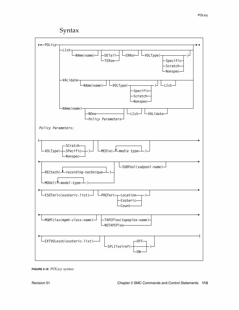
POLicy
Revision 01 Chapter 2 SMC Commands and Control Statements 113
Syntax
FIGURE 2-18 POLicy syntax
POLicyLIst
NAme(name) DETailTERse
ERRor VOLType(SpecificScratchNonspec
)
VALidateNAme(name) VOLType(
SpecificScratchNonspec
) LIst
NAme(name)NOnePolicy Parameters
LIst VALidate
Policy Parameters:
VOLType(SCratchSPecificNonspec
) MEDia( media type )
RECtech(
MODel(
recording-technique
model-type
)
)
SUBPool(subpool-name)
ESOTeric(esoteric-list) PREFer( LocationEsotericCount
)
MGMTclas(mgmt-class-name) TAPEPlex(tapeplex-name)NOTAPEPlex
EXTVOLesot(esoteric-list)SPLITvolref(
OFF
ON)
POLicy
114 ELS 7.1 Command, Control Statement, and Utility Reference • November 2012 Revision 01
ParametersLIst
optionally, displays all policy information. Additional parameters allow you to limit which policies are listed, and how much detail is displayed.
NAme
optionally, specifies the name of the policy to be displayed. If the last character is an asterisk (*), all policies that begin with the prefix are displayed. For example, POL LI NA V*.
DETail
optionally, displays audit detail information about the policy, including last update date, time, and source.
TERse
optionally, lists only policy names and whether each policy name applies to scratch, specific, or all allocations.
ERRor
optionally, displays each policy in error status.
When a policy to be added to the SMC contains a policy specification error, for example, specifying a scratch subpool name with VOLTYPE(SPECIFIC), the SMC still creates the policy object. However, the SMC marks the policy object in error, allowing any reference to the named policy object to find it. However, the returned policy will be empty, indicating that the default tape policy attributes will be applied to the event. ERRor lists only those policies that contain an error.
VOLType
optionally, specifies whether the list applies to scratch or specific policy types.
SCratch or Nonspec
List only scratch (nonspecific) policies.
SPecific
List only specific policies.
Note – ■ Matching policies are listed in alphabetic order, regardless of the order in which the
they were defined to the SMC. When specified with other parameters, the LIst is performed after the other parameters have been processed.
■ DETail and TERse are mutually exclusive.
POLicy
Revision 01 Chapter 2 SMC Commands and Control Statements 115
VALidate
optionally, validates and lists POLICY information against the current TAPEPLEX environment. Additional parameters allow you to limit which policies are validated, and whether all results or just warnings and errors are displayed.
NAme
optionally, specifies the name of the policy to be validated. If the last character is an asterisk (*), all policies that begin with the prefix are displayed. For example, POL VAL NA V*.
VOLType
optionally, specifies whether the list applies to scratch or specific policy types.
SCratch or Nonspec
List only scratch (nonspecific) policies.
SPecific
List only specific policies.
LIst
optionally, specifies whether only warnings and errors are listed, or all tested policies are listed. If not specified, then only a single line for each POLICY that generates a warning or error message is listed.
Note – ■ VALidate produces a return code for each tested POLICY VOLTYPE.
■ 0 indicates the POLICY is correct, could not be validated due to certain environmental conditions, or was assumed correct.
■ 4 is a warning, and includes conditions such as a lack of scratch volumes to satisfy the request.
■ 8 indicates an error, and includes conditions such as undefined SUBPOOL or MGMTCLAS name.
■ If POLicy VALidate is entered without the LIst keyword, then only policies that result in a return code of 4 or 8 are listed. If POLicy VALidate is entered with the LIst keyword, then all policies are listed along with their policy validation results.
■ When multiple policies are validated, the final SMC0224 message indicates the highest return code for all policies validated.
■ If no TAPEPLEX(es) are active when the VALidate command is issued, then the policy validate return code will be 0, indicating that the policy could not be validated.
■ Validated policies are listed in alphabetic order, regardless of the order in which the they were defined to the SMC. When specified with other parameters, the VALidate is performed after the other parameters have been processed.
POLicy
116 ELS 7.1 Command, Control Statement, and Utility Reference • November 2012 Revision 01
NAme
specifies the name of a policy that matches the name specified in a TAPEREQ control statement.
name
the policy name.
NOne
optionally, removes all policy parameters associated with the named policy. Specifying NOne for a policy implies that the default behavior is applied, e.g. any media/rectech, subpool 0, etc.
VOLType
optionally, specifies whether the policy applies to scratch or specific allocation.
SCratch or Nonspec
The policy applies only to scratch (nonspecific) allocations. This is the default.
SPecific
The policy applies only to specific allocations.
Note –
When VOLType(SPecific) is specified:
■ The SUBPool parameter is not permitted.
■ The MEDia parameter is only permitted if the NOTAPEPlex parameter is specified.
■ The SPLITvolref parameter is not permitted.
MEDia
optionally, specifies the desired media type for a data set being created. You can enter a list of media types, separated by commas. A list specifies a generic pool from which a selection is made. There is no implied priority.
media-type
the media type.
See Appendix A, “MEDia, RECtech, and MODel Values” for a list of valid media-type values.
Note – ■ MEDia and VOLType(SPecific) are mutually exclusive unless the NOTAPEPlex
parameter is specified.
■ If this parameter is not specified, a default is chosen based on the value of the RECtech parameter. See Appendix A, “MEDia, RECtech, and MODel Values” for default values used if the MEDia parameter is omitted.
■ If both media type and recording technique are omitted, all available device types are eligible for allocation.
POLicy
Revision 01 Chapter 2 SMC Commands and Control Statements 117
RECtech
optionally, specifies the method used to record data tracks on the tape surface for the desired data set. You can enter a list of recording techniques, but they must be separated by commas. A list specifies a generic pool from which a selection is made. There is no implied priority.
recording-technique
the recording technique.
See Appendix A, “MEDia, RECtech, and MODel Values” for a list of valid recording-technique values.
Note – ■ RECtech and MODel are mutually exclusive.
■ If this parameter is not specified, a default is chosen based on the value of the MEDia parameter. See Appendix A, “MEDia, RECtech, and MODel Values” for default values used if the MEDia parameter is omitted.
■ If both media type and recording technique are omitted, all available device types are eligible for allocation.
MODel
optionally, specifies the model number of a transport. You can enter a list of models, separated by commas. A list specifies a generic pool from which a selection is made. There is no implied priority.
MODel provides the same type of information as RECtech, but a user may find it more convenient to specify a transport model rather than a recording technique.
model-type
the model type.
See Appendix A, “MEDia, RECtech, and MODel Values” for a list of valid model-type values.
Note – MODel and RECtech are mutually exclusive.
SUBPool
optionally, specifies the subpool used to satisfy a scratch request.
subpool-name
the subpool name.
Note – SUBPool and VOLType(SPecific) are mutually exclusive.
POLicy
118 ELS 7.1 Command, Control Statement, and Utility Reference • November 2012 Revision 01
ESOTeric
optionally, specifies the name of a device esoteric group, or list of device groups defining the list of eligible transports to be used to satisfy a tape request.
esoteric-group-name
the esoteric group name.
The name specified can consist of one to eight alphanumeric or national (#, @, $) characters. A slash (/) or hyphen (-) is also valid.
Note – If the esoteric list contains devices not currently in the Eligible Device List, SMC allocation cannot add devices to the list, but can exclude devices not in the specified esoteric. During drive exclusion, devices in any of the listed esoterics are included. During drive prioritization, devices are ordered according to their position in the esoteric list.
PREFer
optionally, specifies the relative value of the esoteric list and additional preferencing information. PREFer is only valid when a list of esoterics is specified.
Location
Drives are preferred based on LSM location of a specific volume. This is the default for specific volumes. Location is only valid for VOLType (SP).
Esoteric
Drives are preferred based on the order specified in the esoteric list. This is the default for scratch allocations.
Count
Drives are preferred based on scratch counts in the LSM. Count is only valid for VOLType (N).
MGMTclas
optionally, specifies a Management Class defined on the VTCS MGMTclas control statement. See “MGMTclas Control Statement” on page 433 for more information.
mgmt-class-name
the Management Class name.
TAPEPlex
optionally, specifies the name of a TapePlex defined to SMC. SMC uses the specified TapePlex name to determine the “owner” of an allocation request. Only the specified TapePlex name is queried to determine specific volume information or scratch availability.
tapeplex-name
the TapePlex name. The following rules apply:
■ The value must be between 1 and 8 characters in length.
■ The first character must be either an alpha character or digit.
■ The last character must be either an alpha character or digit.
■ Any character between the first and last must be either an alpha character, digit, or hyphen.
POLicy
Revision 01 Chapter 2 SMC Commands and Control Statements 119
Note – ■ The named TapePlex must be defined using a TAPEPlex command before the POLicy
command is processed.
■ TAPEPlex and NOTAPEPlex are mutually exclusive.
NOTAPEPlex
optionally, specifies that SMC will not perform a TapePlex lookup to obtain volume information.
Note – NOTAPEPlex and TAPEPlex are mutually exclusive.
EXTVOLesot
optionally, specifies the name of a device esoteric group, or list of device groups defining the list of eligible transports to be used to satisfy a tape request when the specific volume is found to be outside of the library.
esoteric-list
the esoteric list.
Each esoteric group name in the list can consist of one to eight alphanumeric or national (#, @, $) characters. A slash (/) or hyphen (-) is also valid.
Note – EXTVOLesot can only be specified if VOLTYPE=SPECIFIC is also specified.
SPLITvolref
optionally, specifies whether VOL=REF chains are to be broken. This parameter is only valid when VOLType(SCratch) or VOLType(Nonspec) is also specified.
OFF
VOL=REF chains are not broken. This is the default.
ON
VOL=REF chains are broken and the LABEL data set sequence number is set to 1.
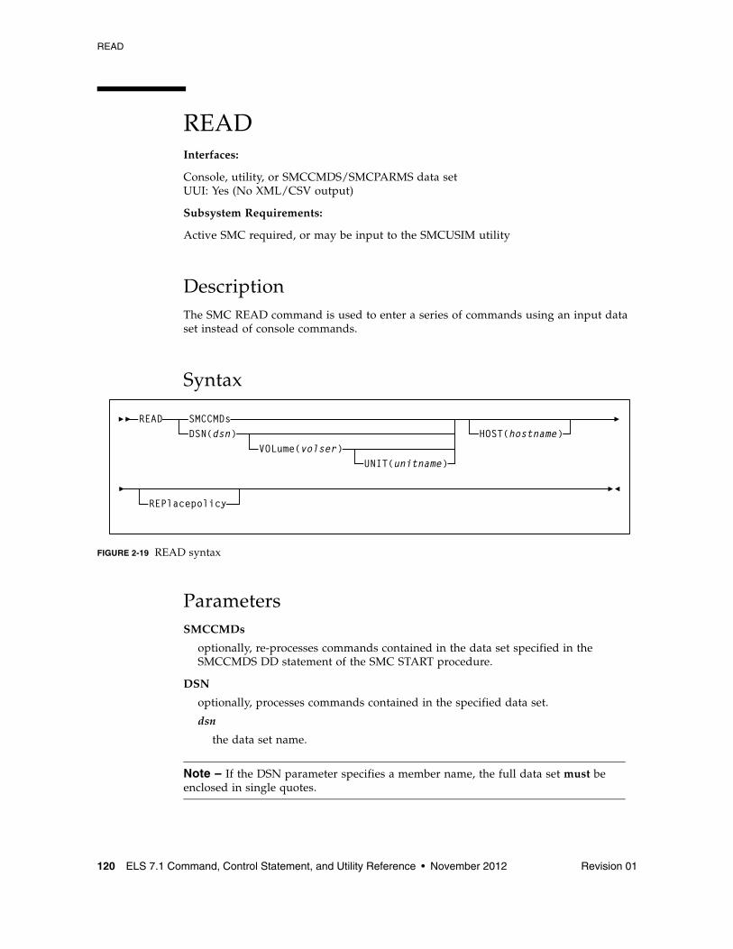
READ
120 ELS 7.1 Command, Control Statement, and Utility Reference • November 2012 Revision 01
READInterfaces:
Console, utility, or SMCCMDS/SMCPARMS data setUUI: Yes (No XML/CSV output)
Subsystem Requirements:
Active SMC required, or may be input to the SMCUSIM utility
DescriptionThe SMC READ command is used to enter a series of commands using an input data set instead of console commands.
Syntax
FIGURE 2-19 READ syntax
ParametersSMCCMDs
optionally, re-processes commands contained in the data set specified in the SMCCMDS DD statement of the SMC START procedure.
DSN
optionally, processes commands contained in the specified data set.
dsn
the data set name.
Note – If the DSN parameter specifies a member name, the full data set must be enclosed in single quotes.
SMCCMDsDSN(dsn)
VOLume(volser)
READ
UNIT(unitname)
HOST(hostname)
REPlacepolicy
READ
Revision 01 Chapter 2 SMC Commands and Control Statements 121
VOLume
optionally, specifies the volume serial number of the DASD volume on which the data set resides. Specify this parameter if the data set is not catalogued.
volser
the volume serial number on which the data set resides.
UNIT
optionally, specifies the unit name of the specified VOLume for uncataloged data sets. Requires that VOLume also be specified.
unitname
the unit name.
If not specified, then a unit name of SYSALLDA is the default.
HOST
optionally, specifies a host name for which this READ command is valid. If this parameter is specified, the READ command is only processed when the specified hostname matches the MSP host. If this parameter is not specified, the READ command is processed regardless of the MSP host.
hostname
the hostname.
Note – ■ HOST is not valid when the READ command is entered from an MSP console.
■ Specification of the HOST parameter allows you to share a single SMC parameter file set across multiple MSP hosts as shown in the following example:
your.parmlib(COMMCMDS)
MSGDEF CASE(MIXED)...other common SMC parameter settings...READ DSN(‘your.parmlib(MSP1CMDS)’) HOST(MSP1)READ DSN(‘your.parmlib(MSP2CMDS)’) HOST(MSP2)
your.parmlib(MSP1CMDS)
DRIVEMAP CL(AB0-AB7) SE(BB0-BB7)
your.parmlib(MSP2CMDS)
DRIVEMAP CL(CB0-CB7) SE(BB0-BB7)
The file COMMCMDS contains SMC parameter settings applicable to all hosts, and the READ commands with HOST specifications for your MSP hosts. The file MSP1CMDS contains SMC specifications applicable only to MSP host MSP1, while the file MSP2CMDS contains SMC specifications applicable only to MSP host MSP2.
READ
122 ELS 7.1 Command, Control Statement, and Utility Reference • November 2012 Revision 01
REPlacepolicy
optionally, specifies that all SMC POLICY objects are to be replaced by any POLICY statements found in the specified dataset (or in any dataset subsequently read by the specified READ dataset).
If REPlacepolicy is not specified, individual POLICY statements within a READ command update or add only the referenced POLICY statements and do not affect unreferenced POLICY statements.
Note – ■ After the READ REPlacepolicy command is executed, any TAPEREQ POLICY
references are re-validated. If any TAPEREQ POLICY references are subsequently found to be in error, the invalid TAPEREQ statements are left active, but reference a "null" POLICY (i.e. the equivalent of specifying POLICY NAME(name) NONE).
■ It is recommended that any TAPEREQ statement(s) be reloaded by inclusion of the TREQDEF command whenever a READ REPlacepolicy command is executed, in order to re-validate all SMC tape policies at the same time.
RESYNChronize
Revision 01 Chapter 2 SMC Commands and Control Statements 123
RESYNChronizeInterfaces:
Console, utility, or SMCCMDS/SMCPARMS data setUUI: Yes (No XML/CSV output)
Subsystem Requirements:
Active SMC required, or may be input to the SMCUSIM utility
DescriptionThe SMC RESYNChronize command is used to re-establish connections to all defined TapePlexes for the purpose of acquiring drive configuration information from all TapePlexes.
This action is automatically performed when the SMC first activates a new path to a TapePlex, when an HSC subsystem (local or remote) reports a configuration change, or when an active local path to a TapePlex is accessed during an MSP allocation or mount event. However, the operator must issue the RESYNChronize command in the following instances:
■ When the user wants to automate pending mounts for a newly activated TapePlex, and does not want to wait for an MSP allocation or mount event to trigger the reconnection.
■ To attempt to redrive outstanding mounts that may have been lost due to hardware or communication errors.
Note – It is recommended that you include a RESYNChronize command at the end of your SMCCMDS file (after all TAPEPlex and SERVer commands) to initialize communication with TapePlexes prior to the first intercepted allocation or mount.
Syntax
FIGURE 2-20 RESYNChronize syntax
ParametersNone.
RESYNChronize
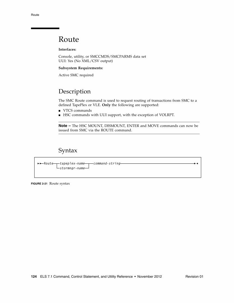
Route
124 ELS 7.1 Command, Control Statement, and Utility Reference • November 2012 Revision 01
RouteInterfaces:
Console, utility, or SMCCMDS/SMCPARMS data setUUI: Yes (No XML/CSV output)
Subsystem Requirements:
Active SMC required
DescriptionThe SMC Route command is used to request routing of transactions from SMC to a defined TapePlex or VLE. Only the following are supported:
■ VTCS commands■ HSC commands with UUI support, with the exception of VOLRPT.
Note – The HSC MOUNT, DISMOUNT, ENTER and MOVE commands can now be issued from SMC via the ROUTE command.
Syntax
FIGURE 2-21 Route syntax
tapeplex-nameRoute command-stringstormngr-name
Route
Revision 01 Chapter 2 SMC Commands and Control Statements 125
Parameterstapeplex-name
specifies a TapePlex name as defined on an SMC TAPEPlex command. SMC routes the request to the specified TapePlex using the currently active TapePlex path. Commands may be sent to either a local or remote HSC TapePlex.
stormngr-name
specifies a VLE name as defined on an SMC STORMNGR command. SMC routes the request to the specified VLE using the currently active VLE path. Commands may be sent to either a local or remote HSC TapePlex or VLE.
command-string
specifies the command string to be routed to the requested TapePlex. Note that VTCS commands should not be prefixed with VT; the HSC UUI interface routes VTCS commands to the correct functional processor without the VT prefix. The command string must be a command supported by the HSC UUI or any VTCS command (except DISPLAY MSG and DISPLAY CMD).
SERVer
126 ELS 7.1 Command, Control Statement, and Utility Reference • November 2012 Revision 01
SERVerInterfaces:
Console, utility, or SMCCMDS/SMCPARMS data setUUI: Yes (No XML/CSV output)
Subsystem Requirements:
Active SMC required, or may be input to the SMCUSIM utility
DescriptionThe SMC SERVer command defines a named path to a remote library server; an HSC subsystem executing on another host. The SERVer command describes the communication path to the HTTP server.
Note – ■ Before a SERVer is defined, the TapePlex that it references must be defined using a
TAPEPlex command. The TapePlex name associated with a SERVer cannot be changed. See “TAPEPlex” on page 137 for more information.
■ Similarly, before a SERVer is defined, the VLE that it references must be defined using a STORMNGR command. The VLE name associated with a SERVer cannot be changed. See for more information.
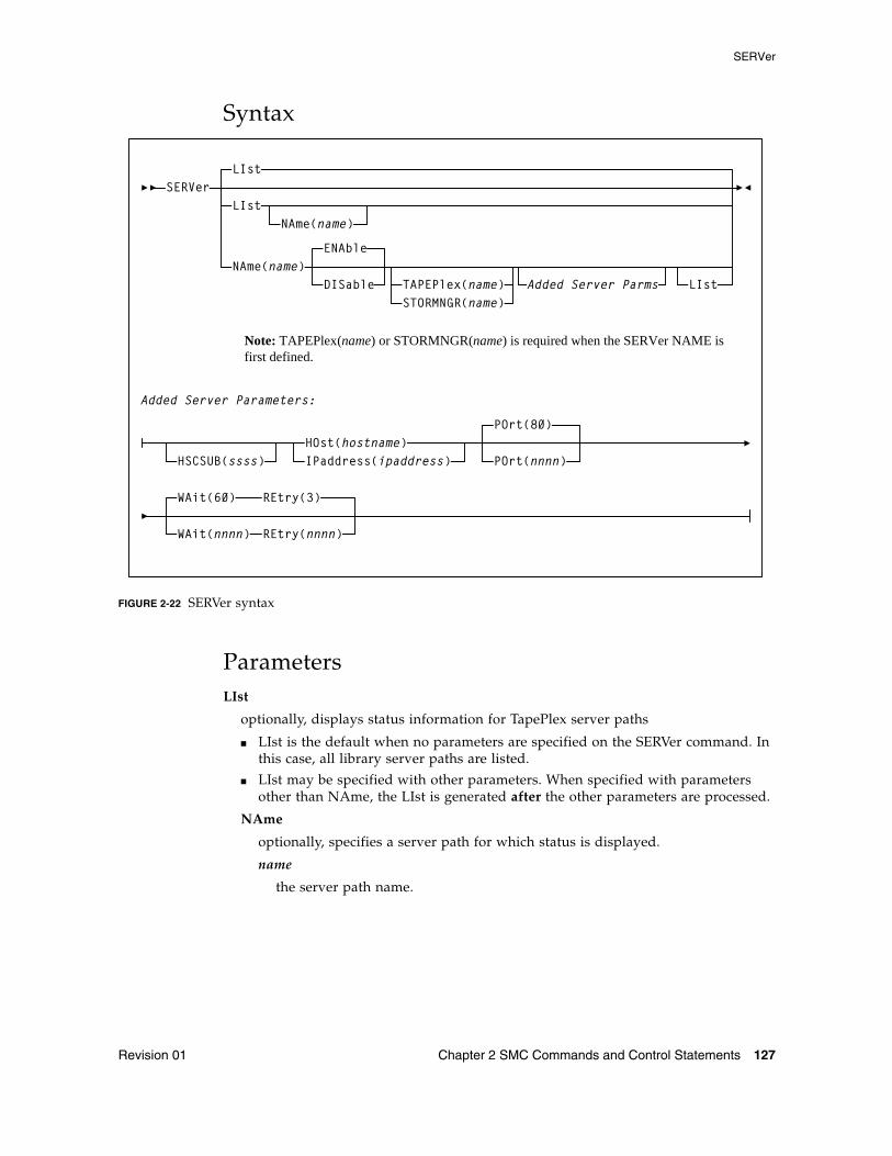
SERVer
Revision 01 Chapter 2 SMC Commands and Control Statements 127
Syntax
FIGURE 2-22 SERVer syntax
ParametersLIst
optionally, displays status information for TapePlex server paths
■ LIst is the default when no parameters are specified on the SERVer command. In this case, all library server paths are listed.
■ LIst may be specified with other parameters. When specified with parameters other than NAme, the LIst is generated after the other parameters are processed.
NAme
optionally, specifies a server path for which status is displayed.
name
the server path name.
SERVerLIst
LIst
NAme(name)
NAme(name)ENAble
DISable TAPEPlex(name)
Added Server Parameters:
HOst(hostname)IPaddress(ipaddress)
POrt(80)
POrt(nnnn)
Note: TAPEPlex(name) or STORMNGR(name) is required when the SERVer NAME is first defined.
LIstAdded Server Parms
HSCSUB(ssss)
STORMNGR(name)
WAit(60)
WAit(nnnn) REtry(nnnn)
REtry(3)
SERVer
128 ELS 7.1 Command, Control Statement, and Utility Reference • November 2012 Revision 01
NAme
optionally, specifies the server name to be defined or modified.
name
the server path name. This name is reported in any communications error message when the error did not occur while communicating with an HSC on the same host. The following rules apply:
■ The value must be between 1 and 8 characters in length.
■ The first character must be either an alpha character or digit.
■ The last character must be either an alpha character or digit.
■ Any character between the first and last must be either an alpha character, digit, or hyphen.
Note – If you are using the SMC HTTP server component, there can be multiple NAMEd server paths for a single TapePlex configuration. Refer to the publication Configuring and Managing SMC for more information.
ENAble
optionally, enables the specified server path to be selected for allocation or mount requests.
DISable
optionally, disables the specified server path. If this is the only path to the TapePlex, the TapePlex is unavailable for allocation or mount requests.
TAPEPlex
optionally, specifies the TapePlex name associated with an actual ACS hardware configuration as defined on an SMC TAPEPlex command. The TAPEPlex parameter must be specified when a new server is first defined.
name
the TapePlex name. This name is reported in any TapePlex error message. The following rules apply:
■ The value must be between 1 and 8 characters in length.
■ The first character must be either an alpha character or digit.
■ The last character must be either an alpha character or digit.
■ Any character between the first and last must be either an alpha character, digit, or hyphen.
STORMNGR
optionally, specifies a VLE name as defined on an SMC STORMNGR command. The STORMNGR parameter must be specified when a new server is first defined.
name
a VLE name as defined on an SMC STORMNGR command. This name is reported in any VLE error message.
Note – TAPEPlex and STORMNGR are mutually exclusive.
SERVer
Revision 01 Chapter 2 SMC Commands and Control Statements 129
HSCSUB
optionally, specifies the name of the HSC subsystem that represents the Tapeplex associated with the server. This parameter is required only when there is more than one HSC subsystem executing on the server host (HSC running in MULT mode).
ssss
the HSC subsystem name.
HOst
optionally, specifies the IP resolver host name on which the remote HSC subsystem resides.
hostname
the name of the remote host. The following rules apply:
■ The value must be between 1 and 8 characters in length.
■ The first character must be either an alpha character or digit.
■ The last character must be either an alpha character or digit.
■ Any character between the first and last must be either an alpha character, digit, hyphen, or dot.
Note – HOst and IPaddress are mutually exclusive.
IPaddress
optionally, specifies the subsystem IP address for the remote HSC subsystem.
ipaddress
the IP address.
Note – IPaddress and HOst are mutually exclusive.
POrt
optionally, specifies the server port.
nnnn
the server port. The default is 80.
WAit
optionally, specifies the maximum wait time for any single request made over the network before the SMC assumes that a communication or server problem exists.
nnnn
the wait time in seconds. The default is 60.
Note – ■ The default for a mount or dismount request is 10 minutes (600 seconds) or more if
the specified WAIT time is greater than 600 seconds.
■ If your HSC CDS backup job runs longer than the specified wait time, set your wait time to match the normal execution time of your CDS backup job.
SERVer
130 ELS 7.1 Command, Control Statement, and Utility Reference • November 2012 Revision 01
REtry
optionally, specifies the number of retry attempts for any single request before the task is allowed to resume, and a failure recorded.
nnnn
the number of retries. The default is 3.
SIMulate
Revision 01 Chapter 2 SMC Commands and Control Statements 131
SIMulateInterfaces:
Console, utility, or SMCCMDS/SMCPARMS data setUUI: Yes (No XML/CSV output)
Subsystem Requirements:
Active SMC required, or may be input to the SMCUSIM utility
DescriptionThe SMC SIMulate command simulates how SMC would process a single DD job step with a given set of jobstep characteristics. The SIMulate command simulates the IDAX and allocation influence (SSI24) portion of SMC processing, but not mount processing.
You provide the keyword jobstep parameters to simulate, and the command invokes SMC allocation, policy lookup, and volume lookup. The SIMulate output displays the simulation results.
While SIMulate does not simulate certain jobstep characteristics (such as multiple units, affinity separation, or volref attributes), it does provide a powerful tool to test how changes in SMC policies, including TAPEREQ and POLICY commands, user exits, and TAPEREQ and SERVER changes will affect your production jobs.
You can issue SIMulate command to an active SMC subsystem or via the SMCUSIM utility. The SMCUSIM utility, working with the SIMulate command, produces XML output that can be manipulated as CSV to produce before and after reports to compare how jobs would be processed. See “SMC UUI Simulation Utility (SMCUSIM)” on page 664 for more information about the SMCUSIM utility.
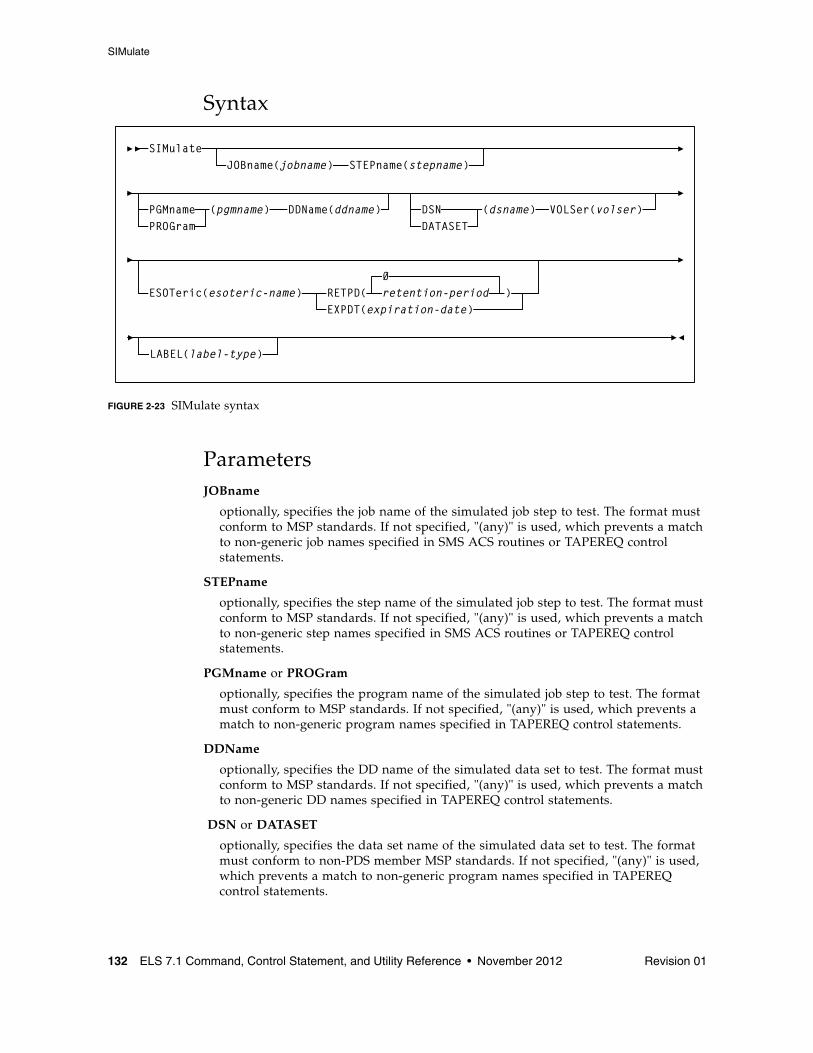
SIMulate
132 ELS 7.1 Command, Control Statement, and Utility Reference • November 2012 Revision 01
Syntax
FIGURE 2-23 SIMulate syntax
ParametersJOBname
optionally, specifies the job name of the simulated job step to test. The format must conform to MSP standards. If not specified, "(any)" is used, which prevents a match to non-generic job names specified in SMS ACS routines or TAPEREQ control statements.
STEPname
optionally, specifies the step name of the simulated job step to test. The format must conform to MSP standards. If not specified, "(any)" is used, which prevents a match to non-generic step names specified in SMS ACS routines or TAPEREQ control statements.
PGMname or PROGram
optionally, specifies the program name of the simulated job step to test. The format must conform to MSP standards. If not specified, "(any)" is used, which prevents a match to non-generic program names specified in TAPEREQ control statements.
DDName
optionally, specifies the DD name of the simulated data set to test. The format must conform to MSP standards. If not specified, "(any)" is used, which prevents a match to non-generic DD names specified in TAPEREQ control statements.
DSN or DATASET
optionally, specifies the data set name of the simulated data set to test. The format must conform to non-PDS member MSP standards. If not specified, "(any)" is used, which prevents a match to non-generic program names specified in TAPEREQ control statements.
JOBname(jobname) STEPname(stepname)
ESOTeric(esoteric-name) RETPD(EXPDT(expiration-date)
0retention-period
SIMulate
LABEL(label-type)
)
VOLSer(volser)DSNDATASET
(dsname)PGMname DDName(ddname)PROGram
(pgmname)
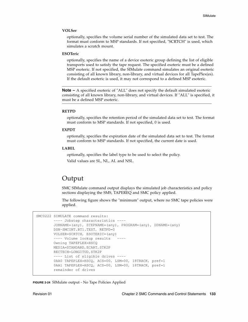
SIMulate
Revision 01 Chapter 2 SMC Commands and Control Statements 133
VOLSer
optionally, specifies the volume serial number of the simulated data set to test. The format must conform to MSP standards. If not specified, "SCRTCH" is used, which simulates a scratch mount.
ESOTeric
optionally, specifies the name of a device esoteric group defining the list of eligible transports used to satisfy the tape request. The specified esoteric must be a defined MSP esoteric. If not specified, the SIMulate command simulates an original esoteric consisting of all known library, non-library, and virtual devices for all TapePlex(es). If the default esoteric is used, it may not correspond to a defined MSP esoteric.
Note – A specified esoteric of "ALL" does not specify the default simulated esoteric consisting of all known library, non-library, and virtual devices. If "ALL" is specified, it must be a defined MSP esoteric.
RETPD
optionally, specifies the retention period of the simulated data set to test. The format must conform to MSP standards. If not specified, 0 is used.
EXPDT
optionally, specifies the expiration date of the simulated data set to test. The format must conform to MSP standards. If not specified, the current date is used.
LABEL
optionally, specifies the label type to be used to select the policy.
Valid values are SL, NL, AL and NSL.
OutputSMC SIMulate command output displays the simulated job characteristics and policy sections displaying the SMS, TAPEREQ and SMC policy applied.
The following figure shows the "minimum" output, where no SMC tape policies were applied.
FIGURE 2-24 SIMulate output - No Tape Policies Applied
SMC0222 SIMULATE command results: ---- Jobstep characteristics ---- JOBNAME=(any), STEPNAME=(any), PROGRAM=(any), DDNAME=(any) DSN-SMCINT.BT1.TEST, RETPD=0 VOLSER=SCRTCH, ESOTERIC=(any) ---- Volume lookup results ---- Owning TAPEPLEX=HSCQ MEDIA=STANDARD,ECART,STK2P RECTECH=LONGITUD,STK2P ---- List of eligible drives ---- 0AA0 TAPEPLEX=HSCQ, ACS=00, LSM=00, 18TRACK, pref=1 0AA1 TAPEPLEX=HSCQ, ACS=00, LSM=00, 18TRACK, pref=1 remainder of drives
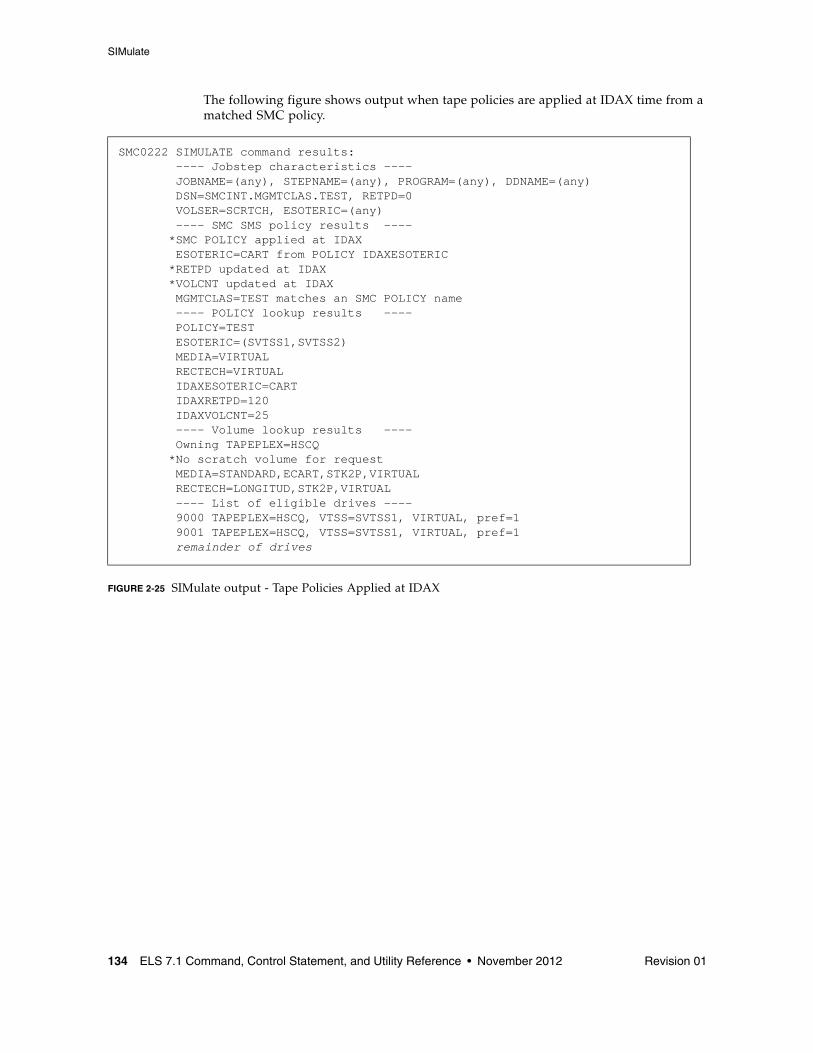
SIMulate
134 ELS 7.1 Command, Control Statement, and Utility Reference • November 2012 Revision 01
The following figure shows output when tape policies are applied at IDAX time from a matched SMC policy.
FIGURE 2-25 SIMulate output - Tape Policies Applied at IDAX
SMC0222 SIMULATE command results: ---- Jobstep characteristics ---- JOBNAME=(any), STEPNAME=(any), PROGRAM=(any), DDNAME=(any) DSN=SMCINT.MGMTCLAS.TEST, RETPD=0 VOLSER=SCRTCH, ESOTERIC=(any) ---- SMC SMS policy results ---- *SMC POLICY applied at IDAX ESOTERIC=CART from POLICY IDAXESOTERIC *RETPD updated at IDAX *VOLCNT updated at IDAX MGMTCLAS=TEST matches an SMC POLICY name ---- POLICY lookup results ---- POLICY=TEST ESOTERIC=(SVTSS1,SVTSS2) MEDIA=VIRTUAL RECTECH=VIRTUAL IDAXESOTERIC=CART IDAXRETPD=120 IDAXVOLCNT=25 ---- Volume lookup results ---- Owning TAPEPLEX=HSCQ *No scratch volume for request MEDIA=STANDARD,ECART,STK2P,VIRTUAL RECTECH=LONGITUD,STK2P,VIRTUAL ---- List of eligible drives ---- 9000 TAPEPLEX=HSCQ, VTSS=SVTSS1, VIRTUAL, pref=1 9001 TAPEPLEX=HSCQ, VTSS=SVTSS1, VIRTUAL, pref=1 remainder of drives
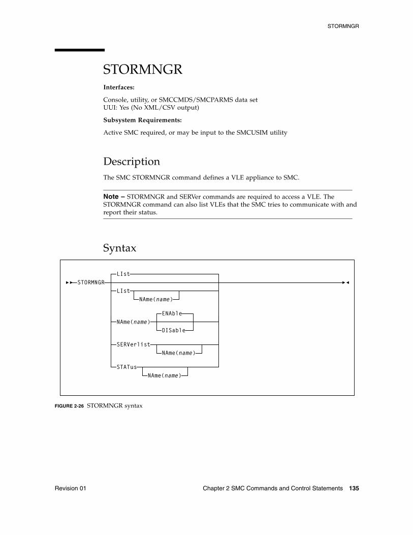
STORMNGR
Revision 01 Chapter 2 SMC Commands and Control Statements 135
STORMNGRInterfaces:
Console, utility, or SMCCMDS/SMCPARMS data setUUI: Yes (No XML/CSV output)
Subsystem Requirements:
Active SMC required, or may be input to the SMCUSIM utility
DescriptionThe SMC STORMNGR command defines a VLE appliance to SMC.
Note – STORMNGR and SERVer commands are required to access a VLE. The STORMNGR command can also list VLEs that the SMC tries to communicate with and report their status.
Syntax
FIGURE 2-26 STORMNGR syntax
STORMNGRLIst
LIstNAme(name)
NAme(name)ENAble
DISable
SERVerlist
STATus
NAme(name)
NAme(name)
STORMNGR
136 ELS 7.1 Command, Control Statement, and Utility Reference • November 2012 Revision 01
ParametersLIst
optionally, lists all or a specific VLE.
NAME
If specified, lists the VLE with the specified name.
NAME
Specifies VLE to be added, modified or listed. If NAme is not specified, then all VLEs are listed.
name
the VLE name, which is also defined to VTCS, and is initially defined by the VLE GUI. The following rules apply:
■ The value must be between 1 and 8 characters in length.
■ The first character must be either an alpha character or digit.
■ The last character must be either an alpha character or digit.
■ Any character between the first and last must be either an alpha character, digit or hyphen.
ENAble
enables the specified VLE. This is the default when new VLE is added.
DISable
disables the specified VLE.
SERVerlist
optionally, lists defined VLEs, their attributes and associated servers. The SERVerlist parameter can also be specified with the NAME parameter to limit the display to a single VLE.
NAME
specifies the VLE name for which servers are to be listed.
name
the VLE name.
STATus
optionally, lists current status of all VLEs or a single named VLE.
TAPEPlex
Revision 01 Chapter 2 SMC Commands and Control Statements 137
TAPEPlexInterfaces:
Console, utility, or SMCCMDS/SMCPARMS data setUUI: Yes (No XML/CSV output)
Subsystem Requirements:
Active SMC required, or may be input to the SMCUSIM utility
DescriptionThe SMC TAPEPlex command defines a TapePlex; a specific Oracle StorageTek tape hardware configuration normally represented by a single CDS. The TAPEPlex command can also list TapePlexes that the SMC tries to communicate with, and report their status.
Note – ■ You must include SMC TAPEPlex commands in either the SMCCMDS or
SMCPARMS data set to define your TapePlexes. If no TAPEPLEX commands are found at SMC startup, then the SMC subsystem terminates and an error message is produced.
When SMC first communicates with an HSC host, this host adopts the TapePlex name specified in the SMCCMDS or SMCPARMS data set and stores it in the CDS. The CDS retains this name unless it is later changed by an SMC Set TapePlex utility command.
■ TAPEPlex and SERVer commands are required to access remote HSC TapePlexes.
■ If a TAPEPlex command is specified, then all TapePlexes must be explicitly defined.
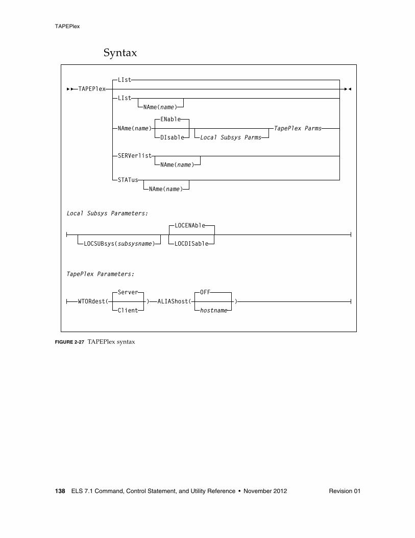
TAPEPlex
138 ELS 7.1 Command, Control Statement, and Utility Reference • November 2012 Revision 01
Syntax
FIGURE 2-27 TAPEPlex syntax
TAPEPlexLIst
LIst
NAme(name)
NAme(name)DIsable Local Subsys Parms
SERVerlistNAme(name)
Local Subsys Parameters:
STATusNAme(name)
TapePlex Parms
LOCSUBsys(subsysname) LOCDISable
LOCENAble
ENable
TapePlex Parameters:
Server
Client)WTORdest( ALIAShost(
OFF
hostname)
TAPEPlex
Revision 01 Chapter 2 SMC Commands and Control Statements 139
ParametersLIst
optionally, lists the specified TapePlex.
NAME
specifies the TapePlex name to be listed.
name
the TapePlex name.
Note – ■ LIst is the default when no parameters are specified on the TAPEPlex command. In
this case, all TapePlexes are listed.
■ LIst may be specified with other parameters. In this case, the named TapePlex is LIsted after the other parameters are processed.
NAME
specifies the TapePlex name to be added, modified, or listed.
name
the TapePlex name. This name is reported in any TapePlex error message. The following rules apply:
■ The value must be between 1 and 8 characters in length.
■ The first character must be either an alpha character or digit.
■ The last character must be either an alpha character or digit.
■ Any character between the first and last must be either an alpha character, digit or hyphen.
ENAble
enables the specified TapePlex to be selected for allocation or mount requests.
DISable
disables the specified TapePlex. The TapePlex is not used for any allocation or mount requests.
LOCSUBsys
specifies a local HSC subsystem.
subsysname
the subsystem name.
LOCENAble
enables the specified HSC subsystem to be used as a local path to the TapePlex.
LOCDISable
disables the specified HSC subsystem. LOCDISable can be used to force the SMC to ignore the local subsystem and access the TapePlex via a remote server
TAPEPlex
140 ELS 7.1 Command, Control Statement, and Utility Reference • November 2012 Revision 01
WTORdest
optionally, specifies the console to which HSC WTOR messages are directed. Refer to the publication Configuring and Managing SMC for messages that apply.
Client
The remote HSC returns selected WTORs to the SMC client without issuing the WTOR message. The SMC client then issues the WTOR to the operator of the system that the SMC executes on. The SMC redrives the mount or dismount request to the server supplying the WTOR response.
Server
WTOR messages are issued on the HSC server console. This is the default.
ALIAShost
optionally, specifies a host alias to be used in communications with the HSC TapePlex.
hostname
a 1-8 character host name.
OFF
The native SMF host name is used in communications with the HSC LIBRARY. This is the default.
SERVerlist
optionally, lists defined TapePlexes, their attributes and associated servers. The SERVerlist parameter may also be specified with the NAME parameter to limit the display to a single TapePlex.
NAME
specifies the TapePlex name for which servers are to be listed.
name
the TapePlex name.
STATus
optionally, lists current status of all TapePlexes, or a single named TapePlex. The TapePlex status indicates whether a TapePlex is active, inactive, or disabled. For an active TapePlex, the status lists the name of the current server or local subsystem. STATus does not perform a RESYNChronize.
NAME
specifies the TapePlex name for which status information is to be listed.
name
the TapePlex name.
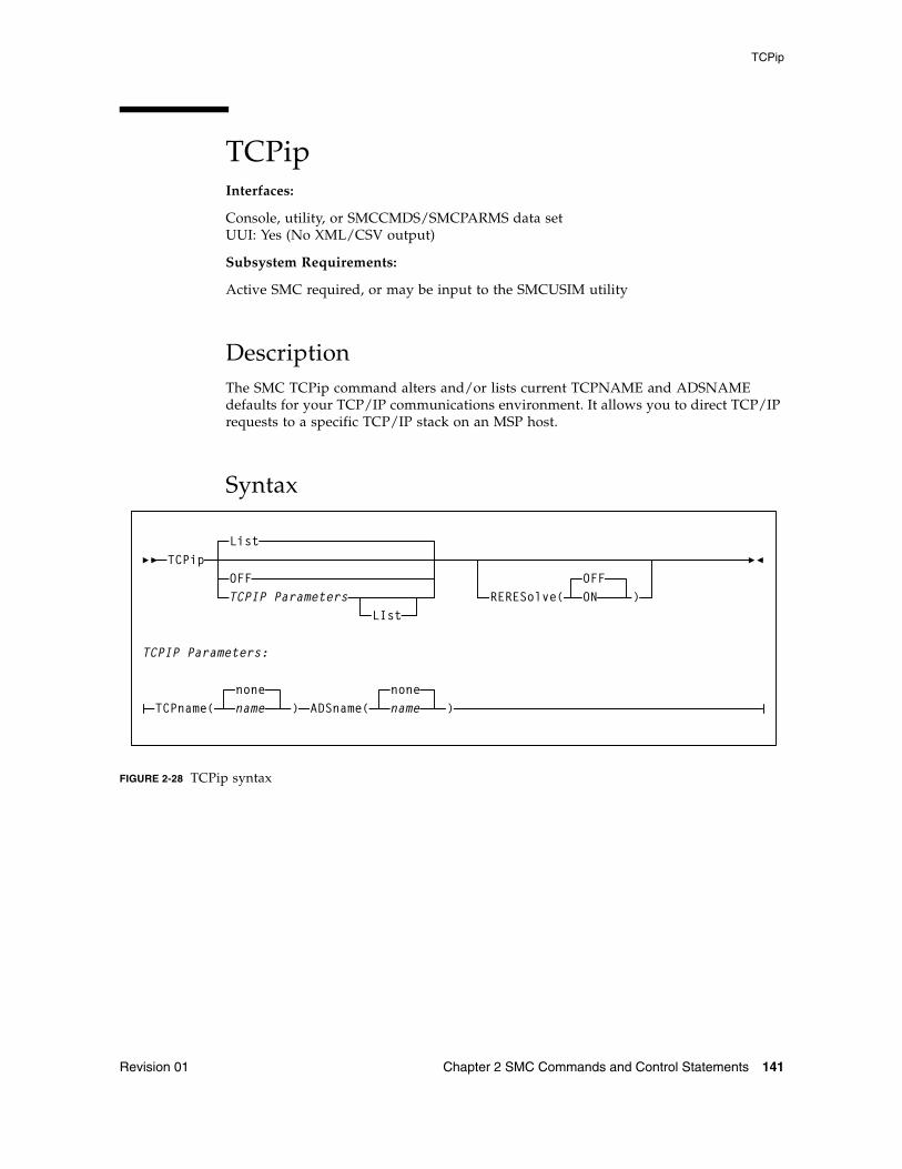
TCPip
Revision 01 Chapter 2 SMC Commands and Control Statements 141
TCPipInterfaces:
Console, utility, or SMCCMDS/SMCPARMS data setUUI: Yes (No XML/CSV output)
Subsystem Requirements:
Active SMC required, or may be input to the SMCUSIM utility
DescriptionThe SMC TCPip command alters and/or lists current TCPNAME and ADSNAME defaults for your TCP/IP communications environment. It allows you to direct TCP/IP requests to a specific TCP/IP stack on an MSP host.
Syntax
FIGURE 2-28 TCPip syntax
TCPipList
OFFTCPIP Parameters
LIst
TCPIP Parameters:
TCPname(nonename ) ADSname(
nonename )
OFFRERESolve( )ON
TCPip
142 ELS 7.1 Command, Control Statement, and Utility Reference • November 2012 Revision 01
ParametersLIst
optionally, lists current TCPNAME and ADSNAME settings. If a PORTrange is specified, LIst also displays currently bound port numbers and the high-water bound port number indicating the largest number of concurrent communication subtasks executing at one time.
■ LIst is the default when no parameters are specified on the TCPip command.
■ LIst may be specified with other parameters. In this case, the LIst is generated after the other parameters are processed.
OFF
optionally, specifies that system defaults are used for client TCP/IP communication.
TCPname
optionally, specifies the TCPNAME value for a specific TCP/IP stack on an MSP host. TCPNAME is the name of the MSP TCP/IP stack. Refer to the Fujitsu publication OS IV TISP Programming Guide for more information about TCPNAME. The default is none.
name
the TCPNAME value
■ If a subsystem name is specified, it must consist of one to four alphanumeric or national (#,@,$) characters, the first character being alphabetic or national.
■ If an address name is specified, it must consist of one to eight alphanumeric or national characters.
ADSname
optionally, specifies the ADSNAME value for a specific TCP/IP stack on an MSP host. ADSNAME is the jobname of the TCP/IP startup job. Refer to the Fujitsu publication TCP/IP for MSP Application Programming Interface Reference for more information about ADSNAME.
name
the ADSNAME value.
RERESolve
optionally, specifies whether SMC attempts to re-resolve the SERVER HOST name after a communication failure.
OFF
SMC does not attempt to re-resolve the server host name. This is the default.
ON
SMC attempts to re-resolve the server host name.
SMC first attempts a retry as specified by the SERVER RETRY parameter. If the error indicates that the IP address may be unavailable, and the RERESolve parameter is ON, SMC then attempts to resolve the HOST name again, and if a new IP address is generated, retries the transaction.
TCPip
Revision 01 Chapter 2 SMC Commands and Control Statements 143
Note – ■ When an SMC mount request to the HSC server results in an outstanding WTOR on
the HSC, the used port number is unavailable until a reply is supplied for the outstanding WTOR. WTOR messages for mount requests are produced on the HSC when TAPEPlex WTORdest(SERVER) is specified, or when TAPEPlex WTORdest(CLIENT) is specified and the HSC mount message is not one returned to the SMC for processing. Refer to the publication Configuring and Managing SMC for messages that apply.
■ The TCPip LIST command may be used to display the high-water port number, indicating the largest number of concurrent communication subtasks executing at one time.
TRace
144 ELS 7.1 Command, Control Statement, and Utility Reference • November 2012 Revision 01
TRaceInterfaces:
Console, utility, or SMCCMDS/SMCPARMS data setUUI: Yes (No XML/CSV output)
Subsystem Requirements:
Active SMC required, or may be input to the SMCUSIM utility
DescriptionThe SMC TRace command enables SMC tracing using the GTF trace facility and optionally provides a snap dump of the address space before and after control block modification.
Note – ■ SMC TRace processing may impact system performance and should be used only as
directed by Oracle StorageTek Software Support.
■ TRace JOBname(jobname) causes SMC traces to be produced for UUI commands issued by the HSC or VTCS subsystem address space when jobname matches the HSC subsystem name. UUI tracing is extremely CPU intensive and should only be used as directed by Oracle StoragTek Software Support.
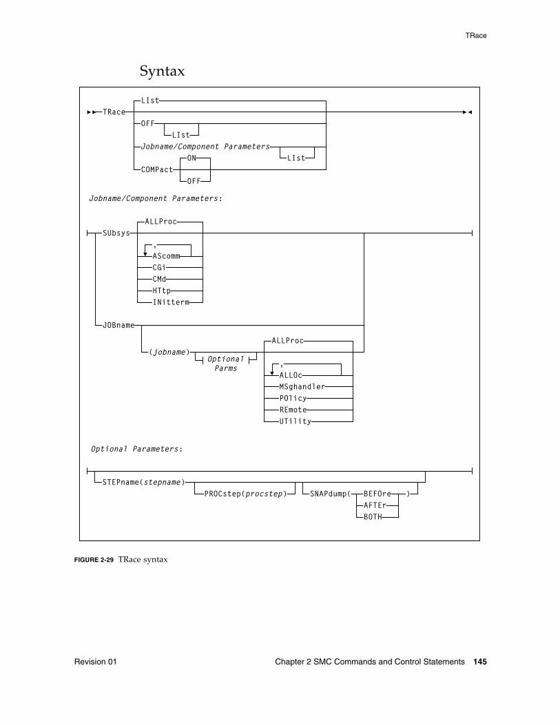
TRace
Revision 01 Chapter 2 SMC Commands and Control Statements 145
Syntax
FIGURE 2-29 TRace syntax
TRaceLIst
OFFLIst
Jobname/Component ParametersLIst
Jobname/Component Parameters:
SUbsys
JOBname
ALLProc
AScommCGiCMdHTtpINitterm
(jobname)ALLProc
OptionalParms
,
,ALLOcMSghandlerPOlicyREmoteUTility
Optional Parameters:
STEPname(stepname)PROCstep(procstep) SNAPdump( BEFOre
AFTErBOTH
)
COMPactON
OFF
TRace
146 ELS 7.1 Command, Control Statement, and Utility Reference • November 2012 Revision 01
ParametersLIst
optionally, lists current SMC trace settings for both the SMC subsystems and SMC components by job name, step name, and PROC step.
■ LIst is the default when no parameters are specified on the TRace command.
■ LIst may be specified with other parameters. In this case, the LIst is generated after the other parameters are processed.
■ If no JOBname is specified, all jobs with SMC components being traced are listed.
■ If JOBname is specified, only those jobs with SMC components being traced whose job name matches the specified job JOBname are listed.
OFF
optionally, disables SMC tracing.
■ If no other parameters are specified, tracing is disabled for all jobs.
■ If only JOBname is specified, tracing is disabled for all entries for that job name.
■ If JOBname, STEPname and PROCstep are specified, tracing is disabled only for the specified entry.
COMPact
Optionally, indicates whether SMC trace output should be produced in "compact" format.
Note – When GTF trace output is produced in this format, you can use the SMC utility program SMCUGTF to reformat the trace to the original SMC trace format. See “Trace Format Utility (SMCUGTF)” on page 671.
ON
SMC trace output is produced in a format that conserves GTF dataset space.This is the default.
OFF
SMC trace output is produced in human readable format.
Jobname/Component ParametersSUbsys
optionally, enables or disables SMC tracing for one or more SMC subsystem components or subtasks.
ALLProc
optionally, enables tracing for all SMC subsystem components and tasks. This is the default if no parameters are specified.
AScomm
optionally, enables tracing for all SMC subsystem ASCOMM Component tasks.
TRace
Revision 01 Chapter 2 SMC Commands and Control Statements 147
CGi
optionally, enables tracing for all SMC subsystem CGI module processing for all connected client requests. To trace CGI module execution for individual client requests, issue a TRace JOBname REMOTE command on the appropriate SMC client.
CMd
optionally, enables tracing for all SMC subsystem Operator Command Component tasks.
HTtp
Optionally, enables tracing for all SMC subsystem HTTP Server Component tasks.
INit
Optionally, enables tracing for all SMC subsystem Initiation/Termination Component tasks.
JOBname
optionally, enables or disables SMC tracing for one or more initiator components in initiators that match the specified jobname, stepname, and procstep name specified. If not specified, tracing information for all jobs is displayed.
jobname
a specific job name
The value entered must be one to eight characters in length. An asterisk (*) can be used as a wildcard when included as the last character. In this case, all jobs whose job names match the characters preceding the asterisk are traced or listed. To trace all jobs, specify TRACE JOB(*).
ALLProc
optionally, enables tracing for all SMC initiator components executing in initiators that match the specified jobname, stepname, and procstep name specified. This is the default if no parameters are specified.
ALLOc
optionally, enables tracing for all SMC Allocation tasks executing in initiators that match the specified jobname, stepname, and procstep name specified.
MSghandler
optionally, enables tracing for all SMC Message Handler Component tasks executing in initiators that match the specified jobname, stepname, and procstep name specified.
POLicy
optionally, enables tracing for SMC POLicy name and selection criteria to the job log of the jobname specified in the TRace command for allocation and mount policies.
Note – NOTE: POLicy tracing does not rely on the GTF trace being active.
TRace
148 ELS 7.1 Command, Control Statement, and Utility Reference • November 2012 Revision 01
REmote
optionally, enables tracing in the remote SMC HTTP Server for requests originating from the jobname, stepname, and procstep name specified.
Note – NOTE: REmote tracing does not rely on the GTF trace being active on the SMC client, but GTF tracing must be active on the corresponding SMC HTTP Server.
UTility
optionally, enables tracing for all SMC Utility Component tasks executing in initiators that match the specified jobname, stepname, and procstep name specified.
Optional ParametersSTEPname
optionally, specifies a step name.
stepname
the step name.
The value entered must be one to eight characters in length. This parameter is only valid if JOBname is also specified.
PROCstep
optionally, specifies a PROC step.
procstep
the PROC step.
The value entered must be one to eight characters in length. This parameter is only valid if JOBname and STEPname are also specified.
SNAPdump
optionally, requests a snap dump.
Note – A snap dump may impact system performance, and should be used only as directed by Oracle StorageTek Software Support.
BEFORe
requests a snap dump before allocation influencing.
AFTEr
requests a snap dump after allocation influencing.
BOTH
requests a snap dump both before and after allocation influencing.
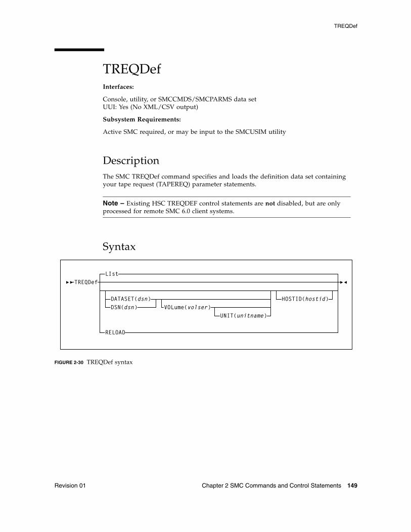
TREQDef
Revision 01 Chapter 2 SMC Commands and Control Statements 149
TREQDefInterfaces:
Console, utility, or SMCCMDS/SMCPARMS data setUUI: Yes (No XML/CSV output)
Subsystem Requirements:
Active SMC required, or may be input to the SMCUSIM utility
DescriptionThe SMC TREQDef command specifies and loads the definition data set containing your tape request (TAPEREQ) parameter statements.
Note – Existing HSC TREQDEF control statements are not disabled, but are only processed for remote SMC 6.0 client systems.
Syntax
FIGURE 2-30 TREQDef syntax
TREQDefLIst
DATASET(dsn)DSN(dsn)
HOSTID(hostid)
RELOAD
VOLume(volser)UNIT(unitname)
TREQDef
150 ELS 7.1 Command, Control Statement, and Utility Reference • November 2012 Revision 01
ParametersLIst
lists information about the definition data set containing TAPEREQ control statements that are currently loaded. Information includes:
■ Data set name■ Member name■ Identifying string (if the data set contains an OPTION TITLE statement)■ Date and time parameters were loaded
LIst is the default when no parameters are specified on the TREQDef command.
DATASET or DSN
optionally, specifies the name of the data set containing the TAPEREQ control statements to be processed and, optionally, an OPTION TITLE control statement.
Note – See “OPTION TITLE Control Statement” on page 515 for more information about the OPTION TITLE control statement.
dsn
the data set name.
This data set can be a fixed length 80-byte sequential data set, or a fixed length 80-byte member of a PDS. If the data set name includes a member name, you must enclose the dsn in quotes. For example:
DATASET(‘YOUR.PDS.DSN(MEMBER)’)
VOLume
optionally, specifies the volume serial number of the DASD volume on which the data set resides. Specify this parameter if the data set is not catalogued.
volser
the volume serial number.
UNIT
optionally, specifies the unit name of the specified VOLume for uncataloged data sets. Requires that VOLume also be specified.
unitname
the unit name.
If not specified, then a unit name of SYSALLDA is the default.
HOSTID
optionally, specifies the hostid from which to execute this control statement. This parameter is valid only for use in PARMLIB, to allow multiple systems to share a parmlib member containing multiple TAPEREQ control statement members.
hostid
the host name(s) from which to execute this control statement. Multiple host names must be separated by commas.
TREQDef
Revision 01 Chapter 2 SMC Commands and Control Statements 151
RELOAD
optionally, reloads the currently loaded TAPEREQ control statements from the same data set. This parameter can be used after a TREQDEF DSN(dsn) command is issued, and changes may then be made to the contents of that data set.
TREQDef
152 ELS 7.1 Command, Control Statement, and Utility Reference • November 2012 Revision 01
TAPEREQ Control StatementThe SMC TAPEREQ control statement specifies a named POLicy to be applied to a particular jobname, stepname, program name, data set or group of data sets.
TAPEREQ statements are placed in the definition data set (DDname) specified by the SMC TREQDEF command. SMC allocation calls on these TAPEREQ statements to help ensure that the correct media type is used to satisfy a request, and that the cartridge is mounted on the appropriate device. TAPEREQ statements must be placed in the definition data set; they cannot be issued as operator commands.
The SMC POLicy command allows you to specify all tape policy specifications in a single named object. It is used with TAPEREQ statements or SMS to associate a named policy with an allocation or mount event.
The TAPEREQ POLicy parameter directs the SMC to reference an associated SMC policy defined by an SMC POLicy command. Refer to the publication Configuring and Managing SMC for more information.
Note – ■ In previous software releases, TAPEREQ parameters were used to define tape
attributes. Refer to the ELS Legacy Interfaces Reference for information about these legacy parameters.
■ See “TREQDef” on page 149 for information about the TREQDEF Command.
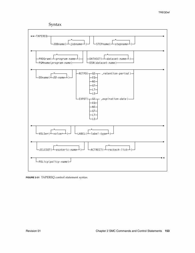
TREQDef
Revision 01 Chapter 2 SMC Commands and Control Statements 153
Syntax
FIGURE 2-31 TAPEREQ control statement syntax
JOBname( jobname*
) STEPname( stepname*
)
TAPEREQ
PROGram( program-name*
PGMname(program-name)DATASET( dataset-name
*
DSN(dataset-name)
RETPD( GE ,retention-periodEQNEGTLTLE
EXPDT( GE ,expiration-dateEQNEGTLTLE
POLicy(policy-name)
VOLSer(*volser )
DDname( DD-name*
)
LABEL(*label-type )
JCLESOT(*esoteric-name ) ACTRECT( rectech-list )
*
) )
)
)
TREQDef
154 ELS 7.1 Command, Control Statement, and Utility Reference • November 2012 Revision 01
Control Statement NameTAPEREQ
initiates the TAPEREQ control statement.
If any of the following conditions exist:
■ There is no TAPEREQ control statement specified in the definition data set to match a request.
■ There is no matching Policy command specifying the MEDia, RECtech, or MODel parameters.
■ There is no definition data loaded.
then the MEDia and RECtech or MODel parameters are set to undefined, which matches all requests. Any available device is eligible for allocation.
Parameters
Note – The JOBname, STEPname, PROGram, and DATASET parameter values can include the following wild card characters:
JOBname
optionally, identifies the job name. If JOBname is not specified, the default value is *.
Note – If you are coding a TAPEREQ statement for DFHSM, you must specify JOBname as a selection criteria. Using DATASET (DSN) can cause unpredictable results.
jobname
the name of the job for which the TAPEREQ control statement is processed.
The TAPEREQ control statement is used only when the specified jobname matches the job name in the request.
STEPname
optionally, specifies the step name. If the STEPname parameter is not specified, the default value is *.
stepname
the name of the step for which the TAPEREQ control statement is processed. The TAPEREQ control statement is used only when the specified stepname matches the step name in the request.
% or ? any single nonblank character
* any character string (length zero to 8) not to exceed one qualification level. For example, A.B.* matches A.B and A.B.C, but does not match A.B.C.D.
** used only in DATASET. Indicates any number of qualifiers (zero or more). Cannot be used with any other characters within a qualifier. For example, A.B.** matches A.B, A.B.C, A.B.C.D, A.B.C.D.E, and so forth.
TREQDef
Revision 01 Chapter 2 SMC Commands and Control Statements 155
PROGram or PGMname
optionally, specifies the program name.
The program name used is the job step program name. The default value is *.
program-name
the program name for which the TAPEREQ control statement is processed.
The TAPEREQ control statement is used only when the specified program-name matches the program name in the request.
DATASET or DSN
optionally, specifies the data set name. The default value is **.
dataset.name
the data set name for which the TAPEREQ control statement is processed.
The TAPEREQ control statement is used only when the specified dataset.name matches the data set name in the request. Rules for RACF and SMS enhanced generic naming apply.
Note – ■ If you are coding a TAPEREQ statement for DFHSM, you must specify JOBname as a
selection criterion. Using DATASET (DSN) can cause unpredictable results.
■ The name you specify on this parameter might be different from the value coded in the DSN parameter on a DD statement. For example, DSN=&&ABC
may be coded on a DD statement if a data set is temporary. However, the actual data set name is not &&ABC. Similarly, if the DSN parameter refers back to a previous DD statement, the data set name is resolved to the referred-to data set. Thus, the data set name referred to must be coded on the DATASET parameter in order for the TAPEREQ control statement to be processed.
DDname
optionally, specifies the DD name of the data set.
DD-name
the DD name.
TREQDef
156 ELS 7.1 Command, Control Statement, and Utility Reference • November 2012 Revision 01
RETPD
optionally, specifies the retention period and the relationship that must exist. If you do not specify either RETPD or EXPDT, the default value is RETPD(GE,0) (any expiration date will match this criterion).
retention-period
the retention period in days for the data set.
Specify the number of days as a 1- to 4-digit decimal number.
EXPDT
optionally, specifies the expiration date and the relationship that must exist.
expiration-date
the expiration date of the data set in YYDDD or YYYY/DDD format.
VOLSer
optionally, identifies a specific volume id. If VOLSer is omitted, the default value is * (any volume). A range of volsers can also be specified.
Using a combination of TAPEREQ statements and POLicy commands, SMC allows you to specify allocation policy based on specific volume serial numbers. Refer to the publication Configuring and Managing SMC for more information.
volser
the volume id.
Note – VOLSer requires that the POLicy parameter is also specified.
LABEL
optionally, specifies the label type to be used to select the policy.
Valid values are SL, NL, AL and NSL.
EQ equal to
NE not equal to
GT greater than
GE greater than or equal to
LT less than
LE less than or equal to
EQ equal to
NE not equal to
GT greater than
GE greater than or equal to
LT less than
LE less than or equal to
TREQDef
Revision 01 Chapter 2 SMC Commands and Control Statements 157
Note – LABEL is valid only if POLicy is also specified.
JCLESOT
optionally, specifies the name of a device esoteric group to be matched with the esoteric supplied in the JCL (or via IDAXESOT).
esoteric-name
the esoteric group name.
This can consist of one to eight alphanumeric or national (#, @, $) characters. A slash (/) or hyphen (-) is also valid.
Note – ■ JCLESOT is valid only if POLicy is also specified.
■ JCLESOT only matches at SSI55 (IDAX) or SSI24 (allocation) time, such that a POLICY containing SUBPOOL and MGMTCLAS will not be selected by this parameter.
The following example illustrates the use of the JCLESOT and ACTRECT parameters:
In this example, jobs that specify UNIT=HVTSS11 (with the matching DSN) will be assigned a VIRTUAL media and rectech at SSI55/SSI24 time. All other data sets will be assigned a media of ECART. At mount message time, if the rectech of the allocated drive is virtual for the matching DSN, then the mgmtclas and subpool from POL1 are assigned. Otherwise, no subpool or mgmtclas is assigned.
ACTRECT
optionally, specifies the recording technique to be used to determine the policy at mount time if the drive where the mount is requested conflicts with the previously selected policy.
For example, if the JCL esoteric prevents selection of a policy recording technique or esoteric substitution, the selected policy might have a scratch subpool inconsistent with the drive where the mount is requested. Specifying ACTRECT allows a default override.
rectech-list
the recording technique list.
TAPEREQ DSN(V047970.JCLESOT.*) JCLESOT(HVTSS11) POLICY(POL1)TAPEREQ DSN(V047970.JCLESOT.*) ACTRECT(V) POLICY(POL1)TAPEREQ DSN(**) POLICY(POL2)
POLICY NAME(POL1) MED(V) REC(V) MGMT(HSCX400) SUBP(SUBP1)POLICY NAME(POL2) MED(ECART)
TREQDef
158 ELS 7.1 Command, Control Statement, and Utility Reference • November 2012 Revision 01
POLicy
optionally, specifies the name of a policy (defined by an SMC POLicy command) to be associated with the allocation or mount request.
policy-name
the policy name.
The SMC uses this policy name to determine all policy information associated with an allocation or mount request.
Note – ■ The named policy must be defined using a POLicy command before the TREQDEF
command is processed.
■ See “POLicy” on page 111 for more information about the SMC POLicy command.
■ Refer to the publication Configuring and Managing SMC for information about creating new POLicy definitions based on existing TAPEREQ statements.
Disabling a TAPEREQ DefinitionUse the following procedure to disable a TAPEREQ definition.
1. Edit the definition data set containing the current TAPEREQ control statements.
2. Delete the parameters of the TAPEREQ control statement you want to disable, or delete the TAPEREQ control statement.
3. Issue the TREQDEF operator command to reload the definition data set.
To disable all TAPEREQ definitions, load a definition data set that contains only one TAPEREQ control statement with no parameters.
Note – If any individual TAPEREQ control statement is in error, the entire set is discarded.
UEXit
Revision 01 Chapter 2 SMC Commands and Control Statements 159
UEXitInterfaces:
Console, utility, or SMCCMDS/SMCPARMS data setUUI: Yes (No XML/CSV output)
Subsystem Requirements:
Active SMC required, or may be input to the SMCUSIM utility
DescriptionUser exits 1, 2, 4, 8, 9, 10, 11, 12, and 13 are invoked and managed by the SMC. The UEXit command defines which load module is invoked for a specific user exit, and whether the user exit is enabled or disabled. HSC user exit formats are supported. The UEXit command specifies the user exit format.
Note – ■ Use this command to load each user exit you wish to use. If a user exit is not loaded,
it will not be called.
■ All user exits are executed on the host where the SMC resides, regardless of where the library server resides.
■ Only one format of a given user exit can be invoked, regardless of the number of TapePlexes the SMC interacts with. The desired format (HSC) is specified using the FORMat parameter.
■ HSC User exit 7 (SLSUX07) is no longer supported.
■ These user exits must reside in a library accessible to the subsystem.
■ User exit information is not honored when an SMC POLicy applies to an allocation, or a mount.
■ Refer to the ELS Legacy Interfaces Reference for information about each user exit.
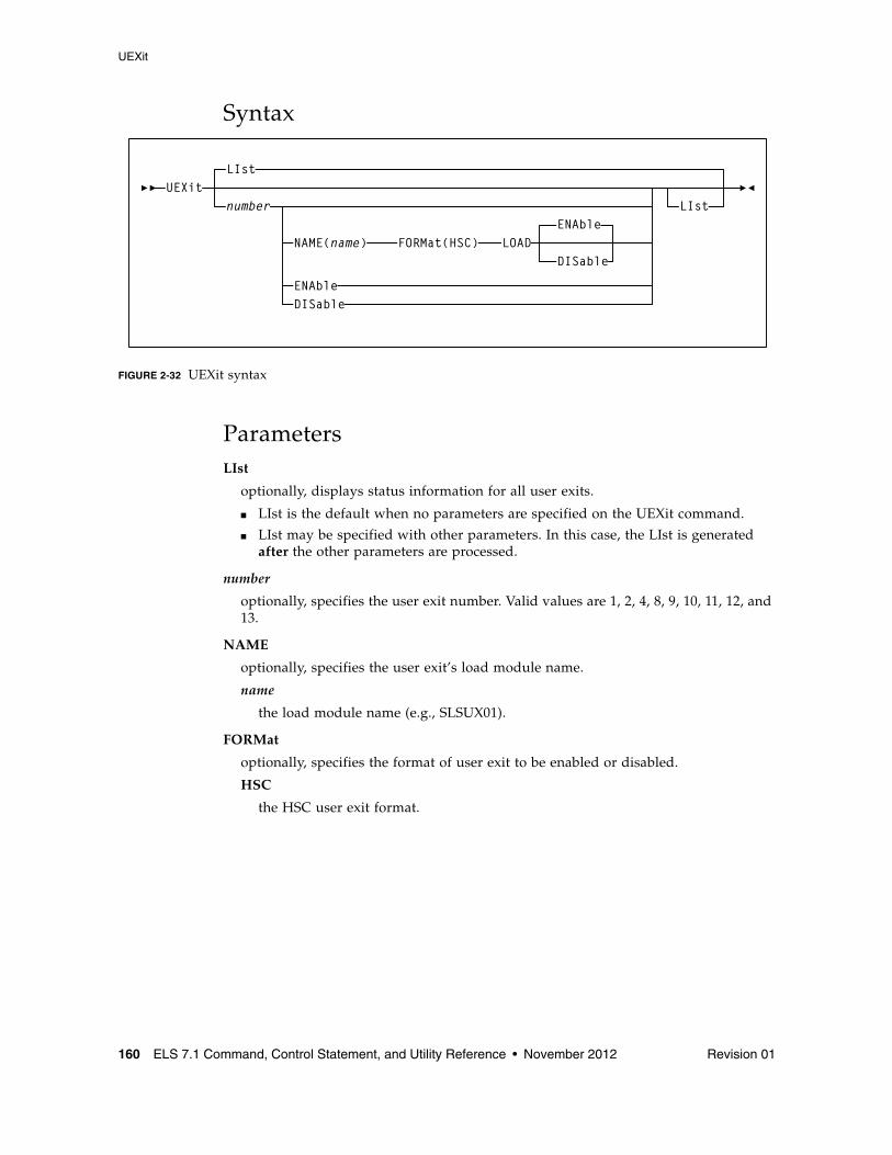
UEXit
160 ELS 7.1 Command, Control Statement, and Utility Reference • November 2012 Revision 01
Syntax
FIGURE 2-32 UEXit syntax
ParametersLIst
optionally, displays status information for all user exits.
■ LIst is the default when no parameters are specified on the UEXit command.
■ LIst may be specified with other parameters. In this case, the LIst is generated after the other parameters are processed.
number
optionally, specifies the user exit number. Valid values are 1, 2, 4, 8, 9, 10, 11, 12, and 13.
NAME
optionally, specifies the user exit’s load module name.
name
the load module name (e.g., SLSUX01).
FORMat
optionally, specifies the format of user exit to be enabled or disabled.
HSC
the HSC user exit format.
UEXit
FORMat(HSC)NAME(name)
LIst
number
ENAbleDISable
ENAble
DISableLOAD
LIst
UEXit
Revision 01 Chapter 2 SMC Commands and Control Statements 161
LOAD
optionally, loads the specified user exit, making it available for use.
Note – ■ If a user exit is not loaded, it will not be called.
■ A subsequent load of a module for the same user exit causes the currently active copy of the load module to be deleted when its use count reaches zero.
ENable
optionally, enables a user exit that was previously disabled due to a problem.
DISable
optionally, disables a user exit to allow for problem resolution.
UNITAttr
162 ELS 7.1 Command, Control Statement, and Utility Reference • November 2012 Revision 01
UNITAttrInterfaces:
Console or SMCCMDS data setUUI: Yes (No XML/CSV output)
Subsystem Requirements:
Active SMC required, or may be input to the SMCUSIM utility
DescriptionThe SMC acquires drive type information from both the MSP/EX operating system and the ELS library control systems (TapePlexes). For the ELS library control systems, HSC data returned from configuration queries is used to augment information returned from the operating system for library-controlled devices.
The SMC UNITAttr command allows you to specify device addresses and attributes to augment operating system information for nonlibrary controlled devices, and effectively ignore configuration information from TapePlexes for specified devices when multiple TapePlexes define the same device address. The SMC UNITAttr command allows you to do the following:
■ Set MODEL=IGNORE for device addresses not available for this host.
■ Specify model types for nonlibrary devices on this host.
■ Specify NOTAPEPlex for a nonlibrary device address or range that is defined to multiple TapePlexes, but for this host the attached devices belong to the specified TapePlex.
■ Specify TapePlex ownership and model for devices that may be referenced by a mount after the SMC is started but before the TapePlex is initialized.
Refer to the publication Configuring and Managing SMC for information about configurations that may require or benefit from the use of UNITAttr commands.
Note – ■ Existing HSC UNITATTR control statements are not disabled. However, UNITATTR
statements for nonlibrary and MODEL(IGNORE) devices are only processed for remote SMC 6.0 client systems. HSC UNITATTR statements for library and virtual drives are not used in any HSC processing after release 6.0.
■ SMC does not support a UNITDEF command. Each UNITATTR command is parsed and processed independently.
■ HSC nonlibrary and MODEL=IGNORE UNITATTR statements are no longer returned to SMC on a configuration query. Therefore, if you use UNITAttrs to bypass devices for allocation or to define the device type of nonlibrary drives, you must define these UNITATTR commands to the SMC subsystem.
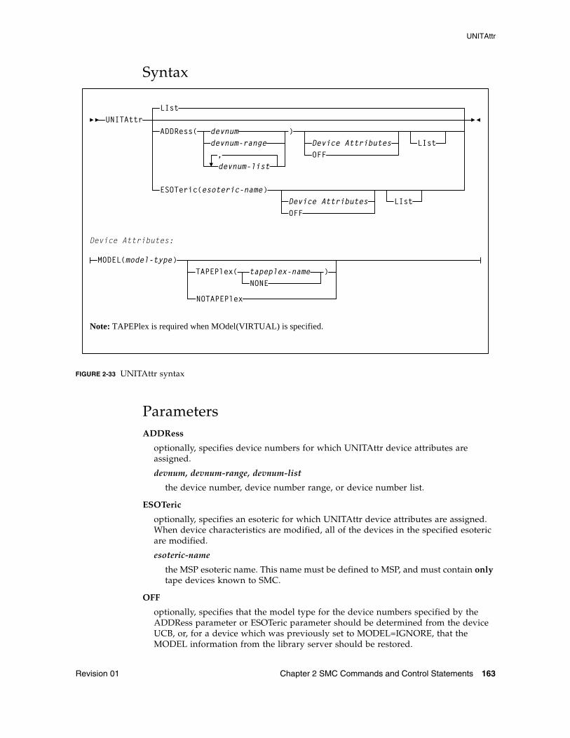
UNITAttr
Revision 01 Chapter 2 SMC Commands and Control Statements 163
Syntax
FIGURE 2-33 UNITAttr syntax
ParametersADDRess
optionally, specifies device numbers for which UNITAttr device attributes are assigned.
devnum, devnum-range, devnum-list
the device number, device number range, or device number list.
ESOTeric
optionally, specifies an esoteric for which UNITAttr device attributes are assigned. When device characteristics are modified, all of the devices in the specified esoteric are modified.
esoteric-name
the MSP esoteric name. This name must be defined to MSP, and must contain only tape devices known to SMC.
OFF
optionally, specifies that the model type for the device numbers specified by the ADDRess parameter or ESOTeric parameter should be determined from the device UCB, or, for a device which was previously set to MODEL=IGNORE, that the MODEL information from the library server should be restored.
UNITAttr
devnum-range
devnum-list
ADDRess( devnumdevnum-range
)
,
TAPEPlex(NONEtapeplex-name )
LIst
Device AttributesOFF
LIst
ESOTeric(esoteric-name)Device AttributesOFF
LIst
Device Attributes:
MODEL(model-type)
NOTAPEPlex
Note: TAPEPlex is required when MOdel(VIRTUAL) is specified.
UNITAttr
164 ELS 7.1 Command, Control Statement, and Utility Reference • November 2012 Revision 01
LIst
lists the UNITAttr model information for the device numbers specified by the ADDRess or ESOTeric parameter.
device attributes:
MOdel
optionally, specifies the model type of the transport to be assigned the device numbers specified by the ADDRess parameter.
model-type
the model type.
See Appendix A, “MEDia, RECtech, and MODel Values” for a list of valid model-type values.
TAPEPlex
optionally, specifies the name of a TapePlex to be associated with the drive before communication is established.
Note – TAPEPlex is required when MOdel(VIRTUAL) is specified. MOdel(VIRTUAL) drives cannot exist as "non-library" devices.
TapePlex-name
the TapePlex name.
If specified, this name must match a TapePlex name defined in a TAPEPlex command.
NONE
optionally, removes the TapePlex association from the specified device addresses.
NOTAPEPlex
optionally, specifies that the specified address or address range are nonlibrary devices, even when configuration queries from ELS library control systems indicate that the device is library controlled. Use this parameter when a local nonlibrary device address overlaps a TapePlex owned device that is not accessible from his host.
Note – ■ When a MOdel is specified with TAPEPlex, the configuration query model
information returned from the TapePlex is assumed to be the “real” or “correct” model, and it overrides any MOdel specified in the UNITAttr command.
■ If TAPEPlex is specified for an address, but that address is not returned from the configuration query for that TapePlex, an error message is issued, but the erroneous TapePlex ownership remains with the specified device address. As a result, any mounts destined for the specified device address are not automated and are rejected by the specified TapePlex.
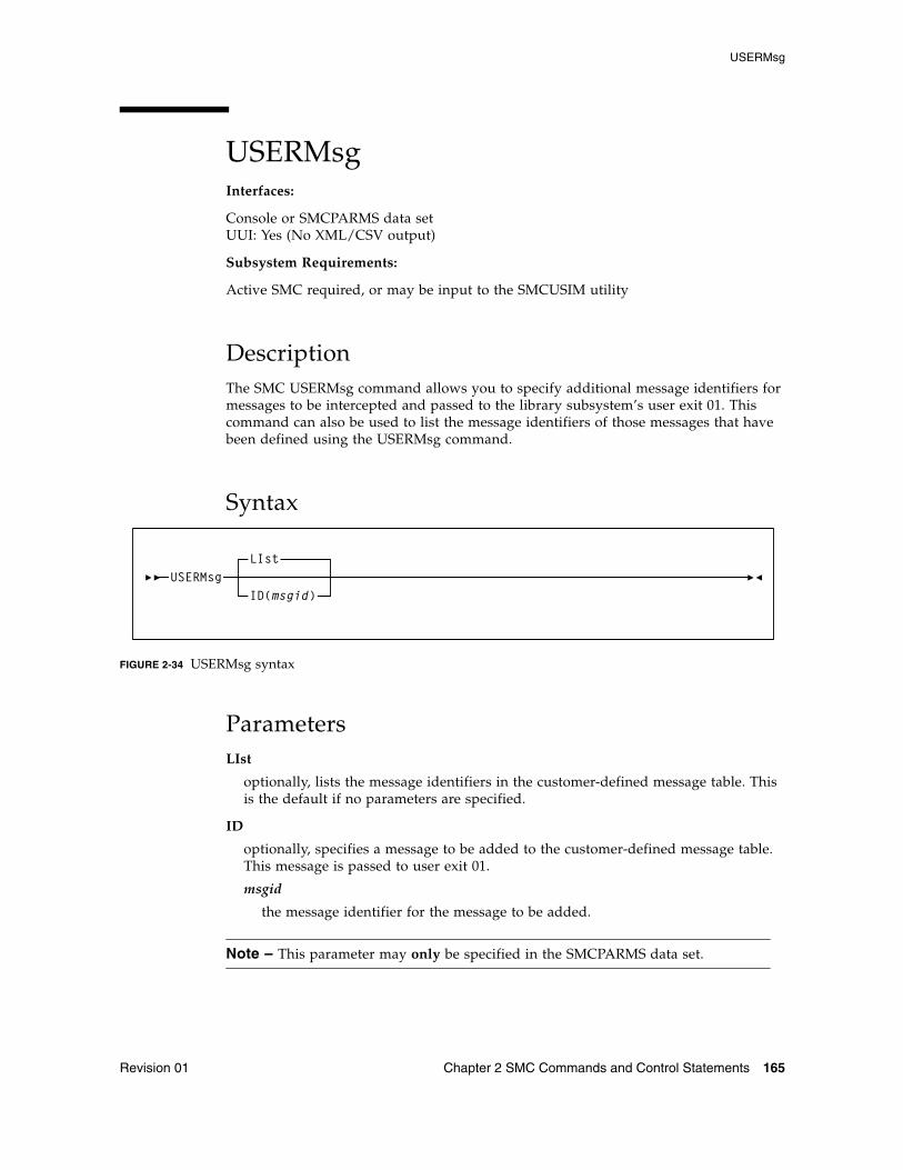
USERMsg
Revision 01 Chapter 2 SMC Commands and Control Statements 165
USERMsgInterfaces:
Console or SMCPARMS data setUUI: Yes (No XML/CSV output)
Subsystem Requirements:
Active SMC required, or may be input to the SMCUSIM utility
DescriptionThe SMC USERMsg command allows you to specify additional message identifiers for messages to be intercepted and passed to the library subsystem’s user exit 01. This command can also be used to list the message identifiers of those messages that have been defined using the USERMsg command.
Syntax
FIGURE 2-34 USERMsg syntax
ParametersLIst
optionally, lists the message identifiers in the customer-defined message table. This is the default if no parameters are specified.
ID
optionally, specifies a message to be added to the customer-defined message table. This message is passed to user exit 01.
msgid
the message identifier for the message to be added.
Note – This parameter may only be specified in the SMCPARMS data set.
USERMsgID(msgid)
LIst
USERMsg
166 ELS 7.1 Command, Control Statement, and Utility Reference • November 2012 Revision 01
Revision 01 167
CHAPTER
3
HSC and VTCS Commands and Control Statements
This chapter contains reference information about HSC and VTCS commands and control statements.
Note – ■ Control statements that are loaded by an operator command are described along
with that command. Other control statements, including those specified in the PARMLIB data set, are described independently.
■ Certain HSC and VTCS commands are described in the ELS Legacy Interfaces Reference. These commands were introduced in a pre-ELS software release and their functionality has been replaced in ELS. These commands are supported by ELS, however, this support will end in a future release.
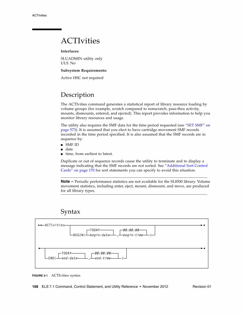
ACTIvities
168 ELS 7.1 Command, Control Statement, and Utility Reference • November 2012 Revision 01
ACTIvitiesInterfaces:
SLUADMIN utility onlyUUI: No
Subsystem Requirements:
Active HSC not required
DescriptionThe ACTIvities command generates a statistical report of library resource loading by volume groups (for example, scratch compared to nonscratch, pass-thru activity, mounts, dismounts, entered, and ejected). This report provides information to help you monitor library resources and usage.
The utility also requires the SMF data for the time period requested (see “SET SMF” on page 573). It is assumed that you elect to have cartridge movement SMF records recorded in the time period specified. It is also assumed that the SMF records are in sequence by:
■ SMF ID■ date■ time, from earliest to latest.
Duplicate or out of sequence records cause the utility to terminate and to display a message indicating that the SMF records are not sorted. See “Additional Sort Control Cards” on page 170 for sort statements you can specify to avoid this situation.
Note – Periodic performance statistics are not available for the SL8500 library. Volume movement statistics, including enter, eject, mount, dismount, and move, are produced for all library types.
Syntax
FIGURE 3-1 ACTIvities syntax
ACTIvities
BEGIN(TODAYbegin-date ,
00:00:00begin-time )
END(TODAYend-date ,
00:00:00end-time )
ACTIvities
Revision 01 Chapter 3 HSC and VTCS Commands and Control Statements 169
ParametersBEGIN
optionally, specifies the beginning of the period for the activities analysis.
begin-date
the starting date of the analysis, expressed in mm/dd/yy or yyyymmdd format.
Note – When using the mm/dd/yy format, specify a yy value of 71 or greater to indicate a 20th century (19xx) date. Specify a yy value of 70 or less to indicate a 21st century (20xx) date. To avoid confusion, you are encouraged to use the yyyymmdd date format.
TODAY
the default date.
begin-time
the beginning time-of-day (24-hour value), expressed in hh:mm:ss format.
The allowable range for the begin-time and end-time parameters is 00:00:00 to 24:00:00. The default value is 00:00:00.
Examples:
In each of the following examples, activity reporting begins on October 27, 2008 at midnight.
BEGIN(10/27/08,00:00:00) BEGIN(20081027,00:00:00) BEGIN(TODAY,00:00:00) BEGIN(,00:00:00)
END
optionally, specifies the end of the period for the activities analysis.
end-date
the ending date of the analysis, expressed in mm/dd/yy or yyyymmdd format. If begin-date is specified, end-date must be in the same format.
Note – When using the mm/dd/yy format, specify a yy value of 71 or greater to indicate a 20th century (19xx) date. Specify a yy value of 70 or less to indicate a 21st century (20xx) date. To avoid confusion, you are encouraged to use the yyyymmdd date format.
ACTIvities
170 ELS 7.1 Command, Control Statement, and Utility Reference • November 2012 Revision 01
TODAY
is the default date.
end-time
the ending time-of-day (24-hour value), expressed in hh:mm:ss format.
The allowable range for the begin-time and end-time parameters is 00:00:00 to 24:00:00. The default value is 23:59:59.
Examples:
END(10/27/08,18:00:00) END(2008501,11:30:00) END(TODAY,23:29:00) END(,23:59:59)
Additional JCL Requirements In addition to the required JCL definition statements described in “Invoking SLUADMIN” on page 674, the following definition statements apply to the ACTIvities JCL:
SLSSMF
SMF data which the utility reports against. This may be a number of data sets concatenated from oldest to newest. This is an off-loaded copy of the active SMF data sets, created by the SMF dump utility IFASMFDP.
Additional Sort Control CardsYou must specify several additional control cards in the SYSIN portion of the SYELSORT JCL to make sure SMF records are sorted.
Note – In the ‘‘INCLUDE COND’’ statement, the SMF type setting, shown as ‘‘X’xx’’’ above, is supplied by the user. The default setting is ‘‘FF’’ (SMF type 255).
//SYSIN DD* INCLUDE COND=(6,1,BI,EQ,X’xx’) SORT FIELDS=(15,4,CH,A,11,4,PD,A,7,4,BI,A) SUM FIELDS=NONE
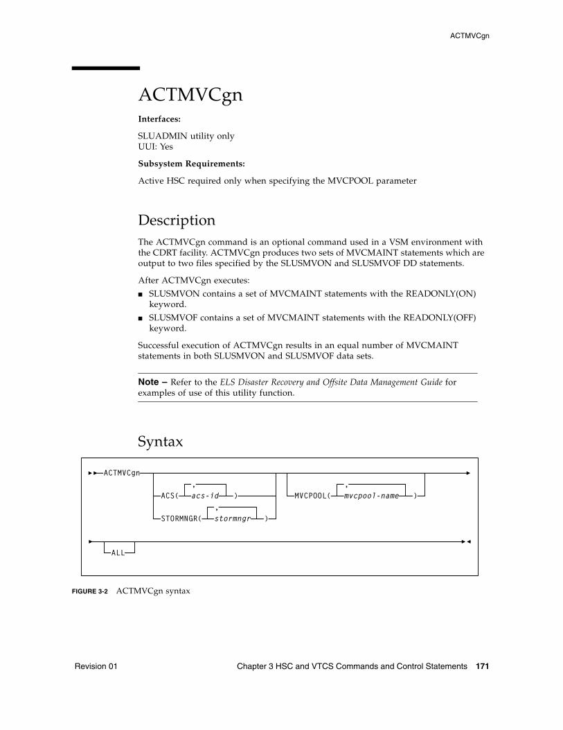
ACTMVCgn
Revision 01 Chapter 3 HSC and VTCS Commands and Control Statements 171
ACTMVCgnInterfaces:
SLUADMIN utility onlyUUI: Yes
Subsystem Requirements:
Active HSC required only when specifying the MVCPOOL parameter
DescriptionThe ACTMVCgn command is an optional command used in a VSM environment with the CDRT facility. ACTMVCgn produces two sets of MVCMAINT statements which are output to two files specified by the SLUSMVON and SLUSMVOF DD statements.
After ACTMVCgn executes:
■ SLUSMVON contains a set of MVCMAINT statements with the READONLY(ON) keyword.
■ SLUSMVOF contains a set of MVCMAINT statements with the READONLY(OFF) keyword.
Successful execution of ACTMVCgn results in an equal number of MVCMAINT statements in both SLUSMVON and SLUSMVOF data sets.
Note – Refer to the ELS Disaster Recovery and Offsite Data Management Guide for examples of use of this utility function.
Syntax
FIGURE 3-2 ACTMVCgn syntax
ACTMVCgn
ACS(,acs-id ) MVCPOOL(
,)
STORMNGR( stormngr,
)
mvcpool-name
ALL
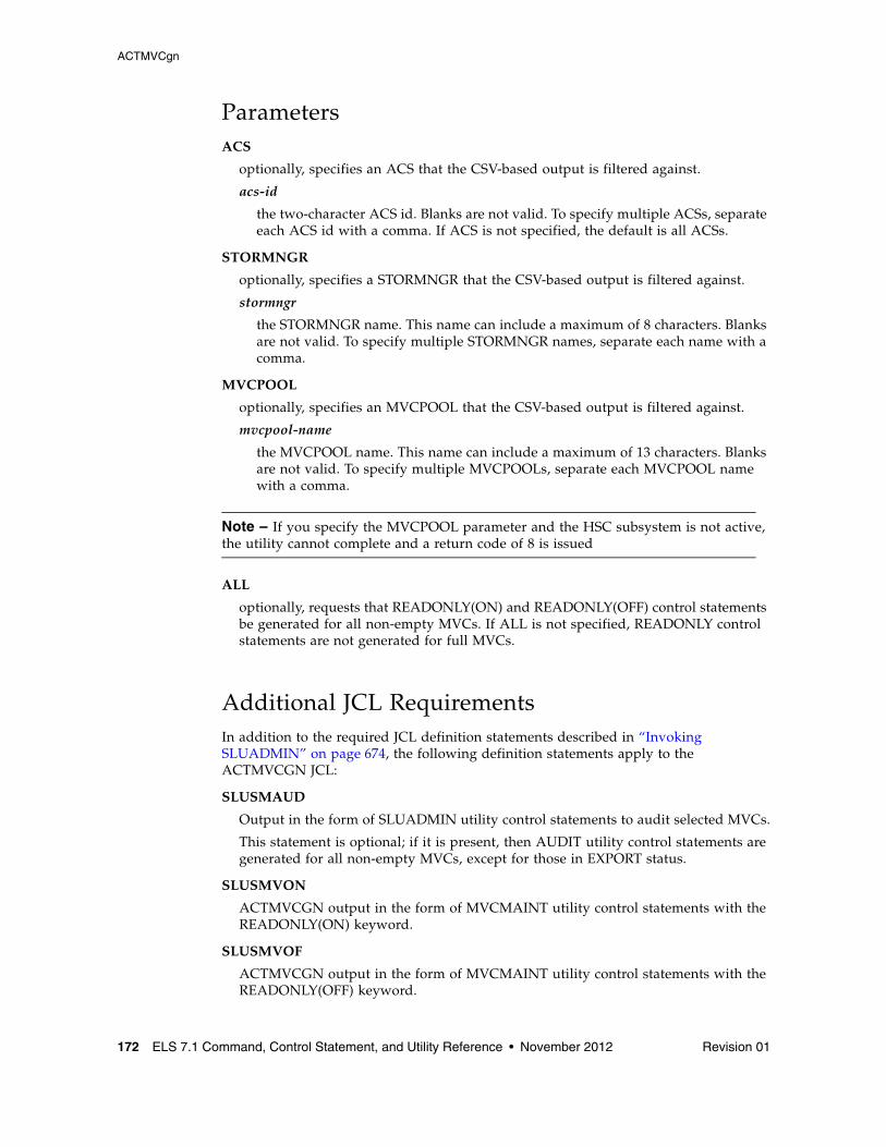
ACTMVCgn
172 ELS 7.1 Command, Control Statement, and Utility Reference • November 2012 Revision 01
ParametersACS
optionally, specifies an ACS that the CSV-based output is filtered against.
acs-id
the two-character ACS id. Blanks are not valid. To specify multiple ACSs, separate each ACS id with a comma. If ACS is not specified, the default is all ACSs.
STORMNGR
optionally, specifies a STORMNGR that the CSV-based output is filtered against.
stormngr
the STORMNGR name. This name can include a maximum of 8 characters. Blanks are not valid. To specify multiple STORMNGR names, separate each name with a comma.
MVCPOOL
optionally, specifies an MVCPOOL that the CSV-based output is filtered against.
mvcpool-name
the MVCPOOL name. This name can include a maximum of 13 characters. Blanks are not valid. To specify multiple MVCPOOLs, separate each MVCPOOL name with a comma.
Note – If you specify the MVCPOOL parameter and the HSC subsystem is not active, the utility cannot complete and a return code of 8 is issued
ALL
optionally, requests that READONLY(ON) and READONLY(OFF) control statements be generated for all non-empty MVCs. If ALL is not specified, READONLY control statements are not generated for full MVCs.
Additional JCL RequirementsIn addition to the required JCL definition statements described in “Invoking SLUADMIN” on page 674, the following definition statements apply to the ACTMVCGN JCL:
SLUSMAUD
Output in the form of SLUADMIN utility control statements to audit selected MVCs.
This statement is optional; if it is present, then AUDIT utility control statements are generated for all non-empty MVCs, except for those in EXPORT status.
SLUSMVON
ACTMVCGN output in the form of MVCMAINT utility control statements with the READONLY(ON) keyword.
SLUSMVOF
ACTMVCGN output in the form of MVCMAINT utility control statements with the READONLY(OFF) keyword.
ARCHive
Revision 01 Chapter 3 HSC and VTCS Commands and Control Statements 173
ARCHiveInterfaces:
Utility onlyUUI: Yes
Subsystem Requirements:
Active HSC not required
DescriptionThe ARCHive command archives VTVs, moving them to MVCs in a different Storage Class.
Syntax
FIGURE 3-3 ARCHive syntax
ARCHiveMGMTclas(mgmt-class-name1...mgmt-class-namen)VTV(vtv-list | vtv-range)
MAXMVC(nn) CONMVC(nn) ELAPSE(nnnn) POLICYdd(ddname)MOVEVTV
ARCHive
174 ELS 7.1 Command, Control Statement, and Utility Reference • November 2012 Revision 01
ParametersMGMTclas
optionally, specifies one or more Management Classes that define Archive Management Policies.
mgmt-class-name1...mgmt-class-namen
one or more Management Classes.
VTV
optionally, specifies a list or range of VTVs.
vtv-list | vtv-range
A list or range of VTVs.
Note – If you do not specify a value for MGMTclas or VTV, VTCS scans (or processes) all VTVs.
MAXMVC(nn)
optionally, specifies the maximum number of MVCs that will be processed by a single archive task.
Valid values are 1 to 98. If not specified the CONFIG RECLAIM value (or default) is used. This parameter is ignored if MOVEVTV is not specified.
CONMVC(nn)
optionally, specifies the maximum number of MVCs that VTCS concurrently processes during subsequent recall and migrate operations.
Valid values are 1 to 99. If not specified the CONFIG RECLAIM value (or default) is used. This parameter is ignored if MOVEVTV is not specified.
ELAPSE(nnnn)
optionally, specifies the maximum time for the archive in minutes. If the maximum time expires, VTCS issues message SLS6682I. If there are no MVCs currently mounted, archive stops when the ELAPSE value is reached. If any MVCs are currently mounted when the ELAPSE value is reached, archive processes the mounted MVCs and then stops.
Valid values are 1 to 1440. If not specified, there is no time limit on the archive process. This parameter is ignored if MOVEVTV is not specified.
POLICYdd(ddname)
optionally, specifies the ddname of a file containing an alternate MGMTclas statement.
Note – POLICYdd and MOVEVTV are mutually exclusive.
MOVEVTV
optionally, archive VTVs per the currently active Management Policies as specified by the MGMTclas statements that apply to the VTVs specified by MGMTclas or VTV. If you do not specify MOVEVTV, only a report is generated.
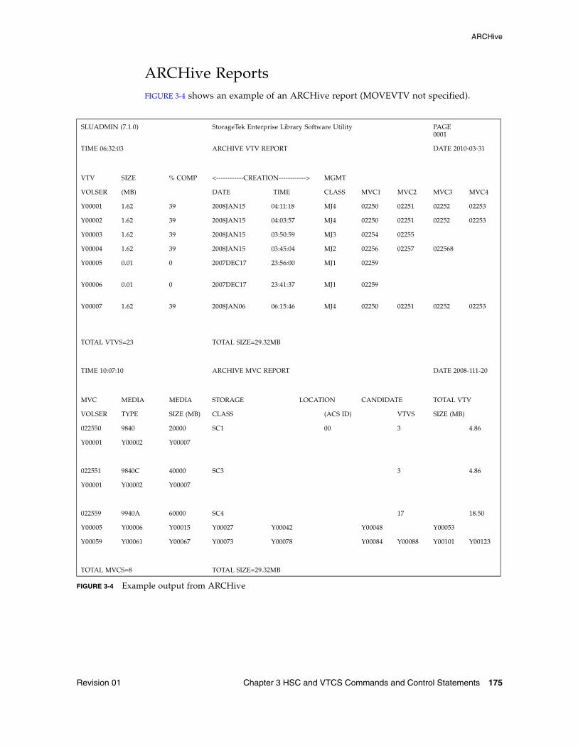
ARCHive
Revision 01 Chapter 3 HSC and VTCS Commands and Control Statements 175
ARCHive ReportsFIGURE 3-4 shows an example of an ARCHive report (MOVEVTV not specified).
FIGURE 3-4 Example output from ARCHive
SLUADMIN (7.1.0) StorageTek Enterprise Library Software Utility PAGE 0001
TIME 06:32:03 ARCHIVE VTV REPORT
DATE 2010-03-31
VTV SIZE % COMP <------------CREATION------------> MGMT
VOLSER (MB) DATE TIME CLASS MVC1 MVC2 MVC3 MVC4
Y00001 1.62 39 2008JAN15 04:11:18 MJ4 02250 02251 02252 02253
Y00002 1.62 39 2008JAN15 04:03:57 MJ4 02250 02251 02252 02253
Y00003 1.62 39 2008JAN15 03:50:59 MJ3 02254 02255
Y00004 1.62 39 2008JAN15 03:45:04 MJ2 02256 02257 022568
Y00005 0.01 0 2007DEC17 23:56:00 MJ1 02259
Y00006 0.01 0 2007DEC17 23:41:37 MJ1 02259
Y00007 1.62 39 2008JAN06 06:15:46 MJ4 02250 02251 02252 02253
TOTAL VTVS=23 TOTAL SIZE=29.32MB
TIME 10:07:10 ARCHIVE MVC REPORT
DATE 2008-111-20
MVC MEDIA MEDIA STORAGE LOCATION CANDIDATE TOTAL VTV
VOLSER TYPE SIZE (MB) CLASS (ACS ID) VTVS SIZE (MB)
022550 9840 20000 SC1 00 3 4.86
Y00001 Y00002 Y00007
022551 9840C 40000 SC3 3 4.86
Y00001 Y00002 Y00007
022559 9940A 60000 SC4 17 18.50
Y00005 Y00006 Y00015 Y00027 Y00042 Y00048 Y00053
Y00059 Y00061 Y00067 Y00073 Y00078 Y00084 Y00088 Y00101 Y00123
TOTAL MVCS=8 TOTAL SIZE=29.32MB
ARCHive
176 ELS 7.1 Command, Control Statement, and Utility Reference • November 2012 Revision 01
ARCHIVE Report FieldsThe following list describes the ARCHive VTV report fields. This section of the report is followed by a total line showing the number of candidate VTVs and the size in MB to be recalled and re-migrated.
VTV Volser
the VTV volser.
Size (MB)
the uncompressed size of the VTV (MB). <MOUNT> indicates that the VTV was mounted when the report ran. <FENCED> indicates that the VTV’s state is unknown. If <FENCED> appears, contact Oracle StorageTek Software Support.
Comp %
the VTV compression percentage achieved. This is the difference between the uncompressed and compressed VTV size expressed as a percentage of the uncompressed VTV size. For example if a 100MB VTV compresses to 40MB then the compression% will be given as 60%. A compression of 0% indicates that no compression was possible on the VTV.
Creation Date and Time
the date and time that the VTV was created.
MGMT Class
the name of the Management Class for the VTV specified.
MVC1, MVC2, MVC3, MVC4
the MVC(s) that contain the VTV. If all of these fields are empty, the VTV has not been migrated or consolidated. If 1 or more of these fields list an MVC volser, the VTV was migrated to each of these MVCs.
ARCHive
Revision 01 Chapter 3 HSC and VTCS Commands and Control Statements 177
MVC Report FieldsThe following list describes the ARCHive MVC report fields. The data for each MVC is followed by one or more VTV volsers with copies on the MVC. This section of the report is followed by a total line showing the number of candidate MVCs and the size in MB to be recalled and re-migrated.
MVC Volser
the MVC volser.
MVC Media Type
the MVC type.
Media Size (MB)
the size of the MVC (MB). This will only be determined after VTCS has used an MVC. “UNKNOWN” appears in this field until VTCS migrates a VTV to the MVC.
Storage Class
the MVC’s Storage Class.
Candidate VTVs
the number of candidate VTVs on the MVC.
Total VTV Size (MB)
the size of all candidate VTVs on the MVC in MBs.
Location (ACS ID)
the ACS where the MVC resides. If blank, the MVC is not currently in an ACS.
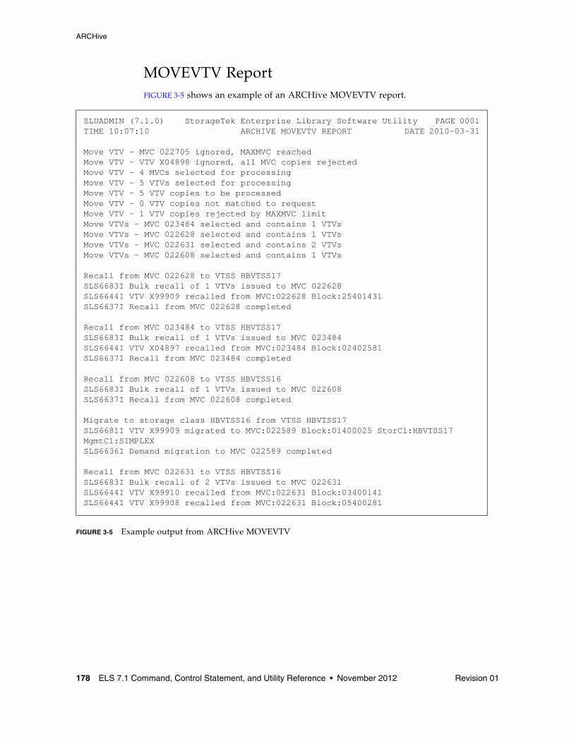
ARCHive
178 ELS 7.1 Command, Control Statement, and Utility Reference • November 2012 Revision 01
MOVEVTV ReportFIGURE 3-5 shows an example of an ARCHive MOVEVTV report.
FIGURE 3-5 Example output from ARCHive MOVEVTV
SLUADMIN (7.1.0) StorageTek Enterprise Library Software Utility PAGE 0001TIME 10:07:10 ARCHIVE MOVEVTV REPORT DATE 2010-03-31
Move VTV - MVC 022705 ignored, MAXMVC reachedMove VTV - VTV X04898 ignored, all MVC copies rejectedMove VTV - 4 MVCs selected for processingMove VTV - 5 VTVs selected for processingMove VTV - 5 VTV copies to be processedMove VTV - 0 VTV copies not matched to requestMove VTV - 1 VTV copies rejected by MAXMVC limitMove VTVs - MVC 023484 selected and contains 1 VTVsMove VTVs - MVC 022628 selected and contains 1 VTVsMove VTVs - MVC 022631 selected and contains 2 VTVsMove VTVs - MVC 022608 selected and contains 1 VTVs
Recall from MVC 022628 to VTSS HBVTSS17SLS6683I Bulk recall of 1 VTVs issued to MVC 022628SLS6644I VTV X99909 recalled from MVC:022628 Block:25401431SLS6637I Recall from MVC 022628 completed Recall from MVC 023484 to VTSS HBVTSS17SLS6683I Bulk recall of 1 VTVs issued to MVC 023484SLS6644I VTV X04897 recalled from MVC:023484 Block:02402581SLS6637I Recall from MVC 023484 completed Recall from MVC 022608 to VTSS HBVTSS16SLS6683I Bulk recall of 1 VTVs issued to MVC 022608SLS6637I Recall from MVC 022608 completed Migrate to storage class HBVTSS16 from VTSS HBVTSS17SLS6681I VTV X99909 migrated to MVC:022589 Block:01400025 StorCl:HBVTSS17 MgmtCl:SIMPLEXSLS6636I Demand migration to MVC 022589 completed
Recall from MVC 022631 to VTSS HBVTSS16SLS6683I Bulk recall of 2 VTVs issued to MVC 022631SLS6644I VTV X99910 recalled from MVC:022631 Block:03400141SLS6644I VTV X99908 recalled from MVC:022631 Block:05400281
AUDit
Revision 01 Chapter 3 HSC and VTCS Commands and Control Statements 179
AUDitInterfaces:
Utility onlyUUI: Yes, when MVC or VTSS is specified
Subsystem Requirements:
■ Active HSC/VTCS (AUDit MVC, VTSS, or INVLDMIR)
■ Active HSC at FULL service level (all others)
DescriptionThe AUDit command performs a volume inventory audit for the following:
■ ACS or LSM■ One or more specified LSMs within an ACS ■ One or more panels within an LSM■ One or more rows within a panel■ One or more columns (cells) within a row ■ One or more VTSSs■ One or more MVCs
Optional parameters allow you to do the following:
■ Update the library control data set to reflect cartridges observed.■ Produce a discrepancy list and do not update the control data set.
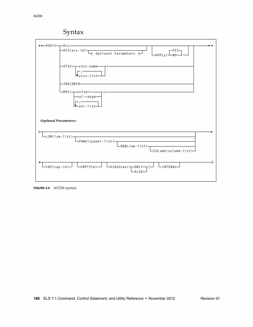
AUDit
180 ELS 7.1 Command, Control Statement, and Utility Reference • November 2012 Revision 01
Syntax
FIGURE 3-6 AUDit syntax
Optional Parameters APPLy(YESNO )
Optional Parameters:
LSM(lsm-list)PANel(panel-list)
ROW(row-list)COLumn(column-list)
CAP(cap-id) EMPTYCel DIAGScan( ONLYALSO
) INTRANs
VTSS( vtss-name
vtss-list,
)
MVC( volservol-range
vol-list,
)
INVLDMIR
AUDit ALLACS(acs-id)
AUDit
Revision 01 Chapter 3 HSC and VTCS Commands and Control Statements 181
Parameters (Real Volume Audit)ALL
optionally, specifies that the total library is to be audited.
ACS
optionally, specifies that only a particular ACS in the library is to be audited.
acs-id
a two digit decimal ACS identifier from 00-99.
Note – If the ACS parameter is specified with no LSM parameters, the audit is performed on all LSMs in the ACS at the same time (multitasking). To audit only certain LSMs within an ACS, you must code the LSM parameter with the LSM or list of LSMs.
APPly
optionally, specifies whether the control data set is updated.
YES
specifies that the Audit operation ejects cartridges with duplicate VOLSERs, unreadable or illegal external media labels, and/or new cartridges unreadable external labels, and performs corrective actions to the control data set to reflect the physical contents of storage cells. YES is the default.
NO
specifies that a discrepancy listing is produced, and the control data set is not updated.
ACS Optional ParametersThe following parameters may only be specified with ACS:
LSM
optionally, specifies that only certain LSMs within the specified ACS are to be audited.
lsm-list
a single LSM number or a list of LSM numbers. An LSM number is a hexadecimal value (00-17).
An LSM range is not allowed. If a list is specified, the elements must be separated by blanks or commas, and the entire list enclosed in parentheses.
PANel
optionally, specifies that only certain panels within an LSM are to be audited.
panel-list
panel-list may be a single panel or a list of panels. Panel ranges are not allowed. If a list is specified, the elements must be separated by blanks or commas, and the entire list enclosed in parentheses.
AUDit
182 ELS 7.1 Command, Control Statement, and Utility Reference • November 2012 Revision 01
Note – If this parameter is specified, the LSM parameter may contain only one LSM number.
A panel-list element is a one or two digit decimal number, specific to the LSM type. See “Panels” on page 721 for a list of valid values.
Note – ■ The SL3000 library has static panels numbers starting with the left-most back panel
(panel 0) and ending with the right-most front panel (panel 23) on a fully-configured library. The panel numbering starts with the BDM, the only required module (panels 12 and 13), and works outward to the left and to the right.
■ Panels 0 (CAP panel) and 1 (drive panel) are allowable entries for an SL8500 audit, however, in this case the HSC displays a condition code 0 because it does not find any storage cells on these panels.
ROW
optionally, specifies that only certain rows within the specified LSM panel are to be audited.
row-list
row-list may be a single row or a list of rows. Ranges are not allowed. If a list is specified, the elements must be separated by blanks or commas, and the entire list enclosed in parentheses.
If this parameter is specified, the LSM and PANel parameters may contain only one element.
A row-list element is a one or two digit decimal number, and is specific to the LSM type. See “Rows” on page 722 for a list of valid values.
COLumn
optionally, specifies that only certain columns (cells) within an LSM panel row are to be audited.
column-list
column-list may be a single column, or a list of columns. Ranges are not allowed. If a list is specified, the elements must be separated by blanks or commas, and the entire list enclosed in parentheses.
If this parameter is specified, the LSM, PANel, and ROW parameters may contain only one element.
A column-list element is a one or two digit decimal number and is specific to the LSM type. See “Columns” on page 723 for a list of valid values.
Note – ■ A list of rows cannot be specified if a list of columns is specified. ■ A list of columns cannot be specified if a list of rows is specified. ■ All SL3000 columns are numbered 0-5 (left to right).
AUDit
Revision 01 Chapter 3 HSC and VTCS Commands and Control Statements 183
CAP
optionally, specifies a particular Cartridge Access Port to be used for any required cartridge ejections during the Audit operation.
cap-id
identifies one or more CAPs. The format of a cap-id is AA:LL:CC, where AA:LL is the LSMid, and CC is the CAP. See “CAPid” on page 720 for a list of valid values.
Note – ■ If a CAP is not specified, a CAP in the identified ACS is selected based on the
CAPPref operator command. See “CAPPref” on page 192 for more information.
■ Multi-ACS audits cannot specify the CAP parameter. A CAP is chosen for each ACS based upon CAP preference values.
EMPTYCel
optionally, specifies that only empty cells are to be audited. This parameter can be used in combination with all other AUDIt parameters except DIAGScan(ONLY).
The main benefit provided by auditing only empty cells is reducing the time required to run an audit.
Note – Oracle does not recommend running an empty cell audit on an SL8500 library because the time to run the audit will not be substantially reduced.
Typically, users will want to specify this parameter when:
■ they have entered an LSM and placed new cartridges in empty cells, or
■ they need to correct cartridge location information for library volumes that have been manually moved to empty cells.
In either case, if APPLy(YES) is specified, the CDS is updated to reflect that these cells are no longer empty.
Caution – In some cases, running an empty cell only audit may compromise the accuracy of the audit.
DIAGScan
optionally, specifies that diagnostic cells are to be scanned. The HSC scans these cells one at a time and displays the contents of each cell in the AUDIt utility report.
ONLY
specifies that only diagnostic cells should be scanned. This parameter cannot be specified in combination with the EMPTYCel parameter.
ALSO
specifies that diagnostic cells should also be scanned along with the normal AUDIt utility operations.
AUDit
184 ELS 7.1 Command, Control Statement, and Utility Reference • November 2012 Revision 01
Note – ■ DIAGScan is mutually exclusive with ROW and COLumn. It can be used in
combination with all other AUDIt parameters.
■ Cartridge movement between diagnostic cells and regular storage or CAP cells is not supported by the LMU, so diagnostic cell contents can only be reported.
INTRANs
optionally, specifies that in-transit cartridges in an LSM are to be processed. All in-transit cartridges, except those identified in the note below, are read and ejected as part of an AUDIt utility operation.
Note – ■ INTRANs is mutually exclusive with APPLY(NO). It can be used in combination
with all other AUDIt parameters.
■ Only the first two cells (columns 0 and 1) in a 9310 playground are accessible to an in-transit audit. Cartridges in other cell positions in a 9310 playground (columns 2 through 5) cannot be ejected by an in-transit operation.
■ 9740 diagnostic cells cannot be scanned by an audit.
Parameters (Virtual Volume Audit)VTSS
optionally, specifies an audit of one or more VTSSs.
vtss-name or vtss-list
the names of one or more VTSSs.
INVLDMIR
optionally, specifies an audit of MVCs with invalid MIRs.
MVC
optionally, specifies an audit of one or more MVCs.
volser, vol-range or vol-list
the volser, volser range, or volser list of MVC(s) to be processed.
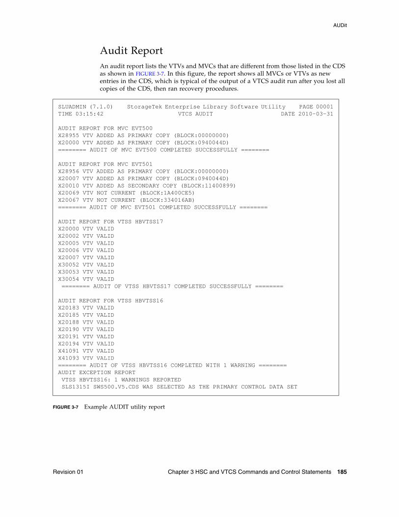
AUDit
Revision 01 Chapter 3 HSC and VTCS Commands and Control Statements 185
Audit ReportAn audit report lists the VTVs and MVCs that are different from those listed in the CDS as shown in FIGURE 3-7. In this figure, the report shows all MVCs or VTVs as new entries in the CDS, which is typical of the output of a VTCS audit run after you lost all copies of the CDS, then ran recovery procedures.
FIGURE 3-7 Example AUDIT utility report
SLUADMIN (7.1.0) StorageTek Enterprise Library Software Utility PAGE 00001TIME 03:15:42 VTCS AUDIT DATE 2010-03-31 AUDIT REPORT FOR MVC EVT500 X28955 VTV ADDED AS PRIMARY COPY (BLOCK:00000000) X20000 VTV ADDED AS PRIMARY COPY (BLOCK:0940044D) ======== AUDIT OF MVC EVT500 COMPLETED SUCCESSFULLY ======== AUDIT REPORT FOR MVC EVT501 X28956 VTV ADDED AS PRIMARY COPY (BLOCK:00000000) X20007 VTV ADDED AS PRIMARY COPY (BLOCK:0940044D) X20010 VTV ADDED AS SECONDARY COPY (BLOCK:11400899) X20069 VTV NOT CURRENT (BLOCK:1A400CE5)X20067 VTV NOT CURRENT (BLOCK:334016AB) ======== AUDIT OF MVC EVT501 COMPLETED SUCCESSFULLY ======== AUDIT REPORT FOR VTSS HBVTSS17 X20000 VTV VALID X20002 VTV VALID X20005 VTV VALID X20006 VTV VALID X20007 VTV VALIDX30052 VTV VALID X30053 VTV VALID X30054 VTV VALID ======== AUDIT OF VTSS HBVTSS17 COMPLETED SUCCESSFULLY ========
AUDIT REPORT FOR VTSS HBVTSS16 X20183 VTV VALID X20185 VTV VALID X20188 VTV VALID X20190 VTV VALID X20191 VTV VALID X20194 VTV VALIDX41091 VTV VALID X41093 VTV VALID ======== AUDIT OF VTSS HBVTSS16 COMPLETED WITH 1 WARNING ========AUDIT EXCEPTION REPORT VTSS HBVTSS16: 1 WARNINGS REPORTED SLS1315I SWS500.V5.CDS WAS SELECTED AS THE PRIMARY CONTROL DATA SET
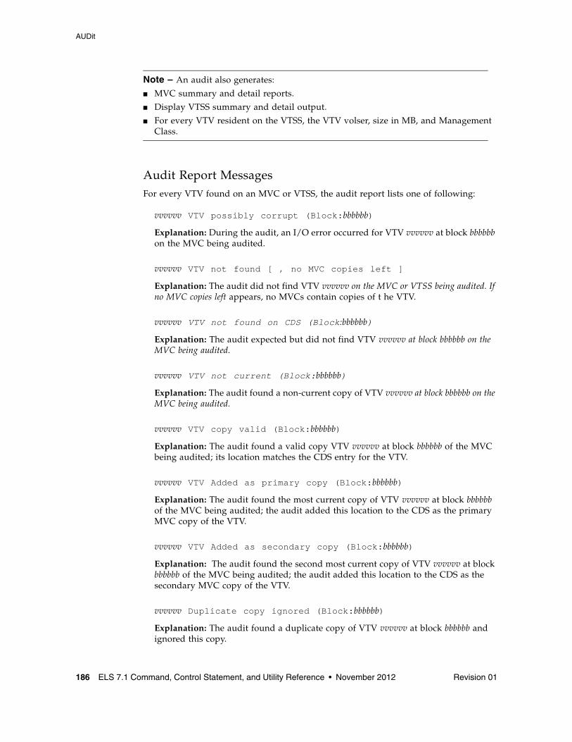
AUDit
186 ELS 7.1 Command, Control Statement, and Utility Reference • November 2012 Revision 01
Note – An audit also generates:
■ MVC summary and detail reports.
■ Display VTSS summary and detail output.
■ For every VTV resident on the VTSS, the VTV volser, size in MB, and Management Class.
Audit Report MessagesFor every VTV found on an MVC or VTSS, the audit report lists one of following:
vvvvvv VTV possibly corrupt (Block:bbbbbb)
Explanation: During the audit, an I/O error occurred for VTV vvvvvv at block bbbbbb on the MVC being audited.
vvvvvv VTV not found [ , no MVC copies left ]
Explanation: The audit did not find VTV vvvvvv on the MVC or VTSS being audited. If no MVC copies left appears, no MVCs contain copies of t he VTV.
vvvvvv VTV not found on CDS (Block:bbbbbb)
Explanation: The audit expected but did not find VTV vvvvvv at block bbbbbb on the MVC being audited.
vvvvvv VTV not current (Block:bbbbbb)
Explanation: The audit found a non-current copy of VTV vvvvvv at block bbbbbb on the MVC being audited.
vvvvvv VTV copy valid (Block:bbbbbb)
Explanation: The audit found a valid copy VTV vvvvvv at block bbbbbb of the MVC being audited; its location matches the CDS entry for the VTV.
vvvvvv VTV Added as primary copy (Block:bbbbbb)
Explanation: The audit found the most current copy of VTV vvvvvv at block bbbbbb of the MVC being audited; the audit added this location to the CDS as the primary MVC copy of the VTV.
vvvvvv VTV Added as secondary copy (Block:bbbbbb)
Explanation: The audit found the second most current copy of VTV vvvvvv at block bbbbbb of the MVC being audited; the audit added this location to the CDS as the secondary MVC copy of the VTV.
vvvvvv Duplicate copy ignored (Block:bbbbbb)
Explanation: The audit found a duplicate copy of VTV vvvvvv at block bbbbbb and ignored this copy.
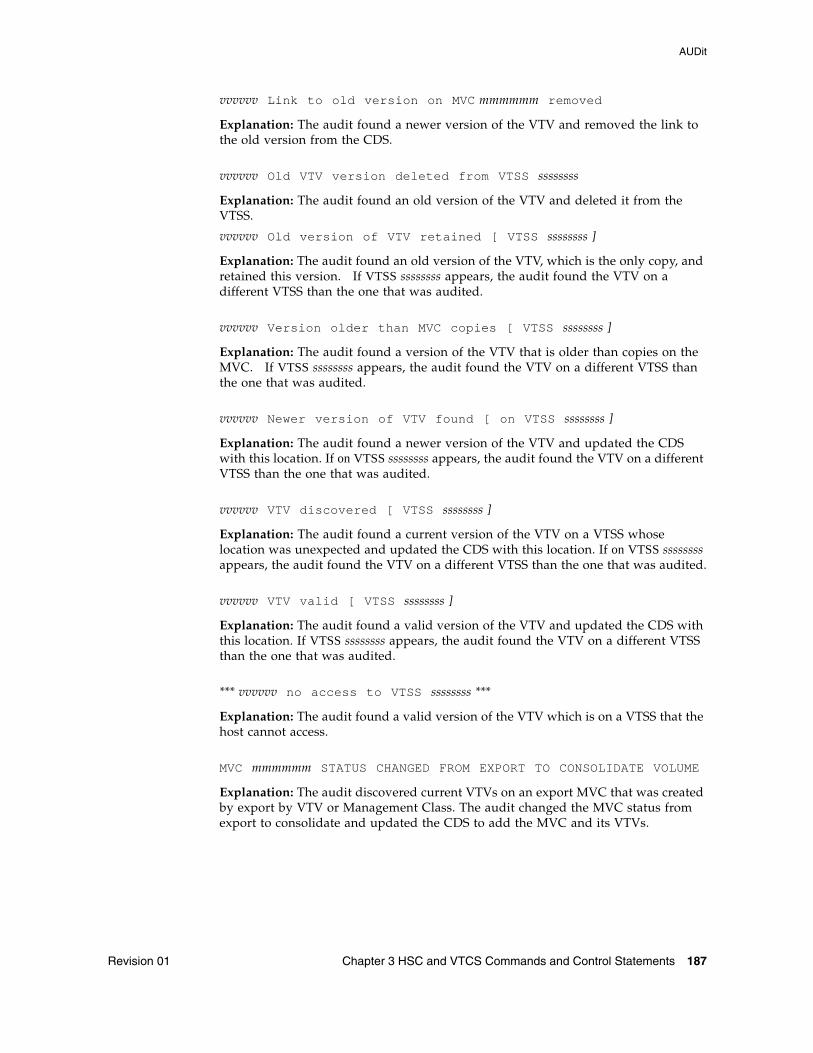
AUDit
Revision 01 Chapter 3 HSC and VTCS Commands and Control Statements 187
vvvvvv Link to old version on MVC mmmmmm removed
Explanation: The audit found a newer version of the VTV and removed the link to the old version from the CDS.
vvvvvv Old VTV version deleted from VTSS ssssssss
Explanation: The audit found an old version of the VTV and deleted it from the VTSS.
vvvvvv Old version of VTV retained [ VTSS ssssssss ]
Explanation: The audit found an old version of the VTV, which is the only copy, and retained this version. If VTSS ssssssss appears, the audit found the VTV on a different VTSS than the one that was audited.
vvvvvv Version older than MVC copies [ VTSS ssssssss ]
Explanation: The audit found a version of the VTV that is older than copies on the MVC. If VTSS ssssssss appears, the audit found the VTV on a different VTSS than the one that was audited.
vvvvvv Newer version of VTV found [ on VTSS ssssssss ]
Explanation: The audit found a newer version of the VTV and updated the CDS with this location. If on VTSS ssssssss appears, the audit found the VTV on a different VTSS than the one that was audited.
vvvvvv VTV discovered [ VTSS ssssssss ]
Explanation: The audit found a current version of the VTV on a VTSS whose location was unexpected and updated the CDS with this location. If on VTSS ssssssss appears, the audit found the VTV on a different VTSS than the one that was audited.
vvvvvv VTV valid [ VTSS ssssssss ]
Explanation: The audit found a valid version of the VTV and updated the CDS with this location. If VTSS ssssssss appears, the audit found the VTV on a different VTSS than the one that was audited.
*** vvvvvv no access to VTSS ssssssss ***
Explanation: The audit found a valid version of the VTV which is on a VTSS that the host cannot access.
MVC mmmmmm STATUS CHANGED FROM EXPORT TO CONSOLIDATE VOLUME
Explanation: The audit discovered current VTVs on an export MVC that was created by export by VTV or Management Class. The audit changed the MVC status from export to consolidate and updated the CDS to add the MVC and its VTVs.
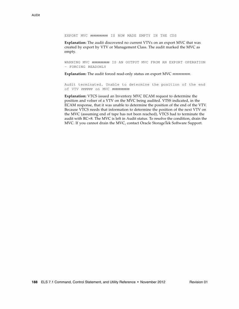
AUDit
188 ELS 7.1 Command, Control Statement, and Utility Reference • November 2012 Revision 01
EXPORT MVC mmmmmm IS NOW MADE EMPTY IN THE CDS
Explanation: The audit discovered no current VTVs on an export MVC that was created by export by VTV or Management Class. The audit marked the MVC as empty.
WARNING MVC mmmmmm IS AN OUTPUT MVC FROM AN EXPORT OPERATION - FORCING READONLY
Explanation: The audit forced read-only status on export MVC mmmmmm.
Audit terminated. Unable to determine the position of the end of VTV vvvvvv on MVC mmmmmm
Explanation: VTCS issued an Inventory MVC ECAM request to determine theposition and volser of a VTV on the MVC being audited. VTSS indicated, in the ECAM response, that it was unable to determine the position of the end of the VTV. Because VTCS needs that information to determine the position of the next VTV on the MVC (assuming end of tape has not been reached), VTCS had to terminate the audit with RC=8. The MVC is left in Audit status. To resolve the condition, drain the MVC. If you cannot drain the MVC, contact Oracle StorageTek Software Support.
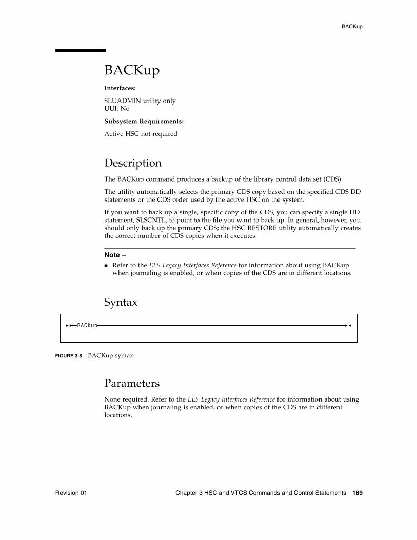
BACKup
Revision 01 Chapter 3 HSC and VTCS Commands and Control Statements 189
BACKupInterfaces:
SLUADMIN utility onlyUUI: No
Subsystem Requirements:
Active HSC not required
DescriptionThe BACKup command produces a backup of the library control data set (CDS).
The utility automatically selects the primary CDS copy based on the specified CDS DD statements or the CDS order used by the active HSC on the system.
If you want to back up a single, specific copy of the CDS, you can specify a single DD statement, SLSCNTL, to point to the file you want to back up. In general, however, you should only back up the primary CDS; the HSC RESTORE utility automatically creates the correct number of CDS copies when it executes.
Note – ■ Refer to the ELS Legacy Interfaces Reference for information about using BACKup
when journaling is enabled, or when copies of the CDS are in different locations.
Syntax
FIGURE 3-8 BACKup syntax
ParametersNone required. Refer to the ELS Legacy Interfaces Reference for information about using BACKup when journaling is enabled, or when copies of the CDS are in different locations.
BACKup
BACKup
190 ELS 7.1 Command, Control Statement, and Utility Reference • November 2012 Revision 01
Additional JCL RequirementsIn addition to the required JCL definition statements described in “Invoking SLUADMIN” on page 674, the following definition statements apply to the BACKup JCL:
SLSBKUP
specifies the created backup data set. The LRECL and BLKSIZE of this data set default to 4096.
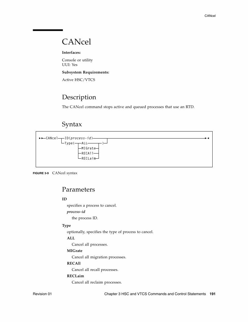
CANcel
Revision 01 Chapter 3 HSC and VTCS Commands and Control Statements 191
CANcelInterfaces:
Console or utilityUUI: Yes
Subsystem Requirements:
Active HSC/VTCS
DescriptionThe CANcel command stops active and queued processes that use an RTD.
Syntax
FIGURE 3-9 CANcel syntax
ParametersID
specifies a process to cancel.
process–id
the process ID.
Type
optionally, specifies the type of process to cancel.
ALL
Cancel all processes.
MIGrate
Cancel all migration processes.
RECAll
Cancel all recall processes.
RECLaim
Cancel all reclaim processes.
CANcel ID(process-id)Type( ALL
MIGrateRECAllRECLaim
)
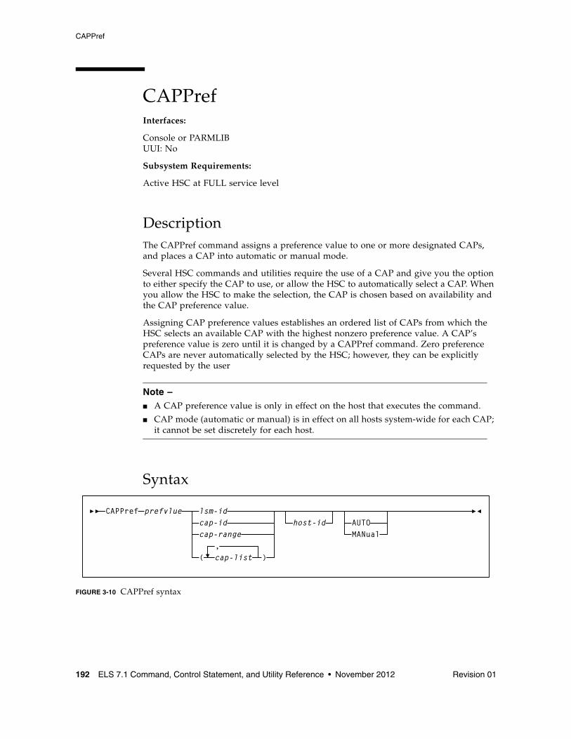
CAPPref
192 ELS 7.1 Command, Control Statement, and Utility Reference • November 2012 Revision 01
CAPPrefInterfaces:
Console or PARMLIBUUI: No
Subsystem Requirements:
Active HSC at FULL service level
DescriptionThe CAPPref command assigns a preference value to one or more designated CAPs, and places a CAP into automatic or manual mode.
Several HSC commands and utilities require the use of a CAP and give you the option to either specify the CAP to use, or allow the HSC to automatically select a CAP. When you allow the HSC to make the selection, the CAP is chosen based on availability and the CAP preference value.
Assigning CAP preference values establishes an ordered list of CAPs from which the HSC selects an available CAP with the highest nonzero preference value. A CAP’s preference value is zero until it is changed by a CAPPref command. Zero preference CAPs are never automatically selected by the HSC; however, they can be explicitly requested by the user
Note – ■ A CAP preference value is only in effect on the host that executes the command.
■ CAP mode (automatic or manual) is in effect on all hosts system-wide for each CAP; it cannot be set discretely for each host.
Syntax
FIGURE 3-10 CAPPref syntax
CAPPref prefvlue lsm-idcap-idcap-range
(,cap-list )
host-id AUTOMANual
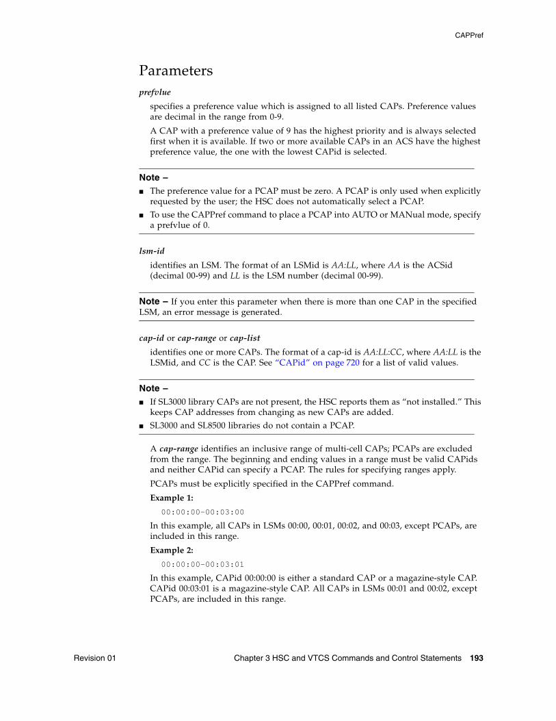
CAPPref
Revision 01 Chapter 3 HSC and VTCS Commands and Control Statements 193
Parametersprefvlue
specifies a preference value which is assigned to all listed CAPs. Preference values are decimal in the range from 0-9.
A CAP with a preference value of 9 has the highest priority and is always selected first when it is available. If two or more available CAPs in an ACS have the highest preference value, the one with the lowest CAPid is selected.
Note – ■ The preference value for a PCAP must be zero. A PCAP is only used when explicitly
requested by the user; the HSC does not automatically select a PCAP.
■ To use the CAPPref command to place a PCAP into AUTO or MANual mode, specify a prefvlue of 0.
lsm-id
identifies an LSM. The format of an LSMid is AA:LL, where AA is the ACSid (decimal 00-99) and LL is the LSM number (decimal 00-99).
Note – If you enter this parameter when there is more than one CAP in the specified LSM, an error message is generated.
cap-id or cap-range or cap-list
identifies one or more CAPs. The format of a cap-id is AA:LL:CC, where AA:LL is the LSMid, and CC is the CAP. See “CAPid” on page 720 for a list of valid values.
Note – ■ If SL3000 library CAPs are not present, the HSC reports them as “not installed.” This
keeps CAP addresses from changing as new CAPs are added.
■ SL3000 and SL8500 libraries do not contain a PCAP.
A cap-range identifies an inclusive range of multi-cell CAPs; PCAPs are excluded from the range. The beginning and ending values in a range must be valid CAPids and neither CAPid can specify a PCAP. The rules for specifying ranges apply.
PCAPs must be explicitly specified in the CAPPref command.
Example 1:
00:00:00-00:03:00
In this example, all CAPs in LSMs 00:00, 00:01, 00:02, and 00:03, except PCAPs, are included in this range.
Example 2:
00:00:00-00:03:01
In this example, CAPid 00:00:00 is either a standard CAP or a magazine-style CAP. CAPid 00:03:01 is a magazine-style CAP. All CAPs in LSMs 00:01 and 00:02, except PCAPs, are included in this range.
CAPPref
194 ELS 7.1 Command, Control Statement, and Utility Reference • November 2012 Revision 01
Each cap-list element can be either a single CAPid or a CAPid range. The elements in a list must be separated by a comma or a blank, and the entire list must be enclosed in parentheses.
host-id
optionally, specifies that the CAPPRef command is to be performed only if the host-id parameter matches the identifier of the issuing host (the SMF system identifier for JES).
■ If CAPPref is issued from PARMLIB and a host-id is specified, the command is executed only by the host with the matching ID.
■ If CAPPref is issued from PARMLIB and a host ID is not specified, the command is executed by each host that accesses PARMLIB.
Refer to the publication Managing HSC and VTCS for more information about PARMLIB.
AUTO
optionally, indicates that the specified CAPs are to be placed in automatic mode (referred to as auto-mode). Auto-mode CAPs remain unlocked when not in use. AUTO is the initial setting for a PCAP.
When a CAP is in auto-mode, you can initiate an enter operation without issuing an ENter command. You do this by opening the CAP door, placing one or more cartridges inside, and closing the CAP. The CAP is locked while the enter is being processed; then it is unlocked again.
Auto-mode CAPs can be used for eject processing by either:
■ specifying the CAPid on an EJect command or EJECt utility, or
■ assigning a preference value and allowing the HSC to automatically select the CAP.
A CAP in auto-mode is locked whenever it is selected for an eject operation, to prevent an enter operation on this CAP until the eject completes.
Note – HSC termination will be slower with CAPs in auto-mode; especially in a multiple-host environment.
MANual
optionally, indicates that the specified CAP is to be locked when not in use. MANual is the initial setting for all multi-cartridge CAPs.
Note – ■ AUTO/MANual settings are sent host-to-host using LMU broadcast and the status is
preserved in the control data set. For this reason, it is recommended that you not make frequent changes to the CAP mode.
■ A prefvlue of 0 must be specified when using the CAPPref command to set a PCAP to AUTO or MANual mode.
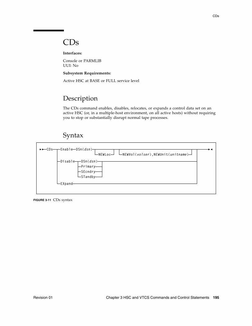
CDs
Revision 01 Chapter 3 HSC and VTCS Commands and Control Statements 195
CDs Interfaces:
Console or PARMLIBUUI: No
Subsystem Requirements:
Active HSC at BASE or FULL service level
DescriptionThe CDs command enables, disables, relocates, or expands a control data set on an active HSC (or, in a multiple-host environment, on all active hosts) without requiring you to stop or substantially disrupt normal tape processes.
Syntax
FIGURE 3-11 CDs syntax
CDs Enable DSn(dsn)NEWLoc NEWVol(volser),NEWUnit(unitname)
Disable DSn(dsn)PrimarySEcndrySTandby
EXpand
CDs
196 ELS 7.1 Command, Control Statement, and Utility Reference • November 2012 Revision 01
ParametersEnable
allocates and activates any preexisting, renamed, or new CDS specified by the DSN parameter. The CDS Enable command can allocate and activate a CDS residing in a new location, either with a preexisting or a new data set name, when the NEWLoc parameter is specified. MSP catalog services are used to resolve the volume and unit definitions, if the NEWVol or NEWUnit parameters are not specified.
The specified control data set must be named in the CDSDEF control statement in PARMLIB.
DSn
specifies the control data set name to allocate for all hosts.
dsn
the data set name.
NEWLoc
optionally, indicates that a relocation activity has occurred for the CDS named by the DSN parameter. MSP uses the catalog facility to determine the volume location of the relocated CDS.
NEWVol
optionally, specifies the volume for a relocated CDS copy. In MSP, if the new CDS copy is not cataloged, this parameter is required. If NEWVol is specified, but NEWUnit is not, NEWUnit defaults to SYSALLDA.
NEWVol is required if the user is executing the command in the HSC VM environment.
volser
the volume.
NEWUnit
optionally, specifies the unit name for a relocated CDS copy. This parameter defaults to SYSALLDA if it is omitted and NEWVol is specified.
NEWUnit is required if the user is executing the command in the HSC VM environment.
unitname
the unit name.
EXpand
expands all enabled CDSs to the maximum number of 4096 blocks that can fit in the physical space allocated for the CDS. The maximum number of 4096 blocks is determined by the smallest CDS copy.
CDs
Revision 01 Chapter 3 HSC and VTCS Commands and Control Statements 197
Disable
unallocates (makes inactive) the specified CDS. The CDs Disable command does not disable the last active copy of the control data set.
DSn
specifies the control data set name to unallocate for all hosts.
dsn
the data set name.
Primary
indicates that the current primary control data set is to be disabled.
SEcndry
indicates that the current secondary control data set is to be disabled.
STandby
indicates that the current standby control data set is to be disabled.
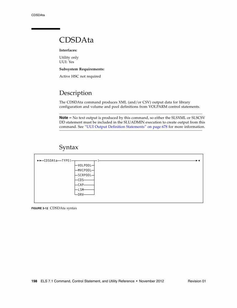
CDSDAta
198 ELS 7.1 Command, Control Statement, and Utility Reference • November 2012 Revision 01
CDSDAtaInterfaces:
Utility onlyUUI: Yes
Subsystem Requirements:
Active HSC not required
DescriptionThe CDSDAta command produces XML (and/or CSV) output data for library configuration and volume and pool definitions from VOLPARM control statements.
Note – No text output is produced by this command, so either the SLSXML or SLSCSV DD statement must be included in the SLUADMIN execution to create output from this command. See “UUI Output Definition Statements” on page 678 for more information.
Syntax
FIGURE 3-12 CDSDAta syntax
CDSDAtaVOLPOOLMVCPOOLSCRPOOL
TYPE( )
CDSCAPLSMDRV
CDSDAta
Revision 01 Chapter 3 HSC and VTCS Commands and Control Statements 199
ParametersTYPE
specifies the type of CDS data for which output is produced. The TYPE Keyword is positional and therefore optional. One of the listed types must be specified.
VOLPOOL
produces XML data for VOLPARM VOLUME pool definitions.
MVCPOOL
produces XML data for VOLPARM MVC pool definitions.
SCRPOOL
produces XML data for VOLPARM SCRATCH pool definitions.
CDS
produces XML CDS data.
CAP
produces XML CAP data.
LSM
produces XML LSM data.
DRV
produces XML drive data.
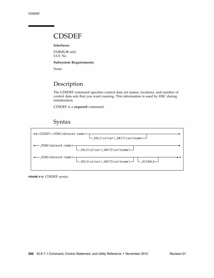
CDSDEF
200 ELS 7.1 Command, Control Statement, and Utility Reference • November 2012 Revision 01
CDSDEF Interfaces:
PARMLIB onlyUUI: No
Subsystem Requirements:
None
DescriptionThe CDSDEF command specifies control data set names, locations, and number of control data sets that you want running. This information is used by HSC during initialization.
CDSDEF is a required command.
Syntax
FIGURE 3-13 CDSDEF syntax
DSN1(dataset-name),VOL1(volser),UNIT1(unitname)
CDSDEF
,DSN2(dataset-name),VOL2(volser),UNIT2(unitname)
,DSN3(dataset-name),VOL3(volser),UNIT3(unitname) ,DISABLE
CDSDEF
Revision 01 Chapter 3 HSC and VTCS Commands and Control Statements 201
ParametersDSNx
dataset.name is the name of an HSC control data set. At least one DSN parameter must be specified, as many as three can be specified. If two data sets are specified, then the volume inventory information on both copies is kept current, and these two data sets are referred to as the primary and the secondary CDS.
If all three are specified, then two copies are kept current and the third data set is a standby CDS which is enabled as the default condition. This standby CDS can be disabled with the DISABLE parameter. In the case where a standby copy of the CDS is being used, you do not need to specify which two of the three CDSs are the primary and secondary copies. The HSC determines, based on last use, which two are the correct copies to use during the initialization of the Control Data Set Services.
VOLx
optionally, volser is the volume serial number of the DASD volume where the specified CDS resides. If the data set is not cataloged, this must be specified.
If omitted, volume and unit information is determined from the MSP catalog, and the UNITx parameter is ignored.
UNITx
optionally, unitname is used to specify the unit parameter in the SVC99 dynamic allocation parameter list. If omitted, SYSALLDA is used.
unitname can be an Fujitsu-defined generic (e.g., 3390), a system-built esoteric (e.g., SYSALLDA), a user-defined esoteric, or a specific device number. It is recommended that a general value of SYSALLDA be specified (or defaulted) to allow maximum flexibility and to reduce the need for CDSDEF updates to keep them consistent with the active CDS.
DISABLE
optionally, disables the standby CDS. If this parameter is not specified, the default is to enable the standby CDS at HSC initialization.
If DISABLE is specified, initialization verifies the standby CDS by allocating, opening, and reading the data set. The standby CDS is then closed and deallocated. This process allows manual control over the use of the standby CDS during a control data set switch situation.
If the standby CDS is enabled, the HSC automatically uses it for switching. If it is disabled, it is not used. There is no enable parameter for CDSDEF, as the enable condition is the default.
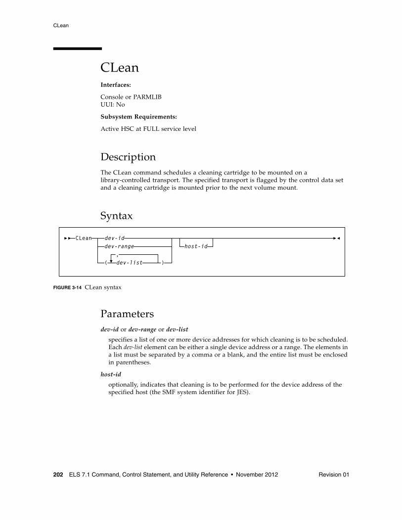
CLean
202 ELS 7.1 Command, Control Statement, and Utility Reference • November 2012 Revision 01
CLeanInterfaces:
Console or PARMLIBUUI: No
Subsystem Requirements:
Active HSC at FULL service level
DescriptionThe CLean command schedules a cleaning cartridge to be mounted on a library-controlled transport. The specified transport is flagged by the control data set and a cleaning cartridge is mounted prior to the next volume mount.
Syntax
FIGURE 3-14 CLean syntax
Parametersdev-id or dev-range or dev-list
specifies a list of one or more device addresses for which cleaning is to be scheduled. Each dev-list element can be either a single device address or a range. The elements in a list must be separated by a comma or a blank, and the entire list must be enclosed in parentheses.
host-id
optionally, indicates that cleaning is to be performed for the device address of the specified host (the SMF system identifier for JES).
CLeandev-rangedev-id
( dev-list,
)
host-id
COMMPath
Revision 01 Chapter 3 HSC and VTCS Commands and Control Statements 203
COMMPathInterfaces:
Console or PARMLIB onlyUUI: No
Subsystem Requirements:
Active HSC at BASE or FULL service level
DescriptionThe COMMPath command is used in a multiple-host environment to do the following:
■ Set up a tiered communication service between HSC hosts which can be modified at any time without bringing down the HSC
■ Define the hierarchy of methods available to each host for communication with other hosts
■ Establish the current method of communication for a host (or switch from one method to another).
It is recommended that host-to-host communication be defined in PARMLIB at startup. Issue the COMMPath command from the console to switch or delete communication paths.
Note – Oracle strongly recommends the use of VTAM host-to-host communications, because a VTAM network does not place a performance burden on HSC components or the library. Refer to “Adding Definitions for ACF/VTAM Communications” in the publication Managing HSC and VTCS for more information.
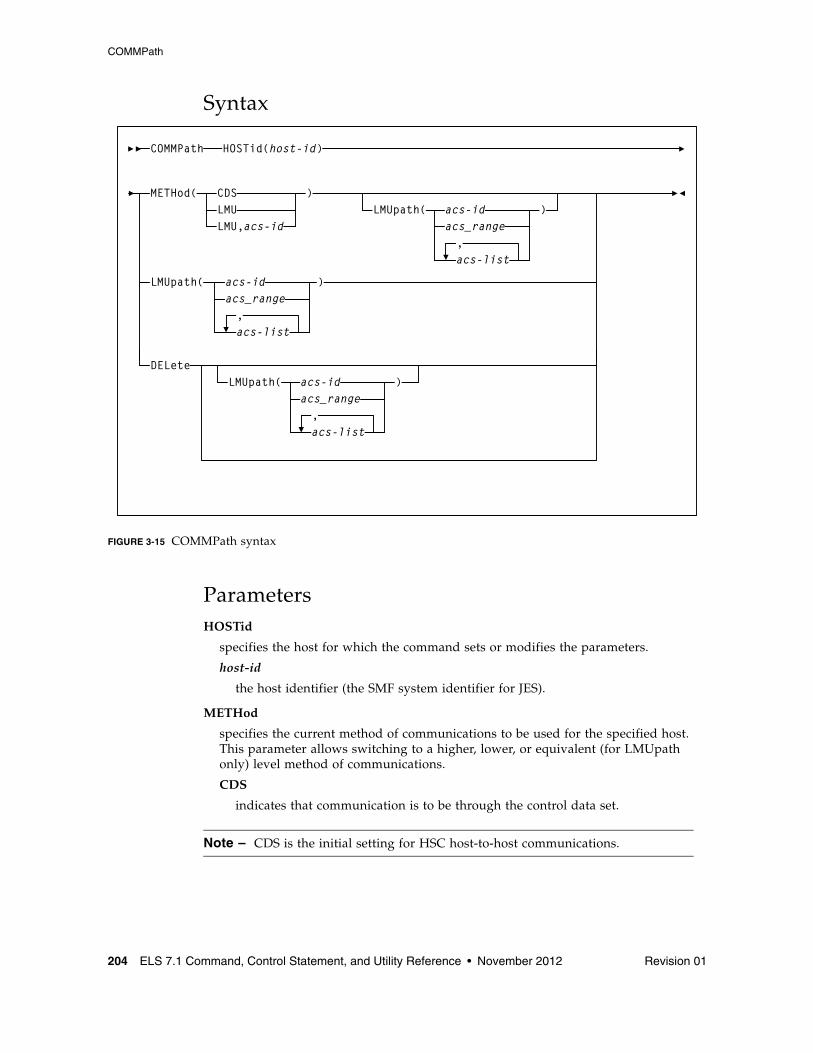
COMMPath
204 ELS 7.1 Command, Control Statement, and Utility Reference • November 2012 Revision 01
Syntax
FIGURE 3-15 COMMPath syntax
ParametersHOSTid
specifies the host for which the command sets or modifies the parameters.
host-id
the host identifier (the SMF system identifier for JES).
METHod
specifies the current method of communications to be used for the specified host. This parameter allows switching to a higher, lower, or equivalent (for LMUpath only) level method of communications.
CDS
indicates that communication is to be through the control data set.
Note – CDS is the initial setting for HSC host-to-host communications.
COMMPath HOSTid(host-id)
METHod( CDSLMULMU,acs-id
)LMUpath( acs-id
acs_range,acs-list
)
LMUpath( acs-idacs_range,acs-list
)
DELeteLMUpath( acs-id
acs_range,acs-list
)
COMMPath
Revision 01 Chapter 3 HSC and VTCS Commands and Control Statements 205
LMU
indicates that communication is to be through an LMU.
acs-id
the LMUpath definition that is to be the active (or current) LMUpath. If you do not supply an acs-id, the first LMUpath specified in the list of LMUpath definitions is made active.
Note – ■ If LMU is specified, the LMUpath parameter must have been specified in a previous
command, or it must be included in the same command.
■ If the LMU method is specified in PARMLIB, the switch from CDS to LMU is delayed until the HSC initializes to the full service level.
■ If the HSC service level drops to base, LMU communications are switched to CDS. When the full service level is restored, an upward switch to the LMU method can only be accomplished by issuing the COMMPath command.
VTAM
specifies that communication is to be through a VTAM network.
Note – ■ If VTAM is specified, the VTAMpath parameter must have been specified in a
previous command, or it must be included in the same command.
■ A downward switch from the VTAM method is performed when the VTAM APPLID of the HSC is varied inactive, or VTAM is shut down.
LMUpath
specifies one or more LMUpaths that can be used for host-to-host communications. An LMU is eligible to be used for host-to-host communications if it is connected to other HSCs sharing a library.
If more than one eligible LMU is specified, the HSC begins searching for an available communications path beginning with the first acs-id in the list. The search continues until a path can be established or the end of the list is reached.
The LMUpath definitions are cumulative; that is, the definitions specified in a command are appended to the current list of definitions. You can insert an LMUpath into the current list by specifying the LMUpath that you wish to insert, followed by the LMUpaths that are to come after it. If a COMMPath command specifies an LMUpath that is already defined in the list, the path is removed from its current position and appended to the end of the list as specified in the command.
For example, the current definition is (02,03,04). You can insert LMUpath 01 after 02 by specifying LMU(01,03,04). Now the current list appears as (02,01,03,04). Also, if the current definition is (02,01,03,04) and the command specifies LMU(01,02), the list becomes (03,04,01,02).
Note – For a temporary outage of an LMU, it is not necessary but may be desirable to delete the LMUpath definition for that LMU. When the LMU is available again, define it to the communications service again by adding it to the current definitions.
COMMPath
206 ELS 7.1 Command, Control Statement, and Utility Reference • November 2012 Revision 01
acs-id or acs-range or acs-list
one or more specific LMUs. Each acs-list element can be either a single ACSid or an ACSid range. The elements in a list must be separated by a comma or a blank, and the entire list must be enclosed in parentheses.
DELete
specifies to delete the definitions specified by the LMUpath parameter and/or the VTAMpath parameter.
If LMU is not the current method, all LMUpath definitions can be deleted by specifying DELete LMUpath (without supplying an acs-id). If the current method is LMU, the active LMUpath cannot be deleted.
If the current method is VTAM, the VTAMpath definition cannot be deleted.
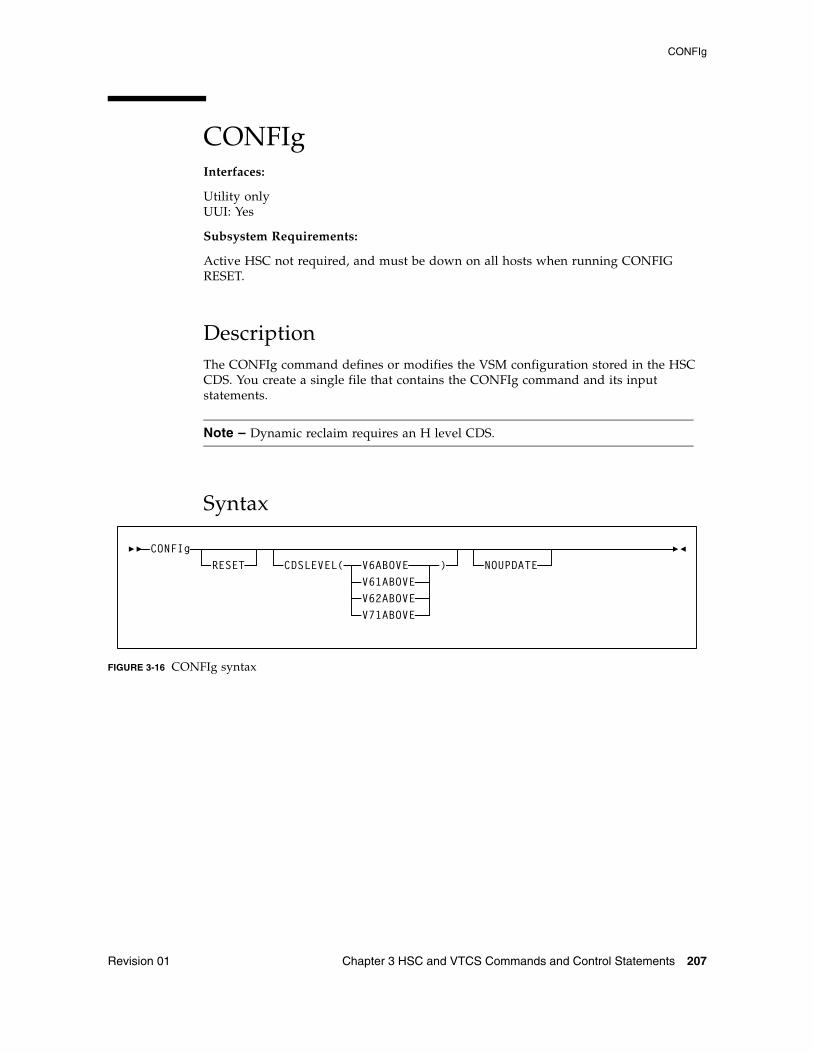
CONFIg
Revision 01 Chapter 3 HSC and VTCS Commands and Control Statements 207
CONFIgInterfaces:
Utility onlyUUI: Yes
Subsystem Requirements:
Active HSC not required, and must be down on all hosts when running CONFIG RESET.
DescriptionThe CONFIg command defines or modifies the VSM configuration stored in the HSC CDS. You create a single file that contains the CONFIg command and its input statements.
Note – Dynamic reclaim requires an H level CDS.
Syntax
FIGURE 3-16 CONFIg syntax
CONFIgRESET CDSLEVEL( V6ABOVE
V61ABOVEV62ABOVE
) NOUPDATE
V71ABOVE
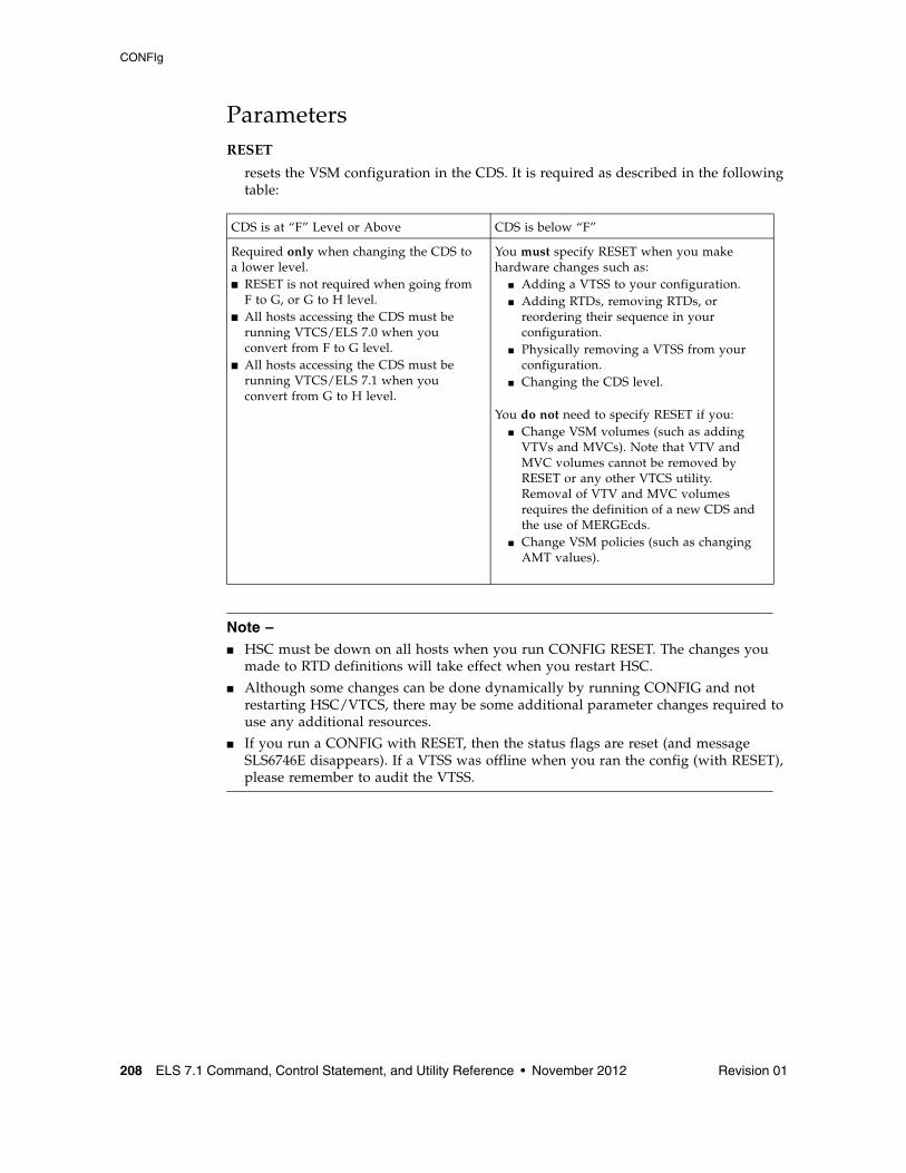
CONFIg
208 ELS 7.1 Command, Control Statement, and Utility Reference • November 2012 Revision 01
ParametersRESET
resets the VSM configuration in the CDS. It is required as described in the following table:
Note – ■ HSC must be down on all hosts when you run CONFIG RESET. The changes you
made to RTD definitions will take effect when you restart HSC.
■ Although some changes can be done dynamically by running CONFIG and not restarting HSC/VTCS, there may be some additional parameter changes required to use any additional resources.
■ If you run a CONFIG with RESET, then the status flags are reset (and message SLS6746E disappears). If a VTSS was offline when you ran the config (with RESET), please remember to audit the VTSS.
CDS is at “F” Level or Above CDS is below “F”
Required only when changing the CDS to a lower level.■ RESET is not required when going from
F to G, or G to H level. ■ All hosts accessing the CDS must be
running VTCS/ELS 7.0 when you convert from F to G level.
■ All hosts accessing the CDS must be running VTCS/ELS 7.1 when you convert from G to H level.
You must specify RESET when you make hardware changes such as:
■ Adding a VTSS to your configuration.■ Adding RTDs, removing RTDs, or
reordering their sequence in your configuration.
■ Physically removing a VTSS from your configuration.
■ Changing the CDS level.
You do not need to specify RESET if you:■ Change VSM volumes (such as adding
VTVs and MVCs). Note that VTV and MVC volumes cannot be removed by RESET or any other VTCS utility. Removal of VTV and MVC volumes requires the definition of a new CDS and the use of MERGEcds.
■ Change VSM policies (such as changing AMT values).
CONFIg
Revision 01 Chapter 3 HSC and VTCS Commands and Control Statements 209
CDSLEVEL
One of the following CDS levels:
V6ABOVE
creates an “E” level CDS, which provides the following enhancements:
■ Full VSM4 Support
■ 4 MVC copies
■ 800Mb VTVs
V61ABOVE
creates an “F” level CDS, which provides the following enhancements:
■ Near Continuous Operations (NCO)
■ Bi-directional clustering
■ Improved CDS I/O performance - reduces I/O required to manage virtual scratch subpools
V62ABOVE
creates a “G” level CDS, which provides the following enhancements:
■ 400Mb/800Mb/2Gb/4gb VTVs
■ Standard/Large VTV Pages
■ 65000 VTVs per MVC
V71ABOVE
creates an “H” level CDS, which provides the following enhancements:
■ Dynamic reclaim
■ Autonomous device support
NOUPDATE
specifies that the configuration is checked and any appropriate messages output, but no updates are made to the CDS.
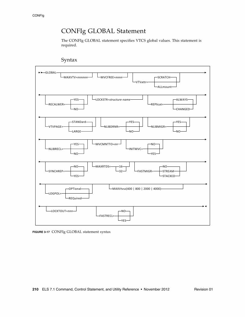
CONFIg
210 ELS 7.1 Command, Control Statement, and Utility Reference • November 2012 Revision 01
CONFIg GLOBAL StatementThe CONFIg GLOBAL statement specifies VTCS global values. This statement is required.
Syntax
FIGURE 3-17 CONFIg GLOBAL statement syntax
GLOBAL
MAXVTV=nnnnnn
VTVattr=
SCRATCH
ALLmount
RECALWER=
YES
NO
LOCKSTR=structure‐name
REPlicat=
ALWAYS
CHANGED
VTVPAGE=
STANDard
LARGE
NLIBDRNR=
YES
NO
NLIBMIGR=
YES
NO
NLIBRECL=
YES
NO
MVCMNTTO=nn
SYNCHREP=
NO
YES
MAXRTDS= 16
32 FASTMIGR=
NO
STACKED
LOGPOL=
OPTional
REQuired
MAXVtvsz(400 | 800 | 2000 | 4000)
STREAM
MVCFREE=nnnn
LOCKTOUT=nnn
INITMVC=
NO
YES
FASTRECL=
NO
YES
CONFIg
Revision 01 Chapter 3 HSC and VTCS Commands and Control Statements 211
ParametersMAXVTV=nnn
optionally, specifies the maximum number of VTVs that can be migrated to a single MVC. The default is 32000 for a D, E, or F level CDS and 65000 for a G level CDS. Valid values are:
■ 4 to 32000 for a D, E or F level CDS.
■ 4 to 65000 for a G level CDS.
For more information about CDS levels, see “CONFIg” on page 207.
MVCFREE=nnn
optionally, specifies the minimum number of free MVCs in the MVC pool. A free MVC has 100% usable space and does not contain any migrated VTVs. Valid values are 0 to 255. The default is 40.
If free MVCs is equal or less than this value, VTCS issues message SLS6616I and starts an automatic space reclamation.
Note – If you set MVCFREE=0, VTCS actually uses the default value (40).
VTVattr=SCRATCH | ALLmount
optionally, specifies when VTCS assigns a Management Class to a VTV.
SCRATCH
Assign a Management Class only when VTCS does a scratch mount of the VTV (the default).
ALLmount
Assign a Management Class whenever VTCS mounts the VTV.
Caution – If you specify that VTCS assigns a Management Class whenever VTCS mounts a VTV, these attributes can change, which can cause undesirable or unpredictable results.For example, if an application writes data set PROD.DATA to VTV100 with a Management Class of PROD, then writes data set TEST.DATA to VTV100 with a Management Class of TEST, then the VTV (and both data sets) has a Management Class of TEST. Similarly, it is possible to write TAPEREQ statements or SMS routines that assign different Management Classes to the same data set (for example, based on jobname), which can also cause a VTV’s Management Class to change.
CONFIg
212 ELS 7.1 Command, Control Statement, and Utility Reference • November 2012 Revision 01
RECALWER
optionally, specifies whether VTCS recalls VTVs with read data checks (applies to recall and drain operations).
YES
recall VTVs with read data checks (the default).
NO
Do not recall VTVs with read data checks.
REPlicat
optionally, specifies when VSM replicates the VTV.
ALWAYS
The replicate request is added to the VTCS replication queue every time the VTV is dismounted, regardless of whether the VTV was changed while it was mounted (the default).
CHANGED
The replicate request is added to the VTCS replication queue if:
■ The VTV was changed while it was mounted.
■ The VTV was only read while mounted but less than the expected number of MVC copies of the VTV exist.
Caution –
Regardless of the CONFIG GLOBAL REPlicat setting, replication also requires that:
■ The VTV must be dismounted in a VTSS that supports replication and there cannot be an identical copy of the VTV in the other VTSS in the Cluster.
■ In addition to the CONFIG GLOBAL REPlicat value, you must specify REPlicat(YES) on a VTV’s Management Class for replication to occur.
VTVPAGE
optionally, specifies the page size used to store VTV data in the VTSS and on the MVCs. This setting only applies to 400 and 800 MB VTVs. If VTVPAGE is not specified on either the MGMTclas statement or the CONFIG GLOBAL statement, the default is STANDard.
STANDard
standard page size, which is compatible with all VSM3/VSM4 models and microcode levels.
LARGE
large page size, which can provide improved performance within the VTSS and for migrates and recalls. Large page size requires a G level CDS. For more information on CDS levels, see “CONFIg” on page 207. For 2 and 4 GB VTVs (MAXVtvsz 2000 or 4000) a VTVPAGE setting of LARGE is always used.
CONFIg
Revision 01 Chapter 3 HSC and VTCS Commands and Control Statements 213
Note – ■ VTVPAGE does not apply to VSM2s. VTVPAGE(LARGE) requires VSM4/VSM5
microcode D02.02.00.00 or VSM3 microcode N01.00.77.00. No installed option is required.
■ MGMTCLAS VTVPAGE, if specified, overrides the CONFIG GLOBAL VTVPAGE value. If VTVPAGE is not specified on either the MGMTclas statement or the CONFIG GLOBAL statement, the default is STANDard.
Caution – ■ The page size of a VTV can only be changed by a VTV scratch mount. Additional
restrictions may also apply for scratch VTVs that were previously resident in a VTSS.
■ If you specify LARGE and the CDS level and/or VTSS microcode do not support LARGE, VTCS issues warning messages and VTVPAGE defaults to STANDard.
■ If you specify STANDard for 2 or 4 GB VTVs VTCS issues warning messages and defaults to LARGE.
■ Creating VTVs with large pages makes these VTVs unreadable in configurations that do not support large VTV pages.
NLIBDRNR
optionally, specifies whether non-library resident MVCs are selected for Drain/Reclaim processing.
YES
Allow non-library resident MVCs to be selected (default).
NO
Do not allow non-library resident MVCs to be selected.
NLIBMIGR
optionally, specifies whether non-library resident MVCs will be selected for Migration processing.
YES
Allow non-library resident MVCs to be selected (default).
NO
Do not allow non-library resident MVCs to be selected.
NLIBRECL
optionally, specifies whether non-library resident MVCs will be selected for Recall processing.
YES
Allow non-library resident MVCs to be selected (default).
NO
Do not allow non-library resident MVCs to be selected.
CONFIg
214 ELS 7.1 Command, Control Statement, and Utility Reference • November 2012 Revision 01
MVCMNTTO=nn
optionally, specifies the value in minutes when a mount of an MVC will timeout. Valid values are 5 to 30 minutes. The default is 15.
INITMVC
optionally, specifies whether un-initialized MVCs are to be initialized when they are first mounted.
NO
Un-initialized MVCs should not be initialized. This is the default.
YES
Un-initialized MVCs should be initialized.
SYNCHREP
optionally, specifies whether VTV synchronous replication feature is enabled.
NO
Synchronous replication is not enabled (the default).
YES
Synchronous replication is enabled.
Note – SYNCHREP=YES merely enables synchronous replication. To actually implement synchronous replication, you must create a Management Class that specifies REPLicat=YES_SYNC For more information, see“MGMTclas Control Statement” on page 433.
MAXRTDS
optionally, specifies the maximum number of RTDs supported.
16
up to 16 RTDs supported.
32
up to 32 RTDs supported.
CONFIg
Revision 01 Chapter 3 HSC and VTCS Commands and Control Statements 215
FASTMIGR
optionally, specifies whether the stacked/streamed migrates feature is enabled for all VTSSs that support this feature.
STREAM
The streaming method is used for migrations. VTCS monitors the responses from the RTD and uses them to decide as to when a VTV has become migrated. Full advantage is made of the buffer within the RTD to improve the throughput when performing migration.
This option also implies the use of the STACKED feature as well.
STACKED
The stacked method is used for migrations. VTCS maintains a small queue of requests to the VTSS. Advantage will be taken of the various buffers in the VTSS and RTD to improve the throughput when performing a migration. For backward compatibility, the value YES is also taken to mean STACKED.
No
Disable stacked migrates (the default).
Note – FASTMIGR=STREAM | STACKED has the following prerequisites:
■ FASTMIGR=STACKED. VSM4/VSM5 microcode D02.05.00.00 or higher. If this level of microcode is not installed on all VTSSs in the configuration, Stacked Migration will be limited to the VTSSs that have it installed.
■ FASTMIGR=STREAM. VSM4/VSM5 microcode D02.15.xx.00 or higher. If this level of microcode is not installed on all VTSSs in the configuration, Streamed Migration will be limited to the VTSSs that have it installed.
■ ELS 7.0 or higher with PTFs.
■ CDS level G or higher.
■ FICON ports for FICON RTDs and CLINKs.
For the Stacked Migration feature to be enabled, all hosts must be running the prerequisites, otherwise:
■ If a host is active that does not support or tolerate stacked migrates, this will cause the CONFIG utility to return an error.
■ If a host is started and does not tolerate or support this feature, the host will shut down.
CONFIg
216 ELS 7.1 Command, Control Statement, and Utility Reference • November 2012 Revision 01
LOGPOL
optionally, specifies whether VTCS CDS logging is optional or required.
OPTional
Logging is optional. This is the default.
This mode is required for configurations that include both 7.0/7.1 and lower level hosts.
REQuired
Logging is enabled for all events on all hosts that share the CDS. This requires all hosts to be at level 7.0 or higher.
The following events are logged:
■ new version of VTV
■ imported VTV
■ first use or re-use of an MVC
■ imported MVC
■ add VTV to MVC
■ VTV on an imported MVC
■ unlink VTV from MVC
■ reclaim VTV from MVC
■ reset MVC EOT backwards
■ electronic export of VTV
MAXVTVSZ
optionally, specifies a default maximum VTV size that may be used during the creation of VTVs. Valid values for this parameter depend on both the CDS level and the microcode levels of the applicable VTSSs.
400
400MB. This is the default.
800
800MB. The CDS must be at E level or above.
2000
2GB. The CDS must be at G level or above.
4000
4GB. The CDS must be at G level or above.
Note – ■ The size of a VTV changes only after it goes through a scratch cycle. Therefore, if you
change the Management Class and DISP=MOD, then it will still retain the original size.
■ If you specify a VTV size that is not supported by the configuration, VTCS issues warning messages and MAXVtvsz defaults to the largest VTV size supported by the configuration.
■ MAXVtvsz does not apply to VSM2s.
■ MAXVTVSZ(2000 | 4000) requires VSM4/VSM5 microcode D02.02.00.00 or VSM3 microcode N01.00.77.00. No installed option is required.
CONFIg
Revision 01 Chapter 3 HSC and VTCS Commands and Control Statements 217
■ The CONFIG GLOBAL and MGMTCLAS MAXVTVSZ parameters interact as follows:
■ If MAXVTVSZ is specified on MGMTCLAS, this value overrides the CONFIG GLOBAL MAXVTVSZ value.
■ If MAXVTVSZ is not specified on MGMTCLAS, the CONFIG GLOBAL MAXVTVSZ value, if specified, is used. Otherwise, MAXVTVSZ defaults to 400MB.
■ If MAXVTVSZ is not specified on MGMTCLAS or on CONFIG GLOBAL, MAXVTVSZ defaults to 400MB.
LOCKTOUT=nnn
optionally, specifies the minimum number of minutes that a resource is locked before message SLS6946E is issued.
Valid values are 0, or any value between 5 and 240. If 0 is specified, message SLS6946E will not be issued when a required resource is locked.
If this parameter is not specified, the current default of 10 minutes is retained.
Note – LOCKTOUT is only supported at ‘F’ level CDS (V61ABOVE) and above.
FASTRECL
Optionally specifies whether VTCS should perform ETTFB for all VTSSs that support the feature. This parameter applies to recalls from RTDs and recalls from ELS.
YES
Enable the ETTFB feature. If you globally enable ETTFB, you can disable it for individual VTSSs via the CONFIG VTSS NOERLYMT parameter.
NO
Disable the ETTFB feature (the default).
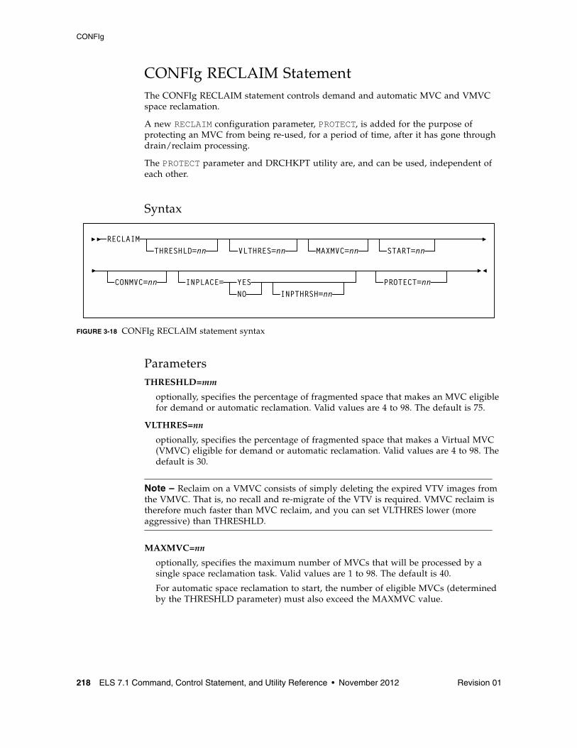
CONFIg
218 ELS 7.1 Command, Control Statement, and Utility Reference • November 2012 Revision 01
CONFIg RECLAIM StatementThe CONFIg RECLAIM statement controls demand and automatic MVC and VMVC space reclamation.
A new RECLAIM configuration parameter, PROTECT, is added for the purpose of protecting an MVC from being re-used, for a period of time, after it has gone through drain/reclaim processing.
The PROTECT parameter and DRCHKPT utility are, and can be used, independent of each other.
Syntax
FIGURE 3-18 CONFIg RECLAIM statement syntax
ParametersTHRESHLD=mm
optionally, specifies the percentage of fragmented space that makes an MVC eligible for demand or automatic reclamation. Valid values are 4 to 98. The default is 75.
VLTHRES=nn
optionally, specifies the percentage of fragmented space that makes a Virtual MVC (VMVC) eligible for demand or automatic reclamation. Valid values are 4 to 98. The default is 30.
Note – Reclaim on a VMVC consists of simply deleting the expired VTV images from the VMVC. That is, no recall and re-migrate of the VTV is required. VMVC reclaim is therefore much faster than MVC reclaim, and you can set VLTHRES lower (more aggressive) than THRESHLD.
MAXMVC=nn
optionally, specifies the maximum number of MVCs that will be processed by a single space reclamation task. Valid values are 1 to 98. The default is 40.
For automatic space reclamation to start, the number of eligible MVCs (determined by the THRESHLD parameter) must also exceed the MAXMVC value.
RECLAIMTHRESHLD=nn MAXMVC=nn START=nn
CONMVC=nn INPLACE= YESNO INPTHRSH=nn
VLTHRES=nn
PROTECT=nn
CONFIg
Revision 01 Chapter 3 HSC and VTCS Commands and Control Statements 219
START=nn
optionally, specifies the level at which automatic space reclamation starts for each ACS (not globally for all ACSs). Specify a percentage value, which is equal to:
(Reclaim Candidates/Reclaim Candidates + Free MVCs) * 100
Where:
Reclaim Candidates
is the number of Reclaim Candidates determined by the CONFIG RECLAIM THRESHLD parameter.
Reclaim Candidates + Free MVCs
equals the number of Reclaim Candidates plus the number of free MVCs.Valid values are 1 to 98. The default is 35.
CONMVC=nn
optionally, specifies the maximum number of MVCs that VTCS concurrently processes for both drain and reclaim.
Valid values are 1 to 99. The default is 1.
INPLACE
optionally, specifies the global default for the usage of dynamic reclaim support within VTCS at the storage class level. The default is INPLACE=NO. This value can be explicitly overridden at the storage class level.
YES
When available and possible, new media selected for this storage class will be formatted in partitioned mode.
NO
When available, new media selected for this storage class will be formatted in standard mode. This option will likely be accompanied by STORCLAS level overrides.
Note – ■ The CDS must be at H level before INPLACE is accepted, enabling dynamic reclaim
support. If INPLACE is specified and the CDS is not at H level, the configuration fails and error messages are displayed.
■ Only T10000B media (and above) is supported for dynamic reclaim. Sport volumes are not supported in partitioned format.
CONFIg
220 ELS 7.1 Command, Control Statement, and Utility Reference • November 2012 Revision 01
INPTHRSH
optionally, specifies the percentage of fragmented space that makes an MVC in partitioned format first eligible for space reclamation processing.
nn
a percentage between 3 and 97. This value must be less than the THRESHLD value. The default is half the THRESHLD value (rounded up).
Note – ■ INPTHRSH cannot be specified without INPLACE.
■ If INPTHRSH is specified, THRESHLD must also be specified. Both INPTHRSH and THRESHLD play roles when space reclamation processes MVCs in partitioned format. Refer to the publication Configuring HSC and VTCS for more information.
PROTECT=nn
optionally, specifies the time, in hours, to prevent (or protect) an MVC from being reused after it is drained or reclaimed. Valid values are 1 to 99.
CONFIg
Revision 01 Chapter 3 HSC and VTCS Commands and Control Statements 221
CONFIg VTVVOL StatementThe CONFIg VTVVOL statement defines a range of VTVs.
Note – Oracle recommends using SET VOLPARM to define VTV and MVC ranges in the VTCS CONFIG.
■ See “SET VOLPARM” on page 580 for more information about the SET VOLPARM statement.
■ Refer to the ELS Legacy Interfaces Reference for information about the use of the VTVVOL and MVCVOL statements in CONFIG to define volumes.
CONFIg
222 ELS 7.1 Command, Control Statement, and Utility Reference • November 2012 Revision 01
CONFIg MVCVOL StatementThe CONFIg MVCVOL statement defines a range of MVCs available to VTCS.
Note – Oracle recommends using SET VOLPARM to define VTV and MVC ranges in the VTCS CONFIG.
■ See “SET VOLPARM” on page 580 for more information about the SET VOLPARM statement.
■ Refer to the ELS Legacy Interfaces Reference for information about the use of the VTVVOL and MVCVOL statements in CONFIG to define volumes.
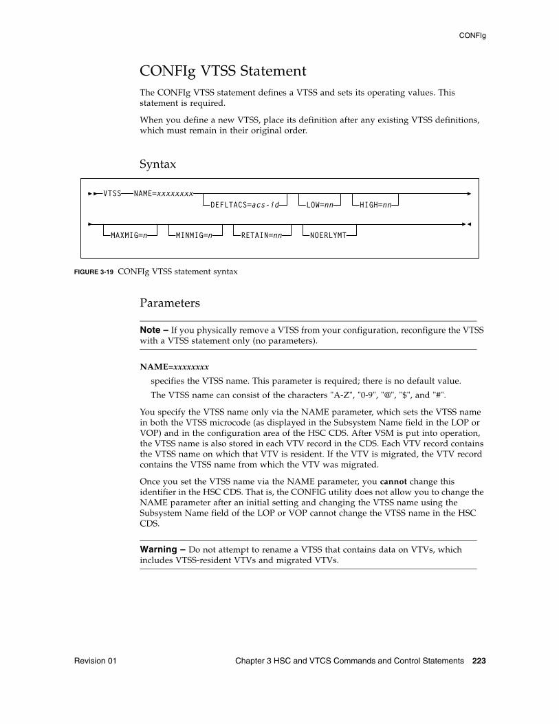
CONFIg
Revision 01 Chapter 3 HSC and VTCS Commands and Control Statements 223
CONFIg VTSS StatementThe CONFIg VTSS statement defines a VTSS and sets its operating values. This statement is required.
When you define a new VTSS, place its definition after any existing VTSS definitions, which must remain in their original order.
Syntax
FIGURE 3-19 CONFIg VTSS statement syntax
Parameters
Note – If you physically remove a VTSS from your configuration, reconfigure the VTSS with a VTSS statement only (no parameters).
NAME=xxxxxxxx
specifies the VTSS name. This parameter is required; there is no default value.
The VTSS name can consist of the characters "A-Z", "0-9", "@", "$", and "#".
You specify the VTSS name only via the NAME parameter, which sets the VTSS name in both the VTSS microcode (as displayed in the Subsystem Name field in the LOP or VOP) and in the configuration area of the HSC CDS. After VSM is put into operation, the VTSS name is also stored in each VTV record in the CDS. Each VTV record contains the VTSS name on which that VTV is resident. If the VTV is migrated, the VTV record contains the VTSS name from which the VTV was migrated.
Once you set the VTSS name via the NAME parameter, you cannot change this identifier in the HSC CDS. That is, the CONFIG utility does not allow you to change the NAME parameter after an initial setting and changing the VTSS name using the Subsystem Name field of the LOP or VOP cannot change the VTSS name in the HSC CDS.
Warning – Do not attempt to rename a VTSS that contains data on VTVs, which includes VTSS-resident VTVs and migrated VTVs.
VTSS NAME=xxxxxxxxDEFLTACS=acs-id LOW=nn HIGH=nn
MAXMIG=n MINMIG=n RETAIN=nn NOERLYMT
CONFIg
224 ELS 7.1 Command, Control Statement, and Utility Reference • November 2012 Revision 01
For an initial setting only (not a change), you can set the VTSS name in the NAME parameter only if the VTSS name value in the VTSS microcode is one of the following:
■ The factory setting (all blanks).■ A value of 99999999 (eight 9s).
Therefore, for an initial setting only, if the name in the VTSS microcode is not all blanks or 99999999, your Oracle StorageTek hardware representative must use the VTSS LOP or VOP to set the VTSS name to 99999999. This allows you to set the VTSS name to the value you want via the NAME parameter.
DEFLTACS=acs-id
optionally, VTCS supports multi-VTSS confirmations, and supports connecting multiple ACSs to each VTSS. In configurations where a VTSS is connected to multiple ACSs, use the DEFLTACS parameter to specify the default ACS from which MVCs will be selected for migration, consolidation, and reclaim processing.
You can migrate up to 4 VTV copies to separate ACSs (per MGMTclas statement) via the MGMTclas MIGpol parameter (and ignores the DEFLTACS parameter, as described below).
If you do not specify DEFLTACS, the default value is x’FF’, which allows VTCS to select MVCs from any ACS.
Note –
VTCS ignores the DEFLTACS value if you specify the DEFLTACS parameter and do either of the following:
■ Specify the ACSlist parameter of the MGMTclas statement.
■ Use a Storage Class.
LOW=nn
optionally, specifies the low automatic migration threshold (LAMT) for this VTSS.
Valid values are 5 to 95 and must be less than the HIGH default threshold. The default is 70.
HIGH=nn
optionally, specifies the high automatic migration threshold (HAMT) for this VTSS.
Valid values are 6 to 95 and must be greater than the LOW default threshold. The default is 80.
MAXMIG=n
optionally, specifies the maximum number of concurrent automatic migration, immediate migration, and migrate-to-threshold tasks for this VTSS.
Valid values are 1 to the number of RTDs attached to the VTSS. The default is half the number of RTDs attached to the VTSS.
MINMIG=n
optionally, specifies the minimum number of concurrent automatic migration, immediate migration, and migrate-to-threshold tasks for this VTSS.
Valid values are 1 to the MAXMIG setting. The default is 1 task.
CONFIg
Revision 01 Chapter 3 HSC and VTCS Commands and Control Statements 225
RETAIN=nn
optionally, specifies the number of minutes that VTCS will retain an MVC on an RTD in idle mode after a migration or recall. Retaining the MVC can reduce MVC mounts.
Valid values are 1 to 60. The default is 10.
The Concurrent Tape Recall/Mount feature is designed to improve mount time for a VTV that is not resident in the VTSS.
NOERLYMT
optionally, disables the Early Time to First Byte (ETTFB) feature for this VTSS. This parameter only applies if CONFIG GLOBAL FASTRECL=YES. This parameter applies to recalls from RTDs and recalls from VLE.
Note – This setting overrides the CONFIG GLOBAL FASTRECL=YES setting.
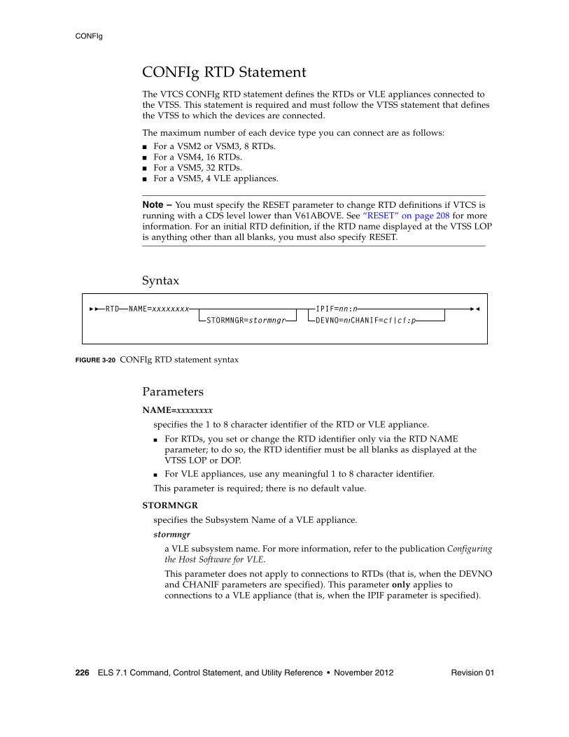
CONFIg
226 ELS 7.1 Command, Control Statement, and Utility Reference • November 2012 Revision 01
CONFIg RTD StatementThe VTCS CONFIg RTD statement defines the RTDs or VLE appliances connected to the VTSS. This statement is required and must follow the VTSS statement that defines the VTSS to which the devices are connected.
The maximum number of each device type you can connect are as follows:
■ For a VSM2 or VSM3, 8 RTDs. ■ For a VSM4, 16 RTDs. ■ For a VSM5, 32 RTDs.■ For a VSM5, 4 VLE appliances.
Note – You must specify the RESET parameter to change RTD definitions if VTCS is running with a CDS level lower than V61ABOVE. See “RESET” on page 208 for more information. For an initial RTD definition, if the RTD name displayed at the VTSS LOP is anything other than all blanks, you must also specify RESET.
Syntax
FIGURE 3-20 CONFIg RTD statement syntax
ParametersNAME=xxxxxxxx
specifies the 1 to 8 character identifier of the RTD or VLE appliance.
■ For RTDs, you set or change the RTD identifier only via the RTD NAME parameter; to do so, the RTD identifier must be all blanks as displayed at the VTSS LOP or DOP.
■ For VLE appliances, use any meaningful 1 to 8 character identifier.
This parameter is required; there is no default value.
STORMNGR
specifies the Subsystem Name of a VLE appliance.
stormngr
a VLE subsystem name. For more information, refer to the publication Configuring the Host Software for VLE.
This parameter does not apply to connections to RTDs (that is, when the DEVNO and CHANIF parameters are specified). This parameter only applies to connections to a VLE appliance (that is, when the IPIF parameter is specified).
RTD NAME=xxxxxxxxSTORMNGR=stormngr
IPIF=nn:nDEVNO=nnnnCHANIF=ci|ci:p
CONFIg
Revision 01 Chapter 3 HSC and VTCS Commands and Control Statements 227
IPIF=nn:n
specifies the IP interface on the VTSS IFF3 card that communicates with the VLE appliance. This value must match the value shown on the VTSS DOP IFF IP Configuration Status screen. For example, Target 0 on card IFF 0 has an interface value of 0A:0.
Note – The IPIF parameter is only valid for specifying a connection to a VLE appliance, it is not valid for RTD connections.
DEVNO=nnnn
specifies the unit address of the RTD.
This parameter is required with CHANIF; there is no default value.
CHANIF=ci or ci:p
specifies the channel interface on the VTSS that communicates with the RTD where:
■ c is the VTSS Storage Cluster number (0 or 1). ■ i is the interface number (A, C, E, G, I, K, M, or O)■ p is the device number on the interface (0, 1, 2, or 3).
This value must match the Nearlink channel interface defined at the VTSS by your Oracle StorageTek hardware representative at VTSS installation and configuration. This parameter is required with DEVNO; there is no default value.
■ Regardless of whether the Maximum 32 RTDs feature is enabled, if you do not have greater than 16 RTDs attached to a VTSS, you can use the “old” addressing scheme(CHANIF=ci).
■ If, however, the Maximum 32 RTDs feature is enabled and you have greater than 16 RTDs attached to a VTSS, you must use the “new” addressing scheme (CHANIF=ci:p).
Refer to the publication Configuring HSC and VTCS for more information.
Note – The DEVNO and CHANIF parameters are only valid for specifying RTD connections, they are not valid for a connection to a VLE appliance.
Caution – For RTDs, driving mount and dismount commands to the device is version dependant. If the remote HSC server is running V6.2, then it is dependant upon the local SMC trapping the MSP message and forwarding the mount/dismount across to the HSC server as if it was a job. If the remote HSC server is running V7 or above, then this is automatically detected and VTCS directs a mount/dismount request directly to the remote HSC server. It is important that the SMC parameters only direct commands to servers of one of these types.
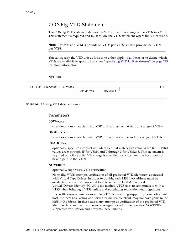
CONFIg
228 ELS 7.1 Command, Control Statement, and Utility Reference • November 2012 Revision 01
CONFIg VTD StatementThe CONFIg VTD statement defines the MSP unit address range of the VTDs in a VTSS. This statement is required and must follow the VTSS statement where the VTDs reside.
Note – VSM2s and VSM3s provide 64 VTDs per VTSS. VSM4s provide 256 VTDs per VTSS.
You can specify the VTD unit addresses to either apply to all hosts or to define which VTDs are available to specific hosts. See “Specifying VTD Unit Addresses” on page 229 for more information.
Syntax
FIGURE 3-21 CONFIg VTD statement syntax
ParametersLOW=xxxx
specifies a four character valid MSP unit address as the start of a range of VTDs.
HIGH=xxxx
specifies a four character valid MSP unit address as the end of a range of VTDs.
CUADDR=xx
optionally, specifies a control unit identifier that matches its value in the IOCP. Valid values are 0 through 15 for VSM4 and 0 through 3 for VSM2/3. This statement is required only if a partial VTD range is specified for a host and the host does not have a path to the VTDs.
NOVERIFY
optionally, suppresses VTD verification.
Normally, VTCS attempts verification of all predicted VTD identifiers associated with Virtual Tape Drives. In order to do this, each MSP I/O address must be available to allow the associated Host to issue the ECAM-T request Virtual_Device_Identify. ECAM is the method VTCS uses to communicate with a VTSS when bringing a VTSS online and scheduling replication and migrations.
In specific cases where, for example, VTCS is providing support for a remote client host, the local host, acting as a server for the remote client, may not have paths to the MSP I/O address. In these cases, any attempt at verification of the predicted VTD identifier fails and results in error messages posted to the operator. NOVERIFY suppresses verification and prevents these failures.
VTD LOW=xxxx HIGH=xxxxCUADDR=xx NOVERIFY
CONFIg
Revision 01 Chapter 3 HSC and VTCS Commands and Control Statements 229
When NOVERIFY is specified for a device or range of devices, the following occurs:
■ The device is reported to SMC so that VTVs can be mounted from MSP.
■ VTCS does not use that device for ECAM I/O. At least one device must be left without NOVERIFY so that it can be used for ECAM I/O.
Specifying VTD Unit AddressesYou can specify VTD addresses by doing one of the following:
■ Specify the VTD unit addresses on a VTD statement following a VTSS statement and do not specify any HOST statements following the VTSS statement. All hosts physically connected to the VTSS have access to its VTDs by the default addresses specified on the VTD statement.
■ Do not specify the VTD unit addresses on the VTD statement following a VTSS statement. Instead, place a VTD statement after a HOST statement for only those hosts for which you want to define connections to the previously defined VTSS. You must specify a placeholder (HOST NAME with no VTD parameter) for any hosts that you do not want connected to this VTSS.
Note – The VTVs created and MVCs initially written to from a VTSS are considered to be resources of that VTSS. Therefore, only hosts with access to a VTSS have access to its VTVs and MVCs. In this type of “restricted” access configuration, each host should have a separate VTV scratch pool to ensure that each host has accurate scratch counts. Similarly, free MVCs and MVC reclaim counts are reported on each host for the MVCs associated with the VTSS to which the host is connected.
You can specify different address ranges for each host, although Oracle recommends that you specify the same address ranges for all hosts for consistency of operations. If you specify different address ranges for different hosts, use the HSC SET DRVHOST and SMC DRIVEMAP statements if you have a client/server configuration. You must include UNITATTR MODEL(IGNORE) commands for all overgenned devices (including VTDs) on all MSP hosts.
Caution – In a multi-host, multi-VTSS configuration, you can use this VTD addressing method to deny access to VTSSs to which hosts are physically connected. You must, however, use this method to deny access from hosts that are not physically connected to a VTSS. If you do not deny access, VTCS on a host that does not have physical connections to a VTSS may wait, trying to communicate with the VTSS while VSM operations may be stalled on all other hosts.
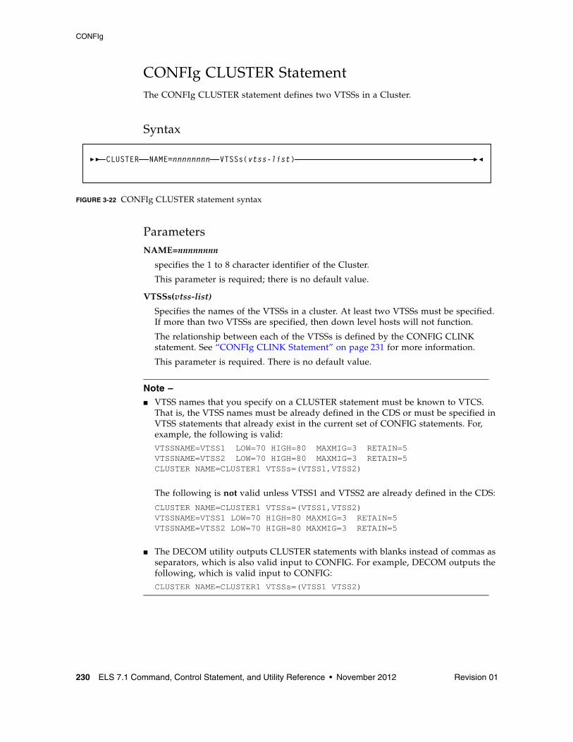
CONFIg
230 ELS 7.1 Command, Control Statement, and Utility Reference • November 2012 Revision 01
CONFIg CLUSTER StatementThe CONFIg CLUSTER statement defines two VTSSs in a Cluster.
Syntax
FIGURE 3-22 CONFIg CLUSTER statement syntax
ParametersNAME=nnnnnnnn
specifies the 1 to 8 character identifier of the Cluster.
This parameter is required; there is no default value.
VTSSs(vtss-list)
Specifies the names of the VTSSs in a cluster. At least two VTSSs must be specified. If more than two VTSSs are specified, then down level hosts will not function.
The relationship between each of the VTSSs is defined by the CONFIG CLINK statement. See “CONFIg CLINK Statement” on page 231 for more information.
This parameter is required. There is no default value.
Note – ■ VTSS names that you specify on a CLUSTER statement must be known to VTCS.
That is, the VTSS names must be already defined in the CDS or must be specified in VTSS statements that already exist in the current set of CONFIG statements. For, example, the following is valid:VTSSNAME=VTSS1 LOW=70 HIGH=80 MAXMIG=3 RETAIN=5VTSSNAME=VTSS2 LOW=70 HIGH=80 MAXMIG=3 RETAIN=5CLUSTER NAME=CLUSTER1 VTSSs=(VTSS1,VTSS2)
The following is not valid unless VTSS1 and VTSS2 are already defined in the CDS:
CLUSTER NAME=CLUSTER1 VTSSs=(VTSS1,VTSS2)VTSSNAME=VTSS1 LOW=70 HIGH=80 MAXMIG=3 RETAIN=5VTSSNAME=VTSS2 LOW=70 HIGH=80 MAXMIG=3 RETAIN=5
■ The DECOM utility outputs CLUSTER statements with blanks instead of commas as separators, which is also valid input to CONFIG. For example, DECOM outputs the following, which is valid input to CONFIG:CLUSTER NAME=CLUSTER1 VTSSs=(VTSS1 VTSS2)
CLUSTER NAME=nnnnnnnn VTSSs(vtss-list)
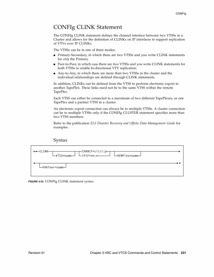
CONFIg
Revision 01 Chapter 3 HSC and VTCS Commands and Control Statements 231
CONFIg CLINK StatementThe CONFIg CLINK statement defines the channel interface between two VTSSs in a Cluster and allows for the definition of CLINKs on IP interfaces to support replication of VTVs over IP CLINKs.
The VTSSs can be in one of three modes:
■ Primary-Secondary, in which there are two VTSSs and you write CLINK statements for only the Primary.
■ Peer-to-Peer, in which case there are two VTSSs and you write CLINK statements for both VTSSs to enable bi-directional VTV replication.
■ Any-to-Any, in which there are more than two VTSSs in the cluster and the individual relationships are defined through CLINK statements.
In addition, CLINKs can be defined from the VTSS to perform electronic export to another TapePlex. These links need not be to the same VTSS within the remote TapePlex.
Each VTSS can either be connected to a maximum of two different TapePlexes, or one TapePlex and a partner VTSS in a cluster.
An electronic export connection can always be to multiple VTSSs. A cluster connection can be to multiple VTSSs only if the CONFIg CLUSTER statement specifies more than two VTSS members.
Refer to the publication ELS Disaster Recovery and Offsite Data Management Guide for examples.
Syntax
FIGURE 3-23 CONFIg CLINK statement syntax
CLINK CHANIF=ci|ci:pVTSS=name REMPlex=name
PARTner=name
IPIF=nn:n
CONFIg
232 ELS 7.1 Command, Control Statement, and Utility Reference • November 2012 Revision 01
ParametersVTSS=name
optionally, specifies the name of the VTCS that owns the CLINK. This is the VTSS from which the VTVs are replicated or exported.
If this parameter is omitted, by default, the CLINK is attached to the current VTSS being defined.
Note – The VTSS name that you specify on a CLINK statement must be known to VTCS. That is, the VTSS name must be already defined in the CDS or it must be specified in a VTSS statement that already exists in the current set of CONFIG statements. For, example, the following is valid:
VTSSNAME=VTSS1 LOW=70 HIGH=80 MAXMIG=3 RETAIN=5CLINK VTSS=VTSS1 CHANIF=0A
The following is not valid unless VTSS1 is already defined in the CDS:
CLINK VTSS=VTSS1 CHANIF=0AVTSSNAME=VTSS1 LOW=70 HIGH=80 MAXMIG=3 RETAIN=5
CHANIF=ci or ci:p
specifies the channel interface on the VTSS that communicates with the RTD where:
■ c is the VTSS Storage Cluster number (0 or 1). ■ i is the interface number (A, C, E, G, I, K, M, or O)■ p is the device number on the interface (0, 1, 2, or 3).
This value must match the Nearlink channel interface defined at the VTSS by your Oracle StorageTek hardware representative at VTSS installation and configuration.
Note – ■ Regardless of whether the Maximum 32 RTDs feature is enabled, if you do not have
greater than 16 RTDs attached to a VTSS, you can use the “old” addressing scheme (CHANIF=ci).
■ If, however, the Maximum 32 RTDs feature is enabled and you have greater than 16 RTDs attached to a VTSS, you must use the “new” addressing scheme (CHANIF=ci:p).
Refer to the publication Configuring HSC and VTCS for more information.
IPIF=nn:n
optionally, allows Ethernet connection of two Native IP (IFF3 card) ports, where the nn:n values are shown in parentheses before each Target IP Address on the IFF IP Configuration Status screen for each IFF ethernet port.
Refer to the publication Configuring HSC and VTCS for more information.
Note – The CLINK statement must contain either the CHANIF or the IPIF parameter, but not both.
CONFIg
Revision 01 Chapter 3 HSC and VTCS Commands and Control Statements 233
REMPlex=name
optionally, specifies the name of the TapePlex at the receiving end of the CLINK that receives the copies of the VTVs. During validation of the link, this name is compared with the THISPLEX definition in the remote system configuration.
The REMPlex parameter indicates that the CLINK is to be used for electronic export. Absence of this parameter indicates that the CLINK is to be used for a cluster connection.
PARTner=name
optionally, specifies the name of the VTSS at the receiving end of the CLINK that receives copies of the VTVs.
This parameter is required for CLINKs used for electronic export, or where the cluster consists of more than two VTSSs.
During validation of the link, this name is compared with the VTSS name at the other end of the CLINK.
VTD=n
optionally, specifies as a single hexadecimal digit, the ordinal number of the VTD in the partner VTSS that forms the inbound part of the connection.
Note – When the VTD parameter is specified, the PARTner parameter must also be specified.
Within a combination of REMPlex, PARTner, and VTD, every CLINK to be used for electronic export must be unique. For a cluster connection, the combination of PARTner and VTD within the configuration deck must be unique.
Caution – Although the uniqueness of the PARTner/VTD parameter values can be validated within a single configuration, it cannot be validated across different TapePlex configurations. If multiple TapePlexes (configurations) are exporting to a single TapePlex, it is essential that each VTD is only defined to one unique CLINK. This also means that each VTSS can only be referenced by a maximum of 14 CLINKs (8 for VSM3).
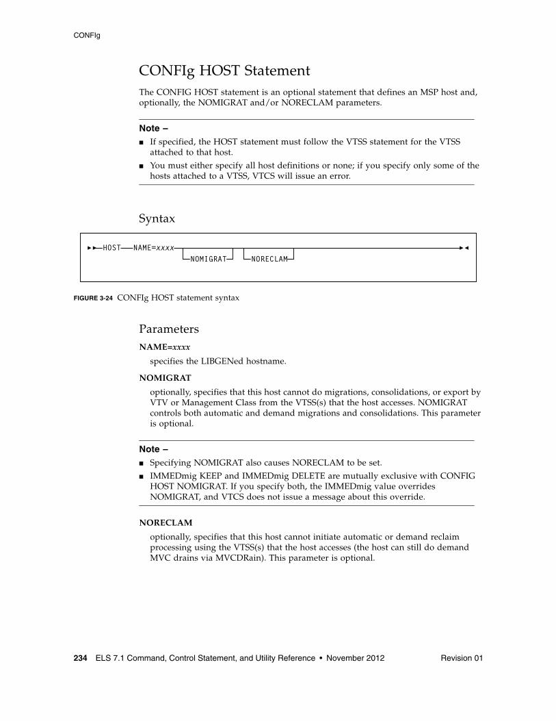
CONFIg
234 ELS 7.1 Command, Control Statement, and Utility Reference • November 2012 Revision 01
CONFIg HOST StatementThe CONFIG HOST statement is an optional statement that defines an MSP host and, optionally, the NOMIGRAT and/or NORECLAM parameters.
Note – ■ If specified, the HOST statement must follow the VTSS statement for the VTSS
attached to that host.
■ You must either specify all host definitions or none; if you specify only some of the hosts attached to a VTSS, VTCS will issue an error.
Syntax
FIGURE 3-24 CONFIg HOST statement syntax
ParametersNAME=xxxx
specifies the LIBGENed hostname.
NOMIGRAT
optionally, specifies that this host cannot do migrations, consolidations, or export by VTV or Management Class from the VTSS(s) that the host accesses. NOMIGRAT controls both automatic and demand migrations and consolidations. This parameter is optional.
Note – ■ Specifying NOMIGRAT also causes NORECLAM to be set.
■ IMMEDmig KEEP and IMMEDmig DELETE are mutually exclusive with CONFIG HOST NOMIGRAT. If you specify both, the IMMEDmig value overrides NOMIGRAT, and VTCS does not issue a message about this override.
NORECLAM
optionally, specifies that this host cannot initiate automatic or demand reclaim processing using the VTSS(s) that the host accesses (the host can still do demand MVC drains via MVCDRain). This parameter is optional.
HOST NAME=xxxxNOMIGRAT NORECLAM
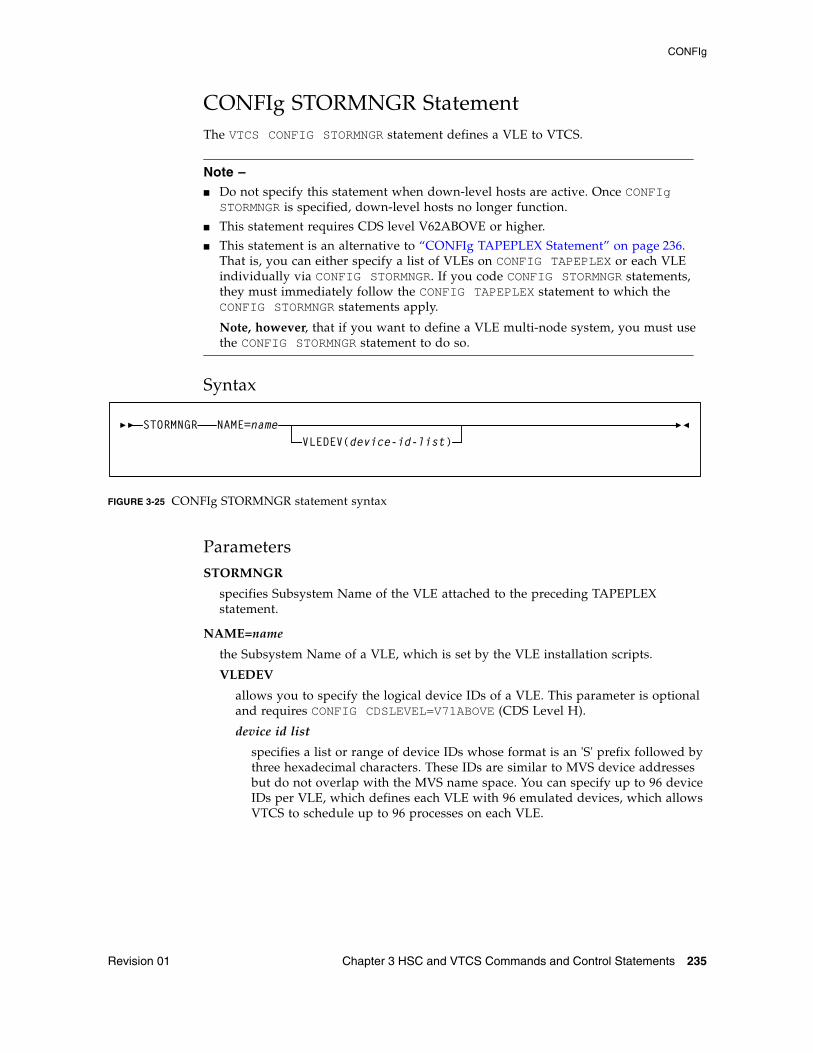
CONFIg
Revision 01 Chapter 3 HSC and VTCS Commands and Control Statements 235
CONFIg STORMNGR StatementThe VTCS CONFIG STORMNGR statement defines a VLE to VTCS.
Note – ■ Do not specify this statement when down-level hosts are active. Once CONFIg
STORMNGR is specified, down-level hosts no longer function.
■ This statement requires CDS level V62ABOVE or higher.
■ This statement is an alternative to “CONFIg TAPEPLEX Statement” on page 236. That is, you can either specify a list of VLEs on CONFIG TAPEPLEX or each VLE individually via CONFIG STORMNGR. If you code CONFIG STORMNGR statements, they must immediately follow the CONFIG TAPEPLEX statement to which the CONFIG STORMNGR statements apply.
Note, however, that if you want to define a VLE multi-node system, you must use the CONFIG STORMNGR statement to do so.
Syntax
FIGURE 3-25 CONFIg STORMNGR statement syntax
ParametersSTORMNGR
specifies Subsystem Name of the VLE attached to the preceding TAPEPLEX statement.
NAME=name
the Subsystem Name of a VLE, which is set by the VLE installation scripts.
VLEDEV
allows you to specify the logical device IDs of a VLE. This parameter is optional and requires CONFIG CDSLEVEL=V71ABOVE (CDS Level H).
device id list
specifies a list or range of device IDs whose format is an 'S' prefix followed by three hexadecimal characters. These IDs are similar to MVS device addresses but do not overlap with the MVS name space. You can specify up to 96 device IDs per VLE, which defines each VLE with 96 emulated devices, which allows VTCS to schedule up to 96 processes on each VLE.
STORMNGR NAME=nameVLEDEV(device-id-list)
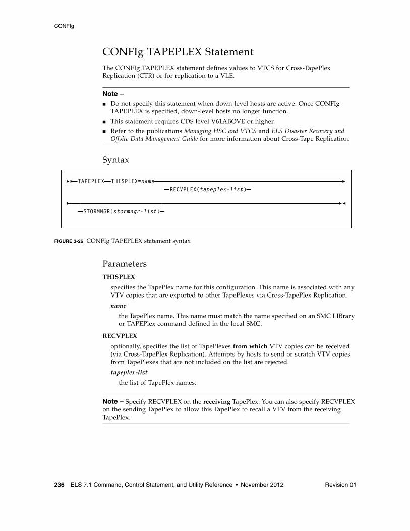
CONFIg
236 ELS 7.1 Command, Control Statement, and Utility Reference • November 2012 Revision 01
CONFIg TAPEPLEX StatementThe CONFIg TAPEPLEX statement defines values to VTCS for Cross-TapePlex Replication (CTR) or for replication to a VLE.
Note – ■ Do not specify this statement when down-level hosts are active. Once CONFIg
TAPEPLEX is specified, down-level hosts no longer function.
■ This statement requires CDS level V61ABOVE or higher.
■ Refer to the publications Managing HSC and VTCS and ELS Disaster Recovery and Offsite Data Management Guide for more information about Cross-Tape Replication.
Syntax
FIGURE 3-26 CONFIg TAPEPLEX statement syntax
ParametersTHISPLEX
specifies the TapePlex name for this configuration. This name is associated with any VTV copies that are exported to other TapePlexes via Cross-TapePlex Replication.
name
the TapePlex name. This name must match the name specified on an SMC LIBrary or TAPEPlex command defined in the local SMC.
RECVPLEX
optionally, specifies the list of TapePlexes from which VTV copies can be received (via Cross-TapePlex Replication). Attempts by hosts to send or scratch VTV copies from TapePlexes that are not included on the list are rejected.
tapeplex-list
the list of TapePlex names.
Note – Specify RECVPLEX on the receiving TapePlex. You can also specify RECVPLEX on the sending TapePlex to allow this TapePlex to recall a VTV from the receiving TapePlex.
TAPEPLEXRECVPLEX(tapeplex-list)
THISPLEX=name
STORMNGR(stormngr-list)
CONFIg
Revision 01 Chapter 3 HSC and VTCS Commands and Control Statements 237
STORMNGR
optionally, specifies Subsystem Names of the VLE appliances attached to this TapePlex.
stormngr-list
the list of VLE subsystem names. For more information, refer to the publication Configuring the Host Software for VLE.
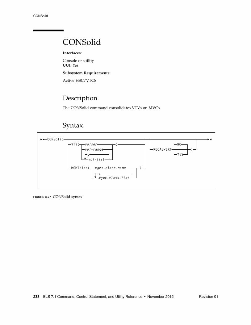
CONSolid
238 ELS 7.1 Command, Control Statement, and Utility Reference • November 2012 Revision 01
CONSolidInterfaces:
Console or utilityUUI: Yes
Subsystem Requirements:
Active HSC/VTCS
DescriptionThe CONSolid command consolidates VTVs on MVCs.
Syntax
FIGURE 3-27 CONSolid syntax
CONSolidVTV(
vol-rangevolser
vol-list,
)
MGMTclas( mgmt-class-name ),mgmt-class-list
RECALWER(NO
YES)
CONSolid
Revision 01 Chapter 3 HSC and VTCS Commands and Control Statements 239
ParametersVTV
optionally, specifies one or more VTVs to consolidate.
volser, vol-range or vol-list
the volser, volser range, or volser list of VTVs. You can specify a maximum of 2,000 VTVs.
MGMTclas
optionally, specifies the names of one or more Management Classes that determine the VTVs to consolidate.
mgmt-class-name | mgmt-class-list
the names of one or more Management Classes that you defined on the MGMTclas control statement; for more information, see “MGMTclas Control Statement” on page 433. You can consolidate a maximum of 2,000 VTVs by specifying a Management Class.
RECALWER
optionally, specifies whether VTCS recalls VTVs with read data checks.
NO
Do not recall VTVs with read data checks. This is the default.
YES
Recall VTVs with read data checks.
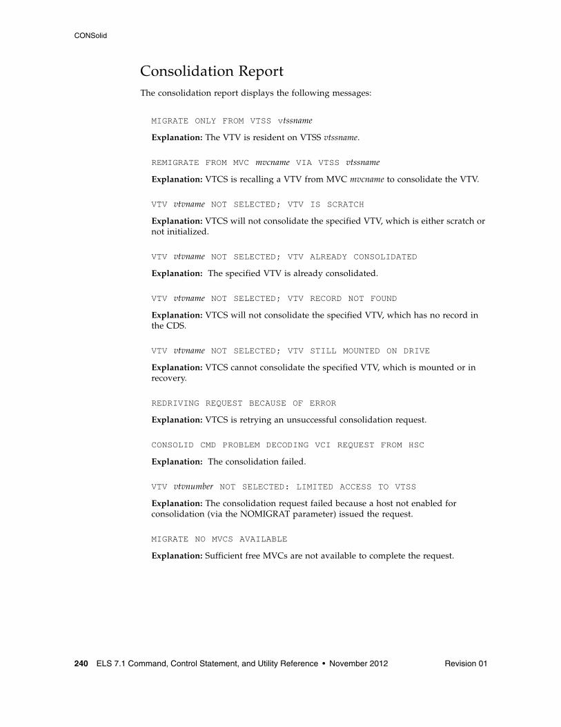
CONSolid
240 ELS 7.1 Command, Control Statement, and Utility Reference • November 2012 Revision 01
Consolidation ReportThe consolidation report displays the following messages:
MIGRATE ONLY FROM VTSS vtssname
Explanation: The VTV is resident on VTSS vtssname.
REMIGRATE FROM MVC mvcname VIA VTSS vtssname
Explanation: VTCS is recalling a VTV from MVC mvcname to consolidate the VTV.
VTV vtvname NOT SELECTED; VTV IS SCRATCH
Explanation: VTCS will not consolidate the specified VTV, which is either scratch or not initialized.
VTV vtvname NOT SELECTED; VTV ALREADY CONSOLIDATED
Explanation: The specified VTV is already consolidated.
VTV vtvname NOT SELECTED; VTV RECORD NOT FOUND
Explanation: VTCS will not consolidate the specified VTV, which has no record in the CDS.
VTV vtvname NOT SELECTED; VTV STILL MOUNTED ON DRIVE
Explanation: VTCS cannot consolidate the specified VTV, which is mounted or in recovery.
REDRIVING REQUEST BECAUSE OF ERROR
Explanation: VTCS is retrying an unsuccessful consolidation request.
CONSOLID CMD PROBLEM DECODING VCI REQUEST FROM HSC
Explanation: The consolidation failed.
VTV vtvnumber NOT SELECTED: LIMITED ACCESS TO VTSS
Explanation: The consolidation request failed because a host not enabled for consolidation (via the NOMIGRAT parameter) issued the request.
MIGRATE NO MVCS AVAILABLE
Explanation: Sufficient free MVCs are not available to complete the request.
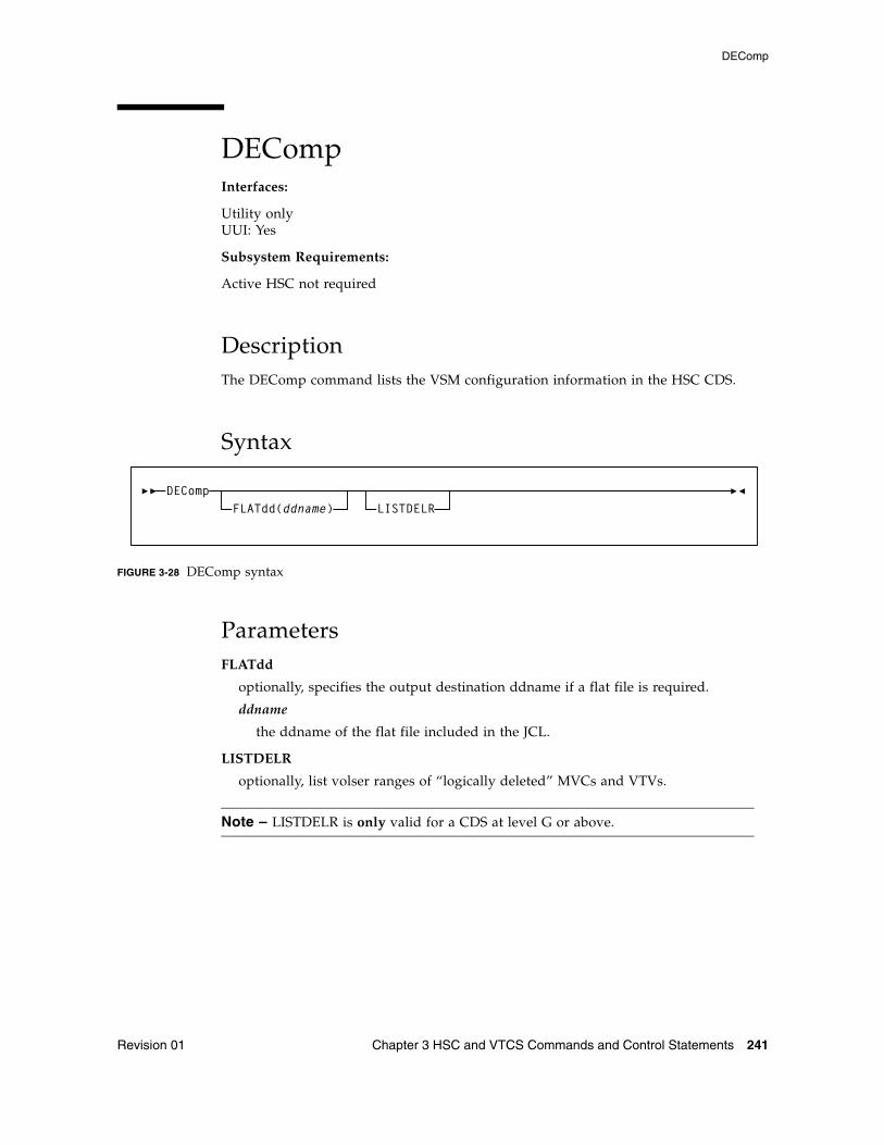
DEComp
Revision 01 Chapter 3 HSC and VTCS Commands and Control Statements 241
DECompInterfaces:
Utility onlyUUI: Yes
Subsystem Requirements:
Active HSC not required
DescriptionThe DEComp command lists the VSM configuration information in the HSC CDS.
Syntax
FIGURE 3-28 DEComp syntax
ParametersFLATdd
optionally, specifies the output destination ddname if a flat file is required.
ddname
the ddname of the flat file included in the JCL.
LISTDELR
optionally, list volser ranges of “logically deleted” MVCs and VTVs.
Note – LISTDELR is only valid for a CDS at level G or above.
DECompFLATdd(ddname) LISTDELR
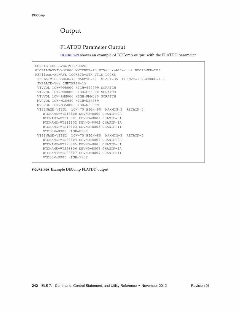
DEComp
242 ELS 7.1 Command, Control Statement, and Utility Reference • November 2012 Revision 01
Output
FLATDD Parameter OutputFIGURE 3-29 shows an example of DEComp output with the FLATDD parameter.
FIGURE 3-29 Example DEComp FLATDD output
CONFIG CDSLEVEL(V62ABOVE)GLOBALMAXVTV=32000 MVCFREE=40 VTVattr=ALLmount RECALWER=YES REPlicat=ALWAYS LOCKSTR=STK_VTCS_LOCKS RECLAIMTHRESHLD=70 MAXMVC=40 START=35 CONMVC=1 VLTHRES=1 + INPLACE=Yes INPTHRSH=15 VTVVOL LOW=905000 HIGH=999999 SCRATCH VTVVOL LOW=C00000 HIGH=C25000 SCRATCH VTVVOL LOW=RMM000 HIGH=RMM020 SCRATCH MVCVOL LOW=N25980 HIGH=N25989 MVCVOL LOW=N35000 HIGH=N35999 VTSSNAME=VTSS1 LOW=70 HIGH=80 MAXMIG=3 RETAIN=5 RTDNAME=VTS18800 DEVNO=8800 CHANIF=0A RTDNAME=VTS18801 DEVNO=8801 CHANIF=0I RTDNAME=VTS18802 DEVNO=8802 CHANIF=1A RTDNAME=VTS18803 DEVNO=8803 CHANIF=1I VTDLOW=8900 HIGH=893F VTSSNAME=VTSS2 LOW=70 HIGH=80 MAXMIG=3 RETAIN=5 RTDNAME=VTS28804 DEVNO=8804 CHANIF=0A RTDNAME=VTS28805 DEVNO=8805 CHANIF=0I RTDNAME=VTS28806 DEVNO=8806 CHANIF=1A RTDNAME=VTS28807 DEVNO=8807 CHANIF=1I VTDLOW=9900 HIGH=993F
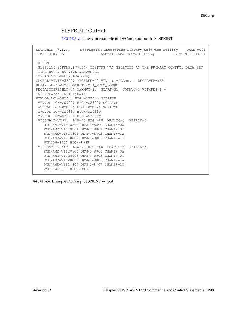
DEComp
Revision 01 Chapter 3 HSC and VTCS Commands and Control Statements 243
SLSPRINT OutputFIGURE 3-30 shows an example of DEComp output to SLSPRINT.
FIGURE 3-30 Example DEComp SLSPRINT output
SLUADMIN (7.1.0) StorageTek Enterprise Library Software Utility PAGE 0001TIME 09:07:06 Control Card Image Listing DATE 2010-03-31
DECOM SLS1315I SSRDMP.P775644.TESTCDS WAS SELECTED AS THE PRIMARY CONTROL DATA SET TIME 09:07:06 VTCS DECOMPILECONFIG CDSLEVEL(V62ABOVE)GLOBALMAXVTV=32000 MVCFREE=40 VTVattr=ALLmount RECALWER=YES REPlicat=ALWAYS LOCKSTR=STK_VTCS_LOCKSRECLAIMTHRESHLD=70 MAXMVC=40 START=35 CONMVC=1 VLTHRES=1 +INPLACE=Yes INPTHRSH=15VTVVOL LOW=905000 HIGH=999999 SCRATCH VTVVOL LOW=C00000 HIGH=C25000 SCRATCH VTVVOL LOW=RMM000 HIGH=RMM020 SCRATCH MVCVOL LOW=N25980 HIGH=N25989 MVCVOL LOW=N35000 HIGH=N35999 VTSSNAME=VTSS1 LOW=70 HIGH=80 MAXMIG=3 RETAIN=5 RTDNAME=VTS18800 DEVNO=8800 CHANIF=0A RTDNAME=VTS18801 DEVNO=8801 CHANIF=0I RTDNAME=VTS18802 DEVNO=8802 CHANIF=1A RTDNAME=VTS18803 DEVNO=8803 CHANIF=1I VTDLOW=8900 HIGH=893F VTSSNAME=VTSS2 LOW=70 HIGH=80 MAXMIG=3 RETAIN=5 RTDNAME=VTS28804 DEVNO=8804 CHANIF=0A RTDNAME=VTS28805 DEVNO=8805 CHANIF=0I RTDNAME=VTS28806 DEVNO=8806 CHANIF=1A RTDNAME=VTS28807 DEVNO=8807 CHANIF=1I VTDLOW=9900 HIGH=993F
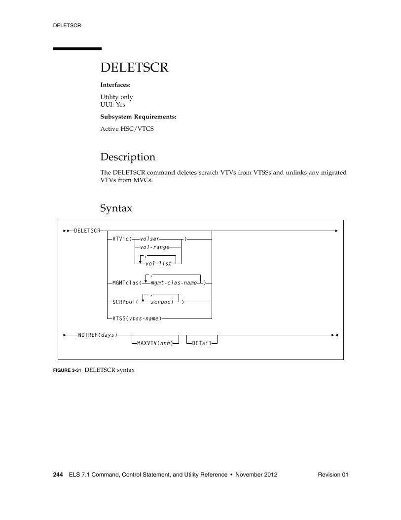
DELETSCR
244 ELS 7.1 Command, Control Statement, and Utility Reference • November 2012 Revision 01
DELETSCRInterfaces:
Utility onlyUUI: Yes
Subsystem Requirements:
Active HSC/VTCS
DescriptionThe DELETSCR command deletes scratch VTVs from VTSSs and unlinks any migrated VTVs from MVCs.
Syntax
FIGURE 3-31 DELETSCR syntax
DELETSCRVTVid(
vol-list
vol-range,
volser )
MGMTclas(,mgmt-clas-name )
SCRPool(,scrpool )
NOTREF(days)MAXVTV(nnn) DETail
VTSS(vtss-name)
DELETSCR
Revision 01 Chapter 3 HSC and VTCS Commands and Control Statements 245
ParametersVTVid
optionally, specifies one or more VTVs to be deleted.
volser, vol-range or vol-list
the volsers of one or more VTVs.
MGMTclas
optionally, specifies the Management Class(es) of the VTVs.
mgmt-class-name
the Management Class name that you specified on the MGMTclas control statement.
SCRPool
optionally, specifies the scratch pool(s) to be deleted. If the pool contains VTVs and real volumes, DELETSCR deletes only VTVs.
scrpool
an existing HSC scratch pool.
VTSS
optionally, causes scratch VTVs within the specified VTSS to be deleted.
vtss-name
the VTSS name.
Note – VTVid, MGMTclas, SCRPool, and VTSS are mutually exclusive. If you do not specify one of these parameters, VTCS processes all scratch VTVs.
NOTREF
specifies the number of days since a VTV was last referenced for it to be deleted by DELETSCR.
days
the number of days (1-999).
MAXVTV
optionally, specifies the maximum number of VTVs that DELETSCR deletes. Note that this is a maximum, not a target.
nnn
the maximum number of VTVs (0-999). If not specified, DELETSCR deletes all scratch VTVs. If you specify 0, DELETSCR does not delete any VTVs, but the summary report shows how many VTVs would have been deleted...at the point at which you ran DELETSCR (that is, the report is just a snapshot).
DETail
optionally, produce a detailed report that also shows detail and summary of VTVs that fall within the NOTREF period.
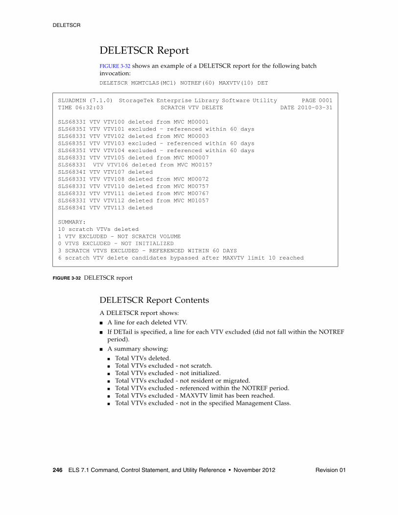
DELETSCR
246 ELS 7.1 Command, Control Statement, and Utility Reference • November 2012 Revision 01
DELETSCR ReportFIGURE 3-32 shows an example of a DELETSCR report for the following batch invocation:DELETSCR MGMTCLAS(MC1) NOTREF(60) MAXVTV(10) DET
FIGURE 3-32 DELETSCR report
DELETSCR Report ContentsA DELETSCR report shows:
■ A line for each deleted VTV.
■ If DETail is specified, a line for each VTV excluded (did not fall within the NOTREF period).
■ A summary showing:
■ Total VTVs deleted. ■ Total VTVs excluded - not scratch. ■ Total VTVs excluded - not initialized. ■ Total VTVs excluded - not resident or migrated. ■ Total VTVs excluded - referenced within the NOTREF period. ■ Total VTVs excluded - MAXVTV limit has been reached. ■ Total VTVs excluded - not in the specified Management Class.
SLUADMIN (7.1.0) StorageTek Enterprise Library Software Utility PAGE 0001TIME 06:32:03 SCRATCH VTV DELETE DATE 2010-03-31
SLS6833I VTV VTV100 deleted from MVC M00001SLS6835I VTV VTV101 excluded – referenced within 60 daysSLS6833I VTV VTV102 deleted from MVC M00003SLS6835I VTV VTV103 excluded – referenced within 60 daysSLS6835I VTV VTV104 excluded – referenced within 60 daysSLS6833I VTV VTV105 deleted from MVC M00007SLS6833I VTV VTV106 deleted from MVC M00157SLS6834I VTV VTV107 deletedSLS6833I VTV VTV108 deleted from MVC M00072SLS6833I VTV VTV110 deleted from MVC M00757SLS6833I VTV VTV111 deleted from MVC M00767SLS6833I VTV VTV112 deleted from MVC M01057SLS6834I VTV VTV113 deleted
SUMMARY:10 scratch VTVs deleted1 VTV EXCLUDED - NOT SCRATCH VOLUME0 VTVS EXCLUDED - NOT INITIALIZED3 SCRATCH VTVS EXCLUDED - REFERENCED WITHIN 60 DAYS6 scratch VTV delete candidates bypassed after MAXVTV limit 10 reached
DIRBLD
Revision 01 Chapter 3 HSC and VTCS Commands and Control Statements 247
DIRBLDInterfaces:
Utility onlyUUI: No
Subsystem Requirements:
Active HSC not required
DescriptionThe DIRBLD command rebuilds the database directory for all defined CDS copies.
The control data set contains a directory of pointers to various important locations and if damaged, can cause operational problems. Normally, HSC corrects such errors automatically. The DIRBLD utility repairs a corrupted CDS database directory. This utility can be run while the HSC is stopped or running to repair damage to the directory and maintain continuous operation. It must be run using all CDS copies as input.
Caution – Contact Oracle StorageTek Support before running the DIRBLD utility to insure that the CDS is not further damaged by inappropriate use or inappropriate operational conditions.
Syntax
FIGURE 3-33 DIRBLD syntax
ParametersNone.
DIRBLD
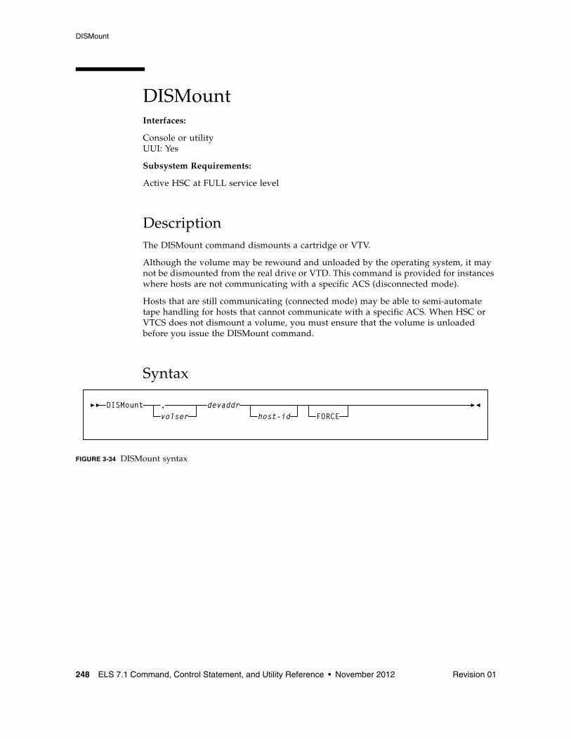
DISMount
248 ELS 7.1 Command, Control Statement, and Utility Reference • November 2012 Revision 01
DISMountInterfaces:
Console or utilityUUI: Yes
Subsystem Requirements:
Active HSC at FULL service level
DescriptionThe DISMount command dismounts a cartridge or VTV.
Although the volume may be rewound and unloaded by the operating system, it may not be dismounted from the real drive or VTD. This command is provided for instances where hosts are not communicating with a specific ACS (disconnected mode).
Hosts that are still communicating (connected mode) may be able to semi-automate tape handling for hosts that cannot communicate with a specific ACS. When HSC or VTCS does not dismount a volume, you must ensure that the volume is unloaded before you issue the DISMount command.
Syntax
FIGURE 3-34 DISMount syntax
DISMountvolser, devaddr
host-id FORCE
DISMount
Revision 01 Chapter 3 HSC and VTCS Commands and Control Statements 249
Parametersvolser
optionally, specifies which volume to dismount. The volser operand is optional. If it is not specified, the robot dismounts whatever volume is mounted on the device.
If volser is not specified, a comma must be entered immediately before the device address to indicate the missing operand. For example:
DISMOUNT ,B00
devaddr
specifies the device address of the transport from which the volume is to be dismounted.
host-id
optionally, indicates that the DISMount command is to be performed for the device address of the specified host (the SMF system identifier for JES).
FORCE
optionally, specifies that the drive will be unloaded before the volume is dismounted. This parameter is not valid for virtual drives.
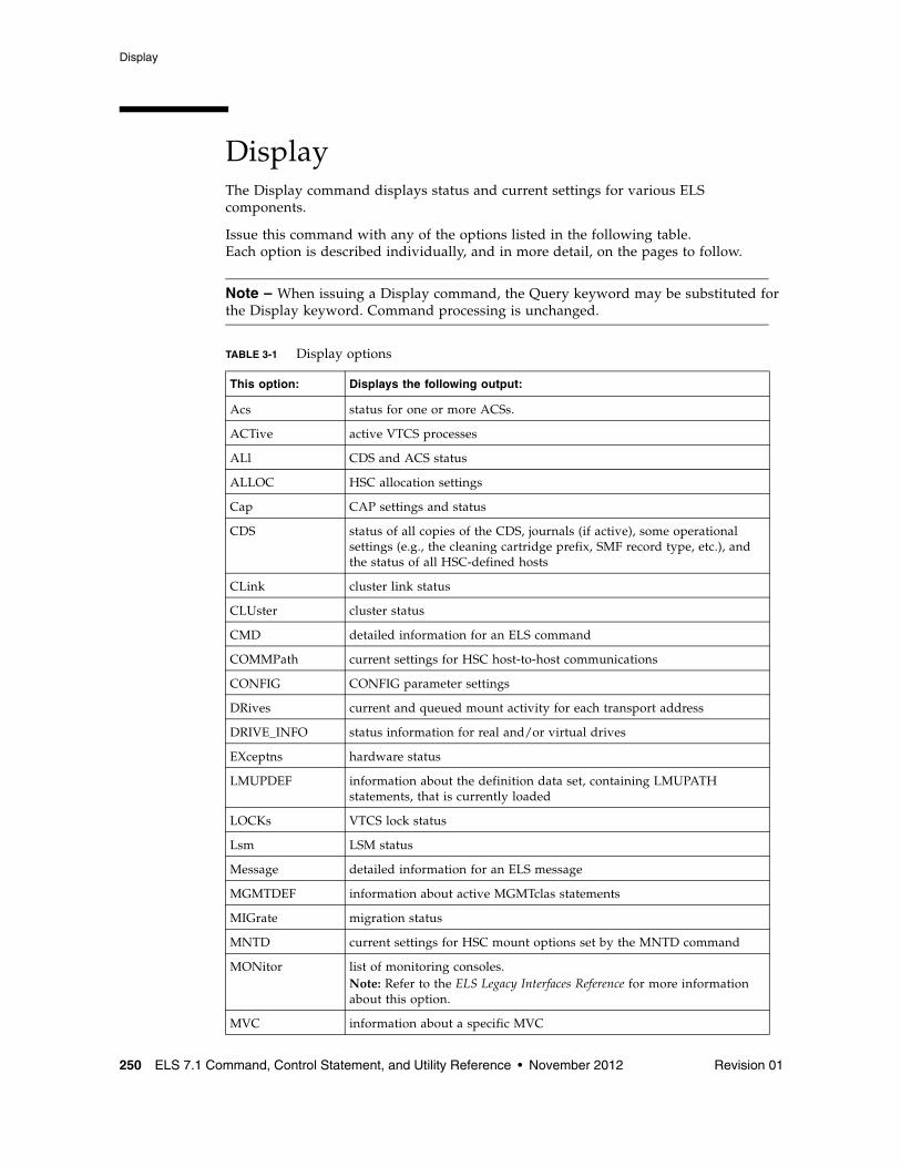
Display
250 ELS 7.1 Command, Control Statement, and Utility Reference • November 2012 Revision 01
DisplayThe Display command displays status and current settings for various ELS components.
Issue this command with any of the options listed in the following table. Each option is described individually, and in more detail, on the pages to follow.
Note – When issuing a Display command, the Query keyword may be substituted for the Display keyword. Command processing is unchanged.
TABLE 3-1 Display options
This option: Displays the following output:
Acs status for one or more ACSs.
ACTive active VTCS processes
ALl CDS and ACS status
ALLOC HSC allocation settings
Cap CAP settings and status
CDS status of all copies of the CDS, journals (if active), some operational settings (e.g., the cleaning cartridge prefix, SMF record type, etc.), and the status of all HSC-defined hosts
CLink cluster link status
CLUster cluster status
CMD detailed information for an ELS command
COMMPath current settings for HSC host-to-host communications
CONFIG CONFIG parameter settings
DRives current and queued mount activity for each transport address
DRIVE_INFO status information for real and/or virtual drives
EXceptns hardware status
LMUPDEF information about the definition data set, containing LMUPATH statements, that is currently loaded
LOCKs VTCS lock status
Lsm LSM status
Message detailed information for an ELS message
MGMTDEF information about active MGMTclas statements
MIGrate migration status
MNTD current settings for HSC mount options set by the MNTD command
MONitor list of monitoring consoles.Note: Refer to the ELS Legacy Interfaces Reference for more information about this option.
MVC information about a specific MVC
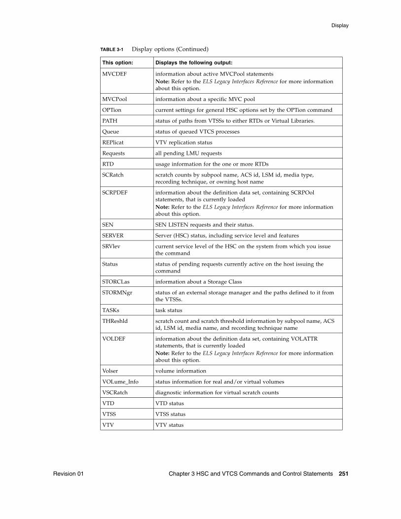
Display
Revision 01 Chapter 3 HSC and VTCS Commands and Control Statements 251
MVCDEF information about active MVCPool statementsNote: Refer to the ELS Legacy Interfaces Reference for more information about this option.
MVCPool information about a specific MVC pool
OPTion current settings for general HSC options set by the OPTion command
PATH status of paths from VTSSs to either RTDs or Virtual Libraries.
Queue status of queued VTCS processes
REPlicat VTV replication status
Requests all pending LMU requests
RTD usage information for the one or more RTDs
SCRatch scratch counts by subpool name, ACS id, LSM id, media type, recording technique, or owning host name
SCRPDEF information about the definition data set, containing SCRPOol statements, that is currently loadedNote: Refer to the ELS Legacy Interfaces Reference for more information about this option.
SEN SEN LISTEN requests and their status.
SERVER Server (HSC) status, including service level and features
SRVlev current service level of the HSC on the system from which you issue the command
Status status of pending requests currently active on the host issuing the command
STORCLas information about a Storage Class
STORMNgr status of an external storage manager and the paths defined to it from the VTSSs.
TASKs task status
THReshld scratch count and scratch threshold information by subpool name, ACS id, LSM id, media name, and recording technique name
VOLDEF information about the definition data set, containing VOLATTR statements, that is currently loadedNote: Refer to the ELS Legacy Interfaces Reference for more information about this option.
Volser volume information
VOLume_Info status information for real and/or virtual volumes
VSCRatch diagnostic information for virtual scratch counts
VTD VTD status
VTSS VTSS status
VTV VTV status
TABLE 3-1 Display options (Continued)
This option: Displays the following output:
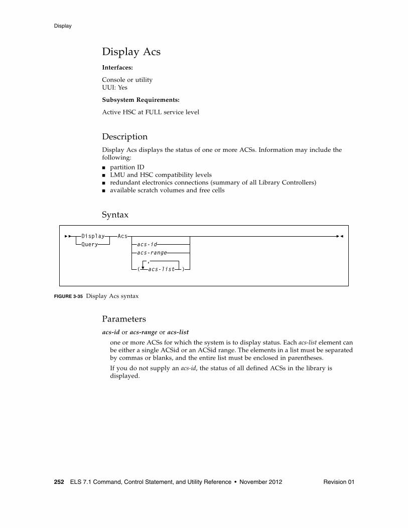
Display
252 ELS 7.1 Command, Control Statement, and Utility Reference • November 2012 Revision 01
Display AcsInterfaces:
Console or utilityUUI: Yes
Subsystem Requirements:
Active HSC at FULL service level
DescriptionDisplay Acs displays the status of one or more ACSs. Information may include the following:
■ partition ID■ LMU and HSC compatibility levels■ redundant electronics connections (summary of all Library Controllers)■ available scratch volumes and free cells
Syntax
FIGURE 3-35 Display Acs syntax
Parametersacs-id or acs-range or acs-list
one or more ACSs for which the system is to display status. Each acs-list element can be either a single ACSid or an ACSid range. The elements in a list must be separated by commas or blanks, and the entire list must be enclosed in parentheses.
If you do not supply an acs-id, the status of all defined ACSs in the library is displayed.
Acsacs-idacs-range
(,acs-list )
DisplayQuery
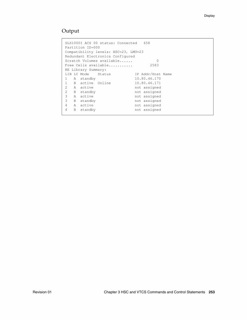
Display
Revision 01 Chapter 3 HSC and VTCS Commands and Control Statements 253
Output
SLS1000I ACS 00 status: Connected 658Partition ID=000Compatibility levels: HSC=23, LMU=23Redundant Electronics ConfiguredScratch Volumes available...... 0Free Cells available........... 2583RE Library Summary:LIB LC Mode Status IP Addr/Host Name1 A standby 10.80.46.1701 B active Online 10.80.46.1712 A active not assigned2 B standby not assigned3 A active not assigned3 B standby not assigned4 A active not assigned4 B standby not assigned
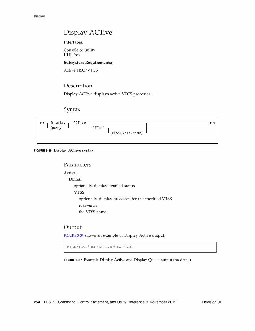
Display
254 ELS 7.1 Command, Control Statement, and Utility Reference • November 2012 Revision 01
Display ACTiveInterfaces:
Console or utilityUUI: Yes
Subsystem Requirements:
Active HSC/VTCS
DescriptionDisplay ACTive displays active VTCS processes.
Syntax
FIGURE 3-36 Display ACTive syntax
ParametersActive
DETail
optionally, display detailed status.
VTSS
optionally, display processes for the specified VTSS.
vtss-name
the VTSS name.
OutputFIGURE 3-37 shows an example of Display Active output.
FIGURE 3-37 Example Display Active and Display Queue output (no detail)
MIGRATES=3RECALLS=2RECLAIMS=0
ACTiveDETail
VTSS(vtss-name)
DisplayQuery
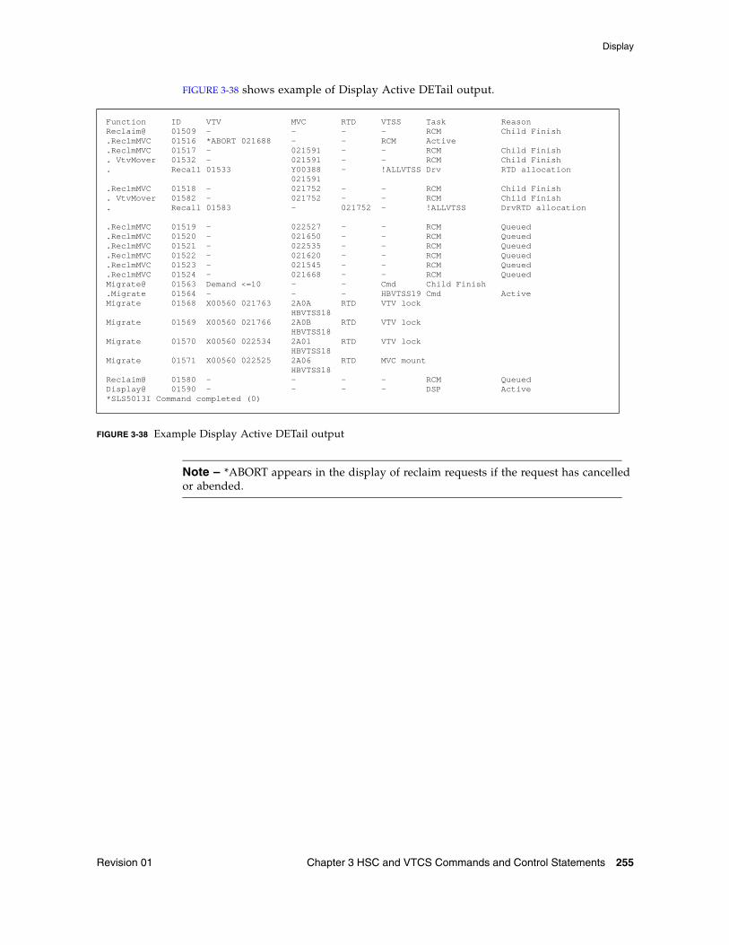
Display
Revision 01 Chapter 3 HSC and VTCS Commands and Control Statements 255
FIGURE 3-38 shows example of Display Active DETail output.
FIGURE 3-38 Example Display Active DETail output
Note – *ABORT appears in the display of reclaim requests if the request has cancelled or abended.
Function ID VTV MVC RTD VTSS Task ReasonReclaim@ 01509 - - - - RCM Child Finish.ReclmMVC 01516 *ABORT 021688 - - RCM Active.ReclmMVC 01517 - 021591 - - RCM Child Finish. VtvMover 01532 - 021591 - - RCM Child Finish. Recall 01533 Y00388 - !ALLVTSS Drv RTD allocation 021591.ReclmMVC 01518 - 021752 - - RCM Child Finish. VtvMover 01582 - 021752 - - RCM Child Finish. Recall 01583 - 021752 - !ALLVTSS DrvRTD allocation
.ReclmMVC 01519 - 022527 - - RCM Queued
.ReclmMVC 01520 - 021650 - - RCM Queued
.ReclmMVC 01521 - 022535 - - RCM Queued
.ReclmMVC 01522 - 021620 - - RCM Queued
.ReclmMVC 01523 - 021545 - - RCM Queued
.ReclmMVC 01524 - 021668 - - RCM QueuedMigrate@ 01563 Demand <=10 - - Cmd Child Finish.Migrate 01564 - - - HBVTSS19 Cmd ActiveMigrate 01568 X00560 021763 2A0A RTD VTV lock HBVTSS18Migrate 01569 X00560 021766 2A0B RTD VTV lock HBVTSS18Migrate 01570 X00560 022534 2A01 RTD VTV lock HBVTSS18Migrate 01571 X00560 022525 2A06 RTD MVC mount HBVTSS18Reclaim@ 01580 - - - - RCM QueuedDisplay@ 01590 - - - - DSP Active*SLS5013I Command completed (0)
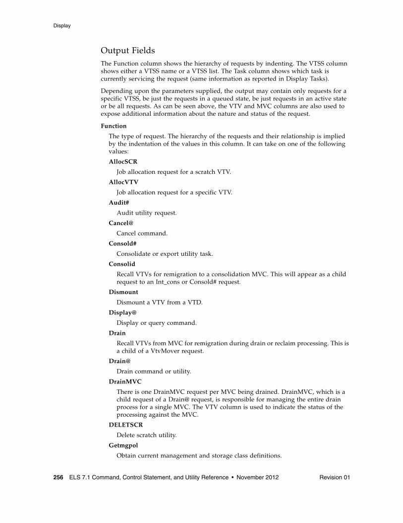
Display
256 ELS 7.1 Command, Control Statement, and Utility Reference • November 2012 Revision 01
Output FieldsThe Function column shows the hierarchy of requests by indenting. The VTSS column shows either a VTSS name or a VTSS list. The Task column shows which task is currently servicing the request (same information as reported in Display Tasks).
Depending upon the parameters supplied, the output may contain only requests for a specific VTSS, be just the requests in a queued state, be just requests in an active state or be all requests. As can be seen above, the VTV and MVC columns are also used to expose additional information about the nature and status of the request.
Function
The type of request. The hierarchy of the requests and their relationship is implied by the indentation of the values in this column. It can take on one of the following values:
AllocSCR
Job allocation request for a scratch VTV.
AllocVTV
Job allocation request for a specific VTV.
Audit#
Audit utility request.
Cancel@
Cancel command.
Consold#
Consolidate or export utility task.
Consolid
Recall VTVs for remigration to a consolidation MVC. This will appear as a child request to an Int_cons or Consold# request.
Dismount
Dismount a VTV from a VTD.
Display@
Display or query command.
Drain
Recall VTVs from MVC for remigration during drain or reclaim processing. This is a child of a VtvMover request.
Drain@
Drain command or utility.
DrainMVC
There is one DrainMVC request per MVC being drained. DrainMVC, which is a child request of a Drain@ request, is responsible for managing the entire drain process for a single MVC. The VTV column is used to indicate the status of the processing against the MVC.
DELETSCR
Delete scratch utility.
Getmgpol
Obtain current management and storage class definitions.
Display
Revision 01 Chapter 3 HSC and VTCS Commands and Control Statements 257
Getconfig
Get configuration information.
HSCChnge
Notification of parameter files being changed.
Import#
Importing of VTV or MVC by a utility.
Int_cons
PGMI initiated consolidate request
Migrate
General request to perform the migrations of VTVs to a MVC. This may appear as a child to a number of other request types.
Migrate@
Migrate command or utility. This includes migrates to threshold and auto migrates. The latter two are signified further details in the VTV and MVC columns as to the source of the command and the target threshold.
Mount
Mount a VTV upon a VTD. Depending upon circumstances, this may be subsequently seen as a VTV transfer or recall request.
Move MVC
There is one Move MVC request per MVC being processed by reconcile or archive. Move MVC, which is a child request of a MoveVTV# request, is responsible for managing the entire VTV movement process for a single MVC. The VTV column is used to indicate the status of the processing against the MVC.
MoveVTV#
This is a request from the ARCHIVE or RECONCILE utility commands to move copies of VTVs between MVCs. The value -TIME- in the VTV column indicates that the ELAPSED parameter was specified.
MvcMaint
MVCMAINT utility request.
MVC_chek
Check status of MVC.
MVC_eot
Reset the end of tape position of a MVC after completing a drain or reclaim. This is a child of either a DrainMVC, ReclmMVC or Move MVC request.
MVC_upd
Reset or update MVC status.
MVC_inv
Audit of an MVC. This will appear as a child request to an Audit# request.
MVCpool#
Obtain details and status of MVC pools for a utility.
PGMI_req
A request received through the PGMI interface that has yet to be decoded.
Display
258 ELS 7.1 Command, Control Statement, and Utility Reference • November 2012 Revision 01
Query@l
Query or Display command.
Recall
General request to perform the recall of VTVs from a MVC. This may include a Cross TapePlex Autorecall (CTA) request from the mounting system.
Recall may appear as a child to a number of other request types.
Recall@
Recall command or utility.
Reclaim@
Auto reclaim request or a Reclaim command or utility. The value -TIME- in the VTV column indicates that the ELAPSED parameter was specified.
ReclmMVC
There is one ReclmMVC request per MVC being reclaimed. ReclmMVC, which is a child request of a Reclaim@ request, is responsible for managing the entire reclaim process for a single MVC. The VTV column is used to indicate the status of the processing against the MVC.
Reconcil
Perform a crosscheck between the contents of the two VTSSs in a cluster.
Replicat
Perform the replication of VTVs between VTSSs in a cluster.
Scratch
Scratch a VTV request from HSC.
Sel_scr
PGMI select scratch.
Set@
Set command.
Transfer
Mount a VTV upon a VTD by transferring the VTV between two VTSSs.
Unload
Unload MVC from RTD.
Uscratch
Unscratch a VTV request from HSC.
Vary_dev
Perform very processing against an individual RTD or CLINK. This will appear as a child request to an VARY@ request.
Vary@
Vary command.
VtvMaint
VTVMAINT utility request.
VTVMover
There is one VTVMover request per MVC being drained or reclaimed. This is a child of either a DrainMVC, ReclmMVC or Move MVC request. This request is responsible for the movement of VTVs from one MVC to another.
Display
Revision 01 Chapter 3 HSC and VTCS Commands and Control Statements 259
VTSS_inv
Audit of a VTSS. This will appear as a child request to an Audit# request.
VTSS_list
Obtain a list of VTV resident within a VTSS. This will appear as a child request to a Reconcil or auto migration request.
VTV_upd
Resynchronize VTV status in the VTSS with the CDS.
ID
The process ID, which is a unique number in the range 0 - 65536. When the process ID reaches 65536 it wraps back to zero.
VTV
the volser of the VTV currently being used in the process. For some types of request, this will contain additional information as to the nature and status of the request.
MVC
the volser of the MVC currently used in the process. For some types of request, this will contain additional information as to the nature and status of the request.
VTSS
the VTSS or the VTSS list name associated with the request. The special value !ALLVTSS indicates that any VTSS with suitable requirements will be used.
RTD
the unit address of the RTD currently being used in the process.
TASK
the task that is processing the queue or the task to which the requests is queued (same information as reported in Display Tasks).
REASON
why the request is queued (queued processes only):
ACTIVE
The request is currently being processed.
CANCELLED
The request is terminating after being cancelled
CHILD FINISH
The request has child requests and is waiting for them to finish.
DEVICE LOCK
The RTD or CLINK device that the request requires is currently locked. This generally indicates contention with another host.
TASK LOCK
The request is waiting for a general task lock to free. This generally indicates contention with another host.
MVC LOCK
The request is waiting for a lock on an MVC to free.
Display
260 ELS 7.1 Command, Control Statement, and Utility Reference • November 2012 Revision 01
VTV LOCK
The request is waiting for a lock on a VTV to free.
VTD LOCK
The request is waiting for a lock on a VTD to free.
RTD LOCK
The request is waiting for a lock on an RTD to free.
QUEUED
The request is sitting in the input queue of the task and is waiting for another request to complete or be rescheduled.
WAIT RESOURCE
The request is held awaiting a (non-specific) resource becoming available.
RTD ONLINE
The request requires an RTD to be brought online to continue.
RTD ALLOCATION
The request is queued awaiting a RTD to become idle or free.
MVC SELECTION
The request is queued awaiting a MVC or migration slot becoming available.
STEAL A RTD
The request is waiting to steal an RTD allocation from another request.
DBU DROP
The request is currently held because the DBU is high.
MVC MOUNT
The request is waiting for a MVC to be mounted.

Display
Revision 01 Chapter 3 HSC and VTCS Commands and Control Statements 261
Display ALlInterfaces:
Console or PARMLIB onlyUUI: No
Subsystem Requirements:
Active HSC at FULL service level
DescriptionDisplay ALl displays CDS and ACS status.
Syntax
FIGURE 3-39 Display ALl syntax
ParametersNone.
ALlDisplayQuery
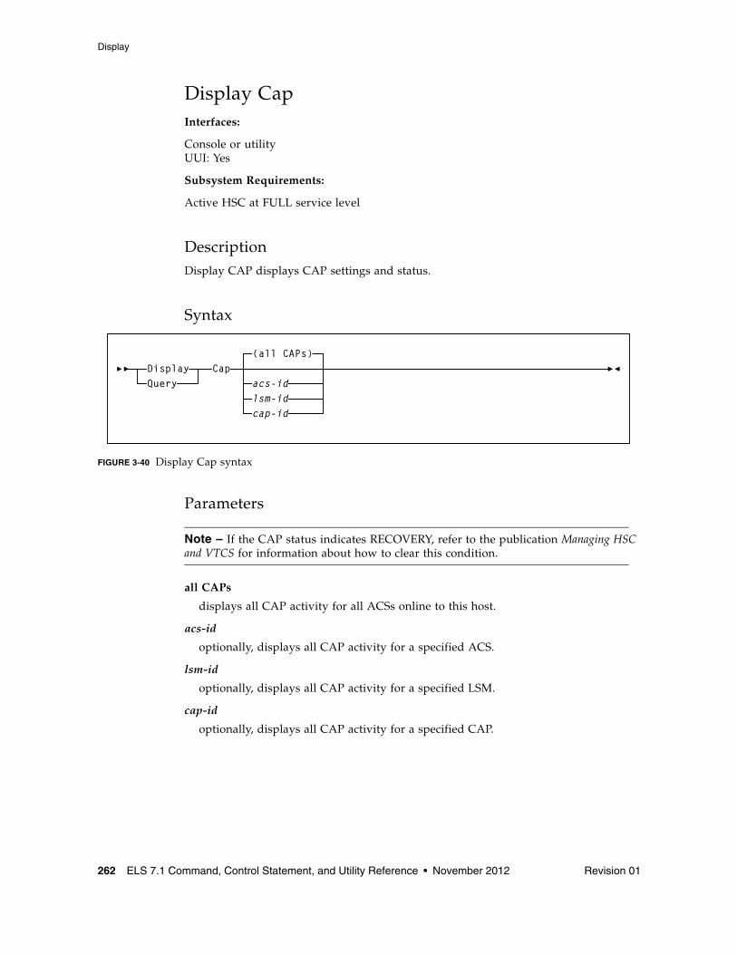
Display
262 ELS 7.1 Command, Control Statement, and Utility Reference • November 2012 Revision 01
Display CapInterfaces:
Console or utilityUUI: Yes
Subsystem Requirements:
Active HSC at FULL service level
DescriptionDisplay CAP displays CAP settings and status.
Syntax
FIGURE 3-40 Display Cap syntax
Parameters
Note – If the CAP status indicates RECOVERY, refer to the publication Managing HSC and VTCS for information about how to clear this condition.
all CAPs
displays all CAP activity for all ACSs online to this host.
acs-id
optionally, displays all CAP activity for a specified ACS.
lsm-id
optionally, displays all CAP activity for a specified LSM.
cap-id
optionally, displays all CAP activity for a specified CAP.
Cap(all CAPs)
acs-idlsm-idcap-id
DisplayQuery
Display
Revision 01 Chapter 3 HSC and VTCS Commands and Control Statements 263
Note – ■ The acsid, lsmid, and capid parameters are positional operands. If no positional
operand is specified, the default operation is to display the status of all CAP activity for all ACSs.
■ The acsid, lsmid, and capid may be expressed as a list.
OutputThe output display contains the following information:
■ CAPid
■ CAP size: PCAP (priority CAP); 21-cell or 14-cell 9740 (standard CAP); 40-cell (enhanced CAP); 20-cell (9360 CAP); 30-cell (9360 optional CAP); 26-cell (SL3000 CAP); 234-cell (SL3000 AEM CAP); or 39-cell (SL8500 CAP)
■ Partition ID
■ Host ID of the host owning the CAP
■ Priority: CAP preference value
■ CAP mode: cleaning, draining, ejecting, entering, or idle
■ CAP status: active, automatic mode, manual mode, offline, online, and/or recovery needed.
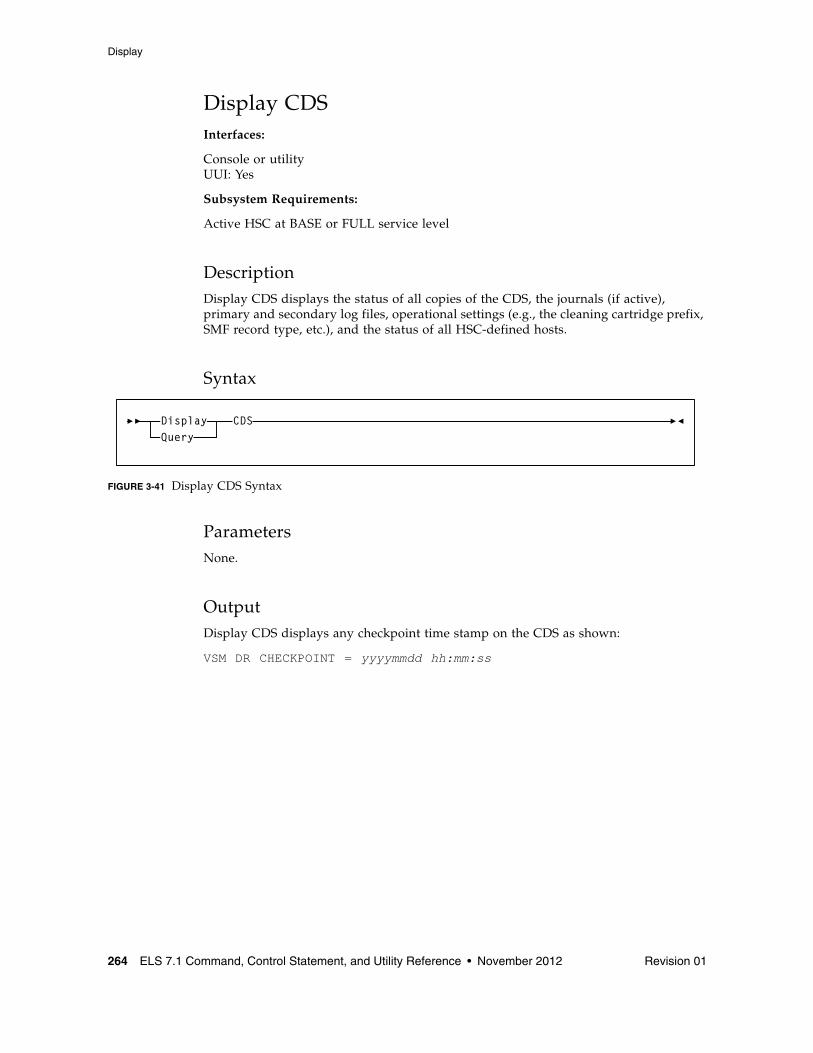
Display
264 ELS 7.1 Command, Control Statement, and Utility Reference • November 2012 Revision 01
Display CDSInterfaces:
Console or utilityUUI: Yes
Subsystem Requirements:
Active HSC at BASE or FULL service level
DescriptionDisplay CDS displays the status of all copies of the CDS, the journals (if active), primary and secondary log files, operational settings (e.g., the cleaning cartridge prefix, SMF record type, etc.), and the status of all HSC-defined hosts.
Syntax
FIGURE 3-41 Display CDS Syntax
ParametersNone.
OutputDisplay CDS displays any checkpoint time stamp on the CDS as shown:
VSM DR CHECKPOINT = yyyymmdd hh:mm:ss
CDSDisplayQuery
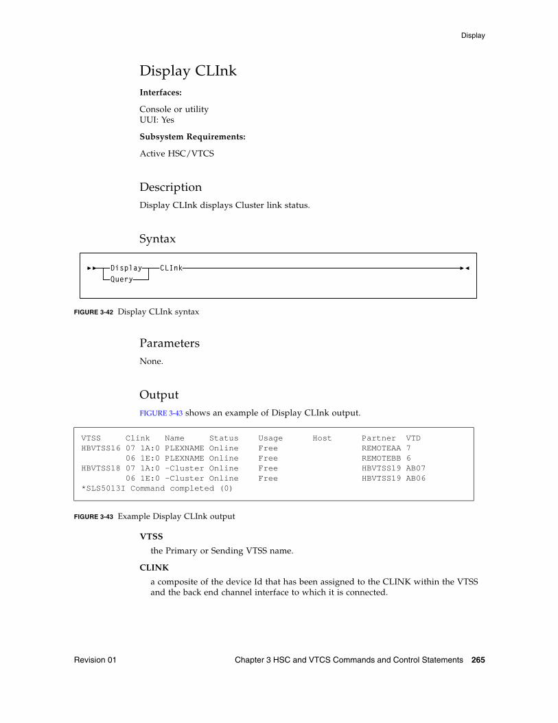
Display
Revision 01 Chapter 3 HSC and VTCS Commands and Control Statements 265
Display CLInkInterfaces:
Console or utilityUUI: Yes
Subsystem Requirements:
Active HSC/VTCS
DescriptionDisplay CLInk displays Cluster link status.
Syntax
FIGURE 3-42 Display CLInk syntax
ParametersNone.
OutputFIGURE 3-43 shows an example of Display CLInk output.
FIGURE 3-43 Example Display CLInk output
VTSS
the Primary or Sending VTSS name.
CLINK
a composite of the device Id that has been assigned to the CLINK within the VTSS and the back end channel interface to which it is connected.
VTSS Clink Name Status Usage Host Partner VTDHBVTSS16 07 1A:0 PLEXNAME Online Free REMOTEAA 7 06 1E:0 PLEXNAME Online Free REMOTEBB 6HBVTSS18 07 1A:0 -Cluster Online Free HBVTSS19 AB07 06 1E:0 -Cluster Online Free HBVTSS19 AB06*SLS5013I Command completed (0)
CLInkDisplayQuery
Display
266 ELS 7.1 Command, Control Statement, and Utility Reference • November 2012 Revision 01
NAME
one of the following values:
name
the name of the TapePlex to which the CLINK is connected. This also indicates that the CLINK will be used for electronic exporting of VTVs. The VTSS name in the partner column indicates the VTSS that will receive VTV copies over this CLINK.
-Cluster
indicates that the CLINK is used for replication of VTVs within the TapePlex and is part of a cluster. The VTSS name in the partner column indicates the other VTSS that operates in the cluster.
STATUS
one of the following link statuses:
Maint
The link has failed or it has been varied into maintenance mode.
Offline
The link is offline and unavailable to all hosts and VTSSs.
Online
The link is available for replication.
P_offlne
The link is pending offline.
P_online
The link is pending online.
On-Sync
Available for synchronous replication.
On-Async
Available for asynchronous replication.
Recovery
The link is being reset following an error or a vary online operation.
Unusable
Not available for replication due to hardware errors or assigned-elsewhere conditions.
UUI err
This is a CLINK defined for electronic export and it has been unable to contact the remote VTCS. There should be messages in the HSC JOBLOG that indicate the reason for the problem. This could include problems with the definitions, the local SMC, or the remote HTTP server on the remote VTCS.
Display
Revision 01 Chapter 3 HSC and VTCS Commands and Control Statements 267
USAGE
one of the following link usages:
Assigned
Link is assigned to the host in the HOST field but is not currently replicating. This usage occurs when VTCS is starting or terminating link use or is attempting error recovery on the link after a replication failure.
Free
Link is idle (not doing replications).
Replicating
Link is actively doing replications.
HOST
the host that the link is assigned to.
PARTNER
the secondary or receiving VTSS.
VTD
the address of the VTD on the partner VTSS that forms the other end point to the connection. For a cluster link, the MSP address of the VTD is reported. For an electronic export link, this is not possible as there is no access to the other TapePlex configuration. In this case, only the ordinal number of the VTV is reported.
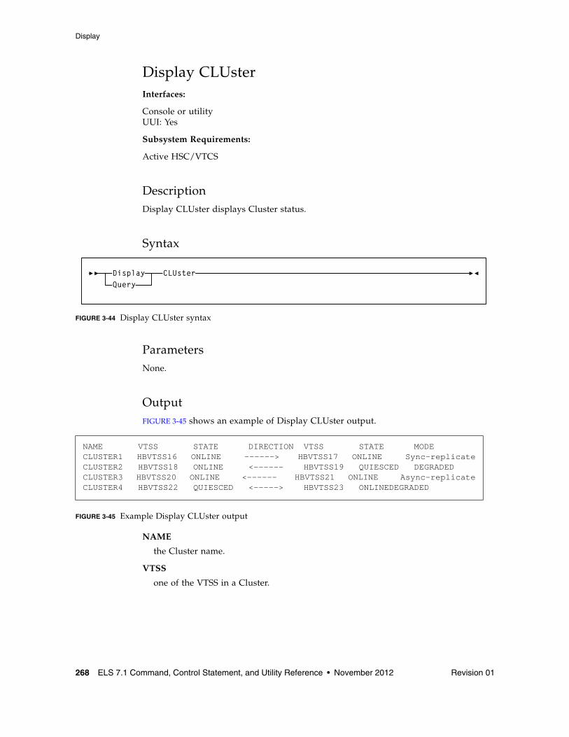
Display
268 ELS 7.1 Command, Control Statement, and Utility Reference • November 2012 Revision 01
Display CLUsterInterfaces:
Console or utilityUUI: Yes
Subsystem Requirements:
Active HSC/VTCS
DescriptionDisplay CLUster displays Cluster status.
Syntax
FIGURE 3-44 Display CLUster syntax
ParametersNone.
OutputFIGURE 3-45 shows an example of Display CLUster output.
FIGURE 3-45 Example Display CLUster output
NAME
the Cluster name.
VTSS
one of the VTSS in a Cluster.
NAME VTSS STATE DIRECTION VTSS STATE MODECLUSTER1 HBVTSS16 ONLINE ------> HBVTSS17 ONLINE Sync-replicateCLUSTER2 HBVTSS18 ONLINE <------ HBVTSS19 QUIESCED DEGRADEDCLUSTER3 HBVTSS20 ONLINE <------ HBVTSS21 ONLINE Async-replicateCLUSTER4 HBVTSS22 QUIESCED <-----> HBVTSS23 ONLINEDEGRADED
CLUsterDisplayQuery
Display
Revision 01 Chapter 3 HSC and VTCS Commands and Control Statements 269
DIRECTION
One of the following:
----->
OR
<-----
Indicates the direction of VTV replication in Uni-Directional Cluster. VTVs can only be replicated from the Sending to the Receiving VTSS.
<---->
Indicates that the VTSSs are configured as a Bi-Directional (Peer-to-Peer) Cluster. VTVs can be replicated from either VTSS to the other.
STATE
one of the following VTSS states:
QUIESCING
Quiescing state.
QUIESCED
Quiesced state.
OFFLINE
Offline state.
OFFLINE-P
Offline pending state.
ONLINE
Online state.
ONLINE-P
Online pending state.
STARTED
The VTSS is initialized and in process of going to the requested state (online, offline, or quiesced).
MODE
one of the following Cluster operating modes:
Async-replicate
Both VTSSs in the Cluster are online to VTCS. Production workload can go to either VTSS, but in the case of a Uni-Directional (Primary/Secondary) Cluster, VTVs can only be replicated from the Sending VTSS. Synchronous replication is not enabled across the cluster.
Sync-replicate
Both VTSSs in the Cluster are online to VTCS. Production workload can go to either VTSS, but in the case of a Uni-Directional (Primary/Secondary) Cluster, VTVs can only be replicated from the Sending VTSS. Synchronous replication is enabled across the cluster.
Display
270 ELS 7.1 Command, Control Statement, and Utility Reference • November 2012 Revision 01
Degraded
One of the two VTSSs in a Bi-Directional (Peer-to-Peer) Cluster is either offline or quiesced. Production workload can go the remaining online VTSS. VTVs requiring replication, however, are allocated to the remaining VTSS only if no other Full-Function clusters are available and suitable. In this case, replicate VTVs are migrated immediately with keep and queued for replication when the other VTSS comes online.
When the other VTSS comes online, VTCS reconciles the contents of both VTSSs.
Degraded-2ndary
The Primary is online to VTCS and the Secondary is either offline or quiesced. Workload can run on the Primary. VTVs requiring replication, however, are allocated to the Primary only if no other Full Function Clusters are available. In this case, Replicate VTVs are migrated immediately with keep and are queued for replication, which occurs when the Secondary comes online.
Degraded primary
The Secondary is online to VTCS and the Primary is either offline or quiesced. Workload can run on the Secondary. VTVs requiring replication, however, are allocated to the Secondary only if no other Full Function Clusters are available. When the Primary comes back ONline, VTCS reconciles the contents of the Primary and Secondary.
Non-operational
No workload is possible on this Cluster.
CLINKs offline
All defined CLINKs are offline. No workload is possible on this Cluster.
Only 2ndary
The Secondary is online to VTCS and the Primary has no CLINKs online. Workload can run on the Secondary. VTVs requiring replication, however, are allocated to the Secondary only if no other Full Function Clusters are available.
Only primary
The Primary is online to VTCS and the Secondary has no CLINKs online. Workload can run on the Primary. VTVs requiring replication, however, are allocated to the Primary only if no other Full Function Clusters are available. In this case, Replicate VTVs are migrated immediately with keep and are queued for replication.
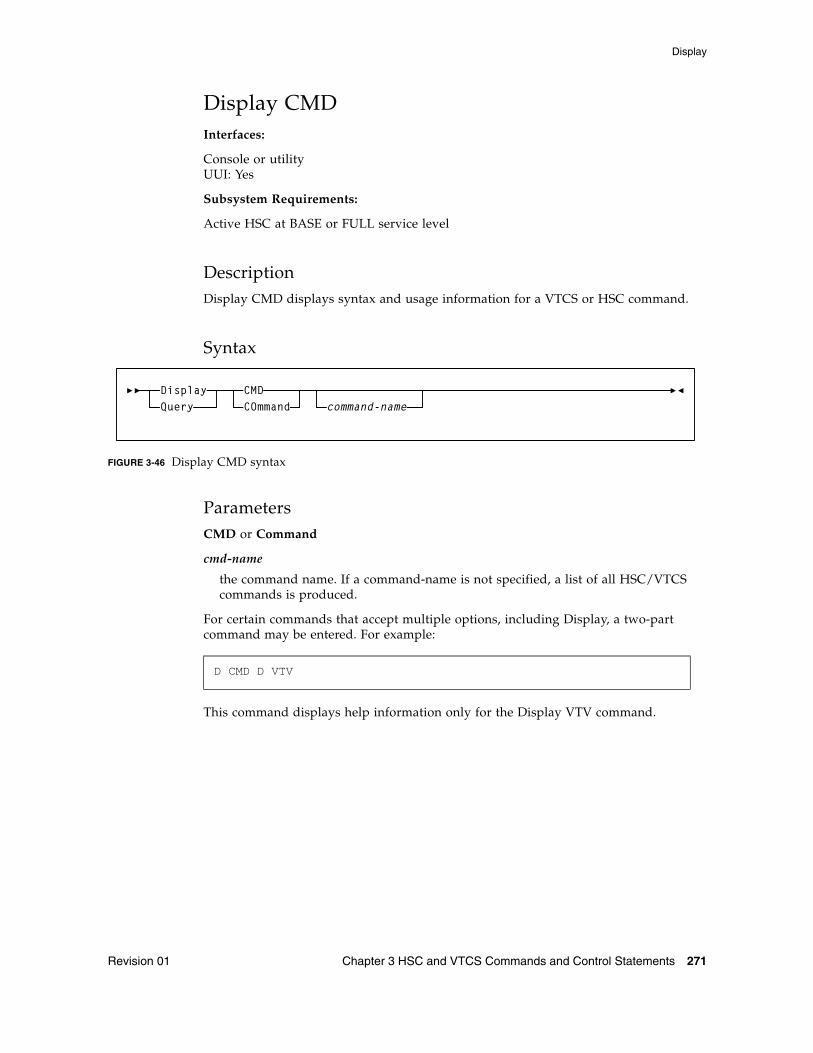
Display
Revision 01 Chapter 3 HSC and VTCS Commands and Control Statements 271
Display CMDInterfaces:
Console or utilityUUI: Yes
Subsystem Requirements:
Active HSC at BASE or FULL service level
DescriptionDisplay CMD displays syntax and usage information for a VTCS or HSC command.
Syntax
FIGURE 3-46 Display CMD syntax
ParametersCMD or Command
cmd-name
the command name. If a command-name is not specified, a list of all HSC/VTCS commands is produced.
For certain commands that accept multiple options, including Display, a two-part command may be entered. For example:
This command displays help information only for the Display VTV command.
D CMD D VTV
CMDCOmmand command-name
DisplayQuery
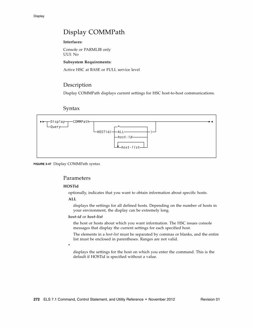
Display
272 ELS 7.1 Command, Control Statement, and Utility Reference • November 2012 Revision 01
Display COMMPathInterfaces:
Console or PARMLIB onlyUUI: No
Subsystem Requirements:
Active HSC at BASE or FULL service level
DescriptionDisplay COMMPath displays current settings for HSC host-to-host communications.
Syntax
FIGURE 3-47 Display COMMPath syntax
ParametersHOSTid
optionally, indicates that you want to obtain information about specific hosts.
ALL
displays the settings for all defined hosts. Depending on the number of hosts in your environment, the display can be extremely long.
host-id or host-list
the host or hosts about which you want information. The HSC issues console messages that display the current settings for each specified host.
The elements in a host-list must be separated by commas or blanks, and the entire list must be enclosed in parentheses. Ranges are not valid.
*
displays the settings for the host on which you enter the command. This is the default if HOSTid is specified without a value.
COMMPath
HOSTid(*ALLhost-id
host-list
)
DisplayQuery
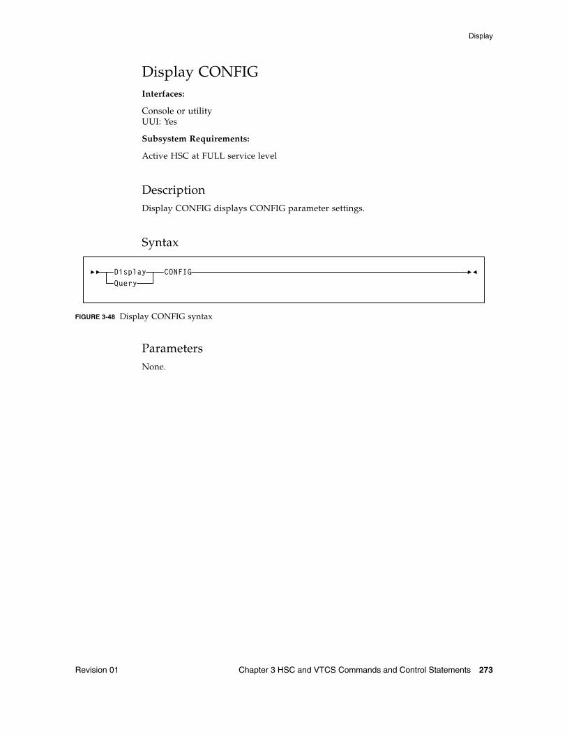
Display
Revision 01 Chapter 3 HSC and VTCS Commands and Control Statements 273
Display CONFIGInterfaces:
Console or utilityUUI: Yes
Subsystem Requirements:
Active HSC at FULL service level
DescriptionDisplay CONFIG displays CONFIG parameter settings.
Syntax
FIGURE 3-48 Display CONFIG syntax
ParametersNone.
CONFIGDisplayQuery
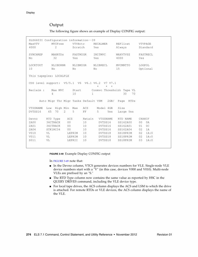
Display
274 ELS 7.1 Command, Control Statement, and Utility Reference • November 2012 Revision 01
OutputThe following figure shows an example of Display CONFIG output:
FIGURE 3-49 Example Display CONFIG output
In FIGURE 3-49 note that:
■ In the Devno column, VTCS generates devices numbers for VLE. Single-node VLE device numbers start with a "V" (in this case, devices V000 and V010). Multi-node VLEs are prefixed by an "S."
■ The RTD Type column now contains the same value as reported by HSC in the QUERY DRIVES command, including the VLE device type.
■ For local tape drives, the ACS column displays the ACS and LSM to which the drive is attached. For remote RTDs or VLE devices, the ACS column displays the name of the VLE.
SLS6603I Configuration information--39MaxVTV MVCFree VTVAttr RECALWER REPlicat VTVPAGE4000 2 Scratch Yes Always Standard
SYNCHREP MAXRTDs FASTMIGR INITMVC MAXVTVSZ FASTRECLNo 32 Yes Yes 4000 Yes
LOCKTOUT NLIBDRNR NLIBMIGR NLIBRECL MVCMNTTO LOGPOL 10 No No No 15 Optional
This tapeplex: LOCALPLX
CDS level support: V5/5.1 V6 V6.1 V6.2 V7 V7.1 * * *Reclaim : Max MVC Start Conmvc Threshold: Tape VL 4 10 1 30 70
Auto Migr Thr Migr Tasks Default VSM 2GB/ Page RTDs
VTSSNAME Low High Min Max ACS Model 4GB Size DVTSS16 65 70 2 5 FF 5 Yes Large Yes
Devno RTD Type ACS Retain VTSSNAME RTD NAME CHANIF2A00 36CTRACK 00 10 DVTSS16 SS162A00 00 0A2A01 36CTRACK 00 10 DVTSS16 SS162A01 01 0C2A04 STK1RC34 00 10 DVTSS16 SS162A04 02 1AV010 VL LEPRIM 10 DVTSS18 SS18PRIM 02 1A:0V011 VL LEPRIM 10 DVTSS18 SS18PRIM 02 1A:0S011 VL LEPRII 10 DVTSS18 SS18PRIM 03 1A:0
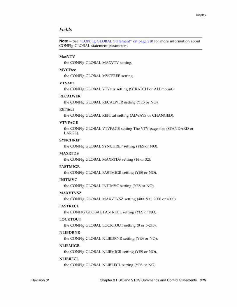
Display
Revision 01 Chapter 3 HSC and VTCS Commands and Control Statements 275
Fields
Note – See “CONFIg GLOBAL Statement” on page 210 for more information about CONFIg GLOBAL statement parameters.
MaxVTV
the CONFIg GLOBAL MAXVTV setting.
MVCFree
the CONFIg GLOBAL MVCFREE setting.
VTVAttr
the CONFIg GLOBAL VTVattr setting (SCRATCH or ALLmount).
RECALWER
the CONFIg GLOBAL RECALWER setting (YES or NO).
REPlicat
the CONFIg GLOBAL REPlicat setting (ALWAYS or CHANGED).
VTVPAGE
the CONFIg GLOBAL VTVPAGE setting The VTV page size (STANDARD or LARGE).
SYNCHREP
the CONFIg GLOBAL SYNCHREP setting (YES or NO).
MAXRTDS
the CONFIg GLOBAL MAXRTDS setting (16 or 32).
FASTMIGR
the CONFIg GLOBAL FASTMIGR setting (YES or NO).
INITMVC
the CONFIg GLOBAL INITMVC setting (YES or NO).
MAXVTVSZ
the CONFIg GLOBAL MAXVTVSZ setting (400, 800, 2000 or 4000).
FASTRECL
the CONFIG GLOBAL FASTRECL setting (YES or NO).
LOCKTOUT
the CONFIg GLOBAL LOCKTOUT setting (0 or 5-240).
NLIBDRNR
the CONFIg GLOBAL NLIBDRNR setting (YES or NO).
NLIBMIGR
the CONFIg GLOBAL NLIBMIGR setting (YES or NO).
NLIBRECL
the CONFIg GLOBAL NLIBRECL setting (YES or NO).
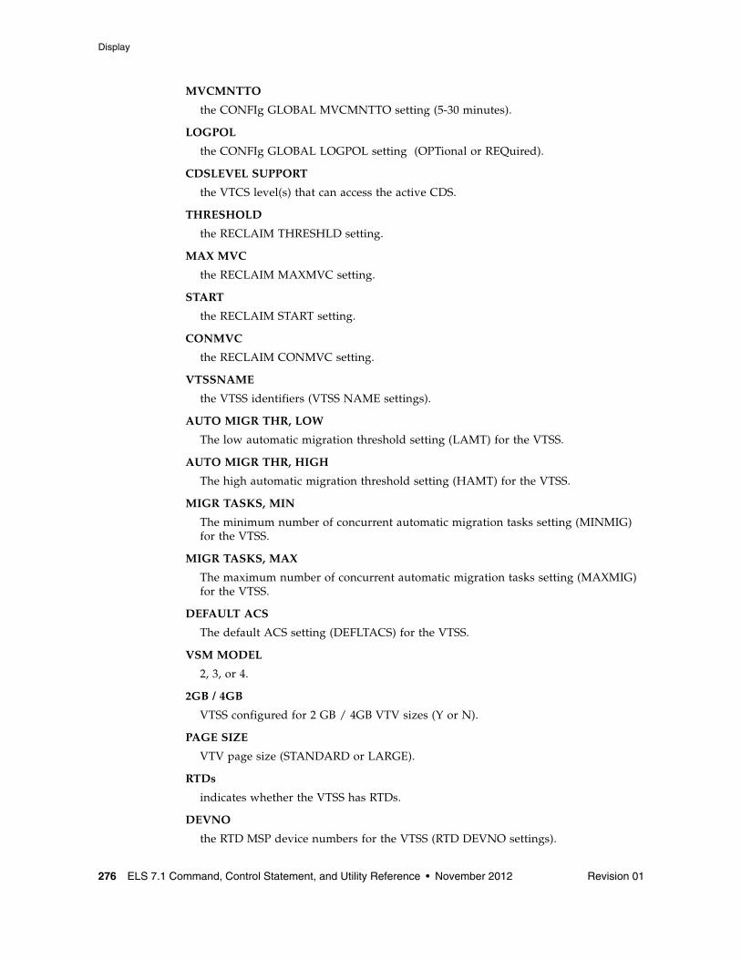
Display
276 ELS 7.1 Command, Control Statement, and Utility Reference • November 2012 Revision 01
MVCMNTTO
the CONFIg GLOBAL MVCMNTTO setting (5-30 minutes).
LOGPOL
the CONFIg GLOBAL LOGPOL setting (OPTional or REQuired).
CDSLEVEL SUPPORT
the VTCS level(s) that can access the active CDS.
THRESHOLD
the RECLAIM THRESHLD setting.
MAX MVC
the RECLAIM MAXMVC setting.
START
the RECLAIM START setting.
CONMVC
the RECLAIM CONMVC setting.
VTSSNAME
the VTSS identifiers (VTSS NAME settings).
AUTO MIGR THR, LOW
The low automatic migration threshold setting (LAMT) for the VTSS.
AUTO MIGR THR, HIGH
The high automatic migration threshold setting (HAMT) for the VTSS.
MIGR TASKS, MIN
The minimum number of concurrent automatic migration tasks setting (MINMIG) for the VTSS.
MIGR TASKS, MAX
The maximum number of concurrent automatic migration tasks setting (MAXMIG) for the VTSS.
DEFAULT ACS
The default ACS setting (DEFLTACS) for the VTSS.
VSM MODEL
2, 3, or 4.
2GB / 4GB
VTSS configured for 2 GB / 4GB VTV sizes (Y or N).
PAGE SIZE
VTV page size (STANDARD or LARGE).
RTDs
indicates whether the VTSS has RTDs.
DEVNO
the RTD MSP device numbers for the VTSS (RTD DEVNO settings).
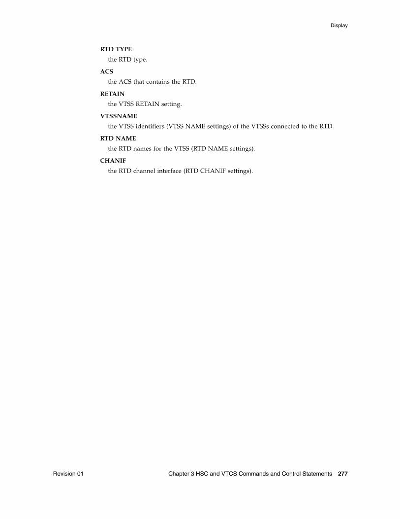
Display
Revision 01 Chapter 3 HSC and VTCS Commands and Control Statements 277
RTD TYPE
the RTD type.
ACS
the ACS that contains the RTD.
RETAIN
the VTSS RETAIN setting.
VTSSNAME
the VTSS identifiers (VTSS NAME settings) of the VTSSs connected to the RTD.
RTD NAME
the RTD names for the VTSS (RTD NAME settings).
CHANIF
the RTD channel interface (RTD CHANIF settings).
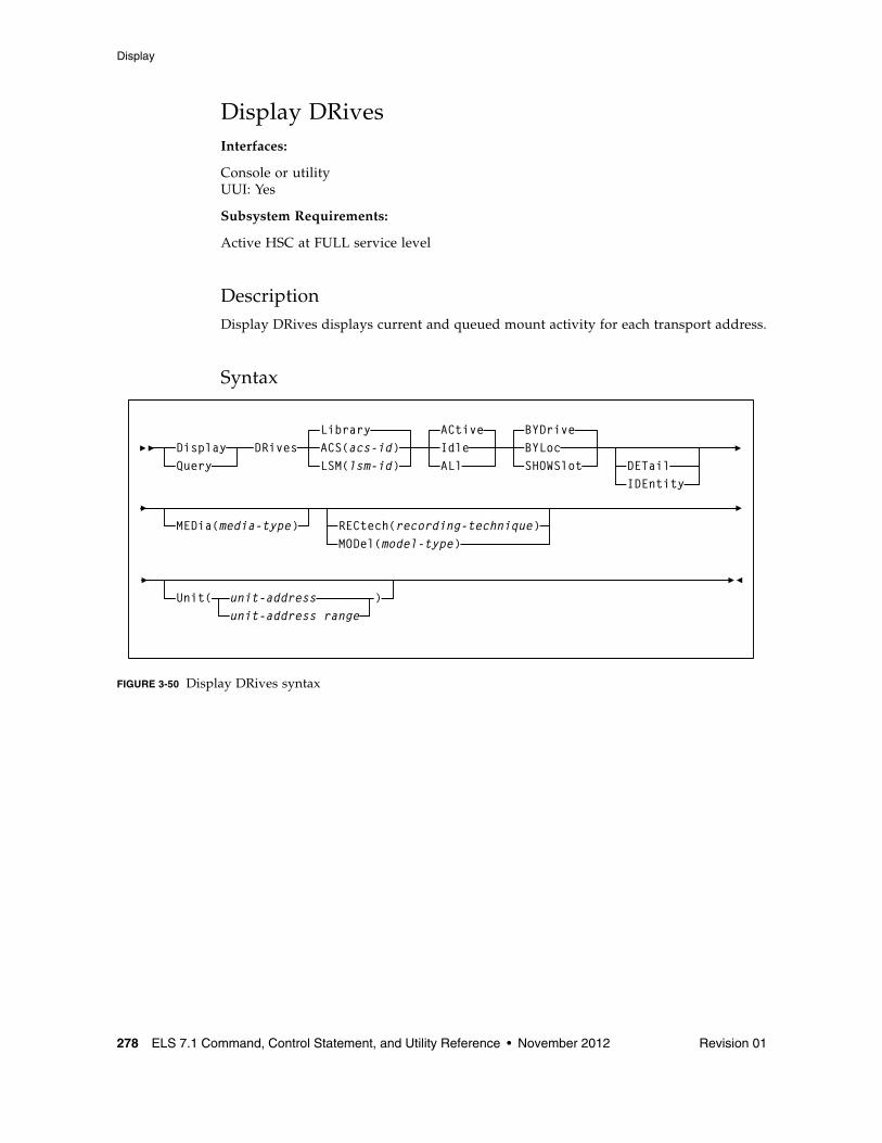
Display
278 ELS 7.1 Command, Control Statement, and Utility Reference • November 2012 Revision 01
Display DRivesInterfaces:
Console or utilityUUI: Yes
Subsystem Requirements:
Active HSC at FULL service level
DescriptionDisplay DRives displays current and queued mount activity for each transport address.
Syntax
FIGURE 3-50 Display DRives syntax
DRivesLibraryACS(acs-id)LSM(lsm-id)
ACtiveIdleALl
BYDriveBYLoc
DETail
MEDia(media-type) RECtech(recording-technique)MODel(model-type)
Unit( unit-addressunit-address range
)
DisplayQuery
IDEntitySHOWSlot
Display
Revision 01 Chapter 3 HSC and VTCS Commands and Control Statements 279
ParametersLibrary
only library-controlled drives are processed. This is the default.
ACS
only drives in a specified ACS are processed.
acs-id
the ACS for which the system is to display drive information.
LSM
only drives in a specified LSM are processed.
lsm-id
the LSM for which the system is to display drive information.
ACtive
only active drives are processed. This is the default.
Idle
only idle drives are processed (includes drives that may be offline).
ALl
all drives are processed regardless of status.
BYDrive
displays the drives by host device address. This is the default.
BYLoc
displays the drives by library location.
SHOWSlot
optionally, displays the drives by host device address, and displays the drive bay location (slot) for drives in SL3000 and SL8500 libraries.
DETail
optionally, displays the drive media types and recording techniques.
IDEntity
optionally, displays the serial number and world wide name of a transport associated with a drive.
The tape library must be at a sufficient compatibility level to provide this information.
■ The serial number requires LMU level 13.
■ The WWN requires LMU level 21.
■ DISPLAY ACS shows the LMU compatibility level. In addition, the transport must supply the LMU with the serial number.
Note – IDEntity and DETail are mutually exclusive.
Display
280 ELS 7.1 Command, Control Statement, and Utility Reference • November 2012 Revision 01
MEDia
optionally, limits the display of drives only to those that support the specified type of media. The default is for all types of media.
media-type
the media type.
See Appendix A, “MEDia, RECtech, and MODel Values” for a list of valid media-type values.
Note – If MEDia is not specified, the drive is selected without regard to media type.
RECtech
optionally, limits the display of drives only to those that support the specified recording technique. The default is for all recording techniques. RECtech refers to the method used to record data tracks on the tape surface.
If RECtech is not specified, the drive is selected without regard to recording technique.
recording-technique
the recording technique.
See Appendix A, “MEDia, RECtech, and MODel Values” for valid recording-technique values.
Note – RECtech and MODel are mutually exclusive.
MODel
optionally, limits the display of drives by the model type of a transport. You can enter a list of models, separated by commas. A list specifies a generic pool.
model-type
the model type.
See Appendix A, “MEDia, RECtech, and MODel Values” for a list of valid model-type values.
Note – MODel and RECtech are mutually exclusive.
UNIT
optionally, limits the display of drives to a unit address or a range of unit addresses.
unit-address or unit-address-range
a single unit address or a range of addresses.
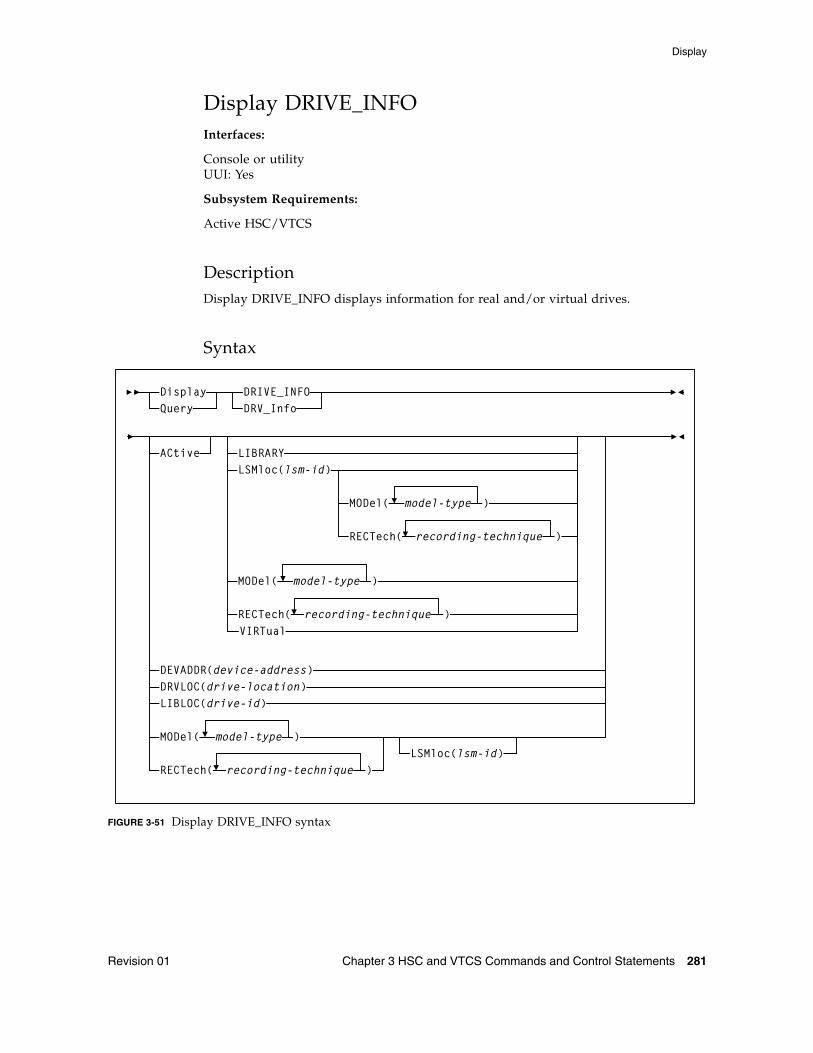
Display
Revision 01 Chapter 3 HSC and VTCS Commands and Control Statements 281
Display DRIVE_INFOInterfaces:
Console or utilityUUI: Yes
Subsystem Requirements:
Active HSC/VTCS
DescriptionDisplay DRIVE_INFO displays information for real and/or virtual drives.
Syntax
FIGURE 3-51 Display DRIVE_INFO syntax
DRIVE_INFODisplayQuery DRV_Info
LIBRARYLSMloc(lsm-id)
LSMloc(lsm-id)
DEVADDR(device-address)
ACtive
DRVLOC(drive-location)LIBLOC(drive-id)
MODel(
RECTech(
model-type )
recording-technique )
MODel( model-type )
RECTech( )recording-technique
MODel(
RECTech(
model-type )
recording-technique )VIRTual
Display
282 ELS 7.1 Command, Control Statement, and Utility Reference • November 2012 Revision 01
ParametersACtive
optionally, specifies that only drives with a volume mounted, or in the process of mounting or dismounting, are displayed.
DEVADDR
optionally, specifies that only the device with the specified drive ID is displayed.
device-address
a three or four digit device address
DRVLOC
optionally, specifies that only the single drive with a matching drive location ID is displayed.
drive-location
the drive location id:
For a real drive, use format R:AA:LL:PP:DD where:
■ AA is the acs ID.
■ LL is the LSM number.
■ PP is the panel.
■ DD is the drive number.
For a virtual drive, use format V:vtssname:nnnn where nnnn is the VTSS drive identifier
LIBLOC
optionally, specifies that only the real drive with the specified drive ID is displayed.
drive-id
the drive ID, in the format AA:LL:PP:DD where:
■ AA is the acs ID.
■ LL is the LSM number.
■ PP is the panel.
■ DD is the drive number.
LIBRARY
optionally, specifies that only library (non-virtual) drives are displayed.
LSMloc
optionally, specifies that only drives in the specified LSM is displayed.
lsm-id
the lsm-id, in the format AA:LL where:
■ AA is the acs ID.
■ LL is the LSM number.
Display
Revision 01 Chapter 3 HSC and VTCS Commands and Control Statements 283
MODel
optionally, specifies that only drives with the specified model type are displayed.
model-type
the model type.
See Appendix A, “MEDia, RECtech, and MODel Values” for a list of valid model-type values.
RECTech
optionally, specifies that only drives with the specified recording technique are displayed.
recording-technique
the recording technique.
See Appendix A, “MEDia, RECtech, and MODel Values” for a list of valid recording-technique values.
VIRTual
optionally, specifies that only virtual drives (not library drives) are displayed.
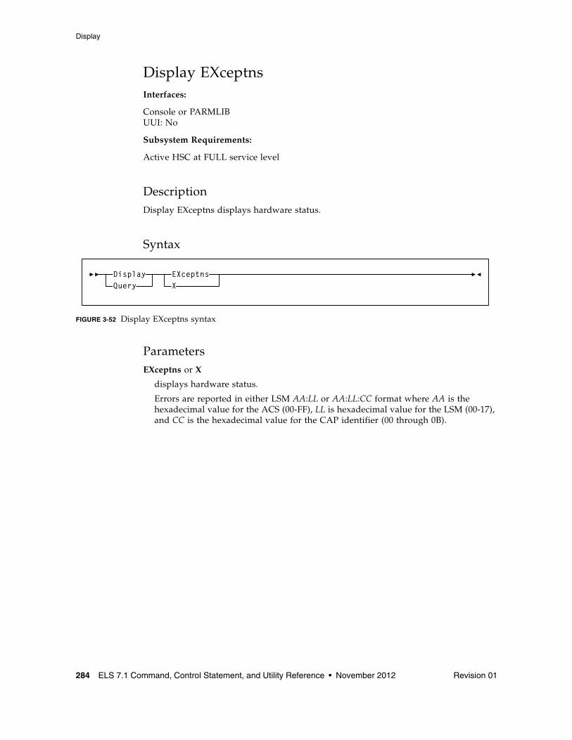
Display
284 ELS 7.1 Command, Control Statement, and Utility Reference • November 2012 Revision 01
Display EXceptnsInterfaces:
Console or PARMLIBUUI: No
Subsystem Requirements:
Active HSC at FULL service level
DescriptionDisplay EXceptns displays hardware status.
Syntax
FIGURE 3-52 Display EXceptns syntax
ParametersEXceptns or X
displays hardware status.
Errors are reported in either LSM AA:LL or AA:LL:CC format where AA is the hexadecimal value for the ACS (00-FF), LL is hexadecimal value for the LSM (00-17), and CC is the hexadecimal value for the CAP identifier (00 through 0B).
EXceptnsX
DisplayQuery
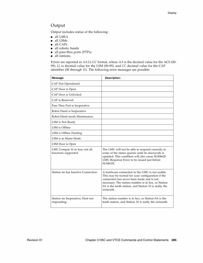
Display
Revision 01 Chapter 3 HSC and VTCS Commands and Control Statements 285
OutputOutput includes status of the following:
■ all LMUs■ all LSMs■ all CAPs■ all robotic hands■ all pass-thru ports (PTPs)■ all stations.
Errors are reported in AA:LL:CC format, where AA is the decimal value for the ACS (00-99), LL is decimal value for the LSM (00-99), and CC decimal value for the CAP identifier (00 through 11). The following error messages are possible:
Message: Description:
CAP Not Operational
CAP Door is Open
CAP Door is Unlocked
CAP is Reserved
Pass Thru Port is Inoperative
Robot Hand is Inoperative
Robot Hand needs Maintenance
LSM is Not Ready
LSM is Offline
LSM is Offline Pending
LSM is in Maint Mode
LSM Door is Open
LMU Compat 10 or less; not all functions supported:
The LMU will not be able to respond correctly to some of the status queries until its microcode is updated. This condition will also cause SLS0662I LMU Response Error to be issued just before SLS4610I.
Station nn has Inactive Connection: A hardware connection to the LMU is not usable. This may be normal for your configuration if the connection has never been made and is not necessary. The station number is in hex, so Station 0A is the tenth station, and Station 10 is really the sixteenth.
Station nn Inoperative; Host not responding:
The station number is in hex, so Station 0A is the tenth station, and Station 10 is really the sixteenth.
Display
286 ELS 7.1 Command, Control Statement, and Utility Reference • November 2012 Revision 01
The following messages are summaries:
■ No CAP problems were detected■ No Pass Thru Port problems were detected■ No Robot Hand problems were detected■ No LSM problems were detected■ No Station problems were detected
Message summaries only reflect that the LMU did not detect hardware errors. Something could be wrong with the software configuration, or with something that the LMU could not detect.
HSC processing continues and no user response is required.
Display
Revision 01 Chapter 3 HSC and VTCS Commands and Control Statements 287
Display LMUPDEFInterfaces:
Console or PARMLIBUUI: No
Subsystem Requirements:
Active HSC at BASE or FULL service level
DescriptionDisplay LMUPDEF displays information about the definition data set containing LMUPATH statements, that is currently loaded.
Syntax
FIGURE 3-53 Display LMUPDEF syntax
ParametersNone.
LMUPDEFDisplayQuery
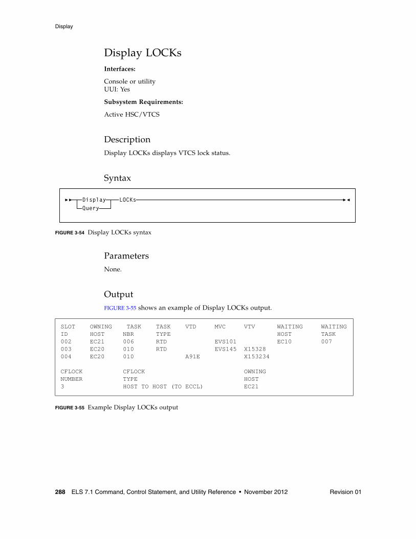
Display
288 ELS 7.1 Command, Control Statement, and Utility Reference • November 2012 Revision 01
Display LOCKsInterfaces:
Console or utilityUUI: Yes
Subsystem Requirements:
Active HSC/VTCS
DescriptionDisplay LOCKs displays VTCS lock status.
Syntax
FIGURE 3-54 Display LOCKs syntax
ParametersNone.
OutputFIGURE 3-55 shows an example of Display LOCKs output.
FIGURE 3-55 Example Display LOCKs output
SLOT OWNING TASK TASK VTD MVC VTV WAITING WAITINGID HOST NBR TYPE HOST TASK002 EC21 006 RTD EVS101 EC10 007003 EC20 010 RTD EVS145 X15328 004 EC20 010 A91E X153234
CFLOCK CFLOCK OWNINGNUMBER TYPE HOST3 HOST TO HOST (TO ECCL) EC21
LOCKsDisplayQuery
Display
Revision 01 Chapter 3 HSC and VTCS Commands and Control Statements 289
Fields
SLOT ID
Slot ID of the lock within the lock buffer.
OWNING HOST
the host that owns the lock.
TASK NBR
the task number associated with the lock.
TASK TYPE
the task type.
VTD
the associated VTD address on the issuing host.
MVC
the locked MVC.
VTV
the locked VTV.
WAITING HOST
the host waiting for the lock or ALL if multiple hosts are waiting.
WAITING TASK
the task waiting for the lock or ALL if multiple tasks are waiting.
CF LOCK NUMBER
the Coupling Facility lock number.
CF LOCK TYPE
one of the following VTCS Coupling Facility lock types:
Host Footprint
used to serialize access to the host footprint list.
Host to Host
used to serialize access to a given host to host list.
Lock data
used to serialize access to the VTCS lock data.
Formatting
used to serialize the initial formatting of the structure; also used when rebuilding data.
System
lock is held, but is not a lock used by VTCS; assume it is used by MSP.
OWNING HOST
the host that owns the lock.
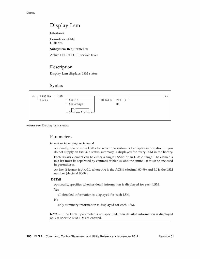
Display
290 ELS 7.1 Command, Control Statement, and Utility Reference • November 2012 Revision 01
Display LsmInterfaces:
Console or utilityUUI: Yes
Subsystem Requirements:
Active HSC at FULL service level
DescriptionDisplay Lsm displays LSM status.
Syntax
FIGURE 3-56 Display Lsm syntax
Parameterslsm-id or lsm-range or lsm-list
optionally, one or more LSMs for which the system is to display information. If you do not supply an lsm-id, a status summary is displayed for every LSM in the library.
Each lsm-list element can be either a single LSMid or an LSMid range. The elements in a list must be separated by commas or blanks, and the entire list must be enclosed in parentheses.
An lsm-id format is AA:LL, where AA is the ACSid (decimal 00-99) and LL is the LSM number (decimal 00-99).
DETail
optionally, specifies whether detail information is displayed for each LSM.
Yes
all detailed information is displayed for each LSM.
No
only summary information is displayed for each LSM.
Note – If the DETail parameter is not specified, then detailed information is displayed only if specific LSM IDs are entered.
Lsmlsm-idlsm-range
)(,lsm-list
DisplayQuery DETail( Yes
No)
Display
Revision 01 Chapter 3 HSC and VTCS Commands and Control Statements 291
OutputLSM status includes:
■ LSMid
■ LSM type
■ Online/offline status
■ Ready/not ready status
■ Automatic/manual status
■ May include detail information:
■ Audits in progress (if any)
■ CAP status, priority and owning host if CAP is not drained
■ Number of free cells and scratch volumes. (Note: The number of free cells in the LSM does NOT include free cells on frozen panels.)
■ Each frozen panel, showing the total number of cells and number of free cells on the panel
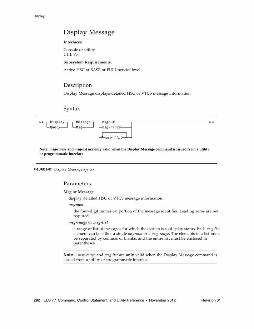
Display
292 ELS 7.1 Command, Control Statement, and Utility Reference • November 2012 Revision 01
Display MessageInterfaces:
Console or utilityUUI: Yes
Subsystem Requirements:
Active HSC at BASE or FULL service level
DescriptionDisplay Message displays detailed HSC or VTCS message information.
Syntax
FIGURE 3-57 Display Message syntax
ParametersMsg or Message
display detailed HSC or VTCS message information.
msgnum
the four–digit numerical portion of the message identifier. Leading zeros are not required.
msg-range or msg-list
a range or list of messages for which the system is to display status. Each msg-list element can be either a single msgnum or a msg-range. The elements in a list must be separated by commas or blanks, and the entire list must be enclosed in parentheses.
Note – msg-range and msg-list are only valid when the Display Message command is issued from a utility or programmatic interface.
Message
Msg
msgnumDisplay
Query msg-range
msg-list
Note: msg-range and msg-list are only valid when the Display Message command is issued from a utility or programmatic interface.
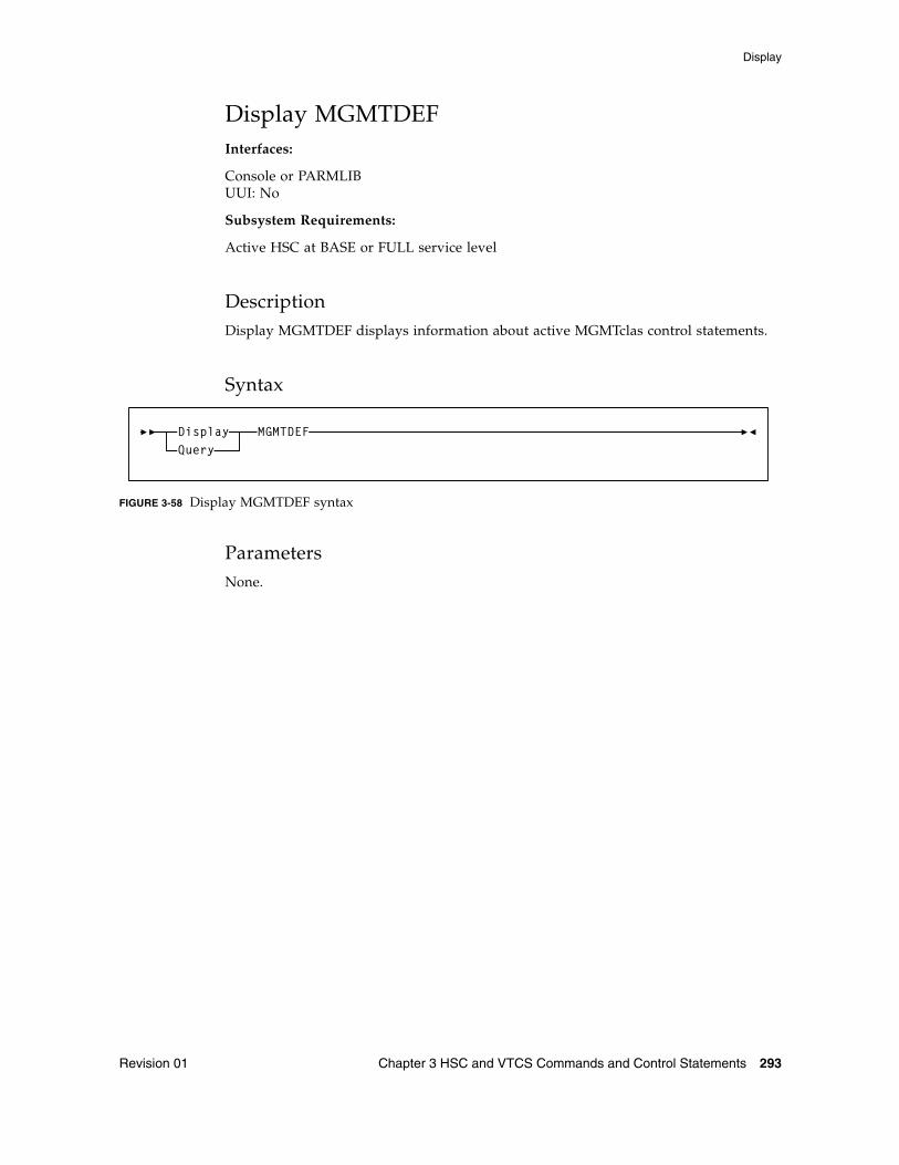
Display
Revision 01 Chapter 3 HSC and VTCS Commands and Control Statements 293
Display MGMTDEFInterfaces:
Console or PARMLIBUUI: No
Subsystem Requirements:
Active HSC at BASE or FULL service level
DescriptionDisplay MGMTDEF displays information about active MGMTclas control statements.
Syntax
FIGURE 3-58 Display MGMTDEF syntax
ParametersNone.
MGMTDEFDisplayQuery
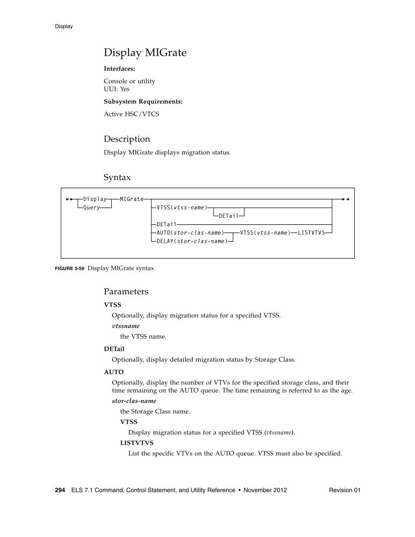
Display
294 ELS 7.1 Command, Control Statement, and Utility Reference • November 2012 Revision 01
Display MIGrateInterfaces:
Console or utilityUUI: Yes
Subsystem Requirements:
Active HSC/VTCS
DescriptionDisplay MIGrate displays migration status.
Syntax
FIGURE 3-59 Display MIGrate syntax
ParametersVTSS
Optionally, display migration status for a specified VTSS.
vtssname
the VTSS name.
DETail
Optionally, display detailed migration status by Storage Class.
AUTO
Optionally, display the number of VTVs for the specified storage class, and their time remaining on the AUTO queue. The time remaining is referred to as the age.
stor-clas-name
the Storage Class name.
VTSS
Display migration status for a specified VTSS (vtssname).
LISTVTVS
List the specific VTVs on the AUTO queue. VTSS must also be specified.
MIGrateDisplayQuery
AUTO(stor-clas-name)
VTSS(vtss-name)
VTSS(vtss-name) LISTVTVS
DETailDETail
DELAY(stor-clas-name)
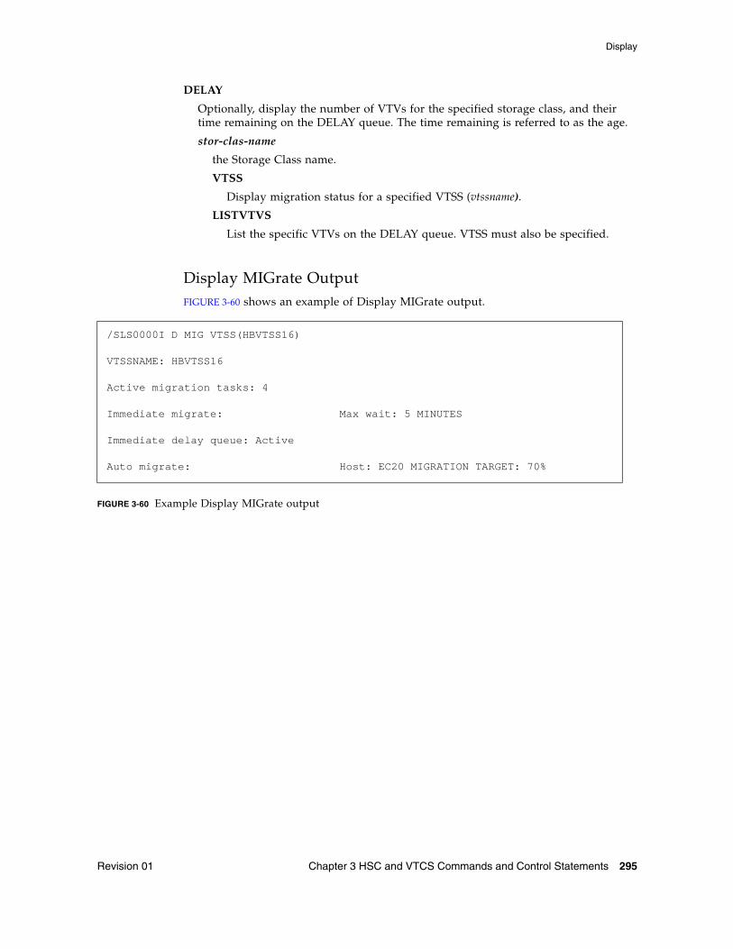
Display
Revision 01 Chapter 3 HSC and VTCS Commands and Control Statements 295
DELAY
Optionally, display the number of VTVs for the specified storage class, and their time remaining on the DELAY queue. The time remaining is referred to as the age.
stor-clas-name
the Storage Class name.
VTSS
Display migration status for a specified VTSS (vtssname).
LISTVTVS
List the specific VTVs on the DELAY queue. VTSS must also be specified.
Display MIGrate OutputFIGURE 3-60 shows an example of Display MIGrate output.
FIGURE 3-60 Example Display MIGrate output
/SLS0000I D MIG VTSS(HBVTSS16)
VTSSNAME: HBVTSS16
Active migration tasks: 4
Immediate migrate: Max wait: 5 MINUTES
Immediate delay queue: Active
Auto migrate: Host: EC20 MIGRATION TARGET: 70%
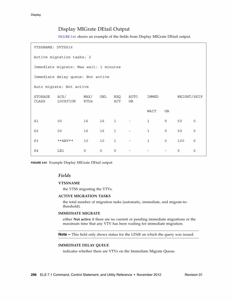
Display
296 ELS 7.1 Command, Control Statement, and Utility Reference • November 2012 Revision 01
Display MIGrate DEtail OutputFIGURE 3-61 shows an example of the fields from Display MIGrate DEtail output.
FIGURE 3-61 Example Display MIGrate DEtail output
Fields
VTSSNAME
the VTSS migrating the VTVs.
ACTIVE MIGRATION TASKS
the total number of migration tasks (automatic, immediate, and migrate-to-threshold).
IMMEDIATE MIGRATE
either Not active if there are no current or pending immediate migrations or the maximum time that any VTV has been waiting for immediate migration.
Note – This field only shows status for the LPAR on which the query was issued.
IMMEDIATE DELAY QUEUE
indicates whether there are VTVs on the Immediate Migrate Queue.
VTSSNAME: DVTSS16
Active migration tasks: 2
Immediate migrate: Max wait: 1 minutes
Immediate delay queue: Not active
Auto migrate: Not active
STORAGE CLASS
ACS/LOCATION
MAX/RTDs
ONL REQACT
AUTO GB
IMMED WEIGHT/SKIP
WAIT GB
S1 00 16 16 1 - 1 9 50 0
S2 00 16 16 1 - 1 9 50 0
S3 **ANY** 10 10 1 - 1 0 100 0
S4 LE1 0 0 0 - - - 0 0
Display
Revision 01 Chapter 3 HSC and VTCS Commands and Control Statements 297
AUTO MIGRATE
either Not active or the name of the host and migration target (LAMT or specified threshold for a migration-to-threshold) if auto migration is active on any host.
STORAGE CLASS
the Storage Class associated with the migration.
Note – If you do not explicitly assign a Storage Class, an MVC’s default Storage Class is the name of the last VTSS that wrote to the MVC for reclamation or migration and this class has the VTCS default media selections. To change these defaults, create a Storage Class with the VTSS name and specify the desired media selection order.
ACS/LOCATION
the ACS defined for the Storage Class.
MAX/ONL RTDs
■ the maximum number of RTD tasks based on the Storage Class and RTD configuration definitions.
■ the maximum number of tasks for those RTDs that are actually online (MAX TASKS minus the number of offline RTDS).
SCH
SCHLIMIT and SCHPREF values from MIGRSEL statements that apply to the active migration for the storage class.
REQ ACT
the number of active migration tasks.
AUTO GB
indicates whether the Storage Class contains automatic migration VTVs.
IMMED WAIT
indicates whether the Storage Class contains immediate migration VTVs.
WEIGHT/SKIP (percent)
the priority of the Storage Class compared to other Storage Classes for the VTSS. Storage Classes with higher priorities are assigned a greater proportion of migration tasks.
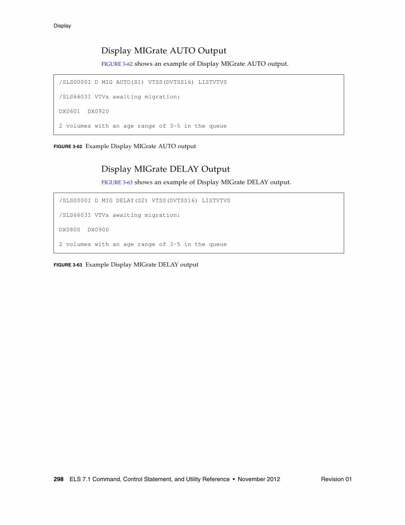
Display
298 ELS 7.1 Command, Control Statement, and Utility Reference • November 2012 Revision 01
Display MIGrate AUTO OutputFIGURE 3-62 shows an example of Display MIGrate AUTO output.
FIGURE 3-62 Example Display MIGrate AUTO output
Display MIGrate DELAY OutputFIGURE 3-63 shows an example of Display MIGrate DELAY output.
FIGURE 3-63 Example Display MIGrate DELAY output
/SLS0000I D MIG AUTO(S1) VTSS(DVTSS16) LISTVTVS
/SLS6603I VTVs awaiting migration: DX0601 DX0920
2 volumes with an age range of 3-5 in the queue
/SLS0000I D MIG DELAY(S2) VTSS(DVTSS16) LISTVTVS
/SLS6603I VTVs awaiting migration:
DX0800 DX0900
2 volumes with an age range of 3-5 in the queue
Display
Revision 01 Chapter 3 HSC and VTCS Commands and Control Statements 299
Display MNTDInterfaces:
Console or PARMLIBUUI: No
Subsystem Requirements:
Active HSC at BASE or FULL service level
DescriptionDisplay MNTD displays current settings for all HSC mount options set by the MNTD command.
Syntax
FIGURE 3-64 Display MNTD syntax
ParametersNone.
MNTDDisplayQuery
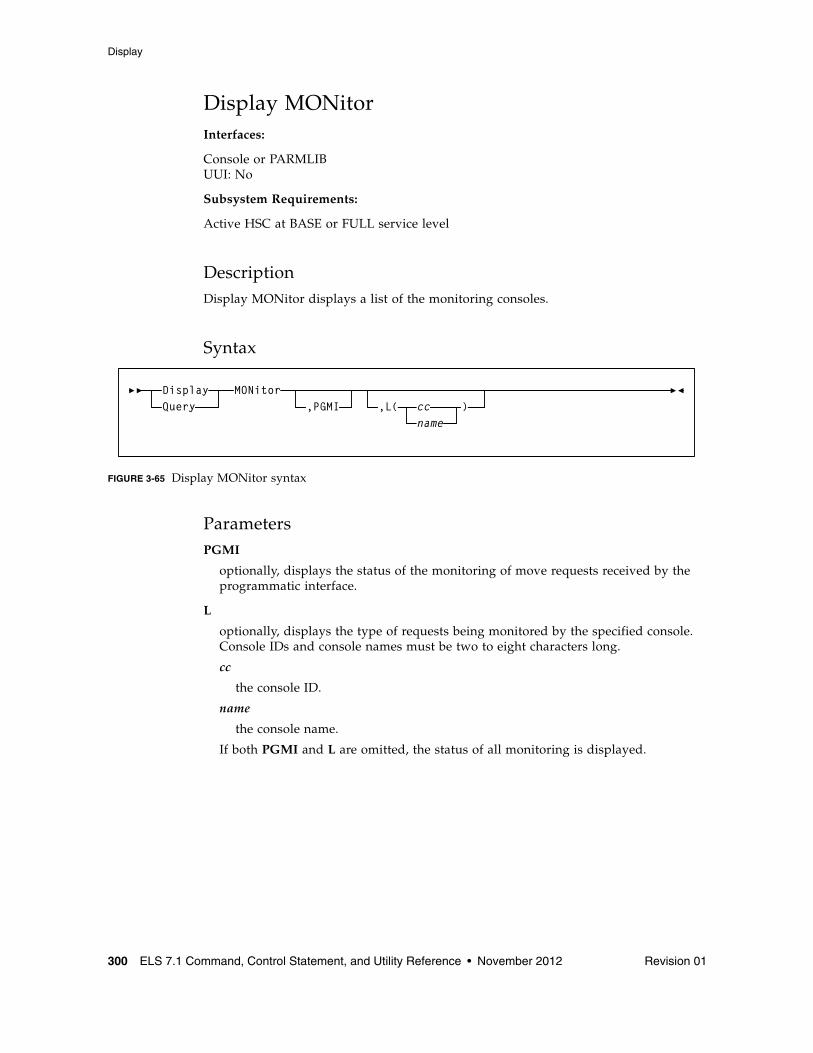
Display
300 ELS 7.1 Command, Control Statement, and Utility Reference • November 2012 Revision 01
Display MONitorInterfaces:
Console or PARMLIBUUI: No
Subsystem Requirements:
Active HSC at BASE or FULL service level
DescriptionDisplay MONitor displays a list of the monitoring consoles.
Syntax
FIGURE 3-65 Display MONitor syntax
ParametersPGMI
optionally, displays the status of the monitoring of move requests received by the programmatic interface.
L
optionally, displays the type of requests being monitored by the specified console. Console IDs and console names must be two to eight characters long.
cc
the console ID.
name
the console name.
If both PGMI and L are omitted, the status of all monitoring is displayed.
MONitor,PGMI ,L( cc
name)
DisplayQuery

Display
Revision 01 Chapter 3 HSC and VTCS Commands and Control Statements 301
Display MVCInterfaces:
Console or utilityUUI: Yes
Subsystem Requirements:
Active HSC/VTCS
DescriptionDisplay MVC displays information about a specific MVC.
Syntax
FIGURE 3-66 Display MVC syntax
Parametersvolser
the volser of the MVC.
MVC(volser)DisplayQuery
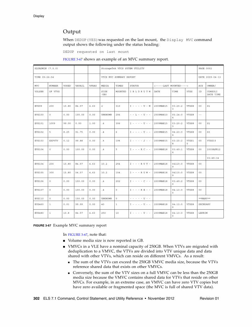
Display
302 ELS 7.1 Command, Control Statement, and Utility Reference • November 2012 Revision 01
OutputWhen DEDUP(YES)was requested on the last mount, the Display MVC command output shows the following under the status heading:
DEDUP requested on last mount
FIGURE 3-67 shows an example of an MVC summary report.
FIGURE 3-67 Example MVC summary report
In FIGURE 3-67, note that:
■ Volume media size is now reported in GB.
■ VMVCs in a VLE have a nominal capacity of 250GB. When VTVs are migrated with deduplication to a VMVC, the VTVs are divided into VTV unique data and data shared with other VTVs, which can reside on different VMVCs. As a result:
■ The sum of the VTVs can exceed the 250GB VMVC media size, because the VTVs reference shared data that exists on other VMVCs.
■ Conversely, the sum of the VTV sizes on a full VMVC can be less than the 250GB media size because the VMVC contains shared data for VTVs that reside on other MVCs. For example, in an extreme case, an VMVC can have zero VTV copies but have zero available or fragmented space (the MVC is full of shared VTV data).
SLUADMIN (7.0.0) StorageTek VTCS SYTEM UTILITY PAGE 0002
TIME 09:26:54 VTCS MVC SUMMARY REPORT DATE 2009-04-13
MVC NUMBER %USED %AVAIL %FRAG MEDIA TIMES STATUS <-----LAST MOUNTED----> ACS OWNER/
VOLSER OF VTVS SIZE (GB)
MOUNTED I B L D R U T M DATE TIME VTSS ID CONSOLIDATE TIME
EVS99 200 10.80 84.57 4.63 2 310 I - - - - U - M 2009MAR15 03:20:23
VTSS8 00 S1
EVS100 0 0.00 100.00 0.00 UNKNOWN 206 - - L - - U - - 2009MAR10 05:24:04
VTSS8 --
EVS101 1009 99.00 0.00 1.00 .4 306 I - - - - U - - 2009MAR15 03:20:23
VTSS8 00 S1
EVS102 5 8.25 91.75 0.00 .4 6 I - - - - U - - 2009MAR15 04:23:04
VTSS8 00 S3
EVS103 EXPVTV 0.12 99.88 0.00 .4 194 I - - - - J - - 2009MAR15 03:20:28
VTSS10
00 VTSS10
EVS104 0 0.00 100.00 0.00 .4 5 I - - - R C - - 2009MAR18 03:49:14
VTSS8 00 2009APR12
03:49:14
EVS104 200 10.80 84.57 4.63 10.2 254 I - - - R U T - 2009MAR18 04110:09
VTSS8 00
EVS105 300 15.80 54.57 4.63 10.2 154 I - - - R U W - 2009MAR18 04110:09
VTSS8 00
EVS106 0 0.00 100.00 0.00 .4 202 I - - - - C - - 2009MAR18 03:49:20
VTSS8 00
EVS107 0 0.00 100.00 0.00 .4 0 I - - - R E - - 2009MAR18 04:13:00
VTSS8 00
EVS110 0 0.00 100.00 0.00 UNKNOWN 0 - - - - - U - - **MANY**
EVS460 1 0.01 99.99 0.00 40 1 I - - - - U - - 2009MAR18 04:13:00
VTSS8 SECNDARY
EVS480 1 10.8 84.57 4.63 250 10 I - - - - U - - 2009MAR18 04:13:00
VTSS8 LEPRIM
Display
Revision 01 Chapter 3 HSC and VTCS Commands and Control Statements 303
■ For local MVC volumes, the 'Location' column reports the ACS in which it is currently stored. For remote MVC volumes or VMVCs within a VLEs, the 'Location' column reports the name of the corresponding VLE.
■ The special name **MANY** appears in the 'Location' column if a MVC with a specific volser has been discovered in more than one location. MVCs in this state are marked unusable.
Note – To return location information for the remotely located MVCs, SMC must be running when running the reports.
■ The same changes also apply to the output of the DISPLAY MVC command.
■ See also the note on page 309.
Fields
MVC VOLSER
the MVC volser.
NUMBER OF VTVS
the number of current VTVs on the MVC. If the MVC has been used for VTV export, this field reports EXPVTV.
%USED
the percentage of the MVC used by current VTVs.
%AVAIL
the percentage of the MVC that is physically available for use.
%FRAG
the percentage of the MVC that contains non-current VTVs. This space is not usable until it is reclaimed or the MVC is drained.
MEDIA SIZE (GB)
the size of the MVC (GB). This will only be determined after VTCS has used an MVC. “UNKNOWN” appears in this field until VTCS migrates a VTV to the MVC.
TIMES MOUNTED
the number of times that the MVC has been mounted for writing or reading since it was added to the MVC inventory.
Display
304 ELS 7.1 Command, Control Statement, and Utility Reference • November 2012 Revision 01
STATUS
one or more of the following statuses:
I
The MVC has been initialized. MVCs written in partitioned format are indicated by the letter 'P' under this column.
B
This is a generic error that indicates the MVC, drive, or combination of the two has a problem. VTCS attempts to de-preference MVCs with this state. To clear this state:
If the MVC caused the problem, use a DRAIN(EJECT) command to remove the MVC from service.
If the RTD caused the problem, use the MVCMAINT utility to reset the MVC state.
Note also that one or more of the following messages is issued for BROKEN status: SLS6686, SLS6687, SLS6688, SLS6690. For detailed recovery procedures for these messages, see VTCS Messages and Codes.
L
VTCS attempted to mount an MVC and the mount did not complete within a 15-minute time-out period. VTCS is attempting to recover from a situation that may be caused by hardware problems, HSC problems, or by the MVC being removed from the ACS. VTCS attempts to de-preference MVCs with this state.
If VTCS does perform a subsequent successful mount of an MVC with LOST(ON) state, VTCS sets the state to LOST(OFF).
Determine the cause of the error and fix it. You can also use the VTCS MVCMAINT utility to set LOST(OFF) for the following events:
LOST(ON) was set due to LSM failures or drive errors that have been resolved
LOST(ON) was set because the MVC was outside the ACS and has been reentered.
D
A data check condition has been reported against this MVC. VTCS attempts to de-preference MVCs with this state. To clear this state:
If all VTVs on the MVC are duplexed, use MVCDRain on the MVC without the Eject option. This recovers all VTVs and removes the MVC from service.
If all VTVs on the MVC are not duplexed, VTCS AUDIT the MVC. The audit will probably fail. After the audit, do an MVCDRAIN (no eject). This recalls the VTVs before the data-check area in ascending block-id order and the VTVs after the data-check area in a descending block-id order. Processing the VTVs in this sequence ensures that VTCS recovers as many VTVs as possible from the media. You then need to recreate the data for any VTVs still on the MVC.
Display
Revision 01 Chapter 3 HSC and VTCS Commands and Control Statements 305
R
The MVC has been marked read-only because of one of the following conditions:
The MVC being the target of an export or consolidation process. The read-only state protects the MVC from further updates.
The MVC media is set to file protect. Correct the error and use the MVCMAINT utility to set READONLY(OFF).
The MVC does not have the appropriate SAF rules set to enable VTCS to update the MVC. Correct the error and use the MVCMAINT utility to set READONLY(OFF). Refer to the publication Installing ELS for information about defining a security subsystem user ID for HSC, SMC, and VTCS.
U
one of the following usage statuses:
U
The MVC is available for output (migration, reclamation, export, or consolidation).
-
The MVC is not available for output (migration, reclamation, export, or consolidation).
A
The MVC is either being audited or the audit failed. If the audit failed, VTCS will not use the MVC for migration. To clear this condition, rerun the AUDIT against this MVC.
C
The MVC is a consolidation MVC.
E
The MVC is an export MVC.
F
There is no space available on the MVC.
J
Either you issued MVCDRain EJect for the MVC or the MVC was ejected for update by a RACROUTE call. The MVC will not be used again for migration or recall. To clear this condition, use MVCDRain against MVC without the EJect option.
N
Either the MVC is being drained because of:
■ an automatic drain or demand reclaim, or an explicit MVCDRain command.
OR
■ The previous DRAIN request failed, in which case VTCS will not use the MVC for migration. To clear this condition, enter MVCDRain against MVC without the EJect option.
X
The MVC has reached the maximum VTVs per MVC.
Display
306 ELS 7.1 Command, Control Statement, and Utility Reference • November 2012 Revision 01
T
One of the following statuses:
T
The MVC is retired. VTCS will recall from, but not migrate to, the MVC. Replace the MVC as soon as possible.
W
The MVC’s warranty has expired. VTCS continues to use the MVC. You should start making plans to replace the MVC when it reaches Retired state.
M
VTCS has received status from an RTD to indicate the MIR (media information record) for a 9x40 media is invalid. An invalid MIR does not prevent access to data but may cause significant performance problems while accessing records on the tape. The MVC is not capable of high-speed searches on areas of the tape that do not have a valid MIR entry.
VTCS attempts to de-preference MVCs with this condition. For recalls, if the VTV resides on multiple MVCs, VTCS selects MVCs with valid MIRs ahead of MVCs with invalid MIRs. VTCS avoids using MVCs with invalid MIRs for migration, unless the migration is at the beginning of the tape. Migrating from the beginning of tape will correct the MIR.
VTCS detects the invalid MIR condition at either mount time or dismount time. If detected at mount time and the operation can be completed with another MVC, VTCS dismounts the first MVC and selects the alternate MVC. Note that VTCS has only a limited ability to switch to an alternate MVC. That is, it is mainly used for migrate and virtual mount.
For MVCs with invalid MIRs, determine the cause of the error, which may be caused by media or drive problems, and fix the error.
To recover an MVC with an invalid MIR, you simply need to read the MVC to the end of the tape, which can be done via a VTCS audit. If the media is the problem, run an MVCDRAIN EJECT to recall the VTVs and cause the MVC to be removed from the MVC pool.
LAST MOUNTED
the date and time that the MVC was last mounted and the VTSS where the MVC was last used.
ACS ID
the ACS where the MVC resides.
OWNER/CONSOLIDATE TIME
If the MVC is empty, this field is null. If the MVC is a consolidation MVC, this field displays the time of the consolidation. If the MVC is a migration MVC and contains current VTVs, this field displays the MVC’s Storage Class. If no Storage Class was explicitly assigned via the MGMTclas statement, the default Storage Class is the name of the last VTSS that wrote to the MVC for reclamation or migration.
If VTCS receives a request to migrate a VTV that is assigned to an invalid Management Class, VTCS will dynamically create the !ERROR Storage Class and migrate the VTVs defined by the invalid Management Class to the !ERROR Storage Class. Use this Storage Class to identify and correct invalid Management Classes, drain the affected MVCs, and resubmit the request.
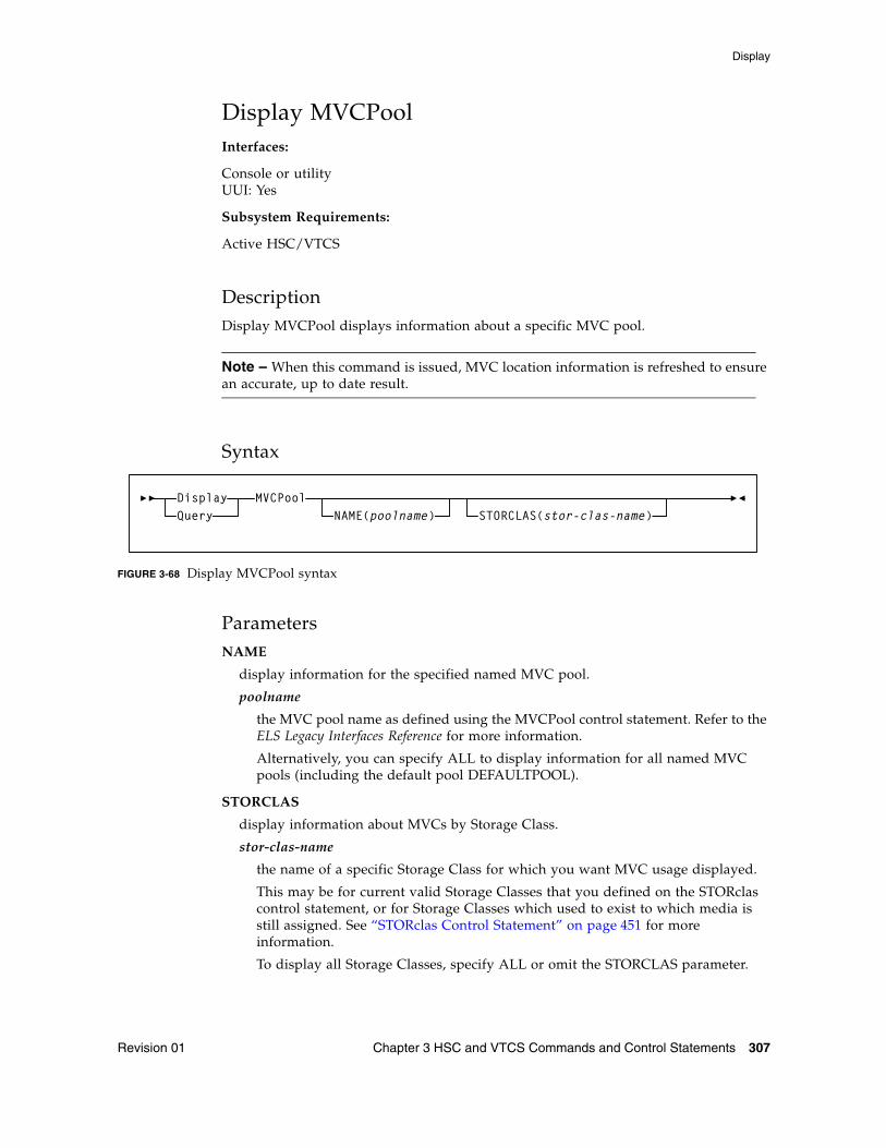
Display
Revision 01 Chapter 3 HSC and VTCS Commands and Control Statements 307
Display MVCPoolInterfaces:
Console or utilityUUI: Yes
Subsystem Requirements:
Active HSC/VTCS
DescriptionDisplay MVCPool displays information about a specific MVC pool.
Note – When this command is issued, MVC location information is refreshed to ensure an accurate, up to date result.
Syntax
FIGURE 3-68 Display MVCPool syntax
ParametersNAME
display information for the specified named MVC pool.
poolname
the MVC pool name as defined using the MVCPool control statement. Refer to the ELS Legacy Interfaces Reference for more information.
Alternatively, you can specify ALL to display information for all named MVC pools (including the default pool DEFAULTPOOL).
STORCLAS
display information about MVCs by Storage Class.
stor-clas-name
the name of a specific Storage Class for which you want MVC usage displayed.
This may be for current valid Storage Classes that you defined on the STORclas control statement, or for Storage Classes which used to exist to which media is still assigned. See “STORclas Control Statement” on page 451 for more information.
To display all Storage Classes, specify ALL or omit the STORCLAS parameter.
MVCPoolNAME(poolname)
DisplayQuery STORCLAS(stor-clas-name)
Display
308 ELS 7.1 Command, Control Statement, and Utility Reference • November 2012 Revision 01
OutputDisplay MVCPOOL displays any checkpoint time stamp on the CDS and/or any configuration PROTECT policy specified as shown:
DR checkpoint set: yyyymmmdd hh:mm:ss
MVC protection period set: nn hrs
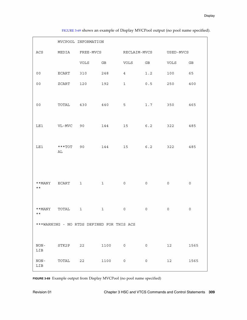
Display
Revision 01 Chapter 3 HSC and VTCS Commands and Control Statements 309
FIGURE 3-69 shows an example of Display MVCPool output (no pool name specified).
FIGURE 3-69 Example output from Display MVCPool (no pool name specified)
MVCPOOL INFORMATION
ACS MEDIA FREE-MVCS RECLAIM-MVCS USED-MVCS
VOLS GB VOLS GB VOLS GB
00 ECART 310 248 4 1.2 100 65
00 ZCART 120 192 1 0.5 250 400
00 TOTAL 430 440 5 1.7 350 465
LE1 VL-MVC 90 144 15 6.2 322 485
LE1 ***TOTAL
90 144 15 6.2 322 485
**MANY**
ECART 1 1 0 0 0 0
**MANY**
TOTAL 1 1 0 0 0 0
***WARNING - NO RTDS DEFINED FOR THIS ACS
NON-LIB
STK2P 22 1100 0 0 12 1565
NON-LIB
TOTAL 22 1100 0 0 12 1565
Display
310 ELS 7.1 Command, Control Statement, and Utility Reference • November 2012 Revision 01
In FIGURE 3-69, note that:
■ For local MVC volumes, the ACS column displays the ACS in which it is currently stored. For remote MVC volumes or VMVCs in VLEs, the ACS column displays the name of the VLE that holds them. For example, LE1 is a VLE name for VMVCs.
■ The special name **MANY** appears in the 'ACS' column if a MVC with a specific volser has been discovered in more than one location. MVCs in this state are marked unusable.
■ ACSs with no RTDs attached are flagged (in this case, LE1, which is a Tapeless configuration with a VLE attached).
Fields
ACS
the ACS containing the MVC pool. NONLIB counts are for initialized MVCs that are now outside the library.
MEDIA
the MVC media type.
FREE-MVCS
MVCs that have 100% usable space and do not contain any migrated VTVs.The storage shown is the total free space based on media type capacity.
RECLAIM-MVCS
MVCs eligible for space reclamation by this host. The storage shown is the total wasted space, including those MVCs not yet eligible for space reclaim.
USED-MVCS
initialized MVCs that are partially or completely full.
Display
Revision 01 Chapter 3 HSC and VTCS Commands and Control Statements 311
Display OPTionInterfaces:
Console or PARMLIBUUI: No
Subsystem Requirements:
Active HSC at BASE or FULL service level
DescriptionDisplay OPTion displays current settings for general HSC options set by the OPTion command.
Syntax
FIGURE 3-70 Display OPTion syntax
ParametersNone.
OPTionDisplayQuery
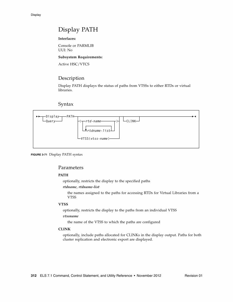
Display
312 ELS 7.1 Command, Control Statement, and Utility Reference • November 2012 Revision 01
Display PATHInterfaces:
Console or PARMLIBUUI: No
Subsystem Requirements:
Active HSC/VTCS
DescriptionDisplay PATH displays the status of paths from VTSSs to either RTDs or virtual libraries.
Syntax
FIGURE 3-71 Display PATH syntax
ParametersPATH
optionally, restricts the display to the specified paths
rtdname, rtdname-list
the names assigned to the paths for accessing RTDs for Virtual Libraries from a VTSS
VTSS
optionally, restricts the display to the paths from an individual VTSS
vtssname
the name of the VTSS to which the paths are configured
CLINK
optionally, include paths allocated for CLINKs in the display output. Paths for both cluster replication and electronic export are displayed.
PATHDisplayQuery ( rtd-name
rtdname-list
)
VTSS(vtss-name)
CLINK
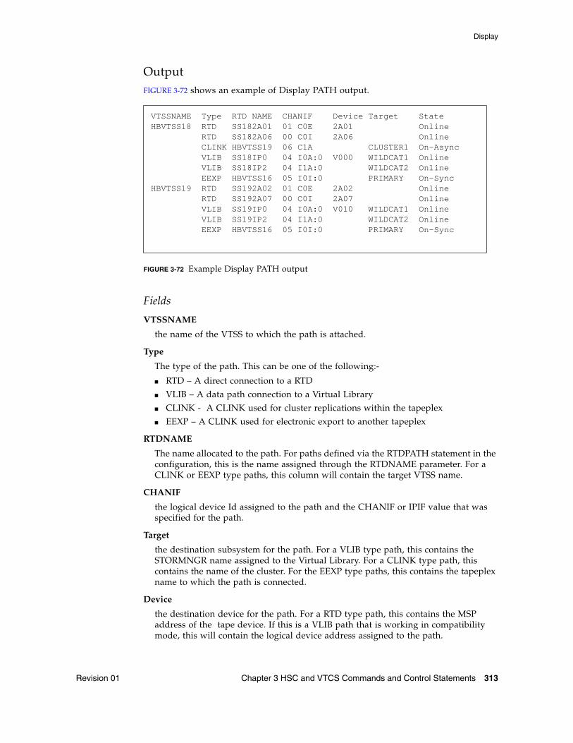
Display
Revision 01 Chapter 3 HSC and VTCS Commands and Control Statements 313
OutputFIGURE 3-72 shows an example of Display PATH output.
FIGURE 3-72 Example Display PATH output
Fields
VTSSNAME
the name of the VTSS to which the path is attached.
Type
The type of the path. This can be one of the following:-
■ RTD – A direct connection to a RTD
■ VLIB – A data path connection to a Virtual Library
■ CLINK - A CLINK used for cluster replications within the tapeplex
■ EEXP – A CLINK used for electronic export to another tapeplex
RTDNAME
The name allocated to the path. For paths defined via the RTDPATH statement in the configuration, this is the name assigned through the RTDNAME parameter. For a CLINK or EEXP type paths, this column will contain the target VTSS name.
CHANIF
the logical device Id assigned to the path and the CHANIF or IPIF value that was specified for the path.
Target
the destination subsystem for the path. For a VLIB type path, this contains the STORMNGR name assigned to the Virtual Library. For a CLINK type path, this contains the name of the cluster. For the EEXP type paths, this contains the tapeplex name to which the path is connected.
Device
the destination device for the path. For a RTD type path, this contains the MSP address of the tape device. If this is a VLIB path that is working in compatibility mode, this will contain the logical device address assigned to the path.
VTSSNAME Type RTD NAME CHANIF Device Target StateHBVTSS18 RTD SS182A01 01 C0E 2A01 Online RTD SS182A06 00 C0I 2A06 Online CLINK HBVTSS19 06 C1A CLUSTER1 On-Async VLIB SS18IP0 04 I0A:0 V000 WILDCAT1 Online VLIB SS18IP2 04 I1A:0 WILDCAT2 Online EEXP HBVTSS16 05 I0I:0 PRIMARY On-SyncHBVTSS19 RTD SS192A02 01 C0E 2A02 Online RTD SS192A07 00 C0I 2A07 Online VLIB SS19IP0 04 I0A:0 V010 WILDCAT1 Online VLIB SS19IP2 04 I1A:0 WILDCAT2 Online EEXP HBVTSS16 05 I0I:0 PRIMARY On-Sync
Display
314 ELS 7.1 Command, Control Statement, and Utility Reference • November 2012 Revision 01
State
The current state of this path. This can be one of the following:-
Online
the path is online and available for use
On-Async
the path is online and available for use for asynchronous replication of VTVs.
On-Sync
the path is online and available for use for synchronous replication of VTVs.
Offline
the path or the device to which it connects has been varied offline.
Maint
the path or the device to which it connects has been varied into an offline maintenance mode. This could be as a result of repeated failures.

Display
Revision 01 Chapter 3 HSC and VTCS Commands and Control Statements 315
Display QueueInterfaces:
Console or utilityUUI: Yes
Subsystem Requirements:
Active HSC/VTCS
DescriptionDisplay Queue displays status of queued VTCS processes.
Syntax
FIGURE 3-73 Display Queue syntax
ParametersDETail
optionally, display detailed status.
VTSS
optionally, display processes for the specified VTSS.
vtss-name
the VTSS name.
OutputSee “Output” on page 254.
QueueDETail
VTSS(vtss-name)
DisplayQuery
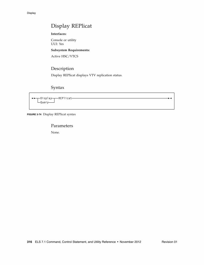
Display
316 ELS 7.1 Command, Control Statement, and Utility Reference • November 2012 Revision 01
Display REPlicatInterfaces:
Console or utilityUUI: Yes
Subsystem Requirements:
Active HSC/VTCS
DescriptionDisplay REPlicat displays VTV replication status.
Syntax
FIGURE 3-74 Display REPlicat syntax
ParametersNone.
REPlicatDisplayQuery
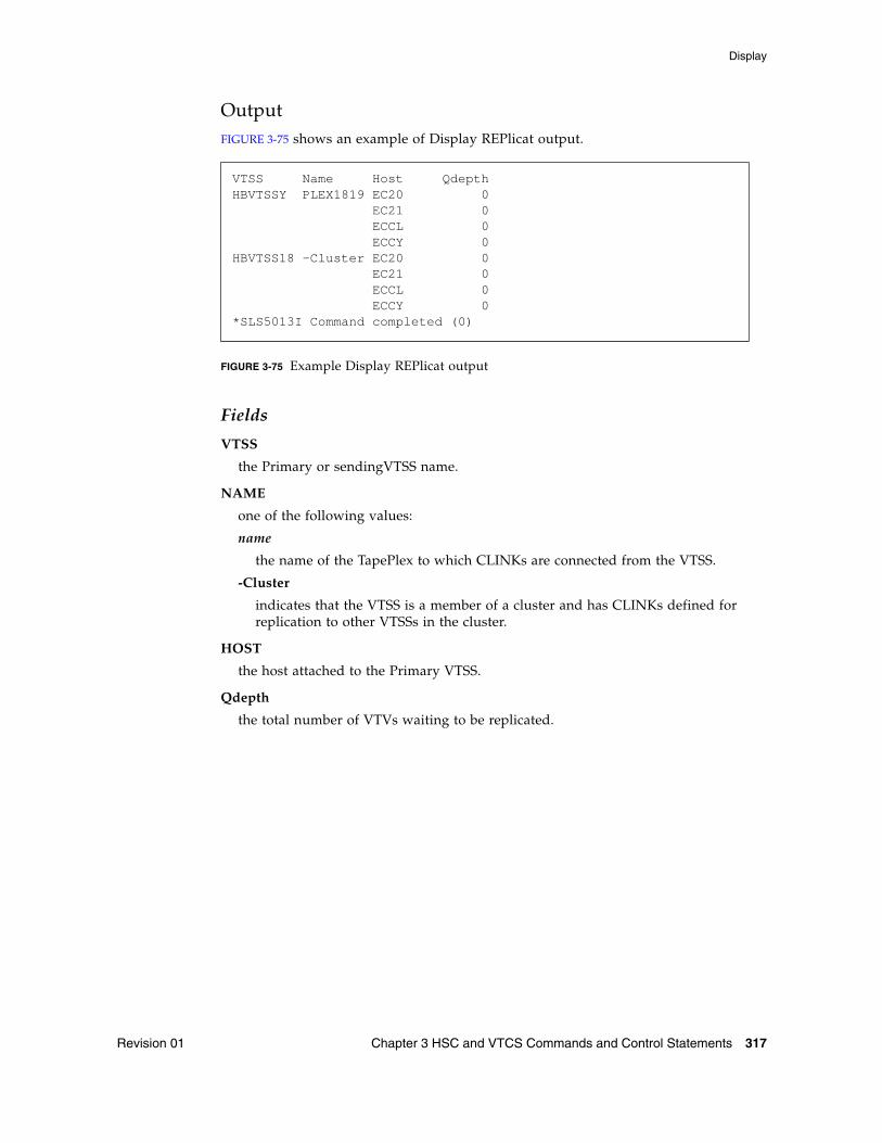
Display
Revision 01 Chapter 3 HSC and VTCS Commands and Control Statements 317
OutputFIGURE 3-75 shows an example of Display REPlicat output.
FIGURE 3-75 Example Display REPlicat output
Fields
VTSS
the Primary or sendingVTSS name.
NAME
one of the following values:
name
the name of the TapePlex to which CLINKs are connected from the VTSS.
-Cluster
indicates that the VTSS is a member of a cluster and has CLINKs defined for replication to other VTSSs in the cluster.
HOST
the host attached to the Primary VTSS.
Qdepth
the total number of VTVs waiting to be replicated.
VTSS Name Host QdepthHBVTSSY PLEX1819 EC20 0 EC21 0 ECCL 0 ECCY 0HBVTSS18 -Cluster EC20 0 EC21 0 ECCL 0 ECCY 0*SLS5013I Command completed (0)
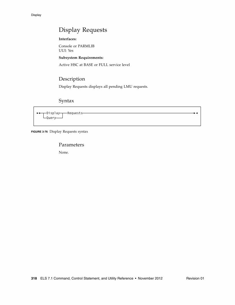
Display
318 ELS 7.1 Command, Control Statement, and Utility Reference • November 2012 Revision 01
Display RequestsInterfaces:
Console or PARMLIBUUI: Yes
Subsystem Requirements:
Active HSC at BASE or FULL service level
DescriptionDisplay Requests displays all pending LMU requests.
Syntax
FIGURE 3-76 Display Requests syntax
ParametersNone.
RequestsDisplayQuery
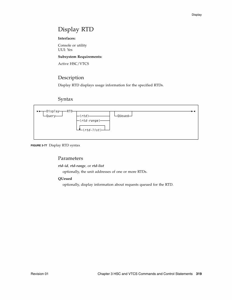
Display
Revision 01 Chapter 3 HSC and VTCS Commands and Control Statements 319
Display RTDInterfaces:
Console or utilityUUI: Yes
Subsystem Requirements:
Active HSC/VTCS
DescriptionDisplay RTD displays usage information for the specified RTDs.
Syntax
FIGURE 3-77 Display RTD syntax
Parametersrtd–id, rtd-range, or rtd-list
optionally, the unit addresses of one or more RTDs.
QUeued
optionally, display information about requests queued for the RTD.
RTD(rtd)(rtd-range)
(rtd-list)
QUeuedDisplayQuery
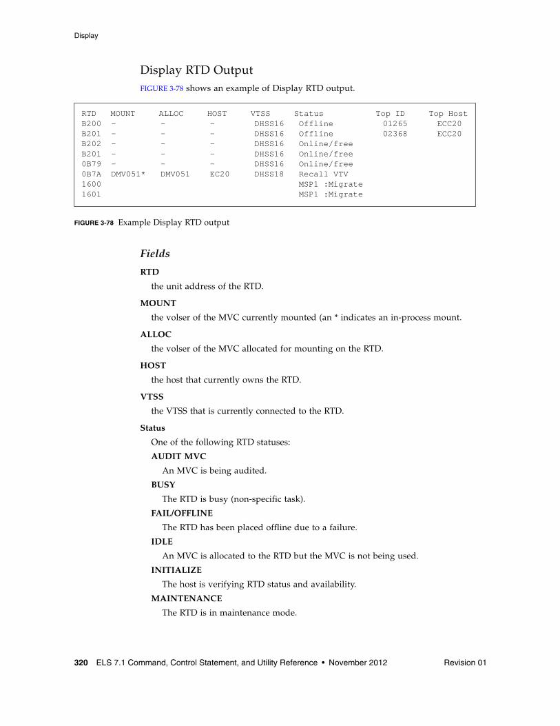
Display
320 ELS 7.1 Command, Control Statement, and Utility Reference • November 2012 Revision 01
Display RTD OutputFIGURE 3-78 shows an example of Display RTD output.
FIGURE 3-78 Example Display RTD output
Fields
RTD
the unit address of the RTD.
MOUNT
the volser of the MVC currently mounted (an * indicates an in-process mount.
ALLOC
the volser of the MVC allocated for mounting on the RTD.
HOST
the host that currently owns the RTD.
VTSS
the VTSS that is currently connected to the RTD.
Status
One of the following RTD statuses:
AUDIT MVC
An MVC is being audited.
BUSY
The RTD is busy (non-specific task).
FAIL/OFFLINE
The RTD has been placed offline due to a failure.
IDLE
An MVC is allocated to the RTD but the MVC is not being used.
INITIALIZE
The host is verifying RTD status and availability.
MAINTENANCE
The RTD is in maintenance mode.
RTD MOUNT ALLOC HOST VTSS Status Top ID Top HostB200 - - - DHSS16 Offline 01265 ECC20B201 - - - DHSS16 Offline 02368 ECC20B202 - - - DHSS16 Online/freeB201 - - - DHSS16 Online/free0B79 - - - DHSS16 Online/free0B7A DMV051* DMV051 EC20 DHSS18 Recall VTV1600 MSP1 :Migrate1601 MSP1 :Migrate
Display
Revision 01 Chapter 3 HSC and VTCS Commands and Control Statements 321
MIGRATE VTV
The RTD is migrating a VTV.
OFFLINE
The RTD is offline and unavailable to all hosts and VTSSs.
ONLINE/FREE
The RTD is online and available.
PATH OFFLINE
The RTD status is unknown because the VTSS cannot contact the RTD or if the paths were not correctly configured.
PATH SUSPEND
An RTD is globally online but the path from the VTSS is suspended due to the RTD being paired with a CLINK.
RECALL VTV
The RTD is recalling a VTV.
RECOVER RTD
The RTD is being reset after a problem, a vary, or an initialization.
RECOVERY
The RTD is being reset following an error or a vary online mode.
SUSPEND
The RTD operations are suspended. This occurs under the following conditions:
■ when two RTDs are connected to two separate ports on the same VSM4 ICE3 card CIP or VSM5, FICON and FIP.
■ when one or more RTDs and a CLINK are configured on the same port. The RTDs remain in SUSPEND mode while the CLINK is online.
Note – An RTD can only be online if the CLINK is offline.
UNLOAD MVC
A forced unload of the RTD is occurring.
VTV TRANSFER
The RTD is migrating a VTV before recalling it on another VTSS.
TOP ID
the process Id of the request that is top of the queue for next using this RTD from this host. The TOP ID column only applies for requests from the host upon which the command has been executed. This host may not have the top claim upon the RTD.
TOP HOST
the host which has the request that is top of the queue for next using this RTD. The TOP HOST indicates which host has the top claim upon the RTD.
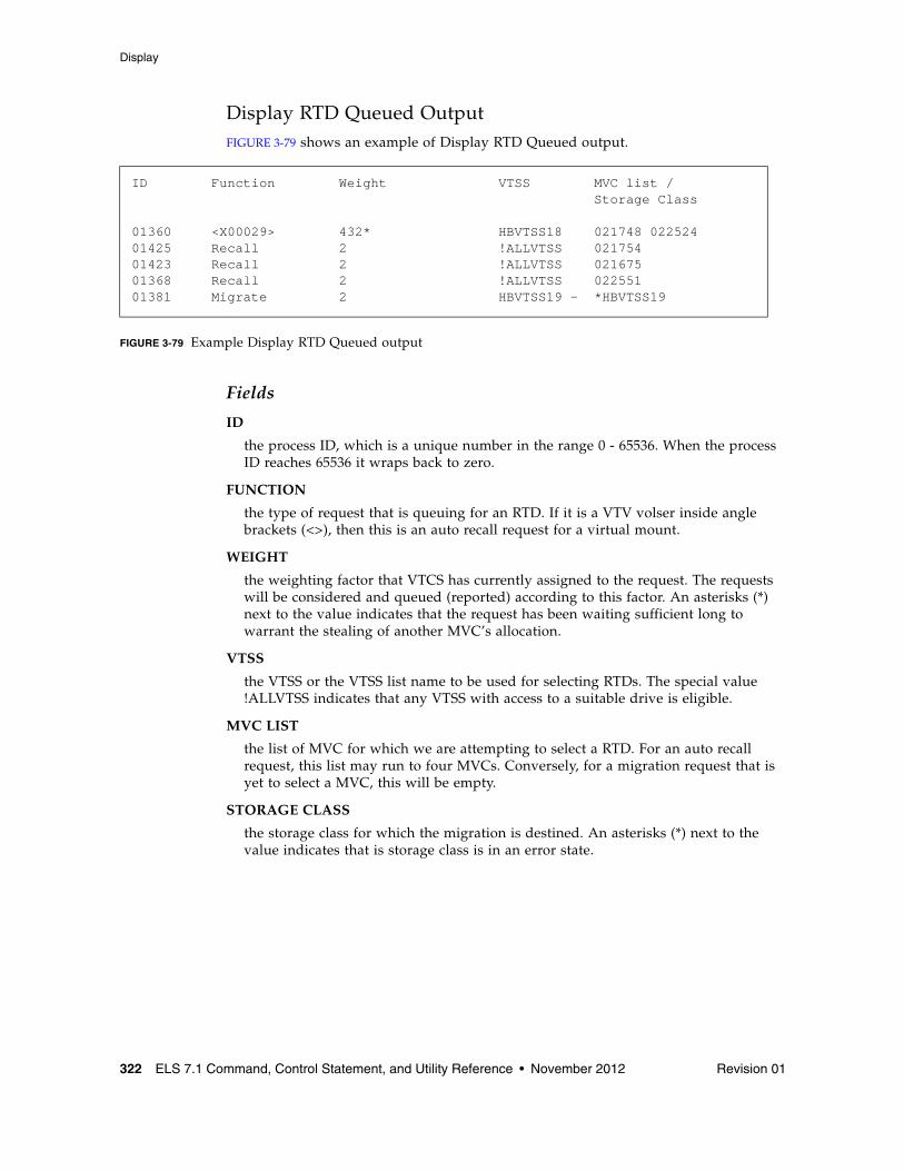
Display
322 ELS 7.1 Command, Control Statement, and Utility Reference • November 2012 Revision 01
Display RTD Queued OutputFIGURE 3-79 shows an example of Display RTD Queued output.
FIGURE 3-79 Example Display RTD Queued output
Fields
ID
the process ID, which is a unique number in the range 0 - 65536. When the process ID reaches 65536 it wraps back to zero.
FUNCTION
the type of request that is queuing for an RTD. If it is a VTV volser inside angle brackets (<>), then this is an auto recall request for a virtual mount.
WEIGHT
the weighting factor that VTCS has currently assigned to the request. The requests will be considered and queued (reported) according to this factor. An asterisks (*) next to the value indicates that the request has been waiting sufficient long to warrant the stealing of another MVC’s allocation.
VTSS
the VTSS or the VTSS list name to be used for selecting RTDs. The special value !ALLVTSS indicates that any VTSS with access to a suitable drive is eligible.
MVC LIST
the list of MVC for which we are attempting to select a RTD. For an auto recall request, this list may run to four MVCs. Conversely, for a migration request that is yet to select a MVC, this will be empty.
STORAGE CLASS
the storage class for which the migration is destined. An asterisks (*) next to the value indicates that is storage class is in an error state.
ID Function Weight VTSS MVC list / Storage Class
01360 <X00029> 432* HBVTSS18 021748 02252401425 Recall 2 !ALLVTSS 02175401423 Recall 2 !ALLVTSS 02167501368 Recall 2 !ALLVTSS 02255101381 Migrate 2 HBVTSS19 - *HBVTSS19
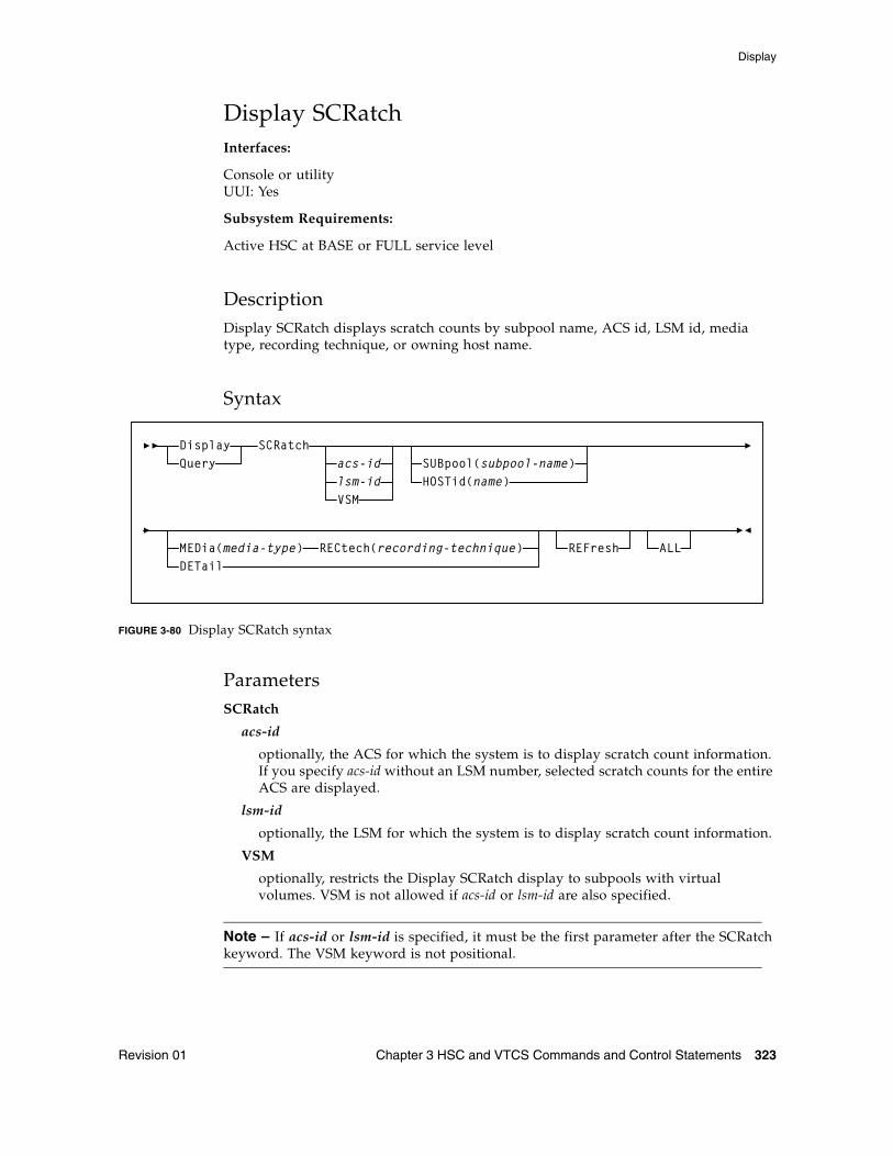
Display
Revision 01 Chapter 3 HSC and VTCS Commands and Control Statements 323
Display SCRatchInterfaces:
Console or utilityUUI: Yes
Subsystem Requirements:
Active HSC at BASE or FULL service level
DescriptionDisplay SCRatch displays scratch counts by subpool name, ACS id, LSM id, media type, recording technique, or owning host name.
Syntax
FIGURE 3-80 Display SCRatch syntax
ParametersSCRatch
acs-id
optionally, the ACS for which the system is to display scratch count information. If you specify acs-id without an LSM number, selected scratch counts for the entire ACS are displayed.
lsm-id
optionally, the LSM for which the system is to display scratch count information.
VSM
optionally, restricts the Display SCRatch display to subpools with virtual volumes. VSM is not allowed if acs-id or lsm-id are also specified.
Note – If acs-id or lsm-id is specified, it must be the first parameter after the SCRatch keyword. The VSM keyword is not positional.
SCRatchacs-idlsm-idVSM
SUBpool(subpool-name)HOSTid(name)
MEDia(media-type) RECtech(recording-technique) ALLDETail
DisplayQuery
REFresh
Display
324 ELS 7.1 Command, Control Statement, and Utility Reference • November 2012 Revision 01
SUBpool
optionally, restricts the scratch count display to the named subpool only. If SUBpool is specified, then LSM and ACS totals will reflect only the named subpool. SUBpool is not allowed if HOSTid is also specified.
subpool-name
the name of the subpool. Specify up to 13 characters.
HOSTid
optionally, restricts the scratch count display to subpools that are accessible from the named HOSTid. If HOSTid is specified, then LSM and ACS totals will reflect only subpools that can be accessed from the named HOSTid. HOSTid is not allowed if SUBpool is also specified.
name
the SMFID or the SMC SERVER ALIASHOST ID of the host. Specify up to 8 characters.
MEDia
optionally, restricts the scratch count display to the volumes compatible with the specified media name. If MEDia is specified, then LSM and ACS totals will reflect only the compatible media types.
media-type
the media type.
See Appendix A, “MEDia, RECtech, and MODel Values” for a list of valid media-type values.
RECtech
optionally, restricts the scratch count display to volumes compatible with the specified recording technique. If RECtech is specified, then LSM and ACS totals will reflect only the compatible recording techniques
recording-technique
the recording technique.
See Appendix A, “MEDia, RECtech, and MODel Values” for valid recording-technique values.
Note – RECtech is not valid with the VSM parameter.
DETail
optionally, lists scratch counts by all media and recording techniques. If specified, then an additional level of media and recording technique detail is displayed for every subpool. DETail is not allowed if either MEDia or RECtech are also specified.
REFresh
optionally, updates VSM scratch counts prior to the display occurring.
Note – The REFresh parameter causes additional I/Os to the CDS and must be used sparingly.
Display
Revision 01 Chapter 3 HSC and VTCS Commands and Control Statements 325
ALL
optionally, lists scratch counts for subpools that have both a 0 scratch count and 0 threshold value. Normally, the Display SCRatch command will only list subpools that have either a non-zero scratch count or non-zero threshold value. Specification of ALL overrides this filter and results in the display of all defined scratch pools.
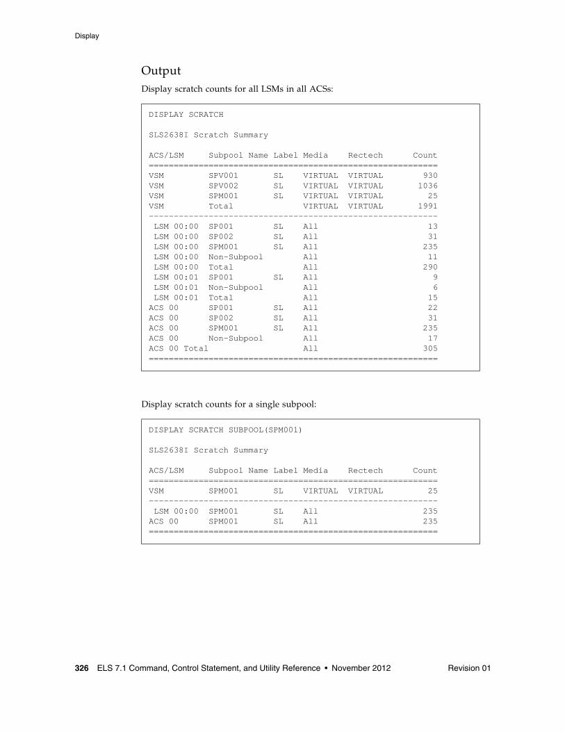
Display
326 ELS 7.1 Command, Control Statement, and Utility Reference • November 2012 Revision 01
OutputDisplay scratch counts for all LSMs in all ACSs:
Display scratch counts for a single subpool:
DISPLAY SCRATCH
SLS2638I Scratch Summary
ACS/LSM Subpool Name Label Media Rectech Count==========================================================VSM SPV001 SL VIRTUAL VIRTUAL 930VSM SPV002 SL VIRTUAL VIRTUAL 1036VSM SPM001 SL VIRTUAL VIRTUAL 25VSM Total VIRTUAL VIRTUAL 1991---------------------------------------------------------- LSM 00:00 SP001 SL All 13 LSM 00:00 SP002 SL All 31 LSM 00:00 SPM001 SL All 235 LSM 00:00 Non-Subpool All 11 LSM 00:00 Total All 290 LSM 00:01 SP001 SL All 9 LSM 00:01 Non-Subpool All 6 LSM 00:01 Total All 15ACS 00 SP001 SL All 22ACS 00 SP002 SL All 31ACS 00 SPM001 SL All 235ACS 00 Non-Subpool All 17ACS 00 Total All 305==========================================================
DISPLAY SCRATCH SUBPOOL(SPM001)
SLS2638I Scratch Summary
ACS/LSM Subpool Name Label Media Rectech Count==========================================================VSM SPM001 SL VIRTUAL VIRTUAL 25---------------------------------------------------------- LSM 00:00 SPM001 SL All 235ACS 00 SPM001 SL All 235==========================================================
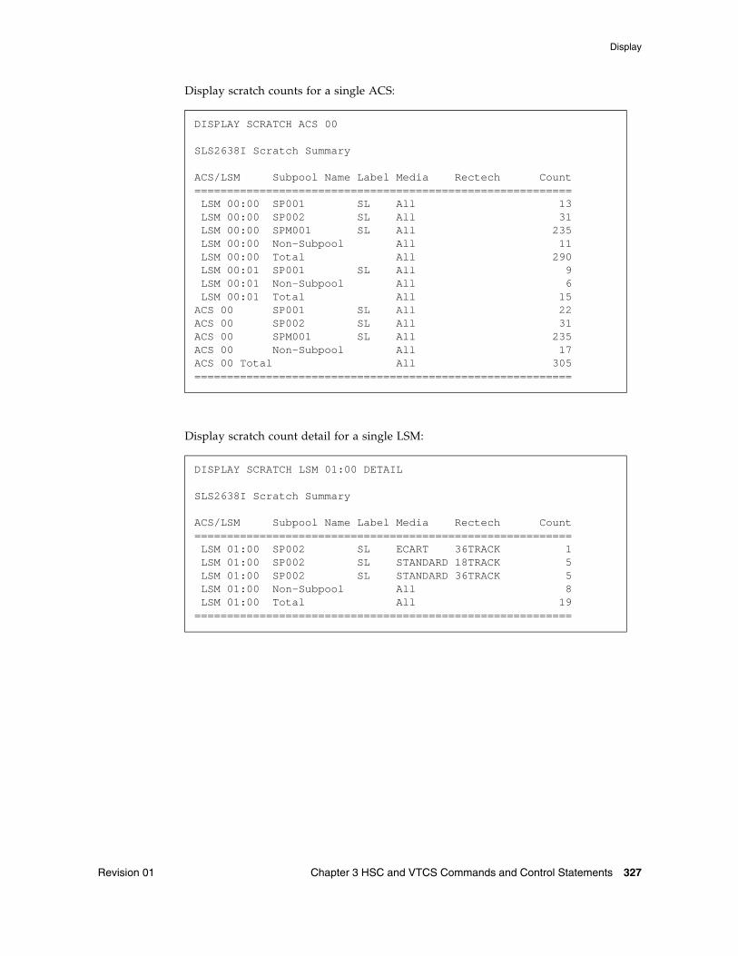
Display
Revision 01 Chapter 3 HSC and VTCS Commands and Control Statements 327
Display scratch counts for a single ACS:
Display scratch count detail for a single LSM:
DISPLAY SCRATCH ACS 00
SLS2638I Scratch Summary
ACS/LSM Subpool Name Label Media Rectech Count========================================================== LSM 00:00 SP001 SL All 13 LSM 00:00 SP002 SL All 31 LSM 00:00 SPM001 SL All 235 LSM 00:00 Non-Subpool All 11 LSM 00:00 Total All 290 LSM 00:01 SP001 SL All 9 LSM 00:01 Non-Subpool All 6 LSM 00:01 Total All 15ACS 00 SP001 SL All 22ACS 00 SP002 SL All 31ACS 00 SPM001 SL All 235ACS 00 Non-Subpool All 17ACS 00 Total All 305==========================================================
DISPLAY SCRATCH LSM 01:00 DETAIL
SLS2638I Scratch Summary
ACS/LSM Subpool Name Label Media Rectech Count========================================================== LSM 01:00 SP002 SL ECART 36TRACK 1 LSM 01:00 SP002 SL STANDARD 18TRACK 5 LSM 01:00 SP002 SL STANDARD 36TRACK 5 LSM 01:00 Non-Subpool All 8 LSM 01:00 Total All 19==========================================================
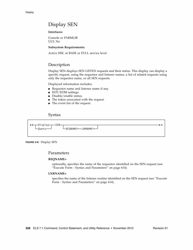
Display
328 ELS 7.1 Command, Control Statement, and Utility Reference • November 2012 Revision 01
Display SENInterfaces:
Console or PARMLIBUUI: No
Subsystem Requirements:
Active HSC at BASE or FULL service level
DescriptionDisplay SEN displays SEN LISTEN requests and their status. This display can display a specific request, using the requestor and listener names, a list of related requests using only the requestor name, or all SEN requests.
Displayed information includes:
■ Requestor name and listener name if any.■ EOT/EOM settings.■ Disable/enable status.■ The token associated with the request.■ The event list of the request.
Syntax
FIGURE 3-81 Display SEN
ParametersREQNAME=
optionally, specifies the name of the requestor identified on the SEN request (see “Execute Form - Syntax and Parameters” on page 614).
LNRNAME=
specifies the name of the listener routine identified on the SEN request (see “Execute Form - Syntax and Parameters” on page 614).
SENREQNAME= LNRNAME=
DisplayQuery
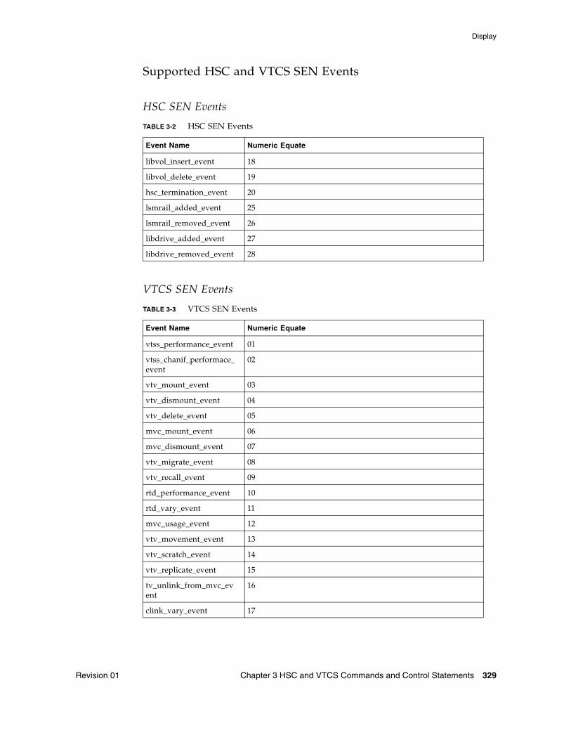
Display
Revision 01 Chapter 3 HSC and VTCS Commands and Control Statements 329
Supported HSC and VTCS SEN Events
HSC SEN Events
VTCS SEN Events
TABLE 3-2 HSC SEN Events
Event Name Numeric Equate
libvol_insert_event 18
libvol_delete_event 19
hsc_termination_event 20
lsmrail_added_event 25
lsmrail_removed_event 26
libdrive_added_event 27
libdrive_removed_event 28
TABLE 3-3 VTCS SEN Events
Event Name Numeric Equate
vtss_performance_event 01
vtss_chanif_performace_event
02
vtv_mount_event 03
vtv_dismount_event 04
vtv_delete_event 05
mvc_mount_event 06
mvc_dismount_event 07
vtv_migrate_event 08
vtv_recall_event 09
rtd_performance_event 10
rtd_vary_event 11
mvc_usage_event 12
vtv_movement_event 13
vtv_scratch_event 14
vtv_replicate_event 15
tv_unlink_from_mvc_event
16
clink_vary_event 17
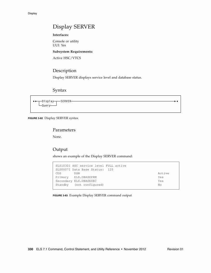
Display
330 ELS 7.1 Command, Control Statement, and Utility Reference • November 2012 Revision 01
Display SERVERInterfaces:
Console or utilityUUI: Yes
Subsystem Requirements:
Active HSC/VTCS
DescriptionDisplay SERVER displays service level and database status.
Syntax
FIGURE 3-82 Display SERVER syntax
ParametersNone.
Outputshows an example of the Display SERVER command:
FIGURE 3-83 Example Display SERVER command output
SLS1030I HSC service level FULL activeSLS0007I Data Base Status: 125CDS DSN ActivePrimary ELS.DBASEPRM YesSecondary ELS.DBASESEC YesStandby (not configured) No
SERVERDisplayQuery
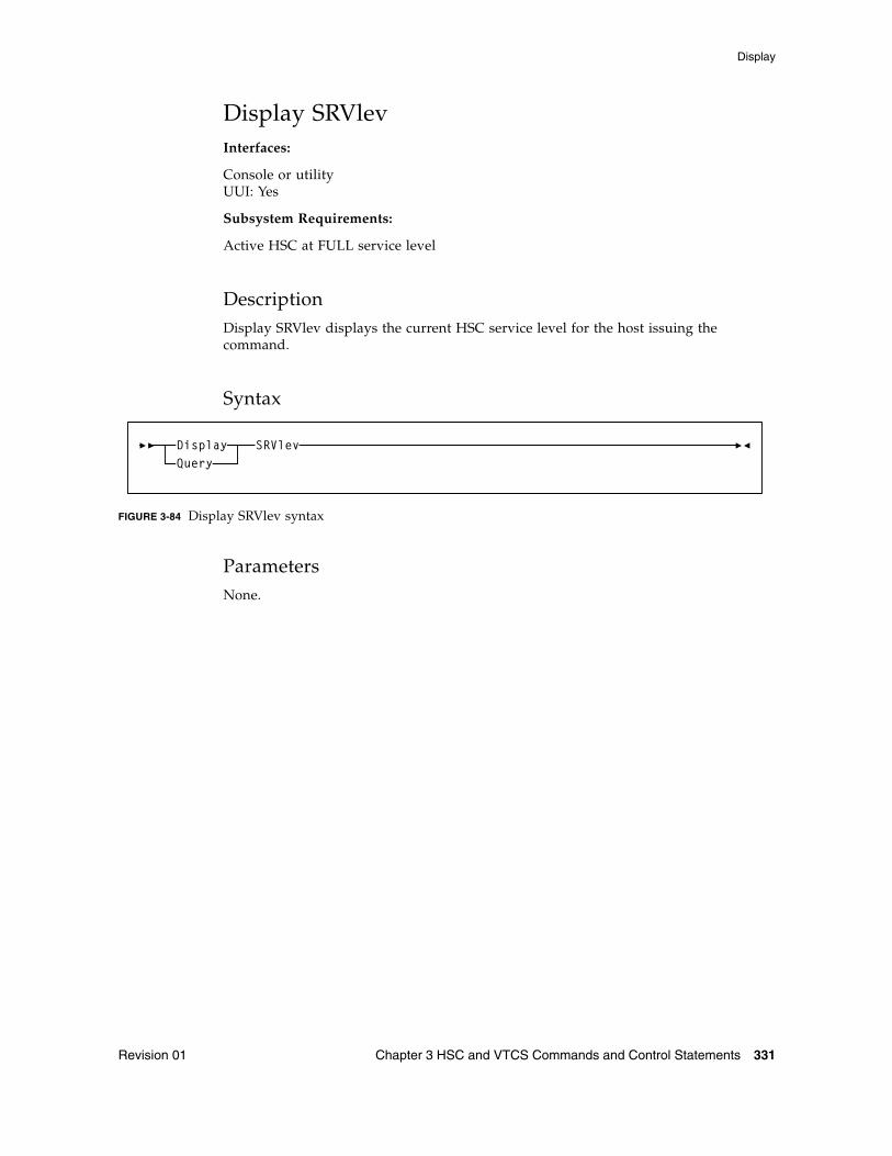
Display
Revision 01 Chapter 3 HSC and VTCS Commands and Control Statements 331
Display SRVlevInterfaces:
Console or utilityUUI: Yes
Subsystem Requirements:
Active HSC at FULL service level
DescriptionDisplay SRVlev displays the current HSC service level for the host issuing the command.
Syntax
FIGURE 3-84 Display SRVlev syntax
ParametersNone.
SRVlevDisplayQuery
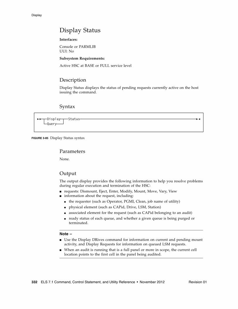
Display
332 ELS 7.1 Command, Control Statement, and Utility Reference • November 2012 Revision 01
Display StatusInterfaces:
Console or PARMLIBUUI: No
Subsystem Requirements:
Active HSC at BASE or FULL service level
DescriptionDisplay Status displays the status of pending requests currently active on the host issuing the command.
Syntax
FIGURE 3-85 Display Status syntax
ParametersNone.
OutputThe output display provides the following information to help you resolve problems during regular execution and termination of the HSC:
■ requests: Dismount, Eject, Enter, Modify, Mount, Move, Vary, View ■ information about the request, including:
■ the requester (such as Operator, PGMI, Clean, job name of utility)
■ physical element (such as CAPid, Drive, LSM, Station)
■ associated element for the request (such as CAPid belonging to an audit)
■ ready status of each queue, and whether a given queue is being purged or terminated.
Note – ■ Use the Display DRives command for information on current and pending mount
activity, and Display Requests for information on queued LSM requests.
■ When an audit is running that is a full panel or more in scope, the current cell location points to the first cell in the panel being audited.
StatusDisplayQuery
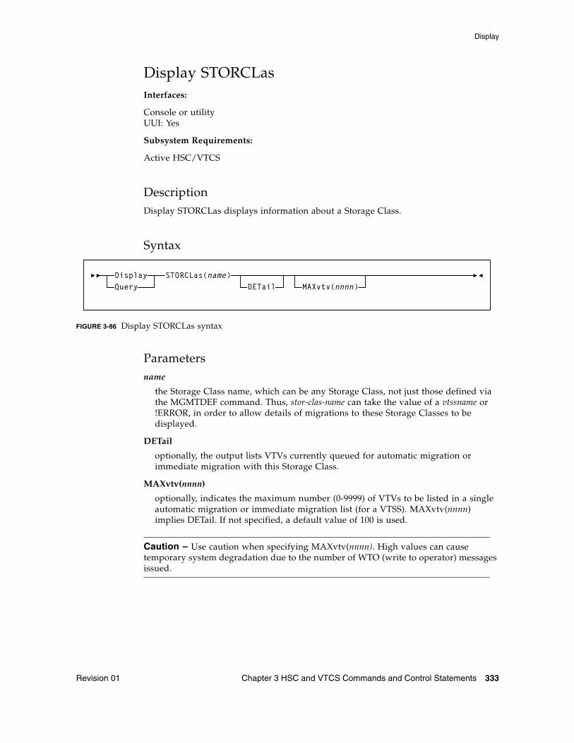
Display
Revision 01 Chapter 3 HSC and VTCS Commands and Control Statements 333
Display STORCLasInterfaces:
Console or utilityUUI: Yes
Subsystem Requirements:
Active HSC/VTCS
DescriptionDisplay STORCLas displays information about a Storage Class.
Syntax
FIGURE 3-86 Display STORCLas syntax
Parametersname
the Storage Class name, which can be any Storage Class, not just those defined via the MGMTDEF command. Thus, stor-clas-name can take the value of a vtssname or !ERROR, in order to allow details of migrations to these Storage Classes to be displayed.
DETail
optionally, the output lists VTVs currently queued for automatic migration or immediate migration with this Storage Class.
MAXvtv(nnnn)
optionally, indicates the maximum number (0-9999) of VTVs to be listed in a single automatic migration or immediate migration list (for a VTSS). MAXvtv(nnnn) implies DETail. If not specified, a default value of 100 is used.
Caution – Use caution when specifying MAXvtv(nnnn). High values can cause temporary system degradation due to the number of WTO (write to operator) messages issued.
STORCLas(name)DETail MAXvtv(nnnn)
DisplayQuery
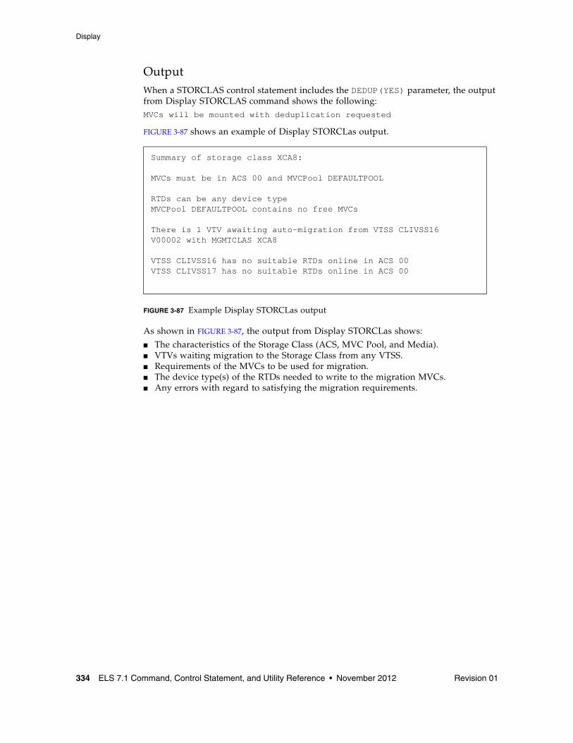
Display
334 ELS 7.1 Command, Control Statement, and Utility Reference • November 2012 Revision 01
OutputWhen a STORCLAS control statement includes the DEDUP(YES) parameter, the output from Display STORCLAS command shows the following:MVCs will be mounted with deduplication requested
FIGURE 3-87 shows an example of Display STORCLas output.
FIGURE 3-87 Example Display STORCLas output
As shown in FIGURE 3-87, the output from Display STORCLas shows:
■ The characteristics of the Storage Class (ACS, MVC Pool, and Media).■ VTVs waiting migration to the Storage Class from any VTSS. ■ Requirements of the MVCs to be used for migration. ■ The device type(s) of the RTDs needed to write to the migration MVCs. ■ Any errors with regard to satisfying the migration requirements.
Summary of storage class XCA8:
MVCs must be in ACS 00 and MVCPool DEFAULTPOOL
RTDs can be any device typeMVCPool DEFAULTPOOL contains no free MVCs
There is 1 VTV awaiting auto-migration from VTSS CLIVSS16V00002 with MGMTCLAS XCA8
VTSS CLIVSS16 has no suitable RTDs online in ACS 00VTSS CLIVSS17 has no suitable RTDs online in ACS 00
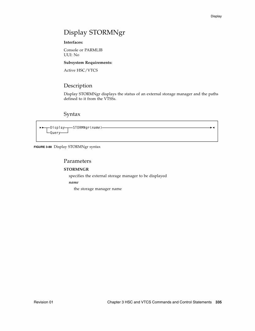
Display
Revision 01 Chapter 3 HSC and VTCS Commands and Control Statements 335
Display STORMNgrInterfaces:
Console or PARMLIBUUI: No
Subsystem Requirements:
Active HSC/VTCS
DescriptionDisplay STORMNgr displays the status of an external storage manager and the paths defined to it from the VTSSs.
Syntax
FIGURE 3-88 Display STORMNgr syntax
ParametersSTORMNGR
specifies the external storage manager to be displayed
name
the storage manager name
STORMNgr(name)DisplayQuery
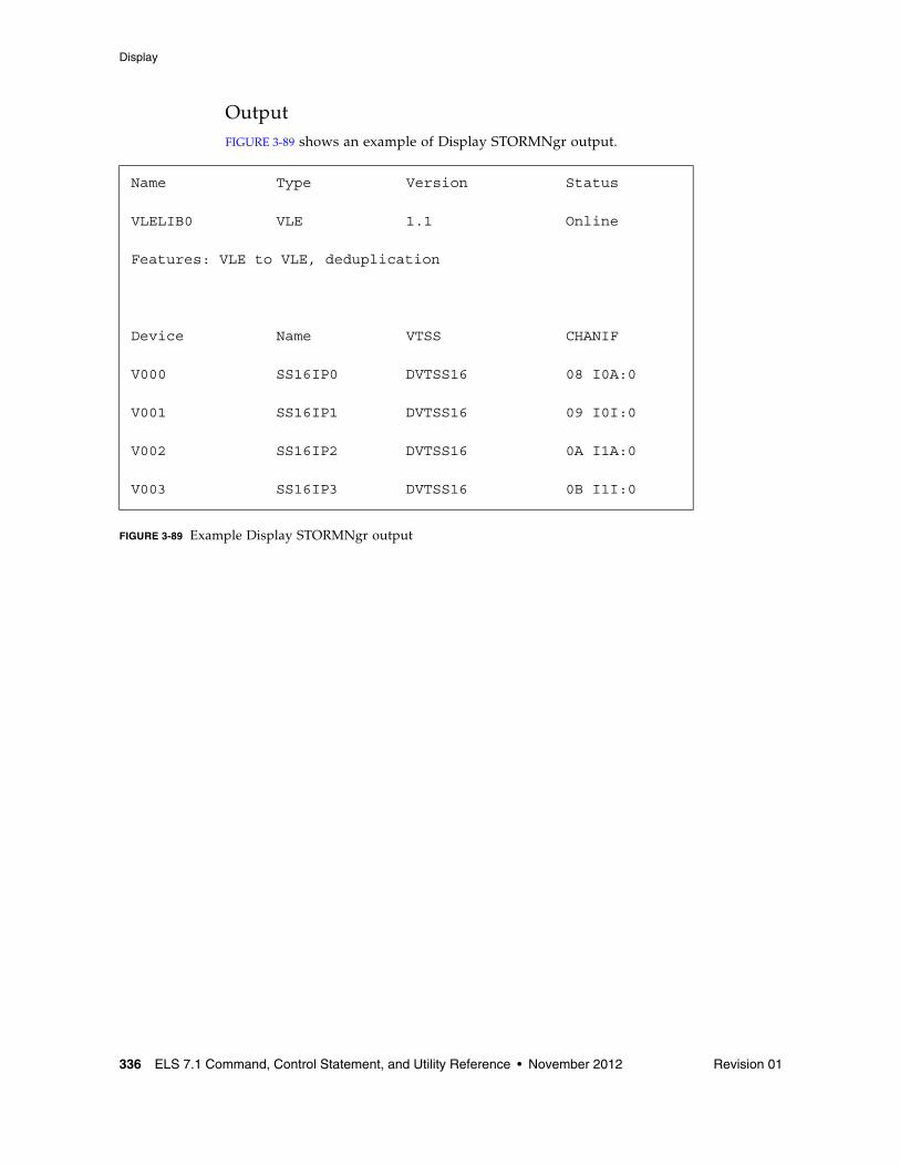
Display
336 ELS 7.1 Command, Control Statement, and Utility Reference • November 2012 Revision 01
OutputFIGURE 3-89 shows an example of Display STORMNgr output.
FIGURE 3-89 Example Display STORMNgr output
Name Type Version Status
VLELIB0 VLE 1.1 Online
Features: VLE to VLE, deduplication
Device Name VTSS CHANIF
V000 SS16IP0 DVTSS16 08 I0A:0
V001 SS16IP1 DVTSS16 09 I0I:0
V002 SS16IP2 DVTSS16 0A I1A:0
V003 SS16IP3 DVTSS16 0B I1I:0
Display
Revision 01 Chapter 3 HSC and VTCS Commands and Control Statements 337
Fields
Name
the name of the external Storage Manager
Type
the type of Storage Manager
■ HSC - An HSC in another TapePlex
■ VLE - A ELS
Version
the software version currently executing on the Storage Manager
Features
a list of significant features installed or supported by the Storage Manager
Status
the current status of the Storage Manager
Device
the destination device for the path. This column is blank in the connection to the Storage Manager is for autonomous device data transfers.
Name
the name allocated to the path within the Storage Manager. This column is blank if the Storage Manager is just for servicing mounts and dismounts to the device. If this is for a CLINK, then this column displays the target VTSS name.
VTSS
the name of a VTSS which has this connection to this Storage Manager. This column is blank if the device is driven directly by the Storage Manager.
CHANIF
the logical device Id assigned to the path and the CHANIF or IPIF value that was specified for the path. This column is blank if the path to the Storage Manager is not directly from a VTSS.
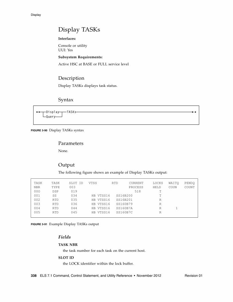
Display
338 ELS 7.1 Command, Control Statement, and Utility Reference • November 2012 Revision 01
Display TASKsInterfaces:
Console or utilityUUI: Yes
Subsystem Requirements:
Active HSC at BASE or FULL service level
DescriptionDisplay TASKs displays task status.
Syntax
FIGURE 3-90 Display TASKs syntax
ParametersNone.
OutputThe following figure shows an example of Display TASKs output:
FIGURE 3-91 Example Display TASKs output
Fields
TASK NBR
the task number for each task on the current host.
SLOT ID
the LOCK identifier within the lock buffer.
TASK TASK SLOT ID VTSS RTD CURRENT LOCKS WAITQ PENDQNBR TYPE 003 PROCESS HELD COUN COUNT00O DSP 019 518 T001 SS 034 HB VTSS16 SS16B200 T002 RTD 035 HB VTSS16 SS16B201 R003 RTD 036 HB VTSS16 SS160B79 R004 RTD 044 HB VTSS16 SS160B7A R 1005 RTD 045 HB VTSS16 SS160B7C R
TASKsDisplayQuery
Display
Revision 01 Chapter 3 HSC and VTCS Commands and Control Statements 339
TASK TYPE
the task type:
VTSS
the VTSS name.
RTD
the RTD name for RTD tasks.
CURRENT PROCESS
the current process ID.
LOCKS HELD
type of lock held:
WAITQ COUNT
the count of requests waiting for locks.
PENDQ COUNT
the count of pending requests.
INV Inventory Manager
CMD Command Task
Ctc Cross TapePlex Communication Manager
DSP Dispatcher Task
SS VTSS Task
RTD RTD Task
DRV RTD Scheduler
SCR Scratch Manager
RCM Reclaim Manager
MSC Migration Scheduler
CSH Clink Scheduler
CLK CLINK Task
UNK Unknown
T Task Lock
M MVC Lock
V VTV Lock
D VTD Lock
R RTD Lock
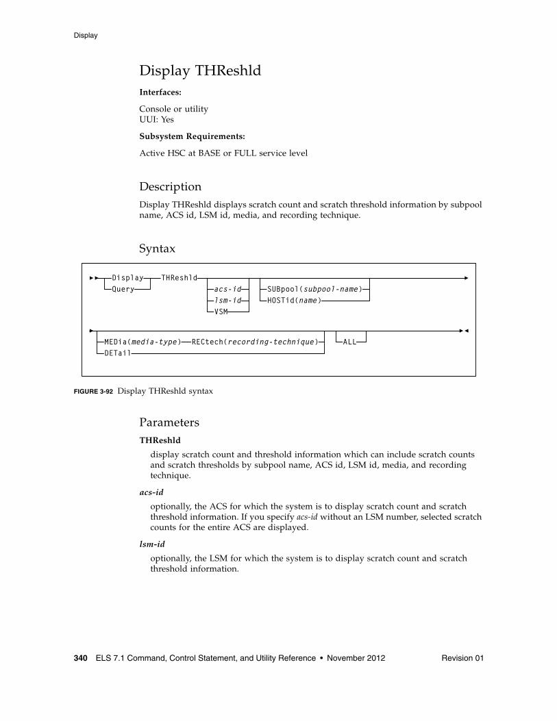
Display
340 ELS 7.1 Command, Control Statement, and Utility Reference • November 2012 Revision 01
Display THReshldInterfaces:
Console or utilityUUI: Yes
Subsystem Requirements:
Active HSC at BASE or FULL service level
DescriptionDisplay THReshld displays scratch count and scratch threshold information by subpool name, ACS id, LSM id, media, and recording technique.
Syntax
FIGURE 3-92 Display THReshld syntax
ParametersTHReshld
display scratch count and threshold information which can include scratch counts and scratch thresholds by subpool name, ACS id, LSM id, media, and recording technique.
acs-id
optionally, the ACS for which the system is to display scratch count and scratch threshold information. If you specify acs-id without an LSM number, selected scratch counts for the entire ACS are displayed.
lsm-id
optionally, the LSM for which the system is to display scratch count and scratch threshold information.
THReshldacs-idlsm-idVSM
SUBpool(subpool-name)HOSTid(name)
DETailMEDia(media-type) RECtech(recording-technique) ALL
DisplayQuery
Display
Revision 01 Chapter 3 HSC and VTCS Commands and Control Statements 341
VSM
optionally, restricts the Display THReshld display to subpools with virtual volumes. VSM is not allowed if acs-id or lsm-id are also specified.
Note – If acs-id or lsm-id are specified, it must be the first parameter after the THReshold keyword. The VSM keyword is not positional.
SUBpool
optionally, restricts the scratch count and scratch threshold display to the named subpool only. If SUBpool is specified, then LSM and ACS totals will reflect only the named subpool. SUBpool is not allowed if HOSTid is also specified.
name
the subpool name. Specify up to 13 characters.
HOSTid
optionally, restricts the scratch count and scratch threshold display to subpools that are accessible from the named HOSTid. If HOSTid is specified, then LSM and ACS totals will reflect only subpools that can be accessed from the named HOSTid. HOSTid is not allowed if SUBpool is also specified.
name
the SMFID or the SMC SERVER ALIASHOST ID of the host. Specify up to 8 characters.
MEDia
optionally, restricts the scratch count and scratch threshold display to the volumes compatible with the specified media name. If MEDia is specified, then LSM and ACS totals will reflect only the compatible media types.
media
the name of the desired media to display. See Appendix A, “MEDia, RECtech, and MODel Values” for valid media name values.
Note – MEDia is not valid with the VSM parameter.
RECtech
optionally, restricts the scratch count and scratch threshold display to volumes compatible with the specified recording technique. If RECtech is specified, then LSM and ACS totals reflect only the compatible recording techniques.
recording technique
the name of the desired recording technique to display. See Appendix A, “MEDia, RECtech, and MODel Values” for valid media name values.
Note – RECtech is not valid with the VSM parameter.
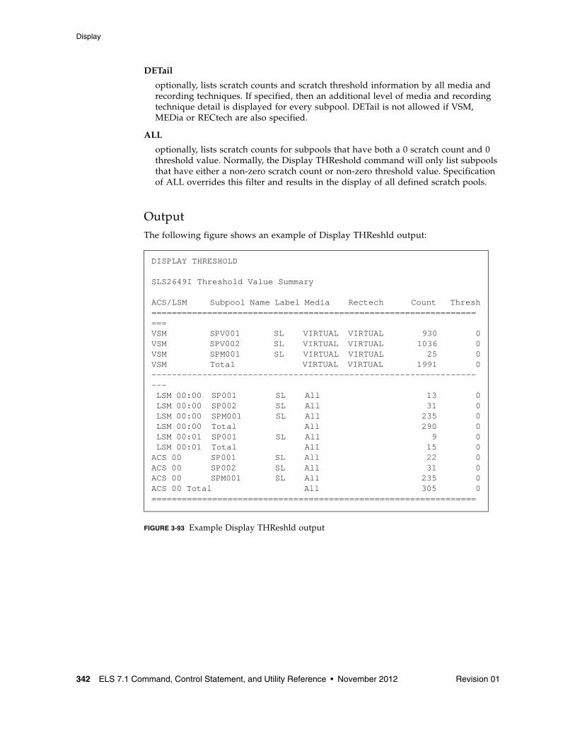
Display
342 ELS 7.1 Command, Control Statement, and Utility Reference • November 2012 Revision 01
DETail
optionally, lists scratch counts and scratch threshold information by all media and recording techniques. If specified, then an additional level of media and recording technique detail is displayed for every subpool. DETail is not allowed if VSM, MEDia or RECtech are also specified.
ALL
optionally, lists scratch counts for subpools that have both a 0 scratch count and 0 threshold value. Normally, the Display THReshold command will only list subpools that have either a non-zero scratch count or non-zero threshold value. Specification of ALL overrides this filter and results in the display of all defined scratch pools.
OutputThe following figure shows an example of Display THReshld output:
FIGURE 3-93 Example Display THReshld output
DISPLAY THRESHOLD
SLS2649I Threshold Value Summary
ACS/LSM Subpool Name Label Media Rectech Count Thresh===================================================================VSM SPV001 SL VIRTUAL VIRTUAL 930 0VSM SPV002 SL VIRTUAL VIRTUAL 1036 0VSM SPM001 SL VIRTUAL VIRTUAL 25 0VSM Total VIRTUAL VIRTUAL 1991 0------------------------------------------------------------------- LSM 00:00 SP001 SL All 13 0 LSM 00:00 SP002 SL All 31 0 LSM 00:00 SPM001 SL All 235 0 LSM 00:00 Total All 290 0 LSM 00:01 SP001 SL All 9 0 LSM 00:01 Total All 15 0ACS 00 SP001 SL All 22 0ACS 00 SP002 SL All 31 0ACS 00 SPM001 SL All 235 0ACS 00 Total All 305 0================================================================
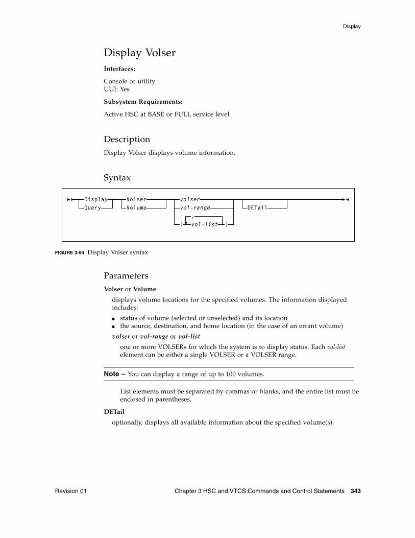
Display
Revision 01 Chapter 3 HSC and VTCS Commands and Control Statements 343
Display VolserInterfaces:
Console or utilityUUI: Yes
Subsystem Requirements:
Active HSC at BASE or FULL service level
DescriptionDisplay Volser displays volume information.
Syntax
FIGURE 3-94 Display Volser syntax
ParametersVolser or Volume
displays volume locations for the specified volumes. The information displayed includes:
■ status of volume (selected or unselected) and its location ■ the source, destination, and home location (in the case of an errant volume)
volser or vol-range or vol-list
one or more VOLSERs for which the system is to display status. Each vol-list element can be either a single VOLSER or a VOLSER range.
Note – You can display a range of up to 100 volumes.
List elements must be separated by commas or blanks, and the entire list must be enclosed in parentheses.
DETail
optionally, displays all available information about the specified volume(s).
vol-range
)(,vol-list
VolserVolume
volserDETail
DisplayQuery
Display
344 ELS 7.1 Command, Control Statement, and Utility Reference • November 2012 Revision 01
OutputThe information displayed includes:
■ the home cell location
■ whether or not the volume is a scratch cartridge
■ whether or not the volume is selected
■ the owning host (displayed if the volume is selected)
■ the drive address or drive ID (displayed if the volume is mounted)
■ whether or not an external label is present
■ whether or not the media label is readable by the robotic vision system (displayed if the external label exists)
■ when the volume was last inserted into the library
■ when the volume was last selected
■ the select count
■ the media type for the volume
■ the recording technique for the volume
■ whether or not the media label was readable (N/A appears if the value was not read from the LMU)
■ how the media type has been determined for the volume. The values that appear in this field are:
■ whether or not the volumes are unusable (i.e., spent cleaning cartridges)
■ the volume density for STK1 and STK2 media volumes.
■ the Media Warranty Life (MWL) percentage, stored on the cartridge MIR and collected during dismount processing. MWL percentage indicates how much of the media life has been used.
Note – To collect and report media warranty life, tape libraries and transports must meet the following requirements:
■ SL8500 or SL3000 libraries■ LMU compatibility level 21 or higher■ T9x40: all media and models at firmware level 1.42 or higher (except 9840B)■ T10000: all models and media at firmware level 1.38 or higher
Refer to the publication Managing HSC and VTCS for more information about media warranty life.
YES The media label and the VOLPARM defined for the volume agree.
NO The media label and the VOLPARM defined for the volume do not agree.
VOLATTR Only A VOLPARM has been defined, but the LMU has not determined the media type.
Label Only The LMU has determined the media type, but a VOLPARM has not been defined.
Undefined A VOLPARM has not been defined, and the LMU has not determined the media type.
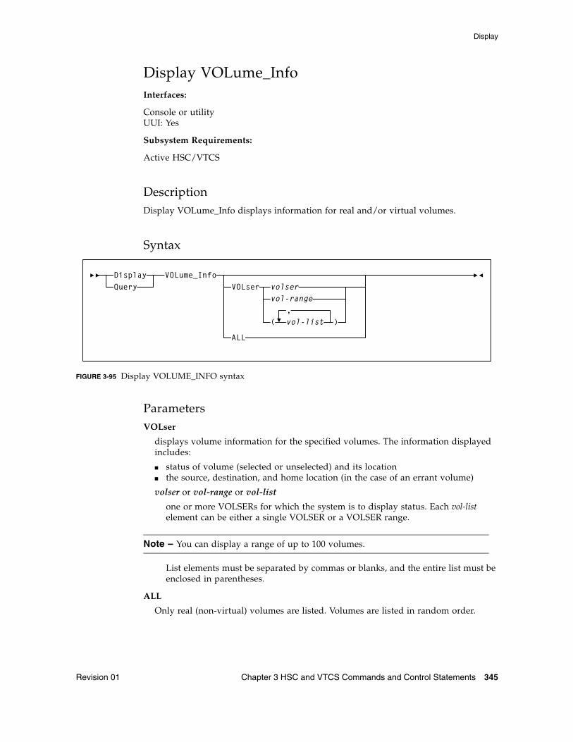
Display
Revision 01 Chapter 3 HSC and VTCS Commands and Control Statements 345
Display VOLume_InfoInterfaces:
Console or utilityUUI: Yes
Subsystem Requirements:
Active HSC/VTCS
DescriptionDisplay VOLume_Info displays information for real and/or virtual volumes.
Syntax
FIGURE 3-95 Display VOLUME_INFO syntax
ParametersVOLser
displays volume information for the specified volumes. The information displayed includes:
■ status of volume (selected or unselected) and its location ■ the source, destination, and home location (in the case of an errant volume)
volser or vol-range or vol-list
one or more VOLSERs for which the system is to display status. Each vol-list element can be either a single VOLSER or a VOLSER range.
Note – You can display a range of up to 100 volumes.
List elements must be separated by commas or blanks, and the entire list must be enclosed in parentheses.
ALL
Only real (non-virtual) volumes are listed. Volumes are listed in random order.
VOLume_InfoDisplayQuery VOLser
ALL
vol-range
)(,vol-list
volser
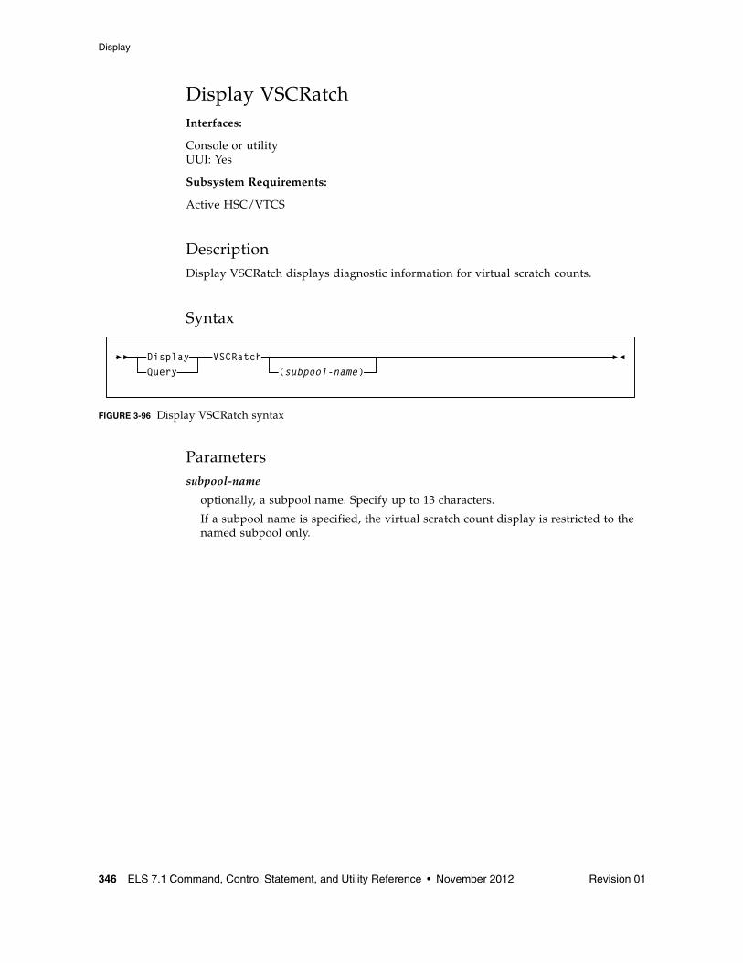
Display
346 ELS 7.1 Command, Control Statement, and Utility Reference • November 2012 Revision 01
Display VSCRatchInterfaces:
Console or utilityUUI: Yes
Subsystem Requirements:
Active HSC/VTCS
DescriptionDisplay VSCRatch displays diagnostic information for virtual scratch counts.
Syntax
FIGURE 3-96 Display VSCRatch syntax
Parameterssubpool-name
optionally, a subpool name. Specify up to 13 characters.
If a subpool name is specified, the virtual scratch count display is restricted to the named subpool only.
VSCRatchDisplayQuery (subpool-name)
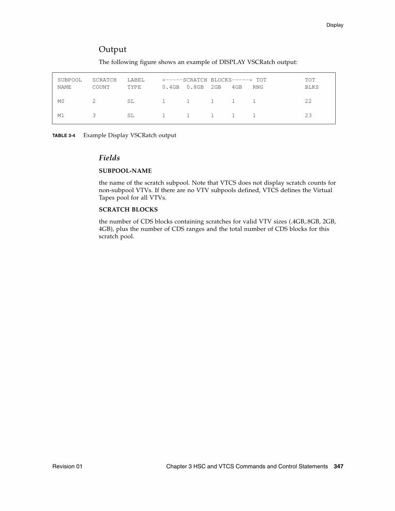
Display
Revision 01 Chapter 3 HSC and VTCS Commands and Control Statements 347
OutputThe following figure shows an example of DISPLAY VSCRatch output:
TABLE 3-4 Example Display VSCRatch output
Fields
SUBPOOL-NAME
the name of the scratch subpool. Note that VTCS does not display scratch counts for non-subpool VTVs. If there are no VTV subpools defined, VTCS defines the Virtual Tapes pool for all VTVs.
SCRATCH BLOCKS
the number of CDS blocks containing scratches for valid VTV sizes (.4GB,.8GB, 2GB, 4GB), plus the number of CDS ranges and the total number of CDS blocks for this scratch pool.
SUBPOOL SCRATCH LABEL <-----SCRATCH BLOCKS-----> TOT TOTNAME COUNT TYPE 0.4GB 0.8GB 2GB 4GB RNG BLKS
M0 2 SL 1 1 1 1 1 22
M1 3 SL 1 1 1 1 1 23
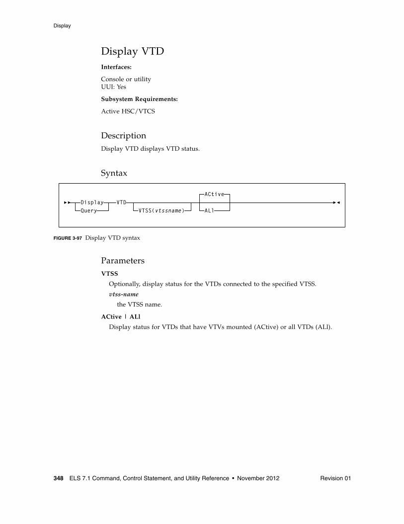
Display
348 ELS 7.1 Command, Control Statement, and Utility Reference • November 2012 Revision 01
Display VTDInterfaces:
Console or utilityUUI: Yes
Subsystem Requirements:
Active HSC/VTCS
DescriptionDisplay VTD displays VTD status.
Syntax
FIGURE 3-97 Display VTD syntax
ParametersVTSS
Optionally, display status for the VTDs connected to the specified VTSS.
vtss-name
the VTSS name.
ACtive | ALl
Display status for VTDs that have VTVs mounted (ACtive) or all VTDs (ALl).
VTDACtive
VTSS(vtssname) ALlDisplayQuery
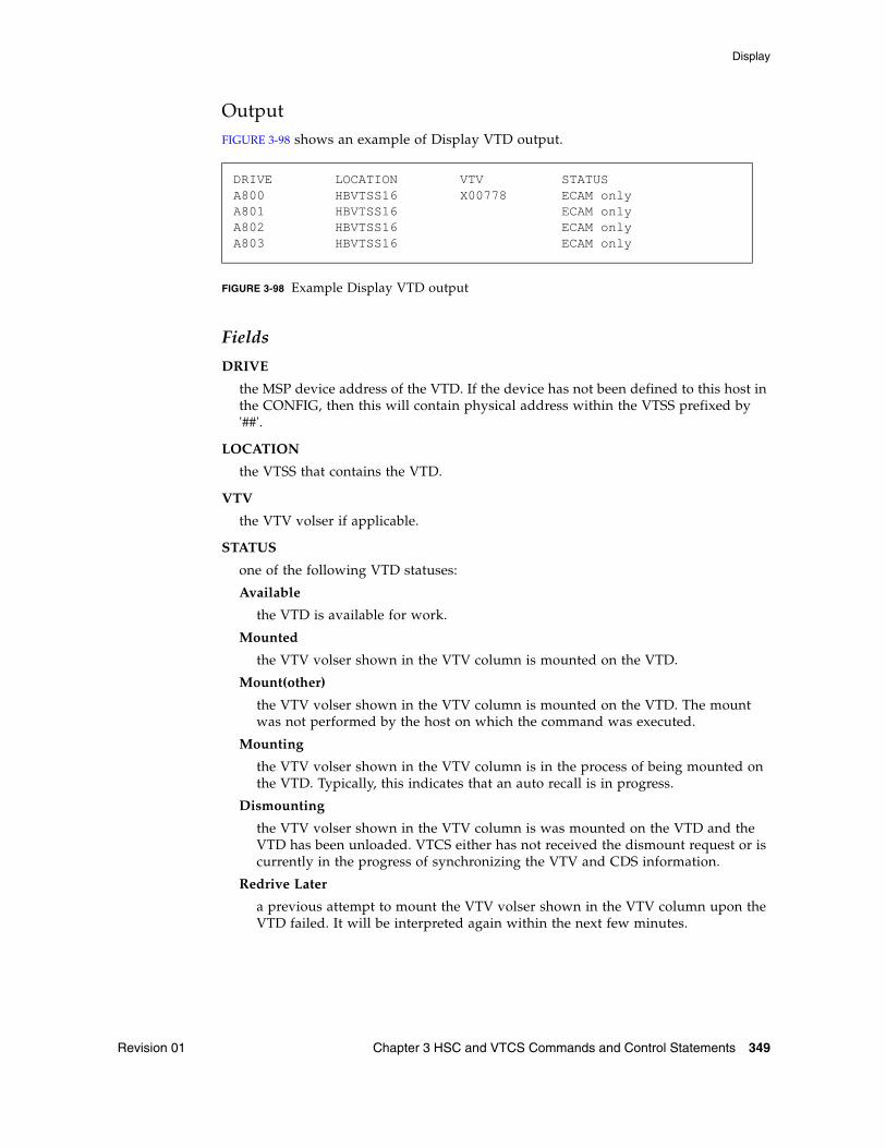
Display
Revision 01 Chapter 3 HSC and VTCS Commands and Control Statements 349
OutputFIGURE 3-98 shows an example of Display VTD output.
FIGURE 3-98 Example Display VTD output
Fields
DRIVE
the MSP device address of the VTD. If the device has not been defined to this host in the CONFIG, then this will contain physical address within the VTSS prefixed by '##'.
LOCATION
the VTSS that contains the VTD.
VTV
the VTV volser if applicable.
STATUS
one of the following VTD statuses:
Available
the VTD is available for work.
Mounted
the VTV volser shown in the VTV column is mounted on the VTD.
Mount(other)
the VTV volser shown in the VTV column is mounted on the VTD. The mount was not performed by the host on which the command was executed.
Mounting
the VTV volser shown in the VTV column is in the process of being mounted on the VTD. Typically, this indicates that an auto recall is in progress.
Dismounting
the VTV volser shown in the VTV column is was mounted on the VTD and the VTD has been unloaded. VTCS either has not received the dismount request or is currently in the progress of synchronizing the VTV and CDS information.
Redrive Later
a previous attempt to mount the VTV volser shown in the VTV column upon the VTD failed. It will be interpreted again within the next few minutes.
DRIVE LOCATION VTV STATUSA800 HBVTSS16 X00778 ECAM onlyA801 HBVTSS16 ECAM onlyA802 HBVTSS16 ECAM onlyA803 HBVTSS16 ECAM only
Display
350 ELS 7.1 Command, Control Statement, and Utility Reference • November 2012 Revision 01
Importing
the VTV volser shown in the VTV column is being electronically imported via the VTD.
Imported
the VTV volser shown in the VTV column has been electronically imported via the VTD. It is awaiting the confirmation request from the host that performed the export.
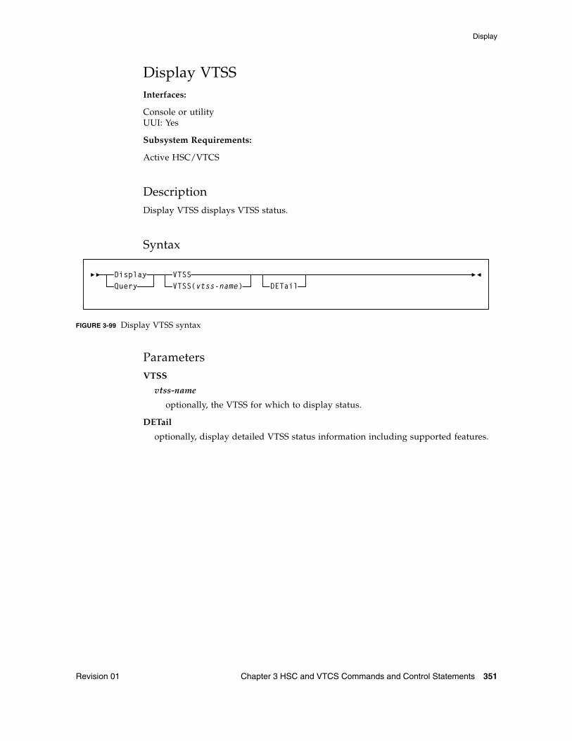
Display
Revision 01 Chapter 3 HSC and VTCS Commands and Control Statements 351
Display VTSSInterfaces:
Console or utilityUUI: Yes
Subsystem Requirements:
Active HSC/VTCS
DescriptionDisplay VTSS displays VTSS status.
Syntax
FIGURE 3-99 Display VTSS syntax
ParametersVTSS
vtss-name
optionally, the VTSS for which to display status.
DETail
optionally, display detailed VTSS status information including supported features.
VTSSDETail
DisplayQuery VTSS(vtss-name)
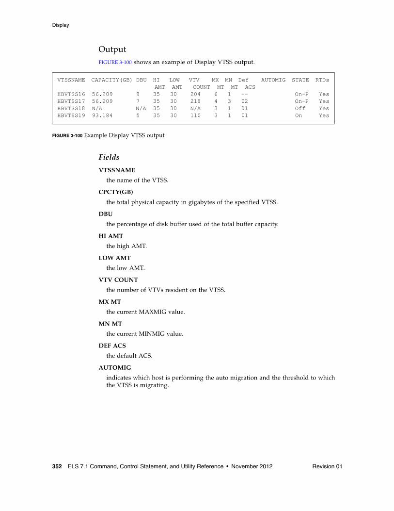
Display
352 ELS 7.1 Command, Control Statement, and Utility Reference • November 2012 Revision 01
OutputFIGURE 3-100 shows an example of Display VTSS output.
FIGURE 3-100 Example Display VTSS output
Fields
VTSSNAME
the name of the VTSS.
CPCTY(GB)
the total physical capacity in gigabytes of the specified VTSS.
DBU
the percentage of disk buffer used of the total buffer capacity.
HI AMT
the high AMT.
LOW AMT
the low AMT.
VTV COUNT
the number of VTVs resident on the VTSS.
MX MT
the current MAXMIG value.
MN MT
the current MINMIG value.
DEF ACS
the default ACS.
AUTOMIG
indicates which host is performing the auto migration and the threshold to which the VTSS is migrating.
VTSSNAME CAPACITY(GB) DBU HI LOW VTV MX MN Def AUTOMIG STATE RTDs AMT AMT COUNT MT MT ACSHBVTSS16 56.209 9 35 30 204 6 1 -- On-P YesHBVTSS17 56.209 7 35 30 218 4 3 02 On-P YesHBVTSS18 N/A N/A 35 30 N/A 3 1 01 Off YesHBVTSS19 93.184 5 35 30 110 3 1 01 On Yes
Display
Revision 01 Chapter 3 HSC and VTCS Commands and Control Statements 353
STATE
one of the following global VTSS states for all hosts:
QUIESCING
Quiescing state.
QUIESCED
Quiesced state.
OFFLINE
Offline state.
OFFLINE-P
Offline pending state.
ONLINE
Online state.
ONLINE-P
Online pending state.
STARTED
The VTSS is initialized and in process of going to the requested state (online, offline, or quiesced).
RTDs
indicates whether the VTSS has RTDs.
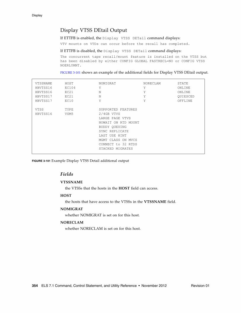
Display
354 ELS 7.1 Command, Control Statement, and Utility Reference • November 2012 Revision 01
Display VTSS DEtail OutputIf ETTFB is enabled, the Display VTSS DETail command displays:VTV mounts on VTDs can occur before the recall has completed.
If ETTFB is disabled, the Display VTSS DETail command displays:The concurrent tape recall/mount feature is installed on the VTSS but has been disabled by either CONFIG GLOBAL FASTRECL=NO or CONFIG VTSS NOERLYMNT.
FIGURE 3-101 shows an example of the additional fields for Display VTSS DEtail output.
FIGURE 3-101 Example Display VTSS Detail additional output
Fields
VTSSNAME
the VTSSs that the hosts in the HOST field can access.
HOST
the hosts that have access to the VTSSs in the VTSSNAME field.
NOMIGRAT
whether NOMIGRAT is set on for this host.
NORECLAM
whether NORECLAM is set on for this host.
VTSSNAME HOST NOMIGRAT NORECLAM STATEHBVTSS16 EC104 Y Y ONLINEHBVTSS16 EC21 N Y ONLINEHBVTSS17 EC21 N Y QUIESCEDHBVTSS17 EC10 Y Y OFFLINE
VTSS TYPE SUPPORTED FEATURESHBVTSS16 VSM5 2/4GB VTVS LARGE PAGE VTVS NOWAIT ON RTD MOUNT BUDDY QUEUING SYNC REPLICATE LAST USE HINT MGMT CLASS ON MVCS CONNECT to 32 RTDS STACKED MIGRATES
Display
Revision 01 Chapter 3 HSC and VTCS Commands and Control Statements 355
STATE
one of the following VTSS states for this host:
QUIESCING
Quiescing state.
QUIESCED
Quiesced state.
OFFLINE
Offline state.
OFFLINE-P
Offline pending state.
ONLINE
Online state.
ONLINE-P
Online pending state.
STARTED
The VTSS is initialized and in process of going to the requested state (online, offline, or quiesced).
TYPE
VTSS model (VSM2, VSM3, VSM4, VSM5, or unknown).
SUPPORTED FEATURES
One or more of the following:
400MB | 800MB | 2/4GB VTVS
Default VTV size.
LARGE PAGE | STANDARD PAGE VTVS
Default VTV page size.
NOWAIT ON RTD MOUNT
VTSS supports polling for RTD mount completion. It does not lock the Nearlink interface while waiting for the mount.
BUDDY QUEUING
VTSS supports queueing of requests to more than one RTD on a Nearlink interface.
REPLICATION
Asynchronous replication enabled.
SYNC REPLICATE
Synchronous replication enabled.
LAST USE HINT
VTSS supports cache management hints indicating when a VTV will be accessed in the near future.
MGMT CLASS ON MVC
Audit MVC is able to return management class for VTVs.
Display
356 ELS 7.1 Command, Control Statement, and Utility Reference • November 2012 Revision 01
CONNECT TO 16 | 32 RTDS
Maximum number of RTDs per VTSS enabled.
STACKED MIGRATES
Stacked migrates enabled.
PARTITIONED RTDs
Partitioned RTDS enabled.
T10KC Partition RTDs
T10KC partitioned RTDs enabled.
Write New VOL1 Label
VTSS supports MVC labeling.
CONCURRENT PORT I/O
VTSS supports multiple I/Os on a single physical nearlink interface.
MANY-TO-MANY CONNECT
VTSS supports target VTD selection for a CLINK.
IP REPLICATION
VTSS supports IP CLINKs and therefore a VLE connection.
CONCURRENT TAPE RECALL/MOUNT
VTV mounts on VTDs can occur before the recall has completed.
CONCURRENT TAPE RECALL/MOUNT *DISABLED
The Concurrent Tape Recall/mount feature is installed on the VTSS but has been disabled by either CONFIG GLOBAL FASTRECL=NO or CONFIG VTSS NOERLYMT.
UNKNOWN VTSS FEATURE
VTSS feature found not supported by VTCS software level.
NONE
No VTSS features defined.
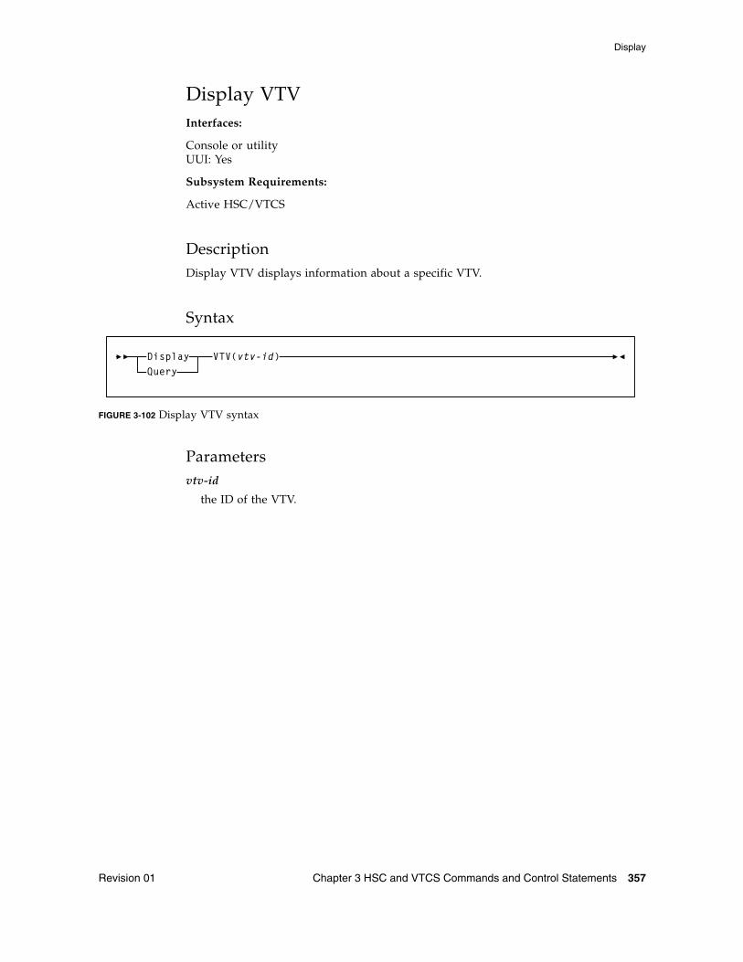
Display
Revision 01 Chapter 3 HSC and VTCS Commands and Control Statements 357
Display VTVInterfaces:
Console or utilityUUI: Yes
Subsystem Requirements:
Active HSC/VTCS
DescriptionDisplay VTV displays information about a specific VTV.
Syntax
FIGURE 3-102 Display VTV syntax
Parametersvtv-id
the ID of the VTV.
VTV(vtv-id)DisplayQuery
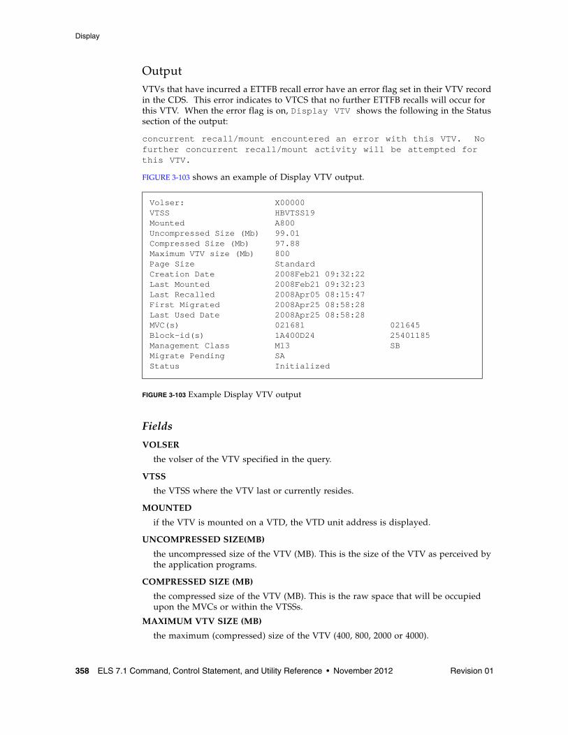
Display
358 ELS 7.1 Command, Control Statement, and Utility Reference • November 2012 Revision 01
OutputVTVs that have incurred a ETTFB recall error have an error flag set in their VTV record in the CDS. This error indicates to VTCS that no further ETTFB recalls will occur for this VTV. When the error flag is on, Display VTV shows the following in the Status section of the output:
concurrent recall/mount encountered an error with this VTV. No further concurrent recall/mount activity will be attempted for this VTV.
FIGURE 3-103 shows an example of Display VTV output.
FIGURE 3-103 Example Display VTV output
Fields
VOLSER
the volser of the VTV specified in the query.
VTSS
the VTSS where the VTV last or currently resides.
MOUNTED
if the VTV is mounted on a VTD, the VTD unit address is displayed.
UNCOMPRESSED SIZE(MB)
the uncompressed size of the VTV (MB). This is the size of the VTV as perceived by the application programs.
COMPRESSED SIZE (MB)
the compressed size of the VTV (MB). This is the raw space that will be occupied upon the MVCs or within the VTSSs.
MAXIMUM VTV SIZE (MB)
the maximum (compressed) size of the VTV (400, 800, 2000 or 4000).
Volser: X00000VTSS HBVTSS19Mounted A800Uncompressed Size (Mb) 99.01Compressed Size (Mb) 97.88Maximum VTV size (Mb) 800Page Size StandardCreation Date 2008Feb21 09:32:22Last Mounted 2008Feb21 09:32:23Last Recalled 2008Apr05 08:15:47First Migrated 2008Apr25 08:58:28Last Used Date 2008Apr25 08:58:28MVC(s) 021681 021645Block-id(s) 1A400D24 25401185Management Class M13 SBMigrate Pending SAStatus Initialized
Display
Revision 01 Chapter 3 HSC and VTCS Commands and Control Statements 359
CREATION DATE
the date and time when the VTV contents was last changed by an application.
LAST MOUNTED
the date and time when the VTV contents was last mount for access by an application.
LAST RECALLED
the date and time when the VTV was last recalled back from a MVC into a VTSS.
FIRST MIGRATED
the date and time when the first MVC copy of this version of VTV was created.
LAST USED DATE
the date and time when the VTV was last touched by VTCS. This includes most functions that update the status of the VTV in some way.
MVC(S)
the MVC(s) where the VTV resides. This entry only appears when the VTV is migrated.
BLOCK-ID
the logical block ID of the beginning of the VTV upon corresponding MVC. This entry only appears when the VTV is migrated.
MANAGEMENT CLASS
the VTV’s Management Class.
MIGRATE PENDING
the Storage classes to which migrations are outstanding.
ARCHIVE PENDING
the Storage classes to which migrations are outstanding in order to satisfy archiving requirements.
REPLICATION STARTED
If the VTV is being replicated between VTSSs in a cluster, the name of the target VTSS is displayed.
REPLICATED
If the VTV has been replicated to another VTSS in the TapePlex, the VTSS name displayed indicates where the replica can be found.
IMPORTING
If the VTV is being mounted via a VTD, the VTD unit address is displayed.
ELECTRONIC IMPORTED
If the VTV has been imported from another TapePlex. This will report the TapePlex name that owns the VTV.
EXPORTED
If the VTV has been exported to another TapePlex. The line will also list the TapePlexes to which the VTV copies has been successfully exported. An asterisks (*) next to the name indicates an export that has been rejected by the target TapePlex.
Display
360 ELS 7.1 Command, Control Statement, and Utility Reference • November 2012 Revision 01
STATUS
one or more of the following statuses:
CONSOLIDATED
VSM has consolidated the VTV.
DUPLEXED
The DUPLEX attribute has been assigned to this VTV. When VSM migrates the VTV, a copy will be written to two MVCs.
EXPORT-FAILED
Export of this VTV to a remote TapePlex was attempted and the request was rejected. Typically, this is due to a different copy of the VTV residing in the remote TapePlex.
EXPORT-REJECTED
Electronic export to one or more TapePlexes was actively rejected. This could be due to the target TapePlex not allowing import of the VTV, or a clash with copy status.
EXPORT-REQUIRED
This VTV should be electronically exported and is currently queued for processing.
EXPORT-STARTED
Electronic export is active for this VTV, but not yet complete.
INITIALIZED
VTCS has used the VTV at least once.
MIGRATED
VSM has migrated the VTV.
MIGRATE PENDING
VTV migration is pending. This status is displayed when a VTV is initially created, or when the VTV requires reconciling or archiving. In these latter cases, individual MVC copies may indicate ‘Reconcil’ or ‘Deletion’.
REPLICATION COMPLETE
A fully replicated copy of this VTV is now resident in the Secondary VTSS.
REPLICATION REQUIRED
This VTV should be replicated and is currently queued for processing.
REPLICATION STARTED
Replication is active for this VTV but not yet complete.
RESIDENT
The VTV is resident on the VTSS.
SCRATCH
The VTV is in scratch status.
UNINITIALIZED
The VTV has been defined via the CONFIG utility, but has not ever been used.
AVOID EARLY MOUNT
Concurrent recall/mount encountered an error with this VTV. No further concurrent recall/mount activity will be attempted for this VTV.
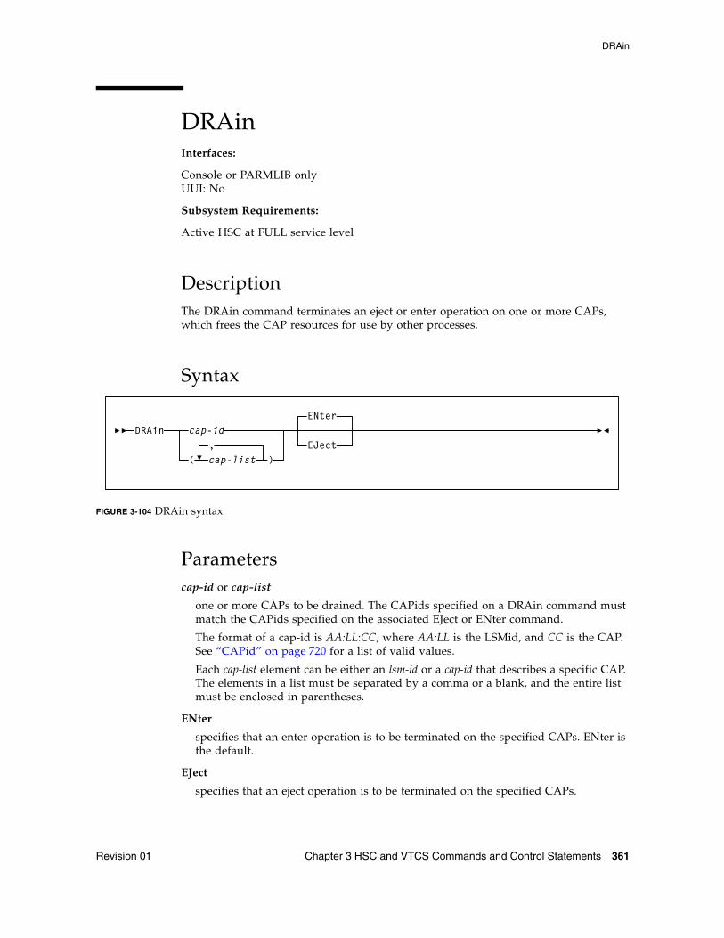
DRAin
Revision 01 Chapter 3 HSC and VTCS Commands and Control Statements 361
DRAinInterfaces:
Console or PARMLIB onlyUUI: No
Subsystem Requirements:
Active HSC at FULL service level
DescriptionThe DRAin command terminates an eject or enter operation on one or more CAPs, which frees the CAP resources for use by other processes.
Syntax
FIGURE 3-104 DRAin syntax
Parameterscap-id or cap-list
one or more CAPs to be drained. The CAPids specified on a DRAin command must match the CAPids specified on the associated EJect or ENter command.
The format of a cap-id is AA:LL:CC, where AA:LL is the LSMid, and CC is the CAP. See “CAPid” on page 720 for a list of valid values.
Each cap-list element can be either an lsm-id or a cap-id that describes a specific CAP. The elements in a list must be separated by a comma or a blank, and the entire list must be enclosed in parentheses.
ENter
specifies that an enter operation is to be terminated on the specified CAPs. ENter is the default.
EJect
specifies that an eject operation is to be terminated on the specified CAPs.
DRAinENter
EJectcap-id
(,cap-list )
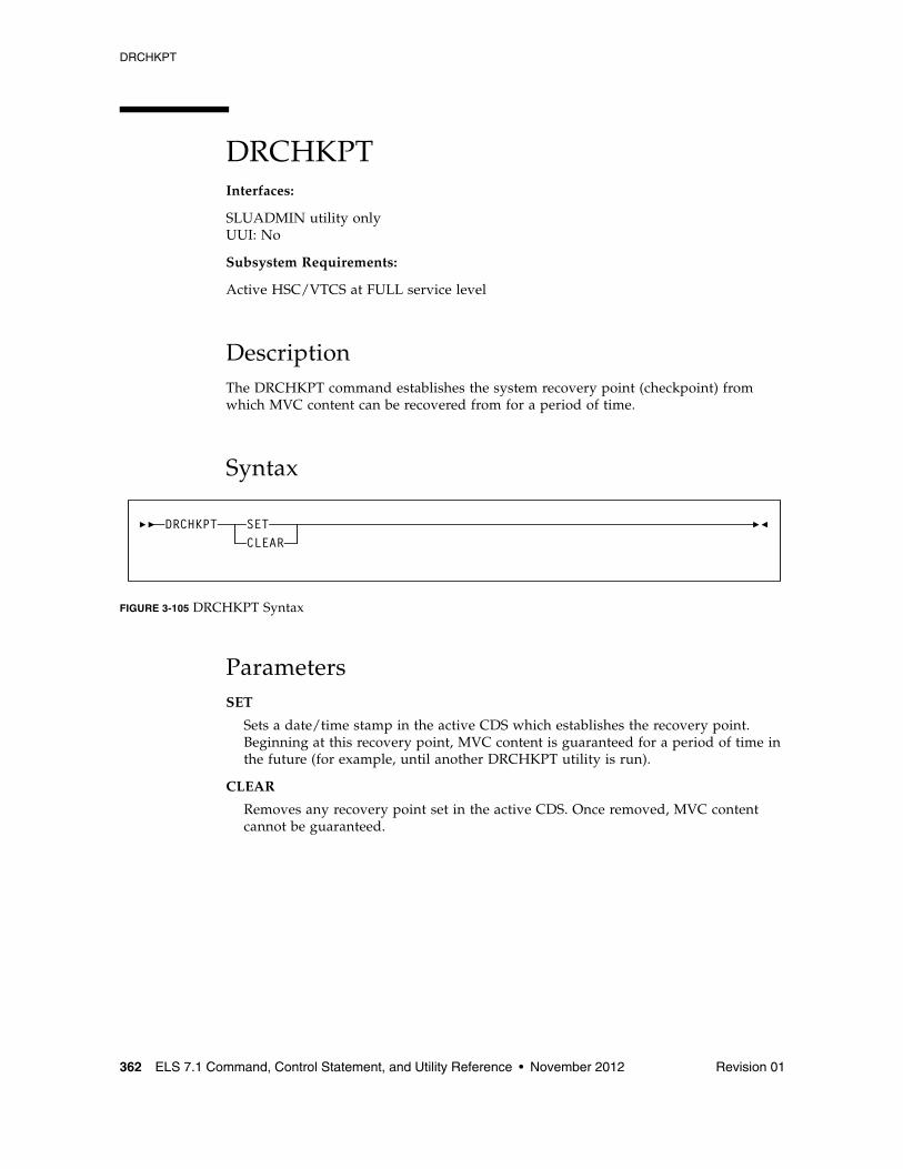
DRCHKPT
362 ELS 7.1 Command, Control Statement, and Utility Reference • November 2012 Revision 01
DRCHKPTInterfaces:
SLUADMIN utility onlyUUI: No
Subsystem Requirements:
Active HSC/VTCS at FULL service level
DescriptionThe DRCHKPT command establishes the system recovery point (checkpoint) from which MVC content can be recovered from for a period of time.
Syntax
FIGURE 3-105 DRCHKPT Syntax
ParametersSET
Sets a date/time stamp in the active CDS which establishes the recovery point. Beginning at this recovery point, MVC content is guaranteed for a period of time in the future (for example, until another DRCHKPT utility is run).
CLEAR
Removes any recovery point set in the active CDS. Once removed, MVC content cannot be guaranteed.
DRCHKPT SETCLEAR
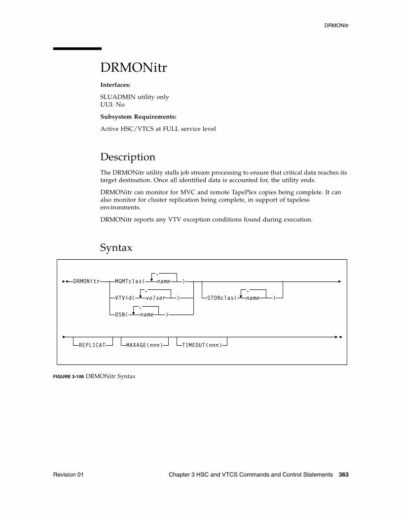
DRMONitr
Revision 01 Chapter 3 HSC and VTCS Commands and Control Statements 363
DRMONitrInterfaces:
SLUADMIN utility onlyUUI: No
Subsystem Requirements:
Active HSC/VTCS at FULL service level
DescriptionThe DRMONitr utility stalls job stream processing to ensure that critical data reaches its target destination. Once all identified data is accounted for, the utility ends.
DRMONitr can monitor for MVC and remote TapePlex copies being complete. It can also monitor for cluster replication being complete, in support of tapeless environments.
DRMONitr reports any VTV exception conditions found during execution.
Syntax
FIGURE 3-106 DRMONitr Syntax
VTVid( volser )
DSN( name )
,
,STORclas( name )
,MGMTclas(
,name )
REPLICAT MAXAGE(nnn) TIMEOUT(nnn)
DRMONitr
DRMONitr
364 ELS 7.1 Command, Control Statement, and Utility Reference • November 2012 Revision 01
ParametersThe MGMTclas, VTVid, and DSN parameters are mutually exclusive.
MGMTclas(name)
optionally, specifies a list of Management Classes to be monitored for VTV migrate/copy completion.
Specified Management Classes must be defined to the active VTCS system and must specify immediate migrate. For tapeless environments, specified Management Classes must specify REPLICAT.
VTVid(volser)
optionally, specifies a list and/or range of VTV volsers to be monitored for migrate/copy completion.
The VTV’s Management Class must be defined to the active VTCS system and must specify immediate migrate. For tapeless environments, the VTV’s Management Class must specify REPLICAT.
DSN(name)
optionally, specifies a list of data sets to be monitored for migrate/copy completion.
The VTVs containing these data sets must have Management Classes defined to the active VTCS system and must specify immediate migrate. For tapeless environments, the VTV’s Management Class must specify REPLICAT.
The following 2 keyword parameters identify the destination criteria. One of the following two keyword parameters must be specified:
STORclas(name)
optionally, specifies the Storage Class locations that the identified VTV data is to be delivered to.
Specified Storage Classes must be defined to the active VTCS system. Although this parameter is optional, the STORclas parameter should only be omitted in tapeless environments.
REPLICAT
optionally, specifies that VTV cluster replication is to be monitored for completion. Replication must be specified on the VTV’s Management Class policy for the VTV to be selected for monitoring. If replications are monitored in a tape environment, their completion overrides any Storage Class requirement.
Note – You must specify either STORclas or REPLICAT or both to specify the destination criteria. Otherwise DRMONitr ends with RC 8 and generates an error message. Additionally, Oracle recommends that you do not specify (or monitor) Storage Classes in tapeless environments because migrations are not possible.
DRMONitr
Revision 01 Chapter 3 HSC and VTCS Commands and Control Statements 365
MAXAGE(nnn)
optionally, specifies the maximum VTV age (time since last update), in hours, when monitoring migrations by Management Class (a MGMTclas value is required). Valid values are 1 to 999. There is no default.
If the VTV's age (time since last update) is greater than MAXAGE, the VTV is not monitored. DRMONitr reports the number of skipped VTVs due to MAXAGE, if specified.
If you do not specify MAXAGE, any active VTV belonging to the specified Management Classes, regardless of age, is monitored for migrate/copy completion.
TIMEOUT(nnn)
optionally, specifies the maximum time, in minutes, for DRMONitr to run.
Valid values are zero to 999. If you do not specify a TIMEOUT value, there is no limit on the time the utility can run (stall).
A TIMEOUT value of zero does not stall the DRMONitr utility. This special case reports on incomplete copies of specified VTV data.
If a non-zero TIMEOUT value is exceeded, DRMONitr ends with RC 8 and generates an error message. If the TIMEOUT value specified was zero, a return code of 4 is set if a VTV’s copy is detected as incomplete, otherwise a return code 0 is set.
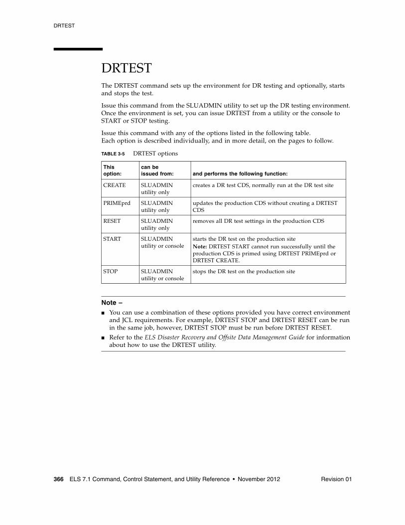
DRTEST
366 ELS 7.1 Command, Control Statement, and Utility Reference • November 2012 Revision 01
DRTESTThe DRTEST command sets up the environment for DR testing and optionally, starts and stops the test.
Issue this command from the SLUADMIN utility to set up the DR testing environment. Once the environment is set, you can issue DRTEST from a utility or the console to START or STOP testing.
Issue this command with any of the options listed in the following table. Each option is described individually, and in more detail, on the pages to follow.
Note – ■ You can use a combination of these options provided you have correct environment
and JCL requirements. For example, DRTEST STOP and DRTEST RESET can be run in the same job, however, DRTEST STOP must be run before DRTEST RESET.
■ Refer to the ELS Disaster Recovery and Offsite Data Management Guide for information about how to use the DRTEST utility.
TABLE 3-5 DRTEST options
This option:
can be issued from: and performs the following function:
CREATE SLUADMIN utility only
creates a DR test CDS, normally run at the DR test site
PRIMEprd SLUADMIN utility only
updates the production CDS without creating a DRTEST CDS
RESET SLUADMIN utility only
removes all DR test settings in the production CDS
START SLUADMIN utility or console
starts the DR test on the production siteNote: DRTEST START cannot run successfully until the production CDS is primed using DRTEST PRIMEprd or DRTEST CREATE.
STOP SLUADMIN utility or console
stops the DR test on the production site
DRTEST
Revision 01 Chapter 3 HSC and VTCS Commands and Control Statements 367
DRTEST CREATEInterfaces:
SLUADMIN utility onlyUUI: No
Subsystem Requirements:
Active HSC not required
DescriptionDRTEST CREATE creates a DR test CDS, normally run at the DR test site.
Note – The NOUPDprd parameter is only valid if the DRTEST PRIMEprd command is executed prior to the DRTEST CREATE command. See “DRTEST PRIMEprd” on page 372 for more information.
Considerations:
■ DR test cannot be active. This refers to the production CDS status.
■ Active HSC/VTCS is not required.
■ If HSC/VTCS is active, SLSCNTL DD statement(s) identifying the production CDS are optional, and if included, must match the active HSC/VTCS.
■ If HSC/VTCS is not active, SLSCNTL DD statement(s) identifying the production CDS are required.
■ SLSNEW DD statement(s) identifying the DRTEST CDS(s) are required.
Sample Control Cards:
DRTEST CREATE HOSTID(ZIPF,ZIPG) -
DRVTSS(VTSSW) -
DRACS(00)
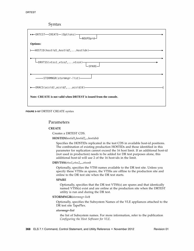
DRTEST
368 ELS 7.1 Command, Control Statement, and Utility Reference • November 2012 Revision 01
Syntax
FIGURE 3-107 DRTEST CREATE syntax
ParametersCREATE
Creates a DRTEST CDS.
HOSTID(hostid1,hostid2,...hostidn)
Specifies the HOSTIDs replicated in the test CDS in available host-id positions. The combination of existing production HOSTIDs and those identified in this parameter for replication cannot exceed the 16 host limit. If an additional host-id (not used in production) needs to be added for DR test purposes alone, this additional host-id will use 2 of the 16 host-ids in the limit.
DRVTSS(vtss1,vtss2,...vtssn)
Optionally, specifies the VTSS names available to the DR test site. Unless you specify these VTSSs as spares, the VTSSs are offline to the production site and online to the DR test site when the DR test starts.
SPARE
Optionally, specifies that the DR test VTSS(s) are spares and that identically named VTSS(s) exist and are online at the production site when the DRTEST utility is run and during the DR test.
STORMNGR(stormngr-list)
Optionally, specifies the Subsystem Names of the VLE appliances attached to the DR test site TapePlex.
stormngr-list
the list of Subsystem names. For more information, refer to the publication Configuring the Host Software for VLE.
DRTEST
DRVTSS(vtss1,vtss2,...vtssn)SPARE
DRACS(acsid1,acsid2,...acsid16)
CREATE |Options|
Options:
HOSTID(hostid1,hostid2,...hostidn)
Note: CREATE is not valid when DRTEST is issued from the console.
NOUPDprd
STORMNGR(stormngr-list)

DRTEST
Revision 01 Chapter 3 HSC and VTCS Commands and Control Statements 369
DRACS(acsid1...acsid16)
Specifies one or more ACSs available to the DR test site. Multiple ACS IDs must be specified as a list, and not as a range of ACS IDs. The ACSs are online to the DR test site but can remain connected (and usually are) to the production site when the DR test starts. CDRT Version 6.2 and above supports a maximum of 16 DR ACSs.
A minimum of one ACS is required. In a VSM environment running without RTDs attached to the VTSS, the ACS specified for DRACS may be a dummy ACS.
NOUPDprd
Optionally, does not update the input production CDS(s).
If this parameter is specified, you can use a single CDS production copy as input and that copy can be either the actual primary production CDS, a backup copy, or a mirrored copy.
This parameter is only valid if the PRIMEprd function has already been run on the production CDS. See “DRTEST PRIMEprd” on page 372 for more information.
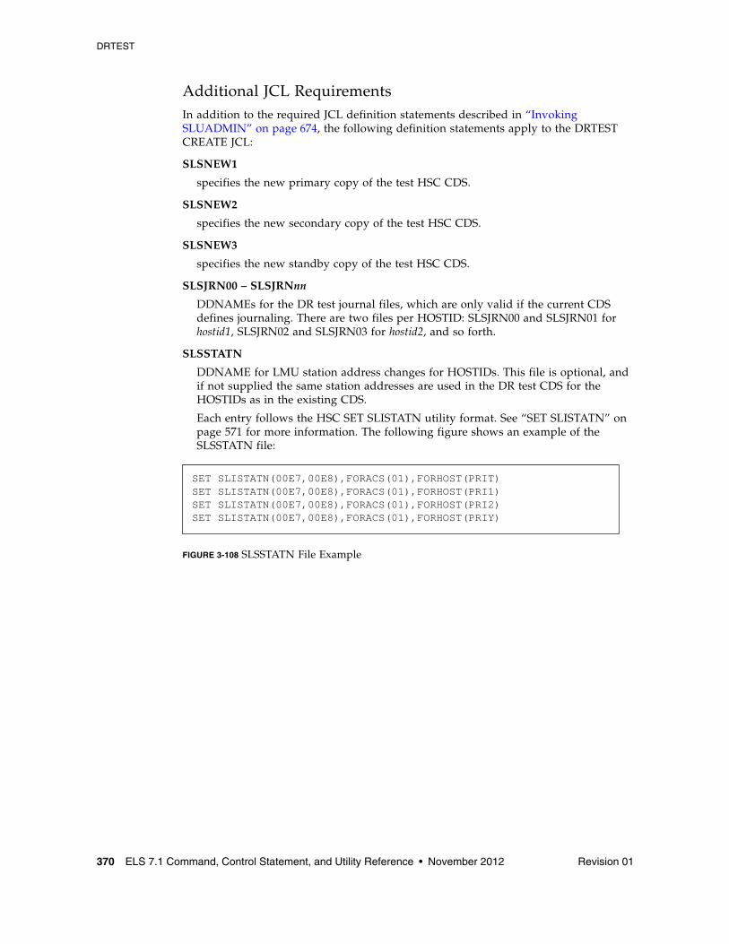
DRTEST
370 ELS 7.1 Command, Control Statement, and Utility Reference • November 2012 Revision 01
Additional JCL RequirementsIn addition to the required JCL definition statements described in “Invoking SLUADMIN” on page 674, the following definition statements apply to the DRTEST CREATE JCL:
SLSNEW1
specifies the new primary copy of the test HSC CDS.
SLSNEW2
specifies the new secondary copy of the test HSC CDS.
SLSNEW3
specifies the new standby copy of the test HSC CDS.
SLSJRN00 – SLSJRNnn
DDNAMEs for the DR test journal files, which are only valid if the current CDS defines journaling. There are two files per HOSTID: SLSJRN00 and SLSJRN01 for hostid1, SLSJRN02 and SLSJRN03 for hostid2, and so forth.
SLSSTATN
DDNAME for LMU station address changes for HOSTIDs. This file is optional, and if not supplied the same station addresses are used in the DR test CDS for the HOSTIDs as in the existing CDS.
Each entry follows the HSC SET SLISTATN utility format. See “SET SLISTATN” on page 571 for more information. The following figure shows an example of the SLSSTATN file:
FIGURE 3-108 SLSSTATN File Example
SET SLISTATN(00E7,00E8),FORACS(01),FORHOST(PRIT)SET SLISTATN(00E7,00E8),FORACS(01),FORHOST(PRI1)SET SLISTATN(00E7,00E8),FORACS(01),FORHOST(PRI2)SET SLISTATN(00E7,00E8),FORACS(01),FORHOST(PRIY)
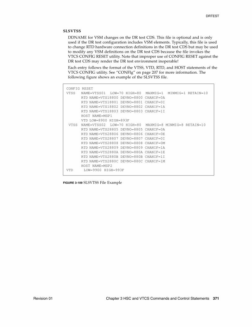
DRTEST
Revision 01 Chapter 3 HSC and VTCS Commands and Control Statements 371
SLSVTSS
DDNAME for VSM changes on the DR test CDS. This file is optional and is only used if the DR test configuration includes VSM elements. Typically, this file is used to change RTD hardware connection definitions in the DR test CDS but may be used to modify any VSM definitions on the DR test CDS because the file invokes the VTCS CONFIG RESET utility. Note that improper use of CONFIG RESET against the DR test CDS may render the DR test environment inoperable!
Each entry follows the format of the VTSS, VTD, RTD, and HOST statements of the VTCS CONFIG utility. See “CONFIg” on page 207 for more information. The following figure shows an example of the SLSVTSS file.
FIGURE 3-109 SLSVTSS File Example
CONFIG RESET VTSS NAME=VTSS01 LOW=70 HIGH=80 MAXMIG=1 MINMIG=1 RETAIN=10 RTD NAME=VTS18800 DEVNO=8800 CHANIF=0A RTD NAME=VTS18801 DEVNO=8801 CHANIF=0I
RTD NAME=VTS18802 DEVNO=8802 CHANIF=1A RTD NAME=VTS18803 DEVNO=8803 CHANIF=1I HOST NAME=MSP1
VTD LOW=8900 HIGH=893F VTSS NAME=VTSS02 LOW=70 HIGH=80 MAXMIG=8 MINMIG=8 RETAIN=10 RTD NAME=VTS28805 DEVNO=8805 CHANIF=0A RTD NAME=VTS28806 DEVNO=8806 CHANIF=0E RTD NAME=VTS28807 DEVNO=8807 CHANIF=0I RTD NAME=VTS28808 DEVNO=8808 CHANIF=0M
RTD NAME=VTS28809 DEVNO=8809 CHANIF=1A RTD NAME=VTS2880A DEVNO=880A CHANIF=1E
RTD NAME=VTS2880B DEVNO=880B CHANIF=1I RTD NAME=VTS2880C DEVNO=880C CHANIF=1M HOST NAME=MSP2VTD LOW=9900 HIGH=993F
DRTEST
372 ELS 7.1 Command, Control Statement, and Utility Reference • November 2012 Revision 01
DRTEST PRIMEprdInterfaces:
SLUADMIN utility onlyUUI: No
Subsystem Requirements:
Active HSC not required
DescriptionDRTEST PRIMEprd updates the production CDS without creating a DRTEST CDS.
Considerations:
■ DR test cannot be active.
■ Active HSC/VTCS is not required.
■ If HSC/VTCS is active, SLSCNTL DD statement(s) identifying the production CDS are optional, and if included, must match the active HSC/VTCS.
■ If HSC/VTCS is not active, SLSCNTL DD statement(s) identifying the production CDS are required.
■ SLSNEW DD statement(s) identifying the DRTEST CDS(s) are not required, and if included, are ignored.
Sample Control Cards:
DRTEST PRIME HOSTID(ZIPF,ZIPG) -
DRVTSS(VTSSW) -
DRACS(00)
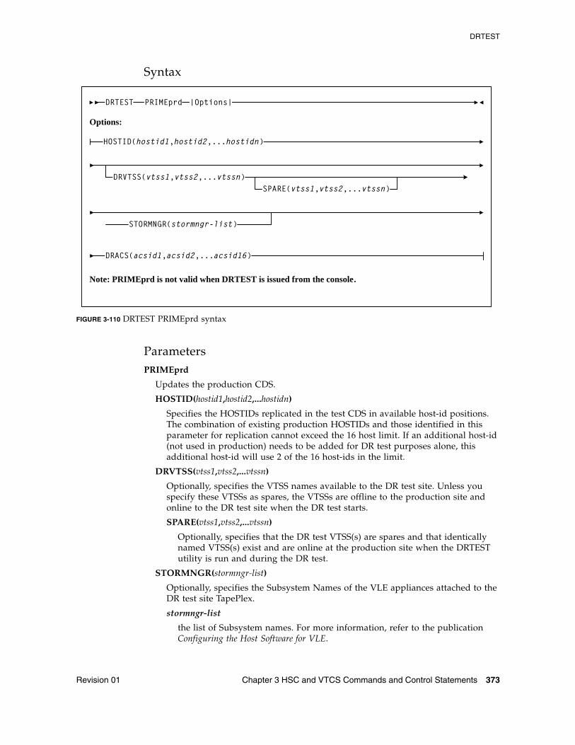
DRTEST
Revision 01 Chapter 3 HSC and VTCS Commands and Control Statements 373
Syntax
FIGURE 3-110 DRTEST PRIMEprd syntax
ParametersPRIMEprd
Updates the production CDS.
HOSTID(hostid1,hostid2,...hostidn)
Specifies the HOSTIDs replicated in the test CDS in available host-id positions. The combination of existing production HOSTIDs and those identified in this parameter for replication cannot exceed the 16 host limit. If an additional host-id (not used in production) needs to be added for DR test purposes alone, this additional host-id will use 2 of the 16 host-ids in the limit.
DRVTSS(vtss1,vtss2,...vtssn)
Optionally, specifies the VTSS names available to the DR test site. Unless you specify these VTSSs as spares, the VTSSs are offline to the production site and online to the DR test site when the DR test starts.
SPARE(vtss1,vtss2,...vtssn)
Optionally, specifies that the DR test VTSS(s) are spares and that identically named VTSS(s) exist and are online at the production site when the DRTEST utility is run and during the DR test.
STORMNGR(stormngr-list)
Optionally, specifies the Subsystem Names of the VLE appliances attached to the DR test site TapePlex.
stormngr-list
the list of Subsystem names. For more information, refer to the publication Configuring the Host Software for VLE.
DRTEST PRIMEprd
DRVTSS(vtss1,vtss2,...vtssn)SPARE(vtss1,vtss2,...vtssn)
DRACS(acsid1,acsid2,...acsid16)
Options:
HOSTID(hostid1,hostid2,...hostidn)
|Options|
Note: PRIMEprd is not valid when DRTEST is issued from the console.
STORMNGR(stormngr-list)
DRTEST
374 ELS 7.1 Command, Control Statement, and Utility Reference • November 2012 Revision 01
DRACS(acsid1...acsid16)
Specifies one or more ACSs available to the DR test site. Multiple ACS IDs must be specified as a list, and not as a range of ACS IDs. The ACSs are online to the DR test site but can remain connected (and usually are) to the production site when the DR test starts. CDRT Version 6.2 and above supports a maximum of 16 DR ACSs.
A minimum of one ACS is required. In a VSM environment running without RTDs attached to the VTSS, the ACS specified for DRACS may be a dummy ACS.
DRTEST
Revision 01 Chapter 3 HSC and VTCS Commands and Control Statements 375
DRTEST RESETInterfaces:
SLUADMIN utility onlyUUI: No
Subsystem Requirements:
Active HSC not required
DescriptionDRTEST RESET removes all DR test settings in the production CDS.
Considerations:
■ DR test cannot be active. This refers to the production CDS status.
■ Active HSC/VTCS is not required.
■ If HSC/VTCS is active, SLSCNTL DD statement(s) identifying the production CDS are optional, and if included, must match the active HSC/VTCS if used.
■ If HSC/VTCS is not active, SLSCNTL DD statement(s) identifying the production CDS are required.
■ SLSNEW DD statement(s) identifying the DRTEST CDS(s) are not required, and if included, are ignored.
Sample Control Cards:
DRTEST RESET
Note – DRTEST STOP and DRTEST RESET can be run in the same job, however, DRTEST STOP must be run before DRTEST RESET.
Syntax
FIGURE 3-111 DRTEST RESET syntax
ParametersNone.
DRTEST RESET
Note: RESET is not valid when DRTEST is issued from the console.
DRTEST
376 ELS 7.1 Command, Control Statement, and Utility Reference • November 2012 Revision 01
DRTEST STARTInterfaces:
Console or utilityUUI: Yes
Subsystem Requirements:
Active HSC at FULL service level
DescriptionDRTEST START starts the DR test on the production site.
Note – DRTEST START cannot run successfully until the production CDS is primed using DRTEST PRIMEprd or DRTEST CREATE.
Considerations:
■ DR test cannot be active. This refers to the production CDS status.
■ Active HSC/VTCS is required.
■ SLSCNTL DD statement(s) identifying the production CDS are optional, and if included, must match the active HSC/VTCS.
■ SLSNEW DD statement(s) identifying the DRTEST CDS(s) are not required, and if included, are ignored.
Sample control cards:
DRTEST START
Syntax
FIGURE 3-112 DRTEST START syntax
ParametersNone.
DRTEST START
DRTEST
Revision 01 Chapter 3 HSC and VTCS Commands and Control Statements 377
DRTEST STOPInterfaces:
Console or utilityUUI: Yes
Subsystem Requirements:
Active HSC at FULL service level
DescriptionDRTEST STOP stops the DR test on the production site.
Considerations:
■ DR test must be active. This refers to the production CDS status.
■ Active HSC/VTCS is required.
■ SLSCNTL DD statement(s) identifying the production CDS are not required, and if included, must match the active HSC/VTCS.
■ SLSNEW DD statement(s) identifying the DRTEST CDS(s) are not required, and if included, are ignored.
Sample control cards:
DRTEST STOP
Note – DRTEST STOP and DRTEST RESET can be run in the same job, however, DRTEST STOP must be run before DRTEST RESET.
Syntax
FIGURE 3-113 DRTEST STOP syntax
ParametersNone.
DRTEST STOP
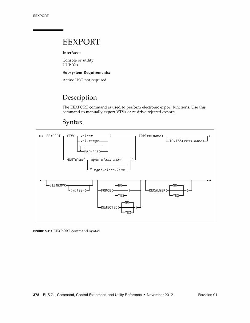
EEXPORT
378 ELS 7.1 Command, Control Statement, and Utility Reference • November 2012 Revision 01
EEXPORTInterfaces:
Console or utilityUUI: Yes
Subsystem Requirements:
Active HSC not required
DescriptionThe EEXPORT command is used to perform electronic export functions. Use this command to manually export VTVs or re-drive rejected exports.
Syntax
FIGURE 3-114 EEXPORT command syntax
EEXPORT VTV( volservol-range
vol-list
)
MGMTclas( mgmt-class-name,mgmt-class-list
)
,
RECALWER(NO
YES)
TOPlex(name)
FORCE(NO
)
REJECTED(NO
ULINKMVC(volser)
YES
YES)
TOVTSS(vtss-name)
EEXPORT
Revision 01 Chapter 3 HSC and VTCS Commands and Control Statements 379
ParametersVTV
specifies one or more VTVs to electronically export.
volser, vol-range, or vol-list
the volsers of one or more VTVs. You can specify a maximum of 2,000 volsers.
MGMTclas
specifies one or more names of Management Classes that determine the VTVs to electronically export.
mgmt-class-name or mgmt-class-list
the Management Class name. This name must be 1 to 8 alphanumeric characters beginning with an alpha character and must follow SMS naming conventions.
TOPlex
specifies the name of the TapePlex to which copies of the VTV are sent via electronic export. There must be at least one CLINK within the configuration that provides a route to the TapePlex.
name
the target TapePlex name.
TOVTSS
optionally, specifies the VTSS name to be preferenced as the receiving VTSS within the target TapePlex specified by the TOPlex parameter.
vtss-name
the VTSS name.
Note – This is a preference only. Validation of the value is not performed.
ULINKMVC
specifies whether MVC copies on the target TapePlex are to be deleted as part of the export process.
volser
a volser from the MVC copy to be deleted from the target VTVs. If not specified, then all MVC copies of the VTV are deleted.
Note – ■ This parameter only applies when the VTV version sent matches the version in the
target TapePlex. If the versions sent is more recent, then the behavior is implicit.
■ This parameter can be used if the only MVC copies of a VTV in the target TapePlex become damaged. A replacement copy of the VTV can be supplied to the TapePlex via the EEXPORT command. The damaged MVC copies are replaced by additional migrations from the VTV copy sent.
FORCE
specifies whether VTCS exports the VTV to locations with disregard for other criteria.
EEXPORT
380 ELS 7.1 Command, Control Statement, and Utility Reference • November 2012 Revision 01
YES
Export VTVs to the TapePlex specified in the TOPlex parameter, regardless of whether the VTVs have been previously exported to the TapePlex, or the management class points to a storage class that specifies the target TapePlex.
NO
Export VTVs to the TapePlex specified in the TOPlex parameter, but ignore any VTVs already marked as exported, and exclude any VTVs for which the management class does not point to a storage class that specifies the TapePlex in the TOPlex parameter. This is the default.
REJECTED
specifies whether VTCS only selects VTVs recorded in the CDS as being rejected by the target TapePlex.
Note – REJECTED and FORCE are mutually exclusive.
NO
Ignore any VTVs already marked as exported, and exclude any VTVs for which the management class does not point to a storage class that specifies the TapePlex in the TOPlex parameter. This is the default.
YES
Only select VTVs previously rejected by the target TapePlex.
RECALWER
specifies whether VTCS recalls VTVs with read data checks.
NO
Do not recall VTVs with read data checks. This is the default.
YES
Recall VTVs with read data checks.
EJect
Revision 01 Chapter 3 HSC and VTCS Commands and Control Statements 381
EJectInterfaces:
Console or utilityUUI: Yes
Subsystem Requirements:
Active HSC at FULL service level
DescriptionThe EJect command moves volumes to a Cartridge Access Port (CAP) for removal.
You can designate a single CAP, a specific CAP, or a list of specific CAPs. Specifying one or more CAPs limits cartridge ejection to those CAPs.
Ejections in a multiple ACS configuration may specify CAPs in each ACS if volumes reside in each ACS. If a CAP list is not provided, HSC selects the highest priority CAP available for each ACS (see “CAPPref” on page 192).
You may elect to submit multiple EJect requests, each of which may specify a particular CAP. If you elect to specify a CAP in a multi-ACS configuration, then the list of volumes must reside within the CAP ACS.
Multiple CAPs within one ACS can be allocated to the EJECt utility. Specifying multiple CAPs in a single EJect Cartridge utility typically improves performance by reducing pass-thrus.
If two CAPs are specified in the same LSM, cartridges in that LSM are ejected in sequential order. This is helpful for vaulting.
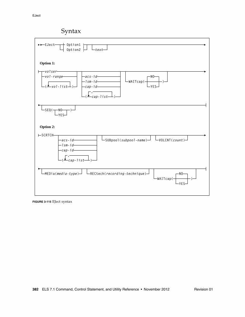
EJect
382 ELS 7.1 Command, Control Statement, and Utility Reference • November 2012 Revision 01
Syntax
FIGURE 3-115 EJect syntax
acs-idlsm-idcap-id
EJectOption2Option1
text
Option 1:
volservol-range
( vol-list )
( cap-list ),
WAITcap(NO
YES)
SEQ( NOYES
)
acs-idlsm-idcap-id
Option 2:
( cap-list ),
WAITcap(NO
YES)
SCRTCHSUBpool(subpool-name) VOLCNT(count)
MEDia(media-type) RECtech(recording-technique)
EJect
Revision 01 Chapter 3 HSC and VTCS Commands and Control Statements 383
Parameterstext
optionally, specifies the address of a 44-byte string issued whenever the operator is requested to open the CAP for an EJECT request. This text is displayed via message SLS1251E.
VOLser
specifies that a VOLSER(s) is to be ejected.
vol-list
the list of volumes to be ejected. A vol-list can be a single VOLSER, a range of VOLSERs or a list of VOLSERs and/or VOLSER ranges in any combination.
If a list is specified, the elements must be delimited by commas or blanks, and the entire list enclosed in parentheses. A range of VOLSERs consists of a starting VOLSER and an ending VOLSER separated by a dash.
SEQ
optionally, specifies whether or not CAP eject processing fills the CAP cells in the same order specified by the VOLser parameter.
Note – ■ If SEQ is not specified, but two CAPs are requested in the same LSM, and the LSM is
not an SL8500, cartridges in the ACS are ejected in sequential order.
■ For best performance, SEQ(NO) is recommended.
NO
specifies to eject the requested volumes in the order of home cell location. Eject processing fills the CAP or magazine (for the SL8500) according to the distance of the home cell to the CAP or magazine; that is, volumes closest to the CAP or magazine are ejected first.
YES
specifies to eject cartridges to the CAP in the order the volumes are listed in the associated VOLser parameter. The first cartridge requested appears in the topmost CAP cell, the second cartridge requested appears in the next CAP cell, and so on until the CAP is full or all cartridges have been moved to the CAP.
WAITcap
optionally, specifies whether or not a list of ejecting volumes waits for an available CAP if one is not available.
YES
specifies that the eject process waits indefinitely for a CAP to become available. YES is the default.
NO
specifies that the eject process does not wait for a CAP if it is not available.
EJect
384 ELS 7.1 Command, Control Statement, and Utility Reference • November 2012 Revision 01
SCRTCH
indicates that scratch volumes are to be ejected.
Note – If no CAPs are specified, only scratch tapes in ACS 00 are ejected.
SUBpool
optionally, specifies the subpool from which scratch volumes are to be ejected. If MEDia or RECtech are specified, cartridges are ejected for that media type or recording technique within the same subpool.
subpool-name
the name for the subpool.
VOLCNT
optionally, specifies that a designated number of scratch volumes are to be ejected.
count
the number of scratch volumes to be ejected.
MEDia
optionally, specifies that scratch cartridges of the desired media are to be ejected.
media-type
the media type.
See Appendix A, “MEDia, RECtech, and MODel Values” for a list of valid media-type values.
Note – ■ If MEDia is not specified, the next scratch cartridge is selected without regard to
media type if RECtech does not exist. If both MEDia and RECtech are supplied, they must be compatible.
■ If SUBpool is not specified, then the next scratch cartridge is selected without regard to whether it belongs to a subpool, is defined to the default subpool using VOLPARMS, or belongs to no scratch subpool whatsoever.
RECtech
optionally, specifies scratch cartridges of the desired recording technique are to be ejected. RECtech indicates the method used to record data tracks on the tape surface.
recording-technique
the recording technique.
See Appendix A, “MEDia, RECtech, and MODel Values” for valid recording-technique values.
Note – If RECtech is not specified, the next scratch cartridge is selected depending on the media type (if supplied). If neither is supplied, the next scratch cartridge is selected without taking media type and recording technique into consideration. If both RECtech and MEDia are supplied, they must be compatible.
EJect
Revision 01 Chapter 3 HSC and VTCS Commands and Control Statements 385
WAITcap
optionally, specifies whether or not a list of ejecting volumes waits for an available CAP if one is not available.
YES
specifies that the eject process waits indefinitely for a CAP to become available. YES is the default.
NO
specifies that the eject process does not wait for a CAP if it is not available or has been released.
CAP
optionally, specifies which Cartridge Access Port(s) is being used for the operation.
This utility ejects scratch volumes to the specified CAP(s) only. EJECt searches for scratch volumes only in the LSMs that contain the specified CAP(s).
Note – If a CAP has not been specified, EJECt determines the CAP to use based upon the CAPPref command setting. See “CAPPref” on page 192 for more information.
If a CAP preference has not been specified, the HSC displays a message and waits until the user enters a CAPPref value. Pass-thrus can be made to CAPs specified by CAPPref.
cap-list
the Cartridge Access Port(s). The cap-list requires explicitly specified CAPids separated by commas. A CAPid range is not allowed.
If more than one CAPid is specified, the elements must be separated by blanks or commas, and the entire list must be enclosed in parentheses. If no CAP is specified, one is chosen in each ACS.
The format of a cap-id is AA:LL:CC, where AA:LL is the LSMid, and CC is the CAP. See “CAPid” on page 720 for a list of valid values.
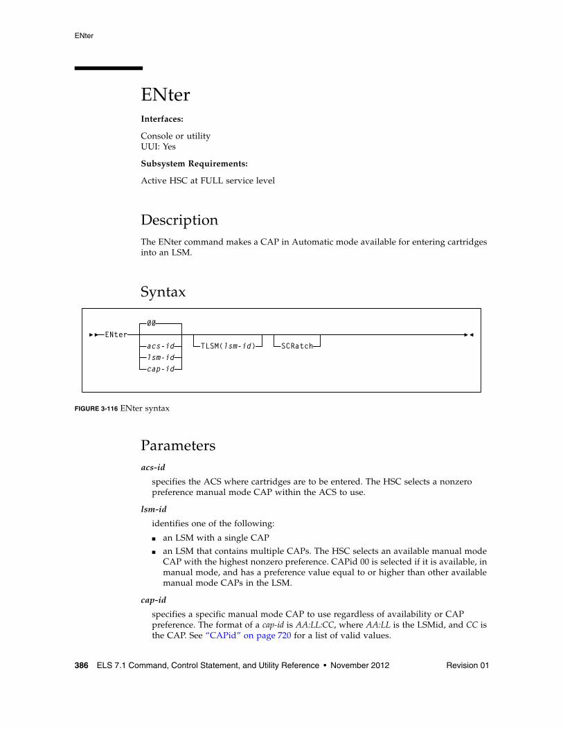
ENter
386 ELS 7.1 Command, Control Statement, and Utility Reference • November 2012 Revision 01
ENterInterfaces:
Console or utilityUUI: Yes
Subsystem Requirements:
Active HSC at FULL service level
DescriptionThe ENter command makes a CAP in Automatic mode available for entering cartridges into an LSM.
Syntax
FIGURE 3-116 ENter syntax
Parametersacs-id
specifies the ACS where cartridges are to be entered. The HSC selects a nonzero preference manual mode CAP within the ACS to use.
lsm-id
identifies one of the following:
■ an LSM with a single CAP
■ an LSM that contains multiple CAPs. The HSC selects an available manual mode CAP with the highest nonzero preference. CAPid 00 is selected if it is available, in manual mode, and has a preference value equal to or higher than other available manual mode CAPs in the LSM.
cap-id
specifies a specific manual mode CAP to use regardless of availability or CAP preference. The format of a cap-id is AA:LL:CC, where AA:LL is the LSMid, and CC is the CAP. See “CAPid” on page 720 for a list of valid values.
ENter00
acs-idlsm-idcap-id
TLSM(lsm-id) SCRatch
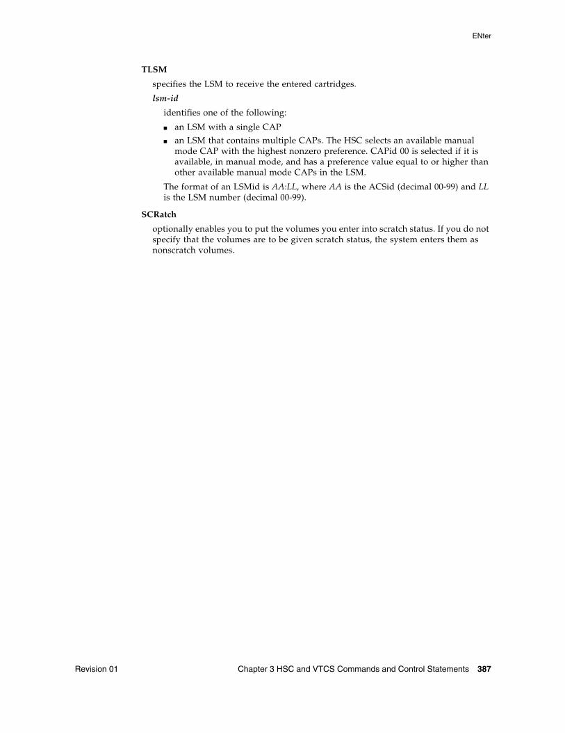
ENter
Revision 01 Chapter 3 HSC and VTCS Commands and Control Statements 387
TLSM
specifies the LSM to receive the entered cartridges.
lsm-id
identifies one of the following:
■ an LSM with a single CAP
■ an LSM that contains multiple CAPs. The HSC selects an available manual mode CAP with the highest nonzero preference. CAPid 00 is selected if it is available, in manual mode, and has a preference value equal to or higher than other available manual mode CAPs in the LSM.
The format of an LSMid is AA:LL, where AA is the ACSid (decimal 00-99) and LL is the LSM number (decimal 00-99).
SCRatch
optionally enables you to put the volumes you enter into scratch status. If you do not specify that the volumes are to be given scratch status, the system enters them as nonscratch volumes.
EXECParm
388 ELS 7.1 Command, Control Statement, and Utility Reference • November 2012 Revision 01
EXECParmInterfaces:
PARMLIB onlyUUI: No
Subsystem Requirements:
None
DescriptionThe EXECParm command provides an alternative method for specifying GTF event and format IDs normally specified in the subsystem startup procedure. It also provides you with the option of displaying the command prefix preceding WTO or WTOR messages.
Syntax
FIGURE 3-117 EXECParm syntax
ParametersMSGPRFX
optionally, specifies control of whether the command prefix is to precede WTO or WTOR messages to the operator.
Yes
indicates that the command prefix is to display preceding WTO or WTOR messages to the operator.
No
indicates that the command prefix is not to display preceding WTO or WTOR messages to the operator.
EXECParm
MSGPRFX(YesNo )
,Eid(gtfeid) ,Fid(gtffid)
,HOSTID(host-id)
EXECParm
Revision 01 Chapter 3 HSC and VTCS Commands and Control Statements 389
Eid
optionally, gtfeid specifies a GTF event ID.
PARM=’Eid(user-specified-event-id)’ parameter is valid for use in the HSC initialization procedure as an alternative method of specifying the GTF event ID.
Fid
optionally, gtffid specifies a GTF format ID.
PARM=’Fid(user-specified-format-id)’ parameter is valid for use in the HSC initialization procedure as an alternative method of specifying the GTF format ID.
HOSTID
optionally, host-id specifies the system ID associated with the request to process the EXECParm control statement.
Note – If the hostid specified does not match the host executing the command, the command is ignored and no message is issued.
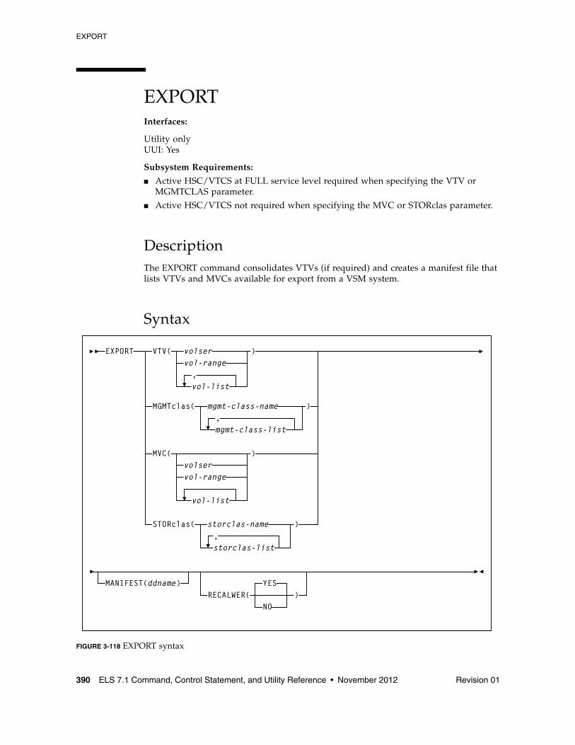
EXPORT
390 ELS 7.1 Command, Control Statement, and Utility Reference • November 2012 Revision 01
EXPORTInterfaces:
Utility onlyUUI: Yes
Subsystem Requirements:
■ Active HSC/VTCS at FULL service level required when specifying the VTV or MGMTCLAS parameter.
■ Active HSC/VTCS not required when specifying the MVC or STORclas parameter.
DescriptionThe EXPORT command consolidates VTVs (if required) and creates a manifest file that lists VTVs and MVCs available for export from a VSM system.
Syntax
FIGURE 3-118 EXPORT syntax
EXPORT VTV( volservol-range
vol-list
)
MGMTclas( mgmt-class-name,mgmt-class-list
)
MVC(volservol-range
vol-list
)
STORclas( storclas-name
storclas-list
)
,
,
MANIFEST(ddname)RECALWER(
YES
NO)
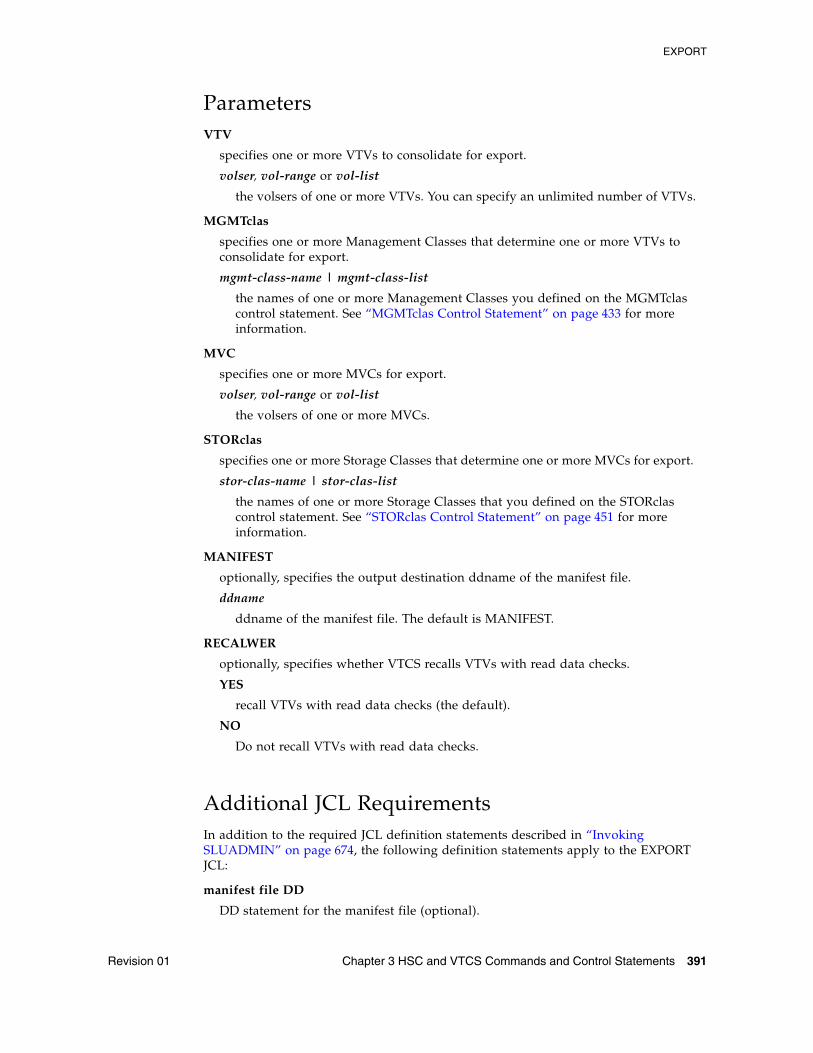
EXPORT
Revision 01 Chapter 3 HSC and VTCS Commands and Control Statements 391
ParametersVTV
specifies one or more VTVs to consolidate for export.
volser, vol-range or vol-list
the volsers of one or more VTVs. You can specify an unlimited number of VTVs.
MGMTclas
specifies one or more Management Classes that determine one or more VTVs to consolidate for export.
mgmt-class-name | mgmt-class-list
the names of one or more Management Classes you defined on the MGMTclas control statement. See “MGMTclas Control Statement” on page 433 for more information.
MVC
specifies one or more MVCs for export.
volser, vol-range or vol-list
the volsers of one or more MVCs.
STORclas
specifies one or more Storage Classes that determine one or more MVCs for export.
stor-clas-name | stor-clas-list
the names of one or more Storage Classes that you defined on the STORclas control statement. See “STORclas Control Statement” on page 451 for more information.
MANIFEST
optionally, specifies the output destination ddname of the manifest file.
ddname
ddname of the manifest file. The default is MANIFEST.
RECALWER
optionally, specifies whether VTCS recalls VTVs with read data checks.
YES
recall VTVs with read data checks (the default).
NO
Do not recall VTVs with read data checks.
Additional JCL RequirementsIn addition to the required JCL definition statements described in “Invoking SLUADMIN” on page 674, the following definition statements apply to the EXPORT JCL:
manifest file DD
DD statement for the manifest file (optional).
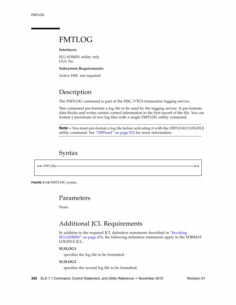
FMTLOG
392 ELS 7.1 Command, Control Statement, and Utility Reference • November 2012 Revision 01
FMTLOGInterfaces:
SLUADMIN utility onlyUUI: No
Subsystem Requirements:
Active HSC not required
DescriptionThe FMTLOG command is part of the HSC/VTCS transaction logging service.
This command pre-formats a log file to be used by the logging service. It pre-formats data blocks and writes certain control information in the first record of the file. You can format a maximum of two log files with a single FMTLOG utility command.
Note – You must pre-format a log file before activating it with the OFFLOAD LOGFILE utility command. See “OFFload” on page 512 for more information.
Syntax
FIGURE 3-119 FMTLOG syntax
ParametersNone.
Additional JCL RequirementsIn addition to the required JCL definition statements described in “Invoking SLUADMIN” on page 674, the following definition statements apply to the FORMAT LOGFILE JCL:
SLSLOG1
specifies the log file to be formatted.
SLSLOG2
specifies the second log file to be formatted.
FMTLOG
IMPORT
Revision 01 Chapter 3 HSC and VTCS Commands and Control Statements 393
IMPORTInterfaces:
Utility onlyUUI: Yes
Subsystem Requirements:
Active HSC/VTCS not required
DescriptionThe IMPORT command imports VTVs and MVCs listed on a manifest file into a VSM system.
Note – Ensure that the “to” CDS has the same features (enabled by CDS level) as the “from” CDS. For example, if the “from” CDS has large VTV page sizes enabled and 2/4 Gb VTVs have been created, then the “to CDS” must have the same capabilities, otherwise the import fails.
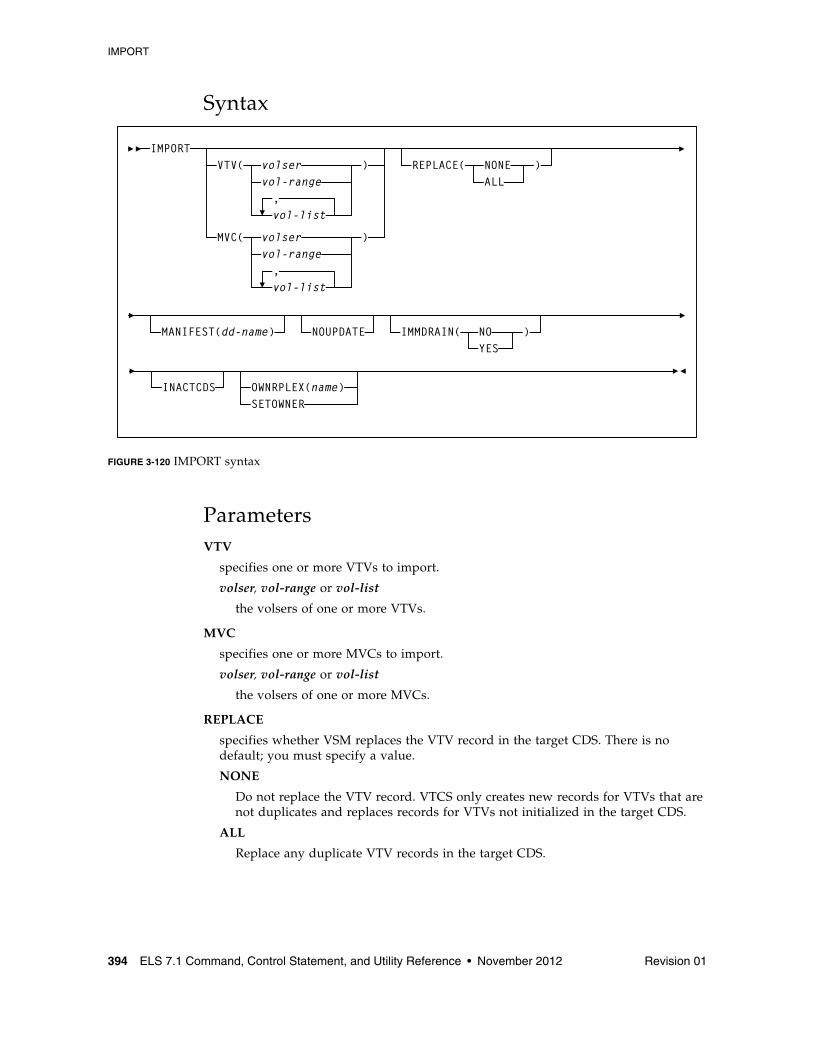
IMPORT
394 ELS 7.1 Command, Control Statement, and Utility Reference • November 2012 Revision 01
Syntax
FIGURE 3-120 IMPORT syntax
ParametersVTV
specifies one or more VTVs to import.
volser, vol-range or vol-list
the volsers of one or more VTVs.
MVC
specifies one or more MVCs to import.
volser, vol-range or vol-list
the volsers of one or more MVCs.
REPLACE
specifies whether VSM replaces the VTV record in the target CDS. There is no default; you must specify a value.
NONE
Do not replace the VTV record. VTCS only creates new records for VTVs that are not duplicates and replaces records for VTVs not initialized in the target CDS.
ALL
Replace any duplicate VTV records in the target CDS.
IMPORT
vol-range
MVC( volservol-range
vol-list
IMMDRAIN( NOYES
)
VTV( volser
vol-list
)
)
,
,
REPLACE( NONEALL
)
MANIFEST(dd-name) NOUPDATE
INACTCDS OWNRPLEX(name)SETOWNER
IMPORT
Revision 01 Chapter 3 HSC and VTCS Commands and Control Statements 395
Caution – ■ Ensure that you actually want to replace duplicate VTV records in the target CDS
before you specify the ALL parameter. You may want to do a “validate” run with NOUPDATE to see which VTV records will be replaced.
■ If a VTV record is replaced, all existing VTSS and MVC copies of the VTV are invalidated.
■ You cannot import an MVC if the target CDS records show that the MVC contains VTVs, even if you specify REPLACE(ALL). In this situation, you must first drain (with eject) the MVC on the target system and eject it from the ACS. You can then import the MVC that you exported from the source system.
IMMDRAIN
optionally, specifies whether VSM will immediately drain imported MVCs.
NO
Do not drain MVCs (the default).
YES
Drain MVCs.
MANIFEST
optionally, specifies the input ddname of the manifest file.
ddname
ddname of the manifest file. The default is MANIFEST.
NOUPDATE
optionally, specifies that VSM does not update the CDS, validates the import operation, and writes information messages to the job log.
INACTCDS
optionally, specifies that the import uses a different CDS from the CDS currently active on the HSC system where you are running the import job. Use the SLSCNTL definition statement in the SLUADMIN JCL to specify the alternate CDS.
Note – ■ If HSC is down on the system where you are running the import job, the CDS on that
system is assumed to be inactive, so you do not need to specify INACTCDS.
■ If you specify the INACTCDS parameter, the CDS specified in the SLSCNTL definition statement in the SLUADMIN JCL must be different from the CDS being used by HSC/VTCS (if active).
OWNRPLEX
specifies ownership of a VTV being imported.
name
the name of the TapePlex that owns the original copy of the VTV. This name must match one of the known TapePlex names in the configuration.
If this name matches that indicated for the THISPLEX parameter on the CONFIg TAPEPlex statement, the electronic imported status is removed.
IMPORT
396 ELS 7.1 Command, Control Statement, and Utility Reference • November 2012 Revision 01
SETOWNER
specifies that ownership information is to be imported.
By default, any ownership information within the manifest is ignored. The SERTOWNER parameter specifies that the TapePlex ownership and export fields are imported. VTVs appear as if electronically imported on Display commands and reports.
Additional JCL RequirementsIn addition to the required JCL definition statements described in “Invoking SLUADMIN” on page 674, the following definition statements apply to the IMPORT JCL:
manifest file DD
DD statement for the manifest file.
INITialize
Revision 01 Chapter 3 HSC and VTCS Commands and Control Statements 397
INITializeInterfaces:
SLUADMIN utility onlyUUI: No
Subsystem Requirements:
Active HSC at FULL service level
DescriptionThe INITialize command allows you to batch enter cartridges into the library through the CAP, and invokes a user-specified program to write a magnetic label on each tape.
The robot accepts cartridges placed into the CAP and reads the Tri-Optic labels, and the HSC passes the VOLSERs to the user-specified program. The magnetically labeled cartridges can be ejected from the library or placed into cell locations. If the cartridges are stored in the library, the control data set is updated with the VOLSER and location information. The control data set can mark each cartridge as either scratch or nonscratch.
INITialize reads the external Tri-Optic labels and records them in a data set defined through the CNTLDD parameter. CNTLDD is a control statement parameter that describes the DDname to be used for TMSTPNIT control statements.
The INITialize utility does not initialize cartridges on its own; it invokes TMS, TLMS, or any other initialization utility, which performs the initialization. CNTLDD specifies, through the HSC to the TMS utility, the DD to be used for the input parameters the TMS utility requires.
Warning – This utility must be executed on an MSP system running SMC and using a local HSC server.
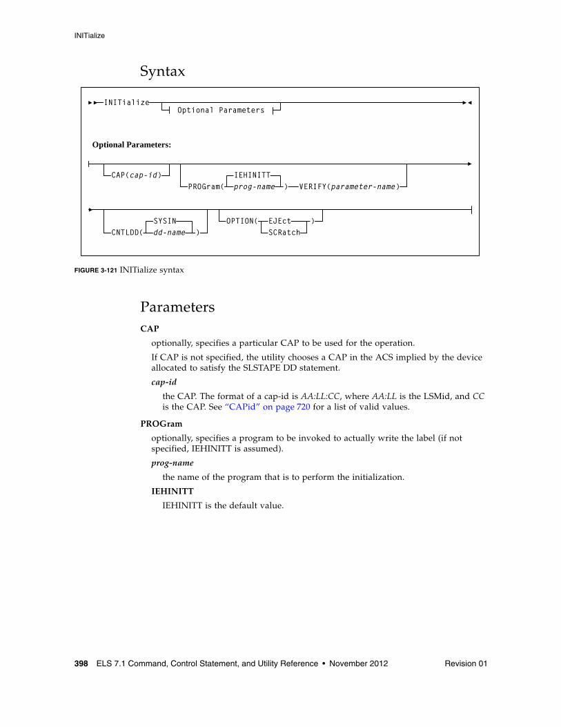
INITialize
398 ELS 7.1 Command, Control Statement, and Utility Reference • November 2012 Revision 01
Syntax
FIGURE 3-121 INITialize syntax
ParametersCAP
optionally, specifies a particular CAP to be used for the operation.
If CAP is not specified, the utility chooses a CAP in the ACS implied by the device allocated to satisfy the SLSTAPE DD statement.
cap-id
the CAP. The format of a cap-id is AA:LL:CC, where AA:LL is the LSMid, and CC is the CAP. See “CAPid” on page 720 for a list of valid values.
PROGram
optionally, specifies a program to be invoked to actually write the label (if not specified, IEHINITT is assumed).
prog-name
the name of the program that is to perform the initialization.
IEHINITT
IEHINITT is the default value.
INITializeOptional Parameters
CAP(cap-id)PROGram( prog-name
IEHINITT) VERIFY(parameter-name)
CNTLDD(SYSINdd-name )
OPTION( EJEctSCRatch
)
Optional Parameters:
INITialize
Revision 01 Chapter 3 HSC and VTCS Commands and Control Statements 399
VERIFY
optionally, specifies a parameter to be passed to the tape initialization program identified by the PROGram parameter. VERIFY is valid only when the PROGram parameter specifies TMSTPNIT.
parameter-name
the parameter passed to the TMSTPNIT program. For example, if the following parameter is entered:
VERIFY(ROBOT)
TMSTPNIT suppresses the TMS CAL0TN01 message for NL (nonlabeled) tapes. Refer to the appropriate CA-1 publication for valid parameter values.
CNTLDD
optionally, specifies the DD statement to which initialization control statements are written, and from which the label program reads its control statements.
Note – This is not your control data set.
dd-name
the name of the DD statement.
Note – The dd-name option may only be specified when using CA-1 (TMS) prior to version 5.1. The default value (SYSIN) MUST be used with CA-1 (TMS) version 5.1 or later.
SYSIN
SYSIN is the default value.
OPTion
optionally, specifies optional handling to be performed following the completion of label processing. If not specified, the default is retention of the new cartridges in the library with a non-scratch status.
EJEct
specifies that the labeled volumes are to be ejected from the library after the labeling process is complete.
SCRatch
specifies that the labeled volumes entering the library are to be added to the scratch list. If the volume is to be treated as scratch, the installation must inform the tape management system of the volume’s scratch status.
INITialize
400 ELS 7.1 Command, Control Statement, and Utility Reference • November 2012 Revision 01
Additional JCL RequirementsIn addition to the required JCL definition statements described in “Invoking SLUADMIN” on page 674, the following definition statements apply to the INITialize JCL:
SLSINIT
substitution control card format for the invoked initialization program.
SLSTAPE
library transport on which the cartridge is mounted for labeling. To prevent a nonlibrary transport from being allocated, specify one of the following:
■ an esoteric containing only library transports ■ a specific library transport address■ a TAPEREQ statement to direct the allocation to a library transport ■ a user exit (refer to the ELS Legacy Interfaces Reference)
CNTLDD or SYSIN
contains volume serial labeling information and is passed as input to the initialization program (IEHINITT or the program specified by the PROG keyword parameter).
If CNTLDD is specified in the utility control statement, then the DDname identifies the data set containing the labeling information.
SYSPRINT
output messages from IEHINITT.
contains volume serial labeling information and is passed as input to the initialization program (IEHINITT or the program specified by the PROG keyword parameter).
If CNTLDD is specified in the utility control statement, then the DDname identifies the data set containing the labeling information.
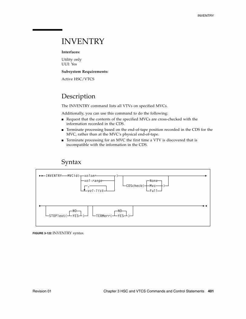
INVENTRY
Revision 01 Chapter 3 HSC and VTCS Commands and Control Statements 401
INVENTRYInterfaces:
Utility onlyUUI: Yes
Subsystem Requirements:
Active HSC/VTCS
DescriptionThe INVENTRY command lists all VTVs on specified MVCs.
Additionally, you can use this command to do the following:
■ Request that the contents of the specified MVCs are cross-checked with the information recorded in the CDS.
■ Terminate processing based on the end-of-tape position recorded in the CDS for the MVC, rather than at the MVC’s physical end-of-tape.
■ Terminate processing for an MVC the first time a VTV is discovered that is incompatible with the information in the CDS.
Syntax
FIGURE 3-122 INVENTRY syntax
INVENTRY MVCid( volservol-range,vol-list
CDScheck(NoneMvcFull
)
STOPleot(NOYES ) TERMerr(
NOYES )
)
INVENTRY
402 ELS 7.1 Command, Control Statement, and Utility Reference • November 2012 Revision 01
ParametersMVCid
specifies the MVC(s) to be inventoried.
volser, vol-range, or vol-list
the volsers of one or more MVCs. You can also specify one or more ranges.
CDScheck
optionally, specifies whether the contents of each inventoried MVC is checked against the information recorded in the CDS.
None
Each VTV found on an inventoried MVC is listed via message SLS6933I. The CDS is not checked. None is the default.
Mvc
Each VTV found on an inventoried MVC is listed via message SLS6933I. The details of the VTV are obtained from the CDS. The MVC and CDS copies of the VTV are compared and listed as a comment on SLS6933I. If the CDS shows a resident or MVC copy of the VTV that differs from the copy listed in SLS6933I, its details are listed via message SLS6934I.
Full
Each VTV found on an inventoried MVC is listed via message SLS6933I.
The details of the VTV are obtained from the CDS. The MVC and CDS copies of the VTV are compared and listed as a comment on SLS6933I. If the CDS shows a resident or MVC copy of the VTV that differs from the copy listed in SLS6933I, its details are listed via message SLS6934I. For each inventoried MVC, the CDS is checked to determine which CTCs are shown to have a copy on the MVC. Any MVCs that were not found on the MVC are listed via message SLS6935E.
STOPleot
optionally, specifies whether processing is to terminate when the logical end-of-tape position is reached. The logical end-of-tape position is the end-of-tape position recorded in the CDS for this MVC.
NO
All VTVs are to be processed on each inventoried MVC. This is the default.
YES
VTVs are processed on each inventoried MVC until one of the following occurs:
■ The MVC’s physical end-of-tape is reached.
■ The first VTV is found on the MVC that is beyond the logical end-of-tape position, if this is earlier than the physical end-of-tape position. This setting is invalid with CDScheck(None).
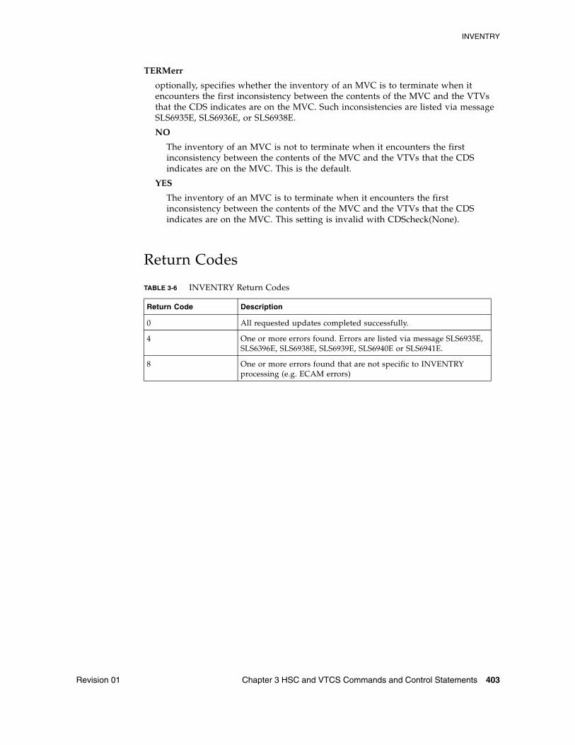
INVENTRY
Revision 01 Chapter 3 HSC and VTCS Commands and Control Statements 403
TERMerr
optionally, specifies whether the inventory of an MVC is to terminate when it encounters the first inconsistency between the contents of the MVC and the VTVs that the CDS indicates are on the MVC. Such inconsistencies are listed via message SLS6935E, SLS6936E, or SLS6938E.
NO
The inventory of an MVC is not to terminate when it encounters the first inconsistency between the contents of the MVC and the VTVs that the CDS indicates are on the MVC. This is the default.
YES
The inventory of an MVC is to terminate when it encounters the first inconsistency between the contents of the MVC and the VTVs that the CDS indicates are on the MVC. This setting is invalid with CDScheck(None).
Return Codes
TABLE 3-6 INVENTRY Return Codes
Return Code Description
0 All requested updates completed successfully.
4 One or more errors found. Errors are listed via message SLS6935E, SLS6396E, SLS6938E, SLS6939E, SLS6940E or SLS6941E.
8 One or more errors found that are not specific to INVENTRY processing (e.g. ECAM errors)
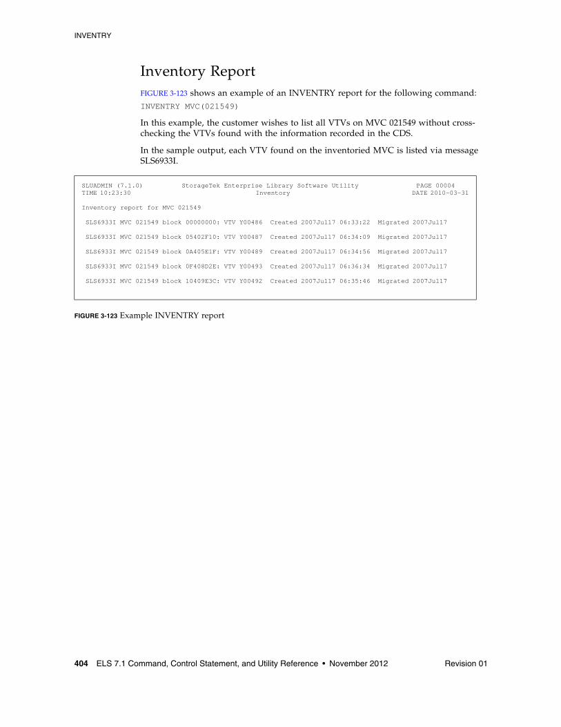
INVENTRY
404 ELS 7.1 Command, Control Statement, and Utility Reference • November 2012 Revision 01
Inventory ReportFIGURE 3-123 shows an example of an INVENTRY report for the following command:INVENTRY MVC(021549)
In this example, the customer wishes to list all VTVs on MVC 021549 without cross-checking the VTVs found with the information recorded in the CDS.
In the sample output, each VTV found on the inventoried MVC is listed via message SLS6933I.
FIGURE 3-123 Example INVENTRY report
SLUADMIN (7.1.0) StorageTek Enterprise Library Software Utility PAGE 00004TIME 10:23:30 Inventory DATE 2010-03-31
Inventory report for MVC 021549
SLS6933I MVC 021549 block 00000000: VTV Y00486 Created 2007Jul17 06:33:22 Migrated 2007Jul17
SLS6933I MVC 021549 block 05402F10: VTV Y00487 Created 2007Jul17 06:34:09 Migrated 2007Jul17
SLS6933I MVC 021549 block 0A405E1F: VTV Y00489 Created 2007Jul17 06:34:56 Migrated 2007Jul17
SLS6933I MVC 021549 block 0F408D2E: VTV Y00493 Created 2007Jul17 06:36:34 Migrated 2007Jul17
SLS6933I MVC 021549 block 10409E3C: VTV Y00492 Created 2007Jul17 06:35:46 Migrated 2007Jul17
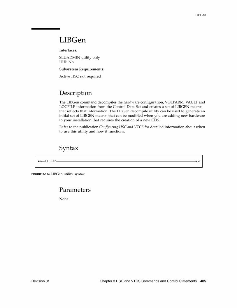
LIBGen
Revision 01 Chapter 3 HSC and VTCS Commands and Control Statements 405
LIBGenInterfaces:
SLUADMIN utility onlyUUI: No
Subsystem Requirements:
Active HSC not required
DescriptionThe LIBGen command decompiles the hardware configuration, VOLPARM, VAULT and LOGFILE information from the Control Data Set and creates a set of LIBGEN macros that reflects that information. The LIBGen decompile utility can be used to generate an initial set of LIBGEN macros that can be modified when you are adding new hardware to your installation that requires the creation of a new CDS.
Refer to the publication Configuring HSC and VTCS for detailed information about when to use this utility and how it functions.
Syntax
FIGURE 3-124 LIBGen utility syntax
ParametersNone.
LIBGen
LIBGen
406 ELS 7.1 Command, Control Statement, and Utility Reference • November 2012 Revision 01
Additional JCL RequirementsIn addition to the required JCL definition statements described in “Invoking SLUADMIN” on page 674, the following definition statements apply to the LIBGen JCL:
SLSLIBGN
output data set to accommodate the LIBGEN created by the utility.
The data set has these characteristics: LRECL=80, fixed-blocked format (multiple of 80). The data set can be assigned to print or to output to a DASD. It may be assigned to DUMMY if only the SLSPRINT output is desired.
SLSSET
output SET VOLPARM, SET VAULT/VAULTVOL, and/or SET LOGFILE control statements from the CDS.
SLSSET is required when VOLPARM, VAULT/VAULTVOL, or LOGFILE records exist in the CDS. If the SLSSET DD is not coded in the JCL, message SLS0212I is issued and the utility ends with a return code 4.
SLSPARM
output VOLPARM card images from CDS.
SLSPARM is required when VOLPARM records exist in the CDS. If the SLSPARM DD is not coded in the JCL, message SLS0212I is issued and the utility ends with a return code 4.
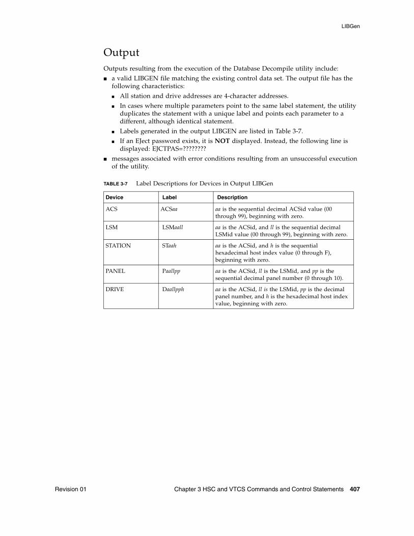
LIBGen
Revision 01 Chapter 3 HSC and VTCS Commands and Control Statements 407
Output Outputs resulting from the execution of the Database Decompile utility include:
■ a valid LIBGEN file matching the existing control data set. The output file has the following characteristics:
■ All station and drive addresses are 4-character addresses.
■ In cases where multiple parameters point to the same label statement, the utility duplicates the statement with a unique label and points each parameter to a different, although identical statement.
■ Labels generated in the output LIBGEN are listed in Table 3-7.
■ If an EJect password exists, it is NOT displayed. Instead, the following line is displayed: EJCTPAS=????????
■ messages associated with error conditions resulting from an unsuccessful execution of the utility.
TABLE 3-7 Label Descriptions for Devices in Output LIBGen
Device Label Description
ACS ACSaa aa is the sequential decimal ACSid value (00 through 99), beginning with zero.
LSM LSMaall aa is the ACSid, and ll is the sequential decimal LSMid value (00 through 99), beginning with zero.
STATION STaah aa is the ACSid, and h is the sequential hexadecimal host index value (0 through F), beginning with zero.
PANEL Paallpp aa is the ACSid, ll is the LSMid, and pp is the sequential decimal panel number (0 through 10).
DRIVE Daallpph aa is the ACSid, ll is the LSMid, pp is the decimal panel number, and h is the hexadecimal host index value, beginning with zero.
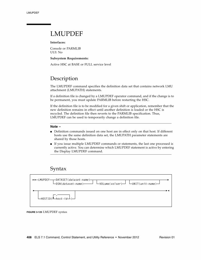
LMUPDEF
408 ELS 7.1 Command, Control Statement, and Utility Reference • November 2012 Revision 01
LMUPDEF Interfaces:
Console or PARMLIBUUI: No
Subsystem Requirements:
Active HSC at BASE or FULL service level
DescriptionThe LMUPDEF command specifies the definition data set that contains network LMU attachment (LMUPATH) statements.
If a definition file is changed by a LMUPDEF operator command, and if the change is to be permanent, you must update PARMLIB before restarting the HSC.
If the definition file is to be modified for a given shift or application, remember that the new definition remains in effect until another definition is loaded or the HSC is recycled. The definition file then reverts to the PARMLIB specification. Thus, LMUPDEF can be used to temporarily change a definition file.
Note – ■ Definition commands issued on one host are in effect only on that host. If different
hosts use the same definition data set, the LMUPATH parameter statements are shared by those hosts.
■ If you issue multiple LMUPDEF commands or statements, the last one processed is currently active. You can determine which LMUPDEF statement is active by entering the Display LMUPDEF command.
Syntax
FIGURE 3-125 LMUPDEF syntax
LMUPDEF DATASET(dataset-name)DSN(dataset-name) VOLume(volser) UNIT(unit-name)
HOSTID( host-id ),
LMUPDEF
Revision 01 Chapter 3 HSC and VTCS Commands and Control Statements 409
ParametersDATASET or DSN
specifies the name of the data set containing the LMUPATH statements to be processed and, optionally, an OPTION TITLE statement.
Note – ■ The definition data set may contain VOLATTR, UNITATTR, TAPEREQ, LMUPATH,
and OPTION TITLE statements, but only LMUPATH and OPTION TITLE statements are processed
■ If any other statement is encountered, an error message is issued and the statement is ignored.
■ See “OPTION TITLE Control Statement” on page 515 for more information about the OPTION TITLE control statement.
dataset.name
the name of the data set containing the LMUPATH address parameters. If the data set name includes a member name, dataset.name must be enclosed in quotes. For example,
DATASET(‘YOUR.DSN(MEMBER)’)
VOLume
optionally, specifies the serial number of the DASD volume on which the data set resides. This parameter is optional. Specify the VOLume parameter if the data set is not cataloged, or if a data set on a volume other than the volume indicated by the catalog is to be used.
volser
the volume serial number for the definition data set.
UNIT
optionally, specifies the unit where the definition data set is located.
unitname
the unit name. If the definition data set is not cataloged and this parameter is omitted, a unit name of SYSALLDA is the default.
HOSTID
optionally, limits the execution of this control statement to the specified hosts. If one of the specified hostids matches the host executing this control statement, the control statement is executed for that host. Otherwise, it is ignored. If this parameter is omitted, the control statement is executed on all hosts.
This parameter is valid only for use in PARMLIB, so that multiple systems can share a PARMLIB member containing TAPEREQ, VOLATTR, UNITATTR, or LMUPATH statements for different releases of HSC. If entered from the console, message SLS0018I is issued.)
host-id
the name of one or more hosts from which to execute this control statement. Multiple hosts must be separated by commas.
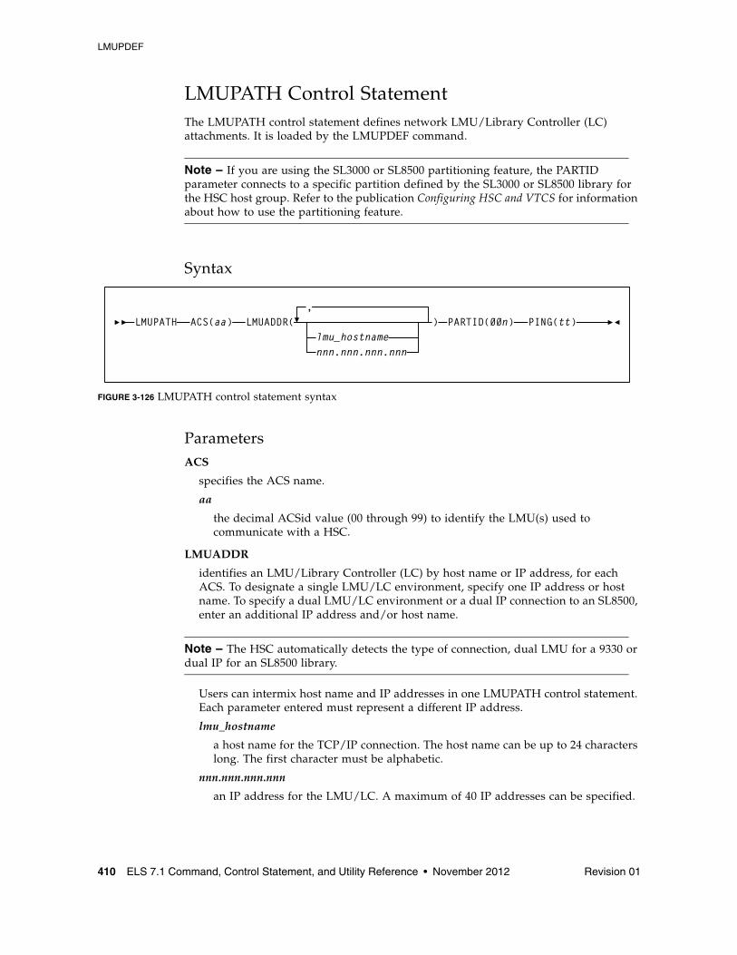
LMUPDEF
410 ELS 7.1 Command, Control Statement, and Utility Reference • November 2012 Revision 01
LMUPATH Control Statement The LMUPATH control statement defines network LMU/Library Controller (LC) attachments. It is loaded by the LMUPDEF command.
Note – If you are using the SL3000 or SL8500 partitioning feature, the PARTID parameter connects to a specific partition defined by the SL3000 or SL8500 library for the HSC host group. Refer to the publication Configuring HSC and VTCS for information about how to use the partitioning feature.
Syntax
FIGURE 3-126 LMUPATH control statement syntax
ParametersACS
specifies the ACS name.
aa
the decimal ACSid value (00 through 99) to identify the LMU(s) used to communicate with a HSC.
LMUADDR
identifies an LMU/Library Controller (LC) by host name or IP address, for each ACS. To designate a single LMU/LC environment, specify one IP address or host name. To specify a dual LMU/LC environment or a dual IP connection to an SL8500, enter an additional IP address and/or host name.
Note – The HSC automatically detects the type of connection, dual LMU for a 9330 or dual IP for an SL8500 library.
Users can intermix host name and IP addresses in one LMUPATH control statement. Each parameter entered must represent a different IP address.
lmu_hostname
a host name for the TCP/IP connection. The host name can be up to 24 characters long. The first character must be alphabetic.
nnn.nnn.nnn.nnn
an IP address for the LMU/LC. A maximum of 40 IP addresses can be specified.
LMUPATH ACS(aa) LMUADDR(lmu_hostnamennn.nnn.nnn.nnn
,) PARTID(00n) PING(tt)
LMUPDEF
Revision 01 Chapter 3 HSC and VTCS Commands and Control Statements 411
PARTID
defines a partition ID for each ACS.
Note – A partitioned SL3000 or SL8500 cannot use the multiple TCP/IP connection feature since partitioning applies only to a single SL3000 or SL8500 box.
00n
a partition ID from 001 to 999.
Note – ■ All three characters must be entered for the partition ID.■ For this release, only IDs 001 through 008 are supported.
PING
specifies the number of minutes in between requests sent from the HSC to the LMU. These requests are to keep the connection active, which prevents a firewall from closing the connection due to inactivity.
tt
the time in minutes from 00-99. The default is 5 minutes if this parameter is not defined, and entering 00 turns off this feature.
LOGUTIL
412 ELS 7.1 Command, Control Statement, and Utility Reference • November 2012 Revision 01
LOGUTILInterfaces:
SLUADMIN utility onlyUUI: No
Subsystem Requirements:
Active HSC not required
DescriptionThe LOGUTIL command initiates the CDS recovery process for VTCS. It is used in the following scenarios:
■ The CDS has become unusable or corrupt and MVCs used since the date of the CDS backup need to be identified for MVCAUDIT purposes.
■ A VTSS has suffered a catastrophic data loss.
LOGUTIL receives input from log files created by the OFFload LOGFILE process, and calls a recovery module to perform the appropriate recovery actions.
Additionally:
■ The LOGUTIL FOR_LOSTMVC statement recovers VTVs that resided on a lost or damaged MVC.
■ The LOGUTIL GENAUDIT statement initiates a re-synchronization of the CDS to VSM via MVCAUDIT statements.
■ The LOGUTIL_LOCATE_VTV statement recovers older versions of VTVs.
■ The LOGUTIL UNDELETE statement recovers deleted VTVs.
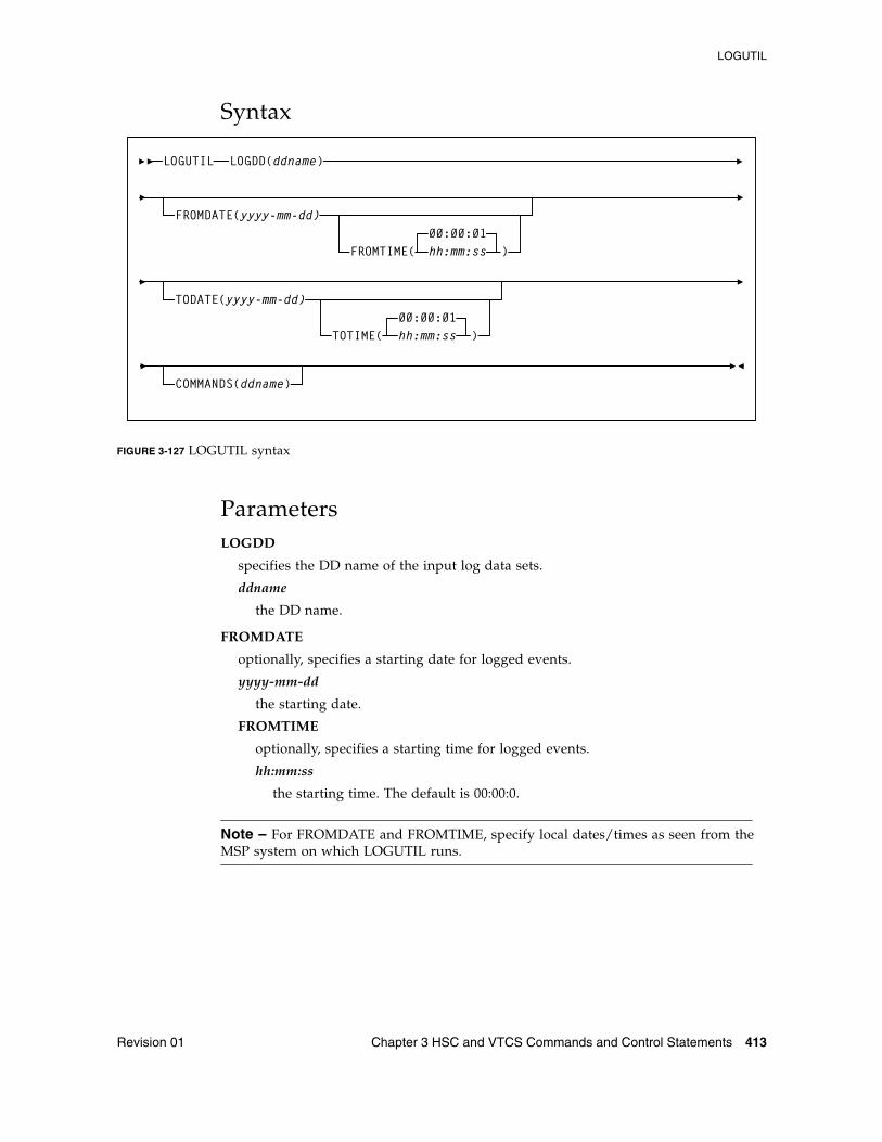
LOGUTIL
Revision 01 Chapter 3 HSC and VTCS Commands and Control Statements 413
Syntax
FIGURE 3-127 LOGUTIL syntax
ParametersLOGDD
specifies the DD name of the input log data sets.
ddname
the DD name.
FROMDATE
optionally, specifies a starting date for logged events.
yyyy-mm-dd
the starting date.
FROMTIME
optionally, specifies a starting time for logged events.
hh:mm:ss
the starting time. The default is 00:00:0.
Note – For FROMDATE and FROMTIME, specify local dates/times as seen from the MSP system on which LOGUTIL runs.
LOGUTIL LOGDD(ddname)
FROMDATE(yyyy-mm-dd)
COMMANDS(ddname)
FROMTIME( hh:mm:ss00:00:01
)
TODATE(yyyy-mm-dd)
TOTIME( hh:mm:ss00:00:01
)
LOGUTIL
414 ELS 7.1 Command, Control Statement, and Utility Reference • November 2012 Revision 01
TODATE
optionally, specifies an ending date and time for logged events
yyyy-mm-dd
the ending date.
TOTIME
optionally, specifies an ending time for logged events.
hh:mm:ss
the ending time. The default is 00:00:01.
Note – For TODATE and TOTIME, specify local dates/times as seen from the MSP system on which LOGUTIL runs.
COMMANDS
optionally, specifies the DD name of a data set that contains recovery commands.
ddname
the DD name.
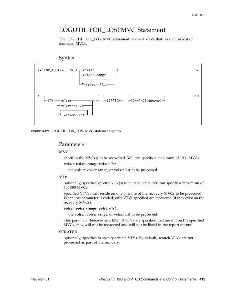
LOGUTIL
Revision 01 Chapter 3 HSC and VTCS Commands and Control Statements 415
LOGUTIL FOR_LOSTMVC StatementThe LOGUTIL FOR_LOSTMVC statement recovers VTVs that resided on lost or damaged MVCs.
Syntax
FIGURE 3-128 LOGUTIL FOR_LOSTMVC statement syntax
ParametersMVC
specifies the MVC(s) to be recovered. You can specify a maximum of 1000 MVCs.
volser, volser-range, volser-list
the volser, volser range, or volser list to be processed.
VTV
optionally, specifies specific VTV(s) to be recovered. You can specify a maximum of 300,000 MVCs.
Specified VTVs must reside on one or more of the recovery MVCs to be processed. When this parameter is coded, only VTVs specified are recovered (if they exist on the recovery MVCs).
volser, volser-range, volser-list
the volser, volser range, or volser list to be processed.
This parameter behaves as a filter. If VTVs are specified that are not on the specified MVCs, they will not be recovered and will not be listed in the report output.
SCRATCH
optionally, specifies to specify scratch VTVs. By default, scratch VTVs are not processed as part of the recovery.
SCRATCH
FOR_LOSTMVC
COMMANDS(ddname)
MVC( volservolser-range
)
volser-list
VTV( volservolser-range
)
volser-list
LOGUTIL
416 ELS 7.1 Command, Control Statement, and Utility Reference • November 2012 Revision 01
COMMANDS
optionally, specifies the DD name of a data set that includes the recovery commands created when the COMMANDS parameter is specified on the LOGUTIL command.
ddname
the DD name.
Note – The FOR_LOSTMVC COMMANDS parameter works with the LOGUTIL COMMANDS parameter as follows:
■ If you specify LOGUTIL COMMANDS, the FOR_LOSTMVC statement outputs recovery commands to the specified data set even if you did not specify GENAUDIT COMMANDS.
■ If you specify COMMANDS on both LOGUTIL and FOR_LOSTMVC, recovery commands are only output to the FOR_LOSTMVC COMMANDS data set.
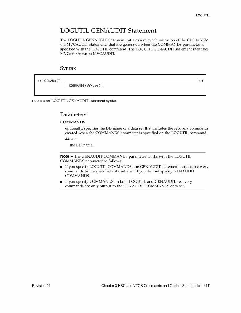
LOGUTIL
Revision 01 Chapter 3 HSC and VTCS Commands and Control Statements 417
LOGUTIL GENAUDIT StatementThe LOGUTIL GENAUDIT statement initiates a re-synchronization of the CDS to VSM via MVCAUDIT statements that are generated when the COMMANDS parameter is specified with the LOGUTIL command. The LOGUTIL GENAUDIT statement identifies MVCs for input to MVCAUDIT.
Syntax
FIGURE 3-129 LOGUTIL GENAUDIT statement syntax
ParametersCOMMANDS
optionally, specifies the DD name of a data set that includes the recovery commands created when the COMMANDS parameter is specified on the LOGUTIL command.
ddname
the DD name.
Note – The GENAUDIT COMMANDS parameter works with the LOGUTIL COMMANDS parameter as follows:
■ If you specify LOGUTIL COMMANDS, the GENAUDIT statement outputs recovery commands to the specified data set even if you did not specify GENAUDIT COMMANDS.
■ If you specify COMMANDS on both LOGUTIL and GENAUDIT, recovery commands are only output to the GENAUDIT COMMANDS data set.
GENAUDITCOMMANDS(ddname)
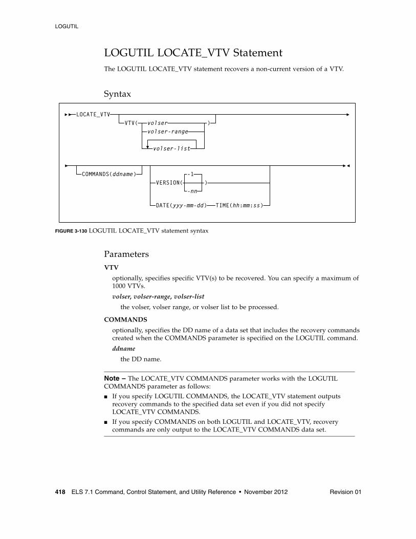
LOGUTIL
418 ELS 7.1 Command, Control Statement, and Utility Reference • November 2012 Revision 01
LOGUTIL LOCATE_VTV StatementThe LOGUTIL LOCATE_VTV statement recovers a non-current version of a VTV.
Syntax
FIGURE 3-130 LOGUTIL LOCATE_VTV statement syntax
ParametersVTV
optionally, specifies specific VTV(s) to be recovered. You can specify a maximum of 1000 VTVs.
volser, volser-range, volser-list
the volser, volser range, or volser list to be processed.
COMMANDS
optionally, specifies the DD name of a data set that includes the recovery commands created when the COMMANDS parameter is specified on the LOGUTIL command.
ddname
the DD name.
Note – The LOCATE_VTV COMMANDS parameter works with the LOGUTIL COMMANDS parameter as follows:
■ If you specify LOGUTIL COMMANDS, the LOCATE_VTV statement outputs recovery commands to the specified data set even if you did not specify LOCATE_VTV COMMANDS.
■ If you specify COMMANDS on both LOGUTIL and LOCATE_VTV, recovery commands are only output to the LOCATE_VTV COMMANDS data set.
LOCATE_VTV
COMMANDS(ddname)
VTV( volservolser-range
)
volser-list
-1
-nnVERSION( )
DATE(yyy-mm-dd) TIME(hh:mm:ss)
LOGUTIL
Revision 01 Chapter 3 HSC and VTCS Commands and Control Statements 419
VERSION
optionally, specifies the version of the VTV to recover.
Valid values are -1 to -99. The default is VERSION(-1), which is one version older than the current version.
Note – VERSION is mutually exclusive the DATE and TIME parameters.
DATE
optionally, specifies the date of the VTV version to recover. If you specify DATE, you must also specify TIME.
yyyy-mm-dd
the date, by year, month and day.
TIME
optionally, specifies the time of the VTV version to recover. If you specify TIME you must also specify DATE.
hh:mm:ss
the time, in hours minutes and seconds.
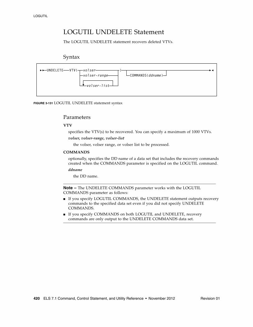
LOGUTIL
420 ELS 7.1 Command, Control Statement, and Utility Reference • November 2012 Revision 01
LOGUTIL UNDELETE StatementThe LOGUTIL UNDELETE statement recovers deleted VTVs.
Syntax
FIGURE 3-131 LOGUTIL UNDELETE statement syntax
ParametersVTV
specifies the VTV(s) to be recovered. You can specify a maximum of 1000 VTVs.
volser, volser-range, volser-list
the volser, volser range, or volser list to be processed.
COMMANDS
optionally, specifies the DD name of a data set that includes the recovery commands created when the COMMANDS parameter is specified on the LOGUTIL command.
ddname
the DD name.
Note – The UNDELETE COMMANDS parameter works with the LOGUTIL COMMANDS parameter as follows:
■ If you specify LOGUTIL COMMANDS, the UNDELETE statement outputs recovery commands to the specified data set even if you did not specify UNDELETE COMMANDS.
■ If you specify COMMANDS on both LOGUTIL and UNDELETE, recovery commands are only output to the UNDELETE COMMANDS data set.
UNDELETE VTV( volservolser-range
volser-list
)COMMANDS(ddname)
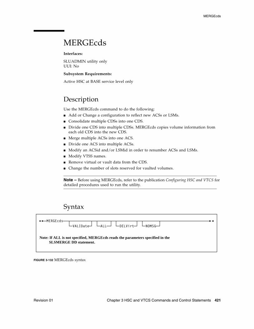
MERGEcds
Revision 01 Chapter 3 HSC and VTCS Commands and Control Statements 421
MERGEcdsInterfaces:
SLUADMIN utility onlyUUI: No
Subsystem Requirements:
Active HSC at BASE service level only
DescriptionUse the MERGEcds command to do the following:
■ Add or Change a configuration to reflect new ACSs or LSMs.
■ Consolidate multiple CDSs into one CDS.
■ Divide one CDS into multiple CDSs. MERGEcds copies volume information from each old CDS into the new CDS.
■ Merge multiple ACSs into one ACS.
■ Divide one ACS into multiple ACSs.
■ Modify an ACSid and/or LSMid in order to renumber ACSs and LSMs.
■ Modify VTSS names.
■ Remove virtual or vault data from the CDS.
■ Change the number of slots reserved for vaulted volumes.
Note – Before using MERGEcds, refer to the publication Configuring HSC and VTCS for detailed procedures used to run the utility.
Syntax
FIGURE 3-132 MERGEcds syntax
MERGEcdsVALIDate ALL NOMSG
Note: If ALL is not specified, MERGEcds reads the parameters specified in the SLSMERGE DD statement.
DELVirt
MERGEcds
422 ELS 7.1 Command, Control Statement, and Utility Reference • November 2012 Revision 01
ParametersVALIDate
optionally, specifies to only validate that the configurations to be reconfigured or merged are compatible, but not perform the operation. MERGEcds VALIDate reports any duplicate, in-transit, and errant volumes.
ALL
optionally, specifies to copy volume information for all ACSs and VTSSs from the "from" CDS to the "to" CDS. For a CDS merge, the ACS ID and LSM IDs, and VTSS names must match. You can also specify the ALL parameter to convert a CDS to extended format.
Note – ALL and SLSMERGE DD are mutually exclusive. If you do not specify ALL, MERGEcds reads the parameters specified on the SLSMERGE control statement. These parameters specify the ACSs, LSMs, VTSSs, and Vaults whose volume information you want to merge or reconfigure. See “SLSMERGE Control Statement” on page 424 for more information.
DELVirt
optionally, specifies that VTV and MVC volume information is not copied to the “to” CDS if both of the following are true:
■ The VTVs and MVCs defined in the "from" CDS are either uninitialized or empty.
An empty VTV is not VTSS resident and has no current MVC copies. An empty MVC contains no current VTVs and does not have an assigned STORCLAS. An MVC is empty when %USED is 0% and %AVAIL is 100% on an MVC Report or Q MVC display.
Follow the procedure in the publication Managing HSC and VTCS for removing MVCs from the pool.
■ The uninitialized or empty VTVs and MVCs in the "from" CDS are not defined in the "to" CDS. That is, no duplicate volsers exist.
DELVirt has no effect unless ALLVIRT is specified on the SLSMERGE control statement.
NOMSG
optionally, suppresses message SLS4245I, which displays the volser of an MVC or VTV that was not copied to the “to” CDS.
NOMSG has no effect unless DELVirt is specified on the MERGECDS control statement and ALLVIRT is specified on the SLSMERGE control statement.
MERGEcds
Revision 01 Chapter 3 HSC and VTCS Commands and Control Statements 423
Additional JCL RequirementsIn addition to the required JCL definition statements described in “Invoking SLUADMIN” on page 674, the following definition statements apply to the MERGEcds JCL:
SLSFCNTL
specifies the current primary copy of the “from” HSC CDS.
SLSFCTL2
specifies the secondary copy of the CDS, if one is defined.
SLSFSTBY
optionally, specifies the standby copy of the CDS, if one is defined.
Note – If more than one of these statements are present, HSC determines the primary CDS from the Database Heartbeat (DHB) record of the “from” CDS. The “from” CDS is not modified. If a single CDS (SLSFCNTL) is specified, ensure that it is the primary CDS. No DHB validation occurs.
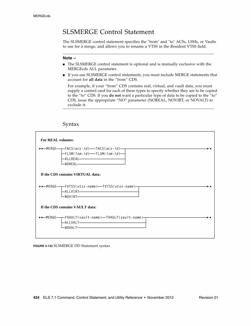
MERGEcds
424 ELS 7.1 Command, Control Statement, and Utility Reference • November 2012 Revision 01
SLSMERGE Control StatementThe SLSMERGE control statement specifies the "from" and "to" ACSs, LSMs, or Vaults to use for a merge, and allows you to rename a VTSS in the Resident VTSS field.
Note – ■ The SLSMERGE control statement is optional and is mutually exclusive with the
MERGEcds ALL parameter.
■ If you use SLSMERGE control statements, you must include MERGE statements that account for all data in the “from” CDS.
For example, if your “from” CDS contains real, virtual, and vault data, you must supply a control card for each of these types to specify whether they are to be copied to the “to” CDS. If you do not want a particular type of data to be copied to the “to” CDS, issue the appropriate “NO” parameter (NOREAL, NOVIRT, or NOVALT) to exclude it.
Syntax
FIGURE 3-133 SLSMERGE DD Statement syntax
MERGE
MERGE
FLSM(lsm-id)
FVTSS(vtss-name)
TLSM(lsm-id)
TVTSS(vtss-name)
FVAULT(vault-name) TVAULT(vault-name)
ALLREAL
ALLVIRT
ALLVALT
NOREAL
NOVIRT
NOVALT
For REAL volumes:
If the CDS contains VIRTUAL data:
If the CDS contains VAULT data:
MERGE FACS(acs-id) TACS(acs-id)
MERGEcds
Revision 01 Chapter 3 HSC and VTCS Commands and Control Statements 425
Parameters
Caution – The “real” parameters (FACS, TACS, FLSM, TLSM) and “vault” parameters (FVAULT, TVAULT) act as selection criteria, while the “virtual” parameters (FVTSS, TVTSS) act only as rename criteria.
For REAL volumes:
FACS(acs-id)
specifies the “from” ACS.
TACS(acs-id)
specifies the “to” ACS.
FLSM(lsm-id)
specifies the “from” LSM.
TLSM(lsm-id)
specifies the “to” LSM.
ALLREAL
Merge all real data only.
NOREAL
Do not merge real data.
If the CDS contains VIRTUAL data:
FVTSS(vtss-name)
specifies the “from” VTSS name.
TVTSS(vtss-name)
specifies the “to” VTSS name.
Caution – You cannot use MERGEcds to remove data for certain VTSSs from the CDS.
FVTSS and TVTSS act only as rename criteria. When these parameters are specified, ALLVIRT is implied.
For example:MERGE FVTSS(VTSS18) TVTSS(VTSS17)
In this example, all VTV records are copied to the new CDS, but the Resident VTSS field is changed from VTSS18 to VTSS17. All VTSSs not specified in these statements are automatically merged to the same-named VTSS in the new CDS.
ALLVIRT
Merge all virtual data only.
NOVIRT
Do not merge virtual data.
MERGEcds
426 ELS 7.1 Command, Control Statement, and Utility Reference • November 2012 Revision 01
If the CDS contains VAULT data:
FVAULT(vault-name)
specifies the “from” vault.
TVAULT(vault-name)
specifies the “to” vault.
ALLVALT
Merge all vault data only.
NOVALT
Do not merge vault data.
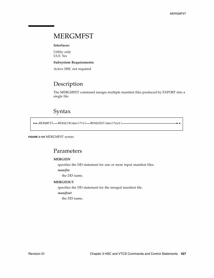
MERGMFST
Revision 01 Chapter 3 HSC and VTCS Commands and Control Statements 427
MERGMFSTInterfaces:
Utility onlyUUI: Yes
Subsystem Requirements:
Active HSC not required
DescriptionThe MERGMFST command merges multiple manifest files produced by EXPORT into a single file.
Syntax
FIGURE 3-134 MERGMFST syntax
ParametersMERGEIN
specifies the DD statement for one or more input manifest files.
manifin
the DD name.
MERGEOUT
specifies the DD statement for the merged manifest file.
manifout
the DD name.
MERGMFST MERGEIN(manifin) MERGEOUT(manifout)
MERGMFST
428 ELS 7.1 Command, Control Statement, and Utility Reference • November 2012 Revision 01
Additional JCL RequirementsIn addition to the required JCL definition statements described in “Invoking SLUADMIN” on page 674, the following definition statements apply to the MERGMFST JCL:
manifin DD
DD statement for the input manifest file(s).
manifout DD
DD statement for the merged manifest file.
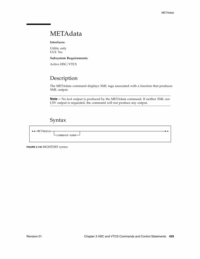
METAdata
Revision 01 Chapter 3 HSC and VTCS Commands and Control Statements 429
METAdataInterfaces:
Utility onlyUUI: Yes
Subsystem Requirements:
Active HSC/VTCS
DescriptionThe METAdata command displays XML tags associated with a function that produces XML output.
Note – No text output is produced by the METAdata command. If neither XML nor CSV output is requested, the command will not produce any output.
Syntax
FIGURE 3-135 MGMTDEF syntax
METAdatacommand-name
METAdata
430 ELS 7.1 Command, Control Statement, and Utility Reference • November 2012 Revision 01
Parameterscommand_name
The command for which metadata is to be produced.
When the command contains "two parts" such as Display Volume, both portions should be entered. The METAdata command uses the same abbreviations for the command_name as the command itself, for example:
METAdata D V
The METAdata command itself does not support metadata.
The following tags are produced by the METAdata command:
<command_name>
The full name of the command.
<security_level>
Required security level if command authorization is in effect. Values are QUERY, SET, and ADMIN.
<command_tags>
Header tag for all XML tags.
The following tags are produced for each XML tag in the requested command:
<tag_data>
Header tag for each XML tag.
<tag_name>
The XML tag name, for example, volser.
<tag_type>
Values are header (header XML tag), data (XML data tag, normally associated with a value), and trailer (indicates the position of the trailer tag associated with a header tag).
<occurrences>
The maximum number of expected occurrences, for tags that may occur multiple times. This may be either a numeric value or "unlimited."
The following tags are produced only for data-type tags.
<data_type>
Indicates the type of data expected in the tag value. Produced only for data tags. Values include: char, numeric, flag, hex, date, time.
<maximum_size>
Indicates the maximum output data size.
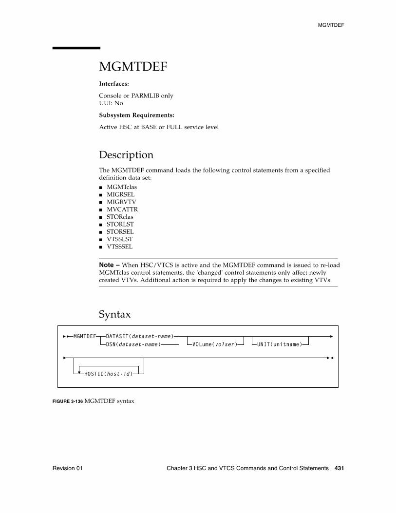
MGMTDEF
Revision 01 Chapter 3 HSC and VTCS Commands and Control Statements 431
MGMTDEFInterfaces:
Console or PARMLIB onlyUUI: No
Subsystem Requirements:
Active HSC at BASE or FULL service level
DescriptionThe MGMTDEF command loads the following control statements from a specified definition data set:
■ MGMTclas■ MIGRSEL■ MIGRVTV■ MVCATTR■ STORclas■ STORLST■ STORSEL■ VTSSLST■ VTSSSEL
Note – When HSC/VTCS is active and the MGMTDEF command is issued to re-load MGMTclas control statements, the 'changed' control statements only affect newly created VTVs. Additional action is required to apply the changes to existing VTVs.
Syntax
FIGURE 3-136 MGMTDEF syntax
MGMTDEFDSN(dataset-name)DATASET(dataset-name)
VOLume(volser) UNIT(unitname)
HOSTID(host-id)
MGMTDEF
432 ELS 7.1 Command, Control Statement, and Utility Reference • November 2012 Revision 01
ParametersDATASET or DSN
specifies the definition data set that contains the MGMTclas and STORclas statements to load.
dataset.name
the data set name.
VOLume
optionally, specifies the DASD volume where the definition data set resides. This parameter is optional, unless the data set is not cataloged, or the data set resides on a volume other than the volume indicated by the catalog.
volser
the DASD volser.
UNIT
optionally, specifies the DASD device where the definition data set resides.
unitname
the DASD unit name. If the definition data set is not cataloged and this parameter is omitted, the unit name defaults to SYSALLDA.
HOSTID
optionally, specifies the host for execution of the MGMTDEF command. This parameter is only valid when MGMTDEF is specified as a PARMLIB control statement.
host-id
the name of one or more hosts from which to execute the MGMTDEF command. Multiple hosts must be separated by commas.
MGMTDEF
Revision 01 Chapter 3 HSC and VTCS Commands and Control Statements 433
MGMTclas Control StatementThe MGMTclas control statement defines a VSM Management Class. It is loaded by the MGMTDEF command.
Note – ■ By default, advanced VSM management features are automatically enabled. The
FEATures command, included in previous ELS releases to enable these features, is no longer valid.
■ ELS includes parameters designed to improve migration control. If you choose not to use these features, refer to the ELS Legacy Interfaces Reference for information about existing legacy MGMTclas parameters.
■ When HSC/VTCS is active and the MGMTDEF command is issued to re-load MGMTclas control statements, the 'changed' control statements only affect newly created VTVs. Additional action is required to apply the changes to existing VTVs.
For example:
■ If you change the IMMDELAY value, you must recycle the HSC to apply the change to existing VTVs.
■ If you change the MIGpol value from 1 storage class to two, you must recall the VTV to allow for creation of the second migrated copy.
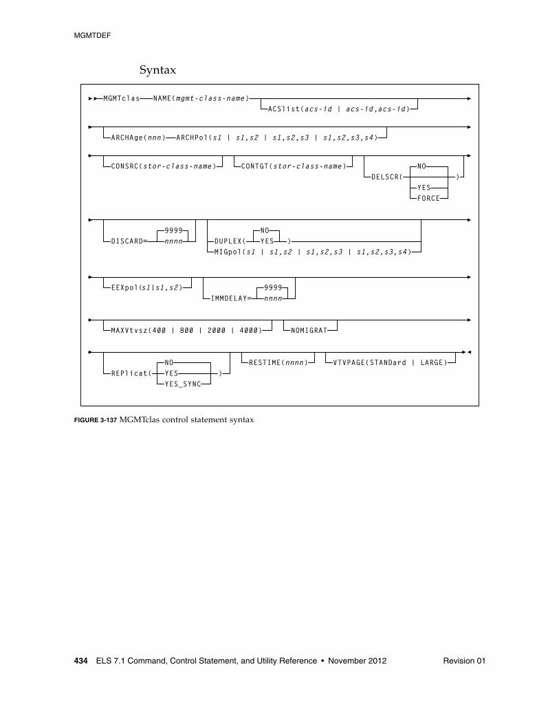
MGMTDEF
434 ELS 7.1 Command, Control Statement, and Utility Reference • November 2012 Revision 01
Syntax
FIGURE 3-137 MGMTclas control statement syntax
MGMTclas NAME(mgmt-class-name)ACSlist(acs-id | acs-id,acs-id)
DUPLEX(NOYES )
MAXVtvsz(400 | 800 | 2000 | 4000)
VTVPAGE(STANDard | LARGE)
DISCARD=9999nnnn
IMMDELAY=9999nnnn
NOMIGRAT
MIGpol(s1 | s1,s2 | s1,s2,s3 | s1,s2,s3,s4)
ARCHAge(nnn) ARCHPol(s1 | s1,s2 | s1,s2,s3 | s1,s2,s3,s4)
RESTIME(nnnn)
CONSRC(stor-class-name) CONTGT(stor-class-name)DELSCR(
NO)
REPlicat(NOYESYES_SYNC
)
EEXpol(s1|s1,s2)
FORCEYES
MGMTDEF
Revision 01 Chapter 3 HSC and VTCS Commands and Control Statements 435
ParametersNAME
specifies the name of the Management Class.
mgmt-class-name
the Management Class name. This name must be 1 to 8 alphanumeric characters beginning with an alpha character and must follow SMS naming conventions.
ACSlist
optionally, specifies the ACSs from which RTDs and MVCs are selected.
If not specified, the default is the ACS specified on the CONFIG DEFLTACS parameter.
See DUPlex, below, for information about using the DUPlex and ACSlist parameters.
acs-id | acs-id,acs-id
either one or two ACS IDs. An ACSid is a two digit decimal ACS identifier from 00-99.
ARCHAge
optionally, specifies the age (in days) of a VTV before it is archived as specified by ARCHPol. If you specify ARCHAge, you must specify ARCHPol.
This parameter is optional; there is no default value. Valid values are 1 to 999.
nnn
the VTV age in days.
ARCHPol
optionally, specifies up to four Storage Classes that specify the ACS and media type of the archive MVCs. If you specify:
■ One Storage Class, VTCS archives one copy of a VTV.
■ Multiple Storage Classes (with different ACS values, different MEDIA values, or both), VTCS archives multiple copies of the VTV to different MVCs in different ACSs.
■ Multiple Storage Classes with identical ACS and MEDIA values, VTCS archives multiple copies of the VTV to the same ACS and media type but to different MVCs.
Note – Multiple Storage Classes on ARCHPol also affects how VTV recall, MVC space reclamation, and VTV consolidation function:
This parameter is optional; there is no default value. If you specify ARCHPol, you must specify ARCHage.
stor-clas-name1...stor-clas-namen
the names of one or more Storage Classes that you defined on the STORclas control statement. Greater than two copies requires you to specify CDSLEVEL(V6ABOVE) or CDSLEVEL(V6ABOVE) on the CONFIG statement.

MGMTDEF
436 ELS 7.1 Command, Control Statement, and Utility Reference • November 2012 Revision 01
CONSRC
optionally, specifies the Storage Class that species a preference for the source MVC ACS and media for consolidation of VTVs that are migrated and copied to multiple MVC locations or media types. If the MVC in the specified Storage Class is unavailable, and the specified Storage Class is not the last (in order specified in the migration policy), VTCS uses the MVC associated with the last Storage Class. If the MVC in the specified Storage Class is unavailable and the specified Storage Class is the last (in order specified in the MIGpol parameter), VTCS uses the MVC associated with the previous Storage Class (in order specified in the MIGpol parameter).
stor-class-name
the name of a Storage Class that you defined on the STORclas control statement.
CONTGT
optionally, specifies the Storage Class that determines the output MVC ACS and media for VTV consolidation. Note that the media preferencing is in the opposite order of the list of media types specified on the Storage Class.
This parameter is optional; there is no default value. If you do not specify a value for CONTGT, VTCS selects the output MVC as follows:
■ For single-ACS and dual-ACS configurations, the media selection order for VTV consolidation.
■ For multiple ACS systems, VTCS selects MVCs from the default ACS specified by the CONFIG DEFLTACS parameter.
stor-class-name
the name of a Storage Class that you defined on the STORclas control statement.
MGMTDEF
Revision 01 Chapter 3 HSC and VTCS Commands and Control Statements 437
DELSCR
optionally, specifies whether VSM deletes scratched VTVs.
NO
Do not delete scratched VTVs (the default).
YES
Delete scratch VTVs unless this would cause a processing delay due to unavailable resources.
FORCE
Delete scratch VTVs and wait for access to any resources that are required.This may cause a processing delay.
Caution – When you scratch a VTV with DELSCR YES attribute, VSM erases the VTV data at scratch synchronization time, which eliminates the ability “unscratch” a VTV to recover data!
Also note that when using HSC to perform scratch synchronization, it is possible that a volume that is scratch in the TMC at the beginning of scratch synchronization run and also scratch in the CDS from the previous scratch update run (and thus is in the list for HSC to scratch in the CDS) is accessed by a job during the scratch update run and written to and made non-scratch by the TMS in the TMC. In this case, it is still possible for HSC to scratch the volume because it was in the originally extracted list of volumes to be scratched. Therefore, Oracle strongly recommends that you do not run any jobs that use scratches during HSC scratch synchronization.
See “Scratch Conversion Utility (SLUCONDB)” on page 690 for more information about HSC scratch synchronization with the Scratch Conversion Utility (SLUCONDB).
DISCARD
optionally, specifies the discard time in hours. This value represents the time after a VTV is dismounted that the VTV is kept in the buffer. After this time value expires, the VTV is preferred for deletion from the VTSS buffer if all required copies of the VTV exist on MVCs.
nnnn
time in hours. Valid values are 0 to 9999. The default is 9999.
Note – ■ When IMMEDmig is specified, DISCARD is not used for immediate migration
processing. It is only applicable for AUTO migration requests.
■ If RESTIME is also specified for a VTV, it overrides the DISCARD value.
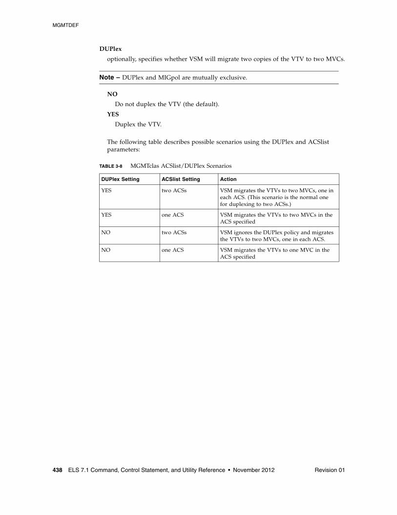
MGMTDEF
438 ELS 7.1 Command, Control Statement, and Utility Reference • November 2012 Revision 01
DUPlex
optionally, specifies whether VSM will migrate two copies of the VTV to two MVCs.
Note – DUPlex and MIGpol are mutually exclusive.
NO
Do not duplex the VTV (the default).
YES
Duplex the VTV.
The following table describes possible scenarios using the DUPlex and ACSlist parameters:
TABLE 3-8 MGMTclas ACSlist/DUPlex Scenarios
DUPlex Setting ACSlist Setting Action
YES two ACSs VSM migrates the VTVs to two MVCs, one in each ACS. (This scenario is the normal one for duplexing to two ACSs.)
YES one ACS VSM migrates the VTVs to two MVCs in the ACS specified
NO two ACSs VSM ignores the DUPlex policy and migrates the VTVs to two MVCs, one in each ACS.
NO one ACS VSM migrates the VTVs to one MVC in the ACS specified
MGMTDEF
Revision 01 Chapter 3 HSC and VTCS Commands and Control Statements 439
MIGpol
optionally, specifies up to four Storage Classes that specify the ACS and media type of migration MVCs.
Note – DUPlex and MIGpol are mutually exclusive.
If you specify:
■ One Storage Class, VTCS migrates one copy of a VTV.
■ Multiple Storage Classes (with different ACS values, different MEDIA values, or both), VTCS makes multiple copies the VTV to different MVCs in different ACSs.
■ Multiple Storage Classes with identical ACS and MEDIA values, VTCS makes multiple copies of the VTV to the same ACS and media type but to different MVCs.
Note – Multiple Storage Classes on MIGpol also affects how VTV recall, MVC space reclamation, and VTV consolidation function.
This parameter is optional; there is no default value.
s1 | s1,s2 | s1,s2,s3 | s1,s2,s3,s4
the names of up to 4 Storage Classes that you defined on the STORclas control statement. Greater than two copies requires you to specify CDSLEVEL(V6ABOVE) or greater on the CONFIG statement.
Note – The CONFIG GLOBAL REPLicat parameter specifies when to replicate a VTV (always, or only when changed while mounted).
EEXpol
optionally, specifies the storage classes for electronic export.
s1 | s1,s2
a maximum of two Storage Classes that specify the TAPEPLEX parameter. If these storage classes do not specify the TAPEPLEX parameter, an error condition results.
Note – ■ If there are two TAPELEX storage classes, then they must specify different
destination TapePlex names.
■ A warning will be generated if the two TapePlex storage classes are specified with the SYNC=YES parameter. It is only possible to synchronously export to one other TapePlex.
■ If there is a conflict, electronic export functionality takes precedence over replication with a cluster.
■ If either one of the storage classes referenced contains the THISPLEX name, then the storage class is silently ignored. This allows common storage class definitions to be applied across TapePlexes.
MGMTDEF
440 ELS 7.1 Command, Control Statement, and Utility Reference • November 2012 Revision 01
IMMDELAY
optionally, specifies the immediate migration delay time; the amount of time after VTV dismount that the migration should be queued for action.
This allows VTVs used in multi-step jobs to remain resident for a specified time before being processed for migration.
nnnn
the immediate migration delay time in minutes. Valid values are 0 to 9999 (the default).
If IMMDELAY=9999 then immediate migration does not occur. Migration and deletion is handled via auto/command migration.
When this value is specified, MIGRSEL and MIGRVTV have no influence on migration control.
RESTIME and DISCARD parameter values represent buffer management priorities:
■ If the IMMDELAY value is less than the RESTIME value, keep the VTD in the VTSS as a priority.
■ If the IMMDELAY value is greater than the RESTIME value but less than the DISCARD value, manage the buffer according to LRU (default state).
■ If the IMMDELAY value is greater than the DISCARD value, remove the VTD from the VTSS as a priority.
The IMMDELAY parameter is designed to replace the IMMEDmig parameter, described in the ELS Legacy Interfaces Reference. These parameters are mutually exclusive. The following table describes equivalent values:
IMMDELAY/DISCARD values Equivalent IMMEDmig value Action
IMMDELAY(1-9998) None Delay migration for the specified number of minutes.
IMMDELAY(9999) IMMED(NO) VSM does not immediately migrate the VTV, but migrates it according to standard VSM migration criteria. MIGRSEL and MIGRVTV have no influence on migration control.
IMMDELAY(0)DISCARD(9999)
IMMED(KEEP) VSM immediately migrates a VTV and keeps a copy resident on the VTSS until the VTV become eligible for deletion.
IMMDELAY(0)DISCARD(0)
IMMED(DELETE) VSM immediately migrates the VTV and then deletes it from the VTSS.
MGMTDEF
Revision 01 Chapter 3 HSC and VTCS Commands and Control Statements 441
MAXVtvsz
optionally, specifies the maximum size for VTVs in this Management Class. Valid values for this parameter depend on both the CDS level and the microcode levels of the applicable VTSSs.
400
400MB. This is the default.
800
800MB. The CDS must be at a E level or above.
2000
2GB. The CDS must be at a G level or above.
4000
4GB. The CDS must be at a G level or above.
Note – ■ The size of a VTV changes only after it goes through a scratch cycle. Therefore, if you
change the Management Class and DISP=MOD, then it will still retain the original size.
■ If you specify a VTV size that is not supported by the configuration, VTCS issues warning messages and MAXVtvsz defaults to the largest VTV size supported by the configuration.
■ MAXVtvsz does not apply to VSM2s.
■ MAXVTVSZ(2000 | 4000) requires VSM4/VSM5 microcode D02.02.00.00 or VSM3 microcode N01.00.77.00. No installed option is required.
NOMIGRAT
optionally, specifies that VTVs in the Management Class are not candidates for migration, consolidation or export, but are candidates to reside on a tapeless VTSS.
VTSS selection is changed to prefer tapeless VTSSs for VTVs in Management Classes with NOMIGRAT, and to disallow VTVs without NOMIGRAT from VTSSs with no RTDs.
NOMIGRAT is mutually exclusive with ACSLIST, IMMDELAY, DUPLEX, MIGPOL, ARCHAGE, ARCHPOL, RESTIME, CONSRC and CONTGT.
MGMTDEF
442 ELS 7.1 Command, Control Statement, and Utility Reference • November 2012 Revision 01
REPlicat
optionally, specifies whether VSM replicates the VTV.
NO
Do not replicate the VTV (the default).
YES
Asynchronously replicate the VTV.
YES_SYNC
Synchronously replicate the VTV.
Note – Synchronous replication must be enabled via the CONFIG GLOBAL SYNCHREP parameter. For more information, see “CONFIg GLOBAL Statement” on page 210.
RESTIME
optionally, specifies how long VTCS attempts to keep a VTV as VTSS-resident before becoming a preferred automatic migration candidate.
This parameter is optional; there is no default value. Valid values are 1 to 9999. Value 9999 specifies that the VTVs in this Management Class are resident permanently unless VTSS space management requires VTCS to automigrate the VTV and then delete it from the VTSS.
nnnn
the residency time in hours.
Note – ■ RESTIME and IMMEDmig(DELETE) are mutually exclusive.
■ RESTIME takes effect when a VTV is created, and does not apply to a recalled VTV.
MGMTDEF
Revision 01 Chapter 3 HSC and VTCS Commands and Control Statements 443
VTVPAGE
optionally, specifies that the page size used to store VTV data in the VTSS and on the MVCs. This setting only applies to 400 and 800 MB VTVs. If VTVPAGE is not specified on either the MGMTclas statement or the CONFIG GLOBAL statement, the default is STANDard.
STANDard
standard page size, which is compatible with all VSM3/VSM4 models and microcode levels.
LARGE
large page size, which can provide improved performance within the VTSS and for migrates and recalls. Large page size requires a G level CDS. For more information on CDS levels, see “CONFIg” on page 207. For 2 and 4 GB VTVs (MAXVtvsz 2000 or 4000) a VTVPAGE setting of LARGE is always used.
Note – ■ VTVPAGE does not apply to VSM2s. VTVPAGE(LARGE) requires VSM4/VSM5
microcode D02.02.00.00 or VSM3 microcode N01.00.77.00. No installed option is required.
■ MGMTCLAS VTVPAGE, if specified, overrides the CONFIG GLOBAL VTVPAGE value. If VTVPAGE is not specified on either the MGMTclas statement or the CONFIG GLOBAL statement, the default is STANDard.
Caution – ■ The page size of a VTV can only be changed by a VTV scratch mount. Additional
restrictions may also apply for scratch VTVs that were previously resident in a VTSS.
■ If you specify LARGE and the CDS level and/or VTSS microcode do not support LARGE, VTCS issues warning messages and VTVPAGE defaults to STANDard.
■ If you specify STANDard for 2 or 4 GB VTVs VTCS issues warning messages and defaults to LARGE.
■ Creating VTVs with large pages makes these VTVs unreadable in configurations that do not support large VTV pages.
■ The VTVPAGE valued specified for this Management Class overrides the global value specified on the CONFIG utility.
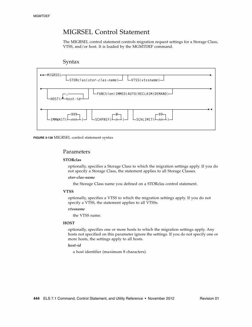
MGMTDEF
444 ELS 7.1 Command, Control Statement, and Utility Reference • November 2012 Revision 01
MIGRSEL Control StatementThe MIGRSEL control statement controls migration request settings for a Storage Class, VTSS, and/or host. It is loaded by the MGMTDEF command.
Syntax
FIGURE 3-138 MIGRSEL control statement syntax
ParametersSTORclas
optionally, specifies a Storage Class to which the migration settings apply. If you do not specify a Storage Class, the statement applies to all Storage Classes.
stor-clas-name
the Storage Class name you defined on a STORclas control statement.
VTSS
optionally, specifies a VTSS to which the migration settings apply. If you do not specify a VTSS, the statement applies to all VTSSs.
vtssname
the VTSS name.
HOST
optionally, specifies one or more hosts to which the migration settings apply. Any hosts not specified on this parameter ignore the settings. If you do not specify one or more hosts, the settings apply to all hosts.
host-id
a host identifier (maximum 8 characters).
MIGRSELSTORclas(stor-clas-name) VTSS(vtssname)
HOST( host-id, FUNCtion(IMMED|AUTO|RECLAIM|DEMAND)
IMMWAIT( nnn999
) SCHPREF( n0
) SCHLIMIT( nn99
)
MGMTDEF
Revision 01 Chapter 3 HSC and VTCS Commands and Control Statements 445
FUNCtion
optionally, specifies the type of migration to which the settings apply:
IMMED
migrations resulting from either of the following:
■ MGMTclas IMMEDmig(KEEP)
■ MGMTclas IMMEDmig(DELETE)
AUTO
automatic migrate to threshold migration processing.
RECLAIM
migrations resulting from MVC DRAIN or RECLAIM requests.
DEMAND
migrations resulting from a MIGRATE command or utility (demand migrations).
IMMWAIT
optionally, makes the MIGRSEL rule sensitive to the state of the current immediate migration work load. The specified value provides an immediate migration wait time or age, in minutes, that this MIGRSEL migration rule will apply to. This value is compared against the amount of time VTVs have been waiting for immediate migration to a particular storage class. If the amount of time (minutes) that VTVs have been waiting is less than or equal to the IMMWAIT value the MIGRSEL rule will apply.
nnn
the immediate migration wait time or age, in minutes. Valid values are 0 to 999. The default is 999.
■ The default value of 999 makes the rule apply to all VTV wait times.
■ A value of zero is used for applying MIGRSEL rules if immediate migration is not active.
SCHPREF
optionally, preferences automatic and immediate migration per storage class. MIGRSEL VTSS and HOST allow you to specify the VTSS and host to which the preferencing applies.
n
the preferencing value. Valid values are 0 to 9. The default is 0.
■ Higher values can produce quicker migration times, but may not optimize MVC usage.
■ Lower values may produce slower migration times, but may optimize MVC usage.
The MIGRSEL SCHPREF setting may be affected by the number of RTDs available, the SCHLIMIT setting, and the GLOBAL MAXMIG parameter for the VTSS.
MGMTDEF
446 ELS 7.1 Command, Control Statement, and Utility Reference • November 2012 Revision 01
SCHLIMIT
optionally, de-preferences migration per Storage Class.
nn
the preferencing value. Valid values are 0 to 99. The default is 99, which indicates no limit, up to the VTSS MAXMIG value.
Lower values de-preference migration, and you can specify automatic, immediate, demand, and reclaim migrates. Lower values can do the following:
■ Optimize MVC usage.
■ Preference migration to other Storage Classes.
■ Limit migration to keep RTDs available for auto recalls.
■ Reduce MVC swapping when workloads change.
For auto and immediate migration processing, MIGRSEL SCHLIMIT de-preferences migration for the VTSS to storage class relationship. This comparison is not global and only effects requests driven by the individual VTCS host.
For demand migration requests, MIGRSEL SCHLIMIT will cause the request to be held if the scheduling of it would cause the number of globally active migration requests on the VTSS that satisfy the same FUNCTION and STORCLAS selection criteria to be exceeded. The migration requests will be released and an MVC picked once the constraint subsides.
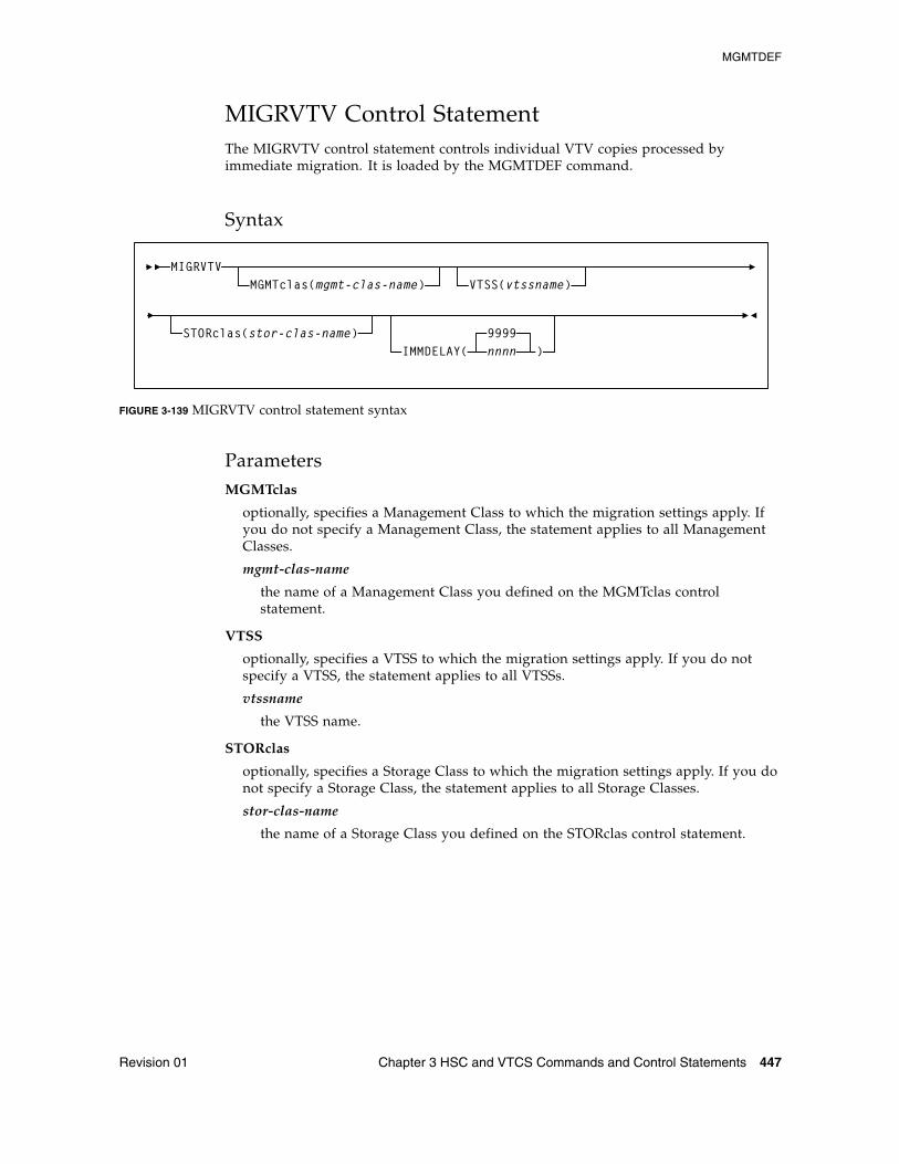
MGMTDEF
Revision 01 Chapter 3 HSC and VTCS Commands and Control Statements 447
MIGRVTV Control StatementThe MIGRVTV control statement controls individual VTV copies processed by immediate migration. It is loaded by the MGMTDEF command.
Syntax
FIGURE 3-139 MIGRVTV control statement syntax
ParametersMGMTclas
optionally, specifies a Management Class to which the migration settings apply. If you do not specify a Management Class, the statement applies to all Management Classes.
mgmt-clas-name
the name of a Management Class you defined on the MGMTclas control statement.
VTSS
optionally, specifies a VTSS to which the migration settings apply. If you do not specify a VTSS, the statement applies to all VTSSs.
vtssname
the VTSS name.
STORclas
optionally, specifies a Storage Class to which the migration settings apply. If you do not specify a Storage Class, the statement applies to all Storage Classes.
stor-clas-name
the name of a Storage Class you defined on the STORclas control statement.
MIGRVTV
STORclas(stor-clas-name)
VTSS(vtssname)MGMTclas(mgmt-clas-name)
IMMDELAY(9999nnnn )
MGMTDEF
448 ELS 7.1 Command, Control Statement, and Utility Reference • November 2012 Revision 01
IMMDELAY
optionally, specifies the immediate migration delay time; the amount of time after VTV dismount that the migration should be queued for action.
This allows VTVs used in multi-step jobs to remain resident for a specified time before being processed for migration.
nnnn
the immediate migration delay time in minutes. Valid values are 0 to 9999 (the default).
■ If IMMDELAY=9999 then immediate migration does not occur. Migration and deletion is handled via auto/command migration.
When this value is specified, MIGRSEL and MIGRVTV have no influence on migration control.
■ If IMMDELAY=0 then immediate migration is scheduled immediately.
■ If IMMDELAY is less than 9999 and DISCARD is greater than IMMDELAY then immediate migration occurs and deletion is deferred to auto/command migration.
■ If IMMDELAY is less than 9999 and DISCARD is less than or equal to IMMDELAY then immediate migration and immediate deletion occur together.
■ If auto migration encounters a VTV that has passed its DISCARD time, the VTV is moved to the front of the migration queue, and it will be processed first.
Note – See “MGMTclas Control Statement” on page 433 for information about the DISCARD parameter.
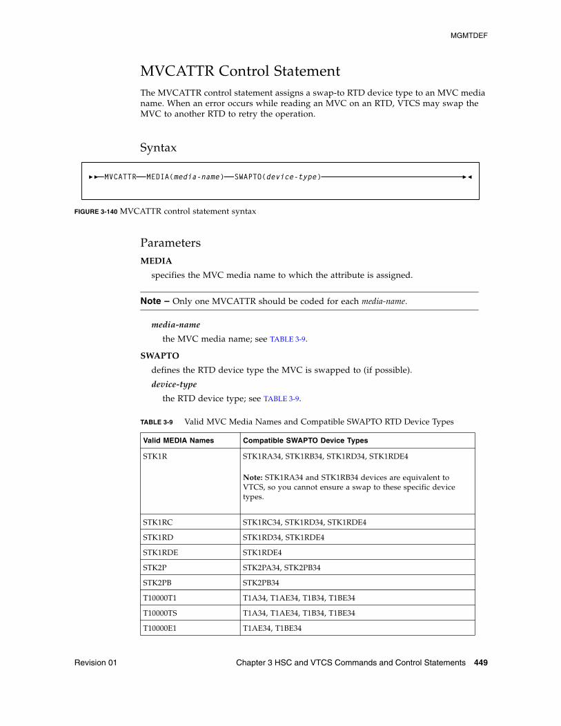
MGMTDEF
Revision 01 Chapter 3 HSC and VTCS Commands and Control Statements 449
MVCATTR Control StatementThe MVCATTR control statement assigns a swap-to RTD device type to an MVC media name. When an error occurs while reading an MVC on an RTD, VTCS may swap the MVC to another RTD to retry the operation.
Syntax
FIGURE 3-140 MVCATTR control statement syntax
ParametersMEDIA
specifies the MVC media name to which the attribute is assigned.
Note – Only one MVCATTR should be coded for each media-name.
media-name
the MVC media name; see TABLE 3-9.
SWAPTO
defines the RTD device type the MVC is swapped to (if possible).
device-type
the RTD device type; see TABLE 3-9.
TABLE 3-9 Valid MVC Media Names and Compatible SWAPTO RTD Device Types
Valid MEDIA Names Compatible SWAPTO Device Types
STK1R STK1RA34, STK1RB34, STK1RD34, STK1RDE4
Note: STK1RA34 and STK1RB34 devices are equivalent to VTCS, so you cannot ensure a swap to these specific device types.
STK1RC STK1RC34, STK1RD34, STK1RDE4
STK1RD STK1RD34, STK1RDE4
STK1RDE STK1RDE4
STK2P STK2PA34, STK2PB34
STK2PB STK2PB34
T10000T1 T1A34, T1AE34, T1B34, T1BE34
T10000TS T1A34, T1AE34, T1B34, T1BE34
T10000E1 T1AE34, T1BE34
MVCATTR MEDIA(media-name) SWAPTO(device-type)
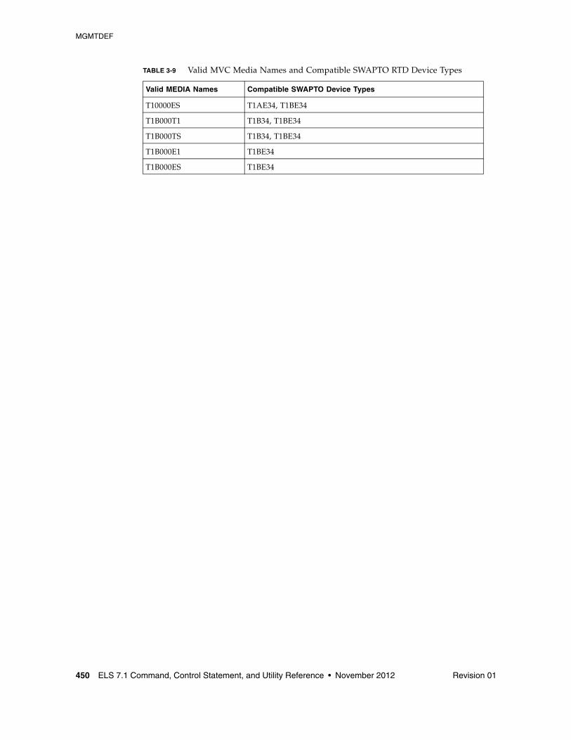
MGMTDEF
450 ELS 7.1 Command, Control Statement, and Utility Reference • November 2012 Revision 01
T10000ES T1AE34, T1BE34
T1B000T1 T1B34, T1BE34
T1B000TS T1B34, T1BE34
T1B000E1 T1BE34
T1B000ES T1BE34
TABLE 3-9 Valid MVC Media Names and Compatible SWAPTO RTD Device Types
Valid MEDIA Names Compatible SWAPTO Device Types
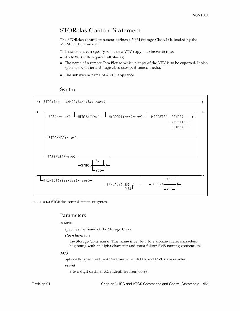
MGMTDEF
Revision 01 Chapter 3 HSC and VTCS Commands and Control Statements 451
STORclas Control StatementThe STORclas control statement defines a VSM Storage Class. It is loaded by the MGMTDEF command.
This statement can specify whether a VTV copy is to be written to:
■ An MVC (with required attributes)
■ The name of a remote TapePlex to which a copy of the VTV is to be exported. It also specifies whether a storage class uses partitioned media.
■ The subsystem name of a VLE appliance.
Syntax
FIGURE 3-141 STORclas control statement syntax
ParametersNAME
specifies the name of the Storage Class.
stor-clas-name
the Storage Class name. This name must be 1 to 8 alphanumeric characters beginning with an alpha character and must follow SMS naming conventions.
ACS
optionally, specifies the ACSs from which RTDs and MVCs are selected.
acs-id
a two digit decimal ACS identifier from 00-99.
STORclas NAME(stor-clas-name)
MIGRATE( SENDERRECEIVEREITHER
)MVCPOOL(poolname)MEDIA(list)
FROMLST(vtss-list-name)
TAPEPLEX(name)
ACS(acs-id)
STORMNGR(name)
SYNC(NO
YES
)
DEDUP(NO
YES
)INPLACE( NO )YES
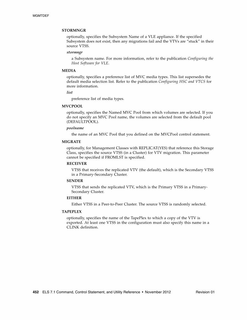
MGMTDEF
452 ELS 7.1 Command, Control Statement, and Utility Reference • November 2012 Revision 01
STORMNGR
optionally, specifies the Subsystem Name of a VLE appliance. If the specified Subsystem does not exist, then any migrations fail and the VTVs are “stuck” in their source VTSS.
stormngr
a Subsystem name. For more information, refer to the publication Configuring the Host Software for VLE.
MEDIA
optionally, specifies a preference list of MVC media types. This list supersedes the default media selection list. Refer to the publication Configuring HSC and VTCS for more information.
list
preference list of media types.
MVCPOOL
optionally, specifies the Named MVC Pool from which volumes are selected. If you do not specify an MVC Pool name, the volumes are selected from the default pool (DEFAULTPOOL).
poolname
the name of an MVC Pool that you defined on the MVCPool control statement.
MIGRATE
optionally, for Management Classes with REPLICAT(YES) that reference this Storage Class, specifies the source VTSS (in a Cluster) for VTV migration. This parameter cannot be specified if FROMLST is specified.
RECEIVER
VTSS that receives the replicated VTV (the default), which is the Secondary VTSS in a Primary-Secondary Cluster.
SENDER
VTSS that sends the replicated VTV, which is the Primary VTSS in a Primary-Secondary Cluster.
EITHER
Either VTSS in a Peer-to-Peer Cluster. The source VTSS is randomly selected.
TAPEPLEX
optionally, specifies the name of the TapePlex to which a copy of the VTV is exported. At least one VTSS in the configuration must also specify this name in a CLINK definition.
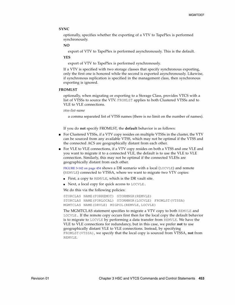
MGMTDEF
Revision 01 Chapter 3 HSC and VTCS Commands and Control Statements 453
SYNC
optionally, specifies whether the exporting of a VTV to TapePlex is performed synchronously.
NO
export of VTV to TapePlex is performed asynchronously. This is the default.
YES
export of VTV to TapePlex is performed synchronously.
If a VTV is specified with two storage classes that specify synchronous exporting, only the first one is honored while the second is exported asynchronously. Likewise, if synchronous replication is specified in the management class, then synchronous exporting is ignored.
FROMLST
optionally, when migrating or exporting to a Storage Class, provides VTCS with a list of VTSSs to source the VTV. FROMLST applies to both Clustered VTSSs and to VLE to VLE connections.
vtss-list-name
a comma separated list of VTSS names (there is no limit on the number of names).
If you do not specify FROMLST, the default behavior is as follows:
■ For Clustered VTSSs, if a VTV copy resides on multiple VTSSs in the cluster, the VTV can be sourced from any available VTSS, which may not be optimal if the VTSS and the connected ACS are geographically distant from each other.
■ For VLE to VLE connections, if a VTV copy resides on both a VTSS and one VLE and you want to migrate it to a connected VLE, the default is to use the VLE to VLE connection. Similarly, this may not be optimal if the connected VLESs are geographically distant from each other.
FIGURE 3-142 on page 454 shows a DR scenario with a local (LOCVLE) and remote (REMVLE) connected to VTSSA, where we want to migrate two VTV copies:
■ First, a copy to REMVLE, which is the DR vault site.
■ Next, a local copy for quick access to LOCVLE.
We do this via the following policies:
STORCLAS NAME(FORREMOT) STORMNGR(REMVLE)STORCLAS NAME(FORLOCAL) STORMNGR(LOCVLE) FROMLST(VTSSA)MGMTCLAS NAME(DRVLE) MIGPOL(REMVLE,LOCVLE)
The MGMTCLAS statement specifies to migrate a VTV copy to both REMVLE and LOCVLE. If the remote copy occurs first then for the local copy the default behavior is to migrate to LOCVLE by performing a data transfer from REMVLE. We have the VLE to VLE connections for redundancy, but in this case, we prefer not to use geographically distant VLE to VLE connections. Instead, by specifying FROMLST(VTSSA), we specify that the local copy is sourced from VTSSA, not from REMVLE.
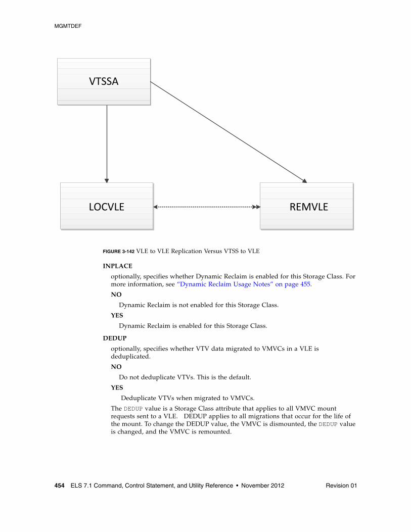
MGMTDEF
454 ELS 7.1 Command, Control Statement, and Utility Reference • November 2012 Revision 01
FIGURE 3-142 VLE to VLE Replication Versus VTSS to VLE
INPLACE
optionally, specifies whether Dynamic Reclaim is enabled for this Storage Class. For more information, see “Dynamic Reclaim Usage Notes” on page 455.
NO
Dynamic Reclaim is not enabled for this Storage Class.
YES
Dynamic Reclaim is enabled for this Storage Class.
DEDUP
optionally, specifies whether VTV data migrated to VMVCs in a VLE is deduplicated.
NO
Do not deduplicate VTVs. This is the default.
YES
Deduplicate VTVs when migrated to VMVCs.
The DEDUP value is a Storage Class attribute that applies to all VMVC mount requests sent to a VLE. DEDUP applies to all migrations that occur for the life of the mount. To change the DEDUP value, the VMVC is dismounted, the DEDUP value is changed, and the VMVC is remounted.
VTSSA
LOCVLE REMVLE
MGMTDEF
Revision 01 Chapter 3 HSC and VTCS Commands and Control Statements 455
Dynamic Reclaim Usage Notes■ Dynamic reclaim only applies to T10000B and above media (full and full encrypted
only) that have been formatted by T10000 drives capable of creating partitions. Dynamic reclaim requires an H level CDS, VSM5 microcode D02.11.16.00 or later, T10KB firmware 1.41a.209 or later.
■ You can specify Dynamic Reclaim policies at the global, system wide level or on a Storage Class and MVC pool level. The global policies are set by the VTCS CONFIG RECLAIM statement:
■ The INPLACE(YES/NO) parameter controls the usage of dynamic reclaim. Its setting can either be explicitly specified upon the STORCLAS statement or inherited from the RECLAIM statement in the VTCS configuration. The default is INPLACE=NO. The setting that is derived for a Storage Class does not force usage of media formatted in either mode. So it is quite acceptable to use with drives or media that do not support partitioning. Also, any media written in a different mode will continue to be a migration target. This will avoid the need to actively manage the transition when dynamic reclaim is activated. Its effect is to cause new media allocated to the Storage Class to be formatted and written in either standard (INPLACE=NO) or partitioned (INPLACE=YES) mode. The switch can only occur when media is empty.
If a hard switch-over is required between standard and dynamic reclaim, then a lengthy process is required. Parameters setting (for example, MEDIA on the STORCLAS statement) will need to be used. MVCs will need to be either taken out of the MVC pool or set into a read-only state by using MVCMAINT. Finally, MVCs formatted in the wrong mode would need to be drained.
■ The INPTHRSH parameter specifies the fragmentation level that makes partitioned MVCs eligible for Dynamic reclaim. When a partitioned MVC’s fragmentation falls between the INPTHRSH value and the THRESH value, it first becomes eligible for Dynamic Reclaim. If no space is freed on the initial reclaim attempt, the reclaim will be retried when the fragmentation level has risen significantly. Should the fragmentation level reach the standard THRESHOLD be reached, then a fall-back method of moving VTVs will be performed. This will still be less than for standard format media.
■ The VTCS CONFIG RECLAIM statements provide the global defaults for the system. These can be overridden at the Storage Class and MVCPool level:
■ The STORCLAS INPLACE parameter specifies whether or not Dynamic Reclaim is enabled for this Storage Class. Note that initially, you may want to specify INPLACE(NO) in the VTCS CONFIG RECLAIM statement and INPLACE(YES) for selected Storage Classes so you can evaluate the effects of Dynamic Reclaim. Subsequently, if you decide you want Dynamic Reclaim to apply to all eligible media, you can specify INPLACE(YES) on the VTCS CONFIG RECLAIM statement.
■ The INPTHRSH parameter on the POOLPARM statement can be used to set a Dynamic Reclaim threshold specifically for this set of MVC media. This can be used if you wish to treat some MVCs differently from the VTCS CONFIG RECLAIM defaults.
MGMTDEF
456 ELS 7.1 Command, Control Statement, and Utility Reference • November 2012 Revision 01
■ Dynamic Reclaim can be disabled either globally at a system wide level or at the Storage Class level:
■ To disable Dynamic reclaim globally specify INPLACE(NO) in the VTCS CONFIG RECLAIM statement and ensure that any Storage Class definition does not override this to YES.
■ To disable Dynamic for one or more Storage Classes change INPLACE to NO in the Storage Class policy statements.
Note – Any MVCs that are currently in use for migration will continue in partitioned format. If you wish to stop active MVCs from further migrates then use the MVCMAINT utility to mark them as read-only. Once the partitioned volumes are empty they will be automatically re-used in non-partitioned mode. An MVC will become empty either when all VTVs have expired or the MVC has been DRAINed.
Note – ■ The CDS must be at H level and dynamic reclaim support must be enabled on the
CONFIg RECLAIM configuration statement before any STORCLAS INPLACE parameter is accepted or displayed.
■ Only T10000B media is supported for dynamic reclaim. INPLACE is only valid if the storage class has access to this media. Sport cartridges are not supported in partitioned format.
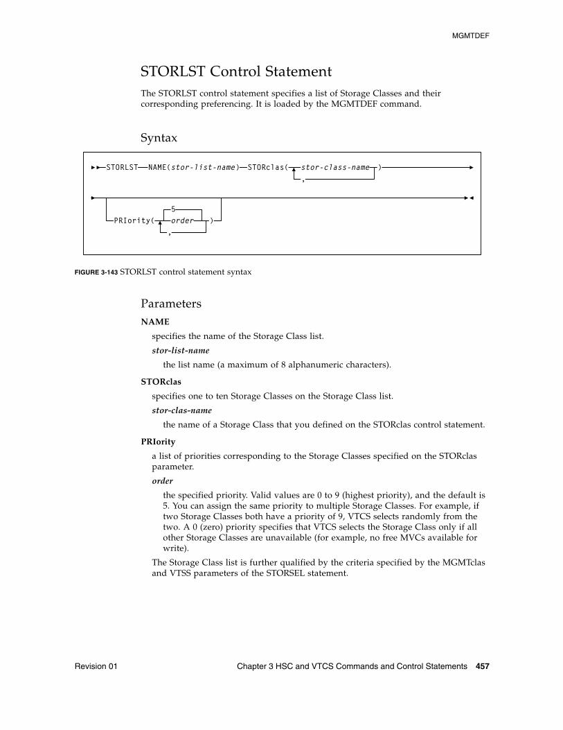
MGMTDEF
Revision 01 Chapter 3 HSC and VTCS Commands and Control Statements 457
STORLST Control StatementThe STORLST control statement specifies a list of Storage Classes and their corresponding preferencing. It is loaded by the MGMTDEF command.
Syntax
FIGURE 3-143 STORLST control statement syntax
ParametersNAME
specifies the name of the Storage Class list.
stor-list-name
the list name (a maximum of 8 alphanumeric characters).
STORclas
specifies one to ten Storage Classes on the Storage Class list.
stor-clas-name
the name of a Storage Class that you defined on the STORclas control statement.
PRIority
a list of priorities corresponding to the Storage Classes specified on the STORclas parameter.
order
the specified priority. Valid values are 0 to 9 (highest priority), and the default is 5. You can assign the same priority to multiple Storage Classes. For example, if two Storage Classes both have a priority of 9, VTCS selects randomly from the two. A 0 (zero) priority specifies that VTCS selects the Storage Class only if all other Storage Classes are unavailable (for example, no free MVCs available for write).
The Storage Class list is further qualified by the criteria specified by the MGMTclas and VTSS parameters of the STORSEL statement.
STORLST NAME(stor-list-name) STORclas( stor-class-name )
,PRIority(
5order )
,
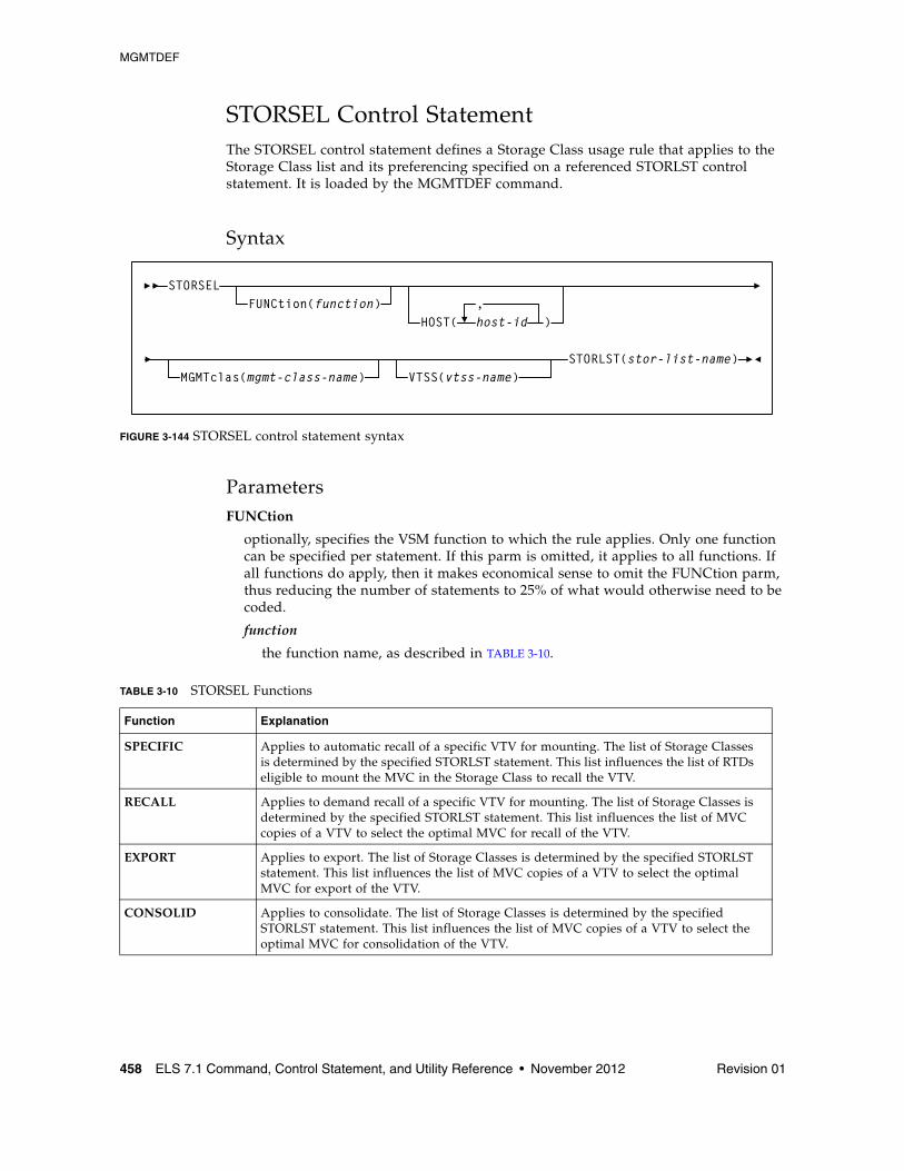
MGMTDEF
458 ELS 7.1 Command, Control Statement, and Utility Reference • November 2012 Revision 01
STORSEL Control StatementThe STORSEL control statement defines a Storage Class usage rule that applies to the Storage Class list and its preferencing specified on a referenced STORLST control statement. It is loaded by the MGMTDEF command.
Syntax
FIGURE 3-144 STORSEL control statement syntax
ParametersFUNCtion
optionally, specifies the VSM function to which the rule applies. Only one function can be specified per statement. If this parm is omitted, it applies to all functions. If all functions do apply, then it makes economical sense to omit the FUNCtion parm, thus reducing the number of statements to 25% of what would otherwise need to be coded.
function
the function name, as described in TABLE 3-10.
TABLE 3-10 STORSEL Functions
Function Explanation
SPECIFIC Applies to automatic recall of a specific VTV for mounting. The list of Storage Classes is determined by the specified STORLST statement. This list influences the list of RTDs eligible to mount the MVC in the Storage Class to recall the VTV.
RECALL Applies to demand recall of a specific VTV for mounting. The list of Storage Classes is determined by the specified STORLST statement. This list influences the list of MVC copies of a VTV to select the optimal MVC for recall of the VTV.
EXPORT Applies to export. The list of Storage Classes is determined by the specified STORLST statement. This list influences the list of MVC copies of a VTV to select the optimal MVC for export of the VTV.
CONSOLID Applies to consolidate. The list of Storage Classes is determined by the specified STORLST statement. This list influences the list of MVC copies of a VTV to select the optimal MVC for consolidation of the VTV.
STORSELFUNCtion(function)
HOST( host-id ),
MGMTclas(mgmt-class-name) VTSS(vtss-name)STORLST(stor-list-name)
MGMTDEF
Revision 01 Chapter 3 HSC and VTCS Commands and Control Statements 459
HOST
optionally, specifies one or more hosts to which the rule applies. If this parameter is used, any hosts not specified on this parameter ignore the rule. If the parameters is not used the statement applies to all hosts.
host-id
a host identifier (maximum 8 characters).
MGMTclas
optionally, specifies a Management Class.
mgmt-class-name
the name of a Management Class that you defined on the MGMTclas control statement.
VTSS
optionally, specifies a VTSS.
vtss-name
the VTSS name, as follows:
■ For automatic recalls, the VTSS where the recall is performed.
■ For all other functions, the VTSS where the VTV previously resided. This may be determined from the VTSS value shown in the Display VTV output.
STORLST
specifies a list of Storage Classes and their corresponding preferencing.
stor-list-name
the name of a Storage Class list that you defined on the STORLST control statement.
Note – The Storage Class list specified on the STORLST parameter is further qualified by the criteria specified by the MGMTclas and VTSS parameters.
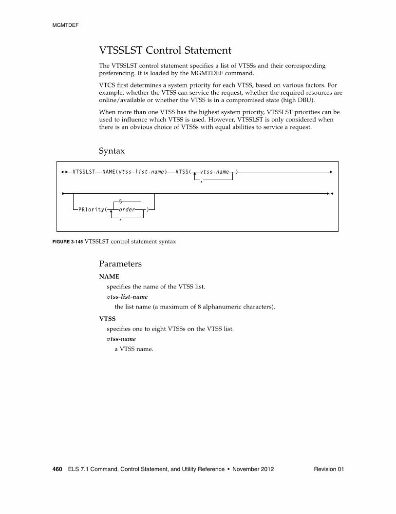
MGMTDEF
460 ELS 7.1 Command, Control Statement, and Utility Reference • November 2012 Revision 01
VTSSLST Control StatementThe VTSSLST control statement specifies a list of VTSSs and their corresponding preferencing. It is loaded by the MGMTDEF command.
VTCS first determines a system priority for each VTSS, based on various factors. For example, whether the VTSS can service the request, whether the required resources are online/available or whether the VTSS is in a compromised state (high DBU).
When more than one VTSS has the highest system priority, VTSSLST priorities can be used to influence which VTSS is used. However, VTSSLST is only considered when there is an obvious choice of VTSSs with equal abilities to service a request.
Syntax
FIGURE 3-145 VTSSLST control statement syntax
ParametersNAME
specifies the name of the VTSS list.
vtss-list-name
the list name (a maximum of 8 alphanumeric characters).
VTSS
specifies one to eight VTSSs on the VTSS list.
vtss-name
a VTSS name.
VTSSLST NAME(vtss-list-name) VTSS( vtss-name )
PRIority( order5
,
,
)
MGMTDEF
Revision 01 Chapter 3 HSC and VTCS Commands and Control Statements 461
PRIority
optionally, lists priorities corresponding to the VTSS names specified on the VTSS parameter.
order
the specified priority. Valid values are 0 to 9 (highest priority), and the default is 5. You can assign the same priority to multiple VTSSs.
Within a set of VTSSs with the highest system priority:
■ If two or more VTSSs have the same highest VTSSLST priority, VTCS selects randomly from the two (according to factors such as DBU and VSM model).
■ A 0 (zero) priority specifies that VTCS selects the VTSS only if all other VTSSs are unavailable (for example, unavailable due to DBU > 95%, VTSS offline, or RTDs offline).
Note – The VTSS list specified on the VTSSLST parameter is further qualified by:
■ The function specified on VTSSSEL statement.
■ The criteria specified by the MGMTclas, VTSS, STORclas, and MVCpool parameters of the VTSSSEL statement.
■ Other factors such as RTD connectivity.
For example, in scratch allocation, the list of VTSSs is reduced to the VTSSs that can meet Management Class policies (such as REPLICAT(YES)). If the list of VTSSs is reduced to zero, the request fails.
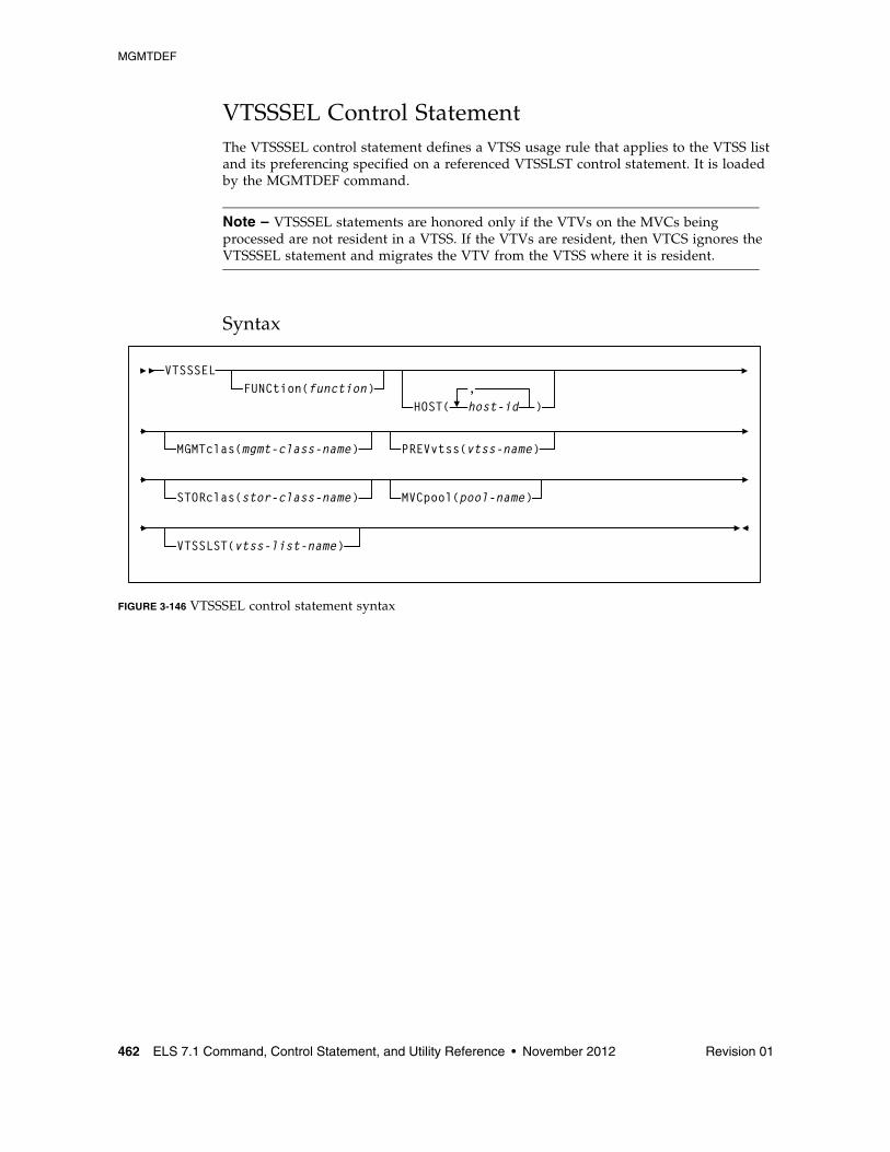
MGMTDEF
462 ELS 7.1 Command, Control Statement, and Utility Reference • November 2012 Revision 01
VTSSSEL Control StatementThe VTSSSEL control statement defines a VTSS usage rule that applies to the VTSS list and its preferencing specified on a referenced VTSSLST control statement. It is loaded by the MGMTDEF command.
Note – VTSSSEL statements are honored only if the VTVs on the MVCs being processed are not resident in a VTSS. If the VTVs are resident, then VTCS ignores the VTSSSEL statement and migrates the VTV from the VTSS where it is resident.
Syntax
FIGURE 3-146 VTSSSEL control statement syntax
VTSSSELFUNCtion(function)
HOST( host-id,
)
MGMTclas(mgmt-class-name) PREVvtss(vtss-name)
STORclas(stor-class-name) MVCpool(pool-name)
VTSSLST(vtss-list-name)
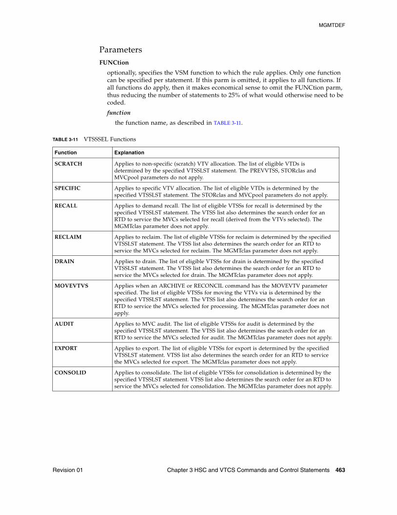
MGMTDEF
Revision 01 Chapter 3 HSC and VTCS Commands and Control Statements 463
ParametersFUNCtion
optionally, specifies the VSM function to which the rule applies. Only one function can be specified per statement. If this parm is omitted, it applies to all functions. If all functions do apply, then it makes economical sense to omit the FUNCtion parm, thus reducing the number of statements to 25% of what would otherwise need to be coded.
function
the function name, as described in TABLE 3-11.
TABLE 3-11 VTSSSEL Functions
Function Explanation
SCRATCH Applies to non-specific (scratch) VTV allocation. The list of eligible VTDs is determined by the specified VTSSLST statement. The PREVVTSS, STORclas and MVCpool parameters do not apply.
SPECIFIC Applies to specific VTV allocation. The list of eligible VTDs is determined by the specified VTSSLST statement. The STORclas and MVCpool parameters do not apply.
RECALL Applies to demand recall. The list of eligible VTSSs for recall is determined by the specified VTSSLST statement. The VTSS list also determines the search order for an RTD to service the MVCs selected for recall (derived from the VTVs selected). The MGMTclas parameter does not apply.
RECLAIM Applies to reclaim. The list of eligible VTSSs for reclaim is determined by the specified VTSSLST statement. The VTSS list also determines the search order for an RTD to service the MVCs selected for reclaim. The MGMTclas parameter does not apply.
DRAIN Applies to drain. The list of eligible VTSSs for drain is determined by the specified VTSSLST statement. The VTSS list also determines the search order for an RTD to service the MVCs selected for drain. The MGMTclas parameter does not apply.
MOVEVTVS Applies when an ARCHIVE or RECONCIL command has the MOVEVTV parameter specified. The list of eligible VTSSs for moving the VTVs via is determined by the specified VTSSLST statement. The VTSS list also determines the search order for an RTD to service the MVCs selected for processing. The MGMTclas parameter does not apply.
AUDIT Applies to MVC audit. The list of eligible VTSSs for audit is determined by the specified VTSSLST statement. The VTSS list also determines the search order for an RTD to service the MVCs selected for audit. The MGMTclas parameter does not apply.
EXPORT Applies to export. The list of eligible VTSSs for export is determined by the specified VTSSLST statement. VTSS list also determines the search order for an RTD to service the MVCs selected for export. The MGMTclas parameter does not apply.
CONSOLID Applies to consolidate. The list of eligible VTSSs for consolidation is determined by the specified VTSSLST statement. VTSS list also determines the search order for an RTD to service the MVCs selected for consolidation. The MGMTclas parameter does not apply.
MGMTDEF
464 ELS 7.1 Command, Control Statement, and Utility Reference • November 2012 Revision 01
HOST
optionally, specifies one or more hosts to which the rule applies. If this parameter is used, any hosts not specified on this parameter ignore the rule. If the parameters is not used the statement applies to all hosts.
host-id
a host identifier (maximum 8 characters).
Note – The VTSS list specified on the VTSSLST parameter is further qualified by the criteria specified by the MGMTclas, VTSS, STORclas, and MVCpool parameters.
MGMTclas
optionally, specifies a Management Class.
mgmt-class-name
the name of a Management Class that you defined on the MGMTclas control statement.
PREVvtss
optionally, specifies a VTSS where a VTV:
■ Is or resident■ Was migrated from
STORclas
optionally, specifies a Storage Class and applies only when MVCs are used to select VTSSs.
stor-clas-name
the name of a Storage Class that you defined on the STORclas control statement.
MVCpool
optionally, specifies a Named MVC Pool and applies only when MVCs are used to select VTSSs.
poolname
the name of an MVC Pool that you defined on the MVCPool control statement.
VTSSLST
optionally, specifies a list of VTSSs and their corresponding preferencing.
vtss-list-name
the name of a VTSS list that you defined on the VTSSLST control statement.
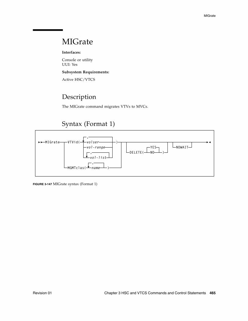
MIGrate
Revision 01 Chapter 3 HSC and VTCS Commands and Control Statements 465
MIGrateInterfaces:
Console or utilityUUI: Yes
Subsystem Requirements:
Active HSC/VTCS
DescriptionThe MIGrate command migrates VTVs to MVCs.
Syntax (Format 1)
FIGURE 3-147 MIGrate syntax (Format 1)
MIGrate VTVid(,volser )
MGMTclas(,name )
DELETE(YESNO )
NOWAITvol-range
vol-list,
MIGrate
466 ELS 7.1 Command, Control Statement, and Utility Reference • November 2012 Revision 01
Parameters (Format 1)VTVid
specifies the VTVs to migrate.
volser, vol-range, or vol-list
the volsers of one or more VTVs. You can also specify one or more ranges.
MGMTclas
specifies one or more Management Classes that determine one or more VTVs to migrate.
mgmt-class-name | mgmt-class-list
the names of one or more Management Classes that you defined on the MGMTclas control statement; for more information, see “MGMTclas Control Statement” on page 433.
Note – MGMTclas, VTVid, and DSN are mutually exclusive.
DELETE
optionally, specifies whether VSM deletes VTVs from the VTSS after migrating the VTVs.
NO
do not delete VTVs from the VTSS after migrating the VTVs.
YES
delete VTVs from the VTSS after migrating the VTVs (the default).
NOWAIT
specifies that the utility does not wait for the operation to complete and returns after the request is submitted.
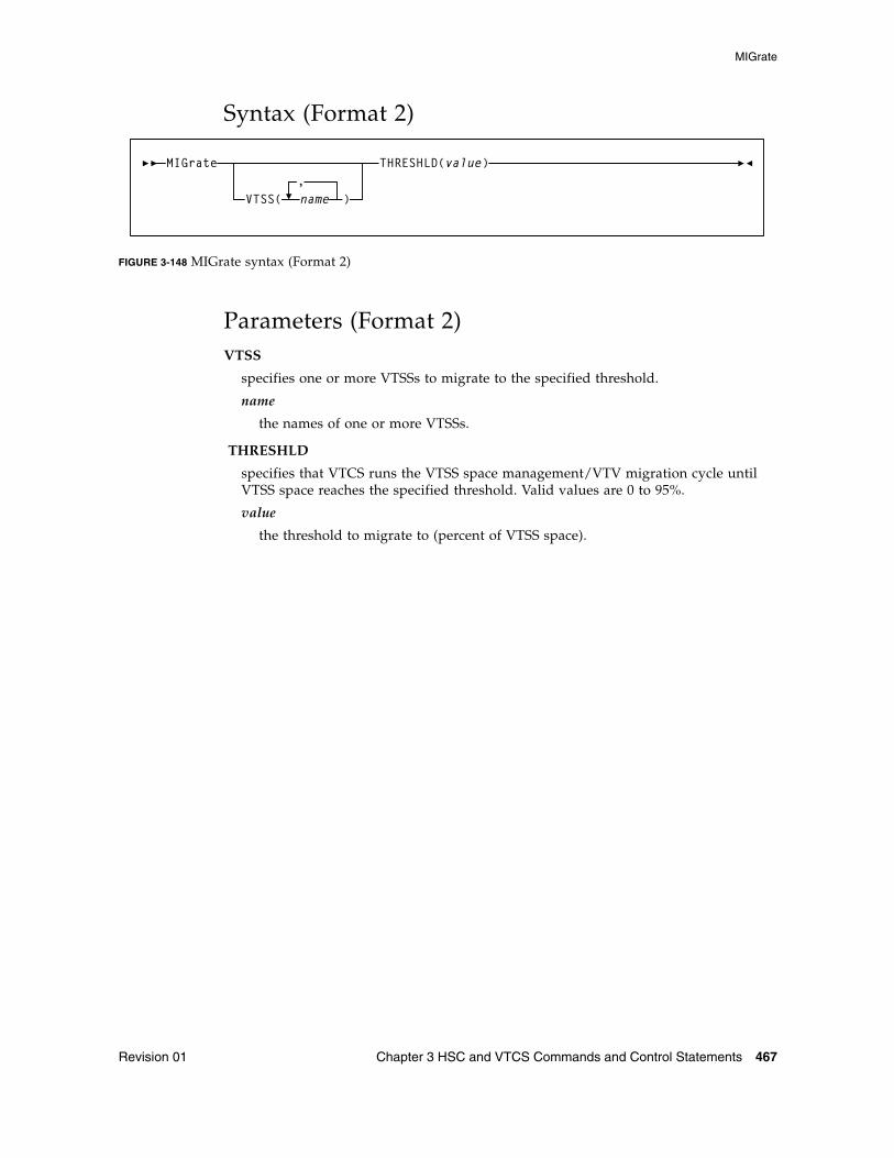
MIGrate
Revision 01 Chapter 3 HSC and VTCS Commands and Control Statements 467
Syntax (Format 2)
FIGURE 3-148 MIGrate syntax (Format 2)
Parameters (Format 2)VTSS
specifies one or more VTSSs to migrate to the specified threshold.
name
the names of one or more VTSSs.
THRESHLD
specifies that VTCS runs the VTSS space management/VTV migration cycle until VTSS space reaches the specified threshold. Valid values are 0 to 95%.
value
the threshold to migrate to (percent of VTSS space).
MIGrate
VTSS(,name )
THRESHLD(value)
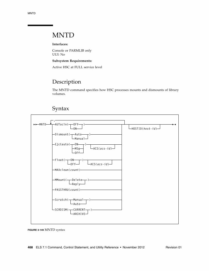
MNTD
468 ELS 7.1 Command, Control Statement, and Utility Reference • November 2012 Revision 01
MNTDInterfaces:
Console or PARMLIB onlyUUI: No
Subsystem Requirements:
Active HSC at FULL service level
DescriptionThe MNTD command specifies how HSC processes mounts and dismounts of library volumes.
Syntax
FIGURE 3-149 MNTD syntax
MNTD,AUTocln( OFf
ON)
Dismount( AutoManual
)
Ejctauto(
Float(
MAXclean(count)
MMount(
PASSTHRU(count)
Scratch(
SCRDISM(
ONMSgOFf
)
ONOFf
DeleteReply
)
ManualAuto
CURRENTARCHIVE
)
)
ACS(acs-id)
ACS(acs-id)
HOSTID(host-id)
)
MNTD
Revision 01 Chapter 3 HSC and VTCS Commands and Control Statements 469
ParametersAUtocln
controls automated transport cleaning.
OFf
disables the automated cleaning function. OFf is the initial value for the HSC.
ON
enables the following HSC cleaning functions:
■ the automated cleaning function, which detects when a transport requires cleaning and schedules the mount of a cleaning cartridge prior to the next volume mount
■ the CLean command which is used to schedule the mount of a cleaning cartridge for a specified transport. See “CLean” on page 202 for more information.
Dismount
specifies whether volumes are to be deleted automatically from the control data set when a dismount is requested in a manual mode LSM for a volume that was mounted by the robot before the LSM was modified offline.
Auto
indicates that volumes are to be automatically deleted from the control data set when a manual dismount is requested for a volume that was mounted by the robot. Auto is the initial value for the HSC.
Manual
directs the HSC to issue a message prompting the operator to decide whether the volume is to be deleted from the control data set when a manual dismount is requested for a volume that was mounted by the robot.
Setting Dismount to Manual is useful when an LSM is modified offline for only a short time. In this case, the operator can choose to not respond to the dismount message and leave the volume mounted on the transport. When the LSM is modified online the HSC re-drives the outstanding dismount request, causing the robot to dismount the volume and place it in a storage cell.
MNTD
470 ELS 7.1 Command, Control Statement, and Utility Reference • November 2012 Revision 01
EJctauto
controls automatic ejection of cleaning cartridges that have exceeded their maximum use.
In a multi-host environment, the EJctauto setting for a given ACS should be the same on all hosts. EJctauto status is not shared among the HSCs on different hosts.
ON
directs the HSC to automatically eject cleaning cartridges that have exceeded the number of times they can be used (as specified by the MNTD MAXclean or VOLATTR MAXclean parameters). ON is the initial value for the HSC.
MSg
directs the HSC to prompt the operator to either eject an over use-limit cartridge from the ACS or to keep a cleaning cartridge in the ACS.
OFf
directs the HSC to keep an over use-limit cleaning cartridge in the ACS. A message is issued displaying the cleaning cartridge’s volser and describing this action.
ACS
optionally, specifies that the EJctauto settings apply only to the specified ACS. If this parameter is omitted, EJctauto settings affect all ACSs.
acsid
indicates a decimal value from 00 to 99 that identifies the ACS. A single digit acsid can be entered.
Float
specifies whether the HSC is to select a new home cell location when it dismounts a volume that required a pass-thru when it was mounted.
In multi-host environments, the Float setting for a specific ACS should be the same on all hosts. Float status is not shared among the HSCs on different hosts.
ON
directs the HSC to select a new home cell location for the volume in the LSM where the dismount occurs (provided a cell is available). If no cells are available in the new LSM, a location is chosen in the nearest LSM with free cells or the volume can be forced to its original home cell. Setting Float to ON reduces the number of pass-thru operations. ON is the initial value for the HSC.
OFf
directs the HSC to return the volume to its original home cell location when it is dismounted.
Note – The MNTD Float OFf command is useful for remote ACS/CDS link down situations to avoid control data set integrity issues by making sure cartridges are returned to their original home cell locations. Refer to the ELS Legacy Interfaces Reference for information about remote libraries.
MNTD
Revision 01 Chapter 3 HSC and VTCS Commands and Control Statements 471
ACS
optionally, specifies that the Float setting applies only to this ACS. If the ACS parameter is omitted, the Float setting affects all ACSs.
acsid
a decimal value from 00 to 99 that identifies the ACS. A single digit acsid can be entered.
MAXclean
specifies the maximum number of times a cleaning cartridge is to be used.
Note – ■ The EJctauto setting in effect for the ACS controls how cleaning cartridges are
handled when they exceed their maximum use.
■ In a multi-host environment, the MAXclean setting should be the same on all hosts. The MAXclean value is not shared among the HSCs on different hosts.
■ Follow the cartridge vendor’s recommendations for the number of times a cleaning cartridge should be used.
count
a decimal value, in the range from 1 through 32767. The initial value for the HSC is 100.
Note – ■ The count value applies to each cleaning cartridge in the library.
■ When a cleaning cartridge is used count number of times, it is not selected if there are cleaning cartridges compatible with the transports in the ACS that have been used less than count number of times. Over use-limit cleaning cartridges may be automatically ejected, depending on the MNTD EJctauto setting.
MMount
specifies whether or not a mount message is issued during manual mode that allows the operator to retain a manually mounted volume in the control data set.
Delete
generates a manual mode mount message which prompts the operator to respond “D” to delete the volume from the control data set, or “I” to ignore the mount request. Delete is the initial value of the HSC.
Reply
generates a manual mode mount message which prompts the operator to reply “M” to DOM the message and retain the volume in the control data set, or “I” to ignore the mount request.
Note – When MNTD MMount(Reply) is specified, the HSC action for a manual mode dismount is determined by the MNTD Dismount setting.
MNTD
472 ELS 7.1 Command, Control Statement, and Utility Reference • November 2012 Revision 01
PASSTHRU
specifies the maximum number of pass-thrus that can occur to allow cartridge archival if SCRDISM(ARCHIVE) is specified.
count
the maximum number of pass-thrus allowed for archival of cartridges. Allowable values are decimal in the range from 1 through 99. The initial value of the HSC is 1.
Scratch
determines how a scratch volume is selected to satisfy a scratch mount request for a manual mode LSM.
Manual
specifies that the operator must select a scratch volume when a scratch mount is requested for a manual mode LSM. Manual is the initial value for the HSC.
Auto
directs the HSC to select a scratch volume when a scratch mount is requested for a manual mode LSM. If Scratch is set to Auto, the HSC manual mount message indicates the cartridge VOLSER and cell location as if it were a request for a specific volume.
SCRDISM
specifies whether or not scratch volumes mounted in a 9310 or 9360 LSM are to be automatically archived to a larger or slower LSM upon dismount.
Note – 9740 LSMs cannot attach to any other type of LSM. Thus, SCRDISM does not affect mounts in ACSs containing 9740s.
CURRENT
indicates that scratch volumes mounted in a 9310 or 9360 LSM are to be dismounted according to the MNTD Float parameter setting. CURRENT is the initial value for the HSC.
ARCHIVE
indicates that scratch volumes mounted in a 9310 or 9360 LSM are to be archived into a larger or slower storage device. Archival occurs only if the number of pass-thrus does not exceed PASSTHRU. Archival of a cartridge can occur
■ from a 9360 to either a 9310 or a 4410
■ from a 9310 to a 4410.
Note – ■ SCRDISM(ARCHIVE) overrides the MNTD Float parameter setting. ■ The ARCHIVE parameter does not affect dismounts in ACSs containing 9740 LSMs.
MNTD
Revision 01 Chapter 3 HSC and VTCS Commands and Control Statements 473
HOSTID
optionally, identifies the host associated with the MNTD command. This allows you to restrict certain startup options to a specific host.
If this parameter is not specified, the command is executed by each host that accesses PARMLIB.
host-id
the host ID (the SMF system identifier for JES).
Note – If the host-id does not match the host executing the command, a message is issued and the command is not processed.
MODify
474 ELS 7.1 Command, Control Statement, and Utility Reference • November 2012 Revision 01
MODifyInterfaces:
Console or PARMLIB onlyUUI: No
Subsystem Requirements:
Active HSC at FULL service level
DescriptionThe MODify command performs the following functions:
■ modifies a CAP or an LSM online or offline to all hosts, independent of the issuing host
■ starts dynamic hardware reconfiguration for a SL3000 or a SL8500 library
■ adds, deletes, or updates an SL3000 or SL8500 ACS definition in the CDS that was preallocated using the SLILIBRY FUTRACS parameter
Dynamic hardware reconfiguration for the SL3000 and SL8500 libraries represents the portion of Near Continuous Operation (NCO) that allows you to dynamically add or delete drives and expansion panels.
Enter the MODify CONFIG command to activate dynamic hardware reconfiguration.
Refer to the publication Configuring HSC and VTCS for more information about Near Continuous Operation and dynamic hardware reconfiguration.
Warning – Before you enter MODify CONFIG, perform a backup of the CDS.
Note – It is possible to remove LSMs from the SL8500 configuration without performing a LIBGEN, MERGEcds, and recycle of the HSC. However, this operation requires assistance from Oracle StorageTek Support.
The MODify command differs from the Vary command in the following ways:
■ The MODify command places a specified CAP or LSM online/offline globally to all hosts.
■ A CAP that is modified offline cannot be used for eject/enter processing.
■ An LSM that is modified offline must be operated in manual mode.
■ A manual mode LSM is still available for diagnostic requests from a host.
■ The Vary command places a host station online/offline to an LMU.
■ A host that has all of its LMU stations varied offline is disconnected from all LSMs attached to the LMU.
■ An LSM can still be used to semi-automate cartridge handling for a disconnected host by issuing HSC commands from a connected host.
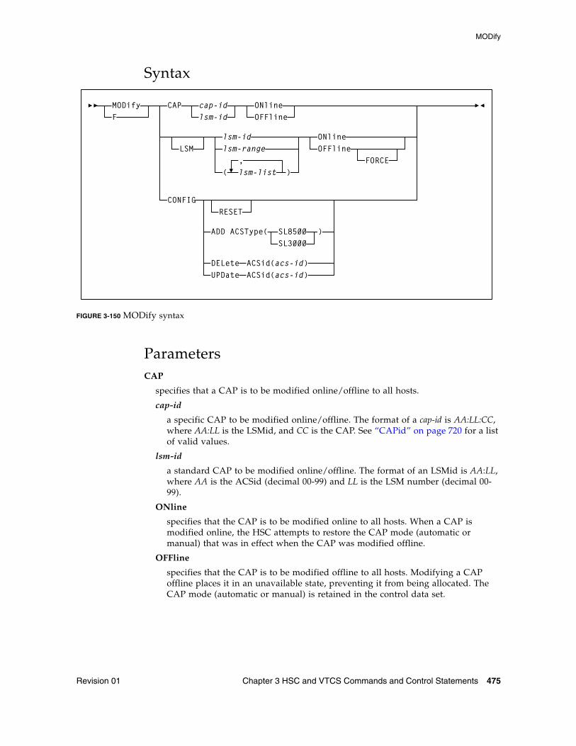
MODify
Revision 01 Chapter 3 HSC and VTCS Commands and Control Statements 475
Syntax
FIGURE 3-150 MODify syntax
ParametersCAP
specifies that a CAP is to be modified online/offline to all hosts.
cap-id
a specific CAP to be modified online/offline. The format of a cap-id is AA:LL:CC, where AA:LL is the LSMid, and CC is the CAP. See “CAPid” on page 720 for a list of valid values.
lsm-id
a standard CAP to be modified online/offline. The format of an LSMid is AA:LL, where AA is the ACSid (decimal 00-99) and LL is the LSM number (decimal 00-99).
ONline
specifies that the CAP is to be modified online to all hosts. When a CAP is modified online, the HSC attempts to restore the CAP mode (automatic or manual) that was in effect when the CAP was modified offline.
OFFline
specifies that the CAP is to be modified offline to all hosts. Modifying a CAP offline places it in an unavailable state, preventing it from being allocated. The CAP mode (automatic or manual) is retained in the control data set.
MODify
lsm-range
)(,lsm-list
F
CONFIGRESET
CAP cap-idlsm-id
ONlineOFFline
LSMlsm-id ONline
OFFlineFORCE
ADD ACSType(SL3000SL8500 )
DELete ACSid(acs-id)UPDate ACSid(acs-id)
MODify
476 ELS 7.1 Command, Control Statement, and Utility Reference • November 2012 Revision 01
Caution – ■ Be sure to specify the CAP parameter to modify a CAP offline. If the LSM is online,
and you specify an lsm-id to modify the CAP offline but do not specify the CAP parameter, the LSM will be modified offline.
■ Use this command only in an emergency. Make sure the CAP is not being used by another active process. Issuing the MODify command on an active CAP may cause the process using the CAP to receive errors.
LSM
optionally, indicates that one or more LSMs are to be modified online/offline to all hosts.
lsm-id or lsm-range or lsm-list
one or more LSMs to be modified online/offline to all hosts. Each lsm-list element may be either a single LSMid or an LSMid range. The elements in a list must be separated by commas or blanks, and the entire list must be enclosed in parentheses.
The format of an LSMid is AA:LL, where AA is the ACSid (decimal 00-99) and LL is the LSM number (decimal 00-99).
ONline
specifies that the LSMs are to be modified online to all hosts. Modifying an LSM online places it in automatic mode. When an LSM is modified online, CAPs that were in auto mode before the LSM was modified offline are again placed in auto mode (unlocked state).
OFFline
specifies that the LSMs are to be modified offline to all hosts. Modifying an LSM offline places it in manual mode. CAPs in a manual mode LSM cannot be used, but the auto/manual state of each CAP is retained.
FORCE
specifies that the LSM(s) is to be modified offline immediately. FORCE is only used with the OFFline parameter to modify an LSM offline.
CONFIG
(no parameters)
optionally, initiates the Near Continuous Operation (NCO) for hardware reconfiguration process for SL3000 and SL8500 libraries. This is a system wide change which propagates to all hosts connected to the CDS.
Note – Refer to the publication Configuring HSC and VTCS for more information about Near Continuous Operation and dynamic hardware reconfiguration.
Warning – Before you enter MODify CONFIG, perform a backup of the CDS.
MODify
Revision 01 Chapter 3 HSC and VTCS Commands and Control Statements 477
ADD
initiates an NCO configuration change to add one ACS to the HSC configuration. The ACS added takes on the library characteristics of the library type specified by the ACSType parameter. The number of ACSs that can be added is limited by the number specified on the SLILIBRY FUTRACS parameter.
ACSType
specifies the library type to use for the configuration change. Options are SL3000 or SL8500.
DELete
initiates an NCO configuration change to delete the disconnected ACS specified in the ACSid(acs-id) parameter.
If the ACSid is the highest numbered ACS, the ACS is entirely deleted and can be re-added as a different ACSType. If the ACSid is not the highest numbered ACS, the ACS becomes a place holder with a status of unallocated and can be re-added only as the same ACSType.
RESET
resets internal flags for any host that may be failing as a hardware configuration is being performed. When the failing host comes back up, the new hardware configuration is automatically recognized and implemented.
A reset is intended only to reset a failing host and does not initiate the actual dynamic hardware reconfiguration operation. The MODify CONFIG command, without the RESET parameter, must be run separately to invoke dynamic hardware reconfiguration.
UPDate
initiates an NCO configuration change to update the ACS configuration specified in the ACSid(acs-id) parameter. This is not a system wide change and does not propagate to other hosts connected to the CDS. If a system wide update is needed, enter the MODify CONFIG command minus any additional parameters
The ADD and DELete parameters are only valid if the FUTRACS parameter was specified in the SLILIBRY macro during the LIBGEN process.
Mount
478 ELS 7.1 Command, Control Statement, and Utility Reference • November 2012 Revision 01
MountInterfaces:
Console or utilityUUI: Yes
Subsystem Requirements:
Active HSC at FULL service level
DescriptionThe Mount command mounts a scratch or specific volume on a transport, or mounts a VTV on a VTD and optionally assigns a Management Class to that VTV.
Note – Do not use this command to manage a mount that appears to have been missed by a batch job. Instead, use the SMC RESYNCHronize command to automate pending mounts. See “RESYNChronize” on page 123 for more information.
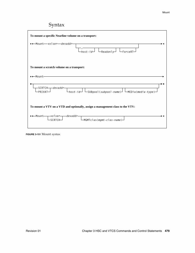
Mount
Revision 01 Chapter 3 HSC and VTCS Commands and Control Statements 479
Syntax
FIGURE 3-151 Mount syntax
Mount volser devaddr
host-id,
Readonly
Mount
SCRTCHPRIVAT
devaddrhost-id SUBpool(subpool-name) MEDia(media-type)
Mount volserSCRTCH
devaddrMGMTclas(mgmt-clas-name)
To mount a specific Nearline volume on a transport:
To mount a scratch volume on a transport:
To mount a VTV on a VTD and optionally, assign a management class to the VTV:
ForceRT
Mount
480 ELS 7.1 Command, Control Statement, and Utility Reference • November 2012 Revision 01
Parameters
To Mount a Specific Volume on a Transportvolser
specifies the volume to be mounted.
devaddr
specifies the device address of the transport on which to mount the volume.
host-id
optionally, indicates that the volume is to be mounted on the device address defined to the specified host (the SMF system identifier for JES).
Note – The host-id specified is only used for device address resolution. The host-id for subpool validation is obtained from the command origin.
Readonly
indicates that the volume is to be mounted for read-only access.
If you do not supply a host-id and do specify Readonly, a comma must be entered immediately before Readonly to indicate the missing operand. For example:
MOUNT 123456 0B0,,READONLY
ForceRT
optionally, allows a volume to be mounted on a device with a different recording technique. The media type for the volume must be compatible with the device. Caution should be used because it is possible to mount a volume written at a high density on a drive that is not capable of reading the high density.
Mount
Revision 01 Chapter 3 HSC and VTCS Commands and Control Statements 481
To Mount a Scratch Volume on a Transport
SCRTCH
specifies a scratch volume is to be mounted.
PRIVAT
specifies a scratch volume is to be mounted.
devaddr
specifies the device address of the transport on which to mount the volume.
host-id
optionally, indicates that the volume is to be mounted on the device address defined to the specified host (the SMF system identifier for JES).
Note – The hostid specified is only used for device address resolution, The hostid for subpool validation is obtained from the command origin.
SUBpool
optionally, indicates the scratch volume is to be taken from a scratch subpool. If this parameter is not specified, then the behavior is dependent upon how scratch pools were defined:
■ If VOLPARM specified, then the volume will be selected from the DEFAULTPOOL which contains all scractch tapes in the ACS that were specified in VOLPARM but were not assigned to a named subpool.
■ If VOLPARM not specified (i.e. VOLATTR, or UX03 scratch pool definitions), then the volume will be selected from subpool-0 which contains all scratch tapes in the ACS including both non-subpool and subpool volumes.
subpool-name
is the name of the subpool from which the scratch volume is to be taken.
MEDia
optionally, specifies the type of media for the scratch volume. The specified media must be compatible with the requested devaddr.
Note – If MEDia is not specified, the next scratch cartridge is selected without regard to media type.
media-type
the media type
See Appendix A, “MEDia, RECtech, and MODel Values” for a list of valid media-type values.
Mount
482 ELS 7.1 Command, Control Statement, and Utility Reference • November 2012 Revision 01
To Mount a VTV on a VTD and Optionally, Assign a Management Class to the VTVvolser | SCRTCH
specifies a specific VTV volser or the scratch VTV attribute (SCRTCH).
volser
the volser of a specific VTV.
devaddr
specifies the MSP device address of the VTD to use to mount the VTV.
MGMTclas
optionally, specifies a Management Class you defined on the MGMTclas control statement.
mgmt-class-name
the Management Class name.
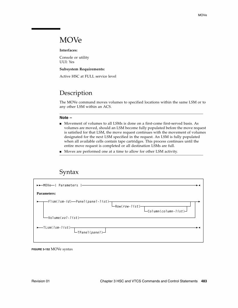
MOVe
Revision 01 Chapter 3 HSC and VTCS Commands and Control Statements 483
MOVeInterfaces:
Console or utilityUUI: Yes
Subsystem Requirements:
Active HSC at FULL service level
DescriptionThe MOVe command moves volumes to specified locations within the same LSM or to any other LSM within an ACS.
Note – ■ Movement of volumes to all LSMs is done on a first-come first-served basis. As
volumes are moved, should an LSM become fully populated before the move request is satisfied for that LSM, the move request continues with the movement of volumes designated for the next LSM specified in the request. An LSM is fully populated when all available cells contain tape cartridges. This process continues until the entire move request is completed or all destination LSMs are full.
■ Moves are performed one at a time to allow for other LSM activity.
Syntax
FIGURE 3-152 MOVe syntax
MOVe
TLsm(lsm-list)TPanel(panel)
| Parameters |
Parameters:
Flsm(lsm-id) Panel(panel-list)Row(row-list)
Column(column-list)
Volume(vol-list)
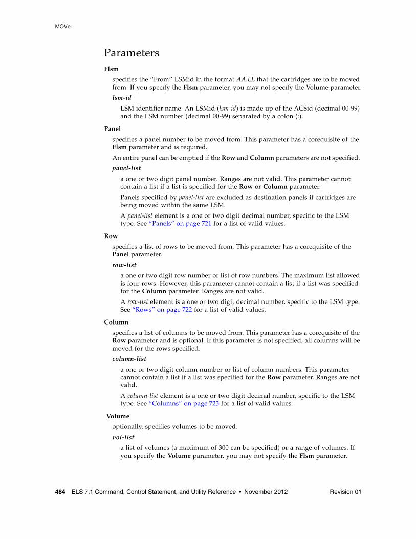
MOVe
484 ELS 7.1 Command, Control Statement, and Utility Reference • November 2012 Revision 01
ParametersFlsm
specifies the ‘‘From’’ LSMid in the format AA:LL that the cartridges are to be moved from. If you specify the Flsm parameter, you may not specify the Volume parameter.
lsm-id
LSM identifier name. An LSMid (lsm-id) is made up of the ACSid (decimal 00-99) and the LSM number (decimal 00-99) separated by a colon (:).
Panel
specifies a panel number to be moved from. This parameter has a corequisite of the Flsm parameter and is required.
An entire panel can be emptied if the Row and Column parameters are not specified.
panel-list
a one or two digit panel number. Ranges are not valid. This parameter cannot contain a list if a list is specified for the Row or Column parameter.
Panels specified by panel-list are excluded as destination panels if cartridges are being moved within the same LSM.
A panel-list element is a one or two digit decimal number, specific to the LSM type. See “Panels” on page 721 for a list of valid values.
Row
specifies a list of rows to be moved from. This parameter has a corequisite of the Panel parameter.
row-list
a one or two digit row number or list of row numbers. The maximum list allowed is four rows. However, this parameter cannot contain a list if a list was specified for the Column parameter. Ranges are not valid.
A row-list element is a one or two digit decimal number, specific to the LSM type. See “Rows” on page 722 for a list of valid values.
Column
specifies a list of columns to be moved from. This parameter has a corequisite of the Row parameter and is optional. If this parameter is not specified, all columns will be moved for the rows specified.
column-list
a one or two digit column number or list of column numbers. This parameter cannot contain a list if a list was specified for the Row parameter. Ranges are not valid.
A column-list element is a one or two digit decimal number, specific to the LSM type. See “Columns” on page 723 for a list of valid values.
Volume
optionally, specifies volumes to be moved.
vol-list
a list of volumes (a maximum of 300 can be specified) or a range of volumes. If you specify the Volume parameter, you may not specify the Flsm parameter.
MOVe
Revision 01 Chapter 3 HSC and VTCS Commands and Control Statements 485
TLsm
specifies the target LSM(s). This is a required parameter. The LSMs are specified as AA:LL, where AA is the ACSid and LL is the LSMid. The ACSid:
■ must be identical to the Flsm parameter ‘‘aa’’ (ACSid), or
■ must be the same ACS in which the volume resides if the Volume parameter is specified.
lsm-list
a list of LSMs (a maximum of 24 can be specified). Ranges are invalid. An LSMid (lsm-id) is made up of the ACSid (decimal 00-99) and the LSM number (decimal 00-99) separated by a colon (:).
TPanel
optionally, specifies the panel in the TLsm to move the cartridge(s) to.
panel
a one or two digit panel number. This parameter cannot contain a list or range. See “Panels” on page 721 for a list of valid values.
MVCDRain
486 ELS 7.1 Command, Control Statement, and Utility Reference • November 2012 Revision 01
MVCDRainInterfaces:
Console or utilityUUI: Yes
Subsystem Requirements:
Active HSC/VTCS
DescriptionThe MVCDRain command recalls all current and scratched VTVs from an MVC and, optionally, “virtually” ejects the MVC, making it unavailable for VSM use without physically ejecting it from the library. You can use this command to override the CONFIG RECLAIM CONMVC setting.
Syntax
FIGURE 3-153 MVCDRain syntax
vol-range,vol-list
)volserMVCDRain MVCid(
MVCPOOL(poolname)STORCLAS(stor-clas-name)
EJect
RECALWER(NO
YES)
NOWAIT WARRANTY RETIRED
DATACHK
CONMVC(nn)
ERROR
MVCDRain
Revision 01 Chapter 3 HSC and VTCS Commands and Control Statements 487
ParametersMVCid
drain one or more MVCs by volser.
volser, vol-range, or vol-list
the volsers of one or more MVCs up to a maximum of 50.
MVCPOOL
drain the MVCs in the specified Named MVC Pool.
poolname
the name of an MVC Pool that you defined on the MVCPool control statement. Refer to the ELS Legacy Interfaces Reference for more information.
STORCLAS
drain the MVCs in the specified Storage Class.
stor-class-name
the name of a Storage Class that you defined on the STORclas control statement; for more information, see “STORclas Control Statement” on page 451.
EJect
optionally, specifies that VTCS “virtually” ejects the MVC (the MVC will not be used for output).
CONMVC(nn)
optionally, specifies the maximum number of MVCs that VTCS concurrently processes for both drain and reclaim.
Valid values are 1 to 99. If not specified, the default is the CONMVC value specified on the CONFIG RECLAIM statement.
RECALWER
optionally, specifies whether VTCS recalls VTVs with read data checks.
NO
Do not recall VTVs with read data checks. This is the default.
YES
Recall VTVs with read data checks.
NOWAIT
optionally, specifies that the utility does not wait for the operation to complete and returns after the request is submitted.
WARRANTY
optionally, selects MVCs with expired warranties (denoted by a W in the Status T column on an MVC Report).
RETIRED
optionally, selects MVCs that are retired (denoted by a T in the Status T column on an MVC Report).
MVCDRain
488 ELS 7.1 Command, Control Statement, and Utility Reference • November 2012 Revision 01
ERROR
selects MVCs that are in error (denoted by a B in the Status B column on an MVC Report).
DATACHK
selects MVCs that have a data check (denoted by a D in the Status D column on an MVC Report).
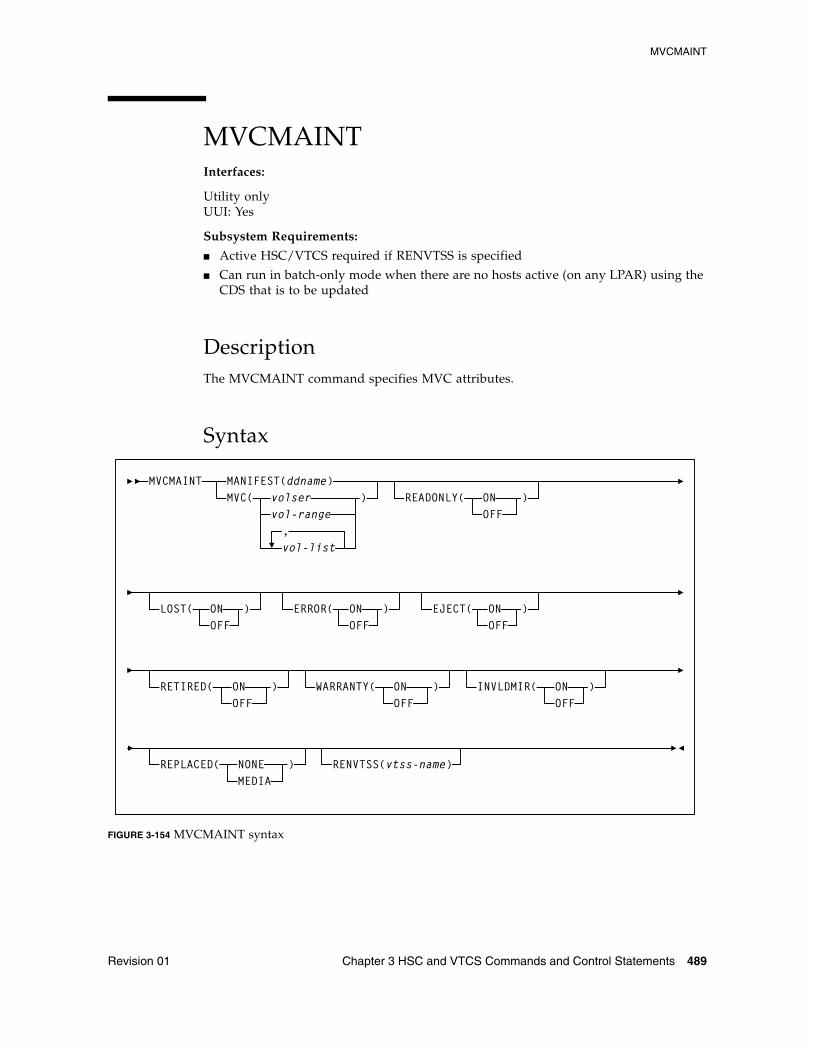
MVCMAINT
Revision 01 Chapter 3 HSC and VTCS Commands and Control Statements 489
MVCMAINTInterfaces:
Utility onlyUUI: Yes
Subsystem Requirements:
■ Active HSC/VTCS required if RENVTSS is specified
■ Can run in batch-only mode when there are no hosts active (on any LPAR) using the CDS that is to be updated
DescriptionThe MVCMAINT command specifies MVC attributes.
Syntax
FIGURE 3-154 MVCMAINT syntax
MVCMAINT
vol-range,vol-list
)volserMANIFEST(ddname)MVC( READONLY( ON )
LOST( ON ) ERROR( ON ) EJECT( )
INVLDMIR( ONOFF
)RETIRED( ) WARRANTY( ONOFF
)
REPLACED( NONEMEDIA
)
OFF
OFF OFF OFFON
ONOFF
RENVTSS(vtss-name)
MVCMAINT
490 ELS 7.1 Command, Control Statement, and Utility Reference • November 2012 Revision 01
ParametersMANIFEST
specifies the input ddname of the manifest file. Note that you can specify a merged manifest file or multiple manifest files.
ddname
ddname of the manifest file. The default is MANIFEST.
When specified, VTCS reads the MANIFEST file to discover which MVCs are to be updated (all MVCs in the manifest file). VTCS then updates the MVCs in the CDS with the actions specified by the remaining parameters (LOST, READONLY, etc.)
MVC
optionally, specifies the MVCs whose read/write attribute is changed.
volser, vol-range or vol-list
the volsers of one or more MVCs.
READONLY
optionally, sets the read/write status of the MVC.
ON
MVC is readonly.
OFF
MVCs is writable.
LOST
optionally, sets the “lost” status of the MVC.
ON
MVC is lost.
OFF
MVC is not lost.
ERROR
optionally, sets the error status of the MVC.
ON
MVC is in error.
OFF
MVC is not in error.
EJECT
optionally, sets the “logical eject” status of the MVC.
ON
MVC is “logically ejected”.
OFF
MVC is not “logically ejected”.
MVCMAINT
Revision 01 Chapter 3 HSC and VTCS Commands and Control Statements 491
RETIRED
optionally, sets the “retired” status of the MVC.
ON
MVC is retired.
OFF
MVC is not retired but is still in “expired warranty” state (still selectable for output).
WARRANTY
optionally, sets the “expired warranty” status of the MVC.
ON
MVC’s warranty has expired.
OFF
MVC’s warranty has not expired.
Note – WARRANTY and RETIRED are mutually exclusive.
INVLDMIR
optionally, sets the invalid MIR status of the MVC.
ON
MIR is invalid.
OFF
MIR is not invalid.
REPLACED
optionally, updates various MVC fields in the MVC record after an MVC is physically replaced.
NONE
The MVC record is not updated.
MEDIA
The following MVC fields are updated:
■ MVC media type is cleared■ Count of times mounted is set to zero■ Warranty Expired Flag is turned off■ Invalid MIR Flag is turned off■ Retired Flag is turned off■ Broke/Error Flag is turned off■ Lost Flag is turned off■ Data Check Flag is turned off■ VTSS Last Written By is cleared■ Date/Time MVC was last written to is cleared■ Storage Class is cleared■ Date/Time of Last Drain/Reclaim is cleared■ Date/Time of Migrate from Empty State is cleared■ Date/Time the MVC was last mounted is cleared
MVCMAINT
492 ELS 7.1 Command, Control Statement, and Utility Reference • November 2012 Revision 01
Note – ■ This parameter requires the MVC to be empty (contain zero) and unmounted.
■ REPLACED is mutually exclusive with the LOST, ERROR, EJECT, RETIRED, WARRANTY, and INVLDMIR parameters.
RENVTSS
optionally, sets the name of the owning VTSS to vtss-name.
vtss-name
the new VTSS name. This must be the name of an existing VTSS in your configuration.
Note – To use RENVTSS, the host on which MVCMAINT is run must have access to the owning VTSS.
Additional JCL RequirementsIn addition to the required JCL definition statements described in “SLUADMIN Definition Statements” on page 677, the following definition statements apply to the MVCMAINT JCL:
manifest file DD
DD statement for the manifest file.
Note – ■ MVCMAINT JCL may specify the CDS to be updated if the CDS is in use by
HSC/VTCS on the LPAR where MVCMAINT is run. If specified, the CDS data sets specified in MVCMAINT JCL must match the CDS data sets used by HSC/VTCS.
■ MVCMAINT JCL must specify the CDS to be updated if MVCMAINT is being executed in batch-only mode, i.e. when there are no hosts active (on any LPAR) using the CDS.
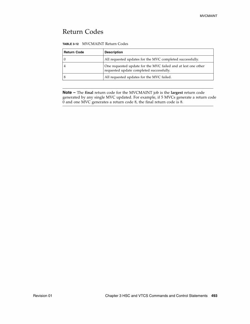
MVCMAINT
Revision 01 Chapter 3 HSC and VTCS Commands and Control Statements 493
Return Codes
Note – The final return code for the MVCMAINT job is the largest return code generated by any single MVC updated. For example, if 5 MVCs generate a return code 0 and one MVC generates a return code 8, the final return code is 8.
TABLE 3-12 MVCMAINT Return Codes
Return Code Description
0 All requested updates for the MVC completed successfully.
4 One requested update for the MVC failed and at lest one other requested update completed successfully.
8 All requested updates for the MVC failed.
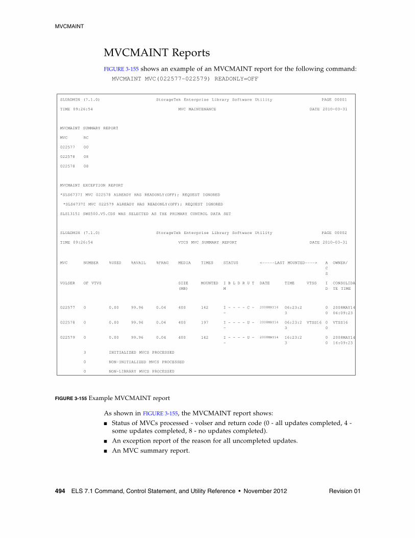
MVCMAINT
494 ELS 7.1 Command, Control Statement, and Utility Reference • November 2012 Revision 01
MVCMAINT ReportsFIGURE 3-155 shows an example of an MVCMAINT report for the following command:
MVCMAINT MVC(022577-022579) READONLY=OFF
FIGURE 3-155 Example MVCMAINT report
As shown in FIGURE 3-155, the MVCMAINT report shows:
■ Status of MVCs processed - volser and return code (0 - all updates completed, 4 - some updates completed, 8 - no updates completed).
■ An exception report of the reason for all uncompleted updates.
■ An MVC summary report.
SLUADMIN (7.1.0) StorageTek Enterprise Library Software Utility PAGE 00001
TIME 09:26:54 MVC MAINTENANCE DATE 2010-03-31
MVCMAINT SUMMARY REPORT
MVC RC
022577 00
022578 08
022578 08
MVCMAINT EXCEPTION REPORT
*SLS6737I MVC 022578 ALREADY HAS READONLY(OFF); REQUEST IGNORED
*SLS6737I MVC 022579 ALREADY HAS READONLY(OFF); REQUEST IGNORED
SLS1315I SWS500.V5.CDS WAS SELECTED AS THE PRIMARY CONTROL DATA SET
SLUADMIN (7.1.0) StorageTek Enterprise Library Software Utility PAGE 00002
TIME 09:26:54 VTCS MVC SUMMARY REPORT DATE 2010-03-31
MVC NUMBER %USED %AVAIL %FRAG MEDIA TIMES STATUS <-----LAST MOUNTED----> ACS
OWNER/
VOLSER OF VTVS SIZE (MB)
MOUNTED I B L D R U T M
DATE TIME VTSS ID
CONSOLIDATE TIME
022577 0 0.00 99.96 0.04 400 142 I - - - - C - -
2008MAY14 06:23:23
00
2008MAY1406:09:23
022578 0 0.00 99.96 0.04 400 197 I - - - - U - -
2008MAY14 06:23:23
VTSS16 00
VTSS16
022579 0 0.00 99.96 0.04 400 142 I - - - - U - -
2008MAY14 16:23:23
00
2008MAY1416:09:23
3 INITIALIZED MVCS PROCESSED
0 NON-INITIALIZED MVCS PROCESSED
0 NON-LIBRARY MVCS PROCESSED
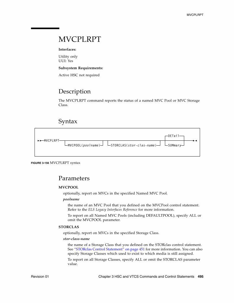
MVCPLRPT
Revision 01 Chapter 3 HSC and VTCS Commands and Control Statements 495
MVCPLRPTInterfaces:
Utility onlyUUI: Yes
Subsystem Requirements:
Active HSC not required
DescriptionThe MVCPLRPT command reports the status of a named MVC Pool or MVC Storage Class.
Syntax
FIGURE 3-156 MVCPLRPT syntax
ParametersMVCPOOL
optionally, report on MVCs in the specified Named MVC Pool.
poolname
the name of an MVC Pool that you defined on the MVCPool control statement. Refer to the ELS Legacy Interfaces Reference for more information.
To report on all Named MVC Pools (including DEFAULTPOOL), specify ALL or omit the MVCPOOL parameter.
STORCLAS
optionally, report on MVCs in the specified Storage Class.
stor-class-name
the name of a Storage Class that you defined on the STORclas control statement. See “STORclas Control Statement” on page 451 for more information. You can also specify Storage Classes which used to exist to which media is still assigned.
To report on all Storage Classes, specify ALL or omit the STORCLAS parameter value.
MVCPOOL(poolname) STORCLAS(stor-clas-name)
DETail
SUMmaryMVCPLRPT
MVCPLRPT
496 ELS 7.1 Command, Control Statement, and Utility Reference • November 2012 Revision 01
The STORCLAS parameter allows you to filter the MVCs reported from the MVCPOOL, i.e. only those MVCs with a matching Storage Class are reported. If the STORCLAS parameter is specified then the summary counts section will contain Storage Class subtotals, either for every Storage Class encountered if the parameter value ALL or no value is specified, or for those media types where there are MVCs matching the specified value.
Note – You can specify MVCPOOL, STORCLAS, or both together to filter the report.
DETail
Report MVC detail lines (the default).
SUMmary
Report summary counts only.
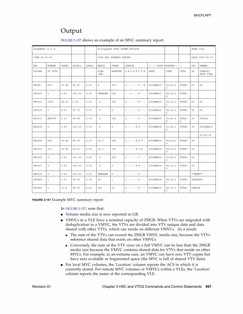
MVCPLRPT
Revision 01 Chapter 3 HSC and VTCS Commands and Control Statements 497
OutputFIGURE 3-157 shows an example of an MVC summary report.
FIGURE 3-157 Example MVC summary report
In FIGURE 3-157, note that:
■ Volume media size is now reported in GB.
■ VMVCs in a VLE have a nominal capacity of 250GB. When VTVs are migrated with deduplication to a VMVC, the VTVs are divided into VTV unique data and data shared with other VTVs, which can reside on different VMVCs. As a result:
■ The sum of the VTVs can exceed the 250GB VMVC media size, because the VTVs reference shared data that exists on other VMVCs.
■ Conversely, the sum of the VTV sizes on a full VMVC can be less than the 250GB media size because the VMVC contains shared data for VTVs that reside on other MVCs. For example, in an extreme case, an VMVC can have zero VTV copies but have zero available or fragmented space (the MVC is full of shared VTV data).
■ For local MVC volumes, the 'Location' column reports the ACS in which it is currently stored. For remote MVC volumes or VMVCs within a VLEs, the 'Location' column reports the name of the corresponding VLE.
SLUADMIN (7.0.0) StorageTek VTCS SYTEM UTILITY PAGE 0002
TIME 09:26:54 VTCS MVC SUMMARY REPORT DATE 2009-04-13
MVC NUMBER %USED %AVAIL %FRAG MEDIA TIMES STATUS <-----LAST MOUNTED----> ACS OWNER/
VOLSER OF VTVS SIZE (GB)
MOUNTED I B L D R U T M DATE TIME VTSS ID CONSOLIDATE TIME
EVS99 200 10.80 84.57 4.63 2 310 I - - - - U - M 2009MAR15 03:20:23
VTSS8 00 S1
EVS100 0 0.00 100.00 0.00 UNKNOWN 206 - - L - - U - - 2009MAR10 05:24:04
VTSS8 --
EVS101 1009 99.00 0.00 1.00 .4 306 I - - - - U - - 2009MAR15 03:20:23
VTSS8 00 S1
EVS102 5 8.25 91.75 0.00 .4 6 I - - - - U - - 2009MAR15 04:23:04
VTSS8 00 S3
EVS103 EXPVTV 0.12 99.88 0.00 .4 194 I - - - - J - - 2009MAR15 03:20:28
VTSS10
00 VTSS10
EVS104 0 0.00 100.00 0.00 .4 5 I - - - R C - - 2009MAR18 03:49:14
VTSS8 00 2009APR12
03:49:14
EVS104 200 10.80 84.57 4.63 10.2 254 I - - - R U T - 2009MAR18 04110:09
VTSS8 00
EVS105 300 15.80 54.57 4.63 10.2 154 I - - - R U W - 2009MAR18 04110:09
VTSS8 00
EVS106 0 0.00 100.00 0.00 .4 202 I - - - - C - - 2009MAR18 03:49:20
VTSS8 00
EVS107 0 0.00 100.00 0.00 .4 0 I - - - R E - - 2009MAR18 04:13:00
VTSS8 00
EVS110 0 0.00 100.00 0.00 UNKNOWN 0 - - - - - U - - **MANY**
EVS460 1 0.01 99.99 0.00 40 1 I - - - - U - - 2009MAR18 04:13:00
VTSS8 SECNDARY
EVS480 1 10.8 84.57 4.63 250 10 I - - - - U - - 2009MAR18 04:13:00
VTSS8 LEPRIM
MVCPLRPT
498 ELS 7.1 Command, Control Statement, and Utility Reference • November 2012 Revision 01
■ The special name **MANY** appears in the 'Location' column if a MVC with a specific volser has been discovered in more than one location. MVCs in this state are marked unusable.
Note – To return location information for the remotely located MVCs, SMC must be running when running the reports.
■ The same changes also apply to the output of the DISPLAY MVC command.
See also the note on page 309.
FieldsThe following list describes the Named MVC Pool report fields. The Summary fields are either for a Storage Class or a Named MVC Pool, depending on which was specified on the report JCL. If a Storage Class specifies a Named MVC Pool, the report gives information for that subpool.
MVC VOLSER
the MVC volser.
NUMBER OF VTVS
the number of current VTVs on the MVC. If the MVC has been used for VTV export, this field reports EXPVTV.
%USED
the percentage of the MVC used by current VTVs.
%AVAIL
the percentage of the MVC that is physically available for use.
%FRAG
the percentage of the MVC that contains non-current VTVs. This space is not usable until it is reclaimed or the MVC is drained.
MEDIA SIZE (GB)
the size of the MVC (GB). This will only be determined after VTCS has used an MVC. “UNKNOWN” appears in this field until VTCS migrates a VTV to the MVC.
TIMES MOUNTED
the number of times that the MVC has been mounted for writing or reading since it was added to the MVC inventory.
MVCPLRPT
Revision 01 Chapter 3 HSC and VTCS Commands and Control Statements 499
STATUS
one or more of the following statuses:
I
The MVC has been initialized.
B
The MVC has an error that should be investigated. The error may not make the MVC unusable, but VTCS will not select the MVC for migration for 12 hours after it is marked “B”. After the 12 hour period, the MVC will be least preferred for subsequent migrations, and recalls from the MVC may cause VTCS to drain it. This error condition may be accompanied by messages SLS6686, SLS6687, SLS6688, SLS6690, and/or SLS6693.
Any of the following conditions can cause this MVC error:
■ MVC corrupted by another job (other than VTCS/VTSS)■ attempt to use a read-only MVC for migration■ DDR swap failure■ RTD failure
L
The MVC was not mounted in response to the last mount request. The MVC can still be used for migration, but will not select the MVC for migration for 12 hours after it is marked “L”. After the 12 hour period, the MVC will be least preferred. This condition will clear itself the next time that the MVC is mounted.
D
A data check was reported for this MVC. VSM will not use this MVC again for migration.
R
the MVC has been marked read-only.
U
one of the following usage statuses:
U
the MVC is available for output (migration, reclamation, export, or consolidation).
-
the MVC is not available for output (migration, reclamation, export, or consolidation).
A
The MVC is either being audited or the audit failed. If the audit failed, VTCS will not use the MVC for migration. To clear this condition, rerun the AUDIT against this MVC.
C
The MVC is a consolidation MVC.
E
The MVC is an export MVC.
F
There is no space available on the MVC.
MVCPLRPT
500 ELS 7.1 Command, Control Statement, and Utility Reference • November 2012 Revision 01
J
Either you issued a MVCDRain EJect for the MVC or the MVC was ejected for update by a RACROUTE call. The MVC will not be used again for migration or recall. To clear this condition, use MVCDRain against MVC without the EJect option.
N
Either:
■ The MVC is being drained because of an automatic drain or demand reclaim or an explicit MVCDRain command.
OR
■ The previous DRAIN request failed, in which case VTCS will not use the MVC for migration. To clear this condition, enter MVCDRain against MVC without the EJect option.
X
The MVC has reached the maximum VTVs per MVC.
T
One of the following statuses:
T
The MVC is retired.
W
The MVC’s warranty has expired.
M
The MVC has an invalid MIR.
LAST MOUNTED
the date and time that the MVC was last mounted and the VTSS where the MVC was last used.
ACS ID
the ACS where the MVC resides.
OWNER/CONSOLIDATE TIME
If the MVC is empty, this field is null. If the MVC is a consolidation MVC, this field displays the time of the consolidation. If the MVC is a migration MVC and contains current VTVs, this field displays the MVC’s Storage Class. If no Storage Class was explicitly assigned via the MGMTclas statement, the default Storage Class is the name of the last VTSS that wrote to the MVC for reclamation or migration.
If VTCS receives a request to migrate a VTV that is assigned to an invalid Management Class, VTCS will dynamically create the !ERROR Storage Class and migrate the VTVs defined by the invalid Management Class to the !ERROR Storage Class. Use this Storage Class to identify and correct invalid Management Classes, drain the affected MVCs, and resubmit the request.
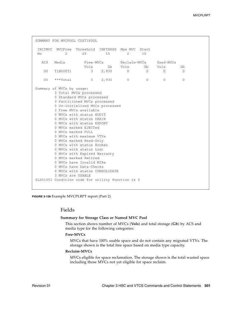
MVCPLRPT
Revision 01 Chapter 3 HSC and VTCS Commands and Control Statements 501
FIGURE 3-158 Example MVCPLRPT report (Part 2)
FieldsSummary for Storage Class or Named MVC Pool
This section shows number of MVCs (Vols) and total storage (Gb) by ACS and media type for the following categories:
Free-MVCs
MVCs that have 100% usable space and do not contain any migrated VTVs. The storage shown is the total free space based on media type capacity.
Reclaim-MVCs
MVCs eligible for space reclamation. The storage shown is the total wasted space including those MVCs not yet eligible for space reclaim.
SUMMARY FOR MVCPOOL CUST1POOL
INITMVC MVCFree Threshold INPTHRSH Max MVC Start No 2 25 15 2 10
ACS Media Free-MVCs Reclaim-MVCs Used-MVCs Vols Gb Vols Gb Vols Gb 00 T1B000T1 3 2,930 0 0 0 0
00 ***Total 3 2,930 0 0 0 0
Summary of MVCs by usage: 3 Total MVCs processed 0 Standard MVCs processed 3 Partitioned MVCs processed 0 Un-initialized MVCs processed 3 Free MVCs available 0 MVCs with status AUDIT 0 MVCs with status DRAIN 0 MVCs with status EXPORT 0 MVCs marked EJECTed 0 MVCs marked FULL 0 MVCs with maximum VTVs 0 MVCs marked Read-Only 0 MVCs with status Broken 0 MVCs with status Lost 0 MVCs with Expired Warranty 0 MVCs marked Retired 0 MVCs have Invalid MIRs 0 MVCs have Data-Checks 0 MVCs with status CONSOLIDATE 3 MVCs are USABLESLS0155I Condition code for utility function is 0
MVCPLRPT
502 ELS 7.1 Command, Control Statement, and Utility Reference • November 2012 Revision 01
Used-MVCS
Initialized MVCs that are partially or completely full.
Total MVCs
Total MVCs for the Storage Class or Named MVC Pool with subtotals for initialized, uninitialized, and free MVCs.
Summary of MVCs by Usage
This section shows number of MVCs by the task that last used the MVC.
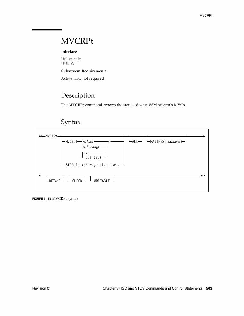
MVCRPt
Revision 01 Chapter 3 HSC and VTCS Commands and Control Statements 503
MVCRPtInterfaces:
Utility onlyUUI: Yes
Subsystem Requirements:
Active HSC not required
DescriptionThe MVCRPt command reports the status of your VSM system’s MVCs.
Syntax
FIGURE 3-159 MVCRPt syntax
MVCRPt
vol-range,vol-list
DETail
MVCid( volser )
CHECK WRITABLE
STORclas(storage-clas-name)
ALL MANIFEST(ddname)
MVCRPt
504 ELS 7.1 Command, Control Statement, and Utility Reference • November 2012 Revision 01
ParametersMVCid
optionally, specifies the MVCs for the report. If you do not specify the MVCs, the report includes all MVCs in your VSM system.
volser, vol-range or vol-list
the volsers of one or more MVCs.
STORclas
optionally, specifies a storage class with the MVCs to be reported.
stor-clas-name
a 1-8 character storage class name.
Note – STORclas is mutually exclusive with MVCid, ALL, and MANIFEST.
ALL
optionally, generate a report for all MVCs.
MANIFEST
optionally, specifies the input ddname of the manifest file used to generate the report.
ddname
ddname of the manifest file. Note that you can specify a merged manifest file or multiple manifest files.
DETail
optionally, produce a detailed MVC report; see FIGURE 3-161 on page 510 for an example. If you do not specify this option, the default is to produce a summary MVC report; see FIGURE 3-160 on page 505 for an example.
CHECK
optionally, MVCRPt does limited MVC integrity checking, during which the CDS is reserved. Use only if directed by Oracle StorageTek Software Support.
WRITABLE
optionally, MVCRPt ignores readonly MVCs on MVC detailed reports and when you specify the CHECK parameter.
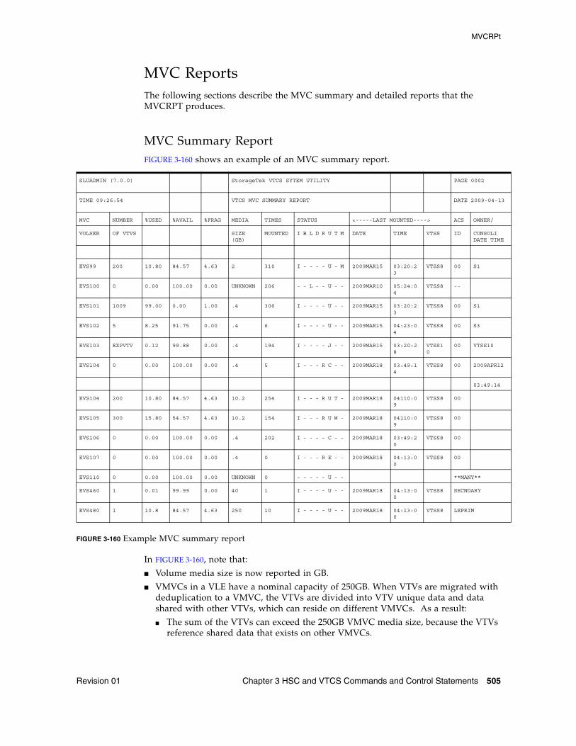
MVCRPt
Revision 01 Chapter 3 HSC and VTCS Commands and Control Statements 505
MVC ReportsThe following sections describe the MVC summary and detailed reports that the MVCRPT produces.
MVC Summary ReportFIGURE 3-160 shows an example of an MVC summary report.
FIGURE 3-160 Example MVC summary report
In FIGURE 3-160, note that:
■ Volume media size is now reported in GB.
■ VMVCs in a VLE have a nominal capacity of 250GB. When VTVs are migrated with deduplication to a VMVC, the VTVs are divided into VTV unique data and data shared with other VTVs, which can reside on different VMVCs. As a result:
■ The sum of the VTVs can exceed the 250GB VMVC media size, because the VTVs reference shared data that exists on other VMVCs.
SLUADMIN (7.0.0) StorageTek VTCS SYTEM UTILITY PAGE 0002
TIME 09:26:54 VTCS MVC SUMMARY REPORT DATE 2009-04-13
MVC NUMBER %USED %AVAIL %FRAG MEDIA TIMES STATUS <-----LAST MOUNTED----> ACS OWNER/
VOLSER OF VTVS SIZE (GB)
MOUNTED I B L D R U T M DATE TIME VTSS ID CONSOLIDATE TIME
EVS99 200 10.80 84.57 4.63 2 310 I - - - - U - M 2009MAR15 03:20:23
VTSS8 00 S1
EVS100 0 0.00 100.00 0.00 UNKNOWN 206 - - L - - U - - 2009MAR10 05:24:04
VTSS8 --
EVS101 1009 99.00 0.00 1.00 .4 306 I - - - - U - - 2009MAR15 03:20:23
VTSS8 00 S1
EVS102 5 8.25 91.75 0.00 .4 6 I - - - - U - - 2009MAR15 04:23:04
VTSS8 00 S3
EVS103 EXPVTV 0.12 99.88 0.00 .4 194 I - - - - J - - 2009MAR15 03:20:28
VTSS10
00 VTSS10
EVS104 0 0.00 100.00 0.00 .4 5 I - - - R C - - 2009MAR18 03:49:14
VTSS8 00 2009APR12
03:49:14
EVS104 200 10.80 84.57 4.63 10.2 254 I - - - R U T - 2009MAR18 04110:09
VTSS8 00
EVS105 300 15.80 54.57 4.63 10.2 154 I - - - R U W - 2009MAR18 04110:09
VTSS8 00
EVS106 0 0.00 100.00 0.00 .4 202 I - - - - C - - 2009MAR18 03:49:20
VTSS8 00
EVS107 0 0.00 100.00 0.00 .4 0 I - - - R E - - 2009MAR18 04:13:00
VTSS8 00
EVS110 0 0.00 100.00 0.00 UNKNOWN 0 - - - - - U - - **MANY**
EVS460 1 0.01 99.99 0.00 40 1 I - - - - U - - 2009MAR18 04:13:00
VTSS8 SECNDARY
EVS480 1 10.8 84.57 4.63 250 10 I - - - - U - - 2009MAR18 04:13:00
VTSS8 LEPRIM
MVCRPt
506 ELS 7.1 Command, Control Statement, and Utility Reference • November 2012 Revision 01
■ Conversely, the sum of the VTV sizes on a full VMVC can be less than the 250GB media size because the VMVC contains shared data for VTVs that reside on other MVCs. For example, in an extreme case, an VMVC can have zero VTV copies but have zero available or fragmented space (the MVC is full of shared VTV data).
■ For local MVC volumes, the 'Location' column reports the ACS in which it is currently stored. For remote MVC volumes or VMVCs within a VLEs, the 'Location' column reports the name of the corresponding VLE.
■ The special name **MANY** appears in the 'Location' column if a MVC with a specific volser has been discovered in more than one location. MVCs in this state are marked unusable.
Note – To return location information for the remotely located MVCs, SMC must be running when running the reports.
■ The same changes also apply to the output of the DISPLAY MVC command.
■ See also the note on page 309.
Fields
MVC VOLSER
the MVC volser.
NUMBER OF VTVS
the number of current VTVs on the MVC. If the MVC has been used for VTV export, this field reports EXPVTV.
%USED
the percentage of the MVC used by current VTVs.
%AVAIL
the percentage of the MVC that is physically available for use.
%FRAG
the percentage of the MVC that contains non-current VTVs. This space is not usable until it is reclaimed or the MVC is drained.
MEDIA SIZE (GB)
the size of the MVC (GB). This will only be determined after VTCS has used an MVC. “UNKNOWN” appears in this field until VTCS migrates a VTV to the MVC.
TIMES MOUNTED
the number of times that the MVC has been mounted for writing or reading since it was added to the MVC inventory.
MVCRPt
Revision 01 Chapter 3 HSC and VTCS Commands and Control Statements 507
STATUS
one or more of the following statuses:
I
The MVC has been initialized. MVCs written in partitioned format are indicated by the letter 'P' under this column.
B
This is a generic error that indicates the MVC, drive, or combination of the two has a problem. VTCS attempts to de-preference MVCs with this state. To clear this state:
If the MVC caused the problem, use a DRAIN(EJECT) command to remove the MVC from service.
If the RTD caused the problem, use the MVCMAINT utility to reset the MVC state.
Note also that one or more of the following messages is issued for BROKEN status: SLS6686, SLS6687, SLS6688, SLS6690. For detailed recovery procedures for these messages, see VTCS Messages and Codes.
L
VTCS attempted to mount an MVC and the mount did not complete within a 15-minute time-out period. VTCS is attempting to recover from a situation that may be caused by hardware problems, HSC problems, or by the MVC being removed from the ACS. VTCS attempts to de-preference MVCs with this state.
If VTCS does perform a subsequent successful mount of an MVC with LOST(ON) state, VTCS sets the state to LOST(OFF).
Determine the cause of the error and fix it. You can also use the VTCS MVCMAINT utility to set LOST(OFF) for the following events:
LOST(ON) was set due to LSM failures or drive errors that have been resolved
LOST(ON) was set because the MVC was outside the ACS and has been reentered.
D
A data check condition has been reported against this MVC. VTCS attempts to de-preference MVCs with this state. To clear this state:
If all VTVs on the MVC are duplexed, use MVCDRain on the MVC without the Eject option. This recovers all VTVs and removes the MVC from service.
If all VTVs on the MVC are not duplexed, VTCS AUDIT the MVC. The audit will probably fail. After the audit, do an MVCDRAIN (no eject). This recalls the VTVs before the data-check area in ascending block-id order and the VTVs after the data-check area in a descending block-id order. Processing the VTVs in this sequence ensures that VTCS recovers as many VTVs as possible from the media. You then need to recreate the data for any VTVs still on the MVC.
MVCRPt
508 ELS 7.1 Command, Control Statement, and Utility Reference • November 2012 Revision 01
R
The MVC has been marked read-only because of one of the following conditions:
The MVC being the target of an export or consolidation process. The read-only state protects the MVC from further updates.
The MVC media is set to file protect. Correct the error and use the MVCMAINT utility to set READONLY(OFF).
The MVC does not have the appropriate SAF rules set to enable VTCS to update the MVC. Correct the error and use the MVCMAINT utility to set READONLY(OFF). Refer to the publication Installing ELS for information about defining a security subsystem user ID for HSC, SMC, and VTCS.
U
one of the following usage statuses:
U
The MVC is available for output (migration, reclamation, export, or consolidation).
-
The MVC is not available for output (migration, reclamation, export, or consolidation).
A
The MVC is either being audited or the audit failed. If the audit failed, VTCS will not use the MVC for migration. To clear this condition, rerun the AUDIT against this MVC.
C
The MVC is a consolidation MVC.
E
The MVC is an export MVC.
F
There is no space available on the MVC.
J
Either you issued MVCDRain EJect for the MVC or the MVC was ejected for update by a RACROUTE call. The MVC will not be used again for migration or recall. To clear this condition, use MVCDRain against MVC without the EJect option.
N
Either the MVC is being drained because of:
■ an automatic drain or demand reclaim, or an explicit MVCDRain command.
OR
■ The previous DRAIN request failed, in which case VTCS will not use the MVC for migration. To clear this condition, enter MVCDRain against MVC without the EJect option.
X
The MVC has reached the maximum VTVs per MVC.
MVCRPt
Revision 01 Chapter 3 HSC and VTCS Commands and Control Statements 509
T
One of the following statuses:
T
The MVC is retired. VTCS will recall from, but not migrate to, the MVC. Replace the MVC as soon as possible.
W
The MVC’s warranty has expired. VTCS continues to use the MVC. You should start making plans to replace the MVC when it reaches Retired state.
M
VTCS has received status from an RTD to indicate the MIR (media information record) for a 9x40 media is invalid. An invalid MIR does not prevent access to data but may cause significant performance problems while accessing records on the tape. The MVC is not capable of high-speed searches on areas of the tape that do not have a valid MIR entry.
VTCS attempts to de-preference MVCs with this condition. For recalls, if the VTV resides on multiple MVCs, VTCS selects MVCs with valid MIRs ahead of MVCs with invalid MIRs. VTCS avoids using MVCs with invalid MIRs for migration, unless the migration is at the beginning of the tape. Migrating from the beginning of tape will correct the MIR.
VTCS detects the invalid MIR condition at either mount time or dismount time. If detected at mount time and the operation can be completed with another MVC, VTCS dismounts the first MVC and selects the alternate MVC. Note that VTCS has only a limited ability to switch to an alternate MVC. That is, it is mainly used for migrate and virtual mount.
For MVCs with invalid MIRs, determine the cause of the error, which may be caused by media or drive problems, and fix the error.
To recover an MVC with an invalid MIR, you simply need to read the MVC to the end of the tape, which can be done via a VTCS audit. If the media is the problem, run an MVCDRAIN EJECT to recall the VTVs and cause the MVC to be removed from the MVC pool.
LAST MOUNTED
the date and time that the MVC was last mounted and the VTSS where the MVC was last used.
ACS ID
the ACS where the MVC resides.
OWNER/CONSOLIDATE TIME
If the MVC is empty, this field is null. If the MVC is a consolidation MVC, this field displays the time of the consolidation. If the MVC is a migration MVC and contains current VTVs, this field displays the MVC’s Storage Class. If no Storage Class was explicitly assigned via the MGMTclas statement, the default Storage Class is the name of the last VTSS that wrote to the MVC for reclamation or migration.
If VTCS receives a request to migrate a VTV that is assigned to an invalid Management Class, VTCS will dynamically create the !ERROR Storage Class and migrate the VTVs defined by the invalid Management Class to the !ERROR Storage Class. Use this Storage Class to identify and correct invalid Management Classes, drain the affected MVCs, and resubmit the request.
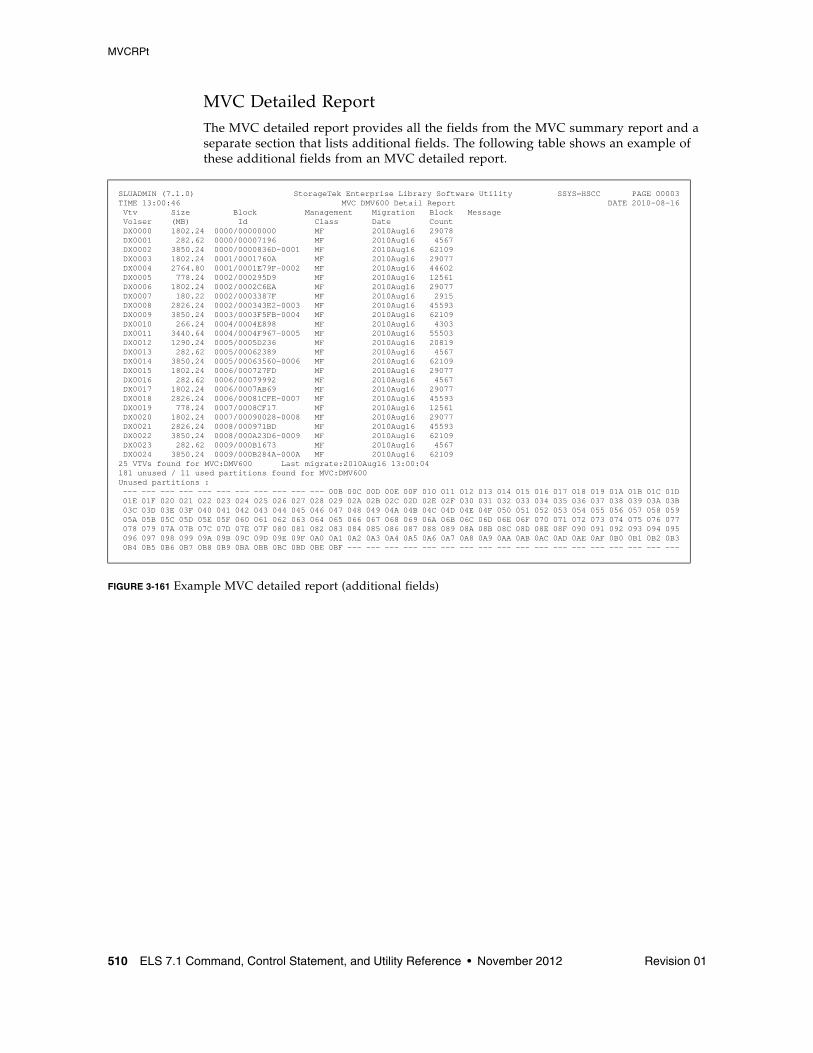
MVCRPt
510 ELS 7.1 Command, Control Statement, and Utility Reference • November 2012 Revision 01
MVC Detailed ReportThe MVC detailed report provides all the fields from the MVC summary report and a separate section that lists additional fields. The following table shows an example of these additional fields from an MVC detailed report.
FIGURE 3-161 Example MVC detailed report (additional fields)
SLUADMIN (7.1.0) StorageTek Enterprise Library Software Utility SSYS=HSCC PAGE 00003TIME 13:00:46 MVC DMV600 Detail Report DATE 2010-08-16 Vtv Size Block Management Migration Block Message Volser (MB) Id Class Date Count DX0000 1802.24 0000/00000000 MF 2010Aug16 29078 DX0001 282.62 0000/00007196 MF 2010Aug16 4567 DX0002 3850.24 0000/0000836D-0001 MF 2010Aug16 62109 DX0003 1802.24 0001/0001760A MF 2010Aug16 29077 DX0004 2764.80 0001/0001E79F-0002 MF 2010Aug16 44602 DX0005 778.24 0002/000295D9 MF 2010Aug16 12561 DX0006 1802.24 0002/0002C6EA MF 2010Aug16 29077 DX0007 180.22 0002/0003387F MF 2010Aug16 2915 DX0008 2826.24 0002/000343E2-0003 MF 2010Aug16 45593 DX0009 3850.24 0003/0003F5FB-0004 MF 2010Aug16 62109 DX0010 266.24 0004/0004E898 MF 2010Aug16 4303 DX0011 3440.64 0004/0004F967-0005 MF 2010Aug16 55503 DX0012 1290.24 0005/0005D236 MF 2010Aug16 20819 DX0013 282.62 0005/00062389 MF 2010Aug16 4567 DX0014 3850.24 0005/00063560-0006 MF 2010Aug16 62109 DX0015 1802.24 0006/000727FD MF 2010Aug16 29077 DX0016 282.62 0006/00079992 MF 2010Aug16 4567 DX0017 1802.24 0006/0007AB69 MF 2010Aug16 29077 DX0018 2826.24 0006/00081CFE-0007 MF 2010Aug16 45593 DX0019 778.24 0007/0008CF17 MF 2010Aug16 12561 DX0020 1802.24 0007/00090028-0008 MF 2010Aug16 29077 DX0021 2826.24 0008/000971BD MF 2010Aug16 45593 DX0022 3850.24 0008/000A23D6-0009 MF 2010Aug16 62109 DX0023 282.62 0009/000B1673 MF 2010Aug16 4567 DX0024 3850.24 0009/000B284A-000A MF 2010Aug16 6210925 VTVs found for MVC:DMV600 Last migrate:2010Aug16 13:00:04181 unused / 11 used partitions found for MVC:DMV600Unused partitions : --- --- --- --- --- --- --- --- --- --- --- 00B 00C 00D 00E 00F 010 011 012 013 014 015 016 017 018 019 01A 01B 01C 01D 01E 01F 020 021 022 023 024 025 026 027 028 029 02A 02B 02C 02D 02E 02F 030 031 032 033 034 035 036 037 038 039 03A 03B 03C 03D 03E 03F 040 041 042 043 044 045 046 047 048 049 04A 04B 04C 04D 04E 04F 050 051 052 053 054 055 056 057 058 059 05A 05B 05C 05D 05E 05F 060 061 062 063 064 065 066 067 068 069 06A 06B 06C 06D 06E 06F 070 071 072 073 074 075 076 077 078 079 07A 07B 07C 07D 07E 07F 080 081 082 083 084 085 086 087 088 089 08A 08B 08C 08D 08E 08F 090 091 092 093 094 095 096 097 098 099 09A 09B 09C 09D 09E 09F 0A0 0A1 0A2 0A3 0A4 0A5 0A6 0A7 0A8 0A9 0AA 0AB 0AC 0AD 0AE 0AF 0B0 0B1 0B2 0B3 0B4 0B5 0B6 0B7 0B8 0B9 0BA 0BB 0BC 0BD 0BE 0BF --- --- --- --- --- --- --- --- --- --- --- --- --- --- --- --- --- ---
MVCRPt
Revision 01 Chapter 3 HSC and VTCS Commands and Control Statements 511
MVC Detailed Report Additional Fields
The following list describes the additional fields for the MVC detailed report.
VTV Volser
the volsers of the VTVs on the MVC.
Size (MB)
the uncompressed size of the VTV (MB).
Block ID
the partition id and logical block ID of the beginning of the VTV on the MVC. If there are VTVs spanning partitions, the 'spanned to' partition is shown to the right of the blockid location.
Management Class
the VTV’s Management Class.
Migration Date
for migrates done by a 6.0 system or above only, the approximate date that the VTV copy was migrated. This date is approximate because it is recorded in the CDS as the number of days since VTV creation, and time zone adjustments can cause the value to slip a day.
Block Count
the decimal number of blocks of data that the VTV occupies on the MVC.
Message
reports the results of MVC integrity checking. Any message not listed below should be reported to Oracle, as it may indicate a serious problem with the CDS except messages that can appear if the MVC is being audited or has failed an audit while the MVC report is being run. An MVC report returns a minimum return code of 4 if any MVCs in audit state are encountered; the audit state also prevents some other errors from being reported.
nnnn empty space to previous
Explanation. Informational message, indicating that there are nnnn (decimal) blocks of free space before this VTV on the MVC.
Migrated size was not as expected
Explanation. If output for VTV v on MVC m, it indicates that the (compressed) size of VTV v migrated to MVC m was different to the (compressed) size of VTV v recorded in the CDS.
This is normal if VTV v had previously been recalled with error. Otherwise this indicates a possible error which should be reported to Oracle StorageTek software support.
Used/Unused Partitions
Summary of used and unused partitions for the MVC.
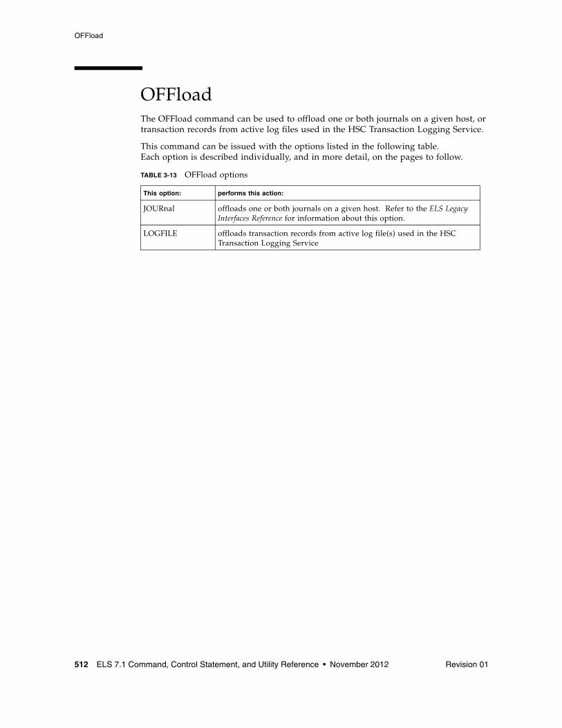
OFFload
512 ELS 7.1 Command, Control Statement, and Utility Reference • November 2012 Revision 01
OFFloadThe OFFload command can be used to offload one or both journals on a given host, or transaction records from active log files used in the HSC Transaction Logging Service.
This command can be issued with the options listed in the following table. Each option is described individually, and in more detail, on the pages to follow.
TABLE 3-13 OFFload options
This option: performs this action:
JOURnal offloads one or both journals on a given host. Refer to the ELS Legacy Interfaces Reference for information about this option.
LOGFILE offloads transaction records from active log file(s) used in the HSC Transaction Logging Service
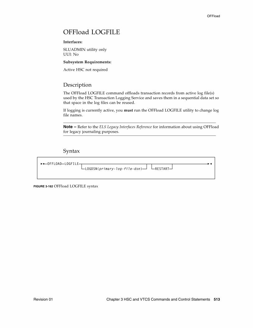
OFFload
Revision 01 Chapter 3 HSC and VTCS Commands and Control Statements 513
OFFload LOGFILEInterfaces:
SLUADMIN utility onlyUUI: No
Subsystem Requirements:
Active HSC not required
DescriptionThe OFFload LOGFILE command offloads transaction records from active log file(s) used by the HSC Transaction Logging Service and saves them in a sequential data set so that space in the log files can be reused.
If logging is currently active, you must run the OFFload LOGFILE utility to change log file names.
Note – Refer to the ELS Legacy Interfaces Reference for information about using OFFload for legacy journaling purposes.
Syntax
FIGURE 3-162 OFFload LOGFILE syntax
OFFLOAD LOGFILERESTARTLOGDSN(primary-log-file-dsn)
OFFload
514 ELS 7.1 Command, Control Statement, and Utility Reference • November 2012 Revision 01
ParametersGenerally, OFFload LOGFILE is issued without parameters. The utility selects the input log data set from the active log data sets as recorded in the CDS.
LOGDSN
optionally, offloads the log file without using or updating the CDS. Use this parameter in any case where the CDS is restored, or is otherwise considered to be unreliable.
primary-log-file-dsn
the data set name for the primary log file.
For example: OFFLOAD LOGFILE LOGDSN(hsc.log1).
Note – If you attempt to run the OFFLOAD LOGFILE utility after restoring the CDS but without specifying the LOGDSN option, the offload may not succeed, or may create an erroneous log offload file.
RESTART
optionally, restarts the offload, selecting the input log file from among the group of log data sets that were active when the failed offload started. It also uses the block number range used by the failed offload.
Use this parameter to recover the records from the log data set(s) that become inactive when a failed offload causes a log data set switch.
Additional JCL Requirements In addition to the required JCL definition statements described in “Invoking SLUADMIN” on page 674, the following definition statements apply to the OFFload LOGFILE JCL:
SLSOFFLD
specifies the output data set
It is recommended that no DCB be specified for this data set. If a DCB is specified, the RECFM and LRECL are ignored.
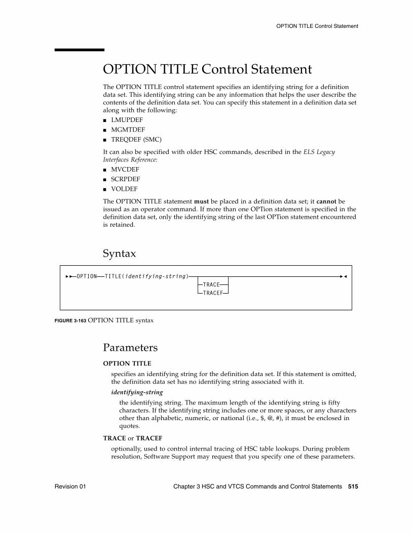
OPTION TITLE Control Statement
Revision 01 Chapter 3 HSC and VTCS Commands and Control Statements 515
OPTION TITLE Control StatementThe OPTION TITLE control statement specifies an identifying string for a definition data set. This identifying string can be any information that helps the user describe the contents of the definition data set. You can specify this statement in a definition data set along with the following:
■ LMUPDEF
■ MGMTDEF
■ TREQDEF (SMC)
It can also be specified with older HSC commands, described in the ELS Legacy Interfaces Reference:
■ MVCDEF
■ SCRPDEF
■ VOLDEF
The OPTION TITLE statement must be placed in a definition data set; it cannot be issued as an operator command. If more than one OPTion statement is specified in the definition data set, only the identifying string of the last OPTion statement encountered is retained.
Syntax
FIGURE 3-163 OPTION TITLE syntax
ParametersOPTION TITLE
specifies an identifying string for the definition data set. If this statement is omitted, the definition data set has no identifying string associated with it.
identifying-string
the identifying string. The maximum length of the identifying string is fifty characters. If the identifying string includes one or more spaces, or any characters other than alphabetic, numeric, or national (i.e., $, @, #), it must be enclosed in quotes.
TRACE or TRACEF
optionally, used to control internal tracing of HSC table lookups. During problem resolution, Software Support may request that you specify one of these parameters.
OPTION TITLE(identifying-string)TRACETRACEF
OPTion
516 ELS 7.1 Command, Control Statement, and Utility Reference • November 2012 Revision 01
OPTionInterfaces:
Console or PARMLIB onlyUUI: No
Subsystem Requirements:
Active HSC at BASE or FULL service level
DescriptionThe OPTion command sets or changes general HSC options.
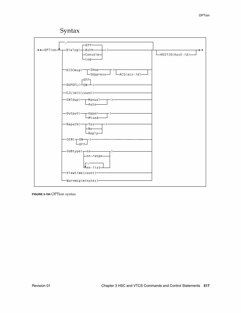
OPTion
Revision 01 Chapter 3 HSC and VTCS Commands and Control Statements 517
Syntax
FIGURE 3-164 OPTion syntax
OPTion Dialog( BothConsoleLog
)
,
HOSTID(host-id)
DISCmsg( SHowSUppress
)ACS(acs-id)
ENTdup(AutoManual )
Output( UpperMixed
)
Repath( YesNo
)
Reply
Off
SEN( ON )
OFf
DUPOFL( ON
OFF
EJLimit(count)
)
SUBtype( nnnn-range
Viewtime(count)
Warnmsg(minutes)
nn-list,
)
OPTion
518 ELS 7.1 Command, Control Statement, and Utility Reference • November 2012 Revision 01
ParametersDialog
allows HSC messages to be written to the operator console and/or the system log. These messages indicate that the HSC is waiting for an active task to complete before the HSC terminates. The initial Dialog value is set by the EXEC statement during HSC startup.
Off
specifies that messages are not to be written. Off is the default value for the HSC if the Dialog parameter is not specified on the EXEC statement.
Both
specifies that messages are written to the system log and the operator console.
Console
specifies that messages are written to the operator console only.
Log
specifies that messages are written to the system log only.
DISCmsg
specifies whether or not the “ACS acs-id is disconnected” message (SLS1664A) is displayed for the specified ACS.
This option is useful when an ACS has been added to the LIBGEN in advance to provide for future expansion. Entering DISCmsg allows the user to turn off the display for those ACSs that will not be connected until later.
SHow
Displays the “ACS acs-id is disconnected” message (SLS1664A) for an ACS. This is the initial value.
SUppress
Suppresses the “ACS acs-id is disconnected” message (SLS1664A) for an ACS.
ACS
optionally, specifies the ACS for which the command applies. If ACS is not specified, the DISCmsg setting entered (Show or Suppress) applies to all ACSs.
acs-id
the decimal ACSid value (00-99).
If ACS is not specified, all ACSs are affected.
DUPOFL
optionally, allows the duplicate VOLSER process to continue when the VOLSER being entered into the CAP shows in the CDS that it exists in an ACS that is disconnected, or in an LSM that is offline.
OFF
disables the duplicate VOLSER process. This is the default.
ON
enables the duplicate VOLSER process.
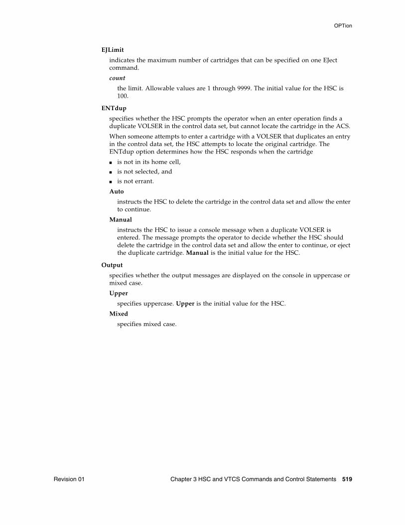
OPTion
Revision 01 Chapter 3 HSC and VTCS Commands and Control Statements 519
EJLimit
indicates the maximum number of cartridges that can be specified on one EJect command.
count
the limit. Allowable values are 1 through 9999. The initial value for the HSC is 100.
ENTdup
specifies whether the HSC prompts the operator when an enter operation finds a duplicate VOLSER in the control data set, but cannot locate the cartridge in the ACS.
When someone attempts to enter a cartridge with a VOLSER that duplicates an entry in the control data set, the HSC attempts to locate the original cartridge. The ENTdup option determines how the HSC responds when the cartridge
■ is not in its home cell,
■ is not selected, and
■ is not errant.
Auto
instructs the HSC to delete the cartridge in the control data set and allow the enter to continue.
Manual
instructs the HSC to issue a console message when a duplicate VOLSER is entered. The message prompts the operator to decide whether the HSC should delete the cartridge in the control data set and allow the enter to continue, or eject the duplicate cartridge. Manual is the initial value for the HSC.
Output
specifies whether the output messages are displayed on the console in uppercase or mixed case.
Upper
specifies uppercase. Upper is the initial value for the HSC.
Mixed
specifies mixed case.
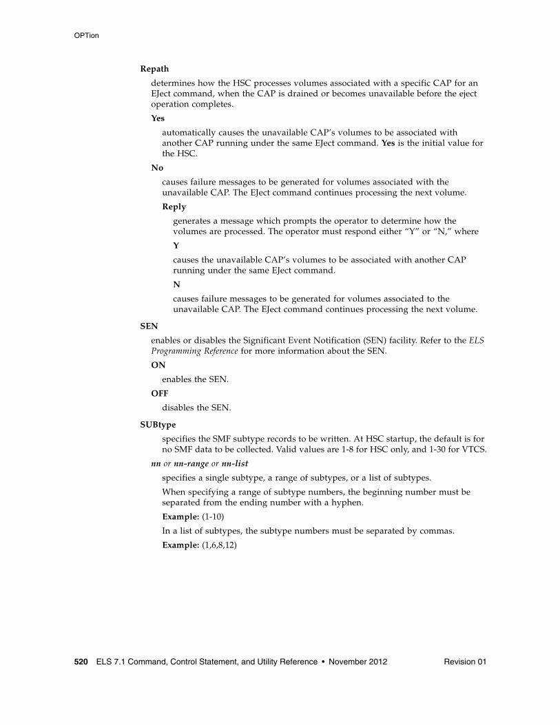
OPTion
520 ELS 7.1 Command, Control Statement, and Utility Reference • November 2012 Revision 01
Repath
determines how the HSC processes volumes associated with a specific CAP for an EJect command, when the CAP is drained or becomes unavailable before the eject operation completes.
Yes
automatically causes the unavailable CAP’s volumes to be associated with another CAP running under the same EJect command. Yes is the initial value for the HSC.
No
causes failure messages to be generated for volumes associated with the unavailable CAP. The EJect command continues processing the next volume.
Reply
generates a message which prompts the operator to determine how the volumes are processed. The operator must respond either “Y” or “N,” where
Y
causes the unavailable CAP’s volumes to be associated with another CAP running under the same EJect command.
N
causes failure messages to be generated for volumes associated to the unavailable CAP. The EJect command continues processing the next volume.
SEN
enables or disables the Significant Event Notification (SEN) facility. Refer to the ELS Programming Reference for more information about the SEN.
ON
enables the SEN.
OFF
disables the SEN.
SUBtype
specifies the SMF subtype records to be written. At HSC startup, the default is for no SMF data to be collected. Valid values are 1-8 for HSC only, and 1-30 for VTCS.
nn or nn-range or nn-list
specifies a single subtype, a range of subtypes, or a list of subtypes.
When specifying a range of subtype numbers, the beginning number must be separated from the ending number with a hyphen.
Example: (1-10)
In a list of subtypes, the subtype numbers must be separated by commas.
Example: (1,6,8,12)
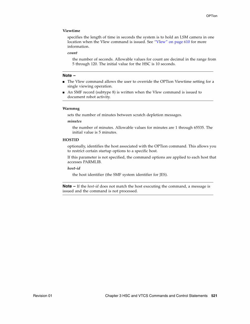
OPTion
Revision 01 Chapter 3 HSC and VTCS Commands and Control Statements 521
Viewtime
specifies the length of time in seconds the system is to hold an LSM camera in one location when the VIew command is issued. See “VIew” on page 610 for more information.
count
the number of seconds. Allowable values for count are decimal in the range from 5 through 120. The initial value for the HSC is 10 seconds.
Note – ■ The VIew command allows the user to override the OPTion Viewtime setting for a
single viewing operation.
■ An SMF record (subtype 8) is written when the VIew command is issued to document robot activity.
Warnmsg
sets the number of minutes between scratch depletion messages.
minutes
the number of minutes. Allowable values for minutes are 1 through 65535. The initial value is 5 minutes.
HOSTID
optionally, identifies the host associated with the OPTion command. This allows you to restrict certain startup options to a specific host.
If this parameter is not specified, the command options are applied to each host that accesses PARMLIB.
host-id
the host identifier (the SMF system identifier for JES).
Note – If the host-id does not match the host executing the command, a message is issued and the command is not processed.
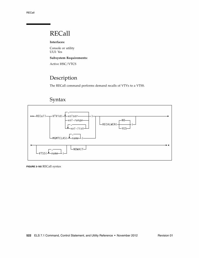
RECall
522 ELS 7.1 Command, Control Statement, and Utility Reference • November 2012 Revision 01
RECallInterfaces:
Console or utilityUUI: Yes
Subsystem Requirements:
Active HSC/VTCS
DescriptionThe RECall command performs demand recalls of VTVs to a VTSS.
Syntax
FIGURE 3-165 RECall syntax
MGMTCLAS( name,
)
RECALWER(NO
YES)
RECall
VTSS(,name )
NOWAIT
VTVid(,volser )vol-range
vol-list,
RECall
Revision 01 Chapter 3 HSC and VTCS Commands and Control Statements 523
ParametersVTVid
specifies the VTVs to recall.
volser, vol-range, or vol-list
the volsers of one or more VTVs. You can also specify one or more ranges.
MGMTCLAS
specifies one or more Management Classes that determine one or more VTVs to recall.
mgmt-class-name | mgmt-class-list
the names of one or more Management Classes that you defined on the MGMTclas control statement; for more information, see “MGMTclas Control Statement” on page 433.
Note – MGMTCLAS, VTVid, and DSN are mutually exclusive.
VTSS
specifies where the VTVs are recalled as follows:
■ If you do not specify a VTSS (the default), VTCS attempts to recall the VTVs to the VTSS of creation if it is accessible. Otherwise VTCS recalls the VTVs to the VTSS with the lowest DBU.
■ If you specify a single VTSS, VTCS attempts to recall the VTVs to the specified VTSS if it is accessible. Otherwise, VTCS recalls the VTVs to the VTSS with the lowest DBU.
■ If you specify a list of VTVs, VTCS attempts to recall the VTVs to the VTSS of creation if it is on the list and accessible, otherwise VTCS recalls the VTVs to the VTSS with the lowest DBU on the list.
vtss-name
the names of one or more VTSSs.
RECALWER
optionally, specifies whether VTCS recalls VTVs with read data checks.
NO
Do not recall VTVs with read data checks.
YES
Do not recall VTVs with read data checks. This is the default.
NOWAIT
optionally, specifies that the utility does not wait for the operation to complete and returns after the request is submitted.
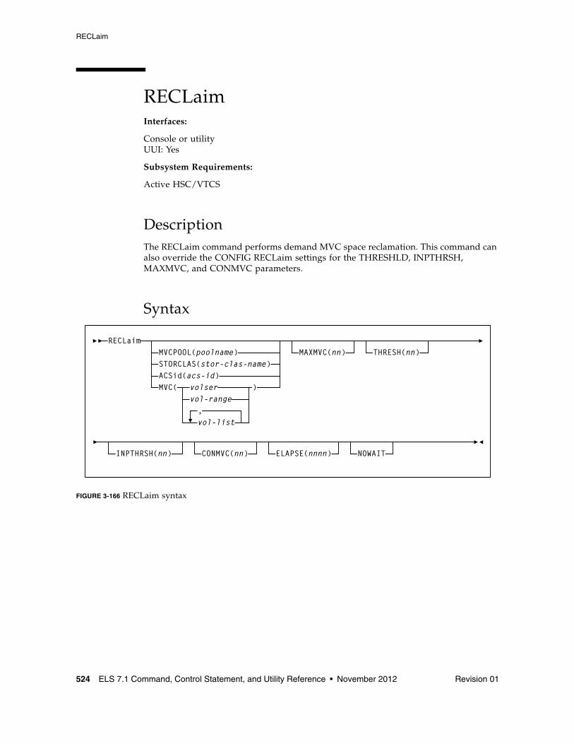
RECLaim
524 ELS 7.1 Command, Control Statement, and Utility Reference • November 2012 Revision 01
RECLaimInterfaces:
Console or utilityUUI: Yes
Subsystem Requirements:
Active HSC/VTCS
DescriptionThe RECLaim command performs demand MVC space reclamation. This command can also override the CONFIG RECLaim settings for the THRESHLD, INPTHRSH, MAXMVC, and CONMVC parameters.
Syntax
FIGURE 3-166 RECLaim syntax
RECLaimMVCPOOL(poolname)STORCLAS(stor-clas-name)ACSid(acs-id)MVC( volser
vol-range
vol-list,
MAXMVC(nn) THRESH(nn)
ELAPSE(nnnn) NOWAITCONMVC(nn)
)
INPTHRSH(nn)
RECLaim
Revision 01 Chapter 3 HSC and VTCS Commands and Control Statements 525
ParametersMVCPOOL
reclaim the MVCs in the specified Named MVC Pool.
poolname
the name of a Named MVC Pool that you defined on the MVCPool control statement. Refer to the ELS Legacy Interfaces Reference for more information.
STORCLAS
reclaim the MVCs in the specified Storage Class.
stor-class-name
the name of a Storage Class that you defined on the STORclas control statement; for more information, see “STORclas Control Statement” on page 451.
ACSid
reclaim the eligible MVCs in the specified ACS.
acs-id
a two digit decimal ACS identifier from 00-99.
MVC
reclaim the specified MVC(s).
volser, vol-range or vol-list
the volsers of one or more MVCs.You can also specify individual MVCs and ranges in a list. For example:
(MVC000-MVC005,MVC010,MVC015)
MAXMVC(nn)
optionally, specifies the maximum number of MVCs that will be processed by a single space reclamation task. Valid values are 1 to 98. There is no default; if not specified, the CONFIG RECLAIM value (or default) is used.
For automatic space reclamation to start, the number of eligible MVCs (determined by the THRESH parameter) must also exceed the MAXMVC value.
THRESH(nn)
optionally, specifies the percentage of fragmented space that makes an MVC eligible for demand or automatic reclamation. Valid values are 4 to 98. If not specified, the CONFIG RECLAIM value (or default) is used.
RECLaim
526 ELS 7.1 Command, Control Statement, and Utility Reference • November 2012 Revision 01
INPTHRSH
optionally, specifies the percentage of fragmented space that makes an MVC in partitioned format eligible for dynamic reclaim processing. This value overrides the global INPTHRSH value specified in the CONFIg RECLAIM statement. If this parameter is not specified, the current active global INPTHRSH value is used.
nn
a percentage between 3 and 97. This value must be less than the THRESHLD value.
Note – If INPTHRSH is specified, THRESHLD must also be specified. Both INPTHRSH and THRESHLD play roles when space reclamation processes MVCs in partitioned format. Refer to the publication Configuring HSC and VTCS for more information.
NOWAIT
optionally, specifies that the utility does not wait for the operation to complete and returns after the request is submitted.
CONMVC(nn)
optionally, specifies the maximum number of MVCs that VTCS concurrently processes for both drain and reclaim.
Valid values are 1 to 99. If not specified, the default is the CONMVC value specified on the CONFIG RECLAIM statement.
ELAPSE(nnnn)
optionally, specifies the maximum time for the reclaim in minutes. If the maximum time expires, VTCS issues message SLS6682I. If there are no MVCs currently mounted, reclaim stops when the ELAPSE value is reached. If any MVCs are currently mounted when the ELAPSE value is reached, reclaim processes the mounted MVCs and then stops.
Valid values are 1 to 1440. If not specified, there is no time limit on the reclaim process.
RECONcil
Revision 01 Chapter 3 HSC and VTCS Commands and Control Statements 527
RECONcilInterfaces:
Utility onlyUUI: Yes
Subsystem Requirements:
Active HSC/VTCS
DescriptionThe RECONcil command reconciles VTV media and location (moves VTVs from one Storage Class to another).
RECONcil performs a series of cross-checks between the MVCs, VTVs, STORCLAS and MGMTCLAS definitions.
RECONCIL has two phases:
■ In the first phase, VTCS selects MVC and Storage Classes to be checked. MVCs are checked to ensure they meet the Storage Class definitions and ACS definitions. If inconsistencies are found, then the VTVs on those MVCs are added to the list of VTVs to be recalled and re-migrated to give correct MVC, ACS and Storage Class copies for that VTV. The RECONcil parameters STORCLAS and MVC limit the checking in this phase.
■ In the second phase, VTCS selects the VTVs and Management Classes to establish the correct number and location of VTV copies. Any VTVs with inconsistencies are added to the list of VTVs to be recalled and re-migrated. The RECONcil parameters MGMTCLAS and VTV limit the checking in this phase.
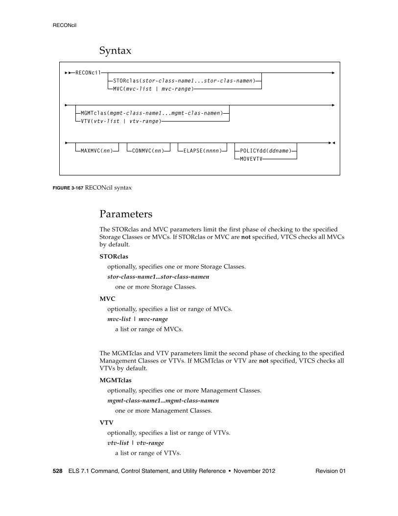
RECONcil
528 ELS 7.1 Command, Control Statement, and Utility Reference • November 2012 Revision 01
Syntax
FIGURE 3-167 RECONcil syntax
ParametersThe STORclas and MVC parameters limit the first phase of checking to the specified Storage Classes or MVCs. If STORclas or MVC are not specified, VTCS checks all MVCs by default.
STORclas
optionally, specifies one or more Storage Classes.
stor-class-name1...stor-class-namen
one or more Storage Classes.
MVC
optionally, specifies a list or range of MVCs.
mvc-list | mvc-range
a list or range of MVCs.
The MGMTclas and VTV parameters limit the second phase of checking to the specified Management Classes or VTVs. If MGMTclas or VTV are not specified, VTCS checks all VTVs by default.
MGMTclas
optionally, specifies one or more Management Classes.
mgmt-class-name1...mgmt-class-namen
one or more Management Classes.
VTV
optionally, specifies a list or range of VTVs.
vtv-list | vtv-range
a list or range of VTVs.
RECONcil
CONMVC(nn) ELAPSE(nnnn)MAXMVC(nn)
STORclas(stor-class-name1...stor-clas-namen)MVC(mvc-list | mvc-range)
MGMTclas(mgmt-class-name1...mgmt-clas-namen)VTV(vtv-list | vtv-range)
POLICYdd(ddname)MOVEVTV
RECONcil
Revision 01 Chapter 3 HSC and VTCS Commands and Control Statements 529
MAXMVC(nn)
optionally, specifies the maximum number of MVCs that will be processed by a single reconciliation task.
Valid values are 1 to 98. If not specified the CONFIG RECLAIM value (or default) is used. This parameter is ignored if MOVEVTV is not specified.
CONMVC(nn)
optionally, specifies the maximum number of MVCs that VTCS concurrently processes during subsequent recall and migrate operations.
Valid values are 1 to 99. If not specified the CONFIG RECLAIM value (or default) is used. This parameter is ignored if MOVEVTV is not specified.
ELAPSE(nnnn)
optionally, specifies the maximum time for the reconciliation in minutes. If the maximum time expires, VTCS issues message SLS6682I. If there are no MVCs currently mounted, reconciliation stops when the ELAPSE value is reached. If any MVCs are currently mounted when the ELAPSE value is reached, reconciliation processes the mounted MVCs and then stops.
Valid values are 1 to 1440. If not specified, there is no time limit on the reconciliation process. This parameter is ignored if MOVEVTV is not specified.
POLICYdd(ddname)
optionally, specifies the ddname of a file containing an alternate MGMTclas statement.
MOVEVTV
optionally, move VTVs per the currently active Management Policies as specified by the MGMTclas statements that apply to the VTVs. If you do not specify MOVEVTV, only a report is generated.
Note – POLICYdd and MOVEVTV are mutually exclusive.
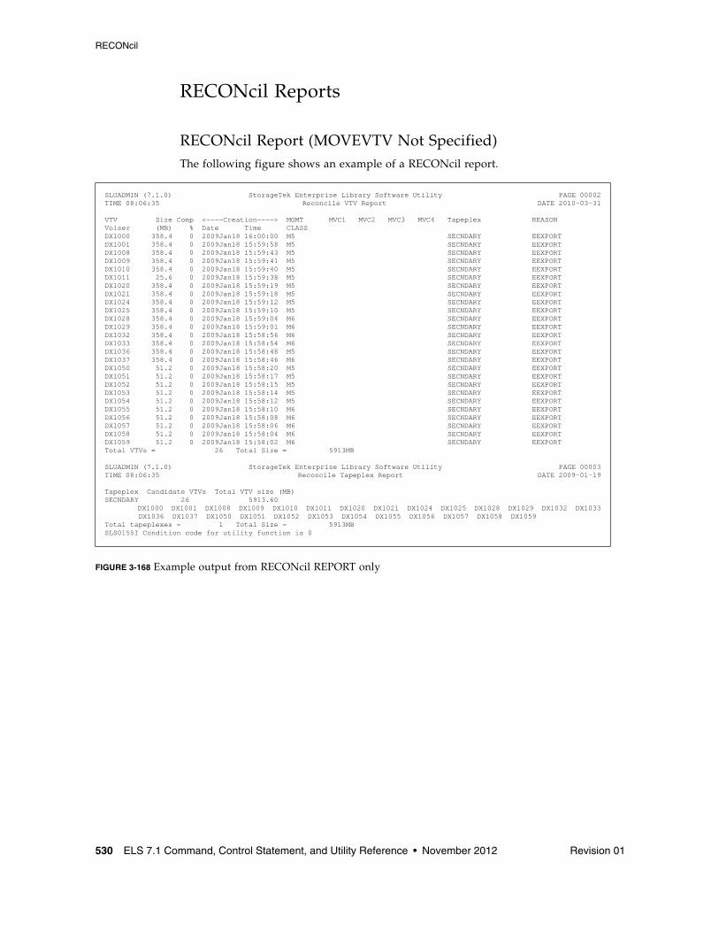
RECONcil
530 ELS 7.1 Command, Control Statement, and Utility Reference • November 2012 Revision 01
RECONcil Reports
RECONcil Report (MOVEVTV Not Specified)The following figure shows an example of a RECONcil report.
FIGURE 3-168 Example output from RECONcil REPORT only
SLUADMIN (7.1.0) StorageTek Enterprise Library Software Utility PAGE 00002TIME 08:06:35 Reconcile VTV Report DATE 2010-03-31
VTV Size Comp <----Creation----> MGMT MVC1 MVC2 MVC3 MVC4 Tapeplex REASONVolser (MB) % Date Time CLASSDX1000 358.4 0 2009Jan18 16:00:00 M5 SECNDARY EEXPORTDX1001 358.4 0 2009Jan18 15:59:58 M5 SECNDARY EEXPORTDX1008 358.4 0 2009Jan18 15:59:43 M5 SECNDARY EEXPORTDX1009 358.4 0 2009Jan18 15:59:41 M5 SECNDARY EEXPORTDX1010 358.4 0 2009Jan18 15:59:40 M5 SECNDARY EEXPORTDX1011 25.6 0 2009Jan18 15:59:38 M5 SECNDARY EEXPORTDX1020 358.4 0 2009Jan18 15:59:19 M5 SECNDARY EEXPORTDX1021 358.4 0 2009Jan18 15:59:18 M5 SECNDARY EEXPORTDX1024 358.4 0 2009Jan18 15:59:12 M5 SECNDARY EEXPORTDX1025 358.4 0 2009Jan18 15:59:10 M5 SECNDARY EEXPORTDX1028 358.4 0 2009Jan18 15:59:04 M6 SECNDARY EEXPORTDX1029 358.4 0 2009Jan18 15:59:01 M6 SECNDARY EEXPORTDX1032 358.4 0 2009Jan18 15:58:56 M6 SECNDARY EEXPORTDX1033 358.4 0 2009Jan18 15:58:54 M6 SECNDARY EEXPORTDX1036 358.4 0 2009Jan18 15:58:48 M5 SECNDARY EEXPORTDX1037 358.4 0 2009Jan18 15:58:46 M6 SECNDARY EEXPORTDX1050 51.2 0 2009Jan18 15:58:20 M5 SECNDARY EEXPORTDX1051 51.2 0 2009Jan18 15:58:17 M5 SECNDARY EEXPORTDX1052 51.2 0 2009Jan18 15:58:15 M5 SECNDARY EEXPORTDX1053 51.2 0 2009Jan18 15:58:14 M5 SECNDARY EEXPORTDX1054 51.2 0 2009Jan18 15:58:12 M5 SECNDARY EEXPORTDX1055 51.2 0 2009Jan18 15:58:10 M6 SECNDARY EEXPORTDX1056 51.2 0 2009Jan18 15:58:08 M6 SECNDARY EEXPORTDX1057 51.2 0 2009Jan18 15:58:06 M6 SECNDARY EEXPORTDX1058 51.2 0 2009Jan18 15:58:04 M6 SECNDARY EEXPORTDX1059 51.2 0 2009Jan18 15:58:02 M6 SECNDARY EEXPORTTotal VTVs = 26 Total Size = 5913MB
SLUADMIN (7.1.0) StorageTek Enterprise Library Software Utility PAGE 00003TIME 08:06:35 Reconcile Tapeplex Report DATE 2009-01-19
Tapeplex Candidate VTVs Total VTV size (MB)SECNDARY 26 5913.60 DX1000 DX1001 DX1008 DX1009 DX1010 DX1011 DX1020 DX1021 DX1024 DX1025 DX1028 DX1029 DX1032 DX1033 DX1036 DX1037 DX1050 DX1051 DX1052 DX1053 DX1054 DX1055 DX1056 DX1057 DX1058 DX1059Total tapeplexes = 1 Total Size = 5913MBSLS0155I Condition code for utility function is 0
RECONcil
Revision 01 Chapter 3 HSC and VTCS Commands and Control Statements 531
RECONcil Report Fields
The following list describes the RECONcil report fields.
VTV Volser
the VTV volser.
Size (MB)
the uncompressed size of the VTV (MB). <MOUNT> indicates that the VTV was mounted when the report ran. <FENCED> indicates that the VTV’s state is unknown. If <FENCED> appears, contact Oracle StorageTek Software Support.
Comp %
the VTV compression percentage achieved. This is the difference between the uncompressed and compressed VTV size expressed as a percentage of the uncompressed VTV size. For example if a 100MB VTV compresses to 40MB then the compression% will be given as 60%. A compression of 0% indicates that no compression was possible on the VTV.
Creation Date and Time
the date and time that the VTV was created.
MGMT Class
the name of the Management Class for the VTV specified.
MVC1, MVC2, MVC3, MVC4
the MVC(s) affected as a result of the Reconcil.
Tapeplex
the TapePlex name.
Reason
the reason for the VTV selection: media type, media location, migration (space release), immediate migration, or Storage Class.
The RECONcil Tapeplex Report section displays the number of candidate VTVs and Total VTV size (MB) for each TapePlex.
RECONcil
532 ELS 7.1 Command, Control Statement, and Utility Reference • November 2012 Revision 01
MVC Report Fields
The following list describes the RECONcil MVC report fields. The data for each MVC is followed by one or more VTV volsers with copies on the MVC. This section of the report is followed by a total line showing the number of candidate MVCs and the size in MB to be recalled and remigrated.
MVC Volser
the MVC volser.
MVC Media Type
the MVC type.
Media Size (MB)
the size of the MVC (MB). This will only be determined after VTCS has used an MVC. “UNKNOWN” appears in this field until VTCS migrates a VTV to the MVC.
Storage Class/Consolidate time
the MVC’s Storage Class or time the VTVs on it were consolidated.
Candidate VTVs
the number of candidate VTVs on the MVC.
Total VTV Size (MB)
the size of all candidate VTVs on the MVC in MBs.
Location (ACS ID)
the ACS where the MVC resides. If blank, the MVC is not currently in an ACS.
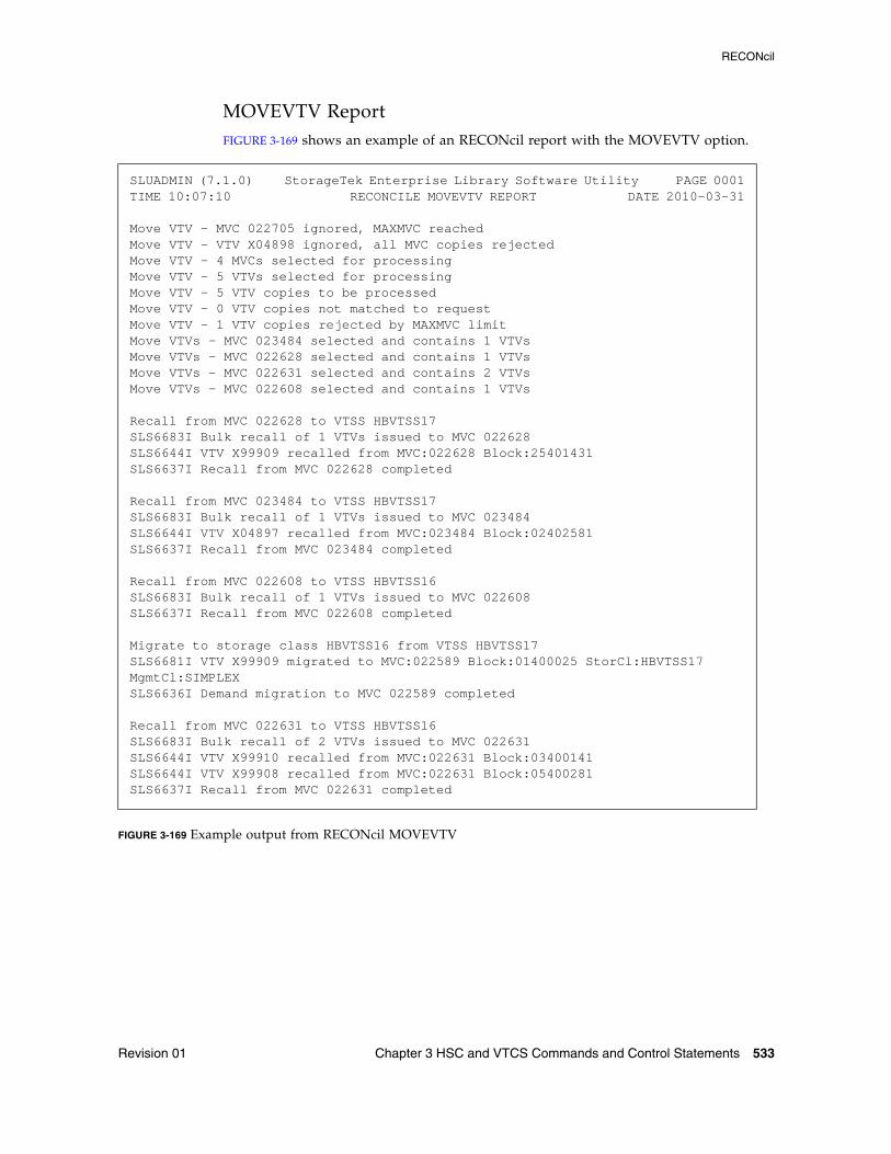
RECONcil
Revision 01 Chapter 3 HSC and VTCS Commands and Control Statements 533
MOVEVTV ReportFIGURE 3-169 shows an example of an RECONcil report with the MOVEVTV option.
FIGURE 3-169 Example output from RECONcil MOVEVTV
SLUADMIN (7.1.0) StorageTek Enterprise Library Software Utility PAGE 0001TIME 10:07:10 RECONCILE MOVEVTV REPORT DATE 2010-03-31
Move VTV - MVC 022705 ignored, MAXMVC reachedMove VTV - VTV X04898 ignored, all MVC copies rejectedMove VTV - 4 MVCs selected for processingMove VTV - 5 VTVs selected for processingMove VTV - 5 VTV copies to be processedMove VTV - 0 VTV copies not matched to requestMove VTV - 1 VTV copies rejected by MAXMVC limitMove VTVs - MVC 023484 selected and contains 1 VTVsMove VTVs - MVC 022628 selected and contains 1 VTVsMove VTVs - MVC 022631 selected and contains 2 VTVsMove VTVs - MVC 022608 selected and contains 1 VTVs
Recall from MVC 022628 to VTSS HBVTSS17SLS6683I Bulk recall of 1 VTVs issued to MVC 022628SLS6644I VTV X99909 recalled from MVC:022628 Block:25401431SLS6637I Recall from MVC 022628 completed Recall from MVC 023484 to VTSS HBVTSS17SLS6683I Bulk recall of 1 VTVs issued to MVC 023484SLS6644I VTV X04897 recalled from MVC:023484 Block:02402581SLS6637I Recall from MVC 023484 completed Recall from MVC 022608 to VTSS HBVTSS16SLS6683I Bulk recall of 1 VTVs issued to MVC 022608SLS6637I Recall from MVC 022608 completed Migrate to storage class HBVTSS16 from VTSS HBVTSS17SLS6681I VTV X99909 migrated to MVC:022589 Block:01400025 StorCl:HBVTSS17 MgmtCl:SIMPLEXSLS6636I Demand migration to MVC 022589 completed
Recall from MVC 022631 to VTSS HBVTSS16SLS6683I Bulk recall of 2 VTVs issued to MVC 022631SLS6644I VTV X99910 recalled from MVC:022631 Block:03400141SLS6644I VTV X99908 recalled from MVC:022631 Block:05400281SLS6637I Recall from MVC 022631 completed
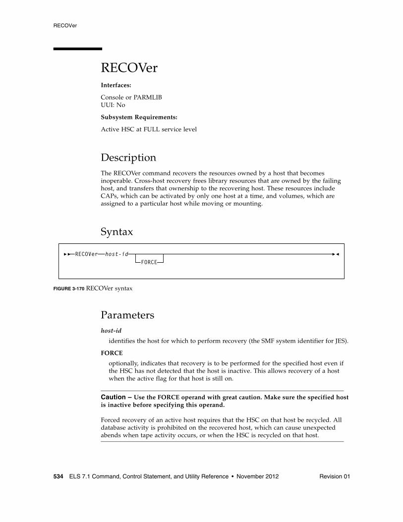
RECOVer
534 ELS 7.1 Command, Control Statement, and Utility Reference • November 2012 Revision 01
RECOVerInterfaces:
Console or PARMLIBUUI: No
Subsystem Requirements:
Active HSC at FULL service level
DescriptionThe RECOVer command recovers the resources owned by a host that becomes inoperable. Cross-host recovery frees library resources that are owned by the failing host, and transfers that ownership to the recovering host. These resources include CAPs, which can be activated by only one host at a time, and volumes, which are assigned to a particular host while moving or mounting.
Syntax
FIGURE 3-170 RECOVer syntax
Parametershost-id
identifies the host for which to perform recovery (the SMF system identifier for JES).
FORCE
optionally, indicates that recovery is to be performed for the specified host even if the HSC has not detected that the host is inactive. This allows recovery of a host when the active flag for that host is still on.
Caution – Use the FORCE operand with great caution. Make sure the specified host is inactive before specifying this operand. Forced recovery of an active host requires that the HSC on that host be recycled. All database activity is prohibited on the recovered host, which can cause unexpected abends when tape activity occurs, or when the HSC is recycled on that host.
RECOVer host-idFORCE
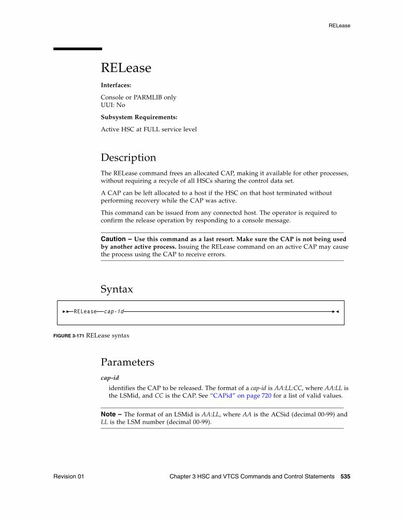
RELease
Revision 01 Chapter 3 HSC and VTCS Commands and Control Statements 535
RELeaseInterfaces:
Console or PARMLIB onlyUUI: No
Subsystem Requirements:
Active HSC at FULL service level
DescriptionThe RELease command frees an allocated CAP, making it available for other processes, without requiring a recycle of all HSCs sharing the control data set.
A CAP can be left allocated to a host if the HSC on that host terminated without performing recovery while the CAP was active.
This command can be issued from any connected host. The operator is required to confirm the release operation by responding to a console message.
Caution – Use this command as a last resort. Make sure the CAP is not being used by another active process. Issuing the RELease command on an active CAP may cause the process using the CAP to receive errors.
Syntax
FIGURE 3-171 RELease syntax
Parameterscap-id
identifies the CAP to be released. The format of a cap-id is AA:LL:CC, where AA:LL is the LSMid, and CC is the CAP. See “CAPid” on page 720 for a list of valid values.
Note – The format of an LSMid is AA:LL, where AA is the ACSid (decimal 00-99) and LL is the LSM number (decimal 00-99).
RELease cap-id
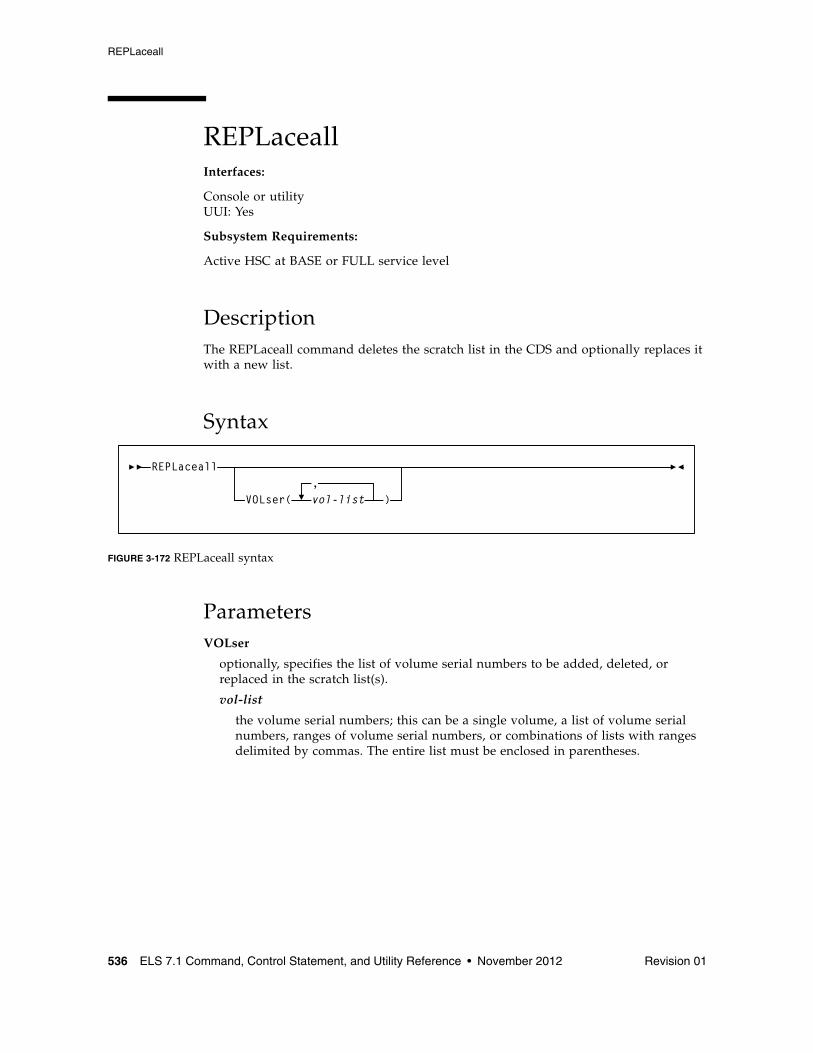
REPLaceall
536 ELS 7.1 Command, Control Statement, and Utility Reference • November 2012 Revision 01
REPLaceallInterfaces:
Console or utilityUUI: Yes
Subsystem Requirements:
Active HSC at BASE or FULL service level
DescriptionThe REPLaceall command deletes the scratch list in the CDS and optionally replaces it with a new list.
Syntax
FIGURE 3-172 REPLaceall syntax
ParametersVOLser
optionally, specifies the list of volume serial numbers to be added, deleted, or replaced in the scratch list(s).
vol-list
the volume serial numbers; this can be a single volume, a list of volume serial numbers, ranges of volume serial numbers, or combinations of lists with ranges delimited by commas. The entire list must be enclosed in parentheses.
REPLaceall
VOLser( vol-list,
)
RESTore
Revision 01 Chapter 3 HSC and VTCS Commands and Control Statements 537
RESToreInterfaces:
SLUADMIN utility onlyUUI: No
Subsystem Requirements:
HSC must be down (inactive)
DescriptionThe RESTore command restores, or re-creates the library Control Data Set (CDS) from a previous CDS backup copy. If multiple CDS DD statements are specified, then multiple CDS copies are created in the RESTore process.
Note – Refer to the ELS Legacy Interfaces Reference for information about using RESTore when journaling is enabled.
Caution – It is critical that you restore all data sets referenced by the HSC (primary, secondary, standby). Failing to restore all data sets can cause CDS mismatches. Refer to the publication Managing HSC and VTCS for detailed information about when to use this utility and how it functions.
Syntax
FIGURE 3-173 RESTore syntax
ParametersNone required. Refer to the ELS Legacy Interfaces Reference for information about using RESTore when journaling is enabled.
RESTore
RESTore
538 ELS 7.1 Command, Control Statement, and Utility Reference • November 2012 Revision 01
Additional JCL Requirements In addition to the required JCL definition statements described in “Invoking SLUADMIN” on page 674, the following definition statements apply to the RESTore JCL:
SLSCNTL
specifies the primary CDS.
SLSCNTL2
optionally, specifies the secondary CDS.
If a secondary CDS exists, include this statement so that if a switch occurs and the secondary CDS becomes active, the CDSs can be reordered to maintain database integrity.
SLSSTBY
optionally, specifies the standby CDS.
If a standby CDS exists, include this statement so that if a switch occurs and the standby CDS becomes active, the CDSs can be reordered to maintain database integrity.
SLSBKUP
the backup data set.
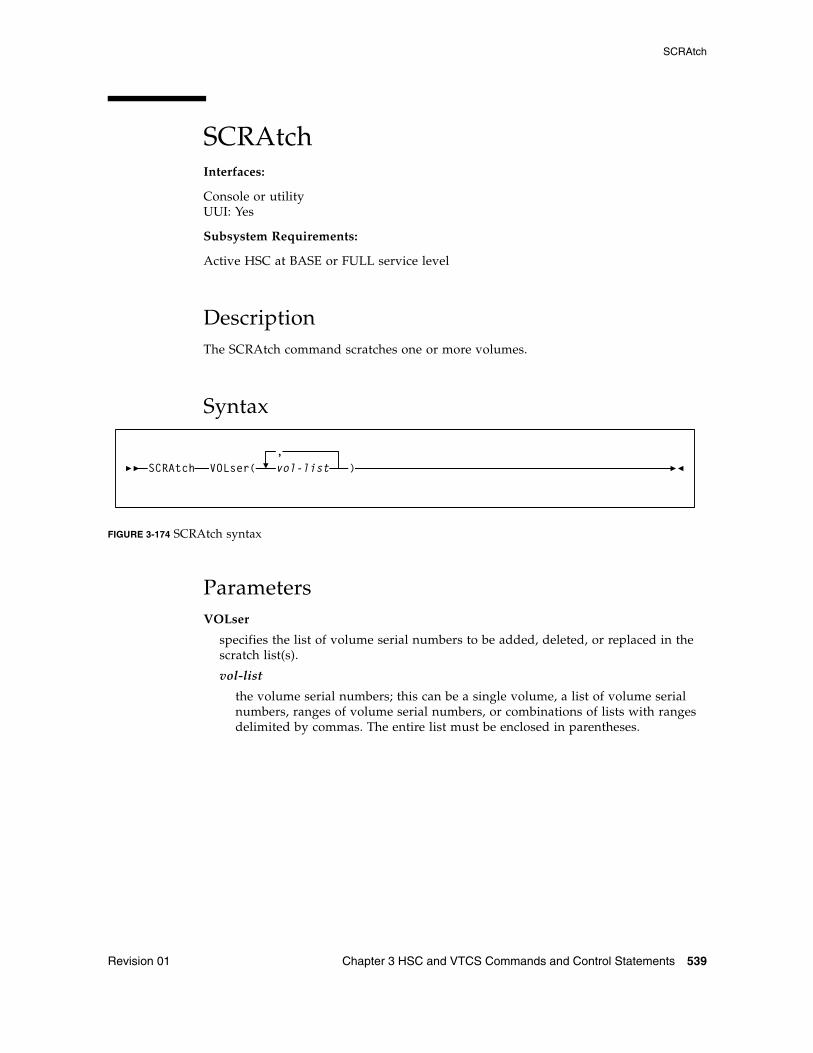
SCRAtch
Revision 01 Chapter 3 HSC and VTCS Commands and Control Statements 539
SCRAtchInterfaces:
Console or utilityUUI: Yes
Subsystem Requirements:
Active HSC at BASE or FULL service level
DescriptionThe SCRAtch command scratches one or more volumes.
Syntax
FIGURE 3-174 SCRAtch syntax
ParametersVOLser
specifies the list of volume serial numbers to be added, deleted, or replaced in the scratch list(s).
vol-list
the volume serial numbers; this can be a single volume, a list of volume serial numbers, ranges of volume serial numbers, or combinations of lists with ranges delimited by commas. The entire list must be enclosed in parentheses.
SCRAtch VOLser(,vol-list )
SCREdist
540 ELS 7.1 Command, Control Statement, and Utility Reference • November 2012 Revision 01
SCREdistInterfaces:
SLUADMIN utility onlyUUI: No
Subsystem Requirements:
Active HSC at FULL service level
DescriptionThe SCREdist command redistributes, or balances, the number of scratch volumes across the library.
SCREdist permits the redistribution of scratch volumes either:
■ among LSMs implied by the specification of an ACS, or
■ among the LSMs explicitly identified through an optional parameter.
SCREdist allows you to select one media type and recording technique. If specified, scratch volume redistribution will be based on the MEDia and RECtech settings.
If neither MEDia nor RECtech is specified, volumes are redistributed without regard to media type or recording technique.
When only the ACS parameter is specified, the redistribution method transfers cartridges from LSMs with a greater number of scratch volumes to LSMs with a lesser number of scratch volumes. The process is repeated until the number of scratch volumes in each LSM is within the defined scratch tolerance level.
Distribution in an ACS containing a mix of LSMs (4410s, 9310s, 9360s, 9740s) is performed based on a percentage of scratch cartridges in the ACS. That is, the utility causes each LSM to have the same percentage of scratch tapes within the ACS as the LSM has cells within the ACS. For example, in an ACS where a 9310 LSM contains 80 percent of the cells within the ACS, 80 percent of the scratch tapes will reside in the 9310.
Note – The SL3000 and SL8500 are standalone libraries and cannot be combined with any other LSM type.
After Scratch Redistribution is completed, only the specified LSMs contain scratch cartridges, if the LSM parameter was specified.
Concurrent redistributions among different ACSs are accomplished by multiple executions of this utility program.
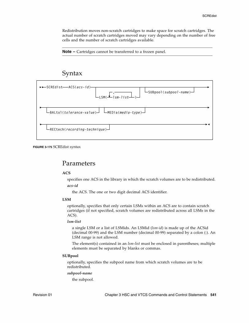
SCREdist
Revision 01 Chapter 3 HSC and VTCS Commands and Control Statements 541
Redistribution moves non-scratch cartridges to make space for scratch cartridges. The actual number of scratch cartridges moved may vary depending on the number of free cells and the number of scratch cartridges available.
Note – Cartridges cannot be transferred to a frozen panel.
Syntax
FIGURE 3-175 SCREdist syntax
ParametersACS
specifies one ACS in the library in which the scratch volumes are to be redistributed.
acs-id
the ACS. The one or two digit decimal ACS identifier.
LSM
optionally, specifies that only certain LSMs within an ACS are to contain scratch cartridges (if not specified, scratch volumes are redistributed across all LSMs in the ACS).
lsm-list
a single LSM or a list of LSMids. An LSMid (lsm-id) is made up of the ACSid (decimal 00-99) and the LSM number (decimal 00-99) separated by a colon (:). An LSM range is not allowed.
The element(s) contained in an lsm-list must be enclosed in parentheses; multiple elements must be separated by blanks or commas.
SUBpool
optionally, specifies the subpool name from which scratch volumes are to be redistributed.
subpool-name
the subpool.
ACS(acs-id)
LSM( lsm-list,
)SUBpool(subpool-name)
SCREdist
BALtol(tolerance-value) MEDia(media-type)
RECtech(recording-technique)
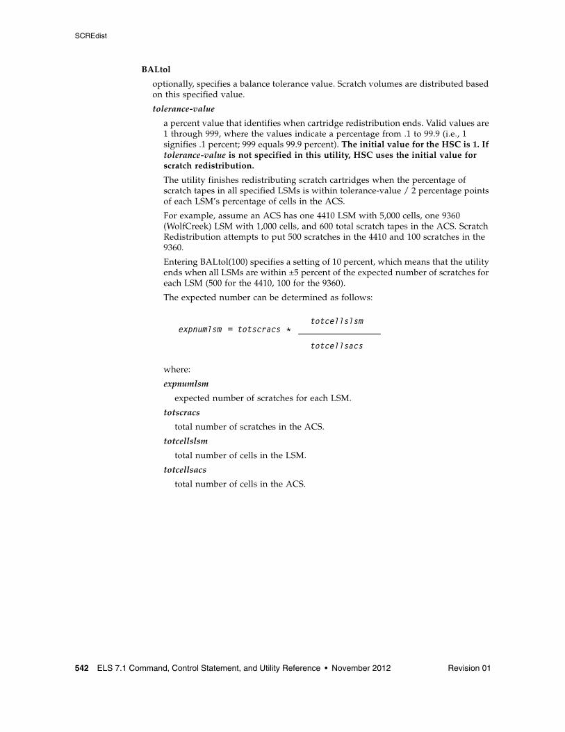
SCREdist
542 ELS 7.1 Command, Control Statement, and Utility Reference • November 2012 Revision 01
BALtol
optionally, specifies a balance tolerance value. Scratch volumes are distributed based on this specified value.
tolerance-value
a percent value that identifies when cartridge redistribution ends. Valid values are 1 through 999, where the values indicate a percentage from .1 to 99.9 (i.e., 1 signifies .1 percent; 999 equals 99.9 percent). The initial value for the HSC is 1. If tolerance-value is not specified in this utility, HSC uses the initial value for scratch redistribution.
The utility finishes redistributing scratch cartridges when the percentage of scratch tapes in all specified LSMs is within tolerance-value / 2 percentage points of each LSM’s percentage of cells in the ACS.
For example, assume an ACS has one 4410 LSM with 5,000 cells, one 9360 (WolfCreek) LSM with 1,000 cells, and 600 total scratch tapes in the ACS. Scratch Redistribution attempts to put 500 scratches in the 4410 and 100 scratches in the 9360.
Entering BALtol(100) specifies a setting of 10 percent, which means that the utility ends when all LSMs are within ±5 percent of the expected number of scratches for each LSM (500 for the 4410, 100 for the 9360).
The expected number can be determined as follows:
where:
expnumlsm
expected number of scratches for each LSM.
totscracs
total number of scratches in the ACS.
totcellslsm
total number of cells in the LSM.
totcellsacs
total number of cells in the ACS.
expnumlsm = totscracs *totcellslsm
totcellsacs
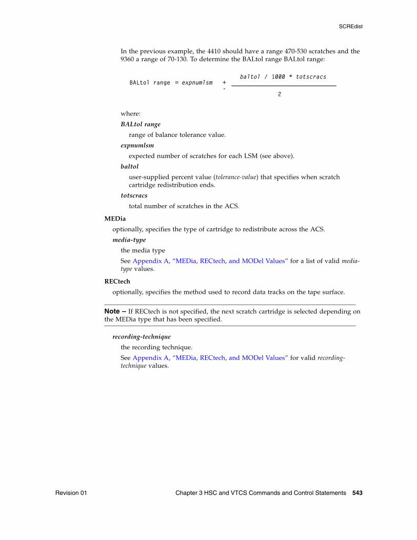
SCREdist
Revision 01 Chapter 3 HSC and VTCS Commands and Control Statements 543
In the previous example, the 4410 should have a range 470-530 scratches and the 9360 a range of 70-130. To determine the BALtol range BALtol range:
where:
BALtol range
range of balance tolerance value.
expnumlsm
expected number of scratches for each LSM (see above).
baltol
user-supplied percent value (tolerance-value) that specifies when scratch cartridge redistribution ends.
totscracs
total number of scratches in the ACS.
MEDia
optionally, specifies the type of cartridge to redistribute across the ACS.
media-type
the media type
See Appendix A, “MEDia, RECtech, and MODel Values” for a list of valid media-type values.
RECtech
optionally, specifies the method used to record data tracks on the tape surface.
Note – If RECtech is not specified, the next scratch cartridge is selected depending on the MEDia type that has been specified.
recording-technique
the recording technique.
See Appendix A, “MEDia, RECtech, and MODel Values” for valid recording-technique values.
BALtol range = expnumlsm +baltol / 1000 * totscracs
2-
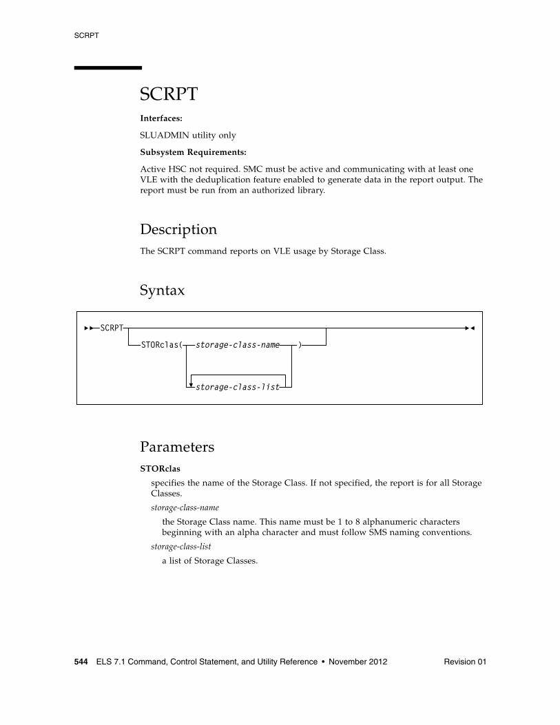
SCRPT
544 ELS 7.1 Command, Control Statement, and Utility Reference • November 2012 Revision 01
SCRPTInterfaces:
SLUADMIN utility only
Subsystem Requirements:
Active HSC not required. SMC must be active and communicating with at least one VLE with the deduplication feature enabled to generate data in the report output. The report must be run from an authorized library.
DescriptionThe SCRPT command reports on VLE usage by Storage Class.
Syntax
ParametersSTORclas
specifies the name of the Storage Class. If not specified, the report is for all Storage Classes.
storage-class-name
the Storage Class name. This name must be 1 to 8 alphanumeric characters beginning with an alpha character and must follow SMS naming conventions.
storage-class-list
a list of Storage Classes.
SCRPT
STORclas( storage-class-name )
storage-class-list
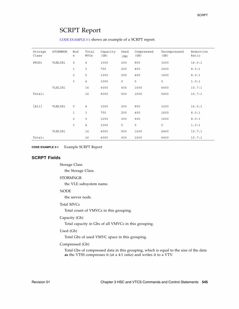
SCRPT
Revision 01 Chapter 3 HSC and VTCS Commands and Control Statements 545
SCRPT ReportCODE EXAMPLE 3-1 shows an example of a SCRPT report.
CODE EXAMPLE 3-1 Example SCRPT Report
SCRPT Fields
Storage Class
the Storage Class.
STORMNGR
the VLE subsystem name.
NODE
the server node.
Total MVCs
Total count of VMVCs in this grouping.
Capacity (Gb)
Total capacity in Gbs of all VMVCs in this grouping.
Used (Gb)
Total Gbs of used VMVC space in this grouping.
Compressed (Gb)
Total Gbs of compressed data in this grouping, which is equal to the size of the data as the VTSS compresses it (at a 4:1 ratio) and writes it to a VTV.
StorageClass
STORMNGR Node
TotalMVCs
Capacity(GB)
Used
(GB)
Compressed(GB)
Uncompressed(GB)
ReductionRatio
PROD1 VLELIB1 0 4 1000 200 800 3200 16.0:1
1 3 750 200 400 1600 8.0:1
2 5 1250 200 400 1600 8.0:1
3 4 1000 0 0 0 1.0:1
VLELIB1 16 4000 600 1600 6400 10.7:1
Total= 16 4000 600 1600 6400 10.7:1
{All} VLELIB1 0 4 1000 200 800 3200 16.0:1
1 3 750 200 400 1600 8.0:1
2 5 1250 200 400 1600 8.0:1
3 4 1000 0 0 0 1.0:1
VLELIB1 16 4000 600 1600 6400 10.7:1
Total= 16 4000 600 1600 6400 10.7:1

SCRPT
546 ELS 7.1 Command, Control Statement, and Utility Reference • November 2012 Revision 01
Uncompressed (Gb)
Total Gbs of uncompressed data in this grouping, which equals the original size of the data before the VTSS compresses it and writes it to a VTV.
Reduction Ratio
The approximate reduction ratio for the data, which is Uncompressed Gb divided by Used Gb. The Reduc tion Ratio, therefore, includes both VTSS compression and VLE deduplication. A larger reduction ratio indicates more effective compression and deduplication. For example, the VTSS receives 16 Mb of data, compresses it to 4Mb, and writes the compressed data to a VTV. VLE subsequently deduplicates the VTV to 2Mb and writes it to a VMVC. Thus, the reduction ratio is 16Mb2Mb or 8.0:1.
Because the calculation is done using Mb, it is possible to see 0Gb in the Used or Uncompressed fields, yet see a reduction ratio other than 1.0:1.
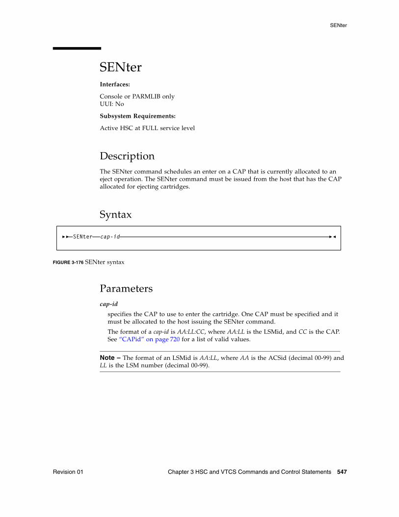
SENter
Revision 01 Chapter 3 HSC and VTCS Commands and Control Statements 547
SENterInterfaces:
Console or PARMLIB onlyUUI: No
Subsystem Requirements:
Active HSC at FULL service level
DescriptionThe SENter command schedules an enter on a CAP that is currently allocated to an eject operation. The SENter command must be issued from the host that has the CAP allocated for ejecting cartridges.
Syntax
FIGURE 3-176 SENter syntax
Parameterscap-id
specifies the CAP to use to enter the cartridge. One CAP must be specified and it must be allocated to the host issuing the SENter command.
The format of a cap-id is AA:LL:CC, where AA:LL is the LSMid, and CC is the CAP. See “CAPid” on page 720 for a list of valid values.
Note – The format of an LSMid is AA:LL, where AA is the ACSid (decimal 00-99) and LL is the LSM number (decimal 00-99).
SENter cap-id
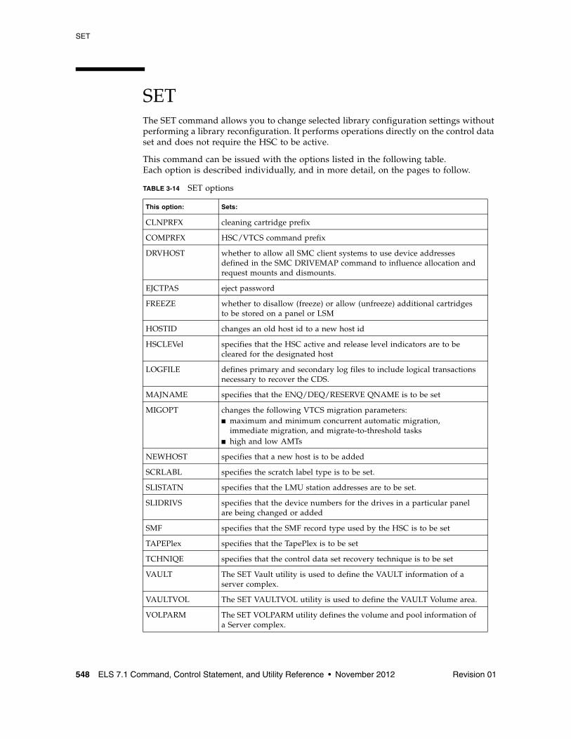
SET
548 ELS 7.1 Command, Control Statement, and Utility Reference • November 2012 Revision 01
SETThe SET command allows you to change selected library configuration settings without performing a library reconfiguration. It performs operations directly on the control data set and does not require the HSC to be active.
This command can be issued with the options listed in the following table. Each option is described individually, and in more detail, on the pages to follow.
TABLE 3-14 SET options
This option: Sets:
CLNPRFX cleaning cartridge prefix
COMPRFX HSC/VTCS command prefix
DRVHOST whether to allow all SMC client systems to use device addresses defined in the SMC DRIVEMAP command to influence allocation and request mounts and dismounts.
EJCTPAS eject password
FREEZE whether to disallow (freeze) or allow (unfreeze) additional cartridges to be stored on a panel or LSM
HOSTID changes an old host id to a new host id
HSCLEVel specifies that the HSC active and release level indicators are to be cleared for the designated host
LOGFILE defines primary and secondary log files to include logical transactions necessary to recover the CDS.
MAJNAME specifies that the ENQ/DEQ/RESERVE QNAME is to be set
MIGOPT changes the following VTCS migration parameters: ■ maximum and minimum concurrent automatic migration,
immediate migration, and migrate-to-threshold tasks■ high and low AMTs
NEWHOST specifies that a new host is to be added
SCRLABL specifies the scratch label type is to be set.
SLISTATN specifies that the LMU station addresses are to be set.
SLIDRIVS specifies that the device numbers for the drives in a particular panel are being changed or added
SMF specifies that the SMF record type used by the HSC is to be set
TAPEPlex specifies that the TapePlex is to be set
TCHNIQE specifies that the control data set recovery technique is to be set
VAULT The SET Vault utility is used to define the VAULT information of a server complex.
VAULTVOL The SET VAULTVOL utility is used to define the VAULT Volume area.
VOLPARM The SET VOLPARM utility defines the volume and pool information of a Server complex.
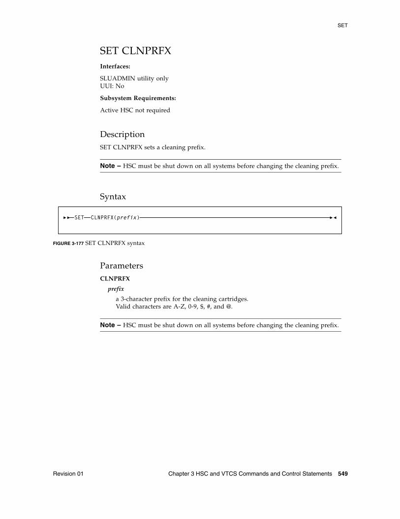
SET
Revision 01 Chapter 3 HSC and VTCS Commands and Control Statements 549
SET CLNPRFXInterfaces:
SLUADMIN utility onlyUUI: No
Subsystem Requirements:
Active HSC not required
DescriptionSET CLNPRFX sets a cleaning prefix.
Note – HSC must be shut down on all systems before changing the cleaning prefix.
Syntax
FIGURE 3-177 SET CLNPRFX syntax
ParametersCLNPRFX
prefix
a 3-character prefix for the cleaning cartridges. Valid characters are A-Z, 0-9, $, #, and @.
Note – HSC must be shut down on all systems before changing the cleaning prefix.
SET CLNPRFX(prefix)
SET
550 ELS 7.1 Command, Control Statement, and Utility Reference • November 2012 Revision 01
SET CLNPRFX Procedure Follow this procedure to change a cleaning cartridge prefix:
1. Eject all cleaning cartridges from all ACSs. The HSC records information about cleaning cartridges in the CDS.
2. Terminate the HSC on all hosts.
3. Change the cleaning prefix using SET CLNPRFX.
4. Initialize the HSC on any desired hosts.
5. Enter new cleaning cartridges identified with the new prefix into all ACSs.
Note – It is preferable to enter new cleaning cartridges because a cartridge’s select count is set to zero when it is ejected and reentered. The select count tracks the number of times a cleaning cartridge has been used.
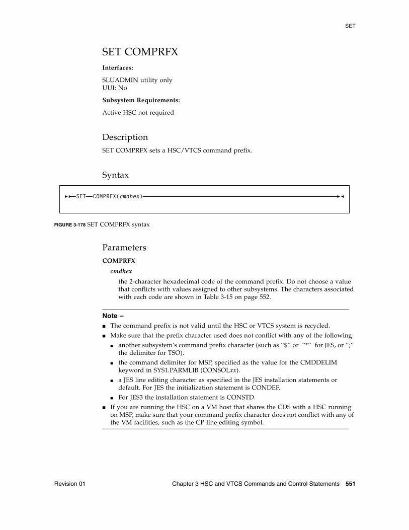
SET
Revision 01 Chapter 3 HSC and VTCS Commands and Control Statements 551
SET COMPRFXInterfaces:
SLUADMIN utility onlyUUI: No
Subsystem Requirements:
Active HSC not required
DescriptionSET COMPRFX sets a HSC/VTCS command prefix.
Syntax
FIGURE 3-178 SET COMPRFX syntax
ParametersCOMPRFX
cmdhex
the 2-character hexadecimal code of the command prefix. Do not choose a value that conflicts with values assigned to other subsystems. The characters associated with each code are shown in Table 3-15 on page 552.
Note – ■ The command prefix is not valid until the HSC or VTCS system is recycled.
■ Make sure that the prefix character used does not conflict with any of the following:
■ another subsystem’s command prefix character (such as ‘‘$’’ or ‘‘*’’ for JES, or ‘‘;’’ the delimiter for TSO).
■ the command delimiter for MSP, specified as the value for the CMDDELIM keyword in SYS1.PARMLIB (CONSOLxx).
■ a JES line editing character as specified in the JES installation statements or default. For JES the initialization statement is CONDEF.
■ For JES3 the installation statement is CONSTD.
■ If you are running the HSC on a VM host that shares the CDS with a HSC running on MSP, make sure that your command prefix character does not conflict with any of the VM facilities, such as the CP line editing symbol.
SET COMPRFX(cmdhex)
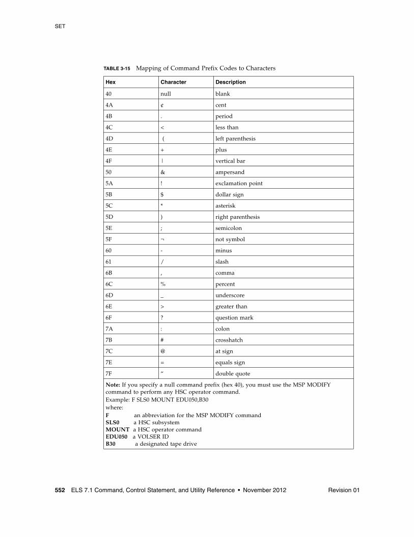
SET
552 ELS 7.1 Command, Control Statement, and Utility Reference • November 2012 Revision 01
TABLE 3-15 Mapping of Command Prefix Codes to Characters
Hex Character Description
40 null blank
4A ¢ cent
4B . period
4C < less than
4D ( left parenthesis
4E + plus
4F | vertical bar
50 & ampersand
5A ! exclamation point
5B $ dollar sign
5C * asterisk
5D ) right parenthesis
5E ; semicolon
5F ¬ not symbol
60 - minus
61 / slash
6B , comma
6C % percent
6D _ underscore
6E > greater than
6F ? question mark
7A : colon
7B # crosshatch
7C @ at sign
7E = equals sign
7F “ double quote
Note: If you specify a null command prefix (hex 40), you must use the MSP MODIFY command to perform any HSC operator command. Example: F SLS0 MOUNT EDU050,B30 where: F an abbreviation for the MSP MODIFY command SLS0 a HSC subsystem MOUNT a HSC operator command EDU050 a VOLSER ID B30 a designated tape drive
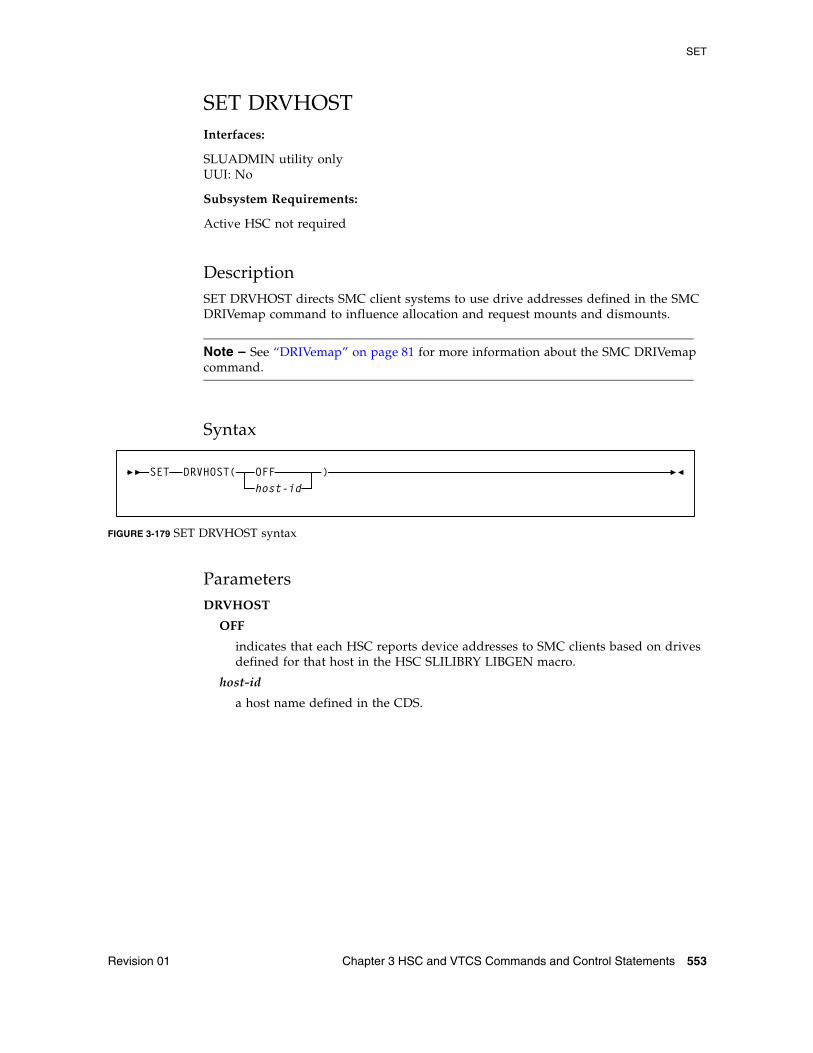
SET
Revision 01 Chapter 3 HSC and VTCS Commands and Control Statements 553
SET DRVHOSTInterfaces:
SLUADMIN utility onlyUUI: No
Subsystem Requirements:
Active HSC not required
DescriptionSET DRVHOST directs SMC client systems to use drive addresses defined in the SMC DRIVemap command to influence allocation and request mounts and dismounts.
Note – See “DRIVemap” on page 81 for more information about the SMC DRIVemap command.
Syntax
FIGURE 3-179 SET DRVHOST syntax
ParametersDRVHOST
OFF
indicates that each HSC reports device addresses to SMC clients based on drives defined for that host in the HSC SLILIBRY LIBGEN macro.
host-id
a host name defined in the CDS.
SET DRVHOST( OFF )host-id
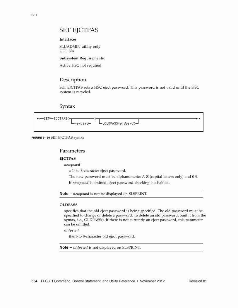
SET
554 ELS 7.1 Command, Control Statement, and Utility Reference • November 2012 Revision 01
SET EJCTPASInterfaces:
SLUADMIN utility onlyUUI: No
Subsystem Requirements:
Active HSC not required
DescriptionSET EJCTPAS sets a HSC eject password. This password is not valid until the HSC system is recycled.
Syntax
FIGURE 3-180 SET EJCTPAS syntax
ParametersEJCTPAS
newpswd
a 1- to 8-character eject password.
The new password must be alphanumeric: A-Z (capital letters only) and 0-9.
If newpswd is omitted, eject password checking is disabled.
Note – newpswd is not be displayed on SLSPRINT.
OLDPASS
specifies that the old eject password is being specified. The old password must be specified to change or delete a password. To delete an old password, omit it from the syntax, i.e., OLDPASS(). If there is not currently an eject password, this parameter can be omitted.
oldpswd
the 1-to 8-character old eject password.
Note – oldpswd is not displayed on SLSPRINT.
SET EJCTPAS( )newpswd ,OLDPASS(oldpswd)
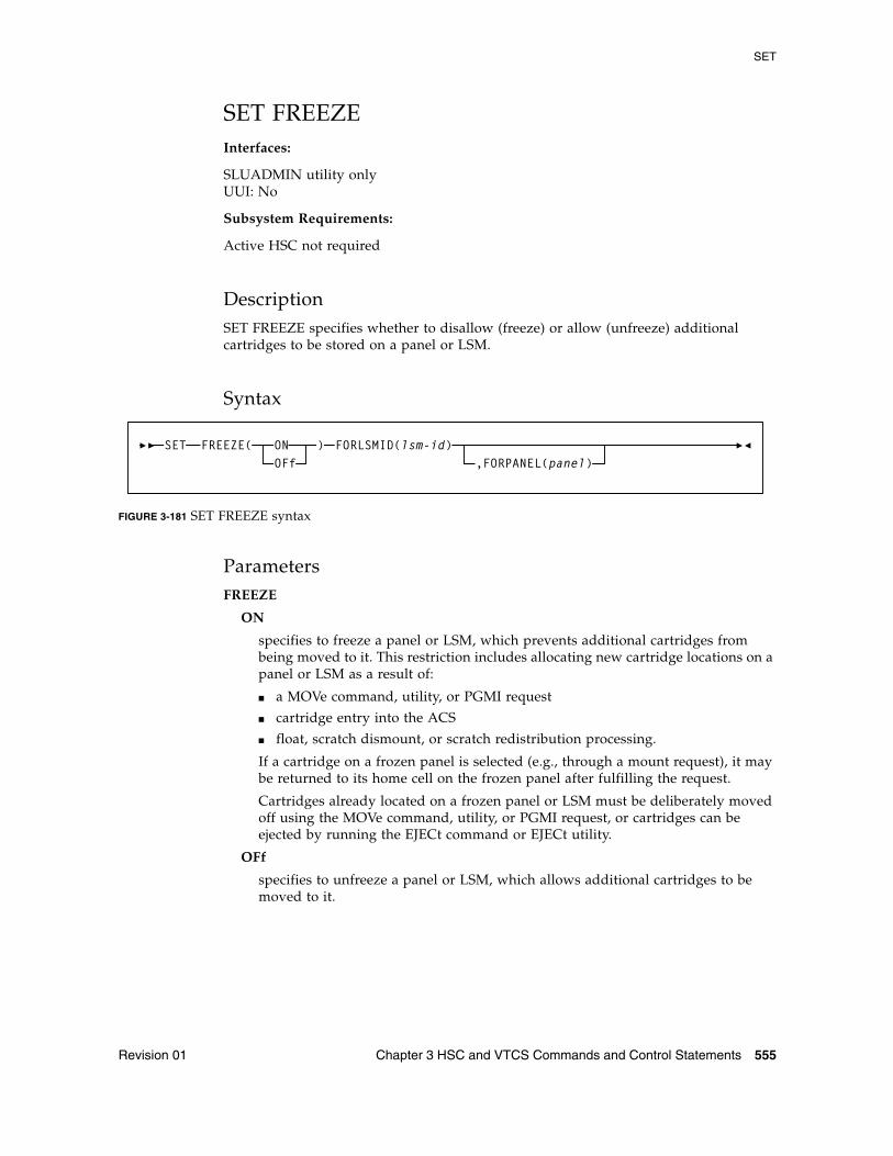
SET
Revision 01 Chapter 3 HSC and VTCS Commands and Control Statements 555
SET FREEZEInterfaces:
SLUADMIN utility onlyUUI: No
Subsystem Requirements:
Active HSC not required
DescriptionSET FREEZE specifies whether to disallow (freeze) or allow (unfreeze) additional cartridges to be stored on a panel or LSM.
Syntax
FIGURE 3-181 SET FREEZE syntax
ParametersFREEZE
ON
specifies to freeze a panel or LSM, which prevents additional cartridges from being moved to it. This restriction includes allocating new cartridge locations on a panel or LSM as a result of:
■ a MOVe command, utility, or PGMI request
■ cartridge entry into the ACS
■ float, scratch dismount, or scratch redistribution processing.
If a cartridge on a frozen panel is selected (e.g., through a mount request), it may be returned to its home cell on the frozen panel after fulfilling the request.
Cartridges already located on a frozen panel or LSM must be deliberately moved off using the MOVe command, utility, or PGMI request, or cartridges can be ejected by running the EJECt command or EJECt utility.
OFf
specifies to unfreeze a panel or LSM, which allows additional cartridges to be moved to it.
SET FREEZE( )ONOFf
FORLSMID(lsm-id),FORPANEL(panel)
SET
556 ELS 7.1 Command, Control Statement, and Utility Reference • November 2012 Revision 01
FORLSMID
specifies that the operation is being restricted to a specific panel or LSM.
lsm_id
the LSMid (AA:LL) of the LSM being frozen or unfrozen. An LSMid (lsm-id) is made up of the ACSid (decimal 00-99) and the LSM number (decimal 00-99) separated by a colon (:).
FORPANEL
optionally, specifies that the operation is being restricted to a specific panel.
panel
the 2-digit ID of the panel to be frozen or unfrozen. The specified panel must be an existing drive panel in the LSM. See “Panels” on page 721 for a list of valid values.
Note – ■ If frozen panels already exist in an LSM, and then you freeze the entire LSM, all
panels will be unfrozen when you unfreeze the LSM.
If you want some panels to remain frozen after unfreezing the entire LSM, you can add SET FREEZE ON FORLSMID FORPANEL statements to the same SLUADMIN JOBSTEP.
■ When an LSM is frozen, no new cell allocations occur. However, any cartridge from the frozen LSM that is currently mounted on a drive will return to its home cell.
■ Frozen or unfrozen panels and LSMs are recognized immediately by all active HSCs. It is not necessary to stop and reinitialize active HSCs to detect changes made by SET FREEZE.
On a frozen panel, if a panel type is changed by running the MERGEcds or Reconfiguration utility, the new panel is not frozen. If the panel type did not change, the panel remains frozen after a merge or reconfiguration.
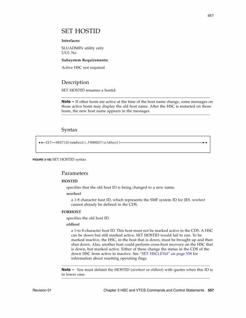
SET
Revision 01 Chapter 3 HSC and VTCS Commands and Control Statements 557
SET HOSTIDInterfaces:
SLUADMIN utility onlyUUI: No
Subsystem Requirements:
Active HSC not required
DescriptionSET HOSTID renames a hostid.
Note – If other hosts are active at the time of the host name change, some messages on those active hosts may display the old host name. After the HSC is restarted on those hosts, the new host name appears in the messages.
Syntax
FIGURE 3-182 SET HOSTID syntax
ParametersHOSTID
specifies that the old host ID is being changed to a new name.
newhost
a 1-8 character host ID, which represents the SMF system ID for JES. newhost cannot already be defined in the CDS.
FORHOST
specifies the old host ID.
oldhost
a 1-to 8-character host ID. This host must not be marked active in the CDS. A HSC can be down but still marked active. SET HOSTID would fail to run. To be marked inactive, the HSC, in the host that is down, must be brought up and then shut down. Also, another host could perform cross-host recovery on the HSC that is down, but marked active. Either of these change the status in the CDS of the down HSC from active to inactive. See “SET HSCLEVel” on page 558 for information about resetting operating flags.
Note – You must delimit the HOSTID (newhost or oldhost) with quotes when this ID is in lower case.
SET HOSTID(newhost),FORHOST(oldhost)
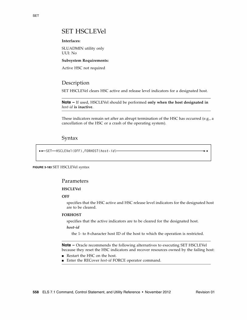
SET
558 ELS 7.1 Command, Control Statement, and Utility Reference • November 2012 Revision 01
SET HSCLEVelInterfaces:
SLUADMIN utility onlyUUI: No
Subsystem Requirements:
Active HSC not required
DescriptionSET HSCLEVel clears HSC active and release level indicators for a designated host.
Note – If used, HSCLEVel should be performed only when the host designated in host-id is inactive.
These indicators remain set after an abrupt termination of the HSC has occurred (e.g., a cancellation of the HSC or a crash of the operating system).
Syntax
FIGURE 3-183 SET HSCLEVel syntax
ParametersHSCLEVel
OFF
specifies that the HSC active and HSC release level indicators for the designated host are to be cleared.
FORHOST
specifies that the active indicators are to be cleared for the designated host.
host-id
the 1- to 8-character host ID of the host to which the operation is restricted.
Note – Oracle recommends the following alternatives to executing SET HSCLEVel because they reset the HSC indicators and recover resources owned by the failing host:
■ Restart the HSC on the host. ■ Enter the RECover host-id FORCE operator command.
SET HSCLEVel(OFF),FORHOST(host-id)
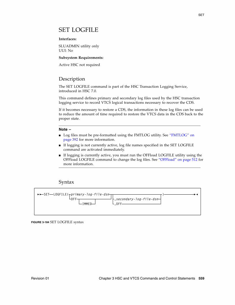
SET
Revision 01 Chapter 3 HSC and VTCS Commands and Control Statements 559
SET LOGFILEInterfaces:
SLUADMIN utility onlyUUI: No
Subsystem Requirements:
Active HSC not required
DescriptionThe SET LOGFILE command is part of the HSC Transaction Logging Service, introduced in HSC 7.0.
This command defines primary and secondary log files used by the HSC transaction logging service to record VTCS logical transactions necessary to recover the CDS.
If it becomes necessary to restore a CDS, the information in these log files can be used to reduce the amount of time required to restore the VTCS data in the CDS back to the proper state.
Note – ■ Log files must be pre-formatted using the FMTLOG utility. See “FMTLOG” on
page 392 for more information.
■ If logging is not currently active, log file names specified in the SET LOGFILE command are activated immediately.
■ If logging is currently active, you must run the OFFload LOGFILE utility using the OFFload LOGFILE command to change the log files. See “OFFload” on page 512 for more information.
Syntax
FIGURE 3-184 SET LOGFILE syntax
SET LOGFILE(,secondary-log-file-dsnOFF
primary-log-file-dsn
,OFF
)
IMMED
SET
560 ELS 7.1 Command, Control Statement, and Utility Reference • November 2012 Revision 01
ParametersLOGFILE
primary-log-file-dsn
the data set name for the primary log file. This parameter is required.
OFF
Specify OFF in place of the primary-log-file-dsn to indicate that logging should be terminated. Logging will continue on the HSC subsystem until you run OFFload LOG, unless you also specify the IMMED parameter.
IMMED
specifies that logging should be immediately stopped on all active HSC subsystems. When IMMED is specified, any previous log data cannot be offloaded.
secondary-log-file-dsn
optionally, the data set name for the secondary log file. This parameter is required if a secondary log file was previously defined.
When changing only the secondary log file data set name, you must re-specify the existing primary log file data set name in the primary log file data set name position.
OFF
Specify OFF in place of the secondary-log-file-dsn to change from duplex to simplex logging.
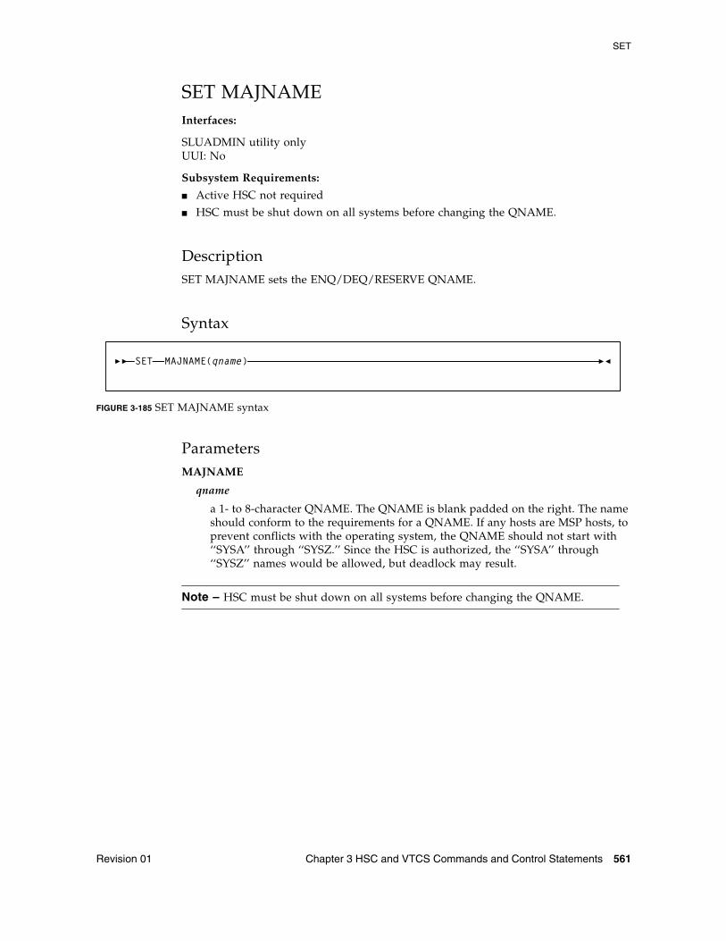
SET
Revision 01 Chapter 3 HSC and VTCS Commands and Control Statements 561
SET MAJNAMEInterfaces:
SLUADMIN utility onlyUUI: No
Subsystem Requirements:
■ Active HSC not required
■ HSC must be shut down on all systems before changing the QNAME.
DescriptionSET MAJNAME sets the ENQ/DEQ/RESERVE QNAME.
Syntax
FIGURE 3-185 SET MAJNAME syntax
ParametersMAJNAME
qname
a 1- to 8-character QNAME. The QNAME is blank padded on the right. The name should conform to the requirements for a QNAME. If any hosts are MSP hosts, to prevent conflicts with the operating system, the QNAME should not start with ‘‘SYSA’’ through ‘‘SYSZ.’’ Since the HSC is authorized, the ‘‘SYSA’’ through ‘‘SYSZ’’ names would be allowed, but deadlock may result.
Note – HSC must be shut down on all systems before changing the QNAME.
SET MAJNAME(qname)
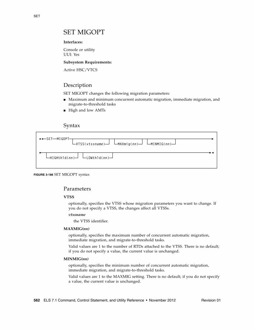
SET
562 ELS 7.1 Command, Control Statement, and Utility Reference • November 2012 Revision 01
SET MIGOPTInterfaces:
Console or utilityUUI: Yes
Subsystem Requirements:
Active HSC/VTCS
DescriptionSET MIGOPT changes the following migration parameters:
■ Maximum and minimum concurrent automatic migration, immediate migration, and migrate-to-threshold tasks
■ High and low AMTs
Syntax
FIGURE 3-186 SET MIGOPT syntax
ParametersVTSS
optionally, specifies the VTSS whose migration parameters you want to change. If you do not specify a VTSS, the changes affect all VTSSs.
vtssname
the VTSS identifier.
MAXMIG(nn)
optionally, specifies the maximum number of concurrent automatic migration, immediate migration, and migrate-to-threshold tasks.
Valid values are 1 to the number of RTDs attached to the VTSS. There is no default; if you do not specify a value, the current value is unchanged.
MINMIG(nn)
optionally, specifies the minimum number of concurrent automatic migration, immediate migration, and migrate-to-threshold tasks.
Valid values are 1 to the MAXMIG setting. There is no default; if you do not specify a value, the current value is unchanged.
SET MIGOPTVTSS(vtssname) MAXmig(nn) MINMIG(nn)
HIGHthld(nn) LOWthld(nn)
SET
Revision 01 Chapter 3 HSC and VTCS Commands and Control Statements 563
HIGHthld
optionally, specifies the new high AMT.
high-thr
the new high AMT as a percent of VTSS space. Valid values are 5 to 95 and must be greater than the LOWthld value.
LOWthld
optionally, specifies the new low AMT.
low-thr
the new low AMT as a percent of VTSS space. Valid values are 5 to 95 and must be less than the HIGHthld value.
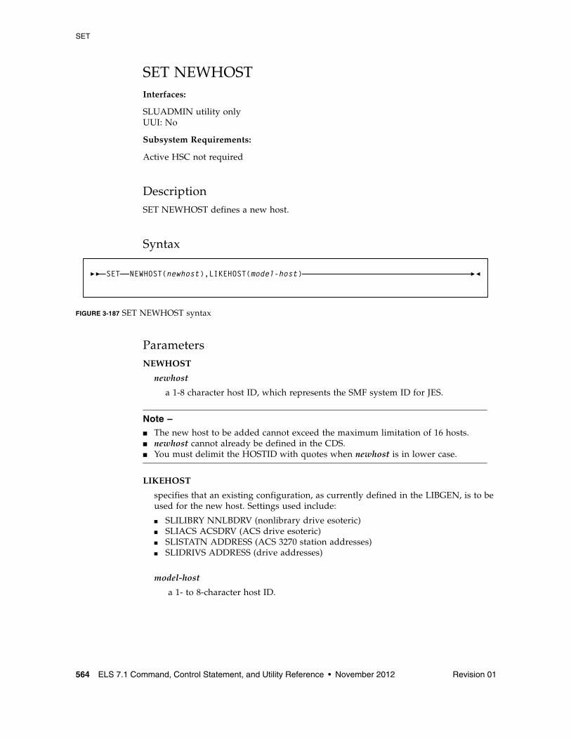
SET
564 ELS 7.1 Command, Control Statement, and Utility Reference • November 2012 Revision 01
SET NEWHOSTInterfaces:
SLUADMIN utility onlyUUI: No
Subsystem Requirements:
Active HSC not required
DescriptionSET NEWHOST defines a new host.
Syntax
FIGURE 3-187 SET NEWHOST syntax
ParametersNEWHOST
newhost
a 1-8 character host ID, which represents the SMF system ID for JES.
Note – ■ The new host to be added cannot exceed the maximum limitation of 16 hosts.■ newhost cannot already be defined in the CDS.■ You must delimit the HOSTID with quotes when newhost is in lower case.
LIKEHOST
specifies that an existing configuration, as currently defined in the LIBGEN, is to be used for the new host. Settings used include:
■ SLILIBRY NNLBDRV (nonlibrary drive esoteric)■ SLIACS ACSDRV (ACS drive esoteric)■ SLISTATN ADDRESS (ACS 3270 station addresses)■ SLIDRIVS ADDRESS (drive addresses)
model-host
a 1- to 8-character host ID.
SET NEWHOST(newhost),LIKEHOST(model-host)
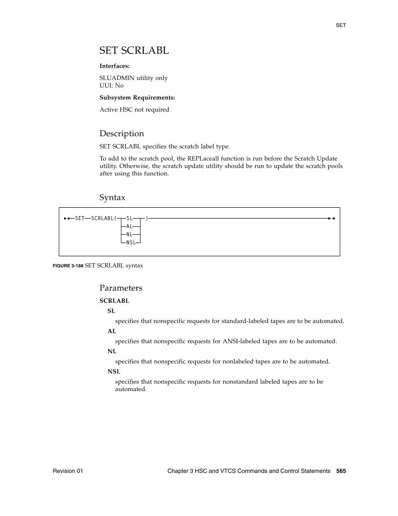
SET
Revision 01 Chapter 3 HSC and VTCS Commands and Control Statements 565
SET SCRLABLInterfaces:
SLUADMIN utility onlyUUI: No
Subsystem Requirements:
Active HSC not required
DescriptionSET SCRLABL specifies the scratch label type.
To add to the scratch pool, the REPLaceall function is run before the Scratch Update utility. Otherwise, the scratch update utility should be run to update the scratch pools after using this function.
Syntax
FIGURE 3-188 SET SCRLABL syntax
ParametersSCRLABL
SL
specifies that nonspecific requests for standard-labeled tapes are to be automated.
AL
specifies that nonspecific requests for ANSI-labeled tapes are to be automated.
NL
specifies that nonspecific requests for nonlabeled tapes are to be automated.
NSL
specifies that nonspecific requests for nonstandard labeled tapes are to be automated.
SET SCRLABL( )SLALNLNSL
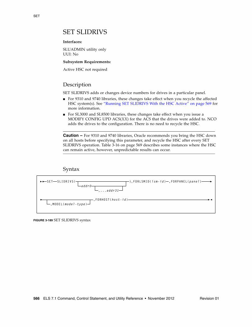
SET
566 ELS 7.1 Command, Control Statement, and Utility Reference • November 2012 Revision 01
SET SLIDRIVSInterfaces:
SLUADMIN utility onlyUUI: No
Subsystem Requirements:
Active HSC not required
DescriptionSET SLIDRIVS adds or changes device numbers for drives in a particular panel.
■ For 9310 and 9740 libraries, these changes take effect when you recycle the affected HSC system(s). See “Running SET SLIDRIVS With the HSC Active” on page 569 for more information.
■ For SL3000 and SL8500 libraries, these changes take effect when you issue a MODIFY CONFIG UPD ACS(XX) for the ACS that the drives were added to. NCO adds the drives to the configuration. There is no need to recycle the HSC.
Caution – For 9310 and 9740 libraries, Oracle recommends you bring the HSC down on all hosts before specifying this parameter, and recycle the HSC after every SET SLIDRIVS operation. Table 3-16 on page 569 describes some instances where the HSC can remain active, however, unpredictable results can occur.
Syntax
FIGURE 3-189 SET SLIDRIVS syntax
SLIDRIVS(addr0
,...addr31
),FORLSMID(lsm-id) ,FORPANEL(panel)
,FORHOST(host-id)
SET
,MODEL(model-type)
SET
Revision 01 Chapter 3 HSC and VTCS Commands and Control Statements 567
ParametersSLIDRIVS
addr0,...addr31
the device numbers for the panel. The numbers are from the top of the panel down. If a device number is omitted, this means that the host cannot access a drive in that particular position in the panel, or the drive does not exist.
Note – ■ Blanks as well as commas may be used to separate the drive specifications.
■ The total number of drives specified (including comma placeholders) must be:
■ 4, 10, or 20 for a 9310
■ 16 for an SL8500
■ 8, 16, 24 or 32 for an SL3000
■ You cannot specify 20-drive panels on 9740 (TimberWolf) LSMs or SL8500 libraries.
■ 10-drive and 20-drive panels cannot be specified on 4410 LSMs.
■ Before this utility can be executed, all cells in the panel must be empty if the user is moving to or from a 20-drive panel configuration.
■ The user can change a drive panel between a 4- or 10-drive panel (normal) and a 20-drive panel (wide) without running a reconfiguration. Affected panels must be empty and no cells in the panels can be allocated to cartridges.
To make sure that drive panels being changed from normal to wide configurations (or vice versa) remain empty, freeze them with the SET FREEZE utility. Then, move all cartridges to other panels or LSMs.
If a panel type is changed by SET SLIDRIVS, the new panel will not be frozen. Frozen panels whose panel type did not change remain frozen after SET SLIDRIVS.
■ HSC does not allow duplicate addresses for drives.
If it becomes necessary to exchange the drive addresses on one panel with the drive addresses on another panel, the addresses on one of the panels must first be changed to temporary addresses that are not currently defined. For example:
LSM00, PANEL10, ADDRESSES-400,401,402,403 LSM01, PANEL11, ADDRESSES-404,405,406,407
If the 400-403 addresses are to be moved to LSM01 and 404-407 are to be moved to LSM0, the SET utility must first be run to change the LSM0 addresses (400-403) to 900-903 (or some other addresses that are not currently defined). The SET utility is then run to change the LSM01 addresses to 400-403. The utility is run a third time to change the temporary LSM0 addresses (900-903) to 404-407.
SET
568 ELS 7.1 Command, Control Statement, and Utility Reference • November 2012 Revision 01
■ On all 9310 LSMs, drives are defined to the HSC from top to bottom, with addr0 representing the topmost drive and addrn the bottommost drive.
However, on a 9740 10-drive panel LSM, the drives are populated and configured to the 9740 LSM from bottom to top. (9740 4-drive panels are configured to the 9740 LSM from top to bottom, as are all other LSM drive panels.)
An example showing how to define a 9740 10-drive panel containing five 9840 drives is:
SET SLIDRIVS(,,,,,BD4,BD3,BD2,BD1,BD0),FORLSMID(lsm-id), FORPANEL(panel)
For the SL3000, drives are defined from top to bottom, right to left, as looking from the front to the back of the library.
For the SL8500, drives are defined from top to bottom, right to left, as viewed from the outside of the library.
FORLSMID
specifies that the operation is being restricted to a specific LSM.
lsm-id
the LSMid (AA:LL) containing the drive panel whose addresses are being changed. An LSMid (lsm-id) is made up of the ACSid (decimal 00-99) and the LSM number (decimal 00-99) separated by a colon (:).
FORPANEL
specifies that the operation is being restricted to a specific panel.
panel
the 2-digit ID of the panel containing the drives whose addresses are being changed. See “Panels” on page 721 for a list of valid values.
Note – The specified panel must be an existing drive panel in the LSM.
MODEL
optionally, specifies the transport model number.
model-type
the model type.
See Appendix A, “MEDia, RECtech, and MODel Values” for a list of valid model-type values.
Note – The MODEL parameter is only used to specify the drive type for manual RTDs., which are defined in a nonexistent ACS. When an LSM is brought online, the (non-manual) drive type is automatically set.
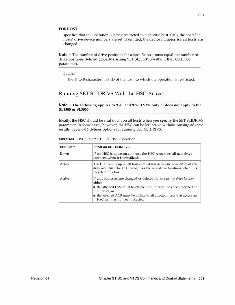
SET
Revision 01 Chapter 3 HSC and VTCS Commands and Control Statements 569
FORHOST
specifies that the operation is being restricted to a specific host. Only the specified hosts’ drive device numbers are set. If omitted, the device numbers for all hosts are changed.
Note – The number of drive positions for a specific host must equal the number of drive positions defined globally (issuing SET SLIDRIVS without the FORHOST parameter).
host-id
the 1- to 8-character host ID of the host, to which the operation is restricted.
Running SET SLIDRIVS With the HSC Active
Note – The following applies to 9310 and 9740 LSMs only. It does not apply to the SL8500 or SL3000.
Ideally, the HSC should be shut down on all hosts when you specify the SET SLIDRIVS parameter. In some cases, however, the HSC can be left active without causing adverse results. Table 3-16 defines options for running SET SLIDRIVS.
TABLE 3-16 HSC State/SET SLIDRIVS Operation
HSC State Effect on SET SLIDRIVS
Down If the HSC is down on all hosts, the HSC recognizes all new drive locations when it is initialized.
Active The HSC can be up on all hosts only if new drives are being added at new drive locations. The HSC recognizes the new drive locations when it is recycled on a host.
Active If unit addresses are changed or deleted for an existing drive location, either ■ the affected LSM must be offline until the HSC has been recycled on
all hosts, or ■ the affected ACS must be offline to all affected hosts that access an
HSC that has not been recycled.
SET
570 ELS 7.1 Command, Control Statement, and Utility Reference • November 2012 Revision 01
SET SLIDRIVS Procedure The following procedures show one method for changing unit addresses with the HSC active.
For the 9310 and 9740: ■ For one host:
1. Modify the affected LSM offline (MODify lsm-id OFFline). The LSM will be offline to all hosts.
2. Use SET SLIDRIVS to update the CDS drive records while the Oracle StorageTek CSE(s) is making the hardware changes.
3. Recycle the HSC on one host.
4. Vary the affected ACS offline (Vary ACS(acs-id) OFFline) on all hosts running an HSC that has not been recycled.
5. Modify the affected LSM online (MODify lsm-id ONline). The LSM will be online to all hosts where the ACS is online.
Note – Only hosts that are online to the ACS and running a recycled HSC will mount to drives connected to this LSM.
■ For the remaining hosts, recycle the HSC, and the affected ACS will come up.
For the SL3000 and SL8500:
1. Make necessary hardware changes (add/delete/move drives).
2. Modify the SET SLIDRIVS JCL deck to reflect the changes.
3. Run SET SLIDRIVS.
4. Issue MODIFY CONFIG (or MODIFY CONFIG ACS(xx))
The changes will cascade to all other hosts.
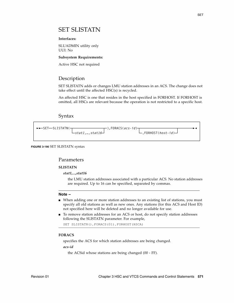
SET
Revision 01 Chapter 3 HSC and VTCS Commands and Control Statements 571
SET SLISTATNInterfaces:
SLUADMIN utility onlyUUI: No
Subsystem Requirements:
Active HSC not required
DescriptionSET SLISTATN adds or changes LMU station addresses in an ACS. The change does not take effect until the affected HSC(s) is recycled.
An affected HSC is one that resides in the host specified in FORHOST. If FORHOST is omitted, all HSCs are relevant because the operation is not restricted to a specific host.
Syntax
FIGURE 3-190 SET SLISTATN syntax
ParametersSLISTATN
stat1,...,stat16
the LMU station addresses associated with a particular ACS. No station addresses are required. Up to 16 can be specified, separated by commas.
Note – ■ When adding one or more station addresses to an existing list of stations, you must
specify all old stations as well as new ones. Any stations (for this ACS and Host ID) not specified here will be deleted and no longer available for use.
■ To remove station addresses for an ACS or host, do not specify station addresses following the SLISTATN parameter. For example, SET SLISTATN(),FORACS(01),FORHOST(HSCA)
FORACS
specifies the ACS for which station addresses are being changed.
acs-id
the ACSid whose stations are being changed (00 - FF).
SLISTATN(stat1,…,stat16
),FORACS(acs-id),FORHOST(host-id)
SET
SET
572 ELS 7.1 Command, Control Statement, and Utility Reference • November 2012 Revision 01
FORHOST
specifies that the operation is being restricted to a specific host. Only the specified hosts’ stations are set. If omitted, the stations for all hosts are changed.
host-id
the 1- to 8-character host ID for the host to which the operation is restricted.
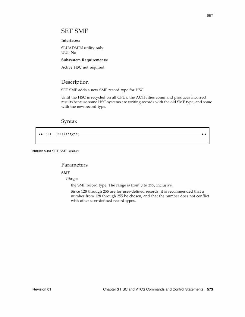
SET
Revision 01 Chapter 3 HSC and VTCS Commands and Control Statements 573
SET SMFInterfaces:
SLUADMIN utility onlyUUI: No
Subsystem Requirements:
Active HSC not required
DescriptionSET SMF adds a new SMF record type for HSC.
Until the HSC is recycled on all CPUs, the ACTIvities command produces incorrect results because some HSC systems are writing records with the old SMF type, and some with the new record type.
Syntax
FIGURE 3-191 SET SMF syntax
ParametersSMF
libtype
the SMF record type. The range is from 0 to 255, inclusive.
Since 128 through 255 are for user-defined records, it is recommended that a number from 128 through 255 be chosen, and that the number does not conflict with other user-defined record types.
SMF(libtype)SET
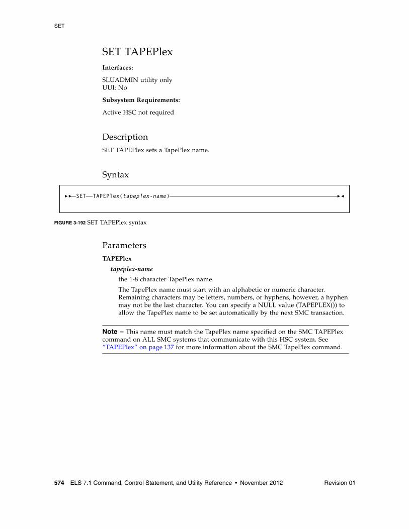
SET
574 ELS 7.1 Command, Control Statement, and Utility Reference • November 2012 Revision 01
SET TAPEPlexInterfaces:
SLUADMIN utility onlyUUI: No
Subsystem Requirements:
Active HSC not required
DescriptionSET TAPEPlex sets a TapePlex name.
Syntax
FIGURE 3-192 SET TAPEPlex syntax
ParametersTAPEPlex
tapeplex-name
the 1-8 character TapePlex name.
The TapePlex name must start with an alphabetic or numeric character. Remaining characters may be letters, numbers, or hyphens, however, a hyphen may not be the last character. You can specify a NULL value (TAPEPLEX()) to allow the TapePlex name to be set automatically by the next SMC transaction.
Note – This name must match the TapePlex name specified on the SMC TAPEPlex command on ALL SMC systems that communicate with this HSC system. See “TAPEPlex” on page 137 for more information about the SMC TapePlex command.
SET TAPEPlex(tapeplex-name)
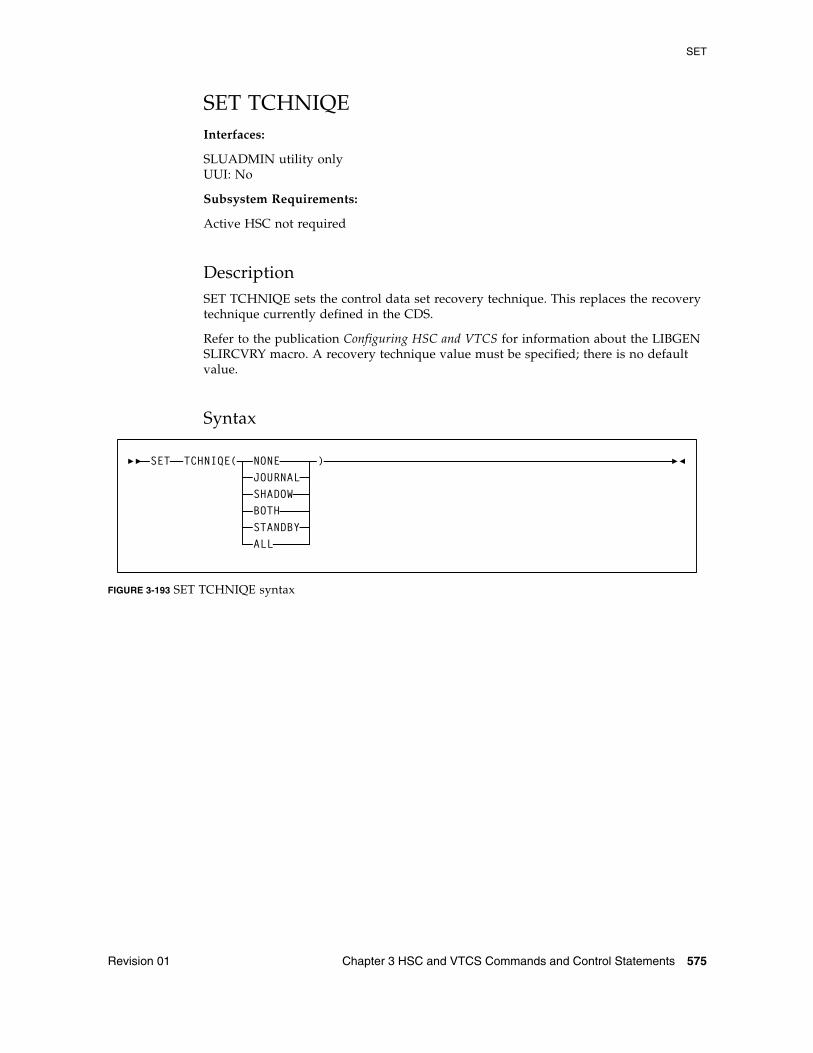
SET
Revision 01 Chapter 3 HSC and VTCS Commands and Control Statements 575
SET TCHNIQEInterfaces:
SLUADMIN utility onlyUUI: No
Subsystem Requirements:
Active HSC not required
DescriptionSET TCHNIQE sets the control data set recovery technique. This replaces the recovery technique currently defined in the CDS.
Refer to the publication Configuring HSC and VTCS for information about the LIBGEN SLIRCVRY macro. A recovery technique value must be specified; there is no default value.
Syntax
FIGURE 3-193 SET TCHNIQE syntax
TCHNIQE( NONEJOURNALSHADOWBOTHSTANDBYALL
)SET
SET
576 ELS 7.1 Command, Control Statement, and Utility Reference • November 2012 Revision 01
ParametersTCHNIQE
NONE
specifies no form of recovery is used for the control data set. Thus, the primary control data set must be rebuilt, if inaccessible.
JOURNAL
specifies that there is to be only one primary control data set and that journals are kept. These data sets are to be used for recovery purposes.
The journals contain a record of all transactions that update the control data set. There are two journals per host. It is recommended that they are placed on separate HDAs from the primary control data set DASD volume.
SHADOW
specifies that there is to be two distinct copies of the control data set (primary and secondary) for recovery purposes. It is recommended that these data sets reside on separate HDAs and separate strings. A journal is not recorded.
BOTH
specifies that two distinct copies of the control data set (primary and secondary) and journals are specified for recovery purposes. The default is BOTH.
STANDBY
specifies that primary, secondary, and standby control data sets are to be recorded for recovery purposes. No journals are recorded during HSC operation.
ALL
specifies that all control data sets (primary, secondary, and standby) and journals are to be kept and available for recovery purposes.
SET TCHNIQE Procedure Use the following procedure to invoke the TCHNIQE utility and to set the appropriate recovery technique value:
1. ALLOCATE, based on existing CDS definitions, any new CDS copies that will be needed for the subsequent SET recovery technique.
2. Stop the HSCs on all hosts configured to use the CDS you are intending to update with SET recovery technique.
3. Run the BACKup utility.
4. Run the RESTore utility to restore all CDS copies required to support the current recovery technique. If the recovery technique update in the following step requires new CDS copies, then include them in this restore.
5. Run the SET utility with the appropriate recovery technique value. It is important to note that the SET utility for this recovery technique update must include DD statements for all CDS copies defined in either the old or the new recovery technique.
6. Run the BACKup utility again. This backup provides you with the ability to restore the updated CDS.
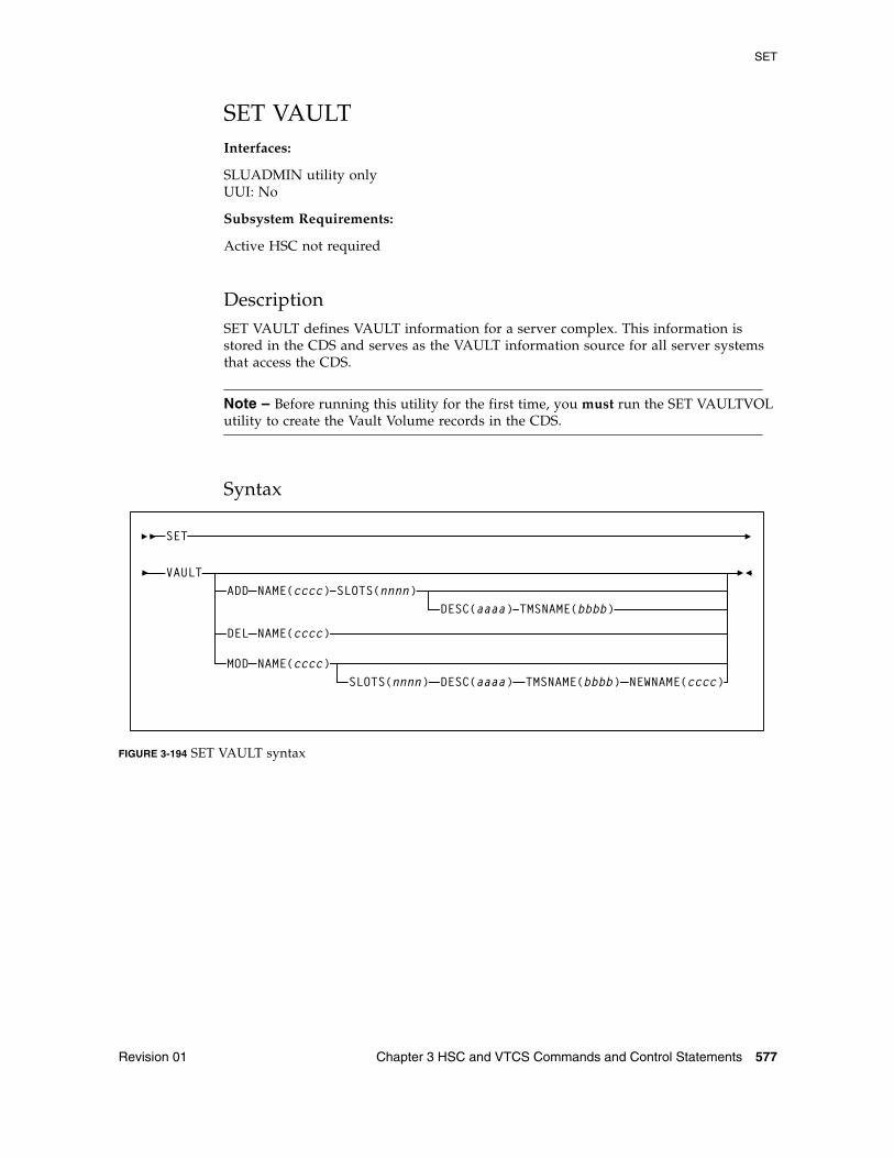
SET
Revision 01 Chapter 3 HSC and VTCS Commands and Control Statements 577
SET VAULTInterfaces:
SLUADMIN utility onlyUUI: No
Subsystem Requirements:
Active HSC not required
DescriptionSET VAULT defines VAULT information for a server complex. This information is stored in the CDS and serves as the VAULT information source for all server systems that access the CDS.
Note – Before running this utility for the first time, you must run the SET VAULTVOL utility to create the Vault Volume records in the CDS.
Syntax
FIGURE 3-194 SET VAULT syntax
VAULTADD NAME(cccc) SLOTS(nnnn)
DESC(aaaa) TMSNAME(bbbb)
MOD NAME(cccc)SLOTS(nnnn) DESC(aaaa) TMSNAME(bbbb) NEWNAME(cccc)
DEL NAME(cccc)
SET
SET
578 ELS 7.1 Command, Control Statement, and Utility Reference • November 2012 Revision 01
ParametersVAULT
ADD, MOD, DEL
specifies to add, modify, or delete a Vault from the CDS. Only one of these parameters may be specified on a SET VAULT statement.
NAME
specifies the name of the Vault. You can specify a maximum of 8 characters. This parameter is required.
DESC
optionally, specifies the description of the Vault. You can specify a maximum of 120 characters. If blank characters are included, the entire value must be enclosed in single quotes. This parameter is only valid with the ADD and MOD parameters.
NEWNAME
optionally, specifies the new name of the Vault. You can specify a maximum of 8 characters. This parameter is only valid with the MOD parameter.
TMSNAME
optionally, specifies the TMS Vault name. You can specify a maximum of 8 characters. This parameter is only valid with the ADD and MOD parameters.
SLOTS
specifies the number of slots in the Vault. The slot number can be 1-999,999,999. When specified with the MOD option, the SLOTS number must be greater than the current number of SLOTS defined to the Vault.
This parameter is required with the ADD option and optional with the MOD option.
Note – The total number of slots for all Vaults cannot exceed the number of Vault Volumes set by the SET VAULTVOL utility.
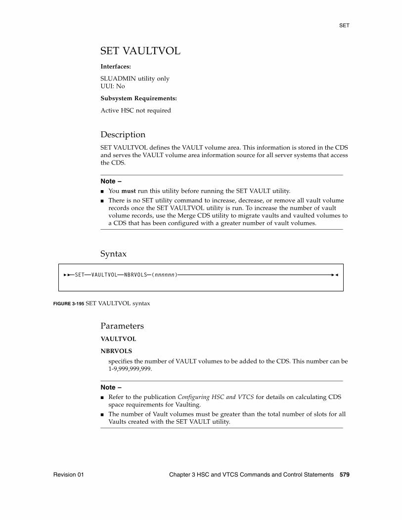
SET
Revision 01 Chapter 3 HSC and VTCS Commands and Control Statements 579
SET VAULTVOLInterfaces:
SLUADMIN utility onlyUUI: No
Subsystem Requirements:
Active HSC not required
DescriptionSET VAULTVOL defines the VAULT volume area. This information is stored in the CDS and serves the VAULT volume area information source for all server systems that access the CDS.
Note – ■ You must run this utility before running the SET VAULT utility.
■ There is no SET utility command to increase, decrease, or remove all vault volume records once the SET VAULTVOL utility is run. To increase the number of vault volume records, use the Merge CDS utility to migrate vaults and vaulted volumes to a CDS that has been configured with a greater number of vault volumes.
Syntax
FIGURE 3-195 SET VAULTVOL syntax
ParametersVAULTVOL
NBRVOLS
specifies the number of VAULT volumes to be added to the CDS. This number can be 1-9,999,999,999.
Note – ■ Refer to the publication Configuring HSC and VTCS for details on calculating CDS
space requirements for Vaulting.
■ The number of Vault volumes must be greater than the total number of slots for all Vaults created with the SET VAULT utility.
VAULTVOL NBRVOLS (nnnnnn)SET
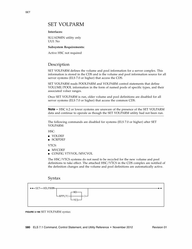
SET
580 ELS 7.1 Command, Control Statement, and Utility Reference • November 2012 Revision 01
SET VOLPARMInterfaces:
SLUADMIN utility onlyUUI: No
Subsystem Requirements:
Active HSC not required
DescriptionSET VOLPARM defines the volume and pool information for a server complex. This information is stored in the CDS and is the volume and pool information source for all server systems (ELS 7.0 or higher) that access the CDS.
SET VOLPARM reads POOLPARM and VOLPARM control statements that define VOLUME/POOL information in the form of named pools of specific types, and their associated volser ranges.
Once SET VOLPARM is run, older volume and pool definitions are disabled for all server systems (ELS 7.0 or higher) that access the common CDS.
Note – HSC 6.2 or lower systems are unaware of the presence of the SET VOLPARM data and continue to operate as though the SET VOLPARM utility had not been run.
The following commands are disabled for systems (ELS 7.0 or higher) after SET VOLPARM:
HSC:
■ VOLDEF■ SCRPDEF
VTCS:
■ MVCDEF■ CONFIG VTVVOL/MVCVOL
The HSC/VTCS systems do not need to be recycled for the new volume and pool definitions to take effect. The attached HSC/VTCS in the CDS complex are notified of the definition changes and the volume and pool definitions are automatically active.
Syntax
FIGURE 3-196 SET VOLPARM syntax
VOLPARM
APPLY(NO
YES)
SET
SET
Revision 01 Chapter 3 HSC and VTCS Commands and Control Statements 581
ParametersVOLPARM
APPLY
specifies whether the POOLPARM/VOLPARM definitions are to be applied to the CDS:
NO
Validate the definitions but do not apply them to the CDS (the default).
YES
Apply the definitions. If you specify YES, the SLSPARM data set containing POOLPARM and VOLPARM control statements is read and applied to the CDS.
POOLPARM and VOLPARM control statements are defined in the SLSPARM data set, and define VOLUME/POOL information in the form of named pools of specific types, and their associated volser ranges.
■ When a POOLPARM statement is read, all subsequent VOLPARMs encountered until the next POOLPARM statement are applied to the prior POOLPARM.
■ When VOLPARM statements are read without a prior POOLPARM, those VOLSER volumes will be considered non sub-pool (subpool 0) volumes.
See “POOLPARM Control Statement” on page 582 and “VOLPARM Control Statement” on page 588 for more information.
Additional JCL RequirementsIn addition to the required JCL definition statements described in “Invoking SLUADMIN” on page 674, the following definition statements apply to the SET VOLPARM JCL:
SLSPARM
specifies the data set that contains the POOLPARM and VOLPARM control statements that define volumes and pools.
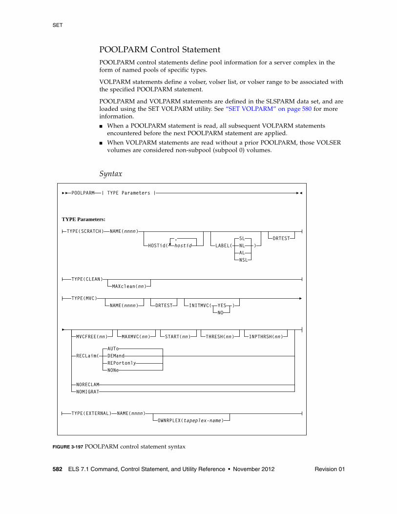
SET
582 ELS 7.1 Command, Control Statement, and Utility Reference • November 2012 Revision 01
POOLPARM Control StatementPOOLPARM control statements define pool information for a server complex in the form of named pools of specific types.
VOLPARM statements define a volser, volser list, or volser range to be associated with the specified POOLPARM statement.
POOLPARM and VOLPARM statements are defined in the SLSPARM data set, and are loaded using the SET VOLPARM utility. See “SET VOLPARM” on page 580 for more information.
■ When a POOLPARM statement is read, all subsequent VOLPARM statements encountered before the next POOLPARM statement are applied.
■ When VOLPARM statements are read without a prior POOLPARM, those VOLSER volumes are considered non-subpool (subpool 0) volumes.
Syntax
FIGURE 3-197 POOLPARM control statement syntax
POOLPARM
TYPE Parameters:
| TYPE Parameters |
TYPE(SCRATCH) NAME(nnnn)
HOSTid( hostid
TYPE(CLEAN)MAXclean(nn)
TYPE(MVC)NAME(nnnn)
, DRTEST
DRTEST
LABEL(SLNLALNSL
)
MVCFREE(nn) MAXMVC(nn) START(nn) THRESH(nn)
INITMVC( YESNO
)
TYPE(EXTERNAL)OWNRPLEX(tapeplex-name)
NAME(nnnn)
INPTHRSH(nn)
RECLaim(AUToDEMandREPortonlyNONe
NORECLAMNOMIGRAT
SET
Revision 01 Chapter 3 HSC and VTCS Commands and Control Statements 583
Parameters
TYPE
specifies the type of pool definition. Valid types are SCRATCH, CLEAN, MVC, and EXTERNAL.
NAME
specifies the name of the volume pool.
nnnn
the volume pool name. A maximum of 13 characters is allowed; blank spaces are not permitted.
■ NAME is required for TYPE(SCRATCH) and TYPE(EXTERNAL) pools.■ NAME is optional for TYPE(MVC) pools.■ NAME is not valid for TYPE(CLEAN) pools.
Additionally:
■ NAME(DEFAULTPOOL) is not valid for TYPE(SCRATCH) or TYPE(MVC).■ NAME(ALL) is not valid for TYPE(MVC).
TYPE(SCRATCH) Subparameters
HOSTid
optionally, defines the hosts that can access the named sub-pool.
hostid
the host id. Multiple host-lists may be specified, separating each host-list value with a comma. If a host id is not specified, the default is all hosts.
HOSTid determines which client hosts can mount volumes from the named subpool. If a mount request is received from a client not specified in the HOSTid list, the HSC rejects the mount request and the mount is not satisfied. If you did not specify an ALIASHOST on the SMC SERVer command, then specify the 4 character SMFID of the MSP hosts that will access the subpool. Otherwise, you can specify up to 8 characters for the host name matching the SMC ALIASHOST specification.
LABEL
optionally, specifies the label type associated with the named sub-pool. Types include:
■ SL - standard label (default)■ NL - no label■ AL - ANSI label■ NSL - nonstandard label
Note – Scratch volume requests without a sub-pool (sub-pool 0) will come from volumes NOT defined in named SUBPOOLS.
DRTEST
optionally, specifies that the scratch pool is to be used in DRTEST environments.
SET
584 ELS 7.1 Command, Control Statement, and Utility Reference • November 2012 Revision 01
TYPE(CLEAN) Subparameters
MAXclean
optionally, specifies the maximum cleaning cartridge usage for the named sub-pool. Do not specify values that exceed the manufacturer's recommendation for usage.
The volumes defined in the CLEAN sub-pools must begin with the cleaning cartridge prefix defined in the LIBGEN.
Note – If MAXclean is not specified in the VOLPARM statement, the value or default of the MAXclean parameter in the MNTD operator command is used for all cleaning cartridge counts.
TYPE(MVC) Subparameters
DRTEST
optionally, specifies that the MVC pool is to be used only in DRTEST environments.
INITMVC
optionally, enables or disables the MVC initialization feature.
YES
enables the MVC initialization feature.
NO
disables the MVC initialization feature.
MVCFREE(nn)
optionally, specifies the minimum number of free MVCs in the MVC pool. A free MVC has 100% usable space and does not contain any migrated VTVs.
Valid values are 0 to 255. There is no default; if not specified, the CONFIG RECLAIM value (or default) is used.
If free MVCs is equal or less than this value, VTCS issues message SLS6616I and initiates an automatic space reclamation.
MAXMVC(nn)
optionally, specifies the maximum number of MVCs to be processed in a single space reclamation run. Valid values are 1 to 98. There is no default; if not specified, the CONFIG RECLAIM value (or default) is used.
For automatic space reclamation to start, the number of eligible MVCs (determined by the THRESH parameter) must also exceed the MAXMVC value.
SET
Revision 01 Chapter 3 HSC and VTCS Commands and Control Statements 585
START=nn
optionally, specifies the level at which automatic space reclamation starts for each ACS (not globally for all ACSs), or, if specified, for a Named MVC Pool. Specify a percentage value, which is equal to:
(Reclaim Candidates/Reclaim Candidates + Free MVCs) * 100
Where:
Reclaim Candidates
is the number of Reclaim Candidates determined by the CONFIG RECLAIM THRESHLD parameter.
Reclaim Candidates + Free MVCs
equals the number of Reclaim Candidates plus the number of free MVCs.
Valid values are 1 to 98. There is no default; if not specified, the CONFIG
RECLAIM value (or default) is used.
THRESH(nn)
optionally, specifies the percentage of fragmented space that makes an MVC eligible for demand or automatic reclamation. Valid values are 4 to 98. There is no default; if not specified, the CONFIG RECLAIM value (or default) is used.
INPTHRSH
optionally, specifies the percentage of fragmented space that makes an MVC in partitioned format (within the pool) eligible for dynamic reclaim processing.
This value overrides the global INPTHRSH value specified in the CONFIg RECLAIM statement. If this parameter is not specified, the current active global INPTHRSH value is used.
nn
a percentage between 3 and 97. This value must be less than the THRESHLD value.
Note – If INPTHRSH is specified, THRESHLD must also be specified. Both INPTHRSH and THRESHLD play roles when space reclamation processes MVCs in partitioned format. Refer to the publication Configuring HSC and VTCS for more information.
RECLaim
optionally, specifies space reclaim behavior of the MVCPOOL.
AUTo
VTCS will output message SLS6699E and schedule automatic space reclaims. Reclaims may also be invoked using the RECLAIM command. This is the default.
DEMand
VTCS will not output message SLS6699E and will not schedule automatic space reclaims. Reclaims may be invoked using the RECLAIM command.
RECLaim(DEMand) is mutually exclusive with MVCFREE and START.
SET
586 ELS 7.1 Command, Control Statement, and Utility Reference • November 2012 Revision 01
REPortonly
VTCS will output message SLS6699E but will not schedule automatic space reclaims. Reclaims may not be invoked using the RECLAIM command.
RECLaim(REPortonly) is mutually exclusive with MAXMVC, START, and THRESH.
Note – REPortonly is equivalent to, and replaces, the NORECLAM parameter though NORECLAM is still tolerated if the RECLaim parameter is not specified.
NONe
VTCS will not output message SLS6699E and will not schedule automatic space reclaims. Reclaims may not be invoked using the RECLAIM command.
RECLaim(NONe) is mutually exclusive with MVCFREE, MAXMVC, START, and THRESH.
NORECLAM
optionally, specifies that the named MVCPOOL will not be eligible for space reclamation.
Note – The use of the MVCFREE, MAXMVC, THRESH, INPTHRSHand START parameters override the values specified on CONFIG for the named sub-pool.
NOMIGRAT
optionally, specifies that the MVCPOOL will not be eligible for selection for migration MVCs This allows MVC information to be retained in the CDS virtual area. The MVCs will not be used for new migrations.
SET
Revision 01 Chapter 3 HSC and VTCS Commands and Control Statements 587
TYPE(EXTERNAL) Subparameters
OWNRPLEX
optionally, specifies the name of the TapePlex that owns the volumes in the external pool.
For VTVs, this controls volumes imported via Cross-TapePlex Replication. A VTV can only be imported if the sending system’s TapePlex name matches the OWNRPLEX value.
Volumes in an EXTERNAL pool can be scratched only if the scratch request originates from the TapePlex matching the OWNRPLEX name. The TapePlex name is defined via the SMC TAPEPLEX NAME parameter and the CONFIG TAPEPLEX THISPLEX parameter.
Alternatively, volumes in an external pool with an OWNRPLEX name of “LOCALHSC” can be scratched on the local system (but not used as scratch volumes on the local system).
Note – Refer to the publications Managing HSC and VTCS and ELS Disaster Recovery and Offsite Data Management Guide for more information about Cross-Tape Replication.
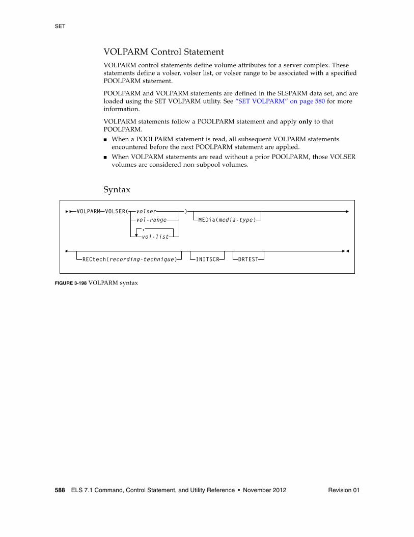
SET
588 ELS 7.1 Command, Control Statement, and Utility Reference • November 2012 Revision 01
VOLPARM Control StatementVOLPARM control statements define volume attributes for a server complex. These statements define a volser, volser list, or volser range to be associated with a specified POOLPARM statement.
POOLPARM and VOLPARM statements are defined in the SLSPARM data set, and are loaded using the SET VOLPARM utility. See “SET VOLPARM” on page 580 for more information.
VOLPARM statements follow a POOLPARM statement and apply only to that POOLPARM.
■ When a POOLPARM statement is read, all subsequent VOLPARM statements encountered before the next POOLPARM statement are applied.
■ When VOLPARM statements are read without a prior POOLPARM, those VOLSER volumes are considered non-subpool volumes.
Syntax
FIGURE 3-198 VOLPARM syntax
VOLPARMvol-range,vol-list
volser )MEDia(media-type)
RECtech(recording-technique)
VOLSER(
INITSCR DRTEST
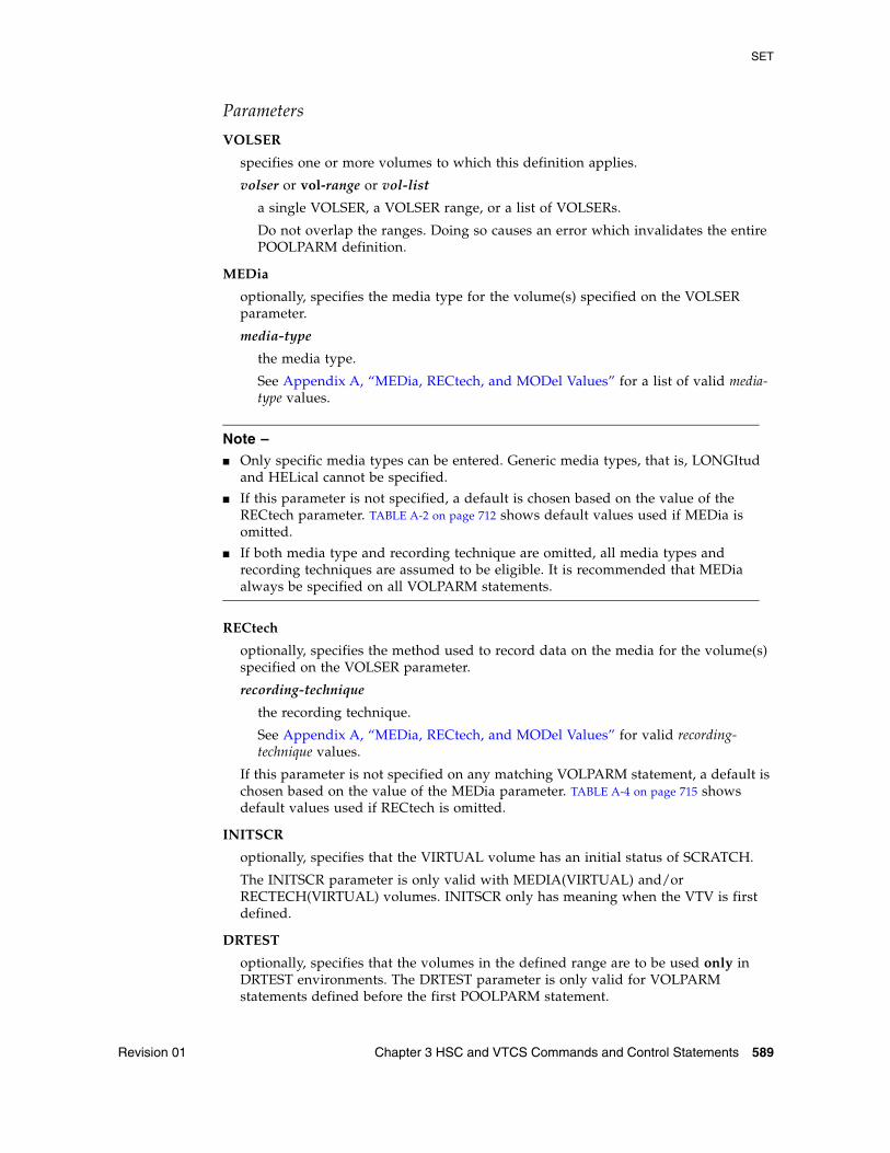
SET
Revision 01 Chapter 3 HSC and VTCS Commands and Control Statements 589
Parameters
VOLSER
specifies one or more volumes to which this definition applies.
volser or vol-range or vol-list
a single VOLSER, a VOLSER range, or a list of VOLSERs.
Do not overlap the ranges. Doing so causes an error which invalidates the entire POOLPARM definition.
MEDia
optionally, specifies the media type for the volume(s) specified on the VOLSER parameter.
media-type
the media type.
See Appendix A, “MEDia, RECtech, and MODel Values” for a list of valid media-type values.
Note – ■ Only specific media types can be entered. Generic media types, that is, LONGItud
and HELical cannot be specified.
■ If this parameter is not specified, a default is chosen based on the value of the RECtech parameter. TABLE A-2 on page 712 shows default values used if MEDia is omitted.
■ If both media type and recording technique are omitted, all media types and recording techniques are assumed to be eligible. It is recommended that MEDia always be specified on all VOLPARM statements.
RECtech
optionally, specifies the method used to record data on the media for the volume(s) specified on the VOLSER parameter.
recording-technique
the recording technique.
See Appendix A, “MEDia, RECtech, and MODel Values” for valid recording-technique values.
If this parameter is not specified on any matching VOLPARM statement, a default is chosen based on the value of the MEDia parameter. TABLE A-4 on page 715 shows default values used if RECtech is omitted.
INITSCR
optionally, specifies that the VIRTUAL volume has an initial status of SCRATCH.
The INITSCR parameter is only valid with MEDIA(VIRTUAL) and/or RECTECH(VIRTUAL) volumes. INITSCR only has meaning when the VTV is first defined.
DRTEST
optionally, specifies that the volumes in the defined range are to be used only in DRTEST environments. The DRTEST parameter is only valid for VOLPARM statements defined before the first POOLPARM statement.
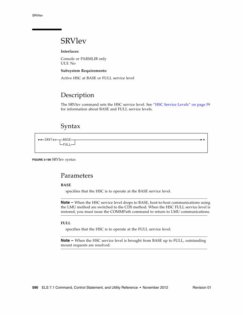
SRVlev
590 ELS 7.1 Command, Control Statement, and Utility Reference • November 2012 Revision 01
SRVlevInterfaces:
Console or PARMLIB onlyUUI: No
Subsystem Requirements:
Active HSC at BASE or FULL service level
DescriptionThe SRVlev command sets the HSC service level. See “HSC Service Levels” on page 59 for information about BASE and FULL service levels.
Syntax
FIGURE 3-199 SRVlev syntax
ParametersBASE
specifies that the HSC is to operate at the BASE service level.
Note – When the HSC service level drops to BASE, host-to-host communications using the LMU method are switched to the CDS method. When the HSC FULL service level is restored, you must issue the COMMPath command to return to LMU communications.
FULL
specifies that the HSC is to operate at the FULL service level.
Note – When the HSC service level is brought from BASE up to FULL, outstanding mount requests are resolved.
SRVlev BASEFULL
STOPMN
Revision 01 Chapter 3 HSC and VTCS Commands and Control Statements 591
STOPMNInterfaces:
Console or PARMLIB onlyUUI: No
Subsystem Requirements:
Active HSC at BASE or FULL service level
DescriptionThe STOPMN command stops monitoring of cartridge move requests from the programmatic interface.
Syntax
FIGURE 3-200 STOPMN syntax
ParametersPGMI
specifies that monitoring of cartridge move requests from the programmatic interface is to be terminated.
L
optionally, identifies the console where the monitoring information is being displayed. If this parameter is omitted or if L= is specified without a console ID or console name, the monitoring being displayed on the console that issued the command is terminated.
cc
optionally, the console ID. Allowable values are decimal in the range from 00 through 99.
Specifying 00 stops information from being sent explicitly to the hardcopy log.
name
optionally, the console name.
STOPMNPM
PGMI,L(
ccname
)
SWitch
592 ELS 7.1 Command, Control Statement, and Utility Reference • November 2012 Revision 01
SWitchInterfaces:
Console or PARMLIB onlyUUI: No
Subsystem Requirements:
Active HSC at FULL service level
DescriptionThe SWitch command can be used to manually reverse the roles of the master and standby LMUs or Library Controllers (LCs). The following configurations support switching:
■ dual LMU■ SL8500 dual Library Controller (LC)
In a dual LMU environment, this command initiates an IPL in the master LMU, causing the current standby LMU to become the master LMU. If the former master LMU completes the IPL successfully, it then assumes the role of the standby LMU.
In a dual LC configuration for a multiple SL8500 library ACS, the SWitch command issues a request to the LMU to switch the library LCs by library ID.
Caution – ■ Issue the Display Acs command before you enter the SWitch command to ensure the
library to switch includes an assigned TCP/IP address or host name for the standby. If it does not, do not switch the library because doing so causes the HSC to lose communication with the library.
■ Before issuing the SWitch command, stop all HSC activity.■ After issuing the SWitch command, do not start any HSC activity (i.e., mounts,
dismounts, Display ACS, and any other commands) until the switch process has completed.
Note – ■ For this release, only the SL8500 library is supported for dual LC switching.
■ For an automatic switch to occur (for example, from LCA to LCB or visa versa), the LC must fail. In this case, if there is a network/communication problem with LCA, the HSC goes into network recovery for the LCA connection(s). If you cannot recover or fix the connection, issue the SWitch command to switch LCA to LCB manually.
■ Before you issue the SWitch command, if the library is partitioned, be aware of other host software groups (ACSLS, HSC, ELS) using other partitions in the same library.
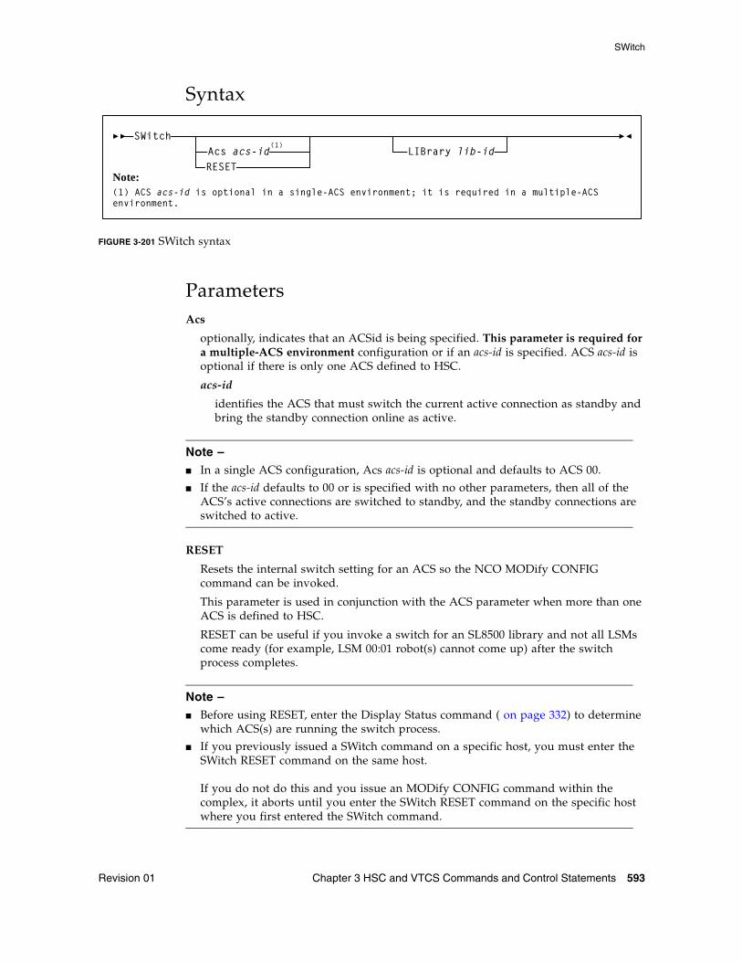
SWitch
Revision 01 Chapter 3 HSC and VTCS Commands and Control Statements 593
Syntax
FIGURE 3-201 SWitch syntax
ParametersAcs
optionally, indicates that an ACSid is being specified. This parameter is required for a multiple-ACS environment configuration or if an acs-id is specified. ACS acs-id is optional if there is only one ACS defined to HSC.
acs-id
identifies the ACS that must switch the current active connection as standby and bring the standby connection online as active.
Note – ■ In a single ACS configuration, Acs acs-id is optional and defaults to ACS 00.
■ If the acs-id defaults to 00 or is specified with no other parameters, then all of the ACS’s active connections are switched to standby, and the standby connections are switched to active.
RESET
Resets the internal switch setting for an ACS so the NCO MODify CONFIG command can be invoked.
This parameter is used in conjunction with the ACS parameter when more than one ACS is defined to HSC.
RESET can be useful if you invoke a switch for an SL8500 library and not all LSMs come ready (for example, LSM 00:01 robot(s) cannot come up) after the switch process completes.
Note – ■ Before using RESET, enter the Display Status command ( on page 332) to determine
which ACS(s) are running the switch process.
■ If you previously issued a SWitch command on a specific host, you must enter the SWitch RESET command on the same host.If you do not do this and you issue an MODify CONFIG command within the complex, it aborts until you enter the SWitch RESET command on the specific host where you first entered the SWitch command.
SWitchAcs acs-id
(1)
Note:(1) ACS acs-id is optional in a single-ACS environment; it is required in a multiple-ACS environment.
LIBrary lib-idRESET
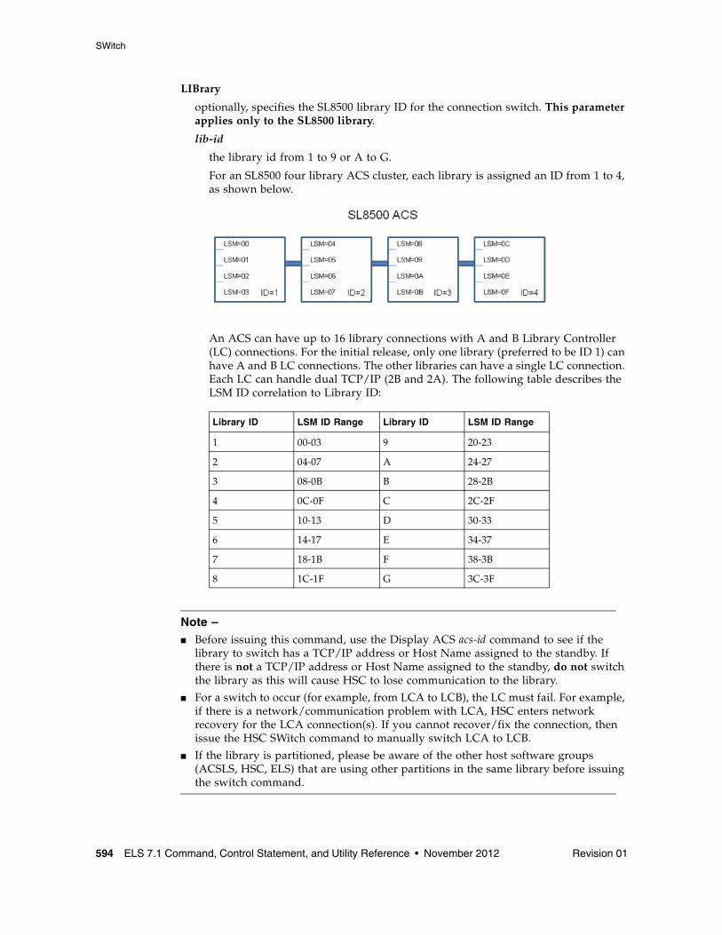
SWitch
594 ELS 7.1 Command, Control Statement, and Utility Reference • November 2012 Revision 01
LIBrary
optionally, specifies the SL8500 library ID for the connection switch. This parameter applies only to the SL8500 library.
lib-id
the library id from 1 to 9 or A to G.
For an SL8500 four library ACS cluster, each library is assigned an ID from 1 to 4, as shown below.
An ACS can have up to 16 library connections with A and B Library Controller (LC) connections. For the initial release, only one library (preferred to be ID 1) can have A and B LC connections. The other libraries can have a single LC connection. Each LC can handle dual TCP/IP (2B and 2A). The following table describes the LSM ID correlation to Library ID:
Note – ■ Before issuing this command, use the Display ACS acs-id command to see if the
library to switch has a TCP/IP address or Host Name assigned to the standby. If there is not a TCP/IP address or Host Name assigned to the standby, do not switch the library as this will cause HSC to lose communication to the library.
■ For a switch to occur (for example, from LCA to LCB), the LC must fail. For example, if there is a network/communication problem with LCA, HSC enters network recovery for the LCA connection(s). If you cannot recover/fix the connection, then issue the HSC SWitch command to manually switch LCA to LCB.
■ If the library is partitioned, please be aware of the other host software groups (ACSLS, HSC, ELS) that are using other partitions in the same library before issuing the switch command.
Library ID LSM ID Range Library ID LSM ID Range
1 00-03 9 20-23
2 04-07 A 24-27
3 08-0B B 28-2B
4 0C-0F C 2C-2F
5 10-13 D 30-33
6 14-17 E 34-37
7 18-1B F 38-3B
8 1C-1F G 3C-3F
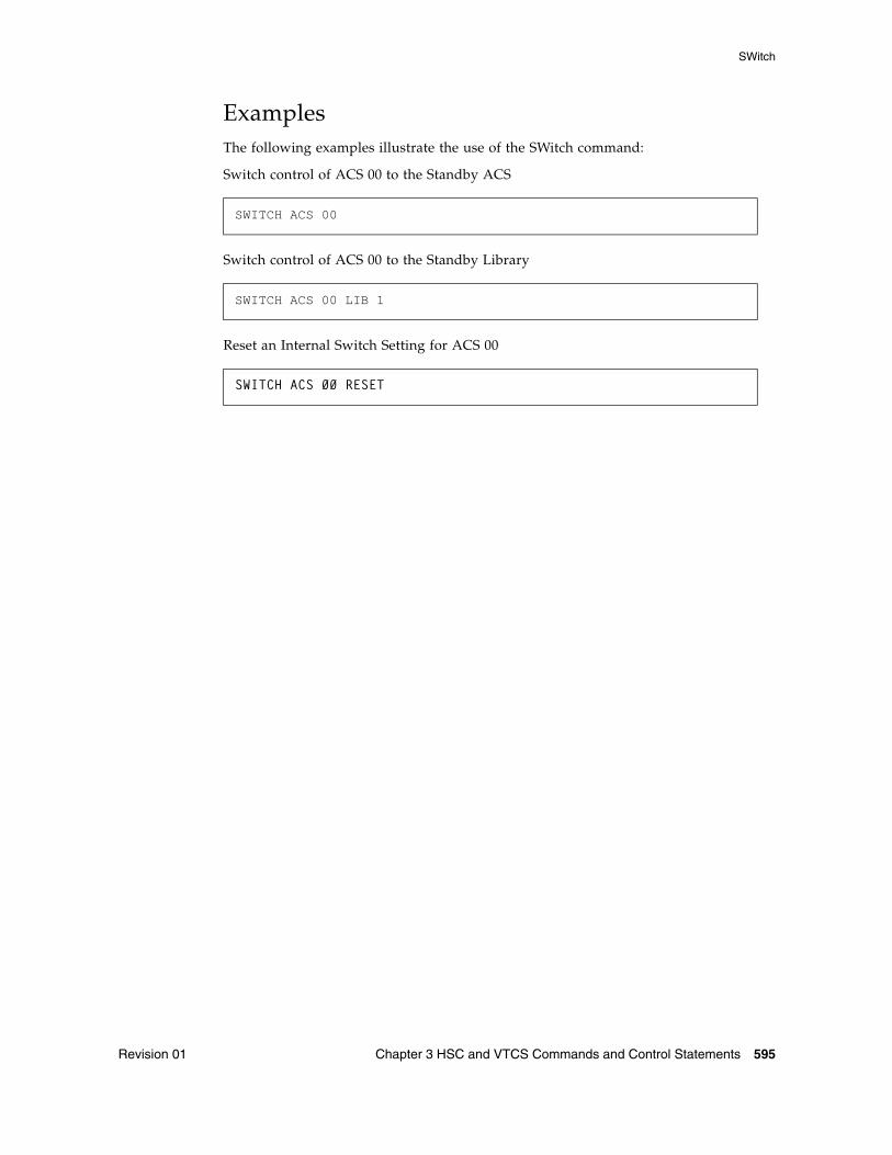
SWitch
Revision 01 Chapter 3 HSC and VTCS Commands and Control Statements 595
Examples The following examples illustrate the use of the SWitch command:
Switch control of ACS 00 to the Standby ACS
Switch control of ACS 00 to the Standby Library
Reset an Internal Switch Setting for ACS 00
SWITCH ACS 00
SWITCH ACS 00 LIB 1
SWITCH ACS 00 RESET
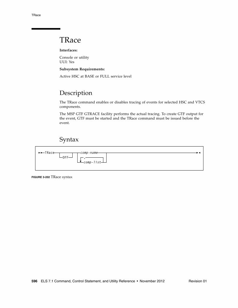
TRace
596 ELS 7.1 Command, Control Statement, and Utility Reference • November 2012 Revision 01
TRaceInterfaces:
Console or utilityUUI: Yes
Subsystem Requirements:
Active HSC at BASE or FULL service level
DescriptionThe TRace command enables or disables tracing of events for selected HSC and VTCS components.
The MSP GTF GTRACE facility performs the actual tracing. To create GTF output for the event, GTF must be started and the TRace command must be issued before the event.
Syntax
FIGURE 3-202 TRace syntax
TRace comp-name
comp-list,OFF
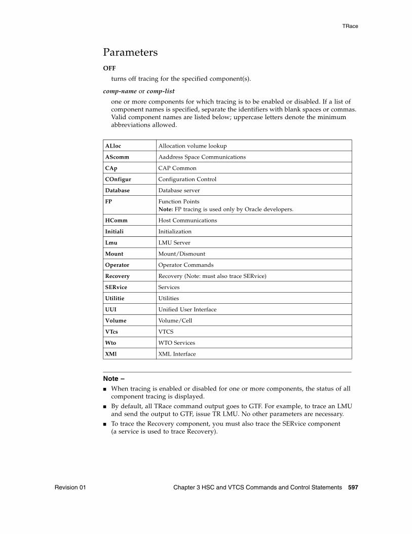
TRace
Revision 01 Chapter 3 HSC and VTCS Commands and Control Statements 597
ParametersOFF
turns off tracing for the specified component(s).
comp-name or comp-list
one or more components for which tracing is to be enabled or disabled. If a list of component names is specified, separate the identifiers with blank spaces or commas. Valid component names are listed below; uppercase letters denote the minimum abbreviations allowed.
Note – ■ When tracing is enabled or disabled for one or more components, the status of all
component tracing is displayed.
■ By default, all TRace command output goes to GTF. For example, to trace an LMU and send the output to GTF, issue TR LMU. No other parameters are necessary.
■ To trace the Recovery component, you must also trace the SERvice component(a service is used to trace Recovery).
ALloc Allocation volume lookup
AScomm Aaddress Space Communications
CAp CAP Common
COnfigur Configuration Control
Database Database server
FP Function PointsNote: FP tracing is used only by Oracle developers.
HComm Host Communications
Initiali Initialization
Lmu LMU Server
Mount Mount/Dismount
Operator Operator Commands
Recovery Recovery (Note: must also trace SERvice)
SERvice Services
Utilitie Utilities
UUI Unified User Interface
Volume Volume/Cell
VTcs VTCS
Wto WTO Services
XMl XML Interface
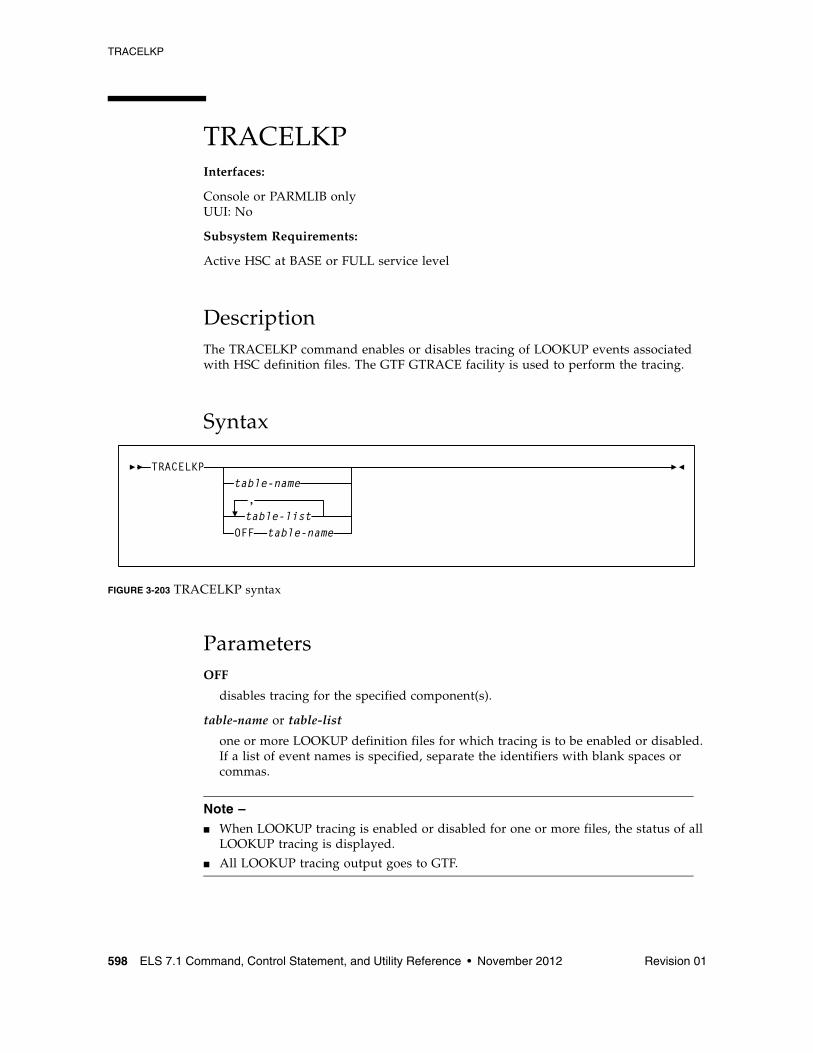
TRACELKP
598 ELS 7.1 Command, Control Statement, and Utility Reference • November 2012 Revision 01
TRACELKPInterfaces:
Console or PARMLIB onlyUUI: No
Subsystem Requirements:
Active HSC at BASE or FULL service level
DescriptionThe TRACELKP command enables or disables tracing of LOOKUP events associated with HSC definition files. The GTF GTRACE facility is used to perform the tracing.
Syntax
FIGURE 3-203 TRACELKP syntax
ParametersOFF
disables tracing for the specified component(s).
table-name or table-list
one or more LOOKUP definition files for which tracing is to be enabled or disabled. If a list of event names is specified, separate the identifiers with blank spaces or commas.
Note – ■ When LOOKUP tracing is enabled or disabled for one or more files, the status of all
LOOKUP tracing is displayed.
■ All LOOKUP tracing output goes to GTF.
TRACELKP
table-list
table-name,
OFF table-name
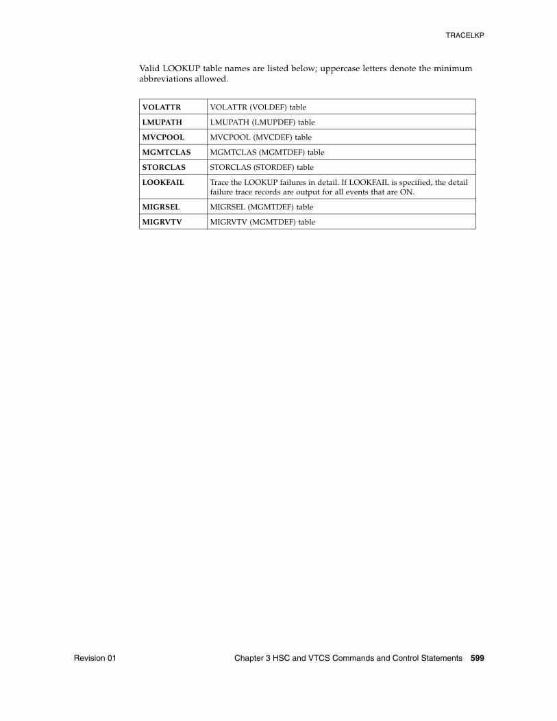
TRACELKP
Revision 01 Chapter 3 HSC and VTCS Commands and Control Statements 599
Valid LOOKUP table names are listed below; uppercase letters denote the minimum abbreviations allowed.
VOLATTR VOLATTR (VOLDEF) table
LMUPATH LMUPATH (LMUPDEF) table
MVCPOOL MVCPOOL (MVCDEF) table
MGMTCLAS MGMTCLAS (MGMTDEF) table
STORCLAS STORCLAS (STORDEF) table
LOOKFAIL Trace the LOOKUP failures in detail. If LOOKFAIL is specified, the detail failure trace records are output for all events that are ON.
MIGRSEL MIGRSEL (MGMTDEF) table
MIGRVTV MIGRVTV (MGMTDEF) table
UEXIT
600 ELS 7.1 Command, Control Statement, and Utility Reference • November 2012 Revision 01
UEXITInterfaces:
Console or PARMLIB onlyUUI: No
Subsystem Requirements:
Active HSC at BASE or FULL service level
DescriptionThe UEXIT command defines how HSC processes your user exits.
HSC user exits allow you to invoke your own processing routines at particular points during HSC processing. User exits controlled by the HSC are loaded at HSC initialization from the load library identified by DDNAME SLSUEXIT. The following user exits are managed by the HSC using the UEXIT command:
■ SLSUX03■ SLSUX05■ SLSUX06■ SLSUX14■ SLSUX15
Using the UEXIT command, you can start the HSC with a user exit disabled and then enable the exit at any time the HSC is operational. If an exit does not perform as expected, make the necessary changes and load it again.
The UEXIT command optionally allows you to provide unique user exit load module names and to create different versions of an exit that can be run at different times (for example, day shift versus night shift). The load modules are contained in a user-defined load module library described at HSC startup
Note – ■ User Exit 03 and User Exit 05 are legacy interfaces and have been replaced by
alternative facilities that do not require a User Exit.
■ User Exit 03 is enabled at HSC initialization. The UEXIT command cannot be used to enable, disable, or reload this exit.
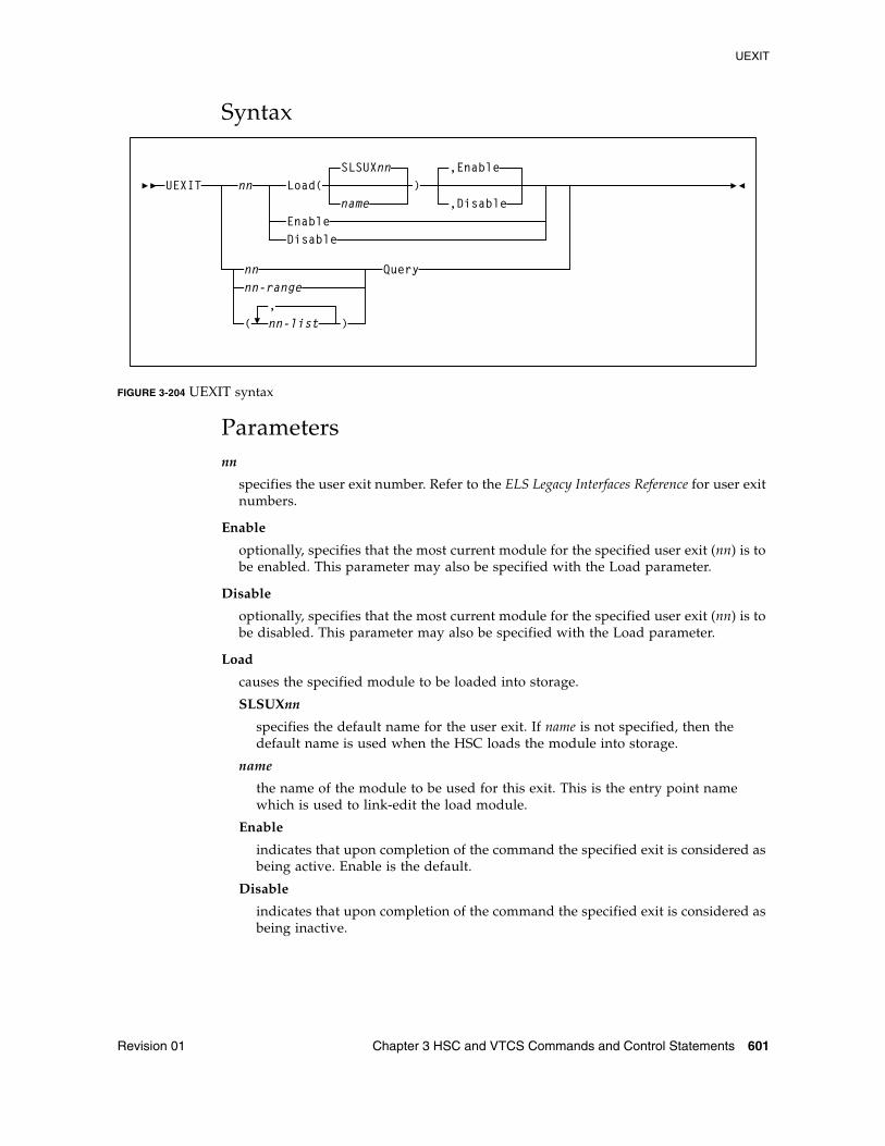
UEXIT
Revision 01 Chapter 3 HSC and VTCS Commands and Control Statements 601
Syntax
FIGURE 3-204 UEXIT syntax
Parametersnn
specifies the user exit number. Refer to the ELS Legacy Interfaces Reference for user exit numbers.
Enable
optionally, specifies that the most current module for the specified user exit (nn) is to be enabled. This parameter may also be specified with the Load parameter.
Disable
optionally, specifies that the most current module for the specified user exit (nn) is to be disabled. This parameter may also be specified with the Load parameter.
Load
causes the specified module to be loaded into storage.
SLSUXnn
specifies the default name for the user exit. If name is not specified, then the default name is used when the HSC loads the module into storage.
name
the name of the module to be used for this exit. This is the entry point name which is used to link-edit the load module.
Enable
indicates that upon completion of the command the specified exit is considered as being active. Enable is the default.
Disable
indicates that upon completion of the command the specified exit is considered as being inactive.
UEXIT nn
nn
Load(name
SLSUXnn)
,Enable
,DisableEnableDisable
nn-range
( nn-list,
)
Query
UEXIT
602 ELS 7.1 Command, Control Statement, and Utility Reference • November 2012 Revision 01
nn or nn-range or nn-list
can be used with the Query parameter to specify a single user exit, a range of exits, or a list of exits.
When specifying a range of user exit numbers, the beginning number must be separated from the ending number by a hyphen.
Example: (04-09)
In a list of user exits, the user exit numbers must be separated by commas and the list must be enclosed in parentheses.
Example: (01,04,10)
Query
requests the status of all the currently loaded versions of the specified user exit number(s). A display of user exit status may be specified for a single user exit, a range of exits, or a list of exits.
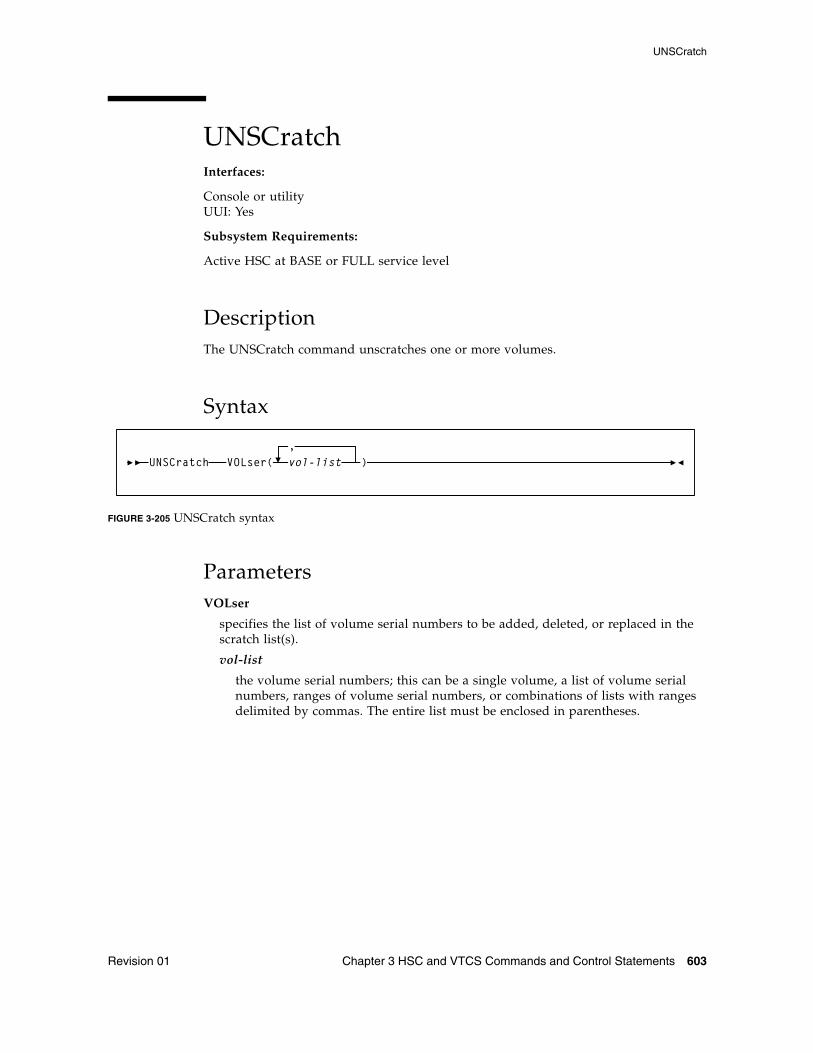
UNSCratch
Revision 01 Chapter 3 HSC and VTCS Commands and Control Statements 603
UNSCratchInterfaces:
Console or utilityUUI: Yes
Subsystem Requirements:
Active HSC at BASE or FULL service level
DescriptionThe UNSCratch command unscratches one or more volumes.
Syntax
FIGURE 3-205 UNSCratch syntax
ParametersVOLser
specifies the list of volume serial numbers to be added, deleted, or replaced in the scratch list(s).
vol-list
the volume serial numbers; this can be a single volume, a list of volume serial numbers, ranges of volume serial numbers, or combinations of lists with ranges delimited by commas. The entire list must be enclosed in parentheses.
UNSCratch VOLser( vol-list,
)
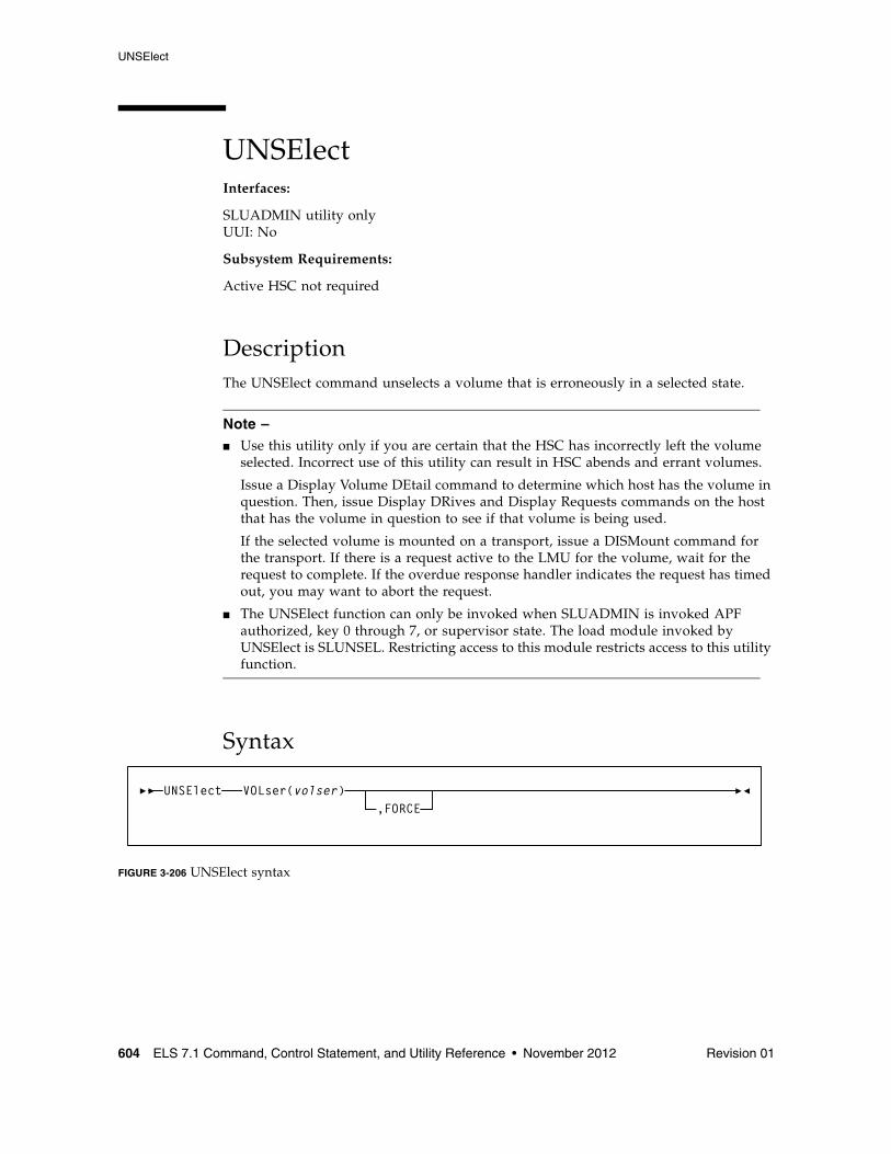
UNSElect
604 ELS 7.1 Command, Control Statement, and Utility Reference • November 2012 Revision 01
UNSElectInterfaces:
SLUADMIN utility onlyUUI: No
Subsystem Requirements:
Active HSC not required
DescriptionThe UNSElect command unselects a volume that is erroneously in a selected state.
Note – ■ Use this utility only if you are certain that the HSC has incorrectly left the volume
selected. Incorrect use of this utility can result in HSC abends and errant volumes.
Issue a Display Volume DEtail command to determine which host has the volume in question. Then, issue Display DRives and Display Requests commands on the host that has the volume in question to see if that volume is being used.
If the selected volume is mounted on a transport, issue a DISMount command for the transport. If there is a request active to the LMU for the volume, wait for the request to complete. If the overdue response handler indicates the request has timed out, you may want to abort the request.
■ The UNSElect function can only be invoked when SLUADMIN is invoked APF authorized, key 0 through 7, or supervisor state. The load module invoked by UNSElect is SLUNSEL. Restricting access to this module restricts access to this utility function.
Syntax
FIGURE 3-206 UNSElect syntax
UNSElect VOLser(volser),FORCE
UNSElect
Revision 01 Chapter 3 HSC and VTCS Commands and Control Statements 605
ParametersVOLser
indicates that a VOLSER is being specified for unselection.
volser
the VOLSER to be unselected.
FORCE
optionally, indicates that the volume is to be unselected even if communication with the host that has the volume selected is not possible.
Vary
606 ELS 7.1 Command, Control Statement, and Utility Reference • November 2012 Revision 01
VaryInterfaces:
■ Console or PARMLIB (Vary ACS)
■ Console or utility, UUI All (Vary CLINK, RTD, or VTSS)
UUI: Yes
Subsystem Requirements:
■ Active HSC at FULL service level (Vary ACS)
■ Active HSC/VTCS (Vary CLINK, RTD, or VTSS)
DescriptionThe Vary command changes the online/offline state for the following:
■ ACS or station■ CLINK■ PATH■ RTD■ VTSS
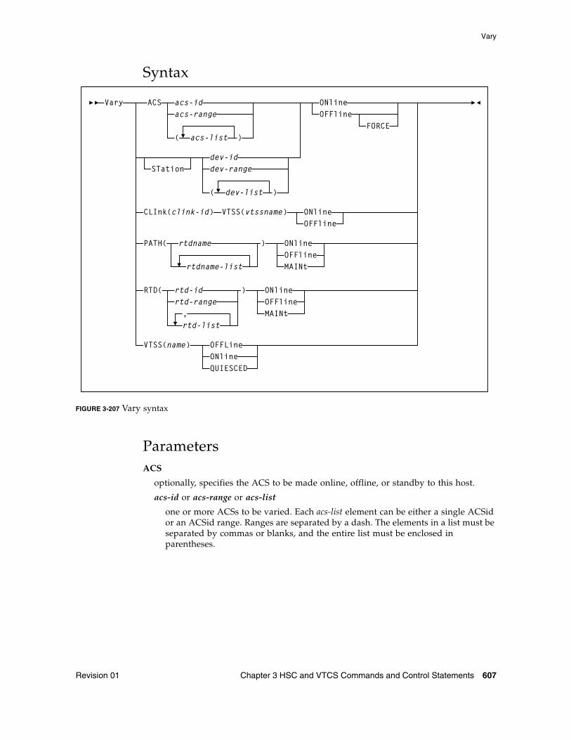
Vary
Revision 01 Chapter 3 HSC and VTCS Commands and Control Statements 607
Syntax
FIGURE 3-207 Vary syntax
ParametersACS
optionally, specifies the ACS to be made online, offline, or standby to this host.
acs-id or acs-range or acs-list
one or more ACSs to be varied. Each acs-list element can be either a single ACSid or an ACSid range. Ranges are separated by a dash. The elements in a list must be separated by commas or blanks, and the entire list must be enclosed in parentheses.
Vary ACS acs-idacs-range
( acs-list )
STationdev-iddev-range
( dev-list )
OFFlineONline
FORCE
CLInk(clink-id) VTSS(vtssname) ONlineOFFline
RTD( rtd-idrtd-range
rtd-list,
) ONlineOFFlineMAINt
VTSS(name) OFFLineONlineQUIESCED
PATH( rtdname
rtdname-list
ONlineOFFlineMAINt
)
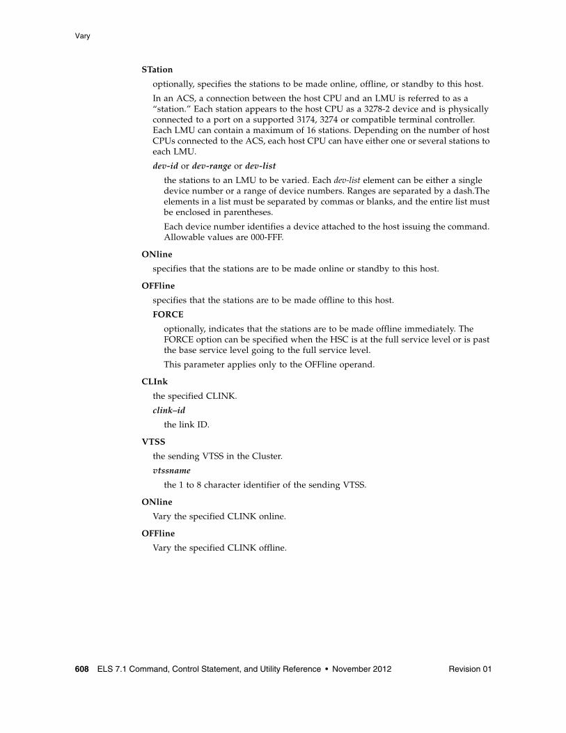
Vary
608 ELS 7.1 Command, Control Statement, and Utility Reference • November 2012 Revision 01
STation
optionally, specifies the stations to be made online, offline, or standby to this host.
In an ACS, a connection between the host CPU and an LMU is referred to as a “station.” Each station appears to the host CPU as a 3278-2 device and is physically connected to a port on a supported 3174, 3274 or compatible terminal controller. Each LMU can contain a maximum of 16 stations. Depending on the number of host CPUs connected to the ACS, each host CPU can have either one or several stations to each LMU.
dev-id or dev-range or dev-list
the stations to an LMU to be varied. Each dev-list element can be either a single device number or a range of device numbers. Ranges are separated by a dash.The elements in a list must be separated by commas or blanks, and the entire list must be enclosed in parentheses.
Each device number identifies a device attached to the host issuing the command. Allowable values are 000-FFF.
ONline
specifies that the stations are to be made online or standby to this host.
OFFline
specifies that the stations are to be made offline to this host.
FORCE
optionally, indicates that the stations are to be made offline immediately. The FORCE option can be specified when the HSC is at the full service level or is past the base service level going to the full service level.
This parameter applies only to the OFFline operand.
CLInk
the specified CLINK.
clink–id
the link ID.
VTSS
the sending VTSS in the Cluster.
vtssname
the 1 to 8 character identifier of the sending VTSS.
ONline
Vary the specified CLINK online.
OFFline
Vary the specified CLINK offline.
Vary
Revision 01 Chapter 3 HSC and VTCS Commands and Control Statements 609
PATH
optionally, specifies the path (from a VTSS to RTDs) to be made online, offline, or standby to this host. This permits the individual RTDPATH from a VTSS to a device to be varied to the desired state. This path may represent either a direct connection to a RTD from a VTSS or a connection to a Virtual Library.
rtdname or rtdname-list
the names assigned to the paths for accessing RTDs for Virtual Libraries from a VTSS
ONline
Vary the specified path (from a VTSS to RTDs) to an online state.
OFFline
Vary the specified path (from a VTSS to RTDs) to an offline state.
MAINt
Vary the specified path (from a VTSS to RTDs) to an offline (maintenance mode) state.
RTD
Change the state of the specified RTDs.
rtd–id, rtd-range, or rtd-list
the unit addresses of one or more RTDs. Lists and ranges of RTDs are limited to 64 items for VSM2s and VSM3s and 256 items for VSM4s.
ONline
Vary the specified RTDs online to their connected VTSSs.
OFFline
Vary the specified RTDs offline to their connected VTSSs.
MAINt
Vary the specified RTDs offline (maintenance mode) to their connected VTSSs.
VTSS
Change the state of the specified VTSS.
name
the VTSS identifier.
OFFline
Vary the specified VTSS offline.
ONline
Vary the specified VTSS online.
QUIESCED
Vary the specified VTSS to quiesced state.
Note – Vary VTSS does not change the state of the VTDs or RTDs associated with the specified VTSS.
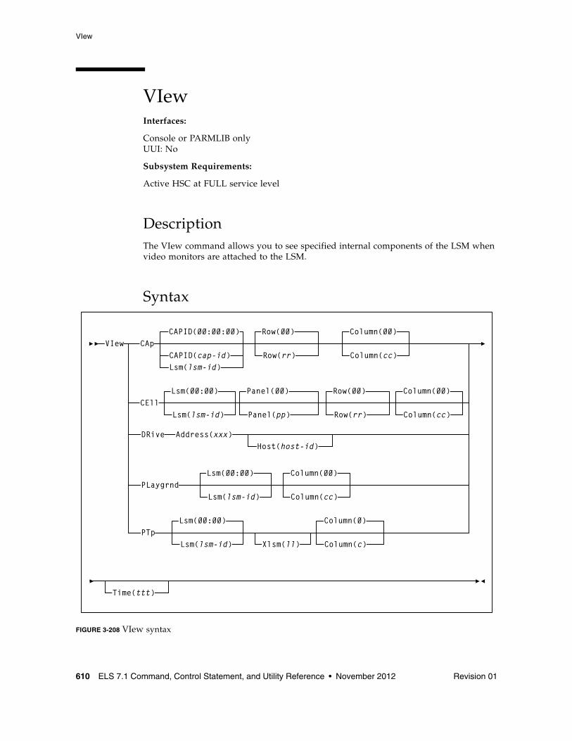
VIew
610 ELS 7.1 Command, Control Statement, and Utility Reference • November 2012 Revision 01
VIewInterfaces:
Console or PARMLIB onlyUUI: No
Subsystem Requirements:
Active HSC at FULL service level
DescriptionThe VIew command allows you to see specified internal components of the LSM when video monitors are attached to the LSM.
Syntax
FIGURE 3-208 VIew syntax
VIew CApCAPID(cap-id)Lsm(lsm-id)
CAPID(00:00:00)
Row(rr)
Row(00)
CEllRow(rr)
Row(00)Lsm(00:00)
Lsm(lsm-id) Panel(pp)
Panel(00)
Column(cc)
Column(00)
Column(cc)
Column(00)
DRive Address(xxx)Host(host-id)
PLaygrndLsm(00:00)
Lsm(lsm-id) Column(cc)
Column(00)
PTpLsm(00:00)
Lsm(lsm-id) Xlsm(ll) Column(c)
Column(0)
Time(ttt)
VIew
Revision 01 Chapter 3 HSC and VTCS Commands and Control Statements 611
ParametersCAp
indicates that a camera is to focus on a cell location in a CAP. If you do not specify the CAPID or Lsm parameter, the command defaults to CAPid 00:00:00. If you do not specify the Row and Column parameters, the command defaults to row 0, column 0.
CAPID
identifies one CAP in an LSM that contains multiple CAPs.
cap-id
the CAP that you want to view. The format of a cap-id is AA:LL:CC, where AA:LL is the LSMid, and CC is the CAP. See “CAPid” on page 720 for a list of valid values.
Lsm
identifies an LSM that contains a single CAP.
lsm-id
the single CAP that you want to view. The format of an LSMid is AA:LL, where AA is the ACSid (decimal 00-99) and LL is the LSM number (decimal 00-99).
Row
identifies a row number in a CAP. If you do not specify this parameter the command defaults to row 0.
rr
the row number. Allowable values for rr are decimal and are specific to the LSM type. See “Rows” on page 722 for a list of valid values.
Column
identifies the column number within a CAP. If you do not specify this parameter the command defaults to column 0.
cc
the column number. Allowable values for cc are decimal and are specific to the LSM type. Columns are numbered starting at the left of the panel. See “Columns” on page 723 for a list of valid values.
VIew
612 ELS 7.1 Command, Control Statement, and Utility Reference • November 2012 Revision 01
CEll
indicates that a camera is to focus on a cartridge storage or diagnostic cell in an LSM panel. If you do not specify the Lsm, Panel, Row, and Column parameters, the command defaults to LSM 00:00, panel 0, row 0, column 0.
Lsm
identifies an LSM. If you do not specify this parameter, the command defaults to LSMid 00:00.
lsm-id
the LSMid. The format of an LSMid is AA:LL, where AA is the ACSid (decimal 00-99) and LL is the LSM number (decimal 00-99).
Panel
designates the LSM panel number containing the cartridge storage or diagnostic cell that the camera is to view. If you do not specify this parameter the command defaults to panel 0.
pp
the panel number. Allowable values for pp are decimal and are specific to the LSM type. See “Panels” on page 721 for a list of valid values.
Row
identifies a row number in an LSM panel. If you do not specify this parameter the command defaults to row 0.
rr
the row number. Allowable values for rr are decimal and are specific to the LSM type. See “Rows” on page 722 for a list of valid values.
Note – ■ Column 3 on panel 2 allows row entries only on rows 28-41. ■ The cells on panel 3 are optional.
Column
identifies the column number within a panel. If you do not specify this parameter the command defaults to column 0.
cc
the column number. Allowable values for cc are decimal and are specific to the LSM type. Columns are numbered starting at the left of the panel. See “Columns” on page 723 for a list of valid values.
DRive
indicates that a camera is to focus on a cartridge drive. You must designate the Address parameter to identify the drive. The Host parameter enables you to view a drive defined to another host.
Address
specifies the address of a cartridge drive. The Address parameter defines the operating system address of the transport you want to inspect.
xxx
the hexadecimal address of the transport. The HSC verifies that the specified address matches the LIBGEN-defined address for the given host.
VIew
Revision 01 Chapter 3 HSC and VTCS Commands and Control Statements 613
Host
gives meaning to the Address parameter when the drive being inspected is not defined in the LIBGEN for the host from which the VIew command is being entered.
If you do not specify the Host parameter, the HSC checks the LIBGEN-defined drive list for the host from which you entered the VIew command. If the address is found in the drive list, the command is executed.
host-id
the host where the transport is defined.
PLaygrnd
indicates that a camera is to focus on a playground cell. If the Lsm and Column parameters are not specified, the command defaults to the relative location of the cell in the playground in LSM 00:00.
Note – The playground is a reserved area of cells where the robot deposits cartridges that it finds in its hands during LSM initialization. Normal LSM initialization recovery processing moves cartridges from the playground cells to either their home cells or their intended destinations, but under abnormal circumstances cartridges may be left in playground cells. Refer to the appropriate Oracle StorageTek hardware publication for the location of the playground in the LSM.
Lsm
identifies an LSM. If you do not specify this parameter, the command defaults to LSMid 00:00.
lsm-id
the LSMid. The format of an LSMid is AA:LL, where AA is the ACSid (decimal 00-99) and LL is the LSM number (decimal 00-99).
Column
identifies the relative location of the cell in the playground for a panel. If you do not specify this parameter, the command defaults to the relative location of the cell in the playground.
cc
the relative location of the cell in the playground. Allowable values for cc are decimal and are specific to the LSM type. (Some LSMs have multiple playground cells and some have only one.)
VIew
614 ELS 7.1 Command, Control Statement, and Utility Reference • November 2012 Revision 01
PTp
indicates that a camera is to focus on a pass-thru port (PTP) cell. You can designate a particular PTP using the Lsm and Xlsm parameters, a particular cell using the Column parameter, and specify the viewing time using the Time parameter.
Lsm
identifies an LSM. If you do not specify this parameter, the command defaults to LSMid 00:00.
lsm-id
the LSMid. The format of an LSMid is AA:LL, where AA is the ACSid (decimal 00-99) and LL is the LSM number (decimal 00-99).
Xlsm
identifies the PTP to be inspected by defining the LSM that shares the PTP.
Each PTP is identified by the two LSMs it services. The Lsm parameter identifies which robot is used to view the PTP, and the Xlsm parameter identifies the LSM that shares the PTP. This distinction is necessary whenever an LSM contains more than one PTP.
If Xlsm is not specified for an LSM containing two or more PTPs, the HSC examines the LIBGEN and selects the first PTP defined there for Lsm(lsm-id).
ll
the LSM number of the adjacent LSM. Values for ll are decimal in the range from 00-99. (The ACS is identified in the Lsm parameter.)
Column
identifies the column number within a panel. If you do not specify this parameter the command defaults to column 0.
c
the column number. Allowable values for c are decimal and are specific to the LSM type:
■ 0-3 for LSM Models 4410, 9310, and 9740 ■ 0 or 1 for WolfCreek LSMs (all models).
Note – When the PTP is being shared by two different LSM types, the upper limit of the column value is determined by the LSM with the smaller PTP capacity.
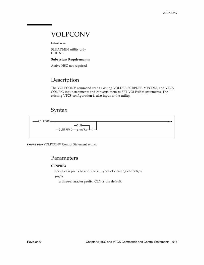
VOLPCONV
Revision 01 Chapter 3 HSC and VTCS Commands and Control Statements 615
VOLPCONVInterfaces:
SLUADMIN utility onlyUUI: No
Subsystem Requirements:
Active HSC not required
DescriptionThe VOLPCONV command reads existing VOLDEF, SCRPDEF, MVCDEF, and VTCS CONFIG input statements and converts them to SET VOLPARM statements. The existing VTCS configuration is also input to the utility.
Syntax
FIGURE 3-209 VOLPCONV Control Statement syntax
ParametersCLNPRFX
specifies a prefix to apply to all types of cleaning cartridges.
prefix
a three-character prefix. CLN is the default.
VOLPCONV
CLNPRFX(CLNprefix )
VOLPCONV
616 ELS 7.1 Command, Control Statement, and Utility Reference • November 2012 Revision 01
Additional JCL RequirementsIn addition to the required JCL definition statements described in “Invoking SLUADMIN” on page 674, the following definition statements apply to the VOLPCONV JCL:
SLSVOLA
input VOLDEF definitions in the form of VOLATTR statements.
Note – VOLATTR statements coded with the masking character (%, ? or *) within the SERIAL parameter are not supported and will cause message SLS0227I to be issued. Any VOLATTR statement using these masking characters must be converted to a range that spans the intent of the masking characters prior to running VOLPCONV.
SLSSCRP
input SCRPDEF definitions in the form of SCRPOOL statements.
SLSMVCP
input MVCDEF definitions in the form of MVCPOOL statements.
SLSVTCS
input VTCS configuration definitions. The VTCS configuration definitions can be obtained by running the VTCS DECOM utility.
SLSPARM
output VOLUME/POOL definitions in the form of POOLPARM and VOLPARM control statements. The logical record size of the SLSPARM data set is 80.
VOLRpt
Revision 01 Chapter 3 HSC and VTCS Commands and Control Statements 617
VOLRptInterfaces:
Utility onlyUUI: Yes
Subsystem Requirements:
Active HSC not required
DescriptionThe VOLRpt command produces a volume report.
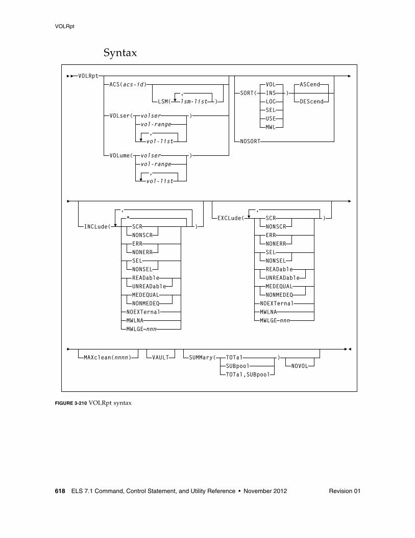
VOLRpt
618 ELS 7.1 Command, Control Statement, and Utility Reference • November 2012 Revision 01
Syntax
FIGURE 3-210 VOLRpt syntax
VOLRpt
vol-range,vol-list
ACS(acs-id)
LSM( lsm-list )
VOLser( volser
VOLume(vol-range
,vol-list
)volser
SORT(VOLINSLOCSEL
)ASCend
NOSORT
INCLude(
,*SCRNONSCRERRNONERRSELNONSELREADableUNREADableMEDEQUALNONMEDEQ
NOEXTernal
EXCLude(,
SCRNONSCRERRNONERRSELNONSELREADableUNREADableMEDEQUALNONMEDEQ
NOEXTernal
))
NOVOLSUMMary( TOTal
SUBpoolTOTal,SUBpool
)
)
,
MAXclean(nnnn)
USEMWL
VAULT
MWLNAMWLGE nnn
MWLNAMWLGE nnn
DEScend
VOLRpt
Revision 01 Chapter 3 HSC and VTCS Commands and Control Statements 619
Parameters
Note – VOLRpt supports additional legacy parameters used to specify flat file or volume report generation. Refer to the ELS Legacy Interfaces Reference for information about these parameters.
ACS
optionally, specifies that a report is to be produced for only a particular ACS.
acs-id
the one or two digit decimal ACS identifier.
LSM
optionally, specifies that a report is to be produced for only certain LSMs within an ACS.
lsm-list
the LSMs. An lsm-list can be a single LSM number or a list of LSM numbers. An LSM number is decimal 00-99.
An LSM range is not allowed. If a list is specified, the elements must be separated by blanks or commas, and the entire list enclosed in parentheses.
VOLser or VOLume
optionally, specifies that the report only contain information on certain VOLSERs.
volser or vol-range or vol-list
the volume serial numbers requested. Any subranges of volumes specified in the vol-list that are not in the control data set are listed in the Control Card Image Listing portion of the report using one line per subrange.
A percent sign (‘‘%’’) may be used as a ‘‘wildcard’’ character in the VOLSER to specify pattern matching. The percent sign designates that any single character can match the corresponding position in the VOLSER.
For example, A9%%%% specifies that all of the six-character volume serial numbers that begin with the characters ‘‘A9’’ are selected for the report.
Q%12% specifies that all five-character VOLSERs that begin with ‘‘Q’’ and have a ‘‘12’’ in the third and fourth positions of the VOLSER are selected for the report. The percent sign cannot be specified in a range specification. Therefore, ‘‘A%0000-A%9999’’ is invalid.
In the Volume Report Listing of the utility, the volumes requested which are not in the control data set are not listed.
VOLRpt
620 ELS 7.1 Command, Control Statement, and Utility Reference • November 2012 Revision 01
SORT
optionally specifies a specified sort sequence.
Multiple sort criteria may be specified. The order, from left to right, specifies the order in which the report is to be sorted.
For example, SORT(INS,USE) produces a report sorted by date inserted in the control data set, and then for each date, sorted by select count.
Note – SORT and NOSORT are mutually exclusive.
The following SORT options are available:
VOL
indicates that the report is to be sorted by volume serial number (VOL is the default).
INS
indicates that the report is to be sorted by date and time the volume was inserted into the control data set.
LOC
indicates that the report is to be sorted by location.
SEL
indicates that the report is to be sorted by date and time the volume was last selected.
USE
indicates that the report is to be sorted by selection count.
MWL
indicates that the report is to be sorted by Media Warranty Life (MWL) percentage, which indicates how much of the media life has been used. Media warranty life is considered to be expired at 100%.
Note – To collect and report media warranty life, tape libraries and transports must meet the following requirements:
■ SL8500 or SL3000 libraries■ LMU compatibility level 21 or higher■ T9x40: all media and models at firmware level 1.42 or higher (except 9840B)■ T10000: all models and media at firmware level 1.38 or higher
Refer to the publication Managing HSC and VTCS for more information about media warranty life.
NOSORT
specifies that an unsorted report is to be produced.
Note – NOSORT is mutually exclusive with SORT, ASCend, and DEScend.
VOLRpt
Revision 01 Chapter 3 HSC and VTCS Commands and Control Statements 621
ASCend
optionally, specifies that the report is to be sorted in ascending order. ASCend is the default. This parameter is ignored if NOSORT is specified.
Note – ASCend is mutually exclusive with NOSORT and DEScend.
DEScend
optionally, specifies that the report is to be sorted in descending order. This parameter is ignored if NOSORT is specified.
Note – DEScend is mutually exclusive with NOSORT and ASCend.
INCLude
optionally, specifies the criteria for including volume information in the report. If this keyword is specified, all volumes that match at least one of the specified criteria are tentatively selected for the report. Information about volumes may be removed from the list of volumes selected for the report if other options, such as EXCLUDE, VOL, ACS, or LSM are specified.
Note – ■ INCLude parameters are applied before EXCLude parameters in volume selection.
■ Parameter values are not checked for the existence of their opposite values (for example, ‘‘SEL’’ is still flagged even if ‘‘NONSEL’’ is specified, and vice versa).
■ Positive attributes are applied before negative attributes (for example, SCR is applied before NONSCR).
*
indicates that all volumes in the library are considered for being included in the report. The default is *. If more than one of the following parameters is specified, the parameters must be separated by commas.
SCR
specifies that scratch volumes match the specified criteria.
NONSCR
specifies that nonscratch volumes match the specified criteria.
ERR
specifies that errant volumes match the criteria.
NONERR
specifies that non-errant volumes match the criteria.
SEL
specifies that selected volumes match the criteria.
NONSEL
specifies that nonselected volumes match the criteria.
READable
specifies that volumes with a readable external label match the criteria.
VOLRpt
622 ELS 7.1 Command, Control Statement, and Utility Reference • November 2012 Revision 01
UNREADable
specifies that volumes with an unreadable external label match the criteria.
MEDEQUAL
specifies that volumes for which the media types of the VOLATTR and the VAR are equal match the criteria.
NONMEDEQ
specifies that volumes for which the media types of the VOLATTR and the VAR are not equal match the criteria.
NOEXTernal
specifies that volumes without an external label match the criteria.
For example, INCLUDE(SEL,ERR) tentatively chooses only selected and errant volumes for the report. INCLude parameters are applied before EXCLude parameters in volume selection.
MWLNA
specifies that volumes with an unknown media warranty life match the criteria. Media warranty life is obtained at volume dismount for tape libraries with an LMU compatibility level of 21 or above. Use the Display ACS command to obtain the LMU compatibility level.
MWLGE nnn
specifies that volumes with a media warranty life greater than or equal to nnn percent match the criteria. It also excludes all volumes with an unknown media warranty life.
Specify INCLUDE(MWLNA) to force inclusion of all volumes with an unknown media warranty life. Valid values for nnn are 0-254.
Note – To collect and report media warranty life, tape libraries and transports must meet the following requirements:
■ SL8500 or SL3000 libraries■ LMU compatibility level 21 or higher■ T9x40: all media and models at firmware level 1.42 or higher (except 9840B)■ T10000: all models and media at firmware level 1.38 or higher
Refer to the publication Managing HSC and VTCS for more information about media warranty life.
EXCLude
optionally, specifies the criteria for excluding volume information from the report. Any volumes that match one or more of the exclusion criteria are excluded from the report.
EXCLude parameter values are the same as INCLude values, except for the ‘‘*’’ parameter (see the INCLude options list above).
As an example, EXCL(NONSEL) excludes nonselected volumes from the report.
VOLRpt
Revision 01 Chapter 3 HSC and VTCS Commands and Control Statements 623
Note – ■ INCLude parameters are applied before EXCLude parameters in volume selection.
■ If MWLGE is specified in both the INCLUDE and EXCLUDE parameters, the EXCLUDE limit value must be greater than the INCLUDE limit value.
■ Parameter values are not checked for the existence of their opposite values (for example, ‘‘SEL’’ is still flagged even if ‘‘NONSEL’’ is specified, and vice versa).
■ Positive attributes are applied before negative attributes (for example, SCR is applied before NONSCR).
MAXclean
optionally, specifies the maximum cleaning cartridge usage for the “over max clean” column. The MAXclean specified for each POOLPARM TYPE(CLEAN) overrides this value. Valid values are 0-32767.
VAULT
optionally, specifies that vaulted volumes are to be included in the detail volume report.
Note – VAULT is mutually exclusive with NOVOL, ACS, and LSM.
If the vault CDS subfile does not exist, this parameter is ignored.
Vaulted volumes are not included in the SUMMARY reports. In the detail report, the cell location for a vaulted volume is identified by the word “VAULT” and the insertion date/time is the date/time that the volume was inserted into the vault; i.e., ejected from the tape library.
SUMMary
optionally, specifies that the utility provide totals of volume attributes on an LSM and ACS basis, and/or subpool data on an ACS or LSM basis. Totals are affected by the use of limiting parameters such as ACS (and possibly LSM), VOLser/VOLume, and INCLude and/or EXCLude.
If both TOTal and SUBpool are specified, both reports are provided. The time and date displayed in the header for the Summary Report(s) are the same as the Volume Report Listing header.
TOTal
specifies that totals of scratch, selected, errant, available cells, and external label status types be provided on an LSM, ACS, and library basis in the report.
The totals are listed on a separate listing, on a new page from the Volume Report Listing and the Control Card Listing.
SUBpool
specifies that subpool totals be provided on an LSM, ACS, and library basis in the report.
Subpool information can be provided using the VOLPARM facility. See “VOLPARM Control Statement” on page 588 for more information about defining VOLPARM information. For alternative methods of specifying subpool information, refer to the ELS Legacy Interfaces Reference.
The totals are listed on a separate listing, on a new page from the Volume Report Listing, the Control Card Listing, and the Volume Report Totals Listing.
VOLRpt
624 ELS 7.1 Command, Control Statement, and Utility Reference • November 2012 Revision 01
If subpools overlap (i.e., a volume belongs to more than one subpool), then each volume is reported only within the first subpool in which it occurs, and totals for the other subpools may be inaccurate.
NOVOL
optionally, when used with SUMMary, specifies to display summary and/or subpool totals without producing volume detail.
NOVOL should not be specified by itself.
Note – NOVOL is mutually exclusive with ACS, VOLser, VOLume, SORT, NOSORT, INCLude, EXCLude, MAXclean, and VAULT.
Additional JCL Requirements If you are not using the VOLPARM facility to define your volume characteristics, refer to the ELS Legacy Interfaces Reference for a description of additional VOLRPT JCL statements that may be required.
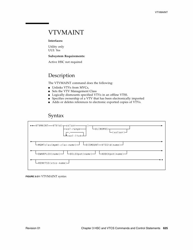
VTVMAINT
Revision 01 Chapter 3 HSC and VTCS Commands and Control Statements 625
VTVMAINT Interfaces:
Utility onlyUUI: Yes
Subsystem Requirements:
Active HSC not required
DescriptionThe VTVMAINT command does the following:
■ Unlinks VTVs from MVCs, ■ Sets the VTV Management Class ■ Logically dismounts specified VTVs in an offline VTSS.■ Specifies ownership of a VTV that has been electronically imported■ Adds or deletes references to electronic exported copies of VTVs.
Syntax
FIGURE 3-211 VTVMAINT syntax
VTVMAINT
MGMTclas(mgmt-clas-name)
VTVid(
vol-list
vol-rangevolser
,
)ULINKMVC
(volser)
DISMOUNT VTSSid(name)
OWNRPLEX(name) DELEXpot(name) ADDEXpot(name)
RENVTSS(vtss-name)
VTVMAINT
626 ELS 7.1 Command, Control Statement, and Utility Reference • November 2012 Revision 01
ParametersVTVid
specifies one or more VTVs.
volser, vol-range or vol-list
the volsers of one or more VTVs.
ULINKMVC
optionally, unlink (logically delete) MVC copies of the specified VTVs.
volser
Unlink the specified VTVs from the specified MVC. If no value is specified, then all MVC copies of the VTVs are deleted.
MGMTclas
optionally, set the Management Class of the VTVs.
mgmt-class-name
the Management Class name that you specified on the MGMTclas control statement. For more information, see “MGMTclas Control Statement” on page 433.
DISMOUNT VTSSid
optionally, logically dismount the specified VTVs in the specified VTSS.
name
the VTSS name.
If migrated copies of the dismounted VTVs exist that an online VTSS can access, you can now use this VTSS to access the VTVs.
Caution – If the VTV copy mounted in the offline VTSS was modified and not migrated, the MVC copy that you recall to an alternate VTSS is not current! Therefore, Oracle strongly recommends that you do not recall these non-current MVC copies!
Tip – When the offline VTSS is ready to be brought back online, it is strongly recommended that you audit the VTSS before running production jobs that use the VTSS. Also ensure that you clear any boxed VTD conditions before issuing the VTSS VARY ONLINE command.
OWNRPLEX
optionally, specifies ownership of a VTV that has been electronically imported.
name
the name of the TapePlex that owns the original copy of the VTV. This name must match one of the known TapePlex names in the configuration.
If this name matches that indicated for the THISPLEX parameter on the CONFIg TAPEPlex statement, the electronic importing status is removed.
VTVMAINT
Revision 01 Chapter 3 HSC and VTCS Commands and Control Statements 627
DELEXpot
optionally, specifies which references to electronic exported copies of the VTVs are removed.
name
the name of the TapePlex that is to be removed. If this parameter value is omitted, then all references to electronic export copies are removed.
This parameter merely removes the reference to the external copy of the VTV from the VTV record. It does not cause a contact of the other TapePlex to modify the remote copy in any way. Depending upon the management class definition for the VTV, removing a reference could cause an automatic re-drive of the export at some later time.
ADDEXpot
optionally, specifies the addition of references to the electronic export copy of the VTV.
name
the name of the TapePlex that is to be added. This name must match to one of the names that has been specified in the VTCS configuration.
This parameter merely adds the reference to the external copy to the VTV record. It is assumed that the required copy of the VTV will have been physically placed there by some other process. The VTV record can track a maximum of two TapePlex locations.
Note – The DELEXpot operation executes before the ADDEXpot operation. This makes it possible to replace the exported location information in a single call. For configurations where the electronic export function is not used, it is acceptable to use the ADDEXpot and DELEXpot parameters to add dummy tracking or user information to the VTV. The information in the VTV record is always cleared when the VTV data is updated.
RENVTSS
optionally, sets the name of the VTSS where the VTV was last mounted to vtss-name.
vtss-name
the new VTSS name. This must be the name of an existing VTSS in your configuration.
Note – To use RENVTSS, the host on which VTVMAINT is run must have access to the owning VTSS.
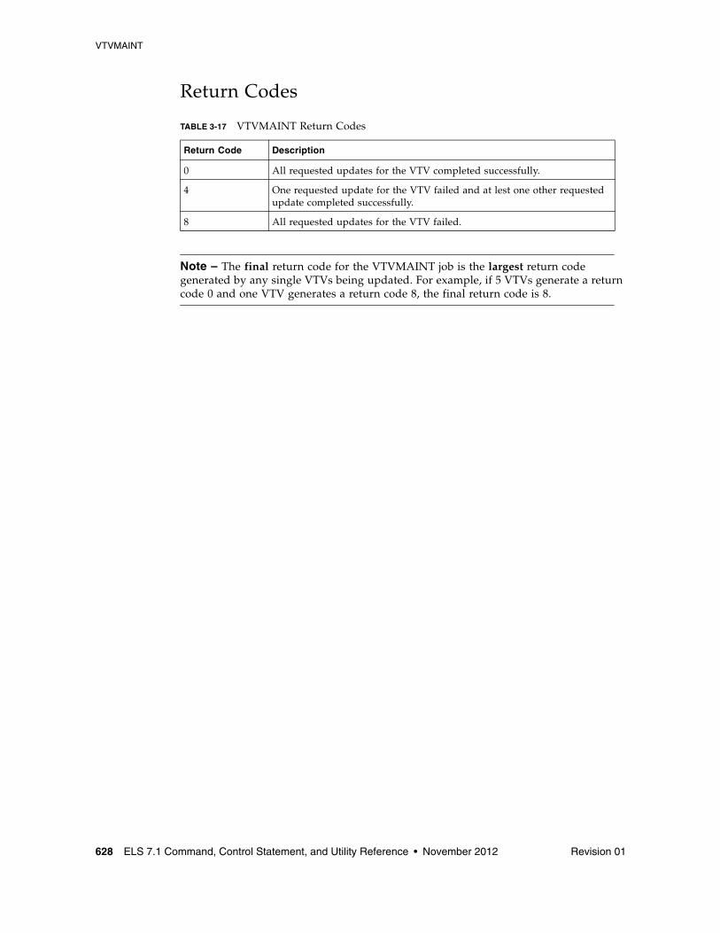
VTVMAINT
628 ELS 7.1 Command, Control Statement, and Utility Reference • November 2012 Revision 01
Return Codes
Note – The final return code for the VTVMAINT job is the largest return code generated by any single VTVs being updated. For example, if 5 VTVs generate a return code 0 and one VTV generates a return code 8, the final return code is 8.
TABLE 3-17 VTVMAINT Return Codes
Return Code Description
0 All requested updates for the VTV completed successfully.
4 One requested update for the VTV failed and at lest one other requested update completed successfully.
8 All requested updates for the VTV failed.
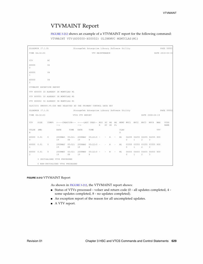
VTVMAINT
Revision 01 Chapter 3 HSC and VTCS Commands and Control Statements 629
VTVMAINT ReportFIGURE 3-212 shows an example of a VTVMAINT report for the following command:VTVMAINT VTV(X00000-X00002) ULINKMVC MGMTCLAS(M1)
FIGURE 3-212 VTVMAINT Report
As shown in FIGURE 3-212, the VTVMAINT report shows:
■ Status of VTVs processed - volser and return code (0 - all updates completed, 4 - some updates completed, 8 - no updates completed).
■ An exception report of the reason for all uncompleted updates.
■ A VTV report.
SLUADMIN (7.1.0) StorageTek Enterprise Library Software Utility PAGE 00001
TIME 06:32:03 VTV MAINTENANCE DATE 2010-03-31
VTV RC
X00000
04
X00001
04
X00002
04
VTVMAINT EXCEPTION REPORT
VTV X00000 IS ALREADY IN MGMTCLAS M1
VTV X00001 IS ALREADY IN MGMTCLAS M1
VTV X00002 IS ALREADY IN MGMTCLAS M1
SLS1315I SWS500.V5.CDS WAS SELECTED AS THE PRIMARY CONTROL DATA SET
SLUADMIN (7.1.0) StorageTek Enterprise Library Software Utility PAGE 00002
TIME 06:32:03 VTCS VTV REPORT DATE 2008-04-19
VTV SIZE COMP% <----CREATION----->
<----LAST USED---->
MIGR
SCRT
RESD
REPL
MGMT MVC1 MVC2 MVC3 MVC4 MAX VTSSNAME
VOLSER
(MB) DATE TIME DATE TIME CLASS
VTV
X00000
0.01 0 2008MAY19
05:02:08
2008MAY19
05:22:08
- - R - M1 022550
022551
022552
022553
800
X00001
0.01 0 2008MAY19
05:02:08
2008MAY19
05:22:08
- - R - M1 033550
033551
033552
033553
800
X00002
0.01 0 2008MAY19
05:02:08
2008MAY19
05:22:08
- - R - M1 044550
044551
044552
044553
800
3 INITIALIZED VTVS PROCESSED
0 NON-INITIALIZED VTVS PROCESSED
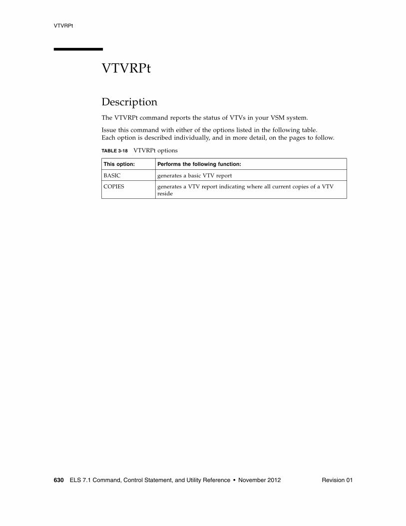
VTVRPt
630 ELS 7.1 Command, Control Statement, and Utility Reference • November 2012 Revision 01
VTVRPt
DescriptionThe VTVRPt command reports the status of VTVs in your VSM system.
Issue this command with either of the options listed in the following table. Each option is described individually, and in more detail, on the pages to follow.
TABLE 3-18 VTVRPt options
This option: Performs the following function:
BASIC generates a basic VTV report
COPIES generates a VTV report indicating where all current copies of a VTV reside
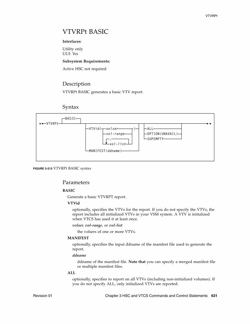
VTVRPt
Revision 01 Chapter 3 HSC and VTCS Commands and Control Statements 631
VTVRPt BASICInterfaces:
Utility onlyUUI: Yes
Subsystem Requirements:
Active HSC not required
DescriptionVTVRPt BASIC generates a basic VTV report.
Syntax
FIGURE 3-213 VTVRPt BASIC syntax
ParametersBASIC
Generate a basic VTVRPT report.
VTVid
optionally, specifies the VTVs for the report. If you do not specify the VTVs, the report includes all initialized VTVs in your VSM system. A VTV is initialized when VTCS has used it at least once.
volser, vol-range, or vol-list
the volsers of one or more VTVs.
MANIFEST
optionally, specifies the input ddname of the manifest file used to generate the report.
ddname
ddname of the manifest file. Note that you can specify a merged manifest file or multiple manifest files.
ALL
optionally, specifies to report on all VTVs (including non-initialized volumes). If you do not specify ALL, only initialized VTVs are reported.
VTVRPtVTVid( volser
vol-range
vol-list,
)
MANIFEST(ddname)
ALLOPTION(UNAVAIL)SUPEMPTY
BASIC
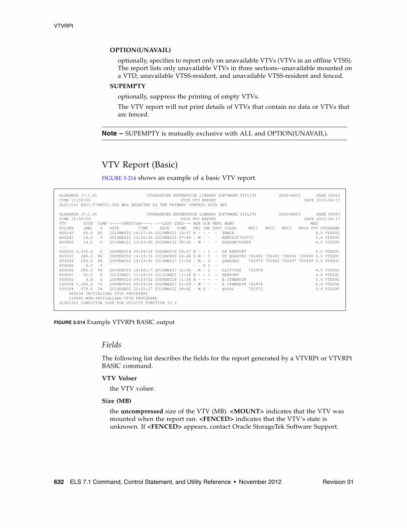
VTVRPt
632 ELS 7.1 Command, Control Statement, and Utility Reference • November 2012 Revision 01
OPTION(UNAVAIL)
optionally, specifies to report only on unavailable VTVs (VTVs in an offline VTSS). The report lists only unavailable VTVs in three sections--unavailable mounted on a VTD, unavailable VTSS-resident, and unavailable VTSS-resident and fenced.
SUPEMPTY
optionally, suppress the printing of empty VTVs.
The VTV report will not print details of VTVs that contain no data or VTVs that are fenced.
Note – SUPEMPTY is mutually exclusive with ALL and OPTION(UNAVAIL).
VTV Report (Basic)FIGURE 3-214 shows an example of a basic VTV report.
FIGURE 3-214 Example VTVRPt BASIC output
Fields
The following list describes the fields for the report generated by a VTVRPt or VTVRPt BASIC command.
VTV Volser
the VTV volser.
Size (MB)
the uncompressed size of the VTV (MB). <MOUNT> indicates that the VTV was mounted when the report ran. <FENCED> indicates that the VTV’s state is unknown. If <FENCED> appears, contact Oracle StorageTek Software Support.
SLUADMIN (7.1.0) STORAGETEK ENTERPRISE LIBRARY SOFTWARE UTILITY SSYS=HSCI PAGE 00002TIME 15:50:09 VTCS VTV REPORT DATE 2010-06-17SLS1315I HSC1.V70EC21.CDS WAS SELECTED AS THE PRIMARY CONTROL DATA SET
SLUADMIN (7.1.0) STORAGETEK ENTERPRISE LIBRARY SOFTWARE UTILITY SSYS=HSCI PAGE 00003TIME 15:50:09 VTCS VTV REPORT DATE 2010-06-17VTV SIZE COMP <----CREATION----> <--LAST USED--> MGR SCR REPL MGMT MAX VOLSER (MB) % DATE TIME DATE TIME RES IMP EXPT CLASS MVC1 MVC2 MVC3 MVC4 VTV VTSSNAMEA00240 66.4 85 2010MAY22 16:27:44 2010MAY22 16:57 R - - - - TRACE 4.0 VTSS92A00241 14.0 0 2010MAY21 13:02:30 2010MAY22 07:48 - M - - - MGMT2CP702972 0.4 VTSS90A00406 14.0 0 2010MAY21 13:03:50 2010MAY22 08:45 - M - - - EXHPDM700486 4.0 VTSS90...X50000 2,430.0 0 2009NOV18 09:04:18 2009NOV18 09:07 R - - I - PE EEXPORT 4.0 VTSS91X50047 280.0 96 2009DEC03 14:29:35 2010APR30 06:48 R M - I - PE QUADYES 700483 700491 700494 700498 4.0 VTSS91X50048 280.0 96 2009DEC03 14:29:41 2010MAY27 21:06 - M - I - QUADYES 702979 700492 700497 700499 4.0 VTSS91X50060 0.0 0 - - S I - X50066 280.0 96 2009DEC03 14:56:17 2010MAY27 21:06 - M - I - DLVTVYES 702978 4.0 VTSS92X50067 42.0 0 2010JAN21 11:28:55 2010JAN21 11:28 R - - I - EEXPORT 4.0 VTSS91Y50000 4.8 0 2009NOV20 09:59:52 2009DEC18 11:56 R - - - - E OTHERDIR 0.4 VTSS91Y50008 1,260.0 75 2009NOV20 09:59:56 2010MAY27 21:09 - M - - - E OTHERDIR 702978 0.4 VTSS92Y50184 578.6 34 2010FEB02 22:25:27 2010MAY22 08:42 - M S - - APOOL 702972 0.4 VTSS90 485434 INITIALIZED VTVS PROCESSED 116566 NON-INITIALIZED VTVS PROCESSED SLS0155I CONDITION CODE FOR UTILITY FUNCTION IS 0
VTVRPt
Revision 01 Chapter 3 HSC and VTCS Commands and Control Statements 633
Comp %
the VTV compression percentage achieved. This is the difference between the uncompressed and compressed VTV size expressed as a percentage of the uncompressed VTV size. For example if a 100MB VTV compresses to 40MB then the compression% will be given as 60%. A compression of 0% indicates that no compression was possible on the VTV.
Creation Date and Time
the date and time that the VTV was created.
Last Used Date and Time
the date and time that the VTV was last used. This date and time value is updated by successful completion of a VTV mount, migrate, recall, or scratch.
Mgr/Res
indicates the copy status of the VTV. The absence of a flag in the columns below indicates that there are no current copies of the VTV within this TapePlex.
■ An ‘R’ in the left column indicates that there is a VTSS resident copy of the VTV.
■ An ‘M’ in the right column indicates that there is at lease one MVC copy of the VTV. As an alternative, if this column contains a ‘C’ then the VTV is also consolidated.
Scr/Imp
indicates the usability of the VTV.
■ An ‘S’ in the left column indicates that the VTV is in a scratched state. If the VTV has also been imported from a remote TapePlex, then the VTV cannot be picked for a scratch mount.
■ An ‘I’ in the right column indicates that the VTV has been imported from another TapePlex. Imported VTVs cannot be modified.
Repl/Expt
indicates the replication or electronic export status of the VTV. A VTV that is not resident does not have any replication requirements.
It can be one of the following statuses in the left column:
PR
The VTV is currently queued for replication.
SR
Replication of the VTV has started.
R
Replication has completed and another copy of the VTV resides in the partner to the currently resident VTSS.
It can be one of the following statuses in the right column:
PE
The VTV is queued for electronic export.
SE
Electronic export of the VTV has started.
VTVRPt
634 ELS 7.1 Command, Control Statement, and Utility Reference • November 2012 Revision 01
FE
Electronic export of the VTV has been rejected by the remote TapePlex.
E
Replication has completed and another copy of the VTV resides in the partner to the currently resident VTSS.
MGMT Class
the name of the Management Class for the VTV specified.
MVC1, MVC2, MVC3, MVC4
the MVC(s) that contain the VTV (for both migration and consolidation). If all of these fields are empty, the VTV has not been migrated or consolidated. If 1 or more of these fields list an MVC volser, the VTV was migrated to each of these MVCs.
Max VTV
the maximum size of the VTV in GB (.4, .8, 2, or 4).
VTSSname
the VTSS where the VTV resides, or, if the VTV is migrated, the VTSS where the VTSS was last resident. If this field is empty, the VTV is non-existent (not created or used, scratched, and deleted) or has been manually imported.
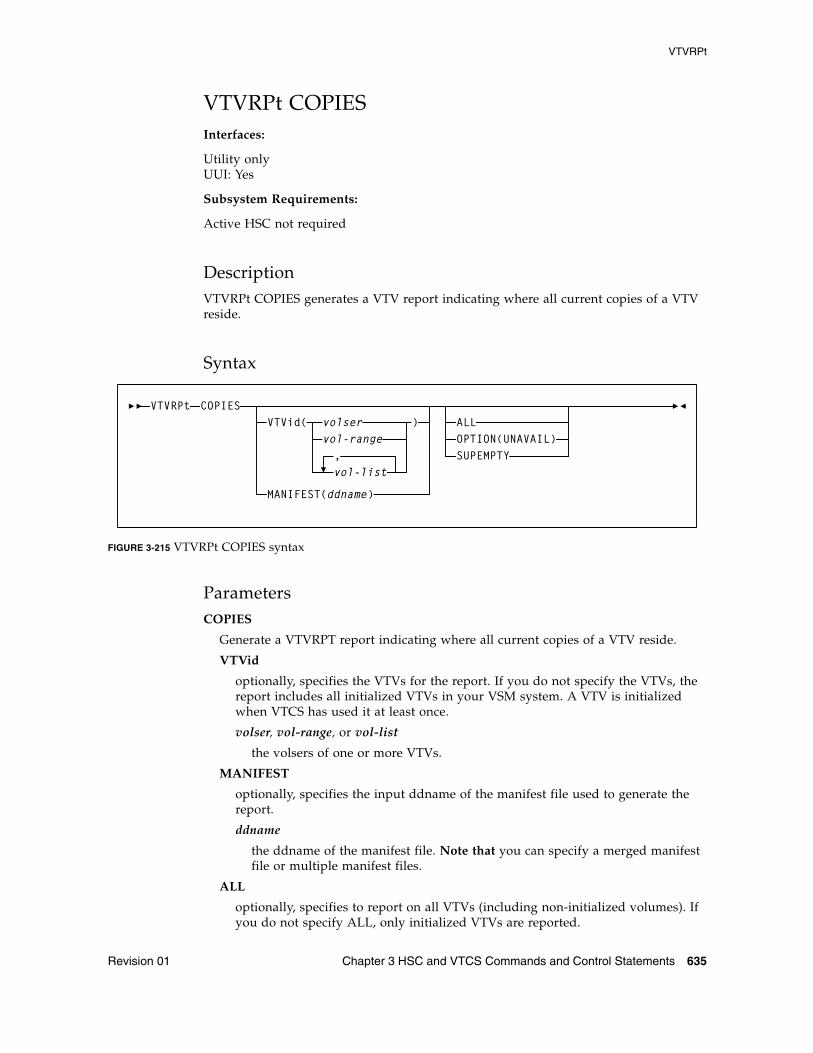
VTVRPt
Revision 01 Chapter 3 HSC and VTCS Commands and Control Statements 635
VTVRPt COPIESInterfaces:
Utility onlyUUI: Yes
Subsystem Requirements:
Active HSC not required
DescriptionVTVRPt COPIES generates a VTV report indicating where all current copies of a VTV reside.
Syntax
FIGURE 3-215 VTVRPt COPIES syntax
ParametersCOPIES
Generate a VTVRPT report indicating where all current copies of a VTV reside.
VTVid
optionally, specifies the VTVs for the report. If you do not specify the VTVs, the report includes all initialized VTVs in your VSM system. A VTV is initialized when VTCS has used it at least once.
volser, vol-range, or vol-list
the volsers of one or more VTVs.
MANIFEST
optionally, specifies the input ddname of the manifest file used to generate the report.
ddname
the ddname of the manifest file. Note that you can specify a merged manifest file or multiple manifest files.
ALL
optionally, specifies to report on all VTVs (including non-initialized volumes). If you do not specify ALL, only initialized VTVs are reported.
VTVRPtVTVid( volser
vol-range
vol-list,
)
MANIFEST(ddname)
COPIESALLOPTION(UNAVAIL)SUPEMPTY
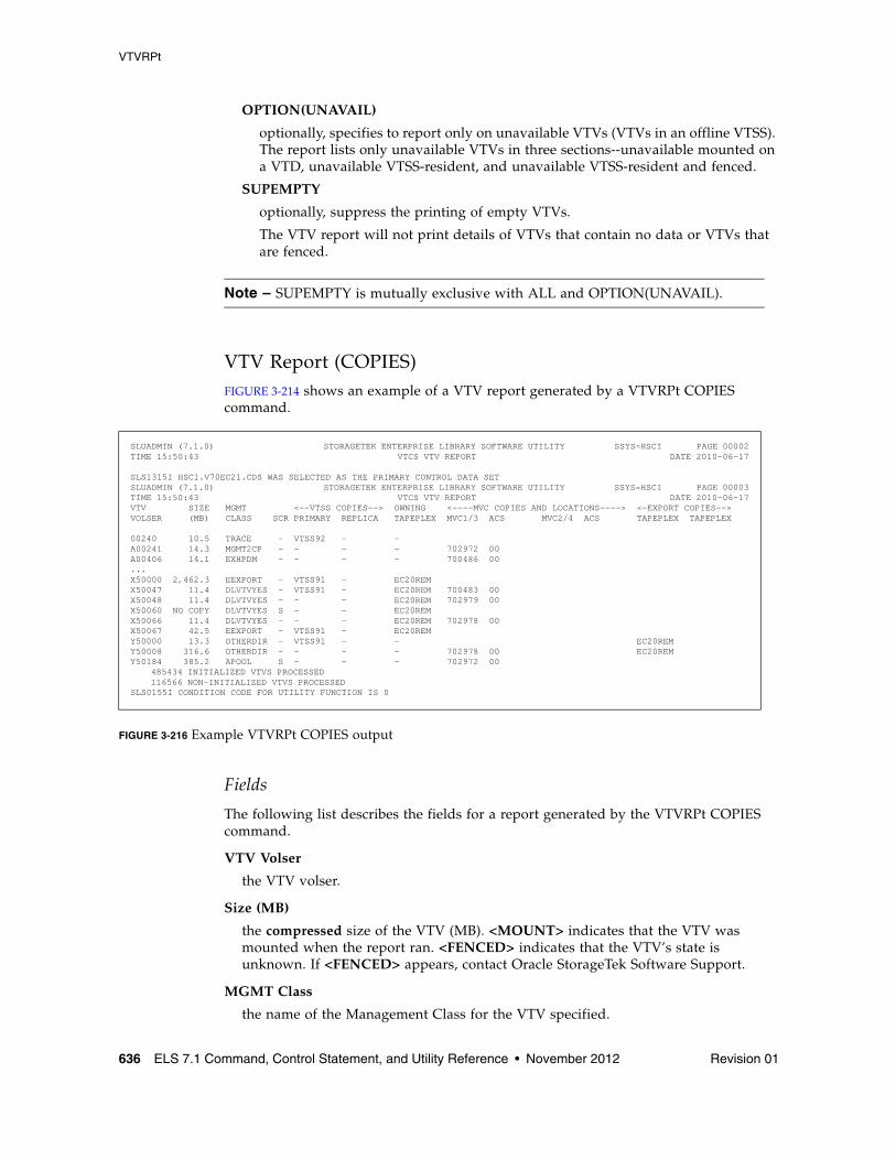
VTVRPt
636 ELS 7.1 Command, Control Statement, and Utility Reference • November 2012 Revision 01
OPTION(UNAVAIL)
optionally, specifies to report only on unavailable VTVs (VTVs in an offline VTSS). The report lists only unavailable VTVs in three sections--unavailable mounted on a VTD, unavailable VTSS-resident, and unavailable VTSS-resident and fenced.
SUPEMPTY
optionally, suppress the printing of empty VTVs.
The VTV report will not print details of VTVs that contain no data or VTVs that are fenced.
Note – SUPEMPTY is mutually exclusive with ALL and OPTION(UNAVAIL).
VTV Report (COPIES)FIGURE 3-214 shows an example of a VTV report generated by a VTVRPt COPIES command.
FIGURE 3-216 Example VTVRPt COPIES output
Fields
The following list describes the fields for a report generated by the VTVRPt COPIES command.
VTV Volser
the VTV volser.
Size (MB)
the compressed size of the VTV (MB). <MOUNT> indicates that the VTV was mounted when the report ran. <FENCED> indicates that the VTV’s state is unknown. If <FENCED> appears, contact Oracle StorageTek Software Support.
MGMT Class
the name of the Management Class for the VTV specified.
SLUADMIN (7.1.0) STORAGETEK ENTERPRISE LIBRARY SOFTWARE UTILITY SSYS=HSCI PAGE 00002TIME 15:50:43 VTCS VTV REPORT DATE 2010-06-17
SLS1315I HSC1.V70EC21.CDS WAS SELECTED AS THE PRIMARY CONTROL DATA SET SLUADMIN (7.1.0) STORAGETEK ENTERPRISE LIBRARY SOFTWARE UTILITY SSYS=HSCI PAGE 00003TIME 15:50:43 VTCS VTV REPORT DATE 2010-06-17VTV SIZE MGMT <--VTSS COPIES--> OWNING <----MVC COPIES AND LOCATIONS----> <-EXPORT COPIES--> VOLSER (MB) CLASS SCR PRIMARY REPLICA TAPEPLEX MVC1/3 ACS MVC2/4 ACS TAPEPLEX TAPEPLEX
00240 10.5 TRACE - VTSS92 - - A00241 14.3 MGMT2CP - - - - 702972 00 A00406 14.1 EXHPDM - - - - 700486 00 ...X50000 2,462.3 EEXPORT - VTSS91 - EC20REM X50047 11.4 DLVTVYES - VTSS91 - EC20REM 700483 00 X50048 11.4 DLVTVYES - - - EC20REM 702979 00 X50060 NO COPY DLVTVYES S - - EC20REM X50066 11.4 DLVTVYES - - - EC20REM 702978 00 X50067 42.5 EEXPORT - VTSS91 - EC20REM Y50000 13.3 OTHERDIR - VTSS91 - - EC20REM Y50008 316.6 OTHERDIR - - - - 702978 00 EC20REM Y50184 385.2 APOOL S - - - 702972 00 485434 INITIALIZED VTVS PROCESSED 116566 NON-INITIALIZED VTVS PROCESSED SLS0155I CONDITION CODE FOR UTILITY FUNCTION IS 0
VTVRPt
Revision 01 Chapter 3 HSC and VTCS Commands and Control Statements 637
Scr
indicates whether the VTV is in a scratched state.
An ‘S’ in this column indicates that the VTV is in a scratched state.
Primary
the name of the VTSS that contains the primary VTSS resident copy of the VTV. If this field is blank, then there are currently no VTSS resident copies of the VTV.
Replica
the name of the VTSS that contains a replica copy of the VTV. If this field is blank, then there are currently no VTSS resident replica copies of the VTV
Owning Tapeplex
the name of the TapePlex that has ownership of this VTV. If this field is blank, then the VTV is owned by another TapePlex and can be processed normally. If this field is set, then the VTV has been imported from another TapePlex and its contents cannot be modified.
MVC1, MVC2, MVC3, MVC4
the MVC(s) that contain the VTV (for both migration and consolidation). If all of these fields are empty, the VTV has not been migrated or consolidated. The number next to each MVC volser is the ACS location of the MVC. If this is set to '--', then the MVC is not library resident.
Export Tapeplex
the names of the TapePlexes to which copies of the VTV have been exported. The copies within these TapePlexes will show the VTV as imported and having an owning TapePlex name. This list is not exhaustive as some of these TapePlexes may have forwarded copies onto further locations. An asterisk (*) next to the name indicates an export that has been rejected by the target TapePlex.
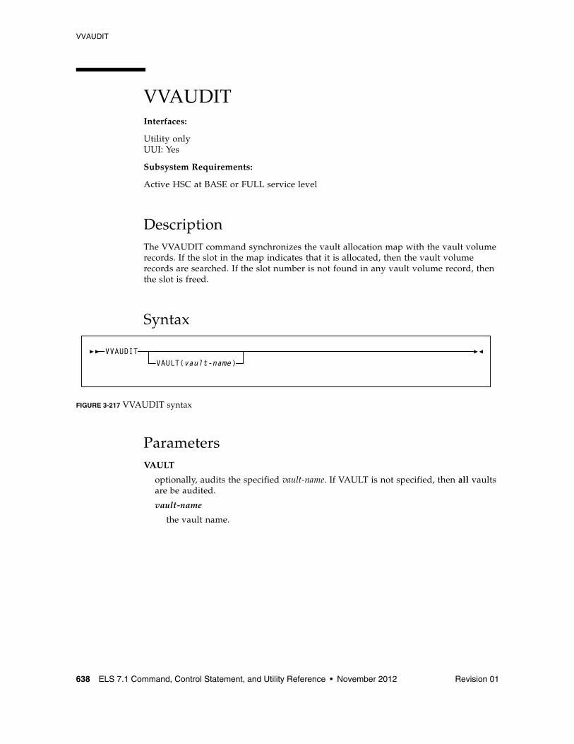
VVAUDIT
638 ELS 7.1 Command, Control Statement, and Utility Reference • November 2012 Revision 01
VVAUDITInterfaces:
Utility onlyUUI: Yes
Subsystem Requirements:
Active HSC at BASE or FULL service level
DescriptionThe VVAUDIT command synchronizes the vault allocation map with the vault volume records. If the slot in the map indicates that it is allocated, then the vault volume records are searched. If the slot number is not found in any vault volume record, then the slot is freed.
Syntax
FIGURE 3-217 VVAUDIT syntax
ParametersVAULT
optionally, audits the specified vault-name. If VAULT is not specified, then all vaults are be audited.
vault-name
the vault name.
VAULT(vault-name)VVAUDIT
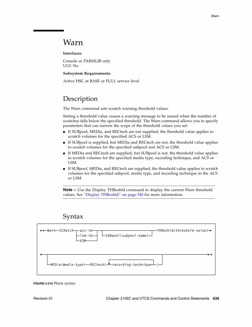
Warn
Revision 01 Chapter 3 HSC and VTCS Commands and Control Statements 639
WarnInterfaces:
Console or PARMLIB onlyUUI: No
Subsystem Requirements:
Active HSC at BASE or FULL service level
DescriptionThe Warn command sets scratch warning threshold values.
Setting a threshold value causes a warning message to be issued when the number of scratches falls below the specified threshold. The Warn command allows you to specify parameters that can narrow the scope of the threshold values you set:
■ If SUBpool, MEDia, and RECtech are not supplied, the threshold value applies to scratch volumes for the specified ACS or LSM.
■ If SUBpool is supplied, but MEDia and RECtech are not, the threshold value applies to scratch volumes for the specified subpool and ACS or LSM.
■ If MEDia and RECtech are supplied, but SUBpool is not, the threshold value applies to scratch volumes for the specified media type, recording technique, and ACS or LSM.
■ If SUBpool, MEDia, and RECtech are supplied, the threshold value applies to scratch volumes for the specified subpool, media type, and recording technique in the ACS or LSM.
Note – Use the Display THReshld command to display the current Warn threshold values. See “Display THReshld” on page 340 for more information.
Syntax
FIGURE 3-218 Warn syntax
WarnSUBpool(subpool-name)
SCRatch acs-idlsm-idVSM
THReshld(threshold-value)
MEDia(media-type) RECtech( recording-technique )
Warn
640 ELS 7.1 Command, Control Statement, and Utility Reference • November 2012 Revision 01
ParametersSCRatch
indicates that scratch threshold values are to be set.
acs-id
the ACS on which to alter threshold values. The ACSid is a decimal value from 00-99.
lsm-id
the LSM on which to alter threshold values. The LSMid is comprised of the ACSid and the LSM number. The format of an LSMid is AA:LL, where AA is the ACSid (decimal 00-99) and LL is the LSM number (decimal 00-99).
VSM
specifies that threshold values are to be set only for subpools for virtual volumes. VSM is not allowed if acs-id or lsm-id are also specified.
SUBpool
optionally, indicates that you want to designate a subpool. This parameter is optional.
subpool-name
the name of the subpool.
Note – Scratch subpool names are specified with the SCRPOol control statement. Refer to the ELS Legacy Interfaces Reference for information.
THReshld
indicates that you want to alter the threshold value.
threshold-value
the minimum number of scratch volumes that are allowed before the HSC issues a warning message. Allowable threshold values are decimal in the range from 0 through 99,999.
The warning interval values are preset at five minutes.
Note – When the number of scratch volumes in an ACS or LSM drops below the threshold value, the system issues a warning message.
MEDia
optionally, specifies the media type for the threshold. When MEDia is specified, RECtech must also be specified.
media-type
the media type.
See Appendix A, “MEDia, RECtech, and MODel Values” for a list of valid media-type values.
Revision 01 641
CHAPTER
4
SMC Utilities
This chapter describes the following SMC utilities:
■ Unified User Interface utility (SMCUUUI)
This utility allows you to issue HSC Unified User Interface (UUI) commands, VTCS commands, or SMC commands from a batch job.
■ POLicy and TAPEREQ Batch Test utility (SMCUTRQ)
This utility allows you to test POLicy and TAPEREQ lookup behavior.
■ Tape Management Extract utility (SMCUDBX)
This utility supports scratch synchronization between the SMC client host and the HSC CDS.
■ UUI Simulation utility (SMCUSIM)
This utility allows you to issue SMC UUI commands in a test environment. Changes to SMC command settings, tape policies, and allocation user exits can be tested before they are put into production without affecting existing SMC clients and HSC servers.
■ Trace Format utility (SMCUGTF)
This utility supports scratch synchronization between the SMC client host and the HSC CDS.
Unlike HSC and VTCS utilities, all SMC utilities are packaged as standalone utility programs. SMC utilities are not initiated using SMC operator commands.
SMC Utility Return Codes and Messages
642 ELS 7.1 Command, Control Statement, and Utility Reference • November 2012 Revision 01
SMC Utility Return Codes and MessagesSMC utilities may return the following return codes:
■ A return code of 0 is returned when the utility program completes successfully with no errors or warnings.
■ A return code of 4 is returned when a warning message is detected.
■ A return code of 8 is returned when an error that prevents the utility from completing is detected.
Refer to the publication ELS Messages and Codes for a listing of SMC messages that may be returned by SMC utilities. These messages are identified by the SMCU prefix.
Unified User Interface Utility (SMCUUUI)
Revision 01 Chapter 4 SMC Utilities 643
Unified User Interface Utility (SMCUUUI)The SMCUUUI utility is used to issue SMC and HSC Unified User Interface (UUI) commands, or VTCS requests from a batch job. The commands can be routed to a local or remote HSC TapePlex.
Several types of output can be received for a UUI command, including:
■ Plain text output
This type of output is written to TEXTOUT, and corresponds to the normal output produced by the HSC or VTCS command or report utility. If plain text output is requested for an HSC or VTCS report, the report headings are not produced by the UUI.
■ Structured XML
This type of output is written to XMLOUT. Structured XML is a well formed XML data stream with XML header tags and XML data tag elements, and XML data element content. Refer to the ELS Programming Reference for a complete list of SMC, HSC and VTCS XML tag names and types.
■ Comma Separated Values (CSV)
This output type is optional and is generated only if the CSV command is specified. See “CSV Command” on page 680 for more information.
This type of output is written to CSVOUT. An input template of XML data tag names is used to define the format of the CSVOUT corresponding to a particular request. The output data for each request is a CSV header line that contains a comma-separated list of the XML data tags requested, followed by CSV detail lines. Each CSV detail line contains one comma-separated entry for each requested XML data tag. This type of output is readily adaptable as input into spreadsheets or customized report writers. Refer to the ELS Programming Reference for more information about the format for specifying CSV.
The type of output received is controlled by the data set definition statements (DD) defined in the JCL to execute the SMCUUUI utility.
Note – ■ In general, error messages are not produced for CSV output. To view error messages
produces by the UUI process, you must include either a TEXTOUT or XMLOUT DD statement.
Exception messages associated with CSV output are directed to the DD statement named CSVOUTX, if present. If no CSVOUTX DD statement is included, and only CSV output is requested, exception messages are not produced.
■ If the SMCUUUI utility is directing utility functions that may include SORT (such as VOLRPT, MVCRPT, etc.) to a remote TapePlex, caution should be exercised to run a limited number of these jobs simultaneously for a single SMC HTTP server. The exact number is dependent on the region size of the SMC running the HTTP server as well as the amount of data being processed.
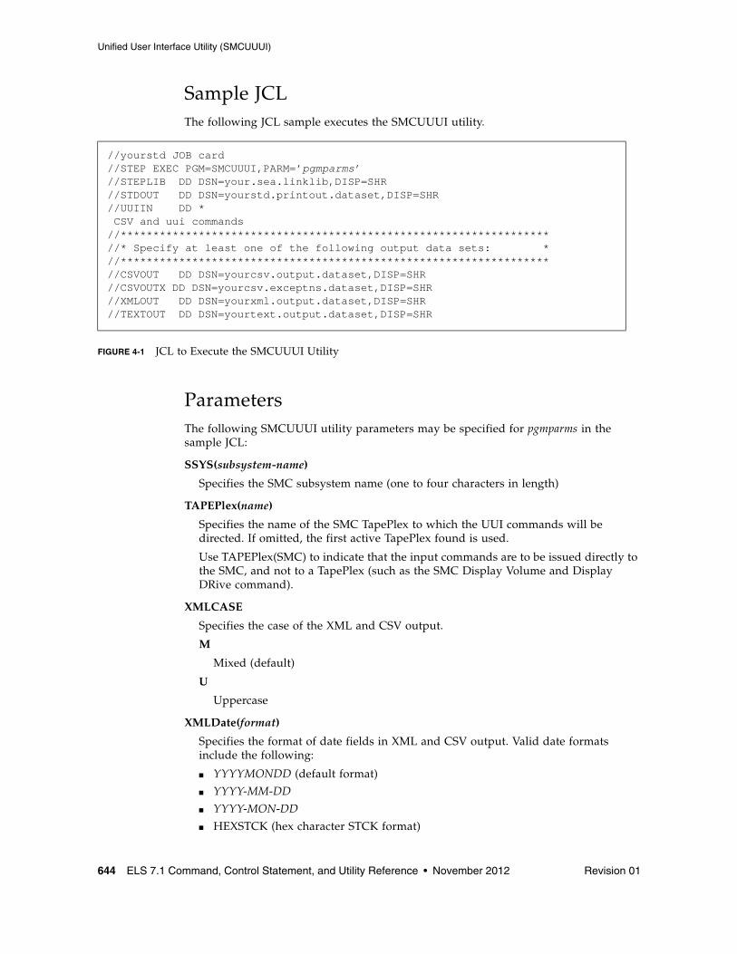
Unified User Interface Utility (SMCUUUI)
644 ELS 7.1 Command, Control Statement, and Utility Reference • November 2012 Revision 01
Sample JCLThe following JCL sample executes the SMCUUUI utility.
FIGURE 4-1 JCL to Execute the SMCUUUI Utility
ParametersThe following SMCUUUI utility parameters may be specified for pgmparms in the sample JCL:
SSYS(subsystem-name)
Specifies the SMC subsystem name (one to four characters in length)
TAPEPlex(name)
Specifies the name of the SMC TapePlex to which the UUI commands will be directed. If omitted, the first active TapePlex found is used.
Use TAPEPlex(SMC) to indicate that the input commands are to be issued directly to the SMC, and not to a TapePlex (such as the SMC Display Volume and Display DRive command).
XMLCASE
Specifies the case of the XML and CSV output.
M
Mixed (default)
U
Uppercase
XMLDate(format)
Specifies the format of date fields in XML and CSV output. Valid date formats include the following:
■ YYYYMONDD (default format)
■ YYYY-MM-DD
■ YYYY-MON-DD
■ HEXSTCK (hex character STCK format)
//yourstd JOB card//STEP EXEC PGM=SMCUUUI,PARM=’pgmparms’//STEPLIB DD DSN=your.sea.linklib,DISP=SHR//STDOUT DD DSN=yourstd.printout.dataset,DISP=SHR//UUIIN DD * CSV and uui commands//******************************************************************//* Specify at least one of the following output data sets: *//******************************************************************//CSVOUT DD DSN=yourcsv.output.dataset,DISP=SHR//CSVOUTX DD DSN=yourcsv.exceptns.dataset,DISP=SHR//XMLOUT DD DSN=yourxml.output.dataset,DISP=SHR//TEXTOUT DD DSN=yourtext.output.dataset,DISP=SHR
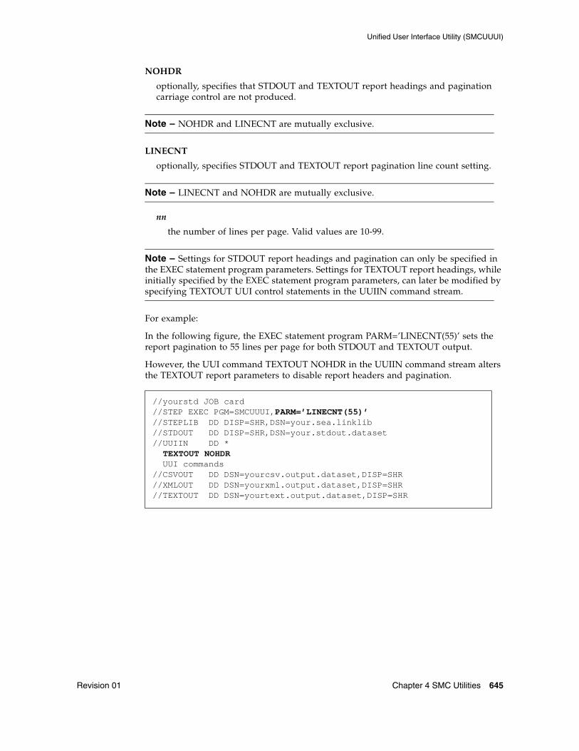
Unified User Interface Utility (SMCUUUI)
Revision 01 Chapter 4 SMC Utilities 645
NOHDR
optionally, specifies that STDOUT and TEXTOUT report headings and pagination carriage control are not produced.
Note – NOHDR and LINECNT are mutually exclusive.
LINECNT
optionally, specifies STDOUT and TEXTOUT report pagination line count setting.
Note – LINECNT and NOHDR are mutually exclusive.
nn
the number of lines per page. Valid values are 10-99.
Note – Settings for STDOUT report headings and pagination can only be specified in the EXEC statement program parameters. Settings for TEXTOUT report headings, while initially specified by the EXEC statement program parameters, can later be modified by specifying TEXTOUT UUI control statements in the UUIIN command stream.
For example:
In the following figure, the EXEC statement program PARM=’LINECNT(55)’ sets the report pagination to 55 lines per page for both STDOUT and TEXTOUT output.
However, the UUI command TEXTOUT NOHDR in the UUIIN command stream alters the TEXTOUT report parameters to disable report headers and pagination.
//yourstd JOB card//STEP EXEC PGM=SMCUUUI,PARM=’LINECNT(55)’//STEPLIB DD DISP=SHR,DSN=your.sea.linklib//STDOUT DD DISP=SHR,DSN=your.stdout.dataset//UUIIN DD * TEXTOUT NOHDR UUI commands//CSVOUT DD DSN=yourcsv.output.dataset,DISP=SHR//XMLOUT DD DSN=yourxml.output.dataset,DISP=SHR//TEXTOUT DD DSN=yourtext.output.dataset,DISP=SHR
Unified User Interface Utility (SMCUUUI)
646 ELS 7.1 Command, Control Statement, and Utility Reference • November 2012 Revision 01
Required Data Set Definition (DD) StatementsYou must specify the UUIIN and STDOUT data set definitions.
UUIIN Data SetThe UUIIN data set can contain:
■ SMCUUUI utility control statements■ SMC UUI commands ■ HSC UUI commands ■ VTCS PGMI requests
Native SMC UUI commands include:
■ Display DRive■ Display Volume■ POLicy■ SIMulate
Refer to the ELS Programming Reference for a list of supported HSC UUI commands and VTCS PGMI requests.
Syntax Rules ■ Input must be 80 byte card images.
■ Only columns 1-72 of the 80 byte card image may contain actual command input. Columns 73-80 may be used for sequence numbers if desired.
■ If the last non-blank character in columns 1-72 is a “+”, the logical command is continued on the next physical card.
■ Comments begin with “/*” (in column 2 or beyond) and end with “*/”.
■ The maximum logical command length is 32000 bytes.
Unified User Interface Utility (SMCUUUI)
Revision 01 Chapter 4 SMC Utilities 647
Control Statements
Utility control statements allow the report pagination for TEXTOUT output and the target TapePlex to be altered for subsequent SMC, HSC, and VTCS UUI and PGMI commands.
PLEXDest
optionally, sets the destination TapePlex for subsequent commands to the specified tapeplex-name. Any communication error occurring during a subsequent SMC, HSC, or VTCS command after execution of the PLEXDest control statement results in the bypassing of all subsequent SMC, HSC, or VTCS commands until another PLEXDest control statement is encountered.
tapeplex-name
the TapePlex name of the target system for subsequent commands.
■ If “SMC” is specified, all subsequent commands are assumed to be SMC UUI commands and are directed to the simulated SMC environment.
■ If a valid HSC TapePlex (as defined via a SMC TAPEPlex command) is specified, all subsequent commands are assumed to be HSC or VTCS commands and are directed to the specified tapeplex-name via the simulated SMC environment.
TEXTOUT
optionally, sets the report pagination parameters for TEXTOUT output. If any errors are encountered on the TEXTOUT command, all subsequent UUI commands are bypassed until a correct TEXTOUT command is encountered.
NOHDR
optionally, specifies that TEXTOUT report headings and pagination carriage control are not produced.
Note – NOHDR and LINECNT are mutually exclusive.
LINECNT(nn)
optionally, specifies TEXTOUT report pagination line count setting.
Note – LINECNT and NOHDR are mutually exclusive.
nn
the number of lines per page. Valid values are 10-99.
Note – ■ Settings for STDOUT report headings and pagination can only be specified in the
EXEC statement program parameters. Settings for TEXTOUT report headings, while initially specified by the EXEC statement program parameters, can later be modified by specifying TEXTOUT UUI control statements in the UUIIN command stream.
■ If multiple TEXTOUT statements are input before a single UUI command, the last TEXTOUT statement controls the TEXTOUT report pagination.
■ PLEXDest and TEXTOUT commands can be specified along with CSV commands to alter the destination TapePlex, and the CSV and TEXTOUT output characteristics of subsequent UUI commands. See “CSV Command” on page 680.
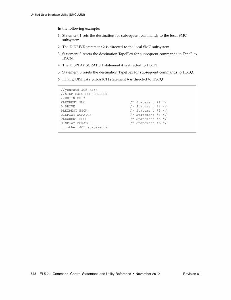
Unified User Interface Utility (SMCUUUI)
648 ELS 7.1 Command, Control Statement, and Utility Reference • November 2012 Revision 01
In the following example:
1. Statement 1 sets the destination for subsequent commands to the local SMC subsystem.
2. The D DRIVE statement 2 is directed to the local SMC subsystem.
3. Statement 3 resets the destination TapePlex for subsequent commands to TapePlex HSCN.
4. The DISPLAY SCRATCH statement 4 is directed to HSCN.
5. Statement 5 resets the destination TapePlex for subsequent commands to HSCQ.
6. Finally, DISPLAY SCRATCH statement 6 is directed to HSCQ.
//yourstd JOB card//STEP EXEC PGM=SMCUUUI//UUIIN DD *PLEXDEST SMC /* Statement #1 */D DRIVE /* Statement #2 */PLEXDEST HSCN /* Statement #3 */DISPLAY SCRATCH /* Statement #4 */PLEXDEST HSCQ /* Statement #5 */DISPLAY SCRATCH /* Statement #6 */...other JCL statements
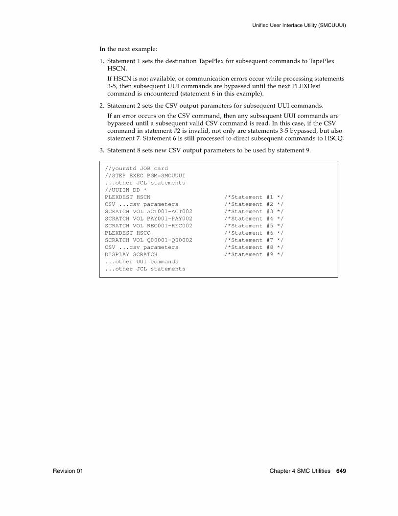
Unified User Interface Utility (SMCUUUI)
Revision 01 Chapter 4 SMC Utilities 649
In the next example:
1. Statement 1 sets the destination TapePlex for subsequent commands to TapePlex HSCN.
If HSCN is not available, or communication errors occur while processing statements 3-5, then subsequent UUI commands are bypassed until the next PLEXDest command is encountered (statement 6 in this example).
2. Statement 2 sets the CSV output parameters for subsequent UUI commands.
If an error occurs on the CSV command, then any subsequent UUI commands are bypassed until a subsequent valid CSV command is read. In this case, if the CSV command in statement #2 is invalid, not only are statements 3-5 bypassed, but also statement 7. Statement 6 is still processed to direct subsequent commands to HSCQ.
3. Statement 8 sets new CSV output parameters to be used by statement 9.
//yourstd JOB card//STEP EXEC PGM=SMCUUUI...other JCL statements//UUIIN DD * PLEXDEST HSCN /*Statement #1 */CSV ...csv parameters /*Statement #2 */SCRATCH VOL ACT001-ACT002 /*Statement #3 */SCRATCH VOL PAY001-PAY002 /*Statement #4 */SCRATCH VOL REC001-REC002 /*Statement #5 */PLEXDEST HSCQ /*Statement #6 */SCRATCH VOL Q00001-Q00002 /*Statement #7 */CSV ...csv parameters /*Statement #8 */DISPLAY SCRATCH /*Statement #9 */...other UUI commands...other JCL statements
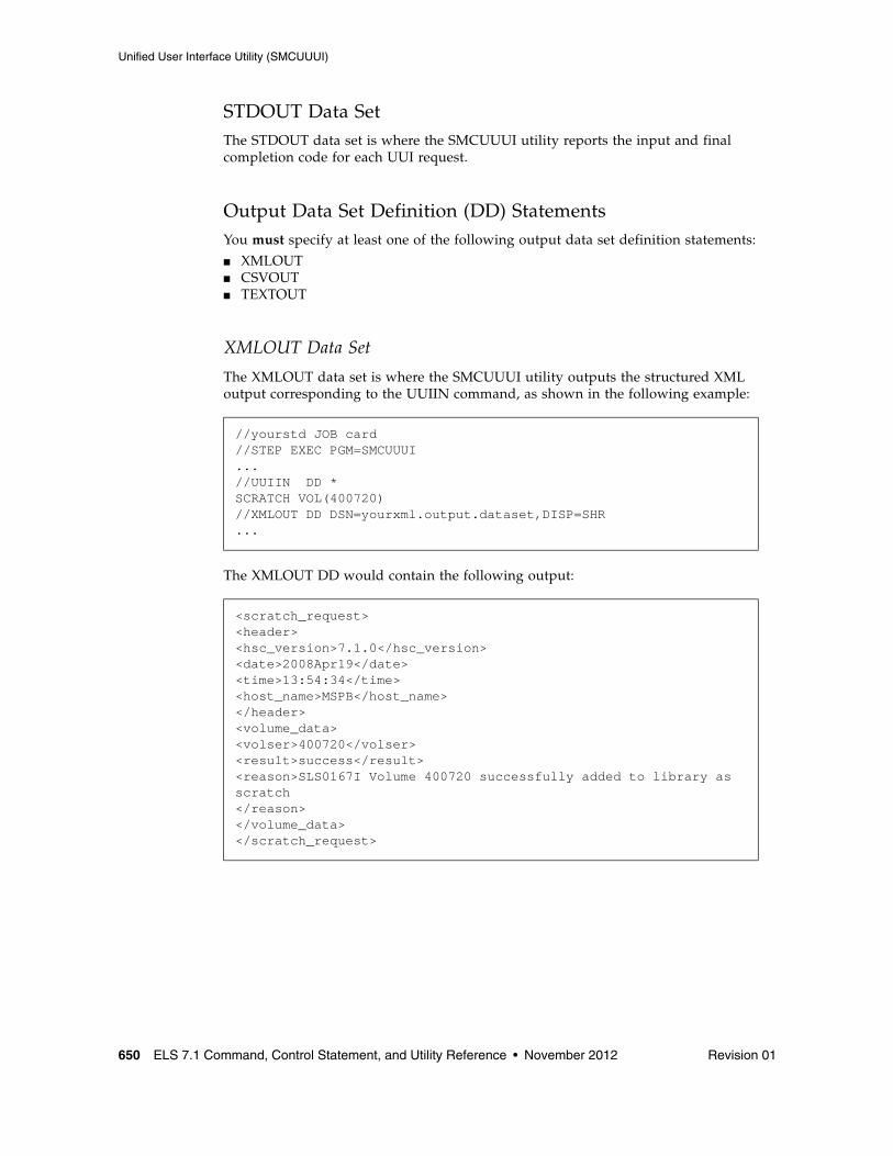
Unified User Interface Utility (SMCUUUI)
650 ELS 7.1 Command, Control Statement, and Utility Reference • November 2012 Revision 01
STDOUT Data SetThe STDOUT data set is where the SMCUUUI utility reports the input and final completion code for each UUI request.
Output Data Set Definition (DD) StatementsYou must specify at least one of the following output data set definition statements:
■ XMLOUT■ CSVOUT■ TEXTOUT
XMLOUT Data Set
The XMLOUT data set is where the SMCUUUI utility outputs the structured XML output corresponding to the UUIIN command, as shown in the following example:
The XMLOUT DD would contain the following output:
//yourstd JOB card//STEP EXEC PGM=SMCUUUI...//UUIIN DD *SCRATCH VOL(400720)//XMLOUT DD DSN=yourxml.output.dataset,DISP=SHR...
<scratch_request><header><hsc_version>7.1.0</hsc_version><date>2008Apr19</date><time>13:54:34</time><host_name>MSPB</host_name></header><volume_data><volser>400720</volser><result>success</result><reason>SLS0167I Volume 400720 successfully added to library as scratch</reason></volume_data></scratch_request>
Unified User Interface Utility (SMCUUUI)
Revision 01 Chapter 4 SMC Utilities 651
CSVOUT Data Set
The CSVOUT data set is where the SMCUUUI utility writes the CSV output for the requested UUIIN commands that specified corresponding CSV formatting. Refer to the ELS Programming Reference for more information about the Comma Separated Value (CSV) specification.
The maximum logical CSV input length is 4096 bytes.
Note – In order to view exceptions associated with generating CSV output, include a CSVOUTX DD statement in the SMCUUUI JCL.
TEXTOUT Data Set
The TEXTOUT data set is where the SMCUUUI utility outputs plain text UUI responses. This is the same output that would be received from the corresponding SMC, HSC or VTCS command, or written to the SLSPRINT DD by the SLUADMIN or SWSADMIN utility, except that page and column headings are not produced. This data set is optional.
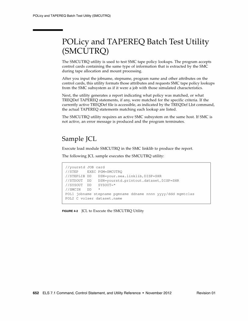
POLicy and TAPEREQ Batch Test Utility (SMCUTRQ)
652 ELS 7.1 Command, Control Statement, and Utility Reference • November 2012 Revision 01
POLicy and TAPEREQ Batch Test Utility (SMCUTRQ)The SMCUTRQ utility is used to test SMC tape policy lookups. The program accepts control cards containing the same type of information that is extracted by the SMC during tape allocation and mount processing.
After you input the jobname, stepname, program name and other attributes on the control cards, this utility formats those attributes and requests SMC tape policy lookups from the SMC subsystem as if it were a job with those simulated characteristics.
Next, the utility generates a report indicating what policy was matched, or what TREQDef TAPEREQ statements, if any, were matched for the specific criteria. If the currently active TREQDef file is accessible, as indicated by the TREQDef LIst command, the actual TAPEREQ statements matching each lookup are listed.
The SMCUTRQ utility requires an active SMC subsystem on the same host. If SMC is not active, an error message is produced and the program terminates.
Sample JCLExecute load module SMCUTRQ in the SMC linklib to produce the report.
The following JCL sample executes the SMCUTRQ utility:
FIGURE 4-2 JCL to Execute the SMCUTRQ Utility
//yourstd JOB card//STEP EXEC PGM=SMCUTRQ//STEPLIB DD DSN=your.sea.linklib,DISP=SHR//STDOUT DD DSN=yourstd.printout.dataset,DISP=SHR//SYSOUT DD SYSOUT=*//SMCIN DD *POL1 jobname stepname pgmname ddname nnnn yyyy/ddd mgmtclasPOL2 C volser dataset.name
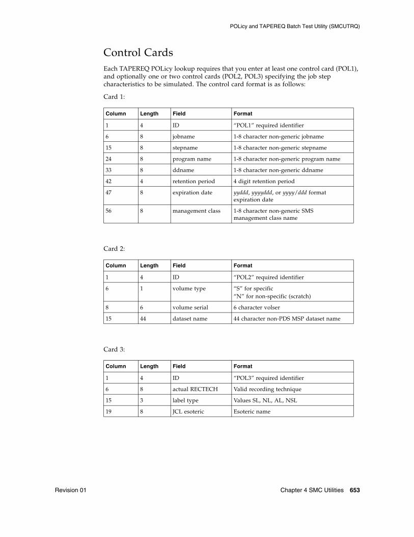
POLicy and TAPEREQ Batch Test Utility (SMCUTRQ)
Revision 01 Chapter 4 SMC Utilities 653
Control CardsEach TAPEREQ POLicy lookup requires that you enter at least one control card (POL1), and optionally one or two control cards (POL2, POL3) specifying the job step characteristics to be simulated. The control card format is as follows:
Card 1:
Card 2:
Card 3:
Column Length Field Format
1 4 ID “POL1” required identifier
6 8 jobname 1-8 character non-generic jobname
15 8 stepname 1-8 character non-generic stepname
24 8 program name 1-8 character non-generic program name
33 8 ddname 1-8 character non-generic ddname
42 4 retention period 4 digit retention period
47 8 expiration date yyddd, yyyyddd, or yyyy/ddd format expiration date
56 8 management class 1-8 character non-generic SMS management class name
Column Length Field Format
1 4 ID “POL2” required identifier
6 1 volume type “S” for specific“N” for non-specific (scratch)
8 6 volume serial 6 character volser
15 44 dataset name 44 character non-PDS MSP dataset name
Column Length Field Format
1 4 ID “POL3” required identifier
6 8 actual RECTECH Valid recording technique
15 3 label type Values SL, NL, AL, NSL
19 8 JCL esoteric Esoteric name
POLicy and TAPEREQ Batch Test Utility (SMCUTRQ)
654 ELS 7.1 Command, Control Statement, and Utility Reference • November 2012 Revision 01
Note – ■ All variable length fields must be left justified.
■ Retention period and expiration date fields are mutually exclusive. When both are specified, retention period is used.
■ The management class field is used to simulate a returned SMS ACS MGMTCLAS and assumes that the SMC SMSDEF MGMTPol(ALL) or (IDAX) policy has been specified. If the SMC finds a matching policy name, then the remaining tape policy lookups are bypassed.
■ If a policy name matching the specified management class name is not found, or if the management class field was not specified, then a series of TAPEREQ lookups is performed using the remaining input criteria.
■ You may ignore the lookup fields that are not important to your lookup. This is determined by looking at what selection criteria you actually use on your TAPEREQ statements. However, it is recommended that you specify all non-mutually exclusive fields.
■ "POL1" control card is required, even if no input fields are coded. Both "POL2" and "POL3" control cards are optional.
■ You can input multiple sets of control cards.
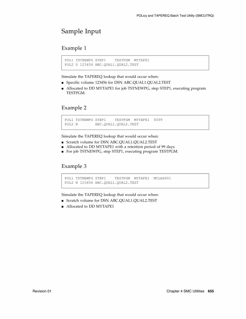
POLicy and TAPEREQ Batch Test Utility (SMCUTRQ)
Revision 01 Chapter 4 SMC Utilities 655
Sample Input
Example 1
Simulate the TAPEREQ lookup that would occur when:
■ Specific volume 123456 for DSN ABC.QUAL1.QUAL2.TEST
■ Allocated to DD MYTAPE1 for job TSTNEWPG, step STEP1, executing program TESTPGM.
Example 2
Simulate the TAPEREQ lookup that would occur when:
■ Scratch volume for DSN ABC.QUAL1.QUAL2.TEST■ Allocated to DD MYTAPE1 with a retention period of 99 days ■ For job TSTNEWPG, step STEP1, executing program TESTPGM.
Example 3
Simulate the TAPEREQ lookup that would occur when:
■ Scratch volume for DSN ABC.QUAL1.QUAL2.TEST
■ Allocated to DD MYTAPE1
POL1 TSTNEWPG STEP1 TESTPGM MYTAPE1POL2 S 123456 ABC.QUAL1.QUAL2.TEST
POL1 TSTNEWPG STEP1 TESTPGM MYTAPE1 0099POL2 N ABC.QUAL1.QUAL2.TEST
POL1 TSTNEWPG STEP1 TESTPGM MYTAPE1 MCLASS01POL2 N 123456 ABC.QUAL1.QUAL2.TEST
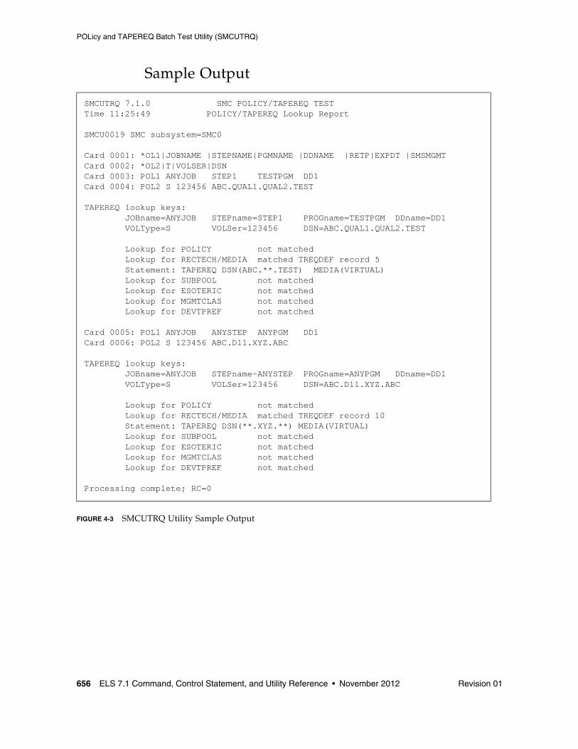
POLicy and TAPEREQ Batch Test Utility (SMCUTRQ)
656 ELS 7.1 Command, Control Statement, and Utility Reference • November 2012 Revision 01
Sample Output
FIGURE 4-3 SMCUTRQ Utility Sample Output
SMCUTRQ 7.1.0 SMC POLICY/TAPEREQ TEST Time 11:25:49 POLICY/TAPEREQ Lookup Report SMCU0019 SMC subsystem=SMC0Card 0001: *OL1|JOBNAME |STEPNAME|PGMNAME |DDNAME |RETP|EXPDT |SMSMGMTCard 0002: *OL2|T|VOLSER|DSNCard 0003: POL1 ANYJOB STEP1 TESTPGM DD1Card 0004: POL2 S 123456 ABC.QUAL1.QUAL2.TESTTAPEREQ lookup keys: JOBname=ANYJOB STEPname=STEP1 PROGname=TESTPGM DDname=DD1 VOLType=S VOLSer=123456 DSN=ABC.QUAL1.QUAL2.TEST Lookup for POLICY not matched Lookup for RECTECH/MEDIA matched TREQDEF record 5 Statement: TAPEREQ DSN(ABC.**.TEST) MEDIA(VIRTUAL) Lookup for SUBPOOL not matched Lookup for ESOTERIC not matched Lookup for MGMTCLAS not matched Lookup for DEVTPREF not matchedCard 0005: POL1 ANYJOB ANYSTEP ANYPGM DD1Card 0006: POL2 S 123456 ABC.D11.XYZ.ABCTAPEREQ lookup keys: JOBname=ANYJOB STEPname-ANYSTEP PROGname=ANYPGM DDname=DD1 VOLType=S VOLSer=123456 DSN=ABC.D11.XYZ.ABC Lookup for POLICY not matched Lookup for RECTECH/MEDIA matched TREQDEF record 10 Statement: TAPEREQ DSN(**.XYZ.**) MEDIA(VIRTUAL) Lookup for SUBPOOL not matched Lookup for ESOTERIC not matched Lookup for MGMTCLAS not matched Lookup for DEVTPREF not matchedProcessing complete; RC=0
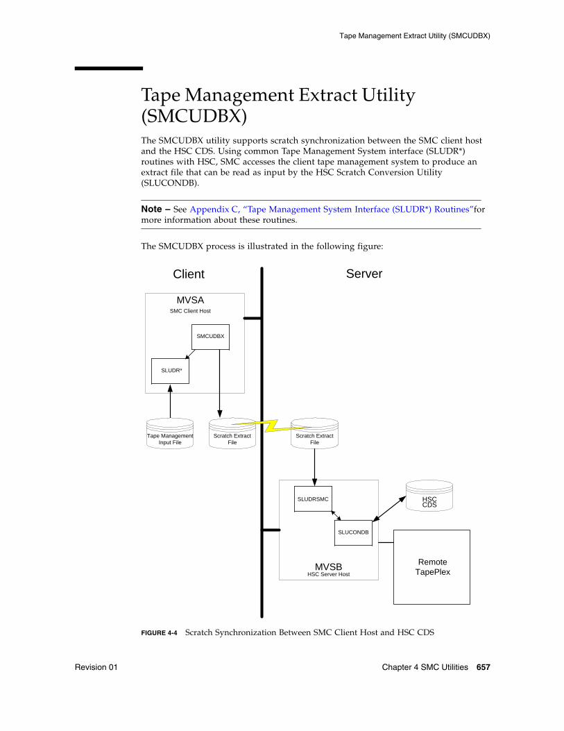
Tape Management Extract Utility (SMCUDBX)
Revision 01 Chapter 4 SMC Utilities 657
Tape Management Extract Utility (SMCUDBX)The SMCUDBX utility supports scratch synchronization between the SMC client host and the HSC CDS. Using common Tape Management System interface (SLUDR*) routines with HSC, SMC accesses the client tape management system to produce an extract file that can be read as input by the HSC Scratch Conversion Utility (SLUCONDB).
Note – See Appendix C, “Tape Management System Interface (SLUDR*) Routines”for more information about these routines.
The SMCUDBX process is illustrated in the following figure:
FIGURE 4-4 Scratch Synchronization Between SMC Client Host and HSC CDS
Client Server
MVSB
MVSASMC Client Host
SLUDR*
CDSHSC
Tape Management Input File
Scratch Extract File
SMCUDBX
Scratch Extract File
HSC Server Host
SLUDRSMC
SLUCONDB
RemoteTapePlex
Tape Management Extract Utility (SMCUDBX)
658 ELS 7.1 Command, Control Statement, and Utility Reference • November 2012 Revision 01
If the client and server share a tape management system, the HSC utility SLUCONDB may be run directly using the common tape management system data base as input.
If, however, the client host has a tape management system that is not accessible to the HSC host, the SMC utility SMCUDBX can be used to extract scratch volumes from the tape management system using label and date parameters. The SMCUDBX output can then be used as input on the HSC host to the SLUCONDB utility. The SMC process supports timing synchronization by comparing the GMT time of the SMCUDBX run with the last select time of the HSC CDS volume record. If the volume was selected after the SMC scratch run, it is not eligible for scratch by SLUCONDB.
Running the SMC Scratch Extract UtilityYou can run the SMC scratch extract utility regardless of whether the SMC is executing on the host.
SMCUDBX processes the CA-1 Tape Management Catalog (TMC), the CA-DYNAM/TLMS Volume Master File (VMF), or the Zara database, and selects the volume serial numbers for processing based on information specified on the PARM parameter of the JCL EXEC statement.
For CA-1, CA-DYNAM/TLMS, and SMCUDBX calls the appropriate Tape Management System interface routine. For Zara, SMCUDBX invokes the SLUDRZAR routine, which in turn invokes an application programming interface (API) to read Zara’s database. The data returned from these routines is used to format the SMC scratch extract file. See Appendix C, “Tape Management System Interface (SLUDR*) Routines” for more information about these routines.
If your installation uses a different tape management system, you can develop a program modeled on one of the supplied examples SLUDRCA1, SLUDRRMM, SLUDRTLM, SLUDRSMC, SLUDRTLM, or SLUDRZAR, or you can write your own program to produce an extract file in the following format:
The time filed in the SMC scratch extract file is a character representation of the first four bytes of the output of the MSP STCK macro. For example, if the STCK macro produces a result of X’B0912345 6789ABCD’, the GMT field of the SMC extract contains the character value C’B0912345’.
SMCUDBX, SLUDRCA1, SLUDRTLM, SLUDRRMM, and SLUDRZAR are provided as load modules. You can use the current versions of these load modules with CA-DYNAM/TLMS Release 5.4 and above, CA-1 Release 5.0 and above, and Zara 1.2. The ELS MACLIB file on the ELS installation tape contains the sample source code.
Position Field Format
1 Scratch volume CL6
7 GMT of run XL8
15 Unused CL2
Tape Management Extract Utility (SMCUDBX)
Revision 01 Chapter 4 SMC Utilities 659
Note – ■ If there are local modifications to your tape management system, you must
reassemble the associated TMS interface routine.
■ If your tape management system is CA-1 Release 4.9 or below, you must modify and reassemble the SLUDRCA1 routine. See “Using SMCUDBX with CA-1 Release 4.9 or Below” on page 659 for information about modifying and reassembling this routine.
■ If your tape management system is CA-DYNAM/TLMS Release 5.3 or below, you must reassemble the SLUDRTLM routine. See “Using SMCUDBX with CA-DYNAM/TLMS Release 5.3 or Below” on page 659 for information about reassembling this routine.
■ If your tape management system is Zara, the SMCUDBX utility must be able to access the data set that contains the Zara API module (ZARAAPI1). You can either store this module in the LINKLIST, or include a JOBLIB or STEPLIB DD statement in the SMCUDBX JCL that points to the library containing the module.
■ Any routine that you modify and reassemble must be re-linked as non-reentrant (NORENT parameter) with AMODE=24 and RMODE=24.
Using SMCUDBX with CA-1 Release 4.9 or BelowTo use SMCUDBX with CA-1 Release 4.9 or below, you must modify and reassemble the SLUDRCA1 routine. The CA-1 MACLIB containing the TMRECORD MACRO must be accessible during the assembly.
Perform the following steps for CA-1 Release 4.9:
1. Delete the asterisk in column 1 of the following line:TMRECORD
2. Add an asterisk in column 1 of the following line:TMMTMREC
3. Reassemble the SLUDRCA1 routine.
Using SMCUDBX with CA-DYNAM/TLMS Release 5.3 or BelowPerform the following steps to use SMCUDBX with CA-DYNAM/TLMS Release 5.3 or below:
1. Verify that the CA-DYNAM/TLMS Release 5.3 MACLIB containing the VMFBASE MACRO is accessible for the re-assembly of the SLUDRTLM routine.
2. Reassemble the SLUDRTLM routine; no modifications to the source code are required.
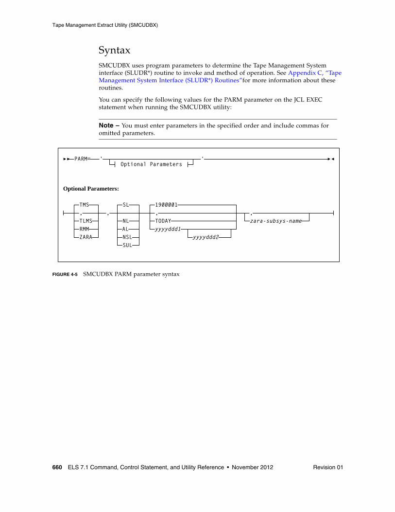
Tape Management Extract Utility (SMCUDBX)
660 ELS 7.1 Command, Control Statement, and Utility Reference • November 2012 Revision 01
SyntaxSMCUDBX uses program parameters to determine the Tape Management System interface (SLUDR*) routine to invoke and method of operation. See Appendix C, “Tape Management System Interface (SLUDR*) Routines”for more information about these routines.
You can specify the following values for the PARM parameter on the JCL EXEC statement when running the SMCUDBX utility:
Note – You must enter parameters in the specified order and include commas for omitted parameters.
FIGURE 4-5 SMCUDBX PARM parameter syntax
PARM= 'Optional Parameters
'
Optional Parameters:
TMS,TLMSRMMZARA
1900001,TODAYyyyyddd1
yyyyddd2
zara-subsys-name,
SL
NLALNSL
,
SUL
Tape Management Extract Utility (SMCUDBX)
Revision 01 Chapter 4 SMC Utilities 661
ParametersPARM=
specifies the parameters that follow can be accessed by the program indicated in the PGM parameter in the JCL.
TMS
optionally, specifies the CA-1 tape management system (TMS). This is the default.
TLMS
optionally, specifies the TLMS: CA-DYNAM/TLMS tape management system.
ZARA
optionally, specifies the ZARA tape management system.
SL
optionally, specifies standard label type for the scratch volume selection. This is the default.
NL
optionally, specifies nonlabeled type for the scratch volume selection.
AL
optionally, specifies ANSI label type for the scratch volume selection.
NSL
optionally, specifies nonstandard label type for the scratch volume selection.
SUL
optionally, specifies standard user label type for the scratch volume selection.
1900001
optionally, specifies January 1, 1900 as the date. This is the default.
TODAY
optionally, indicates the current system date.
yyyyddd1
optionally, the "from" date. The "to" date defaults to the current system date. All specified dates are in Julian notation.
yyyyddd1-yyyyddd2
optionally, the date range in which the volumes became scratch. Neither of these dates can be greater than the current system date.
zara-subsys-name
Specifies the subsystem name for the Zara tape management system, where zara-subsys-name is the four-character name. The default subsystem name is ZARA.
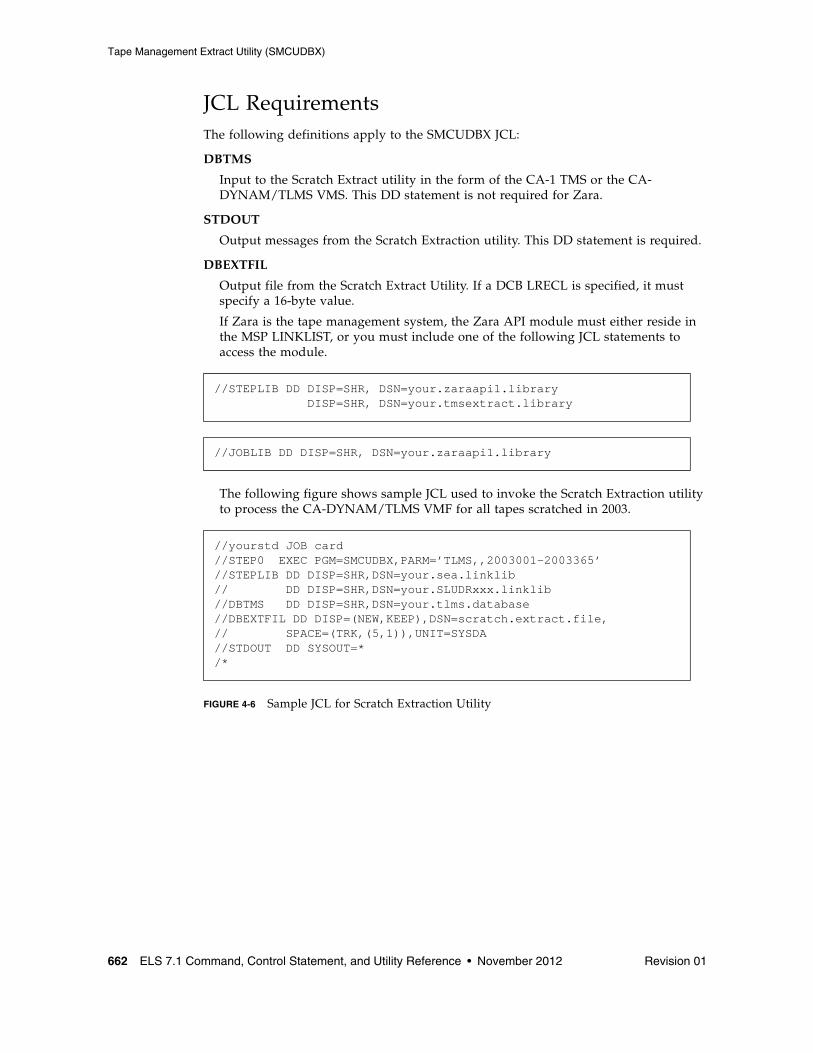
Tape Management Extract Utility (SMCUDBX)
662 ELS 7.1 Command, Control Statement, and Utility Reference • November 2012 Revision 01
JCL RequirementsThe following definitions apply to the SMCUDBX JCL:
DBTMS
Input to the Scratch Extract utility in the form of the CA-1 TMS or the CA-DYNAM/TLMS VMS. This DD statement is not required for Zara.
STDOUT
Output messages from the Scratch Extraction utility. This DD statement is required.
DBEXTFIL
Output file from the Scratch Extract Utility. If a DCB LRECL is specified, it must specify a 16-byte value.
If Zara is the tape management system, the Zara API module must either reside in the MSP LINKLIST, or you must include one of the following JCL statements to access the module.
The following figure shows sample JCL used to invoke the Scratch Extraction utility to process the CA-DYNAM/TLMS VMF for all tapes scratched in 2003.
FIGURE 4-6 Sample JCL for Scratch Extraction Utility
//STEPLIB DD DISP=SHR, DSN=your.zaraapi1.library DISP=SHR, DSN=your.tmsextract.library
//JOBLIB DD DISP=SHR, DSN=your.zaraapi1.library
//yourstd JOB card //STEP0 EXEC PGM=SMCUDBX,PARM=’TLMS,,2003001-2003365’ //STEPLIB DD DISP=SHR,DSN=your.sea.linklib// DD DISP=SHR,DSN=your.SLUDRxxx.linklib //DBTMS DD DISP=SHR,DSN=your.tlms.database //DBEXTFIL DD DISP=(NEW,KEEP),DSN=scratch.extract.file, // SPACE=(TRK,(5,1)),UNIT=SYSDA//STDOUT DD SYSOUT=* /*
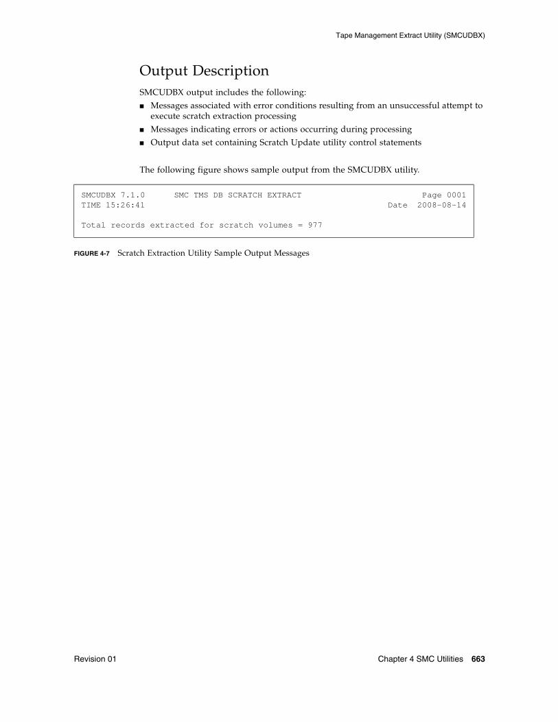
Tape Management Extract Utility (SMCUDBX)
Revision 01 Chapter 4 SMC Utilities 663
Output DescriptionSMCUDBX output includes the following:
■ Messages associated with error conditions resulting from an unsuccessful attempt to execute scratch extraction processing
■ Messages indicating errors or actions occurring during processing
■ Output data set containing Scratch Update utility control statements
The following figure shows sample output from the SMCUDBX utility.
FIGURE 4-7 Scratch Extraction Utility Sample Output Messages
SMCUDBX 7.1.0 SMC TMS DB SCRATCH EXTRACT Page 0001TIME 15:26:41 Date 2008-08-14 Total records extracted for scratch volumes = 977
SMC UUI Simulation Utility (SMCUSIM)
664 ELS 7.1 Command, Control Statement, and Utility Reference • November 2012 Revision 01
SMC UUI Simulation Utility (SMCUSIM)The SMCUSIM utility is used to issue SMC UUI commands, including the SMC SIMulate command, in a test environment. Changes to SMC command settings, tape policies, and allocation user exits can be tested before they are put into production without affecting existing SMC clients and HSC servers.
SMCUSIM code executes similarly to the SMC subsystem, with the following exceptions:
■ It does not initialize the MSP SSI allocation interfaces.■ It does not set up any command or message handling intercepts.■ It does not utilize any CSA storage for processing.
The SMCUSIM utility runs as a batch program, and can execute on the same host as the existing SMC subsystem without interfering with SMC client operations. SMCUSIM processing occurs in two phases.
Phase 1 ProcessingIn this phase, the utility operates similarly to the SMC subsystem startup routine. SMC modules are loaded and the SMCPARMS and SMCCMDS data sets are read.
Similarly to SMC subsystem startup, the SMCPARMS and SMCCMDS data sets are optional. However, as SMCUSIM does not include the SMC subsystem command intercept, you must specify any commands required to set up your test environment during this phase.
Note – ■ Follow the guidelines in “Specifying SMC Commands in the SMCCMDS or
SMCPARMS Data Sets” on page 52 for commands to include in the SMCPARMS and SMCCMDS data sets.
■ See Chapter 2, “SMC Commands and Control Statements” for more information about each individual command.
The SMCUSIM utility processes TAPEPLEX and SERVER commands as if it were an active SMC subsystem, and TCP/IP services may be required. Therefore, the security administration considerations for communication described in the publication Configuring and Managing SMC do apply.
The following SMC commands are disabled by the SMCUSIM because they may interfere with the actual SMC subsystem or HSC server:
■ CMDDef■ HTTP■ LOG■ Route
These commands can be included in the SMCPARMS or SMCCMDS data sets, but are ignored by the utility.
SMC UUI Simulation Utility (SMCUSIM)
Revision 01 Chapter 4 SMC Utilities 665
Phase 2 ProcessingIn this phase, the utility reads and processes the UUIN data set similarly to the SMCUUUI utility, except that only SMC commands are permitted. These commands are targeted to the SMCUSIM simulated environment, and have no effect on the actual SMC subsystem.
You can include SMC SIMulate commands, or any other SMC command in the UUIN data set to test how a job with the specified parameters would be processed using the SMCPARMS and SMCCMDS data sets configured in phase 1. HSC UUI commands are not valid, and are flagged in error. Several types of output can be received, including:
■ Plain text output
This type of output is written to TEXTOUT, and corresponds to the normal output produced by the SMC command.
■ Structured XML
This type of output is written to XMLOUT. Structured XML is a well formed XML data stream with XML header tags and XML data tag elements, and XML data element content. Only specific SMC commands produced structured XML. Refer to the ELS Programming Reference for a complete list of SMC XML tag names and types.
■ Comma Separated Values (CSV)
This type of output is written to CSVOUT. An input template of XML data tag names is used to define the format of the CSVOUT corresponding to a particular request. The output data for each request is a CSV header line that contains a comma-separated list of the XML data tags requested, followed by CSV detail lines. Each CSV detail line contains one comma-separated entry for each requested XML data tag. This type of output is readily adaptable as input into spreadsheets or customized report writers. Refer to the ELS Programming Reference for more information about the format for specifying CSV.
The type of output received is controlled by the data set definition statements (DD) defined in the JCL to execute the SMCUSIM utility.
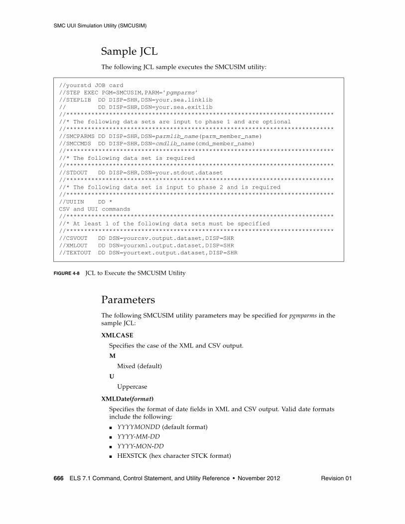
SMC UUI Simulation Utility (SMCUSIM)
666 ELS 7.1 Command, Control Statement, and Utility Reference • November 2012 Revision 01
Sample JCLThe following JCL sample executes the SMCUSIM utility:
FIGURE 4-8 JCL to Execute the SMCUSIM Utility
ParametersThe following SMCUSIM utility parameters may be specified for pgmparms in the sample JCL:
XMLCASE
Specifies the case of the XML and CSV output.
M
Mixed (default)
U
Uppercase
XMLDate(format)
Specifies the format of date fields in XML and CSV output. Valid date formats include the following:
■ YYYYMONDD (default format)
■ YYYY-MM-DD
■ YYYY-MON-DD
■ HEXSTCK (hex character STCK format)
//yourstd JOB card//STEP EXEC PGM=SMCUSIM,PARM=’pgmparms’//STEPLIB DD DISP=SHR,DSN=your.sea.linklib// DD DISP=SHR,DSN=your.sea.exitlib//***************************************************************************//* The following data sets are input to phase 1 and are optional//***************************************************************************//SMCPARMS DD DISP=SHR,DSN=parmlib_name(parm_member_name)//SMCCMDS DD DISP=SHR,DSN=cmdlib_name(cmd_member_name)//***************************************************************************//* The following data set is required//***************************************************************************//STDOUT DD DISP=SHR,DSN=your.stdout.dataset//***************************************************************************//* The following data set is input to phase 2 and is required//***************************************************************************//UUIIN DD *CSV and UUI commands//***************************************************************************//* At least 1 of the following data sets must be specified//***************************************************************************//CSVOUT DD DSN=yourcsv.output.dataset,DISP=SHR//XMLOUT DD DSN=yourxml.output.dataset,DISP=SHR//TEXTOUT DD DSN=yourtext.output.dataset,DISP=SHR
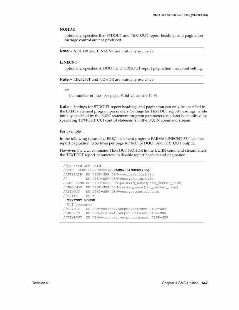
SMC UUI Simulation Utility (SMCUSIM)
Revision 01 Chapter 4 SMC Utilities 667
NOHDR
optionally, specifies that STDOUT and TEXTOUT report headings and pagination carriage control are not produced.
Note – NOHDR and LINECNT are mutually exclusive.
LINECNT
optionally, specifies STDOUT and TEXTOUT report pagination line count setting.
Note – LINECNT and NOHDR are mutually exclusive.
nn
the number of lines per page. Valid values are 10-99.
Note – Settings for STDOUT report headings and pagination can only be specified in the EXEC statement program parameters. Settings for TEXTOUT report headings, while initially specified by the EXEC statement program parameters, can later be modified by specifying TEXTOUT UUI control statements in the UUIIN command stream.
For example:
In the following figure, the EXEC statement program PARM=’LINECNT(55)’ sets the report pagination to 55 lines per page for both STDOUT and TEXTOUT output.
However, the UUI command TEXTOUT NOHDR in the UUIIN command stream alters the TEXTOUT report parameters to disable report headers and pagination.
//yourstd JOB card//STEP EXEC PGM=SMCUSIM,PARM=’LINECNT(55)’//STEPLIB DD DISP=SHR,DSN=your.sea.linklib// DD DISP=SHR,DSN=your.sea.exitlib//SMCPARMS DD DISP=SHR,DSN=parmlib_name(parm_member_name)//SMCCMDS DD DISP=SHR,DSN=cmdlib_name(cmd_member_name)//STDOUT DD DISP=SHR,DSN=your.stdout.dataset//UUIIN DD * TEXTOUT NOHDR UUI commands//CSVOUT DD DSN=yourcsv.output.dataset,DISP=SHR//XMLOUT DD DSN=yourxml.output.dataset,DISP=SHR//TEXTOUT DD DSN=yourtext.output.dataset,DISP=SHR
SMC UUI Simulation Utility (SMCUSIM)
668 ELS 7.1 Command, Control Statement, and Utility Reference • November 2012 Revision 01
MAXRC
specifies whether SMCUSIM initialization is to be terminated when the specified command return code is exceeded. If MAXRC is not specified, then the SMCUSIM always attempts to complete its initialization regardless of any SMCPARMS or SMCCMDS command failure(s). This is the default behavior.
nn
specifies the highest allowed return code. If an SMC command executed from the SMCPARMS or SMCCMDS data set exceeds this value, then SMC0236 and SMC0237 messages are produced, and the SMCUSIM utility terminates before any commands are read from the UUIIN DD. Allowable values are 0, 4, 8, and 12.
Note – ■ Certain SMC commands, such as CMDDef, HTTP, LOG, and Route, that are allowed
in the SMC subsystem environment, but are not allowed in the SMCUSIM environment are merely ignored under SMCUSIM and do not affect MAXRC processing, if specified.
■ Only commands executed as part of the simulated SMC subsystem startup (i.e. those read from the SMCPARMS and SMCCMDS data sets) are evaluated as part of MAXRC processing. Commands read from the UUIIN DD which result in a return code greater than the specified MAXRC value do not automatically terminate the SMCUSIM utility.
PLEXRC
specifies whether SMC subsystem initialization is to be terminated based on the status of TapePlexes returned from the automatically issued RESYNC command.
If PLEXRC is not specified, then the SMC subsystem will complete its initialization regardless of the outcome of the RESYNC command. This is the default behavior.
n
specifies the highest allowed return code from the RESYNC command. Valid values are 0 and 4.
The SMC RESYNC command sets a return code of 8 if SMC is unable to communicate with any defined TapePlex, and a return code of 4 if SMC is able to communicate with one or more, but not all, defined TapePlexes.
SMC UUI Simulation Utility (SMCUSIM)
Revision 01 Chapter 4 SMC Utilities 669
Required Data Set Definition (DD) StatementsYou must specify the UUIIN and STDOUT data set definitions.
UUIIN Data SetThe UUIIN data set can include:
■ SMC UUI commands■ HSC UUI commands■ VTCS PGMI requests
Native SMC UUI commands include:
■ Display Drive■ Display Volume■ POLicy■ SIMulate
Refer to the ELS Programming Reference for a list of supported HSC UUI commands and VTCS PGMI requests.
Syntax Rules■ Input must be 80 byte card images.
■ Only columns 1-72 of the 80 byte card image may contain actual command input. Columns 73-80 may be used for sequence numbers if desired.
■ If the last non-blank character in columns 1-72 is a “+”, the logical command is continued on the next physical card.
■ Comments begin with “/*” (in column 2 and beyond) and end with “*/”.
■ The maximum logical command length is 32000 bytes.
Control Statements
Utility control statements allow the report pagination for TEXTOUT output and the target TapePlex to be altered for subsequent SMC, HSC, and VTCS UUI and PGMI commands.
TEXTOUT
optionally, sets the report pagination parameters for TEXTOUT output. If any errors are encountered on the TEXTOUT command, all subsequent UUI commands are bypassed until a correct TEXTOUT command is encountered.
NOHDR
optionally, specifies that TEXTOUT report headings and pagination carriage control are not produced.
Note – NOHDR and LINECNT are mutually exclusive.
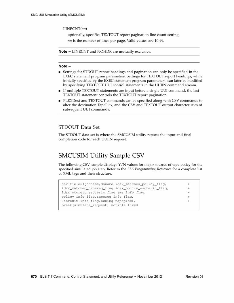
SMC UUI Simulation Utility (SMCUSIM)
670 ELS 7.1 Command, Control Statement, and Utility Reference • November 2012 Revision 01
LINECNT(nn)
optionally, specifies TEXTOUT report pagination line count setting.
nn is the number of lines per page. Valid values are 10-99.
Note – LINECNT and NOHDR are mutually exclusive.
Note – ■ Settings for STDOUT report headings and pagination can only be specified in the
EXEC statement program parameters. Settings for TEXTOUT report headings, while initially specified by the EXEC statement program parameters, can later be modified by specifying TEXTOUT UUI control statements in the UUIIN command stream.
■ If multiple TEXTOUT statements are input before a single UUI command, the last TEXTOUT statement controls the TEXTOUT report pagination.
■ PLEXDext and TEXTOUT commands can be specified along with CSV commands to alter the destination TapePlex, and the CSV and TEXTOUT output characteristics of subsequent UUI commands.
STDOUT Data SetThe STDOUT data set is where the SMCUSIM utility reports the input and final completion code for each UUIIN request.
SMCUSIM Utility Sample CSVThe following CSV sample displays Y/N values for major sources of tape policy for the specified simulated job step. Refer to the ELS Programming Reference for a complete list of XML tags and their structure.
csv field=(jobname,dsname,idax_matched_policy_flag, +idax_matched_tapereq_flag,idax_policy_esoteric_flag, +idax_storgrp_esoteric_flag,sms_info_flag, +policy_info_flag,tapereq_info_flag, +userexit_info_flag,owning_tapeplex), +break(simulate_request) notitle fixed
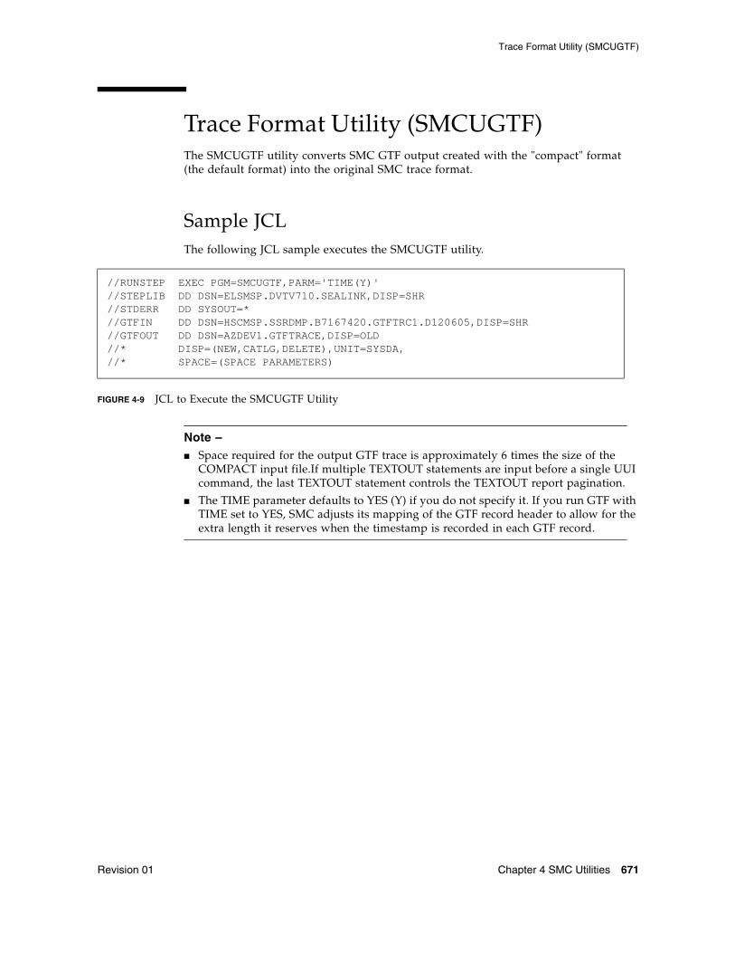
Trace Format Utility (SMCUGTF)
Revision 01 Chapter 4 SMC Utilities 671
Trace Format Utility (SMCUGTF)The SMCUGTF utility converts SMC GTF output created with the "compact" format (the default format) into the original SMC trace format.
Sample JCLThe following JCL sample executes the SMCUGTF utility.
FIGURE 4-9 JCL to Execute the SMCUGTF Utility
Note – ■ Space required for the output GTF trace is approximately 6 times the size of the
COMPACT input file.If multiple TEXTOUT statements are input before a single UUI command, the last TEXTOUT statement controls the TEXTOUT report pagination.
■ The TIME parameter defaults to YES (Y) if you do not specify it. If you run GTF with TIME set to YES, SMC adjusts its mapping of the GTF record header to allow for the extra length it reserves when the timestamp is recorded in each GTF record.
//RUNSTEP EXEC PGM=SMCUGTF,PARM='TIME(Y)' //STEPLIB DD DSN=ELSMSP.DVTV710.SEALINK,DISP=SHR //STDERR DD SYSOUT=* //GTFIN DD DSN=HSCMSP.SSRDMP.B7167420.GTFTRC1.D120605,DISP=SHR//GTFOUT DD DSN=AZDEV1.GTFTRACE,DISP=OLD //* DISP=(NEW,CATLG,DELETE),UNIT=SYSDA, //* SPACE=(SPACE PARAMETERS)
Trace Format Utility (SMCUGTF)
672 ELS 7.1 Command, Control Statement, and Utility Reference • November 2012 Revision 01
Revision 01 673
CHAPTER
5
HSC Stand-Alone Utilities
This chapter describes HSC stand-alone utilities. These utilities run as independent programs.
The following utilities are included:
■ Utility Administrator (SLUADMIN)
■ SLICREAT
■ Scratch Conversion Utility (SLUCONDB)
Utility Administrator (SLUADMIN)
674 ELS 7.1 Command, Control Statement, and Utility Reference • November 2012 Revision 01
Utility Administrator (SLUADMIN)The SLUADMIN program operates as a batch job and controls initialization processing for most utility functions. The utility administrator (SLUADMIN) can accept multiple commands which are handled as serial requests for multiple utilities. If all requirements needed to execute the utility function are met, control is passed to the appropriate program which handles the actual processing.
Utility functions represented by additional control statements are not started until the prior utility function stops and control is returned to the SLUADMIN program.
Caution – The maximum length of a control statement is 32,767 characters. Exceeding this limit causes message SLS0241I to be displayed, which indicates an invalid utility control statement.
Invoking SLUADMINFor convenience, most utility programs are packaged to appear as a single, user-invoked program. An exception is Scratch Conversion.
All other utility functions are invoked as a normal batch job using the SLUADMIN program and user-specified commands needed to invoke the required utility function.
Utility functions represented by additional commands are not started until the prior utility function stops and control is returned to the SLUADMIN program.
The following is a generic example of JCL that can be modified to execute SLUADMIN.
Where ‘‘utility and CSV commands’’ appears in this sample JCL, enter the utility or CSV commands you wish to execute.
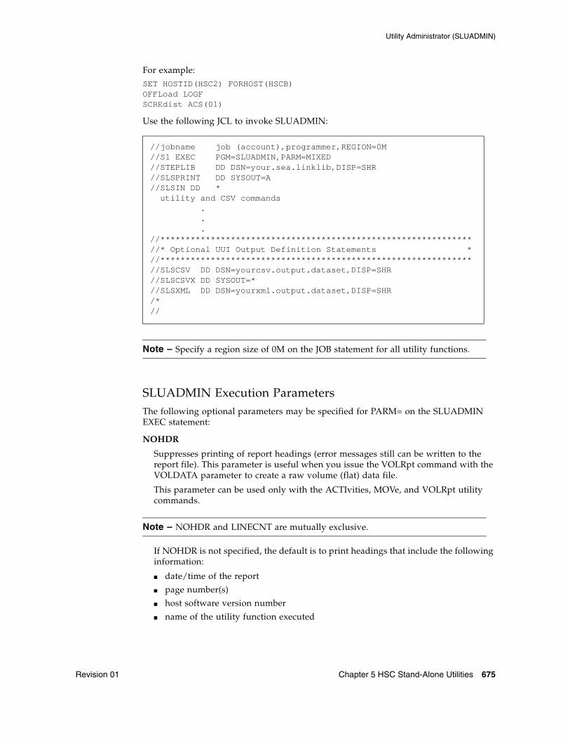
Utility Administrator (SLUADMIN)
Revision 01 Chapter 5 HSC Stand-Alone Utilities 675
For example:SET HOSTID(HSC2) FORHOST(HSCB)OFFLoad LOGFSCREdist ACS(01)
Use the following JCL to invoke SLUADMIN:
Note – Specify a region size of 0M on the JOB statement for all utility functions.
SLUADMIN Execution ParametersThe following optional parameters may be specified for PARM= on the SLUADMIN EXEC statement:
NOHDR
Suppresses printing of report headings (error messages still can be written to the report file). This parameter is useful when you issue the VOLRpt command with the VOLDATA parameter to create a raw volume (flat) data file.
This parameter can be used only with the ACTIvities, MOVe, and VOLRpt utility commands.
Note – NOHDR and LINECNT are mutually exclusive.
If NOHDR is not specified, the default is to print headings that include the following information:
■ date/time of the report
■ page number(s)
■ host software version number
■ name of the utility function executed
//jobname job (account),programmer,REGION=0M//S1 EXEC PGM=SLUADMIN,PARM=MIXED//STEPLIB DD DSN=your.sea.linklib,DISP=SHR//SLSPRINT DD SYSOUT=A//SLSIN DD * utility and CSV commands . . .//**************************************************************//* Optional UUI Output Definition Statements *//**************************************************************//SLSCSV DD DSN=yourcsv.output.dataset,DISP=SHR//SLSCSVX DD SYSOUT=*//SLSXML DD DSN=yourxml.output.dataset,DISP=SHR/*//
Utility Administrator (SLUADMIN)
676 ELS 7.1 Command, Control Statement, and Utility Reference • November 2012 Revision 01
NOPHDR
Suppresses printing of page headings, but produces control headers in the output, such as:
SLS0030I Message ID NNNN Help Info:
or:
SLS0041I Command CCCCCCCC Help Info:
Note – NOPHDR is mutually exclusive with LINECNT and NOHDR.
This parameter is useful when you issue the Display CMd or Display Message command to create a file that includes help text for commands or messages.
MIXED
Prints all report headings and messages in mixed case. The default is uppercase.
LINECNT=nn
Specifies the number of lines per page for the SLUADMIN report. Allowable values are 10 through 99; the default is 60 lines per page.
Note – LINECNT and NOHDR are mutually exclusive.
SSYS(ssss)
Optionally, specifies the name of the HSC subsystem for which the SLUADMIN utility is being run. This parameter is required when the HSC subsystem(s) running on the LPAR have specified the MULT parameter.
XMLDate(date)
Defines the format of date fields in XML and CSV output. Valid date formats include the following:
■ yyyymondd
■ yyyy-mm-dd
■ yyyy-mon-dd
■ HEXSTCK (hex character STCK format)
The default format is yyyymondd. For example, 2005Oct14.
XMLCase(case)
Defines the case of alphabetic data fields in XML and CSV output. Valid case formats include the following:
■ M (mixed uppercase and lowercase)
■ U (all uppercase)
The default is M.
Utility Administrator (SLUADMIN)
Revision 01 Chapter 5 HSC Stand-Alone Utilities 677
SLUADMIN Definition Statements
Note – Additional statements may be required for certain HSC and VTCS commands. In this publication, these statements are described with the applicable command.
General Definition Statements
The following definition statements are always required:
STEPLIB
specifies the link library that contains the ELS modules.
SLSPRINT
specifies the destination for the utility output (plain text).
SLSIN
specifies the input to the SLUADMIN (utility command names and parameters).
SLSOUT
specifies the destination for SLUADMIN processing messages.
CDS Definition Statements
One or more of the following CDS definition statements are required for utility commands executed on a host where the HSC is inactive. These statements specify a primary CDS, and optionally, a secondary and standby CDS.
Note – These statements can be omitted for commands that execute on a host with HSC active. If these statements are omitted, the data sets used by the active HSC on the host are accessed.
SLSCNTL
specifies the primary CDS. This statement is required for utility commands executed on a host where the HSC is inactive.
SLSCNTL2
optionally, specifies the secondary CDS.
If a secondary CDS exists, include this statement so that if a switch occurs and the secondary CDS becomes active, the CDSs can be reordered to maintain database integrity.
SLSSTBY
optionally, specifies the standby CDS.
If a standby CDS exists, include this statement so that if a switch occurs and the standby CDS becomes active, the CDSs can be reordered to maintain database integrity.
Utility Administrator (SLUADMIN)
678 ELS 7.1 Command, Control Statement, and Utility Reference • November 2012 Revision 01
When you specify CDS definition statements, the following conditions apply:
■ The number of DD statements specified must equal the number defined by the SET TCHNIQE command. When you run the SET TCHNIQE command, the number of DD statements defined must equal the number implied by the new technique.
■ Rules for selecting primary, secondary, and standby CDS versions are the same as those used by the HSC subsystem. Refer to the publication Managing HSC and VTCS for more information about CDS configuration.
■ For utilities that are "read only" (e.g. VOLRpt), you can specify a single DD (SLSCNTL) and no internal or external name validation is performed.
UUI Output Definition Statements
One or more of the following definition statements are required when you wish to generate output types added through Unified User Interface (UUI) requests. See “Requesting SLUADMIN Output” on page 679 for more information about requesting these output types.
SLSCSV
specifies the destination for the utility output in Comma Separated Value (CSV) format.
SLSCSVX
specifies the destination for CSV exceptions.
SLSXML
specifies the destination for the utility output in structured XML format.
Utility Administrator (SLUADMIN)
Revision 01 Chapter 5 HSC Stand-Alone Utilities 679
Requesting SLUADMIN OutputIn addition to plain text, SLUADMIN supports output types added through Unified User Interface (UUI) requests. Refer to the ELS Programming Reference for a list of commands and utilities supported by the UUI.
The output type is controlled by DD statements defined in the SLUADMIN JCL. Output types include the following:
■ Plain text
Plain text output is always produced and is unchanged from previous releases. Output is written to the data set specified by the SLSPRINT definition statement.
■ Structured XML
This output type is optional and is generated only if the SLSXML definition statement is specified. Output is written to the data set specified by this statement.
Structured XML is a well-formed XML data stream containing XML header tags, data tags, and data element content. Refer to the ELS Programming Reference for XML tag names and structure for all UUI requests.
■ Comma Separated Values (CSV)
This output type is optional and is generated only if the CSV command and SLSCSV definition statement are specified.
CSV output can be customized. A template of XML data tag names can be input by the user to specify which data values will be output. The output data is a single CSV header line followed by CSV detail lines.
A CSV header line is a list of the XML data tag names requested; each name is separated by a comma. Each CSV detail line is a specified fixed number of data values, separated by a comma. This kind of output is readily adaptable as input into spreadsheets or customizable report writers.
Note – The VOLRpt VOLDATA parameter produces a volume flat file. This option is still supported, but may be discontinued in future releases. Refer to the ELS Legacy Interfaces Reference for more information.
Requesting XML OutputIf the SLSXML DD statement is present, it indicates that structured XML output should be provided for all SLUADMIN commands that support the UUI interface.
When XML is generated, exceptions are generated under their own header tag, <exceptions>, at the end of each request. Each exception is reported using the <reason> tag. Refer to the ELS Programming Reference for more information.
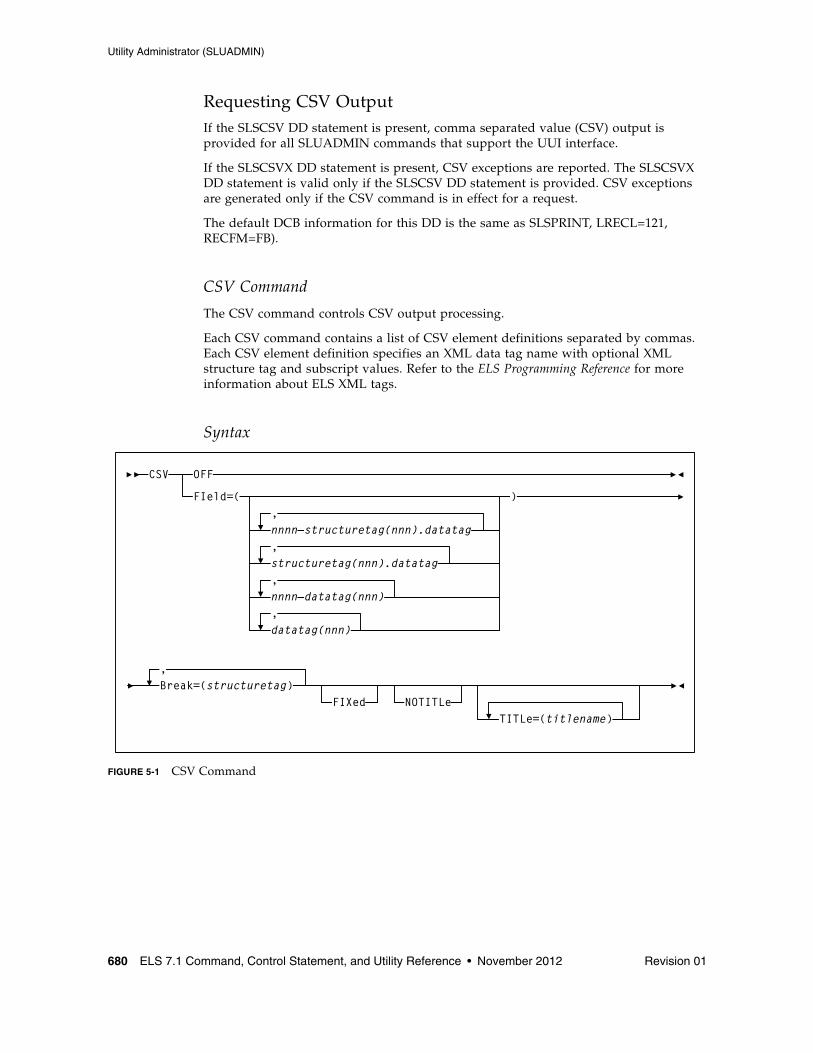
Utility Administrator (SLUADMIN)
680 ELS 7.1 Command, Control Statement, and Utility Reference • November 2012 Revision 01
Requesting CSV OutputIf the SLSCSV DD statement is present, comma separated value (CSV) output is provided for all SLUADMIN commands that support the UUI interface.
If the SLSCSVX DD statement is present, CSV exceptions are reported. The SLSCSVX DD statement is valid only if the SLSCSV DD statement is provided. CSV exceptions are generated only if the CSV command is in effect for a request.
The default DCB information for this DD is the same as SLSPRINT, LRECL=121, RECFM=FB).
CSV Command
The CSV command controls CSV output processing.
Each CSV command contains a list of CSV element definitions separated by commas. Each CSV element definition specifies an XML data tag name with optional XML structure tag and subscript values. Refer to the ELS Programming Reference for more information about ELS XML tags.
Syntax
FIGURE 5-1 CSV Command
CSV OFF
FIeld=( )
structuretag(nnn).datatag,
,
,Break=(structuretag)
FIXed NOTITLeTITLe=(titlename)
datatag(nnn)
,
,nnnn datatag(nnn)
nnnn structuretag(nnn).datatag
Utility Administrator (SLUADMIN)
Revision 01 Chapter 5 HSC Stand-Alone Utilities 681
Parameters
OFF
Disables CSV processing for subsequent requests.
Note – OFF is mutually exclusive with all other CSV parameters.
FIeld
Required if OFF is not specified.
nnnn-
an optional field name prefix containing 1 to 4 numeric characters followed by a dash. When a field name is prefixed by "n(nnn)-", the CSV output for the field always contains exactly the number of characters specified. Numeric fields are right-justified with the most left-most digits truncated; other fields are left-justified with the right-most characters truncated. If the value specified is longer than the actual value, it is padded with blanks on the left for numeric fields and blanks on the right for other fields.
For example:
■ 8-acs_status truncates the acs_status value to 8 characters.
■ 12-acs_status blank-pads the acs_status value to 12 characters.
The maximum value of nnnn is 1024. The specification of "nnnn-" is valid only when the parameter FIXed is also specified.
structuretag(nnn).datatag
an optional XML structure tag and data tag pair. An XML structure tag is an element that contains other elements but does not have content value. Refer to the ELS Programming Reference for more information about ELS XML tags.
Specify an XML structure tag/data tag pair only when the data tag occurs within multiple structure tags. For example, the DISPLAY LSM request data tag free_cell_count is used under the structure lsm_data to contain the total LSM free cell count and under the structure panel_data to contain the panel free cell count. Specifying lsm_data.free_cell_count requests the free cell count from the lsm_data structure; specifying panel_data.free_cell_count requests the free cell count from the panel_data structure. If no structure tag is coded for a data tag that occurs under multiple structure tags, the first occurrence of the data tag in the generated XML is used.
nnn
an optional subscript that determines how many of the multiple XML data values are included in the CSV output.
Specify a subscript only when the structured XML data for a single request contains multiple XML structure elements with the same name. This is indicated in the requestXML description whenever the column labelled "Maximum Occurrences" is greater than 1. A subscript value can be specified in BOTH the structure tag name AND the data tag name, for example:
CSV FIELD=(mvc_instance(4).volser,+mvc_instance(4).partition_id(2))
Utility Administrator (SLUADMIN)
682 ELS 7.1 Command, Control Statement, and Utility Reference • November 2012 Revision 01
creates CSV output with 12 fields, four mvc_instance volser occurrences, followed by two fields representing the partition_id values associated with the first MVC volser, then two fields representing the partition_id values associated with the second MVC, etc.
datatag(nnn)
an optional XML data tag.
If a data tag does not under more than one structure tag in a request, it is not necessary to specify a structure tag qualifier.
nnn
an optional subscript that determines how many of the multiple XML data values are included in the CSV output.
Specify a subscript only when the structured XML data for a single request contains multiple XML structure elements with the same name. This is indicated in the requestXML description whenever the column labelled "Maximum Occurrences" is greater than 1.
Note – The XML tag names are NOT case-sensitive and can be specified in any combination of upper and lower case characters.
BReak
Required if OFF is not specified. The break tag must be a valid structure tag defined for the input request. Whenever a trailer tag matching the break tag is found in the output process, a new CSV record is created. Examples of valid break tags are:
■ For DISPLAY CDS, cds_data or host_data
■ For VOLRPT or Display Volume, volume_data
FIXed
Generates fixed format CSV output. Each field in the CSV output is blank-padded so that it occupies a fixed number of characters. This option can be used to create a customer-specified format flat file for reporting.
NOTITLe
Specifies that no CSV title line is produced. If this keyword is omitted, the first line of each CSV request is a title line containing comma separated tag names.
TITLe
If TITLe is specified, the title names specified are used in the title output line in place of the XML tag names. For any omitted title name, the specified XML tag name from the FIELD parameter is used in the title.
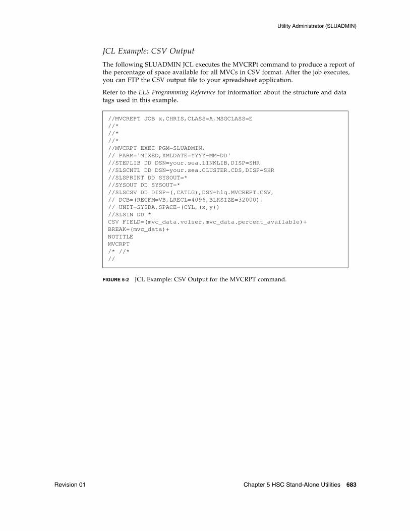
Utility Administrator (SLUADMIN)
Revision 01 Chapter 5 HSC Stand-Alone Utilities 683
JCL Example: CSV Output
The following SLUADMIN JCL executes the MVCRPt command to produce a report of the percentage of space available for all MVCs in CSV format. After the job executes, you can FTP the CSV output file to your spreadsheet application.
Refer to the ELS Programming Reference for information about the structure and data tags used in this example.
FIGURE 5-2 JCL Example: CSV Output for the MVCRPT command.
//MVCREPT JOB x,CHRIS,CLASS=A,MSGCLASS=E//*//*//*//MVCRPT EXEC PGM=SLUADMIN,// PARM='MIXED,XMLDATE=YYYY-MM-DD'//STEPLIB DD DSN=your.sea.LINKLIB,DISP=SHR//SLSCNTL DD DSN=your.sea.CLUSTER.CDS,DISP=SHR//SLSPRINT DD SYSOUT=*//SYSOUT DD SYSOUT=*//SLSCSV DD DISP=(,CATLG),DSN=hlq.MVCREPT.CSV,// DCB=(RECFM=VB,LRECL=4096,BLKSIZE=32000),// UNIT=SYSDA,SPACE=(CYL,(x,y))//SLSIN DD *CSV FIELD=(mvc_data.volser,mvc_data.percent_available)+BREAK=(mvc_data)+NOTITLEMVCRPT/* //*//
Utility Administrator (SLUADMIN)
684 ELS 7.1 Command, Control Statement, and Utility Reference • November 2012 Revision 01
SLUADMIN Program Return CodesThe SLUADMIN program sets a return code for the execution of the job step as defined in TABLE 5-1.
The return code for each utility function is listed in a message. For return codes other than 0, additional messages are listed providing more information and description of the error condition. Refer to the publication ELS Messages and Codes for any messages encountered.
Note – If the return code occurred because of a problem with the HSC CDS or journal files, the problem must be resolved before the HSC can be initialized safely.
Reports Created By Utility CommandsSeveral utility commands produce reports when executed. These reports are in addition to the utility function. The following utility commands produce reports:
■ LIBGen
■ ACTIvities
■ AUDit
■ BACKup
■ MOVe
■ VOLRpt
Report HeadingsReport headings include the following information:
■ date/time of the report
■ page number(s)
■ host software version number
■ name of the utility function executed
TABLE 5-1 SLUADMIN Return Codes
Return Code Description
0 All utility functions requested via control statements completed normally.
4 At least one utility function encountered an abnormal situation, but it did not cause termination of that utility function or any subsequent utility functions.
8 At least one utility function encountered an error condition that prevented continuation of that utility function, but any subsequent utility functions represented by control statements were attempted.
12 An error condition was detected that either prevented the start of any utility functions, or terminated the active utility function and prevented processing of subsequent utility functions.
SLICREAT
Revision 01 Chapter 5 HSC Stand-Alone Utilities 685
SLICREATThe SLICREAT program creates library control data sets and displays library volume capacity in a confirmation message.
These library control data sets are created based on the data set definitions you specify in the SLICREAT data set initialization JCL.
Using SLICREAT involves the following steps:
1. Create data set definitions in the data set initialization JCL using the SLICREAT program.
2. Execute the SLICREAT program to create the library control data sets.
3. Verify successful completion of the SLICREAT program and note the library volume capacity displayed in the confirming message.
These steps are described in the following sections. They must be performed before the library is operational.
Note – ■ Before using SLICREAT, you must first create, assemble and link the LIBGen macros.
Refer to the publication Configuring HSC and VTCS for more information.
■ You can use SLICREAT to reformat your HSC SLSJRNnn journal file(s). Refer to the ELS Legacy Interfaces Reference for more information.
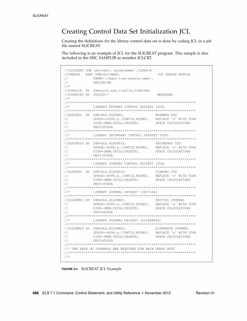
SLICREAT
686 ELS 7.1 Command, Control Statement, and Utility Reference • November 2012 Revision 01
Creating Control Data Set Initialization JCL Creating the definitions for the library control data set is done by coding JCL in a job file named SLICREAT.
The following is an example of JCL for the SLICREAT program. This sample is also included in the HSC SAMPLIB as member JCLCRT.
FIGURE 5-3 SLICREAT JCL Example
//SLICREAT JOB (account),’programmer’,CLASS=A //CREATE EXEC PGM=SLICREAT, CDS CREATE MODULE // PARM=’libgen-load-module-name’, // REGION=0M //*//STEPLIB DD DSN=your.sea.linklib,DISP=SHR //SYSPRINT DD SYSOUT=* MESSAGES //*//******************************************************************//* LIBRARY PRIMARY CONTROL DATASET (CDS) //******************************************************************//SLSCNTL DD DSN=SLS.SLSCNTL, PRIMARY CDS // SPACE=(4096,s,,CONTIG,ROUND), REPLACE ’s’ WITH YOUR// DISP=(NEW,CATLG,DELETE), SPACE CALCULATIONS // UNIT=SYSDA //******************************************************************//* LIBRARY SECONDARY CONTROL DATASET (CDS) //******************************************************************//SLSCNTL2 DD DSN=SLS.SLSCNTL2, SECONDARY CDS // SPACE=(4096,s,,CONTIG,ROUND), REPLACE ’s’ WITH YOUR// DISP=(NEW,CATLG,DELETE), SPACE CALCULATIONS // UNIT=SYSDA //******************************************************************//* LIBRARY STANDBY CONTROL DATASET (CDS) //******************************************************************//SLSSTBY DD DSN=SLS.SLSCNTL3, STANDBY CDS // SPACE=(4096,s,,CONTIG,ROUND), REPLACE ’s’ WITH YOUR// DISP=(NEW,CATLG,DELETE), SPACE CALCULATIONS// UNIT=SYSDA //******************************************************************//* LIBRARY JOURNAL DATASET (INITIAL) //******************************************************************//SLSJRN01 DD DSN=SLS.SLSJRN01, INITIAL JOURNAL // SPACE=(4096,u,,CONTIG,ROUND), REPLACE ’u’ WITH YOUR// DISP=(NEW,CATLG,DELETE), SPACE CALCULATIONS // UNIT=SYSDA //******************************************************************//* LIBRARY JOURNAL DATASET (ALTERNATE)//******************************************************************//SLSJRN02 DD DSN=SLS.SLSJRN02, ALTERNATE JOURNAL // SPACE=(4096,u,,CONTIG,ROUND), REPLACE ’u’ WITH YOUR// DISP=(NEW,CATLG,DELETE), SPACE CALCULATIONS// UNIT=SYSDA //******************************************************************//* ONE PAIR OF JOURNALS ARE REQUIRED FOR EACH GENED HOST //******************************************************************//*
SLICREAT
Revision 01 Chapter 5 HSC Stand-Alone Utilities 687
DD Statements The following JCL DD statements must be used to define the library control data sets:
SYSPRINT
output messages.
Refer to the following criteria when allocating the control and journal data sets:
■ Do not specify the DCB statement. The HSC defines the required blocksize (4K).
■ The data set(s) must be allocated in a single contiguous extent.
■ The CDS(s) must not include existing data sets containing records prior to running the SLICREAT process.
■ Oracle StorageTek recommends that the CDSs do not reside on the same volume(s) as other CDSs or other data sets that generate high I/O activity.
SLSCNTL
primary library control data set.
This is the initial data set that is used to control and synchronize all activities within the HSC. It is used by the HSC until the controlling data set is switched to the secondary, either automatically or manually.
SLSCNTL also controls the SLICREAT process. If you do not include an SLSCNTL DD statement when you run SLICREAT,
■ the CDSs will not be formatted, and
■ the size requirement (in blocks) of the LIBGEN load module included in the PARM statement will be calculated and reported and journal formatting will be attempted.
SLSCNTL2
secondary copy of the primary control data set.
This is required only if the SLIRCVRY macro TCHNIQE parameter is SHADOW, STANDBY, BOTH, or ALL.
SLSSTBY
standby control data set.
This data set is required only if the SLIRCVRY macro TCHNIQE parameter is STANDBY or ALL. A secondary data set is required if a standby control data set is specified. This data set is also required for STBYONLY processing (see “Using SLICREAT to Create Only the Standby CDS” on page 689).
SLICREAT
688 ELS 7.1 Command, Control Statement, and Utility Reference • November 2012 Revision 01
Executing the SLICREAT ProgramExecute the SLICREAT program to create the library control data sets.
SLICREAT EXEC StatementUse the following EXEC statement to execute the SLICREAT program:
The PARM= value indicates the LIBGEN load module name. The steplib statement must point to the appropriate library in which the LIBGEN load module currently resides.
Note – ■ SLICREAT requires a LIBGEN load module assembled with the same level macros as
the release LINKLIB. A LIBGEN load module created with earlier HSC releases cannot be used as input to a later release of SLICREAT.
■ The CDS files that are created by SLICREAT (SLSCNTL, SLSCNTL2, and SLSSTBY) are verified to be empty data sets prior to being formatted. If SLICREAT identifies any of these files as containing records, an error message is displayed and the creation process terminates. If this occurs, specify a different data set(s) or delete and redefine the data set(s) and re-execute SLICREAT.
Verifying Successful Completion of the SLICREAT ProgramAfter the SLICREAT program is successfully processed, a message is generated indicating the status and the capacity of the library. An example is:
Calculating Cartridge Capacity - SL8500 and SL3000Message SLS0557I displays the total cartridge capacity for the library. For the SL8500 and SL3000 libraries, you must first vary the library online (Vary ACS command) to see the actual capacity of the library rather than the maximum capacity of the library. Before you vary the library, the maximum capacity is based on the highest possible number of panels that the HSC allows to be defined, not the number you defined in LIBGEN.
After you vary the library online, issue the Display Acs or Display Lsm command to show the actual library capacity.
EXEC PGM=SLICREAT,PARM=’ libgen-load-module-name ’
SLS0557I DATABASE SUCCESSFULLY INITIALIZED; TOTAL CARTRIDGE CAPACITY: DDDDDDDDDDDD VOLUMES
SLICREAT
Revision 01 Chapter 5 HSC Stand-Alone Utilities 689
Other Uses for SLICREAT
Using SLICREAT to Create Only the Standby CDSSLICREAT can be used to create an additional CDS. If the HSC was previously installed without a standby CDS, you can run the SLICREAT program to create one.
This method does not make a backup of the primary CDS. It formats the additional CDS and allows you to activate it with the CDS Enable command.
SLICREAT EXEC Statement to Create Standby CDS
Specify PARM=’STBYONLY’ on the SLICREAT EXEC statement to create a standby CDS:
Note – ■ You must have a primary CDS before you can run the STBYONLY option of
SLICREAT.
■ For a standby data set to be recognized by the system, it must be defined by a CDSDEF statement in the PARMLIB.
Using SLICREAT to Calculate DASD Space You can determine the minimum DASD space required for the CDSs by executing SLICREAT without specifying the SLSCNTL and SLSJRNnn DD statements. The HSC generates a message that indicates the minimum space requirements in 4096-byte blocks. When you execute SLICREAT, you must specify the number of blocks for each of these data sets that is at least as large as this minimum.
Note – If you are specifying multiple CDSs (SLSCNTL2, SLSSTBY), Oracle StorageTek recommends that you allocate the same amount of space (in blocks) for all your data sets when you define them.
If the data sets are defined with different space allocations, the HSC uses the size of the smallest data set to determine the number of 4K blocks that it will use for the CDS. The additional space in the other CDS data sets, if any, will not be used by the HSC.
The difference in space between the minimum space required (returned by SLICREAT) and the size of the smallest CDS copy is formatted as CDS free blocks.
EXEC PGM=SLICREAT,PARM=’STBYONLY’
Scratch Conversion Utility (SLUCONDB)
690 ELS 7.1 Command, Control Statement, and Utility Reference • November 2012 Revision 01
Scratch Conversion Utility (SLUCONDB)The SLUCONDB program generates scratch transactions from CA-1, CA-DYNAM/TLMS, and Zara tape management systems, or from a file extracted from a client system by the SMC SMCUDBX utility.
Note – See “Tape Management Extract Utility (SMCUDBX)” on page 657 for more information about the SMCUDBX utility.
SLUCONDB can execute as a standalone utility, generating scratch transactions for input to SLUADMIN. Alternatively, it can execute on a host with an active HSC system, and, using the SLUCONDB LIBONLY parameter, generate UUI scratch transactions sent directly to the active HSC system. In a client/server system, using the TAPEPLEX parameter, SLUCONDB can access an HSC system on another host to acquire CDS data and to send UUI scratch transactions.
Warning – ■ SLUCONDB should not be executed with any other SCRAtch, UNSCratch, or
REPLaceall activity.
■ The SLUCONDB module is no longer distributed as source. If you wish to synchronize scratch processing with a tape management system not supported by SLUCONDB, alter one of the distributed SLUCONDB tape management interface modules to use the SLUDRINF interface format.
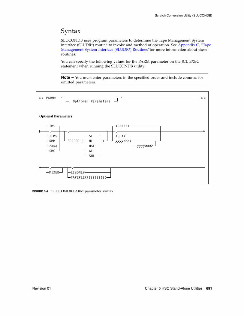
Scratch Conversion Utility (SLUCONDB)
Revision 01 Chapter 5 HSC Stand-Alone Utilities 691
SyntaxSLUCONDB uses program parameters to determine the Tape Management System interface (SLUDR*) routine to invoke and method of operation. See Appendix C, “Tape Management System Interface (SLUDR*) Routines”for more information about these routines.
You can specify the following values for the PARM parameter on the JCL EXEC statement when running the SLUCONDB utility:
Note – You must enter parameters in the specified order and include commas for omitted parameters.
FIGURE 5-4 SLUCONDB PARM parameter syntax
PARM= ‘Optional Parameters
’
Optional Parameters:
TMS,TLMSRMM
SMC
SCRPOOL(SLNLNSLALSUL
)
1900001,TODAYyyyyddd1
yyyyddd2
MIXED,
LIBONLY,
ZARA
,
TAPEPLEX(tttttttt)
Scratch Conversion Utility (SLUCONDB)
692 ELS 7.1 Command, Control Statement, and Utility Reference • November 2012 Revision 01
ParametersPARM=
specifies the parameters that follow can be accessed by the program indicated in the PGM parameter in the JCL.
The defaults for the PARM are:
■ TMS
■ All label types
■ All scratches from January 1, 1900 to the current system date
■ Uppercase only
■ Generate scratch transactions (no direct update).
The keywords for the PARM are positional. If you accept the system defaults, either do not specify PARM, or code PARM=''.
TMS
optionally, specifies the CA-1 tape management system (TMS). This is the default.
TLMS
optionally, specifies the TLMS: CA-DYNAM/TLMS tape management system.
ZARA
optionally, specifies the ZARA tape management system.
SMC
optionally, specifies the extract file from the SMC utility SMCUDBX.
If SMC is specified, label and date parameters are not permitted. (Label and date selection are performed by the SMC utility when it creates the extract file.)
SCRPOOL
optionally, specifies the scratch pool label type used by the library. Valid label type values are:
(SL)
standard label (the default).
(NL)
nonlabeled.
(NSL)
nonstandard label.
(AL)
ANSI label.
(SUL)
standard user label.
1900001
optionally, specifies January 1, 1900 as the date. This is the default.
TODAY
optionally, indicates the current system date.
Scratch Conversion Utility (SLUCONDB)
Revision 01 Chapter 5 HSC Stand-Alone Utilities 693
yyyyddd1
optionally, the "from" date. The "to" date defaults to the current system date. All specified dates are in Julian notation.
yyyyddd1-yyyyddd2
optionally, the date range in which the volumes became scratch. Neither of these dates can be greater than the current system date.
MIXED
optionally, specifies to print all the headings and messages in mixed case characters (uppercase and lowercase characters).
Note – If a comma is specified, or if this keyword is not specified, the system defaults to uppercase letters.
LIBONLY
optionally, specifies that volumes are to be placed in scratch status through the UUI interface. Specifying LIBONLY requires an active HSC, and requires that SLUCONDB be executed from an APF-authorized library.
TAPEPLEX
optionally, specifies the name of an SMC tapeplex to be used to extract CDS volumes and run UUI scratch commands.
tttttttt
the TapePlex name.
The specified tapeplex may be a local HSC executing on the same host as SLUCONDB, or may be an HSC subsystem on another host accessed via the SMC client server feature. Specifying the TAPEPLEX parameter requires an active SMC system on the SLUCONDB host, an active HSC system for the TapePlex, and requires that SLUCONDB be executed from an APF-authorized library.
Scratch Conversion Utility (SLUCONDB)
694 ELS 7.1 Command, Control Statement, and Utility Reference • November 2012 Revision 01
JCL RequirementsThe following definitions apply to the SLUCONDB JCL:
SLSTMS
input to the utility in the form of either the CA-1 TMC or CA-DYNAM/TLMS Volume Master File (VMF). This statement is required.
SLSSOUT
output from the utility specifying the Scratch Update utility control statement. This statement is required if LIBONLY or TAPEPLEX is not specified.
If specifying a temporary or permanent data set for 'DSN=' in the JCL, you must include the appropriate DCB information (i.e., LRECL=72).
SLSPRINT
output messages from the utility program. This statement is required.
Note – The Scratch Conversion utility uses the UUI to extract volume and VTV records from the CDS. The UUI requires read access to the CDS, either from statements in the JCL or by getting the data set information from an active HSC. The SLSCNTL, SLSCNTL2, and SLSSTBY DD statements are optional if an active HSC is running on the same system. The SLSCNTL, SLSCNTL2, and SLSSTBY DD statements are not allowed if either LIBONLY or TAPEPLEX parameters are specified.
SLSCNTL
the primary control data set. This statement is optional.
SLSCNTL2
the secondary control data set. This statement is optional.
SLSSTBY
the standby control data set. This statement is optional.
Scratch Conversion Utility (SLUCONDB)
Revision 01 Chapter 5 HSC Stand-Alone Utilities 695
JCL ExamplesThe following examples illustrate both generating scratch transactions and directly updating the HSC CDS.
The library referred to as "your.sea.smp.loadlib" in the following examples refers to the SEALINK library generated during the ELS installation. This library contains the TMS interface (SLUDR*) modules. If you reassemble these modules, this library is the output of your link edit.
Note – The UNIT, SPACE, and DCB parameter settings are determined by the user.
JCL to Process Tape Management Databases, with Active HSC, Generating Scratch Update Transactions
JCL to Process TMS Database, with HSC CDS DDnames, Generating Scratch Update Transactions
//JOBSCUP JOB (account),programmer//STEP1 EXEC PGM=SLUCONDB,// PARM=('TLMS,,,MIXED')//STEPLIB DD DISP=SHR,DSN=your.sea.smp.loadlib//SLSTMS DD DSN=TMS.MASTER.FILE,DISP=SHR//SLSSOUT DD DSN=&&SCUPINPT,DISP=(NEW,PASS),// UNIT=,SPACE=,DCB=//SLSPRINT DD SYSOUT=*//*//STEP2 EXEC PGM=SLUADMIN,COND=(4,LT,STEP1),PARM=MIXED//SLSIN DD DSN=&&SCUPINPT,DISP=(OLD,DELETE)//SLSPRINT DD SYSOUT=*//
//JOBSCUP JOB (account),programmer//STEP1 EXEC PGM=SLUCONDB,// PARM=(',,2009100-2009110,MIXED')//STEPLIB DD DISP=SHR,DSN=your.sea.smp.loadlib//SLSTMS DD DSN=TMS.MASTER.FILE,DISP=SHR//SLSSOUT DD DSN=&&SCUPINPT,DISP=(NEW,PASS),// UNIT=,SPACE=,DCB=//SLSPRINT DD SYSOUT=*//SLSCNTL DD DSN=primary.control.dataset,DISP=SHR//SLSCNTL2 DD DSN=secondary.control.dataset,DISP=SHR//SLSSTBY DD DSN=standby.control.dataset,DISP=SHR//*//STEP2 EXEC PGM=SLUADMIN,COND=(4,LT,STEP1),PARM=MIXED//SLSIN DD DSN=&&SCUPINPT,DISP=(OLD,DELETE)//SLSPRINT DD SYSOUT=A//
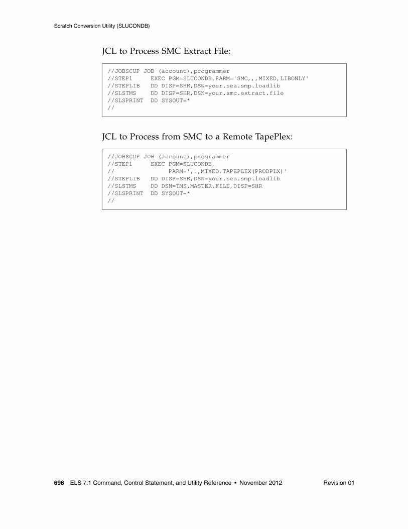
Scratch Conversion Utility (SLUCONDB)
696 ELS 7.1 Command, Control Statement, and Utility Reference • November 2012 Revision 01
JCL to Process SMC Extract File:
JCL to Process from SMC to a Remote TapePlex:
//JOBSCUP JOB (account),programmer//STEP1 EXEC PGM=SLUCONDB,PARM='SMC,,,MIXED,LIBONLY'//STEPLIB DD DISP=SHR,DSN=your.sea.smp.loadlib//SLSTMS DD DISP=SHR,DSN=your.smc.extract.file//SLSPRINT DD SYSOUT=*//
//JOBSCUP JOB (account),programmer//STEP1 EXEC PGM=SLUCONDB,// PARM=',,,MIXED,TAPEPLEX(PRODPLX)'//STEPLIB DD DISP=SHR,DSN=your.sea.smp.loadlib//SLSTMS DD DSN=TMS.MASTER.FILE,DISP=SHR//SLSPRINT DD SYSOUT=*//
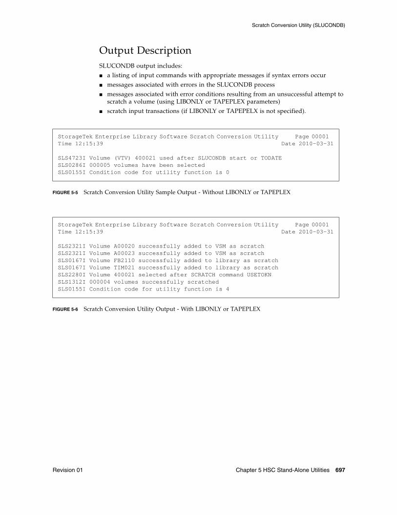
Scratch Conversion Utility (SLUCONDB)
Revision 01 Chapter 5 HSC Stand-Alone Utilities 697
Output DescriptionSLUCONDB output includes:
■ a listing of input commands with appropriate messages if syntax errors occur
■ messages associated with errors in the SLUCONDB process
■ messages associated with error conditions resulting from an unsuccessful attempt to scratch a volume (using LIBONLY or TAPEPLEX parameters)
■ scratch input transactions (if LIBONLY or TAPEPELX is not specified).
FIGURE 5-5 Scratch Conversion Utility Sample Output - Without LIBONLY or TAPEPLEX
FIGURE 5-6 Scratch Conversion Utility Output - With LIBONLY or TAPEPLEX
StorageTek Enterprise Library Software Scratch Conversion Utility Page 00001 Time 12:15:39 Date 2010-03-31
SLS4723I Volume (VTV) 400021 used after SLUCONDB start or TODATESLS0286I 000005 volumes have been selectedSLS0155I Condition code for utility function is 0
StorageTek Enterprise Library Software Scratch Conversion Utility Page 00001 Time 12:15:39 Date 2010-03-31
SLS2321I Volume A00020 successfully added to VSM as scratchSLS2321I Volume A00023 successfully added to VSM as scratchSLS0167I Volume FB2110 successfully added to library as scratchSLS0167I Volume TIM021 successfully added to library as scratchSLS2280I Volume 400021 selected after SCRATCH command USETOKNSLS1312I 000004 volumes successfully scratchedSLS0155I Condition code for utility function is 4

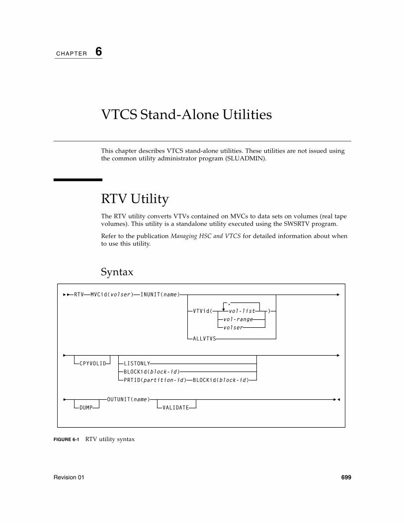
Revision 01 699
CHAPTER
6
VTCS Stand-Alone Utilities
This chapter describes VTCS stand-alone utilities. These utilities are not issued using the common utility administrator program (SLUADMIN).
RTV UtilityThe RTV utility converts VTVs contained on MVCs to data sets on volumes (real tape volumes). This utility is a standalone utility executed using the SWSRTV program.
Refer to the publication Managing HSC and VTCS for detailed information about when to use this utility.
Syntax
FIGURE 6-1 RTV utility syntax
RTV
VTVid( vol-list,
OUTUNIT(name)
)
MVCid(volser) INUNIT(name)
vol-rangevolser
CPYVOLID
DUMP VALIDATE
ALLVTVS
LISTONLYBLOCKid(block-id)PRTID(partition-id) BLOCKid(block-id)
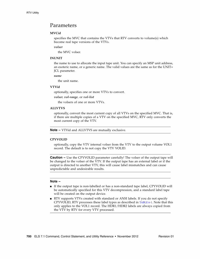
RTV Utility
700 ELS 7.1 Command, Control Statement, and Utility Reference • November 2012 Revision 01
ParametersMVCid
specifies the MVC that contains the VTVs that RTV converts to volume(s) which become real tape versions of the VTVs.
volser
the MVC volser.
INUNIT
the name to use to allocate the input tape unit. You can specify an MSP unit address, an esoteric name, or a generic name. The valid values are the same as for the UNIT= JCL parameter.
name
the unit name.
VTVid
optionally, specifies one or more VTVs to convert.
volser, vol-range, or vol-list
the volsers of one or more VTVs.
ALLVTVS
optionally, convert the most current copy of all VTVs on the specified MVC. That is, if there are multiple copies of a VTV on the specified MVC, RTV only converts the most current copy of the VTV.
Note – VTVid and ALLVTVS are mutually exclusive.
CPYVOLID
optionally, copy the VTV internal volser from the VTV to the output volume VOL1 record. The default is to not copy the VTV VOLID.
Caution – Use the CPYVOLID parameter carefully! The volser of the output tape will be changed to the volser of the VTV. If the output tape has an external label or if the output is directed to another VTV, this will cause label mismatches and can cause unpredictable and undesirable results.
Note – ■ If the output tape is non-labelled or has a non-standard tape label, CPYVOLID will
be automatically specified for this VTV decompression, and a standard label tape will be created on the output device.
■ RTV supports VTVs created with standard or ANSI labels. If you do not specify CPYVOLID, RTV processes these label types as described in TABLE 6-1. Note that this only applies to the VOL1 record. The HDR1/HDR2 labels are always copied from the VTV by RTV for every VTV processed.
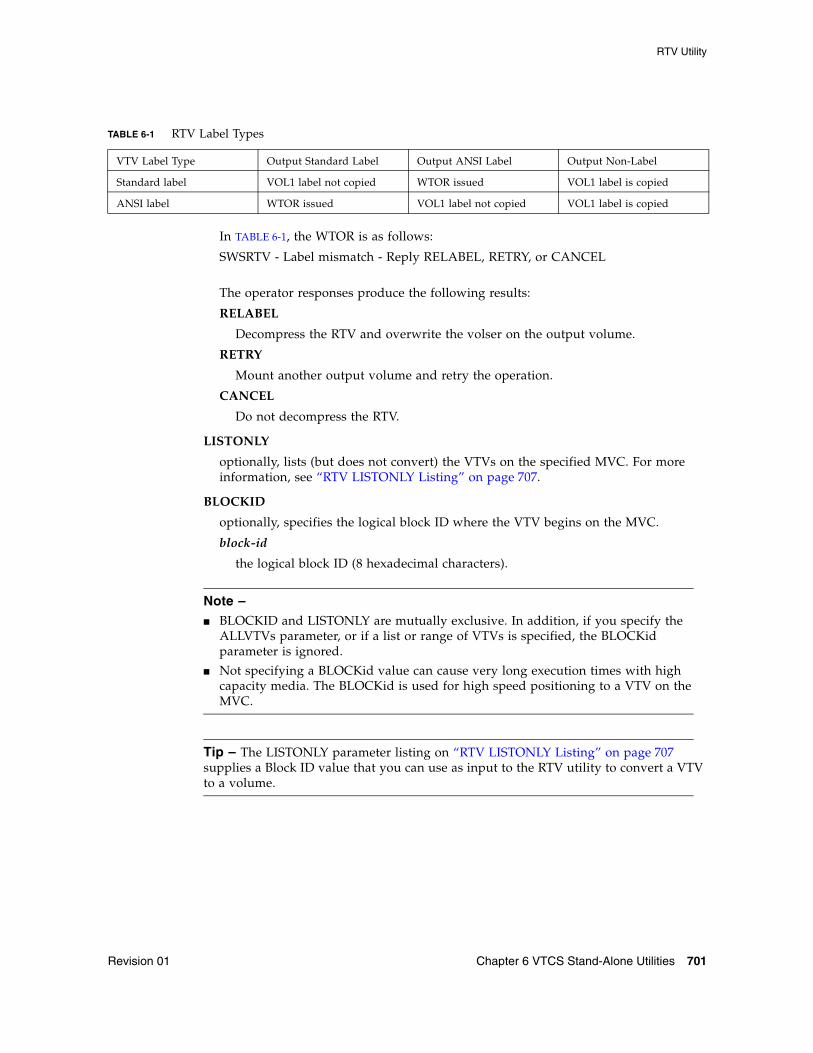
RTV Utility
Revision 01 Chapter 6 VTCS Stand-Alone Utilities 701
In TABLE 6-1, the WTOR is as follows:
SWSRTV - Label mismatch - Reply RELABEL, RETRY, or CANCEL
The operator responses produce the following results:
RELABEL
Decompress the RTV and overwrite the volser on the output volume.
RETRY
Mount another output volume and retry the operation.
CANCEL
Do not decompress the RTV.
LISTONLY
optionally, lists (but does not convert) the VTVs on the specified MVC. For more information, see “RTV LISTONLY Listing” on page 707.
BLOCKID
optionally, specifies the logical block ID where the VTV begins on the MVC.
block-id
the logical block ID (8 hexadecimal characters).
Note – ■ BLOCKID and LISTONLY are mutually exclusive. In addition, if you specify the
ALLVTVs parameter, or if a list or range of VTVs is specified, the BLOCKid parameter is ignored.
■ Not specifying a BLOCKid value can cause very long execution times with high capacity media. The BLOCKid is used for high speed positioning to a VTV on the MVC.
Tip – The LISTONLY parameter listing on “RTV LISTONLY Listing” on page 707 supplies a Block ID value that you can use as input to the RTV utility to convert a VTV to a volume.
TABLE 6-1 RTV Label Types
VTV Label Type Output Standard Label Output ANSI Label Output Non-Label
Standard label VOL1 label not copied WTOR issued VOL1 label is copied
ANSI label WTOR issued VOL1 label not copied VOL1 label is copied
RTV Utility
702 ELS 7.1 Command, Control Statement, and Utility Reference • November 2012 Revision 01
PRTID
optionally, specifies the partition id of the VTV being recovered from a partitioned MVC.
partition-id
the hexadecimal partition ID
Note – ■ If PRTID is specified, BLOCKid must also be specified.
■ PRTID and LISTONLY are mutually exclusive. In addition, if you specify the ALLVTVs parameter, or if a list or range of VTVs is specified, the BLOCKid parameter is ignored.
DUMP
produce a S0C3 abend dump if RTV cannot decompress a VTV. If you specify DUMP, create a SYSMDUMP DD JCL statement to capture the dump.
OUTUNIT
the name to use to allocate the output tape unit. You can specify an MSP unit address, an esoteric name, or a generic name. The valid values are the same as for the UNIT= JCL parameter. This parameter is required if you do not specify LISTONLY.
name
the unit name.
VALIDATE
Validates that the RTV utility can successfully process the specified VTV(s) without creating an output tape.
JCL RequirementsThe following are required or optional statements for the RTV utility JCL:
STEPLIB
specifies the link library (SEALINK) that contains the RTV modules.
SLSPRINT
specifies the destination of the RTV utility report.
SLSIN
specifies the input to the SWSRTV program (RTV utility name and parameters).
SYSMDUMP
optional DD to capture dump.
Note – Because the RTV utility must be capable of rewriting the tape standard labels on the output unit and positioning over label information on the input unit, Dynamic Allocation is used to invoke bypass label processing (BLP) on the tape volumes. This requires that the library that contains the SWSRTV executable code be APF authorized.
RTV Utility
Revision 01 Chapter 6 VTCS Stand-Alone Utilities 703
RTV Utility Report MessagesThe RTV report displays the following messages:
Block number too large in compressed data
Explanation: An error was found in a compressed data record while processing a VTV. Further processing of this VTV is stopped. The VTV will be marked in the RTV Decompress Report output. The utility will continue to process other VTVs as necessary.
Chunked record logic error
Explanation: An error was found while processing a chunked data record for a VTV. Further processing of this VTV is stopped. The VTV will be marked in the RTV Decompress Report output. The utility will continue to process other VTVs as necessary.
Decompress invalid length parameter
Explanation: This indicates a program logic error. Further processing of this VTV is stopped. The VTV will be marked in the RTV Decompress Report output. The utility will continue to process other VTVs as necessary.
Decompress invalid parameter list
Explanation: This indicates a program logic error. Further processing of this VTV is stopped. The VTV will be marked in the RTV Decompress Report output. The utility will continue to process other VTVs as necessary.
Decompress logic error
Explanation: This indicates a program logic error. Further processing of this VTV is stopped. The VTV will be marked in the RTV Decompress Report output. The utility will continue to process other VTVs as necessary.
Decompress pointer to work area is zero
Explanation: This indicates a program logic error. Further processing of this VTV is stopped. The VTV will be marked in the RTV Decompress Report output. The utility will continue to process other VTVs as necessary.
Dynamic allocation error. Reason Code = xxxx-xxxx
Explanation: An error was encountered while attempting to dynamically allocate the INUNIT or OUTUNIT device. Refer to the IBM MSP Authorized Assembler Services Guide for a description of the dynamic allocation reason codes.
I/O error on input MVC
Explanation: An I/O error was encountered while reading a MVC. Further processing is stopped. The utility terminates with return code 12.
RTV Utility
704 ELS 7.1 Command, Control Statement, and Utility Reference • November 2012 Revision 01
I/O error on output volume
Explanation: An I/O error was encountered while writing the output VTV. Further processing of this VTV is stopped. The VTV will be marked in the RTV Decompress Report output. The utility will continue to process other VTVs as necessary.
Invalid compressed data block read
Explanation: This indicates that an invalid data record was found while processing this VTV. Further processing of this VTV is stopped. The VTV will be marked in the RTV Decompress Report output. The utility will continue to process other VTVs as necessary.
Invalid VTV page number encountered
Explanation: A record sequence error was found in a compressed data record while processing a VTV. Further processing of this VTV is stopped. The VTV will be marked in the RTV Decompress Report output. The utility will continue to process other VTVs as necessary.
Invalid VTV record encountered
Explanation: An error was found in a compressed data record while processing a VTV. Further processing of this VTV is stopped. The VTV will be marked in the RTV Decompress Report output. The utility will continue to process other VTVs as necessary.
MVC volser # does not match requested volser #
Explanation: The volume mounted as the input MVC did not match that requested by the MVCid() parameter. The utility terminates with return code 12.
MVC record length error
Explanation: A length error was found in a compressed data record while processing a VTV. Further processing of this VTV is stopped. The VTV will be marked in the RTV Decompress Report output. The utility will continue to process other VTVs as necessary.
Incorrect algo byte
Explanation: Explanation: An error was found in a compressed data record while processing a VTV. Further processing of this VTV is stopped. The VTV will be marked in the RTV Decompress Report output. The utility will continue to process other VTVs as necessary.
RTV Utility
Revision 01 Chapter 6 VTCS Stand-Alone Utilities 705
No HDR1 record found for requested VTV
Explanation: Following positioning by a BLOCKid() statement, there was no HDR1 record located at the desired position. Remove the BLOCKid statement and rerun the utility. The utility terminates with return code 12.
No HDR1 record found on input MVC
Explanation: The volume mounted as a MVC contained no HDR1 record. The utility terminates with return code 12.
No UHL1 record found on input MVC
Explanation: The volume mounted as a MVC contained no UHL1 record. The utility terminates with return code 12.
No VOL1 record found on input MVC
Explanation: The volume mounted as a MVC contained no VOL1 record. The utility terminates with return code 12.
NULL input buffer pointer
Explanation: This indicates a program logic error. Further processing of this VTV is stopped. The VTV will be marked in the RTV Decompress Report output. The utility will continue to process other VTVs as necessary.
NULL output buffer pointer
Explanation: This indicates a program logic error. Further processing of this VTV is stopped. The VTV will be marked in the RTV Decompress Report output. The utility will continue to process other VTVs as necessary.
Requested VTV not found on MVC
Explanation: The volser requested by the VTVid() parameter was not found on the MVC. The utility terminates with return code 12.
Spanned length final error
Explanation: An error was found while processing a spanned data record for a VTV. Further processing of this VTV is stopped. The VTV will be marked in the RTV Decompress Report output. The utility will continue to process other VTVs as necessary.
Spanned length intermediate error
Explanation: An error was found while processing a spanned data record for a VTV. Further processing of this VTV is stopped. The VTV will be marked in the RTV Decompress Report output. The utility will continue to process other VTVs as necessary.
RTV Utility
706 ELS 7.1 Command, Control Statement, and Utility Reference • November 2012 Revision 01
Unexpected request on input I/O
Explanation: This indicates a program logic error. Further processing is stopped. The utility terminates with return code 12.
Unexpected end of tape on output volume
Explanation: While writing the output VTV, an end of tape indication was encountered. The VTV must be completely contained on a single output volume. Further processing of this VTV is stopped. The VTV will be marked in the RTV Decompress Report output. The utility will continue to process other VTVs as necessary.
Unexpected request on output I/O
Explanation: This indicates a program logic error. Further processing of this VTV is stopped. The VTV will be marked in the RTV Decompress Report output. The utility will continue to process other VTVs as necessary.
Unexpected tape mark on input MVC
Explanation: An unexpected tape mark was found on a MVC. Further processing is stopped. The utility terminates with return code 12.
VTVid range parameter is invalid
Explanation: An invalid range value was found in the VTVid() specification. The utility terminates with return code 12.
VTV logical data check encountered
Explanation: A data check indicator was found in a compressed data record while processing a VTV. Further processing of this VTV is stopped. The VTV will be marked in the RTV Decompress Report output. The utility will continue to process other VTVs as necessary.
VTV volser # does not match requested volser #
Explanation: Following positioning by a BLOCKid statement, the VTV volser did not match that requested by the VTVid() parameter. The utility terminates with return code 12. Remove the BLOCKid statement and rerun the utility.
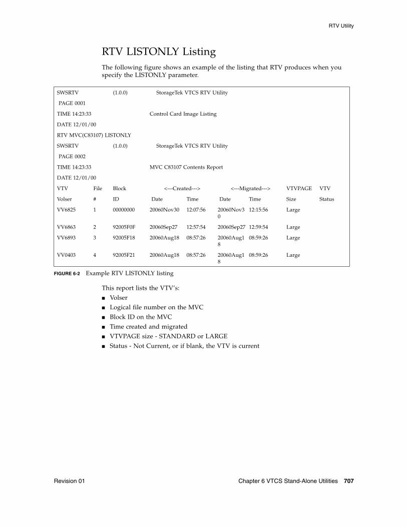
RTV Utility
Revision 01 Chapter 6 VTCS Stand-Alone Utilities 707
RTV LISTONLY ListingThe following figure shows an example of the listing that RTV produces when you specify the LISTONLY parameter.
FIGURE 6-2 Example RTV LISTONLY listing
This report lists the VTV’s:
■ Volser
■ Logical file number on the MVC
■ Block ID on the MVC
■ Time created and migrated
■ VTVPAGE size - STANDARD or LARGE
■ Status - Not Current, or if blank, the VTV is current
SWSRTV (1.0.0) StorageTek VTCS RTV Utility
PAGE 0001
TIME 14:23:33 Control Card Image Listing
DATE 12/01/00
RTV MVC(C83107) LISTONLY
SWSRTV (1.0.0) StorageTek VTCS RTV Utility
PAGE 0002
TIME 14:23:33 MVC C83107 Contents Report
DATE 12/01/00
VTV File Block <---Created---> <---Migrated---> VTVPAGE VTV
Volser # ID Date Time Date Time Size Status
VV6825 1 00000000 20060Nov30 12:07:56 20060Nov30
12:15:56 Large
VV6863 2 92005F0F 20060Sep27 12:57:54 20060Sep27 12:59:54 Large
VV6893 3 92005F18 20060Aug18 08:57:26 20060Aug18
08:59:26 Large
VV0403 4 92005F21 20060Aug18 08:57:26 20060Aug18
08:59:26 Large
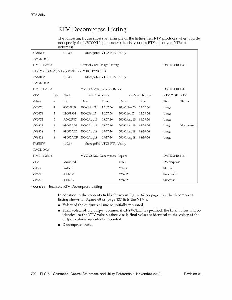
RTV Utility
708 ELS 7.1 Command, Control Statement, and Utility Reference • November 2012 Revision 01
RTV Decompress ListingThe following figure shows an example of the listing that RTV produces when you do not specify the LISTONLY parameter (that is, you run RTV to convert VTVs to volumes).
FIGURE 6-3 Example RTV Decompress Listing
In addition to the contents fields shown in Figure 67 on page 136, the decompress listing shown in Figure 68 on page 137 lists the VTV’s:
■ Volser of the output volume as initially mounted
■ Final volser of the output volume; if CPYVOLID is specified, the final volser will be identical to the VTV volser, otherwise is final volser is identical to the volser of the output volume as initially mounted
■ Decompress status
SWSRTV (1.0.0) StorageTek VTCS RTV Utility
PAGE 0001
TIME 14:28:33 Control Card Image Listing DATE 2010-1-31
RTV MVC(C8228) VTV(VV6800-VV6900) CPYVOLID
SWSRTV (1.0.0) StorageTek VTCS RTV Utility
PAGE 0002
TIME 14:28:33 MVC C83223 Contents Report DATE 2010-1-31
VTV File Block <---Created---> <---Migrated---> VTVPAGE VTV
Volser # ID Date Time Date Time Size Status
VV6070 1 00000000 20060Nov30 12:07:56 20060Nov30 12:15:56 Large
VV0874 2 2B001384 20060Sep27 12:57:54 20060Sep27 12:59:54 Large
VV0772 3 A3002707 20060Aug18 08:57:26 20060Aug18 08:59:26 Large
VV6828 4 9B002AB9 20060Aug18 08:57:26 20060Aug18 08:59:26 Large Not current
VV6828 5 9B002AC2 20060Aug18 08:57:26 20060Aug18 08:59:26 Large
VV6826 6 9B002ACB 20060Aug18 08:57:26 20060Aug18 08:59:26 Large
SWSRTV (1.0.0) StorageTek VTCS RTV Utility
PAGE 0003
TIME 14:28:33 MVC C83223 Decompress Report DATE 2010-1-31
VTV Mounted Final Decompress
Volser Volser Volser Status
VV6826 XX0772 VV6826 Successful
VV6828 XX0773 VV6828 Successful
Revision 01 709
APPENDIX
A
MEDia, RECtech, and MODel Values
This appendix provides values for MEDia, RECtech, and MODel parameters. These parameters are used to specify drive and media characteristics. They are specified in various ELS commands and control statements.
Note – ■ The SL8500 library supports only the T9840A/B/C/D, T9940B, LTO, SDLT, and
T10000A/B/C media types and recording techniques.
■ The SL3000 library supports only the T9840C/D, LTO, SDLT, and T10000A/B/C media types and recording techniques.
■ LTO and SDLT drives are not supported in an MSP environment. These drives are recognized by the HSC but are accessible only to open systems clients using LibraryStation.
Media Type (MEDia)The Media type is used to specify the desired type of media to be used for a data set.It is specified in the following ELS commands and control statements:
SMC:
■ POLicy operator command■ TAPEREQ control statement
HSC/VTCS:
■ Display Drives command■ Display SCRatch command■ Display THReshld command■ EJect command■ SCREdist command■ Warn command■ VOLPARM control statement
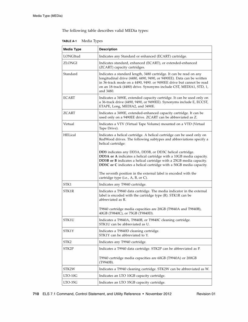
Media Type (MEDia)
710 ELS 7.1 Command, Control Statement, and Utility Reference • November 2012 Revision 01
The following table describes valid MEDia types:
TABLE A-1 Media Types
Media Type Description
LONGItud Indicates any Standard or enhanced (ECART) cartridge.
ZLONGI Indicates standard, enhanced (ECART), or extended-enhanced (ZCART) capacity cartridges.
Standard Indicates a standard length, 3480 cartridge. It can be read on any longitudinal drive (4480, 4490, 9490, or 9490EE). Data can be written in 36-track mode on a 4490, 9490. or 9490EE drive but cannot be read on an 18-track (4480) drive. Synonyms include CST, MEDIA1, STD, 1, and 3480.
ECART Indicates a 3490E, extended capacity cartridge. It can be used only on a 36-track drive (4490, 9490, or 9490EE). Synonyms include E, ECCST, ETAPE, Long, MEDIA2, and 3490E.
ZCART Indicates a 3490E, extended-enhanced capacity cartridge. It can be used only on a 9490EE drive. ZCART can be abbreviated as Z.
Virtual Indicates a VTV (Virtual Tape Volume) mounted on a VTD (Virtual Tape Drive).
HELical Indicates a helical cartridge. A helical cartridge can be used only on RedWood drives. The following subtypes and abbreviations specify a helical cartridge:DD3 indicates any DD3A, DD3B, or DD3C helical cartridge.DD3A or A indicates a helical cartridge with a 10GB media capacity.DD3B or B indicates a helical cartridge with a 25GB media capacity.DD3C or C indicates a helical cartridge with a 50GB media capacity.The seventh position in the external label is encoded with the cartridge type (i.e., A, B, or C).
STK1 Indicates any T9840 cartridge.
STK1R Indicates a T9840 data cartridge. The media indicator in the external label is encoded with the cartridge type (R). STK1R can be abbreviated as R.
T9840 cartridge media capacities are 20GB (T9840A and T9840B), 40GB (T9840C), or 75GB (T9840D).
STK1U Indicates a T9840A, T9840B, or T9840C cleaning cartridge. STK1U can be abbreviated as U.
STK1Y Indicates a T9840D cleaning cartridge.STK1Y can be abbreviated to Y.
STK2 Indicates any T9940 cartridge.
STK2P Indicates a T9940 data cartridge. STK2P can be abbreviated as P.
T9940 cartridge media capacities are 60GB (T9940A) or 200GB (T9940B).
STK2W Indicates a T9940 cleaning cartridge. STK2W can be abbreviated as W.
LTO-10G Indicates an LTO 10GB capacity cartridge.
LTO-35G Indicates an LTO 35GB capacity cartridge.
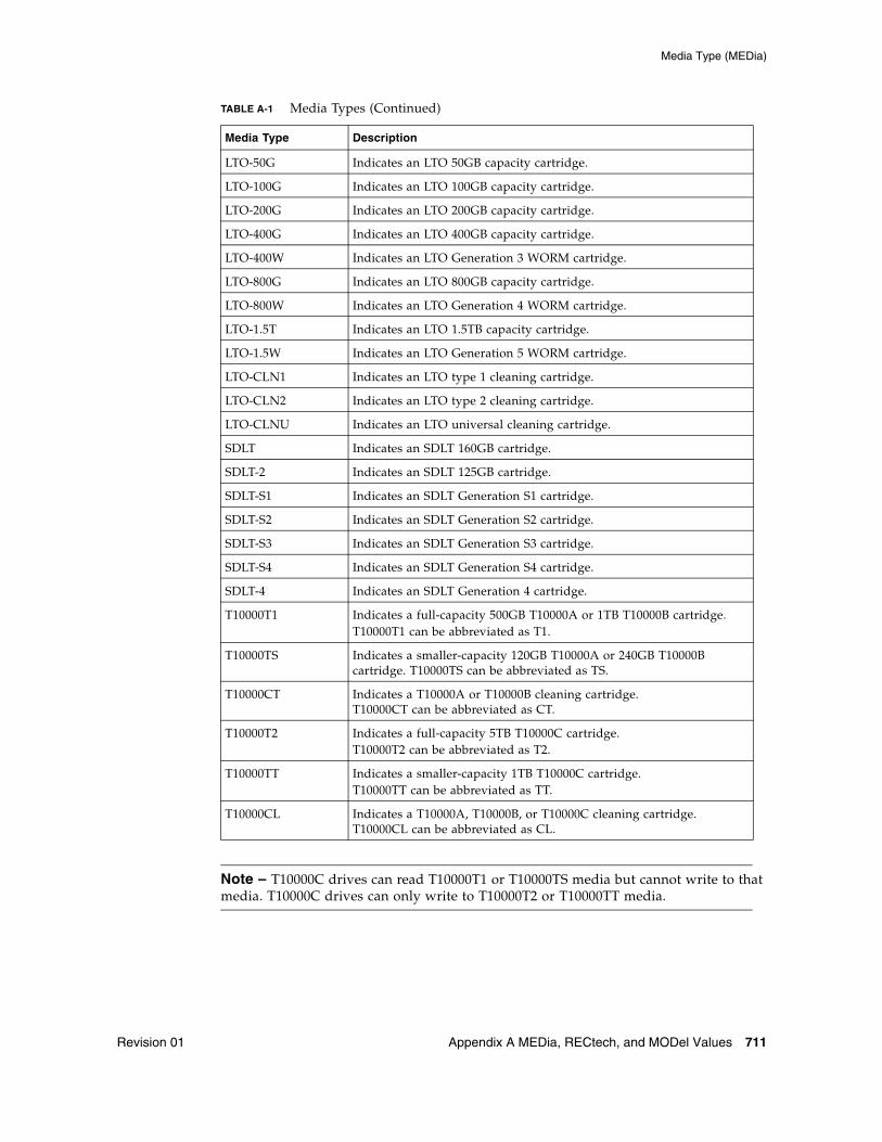
Media Type (MEDia)
Revision 01 Appendix A MEDia, RECtech, and MODel Values 711
Note – T10000C drives can read T10000T1 or T10000TS media but cannot write to that media. T10000C drives can only write to T10000T2 or T10000TT media.
LTO-50G Indicates an LTO 50GB capacity cartridge.
LTO-100G Indicates an LTO 100GB capacity cartridge.
LTO-200G Indicates an LTO 200GB capacity cartridge.
LTO-400G Indicates an LTO 400GB capacity cartridge.
LTO-400W Indicates an LTO Generation 3 WORM cartridge.
LTO-800G Indicates an LTO 800GB capacity cartridge.
LTO-800W Indicates an LTO Generation 4 WORM cartridge.
LTO-1.5T Indicates an LTO 1.5TB capacity cartridge.
LTO-1.5W Indicates an LTO Generation 5 WORM cartridge.
LTO-CLN1 Indicates an LTO type 1 cleaning cartridge.
LTO-CLN2 Indicates an LTO type 2 cleaning cartridge.
LTO-CLNU Indicates an LTO universal cleaning cartridge.
SDLT Indicates an SDLT 160GB cartridge.
SDLT-2 Indicates an SDLT 125GB cartridge.
SDLT-S1 Indicates an SDLT Generation S1 cartridge.
SDLT-S2 Indicates an SDLT Generation S2 cartridge.
SDLT-S3 Indicates an SDLT Generation S3 cartridge.
SDLT-S4 Indicates an SDLT Generation S4 cartridge.
SDLT-4 Indicates an SDLT Generation 4 cartridge.
T10000T1 Indicates a full-capacity 500GB T10000A or 1TB T10000B cartridge.T10000T1 can be abbreviated as T1.
T10000TS Indicates a smaller-capacity 120GB T10000A or 240GB T10000B cartridge. T10000TS can be abbreviated as TS.
T10000CT Indicates a T10000A or T10000B cleaning cartridge. T10000CT can be abbreviated as CT.
T10000T2 Indicates a full-capacity 5TB T10000C cartridge.T10000T2 can be abbreviated as T2.
T10000TT Indicates a smaller-capacity 1TB T10000C cartridge.T10000TT can be abbreviated as TT.
T10000CL Indicates a T10000A, T10000B, or T10000C cleaning cartridge. T10000CL can be abbreviated as CL.
TABLE A-1 Media Types (Continued)
Media Type Description
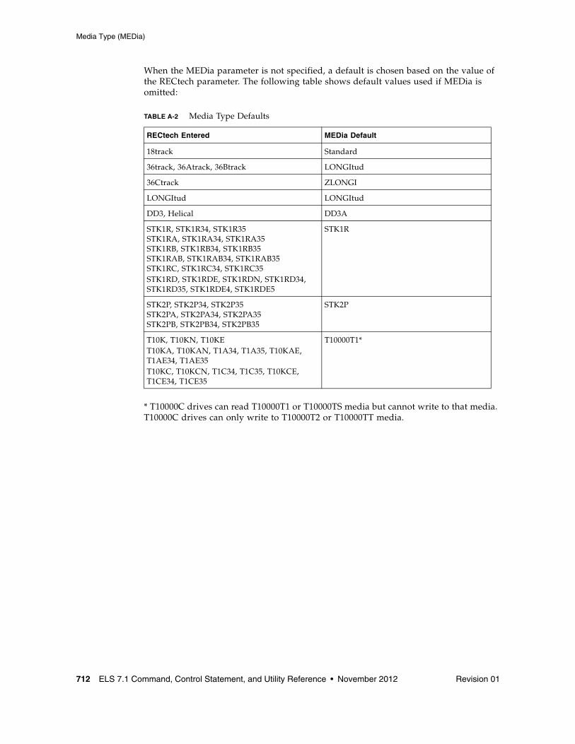
Media Type (MEDia)
712 ELS 7.1 Command, Control Statement, and Utility Reference • November 2012 Revision 01
When the MEDia parameter is not specified, a default is chosen based on the value of the RECtech parameter. The following table shows default values used if MEDia is omitted:
* T10000C drives can read T10000T1 or T10000TS media but cannot write to that media. T10000C drives can only write to T10000T2 or T10000TT media.
TABLE A-2 Media Type Defaults
RECtech Entered MEDia Default
18track Standard
36track, 36Atrack, 36Btrack LONGItud
36Ctrack ZLONGI
LONGItud LONGItud
DD3, Helical DD3A
STK1R, STK1R34, STK1R35 STK1RA, STK1RA34, STK1RA35STK1RB, STK1RB34, STK1RB35STK1RAB, STK1RAB34, STK1RAB35STK1RC, STK1RC34, STK1RC35STK1RD, STK1RDE, STK1RDN, STK1RD34, STK1RD35, STK1RDE4, STK1RDE5
STK1R
STK2P, STK2P34, STK2P35STK2PA, STK2PA34, STK2PA35STK2PB, STK2PB34, STK2PB35
STK2P
T10K, T10KN, T10KET10KA, T10KAN, T1A34, T1A35, T10KAE, T1AE34, T1AE35T10KC, T10KCN, T1C34, T1C35, T10KCE, T1CE34, T1CE35
T10000T1*
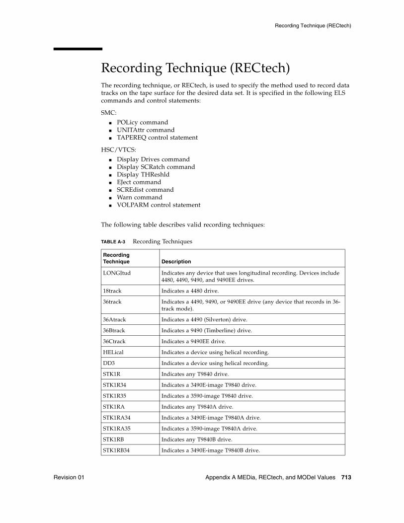
Recording Technique (RECtech)
Revision 01 Appendix A MEDia, RECtech, and MODel Values 713
Recording Technique (RECtech)The recording technique, or RECtech, is used to specify the method used to record data tracks on the tape surface for the desired data set. It is specified in the following ELS commands and control statements:
SMC:
■ POLicy command■ UNITAttr command■ TAPEREQ control statement
HSC/VTCS:
■ Display Drives command■ Display SCRatch command■ Display THReshld■ EJect command■ SCREdist command■ Warn command■ VOLPARM control statement
The following table describes valid recording techniques:
TABLE A-3 Recording Techniques
Recording Technique Description
LONGItud Indicates any device that uses longitudinal recording. Devices include 4480, 4490, 9490, and 9490EE drives.
18track Indicates a 4480 drive.
36track Indicates a 4490, 9490, or 9490EE drive (any device that records in 36-track mode).
36Atrack Indicates a 4490 (Silverton) drive.
36Btrack Indicates a 9490 (Timberline) drive.
36Ctrack Indicates a 9490EE drive.
HELical Indicates a device using helical recording.
DD3 Indicates a device using helical recording.
STK1R Indicates any T9840 drive.
STK1R34 Indicates a 3490E-image T9840 drive.
STK1R35 Indicates a 3590-image T9840 drive.
STK1RA Indicates any T9840A drive.
STK1RA34 Indicates a 3490E-image T9840A drive.
STK1RA35 Indicates a 3590-image T9840A drive.
STK1RB Indicates any T9840B drive.
STK1RB34 Indicates a 3490E-image T9840B drive.
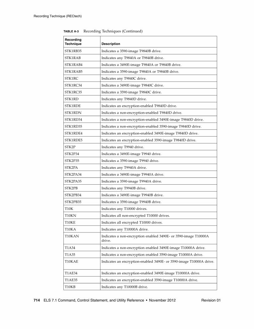
Recording Technique (RECtech)
714 ELS 7.1 Command, Control Statement, and Utility Reference • November 2012 Revision 01
STK1RB35 Indicates a 3590-image T9840B drive.
STK1RAB Indicates any T9840A or T9840B drive.
STK1RAB4 Indicates a 3490E-image T9840A or T9840B drive.
STK1RAB5 Indicates a 3590-image T9840A or T9840B drive.
STK1RC Indicates any T9840C drive.
STK1RC34 Indicates a 3490E-image T9840C drive.
STK1RC35 Indicates a 3590-image T9840C drive.
STK1RD Indicates any T9840D drive.
STK1RDE Indicates an encryption-enabled T9840D drive.
STK1RDN Indicates a non-encryption-enabled T9840D drive.
STK1RD34 Indicates a non-encryption-enabled 3490E-image T9840D drive.
STK1RD35 Indicates a non-encryption-enabled 3590-image T9840D drive.
STK1RDE4 Indicates an encryption-enabled 3490E-image T9840D drive.
STK1RDE5 Indicates an encryption-enabled 3590-image T9840D drive.
STK2P Indicates any T9940 drive.
STK2P34 Indicates a 3490E-image T9940 drive.
STK2P35 Indicates a 3590-image T9940 drive.
STK2PA Indicates any T9940A drive.
STK2PA34 Indicates a 3490E-image T9940A drive.
STK2PA35 Indicates a 3590-image T9940A drive.
STK2PB Indicates any T9940B drive.
STK2PB34 Indicates a 3490E-image T9940B drive.
STK2PB35 Indicates a 3590-image T9940B drive.
T10K Indicates any T10000 drives.
T10KN Indicates all non-encrypted T10000 drives.
T10KE Indicates all encrypted T10000 drives.
T10KA Indicates any T10000A drive.
T10KAN Indicates a non-encryption enabled 3490E- or 3590-image T10000A drive.
T1A34 Indicates a non-encryption enabled 3490E-image T10000A drive.
T1A35 Indicates a non-encryption enabled 3590-image T10000A drive.
T10KAE Indicates an encryption-enabled 3490E- or 3590-image T10000A drive.
T1AE34 Indicates an encryption-enabled 3490E-image T10000A drive.
T1AE35 Indicates an encryption-enabled 3590-image T10000A drive.
T10KB Indicates any T10000B drive.
TABLE A-3 Recording Techniques (Continued)
Recording Technique Description
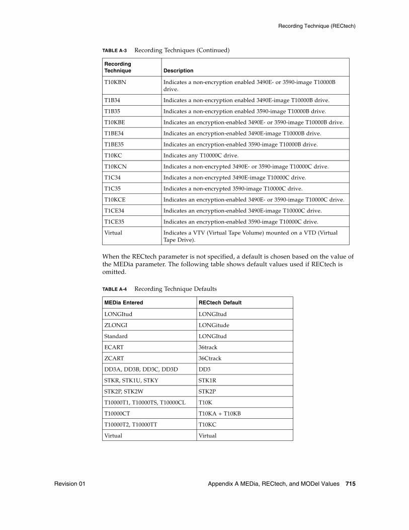
Recording Technique (RECtech)
Revision 01 Appendix A MEDia, RECtech, and MODel Values 715
When the RECtech parameter is not specified, a default is chosen based on the value of the MEDia parameter. The following table shows default values used if RECtech is omitted.
T10KBN Indicates a non-encryption enabled 3490E- or 3590-image T10000B drive.
T1B34 Indicates a non-encryption enabled 3490E-image T10000B drive.
T1B35 Indicates a non-encryption enabled 3590-image T10000B drive.
T10KBE Indicates an encryption-enabled 3490E- or 3590-image T10000B drive.
T1BE34 Indicates an encryption-enabled 3490E-image T10000B drive.
T1BE35 Indicates an encryption-enabled 3590-image T10000B drive.
T10KC Indicates any T10000C drive.
T10KCN Indicates a non-encrypted 3490E- or 3590-image T10000C drive.
T1C34 Indicates a non-encrypted 3490E-image T10000C drive.
T1C35 Indicates a non-encrypted 3590-image T10000C drive.
T10KCE Indicates an encryption-enabled 3490E- or 3590-image T10000C drive.
T1CE34 Indicates an encryption-enabled 3490E-image T10000C drive.
T1CE35 Indicates an encryption-enabled 3590-image T10000C drive.
Virtual Indicates a VTV (Virtual Tape Volume) mounted on a VTD (Virtual Tape Drive).
TABLE A-4 Recording Technique Defaults
MEDia Entered RECtech Default
LONGItud LONGItud
ZLONGI LONGitude
Standard LONGItud
ECART 36track
ZCART 36Ctrack
DD3A, DD3B, DD3C, DD3D DD3
STKR, STK1U, STKY STK1R
STK2P, STK2W STK2P
T10000T1, T10000TS, T10000CL T10K
T10000CT T10KA + T10KB
T10000T2, T10000TT T10KC
Virtual Virtual
TABLE A-3 Recording Techniques (Continued)
Recording Technique Description
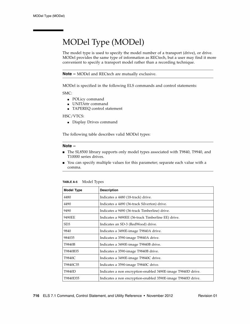
MODel Type (MODel)
716 ELS 7.1 Command, Control Statement, and Utility Reference • November 2012 Revision 01
MODel Type (MODel)The model type is used to specify the model number of a transport (drive), or drive. MODel provides the same type of information as RECtech, but a user may find it more convenient to specify a transport model rather than a recording technique.
Note – MODel and RECtech are mutually exclusive.
MODel is specified in the following ELS commands and control statements:
SMC:
■ POLicy command■ UNITAttr command■ TAPEREQ control statement
HSC/VTCS:
■ Display Drives command
The following table describes valid MODel types:
Note – ■ The SL8500 library supports only model types associated with T9840, T9940, and
T10000 series drives.
■ You can specify multiple values for this parameter; separate each value with a comma.
TABLE A-5 Model Types
Model Type Description
4480 Indicates a 4480 (18-track) drive.
4490 Indicates a 4490 (36-track Silverton) drive.
9490 Indicates a 9490 (36-track Timberline) drive.
9490EE Indicates a 9490EE (36-track Timberline EE) drive.
SD3 Indicates an SD-3 (RedWood) drive.
9840 Indicates a 3490E-image T9840A drive.
984035 Indicates a 3590-image T9840A drive.
T9840B Indicates a 3490E-image T9840B drive.
T9840B35 Indicates a 3590-image T9840B drive.
T9840C Indicates a 3490E-image T9840C drive.
T9840C35 Indicates a 3590-image T9840C drive.
T9840D Indicates a non encryption-enabled 3490E-image T9840D drive.
T9840D35 Indicates a non encryption-enabled 3590E-image T9840D drive.
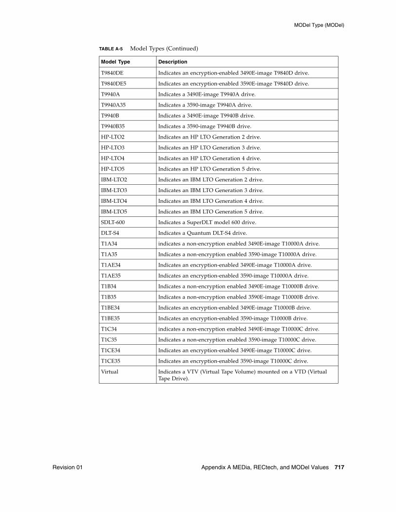
MODel Type (MODel)
Revision 01 Appendix A MEDia, RECtech, and MODel Values 717
T9840DE Indicates an encryption-enabled 3490E-image T9840D drive.
T9840DE5 Indicates an encryption-enabled 3590E-image T9840D drive.
T9940A Indicates a 3490E-image T9940A drive.
T9940A35 Indicates a 3590-image T9940A drive.
T9940B Indicates a 3490E-image T9940B drive.
T9940B35 Indicates a 3590-image T9940B drive.
HP-LTO2 Indicates an HP LTO Generation 2 drive.
HP-LTO3 Indicates an HP LTO Generation 3 drive.
HP-LTO4 Indicates an HP LTO Generation 4 drive.
HP-LTO5 Indicates an HP LTO Generation 5 drive.
IBM-LTO2 Indicates an IBM LTO Generation 2 drive.
IBM-LTO3 Indicates an IBM LTO Generation 3 drive.
IBM-LTO4 Indicates an IBM LTO Generation 4 drive.
IBM-LTO5 Indicates an IBM LTO Generation 5 drive.
SDLT-600 Indicates a SuperDLT model 600 drive.
DLT-S4 Indicates a Quantum DLT-S4 drive.
T1A34 indicates a non-encryption enabled 3490E-image T10000A drive.
T1A35 Indicates a non-encryption enabled 3590-image T10000A drive.
T1AE34 Indicates an encryption-enabled 3490E-image T10000A drive.
T1AE35 Indicates an encryption-enabled 3590-image T10000A drive.
T1B34 Indicates a non-encryption enabled 3490E-image T10000B drive.
T1B35 Indicates a non-encryption enabled 3590E-image T10000B drive.
T1BE34 Indicates an encryption-enabled 3490E-image T10000B drive.
T1BE35 Indicates an encryption-enabled 3590-image T10000B drive.
T1C34 indicates a non-encryption enabled 3490E-image T10000C drive.
T1C35 Indicates a non-encryption enabled 3590-image T10000C drive.
T1CE34 Indicates an encryption-enabled 3490E-image T10000C drive.
T1CE35 Indicates an encryption-enabled 3590-image T10000C drive.
Virtual Indicates a VTV (Virtual Tape Volume) mounted on a VTD (Virtual Tape Drive).
TABLE A-5 Model Types (Continued)
Model Type Description

Revision 01 719
APPENDIX
B
Library Identification
Each ACS, LSM, and CAP is assigned a unique identification number during LIBGEN. Use this number in ELS commands and utilities to identify a specific ACSid, LSMid, or CAPid.
ACSidEach ACS is identified by an ACSid (acs-id), a two digit decimal identifier from 00-99.
The first ACS acquires an identifier of 00, the second ACS acquires and identifier of 01, and so forth until all ACSs are identified.
LSMidEach LSM is identified by an LSMid (lsm-id), consisting of an ACSid and LSM number separated by a colon The LSMid differentiates each LSM from every other LSM in a library.
The format is AA:LL, where:
■ AA is the ACSid, a two digit decimal identifier from 00-99.
■ LL is the LSM number, a two digit decimal identifier from 00-99.
CAPid
720 ELS 7.1 Command, Control Statement, and Utility Reference • November 2012 Revision 01
CAPidEach library CAP is identified by a CAPid (cap-id), consisting of an LSMid and CAP number separated by a colon. The format is AA:LL:CC, where:
■ AA:LL is the LSMid.
■ CC is the CAP number, a two digit decimal identifier from 00-11.
CAP Numbers00
■ For 4410 and 9310 LSMs, standard 21-cell CAP or the right-hand 40-cell enhanced CAP
■ For 9740 LSMs, fixed rack 14-cell or 10-cell removable magazine CAP
■ For SL3000 LSMs, this is a 234-cell AEM CAP
■ For SL8500 LSMs, the CAP consists of 3, 13-cell removable magazines.
01
■ For 4410 and 9310 LSMs, left-hand 40-cell enhanced CAP
■ For SL3000 LSMs, this is an optional CEM CAP consisting of 2, 13-cell removable magazines.
■ For SL8500 LSMs, this is an optional CAP consisting of 3, 13-cell removable magazines.
02
■ priority CAP (PCAP) for a 4410 or 9310 LSM enhanced CAP
■ For SL3000 LSMs, this is an optional CEM CAP consisting of 2, 13-cell removable magazines.
■ For SL8500 LSMs, this is an optional CAP consisting of 3, 13-cell removable magazines.
03, 04, 05
■ For SL3000 LSMs, these are optional CEM/DEM CAPs consisting of 2, 13-cell removable magazines.
06
■ For SL3000 LSMs, this is the only required BDM CAP consisting of 2, 13-cell removable magazines.
07, 08, 09, 10
■ For SL3000 LSMs, these are an optional CEM CAPs consisting of 2, 13-cell removable magazines.
11
■ For SL3000 LSMs, this is a right-side AEM CAP, consisting of 18, 13-cell removable magazines.
■ For SL3000 LSMs, this is a 234-cell AEM CAP.

Panels, Rows and Columns
Revision 01 Appendix B Library Identification 721
Panels, Rows and ColumnsCertain ELS commands and utilities allow you to specify panels, rows, and columns within a library.
Panelspanel-list
Each panel-list element is a one or two digit decimal number, specific to the LSM type:
■ LSM Models 4410 and 9310 PowderHorn
■ 0-11 for outer wall panels ■ 12-19 for inner wall panels
■ LSM Model 9360 WolfCreek
■ 0-2 for Model 9360-050 ■ 0-3 for Model 9360-075 ■ 0-4 for Model 9360-100
■ LSM Model 9740 TimberWolf
■ 0-2 (panel 3 is included if the optional cells are present).
■ LSM Model SL3000 Library
■ Access Expansion Module (AEM optional) - panels 0-1 and 22-23 are located on both ends of the library and in this release serve only as library end caps.
■ Base Drive Module (BDM required) - panels 12-13
■ Drive Expansion Module (DEM optional) - panels 10-11 are located left of the BDM.
■ Cartridge Expansion Module (CEM optional) - panels 2-9 are located left of the BDM or optional DEM.
■ Cartridge Expansion Module (CEM optional) - panels 14-21 are located right of the BDM.
■ Parking Expansion Module (PEM) - Dual Robots only - panel numbers equate to the same panel numbers of the CEM it replaces, depending on its location right or left of the BDM.
Note – The SL3000 library has static panels numbers starting with the left-most back panel (panel 0) and ending with the right-most front panel (panel 23) on a fully-configured library. The panel numbering starts with the BDM, the only required module (panels 12 and 13), and works outward to the left and to the right.
■ LSM Model SL8500 Library
■ base library
■ 2-10
■ With one expansion panel
■ 2-18 (expansion panel is 8-15)
■ With two expansion panels
Panels, Rows and Columns
722 ELS 7.1 Command, Control Statement, and Utility Reference • November 2012 Revision 01
■ 2-26 (expansion panels are 8-23)
■ With three expansion panels
■ 2-34 (expansion panels are 8-31)
Rowsrow-list
Each row-list element is a one or two digit decimal number, specific to the LSM type:
■ LSM Models 4410 and 9310 PowderHorn
■ 0-14 for outer wall panels ■ 0-5 and 8-14 for inner wall panels. ■ The maximum list is 4 rows (approximately 100 cells).
■ LSM Model 9360 WolfCreek
■ 0-41 (all models). The maximum list is 20 rows (approximately 100 cells).
■ LSM Model 9740 TimberWolf
■ 0-41 on panels 0, 2, and 3■ 36-41 on panel 1
Note – ■ Column 3 on panel 2 allows row entries only on rows 28-41.
■ The cells on panel 3 are optional.
■ LSM Model SL3000 Library
■ Access Expansion Modules - panels 0-1 and 22-23 (no cells in this initial release)
■ Base Drive Module (BDM) - panel 12 (back)
■ 12-47 with 8 drives installed■ 23-47 with 16 drives installed■ 35-47 with 24 drives installed
■ Base Drive Module (BDM) - panel 13 (front)
■ 0-51 on the front panel
■ Drive Expansion Module (DEM) - panel 10 (back)
■ 12-47 available with 8 drives installed■ 23-47 available with 16 drives installed■ 35-47 available with 24 drives installed■ No rows available with 32 drives installed
■ Drive Expansion Module (DEM) - panel 11 (front)
■ 0-51 available on the front panel
■ Cartridge Expansion Modules (CEM) - all panels
■ 0-51 available on both front and back panels
■ Parking Expansion Module (PEM) - all panels
■ 0-51 available on the back and front panels
■ LSM Model SL8500 Library
■ 0-26 on a standard panel
■ 0-12 on a short panel (panels 4, 6-7)■ 6-12 on a PTP panel (panel 5)
Panels, Rows and Columns
Revision 01 Appendix B Library Identification 723
Columnscolumn-list
Each column-list element is a one or two digit decimal number, specific to the LSM type:
■ LSM Models 4410 and 9310 PowderHorn
■ 0-23 for outer wall panels ■ 0-19 for inner wall panels
■ LSM Model 9360 WolfCreek
■ 0-5 (all models).
■ LSM Model 9740 TimberWolf
■ 0-3 for panels 0, 2, and 3 (if the optional cells are present)■ 0-2 for panel 1
■ LSM Model SL3000 Library
■ Access Expansion Module (AEM) panels 0-1 and 22-23
■ No columns available in the initial release
■ Base Drive Module (BDM) - panel 12 (back)
■ 0 available, if a CEM or DEM is added to the left of the BDM■ 1-5 available for rows 12-47 with 8 drives installed■ 1-5 available for rows 23-47 with 16 drives installed■ 1-5 available for rows 35-47 with 24 drives installed
■ Base Drive Module (BDM) - panel 13 (front)
■ 0 available with expansion to the left of the BDM■ 5 available for rows 39-51 with expansion to the right of the BDM■ 1-3 available for rows 0-38 with a CAP installed■ 1-4 available for rows 39-51 with a CAP installed■ 1-3 not available for rows 9-16 with optional window/Operator panel installed
■ Drive Expansion Module (DEM) - panel 10 (back)
■ 0 is available with expansion to the left of the DEM■ 1-5 available for rows 12-47 with 8 drives installed■ 1-5 available for rows 23-47 with 16 drives installed■ 1-5 available for rows 35-47 with 24 drives installed■ No columns available with 32 drives installed.
■ Drive Expansion Module (DEM) - panel 11 (front)
■ 0 available with expansion to the left DEM■ 1-3 available for rows 0-38 with a CAP installed■ 1-5 available for rows 39-51, with a CAP installed■ 1-3 not available for rows 9-16 with a window installed■ 1-5 available for rows 0-51 on a standard DEM panel
■ Cartridge Expansion Module (CEM) - panels 2, 4, 6, 8 (back)
■ 0 available with expansion to the left■ 1- 5 available on the standard CEM back panel
■ Cartridge Expansion Module (CEM) - panels 3, 5, 7, 9 (front)
■ 0 available with expansion to the left■ 1-3 available for rows 0-38 with a CAP installed■ 1-4 available for rows 39-51, with a CAP installed■ 1-4 available on the standard CEM front panel
Panels, Rows and Columns
724 ELS 7.1 Command, Control Statement, and Utility Reference • November 2012 Revision 01
■ Cartridge Expansion Module (CEM) - panels 14, 16, 18, 20 (back)
■ 0-5 available on the standard CEM back panel
■ Cartridge Expansion Module (CEM) - panels 15, 17, 19, 21 (front)
■ 0-3 available for rows 0-38 with a CAP installed■ 0-5 available for rows 39-51 with a CAP installed■ 0-5 available on the standard CEM front panel
■ Parking Expansion Module (PEM) - left side PEM
■ 3-5 available on the back and front panels with a second robot installed
■ Parking Expansion Module (PEM) - right side PEM
■ 0-2 available on the back and front panels with a second robot installed
■ LSM Model SL8500 Library
■ 0-1 for all panel types
Note – All SL3000 columns are numbered 0-5 (left to right).
Revision 01 725
APPENDIX
C
Tape Management System Interface (SLUDR*) Routines
This appendix describes TMS (Tape Management System) interface routines called by the HSC SLUCONDB utility and SMC SMCUDBX utility. These utilities call the appropriate routine based on the tape management system being used.
Routines include the following:
■ SLUDRCA1■ SLUDRRMM■ SLUDRTLM■ SLUDRSMC■ SLUDRZAR
These routines are included in the SEALINK library generated during ELS installation. The data returned from these routines is used to format the SMC scratch extract file.
SLUDRCA1The SLUDRCA1 routine is called to read the CA-1 Tape Management Catalog (TMC) when CA-1 is defined as the tape management system. SLUDRCA1 utilizes CA-1 macros to map the layout of the CA-1 TMC.
The macro names which map the CA-1 TMC have changed from Release 4.9 to Release 5.0. Both macros are located at the end of the SLUDRCA1 routine with the CA-1 Release 4.9 macro as a comment. The version of SLUDRCA1 supplied in SAMPLIB utilizes CA-1 Release 5.0 macro and was assembled using this macro.
■ If you are using CA-1 Release 4.9 or earlier, you must comment out the Release 5.0 macro, remove the asterisk in column 1 of the Release 4.9 macro, and reassemble this module. Make sure the appropriate CA-1 macro library is used in the assemble SYSLIB concatenation.
■ If you are running CA-1 Release 5.0 without any local modifications, this module does not need to be reassembled and nothing further must be done to this module. If you have local modifications, you must reassemble this module.
SLUDRRMM
726 ELS 7.1 Command, Control Statement, and Utility Reference • November 2012 Revision 01
SLUDRRMMThe SLUDRRMM routine is called to read the DFSMSrmm report extract file when DFSMSrmm is defined as the tape management system. SLUDRRMM uses the DFSMSrmm EDGRVEXT macro to map the layout of the report extract file.
Fields read in the extract file include:
■ RVTYPE (record type)■ RVVOLSER (volser number)■ RVLCDATE (last change date)■ RVNAME (unit type)■ RVSTATUS (volume status)■ RVEXPDT (volume expiration date)■ RVEXPDTO (volume original expiration date)■ RVLABEL (volume label type).
SLUDRRMM processes the extract and passes the volume record information to SLUCONDB, which builds scratch card images to be input to SLUADMIN. Volume scratch status (scratch/nonscratch) is then updated in the CDS for each volume record in the extract file.
Dates on the RMM report must be in Julian date format (EDGHSKP run with PARM ‘DATEFORM(J)’). Tapes listed on the RMM report without expiration dates are skipped by SLUDRRMM.
SLUDRSMCThe SLUDRSMC routine is called to read the extract file created by the SMCUDBX utility from a client tape management system. This file includes one record for every scratch volume extracted that contains the volume serial number and the time of the extract run.
During execution, correct scratch synchronization is provided by matching the time (in GMT format) of the scratch extract run with the volume’s “last select time.” Any volume selected after the scratch selection run is skipped in SLUCONDB processing.
SLUDRTLMThe SLUDRTLM routine is called to read the CA-DYNAM/TLMS Volume Master File (VMF) when CA-DYNAM/TLMS is defined as the tape management system. SLUDRTLM utilizes a CA-DYNAM/TLMS COPY member to map the layout of the VMF.
SLUDRTLM must be re-assembled if you are running TLMS Release 5.4 or if you have local modifications. If you re-assemble this module, make sure the appropriate CA-DYNAM/TLMS source library is used in the assemble SYSLIB concatenation.
SLUDRZAR
Revision 01 Appendix C Tape Management System Interface (SLUDR*) Routines 727
SLUDRZARThe SLUDRZAR routine is called to invoke an application programming interface (API) to read Zara’s database when Zara is defined as the tape management system.

Revision 01 729
Glossary
This glossary defines terms and abbreviations used in this publication.
Aabnormal end of task (abend) A software or hardware problem that terminates a computer processing task.
access method A technique for moving data between processor storage and input/output devices.
ACSid A method used in the LIBGEN process to identify ACSs by using decimal digits, 00 to 99.
ACS See Automated Cartridge System.
ACS library A library is composed of one or more Automated Cartridge Systems (ACSs), attached cartridge drives, and cartridges residing in the ACSs.
ACS routine An SMS term, referring to automatic class selection routine. Not to be confused with the HSC term, ACS, referring to automatic cartridge system.
address Coded representation of hardware id, or the destination or origination of data.
allocation The assignment of resources to a specific task.
AMT Automatic Migration Threshold.
APF Authorized Program Facility.
APPL VTAM APPLID definition for the HSC.
archiving The storage of backup files and associated journals, usually for a given period of time.
asynchronous transmission Character-oriented data transmission (as distinct from IBM’s block-mode transmission).
audit A VSM audit (which is not the same as an HSC audit) reconstructs VTV and MVC information.
730 ELS 7.1 Command, Control Statement, and Utility Reference • November 2012 Revision 01
Automated Cartridge System (ACS) A fully-automated, cartridge storage and retrieval library subsystem consisting of one or more Library Storage Modules (LSMs) connected by pass-thru ports.
Automated Cartridge System Library Software (ACSLS) The library control software, which runs in the UNIX®-based Library Control System.
automatic mode A relationship between an LSM and all attached hosts. LSMs operating in automatic mode handle cartridges without operator intervention. This is the normal operating mode of an LSM that has been modified online. The opposite situation is “manual mode.” See manual mode.
automatic migration Migrating VTVs to MVCs that is automatically initiated and controlled by VSM.
automatic migration threshold (AMT) AMT values are percentage values that determine when virtual tape volume migration begins and ends. VTV migration begins when the VTSS buffer reaches the high AMT and ends when the buffer reaches or falls below the low AMT. These thresholds apply to all VTSSs.
automatic recall Recalling VTVs to the VTSS that is automatically initiated and controlled by VSM.
automatic reclaim Reclaiming MVC space that is automatically initiated and controlled by VSM.
Bback-end capacity The capacity of the VTSS disk buffer, in bytes, as defined in disk arrays excluding space for system overhead.
bar code A code consisting of a series of bars of varying widths. This code appears on the external label attached to the spine of a cartridge and is equivalent to the volume serial number (volser). This code is read by the robot’s machine vision system.
BISYNC Binary Synchronous Communications. An early low-level protocol developed by IBM and used to transmit data on a synchronous communications link. It is a form of data transmission in which synchronization of characters is controlled by timing signals generated at the sending and receiving stations.
block A collection of contiguous records recorded as a unit. Blocks are separated by interblock gaps, and each block may contain one or more records.
buffer A routine or storage used to compensate for a difference in rate of data flow, or time of occurrence of events, when transferring data from one device to another.
Revision 01 Glossary 731
CCAP See Cartridge Access Port.
capacity See media capacity.
CAPid A CAPid uniquely defines the location of a CAP by the LSM on which it resides. A CAPid is of the form “AA:LL:CC” where “AA:LL” is the LSMid and “CC” is the two digit CAP number.
cartridge The plastic housing around the tape. It is approximately 4 inches (100 mm) by 5 inches (125 mm) by 1 inch (25 mm). The tape is threaded automatically when loaded in a transport. A plastic leader block is attached to the tape for automatic threading. The spine of the cartridge contains an OCR/Bar Code label listing the VOLSER (tape volume identifier).
Cartridge Access Port (CAP) An assembly that allows several cartridges to be inserted into or ejected from an LSM without human entry into the LSM.
cartridge drive (CD) A hardware device containing two or four cartridge transports and associated power and pneumatic supplies.
cartridge tape I/O driver Operating system software that issues commands (for example, read, write, and rewind) to cartridge subsystems. It is the software focal point for attaching a particular type of control unit. (An example is Oracle’s StorageTek CARTLIB product.)
cartridge transport See transport.
CAW See Channel Address Word.
CDRM Cross Domain Resource Manager definition (if not using existing CDRMs).
CDRSC Cross Domain Resource definition.
CDS See control data set.
CE Channel End.
cell A receptacle in the LSM in which a single cartridge is stored.
CFT Customer field test.
CGI Common Gateway Interface
channel A device that connects the host and main storage with the input and output devices’ control units. A full-duplex channel has two paths (that is, 2 wires, or one wire with signals at two frequencies). A half-duplex channel requires that one port receives while the other transmits.
Channel Address Word (CAW) An area in storage that specifies the location in main storage at which a channel program begins.
channel-to-channel (CTC) Refers to the communication (transfer of data) between programs on opposite sides of a channel-to-channel adapter.(I)
check Detection of an error condition.
CI Converter/Interpreter (JES3).
732 ELS 7.1 Command, Control Statement, and Utility Reference • November 2012 Revision 01
client The ultimate user of the ACS services as provided by the Library Control System.
client link The communications link between the LCS and a client.
client-server A model of interaction in a distributed system in which a program at one site serves a request to a program at another site and awaits a response. The requesting program is called a client; the program satisfying the request is called a server.
client system The system to which the LCS provides an interface to an Oracle StorageTek Automated Cartridge System.
Client System Component (CSC) Software that provides an interface between the Client Computing System’s operating system and the Oracle StorageTek Library Control System (LCS).
Clink (cluster link) The path between a primary VTSS and secondary VTSS in a cluster. The Clink path is used to copy replicate VTVs from the primary to the secondary.
Cluster Two VTSSs which are physically cabled together by Clink paths and are defined in CONFIG as a cluster. A cluster consists of a primary and a secondary VTSS. VTVs with the replicate attribute attached will be copied from the primary to the secondary as soon as possible after dismount time.
coaxial cable A transmission medium used in data transmissions for networks using synchronous communications, as opposed to twisted-pair, the primary medium for asynchronous RS-232 communications.
complex A system composed of other systems, specifically the ACS server system and the client system.
connected mode A relationship between a host and an ACS. In this mode, the host and an ACS are capable of communicating (in the sense that at least one station to this ACS is online).
connection number The unique identifier on the server for a communications path. The number is assigned by TCP/IP to identify the unique connection between the server node and a specific port on the server, and the client node and a specific port on the client. The connection number exists only as long as the connection exists.
console The primary I/O device to control a session on a system.
control data set (CDS) The data set used by the host software to control the functions of the automated library. Also called a library database.
control data set allocation map A CDS subfile that marks individual blocks as used or free.
control data set data blocks CDS blocks that contain information about the library and its configuration or environment.
control data set directory A part of the CDS that maps its subdivision into subfiles.
control data set pointer blocks CDS blocks that contain pointers to map data blocks belonging to a subfile.
control data set recovery area A portion of the CDS reserved for maintaining integrity for updates that affect multiple CDS blocks.
Revision 01 Glossary 733
control data set subfile A portion of the CDS consisting of Data Blocks and Pointer Blocks containing related information.
Control Path Adaptor (CPA) A Bus-Tech, Inc. hardware device that allows communications between a host processor’s block multiplexer channel and a local area network.
Control Unit (CU) A microprocessor-based unit situated locally between a channel and an I/O device. It translates channel commands into device commands and sends device status to the channel.
conventional transport An HSC–controlled transport that is not defined to VSM as an RTD.
coupling facility A special logical partition that provides high-speed caching, list processing, and locking functions in a sysplex.(I)
coupling facility channel A high bandwidth fiber optic channel that provides the high-speed connectivity required for data sharing between a coupling facility and the central processor complexes directly attached to it.(I)
coupling services In a sysplex, the functions of XCF that transfer data and status between members of a group residing on one or more MSP systems in the sysplex.(I)
cross–host recovery The ability for one host to perform recovery for another host that has failed.
cross-system coupling facility (XCF) XCF is a component of MSP that provides functions to support cooperation between authorized programs running within a sysplex.(I)
CSE Customer Service Engineer.
CSI Consolidated System Inventory.
CSL Cartridge Scratch Loader.
CSRC Central Support Remote Center (See Remote Diagnostics Center)
CSW Channel Status Word.
CTC Channel-to-channel.
CU See Control Unit.
734 ELS 7.1 Command, Control Statement, and Utility Reference • November 2012 Revision 01
DDAE Dump Analysis Elimination.
DASD Direct access storage device.
data Any representations such as characters or analog quantities to which meaning is, or might be, assigned.
data class A collection of allocation and space attributes, defined by the storage administrator, that are used to create a data set.
data compaction An algorithmic data–reduction technique that encodes data from the host and stores it in less space than unencoded data. The original data is recovered by an inverse process call decompaction.
data–compaction ratio The number of host data bytes divided by the number of encoded bytes. It is variable depending on the characteristics of the data being processed. The more random the data stream, the lower the opportunity to achieve compaction.
Data Control Block (DCB) A control block used by access routines in storing and retrieving data.
Data Path Adapter A hardware device which translates from a client computing system’s data protocol to the data protocol of the Oracle StorageTek Control Unit or IMU. An example is DEC’s TC44-AA/BA STI-to-4400 ACS Interconnect.
data set A set of records treated as a unit.
data sharing The ability of concurrent subsystems or application programs to directly access and change the same data while maintaining data integrity.(I)
data streaming A continuous stream of data being transmitted in character or binary–digit form, using a specified format.
DBU disk buffer utilization.
DCB Data Control Block.
demand allocation An MSP term meaning that a user has requested a specific unit.
demand migration Migrating VTVs to MVCs that an administrator does with the MIGRATE command or utility.
demand recall Recalling VTVs to the VTSS that an administrator does with the RECALL command or utility.
demand reclaim Reclaiming MVC space that an administrator does with the RECLAIM command or utility.
device number A four-digit hexadecimal number that uniquely identifies a device attached to a processor.
device preferencing The process of preferring one 36-track transport type over another 36-track transport type.
device separation See drive exclusion.
DFSMS Data Facility Storage Management Subsystem.
Revision 01 Glossary 735
direct access storage device (DASD) IBM’s term for a disk drive storage device.
directed allocation See drive prioritization.
disconnected mode A relationship between a host and an ACS. In this mode, the host and the ACS are not capable of communicating (there are no online stations to this ACS).
disk buffer utilization (DBU). The ratio of used to total VTSS buffer capacity.
DOMed Pertaining to a console message that was previously highlighted during execution, but is now at normal intensity.
dotted-decimal notation The syntactic representation of a 32-bit integer that consists of four 8-bit numbers written in base ten with periods (dots) separating them. In TCP/IP descriptions, dotted-decimal notation is used for Internet addresses.
drain The deletion of data from an MVC. May be accompanied by a “virtual” eject to prevent the MVC from being reused.
drive exclusion (previously referred to as device separation) refers to the SMC function of excluding drives for an allocation request based on SMC exclusion criteria.
drive loaded A condition of a tape drive in which a tape cartridge has been inserted in the drive, and the tape has been threaded to the beginning–of–tape position.
drive panel An LSM wall containing tape transports. The drive panel for a T9840 transport can contain either 10 or 20 transports. The drive panel for a non-T9840 transport can contain a maximum of 4 transports.
drive prioritization (previously referred to as directed allocation) refers to the SMC function of influencing selection of a particular drive based on allocation criteria, including volume location.
Dual LMU A hardware/microcode feature that provides a redundant LMU capability.
dump A printed representation of the contents of main storage at time t. This representation is used for debugging purposes.
Dynamic Device Reconfiguration (DDR) A facility that allows a demountable volume to be moved, and repositioned if necessary, without abnormally terminating the job or repeating the initial program load procedure.
dynamic server switching The capability of switching server processors when a system failure occurs on the active server.
736 ELS 7.1 Command, Control Statement, and Utility Reference • November 2012 Revision 01
EECART Enhanced Capacity Cartridge.
EDL See eligible device list.
eligible device list A group of tape drives that are available to satisfy an allocation request.
enhanced CAP An enhanced CAP contains two forty–cell magazine–style CAPs and a one–cell priority CAP (PCAP). Each forty–cell CAP holds four removable magazines of ten cells each. An LSM access door with an enhanced CAP contains no cell locations for storing cartridges. An enhanced CAP is ordered as Feature Number CC80. (see also, Cartridge Access Port (CAP), standard CAP, WolfCreek CAP, WolfCreek optional CAP.)
Effective Recording Density The number of user bytes per unit of length of the recording medium.
eject The LSM robot places a cartridge in a Cartridge Access Port (CAP) so the operator can remove it from the LSM.
Enhanced Capacity Cartridge A cartridge that has a length of 1100 feet and can be used only on 36-track transports (i.e., 4490, 9490, and 9490EE).
Enterprise Systems Connection (ESCON) A set of products and services that provides a dynamically connected environment using optical cables as a transmission medium.(I)
EOT End–of–Tape marker.
EPO Emergency Power Off.
ERDS Error Recording Data Set.
EREP Environmental Recording, Editing, Printing.
ERP Error recovery procedures.
error codes (EC) Numeric codes displayed by messages indicating the type of problem that caused an error.
error recovery procedures (ERP) Procedures designed to help isolate and, where possible, to recover from errors in equipment.
ESCON Enterprise Systems Connection.
esoteric name The name assigned to transports that have the same device type.
Ethernet One LAN architecture using a bus topology that allows a variety of computers to be connected to a common shielded coaxial spine. The Ethernet architecture is similar to the IEEE 802.3 standard.
event control block (ECB) Provides an area for a completion code to be stored when an operation has completed.
ExPR Expert Performance Reporter.
Expert Performance Reporter Expert Performance Reporter collects performance data and generates reports about Oracle StorageTek Nearline ACSs and VTSS status and performance. It has an MSP component and a PC component.
Revision 01 Glossary 737
Ffile A set of related records treated as a unit.
file protected Pertaining to a tape volume from which data can be read only. Data cannot be written on or erased from the tape.
File Transfer Protocol (FTP) A TCP/IP command that provides a way to transfer files between machines connected through TCP/IP.
foreign socket One of two end-points in a TCP/IP connection-oriented protocol. Specifies the address of a foreign host that can connect to the server.
format The arrangement or layout of data on a data medium.
GGB 1,073,741,834 bytes of storage
GDG (Generation Data Group) An MSP data set naming convention. Sequence numbers are appended to the basic data set name to track the generations created for that data set.
GTF (Generalized Trace Facility) An MSP facility used to trace software functions and events.
Hhandshake A flow-of-control signal sent by one process to another.
HDA Head/disk assembly.
helical cartridge A high capacity, helical scan cartridge that can hold up to 50GB of uncompressed data. This cartridge can be used only on RedWood (SD-3) transports.
host computer A computer that controls a network of computers.
Host Software Component (HSC) Software running on the Library Control System processor that controls the functions of the ACS.
HSM Hierarchical Storage Manager.
HTTP Hypertext Transfer Protocol.
HWS High Watermark Setup. Relates to chains set up for tape transport allocation in JES3.
738 ELS 7.1 Command, Control Statement, and Utility Reference • November 2012 Revision 01
IIEEE 802.3 A standard produced by the IEEE and accepted worldwide for local area networks using CSMA/CD (Carrier Sense Multiple Access with Collision Detection).
ICRC See Improved Cartridge Recording Capability.
Improved Cartridge Recording Capability (ICRC) A compression and compaction feature that increases the amount of data that can be stored on a 1/2-inch cartridge.
ID Identifier or identification.
IDAX (Interpreter Dynamic Allocation Exit) This is a subfunction of the DFSMS/MSP subsystem request (SSREQ 55) that the MSP JCL Interpreter and dynamic allocation functions issue for calling DFSMS ACS routines for management of the data set requested.
IML See Initial Microprogram Load.
index a function performed by the cartridge loader that moves cartridges down the input or output stack one cartridge position. A loader can perform multiple consecutive indexes.
Initial Microprogram Load (IML) A process that activates a machine reset.
initial program load (IPL) A process that activates a machine reset.
Interactive Storage Management Facility A series of applications for defining DFSMS/MSP storage groups and classes.
Internet A collection of networks using TCP/IP that functions as a virtual network.
Internet address The numbering system used to specify a network or host on that network for TCP/IP communications. Standard Internet address notation is dotted-decimal format.
Internet Protocol (IP) Formal description of messages and rules two networks use to exchange messages.
ISMF Interactive Storage Management Facility.
IVP Installation Verification Programs. A package of programs that is run by a user after the library is installed in order to verify that the library is functioning properly.
Revision 01 Glossary 739
JJCL See Job Control Language.
JES Job entry subsystem.(I)
JES2 An MVS subsystem that receives jobs into the system, converts them to internal format, selects them for execution, processes their output, and purges them from the system. In an installation with more than one processor, each JES2 processor independently controls its job input, scheduling, and output processing. See also JES3.(I)
JES3 An MVS subsystem that receives jobs into the system, converts them to internal format, selects them for execution, processes their output, and purges them from the system. In complexes that have several loosely coupled processing units, the JES3 program manages processors so that the global processor exercises centralized control over the local processors and distributes jobs to them via a common job queue. See also JES2.(I)
job control language A problem oriented language designed to describe a job’s processing requirements to an operating system.
journal The log associated with journaling. The log (stored in a data set) contains a record of completed work and changes to the control data set since the last backup was created.
journaling A technique for recovery that involves creating a backup control data set and maintaining a log of all changes (transactions) to that data set.
LLAN See local area network.
LCS See Library Control System.
LCS processor console The Library Control System processor console is used to control the VM operating system (for the VM-based LCS).
LCU See Library Control Unit.
LIBGEN The process of defining the configuration of a library to the HSC.
library See TapePlex.
library cartridge transport See transport.
library complex A library complex consists of one HSC Control Data Set (CDS) and may contain up to 256 Automatic Cartridge Systems (ACSs), each of which may contain up to 24 Library Storage Modules (LSMs).
library control component Software that controls the mounting and dismounting of cartridges in an ACS.
library control platform The hardware and software that provides the proper environment for the Library Control System.
740 ELS 7.1 Command, Control Statement, and Utility Reference • November 2012 Revision 01
library control processor Properly configured computer hardware that supports the operation of the Library Control System.
Library Control Software A library control component, the client system interface, and library utilities.
Library Control System (LCS) The library control platform and the Library Control Software.
Library Control Unit (LCU) The portion of an LSM that controls the movements of the robot.
library database A file or data set containing information about the location and status of the removable media volumes, such as cell location, scratch status. Also called a control data set (CDS).
library drive A cartridge drive in the ACS, as distinct from a stand-alone cartridge drive.
Library Management Unit (LMU) A hardware and software product that coordinates the activities of one or more LSMs/LCUs.
library mode The operation of a 4480 Cartridge Subsystem as part of a 4400 Automated Cartridge System, as opposed to manual mode, in which the operator inserts cartridges into the transports. See manual mode.
LibraryStation Software that allows MVS hosts to share ACS facilities with client systems.
Library Storage Module (LSM) The standard LSM (4410) a twelve-sided structure with storage space for up to around 6000 cartridges. It also contains a free-standing, vision-assisted robot that moves the cartridges between their storage cells and attached transports. See also PowderHorn, SL8500, and WolfCreek.
LMU See Library Management Unit.
local area network (LAN) A network in a small (local) geographic area.
local port The designation of a given application or process among many that are available for a TCP/IP-capable host processor.
local socket The address combination of a TCP/IP-capable host’s network address and a specific port for an application process.
logical ejection The process of removing a volume from the control data set without physically ejecting it from its LSM location.
logical port (LP) CLS software that interfaces with the client system. The CLSLP is one of the software components used to pass data between the client system and the VM/HSC.
LP See logical port.
LSM See Library Storage Module.
LSMid An LSMid is composed of the ACSid joined to (concatenated with) the LSM number.
LSM number A method used to identify an LSM. An LSM number is the result of defining the SLIACS macro LSM parameter during a LIBGEN. The first LSM listed in this parameter acquires the LSM number of 00 (decimal) the second LSM listed acquires a number of 01, and so forth, until all LSMs are identified (up to a maximum of 99).
Revision 01 Glossary 741
Mmanagement class A collection of management attributes, assigned by the storage administrator, that are used to control the allocation and use of space by a data set. Note that SMS Management Classes are different from VSM Management Classes.
manual mode Operation of a cartridge drive apart from an ACS. See library mode.
master LMU The LMU currently controlling the functional work of the ACS in a dual LMU configuration.
media capacity The amount of data that can be contained on storage media and expressed in bytes of data.
migration The movement of VTVs from the VTSS to the RTD where the VTVs are stacked onto MVCs. See automatic migration and demand migration.
mixed configuration A configuration that contains different types of cartridge drives in both manual and library modes.
modem A device that enables digital data to be transmitted over an analog transmission facility.
multi-client The environment where more than one (homogenous or heterogeneous) client system is connected to one LCS.
Multi-Volume Cartridge (MVC) A physical tape cartridge residing in an LSM that either contains migrated virtual tape volumes (VTVs) or is identified as a volume that can be selected for VTV stacking.
MVS system console The MVS/CSC provides an operator interface through the MVS system console.
OOCR label Optical character recognition label. An external label attached to the spine of a cartridge that is both human and machine readable.
operator console In this document, the operator console refers to the MVS client system console.
operating system (OS) Software that controls the execution of programs that facilitate overall system operation.
742 ELS 7.1 Command, Control Statement, and Utility Reference • November 2012 Revision 01
PPARMLIB control statements Parameter library (PARMLIB) control statements allow you statically specify various operation parameters which take effect at HSC initialization. Identifying your system requirements and then specifying the appropriate control statements permits you to customize the HSC to your data center.
Pass-thru Port (PTP) A mechanism that allows a cartridge to be passed from one LSM to another in a multiple LSM ACS.
physical port The communications hardware required to support a server/client link.
physical volume A physically bound unit of data file media. See cartridge.
PowderHorn (9310) The high-performance version of the standard LSM.
pre-configured package A storage server package including all hardware, software, and configuration parameter settings delivered by the vendor.
primary One of two VTSSs in a cluster which is designated in CONFIG as the primary. During normal operations the primary services the host workload and copies replicate VTVs to the secondary.
product change request (PCR) A request for enhancement to a product. Normally, this request comes from a client, but may come from Oracle.
program temporary fix (PTF) A software release designed to remedy one or a series of defects.
program update tape (PUT) One or more tapes containing updates to, or new versions of, the MVS/CSC system software.
protocol A formal description of message formats and the rules two or more machines must follow to exchange these messages.
HSC See Host Software Component.
PTF See Program Temporary Fix.
PTP See pass–thru port.
PUT See Program Update Tape.
Revision 01 Glossary 743
RRACF See Resource Access Control Facility.
Real Tape Drive (RTD) The physical transport attached to the LSM. The transport has a data path to a VTSS and may optionally have a data path to MSP or to another VTSS.
recall The movement of VTVs from the MVC back to the VTSS. May be automatic or on demand.
reclaim Refers to MVC space reclamation. For automatic and demand reclamation, VTCS uses the amount of fragmented free space on the MVC and the amount of VTV data that would have to be moved to determine if space reclamation is justified.
reconciliation An automatic process initiated when a cluster is reestablished after the primary or secondary has been offline. Reconciliation ensures that the contents of the primary and secondary are identical with respect to replicate VTVs.
recovery Automatic or manual procedures to resolve problems in the server system.
reel-id Identifier of a specific tape volume. Equivalent to volume serial number (VOLSER).
replication Copying a replicate VTV from the primary VTSS to the secondary VTSS in a cluster. When replication completes, there are two copies of the VTV, one in the primary and one in the secondary.
replicate VTV A VTV which has had the replicate attribute attached to it by a management class statement.
request Term used to refer to commands issued to the 4400 ACS to perform a tape-related function.
Resource Access Control Facility (RACF) Security software controlling access to data sets.
RTD See real tape drive.
744 ELS 7.1 Command, Control Statement, and Utility Reference • November 2012 Revision 01
Sscratch tape A tape that is available to any user because it is not owned.
scratch tape subpool A defined subset of all scratch tapes. Subpools are composed of one or more ranges of volsers with similar physical characteristics (type of volume—reel or cartridge, reel size, length, physical location, and so on). Some installations may also subdivide their scratch pools by other characteristics such as label type.
SD-3 The Oracle StorageTek helical cartridge transport. Also known as RedWood.
secondary One of two VTSSs in a cluster which is designated in CONFIG as the secondary. During normal operations the secondary receives copies of replicate VTVs, stores them, and makes a migration copy on an MVC as soon as possible.
secondary recording A technique for recovery involving maintaining both a control data set and a copy (secondary) of the control data set.
SER Software Enhancement Request.
server An NCS library control system such as HSC. In SMC a server is represented by a named SERVER path to a named TAPEPLEX. While the HTTP server software component is required as the middle ware on the remote host, the server, as far as SMC is concerned is the NCS library control system operating on the remote host.
Small Programming Enhancement (SPE) A supplement to a released program that can affect several products or components.
SMP System Modification Program.
SMP/E System Modification Program Extended.
SMS System Managed Storage.
socket A unique address on a network plus a node address plus the id of one specific application on a specific network. An abstraction used by TCP/IP.
SPE Small Programming Enhancement.
standard capacity cartridge A cartridge that can be used on any longitudinal transport (i.e., 4480, 4490, 9490, or 9490EE).
standby The status of a station that has been varied online but is connected to the standby LMU of a dual LMU ACS.
standby LMU The redundant LMU in a dual LMU configuration that is ready to take over in case of a Master LMU failure or when the operator issues a SWITCH command.
station A hardware path between the host computer and an LMU over which the VM/HSC and LMU send control information.
storage class A named list of storage attributes that identify performance goals and availability requirements for a data set. Note that SMS Storage Classes are different from VSM Storage Classes.
storage group A collection of storage volumes and attributes defined by the storage administrator. Note that this is an SMS concept, not a VSM concept.
Revision 01 Glossary 745
storage server A set of hardware and software products designed to enable heterogeneous computer systems to use automated tape cartridge library services.
Storage Management Component (SMC) Software interface between Fujitsu’s MSP/EX operating system and Oracle StorageTek real and virtual tape hardware. SMC performs the allocation processing, message handling, and SMS processing for the ELS solution.
switchover The assumption of master LMU function by the standby LMU.
synchronous See BISYNC.
synchronous LAN Local area network built on synchronous communications.
sysplex A set of MSP systems communicating and cooperating with each other through certain multisystem hardware components and software services to process customer workloads.(I)
Systems Network Architecture (SNA) A description of the logical structure, formats, protocols, and operational sequences for transmitting information units through and controlling the configuration and operation of networks.
Ttape drive A tape processing device consisting of up to four transports in a cabinet. A drive can refer to an individual transport.
tape library management system (TLMS) TLMS, as used in this document, refers to any tape library management system, not to CA-1.
TapePlex (formerly “library”), a single Oracle StorageTek hardware configuration, normally represented by a single HSC Control Data Set (CDS). A TapePlex may contain multiple Automated Cartridge Systems (ACSs) and Virtual Tape Storage Subsystems (VTSSs).
TCP/IP Transmission Control Protocol/Internet Protocol.
trace event type Types of event traced through the system when tracing is enabled.
trace file A file that contains information useful for debugging the system.
transaction A specific set of input that triggers the execution of a specific process.
Transmission Control Protocol (TCP) An inter-network standard protocol that provides a full-duplex stream service.
transport An electro-mechanical device used to thread, position, and read or write from a tape.
746 ELS 7.1 Command, Control Statement, and Utility Reference • November 2012 Revision 01
UUCB Unit Control Block.
userid Sometimes referred to as the VM userid, the userid is the name that identifies a specific “virtual machine” user or client.
utility Program that performs a function ancillary to the chief function(s) of a computer system.
Vvirtual machine (VM) A functional simulation of a computer and its associated devices. Each virtual machine is controlled by a suitable operating system.
virtual storage A feature of the OS where main storage requirements are allocated by segments (or pages) as needed by programs, thus creating the apparent existence of unlimited or virtual storage.
Virtual Storage Manager (VSM) A storage solution that virtualizes volumes and transports in a VTSS buffer in order to improve media and transport use. The hardware includes VTSS, which is the DASD buffer, and RTDs. The software includes VTCS, an HSC–based host software, and VTSS microcode.
Virtual Tape Control System (VTCS) The primary host code that controls activity and information about VTSSs, VTVs, RTDs, and MVCs.
Virtual Tape Drive (VTD) An emulation of a physical transport in the VTSS that looks like a physical tape transport to MSP. The data written to a VTD is really being written to DASD. The VTSS has 64 VTDs that do virtual mounts of VTVs.
Virtual Tape Storage Subsystem (VTSS) The DASD buffer containing virtual volumes (VTVs) and virtual drives (VTDs). The VTSS is a STK RAID 6 hardware device with microcode that enables transport emulation. The RAID device can read and write “tape” data from/to disk, and can read and write the data from/to an RTD.
Virtual Tape Volume (VTV) A portion of the DASD buffer that appears to the operating system as a real tape volume. Data is written to and read from the VTV, and the VTV can be migrated to and recalled from real tape.
Virtual Telecommunications Access Method (VTAM) IBM host-resident communications software that serves as a common interface for communications.
virtual thumbwheel An HSC feature that allows read–only access to a volume that is not physically write–protected.
volume A tape cartridge (data carrier) that is mounted or dismounted as a unit.
volume serial number (VOLSER) An identifier of a physical volume.
VSM See Virtual Storage Manager.
VTCS See Virtual Tape Control System.
VTD See virtual tape drive.
Revision 01 Glossary 747
WWolfCreek (9360) The high-performance LSM with a smaller capacity than the standard LSM.
Write Tape Mark (WTM) The operation performed to record a special magnetic mark on tape. The mark identifies a specific location on the tape.
WTM See Write Tape Mark.
WTO Write–to–Operator.
WTOR Write–to–Operator with reply.
XXCF Cross-system coupling facility.
ZZCART An extended-enhanced cartridge that uses a thinner media to provide twice the capacity of the enhanced capacity (ECART) cartridge. This cartridge has a length of 2200 feet and can be used only on TimberLine 9490EE 36-track transports.
748 ELS 7.1 Command, Control Statement, and Utility Reference • November 2012 Revision 01
Numerics802.3 See IEEE 802.3.
3270 IBM synchronous, block-mode, half-duplex terminals preferred for use with IBM 370 and related types of machine.
3270 protocol A telecommunications protocol that supports networks of 327x CRTs on IBM mainframes.
3274 Terminal control unit used on the ACS for processor-to-LMU communications.
3480 IBM’s 18-track half-inch cartridge tape drive model.
3490 IBM’s 36-track half-inch cartridge tape drive model.
3590 IBM’s newest cartridge tape drive model that supports 128-track recording technique.
4400 Automated Cartridge System (ACS) A fully automated, cartridge-based, 18-track storage and retrieval library. A 4400 ACS consists of 1 to 256 LMUs with each LMU connected to from 1 to 24 LSMs.
4410 The standard Library Storage Module (LSM).
4411 Library Control Unit (LCU).
4480 The StorageTek 18-track 1/2-inch cartridge transport.
4480 Cartridge Subsystem The StorageTek 4480 Cartridge Subsystem consists of a control unit (CU) plus cartridge drives (CDs).
4490 The StorageTek 36-track long-tape cartridge transport with ESCON support. Also known as Silverton.
4780 Same as a 4480, but is used for attachment to certain non-IBM computers.
8380 StorageTek DASD system.
9310 The PowderHorn, a high-performance version of the standard LSM (4410)
9360 The WolfCreek, a high-performance LSM with a smaller capacity than the standard LSM (4410).
9490 The StorageTek 36-track cartridge transport. Also known as TimberLine.
9490EE The StorageTek 36-track cartridge transport. Also known as TimberLine EE.
9740 A small, four-sided StorageTek library that supports large-style cartridge transports. This library can be configured to contain either 326 cartridges or 494 cartridges.
SL3000 The StorageTek high performance library scalable from 200 to 3,000 cartridge slots.
SL8500 The StorageTek high performance library scalable from 29 terabytes to 70 petabytes with up to 70,000 tape slots.
Revision 01 Glossary 749
T9840A The StorageTek access-centric cartridge transport capable of reading and writing 9840A cartridges.
T9840B The StorageTek access-centric cartridge transport capable of reading and writing T9840B cartridges.
T9840C The StorageTek access-centric cartridge transport capable of reading and writing T9840C cartridges.
T9840DThe StorageTek access-centric cartridge transport capable of reading and writing T9840D cartridges.
T9940A The StorageTek capacity-centric cartridge transport capable of reading and writing 60GB T9940A cartridges.
T9940B The StorageTek capacity-centric cartridge transport capable of reading and writing 200GB T9940B cartridges.
T10000 The StorageTek high-capacity cartridge transport capable of reading and writing 120GB or 500GB T10000A cartridges.
T10000B The StorageTek high-capacity cartridge transport capable of reading and writing 240GB or 1TB T10000B cartridges.
T10000C The StorageTek high-capacity cartridge transport capable of reading and writing 1TB or 5TB T10000C cartridges.

Revision 01 751
Index
AACTIvities command
additional JCL requirements, 170description, 168parameters, 169syntax, 168
ACTMVCgn commandadditional JCL requirements, 172description, 171parameters, 172syntax, 171
ALLOCDef commanddescription, 62parameters, 64syntax, 63
ALLOCJob commanddescription, 69parameters, 70syntax, 69
ARCHive commanddescription, 173parameters, 174reports, 175syntax, 173
AUDit commanddescription, 179report, 185report messages, 186syntax, 180
BBACKup command
additional JCL requirements, 190description, 189parameters, 189syntax, 189
balancing scratch volumes in LSM, 540Base service level, initiating with the SRVlev
command, 590
CCANcel command
description, 191parameters, 191syntax, 191
CAPPref commanddescription, 192parameters, 193syntax, 192
cartridgescontrolling whether a scratch cartridge is
automatically, 472displaying location, 343
CDs commanddescription, 195parameters, 196syntax, 195
CDSDAta commanddescription, 198parameters, 199syntax, 198
CDSDEF commanddescription, 200parameters, 201syntax, 200
CLean commanddescription, 202parameters, 202syntax, 202
CMDDef commanddescription, 72parameters, 72syntax, 72
Column values, 723COMMPath command
description, 203parameters, 204syntax, 204
COMMtest commanddescription, 74parameters, 75syntax, 74
communications, VTAM, 205CONFIg command
752 ELS 7.1 Command, Control Statement, and Utility Reference • November 2012 Revision 01
description, 207parameters, 208syntax, 207CLINK statement
description, 231parameters, 232syntax, 231
CLUSTER statementdescription, 230parameters, 230syntax, 230
GLOBAL statementdescription, 210parameters, 211syntax, 210
HOST statementdescription, 234parameters, 234syntax, 234
MVCVOL statementdescription, 222
RECLAIM statementdescription, 218parameters, 218syntax, 218
RTD statementdescription, 226parameters, 226syntax, 226
STORMNGR statementdescription, 235parameters, 235syntax, 235
TAPEPLEX statementdescription, 236parameters, 236syntax, 236
VTD statementdescription, 228parameters, 228syntax, 228
VTSS statementdescription, 223parameters, 223syntax, 223
VTVVOL statementdescription, 221
CONSolid commanddescription, 238parameters, 239reports, 240syntax, 238
control data set (CDS)disabling, 197enabling, 196
conventionscontrol statements, 43
typographic, 39
DDEComp command
description, 241output, 242parameters, 241syntax, 241
DELETSCR commandadditional JCL requirements, 246description, 244parameters, 245report, 246syntax, 244
DIRBLD commanddescription, 247parameters, 247syntax, 247
DISMount commanddescription, 248parameters, 249syntax, 248
Display command (HSC/VTCS)overview, 250Display Acs
description, 252parameters, 252syntax, 252
Display ACTivedescription, 254output, 254parameters, 254syntax, 254
Display ALldescription, 261syntax, 261
Display Capdescription, 262output, 263parameters, 262syntax, 262
Display CDSdescription, 264syntax, 264
Display CLInkdescription, 265output, 265syntax, 265
Display CLUsterdescription, 268output, 268syntax, 268
Display CMDdescription, 271parameters, 271syntax, 271
Revision 01 Index 753
Display COMMPathdescription, 272parameters, 272syntax, 272
Display CONFIGdescription, 273output, 274syntax, 273
Display DRIVE_INFOdescription, 281parameters, 282syntax, 281
Display DRivesdescription, 278parameters, 279syntax, 278
Display EXceptnsdescription, 284output, 285parameters, 284syntax, 284
Display LMUPDEFdescription, 287syntax, 287
Display LOCKsdescription, 288output, 288syntax, 288
Display Lsmdescription, 290output, 291parameters, 290syntax, 290
Display Messagedescription, 292parameters, 292syntax, 292
Display MGMTDEFdescription, 293syntax, 293
Display MIGratedescription, 294output, 295parameters, 294syntax, 294
Display MNTDdescription, 299syntax, 299
Display MONitordescription, 300parameters, 300syntax, 300
Display MVCdescription, 301output, 302parameters, 301syntax, 301
Display MVCPooldescription, 307parameters, 307syntax, 307
Display OPTiondescription, 311syntax, 311
Display PATHdescription, 312output, 313syntax, 312
Display Queuedescription, 315parameters, 315syntax, 315
Display REPlicatdescription, 316output, 317syntax, 316
Display Requestsdescription, 318syntax, 318
Display RTDdescription, 319output, 320parameters, 319syntax, 319
Display SCRatchdescription, 323parameters, 323syntax, 323
Display SENdescription, 328events, 329parameters, 328syntax, 328
Display SERVERdescription, 330
Display SRVlevdescription, 331syntax, 331
Display Statusdescription, 332output, 332syntax, 332
Display STORCLasdescription, 333output, 334parameters, 333syntax, 333
Display STORMNgrdescription, 335output, 336syntax, 335
Display TASKsdescription, 338syntax, 338
754 ELS 7.1 Command, Control Statement, and Utility Reference • November 2012 Revision 01
Display THReshlddescription, 340parameters, 340syntax, 340
Display Volserdescription, 343output, 344parameters, 343syntax, 343
Display VOLume_Infodescription, 345parameters, 345syntax, 345
Display VSCRatchdescription, 346syntax, 346
Display VTDdescription, 348parameters, 348syntax, 348
Display VTSSdescription, 351output, 352parameters, 351syntax, 351
Display VTVdescription, 357output, 358parameters, 357syntax, 357
Display DRive command (SMC)description, 76parameters, 77syntax, 76
Display RCdescription, 78
Display RC commandparameters, 79syntax, 78
Display Volume command (SMC)description, 80parameters, 80syntax, 80
DRAin commanddescription, 361parameters, 361syntax, 361
DRCHKPT commanddescription, 362parameters, 362
DRCHKPTcommanddescription, 362
DRCHKPTin commandsyntax, 362, 363
DRIVemap commanddescription, 81
parameters, 82DRMONitr command
description, 363parameters, 364
DRTEST commanddescription, 366DRTEST CREATE
additional JCL requirements, 370description, 367parameters, 368syntax, 368
DRTEST PRIMEprddescription, 372syntax, 373
DRTEST RESETdescription, 375syntax, 375
DRTEST STARTdescription, 376syntax, 376
DRTEST STOPdescription, 377syntax, 377
EEEXPORT command
description, 378EEXPORTcommand
description, 378parameters, 379syntax, 378
EJect commanddescription, 381parameters, 383syntax, 382
enable the SEN (Significant Event Notification) facility, 520
ENter commanddescription, 386parameters, 386syntax, 386
event notification, enabling, 520EXECParm command
description, 388parameters, 388syntax, 388
expanding the control data set, 196EXPORT command
additional JCL requirements, 391description, 390parameters, 391syntax, 390
FFMTLOG command
Revision 01 Index 755
additional JCL requirements, 392description, 392syntax, 392
freeze panel considerationsSET SLIDRIVS utility, 567
HHelp command
description, 83parameters, 83syntax, 83
HSCcontrol statements, 167operator commands, 167
HTTP commanddescription, 83, 85parameters, 86syntax, 85
IIMPORT command
additional JCL requirements, 396description, 393parameters, 394syntax, 394
INITialize commandadditional JCL requirements, 400description, 397parameters, 398syntax, 398
INVENTRY commanddescription, 401parameters, 402reports, 404return codes, 403syntax, 401
LLIBGen command
additional JCL requirements, 406description, 405output, 407syntax, 405
LIst command (SMC)description, 88parameters, 89syntax, 88
LMUPATH control statementdescription, 410parameters, 410syntax, 410
LMUPDEF commanddescription, 408parameters, 409syntax, 408
LOG commanddescription, 90parameters, 91syntax, 91
LOGUTIL commanddescription, 412parameters, 413syntax, 413FOR_LOSTMVC statement
description, 415parameters, 415syntax, 415
GENAUDIT statementdescription, 417parameters, 417syntax, 417
LOCATE_VTV statementdescription, 418parameters, 418syntax, 418
UNDELETE statementdescription, 420parameters, 420syntax, 420
MMedia Type (MEDIA) values, 709Media Warranty Life (MWL), 344, 620, 622MERGEcds command
additional JCL requirements, 423description, 421parameters, 422syntax, 421
MERGMFST commandadditional JCL requirements, 428description, 427parameters, 427syntax, 427
messagesAUDit report, 186displaying in uppercase or mixed case, 519
METAdata command (HSC/VTCS)description, 429parameters, 430syntax, 429
METAdata command (SMC)description, 94parameters, 94syntax, 94
MGMTclas control statementdescription, 433parameters, 435syntax, 434
MGMTDEF commanddescription, 431parameters, 432
756 ELS 7.1 Command, Control Statement, and Utility Reference • November 2012 Revision 01
syntax, 431MIGrate command
description, 465parameters (format 1), 466parameters (format 2), 467syntax (format 1), 465syntax (format 2), 467
MIGRSEL control statementdescription, 444parameters, 444syntax, 444
MIGRVTV control statementdescription, 447parameters, 447, 449syntax, 447
MNTD commanddescription, 468parameters, 469syntax, 468
MODel Type (MODel) values, 716MODify command
description, 474parameters, 475syntax, 475
Modify command, MVS, 55MONitor command
description, 96parameters, 97syntax, 96
Mount commanddescription, 478parameters, 480syntax, 479
MOUNTDef commanddescription, 99parameters, 101syntax, 100
MOVe commanddescription, 483parameters, 484syntax, 483
MSGDef commanddescription, 105parameters, 106syntax, 105
MSGJob commanddescription, 108parameters, 109syntax, 108
MVCATTR control statementdescription, 449parameters, 449syntax, 449
MVCDRain commanddescription, 486
parameters, 487syntax, 486
MVCMAINT commandadditional JCL requirements, 492description, 489parameters, 490reports, 494return codes, 493syntax, 489
MVCPLRPT commanddescription, 495parameters, 495syntax, 495
MVCRPt commandadditional JCL requirements, 505description, 503parameters, 504reports, 505syntax, 503
Nnative IP support, 231
OOFFload command
description, 512LOGFILE
additional JCL requirements, 514description, 513parameters, 514syntax, 513
OPTion commanddescription, 516parameters, 518syntax, 517
OPTION TITLE control statementdescription, 515parameters, 515syntax, 515
PPanel values, 721POLicy and TAPEREQ Batch Test Utility
(SMCUTRQ), 652POLicy command
description, 111parameters, 114syntax, 113
POOLPARM control statementdescription, 582parameters, 583syntax, 582
programmatic interfacedisplaying status of move requests, 300
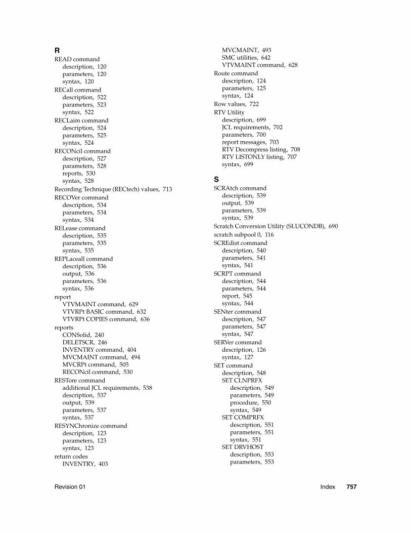
Revision 01 Index 757
RREAD command
description, 120parameters, 120syntax, 120
RECall commanddescription, 522parameters, 523syntax, 522
RECLaim commanddescription, 524parameters, 525syntax, 524
RECONcil commanddescription, 527parameters, 528reports, 530syntax, 528
Recording Technique (RECtech) values, 713RECOVer command
description, 534parameters, 534syntax, 534
RELease commanddescription, 535parameters, 535syntax, 535
REPLaceall commanddescription, 536output, 536parameters, 536syntax, 536
reportVTVMAINT command, 629VTVRPt BASIC command, 632VTVRPt COPIES command, 636
reportsCONSolid, 240DELETSCR, 246INVENTRY command, 404MVCMAINT command, 494MVCRPt command, 505RECONcil command, 530
RESTore commandadditional JCL requirements, 538description, 537output, 539parameters, 537syntax, 537
RESYNChronize commanddescription, 123parameters, 123syntax, 123
return codesINVENTRY, 403
MVCMAINT, 493SMC utilities, 642VTVMAINT command, 628
Route commanddescription, 124parameters, 125syntax, 124
Row values, 722RTV Utility
description, 699JCL requirements, 702parameters, 700report messages, 703RTV Decompress listing, 708RTV LISTONLY listing, 707syntax, 699
SSCRAtch command
description, 539output, 539parameters, 539syntax, 539
Scratch Conversion Utility (SLUCONDB), 690scratch subpool 0, 116SCREdist command
description, 540parameters, 541syntax, 541
SCRPT commanddescription, 544parameters, 544report, 545syntax, 544
SENter commanddescription, 547parameters, 547syntax, 547
SERVer commanddescription, 126syntax, 127
SET commanddescription, 548SET CLNPRFX
description, 549parameters, 549procedure, 550syntax, 549
SET COMPRFXdescription, 551parameters, 551syntax, 551
SET DRVHOSTdescription, 553parameters, 553
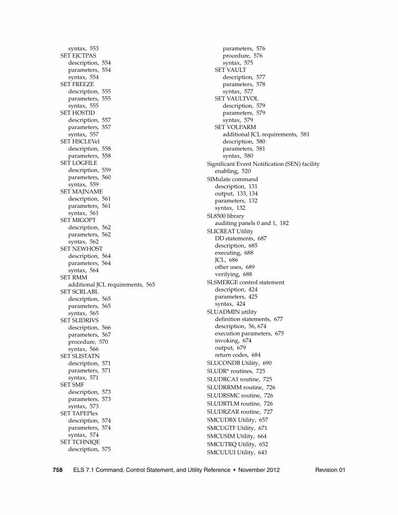
758 ELS 7.1 Command, Control Statement, and Utility Reference • November 2012 Revision 01
syntax, 553SET EJCTPAS
description, 554parameters, 554syntax, 554
SET FREEZEdescription, 555parameters, 555syntax, 555
SET HOSTIDdescription, 557parameters, 557syntax, 557
SET HSCLEVeldescription, 558parameters, 558
SET LOGFILEdescription, 559parameters, 560syntax, 559
SET MAJNAMEdescription, 561parameters, 561syntax, 561
SET MIGOPTdescription, 562parameters, 562syntax, 562
SET NEWHOSTdescription, 564parameters, 564syntax, 564
SET RMMadditional JCL requirements, 565
SET SCRLABLdescription, 565parameters, 565syntax, 565
SET SLIDRIVSdescription, 566parameters, 567procedure, 570syntax, 566
SET SLISTATNdescription, 571parameters, 571syntax, 571
SET SMFdescription, 573parameters, 573syntax, 573
SET TAPEPlexdescription, 574parameters, 574syntax, 574
SET TCHNIQEdescription, 575
parameters, 576procedure, 576syntax, 575
SET VAULTdescription, 577parameters, 578syntax, 577
SET VAULTVOLdescription, 579parameters, 579syntax, 579
SET VOLPARMadditional JCL requirements, 581description, 580parameters, 581syntax, 580
Significant Event Notification (SEN) facilityenabling, 520
SIMulate commanddescription, 131output, 133, 134parameters, 132syntax, 132
SL8500 libraryauditing panels 0 and 1, 182
SLICREAT UtilityDD statements, 687description, 685executing, 688JCL, 686other uses, 689verifying, 688
SLSMERGE control statementdescription, 424parameters, 425syntax, 424
SLUADMIN utilitydefinition statements, 677description, 56, 674execution parameters, 675invoking, 674output, 679return codes, 684
SLUCONDB Utility, 690SLUDR* routines, 725SLUDRCA1 routine, 725SLUDRRMM routine, 726SLUDRSMC routine, 726SLUDRTLM routine, 726SLUDRZAR routine, 727SMCUDBX Utility, 657SMCUGTF Utility, 671SMCUSIM Utility, 664SMCUTRQ Utility, 652SMCUUUI Utility, 643
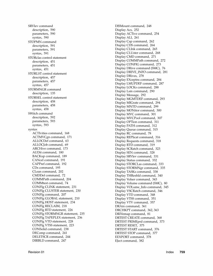
Revision 01 Index 759
SRVlev commanddescription, 590parameters, 590syntax, 590
STOPMN commanddescription, 591parameters, 591syntax, 591
STORclas control statementdescription, 451parameters, 451syntax, 451
STORLST control statementdescription, 457parameters, 457syntax, 457
STORMNGR commanddescription, 135
STORSEL control statementdescription, 458parameters, 458syntax, 458
SWitch commanddescription, 592parameters, 593syntax, 593
syntaxACTIvities command, 168ACTMVCgn command, 171ALLOCDef command, 63ALLOCJob command, 69ARCHive command, 173AUDit command, 180BACKup command, 189CANcel command, 191CAPPref command, 192CDs command, 195CLean command, 202CMDDef command, 72COMMPath command, 204COMMtest command, 74CONFIg CLINK statement, 231CONFIg CLUSTER statement, 230CONFIg command, 207CONFIg GLOBAL statement, 210CONFIg HOST statement, 234CONFIg RECLAIM, 218CONFIg RTD statement, 226CONFIg STORMNGR statement, 235CONFIg TAPEPLEX statement, 236CONFIg VTD statement, 228CONFIg VTSS statement, 223CONSolid command, 238DEComp command, 241DELETSCR command, 244DIRBLD command, 247
DISMount command, 248Display Acs, 252Display ACTive command, 254Display ALl, 261Display Cap command, 262Display CDS command, 264Display CLInk command, 265Display CLUster command, 268Display CMD command, 271Display COMMPath command, 272Display CONFIG command, 273Display DRive command (SMC), 76Display DRIVE_INFO command, 281Display DRives, 278Display EXceptns command, 284Display LMUPDEF command, 287Display LOCKs command, 288Display Lsm command, 290Display Message, 292Display MGMTDEF command, 293Display MIGrate command, 294Display MNTD command, 299Display MONitor command, 300Display MVC command, 301Display MVCPool command, 307Display OPTion command, 311Display PATH command, 312Display Queue command, 315Display RC command, 78Display REPlicat command, 316Display Requests command, 318Display RTD command, 319Display SCRatch command, 323Display SEN command, 328Display SRVlev command, 331Display Status command, 332Display STORCLas command, 333Display STORMNgr command, 335Display TASKs command, 338Display THReshld command, 340Display Volser command, 343Display Volume command (SMC), 80Display VOLume_Info command, 345Display VSCRatch command, 346Display VTD command, 348Display VTSS command, 351Display VTV command, 357DRAin command, 361DRCHKPT command, 362, 363DRIVemap command, 81DRTEST CREATE command, 368DRTEST PRIMEprd command, 373DRTEST RESET, 375DRTEST START command, 376DRTEST STOP command, 377EEXPORT command, 378EJect command, 382
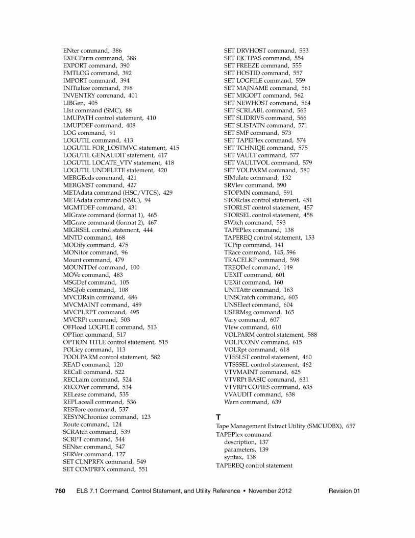
760 ELS 7.1 Command, Control Statement, and Utility Reference • November 2012 Revision 01
ENter command, 386EXECParm command, 388EXPORT command, 390FMTLOG command, 392IMPORT command, 394INITialize command, 398INVENTRY command, 401LIBGen, 405LIst command (SMC), 88LMUPATH control statement, 410LMUPDEF command, 408LOG command, 91LOGUTIL command, 413LOGUTIL FOR_LOSTMVC statement, 415LOGUTIL GENAUDIT statement, 417LOGUTIL LOCATE_VTV statement, 418LOGUTIL UNDELETE statement, 420MERGEcds command, 421MERGMST command, 427METAdata command (HSC/VTCS), 429METAdata command (SMC), 94MGMTDEF command, 431MIGrate command (format 1), 465MIGrate command (format 2), 467MIGRSEL control statement, 444MNTD command, 468MODify command, 475MONitor command, 96Mount command, 479MOUNTDef command, 100MOVe command, 483MSGDef command, 105MSGJob command, 108MVCDRain command, 486MVCMAINT command, 489MVCPLRPT command, 495MVCRPt command, 503OFFload LOGFILE command, 513OPTion command, 517OPTION TITLE control statement, 515POLicy command, 113POOLPARM control statement, 582READ command, 120RECall command, 522RECLaim command, 524RECOVer command, 534RELease command, 535REPLaceall command, 536RESTore command, 537RESYNChronize command, 123Route command, 124SCRAtch command, 539SCRPT command, 544SENter command, 547SERVer command, 127SET CLNPRFX command, 549SET COMPRFX command, 551
SET DRVHOST command, 553SET EJCTPAS command, 554SET FREEZE command, 555SET HOSTID command, 557SET LOGFILE command, 559SET MAJNAME command, 561SET MIGOPT command, 562SET NEWHOST command, 564SET SCRLABL command, 565SET SLIDRIVS command, 566SET SLISTATN command, 571SET SMF command, 573SET TAPEPlex command, 574SET TCHNIQE command, 575SET VAULT command, 577SET VAULTVOL command, 579SET VOLPARM command, 580SIMulate command, 132SRVlev command, 590STOPMN command, 591STORclas control statement, 451STORLST control statement, 457STORSEL control statement, 458SWitch command, 593TAPEPlex command, 138TAPEREQ control statement, 153TCPip command, 141TRace command, 145, 596TRACELKP command, 598TREQDef command, 149UEXIT command, 601UEXit command, 160UNITAttr command, 163UNSCratch command, 603UNSElect command, 604USERMsg command, 165Vary command, 607VIew command, 610VOLPARM control statement, 588VOLPCONV command, 615VOLRpt command, 618VTSSLST control statement, 460VTSSSEL control statement, 462VTVMAINT command, 625VTVRPt BASIC command, 631VTVRPt COPIES command, 635VVAUDIT command, 638Warn command, 639
TTape Management Extract Utility (SMCUDBX), 657TAPEPlex command
description, 137parameters, 139syntax, 138
TAPEREQ control statement
Revision 01 Index 761
description, 152parameters, 154syntax, 153
TCPip commanddescription, 141parameters, 142syntax, 141
TMS interface (SLUDR*) routines, 725TRace command
additional JCL requirements, 598description, 144, 596parameters, 146, 597syntax, 145, 596
Trace Format Utility (SMCUGTF), 671TRACELKP command
description, 598overview, 598parameters, 598syntax, 598
tracing LOOKUP events, 598TREQDef command
description, 149parameters, 150syntax, 149
UUEXIT command
description, 600parameters, 601syntax, 601
UEXit commanddescription, 159parameters, 160syntax, 160
Unified User Interface Utility (SMCUUUI), 643UNITAttr command
description, 162parameters, 163syntax, 163
UNSCratch commanddescription, 603parameters, 603syntax, 603
UNSElect commanddescription, 604parameters, 605syntax, 604
USERMsg commanddescription, 165parameters, 165syntax, 165
utilitiesHSC
Scratch Conversion Utility (SLUCONDB), 690SLICREAT, 685
SLUADMIN, 56, 674SMC
POLicy and TAPEREQ Batch Test Utility (SMCUTRQ), 652
Tape Management Extract Utility (SMCUDBX), 657
Trace Format Utility (SMCUGTF), 671Unified User Interface Utility (SMCUUUI), 643UUI Simulation Utility (SMCUSIM), 664
VTCSRTV Utility, 699
utility return codes and messages, SMC, 642UUI Simulation Utility (SMCUSIM), 664
VVary command
description, 606parameters, 607syntax, 607
VIew commanddescription, 610parameters, 611syntax, 610
VOLPARM control statementdescription, 588parameters, 589syntax, 588
VOLPCONV commandadditional JCL requirements, 616description, 615parameters, 615syntax, 615
VOLRpt commandadditional JCL requirements, 624description, 617parameters, 619syntax, 618
VTAM communications, 205VTCS
control statements, 167operator commands, 167
VTSSLST control statementdescription, 460parameters, 460syntax, 460
VTSSSEL control statementdescription, 462parameters, 463syntax, 462
VTVMAINT commanddescription, 625parameters, 626report, 629return codes, 628syntax, 625
762 ELS 7.1 Command, Control Statement, and Utility Reference • November 2012 Revision 01
VTVRPt commanddescription, 630BASIC
description, 631parameters, 631report, 632syntax, 631
COPIESdescription, 635parameters, 635report, 636syntax, 635
VVAUDIT commanddescription, 638parameters, 638syntax, 638
WWarn command
description, 639parameters, 640syntax, 639