stator non-uniform radial ventilation design methodology for
TRANSCRIPT

energies
Article
Stator Non-Uniform Radial Ventilation Design Methodologyfor a 15 MW Turbo-Synchronous Generator Based on SingleVentilation Duct Subsystem
Ruiye Li 1 , Peng Cheng 1,* , Hai Lan 1 , Weili Li 2 , David Gerada 3 and Yingyi Hong 4
�����������������
Citation: Li, R.; Cheng, P.; Lan, H.;
Li, W.; Gerada, D.; Hong, Y. Stator
Non-Uniform Radial Ventilation
Design Methodology for a 15 MW
Turbo-Synchronous Generator Based
on Single Ventilation Duct Subsystem.
Energies 2021, 14, 2760.
https://doi.org/10.3390/en14102760
Academic Editor: Christopher
Micallef
Received: 4 April 2021
Accepted: 4 May 2021
Published: 11 May 2021
Publisher’s Note: MDPI stays neutral
with regard to jurisdictional claims in
published maps and institutional affil-
iations.
Copyright: © 2021 by the authors.
Licensee MDPI, Basel, Switzerland.
This article is an open access article
distributed under the terms and
conditions of the Creative Commons
Attribution (CC BY) license (https://
creativecommons.org/licenses/by/
4.0/).
1 College of Intelligent Systems Science and Engineering, Harbin Engineering University,Harbin 150001, China; [email protected] (R.L.); [email protected](H.L.)
2 School of Electrical Engineering, Beijing Jiaotong University, Beijing 100044, China; [email protected] Department of Electrical and Electronic Engineering, University of Nottingham, Nottingham NG7 2RD, UK;
[email protected] Department of Electrical Engineering, Chung Yuan Christian University, Chung Li 320, Taiwan;
[email protected]* Correspondence: [email protected]; Tel.: +86-137-668-3161
Abstract: Within large turboalternators, the excessive local temperatures and spatially distributed temperature differences can accelerate the deterioration of electrical insulation as well as lead to deformation of components, which may cause major machine malfunctions. In order to homogenise the stator axial temperature distribution whilst reducing the maximum stator temperature, this paper presents a novel non-uniform radial ventilation ducts design methodology. To reduce the huge computational costs resulting from the large-scale model, the stator is decomposed into several single ventilation duct subsystems (SVDSs) along the axial direction, with each SVDS connected in series with the medium of the air gap flow rate. The calculation of electromagnetic and thermal performances within SVDS are completed by finite element method (FEM) and computational fluid dynamics (CFD), respectively. To improve the optimization efficiency, the radial basis function neural network (RBFNN) model is employed to approximate the finite e lement a nalysis, while the novel isometric sampling method (ISM) is designed to trade off the cost and accuracy of the process. It is found that the proposed methodology can provide optimal design schemes of SVDS with uniform axial temperature distribution, and the needed computation cost is markedly reduced. Finally, results based on a 15 MW turboalternator show that the peak temperature can be reduced by 7.3 ◦C (6.4%). The proposed methodology can be applied for the design and optimisation of electromagnetic-thermal coupling of other electrical machines with long axial dimensions.
Keywords: stator cooling; non-uniform ventilation duct; single ventilation duct subsystem (SVDS); RBFNN surrogate model; isometric sampling method
1. Introduction
In recent years, the research on electrical machines has gradually become increasinglyintegrated, comprehensive, and synergistic, expanding from a single physical field to mul-tiple physical fields, including electromagnetics, thermal, noise, and structure. For manylower speed applications, the main design limits are usually considered to be a combinationof electromagnetic and thermal [1]. Both these physical fields are deeply coupled with thecharacteristics interacting with each other. The losses generated by the electromechanicalconversion process will raise the temperature. Consequently, the increase in temperatureincreases the resistance losses due to the positive temperature coefficient of resistivity.The steady-state temperature of the motor is the result of a balance between the generationand dissipation of heat, the cooling system being the decisive factor.
Each type of electrical machine has its own commonly used cooling system. Turbo-generators typically remove the heat that is mainly generated by the winding using forced
Energies 2021, 14, 2760. https://doi.org/10.3390/en14102760 https://www.mdpi.com/journal/energies
Energies 2021, 14, 2760 2 of 20
air convection [2]. In this study, forced cooling air flows through the air gap and radialventilation ducts, removing heat from the convective surfaces. For the “slender” shapeform typical in turbo-generators, the limited cooling capacity of forced air leads to aphenomenon that the temperature of the components near the fan is slightly higher thanthe inlet air temperature, but the temperature rises significantly at locations which areaxially further away. This can result in excessive local temperatures with exponentiallyreduced insulation service life. In general, the stator has a more pronounced effect onthermal performance than the rotor due to the heat source arrangement. Therefore, itis necessary to plan an effective cooling path by optimizing the geometry of the coolingsystem to reduce the maximum temperature and narrow the temperature gradient.
To ensure that an optimal design is achieved, the temperature distribution of thestator should first be accurately calculated. The common calculation approaches aredivided into two categories: analytical and numerical. The analytical approach has theadvantage of being very fast to calculate; however, the developer of the network modelmust invest significant effort in defining a circuit that accurately models the main heat-transfer paths [3–5]. The combination of Electromagnetic Finite Element Method (EM FEM)and Computational Fluid Dynamics (CFD) provides an effective and high-fidelity approachin addressing electromagnetic-thermal coupled problem calculation [3,6]. EM FEM canaccurately calculate the losses of each part of the stator under various operating conditions,while CFD is an approach that can deal with turbulence, convective and conductive heattransfer simultaneously [7]. However, this numerical approach, while accurate, increasesthe complexity of the calculations.
Considering the physical size and geometrical complexity of the MW-class stator,numerical calculations of the full-scale coupled models are often time-consuming [8].The general solution of this problem is to simplify the model based on its axial and/orcircumferential symmetry. However, for turboalternators with large length-to-diameterratios, the axially symmetric decomposition fails to effectively reduce the computationalcomplexity of the model. Accordingly, this paper proposes a single ventilation ductsubsystem (SVDS) that is composed of one radial ventilation duct and its two sides of ironcore and winding.
In the SVDS, the heat of the stator is mainly generated from the copper losses of thewinding and iron core losses. The heat generated by the winding is transferred throughthe insulation from the inner to the outer surface. The heat of the winding part that isexposed to the radial ventilation duct is directly removed by the cooling air. The other partof the winding that is placed in the stator slot transfers its heat to the iron core. In the end,the cooling air within the radial ventilation duct takes the heat away from the convectivesurface of the iron core.
Due to the convective behaviour being strongly geometry dependent, the width ofthe radial ventilation duct can control the flow rate of cooling air flowing into the SVDSfrom the air gap. Meanwhile, the flow rate of the air gap is a function of the axial positionsand the widths of the radial ventilation duct. The geometry of the winding and iron coredetermines the amount of heat generated, while the size of the radial ventilation ductsstrongly impacts the fluid behaviour of cooling air and in turn also the cooling capacity.Therefore, according to the axial distribution of cooling air and the influence of each SVDSshunt, this paper proposes an innovative approach in the geometric design of non-uniformradial ventilation ducts. This approach not only improves the utilisation of cooling airbut also reduces the calculation size and time required for a numerical calculation of thestator temperature.
The final step of the design is the determination of the geometric dimensions of theSVDSs. This process can employ a global optimization algorithm, such as the genetic algo-rithm (GA), to find the optimal design scheme in the feasible range of design parameters.However, the optimization based on numerical calculation is still expensive in terms ofelapsed time and/or computational cost, so that only a limited number of simulations are

Energies 2021, 14, 2760 3 of 20
possible. To that end, in this paper, a surrogate model is applied to reduce the time spenton each iteration within the optimization process.
The surrogate model inherently captures the underlying mapping among predefinedinput-output pairs by a way of data-driven. Data-driven methods, which are free of set-ting any mechanism a priori, are gaining increasing adoption in the field of performanceprediction [9–11] and parameter fitting [12–14]. In electrical machine design, Kriging [12],response surface [13,14] and multilayer perceptron neural network [15] have been success-fully applied to surrogate models for performance optimization, especially for solvingthe highly nonlinear problem of multi-physics coupled electrical machines. Comparedwith these methods, radial basis function neural network (RBFNN) has simpler structureand much faster training process, which is beneficial for the reduction of computationalcost. Moreover, RBFNNs are better adapted to the environment and have been shown toapproximate any continuous nonlinear network with arbitrary accuracy [16]. Therefore,the RNFBB can reflect the corresponding model based on the actual sampling, that is,different numbers of samples will reflect different levels of accuracy of the model. Thisfacilitates a balanced number of samples versus fidelity for the model.
From the foregoing discussion, the design of non-uniform radial ventilation ducts forthe stator can be achieved. The contributions of this work can be summarized as:
1. The design methodology of the non-uniform radial ventilation ducts of the statoris presented. Through the optimization of the geometries and axial positions of thestator radial ventilation ducts, a reasonable distribution of the cooling air can beachieved. This not only reduces the maximum temperature of the stator but alsonarrows the temperature difference.
2. The construction of single ventilation duct subsystems. This simplifies the geometriccomplexity of the model and avoids the heavy computational cost of full-scale couplednumerical calculation.
3. The application of RBFNN surrogate model provides a solution to reduce the computa-tional sophistication of the optimization objective function. Meanwhile, the isometricsampling method is proposed to balance the relationship between the number ofsampling points and the distance between sampling points.
This paper is organized as follows. Section 2 details the process of establishing theSVDS. Section 3 describes the RBFNN surrogate model. The application of GA optimizationmethods is included in Section 4. Finally, taking an existing turboalternator as a casestudy, the experimental validation together with the optimization results are presented inSections 5 and 6, respectively.
2. Single Ventilation Duct Subsystem
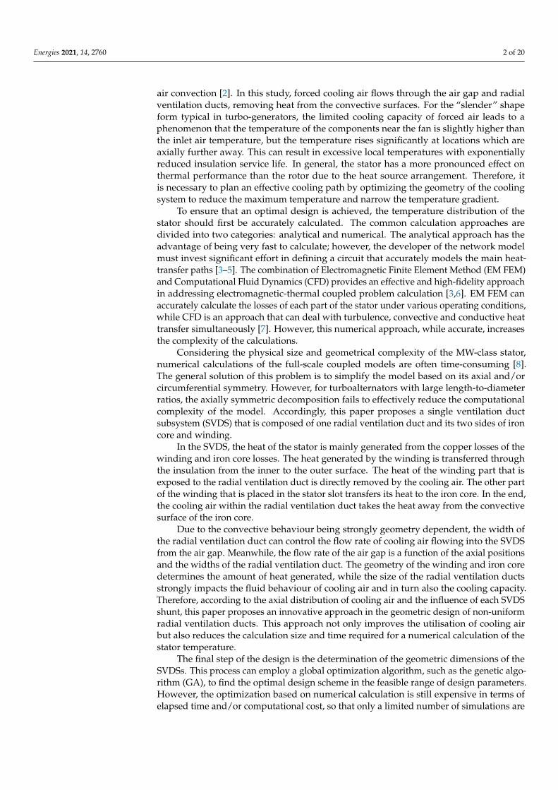
In this section, the single ventilation duct subsystem (SVDS) modelling process andthe magnetic-thermal calculations are explained in detail. It is divided into four subsections:model introduction, loss calculation, conjugate heat transfer in SVDS, and fluid analysiswithin the air gap. The process of establishing the stator temperature model is shownin Figure 1. The SVDS calculation model and the corresponding boundary conditionsare firstly determined by analysing the stator structure, heat generation and removal aswell as by appropriate engineering judgement. Following this, the identification of themain objectives and the analysis of the mechanisms are the basis for the loss calculation.After defining the source of heat loss, temperature analysis is conducted. Through analysisof the cooling air flow characteristics and heat transfer characteristics within the SVDSand air gap, the relationship between the model geometry parameters and the objecttemperature can be established.
Energies 2021, 14, 2760 4 of 20
Figure 1. Flowchart of stator temperature model establishment process.
2.1. Modelling
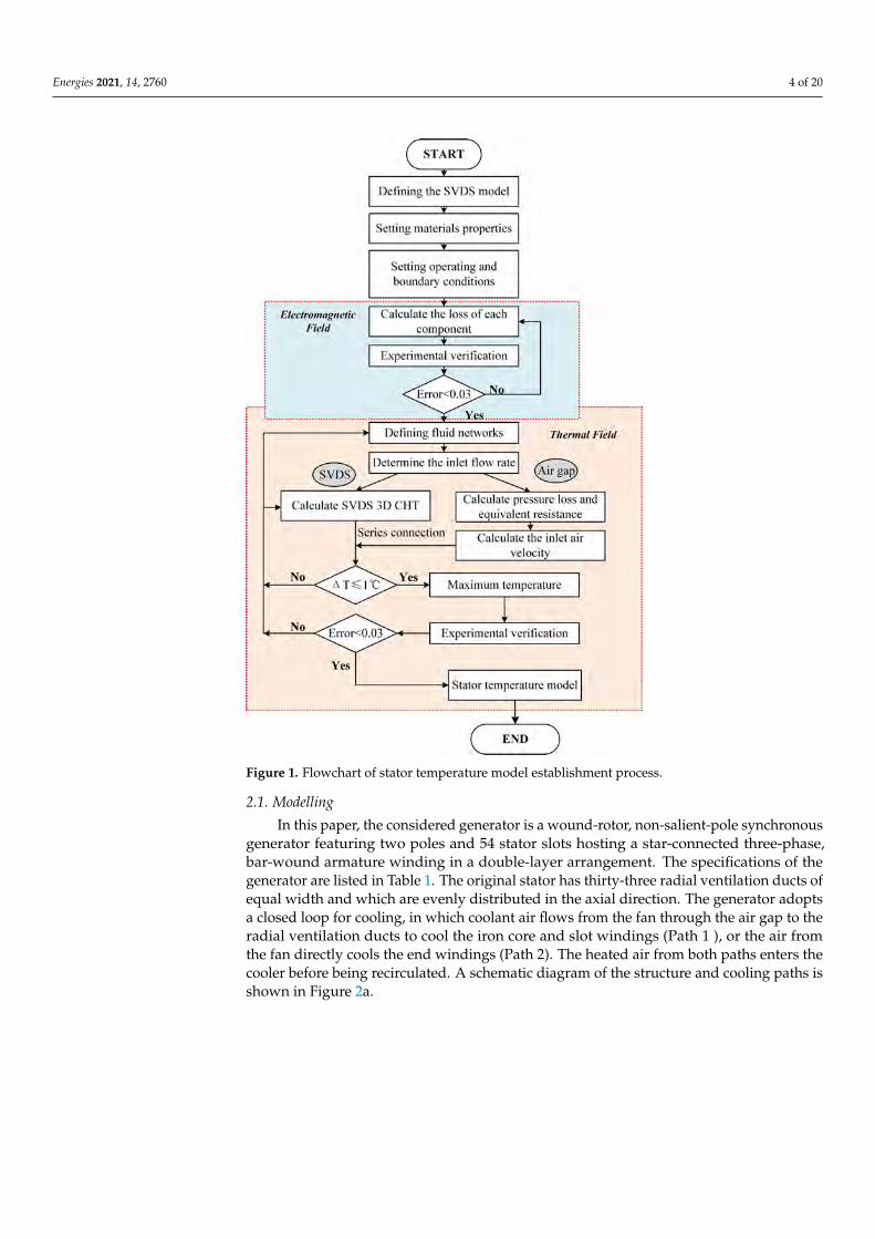
In this paper, the considered generator is a wound-rotor, non-salient-pole synchronousgenerator featuring two poles and 54 stator slots hosting a star-connected three-phase,bar-wound armature winding in a double-layer arrangement. The specifications of thegenerator are listed in Table 1. The original stator has thirty-three radial ventilation ducts ofequal width and which are evenly distributed in the axial direction. The generator adoptsa closed loop for cooling, in which coolant air flows from the fan through the air gap to theradial ventilation ducts to cool the iron core and slot windings (Path 1 ), or the air fromthe fan directly cools the end windings (Path 2). The heated air from both paths enters thecooler before being recirculated. A schematic diagram of the structure and cooling paths isshown in Figure 2a.
Energies 2021, 14, 2760 5 of 20
Table 1. Generator specifications.
Parameter Value (Unit)
Rated power 15 (MW)Rated voltage 10.5 (kV)Stator length 1600 (mm)
Number of ducts 33Radial vent duct width 8 (mm)
Iron core segment width 39.29 (mm)
(a)
(b)
Figure 2. Diagram of machine ventilation. (a) Generator one-eighth model. (b) SVDS model.
The research in this paper focuses specifically on Path 1, and assumes that the twopaths are relatively independent of each other with no heat transfer between them. Exploit-ing the symmetry in the circumferential direction of the stator, one stator slot is used as theresearch domain. The number of conductors per slot is six. One layer of the winding in thestator slot is considered as a homogeneous medium thus ignoring internal temperaturedifferences. Furthermore, it is assumed that the slot is filled with insulating materialaround the winding. The effects of rotor temperature rise on the air gap cooling air arealso considered.

Energies 2021, 14, 2760 6 of 20
The SVDS is created with the intent to design stator radial ventilation ducts withnon-equal widths and non-uniform position distribution. The procedure to design thegeometry of each SVDS is based on the fluid state of the air gap, both in terms of heatgeneration and cooling, in order to achieve a uniform distribution of the stator temperature.
As shown in Figure 2b, the SVDS is composed of a single radial ventilation duct andits corresponding iron core segment on both sides, together with the insulated wrappedwindings. Within the subsystem, heat is generated primarily by winding losses and corelosses, while the generated heat is removed from the convective surfaces by the cooling airflowing through the radial vent ducts. As for the arrangement of subsystems, it is assumedthat each is closely aligned, maintaining continuity of heat transfer between them.
2.2. Loss Calculation
Loss calculations based on FEM have been extensively researched and applied,and very accurate results can be achieved [17,18]. The stator iron losses and windinglosses are two key causes of stator heating. The iron losses consist of hysteresis losses, eddycurrent losses and excess losses [19], of which are related to the frequency of alternatingmagnetization and to the amplitude of magnetic flux density. Moreover, the eddy currentloss is in direct proportion to the square of the thickness of the stator silicon steel sheet.Once the magnetic field strength and stator materials have been determined, the density oflosses is evaluated. The increase in iron core volume means an increase in loss, but it alsomeans an improvement in output power. Regarding the winding copper losses, their valueis directly related to the resistance of the winding material and the winding current. Fur-thermore, it should be noted that the losses themselves are temperature-dependent [20,21].The temperature rise increases the winding resistance, which in turn increases the copperlosses. The process will reach a steady state when heat generation and heat dissipationare equal.
In this work, the losses are calculated at the rated power operating condition of thegenerator. The iron losses are assumed to be constant in the design process. The calculatedloss values are then transferred to the thermal model of the stator as the heat sources in thetemperature calculation process. The interdependent process of stator temperature andcopper losses will converge at a temperature variation of less than 1 ◦C.
2.3. Thermal and Fluid Analysis
Stator steady-state temperature is the state of equilibrium between heat generationand heat dissipation. The heat generated due to the losses is transferred to the surroundingcooling medium through the contact surface between the solid and the cooling mediumand raises its temperature. The heat is removed from the stator with the flow of thecooling medium.
In this case heat conduction and convection are the main heat transfer methodswithin the stator. The closeness of the contact between the stator components affects theability of heat conduction from the winding to the core [22,23]. Different manufacturingprocesses and technologies lead to differences in thermal conductivity, for which empiricalcoefficients are used. The efficiency of thermal convection is related to the local flow stateof the cooling air, including the flow velocity of cooling air and the wind resistance in thecooling paths [7].
The process of simultaneous heat conduction and convection between all the solidcomponents inside this stator and the surrounding fluid region is called conjugate heattransfer [23,24]. In the case of three-dimensional heat steady problem for incompressiblefluids, this process process is governed by continuity, momentum, and energy equation fora fluid and a conduction equation for body, as follows:
∂u∂x
+∂v∂y
+∂w∂z
= 0 (1)

Energies 2021, 14, 2760 7 of 20
u∂u∂x
+ v∂u∂y
+ w∂u∂z
= −1ρ
dpdx
+ gβ(T − T∞) + v(
∂2u∂y2 +
∂2u∂z2
)(2)
u∂T∂x
+ v∂T∂y
+ w∂T∂z
= α
(∂2T∂y2 +
∂2T∂z2
)+
vc p
[(∂u∂y
)2+
(∂u∂z
)2]
(3)
λx∂2Ts
∂x2 + λy∂2Ts
∂y2 + λz∂2Ts
∂z2 = −qv + ρscs∂Ts
∂t(4)
where u, v, w are velocity components [m/s]; β is the volumetric thermal expansion coeffi-cient; Ts and T∞ are solid temperature and ambient temperature [◦C], respectively; α is ther-mal diffusivity [m2/s]; λ is thermal conductivity [W/(m ·K)]; qv is heat source [W/m3].
For the multi-branch stator radial ventilation system, the fluid network is dividedinto multiple SVDSs and air gap. A diagram of the fluid network is shown in Figure 3.The pressure loss H varies with the geometric structure and flow rate Q as describedby [25]:
H = ζ12
γ
g
(QA
)2(5)
Figure 3. Diagram of stator fluid network.
The equivalent resistance Z is:
Z =HQ2 (6)
In Figure 3, ZB is the equivalent resistance for the pressure loss caused by the flowin the radial vent ducts, while ZC is the equivalent resistance for the pressure loss causedby the change in the fluid state of the air gap at the branch due to the subsystem shunt.In order to obtain an accurate temperature distribution, the thermal and fluid analysiswithin the subsystems is completed by CFD. The aforesaid two resistances are only used toillustrate the impact of the radial vent duct on the fluid state in the air gap. The aim of thefluid network here is to obtain the inlet air velocity of the SVDS.
Within the air gap, the resistances are mainly the ‘along-the-way’ frictional resistanceZF between the radial ventilation ducts, as well as the deceleration resistance Zd. The latteris caused by the decrease in the flow velocity within the air gap after the duct shunt, whichis directly related to the shunt velocity. With the air gap inlet velocity known, the variationof the wind velocity in the air gap with axial position is shown in Figure 4.

Energies 2021, 14, 2760 8 of 20
0 200 400 600 800 1000 1200 1400 1600
0.00.20.40.60.81.0
Nor
mal
ized
Air
Vel
ocity
Axial Location (mm)
Inlet flow rate 6 m/s 8 m/s
10 m/s
Figure 4. Air velocity in air gap.
As the cooling air enters the air gap, it is in the turbulent state and the air velocityincreases exponentially [25]. It rises in the first quarter (up to 400 mm) of the axial positionand reaches its maximum value. Subsequently, as the cooling air penetrates further axiallywithin the air-gap, the flow velocity gradually decreases. Meanwhile, due to the shunt ofeach ventilation duct, there is a stepwise decrease in the flow velocity. The thickness of theboundary layer in the beginning section of the air gap is greater than that of the remainingsections, so there is a tendency for the flow velocity to increase. Furthermore, the coolingair also enters the subsystem at a faster velocity, which has a beneficial cooling effect on thesubsystem. However, an increase in flow velocity leads to a thinning of the boundary layerof the air gap, which gradually stabilizes the cooling airflow.
In summary, the temperature within the SVDS can be calculated using CFD based onthe 3D conjugate heat transfer and the inlet air velocity from the air gap. Each SVDS isconnected in series with the air velocity in the air gap as the medium to form the entirestator temperature model.
3. Surrogate Model
The surrogate model is an approximate of the objective system in a black-box fash-ion, which establishes direct correlations between inputs and objective outputs withoutconcern for the internal mechanisms of the system [26–29]. This facilitates the solutionof computationally intensive problems that require a significant amount of time andcomputational resources.
In the development of the SVDS surrogate model, the design space is first sampledusing the isometric sampling method (ISM), and then the sampling points calculated by thecombined FEM and CFD approach are used to train RBFNN surrogate model. The modelfits the relationship between the geometric parameters and maximum temperature of theSVDS. Finally, the accuracy of the model is verified by non-sampling points data.
3.1. Isometric Sampling Method
The selection of interpolation points in the design space, i.e., the sampling method,has a direct impact on the precision of the surrogate model. The common experimentalsampling methods currently used are full factorial design [8], Latin hypercube sampling(LHS) [30], Taguchi orthogonal array [29,31,32], Box–Behnken design (BBD), and centrecomposite design (CCD).
The full factorial design is the most comprehensive and detailed for the design space,but at the same time it is the costliest. Multidimensional and multi-level values aggravatethe computational cost. Moreover, when sampling points are projected onto a certainaxis, there are many overlapping points, which means that information collected in onedimension can overlap another [33]. LHS is a hierarchical chunking sampling method thatavoids overlapping of sampling in a certain dimension. Since the selection of sampling
Energies 2021, 14, 2760 9 of 20
points in each block is random, this results in many different sampling schemes, and thesampling quality of those sampling schemes varies greatly, requiring screening of thesampling schemes [33]. BBD and CCD have similar spatial sampling structures. Comparedto BBD, CCD is better suited for fitting curved surfaces. Taguchi orthogonal arrays arewidely used in industry for robust design and optimization due to their superiority innumber of samples [29,32]. In this study, a new isometric sampling method is proposed interms of the number of sampling points and the distance between sampling points.
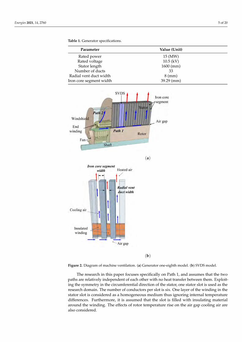
Isometric sampling method is defined as an equal Euclidean distance between adjacentsample points in the design space. Equal distances between sampling points allow fora uniform distribution of sampling points in the design space, avoiding inconsistentspace-filling of each region. At the same time, it is well known that the accuracy of asurrogate model at a non-sampled point is related to the distance of that point from thesampled point. As the distance from the sampled point increases, the accuracy of the modeldecreases [28,33]. The filling of the design space by isometric sampling points is shown inFigure 5.
Figure 5. Diagram of isometric sampling points (three two-level parameters).
In the isometric sampling method, the distance between two known sampled pointscan be controlled by the number of parameters and levels. The accuracy of the surrogatemodel at non-sampled points can thus be ensured by setting the number of points to avoidlarge deviations in the accuracy of the model at different spatial locations.
To assess the distribution of sampling methods in the design space, the maximinmetric is used as a criterion, which is one of the most widely-used measures to evaluate theuniformity of a sampling method [34]. In this study, the following scalar-valued criterionfunction defined by Morris and Mitchell is used to evaluate the space-filling properties φqfor the sampling method [35]:
φq(X) =
(m
∑i=1
Jid−qi
)1/q
(7)
where di is Euclidean norm between all possible pairs of points in a sampling method X; Jiis the number of pairs of points in X separated by the distance di; q is an exponent of thisfunction. The larger the sampling method, the smaller the q required [35].
In this sampling plan, the inlet air velocity, radial vent duct width, and iron coresegment width are used as design parameters. Regarding the determination of the levelvalues, the upper and lower limits of the parameter interval are taken as the upper andlower levels respectively, and the middle value of the interval is considered as the middlelevel. For reference, the levels of these three design parameters are shown in the Table 2.
Energies 2021, 14, 2760 10 of 20
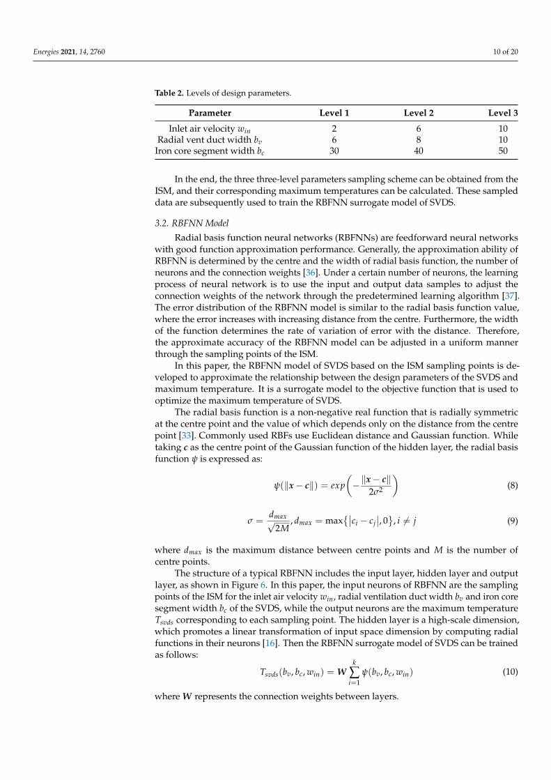
Table 2. Levels of design parameters.
Parameter Level 1 Level 2 Level 3
Inlet air velocity win 2 6 10Radial vent duct width bv 6 8 10
Iron core segment width bc 30 40 50
In the end, the three three-level parameters sampling scheme can be obtained from theISM, and their corresponding maximum temperatures can be calculated. These sampleddata are subsequently used to train the RBFNN surrogate model of SVDS.
3.2. RBFNN Model
Radial basis function neural networks (RBFNNs) are feedforward neural networkswith good function approximation performance. Generally, the approximation ability ofRBFNN is determined by the centre and the width of radial basis function, the number ofneurons and the connection weights [36]. Under a certain number of neurons, the learningprocess of neural network is to use the input and output data samples to adjust theconnection weights of the network through the predetermined learning algorithm [37].The error distribution of the RBFNN model is similar to the radial basis function value,where the error increases with increasing distance from the centre. Furthermore, the widthof the function determines the rate of variation of error with the distance. Therefore,the approximate accuracy of the RBFNN model can be adjusted in a uniform mannerthrough the sampling points of the ISM.
In this paper, the RBFNN model of SVDS based on the ISM sampling points is de-veloped to approximate the relationship between the design parameters of the SVDS andmaximum temperature. It is a surrogate model to the objective function that is used tooptimize the maximum temperature of SVDS.
The radial basis function is a non-negative real function that is radially symmetricat the centre point and the value of which depends only on the distance from the centrepoint [33]. Commonly used RBFs use Euclidean distance and Gaussian function. Whiletaking c as the centre point of the Gaussian function of the hidden layer, the radial basisfunction ψ is expressed as:
ψ(‖x− c‖) = exp(−‖x− c‖
2σ2
)(8)
σ =dmax√
2M, dmax = max
{∣∣ci − cj∣∣, 0}
, i 6= j (9)
where dmax is the maximum distance between centre points and M is the number ofcentre points.
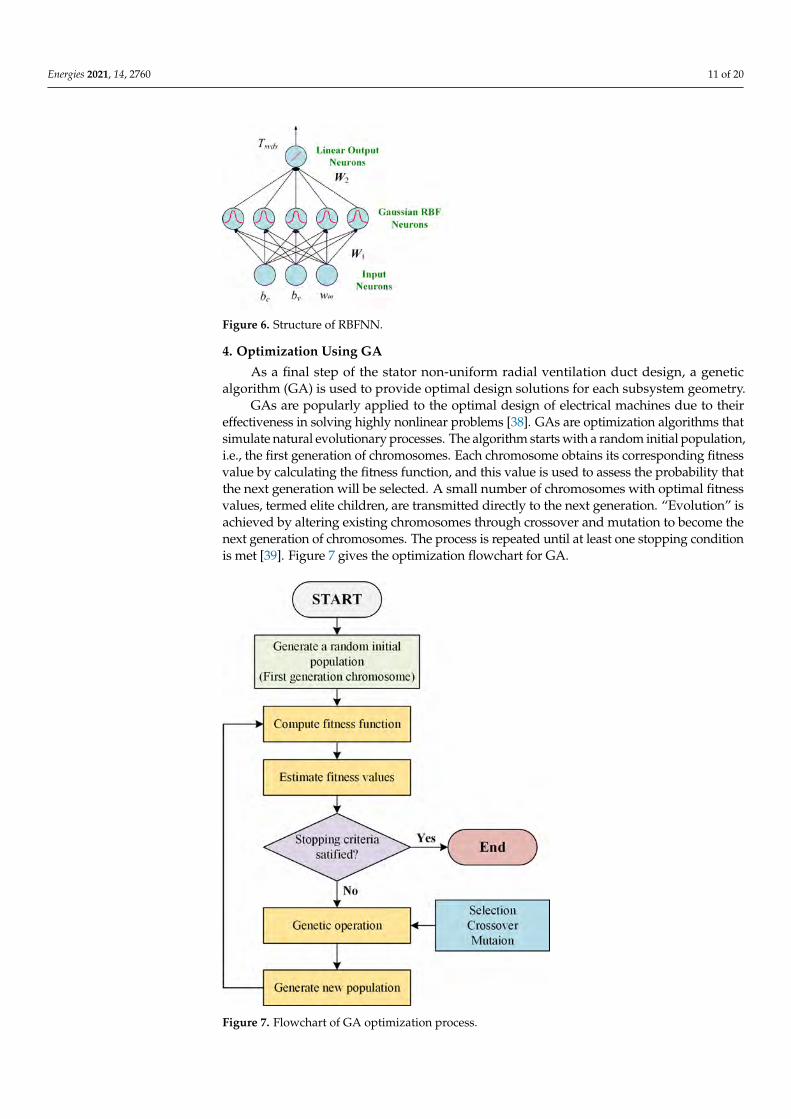
The structure of a typical RBFNN includes the input layer, hidden layer and outputlayer, as shown in Figure 6. In this paper, the input neurons of RBFNN are the samplingpoints of the ISM for the inlet air velocity win, radial ventilation duct width bv and iron coresegment width bc of the SVDS, while the output neurons are the maximum temperatureTsvds corresponding to each sampling point. The hidden layer is a high-scale dimension,which promotes a linear transformation of input space dimension by computing radialfunctions in their neurons [16]. Then the RBFNN surrogate model of SVDS can be trainedas follows:
Tsvds(bv, bc, win) = Wk
∑i=1
ψ(bv, bc, win) (10)
where W represents the connection weights between layers.
Energies 2021, 14, 2760 11 of 20
Figure 6. Structure of RBFNN.
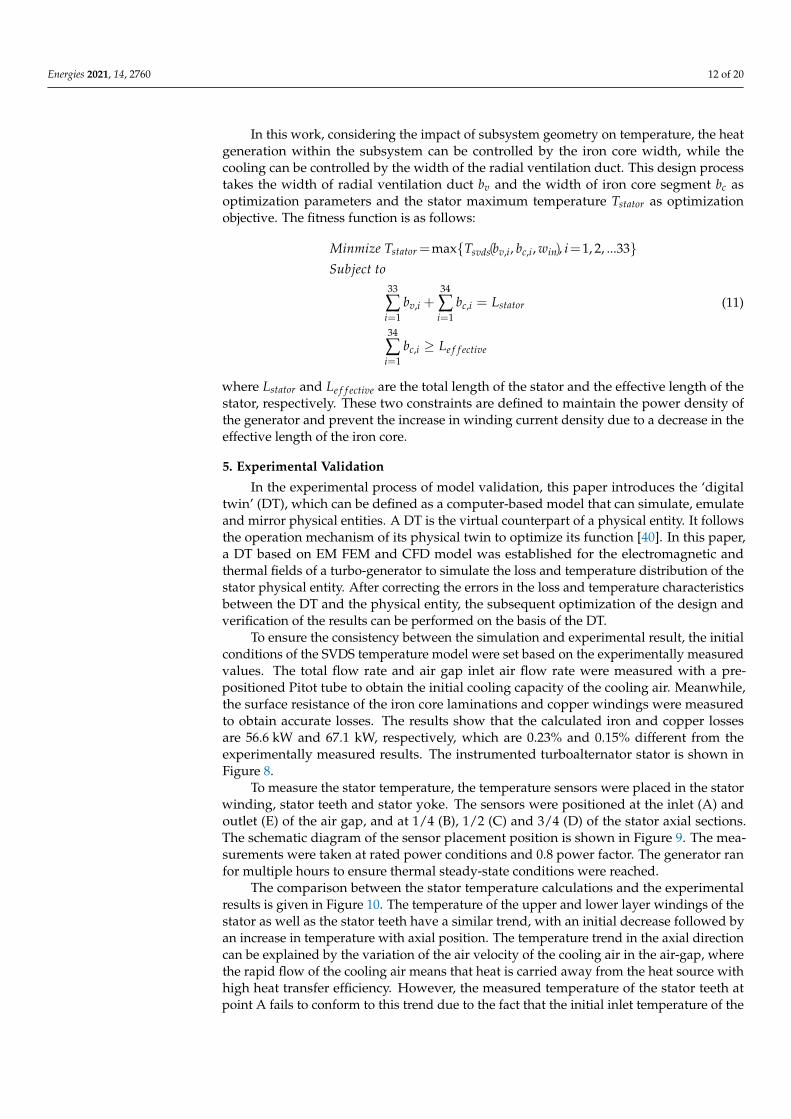
4. Optimization Using GA
As a final step of the stator non-uniform radial ventilation duct design, a geneticalgorithm (GA) is used to provide optimal design solutions for each subsystem geometry.
GAs are popularly applied to the optimal design of electrical machines due to theireffectiveness in solving highly nonlinear problems [38]. GAs are optimization algorithms thatsimulate natural evolutionary processes. The algorithm starts with a random initial population,i.e., the first generation of chromosomes. Each chromosome obtains its corresponding fitnessvalue by calculating the fitness function, and this value is used to assess the probability thatthe next generation will be selected. A small number of chromosomes with optimal fitnessvalues, termed elite children, are transmitted directly to the next generation. “Evolution” isachieved by altering existing chromosomes through crossover and mutation to become thenext generation of chromosomes. The process is repeated until at least one stopping conditionis met [39]. Figure 7 gives the optimization flowchart for GA.
Figure 7. Flowchart of GA optimization process.
Energies 2021, 14, 2760 12 of 20
In this work, considering the impact of subsystem geometry on temperature, the heatgeneration within the subsystem can be controlled by the iron core width, while thecooling can be controlled by the width of the radial ventilation duct. This design processtakes the width of radial ventilation duct bv and the width of iron core segment bc asoptimization parameters and the stator maximum temperature Tstator as optimizationobjective. The fitness function is as follows:
Minmize Tstator =max{Tsvds(bv,i, bc,i, win), i=1, 2, ...33}Subject to
33
∑i=1
bv,i +34
∑i=1
bc,i = Lstator
34
∑i=1
bc,i ≥ Le f f ective
(11)
where Lstator and Le f f ective are the total length of the stator and the effective length of thestator, respectively. These two constraints are defined to maintain the power density ofthe generator and prevent the increase in winding current density due to a decrease in theeffective length of the iron core.
5. Experimental Validation
In the experimental process of model validation, this paper introduces the ‘digitaltwin’ (DT), which can be defined as a computer-based model that can simulate, emulateand mirror physical entities. A DT is the virtual counterpart of a physical entity. It followsthe operation mechanism of its physical twin to optimize its function [40]. In this paper,a DT based on EM FEM and CFD model was established for the electromagnetic andthermal fields of a turbo-generator to simulate the loss and temperature distribution of thestator physical entity. After correcting the errors in the loss and temperature characteristicsbetween the DT and the physical entity, the subsequent optimization of the design andverification of the results can be performed on the basis of the DT.
To ensure the consistency between the simulation and experimental result, the initialconditions of the SVDS temperature model were set based on the experimentally measuredvalues. The total flow rate and air gap inlet air flow rate were measured with a pre-positioned Pitot tube to obtain the initial cooling capacity of the cooling air. Meanwhile,the surface resistance of the iron core laminations and copper windings were measuredto obtain accurate losses. The results show that the calculated iron and copper lossesare 56.6 kW and 67.1 kW, respectively, which are 0.23% and 0.15% different from theexperimentally measured results. The instrumented turboalternator stator is shown inFigure 8.
To measure the stator temperature, the temperature sensors were placed in the statorwinding, stator teeth and stator yoke. The sensors were positioned at the inlet (A) andoutlet (E) of the air gap, and at 1/4 (B), 1/2 (C) and 3/4 (D) of the stator axial sections.The schematic diagram of the sensor placement position is shown in Figure 9. The mea-surements were taken at rated power conditions and 0.8 power factor. The generator ranfor multiple hours to ensure thermal steady-state conditions were reached.
The comparison between the stator temperature calculations and the experimentalresults is given in Figure 10. The temperature of the upper and lower layer windings of thestator as well as the stator teeth have a similar trend, with an initial decrease followed byan increase in temperature with axial position. The temperature trend in the axial directioncan be explained by the variation of the air velocity of the cooling air in the air-gap, wherethe rapid flow of the cooling air means that heat is carried away from the heat source withhigh heat transfer efficiency. However, the measured temperature of the stator teeth atpoint A fails to conform to this trend due to the fact that the initial inlet temperature of the

Energies 2021, 14, 2760 13 of 20
cooling air has a more pronounced effect on the temperature of the core laminations ratherthan the winding.
(a)
(b)
Figure 8. Instrumented turboalternator stator under investigation. (a) Stator iron core end withoutwinding. (b) Stator iron core and winding end.
Figure 9. Schematic diagram of the sensor placement position.

Energies 2021, 14, 2760 14 of 20
A A
A
B B
B
C C
C
D D
D
E EE
0
20
40
60
80
100
120
140
Tooth Winding (Lower Layer)
Tem
pera
ture
()
Experimental Simulated
Winding (Upper Layer)
Figure 10. Stator temperature: calculation vs. experimental results.
The temperature distribution of the SVDS and fluid flow behaviour of cooling air areshown in Figure 11. The maximum temperature of the stator appears on the windings, notonly because of the high heat density of the windings, but also because they are surroundedby insulating materials, which makes heat dissipation difficult. Compared to the lowerlayer winding, the upper layer winding dissipates heat better because it is closer to thecooling air in the air gap. The temperature of the stator iron core increases in the directionof fluid flow. This is because as air flows more and more heat is transferred to it, resultingin a decreasing temperature difference between the cooling air and the solids, and thus thecooling capacity also decreases.
(a)
(b)
Figure 11. Numerical calculations of SVDS. (a) Temperature and fluid flow velocity contour. (b)Fluid flow velocity contour at the air gap and radial ventilation duct inlet.

Energies 2021, 14, 2760 15 of 20
As for the shunting of cooling air, a portion of the cooling air enters the radial ven-tilation duct from the air gap, cooling the stator teeth, windings, and stator yoke in turn,and finally taking the heat away from the back of the stator. As the hydraulic diameterof the fluid decreases, the cooling air entering the radial ventilation duct flows rapidlythrough the sides of the insulation-wrapped windings. From the above results and theforegoing analysis, the flow state of the cooling air in the SVDS is consistent with theanalysis of the fluid network model.
6. Results6.1. Comparison of Sampling Methods
From the maximin metric and scalar-valued criterion function, the space-filling prop-erties of the isometric sampling method (ISM) and other common sampling methods wereobtained. Table 3 shows the corresponding φq for the number of different parameters atthree-level for several sampling methods. The smaller the value of φq, the better the space-filling properties of X were. The Latin hypercube sampling (LHS) used for comparison inthis table is the scheme that was optimized in accordance with the scalar-valued criterionfunction. Face-centred central composite design (FCCD) is the special case where thecentral composite design (CCD) was at alpha equal to one moment, such that all samplingpoints of the sampling method used for comparison were between the unified upper andlower limits.
Table 3. Space-filling properties of the sampling method.
Sampling Plan Number of ParametersTwo Three Four
Full-Factorial Design 2.10 2.17 2.23Taguchi Orthogonal Array 2.10 2.00 1.21Latin Hypercube Sampling 2.91 3.21 3.83
Box–Behnken Design — 1.51 1.56Face-centered Central Composite Design 2.10 2.07 1.47
Isometric Sampling Method 1.45 1.52 1.57
The sampling points of full factorial design, Taguchi orthogonal array and FCCD werethe same at the two three-level parameters. At three three-level parameters, Box–Behnkendesign (BBD) and ISM had a very similar distribution of sampling points, and ISM can beseen as a translation and symmetry of the BBD. For the four parameters, Taguchi orthogonalarray exhibited the smallest φq because it had the smallest number of samples. FurthermoreBBD, FCCD and ISM show similar characteristics.
From the consistency of the distance between sampling points, BBD and ISM weremore advantageous than FCCD. ISM provided a somewhat better description of the spacethan BBD when considering the sampling method for the edge of the design space.
6.2. RBFNN Surrogate Model
Based on the ISM sampled points, an RBFNN surrogate model reflecting the directrelationship between the stator design parameters and the maximum temperature wasdeveloped. It was used as an alternative to the optimization objective function for iterativecalculations in the optimization algorithm and to find the optimal design parameters.
Regarding the accuracy of the surrogate model, it was ascertained that the model couldprecisely describe the output characteristics of the physical entity at the sampled points.As for the accuracy of the model at non-sampled points in the design space, the modelneeded to be detected and analysed through a validation dataset to determine whether itsperformance needed to be further improved. Therefore, this study selected and computeda set of non-sampled points in the design space to serve as a validation dataset.
Considering that the distance between non-sampled and sampled points is a functionof model error, the selected validation points were located at the position of maximum
Energies 2021, 14, 2760 16 of 20
model error and are uniformly distributed in the design space. It should be noted that theunion of the selected validation points and the sampled points was the total combinationof design parameters in the design space.
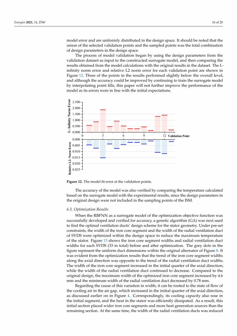
The process of model validation began by using the design parameters from thevalidation dataset as input to the constructed surrogate model, and then comparing theresults obtained from the model calculations with the original results in the dataset. The L-infinity norm error and relative L2 norm error for each validation point are shown inFigure 12. Three of the points in the results performed slightly below the overall level,and although the accuracy could be improved by continuing to train the surrogate modelby interpolating point fills, this paper will not further improve the performance of themodel as its errors were in line with the initial expectations.
0 3 6 9 120.000
0.500
1.000
1.500
2.000
2.500
L- In
finity
Nor
m E
rror
0.000
0.005
0.010
0.015
0.020
0.025
Validation Point
Rela
tive L
2- N
orm
Err
or
Figure 12. The model fit error at the validation points.
The accuracy of the model was also verified by comparing the temperature calculatedbased on the surrogate model with the experimental results, since the design parameters inthe original design were not included in the sampling points of the ISM.
6.3. Optimization Results
When the RBFNN as a surrogate model of the optimization objective function wassuccessfully developed and verified for accuracy, a genetic algorithm (GA) was next usedto find the optimal ventilation ducts’ design scheme for the stator geometry. Under pre-setconstraints, the width of the iron core segment and the width of the radial ventilation ductof SVDS were optimized within the design space to reduce the maximum temperatureof the stator. Figure 13 shows the iron core segment widths and radial ventilation ductwidths for each SVDS (33 in total) before and after optimization. The grey dots in thefigure represent the uniform duct dimensions within the original alternator of Figure 8. Itwas evident from the optimization results that the trend of the iron core segment widthsalong the axial direction was opposite to the trend of the radial ventilation duct widths.The width of the iron core segment increased in the initial quarter of the axial direction,while the width of the radial ventilation duct continued to decrease. Compared to theoriginal design, the maximum width of the optimized iron core segment increased by 4.6mm and the minimum width of the radial ventilation duct decreased by 0.78 mm.
Regarding the cause of this variation in width, it can be rooted to the state of flow ofthe cooling air in the air gap, which increased in the initial quarter of the axial direction,as discussed earlier on in Figure 4. Correspondingly, its cooling capacity also rose inthe initial segment, and the heat in the stator was efficiently dissipated. As a result, thisinitial section placed wider iron core segments and more heat generation sources than theremaining section. At the same time, the width of the radial ventilation ducts was reduced

Energies 2021, 14, 2760 17 of 20
in order to avoid excessive consumption of the cooling capacity in the initial section, sothat more cooling air could flow to the places where the heat was not easily dissipated (i.e.,towards the back section).
34.036.038.040.042.044.0
0 5 10 15 20 25 30 357.07.58.08.59.09.5
10.0
Cor
e Wid
th(m
m)
Original duct design Optimized duct design
Ven
t Duc
t Wid
th(m
m)
SVDS Number
Figure 13. The width of each SVDS radial vent duct and iron core segment.Indeed, in the original design with uniform duct design, the initial section consumed
a large amount of cooling air, which significantly reduced the temperature, but left theremaining back-sections with insufficient cooling capacity which translates to a temperaturerise therein (and also a temperature gradient). Figure 14 presents the maximum temperaturefor each axially distributed SVDS before and after optimization. In the original design,the axial temperature difference reached 15 ◦C, while with the optimized design thetemperature was uniformly distributed at 117 ◦C. The maximum temperature of the statorwas thus reduced by a significant 7.6 ◦C. Considering that the maximum temperature isof key importance to electrical machine reliability, a uniform temperature distribution isbeneficial to machine performance.
0 200 400 600 800 1000 1200 1400 1600
110
112
114
116
118
120
122
124
126
Max
Tem
pera
ture
()
Axial Location(mm)
Optimized duct design Original duct design
Figure 14. Temperature improvement with innovative non-uniform duct design methodology.

Energies 2021, 14, 2760 18 of 20
7. Discussion
The SVDS method proposed within this paper for stator cooling is currently applicablein the case of forced air cooling with uniform air gap (non-salient pole rotor), and is lesscomprehensive in considering the heat dissipation at the end of the stator. Future work willadapt the method to a broader range of cooling types while proposing an analysis modulefor stator end-heat dissipation in order to improve the versatility and flexibility of SVDS.In terms of surrogate modelling, the focus of the approach proposed in this paper, whichcombines ISM and RBFNN, lies in the characteristics of the design parameters in relationto the objective performance. Generally, the variation of such characteristics is smooth,but the introduction of uncertainties such as engineering manufacturing process factors andexternal environmental disturbance will bias the model, which could affect the validity ofthe optimization. Therefore, it is meaningful to introduce reliable uncertainty managementon the establishment of surrogate models [9–11]. Besides, future work will attempt touse interpretable machine learning tools for effectively quantifying the importance andcorrelations of design parameters together with their effects on objective performancein different physical fields. This allows to gather more information about the designspace from the perspective of the data source [41,42]. For the correction of the surrogatemodel errors, non-uniform sampling, space-filling techniques [43] could be employed toimprove the fidelity of the model through error-feedback, forming a closed-loop modelestablishment process.
8. Conclusions
In this paper a novel design methodology of the stator non-uniform radial ventila-tion ducts for large high-power MW-class alternators is presented. Through the designof the specific geometries and axial position of each duct, the maximum stator tempera-ture is reduced while markedly narrowing the differences in the axial distribution of thestator temperatures.
To simplify the model complexity and reduce the computational volume of themodel, the stator is axially decomposed into several SVDSs connected in series during thenumerical-based electromagnetic and temperature analysis calculations. The dimensionsof the SVDS are optimized by NSGA II and RBFNN surrogate model according to thedependence of the cooling effect and the heat generation of the stator on the geometry.The ISM method that trade-offs the number of numerical calculations with the accuracy ofthe fit is proposed in this paper to improve the efficiency of the RBFNN model approxi-mation. The optimization with the proposed method resulted in a 7.6 ◦C reduction in themaximum temperature and a more uniform axial temperature compared to the original15MW baseline design.
Finally, the accuracy of the SVDS and the RBFNN surrogate model were experimen-tally verified on an alternator. The stator non-uniform ventilation ducts design methodol-ogy proposed in this paper provides an integral and comprehensive design scheme for theanalysis of electromagnetic-thermal coupled fields in high-power MW-class alternators.It not only presents novel solutions for model simplification and the surrogate modelsampling, but also significantly reduces the computational cost of the entire procedure.
Author Contributions: conceptualization, R.L. and H.L.; data curation, W.L.; formal analysis, P.C.and D.G. Investigation, R.L.; methodology, R.L., H.L., W.L., D.G. and Y.H.; project administration, P.C.;resources, P.C.; supervision, H.L., D.G. and Y.H.; writing—original draft, R.L.; writing—review andediting, D.G. and Y.H. All authors have read and agreed to the published version of the manuscript.
Funding: This research received no external funding.
Institutional Review Board Statement: Not applicable.
Informed Consent Statement: Not applicable.
Conflicts of Interest: The authors declare no conflict of interest.

Energies 2021, 14, 2760 19 of 20
AbbreviationsThe following abbreviations are used in this manuscript:
BBD Box-Behnken DesignCCD Central Composite DesignCFD Computational Fluid DynamicsCHT Conjugate Heat TransferDT Digital TwinEM FEM Electromagnetic Finite Element MethodFCCD Face-centered Central Composite DesignGA Genetic AlgorithmISM Isometric Sampling MethodLHS Latin Hypercube SamplingRBFNN Radial Basis Function Neural NetworkSVDS Single Ventilation Duct Subsystem
References1. Galea, M.; Gerada, C.; Raminosoa, T.; Wheeler, P. A Thermal Improvement Technique for the Phase Windings of Electrical
Machines. IEEE Trans. Ind. Appl. 2012, 48, 79–87, doi:10.1109/TIA.2011.2175470.2. Nuzzo, S.; Galea, M.; Gerada, C.; Brown, N. Analysis, Modeling, and Design Considerations for the Excitation Systems of
Synchronous Generators. IEEE Trans. Ind. Electron. 2018, 65, 2996–3007, doi:10.1109/TIE.2017.2756592.3. Boglietti, A.; Cavagnino, A.; Staton, D.; Shanel, M.; Mueller, M.; Mejuto, C. Evolution and Modern Approaches for Thermal
Analysis of Electrical Machines. IEEE Trans. Ind. Electron. 2009, 56, 871–882, doi:10.1109/TIE.2008.2011622.4. Staton, D. Thermal computer aided design-advancing the revolution in compact motors. In Proceedings of the IEMDC 2001.
IEEE International Electric Machines and Drives Conference (Cat. No.01EX485); IEEE: New York, NY, USA, 2001; pp. 858–863,doi:10.1109/IEMDC.2001.939420.
5. Boglietti, A.; Cavagnino, A.; Lazzari, M.; Pastorelli, M. A simplified thermal model for variable-speed self-cooled industrialinduction motor. IEEE Trans. Ind. Appl. 2003, 39, 945–952, doi:10.1109/TIA.2003.814555.
6. Boglietti, A.; Carpaneto, E.; Cossale, M.; Vaschetto, S.; Popescu, M.; Staton, D. Stator winding thermal conductivity evalua-tion: An industrial production assessment. In Proceedings of the 2015 IEEE Energy Conversion Congress and Exposition (ECCE);IEEE: New York, NY, USA, 2015; pp. 4865–4871, doi:10.1109/ECCE.2015.7310346.
7. Bersch, K.; Nuzzo, S.; Connor, P.; Eastwick, C.; Rolston, R.; Galea, M. Thermal and Electromagnetic Stator Vent DesignOptimisation for Synchronous Generators. IEEE Trans. Energy Convers. 2020, 36, 207–217, doi:10.1109/TEC.2020.3004393.
8. Li, W.; Wang, P.; Li, D.; Zhang, X.; Cao, J.; Li, J. Multiphysical Field Collaborative Optimization of Premium Induction MotorBased on GA. IEEE Trans. Ind. Electron. 2018, 65, 1704–1710, doi:10.1109/TIE.2017.2752120.
9. Liu, K.; Hu, X.; Wei, Z.; Li, Y.; Jiang, Y. Modified Gaussian Process Regression Models for Cyclic Capacity Prediction ofLithium-Ion Batteries. IEEE Trans. Transp. Electrif. 2019, 5, 1225–1236, doi:10.1109/TTE.2019.2944802.
10. Liu, K.; Li, Y.; Hu, X.; Lucu, M.; Widanage, W.D. Gaussian Process Regression With Automatic Relevance Determination Kernel forCalendar Aging Prediction of Lithium-Ion Batteries. IEEE Trans. Ind. Inform. 2020, 16, 3767–3777, doi:10.1109/TII.2019.2941747.
11. Liu, K.; Shang, Y.; Ouyang, Q.; Widanage, W.D. A Data-Driven Approach With Uncertainty Quantification for Predict-ing Future Capacities and Remaining Useful Life of Lithium-ion Battery. IEEE Trans. Ind. Electron. 2021, 68, 3170–3180,doi:10.1109/TIE.2020.2973876.
12. Sun, X.; Shi, Z.; Lei, G.; Guo, Y.; Zhu, J. Multi-Objective Design Optimization of an IPMSM Based on Multilevel Strategy.IEEE Trans. Ind. Electron. 2021, 68, 139–148, doi:10.1109/TIE.2020.2965463.
13. Zhao, W.; Ma, A.; Ji, J.; Chen, X.; Yao, T. Multiobjective Optimization of a Double-Side Linear Vernier PM Motor Using ResponseSurface Method and Differential Evolution. IEEE Trans. Ind. Electron. 2020, 67, 80–90, doi:10.1109/TIE.2019.2893848.
14. Ma, C.; Qu, L. Multiobjective Optimization of Switched Reluctance Motors Based on Design of Experiments and Particle SwarmOptimization. IEEE Trans. Energy Convers. 2015, 30, 1144–1153, doi:10.1109/TEC.2015.2411677.
15. Ng, W.W.Y.; Chan, Y.; Chan, P.P.K.; Yeung, D.S. Empirical study on the architecture selection of RBFNN using L-GEM formulti-class problems. In Proceedings of the 2011 International Conference on Machine Learning and Cybernetics, Guilin, China,10–13 July 2011; Volume 2, pp. 723–726, doi:10.1109/ICMLC.2011.6016842.
16. Sh-eldin, M.; Alghoul, F.O.; Abouhnik, A.; Sopian, K.; Muftah. M, A. Predication of air velocity in Solar Chimney using RBFNN.2012 7th International Conference on Computing and Convergence Technology (ICCCT), Seoul, Korea, 3–5 December 2012;pp. 976–979.
17. Yu, W.; Hua, W.; Qi, J.; Zhang, H.; Zhang, G.; Xiao, H.; Xu, S.; Ma, G. Coupled Magnetic Field-Thermal Network Analysisof Modular-Spoke-Type Permanent-Magnet Machine for Electric Motorcycle. IEEE Trans. Energy Convers. 2020, 36, 120–130,doi:10.1109/TEC.2020.3006098.

Energies 2021, 14, 2760 20 of 20
18. Qiu, H.; Wang, S.; Sun, F.; Wang, Z.; Zhang, N. Transient Electromagnetic Field Analysis for the Single-Stage Fast LinearTransformer Driver With Two Different Configurations Using the Finite-Element Method and Finite Integration Technique.IEEE Trans. Magn. 2020, 56, 1–5, doi:10.1109/TMAG.2019.2956212.
19. Boglietti, A.; Cavagnino, A.; Staton, D. Determination of Critical Parameters in Electrical Machine Thermal Models.IEEE Trans. Ind. Appl. 2008, 44, 1150–1159, doi:10.1109/TIA.2008.926233.
20. Gai, Y.; Kimiabeigi, M.; Chuan Chong, Y.; Widmer, J.D.; Deng, X.; Popescu, M.; Goss, J.; Staton, D.A.; Steven, A. Cooling ofAutomotive Traction Motors: Schemes, Examples, and Computation Methods. IEEE Trans. Ind. Electron. 2019, 66, 1681–1692,doi:10.1109/TIE.2018.2835397.
21. Ayachit, A.; Kazimierczuk, M.K. Thermal Effects on Inductor Winding Resistance at High Frequencies. IEEE Magn. Lett.2013, 4, 0500304, doi:10.1109/LMAG.2013.2286582.
22. Dorfman, A.S. Conjugate Problems in Convective Heat Transfer; CRC Press: Boca Raton, FL, USA, 2009; pp. 33487–2742.23. Huang, Y.; Dong, J.; Zhu, J.; Guo, Y. Core Loss Modeling for Permanent-Magnet Motor Based on Flux Variation Locus and
Finite-Element Method. IEEE Trans. Magn. 2012, 48, 1023–1026, doi:10.1109/TMAG.2011.2174201.24. Walter-Krause, A. Application of Conjugate Heat Transfer Simulations for the Development of Ventilation and Cooling
Systems for Large Hydro Generators. In Proceedings of the 2018 XIII International Conference on Electrical Machines (ICEM),Alexandroupoli, Greece, 3–6 September 2018; pp. 2633–2639, doi:10.1109/ICELMACH.2018.8507248.
25. Ding, S.N. Heating and Cooling of Large Electrical Machines; Science Press: Beijing, China, 1992.26. Lourenco, J.M.; Lebensztajn, L. Surrogate Modeling and Two-Level Infill Criteria Applied to Electromagnetic Device Optimization.
IEEE Trans. Magn. 2015, 51, 1–4, doi:10.1109/TMAG.2014.2362980.27. Raphael , H.T.; Villanueva, D.; Chaudhuri, A. Parallel surrogate-assisted global optimization with expensivefunctions—A survey.
Struct. Multidiscip. Optim. 2016, 54, 3–13, doi:10.1007/s00158-016-1432-3.28. Parnianifard, A.; Azfanizam, A.S.; Ariffin, M.K.A.; Ismail, M.I.S.; Ebrahim, N. Recent developments in metamodel based robust
black-box simulation optimization An overview. Decis. Sci. Lett. 2019, 8, 17–44, doi:10.5267/j.dsl.2018.5.004.29. Weng, W.C.; Yang, F.; Elsherbeni, A. Electromagnetics and Antenna Optimization Using Taguchi’s Method.
Synthesis Lectures on Computational Electromagnetics 2007, 2, 1–94, doi:10.2200/S00083ED1V01Y200710CEM018.30. Singh, C.; Jirutitijaroen, P.; Mitra, J., Monte Carlo Simulation. In Electric Power Grid Reliability Evaluation: Models and Methods;
IEEE: New York, NY, USA, 2019; pp. 165–183, doi:10.1002/9781119536772.ch6.31. Hong, Y.; Lin, F.; Yu, T. Taguchi method-based probabilistic load flow studies considering uncertain renewables and loads.
IET Renew. Power Gener. 2016, 10, 221–227, doi:10.1049/iet-rpg.2015.0196.32. Li, R.; Cheng, P.; Hong, Y.; Lan, H.; Yin, H. Design Synchronous Generator Using Taguchi-Based Multi-Objective Optimization.
Energies 2020, 13, 3337, doi:10.3390/en13133337.33. Forrester, A.I.J.; Sobester, A.; Keane, A.J. Engineering Design via Surrogate Modelling A Practical Guide; John Wiley & Sons:
Chichester, UK, 2008.34. Johnson, M.; Moore, L.; Ylvisaker, D. Minimax and maximin distance designs. J. Stat. Plan. Inference 1990, 26, 131–148,
doi:10.1016/0378-3758(90)90122-B.35. Morris, M.D.; Mitchell, T.J. Exploratory designs for computational experiments. J. Stat. Plan. Inference 1995, 43, 381–402,
doi:10.1016/0378-3758(94)00035-T.36. Xie, S.; Xie, Y.; Huang, T.; Gui, W.; Yang, C. Generalized Predictive Control for Industrial Processes Based on Neuron Adaptive
Splitting and Merging RBF Neural Network. IEEE Trans. Ind. Electron. 2019, 66, 1192–1202, doi:10.1109/TIE.2018.2835402.37. Wang, D.; Li, Y.; Yuan, T.; Zhou, S.; Wang, X.; Tian, W.; Liu, Z.; Miao, S.; Liu, J. Modeling Method for Robot Servo System
Based on IGSA-RBFNN. In Proceedings of the 2018 37th Chinese Control Conference (CCC), Wuhan, China, 25–27 July 2018;pp. 5587–5590, doi:10.23919/ChiCC.2018.8483880.
38. Mallik, S.; Mallik, K.; Barman, A.; Maiti, D.; Biswas, S.K.; Deb, N.K.; Basu, S. Efficiency and Cost Optimized Design of anInduction Motor Using Genetic Algorithm. IEEE Trans. Ind. Electron. 2017, 64, 9854–9863, doi:10.1109/TIE.2017.2703687.
39. Haupt, R.L. An introduction to genetic algorithms for electromagnetics. IEEE Antennas Propag. Mag. 1995, 37, 7–15,doi:10.1109/74.382334.
40. Barricelli, B.R.; Casiraghi, E.; Fogli, D. A Survey on Digital Twin: Definitions, Characteristics, Applications, and DesignImplications. IEEE Access 2019, 7, 167653–167671, doi:10.1109/ACCESS.2019.2953499.
41. Liu, K.; Hu, X.; Zhou, H.; Tong, L.; Widanalage, D.; Marco, J. Feature Analyses and Modelling of Lithium-ion BatteriesManufacturing based on Random Forest Classification. IEEE ASME Trans. Mechatron. 2021, 1, doi:10.1109/TMECH.2020.3049046.
42. Liu, K.; Wei, Z.; Yang, Z.; Li, K. Mass load prediction for lithium-ion battery electrode clean production: A machine learningapproach. J. Clean. Prod. 2020, 289, doi:10.1016/j.jclepro.2020.125159.
43. Lei, G.; Zhu, J.; Guo, Y. Multidisciplinary Design Optimization Methods for Electrical Machines and Drive Systems, 1st ed.; Springer:Berlin/Heidelberg, Germany, 2016; doi:10.1007/978-3-662-49271-0.