stanfield, oregon - public works standards
TRANSCRIPT

LA GRANDE, OR. WALLA WALLA, WA. REDMOND, OR. HERMISTON, OR.
2018
City of
Stanfield, OregonPublic Works standards
technical sPecifications and draWings
1901 N. Fir StreetLa Grande, Oregon 97850
(541) 963-8309 www.andersonperry.com


4/9/18 i Table of Contents G:\Clients\Stanfield\339‐109 Gen Eng\PWStandards\Tech Specs\TOC.doc Anderson Perry & Associates, Inc.
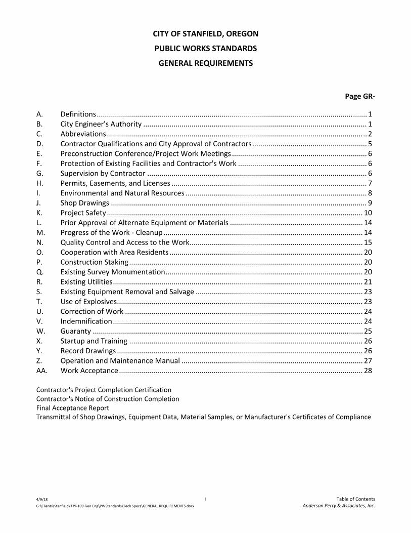
TABLE OF CONTENTS TITLE PAGE RESPONSIBILITY STATEMENT FOR USE OF STANDARDS USE AGREEMENT Date Page GENERAL REQUIREMENTS ................................................................. 04/2018
A. Definitions .................................................................................................... GR‐1 B. City Engineer's Authority ............................................................................. GR‐1 C. Abbreviations ............................................................................................... GR‐2 D. Contractor Qualifications and City Approval of Contractors ....................... GR‐5 E. Preconstruction Conference/Project Work Meetings ................................. GR‐6 F. Protection of Existing Facilities and Contractor's Work .............................. GR‐6 G. Supervision by Contractor ........................................................................... GR‐6 H. Permits, Easements, and Licenses ............................................................... GR‐7 I. Environmental and Natural Resources ........................................................ GR‐8 J. Shop Drawings ............................................................................................. GR‐9 K. Project Safety ............................................................................................. GR‐10 L. Prior Approval of Alternate Equipment or Materials ................................ GR‐14 M. Progress of the Work ‐ Cleanup ................................................................. GR‐14 N. Quality Control and Access to the Work .................................................... GR‐15 O. Cooperation with Area Residents .............................................................. GR‐20 P. Construction Staking .................................................................................. GR‐20 Q. Existing Survey Monumentation ................................................................ GR‐20 R. Existing Utilities .......................................................................................... GR‐21 S. Existing Equipment Removal and Salvage ................................................. GR‐23 T. Use of Explosives ........................................................................................ GR‐23 U. Correction of Work .................................................................................... GR‐24 V. Indemnification .......................................................................................... GR‐24 W. Guaranty .................................................................................................... GR‐25 X. Startup and Training .................................................................................. GR‐26 Y. Record Drawings ........................................................................................ GR‐26 Z. Operation and Maintenance Manual ........................................................ GR‐27 AA. Work Acceptance ....................................................................................... GR‐28 Contractor's Project Completion Certification Contractor's Notice of Construction Completion Final Acceptance Report Transmittal of Shop Drawings, Equipment Data, Material Samples, or Manufacturer's Certificates of Compliance

4/9/18 ii Table of Contents G:\Clients\Stanfield\339‐109 Gen Eng\PWStandards\Tech Specs\TOC.doc Anderson Perry & Associates, Inc.
TECHNICAL SPECIFICATIONS Section 1 ‐ Water Lines ...................................................................... 04/2018
Part 1 ‐ General .......................................................................................................... 1‐1 Part 2 ‐ Materials ....................................................................................................... 1‐2 Part 3 ‐ Execution ....................................................................................................... 1‐9
Section 2 ‐ Sanitary Sewer Lines ........................................................ 04/2018
Part 1 ‐ General .......................................................................................................... 2‐1 Part 2 ‐ Materials ....................................................................................................... 2‐3 Part 3 ‐ Execution ..................................................................................................... 2‐10
Section 3 ‐ Excavation and Backfill of Trenches .................................. 04/2018
Part 1 ‐ General .......................................................................................................... 3‐1 Part 2 ‐ Materials ....................................................................................................... 3‐2 Part 3 ‐ Execution ....................................................................................................... 3‐3
Section 4 ‐ Surface Restoration .......................................................... 04/2018
Part 1 ‐ General .......................................................................................................... 4‐1 Part 2 ‐ Materials ....................................................................................................... 4‐1 Part 3 ‐ Execution ....................................................................................................... 4‐4
Section 5 ‐ Road Work ....................................................................... 04/2018
Part 1 ‐ General .......................................................................................................... 5‐1 Part 2 ‐ Materials ....................................................................................................... 5‐1 Part 3 ‐ Execution ....................................................................................................... 5‐6
Section 6 ‐ Concrete Curb and Gutter, Cross Gutters, Sidewalk, and Driveway Transitions ......................................................................... 04/2018
Part 1 ‐ General .......................................................................................................... 6‐1 Part 2 ‐ Materials ....................................................................................................... 6‐1 Part 3 ‐ Execution ....................................................................................................... 6‐4
Section 7 ‐ Storm Drainage ................................................................ 04/2018
Part 1 ‐ General .......................................................................................................... 7‐1 Part 2 ‐ Materials ....................................................................................................... 7‐2 Part 3 ‐ Execution ....................................................................................................... 7‐6
Section 8 ‐ Underground Utilities ....................................................... 04/2018
Part 1 ‐ General .......................................................................................................... 8‐1 Part 2 ‐ Materials ....................................................................................................... 8‐2 Part 3 ‐ Execution ....................................................................................................... 8‐2

4/9/18 iii Table of Contents G:\Clients\Stanfield\339‐109 Gen Eng\PWStandards\Tech Specs\TOC.doc Anderson Perry & Associates, Inc.
STANDARD DRAWINGS Index I1 Index Standard Water Details W1 Water Service Line Plan and Sections Details W2 Water Meter Details 1" or Smaller Installation W3 Water Meter Details 1 1/2" or 2" Installation W4 Valve Box and Continuous Locating Wire Detail W5 Concrete Collar Details W6 Fire Hydrant and Auxiliary Valve Detail W7 Fire Hydrant Barricade W8 Water Main and Service Line Stub Details W9 Thrust Block Details W10 Water‐Sewer Crossing W11 Water Air Release Valve Standard Sewer Details S1 Standard Precast Manhole S2 Manhole Base and Construction Notes S3 Drop Precast Manhole S4 Sewer Cleanouts S5 Cover Paving Details S6 Sewer Service Line S7 Water‐Sewer Crossing Standard Trench Details T1 Trench Details T2 Trench Restoration Gravel and Pavement Areas T3 Trench Restoration Lawn, Landscaped and Natural Areas Standard Street Details R1 Typical Section Local Street R2 Typical Section Collector Street R3 Typical Section Arterial Street R4 Typical Cul‐de‐Sac R5 Utility Locations R6 Concrete Curb and Gutter Detail R7 Concrete Valley Gutter Section R8 Spill Gutter Detail R9 Sidewalk and Curb and Gutter and Ramp Details R10 Sidewalk Jointing Detail R11 Driveway/Alley Approach R12 Curb Ramp Details R13 Driveway/Curb Ramp Detail

4/9/18 iv Table of Contents G:\Clients\Stanfield\339‐109 Gen Eng\PWStandards\Tech Specs\TOC.doc Anderson Perry & Associates, Inc.
R14 Monument Box Detail R15 Typical Catch Basin Detail R16 Sign Details

4/9/2018 G:\Clients\Stanfield\339‐109 Gen Eng\PWStandards\Tech Specs\Responsibility‐Use Agmt.doc
CITY OF STANFIELD, OREGON PUBLIC WORKS STANDARDS
2018
RESPONSIBILITY STATEMENT FOR USE OF STANDARDS
These City of Stanfield Public Works Standards ‐ Technical Specifications and Standard Drawings have been prepared by Anderson Perry & Associates, Inc., for exclusive use by the City of Stanfield on public works infrastructure projects within the public rights‐of‐way within the City of Stanfield that the City will own, operate, and maintain. The Standards are intended to be general in nature and set minimum guidance for projects within the City. Use of these Technical Specifications and Standard Drawings or any portion thereof on projects outside of the City of Stanfield is strictly prohibited without written approval of the City of Stanfield and Anderson Perry & Associates, Inc. Electronic copies of these Standard Drawings will be provided to third‐party licensed civil engineers only upon receipt of a certification from the third party that these materials will be utilized only on projects within the City of Stanfield's jurisdiction. All users of these documents on projects within the City shall modify and edit these documents as needed to adapt their use for the specific project for which they will be used. The use of the City of Stanfield's Public Works Standards, Technical Specifications, and Standard Drawings, or modifications thereto, shall be stamped and signed by the responsible engineer and shall be submitted to the City of Stanfield for review prior to their use on a project within the City. All third‐party users agree to indemnify, defend, and hold the City of Stanfield, Oregon, and Anderson Perry & Associates, Inc., its partners, agents, and employees harmless from and against any and all claims, suits, demands, losses, and expenses including attorneys’ fees accruing or resulting from any and all persons, firms, or any other legal entity on account of any damage or loss to property or persons, including death, arising out of the result of utilizing these Standard Technical Specifications and Standard Drawings.

4/9/2018 G:\Clients\Stanfield\339‐109 Gen Eng\PWStandards\Tech Specs\Responsibility‐Use Agmt.doc
CITY OF STANFIELD, OREGON PUBLIC WORKS STANDARDS
2018
USE AGREEMENT I hereby acknowledge and assume complete responsibility related to the use of the City of Stanfield Public Works Standards ‐ Technical Specifications and Standard Drawings, in regard to the _____________________________________________________ project. The undersigned third‐party user hereby certifies and agrees to use these Public Works Standards on projects only within the jurisdiction of the City of Stanfield, Oregon. It is agreed that these Standards will not be used in any form on projects outside the jurisdiction of the City of Stanfield and the undersigned will not make these Standards available to any other outside party or user. Supplemental conditions will be provided to identify modifications and edits to these Technical Specifications needed to meet the specific requirements of said project. If supplemental conditions are not prepared, the undersigned hereby takes full responsibility for the applicability of these Technical Specifications and Standard Drawings for the project. The undersigned hereby agrees to use these Standard Drawings on their project. If required, the undersigned hereby further agrees to modify and edit these Standard Drawings as needed to adapt their use for the specific project for which they will be used, as approved by the City and/or Anderson Perry & Associates, Inc. All use of these Standards shall be under the direction of a licensed civil engineer in the state of Oregon, and all Standard Drawings used shall be stamped by the engineer. The undersigned agrees to indemnify, defend, and hold the City of Stanfield, Oregon, and Anderson Perry & Associates, Inc., its partners, agents, and employees harmless from and against any and all claims, suits, demands, losses, and expenses including attorneys’ fees accruing or resulting from any and all persons, firms, or any other legal entity on account of any damage or loss to property or persons, including death, arising out of the result of utilizing these Standard Technical Specifications and Standard Drawings.
CONTRACTOR OR DESIGN ENGINEER:
By: ______________________________ (Signature)
Print Name: ______________________________
Contractor: ______________________________
Responsible Design Engineer: ______________________________ (as applicable)
Contractor's CCB License Number: ______________________________
CCB License Expiration Date: ______________________________

GENERAL REQUIREMENTS
CITY OF STANFIELD, OREGON
PUBLIC WORKS STANDARDS
GENERAL REQUIREMENTS
4/9/18 i Table of Contents G:\Clients\Stanfield\339‐109 Gen Eng\PWStandards\Tech Specs\GENERAL REQUIREMENTS.docx Anderson Perry & Associates, Inc.
Page GR‐
A. Definitions ...................................................................................................................................... 1 B. City Engineer's Authority ............................................................................................................... 1 C. Abbreviations ................................................................................................................................. 2 D. Contractor Qualifications and City Approval of Contractors ......................................................... 5 E. Preconstruction Conference/Project Work Meetings ................................................................... 6 F. Protection of Existing Facilities and Contractor's Work ................................................................ 6 G. Supervision by Contractor ............................................................................................................. 6 H. Permits, Easements, and Licenses ................................................................................................. 7 I. Environmental and Natural Resources .......................................................................................... 8 J. Shop Drawings ............................................................................................................................... 9 K. Project Safety ............................................................................................................................... 10 L. Prior Approval of Alternate Equipment or Materials .................................................................. 14 M. Progress of the Work ‐ Cleanup ................................................................................................... 14 N. Quality Control and Access to the Work ...................................................................................... 15 O. Cooperation with Area Residents ................................................................................................ 20 P. Construction Staking .................................................................................................................... 20 Q. Existing Survey Monumentation .................................................................................................. 20 R. Existing Utilities ............................................................................................................................ 21 S. Existing Equipment Removal and Salvage ................................................................................... 23 T. Use of Explosives .......................................................................................................................... 23 U. Correction of Work ...................................................................................................................... 24 V. Indemnification ............................................................................................................................ 24 W. Guaranty ...................................................................................................................................... 25 X. Startup and Training .................................................................................................................... 26 Y. Record Drawings .......................................................................................................................... 26 Z. Operation and Maintenance Manual .......................................................................................... 27 AA. Work Acceptance ......................................................................................................................... 28 Contractor's Project Completion Certification Contractor's Notice of Construction Completion Final Acceptance Report Transmittal of Shop Drawings, Equipment Data, Material Samples, or Manufacturer's Certificates of Compliance

CITY OF STANFIELD, OREGON
PUBLIC WORKS STANDARDS
GENERAL REQUIREMENTS
4/9/18 GR‐1 General Requirements G:\Clients\Stanfield\339‐109 Gen Eng\PWStandards\Tech Specs\GENERAL REQUIREMENTS.docx. Anderson Perry & Associates, Inc.
A. DEFINITIONS
1. City ‐ City of Stanfield, Oregon, a municipal corporation and authorized City Personnel.
2. City Engineer ‐ The Engineer, and his/her representative, authorized by the City of Stanfield to act as the City’s representative in engineering matters as they relate to improvements to the City’s infrastructure or construction of new infrastructure to be built by developers and then dedicated to the City.
3. Contractor ‐ The person, firm, or corporation that has contracted to construct City infrastructure improvements for which the City will ultimately have ownership; or a developer, and including the developer’s engineer, construction inspector, etc.
4. Drawings ‐ The Project Plans prepared by a Professional Engineer licensed in the State of Oregon that depict the detailed characteristics and scope of work for a particular infrastructure improvement project; and the City Standard Details.
5. Specifications ‐ The detailed project specifications prepared by a registered Professional Engineer that consist of written descriptions of a technical nature of materials, equipment, construction systems, standards, and workmanship for a particular infrastructure improvement project; and the City Standard Technical Specifications.
B. CITY ENGINEER'S AUTHORITY
1. The City Engineer shall act as the City's representative on the project, and shall decide questions which may arise as to quality and acceptability of materials furnished and work performed. The City Engineer may make visits to the site and determine if the work is proceeding in accordance with the Drawings and Specifications. The City Engineer, however, does not guarantee the performance of the Contractor by the City Engineer's providing of such review. The City Engineer's undertaking hereunder shall not relieve the Contractor of his/her obligation to perform the work in conformity with the Drawings and Specifications and in a workmanlike manner; shall not make the City Engineer an insurer of the Contractor's performance; shall not impose upon the City Engineer any obligations to see that the work is performed in a safe manner; and shall not relieve the Contractor from his/her responsibility to adequately supervise the work.
2. The City Engineer will not be responsible for the construction means, controls, techniques, sequences, procedures, or construction safety.

CITY OF STANFIELD, OREGON
PUBLIC WORKS STANDARDS
GENERAL REQUIREMENTS
4/9/18 GR‐2 General Requirements G:\Clients\Stanfield\339‐109 Gen Eng\PWStandards\Tech Specs\GENERAL REQUIREMENTS.docx. Anderson Perry & Associates, Inc.
C. ABBREVIATIONS
The following abbreviations of Associations, units of measurement, and miscellaneous items are defined as they may be used in these Public Works Standards or on the Standard Drawings. This list may not be all‐inclusive.
Associations
AASHTO American Association of State Highway and Transportation Officials ACI American Concrete Institute AGC Associated General Contractors of America AIA American Institute of Architects AISC American Institute of Steel Construction AISI American Iron and Steel Institute AITC American Institute of Timber Construction ANSI American National Standards Institute APA American Plywood Association APWA American Public Works Association AREA American Railway Engineering Association ASME American Society of Mechanical Engineers ASTM American Society for Testing and Materials AWS American Welding Society AWWA American Water Works Association CRSI Concrete Reinforcing Steel Institute DFPA Douglas Fir Plywood Association DIPRA Ductile Iron Pipe Research Association ICEA Insulated Cable Engineers Association IEEE Institute of Electrical and Electronics Engineers IPCEA Insulated Power Cable Engineers Association ITE Institute of Transportation Engineers NEMA National Electrical Manufacturer's Association NFPA National Fire Protection Association SAE Society of Automotive Engineers SDI Steel Door Institute SSPC Steel Structures Painting Council WWPA Western Wood Products Association
Codes and Acts
MUTCD Manual on Uniform Traffic Control Devices NEC National Electrical Code

CITY OF STANFIELD, OREGON
PUBLIC WORKS STANDARDS
GENERAL REQUIREMENTS
4/9/18 GR‐3 General Requirements G:\Clients\Stanfield\339‐109 Gen Eng\PWStandards\Tech Specs\GENERAL REQUIREMENTS.docx. Anderson Perry & Associates, Inc.
NEPA National Environmental Policy Act OAR Oregon Administrative Rules SEPA State Environmental Policy Act UBC Uniform Building Code UL Underwriters Laboratories, Inc. UPC Uniform Plumbing Code
Federal Agencies
BIA Bureau of Indian Affairs BLM Bureau of Land Management BOR Bureau of Reclamation DOD Department of Defense FHWA Federal Highway Administration LCDC Land Conservation and Development Commission NMFS National Marine Fisheries Service NRCS Natural Resources Conservation Service OSHA Occupational Safety and Health Administration USDA U.S. Department of Agriculture USEPA U.S. Environmental Protection Agency USFS U.S. Forest Service USFWS U.S. Fish and Wildlife Service
State Agencies
DEQ Oregon Department of Environmental Quality DWS Oregon Health Authority ‐ Drinking Water Services ODF Oregon Department of Forestry ODFW Oregon Department of Fish and Wildlife ODOT Oregon Department of Transportation OWRD Oregon Water Resources Department
Units of Measurement and Abbreviation (Partial Listing)
AC Asbestos Cement or Asphalt Concrete ACP Asphalt Concrete Pavement BST Bituminous Surface Treatment C.I. Cast Iron CL Centerline C.O. Clean Out

CITY OF STANFIELD, OREGON
PUBLIC WORKS STANDARDS
GENERAL REQUIREMENTS
4/9/18 GR‐4 General Requirements G:\Clients\Stanfield\339‐109 Gen Eng\PWStandards\Tech Specs\GENERAL REQUIREMENTS.docx. Anderson Perry & Associates, Inc.
Cl. Class cfm Cubic Feet Per Minute Conc. Concrete Culv. Culvert CY, C.Y., or Cu.Yd. Cubic Yard(s) DI Ductile Iron Dia. Diameter Ea. Each Elev., EL, or El. Elevation Est. Estimate or Estimated Extg. Existing F Fahrenheit F.F. Finished Floor FLG Flange fps Feet Per Second Ft. Foot or Feet gpm Gallons Per Minute HDPE High Density Polyethylene HMAC Hot‐Mix Asphalt Concrete Hp Horsepower I.D. Inside Diameter I/I Infiltration/Inflow In. Inch or Inches Incl. Including Inv.El. Invert Elevation Irr Irrigation L Liter Lb. Pound(s) L.F. or Lin.Ft. Linear Foot (Feet) LS or L.S. Lump Sum Max. Maximum MH Manhole MJ Mechanical Joint Min. Minimum MPH Miles Per Hour N.T.S. Not to Scale O.C. On Center O.D. Outside Diameter PL Plate PVC Polyvinyl Chloride

CITY OF STANFIELD, OREGON
PUBLIC WORKS STANDARDS
GENERAL REQUIREMENTS
4/9/18 GR‐5 General Requirements G:\Clients\Stanfield\339‐109 Gen Eng\PWStandards\Tech Specs\GENERAL REQUIREMENTS.docx. Anderson Perry & Associates, Inc.
psi Pounds Per Square Inch Q Flow Rate R Radius REQD. Required RPM Revolutions Per Minute R/W Right‐of‐Way S Sanitary Sewer SCH Schedule SD Storm Drain SF, S.F., or Sq.Ft. Square Foot Sht. Sheet Stl. Steel SWL Static Water Level SY, S.Y., or Sq.Yd. Square Yard TDH Total Dynamic Head TM Test Method Typ. Typical W Water WS Wood Stave
D. CONTRACTOR QUALIFICATIONS AND CITY APPROVAL OF CONTRACTORS
All Contractors and Subcontractors proposing to complete infrastructure improvements and/or utility work in the City of Stanfield shall be duly qualified to perform the subject work (must document at least three public works projects of similar scope successfully completed in the last three years), licensed by the state of Oregon and the Construction Contractors Board (CCB), in good standing with the CCB, and hold the necessary bonds.
To demonstrate the Contractor's qualifications to perform the subject work within five days of the City's request, the Contractor shall submit (a) written evidence establishing their qualifications, such as financial data, previous experience, and present commitments, and (b) proposed subcontractor and equipment and materials supplier information. A Contractor's failure to submit required qualifications information within the terms indicated may disqualify the Contractor from completing the project at hand.
Approval of the Contractor shall be at the sole discretion of the City.

CITY OF STANFIELD, OREGON
PUBLIC WORKS STANDARDS
GENERAL REQUIREMENTS
4/9/18 GR‐6 General Requirements G:\Clients\Stanfield\339‐109 Gen Eng\PWStandards\Tech Specs\GENERAL REQUIREMENTS.docx. Anderson Perry & Associates, Inc.
E. PRECONSTRUCTION CONFERENCE/PROJECT WORK MEETINGS
1. Preconstruction Conference
A preconstruction conference shall be held prior to the Work commencing on the project. The Contractor, City, City Engineer, and other appropriate agencies, utilities, etc., shall attend. The meeting shall be held to discuss general contracting procedures, communications, roles and responsibilities, quality control, project work schedule, agency requirements, and other topics that relate to the Work as appropriate.
2. Project Work Meetings
The Contractor and/or his superintendent shall meet with the City and/or City Engineer on a regular basis to review the progress of the Work, Work schedule, project concerns, etc., as may be appropriate. These meetings will also be used to review Record Drawings being kept on the project by the Contractor.
F. PROTECTION OF EXISTING FACILITIES AND CONTRACTOR'S WORK
The Contractor shall exercise care during construction to avoid damaging existing pipes, valves, manholes and other underground and above ground structures. This applies especially to heavy equipment used during street excavations, and base rock operations. The Contractor shall exercise care when operating compaction equipment over pipes. Any piping and structures damaged shall be replaced or repaired by the Contractor, as specified by the utility owner, at no cost to the City.
The Contractor shall take reasonable precautions to protect the work in progress from damage by vandalism, and shall, where reasonably possible, secure the premises where work is being performed from entry by unauthorized persons.
G. SUPERVISION BY CONTRACTOR
1. The Contractor shall supervise and direct the work, and shall be solely responsible for the means, methods, techniques, quality, sequences, and procedures of construction. The Contractor shall employ and maintain on the work site a qualified supervisor or superintendent who shall have been designated in writing by the Contractor as the Contractor's representative at the site. The supervisor shall have full authority to act on behalf of the Contractor and all communications given to the supervisor shall be as binding as if given to the Contractor. The supervisor shall be present on the site at all times as required to perform adequate supervision and coordination of the work.

CITY OF STANFIELD, OREGON
PUBLIC WORKS STANDARDS
GENERAL REQUIREMENTS
4/9/18 GR‐7 General Requirements G:\Clients\Stanfield\339‐109 Gen Eng\PWStandards\Tech Specs\GENERAL REQUIREMENTS.docx. Anderson Perry & Associates, Inc.
If the Contractor does not have any personnel on site under his/her direct employ, but there are personnel under subcontract to the Contractor working on site, then the Contractor shall have either his/her designated Supervisor on site or the Contractor shall authorize, in writing, the Subcontractor to act as the Contractor's representative. All communications given to the Supervisor or Contractor's representative shall be as binding as if given to the Contractor.
2. The Contractor shall at all times enforce strict discipline and good order among his/her employees, and shall not employ on the job any unfit person or anyone not skilled in the work assigned to him. Any employee found to be incompetent, or to act in a disorderly or improper manner, shall be removed from the project.
H. PERMITS, EASEMENTS, AND LICENSES
Temporary permits and licenses necessary for the prosecution of the work including building, electrical and plumbing permits, NPDES Permit 1200‐C for erosion and sedimentation control, shall be obtained by the Contractor unless otherwise stated in the Drawings and Specifications. Permanent permits and licenses such as state highway permits, railroad crossing licenses, county road crossing permits, etc., shall be obtained by the Contractor. The Contractor shall comply with all requirements of these temporary and permanent permits and licenses as they relate to the work, i.e., insurance, traffic control, scheduling, etc. The Contractor shall pay all inspection fees, flagging costs, etc., if any, required by the permits or licenses.
The Contractor shall give all notices and comply with all laws, ordinances, rules and regulations bearing on the conduct of the work as drawn and specified. If the Contractor observes that the Drawings and Specifications are at variance therewith, he/she shall promptly notify the City Engineer in writing.
For City infrastructure projects, all easements and rights‐of way required for the work shall be obtained by the City. For infrastructure projects by others, all easements and rights‐of‐way required for the work shall be obtained by the developer and/or Contractor. The Contractor shall comply with all requirements of these easements and rights‐of way as they relate to the work, i.e., insurance, traffic control, scheduling, restoration, etc.

CITY OF STANFIELD, OREGON
PUBLIC WORKS STANDARDS
GENERAL REQUIREMENTS
4/9/18 GR‐8 General Requirements G:\Clients\Stanfield\339‐109 Gen Eng\PWStandards\Tech Specs\GENERAL REQUIREMENTS.docx. Anderson Perry & Associates, Inc.
I. ENVIRONMENTAL AND NATURAL RESOURCES
Pursuant to ORS 279.318, the agencies listed below may have enacted ordinances or regulations which deal with the prevention of environmental pollution or the preservation of natural resources. The Contractor shall comply with any ordinances or regulations enacted or adopted by these agencies.
Federal Agencies:
Department of Agriculture Forest Service Natural Resources Conservation Service Department of Defense Army Corps of Engineers Environmental Protection Agency Department of Interior Bureau of Sport Fisheries and Wildlife Bureau of Outdoor Recreation Bureau of Land Management Bureau of Indian Affairs Bureau of Reclamation Department of Labor Occupational Safety and Health Administration Department of Transportation Coast Guard Federal Highway Administration State Agencies: Department of Agriculture Department of Environmental Quality Department of Fish and Wildlife Department of Forestry Department of Geology and Mineral Industries Department of Human Resources
Department of State Lands Land Conservation and Development Commission
Oregon Health Authority Soil and Water Conservation Commission State Land Board Water Resources Department

CITY OF STANFIELD, OREGON
PUBLIC WORKS STANDARDS
GENERAL REQUIREMENTS
4/9/18 GR‐9 General Requirements G:\Clients\Stanfield\339‐109 Gen Eng\PWStandards\Tech Specs\GENERAL REQUIREMENTS.docx. Anderson Perry & Associates, Inc.
Local Agencies: City Council County Court Rural Fire Protection District Other Special Districts
J. SHOP DRAWINGS
The Contractor shall submit Shop Drawings or manufacturer's data sheets in accordance with the schedule of Shop Drawings and sample submittals. It should be noted that the City may require Shop Drawings for other items as may be deemed necessary. A minimum of 4 copies of each item shall be submitted.
The data shown on the Shop Drawings will be complete with respect to quantities, dimensions, specified performance and design criteria, materials, and similar data to show the City the services, materials, and equipment Contractor proposes to provide and to enable the City to review the information.
Any work performed prior to City's review and approval of the pertinent Shop Drawing will be at the sole expense and responsibility of Contractor.
All submittals or resubmittals shall be accompanied by and furnished in accordance with the Transmittal of Shop Drawings, Equipment Data, Material Samples, or Manufacturer’s Certificates of Compliance form provided at the end of these General Requirements. All submittals shall be submitted at a time sufficiently early to allow review of same by the City and to accommodate the rate of construction progress required under this Contract.
The City will return two prints of each shop drawing to the Contractor, with comments noted thereon, generally within 15 calendar days following their receipt at his/her office. The Contractor shall make any corrections required by the City and shall return the required number of corrected copies of Shop Drawings and resubmit new samples for review. The Contractor shall direct specific attention in writing to revisions other than the corrections called for by the City on previous submittals. It is considered reasonable that the Contractor shall make a complete and acceptable submittal to the City by the second submission of the drawing. The City reserves the right to withhold monies due the Contractor to cover additional costs of the City's review beyond the second submission.
1. If Shop Drawings are returned to the Contractor marked "NO EXCEPTIONS NOTED," formal revision and resubmittal of said Shop Drawings will not be required.

CITY OF STANFIELD, OREGON
PUBLIC WORKS STANDARDS
GENERAL REQUIREMENTS
4/9/18 GR‐10 General Requirements G:\Clients\Stanfield\339‐109 Gen Eng\PWStandards\Tech Specs\GENERAL REQUIREMENTS.docx. Anderson Perry & Associates, Inc.
2. If Shop Drawings are returned to the Contractor marked "NO EXCEPTIONS, PROVIDED THE FOLLOWING CONDITIONS ARE MET," formal revision and resubmittal of said Shop Drawings will not be required.
3. If Shop Drawings are returned to the Contractor marked "MAKE CORRECTIONS NOTED," formal revision and resubmittal of said Shop Drawings will not be required.
4. If Shop Drawings are returned to the Contractor marked "REVISE AND RESUBMIT," the Contractor shall revise said Shop Drawings and shall resubmit 4 copies of said revised Shop Drawings to the City.
5. If Shop Drawings are returned to the Contractor marked "REJECTED," the Contractor shall revise said Shop Drawings and resubmit 4 copies of said revised Shop Drawings to the City.
6. If Shop Drawings are returned to the Contractor marked "SUBMIT SPECIFIED ITEM," the Contractor shall submit material requested but shall not be required to resubmit all previous material.
For each resubmittal necessary, an additional 15 calendar days shall be allowed for review. The Contractor shall include copies of all approved submittal information in the Contractor’s Record Drawings and Operation and Maintenance Manual. A copy of each shop drawing and sample shall also be kept in good order by the Contractor at the job site and shall be available to the City.
K. PROJECT SAFETY
The Contractor shall be solely responsible for initiating, maintaining, and supervising all safety precautions and programs in connection with the Work, including excavation safety. The Contractor shall comply with all applicable laws, ordinances, rules, regulations, and orders of any public body having jurisdiction as it relates to project and work safety.
The Contractor shall maintain local access to area residents and emergency traffic throughout the life of the project and coordinate construction activities closely with area residents to keep them informed of operations that may impact their use of any streets or roadways.
All signs, barricades, barriers, lights, cones, trench boxes, shoring/bracing, and other such "devices" required to warn, protect, or direct the public and workmen during the life of the Contract shall be furnished, installed, moved, and removed by the Contractor. When conditions warrant their use, flagpersons shall also be provided by the Contractor. The determination of what measures are required, in addition to those specifically called for by the Drawings and Specifications, shall be solely the responsibility of the Contractor.

CITY OF STANFIELD, OREGON
PUBLIC WORKS STANDARDS
GENERAL REQUIREMENTS
4/9/18 GR‐11 General Requirements G:\Clients\Stanfield\339‐109 Gen Eng\PWStandards\Tech Specs\GENERAL REQUIREMENTS.docx. Anderson Perry & Associates, Inc.
The City Engineer and City are not responsible for determining whether proper safety precautions, etc., are being utilized. Should the Contractor fail to furnish the necessary protective measures, the City or City Engineer may, but shall not be required to, bring to the Contractor's attention by written notice of such failure and the Contractor shall undertake such corrective measures as is proper.
All construction work shall be performed in accordance with the provisions of the Occupational Safety and Health Regulations of the Oregon Occupational Safety and Health Division, and other applicable regulations. It shall be the Contractor's responsibility to meet all requirements of Chapter 437 of the State of Oregon Administrative Rules. In addition, Oregon Revised Statutes (ORS) 757.541 through 757.571 and Oregon Administrative Rules (OAR) 860‐024‐0006 and 860‐024‐0007 administered by the Oregon Public Utilities Commission shall apply.
The materials used for and the installation of all warning and traffic control devices shall conform to the applicable provisions of the Oregon Standard Specifications for Construction ‐ current edition and sections, and the Manual on Uniform Traffic Control Devices, U.S. Department of Transportation, Federal Highway Administration, current edition.
It shall be the Contractor's sole responsibility to provide a "competent person" as defined in the regulations to be on the project site during all trenching operations. The "competent person" appointed by the Contractor shall fulfill all requirements of the regulations.
Prior to opening an excavation, the Contractor shall arrange for field location of utility installations such as sewer, telephone, fuel, electric, gas, water lines, or any other underground installations that reasonably may be expected to be encountered during the excavation work. When excavation operations approach the estimated location of underground installations, the Contractor shall determine the exact location of the installations by safe and acceptable means. While the excavation is open, underground installations shall be protected, supported, or removed as necessary to safeguard workers.
The Contractor shall ensure that structural ramps that are used by workers as a means of access or egress from an excavation shall be designed by a competent person, in accordance with all requirements of the regulations.
Workers exposed to public vehicular traffic shall be provided with and shall wear warning vests or other suitable garments marked with, or made of, reflectorized or highly visible material. No worker shall be permitted underneath loads handled by lifting or digging equipment. Workers shall be required to stand away from any vehicle being loaded or unloaded to avoid being struck by any spillage or falling materials. Operators may remain in the cabs of vehicles being loaded or unloaded when the vehicles are equipped in accordance with the regulations to provide adequate protection for the operator during loading and unloading operations.

CITY OF STANFIELD, OREGON
PUBLIC WORKS STANDARDS
GENERAL REQUIREMENTS
4/9/18 GR‐12 General Requirements G:\Clients\Stanfield\339‐109 Gen Eng\PWStandards\Tech Specs\GENERAL REQUIREMENTS.docx. Anderson Perry & Associates, Inc.
The Contractor shall take adequate precautions, in accordance with the regulations, to prevent exposure to harmful levels of atmospheric contaminants and to assure acceptable atmospheric conditions. These precautions include providing proper respiratory protection or ventilation and, when controls are used that are intended to reduce the level of atmospheric contaminants to acceptable levels, the Contractor shall provide testing as often as necessary to ensure that the atmosphere remains safe. The Contractor shall provide emergency rescue equipment, such as breathing apparatus, safety harness, etc., where hazardous atmospheric conditions exist or may reasonably be expected to develop during work in an excavation. This equipment shall be attended when in use.
The Contractor shall not allow work in excavations in which there is accumulated water or in excavations where water is accumulating, unless adequate precautions have been taken to protect workers against the hazards posed by water accumulations. The precautions necessary to protect workers adequately vary with each situation, but include special support or shield systems to protect from cave‐ins, water removal to control the level of accumulating water, or use of a safety harness and life line. If the Contractor is controlling water or preventing it from accumulating by the use of water removal equipment, the water removal equipment and operation shall be monitored by a competent person to ensure proper operation. If excavation work interrupts the natural drainage of surface water, such as streams, then diversion ditches, dikes or other suitable means shall be used to prevent surface water from entering the excavation and to provide adequate drainage of the area adjacent to the excavation.
In situations where the Contractor feels his trench operations pose a risk to the stability of adjoining buildings, walls, or other structures, he shall notify the City and City Engineer and shall provide adequate support systems per the requirements of the regulations. Excavation below the level of the base or footing of any foundation or retaining wall that could be reasonably expected to pose a hazard to workers shall not be permitted except when the Contractor has retained a Registered Professional Engineer and he has approved the determination that the structure is sufficiently removed from the excavation so as to be unaffected by the excavation activity, or said Registered Professional Engineer has approved the determination that such excavation will not pose a hazard to workers.
Sidewalks, pavements, and appurtenant structures shall not be undermined unless a support system or other method of protection is provided to protect workers from the possible collapse of such structures. The Contractor shall provide adequate protection to all persons from loose rock or soil that could pose a hazard by falling or rolling from an excavation face. The Contractor shall also provide protection by placing and keeping excavated materials or equipment at least two feet from the edge of excavations, or by the use of retaining devices that are sufficient to prevent materials or equipment from falling or rolling into excavations or by a combination of both, if necessary.

CITY OF STANFIELD, OREGON
PUBLIC WORKS STANDARDS
GENERAL REQUIREMENTS
4/9/18 GR‐13 General Requirements G:\Clients\Stanfield\339‐109 Gen Eng\PWStandards\Tech Specs\GENERAL REQUIREMENTS.docx. Anderson Perry & Associates, Inc.
The Contractor shall ensure that daily inspections of excavations, the adjacent areas, and protective systems shall be made by a competent person appointed by the Contractor for evidence of a situation that could result in possible cave‐ins, indications of failure of protective systems, hazardous atmospheres, or other hazardous conditions. An inspection shall be conducted by the competent person prior to the start of work and as needed throughout the shift. Inspection shall also be made after every rain storm or other hazard increasing occurrence. These inspections are only required when worker exposure can be reasonably anticipated. Where the competent person finds evidence of a situation that could result in a possible cave‐in, indications of failure of protective systems, hazardous atmospheres, or other hazardous conditions, the Contractor shall remove workers from the hazardous area until the necessary precautions have been taken to ensure their safety.
It shall be the Contractor's responsibility to provide all physical barrier protection at all excavations. All wells, pits, shafts, etc., shall be barricaded or covered. Further, no trenches shall be left open at any time unless guarded with adequate barricades, warning lamps, and signs. Proper traffic and pedestrian control shall be provided by the Contractor.
The Contractor shall ensure that each worker in an excavation shall be protected from cave‐ins by an adequate protective system designed in accordance with the regulations.
It shall be the Contractor's responsibility to design the sloping and benching systems for trench excavation in accordance with the requirements of the regulations stated herein. Where the Contractor takes the option to not utilize one of the standard tables or trench excavation designs contained in OAR Chapter 437, then it is the Contractor's responsibility to retain a Registered Professional Engineer to design said sloping and benching system. When the Contractor chooses this option, the design shall be in written form and shall include at least the following information:
1. The magnitude of the slopes that were determined to be safe for the particular project.
2. The configurations that would determine to be safe for the particular project.
3. The stamp and signature of the Registered Professional Engineer approving the design.
At least one copy of the design shall be maintained at the job site while the slope is being constructed. After that time the design need not be at the job site, but a copy shall be made available to the City upon request.
Where the design of a support system, shield system, or other protective system is required, it shall be the Contractor's responsibility to meet all requirements of the regulations. It shall be the Contractor's responsibility to have on‐site at least one copy of the manufacturer's tabulated data which identifies the Registered Professional Engineer who approved the data or, when a

CITY OF STANFIELD, OREGON
PUBLIC WORKS STANDARDS
GENERAL REQUIREMENTS
4/9/18 GR‐14 General Requirements G:\Clients\Stanfield\339‐109 Gen Eng\PWStandards\Tech Specs\GENERAL REQUIREMENTS.docx. Anderson Perry & Associates, Inc.
support system or shield system or other protective system is not a standard manufactured item but is designed by a Registered Professional Engineer, at least one copy of the design shall be maintained at the job site during construction of the protective system. After that time, the design may be stored off the job site, but a copy of the design shall be made available upon request.
L. PRIOR APPROVAL OF ALTERNATE EQUIPMENT OR MATERIALS
The Contractor may submit to the City Engineer any request for approval of alternate equipment or materials that may be equal to, but are not specifically named as approved equipment or materials in the City Standard Technical Specifications. Such submittals shall contain sufficient information to allow the City and/or City Engineer to fully evaluate the equipment or materials. Any substitutions without prior approval will be rejected and shall be removed from the project, if installed.
M. PROGRESS OF THE WORK ‐ CLEANUP
The Contractor shall arrange his/her work schedule such that all phases of Work, once started, shall be diligently pursued until completed. The intent is that the work area shall not be disturbed for undue periods of time. Work shall not be left uncompleted. If the City determines that Work is not being diligently completed, the City shall request the Contractor to complete said Work.
Cleaning up shall be a continuing process from the start of the Work to final acceptance of the project. The Contractor shall, at all times, at his/her own expense and without further order, keep property on which Work is in progress free from accumulations of waste material or rubbish caused by employees or by the Work, and at all times during the construction period shall maintain structure sites, rights‐of‐way, easements, adjacent property, and the surfaces of streets and roads on which Work is being done in a safe condition for the Contractor's workers and the public. Accumulations of waste materials that might constitute a fire hazard will not be permitted. Spillage from the Contractor's hauling vehicles on traveled public or private roads shall be promptly cleaned up. The Contractor shall take appropriate action to control dust caused by his/her operations. This shall include, but not be limited to, watering of exposed areas, cleaning of roadways, etc. This is considered a normal part of the construction project. Upon completion of the Work, the Contractor shall, at his/her own expense, remove all temporary structures, rubbish, waste material, equipment, and supplies resulting from his/her operations. He/she shall leave such lands in a neat and orderly condition that is at least as good as the condition in which he/she found them prior to his/her operations. Should the Contractor fail to provide said cleanup upon 24‐hour written notice, the City shall have the right to perform such Work at the expense of the Contractor.

CITY OF STANFIELD, OREGON
PUBLIC WORKS STANDARDS
GENERAL REQUIREMENTS
4/9/18 GR‐15 General Requirements G:\Clients\Stanfield\339‐109 Gen Eng\PWStandards\Tech Specs\GENERAL REQUIREMENTS.docx. Anderson Perry & Associates, Inc.
The Contractor shall replace or restore, equivalent to their original condition, all surfaces or existing facilities disturbed by his work, whether within or outside of the work areas. Restoration work will include, but is not limited to, roadways, utilities, structures, landscaping, etc.
N. QUALITY CONTROL AND ACCESS TO THE WORK
The Contractor shall perform all quality control testing during the construction of the work to ensure the work performed is in accordance with the Specifications. The Contractor shall also perform all tests required by laws, ordinances, regulations, and orders of public authorities. Copies of all test results shall be provided to the City for review. Materials, equipment, or work which fails to meet the Contract requirements shall not be used in the Work.
Special inspections and testing shall be performed in accordance with the latest edition of the Oregon Structural Specialty Code (OSSC). As required by the OSSC, any special inspections or tests performed on a project shall be completed by a qualified firm normally engaged in the business of providing said special inspections and tests. The special inspection and testing services shall be paid for by the City. All other testing and inspections required that are not deemed special inspections and testing as defined in the OSSC, shall be performed by and paid for by the Contractor.
The City will at all times have access to the Work. In addition, authorized representatives and agents of any participating federal or state agency shall be permitted to review all Work, materials, invoices of materials, and other relevant data and records. The Contractor will provide proper facilities for such access and observation of the Work and also for any review or testing thereof. The Contractor shall notify testing personnel, including testing personnel provided by the City or City Engineer, at least 48 hours in advance of operations to allow for personnel assignments and test scheduling. All materials to be tested shall be provided by the Contractor at his/her expense. After tests are completed, the Contractor shall be responsible for repairing test areas to match original conditions. The Contractor shall pay for all additional reviews and retesting required because of defective work or ill‐timed notices.
The Contractor shall submit samples of the material to be utilized on the project to the City for review. The City may take additional samples and provide check tests on material being incorporated into the work to verify compliance with the requirements of the Specifications. Materials or workmanship found to be outside of the specification limits shall be replaced with suitable material at no expense to the City.
Tests or reviews by the City or others shall not relieve the Contractor from his/her obligations to perform the Work in accordance with the requirements of the Specifications and does not make the City, or others, an insurer of the Contractor’s Work.

CITY OF STANFIELD, OREGON
PUBLIC WORKS STANDARDS
GENERAL REQUIREMENTS
4/9/18 GR‐16 General Requirements G:\Clients\Stanfield\339‐109 Gen Eng\PWStandards\Tech Specs\GENERAL REQUIREMENTS.docx. Anderson Perry & Associates, Inc.
The Contractor shall be responsible for providing his/her own construction monitoring and quality control program. The Contractor shall provide and maintain a quality control program that will ensure the quality of the work and materials incorporated into the project. The Contractor shall provide appropriate quality control personnel and testing facilities and certified testing personnel to perform the Work. A written quality control program shall be provided to the City Engineer for review prior to any Work being performed. The plan shall describe testing facilities, qualifications of quality control and testing personnel, testing frequency, and reporting schedule.
Following are the minimum required tests and testing frequency that shall be included in the Contractor’s quality control program for the materials listed. See the Technical Specifications for other testing and quality control requirements. If the Contractor fails to provide all or any part of the required quality control for the project after the City has requested him to do so in writing, the City may elect to have the quality control work performed and bill the Contractor the actual cost of quality work plus $100 for each test.
1. Trench Backfill Materials
A minimum of one ASTM D1557 laboratory density test will be performed for each testable material used as trench backfill, providing the maximum theoretical density and optimum moisture content of the material. A minimum of one nuclear gauge density test (ASTM D2922) will be performed every 300 feet along the trench line on each lift of material to show required density is being achieved. Once an acceptable compaction method is established and verified with field density tests, the testing interval can be reduced to 600 feet along the trench line. If backfill material or compaction equipment changes, compaction testing shall immediately be performed to verify that density is being achieved and shall continue at 300‐foot intervals until a new compaction method is verified.
2. Earthwork
A minimum of one ASTM D1557 laboratory density test will be performed for each testable material used as embankment material, providing the maximum theoretical density and optimum moisture content of the material can be determined. A minimum of one nuclear gauge density test (ASTM D2922) will be performed every 800 square yards on each lift of material to show required density is being achieved. Once an acceptable compaction method is established and verified with field density tests, the testing interval can be reduced to one test each 1,600 square yards on each lift. If backfill material or compaction equipment changes, compaction testing shall immediately be performed to verify that density is being achieved and shall continue at 800 square yard intervals until a new compaction method is verified.

CITY OF STANFIELD, OREGON
PUBLIC WORKS STANDARDS
GENERAL REQUIREMENTS
4/9/18 GR‐17 General Requirements G:\Clients\Stanfield\339‐109 Gen Eng\PWStandards\Tech Specs\GENERAL REQUIREMENTS.docx. Anderson Perry & Associates, Inc.
3. Base Rock and Surface Rock
Testing required to qualify material source prior to production consists of the following (ODOT certification of the material source can be substituted for this testing):
Abrasion AASHTO T 96
Degradation ODOT TM T‐208
Quality control testing required during production consists of the following:
Gradation AASHTO T 27 Start of production and one test every 1,000 tons (three tests minimum)
Fracture Face WAQTC TM‐1 Start of production and one test every 3,000 tons (three tests minimum)
Sand Equivalent AASHTO T 176 Start of production and one test every 3,000 tons (three tests minimum)
Compliance of aggregates produced and stockpiled before the Award Date or Notice to Proceed of this Contract will be determined by the following:
Continuing production records meeting the requirements set forth in these Specifications for stockpiled material or furnish records of testing for the entire stockpile, changing sampling frequency to the following:
a. Start of production means “One Set of Tests Per Stockpile.”
b. One per 1,000 tons means “One Set of Tests Per 1,000 Tons of Material in the Stockpile” with a minimum of 3 sets of gradation tests per project.
c. One per 3,000 tons means “One Set of Tests Per 3,000 Tons of Material in the Stockpile.”
A minimum of one ASTM D1557 laboratory density test will be performed on base rock material, providing the maximum theoretical density and optimum moisture content of the material. A minimum of one nuclear gauge density test (ASTM D2922) will be performed every 800 square yards on each lift of base rock to show required density is being achieved. Once an acceptable compaction method is established and verified with field density tests, the testing interval can be reduced to one test each 1,600 square yards on each lift. If base rock material or compaction equipment changes, compaction testing shall immediately be performed to verify that density is being

CITY OF STANFIELD, OREGON
PUBLIC WORKS STANDARDS
GENERAL REQUIREMENTS
4/9/18 GR‐18 General Requirements G:\Clients\Stanfield\339‐109 Gen Eng\PWStandards\Tech Specs\GENERAL REQUIREMENTS.docx. Anderson Perry & Associates, Inc.
achieved and shall continue at 800 square yard intervals until a new compaction method is verified.
4. Hot‐Mix Asphalt Concrete Pavement (HMAP)
Testing required to qualify HMAP aggregate material source prior to production consists of the following (ODOT certification of the material source can be substituted for this testing):
Soundness AASHTO T 104
Abrasion AASHTO T 96
Degradation ODOT TM T‐208
Lightweight Pieces AASHTO T 113
Plastic Index AASHTO T 103
Friable Particles AASHTO T 112
Quality control testing required on HMAP aggregate during production consists of the following:
Gradation AASHTO T 27 Start of production and one test every 1,000 tons (three tests minimum)
Sand Equivalent AASHTO T 176 Start of production and one test every 3,000 tons (three tests minimum)
Fracture Face WAQTC TM‐1 Start of production and one test every 3,000 tons (three tests minimum)
Wood Particles ODOT TM T‐225
Start of production and one test every 3,000 tons (three tests minimum)
Elongated Pieces ODOT TM T‐229
Start of production and one test every 3,000 tons (three tests minimum)
Dust or Clay Coating
ODOT TM T‐226
Start of production and one test every 3,000 tons (three tests minimum)
Compliance of HMAP aggregates produced and stockpiled before the Award Date or Notice to Proceed of this Contract will be determined by the following:

CITY OF STANFIELD, OREGON
PUBLIC WORKS STANDARDS
GENERAL REQUIREMENTS
4/9/18 GR‐19 General Requirements G:\Clients\Stanfield\339‐109 Gen Eng\PWStandards\Tech Specs\GENERAL REQUIREMENTS.docx. Anderson Perry & Associates, Inc.
Continuing production records meeting the requirements set forth in these Specifications for stockpiled material or furnish records of testing for the entire stockpile, changing sampling frequency to the following:
a. Start of production means "One Set of Tests Per Stockpile."
b. One per 1,000 tons means "One Set of Tests Per 1,000 Tons of Material in the Stockpile" with a minimum of 3 sets of gradation tests per project.
c. One per 3,000 tons means "One Set of Tests Per 3,000 Tons of Material in the Stockpile."
Quality control testing of hot‐mix asphalt concrete pavement mixture required during placement is as follows:
Asphalt Content AASHTO T 308 One test every 1,000 tons, one test per day minimum
Gradation (Residual Agg. From AASHTO T 308)
One test every 1,000 tons, one test per day minimum
Maximum Specific Gravity
AASHTO T 209 One test every 1,000 tons, one test per day minimum
Compaction WAQTC TM‐8 5 tests every 1,000 tons
Percent Hydrated Lime ODOT TM T‐321 One test every 1,000 tons
Asphalt content, gradation, and maximum specific gravity testing will be performed at the start of production to verify the hot‐mix asphalt mix design.
5. Portland Cement Concrete (PCC)
Aggregate testing is required to be completed with the mix design. Should additional testing of aggregate for PCC be deemed necessary by the Engineer, testing shall be performed by the Contractor as specified by ASTM C33. Samples shall be selected at random from the stockpile and tested for conformance with the Specifications. The decision to perform aggregate testing and testing frequencies shall be left to the City Engineer.

CITY OF STANFIELD, OREGON
PUBLIC WORKS STANDARDS
GENERAL REQUIREMENTS
4/9/18 GR‐20 General Requirements G:\Clients\Stanfield\339‐109 Gen Eng\PWStandards\Tech Specs\GENERAL REQUIREMENTS.docx. Anderson Perry & Associates, Inc.
Quality control testing of PCC during and following placement is as follows:
Air Content AASHTO T 152
One test per each set of cylinders
One test per each truck
Slump AASHTO T 119 One test per each set of cylinders
One test per each truck
Concrete Temperature
AASHTO T 309 or ASTM C1064
One test per each set of cylinders
Strength AASHTO T 22, AASHTO T 23, ASTM C31, and ASTM C39
One set of three cylinders per 25 cubic yards (minimum one set per day)
O. COOPERATION WITH AREA RESIDENTS
The Contractor shall cooperate with the residents and business owners in the area to provide good access to private property whenever possible. Sidewalks shall be kept clear at all times of any construction materials. Barricades, traffic cones, blinkers, and signing shall be used to direct the public through the work area safely.
P. CONSTRUCTION STAKING
1. The Contractor shall carefully preserve benchmarks, reference points and stakes set by others. In the case of willful or careless destruction by the Contractor, he/she shall be charged with the resulting expense of replacement and shall be responsible for any mistakes or liability that may be caused by the loss or disturbance.
2. All construction staking required for the work shall be performed by the Contractor as reviewed by the City Engineer. Adequate staking shall be provided to install the improvements to the lines and grade called for on the Drawings.
Q. EXISTING SURVEY MONUMENTATION
The Contractor shall be responsible for the protection and perpetuation of existing land survey, property, or construction monuments shown on the Drawings, which are marked or are clearly visible on the ground. The Contractor shall have any disturbed monuments restored following construction.

CITY OF STANFIELD, OREGON
PUBLIC WORKS STANDARDS
GENERAL REQUIREMENTS
4/9/18 GR‐21 General Requirements G:\Clients\Stanfield\339‐109 Gen Eng\PWStandards\Tech Specs\GENERAL REQUIREMENTS.docx. Anderson Perry & Associates, Inc.
R. EXISTING UTILITIES
1. The following utilities may be affected by the Contractor's Work:
a. Power Name: Umatilla Electric Co‐Op Address: 750 W. Elm Avenue, Hermiston, Oregon 97838 Telephone No.: (541) 567‐6414
b. Telephone Name: Century Link Address: 999 E. Elm Avenue, Hermiston, Oregon 97838 Telephone No.: (541) 567‐9701
c. Gas Name: Cascade Natural Gas Address: P.O. Box 219 / 300 S.W. 17th Street, Pendleton,
Oregon 97801 Telephone No.: (541) 278‐0231
d. Water Name: City of Stanfield Address: 160 South Main Street, Stanfield, Oregon 97875 Contact Person: Scott Morris, Public Works Director Telephone No.: (541) 449‐3831
e. Sewer Name: City of Stanfield Address: 160 South Main Street, Stanfield, Oregon 97875 Contact Person: Scott Morris, Public Works Director Telephone No.: (541) 449‐3831
f. Fiber Optic Name: WindWave Communications Address: 162 N. Main Street / P.O. Box 815, Heppner, Oregon 97836 Telephone No.: (541) 676‐9663
2. Known utilities and structures expected to be adjacent to or encountered in the Work should be shown on the Drawings. Information on existing utilities may be provided by others and existing records may not be complete or accurate. It is expected there may be discrepancies and omissions in the location, size, and quantities of utilities and structures shown. Those shown are for convenience of the Contractor only. The

CITY OF STANFIELD, OREGON
PUBLIC WORKS STANDARDS
GENERAL REQUIREMENTS
4/9/18 GR‐22 General Requirements G:\Clients\Stanfield\339‐109 Gen Eng\PWStandards\Tech Specs\GENERAL REQUIREMENTS.docx. Anderson Perry & Associates, Inc.
Contractor shall work closely with the owner of any utilities or structures affected by the Work to avoid any damage.
3. The Contractor shall be responsible for the actual locating and protecting of existing utilities. The Contractor, prior to commencement of work, shall contact existing Utility Companies such as water, sewer, power, telephone, gas, etc., to have the Utility Companies locate all utilities which will be affected by the work to be performed. The Contractor shall give 48‐hour notification in accordance with ORS 757‐541. The "call before you dig" number is 811 or 1‐800‐332‐2344. The Contractor shall perform all necessary coordination work with the Utility Companies in performing the work and shall be fully responsible for any damage to existing utilities caused by the Contractor's operations. The Contractor shall make any advance exploration necessary to protect all existing utilities and to properly plan the installation of pipelines or other work to the design line and grade.
4. If a conflict develops between the design line and grade of a pipeline or project improvement and an existing utility, the City Engineer may adjust the pipeline grade or have the existing utility relocated. The existing utility may be relocated by the owner of the utility or its designated representative or by the Contractor upon the approval of the utility owner and the City Engineer. The Contractor shall perform all relocation work required by the City Engineer. If the Contractor performs the relocation work, a Change Order shall be negotiated prior to any actual work unless payment for the work is specified otherwise.
5. The owner of the utilities shall normally be responsible for taking the utility out of service if necessary for the performance of the work; i.e., shutting valves, etc. In the case of water valves, the City may operate the valves or request the Contractor to do so. When the Contractor is requested to do so, the Contractor shall operate water valves as a normal part of the work at no additional cost to the City. All water valves shall be operated as instructed by the City. It can be expected that some valves may not fully operate properly which may require that additional valves be operated. This situation shall be considered a normal requirement of the work.
6. The Contractor shall receive prior approval from the appropriate authority or utility owner before any public or private utility service is interrupted. The Contractor shall give a minimum of 4 hours' notice to all utility customers who will be affected by the Contractor's operations. No utility service shall be disconnected or interrupted for more than 9 hours or as required by the utility owner, whichever is less, in any 24‐hour period. When disruption of service will be longer than 9 hours in any one day, the Contractor shall provide safe and appropriate temporary service. All temporary service shall be coordinated with the utility owner. When regular utility service interruption is

CITY OF STANFIELD, OREGON
PUBLIC WORKS STANDARDS
GENERAL REQUIREMENTS
4/9/18 GR‐23 General Requirements G:\Clients\Stanfield\339‐109 Gen Eng\PWStandards\Tech Specs\GENERAL REQUIREMENTS.docx. Anderson Perry & Associates, Inc.
required during the course of the work, the Contractor shall submit a written plan to the City Engineer and utility owner which details proposed work plan notification procedures, and estimated extent of service interruption. The Contractor must obtain written approval of his plan from the utility owner prior to interrupting the utility service. As a minimum, notification shall include door hangers and public notification in the newspaper and radio, as appropriate. Personal contact shall be made where practical. The Contractor shall make every effort possible to provide continuous utility service to all utility customers. When special conditions exist where an interruption of utility service would create an extra hardship on the utility customer or create a hazardous condition, the Contractor shall provide continuous service. Particular care and planning must be arranged to provide continuous service of existing services or temporary services as approved by the utility owner and the City Engineer. If the Contractor inadvertently damages or interrupts an existing utility, the Contractor shall immediately notify affected utility users and make arrangements to provide temporary service to the parties affected and shall repair said utility as required by the utility owner and the City Engineer at no cost to the City. If the Contractor fails to make immediate repairs and provide service as required, the City may have said work performed by others and charge the Contractor for the work.
7. The Contractor shall support and otherwise protect all pipes, conduits, cables, poles, and other existing services where they cross the trench or are otherwise undermined or affected by his work. The Contractor shall restore the support of an undermined existing utility using select backfill compacted to 95 percent maximum density as determined by ASTM D698.
S. EXISTING EQUIPMENT REMOVAL AND SALVAGE
Existing equipment or materials removed by the Contractor during the course of the Work, which the City requests to be salvaged, shall remain the property of the City. The equipment and materials shall be removed with care to prevent unnecessary damage and shall be neatly stored at a location directed by the City. Equipment or materials not to be salvaged as requested by the City shall be salvaged or recycled by the Contractor in accordance with ORS 279C.510(1) if feasible and cost effective.
T. USE OF EXPLOSIVES
Rock excavation may be required for the work to be performed. Use of explosives may be allowed if other means for excavating the rock have been shown to be inadequate. Prior to performing the blasting operations, the Contractor shall provide the City and City Engineer with a detailed work plan of the blasting operation. When explosives are utilized, the Contractor shall exercise the utmost care and follow all necessary safety practices so as not to endanger
CITY OF STANFIELD, OREGON
PUBLIC WORKS STANDARDS
GENERAL REQUIREMENTS
4/9/18 GR‐24 General Requirements G:\Clients\Stanfield\339‐109 Gen Eng\PWStandards\Tech Specs\GENERAL REQUIREMENTS.docx. Anderson Perry & Associates, Inc.
life or property, and comply with governing state and local laws and regulations. The blasting operation shall be designed and accomplished by an experienced, qualified, licensed blasting Contractor.
U. CORRECTION OF WORK
The Contractor shall promptly remove from the premises or correct all work rejected by the City or City Engineer for failure to comply with the Drawings and Specifications, whether incorporated into the construction or not, and the Contractor shall promptly replace, correct and re‐execute the work in accordance with the Drawings and Specifications.
V. INDEMNIFICATION
1. To the fullest extent permitted by laws and regulations, the Contractor shall indemnify and hold harmless and defend at the Contractor's expense, including attorney's fees, the City and the City Engineer and their officers, agents, and employees from and against all claims, liabilities, damages, losses and expenses, direct, indirect or consequential (including but not limited to fees and charges of engineers, architects, attorneys and other professionals and court and arbitration costs) arising out of or resulting from the performance of the work. Provided that any such claim, damage, loss or expense is attributable to bodily injury, sickness, disease or death, or to injury to or destruction of tangible property (other than the work itself) including the loss of use resulting therefrom, and is caused in whole or in part by any alleged negligent act or omission of the Contractor, any subcontractor, any person or organization directly or indirectly employed by any of them to perform or furnish any of the work or anyone for whose acts any of them may be liable, regardless of whether or not it is caused in part by a party indemnified hereunder or arises by or is imposed by law and regulations regardless of the negligence of any such party. Indemnification shall also include, but not be limited, to:
a. Liability or claims resulting directly or indirectly from the alleged negligence or carelessness of the Contractor or his/her agents in the performance of the work, or in guarding or maintaining the same, or from any improper materials implements, or appliances used in its construction, or by or on account of any act or omission of the Contractor or his/her agents;
b. Liability or claims arising directly or indirectly from or based on the violation of any law, ordinance, regulation, order, or decree, whether by the Contractor or his/her agents;
c. Liability or claims arising directly or indirectly from the use or manufacture by the Contractor, his/her agents, or the City in the performance of this contract of

CITY OF STANFIELD, OREGON
PUBLIC WORKS STANDARDS
GENERAL REQUIREMENTS
4/9/18 GR‐25 General Requirements G:\Clients\Stanfield\339‐109 Gen Eng\PWStandards\Tech Specs\GENERAL REQUIREMENTS.docx. Anderson Perry & Associates, Inc.
any copyrighted or uncopyrighted composition, secret process, patented or unpatented invention, article, or appliance, unless otherwise specifically stipulated in this contract;
d. Liability or claims arising directly or indirectly from the breach of any warranties, whether express or implied, made to the City or any other parties by the Contractor or his/her agents;
e. Liabilities or claims arising directly or indirectly from the willful misconduct of the Contractor or his/her agents; and
f. Liabilities or claims arising directly or indirectly from any breach of the obligations assumed herein by the Contractor.
g. Liabilities or claims arising directly or indirectly from the Contractor's failure, or his/her agents, to follow and enforce required safety plans, trench excavation plans, etc.
2. In any and all claims against the City or City Engineer or any of their consultants, agents, or employees by any employee of the Contractor, any subcontractor, any person or organization directly or indirectly employed by any of them to perform or furnish any of the work or anyone for whose acts any of them may be liable, the indemnification obligation shall not be limited in any way by any limitation on the amount or type of damages, compensation or benefits payable by or for the Contractor or any such subcontractor or other person or organization under Workers' or Workmen's Compensation Acts, disability benefit acts or other employee benefit acts.
W. GUARANTY
The Contractor shall guaranty all materials and equipment furnished and work performed for a period of one (1) year, unless provided otherwise in the Technical Specifications, from the date of Final Completion. The Contractor warrants and guaranties for a period of one (1) year from the date of Final Completion of the system that the completed system is free from all defects due to faulty materials or workmanship and the Contractor shall promptly make such corrections as may be necessary by reason of such defects including the repairs of any damage to other parts of the system resulting from such defects. The City will give notice of observed defects with reasonable promptness. In the event the Contractor should fail to make such repairs, adjustments, or other work that may be made necessary by such defects, the City may do so and charge the Contractor the cost thereby incurred.

CITY OF STANFIELD, OREGON
PUBLIC WORKS STANDARDS
GENERAL REQUIREMENTS
4/9/18 GR‐26 General Requirements G:\Clients\Stanfield\339‐109 Gen Eng\PWStandards\Tech Specs\GENERAL REQUIREMENTS.docx. Anderson Perry & Associates, Inc.
If any corrections of the work are performed during the one‐year guaranty period which requires monitoring by the City Engineer, the services of the City Engineer shall be paid for by the Contractor.
X. STARTUP AND TRAINING
It shall be the Contractor's responsibility to install all system components in accordance with the Manufacturer's recommendations. All equipment shall be lubricated and adjusted as components prior to testing the system as a whole. The Contractor shall arrange with the City and/or City Engineer to witness a test of the system and equipment after installation is completed. The Contractor shall provide the services of Manufacturers' representatives to assist with the startup of major components and to provide training to the City's personnel. These tests shall demonstrate the complete facility operates in accordance with the Drawings and Specifications and the required functions. It is anticipated that minor adjustments may occur after the system has been started up. The Contractor shall make adjustments and correct deficiencies as required so the system can be kept in operation once it is placed into service. These adjustments, etc., shall be completed before final acceptance. The Contractor shall pay all costs associated with Manufacturer's representatives and startup work.
As part of this Work, the Contractor shall provide startup training to the City and City Engineer in sufficient detail so the City and City Engineer are fully familiar with the proper operation and maintenance of project components and systems. The startup training shall occur after the construction work is complete and properly functioning.
Y. RECORD DRAWINGS
The Contractor shall maintain on the jobsite an up‐to‐date, complete, and accurate set of Record Drawings. These drawings shall include all work performed by the Contractor and shall note any changes or deviations made from the details shown on the Construction Drawings. Such changes include, but are not be limited to, dimensional changes, location, grade changes, elevation changes, material type, configuration, etc. All changes shall be neatly and accurately shown on the Record Drawings. The Record Drawings shall also include all required job photos.
The Contractor shall provide ties to all buried service line taps from an above‐ground reference point such as a valve, manhole, etc. At least two swing tie references shall be provided for all service line stubouts which will not be connected to an active service. Swing tie measurements shall be from some permanent reference point, i.e., house corner, fire hydrant, power pole, etc. All ties shall be provided in such a way so that the buried service line can be accurately located after construction work is complete. All buried improvements shall be described in detail including location, type, size, depth, brand name, model numbers, etc. Buried improvements

CITY OF STANFIELD, OREGON
PUBLIC WORKS STANDARDS
GENERAL REQUIREMENTS
4/9/18 GR‐27 General Requirements G:\Clients\Stanfield\339‐109 Gen Eng\PWStandards\Tech Specs\GENERAL REQUIREMENTS.docx. Anderson Perry & Associates, Inc.
shall include valves, fittings, repair clamps, connections to existing lines, etc. All offsets shall be appropriately noted on the Record Drawings.
A clear color digital photograph shall be taken of each improvement that would be permanently buried, such as connections to existing lines, fittings, and/or valve configurations, etc. A surveying rod or similar device shall be included in the photo to provide a scaling reference. Labels shall indicate the location and date of the photograph plus any appropriate information relative to what is shown. The photographs shall be mounted and indexed in a 3‐ring looseleaf notebook. Two laser color copies of the notebook shall be provided in addition to the original color photo notebook. The intent is that items that may require future maintenance by the City be photographed so that accurate information concerning buried improvements will be known.
The Contractor shall also note the locations, types, size, depth, etc., of any existing utilities which are encountered during the performance of the work. The Record Drawings shall be available for inspection during the project by the City and City Engineer. The Contractor shall keep the record drawings current each day to avoid loss of critical or important information. Upon completion of the work, the Contractor shall give the record drawings and photographs to the City. The project will not be accepted by the City until the complete Record Drawings have been provided.
IT IS INTENDED THAT THE RECORD DRAWINGS BE COMPLETE AND DETAILED. EXAMPLES OF ACCEPTABLE RECORD DRAWINGS ARE AVAILABLE FOR INSPECTION AT THE CITY ENGINEER'S OFFICE. CONSIDERABLE EFFORT SHALL BE EXPENDED IN PREPARING THE RECORD DRAWINGS.
Z. OPERATION AND MAINTENANCE MANUAL
For projects that involve the construction of electrical systems, systems with controlled operation, mechanical systems, or when requested by the City, four copies of an Operation and Maintenance Manual shall be submitted to the City Engineer prior to the Contractor completing the Work. The material shall be bound in a 3‐ring loose‐leaf notebook with the project name, City’s name, and Contractor's name printed on the cover. The material shall also be clearly indexed and grouped by the various systems in the project. These data shall be supplied for all materials, equipment, and devices and components which will require maintenance, replacement of parts, and knowledge of operation. The information furnished shall pertain specifically to the materials and equipment furnished. Manufacturers' O&M manuals that deal with more than one product line shall have the non‐relevant information crossed or blocked out. The Contractor shall furnish a complete listing of all equipment supplied and each respective supplier's name, address, and telephone number. The O&M data furnished shall include detailed Manufacturer's operation and maintenance information on each component, function description of operation, a complete parts list, and a separate parts list for parts not readily available.

CITY OF STANFIELD, OREGON
PUBLIC WORKS STANDARDS
GENERAL REQUIREMENTS
4/9/18 GR‐28 General Requirements G:\Clients\Stanfield\339‐109 Gen Eng\PWStandards\Tech Specs\GENERAL REQUIREMENTS.docx. Anderson Perry & Associates, Inc.
For all electrical systems, in addition to other requirements listed herein, record drawing one‐line diagrams and wiring diagrams properly labeled shall be submitted. The Contractor shall also furnish the City with copies of the appropriate plan sheets marked up with "Record Drawing" locations of conduits underground, under or in concrete slabs, locations of installed equipment, and the name, address, and phone number of the electrician who installed the system.
For mechanical systems, in addition to other requirements listed herein, where appropriate, lubrication schedules shall be furnished or clearly identified in the Manufacturer's Operation and Maintenance Manual.
For painting systems, the Contractor shall provide either fresh labels from paint cans with a list of places used or a written description of the painting systems, locations used and application requirements, and supplier's name, address, and phone number.
IT IS INTENDED THAT THE O&M MANUAL BE COMPLETE AND DETAILED. EXAMPLES OF ACCEPTABLE O&M MANUALS ARE AVAILABLE FOR INSPECTION AT THE CITY ENGINEER'S OFFICE. CONSIDERABLE EFFORT SHALL BE EXPENDED IN PREPARING THE O&M MANUAL.
AA. WORK ACCEPTANCE
Upon receipt of the “Contractor’s Notice of Construction Completion” (contained at the end of the General Requirements), the City and/or City Engineer shall determine whether or not the work is sufficiently complete to warrant a final project review. If the work is not complete, the Contractor shall complete the work prior to requesting final project review. If the work is complete and no items are left undone to the knowledge of the City and the Contractor, the City and/or City Engineer shall, within ten (10) days of receipt of said notice, make a final project review with the Contractor and will notify the Contractor, in writing, of any particulars in which this review reveals that the work is defective. The Contractor shall make such corrections as are necessary to remedy such defects. The completion of items identified in the final project review shall not relieve the Contractor from completing or correcting work that is subsequently found to be incomplete or defective.
After the Contractor has completed any such corrections to the satisfaction of the City and delivered all operations and maintenance manuals, guarantees, certificates of review and other documents, all as required by the Drawings and Technical Specifications, shall submit to the City the “Contractor’s Project Completion Certification.” Upon receipt, completion, and approval of the above listed items, the City will issue a “Final Acceptance Report” stating that to the City's knowledge, information, and belief, the work has been completed by the Contractor.

CITY OF STANFIELD, OREGON
PUBLIC WORKS STANDARDS
GENERAL REQUIREMENTS
4/9/18 GR‐29 General Requirements G:\Clients\Stanfield\339‐109 Gen Eng\PWStandards\Tech Specs\GENERAL REQUIREMENTS.docx. Anderson Perry & Associates, Inc.
Final completion shall be that date designated in the Final Acceptance Report stating that the work is complete and the work has been accepted by the City under the conditions of the Drawings and Technical Specifications.

CONTRACTOR'S PROJECT COMPLETION CERTIFICATION
___________________________________________ hereby certifies that the Project known as (Contractor) __________________________________________________________________________________________________________ (Name of Project)
has been completed in accordance with all requirements of the Project Drawings and Technical Specifications. The Contractor further certifies that information contained in the Record Drawings and Operation and Maintenance Manual is complete, accurate, and properly described equipment, materials, and system installed as a part of the Project. The Contractor further certifies that proper training has been given to the City's designated representative as to proper operation and service of the Project system and components. _________________________________________ (Signature) _________________________________________ (Name) _________________________________________ (Title) _________________________________________ (Date) Instructions: This form shall be completed by the Contractor and submitted to the City when the Contractor believes the Project is complete; i.e., construction, paperwork, etc.

CONTRACTOR'S NOTICE OF CONSTRUCTION COMPLETION
___________________________________________ hereby certifies that all construction work on the (Contractor) Project ______________________________________________________________________________ (Name of Project) has been completed in accordance with all requirements of the Project Drawings and Technical Specifications. The Contractor further certifies that all system components have been properly installed, serviced and lubricated where appropriate, checked and tested for proper operation, all as recommended by the product manufacturer and as required by the Project. By: ______________________________________ (Signature) ____________________________________ __ (Name) _________________________________ _____ (Title) ________________________________ ______ (Date) ‐ ‐ ‐ ‐ ‐ ‐ ‐ ‐ ‐ ‐ ‐ ‐ ‐ ‐ ‐ ‐ ‐ ‐ ‐ ‐ ‐ ‐ ‐ ‐ ‐ ‐ ‐ ‐ ‐ ‐ ‐ ‐ ‐ ‐ ‐ ‐ ‐ ‐ ‐ ‐ ‐ ‐ ‐ ‐ ‐ ‐ ‐ ‐ ‐ ‐ ‐ ‐ ‐ ‐ ‐ ‐ ‐ ‐ ‐ ‐ ‐ ‐ ‐ ‐ ‐ ‐ ‐ ‐ ‐ ‐ (All items below the dotted line shall be completed by the City.) Review by the City: Construction work appears to be complete and a final Project review has been scheduled for
______________________________________. (Date and Time) Construction work is not complete. The Contractor shall complete the necessary work and
resubmit a new "Contractor's Notice of Construction Completion." By: ______________________________________ (Signature) _________________________________ _____ (Name) _______________________________ _______ (Title) ______________________________ ________ (Date)

FINAL ACCEPTANCE REPORT City of Stanfield, Oregon
PROJECT: __________________________________
DATE: _____________________________________
DESIGN ENGINEER: _________________________
CONTRACTOR: ______________________________
CONTRACT DATE: ____________________________
RECITAL: The Work performed under this Project was reviewed for the purpose of determining acceptability of construction. All corrective work requested by the City was completed and reviewed by the City on _______________________ (Date). To the best knowledge and belief of the City, the Work performed by the Contractor has been completed in accordance with the intent of the Project. The City hereby accepts the Work on the above‐referenced project and sets the date of Final Completion as ________________________(Date). City of Stanfield, Oregon By: ______________________________________ (Signature) Title: ____________________________________ Date: ____________________________________ The Contractor, _____________________________________, agrees that the date of Final Completion is also the date of commencement of Project warranties. The Contractor has released all liens on the Project, including materialmen and mechanics liens. _________________________________________ (Contractor) By: ______________________________________
(Signature)
Title: ____________________________________ Date: ____________________________________

TRANSMITTAL OF SHOP DRAWINGS, EQUIPMENT DATA, MATERIAL SAMPLES, OR MANUFACTURER'S CERTIFICATES OF COMPLIANCE
DATE
NO.
SECTION 1 – REQUEST FOR APPROVAL FO THE FOLLOWING ITEMS (This section will be initiated by the Contractor)
TO Engineer:
FROM Contractor:
PROJECT
CHECK ONE:
THIS IS A NEW TRANSMITTAL
THIS IS A RESUBMITTAL OF TRANSMITTAL
ITEM No.
DESCRIPTION OF ITEM SUBMITTED (Type, size, model number, etc.)
MFR. OR CONTR. CAT. CURVE DRAWING
OR BROCHURE NO.
No. OF COPIES
CONTRACT REFERENCE DOCUMENT
COMMENTS SPEC. SECTION NO.
DRAWING SHEET NO.
REMARKS
I certify that the above‐submitted items have been reviewed in detail and are correct and in strict conformance with the contract drawings and specifications except as otherwise stated. NAME AND SIGNATURE OF Contractor
TECHNICAL SPECIFICATIONS

WATER LINES

CITY OF STANFIELD, OREGON
PUBLIC WORKS STANDARDS
TECHNICAL SPECIFICATIONS
TABLE OF CONTENTS
SECTION 1
WATER LINES
4/9/18 i Table of Contents G:\Clients\Stanfield\339‐109 Gen Eng\PWStandards\Tech Specs\WATER LINES.docx Anderson Perry & Associates, Inc.
PART 1 ‐ General ...................................................................................................................................... 1‐1 1.1 Scope ......................................................................................................................................... 1‐1 1.2 Specifications References.......................................................................................................... 1‐1 1.3 Catalog Information .................................................................................................................. 1‐1 1.4 Interruption of Utility Service ................................................................................................... 1‐1 1.5 Care and Handling of Pipe, Valves, Hydrants, and Accessories ................................................ 1‐1 1.6 Materials Furnished by the City ................................................................................................ 1‐2 1.7 Certification by Manufacturer ................................................................................................... 1‐2
PART 2 ‐ Materials .................................................................................................................................... 1‐2 2.1 General ...................................................................................................................................... 1‐2 2.2 Pipe ............................................................................................................................................ 1‐3 2.3 Fittings for Iron and PVC Pipe ................................................................................................... 1‐4 2.4 Restrained Pipe Joints and Fittings ........................................................................................... 1‐4 2.5 Water Main Couplings ............................................................................................................... 1‐5 2.6 Valves ........................................................................................................................................ 1‐5 2.7 Fire Hydrants ............................................................................................................................. 1‐6 2.8 Combination Air Release Valves ................................................................................................ 1‐7 2.9 Service Saddles .......................................................................................................................... 1‐7 2.10 Corporation Stops ..................................................................................................................... 1‐7 2.11 Curb Stops ................................................................................................................................. 1‐7 2.12 Service Line Couplings ............................................................................................................... 1‐7 2.13 Curb Stop Box ............................................................................................................................ 1‐8 2.14 Meter Setters ............................................................................................................................ 1‐8 2.15 Water Meters ............................................................................................................................ 1‐8 2.16 Water Meter Box and Cover ..................................................................................................... 1‐8 2.17 Water Line Blowoff .................................................................................................................... 1‐9 2.18 Locating Wire ............................................................................................................................ 1‐9 2.19 Thrust and Anchor Blocks and Concrete Collars ....................................................................... 1‐9
PART 3 ‐ Execution ................................................................................................................................... 1‐9 3.1 Trench Excavation and Backfill .................................................................................................. 1‐9 3.2 Record Drawings ....................................................................................................................... 1‐9 3.3 Installation of Pipe .................................................................................................................. 1‐10 3.4 Locating Wire .......................................................................................................................... 1‐11

CITY OF STANFIELD, OREGON
PUBLIC WORKS STANDARDS
TECHNICAL SPECIFICATIONS
TABLE OF CONTENTS
SECTION 1
WATER LINES
4/9/18 ii Table of Contents G:\Clients\Stanfield\339‐109 Gen Eng\PWStandards\Tech Specs\WATER LINES.docx Anderson Perry & Associates, Inc.
3.5 Service Connections ................................................................................................................ 1‐12 3.6 Service Lines ............................................................................................................................ 1‐12 3.7 Service Lines by Boring and Open Trench Methods ............................................................... 1‐12 3.8 Valves and Valve Boxes ........................................................................................................... 1‐13 3.9 Fire Hydrants ........................................................................................................................... 1‐13 3.10 Removal of Existing Fire Hydrants ........................................................................................... 1‐14 3.11 Water Line Blowoffs ................................................................................................................ 1‐14 3.12 Connections to Existing Lines .................................................................................................. 1‐14 3.13 Water Meter Installation ......................................................................................................... 1‐15 3.14 Water‐Sewer Line Crossings .................................................................................................... 1‐15 3.15 Capping Existing Water Mains and Services ........................................................................... 1‐16 3.16 Abandoned Water Lines .......................................................................................................... 1‐16 3.17 Air Release Valves ................................................................................................................... 1‐17 3.18 Other Installations ................................................................................................................... 1‐17 3.19 Existing Equipment Removal and Salvage ............................................................................... 1‐17 3.20 Work with Existing Asbestos Cement (A/C) Pipe .................................................................... 1‐17 3.21 Testing and Disinfection .......................................................................................................... 1‐18 3.22 Restoration, Finishing, and Cleanup ....................................................................................... 1‐23
Attachments:
Test Worksheet for the Water Lines ‐ Leakage Test

CITY OF STANFIELD, OREGON
PUBLIC WORKS STANDARDS
TECHNICAL SPECIFICATIONS
SECTION 1
WATER LINES
4/9/18 1‐1 Water Lines G:\Clients\Stanfield\339‐109 Gen Eng\PWStandards\Tech Specs\WATER LINES.docx Anderson Perry & Associates, Inc.
PART 1 ‐ GENERAL
1.1 Scope
These specifications cover the furnishing and installation of potable water lines, valves, fittings, and related appurtenances. This work includes, unless otherwise specified, furnishing all labor, materials, tools, equipment, and incidentals required to construct a complete water line ready for service as outlined on the Drawings and Specifications. Requirements for excavation and backfill of trenches, surface restoration, traffic control, and special appurtenance, etc. are specified under other Technical Specifications, when applicable.
Items specified in this Technical Specification are intended to be broad in scope and may not always apply to all items of work to be constructed. All applicable sections, as determined by the City Engineer, shall control the work outlined in the Drawings and Specifications.
1.2 Specifications References
Specification references made herein for manufactured materials such as pipe, valves, fittings, refer to designations for the American Water Works Association (AWWA), American National Standards Institute, Inc. (ANSI) or to the American Society for Testing and Materials (ASTM).
1.3 Catalog Information
Catalog information on all materials and/or equipment to be installed shall be submitted to the City Engineer prior to purchase and installation.
1.4 Interruption of Utility Service
See the "Existing Utilities" section of the General Requirements.
1.5 Care and Handling of Pipe, Valves, Hydrants, and Accessories
Adequate precautions shall be taken to prevent damage to piping and protective coatings. During transporting, pipe and other materials shall be secured individually by use of wood spacer blocks, wood crates, or otherwise protected to prevent collision of individual pieces and accompanying damage. Where possible, all materials furnished by the Contractor shall be delivered and distributed at the site by the Contractor so that each piece is unloaded opposite or near the place where it is to be placed in the trench. All pipe, fittings, valves, hydrants, and accessories shall be loaded and unloaded by lifting with hoists or skidding so as to avoid shock

CITY OF STANFIELD, OREGON
PUBLIC WORKS STANDARDS
TECHNICAL SPECIFICATIONS
SECTION 1
WATER LINES
4/9/18 1‐2 Water Lines G:\Clients\Stanfield\339‐109 Gen Eng\PWStandards\Tech Specs\WATER LINES.docx Anderson Perry & Associates, Inc.
or damage. During freezing weather, valves shall be stored to prevent accumulation of water in housing which could freeze and damage valves. Under no circumstances shall such materials be dropped. All pipes, valves, fittings and all other materials used in the construction of the water lines shall be carefully inspected by the Contractor prior to installation. All defective materials shall be rejected.
Proper materials, tools and equipment shall be used by the Contractor to provide safe and convenient prosecution of the work.
1.6 Materials Furnished by the City
The Contractor's responsibility for materials furnished by the City shall begin at the point of delivery to the Contractor. Materials already on the site shall become the Contractor's responsibility on the day of the award of the Contract. The Contractor shall examine all material furnished by the City at the time and place of delivery to him and shall separate all defective material. Any material furnished by the City that becomes damaged by the Contractor shall be replaced by the Contractor at his own expense. The Contractor shall assume full responsibility for materials furnished by the City once they are received by the Contractor.
1.7 Certification by Manufacturer
If requested to do so, the Contractor shall furnish to the City Engineer a sworn statement from the product manufacturer, stating that inspection and all specified tests have been made on the supplied material and that the results thereof comply with all appropriate specifications. The statement shall also state that all materials furnished are in accordance with the Drawings and Specifications and that all materials are new.
PART 2 ‐ MATERIALS
2.1 General
Furnish and install water lines and valves of the size, type, class, and material called for on the Drawings and as specified. Where no specific type of pipe is called for, the Contractor may select any type listed herein. Once a particular type and manufacturer is selected, the Contractor shall use that type for the entire project unless other types are specifically called for on the Drawings.
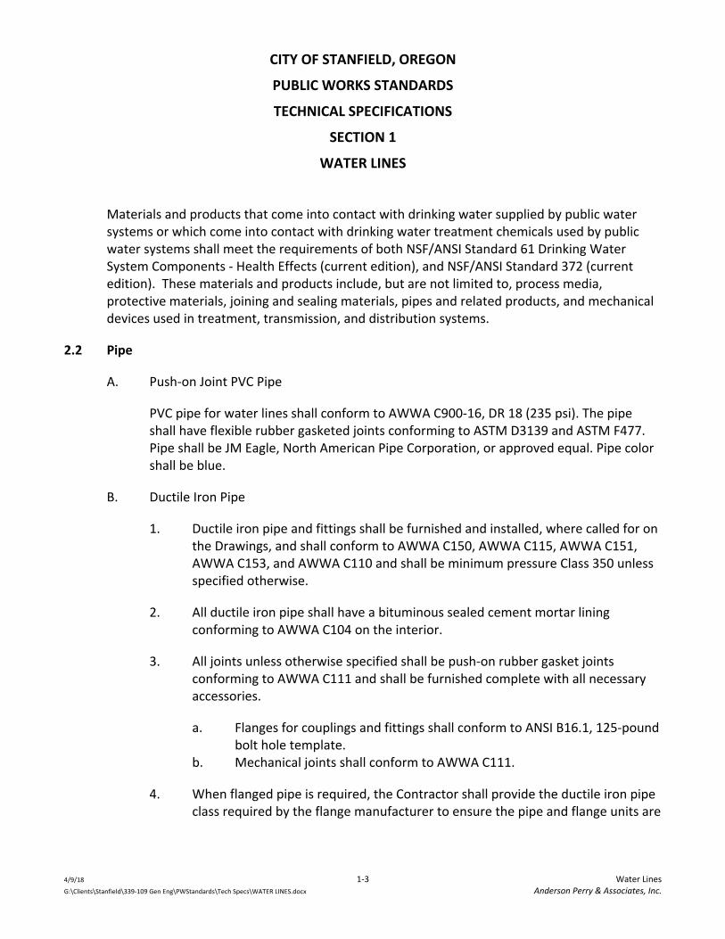
CITY OF STANFIELD, OREGON
PUBLIC WORKS STANDARDS
TECHNICAL SPECIFICATIONS
SECTION 1
WATER LINES
4/9/18 1‐3 Water Lines G:\Clients\Stanfield\339‐109 Gen Eng\PWStandards\Tech Specs\WATER LINES.docx Anderson Perry & Associates, Inc.
Materials and products that come into contact with drinking water supplied by public water systems or which come into contact with drinking water treatment chemicals used by public water systems shall meet the requirements of both NSF/ANSI Standard 61 Drinking Water System Components ‐ Health Effects (current edition), and NSF/ANSI Standard 372 (current edition). These materials and products include, but are not limited to, process media, protective materials, joining and sealing materials, pipes and related products, and mechanical devices used in treatment, transmission, and distribution systems.
2.2 Pipe
A. Push‐on Joint PVC Pipe
PVC pipe for water lines shall conform to AWWA C900‐16, DR 18 (235 psi). The pipe shall have flexible rubber gasketed joints conforming to ASTM D3139 and ASTM F477. Pipe shall be JM Eagle, North American Pipe Corporation, or approved equal. Pipe color shall be blue.
B. Ductile Iron Pipe
1. Ductile iron pipe and fittings shall be furnished and installed, where called for on the Drawings, and shall conform to AWWA C150, AWWA C115, AWWA C151, AWWA C153, and AWWA C110 and shall be minimum pressure Class 350 unless specified otherwise.
2. All ductile iron pipe shall have a bituminous sealed cement mortar lining conforming to AWWA C104 on the interior.
3. All joints unless otherwise specified shall be push‐on rubber gasket joints conforming to AWWA C111 and shall be furnished complete with all necessary accessories.
a. Flanges for couplings and fittings shall conform to ANSI B16.1, 125‐pound bolt hole template.
b. Mechanical joints shall conform to AWWA C111.
4. When flanged pipe is required, the Contractor shall provide the ductile iron pipe class required by the flange manufacturer to ensure the pipe and flange units are

CITY OF STANFIELD, OREGON
PUBLIC WORKS STANDARDS
TECHNICAL SPECIFICATIONS
SECTION 1
WATER LINES
4/9/18 1‐4 Water Lines G:\Clients\Stanfield\339‐109 Gen Eng\PWStandards\Tech Specs\WATER LINES.docx Anderson Perry & Associates, Inc.
compatible. This data shall be provided to the City Engineer for review prior to ordering these materials.
C. High Density Polyethylene Tubing for Service Lines
High density polyethylene tubing for service lines shall be copper tube size (CTS) meeting the requirements of AWWA C901 and ASTM D2737 (PE 4710) and shall be rated for 200 psi working pressure. Stainless steel inserts shall be installed at all compression fittings. The minimum size for residential service lines shall be 3/4‐inch diameter CTS.
2.3 Fittings for Iron and PVC Pipe
A. Unless specified otherwise, all fittings such as elbows, tees, crosses, valves, etc., shall have mechanical joints conforming to AWWA C111 and shall be short‐bodied compact ductile iron fittings conforming to AWWA C153, Class 350.
B. When called for, flanged cast iron fittings shall conform to AWWA C110 with ANSI B16.1, 125‐pound bolt hole template.
C. All fittings shall be cement mortar lined in accordance with AWWA C104.
D. Gaskets shall be either ring or full faced, 1/8‐inch thick conforming to AWWA C111, Appendix B.
2.4 Restrained Pipe Joints and Fittings
A. Restrained Push‐on Joint Pipe
When restrained joint ductile iron pipe is required, the pipe shall be the same class and type as the ductile iron pipe specified herein. Joints shall be Tyton Joint with Field Lok 350 gaskets, or approved equal. The restraint shall be boltless, integral restraining system, rated for 350 psi in accordance with the performance requirements of ANSI/AWWA C111/A21.11.
B. Restrained Fittings
All mechanical joint fittings called out to be restrained shall be equipped with a MEGALUG Series 1100 mechanical joint restraint system, or approved equal.

CITY OF STANFIELD, OREGON
PUBLIC WORKS STANDARDS
TECHNICAL SPECIFICATIONS
SECTION 1
WATER LINES
4/9/18 1‐5 Water Lines G:\Clients\Stanfield\339‐109 Gen Eng\PWStandards\Tech Specs\WATER LINES.docx Anderson Perry & Associates, Inc.
2.5 Water Main Couplings
A. Water main straight and transition couplings shall be Hymax Coupling, or approved equal, conforming to AWWA C219.
B. The Contractor shall provide the appropriate coupling and gaskets as required to match the water line types and sizes being utilized.
C. Couplings shall be rated for the working pressure of the pipe main for which they will be utilized.
D. Where water main couplings are to be restrained, the restraint system shall be Romac Style 611 or Romac Alpha, or approved equal.
2.6 Valves
A. Gate Valves
1. Valves smaller than 2 inches shall be all bronze gate valves, non‐rising stem, conforming to Manufacturers Standardization Society (MSS) SP‐80, Class A rated for a minimum working pressure of 125 psi.
2. Valves 2‐inch to 12‐inch shall be gate valves conforming to AWWA C509 or C515. Valves shall be designed for 200 psi minimum working pressure and shall be of iron body, resilient wedge, non‐rising stem construction. Valves shall be fusion epoxy coated inside and out per AWWA C550, NSF/ANSI 61 Certified. Valves shall be equipped with O‐ring type packing. The valve shall have a 2‐inch AWWA operating nut for buried service or as called for on the Drawings. The valve ends shall be of the type required to match the pipe to which they will be connected, or as shown on the Drawings. Valves shall have mechanical joint connections, unless called for otherwise on the Drawings. Valves shall be resilient wedge M&H Style 4067, American Flow Control Series 2500, Clow, or equal.
B. Butterfly Valves
Valves 14‐inch and larger shall be butterfly valves. All butterfly valves shall be of the rubber‐seated tight‐closing type. They shall meet or exceed the requirements of AWWA C504. All valves shall be M&H 4500 butterfly valves, or equal. The valve shall be for buried service with a sealed gear operator having 2‐inch AWWA operating nut and shall

CITY OF STANFIELD, OREGON
PUBLIC WORKS STANDARDS
TECHNICAL SPECIFICATIONS
SECTION 1
WATER LINES
4/9/18 1‐6 Water Lines G:\Clients\Stanfield\339‐109 Gen Eng\PWStandards\Tech Specs\WATER LINES.docx Anderson Perry & Associates, Inc.
open counter‐clockwise. The valve ends shall be of type required to match the pipe to which they will be connected as shown on the Drawings.
C. Ball Valves
Ball Valve (3 inches and smaller for general water service)
1. Valve shall be all‐bronze and end piece, hard chrome‐plated solid bronze or brass ball, end entry type, RTFE seats, Teflon packing, hand lever operator, rated 150‐pound SWP, 600‐pound WOG.
2. Bronze ball valves shall be installed where shown on the Drawings.
3. Manufacturers and Products
a. Milwaukee Valve ‐ UPBA100 b. Nibco ‐ T‐585‐80 c. Approved equal
D. Cast Iron Valve Box
Each valve shall be equipped with an adjustable cast iron box of the sliding type with a base large enough to cover the top casting of the valve. The diameter of the valve box shall be not less than five (5) inches, and shall be of such length so as to provide the depth of cover over the pipe without full extension. Valve box top and lid shall be Olympic Foundry 910 Vancouver style or approved equal.
2.7 Fire Hydrants
Fire hydrants shall conform to AWWA C502 and shall have 5 1/4‐inch main valve opening, two 2 1/2‐inch NST nozzles and one 4 1/2‐inch NST pumper nozzle. All fire hydrants shall be fitted with a Storz Pumper Connection, Harrington HPHA, or approved equal. Operating nut shall be 1 1/2‐inch pentagon. Fire hydrants shall be Kennedy K‐81 Guardian or Clow Medallion. All hydrants shall have a minimum depth of bury of 36 inches, measured from the finish grade to the top of the lead pipe. Where conditions require, hydrant extensions shall be provided and installed to provide the proper placement and installation of the hydrant. Hydrants shall receive factory coats of yellow enamel paint and shall also receive an additional field coat after installation. All hydrants shall be of the traffic model type.

CITY OF STANFIELD, OREGON
PUBLIC WORKS STANDARDS
TECHNICAL SPECIFICATIONS
SECTION 1
WATER LINES
4/9/18 1‐7 Water Lines G:\Clients\Stanfield\339‐109 Gen Eng\PWStandards\Tech Specs\WATER LINES.docx Anderson Perry & Associates, Inc.
2.8 Combination Air Release Valves
Air release valves shall be a combination air and vacuum type such as APCO No. 143 C, ValMatic No. 201C, or approved equal, with minimum 1‐inch inlet and designed for operating pressure occurring at the location of the installation.
2.9 Service Saddles
Service saddles shall have a ductile iron body, wide stainless steel band, and stainless steel bolts and nuts. Service saddles shall be Ford FS101 style for 3/4‐inch and 1‐inch taps and Ford FS202 for all taps larger than 1 inch, or approved equal. Service saddles shall have standard iron pipe threads. Saddle sizes shall be compatible with the pipe type and sizes being utilized. Service saddles are not required for ductile iron pressure class pipe for taps 1‐inch and less. Service saddles are required for ductile iron pressure class pipe for taps greater than 1‐inch. Service saddles used on PVC water mains shall be specifically sized at the factory for the type of PVC water main used.
2.10 Corporation Stops
Corporation stops shall be brass ball valve stops complying with AWWA C800. Corporation stops shall be Ford ball corp with pack joint, or approved equal. Inlet threads shall be iron pipe threads. Outlet connections shall be as required for type and size of water service lines and service saddles being utilized. Corporation stops shall meet the requirements of Section 2.1 herein.
2.11 Curb Stops
Curb stops shall be Ford brass ball valves, or approved equal. Valve configuration, inlet, and outlet requirements shall be as required for the size and type of water service lines and setters being utilized. Curb stops shall meet the requirements of Section 2.1 herein.
2.12 Service Line Couplings
Service line couplings shall be Ford pack joint couplings, or approved equal. Provide appropriate coupling as required to match water service lines types and sizes being utilized. Appropriate stainless steel insert stiffeners shall be used for all PVC pipe and polyethylene tubing. Where metal pipe of dissimilar type are being connected, an insulating adaptor gasket such as Dresser Style 65, or approved equal, shall be utilized to prevent galvanic corrosion.

CITY OF STANFIELD, OREGON
PUBLIC WORKS STANDARDS
TECHNICAL SPECIFICATIONS
SECTION 1
WATER LINES
4/9/18 1‐8 Water Lines G:\Clients\Stanfield\339‐109 Gen Eng\PWStandards\Tech Specs\WATER LINES.docx Anderson Perry & Associates, Inc.
2.13 Curb Stop Box
Each curb stop shall be equipped with an adjustable cast iron box of the sliding type and shall be of such length so as to provide the depth of cover over the pipe without full extension. The curb stop box shall be equal to Ford Arch Pattern Curb Boxes with 1‐inch upper section and stationary rod and Type PS plug style lid with pentagon bolt, or approved equal. For service curb stops larger than 1‐inch, a curb box base, Ford CB‐7, shall also be provided.
2.14 Meter Setters
Meter setters for 1‐inch and smaller meters shall be Ford 70 Series coppersetters, or approved equal. Meter setters for 1‐1/2‐inch or 2‐inch water meters shall be Ford all brass and copper Series 70 coppersetters, or approved equal. A Ford angle meter ball valve shall be provided on the meter inlet and a single check valve shall be provided on the meter outlet. Provide appropriate meter setter heights, sizes, and connections, etc., as required for the meter and water service lines sizes and types being utilized. Brace pipes of 1‐inch diameter Schedule 40 PVC shall also be installed in the setter pipe eyelets to increase the stability of the meter setting.
2.15 Water Meters
All water meters shall be provided and installed by the City.
2.16 Water Meter Box and Cover
A. Non‐Traffic Areas. The meter box for 1‐inch and smaller meters in non‐traffic areas shall be equal to Raven meter boxes and lids, No. RMB 15x27 with white interior and ductile iron lid, or approved equal.
B. Traffic Areas. The meter box and cover for 1‐inch and smaller meters in traffic areas shall be Armorcast Products Company, Polymer Concrete Construction, or approved equal. The box size shall be 17 inches x 30 inches and a reinforced concrete collar shall be placed around top of the box for support. Box and cover shall be designed with a 20K load rating.
C. For 1‐1/2‐ and 2‐inch meters, meter box and cover shall be Armorcast Products Company, Polymer Concrete Construction, or approved equal. The box size shall be 24 inches x 36 inches for traffic areas. Box and cover shall be designed with a

CITY OF STANFIELD, OREGON
PUBLIC WORKS STANDARDS
TECHNICAL SPECIFICATIONS
SECTION 1
WATER LINES
4/9/18 1‐9 Water Lines G:\Clients\Stanfield\339‐109 Gen Eng\PWStandards\Tech Specs\WATER LINES.docx Anderson Perry & Associates, Inc.
20K load rating, and a reinforced concrete collar shall be placed around top of box for support.
D. For meters larger than 2 inches, meter vaults and covers shall be approved by the City.
2.17 Water Line Blowoff
Kupferle Mainguard 2‐inch blow‐off hydrant Model No. 77 or approved equal.
2.18 Locating Wire
Locating wire shall be a minimum of 12 awg UF solid copper with blue colored insulation. The use of THHN wire will not be acceptable. At all splices the connecting ends of the wires shall be overlapped and tied. The ends shall be stripped and connected with a wire nut to ensure an electrical connection and made waterproof with an approved silicone splice kit. The splice kit shall be King Technology Model 50‐566 (1637 N. Warson Road, St. Louis, MO 63132, 1‐800‐633‐0232), or approved equal. Where location wire is to be secured to the exterior of fire hydrants, valve boxes, posts, etc., stainless steel pipe straps shall be used.
2.19 Thrust and Anchor Blocks and Concrete Collars
Concrete used for thrust and anchor blocks, and concrete collars shall be Portland Cement concrete with a minimum 28‐day compressive strength of 2500 psi. Anchor rods shall be 3/4‐inch diameter galvanized steel or epoxy coated reinforcement bar conforming to AASHTO M284, embedded a minimum of 18 inches in the concrete.
PART 3 ‐ EXECUTION
3.1 Trench Excavation and Backfill
Trench excavation and backfill shall be performed as specified in the Technical Specifications for "Excavation and Backfill of Trenches."
3.2 Record Drawings
The requirements for Record Drawings, etc., as required in the General Requirements shall be carefully complied with.

CITY OF STANFIELD, OREGON
PUBLIC WORKS STANDARDS
TECHNICAL SPECIFICATIONS
SECTION 1
WATER LINES
4/9/18 1‐10 Water Lines G:\Clients\Stanfield\339‐109 Gen Eng\PWStandards\Tech Specs\WATER LINES.docx Anderson Perry & Associates, Inc.
3.3 Installation of Pipe
A. Water pipe shall be installed in accordance with best current practices as required by the manufacturer and as specified herein. PVC pipe installation shall conform to the Uni‐Bell Plastic Pipe Association, "Guide for Installation of PVC Pressure Pipe for Municipal Water Main Distribution Systems" and also AWWA M23 "PVC Pipe ‐ Design and Installation." Ductile iron pipe installation shall conform to the requirements of AWWA C600.
B. Water pipe shall be installed with bell ends laid facing in the direction of laying unless directed otherwise by the City Engineer. Each pipe shall be properly bedded so as to be supported for the full length of the pipe. A suitable foundation shall be achieved by a slight excavation under the bell at each joint. All rubber ring joints shall be lubricated and installed in accordance with the installation instructions of the pipe manufacturer, taking particular care to avoid pinching or otherwise causing damage to the rubber ring. All joints shall be free of dirt and other foreign matter prior to the joining of the next pipe. All joints shall be restrained to prevent creep and misalignment of joints.
C. Water lines shall be installed to the minimum depths called for on the Drawings and to the lines and grades when shown. It shall be recognized that water line depths may vary from the minimum depths shown when adjustment of grade is required to avoid conflict with existing utilities. Additional fittings may also be required when a grade adjustment is required. Grade adjustments to accommodate existing utilities shall be considered a normal part of the work.
D. No pipe shall be installed in water or when conditions exist that, in the opinion of the City Engineer, are unsuitable for the laying of the pipe. At times when pipe laying is not in progress, the open ends of pipe shall be closed by a watertight plug or other approved means. This provision applies during the noon hour as well as overnight. If there is water in the trench, the seal should remain in place until the trench is dewatered sufficiently to prevent groundwater from entering the pipe. Adequate provisions shall be made by the Contractor for final disposal of the groundwater pumped from trenches.
E. All pipe shall be installed true to line, except when approved or specified, the Contractor may install a pipeline on a curve. For rubber gasketed ductile iron pipe installed on a curve, the pipe shall be joined in a straight alignment, then deflected. The amount of deflection shall not exceed 80 percent of the recommended maximum deflection

CITY OF STANFIELD, OREGON
PUBLIC WORKS STANDARDS
TECHNICAL SPECIFICATIONS
SECTION 1
WATER LINES
4/9/18 1‐11 Water Lines G:\Clients\Stanfield\339‐109 Gen Eng\PWStandards\Tech Specs\WATER LINES.docx Anderson Perry & Associates, Inc.
specified in AWWA C600. For PVC pipe installed on a curve, deflection of the pipe shall be achieved by bending the pipe within the limitations specified by the pipe manufacturer. Joint deflection of PVC pipe is not allowed.
F. Thrust and anchor blocks shall be constructed as shown on the Drawings and placed at all changes in direction, all changes in the diameter of the pipe, all dead‐ends, as specifically shown on the Drawings and as required by the City Engineer. All thrust blocks shall be placed between the undisturbed ground and the fitting to be anchored. Plastic sheeting shall be used to provide a bonding barrier between the fittings and the concrete. The quantity of concrete and the area of bearing on the soil shall be as shown on the Drawings. All thrust blocks shall be placed so that the entire pipe and fitting joints will be accessible for repairs. Bolts for mechanical and flange fittings and fire hydrant weep holes shall not be covered with concrete. All bolts shall be accessible and removable without interference from the thrust block. Thrust blocks may not be required where approved restraint joint pipe and fittings are utilized. No backfill of thrust blocks shall occur until the work has been observed by the City.
3.4 Locating Wire
A continuous solid copper locating wire shall be placed along the top of all water pipe, including service lines. This wire shall be secured to the top of the pipe at maximum 10‐foot intervals using 6‐inch strips of 2‐inch wide duct tape. All splices shall be tied, electrically continuous, and made waterproof. Access to terminal ends of the locating wire shall be made at all valve boxes, meter boxes, fire hydrants, vaults, etc. The result of this installation shall be a continuous wire circuit electrically isolated from ground. The Contractor shall be responsible for testing continuity and for testing isolation from ground in the wire after all work has been completed on the test section. The Contractor is advised to do intermediate testing on his own after backfilling operations and prior to surface restoration work to be sure continuity is maintained. If there is a break or defect in the wire, it shall be the Contractor's responsibility to locate and repair the defect. The continuity of the location wire shall be tested from one test load point to the next by use of a temporary wire laid between test points in‐line with an ohmmeter. Resistance shall be measured with an approved ohmmeter that has been properly calibrated. The continuity of a test section will be accepted if the resistance of the test section does not exceed 5 ohms per 500 feet of location wire being tested. Isolation from ground shall be measured with a megohmmeter and shall be a minimum of 20 megohms for any section of location wire tested. The City shall witness the acceptance test.

CITY OF STANFIELD, OREGON
PUBLIC WORKS STANDARDS
TECHNICAL SPECIFICATIONS
SECTION 1
WATER LINES
4/9/18 1‐12 Water Lines G:\Clients\Stanfield\339‐109 Gen Eng\PWStandards\Tech Specs\WATER LINES.docx Anderson Perry & Associates, Inc.
3.5 Service Connections
The Contractor shall connect service lines to new or existing water mains as shown on the Drawings. This work includes the installation of a saddle and corporation stop, and making the connection. The work will include potholing to locate any existing pipeline or service lines as required so the service connection can be performed.
3.6 Service Lines
A. The installation of new service lines and the connecting of existing service lines shall be performed in accordance with the Drawings, manufacturer requirements, and as specified herein. Water service lines shall be laid by placing the pipe on the trench bottom with sufficient slack to prevent pulling apart of the joints when the backfill is placed. Splices shall be kept to an absolute minimum. If required, they shall be made using brass compression joint couplings equal to Ford Pack‐joint. When constructing a new water line to replace an existing line, the existing water line shall remain in service until the new water line has been tested, and disinfected. When possible, the existing line and new line shall both be in operation during the transfer of service lines. The transfer shall be made so that the interruption of water service to the utility customer is held to a minimum. All service lines shall be thoroughly flushed before connecting to existing lines or meters. The City will assist the Contractor in locating existing service lines; however, the primary responsibility for performing excavation work to locate existing lines will be the Contractor's. The work includes potholing to locate any existing pipelines or service lines as may be required so the service lines can be installed. The work also includes connecting to the existing services lines when required.
B. When the Drawings indicate that existing service lines will be utilized, and if the Contractor encounters an existing service line which appears to be in poor or unserviceable condition, he/she shall promptly contact the City.
3.7 Service Lines by Boring and Open Trench Methods
A. It is the general intent to try and install service lines under paved streets by boring where possible. A pneumatic boring tool or other approved method will be used to install service lines under all paved streets. There may be areas where it is not possible to bore due to ground conditions which interfere in the operation. Where requested by the City, the Contractor shall attempt to bore under paved streets. In areas where it appears that boring will be difficult as determined by the City and the Contractor, the

CITY OF STANFIELD, OREGON
PUBLIC WORKS STANDARDS
TECHNICAL SPECIFICATIONS
SECTION 1
WATER LINES
4/9/18 1‐13 Water Lines G:\Clients\Stanfield\339‐109 Gen Eng\PWStandards\Tech Specs\WATER LINES.docx Anderson Perry & Associates, Inc.
service lines shall be installed by the open trench method. The Contractor shall make two attempts, if required, to bore under paved streets. If the second attempt fails, the Contractor shall install the service line by the open trench method. If the Contractor encounters an obstacle and is unable to continue boring, he shall notify the City prior to withdrawing the boring device.
B. The Contractor shall take care to not damage other utilities which might exist in the area. Prior to boring, the Contractor shall pothole to locate existing utilities. "Blind‐boring" is not allowed. Repairs for damage to other utilities shall be the responsibility of the Contractor.
C. Service lines to be installed in areas not under asphalt streets or in asphalt street areas the City believes will be difficult to bore may be installed by open trenching. Refer to the Drawings for additional requirements. All service lines shall be thoroughly flushed and disinfected before connecting to existing lines or meters.
3.8 Valves and Valve Boxes
Valves and valve boxes shall be installed as shown in the Drawings. All valves and valve boxes shall be set plumb. The valve box shall be centered over the valve operator and free of any obstruction which would prevent operation of the valve nut. If the bury depth of the valve is greater than 4 1/2 feet, a valve operator extension shall be provided to within 1 foot of finish grade. The extension shall be permanently attached to the valve operator and a self‐centering device shall be provided near the top of the valve operator extension. The box cover shall be flush with the finished grade. A concrete collar shall be installed.
3.9 Fire Hydrants
Hydrant installation shall conform with AWWA Manual M17 and AWWA C600, and as shown on the Drawings. Extensions required for hydrant adjustment shall be installed to the manufacturer's specifications. Hydrants may be installed on new water mains, installed as part of the work, or on existing mains. Special attention shall be given when installing hydrants on existing mains to ensure that adequate thrust restraint is being achieved as the hydrants can be placed in service before normal cast‐in‐place thrust blocks can achieve the required strength. The block and plug shall be held securely by temporary thrust block or other approved method, such as precast thrust blocks, restraining rods, etc. The newly installed hydrants shall be covered in a manner acceptable to the City until they are placed into permanent service.

CITY OF STANFIELD, OREGON
PUBLIC WORKS STANDARDS
TECHNICAL SPECIFICATIONS
SECTION 1
WATER LINES
4/9/18 1‐14 Water Lines G:\Clients\Stanfield\339‐109 Gen Eng\PWStandards\Tech Specs\WATER LINES.docx Anderson Perry & Associates, Inc.
3.10 Removal of Existing Fire Hydrants
All hydrants removed shall remain the property of the City and shall be delivered and properly stacked at a site designated by the City. After the old hydrant is removed, the lead line, if it is to be abandoned, shall be plugged at the main line tee with a watertight plug and thrust block. When the lead pipe is connected to a water main which is being abandoned, it will not need to be plugged. The Contractor shall apply black paint the same day the existing hydrant is disconnected from service; otherwise, mark the hydrant in a manner acceptable to the City.
3.11 Water Line Blowoffs
The 2‐inch water line blowoffs shall be constructed as shown on the Drawings.
3.12 Connections to Existing Lines
A. If shown on the Drawings, information indicating the size, type, class, and location of existing lines and associated fittings has been obtained from as‐built drawings and other municipal records. It is expected that there may be some discrepancies and omissions in the information shown on the Drawings. Therefore, it shall be the responsibility of the Contractor to excavate and inspect existing water lines requiring a connection in order to determine the exact fittings needed. In connecting to existing lines, the Contractor may select the combination of fittings he wishes to use, subject to approval of the City Engineer. Approved fabricated steel couplings, repair bands, transition couplings, or tapping sleeves are among the options available to the Contractor. The Contractor shall submit to the City Engineer information on the type of couplings he proposes to use. Proper disinfection, as described hereafter, shall always be accomplished. The Contractor shall provide watertight plugs and thrust restraints, as required, to cap old lines after they are disconnected.
B. The Contractor shall provide special attention in providing thrust restraint for fittings installed as part of a connection to an existing line, when such connection will be placed into service before normal cast‐in‐place thrust blocks can achieve required strength. In such cases thrust restrained joints, precast thrust blocks, etc., must be utilized to provide thrust restraint. Methods used by the Contractor shall be approved by the City Engineer.
C. The Contractor shall not interrupt service for the purpose of connecting to an existing line until he has excavated the required location, visually inspected the connection

CITY OF STANFIELD, OREGON
PUBLIC WORKS STANDARDS
TECHNICAL SPECIFICATIONS
SECTION 1
WATER LINES
4/9/18 1‐15 Water Lines G:\Clients\Stanfield\339‐109 Gen Eng\PWStandards\Tech Specs\WATER LINES.docx Anderson Perry & Associates, Inc.
point, and verified that he has available on the site all fittings required for completion of the connection or connections. Isolation of a section of line to be modified will be accomplished by the Contractor only after consultation with the City for the purpose of determining the proper valves to close to effect the isolation. The Contractor shall cooperate with the City in accomplishing this isolation. When work is started on a connection, it shall proceed continuously without interruption, and as rapidly as possible until completed. If the connection involves turning off the water, the Contractor shall be responsible for notifying the residents affected by the shutoff. See the "Existing Utilities" section of the General Requirements.
3.13 Water Meter Installation
The Contractor shall furnish all materials required and shall install the water meters as shown on the Drawings and described herein. Water meter installations shall include appropriate meter box and cover, coppersetter, yokes, and fittings, and shall include the water meter. Meter boxes shall be set plumb with cover level and with equal clearance on all sides between the box and the plumbing.
3.14 Water‐Sewer Line Crossings
A. Wherever possible, the bottom of the new water line shall be 1.5 feet or more above the top of any sanitary sewer line. One full length of water line shall be centered at all sewer crossings when the vertical separation is less than 1.5 feet. Where the water line crosses over an existing sanitary sewer line but with a clearance of less than 1.5 feet, the sewer line shall be exposed to the sewer line joints on both sides of the crossing to permit examination of the sewer pipe. If the sewer pipe is in good condition and there is no evidence of leakage from the sewer line as observed by the City Engineer, the 1.5‐foot separation may be reduced. When the vertical separation is less than 1.5 feet, the Contractor shall center one full length of the new water pipe over the sewer line. If the City and/or City Engineer determines that the conditions are not favorable or finds evidence of leakage from the sewer line, the sewer line shall be replaced with a full length of PVC pressure pipe (AWWA C900, DR 18, 150 psi pipe) centered at the crossing point. When new sewer pipelines are installed as a part of the project, it will not be necessary to expose the new sewer pipe to verify the pipes condition.
B. Where the water line crosses under the sanitary sewer line, the Contractor shall expose the existing sewer line and examine it as indicated above. If conditions are favorable and there is no evidence of leakage from the sewer line, the sewer line may be left in

CITY OF STANFIELD, OREGON
PUBLIC WORKS STANDARDS
TECHNICAL SPECIFICATIONS
SECTION 1
WATER LINES
4/9/18 1‐16 Water Lines G:\Clients\Stanfield\339‐109 Gen Eng\PWStandards\Tech Specs\WATER LINES.docx Anderson Perry & Associates, Inc.
place. The existing sewer line shall be supported with a steel beam, reinforced concrete beam, or other means of preventing settlement when it spans the water line trench, unless otherwise approved by the City. Special precautions must be taken to assure that the backfill material over the water line in the vicinity of the crossing is thoroughly compacted in order to prevent settlement which could result in the leakage of sewage. In this situation, the Contractor shall center one length of the new water line at the crossing. If the City and/or City Engineer determines that conditions are not favorable or finds evidence of leakage from the sewer line, then the sewer line at the crossing shall be replaced as detailed on the Drawings.
C. When constructing water service lines, the depth of the service lines shall be revised in order to eliminate the need for a water‐sewer line crossing.
3.15 Capping Existing Water Mains and Services
When required, the Contractor shall cap an existing water main or service tap when an existing main or service is to be taken out of service. Each location will require different types of fittings, etc., to accomplish the work. All caps are to be permanent and watertight. When required, thrust restraints shall be provided. Corporation stops on service taps shall be in "off" position and an approved watertight cap installed. Unless specified otherwise, the capping shall be performed at the connection to the water main which is to remain in service. No stubbed water mains or service lines shall be left in the ground unless approved otherwise by the City Engineer. The Contractor shall excavate and expose the piping to be capped, perform the work, and backfill as required.
3.16 Abandoned Water Lines
The existing water lines to be taken out of service are to be shown on the Drawings. These lines are to remain in service until the new lines are properly installed and tested, and water services have been connected. Approval from the City shall be obtained before any line is abandoned. The existing lines shall then be abandoned and their actual location and abandoned designation recorded on all Record Drawings. Unless called for otherwise, the abandoned lines will remain in the ground. The ends of all pipes which are abandoned shall be plugged with concrete or other methods approved by the City Engineer.

CITY OF STANFIELD, OREGON
PUBLIC WORKS STANDARDS
TECHNICAL SPECIFICATIONS
SECTION 1
WATER LINES
4/9/18 1‐17 Water Lines G:\Clients\Stanfield\339‐109 Gen Eng\PWStandards\Tech Specs\WATER LINES.docx Anderson Perry & Associates, Inc.
3.17 Air Release Valves
Air release valves shall be installed as shown on the Drawings, and as required by the manufacturer.
3.18 Other Installations
Installations of valves and valve boxes shall be in accordance with the manufacturer requirements and the Drawings.
3.19 Existing Equipment Removal and Salvage
A. The Contractor shall remove all existing valves, hydrants, and fittings as required to properly perform the work, or as shown in the Drawings. All such materials shall be transported to an area designated by the City and stockpiled. Materials shall be removed and handled in such a manner which will prevent damage.
B. All other existing valves and hydrants not used in the new system or specified for removal will be removed by the City after the new system is in operation. Salvaged material shall remain the property of the City. The abandoned existing pipe is to remain in the ground, unless otherwise specified. The Contractor shall apply black paint the same day to all existing hydrants when permanently disconnected from service.
3.20 Work with Existing Asbestos Cement (A/C) Pipe
A. When working with A/C pipe, the Contractor shall take all precautions necessary to reduce airborne asbestos during construction. The Contractor will be required to contact the Oregon Department of Environmental Quality (DEQ), file an ASN 6 notification form, and follow Oregon Administrative Rules (OAR) 340‐248, Asbestos Requirements. The Contractor may initiate consultation with the Occupational Safety and Health Administration (OSHA) prior to construction, if necessary. Any work to be performed on existing A/C pipe shall be completed in accordance with American Water Works Association Guidelines and DEQ guidance document, "How to Remove Nonfriable Asbestos Cement Pipe."
B. The Contractor shall cut asbestos cement pipe by using snap cutters only. The use of carbide‐tipped cutting blades or high speed, abrasive disks shall not be permitted as a

CITY OF STANFIELD, OREGON
PUBLIC WORKS STANDARDS
TECHNICAL SPECIFICATIONS
SECTION 1
WATER LINES
4/9/18 1‐18 Water Lines G:\Clients\Stanfield\339‐109 Gen Eng\PWStandards\Tech Specs\WATER LINES.docx Anderson Perry & Associates, Inc.
means of cutting A/C pipe snap cutters. Machining of this pipe shall be done with a manual or power‐driven field lathe, or with a manual rasp.
C. Hole cutting shall be accomplished with a tapping machine. Use of shell cutters, rasps, chisels, electric drills, right angle sanders, or other high speed abrasive tools shall not be permitted. Uncoupling of asbestos cement pipe shall be accomplished with a hammer and chisel. Use of abrasive disc cutters, right angle sanders, or other high speed abrasive tools shall not be permitted.
D. Dust and cuttings from all work shall be removed by wet mopping.
E. All waste material shall be collected in a covered container and disposed at a landfill certified by the state or EPA to accept demolition waste.
3.21 Testing and Disinfection
A. General
The Contractor shall furnish all necessary equipment and other apparatus, including gauges, necessary to properly perform the testing and disinfection of water lines as specified. Lines to be tested include mains and service lines. Each section of the lines before being tested and placed into service shall be isolated and slowly filled with water. Air should be expelled from the line through hydrants or taps made at the high points. The City and/or City Engineer shall have the option of requiring the use of his own gauges. Water mains shall be generally tested in sections between valves and as the work progresses. The Contractor shall be responsible for determining the length, timing, and section of lines to be tested, unless otherwise noted. When appropriate, testing intermediate sections of long lines should be considered. The Contractor shall provide any temporary test heads, fittings, blocking, etc., as may be required to properly test any given water main section. The Contractor shall be responsible for locating and repairing any defects in the water mains which fail to pass the required test.
B. Acceptance Test
The Contractor shall perform all preliminary testing required to determine that the lines to be tested are acceptable and comply with the requirements of this section of the Specifications. After the Contractor has determined that the lines will pass the required test, the Contractor shall arrange for an acceptance test to be witnessed by the City

CITY OF STANFIELD, OREGON
PUBLIC WORKS STANDARDS
TECHNICAL SPECIFICATIONS
SECTION 1
WATER LINES
4/9/18 1‐19 Water Lines G:\Clients\Stanfield\339‐109 Gen Eng\PWStandards\Tech Specs\WATER LINES.docx Anderson Perry & Associates, Inc.
and/or City Engineer. The lines will not be accepted until the acceptance test has been witnessed and documented as passing. Forms for performing the various tests are included at the end of this Technical Specification for use and reference by the Contractor.
C. Hydrostatic Testing of Pressure Lines
All lines shall be pressure tested at 150 psi gauge or 1.5 times the actual working pressure, whichever is greater, for one hour. Any cracked or defective pipe, joints, or fittings shall be removed and replaced.
D. Leakage Test
Each section of the line, after all backfill and compaction work has been completed and before being placed into service, shall be tested for leakage for a period of two hours at a minimum average gauge pressure of 100 psi. Leakage is defined as the quantity of water supplied into the section of line being tested, during and at the end of the test, that quantity being such that the pressure at the end of the test is equal to the pressure at the beginning of the test. Should any test disclose leakage greater than that specified, the Contractor shall locate and repair the defective joints until the leakage is within the specified allowance.
PVC Pipe: L = ND √ P DI Pipe: L = SD √ P 7,400 133,200
In which: L = Allowable Leakage Gal/Hr S = Length of Pipe Tested in Ft. N = Number of Joints or Connections
D = Nominal Diameter in Inches P = Gauge Pressure in psi
E. Disinfection of Potable Water Mains
1. Each section of the line, before being placed into service, shall be thoroughly flushed and disinfected in accordance with current regulations of the Oregon Health Authority ‐ Drinking Water Services (DWS), specifically Oregon Administrative Rule, Section 333‐061‐0050(10) Construction Standards. For the

CITY OF STANFIELD, OREGON
PUBLIC WORKS STANDARDS
TECHNICAL SPECIFICATIONS
SECTION 1
WATER LINES
4/9/18 1‐20 Water Lines G:\Clients\Stanfield\339‐109 Gen Eng\PWStandards\Tech Specs\WATER LINES.docx Anderson Perry & Associates, Inc.
Contractor's convenience, DWS requirements at the time these standards were developed follow:
"(10) Disinfection of facilities:
(a) Following completion of new facilities and repairs to existing facilities, those portions of the facilities which will be in contact with the water delivered to users shall be disinfected with chlorine before they are placed into service. Other disinfectants may be used if it is demonstrated that they can also achieve the same result as chlorine;
(b) Prior to disinfection, the facilities shall be cleaned and flushed with potable water according to AWWA Standards C651 through C654;
(c) For new construction and installation of wells, pumps, and water mains (with any associated service connections and other appurtenances installed at the time of construction), disinfection by chlorination shall be accomplished according to AWWA standards C651 through C654 which includes, but is not limited to the following:
(A) The introduction of a chlorine solution with a free chlorine residual of 25 mg/l into the system in a manner which will result in a thorough wetting of all surfaces and the discharge of all trapped air. The solution shall remain in place for 24 hours.
(B) After the 24‐hour period, the free chlorine residual shall be checked, and if it is found to be 10 mg/l or more, the chlorine solution shall be drained and the facility flushed with potable water. If the check measurement taken after the 24‐hour contact period indicates a free chlorine residual of less than 10 mg/l, the facilities shall be flushed, rechlorinated and rechecked until a final residual of 10 mg/l or more is achieved after a 24‐hour standing time.
(C) After the final residual is confirmed at 10 mg/l or more, and after the facility is flushed and filled with potable water, bacteriological samples shall be taken to provide a record for determining the procedures’ effectiveness. A minimum of two

CITY OF STANFIELD, OREGON
PUBLIC WORKS STANDARDS
TECHNICAL SPECIFICATIONS
SECTION 1
WATER LINES
4/9/18 1‐21 Water Lines G:\Clients\Stanfield\339‐109 Gen Eng\PWStandards\Tech Specs\WATER LINES.docx Anderson Perry & Associates, Inc.
consecutive samples must be collected at least 24 hours apart from the new facilities for microbiological analysis. If the results of both analyses indicate that the water is free of coliform organisms, the facility may be put into service. Likewise, if the microbiological analysis indicates the presence of coliform organisms, the flushing and disinfection must be repeated until a sample free of coliform organisms is obtained.
(d) For repaired wells, pumps, and completely depressurized water mains, disinfection by chlorination shall be accomplished according to AWWA standards C651 through C654. Following thorough flushing, a minimum of one sample must be collected from each direction of flow downstream from the repaired facilities for microbiological analysis. If the direction of flow is unknown, then samples shall be taken on each side of the repaired facility. If the microbiological analysis indicates the presence of coliform organisms, a follow‐up sample shall be taken. If the follow‐up sample indicates a presence of coliform organisms, then the repaired components shall be flushed and resampled until a sample free of coliform organisms is obtained.
(e) through (i) do not apply to water lines.
(j) A water line may be returned to service, following repairs or routine maintenance, prior to receiving a report on the microbiological analysis if the following procedures have been completed.
(A) Customer meters were shut off prior to placing the water line out of service;
(B) The area below the water line to be repaired was excavated and dewatered;
(C) The exposed pipe was treated with a hypochlorite solution;
(D) The water line and any other appurtenance or item affected by the repair and/or maintenance was disinfected by chlorination according to AWWA standards C651 through C654;

CITY OF STANFIELD, OREGON
PUBLIC WORKS STANDARDS
TECHNICAL SPECIFICATIONS
SECTION 1
WATER LINES
4/9/18 1‐22 Water Lines G:\Clients\Stanfield\339‐109 Gen Eng\PWStandards\Tech Specs\WATER LINES.docx Anderson Perry & Associates, Inc.
(E) The water line was flushed thoroughly, and a concentration of residual chlorine has been re‐established that is comparable to the level normally maintained by the water system, if applicable; and
(F) Microbiological analysis has been conducted as a record of repair effectiveness.
2. When fittings, service lines, or other components of the water system are not disinfected in conjunction with water mains, the Contractor shall disinfect all fittings and service lines using a 300 mg/L minimum chlorine solution. All fittings shall be flushed with the chlorine solution prior to connection with the new service line. The new service line shall be flushed slowly with a 300 mg/L minimum chlorine solution in a manner which will result in a thorough wetting of all surfaces on the inside of the service line. The service line shall have at least 15 minutes contact time prior to flushing and putting it into service.
3. After disinfection, the Contractor shall collect bacteriological samples for testing in the presence of the City. A minimum of one sample shall be taken every 1,000 feet of water line to be tested. The City may require additional samples to be taken if the section to be tested is complex and proper disinfection could be difficult. The analysis shall be performed by a laboratory certified by the DWS. The cost of the bacteriological testing(s) is to be paid by the Contractor. If positive results are obtained, the system shall be disinfected again by the Contractor, at his own expense. Bacteriological samples will again be collected in the presence of the City and resubmitted for testing. This shall be repeated until negative results are obtained. The method of disinfecting and the chlorination materials used are subject to the approval of the City Engineer. Disinfection by introducing granular or tablet chlorine compounds in each pipe length is not an acceptable method of disinfection.
4. The results of all bacteriological tests shall be submitted to the City and to the City Engineer and placed in the Operation and Maintenance Manual. No section of pipe shall be placed into service until acceptable bacteriological tests have been obtained.
5. Disposal of any water containing chlorine shall be performed in accordance with AWWA C651, Section 01100, and any other local requirements. Disposal may be

CITY OF STANFIELD, OREGON
PUBLIC WORKS STANDARDS
TECHNICAL SPECIFICATIONS
SECTION 1
WATER LINES
4/9/18 1‐23 Water Lines G:\Clients\Stanfield\339‐109 Gen Eng\PWStandards\Tech Specs\WATER LINES.docx Anderson Perry & Associates, Inc.
made into existing sanitary sewer systems providing approvals are obtained from the City. Any chlorinated water discharged to open stream channels must be dechlorinated prior to discharge.
3.22 Restoration, Finishing, and Cleanup
The Contractor shall restore or replace all paved surfaces, graveled surfaces, curbing, sidewalks, trees, shrubbery, lawns, pastures, fences, and other existing facilities equal to their original condition. All surplus material and temporary structures as well as excess excavation shall be removed and the entire site of Contractor operations shall be left in a neat and clean condition as outlined in the General Requirements. Also see Technical Specifications ‐ "Excavation and Backfill of Trenches" and Technical Specifications ‐ "Surface Restoration" for specific requirements.
END OF SECTION

TEST WORKSHEET FOR THE
WATER LINES ‐ LEAKAGE TEST
Project Name
Date Job No.
Location of Test/Stationing
Hydrostatic Test
Test Pressure
Time Test Started
Time Test Completed
TOTAL TIME minutes
Test Passed Yes No
Leakage Test (Min. Test Pressure 100 psi)
PVC Pipe: L = ND √ P DI Pipe: L = SD √ P 7,400 133,200
In which:
L = Allowable Leakage Gal/Hr S = Length of Pipe Tested in Ft. N = Number of Joints or Connections D = Nominal Diameter in Inches P = Gauge Pressure in psi

Allowable Leakage
Pipe Section Nominal Diameter Number of Joints or Connections
Length of Pipe Allowable Leakage
_______________ _______________ _______________ _______________ _______________
_______________ _______________ _______________ _______________ _______________
_______________ _______________ _______________ _______________ _______________
_______________ _______________ _______________ _______________ _______________
_______________ _______________ _______________ _______________ _______________
_______________ _______________ _______________ _______________ _______________
_______________ _______________ _______________ _______________ _______________
_______________ _______________ _______________ _______________ _______________
_______________ _______________ _______________ _______________ _______________
_______________ _______________ _______________ _______________ _______________
_______________ _______________ _______________ _______________ _______________
Total Allowable Leakage ___________ gal/hr
Time Test Started Total Leakage Measured gal.
Time Test Completed Total Leakage Measured/Gal=___ gal/hr
TOTAL TIME mins. Time (hr.)
Test Passed Yes No
Contractor's Firm Name:
Contractor's Representative Signature
Engineer's Representative Signature
Note: See Technical Specifications for directions of use.

SANITARY SEWER LINES

CITY OF STANFIELD, OREGON
PUBLIC WORKS STANDARDS
TABLE OF CONTENTS
TECHNICAL SPECIFICATIONS
SECTION 2
SANITARY SEWER LINES
4/9/18 i Table of Contents G:\Clients\Stanfield\339‐109 Gen Eng\PWStandards\Tech Specs\SANITARY SEWER LINES.docx Anderson Perry & Associates, Inc.
PART 1 ‐ General ...................................................................................................................................... 2‐1 1.1 Scope ......................................................................................................................................... 2‐1 1.2 Specifications References.......................................................................................................... 2‐1 1.3 Catalog Information .................................................................................................................. 2‐1 1.4 Care and Handling of Materials ................................................................................................. 2‐1 1.5 Materials Furnished by City ....................................................................................................... 2‐2 1.6 Certification by Manufacturer ................................................................................................... 2‐2 1.7 Restoration, Finishing, and Cleanup ......................................................................................... 2‐2
PART 2 ‐ Materials .................................................................................................................................... 2‐3 2.1 Pipe ............................................................................................................................................ 2‐3 2.2 Fittings ....................................................................................................................................... 2‐3 2.3 Valves and Appurtenances ........................................................................................................ 2‐5 2.4 Thrust and Anchor Blocks for Pressure Sewer Lines ................................................................ 2‐6 2.5 Manholes ................................................................................................................................... 2‐6 2.6 Cleanouts ................................................................................................................................. 2‐10 2.7 Locating Wire .......................................................................................................................... 2‐10
PART 3 ‐ Execution ................................................................................................................................. 2‐10 3.1 Gravity Sewer Construction .................................................................................................... 2‐10 3.2 Gravity Service Lines ............................................................................................................... 2‐12 3.3 Gravity Sewer Testing.............................................................................................................. 2‐13 3.4 Pressure Sewer Construction .................................................................................................. 2‐17 3.5 Manhole Construction ............................................................................................................ 2‐19 3.6 Cleanout Construction ............................................................................................................ 2‐21 3.7 Water‐Sewer Crossing ............................................................................................................. 2‐22 3.8 Locating Wire .......................................................................................................................... 2‐22 3.9 Marker Posts ........................................................................................................................... 2‐23 3.10 Cleaning and Flushing of Completed and Tested Sewers ....................................................... 2‐23 3.11 Work with Existing Asbestos Cement (A/C) Pipe .................................................................... 2‐24 3.12 Sewer Line Inspection ............................................................................................................. 2‐24
Attachments ‐ Worksheets

CITY OF STANFIELD, OREGON
PUBLIC WORKS STANDARDS
TECHNICAL SPECIFICATIONS
SECTION 2
SANITARY SEWER LINES
4/9/18 2‐1 Sanitary Sewer Lines G:\Clients\Stanfield\339‐109 Gen Eng\PWStandards\Tech Specs\SANITARY SEWER LINES.docx Anderson Perry & Associates, Inc.
PART 1 ‐ GENERAL
1.1 Scope
A. These specifications cover the furnishing and installation of gravity sewer lines, pressure sewer lines, service lines, manholes, cleanouts, and miscellaneous appurtenances. The work includes, unless otherwise specified, furnishing all labor, materials, tools, equipment, and incidentals required to construct and test a complete sewer system ready for service as outlined in the Drawings and Specifications. Requirements for excavation and backfill of trenches, surface restoration, traffic control, and special appurtenances are specified under separate Technical Specifications.
B. Items included in this Technical Specification are intended to be broad in scope and may not always apply to all items of work to be constructed. All applicable sections as determined by the City and/or City Engineer shall control the work outlined in the Drawings and Specifications.
1.2 Specifications References
Specification references made herein for manufactured materials such as pipe, fittings, and manhole rings and covers refer to designations for the American Water Works Association (AWWA), or the American Society for Testing and Materials (ASTM).
1.3 Catalog Information
Catalog information on all materials and/or equipment to be installed shall be submitted to the City and/or City Engineer for prior to purchase and installation.
1.4 Care and Handling of Materials
A. Adequate precautions shall be taken to prevent damage to pipes, fittings, manhole components, and all other materials used in construction of a sewerage system. Pipe and other materials during transport shall be secured individually by use of wood spacer blocks or wood crates, or otherwise protected to prevent collision of individual pieces and the possible subsequent damage.
B. All pipe, fittings, manhole components, and valves shall be loaded and unloaded in a manner to prevent shock or damage. Under no circumstances shall such material be dropped. All materials on the ground shall be protected from damage. All pipes,

CITY OF STANFIELD, OREGON
PUBLIC WORKS STANDARDS
TECHNICAL SPECIFICATIONS
SECTION 2
SANITARY SEWER LINES
4/9/18 2‐2 Sanitary Sewer Lines G:\Clients\Stanfield\339‐109 Gen Eng\PWStandards\Tech Specs\SANITARY SEWER LINES.docx Anderson Perry & Associates, Inc.
fittings, manhole components, valves, and all other materials used in the construction of the sewerage system shall be carefully inspected by the Contractor prior to installation. All defective materials shall be rejected. All materials which are delivered considerably in advance of their installation shall be stored in a satisfactory manner.
C. Proper materials, tools, and equipment shall be used by the Contractor for safe and convenient prosecution of the work. All pipes, fittings, etc. shall be carefully lowered into the trench piece by piece in such a manner to prevent any damage to the materials. Under no circumstances shall sewage system materials be dropped or dumped into the trenches.
1.5 Materials Furnished by City
The Contractor's responsibility for material furnished by the City shall begin at the point of delivery to the Contractor. Materials already on the site shall become the Contractor's responsibility on the day of the award of the Contract. The Contractor shall examine all material furnished by the City at the time and place of delivery to him and shall reject all defective material. Any material furnished by the City that becomes damaged by the Contractor shall be replaced by the Contractor at his own expense. The Contractor shall assume full responsibility for materials furnished by the City once they are received by the Contractor.
1.6 Certification by Manufacturer
If requested to do so, the Contractor shall furnish to the City Engineer a sworn statement from the product manufacturer, stating that inspection and all specified tests have been made on the supplied material and that the results thereof comply with all appropriate specifications. The statement shall also state that all materials furnished are in accordance with the Drawings and Specifications and that all materials are new.
1.7 Restoration, Finishing, and Cleanup
The Contractor shall restore or replace all paved surfaces, graveled surfaces, curbing, sidewalks, trees and shrubbery, lawns, pastures, fences and other existing facilities to their original condition. See Technical Specifications ‐ "Excavation and Backfill of Trenches" and Technical Specifications ‐ "Surface Restoration" for specific requirements.

CITY OF STANFIELD, OREGON
PUBLIC WORKS STANDARDS
TECHNICAL SPECIFICATIONS
SECTION 2
SANITARY SEWER LINES
4/9/18 2‐3 Sanitary Sewer Lines G:\Clients\Stanfield\339‐109 Gen Eng\PWStandards\Tech Specs\SANITARY SEWER LINES.docx Anderson Perry & Associates, Inc.
PART 2 ‐ MATERIALS
2.1 Pipe
A. PVC Gravity Pipe
PVC gravity sewer pipe and fittings 15 inches and smaller shall conform to ASTM D3034, SDR 35 unless called for otherwise on the Drawings. Pipes 18 inches to 24 inches shall conform to ASTM F679, PS 46, unless called for otherwise on the Drawings. The joints shall be flexible joint with rubber ring gasket meeting ASTM F477.
B. PVC Pressure Pipe
PVC pipe for pressure sewer lines shall conform to AWWA C900‐16, DR 18 (235 psi pipe). The pipe shall have flexible rubber gasketed joints conforming to ASTM D3139 and ASTM F477. Pipe shall be JM Eagle, North American Pipe Corporation, or approved equal. Pipe color shall be green.
C. High Density Polyethylene Pressure Pipe
High density polyethylene pressure sewer pipe shall conform to AWWA C906 and shall have the SDR requirements called for on the Drawings. All joints shall be by the heat fusion method in accordance with the manufacturer's requirements. Fittings shall be standard commercial products manufactured by injection molding or by extrusion and machining or fabricated from AWWA C906 pipe. The Contractor shall provide detailed shop drawings for all joints and connections, including provisions for expansion and contraction as recommended by the pipe manufacturer.
2.2 Fittings
A. Fittings for Pressure Sewer Pipe
Unless specified otherwise, all fittings such as elbows, tees, crosses, etc., shall be mechanical joint short‐bodied compact ductile iron fittings conforming to AWWA C153, Class 350. When called for, flanged cast iron fittings shall conform to AWWA C110 with ANSI B16.1, 125‐pound bolt hole template. All fittings shall be cement mortar lined in accordance with AWWA C104. Gaskets for flanges shall be either ring or full faced, 1/8 inch thick conforming to AWWA C111, Appendix B.

CITY OF STANFIELD, OREGON
PUBLIC WORKS STANDARDS
TECHNICAL SPECIFICATIONS
SECTION 2
SANITARY SEWER LINES
4/9/18 2‐4 Sanitary Sewer Lines G:\Clients\Stanfield\339‐109 Gen Eng\PWStandards\Tech Specs\SANITARY SEWER LINES.docx Anderson Perry & Associates, Inc.
B. Fittings for Sewer Service Connection
Main line fitting for sewer service connections when installing new gravity sewer pipe shall be a gasketed tee or wye suitable for ASTM D3034 or ASTM F679 sewer pipe. When service connections are required on existing sewer lines, a sewer tapping saddle, such as ROMAC Style CB sewer saddle, Geneco Sealtite, or approved equal of the type and model required to match the sewer main line and service line pipe materials, or approved equal.
C. Couplings
1. Couplings for gravity sewer line shall have stainless steel shear rings of the size and style required to match the pipe size and type being utilized. Couplings shall be manufactured by Fernco or approved equal.
2. Couplings for pressure sewer lines shall be Romac Style 501, Romac Macro HP, or approved equal, conforming to AWWA C219.
3. Where couplings are to be restrained on pressure sewer lines, the restraint system shall be Romac Styles E11, Romac Alpha, or approved equal.
D. Restrained Pipe Joints and Fittings
1. Restrained Push‐on Joint Pipe
When restrained joint ductile iron pipe is required, the pipe shall be the same class and type as the ductile iron pipe specified herein. Joints shall be Tyton Joint with Field Lok 350 gaskets, or approved equal. The restraint shall be boltless, integral restraining system, rated for 350 psi in accordance with the performance requirements of ANSI/AWWA C111/A21.11.
2. Restrained Fittings
All mechanical joint fittings called out to be restrained shall be equipped with a mechanical joint restraint system for ductile iron pipe and MEGALUG Series 2000 PV for PVC pipe MEGALUG Series 1100, or approved equal.

CITY OF STANFIELD, OREGON
PUBLIC WORKS STANDARDS
TECHNICAL SPECIFICATIONS
SECTION 2
SANITARY SEWER LINES
4/9/18 2‐5 Sanitary Sewer Lines G:\Clients\Stanfield\339‐109 Gen Eng\PWStandards\Tech Specs\SANITARY SEWER LINES.docx Anderson Perry & Associates, Inc.
2.3 Valves and Appurtenances
A. Eccentric Plug Valves
1. All eccentric plug valves shall conform to AWWA C504 and C507 standards with round port design with a minimum of 80 percent of the corresponding pipe area.
2. The valve body shall be constructed of Grade B cast iron meeting the requirements of ASTM A126 and shall have welded‐in overlay of 99 percent nickel alloy content on all surfaces contacting the face of the plug. Sprayed, plated, or nickel welded rings or seats screwed into the body are not acceptable.
3. The plug shall be constructed of ductile iron, ASTM A536, Grade 65‐45‐12, with Buna‐N resilient seating surface to match with the body seat. The plug shall be elastomer coated.
4. The valve shaft seals shall be the "U" cup type, in accordance with AWWA C504. Seals shall be self‐adjusting and repackable without moving the bonnet from the valve.
5. Valves shall be furnished with permanently lubricated sleeve type bearings conforming to AWWA C504. Bearings shall be sintered, oil impregnated type 316 stainless steel, ASTM A743, Grande CF‐8M, or bronze ASTM B127.
6. The valves shall have a 2‐inch AWWA operating nut for buried service and handwheel operators for non‐buried service or as called for on the Drawings. Valves 8 inches and larger shall be equipped with worm geared actuators.
7. Valve ends shall be as required to match the pipe to which they will be connected, or as shown on the Drawings.
8. Valves with deeper bury depths shall be provided with operator extension to allow operation with a standard key from ground level.
9. Valves shall be Ballcentric as manufactured by Henry Pratt Company, or approved equal.

CITY OF STANFIELD, OREGON
PUBLIC WORKS STANDARDS
TECHNICAL SPECIFICATIONS
SECTION 2
SANITARY SEWER LINES
4/9/18 2‐6 Sanitary Sewer Lines G:\Clients\Stanfield\339‐109 Gen Eng\PWStandards\Tech Specs\SANITARY SEWER LINES.docx Anderson Perry & Associates, Inc.
B. Valve Boxes
Each valve shall be equipped with an adjustable cast iron box of the sliding type with a base large enough to cover the top casting of the valve. The diameter of the valve box shall be not less than five (5) inches, and shall be of such length so as to provide the depth of cover over the pipe without full extension. Materials and installation workmanship for valve boxes shall be in accordance with AWWA C600, Section 10.3.
C. Sewage Air Release Valve
1. Air release valves shall be as required by the Design Engineer. An auxiliary 2‐inch 125 psi bronze rising stem solid disc gate valve shall be installed with all sewage air release valves. Sewage Air Release valves shall be as manufactured by APCO, or approved equal.
2. Air release valves shall also be furnished with accessory valves and connections (for flushing purposes) as shown on the Drawings.
3. The furnishing and installation of sewage air release valves shall include the construction of all associated structures and appurtenances shown on the Drawings.
2.4 Thrust and Anchor Blocks for Pressure Sewer Lines
Thrust and anchor blocks shall be located and sized as shown on the Drawings, and at all changes in direction, and as required by the City. Concrete used for the blocks shall be Portland Cement concrete with a minimum 28‐day strength of 3,000 psi. All concrete shall be placed so that pipe joints and fittings will be accessible for repair. Concrete shall be placed against undisturbed material. Anchor rods shall be 3/4‐inch diameter galvanized steel, embedded a minimum of 18 inches in concrete.
2.5 Manholes
A. Cast‐in‐place Concrete Base Sections
1. Cast‐in‐place base sections will only be used when approved by the City.
2. Cast‐in‐place concrete base sections for manhole construction shall have a minimum 28‐day compressive strength of 3,000 psi, unless approved otherwise

CITY OF STANFIELD, OREGON
PUBLIC WORKS STANDARDS
TECHNICAL SPECIFICATIONS
SECTION 2
SANITARY SEWER LINES
4/9/18 2‐7 Sanitary Sewer Lines G:\Clients\Stanfield\339‐109 Gen Eng\PWStandards\Tech Specs\SANITARY SEWER LINES.docx Anderson Perry & Associates, Inc.
by the City Engineer, and shall not be less than 6 inches in thickness in any section.
3. Required "U" shaped channels shall be constructed by the use of properly shaped forms. Intersecting flow channels shall have smooth uniform transitions. All channels shall have smooth troweled finishes. All shelf area shall be uniformly shaped, have a rough float finish and shall slightly slope towards the channel. The shelf shall be above the top of the sewer pipe.
4. The Contractor shall be responsible for the determination of pipe hole orientation and grade.
B. Precast Concrete Base Sections
1. Precast concrete base sections shall be approved by the City Engineer and shall conform to ASTM C478. Concrete shall be consolidated by mechanical vibration and shall have a minimum strength of 3,000 psi at 28 days. Reinforcing shall be provided in the base and walls. Minimum concrete thickness shall be 5 inches unless otherwise required for deep manholes.
2. Required "U" shaped channels shall be constructed by the use of properly shaped forms. Intersecting flow channels shall have smooth uniform transitions. All channels shall have smooth troweled finishes. All shelf area shall be uniformly shaped, have a rough float finish and shall slightly slope towards the channel. The shelf shall be above the top of the sewer pipe.
3. The Contractor shall be responsible for the determination of pipe hole orientation and grade.
4. Precast base sections shall be used unless specifically called for otherwise on the Drawings or by the City Engineer.
C. Precast Concrete Manhole Sections
1. Precast concrete manhole sections shall conform to ASTM C478 and consist of circular sections in the standard 48‐inch diameter. No more than two lift holes shall be cast into each section. Holes shall be located as to not damage reinforcing or expose it to corrosion. At the manufacturer's option, steel loops

CITY OF STANFIELD, OREGON
PUBLIC WORKS STANDARDS
TECHNICAL SPECIFICATIONS
SECTION 2
SANITARY SEWER LINES
4/9/18 2‐8 Sanitary Sewer Lines G:\Clients\Stanfield\339‐109 Gen Eng\PWStandards\Tech Specs\SANITARY SEWER LINES.docx Anderson Perry & Associates, Inc.
may be provided for handling in lieu of lift holes. All lift holes shall be patched to prevent water seepage into the manhole, utilizing an approved, non‐shrink grout.
2. Precast manhole cones shall be eccentric unless otherwise specified and shall meet ASTM C478.
3. Flat slab covers for manholes shall conform to ASTM C478. Slabs, cones and ring sections shall be free from fractures, cracks, rock pockets, or exposed reinforcement. Joint seal material shall be "Kent seal" mastic acrylic polymeric sealant, O‐ring rubber gasket, or approved equal.
4. Manholes which have a depth of 5‐1/2 feet or less, from the top of the manhole cover to the pipe invert, shall utilize a 48‐inch diameter section and flat slab cover. Cone sections shall not be used for manholes less than 5‐1/2 feet in depth, unless approved by the City, or called for on the Drawings. Manholes with a flat slab cover may be required for depths greater than 5‐1/2 feet when called for on the Drawings.
D. Pipe Connection to Manholes
1. All pipe connections to manholes shall be constructed as shown on the Drawings, shall be flexible, and shall allow movement of the sewer pipe in all directions. Manhole pipe couplings shall be suitable for the sewer pipe type connecting to the manhole.
2. A‐Lok field sleeve, or approved equal, may be used for cast‐in‐place manhole bases.
3. When precast base sections are used, a Z‐Lok pipe connector as manufactured by A‐Lok Products, Inc., or Kor‐N‐Seal as manufactured by Trelleborg Pipe Seals Milford, Inc., shall be used.
4. Fittings for drop manholes shall be of the same material as the attached sewer pipe.

CITY OF STANFIELD, OREGON
PUBLIC WORKS STANDARDS
TECHNICAL SPECIFICATIONS
SECTION 2
SANITARY SEWER LINES
4/9/18 2‐9 Sanitary Sewer Lines G:\Clients\Stanfield\339‐109 Gen Eng\PWStandards\Tech Specs\SANITARY SEWER LINES.docx Anderson Perry & Associates, Inc.
E. Manhole Rings and Covers
1. Castings shall be tough, close‐grained, gray iron free from blow holes, shrinkage and cold sheets.
2. Manhole rings and covers shall conform to ASTM A48 and shall be smooth, sound, clean and free from blisters and defects. Castings and covers shall be planed and ground when necessary to insure flat and true surfaces. Covers shall be true and shall seat within the ring at all points.
3. Manhole rings and covers shall be East Jordan Iron Works No. 2600 frame and No. 2603 cover with two holes and Style 1 blind pickhole, or approved equal.
4. When watertight cover is called for on the Drawings or in any Special Conditions, East Jordan Iron Works No. 2603 bolted and gasketed assembly with watertight cover, or approved equal, shall be provided. Provide two extra gaskets for each watertight cover furnished.
F. Manhole Stubouts
1. Manhole stubouts shall be constructed as called for on the Drawings or as directed by the City. The stubouts shall have the appropriate flexible connection at the manhole.
2. The outside end of the stubout shall be secured, sealed watertight with a block and plug with rubber ring seal.
3. All stubouts shall be 8‐inch unless otherwise approved or shown.
G. Pressure Sewer Discharge Manholes
The Contractor shall construct the "Pressure Sewer Discharge Manholes" as shown on the project design Drawings and also in accordance with the Specifications herein for standard manholes.

CITY OF STANFIELD, OREGON
PUBLIC WORKS STANDARDS
TECHNICAL SPECIFICATIONS
SECTION 2
SANITARY SEWER LINES
4/9/18 2‐10 Sanitary Sewer Lines G:\Clients\Stanfield\339‐109 Gen Eng\PWStandards\Tech Specs\SANITARY SEWER LINES.docx Anderson Perry & Associates, Inc.
2.6 Cleanouts
A. Cast Iron Rings and Covers
Main line cleanouts shall have cast iron rings and covers such as East Jordan Iron Works No. 3672, for 8‐inch riser pipes, and No. 3671 for 6‐inch riser pipes, or approved equal. Service line cleanouts shall have cast iron rings and covers such as East Jordan Iron Works No. 3675, or approved equal.
B. Pipe
Pipe used in the construction of cleanouts shall be consistent with type of sewer pipe to which it is connected.
2.7 Locating Wire
A. Locating wire shall be a minimum of 12 awg UF solid copper with green colored insulation. The use of THHN wire will not be acceptable.
At all splices the connecting ends of the wires shall be overlapped and tied. The ends shall be stripped and connected with a wire nut to ensure an electrical connection and made waterproof with an approved silicone splice kit such as 3M splice kit UF or approved equal.
B. Where location wire is to be secured to exterior of manhole cleanouts, valve boxes, etc., stainless steel pipe straps shall be used.
PART 3 ‐ EXECUTION
3.1 Gravity Sewer Construction
A. Trench Excavation and Backfill
Trench excavation and backfill shall be performed as specified in the Technical Specifications – "Excavation and Backfill of Trenches."
CITY OF STANFIELD, OREGON
PUBLIC WORKS STANDARDS
TECHNICAL SPECIFICATIONS
SECTION 2
SANITARY SEWER LINES
4/9/18 2‐11 Sanitary Sewer Lines G:\Clients\Stanfield\339‐109 Gen Eng\PWStandards\Tech Specs\SANITARY SEWER LINES.docx Anderson Perry & Associates, Inc.
B. Installation of Pipe
1. Gravity sewer pipe shall be installed in accordance with the best current practices and as required by the manufacturer. Gravity sewer pipe shall be laid by progressing up grade from the existing or newly constructed sewer; the sewer pipe shall be installed with bell ends laid upgrade unless otherwise approved. Each pipe shall be properly bedded so as to be supported along the full length of the pipe. A suitable foundation shall be achieved by a slight excavation for the bell at each joint.
2. All rubber ring joints shall be lubricated, except when using rolling rubber gaskets with concrete pipe, and installed in accordance with the installation instructions of the pipe manufacturer, taking particular care to avoid pinching or otherwise causing damage to the rubber ring. All joints shall be free of dirt and other foreign matter prior to the joining of the next pipe. All pipe shall be installed to prevent creep and misalignment of joints. All pipe shall have a ring painted around the spigot ends in such a manner as to allow field checking of setting depth of pipe in socket.
3. Gravity sewer pipe shall be installed with the use of a laser beam and target. Unless the work involves deep excavations, traffic problems, or water problems, the trench for the first 100 feet shall not be backfilled until the sewer grade has been checked. The Contractor shall set and aim the laser as controlled by the "cuts" and "slopes." Careful attention shall be given to the setting up of the laser and the periodic checking of its aim, etc. All grade checking of laser shall be the responsibility of the Contractor. All pipe shall be installed true to line and grade. A tolerance of plus or minus 1/4‐inch deviation from true grade at each joint will be allowed. Extra care shall be given to the installation of sewer lines at minimum slopes to avoid flat slopes in the line. All pipe shall be installed true to line. Except when approved or specified, the Contractor may not install a pipeline on a curve.
a. For rubber gasketed ductile iron pipe installed on a curve, the pipe shall be joined in a straight alignment, then deflected. The amount of deflection shall not exceed 80 percent of the recommended maximum deflection specified in AWWA C600.

CITY OF STANFIELD, OREGON
PUBLIC WORKS STANDARDS
TECHNICAL SPECIFICATIONS
SECTION 2
SANITARY SEWER LINES
4/9/18 2‐12 Sanitary Sewer Lines G:\Clients\Stanfield\339‐109 Gen Eng\PWStandards\Tech Specs\SANITARY SEWER LINES.docx Anderson Perry & Associates, Inc.
b. For PVC pipe installed on a curve, deflection of the pipe shall be achieved by bending the pipe within the limitations specified by the pipe manufacturer. Joint deflection of PVC pipe is not allowed.
4. All foreign matter and gravel shall be removed from the inside of the pipe and fittings before being installed and the pipe and fittings shall be kept clean during placement. No pipe shall be laid in water or when conditions exist that in the opinion of the City are unsuitable for the placing of pipe. All pipe and manholes shall be covered or plugged at night and whenever the work is not supervised.
5. The Contractor may elect, at his own option, to drain or pump groundwater from the trenches into previously placed new sewer lines as long as adequate disposal is provided. The Contractor shall not discharge any groundwater into existing live sewer lines. Adequate provisions shall be made by the Contractor for final disposal of the groundwater from trenches as approved by the City. Any water discharged into new sewer lines shall be properly screened to prevent the entrance of debris and gravel. At the termination of dewatering operations the Contractor shall thoroughly clean the sewer lines that were used. No sewer lines will be accepted as completed until being cleaned as approved by the City.
6. All pipe/manhole connections shall be watertight. The manhole pipe couplings shall be installed in accordance with all manufacturer instructions. All connections shall match the grade and alignment of the pipe entering and exiting each manhole. Manhole pipe connections shall be constructed so that the wastewater flow through the manhole is not restricted in any way.
3.2 Gravity Service Lines
A. Gravity service lines shall be constructed in accordance with the Drawings, Specifications, and applicable provisions of the International Plumbing Code (IPC) as amended by the State. The minimum slope of service lines shall be 1/4‐inch per foot unless otherwise approved by the City Engineer. The pipe size of gravity service lines shall be a minimum 4‐inch diameter unless otherwise specified. The Contractor shall end gravity service lines at the location and invert elevation as shown on the project Drawings or as set by the design Engineer. Dead ends of service lines shall be marked with steel fence posts installed in the ground as shown on the Standard Drawings.

CITY OF STANFIELD, OREGON
PUBLIC WORKS STANDARDS
TECHNICAL SPECIFICATIONS
SECTION 2
SANITARY SEWER LINES
4/9/18 2‐13 Sanitary Sewer Lines G:\Clients\Stanfield\339‐109 Gen Eng\PWStandards\Tech Specs\SANITARY SEWER LINES.docx Anderson Perry & Associates, Inc.
B. Connection of service lines to new or existing gravity sewer main lines shall be as per the Standard Drawings and shall be inspected and accepted by the City prior to backfilling. All sewer service connections shall be watertight utilizing appropriate sewer service saddles or wyes. An approved tee or wye fitting shall be used when new sewer mains are being installed. All holes and taps into an existing sewer main shall be cut using an approved tapping machine.
C. In the construction of new sewage collection systems, connection of new services allowing sewage into the system shall not be made until approval for connections has been given by the City. No existing sewer service shall be interrupted without the approval of the City and service owner. Connections of new service lines to existing service lines shall be by the proper adaptor coupling.
D. The Contractor shall obtain all necessary permits required to construct service lines on private property. The Contractor must utilize a licensed plumber for service line work on private property when required by state or local regulations.
3.3 Gravity Sewer Testing
A. General
The Contractor shall furnish all labor, necessary equipment, and other apparatus including, but not limited to, gauges, mechanical or pneumatic plugs, and air hoses, necessary to properly perform the testing of sewer lines as specified. The Contractor may low pressure test sections of sewer lines before backfilling at his own option; but the acceptance test shall be performed only after backfilling, cleaning, and flushing has been completed.
B. Acceptance Test
The Contractor shall perform all preliminary testing required to determine that the lines to be tested are acceptable and comply with the requirements of this section of the Specifications. After the Contractor has determined that the lines will pass the required test, the Contractor shall arrange for an acceptance test to be witnessed by the City's representative. The Contractor shall coordinate the timing of this acceptance test with the City's representative. The lines will not be accepted until the acceptance test has been witnessed and documented as passing.

CITY OF STANFIELD, OREGON
PUBLIC WORKS STANDARDS
TECHNICAL SPECIFICATIONS
SECTION 2
SANITARY SEWER LINES
4/9/18 2‐14 Sanitary Sewer Lines G:\Clients\Stanfield\339‐109 Gen Eng\PWStandards\Tech Specs\SANITARY SEWER LINES.docx Anderson Perry & Associates, Inc.
C. Test Procedure
The method of testing follows the procedures outlined in the Oregon Standard Specifications for Construction, Part 00400, Section 00445.72(c), current edition. All air testing shall be by the Time Pressure Drop Method. Specific questions concerning test procedures may be referred to this publication. To facilitate test verification by the City, all air used shall pass through a single, above‐ground control panel. The pressure gauge used in air testing shall have minimum divisions of 0.10 psi and have an accuracy of 0.0625 psi (one ounce per square inch). The City shall have the option of requiring the use of its own gauge. Test procedures are summarized below:
1. Field Test
a. The Contractor may wet the lines prior to testing.
b. Determine the average height of the groundwater over the line. The test pressures required shall be increased 0.433 psi for each foot of average water depth over the exterior crown of the pipe, but no greater than 9.0 psig.
c. Add air slowly to the section of system being tested until the internal air pressure is raised to 4.0 psig greater than the average back pressure due to groundwater.
d. After the test pressure is reached, allow at least two minutes for the air temperature to stabilize adding only the amount of air required to maintain pressure.
e. After the temperature stabilization period, disconnect the air supply.
f. Record the time in seconds that is required for the internal air pressure to drop from 3.5 psig to 2.5 psig greater than the average back pressure due to groundwater.
g. Compare the time recorded in the above step with the test time determined hereafter.

CITY OF STANFIELD, OREGON
PUBLIC WORKS STANDARDS
TECHNICAL SPECIFICATIONS
SECTION 2
SANITARY SEWER LINES
4/9/18 2‐15 Sanitary Sewer Lines G:\Clients\Stanfield\339‐109 Gen Eng\PWStandards\Tech Specs\SANITARY SEWER LINES.docx Anderson Perry & Associates, Inc.
2. Acceptance
a. Record the diameter in inches and the length in feet of all pipe in the section to be tested, including the service connections on the work sheet found at the end of Technical Specifications – "Sanitary Sewer Lines."
b. Using the nomograph (Figure No. 1) found at the end of Technical Specifications – "Sanitary Sewer Lines," place a straightedge from the "d" column (diameter in inches) to the "L" column (length in feet). Read the corresponding "K" and "C" values for each of the pipes listed above, and record them on the work sheet.
c. Add all values of "K" and all values of "C" for the section being tested.
d. If the total of all the "C" values is less than one, the time shall be the total of all the "K" values.
e. If the total of all the "C" values is greater than one, the time shall be found by dividing the total of all the "K" values by the total of all the "C" values. The result is the maximum test time. To make this division using the nomograph (Figure No. 1), use the total "C" and "K" values and read the time from the "tq" scale.
f. In the event that the "d" and "L" values for a particular section of the system do not fall within the limits of the nomograph, the values of "K" and "C" may be computed from the following equations: "K" = 0.011d2L; "C" = 0.0003882dL; "tq" = "K"/"C."
3. If the "actual time" (field test) is equal to or greater than the "test time" required for the pipe section being tested, the pipe section will have passed the pressure test. (See worksheet.)
D. Infiltration Allowance
Groundwater infiltration to the collection system, including manholes, shall not exceed 50 gallons/inch diameter of pipe/mile/day. Any infiltration in excess of this amount shall be corrected at the Contractor's expense.
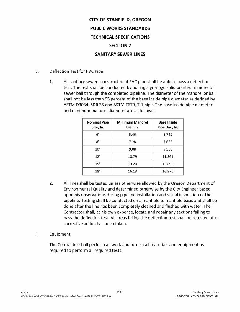
CITY OF STANFIELD, OREGON
PUBLIC WORKS STANDARDS
TECHNICAL SPECIFICATIONS
SECTION 2
SANITARY SEWER LINES
4/9/18 2‐16 Sanitary Sewer Lines G:\Clients\Stanfield\339‐109 Gen Eng\PWStandards\Tech Specs\SANITARY SEWER LINES.docx Anderson Perry & Associates, Inc.
E. Deflection Test for PVC Pipe
1. All sanitary sewers constructed of PVC pipe shall be able to pass a deflection test. The test shall be conducted by pulling a go‐nogo solid pointed mandrel or sewer ball through the completed pipeline. The diameter of the mandrel or ball shall not be less than 95 percent of the base inside pipe diameter as defined by ASTM D3034, SDR 35 and ASTM F679, T‐1 pipe. The base inside pipe diameter and minimum mandrel diameter are as follows:
Nominal Pipe Size, In.
Minimum Mandrel Dia., In.
Base Inside Pipe Dia., In.
6" 5.46 5.742
8" 7.28 7.665
10" 9.08 9.568
12" 10.79 11.361
15" 13.20 13.898
18" 16.13 16.970
2. All lines shall be tested unless otherwise allowed by the Oregon Department of Environmental Quality and determined otherwise by the City Engineer based upon his observations during pipeline installation and visual inspection of the pipeline. Testing shall be conducted on a manhole to manhole basis and shall be done after the line has been completely cleaned and flushed with water. The Contractor shall, at his own expense, locate and repair any sections failing to pass the deflection test. All areas failing the deflection test shall be retested after corrective action has been taken.
F. Equipment
The Contractor shall perform all work and furnish all materials and equipment as required to perform all required tests.

CITY OF STANFIELD, OREGON
PUBLIC WORKS STANDARDS
TECHNICAL SPECIFICATIONS
SECTION 2
SANITARY SEWER LINES
4/9/18 2‐17 Sanitary Sewer Lines G:\Clients\Stanfield\339‐109 Gen Eng\PWStandards\Tech Specs\SANITARY SEWER LINES.docx Anderson Perry & Associates, Inc.
3.4 Pressure Sewer Construction
A. Pipeline
1. The Contractor shall construct pressure sewer lines of the size, type, and class specified on the Drawings. Pipe shall meet the material specifications contained herein. All work performed in the installation of pressure sewer lines shall be performed as per the Standard Drawings, the applicable portions of subsection "Gravity Sewers‐Construction" contained herein, and as required by the manufacturer. All pressure sewer lines shall be installed to grade as shown on the design Drawings and as staked by the developer's design Engineer.
2. Installation of pressure service line pipe shall be in accordance with the applicable requirements contained herein. The Contractor shall end pressure service lines at the location as per the design Drawings and at the invert elevation as shown on the design Drawings or as set by the design Engineer. Dead ends of service lines shall be marked with steel fence posts installed in the ground as shown on the Standard Drawings.
3. In the construction of new pressure sewer systems, connection of new services allowing sewage into the system shall not be made until approval for connections has been given by the City. No existing sewer service shall be interrupted without the approval of the City and service owner.
4. The Contractor shall obtain all necessary permits required to construct service lines on private property. The Contractor must utilize a licensed plumber for service line work on private property when required by state or local regulations.
B. Testing
1. General
The Contractor shall be responsible for determining the length of any given section of line to be tested. It is recommended that the length of line to be tested not be excessive so that the identification of any problem areas can be readily made. It is also recommended that testing follow closely after the pipe installation and backfill.

CITY OF STANFIELD, OREGON
PUBLIC WORKS STANDARDS
TECHNICAL SPECIFICATIONS
SECTION 2
SANITARY SEWER LINES
4/9/18 2‐18 Sanitary Sewer Lines G:\Clients\Stanfield\339‐109 Gen Eng\PWStandards\Tech Specs\SANITARY SEWER LINES.docx Anderson Perry & Associates, Inc.
2. Hydrostatic Testing of Pressure Sewer Lines
a. Each section of the lines before being placed into service shall be isolated and slowly filled with water. Air should be expelled from the lines through taps made at the high points. The Contractor shall be responsible for making any necessary piping taps for testing.
b. All lines shall be pressure tested by the Contractor at 100 psi pressure, at the lowest pipe elevation, for one hour. Any cracked or defective pipe or fitting shall be removed and replaced.
3. Leakage Test
a. Each section of the line before being placed into service shall be tested by the Contractor for leakage for a period of two hours at an average gage pressure of 60 psi. The pressure during the test shall not fall below 40 psi. The allowable leakage is defined by the following equation: L=ND (P)0.5/7400 in which L = allowable leakage (gal/hr), N = number of joints or connections, D = nominal diameter in inches, P = average gage pressure during the test in psi.
b. Leakage is defined as the quantity of water supplied into the section of line being tested, during and at the end of the test, that quantity being such that the pressure at the end of the test is equal to the pressure at the beginning of the test.
c. Should any test disclose leakage greater than that specified, the Contractor shall locate and repair the defective joints until the leakage is within the specified allowance.
4. Equipment
The Contractor shall perform and provide all equipment and materials necessary to perform the required test.

CITY OF STANFIELD, OREGON
PUBLIC WORKS STANDARDS
TECHNICAL SPECIFICATIONS
SECTION 2
SANITARY SEWER LINES
4/9/18 2‐19 Sanitary Sewer Lines G:\Clients\Stanfield\339‐109 Gen Eng\PWStandards\Tech Specs\SANITARY SEWER LINES.docx Anderson Perry & Associates, Inc.
3.5 Manhole Construction
A. Installation
1. Manholes shall be constructed to the line, grade, and detail as shown on both the design Drawings and the Standard Drawings and as approved by the City. Excavation and backfill of the manhole shall be performed in the same manner as specified in Technical Specifications ‐ "Excavation and Backfill of Trenches," where applicable. Backfill shall be brought up evenly on all sides of the manhole.
2. The manhole base section shall be carefully placed on a prepared base of 6‐inch minimum deep crushed rock so as to be fully and uniformly supported in true alignment, and making sure that all entering pipes can be inserted on proper grade.
3. All connections and joints made at manholes shall be watertight. All manholes are to be watertight and any leakage shall be corrected in an approved manner.
B. Testing
1. The Contractor shall be responsible for providing all equipment, labor, and materials necessary for performing manhole testing.
2. All manholes shall be individually tested to verify their watertightness. Each manhole shall be tested for acceptance after all work has been completed including restoration work. Preliminary testing prior to final acceptance is advised.
3. The testing shall be by a vacuum test in conformance with ASTM C1244 "Standard Test Method for Concrete Sewer Manholes by the Negative Air Pressure (Vacuum) Test." All manholes must be watertight. Any points of leakage must be repaired by the Contractor, even if the manhole passed the vacuum test.
4. The vacuum test shall generally follow the following procedures:
a. All pipes entering the manhole shall be temporarily plugged, taking care to securely brace the pipes and plugs to prevent them from being drawn into the manhole.

CITY OF STANFIELD, OREGON
PUBLIC WORKS STANDARDS
TECHNICAL SPECIFICATIONS
SECTION 2
SANITARY SEWER LINES
4/9/18 2‐20 Sanitary Sewer Lines G:\Clients\Stanfield\339‐109 Gen Eng\PWStandards\Tech Specs\SANITARY SEWER LINES.docx Anderson Perry & Associates, Inc.
b. The test head shall be placed at the top of the manhole in accordance with the manufacturer's recommendations.
c. A vacuum of 10 inches of mercury shall be drawn on the manhole, the valve on the vacuum line of the test head closed, and the vacuum pump shut off. The time shall be measured for the vacuum to drop to 9 inches of mercury.
d. The manhole shall pass if the time for the vacuum reading to drop from 10 inches of mercury to 9 inches of mercury meets or exceeds the values indicated in Table 1.
e. If the manhole fails the initial test, necessary repairs shall be made by an approved method. The manhole shall then be retested until a satisfactory test is obtained.
f. The results of the manhole test shall be reported on the "Attachment B ‐ Manhole Test Record" form, a copy of which is located at the end of this section. The Contractor shall complete this form and provide it to the City prior to Substantial Completion.
TABLE 1 ‐ Minimum Test Times for Various Manhole Diameters
Depth (ft.)
Diameter, inches
30 33 36 42 48 54 60 66 72
Time, seconds
≤ 8 11 12 14 17 20 23 26 29 33
10 14 15 18 21 25 29 33 36 41
12 17 18 21 25 30 35 39 43 49
14 20 21 25 30 35 41 46 51 57
16 22 24 39 34 40 46 52 58 67
18 25 27 32 38 45 52 59 65 73
20 28 30 35 42 50 53 65 72 81
22 31 33 39 46 55 64 72 79 89
24 33 36 42 51 59 64 78 87 97

CITY OF STANFIELD, OREGON
PUBLIC WORKS STANDARDS
TECHNICAL SPECIFICATIONS
SECTION 2
SANITARY SEWER LINES
4/9/18 2‐21 Sanitary Sewer Lines G:\Clients\Stanfield\339‐109 Gen Eng\PWStandards\Tech Specs\SANITARY SEWER LINES.docx Anderson Perry & Associates, Inc.
TABLE 1 ‐ Minimum Test Times for Various Manhole Diameters
26 36 39 46 55 64 75 85 94 105
28 39 42 49 59 69 81 91 101 113
30 42 45 53 63 74 87 98 108 121
C. Connection to Existing Manhole
1. Connections to existing manholes when required on the Drawings shall be made by the Contractor. All connections shall be made in such a manner as to leave the existing manhole watertight.
2. All flow lines shall be properly shaped, and all new concrete shall be placed against a clean and sound surface.
3. An approved bonding agent shall be used on all existing surfaces to be bonded to new concrete or mortar. All applicable conditions for new manholes described previously shall apply.
3.6 Cleanout Construction
A. Main Line Cleanouts
Main line cleanouts shall be constructed as shown on the Standard Drawings. The select backfill shall be carefully compacted around the cleanout riser pipe to prevent damage or displacement of the pipe.
B. Service Line Cleanouts
Service line cleanouts in public rights‐of‐way shall be constructed as per the Standard Drawings. Service line cleanouts on private property shall be constructed in accordance with the Uniform Plumbing Code.
C. Testing
Cleanouts shall be tested as a part of the lines to which they are connected.

CITY OF STANFIELD, OREGON
PUBLIC WORKS STANDARDS
TECHNICAL SPECIFICATIONS
SECTION 2
SANITARY SEWER LINES
4/9/18 2‐22 Sanitary Sewer Lines G:\Clients\Stanfield\339‐109 Gen Eng\PWStandards\Tech Specs\SANITARY SEWER LINES.docx Anderson Perry & Associates, Inc.
3.7 Water‐Sewer Crossing
A. Wherever possible, the bottom of new or existing water lines shall be 1.5 feet or more above the top of the sanitary sewer line. Where the water line crosses over the sanitary sewer line but with a clearance of less than 1.5 feet, the Contractor shall center one full length of the new sewer pipe at the crossing point. Use PVC pressure pipe, ASTM D2241, SDR 32.5, (125 psi) at the crossing point. Where the water line crosses under the sanitary sewer line, the Contractor shall center one full length of the new sewer pipe at the crossing point.
B. If the City determines that conditions are not favorable or finds evidence of poor water line condition, the existing water line shall be replaced with a full length of water pipe centered at the crossing point.
C. When constructing sewer service lines, the City may require the depth of the service lines to be revised in order to eliminate the need for a water‐sewer line crossing.
3.8 Locating Wire
A. A continuous solid copper tracer or locating wire shall be taped along the top of all pressure sewer lines, including service lines. This wire shall be secured to the top of the pipe at maximum 10‐foot intervals using 6‐inch strips of 2‐inch wide duct tape. All splices shall be tied, electrically continuous, and made waterproof.
B. The location wire shall be brought to the surface at all valve boxes, cleanouts, and terminal line marker fence posts. The wire shall be secured to valve boxes, cleanouts, and posts with stainless steel pipe clamps.
C. Access to terminal ends of the locating wire shall be made at all manholes, cleanouts, valve boxes, terminal line marker fence posts, and as shown on the Standard Drawings, etc. The result of this installation shall be a continuous wire circuit electrically isolated from ground.
D. The Contractor shall be responsible for testing continuity and for testing isolation from ground in the wire after all work has been completed on the test section. The Contractor is advised to do intermediate testing on his own after backfilling operations and prior to surface restoration work to be sure continuity is maintained. If there is a

CITY OF STANFIELD, OREGON
PUBLIC WORKS STANDARDS
TECHNICAL SPECIFICATIONS
SECTION 2
SANITARY SEWER LINES
4/9/18 2‐23 Sanitary Sewer Lines G:\Clients\Stanfield\339‐109 Gen Eng\PWStandards\Tech Specs\SANITARY SEWER LINES.docx Anderson Perry & Associates, Inc.
break or defect in the wire, it shall be the Contractor's responsibility to locate and repair the defect.
E. The continuity of the location wire shall be tested from one test load point to the next by use of a temporary wire laid between test points in‐line with an ohmmeter. Resistance shall be measured with an approved ohmmeter that has been properly calibrated. The continuity of a test section will be accepted if the resistance of the test section does not exceed 5 ohms per 500 feet of location wire being tested. Isolation from ground shall be measured with a megohm meter and shall be a minimum of 20 megohms for any section of location wire tested.
F. The City shall witness the acceptance test.
3.9 Marker Posts
The Contractor shall furnish and place 4"x4" pressure treated wood posts at locations shown on the Standard Drawings and as directed by the City to mark the locations of certain manholes and other appurtenances. Posts shall be set solidly in the ground. All posts improperly set shall be reset.
3.10 Cleaning and Flushing of Completed and Tested Sewers
A. Prior to final inspection of the sewer system by the City, the Contractor shall flush and clean all parts of the system. All accumulated construction debris, rocks, gravel, sand, silt, and other foreign material shall be removed from the sewer system at or near the closest downstream manhole. If necessary, mechanical rodding or bucketing equipment shall be used.
B. All sewer pipes including gravity sewers, pressure sewer lines, service lines, etc., installed shall be flushed, as thoroughly as possible with the water pressure and outlets available. Flushing shall be done after the pressure test has been made. It must be understood that flushing removes only the lighter solids and cannot be relied upon to remove heavy material allowed to get into the sewers during construction. The Contractor shall provide sufficient water and appropriately sized taps at either end of the line to develop a velocity in the sewers during flushing of at least 2.5 fps.

CITY OF STANFIELD, OREGON
PUBLIC WORKS STANDARDS
TECHNICAL SPECIFICATIONS
SECTION 2
SANITARY SEWER LINES
4/9/18 2‐24 Sanitary Sewer Lines G:\Clients\Stanfield\339‐109 Gen Eng\PWStandards\Tech Specs\SANITARY SEWER LINES.docx Anderson Perry & Associates, Inc.
3.11 Work with Existing Asbestos Cement (A/C) Pipe
A. When working with A/C pipe, the Contractor shall take all precautions necessary to reduce airborne asbestos during construction. The Contractor will be required to contact the Oregon Department of Environmental Quality (DEQ), file an ASN 6 notification form, and follow Oregon Administrative Rules (OAR) 340‐248, Asbestos Requirements. The Contractor may initiate consultation with the Occupational Safety and Health Administration (OSHA) prior to construction, if necessary. Any work to be performed on existing A/C pipe shall be completed in accordance with American Water Works Association Guidelines and DEQ guidance document, "How to Remove Nonfriable Asbestos Cement Pipe."
B. The Contractor shall cut asbestos cement pipe by using snap cutters only. The use of carbide‐tipped cutting blades or high speed, abrasive disks shall not be permitted as a means of cutting A/C pipe snap cutters. Machining of this pipe shall be done with a manual or power‐driven field lathe, or with a manual rasp.
C. Hole cutting shall be accomplished with a tapping machine. Use of shell cutters, rasps, chisels, electric drills, right angle sanders, or other high speed abrasive tools shall not be permitted. Uncoupling of asbestos cement pipe shall be accomplished with a hammer and chisel. Use of abrasive disc cutters, right angle sanders, or other high speed abrasive tools shall not be permitted.
D. Dust and cuttings from all work shall be removed by wet mopping.
E. All waste material shall be collected in a covered container and disposed at a landfill
certified by the state or EPA to accept demolition waste.
3.12 Sewer Line Inspection
A. Television Inspection
All gravity sewer lines shall be visually inspected by means of closed circuit television. The purpose of the television inspection is to inspect the interior of select runs of gravity sewer line to determine the general quality of pipeline installation.
All sections designated by the City and/or City Engineer to be TV inspected shall be cleaned sufficiently to allow passage of TV equipment and so that cracked joints and

CITY OF STANFIELD, OREGON
PUBLIC WORKS STANDARDS
TECHNICAL SPECIFICATIONS
SECTION 2
SANITARY SEWER LINES
4/9/18 2‐25 Sanitary Sewer Lines G:\Clients\Stanfield\339‐109 Gen Eng\PWStandards\Tech Specs\SANITARY SEWER LINES.docx Anderson Perry & Associates, Inc.
breaks can best be observed. Cleaning shall be by high pressure flushing or as approved by the City. New sewer lines that are to be TV inspected shall be flushed with water two hours prior to the TV inspection work. During the TV inspection the Contractor shall maintain a small flow of water in the pipeline in order to observe high or low areas in the grade of the pipe.
The television camera used for the inspection shall be one specifically designed and constructed for such inspections. The camera shall be self‐propelled, with a remote control rotating head type capable of "looking up" service line connections and also capable of 360° scanning of pipeline joints. It shall be operative in 100 percent humidity conditions. Lighting and camera quality shall be suitable to allow a clear, in‐focus picture of a minimum of 6 lineal feet of the entire inside periphery of the sewer pipe. The camera shall be color with standard broadcast quality or better. The Contractor shall submit a DVD video recording which demonstrates the camera picture quality prior to performing the work. The camera picture quality shall be approved by the City. To ensure peak picture quality throughout all conditions encountered during the survey, a variable intensity control of the camera lights and remote control adjustments for focus shall be located at the monitoring station. Focal distance shall be adjustable through a range of 6 inches to infinity. Camera monitors shall be located within a temperature controlled studio which will allow seating of two authorized viewing personnel in addition to the operating technician. There shall be available within the studio two or more viewing monitors operating simultaneously and of a proper size to allow all persons in the studio to have a satisfactory and comfortable view of the video presentation. Monitors shall have good quality resolution. Continuously displayed on the monitors as part of the video presentation shall be the date of the survey, number designation of the manhole section being surveyed, and a continuous forward and reverse readout of the camera distance in feet from the manhole of reference. The ability to change the location of this readout on the picture is a desirable feature.
The operating technician shall have control of the movement of the television camera at all times. This may be accomplished by means of remote control winches or by telephone or other suitable means of communications between the winches at either end of the manhole section being surveyed. The travel speed of the camera shall be uniform and shall not exceed 30 feet per minute. Any means of propelling the camera through the sewer which would exceed this rate of speed or produce non‐uniform or jerky movements shall not be acceptable. At the Contractor's discretion or at the direction of the City, the camera shall be stopped and backed up to view and analyze

CITY OF STANFIELD, OREGON
PUBLIC WORKS STANDARDS
TECHNICAL SPECIFICATIONS
SECTION 2
SANITARY SEWER LINES
4/9/18 2‐26 Sanitary Sewer Lines G:\Clients\Stanfield\339‐109 Gen Eng\PWStandards\Tech Specs\SANITARY SEWER LINES.docx Anderson Perry & Associates, Inc.
conditions that appear unusual or uncommon to a good sound sewer. The operating technician shall at all times be able to move the camera through the line in either direction without loss of quality in the video presentation on the monitor. The picture at all times shall be free of electrical interference and provide a clear, stable image of the resolutions specified.
Video recording of all sewer line inspections shall be made on DVD and shall be enclosed in "jewel cases." The composite video and audio recordings of the sewer line inspections shall be compatible for replay on both computer and DVD players. The replay of the recorded video information, when reviewed on a monitor receiver, shall be free of electrical interference and provide a clear, stable image. The audio portion of the composite signal shall be sufficiently free from electrical interference and background noise to provide complete intelligibility of the oral report. Audio reports shall be recorded by the operating technician on the video as they are being produced and shall include the location of the sewer, the names or numbers of the manholes involved, a manhole‐to‐manhole direction of travel, and a detailed description of the conditions in the sewer line as they are encountered.
In no case will dubbing of the audio portion be allowed after the survey. The video recording and the monitoring equipment shall have the capability to instantly review both video and audio quality of the productions at all times during the television survey. The purpose of the video recording shall be to supply a permanent visual and audio record of the manhole section surveyed, and the DVDs shall become the property of the City upon completion of the project.
Detailed printed location records shall be made by the operating technician and shall clearly show the exact location in relation to the adjacent manholes of each infiltration point, building sewer connections, all joints which are infiltrating or exhibit other unusual conditions, roots, storm sewer connections, collapsed sections of pipe, joints sealed, presence of scale or corrosion, and other discernible features. Handwritten reports shall be submitted to the City daily. Within 20 days of completion of the initial TV inspection work, the inspection report forms shall be typewritten and submitted to the City for review. The video shall be properly indexed to the written reports using real time and an index to the written reports shall be provided which indexes each sewer line section (between manholes) to the reports. The intent is to enable a user of the report to easily find any given section of the sewer system in the reports and on the video. Prior to commencing work, the Contractor shall provide the City a sample of the

CITY OF STANFIELD, OREGON
PUBLIC WORKS STANDARDS
TECHNICAL SPECIFICATIONS
SECTION 2
SANITARY SEWER LINES
4/9/18 2‐27 Sanitary Sewer Lines G:\Clients\Stanfield\339‐109 Gen Eng\PWStandards\Tech Specs\SANITARY SEWER LINES.docx Anderson Perry & Associates, Inc.
proposed report format to be used by the Contractor. The City and Contractor shall agree on the report format before work proceeds. All reports shall be complete and accurate.
B. Necessary Repairs
If, in the opinion of the City, after television inspection, the sewer lines in question require repair and/or replacement to meet the original contract specifications, the Contractor shall be required to perform all necessary repairs and replacement. It shall be understood that any necessary repairs required will have been the result of poor construction or defective materials.
END OF SECTION

WORKSHEET FOR THE GRAVITY SEWER LINE LOW PRESSURE AIR TEST
BY THE TIME PRESSURE DROP METHOD
Project Name
Date Job No.
Location of Test/Stationing
1. Wetted Line: Yes ______ No ______ 2. Average height of groundwater over crown of sewer line _______ ft. 3. Internal Air Pressure (P1): P1 = 4.0 psig + Groundwater Ht. x 0.433 psi = 4.0 + (____' x .433) = ____ psig 4. Initial Starting Test Air Pressure (P2): P2 = P1 ‐ 0.5 psig = ‐ 0.5 = psig 5. Ending Test Air Pressure (P3) P3 = P2 ‐ 1.0 psig = ‐ 1.0 = psig 6. Time of test from P2 to P3 (in seconds) Start Time T1 ____________ End Time T2 ____________
Actual Time = T2 – T1 seconds
7. Test Time
Pipe Diameter (inches)
Length of Pipe
"C" Value* "K" Value*
TOTAL
Page 1 of 2
*See Figure No. 1 for "C" & "K" Values

If Total "C" Value is <1.0, use Total "K" Value as Test Time in seconds. If Total "C" Value is ≥1.0, use Total "K" Value ÷ Total "C" Value as Test Time in seconds. Results of Test Actual time = ________ seconds Test time = ________ seconds If Actual Time is equal to or greater than test time required for the pipe section being tested, the pipe section will have passed the Pressure Test. Test Passed: ______yes ______no Corrective Measures:
Contractor's Firm Name:
Contractor's Representative Signature: Title: City's Representative Signature: Title:
Page 2 of 2


EXCAVATION AND BACKFILL OF TRENCHES

CITY OF STANFIELD, OREGON
PUBLIC WORKS STANDARDS
TABLE OF CONTENTS
TECHNICAL SPECIFICATIONS
SECTION 3
EXCAVATION AND BACKFILL OF TRENCHES
4/9/18 i Table of Contents G:\Clients\Stanfield\339‐109 Gen Eng\PWStandards\Tech Specs\EXC BACKFILL TRENCHES.docx Anderson Perry & Associates, Inc.
PART 1 ‐ General ...................................................................................................................................... 3‐1 1.1 Summary ................................................................................................................................... 3‐1 1.2 Definitions ................................................................................................................................. 3‐1 1.3 Safety ......................................................................................................................................... 3‐1 1.4 Existing Utilities ......................................................................................................................... 3‐2 1.5 Dust and Mud Control ............................................................................................................... 3‐2
PART 2 ‐ Materials .................................................................................................................................... 3‐2 2.1 Foundation Material/Trench Stabilization Fabric ..................................................................... 3‐2 2.2 Bedding and Select Backfill ....................................................................................................... 3‐2 2.3 General Backfill .......................................................................................................................... 3‐2 2.4 Controlled Density Fill ............................................................................................................... 3‐3
PART 3 ‐ Execution ................................................................................................................................... 3‐3 3.1 Clearing and Grubbing ............................................................................................................... 3‐3 3.2 Cutting of Asphalt Pavement and Concrete Sidewalks, Curbs and Driveways ......................... 3‐4 3.3 Trench Excavation ..................................................................................................................... 3‐5 3.4 Shoring, Sheeting, and Bracing of Trenches.............................................................................. 3‐5 3.5 Dewatering Excavated Areas ..................................................................................................... 3‐6 3.6 Location of Excavated Materials ............................................................................................... 3‐6 3.7 Disposal of Excavated Materials ............................................................................................... 3‐6 3.8 Trench Backfill ........................................................................................................................... 3‐6 3.9 Execution of Dust and Mud Control .......................................................................................... 3‐9 3.10 Restoration, Finishing, and Cleanup ......................................................................................... 3‐9
CITY OF STANFIELD, OREGON
PUBLIC WORKS STANDARDS
TECHNICAL SPECIFICATIONS
SECTION 3
EXCAVATION AND BACKFILL OF TRENCHES
4/9/18 3‐1 Excavation and Backfill of Trenches G:\Clients\Stanfield\339‐109 Gen Eng\PWStandards\Tech Specs\EXC BACKFILL TRENCHES.docx Anderson Perry & Associates, Inc.
PART 1 ‐ GENERAL
1.1 Summary
These Specifications cover excavation and backfill of trenches for the installation of storm sewer, sanitary sewer, water lines, service lines, pressure sewer lines, and other underground utilities.
Items specified in this Technical Specification are intended to be broad in scope and may not always apply to all items of work to be constructed. All applicable sections, as determined by the City Engineer, shall control the work outlined in the Drawings and Specifications.
1.2 Definitions
A. Foundation material or stabilization fabric will only be required when standard bedding requirements will not adequately support the pipe.
B. Backfill is the filling of the trench to the existing ground level or the finish grade line shown on the Drawings.
C. General trench excavation shall include whatever materials that are encountered (except solid rock) to the depths shown on the Drawings or as required to properly install the pipe.
D. Solid Rock
Solid rock is defined as being rock formations other than cemented gravels that require hard ripping, jackhammering, blasting, or other extra work beyond the capability of heavy‐duty trench excavating equipment, such as a Hitachi 350 excavator or approved equal, with respect to weight, horsepower, bucket breakout force, etc., utilizing an attachment specifically designed for excavation in solid rock, such as a 36‐inch to 48‐inch long single shank ripper attachment. Weight of equipment shall be a key criterion in defining solid rock.
1.3 Safety
See requirements for project safety in the General Requirements.

CITY OF STANFIELD, OREGON
PUBLIC WORKS STANDARDS
TECHNICAL SPECIFICATIONS
SECTION 3
EXCAVATION AND BACKFILL OF TRENCHES
4/9/18 3‐2 Excavation and Backfill of Trenches G:\Clients\Stanfield\339‐109 Gen Eng\PWStandards\Tech Specs\EXC BACKFILL TRENCHES.docx Anderson Perry & Associates, Inc.
1.4 Existing Utilities
See the General Requirements for requirements for existing utilities and for preservation of survey monumentation.
1.5 Dust and Mud Control
The Contractor shall take appropriate action to control dust and mud caused by his operations. This shall include, but not be limited to, watering of exposed areas, cleaning of roadways, etc. This is considered a normal part of the construction project.
PART 2 ‐ MATERIALS
2.1 Foundation Material/Trench Stabilization Fabric
Foundation material or stabilization fabric will only be required when standard bedding requirements will not adequately support the pipe. Foundation material shall be a well‐graded 2‐1/2"‐0 or 1‐1/2"‐0 crushed rock.
As an alternative to over‐excavation and placement of foundation material, a geotextile stabilization fabric may be used if field use proves acceptable and is approved by the City Engineer. The fabric material shall be placed on the bottom of the trench and the bedding material placed over the fabric to proper pipe grade. The fabric width shall be one foot wider than the trench bottom. Fabric material shall be Mirafi 500X or approved equal.
2.2 Bedding and Select Backfill
Bedding and select backfill materials shall be subject to the approval of the City Engineer. Acceptable materials include well‐graded 3/4"‐0 crushed rock.
2.3 General Backfill
A. General backfill will consist of material excavated from the trench, or material imported by the Contractor. General backfill material shall be free of vegetative matter, boulders (10‐inch plus), frozen material and any other unsuitable material, and shall have a moisture content that will allow for the required compaction of the general backfill material unless approved otherwise by the City Engineer. Use of backfill material containing consolidated masses 6‐inch in diameter or greater is prohibited.

CITY OF STANFIELD, OREGON
PUBLIC WORKS STANDARDS
TECHNICAL SPECIFICATIONS
SECTION 3
EXCAVATION AND BACKFILL OF TRENCHES
4/9/18 3‐3 Excavation and Backfill of Trenches G:\Clients\Stanfield\339‐109 Gen Eng\PWStandards\Tech Specs\EXC BACKFILL TRENCHES.docx Anderson Perry & Associates, Inc.
B. When necessary, the Contractor shall selectively separate suitable general backfill material from unsuitable general backfill material.
C. When the City Engineer determines that the native material excavated from the trench is unsuitable or unacceptable for use as general backfill, the City Engineer may require the Contractor to remove the unsuitable material from the project site and import suitable general backfill material. When imported general backfill must be placed in or below the groundwater, the imported general backfill shall be free draining granular material with less than 20 percent passing a No. 4 sieve and less than 3 percent passing a No. 200 sieve.
2.4 Controlled Density Fill
A. Controlled density fill material shall be a flowable cement, sand or pea gravel, and Fly Ash Pozzolanic, or other approved materials, mixture that contains 75 to 120 pounds of Type II cement per cubic yard.
B. The sand and other aggregates shall generally conform with the requirements of ASTM C 33.
C. Air‐entraining agent shall be added at the rate of 3 to 5 oz. per cubic yard.
D. The material shall have a 28‐day compressive strength of 100‐200 psi and have a slump of 7 inches plus or minus 1 1/2 inches at the time of placement. The Contractor shall provide a mix design and data on the controlled density fill material he proposes to use along with typical compression test results.
PART 3 ‐ EXECUTION
3.1 Clearing and Grubbing
A. Contractor shall do all clearing and grubbing and removal of structures, etc. necessary to permit proper installation of the pipeline and to eliminate the possibility of stumps, logs, brush, or rubbish being mixed with the backfill material. A sufficient amount of all stumps and stump roots shall be removed so that any future removal of any remaining parts of the stumps and/or roots will not damage the pipeline. All stumps, roots, logs, brush and rubbish shall be removed and disposed of in conformance with the requirements of local authorities controlling air pollution, and solid waste disposal.

CITY OF STANFIELD, OREGON
PUBLIC WORKS STANDARDS
TECHNICAL SPECIFICATIONS
SECTION 3
EXCAVATION AND BACKFILL OF TRENCHES
4/9/18 3‐4 Excavation and Backfill of Trenches G:\Clients\Stanfield\339‐109 Gen Eng\PWStandards\Tech Specs\EXC BACKFILL TRENCHES.docx Anderson Perry & Associates, Inc.
B. Should the area in which construction takes place be served by rural mail carrier service, the Contractor shall cooperate with the mail service and re‐install, in a convenient location, any rural mail boxes which will have to be removed or be blocked by construction operations. As soon as the work is completed, all mail boxes removed shall be replaced undamaged in their original location.
C. As soon as the work is completed, all signs, guardrails, utility poles, fences, etc., which were moved for the construction operation shall be replaced undamaged in their original location. Damaged items shall be replaced by the Contractor with new items of equal quality.
3.2 Cutting of Asphalt Pavement and Concrete Sidewalks, Curbs and Driveways
A. Where the excavation is made in an existing paved street, the asphalt surface shall be cut on each side of the trench prior to excavation, to provide a vertical joint in the surface. Cutting of the asphalt will be made with a saw designed for the cutting of asphalt.
B. The use of a jackhammer, wheel cutter, or other similar tool may be allowed by the City Engineer only when the Contractor can demonstrate that the alternate method provides a neat straight edge.
C. Prior to excavating across a concrete structure such as a curb, sidewalk, or driveway, the Contractor shall cut and remove a section of the structure in order to provide for his excavation. The dimensions of the removed section shall be such that the Contractor's excavation will not result in undermining of the remaining structure.
D. The Contractor shall cut the concrete structure with a diamond saw or other equipment designed for that purpose such that a neat, straight, vertical edge is left on the remaining concrete structure. The Contractor shall similarly cut and remove any such concrete structure undermined or damaged by his construction work.
E. Following proper backfill and compaction of his excavation, as specified herein, the Contractor shall repair streets, replace the curbs, sidewalks, or driveways in conformance with the Drawings and Specifications, and permit requirements. Surface restoration shall be performed in accordance with Technical Specifications ‐ "Surface Restoration."

CITY OF STANFIELD, OREGON
PUBLIC WORKS STANDARDS
TECHNICAL SPECIFICATIONS
SECTION 3
EXCAVATION AND BACKFILL OF TRENCHES
4/9/18 3‐5 Excavation and Backfill of Trenches G:\Clients\Stanfield\339‐109 Gen Eng\PWStandards\Tech Specs\EXC BACKFILL TRENCHES.docx Anderson Perry & Associates, Inc.
3.3 Trench Excavation
A. When solid rock is encountered in trench excavation, the City Engineer shall be notified.
B. Trench Width
1. The maximum trench width in the pipe zone shall be 2 feet plus the O.D. of the pipe and the minimum trench width in the pipe zone shall be 1 foot plus the O.D. of the pipe. This width shall be maintained to the top of the pipe.
2. The maximum clear width above the top of the pipe will not be limited except in cases where excess width of excavation would cause damage to adjacent structures or utilities. The determination of the safe trench width is the sole responsibility of the Contractor.
C. Unsuitable Material
When natural soil conditions exist in the bottom of the trench that are unsuitable for proper pipe installation, the Contractor shall immediately notify the City Engineer. The Contractor may then be requested to over‐excavate the trench below the design grade to a depth specified by the City Engineer and place foundation material, or the Contractor may be requested to install a geotextile stabilization fabric.
D. Exploratory Work
The Contractor shall perform appropriate exploratory work to locate utilities when they are known to exist but the specific location is unknown or not marked accurately. Appropriate exploratory work shall be performed in these situations.
3.4 Shoring, Sheeting, and Bracing of Trenches
A. The Contractor shall adequately sheet and brace the trench during excavation whenever necessary to satisfy trench safety standards, prevent cave‐ins, or to protect adjacent structures or property. Where sheeting and bracing are used, the Contractor shall increase trench widths for the bracing material accordingly.
B. The sheeting must be kept in place until the pipe has been placed, backfilled at the pipe zone, tested for defects, and repaired if necessary. All sheeting, shoring, and bracing of trenches shall conform to the requirements of the public agency having jurisdiction.

CITY OF STANFIELD, OREGON
PUBLIC WORKS STANDARDS
TECHNICAL SPECIFICATIONS
SECTION 3
EXCAVATION AND BACKFILL OF TRENCHES
4/9/18 3‐6 Excavation and Backfill of Trenches G:\Clients\Stanfield\339‐109 Gen Eng\PWStandards\Tech Specs\EXC BACKFILL TRENCHES.docx Anderson Perry & Associates, Inc.
3.5 Dewatering Excavated Areas
A. All groundwater, seepage, or stormwater that may occur or accumulate in the excavation during the progress of the work shall be removed. In areas where the nature of soil and hydrostatic pressures are of such a character as to develop a quick condition in the earth mass of the trench, the dewatering operation shall be conducted so that the hydrostatic pressure will be reduced to or near zero in the immediate vicinity of the trench.
B. All excavations shall be kept free of water during the construction.
C. The Contractor shall dispose of all waste and water removed from the trench. Disposal shall be in accordance with all state and local regulations.
3.6 Location of Excavated Materials
A. During trench excavation, the excavated material shall be located within the construction easement or right‐of‐way so that the excavated material will not obstruct any private or public traveled roadways or streets, or cause undue damage to the streets.
B. The Contractor shall provide means of containing overly saturated soils, i.e., muck, or remove the muck from the work area as it is excavated, if such soils are encountered in the excavation. The intent is to prevent excessive damage or disruption to street rights‐of‐way or easement beyond what would normally occur during such work. Pile and maintain material from trenches so that the toe of the slope of the material excavated is at least two feet from the edge of the trench. It shall be the Contractor's responsibility, however, to determine the safe loading of all trenches.
3.7 Disposal of Excavated Materials
The Contractor shall dispose of all excavated material, which is not required for, or is unsuitable for, backfill. The Contractor's method of disposal shall comply with regulations of the governing body having jurisdiction.
3.8 Trench Backfill
A. All backfill material shall be placed into the trench so that free fall of the materials into the trench is prevented until at least two feet of cover is provided over the pipe. Under

CITY OF STANFIELD, OREGON
PUBLIC WORKS STANDARDS
TECHNICAL SPECIFICATIONS
SECTION 3
EXCAVATION AND BACKFILL OF TRENCHES
4/9/18 3‐7 Excavation and Backfill of Trenches G:\Clients\Stanfield\339‐109 Gen Eng\PWStandards\Tech Specs\EXC BACKFILL TRENCHES.docx Anderson Perry & Associates, Inc.
no circumstances shall sharp or heavy pieces of material be allowed to drop directly onto the pipe. Methods of backfilling, other than as specified herein, shall be used only upon the approval of the City Engineer.
B. Bedding and Select Backfill
1. A minimum 4‐inch depth of bedding shall be placed on the trench bottom, compacted to 85 percent of the maximum density as determined by ASTM D 1557 and smoothed to provide uniform bedding so the pipe is supported along its full length and not by the bells.
2. It shall be understood that the 4‐inch depth is a minimum depth only, not an average depth and does not preclude the Contractor at his option from placing additional depth of bedding to facilitate his work. Once the pipe is properly installed, the bedding material shall be brought up to the spring line of the pipe in 4‐inch lifts and compacted to 85 percent of ASTM D 1557 density. Care shall be used to ensure that the bedding material is properly worked under the haunch of the pipe for its full length.
3. Select backfill shall then be brought up from the spring line to a minimum of 6 inches for water lines, and 12 inches for sewer and storm sewer lines above the top of the pipe, leveled and compacted to 85 percent of ASTM D 1557 density. Compaction of the bedding and select backfill by hand tamping will be allowed if the 85 percent density is achieved; otherwise, mechanical tamping will be required.
4. When an open‐graded material is used for bedding or foundation material to facilitate trench dewatering, the open graded material shall be placed to the spring line of the pipe. The Contractor shall make provisions to ensure that fines from the select backfill do not migrate into the open graded bedding or foundation material. To prevent soil migration the Contractor may use any of the following:
a. Provide a properly graded select backfill approved by the Engineer;
b. Provide an approved fiber/fabric between the open graded bedding material and select backfill;
CITY OF STANFIELD, OREGON
PUBLIC WORKS STANDARDS
TECHNICAL SPECIFICATIONS
SECTION 3
EXCAVATION AND BACKFILL OF TRENCHES
4/9/18 3‐8 Excavation and Backfill of Trenches G:\Clients\Stanfield\339‐109 Gen Eng\PWStandards\Tech Specs\EXC BACKFILL TRENCHES.docx Anderson Perry & Associates, Inc.
c. Hydraulically jet select backfill fines into open graded bedding material after dewatering is complete and before general backfill is placed; or
d. Provide an alternative approved by the City Engineer.
C. All general backfill material shall be pushed first onto the slope of the backfill previously placed and allowed to roll down into the trench. The Contractor shall not push the backfill material directly into the trench until at least two feet of cover is provided over the pipe.
D. Compaction
1. In roadways, driveways, under curbs and sidewalks, general backfill shall be placed in horizontal lifts and compacted to 90 percent of the laboratory density as determined by ASTM D 1557. The method of compaction shall be selected by the Contractor.
2. The Contractor shall exercise extreme care to avoid damage to the pipe during compaction of the trench. Where materials consist of cobbles and coarse gravels, compaction of each lift shall be accomplished by at least five passes of an appropriate vibrating type compactor. When materials are such that meaningful in‐place density test cannot be run, then the Contractor and City Engineer will agree on a method of compaction which will provide adequate compaction.
3. In sections where specific compaction requirements are not specified, or required by the City Engineer, general backfill shall be compacted, as a minimum, to a density equal to that of the natural ground adjacent to the trench. All trenches shall be maintained for a period of one year after final acceptance of the project. Any settlement of the trenches during the one‐year guarantee period shall be remedied promptly at the request of the City Engineer and at no cost to the City.
E. Controlled Density Fill (Flowable Fill or Lean Mix Backfill)
1. When called for on the Drawings or Specifications, or where required by state highway or county road crossing permits, the Contractor shall backfill trenches with controlled density fill.
CITY OF STANFIELD, OREGON
PUBLIC WORKS STANDARDS
TECHNICAL SPECIFICATIONS
SECTION 3
EXCAVATION AND BACKFILL OF TRENCHES
4/9/18 3‐9 Excavation and Backfill of Trenches G:\Clients\Stanfield\339‐109 Gen Eng\PWStandards\Tech Specs\EXC BACKFILL TRENCHES.docx Anderson Perry & Associates, Inc.
2. The controlled density fill shall be placed in the trench in such a manner to ensure the trench is completely filled to the lines and grades called for on the Drawings or in the permit. The controlled density fill shall be protected from traffic loads for a three‐hour period after which required surface restoration work may be performed.
F. Canal or Irrigation Ditch Crossing
1. Where the trench crosses a canal, irrigation ditch or culvert, the backfill shall be compacted the entire trench depth with mechanical tampers to 90 percent of the laboratory density as determined by ASTM D 1557.
2. All backfill material in the canal or ditch liner and in the trench cut‐off wall shall be imported clay or a soil/bentonite mixture as approved by the City Engineer. Unless required otherwise, the soil/bentonite mixture shall be 1 part bentonite to 10 parts soil by weight. A high grade bentonite material shall be used.
3. The ditch lining, conduit, or pipe shall be restored to its original condition. The crossing shall be water tight and free of any leakage or seepage. The Contractor shall be fully responsible for repairing canal or ditch banks at no cost to the City should leakage occur at the crossing.
3.9 Execution of Dust and Mud Control
If the Contractor fails to properly control the dust and mud, the City may request him to do so in writing. If, after 24 hours from this request, the Contractor has not corrected the dust or mud problem, the City may elect to have the corrective work performed, bill the Contractor for the work, and withhold final acceptance of the project until the bill is paid.
3.10 Restoration, Finishing, and Cleanup
A. The Contractor shall restore or replace all paved surfaces, graveled surfaces, curbing, sidewalks, trees and shrubbery, lawns, pastures and fences, or other existing facilities disturbed by his work unless otherwise specified. Restoration and cleanup shall be a continuing operation and shall be diligently pursued until completed.

CITY OF STANFIELD, OREGON
PUBLIC WORKS STANDARDS
TECHNICAL SPECIFICATIONS
SECTION 3
EXCAVATION AND BACKFILL OF TRENCHES
4/9/18 3‐10 Excavation and Backfill of Trenches G:\Clients\Stanfield\339‐109 Gen Eng\PWStandards\Tech Specs\EXC BACKFILL TRENCHES.docx Anderson Perry & Associates, Inc.
B. All surplus material and temporary structures as well as excess excavation shall be removed by the Contractor and the entire site of Contractor operations shall be left in a neat and clean condition as outlined in the General Requirements.
C. Surface restoration shall be performed in accordance with Technical Specifications ‐ "Surface Restoration." All other existing facilities shall be replaced or restored equal to their original condition.
END OF SECTION

SURFACE RESTORATION

CITY OF STANFIELD, OREGON
PUBLIC WORKS STANDARDS
TABLE OF CONTENTS
TECHNICAL SPECIFICATIONS
SECTION 4
SURFACE RESTORATION
4/9/18 i Table of Contents G:\Clients\Stanfield\339‐109 Gen Eng\PWStandards\Tech Specs\SURFACE RESTORATION.docx Anderson Perry & Associates, Inc.
PART 1 ‐ General ...................................................................................................................................... 4‐1 1.1 Scope ......................................................................................................................................... 4‐1
PART 2 ‐ Materials .................................................................................................................................... 4‐1 2.1 Base Rock................................................................................................................................... 4‐1 2.2 Asphalt Concrete ....................................................................................................................... 4‐1 2.3 Cold‐Mix Asphalt Concrete ....................................................................................................... 4‐2 2.4 Portland Cement Concrete ........................................................................................................ 4‐2 2.5 Seed ........................................................................................................................................... 4‐2 2.6 Fertilizer ..................................................................................................................................... 4‐3 2.7 Topsoil ....................................................................................................................................... 4‐3 2.8 Mulch ......................................................................................................................................... 4‐3 2.9 Sod ............................................................................................................................................. 4‐3 2.10 Soil Conditioners ....................................................................................................................... 4‐3 2.11 Erosion Control Matting ............................................................................................................ 4‐3 2.12 Hot Asphalt‐Rubber Joint Sealant ............................................................................................. 4‐4
PART 3 ‐ Execution ................................................................................................................................... 4‐4 3.1 Gravel Surface Restoration ....................................................................................................... 4‐4 3.2 Asphalt Street Restoration and Asphalt Parking‐Driveway Restoration................................... 4‐4 3.3 Asphalt Concrete Joint Sealing .................................................................................................. 4‐5 3.4 Concrete Sidewalk and Curb Restoration ................................................................................. 4‐6 3.5 General Surface Restoration ..................................................................................................... 4‐6 3.6 Lawn Sod Restoration ............................................................................................................... 4‐8 3.7 Erosion Control Matting ............................................................................................................ 4‐9 3.8 Mulch ....................................................................................................................................... 4‐10 3.9 Cleanup .................................................................................................................................... 4‐10

CITY OF STANFIELD, OREGON
PUBLIC WORKS STANDARDS
TECHNICAL SPECIFICATIONS
SECTION 4
SURFACE RESTORATION
4/9/18 4‐1 Surface Restoration G:\Clients\Stanfield\339‐109 Gen Eng\PWStandards\Tech Specs\SURFACE RESTORATION.docx Anderson Perry & Associates, Inc.
PART 1 ‐ GENERAL
1.1 Scope
A. These Specifications cover the restoration of gravel and asphalt streets and parking areas, concrete curbs and sidewalks, and agricultural and lawn areas.
B. Items specified in this Technical Specification are intended to be broad in scope and may not always apply to all items of work to be constructed. All applicable sections, as determined by the City Engineer, shall control the work.
C. The Contractor shall perform all work and furnish all materials to restore the work area including any gravel, asphalt, concrete, lawn, fences, or any other surfaces or items damaged or disturbed by his construction operation. Surface restoration shall follow as closely as possible the backfill and compaction of excavations.
PART 2 ‐ MATERIALS
2.1 Base Rock
Base rock shall substantially conform to current Oregon Standard Specifications for Construction for base aggregate materials, or as otherwise approved by the City Engineer. The intent is to specify a base rock which is suitable for use in the restoration of areas disturbed by the Contractor's work. Base rock required shall be 3/4"‐0 unless otherwise specified or approved. The Contractor shall submit to the City Engineer samples of the base rock he plans to use on the project.
2.2 Asphalt Concrete
Asphalt concrete shall be an approved commercial mix conforming to the applicable provisions of the current Oregon Standard Specifications for Construction for asphalt concrete pavement. Unless approved otherwise, the gradation of the mix shall conform to a 1/2‐inch dense mix. The Contractor shall submit for review by the City Engineer data on the asphalt concrete mix to be used. Data shall include aggregates, gradation and tolerances, aggregate suitability, asphalt concrete, mix proportions and tolerances, etc.

CITY OF STANFIELD, OREGON
PUBLIC WORKS STANDARDS
TECHNICAL SPECIFICATIONS
SECTION 4
SURFACE RESTORATION
4/9/18 4‐2 Surface Restoration G:\Clients\Stanfield\339‐109 Gen Eng\PWStandards\Tech Specs\SURFACE RESTORATION.docx Anderson Perry & Associates, Inc.
2.3 Cold‐Mix Asphalt Concrete
Cold‐mix asphalt concrete shall consist of a mixture of asphalt cement cut back with No. 2 fuel oil, and well‐graded aggregate, plant mixed, and laid on a prepared foundation and compacted with a minimum 8‐ton steel wheel roller. The aggregate shall meet the quality and gradation requirements for a standard ODOT 1/2‐inch dense asphalt concrete mix. The liquid fraction of the mix shall be 6‐1/2 to 7 percent content by weight and shall consist of 70 percent PBA‐2 or PBA‐5 asphalt cement, and 30 percent No. 2 fuel oil. The cold‐mix asphalt concrete shall remain alive in the stockpile until it is placed and compacted. After the No. 2 fuel oil evaporates, the remaining asphalt and aggregate mix shall remain stable and durable under traffic.
2.4 Portland Cement Concrete
A. The Portland Cement concrete used for this work shall be an approved commercial transit mix. The exact proportions of all the materials entering into the concrete shall be as established by an approved laboratory mix design and shall be changed only as approved by the City Engineer or laboratory when necessary to obtain the specified strength, desired density, uniformity, or workability. Previously prepared mix designs will be allowed provided adequate test data is available to document the suitability of the mix and the Contractor can document that the same materials are being used.
B. The mix shall have a maximum water‐cement ratio of 0.45, a minimum 28‐day compressive strength of 4,000 psi, a minimum of 564 pounds of cement per cubic yards of mix, and an air content of 4 to 7 percent. The maximum allowable slump shall be 4 inches for all structures covered under this section of the specifications.
2.5 Seed
A. Lawn Seed
Lawn seed shall be a blend typically used in the area and of the type to match existing lawn areas, and must be approved by the City prior to use.
B. Pasture Seed
Pasture seed shall be a mixture of orchard grass, rye grass, and fescue, native to the area and of the type to match existing pasture areas.

CITY OF STANFIELD, OREGON
PUBLIC WORKS STANDARDS
TECHNICAL SPECIFICATIONS
SECTION 4
SURFACE RESTORATION
4/9/18 4‐3 Surface Restoration G:\Clients\Stanfield\339‐109 Gen Eng\PWStandards\Tech Specs\SURFACE RESTORATION.docx Anderson Perry & Associates, Inc.
2.6 Fertilizer
Except for hydroseeding, inorganic fertilizer shall be commercially available 22‐16‐8 with 22 percent nitrogen, 16 percent available phosphoric acid, 8 percent soluble potash, and a minimum of 2 percent sulfur.
2.7 Topsoil
Topsoil shall be native to the area and shall be approved by the City prior to use.
2.8 Mulch
All mulch shall be straw that has been air dried and seasoned before baling or loading. It shall be free of noxious weeds and other materials detrimental to grass growth.
2.9 Sod
A. Sod shall be 100 percent Kentucky Blue Grass or of the type to match existing lawn areas.
B. The sod shall be grown on agricultural land that is cultivated specifically for turf sod. The sod shall be free of weeds, diseases, nematodes, and insects. All sod shall be mature and not less than 10 months old. All sod shall be machine cut to a uniform thickness of 5/8‐inch or more, excluding top growth and thatch.
2.10 Soil Conditioners
Soil conditioners shall be manufactured from composted sewage sludge, amended with organic and inorganic materials. They shall be as manufactured by EKO Systems, Inc. of Lewiston, Idaho, or equal.
2.11 Erosion Control Matting
Erosion control matting shall be seed and curlex blanket as supplied by American Excelsior Co., of Yakima, Washington, or approved equal.

CITY OF STANFIELD, OREGON
PUBLIC WORKS STANDARDS
TECHNICAL SPECIFICATIONS
SECTION 4
SURFACE RESTORATION
4/9/18 4‐4 Surface Restoration G:\Clients\Stanfield\339‐109 Gen Eng\PWStandards\Tech Specs\SURFACE RESTORATION.docx Anderson Perry & Associates, Inc.
2.12 Hot Asphalt‐Rubber Joint Sealant
Hot asphalt‐rubber joint sealant shall be Roadsaver 221 as manufactured by Crafco, Inc., or equal.
PART 3 ‐ EXECUTION
3.1 Gravel Surface Restoration
A. During trench and general excavation, the Contractor shall minimize the disturbance of adjacent gravel surfaces.
B. Backfill of trenches and other work area shall be in accordance with Technical Specifications ‐ "Excavation and Backfill of Trenches," or other applicable requirements.
C. In gravel streets, parking areas or driveways disturbed by the work, the Contractor shall resurface the areas with "Base Rock" to a compacted depth equal to the existing depth of gravel plus the depth of granular subbase, if any, whichever is greater.
D. The resurfacing aggregate shall be compacted to 95 percent of laboratory density as determined by ASTM D 1557.
3.2 Asphalt Street Restoration and Asphalt Parking‐Driveway Restoration
A. Existing asphalt surfaces shall be cut on each side of the trench prior to excavation to provide a vertical, neat, straight‐line joint in the surface. Should any asphalt surface be undermined or damaged during construction, the undermined or damages asphalt shall be similarly cut and removed prior to backfill. This work shall be performed along neat, continuously straight lines to provide a pleasing finished appearance. Irregular lines will not be allowed.
B. Backfill shall be made in accordance with Technical Specifications ‐ "Excavation and Backfill of Trenches."
C. The base rock under the asphalt pavement shall be replaced to a compacted depth equal to the existing base rock depth plus the depth of granular subbase, if any, or 10 inches, whichever is greater. The base rock shall be compacted to 95 percent of the laboratory density as determined by ASTM D 1557.

CITY OF STANFIELD, OREGON
PUBLIC WORKS STANDARDS
TECHNICAL SPECIFICATIONS
SECTION 4
SURFACE RESTORATION
4/9/18 4‐5 Surface Restoration G:\Clients\Stanfield\339‐109 Gen Eng\PWStandards\Tech Specs\SURFACE RESTORATION.docx Anderson Perry & Associates, Inc.
D. Immediately following backfill and compaction of the trench, and until the asphalt concrete is replaced, the base rock course shall be placed and compacted flush with the existing asphalt surface and maintained in a good condition.
E. In areas of heavy traffic, highway crossings, etc., a temporary cold‐mix patch shall be placed and maintained until asphalt surface restoration is accomplished.
F. Just prior to placing the asphalt concrete, the base rock course and any temporary patch shall be excavated to the depth equal to that of the asphalt concrete to be placed.
G. Asphalt concrete for all areas, except in State Highways, shall be 3 inches in depth after compaction or a depth equal to the existing pavement, whichever is greater.
H. The restoration of asphalt concrete pavement in State Highways shall be performed as described on State Highway Crossing Permits.
I. Asphalt concrete shall be compacted with an 8‐ton minimum steel‐wheeled roller and compacted to a minimum of 91 percent of the maximum density as determined by ASTM D 2041.
J. Prior to placing the asphalt concrete, an asphalt tack coat shall be applied to the edges of the existing asphalt. An asphalt tack coat shall also be used between lifts should the Contractor elect to patch with multiple lifts. The Contractor shall utilize a paving machine, spreader box, or other approved mechanical equipment to place the asphalt concrete material. No lift of asphalt placed shall have a compacted thickness of less than 1/2 inch or greater than 3 inches. The finished asphalt surface shall be flush with the existing surface, uniform in appearance equal to or better than the existing pavement, and shall provide a smooth ride.
K. Installation shall conform to the applicable provisions of the current Oregon Standard Specifications for Construction, Sections 00495 and 00744. Asphalt Concrete for temporary patches shall conform to Section 00745.50 of the Oregon Standard Specifications for Construction.
3.3 Asphalt Concrete Joint Sealing
Where required by the City, the Contractor shall rout and clean joints between new asphalt concrete and the existing pavement after a minimum of 30 days following completion of

CITY OF STANFIELD, OREGON
PUBLIC WORKS STANDARDS
TECHNICAL SPECIFICATIONS
SECTION 4
SURFACE RESTORATION
4/9/18 4‐6 Surface Restoration G:\Clients\Stanfield\339‐109 Gen Eng\PWStandards\Tech Specs\SURFACE RESTORATION.docx Anderson Perry & Associates, Inc.
asphalt concrete restoration. Routed joints shall be 1/2 inch wide x 3/4 inch to 1 inch deep. A hot asphalt‐rubber joint sealant shall be placed in the joint flush with the surface to make a watertight seal.
3.4 Concrete Sidewalk and Curb Restoration
A. Existing concrete surfaces shall be saw cut on each side of the trench prior to excavation to provide a vertical, straight‐line joint in the surface. Should any concrete surface be undermined or damaged during construction, the undermined or damaged concrete shall be similarly cut and removed prior to backfill. This work shall be performed along neat lines to provide a pleasing finished appearance. Irregular lines will not be allowed.
B. Backfill shall be made in accordance with Technical Specifications ‐ "Excavation and Backfill of Trenches."
C. A 2‐inch compacted depth leveling course of base rock shall be placed on the prepared subgrade. The base rock shall be compacted to 95 percent of the laboratory density as determined by ASTM D 1557.
D. Any forms used shall be wood or metal and shall be straight. They shall be suitably braced to prevent movement during placement. New joints shall be placed to match existing joints. The placement and curing of the concrete shall follow good concrete placement practices. The concrete thickness, section, finish, configuration, etc. shall match the existing structure as closely as possible.
3.5 General Surface Restoration
A. General
1. The Contractor shall replace or restore, equal to their original condition, all surfaces, trees and shrubbery, lawns, agriculture area, pastures and fences, or other existing facilities disturbed by his work unless otherwise specified. Restoration and cleanup shall be a continuing operation and shall be diligently pursued until completed. Surface restoration shall be completed as soon as possible after the underground work is complete.

CITY OF STANFIELD, OREGON
PUBLIC WORKS STANDARDS
TECHNICAL SPECIFICATIONS
SECTION 4
SURFACE RESTORATION
4/9/18 4‐7 Surface Restoration G:\Clients\Stanfield\339‐109 Gen Eng\PWStandards\Tech Specs\SURFACE RESTORATION.docx Anderson Perry & Associates, Inc.
2. All surplus material, rock and debris, and temporary structures, as well as excess excavation, shall be removed by the Contractor and the entire site of Contractor's operations shall be left in a neat and clean condition.
3. Lawns and pastures in private easement shall be restored to a smooth condition and reseeded with a like mixture of grass unless specified otherwise in the easement documents.
4. When backfilling trenches in private easements, unless otherwise specified, Contractor shall replace topsoil to minimum 1‐foot depth or to a depth equal to the original depth, whichever is less.
5. Lawn sod shall be utilized where called for on the Drawings or as specified in the easement documents.
B. Agricultural Areas
1. Where called for on the Drawings, the existing top soils in the excavation area shall be removed and stockpiled at a separate location from the general trench excavation material. This topsoil shall not be mixed or contaminated with any other materials.
2. Upon completion of the trench backfill and after all rocks and unsuitable material have been removed from the work area, the stockpiled topsoil shall be replaced and graded to match the existing ground. The depth of topsoil restoration shall be as shown on the Drawings or as specified in the easement documents.
C. Seeding
1. All areas to be seeded shall have a minimum of 6 inches of topsoil.
2. After the backfilling and compaction have been completed, the top 2 inches of the topsoil shall be scarified to provide a good seed bed and the area seeded, fertilized, compacted with a weighted roller, a straw mulch applied, and the initial watering completed.
3. All additional watering of the grass seed shall be the responsibility of the property owners.

CITY OF STANFIELD, OREGON
PUBLIC WORKS STANDARDS
TECHNICAL SPECIFICATIONS
SECTION 4
SURFACE RESTORATION
4/9/18 4‐8 Surface Restoration G:\Clients\Stanfield\339‐109 Gen Eng\PWStandards\Tech Specs\SURFACE RESTORATION.docx Anderson Perry & Associates, Inc.
4. Unless required otherwise, the seed shall be applied at a minimum rate of 4 pounds per 1,000 square feet, the fertilizer at 1 pound per 100 square feet, and the mulch at a rate needed to provide a minimum mulch thickness of 1 inch.
3.6 Lawn Sod Restoration
A. Preparation of Areas
1. Cultivate the existing ground so the soil is loose and friable for at least a 6‐inch depth and suitable for fine grading. Remove vegetative matter, rocks, clods, roots, sticks, debris, and other matter detrimental to the germination and growth of sod from the areas to be sodded.
2. Apply herbicide to kill existing weeds and grasses.
3. Spread soil amendments and fertilizers evenly over the sod bed at the rates specified below, then thoroughly till into the upper 4 inches of the soil.
4. After tilling, fine‐grade and roll the area to provide a fine‐textured, smooth, firm surface, free of any undulations or irregularities.
5. The finish grade of the sod bed shall be 1 inch below the finish grade of the walks. Rates of applications shall be as follows:
Material Rate Per 1,000 Sq. Ft.
Soil Conditioner 6 Cu. Yds. (2" Depth)
Fertilizer: 22‐16‐8 10 Lbs.
B. Planting Season
Perform the work only when local weather and other conditions are favorable to bed preparation and placing of sod. Do not place sod before March 15 or after September 30.
C. Placing Sod
1. Do not place sod until it has been approved. Immediately before placing sod, water the bed to prevent drying of grass roots.

CITY OF STANFIELD, OREGON
PUBLIC WORKS STANDARDS
TECHNICAL SPECIFICATIONS
SECTION 4
SURFACE RESTORATION
4/9/18 4‐9 Surface Restoration G:\Clients\Stanfield\339‐109 Gen Eng\PWStandards\Tech Specs\SURFACE RESTORATION.docx Anderson Perry & Associates, Inc.
2. Lay the first row in a straight line and place subsequent rows parallel to and tightly against each other. Stagger lateral joints. Do not stretch or overlap the sod. Tightly butt all joints. Do not use sod segments containing less than 2 square feet of surface area, broken, torn, or uneven pieces.
3. After placing sod, diagonally roll and thoroughly water. Apply a second application of fertilizer (22‐16‐8) at the rate of 10 lbs per 1,000 square feet and thoroughly water.
D. Sod Lawn Establishment
1. The establishment period for sod lawn begins after placing of sod in an area is completed. The establishment period will be at least two weeks and ends when accepted by the City Engineer. During the established period, adequately water all lawn areas. Keep mowed to a height of 1‐1/2 to 2 inches.
2. Do not attempt the first mowing until the sod is firmly rooted and secure in place. Remove no more than 1/3 of the grass leaf during initial or subsequent cuttings.
3. Control all weeds, foreign grasses, etc., that grow in or through the sod for up to 45 days after the sod is placed.
4. Acceptance of sod lawn will be contingent on the grass being uniform in color, density, and height, and being weed‐free. All dead or brown sod shall be replaced at no cost to the Owner.
3.7 Erosion Control Matting
A. Place matting as called for on the Drawings or as required by the Engineer. Prepare site as specified for permanent seeding area preparation.
B. Immediately following the establishment of the finished grade, matting shall be placed parallel to the flow of water. Where more than one strip of matting is required to cover the given area, it shall overlap the adjacent mat a minimum of 4 inches.
C. The ends of the matting shall overlap at least 6 inches with the upgrade section on top. The upslope end of matting shall be staked and buried in a 6‐inch deep trench with the soil firmly tamped against the mat. Three stakes per width of matting (one stake at each

CITY OF STANFIELD, OREGON
PUBLIC WORKS STANDARDS
TECHNICAL SPECIFICATIONS
SECTION 4
SURFACE RESTORATION
4/9/18 4‐10 Surface Restoration G:\Clients\Stanfield\339‐109 Gen Eng\PWStandards\Tech Specs\SURFACE RESTORATION.docx Anderson Perry & Associates, Inc.
overlap) shall be driven below the finish ground line prior to backfilling of the trench. The Engineer may require that any other edge exposed to more than normal flow of water or strong prevailing winds be staked and buried in a similar manner.
D. The edges of matting shall be buried around the edges of catch basins and other structures. Matting must be spread evenly and smoothly and in contact with the soil at all points.
E. Matting shall be held in place by approved wire staples, pins, spikes, or wooden stakes driven vertically into the soil. The matting shall be fastened at intervals not more than 3 feet apart in three rows for each strip of the matting, with one row along each edge and one row alternately spaced in the middle. All ends of the matting and check slots shall be fastened at 6‐inch intervals across their width. Length of fastening devices shall be sufficient to securely anchor the matting against the soil and driven flush with the finished grade.
3.8 Mulch
A. Place mulch approximately 1‐1/2 inches deep in a loose condition at a rate of 2 to 2.5 tons/acre. Place grass straw mulch so that it is loose enough for sunlight to penetrate and air to circulate; but dense enough to shade the ground, reduce water evaporation, and materially reduce soil erosion.
B. Anchor using a crimping disc, an approved tackifier, or approved modified sheepsfoot roller, or another method approved by the City.
3.9 Cleanup
A. Cleaning up shall be a continuing process from the start of the work to final acceptance of the project. The Contractor shall, at all times, keep the area on which work is in progress free from accumulations of waste material or rubbish.
B. Spillage from the Contractor's hauling vehicles on traveled public or private roads shall be promptly cleaned up. Upon completion of the work the Contractor shall remove all temporary structures, rubbish, and waste material, equipment and supplies, resulting from the Contractor's operations. The Contractor shall leave such lands in a neat and orderly condition which is at least as good as the condition in which the Contractor found them prior to the Contractor's operations.

CITY OF STANFIELD, OREGON
PUBLIC WORKS STANDARDS
TECHNICAL SPECIFICATIONS
SECTION 4
SURFACE RESTORATION
4/9/18 4‐11 Surface Restoration G:\Clients\Stanfield\339‐109 Gen Eng\PWStandards\Tech Specs\SURFACE RESTORATION.docx Anderson Perry & Associates, Inc.
C. In roadways and traffic areas, the Contractor shall be responsible for maintaining a road surface suitable for travel by the public from the time of excavation until the road surface has been restored. Such work includes dust control, temporary patching, signing, grading, and filling of potholes on temporary street surfaces, etc. The Contractor shall be responsible for all claims and damages resulting from his failure to maintain a suitable surface.
D. Any deficiencies found during the one‐year guarantee period, such as settlement, potholes, or the breaking up of pavement, etc., including the failure to maintain a suitable temporary road surface, shall be promptly remedied by the Contractor upon the receipt of a written notice from the City Engineer at no cost to the City.
END OF SECTION

ROAD WORK

CITY OF STANFIELD, OREGON
PUBLIC WORKS STANDARDS
TABLE OF CONTENTS
TECHNICAL SPECIFICATIONS
SECTION 5
ROAD WORK
4/9/18 i Table of Contents G:\Clients\Stanfield\339‐109 Gen Eng\PWStandards\Tech Specs\ROAD WORK.docx Anderson Perry & Associates, Inc.
PART 1 ‐ General ...................................................................................................................................... 5‐1 1.1 Scope ......................................................................................................................................... 5‐1
PART 2 ‐ Materials .................................................................................................................................... 5‐1 2.1 Water for Compaction............................................................................................................... 5‐1 2.2 Geotextile Fabric ....................................................................................................................... 5‐1 2.3 Aggregate Base and Base Rock ................................................................................................. 5‐1 2.4 Soil Sterilant .............................................................................................................................. 5‐2 2.5 Paving Fabric ............................................................................................................................. 5‐3 2.6 Asphalt Tack Coat ...................................................................................................................... 5‐3 2.7 Hot‐Mix Asphalt Concrete ......................................................................................................... 5‐4 2.8 Street Monument Boxes ........................................................................................................... 5‐5 2.9 Culverts ...................................................................................................................................... 5‐5 2.10 Drainage Trenches ..................................................................................................................... 5‐6
PART 3 ‐ Execution ................................................................................................................................... 5‐6 3.1 Earthwork .................................................................................................................................. 5‐6 3.2 Geotextile Fabric ....................................................................................................................... 5‐8 3.3 Aggregate Base and Base Rock ................................................................................................. 5‐9 3.4 Soil Sterilant ............................................................................................................................ 5‐10 3.5 Pre‐paving Conference ............................................................................................................ 5‐10 3.6 Overlay Preparation ................................................................................................................ 5‐11 3.7 Hot‐Mix Asphalt Concrete (HMAC) Pavement ........................................................................ 5‐15 3.8 Asphalt Fog Seal ...................................................................................................................... 5‐19 3.9 Construction Staking ............................................................................................................... 5‐19 3.10 Street Monument Boxes ......................................................................................................... 5‐19 3.11 Adjustment of Utility Covers to Grade .................................................................................... 5‐20 3.12 Culverts .................................................................................................................................... 5‐20 3.13 Drainage Trenches ................................................................................................................... 5‐20 3.14 Pavement Striping ................................................................................................................... 5‐20 3.15 Restoration, Finishing, and Cleanup ....................................................................................... 5‐22

CITY OF STANFIELD, OREGON
PUBLIC WORKS STANDARDS
TECHNICAL SPECIFICATIONS
SECTION 5
ROAD WORK
4/9/18 5‐1 Road Work G:\Clients\Stanfield\339‐109 Gen Eng\PWStandards\Tech Specs\ROAD WORK.docx Anderson Perry & Associates, Inc.
PART 1 ‐ GENERAL
1.1 Scope
These Specifications cover the construction, reconstruction and overlaying of streets and roads. Work shall include furnishing all equipment, materials, labor, etc., as required to complete the required improvements. Items specified in this Technical Specification are intended to be broad in scope and may not always apply to all items of work to be constructed. All applicable sections, as determined by the City Engineer, shall control the work.
PART 2 ‐ MATERIALS
2.1 Water for Compaction
The Contractor shall be responsible for obtaining, transporting, and the application of the water. The City will allow the Contractor to use water from the existing municipal water system for a fee set by the City, provided the Contractor follows the requirements set forth by the City.
2.2 Geotextile Fabric
Geotextile fabric shall be Mirafi 500X, or approved equal.
2.3 Aggregate Base and Base Rock
A. Aggregate Base
The aggregate base shall be a well‐graded 4"‐0 angular basalt material with the fraction passing the No. 200 sieve not greater than 8 percent of the total aggregate weight. Aggregate base shall meet the durability requirements for base rock. Other materials may be considered by the City Engineer; however, samples must be submitted for review.
B. Base Rock
Base rock shall conform to the requirements of Section 02630 ‐ Base Aggregate, "Oregon Standard Specifications for Construction," current edition, for dense graded aggregate as modified hereafter. Acceptable gradation includes 1"‐0 or 3/4"‐0 as selected by the Contractor.

CITY OF STANFIELD, OREGON
PUBLIC WORKS STANDARDS
TECHNICAL SPECIFICATIONS
SECTION 5
ROAD WORK
4/9/18 5‐2 Road Work G:\Clients\Stanfield\339‐109 Gen Eng\PWStandards\Tech Specs\ROAD WORK.docx Anderson Perry & Associates, Inc.
1. Fracture of Rounded Rock
Fracture of rounded rock will be determined according to AASHTO TP 61. Provide at least two mechanically fractured faces based on 90 percent of particles retained on the 1/4‐inch sieve.
C. Surface Rock
1. The surface rock shall be crushed stone, slag, or gravel meeting the following requirements:
a. Liquid Limit (AASHTO T 89) 35 Maximum b. Plastic Index (AASHTO T 90) 2‐9 Maximum c. Dust Ratio: % Passing No. 200 2/3 Maximum
% Passing No. 30
Grading Requirements (AASHTO T 11 and T 27):
Sieve Percent Passing
1" 100
3/4" 70‐98
No. 4 36‐60
No. 8 25‐47
No. 30 12‐31
No. 200 8‐15
2. Surface rock shall have at least 70 percent by weight of the particles retained on the No. 4 sieve and shall have at least two fractured faces.
2.4 Soil Sterilant
The sterilant shall be Pramitol 5SP as manufactured by CIBA‐GEIGY, Monobor‐chlorate, or approved equal and shall be applied in accordance with the manufacturer's or suppliers recommendations to adequately sterilize the base.

CITY OF STANFIELD, OREGON
PUBLIC WORKS STANDARDS
TECHNICAL SPECIFICATIONS
SECTION 5
ROAD WORK
4/9/18 5‐3 Road Work G:\Clients\Stanfield\339‐109 Gen Eng\PWStandards\Tech Specs\ROAD WORK.docx Anderson Perry & Associates, Inc.
2.5 Paving Fabric
The paving fabric used shall be non‐woven, fabricated from polypropylene resin, and shall have the following properties:
Weight, oz./sq.yd. 4.0 Minimum
Grab Tensile Strength, lbs. 90 Minimum
Elongation at Break, percent 55 Minimum
Asphalt Retention, gals/sq.yd. 0.20 Minimum
2.6 Asphalt Tack Coat
A. The material is to be CRS‐1 or CSS‐1 emulsified asphalt unless otherwise approved.
B. Furnish emulsified asphalt meeting the requirements of ODOT's publication "Standard Specifications for Asphalt Materials." Copies of the publication are available from the ODOT Pavement Services Engineer. The applicable specifications are those contained in the current publication on the date the project is advertised. The materials may be conditionally accepted at the source or point of loading for transport to the project.
C. Excessive delay in the use of the emulsified asphalt or excessive pumping of the emulsified asphalt may significantly reduce the viscosity and may make the material unsuitable for tack coat use. For this reason, limit pumping between the bulk storage tank, hauling transportation, field storage tanks, and distributors to an absolute minimum to maintain proper viscosity. Final acceptance of emulsified asphalt will be at the point of application.
D. Dilution of the tack coat material may be allowed to a maximum 1:1 ratio. Determine the proportion of water to be added to the emulsified asphalt. Do not dilute the emulsified asphalt until the Engineer approves the dilution ratio. Add the water to the emulsified asphalt and mix according to the asphalt supplier.
E. Obtain samples according to AASHTO T 40 prior to dilution with water, if allowed. Samples will be tested at the ODOT Materials Laboratory or other laboratory as designated by the Engineer. Emulsified asphalt will be tested within 30 calendar days from the date it is sampled.

CITY OF STANFIELD, OREGON
PUBLIC WORKS STANDARDS
TECHNICAL SPECIFICATIONS
SECTION 5
ROAD WORK
4/9/18 5‐4 Road Work G:\Clients\Stanfield\339‐109 Gen Eng\PWStandards\Tech Specs\ROAD WORK.docx Anderson Perry & Associates, Inc.
2.7 Hot‐Mix Asphalt Concrete
A. General
The asphalt concrete shall consist of a hot mixture of asphalt cement, well‐graded high quality aggregate, mineral filler and adhesive as required. It shall be plant mixed into a uniformly coated mass, hot laid on a prepared foundation and compacted to the specified density.
B. Hot‐Mix Asphalt Concrete
Materials shall be in accordance with "Section 00744 ‐ Asphalt Concrete Pavement" and related sections and Special Provisions of the current Oregon Standard Specifications for Construction, supplemented and modified as follows:
1. Add the following to subsection 00744.02:
The terms "Agency," "Owner," and "City" may be used interchangeably in this Technical Specification.
2. Project Mix Requirements
a. Level 3 HMAC b. 1/2‐ or 3/4‐inch Dense Graded c. Asphalt Cement PG 70‐28 d. Lime Treated Aggregate Required
3. Delete subsection 00744.10(4)(b) and replace with the following:
00744.10(4)(b) Reclaimed Asphalt Pavement (RAP) Material ‐ No RAP material shall be used on the project unless otherwise approved by the City Engineer.
4. Replace the first two paragraphs of subsection 00744.11 with the following:
(a) Asphalt Cement ‐ Provide asphalt cement conforming to the requirement of ODOT’s publication "Standard Specifications for Asphalt Materials." Copies of the publication are available from ODOT’s Pavement Services Engineer. The applicable specifications are those contained in the current publication on the date the project is advertised.

CITY OF STANFIELD, OREGON
PUBLIC WORKS STANDARDS
TECHNICAL SPECIFICATIONS
SECTION 5
ROAD WORK
4/9/18 5‐5 Road Work G:\Clients\Stanfield\339‐109 Gen Eng\PWStandards\Tech Specs\ROAD WORK.docx Anderson Perry & Associates, Inc.
Testing of the asphalt cement used on this project will be in accordance with the "Quality Control" section of the General Requirements.
5. Replace the first paragraph of subsection 00744.13 with the following:
00744.13 Job Mix Formula (JMF) Requirements ‐ Previously prepared JMF will be allowed, provided adequate test data are available to document the suitability of the mix, the Contractor can document that the same materials are being used, the JMF was prepared within the last 12 months, and the JMF meets the requirements of these Specifications. Copies of the results of tests made on the mix during production on previous projects shall also be submitted if any are available.
Do not begin production on the project until the JMF is reviewed by the City Engineer and written consent is provided to proceed. A new JMF is required if the asphalt cement grade, any additives, or the source of the aggregate change during production. Provide a JMF for the project meeting the following criteria:
For dense graded Level 3 wearing course mixes, the mix design submittal shall include the results of performance testing as outlined in the latest ODOT Contractor Mix Design Guidelines for Asphalt Concrete.
2.8 Street Monument Boxes
The monument boxes shall be equal to Model Number 3680 as cast by East Jordan Iron Works, or approved equal, and shall have the letters MON cast in the cover.
2.9 Culverts
A. Culverts shall be galvanized corrugated steel pipe and shall be 14‐gauge with 2‐2/3" x 1/2" corrugations. Fabrication of pipe shall conform to AASHTO 218 Specifications. Coating shall be minimum 2‐ounce zinc per square foot. Joints shall be made with corrugated steel culvert bands over 3/8‐inch neoprene gaskets. Culvert bands shall be 12 inches wide.
B. Bedding and backfill material, unless otherwise shown on the Drawings, shall consist of select native material free of particle sizes greater than 1‐1/2‐inch in diameter.

CITY OF STANFIELD, OREGON
PUBLIC WORKS STANDARDS
TECHNICAL SPECIFICATIONS
SECTION 5
ROAD WORK
4/9/18 5‐6 Road Work G:\Clients\Stanfield\339‐109 Gen Eng\PWStandards\Tech Specs\ROAD WORK.docx Anderson Perry & Associates, Inc.
2.10 Drainage Trenches
A. Geotextile fabric for drainage trenches shall be Mirafi 140N or equal approved by the Engineer.
B. Drain rock shall be clean washed round river gravel, 1/2‐inch to 2‐inch size.
PART 3 ‐ EXECUTION
3.1 Earthwork
A. Clearing and Grubbing
1. Clearing and grubbing shall include the removal and disposal of any obstructions, such as existing curbs, sidewalks, pavement, culverts, fences, etc., and organic material such as trees, tree stumps, brush, hedges, vegetation, roots, rubbish, posts, fences, topsoil, and any other obstacles or materials in the construction area which would prevent completing the project, and which are unsuitable for road work construction.
2. All vegetation and rubbish shall be removed and disposed of by the Contractor in conformance with the requirements of local authorities controlling air pollution and solid waste disposal.
B. Roadway Excavation
Prior to any excavation, the area to be excavated shall be cleared and grubbed. Roadway excavation shall consist of the excavation, haul, and satisfactory disposal of all materials taken from within the right‐of‐way for the construction of embankments, subgrade, shoulders, intersections, ditches, waterways, entrances, approaches (including excavation at private entrances outside the right‐of‐way), curbs, sidewalks, and incidental work, in accordance with the Specifications and the lines, grades, and cross sections shown on the Drawings, and as required by the City Engineer.
C. Embankments
1. Prior to construction of any embankment, the area beneath the embankment and the areas from which embankment material will be obtained shall be cleared and grubbed. The existing soil beneath the embankment shall then be

CITY OF STANFIELD, OREGON
PUBLIC WORKS STANDARDS
TECHNICAL SPECIFICATIONS
SECTION 5
ROAD WORK
4/9/18 5‐7 Road Work G:\Clients\Stanfield\339‐109 Gen Eng\PWStandards\Tech Specs\ROAD WORK.docx Anderson Perry & Associates, Inc.
compacted to 90 percent of maximum density as determined by ASTM D698 for a minimum of 6 inches below ground surface. Any unsuitable material shall be removed prior to placement of any embankment.
2. Upon completion of the embankment foundation, embankment material shall be placed in horizontal lifts and compacted to 95 percent of ASTM D698. Embankment lift depth shall not exceed the capability of compaction equipment being used to achieve the required compaction for the full depth of each lift. The embankment material shall be native or import free of vegetative or organic matter, boulders 6 inches or larger in diameter, or frozen material and shall be at or below optimum moisture content at the time of placement.
3. The embankment shall be brought to the lines and grade required on the Drawings . Any unsuitable material which may have been used in constructing the embankment shall be removed and replaced with suitable material and compacted at no cost to the City.
D. Roadbed Cuts
1. In roadbed cuts, the subgrade material shall be compacted to 95 percent of maximum density as determined by ASTM D698 for a minimum of 6 inches below the top of the subgrade.
2. Depending on the type of material encountered, the Contractor may have to scarify, aerate or water, over‐excavate, or take other actions as necessary to achieve the required compaction.
E. Finishing of Subgrade
1. All roadbeds, ditches, and other excavations and embankments shall be trimmed accurately to the lines, grades, and cross sections as shown on the Drawings and shall be finished in a thoroughly workmanlike manner to within plus or minus 0.05 foot of the required grade. They shall be in neat and well finished condition at the time the project is completed. The entire right‐of‐way area shall be cleaned up and made free of debris and foreign matter of all kinds. Accumulations of dirt and/or other materials shall be disposed of in a satisfactory manner.

CITY OF STANFIELD, OREGON
PUBLIC WORKS STANDARDS
TECHNICAL SPECIFICATIONS
SECTION 5
ROAD WORK
4/9/18 5‐8 Road Work G:\Clients\Stanfield\339‐109 Gen Eng\PWStandards\Tech Specs\ROAD WORK.docx Anderson Perry & Associates, Inc.
2. Upon completion of the subgrade and prior to placement of base rock, the Contractor shall load test the finished subgrade surface. The load test shall consist of slowly driving a loaded dump truck over the road surface. The dump truck shall have a minimum capacity of 10 cubic yards. All soft areas shall be noted. City staff and the Contractor shall note any soft areas. The Contractor shall excavate out and either replace unsuitable material or properly compact all soft areas in order to provide a firm base that conforms to the Specifications. Any soft areas that occur as part of the project because of over‐watering, improper compaction, weather, etc., shall be replaced.
F. Dust and Mud Control
1. The Contractor shall be responsible for controlling dust and mud caused by his operations. This shall include, but not be limited to, street work, trench work, shoulder work, sidewalk work, driveways, connecting streets, etc. The Contractor shall be responsible for controlling dust on the roadway surface until the time asphalt pavement is placed.
2. Dust and mud control performed by the Contractor is considered a normal part of the construction project. If the Contractor fails to properly control the dust and mud, the City may request him to do so in writing. If, after 24 hours from this request, the Contractor has not corrected the dust or mud problem, the City may elect to have the corrective work performed, bill the Contractor for the work, and withhold final acceptance of the project until the bill is paid.
3.2 Geotextile Fabric
A. Scope
This work consists of furnishing and placing geotextile fabrics in underdrains, under embankments, over roadbed subgrade, and at other locations as shown on the Drawings or directed by the City Engineer.
B. Construction
1. Geotextile fabric shall be installed as shown on the Drawings or as directed by the City Engineer.

CITY OF STANFIELD, OREGON
PUBLIC WORKS STANDARDS
TECHNICAL SPECIFICATIONS
SECTION 5
ROAD WORK
4/9/18 5‐9 Road Work G:\Clients\Stanfield\339‐109 Gen Eng\PWStandards\Tech Specs\ROAD WORK.docx Anderson Perry & Associates, Inc.
2. Fabric placed for subgrade stabilization under embankments or over roadbed subgrade shall be placed parallel to the centerline of the roadway, with placement starting at the low side of the super elevation or crown. The fabric shall either be sewn together at all longitudinal and transverse edges or overlapped a minimum of two feet at all edges. Transverse overlaps shall be made in the direction of base material placement.
3.3 Aggregate Base and Base Rock
A. Scope
Aggregate base and base rock shall be placed to the lines, depths, and grades shown on the Drawings. Prior to placement of the materials, each succeeding lift, i.e., subgrade, aggregate base, base, etc., shall be properly constructed and reviewed by the City Engineer.
B. Construction
1. The construction procedure here described shall be understood to apply to each of the courses and/or layers of which the road base is to be constructed. The construction of the road base shall not be limited to the construction of the main roadway, but shall include the construction of base on approach roads, driveways, connecting roads and connecting streets as shown on the Drawings.
2. After the subgrade is brought to the proper line, cross section and compaction, the aggregate materials shall be spread and shaped as required. The spreading and shaping of the aggregate materials shall be so performed as to prevent separation of the coarser material from the finer materials including the use of adequate water.
3. The aggregate materials shall be brought to proper moisture content as required for compaction and compacted to 90 percent of maximum density as determined by ASTM D1557, as appropriate.
4. The finished surface when tested with a 10‐foot straightedge shall not vary from the testing edge by more than 0.05 foot at any point.

CITY OF STANFIELD, OREGON
PUBLIC WORKS STANDARDS
TECHNICAL SPECIFICATIONS
SECTION 5
ROAD WORK
4/9/18 5‐10 Road Work G:\Clients\Stanfield\339‐109 Gen Eng\PWStandards\Tech Specs\ROAD WORK.docx Anderson Perry & Associates, Inc.
5. Following construction of each lift, the Contractor shall do such blading, brooming, watering, and other work as necessary to prevent raveling and rutting. These operations are to be continued as required until the lift is covered by a following lift or until all work to be done under the Contract is completed. If the required compacted depth of the base exceeds 8 inches, it shall be constructed in two or more lifts, each lift not exceeding 8 inches in depth.
6. Upon completion of the aggregate materials and prior to placement of asphalt concrete pavement, the Contractor shall load test the finished base surface. The load test shall consist of slowly driving a loaded minimum 10 yard dump truck over the road surface. All soft areas shall be noted. The Contractor shall excavate and/or compact all soft areas in order to provide a firm base that conforms to the requirements of the Technical Specifications.
7. Gravel shoulders when required shall be constructed as a part of construction of the base and are not to be added on after completion of asphalt paving. The finished gravel shoulder shall be graded, trimmed and compacted to the required lines, grades and cross sections in a neat manner leaving the gravel shoulder flush with the edge of the asphalt pavement. Coarse segregated aggregate shall not be used in the construction of gravel shoulders. All such non‐specification material shall be removed and replaced with specification material.
3.4 Soil Sterilant
A. Upon completion of the base and prior to placement of asphalt concrete, the Contractor shall apply a soil sterilant to the surface of the base.
B. The Contractor shall supply the City Engineer with a description of the sterilant and the name of the supplier prior to application in order that the suitability of the proposed product may be verified. The applicator shall be licensed by the State of Oregon for the class of herbicide utilized. Any damage to adjacent areas caused by the sterilant shall be repaired by the Contractor.
3.5 Pre‐paving Conference
At least one week before paving is scheduled to begin, the Contractor will set up a pre‐paving meeting between the Contractor and the City Engineer. If a paving Subcontractor is being used they shall also be present. The intent of the meeting is to allow the City Engineer and the

CITY OF STANFIELD, OREGON
PUBLIC WORKS STANDARDS
TECHNICAL SPECIFICATIONS
SECTION 5
ROAD WORK
4/9/18 5‐11 Road Work G:\Clients\Stanfield\339‐109 Gen Eng\PWStandards\Tech Specs\ROAD WORK.docx Anderson Perry & Associates, Inc.
Contractor to jointly review the proposed method of operation, equipment, personnel, mix, schedule, etc., along with the project specifications.
3.6 Overlay Preparation
A. Asphalt Concrete Patching
1. The City will mark all unstable or unsuitable areas. The Contractor shall then remove all material from the designated areas to a depth as detailed on the Drawings or as required by the City.
2. The area shall then be backfilled with base rock as detailed on the Drawings, or as required by the City. All materials shall be properly placed and compacted as outlined in this Technical Specification.
B. Asphalt Crack Sealing
1. All cracks and joints shall be routed and cleaned of all loose material and vegetation. Cleaning shall be accomplished by using a hook or other similar device to loosen the material and either blowing, brooming or flushing the material from the crack. After all cracks are cleaned, the entire paved surface shall be cleaned of foreign material. Care shall be taken not to refill the cracks with foreign material.
2. Filling of cracks and voids shall not commence until they are clean and dry.
a. Voids in the base below the pavement shall be filled with clean sand and compacted. Cracks 1‐inch and less in width shall be completely filled to the pavement surface with hot liquid rubberized asphalt conforming to ASTM D3405.
b. Cracks greater than 1‐inch in width shall be filled with a mixture of 50 percent 1/4‐0 aggregate and 50 percent CSS‐1 asphalt emulsion or other approved mixture to within 1/4 inch of the pavement surface and topped off with hot liquid rubberized asphalt.
c. The following day, any cracks which are not completely full shall be topped off with additional rubberized asphalt. After sealing, the filler
CITY OF STANFIELD, OREGON
PUBLIC WORKS STANDARDS
TECHNICAL SPECIFICATIONS
SECTION 5
ROAD WORK
4/9/18 5‐12 Road Work G:\Clients\Stanfield\339‐109 Gen Eng\PWStandards\Tech Specs\ROAD WORK.docx Anderson Perry & Associates, Inc.
shall be broomed or squeegeed flush with the existing pavement surface and allowed to cure prior to constructing the asphalt concrete overlay.
d. All sealed cracks shall be flush with the existing pavement after sealing is complete.
C. Cleaning
The existing surface of all areas to be overlaid shall be thoroughly cleaned of all loose material, dirt, debris, or other undesirable materials by brooming, flushing with water, or other methods acceptable to the City.
D. Asphalt Concrete Preleveling
1. All areas with irregular grades to be preleveled will be marked by the City and/or City Engineer and preleveled by the Contractor with 3/8‐inch dense graded asphalt concrete.
2. The preleveling will be performed while the street is clean and thoroughly dry and will be accomplished by applying a tack coat of CRS‐1 or CSS‐1 emulsified asphalt at a rate of 0.05 to 0.15 gallons per square yard and then placing and compacting the asphalt mix. The actual rate of tack coat application will be determined in the field by the Contractor and the City Engineer.
3. The compaction of the asphalt concrete shall be accomplished with a pneumatic‐tired roller. The rolling shall follow directly behind the placement and be performed in such a manner that the entire surface receives at least four coverages of the roller. The pneumatic‐tired roller shall be capable of exerting at least 80 pounds per square inch ground pressures and shall not be operated at speeds in excess of 5 mph. Finish rolling shall be accomplished with a steel‐wheeled roller and shall continue until all roller marks are eliminated.
E. Paving Fabric
Once the street is clean and all repair work is completed, the paving fabric shall be installed where called for on the Drawings or as required by the City Engineer. The following procedures and materials are to be used.

CITY OF STANFIELD, OREGON
PUBLIC WORKS STANDARDS
TECHNICAL SPECIFICATIONS
SECTION 5
ROAD WORK
4/9/18 5‐13 Road Work G:\Clients\Stanfield\339‐109 Gen Eng\PWStandards\Tech Specs\ROAD WORK.docx Anderson Perry & Associates, Inc.
1. Tack Coat Application
a. Apply a tack coat of AR4000W graded asphalt cement at the rate of 0.15 to 0.25 gallons per square yard. This can only be done with the ambient temperatures above 60°F. The actual rate will be determined in the field by the City Engineer to suit the existing surface.
b. The tack material shall be between 275° and 325°F at the time of application and shall be applied with a single pass of distributor truck.
c. An accessory hand sprayer shall be used on patches, lap sections and areas where truck spraying is impractical. It is extremely important that the tack coat be uniformly applied. Application will not be allowed unless the distributor equipment is operating properly.
2. The paving fabric, when required, shall be placed directly behind the distributor with the use of equipment that will provide automatic tensioning capabilities to assure fast wrinkle‐free unrolling.
a. Any minor wrinkles or air bubbles shall be brushed out with a stiff‐bristle push broom. Wrinkles that won't brush out shall be cut out and a patch of fabric layered at least 6 inches in all directions be installed.
b. The fabric shall be cut into sections to match curves and corners. Overlap these sections and the start of all new rolls at least 6 inches and apply approximately 0.20 gallons per square yard tack coat to the seams.
c. If any blistering of the fabric arises a 4‐ton tandem roller shall be used to restore the fabric adhesion prior to the overlay application.
3. The overlay work shall begin as soon after laydown of the paving fabric as practical.
F. Asphalt Tack Coat
1. An asphalt tack coat shall be applied to existing pavement surfaces to be overlaid with new asphalt concrete, except where paving fabric has been placed. All pavement repair work and surface cleaning shall be completed prior to application of tack coat.
CITY OF STANFIELD, OREGON
PUBLIC WORKS STANDARDS
TECHNICAL SPECIFICATIONS
SECTION 5
ROAD WORK
4/9/18 5‐14 Road Work G:\Clients\Stanfield\339‐109 Gen Eng\PWStandards\Tech Specs\ROAD WORK.docx Anderson Perry & Associates, Inc.
2. Provide an asphalt distributor designed, equipped, maintained, and operated so the emulsified asphalt material may be applied uniformly at even heat. The distributor shall be capable of applying the asphalt on variable surface widths up to 16 feet, at readily determined and controlled rates from 0.05 to 2.0 gallons per square yard, and with uniform pressure. The variation allowed from any specified rate shall not exceed 0.02 gallons per square yard. Provide distributor equipment that includes a tachometer, pressure gauges, accurate volume measuring devices, and a thermometer for measuring temperature of tank contents. Provide distributors equipped with a positive power unit for the asphalt pump, and full circulation spray bars adjustable both laterally and vertically. Set the bar height for triple lap coverage.
3. Apply the emulsified asphalt with a pressure distributor. Apply the emulsified asphalt to the prepared surface at a rate between 0.05 and 0.20 gallons per square yard as directed and with the emulsified asphalt temperature between 140°F and 185°F as recommended by the manufacturer. Application rates for tack coat diluted will be increased as necessary to provide the same amount of residual asphalt as the application rates specified above.
Do not place hot mixed asphalt concrete pavement or emulsified asphalt concrete pavement on the tack coat until the emulsified asphalt separates from the water (breaks), but before it loses its tackiness.
4. All surfaces must be clean and dry at the time of the tack coat application and at a temperature of at least 50°F. Remove all loose material from the surface. The tack coat shall only be constructed far enough in advance as is appropriate to ensure a tacky, sticky condition at the time the asphalt concrete is placed on it.
5. A tack coat will not be required between pavement lifts if paving of succeeding lifts occurs within 24 hours and the pavement surface is kept clean. If the pavement surface is not clean, as determined by the City Engineer, a tack coat will be required between lifts.

CITY OF STANFIELD, OREGON
PUBLIC WORKS STANDARDS
TECHNICAL SPECIFICATIONS
SECTION 5
ROAD WORK
4/9/18 5‐15 Road Work G:\Clients\Stanfield\339‐109 Gen Eng\PWStandards\Tech Specs\ROAD WORK.docx Anderson Perry & Associates, Inc.
3.7 Hot‐Mix Asphalt Concrete (HMAC) Pavement
A. Scope
After completion of the base, the Contractor shall place and compact the hot‐mix asphalt concrete to the lines, grades, thicknesses, and cross‐sections shown on the Drawings and as established by the Engineer.
B. Construction
Construction shall be performed in accordance with applicable "Section 00744 ‐ Asphalt Concrete Pavement" and related sections and Special Provisions of the Oregon Standard Specifications for Construction, current edition, supplemented and modified as follows:
1. Delete subsection 00744.16 and replace with the following:
00744.16 HMAC Acceptance ‐ Perform sampling and testing according to the "Quality Control" section of the General Requirements.
2. Replace Section 00744.40 with the following:
00744.40 Season and Temperature Limitations ‐ Place HMAC when the temperature of the surface that is to be paved is not less than the temperature indicated, unless approved by the City Engineer:
Nominal Compacted Thickness of Individual Lifts and Courses as shown on the typical section of the plans
All Levels
Surface Temperature*
Dense Graded Mixes Less than 2 inches 60°F 2 inches ‐ 2 1/2 inches 50°F Greater than 2 1/2 inches 40°F Temporary 40°F
* If placing HMAC between March 15 and September 30, temperature requirement may be lowered 5°F. Do not use field burners or other devices to heat the pavement surface to the specified minimum temperature.

CITY OF STANFIELD, OREGON
PUBLIC WORKS STANDARDS
TECHNICAL SPECIFICATIONS
SECTION 5
ROAD WORK
4/9/18 5‐16 Road Work G:\Clients\Stanfield\339‐109 Gen Eng\PWStandards\Tech Specs\ROAD WORK.docx Anderson Perry & Associates, Inc.
3. Add the following to the end of subsection 00744.43:
Treat all paved surfaces on and against which HMAC is to be placed with an asphalt tack coat, according to Section 00730. Immediately before applying the tack coat, clean and dry the surface to be tacked. Remove all material, loose or otherwise, that will reduce adhesion of the tack by brooming, flushing with water, or other approved methods.
4. Add the following subsection:
00744.45 Control of Line and Grade ‐ Use a floating beam device of adequate length and sensitivity to control the grade of the paver. Where this method is impractical, manual control of grade will be allowed when approved.
5. Replace subsection 00744.48 with the following subsection:
00744.48 Hauling, Depositing, and Placing ‐ Haul, deposit, and place HMAC as follows:
(a) Hauling ‐ Cover HMAC if rain or cold air temperatures are encountered any time between loading and placement.
HMAC will be rejected before placing if one or more of the following is found:
Below specified placing temperature limit
Slumping or separating
Solidifying or crusting
Absorbing moisture
Dispose of rejected loads at no cost to the City.
Deliver the mixture to the paving machine at a rate that provides continuous operation of the paving machine, except for unavoidable delay or breakdown. If excessive stopping of the paving machine occurs during paving operations, the City Engineer may suspend paving operations until the mixture delivery rate matches the paving machine operation.

CITY OF STANFIELD, OREGON
PUBLIC WORKS STANDARDS
TECHNICAL SPECIFICATIONS
SECTION 5
ROAD WORK
4/9/18 5‐17 Road Work G:\Clients\Stanfield\339‐109 Gen Eng\PWStandards\Tech Specs\ROAD WORK.docx Anderson Perry & Associates, Inc.
(b) Depositing ‐ Deposit HMAC from the hauling vehicles so segregation is prevented. The Contractor shall consider delivering the HMAC to the paving machine by either a windrow pick‐up machine or an end‐dump transfer machine where the continuous length of the panel is greater than 500 feet.
When HMAC is windrowed, the pick‐up equipment shall:
Pick up substantially all of the HMAC deposited on the roadway.
Be self‐supporting, not exerting any vertical load on the paving machine, or causing vibrations or other motions which could have a harmful effect on the riding quality of the completed pavement.
(c) Placing ‐ Alternative equipment and means may be allowed by the Engineer if the use of a paver is impractical.
Do not place HMAC during rain or other adverse weather conditions, unless allowed by the City Engineer. HMAC in transit at the time adverse conditions occur may be placed if:
It has been covered during transit.
The HMAC temperature is satisfactory.
It is placed on a foundation free from pools or flow of water.
All other requirements are met.
When leveling irregular surfaces and raising low areas, do not exceed 2 inches actual compacted thickness of any one lift, except the actual compacted thickness of intermittent areas of 1,000 square feet or less may exceed 2 inches, but not more than 4 inches. This may require portions of the mixture to be laid in two or more lifts.
Place the mixture in the number of lifts and courses, and to the compacted thickness for each lift and course, as shown. Place each course in one lift unless otherwise specified. Do not exceed a compacted thickness of 3 inches for any lift. Limit the minimum lift thickness to twice the maximum aggregate size in the mix.

CITY OF STANFIELD, OREGON
PUBLIC WORKS STANDARDS
TECHNICAL SPECIFICATIONS
SECTION 5
ROAD WORK
4/9/18 5‐18 Road Work G:\Clients\Stanfield\339‐109 Gen Eng\PWStandards\Tech Specs\ROAD WORK.docx Anderson Perry & Associates, Inc.
Do not intermingle HMAC produced from more than one JMF. Each base course panel placed during a working shift shall conform to a single JMF. The wearing course shall conform to a single JMF.
6. Replace subsection 00744.49 with the following:
00744.49 Compaction ‐ Immediately after the HMAC has been spread, struck off, and surface irregularities and other defects remedied, roll it uniformly with rollers meeting the requirements of 00744.24 until compacted to a minimum of 91% for the base course and 92% for the wearing course. Perform finish rolling and continue until all roller marks are eliminated.
Compaction to a specified density will not be required on temporary surfacing (see 00745.50), guardrail flares, mailbox turnouts, road approaches, pavement repair, and areas of restricted width (less than 8 feet wide) or limited length, regardless of thickness. Compact these surfaces according to 00749.45.
7. Add the following subsection:
00744.50 Preparation of Underlying Surfaces ‐ All edges of manholes, valve boxes, curbs, existing pavement, etc., that are to be in contact with the new asphalt concrete shall be cleaned and painted or sprayed with a thin tack coat. This tack coat is to be applied only far enough in advance as is appropriate to ensure a tacky, sticky condition at the time the asphalt concrete comes in contact with the structure. The application of the tack coat shall be done in a neat, workmanlike fashion. Any material inadvertently applied to surfaces outside the limits of the paving, such as on sidewalks, exposed sections of curbs, etc., shall be fully cleaned by the Contractor.
8. Add the following subsection:
00744.51 Paving Crew ‐ Only trained and experienced personnel shall be used on the paving crew performing the work. The Contractor shall submit to the City, prior to the pre‐paving conference, job assignments, experience history, and training background for all members of the paving crew. Untrained and inexperienced personnel may not be used. The City may request personnel be replaced if it cannot be demonstrated that they have the proper training and experience to be a part of an experienced crew. The paving superintendent and

CITY OF STANFIELD, OREGON
PUBLIC WORKS STANDARDS
TECHNICAL SPECIFICATIONS
SECTION 5
ROAD WORK
4/9/18 5‐19 Road Work G:\Clients\Stanfield\339‐109 Gen Eng\PWStandards\Tech Specs\ROAD WORK.docx Anderson Perry & Associates, Inc.
paving machine operator shall have at least five years' experience, and the roller operators shall have at least two years' experience.
9. Delete the following subsections:
a. 00744.80 b. 00744.90
3.8 Asphalt Fog Seal
A. After the construction of the asphalt concrete, the City Engineer will evaluate the surface to determine whether a fog seal is required. When test results and inspection shows that the Asphalt Concrete meets the minimum requirements of these Specifications, but a seal is still needed, then the Contractor shall apply a fog seal consisting of CSS‐1 emulsified asphalt mixed with water at a rate of 1 to 1 and applied at a rate to be determined by the City Engineer. It is anticipated that this rate will be between 0.05 to 0.20 (0.03 to 0.10 residual) gallons per square yard.
B. The areas to be sealed shall be dry and free of dirt, dust, leaves, or other foreign matter at the time of placement. After application and initial cure of the emulsified asphalt the Contractor shall apply a light coat of clean fine sand. The sand shall be applied evenly and then broomed across the pavement surface. After approximately 5 days the Contractor shall sweep the street and remove the excess loose sand.
C. All of this work, a portion of it, or none of it may be performed, depending on the evaluation made by the City Engineer.
3.9 Construction Staking
The Contractor shall provide all construction staking necessary as described in the General Requirements.
3.10 Street Monument Boxes
The Contractor shall provide and install cast iron street monument boxes at all points shown on the Drawings and/or where required by the County Surveyor. Reference stakes for location of the monument boxes shall be provided by the City Engineer. Monument boxes shall be installed after placement of the asphalt concrete pavement. Holes in the pavement shall be neatly cut to a 24‐inch diameter. After installation of a street monument box, the hole shall be

CITY OF STANFIELD, OREGON
PUBLIC WORKS STANDARDS
TECHNICAL SPECIFICATIONS
SECTION 5
ROAD WORK
4/9/18 5‐20 Road Work G:\Clients\Stanfield\339‐109 Gen Eng\PWStandards\Tech Specs\ROAD WORK.docx Anderson Perry & Associates, Inc.
backfilled with Portland cement concrete (minimum 3000 psi compression strength). The asphalt concrete shall be patched to leave a smooth ride. Monuments within the boxes shall be installed by a Registered Professional Land Surveyor.
3.11 Adjustment of Utility Covers to Grade
The Contractor shall adjust the tops of all existing manholes, valve boxes and other utility covers as required to bring the covers or gratings of the structures to the grade required by the improvement involved. The method of adjustment shall be shown on the Drawings or as approved by the City. The Contractor shall repair any of these structures which are damaged during performance of the work at no cost to the City.
3.12 Culverts
A. General
Culverts shall be installed in the location as shown on the Drawings, in accordance with the details.
B. Installation
Culverts shall be bedded and backfilled uniformly on both sides of the pipe at the same time to prevent displacement or buckling of the pipe. Bedding material shall be worked carefully under the pipe haunches and then compacted.
C. All culverts to be extended shall be installed at the extended grade and slope of the existing CMP.
3.13 Drainage Trenches
Drainage trenches shall be constructed in the locations shown on the Drawings in accordance with the details and as specified herein.
3.14 Pavement Striping
A. General
Materials for painted traffic markings and striping shall meet or exceed the requirements for striping paint and glass beads of "Pavement Marking Materials" and

CITY OF STANFIELD, OREGON
PUBLIC WORKS STANDARDS
TECHNICAL SPECIFICATIONS
SECTION 5
ROAD WORK
4/9/18 5‐21 Road Work G:\Clients\Stanfield\339‐109 Gen Eng\PWStandards\Tech Specs\ROAD WORK.docx Anderson Perry & Associates, Inc.
"Oregon Standard Specifications for Construction," current edition. The paint color and type of markings shall be as shown on the Drawings or as required by the City Engineer. The Contractor shall lay out all pavement markings and striping.
B. Materials
Use materials conforming to the requirements of Section 00800 of the "Oregon Standard Specifications for Construction," current edition. Materials and suppliers for traffic paint and reflective beads shall be listed in the ODOT Qualified Products List as approved by the City Engineer for the intended use. Paint shall be standard waterborne traffic paint. Beads shall be virgin large reflective traffic beads.
C. Pavement Marking Placement
Pavement striping and markings shall be placed as shown on the Project Drawings according to the Manual on Uniform Traffic Control Devices, and the ODOT Traffic Line Manual. Apply the striping and markings according to the manufacturer's recommendations. Unless otherwise specified, apply pavement striping and markings before public traffic is allowed on the freshly paved surface.
Remove and replace striping and markings not conforming to these Specifications or not properly installed before continuing the operation.
D. Submittal
A detailed of the pavement striping plan, including materials to be utilized, application process, equipment to be used, application rates, placement tolerances, accommodations for public safety, disposal of waste, and repair procedures, shall be provided to the City a minimum of seven days before placing markings.
E. Warranty
The Contractor shall guarantee the paint markings and paint striping for a period of one year from the date of application against deterioration and/or delamination beyond normal wear.

CITY OF STANFIELD, OREGON
PUBLIC WORKS STANDARDS
TECHNICAL SPECIFICATIONS
SECTION 5
ROAD WORK
4/9/18 5‐22 Road Work G:\Clients\Stanfield\339‐109 Gen Eng\PWStandards\Tech Specs\ROAD WORK.docx Anderson Perry & Associates, Inc.
3.15 Restoration, Finishing, and Cleanup
A. Prior to the final inspection of the work, the Contractor shall restore or replace all paved surfaces, graveled surfaces, curbing, sidewalks, trees and shrubbery, lawns, pastures and fences, or other existing facilities disturbed or damaged by his work.
B. The Contractor shall clean up and leave in a neat, orderly condition the right‐of‐way and other property occupied in connection with the work.
C. The Contractor shall reshape, clean out ditches, retrieve shoulders and slopes, and do all other work required to bring the project to the final lines, grades, and condition called for. The finished project shall be clean and neat in its final appearance.
D. See Technical Specifications ‐ "Surface Restoration" for additional requirements.
END OF SECTION

CONCRETE CURB AND GUTTER, CROSS GUTTERS, SIDEWALK,
AND DRIVEWAY TRANSITIONS

CITY OF STANFIELD, OREGON
PUBLIC WORKS STANDARDS
TABLE OF CONTENTS
TECHNICAL SPECIFICATIONS
SECTION 6
CONCRETE CURB AND GUTTER, CROSS GUTTERS, SIDEWALK, AND DRIVEWAY TRANSITIONS
4/9/18 i Table of Contents G:\Clients\Stanfield\339‐109 Gen Eng\PWStandards\Tech Specs\CURB‐GUTTER.docx Anderson Perry & Associates, Inc.
PART 1 ‐ General ...................................................................................................................................... 6‐1 1.1 Scope ......................................................................................................................................... 6‐1
PART 2 ‐ Materials .................................................................................................................................... 6‐1 2.1 Concrete Characteristics ........................................................................................................... 6‐1 2.2 Portland Cement ....................................................................................................................... 6‐2 2.3 Aggregates ................................................................................................................................. 6‐2 2.4 Water ......................................................................................................................................... 6‐3 2.5 Admixtures ................................................................................................................................ 6‐3 2.6 Premolded Joint Filler ............................................................................................................... 6‐4 2.7 Base Rock................................................................................................................................... 6‐4 2.8 Truncated Dome Detectable Warning Texture ......................................................................... 6‐4
PART 3 ‐ Execution ................................................................................................................................... 6‐4 3.1 Earthwork .................................................................................................................................. 6‐4 3.2 Base Rock................................................................................................................................... 6‐5 3.3 Forms ......................................................................................................................................... 6‐5 3.4 General Placement and Finishing .............................................................................................. 6‐5 3.5 Curing ........................................................................................................................................ 6‐6 3.6 Restrictions Due to Weather ..................................................................................................... 6‐6 3.7 Backfill ....................................................................................................................................... 6‐8 3.8 Curb and Curb and Gutter ......................................................................................................... 6‐8 3.9 Sidewalk and Driveway and Alley Approaches ....................................................................... 6‐11 3.10 Reinforcing Bars ...................................................................................................................... 6‐12 3.11 Truncated Dome Detectable Warning Texture ....................................................................... 6‐12 3.12 ADA Requirements .................................................................................................................. 6‐12 3.13 Testing and Inspection ............................................................................................................ 6‐12 3.14 Guaranty .................................................................................................................................. 6‐13

CITY OF STANFIELD, OREGON
PUBLIC WORKS STANDARDS
TECHNICAL SPECIFICATIONS
SECTION 6
CONCRETE CURB AND GUTTER, CROSS GUTTERS, SIDEWALK, AND DRIVEWAY TRANSITIONS
4/9/18 6‐1 Concrete Curb and Gutter, Cross Gutters, Sidewalk, G:\Clients\Stanfield\339‐109 Gen Eng\PWStandards\Tech Specs\CURB‐GUTTER.docx and Driveway Transitions Anderson Perry & Associates, Inc.
PART 1 ‐ GENERAL
1.1 Scope
A. This work shall consist of the construction of Portland Cement concrete curb, curb and gutter, sidewalk, steps, and driveway and alley approaches at the locations shown on the Drawings or where designated by the City. They shall be constructed in accordance with the Drawings and Specifications and shall be in reasonably close conformity to the lines, grades, and dimensions established by the City, City Engineer, or Design Engineer.
B. When shown on the Drawings, concrete cross gutters shall be constructed to the same requirements as concrete curb and gutter and as detailed on the Drawings.
C. Work shall conform with the general practices outlined in the American Concrete Institute publication "Slabs on Grade" and in accordance with applicable provisions of ACI Manual of Concrete Practices, Parts 1, 2, and 3, and "Standard Specifications for Ready Mixed Concrete" (ASTM C94) except as modified below.
PART 2 ‐ MATERIALS
2.1 Concrete Characteristics
A. The Portland Cement concrete used for this work shall be a commercial transit mix. The exact proportions of all the materials entering into the concrete shall be as established by an approved laboratory mix design and shall be changed only as directed by the Engineer or Laboratory when necessary to obtain the specified strength, desired density, uniformity, or workability. Previously prepared mix designs will be allowed provided adequate test data is available to document the suitability of the mix and the Contractor can document that the same materials are being used. The mix design shall be provided to the City Engineer for review.
B. The concrete shall have the following characteristics:
CITY OF STANFIELD, OREGON
PUBLIC WORKS STANDARDS
TECHNICAL SPECIFICATIONS
SECTION 6
CONCRETE CURB AND GUTTER, CROSS GUTTERS, SIDEWALK, AND DRIVEWAY TRANSITIONS
4/9/18 6‐2 Concrete Curb and Gutter, Cross Gutters, Sidewalk, G:\Clients\Stanfield\339‐109 Gen Eng\PWStandards\Tech Specs\CURB‐GUTTER.docx and Driveway Transitions Anderson Perry & Associates, Inc.
Parameter Value
Min. 28‐day Compressive Strength 4,000 psi
Min. Cement per Cubic Yard 564 lbs./yd.
Max. Water‐Cement Ratio 0.45
Air Content (range) 5‐7 percent
Max. Allowable Slump 4 inches
C. In some localities, additional cement may be required to achieve the minimum 4,000 psi 28‐day compressive strength. The use of additives will be allowed when designed into the mix. Mixes used with reinforcing steel shall have a maximum water soluble chlorine ion content of 0.06 percent of mix design concrete weight.
2.2 Portland Cement
A. Portland cement shall conform to the requirements of ASTM C150, for Type I ‐ II cement.
B. All cement shall be stored in a suitable weather‐tight building in such a manner as to protect the cement from dampness and to permit easy access for proper inspection. Storage bins for bulk cement shall be weather‐tight and constructed so there will be no dead storage.
2.3 Aggregates
A. General
1. All aggregates for concrete shall conform to the requirements of ASTM C33. No aggregate shall be incorporated into the work until and unless the aggregates are approved by the City Engineer. The decision to perform any or all tests on aggregates shall be left to the City Engineer. Should testing of the aggregates be deemed necessary, samples shall be selected at random from the stockpile and tested for conformance with the specifications. When the aggregates have been approved by the City Engineer, the source shall not be changed without the written approval of the City Engineer.
2. Fine and coarse aggregates shall be stored and measured separately. Aggregates shall be protected from contamination with dust, dirt or other foreign materials.

CITY OF STANFIELD, OREGON
PUBLIC WORKS STANDARDS
TECHNICAL SPECIFICATIONS
SECTION 6
CONCRETE CURB AND GUTTER, CROSS GUTTERS, SIDEWALK, AND DRIVEWAY TRANSITIONS
4/9/18 6‐3 Concrete Curb and Gutter, Cross Gutters, Sidewalk, G:\Clients\Stanfield\339‐109 Gen Eng\PWStandards\Tech Specs\CURB‐GUTTER.docx and Driveway Transitions Anderson Perry & Associates, Inc.
B. Fine Aggregate
Fine aggregate shall consist of natural sand, having hard, strong, and durable particles and which does not contain more than 2 percent by weight of such deleterious substances as clay lumps, shale, schist, alkali, mica coated grains, or soft and flaky particles. The grading of fine aggregate shall range uniformly from coarse to fine within the limits indicated in ASTM C33.
C. Coarse Aggregate
1. Coarse aggregate shall consist of clean, hard, fine grained, sound crushed rock, or washed gravel which does not contain in excess of 5 percent by weight of flat, chip‐like, thin, elongated, friable or laminated pieces, or more than 2 percent by weight of shale or cherty material.
2. Any piece having a major dimension in excess of 2‐1/2 times the average thickness shall be considered to be flat and/or elongated.
3. The maximum size of coarse aggregate shall not exceed 1‐1/2 inches nor 1/5th of the narrowest dimension between the forms nor 3/4th of the clear spacing between reinforcing bars. The minimum size of coarse aggregate shall be 3/4 inch unless approved otherwise.
4. Coarse aggregate shall be uniformly graded from coarse to fine within the limits allowed in ASTM C33.
2.4 Water
Water for mixing shall be clean, fresh, and free from injurious amounts of oil, acid, chlorides, sulfates, alkali, organic matter, or other deleterious substances.
2.5 Admixtures
The use of admixtures will be allowed only when included in the mix design or as specified. Admixtures used will be considered as a means of improving workability and/or placement of the concrete. Admixtures shall conform to the following:

CITY OF STANFIELD, OREGON
PUBLIC WORKS STANDARDS
TECHNICAL SPECIFICATIONS
SECTION 6
CONCRETE CURB AND GUTTER, CROSS GUTTERS, SIDEWALK, AND DRIVEWAY TRANSITIONS
4/9/18 6‐4 Concrete Curb and Gutter, Cross Gutters, Sidewalk, G:\Clients\Stanfield\339‐109 Gen Eng\PWStandards\Tech Specs\CURB‐GUTTER.docx and Driveway Transitions Anderson Perry & Associates, Inc.
Parameter Reference
Air‐entraining ASTM C260
Water Reducer ASTM C494, Type A
Set Retarding ASTM C494, Type B
Water Reducing/Set Retarding ASTM C494, Type D
High Range Water Reducing (Superplasticizer) ASTM C494, Type F and G
Pozzolanic ASTM C618
Fly Ash AASHTO M 295, Class C or F
2.6 Premolded Joint Filler
Premolded joint filler for use in expansion (through) joints shall be asphalt‐impregnated cane fiber and shall conform to ASTM D1751. The thickness shall be 1/2‐inch thick or match existing adjacent expansion joints.
2.7 Base Rock
Base rock shall be 3/4"‐0 or 1"‐0 base rock conforming to the requirements of the Technical Specifications ‐ "Road Work."
2.8 Truncated Dome Detectable Warning Texture
Truncated dome detectable warning texture used on sidewalk ramps shall be a material listed on the ODOT Qualified Products List as approved by ODOT for the intended use.
PART 3 ‐ EXECUTION
3.1 Earthwork
Excavation shall be made to the required depths and to a width that will permit the installation and bracing of forms. All soft and unsuitable material shall be removed and replaced with suitable material. The top 6 inches of any cut section and the full depth of any embankment shall be compacted to a minimum of 95 percent of the maximum density as determined by ASTM D1557.

CITY OF STANFIELD, OREGON
PUBLIC WORKS STANDARDS
TECHNICAL SPECIFICATIONS
SECTION 6
CONCRETE CURB AND GUTTER, CROSS GUTTERS, SIDEWALK, AND DRIVEWAY TRANSITIONS
4/9/18 6‐5 Concrete Curb and Gutter, Cross Gutters, Sidewalk, G:\Clients\Stanfield\339‐109 Gen Eng\PWStandards\Tech Specs\CURB‐GUTTER.docx and Driveway Transitions Anderson Perry & Associates, Inc.
3.2 Base Rock
The base rock shall be placed as shown on the Drawings and shall be compacted to 92 percent of the maximum density as determined by ASTM D1557.
3.3 Forms
Forms shall be wood or metal and shall extend for the full depth of the concrete. All forms shall be straight, free from wanes, and of sufficient strength to resist the pressure of the concrete without springing. Bracing and staking of forms shall be such that the forms remain in both horizontal and vertical alignment until their removal.
3.4 General Placement and Finishing
A. The foundation and forms shall be well wetted prior to the placement of the concrete. Unless otherwise specified, all concrete shall be placed upon clean, damp surfaces free of running or standing water, and never upon soft mud, dry porous earth, or frozen subgrade.
B. All concrete shall be placed before the initial set has occurred and unless otherwise authorized by the City Engineer. It shall be placed within 1‐1/2 hours after water has been added to the mix. The temperature of the concrete at placement shall not be below 50°F or exceed 90°F unless approved otherwise by the City Engineer.
C. The concrete shall be placed on a moist base and deposited as close as possible to its final location and to its required depth. Movement of the concrete horizontally with a vibrator will not be allowed.
D. Once the concrete has been placed, it shall be struck off to the proper elevation using a straightedge and sawing motion. A smooth surface shall be provided after the concrete has been straightedged by the use of a bull float or Darbie. A wooden bull float shall be used unless the Contractor can show that a magnesium bull float does not seal in the bleed water.
E. Bull floating shall occur immediately after striking off and before bleed water accumulates on the surface. Bull floating shall be done in such a manner that the surface is not sealed, so bleed water is not trapped below the surface. Care shall be

CITY OF STANFIELD, OREGON
PUBLIC WORKS STANDARDS
TECHNICAL SPECIFICATIONS
SECTION 6
CONCRETE CURB AND GUTTER, CROSS GUTTERS, SIDEWALK, AND DRIVEWAY TRANSITIONS
4/9/18 6‐6 Concrete Curb and Gutter, Cross Gutters, Sidewalk, G:\Clients\Stanfield\339‐109 Gen Eng\PWStandards\Tech Specs\CURB‐GUTTER.docx and Driveway Transitions Anderson Perry & Associates, Inc.
taken not to overwork the surface. The use of a jitterbug or tamper will not be allowed unless approved by the City Engineer. Initial edging shall be performed with a wide edger, again in a manner that will avoid sealing the surface.
F. The concrete shall be allowed to sit until the bleeding has stopped and after the concrete is firm enough to permit a worker to walk on the surface leaving footprints no more than 1/4 inch deep. After the waiting period, the concrete may be floated and finished as required.
3.5 Curing
A. As soon as the concrete has been placed and finished, as specified, it shall be cured:
1. By application of an approved Type 2, Class B white or gray pigmented or Type 1‐D clear compound with fugitive dye liquid membrane‐forming compound applied uniformly at a rate of at least 1 gallon per 200 sq. ft. to the damp concrete by pressure spray methods; or
2. By keeping the concrete continually damp for at least 120 hours. The actual curing method and materials shall meet the requirements of ACI 308 and ASTM C309.
B. The Contractor shall submit a proposed method of curing to the City Engineer prior to the placement of any concrete.
C. The Contractor shall protect the newly placed concrete from vandalism and any other damages. The exact method of protection shall be left up to the Contractor. Any damages, regardless of the cause, shall be repaired or replaced to the satisfaction of the City Engineer at no cost to the City.
3.6 Restrictions Due to Weather
A. Cold Weather
1. Concrete placement in cold weather, i.e., 50°F or less, will be permitted only under conditions which shall meet the approval of the City Engineer. In general,

CITY OF STANFIELD, OREGON
PUBLIC WORKS STANDARDS
TECHNICAL SPECIFICATIONS
SECTION 6
CONCRETE CURB AND GUTTER, CROSS GUTTERS, SIDEWALK, AND DRIVEWAY TRANSITIONS
4/9/18 6‐7 Concrete Curb and Gutter, Cross Gutters, Sidewalk, G:\Clients\Stanfield\339‐109 Gen Eng\PWStandards\Tech Specs\CURB‐GUTTER.docx and Driveway Transitions Anderson Perry & Associates, Inc.
cold weather placing shall conform to "Recommended Practice for Cold Weather Concreting" (ACI 306).
2. Salts, chemicals, or other foreign materials shall not be mixed with the concrete to prevent freezing, unless such use is authorized by the City Engineer in writing.
3. All concrete shall be effectively protected from frost action for a period of five days after placement. Upon written notice from the City Engineer, all concrete which may have become damaged by frost action shall be replaced by the Contractor at his own expense.
B. Hot Weather
1. For concrete placed during extremely hot weather (air temperature exceeding 95°F), the aggregate shall be cooled by frequent spraying in such a manner as to utilize the cooling effect of evaporation.
2. During such periods, the placement schedule shall be arranged, as approved, in such a manner as to provide time for the temperature of the previously placed concrete to begin to recede.
3. The mixing water shall be the coolest available at the site insofar as is practicable.
C. Low Humidity/Wind
1. Pouring of concrete during periods of low humidity (below 50 percent) and/or windy conditions should be avoided when feasible and economically possible, particularly when large surface areas need to be finished.
2. No concrete shall be placed if the rate of evaporation approaches 0.2 lb/sq. ft./hr. unless approved by the City Engineer and precautions against plastic shrinkage cracking are taken.
3. In any event, surfaces exposed to the drying wind shall be covered up immediately after finishing with polyethylene sheets and be water cured

CITY OF STANFIELD, OREGON
PUBLIC WORKS STANDARDS
TECHNICAL SPECIFICATIONS
SECTION 6
CONCRETE CURB AND GUTTER, CROSS GUTTERS, SIDEWALK, AND DRIVEWAY TRANSITIONS
4/9/18 6‐8 Concrete Curb and Gutter, Cross Gutters, Sidewalk, G:\Clients\Stanfield\339‐109 Gen Eng\PWStandards\Tech Specs\CURB‐GUTTER.docx and Driveway Transitions Anderson Perry & Associates, Inc.
continuously as soon as the concrete has set up. Curing compounds, in lieu of water, may not be used.
3.7 Backfill
A. After the concrete has reached sufficient strength, the space in back of structures shall be backfilled to the required elevation with the proper material as shown on the Drawings, which shall be compacted until firm and solid.
B. When the entire project has been finished, any damaged structure sections shall be repaired or replaced at no additional cost to the City.
3.8 Curb and Curb and Gutter
A. General
1. Concrete curb and curb and gutter shall be constructed in accordance with these Technical Specifications and the lines, grades, and cross sections shown on the Drawings and as staked. They can be constructed with forms or with a curbing machine meeting the requirements of these Technical Specifications.
2. Curbs located on vertical or horizontal curves shall be constructed to result in a smooth curve.
B. Curbing Machine
1. The machine for extruding Portland Cement concrete curb shall be of the self‐propelled type equipped with a material hopper, distributing screw and adjustable curb forming devices capable of placing and compacting Portland Cement concrete to the lines, grades, and cross sections as shown in an even homogeneous manner.
2. A grade line gauge or pointer shall be attached to the machine in such a manner that a continual comparison can be made between the curb being placed and the established curb grade as indicated by the offset guideline.

CITY OF STANFIELD, OREGON
PUBLIC WORKS STANDARDS
TECHNICAL SPECIFICATIONS
SECTION 6
CONCRETE CURB AND GUTTER, CROSS GUTTERS, SIDEWALK, AND DRIVEWAY TRANSITIONS
4/9/18 6‐9 Concrete Curb and Gutter, Cross Gutters, Sidewalk, G:\Clients\Stanfield\339‐109 Gen Eng\PWStandards\Tech Specs\CURB‐GUTTER.docx and Driveway Transitions Anderson Perry & Associates, Inc.
C. Placement and Finishing
1. The top and face of finished curb and curb and gutter shall be true and straight, and the top surface of curb shall be of uniform width free from humps, sags, honeycombs, or other irregularities.
2. When a straightedge 6 feet long is laid on the top face of the curb or on the surface of the gutter, the surface shall not vary more than 0.02 feet from the edge of the straightedge except at grade changes or vertical curves.
3. The Contractor shall construct all curb and gutter within 0.02 feet of true line, within 0.02 feet of established surface grade, cross section, and slope, and within 0.02 feet of specified thickness.
4. When the curbing machine is used, the Contractor shall feed the concrete into the extruding machine at a uniform rate and operate the machine under sufficient restraint in a forward motion to produce a well compacted mass of concrete.
5. All exposed surfaces of the curb or curb and gutter shall be floated, followed by a light brush finish.
6. If forms are used, they shall be removed after the concrete has taken its initial set and while the concrete is still green enough to finish.
7. Minor defects shall be repaired with mortar containing one part Portland Cement and two parts sand. Honeycombed, slumped, and other structurally defective concrete shall be removed and replaced at no expense to the City.
8. All exposed formed surfaces shall receive a rubbed finish utilizing a Carborundum brick or other abrasive until a uniform color and texture is produced.

CITY OF STANFIELD, OREGON
PUBLIC WORKS STANDARDS
TECHNICAL SPECIFICATIONS
SECTION 6
CONCRETE CURB AND GUTTER, CROSS GUTTERS, SIDEWALK, AND DRIVEWAY TRANSITIONS
4/9/18 6‐10 Concrete Curb and Gutter, Cross Gutters, Sidewalk, G:\Clients\Stanfield\339‐109 Gen Eng\PWStandards\Tech Specs\CURB‐GUTTER.docx and Driveway Transitions Anderson Perry & Associates, Inc.
D. Joints
1. Expansion Joints
a. Expansion joints shall be provided opposite abutting expansion joints, at the end of curved sections, at connections to existing curbs, and adjacent to any structure.
b. The width of joints and thicknesses of filler shall match those of the joints and abutting or underlying concrete; elsewhere the filler thickness shall be 1/2 inch.
c. Each expansion joint shall be at right angles to the structure alignment, vertical to the structure surface, placed full depth of the concrete section, and shall fully separate the concrete section.
2. Transverse Contraction Joints
a. Transverse contraction joints of the weakened plane or dummy type shall be formed in the exposed surfaces opposite contraction joints in abutting Portland Cement concrete and at other locations in the new curb as required to confine the contraction joint spacing to a maximum of 10 feet. The joints shall be formed by grooving, by insertion and removal of plates or other devices, by insertion and leaving in place of preformed bituminous filler, or by sawing.
b. Contraction joints shall be 3/16‐inch in width and a minimum depth of one‐quarter of the thickness of the concrete. The edges of joints shall be tooled, unfilled grooves, and shall be clean and neat. Joint filler shall be even and flush with the surface of the concrete.
c. If the joints are constructed by sawing, the sawing shall be performed as soon as practical after pouring and prior to the occurrence of any shrinkage cracking.

CITY OF STANFIELD, OREGON
PUBLIC WORKS STANDARDS
TECHNICAL SPECIFICATIONS
SECTION 6
CONCRETE CURB AND GUTTER, CROSS GUTTERS, SIDEWALK, AND DRIVEWAY TRANSITIONS
4/9/18 6‐11 Concrete Curb and Gutter, Cross Gutters, Sidewalk, G:\Clients\Stanfield\339‐109 Gen Eng\PWStandards\Tech Specs\CURB‐GUTTER.docx and Driveway Transitions Anderson Perry & Associates, Inc.
3.9 Sidewalk and Driveway and Alley Approaches
A. General
Concrete sidewalks shall be constructed in accordance with these Technical Specifications and the lines, grades, and cross sections shown on the Drawings and as staked.
B. Placement and Finishing
Before the concrete is given the final finishing, the surface of the sidewalk shall be checked with a 10‐foot straightedge and any irregularities of more than 1/4‐inch in 10 feet shall be eliminated. Edges including those of expansion joints shall be rounded with an approved finishing tool. The final surface of the concrete shall receive a medium to coarse cross brooming finish so as to provide a granular or matte texture which will not be slick when wet. Cross brooming shall be transverse to the length of the sidewalk and approaches.
C. Joints
1. Expansion Joints
a. Expansion joints shall be provided opposite abutting expansion joints, at the end of curved sections, at all corners other than those 90°, at connections to existing sidewalks, adjacent to any structure, and as shown on the Drawings.
b. The width of the joints and thickness of the filler shall match those of the joints and abutting or underlying concrete; elsewhere, the thickness shall be 1/2 inch.
c. Each expansion joint shall be at right angles to the structure alignment, vertical to the structure surface, and shall provide complete separation.
2. Transverse Contraction Joints
a. Transverse contraction joints are required every 5 feet along the length of sidewalks.

CITY OF STANFIELD, OREGON
PUBLIC WORKS STANDARDS
TECHNICAL SPECIFICATIONS
SECTION 6
CONCRETE CURB AND GUTTER, CROSS GUTTERS, SIDEWALK, AND DRIVEWAY TRANSITIONS
4/9/18 6‐12 Concrete Curb and Gutter, Cross Gutters, Sidewalk, G:\Clients\Stanfield\339‐109 Gen Eng\PWStandards\Tech Specs\CURB‐GUTTER.docx and Driveway Transitions Anderson Perry & Associates, Inc.
b. The joints between sections shall be formed by steel templates 1/8 inch in thickness or sawn in with a concrete saw after initial set of the concrete to a minimum depth of 1/4 the thickness of the concrete. Joints shall be at right angles to the alignment.
3.10 Reinforcing Bars
A. Mild steel reinforcing bars shall be furnished, cut, bent, and placed as indicated on the Drawings and to the latest methods of practice approved by the Concrete Reinforcing Steel Institute.
B. At the time of placing concrete, all reinforcement shall be free from loose mill scale, rust, grease, or other coating which might destroy or reduce its bond with concrete. Steel reinforcement not placed in the work shall be stored under cover to prevent rusting, and shall be placed on blocking such that no steel touches any ground surfaces.
C. Reinforcing steel shall be in position before concrete placement is begun. All reinforcing steel shall be tied together and supported in such a manner that displacement during placing of concrete will not occur.
3.11 Truncated Dome Detectable Warning Texture
Truncated dome detectable warning texture shall be installed in accordance with the manufacturer's requirements.
3.12 ADA Requirements
All sidewalks, curb ramps, etc., shall be constructed in accordance with all ADA standards and requirements. The Contractor shall immediately notify the Engineer if non‐ADA work is being required or being performed.
3.13 Testing and Inspection
The Contractor shall provide and maintain a quality control program that will ensure the quality of the work and materials incorporated into the project. See the Quality Control section of the General Requirements.
CITY OF STANFIELD, OREGON
PUBLIC WORKS STANDARDS
TECHNICAL SPECIFICATIONS
SECTION 6
CONCRETE CURB AND GUTTER, CROSS GUTTERS, SIDEWALK, AND DRIVEWAY TRANSITIONS
4/9/18 6‐13 Concrete Curb and Gutter, Cross Gutters, Sidewalk, G:\Clients\Stanfield\339‐109 Gen Eng\PWStandards\Tech Specs\CURB‐GUTTER.docx and Driveway Transitions Anderson Perry & Associates, Inc.
3.14 Guaranty
The Contractor shall provide a 3‐year guaranty against defects in the concrete which become evident during the 3‐year guaranty period. A 3‐year warranty bond shall be purchased by the Contractor, properly executed, and delivered to the City prior to project acceptance by the City. The Contractor shall repair or replace the concrete as requested by the City when defects, due to improper materials or workmanship occur. Specifically, defects such as scaling, spalling, plastic shrinkage, soft surface will be the responsibility of the Contractor to correct. The guaranty is not limited, however, to these defects alone.
END OF SECTION

STORM DRAINAGE

CITY OF STANFIELD, OREGON
PUBLIC WORKS STANDARDS
TABLE OF CONTENTS
TECHNICAL SPECIFICATIONS
SECTION 7
STORM DRAINAGE
4/9/18 i Table of Contents G:\Clients\Stanfield\339‐109 Gen Eng\PWStandards\Tech Specs\STORM DRAINAGE.docx Anderson Perry & Associates, Inc.
PART 1 ‐ General ...................................................................................................................................... 7‐1 1.1 Scope ......................................................................................................................................... 7‐1 1.2 Specification References ........................................................................................................... 7‐1 1.3 Catalog Information .................................................................................................................. 7‐1 1.4 Care and Handling of Materials ................................................................................................. 7‐1 1.5 Certification by Manufacturer ................................................................................................... 7‐2 1.6 Alternate Materials ................................................................................................................... 7‐2
PART 2 ‐ Materials .................................................................................................................................... 7‐2 2.1 Gravity Storm Drains ................................................................................................................. 7‐2 2.2 Manholes ................................................................................................................................... 7‐3 2.3 Catch Basins, Area Drains, and Field Inlets ............................................................................... 7‐5
PART 3 ‐ Execution ................................................................................................................................... 7‐6 3.1 Existing Utilities ......................................................................................................................... 7‐6 3.2 Restoration, Finishing, and Cleanup ......................................................................................... 7‐6 3.3 Installation of Gravity Storm Drains .......................................................................................... 7‐7 3.4 Manhole Installation and Connections ..................................................................................... 7‐9 3.5 Catch Basins, Area Drains, and Field Units ................................................................................ 7‐9 3.6 Culverts .................................................................................................................................... 7‐10 3.7 Drainage Channel and Ditches ................................................................................................ 7‐11 3.8 Erosion and Stormwater Pollution Control ............................................................................. 7‐11 3.9 Environmental Protection of Catch Basins .............................................................................. 7‐11 3.10 Cleaning and Flushing of Completed Storm Drains ................................................................ 7‐11

CITY OF STANFIELD, OREGON
PUBLIC WORKS STANDARDS
TECHNICAL SPECIFICATIONS
SECTION 7
STORM DRAINAGE
4/9/18 7‐1 Storm Drainage G:\Clients\Stanfield\339‐109 Gen Eng\PWStandards\Tech Specs\STORM DRAINAGE.docx Anderson Perry & Associates, Inc.
PART 1 ‐ GENERAL
1.1 Scope
These Specifications cover the furnishing and installation of culverts, storm drain lines, catch basins, manholes, drywells, channel improvements, and miscellaneous drainage appurtenances. The work includes, unless otherwise specified, furnishing all labor, materials, tools, equipment and incidentals required to construct a complete storm drainage system ready for service as outlined in the Drawings and Specifications.
1.2 Specification References
Specification references made herein for manufactured materials such as pipe, fittings, and manhole rings and covers refer to designations for the American Water Works Association (AWWA), or the American Society for Testing and Materials (ASTM).
1.3 Catalog Information
Catalog information on all equipment to be installed shall be submitted to the City Engineer for approval prior to purchase and installation.
1.4 Care and Handling of Materials
A. Adequate precautions shall be taken to prevent damage to pipes, fittings, manhole components, and all other materials used in construction of the storm drainage system. Pipe and other materials during transport shall be secured individually by use of wood spacer blocks or wood crates, or otherwise protected to prevent collision of individual pieces and the possible subsequent damage.
B. All pipe, fittings, and manhole components shall be loaded and unloaded in a manner to prevent shock or damage. Under no circumstances shall such material be dropped. All materials on the ground shall be protected from damage. All pipes, fittings, manhole components, and all other materials used in the construction of the drainage system shall be carefully inspected by the Contractor prior to installation. All defective materials shall be rejected. All materials which are delivered considerably in advance of their installation shall be stored in a satisfactory manner. The Contractor will receive no payment for materials on hand that are not so protected.

CITY OF STANFIELD, OREGON
PUBLIC WORKS STANDARDS
TECHNICAL SPECIFICATIONS
SECTION 7
STORM DRAINAGE
4/9/18 7‐2 Storm Drainage G:\Clients\Stanfield\339‐109 Gen Eng\PWStandards\Tech Specs\STORM DRAINAGE.docx Anderson Perry & Associates, Inc.
C. Proper materials, tools, and equipment shall be used by the Contractor for safe and convenient prosecution of the work. All pipes, fittings, etc. shall be carefully lowered into the trench piece by piece in such a manner to prevent any damage to the materials. Under no circumstances shall materials be dropped or dumped into the trenches.
1.5 Certification by Manufacturer
At the request of the City Engineer, the Contractor shall furnish a sworn statement from the manufacturer, stating that inspection and all specified tests have been made on the supplied material and that the results thereof comply with appropriate specifications. The statement shall also state that all materials furnished are in accordance with these Contract Documents and that all materials are new.
1.6 Alternate Materials
Alternate materials will be considered in accordance with the General Conditions.
PART 2 ‐ MATERIALS
2.1 Gravity Storm Drains
A. Solid Wall PVC Pipe
Solid wall PVC pipe shall be solid wall construction and shall conform to the requirements of ASTM D3034, SDR 35 for pipe up to 15‐inch diameter and ASTM F679, PS46, for pipe sizes 18‐ to 27‐inch diameter. Joints for solid wall PVC pipe shall conform to ASTM D3212 using elastomeric gaskets conforming to ASTM F477.
B. Ductile Iron Pipe
Ductile iron pipe and fittings shall conform to AWWA C150, AWWA C115, AWWA C151, and AWWA C110 and shall be minimum pressure Class 150 unless specified otherwise. All ductile iron pipe shall have a bituminous sealed cement mortar lining conforming to AWWA C104. All joints, unless otherwise specified, shall be push‐on rubber gasket joints conforming to AWWA C111.

CITY OF STANFIELD, OREGON
PUBLIC WORKS STANDARDS
TECHNICAL SPECIFICATIONS
SECTION 7
STORM DRAINAGE
4/9/18 7‐3 Storm Drainage G:\Clients\Stanfield\339‐109 Gen Eng\PWStandards\Tech Specs\STORM DRAINAGE.docx Anderson Perry & Associates, Inc.
C. HDPE Pipe
Corrugated high density polyethylene pipe and fittings 48 inches and smaller shall conform to AASHTO M 252 and AASHTO M 294 accordingly. Corrugated high density polyethylene pipe and fittings shall have watertight joints and shall be either Hancor "Blue‐Seal,” Advance Drainage System "N‐12,” or equal. All joints for corrugated polyethylene pipe shall be made with a bell/bell or bell and spigot coupling and shall conform to ASTM D3212 using elastomeric gaskets conforming to ASTM F477. All gaskets shall be factory installed on the pipe in accordance with the manufacturer’s recommendations.
2.2 Manholes
A. Precast Base Sections
1. Precast base sections shall be approved by the City Engineer and shall conform to ASTM C479. Concrete shall be consolidated by mechanical vibration. Reinforcing shall be provided in the base and walls. Minimum concrete thickness shall be 5 inches.
2. All shelf area shall be uniformly shaped, have a rough float finish, and slightly slope towards the channel. The shelf shall be above the top of the storm drain pipe.
3. The Contractor shall be responsible for the determination of pipe hole orientation and grade.
4. Precast base sections shall be used unless otherwise specifically called for on the Drawings or by the City Engineer.
B. Precast Manhole Sections
1. Precast manhole sections shall conform to ASTM C478 and consist of circular sections in the standard 48‐inch diameter.
2. No more than two lift holes shall be cast into each section. Holes shall be located as to not damage reinforcing or expose it to corrosion. At the manufacturer's option, steel loops may be provided for handling in lieu of lift holes. All lift holes shall be patched after installation.

CITY OF STANFIELD, OREGON
PUBLIC WORKS STANDARDS
TECHNICAL SPECIFICATIONS
SECTION 7
STORM DRAINAGE
4/9/18 7‐4 Storm Drainage G:\Clients\Stanfield\339‐109 Gen Eng\PWStandards\Tech Specs\STORM DRAINAGE.docx Anderson Perry & Associates, Inc.
3. Precast manhole cones shall be eccentric unless otherwise specified and shall meet ASTM C478.
4. Flat slab covers for Type "B" manholes shall conform to ASTM C478.
5. Slabs, cones, and ring sections shall be free from fractures, cracks, rock pockets, or exposed reinforcement.
C. Pipe Connections to Manholes
1. All pipe connections to manholes shall be constructed as shown on the Drawings and shall be watertight.
2. For solid wall PVC and ductile iron pipe, a 1/2‐inch pipe gasket stretched over the pipe shall be used in combination with a non‐shrink grout to provide a watertight seal.
3. HDPE pipe to manhole connections shall utilize gaskets or fittings in combination with a non‐shrink grout to provide a watertight seal as approved by the City Engineer.
4. The Contractor shall submit shop drawings for proposed pipe connections to manholes.
5. All connections shall match the grade and alignment of the pipe entering and exiting each manhole. Manhole pipe connections shall be constructed so flow through the manhole is not restricted in any way.
D. Manhole Rings and Covers
1. Manhole rings and covers shall be East Jordan Iron Works 2601 frame with 16 hole cover, Style 2 Pickhole, raised surface skid, 2603 cover, or approved equal.
2. Castings shall be tough, close‐grained, gray iron free from blow holes, shrinkage, and cold sheets. They shall conform to ASTM A48 and shall be smooth, sound, clean, and free from blisters and defects.
3. Castings and covers shall be planed and ground when necessary to ensure flat and true surfaces.

CITY OF STANFIELD, OREGON
PUBLIC WORKS STANDARDS
TECHNICAL SPECIFICATIONS
SECTION 7
STORM DRAINAGE
4/9/18 7‐5 Storm Drainage G:\Clients\Stanfield\339‐109 Gen Eng\PWStandards\Tech Specs\STORM DRAINAGE.docx Anderson Perry & Associates, Inc.
4. Covers shall be true and shall seat within the ring at all points.
2.3 Catch Basins, Area Drains, and Field Inlets
A. Catch Basins, Area Drains, and Field Inlets
1. Catch basins, area drains, and field inlets shall be precast units manufactured in accordance with ASTM C139 and C913. Basin type shall be ODOT standard G‐2 inlet base with appropriate precast concrete adapter to match frame and grade, or approved equal.
2. Concrete shall have a compressive strength of 3,000 psi.
3. Reinforcement in precast structures shall be rebar meeting ASTM A615 Grade 60 or welded wire meeting ASTM A497. Reinforcement shall not be required for cast‐in‐place structures.
4. Precast bases shall be furnished with cutouts or knockouts. Knockouts for pipes shall have a wall thickness of 2 inches minimum and may be located on all four sides.
B. Frames and Grates
1. Catch basin and area drain grates shall be metal castings conforming to the requirements of ASTM A48, Class 30. Castings shall be tough, close‐grained, gray iron free from blow holes, shrinkage, and cold sheets. They shall be smooth, sound, clean, and free from blisters and defects. Castings shall be planed and ground when necessary to ensure flat and true surfaces.
2. Catch basin frame and grate shall be East Jordan Iron Works 7035 with M6 vane grate, or approved equal.
3. Field inlet frames and grates shall be hot dip galvanized flat bar A36 steel as shown on the Drawings, or approved equal.
C. Oil‐Water Separators
1. Oil‐water separators shall be The Snout by Best Management Products, Inc. (800‐504‐8008), or approved equal.

CITY OF STANFIELD, OREGON
PUBLIC WORKS STANDARDS
TECHNICAL SPECIFICATIONS
SECTION 7
STORM DRAINAGE
4/9/18 7‐6 Storm Drainage G:\Clients\Stanfield\339‐109 Gen Eng\PWStandards\Tech Specs\STORM DRAINAGE.docx Anderson Perry & Associates, Inc.
2. Oil‐water separators shall be constructed of a corrosion resistant material and be equipped with a watertight access port, a mounting flange, and a means to prevent siphons.
3. The size and position of the oil‐water separator shall accommodate the outlet pipe size and allow the bottom of the device to be located 6 inches below the pipe invert elevation. The oil‐water separator shall be securely attached to the structure wall with an oil‐resistant gasket, corrosion resistant hardware, couplings, etc., for a complete installation.
D. Pipe Connection to Catch Basins, Area Drains, and Field Inlets
1. All pipe connections to precast units shall be watertight.
2. For solid wall PVC and ductile iron pipe, a 1/2‐inch pipe gasket stretched over the pipe shall be used in combination with a non‐shrink grout to provide a watertight seal.
3. The profile wall PVC and HDPE pipe connection shall utilize gaskets or fittings in combination with a non‐shrink grout to provide a watertight seal and shall be approved by the City Engineer.
PART 3 ‐ EXECUTION
3.1 Existing Utilities
The Contractor shall be responsible for the actual locating and protecting of existing utilities. If a conflict develops between the design line and grade of a pipeline and an existing utility, the Design Engineer may, upon receiving approval from the City Engineer, adjust the pipeline grade or have the existing utility relocated. See the General Requirements for further requirements.
3.2 Restoration, Finishing, and Cleanup
The Contractor shall restore or replace all paved surfaces, graveled surfaces, curbing, sidewalks, trees and shrubbery, lawns, pastures, fences, and other existing facilities to their original condition. See Technical Specifications ‐ "Surface Restoration" for specific requirements.

CITY OF STANFIELD, OREGON
PUBLIC WORKS STANDARDS
TECHNICAL SPECIFICATIONS
SECTION 7
STORM DRAINAGE
4/9/18 7‐7 Storm Drainage G:\Clients\Stanfield\339‐109 Gen Eng\PWStandards\Tech Specs\STORM DRAINAGE.docx Anderson Perry & Associates, Inc.
3.3 Installation of Gravity Storm Drains
A. Trench Excavation and Backfill
Trench excavation and backfill shall be performed as specified in the Technical Specifications ‐ "Excavation and Backfill of Trenches." When installation involves replacement of an existing line, trench excavation and backfill shall include the removal of existing curbs, sidewalks, paving and base rock, and also the existing line.
B. Installation of Pipe
1. Gravity storm drain pipe shall be installed in accordance with the best current practices and as required by the manufacturer. Gravity storm drain pipe, unless otherwise approved by the City Engineer, shall be laid by progressing upgrade from the existing or newly constructed storm drain; the pipe shall be installed with bell ends laid upgrade unless otherwise approved. Each pipe shall be properly bedded so as to be supported along the full length of the pipe. A suitable foundation shall be achieved by a slight excavation for the bell at each joint.
2. All joints shall be properly lubricated, where required, and installed in accordance with the installation instructions of the pipe manufacturer, taking particular care to avoid pinching or otherwise causing damage to pipe gaskets. All joints shall be free of dirt and other foreign matter prior to the joining of the next pipe. All joints shall be restrained to prevent creep and misalignment of joints. All pipe shall have a ring painted around the spigot ends in such a manner as to allow field checking of setting depth of pipe in socket.
3. Gravity storm drain main lines shall be installed with the use of a laser beam and target. Slopes for each line and "cuts" from a hub set at each manhole shall be provided. A check hub will also be set 100 feet upstream from each manhole for laser checking by the Contractor. The hub will be for grade checking only. Unless the work involves deep excavations, traffic problems, water problems, or other conditions approved by the City Engineer, the trench for the first 100 feet shall not be backfilled until the pipe grade has been checked. The Contractor shall set and aim the laser as controlled by the "cuts" and "slopes." Careful attention shall be given to the setting up of the laser and the periodic checking of its aim, etc. All grade checking of the laser shall be the responsibility of the Contractor.

CITY OF STANFIELD, OREGON
PUBLIC WORKS STANDARDS
TECHNICAL SPECIFICATIONS
SECTION 7
STORM DRAINAGE
4/9/18 7‐8 Storm Drainage G:\Clients\Stanfield\339‐109 Gen Eng\PWStandards\Tech Specs\STORM DRAINAGE.docx Anderson Perry & Associates, Inc.
4. All pipe shall be installed true to line except when approved otherwise by the City Engineer or shown on the Drawings. A tolerance of ±1/4‐inch deviation from true grade at each joint will be allowed. Extra care shall be given to the installation of storm drain lines at minimum slopes to avoid flat slopes in the line.
5. All foreign matter and gravel shall be removed from the inside of the pipe and fittings before being installed, and the pipe and fittings shall be kept clean during placement. No pipe shall be laid when conditions exist that, in the opinion of the City, are unsuitable for the placing of pipe. All pipe and manholes shall be covered or plugged at night.
6. The Contractor may elect, at his own option, to drain or pump groundwater from the trenches into previously placed new storm drain lines as long as adequate disposal is provided. Adequate provisions shall be made by the Contractor for final disposal of the groundwater from trenches as approved by the City. Discharge water into new storm drain lines shall be properly screened to prevent siltation, debris, and/or gravel from entering the receiving waterway. At the termination of dewatering operations, the Contractor shall thoroughly clean the storm drain lines that were used. No storm drain lines will be accepted as completed until being cleaned and until approved by the City.
C. Testing
1. Deflection Test for PVC and HDPE Pipe
All storm drains constructed of PVC and HDPE pipe shall be deflection tested not less than 30 days after the trench backfill and compaction has been completed. The test shall be conducted by pulling a go/no‐go solid pointed mandrel or sewer ball through the completed pipeline. The diameter of the mandrel or ball shall be 95 percent of the inside pipe diameter. Testing shall be conducted on a catch basin‐to‐manhole and manhole‐to‐manhole basis and shall be done after the line has been completely cleaned and flushed with water. The Contractor shall, at his own expense, locate and repair any sections failing to pass the deflection test and retest the section.

CITY OF STANFIELD, OREGON
PUBLIC WORKS STANDARDS
TECHNICAL SPECIFICATIONS
SECTION 7
STORM DRAINAGE
4/9/18 7‐9 Storm Drainage G:\Clients\Stanfield\339‐109 Gen Eng\PWStandards\Tech Specs\STORM DRAINAGE.docx Anderson Perry & Associates, Inc.
2. Equipment
The Contractor shall perform all work and furnish all materials and equipment as required to perform all required tests.
3.4 Manhole Installation and Connections
A. Construction
1. Manholes shall be constructed to the line, grade, and detail as shown on the Drawings and as approved by the City Engineer.
2. Excavation and backfill of the manhole shall be performed in the same manner as specified in Technical Specifications ‐ "Excavation and Backfill of Trenches," where applicable. Backfill shall be brought up evenly on all sides of the manhole.
3. The "U" shaped channels in the manhole bases shall be constructed by the use of properly shaped forms.
4. Intersecting flow channels shall have uniform transitions. All channels inside the manhole shall have smooth troweled finishes.
B. Connection to Existing Manhole
1. Connections to existing manholes, when required on the Drawings, shall be made by the Contractor.
2. All flow lines shall be properly shaped, and all new concrete shall be placed against a clean and sound surface.
3. An approved epoxy bonding agent shall be used on all existing surfaces to be bonded to new concrete or mortar.
4. All applicable conditions for new manholes described previously shall apply.
3.5 Catch Basins, Area Drains, and Field Units
A. Catch basins, area drains, and field units shall be constructed to the line, grade, and detail as shown on the Drawings and as approved by the City Engineer.

CITY OF STANFIELD, OREGON
PUBLIC WORKS STANDARDS
TECHNICAL SPECIFICATIONS
SECTION 7
STORM DRAINAGE
4/9/18 7‐10 Storm Drainage G:\Clients\Stanfield\339‐109 Gen Eng\PWStandards\Tech Specs\STORM DRAINAGE.docx Anderson Perry & Associates, Inc.
B. Excavation and backfill shall be performed in the same manner as specified in Technical Specifications ‐ "Excavation and Backfill of Trenches," where applicable. Backfill shall be brought up evenly on all sides of the catch basin.
C. All catch basins, area drains, and field inlets are to be watertight, including all connections and joints, and any leakage shall be corrected in an approved manner.
D. New Connections
1. All connections shall match the grade and alignment of the pipe entering and exiting each unit. Pipe connections shall be constructed so flow is not restricted in any way.
2. All holes shall be located to provide the design flow line and direction of any pipe entering the catch basin, area drain, or field inlet. After the pipe connection is made and set to grade, the annular space between the precast unit and the pipe shall be cement grouted to permanently set the flow line of the pipe. Non‐shrink cement grout shall be used.
E. Connection to Existing Catch Basins
1. Connections to existing catch basins, when required on the Project Drawings, shall be made by the Contractor.
2. All connections shall be made in such a manner as to leave the existing catch basin watertight. All new concrete shall be placed against a clean and sound surface.
3. An approved epoxy bonding agent shall be used on all existing surfaces to be bonded to new concrete or mortar.
4. All applicable conditions for new catch basins described previously shall apply.
3.6 Culverts
Refer to Technical Specifications ‐ "Road Work."

CITY OF STANFIELD, OREGON
PUBLIC WORKS STANDARDS
TECHNICAL SPECIFICATIONS
SECTION 7
STORM DRAINAGE
4/9/18 7‐11 Storm Drainage G:\Clients\Stanfield\339‐109 Gen Eng\PWStandards\Tech Specs\STORM DRAINAGE.docx Anderson Perry & Associates, Inc.
3.7 Drainage Channel and Ditches
Drainage channels and ditches shall be constructed to the lines, grades, and locations shown on the Drawings. Where storm drain pipes and culverts discharge into open ditches, a riprap layer shall be required to prevent erosion as approved by the City Engineer. Restoration shall be as called for in the Drawings and Specifications and as approved by the City Engineer.
3.8 Erosion and Stormwater Pollution Control
A. The Contractor shall install such devices as may be required to prevent erosion from the site during the construction operations and to prevent and mitigate stormwater pollution in accordance with the requirements of the State, Federal and local agencies, the Drawings and Specifications, and environmental permits. Where necessary, the Contractor shall install silt fences, sand bags, straw/hay bales, matting, etc., to prevent soil erosion and stormwater pollution.
B. The Contractor shall protect and maintain all new manholes and catch basins from construction surface water and silt until the project is completed.
3.9 Environmental Protection of Catch Basins
The Contractor shall provide biofilter bags, or approved equal, at each catch basin, field inlet, or area drain installed by the Contractor on the project. The biofilter bags shall be in place during the Contractor's work to prevent sediment from entering the catch basins and shall be maintained until the risk of sediment entering the catch basin from construction activities on the site no longer exists. When all work is complete, the biofilter bags shall be removed by the Contractor.
3.10 Cleaning and Flushing of Completed Storm Drains
A. Prior to final inspection of the drainage system by the City Engineer, the Contractor shall flush and clean all parts of the system. All accumulated construction debris, rocks, gravel, sand, silt, and other foreign material shall be removed from the system at or near the downstream manhole or outlet. If necessary, mechanical rodding or bucketing equipment shall be used.
B. All drain pipes shall be flushed, as thoroughly as possible, with the water pressure and outlets available. It must be understood that flushing removes only the lighter solids and

CITY OF STANFIELD, OREGON
PUBLIC WORKS STANDARDS
TECHNICAL SPECIFICATIONS
SECTION 7
STORM DRAINAGE
4/9/18 7‐12 Storm Drainage G:\Clients\Stanfield\339‐109 Gen Eng\PWStandards\Tech Specs\STORM DRAINAGE.docx Anderson Perry & Associates, Inc.
cannot be relied upon to remove heavy material allowed to get into the drainage system during construction. Where practical, the Contractor shall provide sufficient water at the upper end of the line to develop a velocity in the storm drain line during flushing of at least 2.5 fps.
END OF SECTION

UNDERGROUND UTILITIES
CITY OF STANFIELD, OREGON
PUBLIC WORKS STANDARDS
TABLE OF CONTENTS
TECHNICAL SPECIFICATIONS
SECTION 8
UNDERGROUND UTILITIES
4/9/18 i Table of Contents G:\Clients\Stanfield\339‐109 Gen Eng\PWStandards\Tech Specs\UNDERGROUND UTILITIES.docx Anderson Perry & Associates, Inc.
PART 1 ‐ General ...................................................................................................................................... 8‐1 1.1 Scope ......................................................................................................................................... 8‐1 1.2 Utility Contacts .......................................................................................................................... 8‐1 1.3 Specification References ........................................................................................................... 8‐1 1.4 Catalog Information .................................................................................................................. 8‐1 1.5 Care and Handling of Materials ................................................................................................. 8‐1 1.6 Certification by Manufacturer ................................................................................................... 8‐2
PART 2 ‐ Materials .................................................................................................................................... 8‐2 2.1 General ...................................................................................................................................... 8‐2
PART 3 ‐ Execution ................................................................................................................................... 8‐2 3.1 Coordination .............................................................................................................................. 8‐2 3.2 Construction Staking ................................................................................................................. 8‐3 3.3 Trench Excavation and Backfill .................................................................................................. 8‐3 3.4 Record Drawings ....................................................................................................................... 8‐3 3.5 Installation of Conduit ............................................................................................................... 8‐3 3.6 Pull Line ..................................................................................................................................... 8‐4 3.7 Elbows ....................................................................................................................................... 8‐4 3.8 Acceptance ................................................................................................................................ 8‐5

CITY OF STANFIELD, OREGON
PUBLIC WORKS STANDARDS
TECHNICAL SPECIFICATIONS
SECTION 8
UNDERGROUND UTILITIES
4/9/18 8‐1 Underground Utilities G:\Clients\Stanfield\339‐109 Gen Eng\PWStandards\Tech Specs\UNDERGROUND UTILITIES.docx Anderson Perry & Associates, Inc.
PART 1 ‐ GENERAL
1.1 Scope
A. These Specifications cover the installation of the utility systems and appurtenances for the electrical power, telephone, gas, and television as shown in the Drawings. The work includes, unless otherwise specified, furnishing all labor, materials, tools, equipment and incidentals, working in cooperation with the various utility companies, required to construct the various utility systems, ready for service or cable installation as outlined in the Drawings and Specifications.
B. Requirements for excavation and backfill of trenches, surface restoration, and traffic control are specified under separate sections.
1.2 Utility Contacts
A. The various utility companies serving the City are listed in the General Requirements.
B. Items included in this Technical Specification are intended to be broad in scope and may not always apply to all items of work to be constructed. All applicable sections, as determined by the City Engineer, shall control the work.
C. Specific requirements of the utility owner shall take precedence over these Specifications.
1.3 Specification References
Specification references made herein such as conduits, elbows, junction boxes, transformer pad vaults, etc., refers to designations for the American Society for Materials and Testing.
1.4 Catalog Information
Catalog information on all materials and/or equipment to be installed shall be submitted to the utility owner for review prior to installation.
1.5 Care and Handling of Materials
A. Adequate care shall be taken to prevent damage to all material used in the construction of the utility systems. Conduit and other materials shall be adequately protected and

CITY OF STANFIELD, OREGON
PUBLIC WORKS STANDARDS
TECHNICAL SPECIFICATIONS
SECTION 8
UNDERGROUND UTILITIES
4/9/18 8‐2 Underground Utilities G:\Clients\Stanfield\339‐109 Gen Eng\PWStandards\Tech Specs\UNDERGROUND UTILITIES.docx Anderson Perry & Associates, Inc.
secured during transport to prevent collision of individual pieces and possible subsequent damage.
B. All materials shall be loaded and unloaded in a manner to prevent shock or damage. Under no circumstances shall such material be dropped. All materials on the ground shall be protected from damage. All conduit, fittings, and all other materials used in the construction of the utility systems shall be carefully inspected by the Contractor prior to installation. All defective materials shall be rejected. All materials which are delivered considerably in advance of their installation shall be stored in a satisfactory manner.
C. The proper materials, tools and equipment shall be used by the Contractor for safe and convenient prosecution of the work. All conduits and fittings, etc., shall be carefully lowered into the trench piece by piece in such a manner to prevent any damage to the materials. Under no circumstances shall conduit system materials or appurtenances be dropped or dumped into the trenches.
1.6 Certification by Manufacturer
The Contractor shall furnish to the City, when required by the City Engineer, a sworn statement from the manufacturer, stating that inspection and all specified tests have been made on the supplied material and that the results thereof comply with appropriate specifications. The statement shall also state that all materials furnished are in accordance with these Technical Specifications and that all materials are new.
PART 2 ‐ MATERIALS
2.1 General
The Contractor shall verify all materials to be provided for underground utility installation are acceptable to the utility owner prior to installation.
PART 3 ‐ EXECUTION
3.1 Coordination
Prior to construction of underground utility conduits, etc., the Contractor shall hold a meeting with all utilities to coordinate the work and to work out all details related to the utility services to be provided.

CITY OF STANFIELD, OREGON
PUBLIC WORKS STANDARDS
TECHNICAL SPECIFICATIONS
SECTION 8
UNDERGROUND UTILITIES
4/9/18 8‐3 Underground Utilities G:\Clients\Stanfield\339‐109 Gen Eng\PWStandards\Tech Specs\UNDERGROUND UTILITIES.docx Anderson Perry & Associates, Inc.
The Contractor shall plan the installation of the power and communication conduit systems in such a manner as to avoid grade conflicts with other utilities. When crossing other power or communication conduits the grade of the primary conduits shall be held and the service conduits shall pass underneath. Where necessary, the grade of the utility conduits shall be adjusted up or down to accommodate the grade of other fixed underground utilities.
3.2 Construction Staking
A. See the General Requirements for staking requirements.
B. All conduits shall be installed to the following tolerances except where grade adjustment is required to accommodate other utilities.
Horizontal ±0.5 feet of plan location
Grade ±0.2 feet of plan location
3.3 Trench Excavation and Backfill
Trench excavation and backfill shall be performed as specified in the Technical Specifications ‐ "Excavation and Backfill of Trenches."
3.4 Record Drawings
In addition to the requirements for Record Drawings, etc., as required in the General Requirements, which shall be carefully complied with, the Contractor shall maintain a record showing the locations and depths of the various utility systems installed.
3.5 Installation of Conduit
A. Conduit shall be installed in accordance with best current practices as required by the manufacturer and as specified herein.
B. Conduit shall be installed with bell ends laid facing in the direction of laying unless directed otherwise by the City Engineer. Each pipe shall be properly bedded so as to be supported for the full length of the pipe. All joints shall be glued with waterproof solvent cement and joined in accordance with the installation instructions of the conduit manufacturer. All joints shall be free of dirt and other foreign matter prior to application of glue and the joining of the next conduit.

CITY OF STANFIELD, OREGON
PUBLIC WORKS STANDARDS
TECHNICAL SPECIFICATIONS
SECTION 8
UNDERGROUND UTILITIES
4/9/18 8‐4 Underground Utilities G:\Clients\Stanfield\339‐109 Gen Eng\PWStandards\Tech Specs\UNDERGROUND UTILITIES.docx Anderson Perry & Associates, Inc.
C. Conduits shall be installed to the minimum depths called for on the Drawings and to the lines and grades when shown. It shall be recognized that conduit depths may vary from the minimum depths shown when adjustment of grade is required to avoid conflict when crossing other utilities.
D. No conduit shall be installed in water or when conditions exist that, in the opinion of the City Engineer, are unsuitable for the installation. At times when conduit laying is not in progress, the open ends of the conduit shall be closed by a watertight plug or other approved means. This provision applied during the noon hour as well as overnight. If there is water in the trench, the seal should remain in place until the trench is dewatered sufficiently to prevent groundwater from entering the conduit. Conduits shall be kept clean and dry during installation. Secure ends of all open conduits after installation to prevent the introduction of debris and/or water.
3.6 Pull Line
A. Each power conduit shall be installed with a nylon pull string having a tensile strength of at least 400 pounds for the power conduit system and 100 pounds for the phone and television conduit system.
B. Each conduit shall be proved to verify that it is properly installed.
C. Where conduits are stubbed up and capped, coil a minimum of 72 inches of pull line at the termination of primary or main conduit, and 15 feet at the termination of secondary or service conduits.
D. Attach a label to each pull line as to conduit starting or termination point and the intended future use.
E. Use plastic labels with indelible markings.
3.7 Elbows
All vertical elbows shall be installed plumb and at the locations shown on the Drawings. Adjust depth of conduit for the required stub‐up height. Do not cut off elbows. Bundle stubs together as shown on the Drawings and bind together with a PVC tie or stainless steel band. Place a PVC lock nut on the terminal ends of all elbows.

CITY OF STANFIELD, OREGON
PUBLIC WORKS STANDARDS
TECHNICAL SPECIFICATIONS
SECTION 8
UNDERGROUND UTILITIES
4/9/18 8‐5 Underground Utilities G:\Clients\Stanfield\339‐109 Gen Eng\PWStandards\Tech Specs\UNDERGROUND UTILITIES.docx Anderson Perry & Associates, Inc.
3.8 Acceptance
The systems will be considered accepted after the various utilities have successfully installed their conductors and communication cables. Any defects of the conduit systems discovered during the installation of the power conductors or the communication cables shall be promptly and properly repaired by the Contractor, at the Contractor’s expense.
END OF SECTION

FIGURE
REVISION DATE
STANFIELD, OREGON
CITY OF
I1
STANDARD DETAILS
INDEX
W1 WATER SERVICE LINE PLAN AND SECTIONS DETAILS
W2 WATER METER DETAILS 1" OR SMALLER INSTALLATION
W3 WATER METER DETAILS 1 1/2 " OR 2" INSTALLATION
W4 VALVE BOX AND CONTINUOUS LOCATING WIRE DETAIL
W5 CONCRETE COLLAR DETAILS
W6 FIRE HYDRANT AND AUXILIARY VALVE DETAIL
W7 FIRE HYDRANT BARRICADE
W8 WATER MAIN AND SERVICE LINE STUB DETAILS
W9 THRUST BLOCK DETAILS
W10 WATER-SEWER CROSSING
W11 WATER AIR RELEASE VALVE
S1 STANDARD PRECAST MANHOLE
S2 MANHOLE BASE AND CONSTRUCTION NOTES
S3 DROP PRECAST MANHOLE
S4 SEWER CLEANOUTS
S5 COVER PAVING DETAILS
S6 SEWER SERVICE LINE
S7 WATER-SEWER CROSSING
T1 TRENCH DETAILS
T2 TRENCH RESTORATION GRAVEL AND PAVEMENT AREAS
T3 TRENCH RESTORATION LAWN, LANDSCAPED AND NATURAL AREAS
R1 TYPICAL SECTION LOCAL STREET
R2 TYPICAL SECTION COLLECTOR STREET
R3 TYPICAL SECTION ARTERIAL STREET
R4 TYPICAL CUL-DE-SAC
R5 UTILITY LOCATIONS
R6 CONCRETE CURB AND GUTTER DETAIL
R7 CONCRETE VALLEY GUTTER SECTION
R8 SPILL GUTTER DETAIL
R9 SIDEWALK AND CURB AND GUTTER AND RAMP DETAILS
R10 SIDEWALK JOINTING DETAIL
R11 DRIVEWAY/ALLEY APPROACH
R12 CURB RAMP DETAILS
R13 DRIVEWAY/CURB RAMP DETAIL
R14 MONUMENT BOX DETAIL
R15 TYPICAL CATCH BASIN DETAIL
R16 SIGN DETAILS
INDEX
R:\S
TA
NF
IE
LD
\3
39
-1
09
-0
10
_C
ityS
ta
nd
ard
Dw
gs\D
RA
FT
IN
G\3
39
-1
09
-0
10
R-In
de
xS
he
et.d
wg
, F
IG
, 4
/1
0/2
01
8 1
0:1
7:1
0 A
M, A
uto
CA
D P
DF
(G
en
era
l D
ocu
me
nta
tio
n).p
c3
, D
MC

TYPICAL WATER SERVICE LINE
SECTION
SINGLE WATER SERVICE LINE
PLAN
DUAL WATER SERVICE LINES
PLAN
FIGURE
REVISION DATE
STANFIELD, OREGON
CITY OF
W1
STANDARD DETAILS
WATER SERVICE LINE
PLAN AND SECTIONS DETAILS
R:\STAN
FIELD
\339-109-010_CityStandardD
wgs\D
RAFTIN
G\339-109-010W
-W
atrServiceLinePlnSectD
etls.dw
g, FIG
, 4/5/2018 8:41:06 AM
, prichardson

TYPICAL 1" OR SMALLER
WATER METER INSTALLATION
(USING COPPERSETTER)
METER BOX INSULATION DETAIL
(REQUIRED FOR ALL METER INSTALLATIONS)
FIGURE
REVISION DATE
STANFIELD, OREGON
CITY OF
W2
STANDARD DETAILS
WATER METER DETAILS
1" OR SMALLER INSTALLATION
R:\STAN
FIELD
\339-109-010_CityStandardD
wgs\D
RAFTIN
G\339-109-010W
-W
atrM
eter1-inchO
rSm
aller.dw
g, FIG
, 4/5/2018 8:42:16 AM
, prichardson

TYPICAL 1 1/2" OR 2" WATER METER INSTALLATION
(USING BRASS AND COPPER COPPERSETTER)
FIGURE
REVISION DATE
STANFIELD, OREGON
CITY OF
W3
STANDARD DETAILS
WATER METER DETAILS
1 1/2" OR 2" INSTALLATION
R:\STAN
FIELD
\339-109-010_CityStandardD
wgs\D
RAFTIN
G\339-109-010W
-W
atrM
eter1-H
alfor2-inch.dw
g, FIG
, 4/5/2018 9:01:21 AM
, prichardson

VALVE BOX DETAIL CONTINUOUS LOCATING WIRE DETAIL
FIGURE
REVISION DATE
STANFIELD, OREGON
CITY OF
W4
STANDARD DETAILS
VALVE BOX AND
CONTINUOUS LOCATING WIRE DETAIL
R:\STA
NFIELD
\339-109-010_C
ityStan
dard
Dw
gs\D
RA
FTIN
G\339-109-010W
-V
alveB
ox_Lo
cateW
ire.d
wg
, FIG
, 3/19/2018 6:31:28 P
M,
lw
illh
ite

CONCRETE COLLAR DETAIL
IN GRAVEL STREETS OR NATURAL GROUND
CONCRETE COLLAR DETAIL
IN ASPHALT PAVEMENT
FIGURE
REVISION DATE
STANFIELD, OREGON
CITY OF
W5
STANDARD DETAILS
CONCRETE COLLAR DETAILS
R:\STANFIELD\339-109-010_CityStandardDwgs\DRAFTING\339-109-010W-ConcreteCollarDetls.dwg, FIG, 11/9/2017 11:03:30 AM,
lwillhite

FIRE HYDRANT ASSEMBLY DETAIL
FIGURE
REVISION DATE
STANFIELD, OREGON
CITY OF
W6
STANDARD DETAILS
FIRE HYDRANT AND
AUXILIARY VALVE DETAIL
R:\STA
NFIELD
\339-109-010_C
ityStan
dard
Dw
gs\D
RA
FTIN
G\339-109-010W
-FireH
yd
_A
uxilaryV
alveD
etl.d
wg
, FIG
, 3/19/2018 6:30:30 P
M,
lw
illh
ite

FIRE HYDRANT BARRICADE
PLAN
SECTION
FIGURE
REVISION DATE
STANFIELD, OREGON
CITY OF
W7
STANDARD DETAILS
FIRE HYDRANT BARRICADE
R:\STANFIELD\339-109-010_CityStandardDwgs\DRAFTING\339-109-010W-FireHydBarricade.dwg, FIG, 11/13/2017 2:09:44 PM,
lwillhite

TYPICAL WATER MAIN STUB
SECTION
TYPICAL WATER SERVICE LINE STUB
SECTION
FIGURE
REVISION DATE
STANFIELD, OREGON
CITY OF
W8
STANDARD DETAILS
WATER MAIN AND
SERVICE LINE STUB DETAILS
R:\STA
NFIELD
\339-109-010_C
ityStan
dard
Dw
gs\D
RA
FTIN
G\339-109-010W
-W
atrM
ain
_ServiceLin
eStu
bD
etls.d
wg
, FIG
, 3/19/2018 6:28:35 P
M,
lw
illh
ite

PLAN VIEWS
ANCHOR COLLAR
PLAN
SECTION
TABLE NO.3
TABLE NO.2
TABLE NO.1
THRUST AT FITTINGS IN POUNDS AT 100 PSI OF WATER PRESSURE
DETERMINATION OF THRUST BLOCK BEARING AREA
THRUST BLOCK NOTES
TYPICAL THRUST BLOCK LOCATIONS
SECTION VIEWS
TYPICAL THRUST BLOCK DETAILS
FIGURE
REVISION DATE
STANFIELD, OREGON
CITY OF
W9
STANDARD DETAILS
THRUST BLOCK DETAILS
R:\STANFIELD\339-109-010_CityStandardDwgs\DRAFTING\339-109-010W-ThrustBlkDetls.dwg, FIG, 11/9/2017 11:08:02 AM,
lwillhite

WATER-SEWER CROSSING
(NEW WATER LINE CONSTRUCTION)
SUPPORT BEAM OPTIONS
OR
SEWER LINE SUPPORT BEAM DETAIL
OR
FIGURE
REVISION DATE
STANFIELD, OREGON
CITY OF
W10
STANDARD DETAILS
WATER-SEWER CROSSING
R:\STA
NFIELD
\339-109-010_C
ityStan
dard
Dw
gs\D
RA
FTIN
G\339-109-010W
-W
atr_Sew
erC
ro
ssin
g.d
wg
, FIG
, 3/19/2018 6:27:17 P
M,
lw
illh
ite

WATER AIR RELEASE VALVE
PLAN DETAIL
TOP VIEW
FIGURE
REVISION DATE
STANFIELD, OREGON
CITY OF
W11
STANDARD DETAILS
WATER AIR RELEASE VALVE
R:\STA
NFIELD
\339-109-010_C
ityStan
dard
Dw
gs\D
RA
FTIN
G\339-109-010W
-W
atrA
irR
eleaseV
lv.d
wg
, FIG
, 3/19/2018 6:25:42 P
M,
lw
illh
ite
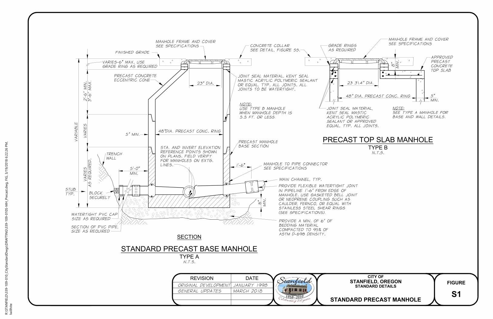
SECTION
STANDARD PRECAST BASE MANHOLE
TYPE A
PRECAST TOP SLAB MANHOLE
TYPE B
FIGURE
REVISION DATE
STANFIELD, OREGON
CITY OF
S1
STANDARD DETAILS
STANDARD PRECAST MANHOLE
R:\STA
NFIELD
\339-109-010_C
ityStan
dard
Dw
gs\D
RA
FTIN
G\339-109-010S-M
H_P
recast.d
wg
, FIG
, 3/19/2018 6:22:26 P
M,
lw
illh
ite

MANHOLE CONSTRUCTION NOTES
PLAN
MANHOLE BASE
FIGURE
REVISION DATE
STANFIELD, OREGON
CITY OF
S2
STANDARD DETAILS
MANHOLE BASE
AND CONSTRUCTION NOTES
R:\STANFIELD\339-109-010_CityStandardDwgs\DRAFTING\339-109-010S-MH_Base.dwg, FIG, 11/9/2017 10:48:33 AM,
lwillhite

®
®
DROP PRECAST MANHOLE
FIGURE
REVISION DATE
STANFIELD, OREGON
CITY OF
S3
STANDARD DETAILS
DROP PRECAST MANHOLE
R:\STANFIELD\339-109-010_CityStandardDwgs\DRAFTING\339-109-010S-MH_DropPrecast.dwg, FIG, 11/9/2017 10:49:39 AM,
lwillhite

GRAVITY SEWER MAIN LINE CLEANOUT SEWER SERVICE LINE CLEANOUT
FIGURE
REVISION DATE
STANFIELD, OREGON
CITY OF
S4
STANDARD DETAILS
SEWER CLEANOUTS
R:\STANFIELD\339-109-010_CityStandardDwgs\DRAFTING\339-109-010S-Cleanout.dwg, FIG, 11/9/2017 10:50:48 AM,
lwillhite

MANHOLE COVER PAVING DETAIL MANHOLE AND CLEANOUT CONCRETE COLLAR DETAIL
IN GRAVEL STREETS OR NATURAL GROUND
FIGURE
REVISION DATE
STANFIELD, OREGON
CITY OF
S5
STANDARD DETAILS
COVER PAVING DETAILS
R:\STANFIELD\339-109-010_CityStandardDwgs\DRAFTING\339-109-010S-MH-CvrPavingDtls.dwg, FIG, 11/9/2017 10:52:12 AM,
lwillhite

SEWER SERVICE LINE
FIGURE
REVISION DATE
STANFIELD, OREGON
CITY OF
S6
STANDARD DETAILS
SEWER SERVICE LINE
R:\STANFIELD\339-109-010_CityStandardDwgs\DRAFTING\339-109-010S-SewerServiceLine.dwg, FIG, 11/9/2017 10:53:26 AM,
lwillhite

WATER-SEWER CROSSING
(NEW SEWER LINE CONSTRUCTION)
FIGURE
REVISION DATE
STANFIELD, OREGON
CITY OF
S7
STANDARD DETAILS
WATER-SEWER CROSSING
R:\STA
NFIELD
\339-109-010_C
ityStan
dard
Dw
gs\D
RA
FTIN
G\339-109-010S-Sew
er_W
atrC
ro
ssin
g.d
wg
, FIG
, 3/19/2018 6:19:06 P
M,
lw
illh
ite

TRENCH EXCAVATION AND BACKFILL
WATER LINES
TRENCH EXCAVATION AND BACKFILL
SEWER AND STORM SEWER LINES
FIGURE
REVISION DATE
STANFIELD, OREGON
CITY OF
T1
STANDARD DETAILS
TRENCH DETAILS
R:\STA
NFIELD
\339-109-010_C
ityStan
dard
Dw
gs\D
RA
FTIN
G\339-109-010T-Tren
ch
Details.d
wg
, FIG
, 3/19/2018 6:17:43 P
M,
lw
illh
ite

TRENCH RESTORATION
GRAVEL STREETS, ROADWAYS, SHOULDERS,
AND PARKING AREAS
TRENCH RESTORATION
PAVED STREETS AND ROADWAYS
FIGURE
REVISION DATE
STANFIELD, OREGON
CITY OF
T2
STANDARD DETAILS
TRENCH RESTORATION
GRAVEL AND PAVEMENT AREAS
R:\STANFIELD\339-109-010_CityStandardDwgs\DRAFTING\339-109-010T-TrenchRestoration-Gravel_Pavement.dwg, FIG, 11/9/2017 10:56:45 AM,
lwillhite
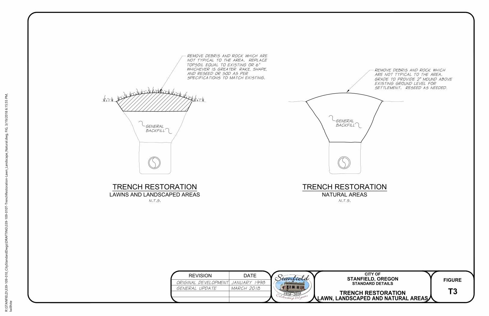
TRENCH RESTORATION
LAWNS AND LANDSCAPED AREAS
TRENCH RESTORATION
NATURAL AREAS
FIGURE
REVISION DATE
STANFIELD, OREGON
CITY OF
T3
STANDARD DETAILS
TRENCH RESTORATION
LAWN, LANDSCAPED AND NATURAL AREAS
R:\STA
NFIELD
\339-109-010_C
ityStan
dard
Dw
gs\D
RA
FTIN
G\339-109-010T-Tren
ch
Resto
ratio
n-Law
n_Lan
dscap
e_N
atu
ral.d
wg
, FIG
, 3/19/2018 6:15:55 P
M,
lw
illh
ite

TYPICAL SECTION
LOCAL STREET
FIGURE
REVISION DATE
STANFIELD, OREGON
CITY OF
R1
STANDARD DETAILS
TYPICAL SECTION
LOCAL STREET
R:\STA
NFIELD
\339-109-010_C
ityStan
dard
Dw
gs\D
RA
FTIN
G\339-109-010R
-Typ
Sect_Lo
calSt.d
wg
, FIG
, 3/19/2018 6:10:49 P
M,
lw
illh
ite

TYPICAL SECTION
COLLECTOR STREET - RESIDENTIAL
FIGURE
REVISION DATE
STANFIELD, OREGON
CITY OF
R2
STANDARD DETAILS
TYPICAL SECTION
COLLECTOR STREET
R:\STA
NFIELD
\339-109-010_C
ityStan
dard
Dw
gs\D
RA
FTIN
G\339-109-010R
-Typ
Sect_C
ollecto
rSt.d
wg
, FIG
, 3/19/2018 6:09:28 P
M,
lw
illh
ite

TYPICAL SECTION
ARTERIAL STREET
FIGURE
REVISION DATE
STANFIELD, OREGON
CITY OF
R3
STANDARD DETAILS
TYPICAL SECTION
ARTERIAL STREET
R:\STA
NFIELD
\339-109-010_C
ityStan
dard
Dw
gs\D
RA
FTIN
G\339-109-010R
-Typ
Sect_A
rterialSt.d
wg
, FIG
, 3/19/2018 6:08:27 P
M,
lw
illh
ite

TYPICAL CUL-DE-SAC
BUSINESS AND INDUSTRIAL
TYPICAL CUL-DE-SAC
RESIDENTIAL
FIGURE
REVISION DATE
STANFIELD, OREGON
CITY OF
R4
STANDARD DETAILS
TYPICAL CUL-DE-SAC
R:\STANFIELD\339-109-010_CityStandardDwgs\DRAFTING\339-109-010R-CulDeSacTyp.dwg, FIG, 11/10/2017 8:06:36 AM,
lwillhite

UTILITY LOCATIONS
TYPICAL SECTION
FIGURE
REVISION DATE
STANFIELD, OREGON
CITY OF
R5
STANDARD DETAILS
UTILITY LOCATIONS
R:\STANFIELD\339-109-010_CityStandardDwgs\DRAFTING\339-109-010R-UtilityLocations.dwg, FIG, 11/10/2017 8:07:19 AM,
lwillhite

CONCRETE CURB AND GUTTER DETAIL
FIGURE
REVISION DATE
STANFIELD, OREGON
CITY OF
R6
STANDARD DETAILS
CONCRETE CURB AND GUTTER DETAIL
R:\STANFIELD\339-109-010_CityStandardDwgs\DRAFTING\339-109-010R-ConcCurb_GutterDetl.dwg, FIG, 11/10/2017 8:08:41 AM,
lwillhite
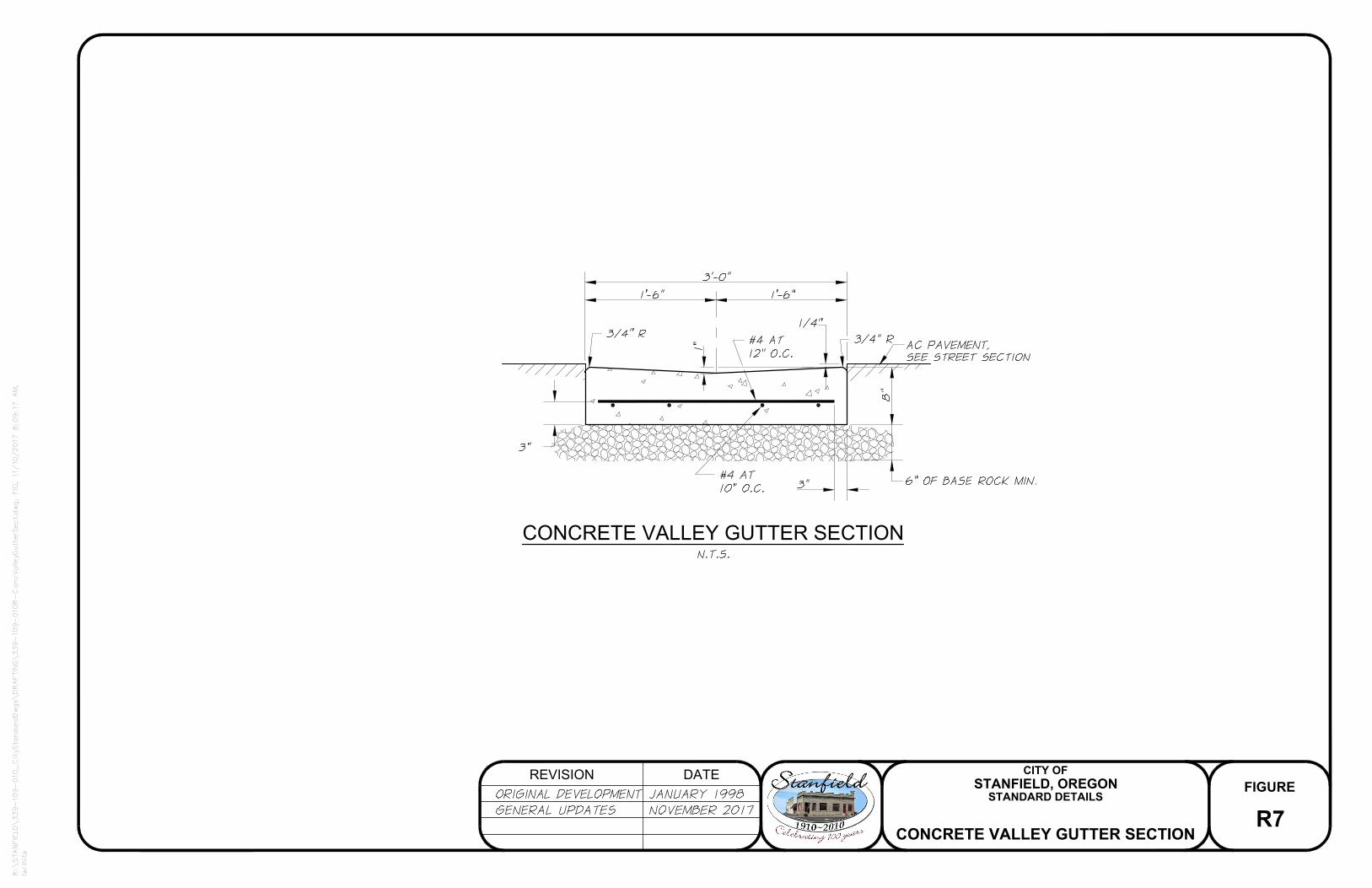
CONCRETE VALLEY GUTTER SECTION
FIGURE
REVISION DATE
STANFIELD, OREGON
CITY OF
R7
STANDARD DETAILS
CONCRETE VALLEY GUTTER SECTION
R:\STANFIELD\339-109-010_CityStandardDwgs\DRAFTING\339-109-010R-ConcValleyGutterSect.dwg, FIG, 11/10/2017 8:09:17 AM,
lwillhite

SPILL GUTTER DETAILS
A
SECTION A DETAIL
FIGURE
REVISION DATE
STANFIELD, OREGON
CITY OF
R8
STANDARD DETAILS
SPILL GUTTER DETAIL
R:\STA
NFIELD
\339-109-010_C
ityStan
dard
Dw
gs\D
RA
FTIN
G\339-109-010R
-Sp
illG
utterD
etl.d
wg
, FIG
, 3/19/2018 6:06:56 P
M,
lw
illh
ite

SIDEWALK/CURB AND GUTTER DETAIL
(FOR CURBSIDE SIDEWALK)
END OF SIDEWALK RAMP DETAIL
FIGURE
REVISION DATE
STANFIELD, OREGON
CITY OF
R9
STANDARD DETAILS
SIDEWALK AND
CURB AND GUTTER AND RAMP DETAILS
R:\STA
NFIELD
\339-109-010_C
ityStan
dard
Dw
gs\D
RA
FTIN
G\339-109-010R
-Sw
lk_C
urb
Gu
tterD
etl.d
wg
, FIG
, 3/19/2018 6:06:09 P
M,
lw
illh
ite
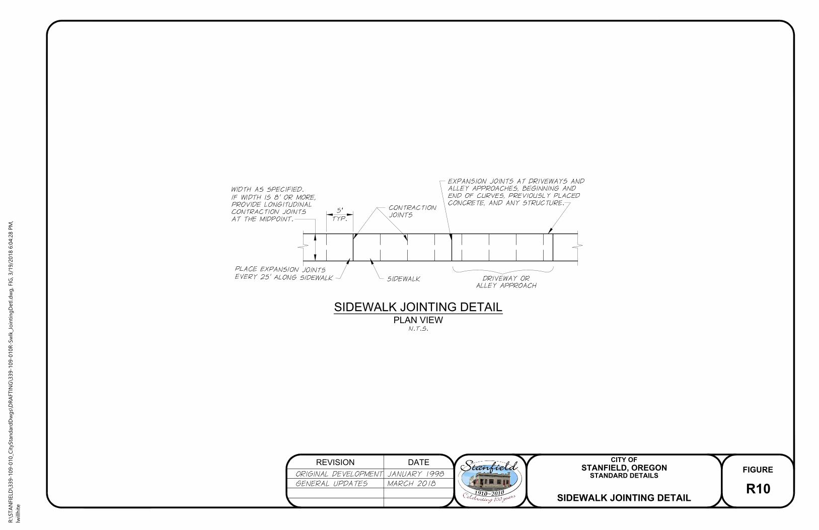
SIDEWALK JOINTING DETAIL
PLAN VIEW
FIGURE
REVISION DATE
STANFIELD, OREGON
CITY OF
R10
STANDARD DETAILS
SIDEWALK JOINTING DETAIL
R:\STA
NFIELD
\339-109-010_C
ityStan
dard
Dw
gs\D
RA
FTIN
G\339-109-010R
-Sw
lk_Jo
in
tin
gD
etl.d
wg
, FIG
, 3/19/2018 6:04:28 P
M,
lw
illh
ite

DRIVEWAY/ALLEY APPROACH
FIGURE
REVISION DATE
STANFIELD, OREGON
CITY OF
R11
STANDARD DETAILS
DRIVEWAY/ALLEY APPROACH
R:\STA
NFIELD
\339-109-010_C
ityStan
dard
Dw
gs\D
RA
FTIN
G\339-109-010R
-D
rvw
y_A
lleyA
pp
ro
ach
.d
wg
, FIG
, 3/19/2018 6:02:58 P
M,
lw
illh
ite

CURB RAMP DETAIL
RAMP TEXTURE PATTERN
TRUNCATED
DOME
RAMP TEXTURE PATTERN DETAILS
CURB RAMP PLACEMENT DETAIL
FIGURE
REVISION DATE
STANFIELD, OREGON
CITY OF
R12
STANDARD DETAILS
CURB RAMP DETAILS
R:\STA
NFIELD
\339-109-010_C
ityStan
dard
Dw
gs\D
RA
FTIN
G\339-109-010R
-C
urb
Ram
pD
etl.d
wg
, FIG
, 3/19/2018 6:02:06 P
M,
lw
illh
ite

DRIVEWAY/CURB RAMP DETAIL
FIGURE
REVISION DATE
STANFIELD, OREGON
CITY OF
R13
STANDARD DETAILS
DRIVEWAY/CURB RAMP DETAIL
R:\STA
NFIELD
\339-109-010_C
ityStan
dard
Dw
gs\D
RA
FTIN
G\339-109-010R
-D
rvw
y_C
urb
Ram
pD
etl.d
wg
, FIG
, 3/19/2018 5:59:47 P
M,
lw
illh
ite

MONUMENT BOX DETAIL
FIGURE
REVISION DATE
STANFIELD, OREGON
CITY OF
R14
STANDARD DETAILS
MONUMENT BOX DETAIL
R:\STANFIELD\339-109-010_CityStandardDwgs\DRAFTING\339-109-010R-MonumentBoxDetl.dwg, FIG, 11/10/2017 8:16:59 AM,
lwillhite

TYPICAL CATCH BASIN DETAIL
2'-4-1/4"
L W 1
G-1
INLET TYPE
2'-4-1/4"
G-2
1'-8-7/8"
2'-3-3/8"
A
SECTION A
TOP VIEW
FIGURE
REVISION DATE
STANFIELD, OREGON
CITY OF
R15
STANDARD DETAILS
TYPICAL CATCH BASIN DETAIL
R:\STA
NFIELD
\339-109-010_C
ityStan
dard
Dw
gs\D
RA
FTIN
G\339-109-010R
-C
atch
Basin
Typ
Detl.d
wg
, FIG
, 3/19/2018 5:57:07 P
M,
lw
illh
ite

TRAFFIC SIGN DETAIL
STREET NAME
STOP
PARKING
NO
N
LARCH
AVE
ANY TIME
TRAFFIC SIGN INSTALLATION NOTES
STREET SIGN DETAIL
FIGURE
REVISION DATE
STANFIELD, OREGON
CITY OF
R16
STANDARD DETAILS
SIGN DETAILS
R:\STA
NFIELD
\339-109-010_C
ityStan
dard
Dw
gs\D
RA
FTIN
G\339-109-010R
-Sig
nD
etls.d
wg
, FIG
, 3/19/2018 5:35:26 P
M,
lw
illh
ite