standby-redundant control using erlang/otp and jade for a
TRANSCRIPT
The financial assistance of the National Research Foundation (NRF) towards this
research is hereby acknowledged. Opinions expressed and conclusions arrived at,
are those of the author and are not necessarily to be attributed to the NRF.
Standby-redundant control using Erlang/OTP
and JADE for a manufacturing cell
by
Gregory Thomas Hawkridge
April 2019
Dissertation presented for the degree of Doctor of Philosophy in the
Faculty of Engineering at
Stellenbosch University
Supervisor: Prof Anton Herman Basson
Co-supervisor: Dr Karel Kruger
i
Plagiarism Declaration
By submitting this dissertation electronically, I declare that the entirety of the work contained therein is my own, original work, that I am the sole author thereof (save to the extent explicitly otherwise stated), that reproduction and publication thereof by Stellenbosch University will not infringe any third party rights and that I have not previously in its entirety or in part submitted it for obtaining any qualification.
This dissertation includes 1 original paper published in peer-reviewed journals or books and 5 unpublished publications. The development and writing of the papers (published and unpublished) were the principal responsibility of myself and, for each of the cases where this is not the case, a declaration is included in the dissertation indicating the nature and extent of the contributions of co-authors.
Date: April 2019
Copyright © 2019 Stellenbosch University
All rights reserved
Stellenbosch University https://scholar.sun.ac.za
ii
Plagiaatverklaring / Plagiarism Declaration 1 Plagiaat is die oorneem en gebruik van die idees, materiaal en ander intellektuele
eiendom van ander persone asof dit jou eie werk is.
Plagiarism is the use of ideas, material and other intellectual property of another’s work
and to present is as my own.
2 Ek erken dat die pleeg van plagiaat 'n strafbare oortreding is aangesien dit ‘n vorm van
diefstal is.
I agree that plagiarism is a punishable offence because it constitutes theft.
3 Ek verstaan ook dat direkte vertalings plagiaat is.
I also understand that direct translations are plagiarism.
4 Dienooreenkomstig is alle aanhalings en bydraes vanuit enige bron (ingesluit die
internet) volledig verwys (erken). Ek erken dat die woordelikse aanhaal van teks
sonder aanhalingstekens (selfs al word die bron volledig erken) plagiaat is.
Accordingly all quotations and contributions from any source whatsoever (including the
internet) have been cited fully. I understand that the reproduction of text without
quotation marks (even when the source is cited) is plagiarism.
5 Ek verklaar dat die werk in hierdie skryfstuk vervat, behalwe waar anders aangedui, my
eie oorspronklike werk is en dat ek dit nie vantevore in die geheel of gedeeltelik
ingehandig het vir bepunting in hierdie module/werkstuk of ‘n ander module/werkstuk
nie.
I declare that the work contained in this assignment, except otherwise stated, is my
original work and that I have not previously (in its entirety or in part) submitted it for
grading in this module/assignment or another module/assignment.
G.T. Hawkridge
Voorletters en van / Initials and surname
April 2019
Datum / Date
Stellenbosch University https://scholar.sun.ac.za

iii
Declaration of Contributions Declaration by the candidate: With regard to Chapters 4.1 (pg. 24-36), 5.1 (pg. 46-74), 5.2 (pg. 75-105), 5.3 (pg. 106-116), 6 (pg. 118-140), 7 (pg. 142-178) and A.1 (pg. 190-200), the nature and scope of my contribution were as follows:
Nature of Contribution Extent of contribution
Performed the research and drafted the papers 95%
The following co-authors have contributed to Chapters 4.1 (pg. 24-36), 5.1 (pg. 46-74), 5.2 (pg. 75-105), 5.3 (pg. 106-116), 6 (pg. 118-140), 7 (pg. 142-178) and A.1 (pg. 190-200):
Name e-mail address Nature of contribution Extent of contribution (%)
Prof A.H. Basson
[email protected] Structuring the content of the papers
2.5
Dr K. Kruger [email protected] Structuring the content of the papers
2.5
Signature of candidate: G.T. Hawkridge
Date: April 2019
Declaration by co-authors: The undersigned hereby confirm that 1. the declaration above accurately reflects the nature and extent of the
contributions of the candidate and the co-authors to Chapters 4.1 (pg. 24-36), 5.1 (pg. 46-74), 5.2 (pg. 75-105), 5.3 (pg. 106-116), 6 (pg. 118-140), 7 (pg. 142-178) and A.1 (pg. 190-200),
2. no other authors contributed to Chapters 4.1 (pg. 24-36), 5.1 (pg. 46-74), 5.2 (pg. 75-105), 5.3 (pg. 106-116), 6 (pg. 118-140), 7 (pg. 142-178) and A.1 (pg. 190-200), besides those specified above, and
3. potential conflicts of interest have been revealed to all interested parties and that the necessary arrangements have been made to use the material in Chapters 4.1 (pg. 24-36), 5.1 (pg. 46-74), 5.2 (pg. 75-105), 5.3 (pg. 106-116), 6 (pg. 118-140), 7 (pg. 142-178) and A.1 (pg. 190-200) of this dissertation.
Signature Institutional affiliation Date
A.H. Basson Stellenbosch University April 2019
K. Kruger Stellenbosch University April 2019
Stellenbosch University https://scholar.sun.ac.za
iv
Abstract
Standby-redundant control using Erlang/OTP and JADE for a manufacturing cell
G.T. Hawkridge
Department of Mechanical and Mechatronic Engineering Stellenbosch University
Dissertation: Ph.D. (Mechatronic Engineering) April 2019
In past decades, the manufacturing sector has been characterised by intense competition resulting from globalisation and shifting customer requirements. This has led to the pursuit of approaches and paradigms that better handle the requirements of modern manufacturers. This pursuit has culminated in the recent focus on the Industry 4.0 and Industrial Internet of Things (IIoT) paradigms.
The future manufacturing systems envisioned by these paradigms are increasingly complex. The reliability or availability of complex systems is a concern since complexity increases the likelihood of unexpected failure modes. Holonic systems show great promise for managing this complexity, but they may contain holons that represent single points of failure. The availability of these holons can be improved through standby redundancy.
This dissertation evaluates the hypothesis that Erlang/OTP provides an effective platform for implementing standby redundancy in a distributed holonic manufacturing cell. Erlang is a functional programming language designed for the development of fault-tolerant soft real-time control systems. The Open Telecom Platform (OTP) is a set of Erlang libraries that simplifies the development of large complex systems. OTP is such a central feature of Erlang that they are typically referred to collectively, as Erlang/OTP.
Erlang/OTP’s standby redundancy effectiveness is evaluated in two stages. First, it is evaluated through the implementation of standby redundancy for a monolithic station controller, the performance of which is benchmarked against the claims of an existing commercial solution. This implementation is representative of standby redundancy for singular resource holons. The evaluation shows that the Erlang/OTP implementation can handle the same failure modes as the commercial solution and achieves a similar changeover time. Furthermore, it shows that Erlang/OTP is suitable for implementing standby redundancy at a software level for embedded devices that do not provide such mechanisms at a hardware level.
Next, Erlang/OTP’s effectiveness for standby redundancy in a distributed holonic cell controller is evaluated through a case study comparison of an Erlang/OTP implementation and a Java Agent Development (JADE) framework
Stellenbosch University https://scholar.sun.ac.za
v
implementation. JADE is a popular Multi-Agent System framework and has in many respects become the de facto standard for holonic control implementations in academic research. The two implementations are compared using a set of quantitative and qualitative criteria. The comparison demonstrates that the Erlang/OTP implementation outperforms the JADE implementation for all the standby-redundant performance metrics. This is attributed to the centrality of fault-tolerance in Erlang and OTP. The comparison suggests that more development effort may be required for a standby-redundant Erlang/OTP holonic implementation, since Erlang/OTP does not contain the same degree of supporting communication and protocol infrastructure as an established framework like JADE. However, Erlang/OTP’s superior performance outweighs this shortcoming and the comparison concludes that Erlang/OTP provides a better platform for implementing standby redundancy than JADE.
The findings of both evaluations confirm that Erlang/OTP provides an effective platform for implementing standby redundancy in a distributed holonic controller for a manufacturing cell. Using Erlang/OTP, the ability to combine standby redundancy and holonic control has the potential to improve controller availability for the complex distributed systems envisioned by Industry 4.0 and IIoT.
Stellenbosch University https://scholar.sun.ac.za
vi
Uittreksel
Bystandsoortollige beheer met gebruik van Erlang/OTP en JADE vir 'n vervaardigingsel
G.T. Hawkridge
Departement Meganiese en Megatroniese Ingenieurswese Universiteit Stellenbosch
Proefskrif: PhD (Megatroniese Ingenieurswese) April 2019
Vir die afgelope dekades is die vervaardigingsektor gekenmerk deur intense kompetisie, voortgebring deur globalisering en veranderende kliëntvereistes. Hierdie kompetisie het gelei tot die strewe na benaderings en paradigmas wat die vereistes van moderne vervaardigers beter bevredig. Hierdie strewe het uitgeloop op die onlangse fokus op Industrie 4.0 en die Industrial Internet of Things (IIoT) paradigmas.
Toekomstige vervaardigingstelsels, soos beoog deur hierdie paradigmas, is toenemend kompleks. Die betroubaarheid en beskikbaarheid van komplekse stelsels wek kommer omdat die kompleksiteit die waarskynlikheid van onverwagte falingsmodusse verhoog. Holoniese stelsels is belowend vir die hantering van hierdie kompleksiteit, maar sulke stelsels mag steeds enkel-falingspunte bevat. Die beskikbaarheid van hierdie stelsels kan verbeter word deur bystandsoortolligheid.
Hierdie proefskrif evalueer die hipotese dat Erlang/OTP ‘n doeltreffende platform bied vir die implementering van bystandsoortolligheid in ‘n verspreide, holoniese vervaardigingsel. Erlang is ‘n funksionele programmeringstaal wat ontwerp is vir die ontwikkeling van fout-verdraagsame, sagte-waretyd-beheerstelsels. Die Open Telecom Platform (OTP) is ‘n versameling Erlang programmateke wat die ontwikkeling van groot, komplekse stelsels vergemaklik. OTP is só ‘n sentrale deel van Erlang dat hul gewoonlik saam na verwys word as Erlang/OTP.
Die doeltreffendheid van Erlang/OTP se bystandsoortolligheid word in twee fases geëvalueer. Eers word dit geëvalueer deur die implementasie van bystandsoortolligheid vir ‘n monolitiese werkstasiebeheerder, waarvan die verrigting met ‘n bestaande kommersiële oplossing vergelyk word. Hierdie implementasie is verteenwoordigend van die gebruik van Erlang/OTP om ‘n enkele hulpbron (resource) holon te implementeer. Die evaluasie wys dat die Erlang/OTP implementasie dieselfde falingsmodusse as die kommersiële oplossing kan hanteer en eenderse oorgangstye behaal. Verder wys dit dat Erlang/OTP gepas is vir die implementasie van bystandsoortolligheid in ‘n sagteware-vlak vir ingebedde toestelle wat nie vir sulke meganismes op ‘n hardware-vlak voorsiening maak nie.
Stellenbosch University https://scholar.sun.ac.za
vii
Volgende is Erlang/OTP se doeltreffendheid vir bystandsoortolligheid in ‘n verspreide holoniese selbeheerder geëvalueer deur middel van ‘n gevallestudie-vergelyking tussen implementasies in die Erlang/OTP en Java Agent Development (JADE) raamwerke. JADE is ‘n gewilde raamwerk vir multi-agentstelsels en het die de facto standaard vir holoniese beheerimplementasies in akademiese navorsing geword. Die twee implementasies word vergelyk deur gebruik te maak van ‘n stel kwantitatiewe en kwalitatiewe kriteria. Die vergelyking demonstreer dat die Erlang/OTP implementasie die JADE implementasie uitpresteer in al die bystandsoortolligheid-werkverrigtingsmaatstawwe. Dit kan toegeskryf word aan die sentraliteit van fout-verdraagsaamheid in Erlang en OTP. Die vergelyking dui wel daarop dat meer ontwikkelingsmoeite benodig mag word om bystandsoortolligheid in Erlang/OTP te implementeer, aangesien Erlang/OTP nie dieselfde vlak van ondersteunende kommunikasie- en protokolinfrastruktuur voorsien as ‘n gevestigde raamwerk soos JADE nie. Tog oortref die werkverrigting van Erlang/OTP hierdie tekortkoming en die vergelyking bereik die gevolgtrekking dat Erlang/OTP ‘n beter platform vir bystandsoortolligheid bied as JADE.
Die bevindinge van beide evaluasies bevestig dat Erlang/OTP ‘n doeltreffende platform vir die implementasie van bystandsoortolligheid in ‘n verspreide, holoniese beheerder vir ‘n vervaardigingstelsel bied. Die kombinasie van bystandsoortolligheid en holoniese beheer in Erlang/OTP het die potensiaal om beheerderbeskikbaarheid vir komplekse, verspreide stelsels, soos beoog deur Industrie 4.0 en IIOT, te verbeter.
Stellenbosch University https://scholar.sun.ac.za

viii
To my wife, Loren –
For all your loving support and patience
Stellenbosch University https://scholar.sun.ac.za
ix
Acknowledgements
I would like to express my appreciation to everyone who helped to make this research possible in any way, shape or form. The following people/institutions deserve special mention for their contributions towards the realisation of this dissertation:
To my supervisors, Prof A.H. Basson and Dr K. Kruger – I would like to express my sincere gratitude for all your support, encouragement and patience. Without your guidance and expert knowledge, this research would not have been possible. I would also like to thank you for the opportunity to present part of this research at the SOHOMA conference in Bergamo, Italy.
I am thankful to Mr R. Rodriguez for his technical assistance and for maintaining a laboratory environment that so effectively facilitated this research. I would also like to thank my fellow members of the Mechatronics, Automation and Design Research Group for their friendship and thought-provoking conversations. I am grateful to the Department of Mechanical and Mechatronic Engineering for providing the facilities and infrastructure for this research. I would like to acknowledge my gratitude to the NRF for their financial support which enabled me to pursue this degree in a full-time capacity.
I am grateful to my friends and family - for sharing in my frustrations and celebrating my victories. To my wife, Loren, thank you for believing in me, supporting me, and patiently bearing with me.
Above all, I am grateful to God my father who has blessed me with the talents and abilities that have allowed me to pursue this doctoral degree. He has supported me throughout this time – all honour belongs to him.
Stellenbosch University https://scholar.sun.ac.za
x
Table of Contents
List of Tables .................................................................................... xvi
List of Figures .................................................................................. xvii
List of Acronyms ................................................................................ xx
1. Introduction ................................................................................... 1
1.1. Background ................................................................................................... 1
1.2. Objectives and Contributions ........................................................................ 2
1.3. Motivation ..................................................................................................... 3
1.4. Methodology ................................................................................................. 5
1.5. Dissertation Structure ................................................................................... 5
2. Literature Review ........................................................................... 7
2.1. Manufacturing System Paradigms ................................................................ 7
2.1.1. Flexible and Reconfigurable Manufacturing Systems .......................... 7
2.1.2. Industry 4.0, Cyber-Physical Systems and the Industrial Internet of Things .................................................................................................... 8
2.2. Control Architectures .................................................................................... 9
2.2.1. Centralised Control ............................................................................. 10
2.2.2. Hierarchical Control ............................................................................ 10
2.2.3. Decentralised Control ......................................................................... 11
2.2.4. Heterarchical Control .......................................................................... 11
2.2.5. Holonic Control ................................................................................... 12
2.3. Holonic Reference Architectures ................................................................ 12
2.3.1. PROSA.................................................................................................. 12
2.3.2. ADACOR............................................................................................... 13
2.3.3. ARTI ..................................................................................................... 14
2.3.4. Selection .............................................................................................. 15
2.4. Redundancy ................................................................................................. 15
2.4.1. Need for Redundancy ......................................................................... 15
2.4.2. Challenges ........................................................................................... 16
Stellenbosch University https://scholar.sun.ac.za
xi
2.4.3. Controller Redundancy Approaches ................................................... 17
2.4.4. Redundancy for Software Entities ...................................................... 19
3. Erlang/OTP Overview ................................................................... 20
3.1. Concurrency ................................................................................................ 20
3.2. Distribution.................................................................................................. 20
3.3. Fault-Tolerance ........................................................................................... 21
3.4. Interfacing with Native C Code ................................................................... 22
4. Erlang/OTP-Based Standby Redundancy for Monolithic Station Control ............................................................................................. 23
4.1. An Evaluation of Erlang for Implementing Standby Redundancy in a Manufacturing Station Controller ........................................................... 24
4.1.1. Introduction ........................................................................................ 24
4.1.2. Types of Redundancy .......................................................................... 25
4.1.3. Siemens Software Redundancy .......................................................... 26
4.1.4. Erlang Based Standby Redundancy ..................................................... 27
4.1.5. Case Study ........................................................................................... 33
4.1.6. Conclusions ......................................................................................... 35
4.1.7. References .......................................................................................... 35
4.2. Further Case Study Details and Testing Methodology................................ 37
4.2.1. Tumbling Barrel Singulation Unit Details ............................................ 37
4.2.2. Software Architecture ......................................................................... 38
4.2.3. State Machine Implementation .......................................................... 39
4.2.4. Standby Redundancy Implementation Details ................................... 40
4.2.5. Testing Methodology .......................................................................... 43
4.3. Handling Process and Node Failure Due to Software Issues ...................... 44
5. Erlang/OTP-Based Standby Redundancy for Distributed Holonic Cell Control ............................................................................................. 45
5.1. Conversation Recovery after Failover for Contract Net Protocol Communication in an Erlang-Based Holonic Architecture ...................... 46
5.1.1. Introduction ........................................................................................ 46
5.1.2. Erlang Background .............................................................................. 48
Stellenbosch University https://scholar.sun.ac.za
xii
5.1.3. Holonic Background and Architecture ................................................ 50
5.1.4. The Contract Net Protocol .................................................................. 52
5.1.5. Standby Controller Redundancy ......................................................... 54
5.1.6. Conversation Recovery Background ................................................... 55
5.1.7. Holarchy Conversation Decomposition .............................................. 57
5.1.8. Conversation Recovery with Outside World Processes ...................... 59
5.1.9. Contract Net Protocol with Failover in Erlang .................................... 62
5.1.10. Case Study ........................................................................................... 70
5.1.11. Conclusions ......................................................................................... 72
5.1.12. References .......................................................................................... 73
5.2. An Erlang-Based Standby-Redundant Distributed Holonic Controller for a Manufacturing Cell .................................................................................. 75
5.2.1. Introduction ........................................................................................ 75
5.2.2. Holonic Control Review ....................................................................... 77
5.2.3. Redundant Distributed Holonic Controller Architecture .................... 80
5.2.4. Erlang Background .............................................................................. 89
5.2.5. Erlang Implementation ....................................................................... 92
5.2.6. Case Study ........................................................................................... 99
5.2.7. Conclusions ....................................................................................... 103
5.2.8. References ........................................................................................ 104
5.3. Extensible Callback Module Layering in Erlang ......................................... 106
5.3.1. Introduction ...................................................................................... 106
5.3.2. Erlang Background ............................................................................ 107
5.3.3. Behaviours ........................................................................................ 109
5.3.4. Message Handling ............................................................................. 113
5.3.5. State Access ...................................................................................... 114
5.3.6. Conclusions ....................................................................................... 115
5.3.7. References ........................................................................................ 115
6. Standby Redundancy in JADE ..................................................... 117
Stellenbosch University https://scholar.sun.ac.za
xiii
6.1. Introduction .............................................................................................. 118
6.2. Holonic Control ......................................................................................... 120
6.2.1. Background ....................................................................................... 120
6.2.2. Control Architectures ........................................................................ 120
6.2.3. The PROSA Reference Architecture .................................................. 121
6.3. Software-Based Standby Redundancy ...................................................... 122
6.3.1. Background ....................................................................................... 122
6.3.2. Handled Fault Types .......................................................................... 122
6.3.3. Redundancy in Holonic Manufacturing Controllers ......................... 122
6.4. MAS and JADE ........................................................................................... 123
6.4.1. Agents and Multi-Agent Systems ...................................................... 123
6.4.2. FIPA Standards .................................................................................. 123
6.4.3. Agent Platform .................................................................................. 123
6.4.4. JADE ................................................................................................... 124
6.5. Standby Redundancy in JADE .................................................................... 124
6.5.1. Overview ........................................................................................... 124
6.5.2. Main Container Replication .............................................................. 125
6.5.3. DF Persistence and Synchronisation ................................................. 126
6.5.4. Agent Replication Service ................................................................. 127
6.5.5. Standby Redundancy Implementation ............................................. 128
6.5.6. Failure Detection ............................................................................... 130
6.5.7. Handling Standby Redundancy Events ............................................. 133
6.6. Case Study ................................................................................................. 134
6.6.1. Case Study Configuration .................................................................. 134
6.6.2. Test Procedure .................................................................................. 135
6.6.3. Test Results ....................................................................................... 136
6.7. Conclusions ............................................................................................... 138
6.8. References ................................................................................................. 139
7. Evaluation................................................................................... 142
Stellenbosch University https://scholar.sun.ac.za
xiv
7.1. Introduction .............................................................................................. 143
7.2. Methodology ............................................................................................. 145
7.3. Holonic Architecture ................................................................................. 146
7.3.1. Gateway Holon .................................................................................. 146
7.3.2. Order Manager Holon ....................................................................... 147
7.3.3. Service Directory ............................................................................... 147
7.3.4. Product Holons .................................................................................. 147
7.3.5. Resource Holons ............................................................................... 147
7.3.6. Order Holons ..................................................................................... 148
7.4. Standby Redundancy Implementations .................................................... 148
7.4.1. Background ....................................................................................... 148
7.4.2. Erlang Implementation ..................................................................... 148
7.4.3. JADE Implementation ....................................................................... 148
7.4.4. Equivalency ....................................................................................... 149
7.5. Evaluation Criteria ..................................................................................... 150
7.5.1. Quantitative Metrics ......................................................................... 150
7.5.2. Qualitative Metrics ........................................................................... 152
7.6. Overview of Experiments .......................................................................... 153
7.6.1. Case Study ......................................................................................... 153
7.6.2. Normal Operation Experiment ......................................................... 155
7.6.3. Changeover Experiments .................................................................. 155
7.7. Quantitative Results .................................................................................. 156
7.7.1. Changeover Times ............................................................................. 156
7.7.2. Computational Resource Requirements ........................................... 160
7.7.3. Standby Redundancy Overhead........................................................ 161
7.8. Qualitative Results .................................................................................... 165
7.8.1. Fault Handling Capabilities ............................................................... 165
7.8.2. Distributability .................................................................................. 166
7.8.3. Ease of Development ........................................................................ 170
Stellenbosch University https://scholar.sun.ac.za
xv
7.8.4. Configurability ................................................................................... 173
7.9. Comparison ............................................................................................... 174
7.10. Conclusion ............................................................................................... 175
7.11. References ............................................................................................... 176
8. Conclusions ................................................................................ 180
9. References.................................................................................. 183
Appendix A: Redundancy in Erlang/OTP Lab Report ...................... 191
A.1. Introduction .............................................................................................. 191
A.2. Erlang Boot Scripts .................................................................................... 191
A.3. The Heart Mechanism ............................................................................... 191
A.4. Distributed Applications ........................................................................... 192
A.4.1. Standard Applications ........................................................................ 193
A.4.2. Enabling the Failover and Takeover Mechanism ............................... 194
A.4.3. Enabling Failover and Takeover Application Start Types ................... 195
A.4.4. Start Phases ........................................................................................ 195
A.4.5. Failover/Takeover Issues .................................................................... 196
A.5. gen_statem Implementation Details ........................................................ 196
A.5.1. Event Ordering ................................................................................... 196
A.5.2. Event Queue Extraction/ Replication ................................................. 197
A.5.3. Compound State Machine.................................................................. 198
A.6. Records vs Maps ....................................................................................... 198
A.6.1. Background......................................................................................... 198
A.6.2. Evaluation ........................................................................................... 199
A.6.3. Conclusions......................................................................................... 200
A.7. Handling Controller I/O ............................................................................. 200
A.7.1. GPIO and Interrupts ........................................................................... 200
A.7.2. Timing and Pulse Generation ............................................................. 201
A.7.3. IP Socket I/O ....................................................................................... 201
Stellenbosch University https://scholar.sun.ac.za
xvi
List of Tables
Table 1: Overview of Erlangs Syntactic Conventions ........................................... 107
Table 2: Measured Changeover Times for Container Failure .............................. 137
Table 3: Measured Failure Detection, Start-up and Changeover Times for the Order Holon during Test Case 1 ..................................................................................... 157
Table 4: Measured Start-up and Changeover Times for the Order Manager, Gateway Holon and Service Directory during Test Case 2 .................................. 158
Table 5: Measured Start-up and Changeover Times for the Order Manager, Gateway Holon, Order Holon and Service Directory during Test Case 3 ............ 159
Table 6: Measured Computational Resource Requirements for the Standby-Redundant Implementations ............................................................................... 161
Table 7: Measured Computational Resource Requirements of the Erlang/OTP Standby-Redundant and Non-Redundant Implementations............................... 162
Table 8: Measured Computational Resource Requirements of the JADE Standby-Redundant and Non-Redundant Implementations ............................................. 163
Stellenbosch University https://scholar.sun.ac.za
xvii
List of Figures
Figure 1: Manufacturing Control Architectures ..................................................... 10
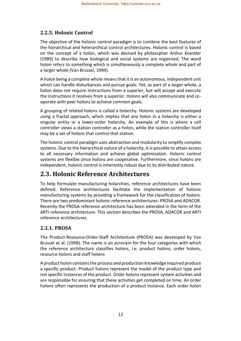
Figure 2: Interaction of the Standard Holons in a PROSA Architecture (adapted from Van Brussel et al., 1998)................................................................................ 13
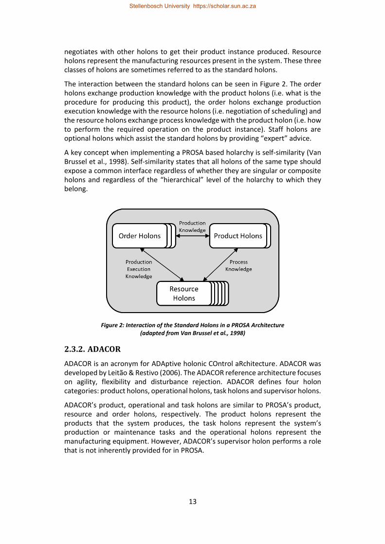
Figure 3: ADACOR Holon Interaction during Normal Operation (Adapted from Leitão & Restivo, 2006) .......................................................................................... 14
Figure 4: Types of Controller Redundancy ............................................................ 17
Figure 5: Controller Architecture for Erlang-Based Standby Redundancy ............ 28
Figure 6: Primary Controller Failure due to Power Loss or Hardware Fault ......... 30
Figure 7: Primary Controller Isolation due to a Network Fault ............................. 31
Figure 8: Feeder Station used as a Case Study ...................................................... 34
Figure 9: Overview of the Operation of the Singulation Unit (Shown with the Barrel Removed) ............................................................................................................... 37
Figure 10: Sectional View of the Barrel Showing the Screw Mechanism and the Part Scoops .................................................................................................................... 38
Figure 11: Structure of the Redundant Application used for the Case Study Implementation ..................................................................................................... 39
Figure 12: Message Passing Interaction of the Tumbling Barrel State Machine Process ................................................................................................................... 39
Figure 13: State Machine for the Tumbling Barrel Singulation Unit ..................... 40
Figure 14: Handling Device Triggering ................................................................... 42
Figure 15: Interaction between Order, Product and Resource Holons in a PROSA Architecture ........................................................................................................... 52
Figure 16: The Fundamental Phases of the Contract Net Protocol ....................... 53
Figure 17: Example Communication Structure within a Holarchy ........................ 56
Figure 18: Separating the Holarchy Communication into Multiple One-to-One Conversations ........................................................................................................ 59
Figure 19: Messages with Causal Precedence for Party A ..................................... 62
Figure 20: Architecture of an Erlang Holarchy....................................................... 63
Figure 21: An Example Alternating Contract Net Protocol Conversation ............. 65
Figure 22: Handling Failure of the Active Party ..................................................... 66
Stellenbosch University https://scholar.sun.ac.za
xviii
Figure 23: Handling Failure of the Waiting Party .................................................. 67
Figure 24: Recovery of a Non-Alternating Conversation ....................................... 68
Figure 25: Erlang’s Monitor Functionality used to Reduce Time Spent Waiting for Bids ......................................................................................................................... 69
Figure 26: Extension of the Contract Net Protocol to include an Acknowledge Message ................................................................................................................. 70
Figure 27: CNP Conversation Structure between Order and Resource Holons .... 71
Figure 28: Test Cases Considered - (a) Failure of a Redundant Order Holon (b) Failure of a Redundant Resource Holon ................................................................ 71
Figure 29: Conversation Failure Test Points .......................................................... 72
Figure 30: The Phases of the Contract Net Protocol ............................................. 79
Figure 31: Architecture of the Redundant Distributed Holonic Controller ........... 80
Figure 32: Typical Controller Structure in a Distributed Holonic Cell .................... 85
Figure 33: The Split Resource Approach for Holon Assignment ............................ 86
Figure 34: The Self-Contained Resource Approach for Holon Assignment ........... 87
Figure 35: The Mesh Approach for Holon Assignment .......................................... 87
Figure 36: OTP Application Architecture for a Resource Node ............................. 93
Figure 37: Process Architecture of a Singular Erlang/OTP Resource Holon .......... 94
Figure 38: Process Architecture of an Erlang/OTP Order Holon ........................... 96
Figure 39: Order Holon Distribution Architecture ................................................. 98
Figure 40: Physical Layout of Case Study Cell ...................................................... 100
Figure 41: Production Procedure for a Product that Requires 1x Part A and 1x Part B ........................................................................................................................... 101
Figure 42: Dynamic Typing Example .................................................................... 108
Figure 43: Pattern Matching Examples ................................................................ 109
Figure 44: Example Behaviour and Callback Modules for a Simple Agenda Manager ............................................................................................................................. 110
Figure 45: Callback Module Layering ................................................................... 112
Figure 46: Interaction between the Standard Holons in a PROSA Architecture . 121
Figure 47: Controller and Container Architecture for JADE Agent Standby Redundancy ......................................................................................................... 125
Stellenbosch University https://scholar.sun.ac.za
xix
Figure 48: Case Study Architecture...................................................................... 134
Figure 49: Calculating the Time Difference between Two Parties using Cristian’s Algorithm ............................................................................................................. 136
Figure 50: Architecture of the Redundant Distributed Holonic Controller ......... 146
Figure 51: Physical Layout of Case Study Cell ...................................................... 154
Figure 52: Box and Whisker Plot of Individual State Synchronisation Times for the JADE and Erlang/OTP Implementations .............................................................. 165
Figure 53: Event Insertion into gen_statem Event Queues ................................. 197
Stellenbosch University https://scholar.sun.ac.za

xx
List of Acronyms
AID – Agent Identifier
AMS – Agent Management System
AP – Agent Platform
ARS – Agent Replication Service
ARTI – Activity-Resource-Type-Instance architecture
BEAM – Bogdan/Björn's Erlang Abstract Machine
CFP – Call For Proposal
CNP – Contract Net Protocol
CPS – Cyber-Physical System
DF – Directory Facilitator
EPMD – Erlang Port Mapper Daemon
FIPA – Foundation for Intelligent Physical Agents
FMS – Flexible Manufacturing System
FQDN – Fully Qualified Domain Name
HLC – Higher-Level Controller
IIoT – Industrial Internet of Things
I/O – Input and Output
JADE – Java Agent DEvelopment framework
JDBC – Java DataBase Connectivity
JVM – Java Virtual Machine
MAS – Multi-Agent System
MCRS – Main Container Replication Service
MES – Manufacturing Execution System
MTS – Message Transport System
NEU – Next-Execute-Update protocol
OTP – Open Telecom Platform
OS – Operating System
Stellenbosch University https://scholar.sun.ac.za

xxi
OWP – Outside World Process
PC – Personal Computer
pid – process identifier
PLC – Programmable Logic Controller
PROSA – Product-Resource-Order-Staff Architecture
RMI – Remote Method Invocation
RMS – Reconfigurable Manufacturing System
SMP – Symmetric Multi-Processing
UDPNMS – UDP Node Monitoring Service
XML – Extensible Markup Language
Stellenbosch University https://scholar.sun.ac.za
1
1. Introduction
This introductory chapter provides the background and context for the research presented in this dissertation. The objectives and contributions of this research are presented, followed by a motivation of their importance. The methodology that was followed in pursuing these objectives is then described. Finally, this dissertation’s structure is outlined.
1.1. Background
In the past decades the manufacturing sector has been characterised by intense competition resulting from globalisation and shifting customer requirements. To better handle this competition, the manufacturing sector has been pursuing manufacturing systems and paradigms which provide shorter lead times, increased product customisation, flexible production capacity, real-time feedback, lower costs and improved resource efficiency (Bi et al., 2008; Lasi et al., 2014).
Various paradigms, such as flexible manufacturing systems (FMSs) and reconfigurable manufacturing systems (RMSs), have been investigated with varying levels of success. This investigation continues with the recent focus on Industry 4.0, cyber-physical systems (CPSs) and the Industrial Internet of Things (IIoT) (Brettel et al., 2014; Bi, Xu & Wang 2014; Gerbert et al., 2015). With these progressions, modern manufacturing systems are becoming increasingly distributed and complex.
The reliability or availability of such complex systems is a significant concern. Availability here refers to the percentage of time for which a system is ready and able to perform its expected functions. The reduced availability of critical subsystems (such as controllers) can have significant financial implications due to lost productivity and may lead to reduced product quality or missed deadlines.
The holonic paradigm has been highlighted as a promising tool for managing complexity, changes and disturbances in systems (Monostori et al., 2016). Holonic manufacturing control maintains the global control and optimisation potential of hierarchical structures, while leveraging the improved flexibility and fault-tolerance of heterarchical structures.
Standby redundancy is a common approach for improving the availability of traditional manufacturing control systems. For standby-redundant control there is a single primary controller and one or more backup controllers which takeover as primary when the current primary experiences a fault (described in greater detail in section 2.4.3.2). In this dissertation standby redundancy is considered for improving the availability of holons in a holonic control architecture.
This dissertation contributes to research by the Mechatronics, Automation and Design Research Group, at the Department of Mechanical and Mechatronic Engineering of Stellenbosch University, into control solutions for modern manufacturing systems. This research follows on from research by Kruger (2018)
Stellenbosch University https://scholar.sun.ac.za
2
which evaluated Erlang as an alternative to multi-agent systems (MAS) for the implementation of holonic control in a RMS.
Erlang is a functional programming language designed for the development of fault-tolerant soft real-time control systems (Armstrong, 1996). The Open Telecom Platform (OTP) is a set of Erlang libraries that simplifies the development of large complex systems (Armstrong, 2010). OTP is such a central feature of Erlang that they are typically referred to collectively, as Erlang/OTP.
1.2. Objectives and Contributions
This dissertation evaluates the following hypothesis:
Erlang/OTP is an effective platform for implementing standby-redundant control in a distributed holonic manufacturing cell.
This hypothesis is evaluated through the case study implementation of a standby-redundant holonic controller for a singulation and feeder cell in an assembly line. This implementation is developed around the PROSA reference architecture since it provides a proven and well-known foundation.
The objectives of this dissertation use the concepts of a manufacturing cell and of a manufacturing station (shortened form of workstation). These concepts are understood to have the following definitions:
• A manufacturing cell is a grouping of stations that perform a single, or set of similar, production tasks. The production tasks performed by a cell are usually compound and/or performed for multiple product instances simultaneously.
• In the context of a cell, a station is a set of manufacturing equipment that performs a specific manufacturing task. This manufacturing equipment may be fully automated or utilised by an operator. The tasks performed by a station are typically elementary manufacturing operations (i.e. singulation, riveting, part pick and place) and are usually only applied to a single product instance at a time.
Station-level control is focussed on the execution of the manufacturing equipment. This includes managing sensors and coordinating actuators. Cell-level control is focussed on coordinating the execution of the stations. This includes managing the information and material flow throughout the cell. In this dissertation, the cell level control is achieved using a holonic architecture within which the stations are represented by singular resource holons.
This dissertation considers the implementation of standby redundancy for a holonic cell in two stages;
• First, standby redundancy for a singular station controller. This standby redundancy implementation is representational of standby redundancy for singular resource holons. Special attention is given to complications that
Stellenbosch University https://scholar.sun.ac.za
3
arise due to the coupling between the holon’s software entity and the physical equipment it represents.
• Next, the ability to implement standby redundancy for resource holons is expanded to achieve standby redundancy within a holonic cell controller. Consideration is given to maintaining communication integrity within the cell in the presence of standby redundancy events.
Although this dissertation considers cell-level control where the resource holons are singular, these resource holons could in fact be compound (i.e. lower order holarchies) due to the fractal nature of holonic architectures. It is therefore expected that many of the proposed approaches and findings can applied or adapted to higher levels of holonic control.
This research is the first evaluation of standby-redundant control using Erlang/OTP for manufacturing and offers the following contributions:
• An implementation approach for standby redundancy in a monolithic/centralised station controller using Erlang/OTP.
• A review and evaluation of rollback conversation recovery protocols based on the requirements of holonic manufacturing control.
• An evaluation of the redundancy requirements for a PROSA-based holonic controller.
• An implementation approach for standby redundancy in a distributed holonic cell controller using Erlang/OTP.
• An approach for achieving process specialisation in Erlang/OTP. • An implementation approach for agent standby redundancy in JADE. • An evaluation and comparison of two distributed standby-redundant
implementations, using Erlang/OTP and JADE, for a distributed holonic manufacturing cell controller.
1.3. Motivation
Industry 4.0 is characterised by several concepts, such as cloud-computing, IIoT and Big Data, that are radically different to those of traditional manufacturing systems (Almada-Lobo, 2016). These concepts lead to dramatic increases in system complexity, especially for small- and medium size manufacturers (Schumacher et al., 2016). According to Thames & Schaefer (2016), managing complexity is one of the limiting factors in the application of Industry 4.0 concepts. The reliability of these complex systems is concerning, since as the complexity of a system increases, so does the likelihood of failure mechanisms that are not anticipated by the designers (Sagan, 2004).
Due to the sheer number of control devices required for IIoT systems, embedded systems, such as microcontrollers, are likely to play a vital role since they are flexible and inexpensive (Wan et al., 2016; Jazdi, 2014). However, low cost embedded devices do not typically undergo strict quality assurance procedures and their reliability may therefore be a concern.
Stellenbosch University https://scholar.sun.ac.za
4
Holonic control has been proposed as a solution for managing the complexity of Industry 4.0 systems (Monostori et al., 2016). Holonic control inherently allows for functional redundancy. Functional redundancy here refers to the existence of multiple holons that offer the same capability. Even though holonic systems will, in general, continue operating in the presence of holon failure (for holons that have functional redundancy), this holon failure will reduce the functionality or capacity of the system, leading to bottlenecks and possible system failure. Additionally, certain holon types do not allow for functional redundancy and may therefore represent single points of failure.
Standby redundancy is a common mechanism for handling single points of failure in traditional manufacturing control system. Standby redundancy is therefore considered for improving the availability of individual holons in a holonic architecture.
Erlang/OTP is not widely known in the manufacturing systems’ academic community; however, it has a strong track record in the telecommunication and web industries. Erlang/OTP is well suited to large scale message handling systems, which is a primary contributor to its success in the telecommunication and web industries. A prominent example of this is WhatsApp, which used Erlang/OTP to develop a high-reliability, massively-scalable messaging service that serves more than 450 million users (O’Connell, 2014). Erlang/OTP should therefore be considered as a candidate for use in Industry 4.0 and IIoT systems, since the handling of large volumes of communication traffic is a key concern in these systems.
As far as its suitability for manufacturing control is concerned, according to Kruger (2018), Erlang is an effective platform for the implementing holonic control and has several advantages over existing MAS frameworks in this regard. Furthermore, Erlang/OTP has been used to achieve a technology readiness level 7 for the control implementation of a 3D printing factory (Valckenaers & Van Brussel, 2015).
Erlang/OTP has several characteristics that make it an attractive candidate for the implementation of standby redundancy in holonic control. Fault tolerance is one of the core development objectives for Erlang/OTP, due to its initial intended usage for high reliability telecommunication systems. This focus on fault tolerance has shaped many of the platform’s philosophies and features (described in section 3.3). Furthermore, Erlang/OTP has a strong heritage in embedded systems; one of Erlang’s earliest successes was in Ericsson’s AXD301 asynchronous transfer mode switch. More recently, Erlang/OTP has been used by GRiSP to create robust embedded controllers (Anonymous, s.a. (a)). This embedded system heritage enables an Erlang/OTP standby-redundancy approach to be used to improve the availability of low-level control systems, developed using low-cost embedded devices, as well as higher-level holonic control architectures.
Through Erlang/OTP, the ability to combine standby redundancy and holonic control has the potential to improve controller availability for the complex distributed systems envisioned by Industry 4.0 and IIoT.
Stellenbosch University https://scholar.sun.ac.za
5
1.4. Methodology
To evaluate the effectiveness of Erlang/OTP for implementing standby-redundant control in a distributed holonic manufacturing cell, this dissertation uses case study evaluations. Although a case study, by its nature, provides a restricted context, the key results of the study should be transferable to other situations if the case study contains elements that are typical of practical applications. This dissertation considers case study implementations for a singulation and feeder cell in an assembly line.
In this dissertation, Erlang/OTP is first evaluated for implementing standby redundancy in a centralised station controller. This evaluation is performed by benchmarking the performance of an Erlang/OTP standby-redundant case study implementation against the standby-redundant performance metrics claimed by a similar existing commercial solution for software-based redundancy on PLCs, namely Siemens Software Redundancy.
Erlang/OTP is then evaluated for implementing standby redundancy within a distributed holonic cell controller through a comparison with a JADE implementation of standby redundancy for the same holonic architecture. JADE is a MAS framework which is the predominant implementation tool for holonic control in academic research. Both the Erlang/OTP and JADE implementations are restricted to using standard features of their respective software platforms.
As discussed in Kruger (2018), generalised comparisons of software platforms are complicated by paradigmatic, syntactic and philosophic differences. Instead, this comparison follows the examples of Chirn and McFarlane (2005) and Kruger (2018) by focusing on each platform’s supporting functionality for a specific use case. In this comparison, that focus is the implementation of standby redundancy in a holonic cell controller.
This comparison uses a combination of quantitative and qualitative metrics. Qualitative metrics are necessary to compare the behaviour and characteristics of the standby redundancy implementations and their underlying software frameworks. Qualitative evaluations are based on experiences and impressions of the author and are therefore susceptible to the preconceptions and agenda of the evaluator. While the subjective nature of qualitative metrics is unavoidable, the comparison endeavours to provide an impartial evaluation, reinforced by experimental results and references to literature where applicable.
1.5. Dissertation Structure
This dissertation is formulated as a collection of papers. All the presented papers are co-authored by the supervisors of this research. However, the author is the primary contributor for these papers. The supervisors’ contributions have been in reviewing these papers and providing feedback and advice on the structuring of arguments.
Stellenbosch University https://scholar.sun.ac.za
6
The contents of the included papers are presented in the same form as they were submitted for publication. Changes have been made to the formatting, numbering and referencing styles of the presented papers to improve the consistency and flow of this dissertation. Each of the presented papers contains an abstract, introduction, a review of the literature relevant to that paper, and a reference list. It is therefore expected that significant portions of these sections will overlap with one another from paper to paper. The context and objective of the included papers are described at the beginning of each chapter. This dissertation is divided into eight chapters, structured as follows:
Chapter 2 presents a review of the literature relevant to this research. This review overlaps with and expands on those in the papers in the following chapters. The review discusses the different manufacturing paradigms. The different control architectures are then discussed, followed by some background on the PROSA and ARTI reference architectures for holonic control. The different forms of redundancy are then described.
Chapter 3 provides an overview of the Erlang programming language, focussing on the aspects that are utilised in this research.
Chapter 4 contains a paper describing the implementation of standby redundancy for a monolithic/centralised station controller. This paper is followed by supplementary sections that elaborate on case study details that could not be included in the paper and describe the handling of software faults in Erlang/OTP-based standby-redundant implementations.
Chapter 5 considers the implementation of standby redundancy in a holonic cell. This chapter includes three papers. The first paper presents an approach for the recovery of contract net-based conversations in holonic systems that implement standby redundancy. The second paper proposes an architecture for implementing redundancy in a holonic cell controller and presents the Erlang/OTP implementation thereof. The third paper discusses the use of callback module layering to achieve extensible process specialisation in Erlang/OTP.
Chapter 6 contains a paper that proposes an approach for the implementation of standby redundancy in the JADE multi-agent framework. Chapter 7 presents a paper that compares the Erlang/OTP and JADE implementations of standby redundancy for a case study holonic manufacturing cell.
This dissertation is concluded in chapter 8 which summarises the findings and contributions of this research and makes some recommendations for future research. The reference list is provided in chapter 9 and includes all the sources referenced in this dissertation, including those referenced within the presented papers.
Stellenbosch University https://scholar.sun.ac.za
7
2. Literature Review
This section begins with an overview of flexible and reconfigurable manufacturing systems followed by a summary of the Industry 4.0 paradigm. The different architectures that can be used to control these systems are then reviewed – focussing on the holonic control paradigm. The prominent reference architectures for holonic control are then described. Finally, redundancy for manufacturing control is discussed.
2.1. Manufacturing System Paradigms
This section describes the context of this research. The FMS paradigm is well-established within manufacturing system. RMSs are similar to FMSs and have been the topic of a lot of recent research. Both paradigms have influenced and are applicable to the recent Industry 4.0 paradigm.
2.1.1. Flexible and Reconfigurable Manufacturing Systems
The development of both the flexible and reconfigurable manufacturing system paradigms were driven by two primary goals: the ability to adapt production capabilities to match market demand and the ability to cost effectively achieve product customisation (Mehrabi et al., 2000).
An FMS is described by Browne et al. (1984) as an integrated, computer-controlled system which contains automated material handling equipment and CNC machines. By using an intelligent control solution, FMS systems are able to produce a variety of products at the same time and each individual product can be customised. Due to this flexibility, FMSs are inherently able to adapt to demand variations. The production capacity is easily scaled by adding or removing machines. The disadvantage of FMSs is that they are typically only suitable when producing a large variety of parts in small quantities since CNC machines have a low throughput (Koren et al., 1999).
An RMS is defined as a system which can quickly and cost-effectively change its production capacity within a family of parts. This concept of a part family is key, a part family is a group of parts or products which are physically similar and require similar machining processes (Goyal et al., 2013). In other words, the manufacturing equipment within an RMS system is able to perform a specific set of similar operations on a set of similar parts, whereas the manufacturing equipment in an FMS system is able to perform a type of manufacturing operation (i.e. milling, turning, etc.) on a variety of parts. RMSs can be considered an intermediary between traditional dedicated production lines and FMSs, since they provide more flexibility that traditional systems and higher throughput than FMSs. RMSs are reconfigured through the addition, removal or restructuring of physical or software components (Azab et al., 2013).
Both flexible and reconfigurable systems require a significant amount of intelligence in their control systems to manage product variations and to
Stellenbosch University https://scholar.sun.ac.za
8
efficiently handle the restructuring of manufacturing equipment. The holonic control paradigm (discussed in section 2.2.5) has been investigated as a promising solution for controlling such systems.
2.1.2. Industry 4.0, Cyber-Physical Systems and the Industrial Internet of Things
There have been three industrial revolutions, each of which were initiated a technological breakthrough and were characterised by remarkable economic growth. According to Drath & Horch (2014) these three revolutions were mechanisation, electrification and digitalisation. Mechanisation, the first industrial revolution, took place in the 1780s. It is epitomised by the invention of the mechanical loom which transformed the textile industry from local home-based production to centralised factories. Electrification, the second industrial revolution, began with the use of electric power in factories and culminated with the invention of the production line. Digitisation, the third industrial revolution, began with the use of PLCs which enabled software-based automation of manufacturing systems.
It is believed that the fourth industrial revolution will be due to the increased connectivity that results from the application of modern internet and communication technology to the manufacturing industry (Lasi et al., 2014). There is some debate as to whether the fourth industrial revolution has already begun or whether it has yet to be realised. The pursuit of systems that embody the fourth industrial revolution has been termed Industry 4.0. There are several research topics that contribute to the Industry 4.0 paradigm (Brettel et al., 2014). CPSs and the IIoT are two such topics.
2.1.2.1. Cyber-Physical Systems
The CPS concept focuses on the deep integration of the physical and computational aspects of systems (Lee et al., 2015). According to Leitao et al. (2016), “a cyber-physical entity is one that integrates its hardware function with a cyber-representation acting as a virtual representation for the physical part”. A CPS is a collection of multiple cooperating cyber-physical entities.
To achieve this integration between the virtual and the physical, CPSs are reliant on advances in sensor technology to enable accurate real-time measurements of the physical system’s state (Baheti & Gill, 2011). CPSs extend beyond virtual representations of the physical world; the aim is to improve the operation of physical systems through feedback from the cyber representation (Lee, 2008). These improvements are exhibited for the different levels of a cyber-physical production systems (CPPSs) in the 5C architecture proposed by Lee et al. (2015):
1. The Smart Connection Level facilitates the interoperability and ease-of-integration of sensors through Plug & Play approaches. This level is also concerned with the accuracy of sensor measurements and may use
Stellenbosch University https://scholar.sun.ac.za
9
condition-based monitoring to assess the health of sensors and components.
2. The Conversion Level is responsible for converting the raw data extracted from sensors into meaningful information about the state of the CPS’s physical component. This leads to manufacturing equipment that is self-aware.
3. The Cyber Level collates and manages the information generated across the system. The cyber level can use historical information to generate performance estimates.
4. The Cognition Level is a decision support system that presents system information in meaningful ways to simplify and improve the decision-making processes of experts and management.
5. The Configuration Level performs system optimisation and adaptation based on feedback from the high-level data-analytic and machine learning systems.
The CPPS paradigm draws on many other research topics, including RMSs and holonic control paradigms (Monostori et al., 2016).
2.1.2.2. The Industrial Internet of Things
The Internet of Things (IoT) refers to the creation of a network of everyday objects that are connected to one another and can communicate with one another over the Internet or using Internet technologies. This is typically achieved in one of two ways, either through the embedding of communication capable computational device in the object (Wortmann & Flüchter, 2015), or through the embedding of an identification mechanism that corresponds to a separate digital representation of the object (Xu et al., 2014).
The IIoT paradigm refers to the use of IoT approaches and technologies in industrial applications. There is a degree of overlap between IIoT and CPS systems since both consider digital representations of physical devices. This has led certain researchers to conclude that the IIoT and CPS concepts are the same thing (Yang, 2014), whereas others believe that IIoT is a building block for CPS systems (Monostori, 2014).
2.2. Control Architectures
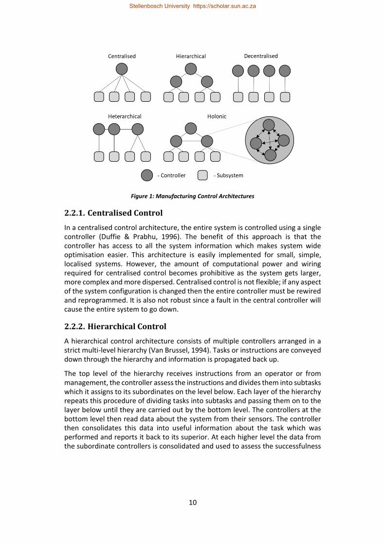
This section provides an overview of some of the common architectures used for manufacturing control. This overview covers centralised, hierarchical, decentralised and heterarchical control architectures to provide background and context to the holonic control paradigm which is considered in this dissertation. These architectures are depicted in Figure 1 and described below.
Stellenbosch University https://scholar.sun.ac.za
10
Figure 1: Manufacturing Control Architectures
2.2.1. Centralised Control
In a centralised control architecture, the entire system is controlled using a single controller (Duffie & Prabhu, 1996). The benefit of this approach is that the controller has access to all the system information which makes system wide optimisation easier. This architecture is easily implemented for small, simple, localised systems. However, the amount of computational power and wiring required for centralised control becomes prohibitive as the system gets larger, more complex and more dispersed. Centralised control is not flexible; if any aspect of the system configuration is changed then the entire controller must be rewired and reprogrammed. It is also not robust since a fault in the central controller will cause the entire system to go down.
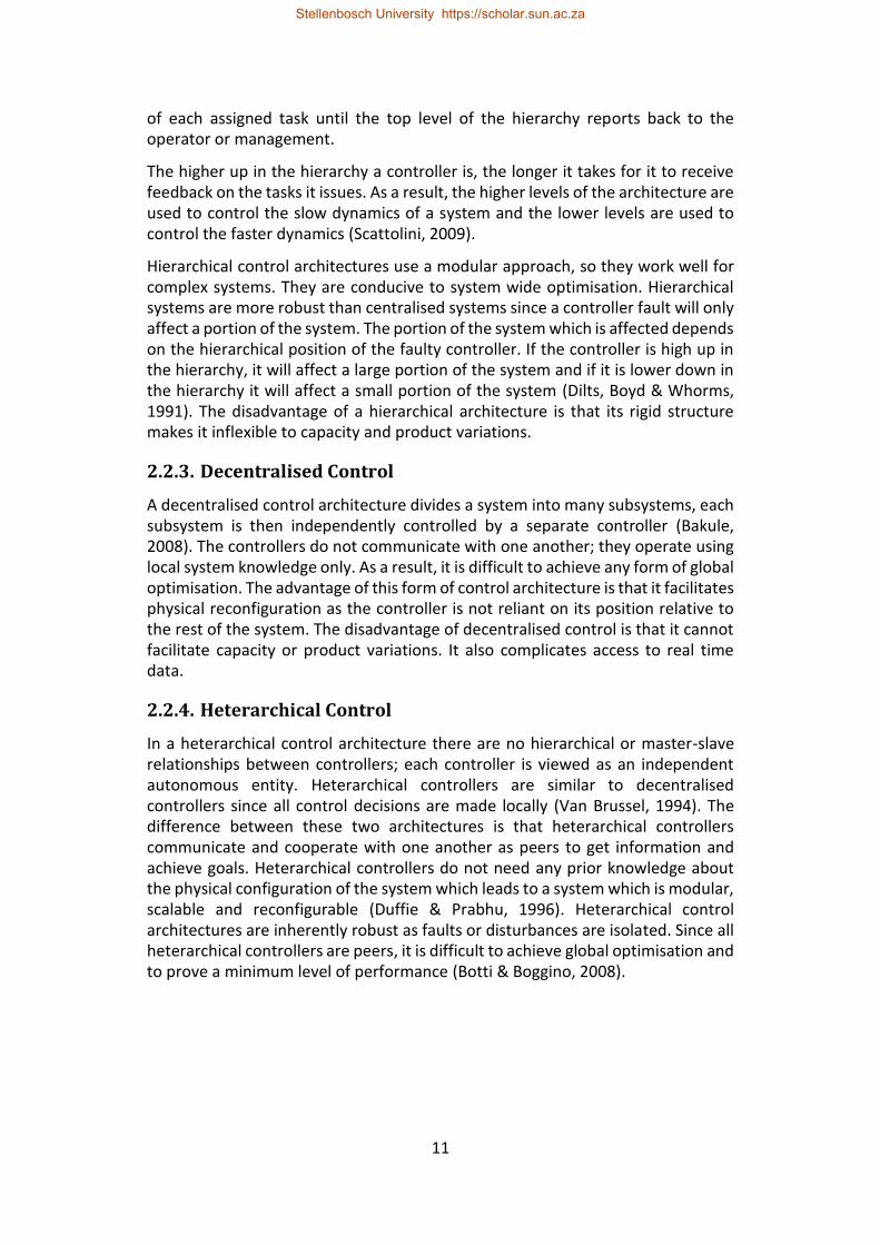
2.2.2. Hierarchical Control
A hierarchical control architecture consists of multiple controllers arranged in a strict multi-level hierarchy (Van Brussel, 1994). Tasks or instructions are conveyed down through the hierarchy and information is propagated back up.
The top level of the hierarchy receives instructions from an operator or from management, the controller assess the instructions and divides them into subtasks which it assigns to its subordinates on the level below. Each layer of the hierarchy repeats this procedure of dividing tasks into subtasks and passing them on to the layer below until they are carried out by the bottom level. The controllers at the bottom level then read data about the system from their sensors. The controller then consolidates this data into useful information about the task which was performed and reports it back to its superior. At each higher level the data from the subordinate controllers is consolidated and used to assess the successfulness
Stellenbosch University https://scholar.sun.ac.za
11
of each assigned task until the top level of the hierarchy reports back to the operator or management.
The higher up in the hierarchy a controller is, the longer it takes for it to receive feedback on the tasks it issues. As a result, the higher levels of the architecture are used to control the slow dynamics of a system and the lower levels are used to control the faster dynamics (Scattolini, 2009).
Hierarchical control architectures use a modular approach, so they work well for complex systems. They are conducive to system wide optimisation. Hierarchical systems are more robust than centralised systems since a controller fault will only affect a portion of the system. The portion of the system which is affected depends on the hierarchical position of the faulty controller. If the controller is high up in the hierarchy, it will affect a large portion of the system and if it is lower down in the hierarchy it will affect a small portion of the system (Dilts, Boyd & Whorms, 1991). The disadvantage of a hierarchical architecture is that its rigid structure makes it inflexible to capacity and product variations.
2.2.3. Decentralised Control
A decentralised control architecture divides a system into many subsystems, each subsystem is then independently controlled by a separate controller (Bakule, 2008). The controllers do not communicate with one another; they operate using local system knowledge only. As a result, it is difficult to achieve any form of global optimisation. The advantage of this form of control architecture is that it facilitates physical reconfiguration as the controller is not reliant on its position relative to the rest of the system. The disadvantage of decentralised control is that it cannot facilitate capacity or product variations. It also complicates access to real time data.
2.2.4. Heterarchical Control
In a heterarchical control architecture there are no hierarchical or master-slave relationships between controllers; each controller is viewed as an independent autonomous entity. Heterarchical controllers are similar to decentralised controllers since all control decisions are made locally (Van Brussel, 1994). The difference between these two architectures is that heterarchical controllers communicate and cooperate with one another as peers to get information and achieve goals. Heterarchical controllers do not need any prior knowledge about the physical configuration of the system which leads to a system which is modular, scalable and reconfigurable (Duffie & Prabhu, 1996). Heterarchical control architectures are inherently robust as faults or disturbances are isolated. Since all heterarchical controllers are peers, it is difficult to achieve global optimisation and to prove a minimum level of performance (Botti & Boggino, 2008).
Stellenbosch University https://scholar.sun.ac.za
12
2.2.5. Holonic Control
The objective of the holonic control paradigm is to combine the best features of the hierarchical and heterarchical control architectures. Holonic control is based on the concept of a holon, which was devised by philosopher Arthur Koestler (1989) to describe how biological and social systems are organised. The word holon refers to something which is simultaneously a complete whole and part of a larger whole (Van Brussel, 1994).
A holon being a complete whole means that it is an autonomous, independent unit which can handle disturbances and pursue goals. Yet, as part of a larger whole, a holon does not require instructions from a superior, but will accept and execute the instructions it receives from a superior. Holons will also communicate and co-operate with peer holons to achieve common goals.
A grouping of related holons is called a holarchy. Holonic systems are developed using a fractal approach, which implies that any holon in a holarchy is either a singular entity or a lower-order holarchy. An example of this is where a cell controller views a station controller as a holon, while the station controller itself may be a set of holons that control that station.
The holonic control paradigm uses abstraction and modularity to simplify complex systems. Due to the hierarchical nature of a holarchy, it is possible to attain access to all necessary information and achieve global optimisation. Holonic control systems are flexible since holons are cooperative. Furthermore, since holons are independent, holonic control is inherently robust due to its distributed nature.
2.3. Holonic Reference Architectures
To help formulate manufacturing holarchies, reference architectures have been defined. Reference architectures facilitate the implementation of holonic manufacturing systems by providing a framework for the classification of holons. There are two predominant holonic reference architectures: PROSA and ADACOR. Recently the PROSA reference architecture has been extended in the form of the ARTI reference architecture. This section describes the PROSA, ADACOR and ARTI reference architectures.
2.3.1. PROSA
The Product-Resource-Order-Staff Architecture (PROSA) was developed by Van Brussel et al. (1998). The name is an acronym for the four categories with which the reference architecture classifies holons, i.e. product holons, order holons, resource holons and staff holons
A product holon contains the process and production knowledge required produce a specific product. Product holons represent the model of the product type and not specific instances of the product. Order holons represent system activities and are responsible for ensuring that these activities get completed on time. An order holons often represents the production of a product instance. Each order holon
Stellenbosch University https://scholar.sun.ac.za
13
negotiates with other holons to get their product instance produced. Resource holons represent the manufacturing resources present in the system. These three classes of holons are sometimes referred to as the standard holons.
The interaction between the standard holons can be seen in Figure 2. The order holons exchange production knowledge with the product holons (i.e. what is the procedure for producing this product), the order holons exchange production execution knowledge with the resource holons (i.e. negotiation of scheduling) and the resource holons exchange process knowledge with the product holon (i.e. how to perform the required operation on the product instance). Staff holons are optional holons which assist the standard holons by providing “expert” advice.
A key concept when implementing a PROSA based holarchy is self-similarity (Van Brussel et al., 1998). Self-similarity states that all holons of the same type should expose a common interface regardless of whether they are singular or composite holons and regardless of the “hierarchical” level of the holarchy to which they belong.
Figure 2: Interaction of the Standard Holons in a PROSA Architecture (adapted from Van Brussel et al., 1998)
2.3.2. ADACOR
ADACOR is an acronym for ADAptive holonic COntrol aRchitecture. ADACOR was developed by Leitão & Restivo (2006). The ADACOR reference architecture focuses on agility, flexibility and disturbance rejection. ADACOR defines four holon categories: product holons, operational holons, task holons and supervisor holons.
ADACOR’s product, operational and task holons are similar to PROSA’s product, resource and order holons, respectively. The product holons represent the products that the system produces, the task holons represent the system’s production or maintenance tasks and the operational holons represent the manufacturing equipment. However, ADACOR’s supervisor holon performs a role that is not inherently provided for in PROSA.
Stellenbosch University https://scholar.sun.ac.za
14
The supervisor holon is responsible for grouping the other holons into suitable hierarchies to achieve the global optimisation potential of hierarchical control. During normal operation, the supervisor holon manages all interaction between the task and operational holons as shown in Figure 3. When a disturbance is detected, the supervisor holons dissolve the hierarchy, resulting in task and operational holons interacting directly as in a heterarchical architecture. Over time, the supervisor establishes a new hierarchy that is better equipped to handle the new manufacturing conditions.
Figure 3: ADACOR Holon Interaction during Normal Operation (Adapted from Leitão & Restivo, 2006)
2.3.3. ARTI
The Activity-Resource-Type-Instance (ARTI) architecture is an extension to the PROSA reference architecture that arose out of need to generalise PROSA terminology for application to non-manufacturing domains (Van Brussel & Valckenaers, 2017). ARTI separates holons into those that represent activities and those that represent resources. Each category is then further divided into holons that represent types and holons that represent instances. Each instance holon is an instance of specific type holon. This leads to four possible classifications: activity type, activity instance, resource type and resource instance.
An activity type holon represents a type of activity that can be performed in the holonic system. The PROSA product holon is an example of an activity type, since represents a type of product that could be produced. A scheduled maintenance task such as relubricating bearings is also an example of and activity type. An activity instance holon represents a specific instance of an activity type holon. To PROSA order holon is an activity instance of a “product” activity type. A resource type holon represents the type of resource (i.e. a CNC mill). A resource instance holon represents a specific piece of manufacturing equipment (i.e. the CNC mill with asset number “xyz”).
Stellenbosch University https://scholar.sun.ac.za
15
ARTI further distinguishes between intelligent beings and intelligent agents within each holon class (Valckenaers & Van Brussel, 2015). An intelligent being reflects the reality of what it represents while an intelligent agent encompasses the decision-making components. This segregation seeks to separate the generic from the application specific.
While the ARTI reference architecture contains several aspects that help to generalise holonic implementations, it requires further evaluation, implementation and clarification by researchers other than the architecture’s developers before it can be considered a mature reference architecture. It is, however, believed that the ARTI reference architecture shows great promise for use within the Industry 4.0 paradigm.
2.3.4. Selection
This dissertation uses the PROSA reference architecture to formulate and describe the considered holonic cell control architecture. PROSA is selected since it was the first developed reference architectures and is therefore more familiar within the manufacturing research community. It is expected that the findings can be carried over to an ADACOR-based implementation with minimal effort due to the similarities between PROSA’s product, resource and order holons and ADACOR’s product, operational and task holons. It is similarly expected that this research could be extended to the ARTI reference architecture since it is based on PROSA, and that doing so may make this research more accessible to other industrial use cases.
2.4. Redundancy
Redundancy refers to the use of additional elements or systems to provide a backup in the event of a failure (Downer, 2009). The concept of redundancy is based on the idea of probabilistic independence. If a single element has a failure probability of 𝑝1 and if 𝑛 identical independent elements are placed in parallel, then the chance of all of them failing is 𝑝𝑛 = 𝑝1
𝑛. The combination of 𝑛 independent parallel components is therefore more reliable than a single component. This section considers the need for redundancy in the manufacturing industry and describes the different types of redundancy for controllers (i.e. control hardware and software) and for control entities that are entirely software based.
2.4.1. Need for Redundancy
There is always a possibility of failure in systems that are complex and tightly coupled (Sagan, 2004). Furthermore, as the complexity of a system increases, so does the likelihood of failure mechanisms that are not anticipated by the designer. Problematically, most manufacturing systems fall into the category of complex, tightly coupled systems. Systems can be designed with one of three approaches to handling failures: they can be fail-safe, fault-tolerant or fail-operational (Blanke et al., 2001). Redundancy is the primary tool for achieving these approaches.
Stellenbosch University https://scholar.sun.ac.za
16
A fail-safe system responds to the occurrence of a fault by returning to a known safe state in a controlled manner. In some stable systems this can be achieved without redundancy by disengaging the power and letting the system come to a stop at its natural equilibrium. In cases that are safety critical or when the system is naturally unstable, redundancy is necessary to maintain control of the system so that it can be brought to a safe state.
Systems that need to continue operating in the presence of faults can be designed to be fault-tolerant or fail-operational. The distinction between the two is that fail-operational systems must maintain the same level of performance in the presence of a fault, whereas a degradation in the level of performance is acceptable for fault-tolerant systems. These approaches are not possible without some form of redundancy. Although these approaches are often used for safety critical systems, this research will evaluate the use of redundancy to avoid the financial implications of reduced availability in manufacturing systems. Availability refers to the percentage of time for which a system is ready and able to perform its expected function.
2.4.2. Challenges
In theory, redundancy is a wonderful tool that can dramatically increase the availability of a system. In practice, redundancy must be implemented with care as it may not improve availability as much as is expected and in some cases, it can even degrade the availability of a system (Sagan, 2004: 17). This is because the principle of redundancy requires that the redundant elements fail independently, and real system elements are seldom completely independent. Since the redundant elements are exposed to the same conditions, it is possible for them to fail at the same time and for the same reason due to common-cause faults. Common-cause faults are especially likely if all elements are identical. It is therefore necessary to ensure that all common-cause faults are identified and mitigated to prevent these faults becoming single points of failure. There is also the possibility that an element may fail in a way that causes others to fail, either directly or because of the additional load placed upon them. Adding redundancy increases the complexity of the system and may introduce additional points of failure. This is particularly true when additional hardware is required to facilitate redundancy as this could become a new point of failure.
Another challenge when designing redundant systems is that they do not always fail in the manner which is expected. The naïve assumption is that a failed component’s outputs will cease. However, the output may also become noisier, drift, get stuck at a certain value/point, become random or any number of other possibilities. All these possibilities need to be considered to ensure that they do not affect the system. One of the biggest threats to the effectiveness of redundant systems is the human aspect. Operators and management are more likely to push a system beyond its designed operating range when they believe that the redundant backup is guaranteed to prevent complete failure.
Stellenbosch University https://scholar.sun.ac.za
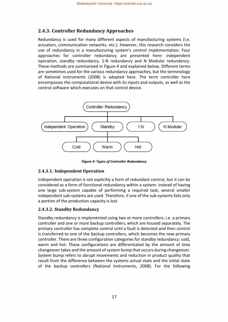
17
2.4.3. Controller Redundancy Approaches
Redundancy is used for many different aspects of manufacturing systems (i.e. actuators, communication networks, etc.). However, this research considers the use of redundancy in a manufacturing system’s control implementation. Four approaches for controller redundancy are presented here: independent operation, standby redundancy, 1:N redundancy and N Modular redundancy. These methods are summarised in Figure 4 and explained below. Different terms are sometimes used for the various redundancy approaches, but the terminology of National Instruments (2008) is adopted here. The term controller here encompasses the computational device with its inputs and outputs, as well as the control software which executes on that control device.
Figure 4: Types of Controller Redundancy
2.4.3.1. Independent Operation
Independent operation is not explicitly a form of redundant control, but it can be considered as a form of functional redundancy within a system: instead of having one large sub-system capable of performing a required task, several smaller independent sub-systems are used. Therefore, if one of the sub-systems fails only a portion of the production capacity is lost.
2.4.3.2. Standby Redundancy
Standby redundancy is implemented using two or more controllers, i.e. a primary controller and one or more backup controllers, which are housed separately. The primary controller has complete control until a fault is detected and then control is transferred to one of the backup controllers, which becomes the new primary controller. There are three configuration categories for standby redundancy: cold, warm and hot. These configurations are differentiated by the amount of time changeover takes and the amount of system bump that occurs during changeover. System bump refers to abrupt movements and reduction in product quality that result from the difference between the systems actual state and the initial state of the backup controllers (National Instruments, 2008). For the following
Stellenbosch University https://scholar.sun.ac.za
18
descriptions of the standby redundancy configuration categories, a system containing a single primary and a single backup are considered.
If a long changeover time and a substantial amount of system bump are acceptable then cold standby redundancy can be used. In this configuration the backup controller is completely powered down, when a fault is detected by the operator or a third-party watchdog then the primary is shut down and the backup controller is powered up. The advantage of this approach is that there is minimal chance of the backup controller experiencing a failure prior to changeover. The disadvantage is that since the backup system has no knowledge of the system state it must assume some default state which can result in substantial system bump.
Hot standby redundancy is used in cases where a fast changeover time and little or no system bump are required. In this configuration the backup controller is powered on and operates with its outputs disabled. The backup controller monitors the control inputs and outputs of the primary controller to maintain accurate knowledge of the system state and will initiate changeover if it does not agree with the outputs of the primary controller. Additionally, the primary controller can initiate a changeover if it detects a fault in its own execution. The disadvantage of this approach is that, since the backup controller is operational, it may need to be replaced sooner.
Warm standby redundancy refers to configurations that fall between hot and cold standby redundancy. The backup controllers are powered on, but changeover is still governed by an operator or third-party watchdog. The backup might only monitor the control inputs, or the primary might send its knowledge of the system state at regular intervals. Changeover time is usually similar to hot redundant systems, but the system bump is typically larger as the backup’s knowledge of the system state could be old, inaccurate or incomplete.
2.4.3.3. N Modular Redundancy
N modular redundancy is implemented using a set of three or more functionally identical controllers connected in parallel. These controllers are all provided with the same control inputs while their outputs are sent to arbitration circuitry. This circuitry decides what output to give to the system by applying some selection criteria to the outputs from the controllers (National Instruments, 2008).
A majority vote is typically used; however, some applications require more advanced logic. To avoid ties, this method usually uses an odd number of controllers. The arbitration circuitry is also responsible for identifying controller faults. This is simple if the controllers are required to give identical results, as a lack of consensus indicates a fault. If slight variations in numerical or analogue results are acceptable then this can be a challenge.
The advantage of this method is that there is no system bump or delay when a fault occurs, which means that control of the system is seamless. Unfortunately, this method is expensive due to the number of controllers required. As a result,
Stellenbosch University https://scholar.sun.ac.za
19
this approach is usually only used when the need for system to be fail-operational warrants the cost.
In highly critical applications the reliability of an N modular redundant system is improved by using different makes of controllers, programmed by different people, manufactured in different places and tested on different days to ensure that the controllers are as independent as possible (Bjorndahl & Byers, 2011). Additionally, the number of controller faults/failures (𝑛𝑓) which the system can accommodate can be improved by increasing the number of redundant controllers (𝑁) according to the equation: 𝑁 = 2𝑛𝑓 + 1.
2.4.3.4. 1:N Redundancy
1:N redundancy uses a single standby controller as a backup for multiple active controllers. The obvious disadvantage of this method is that more than one active controller fault will result in partial or complete system failure. A further disadvantage is that some form of multiplexer is needed to route the correct input and output signals to the standby controller. However, this is less of a problem when distributed IO is used. The advantage of this form of redundancy is its cost effectiveness. It is well suited for applications with a limited budget where the availability of a fault-tolerant system is desired for financial reasons, but not essential to meet safety requirements.
2.4.4. Redundancy for Software Entities
For many distributed manufacturing control architectures there is a one-to-one mapping between the controller software and the computational control device that executes it. However, this is not typically the case for holonic and multi-agent systems which are comprised of autonomous independent software entities. These entities are not tied to a specific control device; therefore, their redundancy approaches need to be considered separately.
Not much literature regarding redundancy in manufacturing control could be found within the academic realm. However, within the commercial domain, there is a significant amount of literature relating to distributed controller redundancy solutions as discussed in the previous section. There has been some research into redundancy through replication for multi-agent systems (Guessoum et al., 2002; Carzaniga et al., 2009).
Stellenbosch University https://scholar.sun.ac.za
20
3. Erlang/OTP Overview
This section provides an overview of Erlang/OTP, as well as its core features and approaches. Erlang is a programming language and runtime environment developed at Ericsson in the 1980s and publicly released as open source software in 1998. The Erlang programming language was designed for applications that require concurrency, fault tolerance and distribution (Anonymous s.a. (b)). A key feature of Erlang is its Open Telecom Platform (OTP), which is a set of libraries that simplifies the development of large complex systems (Armstrong 2010: 73).
3.1. Concurrency
Erlang programs are built up by independent concurrent processes which cooperate with one another to achieve the systems goals. Erlang processes have the following properties: processes have sole access to their internal state, processes influence one another through asynchronous message passing and processes have the capability to spawn further processes (Armstrong 2010: 70).
Erlang code runs within its own virtual machine, known as BEAM (Bogdan/Björn's Erlang Abstract Machine), which handles scheduling, memory management and message passing for the Erlang processes. Additionally, BEAM supports symmetric multiprocessing (SMP) which enhances process concurrency on multicore processors (Lundin 2008). BEAM provides Erlang with processes that are lightweight, which facilitates the large number of processes required to implement complex systems (Larson, 2009: 55). Furthermore, BEAM can run on most Unix, Linux and Microsoft Windows based operating systems which enhances the portability of Erlang code (Anonymous s.a. (c)). In Erlang, a node refers to an instance of BEAM.
3.2. Distribution
Distribution flows naturally from Erlang's concurrency model. Since processes communicate through message passing and there is no shared state, the only difference between process communication within a node and process communication between nodes is latency. As a result, it possible to develop an Erlang program on a single device and deploy it to a cluster with minimal code modification (Armstrong 2010: 70).
For a process to send a message to another process, it must know the process’s pid (process identifier). A pid can be thought of as the address of the process. Pids are unique within and between different nodes. When a process sends a message to another, it typically includes its own pid so that the other process can reply.
There are two mechanisms through which a process can obtain another process’ pid. The first is that it can be passed as an argument when the process is spawned. The second and more common mechanism is registered names. Erlang provides the mechanism for processes to register themselves under a certain name. Other processes can use this name to query the name registry and obtain the
Stellenbosch University https://scholar.sun.ac.za
21
corresponding pid. There are two different name registries: the local registry and the global registry. Names within a local registry are unique to processes within that registry’s node. The global registry is synchronised across all nodes which belong to the same global group, so names within the global registry are unique within a global group.
3.3. Fault-Tolerance
Erlang’s process model facilitates fault-tolerance by providing process isolation. Process isolation means that if an Erlang process is killed, whether by an error or by another process, it will not cause an error in any of the other processes.
To handle situations where processes are reliant on other processes to be able to fulfil their function, Erlang provides mechanisms for process linking and process monitoring. If two processes are linked, the death of the one will result in the death of the other. Alternatively, if a process is monitoring another process, it will receive a message if the other dies. These features are used by OTP to implement supervisor processes.
A supervisor process starts and monitors its child processes and restarts them if they fail. If the failure rate exceeds a specified frequency, the supervisor fails, and all its children are killed. The children of a supervisor processes can include other supervisor processes. This leads to a supervision tree. The principle behind a supervision tree is that, if an error occurs, it will propagate through the supervision tree until it reaches the point where all the processes required to rectify that error have been restarted. In this way, an error can be contained in the region which it affects.
An OTP application is a supervision tree where all the children are implementations of standard OTP behaviours. A behaviour is an abstraction that implements the generic portions of a common model or pattern. The standard behaviours include gen_server (that implements a client-server relationship), gen_event (that implements a publish-subscribe mechanism), gen_statem (that implements an event driven state machine) and the supervisor model. The application specific logic for these behaviours is implemented in the form of callback modules. An advantage of using these behaviours is that they have been thoroughly tested in many software products.
An interesting feature in Erlang/OTP is OTP's distributed application failover and takeover mechanisms. These mechanisms will restart an OTP application on another node if the node upon which it is currently running fails. To enable the failover and takeover mechanisms, an OTP application must be configured as a distributed application. This configuration specifies on which nodes the application is permitted to run, as well as the priority of each node. OTP will start the application on the running node with the highest priority. If this node fails, OTP's failover mechanism will restart the application on the running node with the next highest priority. On the other hand, if at any time a node with a higher priority comes online, the takeover mechanism executes. The takeover mechanism starts
Stellenbosch University https://scholar.sun.ac.za
22
the application on the higher priority node and stops the application on the lower priority node once the higher priority node is initialised. There is a brief period when the application is running on both nodes simultaneously, which must be handled to avoid unintended side effects.
A further interesting feature offered by Erlang/OTP for high availability systems is the ability to perform live code upgrades. This allows the system’s code to updated to a new version while the system is running and without disturbing its performance (Armstrong, 1996).
3.4. Interfacing with Native C Code
In manufacturing contexts, controllers often need to interface with sensors and actuators. On general purpose computers, such interfacing often relies on software drivers that can be accessed from C-programs. Erlang provides four mechanisms for interfacing with native C code, namely C-nodes, ports, port drivers and Native Implemented Functions (NIFs). These mechanisms offer varying levels of compromise between fault-tolerance and performance. C-nodes and ports allow Erlang to interface with C code without risking the integrity of the Erlang system.
From Erlang's perspective, a C-node is just like any other Erlang node, since it can send and receive messages and be monitored. The C-node sends and receives messages over TCP/IP using native Erlang types. However, using TCP/IP makes communicating with C-nodes slower than the other options. If a C-node crashes, the Erlang system will view the crash as a node failure and handle it accordingly.
A port consists of an Erlang process which forwards messages between the Erlang system and C code running in an OS process separate from the BEAM instance. The input and output streams of the C code are piped to the connected Erlang process, which makes ports faster than C-nodes. If the C code crashes, the connected process is notified and can then restart it.
Port drivers and NIFs offer performance advantages at the expense of fault-tolerance. A port driver is a port which, instead of running in a separate OS process, is compiled as a shared library and linked directly into the BEAM process. Port drivers perform better than ports since there is no context switching between OS processes, but if the port driver crashes it will bring down the BEAM instance as well. NIFs are C functions which are called as Erlang functions. NIFs are also shared libraries linked into BEAM and have the same benefits and risks as port drivers.
Stellenbosch University https://scholar.sun.ac.za
23
4. Erlang/OTP-Based Standby Redundancy for Monolithic Station Control
This chapter begins with a paper entitled “An Evaluation of Erlang for Implementing Standby Redundancy in a Manufacturing Station Controller” (Hawkridge et al., 2018 (a)). This paper presents an Erlang/OTP implementation of standby redundancy for a monolithic station controller. This implementation is benchmarked against the performance and features offered by Siemens Software Redundancy for PLCs. This paper was presented at the eighth international workshop on Service Orientation in Holonic and Multi-Agent Manufacturing (SOHOMA) in Bergamo, Italy (2018).
This chapter considers the simplest case of standby redundancy, where there is a single primary controller and a single backup controller. The presented case of a monolithic station controller is also representational of implementing standby redundancy for the hardware interface of a singular resource holon (i.e. a resource holon that is not a lower order holarchy).
Following the paper are two additional sections. The first section presents supplementary case study details that could not be included in the paper due to space limitations. This includes a more detailed description of the case study system, its software architecture and the state machine used to achieve its control as well as a discussion of the standby redundancy issues that arose during its implementation and how they were rectified.
The second section discusses the handling of process failure due to software errors and the handling of Erlang node failure. Software errors that cause controller failure are not common in PLCs due to the rigidity of IEC 61131-3 languages. Instead, most PLC software errors are in fact incorrect code that results in erroneous behaviour. This section was not included in the paper since there isn’t software error handling in the PLC solution to benchmark against.
Stellenbosch University https://scholar.sun.ac.za
24
4.1. An Evaluation of Erlang for Implementing Standby Redundancy in a Manufacturing Station
Controller
G Hawkridge, AH Basson, K Kruger Department of Mechanical and Mechatronic Engineering, Stellenbosch University
{hawkridge, ahb, kkruger}@sun.ac.za
Abstract
Standby redundancy for controllers is used to improve the availability of many manufacturing systems. The software redundancy features offered by typical programmable logic controllers (PLCs) are reviewed. An equivalent Erlang based standby redundancy solution is presented in this paper. Erlang is a functional programming language designed for the development of fault-tolerant soft real-time control systems. The Erlang software redundancy solution employs various features in Erlang (and its associated library, OTP) that greatly simplify achieving standby redundancy. This paper describes an Erlang and OTP approach that facilitates implementing standby controller redundancy at a software level for devices which do not provide such mechanisms at a hardware level, similar to that provided by typical PLCs.
Keywords: Erlang; Standby Redundancy
4.1.1. Introduction
The recent advance towards Industry 4.0, cyber-physical systems (CPSs) and the Industrial Internet of Things has increased interest in the concepts of distributed sensing and control (Brettel et al., 2014). Embedded systems, such as microcontrollers, are likely to play a vital role in these distributed systems since they are flexible and inexpensive (Wan et al., 2016; Jazdi, 2014). However, in manufacturing systems, microcontrollers are often perceived to lack reliability since they do not have the track record of PLCs. This perception is often true due to the use of lower tier electronics in low cost microcontrollers.
A lack of reliability, whether perceived or real, will hinder the manufacturing industry’s adoption since the failure of one subsystem in a manufacturing system can lead to the whole system becoming idle. Therefore, reduced availability of critical subsystems (such as controllers) has significant financial implications for complex subsystems. Here availability is taken to be the percentage of time for which a system is ready to function at the normally expected performance. A common method for increasing the availability of a system is the use of standby redundancy. The ability to implement standby redundancy using microcontrollers could therefore assist in applications where availability is a concern.
Erlang is a functional programming language designed for the development of fault-tolerant soft real-time control systems (Armstrong, 1996). A key feature of Erlang is OTP (Open Telecom Platform), which is a set of libraries that simplifies
Stellenbosch University https://scholar.sun.ac.za
25
the development of large complex systems (Armstrong, 2010). Erlang was created by Ericsson (Anonymous, s.a. (a)) and has been used to develop several systems including the AXD301 ATM switch which is renowned for its reliability (Cesarini & Thompson, 2009). Erlang has since seen wide-spread popularity and adoption by many companies in the web industry (Anonymous, s.a. (b)).
Erlang has many features, such as concurrency and scalability, that are attractive when implementing holonic manufacturing control systems (Kruger & Basson, 2017). Another interesting feature that Erlang and OTP provide is the built-in mechanism for application failover. This mechanism will restart an OTP application on another node if the node upon which it is currently running fails. An OTP application is a tree of related Erlang processes that together implement a specific functionality. A node refers to an instance of the Erlang runtime, which can be run on the same device or on different devices.
This paper describes the use of the built-in features of Erlang and OTP for implementing standby controller redundancy for improved availability in a manufacturing station. The performance and features provided by an Erlang based approach are compared to those offered by existing solutions. This paper next considers the redundancy solution features provided by a typical major automation system vendor. This is followed by a description of an Erlang based solution.
4.1.2. Types of Redundancy
Control redundancy is used to ensure the continued operation of a control system in the event of a certain subset of potential faults. This continued operation is often required to meet safety or availability requirements. Several terms are used when categorising the different forms of redundancy, for this paper we will be adopting the terminology used by National Instruments (2008) who divide control redundancy into the following categories: N-modular redundancy, 1:N redundancy and standby redundancy.
N-modular redundancy consists of multiple independent controllers which execute the same control logic based on the same inputs. The controller outputs are sent to an arbitration module which decides the correct system output, typically using a majority vote. N-modular redundancy is typically used in safety critical systems (i.e. aerospace, military, and nuclear applications).
1:N redundancy uses a single controller as the backup unit for multiple other controllers each controlling different subsystems. When one of the controllers fails, the backup takes over from that controller. This redundancy approach has limited benefits since it can only handle a single controller failure. This approach allows a level of redundancy to be achieved at a low cost. However, if distributed I/O is not used, the complexity of multiplexing direct I/O can lead to additional expenses.
Stellenbosch University https://scholar.sun.ac.za
26
Standby Redundancy appears to be the most prevalent form of controller redundancy in the manufacturing industry. It is also commonly referred to as mirror mode or shadow mode redundancy. In standby redundancy there are two controllers, a primary and a backup. When the primary fails the backup takes over. There are three levels of standby redundancy, i.e. cold, warm, and hot. These levels are ranked according to their changeover time and the resulting system bump. System bump refers to abrupt movements and/or reduction in product quality that result from the difference between the system's actual state before changeover and the initial state of the backup controller.
Cold standby is the lowest of the three levels, it is characterised by relatively long changeover times and substantial system bump. Typically, the backup controller is powered down until it is started by an operator or a watchdog mechanism. In contrast, hot standby is characterised by changeover times in the order of milliseconds and little or no system bump. Here the backup controller is fully operational and processes the same inputs as the primary, except that its outputs are disabled. The backup controller compares its own state to that of the primary to detect faults in the execution of the primary. Warm standby falls between the other two forms. Typically, the backup is powered on and regularly synchronises with the primary's state so that changeover is relatively quick and there is minimal system bump. The ability to implement standby redundancy using microcontrollers could therefore assist in applications where availability is a concern.
4.1.3. Siemens Software Redundancy
There is not much prior academic research on standby redundancy in manufacturing station control, most of the research around this topic exists in the commercial domain. Due to the variety of industrial controller suppliers it is not feasible to provide a broad review of commercially available controllers in the manufacturing industry. Instead, Siemens was selected as benchmark since it is a well-known and reputable manufacturer of industrial controllers. Also, due to the competitive nature of the industry, it is expected that other leading vendors offer solutions with similar performance and features to Siemens.
Although the Erlang based solution is being compared to one of Siemens’ redundancy solution, it is not being proposed as an alternative since PLCs and embedded devices, such as microcontrollers, have different use cases. Rather, as a similar existing commercial solution, the features provided by Siemens are used as a benchmark for the Erlang based system.
The most appropriate benchmark for the Erlang based system is Siemens software redundancy since both approaches implement standby redundancy at a software level for standard hardware communicating over a network. (Siemens software redundancy uses standard S7-300 or S7-400 systems connected over Siemen’s Multi-Point Interface (MPI), PROFIBUS or Ethernet to achieve warm standby redundancy (Siemens, 2010)).
Stellenbosch University https://scholar.sun.ac.za
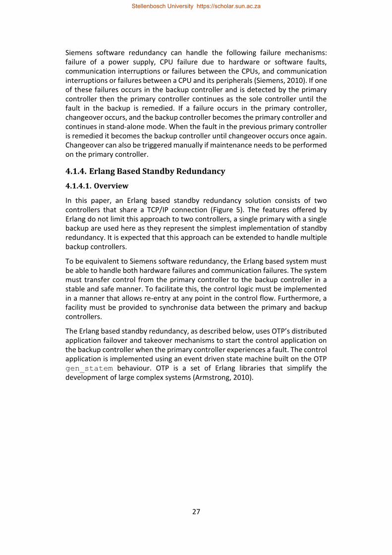
27
Siemens software redundancy can handle the following failure mechanisms: failure of a power supply, CPU failure due to hardware or software faults, communication interruptions or failures between the CPUs, and communication interruptions or failures between a CPU and its peripherals (Siemens, 2010). If one of these failures occurs in the backup controller and is detected by the primary controller then the primary controller continues as the sole controller until the fault in the backup is remedied. If a failure occurs in the primary controller, changeover occurs, and the backup controller becomes the primary controller and continues in stand-alone mode. When the fault in the previous primary controller is remedied it becomes the backup controller until changeover occurs once again. Changeover can also be triggered manually if maintenance needs to be performed on the primary controller.
4.1.4. Erlang Based Standby Redundancy
4.1.4.1. Overview
In this paper, an Erlang based standby redundancy solution consists of two controllers that share a TCP/IP connection (Figure 5). The features offered by Erlang do not limit this approach to two controllers, a single primary with a single backup are used here as they represent the simplest implementation of standby redundancy. It is expected that this approach can be extended to handle multiple backup controllers.
To be equivalent to Siemens software redundancy, the Erlang based system must be able to handle both hardware failures and communication failures. The system must transfer control from the primary controller to the backup controller in a stable and safe manner. To facilitate this, the control logic must be implemented in a manner that allows re-entry at any point in the control flow. Furthermore, a facility must be provided to synchronise data between the primary and backup controllers.
The Erlang based standby redundancy, as described below, uses OTP’s distributed application failover and takeover mechanisms to start the control application on the backup controller when the primary controller experiences a fault. The control application is implemented using an event driven state machine built on the OTP gen_statem behaviour. OTP is a set of Erlang libraries that simplify the development of large complex systems (Armstrong, 2010).
Stellenbosch University https://scholar.sun.ac.za
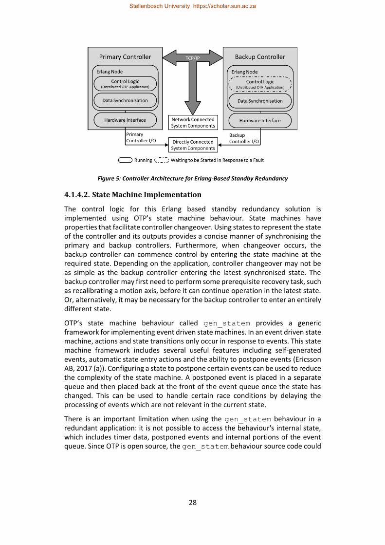
28
Figure 5: Controller Architecture for Erlang-Based Standby Redundancy
4.1.4.2. State Machine Implementation
The control logic for this Erlang based standby redundancy solution is implemented using OTP's state machine behaviour. State machines have properties that facilitate controller changeover. Using states to represent the state of the controller and its outputs provides a concise manner of synchronising the primary and backup controllers. Furthermore, when changeover occurs, the backup controller can commence control by entering the state machine at the required state. Depending on the application, controller changeover may not be as simple as the backup controller entering the latest synchronised state. The backup controller may first need to perform some prerequisite recovery task, such as recalibrating a motion axis, before it can continue operation in the latest state. Or, alternatively, it may be necessary for the backup controller to enter an entirely different state.
OTP’s state machine behaviour called gen_statem provides a generic framework for implementing event driven state machines. In an event driven state machine, actions and state transitions only occur in response to events. This state machine framework includes several useful features including self-generated events, automatic state entry actions and the ability to postpone events (Ericsson AB, 2017 (a)). Configuring a state to postpone certain events can be used to reduce the complexity of the state machine. A postponed event is placed in a separate queue and then placed back at the front of the event queue once the state has changed. This can be used to handle certain race conditions by delaying the processing of events which are not relevant in the current state.
There is an important limitation when using the gen_statem behaviour in a redundant application: it is not possible to access the behaviour's internal state, which includes timer data, postponed events and internal portions of the event queue. Since OTP is open source, the gen_statem behaviour source code could
Stellenbosch University https://scholar.sun.ac.za
29
be altered to allow access to this data, but this would negate the benefit of using a tried and tested framework.
To overcome this limitation, in the application presented here, self-generated events are disallowed, and timeouts are implemented using external Erlang timers instead of internal gen_statem timers. By doing this all event sources are external to the state machine and can be accessed by querying the process’s message queue. In addition, it is necessary to mirror the postponed events queue within user data. Despite these restrictions on the gen_statem behaviour, it is still an effective foundation for implementing control logic which facilitates standby redundancy.
4.1.4.3. Failover and Takeover Mechanism
Controller changeover, i.e. when one controller takes over control from another, is here considered to include failover and takeover. Failover is a changeover triggered by a failure, while takeover is a changeover initiated by a user/operator or a controller of higher priority becoming available (as explained below).
OTP's distributed application failover and takeover mechanism is a primary component of an Erlang-based standby redundancy system. To enable the failover and takeover mechanism, an OTP application must be configured as a distributed application. This configuration specifies on which nodes the application is permitted to run, as well as the priority of each node. OTP will start the application on the running node with the highest priority. If this node fails, OTP's failover mechanism will restart the application on the running node with the next highest priority. On the other hand, if at any time, a node with a higher priority comes online, the takeover mechanism executes. The takeover mechanism starts the application on the higher priority node and stops the application on the lower priority node once the higher priority node is initialised. There is a brief period when the application is running on both nodes simultaneously, which must be handled to avoid unintended side effects.
If it was desired, the node priority could be used to give preference to a controller with better hardware. However, this should be carefully considered as a failover-takeover loop could occur if the higher priority device has a fault that continually occurs shortly after takeover is complete. To be comparable to Siemen’s software redundancy, in the application presented here, the primary and backup controllers will have equal priority. Therefore, takeover will only occur when triggered by an operator.
4.1.4.4. Controller Changeover Time
The changeover time of the Erlang based system is determined by how long it takes the failover mechanism to detect that a node has become inaccessible and how long it takes the control logic to initialise. The time it takes Erlang to detect if a connected node goes down is controlled by the configuration parameter net_ticktime (an integer value, in seconds). Erlang claims that an inaccessible
Stellenbosch University https://scholar.sun.ac.za
30
node will be detected within an interval of 0.75*net_ticktime to 1.25*net_ticktime (Ericsson AB, 2017 (b)).
4.1.4.5. Standby Redundancy Events
There are three types of events that must be handled by the standby redundancy solution: controller failure due to a hardware or power fault, controller isolation due to a network fault and operator requested changeover.
4.1.4.5.1 Power Loss or Hardware Faults.
Controller failure due to loss of power or hardware fault is the type of redundancy event that the failover mechanism handles best. When the backup controller fails the primary controller maintains control of the system. Alternatively, when failure occurs in the primary controller (Figure 6), the failover mechanism starts the distributed application on the backup controller, which then becomes the new primary controller. When the failed controller comes back online, it synchronises with the primary controller and becomes the backup controller (regardless of whether it was previously the primary or the backup).
Figure 6: Primary Controller Failure due to Power Loss or Hardware Fault
Stellenbosch University https://scholar.sun.ac.za
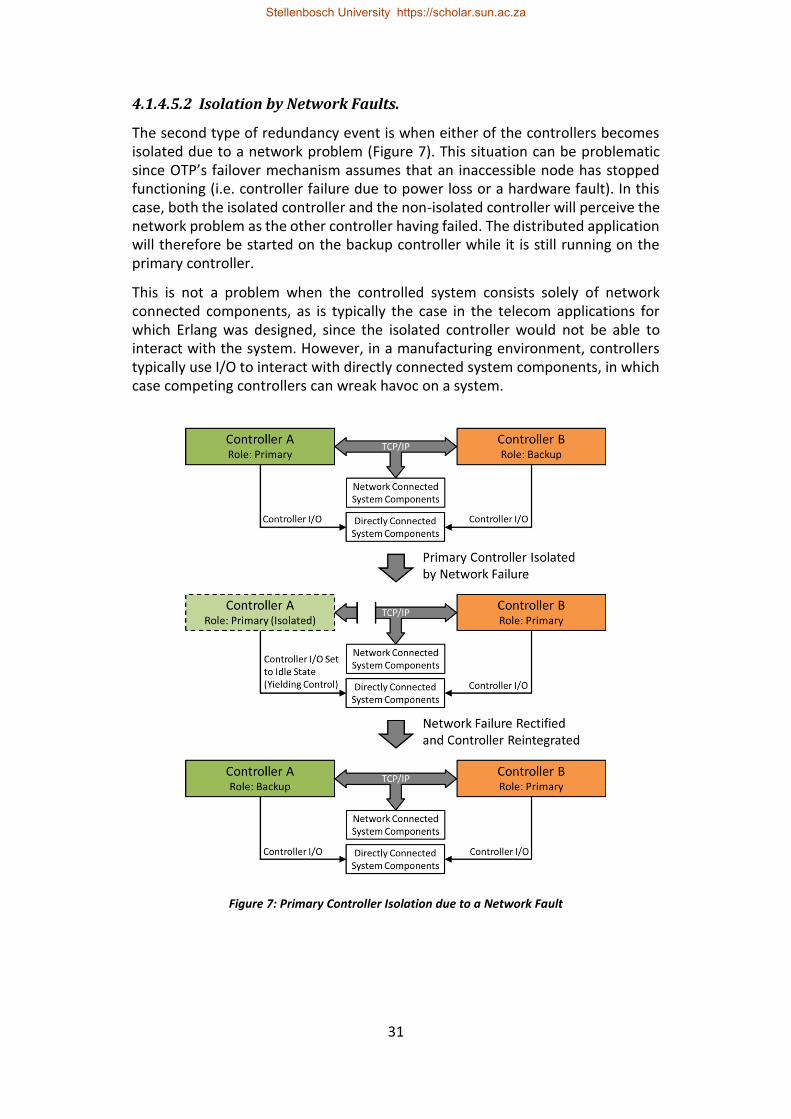
31
4.1.4.5.2 Isolation by Network Faults.
The second type of redundancy event is when either of the controllers becomes isolated due to a network problem (Figure 7). This situation can be problematic since OTP’s failover mechanism assumes that an inaccessible node has stopped functioning (i.e. controller failure due to power loss or a hardware fault). In this case, both the isolated controller and the non-isolated controller will perceive the network problem as the other controller having failed. The distributed application will therefore be started on the backup controller while it is still running on the primary controller.
This is not a problem when the controlled system consists solely of network connected components, as is typically the case in the telecom applications for which Erlang was designed, since the isolated controller would not be able to interact with the system. However, in a manufacturing environment, controllers typically use I/O to interact with directly connected system components, in which case competing controllers can wreak havoc on a system.
Figure 7: Primary Controller Isolation due to a Network Fault
Stellenbosch University https://scholar.sun.ac.za
32
This type of problem is not specific to Erlang and OTP. When Siemens software redundancy experiences a fault in the redundant link between the controllers, both controllers assume the role of primary controller (Siemens, 2010: 56). To prevent the controllers from competing, Siemens software redundancy makes use of distributed I/O. This distributed I/O is connected to the controllers on a different bus system to the redundant link, so it remains assigned to the previous primary controller. This approach essentially changes directly connected system components into network connected system components, albeit on a different network.
For systems using the types of devices upon which Erlang based standby redundancy would be implemented, it is likely that the use of directly connected system components would be unavoidable. To handle network faults when this is the case, there must be a method that the controllers can use to determine whether they should interact with the system or remain idle. If a higher-level controller is present in the system, it is recommended that each controller determine if they are isolated by attempting to contact this higher-level controller. Additionally, if there are other network connected system components upon which the controller relies to perform its control task, then contact with these components should also be used. If the controller determines that it is isolated, it must switch to an idle state and yield control to the other controller which is presumed not to be isolated. There is the possibility that both controllers could conclude that they are isolated and become idle, but in such a situation it is unlikely that either controller would be able function correctly.
A shortcoming of OTP's failover-takeover mechanism is that when a controller that was previously isolated due to a network problem, is reconnected to the network, the controller is not automatically reintegrated into the failover-takeover relationship. To work around this, the isolated controller must detect when the network connection is re-established and restart the Erlang node so that the failover relationship can be synchronised during node start-up.
4.1.4.5.3 Operator Triggered Changeover.
The third type of redundancy event is changeover resulting from the operator triggering the takeover mechanism. Since this changeover is not the result of a fault, data is synchronized directly between the controllers during the overlap period when both are operational. Furthermore, if the primary controller is in a state where the transfer of control would require a recovery task, then the transfer can be delayed until it enters a state which is better suited to transferring control. This form of changeover is typically initiated if the controller which is currently the primary needs to be brought offline for maintenance.
4.1.4.6. Data Synchronisation
To achieve warm standby redundancy, the backup controller needs to regularly synchronise data with the primary controller. OTP’s failover and takeover mechanism for distributed applications does not provide for the synchronisation
Stellenbosch University https://scholar.sun.ac.za
33
of the application’s state. Distributed applications are always (re)started by OTP as if for the first time. However, they can be configured so that their initialisation function receives an argument indicating whether the application start is normal or because of failover or takeover, as well as the node on which the application was/is running.
Since OTP's distributed application framework does not provide a facility for synchronising state data, it must be implemented using a different OTP feature called mnesia. Mnesia is a distributed database which transparently replicates data between nodes. In the present application, mnesia is used to synchronise the state, event queue, timer data and user data of the state machine that implements the control logic on the primary and backup controllers. When implementing warm standby redundancy, it is important to consider the latency in the link connecting the two controllers. This latency limits how often synchronisation can be performed and makes it impractical to synchronise user data which changes too rapidly.
When transferring timer data, there are two possible formats which can be used. In situations where the clocks of the two controllers can be accurately synchronised, it is recommended that timestamps be used for more accuracy after changeover. If the clocks of the two controllers cannot be synchronised accurately, the time remaining on the timer should be transferred, even though this will be less accurate since an unknown duration will have elapsed between changeover and the previous synchronisation.
Mnesia needs to be started and configured on both the primary and backup controllers before the redundant application is started. Since the distributed application will only start on the backup controller once failover occurs, a possible solution is to package the initialisation code for mnesia as a separate application which is started when the Erlang node starts.
4.1.5. Case Study
A case study was used to evaluate Erlang's supporting capabilities for creating a standby-redundant controller architecture within a manufacturing station. The significant aspect of the manufacturing station considered here is that it has a single controller that interacts with various hardware subsystems and synchronizes their actions.
4.1.5.1. Physical Architecture
A singulation and feeder station in an assembly cell is used as a case study to evaluate the Erlang based redundancy approach. The station consists of a singulation unit, a six-axis robot (Figure 8) and a fixture, which is typically on a conveyor. The singulation unit takes a batch of unordered parts and presents them one-by-one to the robot in collectable orientations. The robot then collects the parts and place them in the fixture for processing after all the parts have been placed.
Stellenbosch University https://scholar.sun.ac.za
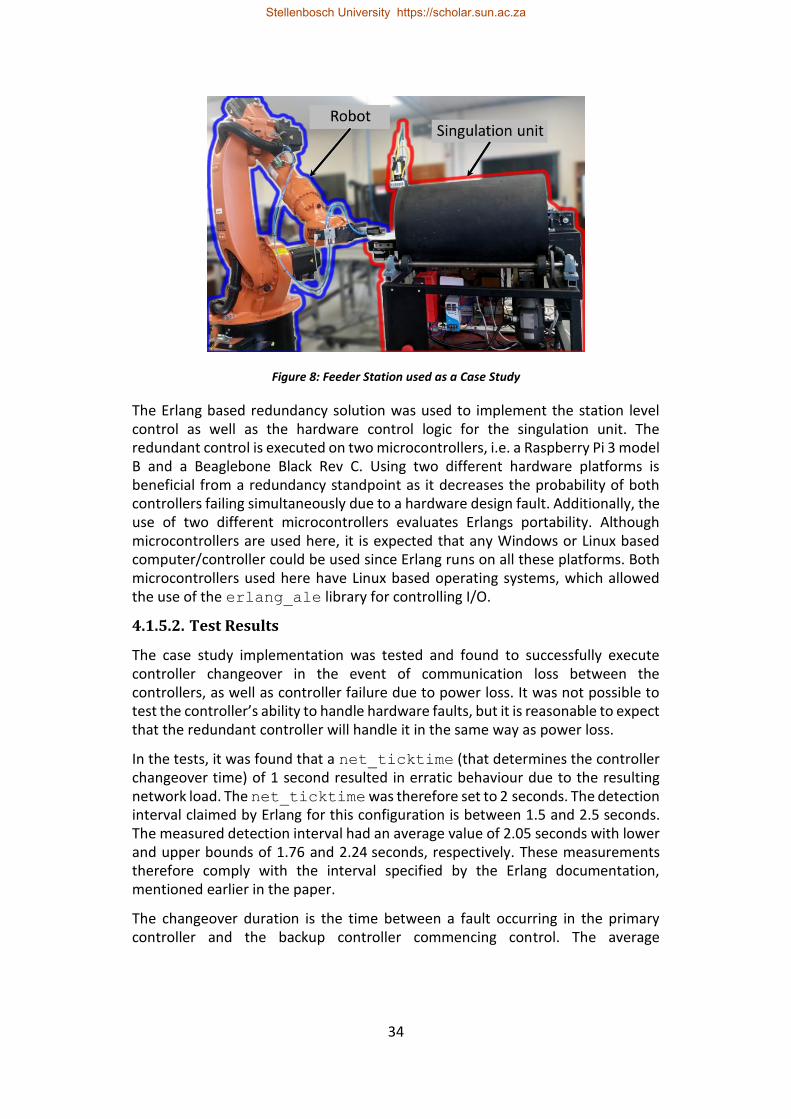
34
Figure 8: Feeder Station used as a Case Study
The Erlang based redundancy solution was used to implement the station level control as well as the hardware control logic for the singulation unit. The redundant control is executed on two microcontrollers, i.e. a Raspberry Pi 3 model B and a Beaglebone Black Rev C. Using two different hardware platforms is beneficial from a redundancy standpoint as it decreases the probability of both controllers failing simultaneously due to a hardware design fault. Additionally, the use of two different microcontrollers evaluates Erlangs portability. Although microcontrollers are used here, it is expected that any Windows or Linux based computer/controller could be used since Erlang runs on all these platforms. Both microcontrollers used here have Linux based operating systems, which allowed the use of the erlang_ale library for controlling I/O.
4.1.5.2. Test Results
The case study implementation was tested and found to successfully execute controller changeover in the event of communication loss between the controllers, as well as controller failure due to power loss. It was not possible to test the controller’s ability to handle hardware faults, but it is reasonable to expect that the redundant controller will handle it in the same way as power loss.
In the tests, it was found that a net_ticktime (that determines the controller changeover time) of 1 second resulted in erratic behaviour due to the resulting network load. The net_ticktime was therefore set to 2 seconds. The detection interval claimed by Erlang for this configuration is between 1.5 and 2.5 seconds. The measured detection interval had an average value of 2.05 seconds with lower and upper bounds of 1.76 and 2.24 seconds, respectively. These measurements therefore comply with the interval specified by the Erlang documentation, mentioned earlier in the paper.
The changeover duration is the time between a fault occurring in the primary controller and the backup controller commencing control. The average
Stellenbosch University https://scholar.sun.ac.za
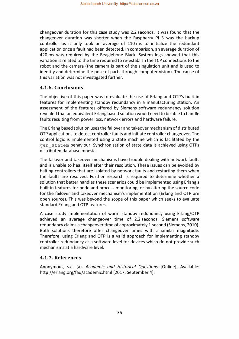
35
changeover duration for this case study was 2.2 seconds. It was found that the changeover duration was shorter when the Raspberry Pi 3 was the backup controller as it only took an average of 110 ms to initialize the redundant application once a fault had been detected. In comparison, an average duration of 420 ms was required by the Beaglebone Black. System logs showed that this variation is related to the time required to re-establish the TCP connections to the robot and the camera (the camera is part of the singulation unit and is used to identify and determine the pose of parts through computer vision). The cause of this variation was not investigated further.
4.1.6. Conclusions
The objective of this paper was to evaluate the use of Erlang and OTP’s built in features for implementing standby redundancy in a manufacturing station. An assessment of the features offered by Siemens software redundancy solution revealed that an equivalent Erlang based solution would need to be able to handle faults resulting from power loss, network errors and hardware failure.
The Erlang based solution uses the failover and takeover mechanism of distributed OTP applications to detect controller faults and initiate controller changeover. The control logic is implemented using a state machine which is facilitated by the gen_statem behaviour. Synchronisation of state data is achieved using OTPs distributed database mnesia.
The failover and takeover mechanisms have trouble dealing with network faults and is unable to heal itself after their resolution. These issues can be avoided by halting controllers that are isolated by network faults and restarting them when the faults are resolved. Further research is required to determine whether a solution that better handles these scenarios could be implemented using Erlang's built in features for node and process monitoring, or by altering the source code for the failover and takeover mechanism's implementation (Erlang and OTP are open source). This was beyond the scope of this paper which seeks to evaluate standard Erlang and OTP features.
A case study implementation of warm standby redundancy using Erlang/OTP achieved an average changeover time of 2.2 seconds. Siemens software redundancy claims a changeover time of approximately 1 second (Siemens, 2010). Both solutions therefore offer changeover times with a similar magnitude. Therefore, using Erlang and OTP is a valid approach for implementing standby controller redundancy at a software level for devices which do not provide such mechanisms at a hardware level.
4.1.7. References
Anonymous, s.a. (a). Academic and Historical Questions [Online]. Available: http://erlang.org/faq/academic.html [2017, September 4].
Stellenbosch University https://scholar.sun.ac.za
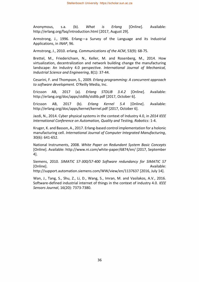
36
Anonymous, s.a. (b). What is Erlang [Online]. Available: http://erlang.org/faq/introduction.html [2017, August 29].
Armstrong, J., 1996. Erlang—a Survey of the Language and its Industrial Applications, in INAP, 96.
Armstrong, J., 2010. erlang. Communications of the ACM, 53(9): 68-75.
Brettel, M., Friederichsen, N., Keller, M. and Rosenberg, M., 2014. How virtualization, decentralization and network building change the manufacturing landscape: An industry 4.0 perspective. International Journal of Mechanical, Industrial Science and Engineering, 8(1): 37-44.
Cesarini, F. and Thompson, S., 2009. Erlang programming: A concurrent approach to software development. O'Reilly Media, Inc.
Ericsson AB, 2017 (a). Erlang STDLIB 3.4.2 [Online]. Available: http://erlang.org/doc/apps/stdlib/stdlib.pdf [2017, October 6].
Ericsson AB, 2017 (b). Erlang Kernel 5.4 [Online]. Available: http://erlang.org/doc/apps/kernel/kernel.pdf [2017, October 6].
Jazdi, N., 2014. Cyber physical systems in the context of Industry 4.0, in 2014 IEEE International Conference on Automation, Quality and Testing, Robotics: 1-4.
Kruger, K. and Basson, A., 2017. Erlang-based control implementation for a holonic manufacturing cell. International Journal of Computer Integrated Manufacturing, 30(6): 641-652.
National Instruments, 2008. White Paper on Redundant System Basic Concepts [Online]. Available: http://www.ni.com/white-paper/6874/en/ [2017, September 4].
Siemens, 2010. SIMATIC S7-300/S7-400 Software redundancy for SIMATIC S7 [Online]. Available: http://support.automation.siemens.com/WW/view/en/1137637 [2016, July 14].
Wan, J., Tang, S., Shu, Z., Li, D., Wang, S., Imran, M. and Vasilakos, A.V., 2016. Software-defined industrial internet of things in the context of industry 4.0. IEEE Sensors Journal, 16(20): 7373-7380.
Stellenbosch University https://scholar.sun.ac.za
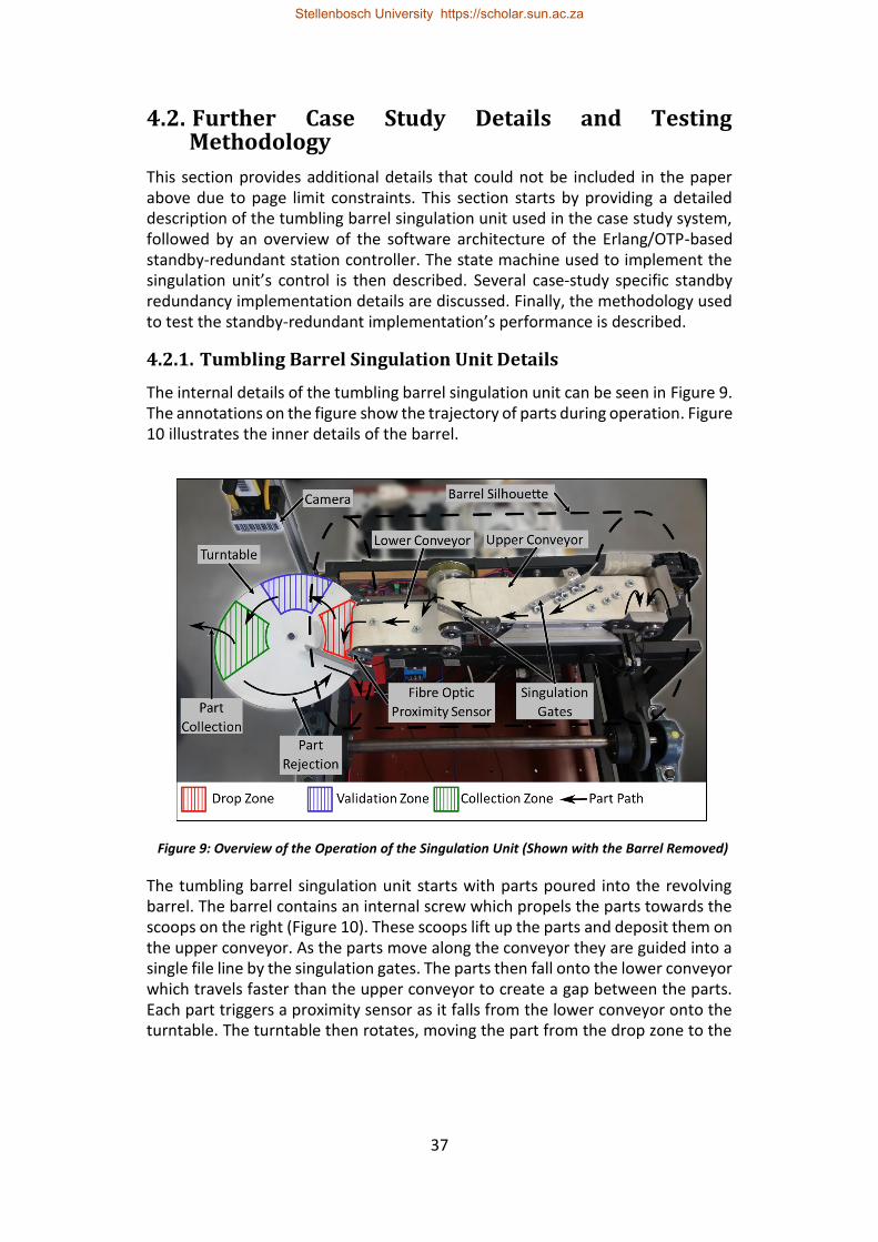
37
4.2. Further Case Study Details and Testing Methodology
This section provides additional details that could not be included in the paper above due to page limit constraints. This section starts by providing a detailed description of the tumbling barrel singulation unit used in the case study system, followed by an overview of the software architecture of the Erlang/OTP-based standby-redundant station controller. The state machine used to implement the singulation unit’s control is then described. Several case-study specific standby redundancy implementation details are discussed. Finally, the methodology used to test the standby-redundant implementation’s performance is described.
4.2.1. Tumbling Barrel Singulation Unit Details
The internal details of the tumbling barrel singulation unit can be seen in Figure 9. The annotations on the figure show the trajectory of parts during operation. Figure 10 illustrates the inner details of the barrel.
Figure 9: Overview of the Operation of the Singulation Unit (Shown with the Barrel Removed)
The tumbling barrel singulation unit starts with parts poured into the revolving barrel. The barrel contains an internal screw which propels the parts towards the scoops on the right (Figure 10). These scoops lift up the parts and deposit them on the upper conveyor. As the parts move along the conveyor they are guided into a single file line by the singulation gates. The parts then fall onto the lower conveyor which travels faster than the upper conveyor to create a gap between the parts. Each part triggers a proximity sensor as it falls from the lower conveyor onto the turntable. The turntable then rotates, moving the part from the drop zone to the
Stellenbosch University https://scholar.sun.ac.za
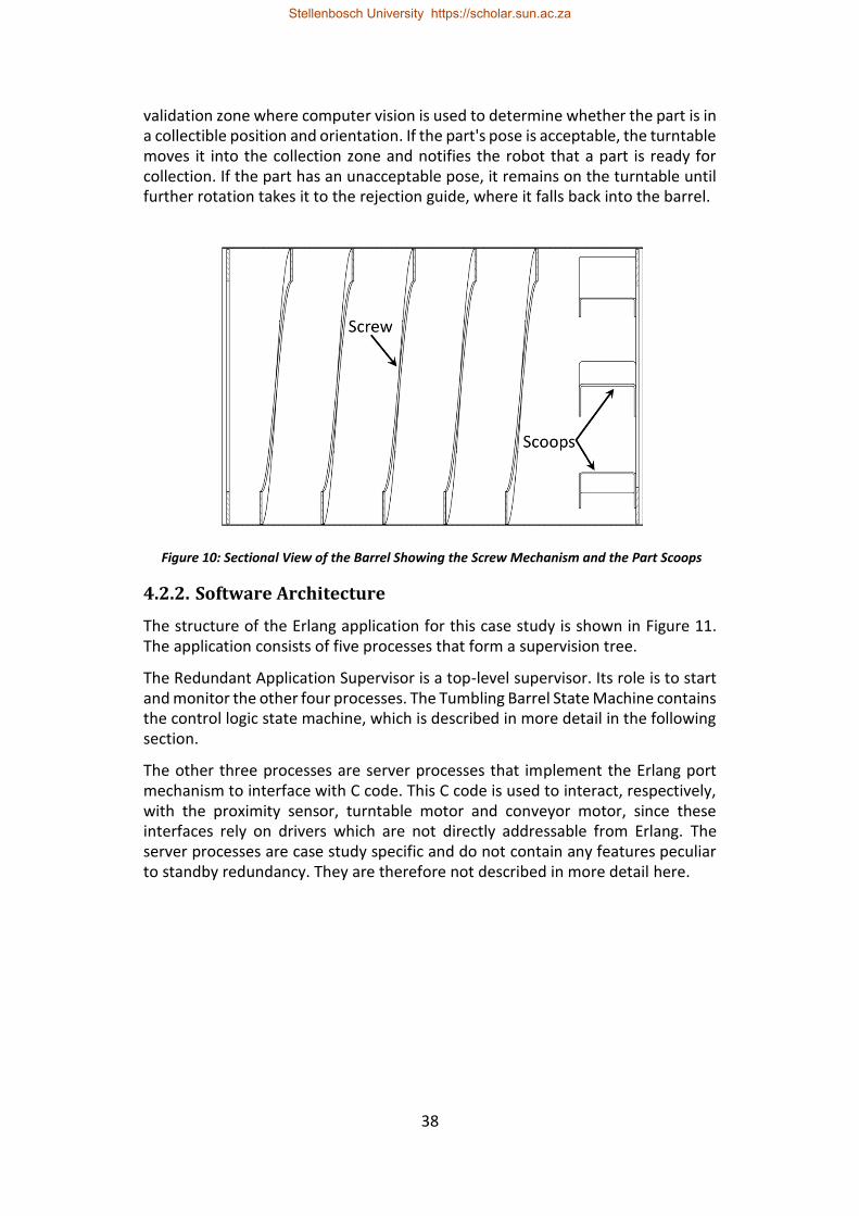
38
validation zone where computer vision is used to determine whether the part is in a collectible position and orientation. If the part's pose is acceptable, the turntable moves it into the collection zone and notifies the robot that a part is ready for collection. If the part has an unacceptable pose, it remains on the turntable until further rotation takes it to the rejection guide, where it falls back into the barrel.
Figure 10: Sectional View of the Barrel Showing the Screw Mechanism and the Part Scoops
4.2.2. Software Architecture
The structure of the Erlang application for this case study is shown in Figure 11. The application consists of five processes that form a supervision tree.
The Redundant Application Supervisor is a top-level supervisor. Its role is to start and monitor the other four processes. The Tumbling Barrel State Machine contains the control logic state machine, which is described in more detail in the following section.
The other three processes are server processes that implement the Erlang port mechanism to interface with C code. This C code is used to interact, respectively, with the proximity sensor, turntable motor and conveyor motor, since these interfaces rely on drivers which are not directly addressable from Erlang. The server processes are case study specific and do not contain any features peculiar to standby redundancy. They are therefore not described in more detail here.
Stellenbosch University https://scholar.sun.ac.za
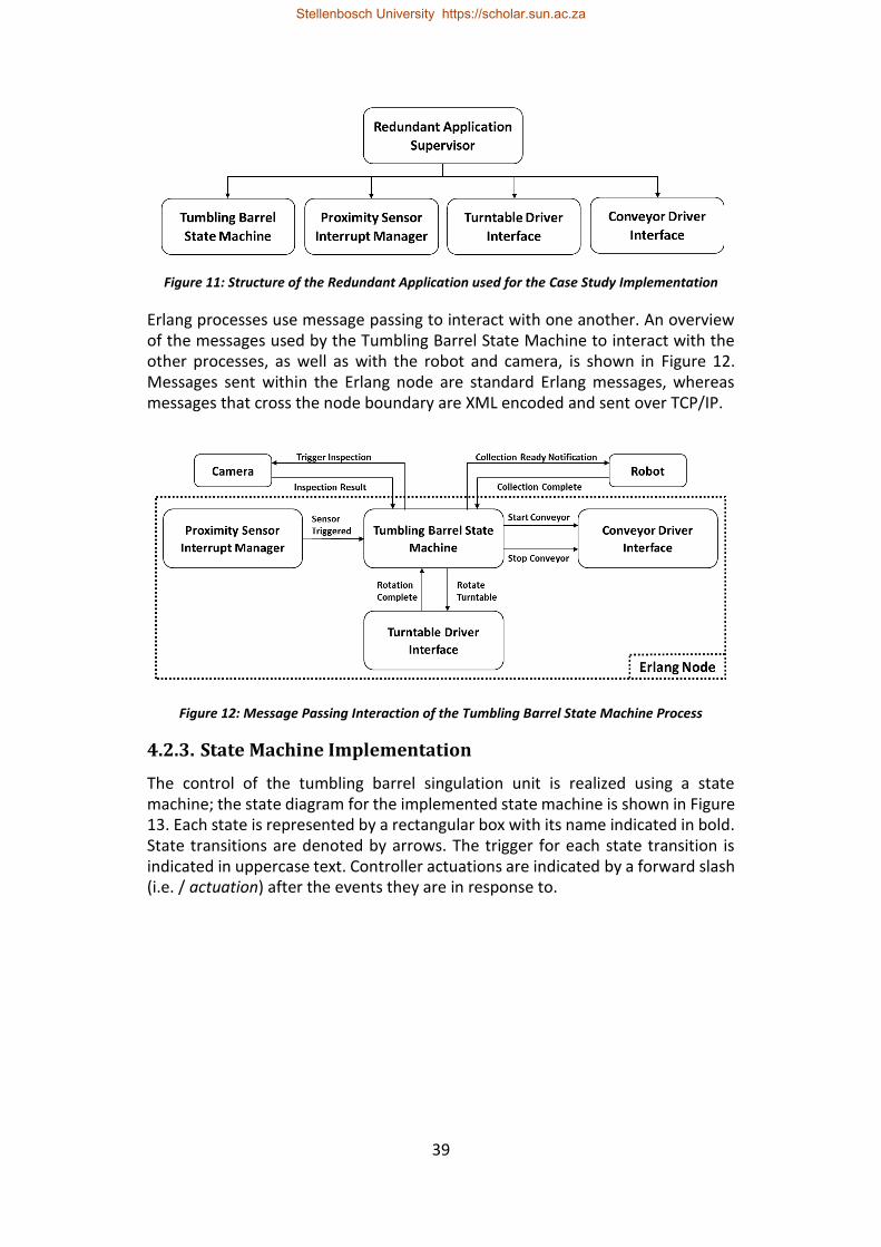
39
Figure 11: Structure of the Redundant Application used for the Case Study Implementation
Erlang processes use message passing to interact with one another. An overview of the messages used by the Tumbling Barrel State Machine to interact with the other processes, as well as with the robot and camera, is shown in Figure 12. Messages sent within the Erlang node are standard Erlang messages, whereas messages that cross the node boundary are XML encoded and sent over TCP/IP.
Figure 12: Message Passing Interaction of the Tumbling Barrel State Machine Process
4.2.3. State Machine Implementation
The control of the tumbling barrel singulation unit is realized using a state machine; the state diagram for the implemented state machine is shown in Figure 13. Each state is represented by a rectangular box with its name indicated in bold. State transitions are denoted by arrows. The trigger for each state transition is indicated in uppercase text. Controller actuations are indicated by a forward slash (i.e. / actuation) after the events they are in response to.
Stellenbosch University https://scholar.sun.ac.za

40
Figure 13: State Machine for the Tumbling Barrel Singulation Unit
4.2.4. Standby Redundancy Implementation Details
This section discusses certain standby redundancy implementation details peculiar to the case study station controller.
Stellenbosch University https://scholar.sun.ac.za
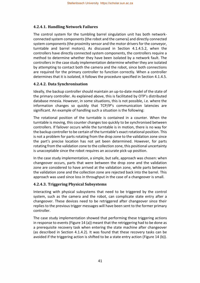
41
4.2.4.1. Handling Network Failures
The control system for the tumbling barrel singulation unit has both network-connected system components (the robot and the camera) and directly connected system components (the proximity sensor and the motor drivers for the conveyor, turntable and barrel motors). As discussed in Section 4.1.4.5.2, when the controllers have directly connected system components, the controllers require a method to determine whether they have been isolated by a network fault. The controllers in the case study implementation determine whether they are isolated by attempting to contact both the camera and the robot, since both connections are required for the primary controller to function correctly. When a controller determines that it is isolated, it follows the procedure specified in Section 4.1.4.5.
4.2.4.2. Data Synchronisation
Ideally, the backup controller should maintain an up-to-date model of the state of the primary controller. As explained above, this is facilitated by OTP’s distributed database mnesia. However, in some situations, this is not possible, i.e. where the information changes so quickly that TCP/IP's communication latencies are significant. An example of handling such a situation is the following:
The rotational position of the turntable is contained in a counter. When the turntable is moving, this counter changes too quickly to be synchronised between controllers. If failover occurs while the turntable is in motion, there is no way for the backup controller to be certain of the turntable’s exact rotational position. This is not a problem for parts rotating from the drop zone to the validation zone since the part's precise location has not yet been determined. However, for parts rotating from the validation zone to the collection zone, this positional uncertainty is unacceptable since the robot requires an accurate pick-up position.
In the case study implementation, a simple, but safe, approach was chosen: when changeover occurs, parts that were between the drop zone and the validation zone are considered to have arrived at the validation zone, while parts between the validation zone and the collection zone are rejected back into the barrel. This approach was used since loss in throughput in the case of a changeover is small.
4.2.4.3. Triggering Physical Subsystems
Interacting with physical subsystems that need to be triggered by the control system, such as the camera and the robot, can complicate state entry after a changeover. These devices need to be retriggered after changeover since their replies to the previous trigger messages will have been sent to the former primary controller.
The case study implementation showed that performing these triggering actions in response to events (Figure 14 (a)) meant that the retriggering had to be done as a prerequisite recovery task when entering the state machine after changeover (as described in Section 4.1.4.2). It was found that these recovery tasks can be avoided if the triggering action is shifted to be a state entry action (Figure 14 (b)).
Stellenbosch University https://scholar.sun.ac.za
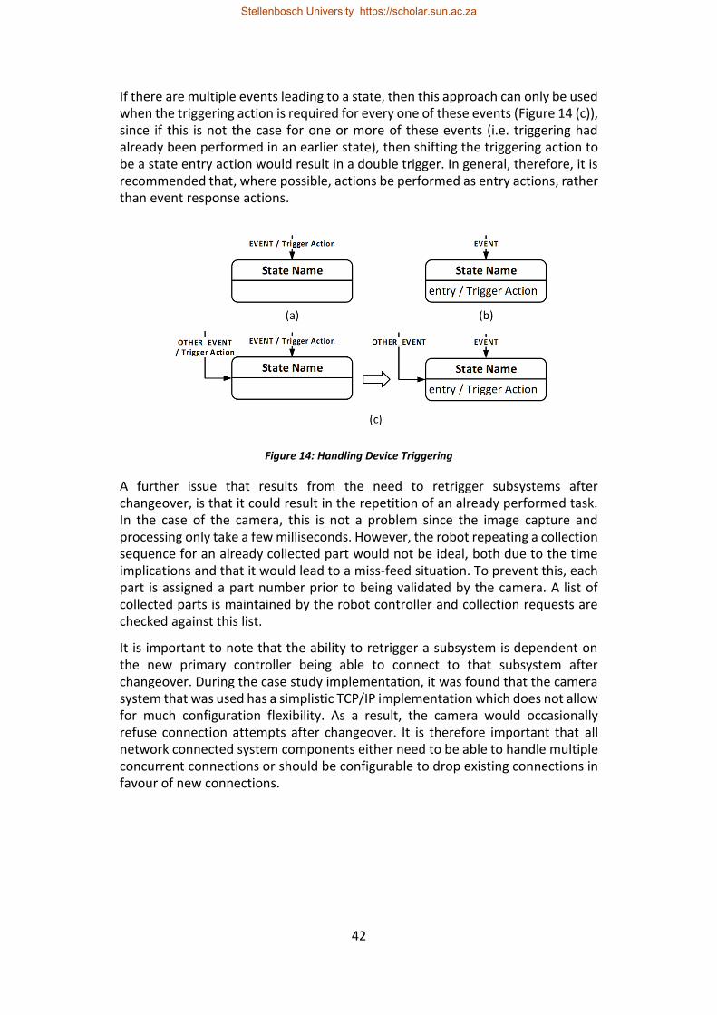
42
If there are multiple events leading to a state, then this approach can only be used when the triggering action is required for every one of these events (Figure 14 (c)), since if this is not the case for one or more of these events (i.e. triggering had already been performed in an earlier state), then shifting the triggering action to be a state entry action would result in a double trigger. In general, therefore, it is recommended that, where possible, actions be performed as entry actions, rather than event response actions.
Figure 14: Handling Device Triggering
A further issue that results from the need to retrigger subsystems after changeover, is that it could result in the repetition of an already performed task. In the case of the camera, this is not a problem since the image capture and processing only take a few milliseconds. However, the robot repeating a collection sequence for an already collected part would not be ideal, both due to the time implications and that it would lead to a miss-feed situation. To prevent this, each part is assigned a part number prior to being validated by the camera. A list of collected parts is maintained by the robot controller and collection requests are checked against this list.
It is important to note that the ability to retrigger a subsystem is dependent on the new primary controller being able to connect to that subsystem after changeover. During the case study implementation, it was found that the camera system that was used has a simplistic TCP/IP implementation which does not allow for much configuration flexibility. As a result, the camera would occasionally refuse connection attempts after changeover. It is therefore important that all network connected system components either need to be able to handle multiple concurrent connections or should be configurable to drop existing connections in favour of new connections.
Stellenbosch University https://scholar.sun.ac.za
43
4.2.5. Testing Methodology
The performance of standby-redundant systems is quantified by changeover time and system bump (as described in section 4.1.2). System bump is easily quantified for continuous systems; however, quantification is difficult for discrete systems since it is dependent on the probability of an event occurring during changeover. For example, if there are no system events during changeover then there is no system bump, but if there is a critical event that is missed then the system bump could be substantial. This is further compounded by the fact that certain missed events can be recovered (i.e. such as retriggering the camera and robot). Since it is so application specific, a quantification of the system bump is not attempted nor presented for the case study. The changeover time is used as the sole standby redundancy metric since it is generalisable to similar implementations.
The paper considers two failure scenarios: controller isolation by network faults and controller failure due to power loss or hardware failure. The handling of these failure scenarios is discussed in section 4.1.4.5. The failure detection and changeover times were measured and presented for controller failure due to power loss or hardware failure. The detection and changeover times for controller isolation due to network faults were not presented since the isolated primary controller maintains control until it detects its isolation, leading to a substantially shorter period without control. Controller failure due to power loss or fail-stop hardware faults was simulated by removing power from the controller in question.
The Erlang/OTP-based standby-redundant application structure was executed on both the Raspberry Pi and the Beaglebone Black. During tests, the first controller to initialise started as the primary controller (usually the Raspberry Pi) and once the other controller had initialised, it became the backup controller. To avoid giving preference to one particular configuration, changeover was performed in both directions during tests. The only difference between the Erlang code running on the two devices is the pin assignments provided in their configuration files.
To measure the failure detection time, the code was modified so that each controller would set one of its pins high whenever it considered itself to be the primary instance. When the controller fault is injected, the controller is no longer able to assert that pin and the signal drops low. Then when the backup controller detects the failure and assumes the role of primary it will set its own pin high. The failure detection time was then measured using an oscilloscope to determine the time difference between the falling edge of the failed controller’s signal and the rising edge of the new primary controller’s signal. In a similar manner, the changeover time was measured between the falling edge of the primary’s signal pin and the rising edge of the barrel motor control pin of the new primary (the barrel motor control is set after initialisation is complete). The results of these tests are presented in section 4.1.5.2.
Stellenbosch University https://scholar.sun.ac.za
44
4.3. Handling Process and Node Failure Due to Software Issues
The paper considers two failure scenarios, namely controller isolation by network faults and controller failure due to power loss or hardware faults. However, there are two further forms of failure that should be considered. This section discusses the handling of node and process failures due to software errors.
To simulate node failure due to software errors, either the BEAM process can be terminated, or init:stop can be called. Terminating the process is more representative of a true failure but using init:stop enables fault injection at a specific point in execution. To simulate process failure, either the process code can be written so that an error is generated at the desired instant, or the process can be killed from the shell or another process using the kill function.
Process failure due to software faults are primarily handled by the supervisor mechanism. The standby-redundant implementation uses Erlang/OTP’s supervision tree concept, as described in section 4.2.2. OTP’s supervisor behaviour starts and monitors child processes; if one of the children fails then the supervisor restarts it. Testing showed a typical restart time of 1.2 ms. If restarting corrects the error then operation continues normally, but if failure continues to occur at a rate that exceeds the one specified in the supervisor's callback then it too fails.
Several supervisors are often stacked to create supervision trees where top-level supervisors supervise lower-level supervisors. When failure occurs in a supervision tree, it propagates through the supervision tree until enough of the application’s processes have been restarted to rectify the error, or alternatively the top-level supervisor fails. When the top-level supervisor fails, the node will terminate if that application is configured as permanent or transient. When top-level supervisor failure causes a distributed application to fail, the distributed application is not restarted by the failover mechanism. This may be considered a shortcoming since manual intervention is required to restart the application. However, it appears to be a design decision. If the failover mechanism restarts the application, only to have it fail shortly afterward, then it could lead to each node in the system being terminated one-by-one. Distributed applications used to achieve standby redundancy should therefore be developed such that the top-most supervisor will only fail due to an irrecoverable error.
Software-caused node failure can occur for several reasons in Erlang/OTP. For the standby-redundant approach described above, this node failure is detected in the same way as other failure conditions and is handled the same way as controller failure due to power loss or hardware faults. The only difference is that the failure detection time is shorter because the operating system of the host device is still operational so the TCP/IP connection between the primary and backup nodes is terminated correctly. Erlang/OTP includes a heartbeat mechanism that can be used to automatically detect and restart nodes that fail. This mechanism is described in greater detail in appendix A.3.
Stellenbosch University https://scholar.sun.ac.za
45
5. Erlang/OTP-Based Standby Redundancy for Distributed Holonic Cell Control
This section presents the development of a standby-redundant holonic cell controller. The section is comprised of three papers.
The first paper, “Conversation Recovery after Failover for Contract Net Protocol Communication in an Erlang-Based Holonic Architecture” (Hawkridge et al., 2018 (b)) is presented in section 5.1. The paper reviews and evaluates the various rollback recovery protocols in terms of the conversation recovery requirements of a holonic architecture. Recovery mechanisms enable the communication within holonic systems to withstand standby redundancy events. The paper presents an Erlang/OTP implementation of a pessimistic logging form of rollback recovery. This implementation is evaluated using the case of order-resource holon interaction in a holonic singulation and feeder cell.
The second paper, “An Erlang-based Standby-Redundant Distributed Holonic Controller for a Manufacturing Cell” (Hawkridge et al., 2018 (c)) is presented in section 5.2. The paper first evaluates the redundancy requirements of a PROSA-based holonic architecture. An Erlang/OTP implementation of standby redundancy for a holonic cell is then described. The case study of holonic singulation and feeder cell is used to evaluate the implementation.
The third paper, “Extensible Callback Module Layering in Erlang” (Hawkridge et al., 2018 (d)) is presented in section 5.3. The paper presents an approach for achieving process specialisation using Erlang’s behaviour mechanism. This approach was used to facilitate modularity and code re-use in the development of the Erlang/OTP standby-redundant holonic cell implementation.
Stellenbosch University https://scholar.sun.ac.za
46
5.1. Conversation Recovery after Failover for Contract Net Protocol Communication in an Erlang-Based
Holonic Architecture
G Hawkridge, AH Basson, K Kruger Department of Mechanical and Mechatronic Engineering, Stellenbosch University
Abstract
The reliability or availability of complex systems encountered in Industry 4.0, cyber-physical systems (CPSs) and the Industrial Internet of Things (IIoT) is a significant concern. This paper considers situations where three approaches are combined to enhance the availability of such systems: holonic architectures, standby controller redundancy and using the Erlang programming language. The benefits of holonic architectures include their suitability for complex control situations and their fault tolerance. Both of these aspects are supported by the use of the contract net protocol (CNP). Standby redundancy is a well-known approach to improve the availability of systems. Erlang is a functional programming language designed for the development of fault-tolerant soft real-time control systems. Erlang and its associated library OTP contain features that simplify the implementation of standby redundancy. Erlang/OTP also has many features, such as concurrency and scalability, that are attractive when implementing holonic control systems.
This paper presents an approach for the recovery of CNP conversations between holons that implement standby redundancy. A recovery mechanism is needed to ensure that these conversations can continue in the presence of failover events. The various forms of rollback conversation recovery protocols are reviewed based on the requirements of a holonic system. This review also considers the need to interact with parties that are external to the holonic system, including interaction with the physical world through controller I/O. It is concluded that a pessimistic logging form of rollback recovery is well suited to standby-redundant holonic systems. The complex multi-party communication structure within a holarchy is decomposed into several simpler parallel one-to-one conversations using certain properties of the contract net protocol and holonic control. An Erlang/OTP implementation of a pessimistic logging form of rollback recovery is described. A case study is used to validate the Erlang/OTP implementation.
Keywords: Contract Net Protocol; Standby Redundancy; Erlang; Conversation Recovery
5.1.1. Introduction
Modern manufacturing paradigms are becoming increasingly distributed and complex. This is particularly evident in the recent focus on Industry 4.0, cyber-physical systems (CPSs) and the Industrial Internet of Things (IIoT) (Brettel et al., 2014; Bi, Xu & Wang 2014; Gerbert et al., 2015). The reliability or availability of such complex systems is a significant concern. Availability here refers to the
Stellenbosch University https://scholar.sun.ac.za
47
percentage of time for which a system is ready and able to perform its expected functions. This paper considers situations where three approaches are combined to enhance the availability of such systems: holonic architectures, standby controller redundancy and using the Erlang programming language.
Holonic systems have been highlighted as promising tools for managing complexity, changes and disturbances in systems (Monostori et al., 2016). The holonic manufacturing paradigm maintains the global control and optimisation potential of hierarchical structures, while leveraging the improved flexibility and fault-tolerance of a heterarchical structure. This improved fault-tolerance is due to the collaborative nature of holons which facilitates having multiple holons capable of performing each task thereby avoiding potential single points of failure. Single points of failure are system elements where failure of one element results in system failure, which should obviously be avoided in large complex systems.
Even though holonic architectures in general will continue operating even if some holons fail, the failure of a holon will reduce the functionality or capacity of the system. An approach that can be used to improve the availability of individual holons is standby controller redundancy, which has traditionally been used to improve the availability of hierarchical or monolithic control systems. A key aspect, when standby controller redundancy is used within holonic architectures, is the facilitation of inter-holon communication when failover events occur. Failover here is the process by which a standby subsystem takes over when the primary subsystem fails.
Inter-holon communication is necessary for collaboration between holons and is typically formulated as negotiation mechanisms such as the contract net protocol (CNP). This paper focuses on implementing failover during conversations that are built around the CNP. In addition to the conversations between parties of the CNP, consideration must also be given to two other types of conversations in these situations: firstly, the conversations between the software elements of holons and their corresponding hardware elements; and secondly, conversations between holons and other parties that are external to the holonic system, here referred to as “outside world processes” (OWPs).
Erlang is a functional programming language designed for the development of fault-tolerant soft real-time control systems (Armstrong, 1996). The Open Telecom Platform (OTP), a key feature of Erlang, is a set of libraries that simplifies the development of large complex systems (Armstrong 2010: 73). Erlang has many attractive features, such as concurrency and scalability, that are useful when implementing holonic manufacturing control systems (Kruger & Basson, 2017). An interesting feature that Erlang and OTP provide is the built-in mechanism for application failover. This mechanism will restart an application on another node if the node upon which it is currently running fails (the meanings of “application” and “node” are described later in the paper). This mechanism has been used to implement standby controller redundancy in a monolithic station controller (Hawkridge et al., 2018 (a)).
Stellenbosch University https://scholar.sun.ac.za
48
This paper investigates the adaptation of the CNP for use within a holonic control architecture where certain holons implement standby redundancy. This includes conversation recovery in the presence of failures and the use of Erlang/OTP specific mechanisms to avoid certain potential shortcomings of the CNP. Conversation recovery with OWPs is also considered. Although this paper focuses on a holonic control architecture, it is expected that the key elements of the approach will be applicable to other architectures which make use of the CNP and/or standby redundancy.
This paper next provides some background on Erlang and OTP, holonic control architectures, the CNP and rollback recovery protocols followed by a description of the approach used to enable CNP conversation recovery. A case study is then used to validate the recovery solution.
5.1.2. Erlang Background
The Erlang programming language was designed for applications which require concurrency, fault tolerance and distribution (Anonymous, s.a. (a)). It is these features that make it an attractive solution for the implementation of holonic control systems (Kruger & Basson, 2017). This section introduces foundational concepts in Erlang that are referred to later in the paper.
5.1.2.1. Concurrency
Erlang programs are built up by independent concurrent processes which cooperate with one another to achieve overall goals. Erlang processes have the following properties: processes have sole access to their internal state, processes influence one another through asynchronous message passing and processes have the capability to spawn further processes (Armstrong 2010: 70).
Erlang code runs within its own virtual machine, known as BEAM (Bogdan/Björn's Erlang Abstract Machine). In Erlang, a node refers to an instance of BEAM, which handles scheduling, memory management and message passing for the Erlang processes. Additionally, BEAM supports symmetric multiprocessing (SMP) which enhances process concurrency on multicore processors (Lundin 2008). BEAM provides Erlang with processes that are lightweight, which facilitates the large number of processes required to implement complex systems (Larson, 2009: 55).
5.1.2.2. Distribution
Distribution flows naturally from Erlang's concurrency model. Since processes communicate through message passing and there is no shared state, the only difference between process communication within a node and process communication between nodes is latency. As a result, it possible to develop an Erlang program on a single device and deploy it to a cluster with minimal code modification (Armstrong 2010: 70).
Stellenbosch University https://scholar.sun.ac.za
49
5.1.2.3. Process Identifiers and Named Processes
For a process to send a message to another process, it must know the process’ pid (process identifier). A pid can be thought of as the address of the process. Pids are unique within and between different nodes. When a process sends a message to another process, it typically includes its own pid so that the other process can reply. There are two mechanisms that can be used to obtain another process’ pid. Firstly, it can be passed as an argument when the process is spawned. The second and more common mechanism is registered names. Erlang provides the mechanism for processes to register themselves under a certain name. Other processes can use this name to query the name registry and obtain the corresponding pid. There are two different name registries: the local registry and the global registry. The local registry only has scope for its node, i.e. it maps processes within a node to names that are unique within that node. The global registry has scope for and is synchronised across all nodes that belong to the same global group.
5.1.2.4. Process Monitoring, Supervision Trees and OTP Applications
Erlang’s process model provides process isolation, which contributes to its fault-tolerance. Process isolation means that if an Erlang process is killed, whether by an error or by another process, it will by default not cause an error in any of the other processes.
To handle situations where processes are reliant on other processes to be able to fulfil their function, Erlang provides mechanisms for process linking and process monitoring. If two processes are linked, the death of the one will result in the death of the other. Alternatively, if a process is monitoring another process, it will receive a message if the other dies. These features are used by OTP to implement supervisor processes.
A supervisor process starts and monitors its child processes and restarts them if they fail. If the failure rate exceeds a specified frequency, the supervisor fails, and all its children are killed. The children of a supervisor process can include other supervisor processes. This leads to a supervision tree. The principle behind a supervision tree is that, if an error occurs, it will propagate through the supervision tree until it reaches the point where all the processes required to rectify that error have been restarted. In this way, an error can be contained in the region which it affects.
An OTP application is a supervision tree where all the children are implementations of standard OTP behaviours. A behaviour is an abstraction that implements the generic portions of a common model or pattern. The standard behaviours include gen_server (that implements a client-server relationship), gen_event (that implements a publish-subscribe mechanism), gen_statem (that implements an event driven state machine) and the supervisor model. The application specific logic for these behaviours is implemented in the form of
Stellenbosch University https://scholar.sun.ac.za
50
callback modules. An advantage of using these behaviours is that they have been thoroughly tested in many software products.
5.1.2.5. Failover and Takeover Mechanisms
OTP's distributed application failover and takeover mechanisms are key components in an Erlang/OTP based redundancy system. To enable the failover and takeover mechanism, an OTP application must be configured as a distributed application. This configuration specifies on which nodes the application is permitted to run, as well as the priority of each node. OTP will start the application on the running node with the highest priority. If this node fails, OTP's failover mechanism will restart the application on the running node with the next highest priority. On the other hand, if at any time a node with a higher priority comes online, the takeover mechanism executes which starts the application on the higher priority node and stops the application on the lower priority node once the higher priority node is initialised. There is a brief period when the application is running on both nodes simultaneously, which must be handled to avoid unintended side effects.
The time it takes Erlang to detect that a connected node has gone down is controlled by the configuration parameter net_ticktime (an integer value, in seconds). Erlang claims that an inaccessible node will be detected within an interval of 0.75*net_ticktime to 1.25*net_ticktime (Ericsson AB, 2017 (a): 7).
Another situation that should be considered is when a node is isolated due to communication loss, but the node remains operational. If communication is re-established in this situation, the distributed application framework does not re-establish the failover/takeover relationships for the reconnected node. A workaround for these situations is that when a node determines that it has been reconnected, it brings any physical devices related to it to a safe state and then restarts (Hawkridge et al., 2018 (a)). Restarting the node will re-establish the failover/takeover relationships.
5.1.2.6. Mnesia
Mnesia is a distributed database management system that is suitable for Erlang applications that require continuous operation and exhibit soft real-time properties (Ericsson AB, 2017 (b): 2). Mnesia can be used for transparently replicating data across Erlang nodes. A useful feature of Mnesia is the ability to store Erlang datatypes such as records and references.
5.1.3. Holonic Background and Architecture
The holonic control paradigm is based on the concept of a holon which was devised by Koestler (1989) to describe how biological and social systems are organised. The word holon refers to something which is simultaneously a complete whole and part of a larger whole (Van Brussel, 1994). In the control context, holons are independent units of control which communicate and
Stellenbosch University https://scholar.sun.ac.za
51
cooperate with one another to achieve the system’s goals. A grouping of related holons is called a holarchy. Holonic systems typically have a fractal nature: any holon in a holarchy can internally contain a lower-order holarchy. An example of this is where a cell controller views a station controller as a holon, while the station controller itself is a set of holons that control that station.
Reference architectures are used to facilitate the implementation of holonic manufacturing systems by providing a framework for the classification of holons and holarchies. The PROSA architecture is a popular and prevalent reference architecture. The PROSA reference architecture specifies four categories of holon, namely product holons, order holons, resource holons and staff holons (Van Brussel et al., 1998).
A product holon contains the process and product knowledge required to produce a specific product. Product holons represent the model of the product type and not specific instances of the product. Order holons represent any task that must occur within the manufacturing system. An order holon is responsible for negotiating with other holons to ensure that the task it represents gets completed correctly and on time. Order holons are often used to represent instances of products. Resource holons represent the manufacturing resources which drive production.
Even though this discussion is frames in terms of a manufacturing situation, PROSA can naturally be extended to other scenarios, even with virtual “products” and “resources”.
The interaction between these three holons is shown in Figure 15. The order holons exchange production knowledge with the product holons (i.e. what is the procedure for producing this product), the order holons exchange production execution knowledge with the resource holons (i.e. negotiation of scheduling) and the resource holons exchange process knowledge with the product holon (i.e. how to perform the required operation on the product instance). Staff holons are optional holons which assist other holons in performing their roles by providing “expert” advise.
The recent book by Valkenaers and Van Brussel (2015) provides an excellent reference for holonic manufacturing systems, as well as the PROSA reference architecture and its recent extension into the ARTI reference architecture. ARTI seeks to generalise PROSA for non-manufacturing applications. Even though PROSA is used as context in this paper, the work presented here is applicable to other holonic architectures too.
Stellenbosch University https://scholar.sun.ac.za
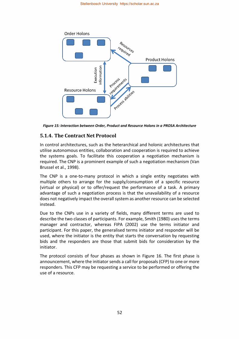
52
Figure 15: Interaction between Order, Product and Resource Holons in a PROSA Architecture
5.1.4. The Contract Net Protocol
In control architectures, such as the heterarchical and holonic architectures that utilise autonomous entities, collaboration and cooperation is required to achieve the systems goals. To facilitate this cooperation a negotiation mechanism is required. The CNP is a prominent example of such a negotiation mechanism (Van Brussel et al., 1998).
The CNP is a one-to-many protocol in which a single entity negotiates with multiple others to arrange for the supply/consumption of a specific resource (virtual or physical) or to offer/request the performance of a task. A primary advantage of such a negotiation process is that the unavailability of a resource does not negatively impact the overall system as another resource can be selected instead.
Due to the CNPs use in a variety of fields, many different terms are used to describe the two classes of participants. For example, Smith (1980) uses the terms manager and contractor, whereas FIPA (2002) use the terms initiator and participant. For this paper, the generalised terms initiator and responder will be used, where the initiator is the entity that starts the conversation by requesting bids and the responders are those that submit bids for consideration by the initiator.
The protocol consists of four phases as shown in Figure 16. The first phase is announcement, where the initiator sends a call for proposals (CFP) to one or more responders. This CFP may be requesting a service to be performed or offering the use of a resource.
Stellenbosch University https://scholar.sun.ac.za
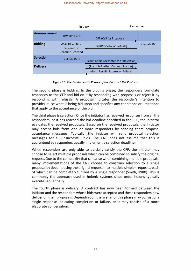
53
Figure 16: The Fundamental Phases of the Contract Net Protocol
The second phase is bidding. In the bidding phase, the responders formulate responses to the CFP and bid on it by responding with proposals or reject it by responding with refusals. A proposal indicates the responder’s intention to provide/utilise what is being bid upon and specifies any conditions or limitations that apply to the acceptance of the bid.
The third phase is selection. Once the initiator has received responses from all the responders, or it has reached the bid deadline specified in the CFP, the initiator evaluates the received proposals. Based on the received proposals, the initiator may accept bids from one or more responders by sending them proposal acceptance messages. Typically, the initiator will send proposal rejection messages for all unsuccessful bids. The CNP does not assume that this is guaranteed so responders usually implement a selection deadline.
When responders are only able to partially satisfy the CFP, the initiator may choose to select multiple proposals which can be combined so satisfy the original request. Due to the complexity that can arise when combining multiple proposals, many implementations of the CNP choose to constrain selection to a single proposal by decomposing the original request into multiple simpler requests, each of which can be completely fulfilled by a single responder (Smith, 1980). This is commonly the approach used in holonic systems since order holons typically execute sequentially.
The fourth phase is delivery. A contract has now been formed between the initiator and the responders whose bids were accepted and these responders now deliver on their proposals. Depending on the scenario, this phase may consist of a single response indicating completion or failure, or it may consist of a more elaborate conversation.
Stellenbosch University https://scholar.sun.ac.za
54
5.1.5. Standby Controller Redundancy
5.1.5.1. Comparison with Other Forms of Redundancy
Control redundancy is used to ensure the continued operation of a control system in the event of a certain subset of potential faults. This continued operation is often required to meet safety or availability requirements. Several different terms are used when categorising the different forms of redundancy, but this paper adopts the terminology used by National Instruments (2008) who divide control redundancy into the following categories: N-modular redundancy, 1:N redundancy and standby redundancy.
N-modular redundancy consists of multiple independent controllers which execute the same control logic based on the same inputs. The controller outputs are sent to an arbitration module which decides the correct system output, typically using a majority vote. N-modular redundancy is typically used in safety critical systems.
For a 1:N redundancy setup there is a single backup unit for several controllers each performing different control tasks. This redundancy approach has limited benefits since it can only handle a single controller failure. The approach requires input and output multiplexing to allow the backup controller to takeover control from any of the other controllers. This approach allows a level of redundancy to be achieved at a low cost. However, if distributed I/O is not used, the complexity of multiplexing direct I/O can lead to additional expenses.
Standby Redundancy appears to be the most common form of redundancy in the manufacturing industry. In standby redundancy there are two controllers, a primary and a backup, and when the primary fails the backup takes over. There are three levels of standby redundancy, i.e. cold, warm and hot. These levels are ranked according to their switchover time and the resulting system bump. System bump refers to abrupt movements and reduction in product quality that result from the difference between the system's actual state before changeover and the initial state of the backup controller. Cold standby is the lowest of the three levels and is characterised by relatively long changeover times and substantial system bump. Typically, the backup controller is powered down until it is started by an operator or a watchdog mechanism. In contrast, hot standby is characterised by changeover times in the order of milliseconds and little or no system bump. Here the backup controller is fully operational and processes the same inputs as the primary, except that its outputs are disabled. The backup controller compares its own state to that of the primary to detect faults in the execution of the primary. Warm standby falls between the other two forms: typically, the backup is powered on and regularly synchronises with the primary's state so that changeover is relatively quick and there is minimal system bump.
Stellenbosch University https://scholar.sun.ac.za
55
5.1.5.2. Standby Redundancy in Holonic Systems
Holonic, and heterarchical, architectures are considered to inherently provide greater potential for availability as resources are dynamically selected. They also facilitate the dynamic addition and removal of resources. This enables a form of resource redundancy, whereby the system can easily have multiple resources capable of performing each task. This paper considers a scenario where resource holons also implement standby redundancy.
Guessoum et al., (2002) present a solution for the dynamic replication of agents according to their criticality and load. This approach is suitable for scenarios where agents are purely software entities and the use of replication corresponds to assignment of additional computational resources. However, in the holonic manufacturing context there is a direct mapping between certain holons, such as resource and order holons, and the instances which they represent. In these scenarios standby redundancy is better suited as it maintains the one-to-one mapping.
This replication approach could be used to provide improved availability and load distribution for holons that are not instance specific such as product holons and certain staff holons. However, care should be taken to ensure consistency between replicas.
5.1.6. Conversation Recovery Background
The ability to re-establish a conversation when one of the parties is restarted after failing is a critical component of message passing for systems that implement standby redundancy. In this section an application context is first presented and then rollback recovery, as an approach to conversation recovery, is discussed.
5.1.6.1. Holonic Cell Context
This paper uses the context of a holarchy in which the resource holons and the order holons may implement standby redundancy. In this holarchy, the negotiation and exchange of production execution knowledge between these holons is based on the CNP. It should be noted that standby redundancy can also be applied to other types of holons by straight-forward adaptation of what is presented here. However, when holon communication is stateless (i.e. the reply from the holon is entirely based on the contents of the original request), such as between order and product holons, it does not require a recovery mechanism as requests can simply be retried.
The holarchy in Figure 17 is considered here: Order holons are created to handle a request from a higher-level controller/customer. These order holons interact with resource holons using a CNP based protocol. A resource holon may be a single controller corresponding to a physical device or a lower-level holarchy responsible for a set of manufacturing hardware. The resource holons interact with their corresponding hardware through some form of I/O. In this holarchy, the manufacturing hardware, and in some scenarios the higher-level controller, are
Stellenbosch University https://scholar.sun.ac.za
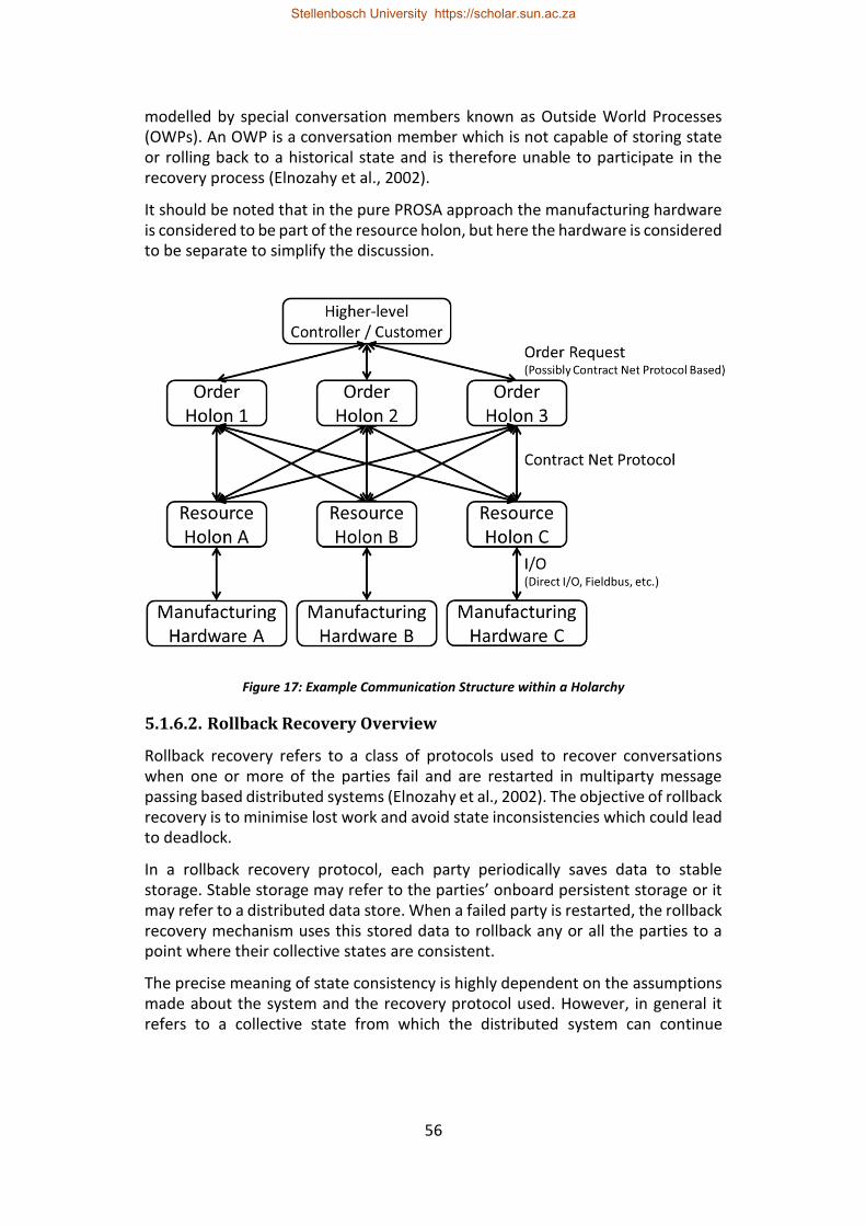
56
modelled by special conversation members known as Outside World Processes (OWPs). An OWP is a conversation member which is not capable of storing state or rolling back to a historical state and is therefore unable to participate in the recovery process (Elnozahy et al., 2002).
It should be noted that in the pure PROSA approach the manufacturing hardware is considered to be part of the resource holon, but here the hardware is considered to be separate to simplify the discussion.
Figure 17: Example Communication Structure within a Holarchy
5.1.6.2. Rollback Recovery Overview
Rollback recovery refers to a class of protocols used to recover conversations when one or more of the parties fail and are restarted in multiparty message passing based distributed systems (Elnozahy et al., 2002). The objective of rollback recovery is to minimise lost work and avoid state inconsistencies which could lead to deadlock.
In a rollback recovery protocol, each party periodically saves data to stable storage. Stable storage may refer to the parties’ onboard persistent storage or it may refer to a distributed data store. When a failed party is restarted, the rollback recovery mechanism uses this stored data to rollback any or all the parties to a point where their collective states are consistent.
The precise meaning of state consistency is highly dependent on the assumptions made about the system and the recovery protocol used. However, in general it refers to a collective state from which the distributed system can continue
Stellenbosch University https://scholar.sun.ac.za
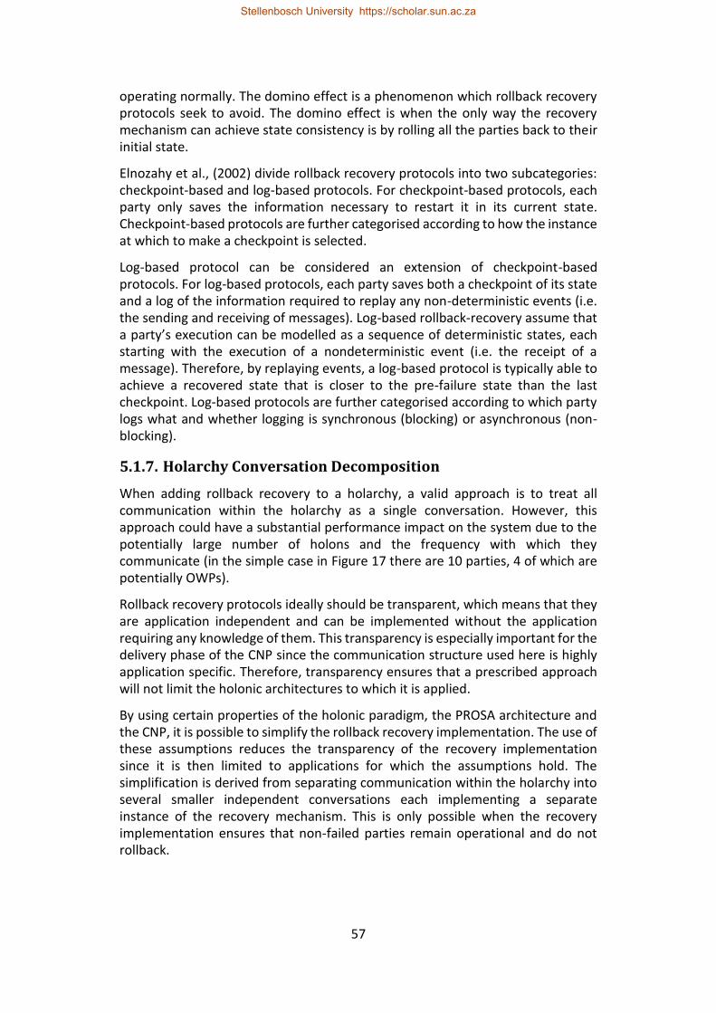
57
operating normally. The domino effect is a phenomenon which rollback recovery protocols seek to avoid. The domino effect is when the only way the recovery mechanism can achieve state consistency is by rolling all the parties back to their initial state.
Elnozahy et al., (2002) divide rollback recovery protocols into two subcategories: checkpoint-based and log-based protocols. For checkpoint-based protocols, each party only saves the information necessary to restart it in its current state. Checkpoint-based protocols are further categorised according to how the instance at which to make a checkpoint is selected.
Log-based protocol can be considered an extension of checkpoint-based protocols. For log-based protocols, each party saves both a checkpoint of its state and a log of the information required to replay any non-deterministic events (i.e. the sending and receiving of messages). Log-based rollback-recovery assume that a party’s execution can be modelled as a sequence of deterministic states, each starting with the execution of a nondeterministic event (i.e. the receipt of a message). Therefore, by replaying events, a log-based protocol is typically able to achieve a recovered state that is closer to the pre-failure state than the last checkpoint. Log-based protocols are further categorised according to which party logs what and whether logging is synchronous (blocking) or asynchronous (non-blocking).
5.1.7. Holarchy Conversation Decomposition
When adding rollback recovery to a holarchy, a valid approach is to treat all communication within the holarchy as a single conversation. However, this approach could have a substantial performance impact on the system due to the potentially large number of holons and the frequency with which they communicate (in the simple case in Figure 17 there are 10 parties, 4 of which are potentially OWPs).
Rollback recovery protocols ideally should be transparent, which means that they are application independent and can be implemented without the application requiring any knowledge of them. This transparency is especially important for the delivery phase of the CNP since the communication structure used here is highly application specific. Therefore, transparency ensures that a prescribed approach will not limit the holonic architectures to which it is applied.
By using certain properties of the holonic paradigm, the PROSA architecture and the CNP, it is possible to simplify the rollback recovery implementation. The use of these assumptions reduces the transparency of the recovery implementation since it is then limited to applications for which the assumptions hold. The simplification is derived from separating communication within the holarchy into several smaller independent conversations each implementing a separate instance of the recovery mechanism. This is only possible when the recovery implementation ensures that non-failed parties remain operational and do not rollback.
Stellenbosch University https://scholar.sun.ac.za

58
The first property that can be used is that in a PROSA architecture, each order holon corresponds to a single task (comprising a sequence of processing steps). Therefore, in the classical situation, there is no need for one order holon to interact with another order holon. In more complex scenarios (e.g. requiring the combination of two or more components into a single assembly), an order holon can spawn two or more subsidiary order holons to produce components for the assembly, followed by an assembly process controlled by the original order holon.
Further, due to the hierarchical/fractal nature of a holarchy, resource holons can be assumed to never interact directly with the higher-level controller. Also, the manufacturing hardware does not interact with any party other than its corresponding resource holon. In certain holonic implementations it is necessary for resource holons to communicate with one another. For example, in a feeder cell, a pick and place robot may need to notify a singulation unit once it has completed part collection. This can be implemented using direct resource-to-resource communication, but that would require that additional conversations implement recovery mechanisms, which adds complexity. To reduce the number of types of conversations, and by extension the complexity, all inter-resource communication is channelled through the relevant order holon. In this way the existing recovery mechanism for resource-order conversations can be used.
Since the CNP is a one-to-many protocol (as opposed to a multiparty protocol) it can be treated as several parallel one-to-one conversations. The implication of this is that a conversation between a particular resource and an order holon will not affect the conversations between that order holon and other resource holons.
Therefore, without loss of generality, the communication within the holarchy can be separated into the following independent conversations (Figure 18):
• Each order holon can have a conversation with the higher-level controller;
• Each order holon can have a conversation with each relevant resource
holon; and
• Each resource holon can have a conversation with its corresponding
manufacturing hardware.
Stellenbosch University https://scholar.sun.ac.za
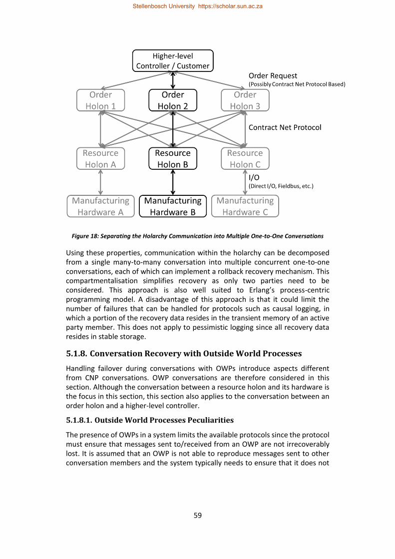
59
Figure 18: Separating the Holarchy Communication into Multiple One-to-One Conversations
Using these properties, communication within the holarchy can be decomposed from a single many-to-many conversation into multiple concurrent one-to-one conversations, each of which can implement a rollback recovery mechanism. This compartmentalisation simplifies recovery as only two parties need to be considered. This approach is also well suited to Erlang’s process-centric programming model. A disadvantage of this approach is that it could limit the number of failures that can be handled for protocols such as causal logging, in which a portion of the recovery data resides in the transient memory of an active party member. This does not apply to pessimistic logging since all recovery data resides in stable storage.
5.1.8. Conversation Recovery with Outside World Processes
Handling failover during conversations with OWPs introduce aspects different from CNP conversations. OWP conversations are therefore considered in this section. Although the conversation between a resource holon and its hardware is the focus in this section, this section also applies to the conversation between an order holon and a higher-level controller.
5.1.8.1. Outside World Processes Peculiarities
The presence of OWPs in a system limits the available protocols since the protocol must ensure that messages sent to/received from an OWP are not irrecoverably lost. It is assumed that an OWP is not able to reproduce messages sent to other conversation members and the system typically needs to ensure that it does not
Stellenbosch University https://scholar.sun.ac.za
60
resend an already sent message to an OWP, since the OWP may not identify it as the same message which could result in undesired side effects. There are some scenarios where OWPs may be able to reproduce messages or handle repeated messages (such as the re-reading of a sensor). In such scenarios message loss/repeat is less significant but still generally undesirable.
In the application scenario shown in Figure 17, it is particularly important that messages between the manufacturing hardware and the resource holons are not lost since the state of the resource holon does not exist purely in software but must corresponds to the physical reality of the manufacturing hardware. Message loss is analogous to system bump as it can lead to a difference between the system's apparent state in the resource holon and the system's physical state. It is therefore desirable that the selected recovery protocol roll back as little as possible, ideally no further than the last checkpoint.
It should be noted that rollback recovery protocols assume that OWPs do not fail. Practically it is possible for an OWP to fail. However, since an OWP is incapable of participating in the recovery process, this assumption holds because OWP failures are not handled by the recovery protocol but are instead handled at an application level.
Regardless of the form of rollback recovery used, messages sent from OWPs to parties that are offline or in the process of being restarted by the standby redundancy mechanism will inevitably be lost if the OWP does not have the ability to replay messages.
5.1.8.2. Checkpointing with Outside World Processes
Checkpointing protocols are usually not suitable for scenarios with OWPs since recovery often requires multiple parties to rollback by one or more checkpoints which could result in a substantial system bump. One exception is coordinated checkpointing which uses a two-phase commit initiated by one of the parties to ensure that there are no in transit messages at the time of checkpointing, so rollback extends no further than the last checkpoint. To prevent messages being lost, a checkpoint is made immediately after any interaction with an OWP. Unfortunately, this checkpointing tends to have a significant performance impact since the two-phase commit blocks execution of all conversation members until the checkpoint is finalised. This is particularly problematic if OWP interaction is frequent.
5.1.8.3. Log Based Protocols with Outside World Processes
Log based protocols are the preferred form of rollback recovery when dealing with OWPs (Elnozahy et al., 2002). By logging messages sent to OWPs and logging messages from OWPs as soon as they arrive, log-based protocols reduce the likelihood of messages being lost or re-sent (due to race conditions, resending is usually still a possibility). There are three forms of log-based rollback recovery optimistic logging, pessimistic logging and causal logging.
Stellenbosch University https://scholar.sun.ac.za
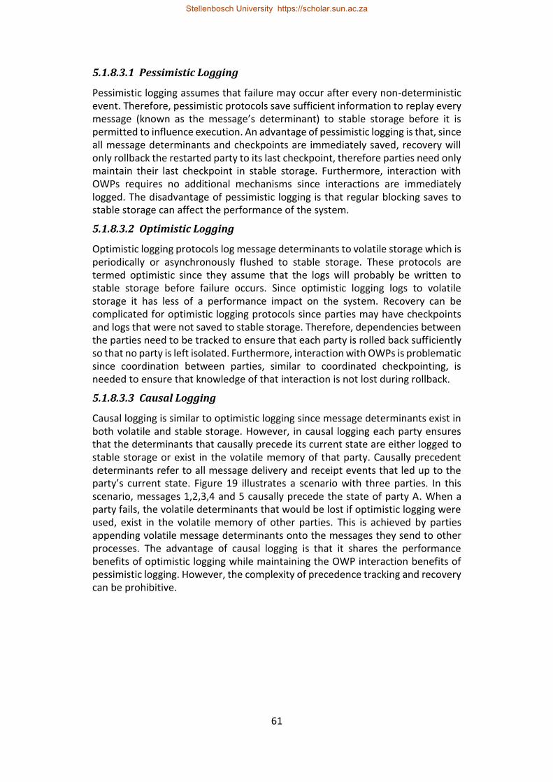
61
5.1.8.3.1 Pessimistic Logging
Pessimistic logging assumes that failure may occur after every non-deterministic event. Therefore, pessimistic protocols save sufficient information to replay every message (known as the message’s determinant) to stable storage before it is permitted to influence execution. An advantage of pessimistic logging is that, since all message determinants and checkpoints are immediately saved, recovery will only rollback the restarted party to its last checkpoint, therefore parties need only maintain their last checkpoint in stable storage. Furthermore, interaction with OWPs requires no additional mechanisms since interactions are immediately logged. The disadvantage of pessimistic logging is that regular blocking saves to stable storage can affect the performance of the system.
5.1.8.3.2 Optimistic Logging
Optimistic logging protocols log message determinants to volatile storage which is periodically or asynchronously flushed to stable storage. These protocols are termed optimistic since they assume that the logs will probably be written to stable storage before failure occurs. Since optimistic logging logs to volatile storage it has less of a performance impact on the system. Recovery can be complicated for optimistic logging protocols since parties may have checkpoints and logs that were not saved to stable storage. Therefore, dependencies between the parties need to be tracked to ensure that each party is rolled back sufficiently so that no party is left isolated. Furthermore, interaction with OWPs is problematic since coordination between parties, similar to coordinated checkpointing, is needed to ensure that knowledge of that interaction is not lost during rollback.
5.1.8.3.3 Causal Logging
Causal logging is similar to optimistic logging since message determinants exist in both volatile and stable storage. However, in causal logging each party ensures that the determinants that causally precede its current state are either logged to stable storage or exist in the volatile memory of that party. Causally precedent determinants refer to all message delivery and receipt events that led up to the party’s current state. Figure 19 illustrates a scenario with three parties. In this scenario, messages 1,2,3,4 and 5 causally precede the state of party A. When a party fails, the volatile determinants that would be lost if optimistic logging were used, exist in the volatile memory of other parties. This is achieved by parties appending volatile message determinants onto the messages they send to other processes. The advantage of causal logging is that it shares the performance benefits of optimistic logging while maintaining the OWP interaction benefits of pessimistic logging. However, the complexity of precedence tracking and recovery can be prohibitive.
Stellenbosch University https://scholar.sun.ac.za
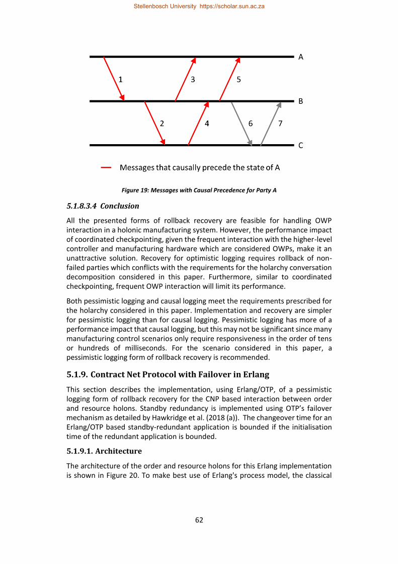
62
Figure 19: Messages with Causal Precedence for Party A
5.1.8.3.4 Conclusion
All the presented forms of rollback recovery are feasible for handling OWP interaction in a holonic manufacturing system. However, the performance impact of coordinated checkpointing, given the frequent interaction with the higher-level controller and manufacturing hardware which are considered OWPs, make it an unattractive solution. Recovery for optimistic logging requires rollback of non-failed parties which conflicts with the requirements for the holarchy conversation decomposition considered in this paper. Furthermore, similar to coordinated checkpointing, frequent OWP interaction will limit its performance.
Both pessimistic logging and causal logging meet the requirements prescribed for the holarchy considered in this paper. Implementation and recovery are simpler for pessimistic logging than for causal logging. Pessimistic logging has more of a performance impact that causal logging, but this may not be significant since many manufacturing control scenarios only require responsiveness in the order of tens or hundreds of milliseconds. For the scenario considered in this paper, a pessimistic logging form of rollback recovery is recommended.
5.1.9. Contract Net Protocol with Failover in Erlang
This section describes the implementation, using Erlang/OTP, of a pessimistic logging form of rollback recovery for the CNP based interaction between order and resource holons. Standby redundancy is implemented using OTP’s failover mechanism as detailed by Hawkridge et al. (2018 (a)). The changeover time for an Erlang/OTP based standby-redundant application is bounded if the initialisation time of the redundant application is bounded.
5.1.9.1. Architecture
The architecture of the order and resource holons for this Erlang implementation is shown in Figure 20. To make best use of Erlang's process model, the classical
Stellenbosch University https://scholar.sun.ac.za
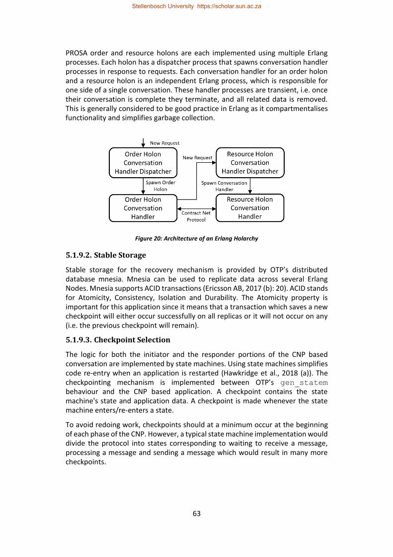
63
PROSA order and resource holons are each implemented using multiple Erlang processes. Each holon has a dispatcher process that spawns conversation handler processes in response to requests. Each conversation handler for an order holon and a resource holon is an independent Erlang process, which is responsible for one side of a single conversation. These handler processes are transient, i.e. once their conversation is complete they terminate, and all related data is removed. This is generally considered to be good practice in Erlang as it compartmentalises functionality and simplifies garbage collection.
Figure 20: Architecture of an Erlang Holarchy
5.1.9.2. Stable Storage
Stable storage for the recovery mechanism is provided by OTP’s distributed database mnesia. Mnesia can be used to replicate data across several Erlang Nodes. Mnesia supports ACID transactions (Ericsson AB, 2017 (b): 20). ACID stands for Atomicity, Consistency, Isolation and Durability. The Atomicity property is important for this application since it means that a transaction which saves a new checkpoint will either occur successfully on all replicas or it will not occur on any (i.e. the previous checkpoint will remain).
5.1.9.3. Checkpoint Selection
The logic for both the initiator and the responder portions of the CNP based conversation are implemented by state machines. Using state machines simplifies code re-entry when an application is restarted (Hawkridge et al., 2018 (a)). The checkpointing mechanism is implemented between OTP’s gen_statem behaviour and the CNP based application. A checkpoint contains the state machine's state and application data. A checkpoint is made whenever the state machine enters/re-enters a state.
To avoid redoing work, checkpoints should at a minimum occur at the beginning of each phase of the CNP. However, a typical state machine implementation would divide the protocol into states corresponding to waiting to receive a message, processing a message and sending a message which would result in many more checkpoints.
Stellenbosch University https://scholar.sun.ac.za
64
It is worth noting that, since the duration of a CNP is short compared to the conversations for which rollback recovery is typically used, a naïve approach would be to use the initial conversation state as the sole checkpoint and reconstruct the pre-failure state through message replay. This approach would use more system resources since all non-selected responders would need to remain alive until the order has been completed so that their bids could be replayed if necessary. Furthermore, potentially non-deterministic aspects of the protocol must be mitigated to ensure that reconstruction does not result in a different state (i.e. storing timestamps of received messages to ensure that a potentially winning bid that originally arrived after the deadline is not selected during recovery).
5.1.9.4. Message Logging
For a pessimistic logging, rollback recovery protocol messages are logged to stable storage before they are allowed to affect execution. This implementation uses sender-based message logging (Elnozahy et al., 2002). This means that messages are logged on the sender side. The receiving party may store the received message at an application level (i.e. the responder may need to be store the CFP for later use), but this is not required by the recovery mechanism.
5.1.9.5. Conversation Identifiers
When a holon is restarted by the standby redundancy mechanism, the process identifiers (pids) of the Erlang processes in the new instance of the holon will be different to the pids in the previous instance. This means that pids are not a reliable method of identifying conversation members when redundancy is present in a system. Erlang’s feature for global name registration could be considered to simplify the handling of this case, since the new holon’s processes could reregister themselves once restarted. However, global name lookup would have to be performed for every message transmission which would impact performance. The case where pids alone are used for process addressing is therefore preferred here since it is the more general case.
In this Erlang implementation, a conversation handler process is spawned to handle new CFPs. This means that for an initiator to keep track of which responders have replied to a CFP, the initiator cannot use the sender pid of a proposal message to identify which responder sent the proposal since the pid of the conversation handler will be different from that of the dispatcher to which the initial CFP was sent.
To handle pid changes during failover and the use of conversation handler processes, a conversation identifier is introduced. Erlang's mechanism for the generation of unique identifiers, known as references, is used in the present implementation. A new reference is generated to serve as a conversation identifier for the conversation between each initiator-responder pair. This conversation identifier can then be used by initiators to keep track of replies. Additionally, the conversation identifier is saved to stable storage by both
Stellenbosch University https://scholar.sun.ac.za
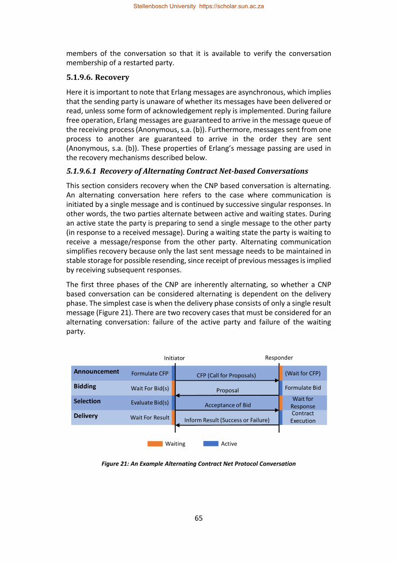
65
members of the conversation so that it is available to verify the conversation membership of a restarted party.
5.1.9.6. Recovery
Here it is important to note that Erlang messages are asynchronous, which implies that the sending party is unaware of whether its messages have been delivered or read, unless some form of acknowledgement reply is implemented. During failure free operation, Erlang messages are guaranteed to arrive in the message queue of the receiving process (Anonymous, s.a. (b)). Furthermore, messages sent from one process to another are guaranteed to arrive in the order they are sent (Anonymous, s.a. (b)). These properties of Erlang’s message passing are used in the recovery mechanisms described below.
5.1.9.6.1 Recovery of Alternating Contract Net-based Conversations
This section considers recovery when the CNP based conversation is alternating. An alternating conversation here refers to the case where communication is initiated by a single message and is continued by successive singular responses. In other words, the two parties alternate between active and waiting states. During an active state the party is preparing to send a single message to the other party (in response to a received message). During a waiting state the party is waiting to receive a message/response from the other party. Alternating communication simplifies recovery because only the last sent message needs to be maintained in stable storage for possible resending, since receipt of previous messages is implied by receiving subsequent responses.
The first three phases of the CNP are inherently alternating, so whether a CNP based conversation can be considered alternating is dependent on the delivery phase. The simplest case is when the delivery phase consists of only a single result message (Figure 21). There are two recovery cases that must be considered for an alternating conversation: failure of the active party and failure of the waiting party.
Figure 21: An Example Alternating Contract Net Protocol Conversation
Stellenbosch University https://scholar.sun.ac.za
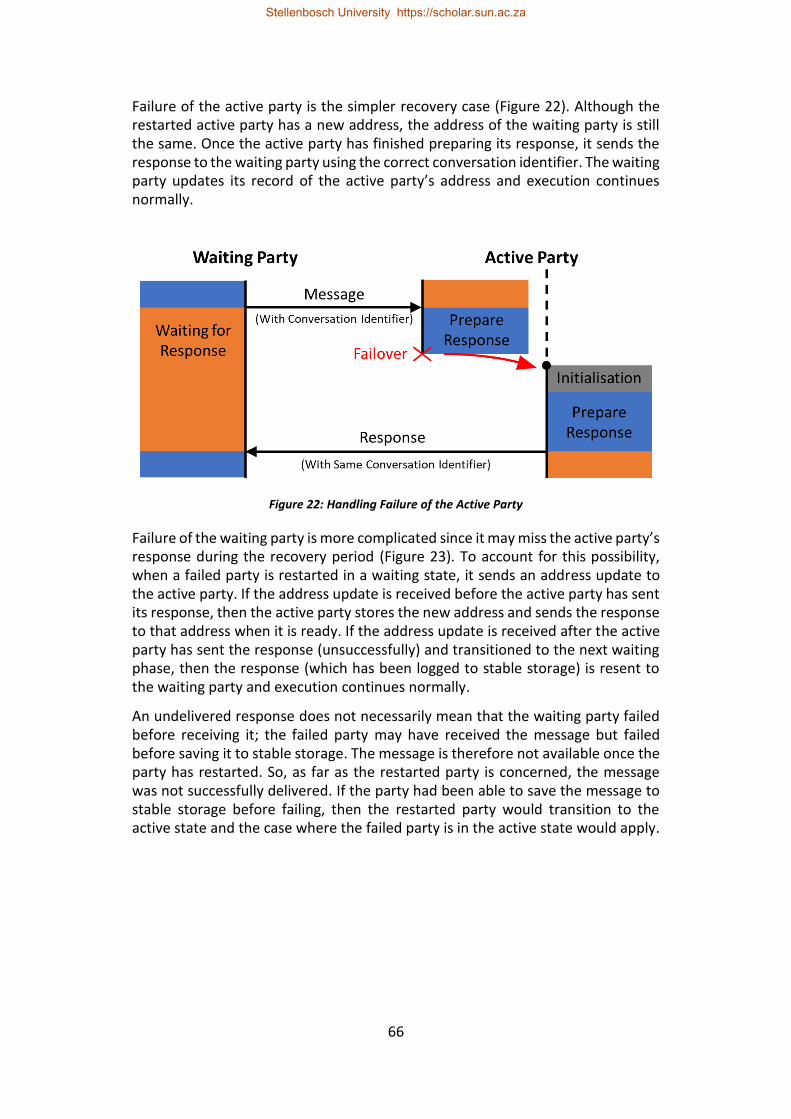
66
Failure of the active party is the simpler recovery case (Figure 22). Although the restarted active party has a new address, the address of the waiting party is still the same. Once the active party has finished preparing its response, it sends the response to the waiting party using the correct conversation identifier. The waiting party updates its record of the active party’s address and execution continues normally.
Figure 22: Handling Failure of the Active Party
Failure of the waiting party is more complicated since it may miss the active party’s response during the recovery period (Figure 23). To account for this possibility, when a failed party is restarted in a waiting state, it sends an address update to the active party. If the address update is received before the active party has sent its response, then the active party stores the new address and sends the response to that address when it is ready. If the address update is received after the active party has sent the response (unsuccessfully) and transitioned to the next waiting phase, then the response (which has been logged to stable storage) is resent to the waiting party and execution continues normally.
An undelivered response does not necessarily mean that the waiting party failed before receiving it; the failed party may have received the message but failed before saving it to stable storage. The message is therefore not available once the party has restarted. So, as far as the restarted party is concerned, the message was not successfully delivered. If the party had been able to save the message to stable storage before failing, then the restarted party would transition to the active state and the case where the failed party is in the active state would apply.
Stellenbosch University https://scholar.sun.ac.za
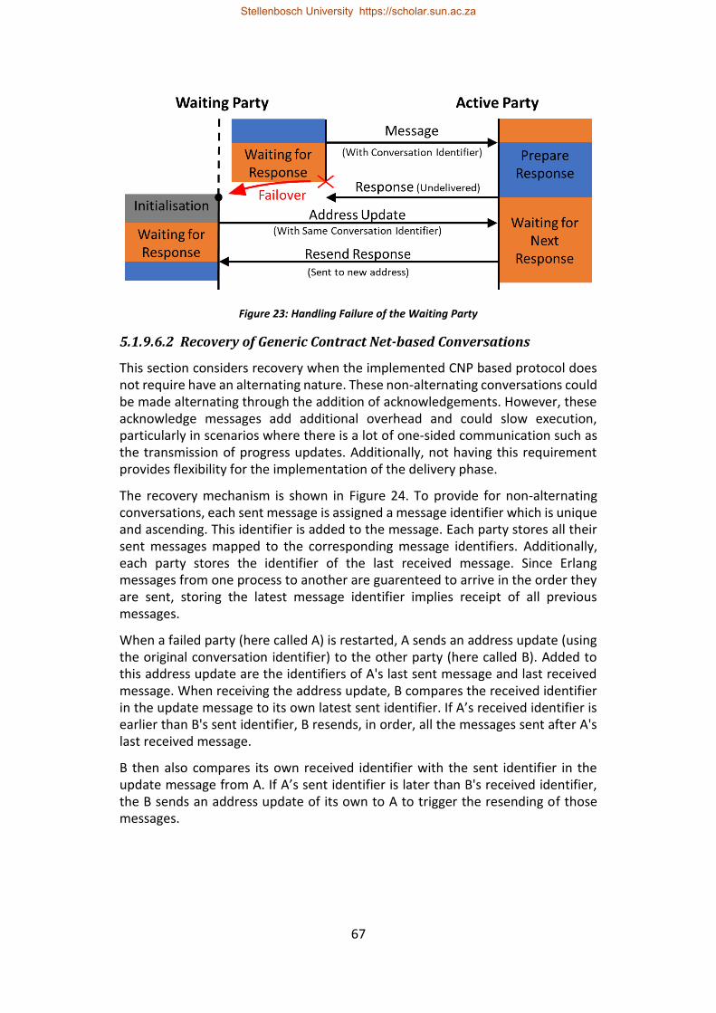
67
Figure 23: Handling Failure of the Waiting Party
5.1.9.6.2 Recovery of Generic Contract Net-based Conversations
This section considers recovery when the implemented CNP based protocol does not require have an alternating nature. These non-alternating conversations could be made alternating through the addition of acknowledgements. However, these acknowledge messages add additional overhead and could slow execution, particularly in scenarios where there is a lot of one-sided communication such as the transmission of progress updates. Additionally, not having this requirement provides flexibility for the implementation of the delivery phase.
The recovery mechanism is shown in Figure 24. To provide for non-alternating conversations, each sent message is assigned a message identifier which is unique and ascending. This identifier is added to the message. Each party stores all their sent messages mapped to the corresponding message identifiers. Additionally, each party stores the identifier of the last received message. Since Erlang messages from one process to another are guarenteed to arrive in the order they are sent, storing the latest message identifier implies receipt of all previous messages.
When a failed party (here called A) is restarted, A sends an address update (using the original conversation identifier) to the other party (here called B). Added to this address update are the identifiers of A's last sent message and last received message. When receiving the address update, B compares the received identifier in the update message to its own latest sent identifier. If A’s received identifier is earlier than B's sent identifier, B resends, in order, all the messages sent after A's last received message.
B then also compares its own received identifier with the sent identifier in the update message from A. If A’s sent identifier is later than B's received identifier, the B sends an address update of its own to A to trigger the resending of those messages.
Stellenbosch University https://scholar.sun.ac.za
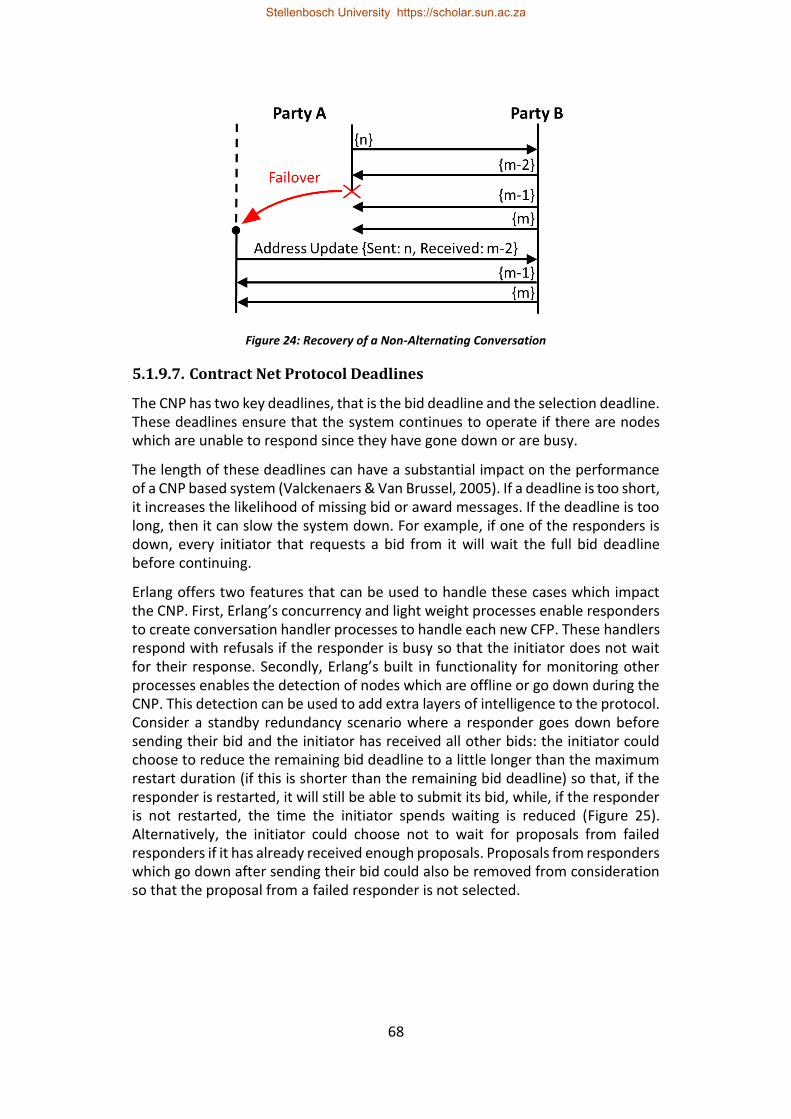
68
Figure 24: Recovery of a Non-Alternating Conversation
5.1.9.7. Contract Net Protocol Deadlines
The CNP has two key deadlines, that is the bid deadline and the selection deadline. These deadlines ensure that the system continues to operate if there are nodes which are unable to respond since they have gone down or are busy.
The length of these deadlines can have a substantial impact on the performance of a CNP based system (Valckenaers & Van Brussel, 2005). If a deadline is too short, it increases the likelihood of missing bid or award messages. If the deadline is too long, then it can slow the system down. For example, if one of the responders is down, every initiator that requests a bid from it will wait the full bid deadline before continuing.
Erlang offers two features that can be used to handle these cases which impact the CNP. First, Erlang’s concurrency and light weight processes enable responders to create conversation handler processes to handle each new CFP. These handlers respond with refusals if the responder is busy so that the initiator does not wait for their response. Secondly, Erlang’s built in functionality for monitoring other processes enables the detection of nodes which are offline or go down during the CNP. This detection can be used to add extra layers of intelligence to the protocol. Consider a standby redundancy scenario where a responder goes down before sending their bid and the initiator has received all other bids: the initiator could choose to reduce the remaining bid deadline to a little longer than the maximum restart duration (if this is shorter than the remaining bid deadline) so that, if the responder is restarted, it will still be able to submit its bid, while, if the responder is not restarted, the time the initiator spends waiting is reduced (Figure 25). Alternatively, the initiator could choose not to wait for proposals from failed responders if it has already received enough proposals. Proposals from responders which go down after sending their bid could also be removed from consideration so that the proposal from a failed responder is not selected.
Stellenbosch University https://scholar.sun.ac.za
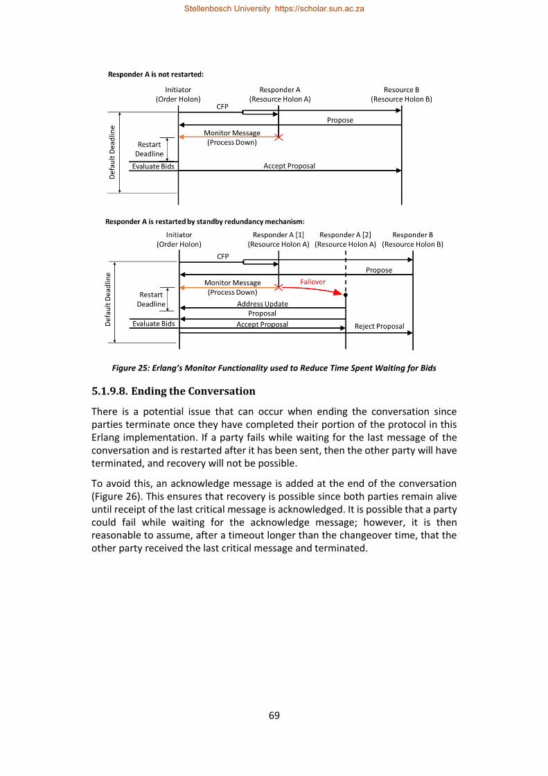
69
Figure 25: Erlang’s Monitor Functionality used to Reduce Time Spent Waiting for Bids
5.1.9.8. Ending the Conversation
There is a potential issue that can occur when ending the conversation since parties terminate once they have completed their portion of the protocol in this Erlang implementation. If a party fails while waiting for the last message of the conversation and is restarted after it has been sent, then the other party will have terminated, and recovery will not be possible.
To avoid this, an acknowledge message is added at the end of the conversation (Figure 26). This ensures that recovery is possible since both parties remain alive until receipt of the last critical message is acknowledged. It is possible that a party could fail while waiting for the acknowledge message; however, it is then reasonable to assume, after a timeout longer than the changeover time, that the other party received the last critical message and terminated.
Stellenbosch University https://scholar.sun.ac.za
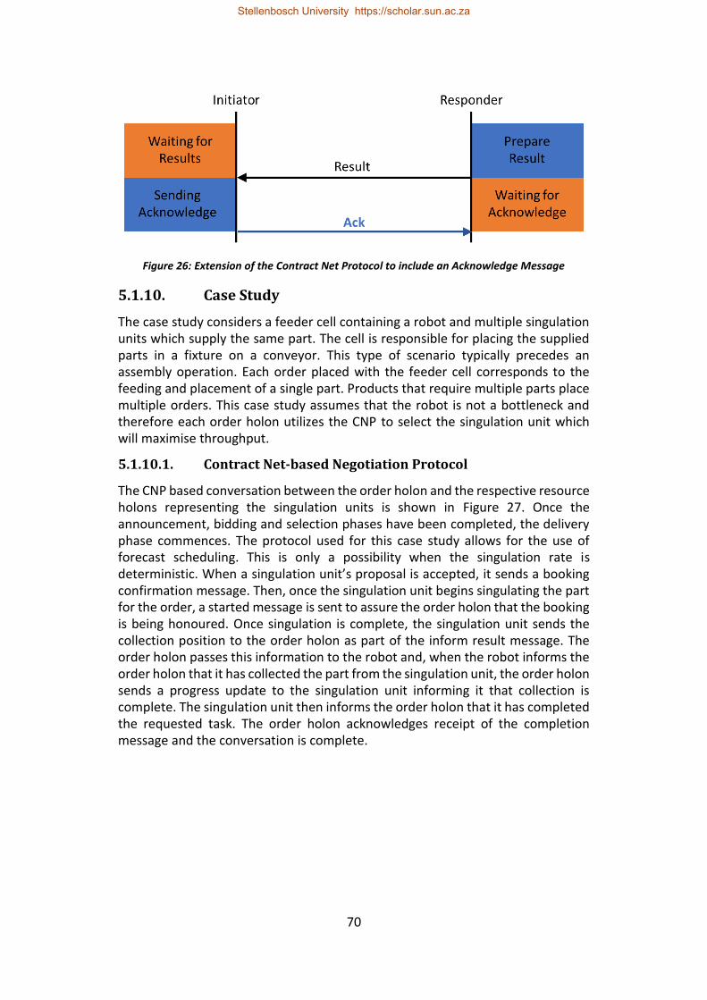
70
Figure 26: Extension of the Contract Net Protocol to include an Acknowledge Message
5.1.10. Case Study
The case study considers a feeder cell containing a robot and multiple singulation units which supply the same part. The cell is responsible for placing the supplied parts in a fixture on a conveyor. This type of scenario typically precedes an assembly operation. Each order placed with the feeder cell corresponds to the feeding and placement of a single part. Products that require multiple parts place multiple orders. This case study assumes that the robot is not a bottleneck and therefore each order holon utilizes the CNP to select the singulation unit which will maximise throughput.
5.1.10.1. Contract Net-based Negotiation Protocol
The CNP based conversation between the order holon and the respective resource holons representing the singulation units is shown in Figure 27. Once the announcement, bidding and selection phases have been completed, the delivery phase commences. The protocol used for this case study allows for the use of forecast scheduling. This is only a possibility when the singulation rate is deterministic. When a singulation unit’s proposal is accepted, it sends a booking confirmation message. Then, once the singulation unit begins singulating the part for the order, a started message is sent to assure the order holon that the booking is being honoured. Once singulation is complete, the singulation unit sends the collection position to the order holon as part of the inform result message. The order holon passes this information to the robot and, when the robot informs the order holon that it has collected the part from the singulation unit, the order holon sends a progress update to the singulation unit informing it that collection is complete. The singulation unit then informs the order holon that it has completed the requested task. The order holon acknowledges receipt of the completion message and the conversation is complete.
Stellenbosch University https://scholar.sun.ac.za
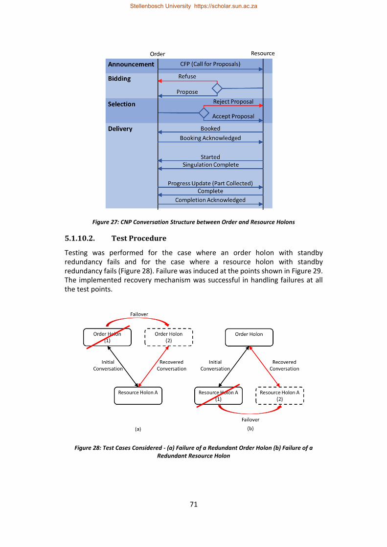
71
Figure 27: CNP Conversation Structure between Order and Resource Holons
5.1.10.2. Test Procedure
Testing was performed for the case where an order holon with standby redundancy fails and for the case where a resource holon with standby redundancy fails (Figure 28). Failure was induced at the points shown in Figure 29. The implemented recovery mechanism was successful in handling failures at all the test points.
Figure 28: Test Cases Considered - (a) Failure of a Redundant Order Holon (b) Failure of a Redundant Resource Holon
Stellenbosch University https://scholar.sun.ac.za
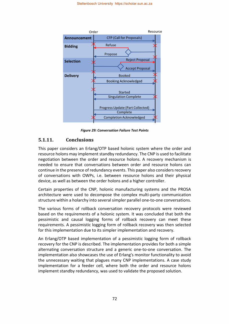
72
Figure 29: Conversation Failure Test Points
5.1.11. Conclusions
This paper considers an Erlang/OTP based holonic system where the order and resource holons may implement standby redundancy. The CNP is used to facilitate negotiation between the order and resource holons. A recovery mechanism is needed to ensure that conversations between order and resource holons can continue in the presence of redundancy events. This paper also considers recovery of conversations with OWPs, i.e. between resource holons and their physical device, as well as between the order holons and a higher controller.
Certain properties of the CNP, holonic manufacturing systems and the PROSA architecture were used to decompose the complex multi-party communication structure within a holarchy into several simpler parallel one-to-one conversations.
The various forms of rollback conversation recovery protocols were reviewed based on the requirements of a holonic system. It was concluded that both the pessimistic and causal logging forms of rollback recovery can meet these requirements. A pessimistic logging form of rollback recovery was then selected for this implementation due to its simpler implementation and recovery.
An Erlang/OTP based implementation of a pessimistic logging form of rollback recovery for the CNP is described. The implementation provides for both a simple alternating conversation structure and a generic one-to-one conversation. The implementation also showcases the use of Erlang's monitor functionality to avoid the unnecessary waiting that plagues many CNP implementations. A case study implementation for a feeder cell, where both the order and resource holons implement standby redundancy, was used to validate the proposed solution.
Stellenbosch University https://scholar.sun.ac.za
73
5.1.12. References
Anonymous, s.a. (a). What is Erlang [Online]. Available: http://erlang.org/faq/introduction.html [2017, August 29].
Anonymous, s.a. (b). Academic and Historical Questions [Online]. Available: http://erlang.org/faq/academic.html [2017, August 29].
Armstrong, J., 1996. Erlang—a Survey of the Language and its Industrial Applications, in INAP 96.
Armstrong, J., 2010. erlang. Communications of the ACM, 53(9): 68-75.
Bi, Z., Da Xu, L. and Wang, C., 2014. Internet of things for enterprise systems of modern manufacturing. IEEE Transactions on industrial informatics, 10(2):1537-1546.
Brettel, M., Friederichsen, N., Keller, M. and Rosenberg, M., 2014. How virtualization, decentralization and network building change the manufacturing landscape: An industry 4.0 perspective. International Journal of Mechanical, Industrial Science and Engineering, 8(1): 37-44.
Elnozahy, E.N., Alvisi, L., Wang, Y.M. and Johnson, D.B., 2002. A survey of rollback-recovery protocols in message-passing systems. ACM Computing Surveys (CSUR), 34(3): 375-408.
Ericsson AB, 2017 (a). Erlang Kernel 5.4 [Online]. Available: http://erlang.org/doc/apps/kernel/kernel.pdf [2017, October 6].
Ericsson AB, 2017 (b). Erlang Mnesia 4.15.1 [Online]. Available: http://erlang.org/doc/apps/mnesia/mnesia.pdf [2017, October 9].
FIPA (Foundation for Intelligent Physical Agents), 2002. Contract Net Interaction Protocol Specification. [Online]. Available: http://www.fipa.org/specs/fipa00029/SC00029H.pdf [2018, February 4].
Gerbert, P., Lorenz, M., Rüßmann, M., Waldner, M., Justus, J., Engel, P. and Harnisch, M., 2015. White Paper on Industry 4.0: The future of productivity and growth in manufacturing industries [Online]. Available: https://www.bcg.com/en-za/publications/2015/engineered_products_project_business_industry_4_future_productivity_growth_manufacturing_industries.aspx [2018, November 10].
Guessoum, Z., Briot, J.P., Marin, O., Hamel, A. and Sens, P., 2002. Dynamic and adaptive replication for large-scale reliable multi-agent systems, in International Workshop on Software Engineering for Large-Scale Multi-agent Systems. Berlin, Heidelberg: 182-198.
Hawkridge, G., Basson, A.H. and Kruger, K., 2018 (a). An Evaluation of Erlang for Implementing Standby Redundancy in a Manufacturing Station Controller, 8th Workshop on Service Orientation in Holonic and Multi-Agent Manufacturing.
Stellenbosch University https://scholar.sun.ac.za
74
Koestler, A., 1989. The ghost in the machine. Arkana, London.
Kruger, K. and Basson, A., 2017. Erlang-based control implementation for a holonic manufacturing cell. International Journal of Computer Integrated Manufacturing, 30(6): 641-652.
Larson, J., 2009. Erlang for concurrent programming. Communications of the ACM, 52(3): 48-56.
Lundin, K., 2008. Inside the Erlang VM with focus on SMP, in Erlang User Conference, Stockholm.
Monostori, L., Kádár, B., Bauernhansl, T., Kondoh, S., Kumara, S., Reinhart, G., Sauer, O., Schuh, G., Sihn, W. and Ueda, K., 2016. Cyber-physical systems in manufacturing. CIRP Annals, 65(2): 621-641.
National Instruments, 2008. White Paper on Redundant System Basic Concepts [Online]. Available: http://www.ni.com/white-paper/6874/en/ [2017, September 4]
Smith, R.G., 1980. The contract net protocol: High-level communication and control in a distributed problem solver. IEEE Transactions on computers, 12:1104-1113.
Valckenaers, P. and Van Brussel, H., 2005. Holonic manufacturing execution systems. CIRP Annals-Manufacturing Technology, 54(1): 427-432.
Valckenaers, P. and Van Brussel, H., 2015. Design for the unexpected: From holonic manufacturing systems towards a humane mechatronics society. Butterworth-Heinemann.
Van Brussel, H., 1994. Holonic manufacturing systems the vision matching the problem, in Proceedings of the 1st European Conference on Holonic Manufacturing Systems, Hannover, Germany.
Van Brussel, H., Wyns, J., Valckenaers, P., Bongaerts, L. and Peeters, P., 1998. Reference architecture for holonic manufacturing systems: PROSA. Computers in industry, 37(3): 255-274.
Stellenbosch University https://scholar.sun.ac.za
75
5.2. An Erlang-Based Standby-Redundant Distributed Holonic Controller for a Manufacturing Cell
G Hawkridge, AH Basson, K Kruger Department of Mechanical and Mechatronic Engineering, Stellenbosch University
Abstract
This paper evaluates the ability to increase availability through an Erlang implementation of redundancy within a distributed holonic cell controller. Distributed control is prominent in modern manufacturing systems and holonic architectures are a popular approach for the implementation of distributed control. Holonic control typically contains holons that represent single points of failure and are therefore susceptible to controller failures. This paper proposes a redundant distributed holonic architecture for a manufacturing cell controller. The redundancy implementation is separated into a holon redundancy level and a controller platform level. The holon redundancy level ensures the availability of the software entities used to implement holons. The forms of redundancy that are best suited to different types of holons are discussed. The controller platform considers the control hardware to maintain the availability of computational capacity used to execute holons. Three controller platform architectures are discussed: the split resource approach, the self-contained approach and the mesh approach.
Erlang is a functional programming language designed for the development of fault-tolerant soft real-time control systems. The Erlang solution employs various features in Erlang (and its associated library, OTP) that greatly simplify both distribution and achieving standby redundancy. The controller architecture presented here can utilise all the controllers in a cell, in a mesh approach, distributing the computational work dynamically amongst controllers that have the capacity and capability to contribute. A case study implementation is used to evaluate the proposed controller architecture. This paper shows that Erlang and OTP provide an attractive platform for implementing redundancy in a distributed holonic cell controller. The combination of the proposed standby-redundant, distributed holonic architecture and the Erlang/OTP standby redundancy implementation approach can improve the availability of a manufacturing cell by enabling it to withstand a selection of controller failure modes.
Keywords: Erlang; Standby Redundancy; Holonic Architectures; Distributed Control
5.2.1. Introduction
In the past decades the manufacturing sector has been characterised by intense competition resulting from globalisation and shifting customer requirements. To handle this competition, the manufacturing sector has been pursuing manufacturing systems and paradigms which provide shorter lead times,
Stellenbosch University https://scholar.sun.ac.za
76
increased product customisation, flexible production capacity, real-time feedback, lower costs and improved resource efficiency (Bi et al., 2008; Lasi et al., 2014).
Various paradigms, such as flexible manufacturing systems (FMSs) and reconfigurable manufacturing systems (RMSs), have been investigated with varying levels of success. This investigation continues with the recent focus on Industry 4.0, cyber-physical systems (CPSs) and the Industrial Internet of Things (IIoT) (Brettel et al., 2014; Bi, Xu & Wang 2014; Gerbert et al., 2015). A common element amongst these paradigms is the distributed nature of their control.
The holonic manufacturing paradigm is a control approach that offers flexibility and the ability to manage disturbances in an efficient manner (Van Brussel et al., 1998). Holonic control is also well suited to distributed control. Holonic systems are built from holons that are independent autonomous units of control which collaborate to achieve the desired functionality. Holonic control offers increased availability by reducing (but not eliminating) the effect of certain single points of failure through functional redundancy. Availability here refers to the percentage of time for which a system is ready and able to perform its expected function. Single points of failure are system elements where failure of the element results in system failure. Functional redundancy here refers to the use of multiple holons that can perform a certain task. Even though holonic systems will, in general, continue operating in the presence of holon failure (for holons that have functional redundancy), this holon failure will reduce the functionality or capacity of the system, leading to bottlenecks and possible system failure. Additionally, functional redundancy is not always possible for all types of holon. Standby redundancy is an approach that can be used to improve the availability of individual holons. Standby redundancy has traditionally been used to improve the availability of hierarchical or monolithic control systems.
Erlang is a functional programming language designed for the development of fault-tolerant soft real-time control systems (Armstrong, 1996). The Open Telecom Platform (OTP) is a key feature of Erlang, is a set of libraries that simplifies the development of large complex systems (Armstrong 2010: pg. 73). Erlang has many attractive features, such as concurrency and scalability, that are useful when implementing holonic manufacturing control systems (Kruger & Basson, 2017). An interesting feature that Erlang and OTP provide is the built-in mechanism for application failover. This mechanism will restart an application on another node if the node upon which it is currently running fails (the meanings of "application" and "node" are described later in the paper). This mechanism has been used to implement standby controller redundancy in a centralised station controller (Hawkridge et al., 2018 (a)).
This paper proposes an architecture for implementing redundancy in a distributed holonic cell controller and investigates the use of Erlang’s and OTP’s built-in features to facilitate the implementation of redundancy in this architecture. Although this paper focuses on redundancy in a holonic control architecture, it is
Stellenbosch University https://scholar.sun.ac.za
77
expected that elements of this work could also be applicable to both hierarchical and heterarchical architectures.
This paper next provides a background on holonic control architectures, followed by a description of the redundant distributed holonic architecture considered in this paper. Following this, some background information on Erlang and OTP is provided, followed by a description of the Erlang/OTP based implementation of the proposed holonic architecture. A case study of the redundant holonic architecture in an assembly cell is then used to evaluate the Erlang/OTP implementation.
5.2.2. Holonic Control Review
5.2.2.1. Background
The holonic control paradigm is based on the concept of a holon which was devised by philosopher Arthur Koestler (1989) to describe how biological and social systems are organised. The word holon refers to an entity which is simultaneously a complete whole and part of a larger whole (Van Brussel, 1994). In the manufacturing context, holons are independent units of control which communicate and cooperate with one another to achieve the systems goals. A grouping of related holons is called a holarchy. Holonic systems are developed using a fractal approach, which implies any holon in a holarchy is either a singular entity or a lower-order holarchy. An example of this is where a cell controller views a station controller as a holon, while the station controller itself may be a set of holons that control that station.
5.2.2.2. Control Architectures
Holonic control seeks to combine the advantages of both hierarchical and heterarchical architectures (Van Brussel et al., 1998). Hierarchical control arranges the system into levels with strict master slave relationships. These strict relationships can diminish availability since a controller fault results in the portion of the hierarchy that is subordinate to that controller becoming frozen (Dilts, Boyd & Whorms, 1991). This is particularly detrimental if the faulty controller is high up in the hierarchy. Heterarchical control seeks to entirely avoid master-slave relationships by using controllers that are autonomous cooperative peers. The advantage of this is that it leads to an inherent level of fault tolerance since the interdependency between controllers is reduced. Similarly, holonic control exhibits an inherent fault tolerance since holons are independent and cooperative.
An advantage of the master-slave relationships in hierarchical architectures is that they facilitate achieving a global system view which simplifies global optimisation. In heterarchical architectures, each control element maintains its own local system view. The benefit of this is that control elements are not dependant on some central state repository. However, the lack of global system view in heterarchical systems limits the implementation of global optimization and coordination (Leitão, 2009). For holonic systems, a global system view is achieved
Stellenbosch University https://scholar.sun.ac.za
78
through the fractal hierarchy of holarchies. Each holon is the single source of truth about its own state and maintains a local system view to facilitate fault tolerance and autonomy. Global optimisation is assisted using advisory holons which suggest optimal solutions that other holons may choose to accept.
Hierarchical control elements are problematic from a system availability standpoint as they are often single points of failure (Colombo, Schoop & Neubert, 2006). Although holonic control seeks to limit hierarchical relationships to advisory relationships, these single points of failure are sometimes still present.
5.2.2.3. The PROSA Reference Architecture
Reference architectures facilitate the implementation of holonic manufacturing systems by providing a framework for the classification of holons. The PROSA architecture is a popular and prevalent reference architecture. The PROSA reference architecture specifies four categories of holon, i.e. product holons, order holons, resource holons and staff holons (Van Brussel et al., 1998).
A product holon contains the process and production knowledge required produce a specific product. Product holons represent the model of the product type and not specific instances of the product. Order holons represent system activities and are responsible for ensuring that these activities get completed on time. Order holons often represent the production of a product instance. Each product instance negotiates with other holons to get themselves produced. Resource holons represent the manufacturing resources present in the system. These three classes of holons are sometimes referred to as the standard holons.
The order holons exchange production knowledge with the product holons (i.e. what is the procedure for producing this product), the order holons exchange production execution knowledge with the resource holons (i.e. negotiation of scheduling) and the resource holons exchange process knowledge with the product holon (i.e. how to perform the required operation on the product instance). (The interaction between the standard holons can be seen in the proposed architecture in Figure 31). Staff holons are optional holons which assist the standard holons by providing “expert” advice.
A key concept when implementing a PROSA based holarchy is self-similarity (Van Brussel et al., 1998). Self-similarity states that all holons of the same type should expose a common interface regardless of whether they are singular or composite holons and regardless of the “hierarchical” level of the holarchy to which they belong.
The recent book by Valkenaers and Van Brussel (2015) provide an excellent reference for holonic manufacturing systems, as well as the PROSA reference architecture and its recent extension the ARTI reference architecture.
Stellenbosch University https://scholar.sun.ac.za
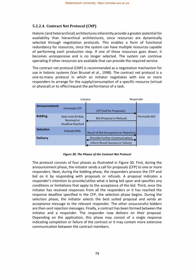
79
5.2.2.4. Contract Net Protocol (CNP)
Holonic (and heterarchical) architectures inherently provide a greater potential for availability than hierarchical architectures, since resources are dynamically selected through negotiation protocols. This enables a form of functional redundancy for resources, since the system can have multiple resources capable of performing each production step. If one of these resources goes down, it becomes unresponsive and is no longer selected. The system can continue operating if other resources are available that can provide the required service.
The contract net protocol (CNP) is recommended as a negotiation mechanism for use in holonic systems (Van Brussel et al., 1998). The contract net protocol is a one-to-many protocol in which an initiator negotiates with one or more responders to arrange for the supply/consumption of a specific resource (virtual or physical) or to offer/request the performance of a task.
Figure 30: The Phases of the Contract Net Protocol
The protocol consists of four phases as illustrated in Figure 30. First, during the announcement phase, the initiator sends a call for proposals (CFP) to one or more responders. Next, during the bidding phase, the responders process the CFP and bid on it by responding with proposals or refusals. A proposal indicates a responder’s intention to provide/utilise what is being bid upon and specifies any conditions or limitations that apply to the acceptance of the bid. Third, once the initiator has received responses from all the responders or it has reached the response deadline specified in the CFP, the selection phase begins. During the selection phase, the initiator selects the best suited proposal and sends an acceptance message to the relevant responder. The other unsuccessful bidders are then sent rejection messages. Finally, a contract has been formed between the initiator and a responder. The responder now delivers on their proposal. Depending on the application, this phase may consist of a single response indicating completion or failure of the contract or it may contain more extensive communication between the contract members.
Stellenbosch University https://scholar.sun.ac.za
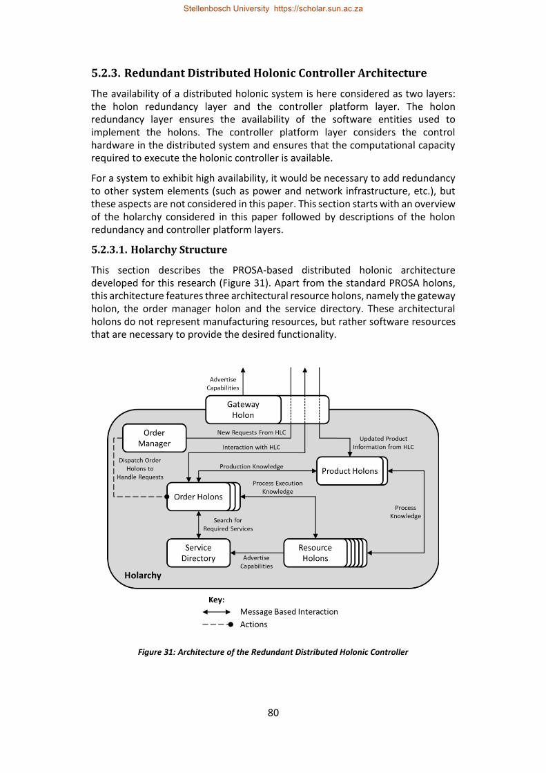
80
5.2.3. Redundant Distributed Holonic Controller Architecture
The availability of a distributed holonic system is here considered as two layers: the holon redundancy layer and the controller platform layer. The holon redundancy layer ensures the availability of the software entities used to implement the holons. The controller platform layer considers the control hardware in the distributed system and ensures that the computational capacity required to execute the holonic controller is available.
For a system to exhibit high availability, it would be necessary to add redundancy to other system elements (such as power and network infrastructure, etc.), but these aspects are not considered in this paper. This section starts with an overview of the holarchy considered in this paper followed by descriptions of the holon redundancy and controller platform layers.
5.2.3.1. Holarchy Structure
This section describes the PROSA-based distributed holonic architecture developed for this research (Figure 31). Apart from the standard PROSA holons, this architecture features three architectural resource holons, namely the gateway holon, the order manager holon and the service directory. These architectural holons do not represent manufacturing resources, but rather software resources that are necessary to provide the desired functionality.
Figure 31: Architecture of the Redundant Distributed Holonic Controller
Stellenbosch University https://scholar.sun.ac.za
81
5.2.3.1.1 Gateway Holon
The gateway holon is the communication interface between the higher-level controller (HLC) and the holarchy. The gateway holon serves as a middleman which forwards messages between the HLC and holons within the holarchy. The gateway holon can act as a reverse proxy and rewrite the source address of outgoing messages to hide the internal structure of the holarchy. If the HLC is also a holonic controller then the single point of contact provided by the gateway holon contributes to the holarchy appearing as a single resource holon to the HLC. As the single point of contact, the gateway holon is responsible for advertising the holarchy’s capabilities with the HLC (should the HLC provide such a mechanism).
If the holarchy and the HLC use different messaging schemes, the gateway holon can be used to translate between these messaging schemes. This may include translating between different encodings (i.e. from XML encoded text to Erlang records), performing encryption/decryption or converting between different transmission media (i.e. from TCP/IP to RS-232).
5.2.3.1.2 Order Manager Holon
The order manager holon dispatches order holons to handle new requests from the HLC (i.e. in response to a CFP, if the CNP is used for HLC interaction). The order manager holon can be used to limit the number of active orders to prevent the holarchy from being flooded by requests. When the number of active orders reaches a specified limit, the order manager holon queues additional requests and dispatches them when current active orders are completed.
5.2.3.1.3 Service Directory
The service directory is an architectural resource holon that assists both resource and order holons. By allowing resource holons to advertise their capabilities, the service directory helps each order holon find resource holons with the capabilities required for the next stage of that order's production procedure. A service directory can contribute to the modularity and reconfigurability of a holarchy since a resource can be added to or removed from active use by registering or deregistering with the service directory without directly affecting the remainder of the holarchy. This service directory functionality is sometimes integrated into the product holons rather than implemented as a separate architectural resource holon.
5.2.3.1.4 Product Holons
Each product holon contains the production procedure, product model and parameters required to produce an instance of that product. Typically, when products have many possible alternative procedures, the complete production procedure is stored in a top-level product holon, while the local product holons maintain a subset of the complete procedure based on the capabilities present within their holarchy. If the holarchy's capabilities change or the top-level product holon is updated, then the local product holons are updated.
Stellenbosch University https://scholar.sun.ac.za
82
5.2.3.1.5 Resource Holons
The resource holons in this holarchy are standard PROSA resource holons. They may be singular holons or they may represent lower order holarchies. Resource holons can represent both hardware and software resources. Examples of resources include interchangeable machine tools, storage slots, specialised software, conveyor intersections, execution time on specialised hardware and robotic arms.
5.2.3.1.6 Order Holons
Each order holon is responsible for managing the production of a single instance of a product. In this paper, interaction between the order and product holons is based on the NEU interaction protocol (Valkenaers & Van Brussel, 2015). NEU is an acronym for the phases of the protocol: Next-Execute-Update. In the NEU protocol, each order holon serves as repository for the state data of their product instance. When an order holon is initialised, it requests the initial state data for its product from the relevant product holon. The order holon then loops through the NEU phases.
First, the order holon sends a next request to the product holon. Contained in this request is the order holon’s state data for its product instance. Based on the order's state, the product responds with a list of candidate next production steps. The order holon then selects and executes one of the candidate production steps. When the production step is complete, the order holon sends the execution result along with the product state to the product holon for updating. The product holon responds with an updated version of the state data. These three phases are repeated until the order is complete. An advantage of this approach is that it enables generic, product-agnostic order holons, since state data and result messages are handled exclusively by the product holons (but stored in the order holons).
5.2.3.2. The Holon Redundancy Layer
In a holonic manufacturing cell controller, holons are autonomous software entities. The holon redundancy layer considers the availability of holons at a software level. While the heterarchical aspects of holonic control limit the interdependence of holons, certain holons require redundancy to ensure that they do not represent single points of failure when experiencing software or controller faults.
For the holarchy considered in this paper, there are multiple critical holons that represent potential single points of failure. The gateway holon is critical since unavailability would suspend all communication between HLC elements and holons in the holarchy. The order manager holon is critical since unavailability would prevent the dispatching of new orders. The unavailability of a product holon would halt order holons attempting to produce an instance of that product. Order holons need redundancy to ensure that the state of the in-progress products they represent is not lost in the event of failure. If the service directory is the sole
Stellenbosch University https://scholar.sun.ac.za
83
method of resource discovery, then it is also a single point of failure since unavailability would result in the order holons being unable to locate viable service providers. In general, redundancy is required for all resource holons that are the sole provider of a particular service. This architecture does not include any staff holons, but if it did then they would not require redundancy since their role should be purely advisory.
5.2.3.2.1 Forms of Redundancy
When considering the forms of redundancy that are applicable to a holon, it is important to identify whether the holon is entirely software based or if it is physically coupled. Physically coupled holons are holons which are required to execute on a specific controller or set of controllers. The resource holon corresponding to a machine tool is an example of an uncoupled resource holon; the resource holon is simply a software representation of the properties and allocation of the machine tool and can therefore execute anywhere. Resource holons are often physically coupled by controller I/O; resource holons may control the manufacturing equipment they represent directly using controller I/O and are therefore restricted to executing on controllers that are connected to their manufacturing equipment. This is the case for the singulation station controller presented in Hawkridge et al. (2018 (a)).
Holons may also be physically coupled by communication infrastructure. In such a case, holons would be restricted to executing on controllers that are able to meet their communication requirements. For resource holons this may occur when the manufacturing equipment they represent has a dedicated low-level control unit. The resource holon corresponding to a robotic arm is an example of such a resource holon. If the resource holon can communicate with the robot control unit from any of the controllers in the system (i.e. over TCP/IP), then the resource holon is uncoupled. However, if the resource holon can only communicate with the robot control unit from specific controllers (i.e. only certain controllers have RS-232 connections to the control unit), then the resource holon is coupled to those controllers.
For physically coupled holon, the redundancy implementation is highly dependent on the number of controllers to which the holon is coupled. In general, the approaches discussed below for uncoupled holons are expected to be applicable to coupled holons, particularly those that are coupled by communication infrastructure, however the application specific nature of a holon’s coupling may give rise to additional complications or limit the holon to a particular form of redundancy.
For uncoupled holons (i.e. holons that are entirely software based), additional instances can be created as required, provided that the necessary computational capacity is available. This paper will consider two forms of redundancy for uncoupled holons, i.e. replication and standby redundancy.
Stellenbosch University https://scholar.sun.ac.za
84
Replication of uncoupled holons, here refers to the creation of multiple replicas of a holon within the holarchy. All replicas of the holon are active so should one of the replicas fail, the other replicas are still available. Replication facilitates load balancing since other holons may interact with any of replicas. However, consensus algorithms may be required to maintain consistency between all replicas. This approach is common in multi-agent systems, for example Guessoum et al. (2002) present an approach for dynamic replication in a multi-agent system according to agent criticality and load.
Standby redundancy of software holons refers to the scenario where there is a single primary instance. The primary instance is the only instance that performs any interaction with other holons. Upon failure of the primary instance, a backup instance takes over as the new primary. This backup instance may have existed in an idle state prior to taking over from the primary or it may be created when failure of the primary is detected.
Standby redundancy is more suitable for holons, such as resource and order holons, that exhibit a one-to-one mapping between the holons software instance and the role/functionality/entity it represents. Standby redundancy maintains this one-to-one mapping. In contrast, replication is well suited for holons that are not instance specific, such as product holons and certain staff holons. For example, standby redundancy preserves the gateway holon as a single point of contact for the holarchy, whereas replication would lead to multiple gateways which breaks this single point of contact property and the singular appearance of sub-holarchies.
For the holonic architecture considered here, standby redundancy is implemented by the gateway holon, the order manager holon, the order holons, the service directory and resource holons that are not functionally redundant and are not limited by physical coupling. Replication will be implemented by the product holons.
5.2.3.2.2 Managing Conversations
A fundamental characteristic of holonic manufacturing systems is the interaction between holons. The correct functioning of this inter-holon communication is critical to the stability of any holarchy. Systems which contain holon redundancy need to implement some form of conversation recovery to handle communication interruptions caused by redundancy events. These interruptions can include message loss during changeover and changes to the execution location (i.e. message destination address) of affected holons.
The complexity of recovery is dependent on whether the interaction protocol is stateful or stateless. Stateless protocols typically exhibit a request-response pattern where responses are dependent solely on the content of the request. The NEU protocol, used for interaction between the order and product holons, is an example of a stateless protocol since all necessary state is contained in each request.
Stellenbosch University https://scholar.sun.ac.za
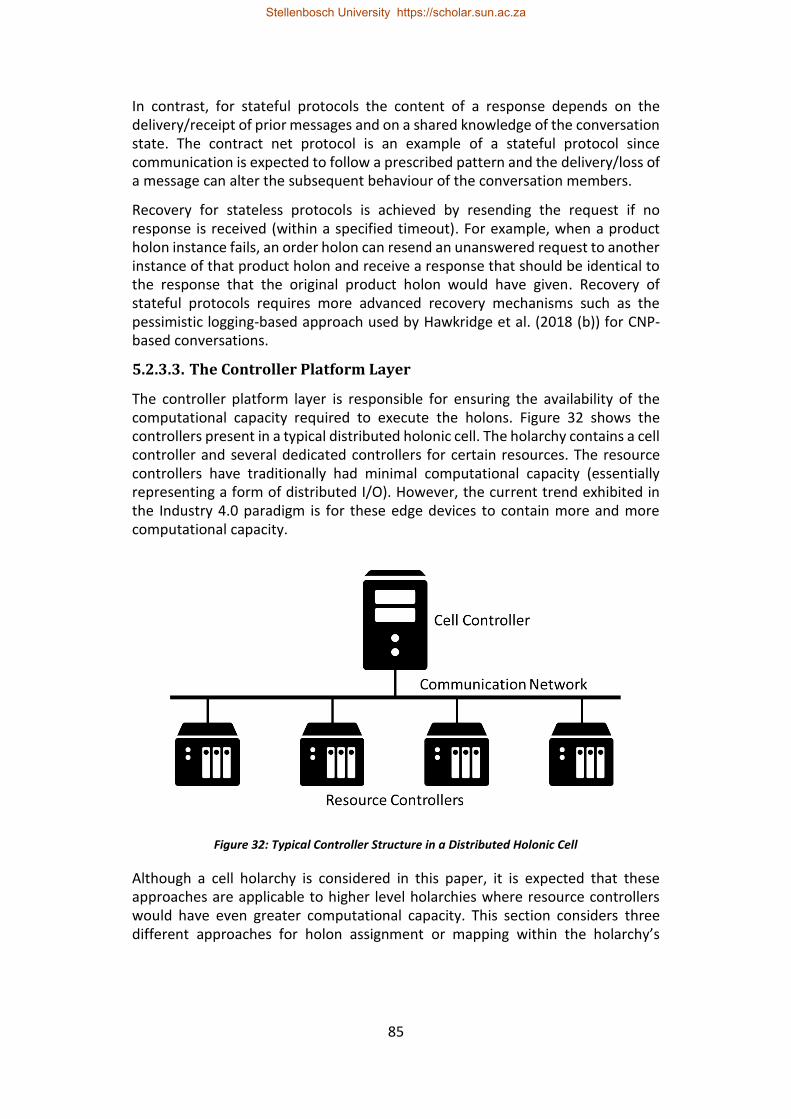
85
In contrast, for stateful protocols the content of a response depends on the delivery/receipt of prior messages and on a shared knowledge of the conversation state. The contract net protocol is an example of a stateful protocol since communication is expected to follow a prescribed pattern and the delivery/loss of a message can alter the subsequent behaviour of the conversation members.
Recovery for stateless protocols is achieved by resending the request if no response is received (within a specified timeout). For example, when a product holon instance fails, an order holon can resend an unanswered request to another instance of that product holon and receive a response that should be identical to the response that the original product holon would have given. Recovery of stateful protocols requires more advanced recovery mechanisms such as the pessimistic logging-based approach used by Hawkridge et al. (2018 (b)) for CNP-based conversations.
5.2.3.3. The Controller Platform Layer
The controller platform layer is responsible for ensuring the availability of the computational capacity required to execute the holons. Figure 32 shows the controllers present in a typical distributed holonic cell. The holarchy contains a cell controller and several dedicated controllers for certain resources. The resource controllers have traditionally had minimal computational capacity (essentially representing a form of distributed I/O). However, the current trend exhibited in the Industry 4.0 paradigm is for these edge devices to contain more and more computational capacity.
Figure 32: Typical Controller Structure in a Distributed Holonic Cell
Although a cell holarchy is considered in this paper, it is expected that these approaches are applicable to higher level holarchies where resource controllers would have even greater computational capacity. This section considers three different approaches for holon assignment or mapping within the holarchy’s
Stellenbosch University https://scholar.sun.ac.za
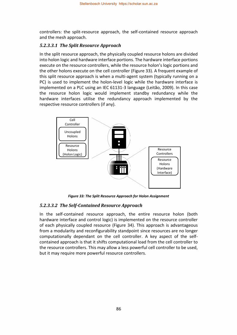
86
controllers: the split-resource approach, the self-contained resource approach and the mesh approach.
5.2.3.3.1 The Split Resource Approach
In the split resource approach, the physically coupled resource holons are divided into holon logic and hardware interface portions. The hardware interface portions execute on the resource controllers, while the resource holon’s logic portions and the other holons execute on the cell controller (Figure 33). A frequent example of this split resource approach is when a multi-agent system (typically running on a PC) is used to implement the holon-level logic while the hardware interface is implemented on a PLC using an IEC 61131-3 language (Leitão, 2009). In this case the resource holon logic would implement standby redundancy while the hardware interfaces utilise the redundancy approach implemented by the respective resource controllers (if any).
Figure 33: The Split Resource Approach for Holon Assignment
5.2.3.3.2 The Self-Contained Resource Approach
In the self-contained resource approach, the entire resource holon (both hardware interface and control logic) is implemented on the resource controller of each physically coupled resource (Figure 34). This approach is advantageous from a modularity and reconfigurability standpoint since resources are no longer computationally dependant on the cell controller. A key aspect of the self-contained approach is that it shifts computational load from the cell controller to the resource controllers. This may allow a less powerful cell controller to be used, but it may require more powerful resource controllers.
Stellenbosch University https://scholar.sun.ac.za
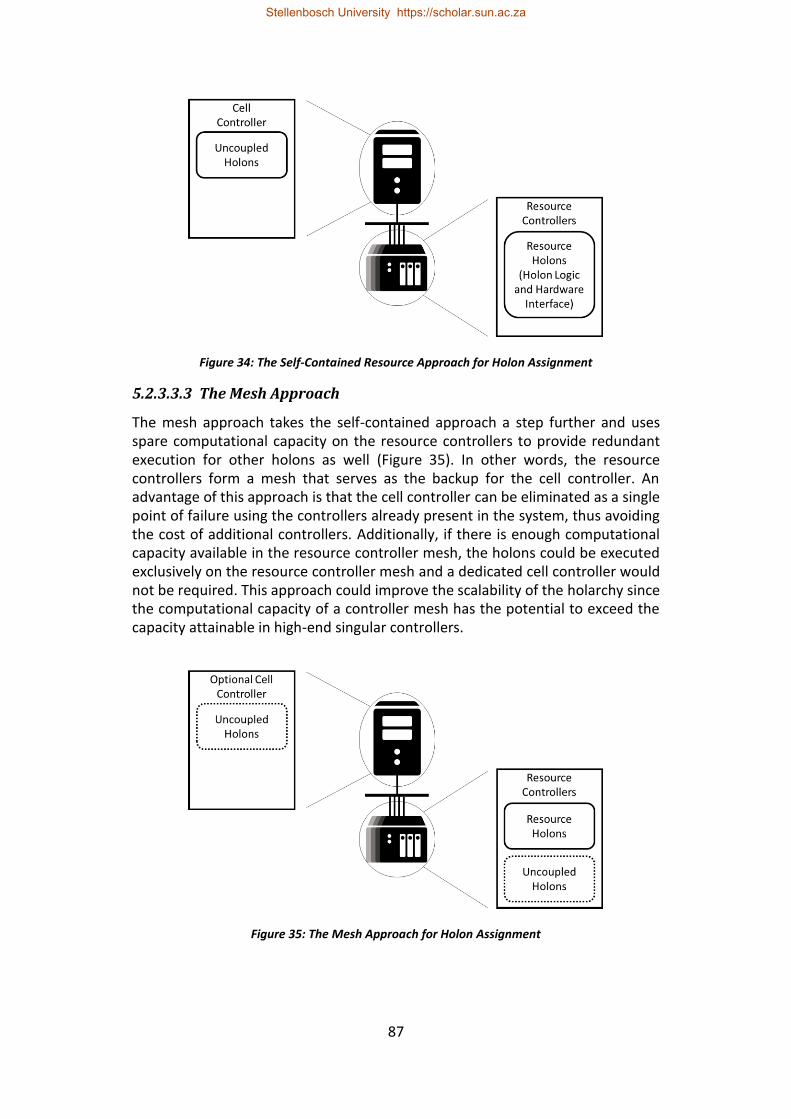
87
Figure 34: The Self-Contained Resource Approach for Holon Assignment
5.2.3.3.3 The Mesh Approach
The mesh approach takes the self-contained approach a step further and uses spare computational capacity on the resource controllers to provide redundant execution for other holons as well (Figure 35). In other words, the resource controllers form a mesh that serves as the backup for the cell controller. An advantage of this approach is that the cell controller can be eliminated as a single point of failure using the controllers already present in the system, thus avoiding the cost of additional controllers. Additionally, if there is enough computational capacity available in the resource controller mesh, the holons could be executed exclusively on the resource controller mesh and a dedicated cell controller would not be required. This approach could improve the scalability of the holarchy since the computational capacity of a controller mesh has the potential to exceed the capacity attainable in high-end singular controllers.
Figure 35: The Mesh Approach for Holon Assignment
Stellenbosch University https://scholar.sun.ac.za
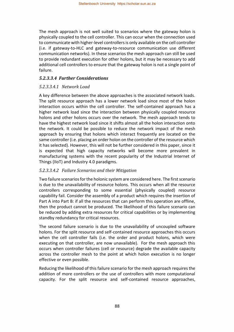
88
The mesh approach is not well suited to scenarios where the gateway holon is physically coupled to the cell controller. This can occur when the connection used to communicate with higher-level controllers is only available on the cell controller (i.e. if gateway-to-HLC and gateway-to-resource communication use different communication networks). In these scenarios the mesh approach can still be used to provide redundant execution for other holons, but it may be necessary to add additional cell controllers to ensure that the gateway holon is not a single point of failure.
5.2.3.3.4 Further Considerations
5.2.3.3.4.1 Network Load
A key difference between the above approaches is the associated network loads. The split resource approach has a lower network load since most of the holon interaction occurs within the cell controller. The self-contained approach has a higher network load since the interaction between physically coupled resource holons and other holons occurs over the network. The mesh approach tends to have the highest network load since it shifts almost all the holon interaction onto the network. It could be possible to reduce the network impact of the mesh approach by ensuring that holons which interact frequently are located on the same controller (i.e. placing an order holon on the controller of the resource which it has selected). However, this will not be further considered in this paper, since it is expected that high capacity networks will become more prevalent in manufacturing systems with the recent popularity of the Industrial Internet of Things (IIoT) and Industry 4.0 paradigms.
5.2.3.3.4.2 Failure Scenarios and their Mitigation
Two failure scenarios for the holonic system are considered here. The first scenario is due to the unavailability of resource holons. This occurs when all the resource controllers corresponding to some essential (physically coupled) resource capability fail. Consider the assembly of a product which requires the insertion of Part A into Part B: if all the resources that can perform this operation are offline, then the product cannot be produced. The likelihood of this failure scenario can be reduced by adding extra resources for critical capabilities or by implementing standby redundancy for critical resources.
The second failure scenario is due to the unavailability of uncoupled software holons. For the split resource and self-contained resource approaches this occurs when the cell controller fails (i.e. the order and product holons, which were executing on that controller, are now unavailable). For the mesh approach this occurs when controller failures (cell or resource) degrade the available capacity across the controller mesh to the point at which holon execution is no longer effective or even possible.
Reducing the likelihood of this failure scenario for the mesh approach requires the addition of more controllers or the use of controllers with more computational capacity. For the split resource and self-contained resource approaches,
Stellenbosch University https://scholar.sun.ac.za
89
redundancy between two or more cell controllers is needed. The cell controllers may be high-reliability embedded PCs or PLCs which will make failures less frequent, but this may not negate the need for redundancy since failure is always a possibility.
Cell controller redundancy, for the split resource and self-contained approaches, can be implemented using standby redundancy or parallel execution. For standby redundancy, one of the controllers is the primary which executes the holons exclusively and the other controllers are standby controllers which wait to takeover when the primary fails. For parallel execution, all the cell controllers are active and the holons are distributed across them. Standby redundancy keeps uncoupled holon interaction within the primary controller, whereas some of this interaction occurs on the network with parallel cell controllers. Parallel controllers are advantageous when considering changeover time since only the holons which were executing on the failed controller need to be restarted. Furthermore, parallel cell controllers are preferable when there are holons which are replicated since replicas can be assigned to different cell controllers.
5.2.3.3.4.3 Selection
The abovementioned split resource, self-contained resource and the mesh approaches each have their merits. The split resource approach is well suited to systems where the resource controllers have limited computational capacity or where the software development platforms of the resource controllers are not conducive to implementing holon level logic. This approach is also well suited to heterogeneous environments where each resource controller has a different software platform. The self-contained resource approach provides modularity by implementing the whole resource holon on the resource’s controller. This approach takes some of the computational load off the cell controller which can improve scalability. The mesh approach has the potential to be more scalable and handle more failures by utilising the computational capacity of all the controllers in the holarchy. In a heterogeneous environment, this approach is not practical if the logic for each holon must be separately developed for every controller software platform in the system.
For the remainder of this paper, the considered holarchy will use the mesh approach for the controller platform since the mesh approach places the fewest restrictions on the locations of various holons. The mesh approach, therefore, also showcases the ease with which Erlang/OTP based holons can be redundantly distributed and the portability of Erlang/OTP (i.e. it’s ability to run on heterogeneous hardware).
5.2.4. Erlang Background
The Erlang programming language is designed for applications that require concurrency, fault tolerance and distribution (Anonymous s.a. (a)). It is these features which make it an attractive solution for the implementation of holonic
Stellenbosch University https://scholar.sun.ac.za
90
control systems (Kruger & Basson, 2017). This section introduces foundational Erlang concepts for the sake of readers not familiar with the language.
5.2.4.1. Concurrency
Erlang programs are built up by independent concurrent processes which cooperate with one another to achieve the systems goals. Erlang processes have the following properties: processes have sole access to their internal state, processes influence one another through asynchronous message passing and processes have the capability to spawn further processes (Armstrong 2010: 70).
Erlang code runs within its own virtual machine, known as BEAM (Bogdan/Björn's Erlang Abstract Machine), which handles scheduling, memory management and message passing for the Erlang processes. Additionally, BEAM supports symmetric multiprocessing (SMP) which enhances process concurrency on multicore processors (Lundin 2008). BEAM provides Erlang with processes that are lightweight, which facilitates the large number of processes required to implement complex systems (Larson, 2009: 55). Furthermore, BEAM can run on most Unix, Linux and Microsoft Windows based operating systems which enhances the portability of Erlang code (Anonymous s.a. (b)). An instance of BEAM is referred to as a node.
5.2.4.2. Distribution
Distribution flows naturally from Erlang's concurrency model. Since processes communicate through message passing and there is no shared state, the only difference between process communication within a node and process communication between nodes is latency. As a result, it possible to develop an Erlang program on a single device and deploy it to a cluster with minimal code modification (Armstrong 2010: 70).
5.2.4.3. Supervision Trees and OTP Applications
Erlang’s process model provides process isolation, which contributes to its fault-tolerance. Process isolation means that if an Erlang process is terminated, whether by an error or by another process, it will not cause an error in any of the other processes.
To handle situations where processes are reliant on other processes to be able to fulfil their function, Erlang provides mechanisms for process linking and process monitoring. If two processes are linked, the death of the one will result in the death of the other. Alternatively, if a process is monitoring another process, it will receive a message if the other dies. These features are used by OTP to implement supervisor processes.
A supervisor process starts and monitors its child processes and restarts them if they fail. If the failure rate exceeds a specified frequency, the supervisor fails, and all its children are terminated. The children of a supervisor processes can include other supervisor processes. This leads to a supervision tree. The principle behind
Stellenbosch University https://scholar.sun.ac.za
91
a supervision tree is that, if an error occurs, it will propagate through the supervision tree until it reaches the point where all the processes required to rectify that error have been restarted. In this way, an error can be contained in the region which it affects.
An OTP application is a supervision tree where all the children are implementations of standard OTP behaviours. A behaviour is an abstraction that implements the generic portions of a common model or pattern. The standard behaviours include gen_server (that implements a client-server relationship), gen_event (that implements a publish-subscribe mechanism), gen_statem (that implements an event driven state machine) and the supervisor model. The application specific logic for these behaviours is implemented in the form of callback modules. An advantage of using these behaviours is that they have been thoroughly tested in many software products.
5.2.4.4. Failover and Takeover Mechanisms
OTP's distributed application failover and takeover mechanisms are key components in an Erlang/OTP based redundancy system. To enable the failover and takeover mechanisms, an OTP application must be configured as a distributed application. This configuration specifies on which nodes the application is permitted to run, as well as the priority of each node. OTP will start the application on the running node with the highest priority. If this node fails, OTP's failover mechanism will restart the application on the running node with the next highest priority. On the other hand, if at any time, a node with a higher priority comes online, the takeover mechanism executes. The takeover mechanism starts the application on the higher priority node and stops the application on the lower priority node once the higher priority node is initialised. There is a brief period when the application is running on both nodes simultaneously, which must be handled to avoid unintended side effects.
The time it takes Erlang to detect that a connected node has gone down is controlled by the configuration parameter net_ticktime (an integer value, in seconds). Erlang claims that an inaccessible node will be detected within an interval of 0.75*net_ticktime to 1.25*net_ticktime (Ericsson AB, 2017 (a): 7).
Another situation that should be considered is when a node is isolated due to communication loss, but the node remains operational. If communication is re-established in this situation, the distributed application framework does not re-establish the failover/takeover relationships for the reconnected node. A workaround for these situations is that when a node determines that it has been reconnected, it brings any physical devices related to it to a safe state and then restarts (Hawkridge et al., 2018 (a)). Restarting the node will re-establish the failover/takeover relationships.
Stellenbosch University https://scholar.sun.ac.za
92
5.2.4.5. Mnesia
Mnesia is an Erlang/OTP-based distributed database management system that is designed for Erlang applications that require continuous operation and exhibit soft real-time properties (Ericsson AB, 2017 (b): 2). For data redundancy, mnesia can be configured to transparently replicate all stored data across a specified set of Erlang nodes. A useful feature of Mnesia is the ability to store Erlang datatypes such as records and references.
5.2.5. Erlang Implementation
This section describes the Erlang/OTP implementation of the holonic architecture considered in this paper. The architecture is implemented across a controller mesh. To achieve this, each controller executes an instance of BEAM and is therefore an Erlang node.
5.2.5.1. OTP Application Architecture
OTP applications (hereafter referred to as applications) are used to package supervision trees that implement specific functionalities. In this paper, most holons are packaged as applications. The failover/takeover mechanism of distributed applications restarts an application on another node if the node on which it is running goes down. The failover/takeover functionality and OTP’s distributed database (mnesia) are used to implement standby redundancy for holons that require it. If the system contains dedicated cell controllers (i.e. to add additional capacity to the controller mesh), the node priority feature of OTP’s distributed application framework can be used to ensure that uncoupled software holons will prioritise execution on these controllers whenever they are online and that resource controllers in the mesh will only be used as redundant backups.
Holons which implement replication are packaged as standard applications and these applications are started on each node where a replica is required. Erlang/OTP does not contain a built-in feature for managing the replication of applications at runtime (such as the ability to specify a required number of active replicas within a pool of nodes). It is expected that such a feature could be developed using Erlang’s core functionalities, but this is left for future work.
Each Erlang node hosts multiple applications, including an instance of the mnesia application. Holons that implement standby redundancy, such as the gateway holon, service directory and uncoupled resource holons, are packaged as distributed applications. The order holons also implement standby redundancy, but a different implementation approach is used as explained below. A node may also host replicas of product holons. If a node is on the controller of a physically coupled resource, then the node will also host that resource holon application (Figure 36). If the physically coupled resource implements Erlang-based standby redundancy using the approach proposed in Hawkridge et al. (2018 (a)), this application will be distributed and configured to only run on the controllers corresponding to that resource.
Stellenbosch University https://scholar.sun.ac.za
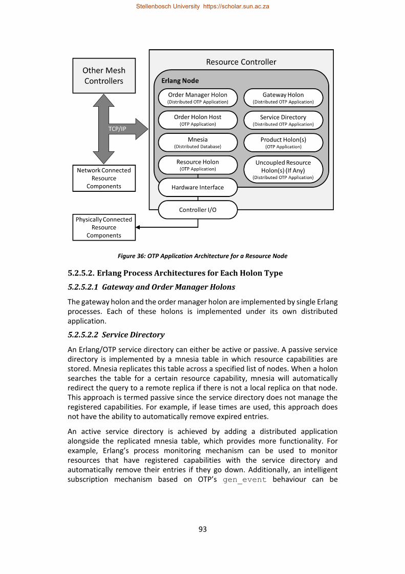
93
Figure 36: OTP Application Architecture for a Resource Node
5.2.5.2. Erlang Process Architectures for Each Holon Type
5.2.5.2.1 Gateway and Order Manager Holons
The gateway holon and the order manager holon are implemented by single Erlang processes. Each of these holons is implemented under its own distributed application.
5.2.5.2.2 Service Directory
An Erlang/OTP service directory can either be active or passive. A passive service directory is implemented by a mnesia table in which resource capabilities are stored. Mnesia replicates this table across a specified list of nodes. When a holon searches the table for a certain resource capability, mnesia will automatically redirect the query to a remote replica if there is not a local replica on that node. This approach is termed passive since the service directory does not manage the registered capabilities. For example, if lease times are used, this approach does not have the ability to automatically remove expired entries.
An active service directory is achieved by adding a distributed application alongside the replicated mnesia table, which provides more functionality. For example, Erlang’s process monitoring mechanism can be used to monitor resources that have registered capabilities with the service directory and automatically remove their entries if they go down. Additionally, an intelligent subscription mechanism based on OTP’s gen_event behaviour can be
Stellenbosch University https://scholar.sun.ac.za
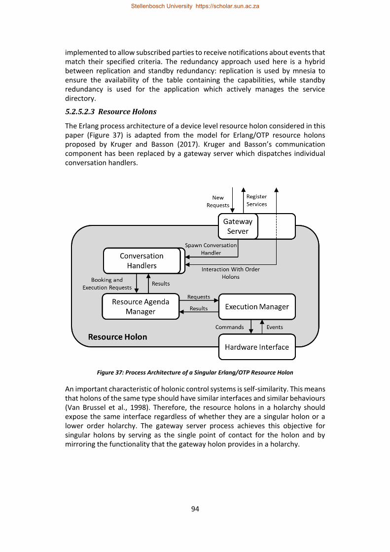
94
implemented to allow subscribed parties to receive notifications about events that match their specified criteria. The redundancy approach used here is a hybrid between replication and standby redundancy: replication is used by mnesia to ensure the availability of the table containing the capabilities, while standby redundancy is used for the application which actively manages the service directory.
5.2.5.2.3 Resource Holons
The Erlang process architecture of a device level resource holon considered in this paper (Figure 37) is adapted from the model for Erlang/OTP resource holons proposed by Kruger and Basson (2017). Kruger and Basson’s communication component has been replaced by a gateway server which dispatches individual conversation handlers.
Figure 37: Process Architecture of a Singular Erlang/OTP Resource Holon
An important characteristic of holonic control systems is self-similarity. This means that holons of the same type should have similar interfaces and similar behaviours (Van Brussel et al., 1998). Therefore, the resource holons in a holarchy should expose the same interface regardless of whether they are a singular holon or a lower order holarchy. The gateway server process achieves this objective for singular holons by serving as the single point of contact for the holon and by mirroring the functionality that the gateway holon provides in a holarchy.
Stellenbosch University https://scholar.sun.ac.za
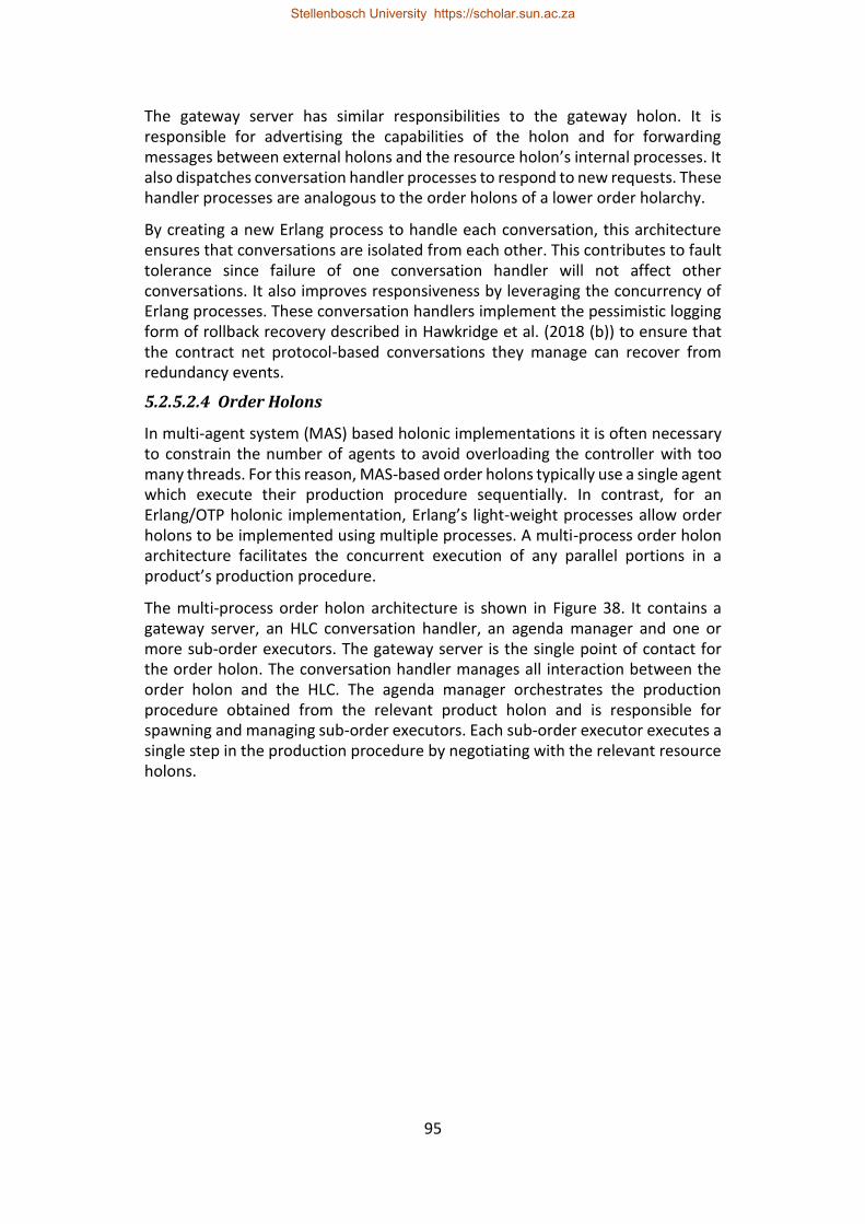
95
The gateway server has similar responsibilities to the gateway holon. It is responsible for advertising the capabilities of the holon and for forwarding messages between external holons and the resource holon’s internal processes. It also dispatches conversation handler processes to respond to new requests. These handler processes are analogous to the order holons of a lower order holarchy.
By creating a new Erlang process to handle each conversation, this architecture ensures that conversations are isolated from each other. This contributes to fault tolerance since failure of one conversation handler will not affect other conversations. It also improves responsiveness by leveraging the concurrency of Erlang processes. These conversation handlers implement the pessimistic logging form of rollback recovery described in Hawkridge et al. (2018 (b)) to ensure that the contract net protocol-based conversations they manage can recover from redundancy events.
5.2.5.2.4 Order Holons
In multi-agent system (MAS) based holonic implementations it is often necessary to constrain the number of agents to avoid overloading the controller with too many threads. For this reason, MAS-based order holons typically use a single agent which execute their production procedure sequentially. In contrast, for an Erlang/OTP holonic implementation, Erlang’s light-weight processes allow order holons to be implemented using multiple processes. A multi-process order holon architecture facilitates the concurrent execution of any parallel portions in a product’s production procedure.
The multi-process order holon architecture is shown in Figure 38. It contains a gateway server, an HLC conversation handler, an agenda manager and one or more sub-order executors. The gateway server is the single point of contact for the order holon. The conversation handler manages all interaction between the order holon and the HLC. The agenda manager orchestrates the production procedure obtained from the relevant product holon and is responsible for spawning and managing sub-order executors. Each sub-order executor executes a single step in the production procedure by negotiating with the relevant resource holons.
Stellenbosch University https://scholar.sun.ac.za
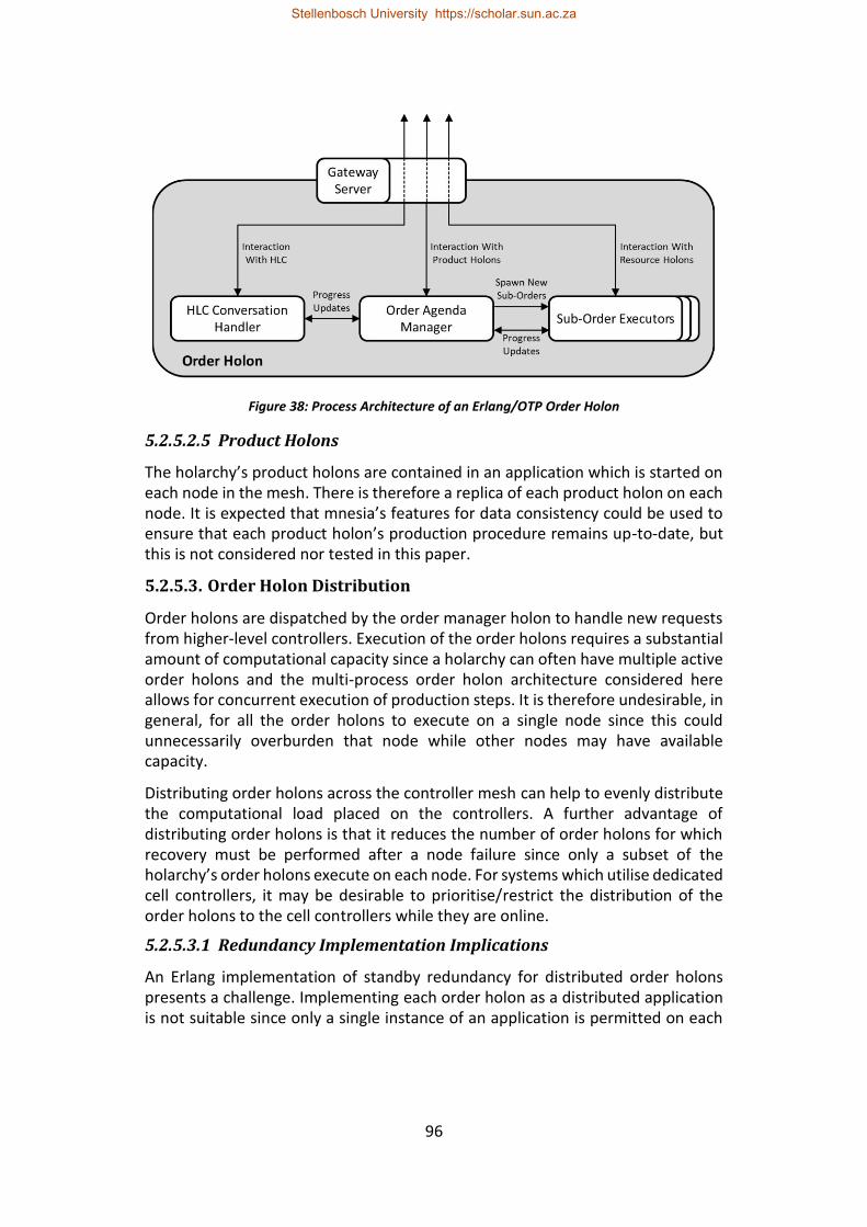
96
Figure 38: Process Architecture of an Erlang/OTP Order Holon
5.2.5.2.5 Product Holons
The holarchy’s product holons are contained in an application which is started on each node in the mesh. There is therefore a replica of each product holon on each node. It is expected that mnesia’s features for data consistency could be used to ensure that each product holon’s production procedure remains up-to-date, but this is not considered nor tested in this paper.
5.2.5.3. Order Holon Distribution
Order holons are dispatched by the order manager holon to handle new requests from higher-level controllers. Execution of the order holons requires a substantial amount of computational capacity since a holarchy can often have multiple active order holons and the multi-process order holon architecture considered here allows for concurrent execution of production steps. It is therefore undesirable, in general, for all the order holons to execute on a single node since this could unnecessarily overburden that node while other nodes may have available capacity.
Distributing order holons across the controller mesh can help to evenly distribute the computational load placed on the controllers. A further advantage of distributing order holons is that it reduces the number of order holons for which recovery must be performed after a node failure since only a subset of the holarchy’s order holons execute on each node. For systems which utilise dedicated cell controllers, it may be desirable to prioritise/restrict the distribution of the order holons to the cell controllers while they are online.
5.2.5.3.1 Redundancy Implementation Implications
An Erlang implementation of standby redundancy for distributed order holons presents a challenge. Implementing each order holon as a distributed application is not suitable since only a single instance of an application is permitted on each
Stellenbosch University https://scholar.sun.ac.za
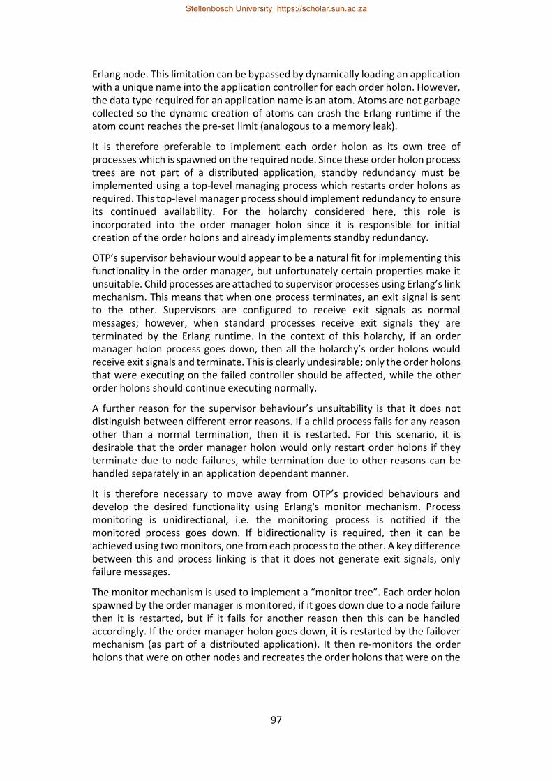
97
Erlang node. This limitation can be bypassed by dynamically loading an application with a unique name into the application controller for each order holon. However, the data type required for an application name is an atom. Atoms are not garbage collected so the dynamic creation of atoms can crash the Erlang runtime if the atom count reaches the pre-set limit (analogous to a memory leak).
It is therefore preferable to implement each order holon as its own tree of processes which is spawned on the required node. Since these order holon process trees are not part of a distributed application, standby redundancy must be implemented using a top-level managing process which restarts order holons as required. This top-level manager process should implement redundancy to ensure its continued availability. For the holarchy considered here, this role is incorporated into the order manager holon since it is responsible for initial creation of the order holons and already implements standby redundancy.
OTP’s supervisor behaviour would appear to be a natural fit for implementing this functionality in the order manager, but unfortunately certain properties make it unsuitable. Child processes are attached to supervisor processes using Erlang’s link mechanism. This means that when one process terminates, an exit signal is sent to the other. Supervisors are configured to receive exit signals as normal messages; however, when standard processes receive exit signals they are terminated by the Erlang runtime. In the context of this holarchy, if an order manager holon process goes down, then all the holarchy’s order holons would receive exit signals and terminate. This is clearly undesirable; only the order holons that were executing on the failed controller should be affected, while the other order holons should continue executing normally.
A further reason for the supervisor behaviour’s unsuitability is that it does not distinguish between different error reasons. If a child process fails for any reason other than a normal termination, then it is restarted. For this scenario, it is desirable that the order manager holon would only restart order holons if they terminate due to node failures, while termination due to other reasons can be handled separately in an application dependant manner.
It is therefore necessary to move away from OTP’s provided behaviours and develop the desired functionality using Erlang's monitor mechanism. Process monitoring is unidirectional, i.e. the monitoring process is notified if the monitored process goes down. If bidirectionality is required, then it can be achieved using two monitors, one from each process to the other. A key difference between this and process linking is that it does not generate exit signals, only failure messages.
The monitor mechanism is used to implement a “monitor tree”. Each order holon spawned by the order manager is monitored, if it goes down due to a node failure then it is restarted, but if it fails for another reason then this can be handled accordingly. If the order manager holon goes down, it is restarted by the failover mechanism (as part of a distributed application). It then re-monitors the order holons that were on other nodes and recreates the order holons that were on the
Stellenbosch University https://scholar.sun.ac.za
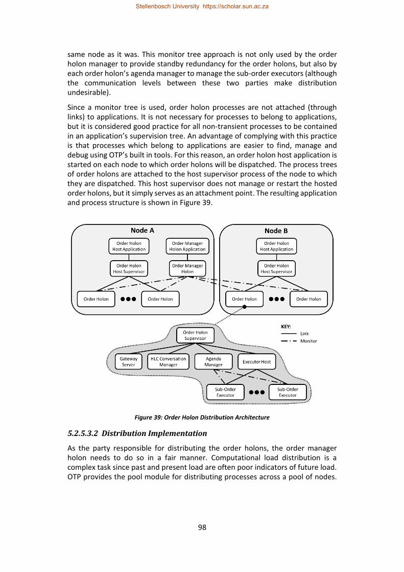
98
same node as it was. This monitor tree approach is not only used by the order holon manager to provide standby redundancy for the order holons, but also by each order holon’s agenda manager to manage the sub-order executors (although the communication levels between these two parties make distribution undesirable).
Since a monitor tree is used, order holon processes are not attached (through links) to applications. It is not necessary for processes to belong to applications, but it is considered good practice for all non-transient processes to be contained in an application’s supervision tree. An advantage of complying with this practice is that processes which belong to applications are easier to find, manage and debug using OTP’s built in tools. For this reason, an order holon host application is started on each node to which order holons will be dispatched. The process trees of order holons are attached to the host supervisor process of the node to which they are dispatched. This host supervisor does not manage or restart the hosted order holons, but it simply serves as an attachment point. The resulting application and process structure is shown in Figure 39.
Figure 39: Order Holon Distribution Architecture
5.2.5.3.2 Distribution Implementation
As the party responsible for distributing the order holons, the order manager holon needs to do so in a fair manner. Computational load distribution is a complex task since past and present load are often poor indicators of future load. OTP provides the pool module for distributing processes across a pool of nodes.
Stellenbosch University https://scholar.sun.ac.za
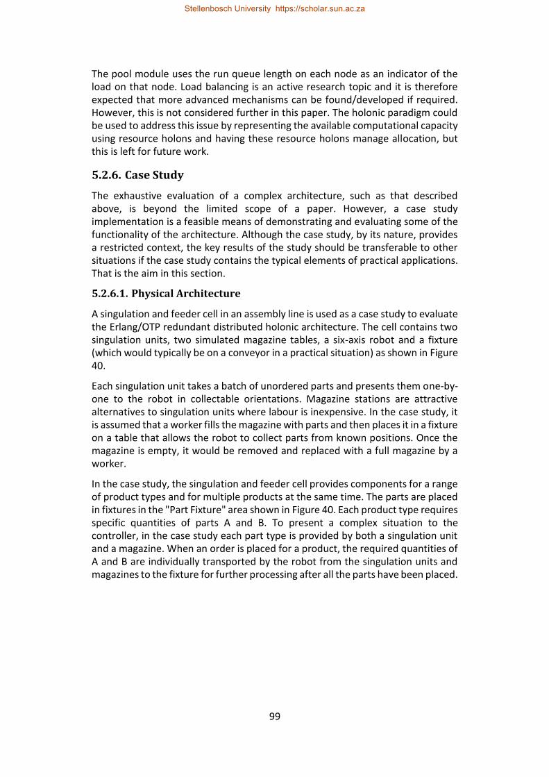
99
The pool module uses the run queue length on each node as an indicator of the load on that node. Load balancing is an active research topic and it is therefore expected that more advanced mechanisms can be found/developed if required. However, this is not considered further in this paper. The holonic paradigm could be used to address this issue by representing the available computational capacity using resource holons and having these resource holons manage allocation, but this is left for future work.
5.2.6. Case Study
The exhaustive evaluation of a complex architecture, such as that described above, is beyond the limited scope of a paper. However, a case study implementation is a feasible means of demonstrating and evaluating some of the functionality of the architecture. Although the case study, by its nature, provides a restricted context, the key results of the study should be transferable to other situations if the case study contains the typical elements of practical applications. That is the aim in this section.
5.2.6.1. Physical Architecture
A singulation and feeder cell in an assembly line is used as a case study to evaluate the Erlang/OTP redundant distributed holonic architecture. The cell contains two singulation units, two simulated magazine tables, a six-axis robot and a fixture (which would typically be on a conveyor in a practical situation) as shown in Figure 40.
Each singulation unit takes a batch of unordered parts and presents them one-by-one to the robot in collectable orientations. Magazine stations are attractive alternatives to singulation units where labour is inexpensive. In the case study, it is assumed that a worker fills the magazine with parts and then places it in a fixture on a table that allows the robot to collect parts from known positions. Once the magazine is empty, it would be removed and replaced with a full magazine by a worker.
In the case study, the singulation and feeder cell provides components for a range of product types and for multiple products at the same time. The parts are placed in fixtures in the "Part Fixture" area shown in Figure 40. Each product type requires specific quantities of parts A and B. To present a complex situation to the controller, in the case study each part type is provided by both a singulation unit and a magazine. When an order is placed for a product, the required quantities of A and B are individually transported by the robot from the singulation units and magazines to the fixture for further processing after all the parts have been placed.
Stellenbosch University https://scholar.sun.ac.za
100
Figure 40: Physical Layout of Case Study Cell
5.2.6.2. Controller Architecture
To illustrate that cell controllers are optional if there is enough available computational capacity on the resource controller mesh, this case study was implemented without a dedicated cell controller. Instead, the uncoupled holons are implemented in a distributed manner across the resource controllers (as described in section 5.2.3.3.3). Also, to illustrate that the architecture can be implemented on dissimilar controllers, two different microcontrollers and two Windows-based PCs are used for resource controllers
The singulation units are controlled using two embedded Linux microcontrollers, a Raspberry Pi 3 model B for singulation unit A and a Beaglebone Black Rev C for singulation unit B. The simulated controllers for the magazine tables operate within two separate Erlang nodes on a Microsoft Windows PC. The resource holon for the robot is implemented on a second Microsoft Windows PC. In total there are five Erlang nodes, each responsible for a single resource holon, with the uncoupled holons distributed across them. The Erlang code for the uncoupled holons is identical for all the nodes, which highlights Erlang’s portability.
The holonic architecture described in section 5.2.3.1 was implemented for the case study. The only specialisation required was for the product and resource holons. The product holons were specialised to contain the production plan considered in this case study. The execution manager components of the resource holons were specialised according to the manufacturing equipment to which each
Stellenbosch University https://scholar.sun.ac.za
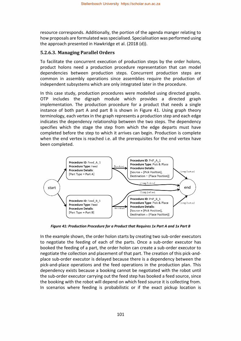
101
resource corresponds. Additionally, the portion of the agenda manger relating to how proposals are formulated was specialised. Specialisation was performed using the approach presented in Hawkridge et al. (2018 (d)).
5.2.6.3. Managing Parallel Orders
To facilitate the concurrent execution of production steps by the order holons, product holons need a production procedure representation that can model dependencies between production steps. Concurrent production steps are common in assembly operations since assemblies require the production of independent subsystems which are only integrated later in the procedure.
In this case study, production procedures were modelled using directed graphs. OTP includes the digraph module which provides a directed graph implementation. The production procedure for a product that needs a single instance of both part A and part B is shown in Figure 41. Using graph theory terminology, each vertex in the graph represents a production step and each edge indicates the dependency relationship between the two steps. The dependency specifies which the stage the step from which the edge departs must have completed before the step to which it arrives can begin. Production is complete when the end vertex is reached i.e. all the prerequisites for the end vertex have been completed.
Figure 41: Production Procedure for a Product that Requires 1x Part A and 1x Part B
In the example shown, the order holon starts by creating two sub-order executors to negotiate the feeding of each of the parts. Once a sub-order executor has booked the feeding of a part, the order holon can create a sub-order executor to negotiate the collection and placement of that part. The creation of this pick-and-place sub-order executor is delayed because there is a dependency between the pick-and-place operations and the feed operations in the production plan. This dependency exists because a booking cannot be negotiated with the robot until the sub-order executor carrying out the feed step has booked a feed source, since the booking with the robot will depend on which feed source it is collecting from. In scenarios where feeding is probabilistic or if the exact pickup location is
Stellenbosch University https://scholar.sun.ac.za
102
necessary for the booking, this dependency could even be stricter and require that the part has already been fed before the pick-and-place operation is negotiated.
Concurrent sub-order executors do not only exist for parallel production steps, but they can also exist when there is concurrent execution of sequential steps due to booking overlaps. In the context of this case study, there is a potential booking overlap when the robot collects a part from one of the singulation units, since the singulation unit may not be able to continue feeding parts until the robot has collected the part and has exited the singulation unit’s workspace. The robot would not necessarily have the required expertise to determine when it has left a singulation unit’s workspace. Therefore, it should send progress updates to the singulation unit from which it is collecting so that the singulation unit can decide when it is safe to resume operation.
These progress updates are not required when the robot is collecting from a magazine table since the magazine is static. Therefore, a subscription mechanism was implemented so that specific resource holons can decide which other resources they need progress updates from. Although progress updates could be sent directly from resource holon to resource holon, it was decided to channel these updates through the relevant order holon since it reduced the number of conversations which needed to implement recovery mechanisms.
5.2.6.4. Test Results
The case study was tested for three different node failure cases: node failure due to software faults; node isolation by network faults; and controller failure due to power loss or hardware faults. These failure cases were simulated using the following fault injection approaches: node failure due to a software fault was simulated by terminating the node’s host process; node isolation was simulated by removing the network cable from the host device; and controller failure was simulated by removing power from the device.
The tests showed that the case study implementation can handle all three failure cases. When an order holon is terminated by a node failure, the order manager holon is notified and restarts the order holon on another node. The order holon then retrieves its latest state from mnesia and performs conversation recovery for all ongoing conversations, including the CNP-based conversation with the HLC. Once conversation recovery is complete, the order holon resumes operation.
When the order manager holon is terminated by a node failure, it is restarted by OTP’s failover mechanism. Order holons that are not terminated by the node failure are not affected by the order manager’s failure and therefore continue to execute. When the order manager is restarted it retrieves its state from mnesia and checks the status of all active order holons listed in that state. Order holons that are still alive are re-monitored and order holons that were terminated by node failures are restarted.
Stellenbosch University https://scholar.sun.ac.za
103
Standby redundancy for the gateway holon and service directory is achieved using OTP’s failover and takeover mechanisms for distributed applications and mnesia in a similar manner to the order manager holon. A know issue with the failover and takeover mechanisms is that they do not allow for reintegration of nodes that were isolated by network faults. The workaround proposed by Hawkridge et al. (2018 (a)), where the isolated node is restarted, can still be used. However, in this case, the distributed application is not the only application executing on each node. For this approach to be used, the resource to which the controller belongs must be brought to a controlled stop before the node is restarted.
These tests were performed with Erlang’s net_ticktime parameter set to 5 seconds. For this value of net_ticktime, the failover detection interval for distributed applications is specified by Erlang documentation to be between 3.75 and 6.25 seconds. This detection interval was satisfactory for the case study.
5.2.7. Conclusions
This paper presents a redundant architecture for a holonic cell controller and investigates the benefits of using of Erlang’s and OTP’s built-in features to implement this architecture. A distributed holonic architecture based on the PROSA reference architecture is described. Within this architecture, redundancy is divided into a holon redundancy level and a controller platform level. The holon level ensures the availability of the software entities used to implement holons. It is concluded that standby redundancy is best suited to holons that are instance specific as it maintains the one-to-one mapping between the holon and the entity it represents. Holons that are not instance specific may benefit from the use of replication.
The controller platform considers the allocation of holons to control hardware to ensure the continued availability of the computational capacity required to execute the holons. Three approaches for holon allocation are discussed: the split resource approach, the self-contained approach and the mesh approach. Each offer different compromises between the network load and the required computational capacity of the cell and resource control hardware. The mesh approach was further considered in this paper since it places the fewest restrictions on holon execution location. Additionally, it highlights the ease of distribution and portability of Erlang/OTP. Furthermore, the mesh approach is well suited to the use of more powerful edge controllers and higher capacity networks envisioned by the Industry 4.0 and IIoT paradigms.
An Erlang/OTP implementation of the proposed holonic architecture is described. Erlang’s distributed application framework was used to provide standby redundancy for holons which require it. To allow the order holons to be distributed across the controller mesh, a standby redundancy approach for the order holons was developed based around a supervisory tree that uses Erlang’s process monitoring capability. The data for these redundant entities is replicated across the relevant controllers using OTP’s distributed database called Mnesia.
Stellenbosch University https://scholar.sun.ac.za
104
A case study that implemented the Erlang/OTP redundant holonic architecture on a set of heterogeneous controllers showed that the architecture could handle: node failure due to software faults; node isolation by network faults; and controller failure due to power loss or hardware faults. The case study also showed that restarted holons, such as order holons, were able to resume operation from their prior state. The case study further illustrated that this distributed architecture can be implemented without a dedicated, stand-alone cell controller.
This paper therefore demonstrates that standby redundancy is useful for counteracting the single points of failure represented by the hierarchical elements within holonic control architectures. Further, it shows that Erlang and OTP provide a suitable platform for implementing redundancy within distributed holonic cell controllers. This proposed Erlang/OTP standby redundancy approach can improve the availability of a manufacturing cell by enabling it to withstand a selection of controller failure modes.
5.2.8. References
Anonymous, s.a. (a). What is Erlang [Online]. Available: http://erlang.org/faq/introduction.html [2017, August 29].
Anonymous, s.a. (b). Implementation and Ports of Erlang [Online]. Available: http://erlang.org/faq/implementations.html [2017, August 29].
Armstrong, J., 1996. Erlang—a Survey of the Language and its Industrial Applications, in. INAP 96.
Armstrong, J., 2010. erlang. Communications of the ACM, 53(9): 68-75.
Bi, Z.M., Lang, S.Y., Shen, W. and Wang, L., 2008. Reconfigurable manufacturing systems: the state of the art. International Journal of Production Research, 46(4): 967-992.
Bi, Z., Da Xu, L. and Wang, C., 2014. Internet of things for enterprise systems of modern manufacturing. IEEE Transactions on industrial informatics, 10(2): 1537-1546.
Brettel, M., Friederichsen, N., Keller, M. and Rosenberg, M., 2014. How virtualization, decentralization and network building change the manufacturing landscape: An industry 4.0 perspective. International Journal of Mechanical, Industrial Science and Engineering, 8(1): 37-44.
Colombo, A.W., Schoop, R. and Neubert, R., 2006. An agent-based intelligent control platform for industrial holonic manufacturing systems. IEEE Transactions on Industrial Electronics, 53(1): 322-337.
Dilts, D.M., Boyd, N.P. and Whorms, H.H., 1991. The evolution of control architectures for automated manufacturing systems. Journal of manufacturing systems, 10(1): 79-93.
Stellenbosch University https://scholar.sun.ac.za
105
Ericsson AB, 2017 (a). Erlang Kernel 5.4, [Online]. Available: http://erlang.org/doc/apps/kernel/kernel.pdf [2017, October 6].
Ericsson AB, 2017 (b). Erlang Mnesia 4.15.1, [Online]. Available: http://erlang.org/doc/apps/mnesia/mnesia.pdf [2017, October 9].
Gerbert, P., Lorenz, M., Rüßmann, M., Waldner, M., Justus, J., Engel, P. and Harnisch, M., 2015. White Paper on Industry 4.0: The future of productivity and growth in manufacturing industries [Online]. Available: https://www.bcg.com/en-za/publications/2015/engineered_products_project_business_industry_4_future_productivity_growth_manufacturing_industries.aspx [2018, November 10].
Hawkridge, G., Basson, A.H. and Kruger, K., 2018 (a). An Evaluation of Erlang for Implementing Standby Redundancy in a Manufacturing Station Controller, in 8th Workshop on Service Orientation in Holonic and Multi-Agent Manufacturing. Italy, Bergamo.
Hawkridge, G., Basson, A.H. and Kruger, K., 2018 (b). Conversation Recovery after Failover for Contract Net Protocol Communication in an Erlang-Based Holonic Architecture. submitted to the International Journal of Computer Integrated Manufacturing.
Hawkridge, G., Kruger, K. and Basson, A.H., 2018 (d). Extensible Callback Module Layering in Erlang. submitted to the 7th International Conference on Competitive Manufacturing (COMA), January 2019.
Koestler, A., 1989. The ghost in the machine. Arkana, London.
Kruger, K. and Basson, A., 2017. Erlang-based control implementation for a holonic manufacturing cell. International Journal of Computer Integrated Manufacturing, 30(6): 641-652.
Larson, J., 2009. Erlang for concurrent programming. Communications of the ACM, 52(3): 48-56.
Lasi, H., Fettke, P., Kemper, H.G., Feld, T. and Hoffmann, M., 2014. Industry 4.0. Business & Information Systems Engineering, 6(4): 239-242.
Leitão, P., 2009. Agent-based distributed manufacturing control: A state-of-the-art survey. Engineering Applications of Artificial Intelligence, 22(7): 979-991.
Lundin, K., 2008. Inside the Erlang VM with focus on SMP, in Erlang User Conference, Stockholm.
Valckenaers, P. and Van Brussel, H., 2015. Design for the unexpected: From holonic manufacturing systems towards a humane mechatronics society. Butterworth-Heinemann.
Van Brussel, H., Wyns, J., Valckenaers, P., Bongaerts, L. and Peeters, P., 1998. Reference architecture for holonic manufacturing systems: PROSA. Computers in industry, 37(3): 255-274.
Stellenbosch University https://scholar.sun.ac.za
106
5.3. Extensible Callback Module Layering in Erlang
G.T. Hawkridge1, K. Kruger1, A.H. Basson1 1Mechatronic, Automation and Design Research Group, Department of Mechanical and
Mechatronic Engineering, University of Stellenbosch, South Africa
Abstract
Intelligent manufacturing control is a key aspect of the Industry 4.0 paradigm. Erlang is a functional programming language designed for the development of soft real-time control systems. Erlang has many characteristics that are attractive when implementing manufacturing control. These characteristics include fault tolerance and ease of distribution. Erlang programs are built from multiple concurrent processes which interact through message passing. Code abstraction is provided by Erlang's behaviour mechanism, which separates code into a generic portion (the behaviour) and an application specific callback module. This paper presents an approach for the development of layered callback modules. Layered callback modules can be used to achieve process specialisation. To effectively layer callback modules, it is important that each layer be extensible. Extensible layers are callback modules that do not limit the functionality of subsequent layers. Some best practices relating to message handling and state access are presented. These best practices facilitate the development of callback modules that can be layered in a manner that assists modularity and code reuse. It is expected that this approach for process specialisation will be beneficial in Erlang based IIoT applications since many of the “things” in these systems will share common base functionality.
Keywords: Erlang; Code Abstraction; Software for Manufacturing
5.3.1. Introduction
Current progression, by both industry and academia, towards the realisation of Industry 4.0 has highlighted the need for intelligent manufacturing control (Brettel et al., 2014; Zhou et al., 2015; Lasi et al., 2014; Zhong et al., 2017). Key aspects of intelligent manufacturing control include decentralisation, cyber-physical systems (CPS) and the Industrial Internet of Things (IIoT) (Lasi et al., 2014).
Erlang is a functional programming language designed for the development of fault-tolerant soft real-time control systems (Armstrong, 1996). OTP (Open Telecom Platform) is a set of libraries included in Erlang that simplify the development of large complex systems (Armstrong, 2010: 73). Erlang has many attractive features, such as concurrency, scalability and fault tolerance, that are useful when implementing intelligent manufacturing control systems (Kruger & Basson, 2017). Erlang has been used to implement standby redundancy on embedded systems for a manufacturing station (Hawkridge et al., 2018 (a)).
Code abstraction is a necessary feature when developing the control software for large systems. Erlang provides for code abstraction with the behaviour mechanism
Stellenbosch University https://scholar.sun.ac.za
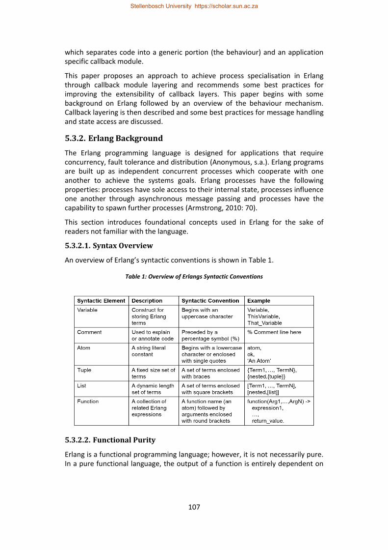
107
which separates code into a generic portion (the behaviour) and an application specific callback module.
This paper proposes an approach to achieve process specialisation in Erlang through callback module layering and recommends some best practices for improving the extensibility of callback layers. This paper begins with some background on Erlang followed by an overview of the behaviour mechanism. Callback layering is then described and some best practices for message handling and state access are discussed.
5.3.2. Erlang Background
The Erlang programming language is designed for applications that require concurrency, fault tolerance and distribution (Anonymous, s.a.). Erlang programs are built up as independent concurrent processes which cooperate with one another to achieve the systems goals. Erlang processes have the following properties: processes have sole access to their internal state, processes influence one another through asynchronous message passing and processes have the capability to spawn further processes (Armstrong, 2010: 70).
This section introduces foundational concepts used in Erlang for the sake of readers not familiar with the language.
5.3.2.1. Syntax Overview
An overview of Erlang’s syntactic conventions is shown in Table 1.
Table 1: Overview of Erlangs Syntactic Conventions
5.3.2.2. Functional Purity
Erlang is a functional programming language; however, it is not necessarily pure. In a pure functional language, the output of a function is entirely dependent on
Stellenbosch University https://scholar.sun.ac.za
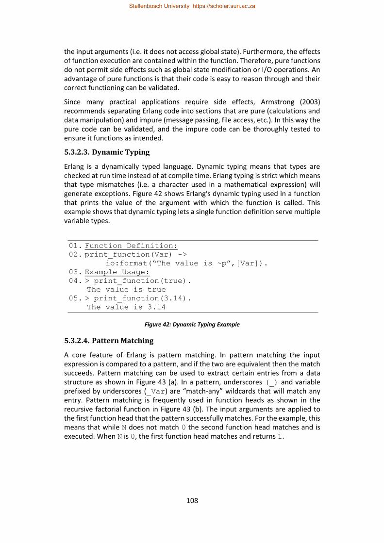
108
the input arguments (i.e. it does not access global state). Furthermore, the effects of function execution are contained within the function. Therefore, pure functions do not permit side effects such as global state modification or I/O operations. An advantage of pure functions is that their code is easy to reason through and their correct functioning can be validated.
Since many practical applications require side effects, Armstrong (2003) recommends separating Erlang code into sections that are pure (calculations and data manipulation) and impure (message passing, file access, etc.). In this way the pure code can be validated, and the impure code can be thoroughly tested to ensure it functions as intended.
5.3.2.3. Dynamic Typing
Erlang is a dynamically typed language. Dynamic typing means that types are checked at run time instead of at compile time. Erlang typing is strict which means that type mismatches (i.e. a character used in a mathematical expression) will generate exceptions. Figure 42 shows Erlang's dynamic typing used in a function that prints the value of the argument with which the function is called. This example shows that dynamic typing lets a single function definition serve multiple variable types.
01. Function Definition: 02. print_function(Var) ->
io:format(“The value is ~p”,[Var]).
03. Example Usage: 04. > print_function(true).
The value is true
05. > print_function(3.14). The value is 3.14
Figure 42: Dynamic Typing Example
5.3.2.4. Pattern Matching
A core feature of Erlang is pattern matching. In pattern matching the input expression is compared to a pattern, and if the two are equivalent then the match succeeds. Pattern matching can be used to extract certain entries from a data structure as shown in Figure 43 (a). In a pattern, underscores (_) and variable prefixed by underscores (_Var) are “match-any” wildcards that will match any entry. Pattern matching is frequently used in function heads as shown in the recursive factorial function in Figure 43 (b). The input arguments are applied to the first function head that the pattern successfully matches. For the example, this means that while N does not match 0 the second function head matches and is executed. When N is 0, the first function head matches and returns 1.
Stellenbosch University https://scholar.sun.ac.za
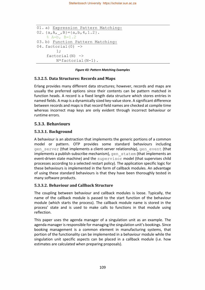
109
01. a) Expression Pattern Matching: 02. {a,A,_,B}={a,b,4,1.2}.
% A=b, B=1.2
03. b) Function Pattern Matching: 04. factorial(0) ->
1;
factorial(N) ->
N*factorial(N-1).
Figure 43: Pattern Matching Examples
5.3.2.5. Data Structures: Records and Maps
Erlang provides many different data structures; however, records and maps are usually the preferred options since their contents can be pattern matched in function heads. A record is a fixed length data structure which stores entries in named fields. A map is a dynamically sized key-value store. A significant difference between records and maps is that record field names are checked at compile time whereas incorrect map keys are only evident through incorrect behaviour or runtime errors.
5.3.3. Behaviours
5.3.3.1. Background
A behaviour is an abstraction that implements the generic portions of a common model or pattern. OTP provides some standard behaviours including gen_server (that implements a client-server relationship), gen_event (that implements a publish-subscribe mechanism), gen_statem (that implements an event-driven state machine) and the supervisor model (that supervises child processes according to a selected restart policy). The application specific logic for these behaviours is implemented in the form of callback modules. An advantage of using these standard behaviours is that they have been thoroughly tested in many software products.
5.3.3.2. Behaviour and Callback Structure
The coupling between behaviour and callback modules is loose. Typically, the name of the callback module is passed to the start function of the behaviour module (which starts the process). The callback module name is stored in the process’ state and is used to make calls to functions in that module using reflection.
This paper uses the agenda manager of a singulation unit as an example. The agenda manager is responsible for managing the singulation unit’s bookings. Since booking management is a common element in manufacturing systems, that portion of the functionality can be implemented in a behaviour module while the singulation unit specific aspects can be placed in a callback module (i.e. how estimates are calculated when preparing proposals).
Stellenbosch University https://scholar.sun.ac.za
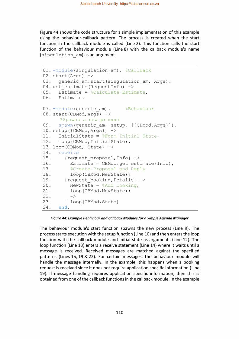
110
Figure 44 shows the code structure for a simple implementation of this example using the behaviour-callback pattern. The process is created when the start function in the callback module is called (Line 2). This function calls the start function of the behaviour module (Line 8) with the callback module's name (singulation_am) as an argument.
01. -module(singulation_am). %Callback 02. start(Args) -> 03. generic_am:start(singulation_am, Args). 04. get_estimate(RequestInfo) -> 05. Estimate = %Calculate Estimate, 06. Estimate.
07. -module(generic_am). %Behaviour 08. start(CBMod,Args) ->
%Spawns a new process
09. spawn(generic_am, setup, [{CBMod,Args}]). 10. setup({CBMod,Args}) -> 11. InitialState = %Form Initial State, 12. loop(CBMod,InitialState). 13. loop(CBMod, State) -> 14. receive 15. {request_proposal,Info} -> 16. Estimate = CBMod:get_estimate(Info), 17. %Create Proposal and Reply 18. loop(CBMod,NewState); 19. {request_booking,Details} -> 20. NewState = %Add booking, 21. loop(CBMod,NewState); 22. _ -> 23. loop(CBMod,State) 24. end.
Figure 44: Example Behaviour and Callback Modules for a Simple Agenda Manager
The behaviour module's start function spawns the new process (Line 9). The process starts execution with the setup function (Line 10) and then enters the loop function with the callback module and initial state as arguments (Line 12). The loop function (Line 13) enters a receive statement (Line 14) where it waits until a message is received. Received messages are matched against the specified patterns (Lines 15, 19 & 22). For certain messages, the behaviour module will handle the message internally. In the example, this happens when a booking request is received since it does not require application specific information (Line 19). If message handling requires application specific information, then this is obtained from one of the callback functions in the callback module. In the example
Stellenbosch University https://scholar.sun.ac.za
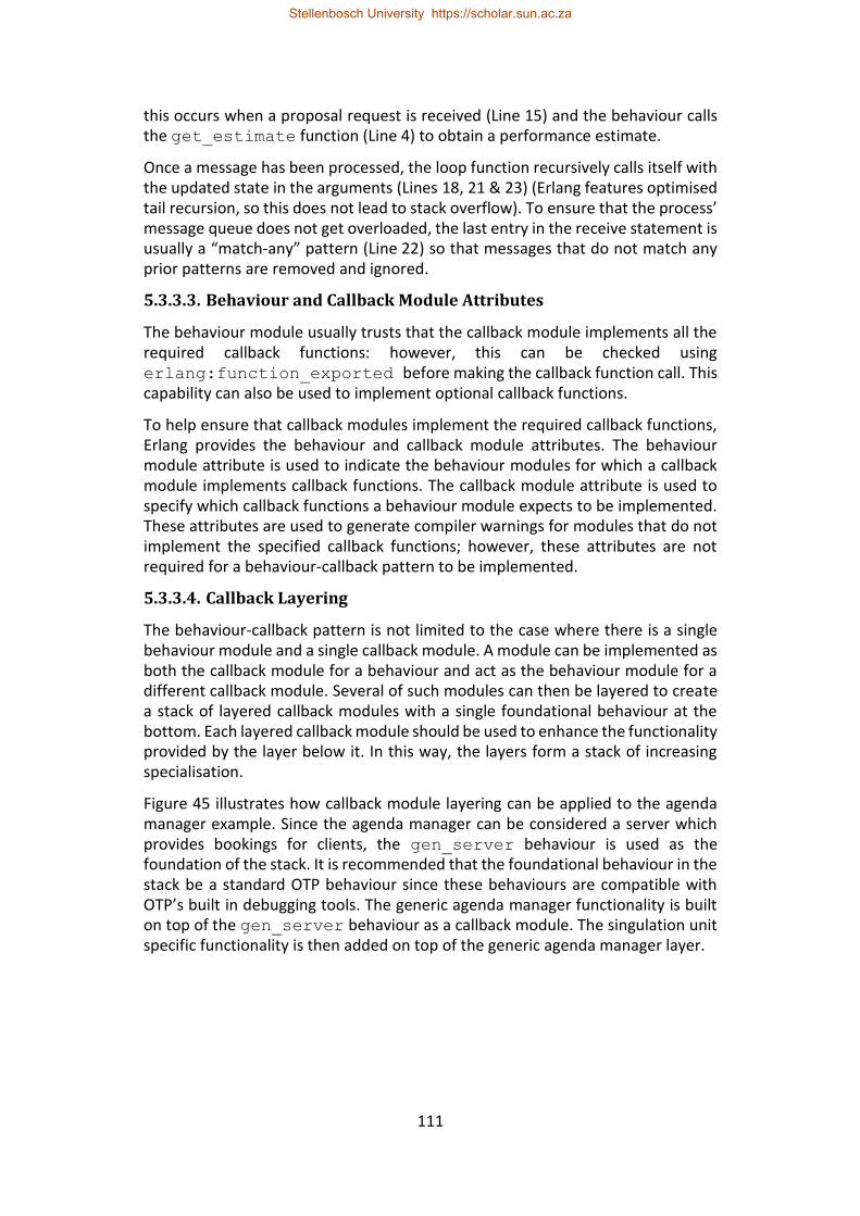
111
this occurs when a proposal request is received (Line 15) and the behaviour calls the get_estimate function (Line 4) to obtain a performance estimate.
Once a message has been processed, the loop function recursively calls itself with the updated state in the arguments (Lines 18, 21 & 23) (Erlang features optimised tail recursion, so this does not lead to stack overflow). To ensure that the process’ message queue does not get overloaded, the last entry in the receive statement is usually a “match-any” pattern (Line 22) so that messages that do not match any prior patterns are removed and ignored.
5.3.3.3. Behaviour and Callback Module Attributes
The behaviour module usually trusts that the callback module implements all the required callback functions: however, this can be checked using erlang:function_exported before making the callback function call. This capability can also be used to implement optional callback functions.
To help ensure that callback modules implement the required callback functions, Erlang provides the behaviour and callback module attributes. The behaviour module attribute is used to indicate the behaviour modules for which a callback module implements callback functions. The callback module attribute is used to specify which callback functions a behaviour module expects to be implemented. These attributes are used to generate compiler warnings for modules that do not implement the specified callback functions; however, these attributes are not required for a behaviour-callback pattern to be implemented.
5.3.3.4. Callback Layering
The behaviour-callback pattern is not limited to the case where there is a single behaviour module and a single callback module. A module can be implemented as both the callback module for a behaviour and act as the behaviour module for a different callback module. Several of such modules can then be layered to create a stack of layered callback modules with a single foundational behaviour at the bottom. Each layered callback module should be used to enhance the functionality provided by the layer below it. In this way, the layers form a stack of increasing specialisation.
Figure 45 illustrates how callback module layering can be applied to the agenda manager example. Since the agenda manager can be considered a server which provides bookings for clients, the gen_server behaviour is used as the foundation of the stack. It is recommended that the foundational behaviour in the stack be a standard OTP behaviour since these behaviours are compatible with OTP’s built in debugging tools. The generic agenda manager functionality is built on top of the gen_server behaviour as a callback module. The singulation unit specific functionality is then added on top of the generic agenda manager layer.
Stellenbosch University https://scholar.sun.ac.za
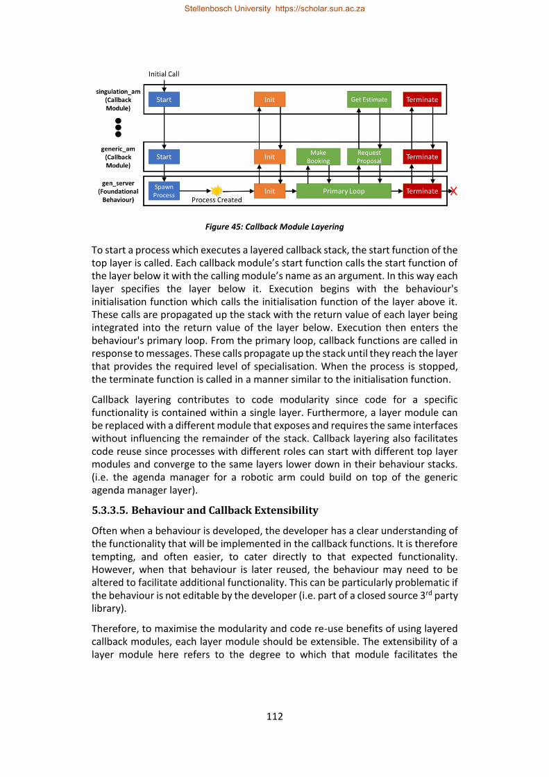
112
Figure 45: Callback Module Layering
To start a process which executes a layered callback stack, the start function of the top layer is called. Each callback module’s start function calls the start function of the layer below it with the calling module’s name as an argument. In this way each layer specifies the layer below it. Execution begins with the behaviour's initialisation function which calls the initialisation function of the layer above it. These calls are propagated up the stack with the return value of each layer being integrated into the return value of the layer below. Execution then enters the behaviour's primary loop. From the primary loop, callback functions are called in response to messages. These calls propagate up the stack until they reach the layer that provides the required level of specialisation. When the process is stopped, the terminate function is called in a manner similar to the initialisation function.
Callback layering contributes to code modularity since code for a specific functionality is contained within a single layer. Furthermore, a layer module can be replaced with a different module that exposes and requires the same interfaces without influencing the remainder of the stack. Callback layering also facilitates code reuse since processes with different roles can start with different top layer modules and converge to the same layers lower down in their behaviour stacks. (i.e. the agenda manager for a robotic arm could build on top of the generic agenda manager layer).
5.3.3.5. Behaviour and Callback Extensibility
Often when a behaviour is developed, the developer has a clear understanding of the functionality that will be implemented in the callback functions. It is therefore tempting, and often easier, to cater directly to that expected functionality. However, when that behaviour is later reused, the behaviour may need to be altered to facilitate additional functionality. This can be particularly problematic if the behaviour is not editable by the developer (i.e. part of a closed source 3rd party library).
Therefore, to maximise the modularity and code re-use benefits of using layered callback modules, each layer module should be extensible. The extensibility of a layer module here refers to the degree to which that module facilitates the
Stellenbosch University https://scholar.sun.ac.za
113
implementation of additional functionality within the subsequent callback layers. In other words, a highly extensible callback layer does not make limiting assumptions about the implementation of the layer above it.
Two categories of assumptions that limit or prevent the implementations of layered callback modules have been identified. These two categories are: assumptions about the message handling requirements of subsequent layers and assumptions about the state access requirements of subsequent layers. The following sections will discuss these assumptions in greater detail.
5.3.4. Message Handling
Interprocess communication is a foundational aspect of Erlang programs. It is therefore understandable that a behaviour that limits the message handling capabilities available to its callback module will limit the functionality that can be implemented in that callback module. For a layered callback module to be extensible, it must therefore not restrict the ability of the layer above it to send and receive messages. In the case of the agenda manager example, the singulation_am layer may need to request information from another process before it can generate a performance estimate.
Sending messages from different layers does not cause complications, as long as layers have access to all the data needed to formulate and send the required messages. However, complications arise if layers implement their own message receiving.
The presence of multiple receive statements in a layered callback stack can result in hanging or poor responsiveness (i.e. when blocking receive statements are used to achieve synchronous calls). Furthermore, there needs to be a “match-any” pattern in at least one of the receive statements so that messages that do not match any of the receive statements do not overload the message queue. However, this has the potential to erroneously remove messages that are intended for other layers. (i.e. a receive statement in singulation_am removing a booking request for generic_am).
Therefore, the recommended approach is to have a single receive statement in the foundational behaviour module. If a received message does not match any of the patterns for that module then the message should be passed on to the next layer in the stack using a predefined callback function (i.e. handle_message). The next layer then attempts to match it against its own patterns and passes it on upwards using a similar callback function if no match is found. If a message reaches the top of the stack without matching, it can then be safely ignored. This leads to a hierarchy since lower layers have message handling precedence over higher layers. Care should be taken to avoid (unintended) message pattern overlaps between layers.
Stellenbosch University https://scholar.sun.ac.za
114
If having additional receive statements within layers is unavoidable, then these receive statements should be non-blocking and only match messages intended for that layer.
A further advantage of having every layer in the stack use only the foundational behaviour's receive statement is that more of the callback functions in higher layer modules can be functionally pure and therefore easier to validate.
5.3.5. State Access
State is a representation of a process' current condition. The ability to maintain state is a necessary requirement for any non-trivial process since it allows past events to influence the handling of future events. Erlang processes typically rely on local state. This local state is implemented as an argument to the foundational behaviour’s primary loop. If a function requires access to this state, then it is passed as an argument to that function. Erlang provides facilities for a global process state (i.e. the process dictionary); however, the use of global state is generally discouraged as it leads to code that is functionally impure and therefore difficult to validate.
If a callback module does not have the facility to maintain its own local state, then it will either limit the functionality that can be implemented in that module or force the callback module to use global state. An extensible layer module should therefore provide local state storage facilities for the layer above it (regardless of whether that layer currently requires state storage).
In the case of the agenda manager example, the gen_server module provides the generic_am module with state storage facilities which are used to store the booking list, etc. However, if the generic_am module does not provide the singulation_am module with state storage facilities then this would limit that layer. For example, it would not be possible to implement functionality whereby the singulation_am receives status updates from the singulation unit’s execution manager and stores the current status for consideration when generating performance estimates.
Erlang’s dynamic typing is helpful in this regard. A layer can allocate a term in its own local state for the local state of the layer above without knowing the format or contents of that layer’s state. This callback-state is then included as an argument whenever the layer calls a callback function in the layer above. Since function arguments are passed by value, callback functions should return an updated state, which the lower layer uses to replace the previous callback-state.
Another way that the achievable functionality of a layer can be limited is when the layer below it only includes certain state elements in callback function arguments. This may be because only a specific subset of the layer's state was required for the initial callback implementation.
In terms of extensibility, it may be desirable for a layer to have as much access to the state of the layers below it as possible. However, this will be detrimental to
Stellenbosch University https://scholar.sun.ac.za
115
the modularity of the callback layer, since it could require knowledge of the state structure of lower layers. If a layer incorporates references to the layer below it, these interfaces would need to be validated if changes were made to that lower layer. Erlang maps are helpful in this regard since they do not require the higher layer to import a definition header file, but this advantage of maps comes with the risk of run-time errors, as pointed out Section 5.3.2.5.
Access to another layer's state here implies read access, since it is recommended that layers have sole write access to their own state. This prevents modifications in other layers from creating state inconsistencies. If modification of a state entry by higher layers is desired, then this can be implemented by allowing modify requests to be included in the return values of callback functions.
5.3.6. Conclusions
This paper proposes an approach for achieving process specialisation in Erlang through callback module layering. The use of extensible layers can improve the ease of development, modularity, code re-use and ease of modification of layered callback modules.
Extensible message handling is facilitated by limiting layers to using the foundational behaviour's receive statement. Extensible state access is facilitated by providing each layer with a mechanism for storing local state and by providing each layer with access to the relevant state of the layer below it. These best practices facilitate the development of extensible callback module layers.
Erlang has a strong heritage in telecom and internet applications. It is expected that this approach for process specialisation will be beneficial in Erlang based IIoT applications since many of the “things” in these systems will share common base functionality.
5.3.7. References
Anonymous, s.a. What is Erlang [Online]. Available: http://erlang.org/faq/introduction.html [2017, August 29].
Armstrong, J., 1996. Erlang—a Survey of the Language and its Industrial Applications, in INAP 96.
Armstrong, J., 2003. Making reliable distributed systems in the presence of software errors. doctoral dissertation. Royal Institute of Technology, Stockholm, Sweden.
Armstrong, J., 2010, erlang, Communications of the ACM, 53/9:68-75.
Brettel, M., Friederichsen, N., Keller, M. and Rosenberg, M., 2014. How virtualization, decentralization and network building change the manufacturing landscape: An industry 4.0 perspective, International Journal of Mechanical, Industrial Science and Engineering, 8(1):37-44.
Stellenbosch University https://scholar.sun.ac.za
116
Hawkridge, G., Basson, A.H. and Kruger, K., 2018 (a). An Evaluation of Erlang for Implementing Standby Redundancy in a Manufacturing Station Controller, in 8th Workshop on Service Orientation in Holonic and Multi-Agent Manufacturing. Italy, Bergamo.
Kruger, K. and Basson, A., 2017. Erlang-based control implementation for a holonic manufacturing cell, International Journal of Computer Integrated Manufacturing, 30(6):641-652.
Lasi, H., Fettke, P., Kemper, H.G., Feld, T. and Hoffmann, M., 2014. Industry 4.0. Business & Information Systems Engineering, 6(4):239-242.
Zhong, R.Y., Xu, X., Klotz, E. and Newman, S.T., 2017. Intelligent manufacturing in the context of industry 4.0: a review, Engineering, 3(5):616-630.
Zhou, K., Liu, T. and Zhou, L., 2015. Industry 4.0: Towards future industrial opportunities and challenges, in IEEE International Conference on Fuzzy Systems and Knowledge Discovery, 12: 2147-2152.
Stellenbosch University https://scholar.sun.ac.za
117
6. Standby Redundancy in JADE
To evaluate the Erlang/OTP standby redundancy implementation for a holonic cell controller, it is compared with a JADE implementation. JADE is a popular framework for MAS implementations, which has in many respects become the de facto standard for holonic control implementations in academic research. This section presents an implementation approach for standby redundancy using JADE’s standard features.
The implementation approach is presented in a paper titled “JADE for Implementing Standby Redundancy in a Distributed Holonic Architecture” (Hawkridge et al., 2018 (e)). The paper evaluates the effectiveness of JADE’s features for the detection and handling of failure conditions. A case study of a generalised distributed holonic cell controller is used to validate the approach.
Stellenbosch University https://scholar.sun.ac.za
118
JADE for Implementing Standby Redundancy in a Distributed Holonic Architecture
G Hawkridge, AH Basson, K Kruger Department of Mechanical and Mechatronic Engineering, Stellenbosch University
Abstract
This paper presents and evaluates an approach for using the JADE multi-agent platform to develop a distributed holonic controller that includes standby redundancy to improve the controller's availability.
Distributed control is prominent in modern manufacturing systems and holonic architectures are popular approaches for the implementation of distributed control. Holonic control typically contains holons that represent single points of failure and are therefore susceptible to failures. Standby redundancy is a common approach for improving the availability of systems. Availability here refers to the percentage of time for which a system is ready and able to perform its intended function.
JADE is a popular framework for implementing multi-agent systems. This paper presents an approach for implementing standby redundancy using standard JADE features. The proposed approach uses JADE’s Main Container Replication Service to ensure that the main container is not a single point of failure. JADE’s Agent Replication Service is used to facilitate primary holon selection and the creation of backup holons. JADE’s UDP Node Monitoring Service is used to detect container failures as it offers performance that is superior to JADE’s default remote method invocation-based approach.
The proposed approach can handle four categories of faults: agent failure due to software faults, container shutdown or failure due to software faults, container isolation by network faults and control device failure due to power loss or fail-stop hardware faults. An issue with the UDP Node Monitoring Service is identified which results in delayed failure detection for container isolation and control device failure. A case study of a generalised distributed holonic cell controller is used to validate the proposed approach. The case study implementation achieves changeover times in the order of 20-40 seconds, depending on the specific failure scenario. The JADE standby redundancy implementation can successfully handle all types of failures that are typically expected from a software based standby redundancy solution. However, the achievable changeover times may be unacceptable for many manufacturing cell control applications.
Keywords: Standby Redundancy; JADE; Holonic Control
6.1. Introduction
In the past decades the manufacturing sector has been characterised by intense competition resulting from globalisation and shifting customer requirements. To handle this competition, the manufacturing sector has been pursuing
Stellenbosch University https://scholar.sun.ac.za
119
manufacturing systems and paradigms which provide shorter lead times, increased product customisation, flexible production capacity, real-time feedback, lower costs and improved resource efficiency (Bi et al., 2008; Lasi et al., 2014).
Various paradigms, such as flexible manufacturing systems (FMSs) and reconfigurable manufacturing systems (RMSs), have been investigated with varying levels of success. This investigation continues with the recent focus on Industry 4.0, cyber-physical systems (CPSs) and the Industrial Internet of Things (IIoT) (Brettel et al., 2014; Bi, Xu & Wang 2014; Gerbert et al., 2015). A common element amongst these paradigms is the distributed nature of their control.
The holonic manufacturing paradigm is a control approach that offers flexibility and the ability to manage disturbances in an efficient manner (Van Brussel et al., 1998). Holonic control is also well suited to distributed control. Holonic systems are built from holons that are independent autonomous units of control which collaborate to achieve the desired functionality. Holonic control offers increased availability by reducing (but not eliminating) the effect of certain single points of failure through functional redundancy. Availability here refers to the percentage of time for which a system is ready and able to perform its expected function. Single points of failure are system elements where failure of the element results in system failure. Functional redundancy here refers to the use of multiple holons that can perform a certain task. Even though holonic systems will, in general, continue operating in the presence of holon failure (for holons that have functional redundancy), this holon failure will reduce the functionality or capacity of the system, leading to bottlenecks and possible system failure. Additionally, functional redundancy is not always possible for all types of holon. Standby redundancy is an approach that can be used to improve the availability of individual holons. Standby redundancy has traditionally been used to improve the availability of hierarchical or monolithic control systems. Standby redundancy is well suited for improving the availability of holons that are instance specific (such as resource and order holons in the PROSA reference architecture) as it maintains the one-to-one mapping between the software element and the entity it represents (Hawkridge et al., 2018 (c)).
JADE (Java Agent DEvelopment Framework) is a popular Java-based framework that facilitates the implementation of multi-agent systems. The multi-agent system (MAS) is a computational paradigm in which systems are composed of many intelligent agents which interact with one another. MASs are typically used in distributed systems where the size and complexity of the system discourage the use of centralized computational approaches. MASs are frequently used when implementing holonic manufacturing systems due to the similarities between agents and holons (Babiceanu & Chen, 2006).
This paper evaluates an approach for implementing standby-redundant holons using JADE’s built in functionality. This paper next provides a background on holonic control architectures followed by an overview of software-based standby redundancy. Following this, some background information on MASs and JADE is
Stellenbosch University https://scholar.sun.ac.za
120
provided, followed by a description of the JADE standby redundancy implementation. A case study of the redundant holonic architecture is then used to evaluate the implementation.
6.2. Holonic Control
6.2.1. Background
The holonic control paradigm is based on the concept of a holon which was devised by philosopher Arthur Koestler (1989) to describe how biological and social systems are organised. The word holon refers to an entity which is simultaneously a complete whole and part of a larger whole (Van Brussel, 1994). In the manufacturing context, holons are independent units of control which communicate and cooperate with one another to achieve the systems goals. A grouping of related holons is called a holarchy. Holonic systems are developed using a fractal approach, which implies any holon in a holarchy is either a singular entity or a lower-order holarchy. An example of this is where a cell controller views a station controller as a holon, while the station controller itself may be a set of holons that control that station.
6.2.2. Control Architectures
Holonic control seeks to combine the advantages of both hierarchical and heterarchical architectures (Van Brussel et al., 1998). Hierarchical control arranges the system into levels with strict master slave relationships. These strict relationships can diminish availability since a controller fault results in the portion of the hierarchy that is subordinate to that controller becoming frozen (Dilts, Boyd & Whorms, 1991). This is particularly detrimental if the faulty controller is high up in the hierarchy. Heterarchical control seeks to entirely avoid master-slave relationships by using controllers that are autonomous cooperative peers. The advantage of this is that it leads to an inherent level of fault tolerance since the interdependency between controllers is reduced. Similarly, holonic control exhibits an inherent fault tolerance since holons are independent and cooperative.
An advantage of the master-slave relationships in hierarchical architectures is that they facilitate achieving a global system view which simplifies global optimisation. In heterarchical architectures, each control element maintains its own local system view. The benefit of this is that control elements are not dependant on some central state repository. However, the lack of global system view in heterarchical systems limits the implementation of global optimization and coordination (Leitão, 2009). For holonic systems, a global system view is achieved through the fractal hierarchy of holarchies. Each holon is the single source of truth about its own state and maintains a local system view to facilitate fault tolerance and autonomy. Global optimisation is assisted through the use of advisory holons which suggest optimal solutions that other holons may choose to accept.
Hierarchical control elements are problematic from a system availability standpoint as they are often single points of failure (Colombo, Schoop & Neubert,
Stellenbosch University https://scholar.sun.ac.za
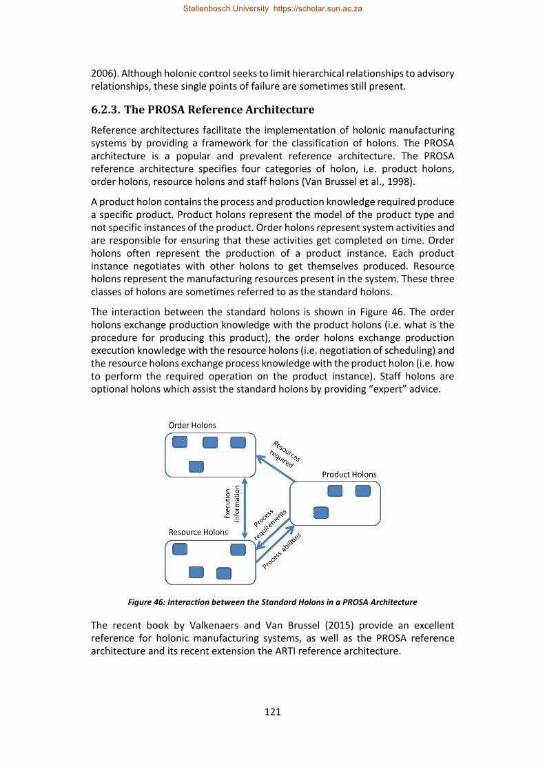
121
2006). Although holonic control seeks to limit hierarchical relationships to advisory relationships, these single points of failure are sometimes still present.
6.2.3. The PROSA Reference Architecture
Reference architectures facilitate the implementation of holonic manufacturing systems by providing a framework for the classification of holons. The PROSA architecture is a popular and prevalent reference architecture. The PROSA reference architecture specifies four categories of holon, i.e. product holons, order holons, resource holons and staff holons (Van Brussel et al., 1998).
A product holon contains the process and production knowledge required produce a specific product. Product holons represent the model of the product type and not specific instances of the product. Order holons represent system activities and are responsible for ensuring that these activities get completed on time. Order holons often represent the production of a product instance. Each product instance negotiates with other holons to get themselves produced. Resource holons represent the manufacturing resources present in the system. These three classes of holons are sometimes referred to as the standard holons.
The interaction between the standard holons is shown in Figure 46. The order holons exchange production knowledge with the product holons (i.e. what is the procedure for producing this product), the order holons exchange production execution knowledge with the resource holons (i.e. negotiation of scheduling) and the resource holons exchange process knowledge with the product holon (i.e. how to perform the required operation on the product instance). Staff holons are optional holons which assist the standard holons by providing “expert” advice.
Figure 46: Interaction between the Standard Holons in a PROSA Architecture
The recent book by Valkenaers and Van Brussel (2015) provide an excellent reference for holonic manufacturing systems, as well as the PROSA reference architecture and its recent extension the ARTI reference architecture.
Stellenbosch University https://scholar.sun.ac.za
122
6.3. Software-Based Standby Redundancy
6.3.1. Background
This paper considers redundancy of the control elements in a manufacturing cell. Redundancy is a mechanism for improving the availability of a system, typically to avoid the financial implications of unplanned downtime.
In standby redundancy for control elements, there is a primary instance and one or more backup instances. When the primary instance fails, one of the backup instances takes over as the primary instance – this is referred to as changeover. When dealing with software entities, the backup instances may exist in an idle state prior to changeover or they may be created when failure of the primary is detected.
Standby-redundant control elements are categorised based on their changeover time and the resulting system bump. Changeover time refers to the time between failure of the primary instance and one of the backup control elements beginning to execute as the new primary. System bump refers to the impact on the controlled system due to the period of control inactivity, as well as the impact caused by differences between the backup controller’s version of the system state and the actual system state.
6.3.2. Handled Fault Types
Software-based standby redundancy for software control elements can be used to handle certain computational hardware, software and network faults. In terms of computational hardware, it can handle fail-stop faults. These are faults that cause the computational hardware to stop operating. Similarly, for software faults, standby redundancy can be used to handle software faults that cause the control element to stop working; however, it is not able to mitigate faults that cause the control software to behave incorrectly. Standby redundancy can handle network faults that isolate control elements from the rest of the distributed system; however, it is not a suitable mechanism for handling data corruption or complete network failure.
6.3.3. Redundancy in Holonic Manufacturing Controllers
Holonic and heterarchical architectures are considered to inherently provide greater potential for availability as resources are dynamically selected. They also facilitate the dynamic addition and removal of resources. This enables a form of functional redundancy, whereby the system can easily have multiple resources capable of performing a given function. However, there are often other system elements, particularly architectural resources, that represent single points of failure.
In the holonic manufacturing context there is a direct mapping between certain holons, such as resource and order holons, and the entities which they represent.
Stellenbosch University https://scholar.sun.ac.za
123
In these scenarios standby redundancy is well suited as it maintains this one-to-one mapping between the software element and the represented entity (Hawkridge et al., 2018 (c)). For holons that are not instance specific, such as product holons, replication is a useful alternative since it allows for load balancing, however care must be taken to ensure consistency between replicas.
6.4. MAS and JADE
This section provides some background on agents, multi-agent systems (MASs), the standards defined by the Foundation for Intelligent Physical Agents (FIPA), Agent Platforms (APs) and JADE for readers not familiar with these concepts.
6.4.1. Agents and Multi-Agent Systems
Agents are software entities that are autonomous, proactive, reactive and cooperative/collaborative (Bellifemine et al., 2007; Poslad, 2007). Autonomy means that agents can execute independently. Since agents are proactive, they will automatically take the initiative to start achieving their goals. Reactivity refers to the fact that agents are aware of their surrounding environment and will react to changes. Agents are cooperative since they will help other agents to achieve their goals when those agents’ goals do not conflict with their own. Agents being collaborative means they will work together with one another when their goals are the same/similar.
To exhibit these characteristics, agents need to communicate with one another. Each agent also has a set of internal behaviours that define the agent’s goals, how it reacts to external stimuli and the degree to which it will cooperate/collaborate with other agents (Poslad, 2007).
A multi-agent system (MAS) refers to a system that contains several agents. The interaction of these agents leads to an emergent system behaviour. In this way the agents are collectively able to solve problems that would not be solvable individually.
6.4.2. FIPA Standards
FIPA is an international standards organisation which focuses on the facilitation of agent interoperability within heterogeneous environments. FIPA has developed several standards that enable agents developed using different frameworks and residing on different Agent Platforms to communicate in a vendor neutral manner. These include specifications related to agent naming, address resolution, expected message fields and message encoding.
6.4.3. Agent Platform
An Agent Platform (AP) refers to the infrastructure required to facilitate agent execution. This includes both the computational hardware and the software framework, which can be distributed over multiple hardware devices. The minimum requirements for an AP are specified in FIPA00023 (FIPA, 2004). Every
Stellenbosch University https://scholar.sun.ac.za
124
AP must have an Agent Management System (AMS) and a Message Transport System (MTS). Optionally an AP can also include a Directory Facilitator (DF). The AMS is the authority regarding which agents are permitted to join or be started in the AP. The AMS assigns agent identifiers (AIDs) and maintains a list of active agents and their transport addresses. The MTS is the default mechanism for inter-agent communication within the AP. The DF provides a mechanism for agents to register the services they provide and search for providers of required services.
6.4.4. JADE
JADE is an open source, FIPA compliant MAS framework originally developed by Telecom Italia. One of JADE’s strengths is its portability; since JADE is Java based, it can run on any device or operating system (OS) capable of executing an instance of the Java Virtual Machine (JVM).
Another strength of JADE is distribution, which JADE facilitates through the concept of containers. Each JADE AP contains one or more containers. A container is any JVM instance that executes JADE. This leads to the concept of the main container, which is where the AMS (and DF) reside. When JADE is distributed, multiple containers are started on different devices. The main container is started first and all subsequent containers register with it when they start (the main container’s network address is provided as a boot argument). JADE agents interact through the sending and receiving of messages. Each JADE agent has the ability to execute a number of behaviours which govern its actions.
6.5. Standby Redundancy in JADE
6.5.1. Overview
When implementing holonic systems in JADE, a single agent is typically used for each singular holon. Therefore, implementing holon standby redundancy requires the ability to implement agent standby redundancy. In this paper, agent standby redundancy is considered within a distributed JADE application with two or more control devices that each execute a JADE container (Figure 47). This is the simplest scenario in which standby redundancy can be implemented. The proposed agent standby redundancy solution, as described below, is built upon JADE’s Agent Replication Service (ARS). The ARS provides the ability to create backup replicas and synchronise state across them. JADE’s Main Container Replication Service (MCRS) is used to handle scenarios where the main container fails. The control logic is implemented using classes that inherit from JADE’s finite state machine behaviour to facilitate state entry after changeover. The following sections provide more detail on each of the individual components and how they facilitate the implementation of standby-redundant agents.
Stellenbosch University https://scholar.sun.ac.za
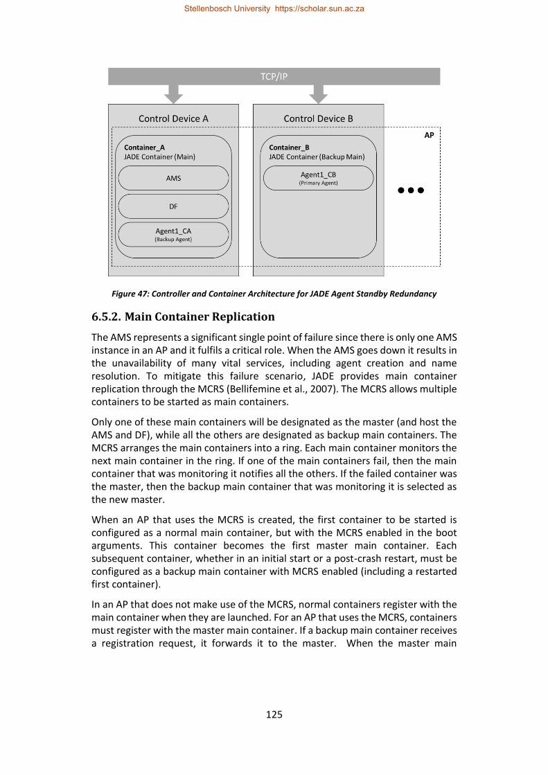
125
Figure 47: Controller and Container Architecture for JADE Agent Standby Redundancy
6.5.2. Main Container Replication
The AMS represents a significant single point of failure since there is only one AMS instance in an AP and it fulfils a critical role. When the AMS goes down it results in the unavailability of many vital services, including agent creation and name resolution. To mitigate this failure scenario, JADE provides main container replication through the MCRS (Bellifemine et al., 2007). The MCRS allows multiple containers to be started as main containers.
Only one of these main containers will be designated as the master (and host the AMS and DF), while all the others are designated as backup main containers. The MCRS arranges the main containers into a ring. Each main container monitors the next main container in the ring. If one of the main containers fail, then the main container that was monitoring it notifies all the others. If the failed container was the master, then the backup main container that was monitoring it is selected as the new master.
When an AP that uses the MCRS is created, the first container to be started is configured as a normal main container, but with the MCRS enabled in the boot arguments. This container becomes the first master main container. Each subsequent container, whether in an initial start or a post-crash restart, must be configured as a backup main container with MCRS enabled (including a restarted first container).
In an AP that does not make use of the MCRS, normal containers register with the main container when they are launched. For an AP that uses the MCRS, containers must register with the master main container. If a backup main container receives a registration request, it forwards it to the master. When the master main
Stellenbosch University https://scholar.sun.ac.za
126
container goes down, the normal containers become orphaned and must re-register with the new master. If an orphaned container is not able to reconnect, the agents executing on it become isolated. To reregister, normal containers need a list of all the main containers. This list can either be provided as a boot argument or updated dynamically using the Address Notification Service (Bellifemine et al., 2007).
The present authors recommend that the MCRS be used for all implementations of agent standby redundancy in JADE, since there is little value in improving the availability of application agents if the main container remains a single point of failure. The number of containers that are configured as backup main containers will determine how many container failures the resulting system can withstand. For the remainder of this paper, it is assumed that every container in the AP is configured as a backup main controller so that application agent failure becomes the primary potential cause of unavailability.
6.5.3. DF Persistence and Synchronisation
Since the DF executes on the main container, using the MCRS to ensure AMS availability also ensures that the DF is available. However, DF entries are not synchronised across the backup main containers. So, when the DF is restarted on a new master main container, it is started from scratch without any entries. This is problematic since it could prevent agents from finding other agents that provide required services.
A partial remedy to this issue is to enforce short lease times for DF registrations using the jade_domain_df_maxleasetime configuration parameter. This ensures that registered agents regularly renew their registrations. Therefore, when the DF is restarted on a new main container, all active agents’ DF registrations will have been renewed within a period of “max lease time” after DF start up. The potential problem with this approach is that, to reduce the time during which DF entries are unavailable, the max lease time must be short which may have an impact on performance during normal operations (since registered agents must continually renew their registrations).
An alternative approach for addressing DF entry synchronisation could be achieved using JADE’s included DF persistence functionality. This functionality allows the DF contents to be stored in a relational database instead of the default in-memory approach. Bellifemine et al. (2007) state that DF persistence provides scalability and fault tolerance. Storing the DF contents in a relational database does improve the number of entries that can be stored in the DF. However, it only makes the DF tolerant against JADE container faults – the system is still susceptible to the database server experiencing hardware or network faults. Fortunately, since the DF persistence mechanism uses standard SQL instructions and the Java DataBase Connectivity (JDBC) interface, it would be possible to use a high availability clustered database solution to achieve true fault tolerance.
Stellenbosch University https://scholar.sun.ac.za
127
6.5.4. Agent Replication Service
The Agent Replication Service (ARS) facilitates fault tolerance in JADE by allowing an agent to be replicated. The functionality of the ARS revolves around the concept of the master replica. This master replica is the only replica with the authority to interact directly with the ARS. The first instance of a replicated agent is automatically designated as the master replica. If the master replica fails, then one of the other replicas is selected as the new master (if there is another replica).
Additional replicas are created by the ARS when requested by the master replica. When a replica creation request is received, the ARS creates a clone of the master replica using the agent name and container specified in the request. The ARS and the Agent Mobility Service (which facilitates agent cloning) must be enabled for every container that will execute a replica. Each new replica is a fully operational agent capable interacting with other agents. When the master replica is cloned all the non-transient class variables are copied to the new replica (all non-transient variables must be serializable). When a replica is created, its scheduler contains all the behaviours that the master replica was executing when cloned. By default, this new replica will therefore continue to execute the behaviours with which it was cloned.
The ARS includes an event listener interface. If this interface is implemented, replicas are notified whenever new replica creation succeeds or fails and whenever one of the other replicas is removed. This interface will also notify a replica when it becomes the new master replica.
A useful feature provided by the ARS is the ability to create a virtual AID for the replicated agent. Creation of a virtual AID can be requested by the master replica and is typically used instead of using the master replica’s own AID when registering services with the DF. A virtual AID is handled by the ARS and always redirects messages to one of the active replicas. How messages are redirected depends on whether the virtual AID is configured for cold replication or hot replication. When cold replication is configured, the virtual AID always redirects to the current master replica. When hot replication is configured, messages are evenly distributed across all the active replicas. This would typically be used in a load balancing scenario.
Another useful mechanism is the ability for the master replica to request replicated method calls. When a replicated method call is requested, the ARS uses reflection to call the required method with the given arguments on each replica. Replicated calls to methods that update class variables can be used to synchronise state across all replicas.
Stellenbosch University https://scholar.sun.ac.za
128
Although the ARS is included as a standard feature in JADE, there is certain necessary functionality which is not yet implemented1, such as the ability to get a list of currently active replicas. Furthermore, it is difficult to find documentation about its use; the JADE API documentation does not contain entries for any of the classes included in jade.core.replication. Most of the information in this section has been obtained from the virtual replicated agents tutorial included in the JADE documentation and by examining the source code of the relevant classes.
6.5.5. Standby Redundancy Implementation
For an agent to implement standby redundancy there must be a single primary agent and one or more idle backup agents. It is desirable to be able to specify a list of containers on which the primary agent and its backups are permitted to execute as part of the agent’s configuration. In the research presented here, using Java’s object-oriented principle of inheritance, a base standby-redundant agent class was developed that inherits from JADE’s agent class and from which standby-redundant application agents can inherit. This allows the functionality to be developed once and minimises the level of knowledge about the ARS required when developing standby-redundant agents. The standby-redundant agent class handles the creation of backup replicas and provides mechanisms for state storage and synchronisation.
The following sections provide details on specific aspects of the standby-redundant agent class’ implementation. These aspects include primary agent selection, backup agent creation, state synchronisation and conversation recovery. This is followed by a section detailing the potential issues and shortcomings of standby-redundant agent base class implementation.
6.5.5.1. Primary Agent Selection and Backup Creation
The standby-redundant agent class uses the master replica selected by the ARS as the primary standby-redundant instance. To start a standby-redundant agent, an instance is started on one of the AP’s containers. This instance is automatically selected as the primary instance. The primary agent then requests a list of active containers from the AMS and creates backup replicas of itself on all active containers that are in its permitted container list. The primary agent also subscribes to platform events to detect when containers are added to the AP. The primary agent can then create additional backup replicas whenever a container in its permitted container list comes online. It is not possible to implement container priorities in the permitted container list for standby-redundant agent execution since the ARS does not provide a mechanism for specifying which replica becomes the next master replica.
1 in JADE 4.50
Stellenbosch University https://scholar.sun.ac.za
129
When a primary agent (master replica) fails, the ARS selects a new master replica which becomes the new primary agent. This new primary is notified of its new status using the ARS’s event listener functionality. The ARS’s event listener functionality is also used to detect the successful creation of backups, as well as to detect the failure of backup agents so that they can be recreated if their host container is still operational.
When using the ARS’s replication functionality to create backup agents, it is problematic that these additional replicas are created by cloning the master replica. Backup agents are meant to be idle, but when a cloned replica is created it continues to execute the behaviours that were copied from the master replicas scheduler. To solve this, it was necessary to overload the addBehaviour and removeBehaviour methods in the standby-redundant agent class so that a list of currently executing behaviours could be maintained. This list is then used in the start-up procedure of backup agents to remove all added behaviours and leave these agents idle. When an agent becomes the primary, the required behaviours are added again.
6.5.5.2. Container Monitoring
As mentioned in the previous section, to create backup agents it is necessary for the primary agent to monitor the addition and removal of containers in the AP. This is achieved using JADE’s platform events, which include events for the creation and death of agents, the addition and removal of containers and when agents are moved or cloned (these are the same events used to implement JADE’s remote management agent). The primary agent subscribes to platform events by sending a subscription request to the AMS and then filters the received events for events pertaining to container addition or removal.
6.5.5.3. State Synchronisation
To facilitate agent state storage, the base standby-redundant agent class uses Java’s Generics feature to allow the definition of an application state class. This application state class must inherit from a base redundant state class to ensure it is serializable. The base redundant state class also contains state entries used by the redundant agent base class that require synchronisation (such as the list of containers executing standby agents). An instance of the application state class is created by the standby-redundant agent base class and synchronised using the ARS’s replicated method call functionality when requested in the application agent code.
6.5.5.4. Communication Recovery
Cooperation and collaboration are key aspects of both holonic and multi-agent systems. Therefore, it is important that the communication between holons/agents can be recovered after a changeover event. If the communication is stateful (i.e. the contents of responses are dependent on the receipt of prior messages), as is the case with contract net protocol-based communication, it is
Stellenbosch University https://scholar.sun.ac.za
130
necessary to implement some form of rollback recovery mechanism. This is discussed in detail in Hawkridge et al. (2018 (b)).
The ARS’s virtual AID functionality can be helpful when implementing a conversation recovery mechanism. The standby-redundant agent class uses a virtual AID, configured for cold replication, for all interaction with other agents. In this way, when changeover occurs, the virtual AID is redirected to the new primary agent. This avoids the need to inform other agents of the new primary agent’s AID.
6.5.5.5. Implementation Issues
Two issues were identified for the standby-redundant base class implementation: the first is a potential issue relating to how containers are monitored, and the second is related to how the ARS performs replicated method calls.
The possible issue with JADE’s platform event implementation, which is used for container monitoring, is that there is no way to subscribe to a specific subset of the different event types; an agent either gets all the events or none of them. Therefore, the receive statements of subscribed agents need to be developed in such a way that they only match the desired events and ignore the remainder.
This could have a substantial communication overhead, especially in large systems, since every standby-redundant agent would be sent a message for every platform event. This scalability impact could be reduced by using a separate agent that subscribes to the platform events and monitors the received events for container events which are then forwarded to all the standby-redundant agents. This container monitor agent would then become a single point of failure in the system and would therefore need to implement a form of redundancy.
An issue when using inheritance with the ARS’s replicated method calls was identified: The reflection approach used for replicated method calls in the ARS only looks for the required method in the lowest-level subclass of the agent. This means that it is not possible to make replicated calls to methods in the standby-redundant agent base class when it is inherited from to create a standby-redundant application agent. A workaround for this is to make the replicated calls to an abstract method that must be implemented in the application agent class and then call the state synchronisation method in the base class from that method. Unfortunately, this workaround is not elegant since the developer must remember to implement the call to the base class’s state synchronisation method in each class that inherits from it.
6.5.6. Failure Detection
An important aspect of any standby redundancy implementation is how it detects failure of the primary instance. In the case of this JADE implementation, there are two forms of failure that must be detected, i.e. agent failure and container failure.
JADE services are implemented using a distributed coordinated filters architecture (Bellifemine et al., 2007). When an agent fails, the container on which the agent
Stellenbosch University https://scholar.sun.ac.za
131
was executing generates a notification which is sent to the AMS. The ARS implements a filter which intercepts this notification and checks whether the failed agent is a replica before passing the message on to the AMS. If the failed agent is one of the replicas, then the ARS can act accordingly. In order to generate a notification when a container fails, the master main container must monitor all of the containers in the AP (since a container may be unable to generate a notification about its own failure).
6.5.6.1. The Default RMI-Based Container Monitoring Mechanism
JADE’s default container monitoring mechanism uses Java’s Remote Method Invocation (RMI) interface, which operates over a permanent TCP connection. These RMI connections already exist between all the AP’s containers since they are used to serve inter-container commands. The default mechanism on the master main container uses RMI to make a blocking call on each of the containers in the AP. When the TCP connection between the master main container and one of the containers is dropped, the RMI mechanism generates an exception. The master main container assumes that this exception has occurred because the other container has failed, and that container is removed from the AP.
This approach works well on reliable networks when the AP only contains a few containers (Bellifemine et al., 2010). However, as the system grows there will be increasing network congestion, which increases the chance that the TCP connection of an active container will be dropped, and that container will be falsely removed.
6.5.6.2. The UDP Node Monitoring Service
JADE provides the UDP Node Monitoring Service (UDPNMS) as an alternative container monitoring mechanism to facilitate APs that have many containers or that use unreliable networks (Bellifemine et al., 2010). The UDPNMS uses UDP multicast heartbeats to identify unresponsive containers. The UDPNMS must be enabled at start up for all containers in the AP. An advantage of the UDPNMS is that it allows containers to be temporarily unavailable without being falsely removed from the AP (Bellifemine et al., 2010). A further advantage is that its configuration parameters allows for greater control of the container failure detection delay.
There are four configuration parameters that control how the UDPNMS behaves: the port_number, the ping_delay, the ping_delay_limit and the unreachable_limit. The port_number specifies the port on which the master main container listens and to which the UDP heartbeats are addressed. The ping_delay (in milliseconds) determines the rate at which containers will emit heartbeats. If the master main container does not receive a heartbeat from a container within the ping_delay_limit (in milliseconds), then that container is considered unreachable. If the container remains unreachable for longer than the unreachable_limit (in milliseconds), then it is considered to
Stellenbosch University https://scholar.sun.ac.za
132
have failed and is removed. These parameters are specified on the main container and propagated to the other containers in the AP during execution.
6.5.6.3. Comparison
It was observed that the default RMI-based implementation has a short detection period for faults that result in immediate termination of the TCP connection (i.e. software faults that terminate the container but leave the host device’s OS operational). However, for faults that do not result in immediate termination of the TCP socket (i.e. whenever the container’s host device experienced power loss or was isolated by network failure), the detection of a failed container is delayed until the TCP socket times out. This timeout is dependent on the device and OS but may be in the order of several minutes.
Disappointingly, the UDPNMS also experiences a similarly delayed failure detection whenever container failure is due to power loss or network isolation of the container’s host device. Fortunately, the delayed detection period is substantially shorter than that of the default mechanism (tens of seconds as opposed to minutes).
An examination of the UDPNMS source code, in conjunction with system logs at JADE’s finest logging level, revealed the source of this added delay as an RMI ping timeout. Before classifying a container as unreachable, the master main container first attempts a non-blocking ping of the container over the RMI connection between the two containers. It is suspected that this is done to ensure that the unresponsive container is in fact unreachable, since UDP is a connectionless protocol characterised by best-effort packet delivery – therefore neither the sender nor the intended receiver of a UDP packet have any awareness or control of packet loss. If the ping is successful, then the container it is not classified as unreachable since the UDP heartbeats were assumedly lost. However, if the container has failed, the ping blocks until it times out and the UDPNMS handles the container failure as expected.
Although a logical motivation for the non-blocking RMI ping can be theorised, it is not strictly necessary. To avoid scenarios where the ping_delay_limit is falsely reached for an active container, the ping_delay and ping_delay_limit could rather be adjusted to increase the number of heartbeat pings that would need to be lost before a node is considered unavailable. Alternatively, the ability to configure the RMI ping timeout would be desirable. It could be possible to reduce the RMI ping timeout using certain flags when compiling JADE, but this may affect the stability of other aspects of the JADE platform that utilise RMI. Since JADE is open source, the RMI ping could be removed from the UDPNMS source code, but this paper seeks to use standard JADE features. Despite its shortcomings, the UDPNMS is the superior node monitoring mechanism and is therefore the mechanism used in this standby redundancy implementation.
Stellenbosch University https://scholar.sun.ac.za
133
6.5.7. Handling Standby Redundancy Events
The three forms of standby redundancy events that are typically catered for by software based standby redundancy implementations are controller failure due to power loss or a hardware fault, controller isolation by a network fault, and operator triggered changeover. The JADE standby redundancy implementation’s ability to handle each of these scenarios is discussed below.
6.5.7.1. Controller Failure due to Power Loss or Hardware Fault
Changeover due to power loss or fail-stop hardware faults is the simplest form of standby redundancy event to address. If the failed control device was host to a backup agent, then the primary agent continues execution with one fewer backup agent. If the failed device was host to the primary agent, then the standby redundancy base class implementation detects the failure and selects a new primary agent. When the failed control device is brought back online, the JADE container is restarted. The primary agent will detect the addition of this container to the AP and create a backup replica on it.
6.5.7.2. Controller Isolation by a Network Fault
Controller isolation due to a network fault is usually complicated to manage for software based standby redundancy implementations. This is because, to the rest of the system, the isolated controller appears to have failed, while to the isolated controller, the rest of the system appears to have failed. This is most evident in systems with only two containers. These systems will contain a primary redundant agent and a single backup agent. When one of the controllers is isolated, both containers detect this as the other container having failed. As a result, the backup agent is promoted to primary agent. There are now two primaries in the system.
This is less of an issue if the only means by which these agents influence the rest of the system is over the network since the primary on the isolated container would not be able to conflict with the primary on the non-isolated container. However, if the primary agents interact with the system using the control device’s I/O then this is a significant issue and mechanisms need to be implemented to ensure that only the non-isolated primary agent performs I/O operations, as described by Hawkridge et al. (2018 (a)).
A second key aspect of handling controller isolation is reintegration of the controller after the network fault has been rectified. The JADE functionalities used here to implement standby redundancy do not provide an easy mechanism for achieving this. The main issue is that, due to the use of the MCRS, the isolated container is now a main container. In the work presented here, it was found that the best approach to reintegrate a container, is to shut it down and then restart it.
Stellenbosch University https://scholar.sun.ac.za
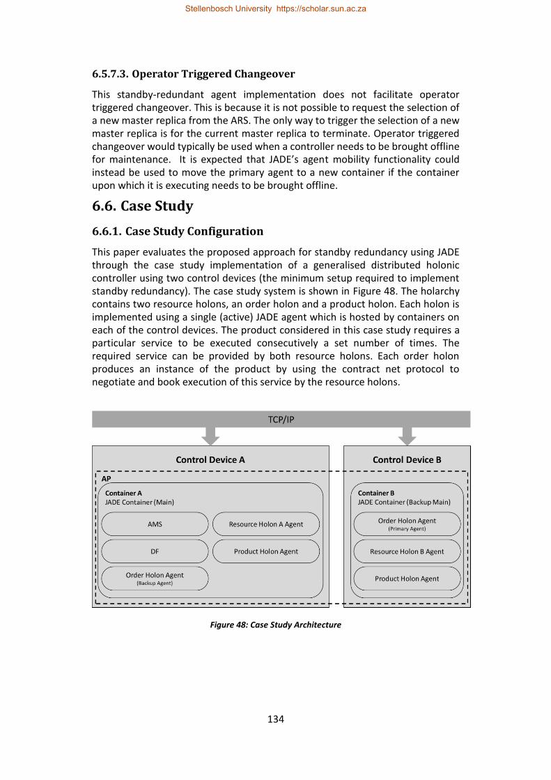
134
6.5.7.3. Operator Triggered Changeover
This standby-redundant agent implementation does not facilitate operator triggered changeover. This is because it is not possible to request the selection of a new master replica from the ARS. The only way to trigger the selection of a new master replica is for the current master replica to terminate. Operator triggered changeover would typically be used when a controller needs to be brought offline for maintenance. It is expected that JADE’s agent mobility functionality could instead be used to move the primary agent to a new container if the container upon which it is executing needs to be brought offline.
6.6. Case Study
6.6.1. Case Study Configuration
This paper evaluates the proposed approach for standby redundancy using JADE through the case study implementation of a generalised distributed holonic controller using two control devices (the minimum setup required to implement standby redundancy). The case study system is shown in Figure 48. The holarchy contains two resource holons, an order holon and a product holon. Each holon is implemented using a single (active) JADE agent which is hosted by containers on each of the control devices. The product considered in this case study requires a particular service to be executed consecutively a set number of times. The required service can be provided by both resource holons. Each order holon produces an instance of the product by using the contract net protocol to negotiate and book execution of this service by the resource holons.
Figure 48: Case Study Architecture
Stellenbosch University https://scholar.sun.ac.za
135
The order holon implements standby redundancy and is the focus of the evaluation in this section. The resource holons do not implement redundancy and are each assigned their own container. The product holon is replicated (i.e. executes on both containers) since it is not instance specific (Hawkridge et al., 2018 (c)). This could be achieved using the ARS, however product replication is not further considered in this paper.
The two control devices used in this case study are a Microsoft Windows PC and an embedded Linux microcontroller (a Raspberry Pi 3 model B). This highlights the portability of Java/JADE code since the holon code is identical for both control devices. The ability to use different computational hardware and different operating systems is beneficial from a redundancy standpoint as it reduces the likelihood of common cause faults.
6.6.2. Test Procedure
There are two measures for standby-redundant systems: changeover time and system bump. Since holonic control typically deals with discrete event systems, changeover time is one of the main contributors to system bump as it increases the probability that events will be missed. Therefore, the JADE implementation will be evaluated in terms of its changeover time.
The changeover time is the sum of the failure detection time, the primary selection time and the application initialisation time. The application initialisation time will vary from use case to use case and will be of little meaning since this case study uses a generic holarchy. The application initialisation time is therefore disregarded from the analysis and changeover is measured from primary failure until the backup is notified of its new status as primary.
6.6.2.1. Measuring Changeover Time
Changeover times are calculated using custom system logs that generate timestamps with millisecond precision. Using timestamps is complicated due to differences between the two devices’ system times and clock drift. A mechanism was implemented that periodically logs the time difference between the two containers as calculated using an adaptation of Cristian’s clock synchronisation algorithm (Cristian, 1989).
The algorithm is shown in Figure 49. First party A sends a timestamp request to party B and stores its local timestamp (𝑡𝐴1) at the time of sending. When party B receives the timestamp request, it sends a reply containing its local timestamp (𝑡𝐵). When it receives the response from B, party A takes a second timestamp (𝑡𝐴2). The time difference is then calculated as ∆ =
𝑡𝐴1+𝑡𝐴2
2− 𝑡𝐵 with a round-trip
time of 𝑅𝑇𝑇 = 𝑡𝐴2 − 𝑡𝐴1. The algorithm assumes that the outbound and inbound transmission time are equal. These synchronisation measures were performed at regular intervals and the time difference with the shortest round-trip time was used in order to reduce the accuracy impact of possible differences between the outbound and inbound transmission time.
Stellenbosch University https://scholar.sun.ac.za
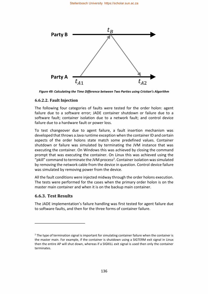
136
Figure 49: Calculating the Time Difference between Two Parties using Cristian’s Algorithm
6.6.2.2. Fault Injection
The following four categories of faults were tested for the order holon: agent failure due to a software error; JADE container shutdown or failure due to a software fault; container isolation due to a network fault; and control device failure due to a hardware fault or power loss.
To test changeover due to agent failure, a fault insertion mechanism was developed that throws a Java runtime exception when the container ID and certain aspects of the order holons state match some predefined values. Container shutdown or failure was simulated by terminating the JVM instance that was executing the container. On Windows this was achieved by closing the command prompt that was executing the container. On Linux this was achieved using the “pkill” command to terminate the JVM process2. Container isolation was simulated by removing the network cable from the device in question. Control device failure was simulated by removing power from the device.
All the fault conditions were injected midway through the order holons execution. The tests were performed for the cases when the primary order holon is on the master main container and when it is on the backup main container.
6.6.3. Test Results
The JADE implementation’s failure handling was first tested for agent failure due to software faults, and then for the three forms of container failure.
2 The type of termination signal is important for simulating container failure when the container is the master main. For example, if the container is shutdown using a SIGTERM exit signal in Linux then the entire AP will shut down, whereas if a SIGKILL exit signal is used then only the container terminates.
Stellenbosch University https://scholar.sun.ac.za
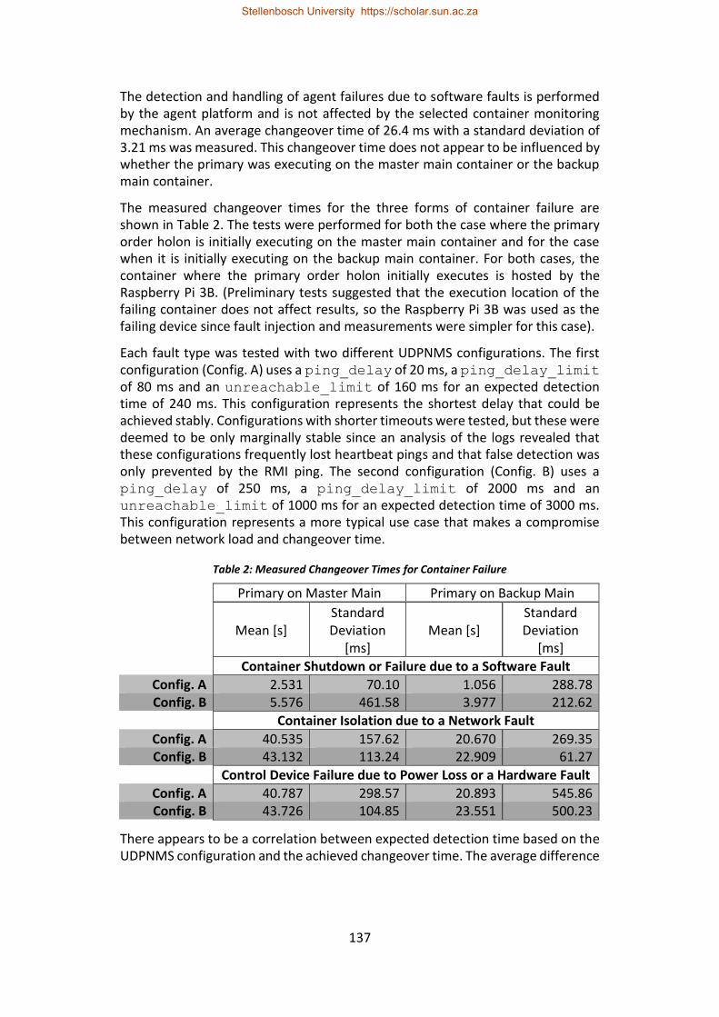
137
The detection and handling of agent failures due to software faults is performed by the agent platform and is not affected by the selected container monitoring mechanism. An average changeover time of 26.4 ms with a standard deviation of 3.21 ms was measured. This changeover time does not appear to be influenced by whether the primary was executing on the master main container or the backup main container.
The measured changeover times for the three forms of container failure are shown in Table 2. The tests were performed for both the case where the primary order holon is initially executing on the master main container and for the case when it is initially executing on the backup main container. For both cases, the container where the primary order holon initially executes is hosted by the Raspberry Pi 3B. (Preliminary tests suggested that the execution location of the failing container does not affect results, so the Raspberry Pi 3B was used as the failing device since fault injection and measurements were simpler for this case).
Each fault type was tested with two different UDPNMS configurations. The first configuration (Config. A) uses a ping_delay of 20 ms, a ping_delay_limit of 80 ms and an unreachable_limit of 160 ms for an expected detection time of 240 ms. This configuration represents the shortest delay that could be achieved stably. Configurations with shorter timeouts were tested, but these were deemed to be only marginally stable since an analysis of the logs revealed that these configurations frequently lost heartbeat pings and that false detection was only prevented by the RMI ping. The second configuration (Config. B) uses a ping_delay of 250 ms, a ping_delay_limit of 2000 ms and an unreachable_limit of 1000 ms for an expected detection time of 3000 ms. This configuration represents a more typical use case that makes a compromise between network load and changeover time.
Table 2: Measured Changeover Times for Container Failure
Primary on Master Main Primary on Backup Main
Mean [s] Standard Deviation
[ms] Mean [s]
Standard Deviation
[ms]
Container Shutdown or Failure due to a Software Fault
Config. A 2.531 70.10 1.056 288.78 Config. B 5.576 461.58 3.977 212.62
Container Isolation due to a Network Fault
Config. A 40.535 157.62 20.670 269.35 Config. B 43.132 113.24 22.909 61.27
Control Device Failure due to Power Loss or a Hardware Fault
Config. A 40.787 298.57 20.893 545.86 Config. B 43.726 104.85 23.551 500.23
There appears to be a correlation between expected detection time based on the UDPNMS configuration and the achieved changeover time. The average difference
Stellenbosch University https://scholar.sun.ac.za
138
between the changeover times for Config. B and Config. A is 2.73 seconds and the difference between their expected detection times is 2.76 seconds. However, further tests with multiple configurations would be required to identify the relationship between the UDPNMS configuration parameters and the achieved changeover time with a level of certainty.
The test results show that the changeover takes longer when the primary order holon is on the master main container than when it is on the backup main container. This is because the MCRS first needs to handle the master main container failure and select the new master main container before the ARS-based standby redundancy implementation can select a new primary holon.
The results also highlight the effect of the RMI ping timeout on the changeover time for container isolation and control device failure. For the case where the primary holon begins on the backup main container, the RMI ping timeout appears to add approximately 20 seconds of additional delay. For the case where the primary holon begins on the master main container, the additional delay is approximately 40 seconds. It is suspected that this may in fact be due to two RMI ping timeouts: the initial ping for container failure detection and an additional ping once the backup main container is selected as master main. However, this requires further investigation. The changeover times achieved for container shutdown or failure due to software errors are potentially an indication of the changeover times that could be achieved for container isolation and control device failure if the RMI ping timeout delay is rectified.
6.7. Conclusions
This paper presents and evaluates an approach for implementing, by using JADE’s built-in functionality, standby redundancy for a distributed holonic cell controller. The paper considers holon standby redundancy as agent standby redundancy, since MAS implementations of holonic systems typically use a single agent for each holon. The approach uses JADE’s Main Container Replication Service (MCRS) to ensure that main container failure does not result in Agent Platform (AP) failure. The creation of backup holon instances and primary holon instance selection is facilitated by the Agent Replication Service (ARS). JADE’s UDP Node Monitoring Service (UDPNMS) is used to detect container faults since its fault detection period is superior to that of the default Remote Method Invocation (RMI) based container monitoring mechanism.
The presented standby redundancy implementation can handle four categories of failure: agent failure due to software faults; container shutdown or failure due to software faults; container isolation by network faults; and control device failure due to power loss or fail-stop hardware faults. The implementation does not facilitate automatic reintegration of containers that have been isolated by network faults – instead it requires that they be terminated and restarted. The implementation also does not allow for operator triggered changeover, but JADE’s agent mobility functionality can be used to achieve a similar effect.
Stellenbosch University https://scholar.sun.ac.za
139
The case study of a minimal distributed holonic cell was used to validate the proposed approach. The holarchy contained two resource holons, an order holon, and a product holon and was implemented across two control devices. The changeover time was measured for each of the four fault categories using two different UDPNMS configurations and for both the case when the primary holon is on the master main container and for when the primary holon is on the backup main container.
Changeover times in the event of controller isolation or control device failure in the order of 40 seconds for the master main container and 20 seconds for a backup main container were observed. Changeover durations of this magnitude may be acceptable at higher levels of manufacturing control. However, at a cell level changeover times that exceed a few seconds are typically unacceptable.
In conclusion, it is possible to implement standby-redundant holonic cell control, using JADE, that can handle the types of failures that are typically expected from a software based standby redundancy solution. However, the achievable changeover times may be unacceptable for many manufacturing cell applications without making modifications to the JADE source code.
6.8. References
Babiceanu, R.F. and Chen, F.F., 2006. Development and applications of holonic manufacturing systems: a survey. Journal of Intelligent Manufacturing, 17(1): 111-131.
Bellifemine, F.L., Caire, G. and Greenwood, D., 2007. Developing multi-agent systems with JADE (Vol. 7). John Wiley & Sons.
Bellifemine, F., Caire, G., Trucco, T., Rimassa, G. and Mungenast, R., 2010. Jade administrator’s guide. [Online]. Available: http://jade.tilab.com/doc/administratorsguide.pdf [2018, October 1].
Bi, Z.M., Lang, S.Y., Shen, W. and Wang, L., 2008. Reconfigurable manufacturing systems: the state of the art. International Journal of Production Research, 46(4): 967-992.
Bi, Z., Da Xu, L. and Wang, C., 2014. Internet of things for enterprise systems of modern manufacturing. IEEE Transactions on industrial informatics, 10(2): 1537-1546.
Brettel, M., Friederichsen, N., Keller, M. and Rosenberg, M., 2014. How virtualization, decentralization and network building change the manufacturing landscape: An industry 4.0 perspective. International Journal of Mechanical, Industrial Science and Engineering, 8(1): 37-44.
Colombo, A.W., Schoop, R. and Neubert, R., 2006. An agent-based intelligent control platform for industrial holonic manufacturing systems. IEEE Transactions on Industrial Electronics, 53(1): 322-337.
Stellenbosch University https://scholar.sun.ac.za
140
Cristian, F., 1989. Probabilistic clock synchronization. Distributed computing, 3(3): 146-158.
Dilts, D.M., Boyd, N.P. and Whorms, H.H., 1991. The evolution of control architectures for automated manufacturing systems. Journal of manufacturing systems, 10(1): 79-93.
FIPA, 2004. FIPA Agent Management Specification. [Online]. Available: http://www.fipa.org/specs/fipa00023/ [2018, October 1].
Gerbert, P., Lorenz, M., Rüßmann, M., Waldner, M., Justus, J., Engel, P. and Harnisch, M., 2015. White Paper on Industry 4.0: The future of productivity and growth in manufacturing industries [Online]. Available: https://www.bcg.com/en-za/publications/2015/engineered_products_project_business_industry_4_future_productivity_growth_manufacturing_industries.aspx [2018, November 10].
Hawkridge, G., Basson, A.H. and Kruger, K., 2018 (a). An Evaluation of Erlang for Implementing Standby Redundancy in a Manufacturing Station Controller, in 8th Workshop on Service Orientation in Holonic and Multi-Agent Manufacturing. Italy, Bergamo.
Hawkridge, G., Basson, A.H. and Kruger, K., 2018 (b). Conversation Recovery after Failover for Contract Net Protocol Communication in an Erlang-Based Holonic Architecture. submitted to the International Journal of Computer Integrated Manufacturing.
Hawkridge, G., Basson, A.H. and Kruger, K., 2018 (c). An Erlang-based Standby-Redundant Distributed Holonic Controller for a Manufacturing Cell. submitted to the International Journal of Computer Integrated Manufacturing.
Koestler, A., 1989. The ghost in the machine. Arkana, London.
Lasi, H., Fettke, P., Kemper, H.G., Feld, T. and Hoffmann, M., 2014. Industry 4.0. Business & Information Systems Engineering, 6(4): 239-242.
Leitão, P., 2009. Agent-based distributed manufacturing control: A state-of-the-art survey. Engineering Applications of Artificial Intelligence, 22(7): 979-991.
Poslad, S., 2007. Specifying protocols for multi-agent systems interaction. ACM Transactions on Autonomous and Adaptive Systems (TAAS), 2(4): 15.
Van Brussel, H., 1994. Holonic manufacturing systems the vision matching the problem, in Proceedings of the 1st European Conference on Holonic Manufacturing Systems, Hannover, Germany.
Van Brussel, H., Wyns, J., Valckenaers, P., Bongaerts, L. and Peeters, P., 1998. Reference architecture for holonic manufacturing systems: PROSA. Computers in industry, 37(3): 255-274.
Stellenbosch University https://scholar.sun.ac.za

141
Valckenaers, P. and Van Brussel, H., 2015. Design for the unexpected: From holonic manufacturing systems towards a humane mechatronics society. Butterworth-Heinemann.
Stellenbosch University https://scholar.sun.ac.za

142
7. Evaluation
This section describes the evaluation of the Erlang/OTP implementation of standby redundancy. The evaluation seeks to determine the suitability of Erlang/OTP for implementing standby redundancy in a distributed holonic cell.
The evaluation is performed through a case study comparison with a similar JADE implementation as described in section 1.4. The comparison is presented in the form of a paper titled “Comparison of Erlang/OTP and JADE Implementations for Standby Redundancy in a Holonic Cell Controller” (Hawkridge et al., 2018 (f)).
Stellenbosch University https://scholar.sun.ac.za
143
Comparison of Erlang/OTP and JADE Implementations for Standby Redundancy in a
Holonic Controller
G Hawkridge, AH Basson, K Kruger Department of Mechanical and Mechatronic Engineering, Stellenbosch University
Abstract
This paper presents a comparison between two standby redundancy implementations within the context of a holonic controller for a manufacturing cell: using the Erlang/OTP programming framework and the JADE (Java Agent DEvelopment framework) multi-agent system (MAS) framework. Erlang (and its associated library OTP) contains several features that greatly simplify the implementation of standby redundancy. JADE is a popular MAS framework that has become the prevailing solution within academic research in holonic control. Both solutions implement standby redundancy using standard features of their respective frameworks. A case study comparison is performed using both quantitative and qualitative measures.
The comparison shows that, for the case study, the Erlang/OTP implementation performs better than the JADE implementation for all the standby-redundant metrics: it achieves shorter changeover times, lower computational requirements overall, less computational and state synchronisation overhead, and greater fault handling flexibility. Erlang/OTP lacks the level of supporting communication and protocol infrastructure that is available in JADE due to JADE's strong heritage within multi-agent systems.
Keywords: Standby Redundancy; Holonic Control; Erlang/OTP; JADE
7.1. Introduction
Modern manufacturing paradigms are becoming increasingly distributed and complex. This is particularly evident in the recent focus on Industry 4.0, cyber-physical systems (CPSs) and the Industrial Internet of Things (IIoT) (Brettel et al., 2014; Bi, Xu & Wang 2014; Gerbert et al., 2015). The reliability or availability of such complex systems is a significant concern. Availability here refers to the percentage of time for which a system is ready and able to perform its expected functions.
The holonic paradigm has been highlighted as a promising approach for managing complexity, changes and disturbances in systems (Monostori et al., 2016). Holonic manufacturing control maintains the global control and optimisation potential of hierarchical structures, while leveraging the improved flexibility and fault-tolerance of heterarchical structures.
Holonic manufacturing systems achieve fault-tolerance by facilitating functional redundancy. Functional redundancy here refers to the use of multiple holons that can perform a certain task. Even though holonic systems will, in general, continue
Stellenbosch University https://scholar.sun.ac.za
144
operating in the presence of holon failure (for holons that have functional redundancy), this holon failure will reduce the functionality or capacity of the system, leading to bottlenecks and possible system failure. Additionally, functional redundancy is not always possible for all types of holon. Standby redundancy is an approach that can be used to improve the availability of individual holons. Standby redundancy has traditionally been used to improve the availability of hierarchical or monolithic control systems.
This paper compares two alternative software platforms, Erlang/OTP and the Java Agent DEvelopment framework (JADE), in terms of their suitability for the implementation of standby redundancy in a holonic controller for a manufacturing cell.
JADE is a framework that facilitates the implementation of multi-agent systems. The multi-agent system (MAS) is a computational paradigm in which systems are composed of many intelligent agents which interact with one another. Kravari and Bassiliades (2015) claim that JADE is the most popular framework in the agent-based computing community. This popularity can be largely attributed to JADE’s foundations in the Java ecosystem and the supporting tools and community that foundation brings. Additionally, JADE is compliant with the Foundation of Intelligent Physical Agents (FIPA) standards which facilitate interoperability between different MAS frameworks by specifying common architectural, communication and management components (Leitao et al., 2016; Bellifemine et al., 2007). MASs are frequently used when implementing holonic manufacturing systems due to the similarities between agents and holons (Babiceanu & Chen, 2006). Due to its popularity within the MAS environment, JADE has in many respects become the de facto standard for holonic implementations in academic research.
Erlang is a functional programming language designed for the development of fault-tolerant soft real-time control systems (Armstrong, 1996). OTP (Open Telecom Platform), a key feature of Erlang, is a set of libraries that simplify the development of large complex systems (Armstrong 2010: 73). Erlang/OTP is not well known within the manufacturing systems’ academic community, but it has an impressive industrial track record. Initially developed by Ericsson, Erlang/OTP has been used in several successful, large-scale products such as the AXD301 switch (Armstrong, 2003). Erlang and OTP were public released as open source software in 1998. Since then, its use has provided several companies with competitive advantages, leading to a rapidly growing user community. A prominent example of the competitive advantage that Erlang/OTP can provide is WhatsApp, which used Erlang/OTP to develop a high-reliability, massively-scalable messaging service that serves more than 450 million users (O’Connell, 2014).
Erlang has many attractive features, such as concurrency and scalability, that are useful when implementing holonic manufacturing control systems (Kruger & Basson, 2017). Researchers at KU Leuven have used Erlang/OTP to achieve a technology readiness level 7 for the control implementation of a 3D printing
Stellenbosch University https://scholar.sun.ac.za
145
factory (Valckenaers and Van Brussel, 2015). Furthermore, GRiSP has used Erlang/OTP to create robust embedded controllers (Anonymous, s.a.). Erlang/OTP has been proposed as an alternative to JADE and MAS for holonic implementations as it inherently provides greater modularity and fault tolerance (Kruger, 2018).
This paper begins with an outline of the comparison’s methodology. This is followed by an overview of the holonic cell controller considered in this paper and the two standby redundancy solutions. The evaluation criteria are then presented and motivated. The two solutions are then compared based on those criteria. Finally, some conclusions and recommendation are provided.
7.2. Methodology
This paper presents a comparison between two different software frameworks. As discussed in Kruger (2018), generalised comparisons of software platforms are complicated by paradigmatic, syntactic and philosophic differences. Instead, this paper follows the examples of Chirn and McFarlane (2005), and Kruger (2018) by performing a comparison that focuses on each platform’s supporting functionality for a specific use case. In this paper, that use case is the implementation of standby redundancy in a holonic cell controller. This comparison is performed using separate standby redundancy implementations of the same holonic architecture for a case study system. Both implementations are restricted to using the standard features and functionalities of their respective software frameworks.
This comparison uses a combination of quantitative and qualitative metrics. Quantitative metrics are used to compare the solutions in terms of their performance and overhead. Qualitative metrics are used to compare the behaviour and characteristics of the standby redundancy implementations and their underlying software frameworks. Qualitative evaluations are based on experiences and impressions of the authors and are therefore susceptible to the preconceptions and agenda of the evaluator. While the subjective nature of qualitative metrics is unavoidable, this paper endeavours to provide an impartial evaluation.
Since this paper considers a system with multiple control devices and multiple software elements that can be distributed across those devices, there are a multitude of potential permutations. Although this paper endeavours to test a representative selection of those permutations, it is possible that unexpected edge cases may exist. It is further emphasised that the results obtained in this paper are specific to the case study scenario considered, and that application of these standby redundancy approaches to other scenarios may lead to different results.
Although this paper considers standby redundancy in a holonic architecture, this comparison will only focus on aspects of holonic architecture implementation that are pertinent to standby redundancy. For a more complete evaluation and comparison of Erlang/OTP and JADE for the implementation of holonic architectures, the reader is referred to Kruger (2018).
Stellenbosch University https://scholar.sun.ac.za
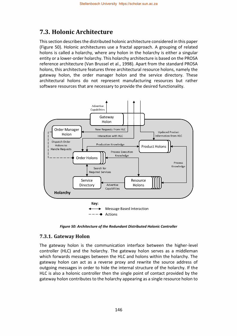
146
7.3. Holonic Architecture
This section describes the distributed holonic architecture considered in this paper (Figure 50). Holonic architectures use a fractal approach. A grouping of related holons is called a holarchy, where any holon in the holarchy is either a singular entity or a lower-order holarchy. This holarchy architecture is based on the PROSA reference architecture (Van Brussel et al., 1998). Apart from the standard PROSA holons, this architecture features three architectural resource holons, namely the gateway holon, the order manager holon and the service directory. These architectural holons do not represent manufacturing resources but rather software resources that are necessary to provide the desired functionality.
Figure 50: Architecture of the Redundant Distributed Holonic Controller
7.3.1. Gateway Holon
The gateway holon is the communication interface between the higher-level controller (HLC) and the holarchy. The gateway holon serves as a middleman which forwards messages between the HLC and holons within the holarchy. The gateway holon can act as a reverse proxy and rewrite the source address of outgoing messages in order to hide the internal structure of the holarchy. If the HLC is also a holonic controller then the single point of contact provided by the gateway holon contributes to the holarchy appearing as a single resource holon to
Stellenbosch University https://scholar.sun.ac.za

147
the HLC. As the single point of contact, the gateway holon is responsible for advertising the holarchy’s capabilities with the HLC (should the HLC provide such a mechanism).
If the holarchy and the HLC use different messaging schemes, the gateway holon can be used to translate between these messaging schemes. This may include translating between different encodings (i.e. from XML encoded text to Erlang records), performing encryption/decryption or converting between different transmission media (i.e. from TCP/IP to RS-232).
7.3.2. Order Manager Holon
The order manager holon dispatches order holons to handle new requests from the HLC. The order manager holon can be used to limit the number of active orders to prevent the holarchy from being flooded by requests. When the number of active orders reaches a specified limit, the order manager holon queues additional requests and dispatches them when current active orders are completed.
7.3.3. Service Directory
The service directory is an architectural resource holon which assists both resource and order holons. By allowing resource holons to advertise their capabilities, the service directory helps each order holon find resource holons with the capabilities required for the next stage of that order’s production procedure. A service directory can contribute to the modularity and reconfigurability of a holarchy since a resource can be added to or removed from active use by registering or deregistering with the service directory without directly affecting the remainder of the holarchy.
7.3.4. Product Holons
Each product holon contains the production procedure, product model and parameters required to produce an instance of that product. Typically, when products have many possible alternative procedures, the complete production procedure is stored in a top-level product holon, while the local product holons maintain a subset of the complete procedure based on the capabilities present within their holarchy. If the holarchy's capabilities change or the top-level product holon is updated, then the local product holons are updated.
7.3.5. Resource Holons
The resource holons in this holarchy are standard PROSA resource holons. They may be singular holons or they may represent lower order holarchies. Resource holons can represent both hardware and software resources. Examples of resources include interchangeable machine tools, storage slots, specialised software, conveyor intersections, execution time on specialised hardware and robotic arms.
Stellenbosch University https://scholar.sun.ac.za
148
7.3.6. Order Holons
Each order holon is responsible for managing the production of a single instance of a product type. The order holons interact with the relevant product holon to obtain the production procedure for their product instance. The order holon then negotiates the production of its instance with the required resource holons as determined by the production procedure.
7.4. Standby Redundancy Implementations
7.4.1. Background
Standby controller redundancy refers to the scenario where there is a single primary control element and one or more backup control elements. If the primary instance fails, then one of the backup instances assumes the role of primary – this is referred to as changeover. Standby-redundant control is categorised as either cold, warm or hot, based on its performance and features (Hawkridge et al., 2018 (a)). The two implementations considered in this paper can be categorised as warm standby redundancy, since the state of the primary controller is synchronised with the backups to ensure that the initial state after changeover is relatively close to the system’s actual state. Also, the changeover time is shorter than would be expected for cold standby redundancy.
7.4.2. Erlang Implementation
The details of the Erlang/OTP implementation of standby redundancy for this holonic architecture are given in Hawkridge et al. (2018 (c)). The gateway holon, order manager holon, service directory and order holons implement standby redundancy. The product holons use replication, rather than standby redundancy, since they are not instance specific (Hawkridge et al., 2018 (c)). The resource holons could also implement standby redundancy (Hawkridge et al., 2018 (b); Hawkridge et al., 2018 (c)), but that was excluded here since the coupling between the resource holons and the manufacturing equipment they represent is application specific.
The control logic for the standby-redundant holons is implemented as state machines using OTP’s gen_statem behaviour. State replication is achieved using OTP’s distributed database management system, mnesia. Primary changeover is implemented using OTP’s failover and takeover mechanism for distributed applications.
7.4.3. JADE Implementation
The implementation of a standby-redundant holon in JADE is described in Hawkridge et al. (2018 (e)). This implementation uses the following JADE features: The Main Container Replication Service (MCRS) to ensure the availability of the Agent Management System (AMS); the UDP Node Monitoring Service (UDPNMS) for container failure detection; and the Agent Replication Service (ARS) to create
Stellenbosch University https://scholar.sun.ac.za
149
backup agents, perform state synchronisation and handle primary agent selection. The JADE holonic framework developed by Kruger (2018) was adapted to implement the holonic architecture described above using the standby-redundant agent base class developed in Hawkridge et al. (2018 (e)). Standby redundancy was added to the gateway holon, order manager holon and all the order holons. The service directory functionality is fulfilled by the Directory Facilitator (DF), which features its own fault tolerance mechanisms. As for the Erlang implementation, standby redundancy was not tested here for the product holons and resource holons, although Hawkridge et al. (2018 (e)) gives approaches to implement that.
7.4.4. Equivalency
Establishing that the two implementations are equivalent is an important foundation for their comparison. These solutions are being compared according to their suitability for standby redundancy and, therefore, equivalency is based on their ability to handle the same fault cases.
Both implementations are expected to handle the following fault categories: failure of holons due to software errors; failure of a node3 due to a software fault; node isolation due to a network fault; and controller failures due to power loss or fail-stop hardware faults. These fault categories are typical of what would be expected from a software-based standby redundancy implementation.
The implementations are not expected to handle hardware faults that lead to erroneous behaviour (such as stuck outputs, etc.), since these faults require standby redundancy implementations that include a redundant hardware component. The implementations are also not expected to handle software errors that lead to incorrect behaviour, since these forms of fault are either handled at an application level or using a hot standby redundancy that provides consistency checking between the primary and backups over a high bandwidth connection.
For the Erlang/OTP solution, detection and handling of holon failure due to software errors is facilitated by OTP’s supervision tree mechanism, while node failure, node isolation and controller failure are all detected and handled by OTP’s application failover and takeover mechanism. For the JADE solution, all the fault categories are detected and handled by the ARS. Therefore, the two solutions are both able to handle the same fault scenarios, but they may not be able to handle each scenario equally well (as discussed in Section 7.8.1). However, for both implementations the holonic cell will continue to operate after theses faults are experienced.
Both implementations implement a form of conversation recovery. However, since the contract net protocol classes in JADE restrict access to internal state, the
3 A node here refers to a distributed instance of the specific control implementation, i.e. an Erlang node or a JADE container.
Stellenbosch University https://scholar.sun.ac.za
150
JADE implementation is not able to recover to the same extent as the Erlang/OTP implementation. Instead the JADE recovery mechanism must restart any ongoing contract net negotiations. JADE contract net classes that allow for the same level of internal state access as the Erlang/OTP implementation could be developed for equivalency, but one of JADE’s strengths it the presence of existing frameworks that reduce development effort (discussed in greater detail in Section 7.8.3.2).
7.5. Evaluation Criteria
This section presents the evaluation criteria used to compare the Erlang/OTP and JADE implementations of standby redundancy. These criteria consist of both quantitative and qualitative metrics.
7.5.1. Quantitative Metrics
The quantitative criteria considered in this paper are: the standby-redundant performance of the implementations; the computational requirements of each implementation; and the system overhead due to the use of standby redundancy.
7.5.1.1. Standby Redundancy Metrics
The performance of a standby-redundant controller is quantified by two key measures: the changeover time and the system bump. The changeover time refers to the time it takes for a backup instance to assume control in the event of primary failure. System bump refers to the impact on the system (i.e. loss of product quality, etc.) due to the changeover period during which there is no active control. Since both implementations implement state synchronisation, system bump is also influenced by the difference between the last synchronised state, which is the backup’s initial state, and the systems’ actual state when the backup assumes control.
In a continuous system where the state trajectory of the system is to be controlled (i.e. the temperature profile of a solder reflow oven), the system bump is easily quantified by how far the system has drifted from its desired state trajectory during the changeover period. However, system bump is harder to quantify for discrete event systems, such as the case study considered in this paper. Manufacturing execution systems (MESs) are an example of discrete event systems to which the holonic paradigm is applied.
For discrete event systems, the system bump can be considered as missed events (i.e. missed requests or notifications) and lost opportunities (i.e. missing a bid deadline due to changeover). The significance of a missed event or lost opportunity is highly application dependent. Loss of a periodic progress update may simply lead to a slightly incorrect world view until the next update is received, whereas loss of a request relating to an urgent order could have a substantial impact.
The changeover time has a significant influence on the system bump since the longer the control element is down, the more likely it is that an event or
Stellenbosch University https://scholar.sun.ac.za
151
opportunity will be missed. Certain missed events can be recovered using rollback conversation recovery mechanisms as discussed in Hawkridge et al. (2018 (b)). However, it may not be possible to recover events originating outside the system. Due to the probabilistic and application specific nature of system bump in discrete event systems, the system bump is not quantified nor used to compare the two implementations in this paper. Instead, changeover time is used as the primary measure of standby-redundant performance.
7.5.1.2. Computational Resource Requirements
As industry progresses towards the systems envisioned by Industry 4.0 and the Industrial Internet of Things (IIoT), the use of low-cost embedded systems will become more prolific. The computational capability of these embedded devices is a significant factor in their cost. As a result, the computational requirements of a control implementation will impact on the cost of that system.
For this paper, the computational resource requirements of each implementation are quantified using three metrics: CPU time, peak RAM usage and thread count. CPU time is a measure of the cumulative CPU usage by the application’s threads across all the device’s logical cores. It gives an indication of processing requirements of each implementation and provides an estimate of the tier of device required to execute them. Peak RAM usage is an indicator of each implementation’s memory requirements. Peak RAM usage is a consideration particularly for embedded devices, since RAM is a scarce resource. If usage exceeds the available RAM, then paging may be used, but this is usually undesirable due to the low speed of secondary storage for these devices. Ideally, the minimum and average RAM usage would also be profiled, but due to the complication of testing on multiple heterogeneous distributed devices, this could not be achieved.
These metrics are assessed for normal operation (i.e. no failures) since this is the predominant state in which the standby-redundant system will operate.
7.5.1.3. Standby Redundancy Overhead
The overhead of a standby-redundant system is a significant consideration. Overhead here refers to the impact that the implementation of standby redundancy has on the system during normal operation. This is quantified in two ways: the additional computational resources required, and the total time for which process execution is blocked while waiting for state synchronisation to complete.
As discussed in the previous section, the computational resource requirements have a direct relationship with the implementation costs of a system. By comparing the computational requirements of each standby-redundant implementation to their equivalent non-redundant implementation, it is possible to quantify the “computational cost” of implementing standby redundancy.
Stellenbosch University https://scholar.sun.ac.za
152
Additionally, since both implementations provide warm standby redundancy, they both perform synchronisation of state data. This state synchronisation is blocking in nature, which ensures that control execution, and by extension the system’s state, does not progress too far beyond the standby redundancy recovery point. This time spent blocking reduces the potential speed of the control system and may influence its reactivity. The total time spent blocking during state synchronisation should therefore be considered as part of the standby system’s overhead.
7.5.2. Qualitative Metrics
This section presents the qualitative criteria that are used to compare the nature and behaviour of the two standby-redundant implementations.
7.5.2.1. Fault Handling Capabilities
As discussed in section 7.4.4, the two standby redundancy systems can handle the same categories of faults, but certain fault scenarios may be handled better by one implementation than the other. This criterion evaluates how well each software platform facilitates the handling and recovery of faults.
7.5.2.2. Distributability
Distribution is key to the implementation of standby redundancy because multiple controllers are required if a system is to be expected to withstand controller failures. The distribution of control is also foundational to modern manufacturing paradigms. Distributed control offers the following benefits: it is useful for managing the physical distribution of manufacturing hardware; it improves modularity which assists in reconfiguration; it improves robustness and fault tolerance through fault isolation and the mitigation of certain single points of failure; and the collective computational capabilities of a distributed system enables functionality that could not be achieved in a centralised controller (Leitão, 2009; Al-Fuqaha et al., 2015; Yu et al., 2018).
The distributability of the two software platforms is evaluated in terms of the following criteria:
• Portability – The ability for the software platform to run on heterogeneous
devices is beneficial from a standby redundancy perspective as it reduces
the likelihood of common-cause hardware failures.
• Architectural provisions – This criterion considers how distribution is
achieved on each platform.
• Communication infrastructure – This criterion considers the mechanisms
and infrastructure provided by each implementation for communication
between distributed entities.
• Scalability – Scalability here refers to the ease with which a distributed
approach or implementation can be expanded for increasing numbers of
devices. This is an important consideration if the standby redundancy
Stellenbosch University https://scholar.sun.ac.za
153
implementations considered here are to be used in large scale systems,
such as those envisioned by the IIoT paradigm.
7.5.2.3. Ease of Development
The development of control software for complex systems represents a significant investment of both time and money. Therefore, software platforms that simplify development are highly attractive. This is particularly important when considering that the implementation of standby redundancy is something that may not be familiar to many developers.
• Development and debugging tools – The existence of effective
development and debugging tools contribute to development
productivity.
• Existing features and frameworks – Existing features and frameworks
reduce the amount of development work that is required and can provide
a firm foundation for the developed system.
• Documentation – The effectiveness of a software platform’s
documentation is of critical importance since it is the primary source of
knowledge and understanding for developers. Documentation that is
unclear or outdated can contribute to substantial development delays.
7.5.2.4. Configurability
Configurability refers to the degree to which each implementation allows its standby-redundant behaviour or performance to be configured or customised to suit the specific application. Configurability allows developers to make compromises between the performance and overhead of the standby-redundant system.
7.6. Overview of Experiments
Two different sets of experiments were used to evaluate the standby redundancy implementations for a case study system. The first set of experiments considers production during normal operation. The second set of experiments considers production during which a fault leads to changeover of one or more of the standby-redundant holons.
7.6.1. Case Study
The distributed holonic architecture for a singulation and feeder cell in an assembly line shown in Figure 51 is used as a case study to evaluate the two standby redundancy implementations. The cell contains two singulation units, two simulated magazine tables, a six-axis robot and a fixture (which would typically be on a conveyor). The singulation units are controlled using two embedded Linux microcontrollers, a Raspberry Pi 3 model B for singulation unit A and a Beaglebone Black Rev C for singulation unit B. Each of these controllers executes a single node. The simulated controllers for the magazine tables operate within two separate
Stellenbosch University https://scholar.sun.ac.za
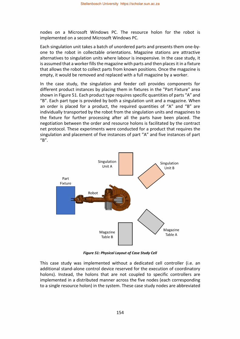
154
nodes on a Microsoft Windows PC. The resource holon for the robot is implemented on a second Microsoft Windows PC.
Each singulation unit takes a batch of unordered parts and presents them one-by-one to the robot in collectable orientations. Magazine stations are attractive alternatives to singulation units where labour is inexpensive. In the case study, it is assumed that a worker fills the magazine with parts and then places it in a fixture that allows the robot to collect parts from known positions. Once the magazine is empty, it would be removed and replaced with a full magazine by a worker.
In the case study, the singulation and feeder cell provides components for different product instances by placing them in fixtures in the "Part Fixture" area shown in Figure 51. Each product type requires specific quantities of parts “A” and “B”. Each part type is provided by both a singulation unit and a magazine. When an order is placed for a product, the required quantities of “A” and “B” are individually transported by the robot from the singulation units and magazines to the fixture for further processing after all the parts have been placed. The negotiation between the order and resource holons is facilitated by the contract net protocol. These experiments were conducted for a product that requires the singulation and placement of five instances of part “A” and five instances of part “B”.
Figure 51: Physical Layout of Case Study Cell
This case study was implemented without a dedicated cell controller (i.e. an additional stand-alone control device reserved for the execution of coordinatory holons). Instead, the holons that are not coupled to specific controllers are implemented in a distributed manner across the five nodes (each corresponding to a single resource holon) in the system. These case study nodes are abbreviated
Stellenbosch University https://scholar.sun.ac.za
155
as SU-A (Singulation Unit A), SU-B (Singulation Unit B), MT-A (Magazine Table A), MT-B (Magazine Table B) and RA (Robotic Arm) for the remainder of this paper.
Both resource holons for the two singulation units interact with the manufacturing equipment they represent through the I/O of their control devices. Since this interaction is typically facilitated by some form of driver that is typically written in a separate, lower-level language (such as C), this portion of the resource holons is not considered in this paper’s comparison to prevent differently performing drivers from influencing results. Instead the low-level control was removed and replaced with a TCP/IP bridge to a separate independent control logic implementation that is used for both implementations, for consistency.
7.6.2. Normal Operation Experiment
The normal operation experiment is performed twice for each software platform, i.e. once with standby redundancy enabled and once with the standby redundancy features disabled/removed. The experiment was conducted with the gateway holon and order manage holon executing on the RA node and the order holon executing on the SU-A node. For the Erlang implementation, the service directory also executes on the RA node. For the JADE implementation, the RA node is the (master) main container and therefore executed the DF. Both implementations were configured for an expected failure detection time of approximately 5 seconds. The execution locations of the specific holons are not important for this experiment as long as they are the same for corresponding redundant and non-redundant runs. These experiments are used to quantify the typical computational requirements and overhead of each standby redundancy solution.
7.6.3. Changeover Experiments
The changeover experiments consider three test cases. Each test case is evaluated for each of the three node fault categories: node failure due to a software fault, node isolation by a network fault and controller failure due to power loss or hardware fault. The fourth fault category, namely holon failure due to a software fault, is considered separately since it is not typically influenced by other holons’ execution locations.
Test cases one and two use the same holon configuration (i.e. which holons execute on which nodes). For this holon configuration, the order holon executes on one node, while the gateway holon, order manager holon and service directory execute a second node. For the JADE implementation, the service directory is implemented by the DF and, therefore, the second node is the master main container. In test case one, faults are injected for the node that hosts the order holon. This is the simplest test case since only the standby-redundant order holon fails. In test case two, faults are injected for the node that hosts the gateway holon, order manager holon and service directory.
Test case three uses a different holon configuration, i.e. the gateway holon, order manager holon, service directory and order holon all execute on the same node.
Stellenbosch University https://scholar.sun.ac.za
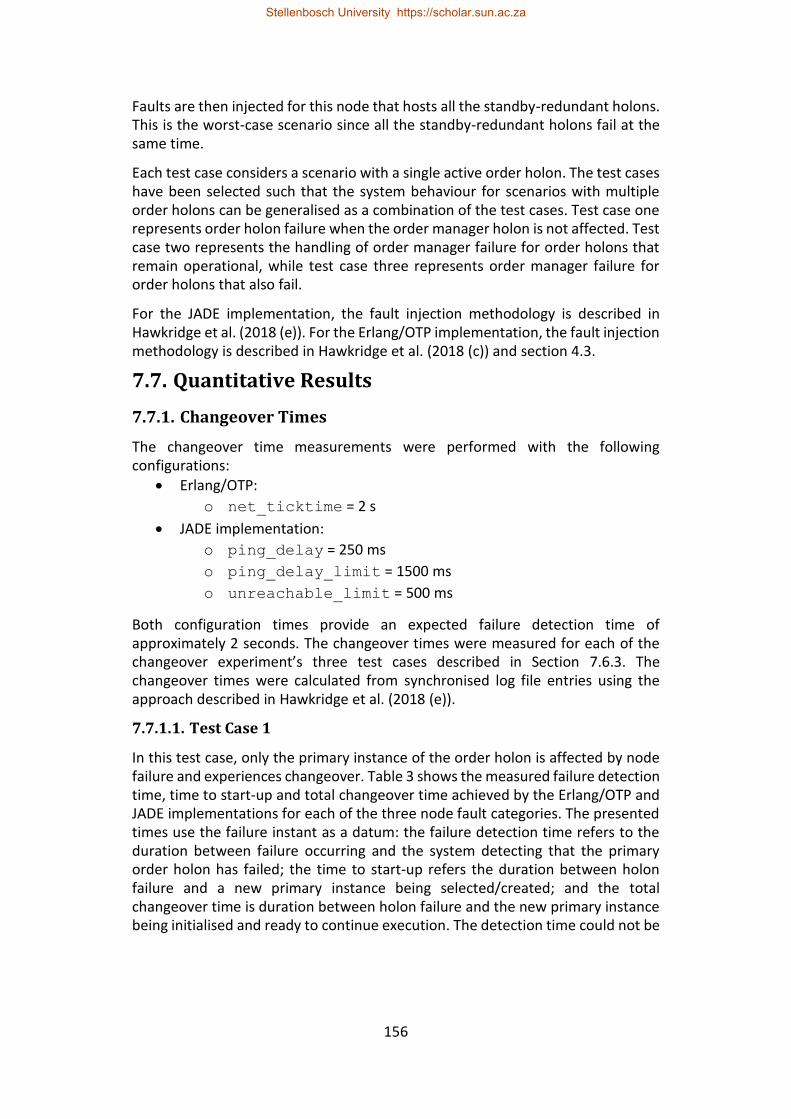
156
Faults are then injected for this node that hosts all the standby-redundant holons. This is the worst-case scenario since all the standby-redundant holons fail at the same time.
Each test case considers a scenario with a single active order holon. The test cases have been selected such that the system behaviour for scenarios with multiple order holons can be generalised as a combination of the test cases. Test case one represents order holon failure when the order manager holon is not affected. Test case two represents the handling of order manager failure for order holons that remain operational, while test case three represents order manager failure for order holons that also fail.
For the JADE implementation, the fault injection methodology is described in Hawkridge et al. (2018 (e)). For the Erlang/OTP implementation, the fault injection methodology is described in Hawkridge et al. (2018 (c)) and section 4.3.
7.7. Quantitative Results
7.7.1. Changeover Times
The changeover time measurements were performed with the following configurations:
• Erlang/OTP:
o net_ticktime = 2 s
• JADE implementation:
o ping_delay = 250 ms
o ping_delay_limit = 1500 ms
o unreachable_limit = 500 ms
Both configuration times provide an expected failure detection time of approximately 2 seconds. The changeover times were measured for each of the changeover experiment’s three test cases described in Section 7.6.3. The changeover times were calculated from synchronised log file entries using the approach described in Hawkridge et al. (2018 (e)).
7.7.1.1. Test Case 1
In this test case, only the primary instance of the order holon is affected by node failure and experiences changeover. Table 3 shows the measured failure detection time, time to start-up and total changeover time achieved by the Erlang/OTP and JADE implementations for each of the three node fault categories. The presented times use the failure instant as a datum: the failure detection time refers to the duration between failure occurring and the system detecting that the primary order holon has failed; the time to start-up refers the duration between holon failure and a new primary instance being selected/created; and the total changeover time is duration between holon failure and the new primary instance being initialised and ready to continue execution. The detection time could not be
Stellenbosch University https://scholar.sun.ac.za
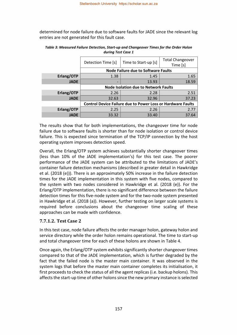
157
determined for node failure due to software faults for JADE since the relevant log entries are not generated for this fault case.
Table 3: Measured Failure Detection, Start-up and Changeover Times for the Order Holon during Test Case 1
Detection Time [s] Time to Start-up [s]
Total Changeover Time [s]
Node Failure due to Software Faults
Erlang/OTP 1.38 1.45 1.65
JADE - 13.93 18.59
Node Isolation due to Network Faults
Erlang/OTP 2.26 2.28 2.51
JADE 32.63 32.96 37.23
Control Device Failure due to Power Loss or Hardware Faults
Erlang/OTP 2.25 2.26 2.77
JADE 33.32 33.40 37.64
The results show that for both implementations, the changeover time for node failure due to software faults is shorter than for node isolation or control device failure. This is expected since termination of the TCP/IP connection by the host operating system improves detection speed.
Overall, the Erlang/OTP system achieves substantially shorter changeover times (less than 10% of the JADE implementation’s) for this test case. The poorer performance of the JADE system can be attributed to the limitations of JADE’s container failure detection mechanisms (described in greater detail in Hawkridge et al. (2018 (e))). There is an approximately 50% increase in the failure detection times for the JADE implementation in this system with five nodes, compared to the system with two nodes considered in Hawkridge et al. (2018 (e)). For the Erlang/OTP implementation, there is no significant difference between the failure detection times for this five-node system and for the two-node system presented in Hawkridge et al. (2018 (a)). However, further testing on larger scale systems is required before conclusions about the changeover time scaling of these approaches can be made with confidence.
7.7.1.2. Test Case 2
In this test case, node failure affects the order manager holon, gateway holon and service directory while the order holon remains operational. The time to start-up and total changeover time for each of these holons are shown in Table 4.
Once again, the Erlang/OTP system exhibits significantly shorter changeover times compared to that of the JADE implementation, which is further degraded by the fact that the failed node is the master main container. It was observed in the system logs that before the master main container completes its initialisation, it first proceeds to check the status of all the agent replicas (i.e. backup holons). This affects the start-up time of other holons since the new primary instance is selected
Stellenbosch University https://scholar.sun.ac.za
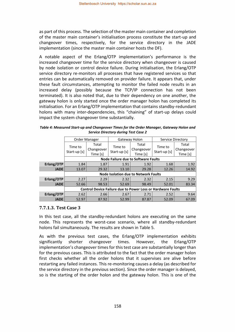
158
as part of this process. The selection of the master main container and completion of the master main container’s initialisation process constitute the start-up and changeover times, respectively, for the service directory in the JADE implementation (since the master main container hosts the DF).
A notable aspect of the Erlang/OTP implementation’s performance is the increased changeover time for the service directory when changeover is caused by node isolation or control device failure. During initialisation, the Erlang/OTP service directory re-monitors all processes that have registered services so that entries can be automatically removed on provider failure. It appears that, under these fault circumstances, attempting to monitor the failed node results in an increased delay (possibly because the TCP/IP connection has not been terminated). It is also noted that, due to their dependency on one another, the gateway holon is only started once the order manager holon has completed its initialisation. For an Erlang/OTP implementation that contains standby-redundant holons with many inter-dependencies, this “chaining” of start-up delays could impact the system changeover time substantially.
Table 4: Measured Start-up and Changeover Times for the Order Manager, Gateway Holon and Service Directory during Test Case 2
Order Manager Gateway Holon Service Directory
Time to
Start-up [s]
Total Changeover
Time [s]
Time to Start-up [s]
Total Changeover
Time [s]
Time to Start-up [s]
Total Changeover
Time [s]
Node Failure due to Software Faults
Erlang/OTP 1.84 1.87 1.91 1.92 1.68 1.92
JADE 13.07 29.32 13.10 29.28 12.26 14.92
Node Isolation due to Network Faults
Erlang/OTP 2.27 2.29 2.32 2.32 2.15 9.29
JADE 52.66 98.53 52.69 98.49 52.01 83.34
Control Device Failure due to Power Loss or Hardware Faults
Erlang/OTP 2.62 2.66 2.67 2.71 2.52 9.64
JADE 52.97 87.92 52.99 87.87 52.09 67.09
7.7.1.3. Test Case 3
In this test case, all the standby-redundant holons are executing on the same node. This represents the worst-case scenario, where all standby-redundant holons fail simultaneously. The results are shown in Table 5.
As with the previous test cases, the Erlang/OTP implementation exhibits significantly shorter changeover times. However, the Erlang/OTP implementation’s changeover times for this test case are substantially longer than for the previous cases. This is attributed to the fact that the order manager holon first checks whether all the order holons that it supervises are alive before restarting any failed instances. This re-monitoring causes a delay (as described for the service directory in the previous section). Since the order manager is delayed, so is the starting of the order holon and the gateway holon. This is one of the
Stellenbosch University https://scholar.sun.ac.za
159
downsides of using a monitor-based supervision tree to provide standby redundancy for order holons (described in greater detail in Hawkridge et al. (2018 (c))). It is expected that the initialisation of the order manager, and thereby the other order and gateway holons, could be reduced by optimising the order manager's initialisation procedure.
The changeover times for the JADE implementation are also longer for this case than for the previous cases. The start-up times are similar for cases two and three and, therefore, the increased changeover times for case three can be attributed to the additional computation required to restart the order holon.
Table 5: Measured Start-up and Changeover Times for the Order Manager, Gateway Holon, Order Holon and Service Directory during Test Case 3
Order Manager Gateway Holon Order Holon Service Directory
Time to Start-up
[s]
Total Change
over Time [s]
Time to Start-up
[s]
Total Change
over Time [s]
Time to Start-up
[s]
Total Change
over Time [s]
Start-up Time [s]
Total Change
over Time [s]
Node Failure due to Software Faults
Erlang/OTP 1.06 1.21 1.24 1.24 1.14 1.27 0.93 1.09
JADE 12.95 41.63 13.01 40.92 23.26 26.56 12.46 13.79
Node Isolation due to Network Faults
Erlang/OTP 2.591 9.73 9.78 9.79 9.60 12.11 2.44 9.63
JADE 53.000 109.54 53.04 109.50 53.11 79.70 52.76 91.43
Control Device Failure due to Power Loss or Hardware Faults
Erlang/OTP 2.66 10.00 10.18 10.20 9.76 12.54 2.41 9.80
JADE 52.99 111.71 53.04 111.67 64.29 85.88 52.45 91.11
7.7.1.4. Holon Failure due to Software Faults
Holon failure due to software faults is handled differently for the two implementations. For the JADE implementation, holon failure is handled by the ARS – the same mechanism as for node failures, except that failure detection is achieved using JADE’s platform events. As a result, the tests showed a start-up time of 0.058 s and a changeover time of 1.928 s for failure of the order holon.
For the Erlang/OTP implementation, each holon may typically consists of multiple processes and, therefore, software faults can lead to failure of one of these processes. As described in section 4.3, the criticality of the failed process determines whether it leads to that process simply being restarted by its supervisor in the applications supervision tree, or to the application failing if the error is irrecoverable. If the application fails, it is not restarted to preserve the integrity of the system (explained in greater detail in section 4.3). Tests for failure of the gateway holon’s primary server process showed a start-up time of 0.0025 s and a changeover time of 0.074 s when restarted by the gateway holon’s supervisor process.
This case study also includes the addition of order holons that are supervised by the order manager holon using Erlang’s monitor mechanism (described in
Stellenbosch University https://scholar.sun.ac.za
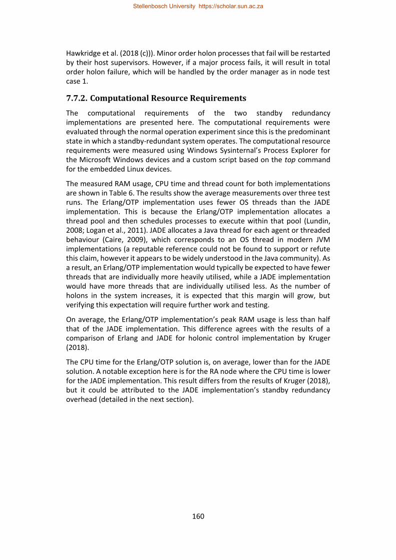
160
Hawkridge et al. (2018 (c))). Minor order holon processes that fail will be restarted by their host supervisors. However, if a major process fails, it will result in total order holon failure, which will be handled by the order manager as in node test case 1.
7.7.2. Computational Resource Requirements
The computational requirements of the two standby redundancy implementations are presented here. The computational requirements were evaluated through the normal operation experiment since this is the predominant state in which a standby-redundant system operates. The computational resource requirements were measured using Windows Sysinternal’s Process Explorer for the Microsoft Windows devices and a custom script based on the top command for the embedded Linux devices.
The measured RAM usage, CPU time and thread count for both implementations are shown in Table 6. The results show the average measurements over three test runs. The Erlang/OTP implementation uses fewer OS threads than the JADE implementation. This is because the Erlang/OTP implementation allocates a thread pool and then schedules processes to execute within that pool (Lundin, 2008; Logan et al., 2011). JADE allocates a Java thread for each agent or threaded behaviour (Caire, 2009), which corresponds to an OS thread in modern JVM implementations (a reputable reference could not be found to support or refute this claim, however it appears to be widely understood in the Java community). As a result, an Erlang/OTP implementation would typically be expected to have fewer threads that are individually more heavily utilised, while a JADE implementation would have more threads that are individually utilised less. As the number of holons in the system increases, it is expected that this margin will grow, but verifying this expectation will require further work and testing.
On average, the Erlang/OTP implementation’s peak RAM usage is less than half that of the JADE implementation. This difference agrees with the results of a comparison of Erlang and JADE for holonic control implementation by Kruger (2018).
The CPU time for the Erlang/OTP solution is, on average, lower than for the JADE solution. A notable exception here is for the RA node where the CPU time is lower for the JADE implementation. This result differs from the results of Kruger (2018), but it could be attributed to the JADE implementation’s standby redundancy overhead (detailed in the next section).
Stellenbosch University https://scholar.sun.ac.za
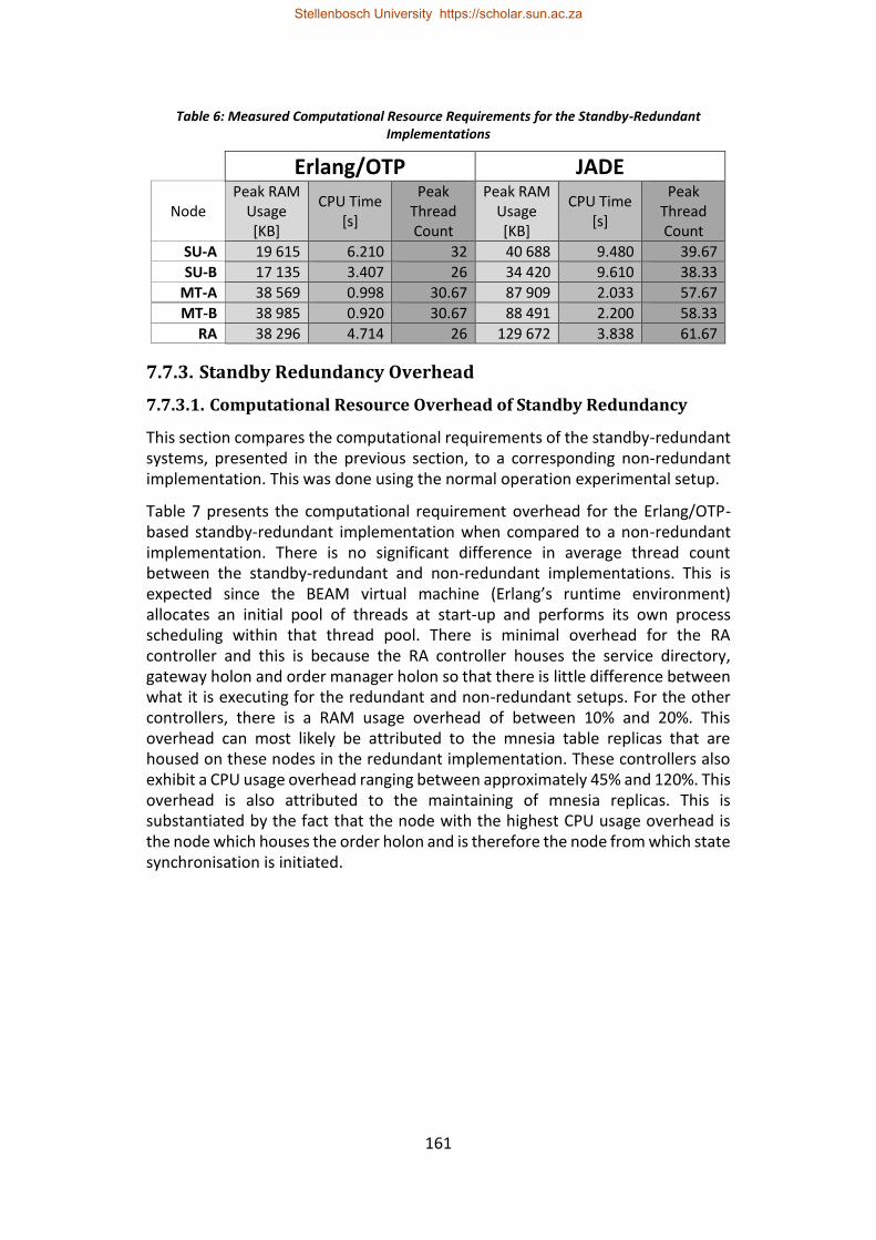
161
Table 6: Measured Computational Resource Requirements for the Standby-Redundant Implementations
Erlang/OTP JADE
Node Peak RAM
Usage [KB]
CPU Time [s]
Peak Thread Count
Peak RAM Usage [KB]
CPU Time [s]
Peak Thread Count
SU-A 19 615 6.210 32 40 688 9.480 39.67
SU-B 17 135 3.407 26 34 420 9.610 38.33
MT-A 38 569 0.998 30.67 87 909 2.033 57.67
MT-B 38 985 0.920 30.67 88 491 2.200 58.33
RA 38 296 4.714 26 129 672 3.838 61.67
7.7.3. Standby Redundancy Overhead
7.7.3.1. Computational Resource Overhead of Standby Redundancy
This section compares the computational requirements of the standby-redundant systems, presented in the previous section, to a corresponding non-redundant implementation. This was done using the normal operation experimental setup.
Table 7 presents the computational requirement overhead for the Erlang/OTP-based standby-redundant implementation when compared to a non-redundant implementation. There is no significant difference in average thread count between the standby-redundant and non-redundant implementations. This is expected since the BEAM virtual machine (Erlang’s runtime environment) allocates an initial pool of threads at start-up and performs its own process scheduling within that thread pool. There is minimal overhead for the RA controller and this is because the RA controller houses the service directory, gateway holon and order manager holon so that there is little difference between what it is executing for the redundant and non-redundant setups. For the other controllers, there is a RAM usage overhead of between 10% and 20%. This overhead can most likely be attributed to the mnesia table replicas that are housed on these nodes in the redundant implementation. These controllers also exhibit a CPU usage overhead ranging between approximately 45% and 120%. This overhead is also attributed to the maintaining of mnesia replicas. This is substantiated by the fact that the node with the highest CPU usage overhead is the node which houses the order holon and is therefore the node from which state synchronisation is initiated.
Stellenbosch University https://scholar.sun.ac.za
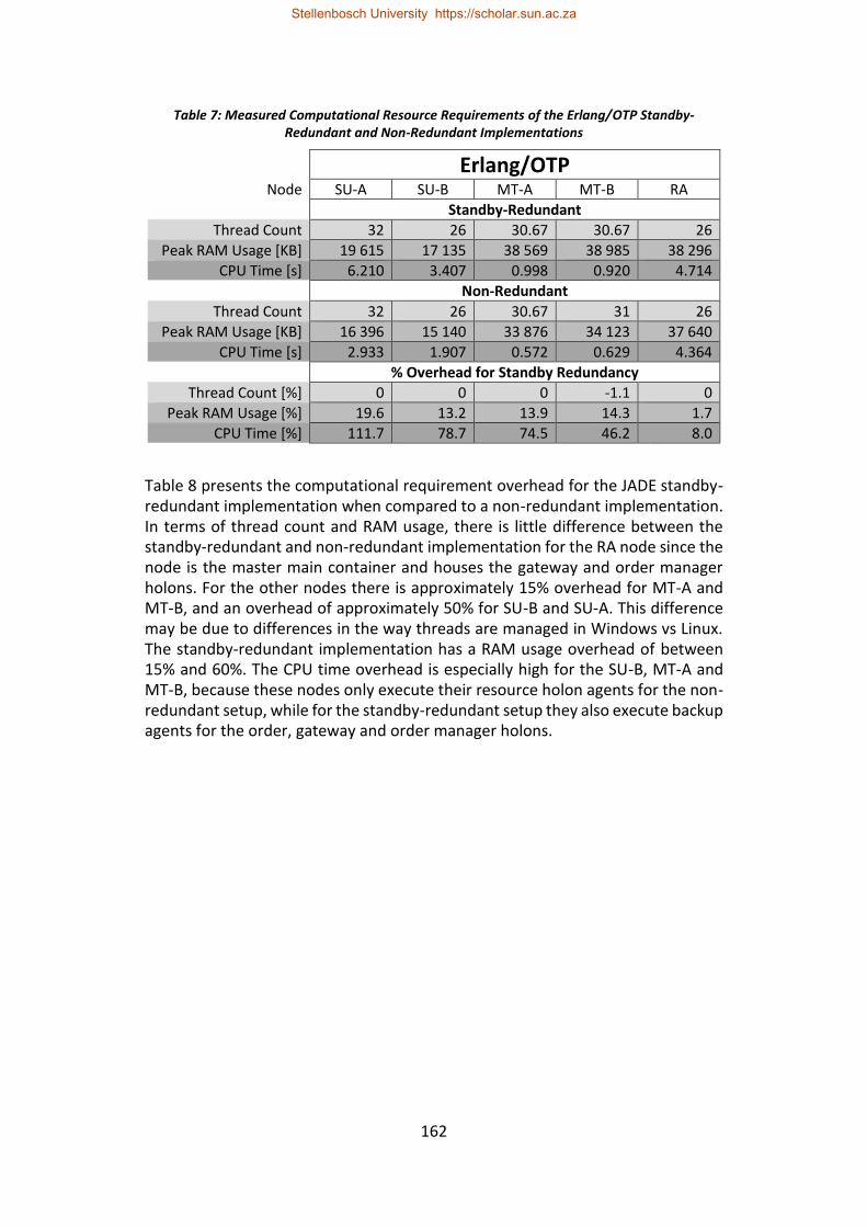
162
Table 7: Measured Computational Resource Requirements of the Erlang/OTP Standby-Redundant and Non-Redundant Implementations
Erlang/OTP Node SU-A SU-B MT-A MT-B RA
Standby-Redundant
Thread Count 32 26 30.67 30.67 26
Peak RAM Usage [KB] 19 615 17 135 38 569 38 985 38 296
CPU Time [s] 6.210 3.407 0.998 0.920 4.714
Non-Redundant
Thread Count 32 26 30.67 31 26
Peak RAM Usage [KB] 16 396 15 140 33 876 34 123 37 640
CPU Time [s] 2.933 1.907 0.572 0.629 4.364
% Overhead for Standby Redundancy
Thread Count [%] 0 0 0 -1.1 0
Peak RAM Usage [%] 19.6 13.2 13.9 14.3 1.7
CPU Time [%] 111.7 78.7 74.5 46.2 8.0
Table 8 presents the computational requirement overhead for the JADE standby-redundant implementation when compared to a non-redundant implementation. In terms of thread count and RAM usage, there is little difference between the standby-redundant and non-redundant implementation for the RA node since the node is the master main container and houses the gateway and order manager holons. For the other nodes there is approximately 15% overhead for MT-A and MT-B, and an overhead of approximately 50% for SU-B and SU-A. This difference may be due to differences in the way threads are managed in Windows vs Linux. The standby-redundant implementation has a RAM usage overhead of between 15% and 60%. The CPU time overhead is especially high for the SU-B, MT-A and MT-B, because these nodes only execute their resource holon agents for the non-redundant setup, while for the standby-redundant setup they also execute backup agents for the order, gateway and order manager holons.
Stellenbosch University https://scholar.sun.ac.za
163
Table 8: Measured Computational Resource Requirements of the JADE Standby-Redundant and Non-Redundant Implementations
JADE Node SU-A SU-B MT-A MT-B RA
Standby-Redundant
Thread Count 39.67 38.33 57.67 58.33 61.67
Peak RAM Usage [KB] 40 688 34 420 87 909 88 491 129 672
CPU Time [s] 9.480 9.610 2.033 2.200 3.838
Non-Redundant
Thread Count 26 26 50 50 61
Peak RAM Usage [KB] 35 421 26 712 55 859 59 512 122 819
CPU Time [s] 4.193 2.367 0.260 0.754 1.802
% Overhead for Standby Redundancy
Thread Count [%] 52.6 47.4 15.3 16.7 1.1
Peak RAM Usage [%] 14.7 28.9 57.4 48.7 5.6
CPU Time [%] 126.1 306.1 680.9 191.8 113.0
In summary, the JADE implementation has a substantially higher CPU usage overhead and, on average, a slightly higher RAM usage overhead than the Erlang/OTP implementation. This is primarily attributed to the fact that the JADE implementation creates backup agents in advance which synchronise their state with the primary agent so that they are ready to take over when a fault is detected. In contrast, the Erlang/OTP solution uses an independent state synchronisation mechanism for all the standby-redundant holons and the new primary holon is started from scratch when failure of the previous primary is detected, thereby avoiding the overhead of “idle” backups. Theoretically, the approach used for the JADE implementation has the potential for a quicker changeover time since there is no start-up and state retrieval delay, but practically this is not the case (as shown in section 7.7.1). The Erlang/OTP implementation has a lower thread count overhead than the JADE implementation due to the differences in how they manage concurrency. The JADE implementation creates additional Java threads to execute the backup agents, whereas the Erlang/OTP solution makes more extensive use of its existing thread pool.
7.7.3.2. Time Spent Blocking during State Synchronisation
State synchronisation is a fundamental part of warm standby redundancy that enables backups to begin with a post-changeover initial state that is close to the pre-failure state. The state synchronisation for both implementations is blocking and therefore has the potential to impact the performance of a standby-redundant holon.
The state synchronisation blocking time for the order holon is considered here since it is the main redundant holon in the case study system. The state synchronisation blocking time was measured by taking timestamps before and after the synchronisation call and recording the difference in the system logs.
Stellenbosch University https://scholar.sun.ac.za
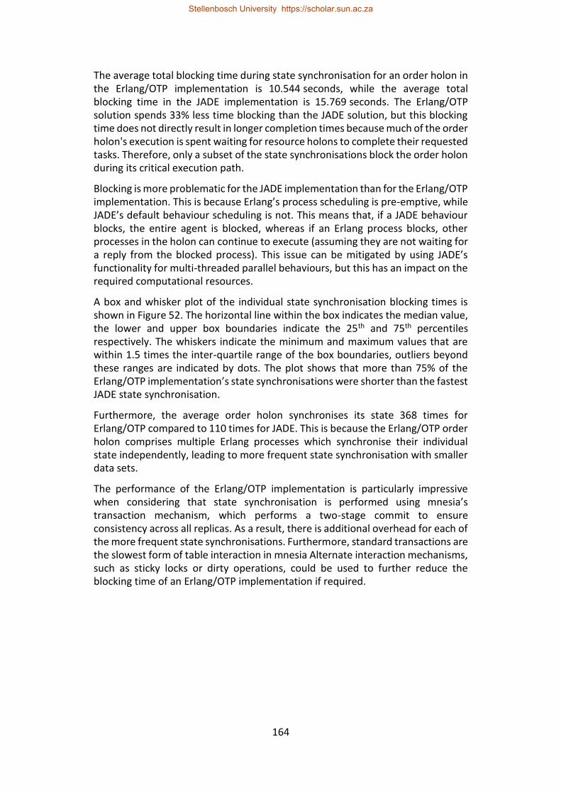
164
The average total blocking time during state synchronisation for an order holon in the Erlang/OTP implementation is 10.544 seconds, while the average total blocking time in the JADE implementation is 15.769 seconds. The Erlang/OTP solution spends 33% less time blocking than the JADE solution, but this blocking time does not directly result in longer completion times because much of the order holon's execution is spent waiting for resource holons to complete their requested tasks. Therefore, only a subset of the state synchronisations block the order holon during its critical execution path.
Blocking is more problematic for the JADE implementation than for the Erlang/OTP implementation. This is because Erlang’s process scheduling is pre-emptive, while JADE’s default behaviour scheduling is not. This means that, if a JADE behaviour blocks, the entire agent is blocked, whereas if an Erlang process blocks, other processes in the holon can continue to execute (assuming they are not waiting for a reply from the blocked process). This issue can be mitigated by using JADE’s functionality for multi-threaded parallel behaviours, but this has an impact on the required computational resources.
A box and whisker plot of the individual state synchronisation blocking times is shown in Figure 52. The horizontal line within the box indicates the median value, the lower and upper box boundaries indicate the 25th and 75th percentiles respectively. The whiskers indicate the minimum and maximum values that are within 1.5 times the inter-quartile range of the box boundaries, outliers beyond these ranges are indicated by dots. The plot shows that more than 75% of the Erlang/OTP implementation’s state synchronisations were shorter than the fastest JADE state synchronisation.
Furthermore, the average order holon synchronises its state 368 times for Erlang/OTP compared to 110 times for JADE. This is because the Erlang/OTP order holon comprises multiple Erlang processes which synchronise their individual state independently, leading to more frequent state synchronisation with smaller data sets.
The performance of the Erlang/OTP implementation is particularly impressive when considering that state synchronisation is performed using mnesia’s transaction mechanism, which performs a two-stage commit to ensure consistency across all replicas. As a result, there is additional overhead for each of the more frequent state synchronisations. Furthermore, standard transactions are the slowest form of table interaction in mnesia Alternate interaction mechanisms, such as sticky locks or dirty operations, could be used to further reduce the blocking time of an Erlang/OTP implementation if required.
Stellenbosch University https://scholar.sun.ac.za
165
Figure 52: Box and Whisker Plot of Individual State Synchronisation Times for the JADE and Erlang/OTP Implementations
7.8. Qualitative Results
7.8.1. Fault Handling Capabilities
This section highlights key aspects of how the redundant implementations handle faults and changeovers.
7.8.1.1. Handling Agent/Process Failure
One of Erlang/OTP’s strengths is the facilities it provides for managing process failure (Armstrong, 2010). Erlang provides a mechanism for process monitoring, where a monitoring process is notified if the monitored process fails. A similar functionality can be implemented in JADE using platform event subscription. However, the primary difference between these implementations is that failure notification for Erlang’s monitor mechanism provides the reason for failure. As a result, Erlang/OTP applications can handle failures differently depending on the reason (i.e. doing nothing if the process terminated normally), whereas a JADE implementation only knows that the agent is no longer alive.
7.8.1.2. Recovery from Network Faults
There are no significant differences between Erlang/OTP and JADE in this regard. Both standby redundancy implementations detect the isolation of nodes. In both cases, if a primary holon is isolated, a new primary holon is selected within the non-isolated containers/nodes and the previous primary holon continues to
Stellenbosch University https://scholar.sun.ac.za
166
execute on the isolated container/node. Backup holons on an isolated container/node interpret the isolation as their corresponding primary having failed and subsequently assume that role. If controller I/O is used, then some form of isolation detection may be required to avoid conflicting controller outputs from the duplicate primary holons (Hawkridge et al., 2018 (a)).
When the network fault is rectified, neither solution has a mechanism for re-integrating the previously isolated controller. This can be worked around by restarting the previously isolated container, but this is not ideal. This lack of reintegration is a shortcoming in both Erlang/OTP and JADE.
7.8.2. Distributability
7.8.2.1. Architectural Provisions
Distribution can be achieved in JADE using two different concepts: Agent Platforms (APs) and containers. The AP is a FIPA concept that refers to the infrastructure required to facilitate agent execution. FIPA is an international standards body focused on agent interoperability within heterogeneous environments. This includes both the computational hardware and the software framework – essentially a complete MAS (FIPA, 2004). Distribution based around APs is designed for interoperability so that APs implemented using different software frameworks can be used. This essentially leads to several complete MASs which interact with one another. In contrast, containers are a JADE specific concept designed to achieve distribution within an AP. Each JADE AP contains one or more containers. A container is any JVM instance that executes JADE. In JADE, message transmission between containers has less latency than between APs since there is an added overhead for marshalling JADE messages into a FIPA compliant format for inter-platform communication (Cortese et al., 2002). Therefore, container-based distribution is better for lower-level control architectures, such as in a manufacturing cell, while AP-based distribution is better for higher-level control, such as between different manufacturing plants, where interoperability is a more significant concern.
Since a JADE AP may contain multiple containers, this leads to the concept of the main container, which is where the AMS (and DF) reside. When JADE is distributed, multiple containers are started on different devices. The main container is started first and all subsequent containers register with it when they start. To achieve this, the hostname and port used by the main container is provided as a boot argument to each of the non-main containers. If the MCRS is used, multiple main containers exist with a single master main and JADE provides multiple mechanisms for resolving the network address of the current master main container (discussed in greater detail in Hawkridge et al. (2018 (e))).
Distribution in Erlang/OTP is achieved using nodes. A node refers to an instance of the BEAM virtual machine. Each distributed Erlang node must be given a unique name by which it can be referenced. A node can either use Erlang’s short naming scheme or long naming scheme, but all nodes must use the same naming scheme.
Stellenbosch University https://scholar.sun.ac.za
167
During the case study implementation, it was found that the long naming scheme worked best for networks with domain names. The format of a long node name is (Name)@(FQDN), where (Name) is the unique node name (for that device) and (FQDN) is the Fully Qualified Domain Name of the host device. When a process sends a message to a process in a different node, the Erlang Port Mapper Daemon (EPMD) resolves the node name to the transport address for that node, i.e. the IP address and port for TCP/IP based distribution (Ericsson AB, 2018 (a): 274). The message is then transmitted to the corresponding address.
7.8.2.2. Communication Infrastructure
Both Erlang/OTP and JADE feature send and receive primitives. (In Erlang/OTP code, message sending is typically represented by the “!” operator rather than the primitive send function). Both Erlang/OTP and JADE allow messages to be extracted from the relevant message queues through pattern matching.
JADE messages are addressed using an Agent Identifier (AID). If the AID contains transport addresses, then the JADE Message Transport System (MTS) attempts to send the message using these addresses, but if there are no associated transport addresses or the contained addresses are unsuccessful then the JADE MTS attempts to resolve the agent name with AMS (FIPA, 2002 (b)).
In Erlang/OTP, each process has a process identifier (pid) which serves as a unique identifier for message transmission. Erlang/OTP also features mechanisms for both local and global name registration: local names have scope within each node, whereas global names have scope within the global group. Registered names and process identifiers can be used interchangeably, since registered names are automatically resolved when a message is sent.
A key difference between the communication of holons for the two implementations is how holon communication interacts with the concurrency approach. For the JADE implementation, concurrency within holons is achieved through behaviours, all of which share the message queue of their host process. In contrast, for the Erlang/OTP implementation, concurrency within a holon is achieved using multiple processes, each of which have their own “address” and message queue. Each approach has its compromise: for the Erlang/OTP solution, managing all the pids of the holon’s processes to ensure that external messages arrive at the correct process can be a cause of complication; for the JADE implementation, each message may be checked by several behaviours before arriving at the correct one, and additionally, care must be taken to ensure that behaviours’ receive patterns only match messages that are intended for them.
A key difference between JADE and Erlang/OTP is that name resolution is centralised in JADE, whereas Erlang/OTP offers various levels of naming in a decentralised manner. As a result, holons in the Erlang/OTP implementation are typically not influenced by failures that do not affect them directly. In contrast, in JADE, failure of the master main container halts all name resolution until the AMS is restarted on the new master main container.
Stellenbosch University https://scholar.sun.ac.za
168
All JADE messages use the ACL Message Structure defined by FIPA 00061 (FIPA, 2002 (a)). Erlang/OTP does not enforce any format or structure on message contents; it is the developer’s responsibility to design/select and implement any required structures.
7.8.2.3. Portability
Portability is highly beneficial from a standby redundancy standpoint as it allows for the use of dissimilar control hardware and operating systems. This reduces the likelihood of multiple controllers failing due to common-cause faults. Additionally, since the code for a redundant application must be available on every device where it will execute, the ability to re-use the same application code on each of the distributed devices is desirable.
Since JADE is Java-based, it benefits from the exceptional portability of the JVM. JVM versions are available for all major operating systems, including a variety of embedded systems. Additionally, JADE features the JADE-LEAP variant designed for resource constrained mobile devices (Bellifemine et al., 2007; Bellifemine et al., 2008). Erlang/OTP applications are also executed by a virtual machine, called BEAM. BEAM is not as ubiquitous as the JVM, but is it available for Windows, macOS and many major Linux/Unix-based operating systems. Both Erlang and Java code can generally be considered as platform independent, given that they do not utilise OS specific functionalities or drivers (i.e. for I/O control), and can therefore be reused for all the distributed control devices in a system.
7.8.2.4. Local Debugging
There is a substantial time overhead involved in debugging a distributed system on multiple devices, especially since any fix must be propagated to all the devices before it can be tested. The ability to test/simulate a distributed system locally on a single machine is therefore highly beneficial since it has the potential to reduce development time substantially
Armstrong (2010: 70) claims that it is possible to develop an Erlang program on a single device and deploy it to a cluster with minimal code modification. During the development of the Erlang/OTP case study implementation, this was found to be true; the distribution of the system could be simulated by starting multiple BEAM instances on a single device. The local simulation of the system provided a good representation of the implementation’s behaviour in an actual distributed system, with the exception that there was less latency and it was not possible to simulate hardware and network failures properly. Distributed tests are, therefore, still required to validate the standby-redundant performance under all fault conditions. However, by this stage, local testing will have helped to rectify many of the system’s bugs.
It is similarly possible to locally simulate the distributed behaviour of a JADE implementation by creating multiple containers on the same device. It was found that each JADE container needs to be executed in its own JVM instance. This is
Stellenbosch University https://scholar.sun.ac.za
169
supported by Czajkowski & Daynàs (2012) who suggest that Java applications should run in separate JVM instances to achieve isolation from one another. Several transient errors relating to the Main Container Replication Service and the Agent Replication Service were observed when executing multiple containers within the same JVM instance. Nevertheless, local testing was found to be useful for validating the distribution aspects of the implementation before commencing with distributed tests to validate the standby redundancy aspects.
7.8.2.5. Scalability
It is not possible to accurately evaluate the scalability of the two solutions without performing tests for a large number of nodes. For this reason, the scalability of the two implementations is compared based on the authors' opinions.
The JADE standby redundancy implementation’s use of platform events for container monitoring is a scalability concern. Subscribed agents are notified of every event in the AP. Therefore, as the number of subscribed standby-redundant agents increases, so does the number of agents to which each platform event is sent. This is further aggravated by the fact that an “agent born” event is sent for each replica creation when a new container is added. This could, therefore, lead to substantial congestion when a container is added or removed. As discussed in Hawkridge et al. (2018 (e)), this could be mitigated through a centralised monitoring mechanism, but this has its own complications.
Bellifemine et al. (2008) state that JADE is used in Telecom Italia’s Network Neutral Element Manager which manages ten thousand devices. Bellifemine et al. imply that the implementation is distributed over multiple containers, but do not specify how many. The scalability of the JADE DF is a concern (Buckle et al., 2002; Bellifemine et al., 2007). JADE offers a variety of mechanisms that can be used to address these issues, including federated DFs and storing DF contents in relational databases.
Erlang/OTP has been used to develop several commercial software products that are renowned for their scalability. Notable examples include: ejabberd (an XMPP server), RabbitMQ (a message broker service), Apache CouchDB (a document-oriented NoSQL database), and RIAK (a distributed NoSQL key-value store). ejabberd claims to be able to handle two million concurrent users on a single Erlang node (Rémond, 2016). Further scaling is achieved using multi-node clusters.
When considering clustered Erlang nodes, it is important to consider how nodes interact. Inter-node connections are generally established when the first message is exchanged. Additionally, when two nodes connect, they exchange their list of currently known nodes, each node then attempts to connect to all the nodes in that list for which it does not currently have an existing connection. Therefore, all the nodes in an Erlang/OTP system are typically interconnected. This can be problematic in large systems, particularly for features that have a global scope such as the global name registry and node failure detection (Ghaffari, 2014). Often this interconnectedness is unnecessary since many of the nodes which are
Stellenbosch University https://scholar.sun.ac.za
170
connected to one another may never exchange messages. Erlang/OTP’s functionality for hidden nodes and global groups can be used to group nodes and limit this interconnectedness, but it may complicate development. An alternative solution is the use of SD (Scalable Distributed) Erlang, an Erlang variation developed as part of the RELEASE project, which offers a distribution scheme that claims to scale better (Trinder et al., 2017) using an approach that is similar to the fractal hierarchy used in holonic systems. Chechina et al. (2017) compare standard Erlang and SD Erlang using a series of case study benchmarks for a system with up to 256 nodes. Their results suggest that standard Erlang performs better for systems with fewer than 40 nodes and thereafter SD Erlang scales better.
7.8.3. Ease of Development
7.8.3.1. Development and Debugging Tools
7.8.3.1.1 Development Tools
The existence of effective development tools can improve development productivity. There is a large variety of development tools and frameworks available for use with JADE thanks to its use of the Java ecosystem. Erlang/OTP has a substantial user base and therefore a complete set of tooling has been developed. Both software platforms provide IDE support, build systems, unit testing, system testing, code coverage analysis and interactive code execution through a shell interface.
7.8.3.1.2 Debugging Holons’ Internal Behaviour
The ability to debug a holon’s internal behaviour is important especially when the holon does not perform as expected after changeover has occurred.
There are two main tools that can be used to examine a JADE agent’s execution: JADE’s Introspector Agent and the Java debugger. The Introspector Agent provides a graphical interface that can be used to interrogate an agent’s behaviour and message queues. Using the Introspector, an agent’s execution can be slowed, halted or stepped through. The Introspector can be useful for troubleshooting behaviours that are not executed or messages which are not received. However, it cannot be used to view the values of agents’ or behaviours’ class variables – this requires a tool like the Java debugger. The Java debugger is relatively complicated and not particularly user friendly, but using it on a local node is achievable. Remotely debugging a Java application on a different device is possible but adds further complication.
Erlang/OTP’s primary debugging tool is the Observer application. The Observer provides a graphical interface that can be used to monitor both local and remote nodes. Notable features of the Observer include system performance metrics and load charts, a graphical representation of the executing applications’ supervision trees, and the ability to view the contents of ETS and mnesia tables housed on that node.
Stellenbosch University https://scholar.sun.ac.za
171
When using the Observer to debug a holon, there are two features that were found to be useful. Firstly, the ability to view the contents of mnesia tables is helpful for ensuring that the correct state data is synchronised for each holon. Secondly, the Observer can be used to view the state variable contents of processes that are built on top of OTP behaviours or are developed according to OTP conventions. This is especially beneficial when debugging state machines.
If these features are insufficient, the Observer provides an interface for Erlang/OTP’s trace functionality which is extremely powerful, although not particularly user friendly, and can be used to investigate the execution of a process with a high level of granularity. This includes the ability to trace individual function calls with their arguments, as well as the sending and receiving of messages.
7.8.3.1.3 Inter-Holon Communication Debugging
Inter-holon communication is foundational to holonic architectures. The ability to effectively debug this communication is crucial, especially when implementing conversation recovery mechanisms.
The primary tool for monitoring and evaluating inter-agent communication in JADE is the Sniffer tool. The Sniffer is a graphical tool that shows the message interactions between selected agents. The Sniffer was found to be an effective and user-friendly tool in this regard. The only identified shortcoming is the inability to filter out certain messages, since the platform event messages sent to the standby-redundant agents often obscured those of the contract net-based negotiations.
Erlang/OTP does not have a graphical means for debugging inter-holon communication. The trace functionality can be used to log the inbound and outbound messages for selected processes but understanding the conversation dynamics from these logs is not trivial.
7.8.3.2. Existing Features and Frameworks
This section considers the features and frameworks provided by each software platform that facilitate the implementation of holonic control and redundancy. The benefit of these existing features and frameworks are twofold: firstly, they minimise the amount of development work required, and secondly, they provide a tried and tested foundation.
JADE has a many existing features and frameworks that facilitate the development of holonic architectures. JADE has a fully featured Directory Facilitator which has been verified and optimised for use in large systems. The JADE platform has a wealth of communication and protocol infrastructure due to its FIPA compliance (Bellifemine et al., 2001). For example, JADE’s base classes for the contract net protocol were valuable in the case study implementation. The implementation of holonic features, that are not inherently provided for, is facilitated by several behaviour base classes, including a state machine implementation.
Stellenbosch University https://scholar.sun.ac.za
172
When it comes to standby redundancy, JADE provides several features that can be combined to implement standby-redundant agents (as described in Hawkridge et al. (2018 (e))). However, this requires development time and effort to implement and debug.
For Erlang/OTP, there are no existing features for holonic architectures. OTP provides several behaviours which implement generic architectural models or patterns, which include gen_server (which implements a client-server model), gen_statem (which implements an event driven state machine), gen_event (which implements a publish-subscribe mechanism) and the supervisor model (which is used to implement supervision trees). These behaviours were found to provide a useful foundation for the development of the architectural elements required to implement the case study’s holonic architecture. However, the implementation of the case study’s holonic architecture required more development effort since it was necessary to develop the service directory, as well as base behaviours for the contract net protocol. In contrast, when considering the implementation of standby redundancy, there are several features than can be combined with relative ease. The standby redundancy implementation still requires development effort to ensure that each failure case is handled as intended, particularly when state synchronisation is used to achieve warm standby redundancy.
7.8.3.3. Documentation
The effectiveness of a software platform’s documentation is of critical importance since it is the primary source of knowledge and understanding for developers. Documentation that is unclear or outdated can contribute to substantial development delays.
The official JADE documentation includes an API and tutorials, as well as programming and administration guides. The book by Bellifemine et al. (2007) was found to be the most complete information source for the JADE system, especially for more advanced features such as platform events and the Main Container Replication Service. During the development of the JADE standby redundancy implementation it was found that there is a lack of documentation about the functioning and usage of JADE’s ARS.
Erlang and OTP have an abundance of documentation. The official Erlang/OTP documentation contains the typical API documentation and several development guides – included in which are tutorials for various Erlang and OTP features. A standout among these guides is the OTP design principles guide, which provides a highly detailed description of the functioning and use of OTP’s primary functionalities.
A key aspect of Erlang/OTP’s documentation that is lacking for JADE is the existence of third-party reference sources. Due to Erlang/OTP’s large and active community of users there are several books, guides, tutorials and blogs that have been developed by Erlang/OTP users, many of whom are not directly associated
Stellenbosch University https://scholar.sun.ac.za
173
with the development of Erlang and OTP. The fundamental advantages of this variety of sources are two-fold: firstly, different perspectives help to prevent misinterpretation and, secondly, they reflect the practical experiences of users from real-world production usage of Erlang and OTP.
7.8.4. Configurability
Configurability is the degree to which each implementation allows its standby-redundant behaviour or performance to be configured or customised to suit the specific application. There are two key configuration aspects for the standby-redundant systems: execution location and changeover time.
In terms of execution location configurability, both systems allow for the specification of which nodes each standby-redundant holon is permitted to execute upon. However, the Erlang/OTP implementation takes this configuration a step further by allowing node priorities to be specified (Ericsson AB, 2018 (b): 338). This is highly beneficial as it allows preference to be given to more powerful or reliable hardware. Additionally, it can be used to avoid the scenario where all the redundant holons end up executing on, and overburdening, a single device when others are still available. A similar functionality is not possible for the JADE implementation since JADE’s ARS does not allow for control/influence of the selected master replica.
In terms of changeover time configurability, both systems allow the changeover time to be tuned to suit an application’s needs. Changeover time is determined by the fault detection time, the primary selection time and the application start-up time. The failure detection time of the JADE implementation is configured using the UDPNMS’s three configuration parameters: ping_delay which specifies the rate at which containers send heartbeat messages; ping_delay_limit which specifies the timeout after which a container is considered unreachable; and unreachable_limit after which an unreachable container is considered to have failed. The failure detection time of the Erlang/OTP implementation is configured using a single parameter namely the net_ticktime, which specifies the timeout after which an unresponsive node is considered to have failed.
The JADE implementation allows the fault detection time configuration parameters to be specified with millisecond resolution. Unfortunately, although the configuration parameters appear to influence the node failure detection time (Hawkridge et al., 2018 (e)), there is no defined relationship between the configuration parameters and the actual fault detection time. This is evident in the changeover time measurements in section 7.7.1. As a result, achieving the desired changeover time is an iterative procedure for JADE-based standby redundancy and could take a substantial amount of time to perform.
Erlang/OTP’s net_ticktime parameter is only specified with second resolution. The limited resolution for Erlang/OTP was not an issue in the case study implementation since sub-second changeover times were not achievable over the
Stellenbosch University https://scholar.sun.ac.za
174
100 Mb/s network infrastructure that was used. However, in higher speed networks Erlang/OTP’s shortcoming in this regard could be a limiting factor. Erlang/OTP’s node failure detection time is bounded by net_ticktime ± 25% (Ericsson AB, 2017: 7). This predictability greatly simplifies achieving the desired changeover time.
7.9. Comparison
This section discusses the findings of the quantitative and qualitative evaluations of the Erlang/OTP and JADE implementations presented in sections 7.7 and 7.8.
In terms of standby-redundant performance, the Erlang/OTP implementation provides a significantly better changeover time for all the considered test cases. Overall, the Erlang/OTP implementation uses less computational resources than the JADE implementation. This is due, in part, to the fact that the JADE implementation of standby redundancy has a higher computational overhead, particularly in terms of CPU usage. That is not to say that the computational overhead for the Erlang/OTP implementation is negligible; the evaluation shows that, for both implementations, the addition of standby redundancy requires significantly more computational resources compared to a non-redundant implementation. The Erlang/OTP implementation also has the advantage in terms of state synchronisation overhead, spending 33% less time blocking in total and having significantly shorter individual state synchronisation blocking times.
As far as fault handling is concerned, the inclusion of a failure reason in Erlang/OTP’s monitoring mechanism offers enhanced flexibility. However, both implementations lack a graceful mechanism for nodes to be re-integrated after having been isolated by network faults. Both software platforms provide a firm foundation for the implementation of distributed control and facilitate use in heterogeneous environments through their portability. Both systems simplify the development of distributed applications by allowing them to be tested locally on a single device. Both software platforms claim to offer scalability. It is suspected that the Erlang/OTP implementation will scale well due to the renowned scalability of several Erlang/OTP-based commercial applications and the amount of research that has gone into improving Erlang’s scalability. However, the scalability of both standby redundancy implementations could not be verified without further (large scale) testing.
The development of holonic systems in JADE is simplified by the wealth of communication and protocol infrastructure associated with its FIPA compliance. Many of the required message structures and protocol implementations must be developed from scratch for Erlang/OTP-based systems. Debugging the internal behaviour of holons was found to be easier in Erlang/OTP due to the ease with which a process’s internal state can be examined using the Observer application. On the other hand, debugging inter-holon communication was found to be easier and more user friendly in JADE thanks to the graphical representation provided by JADE’s Sniffer. Erlang/OTP’s documentation was found to be superior to JADE’s.
Stellenbosch University https://scholar.sun.ac.za
175
This is particularly evident when considering the shortage of documentation on the ARS, a key component of the JADE standby redundancy implementation.
In terms of configurability, the Erlang/OTP implementation allows for more control over the execution location of standby-redundant holons, while the JADE implementation provides a greater level of control over the behaviour of the fault detection mechanism since it provides more configuration parameters. The limited resolution of Erlang/OTP’s net_ticktime parameter is problematic and could hinder its ability to fully utilise high bandwidth network infrastructure. However, JADE’s lack of a predictable and defined relationship between the configuration parameters and the achieved failure detection time is a major deficiency.
7.10. Conclusion
The paper presents a comparison between two software platforms, Erlang/OTP and JADE, for the implementation of standby redundancy in a holonic manufacturing cell controller. The holonic architecture and standby redundancy implementations are described, along with the case study system considered in this paper. A set of quantitative and qualitative evaluation criteria are developed and described. These criteria were applied to each of the two implementations using two experimental scenarios: one for normal production, and one where failure is induced and standby-redundant holons perform changeover.
The comparison shows that the Erlang/OTP implementation performs better than the JADE implementation for all the standby-redundant metrics: it achieves shorter changeover times, lower computation requirements overall, less computational and state synchronisation overhead and greater fault handling flexibility. However, Erlang/OTP lacks the same level of supporting communication and protocol infrastructure that is available in JADE due to JADE's strong heritage within multi-agent systems. The documentation available for Erlang/OTP is superior to that of JADE, especially with respect to the features used to achieve standby redundancy. The configurability of both implementations is less than ideal, but the lack a predictable and defined relationship between JADE’s configuration parameters and the achieved failure detection time is a major deficiency.
In conclusion, fault tolerance is a foundational design objective for the Erlang/OTP platform and as such the features used to achieve standby redundancy are core to the both Erlang and OTP. On the other hand, JADE endeavours to provide seamless communication in large-scale, distributed peer-to-peer agent networks and therefore the features used to achieve standby redundancy in JADE are essentially add-ons. Erlang/OTP’s focus on fault-tolerance is evident in the superior standby-redundant performance achieved by the Erlang/OTP implementation and the degree to which it facilitates the implementation of such functionality. It is therefore concluded that Erlang/OTP provides a better platform for the
Stellenbosch University https://scholar.sun.ac.za
176
implementation of standby redundancy for the case study system considered in this paper.
7.11. References
Al-Fuqaha, A., Guizani, M., Mohammadi, M., Aledhari, M. and Ayyash, M., 2015. Internet of things: A survey on enabling technologies, protocols, and applications. IEEE Communications Surveys & Tutorials, 17(4): 2347-2376.
Anonymous, s.a. GRiSP: Dive into a New Experience of Building Wireless Embedded Systems. [Online]. Available: http://www.grisp.org [2018, November 10].
Armstrong, J., 1996. Erlang—a Survey of the Language and its Industrial Applications, in INAP, 96.
Armstrong, J., 2003. Making reliable distributed systems in the presence of software errors. doctoral dissertation. Royal Institute of Technology, Stockholm, Sweden.
Armstrong, J., 2010. erlang. Communications of the ACM, 53(9): 68-75.
Babiceanu, R.F. and Chen, F.F., 2006. Development and applications of holonic manufacturing systems: a survey. Journal of Intelligent Manufacturing, 17(1): 111-131.
Bellifemine, F., Poggi, A. and Rimassa, G., 2001. Developing multi‐agent systems with a FIPA‐compliant agent framework. Software: Practice and Experience, 31(2): 103-128.
Bellifemine, F.L., Caire, G. and Greenwood, D., 2007. Developing multi-agent systems with JADE (Vol. 7). John Wiley & Sons.
Bellifemine, F., Caire, G., Poggi, A. and Rimassa, G., 2008. JADE: A software framework for developing multi-agent applications. Lessons learned. Information and Software Technology, 50(1-2): 10-21.
Bi, Z., Da Xu, L. and Wang, C., 2014. Internet of things for enterprise systems of modern manufacturing. IEEE Transactions on industrial informatics, 10(2): 1537-1546.
Brettel, M., Friederichsen, N., Keller, M. and Rosenberg, M., 2014. How virtualization, decentralization and network building change the manufacturing landscape: An industry 4.0 perspective. International Journal of Mechanical, Industrial Science and Engineering, 8(1): 37-44.
Buckle, P., Moore, T., Robertshaw, S., Treadway, A., Tarkoma, S. and Poslad, S., 2002. Scalability in multi-agent systems: The fipa-os perspective, in Foundations and Applications of Multi-Agent Systems. Berlin, Heidelberg: 110-130.
Stellenbosch University https://scholar.sun.ac.za
177
Caire, G., 2009. JADE tutorial: JADE programming for beginners. [Online] Available: http://jade.tilab.com/doc/tutorials/JADEProgramming-Tutorial-for-beginners.pdf [2018, October 31].
Chechina, N., MacKenzie, K., Thompson, S., Trinder, P., Boudeville, O., Fördős, V., Hoch, C., Ghaffari, A. and Hernandez, M.M., 2017. Evaluating scalable distributed Erlang for scalability and reliability. IEEE Transactions on Parallel and Distributed Systems, 28(8): 2244-2257.
Chirn, J.L. and McFarlane, D., 2005. Evaluating holonic control systems: a case study, in Proceedings of the 16th IFAC world congress, Prague.
Cortese, E., Quarta, F., Vitaglione, G. and Vrba, P., 2002. Scalability and performance of jade message transport system, in AAMAS workshop on agentcities, Bologna (16): 28.
Czajkowski, G. and Daynàs, L., 2012. Multitasking without compromise: a virtual machine evolution. ACM SIGPLAN Notices, 47(4a): 60-73.
Ericsson AB, 2017 (a). Erlang Kernel 5.4, [Online]. Available: http://erlang.org/doc/apps/kernel/kernel.pdf [2017, October 6].
Ericsson AB, 2018 (a). Erlang Run-Time System Application (ERTS) 10.1, [Online]. Available: http://erlang.org/doc/apps/erts/erts.pdf [2018, November 7].
Ericsson AB, 2018 (b), Erlang/OTP System Documentation 10.1, [Online]. Available: http://erlang.org/doc/pdf/otp-system-documentation.pdf [2018, November 7].
FIPA, 2002 (a). FIPA ACL Message Structure Specification. [Online]. Available: http://www.fipa.org/specs/fipa00061/ [2018, October 31].
FIPA, 2002 (b). FIPA Agent Message Transport Service Specification. [Online]. Available: http://www.fipa.org/specs/fipa00067/ [2018, October 31].
FIPA, 2004. FIPA Agent Management Specification. [Online]. Available: http://www.fipa.org/specs/fipa00023/ [2018, October 1].
Gerbert, P., Lorenz, M., Rüßmann, M., Waldner, M., Justus, J., Engel, P. and Harnisch, M., 2015. White Paper on Industry 4.0: The future of productivity and growth in manufacturing industries [Online]. Available: https://www.bcg.com/en-za/publications/2015/engineered_products_project_business_industry_4_future_productivity_growth_manufacturing_industries.aspx [2018, November 10].
Ghaffari, A., 2014, September. Investigating the scalability limits of distributed Erlang, in Proceedings of the Thirteenth ACM SIGPLAN workshop on Erlang: 43-49.
Hawkridge, G., Basson, A.H. and Kruger, K., 2018 (a). An Evaluation of Erlang for Implementing Standby Redundancy in a Manufacturing Station Controller, in 8th Workshop on Service Orientation in Holonic and Multi-Agent Manufacturing. Italy, Bergamo.
Stellenbosch University https://scholar.sun.ac.za
178
Hawkridge, G., Basson, A.H. and Kruger, K., 2018 (b). Conversation Recovery after Failover for Contract Net Protocol Communication in an Erlang-Based Holonic Architecture. submitted to the International Journal of Computer Integrated Manufacturing.
Hawkridge, G., Basson, A.H. and Kruger, K., 2018 (c). An Erlang-based Standby-Redundant Distributed Holonic Controller for a Manufacturing Cell. submitted to the International Journal of Computer Integrated Manufacturing.
Hawkridge, G., Basson, A.H. and Kruger, K., 2018 (e). JADE for Implementing Standby Redundancy in a Distributed Holonic Architecture. submitted to the International Journal of Computer Integrated Manufacturing.
Kravari, K. and Bassiliades, N., 2015. A Survey of Agent Platforms. Journal of Artificial Societies and Social Simulation. 18(1): 11.
Kruger, K. and Basson, A., 2017. Erlang-based control implementation for a holonic manufacturing cell. International Journal of Computer Integrated Manufacturing, 30(6), pp.641-652. [DOI: 10.1080/0951192X.2016.1195923]
Kruger, K. 2018. Development and Evaluation of an Erlang Control System for Reconfigurable Manufacturing Systems. Doctoral dissertation. Stellenbosch: Stellenbosch University.
Leitao, P., Karnouskos, S., Ribeiro, L., Lee, J., Strasser, T. and Colombo, W., 2016. Smart Agents in Industrial Cyber-Physical Systems. Proceedings of the IEEE. 104(5): 1086-1011.
Logan, M., Merrit, E., and Carlsson, R., 2011. Erlang and OTP in Action. Stamford: Manning Publications Co.
Lundin, K., 2008. Inside the Erlang VM with focus on SMP, in Erlang User Conference, Stockholm.
Monostori, L., Kádár, B., Bauernhansl, T., Kondoh, S., Kumara, S., Reinhart, G., Sauer, O., Schuh, G., Sihn, W. and Ueda, K., 2016. Cyber-physical systems in manufacturing. CIRP Annals, 65(2): 621-641.
O’Connell, A., 2014. Inside Erlang, the Rare Programming Language behind WhatsApp’s Success. [Online]. Available: https://www.fastcompany.com/3026758/inside-erlang-the-rare-programming-language-behind-whatsapps-success [2018, October 20].
Rémond, M., 2016. ejabberd Massive Scalability: 1 Node - 2+ Million Concurrent Users [Online]. Available: https://blog.process-one.net/ejabberd-massive-scalability-1node-2-million-concurrent-users/ [2018, November 8].
Trinder, P., Chechina, N., Papaspyrou, N., Sagonas, K., Thompson, S., Adams, S., Aronis, S., Baker, R., Bihari, E., Boudeville, O. and Cesarini, F., 2017. Scaling reliably: Improving the scalability of the Erlang distributed actor platform. ACM Transactions on Programming Languages and Systems (TOPLAS), 39(4): 17.
Stellenbosch University https://scholar.sun.ac.za
179
Valckenaers, P. and Van Brussel, H., 2015. Design for the Unexpected: From Holonic Manufacturing Systems Towards a Humane Mechatronics Society. Elsevier.
Van Brussel, H., Wyns, J., Valckenaers, P., Bongaerts, L. and Peeters, P., 1998. Reference architecture for holonic manufacturing systems: PROSA. Computers in industry, 37(3): 255-274.
Yu, W., Liang, F., He, X., Hatcher, W.G., Lu, C., Lin, J. and Yang, X., 2018. A survey on the edge computing for the Internet of Things. IEEE Access, 6: 6900-6919.
Stellenbosch University https://scholar.sun.ac.za
180
8. Conclusions
Future manufacturing systems as envisioned by Industry 4.0 and the Industrial Internet of Things are becoming increasingly complex. The reliability or availability of these complex systems is a concern. Holonic systems show great promise for managing this complexity, but they may contain holons that represent single points of failure. The availability of these holons can be improved through standby redundancy.
This dissertation evaluates the hypothesis that Erlang/OTP is an effective platform for implementing standby-redundant control in a distributed holonic manufacturing cell. This hypothesis is investigated by first assessing the effectiveness of Erlang/OTP for implementing standby redundancy at a device level in a monolithic station controller. The implementation approach is then expanded to the implementation of standby redundancy in a distributed holonic cell controller. The Erlang/OTP standby redundancy approaches are evaluated through case study implementations in the context of a singulation and feeder cell in an assembly line.
The Erlang/OTP implementation of standby redundancy for a monolithic station controller is presented. This implementation is representative of standby redundancy for a resource holon in a holonic cell. The implementation is benchmarked against the standby-redundant metrics claimed by Siemens Software Redundancy solution for S7 class PLCs. The Erlang/OTP implementation can handle the same failure modes as the Siemens solution and achieves a similar changeover time. This evaluation shows that using Erlang and OTP is a valid approach for implementing standby controller redundancy at a software level for embedded systems which do not provide such mechanisms at a hardware level.
This dissertation evaluates the redundancy requirements of a PROSA-based holonic cell controller architecture and presents an Erlang/OTP implementation of standby redundancy for the presented architecture. The Erlang/OTP implementation is evaluated through a case study comparison with a JADE implementation of the same architecture. JADE is in many respects the de facto standard for holonic control implementations in academic research. An approach for achieving standby redundancy using JADE’s standard features is presented.
The evaluation is performed using a set of quantitative and qualitative evaluation criteria and shows that the Erlang/OTP implementation performs better than the JADE implementation for all the standby-redundant metrics: it achieves shorter changeover times, lower computational requirements overall, less computational and state synchronisation overhead, and greater fault handling flexibility. Erlang/OTP lacks the same level of supporting communication and protocol infrastructure that exists in JADE due to JADE’s strong heritage within multi-agent systems. This comparison shows that Erlang/OTP provides a better platform for the implementation of standby redundancy for the considered case study system.
Stellenbosch University https://scholar.sun.ac.za
181
Kruger’s (2018) comparison between Erlang and JADE for RMS implementation found that Erlang has an inherent suitability for holonic control and offers enhanced modularity and fault tolerance. Kruger’s fault tolerance evaluation uses qualitative arguments based on the software platforms’ claimed features. This dissertation augments these arguments by showing Erlang/OTP’s superior performance when using these features to achieve fault tolerance through the implementation of standby redundancy for a case study holonic system.
It is concluded that Erlang/OTP provides an effective platform for the implementation of standby-redundancy in a distributed holonic manufacturing cell. However, some challenges were identified with the Erlang/OTP approaches and implementations that require further investigation and development:
• Erlang/OTP’s failover and takeover mechanisms for distributed applications do not handle node reintegration after isolation by network faults (the mechanisms used for the JADE implementation are not able to handle this case either). As a result, developers are required to make provisions for this shortcoming. The modification of this mechanism, or the creation of a new mechanism, to better handle recovery from this failure scenario would greatly simplify standby redundancy implementations.
• Erlang lacks an effective, easy-to-use tool for validating and debugging inter-holon communication. The existence of a graphical tool like JADE’s Sniffer would be useful in this regard.
• One of JADE’s strengths is its wealth of communication and protocol infrastructure. The development of such infrastructure in Erlang/OTP, and possibly the development of an Erlang/OTP-based FIPA compliant MAS platform, would be of great benefit to Erlang/OTP standby redundancy implementations.
If these issues are rectified, it would further improve Erlang/OTP’s advantages for implementing standby redundancy in distributed holonic cell controllers.
Furthermore, there is potential for future research into the use of Erlang/OTP for standby redundancy in holonic control architectures. The following topics have been identified for future work:
• Further refinement of the approaches and architectures presented in this dissertation through application to other manufacturing scenarios could provide a more complete view of Erlang/OTP’s advantages.
• Further testing of the Erlang/OTP standby redundancy for large scale systems would enhance the scalability arguments of this dissertation. Additionally, an investigation into the implementation of a large-scale holarchy using SD Erlang may prove interesting due to similarities between SD Erlang’s distribution approach and the holonic paradigm.
• Extension of the PROSA-based architecture considered in this dissertation for use with the ARTI reference architecture may open the approaches developed here to application in holonic systems outside of manufacturing.
Stellenbosch University https://scholar.sun.ac.za

182
• This dissertation specifically focusses on standby redundancy. However, it was found that replication is better suited to holons that are not instance specific, such as product holons. Erlang/OTP does not currently contain a feature for the creation and management of replicated applications. The existence of such a feature would assist in providing a complete redundancy solution using Erlang/OTP.
Stellenbosch University https://scholar.sun.ac.za
183
9. References
This list contains all the references used in this dissertation. For the papers contained in this dissertation, references with the same author(s) and year have been distinguished with lowercase letters. Since different designations correspond to different references in different papers, this reference list will re-label such references in the order they appear. As such, reference designations in this list may not correspond to designations in included papers, for such references the papers’ reference lists are authoritative.
Al-Fuqaha, A., Guizani, M., Mohammadi, M., Aledhari, M. and Ayyash, M., 2015. Internet of things: A survey on enabling technologies, protocols, and applications. IEEE Communications Surveys & Tutorials, 17(4): 2347-2376.
Almada-Lobo, F., 2016. The Industry 4.0 revolution and the future of Manufacturing Execution Systems (MES). Journal of Innovation Management, 3(4): 16-21.
Anonymous, s.a. (a). GRiSP: Dive into a New Experience of Building Wireless Embedded Systems. [Online]. Available: http://www.grisp.org [2018, November 10].
Anonymous, s.a. (b). What is Erlang [Online]. Available: http://erlang.org/faq/introduction.html [2017, August 29].
Anonymous, s.a. (c). Implementation and Ports of Erlang [Online]. Available: http://erlang.org/faq/implementations.html [2017, August 29].
Anonymous, s.a. (d). Academic and Historical Questions [Online]. Available: http://erlang.org/faq/academic.html [2017, September 4].
Armstrong, J., 1996. Erlang—a Survey of the Language and its Industrial Applications, in INAP, 96.
Armstrong, J., 2003. Making reliable distributed systems in the presence of software errors. doctoral dissertation. Royal Institute of Technology, Stockholm, Sweden.
Armstrong, J., 2010. erlang. Communications of the ACM, 53(9): 68-75.
Azab, A., ElMaraghy, H., Nyhuis, P., Pachow-Frauenhofer, J. and Schmidt, M., 2013. Mechanics of change: A framework to reconfigure manufacturing systems. CIRP Journal of Manufacturing Science and Technology, 6(2): 110-119.
Babiceanu, R.F. and Chen, F.F., 2006. Development and applications of holonic manufacturing systems: a survey. Journal of Intelligent Manufacturing, 17(1): 111-131.
Baheti, R. and Gill, H., 2011. Cyber-physical systems. The impact of control technology, 12(1): 161-166.
Stellenbosch University https://scholar.sun.ac.za
184
Bakule, L., 2008. Decentralized control: An overview. Annual reviews in control, 32(1): 87-98.
Bellifemine, F., Poggi, A. and Rimassa, G., 2001. Developing multi‐agent systems with a FIPA‐compliant agent framework. Software: Practice and Experience, 31(2): 103-128.
Bellifemine, F.L., Caire, G. and Greenwood, D., 2007. Developing multi-agent systems with JADE (Vol. 7). John Wiley & Sons.
Bellifemine, F., Caire, G., Poggi, A. and Rimassa, G., 2008. JADE: A software framework for developing multi-agent applications. Lessons learned. Information and Software Technology, 50(1-2): 10-21.
Bellifemine, F., Caire, G., Trucco, T., Rimassa, G. and Mungenast, R., 2010. Jade administrator’s guide. [Online]. Available: http://jade.tilab.com/doc/administratorsguide.pdf [2018, October 1].
Bi, Z.M., Lang, S.Y., Shen, W. and Wang, L., 2008. Reconfigurable manufacturing systems: the state of the art. International Journal of Production Research, 46(4): 967-992.
Bi, Z., Da Xu, L. and Wang, C., 2014. Internet of things for enterprise systems of modern manufacturing. IEEE Transactions on industrial informatics, 10(2):1537-1546.
Bjorndahl, W. and Byers, M., 2011. Redundancy implementations and consideration of related failures in spacecraft electronic systems, in IEEE Aerospace Conference: 1-12.
Blanke, M., Staroswiecki, M. and Wu, N.E., 2001. Concepts and methods in fault-tolerant control, in Proceedings of the 2001 IEEE American Control Conference, 4: 2606-2620.
Botti, V. and Boggino, A.G., 2008. ANEMONA: A multi-agent methodology for Holonic Manufacturing Systems. Springer Science & Business Media.
Brettel, M., Friederichsen, N., Keller, M. and Rosenberg, M., 2014. How virtualization, decentralization and network building change the manufacturing landscape: An industry 4.0 perspective. International Journal of Mechanical, Industrial Science and Engineering, 8(1): 37-44.
Browne, J., Dubois, D., Rathmill, K., Sethi, S.P. and Stecke, K.E., 1984. Classification of flexible manufacturing systems. The FMS magazine, 2(2): 114-117.
Buckle, P., Moore, T., Robertshaw, S., Treadway, A., Tarkoma, S. and Poslad, S., 2002. Scalability in multi-agent systems: The fipa-os perspective, in Foundations and Applications of Multi-Agent Systems. Berlin, Heidelberg: 110-130.
Stellenbosch University https://scholar.sun.ac.za
185
Caire, G., 2009. JADE tutorial: JADE programming for beginners. [Online] Available: http://jade.tilab.com/doc/tutorials/JADEProgramming-Tutorial-for-beginners.pdf [2018, October 31].
Carzaniga, A., Gorla, A. and Pezzè, M., 2009. Handling software faults with redundancy, in Architecting Dependable Systems VI, Berlin, Heidelberg: 148-171.
Cesarini, F. and Thompson, S., 2009. Erlang programming: A concurrent approach to software development. O'Reilly Media, Inc.
Chechina, N., MacKenzie, K., Thompson, S., Trinder, P., Boudeville, O., Fördős, V., Hoch, C., Ghaffari, A. and Hernandez, M.M., 2017. Evaluating scalable distributed Erlang for scalability and reliability. IEEE Transactions on Parallel and Distributed Systems, 28(8): 2244-2257.
Chirn, J.L. and McFarlane, D., 2005. Evaluating holonic control systems: a case study, in Proceedings of the 16th IFAC world congress, Prague.
Colombo, A.W., Schoop, R. and Neubert, R., 2006. An agent-based intelligent control platform for industrial holonic manufacturing systems. IEEE Transactions on Industrial Electronics, 53(1): 322-337.
Cortese, E., Quarta, F., Vitaglione, G. and Vrba, P., 2002. Scalability and performance of jade message transport system, in AAMAS workshop on agentcities, Bologna (16): 28.
Cristian, F., 1989. Probabilistic clock synchronization. Distributed computing, 3(3): 146-158.
Czajkowski, G. and Daynàs, L., 2012. Multitasking without compromise: a virtual machine evolution. ACM SIGPLAN Notices, 47(4a): 60-73.
Da Xu, L., He, W. and Li, S., 2014. Internet of things in industries: A survey. IEEE Transactions on industrial informatics, 10(4): 2233-2243.
Dilts, D.M., Boyd, N.P. and Whorms, H.H., 1991. The evolution of control architectures for automated manufacturing systems. Journal of manufacturing systems, 10(1): 79-93.
Drath, R. and Horch, A., 2014. Industrie 4.0: Hit or hype? [industry forum]. IEEE industrial electronics magazine, 8(2): 56-58.
Duffie, N.A. and Prabhu, V.V., 1996. Heterarchical control of highly distributed manufacturing systems. International Journal of Computer Integrated Manufacturing, 9(4): 270-281.
Elnozahy, E.N., Alvisi, L., Wang, Y.M. and Johnson, D.B., 2002. A survey of rollback-recovery protocols in message-passing systems. ACM Computing Surveys (CSUR), 34(3): 375-408.
Stellenbosch University https://scholar.sun.ac.za
186
Ericsson AB, 2017 (a). Erlang STDLIB 3.4.2 [Online]. Available: http://erlang.org/doc/apps/stdlib/stdlib.pdf [2017, October 6].
Ericsson AB, 2017 (b). Erlang Kernel 5.4 [Online]. Available: http://erlang.org/doc/apps/kernel/kernel.pdf [2017, October 6].
Ericsson AB, 2017 (c). Erlang Mnesia 4.15.1 [Online]. Available: http://erlang.org/doc/apps/mnesia/mnesia.pdf [2017, October 9].
Ericsson AB, 2018 (a). Erlang Run-Time System Application (ERTS) 10.1, [Online]. Available: http://erlang.org/doc/apps/erts/erts.pdf [2018, November 7].
Ericsson AB, 2018 (b), Erlang/OTP System Documentation 10.1, [Online]. Available: http://erlang.org/doc/pdf/otp-system-documentation.pdf [2018, November 7].
FIPA, 2002(a). Contract Net Interaction Protocol Specification. [Online]. Available: http://www.fipa.org/specs/fipa00029/SC00029H.pdf [2018, February 4].
FIPA, 2002(b). FIPA ACL Message Structure Specification. [Online]. Available: http://www.fipa.org/specs/fipa00061/ [2018, October 31].
FIPA, 2002(c). FIPA Agent Message Transport Service Specification. [Online]. Available: http://www.fipa.org/specs/fipa00067/ [2018, October 31].
FIPA, 2004. FIPA Agent Management Specification. [Online]. Available: http://www.fipa.org/specs/fipa00023/ [2018, October 1].
Gerbert, P., Lorenz, M., Rüßmann, M., Waldner, M., Justus, J., Engel, P. and Harnisch, M., 2015. White Paper on Industry 4.0: The future of productivity and growth in manufacturing industries [Online]. Available: https://www.bcg.com/en-za/publications/2015/engineered_products_project_business_industry_4_future_productivity_growth_manufacturing_industries.aspx [2018, November 10].
Ghaffari, A., 2014, September. Investigating the scalability limits of distributed Erlang, in Proceedings of the Thirteenth ACM SIGPLAN workshop on Erlang: 43-49.
Goyal, K.K., Jain, P.K. and Jain, M., 2013. A comprehensive approach to operation sequence similarity based part family formation in the reconfigurable manufacturing system. International Journal of Production Research, 51(6): 1762-1776.
Guessoum, Z., Briot, J.P., Marin, O., Hamel, A. and Sens, P., 2002. Dynamic and adaptive replication for large-scale reliable multi-agent systems, in International Workshop on Software Engineering for Large-Scale Multi-agent Systems. Berlin, Heidelberg: 182-198.
Hawkridge, G., Basson, A.H. and Kruger, K., 2018 (a). An Evaluation of Erlang for Implementing Standby Redundancy in a Manufacturing Station Controller, in 8th Workshop on Service Orientation in Holonic and Multi-Agent Manufacturing. Italy, Bergamo.
Stellenbosch University https://scholar.sun.ac.za
187
Hawkridge, G., Basson, A.H. and Kruger, K., 2018 (b). Conversation Recovery after Failover for Contract Net Protocol Communication in an Erlang-Based Holonic Architecture. submitted to the International Journal of Computer Integrated Manufacturing.
Hawkridge, G., Basson, A.H. and Kruger, K., 2018 (c). An Erlang-based Standby-Redundant Distributed Holonic Controller for a Manufacturing Cell. submitted to the International Journal of Computer Integrated Manufacturing.
Hawkridge, G., Kruger, K. and Basson, A.H., 2018 (d). Extensible Callback Module Layering in Erlang. submitted to the 7th International Conference on Competitive Manufacturing (COMA), January 2019.
Hawkridge, G., Basson, A.H. and Kruger, K., 2018 (e). JADE for Implementing Standby Redundancy in a Distributed Holonic Architecture. submitted to the International Journal of Computer Integrated Manufacturing.
Hawkridge, G., Basson, A.H. and Kruger, K., 2018 (f). Comparison of Erlang/OTP and JADE Implementations for Standby Redundancy in a Holonic Cell Controller. submitted to the International Journal of Computer Integrated Manufacturing.
Jazdi, N., 2014. Cyber physical systems in the context of Industry 4.0, in 2014 IEEE International Conference on Automation, Quality and Testing, Robotics: 1-4.
Koestler, A., 1989. The ghost in the machine. Arkana, London.
Koren, Y., Heisel, U., Jovane, F., Moriwaki, T., Pritschow, G., Ulsoy, G. and Van Brussel, H., 1999. Reconfigurable manufacturing systems. CIRP annals, 48(2): 527-540.
Kravari, K. and Bassiliades, N., 2015. A Survey of Agent Platforms. Journal of Artificial Societies and Social Simulation. 18(1): 11.
Kruger, K. and Basson, A., 2017. Erlang-based control implementation for a holonic manufacturing cell. International Journal of Computer Integrated Manufacturing, 30(6): 641-652.
Kruger, K. 2018. Development and Evaluation of an Erlang Control System for Reconfigurable Manufacturing Systems. Doctoral dissertation. Stellenbosch: Stellenbosch University.
Lasi, H., Fettke, P., Kemper, H.G., Feld, T. and Hoffmann, M., 2014. Industry 4.0. Business & Information Systems Engineering, 6(4): 239-242.
Larson, J., 2009. Erlang for concurrent programming. Communications of the ACM, 52(3): 48-56.
Lee, J., Bagheri, B. and Kao, H.A., 2015. A cyber-physical systems architecture for industry 4.0-based manufacturing systems. Manufacturing Letters, 3: 18-23.
Stellenbosch University https://scholar.sun.ac.za
188
Lee, E.A., 2008. Cyber physical systems: Design challenges, in 11th IEEE Symposium on Object Oriented Real-Time Distributed Computing (ISORC): 363-369.
Leitão, P., 2009. Agent-based distributed manufacturing control: A state-of-the-art survey. Engineering Applications of Artificial Intelligence, 22(7): 979-991.
Leitao, P., Karnouskos, S., Ribeiro, L., Lee, J., Strasser, T. and Colombo, W., 2016. Smart Agents in Industrial Cyber-Physical Systems. Proceedings of the IEEE. 104(5): 1086-1011.
Logan, M., Merrit, E., and Carlsson, R., 2011. Erlang and OTP in Action. Stamford: Manning Publications Co.
Lundin, K., 2008. Inside the Erlang VM with focus on SMP, in Erlang User Conference, Stockholm.
Mehrabi, M.G., Ulsoy, A.G. and Koren, Y., 2000. Reconfigurable manufacturing systems: Key to future manufacturing. Journal of Intelligent manufacturing, 11(4): 403-419.
Monostori, L., 2014. Cyber-physical production systems: Roots, expectations and R&D challenges. Procedia Cirp, 17: 9-13.
Monostori, L., Kádár, B., Bauernhansl, T., Kondoh, S., Kumara, S., Reinhart, G., Sauer, O., Schuh, G., Sihn, W. and Ueda, K., 2016. Cyber-physical systems in manufacturing. CIRP Annals, 65(2): 621-641.
National Instruments, 2008. White Paper on Redundant System Basic Concepts [Online]. Available: http://www.ni.com/white-paper/6874/en/ [2017, September 4].
O’Connell, A., 2014. Inside Erlang, the Rare Programming Language behind WhatsApp’s Success. [Online]. Available: https://www.fastcompany.com/3026758/inside-erlang-the-rare-programming-language-behind-whatsapps-success [2018, October 20].
Poslad, S., 2007. Specifying protocols for multi-agent systems interaction. ACM Transactions on Autonomous and Adaptive Systems (TAAS), 2(4): 15.
Rémond, M., 2016. ejabberd Massive Scalability: 1 Node - 2+ Million Concurrent Users [Online]. Available: https://blog.process-one.net/ejabberd-massive-scalability-1node-2-million-concurrent-users/ [2018, November 8].
Sagan, S.D., 2004. The problem of redundancy problem: why more nuclear security forces may produce less nuclear security. Risk Analysis: An International Journal, 24(4): 935-946.
Scattolini, R., 2009. Architectures for distributed and hierarchical model predictive control–a review. Journal of Process Control, 19(5): 723-731.
Stellenbosch University https://scholar.sun.ac.za
189
Schumacher, A., Erol, S. and Sihn, W., 2016. A maturity model for assessing industry 4.0 readiness and maturity of manufacturing enterprises. Procedia CIRP, 52: 161-166.
Siemens, 2010. SIMATIC S7-300/S7-400 Software redundancy for SIMATIC S7 [Online]. Available: http://support.automation.siemens.com/WW/view/en/1137637 [2016, July 14].
Smith, R.G., 1980. The contract net protocol: High-level communication and control in a distributed problem solver. IEEE Transactions on computers, 12:1104-1113.
Thames, L. and Schaefer, D., 2016. Software-defined cloud manufacturing for industry 4.0. Procedia CIRP, 52: 12-17.
Trinder, P., Chechina, N., Papaspyrou, N., Sagonas, K., Thompson, S., Adams, S., Aronis, S., Baker, R., Bihari, E., Boudeville, O. and Cesarini, F., 2017. Scaling reliably: Improving the scalability of the Erlang distributed actor platform. ACM Transactions on Programming Languages and Systems (TOPLAS), 39(4): 17.
Valckenaers, P. and Van Brussel, H., 2005. Holonic manufacturing execution systems. CIRP Annals-Manufacturing Technology, 54(1): 427-432.
Valckenaers, P. and Van Brussel, H., 2015. Design for the unexpected: From holonic manufacturing systems towards a humane mechatronics society. Butterworth-Heinemann.
Van Brussel, H., 1994. Holonic manufacturing systems the vision matching the problem, in Proceedings of the 1st European Conference on Holonic Manufacturing Systems, Hannover, Germany.
Van Brussel, H., Wyns, J., Valckenaers, P., Bongaerts, L. and Peeters, P., 1998. Reference architecture for holonic manufacturing systems: PROSA. Computers in industry, 37(3): 255-274.
Van Brussel, H. and Valckenaers, P., 2017. Design of holonic manufacturing systems. Journal of Machine Engineering, 17.
Wan, J., Tang, S., Shu, Z., Li, D., Wang, S., Imran, M. and Vasilakos, A.V., 2016. Software-defined industrial internet of things in the context of industry 4.0. IEEE Sensors Journal, 16(20): 7373-7380.
Wortmann, F. and Flüchter, K., 2015. Internet of things. Business & Information Systems Engineering, 57(3): 221-224.
Yang, S.H., 2014. Internet of things, in Wireless Sensor Networks, London: 247-261.
Yu, W., Liang, F., He, X., Hatcher, W.G., Lu, C., Lin, J. and Yang, X., 2018. A survey on the edge computing for the Internet of Things. IEEE Access, 6: 6900-6919.
Stellenbosch University https://scholar.sun.ac.za

190
Zhong, R.Y., Xu, X., Klotz, E. and Newman, S.T., 2017. Intelligent manufacturing in the context of industry 4.0: a review, Engineering, 3(5):616-630.
Zhou, K., Liu, T. and Zhou, L., 2015. Industry 4.0: Towards future industrial opportunities and challenges, in IEEE International Conference on Fuzzy Systems and Knowledge Discovery, 12: 2147-2152.
Stellenbosch University https://scholar.sun.ac.za
191
Appendix A: Redundancy in Erlang/OTP Lab Report
G Hawkridge, AH Basson, K Kruger Department of Mechanical and Mechatronic Engineering, Stellenbosch University
A.1. Introduction
The objective of this report is to provide detailed information about specific aspects of the Erlang/OTP based standby redundancy approach developed by the authors. This report will also describe some best practices and potential pitfalls. This report assumes that the reader is familiar with the authors’ work and with Erlang/OTP and its associated terminology.
A.2. Erlang Boot Scripts
Documentation: http://erlang.org/doc/system_principles/system_principles.html http://erlang.org/doc/man/systools.html http://erlang.org/doc/man/rel.html http://erlang.org/doc/man/erl.html
A boot script is used to provide instructions for the initialisation procedure of a BEAM instance so that all the necessary code is loaded, and all the required applications are started in the correct order. Boot scripts can be written by hand, but it is easier to generate them using the systools module. To use systools a release resource file (.rel file) must be created. This file specifies every application that is to be included and started as part of the boot procedure. For a release resource file “filename.rel”; a boot script is created using systools:make_script(“filename”). An advantage of using systools (apart from the time it saves) is that it automatically determines the correct order in which the applications must be started to satisfy the dependency relationships listed in the applications field of the .app files.
There are two forms of a boot script; the human readable form which has the .script extension and the binary form with the .boot extension which BEAM requires. The make_script function generates both forms of the boot script. (If a hand-crafted boot script is used, it can be converted to a binary boot script using systools:script2boot(File))
To start a BEAM instance using a boot script the -boot command line flag is used. For a start script called “start.boot” the usage would be:
erl -boot start
A.3. The Heart Mechanism
Documentation:
Stellenbosch University https://scholar.sun.ac.za
192
http://erlang.org/doc/man/heart.html
The heart mechanism creates a separate OS process that monitors an instance of BEAM and executes a specified OS command if the BEAM instance terminates or stops emitting heartbeat signals. The executed command is set in the HEART_COMMAND OS environment variable prior to initialisation of the heart process. This functionality can be used to restart a node (BEAM instance) when it terminates. (If a deliberate shutdown is required then the heart process must first be terminated). The heart mechanism is activated by adding the -heart command line flag when starting a BEAM instance with erl (Code Example 1: Line 11). The heart process terminates after it executes HEART_COMMAND so the -heart flag must be included in HEART_COMMAND so that the heart process is restarted as well, otherwise the node will only be restarted the first time.
A heart restart can be detected by setting an application configuration parameter in the command line flags of the HEART_COMMAND which restarts the node using to the syntax -Application Parameter Value. The application can then check the value of the specified parameter to detect if the BEAM instance has been (re)started by the heart mechanism and possibly log a warning to some higher-level controller. Code Example 1 (Line 9) show an example which sets the heart_restart parameter to true for the tb_sm application.
01. #Identify current controller 02. TB_DIR= … 03. #Initialise Parameter Values 04. ERL_PATH=”$TB_DIR/ebin $TB_DIR/*/ebin/
$TB_DIR/*/*/ebin”
05. CONFIG_FILE=”$TB_DIR/sys.config” 06. NODE_NAME=”tb@$(hostname -f)” 07. BOOT_FILE=”$TB_DIR/tumbling_barrel-1.0” 08. #Heart command to run when BEAM goes down 09. export HEART_COMMAND="erl -pa $ERL_PATH -config
$CONFIG_FILE -name $NODE_NAME -detached -tb_sm
heart_restart true -heart -boot $BOOT_FILE”
10. #Start BEAM with heart mechanism activated 11. erl -pa $ERL_PATH -config $CONFIG_FILE -name
$NODE_NAME -detached -heart -boot $BOOT_FILE
Code Example 1: Bash (Linux) Shell Script that Initialises the Heart Mechanism
A.4. Distributed Applications
Documentation: http://erlang.org/doc/man/app.html http://erlang.org/doc/apps/kernel/application.html http://erlang.org/doc/design_principles/applications.html http://erlang.org/doc/design_principles/distributed_applications.html
Stellenbosch University https://scholar.sun.ac.za
193
A.4.1. Standard Applications
An application is a group of related modules. Each application has an application resource file (or .app file). (Typically stored as <Application
Name>.app.src in the src directory and copied to a .app file in the ebin directory during compilation). Shown below in Code Example 2 is an example .app file with the parameters relevant to this report.
01. {application, Application, 02. [{vsn, Vsn}, 03. {description, Description}, 04. {modules, [Modules]}, 05. {applications, [Apps]}, 06. {registered, [Names]}, 07. % {included_applications, [InclApps]}, 08. {mod, {Module,StartArgs}}, 09. {start_phases, [{Phase,PhaseArgs}]}, 10. {env, [{Par,Val}]}]}.
Code Example 2: Example Application Resource File
Starting at the top, the Application parameter is the name of the application. Vsn is a string representation of the version number. Description is a short description of the application. Modules is a list of modules in the application. When the application is started, the application controller ensures that all these modules are loaded. Apps is a list of applications that this application depends on and must be started before it (used by systools to generate boot scripts, see Section A.2). Names is a list of registered names used by the applications (used by systools to detect name clashes between apps).
There are two types of applications: library applications and supervision tree applications. A library application does not have a mod parameter in its .app file. Library applications are used to ensure that the contained modules are loaded (usually library apps are dependencies listed in the application parameter field of one or more supervision tree applications). A supervision tree application starts a supervision tree of Erlang processes. The mod parameter specifies the callback module (Module) that contains the initialisation code for the supervision tree and any start arguments (StartArgs). The start_phases parameter is discussed in detail below. The env field can contain a list of key-value parameters. Code Example 3 shows the .app file of the order holon host application.
Stellenbosch University https://scholar.sun.ac.za
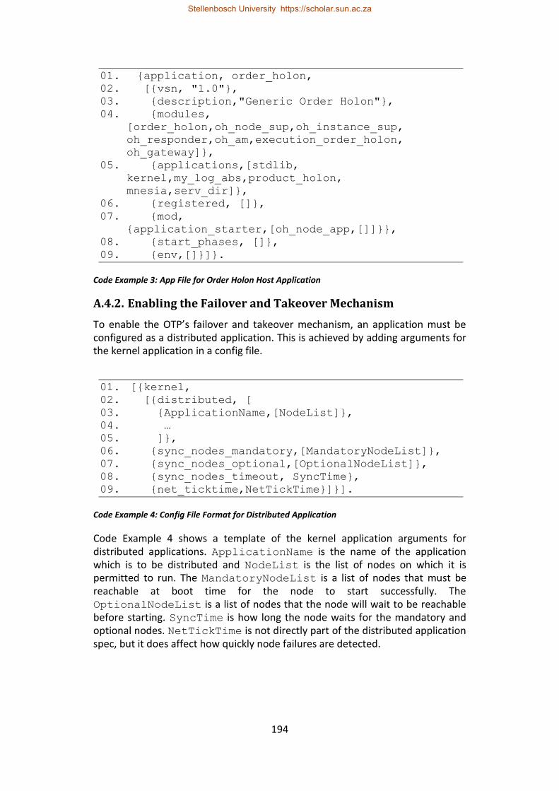
194
01. {application, order_holon, 02. [{vsn, "1.0"}, 03. {description,"Generic Order Holon"}, 04. {modules,
[order_holon,oh_node_sup,oh_instance_sup,
oh_responder,oh_am,execution_order_holon,
oh_gateway]},
05. {applications,[stdlib, kernel,my_log_abs,product_holon,
mnesia,serv_dir]},
06. {registered, []}, 07. {mod,
{application_starter,[oh_node_app,[]]}},
08. {start_phases, []}, 09. {env,[]}]}.
Code Example 3: App File for Order Holon Host Application
A.4.2. Enabling the Failover and Takeover Mechanism
To enable the OTP’s failover and takeover mechanism, an application must be configured as a distributed application. This is achieved by adding arguments for the kernel application in a config file.
01. [{kernel, 02. [{distributed, [ 03. {ApplicationName,[NodeList]}, 04. … 05. ]}, 06. {sync_nodes_mandatory,[MandatoryNodeList]}, 07. {sync_nodes_optional,[OptionalNodeList]}, 08. {sync_nodes_timeout, SyncTime}, 09. {net_ticktime,NetTickTime}]}].
Code Example 4: Config File Format for Distributed Application
Code Example 4 shows a template of the kernel application arguments for distributed applications. ApplicationName is the name of the application which is to be distributed and NodeList is the list of nodes on which it is permitted to run. The MandatoryNodeList is a list of nodes that must be reachable at boot time for the node to start successfully. The OptionalNodeList is a list of nodes that the node will wait to be reachable before starting. SyncTime is how long the node waits for the mandatory and optional nodes. NetTickTime is not directly part of the distributed application spec, but it does affect how quickly node failures are detected.
Stellenbosch University https://scholar.sun.ac.za
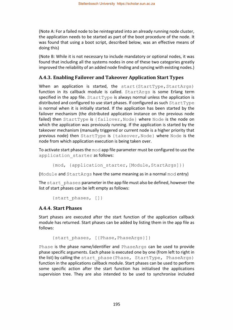
195
(Note A: For a failed node to be reintegrated into an already running node cluster, the application needs to be started as part of the boot procedure of the node. It was found that using a boot script, described below, was an effective means of doing this)
(Note B: While it is not necessary to include mandatory or optional nodes, it was found that including all the systems nodes in one of these two categories greatly improved the reliability of an added node finding and syncing with existing nodes.)
A.4.3. Enabling Failover and Takeover Application Start Types
When an application is started, the start(StartType,StartArgs) function in its callback module is called. StartArgs is some Erlang term specified in the app file. StartType is always normal unless the application is distributed and configured to use start phases. If configured as such StartType is normal when it is initially started. If the application has been started by the failover mechanism (the distributed application instance on the previous node failed) then StartType is {failover,Node} where Node is the node on which the application was previously running. If the application is started by the takeover mechanism (manually triggered or current node is a higher priority that previous node) then StartType is {takeover,Node} where Node is the node from which application execution is being taken over.
To activate start phases the mod app file parameter must be configured to use the application_starter as follows:
{mod, {application_starter,[Module,StartArgs]}}
(Module and StartArgs have the same meaning as in a normal mod entry)
The start_phases parameter in the app file must also be defined, however the list of start phases can be left empty as follows:
{start_phases, []}
A.4.4. Start Phases
Start phases are executed after the start function of the application callback module has returned. Start phases can be added by listing them in the app file as follows:
{start_phases, [{Phase,PhaseArgs}]}
Phase is the phase name/identifier and PhaseArgs can be used to provide phase specific arguments. Each phase is executed one by one (from left to right in the list) by calling the start_phase(Phase, StartType, PhaseArgs) function in the applications callback module. Start phases can be used to perform some specific action after the start function has initialised the applications supervision tree. They are also intended to be used to synchronise included
Stellenbosch University https://scholar.sun.ac.za
196
applications. (Included applications are applications that are started under this applications supervision tree instead of being started separately by the application controller. Since an application can only be included by one other application and there can therefore only be one instance of the included application on a node, the included application functionality has not been used in this research).
(Note: During takeover, the instance of the application on the “old” node only terminates after all the start phases have completed on the new node.)
A.4.5. Failover/Takeover Issues
The failover/takeover mechanism is not able to reintegrate nodes that are separated due to network faults. This issue has been discussed in the research and a workaround has been proposed.
Another potential issue that must be considered is that the failover/takeover mechanism is susceptible to software errors in code that is executed by the application controller when starting a distributed application. This includes the call to the start function in the application callback, the initialisation of the supervision tree (a delayed initialisation can mitigate this) and start phase calls. If an error occurs during this critical phase, then the application does not start successfully on the node and the failover mechanism stops operating. It is important to note that this critical phase of application starting occurs when the application is initially started and every time it is started on a node due to failover or takeover. It is recommended that distributed application start up code be thoroughly tested and that as much initialisation as possible be deferred until after the supervision tree has been created.
A.5. gen_statem Implementation Details
State machines were found to be an appropriate method for implementing redundant control as they allowed the state of control execution to be easily summarised and facilitated re-entry at the required point of execution. This section provides some details about the functioning of OTP’s gen_statem behaviour that are necessary when using it to develop standby-redundant/complex systems.
A.5.1. Event Ordering
The gen_statem behaviour can be considered to have two event queues; an internal event queue and an external event queue. The external event queue is the message queue of the process which executes the state machine. The message queue uses a FIFO policy, so all received messages are handled in the order that they are received. The state machine takes its next event from the external event queue only once the internal event queue is empty. The internal event queue stores events that are generated by the state machine behaviour when processing the results of a handled event.
Stellenbosch University https://scholar.sun.ac.za
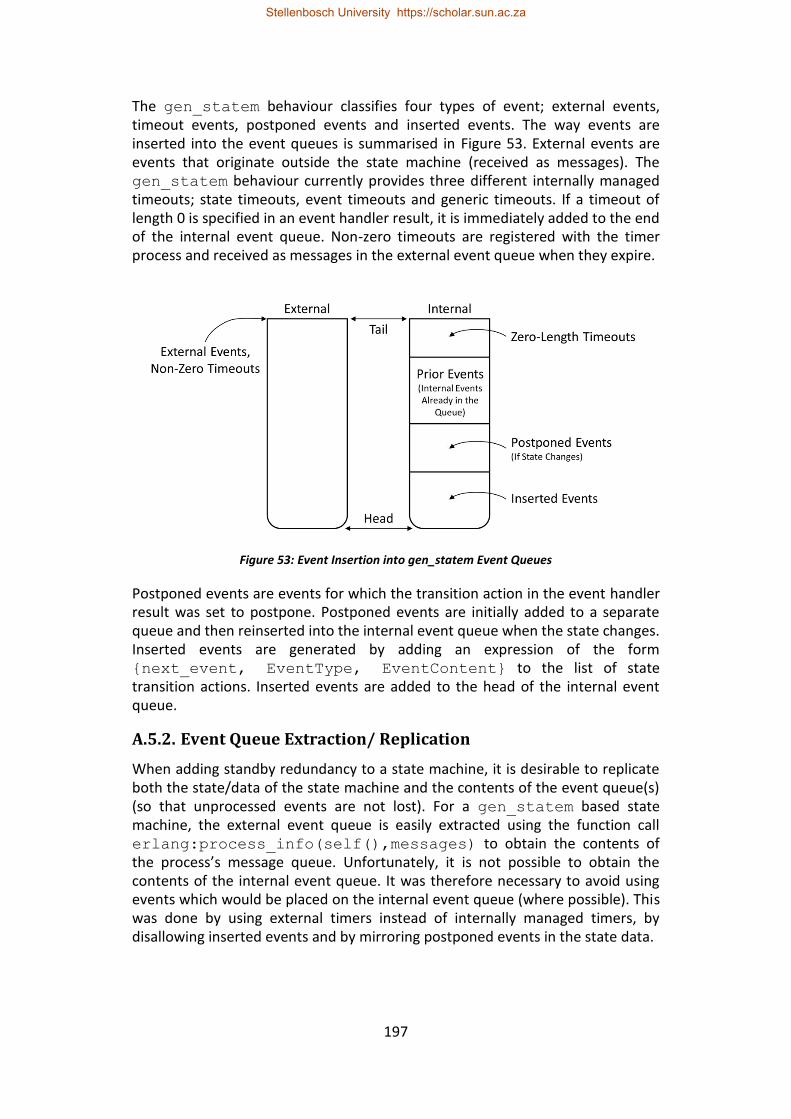
197
The gen_statem behaviour classifies four types of event; external events, timeout events, postponed events and inserted events. The way events are inserted into the event queues is summarised in Figure 53. External events are events that originate outside the state machine (received as messages). The gen_statem behaviour currently provides three different internally managed timeouts; state timeouts, event timeouts and generic timeouts. If a timeout of length 0 is specified in an event handler result, it is immediately added to the end of the internal event queue. Non-zero timeouts are registered with the timer process and received as messages in the external event queue when they expire.
Figure 53: Event Insertion into gen_statem Event Queues
Postponed events are events for which the transition action in the event handler result was set to postpone. Postponed events are initially added to a separate queue and then reinserted into the internal event queue when the state changes. Inserted events are generated by adding an expression of the form {next_event, EventType, EventContent} to the list of state transition actions. Inserted events are added to the head of the internal event queue.
A.5.2. Event Queue Extraction/ Replication
When adding standby redundancy to a state machine, it is desirable to replicate both the state/data of the state machine and the contents of the event queue(s) (so that unprocessed events are not lost). For a gen_statem based state machine, the external event queue is easily extracted using the function call erlang:process_info(self(),messages) to obtain the contents of the process’s message queue. Unfortunately, it is not possible to obtain the contents of the internal event queue. It was therefore necessary to avoid using events which would be placed on the internal event queue (where possible). This was done by using external timers instead of internally managed timers, by disallowing inserted events and by mirroring postponed events in the state data.
Stellenbosch University https://scholar.sun.ac.za
198
A.5.3. Compound State Machine
When developing a complex gen_statem state machine, the resulting code in the callback module can become rather large. It would be desirable to separate this code into logical sections. This is particularly relevant for scenarios where execution can be divided into consecutive portions, as was the case for the interaction between order and resource holons in this research (First a contract net-based bidding phase followed by execution related messaging once a contract is established). It is possible to turn one state machine into another one using gen_statem:enter_loop(…) however care must be taken as events in the first state machine’s internal event queue are not carried over. It is expected that more effective compound state machine functionality could be achieved using callback module layering as described in Hawkridge et al. (2018 (d)) to insert a faciliatory module between the gen_statem behaviour and the state machine implementing callback modules, however this was not further investigated.
A.6. Records vs Maps
Documentation: http://erlang.org/doc/reference_manual/records.html http://erlang.org/documentation/doc-6.0/doc/reference_manual/maps.html
A.6.1. Background
Erlang and OTP have many mechanisms for storing structured data. Records and Maps are two of the most commonly used mechanisms. The advantage that these two mechanisms offer over other mechanisms, such as dicts, sets and gb_trees, is that their contents can be pattern matched in function heads. Pattern matching is a core feature in Erlang. In pattern matching the input expression is compared to a pattern, and if the two are equivalent then the match succeeds. This is often done in function heads to test arguments and select the appropriate function body, as opposed to in an if statement for imperative languages. Being able to perform pattern matching in the function head can lead to clearer and more concise code. (Section 5.3.2.4 provides a more detailed description along with some usage examples)
A.6.1.1. Records
A record is a data structures which stores a fixed number of elements in named fields. Code Example 5 shows the definition and usage of a record with three fields in lines 2 and 4. Records are built on top of Erlangs tuple data type as shown in line 8. During compilation record expressions are converted to tuple expressions. For example: line 6 which extracts the value stored in field1 and stores it in Var would be converted to Var = element(2, RecordVar) which extracts the 2nd element in the record tuple.
Stellenbosch University https://scholar.sun.ac.za
199
01. %Definition: 02. -record(record_name,[field1,field2,field3]). 03. %Usage: 04. RecordVar=
#record_name{field1=Value1,field2=Value2,field3=V
alue3}.
05. %Pattern Matching: 06. #record_name(field1=Var)=RecordVar. 07. %Tuple form: 08. {record_name,Value1,Value2,Value3}
Code Example 5: Erlang Records
A.6.1.2. Maps
A map is a key-value data structure comparable to a hash map (Large maps are implemented as hash maps). Maps are dynamic, i.e. the number of stored entries can vary during execution. Code Example 6 shows an overview of the definition and usage of maps.
01. %Definition and Usage: 02. MapVar =
#{key1=>Value1,key2=>Value2,key3=>Value3}.
03. %Pattern Matching: 04. #{key1:=Var} = MapVar. 05. %or Direct Access: 06. Var = maps:get(key1,MapVar).
Code Example 6: Erlang Maps
(Note A: When maps are pattern matched, the key must be bound (i.e. not a variable). The following is not currently valid in a function head: f(A,#{A:=Var})->… however this is valid: f(A,M)-> #{A:=Var}=M, …)
(Note B: Erlang’s Maps implementation is still under development [see the proposal at http://erlang.org/eeps/eep-0043.html]. It is likely that the functionality they provide will improve with future releases)
A.6.2. Evaluation
During this research, three main considerations were identified when deciding whether to implement data structures as records or maps. These considerations are: ease of inter module use, ease of definition modification and ease of debugging.
Stellenbosch University https://scholar.sun.ac.za
200
A.6.2.1. Ease of Inter Module Usage
For records, the header file containing the record definition must be included in all modules that require access to contents of record instances. This is not required for maps; all modules need only reference the key corresponding to the data they want to extract.
A.6.2.2. Ease of Definition Modification
When a records field names are refactored, then compile time errors will occur for code that references the previous (un-refactored) field names. Furthermore, if additional fields are added to the record, then all code that references that record definition must be recompiled. This is because the underlying tuple implementation of records means that code which is not recompiled may be referring to the previous tuple index of a field instead of its new index and could result in unexpected behaviour or runtime errors.
For maps, key-value pairs can easily be added or refactored. However, code that contains references to previous (un-refactored) keys will not be evident at compile time and may result in unexpected behaviour or runtime errors.
A.6.2.3. Ease of Debugging
When records are printed to logs or in debugging tools, the record fields are not shown, only the underlying tuple is shown which contains the field contents separated by commas. This can make debugging large and nested records exceptionally difficult. In contrast, printed maps are more conducive to debugging large data structures as they show the key-value mappings.
A.6.3. Conclusions
For this research, records were primarily used to store data. Since the code developed as part of this research is experimental, the data structures were frequently adapted and improved. Therefore, the use of records to avoid accidental runtime errors outweighed the extra effort required for inter module use and the difficulty that their use adds to debugging. It should be noted that established code, such as OTP’s supervisor module, have started migrating to maps for data structures that cross the module boundaries (At the time of writing, the supervisor module still uses records for internal data structures).
A.7. Handling Controller I/O
A.7.1. GPIO and Interrupts
The Erlang/ALE library (https://github.com/esl/erlang_ale) was used to access the GPIO of the two microcontrollers used in this research. This library provides GPIO access and control through Linux’s sysfs file system. GPIO simulation was achieved by developing an interface module that mirrors the API of Erlang/ALE. If
Stellenbosch University https://scholar.sun.ac.za
201
the simulation compile flag is set, then it redirects calls to a simulation module, otherwise they are forwarded to the Erlang/ALE library.
A.7.2. Timing and Pulse Generation
To control one of the singulation units, which was used in this research’s case study setup(s), it was necessary to generate a pulse train to control a stepper motor driver board. This was initially attempted from within Erlang using the receive - after approach to generate the required delays between pulses. However, it was determined that this could not provide a reliable pulse train above 50 Hz. It was therefore necessary to program the pulse generation in C and link it to the system using Erlang’s port mechanism.
A.7.3. IP Socket I/O
Erlang provides the gen_tcp and gen_udp modules to handle TCP and UDP communication respectively. Both TCP and UDP sockets (referred to as sockets hereafter) can either be set to active mode or passive mode. In passive mode, the socket is read by calling the recv function. In active mode, received socket messages are automatically converted to Erlang messages and sent to the Erlang process which controls that socket (Usually the process that created the socket, but can be changed). Active mode is generally preferred as it is considered easier to work with since socket messages become normal Erlang messages. However, passive mode is preferred in high load scenarios as it can prevent the controlling process’s message queue from being overloaded.
When using socket communication in a standby-redundant state machine as part of this research, two approaches were investigated; the standalone approach and the integrated approach. For the integrated approach, the socket communication (in active mode) is integrated into the state machine (which is the controlling process for the socket). For the standalone approach, the socket communication is managed by a separate gen_server process which parses received socket messages and generates the relevant state machine events.
The advantage of the integrated approach is that all socket messages are placed in the event queue of the state machine and therefore replicated whenever a checkpoint is made. This means that it is less likely that a socket-message-based event will be lost during failover. An advantage of the standalone approach is that it has the option of both active and passive mode. Furthermore, separating the state machine from the socket message encoding and decoding operations isolates the state machine from errors that may occur there. For this research, the standalone approach was found to be easier to implement and debug than the integrated approach.
Stellenbosch University https://scholar.sun.ac.za