standard product portfolio - wika
TRANSCRIPT

WIKAStandard product portfolio
Pressure | Temperature | Level | Force | Flow | Calibration

2
Alexander Wiegand, Chairman and CEO, WIKA
About us
As a family-run business acting globally, with 10,200 highly qualified employees, the WIKA group of companies is a worldwide leader in pressure and temperature measurement. The company also sets the standard in the measurement of level, force and flow, and in calibration technology.
Founded in 1946, WIKA is today a strong and reliable partner for all the requirements of industrial measurement technology, thanks to a broad portfolio of high-precision instruments and comprehensive services.
With manufacturing locations around the globe, WIKA ensures flexibility and the highest delivery performance. Every year, over 50 million quality products, both standard and customer-specific solutions, are delivered in batches of 1 to over 10,000 units.
With numerous wholly owned subsidiaries and partners, WIKA competently and reliably supports its customers worldwide. Our experienced engineers and sales experts are your competent and dependable contacts locally.
3
Diff erential pressureTemperatureHumidityAir fl ow
Measuring instruments and controllers for ventilation and air-conditioning
PharmaceuticalFoodBiotechnologyCosmetics
Sanitary applications
Process gas managementFacilities support equipment
for semiconductor, solar, light
Measurement solutions
Gas density monitoringGas analysisGas handlingAsset protection
Innovative SF6 solutions
gridSolutions
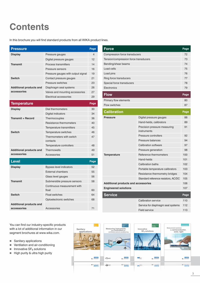
Contents
Pressure Page
Display Pressure gauges 4
Digital pressure gauges 12
Transmit Process transmitters 14Pressure sensors 16Pressure gauges with output signal 19
Switch Contact pressure gauges 21Pressure switches 23
Additional products and accessories
Diaphragm seal systems 26Valves and mounting accessories 27Electrical accessories 29
Temperature Page
Display Dial thermometers 30Digital indicators 34
Transmit + Record Thermocouples 36Resistance thermometers 40Temperature transmitters 45
Switch Temperature switches 46Thermometers with switch contacts
47
Temperature controllers 48Additional products and accessories
Thermowells 49Accessories 51
Level Page
Display Bypass level indicators 52External chambers 55Glass level gauges 56
Transmit Submersible pressure sensors 58Continuous measurement with float 60
Switch Float switches 64Optoelectronic switches 68
Additional products and accessories Accessories 71
Force Page
Compression force transducers 72Tension/compression force transducers 73Bending/shear beams 74Load cells 75Load pins 76Ring force transducers 77Special force transducers 78Electronics 79
Flow Page
Primary flow elements 80Flow switches 87
Calibration Page
Pressure Digital pressure gauges 88Hand-helds, calibrators 89Precision pressure measuring instruments
91
Pressure controllers 92Pressure balances 94Calibration software 97Pressure generation 98
Temperature Reference thermometers 100Hand-helds 101Calibration baths 102Portable temperature calibrators 103Resistance thermometry bridges 104Standard reference resistors, AC/DC 105
Additional products and accessories 106Engineered solutions 107
Service Page
Calibration service 110Service for diaphragm seal systems 112Field service 113
In this brochure you will find standard products from all WIKA product lines.
You can find our industry-specific products with a lot of additional information in our segment brochures at www.wika.com.
� Sanitary applications � Ventilation and air-conditioning � Innovative SF6 solutions � High purity & ultra high purity
4
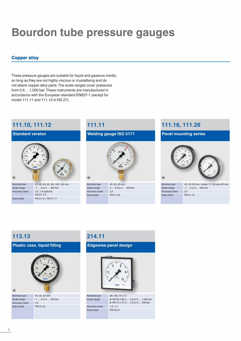
Bourdon tube pressure gauges
Copper alloy
These pressure gauges are suitable for liquid and gaseous media, so long as they are not highly viscous or crystallising and do not attack copper alloy parts. The scale ranges cover pressures from 0.6 ... 1,000 bar. These instruments are manufactured in accordance with the European standard EN837-1 (except for model 111.11 and 111.12 in NS 27).
113.13Plastic case, liquid filling
Nominal size 40, 50, 63 mmScale range -1 … 0 to 0 … 400 barAccuracy class 2.5Data sheet PM 01.04
111.11Welding gauge ISO 5171
Nominal size 40, 50, 63 mmScale range 0 … 0.6 to 0 … 400 barAccuracy class 2.5Data sheet PM 01.03
111.10, 111.12Standard version
Nominal size 27, 40, 50, 63, 80, 100, 160 mmScale range -1 … 0 to 0 … 400 barAccuracy class 2.5, 1.6 optional
NS 27: 4.0Data sheet PM 01.01, PM 01.17
214.11Edgewise panel design
Nominal size 96 x 96, 72 x 72Scale range ■ NS 96 x 96: 0 … 0.6 to 0 … 1,000 bar
■ NS 72 x 72: 0 … 0.6 to 0 … 400 barAccuracy class 1.6, 1.0Data sheet PM 02.07
111.16, 111.26Panel mounting series
Nominal size 40, 50, 63 mm, model 111.26 also 80 mmScale range -1 … 0 to 0 … 400 barAccuracy class 2.5Data sheet PM 01.10
Copper alloy
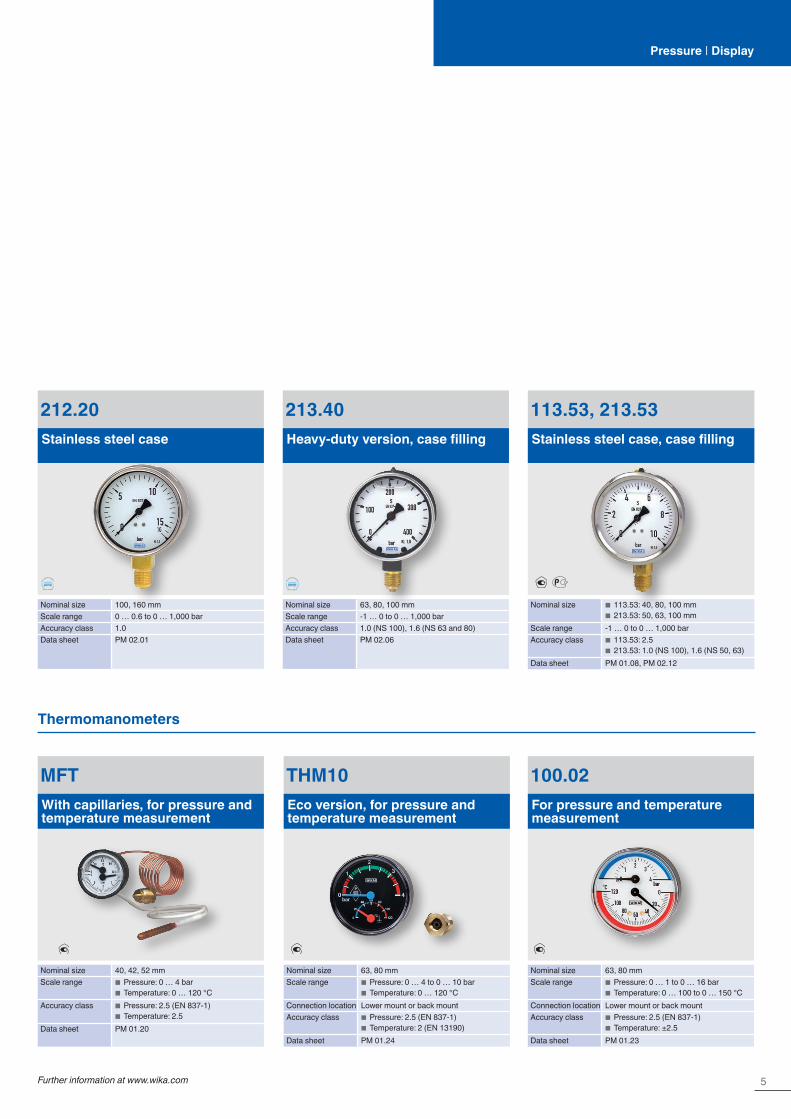
5Further information at www.wika.com
Pressure | Display
113.53, 213.53Stainless steel case, case filling
Nominal size ■ 113.53: 40, 80, 100 mm ■ 213.53: 50, 63, 100 mm
Scale range -1 … 0 to 0 … 1,000 barAccuracy class ■ 113.53: 2.5
■ 213.53: 1.0 (NS 100), 1.6 (NS 50, 63)Data sheet PM 01.08, PM 02.12
212.20Stainless steel case
Nominal size 100, 160 mmScale range 0 … 0.6 to 0 … 1,000 barAccuracy class 1.0Data sheet PM 02.01
213.40Heavy-duty version, case filling
Nominal size 63, 80, 100 mmScale range -1 … 0 to 0 … 1,000 barAccuracy class 1.0 (NS 100), 1.6 (NS 63 and 80)Data sheet PM 02.06
MFTWith capillaries, for pressure and temperature measurement
Nominal size 40, 42, 52 mmScale range ■ Pressure: 0 … 4 bar
■ Temperature: 0 … 120 °CAccuracy class ■ Pressure: 2.5 (EN 837-1)
■ Temperature: 2.5Data sheet PM 01.20
THM10Eco version, for pressure and temperature measurement
Nominal size 63, 80 mmScale range ■ Pressure: 0 … 4 to 0 … 10 bar
■ Temperature: 0 … 120 °CConnection location Lower mount or back mountAccuracy class ■ Pressure: 2.5 (EN 837-1)
■ Temperature: 2 (EN 13190)Data sheet PM 01.24
Thermomanometers
100.02For pressure and temperature measurement
Nominal size 63, 80 mmScale range ■ Pressure: 0 … 1 to 0 … 16 bar
■ Temperature: 0 … 100 to 0 … 150 °CConnection location Lower mount or back mountAccuracy class ■ Pressure: 2.5 (EN 837-1)
■ Temperature: ±2.5Data sheet PM 01.23
6
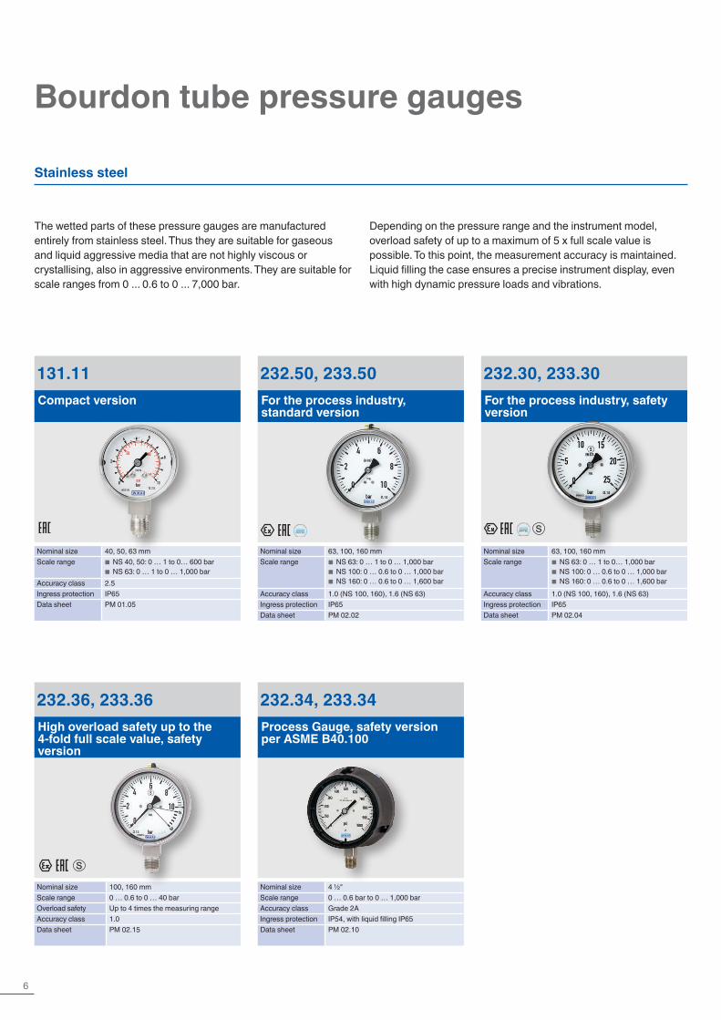
Bourdon tube pressure gauges
Stainless steel
The wetted parts of these pressure gauges are manufactured entirely from stainless steel. Thus they are suitable for gaseous and liquid aggressive media that are not highly viscous or crystallising, also in aggressive environments. They are suitable for scale ranges from 0 ... 0.6 to 0 ... 7,000 bar.
Depending on the pressure range and the instrument model, overload safety of up to a maximum of 5 x full scale value is possible. To this point, the measurement accuracy is maintained. Liquid filling the case ensures a precise instrument display, even with high dynamic pressure loads and vibrations.
131.11Compact version
Nominal size 40, 50, 63 mmScale range ■ NS 40, 50: 0 … 1 to 0… 600 bar
■ NS 63: 0 … 1 to 0 … 1,000 barAccuracy class 2.5Ingress protection IP65Data sheet PM 01.05
232.36, 233.36High overload safety up to the 4-fold full scale value, safety version
Nominal size 100, 160 mmScale range 0 … 0.6 to 0 … 40 barOverload safety Up to 4 times the measuring rangeAccuracy class 1.0Data sheet PM 02.15
232.30, 233.30For the process industry, safety version
Nominal size 63, 100, 160 mmScale range ■ NS 63: 0 … 1 to 0… 1,000 bar
■ NS 100: 0 … 0.6 to 0 … 1,000 bar ■ NS 160: 0 … 0.6 to 0 … 1,600 bar
Accuracy class 1.0 (NS 100, 160), 1.6 (NS 63)Ingress protection IP65Data sheet PM 02.04
232.50, 233.50For the process industry, standard version
Nominal size 63, 100, 160 mmScale range ■ NS 63: 0 … 1 to 0 … 1,000 bar
■ NS 100: 0 … 0.6 to 0 … 1,000 bar ■ NS 160: 0 … 0.6 to 0 … 1,600 bar
Accuracy class 1.0 (NS 100, 160), 1.6 (NS 63)Ingress protection IP65Data sheet PM 02.02
232.34, 233.34Process Gauge, safety version per ASME B40.100
Nominal size 4 ½"Scale range 0 … 0.6 bar to 0 … 1,000 barAccuracy class Grade 2AIngress protection IP54, with liquid filling IP65Data sheet PM 02.10
7Further information at www.wika.com
Pressure | Display
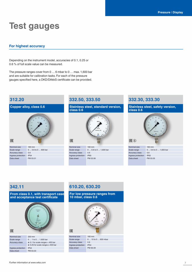
Depending on the instrument model, accuracies of 0.1, 0.25 or 0.6 % of full scale value can be measured.
The pressure ranges cover from 0 … 6 mbar to 0 … max. 1,600 bar and are suitable for calibration tasks. For each of the pressure gauges specified here, a DKD/DAkkS certificate can be provided.
312.20Copper alloy, class 0.6
Nominal size 160 mmScale range 0 … 0.6 to 0 … 600 barAccuracy class 0.6Ingress protection IP54Data sheet PM 03.01
342.11From class 0.1, with transport case and acceptance test certificate
Nominal size 250 mmScale range 0 … 1 to 0 … 1,600 barAccuracy class ■ 0.1 for scale ranges < 400 bar
■ 0.25 for scale ranges ≥ 400 barIngress protection IP54Data sheet PM 03.03
610.20, 630.20For low pressure ranges from 10 mbar, class 0.6
Nominal size 160 mmScale range 0 … 10 to 0 … 600 mbarAccuracy class 0.6Ingress protection IP54Data sheet PM 06.09
332.50, 333.50Stainless steel, standard version, class 0.6
Nominal size 160 mmScale range 0 … 0.6 to 0 … 1,600 barAccuracy class 0.6Ingress protection IP65Data sheet PM 03.06
Test gauges
For highest accuracy
332.30, 333.30Stainless steel, safety version, class 0.6
Nominal size 160 mmScale range 0 … 0.6 to 0 … 1,600 barAccuracy class 0.6Ingress protection IP65Data sheet PM 03.05

8
Diaphragm pressure gauges
The application areas for diaphragm pressure gauges are very versatile. They are the specialists in the process industry when it comes to critical measuring tasks such as with highly corrosive or viscous media or when it comes to low pressures and high over-load. The scale ranges are from as low as 0 … 16 mbar to typically 0 … 25 to 0 … 40 bar. Depending on the pressure range and the instrument model, overload safety of 3 x or 5 x full scale value is possible as standard.
For special designs, an overload safety of up to 400 bar is possible, with the measurement accuracy maintained.Diaphragm pressure gauges are even suitable for highly viscous or contaminated media by using an open connecting flange (per DIN/ASME). For measuring particularly aggressive media, the complete wetted surface can be lined with a large selection of special materials (e.g. PTFE, Hastelloy, tantalum, and many more).
422.12, 423.12Grey cast iron case
Nominal size 100, 160 mmScale range 0 … 16 mbar to 0 … 40 barAccuracy class 1.6Ingress protection IP54, with liquid filling IP65Data sheet PM 04.02
432.50, 433.50For the process industry, high overload safety up to the 10-fold full scale value, max. 40 bar
Nominal size 100, 160 mmScale range 0 … 16 mbar to 0 … 25 barAccuracy class 1.6Ingress protection IP54, with liquid filling IP65Data sheet PM 04.03
432.36, 432.56For the process industry, high overload safety to 40, 100 or 400 bar
Nominal size 100, 160 mmScale range 0 … 16 mbar to 0 … 40 barAccuracy class 1.6Ingress protection IP54, with liquid filling IP65Data sheet PM 04.07
9Further information at www.wika.com
Capsule pressure gaugesPressure | Display
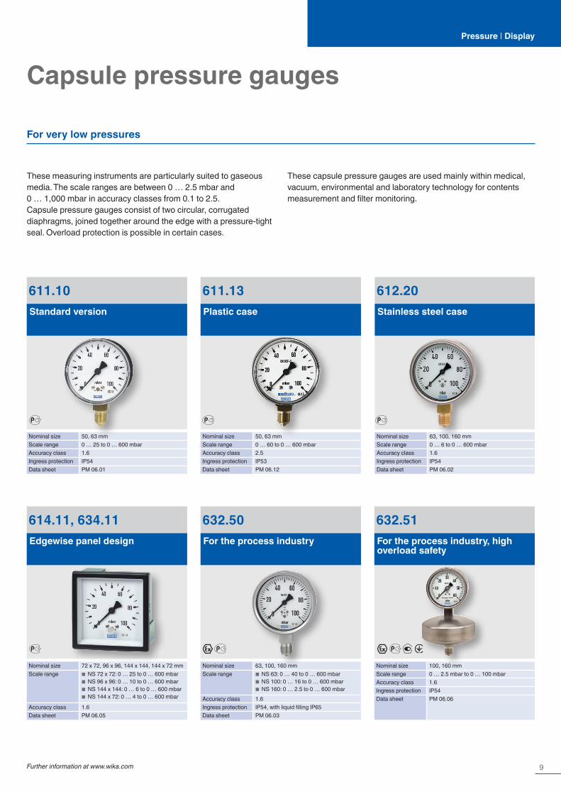
For very low pressures
These measuring instruments are particularly suited to gaseous media. The scale ranges are between 0 … 2.5 mbar and 0 … 1,000 mbar in accuracy classes from 0.1 to 2.5.Capsule pressure gauges consist of two circular, corrugated diaphragms, joined together around the edge with a pressure-tight seal. Overload protection is possible in certain cases.
These capsule pressure gauges are used mainly within medical, vacuum, environmental and laboratory technology for contents measurement and filter monitoring.
611.10Standard version
Nominal size 50, 63 mmScale range 0 … 25 to 0 … 600 mbarAccuracy class 1.6Ingress protection IP54Data sheet PM 06.01
611.13Plastic case
Nominal size 50, 63 mmScale range 0 … 60 to 0 … 600 mbarAccuracy class 2.5Ingress protection IP53Data sheet PM 06.12
612.20Stainless steel case
Nominal size 63, 100, 160 mmScale range 0 … 6 to 0 … 600 mbarAccuracy class 1.6Ingress protection IP54Data sheet PM 06.02
614.11, 634.11Edgewise panel design
Nominal size 72 x 72, 96 x 96, 144 x 144, 144 x 72 mmScale range ■ NS 72 x 72: 0 … 25 to 0 … 600 mbar
■ NS 96 x 96: 0 … 10 to 0 … 600 mbar ■ NS 144 x 144: 0 … 6 to 0 … 600 mbar ■ NS 144 x 72: 0 … 4 to 0 … 600 mbar
Accuracy class 1.6Data sheet PM 06.05
632.50For the process industry
Nominal size 63, 100, 160 mmScale range ■ NS 63: 0 … 40 to 0 … 600 mbar
■ NS 100: 0 … 16 to 0 … 600 mbar ■ NS 160: 0 … 2.5 to 0 … 600 mbar
Accuracy class 1.6Ingress protection IP54, with liquid filling IP65Data sheet PM 06.03
632.51For the process industry, high overload safety
Nominal size 100, 160 mmScale range 0 … 2.5 mbar to 0 … 100 mbarAccuracy class 1.6Ingress protection IP54Data sheet PM 06.06
10
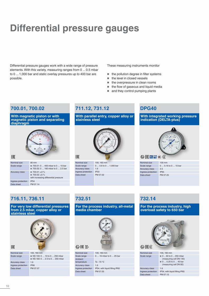
Differential pressure gauges
Differential pressure gauges work with a wide range of pressure elements. With this variety, measuring ranges from 0 ... 0.5 mbar to 0 ... 1,000 bar and static overlay pressures up to 400 bar are possible.
These measuring instruments monitor
� the pollution degree in filter systems � the level in closed vessels � the overpressure in clean rooms � the flow of gaseous and liquid media � and they control pumping plants
700.01, 700.02With magnetic piston or with magnetic piston and separating diaphragm
Nominal size 80 mmScale range ■ 700.01: 0 … 400 mbar to 0 … 10 bar
■ 700.02: 0 … 160 mbar to 0 … 2.5 barAccuracy class ■ 700.01: ±3 %
■ 700.02: ±5 %with increasing differential pressure
Ingress protection IP54Data sheet PM 07.14
711.12, 731.12With parallel entry, copper alloy or stainless steel
Nominal size 100, 160 mmScale range 0 … 0.6 to 0 … 1,000 barAccuracy class 1.6Ingress protection IP33Data sheet PM 07.02
716.11, 736.11For very low differential pressures from 2.5 mbar, copper alloy or stainless steel
Nominal size 100, 160 mmScale range ■ NS 100: 0 … 10 to 0 … 250 mbar
■ NS 160: 0 … 2.5 to 0 … 250 mbarAccuracy class 1.6Ingress protection IP66Data sheet PM 07.07
DPG40With integrated working pressure indication (DELTA-plus)
Nominal size 100 mmScale range 0 … 0.16 to 0 … 10 barAccuracy class 2.5Ingress protection IP65Data sheet PM 07.20
732.14For the process industry, high overload safety to 650 bar
Nominal size 100, 160 mmScale range ■ 0 ... 60 to 0 ... 250 mbar
(measuring cell DN 140) ■ 0 … 0.25 to 0 … 40 bar (measuring cell DN 82)
Accuracy class 1.6Ingress protection IP54, with liquid filling IP65Data sheet PM 07.13
732.51For the process industry, all-metal media chamber
Nominal size 100, 160 mmScale range 0 … 16 mbar to 0 … 25 barAmbient temperature To - 70 °CAccuracy class 1.6Ingress protection IP54, with liquid filling IP65Data sheet PM 07.05
11Further information at www.wika.com
Pressure | Display
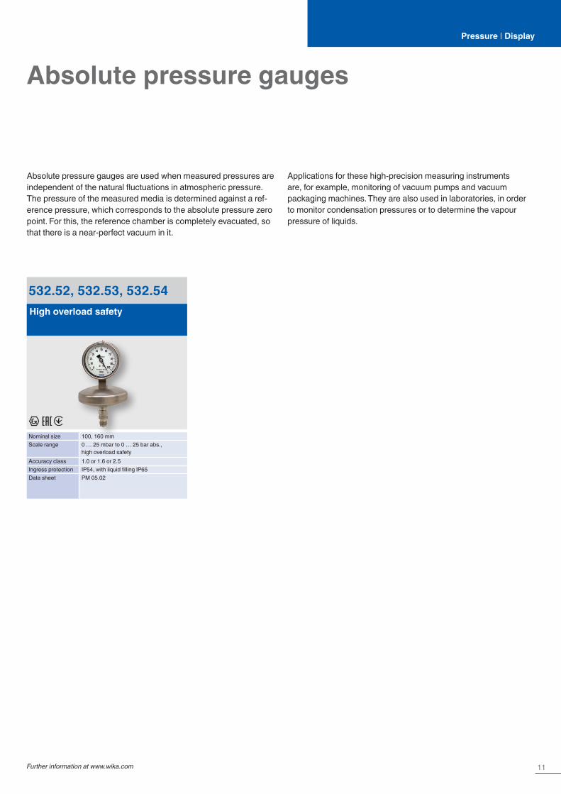
Absolute pressure gauges
Absolute pressure gauges are used when measured pressures are independent of the natural fluctuations in atmospheric pressure. The pressure of the measured media is determined against a ref-erence pressure, which corresponds to the absolute pressure zero point. For this, the reference chamber is completely evacuated, so that there is a near-perfect vacuum in it.
532.52, 532.53, 532.54High overload safety
Nominal size 100, 160 mmScale range 0 … 25 mbar to 0 … 25 bar abs.,
high overload safetyAccuracy class 1.0 or 1.6 or 2.5Ingress protection IP54, with liquid filling IP65Data sheet PM 05.02
Applications for these high-precision measuring instruments are, for example, monitoring of vacuum pumps and vacuum packaging machines. They are also used in laboratories, in order to monitor condensation pressures or to determine the vapour pressure of liquids.
12
Pressure | Display
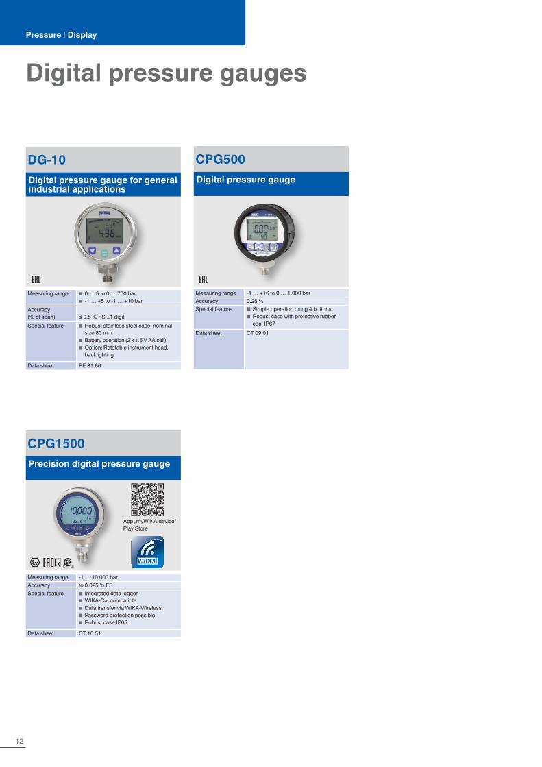
Digital pressure gauges
CPG500Digital pressure gauge
Measuring range -1 … +16 to 0 … 1,000 barAccuracy 0.25 %Special feature ■ Simple operation using 4 buttons
■ Robust case with protective rubber cap, IP67
Data sheet CT 09.01
DG-10Digital pressure gauge for general industrial applications
Measuring range ■ 0 … 5 to 0 … 700 bar ■ -1 … +5 to -1 … +10 bar
Accuracy (% of span) ≤ 0.5 % FS ±1 digitSpecial feature ■ Robust stainless steel case, nominal
size 80 mm ■ Battery operation (2 x 1.5 V AA cell) ■ Option: Rotatable instrument head, backlighting
Data sheet PE 81.66
CPG1500Precision digital pressure gauge
Measuring range -1 … 10,000 barAccuracy to 0.025 % FSSpecial feature ■ Integrated data logger
■ WIKA-Cal compatible ■ Data transfer via WIKA-Wireless ■ Password protection possible ■ Robust case IP65
Data sheet CT 10.51
App „myWIKA device“Play Store
13Further information at www.wika.com
Pressure | Transmit
MPR-1Pressure sensor module
Non-linearity (± % of span) ≤ 0.125 or 0.25Measuring range ■ 0 … 0.4 to 0 … 25 bar
■ 0 … 0.4 to 0 … 25 bar abs.Special feature ■ 19 mm spanner width for limited
mounting space ■ No calibration necessary, due to compensated output signal
Signal Analogue and digitalData sheet PE 81.64
MTF-1Pressure sensor module
Non-linearity (± % of span) ≤ 0.125 or 0.25Measuring range ■ 0 … 10 to 0 … 1,000 bar
■ -1 … 9 to -1 … +24 barSpecial feature ■ 19 and 27 mm spanner width
■ No calibration necessary, due to compensated output signal
Signal Analogue and digitalData sheet PE 83.01
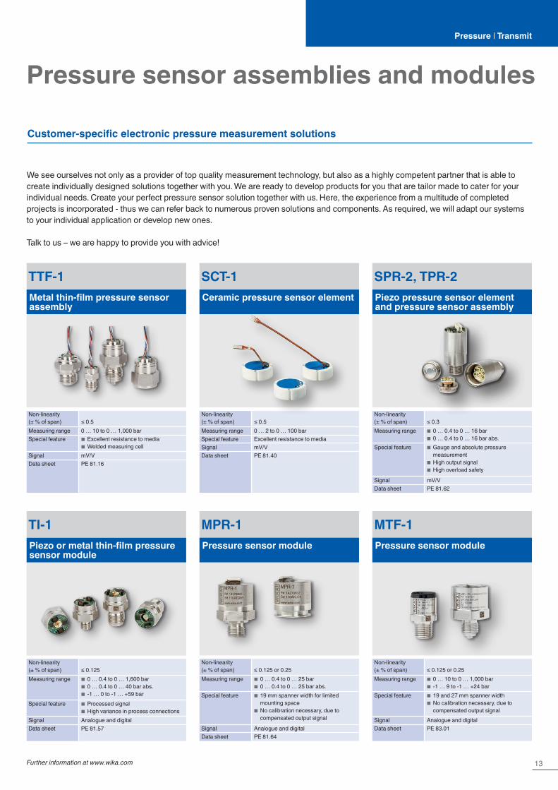
Pressure sensor assemblies and modules
Customer-specific electronic pressure measurement solutions
TTF-1Metal thin-film pressure sensor assembly
Non-linearity (± % of span) ≤ 0.5Measuring range 0 … 10 to 0 … 1,000 barSpecial feature ■ Excellent resistance to media
■ Welded measuring cellSignal mV/VData sheet PE 81.16
TI-1Piezo or metal thin-film pressure sensor module
Non-linearity (± % of span) ≤ 0.125Measuring range ■ 0 … 0.4 to 0 … 1,600 bar
■ 0 … 0.4 to 0 … 40 bar abs. ■ -1 … 0 to -1 … +59 bar
Special feature ■ Processed signal ■ High variance in process connections
Signal Analogue and digitalData sheet PE 81.57
SCT-1Ceramic pressure sensor element
Non-linearity (± % of span) ≤ 0.5Measuring range 0 … 2 to 0 … 100 barSpecial feature Excellent resistance to mediaSignal mV/VData sheet PE 81.40
SPR-2, TPR-2Piezo pressure sensor element and pressure sensor assembly
Non-linearity (± % of span) ≤ 0.3Measuring range ■ 0 … 0.4 to 0 … 16 bar
■ 0 … 0.4 to 0 … 16 bar abs.Special feature ■ Gauge and absolute pressure
measurement ■ High output signal ■ High overload safety
Signal mV/VData sheet PE 81.62
We see ourselves not only as a provider of top quality measurement technology, but also as a highly competent partner that is able to create individually designed solutions together with you. We are ready to develop products for you that are tailor made to cater for your individual needs. Create your perfect pressure sensor solution together with us. Here, the experience from a multitude of completed projects is incorporated - thus we can refer back to numerous proven solutions and components. As required, we will adapt our systems to your individual application or develop new ones.
Talk to us – we are happy to provide you with advice!
14
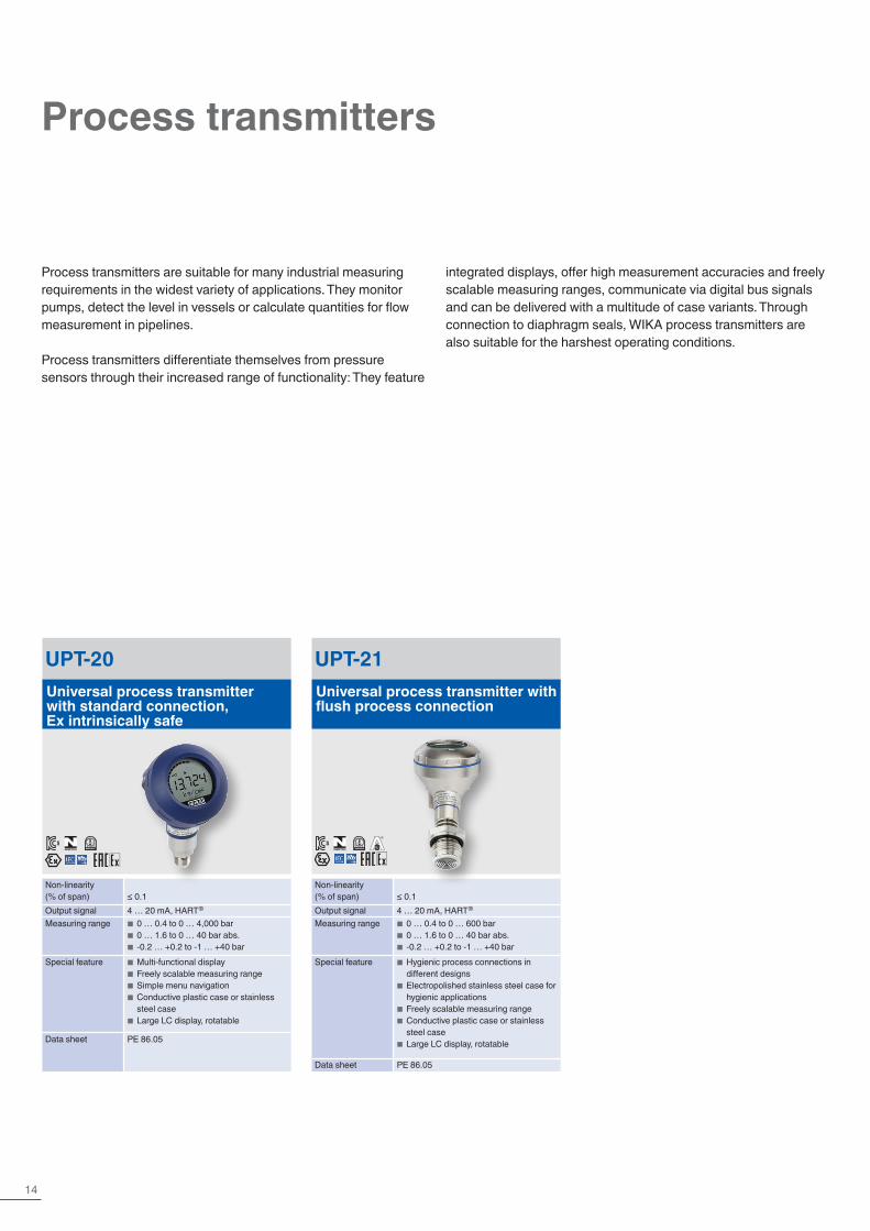
Process transmitters
UPT-20Universal process transmitter with standard connection, Ex intrinsically safe
Non-linearity (% of span) ≤ 0.1Output signal 4 … 20 mA, HART®
Measuring range ■ 0 … 0.4 to 0 … 4,000 bar ■ 0 … 1.6 to 0 … 40 bar abs. ■ -0.2 … +0.2 to -1 … +40 bar
Special feature ■ Multi-functional display ■ Freely scalable measuring range ■ Simple menu navigation ■ Conductive plastic case or stainless steel case
■ Large LC display, rotatable
Data sheet PE 86.05
UPT-21Universal process transmitter with flush process connection
Non-linearity (% of span) ≤ 0.1Output signal 4 … 20 mA, HART®
Measuring range ■ 0 … 0.4 to 0 … 600 bar ■ 0 … 1.6 to 0 … 40 bar abs. ■ -0.2 … +0.2 to -1 … +40 bar
Special feature ■ Hygienic process connections in different designs
■ Electropolished stainless steel case for hygienic applications
■ Freely scalable measuring range ■ Conductive plastic case or stainless steel case
■ Large LC display, rotatable
Data sheet PE 86.05
Process transmitters are suitable for many industrial measuring requirements in the widest variety of applications. They monitor pumps, detect the level in vessels or calculate quantities for flow measurement in pipelines.
Process transmitters differentiate themselves from pressure sensors through their increased range of functionality: They feature
integrated displays, offer high measurement accuracies and freely scalable measuring ranges, communicate via digital bus signals and can be delivered with a multitude of case variants. Through connection to diaphragm seals, WIKA process transmitters are also suitable for the harshest operating conditions.
®

15Further information at www.wika.com
IPT-20, IPT-21Process pressure transmitter with welded metal measuring cell
Non-linearity (% of span) ≤ 0.075 … 0.1Output signal 4 … 20 mA, HART® protocol (optional),
PROFIBUS® PA, FOUNDATION™ Fieldbus
Measuring range ■ 0 … 0.1 to 0 … 4,000 bar ■ 0 … 0.1 to 0 … 40 bar abs. ■ -1 … 0 to -1 … +40 bar
Special feature ■ Freely scalable measuring ranges ■ Case from plastic, aluminium or stainless steel
■ Flush process connection (optional) ■ With integrated display and instrument mounting bracket for wall/pipe mounting (optional)
■ Process temperature ranges to 200 °C
Data sheet PE 86.06
DPT-20Differential pressure transmitter, intrinsically safe or with flame-proof enclosure
Non-linearity (% of span) ≤ 0.065 … 0.5Output signal 4 … 20 mA, HART® protocol (option-
al), PROFIBUS® PA, FOUNDATION™ Fieldbus
Measuring range 0 … 10 mbar to 0 … 16 barSpecial feature ■ Freely scalable measuring ranges
■ Static load 160 bar, optionally 420 bar ■ Case from plastic, aluminium or stainless steel
■ With integrated display and instrument mounting bracket for wall/pipe mounting (optional)
■ 3- or 5-way valve optional ■ SIL2 per IEC61508
Data sheet PE 86.22
CPT-20, CPT-21Process pressure transmitter with capacitive ceramic measuring cell
Non-linearity (% of span) ≤ 0.05Output signal 4 … 20 mA, HART® protocol (optional),
PROFIBUS® PA, FOUNDATION™ Fieldbus
Measuring range ■ 0 … 0.025 to 0 … 100 bar abs. ■ -1 … 0 to -1 … +100 bar
Special feature ■ Particularly robust, ceramic measuring cell
■ Dry ceramic measuring cell with varia-ble sealing concept
■ Freely scalable measuring ranges ■ Case from plastic, aluminium or stainless steel
■ Flush process connection (optional)
Data sheet PE 86.07
Pressure | Transmit
DPT-ELElectronic differential pressure transmitter in primary and second-ary circuits
Non-linearity (% of span) ≤ 0.05 … 0.1Output signal 4 … 20 mA, HART® protocol (option-
al), PROFIBUS® PA, FOUNDATION™ Fieldbus
Measuring range ■ 0 … 0.1 to 0 … 1,000 bar ■ 0 … 1.6 to 0 … 40 bar abs. ■ -0.05 … +0.05 to -1 … +40 bar
Special feature ■ Simple, uncomplicated installation ■ Mounting possible without diaphragm seal
■ Elimination of capillaries, that can easily kink
■ For applications to SIL 2 (SIL 3) ■ Can be combined with two different designs of transmitters from model IPT-2x and/or model CPT-2x
Data sheet PE 86.23
SILIEC 61508 / IEC 61511

16
Pressure sensors
A-10For general industrial applications
Non-linearity (± % of span) ≤ 0.25 or 0.5 BFSLMeasuring range ■ 0 … 0.05 to 0 …1,000 bar
■ 0 … 0.1 to 0 … 25 bar abs. ■ -0.05 … 0 to -1 … +24 bar
Special feature ■ Compact design ■ Free test report ■ 2 million possible variants
Data sheet PE 81.60
S-11Flush diaphragm
Non-linearity (± % of span) ≤ 0.2 BFSLMeasuring range ■ 0 … 0.1 to 0 … 600 bar
■ 0 … 0.25 to 0 … 16 bar abs. ■ -0.1 … 0 to -1 … +24 bar
Special feature ■ Flush process connection ■ Medium temperature to 150 °C ■ Comprehensive stocks
Data sheet PE 81.02
S-20For superior industrial applications
Non-linearity (± % of span) ≤ 0.125, 0.25 or 0.5 BFSLMeasuring range ■ 0 … 0.4 to 0 … 1,600 bar
■ 0 … 0.4 to 0 … 40 bar abs. ■ -0.4 … 0 to -1 … +59 bar
Special feature ■ Extreme operating conditions ■ Customer-specific variants ■ Free test report
Data sheet PE 81.61
IS-3Intrinsic safety Ex i
Non-linearity (± % of span) ≤ 0.2 BFSLMeasuring range ■ 0 … 0.1 to 0 … 6,000 bar
■ 0 … 0.25 to 0 … 25 bar abs. ■ -1 … 0 to -1 … +24 bar
Special feature ■ Further worldwide Ex approvals ■ High-pressure version (optional) ■ Flush process connection (optional)
Data sheet PE 81.58
E-10, E-11Flameproof enclosure Ex d
Non-linearity (± % of span) ≤ 0.5 BFSLMeasuring range ■ 0 … 0.4 to 0 … 1,000 bar
■ 0 … 0.4 to 0 … 16 bar abs. ■ -1 … 0 to -1 … +25 bar
Special feature ■ Low-power version ■ For sour gas applications (NACE) ■ Flush process connection (optional) ■ Further worldwide Ex approvals
Data sheet PE 81.27
A-1200With IO-Link, PNP or NPN switching output
Accuracy (± % of span) ≤ 0.5 or ≤ 1Measuring range ■ 0 … 0.4 to 0 … 1,000 bar
■ 0 … 0.4 to 0 … 25 bar abs. ■ 1 … 0 to -1 … +24 bar
Special feature ■ IO-Link version 1.1 ■ Medium temperature to +125 °C ■ Multicolour 360° LED status display
Data sheet PE 81.90
®
®
17Further information at www.wika.com
Pressure | Transmit
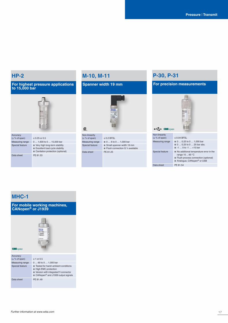
HP-2For highest pressure applications to 15,000 bar
Accuracy (± % of span) ≤ 0.25 or 0.5Measuring range 0 … 1,600 to 0 … 15,000 barSpecial feature ■ Very high long-term stability
■ Excellent load cycle stability ■ Cavitation protection (optional)
Data sheet PE 81.53
M-10, M-11Spanner width 19 mm
Non-linearity (± % of span) ≤ 0.2 BFSLMeasuring range ■ 0 … 6 to 0 … 1,000 barSpecial feature ■ Small spanner width 19 mm
■ Flush connection G ¼ availableData sheet PE 81.25
P-30, P-31For precision measurements
Non-linearity (± % of span) ≤ 0.04 BFSLMeasuring range ■ 0 … 0.25 to 0 … 1,000 bar
■ 0 … 0.25 to 0 … 25 bar abs. ■ -1 … 0 to -1 … +15 bar
Special feature ■ No additional temperature error in the range 10 ... 60 °C
■ Flush process connection (optional) ■ Analogue, CANopen® or USB
Data sheet PE 81.54
MHC-1For mobile working machines, CANopen® or J1939
Accuracy (± % of span) ≤ 1 or 0.5Measuring range 0 … 60 to 0 … 1,000 barSpecial feature ■ Tested for harsh ambient conditions
■ High EMC protection ■ Version with integrated Y-connector ■ CANopen and J1939 output signals
Data sheet PE 81.49

18
OEM pressure sensors
MH-4For mobile working machines
Non-linearity (per IEC 61298-2) ≤ ±0.25 % of span (BFSL)Measuring range 0 … 40 to 0 … 1,000 barSpecial feature ■ Developed for the extreme operating
conditions in mobile working machines ■ Reliability and highest accuracy over the entire life cycle
■ Customer-specific adaptations and individualisation
■ High production capacities
Data sheet PE 81.63
MH-3-HYFor mobile hydrogen applications
Accuracy (± % of span) ≤ 1Measuring range 0 … 20 to 0 … 600 barSpecial feature ■ Approval per EC79/2009
■ Compact and robust design ■ Diagnostic function (optional)
Data sheet PE 81.59
R-1For refrigeration and air-conditioning applications
Accuracy (± % of span) ≤ 2Measuring range ■ 0 … 6 to 0 … 160 bar
■ -1 … +7 to -1 … +45 barSpecial feature ■ Special case design for the best
possible condensation tightness ■ Resistant to all common refrigerants ■ Wetted parts from stainless steel
Data sheet PE 81.45
O-10For industrial applications
Non-linearity (± % of span) ≤ 0.5 BFSLMeasuring range ■ 0 … 6 to 0 … 600 bar
■ -1 … +5 to -1 … +59 barSpecial feature ■ For OEM quantities
■ Customer-specific variantsData sheet PE 81.65
MG-1For medical gases
Non-linearity (± % of span) ≤ 0.5 BFSLMeasuring range 0 … 6 to 0 … 400 barSpecial feature Cleaned, packed and labelled for oxygen
per international standards
Data sheet PE 81.44

19Further information at www.wika.com
Pressure | Transmit
Pressure gauges with output signal
The multi-functional intelliGAUGEs present a cost-effective and, at the same time, reliable solution for nearly all pressure measurement applications. They combine the analogue indication of a mechanical pressure gauge, needing no external power, with the electrical output signal of a pressure sensor. These hybrid instruments are available with all commonly used electrical signals. The sensor works in a non-contact way, without any influence on the measuring signal. Many instruments are available in versions for use in hazardous areas.
Depending on the pressure gauge, the following electrical output signals are possible:
� 0.5 … 4.5 V ratiometric � 4 … 20 mA, 2-wire � 4 ... 20 mA, 2-wire with Ex approvals � 0 … 20 mA, 3-wire � 0 … 10 V, 3-wire
For pressure gauges with nominal sizes 100 and 160 mm, the electrical output signals can also be combined with switch contacts.
PGT21Bourdon tube, stainless steel case
Nominal size 50, 63 mmScale range 0 … 1.6 to 0 … 400 barAccuracy class 2.5Ingress protection IP65 (IP67 optional)Data sheet PV 11.03
PGT23.100, PGT23.160Bourdon tube, for the process industry, standard or safety version
Nominal size 100, 160 mmScale range 0 … 0.6 to 0 … 1,600 barAccuracy class 1.0Ingress protection IP54, filled IP65Data sheet PV 12.04
PGT23.063Bourdon tube, for the process industry, safety version
Nominal size 63 mmScale range 0 … 1 to 0 … 1,000 barAccuracy class 1.6Ingress protection IP54, filled IP65Data sheet PV 12.03
PGT43Diaphragm element, for the process industry, high overload safety up to the 10-fold full scale value, max. 40 bar
Nominal size 100, 160 mmScale range 0 … 16 mbar to 0 … 25 barAccuracy class 1.6Ingress protection IP54, with liquid filling IP65Data sheet PV 14.03
PGT43HPDiaphragm element, for the process industry, high overload safety to 40, 100 or 400 bar
Nominal size 100, 160 mmScale range 0 … 16 mbar to 0 … 40 barAccuracy class 1.6Ingress protection IP54, with liquid filling IP65Data sheet PV 14.07
PGT63HPCapsule element, for the process industry, high overload safety
Nominal size 100, 160 mmScale range 2.5 … 100 mbarAccuracy class 1.6Ingress protection IP54Data sheet PV 16.06
20
Pressure | Transmit
DPGT43Differential pressure, for the process industry, all-metal media chamber
Nominal size 100, 160 mmScale range 0 … 16 mbar to 0 … 25 barAccuracy class 1.6Ingress protection IP54, filled IP65Data sheet PV 17.05
DPGT43HPDifferential pressure, for the process industry, high overload safety to 650 bar
Nominal size 100, 160 mmScale range 0 … 60 mbar to 0 … 40 barAccuracy class 1.6Ingress protection IP54, filled IP65Data sheet PV 17.13
DPGT40Differential pressure, with integrated working pressure indication (DELTA-trans)
Nominal size 100 mmScale range 0 … 0.16 to 0 … 10 barAccuracy class 2.5 (1.6 optional)Ingress protection IP65Data sheet PV 17.19
APGT43Absolute pressure, for the process industry
Nominal size 100, 160 mmScale range 0 … 25 mbar to 0 … 25 bar abs.Accuracy class 2.5Ingress protection IP54, with liquid filling IP65Data sheet PV 15.02
Pressure gauges with output signal
21Further information at www.wika.com
Control systems are gaining more and more importance in industrial applications. Consequently, mere pressure indication on the measuring instrument itself is no longer sufficient, rather the measured value must be transferred to the control system via an electrical signal, e.g. by closing or opening of a circuit. WIKA is focusing on its contact pressure gauges in order to satisfy this trend.
All instruments with inductive contacts are certified in accordance with ATEX Ex ia.
Depending on the model the following contacts are built-in:
� Magnetic snap-action contact, e.g. model 821, for general applications
� Inductive contact model 831, for hazardous areas � Electronic contact model 830 E, for PLC � Reed contact model 851, for general applications and PLC � Micro switch model 850 � Transistor output NPN or PNP
Contact pressure gauges
PGS23.100, PGS23.160Bourdon tube, for the process industry, standard or safety version
Nominal size 100, 160 mmScale range 0 … 0.6 to 0 … 1,600 barAccuracy class 1.0Ingress protection IP65 or IP66Data sheet PV 22.02
PGS23.063Bourdon tube, for the process industry, safety version
Nominal size 63 mmScale range 0 … 4 to 0 … 400 barAccuracy class 1.6Ingress protection IP54Data sheet PV 22.03
PGS43.100, PGS43.160Diaphragm element, for the process industry, high overload safety up to the 10-fold full scale value, max. 40 bar
Nominal size 100, 160 mmScale range 0 … 25 mbar to 0 … 25 barAccuracy class 1.6Ingress protection IP54, with liquid filling IP65Data sheet PV 24.03
PGS21Bourdon tube, stainless steel case
Nominal size 40, 50, 63 mmScale range 0 … 2.5 to 0 … 400 barAccuracy class 2.5Ingress protection IP65Special feature Version with VdS or LPCB approval
possibleData sheet PV 21.02
PGS25Bourdon tube, with electronic pressure switch, stainless steel case
Nominal size 50, 63 mmScale range 0 … 1.6 to 0 … 400 barAccuracy class 2.5Ingress protection IP65Data sheet PV 21.04
PGS21.100, PGS21.160Bourdon tube, stainless steel case
Nominal size 100, 160 mmScale range 0 … 0.6 to 0 … 600 barAccuracy class 1.0Ingress protection IP54Data sheet PV 22.01
Pressure | Display + Switch
22
Pressure | Display + Switch
432.36, 432.56 with 8xxDiaphragm element, for the process industry, high overload safety to 100 or 400 bar
Nominal size 100, 160 mmScale range 0 … 25 mbar to 0 … 40 barAccuracy class 1.6Ingress protection IP54, with liquid filling IP65Data sheet PV 24.07
532.53 with 8xxAbsolute pressure, for the process industry, high overload safety
Nominal size 100, 160 mmScale range 0 … 25 mbar to 0 … 25 bar abs.Accuracy class 1.6Ingress protection IP54, with liquid filling IP65Data sheet PV 25.02
632.51 with 8xxCapsule element, for the process industry, high overload safety
Nominal size 100, 160 mmScale range 0 … 2.5 to 0 … 100 mbarAccuracy class 1.6Ingress protection IP54Data sheet PV 26.06
DPGS43Differential pressure, for the process industry, all-metal media chamber
Nominal size 100, 160 mmScale range 0 … 16 mbar to 0 … 25 barAccuracy class 1.6Ingress protection IP54, filled IP65Data sheet PV 27.05
DPGS40Differential pressure, with micro switches, with integrated working pressure indication (DELTA-comb)
Nominal size 100 mmScale range 0 … 0.25 to 0 … 10 barAccuracy class 2.5 (1.6 optional)Ingress protection IP65Data sheet PV 27.20
DPGS40TADifferential pressure, with micro switches, with integrated working pressure indication (DELTA-comb), with component testing
Nominal size 100 mmScale range 0 … 0.25 to 0 … 10 barAccuracy class 2.5 (1.6 optional)Ingress protection IP65Data sheet PV 27.22
DPGS43HPDifferential pressure, for the process industry, high overload safety to 400 bar
Nominal size 100, 160 mmScale range 0 … 60 mbar to 0 … 40 barAccuracy class 1.6Ingress protection IP54, filled IP65Data sheet PV 27.13
Contact pressure gauges
SILIEC 61508 / IEC 61511

23Further information at www.wika.com
Pressure switches
Electronic pressure switches
PSD-4Electronic pressure switch with display
Accuracy (± % of span) ≤ 0.5Measuring range ■ 0 … 0.4 to 0 … 1,000 bar
■ 0 … 0.4 to 0 … 25 bar abs. ■ -1 … 0 to -1 … +24 bar
Special feature ■ Intuitive and fast setup ■ Flexibly configurable and scalable output signals (NPN/PNP, mA/VDC)
■ Turndown, analogue output 5 : 1
Data sheet PE 81.86
PSD-4-ECOElectronic pressure switch with display
Accuracy (± % of span) ≤ 1.0Measuring range ■ 0 … 0.4 to 0 … 1,000 bar
■ 0 … 0.4 to 0 … 25 bar abs. ■ -1 … 0 to -1 … +24 bar
Special feature ■ Good/bad indication through parameter-isable digital display (red/green)
■ Compact size enables easy installation in confined spaces
■ Optimised design makes OEM machine integration easier
■ Designed for rough demands of up to 50 g shock and -40 … +125 °C [-40 … +257 °F]
Data sheet PE 81.69
A-1200With IO-Link, PNP or NPN switching output
Accuracy (± % of span) ≤ 0.5 or ≤ 1Measuring range ■ 0 … 0.4 to 0 … 1,000 bar
■ 0 … 0.4 to 0 … 25 bar abs. ■ 1 … 0 to -1 … +24 bar
Special feature ■ IO-Link version 1.1 ■ Medium temperature to +125 °C ■ Multicolour 360° LED status display
Data sheet PE 81.90
Pressure | Switch
24
Mechanical pressure switches for industrial applications
PSM01Compact pressure switch
Setting range ■ -0.85 … -0.15 bar ■ 0.2 … 2 bar to 30 … 320 bar
Switching function Normally open, normally closed, change-over contact
Material Galvanised steel or stainless steelSwitching power ■ 2 A, AC 48 V
■ 1 A / 2 A, DC 24 VData sheet PV 34.81
PSM02Compact pressure switch, settable hysteresis
Setting range ■ -0.85 … -0.15 bar ■ 0.2 … 2 bar to 30 … 320 bar
Switching function Normally open, normally closed, change-over contact
Material Galvanised steel or stainless steelSwitching power ■ 2 A / 4 A, AC 250 V
■ 2 A / 4 A, DC 24 VData sheet PV 34.82
PSM-520Pressure switch, adjustable hysteresis
Setting range ■ -0.4 … +7 bar ■ 0 … 5 bar to 6 … 30 bar
Switching function Normally open, normally closed, change-over contact
Material ■ Bellow: Copper alloy CuSn6 per EN 1652
■ Process connection: Free cutting steel EN1A per EN 10277-3, tin-plated
Switching power 10 A / 6 A, AC 230 VData sheet PV 35.01
PSM-550Pressure switch, for superior industrial applications
Setting range ■ -1 … 0 and -0.8 … +5 bar ■ 0 … 300 mbar ■ 0.1 … 1.1 bar to 10 … 30 bar
Switching function Change-over contact (SPDT)Material ■ Bellow/Process connection: Copper
alloy CuSn6 per EN 1652 or stainless steel 1.4401
■ With NBR diaphragm: Process connection: Free cutting steel EN1A per EN 10277-3, tin-plated
Switching power 4 A / 10 A, AC 230 VData sheet PV 35.03
PSM-700Pressure switch, high adjustability of switch differential
Setting range ■ -1 … 1.5 bar ■ 0.2 … 1.6 bar, 7 … 35 bar
Switching function Change-over contact (SPDT and DPDT)Material ■ Measuring element: Stainless steel
316L ■ Process connection: Stainless steel 316L
■ Case: Aluminum
Switching power Up to AC 250 V/15Data sheet PV 35.05
Pressure switches
25Further information at www.wika.com
Pressure | Switch
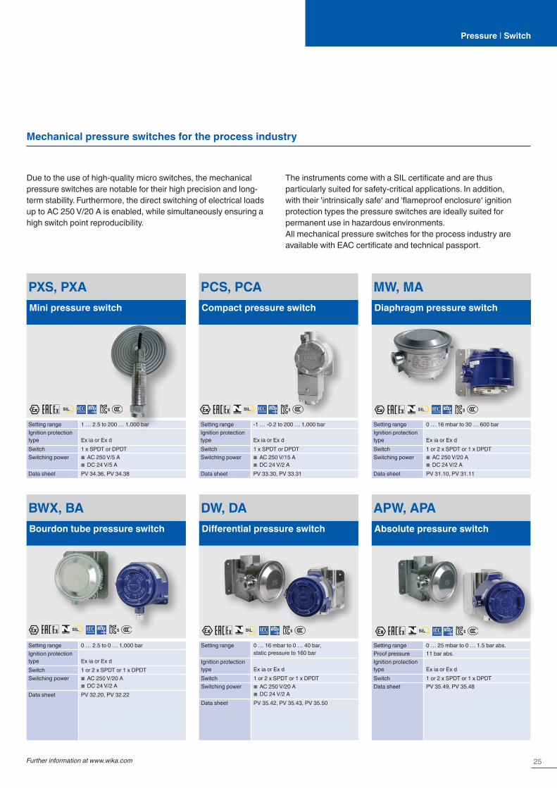
Due to the use of high-quality micro switches, the mechanical pressure switches are notable for their high precision and long-term stability. Furthermore, the direct switching of electrical loads up to AC 250 V/20 A is enabled, while simultaneously ensuring a high switch point reproducibility.
The instruments come with a SIL certificate and are thus particularly suited for safety-critical applications. In addition, with their 'intrinsically safe‘ and 'flameproof enclosure‘ ignition protection types the pressure switches are ideally suited for permanent use in hazardous environments.All mechanical pressure switches for the process industry are available with EAC certificate and technical passport.
MW, MADiaphragm pressure switch
Setting range 0 … 16 mbar to 30 … 600 barIgnition protection type Ex ia or Ex dSwitch 1 or 2 x SPDT or 1 x DPDTSwitching power ■ AC 250 V/20 A
■ DC 24 V/2 AData sheet PV 31.10, PV 31.11
PCS, PCACompact pressure switch
Setting range -1 … -0.2 to 200 … 1,000 barIgnition protection type Ex ia or Ex dSwitch 1 x SPDT or DPDTSwitching power ■ AC 250 V/15 A
■ DC 24 V/2 AData sheet PV 33.30, PV 33.31
PXS, PXAMini pressure switch
Setting range 1 … 2.5 to 200 … 1,000 barIgnition protection type Ex ia or Ex dSwitch 1 x SPDT or DPDTSwitching power ■ AC 250 V/5 A
■ DC 24 V/5 AData sheet PV 34.36, PV 34.38
Mechanical pressure switches for the process industry
APW, APAAbsolute pressure switch
Setting range 0 … 25 mbar to 0 … 1.5 bar abs.Proof pressure 11 bar abs.Ignition protection type Ex ia or Ex dSwitch 1 or 2 x SPDT or 1 x DPDTData sheet PV 35.49, PV 35.48
BWX, BABourdon tube pressure switch
Setting range 0 … 2.5 to 0 … 1,000 barIgnition protection type Ex ia or Ex dSwitch 1 or 2 x SPDT or 1 x DPDTSwitching power ■ AC 250 V/20 A
■ DC 24 V/2 AData sheet PV 32.20, PV 32.22
DW, DADifferential pressure switch
Setting range 0 … 16 mbar to 0 … 40 bar, static pressure to 160 bar
Ignition protection type Ex ia or Ex dSwitch 1 or 2 x SPDT or 1 x DPDTSwitching power ■ AC 250 V/20 A
■ DC 24 V/2 AData sheet PV 35.42, PV 35.43, PV 35.50
SILIEC 61508 / IEC 61511
SILIEC 61508 / IEC 61511
SILIEC 61508 / IEC 61511
SILIEC 61508 / IEC 61511 SIL
IEC 61508 / IEC 61511
SILIEC 61508 / IEC 61511

26
Pressure | Diaphragm seal systems
With flange connection
Diaphragm seal systems
These combinations of diaphragm seals and pressure gauges or pressure sensors feature fast availability. They are particularly suitable for demanding measuring tasks in the pharmaceutical and biotechnology industries, food and beverage industries, and through to the oil & gas, chemical, petrochemical and semiconductor industries.The diaphragm seal systems can be used for processes with gases, compressed air or vapour, with liquid, pasty, powdery and crystallising media and also with aggressive, adhesive, corrosive, highly viscous, environmentally hazardous or toxic media.
The diaphragm seal is directly welded to the pressure gauge or pressure sensor. The diaphragm made of stainless steel provides for the separation from the medium. The pressure is transmitted to the measuring instrument via the system fill fluid which is inside the diaphragm seal system.
DSS26MWith pressure gauge per EN 837-1, internal diaphragm
Applications with small flange process connections in the process industryPN max. 40 barSystem fill fluid
KN2Data sheet DS 95.09
DSS26TWith high-quality pressure sensor, internal diaphragm
Applications with small flange process connections in the process industryPN max. 40 barSystem fill fluid
KN2Data sheet DS 95.10
With threaded connection
DSS34MWith pressure gauge per EN 837-1, welded design
Applications with high requirements in the chemical, petrochemical and water treatment industriesPN max. 60 barSystem fill fluid
KN2 for general applicationsData sheet DS 95.15
DSS34TWith high-quality pressure sensor, welded design
Applications with high requirements in the chemical, petrochemical and water treatment industriesPN max. 60 barSystem fill fluid
KN2 for general applicationsData sheet DS 95.16
Extensive information can be found in our brochure “Diaphragm seals – combinations
and accessories” at www.wika.de.
Extensive information can be found in our brochure “Diaphragm seal systems with
short delivery times” at www.wika.de.
Diaphragm seals
Diaphragm seals – combinations and accessories
Order information
Diaphragm seal systemswith short delivery times
27Further information at www.wika.com
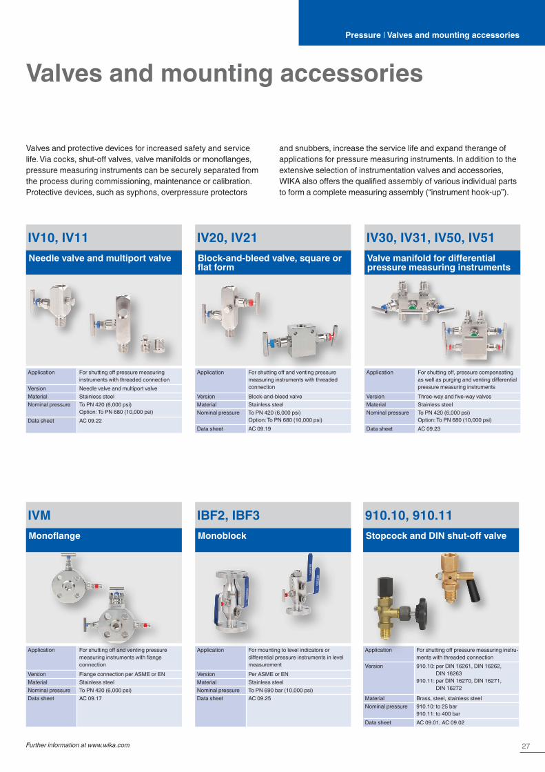
Valves and mounting accessories
IVMMonoflange
Application For shutting off and venting pressure measuring instruments with flange connection
Version Flange connection per ASME or ENMaterial Stainless steelNominal pressure To PN 420 (6,000 psi)Data sheet AC 09.17
IBF2, IBF3Monoblock
Application For mounting to level indicators or differential pressure instruments in level measurement
Version Per ASME or ENMaterial Stainless steelNominal pressure To PN 690 bar (10,000 psi)Data sheet AC 09.25
IV30, IV31, IV50, IV51Valve manifold for differential pressure measuring instruments
Application For shutting off, pressure compensating as well as purging and venting differential pressure measuring instruments
Version Three-way and five-way valvesMaterial Stainless steelNominal pressure To PN 420 (6,000 psi)
Option: To PN 680 (10,000 psi)Data sheet AC 09.23
IV10, IV11Needle valve and multiport valve
Application For shutting off pressure measuring instruments with threaded connection
Version Needle valve and multiport valveMaterial Stainless steelNominal pressure To PN 420 (6,000 psi)
Option: To PN 680 (10,000 psi)Data sheet AC 09.22
IV20, IV21Block-and-bleed valve, square or flat form
Application For shutting off and venting pressure measuring instruments with threaded connection
Version Block-and-bleed valveMaterial Stainless steelNominal pressure To PN 420 (6,000 psi)
Option: To PN 680 (10,000 psi)Data sheet AC 09.19
910.10, 910.11Stopcock and DIN shut-off valve
Application For shutting off pressure measuring instru-ments with threaded connection
Version 910.10: per DIN 16261, DIN 16262, DIN 16263
910.11: per DIN 16270, DIN 16271, DIN 16272
Material Brass, steel, stainless steelNominal pressure 910.10: to 25 bar
910.11: to 400 barData sheet AC 09.01, AC 09.02
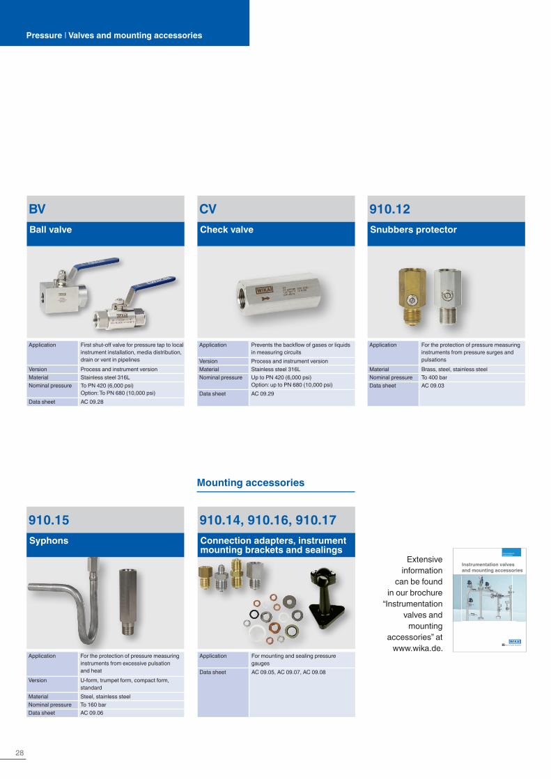
Valves and protective devices for increased safety and service life. Via cocks, shut-off valves, valve manifolds or monoflanges, pressure measuring instruments can be securely separated from the process during commissioning, maintenance or calibration. Protective devices, such as syphons, overpressure protectors
and snubbers, increase the service life and expand therange of applications for pressure measuring instruments. In addition to the extensive selection of instrumentation valves and accessories, WIKA also offers the qualified assembly of various individual parts to form a complete measuring assembly (“instrument hook-up”).
Pressure | Valves and mounting accessories
28
Pressure | Valves and mounting accessories
CVCheck valve
Application Prevents the backflow of gases or liquids in measuring circuits
Version Process and instrument versionMaterial Stainless steel 316LNominal pressure Up to PN 420 (6,000 psi)
Option: up to PN 680 (10,000 psi)Data sheet AC 09.29
BVBall valve
Application First shut-off valve for pressure tap to local instrument installation, media distribution, drain or vent in pipelines
Version Process and instrument versionMaterial Stainless steel 316LNominal pressure To PN 420 (6,000 psi)
Option: To PN 680 (10,000 psi)Data sheet AC 09.28
Mounting accessories
910.14, 910.16, 910.17Connection adapters, instrument mounting brackets and sealings
Application For mounting and sealing pressure gauges
Data sheet AC 09.05, AC 09.07, AC 09.08
Instrumentation valves and mounting accessories
From process to measurement
Extensive information
can be found in our brochure
“Instrumentation valves and
mounting accessories” at
www.wika.de.
910.15Syphons
Application For the protection of pressure measuring instruments from excessive pulsation and heat
Version U-form, trumpet form, compact form, standard
Material Steel, stainless steelNominal pressure To 160 barData sheet AC 09.06
910.12Snubbers protector
Application For the protection of pressure measuring instruments from pressure surges and pulsations
Material Brass, steel, stainless steelNominal pressure To 400 barData sheet AC 09.03

29Further information at www.wika.com
Electrical accessories
M12 x 1 cableCable assemblies M12 x 1
■ Circular connector M12 x 1, 4- and 5-pin ■ Straight and angled version ■ 2, 5 or 10 m cable ■ Ingress protection IP67
A-AI-1, A-IAI-1LCD attachable indicator, 50 x 50 mm
Input 4 … 20 mA, 2-wireSupply voltage From the 4 … 20 mA current loopSpecial feature Model A-IAI-1 intrinsically safe per ATEXData sheet AC 80.07
905Contact protection relay for model 821 switch contacts
Application For optimal contact protection and highest switching reliability
Data sheet AC 08.01
904Control unit for inductive contacts model 831
Application For operating measuring instruments with inductive switch contacts
Data sheet AC 08.01
Pressure | Electrical accessories
IS BarrierIntrinsically safe repeater power supply
■ 1-channel input 0/4 … 20 mA ■ Intrinsically safe [Ex ia], supplying and non-supplying ■ Galvanic isolation ■ Bidirectional HART® signal transmission ■ Suitable for SIL 2 per IEC 61508/IEC 61511 ■ Data sheet AC 80.14
SILIEC 61508 / IEC 61511

30
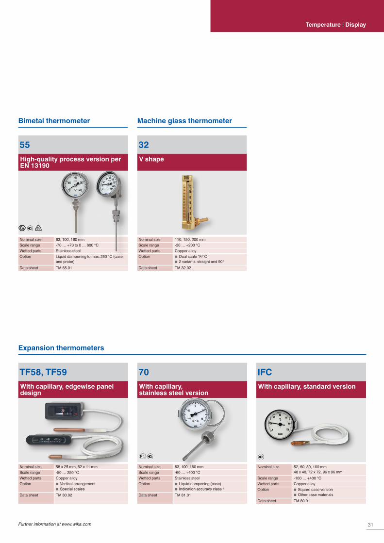
Dial thermometers
Bimetal thermometers
Our dial thermometers work on the bimetal, expansion or gas actuation principle. This enables scale ranges of -200 ... +700 °C in different class accuracies, response times and resilience to environmental influences. Diverse connection designs, stem diameters and individual stem lengths enable a flexible measuring point design.
Dial thermometers with remote capillaries are particularly versatile.All thermometers are suited for operation in a thermowell if necessary.
A43Heating technology
Nominal size 63, 80, 100 mmScale range -30 … +120 °CPermissible operating pres-sure at thermowell/stem Max. 6 barWetted parts Copper alloyData sheet TM 43.01
A48Refrigeration and air-conditioning technology
Nominal size 63, 80, 100, 160 mmScale range -30 … +120 °CWetted parts Copper alloyData sheet TM 48.01
A50Standard version
Nominal size 63, 80, 100, 160 mmScale range -30 … +200 °CConnection Removable thermowell with
retainer screwWetted parts Copper alloyData sheet TM 50.03
A52, R52Industrial series, axial and radial
Nominal size 25, 33, 40, 50, 63, 80, 100, 160 mm
Scale range -30 … +50 to 0 … +500 °CPermissible operating pres-sure at thermowell/stem Max. 25 barWetted parts Stainless steelData sheet TM 52.01
TG53Process version per ASME B40.200
Nominal size 3, 4, 5, 6"Scale range -70 … +70 to 0 … +600 °CWetted parts Stainless steelOption Liquid dampening to max. 250 °C
(case and probe)Data sheet TM 53.02
TG54Process version per EN 13190
Nominal size 63, 80, 100, 160 mmScale range -70 … +70 to 0 … +600 °CWetted parts Stainless steelOption Liquid dampening to max. 250 °C
(case and probe)Data sheet TM 54.02
31Further information at www.wika.com
Temperature | Display
Bimetal thermometer Machine glass thermometer
Expansion thermometers
55High-quality process version per EN 13190
Nominal size 63, 100, 160 mmScale range -70 … +70 to 0 … 600 °CWetted parts Stainless steelOption Liquid dampening to max. 250 °C (case
and probe)Data sheet TM 55.01
TF58, TF59With capillary, edgewise panel design
Nominal size 58 x 25 mm, 62 x 11 mmScale range -50 … 250 °CWetted parts Copper alloyOption ■ Vertical arrangement
■ Special scalesData sheet TM 80.02
70With capillary, stainless steel version
Nominal size 63, 100, 160 mmScale range -60 … +400 °CWetted parts Stainless steelOption ■ Liquid dampening (case)
■ Indication accuracy class 1Data sheet TM 81.01
IFCWith capillary, standard version
Nominal size 52, 60, 80, 100 mm48 x 48, 72 x 72, 96 x 96 mm
Scale range -100 … +400 °CWetted parts Copper alloyOption ■ Square case version
■ Other case materialsData sheet TM 80.01
32V shape
Nominal size 110, 150, 200 mmScale range -30 … +200 °CWetted parts Copper alloyOption ■ Dual scale °F/°C
■ 2 variants: straight and 90°Data sheet TM 32.02

32
Dial thermometers
Gas-actuated thermometers
F73With capillary
Nominal size 100, 160 mmScale range -200 … +100 to 0 … +700 °CWetted parts Stainless steelOption ■ Armoured or coated capillary
(PVC coating) ■ Liquid dampening (case) ■ Contact bulb
Data sheet TM 73.01
75Highly vibration resistant
Nominal size 100 mmScale range 0 … +700 or -50 … +650 °CWetted parts Stainless steelOption Various neck tube and insertion lengthsData sheet TM 75.01
Thermomanometers
R73, S73, A73Axial and radial, adjustable stem and dial
Nominal size 100, 160 mmScale range -200 … +100 to 0 … +700 °CWetted parts Stainless steelOption ■ Liquid dampening (case)
■ Contact bulbData sheet TM 73.01
100.02For pressure and temperature measurement
Nominal size 63, 80 mmScale range ■ Pressure: 0 … 1 to 0 … 16 bar
■ Temperature: 0 … 100 to 0 … 150 °CAccuracy class ■ Pressure: 2.5 (EN 837-1)
■ Temperature: 2.5 °CData sheet PM 01.23
MFTWith capillaries, for pressure and temperature measurement
Nominal size 40, 42, 52 mmScale range ■ Pressure: 0 … 4 bar
■ Temperature: 0 … 120 °CAccuracy class ■ Pressure: 2.5 (EN 837-1)
■ Temperature: 2.5Data sheet PM 01.20
THM10Eco version, for pressure and temperature measurement
Nominal size 63, 80 mmScale range ■ Pressure: 0 … 4 to 0 … 10 bar
■ Temperature: 0 … 120 °CConnection location Lower mount or back mountAccuracy class ■ Pressure: 2.5 (EN 837-1)
■ Temperature: 2 (EN 13190)Data sheet PM 01.24
33Further information at www.wika.com
Temperature | Display
Dial thermometers with output signal
TGT70Expansion thermometer with output signal
Nominal size 63, 100 mmScale range -40 … +60 to 0 … 250 °CWetted parts Stainless steelOption ■ Capillary
■ Output signals 4 … 20 mA or 0.5 … 4.5 V
■ Other connection designs
Data sheet TV 18.01
TGT73Gas-actuated thermometer with output signal
Nominal size 100, 160 mmScale range -200 … +100 to 0 … 700 °CWetted parts Stainless steelOption ■ Capillary
■ Liquid dampening (case) ■ Output signal 4 … 20 mA or 0 … 10 V
Data sheet TV 17.10

34
Digital indicators
DI32-1For panel mounting, 48 x 24 mm
Input Multi-function input for resistance thermo-meters, thermocouples and standard signals
Alarm output 2 electronic contactsSupply voltage DC 9 … 28 VData sheet AC 80.13
DI25For panel mounting, 96 x 48 mm
Input Multi-function input for resistance thermo-meters, thermocouples and standard signals
Alarm output ■ 3 relays ■ 2 relays for instruments with integrated transmitter power supply DC 24 V
Supply voltage ■ AC 100 … 240 V ■ AC/DC 24 V
Special feature Analogue output signalData sheet AC 80.02
DI30For panel mounting, 96 x 96 mm
Input Standard signalsAlarm output 2 relaysSpecial feature ■ Integrated transmitter power supply
■ Wall-mounting case (optional)Supply voltage AC 230 V or AC 115 VData sheet AC 80.05
DI10For panel mounting, current loop display, 96 x 48 mm
Input 4 … 20 mA, 2-wireAlarm output 2 electronic contacts (optional)Special feature Wall-mounting case (optional)Supply voltage From the 4 … 20 mA current loopData sheet AC 80.06
DI35For panel mounting, 96 x 48 mm
Input ■ Multi-function input for resistance thermometers, thermocouples and standard signals
■ Alternatively double input for standard signals with calculation function (+ - x /) for two transmitters
Alarm output 2 or 4 relays (optional)Special feature ■ Integrated transmitter power supply
■ Analogue output signal (optional)Supply voltage ■ AC/DC 100 … 240 V
■ DC 10 … 40 V, AC 18 … 30 VData sheet AC 80.03
35Further information at www.wika.com
Temperature | Display
DIH10Connection head with digital indicator
Input 4 … 20 mASupply voltage From the 4 ... 20 mA current loopData sheet AC 80.11
DIH50, DIH52For current loops with HART® communication
Dimensions 150 x 127 x 127 mmCase Aluminium, stainless steelSpecial feature ■ Adjustment of indication range and unit
via HART® communication ■ Model DIH52 additionally suitable for multidrop operation and with local master function
Approval ■ Intrinsically safe ■ Flameproof enclosure
Data sheet AC 80.10
TF-LCDLonglife digital thermometer
Measuring range -40 … +120 °CSpecial feature ■ Dust and waterproof case, IP68
■ Battery or solar powered ■ Extremely long service life
Data sheet TE 85.01
SILIEC 61508 / IEC 61511
36
Thermocouples
TC10-AMeasuring insert
Sensor element Types K, J, E, N or TMeasuring range -40 … +1,200 °C, -40 … +2,192 °FMeasuring location Ungrounded or groundedData sheet TE 65.01
TC10-BFor additional thermowell
Sensor element Types K, J, E, N or TMeasuring range -40 … +1,200 °C, -40 … +2,192 °FMeasuring location Ungrounded or groundedData sheet TE 65.02
TC10-CThreaded, with protection tube
Sensor element Types K, J, E, N or TMeasuring range -40 … +1,200 °C, -40 … +2,192 °FMeasuring location Ungrounded or groundedProcess connection Mounting threadData sheet TE 65.03
TC10-DThreaded, miniature design
Sensor element Types K, J, E, N or TMeasuring range -40 … +600 °C, -40 … +1,112 °FMeasuring location Ungrounded or groundedProcess connection Mounting threadData sheet TE 65.04
TC10-FFlanged thermocouple, with protection tube
Sensor element Types K, J, E, N or TMeasuring range -40 … +1,200 °C, -40 … +2,192 °FMeasuring location Ungrounded or groundedProcess connection FlangeData sheet TE 65.06
TC10-HWithout thermowell
Sensor element Types K, J, E, N or TMeasuring range -40 … +1,200 °C, -40 … +2,192 °FMeasuring location Ungrounded or groundedProcess connection Mounting threadData sheet TE 65.08
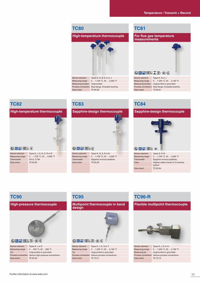
Thermocouples generate a voltage directly dependent on temperature. They are particularly suitable for high temperatures to 1,700 °C (3,092 °F) and for very high oscillating stresses. For thermocouples, the accuracy classes per IEC 60584-1 and ASTM E230 apply.
In our range of products you will find all market-standard instrument versions. If required, a temperature transmitter can be installed in the connection head.
NAMUR NAMUR
NAMUR
NAMUR
NAMUR
37Further information at www.wika.com
Temperature | Transmit + Record
TC10-KMeasuring insert, for installation in TC10-L
Sensor element Types K, J, E, N or TMeasuring range -40 … +1,200 °C, -40 … +2,192 °FMeasuring location Ungrounded or groundedData sheet TE 65.11
TC10-LFlameproof enclosure, for additional thermowell
Sensor element Types K, J, E, N or TMeasuring range -40 … +1,200 °C, -40 … +2,192 °FMeasuring location Ungrounded or groundedData sheet TE 65.12
TC12-BProcess thermocouple, for additional thermowell
Sensor element Types K, J, E, N or TMeasuring range -40 … +1,200 °C, -40 … +2,192 °FMeasuring location Ungrounded or groundedOption Ex i, Ex dData sheet TE 65.17
TC12-AMeasuring insert for process thermocouple
Sensor element Types K, J, N or TMeasuring range ■ -40 … +1,200 °C,
■ -40 … +2,192 °FMeasuring location Ungrounded or groundedData sheet TE 65.16
TC12-MProcess thermocouple, basic module
Sensor element Types K, J, E, N or TMeasuring range -40 … +1,200 °C, -40 … +2,192 °FMeasuring location Ungrounded or groundedOption Ex i, Ex dData sheet TE 65.17

38
Thermocouples
TC53Bayonet thermocouple
Sensor element Types K, J, N, E or TMeasuring range -40 … +1,200 °C, -40 … +2,192 °FMeasuring location Ungrounded or groundedSpecial feature ■ Single and dual thermocouple
■ Explosion-protected versionsData sheet TE 65.53
TC50Surface thermocouple
Sensor element Types K, J, E, N or TMeasuring range -40 … +1,200 °C, -40 … +2,192 °FMeasuring location Ungrounded or groundedProcess connection Surface mountingData sheet TE 65.50
TC47Thermocouple for plastics machinery
Sensor element Types J or KMeasuring range -25 … +400 °C, -13 … + 752 °FMeasuring location Ungrounded or groundedSpecial feature ■ Various process connections
■ Connection lead fibreglass with stain-less steel braid
Data sheet TE 67.20
TC59Tubeskin thermocouple
Sensor element Types K, J, N, EMeasuring range 0 … 1,200 °C, 32 … 2,192 °FMeasuring location Welded or exchangeableProcess connection Surface mountingData sheet TE 65.56 … TE 65.60
TC40Cable thermocouple
Sensor element Types K, J, E, N or TMeasuring range -40 … +1,200 °C, -40 … +2,192 °FMeasuring location Ungrounded or groundedCable Silicone, PTFE/PFA, fibreglassData sheet TE 65.40
TC46Hot runner thermocouple
Sensor element Types J or KMeasuring range -25 … +400 °C, -13 … +752 °FMeasuring location Ungrounded or groundedSpecial feature ■ Probe diameter 0.5 … 3.0 mm
■ Plastic-moulded transitionData sheet TE 65.46
39Further information at www.wika.com
Temperature | Transmit + Record
TC82High-temperature thermocouple
Sensor element Types K, J, E, N, S, R or BMeasuring range 0 … 1,700 °C, 32 … 3,092 °FThermowell C610, C799Data sheet TE 65.82
TC80High-temperature thermocouple
Sensor element Types S, R, B, K, N or JMeasuring range 0 … 1,700 °C, 32 … 3,092 °FMeasuring location UngroundedProcess connection Stop flange, threaded bushingData sheet TE 65.80
TC83Sapphire-design thermocouple
Sensor element Types K, N, S, R or BMeasuring range 0 … 1,700 °C, 32 … 3,092 °FThermowell Sapphire (monocrystalline)Data sheet TE 65.83
TC81For flue gas temperature measurements
Sensor element Types K, N or JMeasuring range 0 … 1,200 °C, 32 … 2,192 °FMeasuring location Ungrounded or groundedProcess connection Stop flange, threaded bushingData sheet TE 65.81
TC84Sapphire-design thermocouple
Sensor element Types S, R, BMeasuring range 0 … 1,700 °C, 32 … 3,092 °FThermowell Sapphire (monocrystalline)Case Highest safety thanks to 2-chamber
systemData sheet TE 65.84
TC90High-pressure thermocouple
Sensor element Types K, J or EMeasuring range 0 … 350 °C, 32 … 662 °FTip Ungrounded or groundedProcess connection Various high-pressure connectionsData sheet TE 65.90
TC95Multipoint thermocouple in band design
Sensor element Types K, J, E, N or TMeasuring range 0 … 1,200 °C, 32 … 2,192 °FTip Ungrounded or groundedProcess connection Various process connectionsData sheet TE 70.01
TC96-RFlexible multipoint thermocouple
Sensor element Types K, J, E or NMeasuring range 0 … 1,200 °C, 32 … 2,192 °FMeasuring tip Ungrounded or groundedProcess connection Various process connectionsData sheet TE 70.10
40
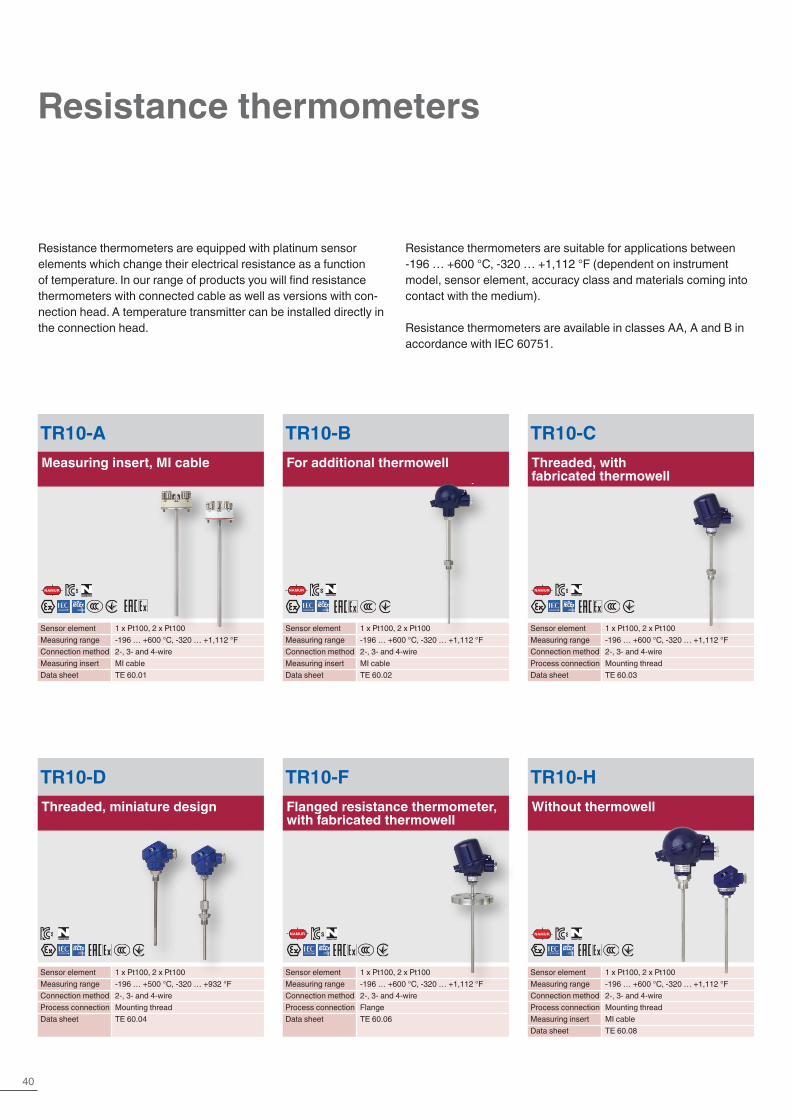
Resistance thermometers
TR10-AMeasuring insert, MI cable
Sensor element 1 x Pt100, 2 x Pt100Measuring range -196 … +600 °C, -320 … +1,112 °FConnection method 2-, 3- and 4-wireMeasuring insert MI cableData sheet TE 60.01
TR10-BFor additional thermowell
Sensor element 1 x Pt100, 2 x Pt100Measuring range -196 … +600 °C, -320 … +1,112 °FConnection method 2-, 3- and 4-wireMeasuring insert MI cableData sheet TE 60.02
TR10-CThreaded, with fabricated thermowell
Sensor element 1 x Pt100, 2 x Pt100Measuring range -196 … +600 °C, -320 … +1,112 °FConnection method 2-, 3- and 4-wireProcess connection Mounting threadData sheet TE 60.03
TR10-DThreaded, miniature design
Sensor element 1 x Pt100, 2 x Pt100Measuring range -196 … +500 °C, -320 … +932 °FConnection method 2-, 3- and 4-wireProcess connection Mounting threadData sheet TE 60.04
TR10-FFlanged resistance thermometer, with fabricated thermowell
Sensor element 1 x Pt100, 2 x Pt100Measuring range -196 … +600 °C, -320 … +1,112 °FConnection method 2-, 3- and 4-wireProcess connection FlangeData sheet TE 60.06
TR10-HWithout thermowell
Sensor element 1 x Pt100, 2 x Pt100Measuring range -196 … +600 °C, -320 … +1,112 °FConnection method 2-, 3- and 4-wireProcess connection Mounting threadMeasuring insert MI cableData sheet TE 60.08
Resistance thermometers are equipped with platinum sensor elements which change their electrical resistance as a function of temperature. In our range of products you will find resistance thermometers with connected cable as well as versions with con-nection head. A temperature transmitter can be installed directly in the connection head.
Resistance thermometers are suitable for applications between -196 … +600 °C, -320 … +1,112 °F (dependent on instrument model, sensor element, accuracy class and materials coming into contact with the medium).
Resistance thermometers are available in classes AA, A and B in accordance with IEC 60751.
NAMUR NAMUR
NAMUR NAMUR
NAMUR
41Further information at www.wika.com
Temperature | Transmit + Record
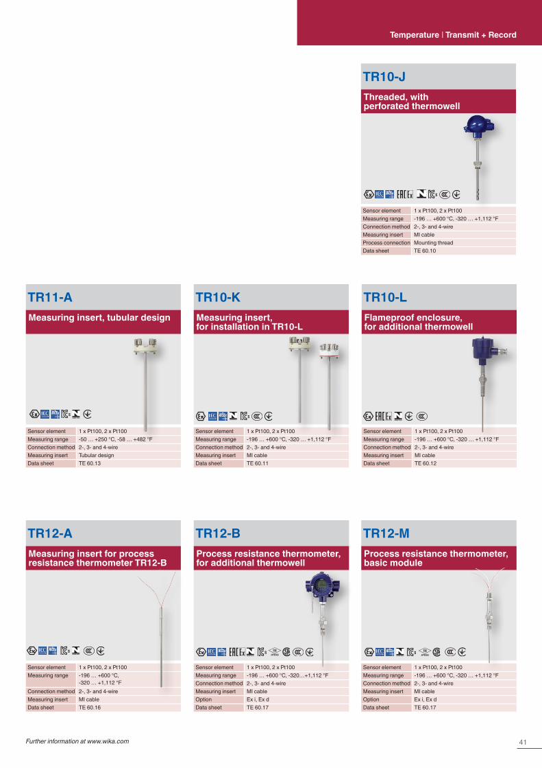
TR10-JThreaded, with perforated thermowell
Sensor element 1 x Pt100, 2 x Pt100Measuring range -196 … +600 °C, -320 … +1,112 °FConnection method 2-, 3- and 4-wireMeasuring insert MI cableProcess connection Mounting threadData sheet TE 60.10
TR10-KMeasuring insert, for installation in TR10-L
Sensor element 1 x Pt100, 2 x Pt100Measuring range -196 … +600 °C, -320 … +1,112 °FConnection method 2-, 3- and 4-wireMeasuring insert MI cableData sheet TE 60.11
TR10-LFlameproof enclosure, for additional thermowell
Sensor element 1 x Pt100, 2 x Pt100Measuring range -196 … +600 °C, -320 … +1,112 °FConnection method 2-, 3- and 4-wireMeasuring insert MI cableData sheet TE 60.12
TR11-AMeasuring insert, tubular design
Sensor element 1 x Pt100, 2 x Pt100Measuring range -50 … +250 °C, -58 … +482 °FConnection method 2-, 3- and 4-wireMeasuring insert Tubular designData sheet TE 60.13
TR12-BProcess resistance thermometer, for additional thermowell
Sensor element 1 x Pt100, 2 x Pt100Measuring range -196 … +600 °C, -320…+1,112 °FConnection method 2-, 3- and 4-wireMeasuring insert MI cableOption Ex i, Ex dData sheet TE 60.17
TR12-AMeasuring insert for process resistance thermometer TR12-B
Sensor element 1 x Pt100, 2 x Pt100Measuring range -196 … +600 °C,
-320 … +1,112 °FConnection method 2-, 3- and 4-wireMeasuring insert MI cableData sheet TE 60.16
TR12-MProcess resistance thermometer, basic module
Sensor element 1 x Pt100, 2 x Pt100Measuring range -196 … +600 °C, -320 … +1,112 °FConnection method 2-, 3- and 4-wireMeasuring insert MI cableOption Ex i, Ex dData sheet TE 60.17

42
TFT35Threaded thermometer with integrated transmitter
Measuring range -50 … +200 °CSpecial feature ■ Output signal 4 … 20 mA, 0 … 10 V,
0.5 … 4.5 V ■ Factory configured ■ Measuring insert exchangeable ■ Electr. connection via plug connection
Data sheet TE 76.18
Resistance thermometers
TR31OEM miniature design
Sensor element 1 x Pt100, 1 x Pt1000Measuring range -50 … +250 °C, -58 … +482 °FOutput Pt100, Pt1000, 4 … 20 mACSA Ordinary and hazardous locationsData sheet TE 60.31
TR40Cable resistance thermometerMI cable
Sensor element 1 x Pt100, 2 x Pt100Measuring range -196 … +600 °C, -320 … +1,112 °FConnection method 2-, 3- and 4-wireCable Silicone, PTFE, PFAData sheet TE 60.40
TR41Cable resistance thermometer Tubular design
Sensor element 1 x Pt100, 2 x Pt100Measuring range -60 ... +250 °C, -76 ... +482 °FConnection method 2-, 3- and 4-wireCable Silicone, PTFE, PFAData sheet TE 60.41
TR36Compact version
Sensor element 1 x Pt100, 1 x Pt1000Measuring range -50 … +250 °C, -58 … +482 °FOutput Pt100, 4 … 20 mAData sheet TE 60.36
TR33Miniature design, standard version
Sensor element 1 x Pt100, 1 x Pt1000Measuring range -50 … +250 °C, -58 … +482 °FOutput Pt100, Pt1000, 4 … 20 mACSA Ordinary locationsData sheet TE 60.33
TR34Miniature design, explosion-protected
Sensor element 1 x Pt100, 1 x Pt1000Measuring range -50 … +250 °C, -58 … +482 °FOutput Pt100, Pt1000, 4 … 20 mACSA Hazardous locationsData sheet TE 60.34
43Further information at www.wika.com
Temperature | Transmit + Record
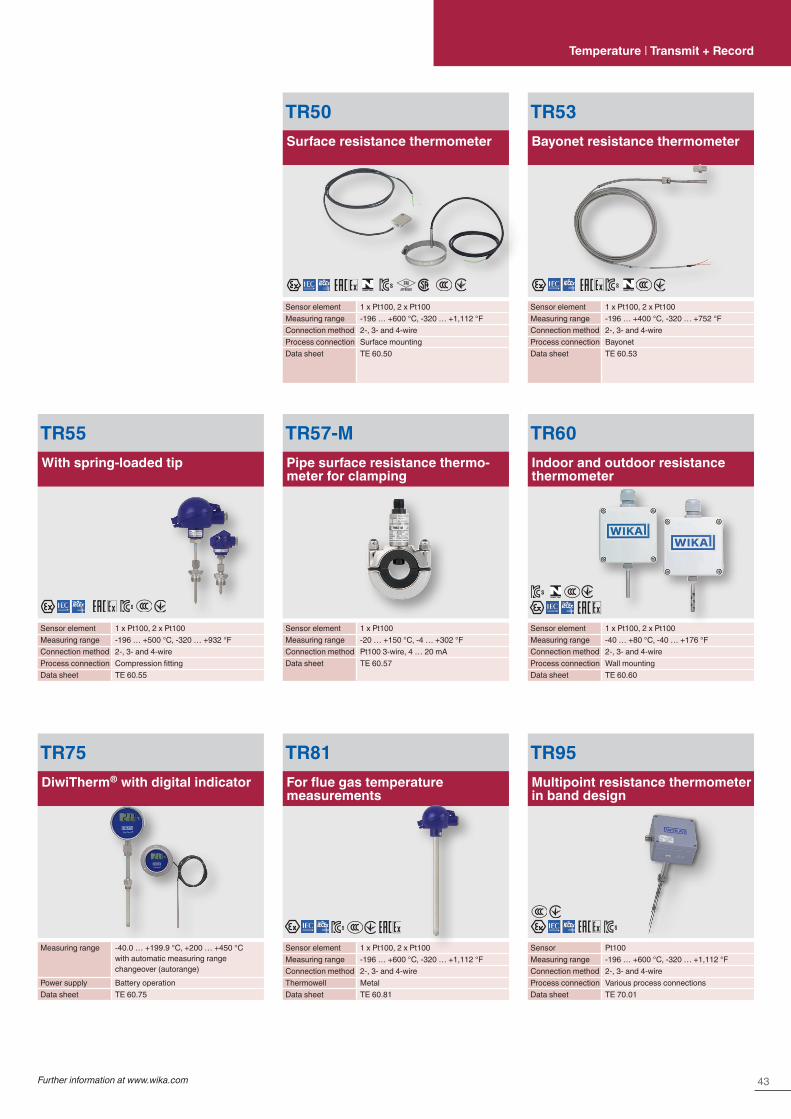
TR50Surface resistance thermometer
Sensor element 1 x Pt100, 2 x Pt100Measuring range -196 … +600 °C, -320 … +1,112 °FConnection method 2-, 3- and 4-wireProcess connection Surface mountingData sheet TE 60.50
TR53Bayonet resistance thermometer
Sensor element 1 x Pt100, 2 x Pt100Measuring range -196 … +400 °C, -320 … +752 °FConnection method 2-, 3- and 4-wireProcess connection BayonetData sheet TE 60.53
TR57-MPipe surface resistance thermo-meter for clamping
Sensor element 1 x Pt100Measuring range -20 … +150 °C, -4 … +302 °FConnection method Pt100 3-wire, 4 … 20 mAData sheet TE 60.57
TR55With spring-loaded tip
Sensor element 1 x Pt100, 2 x Pt100Measuring range -196 … +500 °C, -320 … +932 °FConnection method 2-, 3- and 4-wireProcess connection Compression fittingData sheet TE 60.55
TR75DiwiTherm® with digital indicator
Measuring range -40.0 … +199.9 °C, +200 … +450 °Cwith automatic measuring range changeover (autorange)
Power supply Battery operationData sheet TE 60.75
TR81For flue gas temperature measurements
Sensor element 1 x Pt100, 2 x Pt100Measuring range -196 … +600 °C, -320 … +1,112 °FConnection method 2-, 3- and 4-wireThermowell MetalData sheet TE 60.81
TR60Indoor and outdoor resistance thermometer
Sensor element 1 x Pt100, 2 x Pt100Measuring range -40 … +80 °C, -40 … +176 °FConnection method 2-, 3- and 4-wireProcess connection Wall mountingData sheet TE 60.60
TR95Multipoint resistance thermometer in band design
Sensor Pt100Measuring range -196 … +600 °C, -320 … +1,112 °FConnection method 2-, 3- and 4-wireProcess connection Various process connectionsData sheet TE 70.01
44
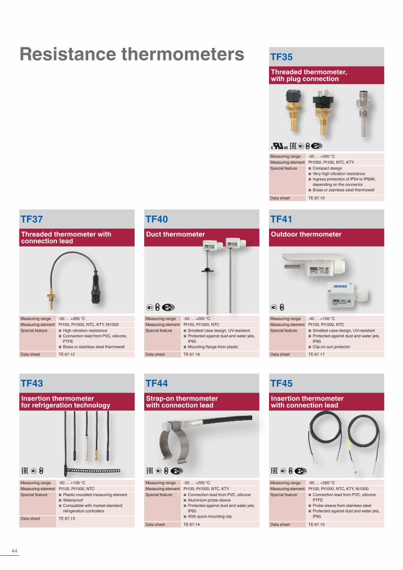
Resistance thermometers
TF40Duct thermometer
Measuring range -50 … +200 °CMeasuring element Pt100, Pt1000, NTCSpecial feature ■ Smallest case design, UV-resistant
■ Protected against dust and water jets, IP65
■ Mounting flange from plastic
Data sheet TE 67.16
TF41Outdoor thermometer
Measuring range -40 … +100 °CMeasuring element Pt100, Pt1000, NTCSpecial feature ■ Smallest case design, UV-resistant
■ Protected against dust and water jets, IP65
■ Clip-on sun protector
Data sheet TE 67.17
TF35Threaded thermometer, with plug connection
Measuring range -50 … +200 °CMeasuring element Pt1000, Pt100, NTC, KTYSpecial feature ■ Compact design
■ Very high vibration resistance ■ Ingress protection of IP54 to IP69K, depending on the connector
■ Brass or stainless steel thermowell
Data sheet TE 67.10
TF43Insertion thermometer for refrigeration technology
Measuring range -50 … +105 °CMeasuring element Pt100, Pt1000, NTCSpecial feature
■ Plastic-moulded measuring element ■ Waterproof ■ Compatible with market-standard refrigeration controllers
Data sheet TE 67.13
TF45Insertion thermometer with connection lead
Measuring range -50 … +260 °CMeasuring element Pt100, Pt1000, NTC, KTY, Ni1000Special feature
■ Connection lead from PVC, silicone, PTFE
■ Probe sleeve from stainless steel ■ Protected against dust and water jets, IP65
Data sheet TE 67.15
TF44Strap-on thermometer with connection lead
Measuring range -50 … +200 °CMeasuring element Pt100, Pt1000, NTC, KTYSpecial feature ■ Connection lead from PVC, silicone
■ Aluminium probe sleeve ■ Protected against dust and water jets, IP65
■ With quick-mounting clip
Data sheet TE 67.14
TF37Threaded thermometer with connection lead
Measuring range -50 … +260 °CMeasuring element Pt100, Pt1000, NTC, KTY, Ni1000Special feature ■ High vibration resistance
■ Connection lead from PVC, silicone, PTFE
■ Brass or stainless steel thermowell
Data sheet TE 67.12

45Further information at www.wika.com
Temperature transmittersTemperature | Transmit + Record
T15Digital temperature transmitter for resistance sensors
Input Resistance thermometers, potentiometersAccuracy < 0.1 %Output 4 … 20 mASpecial feature The fastest and simplest configuration on
the marketData sheet TE 15.01
T91Analogue temperature transmitter 3-wire, 0 … 10 V
Input Resistance thermometers, thermocouples
Accuracy < 0.5 or < 1 %Output 0 … 10 V, 0 … 5 VSpecial feature Fixed measuring rangeData sheet TE 91.01, TE 91.02
T32HART® temperature transmitter
Input Resistance thermometers, thermocouples, potentiometers
Accuracy < 0.1 %Output 4 … 20 mA, HART® protocolSpecial feature TÜV certified SIL version
(full assessment)Data sheet TE 32.04
TIF50, TIF52HART® field temperature transmitter
Input Resistance thermometers, thermocouples, potentiometers
Accuracy < 0.1 %Output 4 … 20 mA, HART® protocolSpecial feature PC configurableData sheet TE 62.01
T16Digital temperature transmitter for thermocouples
Input All commercially available thermocouplesAccuracy Typical < 2 KOutput 4 … 20 mASpecial feature The fastest and simplest configuration on
the marketData sheet TE 16.01
SILIEC 61508 / IEC 61511
NAMUR
46
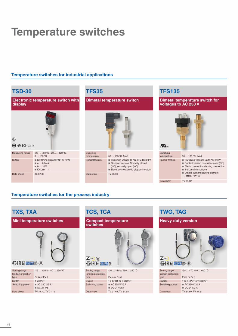
Temperature switches
Temperature switches for industrial applications
Temperature switches for the process industry
TSD-30Electronic temperature switch with display
Measuring range -20 … +80 °C, -20 … +120 °C, 0 … 150 °C
Output ■ Switching outputs PNP or NPN ■ 4 … 20 mA ■ 0 … 10 V ■ IO-Link 1.1
Data sheet TE 67.03
TWG, TAGHeavy-duty version
Setting range -30 … +70 to 0 … 600 °CIgnition protection type Ex ia or Ex dSwitch 1 or 2 SPDT or 1x DPDTSwitching power ■ AC 250 V/20 A
■ DC 24 V/2 AData sheet TV 31.60, TV 31.61
TCS, TCACompact temperature switches
Setting range -30 … +10 to 160 … 250 °CIgnition protection type Ex ia or Ex dSwitch 1 x SPDT or 1 x DPDTSwitching power ■ AC 250 V/15 A
■ DC 24 V/2 AData sheet TV 31.64, TV 31.65
TXS, TXAMini temperature switches
Setting range -15 … +20 to 180 … 250 °CIgnition protection type Ex ia or Ex dSwitch 1 x SPDTSwitching power ■ AC 220 V/5 A
■ DC 24 V/5 AData sheet TV 31.70, TV 31.72
TFS35Bimetal temperature switch
Switching temperature 50 … 155 °C, fixedSpecial feature ■ Switching voltage to AC 48 V, DC 24 V
■ Compact version: Normally closed (NC), normally open (NO)
■ Electr. connection via plug connection
Data sheet TV 35.01
TFS135Bimetal temperature switch for voltages to AC 250 V
Switching temperature 50 … 130 °C, fixedSpecial feature ■ Switching voltages up to AC 250 V
■ Contact version normally closed (NC) ■ Electr. connection via plug connection ■ 1 or 2 switch contacts ■ Option: With measuring element Pt1000 / Pt100
Data sheet TV 35.02
SILIEC 61508 / IEC 61511
SILIEC 61508 / IEC 61511
47Further information at www.wika.com
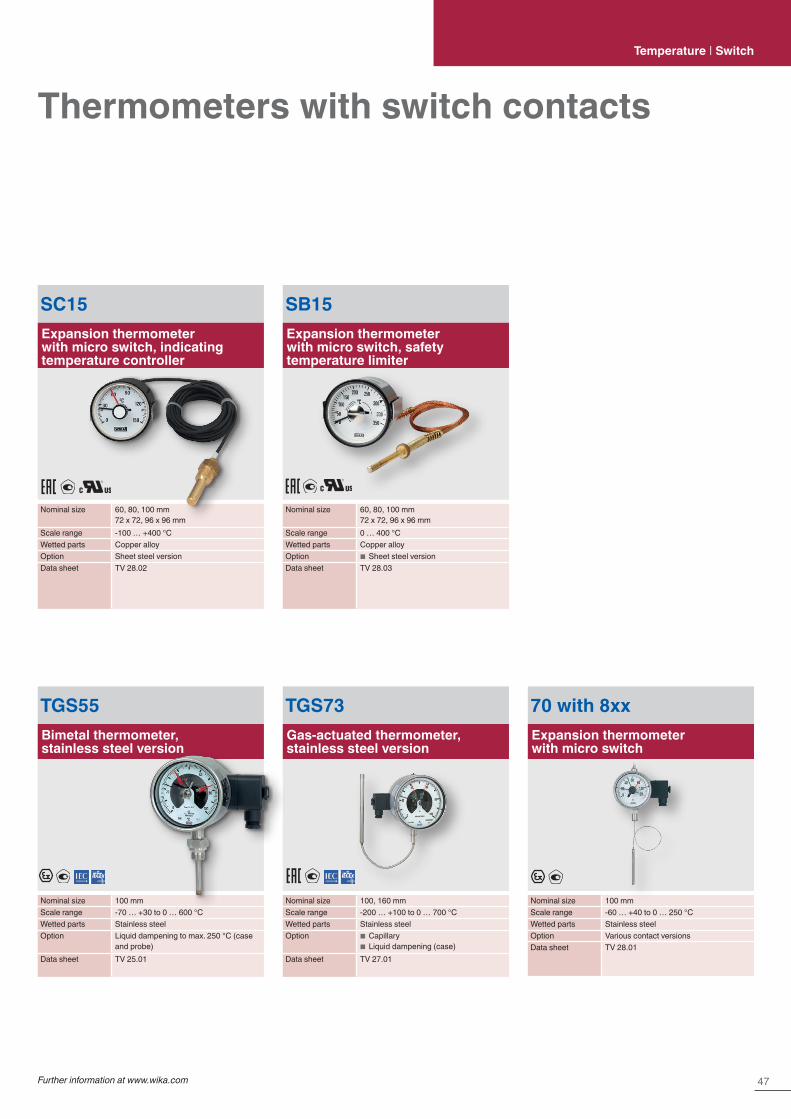
Thermometers with switch contactsTemperature | Switch
TGS55Bimetal thermometer, stainless steel version
Nominal size 100 mmScale range -70 … +30 to 0 … 600 °CWetted parts Stainless steelOption Liquid dampening to max. 250 °C (case
and probe)Data sheet TV 25.01
TGS73Gas-actuated thermometer, stainless steel version
Nominal size 100, 160 mmScale range -200 … +100 to 0 … 700 °CWetted parts Stainless steelOption ■ Capillary
■ Liquid dampening (case)Data sheet TV 27.01
70 with 8xxExpansion thermometer with micro switch
Nominal size 100 mmScale range -60 … +40 to 0 … 250 °CWetted parts Stainless steelOption Various contact versionsData sheet TV 28.01
SC15Expansion thermometer with micro switch, indicating temperature controller
Nominal size 60, 80, 100 mm72 x 72, 96 x 96 mm
Scale range -100 … +400 °CWetted parts Copper alloyOption Sheet steel versionData sheet TV 28.02
SB15Expansion thermometer with micro switch, safety temperature limiter
Nominal size 60, 80, 100 mm72 x 72, 96 x 96 mm
Scale range 0 … 400 °CWetted parts Copper alloyOption ■ Sheet steel versionData sheet TV 28.03

48
Temperature | Switch
Temperature controllers
CS4RFor rail mounting, 22.5 x 75 mm
Input Multi-function input for resistance thermo-meters, thermocouples and standard signals
Control mode PID, PI, PD, P, ON/OFF (configurable)Monitoring output Relay or logic level DC 0/12 V to control an
electronic switch relay (SSR) or analogue current signal 4 … 20 mA
Supply voltage ■ AC 100 … 240 V ■ AC/DC 24 V
Data sheet AC 85.05
SC64For panel mounting, 64 mm, round
Input Pt100 or PTCControl mode Simple 2-point controllerMonitoring output Relay switching output 16 A, 250 VSupply voltage ■ AC 230 V
■ AC 12 … 24 V or DC 16 … 32 VData sheet AC 85.25
SC58For panel mounting, 62 x 28 mm
Input Pt100 or PTCControl mode Simple 2-point controllerMonitoring output Relay switching output 12 A, 250 VSupply voltage ■ AC 230 V
■ AC 12 … 24 V or DC 16 … 32 VData sheet AC 85.24
CS6S, CS6H, CS6LFor panel mounting, 48 x 48, 48 x 96, 96 x 96 mm
Input Multi-function input for resistance thermo-meters, thermocouples and standard signals
Control mode PID, PI, PD, P, ON/OFF (configurable)Monitoring output Relay (AC 250 V, 3A, (R) or 1A (L)) or
logic level DC 0/12 V for 3-point control to control an electronic switch relay (SSR) or analogue current signal 4 … 20 mA
Supply voltage ■ AC 100 … 240 V ■ AC/DC 24 V
Data sheet AC 85.08

49Further information at www.wika.com
Thermowells/protection tubesTemperature | Thermowells/protection tubes
Whether in aggressive or abrasive process media, whether in high- or low-temperature ranges: For electrical or mechanical thermometers, to prevent direct exposure of their temperature probes to the medium, thermowells/protection tubes that suit each application are available. Thermowells/protection tubes can be machined from bar stock material or assembled from tube sections and can either be screw-, weld- or flange-fitted.
They are offered in standard and special materials such as stainless steel 1.4571, 316L, Hastelloy® or titanium. Each version, depending on its construction type and its mounting to the process, has certain advantages and drawbacks with respect to its load limits and the special materials that can be used.
In order to manufacture thermowells/protection tubes for flange mounting at low cost from special materials, the designs used differ from standard thermowells/protection tubes in accordance with DIN 43772.Thus, only the wetted parts of the thermowell/protection tube are manufactured from special materials, whereas the non-wetted flange is made of stainless steel and is welded to the special material.
This design is used both for protection tubes and thermowells. With tantalum as special material a removable jacket is used, which is slid over the supporting thermowell/protection tube from stainless steel.
TW10Thermowell with flange
Thermowell form Tapered, straight or steppedNominal width ■ ASME 1 … 4 inch DIN/EN
■ DN 25 … 100Pressure rating ASME to 2,500 lbs (DIN/EN to PN 100)Data sheet TW 95.10, TW 95.11, TW 95.12
TW15Threaded thermowell
Thermowell form Tapered, straight or steppedHead design Hexagon, round with hexagon, or
round with spanner flatsProcess connection ½, ¾ or 1 NPTData sheet TW 95.15
TW20Weld-in thermowell for weld-ing socket
Thermowell form Tapered, straight or steppedWelding diameter 1.050, 1.315 or 1.900 inch
(26.7, 33.4 or 48.3 mm)Pressure rating 3,000 or 6,000 psiData sheet TW 95.20
TW25Weld-in thermowell
Thermowell form Tapered, straight or steppedBar diameter Up to 2 inch (50.8 mm)Data sheet TW 95.25
TW30Vanstone, thermowell for lap flanges
Thermowell form Tapered, straight or steppedNominal width ASME 1, 1½ or 2 inchPressure rating ASME up to 2,500 lbsData sheet TW 95.30
TW31Vanstone design in accordance with petrochemical standard
Thermowell form In accordance with Shell drawings S38.113 and S38.114
Material Stainless steel, special alloysFlange Slip-on flanges per ASME B16.5Data sheet TW 95.31
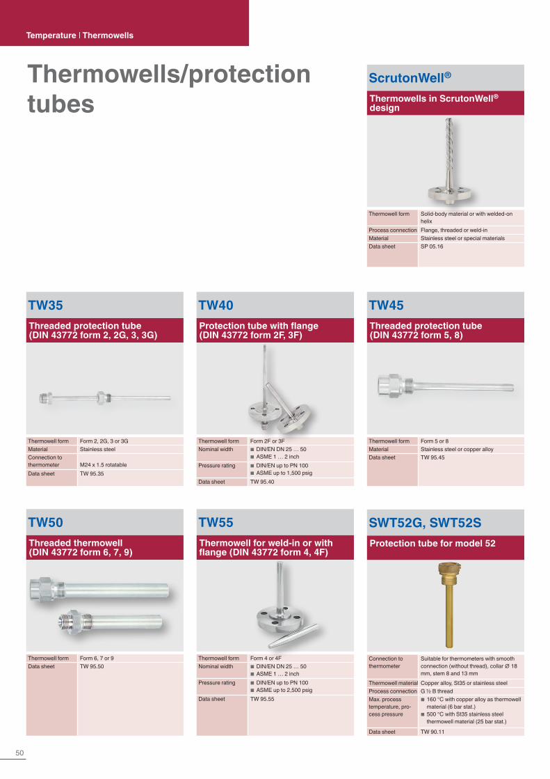
50
Thermowells/protection tubes
Temperature | Thermowells
TW40Protection tube with flange (DIN 43772 form 2F, 3F)
Thermowell form Form 2F or 3FNominal width ■ DIN/EN DN 25 … 50
■ ASME 1 … 2 inchPressure rating ■ DIN/EN up to PN 100
■ ASME up to 1,500 psigData sheet TW 95.40
TW50Threaded thermowell (DIN 43772 form 6, 7, 9)
Thermowell form Form 6, 7 or 9Data sheet TW 95.50
TW55Thermowell for weld-in or with flange (DIN 43772 form 4, 4F)
Thermowell form Form 4 or 4FNominal width ■ DIN/EN DN 25 … 50
■ ASME 1 … 2 inchPressure rating ■ DIN/EN up to PN 100
■ ASME up to 2,500 psigData sheet TW 95.55
TW45Threaded protection tube (DIN 43772 form 5, 8)
Thermowell form Form 5 or 8Material Stainless steel or copper alloyData sheet TW 95.45
SWT52G, SWT52SProtection tube for model 52
Connection to thermometer
Suitable for thermometers with smooth connection (without thread), collar ∅ 18 mm, stem 8 and 13 mm
Thermowell material Copper alloy, St35 or stainless steelProcess connection G ½ B threadMax. process temperature, pro-cess pressure
■ 160 °C with copper alloy as thermowell material (6 bar stat.)
■ 500 °C with St35 stainless steel thermowell material (25 bar stat.)
Data sheet TW 90.11
TW35Threaded protection tube (DIN 43772 form 2, 2G, 3, 3G)
Thermowell form Form 2, 2G, 3 or 3GMaterial Stainless steelConnection to thermometer M24 x 1.5 rotatableData sheet TW 95.35
ScrutonWell®
Thermowells in ScrutonWell® design
Thermowell form Solid-body material or with welded-on helix
Process connection Flange, threaded or weld-inMaterial Stainless steel or special materialsData sheet SP 05.16
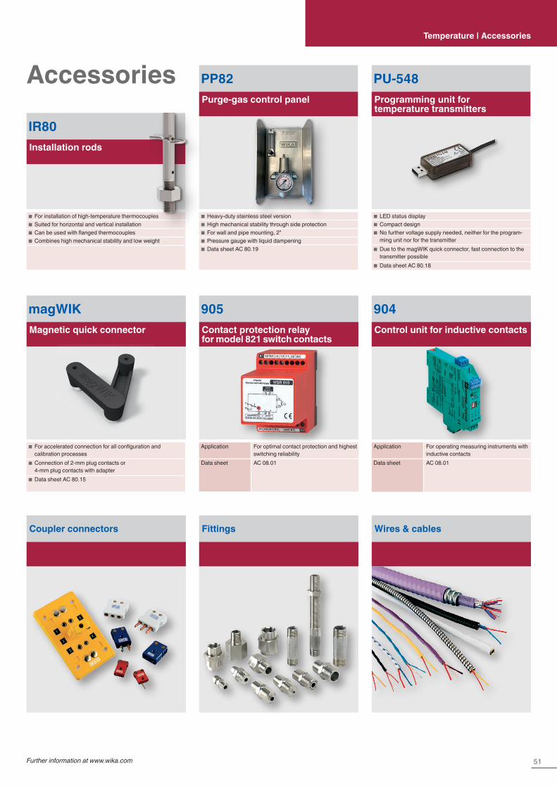
51Further information at www.wika.com
Temperature | Accessories
Accessories PU-548Programming unit for temperature transmitters
■ LED status display ■ Compact design ■ No further voltage supply needed, neither for the program-ming unit nor for the transmitter
■ Due to the magWIK quick connector, fast connection to the transmitter possible
■ Data sheet AC 80.18
PP82Purge-gas control panel
■ Heavy-duty stainless steel version ■ High mechanical stability through side protection ■ For wall and pipe mounting, 2" ■ Pressure gauge with liquid dampening ■ Data sheet AC 80.19
magWIKMagnetic quick connector
■ For accelerated connection for all configuration and calibration processes
■ Connection of 2-mm plug contacts or 4-mm plug contacts with adapter
■ Data sheet AC 80.15
905Contact protection relay for model 821 switch contacts
Application For optimal contact protection and highest switching reliability
Data sheet AC 08.01
904Control unit for inductive contacts
Application For operating measuring instruments with inductive contacts
Data sheet AC 08.01
Coupler connectors Fittings Wires & cables
IR80Installation rods
■ For installation of high-temperature thermocouples ■ Suited for horizontal and vertical installation ■ Can be used with flanged thermocouples ■ Combines high mechanical stability and low weight
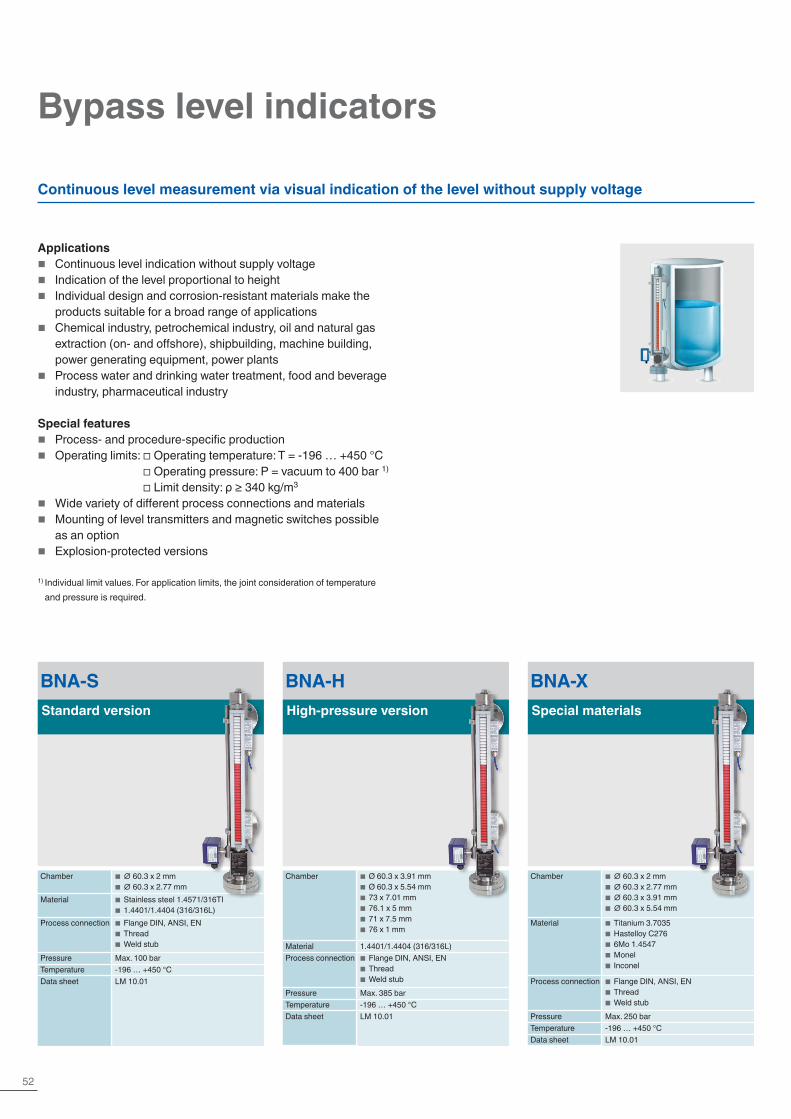
52
BNA-SStandard version
Chamber ■ ∅ 60.3 x 2 mm ■ ∅ 60.3 x 2.77 mm
Material ■ Stainless steel 1.4571/316TI ■ 1.4401/1.4404 (316/316L)
Process connection ■ Flange DIN, ANSI, EN ■ Thread ■ Weld stub
Pressure Max. 100 barTemperature -196 … +450 °CData sheet LM 10.01
BNA-XSpecial materials
Chamber ■ ∅ 60.3 x 2 mm ■ ∅ 60.3 x 2.77 mm ■ ∅ 60.3 x 3.91 mm ■ ∅ 60.3 x 5.54 mm
Material ■ Titanium 3.7035 ■ Hastelloy C276 ■ 6Mo 1.4547 ■ Monel ■ Inconel
Process connection ■ Flange DIN, ANSI, EN ■ Thread ■ Weld stub
Pressure Max. 250 barTemperature -196 … +450 °CData sheet LM 10.01
BNA-HHigh-pressure version
Chamber ■ Ø 60.3 x 3.91 mm ■ Ø 60.3 x 5.54 mm ■ 73 x 7.01 mm ■ 76.1 x 5 mm ■ 71 x 7.5 mm ■ 76 x 1 mm
Material 1.4401/1.4404 (316/316L)Process connection ■ Flange DIN, ANSI, EN
■ Thread ■ Weld stub
Pressure Max. 385 barTemperature -196 … +450 °CData sheet LM 10.01
Bypass level indicators
Continuous level measurement via visual indication of the level without supply voltage
Applications � Continuous level indication without supply voltage � Indication of the level proportional to height � Individual design and corrosion-resistant materials make the
products suitable for a broad range of applications � Chemical industry, petrochemical industry, oil and natural gas
extraction (on- and offshore), shipbuilding, machine building, power generating equipment, power plants
� Process water and drinking water treatment, food and beverage industry, pharmaceutical industry
Special features � Process- and procedure-specific production � Operating limits: □ Operating temperature: T = -196 … +450 °C
□ Operating pressure: P = vacuum to 400 bar 1) □ Limit density: ρ ≥ 340 kg/m3
� Wide variety of different process connections and materials � Mounting of level transmitters and magnetic switches possible
as an option � Explosion-protected versions
1) Individual limit values. For application limits, the joint consideration of temperature and pressure is required.
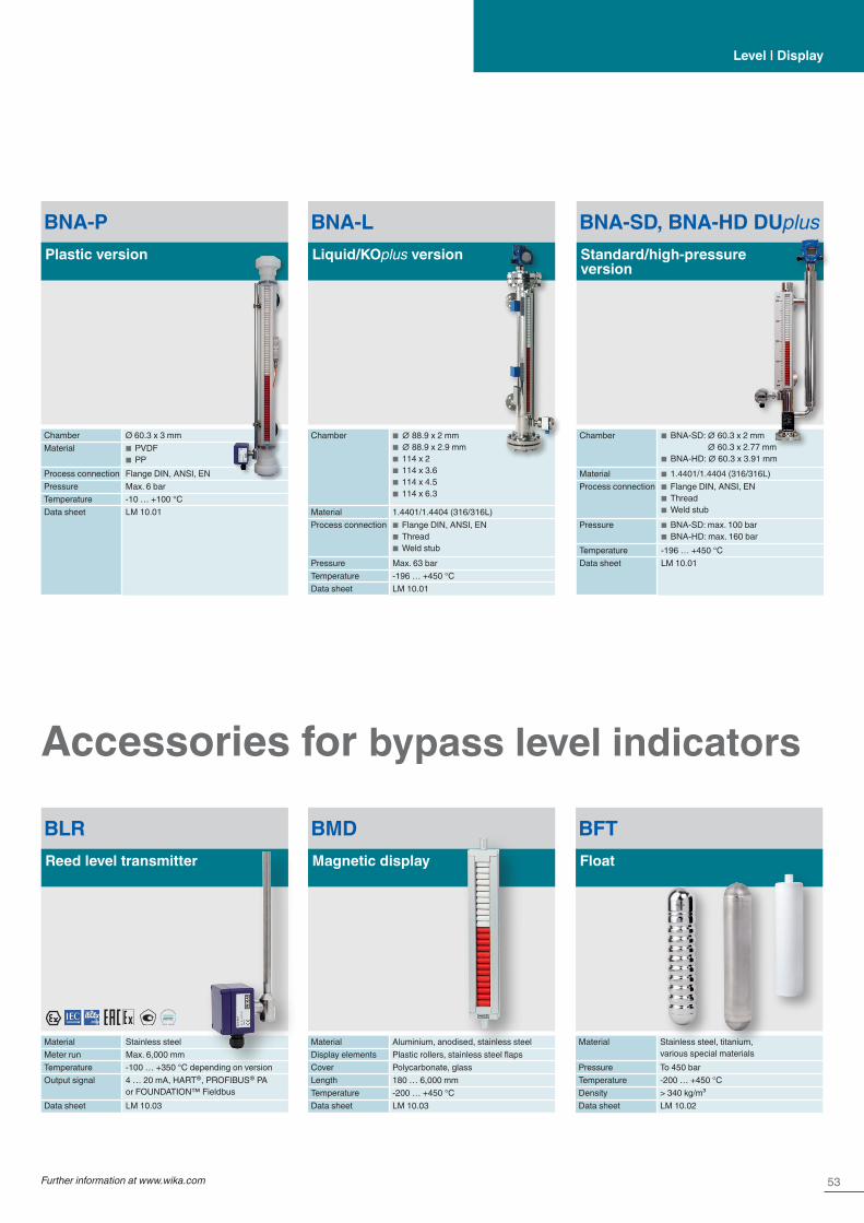
53Further information at www.wika.com
BNA-PPlastic version
Chamber Ø 60.3 x 3 mmMaterial ■ PVDF
■ PPProcess connection Flange DIN, ANSI, ENPressure Max. 6 barTemperature -10 … +100 °CData sheet LM 10.01
Level | Display
BNA-SD, BNA-HD DUplusStandard/high-pressure version
Chamber ■ BNA-SD: ∅ 60.3 x 2 mm ∅ 60.3 x 2.77 mm
■ BNA-HD: ∅ 60.3 x 3.91 mmMaterial ■ 1.4401/1.4404 (316/316L)Process connection ■ Flange DIN, ANSI, EN
■ Thread ■ Weld stub
Pressure ■ BNA-SD: max. 100 bar ■ BNA-HD: max. 160 bar
Temperature -196 … +450 °CData sheet LM 10.01
BNA-LLiquid/KOplus version
Chamber ■ ∅ 88.9 x 2 mm ■ ∅ 88.9 x 2.9 mm ■ 114 x 2 ■ 114 x 3.6 ■ 114 x 4.5 ■ 114 x 6.3
Material 1.4401/1.4404 (316/316L)Process connection ■ Flange DIN, ANSI, EN
■ Thread ■ Weld stub
Pressure Max. 63 barTemperature -196 … +450 °CData sheet LM 10.01
BLRReed level transmitter
Material Stainless steelMeter run Max. 6,000 mmTemperature -100 … +350 °C depending on versionOutput signal 4 … 20 mA, HART®, PROFIBUS® PA
or FOUNDATION™ FieldbusData sheet LM 10.03
BMDMagnetic display
Material Aluminium, anodised, stainless steelDisplay elements Plastic rollers, stainless steel flapsCover Polycarbonate, glassLength 180 … 6,000 mmTemperature -200 … +450 °CData sheet LM 10.03
BFTFloat
Material Stainless steel, titanium, various special materials
Pressure To 450 barTemperature -200 … +450 °CDensity > 340 kg/m³Data sheet LM 10.02
Accessories for bypass level indicators
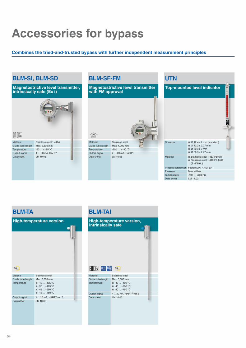
54
Accessories for bypass
BLM-SI, BLM-SDMagnetostrictive level transmitter, intrinsically safe (Ex i)
Material Stainless steel 1.4404Guide tube length Max. 5,800 mmTemperature -60 … +185 °COutput signal 4 … 20 mA, HART®
Data sheet LM 10.05
BLM-SF-FMMagnetostrictive level transmitter with FM approval
Material Stainless steelGuide tube length Max. 4,000 mmTemperature -200 … +180 °COutput signal 4 … 20 mA, HART®
Data sheet LM 10.05
Combines the tried-and-trusted bypass with further independent measurement principles
UTNTop-mounted level indicator
Chamber ■ ∅ 42.4 x 2 mm (standard) ■ ∅ 42.2 x 2.77 mm ■ ∅ 60.3 x 2 mm ■ ∅ 60.3 x 2.77 mm
Material ■ Stainless steel 1.4571/316Ti ■ Stainless steel 1.4401/1.4404 (316/316L)
Process connection Flange DIN, ANSI, ENPressure Max. 40 barTemperature -196 … +300 °CData sheet LM 11.02
BLM-TAHigh-temperature version
Material Stainless steelGuide tube length Max. 6,000 mmTemperature ■ -40 ... +125 °C
■ -90 ... +125 °C ■ -45 ... +250 °C ■ -45 ... +450 °C
Output signal 4 ... 20 mA, HART® ver. 6Data sheet LM 10.05
BLM-TAIHigh-temperature version, intrinsically safe
Material Stainless steelGuide tube length Max. 6,000 mmTemperature ■ -40 ... +125 °C
■ -40 ... +250 °C ■ -40 ... +450 °C
Output signal 4 ... 20 mA, HART® ver. 6Data sheet LM 10.05
SILIEC 61508 / IEC 61511
SILIEC 61508 / IEC 61511

55Further information at www.wika.com
Level | Display
BZG-SExternal chamber, standard version
Material Stainless steel 1.4571 (316Ti), stainless steel 1.4401/1.4404 (316/316L)
Process connection Flange ■ DIN EN 1092-1 DN 10 … DN 100, PN 6 … PN 63
■ DIN DN 10 … DN 100, PN 6 … PN 64 ■ ANSI B 16.5 ½" … 4", class 150 … 600
Pressure 64 barTemperature -196 … +450 °CData sheet LM 11.01
BZG-HExternal chamber, high-pressure version
Material ■ Stainless steel 1.4571 (316Ti) ■ Stainless steel 1.4401/1.4404 (316/316L)
Process connection Flange ■ DIN EN 1092-1 DN 10 … DN 100, PN 100 … PN 400
■ DIN DN 10 … DN 100, PN 100 … PN 400
■ ANSI B 16.5 ½" … 4", class 600 … 2,500
Pressure 400 barTemperature -196 … +450 °CData sheet LM 11.01
BZG-KExternal chamber, steel version
Material ■ Steel 1.0345/1.0460 ■ Steel 1.5415 (16Mo3) ■ A105/A106 Gr. B ■ A350 LF2/A333 Gr. 6
Process connection Flange ■ DIN EN 1092-1 DN 10 … DN 50, PN 16 … PN 400
■ DIN DN 10 … DN 50, PN 16 … PN 400 ■ ANSI B 16.5 ½" … 4", class 150 … 2,500
Pressure Max. 255 bar (material-dependent)Temperature -10 … +425 °C (material-dependent)Data sheet LM 11.01
BZG-XExternal chamber, special material version
Material ■ Stainless steel 6Mo 1.4547 (UNS S31254)
■ Stainless steel 1.4306 (304L) ■ Duplex 1.4462 (UNS S31803) ■ Super Duplex 1.4410 (UNS S3850) ■ Titanium 3.7035 (grade 2) ■ Hastelloy C276 (2.4819)
Process connection
Flange ■ DIN EN 1092-1 DN 10 … DN 100, PN 63 … PN 400
■ DIN DN 10 … DN 100, PN 64 … PN 400 ■ ANSI B 16.5 ½" … 4", class 600 … 2,500
Pressure Max. 430 bar (material-dependent)Temperature -196 … +450 °C (material-dependent)Data sheet LM 11.01
External chambers
Applications � Level detection for almost all liquid media � Individual design and corrosion-resistant materials make the
products suitable for a broad range of applications � Chemical industry, petrochemical industry, oil and natural gas
extraction (on- and offshore), shipbuilding, machine building, power generating equipment, power plants
Special featuresProcess- and procedure-specific productionOperating limits: □ Operating temperature: T = -196 … +450 °C
□ Operating pressure: P = Vacuum to 400 bar 1)
� Wide variety of different process connections and materials � Mounting of level transmitters and guided wave radars possible
as an option
1) Individual limit values. For application limits, the joint consideration of temperature and pressure is required.
The external chamber model BZG consists of an external chamber vessel that is mounted laterally to a vessel using at least 2 process connections (flange, thread or weld stub). Through this type of arrangement, the level in the external chamber vessel corresponds
to the level in the vessel. The level is measured by a measuring instrument inserted additionally in the external chamber vessel, for example model FLR or FLS, or by a guided wave radar.
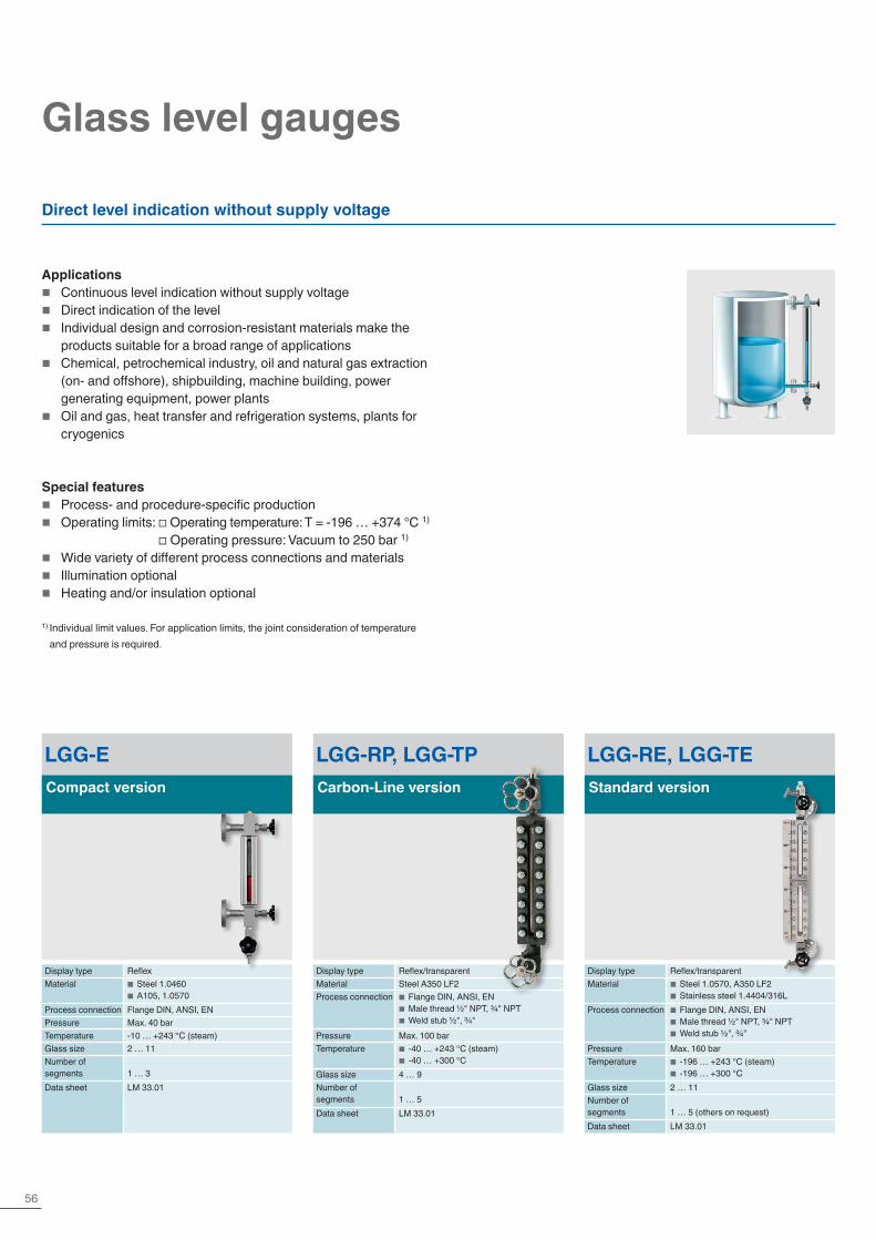
56
Glass level gauges
LGG-ECompact version
Display type ReflexMaterial ■ Steel 1.0460
■ A105, 1.0570Process connection Flange DIN, ANSI, ENPressure Max. 40 barTemperature -10 … +243 °C (steam)Glass size 2 … 11Number of segments 1 … 3Data sheet LM 33.01
LGG-RP, LGG-TPCarbon-Line version
Display type Reflex/transparentMaterial Steel A350 LF2Process connection ■ Flange DIN, ANSI, EN
■ Male thread ½" NPT, ¾" NPT ■ Weld stub ½", ¾"
Pressure Max. 100 barTemperature ■ -40 … +243 °C (steam)
■ -40 … +300 °CGlass size 4 … 9Number of segments 1 … 5Data sheet LM 33.01
LGG-RE, LGG-TEStandard version
Display type Reflex/transparentMaterial ■ Steel 1.0570, A350 LF2
■ Stainless steel 1.4404/316LProcess connection ■ Flange DIN, ANSI, EN
■ Male thread ½" NPT, ¾" NPT ■ Weld stub ½", ¾"
Pressure Max. 160 barTemperature ■ -196 … +243 °C (steam)
■ -196 … +300 °CGlass size 2 … 11Number of segments 1 … 5 (others on request)Data sheet LM 33.01
Direct level indication without supply voltage
Applications � Continuous level indication without supply voltage � Direct indication of the level � Individual design and corrosion-resistant materials make the
products suitable for a broad range of applications � Chemical, petrochemical industry, oil and natural gas extraction
(on- and offshore), shipbuilding, machine building, power generating equipment, power plants
� Oil and gas, heat transfer and refrigeration systems, plants for cryogenics
Special features � Process- and procedure-specific production � Operating limits: □ Operating temperature: T = -196 … +374 °C 1)
□ Operating pressure: Vacuum to 250 bar 1)
� Wide variety of different process connections and materials � Illumination optional � Heating and/or insulation optional
1) Individual limit values. For application limits, the joint consideration of temperature and pressure is required.

57Further information at www.wika.com
LGG-RI, LGG-TIHigh-pressure version
Display type Reflex/transparentMaterial ■ Steel 1.5415
■ Stainless steel 1.4404/316LProcess connection ■ Flange DIN, ANSI, EN
■ Male thread ½" NPT, ¾" NPT ■ Weld stub ½", ¾"
Pressure Max. 250 barTemperature -196 … +100 °CGlass size 2 … 9Number of segments 1 … 5Data sheet LM 33.01
LGG-MRefraction version
Display type RefractionMaterial Steel 1.5415Process connection ■ Flange DIN, ANSI, EN
■ Male thread G ½, G ¾, ½" NPT, ¾" NPT ■ Weld stub ½", ¾"
Pressure Max. 250 barTemperature -10 … +374 °CGlass size 2 … 11Number of segments 1 … 9Data sheet LM 33.01
Level | Display

58
Hydrostatic level measurement
Submersible pressure sensors
Applications � Level measurement in rivers and lakes � Control of sewage lift and pumping
stations � Monitoring of sewage, settling and
rainwater retention basins � Level measurement in vessel and
storage systems for oils and fuels
Special features � Slimline and hermetically sealed design
up to 300 m water column � Highly resistant versions available � Explosion protection per ATEX, IECEx,
FM and CSA � Drinking water conformity per KTW and
ACS � Temperature output, HART® and
low-power output signal for battery operation
LF-1For superior applications
Accuracy (± % of span) ≤ 0.5 or ≤ 1Measuring range ■ 0 … 0.1 to 0 … 6 bar
■ 0 … 1.6 to 0 … 6 bar abs.Output signal ■ 4 … 20 mA (2-wire)
■ 4 … 20 mA + HART® (2-wire) ■ DC 0.1 … 2.5 V (3-wire)
Special feature ■ Suitable for measurements in contaminated and aggressive media
■ An optimised discharge behaviour and a large pressure port prevent the instrument from clogging and ensure a minimum maintenance effort
■ Can be used in explosion-protected areas
■ Developed for wireless applications
Data sheet LM 40.04
LH-20High-performance
Accuracy (± % of span) ≤ 0.2 or 0.1Measuring range ■ 0 … 0.1 to 0 … 25 bar
■ 0 … 1.6 to 0 … 25 bar abs.Special feature ■ Scalable measuring range (optional)
■ Resistant against the harshest environmental conditions
■ Reliable and secure by double-sealed design
■ Titanium case for especially high resistance (optional)
Output signal ■ 4 … 20 mA (2-wire) ■ 4 … 20 mA (2-wire) + HART® + PT100
Data sheet PE 81.56
LS-10For general applications
Accuracy (± % of span) ≤ 0.5Measuring range 0 … 0.25 to 0 … 10 barOutput signal 4 … 20 mA (2-wire)Data sheet PE 81.55
IL-10For applications in hazardous areas
Accuracy (± % of span)
■ ≤ 0.5 or ≤ 0.25 (only applies to measur-ing ranges ≥ 0.25 bar (3.6 psi))
Measuring range 0 … 0.1 to 0 … 25 barSpecial feature ■ Suitable for all level measurements in
hazardous areas ■ Explosion protection per IECEx, ATEX and CSA
■ Shipbuilding approval in accordance with GL
Output signal 4 … 20 mA (2-wire)Data sheet PE 81.23
LH-10High-performance
Accuracy (± % of span)
■ Measuring range: < 0.25 bar: ≤ ±0.50 % ■ Measuring range: ≥ 0.25 bar: ≤ ±0.25 %
Measuring range ■ 0 … 0.1 to 0 … 25 barSpecial feature ■ Precise and reliable
■ Integrated temperature measurement (option)
■ Design from Hastelloy and FEP cable for especially high resistance (optional)
Output signal ■ 4 … 20 mA (2-wire) ■ 0 … 20 mA (3-wire) ■ DC 0 ... 5 V ■ DC 0 ... 10 V ■ DC 0.5 ... 2.5 V
Data sheet PE 81.09
GL

59
Level | Transmit
Continuous measurement with float for industrial applications
RLT-1000Stainless steel version
Accuracy 24, 12, 10, 6 or 3 mmOutput signal Resistance signal
or 4 … 20 mATemperature -30 … +80 °C
(-30 … +120 °C optional)Guide tube length 150 … 1,500 mmData sheet LM 50.02
RLT-2000Plastic version
Accuracy 24, 12, 10, 6 or 3 mmOutput signal Resistance signal
or 4 … 20 mATemperature -10 … +80 °C
(-30 … +120 °C optional)Guide tube length 150 … 1,500 mmData sheet LM 50.01
RLT-3000Stainless steel version with temperature output signal
Accuracy 24, 12, 10, 6 or 3 mmLevel output signal 4 … 20 mAOutput signalTemperature Pt100 or Pt1000Temperature -30 … +100 °CGuide tube length 150 … 1,500 mmData sheet LM 50.05
Applications � Level measurement of liquids in machine building � Control and monitoring tasks for hydraulic power packs,
compressors and cooling systems
Special features � Media compatibility: Oil, water, diesel, refrigerants and other
liquids � Permissible medium temperature: -30 … +120 °C � Output signals for level and temperature (optional) as
resistance output signal or 4 ... 20 mA current output � Accuracy, resolution: 24, 12, 10, 6 or 3 mm
With reed measuring chain
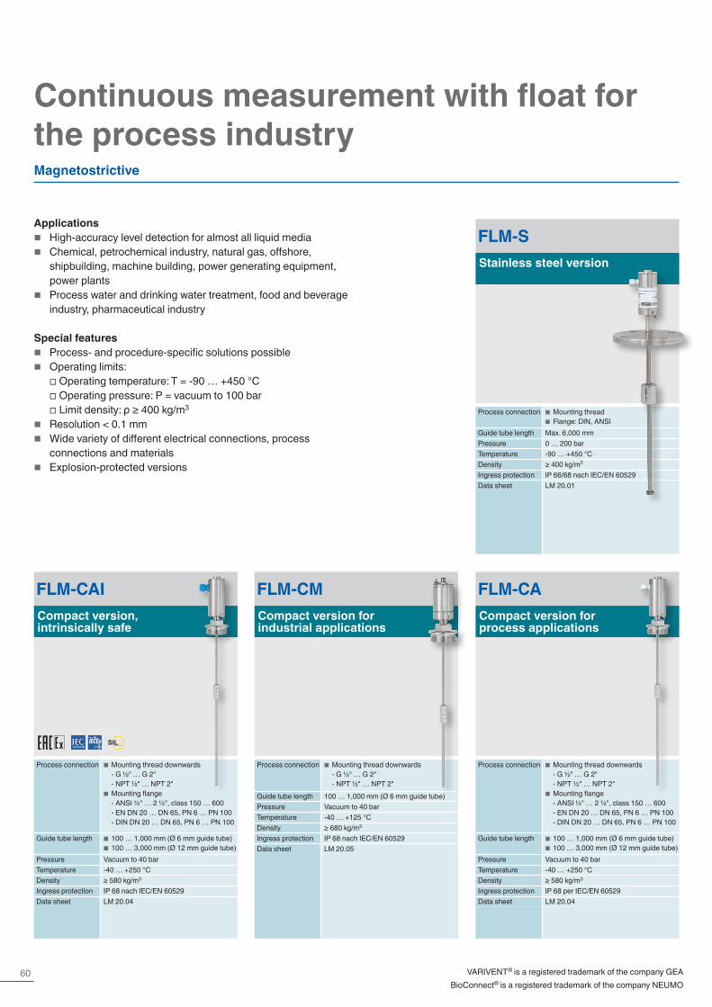
60
Continuous measurement with float for the process industry
FLM-SStainless steel version
Process connection ■ Mounting thread ■ Flange: DIN, ANSI
Guide tube length Max. 6,000 mmPressure 0 … 200 barTemperature -90 … +450 °CDensity ≥ 400 kg/m³Ingress protection IP 66/68 nach IEC/EN 60529Data sheet LM 20.01
FLM-CACompact version for process applications
Process connection ■ Mounting thread downwards - G ½" … G 2" - NPT ½" … NPT 2"
■ Mounting flange - ANSI ½" … 2 ½", class 150 … 600 - EN DN 20 … DN 65, PN 6 … PN 100 - DIN DN 20 … DN 65, PN 6 … PN 100
Guide tube length ■ 100 … 1,000 mm (Ø 6 mm guide tube) ■ 100 … 3,000 mm (Ø 12 mm guide tube)
Pressure Vacuum to 40 barTemperature -40 … +250 °CDensity ≥ 580 kg/m3
Ingress protection IP 68 per IEC/EN 60529Data sheet LM 20.04
FLM-CMCompact version for industrial applications
Process connection ■ Mounting thread downwards - G ½" … G 2" - NPT ½" … NPT 2"
Guide tube length 100 … 1,000 mm (Ø 6 mm guide tube)Pressure Vacuum to 40 barTemperature -40 … +125 °CDensity ≥ 680 kg/m3
Ingress protection IP 68 nach IEC/EN 60529Data sheet LM 20.05
Applications � High-accuracy level detection for almost all liquid media � Chemical, petrochemical industry, natural gas, offshore,
shipbuilding, machine building, power generating equipment, power plants
� Process water and drinking water treatment, food and beverage industry, pharmaceutical industry
Special features � Process- and procedure-specific solutions possible � Operating limits:
□ Operating temperature: T = -90 … +450 °C □ Operating pressure: P = vacuum to 100 bar □ Limit density: ρ ≥ 400 kg/m3
� Resolution < 0.1 mm � Wide variety of different electrical connections, process
connections and materials � Explosion-protected versions
Magnetostrictive
VARIVENT® is a registered trademark of the company GEABioConnect® is a registered trademark of the company NEUMO
FLM-CAICompact version, intrinsically safe
Process connection ■ Mounting thread downwards - G ½" … G 2" - NPT ½" … NPT 2"
■ Mounting flange - ANSI ½" … 2 ½", class 150 … 600 - EN DN 20 … DN 65, PN 6 … PN 100 - DIN DN 20 … DN 65, PN 6 … PN 100
Guide tube length ■ 100 … 1,000 mm (Ø 6 mm guide tube) ■ 100 … 3,000 mm (Ø 12 mm guide tube)
Pressure Vacuum to 40 barTemperature -40 … +250 °CDensity ≥ 580 kg/m3
Ingress protection IP 68 nach IEC/EN 60529Data sheet LM 20.04
SILIEC 61508 / IEC 61511
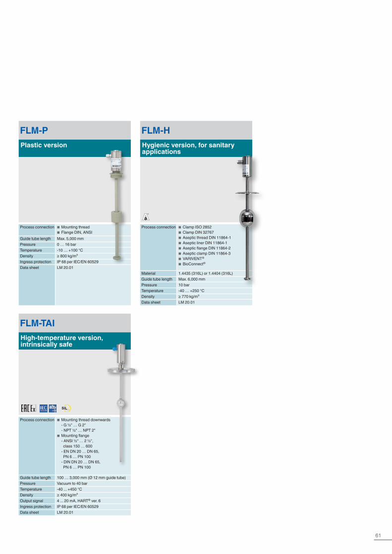
61
FLM-PPlastic version
Process connection ■ Mounting thread ■ Flange DIN, ANSI
Guide tube length Max. 5,000 mmPressure 0 … 16 barTemperature -10 … +100 °CDensity ≥ 800 kg/m³Ingress protection IP 68 per IEC/EN 60529Data sheet LM 20.01
FLM-HHygienic version, for sanitary applications
Process connection ■ Clamp ISO 2852 ■ Clamp DIN 32767 ■ Aseptic thread DIN 11864-1 ■ Aseptic liner DIN 11864-1 ■ Aseptic flange DIN 11864-2 ■ Aseptic clamp DIN 11864-3 ■ VARIVENT®
■ BioConnect®
Material 1.4435 (316L) or 1.4404 (316L)Guide tube length Max. 6,000 mmPressure 10 barTemperature -40 … +250 °CDensity ≥ 770 kg/m³Data sheet LM 20.01
FLM-TAIHigh-temperature version, intrinsically safe
Process connection ■ Mounting thread downwards - G ½" … G 2" - NPT ½" … NPT 2"
■ Mounting flange - ANSI ½" … 2 ½", class 150 … 600 - EN DN 20 … DN 65, PN 6 … PN 100 - DIN DN 20 … DN 65, PN 6 … PN 100
Guide tube length 100 … 3,000 mm (Ø 12 mm guide tube)Pressure Vacuum to 40 barTemperature -40 ... +450 °CDensity ≥ 400 kg/m³Output signal 4 ... 20 mA, HART® ver. 6Ingress protection IP 68 per IEC/EN 60529Data sheet LM 20.01
®
SILIEC 61508 / IEC 61511

62
FLR-SA, FLR-SBStainless steel version
Process connection ■ Mounting thread ■ Flange DIN, ANSI, EN
Guide tube length Max. 6,000 mmPressure 0 … 100 barTemperature -80 … +200 °CDensity ≥ 400 kg/m³Ingress protection To IP 66/68 per
IEC/EN 60529Data sheet LM 20.02
FLR-SAI, FLR-SBIIntrinsically safe
Process connection ■ Mounting thread ■ Flange DIN, ANSI, EN
Guide tube length Max. 6,000 mmPressure 0 … 100 barTemperature -80 … +200 °CDensity ≥ 400 kg/m³Ingress protection To IP 66/68 per
IEC/EN 60529Data sheet LM 20.02
With reed measuring chain
Applications � Level detection for almost all liquid media � Chemical, petrochemical industry, natural gas, offshore,
shipbuilding, machine building, power generating equipment, power plants
� Process water and drinking water treatment, food and beverage industry, pharmaceutical industry
Special features � Process- and procedure-specific solutions possible � Operating limits: □ Operating temperature: T = -80 … +200 °C
□ Operating pressure: P = vacuum to 80 bar □ Limit density: ρ ≥ 400 kg/m3
� Wide variety of different electrical connections, process connections and materials
� Optionally with programmable and configurable head-mounted transmitter for 4 … 20 mA field signals, HART®, PROFIBUS® PA and FOUNDATION™ Fieldbus
� Explosion-protected versions
Continuous measurement with float for the process industry
FLR-FReed level transmitter for food applications
Process connection ■ Threaded pipe connection DIN 11851, downwards, DN 50 ... DN 150
■ Clamp pipe connection DIN 32676, DN 25 … DN 100 or 1" … 4"
■ Clamp pipe connection ISO 2852, DN 25 ... DN 150
■ Others on request
Guide tube length ■ Max. 1,500 mm (guide tube diameter 12 mm)
■ Max. 3,500 mm (guide tube diameter 14 mm)
■ Max. 6,000 mm (guide tube diameter 18 mm)
Pressure 0 ... 25 barTemperature Normal temperature: -20 ... +120 °C
High temperature: +120 ... +200 °CLow temperature: -80 ... -20 °C
Density ≥ 400 kg/m³Ingress protection To IP66/IP68 per IEC/EN 60529Data sheet LM 20.06

63
Level | Transmit
FLR-PA, FLR-PBPlastic version, PP, PVDF, PP
Process connection ■ Mounting thread ■ Flange DIN, ANSI, EN
Guide tube length Max. 5,000 mmPressure 0 … 3 barTemperature -10 … +100 °CDensity ≥ 800 kg/m3
Data sheet LM 20.02
FLR-HA3Hygienic version, for sanitary applications
Process connection ■ Clamp ISO 2852 ■ Clamp DIN 32767 ■ Aseptic thread DIN 11864-1 ■ Aseptic liner DIN 11864-1 ■ Aseptic flange DIN 11864-2 ■ Aseptic clamp DIN 11864-3 ■ VARIVENT®
■ BioConnect®
Material 1.4435 (316L) or 1.4404 (316L)Guide tube length Max. 6,000 mmPressure 10 barTemperature -40 … +250 °CDensity ≥ 770 kg/m³Ingress protection To IP 66/68 per IEC/EN 60529Data sheet LM 20.02
VARIVENT® is a registered trademark of the company GEABioConnect® is a registered trademark of the company NEUMO
®

64
Applications � Level measurement of liquids in machine building � Control and monitoring tasks for hydraulic power packs,
compressors and cooling systems
Special features � Media compatibility: Oil, water, diesel, refrigerants and other
liquids � Permissible medium temperature range: -30 ... +150 °C � Up to 4 switching outputs freely definable as normally open,
normally closed or change-over contact � Optional temperature output signal, selectable as
preconfigured bimetal switch or either Pt100 or Pt1000
RLS-1000Stainless steel version
Switching output Up to 4(normally closed, normally open, change-over contact)
Medium temperature -30 … +80 °C(-30 … +150 °C optional)
Guide tube length 60 … 1,500 mmData sheet LM 50.03
RLS-2000Plastic version
Switching output Up to 4(normally closed, normally open, change-over contact)
Medium temperature -10 … +80 °C(-30 … +120 °C optional)
Guide tube length 70 … 1,500 mmData sheet LM 50.04
RLS-3000Stainless steel version, with temperature output signal
Switching output Up to 3(normally closed, normally open, change-over contact)
Temperature output Normally closed, normally open, Pt100, Pt1000
Medium temperature -30 … +80 °C(-30 … +150 °C optional)
Guide tube length 60 … 1,500 mmData sheet LM 50.06
Float switches for industrial applications
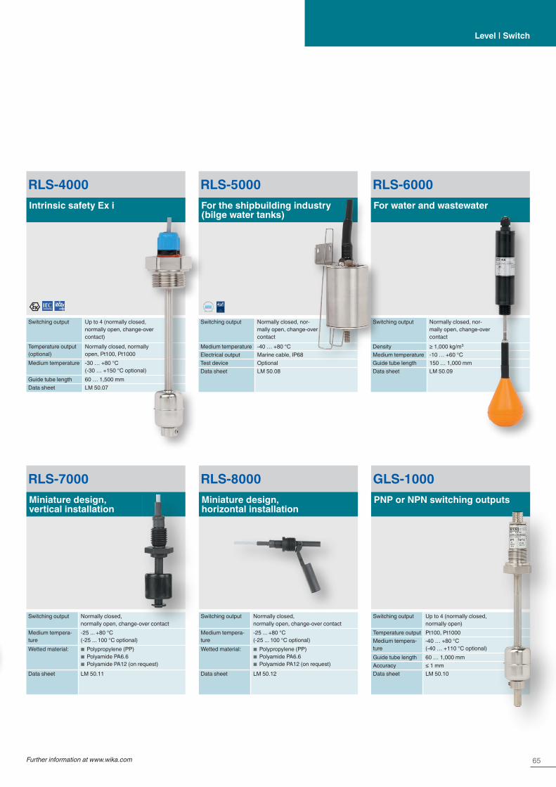
65Further information at www.wika.com
Level | Switch
RLS-7000Miniature design, vertical installation
Switching output Normally closed, normally open, change-over contact
Medium tempera-ture
-25 ... +80 °C(-25 ... 100 °C optional)
Wetted material: ■ Polypropylene (PP) ■ Polyamide PA6.6 ■ Polyamide PA12 (on request)
Data sheet LM 50.11
RLS-8000Miniature design, horizontal installation
Switching output Normally closed, normally open, change-over contact
Medium tempera-ture
-25 ... +80 °C(-25 ... 100 °C optional)
Wetted material: ■ Polypropylene (PP) ■ Polyamide PA6.6 ■ Polyamide PA12 (on request)
Data sheet LM 50.12
GLS-1000PNP or NPN switching outputs
Switching output Up to 4 (normally closed, normally open)
Temperature output Pt100, Pt1000Medium tempera-ture
-40 … +80 °C(-40 … +110 °C optional)
Guide tube length 60 … 1,000 mmAccuracy ≤ 1 mmData sheet LM 50.10
RLS-4000Intrinsic safety Ex i
Switching output Up to 4 (normally closed, normally open, change-over contact)
Temperature output (optional)
Normally closed, normally open, Pt100, Pt1000
Medium temperature -30 … +80 °C(-30 … +150 °C optional)
Guide tube length 60 … 1,500 mmData sheet LM 50.07
RLS-5000For the shipbuilding industry (bilge water tanks)
Switching output Normally closed, nor-mally open, change-over contact
Medium temperature -40 … +80 °CElectrical output Marine cable, IP68Test device OptionalData sheet LM 50.08
RLS-6000For water and wastewater
Switching output Normally closed, nor-mally open, change-over contact
Density ≥ 1,000 kg/m3
Medium temperature -10 … +60 °CGuide tube length 150 … 1,000 mmData sheet LM 50.09
APP ROV EDTYPE
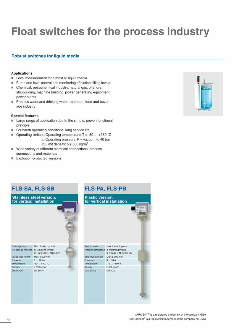
66
Float switches for the process industry
FLS-SA, FLS-SBStainless steel version, for vertical installation
Switch points Max. 8 switch pointsProcess connection ■ Mounting thread
■ Flange DIN, ANSI, ENGuide tube length Max. 6,000 mmPressure 0 … 40 barTemperature -50 … +300 °CDensity ≥ 390 kg/m³Data sheet LM 30.01
FLS-PA, FLS-PBPlastic version, for vertical installation
Switch points Max. 8 switch pointsProcess connection ■ Mounting thread
■ Flange DIN, ANSI, ENGuide tube length Max. 5,000 mmPressure 0 … 3 barTemperature -10 … +100 °CDensity ≥ 400 kg/m³Data sheet LM 30.01
Robust switches for liquid media
Applications � Level measurement for almost all liquid media � Pump and level control and monitoring of distinct filling levels � Chemical, petrochemical industry, natural gas, offshore,
shipbuilding, machine building, power generating equipment, power plants
� Process water and drinking water treatment, food and bever-age industry
Special features � Large range of application due to the simple, proven functional
principle � For harsh operating conditions, long service life � Operating limits: □ Operating temperature: T = -50 … +350 °C
□ Operating pressure: P = vacuum to 40 bar □ Limit density: ρ ≥ 300 kg/m³
� Wide variety of different electrical connections, process connections and materials
� Explosion-protected versions
VARIVENT® is a registered trademark of the company GEABioConnect® is a registered trademark of the company NEUMO

67Further information at www.wika.com
Level | Switch
ELS-SFor lateral mounting with external chamber
External chamber Stainless steelProcess connection Threaded pipe connection GE10-LR
galvanised steelPressure To 6 barTemperature -30 … +300 °CData sheet LM 30.03
ELS-AFor lateral mounting with external chamber
External chamber AluminiumProcess connection Threaded pipe connection GE10-LR
galvanised steelPressure Max. 1 barTemperature -30 … +150 °CData sheet LM 30.03
HLS-SBI Ex iIntrinsically safe stainless steel version for horizontal installation
Process connection ■ Mounting flange: DIN DN 50 … DN 100, PN 6 … 160 EN 1092 DN 50 … DN 100, PN 6 … PN 160 ANSI 2" … 4", class 150 … 900
■ Square flange: DN 80 and DN 92 (other flanges on request)
Pressure 0 ... 100 bar (180 bar on request)Temperature class T2 T3 T4 T5 T6Process temperature 180 °C 160 °C 108 °C 80 °C 65 °CAmbient temperature at case 80 °C
Density 600 kg/m³Material Stainless steel 1.4571Data sheet LM 30.02
HLS-SStainless steel version, for horizontal installation
Process connection Flange DIN, ANSI, ENPressure 0 … 232 barTemperature -196 … +350 °CDensity ≥ 600 kg/m³Material Stainless steel, titaniumData sheet LM 30.02
HLS-PPlastic version, for horizontal installation
Process connection Flange DIN, ANSI, ENPressure 0 … 3 barTemperature -10 … +80 °CDensity ≥ 750 kg/m³Material PPData sheet LM 30.02
HLS-M1, HLS-M2Plastic or stainless steel version, with cable outlet
Process connection ■ ½" NPT (installation in the tank from outside)
■ G ¼" (installation from inside, PP version)
■ G E" (installation from inside, stainless steel version)
Pressure ■ HLS-M1: 1 bar ■ HLS-M2: 5 bar
Temperature ■ HLS-M1: -10 … +80 °C ■ HLS-M2: -40 … +120 °C
Material ■ HLS-M1: PP ■ HLS-M2: Stainless steel 1.4301
Electrical connection
■ HLS-M1: Cable ■ HLS-M2: Cable or connector
Data sheet LM 30.06
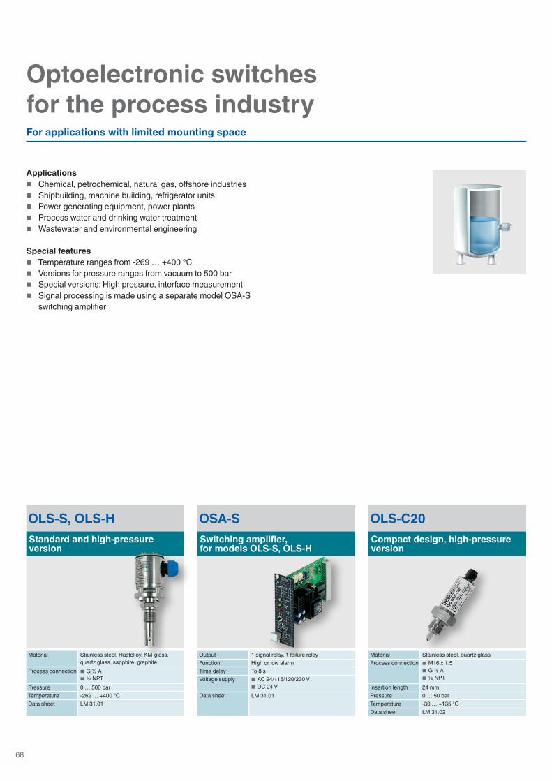
68
Optoelectronic switches for the process industry
OLS-S, OLS-HStandard and high-pressure version
Material Stainless steel, Hastelloy, KM-glass, quartz glass, sapphire, graphite
Process connection ■ G ½ A ■ ½ NPT
Pressure 0 … 500 barTemperature -269 … +400 °CData sheet LM 31.01
OSA-SSwitching amplifier, for models OLS-S, OLS-H
Output 1 signal relay, 1 failure relayFunction High or low alarmTime delay To 8 sVoltage supply ■ AC 24/115/120/230 V
■ DC 24 VData sheet LM 31.01
OLS-C20Compact design, high-pressure version
Material Stainless steel, quartz glassProcess connection ■ M16 x 1.5
■ G ½ A ■ ½ NPT
Insertion length 24 mmPressure 0 … 50 barTemperature -30 … +135 °CData sheet LM 31.02
For applications with limited mounting space
Applications � Chemical, petrochemical, natural gas, offshore industries � Shipbuilding, machine building, refrigerator units � Power generating equipment, power plants � Process water and drinking water treatment � Wastewater and environmental engineering
Special features � Temperature ranges from -269 … +400 °C � Versions for pressure ranges from vacuum to 500 bar � Special versions: High pressure, interface measurement � Signal processing is made using a separate model OSA-S
switching amplifier

69Further information at www.wika.com
Level | Switch
Optoelectronic level switches for industrial applications
Applications � Limit detection of liquids � Machine tools � Hydraulics � Machine building � Water technology
Optoelectronic limit level switches – for general applications in machine building
Special features � For liquids such as oils, water, distilled water, aqueous media � Compact design � Mounting position as required � Accuracy ±2 mm � No moving components
OLS-C01Standard version
Material Stainless steel, borosilicate glassProcess connection G ⅜", G ½" or M12 x 1Pressure Max. 25 barTemperature -30 … +100 °CSwitching output 1 x PNPData sheet LM 31.31
OLS-C05High-temperature version
Material Stainless steel, borosilicate glassProcess connection G ½"Pressure Max. 25 barTemperature -40 … +170 °CSwitching output 1 x PNPData sheet LM 31.33
OLS-C02With selectable switch length
Material Stainless steel, borosilicate glassProcess connection G ½"Pressure Max. 25 barTemperature -30 … +100 °CSwitch length 65 … 1,500 mmSwitching output 1 x PNPData sheet LM 31.32

70
Optoelectronic limit level switches – application specialists
OLS-C51Intrinsic safety Ex i
Material Stainless steel, borosilicate glassProcess connection G ½"Pressure Max. 40 barTemperature -30 … +135 °COutput signal 4 … 20 mA low/high as switching outputData sheet LM 31.04
OLS-C04For refrigeration technology
Material Steel, nickel-plated; melted glassProcess connection G ½", ½" NPTPressure Max. 40 barTemperature -40 … +100 °CSwitching output 1 x PNPData sheet LM 31.34
OLS-5200For the shipbuilding industry
Material Stainless steel, borosilicate glassProcess connection Male thread G ½" or M18 x 1.5Pressure Max. 25 barTemperature -40 … +130 °CSwitching output 1 x PNPVibration resistance 10 … 5,000 Hz, 0 … 60 gData sheet LM 31.06
Optoelectronic level switches for industrial applications
Level | Switch
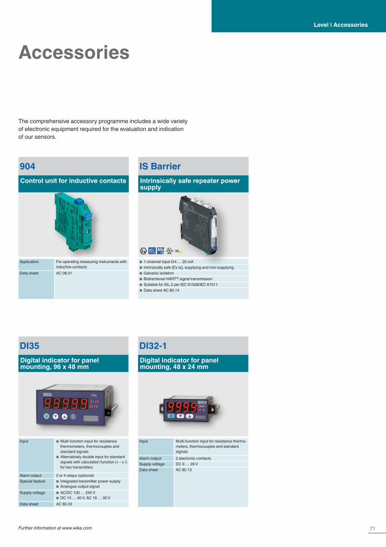
71Further information at www.wika.com
Accessories
IS BarrierIntrinsically safe repeater power supply
■ 1-channel input 0/4 … 20 mA ■ Intrinsically safe [Ex ia], supplying and non-supplying ■ Galvanic isolation ■ Bidirectional HART® signal transmission ■ Suitable for SIL 2 per IEC 61508/IEC 61511 ■ Data sheet AC 80.14
The comprehensive accessory programme includes a wide variety of electronic equipment required for the evaluation and indication of our sensors.
DI32-1Digital indicator for panel mounting, 48 x 24 mm
Input Multi-function input for resistance thermo-meters, thermocouples and standard signals
Alarm output 2 electronic contactsSupply voltage DC 9 … 28 VData sheet AC 80.13
DI35Digital indicator for panel mounting, 96 x 48 mm
Input ■ Multi-function input for resistance thermometers, thermocouples and standard signals
■ Alternatively double input for standard signals with calculation function (+ - x /) for two transmitters
Alarm output 2 or 4 relays (optional)Special feature ■ Integrated transmitter power supply
■ Analogue output signalSupply voltage ■ AC/DC 100 … 240 V
■ DC 10 … 40 V, AC 18 … 30 VData sheet AC 80.03
Level | Accessories
904Control unit for inductive contacts
Application For operating measuring instruments with inductive contacts
Data sheet AC 08.01
SILIEC 61508 / IEC 61511

72
Compression force transducers
Compression force transducers are designed for determining compression forces and are suitable for static and dynamic measurements in the direct force flow. WIKA force transducers are manufactured from stainless steel and other high-quality materials, are robust and are notable for their reliability and high quality even in complex applications. Our compression force transducers are available in different rated loads.
They cover a wide range of application areas: For instance, these force sensors are employed in machine building or in the automa-tion of plants to determine the pressing and joining forces, as well as for detecting weight in many industrial applications. You can select the pertinent technical and regional approvals as options.
F1211Compression force transducer to 1,000 kN
Rated force Fnom 0 … 1 to 0 … 1,000 kNRelative linearity error ±0.3 % Fnom (≤ ±0.1 % Fnom optional)Output signal 2 mV/V IP67Data sheet FO 51.10
F1222Miniature compression force transducer from 10 N
Rated force Fnom 0 … 10 N to 0 … 5,000 NRelative linearity error ±1 % Fnom
Output signal ■ 1.0 mV/V (10 N) ■ 2.0 mV/V (20 N to 5 kN)
Ingress protection IP65Data sheet FO 51.11
F1224Miniature compression force transducer from 1 kN
Rated force Fnom 0 … 1 to 0 … 500 kNRelative linearity error ±1.0 % Fnom
Output signal 1.5 mV/VIngress protection IP65Data sheet FO 51.12
F1119Hydraulic compression force transducer, clamping force test instrument to 120 kN
Measuring range 0 … 320 N to 0 … 120 kNRelative linearity error
■ Analogue ≤ ±1.6 % Fnom ■ Digital ≤ ±0.5 % Fnom
Output signal ■ Analogue: Display ■ Digital: 4 … 20 mA, 3-wire
Ingress protection ■ Analogue: IP65 ■ Digital: IP67
Data sheet FO 52.10
F1136Hydraulic compression force transducer, clamping force test instrument to 500 kN
Measuring range 0 … 1.2 kN to 0 … 500 kNRelative linearity error
■ Analogue ≤ ±1.6 % Fnom ■ Digital ≤ ±0.5 % Fnom
Output signal ■ Analogue: Display ■ Digital: 4 … 20 mA, 3-wire
Ingress protection ■ Analogue: IP65 ■ Digital: IP67
Data sheet FO 52.27

73Further information at www.wika.com
Force | Force transducers
Tension/compression force transducer
F2226Tension/compression force trans-ducer, male thread to 3,300 kN
Rated force Fnom 0 …10 kN to 0 … 3,300 kNRelative linearity error
■ ≤ ±0.15 % Fnom (≤ 200 kN) ■ ≤ ±0.20 % Fnom (> 200 kN)
Output signal 2 mV/VIngress protection IP66Data sheet FO 51.51
F2220Miniature tension/compression force transducer, from 10 N
Rated force Fnom 0 … 10 N to 0 … 5,000 NRelative linearity error ±0.5 % Fnom
Output signal 2 mV/V (10 N 1.5 mV/V)Ingress protection IP65Data sheet FO 51.16
F2221Tension/compression force transducer from 10 N
Rated force Fnom 0 … 10 N to 0 … 50,000 NRelative linearity error
■ ±0,15 % Fnom bis 1.000 N ■ ±0,20 % Fnom ab 2.000 N
Output signal 2 mV/V (to 10 N 1.5 mV/V)Ingress protection IP65Data sheet FO 51.26
F2222Tension/compression force transducer up to 2,200 kN
Rated force Fnom 0 … 22 N up to 0 … 2,200 kNRelative linearity error ±0.1 % Fnom
Output signal ■ ≤ 25 lbs: 2 mV/V ■ > 50 lbs: 3 mV/V
Ingress protection IP66Data sheet FO 51.29
WIKA offers tension/compression force transducers in different designs and versions. They are available in miniature designs, as traditional s-type, as transducers with different thread forms or as low-profile force transducers. Transducers in miniature design are used for small mounting spaces and also for detecting small forces. The s-type with female thread, which is very well suited for this purpose, features a particularly high accuracy and is used
in rated load ranges of up to 50 kN. For measuring high forces, tension/compression force transducers in compact design are the first choice. For low-profile force transducers, the force is transmit-ted via the centrical female thread. They are highly dynamic and possess a high fatigue strength.
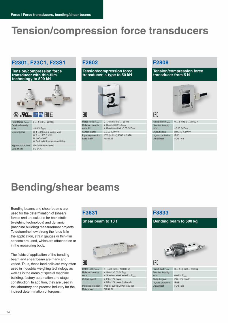
74
Force | Force transducers, bending/shear beams
Tension/compression force transducers
F2802Tension/compression force transducer, s-type to 50 kN
Rated force Fnom 0 … 0.5 kN to 0 … 50 kNRelative linearity error dlin
■ Steel ±0.03 % Fnom ■ Stainless steel ±0.05 % Fnom
Output signal 2.0 ±5 % mV/VIngress protection IP65 (< 5 kN), IP67 (≥ 5 kN)Data sheet FO 51.48
F2301, F23C1, F23S1Tension/compression force transducer with thin-film technology to 500 kN
Rated force Fnom 0 … 1 to 0 … 500 kNRelative linearity error ±0.5 % Fnom
Output signal ■ 4 … 20 mA, 2-wire/3-wire ■ 0 … 10 V, 3-wire ■ CANopen®
■ Redundant versions available
Ingress protection IP67 (IP69k optional)Data sheet FO 51.17
F2808Tension/compression force transducer from 5 N
Rated force Fnom 0 … 5 N to 0 … 2,000 NRelative linearity error ±0.15 % Fnom
Output signal 2.0 ±10 % mV/VIngress protection IP66Data sheet FO 51.68
F3831Shear beam to 10 t
Rated load Fnom 0 … 500 to 0 … 10,000 kgRelative linearity error
■ Steel: ±0.03 % Fnom ■ Stainless steel: ±0.05 % Fnom
Output signal ■ 2.0 ±1 % mV/V ■ 3.0 ±1 % mV/V (optional)
Ingress protection IP65 (< 500 kg), IP67 (500 kg)Data sheet FO 51.21
F3833Bending beam to 500 kg
Rated load Fnom 0 … 5 kg to 0 … 500 kgRelative linearity error 0.02 % Fnom
Output signal 2.0 ±1 % mV/VIngress protection IP68Data sheet FO 51.22
Bending/shear beams
Bending beams and shear beams are used for the determination of (shear) forces and are suitable for both static (weighing technology) and dynamic (machine building) measurement projects. To determine how strong the force is in the application, strain gauges or thin-film sensors are used, which are attached on or in the measuring body.
The fields of application of the bending beam and shear beam are many and varied. Thus, these load cells are very often used in industrial weighing technology as well as in the areas of special machine building, factory automation and stage construction. In addition, they are used in the laboratory and process industry for the indirect determination of torques.
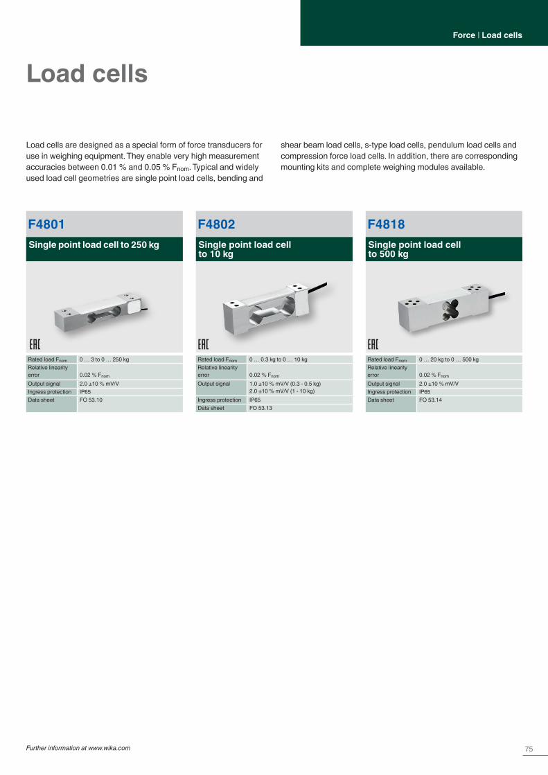
75Further information at www.wika.com
Force | Load cells
Load cells
F4818Single point load cell to 500 kg
Rated load Fnom 0 … 20 kg to 0 … 500 kgRelative linearity error 0.02 % Fnom
Output signal 2.0 ±10 % mV/VIngress protection IP65Data sheet FO 53.14
F4801Single point load cell to 250 kg
Rated load Fnom 0 … 3 to 0 … 250 kgRelative linearity error 0.02 % Fnom
Output signal 2.0 ±10 % mV/VIngress protection IP65Data sheet FO 53.10
F4802Single point load cell to 10 kg
Rated load Fnom 0 … 0.3 kg to 0 … 10 kgRelative linearity error 0.02 % Fnom
Output signal 1.0 ±10 % mV/V (0.3 - 0.5 kg)2.0 ±10 % mV/V (1 - 10 kg)
Ingress protection IP65Data sheet FO 53.13
Load cells are designed as a special form of force transducers for use in weighing equipment. They enable very high measurement accuracies between 0.01 % and 0.05 % Fnom. Typical and widely used load cell geometries are single point load cells, bending and
shear beam load cells, s-type load cells, pendulum load cells and compression force load cells. In addition, there are corresponding mounting kits and complete weighing modules available.

76
Load pinsForce | Load pins
F5301, F53C1Load pin with thin-film technology to 200 kN
Rated force Fnom 0 … 5 kN to 0 … 200 kNRelative linearity error ±1 % Fnom/±1.5 % Fnom/±2 % Fnom
Output signal ■ 4 … 20 mA, 2-wire/3-wire ■ 0 … 10 V, 3-wire ■ CANopen® redundant versions available
Ingress protection IP67Data sheet FO 51.18
F5308, F53C8, F53S8Load pin, heavy-duty version, with thin-film technology from 10 kN
Rated force Fnom From 10 kNRelative linearity error ±1 % Fnom/±1.5 % Fnom
Output signal ■ 4 … 20 mA, 2-wire/3-wire ■ 0 … 10 V, 3-wire ■ CANopen® redundant versions available
Ingress protection IP67, IP69k (optional)Data sheet FO 51.43
Load pins represent one of the most important components for measuring forces. Existing retention bolts can easily be replaced by these products in existing applications. The application areas range from construction machinery and cranes to stage con-struction. These force transducers are often used by designers, because, due to their design, they can be directly integrated into the force flow, without taking up space.
Since the design requirements for the use of load pins are very individual, the exact layout is important. With WIKA, you will have specialists by your side who already have lots of experience in force measurement.
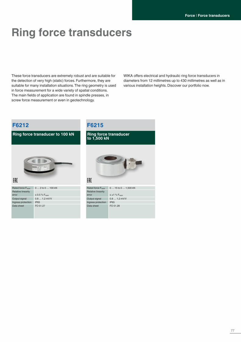
77
Force | Force transducers
These force transducers are extremely robust and are suitable for the detection of very high (static) forces. Furthermore, they are suitable for many installation situations. The ring geometry is used in force measurement for a wide variety of spatial conditions.The main fields of application are found in spindle presses, in screw force measurement or even in geotechnology.
WIKA offers electrical and hydraulic ring force transducers in diameters from 12 millimetres up to 430 millimetres as well as in various installation heights. Discover our portfolio now.
Ring force transducers
F6212Ring force transducer to 100 kN
Rated force Fnom 0 … 2 to 0 … 100 kNRelative linearity error ≤ 0.5 % Fnom
Output signal 0.8 … 1.2 mV/VIngress protection IP65Data sheet FO 51.27
F6215Ring force transducer to 1,500 kN
Rated force Fnom 0 … 15 to 0 … 1,500 kNRelative linearity error ≤ ±1 % Fnom
Output signal 0.8 … 1.2 mV/VIngress protection IP65Data sheet FO 51.28
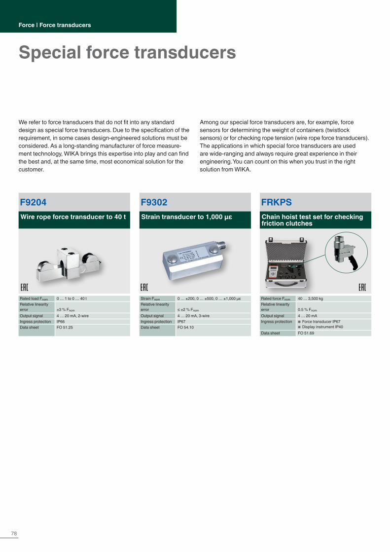
78
Force | Force transducers
Special force transducers
F9204Wire rope force transducer to 40 t
Rated load Fnom 0 … 1 to 0 … 40 tRelative linearity error ±3 % Fnom
Output signal 4 … 20 mA, 2-wireIngress protection IP66Data sheet FO 51.25
FRKPSChain hoist test set for checking friction clutches
Rated force Fnom 40 … 3,500 kgRelative linearity error 0.5 % Fnom
Output signal 4 … 20 mAIngress protection ■ Force transducer IP67
■ Display instrument IP40Data sheet FO 51.69
F9302Strain transducer to 1,000 µε
Strain Fnom 0 … ±200, 0 … ±500, 0 … ±1,000 µεRelative linearity error ≤ ±2 % Fnom
Output signal 4 … 20 mA, 3-wireIngress protection IP67Data sheet FO 54.10
We refer to force transducers that do not fit into any standard design as special force transducers. Due to the specification of the requirement, in some cases design-engineered solutions must be considered. As a long-standing manufacturer of force measure-ment technology, WIKA brings this expertise into play and can find the best and, at the same time, most economical solution for the customer.
Among our special force transducers are, for example, force sensors for determining the weight of containers (twistlock sensors) or for checking rope tension (wire rope force transducers). The applications in which special force transducers are used are wide-ranging and always require great experience in their engineering. You can count on this when you trust in the right solution from WIKA.

79Further information at www.wika.com
Force | Electronics
Electronics
EZE09Analogue cable amplifier for strain gauge resistance thermometry bridges
Input Resistance thermometry bridge, 4- or 6-wire
Output 0 /4 … 20 mA, DC 0 … 10 VSpecial feature ■ High accuracy
■ Cable length between amplifier and read-out unit: up to 100 m are possible
■ Compact design ■ Ingress protection IP67
Supply voltage DC 12 … 28 VData sheet AC 50.09
ELMS1Safety electronics PLe in accordance with DIN EN ISO 13849-1
Input ■ 8 safe 4 … 20 mA analogue inputs ■ 8 safe digital inputs ■ Fieldbus: Optionally PROFIBUS® PA, ProfiNet®, EtherCat® and CANopen®
Output ■ 2 safe relay outputs ■ 6 safe, positive-switching semiconduc-tor outputs
■ Fieldbus: Optionally PROFIBUS® PA, ProfiNet®, EtherCat® and CANopen®
Special feature ■ Certified safety electronics, certified in accordance with DIN EN ISO 13849-1, PLe
■ Certified system solution incl. force measurement, certified in accordance with DIN EN 13849-1 cat. 3, PLd
■ Complex functionality, easy to configure via PC
■ Complete system available in a control cabinet
Supply voltage DC 24 VData sheet AC 50.06
EGS80Digital limit switch
Input ■ 0/4 … 20 mAOutput ■ Two potential-free relay contacts
(change-over) with status LED ■ One freely programmable analogue output (0 … 20 mA)
Special feature ■ Galvanic isolation, line break (LB) and short-circuit (SC) monitoring
■ Easy setting of extensive functions on the instrument or via PC software
■ Up to SIL 2 in accordance with IEC 61508
Supply voltage ■ DC 20 … 90 V ■ AC 48 … 253 V
Data sheet AC 50.01
Many force measurement applications can be complemented by electronic components. To ensure that all system-relevant com-ponents come from a single source, WIKA continuously expands its product range with useful electronics. WIKA offers controllers, amplifiers, limit switches, hand-held measuring instruments, digital indicators and electronic accessories that ensure trouble-free
operation. With the help of electronics matched to the measuring components, set limit values are maintained and checked with the reading instruments. Amplifiers are available with analogue and digital output signals. The LED display or LCD are available with 4 or 6 digits.
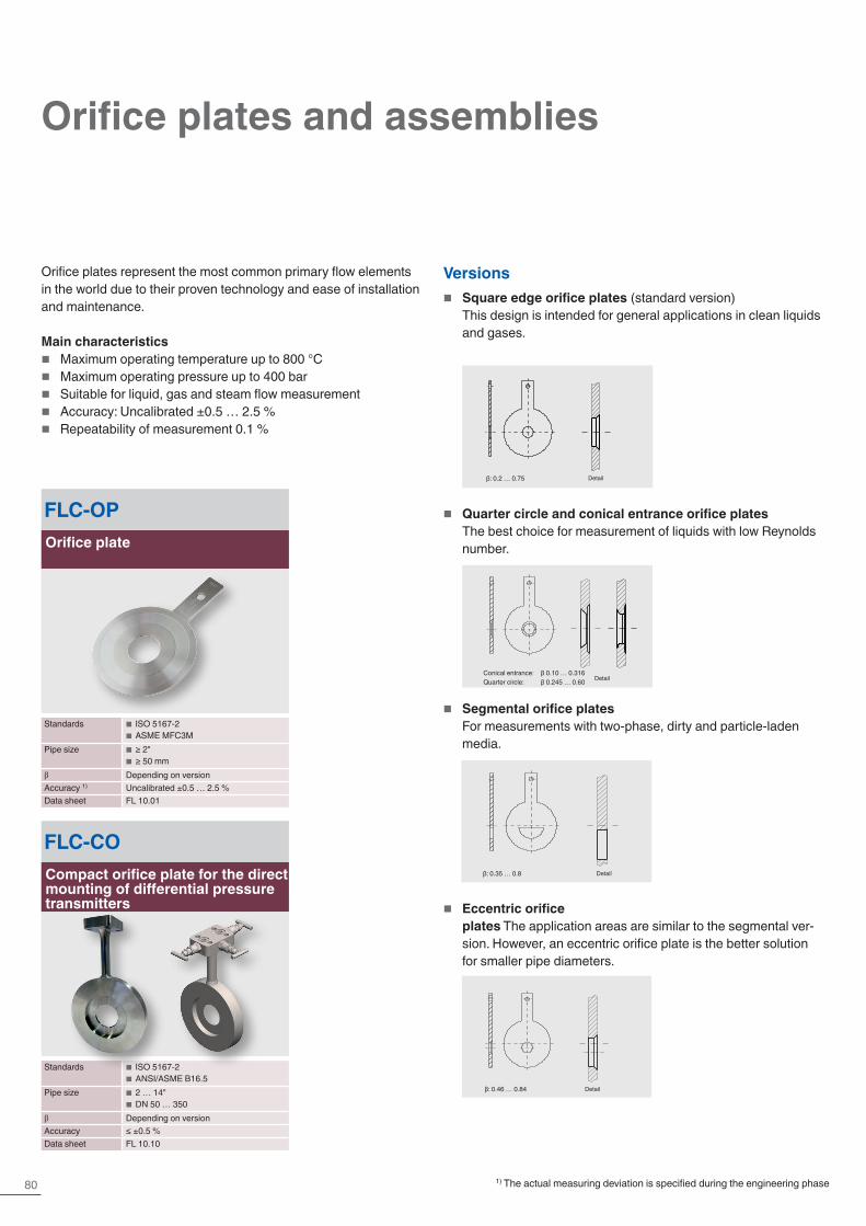
80
Orifice plates represent the most common primary flow elements in the world due to their proven technology and ease of installation and maintenance.
Main characteristics � Maximum operating temperature up to 800 °C � Maximum operating pressure up to 400 bar � Suitable for liquid, gas and steam flow measurement � Accuracy: Uncalibrated ±0.5 … 2.5 % � Repeatability of measurement 0.1 %
FLC-OPOrifice plate
Standards ■ ISO 5167-2 ■ ASME MFC3M
Pipe size ■ ≥ 2" ■ ≥ 50 mm
β Depending on versionAccuracy 1) Uncalibrated ±0.5 … 2.5 %Data sheet FL 10.01
FLC-COCompact orifice plate for the direct mounting of differential pressure transmitters
Standards ■ ISO 5167-2 ■ ANSI/ASME B16.5
Pipe size ■ 2 … 14" ■ DN 50 … 350
β Depending on versionAccuracy ≤ ±0.5 %Data sheet FL 10.10
Versions � Square edge orifice plates (standard version)
This design is intended for general applications in clean liquids and gases.
� Quarter circle and conical entrance orifice plates The best choice for measurement of liquids with low Reynolds number.
� Segmental orifice plates For measurements with two-phase, dirty and particle-laden media.
� Eccentric orifice plates The application areas are similar to the segmental ver-sion. However, an eccentric orifice plate is the better solution for smaller pipe diameters.
Detail
Detail
Detail
Detail
β: 0.2 … 0.75
Conical entrance: β 0.10 … 0.316Quarter circle: β 0.245 … 0.60
β: 0.35 … 0.8
β: 0.46 … 0.84
1) The actual measuring deviation is specified during the engineering phase
Orifice plates and assemblies

81
FLC-FLOrifice flanges
Standards ■ ISO 5167-2 ■ ASME B 16.36
Pipe size ■ ≥ 2" ■ ≥ 50 mm
β Depending on versionAccuracy 1) Uncalibrated ±0.5 … 2.5 %Data sheet FL 10.12
FLC-ACAnnular chambers
Standards ISO 5167-2Pipe size ■ ≥ 2"
■ ≥ 50 mmβ Depending on versionAccuracy 1) Uncalibrated ±0.5 … 2.5 %Data sheet FL 10.13
Orifice flanges are intended for use instead of standard pipe flanges when an orifice plate or flow nozzle must be installed.Pairs of pressure tappings are machined into the orifice flange, making separate orifice carriers or tappings in the pipe wall unnecessary.
Main characteristics � Wide range of materials available � The number and type of pressure tapping (flange tap or corner
tap) can be manufactured to customer requirements � Special assemblies can be designed on request
Annular chambers are designed to be mounted between standard pipe flanges. Versions are available to suit all common flange standards, including DIN and ANSI B16.5.
Main characteristics � Standard material is 316/316L stainless steel, but a wide range
of alternative materials is available � Sealings are included in the scope of delivery (as standard,
4.4 mm thick spiral-wound sealing 316/graphite filler, unless requested otherwise)
Flow | Primary flow elements
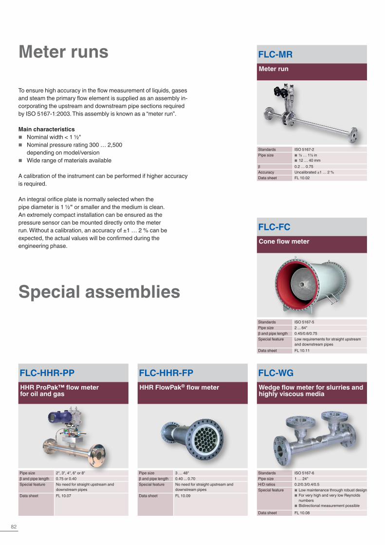
82
Meter runs
Special assemblies
FLC-MRMeter run
Standards ISO 5167-2Pipe size ■ ½ … 1½ in
■ 12 … 40 mmβ 0.2 … 0.75Accuracy Uncalibrated ±1 … 2 %Data sheet FL 10.02
To ensure high accuracy in the flow measurement of liquids, gases and steam the primary flow element is supplied as an assembly in-corporating the upstream and downstream pipe sections required by ISO 5167-1:2003. This assembly is known as a “meter run”.
Main characteristics � Nominal width < 1 ½" � Nominal pressure rating 300 … 2,500
depending on model/version � Wide range of materials available
A calibration of the instrument can be performed if higher accuracy is required.
An integral orifice plate is normally selected when the pipe diameter is 1 ½" or smaller and the medium is clean. An extremely compact installation can be ensured as the pressure sensor can be mounted directly onto the meter run. Without a calibration, an accuracy of ±1 … 2 % can be expected, the actual values will be confirmed during the engineering phase.
FLC-HHR-PPHHR ProPak™ flow meter for oil and gas
Pipe size 2", 3", 4", 6" or 8"β and pipe length 0.75 or 0.40Special feature No need for straight upstream and
downstream pipesData sheet FL 10.07
FLC-HHR-FPHHR FlowPak® flow meter
Pipe size 3 … 48"β and pipe length 0.40 ... 0.70Special feature No need for straight upstream and
downstream pipesData sheet FL 10.09
FLC-WGWedge flow meter for slurries and highly viscous media
Standards ISO 5167-6Pipe size 1 … 24"H/D ratios 0.2/0.3/0.4/0.5Special feature ■ Low maintenance through robust design
■ For very high and very low Reynolds numbers
■ Bidirectional measurement possible
Data sheet FL 10.08
FLC-FCCone flow meter
Standards ISO 5167-5Pipe size 2 ... 64"β and pipe length 0.45/0.6/0.75Special feature Low requirements for straight upstream
and downstream pipesData sheet FL 10.11

83
Flow | Primary flow elements
Flow nozzles
A flow nozzle consists of a convergent section with a rounded profile and a cylindrical throat. This design is generally selected for steam flow measurement at high velocity.
To reduce pressure loss an axisymmetric solution, called a Venturi nozzle, can be offered. It combines the standard features of a flow nozzle with a divergent section.
Main characteristics � Suitable for liquid, gas and steam flow measurement � Optimum solution for measuring the flow of steam � Accuracy: Uncalibrated ±0.8 … 2 % � Repeatability of measurement 0.1 % � Lower pressure loss compared to orifice plate family.
FLC-FN-FLNFlow nozzle for flange assembly
Pipe size ■ ≥ 2 in ■ ≥ 50 mm
β 0.3 … 0.8Accuracy 1) Uncalibrated ±0.8 %Data sheet FL 10.03
FLC-FN-PIPFlow nozzle for in-pipe installation
Pipe size ■ ≥ 2 in ■ ≥ 50 mm
β 0.2 … 0.8Accuracy 1) Uncalibrated ≤ ±1 %Data sheet FL 10.03
FLC-VNVenturi nozzle
Pipe size ■ ≥ 2 in ■ ≥ 50 mm
β 0.316 ... 0.775Accuracy 1) Uncalibrated ±1 %Data sheet FL 10.03
Flow nozzle for in-pipe installation
Venturi nozzle
1) The actual measuring deviation is specified during the engineering phase
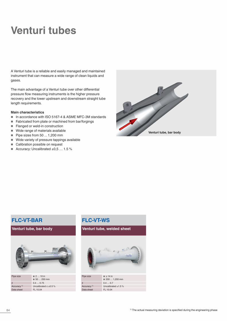
84
Venturi tubes
A Venturi tube is a reliable and easily managed and maintained instrument that can measure a wide range of clean liquids and gases.
The main advantage of a Venturi tube over other differential pressure flow measuring instruments is the higher pressure recovery and the lower upstream and downstream straight tube length requirements.
Main characteristics � In accordance with ISO 5167-4 & ASME MFC-3M standards � Fabricated from plate or machined from bar/forgings � Flanged or weld-in construction � Wide range of materials available � Pipe sizes from 50 ... 1,200 mm � Wide variety of pressure tappings available � Calibration possible on request � Accuracy: Uncalibrated ±0,5 … 1.5 %
FLC-VT-BARVenturi tube, bar body
Pipe size ■ 2 … 10 in ■ 50 … 250 mm
β 0.4 … 0.75Accuracy 1) Uncalibrated ≤ ±0.5 %Data sheet FL 10.04
FLC-VT-WSVenturi tube, welded sheet
Pipe size ■ ≥ 14 in ■ 200 … 1,200 mm
β 0.4 … 0.7Accuracy 1) Uncalibrated ±1.5 %Data sheet FL 10.04
Venturi tube, bar body
1) The actual measuring deviation is specified during the engineering phase

85
FloTec (averaging pitot tubes)
FloTec (a multi-port, averaging pitot tube) measures the difference between the static pressure and the dynamic pressure of the media in the pipe. The volumetric flow is calculated from that dif-ference using Bernoulli’s principle and taking into account the pipe inner diameter. Using four dynamic ports this instrument is able to evaluate a better velocity profile inside the pipe. This ensures a higher accuracy in the flow measurement.
Main characteristics � Low installation costs � Long-term accuracy � Minimal permanent pressure loss � Fixed and extractable versions available
Vortex generation
Vortex shedding frequencyDepending on the inner diameter, the medium characteristics and the Reynolds number, a vortex will be generated around the pitot tube. A support mounted on the opposite side of the pipe can be supplied should the natural frequency of the pitot coincide with the vortex shedding frequency. The necessity test is performed during the design phase.
FLC-APT-FFloTec, fixed
Pipe size ■ ≥ 3 in ■ ≥ 50 … 1,800 mm
Accuracy Uncalibrated ±1 %Data sheet FL 10.05
FLC-APT-EFloTec, extractable
Pipe size ■ ≥ 3 in ■ ≥ 50 … 1,800 mm
Accuracy Uncalibrated ±1 %Data sheet FL 10.05
Flow | Primary flow elements
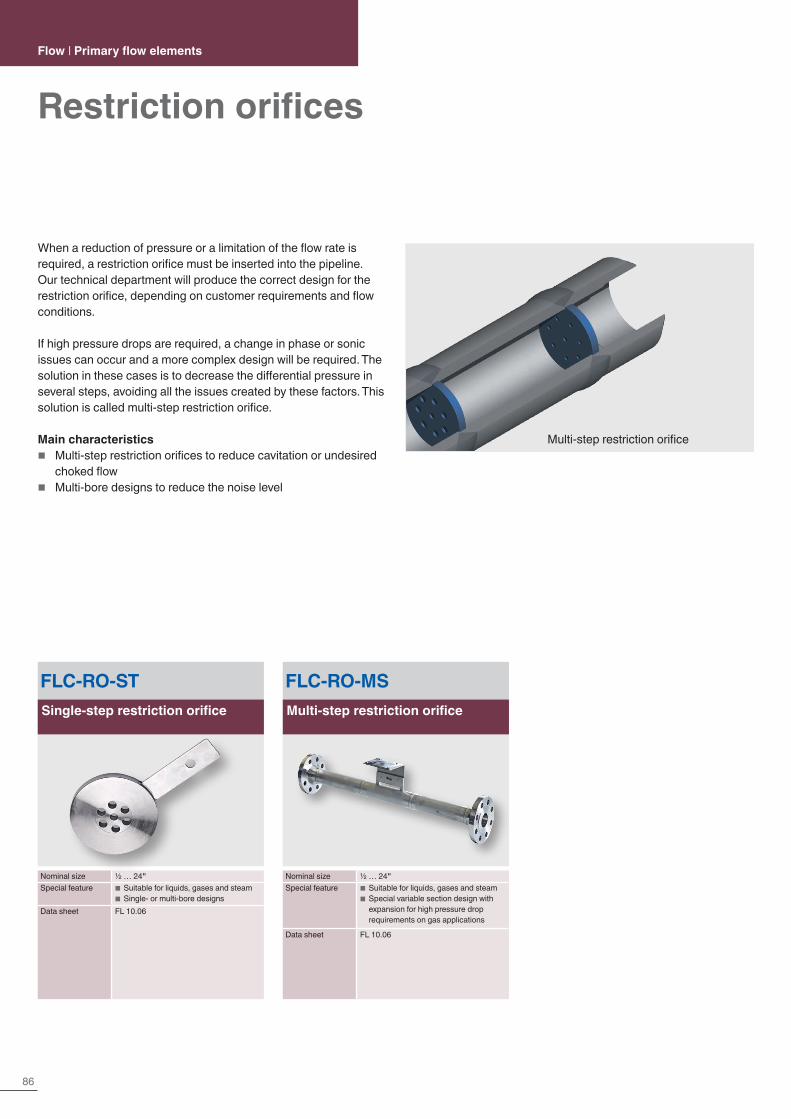
86
FLC-RO-STSingle-step restriction orifice
Nominal size ½ … 24"Special feature ■ Suitable for liquids, gases and steam
■ Single- or multi-bore designsData sheet FL 10.06
FLC-RO-MSMulti-step restriction orifice
Nominal size ½ … 24"Special feature ■ Suitable for liquids, gases and steam
■ Special variable section design with expansion for high pressure drop requirements on gas applications
Data sheet FL 10.06
Multi-step restriction orifice
When a reduction of pressure or a limitation of the flow rate is required, a restriction orifice must be inserted into the pipeline. Our technical department will produce the correct design for the restriction orifice, depending on customer requirements and flow conditions.
If high pressure drops are required, a change in phase or sonic issues can occur and a more complex design will be required. The solution in these cases is to decrease the differential pressure in several steps, avoiding all the issues created by these factors. This solution is called multi-step restriction orifice.
Main characteristics � Multi-step restriction orifices to reduce cavitation or undesired
choked flow � Multi-bore designs to reduce the noise level
Restriction orificesFlow | Primary flow elements
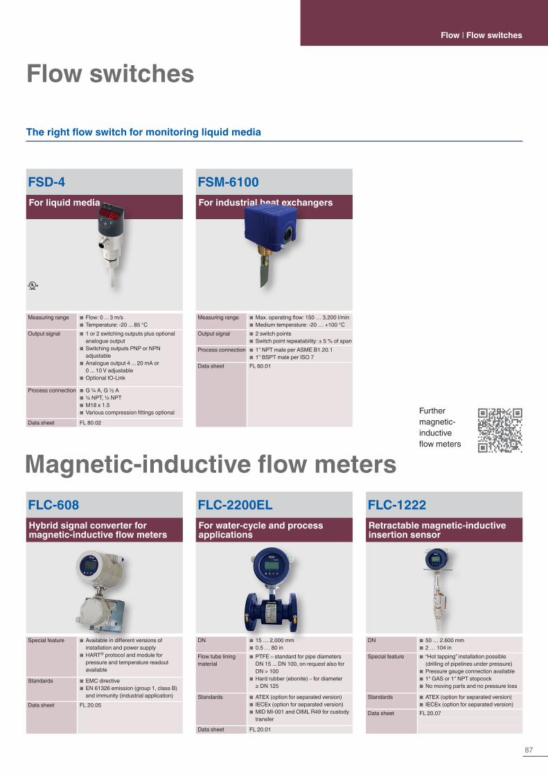
87
The right flow switch for monitoring liquid media
Flow switchesFlow | Flow switches
FSM-6100For industrial heat exchangers
Measuring range ■ Max. operating flow: 150 … 3,200 l/min ■ Medium temperature: -20 … +100 °C
Output signal ■ 2 switch points ■ Switch point repeatability: ± 5 % of span
Process connection ■ 1" NPT male per ASME B1.20.1 ■ 1" BSPT male per ISO 7
Data sheet FL 60.01
FSD-4For liquid media
Measuring range ■ Flow: 0 ... 3 m/s ■ Temperature: -20 ... 85 °C
Output signal ■ 1 or 2 switching outputs plus optional analogue output
■ Switching outputs PNP or NPN adjustable
■ Analogue output 4 ... 20 mA or 0 ... 10 V adjustable
■ Optional IO-Link
Process connection ■ G ¼ A, G ½ A ■ ¼ NPT, ½ NPT ■ M18 x 1.5 ■ Various compression fittings optional
Data sheet FL 80.02
Magnetic-inductive flow metersFLC-608Hybrid signal converter for magnetic-inductive flow meters
Special feature ■ Available in different versions of installation and power supply
■ HART® protocol and module for pressure and temperature readout available
Standards ■ EMC directive ■ EN 61326 emission (group 1, class B) and immunity (industrial application)
Data sheet FL 20.05
FLC-2200ELFor water-cycle and process applications
DN ■ 15 … 2,000 mm ■ 0.5 … 80 in
Flow tube lining material
■ PTFE – standard for pipe diameters DN 15 ... DN 100, on request also for DN > 100
■ Hard rubber (ebonite) – for diameter ≥ DN 125
Standards ■ ATEX (option for separated version) ■ IECEx (option for separated version) ■ MID MI-001 and OIML R49 for custody transfer
Data sheet FL 20.01
FLC-1222Retractable magnetic-inductive insertion sensor
DN ■ 50 … 2.600 mm ■ 2 … 104 in
Special feature ■ “Hot tapping” installation possible (drilling of pipelines under pressure)
■ Pressure gauge connection available ■ 1" GAS or 1" NPT stopcock ■ No moving parts and no pressure loss
Standards ■ ATEX (option for separated version) ■ IECEx (option for separated version)
Data sheet FL 20.07
Further magnetic-inductive flow meters
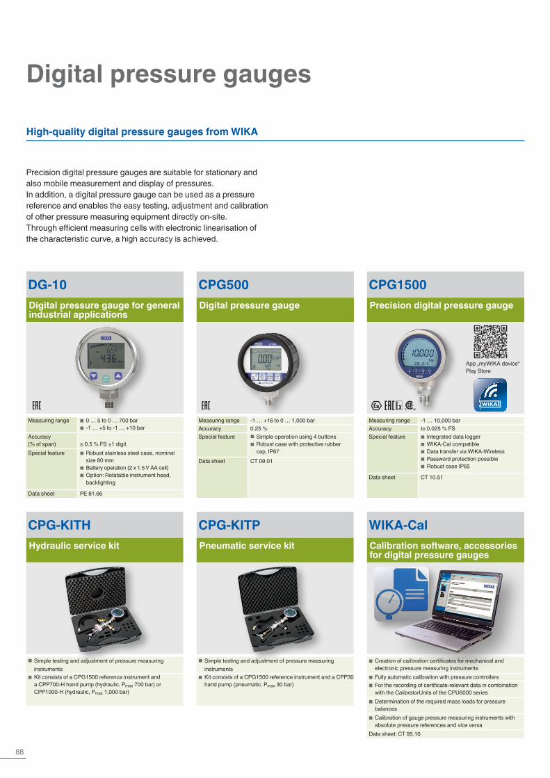
88
CPG-KITHHydraulic service kit
■ Simple testing and adjustment of pressure measuring instruments
■ Kit consists of a CPG1500 reference instrument and a CPP700-H hand pump (hydraulic, Pmax 700 bar) or CPP1000-H (hydraulic, Pmax 1,000 bar)
CPG-KITPPneumatic service kit
■ Simple testing and adjustment of pressure measuring instruments
■ Kit consists of a CPG1500 reference instrument and a CPP30 hand pump (pneumatic, Pmax 30 bar)
Digital pressure gauges
Precision digital pressure gauges are suitable for stationary and also mobile measurement and display of pressures.In addition, a digital pressure gauge can be used as a pressure reference and enables the easy testing, adjustment and calibration of other pressure measuring equipment directly on-site.Through efficient measuring cells with electronic linearisation of the characteristic curve, a high accuracy is achieved.
High-quality digital pressure gauges from WIKA
CPG1500Precision digital pressure gauge
Measuring range -1 … 10,000 barAccuracy to 0.025 % FSSpecial feature ■ Integrated data logger
■ WIKA-Cal compatible ■ Data transfer via WIKA-Wireless ■ Password protection possible ■ Robust case IP65
Data sheet CT 10.51
CPG500Digital pressure gauge
Measuring range -1 … +16 to 0 … 1,000 barAccuracy 0.25 %Special feature ■ Simple operation using 4 buttons
■ Robust case with protective rubber cap, IP67
Data sheet CT 09.01
WIKA-CalCalibration software, accessories for digital pressure gauges
■ Creation of calibration certificates for mechanical and electronic pressure measuring instruments
■ Fully automatic calibration with pressure controllers ■ For the recording of certificate-relevant data in combination with the CalibratorUnits of the CPU6000 series
■ Determination of the required mass loads for pressure balances
■ Calibration of gauge pressure measuring instruments with absolute pressure references and vice versa
Data sheet: CT 95.10
DG-10Digital pressure gauge for general industrial applications
Measuring range ■ 0 … 5 to 0 … 700 bar ■ -1 … +5 to -1 … +10 bar
Accuracy (% of span) ≤ 0.5 % FS ±1 digitSpecial feature ■ Robust stainless steel case, nominal
size 80 mm ■ Battery operation (2 x 1.5 V AA cell) ■ Option: Rotatable instrument head, backlighting
Data sheet PE 81.66
App „myWIKA device“Play Store

89Further information at www.wika.com
Calibration | Pressure
CPH6000ProcessCalibrator
Measuring range 0 … 0.25 to -1 … 6,000 barAccuracy 0.025 %Special feature ■ Calibration function
■ Pressure switch test ■ Transmitter supply
Data sheet CT 15.01
CPH6200, CPH62I0Hand-held pressure indicator
Measuring range -0.025 … +0.025 to -1 … 1,000 barAccuracy 0.2 %, 0.1 % (optional)Special feature ■ Integrated data logger
■ Differential pressure measurement (optional)
■ Ex version: Model CPH62I0 (optional)Data sheet
CT 11.01, CT 11.02
CPH6400Precision hand-held pressure indicator
Measuring range 0 … 0.25 to -1 … 6,000 barAccuracy 0.025 %Special feature ■ Integrated data logger
■ Temperature measurement (optional)Data sheet CT 14.01
CPH6300Hand-held pressure indicator
Measuring range -0.025 … +0.025 to -1 … 1,000 barAccuracy 0.2 %, 0.1 % (optional)Special feature ■ Robust and waterproof case with IP65,
IP67 ■ Integrated data logger ■ Differential pressure measurement (optional)
Data sheet CT 12.01
Hand-helds, calibrators
Hand-helds are portable calibration instruments for mobile use for the accurate measurement and recording of pressure profiles. There are interchangeable pressure sensors with measuring ranges of up to 10,000 bar available for the instruments. Through this, hand-helds are particularly suitable as test instruments for a
large variety of applications in the widest range of industries. Data recorded in the hand-held can be evaluated via PC software, some instruments document calibrations in the internal memory, which are later read on a PC. Optionally, a calibration certificate can be generated with our calibration software WIKA-Cal.
Complete test and service cases
These cases can be assembled exactly to your requirements. Thus you will be fully equipped on-site!
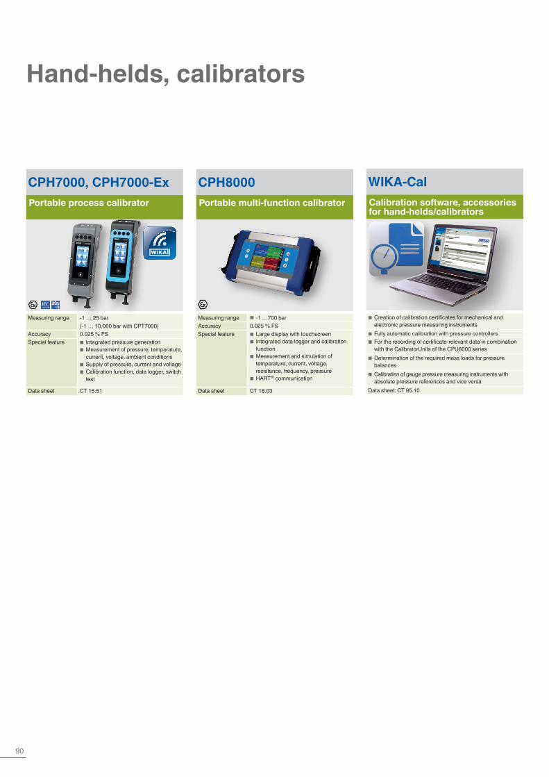
90
Hand-helds, calibrators
CPH7000, CPH7000-ExPortable process calibrator
Measuring range -1 … 25 bar (-1 … 10,000 bar with CPT7000)
Accuracy 0.025 % FSSpecial feature ■ Integrated pressure generation
■ Measurement of pressure, temperature, current, voltage, ambient conditions
■ Supply of pressure, current and voltage ■ Calibration function, data logger, switch test
Data sheet CT 15.51
CPH8000Portable multi-function calibrator
Measuring range ■ -1 ... 700 barAccuracy 0.025 % FSSpecial feature ■ Large display with touchscreen
■ Integrated data logger and calibration function
■ Measurement and simulation of temperature, current, voltage, resistance, frequency, pressure
■ HART® communication
Data sheet CT 18.03
WIKA-CalCalibration software, accessories for hand-helds/calibrators
■ Creation of calibration certificates for mechanical and electronic pressure measuring instruments
■ Fully automatic calibration with pressure controllers ■ For the recording of certificate-relevant data in combination with the CalibratorUnits of the CPU6000 series
■ Determination of the required mass loads for pressure balances
■ Calibration of gauge pressure measuring instruments with absolute pressure references and vice versa
Data sheet: CT 95.10
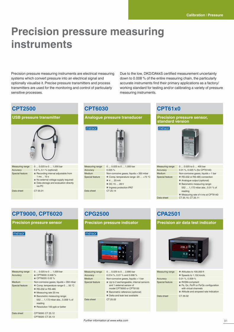
91
Calibration | Pressure
Precision pressure measuring instruments
CPT61x0Precision pressure sensor, standard version
Measuring range 0 … 0.025 to 0 … 400 barAccuracy 0.01 %, 0.025 % (for CPT6140)Medium Non-corrosive gases, liquids > 1 barSpecial feature ■ RS-232 or RS-485 connection
■ Analogue output (optional) ■ Barometric measuring range: 552 … 1,172 mbar abs., 0.01 % of reading
■ Measuring rate of 4 ms at CPT6140Data sheet CT 25.10, CT 25.11
CPT6030Analogue pressure transducer
Measuring range 0 … 0.025 to 0 … 1,000 barAccuracy 0.025 %Medium Non-corrosive gases, liquids > 350 mbarSpecial feature ■ Comp. temperature range -20 … +75 °C
■ 4 … 20 mA ■ DC 15 … 28 V ■ Ingress protection IP67
Data sheet CT 25.14
CPT9000, CPT6020Precision pressure sensor
Measuring range 0 … 0.025 to 0 … 1,000 barAccuracy ■ CPT9000: 0.008 %
■ CPT6020: 0.02 %Medium Non-corrosive gases, liquids > 350 mbarSpecial feature ■ Comp. temperature range 0 … 50 °C
■ RS-232 or RS-485 ■ Measuring rate 20 ms ■ Barometric measuring range: 552 … 1,172 mbar abs., 0.008 % of reading
■ Resolution 100 ppb or better
Data sheet CPT9000: CT 25.12CPT6020: CT 25.13
Precision pressure measuring instruments are electrical measuring systems which convert pressure into an electrical signal and optionally visualise it. Precise pressure transmitters and process transmitters are used for the monitoring and control of particularly sensitive processes.
Due to the low, DKD/DAkkS certified measurement uncertainty down to 0.008 % of the entire measuring chain, the particularly accurate instruments find their primary applications as a factory/working standard for testing and/or calibrating a variety of pressure measuring instruments.
CPT2500USB pressure transmitter
Measuring range 0 … 0.025 to 0 … 1,000 barAccuracy 0.2 %, 0.1 % (optional)Special feature ■ Recording interval adjustable from
1 ms ... 10 s ■ No external voltage supply required ■ Data storage and evaluation directly via PC
Data sheet CT 05.01
CPG2500Precision pressure indicator
Measuring range 0 … 0.025 to 0 … 2,890 barAccuracy 0.014 %, 0.01 % and 0.008 %Medium Non-corrosive gases, liquids > 1 barSpecial feature ■ Up to 2 exchangeable, internal sensors
and 1 external sensor of model CPT9000 or CPT6100
■ Barometric reference (optional) ■ Delta and leak test available
Data sheet CT 25.02
CPA2501Precision air data test indicator
Measuring range ■ Altitudes to 100,000 ft ■ Speeds to 1,150 knots
Accuracy 0.01 %, 0.009 %Special feature ■ RVSM-compliant
■ Ps, Qc, Ps/Pt or Ps/Qc configuration with virtual channels
■ Altitude and airspeed rate indication
Data sheet CT 29.02
Further information at www.wika.com
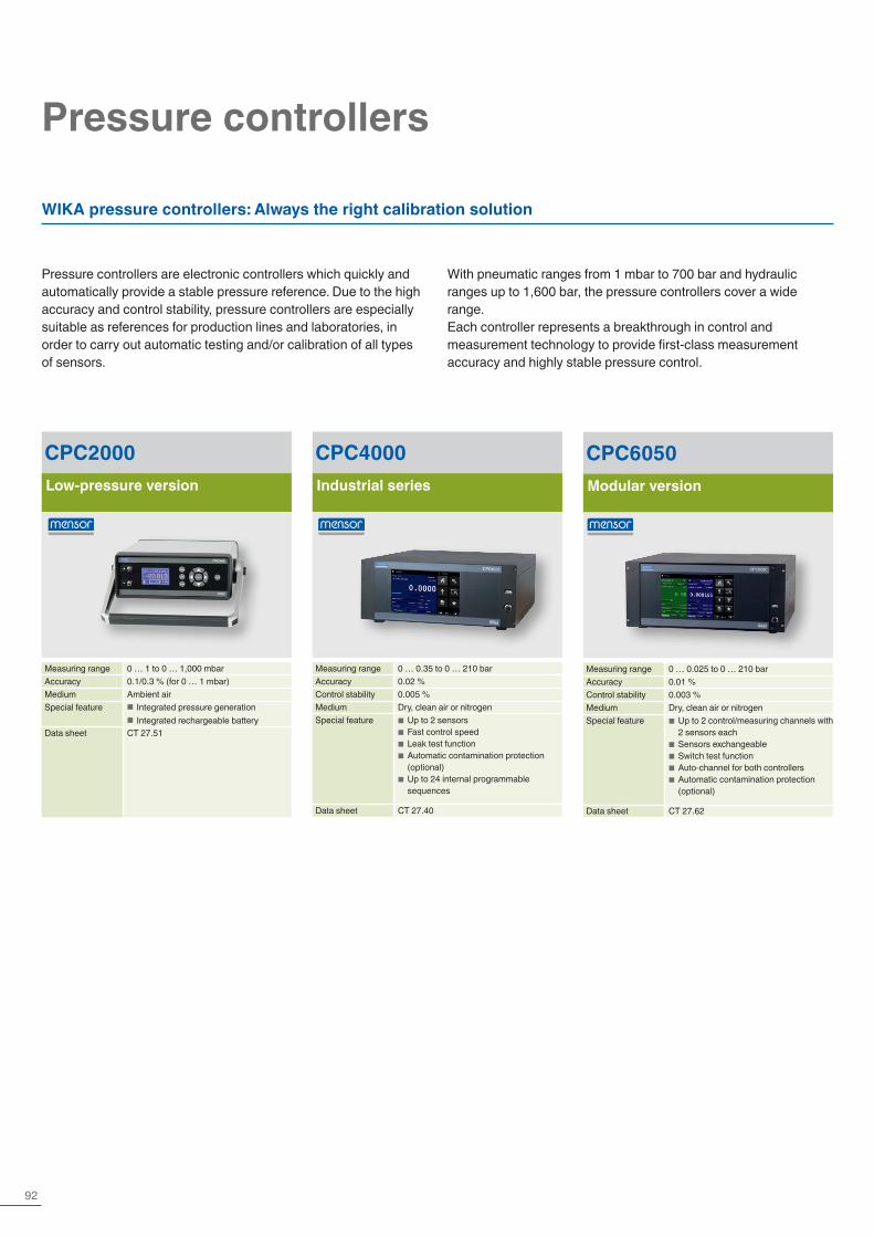
92
Pressure controllers
Pressure controllers are electronic controllers which quickly and automatically provide a stable pressure reference. Due to the high accuracy and control stability, pressure controllers are especially suitable as references for production lines and laboratories, in order to carry out automatic testing and/or calibration of all types of sensors.
WIKA pressure controllers: Always the right calibration solution
CPC2000Low-pressure version
Measuring range 0 … 1 to 0 … 1,000 mbarAccuracy 0.1/0.3 % (for 0 … 1 mbar)Medium Ambient airSpecial feature ■ Integrated pressure generation
■ Integrated rechargeable batteryData sheet CT 27.51
CPC4000Industrial series
Measuring range 0 … 0.35 to 0 … 210 barAccuracy 0.02 %Control stability 0.005 %Medium Dry, clean air or nitrogenSpecial feature ■ Up to 2 sensors
■ Fast control speed ■ Leak test function ■ Automatic contamination protection (optional)
■ Up to 24 internal programmable sequences
Data sheet CT 27.40
CPC6050Modular version
Measuring range 0 … 0.025 to 0 … 210 barAccuracy 0.01 %Control stability 0.003 %Medium Dry, clean air or nitrogenSpecial feature ■ Up to 2 control/measuring channels with
2 sensors each ■ Sensors exchangeable ■ Switch test function ■ Auto-channel for both controllers ■ Automatic contamination protection (optional)
Data sheet CT 27.62
With pneumatic ranges from 1 mbar to 700 bar and hydraulic ranges up to 1,600 bar, the pressure controllers cover a wide range.Each controller represents a breakthrough in control and measurement technology to provide first-class measurement accuracy and highly stable pressure control.

93Further information at www.wika.com
Pneumatic pressure controllers Hydraulic pressure controller
For aviation
CPC7000High-pressure version
Measuring range 0 … 100 bar to 0 … 700 barAccuracy 0.01 %Control stability 0.008 %Medium NitrogenSpecial feature ■ Robust and low-wear valve technology
with long-term stability ■ Up to three interchangeable sensors ■ 6 x digital I/O ■ High-pressure safety
Data sheet CT 27.63
CPC8000Premium version
Measuring range 0 … 0.35 to 0 … 400 barAccuracy 0.01 … 0.008 %Control stability 0.002 %Medium Dry, clean air or nitrogenSpecial feature ■ Excellent control stability and pressure
control without overshooting ■ Up to three interchangeable sensors ■ Optional barometer for automatic conversion of the pressure type
■ Control performance can be matched to application
Data sheet CT 28.01
CPC8000-HHigh-pressure version
Measuring range 0 … 100 to 0 … 1,600 barAccuracy 0.014 % … 0.01 %Control stability 0.005 %Medium Hydraulic oil or waterSpecial feature ■ High stability
■ Up to two interchangeable reference sensors
■ Automatic flooding ■ Hydraulic liquids available, e.g. Sebacate, Shell Tellus 22, Krytox, FC77
Data sheet CT 28.05
CPA8001Air data test set
Measuring range ■ Altitudes to 100,000 ft ■ Speeds to 1,150 knots
Accuracy 0.01 % … 0.009 %Control stability 0.002 %Medium Dry, clean air or nitrogenSpecial feature ■ Excellent control stability, even with
rate control ■ Overshoot-free control ■ RVSM compatible ■ Configurations Ps/Pt, Ps/Qc
Data sheet CT 29.01
Calibration | Pressure
An air data test set is a an electronic controller which provides a pressure at a variable and adjustable rate.
Air data test sets are specifically developed to convert the pressure to be controlled into a height or rate of climb and velocity.As a result of the high accuracy, control stability and ability to simulate altitude and velocity, an air data test set is particularly suitable as a reference for aircraft workshops and also for instrument manufacturers and calibration laboratories in the aviation industry, in order to make calibrations on sensors and displays.
WIKA-CalCalibration software, accessories for pressure controllers
■ Creation of calibration certificates for mechanical and electronic pressure measuring instruments
■ Fully automatic calibration with pressure controllers ■ For the recording of certificate-relevant data in combination with the CalibratorUnits of the CPU6000 series
■ Determination of the required mass loads for pressure balances
■ Calibration of gauge pressure measuring instruments with absolute pressure references and vice versa
Data sheet: CT 95.10
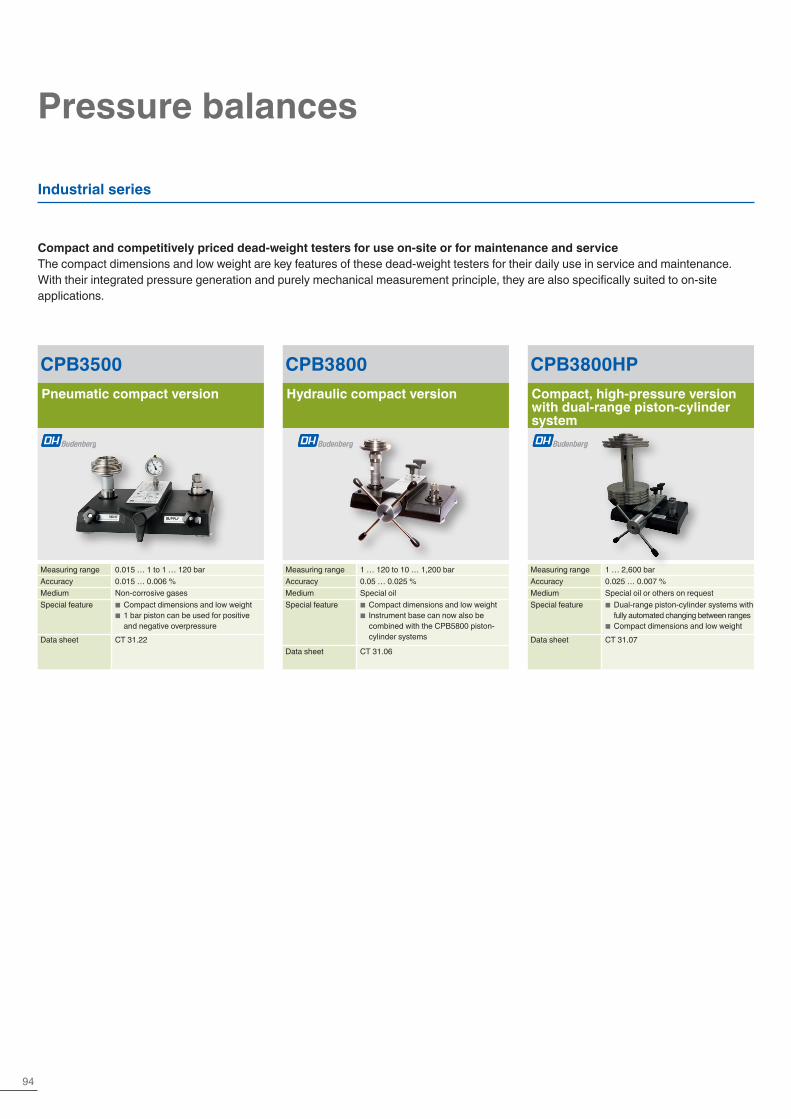
94
Pressure balances
Compact and competitively priced dead-weight testers for use on-site or for maintenance and serviceThe compact dimensions and low weight are key features of these dead-weight testers for their daily use in service and maintenance. With their integrated pressure generation and purely mechanical measurement principle, they are also specifically suited to on-site applications.
Industrial series
CPB3800HPCompact, high-pressure version with dual-range piston-cylinder system
Measuring range 1 … 2,600 barAccuracy 0.025 … 0.007 %Medium Special oil or others on requestSpecial feature ■ Dual-range piston-cylinder systems with
fully automated changing between ranges ■ Compact dimensions and low weight
Data sheet CT 31.07
CPB3500Pneumatic compact version
Measuring range 0.015 … 1 to 1 … 120 barAccuracy 0.015 … 0.006 %Medium Non-corrosive gasesSpecial feature ■ Compact dimensions and low weight
■ 1 bar piston can be used for positive and negative overpressure
Data sheet CT 31.22
CPB3800Hydraulic compact version
Measuring range 1 … 120 to 10 … 1,200 barAccuracy 0.05 … 0.025 %Medium Special oilSpecial feature ■ Compact dimensions and low weight
■ Instrument base can now also be combined with the CPB5800 piston-cylinder systems
Data sheet CT 31.06
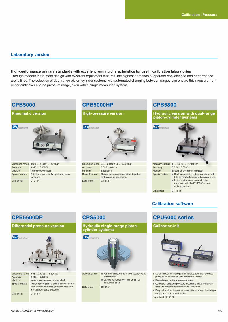
95Further information at www.wika.com
High-performance primary standards with excellent running characteristics for use in calibration laboratoriesThrough modern instrument design with excellent equipment features, the highest demands of operator convenience and performance are fulfilled. The selection of dual-range piston-cylinder systems with automated changing between ranges can ensure this measurement uncertainty over a large pressure range, even with a single measuring system.
CPB5000Pneumatic version
Measuring range -0.03 … -1 to 0.4 … 100 barAccuracy 0.015 … 0.008 %Medium Non-corrosive gasesSpecial feature Patented system for fast piston-cylinder
exchangeData sheet CT 31.01
CPB5600DPDifferential pressure version
Measuring range 0.03 … 2 to 25 … 1,600 barAccuracy 0.015 … 0.008 %Medium Non-corrosive gases or special oilSpecial feature Two complete pressure balances within one
case for real differential pressure measure-ments under static pressure
Data sheet CT 31.56
CPB5000HPHigh-pressure version
Measuring range 25 … 2,500 to 25 … 6,000 barAccuracy 0.025 … 0.02 %Medium Special oilSpecial feature Robust instrument base with integrated
high-pressure generationData sheet CT 31.51
CPB5800Hydraulic version with dual-range piston-cylinder systems
Measuring range 1 … 120 to 1 … 1,400 barAccuracy 0.015 … 0.006 %Medium Special oil or others on requestSpecial feature ■ Dual-range piston-cylinder systems with
fully automated changing between ranges ■ Instrument base can now also be combined with the CPS5000 piston-cylinder systems
Data sheet CT 31.11
CPS5000Hydraulic single-range piston-cylinder systems
Special feature ■ For the highest demands on accuracy and performance
■ Can be combined with the CPB5800 instrument base
Data sheet CT 31.01
Laboratory version
Calibration | Pressure
CPU6000 seriesCalibratorUnit
■ Determination of the required mass loads or the reference pressure for calibration with pressure balances
■ Recording of certificate-relevant data ■ Calibration of gauge pressure measuring instruments with absolute pressure references and vice versa
■ Easy calibration of pressure transmitters through the voltage supply and multimeter function
Data sheet: CT 35.02
Calibration software
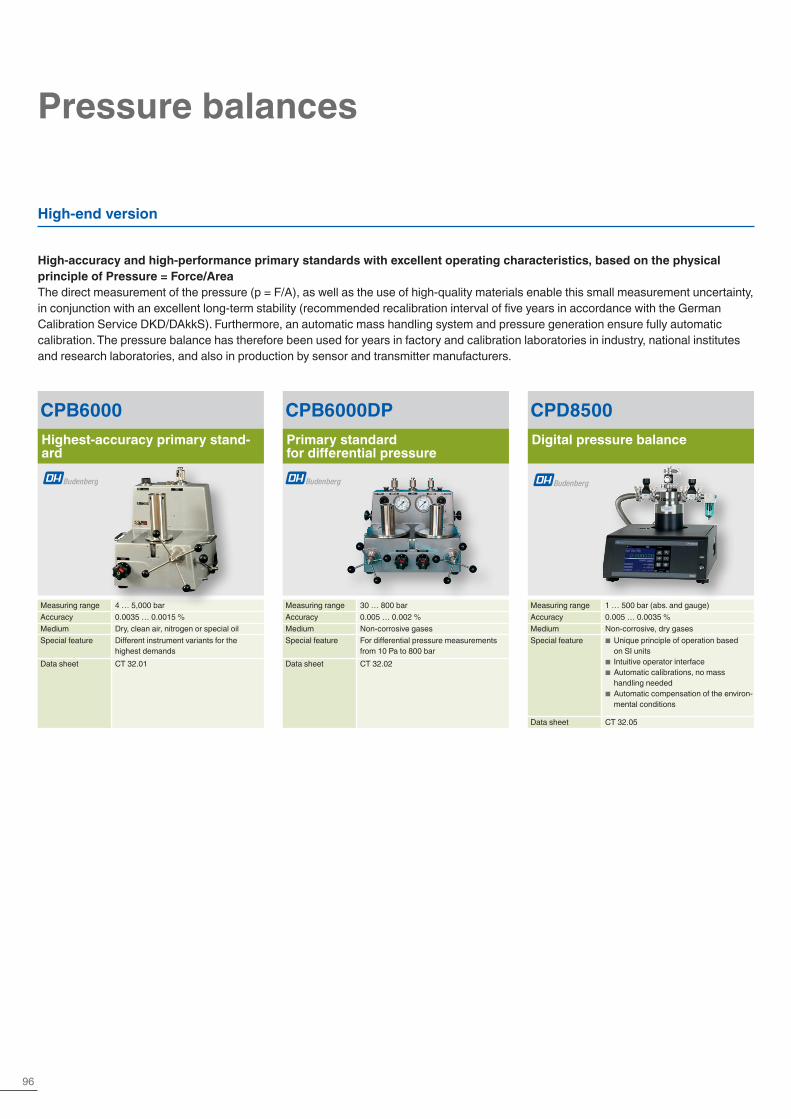
96
Pressure balances
CPD8500Digital pressure balance
Measuring range 1 … 500 bar (abs. and gauge)Accuracy 0.005 … 0.0035 %Medium Non-corrosive, dry gasesSpecial feature ■ Unique principle of operation based
on SI units ■ Intuitive operator interface ■ Automatic calibrations, no mass handling needed
■ Automatic compensation of the environ-mental conditions
Data sheet CT 32.05
High-accuracy and high-performance primary standards with excellent operating characteristics, based on the physical principle of Pressure = Force/AreaThe direct measurement of the pressure (p = F/A), as well as the use of high-quality materials enable this small measurement uncertainty, in conjunction with an excellent long-term stability (recommended recalibration interval of five years in accordance with the German Calibration Service DKD/DAkkS). Furthermore, an automatic mass handling system and pressure generation ensure fully automatic calibration. The pressure balance has therefore been used for years in factory and calibration laboratories in industry, national institutes and research laboratories, and also in production by sensor and transmitter manufacturers.
High-end version
CPB6000Highest-accuracy primary stand-ard
Measuring range 4 … 5,000 barAccuracy 0.0035 … 0.0015 %Medium Dry, clean air, nitrogen or special oilSpecial feature Different instrument variants for the
highest demandsData sheet CT 32.01
CPB6000DPPrimary standard for differential pressure
Measuring range 30 … 800 barAccuracy 0.005 … 0.002 %Medium Non-corrosive gasesSpecial feature For differential pressure measurements
from 10 Pa to 800 barData sheet CT 32.02
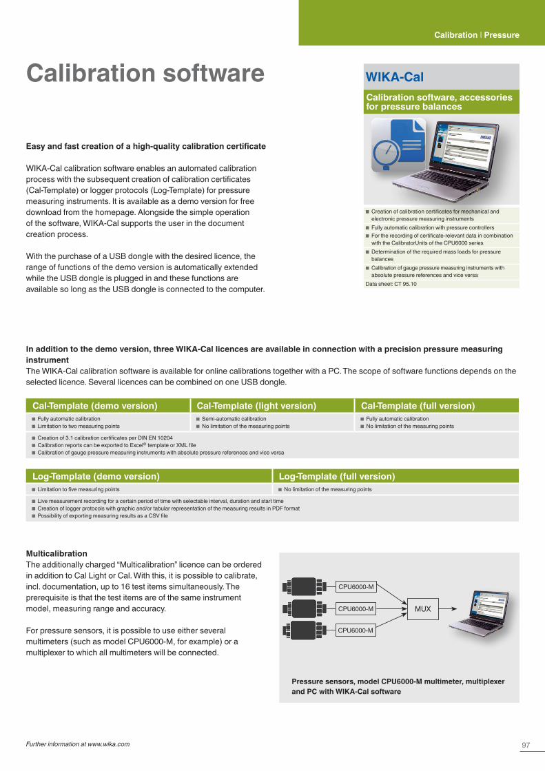
97Further information at www.wika.com
Calibration | Pressure
WIKA-CalCalibration software, accessories for pressure balances
■ Creation of calibration certificates for mechanical and electronic pressure measuring instruments
■ Fully automatic calibration with pressure controllers ■ For the recording of certificate-relevant data in combination with the CalibratorUnits of the CPU6000 series
■ Determination of the required mass loads for pressure balances
■ Calibration of gauge pressure measuring instruments with absolute pressure references and vice versa
Data sheet: CT 95.10
Calibration software
MulticalibrationThe additionally charged “Multicalibration” licence can be ordered in addition to Cal Light or Cal. With this, it is possible to calibrate, incl. documentation, up to 16 test items simultaneously. The prerequisite is that the test items are of the same instrument model, measuring range and accuracy.
For pressure sensors, it is possible to use either several multimeters (such as model CPU6000-M, for example) or a multiplexer to which all multimeters will be connected.
Pressure sensors, model CPU6000-M multimeter, multiplexer and PC with WIKA-Cal software
Easy and fast creation of a high-quality calibration certificate
WIKA-Cal calibration software enables an automated calibration process with the subsequent creation of calibration certificates (Cal-Template) or logger protocols (Log-Template) for pressure measuring instruments. It is available as a demo version for free download from the homepage. Alongside the simple operation of the software, WIKA-Cal supports the user in the document creation process.
With the purchase of a USB dongle with the desired licence, the range of functions of the demo version is automatically extended while the USB dongle is plugged in and these functions are available so long as the USB dongle is connected to the computer.
In addition to the demo version, three WIKA-Cal licences are available in connection with a precision pressure measuring instrumentThe WIKA-Cal calibration software is available for online calibrations together with a PC. The scope of software functions depends on the selected licence. Several licences can be combined on one USB dongle.
Cal-Template (demo version) Cal-Template (light version) Cal-Template (full version) ■ Fully automatic calibration ■ Limitation to two measuring points
■ Semi-automatic calibration ■ No limitation of the measuring points
■ Fully automatic calibration ■ No limitation of the measuring points
■ Creation of 3.1 calibration certificates per DIN EN 10204 ■ Calibration reports can be exported to Excel® template or XML file ■ Calibration of gauge pressure measuring instruments with absolute pressure references and vice versa
Log-Template (demo version) Log-Template (full version) ■ Limitation to five measuring points ■ No limitation of the measuring points
■ Live measurement recording for a certain period of time with selectable interval, duration and start time ■ Creation of logger protocols with graphic and/or tabular representation of the measuring results in PDF format ■ Possibility of exporting measuring results as a CSV file
MUX
CPU6000-M
CPU6000-M
CPU6000-M
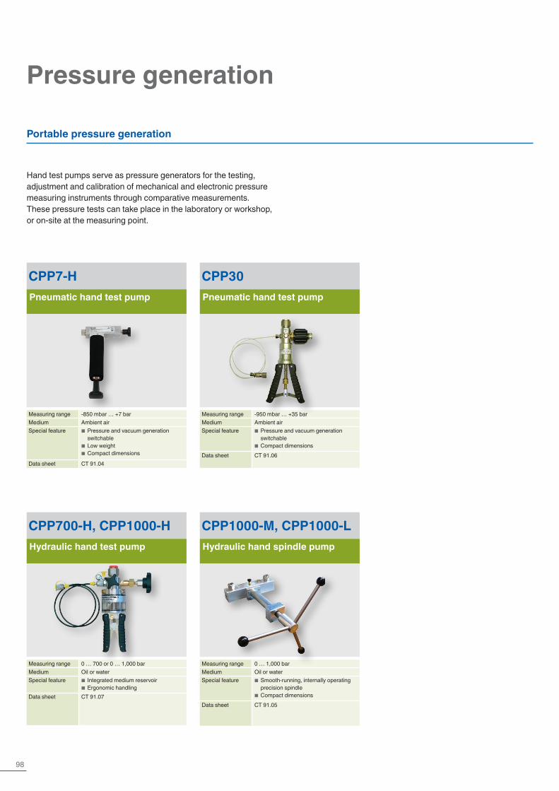
98
Pressure generation
Hand test pumps serve as pressure generators for the testing, adjustment and calibration of mechanical and electronic pressure measuring instruments through comparative measurements. These pressure tests can take place in the laboratory or workshop, or on-site at the measuring point.
Portable pressure generation
CPP30Pneumatic hand test pump
Measuring range -950 mbar … +35 barMedium Ambient airSpecial feature ■ Pressure and vacuum generation
switchable ■ Compact dimensions
Data sheet CT 91.06
CPP7-HPneumatic hand test pump
Measuring range -850 mbar … +7 barMedium Ambient airSpecial feature ■ Pressure and vacuum generation
switchable ■ Low weight ■ Compact dimensions
Data sheet CT 91.04
CPP700-H, CPP1000-HHydraulic hand test pump
Measuring range 0 … 700 or 0 … 1,000 barMedium Oil or waterSpecial feature ■ Integrated medium reservoir
■ Ergonomic handlingData sheet CT 91.07
CPP1000-M, CPP1000-LHydraulic hand spindle pump
Measuring range 0 … 1,000 barMedium Oil or waterSpecial feature ■ Smooth-running, internally operating
precision spindle ■ Compact dimensions
Data sheet CT 91.05

99Further information at www.wika.com
Comparison test pumps serve as pressure generators or controllers for the testing, adjustment and calibration of mechanical and electronic pressure measuring instruments.Due to their stable case, these test pumps are particularly suitable for stationary use in laboratories or workshops.
Laboratory version
CPP120-XPneumatic comparison test pump
Measuring range 0 … 120 barMedium Clean, dry, non-corrosive gasesSpecial feature ■ Accurate pressure setting
■ Robust industrial series ■ External initial pressure supply necessary
Data sheet CT 91.03
CPP1200-XHydraulic comparison test pump
Measuring range 0 … 1,200 barMedium Oil or waterSpecial feature ■ Integrated tank
■ Dual-area spindle pump ■ Robust industrial series
Data sheet CT 91.08
CPP4000-XHydraulic comparison test pump
Measuring range 0 … 1,200 barMedium Oil or waterSpecial feature ■ Integrated tank
■ Dual-area spindle pump ■ Robust industrial series
Data sheet CT 91.09
CPP7000-XHydraulic comparison test pump
Measuring range 0 … 7,000 barMedium Sebacate oilSpecial feature ■ Integrated tank
■ Robust laboratory version with priming pump
Data sheet CT 91.13
CPP1000-X, CPP1600-XHydraulic comparison test pump
Measuring range 0 … 1,000 to 0 … 1,600 barMedium Oil or waterSpecial feature ■ Integrated tank
■ Robust laboratory version with priming pump
■ Compact industrial series with priming pump
Data sheet CT 91.12
Calibration | Pressure
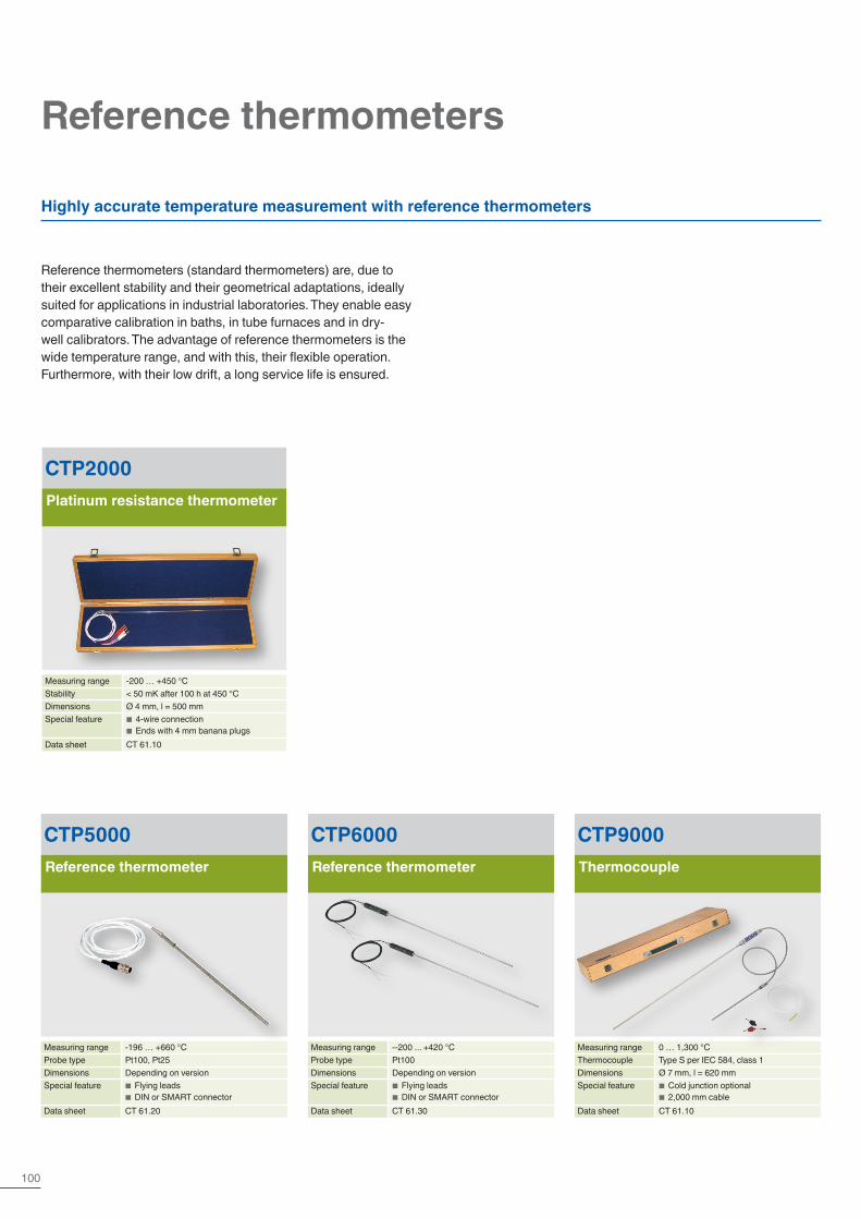
100
Reference thermometers
Highly accurate temperature measurement with reference thermometers
Reference thermometers (standard thermometers) are, due to their excellent stability and their geometrical adaptations, ideally suited for applications in industrial laboratories. They enable easy comparative calibration in baths, in tube furnaces and in dry-well calibrators. The advantage of reference thermometers is the wide temperature range, and with this, their flexible operation. Furthermore, with their low drift, a long service life is ensured.
CTP2000Platinum resistance thermometer
Measuring range -200 … +450 °CStability < 50 mK after 100 h at 450 °CDimensions Ø 4 mm, l = 500 mmSpecial feature ■ 4-wire connection
■ Ends with 4 mm banana plugsData sheet CT 61.10
CTP5000Reference thermometer
Measuring range -196 … +660 °CProbe type Pt100, Pt25Dimensions Depending on versionSpecial feature ■ Flying leads
■ DIN or SMART connectorData sheet CT 61.20
CTP6000Reference thermometer
Measuring range --200 ... +420 °CProbe type Pt100Dimensions Depending on versionSpecial feature ■ Flying leads
■ DIN or SMART connectorData sheet CT 61.30
CTP9000Thermocouple
Measuring range 0 … 1,300 °CThermocouple Type S per IEC 584, class 1Dimensions Ø 7 mm, l = 620 mmSpecial feature ■ Cold junction optional
■ 2,000 mm cableData sheet CT 61.10

101Further information at www.wika.com
Calibration | Temperature
Hand-helds
Hand-helds are portable calibration instruments for mobile use for the accurate measurement and recording of temperature profiles. For the instruments there are various designs of thermometers available. Through this, hand-helds are particularly suitable as test instruments for a large variety of applications in the widest range of industries.
CTH6200Hand-held thermometer
Measuring range -50 … +250 °CAccuracy < 0.2Probe type Pt100Special feature Integrated data loggerData sheet CT 51.01
CTH6300, CTH63I0Hand-held thermometer
Measuring range -200 … +1,500 °CAccuracy 0.1 … 1 KProbe type Pt100, TCSpecial feature ■ 2 channels (optional)
■ Ex version: Model CTH63I0Data sheet CT 51.05
CTH6500, CTH65I0Hand-held thermometer
Measuring range -200 … +1,500 °CAccuracy 0.03 … 0.2 KProbe type Pt100, TCSpecial feature ■ Integrated data logger (optional)
Ex version: Model CTH65I0Data sheet CT 55.10
CTH7000Hand-held thermometer
Measuring range -200 … +962 °CAccuracy 0.015 KProbe type Pt100, Pt25 and NTCSpecial feature Integrated data loggerData sheet CT 55.50
Data recorded in the hand-held can be evaluated via PC software, some instruments document calibrations in the internal memory, which are later read on a PC. Optionally, a calibration certificate can be generated with our calibration software WIKA-Cal.
CTR1000Infrared hand-held thermometer
Measuring range -60 … +1,000 °CAccuracy 2 K or 2 % of readingSpecial feature Thermocouple connection (optional)Data sheet CT 55.21

102
Calibration baths
Calibration baths are electronic controllers which automatically, quickly and with the help of a liquid supply a temperature.Due to the high reliability, accuracy and exceptional homogeneity in the measuring chamber, calibration baths are particularly suitable as a factory/working standard for the automatic testing and/or calibration of the widest range of temperature probes - independent of diameter. A special micro calibration bath design enables on-site applications.
CTB9100Micro calibration bath
Measuring range -35 … +255 °CAccuracy ±0.2 … 0.3 KStability ±0.05 KSpecial feature ■ Short heating and cooling times
■ Easy to useData sheet CT 46.30
CTB9400Calibration bath, medium measuring range
Measuring range 28 … 300 °CStability ±0.02 KImmersion depth 200 mmMedium Water, oil or similar mediaData sheet CT 46.20
CTB9500Calibration bath, low measuring range
Measuring range -45 … +200 °CStability ±0.02 KImmersion depth 200 mmMedium Water, oil or similar mediaData sheet CT 46.20
CTM9100-150Multi-function calibrator
Measuring range -35 … +165 °C depending on the application
Accuracy ±0.3 K … 1 K depending on the application
Immersion depth 150 mmSpecial feature Use as a dry-well calibrator, micro calibra-
tion bath, infrared calibrator and surface calibrator
Data sheet CT 41.40
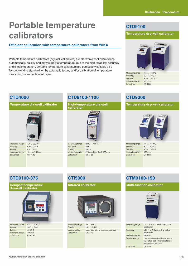
103Further information at www.wika.com
Calibration | Temperature
Portable temperature calibratorsEfficient calibration with temperature calibrators from WIKA
Portable temperature calibrators (dry-well calibrators) are electronic controllers which automatically, quickly and dryly supply a temperature. Due to the high reliability, accuracy and simple operation, portable temperature calibrators are particularly suitable as a factory/working standard for the automatic testing and/or calibration of temperature measuring instruments of all types.
CTM9100-150Multi-function calibrator
Measuring range -35 … +165 °C depending on the application
Accuracy ±0.3 K … 1 K depending on the application
Immersion depth 150 mmSpecial feature Use as a dry-well calibrator, micro
calibration bath, infrared calibrator and surface calibrator
Data sheet CT 41.40
CTD9100Temperature dry-well calibrator
Measuring range -55 … +650 °CAccuracy ±0.15 … 0.8 KStability ±0.01 … 0.05 KImmersion depth 150 mmData sheet CT 41.28
CTD9100-1100High-temperature dry-well calibrator
Measuring range 200 … 1,100 °CAccuracy ±3 KStability ±0.3 KImmersion depth 220 mm, bore depth 155 mmData sheet CT 41.29
CTD9300Temperature dry-well calibrator
Measuring range -35 … +650 °CAccuracy ±0.1 … 0.65 KStability ±0.01 … 0.1 KImmersion depth 150 mmData sheet CT 41.38
CTD9100-375Compact temperature dry-well calibrator
Measuring range tamb … 375 °CAccuracy ±0.5 … 0.8 KStability ±0.05 KImmersion depth 100 mmData sheet CT 41.32
CTD4000Temperature dry-well calibrator
Measuring range -24 … 650 °CAccuracy 0.25 … 0.5 KStability 0.1 … 0.3 KImmersion depth 104 mm/150 mmData sheet CT 41.10
CTI5000Infrared calibrator
Measuring range 50 … 500 °CStability ±0.1 … 0.4 KSpecial feature Large diameter of measuring surfaceData sheet CT 41.42
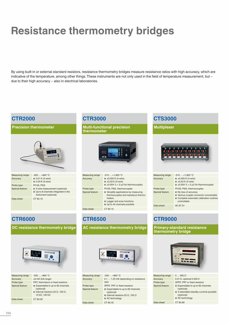
104
Resistance thermometry bridges
By using built-in or external standard resistors, resistance thermometry bridges measure resistance ratios with high accuracy, which are indicative of the temperature, among other things. These instruments are not only used in the field of temperature measurement, but − due to their high accuracy − also in electrical laboratories.
CTR3000Multi-functional precision thermometer
Measuring range -210 … +1,820 °CAccuracy ■ ±0.005 K (4-wire)
■ ±0.03 K (3-wire) ■ ±0.004 % + 2 µV for thermocouples
Probe type Pt100, Pt25, thermocouplesSpecial feature ■ Versatile applications by measuring
thermocouples and resistance thermo-meters
■ Logger and scan functions ■ Up to 44 channels possible
Data sheet CT 60.15
CTR2000Precision thermometer
Measuring range -200 … +850 °CAccuracy ■ 0.01 K (4-wire)
■ 0.03 K (3-wire)Probe type Pt100, Pt25Special feature ■ 3-wire measurement (optional)
■ Up to 8 channels integrated in the instrument (optional)
Data sheet CT 60.10
CTS3000Multiplexer
Measuring range -210 … +1,820 °CAccuracy ■ ±0.005 K (4-wire)
■ ±0.03 K (3-wire) ■ ±0.004 % + 2 µV for thermocouples
Probe type Pt100, Pt25, thermocouplesSpecial feature ■ No loss of accuracy
■ Various coupler connector connectable ■ Complete automatic calibration routines controllable
Data sheet AC 87.01
CTR6000DC resistance thermometry bridge
Measuring range -200 … +962 °CAccuracy ±3 mK (full range)Probe type PRT, thermistors or fixed resistorsSpecial feature ■ Expendable to up to 60 channels
(optional) ■ Internal resistors 25 Ω, 100 Ω, 10 kΩ, 100 kΩ
Data sheet CT 60.30
CTR6500AC resistance thermometry bridge
Measuring range -200 … +962 °CAccuracy 0.1 … 1.25 mK depending on resistance
ratioProbe type SPRT, PRT or fixed resistorsSpecial feature ■ Expendable to up to 60 channels
(optional) ■ Internal resistors 25 Ω, 100 Ω ■ AC technology
Data sheet CT 60.40
CTR9000Primary-standard resistance thermometry bridge
Measuring range 0 … 260 ΩAccuracy 0.01 K, optional 0.005 KProbe type SPRT, PRT or fixed resistorsSpecial feature ■ Expendable to up to 60 channels
(optional) ■ 4 selectable standby currents possible (optional)
■ AC technology
Data sheet CT 60.80
Red
White

105Further information at www.wika.com
Calibration | Temperature
Standard reference resistors, AC/DC
Electrical comparison standard
Reference resistors with high-accuracy, fixed resistance values, which are used in connection with resistance thermometry bridges.They are also used as standards in accredited electrical laboratories.
CER6000-RRReference resistor
Resistance value 1, 10, 25, 100, 300, 400, 500, 1,000 and 10,000 Ω
Long-term stability < ±5 ppm per yearSpecial feature ■ Low temperature coefficient
■ Rugged stainless steel constructionData sheet CT 70.30
CER6000-RWStandard reference resistor
Resistance value 1, 10, 25, 100, 300, 400, 500, 1,000 and 10,000 Ω
Long-term stability ±2 ppm per year (HS version 0.5 ppm per year)
Special feature ■ Low temperature coefficient ■ Rugged stainless steel construction
Data sheet CT 70.30
Red Red
White White
Connections of the reference resistor, model CER6000-RR
Reference resistor, model CER6000-RR with different resistance range
Model CER6000-RR reference resistor with 100 Ω V A
V B IB
IA

106
Accessories
The following accessory components are the ideal complement to the individual calibration instruments. Thus a complete solution is not only quickly and easily configured, but can also be installed in the same manner. The various packages complete the product programme for calibration technology and can be used in many different applications.
Customer-specific drilled inserts, silicone oil suited for calibration in micro calibration baths and interface cables complete the product portfolio for temperature.
You can find a detailed description in our catalogue “Accessories for calibration technology”.
Calibration technology
Accessories for calibration technology
From individual components ... to complete turnkey kits
Pressure supply case Pressure and vacuum supply packages Connection components
Pressure control Temperature accessoriesCalibration and adjustment tools

107Further information at www.wika.com
Calibration | Accessories
Test and calibration systems for workshops and laboratories
For the fitting-out of calibration laboratories, we offer individuallydesigned test workstations. Here we integrateproven calibration systems from our extensiveproduct range into ergonomic workstations. Thesecan be individually equipped with the following components:
� 19" calibration racks in modular design for pressure sensors � Connection columns with quick-release fasteners for test items
and references with exchangeable threaded inserts � Electric and pneumatic power strips with 230-V voltage supply
and compressed air with air blow gun connection including pressure regulator
� Work panel for setting the operating pressure with inlet pressure gauge, outlet pressure gauge and alternative pressure supply
� PC workstations
Engineered solutions
We have been developing systems for use in our own group of companies for years and can draw on our own process knowledge to continually develop our systems further.We offer robust and compact turnkey machinery from a single source, with our own fixture construction and customer-specific solutions as well as many application possibilities.

108
Leak and pressure function test systems for production
We offer individual and turnkey solutions in various degrees of automation for a wide variety of applications, from simple test equipment through semi-automatic test benches to fully automated testing systems.The testing processes can also be combined with assembly processes, laser marking, automated parts handling (infeed/outfeed) - in addition, the chaining of several stations is possible.
Pneumatic or helium leak testingon fittings, valves, hoses, coolers, pumps, filters and many other test parts.
Pressure function tests or setting proceduresamong other things for
� Control pressure of pressure reducers or thermostat control valves
� The cracking pressure of safety relief valves � Switch points of pressure switches and control valves � Pressure containment of different components
Test methods � Integral vacuum methods � Accumulation methods (under atmosphere) � Sniffing test
Test and calibration systems for production
The complete solutions are available in the widest range of automation levels incl. tempering units, workpiece transport systems, workpiece fixtures and electrical and pressure-side contacting.
The focus is on the precise interaction of measurement technology, testing system mechanics and control components.In addition, the actual testing and adjustment processes can also be combined with mounting and labelling processes.
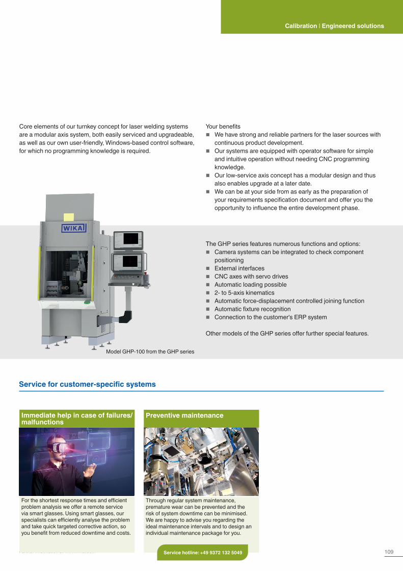
109Further information at www.wika.com
Calibration | Engineered solutions
Service for customer-specific systems
Immediate help in case of failures/malfunctions
For the shortest response times and efficient problem analysis we offer a remote service via smart glasses. Using smart glasses, our specialists can efficiently analyse the problem and take quick targeted corrective action, so you benefit from reduced downtime and costs.
Preventive maintenance
Through regular system maintenance, premature wear can be prevented and the risk of system downtime can be minimised. We are happy to advise you regarding the ideal maintenance intervals and to design an individual maintenance package for you.
Service hotline: +49 9372 132 5049
Your benefits � We have strong and reliable partners for the laser sources with
continuous product development. � Our systems are equipped with operator software for simple
and intuitive operation without needing CNC programming knowledge.
� Our low-service axis concept has a modular design and thus also enables upgrade at a later date.
� We can be at your side from as early as the preparation of your requirements specification document and offer you the opportunity to influence the entire development phase.
The GHP series features numerous functions and options: � Camera systems can be integrated to check component
positioning � External interfaces � CNC axes with servo drives � Automatic loading possible � 2- to 5-axis kinematics � Automatic force-displacement controlled joining function � Automatic fixture recognition � Connection to the customer's ERP system
Other models of the GHP series offer further special features.
Core elements of our turnkey concept for laser welding systems are a modular axis system, both easily serviced and upgradeable, as well as our own user-friendly, Windows-based control software, for which no programming knowledge is required.
Model GHP-100 from the GHP series
110
Manufacturer-independent calibration - fast and precise for ...
Calibration service
� -1 bar … +10,000 bar � Calibration using working standards (precise electrical pressure
measuring instruments) or high-accuracy reference standards (pressure balances)
� With an accuracy down to 0.003 % of reading for the standard used � In accordance with the directives DIN EN 837, DKD-R 6-1 or
EURAMET cg-3
Pressure Temperature
Our calibration laboratory has been accredited for pressure for almost 40 years and for temperature for almost 30 years.Since 2014, our calibration laboratory has also been accredited for the electrical measurands DC current, DC voltage and DC resistance. Since 2020, our calibration laboratory at tecsis has been accredited for force.
� Certified to ISO 9001 and ISO 14001 � DAkkS accredited (in accordance with DIN EN ISO/IEC 17025) � Cooperation in the DKD working groups � Over 60 years of experience in pressure and temperature
measurement � Highly qualified, individually trained personnel � Latest reference instruments with the highest accuracy
� -196 °C … +1,600 °C � Comparative calibration in calibration baths with an accuracy down
to 10 mK � Comparative calibration in tube furnaces with an accuracy down
to 100 mK � Calibration at fixed points of ITS-90 with an accuracy down to 2 mK
Triple point of mercury (-38.8344 °C) - Triple point of water (0.01 °C) - Melting point of gallium (29.7646 °C) - Freezing point of indium (156.5985 °C) - Freezing point of tin (231.928 °C) - Freezing point of zinc (419.527 °C) - Freezing point of aluminium (660.323 °C)
� In accordance with the appropriate DKD directives

111
Further information on our services and the contact details can be found here.
Service
In order to have the least possible impact on the production process, we offer you a time-saving, on-site DAkkS calibration, throughout Germany, in the mobile calibration laboratory and on-site.
� In our calibration van or on your workbench � With a DAkkS accreditation for pressure
- from -1 bar … +8,000 bar - with accuracies down to 0.01 % of full scale for the standard used
� With a DAkkS accreditation for temperature from -90 °C … +1,100 °C
� 1 kN … 200 kN with a measurement uncertainty of 0.1 % in tension and compression force direction in accordance with DIN EN ISO 376 (calibration certificate per ISO 17025)
� 500 N ... 6 MN with a system accuracy of 0.5 % in tension and compression force direction (3.1 inspection certificate in accordance with DIN EN 10204)
� DC current from 0 mA ... 100 mA � DC voltage from 0 V ... 100 V � DC resistance from 0 Ω … 10 kΩ � In accordance with the directives VDI/VDE/DGQ/DKD 2622
� 3.1 inspection certificate (factory calibration) � Replacement of the measuring device if required � Calibration of special-purpose gauges in accordance with
customer drawings � Calibratable measuring devices
- Caliper gauges to 800 mm - Testing pins to 100 mm - Ring gauges and plug gauges to 150 mm - Tapered thread gauges to 150 mm - Gauge blocks to 170 mm (also possible as a set) - others on request
Current, voltage, resistance
Length Mobile and on-site (pressure and temperature)
Force
tecsis GmbH

112
Service for diaphragm seal systems
Diaphragm seal systems are used for demanding measuring requirements with extreme medium temperatures of -90 °C up to +400 °C in the process industry. The diaphragm seal assemblies protect the measuring instrument from aggressive, corrosive, heterogeneous, abrasive, highly viscous or toxic media.
With this service, the total costs of the diaphragm seal system can be clearly lowered. In this way, the service life of the measuring instrument can be fully utilised and only the diaphragm seal assembly needs replacement or repair, preventatively or after failure.
With a preventative repair, scheduled in line with planned shutdowns to your plant, you can reduce downtimes.
Services covered � Replacement service for diaphragm seal systems with process
transmitters or mechanical measuring instruments � Repair of the defective parts � Optimisation of the existing diaphragm seal system
Your benefits � Cost and time saving � Functional test of a process transmitter � Current material certificate � New calibration of the entire system
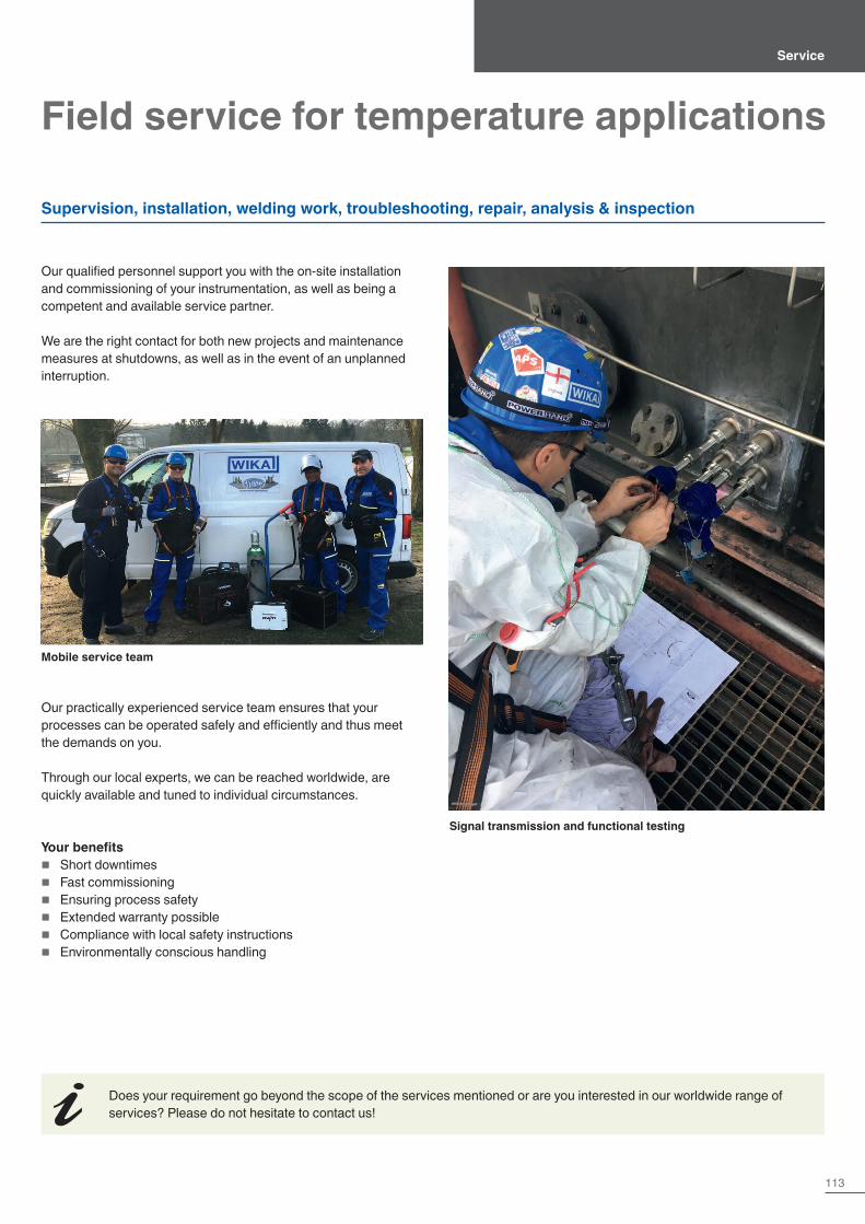
113
Field service for temperature applications
Our qualified personnel support you with the on-site installation and commissioning of your instrumentation, as well as being a competent and available service partner.
We are the right contact for both new projects and maintenance measures at shutdowns, as well as in the event of an unplanned interruption.
Our practically experienced service team ensures that your processes can be operated safely and efficiently and thus meet the demands on you.
Through our local experts, we can be reached worldwide, are quickly available and tuned to individual circumstances.
Your benefits � Short downtimes � Fast commissioning � Ensuring process safety � Extended warranty possible � Compliance with local safety instructions � Environmentally conscious handling
Service
Supervision, installation, welding work, troubleshooting, repair, analysis & inspection
Mobile service team
Signal transmission and functional testing
Does your requirement go beyond the scope of the services mentioned or are you interested in our worldwide range of services? Please do not hesitate to contact us!
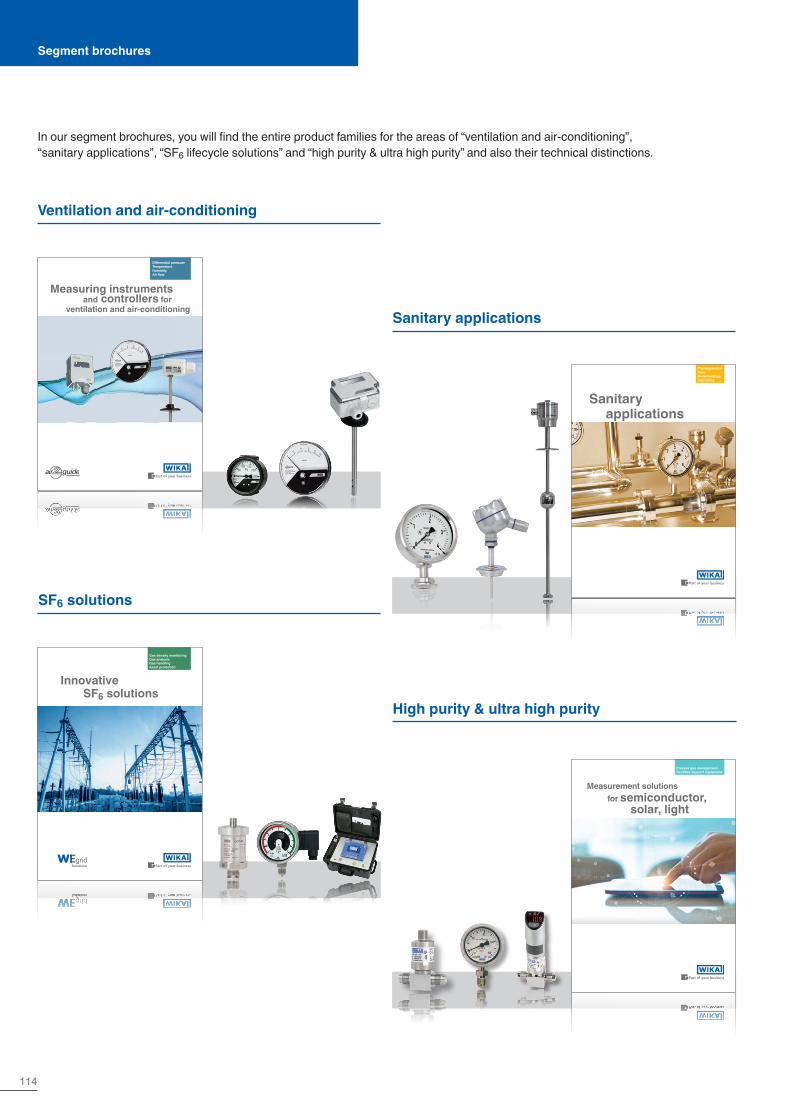
114
In our segment brochures, you will find the entire product families for the areas of “ventilation and air-conditioning”, “sanitary applications”, “SF6 lifecycle solutions” and “high purity & ultra high purity” and also their technical distinctions.
Segment brochures
Ventilation and air-conditioning
SF6 solutions
Sanitary applications
High purity & ultra high purity
Diff erential pressureTemperatureHumidityAir fl ow
Measuring instruments and controllers for ventilation and air-conditioning
Diff erenzdruckTemperaturFeuchtigkeitVolumenstrom
Mess- und Regelgeräte für die Raumlufttechnik
Gas density monitoringGas analysisGas handlingAsset protection
Innovative SF6 solutions
gridSolutions
Gas density monitoringGas analysisGas handlingAsset protection
Innovative SF6 solutions
gridSolutions
PharmaceuticalFoodBiotechnologyCosmetics
Sanitary applications
PharmaceuticalFoodBiotechnologyCosmetics
Sanitary applicationsProcess gas management
Facilities support equipment
for semiconductor, solar, light
Measurement solutions
Process gas managementFacilities support equipment
for semiconductor, solar, light
Measurement solutions

Visit us on our website and on our social media channels.
Find out about our wide range of measurement technology and services, or market sectors. Download 3D drawings, technical documents or informative brochures.And please register for our free newsletter!
In our blog, you can expect many interesting ar-ticles on the theme of measurement technolo-gy. Furthermore, there are various insights into the world of the WIKA Group.
WIKA website
WIKA on LinkedIn WIKA YouTube channel
WIKA blog
Follow us on LinkedIn. Don't just follow our news on products and applications, but also on important events within the WIKA Group.
We are also happy to welcome you to our You-Tube channel. Here we don't just promote our company, but also present complex technical contents, explained in a simple and under-standable way.
Website and social media

Europe
AustriaWIKA MessgerätevertriebUrsula Wiegand GmbH & Co. KGPerfektastr. 731230 ViennaTel. +43 1 [email protected]
BelarusIOOO «WIKA BELRUS»18B Krasnozvezdnaya Street, office 61220034 MinskTel. +375 17 [email protected]
BeneluxWIKA BeneluxIndustrial estate De BerkNewtonweg 126101 WX EchtTel. +31 475 [email protected]
BulgariaWIKA Bulgaria EOODAkad.Ivan Geshov Blvd. 2EBusiness Center Serdika, building 3Office 3/1041330 SofiaTel. +359 2 [email protected]
CroatiaWIKA Croatia d.o.o.Hrastovicka 1910250 Zagreb-LuckoTel. +385 1 [email protected]
DenmarkWIKA Danmark A/SBanevænget 133460 BirkerødTel. +45 4581 [email protected]
FinlandWIKA Finland OyTammasaarenkatu 100180 HelsinkiTel. +358 9 [email protected]
FranceWIKA Instruments s.a.r.l.Immeuble Le Trident38 avenue du Gros Chêne95220 HerblayTel. +33 1 [email protected]
GermanyWIKA Alexander Wiegand SE & Co. KGAlexander-Wiegand-Str. 3063911 KlingenbergTel. +49 9372 [email protected]
ItalyWIKA Italia S.r.l. & C. S.a.s.Via G. Marconi 820044 Arese (Milano)Tel. +39 02 [email protected]
PolandWIKA Polska spółka z ograniczoną odpowiedzialnością sp. k.Ul. Legska 29/3587-800 WloclawekTel. +48 54 [email protected]
RomaniaWIKA Instruments Romania S.R.L.050897 BucurestiCalea Rahovei Nr. 266-268Corp 61, Etaj 1Tel. +40 21 [email protected]
RussiaAO “WIKA MERA”Sosenskoye settlementNikolo-Khovanskoye, 1011A / 1 office 2 / 2.09142770, MoscowTel. +7 [email protected]
SerbiaWIKA Merna Tehnika d.o.o.Sime Solaje 1511060 BeogradTel. +381 11 [email protected]
SpainInstrumentos WIKA S.A.U.C/Josep Carner, 11-1708205 Sabadell BarcelonaTel. +34 933 [email protected]
SwitzerlandWIKA Schweiz AGIndustriestrasse 116285 HitzkirchTel. +41 41 [email protected]
TurkeyWIKA InstrumentsEndüstriyel Ölçüm Cihazları Tic. Ltd. Şti.Şerifali Mah. Bayraktar Bulvarı No:1734775 Ümraniye, IstanbulTel. +90 216 [email protected]
UkraineTOV WIKA PryladStr. Generala Almazova, 18/7Office 101 01133 KiewTel. +38 044 496 83 [email protected]
United KingdomWIKA Instruments LtdMerstham, Redhill RH13LGTel. +44 1737 [email protected]
North America
CanadaWIKA Instruments Ltd.Head Office3103 Parsons RoadEdmonton, Alberta, T6N 1C8Tel. +1 780 [email protected]
USAWIKA Instrument, LP1000 Wiegand BoulevardLawrenceville, GA 30043Tel. +1 770 [email protected]
Gayesco-WIKA USA, LP229 Beltway Green BoulevardPasadena, TX 77503Tel. +1 713 [email protected]
Mensor Corporation201 Barnes DriveSan Marcos, TX 78666Tel. +1 512 [email protected]
Latin America
ArgentinaWIKA Argentina S.A.Cte. Benjamín Franklin 600(B1603BRL) Villa MartelliBuenos AiresTel. +54 11 5442 [email protected]
BrazilWIKA do Brasil Ind. e Com. Ltda.Av. Úrsula Wiegand, 0318560-000 Iperó - SPTel. +55 15 3459-9700 [email protected]
ChileWIKA Chile S.p.A.Av. Providencia 2319Providencia SantiagoTel. +56 9 4279 [email protected]
ColombiaInstrumentos WIKA Colombia S.A.S.Avenida Carrera 63 # 98 - 25Bogotá – ColombiaTel. +57 601 [email protected]
MexicoInstrumentos WIKA Mexico S.A. de C.V.Calzada San Isidro No. 97 P1-1Col. San Francisco Tetecala Deleg. AzcapotzalcoCiudad de Mexico CP. 02730Tel. +52 55 [email protected]
Asia
ChinaWIKA Instrumentation Suzhou Co., Ltd.81, Ta Yuan Road, SNDSuzhou 215011Tel. +86 512 6878 [email protected]
IndiaWIKA Instruments India Pvt. Ltd.Village Kesnand, WagholiPune - 412 207Tel. +91 20 [email protected]
JapanWIKA Japan K. K.MG Shibaura Bldg. 6F1-8-4, Shibaura, Minato-kuTokyo 105-0023Tel. +81 3 [email protected]
KazakhstanTOO WIKA KazakhstanMicrodistrict 1, 50/2050036 AlmatyTel. +7 727 225 [email protected]
KoreaWIKA Korea Ltd.39 Gajangsaneopseo-ro Osan-siGyeonggi-do 447-210Tel. +82 2 [email protected]
MalaysiaWIKA Instrumentation (M) Sdn. Bhd.No. 23, Jalan Jurukur U1/19Hicom Glenmarie Industrial Park40150 Shah Alam, SelangorTel. +60 3 5590 [email protected]
PhilippinesWIKA Instruments Philippines Inc.Ground Floor, Suite ARose Industries Building#11 Pioneer St., Pasig CityPhilippines 1600Tel. +63 2 [email protected]
SingaporeWIKA Instrumentation Pte. Ltd.13 Kian Teck Crescent628878 SingaporeTel. +65 6844 [email protected]
TaiwanWIKA Instrumentation Taiwan Ltd.Min-Tsu Road, Pinjen32451 TaoyuanTel. +886 3 420 [email protected]
ThailandWIKA Instrumentation Corporation (Thailand) Co., Ltd.850/7 Lat Krabang Road, Lat KrabangBangkok 10520Tel. +66 2 [email protected]
Africa / Middle East
EgyptWIKA Near East Ltd.Villa No. 6, Mohamed FahmyElmohdar St. - of Eltayaran St.1st District - Nasr City - CairoTel. +20 2 240 [email protected]
NamibiaWIKA Instruments Namibia Pty Ltd.P.O. Box 31263PioniersparkWindhoekTel. +26 4 [email protected]
NigeriaWIKA WEST AFRICA LIMITEDBlock B10, 1004 EstateVictoria Island, LagosTel. +234 [email protected]
Saudi ArabiaWIKA Saudi Arabia LlcWh#3, Al Tawuun Al Khobar 34644Baghlaf Al Sanaiya AziziyaPlan Sh-Kh 564, Land No 13&15Al KhobarTel. +966 53 555 [email protected]
South AfricaWIKA Instruments Pty. Ltd.Chilvers Street, DenverJohannesburg, 2094Tel. +27 11 [email protected]
United Arab EmiratesWIKA Middle East FZEWarehouse No. RB08JB02P.O. Box 17492Jebel Ali, DubaiTel. +971 4 [email protected]
Australia
AustraliaWIKA Australia Pty. Ltd.Unit K, 10-16 South StreetRydalmere, NSW 2116Tel. +61 2 [email protected]
New ZealandWIKA Instruments LimitedUnit 7 / 49 Sainsbury RoadSt Lukes - Auckland 1025Tel. +64 9 [email protected]
WIKA Alexander Wiegand SE & Co. KGAlexander-Wiegand-Straße 30∙63911 Klingenberg∙Germany Tel. +49 9372 132-0∙[email protected]∙www.wika.de
12393852 12/2021 EN
WIKA worldwide