stan da rd test method offshore platform atmospheric and
TRANSCRIPT
NACE Standard TM0404-2004 Item No. 21246
Stan da rd Test Method
Offshore Platform Atmospheric and Splash Zone New Construction Coating System Evaluation
This NACE International standard represents a consensus of those individual members who have reviewed this document, its scope, and provisions. Its acceptance does not in any respect preclude anyone, whether he or she has adopted the standard or not, from manufacturing, marketing, purchasing, or using products, processes, or procedures not in conformance with this standard. Nothing contained in this NACE International standard is to be construed as granting any right, by implication or otherwise, to manufacture, sell, or use in connection with any method, apparatus, or product covered by Letters Patent, or as indemnifying or protecting anyone against liability for infringement of Letters Patent. This standard represents minimum requirements and should in no way be interpreted as a restriction on the use of better procedures or materials. Neither is this standard intended to apply in all cases relating to the subject. Unpredictable circumstances may negate the usefulness of this standard in specific instances. NACE International assumes no responsibility for the interpretation or use of this standard by other parties and accepts responsibility for only those official NACE International interpretations issued by NACE International in accordance with its governing procedures and policies which preclude the issuance of interpretations by individual volunteers.
Users of this NACE International standard are responsible for reviewing appropriate health, safety, environmental, and regulatory documents and for determining their applicability in relation to this standard prior to its use. This NACE International standard may not necessarily address all potential health and safety problems or environmental hazards associated with the use of materials, equipment, and/or operations detailed or referred to within this standard. Users of this NACE International standard are also responsible for establishing appropriate health, safety, and environmental protection practices, in consultation with appropriate regulatory authorities if necessary, to achieve compliance with any existing applicable regulatory requirements prior to the use of this standard.
CAUTIONARY NOTICE: NACE International standards are subject to periodic review, and may be revised or withdrawn at any time. NACE International requires that action be taken to reaffirm, revise, or withdraw this standard no later than five years from the date of initial publication. The user is cautioned to obtain the latest edition. Purchasers of NACE International standards may receive current information on all standards and other NACE International publications by contacting the NACE International Membership Services Department, 1440 South Creek Drive, Houston, Texas 77084-4906 (telephone + I [281] 228-6200).
Approved 2004-12-03
NACE International 1440 South Creek Drive
Houston, Texas 77084-4906 + I (281) 228-6200
ISBN 1-57590-1 95-1 02004, NACE International
Copyright NACE International Provided by IHS under license with NACE Licensee=LOC 1-Houston TX/5919206101, User=wang, jiangang
Not for Resale, 12/08/2005 21:38:51 MSTNo reproduction or networking permitted without license from IHS
--``,,,,,``,,,`,,``,````,,`,`,,-`-`,,`,,`,`,,`---
TM0404-2004
Foreword
The purpose of this NACE standard is to specify the laboratory test methods to evaluate the performance of liquid-applied new construction coating systems for the atmospheric zone and splash zone of an offshore platform. It is intended for use by facility owners and coating manufacturers.
This standard was prepared by NACE Task Group (TG) 313 on Standard Test Methods for Offshore Platíorm Maintenance Coatings (Nonimmersion). This TG is administered by Specific Technology Group (STG) 02 on Coatings and Linings, Protective: Atmospheric. This standard is issued by NACE International under the auspices of STG 02.
In NACE standards, the terms shall, must, should, and may are used in accordance with the definitions of these terms in the NACE Publications Style Manual, 4th ed., Paragraph 7.4.1.9. Shall and must are used to state mandatory requirements. The term should is used to state something good and is recommended but is not mandatory. The term may is used to state something considered optional.
NACE International I
Copyright NACE International Provided by IHS under license with NACE Licensee=LOC 1-Houston TX/5919206101, User=wang, jiangang
Not for Resale, 12/08/2005 21:38:51 MSTNo reproduction or networking permitted without license from IHS
--``,,,,,``,,,`,,``,````,,`,`,,-`-`,,`,,`,`,,`---
TM0404-2004
NACE International Stand a rd
Test Method
Offshore Platform Atmospheric and Splash Zone New Construction Coating System Evaluation
Contents
.........................................................................
......................................................................... 3. Coating Materials .......................................................................... 4. Test Solutions ......................................................................... 5. Test Specimens ............................................................................ 6. Coating Applications ............................................ ............................... 4 7. Rust Creepage Resistance Test .......................... ............................... 4 8. Edge-Retention Test ............................................ ............................... 4 9. Thermal-Cycling Resistance Test ........................ ............................... 5 1 O. Seawater Immersion Resistance Test ................. ............................... 6 11. Cathodic Disbondment Test ................................. ............................... 7 12. Flexibility Test ...................................................... ............................... 8 13. Impact Resistance Test ....................................... ............................... 8 References.. ............................................................... ............................... 9 Figure 1 : 90" Angle Aluminum Bar for Edge-Retenti ............................... 5
Table 1 : Fingerprinting of Coating Materials .............. ............................... 2 Table 2: Test Specimen Geometry, Size, Substrate Material, and Minimum Quantity ..... 3
. . .
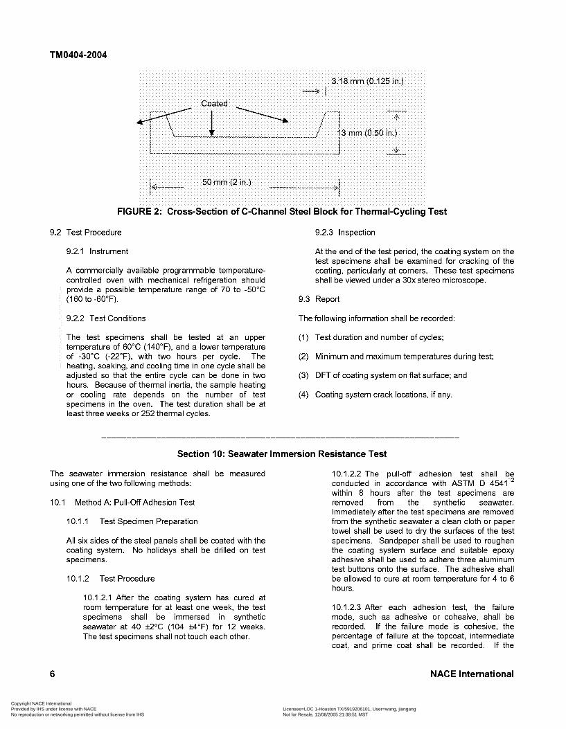
Figure 2: Cross-Section of C-Channel Steel Block
.. II NACE International
Copyright NACE International Provided by IHS under license with NACE Licensee=LOC 1-Houston TX/5919206101, User=wang, jiangang
Not for Resale, 12/08/2005 21:38:51 MSTNo reproduction or networking permitted without license from IHS
--``,,,,,``,,,`,,``,````,,`,`,,-`-`,,`,,`,`,,`---
TM0404-2004
Section 1: General
1 . I This standard test method covers liquid-applied new construction coating systems for the atmospheric zone and splash zone of an offshore platíorm. These coating systems are applied by conventional air, airless, or plural- component spray. Other types of coating materials, such as thermal spray metallic and elastomeric or petrolatum tape splash zone coatings, are not covered in this standard.
1.2 Five test methods-rust creepage resistance, edge retention, thermal-cycling resistance, flexibility, and impact strength-are used to evaluate coating systems for atmospheric service. In addition to these five test methods, seawater immersion resistance and cathodic disbondment
are also used to evaluate splash zone coating systems. The types of offshore platíorms covered by this standard include fixed-leg, semi-submersible, tension-leg, floating production storage and offloading (FPSO), etc.
1.3 The steel surface preparation for all test methods requires grit blasting to near-white metal finish. If a particular type of pre-construction primer (PCP) is required to remain on the grit-blasted surface prior to the application of primer in the field, the PCP shall be applied onto the grit- blasted steel surfaces according to the manufacturer’s specification. All the test methods shall still be applicable.
Section 2: Definitions
Atmospheric Zone: The area on an offshore structure that is above the splash zone.
Coating System: The complete number and types of coats applied to a substrate in a predetermined order.
Cracking (of Coating): Breaks in a coating that extend through to the substrate.
Delamination: The separation of a coat or coats from the previous coat or from the substrate.
Disbondment: The loss of adhesion between a coating and the substrate.
Edge Retention: The ratio of dry-film thickness (DFT) of the entire multicoat coating system at peak to average DFT on both flat surfaces on a sharp angle bar, used as a measure of a coating’s ability to retain its film coverage over sharp corners.
Fingerprinting: Method of identifying a coating material through laboratory analyses of coating density, solids content, pigment content, etc. Infrared (IR) spectroscopy is often used in the analyses.
Plural-Component Spraying: An application method that automatically proportions and mixes two or more components of a coating material in the process of delivering them to the spray gun. Plural-component spray equipment is used to apply coatings with a pot life that is too
short to permit mixing and application by conventional air and airless spray equipment.
Pot Life: The elapsed time within which a coating can be effectively applied after all components of the coating have been thoroughly mixed.
Recoat Window: The duration required for a coating to dry or cure before a subsequent coat can be applied successfully.
Room Temperature: An indoor temperature generally between 20 and 25°C (68 and 77°F).
Rust Creepage (Undercutting): The penetration of a coating and the spread of delamination or corrosion from a scribe or holiday in the film.
Shelf Life: The amount of time a coating or other material remains in usable condition.
Splash Zone: The area on an offshore structure that is alternatively dry and wet because of the influence of tides, winds, and waves.
Synthetic Seawater: An aqueous solution containing inorganic salts in proportions and concentrations representative of ocean water (also known as “substitute ocean water”).
NACE International 1
Copyright NACE International Provided by IHS under license with NACE Licensee=LOC 1-Houston TX/5919206101, User=wang, jiangang
Not for Resale, 12/08/2005 21:38:51 MSTNo reproduction or networking permitted without license from IHS
--``,,,,,``,,,`,,``,````,,`,`,,-`-`,,`,,`,`,,`---
TM0404-2004
Section 3: Coating Materials
3.1 General When each coating system is submitted to qualification testing the coating manufacturer shall provide the following
The selection of the coating system may depend on the information as part of the test report. weather (ambient temperature, humidity) and recoat window, in addition to the coating petformance. The (1) Product data sheet coating system petformance shall pass the acceptance criteria specified by each facility owner. If the coating (2) Material safety data sheet (MSDS) formulation is changed after the qualification, the coating system shall be requalified in accordance with the latest revision of this standard.
3.2 Required Product Information
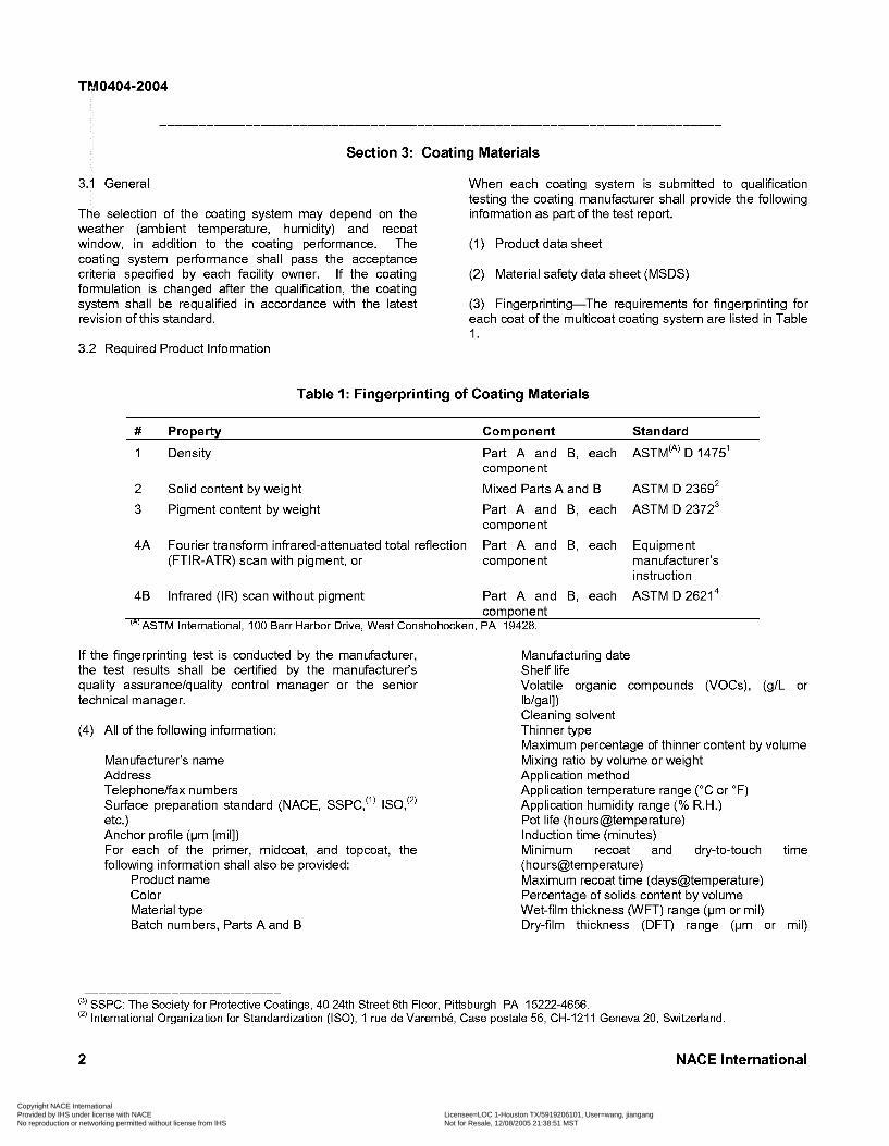
(3) Fingerprinting-The requirements for fingerprinting for each coat of the multicoat coating system are listed in Table 1.
Table 1 : Fingerprinting of Coating Materials
# Property Component Standard
1 Density Part A and B, each ASTM‘A’ D 1475’
2 Solid content by weight Mixed Parts A and B ASTM D 2369’
3 Pigment content by weight Part A and B, each ASTMD23723
4A Fourier transform infrared-attenuated total reflection Part A and B, each Equipment
instruction
component
component
(FTIR-ATR) scan with pigment, or component manufacturer’s
4B Infrared (IR) scan without pigment Part A and B, each ASTM D26214
‘A’ASTM International, 1 O0 Barr Harbor Drive, West Conshohocken, PA 19428. component
If the fingerprinting test is conducted by the manufacturer, the test results shall be certified by the manufacturer’s quality assurance/quality control manager or the senior technical manager.
(4) All of the following information:
Manufacturer’s name Address Telephone/fax numbers Sutface preparation standard (NACE, SSPC,”’ ISO,‘’’ etc.) Anchor profile (pm [mil]) For each of the primer, midcoat, and topcoat, the following information shall also be provided:
Product name Color Material type Batch numbers, Parts A and B
Manufacturing date Shelf life Volatile organic compounds (VOCs), (g/L or Ib/gal]) Cleaning solvent Thinner type Maximum percentage of thinner content by volume Mixing ratio by volume or weight Application method Application temperature range (“C or OF) Application humidity range (% R.H.) Pot life (hours@tem peratu re) Induction time (minutes) Minimum recoat and dry-to-touch time (hou rs@tem peratu re) Maximum recoat time (days@temperature) Percentage of solids content by volume Wet-film thickness (WFT) range (pm or mil) Dry-film thickness (DFT) range (pm or mil)
(3) SSPC: The Society for Protective Coatings, 40 24th Street 6th Floor, Pittsburgh PA 15222-4656. International Organization for Standardization (ISO), 1 rue de Varernbé, Case postale 56, CH-I21 1 Geneva 20, Switzerland.
2 NACE International
Copyright NACE International Provided by IHS under license with NACE Licensee=LOC 1-Houston TX/5919206101, User=wang, jiangang
Not for Resale, 12/08/2005 21:38:51 MSTNo reproduction or networking permitted without license from IHS
--``,,,,,``,,,`,,``,````,,`,`,,-`-`,,`,,`,`,,`---
TM0404-2004
Section 4: Test Solution
Synthetic seawater used in several of the test methods in synthetic seawater. Commercial-grade sea salts may be this standard shall be prepared with the sea salt chemical used instead of reagent-grade sea salts to prepare the composition in accordance with ASTM D 1 141.5 The minute synthetic seawater. concentration of heavy metals is not required to prepare the
Section 5: Test Specimens
5.1 Test Specimen Geometry, Size, Substrate Material, and Minimum Quantity
5.1.1 Table 2 lists the specified test specimen geometry, size, substrate material, and minimum quantity of test specimens for each test method. Extra 5.2 coated test specimens should be prepared in case a repeat test is needed later.
center of one of the 76-mm (3.0-in.) sides of each steel panel to suspend the panel in the air so that the entire panel can be coated at one time. Other techniques to spray all sides of a panel may also be used.
Su iface Preparation
5.2.1 NACE No. 2ESPC-SP 106 or IS0 8501-1 Sa 2.57 near-white metal finish.
5.1.2 A welding rod 3.18 mm (0.125 in.) in diameter and 76 mm (3.0 in.) in length should be welded to the
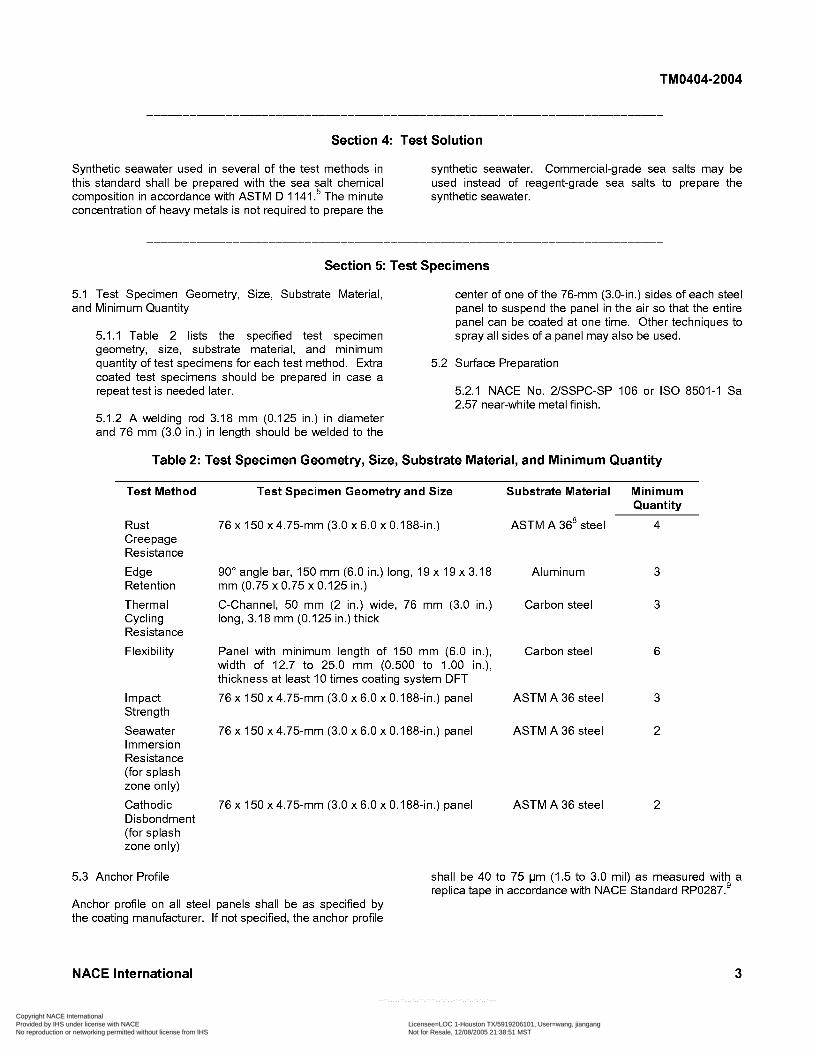
Table 2: Test Specimen Geometry, Size, Substrate Material, and Minimum Quantity
Test Method Test Specimen Geometry and Size Substrate Material Minimum Quantity
Rust Creepage Resistance
Edge Retention
Thermal Cycling Resistance
Flexibility
Impact Strength
Seawater Immersion Resistance (for splash zone only)
Cathodic Disbondment (for splash zone only)
5.3 Anchor Profile
76 x 150 x4.75-mm (3.0 x 6.0 x 0,188-in.)
90" angle bar, 150 mm (6.0 in.) long, 19 x 19 x 3.18 mm (0.75 x 0.75 x 0.125 in.)
C-Channel, 50 mm (2 in.) wide, 76 mm (3.0 in.) long, 3.18 mm (0.125 in.) thick
Panel with minimum length of 150 mm (6.0 in.), width of 12.7 to 25.0 mm (0.500 to 1.00 in.), thickness at least 10 times coating system DFT
76 x 150 x 4.75-mm (3.0 x 6.0 x 0,188-in.) panel
76 x 150 x 4.75-mm (3.0 x 6.0 x 0,188-in.) panel
76 x 150 x 4.75-mm (3.0 x 6.0 x 0,188-in.) panel
ASTM A 368 steel 4
Aluminum 3
Carbon steel 3
Carbon steel 6
ASTM A 36 steel 3
ASTM A 36 steel 2
ASTM A 36 steel 2
shall be 40 to 75 pm (1.5 to 3.0 mil) as measured with a replica tape in accordance with NACE Standard RP0287.'
Anchor profile on all steel panels shall be as specified by the coating manufacturer. If not specified, the anchor profile
NACE International 3
Copyright NACE International Provided by IHS under license with NACE Licensee=LOC 1-Houston TX/5919206101, User=wang, jiangang
Not for Resale, 12/08/2005 21:38:51 MSTNo reproduction or networking permitted without license from IHS
--``,,,,,``,,,`,,``,````,,`,`,,-`-`,,`,,`,`,,`---
TM0404-2004
Section 6: Coating Application
6.1 All coatings shall be well mixed using Part N B ratios as specified by the manufacturers. Each coat of the coating system shall be applied to the substrate material at the specified DFT by a conventional air or airless spray gun, whichever is specified by the facility owner.
6.2 The application method, temperature, and relative humidity at the time of application shall be recorded. After
the coating system has cured, DFT measurements shall be made in five locations on each test specimen, and the average DFT shall be determined.
6.3 All coating systems shall be allowed to cure at room temperature for at least one week before testing.
Section 7: Rust Creepage Resistance Test
7.1 Test Specimen Preparation
All six sides of steel panels shall be coated with the coating system. After the coating system has cured for at least one week, a vertical scribe, 90 mm (3.5 in.) long and 1 to 2 mm (0.04 to 0.08 in.) wide, shall be made on each test specimen using a motorized circular blade. Care shall be taken to make sure that each scribe is just deep enough to expose bare steel. The scribe shall be made at the appropriate location on the test specimen to receive uniform ultraviolet (UV) light exposure. The scribe shall be cleaned with compressed air, leaving no debris in the scribe.
7.2 Test Procedure
7.2.1 For the rust creepage resistance test, ASTM D 5894” shall be adopted, but modified, replacing the acid test solution with synthetic seawater.
7.2.2 After the total test duration of 12 weeks, the test specimens shall be rinsed with tap water to remove residual salt. The coatings that have been undercut and have suffered loss of adhesion may be removed mechanically with a scraper as described in ASTM D 1654.” Alternatively, a 21-MPa (3,000-psi) pressure wash may also be used to remove loose coating along the scribe. Twelve lines, perpendicular to the scribe, shall be drawn along the length of the scribe at 6.4-mm (0.25-in.) intervals. The average rust creepage value shall be calculated using Equation (1).
average rust creepage width - scribe width
2 Average Rust Creepage Value =
7.2.3 Visual inspection shall also be conducted to (1) DFT and rust creepage of each test specimen; examine other failure modes such as blister formation, coating cracking, etc. (2) Average rust creepage; and
7.3 Report (3) Blisters, cracking, or other failures.
The following information shall be reported:
Section 8: Edge-Retention Test
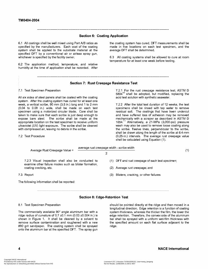
8.1 Test Specimen Preparation
The commercially available 90” angle aluminum bar with a ridge radius of curvature of 0.7 IO. l mm (0.03 I0.004 in.) is shown in Figure 1. It shall be cleaned by a solvent to remove sutface contamination and roughened with a new #80 grit sandpaper. The coating system shall be sprayed ridge. onto the aluminum bar at the specified DFT. The spray gun
should be pointed directly at the ridge and then moved in a longitudinal direction. Edge retention is a function of coating system thickness, whereas the thicker the film, the lower the edge retention. Therefore, the convex side of the aluminum bar shall be sprayed with a uniform wet-film thickness with the specified amount on each flat sutface adjacent to the
4 NACE International
Copyright NACE International Provided by IHS under license with NACE Licensee=LOC 1-Houston TX/5919206101, User=wang, jiangang
Not for Resale, 12/08/2005 21:38:51 MSTNo reproduction or networking permitted without license from IHS
--``,,,,,``,,,`,,``,````,,`,`,,-`-`,,`,,`,`,,`---
TM0404-2004
8.2 Test Procedure
After the coating system has been allowed to cure for at least one week, a band saw shall be used to cut nine 12.7- mm (0.500-in.) test specimens from the 150-mm (6.0411.) aluminum bar. Three test specimens should be bundled together to cast in a 25-mm (1.0-in.) diameter cold mount. The cold-mount material can be either polyester or epoxy resin. Three cold mounts with nine test specimens in total for each coating system shall be made. Edge retention of a coating system varies along the length of the ridge. Nine data points shall be collected to obtain a more representative average value. The cold mounts shall be ground with sandpaper. Polishing is not necessary. The coating system thickness shall be measured at the peak of the ridge and on both adjacent flat sutfaces. The average peaklflat coating system thickness ratio and the average DFT of the coating system on the flat sutfaces shall be calculated. The coating system thickness shall be measured by one of the following three methods:
(1) Photographs shall be taken under a microscope with the magnification mark on the tab of the print;
(2) Optical filar micrometer on an eyepiece of a stereo microscope; or
(3) Optical profilometer.
8.3 Report
The following information shall be reported:
(1) Type of spray gun used to apply the coating system;
(2) Radius of curvature of the ridge of the 90" angle aluminum bar;
(3) DFT of the coating system at the peak of the ridge and on both adjacent flat sutfaces for each test specimen;
(4) Peaklflat coating system thickness ratio for each test specimen; and
(5) Average peaklflat coating system thickness ratio and the average DFT of the coating system on the flat sutfaces.
Section 9: Thermal-Cycling Resistance Test
9.1 Test Specimen Preparation A full coating system with manufacturer-specified DFT shall be sprayed on the inner sutface of the C-channel. The
The test specimen used for the thermal-cycling resistance coated C-channel block shall be postcured at 60°C (140°F) test shall be a C-channel steel block, illustrated in Figure 2. for one week before running the thermal-cycling test.
NACE International 5
Copyright NACE International Provided by IHS under license with NACE Licensee=LOC 1-Houston TX/5919206101, User=wang, jiangang
Not for Resale, 12/08/2005 21:38:51 MSTNo reproduction or networking permitted without license from IHS
--``,,,,,``,,,`,,``,````,,`,`,,-`-`,,`,,`,`,,`---
TM0404-2004
Test
9.2 Test Procedure 9.2.3 Inspection
9.2.1 Instrument
A commercially available programmable temperature- controlled oven with mechanical refrigeration should provide a possible temperature range of 70 to -50°C (1 60 to -60°F).
9.2.2 Test Conditions
The test specimens shall be tested at an upper temperature of 60°C (140"F), and a lower temperature of -30°C (-22"F), with two hours per cycle. The heating, soaking, and cooling time in one cycle shall be adjusted so that the entire cycle can be done in two hours. Because of thermal inertia, the sample heating or cooling rate depends on the number of test specimens in the oven. The test duration shall be at least three weeks or 252 thermal cycles.
At the end of the test period, the coating system on the test specimens shall be examined for cracking of the coating, particularly at corners. These test specimens shall be viewed under a 30x stereo microscope.
9.3 Report
The following information shall be recorded:
(1) Test duration and number of cycles;
(2) Minimum and maximum temperatures during test;
(3) DFT of coating system on flat surface; and
(4) Coating system crack locations, if any.
Section 1 O: Seawater Immersion Resistance Test
The seawater immersion resistance shall be measured using one of the two following methods:
10.1 Method A: Pull-ûfíAdhesion Test
10.1 . I Test Specimen Preparation
All six sides of the steel panels shall be coated with the coating system. No holidays shall be drilled on test specimens.
10.1.2 Test Procedure
10.1.2.1 After the coating system has cured at room temperature for at least one week, the test specimens shall be immersed in synthetic seawater at 40 I2"C (104 k4OF) for 12 weeks. The test specimens shall not touch each other.
10.1.2.2 The pull-off adhesion test shall be conducted in accordance with ASTM D 4541" within 8 hours after the test specimens are removed from the synthetic seawater. Immediately after the test specimens are removed from the synthetic seawater a clean cloth or paper towel shall be used to dry the sutfaces of the test specimens. Sandpaper shall be used to roughen the coating system sutface and suitable epoxy adhesive shall be used to adhere three aluminum test buttons onto the sutface. The adhesive shall be allowed to cure at room temperature for 4 to 6 hours.
10.1.2.3 After each adhesion test, the failure mode, such as adhesive or cohesive, shall be recorded. If the failure mode is cohesive, the percentage of failure at the topcoat, intermediate coat, and prime coat shall be recorded. If the
6 NACE International
Copyright NACE International Provided by IHS under license with NACE Licensee=LOC 1-Houston TX/5919206101, User=wang, jiangang
Not for Resale, 12/08/2005 21:38:51 MSTNo reproduction or networking permitted without license from IHS
--``,,,,,``,,,`,,``,````,,`,`,,-`-`,,`,,`,`,,`---
TM0404-2004
failure mode is a mixture of cohesive and adhesive, the percentage of failure shall be recorded for each. If more than 50% of the failure is at the adhesive and the adhesion is less than 10 MPa (1,400 psi), the test shall be repeated.
10.1.2.4 All immersed test specimens shall be evaluated for the presence of blisters. Blister formation shall be measured in accordance with ASTM D 714.13
holiday and the values used to calculate the average radial disbondment in mm (in.). The average wet disbondment of four holidays for two test specimens shall then be calculated.
10.2.2.3 All immersed test specimens shall be evaluated for the presence of blisters. Blister formation shall be measured in accordance with ASTM D 714.
10.2.3Report 10.2 Method B: Wet Disbondment Test
10.2.1 Test Specimen Preparation
All six sides of the steel panels shall be coated with the coating system. After the coating system has cured at room temperature for at least one week, a flat-head drill bit shall be used to drill a 3.18-mm (0,125-in.) holiday through the coating system in the center on each side of the test specimen. The holiday shall be deep enough to expose the bare steel and shall be cleaned with compressed air without debris left in the holiday.
10.2.2Test Procedure
10.2.2.1 The test specimens shall then be immersed in synthetic seawater at 40 I2"C (104 k4OF) for 12 weeks.
10.2.2.2 Loose coating around the holiday shall be peeled off with a pocket knife within 8 hours after the test specimens are removed from the synthetic seawater. Four diagonal disbondment lengths shall be measured from the edge of each
The following information shall be reported:
(1) Synthetic seawater temperature during test and test duration;
(2) Coating system DFT for each side of the test specimens; and
(3) Presence of any blisters; and for Method A,
(4) Pull-off adhesion value and coating failure mode associated with each aluminum test button; and
(5) Average pull-off adhesion value for the coating system and the dominant coating system failure mode; or for Method B,
(4) Wet disbondment of each holiday in mm (in.); and
(5) Average wet disbondment of four holidays in mm (in.).
Section 11: Cathodic Disbondment Test
11 . I Test Specimen Preparation
All six sides of the steel panels shall be coated with the coating system. After the coating system has cured for at least one week, a flat-head drill bit shall be used to drill a 3.18-mm (0,125-in.) diameter holiday through the coating system in the center on each side of the test specimen. The holiday shall be deep enough to expose the bare steel and shall be cleaned with compressed air without debris left in the holiday.
11.2 Test Procedure
11.2.1 A modified ASTM G 814 procedure shall be used to measure the cathodic disbondment of the coating system. The test shall be done by one of two acceptable methods, either attaching a galvanic zinc anode to each test specimen immersed in the synthetic
seawater, or by using impressed current. If zinc anodes are used, the anode sutface shall be abraded to make sure the sutface is active. For the impressed current method, synthetic seawater shall be used instead of the 3 wt% mixed-salt solution. A single DC power supplier shall be used to provide the -1.0 (+O/- 0.1) V DC electrical potential to the test specimens with reference to a standard calomel electrode.
11.2.2 After 12 weeks, the test specimens shall be removed from the synthetic seawater. After the removal of loose coating, the disbondment length shall be measured. The radial disbondment shall be calculated using Equation (2). The average radial disbondment value from the edge of the holiday shall be calculated over the four holidays for two test specimens.
average disbondment length - holiday size 2 Radial disbondment =
NACE International
Copyright NACE International Provided by IHS under license with NACE Licensee=LOC 1-Houston TX/5919206101, User=wang, jiangang
Not for Resale, 12/08/2005 21:38:51 MSTNo reproduction or networking permitted without license from IHS
--``,,,,,``,,,`,,``,````,,`,`,,-`-`,,`,,`,`,,`---
TM0404-2004
11.3 Report (3) Average coating system DFT on each side of the test specimens;
The following information shall be recorded: (4) Synthetic seawater temperature; and
(1) Radial cathodic disbondment for each holiday;
(2) Average cathodic disbondment value of the four h o1 idays ;
(5) Anode material, and reference electrode.
12.1 Test Specimen Preparation
Section 12: Flexibility Test
Any metal burrs shall be removed. Only one side of the six steel panels shall be coated. Test specimens shall be postcured at 60°C (140°F) for one week in addition to the initial curing at room temperature for one week.
12.2 Test Procedure
12.2.1 Instrument
12.2.1 . I A fixed-radii mandrel bending machine, as described in NACE Standard RP0394I5 for the measurement of the flexibility of fusion-bonded epoxy pipeline coating material, shall be used to measure the flexure strain of the coating systems.
12.2.1.2 A stereo microscope with 30x magnification and a low-voltage holiday detector shall be used to detect cracking.
12.2.2 The bare face of the test specimen shall be bent over the fixed-radius steel mandrel. The deformed coating sutface shall be examined for signs of cracking using a stereo microscope and a low- voltage holiday detector. If no cracking is detected, the test specimen shall be bent over a mandrel with a smaller radius. The process shall be repeated until cracking is detected. The flexure strain of the coating material shall be calculated using Equation (3).
(t/2 + c) (R+t/2) flexure strain of coating = (3)
Where t = steel panel thickness (mm or in.) c = coating system thickness (mm or in.) R = mandrel radius (mm or in.)
12.2.3 Because discrete bending radii are used, the true flexure strain is actually somewhere between two consecutive mandrel radii. For practical purposes, the flexure strain of the coating system shall be reported as the average of these two values.
12.2.4 If the coating system is intended to be used in cold weather, test specimens should all be cooled in a cold chamber to the coldest service temperature for at least 30 minutes prior to the flexibility test at room temperature. The test shall be done immediately after the test specimen is removed from the cold chamber.
12.3 Report
The following information shall be reported:
(1) Steel panel thickness and coating system thickness;
(2) Preconditioning temperature and time;
(3) Steel mandrel radii; and
(4) Coating system flexure strain in % and room temperature.
Section 13: Impact Resistance Test
13.1 Test Specimen Preparation This test shall be conducted in accordance with procedures described in ASTM G 1416 and D 2794.17 If the coating
Only one side of the steel panels shall be coated. Test system is intended for use in a very cold climate, test specimens shall be postcured at 60°C (140°F) for one week specimens shall be conditioned at the coldest field in addition to the initial curing at room temperature for one temperature for at least 30 minutes and then tested at room week. temperature immediately after removal from the cold
13.2 Test Procedure
8
chamber.
13.3 Report
NACE International
Copyright NACE International Provided by IHS under license with NACE Licensee=LOC 1-Houston TX/5919206101, User=wang, jiangang
Not for Resale, 12/08/2005 21:38:51 MSTNo reproduction or networking permitted without license from IHS
--``,,,,,``,,,`,,``,````,,`,`,,-`-`,,`,,`,`,,`---
TM0404-2004
The following information shall be reported: (3) Test temperature;
(1) Steel panel dimensions;
(2) Average coating system DFT;
(4) Preconditioning temperature (if applicable); and
(5) Impact test results.
Refe re n ces
1. ASTM D 1475 (latest revision), “Standard Test Method for Density of Liquid Coatings, Inks, and Related Products” (West Conshohocken, PA: ASTM).
2. ASTM D 2369 (latest revision), “Standard Test Method for Volatile Content of Coatings” (West Conshohocken, PA: ASTM).
3. ASTM D 2372 (latest revision), “Standard Practice for Separation of Vehicle From Solvent-Reducible Paints” (West Conshohocken, PA: ASTM).
4. ASTM D 2621 (latest revision), “Standard Test Method for Infrared Identification of Vehicle Solids from Solvent- Reducible Paints” (West Conshohocken, PA: ASTM).
5. ASTM D 1141 (latest revision), “Standard Practice for Substitute Ocean Water” (West Conshohocken, PA: ASTM).
6. NACE No. 2/SSPC-SP 10 (latest revision), “Near-White Metal Blast Cleaning” (Houston, TX: NACE, and Pittsburgh, PA: SSPC).
7. IS0 8501-1 (latest revision), “Preparation of Steel Substrates Before Application of Paints and Related Products-Visual Assessment of Surface Cleanliness-Part 1: Rust Grades and Preparation Grades of Uncoated Steel Substrates and of Steel Substrates After Overall Removal of Previous Coatings” (Geneva, Switzerland: ISO).
IO. ASTM D 5894 (latest revision), “Standard Practice for Cyclic Salt Fog/UV Exposure of Painted Metal, (Alternating Exposures in a Fog/Dty Cabinet and a UV/Condensation Cabinet)” (West Conshohocken, PA: ASTM).
11. ASTM D 1654 (latest revision), “Standard Test Method for Evaluation of Painted or Coated Specimens Subjected to Corrosive Environments” (West Conshohocken, PA: ASTM).
12. ASTM D 4541 (latest revision), “Standard Test Method for Pull-Off Strength of Coatings Using Portable Adhesion Testers” (West Conshohocken, PA: ASTM).
13. ASTM D 714 (latest revision), “Standard Test Method for Evaluating Degree of Blistering of Paints” (West Conshohocken, PA: ASTM).
14. ASTM G 8 (latest revision), “Standard Test Methods for Cathodic Disbonding of Pipeline Coatings” (West Conshohocken, PA: ASTM).
15. NACE Standard RP0394 (latest revision), “Application, Performance, and Quality Control of Plant-Applied, Fusion- Bonded Epoxy External Pipe Coating” (Houston, TX: NACE).
16. ASTM G 14 (latest revision), “Standard Test Method for Impact Resistance of Pipeline Coatings (Falling Weight Test)” (West Conshohocken, PA: ASTM).
8. ASTM A 36/A 36M (latest revision), “Standard 17. ASTM D 2794 (latest revision), “Standard Test Method Specification for Carbon Structural Steel” (West for Resistance of Organic Coatings to the Effects of Rapid Conshohocken, PA: ASTM). Deformation (Impact)” (West Conshohocken, PA: ASTM).
9. NACE Standard RP0287 (latest revision), “Field Measurement of Surface Profile of Abrasive Blast-Cleaned Steel Surfaces Using a Replica Tape” (Houston, TX: NACE).
NACE International 9
Copyright NACE International Provided by IHS under license with NACE Licensee=LOC 1-Houston TX/5919206101, User=wang, jiangang
Not for Resale, 12/08/2005 21:38:51 MSTNo reproduction or networking permitted without license from IHS
--``,,,,,``,,,`,,``,````,,`,`,,-`-`,,`,,`,`,,`---