st-45-kfa-e/st-70t-kfa-e/st-125t-kfa-e st-175t-kfa-e
TRANSCRIPT

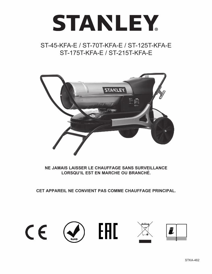
ST-45-KFA-E/ST-70T-KFA-E/ST-125T-KFA-E ST-175T-KFA-E/ST-215T-KFA-E
LAAT DE KACHEL NOOIT ONBEWAAKT ACHTER TERWIJL HIJ AANSTAAT OF DE STEKKER IN HET STOPCONTACT IS GESTOKEN.
DIT PRODUCT IS NIET GESCHIKT ALS HOOFDVERWARMING.
STKA-462
© 2018, Obelis S.A. Vestigingsadres: Bd. Général Wahis, 531030 Brussels, Belgium
LAAT DE KACHEL NOOIT ONBEWAAKT ACHTER MET DE STEKKER IN HET STOPCONTACT
LEES DE ONDERSTAANDE AANWIJZINGEN AANDACHTIG VOORDAT U HET APPARAAT GEBRUIKT.
- Dit apparaat mag worden gebruikt door kinderen van 8 jaar en ouder en door personen met verminderde lichamelijke, zintuiglijke of mentale capaciteiten of gebrek aan ervaring of kennis mits onder toezicht of nadat zij zijn ingelicht over veilig gebruik van het apparaat en de gevaren waarmee gebruik gepaard gaat. Kinderen mogen niet met dit apparaat spelen. Reiniging en onderhoud mogen niet door kinderen zonder toezicht worden uitgevoerd.
- Kinderen onder de 3 moeten uit de buurt worden gehouden tenzij onder voortdurend toezicht. Kinderen van 3 tot en met 8 jaar oud mogen het apparaat alleen in- en uitschakelen als het in de beoogde normale bedrijfsstand staat/is geïnstalleerd indien onder toezicht of nadat zij zijn ingelicht over veilig gebruik van het apparaat en de gevaren waarmee gebruik gepaard gaat. Kinderen van 3 tot en met 8 jaar oud mogen de stekker van het apparaat niet in het stopcontact steken, het apparaat niet bedienen en het apparaat niet reinigen of onderhouden.
- LET OP: Sommige onderdelen van dit product worden heel heet en kunnen brandwonden veroorzaken. Bij aanwezigheid van kinderen en kwetsbare personen is extra voorzichtigheid geboden.
- Als het snoer beschadigd raakt, moet het worden vervangen door de fabrikant, diens service-agent of andere bevoegde personen om gevaren te voorkomen.
- De kachel mag niet vlak onder een stopcontact worden geplaatst. - Gebruik deze kachel niet in de onmiddellijke nabijheid van een bad, douche of
zwembad. - Deze kachel is gevuld met een bepaalde hoeveelheid speciale olie. Reparaties
waarvoor het oliereservoir geopend moet worden, mogen alleen worden uitgevoerd door de fabrikant of een erkende reparateur, waarmee in geval van olielekkage contact moet worden opgenomen.
- Neem bij afvoer van de kachel de voor afvoer van de olie geldende regels in acht. Gooi de kachel niet met huishoudelijk afval weg, en recycleer de kachel als er ter plaatse voorzieningen zijn voor elektrische apparaten en olie.
- Zet het apparaat op een horizontaal, stabiel, hittebestendig oppervlak. Gebruik van het product in een andere positie kan gevaarlijk zijn.
- Bij het eerste gebruik zult u enkele minuten lang misschien een geur bespeuren. Dit is normaal en zal snel verdwijnen.
- Probeer niet om het apparaat te repareren, demonteren of wijzigen. Er zijn geen onderdelen die door de gebruiker kunnen worden gerepareerd.
- LET OP – Bij gebruik van een verlengsnoer mag de maximale nominale spanning/belasting van het verlengsnoer niet overschreden worden.
© 2018, Obelis S.A. Vestigingsadres: Bd. Général Wahis, 531030 Brussels, Belgium
LAAT DE KACHEL NOOIT ONBEWAAKT ACHTER MET DE STEKKER IN HET STOPCONTACT
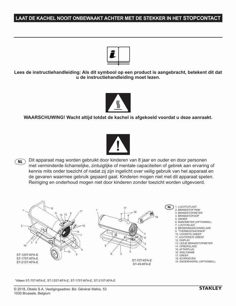
Lees de instructiehandleiding: Als dit symbool op een product is aangebracht, betekent dit dat u de instructiehandleiding moet lezen.
WAARSCHUWING! Wacht altijd totdat de kachel is afgekoeld voordat u deze aanraakt.
Dit apparaat mag worden gebruikt door kinderen van 8 jaar en ouder en door personen met verminderde lichamelijke, zintuiglijke of mentale capaciteiten of gebrek aan ervaring of kennis mits onder toezicht of nadat zij zijn ingelicht over veilig gebruik van het apparaat en de gevaren waarmee gebruik gepaard gaat. Kinderen mogen niet met dit apparaat spelen. Reiniging en onderhoud mogen niet door kinderen zonder toezicht worden uitgevoerd.
5
3
4
6
28
9
17
19
7
118
12
110
19
11
7
6
316
13
4
5
89
14
2
15
ST-70T-KFA-EST-45-KFA-E
ST-125T-KFA-EST-175T-KFA-EST-215T-KFA-E
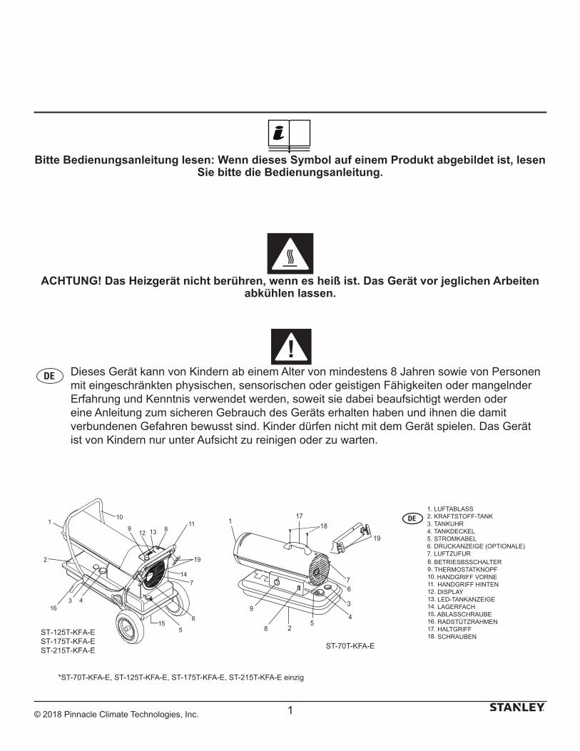
1. LUCHTUITLAAT2. BRANDSTOFTANK3. BRANDSTOFMETER4. BRANDSTOFDOP5. SNOER6. MANOMETER (OPTIONEEL)7. LUCHTINLAAT8. BEDIENINGSSCHAKELAAR9. *THERMOSTAATKNOP10. VOORSTE GREEP11. ACHTERSTE GREEP12. DISPLAY13. LEDJE BRANDSTOFMETER14. OPBERGLADE15. AFTAPPLUG16. WIELFRAME17. GREEP18. SCHROEVEN19. SNOERHASPEL (OPTIONEEL)
*Alleen ST-70T-KFA-E, ST-125T-KFA-E, ST-175T-KFA-E, ST-215T-KFA-E
© 2018, Obelis S.A. Vestigingsadres: Bd. Général Wahis, 531030 Brussels, Belgium
LAAT DE KACHEL NOOIT ONBEWAAKT ACHTER MET DE STEKKER IN HET STOPCONTACT
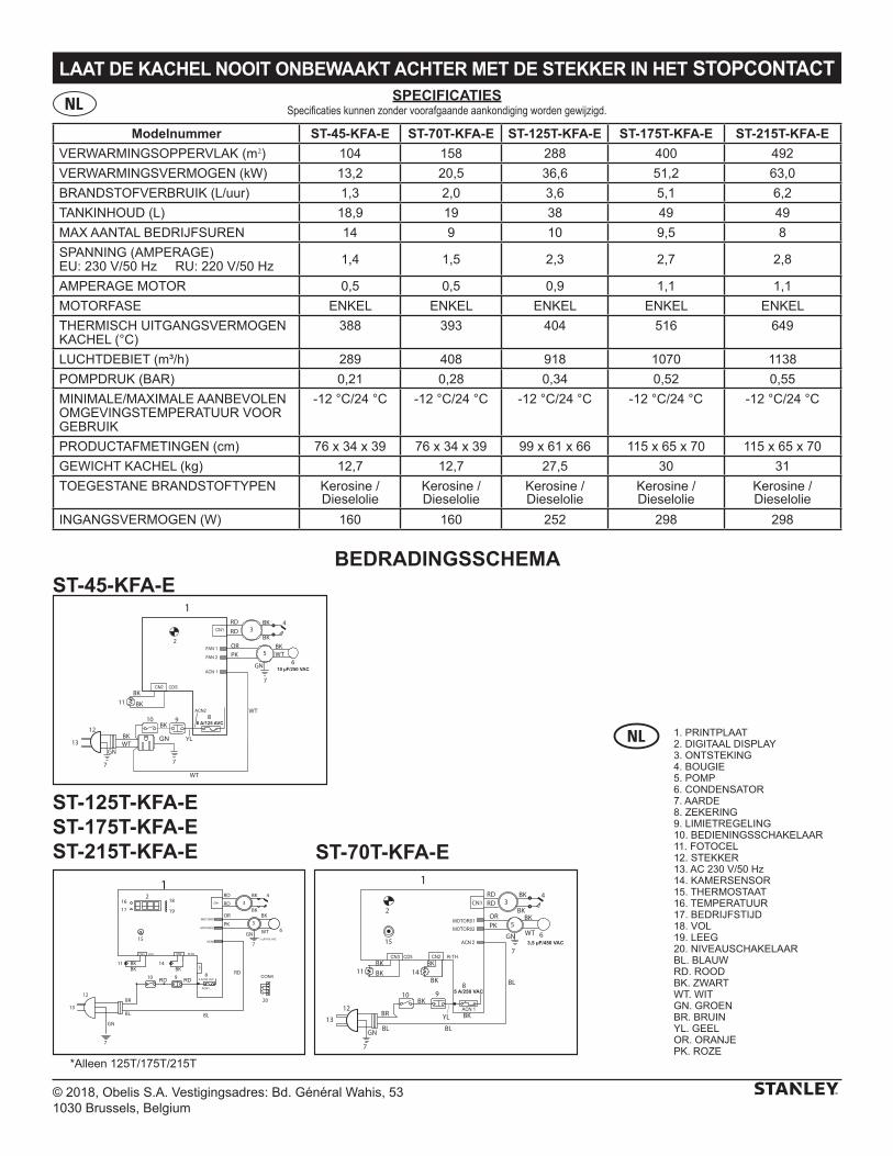
Modelnummer ST-45-KFA-E ST-70T-KFA-E ST-125T-KFA-E ST-175T-KFA-E ST-215T-KFA-E
VERWARMINGSOPPERVLAK (m2) 104 158 288 400 492
VERWARMINGSVERMOGEN (kW) 13,2 20,5 36,6 51,2 63,0
BRANDSTOFVERBRUIK (L/uur) 1,3 2,0 3,6 5,1 6,2
TANKINHOUD (L) 18,9 19 38 49 49
MAX AANTAL BEDRIJFSUREN 14 9 10 9,5 8
SPANNING (AMPERAGE)EU: 230 V/50 Hz RU: 220 V/50 Hz 1,4 1,5 2,3 2,7 2,8
AMPERAGE MOTOR 0,5 0,5 0,9 1,1 1,1
MOTORFASE ENKEL ENKEL ENKEL ENKEL ENKEL
THERMISCH UITGANGSVERMOGEN KACHEL (°C)
388 393 404 516 649
LUCHTDEBIET (m³/h) 289 408 918 1070 1138
POMPDRUK (BAR) 0,21 0,28 0,34 0,52 0,55
MINIMALE/MAXIMALE AANBEVOLEN OMGEVINGSTEMPERATUUR VOOR GEBRUIK
-12 °C/24 °C -12 °C/24 °C -12 °C/24 °C -12 °C/24 °C -12 °C/24 °C
PRODUCTAFMETINGEN (cm) 76 x 34 x 39 76 x 34 x 39 99 x 61 x 66 115 x 65 x 70 115 x 65 x 70
GEWICHT KACHEL (kg) 12,7 12,7 27,5 30 31
TOEGESTANE BRANDSTOFTYPEN Kerosine / Dieselolie
Kerosine / Dieselolie
Kerosine / Dieselolie
Kerosine / Dieselolie
Kerosine / Dieselolie
INGANGSVERMOGEN (W) 160 160 252 298 298
SPECIFICATIESSpecificaties kunnen zonder voorafgaande aankondiging worden gewijzigd.
BEDRADINGSSCHEMA
1
WT
BK
OR
BK 4
2
12
13
GN
7
GN
7
11
10BK
9
BR
BKBK
BL
BL8
5
3
615
14BK
RDRD
BKPK
BK
BL
YL
BKCN1
5 A/250 VAC
3,5 µF/450 VAC
RD10
11
12
13
1RD
RD
PK
OR
WT
BK3
4
5
GN
7
6
8 RD
BL
9
GN
7
BR
BL
14BKBK
BK
15
20
RD
BKBK
1617
18
19
2
7 µF/450 VAC
5 A/250 VAC
10 µF/250 VAC
1RD
WT
RD
OR
BK
BK
WT
BK
BK
BK
BK
PKBK
4
2
12
13GN
GN
7
7
11
10 9 8
5
3
6
WT
YLGN
7
WT
8 A/125 AVC
ST-45-KFA-E
ST-70T-KFA-E
ST-125T-KFA-EST-175T-KFA-EST-215T-KFA-E
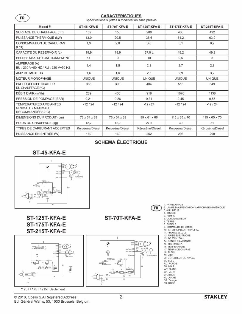
1. PRINTPLAAT2. DIGITAAL DISPLAY3. ONTSTEKING4. BOUGIE5. POMP6. CONDENSATOR7. AARDE8. ZEKERING9. LIMIETREGELING10. BEDIENINGSSCHAKELAAR11. FOTOCEL12. STEKKER13. AC 230 V/50 Hz14. KAMERSENSOR15. THERMOSTAAT16. TEMPERATUUR17. BEDRIJFSTIJD18. VOL19. LEEG20. NIVEAUSCHAKELAARBL. BLAUWRD. ROODBK. ZWARTWT. WITGN. GROENBR. BRUINYL. GEELOR. ORANJEPK. ROZE
*Alleen 125T/175T/215T
© 2018, Obelis S.A. Vestigingsadres: Bd. Général Wahis, 531030 Brussels, Belgium
LAAT DE KACHEL NOOIT ONBEWAAKT ACHTER MET DE STEKKER IN HET STOPCONTACT
VeiligheidsinformatieDit is een direct op kerosine werkende kachel met luchtverplaatsing. Hij is voornamelijk bestemd voor tijdelijke verwarming van gebouwen in aanbouw, verbouwing of reparatie. Dit apparaat produceert kleine hoeveelheden koolmonoxide. WAARSCHUWING! Risico van luchtverontreiniging binnenshuis! Gebruik deze kachel alleen op goed geventileerde locaties! Zorg voor een opening naar de buitenlucht van ten minste 2800 cm2 voor elke 29 kW/h of 100.000 BTU/h nominaal verwarmingsvermogen. Zorg voor een grotere opening als er meer kachels worden gebruikt.
Risico van brandwonden/brand en explosies! Gebruik NOOIT brandstof
zoals benzine, benzeen, alcohol, gaspatronen, verfverdunner of andere oliesamenstellingen in deze kachel. (DIT ZIJN VLUCHTIGE BRANDSTOFFEN DIE BRAND OF EEN EXPLOSIE KUNNEN VEROORZAKEN.)
Minimumafstand voor ontvlambaar materiaal:
ST-45-/ 70T-/ 125T-/ 175T-/ 215T-KFA-E Bovenkant 1,2 m Zijkanten 1,2 m Voorkant 3,0 m
- Vul de brandstoftank van de kachel NOOIT bij terwijl de kachel aan staat of nog heet is. Deze kachel wordt tijdens gebruikt ZEER HEET.
- Houd brandbaar materiaal uit de buurt van deze kachel.- De luchttoevoer (achter) of luchtafvoer (voor) van de kachel NOOIT
blokkeren.- Sluit NOOIT leidingen aan op de voor- of achterkant van de kachel. - Verplaats en hanteer de kachel NOOIT terwijl deze nog heet is.- Vervoer de kachel NOOIT met brandstof in de tank.- Als de kachel een thermostaat heeft, kan hij op elk moment aanslaan.- Zet de kachel ALTIJD op een stabiele horizontale ondergrond.- Houd kinderen en huisdieren ALTIJD op veilige afstand van de kachel.- Bulkvoorraden brandstof moeten op een afstand van ten
minste 8 m van kachels, lasapparaten, aggregaten en andere ontstekingsbronnen worden bewaard.
- Trek de stekker van de kachel ALTIJD uit het stopcontact als hij niet wordt gebruikt.
- Niet voor gebruik in woonhuizen of in recreatievoertuigen.- Gebruik deze kachel nooit in woon- of slaapruimten.- Gebruik de kachel NOOIT bij mogelijke aanwezigheid van
ontvlambare dampen.- Gebruik uitsluitend de stroom (spanning en frequentie) die op het
modelplaatje van de kachel vermeld staat.
- Installeer de kachel ALTIJD zo dat hij niet direct wordt blootgesteld aan spattend water, regen, waterdruppels of wind.
- Sla brandstof NOOIT op in direct zonlicht, binnenshuis of in de buurt van warmtebronnen.
- Gebruik NOOIT brandstof van het vorige jaar. De kwaliteit van brandstof verslechtert na verloop van tijd. OUDE BRANDSTOF ZAL NIET GOED VERBRANDEN IN DEZE KACHEL.
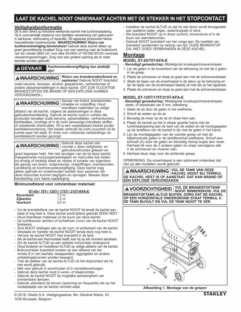
MontageMODEL ST-45/70T-KFA-E- Benodigd gereedschap: Middelgrote kruiskopschroevendraaier1. Lijn de gaten in de bovenkant van de behuizing uit met de 2 gaten
in de greep.2. Plaats de schroeven en draai ze goed aan met de schroevendraaier.3. Steek de lipjes van de snoerhaspel in de steun op de behuizing en
lijn de lipjes van de snoerhaspel daarbij uit met die op het zijpaneel.4. Plaats de schroeven en draai ze goed aan met de schroevendraaier.
MODEL ST-125T/175T/215T-KFA-E- Benodigd gereedschap: Middelgrote kruiskopschroevendraaier,
steek- of dopsleutel van 8 mm, kabeltang1. Steek de as door de gaten in het wielframe. 2. Schuif de wielen op de as.3. Bevestig de moer op de as en draai hem aan.4. Plaats de kachel op het in elkaar gezette frame met de
luchtinlaatopening aan de kant van de wielen en de montagegaten op de tankflens van de kachel in lijn met de gaten in het frame.
5. Lijn de montagegaten van de voorste greep uit met de bijbehorende gaten in de tankflens/het wielframe. Schuif een schroef (A) door de gaten en bevestig hierop losjes een moer. Herhaal dit voor de 3 andere gaten en draai vervolgens alle 4 de schroeven en moeren aan.
6. Herhaal deze stap voor de achterste greep.
OPMERKING: De snoerhaspel is een optioneel onderdeel dat niet op alle modellen wordt gebruikt.
WAARSCHUWING
Koolmonoxidevergiftiging kan dodelijk zijn!
VUL DE TANK VAN DEZE KACHEL NOOIT BIJ TERWIJL
DE KACHEL HEET IS OF AANSTAAT. DAT KAN BRAND OF EEN EXPLOSIE VEROORZAKEN.
VUL DE BRANDSTOFTANK NOOIT BINNENSHUIS. VUL DE
BRANDSTOFTANK ALTIJD BUITEN. ZORG DAT DE KACHEL OP EEN HORIZONTALE ONDERGROND STAAT TERWIJL U DE TANK BIJVULT EN VUL DE TANK NOOIT TE VER.
VOORZICHTIGHEID
Afbeelding 1. Montage van de grepen
Gebruik deze kachel niet voordat u deze veiligheids- en gebruiksinstructies gelezen en
goed begrepen hebt. Het niet opvolgen van de bij deze kachel meegeleverde voorzorgsmaatregelen en instructies kan leiden tot ernstig of dodelijk letsel en verlies of schade van eigendom als gevolg van brand, roetproductie, ontploffingen, brandwonden, verstikking en koolmonoxidevergiftiging. Deze kachel mag alleen gebruikt en onderhouden worden door personen die deze instructies kunnen begrijpen en opvolgen. Bewaar deze handleiding voor latere raadpleging.
Gevaar van brand, brandwonden, inhalatie en ontploffing. Houd brandbare materialen op veilige
afstand van de kachel, volgens de aanbevelingen in deze gebruikershandleiding. Gebruik de kachel nooit in ruimten die producten bevatten zoals benzine, oplosmiddelen, verfverdunners, stofdeeltjes, vluchtige of in de lucht aanwezige brandbare stoffen of onbekende chemicaliën. Dit is een verplaatsbare kachel zonder ventilatievoorziening. Het toestel verbruikt de lucht (zuurstof) uit de ruimte waar het staat. Er moet voor voldoende verbrandings- en ventilatielucht worden gezorgd.
WAARSCHUWINGWAARSCHUWING
WAARSCHUWING
WAARSCHUWING
© 2018, Obelis S.A. Vestigingsadres: Bd. Général Wahis, 531030 Brussels, Belgium
LAAT DE KACHEL NOOIT ONBEWAAKT ACHTER MET DE STEKKER IN HET STOPCONTACT
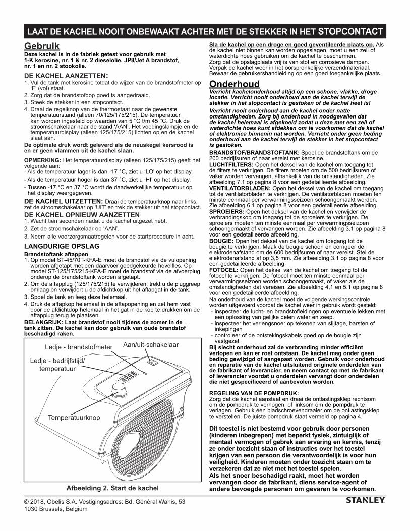
GebruikDeze kachel is in de fabriek getest voor gebruik met 1-K kerosine, nr. 1 & nr. 2 dieselolie, JP8/Jet A brandstof, nr. 1 en nr. 2 stookolie.
DE KACHEL AANZETTEN:1. Vul de tank met kerosine totdat de wijzer van de brandstofmeter op
‘F’ (vol) staat.2. Zorg dat de brandstofdop goed is aangedraaid.3. Steek de stekker in een stopcontact.4. Draai de regelknop van de thermostaat naar de gewenste
temperatuurstand (alleen 70/125/175/215). De temperatuur kan worden ingesteld op waarden van 5 °C t/m 45 °C. Druk de stroomschakelaar naar de stand ‘AAN’. Het voedingslampje en de temperatuurdisplay (alleen 125/175/215) lichten op en de kachel slaat aan.
De optimale druk wordt geleverd als de neuskegel kersrood is en er geen vlammen uit de kachel slaan.
OPMERKING: Het temperatuurdisplay (alleen 125/175/215) geeft het volgende aan:- Als de temperatuur lager is dan -17 °C, ziet u ‘LO’ op het display.- Als de temperatuur hoger is dan 37 °C, ziet u ‘HI’ op het display.- Tussen -17 °C en 37 °C wordt de daadwerkelijke temperatuur op
het display weergegeven.
DE KACHEL UITZETTEN: Draai de temperatuurknop naar links, zet de stroomschakelaar op ‘UIT’ en trek de stekker uit het stopcontact.
DE KACHEL OPNIEUW AANZETTEN1. Wacht tien seconden nadat u de kachel uitgezet hebt.2. Zet de stroomschakelaar op ‘AAN’.3. Neem alle voorzorgsmaatregelen voor de startprocedure in acht.
LANGDURIGE OPSLAGBrandstoftank aftappen1. Op model ST-45/70T-KFA-E moet de brandstof via de vulopening
worden afgetapt met een daarvoer goedgekeurde hevelfles. Op model ST-125/175/215-KFA-E moet de brandstof via de afvoerplug onderop de brandstoftank worden afgetapt.
2. Om de aftapplug (125/175/215) te verwijderen, trekt u de pluggreep omlaag en verwijdert u de afdichtkop uit het aftapgat in de tank.
3. Spoel de tank en leeg deze helemaal.4. Druk de aftapkop helemaal in de aftapopening en zet hem vast
door de afdichtdop helemaal in het gat in de kop te drukken om de aftapplug terug te plaatsen.
BELANGRIJK: Laat brandstof nooit tijdens de zomer in de tank zitten. De kachel kan door gebruik van oude brandstof beschadigd raken.
Sla de kachel op een droge en goed geventileerde plaats op. Als de kachel niet binnen kan worden opgeslagen, moet u een zeil of waterdichte hoes gebruiken om de kachel te beschermen.Zorg dat de opslagplaats vrij is van stof en corrosieve dampen. Verpak de kachel weer in het oorspronkelijke verzendmateriaal. Bewaar de gebruikershandleiding op een goed toegankelijke plaats.
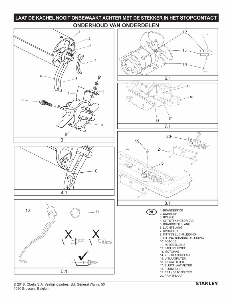
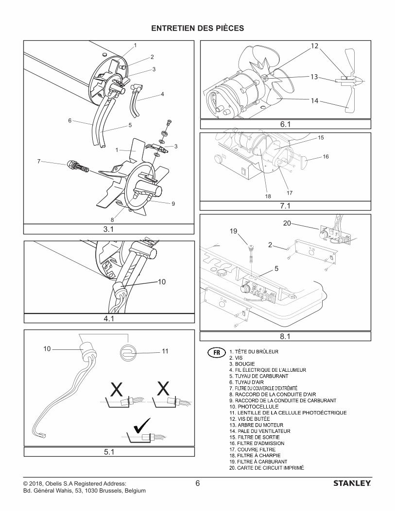
OnderhoudVerricht kachelonderhoud altijd op een schone, vlakke, droge locatie. Verricht nooit onderhoud aan de kachel terwijl de stekker in het stopcontact is gestoken of de kachel heet is!Verricht nooit onderhoud aan de kachel onder natte omstandigheden. Zorg bij onderhoud in noodgevallen dat de kachel helemaal is afgekoeld zodat u deze met een zeil of waterdichte hoes kunt afdekken om te voorkomen dat de kachel of elektronica binnenin nat worden. Verricht onder geen beding onderhoud aan de kachel terwijl de stekker in het stopcontact is gestoken. BRANDSTOF/BRANDSTOFTANK: Spoel de brandstoftank om de 200 bedrijfsuren of naar vereist met kerosine. LUCHTFILTERS: Open het deksel van de kachel om toegang tot de filters te verkrijgen. De filters moeten om de 500 bedrijfsuren of vaker worden vervangen, afhankelijk van de omstandigheden. Zie afbeelding 7.1 op pagina 8 voor een gedetailleerde afbeelding.VENTILATORBLADEN: Open het deksel van de kachel om toegang tot de ventilatorbladen te verkrijgen. De ventilatorbladen moeten ten minste eenmaal per verwarmingsseizoen schoongemaakt worden. Zie afbeelding 6.1 op pagina 8 voor een gedetailleerde afbeelding.SPROEIERS: Open het deksel van de kachel en verwijder de verbrandingskop om toegang tot de sproeiers te verkrijgen. De sproeiers moeten ten minste eenmaal per verwarmingsseizoen schoongemaakt of vervangen worden. Zie afbeelding 3.1 op pagina 8 voor een gedetailleerde afbeelding.BOUGIE: Open het deksel van de kachel om toegang tot de bougie te verkrijgen. Maak de bougie schoon en corrigeer de elektrodenafstand om de 600 bedrijfsuren of naar vereist. Stel de elektrodenafstand af op 3,5 mm. Zie afbeelding 3.1 op pagina 8 voor een gedetailleerde afbeelding.FOTOCEL: Open het deksel van de kachel om toegang tot de fotocel te verkrijgen. De fotocel moet ten minste eenmaal per verwarmingsseizoen worden schoongemaakt, of vaker als de omstandigheden dat vereisen. Zie afbeelding 4,1 en 5.1 op pagina 8 voor een gedetailleerde afbeelding. Na onderhoud van de kachel moet de volgende werkingscontrole worden uitgevoerd voordat de kachel weer in gebruik wordt gesteld: - inspecteer de lucht- en brandstofleidingen op eventuele lekken met
een oplossing van gelijke delen water en zeep. - inspecteer het verlengsnoer op tekenen van slijtage, barsten of
inkepingen - controleer of de ontstekingskabels goed op de bougie zijn
vastgezetBij slecht onderhoud zal de verbranding minder efficiënt verlopen en kan er roet ontstaan. De kachel mag onder geen beding gewijzigd of aangepast worden. Gebruik voor onderhoud en reparatie van de kachel uitsluitend originele onderdelen van de fabrikant of leverancier, en neem contact op met de fabrikant of leverancier voordat u onderdelen vervangt door onderdelen die niet gespecificeerd of aanbevolen worden.
REGELING VAN DE POMPDRUK:Zorg dat de kachel aanstaat en draai de ontlastingsklep rechtsom om de pompdruk te verhogen, of linksom om de pompdruk te verlagen. Gebruik een bladschroevendraaier om de ontlastingsklep te verstellen. De juiste pompdruk staat vermeld op pagina 4.
Dit toestel is niet bestemd voor gebruik door personen (kinderen inbegrepen) met beperkt fysiek, zintuiglijk of mentaal vermogen of gebrek aan ervaring en kennis, tenzij ze onder toezicht staan of instructies over het toestel krijgen van een persoon die verantwoordelijk is voor hun veiligheid. Kinderen moeten onder toezicht staan om te verzekeren dat ze niet met het toestel spelen.Als het snoer beschadigd raakt, moet het worden vervangen door de fabrikant, diens service-agent of andere bevoegde personen om gevaren te voorkomen.Afbeelding 2. Start de kachel
Aan/uit-schakelaar
Ledje - bedrijfstijd/temperatuur
Temperatuurknop
Ledje - brandstofmeter
© 2018, Obelis S.A. Vestigingsadres: Bd. Général Wahis, 531030 Brussels, Belgium
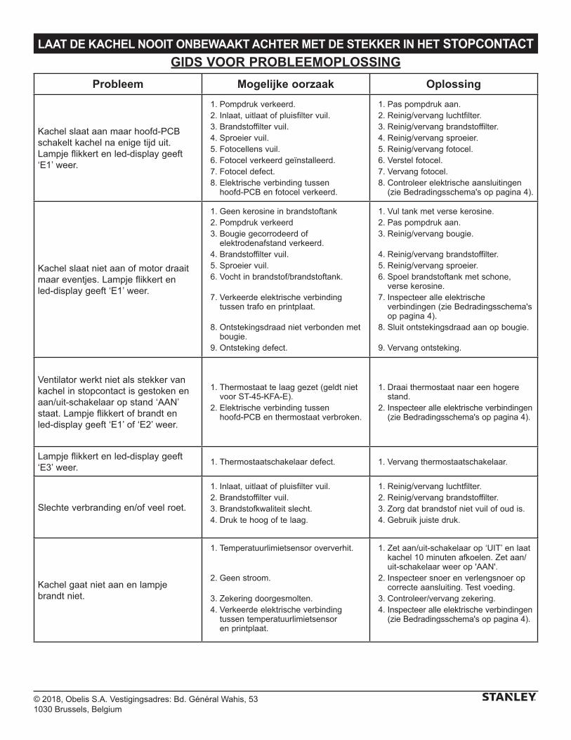
LAAT DE KACHEL NOOIT ONBEWAAKT ACHTER MET DE STEKKER IN HET STOPCONTACTGIDS VOOR PROBLEEMOPLOSSING
Probleem Mogelijke oorzaak Oplossing
Kachel slaat aan maar hoofd-PCB schakelt kachel na enige tijd uit. Lampje flikkert en led-display geeft ‘E1’ weer.
1. Pompdruk verkeerd. 2. Inlaat, uitlaat of pluisfilter vuil. 3. Brandstoffilter vuil. 4. Sproeier vuil. 5. Fotocellens vuil. 6. Fotocel verkeerd geïnstalleerd. 7. Fotocel defect. 8. Elektrische verbinding tussen
hoofd-PCB en fotocel verkeerd.
1. Pas pompdruk aan. 2. Reinig/vervang luchtfilter. 3. Reinig/vervang brandstoffilter. 4. Reinig/vervang sproeier. 5. Reinig/vervang fotocel. 6. Verstel fotocel. 7. Vervang fotocel. 8. Controleer elektrische aansluitingen
(zie Bedradingsschema's op pagina 4).
Kachel slaat niet aan of motor draait maar eventjes. Lampje flikkert en led-display geeft ‘E1’ weer.
1. Geen kerosine in brandstoftank 2. Pompdruk verkeerd 3. Bougie gecorrodeerd of
elektrodenafstand verkeerd. 4. Brandstoffilter vuil. 5. Sproeier vuil. 6. Vocht in brandstof/brandstoftank.
7. Verkeerde elektrische verbinding tussen trafo en printplaat.
8. Ontstekingsdraad niet verbonden met bougie.
9. Ontsteking defect.
1. Vul tank met verse kerosine. 2. Pas pompdruk aan. 3. Reinig/vervang bougie.
4. Reinig/vervang brandstoffilter. 5. Reinig/vervang sproeier. 6. Spoel brandstoftank met schone,
verse kerosine. 7. Inspecteer alle elektrische
verbindingen (zie Bedradingsschema's op pagina 4).
8. Sluit ontstekingsdraad aan op bougie.
9. Vervang ontsteking.
Ventilator werkt niet als stekker van kachel in stopcontact is gestoken en aan/uit-schakelaar op stand ‘AAN’ staat. Lampje flikkert of brandt en led-display geeft ‘E1’ of ‘E2’ weer.
1. Thermostaat te laag gezet (geldt niet voor ST-45-KFA-E).
2. Elektrische verbinding tussen hoofd-PCB en thermostaat verbroken.
1. Draai thermostaat naar een hogere stand.
2. Inspecteer alle elektrische verbindingen (zie Bedradingsschema's op pagina 4).
Lampje flikkert en led-display geeft ‘E3’ weer.
1. Thermostaatschakelaar defect. 1. Vervang thermostaatschakelaar.
Slechte verbranding en/of veel roet.
1. Inlaat, uitlaat of pluisfilter vuil. 2. Brandstoffilter vuil. 3. Brandstofkwaliteit slecht. 4. Druk te hoog of te laag.
1. Reinig/vervang luchtfilter. 2. Reinig/vervang brandstoffilter. 3. Zorg dat brandstof niet vuil of oud is. 4. Gebruik juiste druk.
Kachel gaat niet aan en lampje brandt niet.
1. Temperatuurlimietsensor oververhit.
2. Geen stroom.
3. Zekering doorgesmolten. 4. Verkeerde elektrische verbinding
tussen temperatuurlimietsensor en printplaat.
1. Zet aan/uit-schakelaar op ‘UIT’ en laat kachel 10 minuten afkoelen. Zet aan/uit-schakelaar weer op 'AAN'.
2. Inspecteer snoer en verlengsnoer op correcte aansluiting. Test voeding.
3. Controleer/vervang zekering. 4. Inspecteer alle elektrische verbindingen
(zie Bedradingsschema's op pagina 4).
© 2018, Obelis S.A. Vestigingsadres: Bd. Général Wahis, 531030 Brussels, Belgium
LAAT DE KACHEL NOOIT ONBEWAAKT ACHTER MET DE STEKKER IN HET STOPCONTACT
ONDERHOUD VAN ONDERDELEN
15
16
1718
12
14
13
XX
10 11
10
20
2
5
19
1
2
3
4
56
7
1 3
9
8
3.1
4.1
5.1
8.1
6.1
7.1
1. BRANDERKOP2. SCHROEF3. BOUGIE4. ONTSTEKINGSDRAAD5. BRANDSTOFSLANG6. LUCHTSLANG7. SPROEIER8. FITTING LUCHTLEIDING9. FITTING BRANDSTOFLEIDING10. FOTOCEL11. FOTOCELLENS12. STELSCHROEF13. MOTORAS14. VENTILATORBLAD15. UITLAATFILTER16. INLAATFILTER17. SLUITPLAAT FILTER18. PLUISFILTER19. BRANDSTOFFILTER20. PRINTPLAAT

© 2018, Obelis S.A. Vestigingsadres: Bd. Général Wahis, 531030 Brussels, Belgium
LAAT DE KACHEL NOOIT ONBEWAAKT ACHTER MET DE STEKKER IN HET STOPCONTACT
OPENGEWERKTE TEKENING
41
43
44
45
46
47
48
49
50
19
20
21
2223
24
25
2627
28
29
30
31
32
33
3435
36
37
38
39
40
42
5152
© 2018, Obelis S.A. Vestigingsadres: Bd. Général Wahis, 531030 Brussels, Belgium
LAAT DE KACHEL NOOIT ONBEWAAKT ACHTER MET DE STEKKER IN HET STOPCONTACT
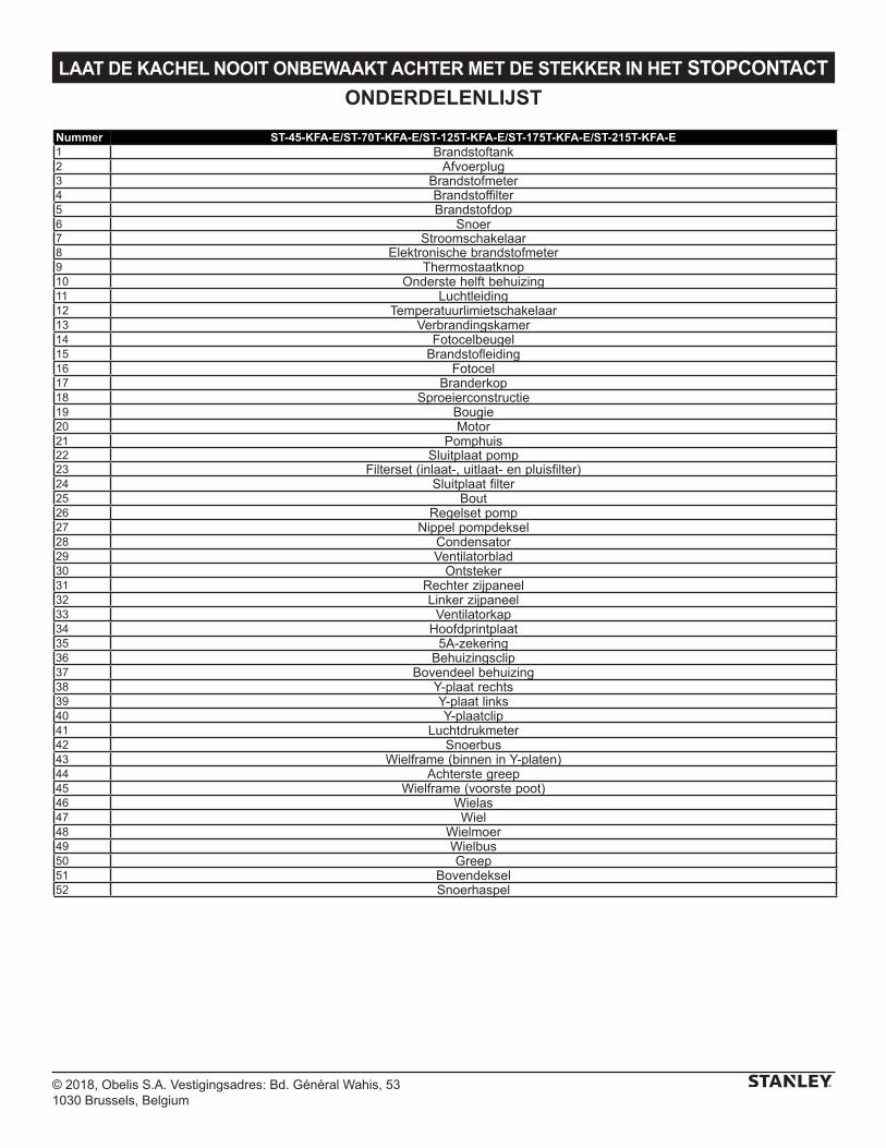
ONDERDELENLIJST
Nummer ST-45-KFA-E/ST-70T-KFA-E/ST-125T-KFA-E/ST-175T-KFA-E/ST-215T-KFA-E1 Brandstoftank2 Afvoerplug3 Brandstofmeter4 Brandstoffilter5 Brandstofdop6 Snoer7 Stroomschakelaar8 Elektronische brandstofmeter9 Thermostaatknop10 Onderste helft behuizing11 Luchtleiding12 Temperatuurlimietschakelaar13 Verbrandingskamer14 Fotocelbeugel15 Brandstofleiding16 Fotocel17 Branderkop18 Sproeierconstructie19 Bougie20 Motor21 Pomphuis22 Sluitplaat pomp23 Filterset (inlaat-, uitlaat- en pluisfilter)24 Sluitplaat filter25 Bout26 Regelset pomp27 Nippel pompdeksel28 Condensator29 Ventilatorblad30 Ontsteker31 Rechter zijpaneel32 Linker zijpaneel33 Ventilatorkap34 Hoofdprintplaat35 5A-zekering36 Behuizingsclip37 Bovendeel behuizing38 Y-plaat rechts39 Y-plaat links40 Y-plaatclip41 Luchtdrukmeter42 Snoerbus43 Wielframe (binnen in Y-platen)44 Achterste greep45 Wielframe (voorste poot)46 Wielas47 Wiel48 Wielmoer49 Wielbus50 Greep51 Bovendeksel52 Snoerhaspel
© 2018, Obelis S.A. Vestigingsadres: Bd. Général Wahis, 531030 Brussels, Belgium
LAAT DE KACHEL NOOIT ONBEWAAKT ACHTER MET DE STEKKER IN HET STOPCONTACT
Belgique et LuxembourgBelgië en Luxemburg
E. Walschaertstraat 14 2800 Mechelen Belgium
[email protected]= +32 15 47 37 65BE-FR = +32 15 47 37 64BE Fax: +32 15 47 37 100
Danmark Roskildevej 22 2620 Albertslund
[email protected]: 70224910
Deutschland Richard Klinger Str. 11 65510 Idstein
[email protected]: 06126-21-1Fax: 06126-21-2770
Ελλάς Hμερος Τόπος 2 - Χάνι Αδάμ Ασπρόπυργος -19300 -Αττική - Αττικής
[email protected]Τηλ: +30 210 8985208Φαξ: +30 210 5597598
España Parque de Negocios “Mas Blau”
08820 El Prat de Llobregat (Barcelona)
[email protected]: 934 797 400Fax: 934 797 419
France 5, allée des hêtres BP 30084, 69579 Limonest Cedex
[email protected]: 04 72 20 39 77Fax: 04 72 20 39 00
SchweizSuisse Svizzera
In der Luberzen 42 8902 Urdorf
[email protected]: 044 - 755 60 70Fax: 044 - 730 70 67
Ireland 210 Bath Road; Slough, Berks SL1 3YD UK www.stanleytools.co.ukTel: +44 (0)1753 511234Fax: +44 (0)1753 512365
Italia www.stanley.itTel. 039-9590-200Fax 039-9590-313
Nederlands Stanley Black & Decker Netherlands B.V. Postbus 83 6120 AD Born
[email protected] : +31 164 28 30 63NL Fax: +31 164 28 32 00
Norge Postboks 4613, Nydalen0405 Oslo
[email protected]: 45 25 08 00
Österreich Oberlaaerstrasse 248A-1230 Wien
[email protected]: 01 - 66116 - 0Fax: 01 - 66116 - 14
Portugal Quinta da Fonte - Edifício Q55 D. Diniz Rua dos Malhões, 2 e 2A - Piso 2 Esquerdo 2770 - 071 Paço de Arcos
[email protected]: 214 66 75 00Fax: 214 66 75 75
Suomi PL 47 00521 Helsinki
Puh: 010 400 4333
Sverige Box 94 431 22 Mölndal
[email protected]: 31 68 60 08
United Kingdom 210 Bath Road; Slough, Berks SL1 3YD www.stanleytools.co.ukTel: +44 (0)1753 511234Fax: +44 (0)1753 512365
Hungary Rotel Kft.1163 Budapest,Thököly út 17.
[email protected] +36 1 404-0014Fax+36 1 403-2260
Czech Republic BAND SERVIS CZ s.r.o. K Pasekam 4440 760 01 Zlín, Czech Republic
www.stanleyworks.czhttp://www.bandservis.czTel.: +420 577 008 550Fax.: +420 577 008 559
Slovakia BAND SERVIS s.r.o. Paulinska 22 917 01 Trnava, Slovakia
www.bandservis.skTel.: +421 335 511 063Fax.: +421 335 512 624
Poland Erpatech ul. Bakaliowa 26 05-080 Mościska
www.stanleyworks.plTel.: +48 22 431 05 00Fax.: +48 22 468 87 35
Slovenia G-M&M d.o.o. Brvace 11 1290 Grosuplje Slovenija
[email protected]: +386 01 78 66 500F: +386 01 78 63 023
Cyprus IOANNOU J. 4A Ath.Diakou street 1046- Nicosia -Cyprus
[email protected]Τel : +357 22344302Fax : +357 22348098
Bosnia-Herzegovina G-M&M d.o.o. Brvace 11 1290 Grosuplje Slovenija
[email protected]: +386 01 78 66 500F: +386 01 78 63 023
Bulgaria TASHEV-GALVING LTD 68 KLIMENT OHRIDSKI BLVD.
www.tashev-galving.comT: +359 2 700 45 45 4F: +359 (2) 439 21 12
Croatia G-M&M d.o.o. Brvace 11 1290 Grosuplje Slovenija
[email protected]: +386 01 78 66 500F: +386 01 78 63 023
Estonia AS Tallmac Mustame tee 44, EE-10621 Tallinn
www.tallmac.ee/estT: +372 6562999F: +372 6562855
Latvia LIC GOTUS SIA Ulbrokas Str. LT - 1021 Rīga
www.licgotus.lvT: +371 67556949F: +371 67555140
Lithuania UAB ELREMTA OU Neries kr. 16E LT - 48402 Kaunas
[email protected]: +370-685-29035F: +370-37-406540
Malta Energypark–Building 03 sud, Via Energy Park 6 20871 Vimercate (MB)
www.stanley.itTel. 039-9590-200Fax 039-9590-313
Romania Stanley Black & Decker Phoenicia Business Center Strada Turturelelor, nr 11A, Etaj 6, Modul 15, Sector 3 Bucuresti
www.stanleyworks.roT: +4021.320.61.04/05F: +4037.225.36.84
Serbia G-M&M d.o.o. Brvace 11 1290 Grosuplje Slovenija
[email protected]: +386 01 78 66 500F: +386 01 78 63 023
ONDERHOUD
Energy Park–Building 03 sudVia Energy Park 620871 Vimercate (MB)

Vervaardigd door:Pinnacle Climate Technologies, Inc.
Sauk Rapids, MN 56379 USA
EC REP
Obelis S.A.Geregistreerd adres:
Bd. Général Wahis, 53 1030 Brussels, Belgium
© 2018 Stanley Black & Decker, Inc.
STKA-462
ST-45-KFA-E / ST-70T-KFA-E / ST-125T-KFA-E ST-175T-KFA-E / ST-215T-KFA-E
NE JAMAIS LAISSER LE CHAUFFAGE SANS SURVEILLANCE LORSQU’IL EST EN MARCHE OU BRANCHÉ.
CET APPAREIL NE CONVIENT PAS COMME CHAUFFAGE PRINCIPAL.
© 2018, Obelis S.A Registered Address: Bd. Général Wahis, 53, 1030 Brussels, Belgium
LIRE SOIGNEUSEMENT LES INSTRUCTIONS CI-APRÈS AVANT D’UTILISER CET APPAREIL.
- Cet appareil peut être utilisé par des enfants âgés de 8 ans ou plus et par des personnes handicapées physiques ou mentales ou des personnes manquant d’expérience ou de connaissances, si elles sont surveillées ou ont appris à utiliser l’appareil de manière sûre et en ayant compris les risques encourus. Les enfants ne doivent pas jouer avec l’appareil. Le nettoyage et l’entretien de l’appareil ne doivent pas être effectués par des enfants sans surveillance.
- Les enfants de moins de 3 ans doivent être tenus éloignés sauf s’ils sont surveillés en permanence. Les enfants âgés de 3 à 8 ans ne peuvent qu’allumer ou éteindre l’appareil à la condition qu’il ait été placé ou installé dans sa position prévue pour un fonctionnement normal et qu’ils soient surveillés, ou qu’ils aient appris à utiliser l’appareil de manière sûre et en ayant compris les risques encourus. Les enfants âgés de 3 à 8 ans ne doivent pas manipuler la prise électrique, régler et nettoyer l’appareil ou bien en effectuer l’entretien.
- ATTENTION : Certaines parties de cet appareil peuvent devenir très chaudes et provoquer des brûlures. Une attention particulière doit être apportée lorsque des enfants ou des personnes vulnérables sont présentes.
- Si le cordon d’alimentation est endommagé, il doit être remplacé par le fabricant, un agent d’entretien ou toute personne qualifiée afin d’éviter tout risque.
- Le chauffage ne doit pas être placé juste sous une prise électrique murale. - Ne pas utiliser ce chauffage à proximité immédiate d’une baignoire, d’une douche
ou d’une piscine. - Ce chauffage contient une certaine quantité d’huile spéciale. Toute réparation
nécessitant l’ouverture du réservoir d’huile doit être effectuée uniquement par le fabricant ou un technicien de maintenance qui doivent être contactés en cas de fuite d’huile.
- Lors de la mise au rebut du chauffage, il convient de respecter les règlements relatifs à l’élimination des huiles. Ne pas jeter le chauffage avec les déchets ménagers. Déposer le chauffage dans une déchetterie locale à même de recycler le matériel électrique et les huiles.
- Placer l’appareil sur une surface plane, stable et résistante à la chaleur. Utiliser l’appareil dans toute autre position présente un risque.
- Une odeur peut se dégager de l’appareil pendant les premières minutes de fonctionnement. Ceci est normal et disparaîtra rapidement.
- Ne pas tenter de réparer, démonter ou modifier l’appareil. Aucune pièce interne n’est réparable par l’utilisateur.
- ATTENTION : En cas d’utilisation d’une rallonge électrique, s’assurer de ne pas dépasser la puissance et la charge maximales de la rallonge.
FR
© 2018, Obelis S.A Registered Address: Bd. Général Wahis, 53, 1030 Brussels, Belgium
1
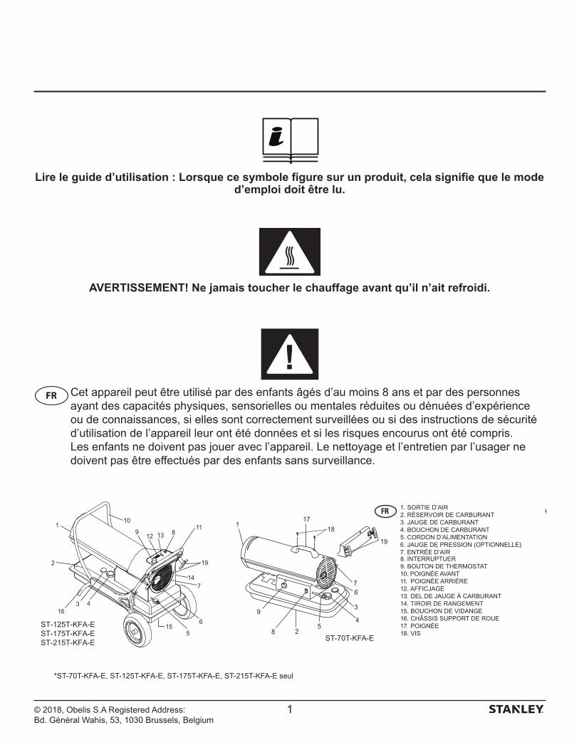
Lire le guide d’utilisation : Lorsque ce symbole figure sur un produit, cela signifie que le mode d’emploi doit être lu.
AVERTISSEMENT! Ne jamais toucher le chauffage avant qu’il n’ait refroidi.
Cet appareil peut être utilisé par des enfants âgés d’au moins 8 ans et par des personnes ayant des capacités physiques, sensorielles ou mentales réduites ou dénuées d’expérience ou de connaissances, si elles sont correctement surveillées ou si des instructions de sécurité d’utilisation de l’appareil leur ont été données et si les risques encourus ont été compris. Les enfants ne doivent pas jouer avec l’appareil. Le nettoyage et l’entretien par l’usager ne doivent pas être effectués par des enfants sans surveillance.
5
3
4
6
28
9
17
19
7
118
12
110
19
11
7
6
316
13
4
5
89
14
2
15
ST-70T-KFA-E
ST-125T-KFA-EST-175T-KFA-EST-215T-KFA-E
8.9.10.11.12.13.14.15.16.17.18.
FR
*ST-70T-KFA-E, ST-125T-KFA-E, ST-175T-KFA-E, ST-215T-KFA-E seul
© 2018, Obelis S.A Registered Address: Bd. Général Wahis, 53, 1030 Brussels, Belgium
/ AFFICHAGE NUMÉRIQUE*
Model # ST-45-KFA-E ST-70T-KFA-E ST-125T-KFA-E ST-175T-KFA-E ST-215T-KFA-E
SURFACE DE CHAUFFAGE (m²) 102 158 288 400 492
PUISSANCE THERMIQUE (kW) 13,0 20,5 36,6 51,2 63,0
CONSOMMATION DE CARBURANT (L/H)
1,3 2,0 3,6 5,1 6,2
CAPACITÉ DU RÉSERVOIR (L) 18,9 18,9 37,9 L 49,2 49,2
HEURES MAX. DE FONCTIONNEMENT 14 9 10 9,5 8
AMPÉRAGE (A)EU : 230 V~50 HZ / RU : 220 V~50 HZ
1,4 1,5 2,3 2,7 2,8
AMP DU MOTEUR 1,6 1,6 2,5 2,9 3,2
MOTEUR MONOPHASÉ UNIQUE UNIQUE UNIQUE UNIQUE UNIQUE
PRODUCTION DE CHALEUR DU CHAUFFAGE (ºC)
388 393 404 516 649
DÉBIT D’AIR (m3/h) 289 408 918 1070 1138
PRESSION DE POMPAGE (BAR) 0,21 0,26 0,31 0,45 0,55
TEMPÉRATURES AMBIANTES MINIMALE / MAXIMALE RECOMMANDÉES (°C)
-12 / 24 -12 / 24 -12 / 24 -12 / 24 -12 / 24
DIMENSIONS DU PRODUIT (cm) 76 x 34 x 39 76 x 34 x 39 99 x 61 x 66 115 x 65 x 70 115 x 65 x 70
POIDS DU CHAUFFAGE (kg) 12,7 12,7 27,5 30 31
TYPES DE CARBURANT ACCEPTÉS Kérosène/Diesel Kérosène/Diesel Kérosène/Diesel Kérosène/Diesel Kérosène/Diesel
PUISSANCE EN ENTRÉE (W) 160 160 252 298 298
CARACTERISTIQUESSpécifications sujettes à modification sans préavis
2
SCHEMA ÉLECTRIQUE
1
WT
BK
OR
BK 4
2
12
13
GN
7
GN
7
11
10BK
9
BR
BKBK
BL
BL8
5
3
615
14BK
RDRD
BKPK
BK
BL
YL
BKCN1
RD10
11
12
13
1RD
RD
PK
OR
WT
BK3
4
5
GN
7
6
8 RD
BL
9
GN
7
BR
BL
14BKBK
BK
15
20
RD
BKBK
1617
18
19
2
10UF/250VAC
1RD
WT
RD
OR
BK
BK
WT
BK
BK
BK
BK
PKBK
4
2
12
13GN
GN
7
7
11
10 9 8
5
3
6
WT
YLGN
7
WT
8A/125AVC
ST-45-KFA-E
ST-70T-KFA-EST-125T-KFA-EST-175T-KFA-EST-215T-KFA-E
FR
*125T / 175T / 215T Seulement
© 2018, Obelis S.A Registered Address: Bd. Général Wahis, 53, 1030 Brussels, Belgium
Consignes de sécuritéCe chauffage à paraffine, à air forcé et alimentation directe est destiné principalement à chauffer temporairement les bâtiments en construction, en rénovation ou en réparation. Cet appareil produit des quantités réduites de monoxyde de carbone. AVERTISSEMENT ! Risque de pollution intérieure des locaux ! N’utiliser ce chauffage que dans des locaux bien ventilés. Une ouverture sur l’extérieur de 2 800 cm2 minimum doit être prévue pour chaque tranche de 29,3 kWh ou 100 000 BTU/hr de puissance de chauffage. L’ouverture doit être plus large lorsque plusieurs chauffages fonctionnent ensemble.
Risques de brûlures / incendies / explosion ! NE JAMAIS UTILISER de carburants tels que
l’essence, le benzène, l’alcool, l’essence sans plomb, l’essence à réchaud de camping, les diluants pour peinture ou autres composés d’essence dans ce chauffage. (CES COMBUSTIBLES VOLATILES PEUVENT CAUSER DES INCENDIES OU DES EXPLOSIONS.)
Distance minimum de tout combustible :
ST-45-/ 70T-/ 125T-/ 175T-/ 215T-KFA-EDessus 1,20 mCôtés 1,20 mDevant 3,00 m
- NE JAMAIS recharger le réservoir du chauffage lorsque celui-ci est en marche ou encore chaud. Le chauffage est EXTRÊMEMENT CHAUD en cours d’utilisation.
- Garder tous les matériaux combustibles à distance du chauffage.- NE JAMAIS bloquer l’arrivée (arrière) ou la sortie (devant) d’air du
chauffage.- NE JAMAIS utiliser de gaines ou conduits d’air devant ou derrière
le chauffage.- NE JAMAIS déplacer ou manier le chauffage lorsque celui-ci est
encore chaud.- NE JAMAIS transporter le chauffage avec du carburant dans son
réservoir.- S’il est équipé d’un thermostat, le chauffage peut se mettre en
marche à tout moment.- TOUJOURS placer le chauffage sur une surface stable et plane.- TOUJOURS tenir les enfants et les animaux à distance du
chauffage.- Le stock de carburant devrait se trouver au minimum à 8 m
des chauffages, des lampes électriques, des générateurs portables ou de toute autre source d’allumage.
- TOUJOURS débrancher le chauffage lorsqu’il n’est pas utilisé.- Ne pas l’utiliser à la maison ou pour des véhicules de loisir.- NE JAMAIS utiliser le chauffage dans des pièces de séjour ou de
couchage.- NE JAMAIS utiliser le chauffage là où des vapeurs inflammables
pourraient se trouver.
- Utiliser uniquement l’alimentation électrique (tension et fréquence) spécifiée sur la plaque du modèle du chauffage.
- TOUJOURS installer le chauffage de façon à ce qu’il ne soit pas directement exposé aux pulvérisations d’eau, à la pluie, aux égouttements d’eau ou au vent.
- NE JAMAIS entreposer le carburant directement au soleil, en intérieur ou près d’une source de chaleur.
- NE JAMAIS utiliser le carburant qui a été stocké d’une saison sur l’autre. Le carburant se détériore avec le temps. LE VIEUX CARBURANT NE BRÛLERA PAS AUSSI EFFICACEMENT DANS LE CHAUFFAGE.
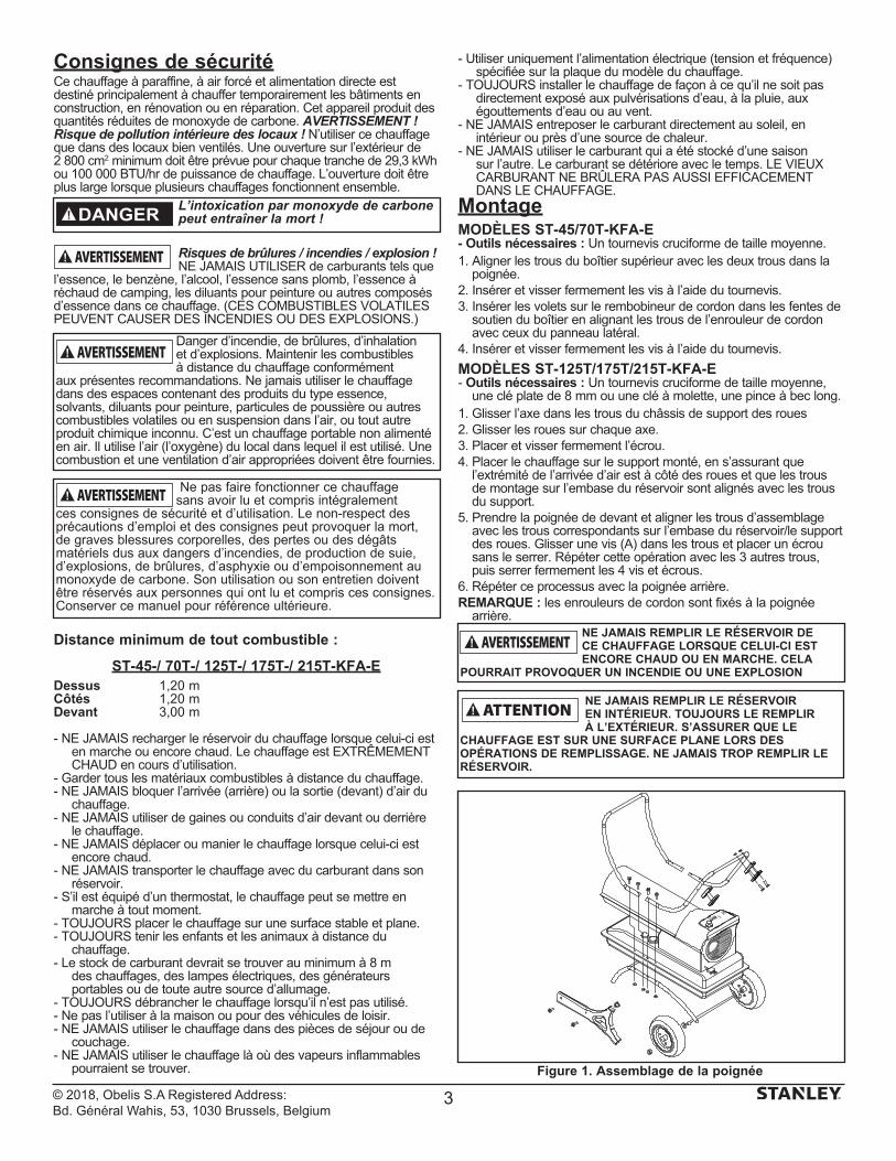
MontageMODÈLES ST-45/70T-KFA-E- Outils nécessaires : Un tournevis cruciforme de taille moyenne.1. Aligner les trous du boîtier supérieur avec les deux trous dans la
poignée.2. Insérer et visser fermement les vis à l’aide du tournevis.3. Insérer les volets sur le rembobineur de cordon dans les fentes de
soutien du boîtier en alignant les trous de l’enrouleur de cordon avec ceux du panneau latéral.
4. Insérer et visser fermement les vis à l’aide du tournevis.
MODÈLES ST-125T/175T/215T-KFA-E- Outils nécessaires : Un tournevis cruciforme de taille moyenne,
une clé plate de 8 mm ou une clé à molette, une pince à bec long.1. Glisser l’axe dans les trous du châssis de support des roues 2. Glisser les roues sur chaque axe.3. Placer et visser fermement l’écrou.4. Placer le chauffage sur le support monté, en s’assurant que
l’extrémité de l’arrivée d’air est à côté des roues et que les trous de montage sur l’embase du réservoir sont alignés avec les trous du support.
5. Prendre la poignée de devant et aligner les trous d’assemblage avec les trous correspondants sur l’embase du réservoir/le support des roues. Glisser une vis (A) dans les trous et placer un écrou sans le serrer. Répéter cette opération avec les 3 autres trous, puis serrer fermement les 4 vis et écrous.
6. Répéter ce processus avec la poignée arrière. REMARQUE : les enrouleurs de cordon sont fixés à la poignée
arrière.
L’intoxication par monoxyde de carbone peut entraîner la mort !DANGER
NE JAMAIS REMPLIR LE RÉSERVOIR DE CE CHAUFFAGE LORSQUE CELUI-CI EST ENCORE CHAUD OU EN MARCHE. CELA
POURRAIT PROVOQUER UN INCENDIE OU UNE EXPLOSION
NE JAMAIS REMPLIR LE RÉSERVOIR EN INTÉRIEUR. TOUJOURS LE REMPLIR À L’EXTÉRIEUR. S’ASSURER QUE LE
CHAUFFAGE EST SUR UNE SURFACE PLANE LORS DES OPÉRATIONS DE REMPLISSAGE. NE JAMAIS TROP REMPLIR LE RÉSERVOIR.
Figure 1. Assemblage de la poignée
Ne pas faire fonctionner ce chauffage sans avoir lu et compris intégralement
ces consignes de sécurité et d’utilisation. Le non-respect des précautions d’emploi et des consignes peut provoquer la mort, de graves blessures corporelles, des pertes ou des dégâts matériels dus aux dangers d’incendies, de production de suie, d’explosions, de brûlures, d’asphyxie ou d’empoisonnement au monoxyde de carbone. Son utilisation ou son entretien doivent être réservés aux personnes qui ont lu et compris ces consignes. Conserver ce manuel pour référence ultérieure.
Danger d’incendie, de brûlures, d’inhalation et d’explosions. Maintenir les combustibles à distance du chauffage conformément
aux présentes recommandations. Ne jamais utiliser le chauffage dans des espaces contenant des produits du type essence, solvants, diluants pour peinture, particules de poussière ou autres combustibles volatiles ou en suspension dans l’air, ou tout autre produit chimique inconnu. C’est un chauffage portable non alimenté en air. Il utilise l’air (l’oxygène) du local dans lequel il est utilisé. Une combustion et une ventilation d’air appropriées doivent être fournies.
3
© 2018, Obelis S.A Registered Address: Bd. Général Wahis, 53, 1030 Brussels, Belgium
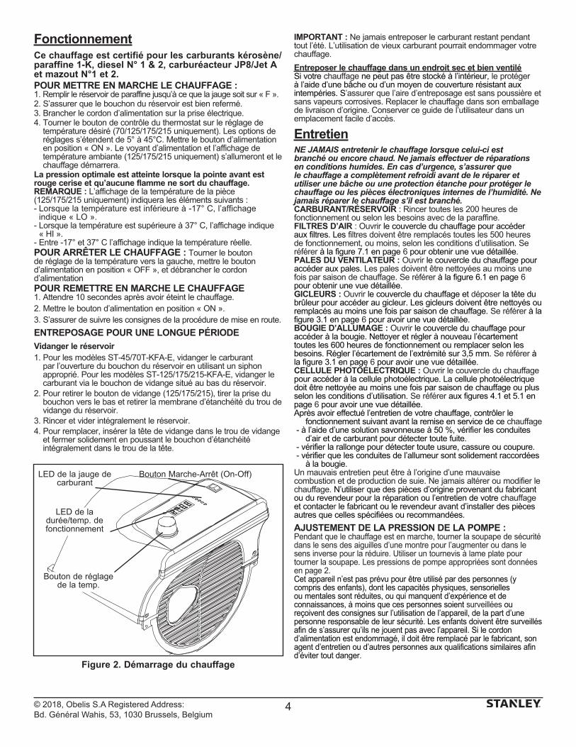
FonctionnementCe chauffage est certifié pour les carburants kérosène/paraffine 1-K, diesel N° 1 & 2, carburéacteur JP8/Jet A et mazout N°1 et 2. POUR METTRE EN MARCHE LE CHAUFFAGE :1. Remplir le réservoir de paraffine jusqu’à ce que la jauge soit sur « F ».2. S’assurer que le bouchon du réservoir est bien refermé.3. Brancher le cordon d’alimentation sur la prise électrique.4. Tourner le bouton de contrôle du thermostat sur le réglage de
température désiré (70/125/175/215 uniquement). Les options de réglages s’étendent de 5° à 45°C. Mettre le bouton d’alimentation en position « ON ». Le voyant d’alimentation et l’affichage de température ambiante (125/175/215 uniquement) s’allumeront et le chauffage démarrera.
La pression optimale est atteinte lorsque la pointe avant est rouge cerise et qu’aucune flamme ne sort du chauffage. REMARQUE : L’affichage de la température de la pièce (125/175/215 uniquement) indiquera les éléments suivants :- Lorsque la température est inférieure à -17° C, l’affichage
indique « LO ».- Lorsque la température est supérieure à 37° C, l’affichage indique
« HI ».- Entre -17° et 37° C l’affichage indique la température réelle.POUR ARRÊTER LE CHAUFFAGE : Tourner le bouton de réglage de la température vers la gauche, mettre le bouton d’alimentation en position « OFF », et débrancher le cordon d’alimentationPOUR REMETTRE EN MARCHE LE CHAUFFAGE 1. Attendre 10 secondes après avoir éteint le chauffage.2. Mettre le bouton d’alimentation en position « ON ».3. S’assurer de suivre les consignes de la procédure de mise en route.
ENTREPOSAGE POUR UNE LONGUE PÉRIODE
Vidanger le réservoir1. Pour les modèles ST-45/70T-KFA-E, vidanger le carburant
par l’ouverture du bouchon du réservoir en utilisant un siphon approprié. Pour les modèles ST-125/175/215-KFA-E, vidanger le carburant via le bouchon de vidange situé au bas du réservoir.
2. Pour retirer le bouton de vidange (125/175/215), tirer la prise du bouchon vers le bas et retirer la membrane d’étanchéité du trou de vidange du réservoir.
3. Rincer et vider intégralement le réservoir. 4. Pour remplacer, insérer la tête de vidange dans le trou de vidange
et fermer solidement en poussant le bouchon d’étanchéité intégralement dans le trou de la tête.
IMPORTANT : Ne jamais entreposer le carburant restant pendant tout l’été. L’utilisation de vieux carburant pourrait endommager votre chauffage.
Entreposer le chauffage dans un endroit sec et bien ventiléSi votre chauffage ne peut pas être stocké à l’intérieur, le protéger à l’aide d’une bâche ou d’un moyen de couverture résistant aux intempéries. S’assurer que l’aire d’entreposage est sans poussière et sans vapeurs corrosives. Replacer le chauffage dans son emballage de livraison d’origine. Conserver ce guide de l’utilisateur dans un emplacement facile d’accès.
EntretienNE JAMAIS entretenir le chauffage lorsque celui-ci est branché ou encore chaud. Ne jamais effectuer de réparations en conditions humides. En cas d’urgence, s’assurer que le chauffage a complètement refroidi avant de le réparer et utiliser une bâche ou une protection étanche pour protéger le chauffage ou les pièces électroniques internes de l’humidité. Ne jamais réparer le chauffage s’il est branché.CARBURANT/RÉSERVOIR : Rincer toutes les 200 heures de fonctionnement ou selon les besoins avec de la paraffine.FILTRES D’AIR : Ouvrir le couvercle du chauffage pour accéder aux filtres. Les filtres doivent être remplacés toutes les 500 heures de fonctionnement, ou moins, selon les conditions d’utilisation. Se référer à la figure 7.1 en page 6 pour obtenir une vue détaillée.PALES DU VENTILATEUR : Ouvrir le couvercle du chauffage pour accéder aux pales. Les pales doivent être nettoyées au moins une fois par saison de chauffage. Se référer à la figure 6.1 en page 6 pour obtenir une vue détaillée.GICLEURS : Ouvrir le couvercle du chauffage et déposer la tête du brûleur pour accéder au gicleur. Les gicleurs doivent être nettoyés ou remplacés au moins une fois par saison de chauffage. Se référer à la figure 3.1 en page 6 pour avoir une vue détaillée.BOUGIE D’ALLUMAGE : Ouvrir le couvercle du chauffage pour accéder à la bougie. Nettoyer et régler à nouveau l’écartement toutes les 600 heures de fonctionnement ou remplacer selon les besoins. Régler l’écartement de l’extrémité sur 3,5 mm. Se référer à la figure 3.1 en page 6 pour avoir une vue détaillée.CELLULE PHOTOÉLECTRIQUE : Ouvrir le couvercle du chauffage pour accéder à la cellule photoélectrique. La cellule photoélectrique doit être nettoyée au moins une fois par saison de chauffage ou plus selon les conditions d’utilisation. Se référer aux figures 4.1 et 5.1 en page 6 pour avoir une vue détaillée. Après avoir effectué l’entretien de votre chauffage, contrôler le
fonctionnement suivant avant la remise en service de ce chauffage - à l’aide d’une solution savonneuse à 50 %, vérifier les conduites
d’air et de carburant pour détecter toute fuite. - vérifier la rallonge pour détecter toute usure, cassure ou coupure. - vérifier que les conduites de l’allumeur sont solidement raccordées
à la bougie.Un mauvais entretien peut être à l’origine d’une mauvaise combustion et de production de suie. Ne jamais altérer ou modifier le chauffage. N’utiliser que des pièces d’origine provenant du fabricant ou du revendeur pour la réparation ou l’entretien de votre chauffage et contacter le fabricant ou le revendeur avant d’installer des pièces autres que celles spécifiées ou recommandées.
AJUSTEMENT DE LA PRESSION DE LA POMPE :Pendant que le chauffage est en marche, tourner la soupape de sécurité dans le sens des aiguilles d’une montre pour l’augmenter ou dans le sens inverse pour la réduire. Utiliser un tournevis à lame plate pour tourner la soupape. Les pressions de pompe appropriées sont données en page 2.Cet appareil n’est pas prévu pour être utilisé par des personnes (y compris des enfants), dont les capacités physiques, sensorielles ou mentales sont réduites, ou qui manquent d’expérience et de connaissances, à moins que ces personnes soient surveillées ou reçoivent des consignes sur l’utilisation de l’appareil, de la part d’une personne responsable de leur sécurité. Les enfants doivent être surveillés afin de s’assurer qu’ils ne jouent pas avec l’appareil. Si le cordon d’alimentation est endommagé, il doit être remplacé par le fabricant, son agent d’entretien ou d’autres personnes aux qualifications similaires afin d’éviter tout danger.
Figure 2. Démarrage du chauffage
Bouton Marche-Arrêt (On-Off)
LED de la durée/temp. de fonctionnement
Bouton de réglage de la temp.
LED de la jauge de carburant
4
© 2018, Obelis S.A Registered Address: Bd. Général Wahis, 53, 1030 Brussels, Belgium
DÉPANNAGE
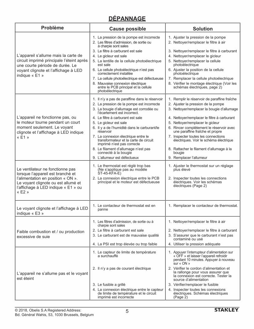
Problème Cause possible Solution
L’appareil s’allume mais la carte de circuit imprimé principale l’éteint après une courte période de durée. Le voyant clignote et l’affichage à LED indique « E1 »
1. La pression de la pompe est incorrecte2. Les filtres d’admission, de sortie ou
à charpie sont sales3. Le filtre à carburant est sale4. Le gicleur est sale5. La lentille de la cellule photoélectrique
est sale6. La cellule photoélectrique n’est pas
correctement installée 7. La cellule photoélectrique est défectueuse8. Mauvaise connexion électrique
entre le PCB principal et la cellule photoélectrique
1. Ajuster la pression de la pompe2. Nettoyer/remplacer le filtre à air
3. Nettoyer/remplacer le filtre à carburant4. Nettoyer/remplacer le gicleur5. Nettoyer/remplacer la cellule
photoélectrique 6. Ajuster la position de la cellule
photoélectrique 7. Remplacer la cellule photoélectrique 8. Vérifier le montage électrique (Voir les
schémas électriques, page 2)
L’appareil ne fonctionne pas, ou le moteur tourne pendant un court moment seulement. Le voyant clignote et l’affichage à LED indique « E1 »
1. Il n’y a pas de paraffine dans le réservoir2. La pression de la pompe est incorrecte3. La bougie d’allumage est corrodée ou
l’écartement est incorrect.4. Le filtre à carburant est sale5. Le gicleur est sale6. Il y a de l’humidité dans le carburant/le
réservoir7. La connexion électrique entre le
transformateur et la carte de circuit imprimé n’est pas correcte
8. Le filament d’allumage n’est pas connecté à la bougie
9. L’allumeur est défectueux
1. Remplir le réservoir de paraffine fraîche2. Ajuster la pression de la pompe3. Nettoyer/remplacer la bougie d’allumage
4. Nettoyer/remplacer le filtre à carburant5. Nettoyer/remplacer le gicleur6. Rincer complètement le réservoir avec
une paraffine fraîche et propre7. Inspecter toutes les connections
électriques. Voir le schéma électrique
8. Rattacher le filament d’allumage à la bougie
9. Remplacer l’allumeur
Le ventilateur ne fonctionne pas lorsque l’appareil est branché et l’alimentation en position « ON ». Le voyant clignote ou est allumé et l’affichage à LED indique « E1 » ou « E2 »
1. Le thermostat est réglé trop bas (Ne s’applique pas au modèle ST-45-KFA-E)
2. La connexion électrique entre le PCB principal et le moteur est défectueuse
1. Ajuster le thermostat sur un réglage plus élevé
2. Inspecter toutes les connections électriques. Voir les schémas électriques (Page 2)
Le voyant clignote et l’affichage à LED indique « E3 »
1. Le contacteur de thermostat est en panne
1. Remplacer le contacteur de thermostat.
Faible combustion et / ou production excessive de suie
1. Les filtres d’admission, de sortie ou à charpie sont sales
2. Le filtre à carburant est sale3. Le carburant est de mauvaise qualité
4. La PSI est trop élevée ou trop faible
1. Nettoyer/remplacer le filtre à air
2. Nettoyer/remplacer le filtre à carburant3. S’assurer que le carburant n’est pas
contaminé ou usé4. Utiliser la pression adéquate
L’appareil ne s’allume pas et le voyant est éteint
1. Le capteur de limite de température a surchauffé
2. Il n’y a pas de courant électrique
3. Le fusible a grillé4. La connexion électrique entre le capteur
de limite de température et le circuit imprimé est incorrecte
1. Appuyer l’interrupteur d’alimentation sur « OFF » et laisser l’appareil refroidir pendant 10 minutes. Appuyer à nouveau sur « ON »
2. Vérifier le cordon d’alimentation et la rallonge pour vous assurer que la connexion est correcte. Tester la source d’alimentation
3. Vérifier/remplacer le fusible4. Inspecter toutes les connexions
électriques. Schémas électriques (Page 2)
5
© 2018, Obelis S.A Registered Address: Bd. Général Wahis, 53, 1030 Brussels, Belgium
ENTRETIEN DES PIÈCES
15
16
1718
12
14
13
XX
10 11
10
20
2
5
19
1
2
3
4
56
7
1 3
9
8
3.1
4.1
5.1
8.1
6.1
7.1
6
© 2018, Obelis S.A Registered Address: Bd. Général Wahis, 53, 1030 Brussels, Belgium
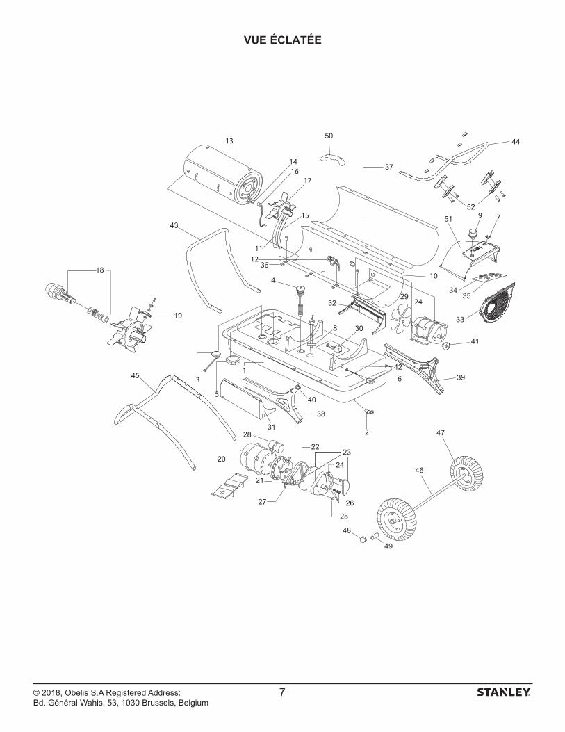
VUE ÉCLATÉE
41
43
44
45
46
47
48
49
50
19
20
21
2223
24
25
2627
28
29
30
31
32
33
3435
36
37
38
39
40
42
5152
7
© 2018, Obelis S.A Registered Address: Bd. Général Wahis, 53, 1030 Brussels, Belgium
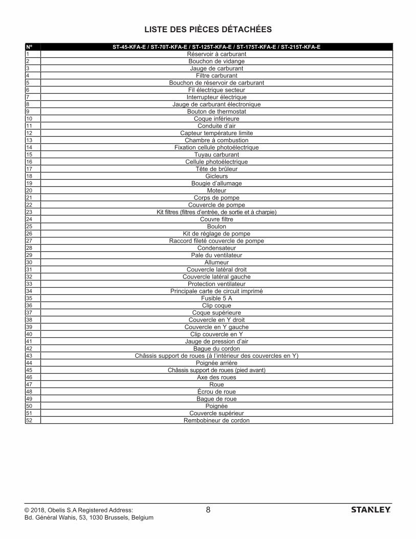
LISTE DES PIÈCES DÉTACHÉES
8
Nº ST-45-KFA-E / ST-70T-KFA-E / ST-125T-KFA-E / ST-175T-KFA-E / ST-215T-KFA-E1 Réservoir à carburant2 Bouchon de vidange3 Jauge de carburant4 Filtre carburant5 Bouchon de réservoir de carburant6 Fil électrique secteur7 Interrupteur électrique8 Jauge de carburant électronique9 Bouton de thermostat10 Coque inférieure11 Conduite d’air12 Capteur température limite13 Chambre à combustion14 Fixation cellule photoélectrique15 Tuyau carburant16 Cellule photoélectrique17 Tête de brûleur18 Gicleurs19 Bougie d’allumage20 Moteur21 Corps de pompe22 Couvercle de pompe23 Kit filtres (filtres d’entrée, de sortie et à charpie)24 Couvre filtre25 Boulon26 Kit de réglage de pompe27 Raccord fileté couvercle de pompe28 Condensateur29 Pale du ventilateur30 Allumeur31 Couvercle latéral droit32 Couvercle latéral gauche33 Protection ventilateur34 Principale carte de circuit imprimé 35 Fusible 5 A36 Clip coque37 Coque supérieure38 Couvercle en Y droit39 Couvercle en Y gauche40 Clip couvercle en Y41 Jauge de pression d’air42 Bague du cordon43 Châssis support de roues (à l’intérieur des couvercles en Y)44 Poignée arrière45 Châssis support de roues (pied avant)46 Axe des roues47 Roue48 Écrou de roue49 Bague de roue50 Poignée51 Couvercle supérieur52 Rembobineur de cordon
© 2018, Obelis S.A Registered Address: Bd. Général Wahis, 53, 1030 Brussels, Belgium
Belgique et LuxemburgBelgië en Luxembourg
E. Walschaertstraat 14 2800 Mechelen Belgium
[email protected]= +32 15 47 37 65BE-FR = +32 15 47 37 64BE Fax: +32 15 47 37 100
Danmark Roskildevej 22 2620 Albertslund
[email protected]: 70224910
Deutschland Richard Klinger Str. 11 65510 Idstein
[email protected]: 06126-21-1Fax: 06126-21-2770
Ελλάς Hμερος Τόπος 2 - Χάνι Αδάμ Ασπρόπυργος -19300 -Αττική - Αττικής
[email protected]Τηλ: +30 210 8985208Φαξ: +30 210 5597598
España Parque de Negocios “Mas Blau” Edificio Muntadas, c/Bergadá, 1, Of. A6 08820 El Prat de Llobregat (Barcelona)
[email protected]: 934 797 400Fax: 934 797 419
France 5, allée des hêtres BP 30084, 69579 Limonest Cedex
[email protected]: 04 72 20 39 77Fax: 04 72 20 39 00
SchweizSuisse Svizzera
In der Luberzen 42 8902 Urdorf
[email protected]: 044 - 755 60 70Fax: 044 - 730 70 67
Ireland 210 Bath Road; Slough, Berks SL1 3YD UK www.stanleytools.co.ukTel: +44 (0)1753 511234Fax: +44 (0)1753 512365
Italia Energypark–Building 03 sud, Via Energy Park 6 20871 Vimercate (MB)
www.stanley.itTel. 039-9590-200Fax 039-9590-313
Nederlands Stanley Black & Decker Netherlands B.V. Postbus 83 6120 AD Born
[email protected] : +31 164 28 30 63NL Fax: +31 164 28 32 00
Norge Postboks 4613, Nydalen0405 Oslo
[email protected]: 45 25 08 00
Österreich Oberlaaerstrasse 248A-1230 Wien
[email protected]: 01 - 66116 - 0Fax: 01 - 66116 - 14
Portugal Quinta da Fonte - Edifício Q55 D. Diniz Rua dos Malhões, 2 e 2A - Piso 2 Esquerdo 2770 - 071 Paço de Arcos
[email protected]: 214 66 75 00Fax: 214 66 75 75
Suomi PL 47 00521 Helsinki
[email protected]: 010 400 4333
Sverige Box 94 431 22 Mölndal
[email protected]: 31 68 60 08
United Kingdom 210 Bath Road; Slough, Berks SL1 3YD www.stanleytools.co.ukTel: +44 (0)1753 511234Fax: +44 (0)1753 512365
Hungary Rotel Kft.1163 Budapest,Thököly út 17.
[email protected] +36 1 404-0014Fax+36 1 403-2260
Czech Republic BAND SERVIS CZ s.r.o. K Pasekam 4440 760 01 Zlín, Czech Republic
www.stanleyworks.czhttp://www.bandservis.czTel.: +420 577 008 550Fax.: +420 577 008 559
Slovakia BAND SERVIS s.r.o. Paulinska 22 917 01 Trnava, Slovakia
www.bandservis.skTel.: +421 335 511 063Fax.: +421 335 512 624
Poland Erpatech ul. Bakaliowa 26 05-080 Mościska
www.stanleyworks.plTel.: +48 22 431 05 00Fax.: +48 22 468 87 35
Slovenia G-M&M d.o.o. Brvace 11 1290 Grosuplje Slovenija
[email protected]: +386 01 78 66 500F: +386 01 78 63 023
Cyprus IOANNOU J. 4A Ath.Diakou street 1046- Nicosia -Cyprus
[email protected]Τel : +357 22344302Fax : +357 22348098
Bosnia-Herzegovina G-M&M d.o.o. Brvace 11 1290 Grosuplje Slovenija
[email protected]: +386 01 78 66 500F: +386 01 78 63 023
Bulgaria TASHEV-GALVING LTD 68 KLIMENT OHRIDSKI BLVD. 1756 Sofia, Bulgaria
www.tashev-galving.comT: +359 2 700 45 45 4F: +359 (2) 439 21 12
Croatia G-M&M d.o.o. Brvace 11 1290 Grosuplje Slovenija
[email protected]: +386 01 78 66 500F: +386 01 78 63 023
Estonia AS Tallmac Mustame tee 44, EE-10621 Tallinn
www.tallmac.ee/estT: +372 6562999F: +372 6562855
Latvia LIC GOTUS SIA Ulbrokas Str. LT - 1021 Rīga
www.licgotus.lvT: +371 67556949F: +371 67555140
Lithuania UAB ELREMTA OU Neries kr. 16E LT - 48402 Kaunas
[email protected]: +370-685-29035F: +370-37-406540
Malta Energypark–Building 03 sud, Via Energy Park 6 20871 Vimercate (MB)
www.stanley.itTel. 039-9590-200Fax 039-9590-313
Romania Stanley Black & Decker Phoenicia Business Center Strada Turturelelor, nr 11A, Etaj 6, Modul 15, Sector 3 Bucuresti
www.stanleyworks.roT: +4021.320.61.04/05F: +4037.225.36.84
Serbia G-M&M d.o.o. Brvace 11 1290 Grosuplje Slovenija
[email protected]: +386 01 78 66 500F: +386 01 78 63 023
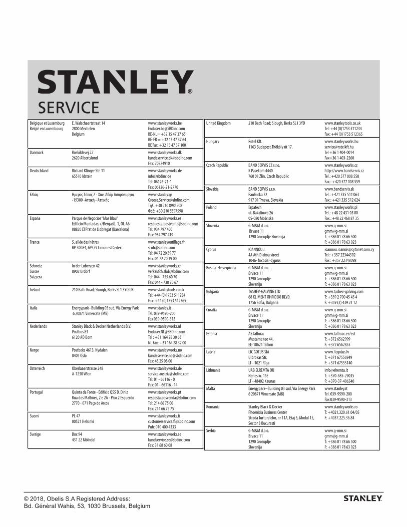
SERVICE

Manufactured by:Pinnacle Climate Technologies, Inc.
Sauk Rapids, MN 56379 USA
EC REP
Obelis S.ARegistered Address:
Bd. Général Wahis, 53, 1030 Brussels, Belgium
© 2018 Stanley Black & Decker, Inc.
ST-45-KFA-E / ST-70T-KFA-E / ST-125T-KFA-E ST-175T-KFA-E / ST-215T-KFA-E
LASSEN SIE DAS HEIZGERÄT WÄHREND DES BETRIEBS, ODER WÄHREND ES MIT STROM VERSORGT WIRD, NIEMALS UNBEAUFSICHTIGT.
DIESES PRODUKT EIGNET SICH NICHT ALS HAUPTHEIZGERÄT.
STKA-462
BITTE LESEN SIE VOR VERWENDUNG DES GERÄTS DIE ANLEITUNG SORGFÄLTIG DURCH.
- Dieses Gerät kann von Kindern ab acht Jahren und älter und von Personen mit eingeschränkten physischen oder geistigen Fähigkeiten oder mangelnder Erfahrung und fehlendem Wissen verwendet werden, wenn diese beaufsichtigt werden bzw. Anweisungen im sicheren Einsatz des Geräts und bei den damit verbundenen Gefahren erhalten haben. Das Gerät ist kein Spielzeug für Kinder. Reinigung und Bedienerwartung dürfen nicht von Kindern ohne entsprechende Beaufsichtigung erfolgen.
- Kinder unter drei Jahren müssen von dem Gerät ferngehalten werden, es sei denn, sie werden ununterbrochen beaufsichtigt. Kinder von drei Jahren bis zu acht Jahren dürfen das Gerät nur dann ein- und ausschalten, wenn es in der normalen Betriebsposition aufgestellt bzw. installiert wurde. Ebenso müssen sie dabei beaufsichtigt werden bzw. Anweisungen im sicheren Einsatz des Geräts und bei den damit verbundenen Gefahren erhalten haben. Kinder von drei Jahren bis zu acht Jahren dürfen das Gerät nicht anschließen, es nicht entsprechend einstellen und reinigen oder Bedienerwartung jeglicher Art vornehmen.
- VORSICHT: Manche Teile des Produkts können sehr heiß werden und Verbrennungen verursachen. Besondere Aufmerksamkeit muss in der Gegenwart von Kindern und schutzbedürftigen Personen gewährt werden.
- Ist das Kabel beschädigt, dann muss es zum Ausschluss einer Gefährdung vom Hersteller, seinem Servicevertreter oder einer anderen zugelassenen Person ersetzt werden.
- Das Heizgerät darf nicht in unmittelbarer Nähe unter einer Steckdose aufgestellt werden.
- Verwenden Sie das Heizgerät nicht in unmittelbarer Nähe eines Bades, einer Dusche oder eines Schwimmbads.
- Dieses Heizgerät ist mit einer bestimmten Menge Spezialöl gefüllt. Reparaturen, die das Öffnen des Ölbehälters erfordern, dürfen ausschließlich vom Hersteller oder einem Servicevertreter durchgeführt werden, der im Falle eines Öllecks zu kontaktieren ist.
- Bei Verschrottung des Heizgeräts sind die einschlägigen Vorschriften für die Entsorgung von Öl zu befolgen. Das Heizgerät darf nicht im Hausmüll entsorgt werden, sondern muss bei einer lokalen Recyclingeinrichtung für elektrische Geräte und Öl abgegeben werden.
- Stellen Sie das Gerät auf eine gerade, stabile, hitzebeständige Oberfläche. Wird das Produkt in einer anderen Weise betrieben, könnte dies eine Gefahr darstellen.
- In den ersten Minuten nach erstmaligem Einschalten könnte sich ein leichter Geruch entwickeln. Dies ist normal und wird rasch verschwinden.
- Versuchen Sie nicht, das Gerät zu reparieren, zu zerlegen oder zu ändern. Das Gerät enthält keine für den Bediener vorgesehen Wartungsteile.
- VORSICHT – Bei Verwendung eines Verlängerungskabels stellen Sie sicher, dass die maximale Nennspannung/-leistung des Verlängerungskabels nicht überschritten wird.
© 2018 Pinnacle Climate Technologies, Inc.
© 2018 Pinnacle Climate Technologies, Inc. 1
Bitte Bedienungsanleitung lesen: Wenn dieses Symbol auf einem Produkt abgebildet ist, lesen Sie bitte die Bedienungsanleitung.
ACHTUNG! Das Heizgerät nicht berühren, wenn es heiß ist. Das Gerät vor jeglichen Arbeiten abkühlen lassen.
Dieses Gerät kann von Kindern ab einem Alter von mindestens 8 Jahren sowie von Personen mit eingeschränkten physischen, sensorischen oder geistigen Fähigkeiten oder mangelnder Erfahrung und Kenntnis verwendet werden, soweit sie dabei beaufsichtigt werden oder eine Anleitung zum sicheren Gebrauch des Geräts erhalten haben und ihnen die damit verbundenen Gefahren bewusst sind. Kinder dürfen nicht mit dem Gerät spielen. Das Gerät ist von Kindern nur unter Aufsicht zu reinigen oder zu warten.
5
3
4
6
28
9
17
19
7
118
12
110
19
11
7
6
316
13
4
5
89
14
2
15
ST-70T-KFA-E
ST-125T-KFA-EST-175T-KFA-EST-215T-KFA-E
8.9.10.11.12.13.14.15.16.17.18.
*ST-70T-KFA-E, ST-125T-KFA-E, ST-175T-KFA-E, ST-215T-KFA-E einzig

/ DIGITALER BILDSCHIRM*
2
Modellnr. ST-45-KFA-E ST-70T-KFA-E ST-125T-KFA-E ST-175T-KFA-E ST-215T-KFA-E
HEIZFLÄCHE (m²) 102 158 288 400 492
THERMISCHE ENERGIE (kW) 13,0 20,5 36,6 51,3 63,0
BRENNSTOFFVERBRAUCH(L/STUNDE)
1,3 2,0 3,6 5,07 6,2
TANKINHALT (L) 18,9 19 38 49 49,2
MAXIMALE BETRIEBSDAUER (h) 14 9 10 9,5 8
SPANNUNG (AMPERE)EU: 230 V~ 50 HZ / RU: 220 V~ 50 HZ
1,4 1,5 2,3 2,7 2,8
MOTOR AMPERELEISTUNG 1,6 1,6 2,5 2,9 3,2
MOTOR-STROMPHASEN EINPHASIG EINPHASIG EINPHASIG EINPHASIG EINPHASIG
HEIZGERÄT WÄRMELEISTUNG (ºC) 388 393 404 516 649
LUFTSTROM (CMH) 289 408 918 1070 1138
PUMPENDRUCK (BAR) 0,21 0,28 0,34 0,52 0,55
EMPFOHLENER UMGE-BUNGSTEMPERATURBEREICH FÜR DEN BETRIEB (ºC)
-12/24 -12/24 -12/24 -12/24 -12/24
ABMESSUNGEN (cm) 76 x 34 x 39 76 x 34 x 39 99 x 61 x 66 115 x 65 x 70 115 x 65 x 70
GEWICHT (kg) 12,7 12,7 27,5 30 31
ZULÄSSIGE BRENNSTOFFSORTEN
Kerosin/Diesel Kerosin/Diesel Kerosin/Diesel Kerosin/Diesel Kerosin/Diesel
EINGANGSLEISTUNG (W) 160 160 252 298 298
TECHNISCHE DATENÄnderungen vorbehalten
© 2018 Pinnacle Climate Technologies, Inc.
1
WT
BK
OR
BK 4
2
12
13
GN
7
GN
7
11
10BK
9
BR
BKBK
BL
BL8
5
3
615
14BK
RDRD
BKPK
BK
BL
YL
BKCN1
RD10
11
12
13
1RD
RD
PK
OR
WT
BK3
4
5
GN
7
6
8 RD
BL
9
GN
7
BR
BL
14BKBK
BK
15
20
RD
BKBK
1617
18
19
2
10UF/250VAC
1RD
WT
RD
OR
BK
BK
WT
BK
BK
BK
BK
PKBK
4
2
12
13GN
GN
7
7
11
10 9 8
5
3
6
WT
YLGN
7
WT
8A/125AVC
ST-45-KFA-E
ST-70T-KFA-EST-125T-KFA-EST-175T-KFA-EST-215T-KFA-E
SCHALTPLAN
Nur 125T/175T/215T
© 2018 Pinnacle Climate Technologies, Inc.
Sicherheitshinweis Dies ist ein mit Petroleum betriebenes Heizgerät. Es dient in erster Linie zur vorübergehenden Beheizung von Gebäuden, die sich in Bau befinden oder an denen Umbauarbeiten oder Reparaturen durchgeführt werden. Dieses Gerät produziert geringe Mengen von Kohlenmonoxid. ACHTUNG! Gefahr von Luftverschmutzung in Innenräumen! Dieses Heizgerät darf nur in gut belüfteten Bereichen benutzt werden! Sorgen Sie pro 29,3 kW/Stunde oder 100.000 BTU/ Stunde Heizleistung für eine Frischluftöffnung von mindestens 2.800 cm2.
Verbrennungs-/Brand-/Explosionsgefahr! Verwenden Sie für diesen Heizer NIEMALS
Brennstoffe wie Benzin, Benzol, Alkohol, Reinigungsbenzin, Campingkocherbenzin, Farbverdünner oder andere Ölmischungen (DIES SIND FLÜCHTIGE KRAFTSTOFFE, DIE ZU BRAND ODER EXPLOSION FÜHREN KÖNNEN).
Mindestabstand von Brennstoffen:ST-45-/ 70T-/ 125T-/ 175T-/ 215T- KFA-E
Oben 1,22 mSeitlich 1,22 mVorne 3,05 m - Brennstofftank des Heizgeräts NIEMALS auffüllen, wenn der
Heizer in Betrieb oder noch heiß ist. Dieses Heizgerät ist im Betriebszustand EXTREM HEISS.
- Alle Brennstoffe vom Gerät fernhalten. - Luftzufuhröffnung (hinten) oder Luftablassöffnung (vorne) des
Heizgeräts NIEMALS versperren. - An der Vorder- oder Rückseite des Heizers NIEMALS
Leerrohre anbringen. - Heizgerät NIEMALS bewegen oder anfassen, wenn es noch
heiß ist. - Heizgerät NIEMALS mit gefülltem Tank transportieren. - Wenn es mit einem Thermostat ausgestattet ist, kann sich das
Heizgerät jederzeit einschalten. - Heizgerät STETS auf einer stabilen und ebenen Fläche
aufstellen. - Kinder und Tiere STETS vom Heizgerät fernhalten. - Größere Brennstoffmengen mindestens 7,6 m von
Heizkörpern, Fackeln, tragbaren Generatoren oder anderen Zündquellen fernhalten.
- Stecker STETS herausziehen, wenn das das Gerät nicht benutzt wird.
- Nicht zur Nutzung in Wohnhäusern oder Wohnmobilen geeignet.
- Heizgerät niemals in Wohn- oder Schlafbereichen nutzen. - Heizgerät NIEMALS in Bereichen nutzen, in denen sich
entzündliche Dämpfe befinden könnten.
- Nur Strom der Spannung und Netzfrequenz gemäß der Angabe auf dem Modellschild des Heizgeräts verwenden.
- Heizgerät STETS so aufstellen, dass es nicht unmittelbar Spritzwasser, Regen, Tropfwasser oder Wind ausgesetzt ist.
- Brennstoffe NIEMALS direkter Sonnenstrahlung aussetzen oder in Innenräumen oder in der Nähe von Wärmequellen aufbewahren.
- NIEMALS überlagerte Brennstoffe aus der vorherigen Heizsaison verwenden. Brennstoffe werden mit der Zeit unbrauchbar. ALTER BRENNSTOFF WIRD IN DIESEM HEIZGERÄT NICHT RICHTIG VERBRENNEN.
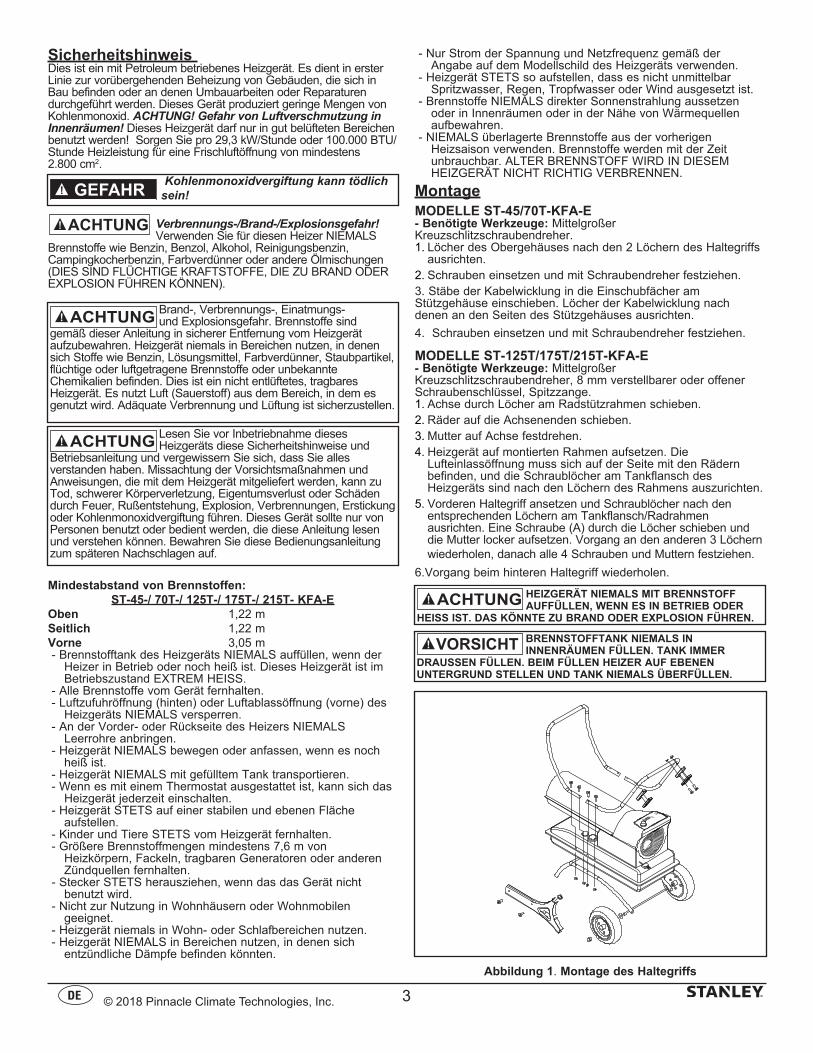
MontageMODELLE ST-45/70T-KFA-E- Benötigte Werkzeuge: Mittelgroßer Kreuzschlitzschraubendreher.1. Löcher des Obergehäuses nach den 2 Löchern des Haltegriffs
ausrichten. 2. Schrauben einsetzen und mit Schraubendreher festziehen.3. Stäbe der Kabelwicklung in die Einschubfächer amStützgehäuse einschieben. Löcher der Kabelwicklung nachdenen an den Seiten des Stützgehäuses ausrichten.
4. Schrauben einsetzen und mit Schraubendreher festziehen.
MODELLE ST-125T/175T/215T-KFA-E- Benötigte Werkzeuge: Mittelgroßer Kreuzschlitzschraubendreher, 8 mm verstellbarer oder offener Schraubenschlüssel, Spitzzange.1. Achse durch Löcher am Radstützrahmen schieben.2. Räder auf die Achsenenden schieben.3. Mutter auf Achse festdrehen.4. Heizgerät auf montierten Rahmen aufsetzen. Die
Lufteinlassöffnung muss sich auf der Seite mit den Rädern befinden, und die Schraublöcher am Tankflansch des Heizgeräts sind nach den Löchern des Rahmens auszurichten.
5. Vorderen Haltegriff ansetzen und Schraublöcher nach den entsprechenden Löchern am Tankflansch/Radrahmen ausrichten. Eine Schraube (A) durch die Löcher schieben und die Mutter locker aufsetzen. Vorgang an den anderen 3 Löchern wiederholen, danach alle 4 Schrauben und Muttern festziehen.
6.Vorgang beim hinteren Haltegriff wiederholen.
Kohlenmonoxidvergiftung kann tödlich sein!GEFAHR
HEIZGERÄT NIEMALS MIT BRENNSTOFF AUFFÜLLEN, WENN ES IN BETRIEB ODER
HEISS IST. DAS KÖNNTE ZU BRAND ODER EXPLOSION FÜHREN.
BRENNSTOFFTANK NIEMALS IN INNENRÄUMEN FÜLLEN. TANK IMMER
DRAUSSEN FÜLLEN. BEIM FÜLLEN HEIZER AUF EBENEN UNTERGRUND STELLEN UND TANK NIEMALS ÜBERFÜLLEN.
VORSICHT
Abbildung 1. Montage des Haltegriffs
Lesen Sie vor Inbetriebnahme dieses Heizgeräts diese Sicherheitshinweise und
Betriebsanleitung und vergewissern Sie sich, dass Sie alles verstanden haben. Missachtung der Vorsichtsmaßnahmen und Anweisungen, die mit dem Heizgerät mitgeliefert werden, kann zu Tod, schwerer Körperverletzung, Eigentumsverlust oder Schäden durch Feuer, Rußentstehung, Explosion, Verbrennungen, Erstickung oder Kohlenmonoxidvergiftung führen. Dieses Gerät sollte nur von Personen benutzt oder bedient werden, die diese Anleitung lesen und verstehen können. Bewahren Sie diese Bedienungsanleitung zum späteren Nachschlagen auf.
Brand-, Verbrennungs-, Einatmungs- und Explosionsgefahr. Brennstoffe sind
gemäß dieser Anleitung in sicherer Entfernung vom Heizgerät aufzubewahren. Heizgerät niemals in Bereichen nutzen, in denen sich Stoffe wie Benzin, Lösungsmittel, Farbverdünner, Staubpartikel, flüchtige oder luftgetragene Brennstoffe oder unbekannte Chemikalien befinden. Dies ist ein nicht entlüftetes, tragbares Heizgerät. Es nutzt Luft (Sauerstoff) aus dem Bereich, in dem es genutzt wird. Adäquate Verbrennung und Lüftung ist sicherzustellen.
3
© 2018 Pinnacle Climate Technologies, Inc.
BetriebDieses Heizgerät ist für den Betrieb mit 1-K Kerosin/Paraffin, Dieselkraftstoff Nr. 1 und 2, JP8/Jet A Brennstoff und Heizöl Nr. 1 und 2 zertifiziert.HEIZGERÄT EINSCHALTEN:1. Tank mit Petroleum befüllen, bis Tankanzeige auf „F“ zeigt.2. Tankdeckel sichern.3. Stromkabel in Steckdose stecken.4. Thermostatregler auf gewünschte Temperatureinstellung
drehen (nur 70/125/175/215). Der Einstellbereich geht von 5 °C bis 45 °C Netzschalter auf „ON“ (EIN) stellen. Die Stromanzeige und die Raumtemperaturanzeige werden aufleuchten (nur 125/175/215), und der Heizer wird anlaufen.
Der optimale Druck ist erreicht, wenn der Glühkegel kirschrot ist und keine Flammen aus dem Heizgerät austreten.HINWEIS: Die Raumtemperaturanzeige (nur 125/175/215) wird Folgendes anzeigen:- Wenn die Temperatur unter -17 °C liegt, zeigt die Anzeige „LO“.- Wenn die Temperatur 37 °C übersteigt, zeigt die Anzeige „HI“.-Zwischen -17 °C und 37 °C wird die tatsächliche Temperatur angezeigt.HEIZGERÄT AUSSCHALTEN: Temperatureinstellknopf nach links drehen, Netzschalter auf „OFF“ (AUS) stellen und Netzkabel aus der Steckdose ziehen.HEIZGERÄT WIEDER EINSCHALTEN:1. Nach Ausschalten des Heizgeräts 10 Sekunden warten.2. Netzschalter auf „ON“ (EIN) stellen.3. Vorsichtsmaßnahmen zum Startvorgang beachten.
LANGFRISTIGE AUFBEWAHRUNGBrennstofftank leeren1. Bei den Modellen ST-45/70T-KFA-E den Brennstoff mit
Hilfe eines zugelassenen Saugrohrs durch die Tanköffnung ablassen. Bei den Modellen ST-125/175/215-KFA-E den Brennstoff durch die Ablassöffnung an der Unterseite des Brennstofftanks ablassen.
2. Um die Ablassschraube abzunehmen (125/175/215), den Griff der Schraube nach unten ziehen und den Siegelkopf von der Ablassöffnung des Tanks lösen.
3. Tank ausspülen und vollständig leeren.4. Zum Wiederverschließen Ablasskopf vollständig in die
Ablassöffnung hineindrücken und durch Festdrücken der Siegelkappe im Kopfloch sichern.
WICHTIG: Bewahren Sie überschüssigen Brennstoff niemals über den Sommer hinweg auf. Die Verwendung alten Brennstoffs kann Ihr Heizgerät beschädigen.
Bewahren Sie den Heizgerät in einem trockenen, gut belüfteten Bereich auf. Falls das Heizgerät nicht in einem Gebäude aufbewahrt werden kann, schützen Sie es mit einer Haube oder wasserfesten Abdeckplane.Der Aufbewahrungsraum ist vor Staub und ätzenden Dämpfen zu schützen. Packen Sie das Heizgerät wieder in sein ursprüngliches Verpackungsmaterial. Bewahren Sie die Bedienungsanleitung griffbereit auf.
WartungWarten Sie den Heizgerät niemals, wenn es angeschlossen oder heiß ist! Bringen Sie das Heizgerät zur Wartung stets in einen sauberen, ebenen, trockenen Bereich. Warten Sie das Heizgerät niemals bei Nässe. Vergewissern Sie sich bei einem Notfall, dass das Heizgerät sich vollständig abgekühlt hat, bevor Sie es warten, um sicherzustellen, dass das Heizgerät oder die Elektronik im Gerät keiner Nässe ausgesetzt wird. Warten Sie das Heizgerät unter keinen Umständen, so lange es noch an die Stromversorgung angeschlossen ist.BRENNSTOFF/BRENNSTOFFTANK: Alle 200 Betriebsstunden oder je nach Bedarf mit Petroleum ausspülen.LUFTFILTER: Öffnen Sie die Klappe am Heizgerät, um Zugriff auf die Filter zu erhalten. Filter sind nach höchstens 500 Betriebsstunden auszutauschen, unter Umständen öfter. Eine detaillierte Darstellung finden Sie in Abb.7.1 auf Seite 6.GEBLÄSEFLÜGEL: Öffnen Sie die Klappe am Heizgerät, um Zugriff auf die Gebläseflügel zu erhalten. Die Flügel sind mindestens einmal pro Heizsaison zu reinigen. Eine detaillierte Darstellung finden Sie in Abb. 6.1 auf Seite 6.DÜSEN: Öffnen die Klappe am Heizgerät und entfernen Sie den Brennerkopf, um Zugriff auf die Düse zu erhalten. Düsen sind mindestens einmal pro Heizsaison zu reinigen oder zu ersetzen. Eine detaillierte Darstellung finden Sie in Abb. 3.1 auf Seite 6.ZÜNDKERZE: Öffnen Sie die Klappe am Heizgerät, um Zugriff auf die Zündkerze zu erhalten. Alle 600 Betriebsstunden reinigen und neu einstellen oder nach Bedarf auswechseln. Elektrodenstand auf 3,5 mm einstellen. Eine detaillierte Darstellung finden Sie in Abb. 3.1 auf Seite 6.FOTOZELLE: Öffnen Sie die Klappe am Heizgerät, um Zugriff auf die Fotozelle zu erhalten. Die Fotozelle ist mindestens einmal pro Heizsaison zu reinigen, unter Umständen öfter. Eine detaillierte Darstellung finden Sie in Abb. 4.1 und 5.1 auf Seite 6 Nach der Wartung des Heizgeräts sollten Sie vor der Inbetriebnahme des Heizgeräts folgende Funktionsprüfung durchführen: - kontrollieren Sie die Luft- und Brennstoffleitungen mit
einer 50:50-Seifenlauge; - kontrollieren Sie das Verlängerungskabel auf Verschleiß, Risse
oder Schnitte; - kontrollieren Sie, ob das Zündkabel fest an der Zündkerze
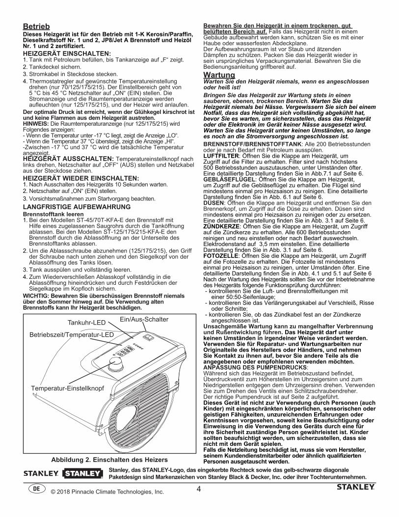
angeschlossen ist.Unsachgemäße Wartung kann zu mangelhafter Verbrennung und Rußentwicklung führen. Das Heizgerät darf unter keinen Umständen in irgendeiner Weise verändert werden. Verwenden Sie für Reparatur- und Wartungsarbeiten nur Originalteile des Herstellers oder Händlers, und nehmen Sie Kontakt zu ihnen auf, bevor Sie andere Teile als die angegebenen oder empfohlenen verwenden möchten.ANPASSUNG DES PUMPENDRUCKS:Während sich das Heizgerät im Betriebszustand befindet, Überdruckventil zum Höherstellen im Uhrzeigersinn und zum Niedrigerstellen entgegen dem Uhrzeigersinn drehen. Verwenden Sie zum Drehen des Ventils einen Schlitzschraubendreher. Der richtige Pumpendruck ist auf Seite 2 aufgeführt. Dieses Gerät ist nicht zur Verwendung durch Personen (auch Kinder) mit eingeschränkten körperlichen, sensorischen oder geistigen Fähigkeiten, unzureichenden Erfahrungen oder Kenntnissen vorgesehen, soweit keine Beaufsichtigung oder Einweisung in die Verwendung des Geräts durch eine für ihre Sicherheit zuständige Person gewährleistet ist. Kinder sollten beaufsichtigt werden, um sicherzustellen, dass sie nicht mit dem Gerät spielen. Falls die Netzleitung beschädigt ist, muss sie vom Hersteller, seinem Kundendienstmitarbeiter oder ähnlich qualifizierten Personen ausgetauscht werden.Abbildung 2. Einschalten des Heizers
Ein/Aus-Schalter
Temperatur-Einstellknopf
Tankuhr-LED
Stanley, das STANLEY-Logo, das eingekerbte Rechteck sowie das gelb-schwarze diagonale Paketdesign sind Markenzeichen von Stanley Black & Decker, Inc. oder ihrer Tochterunternehmen.
4
Betriebszeit/Temperatur-LED
© 2018 Pinnacle Climate Technologies, Inc.
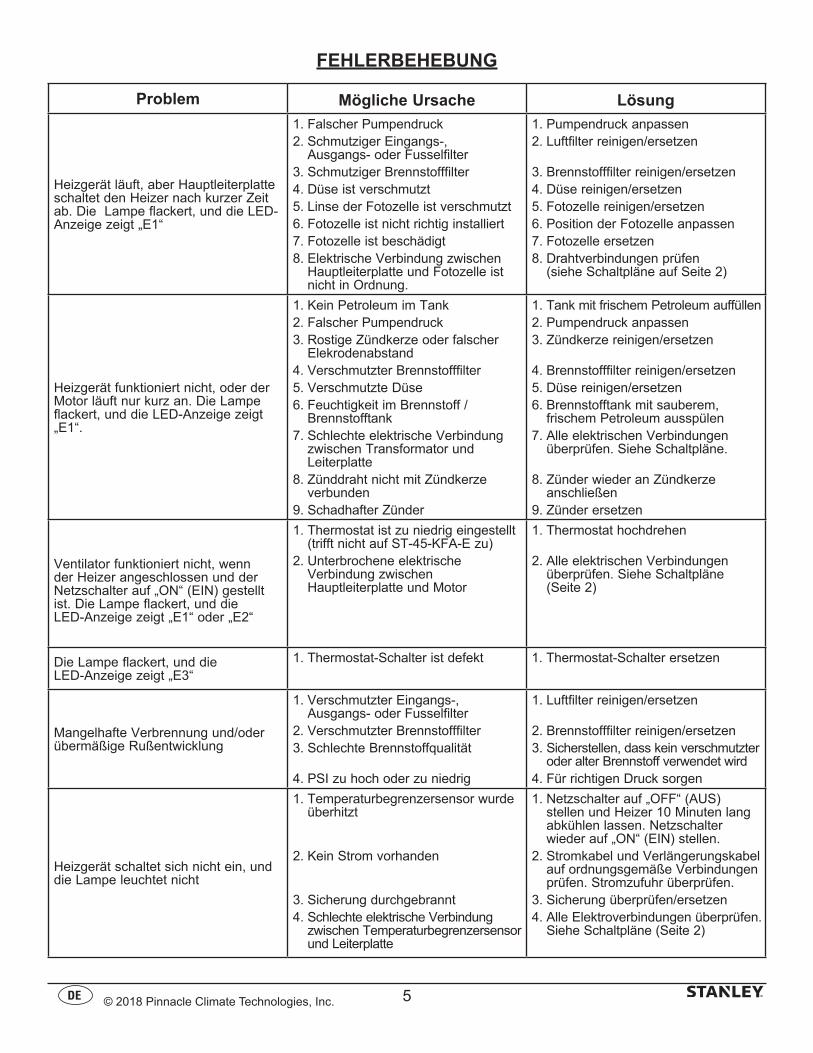
FEHLERBEHEBUNG
Problem Mögliche Ursache Lösung
Heizgerät läuft, aber Hauptleiterplatte schaltet den Heizer nach kurzer Zeit ab. Die Lampe flackert, und die LED-Anzeige zeigt „E1“
1. Falscher Pumpendruck2. Schmutziger Eingangs-,
Ausgangs- oder Fusselfilter3. Schmutziger Brennstofffilter4. Düse ist verschmutzt5. Linse der Fotozelle ist verschmutzt6. Fotozelle ist nicht richtig installiert7. Fotozelle ist beschädigt8. Elektrische Verbindung zwischen
Hauptleiterplatte und Fotozelle ist nicht in Ordnung.
1. Pumpendruck anpassen2. Luftfilter reinigen/ersetzen
3. Brennstofffilter reinigen/ersetzen4. Düse reinigen/ersetzen5. Fotozelle reinigen/ersetzen6. Position der Fotozelle anpassen7. Fotozelle ersetzen8. Drahtverbindungen prüfen
(siehe Schaltpläne auf Seite 2)
Heizgerät funktioniert nicht, oder der Motor läuft nur kurz an. Die Lampe flackert, und die LED-Anzeige zeigt „E1“.
1. Kein Petroleum im Tank2. Falscher Pumpendruck3. Rostige Zündkerze oder falscher
Elekrodenabstand4. Verschmutzter Brennstofffilter 5. Verschmutzte Düse6. Feuchtigkeit im Brennstoff /
Brennstofftank7. Schlechte elektrische Verbindung
zwischen Transformator und Leiterplatte
8. Zünddraht nicht mit Zündkerze verbunden
9. Schadhafter Zünder
1. Tank mit frischem Petroleum auffüllen2. Pumpendruck anpassen3. Zündkerze reinigen/ersetzen
4. Brennstofffilter reinigen/ersetzen5. Düse reinigen/ersetzen6. Brennstofftank mit sauberem,
frischem Petroleum ausspülen7. Alle elektrischen Verbindungen
überprüfen. Siehe Schaltpläne.
8. Zünder wieder an Zündkerze anschließen
9. Zünder ersetzen
Ventilator funktioniert nicht, wenn der Heizer angeschlossen und der Netzschalter auf „ON“ (EIN) gestellt ist. Die Lampe flackert, und die LED-Anzeige zeigt „E1“ oder „E2“
1. Thermostat ist zu niedrig eingestellt (trifft nicht auf ST-45-KFA-E zu)
2. Unterbrochene elektrische Verbindung zwischen Hauptleiterplatte und Motor
1. Thermostat hochdrehen
2. Alle elektrischen Verbindungen überprüfen. Siehe Schaltpläne (Seite 2)
Die Lampe flackert, und die LED-Anzeige zeigt „E3“
1. Thermostat-Schalter ist defekt 1. Thermostat-Schalter ersetzen
Mangelhafte Verbrennung und/oder übermäßige Rußentwicklung
1. Verschmutzter Eingangs-, Ausgangs- oder Fusselfilter
2. Verschmutzter Brennstofffilter3. Schlechte Brennstoffqualität
4. PSI zu hoch oder zu niedrig
1. Luftfilter reinigen/ersetzen
2. Brennstofffilter reinigen/ersetzen3. Sicherstellen, dass kein verschmutzter
oder alter Brennstoff verwendet wird4. Für richtigen Druck sorgen
Heizgerät schaltet sich nicht ein, und die Lampe leuchtet nicht
1. Temperaturbegrenzersensor wurde überhitzt
2. Kein Strom vorhanden
3. Sicherung durchgebrannt4. Schlechte elektrische Verbindung
zwischen Temperaturbegrenzersensor und Leiterplatte
1. Netzschalter auf „OFF“ (AUS) stellen und Heizer 10 Minuten lang abkühlen lassen. Netzschalter wieder auf „ON“ (EIN) stellen.
2. Stromkabel und Verlängerungskabel auf ordnungsgemäße Verbindungen prüfen. Stromzufuhr überprüfen.
3. Sicherung überprüfen/ersetzen4. Alle Elektroverbindungen überprüfen.
Siehe Schaltpläne (Seite 2)
5
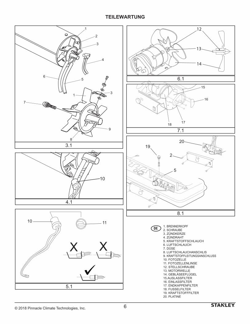
© 2018 Pinnacle Climate Technologies, Inc. 6
TEILEWARTUNG
XX
10 11
10
1
2
3
4
56
7
1 3
9
8
3.1
4.1
5.1
15
16
1718
12
14
13
20
2
5
19
8.1
6.1
7.1
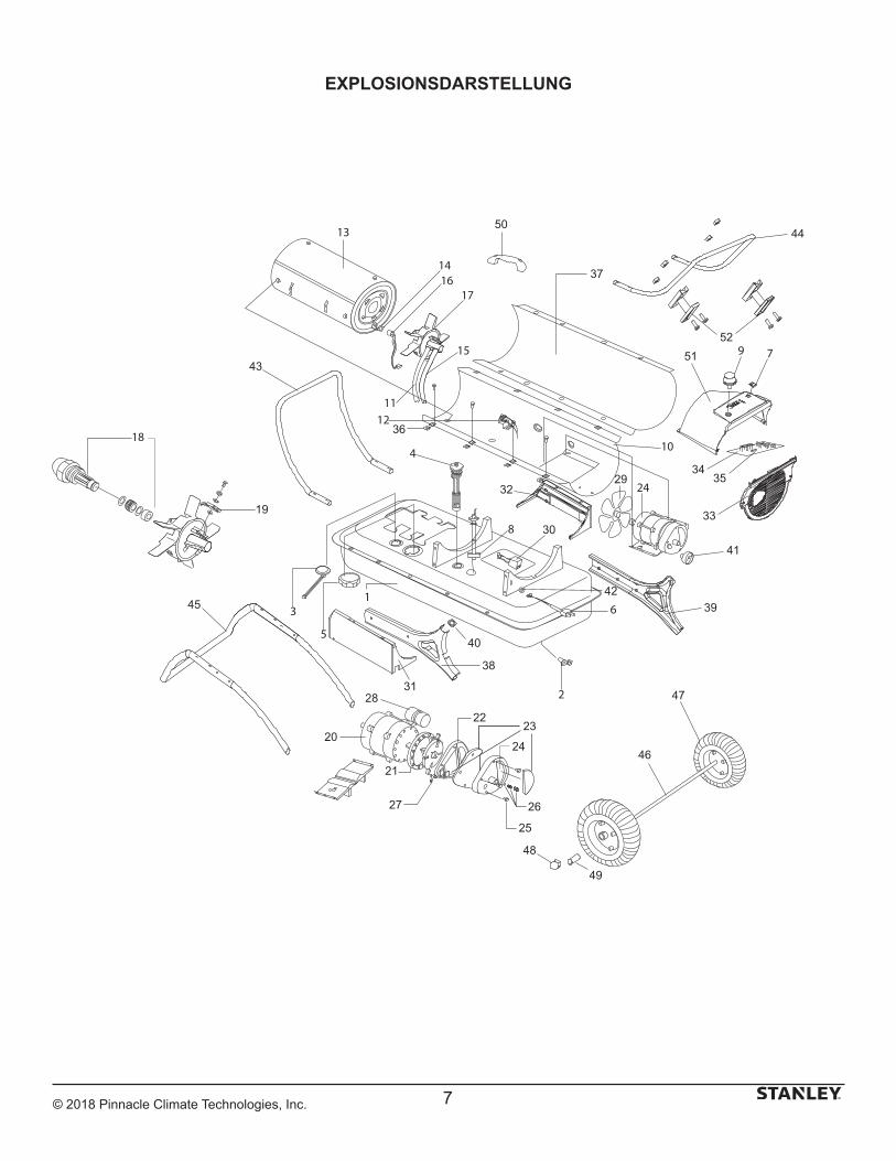
© 2018 Pinnacle Climate Technologies, Inc.
EXPLOSIONSDARSTELLUNG
41
43
44
45
46
47
48
49
50
19
20
21
2223
24
25
2627
28
29
30
31
32
33
3435
36
37
38
39
40
42
5152
7
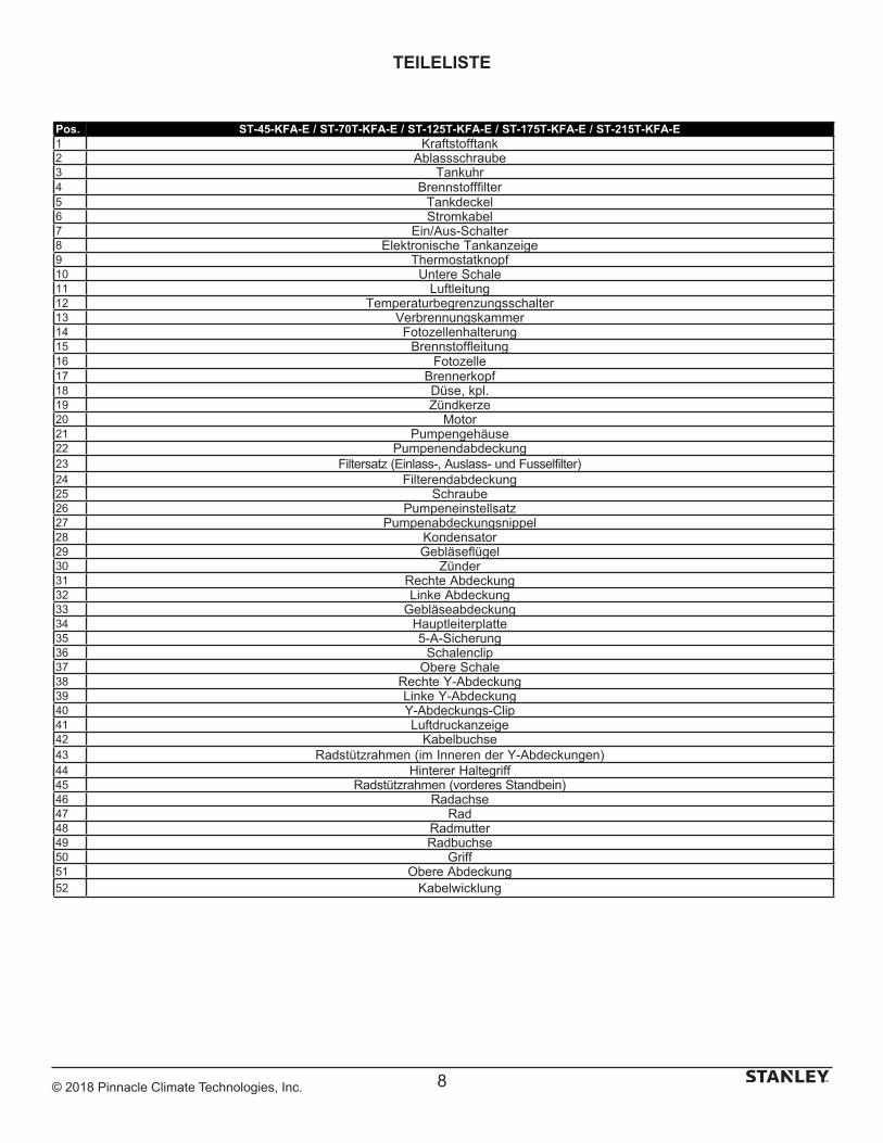
© 2018 Pinnacle Climate Technologies, Inc.
TEILELISTE
8
Pos. ST-45-KFA-E / ST-70T-KFA-E / ST-125T-KFA-E / ST-175T-KFA-E / ST-215T-KFA-E1 Kraftstofftank2 Ablassschraube3 Tankuhr4 Brennstofffilter5 Tankdeckel6 Stromkabel7 Ein/Aus-Schalter8 Elektronische Tankanzeige9 Thermostatknopf10 Untere Schale11 Luftleitung12 Temperaturbegrenzungsschalter13 Verbrennungskammer14 Fotozellenhalterung15 Brennstoffleitung16 Fotozelle17 Brennerkopf18 Düse, kpl.19 Zündkerze20 Motor21 Pumpengehäuse22 Pumpenendabdeckung23 Filtersatz (Einlass-, Auslass- und Fusselfilter)24 Filterendabdeckung25 Schraube26 Pumpeneinstellsatz27 Pumpenabdeckungsnippel28 Kondensator29 Gebläseflügel30 Zünder31 Rechte Abdeckung32 Linke Abdeckung33 Gebläseabdeckung34 Hauptleiterplatte35 5-A-Sicherung36 Schalenclip37 Obere Schale38 Rechte Y-Abdeckung39 Linke Y-Abdeckung40 Y-Abdeckungs-Clip41 Luftdruckanzeige42 Kabelbuchse43 Radstützrahmen (im Inneren der Y-Abdeckungen)44 Hinterer Haltegriff45 Radstützrahmen (vorderes Standbein)46 Radachse47 Rad48 Radmutter49 Radbuchse50 Griff51 Obere Abdeckung52 Kabelwicklung

© 2018 Pinnacle Climate Technologies, Inc.
Belgique et LuxemburgBelgië en Luxembourg
E. Walschaertstraat 14 2800 Mechelen Belgium
[email protected]= +32 15 47 37 65BE-FR = +32 15 47 37 64BE Fax: +32 15 47 37 100
Danmark Roskildevej 22 2620 Albertslund
[email protected]: 70224910
Deutschland Richard Klinger Str. 11 65510 Idstein
[email protected]: 06126-21-1Fax: 06126-21-2770
Ελλάς Hμερος Τόπος 2 - Χάνι Αδάμ Ασπρόπυργος -19300 -Αττική - Αττικής
[email protected]Τηλ: +30 210 8985208Φαξ: +30 210 5597598
España Parque de Negocios “Mas Blau” Edificio Muntadas, c/Bergadá, 1, Of. A6 08820 El Prat de Llobregat (Barcelona)
[email protected]: 934 797 400Fax: 934 797 419
France 5, allée des hêtres BP 30084, 69579 Limonest Cedex
[email protected]: 04 72 20 39 77Fax: 04 72 20 39 00
SchweizSuisse Svizzera
In der Luberzen 42 8902 Urdorf
[email protected]: 044 - 755 60 70Fax: 044 - 730 70 67
Ireland 210 Bath Road; Slough, Berks SL1 3YD UK www.stanleytools.co.ukTel: +44 (0)1753 511234Fax: +44 (0)1753 512365
Italia Energypark–Building 03 sud, Via Energy Park 6 20871 Vimercate (MB)
www.stanley.itTel. 039-9590-200Fax 039-9590-313
Nederlands Stanley Black & Decker Netherlands B.V. Postbus 83 6120 AD Born
[email protected] : +31 164 28 30 63NL Fax: +31 164 28 32 00
Norge Postboks 4613, Nydalen0405 Oslo
[email protected]: 45 25 08 00
Österreich Oberlaaerstrasse 248A-1230 Wien
[email protected]: 01 - 66116 - 0Fax: 01 - 66116 - 14
Portugal Quinta da Fonte - Edifício Q55 D. Diniz Rua dos Malhões, 2 e 2A - Piso 2 Esquerdo 2770 - 071 Paço de Arcos
[email protected]: 214 66 75 00Fax: 214 66 75 75
Suomi PL 47 00521 Helsinki
[email protected]: 010 400 4333
Sverige Box 94 431 22 Mölndal
[email protected]: 31 68 60 08
United Kingdom 210 Bath Road; Slough, Berks SL1 3YD www.stanleytools.co.ukTel: +44 (0)1753 511234Fax: +44 (0)1753 512365
Hungary Rotel Kft.1163 Budapest,Thököly út 17.
[email protected] +36 1 404-0014Fax+36 1 403-2260
Czech Republic BAND SERVIS CZ s.r.o. K Pasekam 4440 760 01 Zlín, Czech Republic
www.stanleyworks.czhttp://www.bandservis.czTel.: +420 577 008 550Fax.: +420 577 008 559
Slovakia BAND SERVIS s.r.o. Paulinska 22 917 01 Trnava, Slovakia
www.bandservis.skTel.: +421 335 511 063Fax.: +421 335 512 624
Poland Erpatech ul. Bakaliowa 26 05-080 Mościska
www.stanleyworks.plTel.: +48 22 431 05 00Fax.: +48 22 468 87 35
Slovenia G-M&M d.o.o. Brvace 11 1290 Grosuplje Slovenija
[email protected]: +386 01 78 66 500F: +386 01 78 63 023
Cyprus IOANNOU J. 4A Ath.Diakou street 1046- Nicosia -Cyprus
[email protected]Τel : +357 22344302Fax : +357 22348098
Bosnia-Herzegovina G-M&M d.o.o. Brvace 11 1290 Grosuplje Slovenija
[email protected]: +386 01 78 66 500F: +386 01 78 63 023
Bulgaria TASHEV-GALVING LTD 68 KLIMENT OHRIDSKI BLVD. 1756 Sofia, Bulgaria
www.tashev-galving.comT: +359 2 700 45 45 4F: +359 (2) 439 21 12
Croatia G-M&M d.o.o. Brvace 11 1290 Grosuplje Slovenija
[email protected]: +386 01 78 66 500F: +386 01 78 63 023
Estonia AS Tallmac Mustame tee 44, EE-10621 Tallinn
www.tallmac.ee/estT: +372 6562999F: +372 6562855
Latvia LIC GOTUS SIA Ulbrokas Str. LT - 1021 Rīga
www.licgotus.lvT: +371 67556949F: +371 67555140
Lithuania UAB ELREMTA OU Neries kr. 16E LT - 48402 Kaunas
[email protected]: +370-685-29035F: +370-37-406540
Malta Energypark–Building 03 sud, Via Energy Park 6 20871 Vimercate (MB)
www.stanley.itTel. 039-9590-200Fax 039-9590-313
Romania Stanley Black & Decker Phoenicia Business Center Strada Turturelelor, nr 11A, Etaj 6, Modul 15, Sector 3 Bucuresti
www.stanleyworks.roT: +4021.320.61.04/05F: +4037.225.36.84
Serbia G-M&M d.o.o. Brvace 11 1290 Grosuplje Slovenija
[email protected]: +386 01 78 66 500F: +386 01 78 63 023
SERVICE

Obelis S.A Registered Address:
Bd. Général Wahis, 53 1030 Brussels, Belgium
© 2018 Stanley Black & Decker, Inc.
Pinnacle Climate Technologies, Inc.Sauk Rapids, MN 56379 USA
EC REP
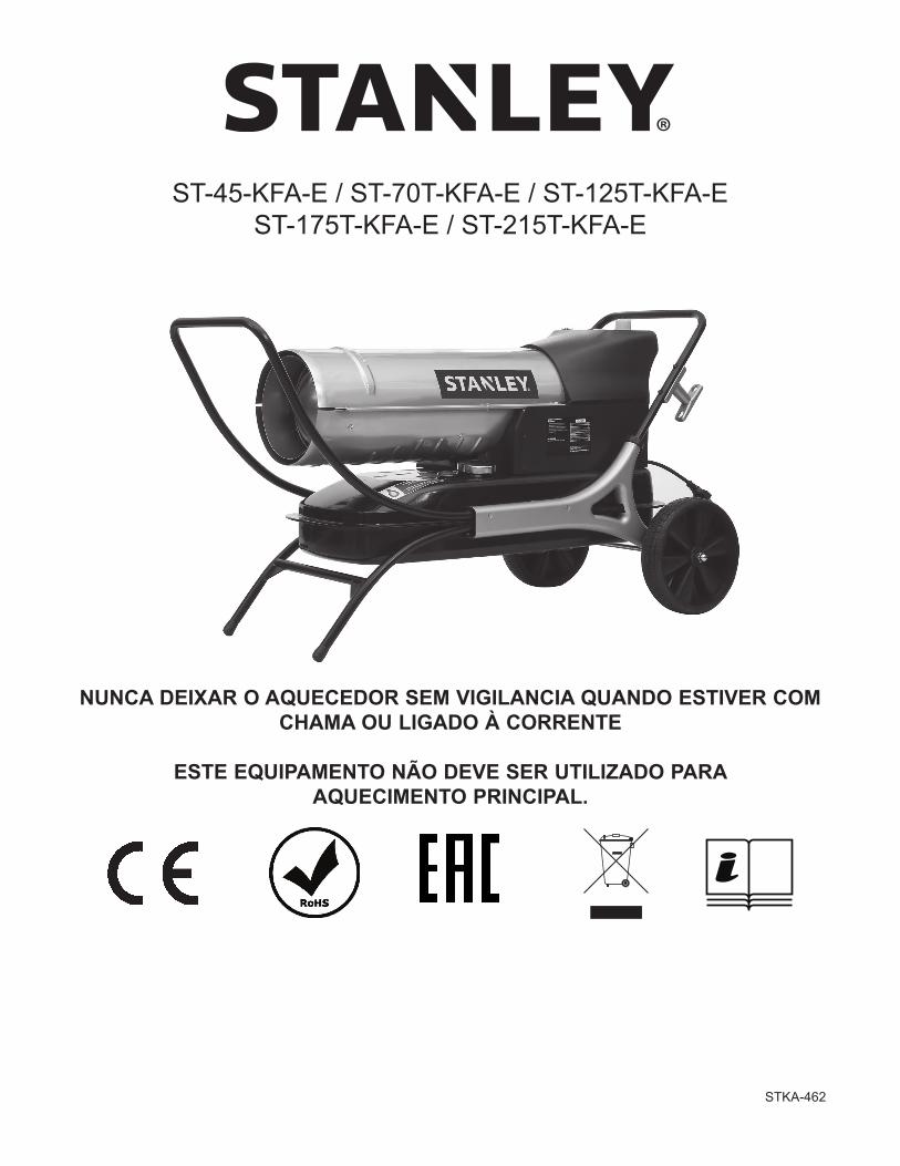
ST-45-KFA-E / ST-70T-KFA-E / ST-125T-KFA-EST-175T-KFA-E / ST-215T-KFA-E
NUNCA DEIXAR O AQUECEDOR SEM VIGILÂNCIA QUANDO ESTIVER COM CHAMA OU LIGADO À CORRENTE
ESTE EQUIPAMENTO NÃO DEVE SER UTILIZADO PARA AQUECIMENTO PRINCIPAL.
STKA-462
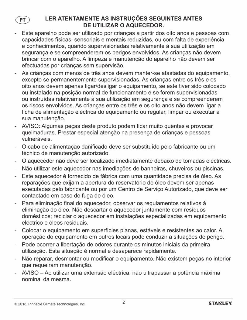
© 2018, Pinnacle Climate Technologies, Inc. 2
LER ATENTAMENTE AS INSTRUÇÕES SEGUINTES ANTES DE UTILIZAR O AQUECEDOR.
- Este aparelho pode ser utilizado por crianças a partir dos oito anos e pessoas com capacidades físicas, sensoriais e mentais reduzidas, ou com falta de experiência e conhecimentos, quando supervisionadas relativamente à sua utilização em segurança e se compreenderem os perigos envolvidos. As crianças não devem brincar com o aparelho. A limpeza e manutenção do aparelho não devem ser efectuadas por crianças sem supervisão.
- As crianças com menos de três anos devem manter-se afastadas do equipamento, excepto se permanentemente supervisionadas. As crianças entre os três e os oito anos devem apenas ligar/desligar o equipamento, se este tiver sido colocado ou instalado na posição normal de funcionamento e se forem supervisionadas ou instruídas relativamente à sua utilização em segurança e se compreenderem os riscos envolvidos. As crianças entre os três e os oito anos não devem ligar a ficha de alimentação eléctrica do equipamento ou regular, limpar ou executar a sua manutenção.
- AVISO: Algumas peças deste produto podem ficar muito quentes e provocar queimaduras. Prestar especial atenção na presença de crianças e pessoas vulneráveis.
- O cabo de alimentação danificado deve ser substituído pelo fabricante ou um técnico de manutenção autorizado.
- O aquecedor não deve ser localizado imediatamente debaixo de tomadas eléctricas. - Não utilizar este aquecedor nas imediações de banheiras, chuveiros ou piscinas. - Este aquecedor é fornecido de fábrica com uma quantidade precisa de óleo. As
reparações que exijam a abertura do reservatório de óleo devem ser apenas executadas pelo fabricante ou por um Centro de Serviço Autorizado, que deve ser contactado em caso de fuga de óleo.
- Para eliminação final do aquecedor, observar os regulamentos relativos à eliminação do óleo. Não descartar o aquecedor juntamente com resíduos domésticos; reciclar o aquecedor em instalações especializadas em equipamento eléctrico e óleos residuais.
- Colocar o equipamento em superfícies planas, estáveis e resistentes ao calor. A operação do equipamento em outros locais pode conduzir a situações de perigo.
- Pode ocorrer a libertação de odores durante os minutos iniciais da primeira utilização. Esta situação é normal e desaparece rapidamente.
- Não reparar, desmontar ou modificar o equipamento. Não existem peças no interior que requeiram manutenção.
- AVISO – Ao utilizar uma extensão eléctrica, não ultrapassar a potência máxima nominal da mesma.
PT
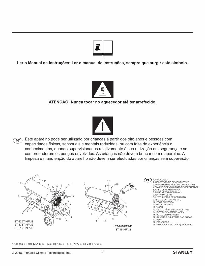
© 2018, Pinnacle Climate Technologies, Inc. 3
Ler o Manual de Instruções: Ler o manual de instruções, sempre que surgir este símbolo.
ATENÇÃO! Nunca tocar no aquecedor até ter arrefecido.
PT Este aparelho pode ser utilizado por crianças a partir dos oito anos e pessoas com capacidades físicas, sensoriais e mentais reduzidas, ou com falta de experiência e conhecimentos, quando supervisionadas relativamente à sua utilização em segurança e se compreenderem os perigos envolvidos. As crianças não devem brincar com o aparelho. A limpeza e manutenção do aparelho não devem ser efectuadas por crianças sem supervisão.
5
3
4
6
28
9
17
19
7
118
12
110
19
11
7
6
316
13
4
5
89
14
2
15
ST-70T-KFA-EST-45-KFA-E
ST-125T-KFA-EST-175T-KFA-EST-215T-KFA-E
1. SAÍDA DE AR2. RESERVATÓRIO DE COMBUSTÍVEL3. INDICADOR DE NÍVEL DE COMBUSTÍVEL4. TAMPÃO DE ENCHIMENTO DE COMBUSTÍVEL5. CABO DE ALIMENTAÇÃO6. MANÓMETRO (OPCIONAL)7. ENTRADA DE AR8. INTERRUPTOR DE OPERAÇÃO9. *BOTÃO DO TERMÓSTATO10. PEGA DIANTEIRA11. PEGA TRASEIRA12. VISOR13. LED DO NÍVEL DE COMBUSTÍVEL14. GAVETA DE ARMAZENAGEM15. BUJÃO DE DRENAGEM16. QUADRO DE SUPORTE DAS RODAS17. PEGA18. PARAFUSOS19. ENROLADOR DO CABO (OPCIONAL)
* Apenas ST-70T-KFA-E, ST-125T-KFA-E, ST-175T-KFA-E, ST-215T-KFA-E
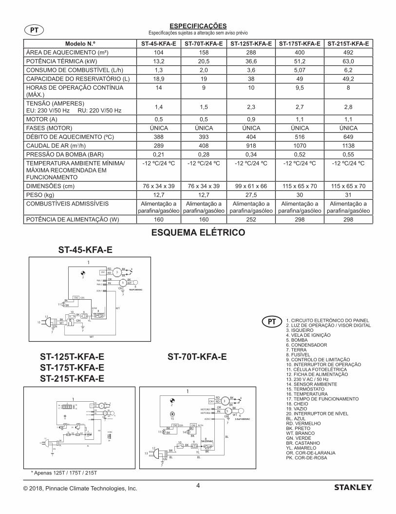
© 2018, Pinnacle Climate Technologies, Inc. 4
Modelo N.º ST-45-KFA-E ST-70T-KFA-E ST-125T-KFA-E ST-175T-KFA-E ST-215T-KFA-E
ÁREA DE AQUECIMENTO (m²) 104 158 288 400 492
POTÊNCIA TÉRMICA (kW) 13,2 20,5 36,6 51,2 63,0
CONSUMO DE COMBUSTÍVEL (L/h) 1,3 2,0 3,6 5,07 6,2
CAPACIDADE DO RESERVATÓRIO (L) 18,9 19 38 49 49,2
HORAS DE OPERAÇÃO CONTÍNUA (MÁX.)
14 9 10 9,5 8
TENSÃO (AMPERES)EU: 230 V/50 Hz RU: 220 V/50 Hz
1,4 1,5 2,3 2,7 2,8
MOTOR (A) 0,5 0,5 0,9 1,1 1,1
FASES (MOTOR) ÚNICA ÚNICA ÚNICA ÚNICA ÚNICA
DÉBITO DE AQUECIMENTO (ºC) 388 393 404 516 649
CAUDAL DE AR (m3/h) 289 408 918 1070 1138
PRESSÃO DA BOMBA (BAR) 0,21 0,28 0,34 0,52 0,55
TEMPERATURA AMBIENTE MÍNIMA/MÁXIMA RECOMENDADA EM FUNCIONAMENTO
-12 ºC/24 ºC -12 ºC/24 ºC -12 ºC/24 ºC -12 ºC/24 ºC -12 ºC/24 ºC
DIMENSÕES (cm) 76 x 34 x 39 76 x 34 x 39 99 x 61 x 66 115 x 65 x 70 115 x 65 x 70
PESO (kg) 12,7 12,7 27,5 30 31
COMBUSTÍVEIS ADMISSÍVEIS Alimentação a parafina/gasóleo
Alimentação a parafina/gasóleo
Alimentação a parafina/gasóleo
Alimentação a parafina/gasóleo
Alimentação a parafina/gasóleo
POTÊNCIA DE ALIMENTAÇÃO (W) 160 160 252 298 298
ESPECIFICAÇÕESEspecificações sujeitas a alteração sem aviso prévioPT
ESQUEMA ELÉTRICO
1
WT
BK
OR
BK 4
2
12
13
GN
7
GN
7
11
10BK
9
BR
BKBK
BL
BL8
5
3
615
14BK
RDRD
BKPK
BK
BL
YL
BKCN1
RD10
11
12
13
1RD
RD
PK
OR
WT
BK3
4
5
GN
7
6
8 RD
BL
9
GN
7
BR
BL
14BKBK
BK
15
20
RD
BKBK
1617
18
19
2
10UF/250VAC
1RD
WT
RD
OR
BK
BK
WT
BK
BK
BK
BK
PKBK
4
2
12
13GN
GN
7
7
11
10 9 8
5
3
6
WT
YLGN
7
WT
8A/125AVC
ST-45-KFA-E
ST-70T-KFA-EST-125T-KFA-EST-175T-KFA-EST-215T-KFA-E
1. CIRCUITO ELETRÓNICO DO PAINEL2. LUZ DE OPERAÇÃO / VISOR DIGITAL3. ISQUEIRO4. VELA DE IGNIÇÃO5. BOMBA6. CONDENSADOR7. TERRA8. FUSÍVEL9. CONTROLO DE LIMITAÇÃO10. INTERRUPTOR DE OPERAÇÃO11. CÉLULA FOTOELÉTRICA12. FICHA DE ALIMENTAÇÃO13. 230 V AC / 50 Hz14. SENSOR AMBIENTE15. TERMÓSTATO16. TEMPERATURA17. TEMPO DE FUNCIONAMENTO18. CHEIO19. VAZIO20. INTERRUPTOR DE NÍVELBL. AZULRD. VERMELHOBK. PRETOWT. BRANCOGN. VERDEBR. CASTANHOYL. AMARELOOR. COR-DE-LARANJAPK. COR-DE-ROSA
* Apenas 125T / 175T / 215T
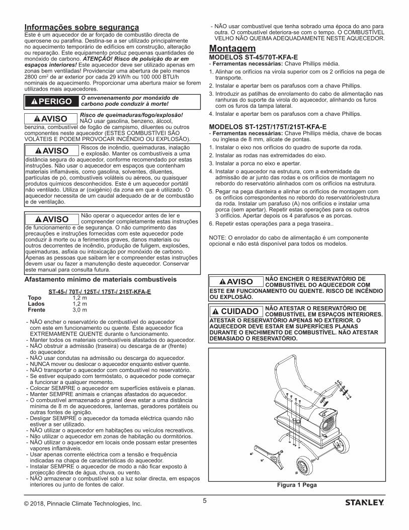
© 2018, Pinnacle Climate Technologies, Inc. 5
Informações sobre segurançaEste é um aquecedor de ar forçado de combustão directa de querosene ou parafina. Destina-se a ser utilizado principalmente no aquecimento temporário de edifícios em construção, alteração ou reparação. Este equipamento produz pequenas quantidades de monóxido de carbono. ATENÇÃO! Risco de poluição do ar em espaços interiores! Este aquecedor deve ser utilizado apenas em zonas bem ventiladas! Providenciar uma abertura de pelo menos 2800 cm2 de ar exterior por cada 29 kW/h ou 100 000 BTU/h nominais de aquecimento. Proporcionar uma abertura maior se forem utilizados mais aquecedores.
Risco de queimaduras/fogo/explosão! NÃO usar gasolina, benzeno, álcool,
benzina, combustível de fogão de campismo, diluentes ou outros componentes neste aquecedor (ESTES COMBUSTÍVEI SÃO VOLÁTEIS E PODEM PROVOCAR INCÊNDIO OU EXPLOSÃO).
Afastamento mínimo de materiais combustíveis
ST-45-/ 70T-/ 125T-/ 175T-/ 215T-KFA-E Topo 1,2 m Lados 1,2 m Frente 3,0 m
- NÃO encher o reservatório de combustível do aquecedor com este em funcionamento ou quente. Este aquecedor fica EXTREMAMENTE QUENTE durante o funcionamento.
- Manter todos os materiais combustíveis afastados do aquecedor. - NÃO obstruir a admissão (traseira) ou descarga de ar (frente)
do aquecedor. - NÃO usar condutas na admissão ou descarga do aquecedor. - NUNCA mover ou deslocar o aquecedor enquanto estiver quente. - NÃO transportar o aquecedor com combustível no reservatório. - Se estiver equipado com termóstato, o aquecedor pode começar
a funcionar a qualquer momento. - Colocar SEMPRE o aquecedor em superfícies estáveis e planas. - Manter SEMPRE animais e crianças afastados do aquecedor. - O combustível armazenado a granel deve estar a uma distância
mínima de 8 m de aquecedores, lanternas, geradores portáteis ou outras fontes de ignição.
- Desligar SEMPRE o aquecedor da tomada eléctrica quando não estiver a ser utilizado.
- NÃO utilizar o aquecedor em habitações ou veículos recreativos. - Não utilizar o aquecedor em zonas de habitação ou dormitórios. - NÃO utilizar o aquecedor em locais onde possam estar presentes
vapores inflamáveis. - Usar apenas corrente eléctrica com a tensão e frequência
indicadas na chapa de características do aquecedor. - Instalar SEMPRE o aquecedor de modo a não ficar exposto à
projecção directa de água, chuva, ou vento. - NÃO armazenar o combustível sob a luz solar directa, em espaços
interiores ou junto de fontes de calor.
- NÃO usar combustível que tenha sobrado uma época do ano para outra. O combustível deteriora-se com o tempo. O COMBUSTÍVEL VELHO NÃO QUEIMA ADEQUADAMENTE NESTE AQUECEDOR.
MontagemMODELOS ST-45/70T-KFA-E- Ferramentas necessárias: Chave Phillips média.
1. Alinhar os orifícios na virola superior com os 2 orifícios na pega de transporte.
2. Instalar e apertar bem os parafusos com a chave Phillips.
3. Introduzir as patilhas de enrolamento do cabo de alimentação nas ranhuras do suporte da virola do aquecedor, alinhando os furos com os furos da tampa lateral.
4. Instalar e apertar bem os parafusos com a chave Phillips.
MODELOS ST-125T/175T/215T-KFA-E- Ferramentas necessárias: Chave Phillips média, chave de bocas
ou inglesa de 8 mm, alicate de pontas.
1. Instalar o eixo nos orifícios do quadro de suporte da roda.
2. Instalar as rodas nas extremidades do eixo.
3. Instalar a porca no eixo e apertar.
4. Instalar o aquecedor na estrutura, com a extremidade da admissão de ar junto das rodas e os orifícios de montagem no rebordo do reservatório alinhados com os orifícios na estrutura.
5. Pegar na pega dianteira e alinhar os orifícios de montagem com os orifícios correspondentes no rebordo do reservatório/estrutura da roda. Instalar um parafuso (A) nos orifícios e instalar uma porca (sem apertar). Repetir estas operações para os outros 3 orifícios. Apertar depois os 4 parafusos e as porcas.
6. Repetir estas operações para a pega traseira..
NOTE: O enrolador do cabo de alimentação é um componente opcional e não está disponível para todos os modelos.
AVISO
O envenenamento por monóxido de carbono pode conduzir à morte!PERIGO
NÃO ENCHER O RESERVATÓRIO DE COMBUSTÍVEL DO AQUECEDOR COM
ESTE EM FUNCIONAMENTO OU QUENTE. RISCO DE INCÊNDIO OU EXPLOSÃO.
AVISO
NÃO ATESTAR O RESERVATÓRIO DE COMBUSTÍVEL EM ESPAÇOS INTERIORES.
ATESTAR O RESERVATÓRIO APENAS NO EXTERIOR. O AQUECEDOR DEVE ESTAR EM SUPERFÍCIES PLANAS DURANTE O ENCHIMENTO DE COMBUSTÍVEL. NÃO ATESTAR DEMASIADO O RESERVATÓRIO.
Figura 1 Pega
Não operar o aquecedor antes de ler e compreender completamente estas instruções
de funcionamento e de segurança. O não cumprimento das precauções e instruções fornecidas com este aquecedor pode conduzir à morte ou a ferimentos graves, danos materiais ou outros decorrentes de incêndio, produção de fuligem, explosões, queimaduras, asfixia ou intoxicação por monóxido de carbono. Apenas as pessoas que saibam ler e compreender estas instruções devem usar ou fazer a manutenção deste aquecedor. Conservar este manual para consulta futura.
AVISO
Riscos de incêndio, queimaduras, inalação e explosão. Manter os combustíveis a uma
distância segura do aquecedor, conforme recomendado por estas instruções. Não usar o aquecedor em espaços que contenham materiais inflamáveis, como gasolina, solventes, diluentes, partículas de pó, combustíveis voláteis ou aéreos, ou quaisquer produtos químicos desconhecidos. Este é um aquecedor portátil não ventilado. Utiliza ar (oxigénio) da zona em que é utilizado. O aquecedor necessita de um caudal adequado de ar de combustão e de ventilação.
AVISO
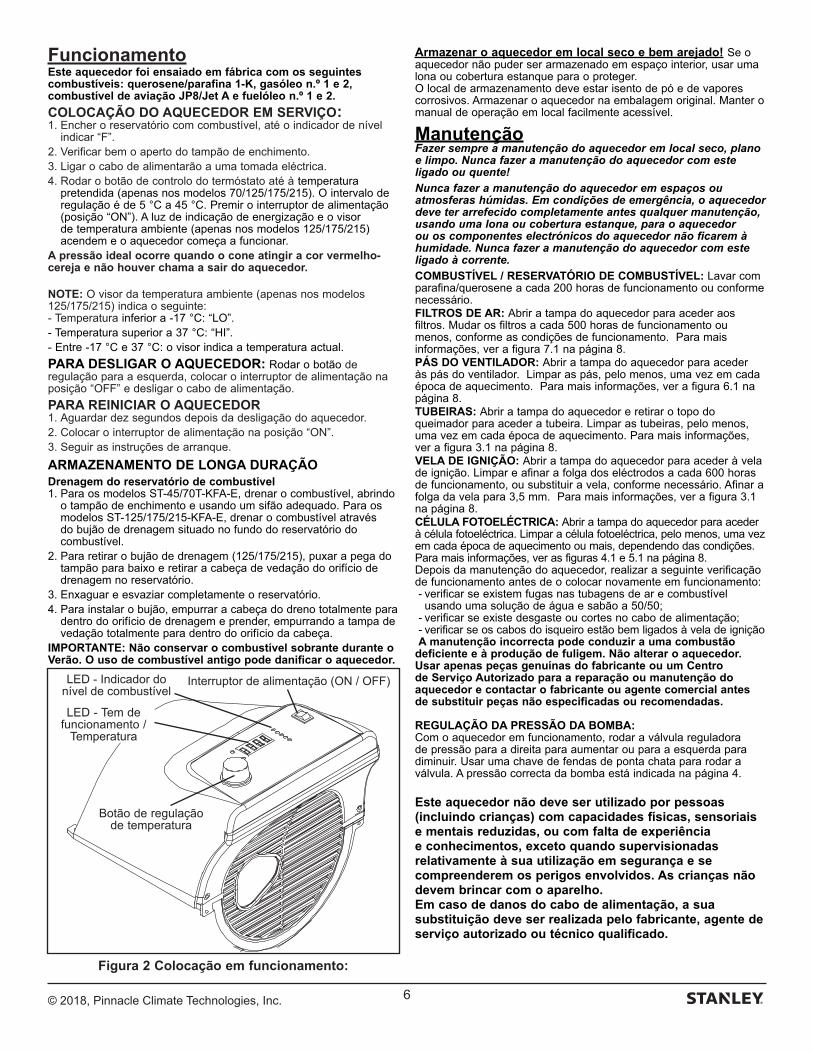
© 2018, Pinnacle Climate Technologies, Inc. 6
FuncionamentoEste aquecedor foi ensaiado em fábrica com os seguintes combustíveis: querosene/parafina 1-K, gasóleo n.º 1 e 2, combustível de aviação JP8/Jet A e fuelóleo n.º 1 e 2.
COLOCAÇÃO DO AQUECEDOR EM SERVIÇO:1. Encher o reservatório com combustível, até o indicador de nível
indicar “F”.2. Verificar bem o aperto do tampão de enchimento.3. Ligar o cabo de alimentarão a uma tomada eléctrica.4. Rodar o botão de controlo do termóstato até à temperatura
pretendida (apenas nos modelos 70/125/175/215). O intervalo de regulação é de 5 °C a 45 °C. Premir o interruptor de alimentação (posição “ON”). A luz de indicação de energização e o visor de temperatura ambiente (apenas nos modelos 125/175/215) acendem e o aquecedor começa a funcionar.
A pressão ideal ocorre quando o cone atingir a cor vermelho-cereja e não houver chama a sair do aquecedor.
NOTE: O visor da temperatura ambiente (apenas nos modelos 125/175/215) indica o seguinte:- Temperatura inferior a -17 °C: “LO”.- Temperatura superior a 37 °C: “HI”.- Entre -17 °C e 37 °C: o visor indica a temperatura actual.
PARA DESLIGAR O AQUECEDOR: Rodar o botão de regulação para a esquerda, colocar o interruptor de alimentação na posição “OFF” e desligar o cabo de alimentação.
PARA REINICIAR O AQUECEDOR1. Aguardar dez segundos depois da desligação do aquecedor.2. Colocar o interruptor de alimentação na posição “ON”.3. Seguir as instruções de arranque.
ARMAZENAMENTO DE LONGA DURAÇÃODrenagem do reservatório de combustível1. Para os modelos ST-45/70T-KFA-E, drenar o combustível, abrindo
o tampão de enchimento e usando um sifão adequado. Para os modelos ST-125/175/215-KFA-E, drenar o combustível através do bujão de drenagem situado no fundo do reservatório do combustível.
2. Para retirar o bujão de drenagem (125/175/215), puxar a pega do tampão para baixo e retirar a cabeça de vedação do orifício de drenagem no reservatório.
3. Enxaguar e esvaziar completamente o reservatório.4. Para instalar o bujão, empurrar a cabeça do dreno totalmente para
dentro do orifício de drenagem e prender, empurrando a tampa de vedação totalmente para dentro do orifício da cabeça.
IMPORTANTE: Não conservar o combustível sobrante durante o Verão. O uso de combustível antigo pode danificar o aquecedor.
Armazenar o aquecedor em local seco e bem arejado! Se o aquecedor não puder ser armazenado em espaço interior, usar uma lona ou cobertura estanque para o proteger.O local de armazenamento deve estar isento de pó e de vapores corrosivos. Armazenar o aquecedor na embalagem original. Manter o manual de operação em local facilmente acessível.
ManutençãoFazer sempre a manutenção do aquecedor em local seco, plano e limpo. Nunca fazer a manutenção do aquecedor com este ligado ou quente!
Nunca fazer a manutenção do aquecedor em espaços ou atmosferas húmidas. Em condições de emergência, o aquecedor deve ter arrefecido completamente antes qualquer manutenção, usando uma lona ou cobertura estanque, para o aquecedor ou os componentes electrónicos do aquecedor não ficarem à humidade. Nunca fazer a manutenção do aquecedor com este ligado à corrente.
COMBUSTÍVEL / RESERVATÓRIO DE COMBUSTÍVEL: Lavar com parafina/querosene a cada 200 horas de funcionamento ou conforme necessário.FILTROS DE AR: Abrir a tampa do aquecedor para aceder aos filtros. Mudar os filtros a cada 500 horas de funcionamento ou menos, conforme as condições de funcionamento. Para mais informações, ver a figura 7.1 na página 8.PÁS DO VENTILADOR: Abrir a tampa do aquecedor para aceder às pás do ventilador. Limpar as pás, pelo menos, uma vez em cada época de aquecimento. Para mais informações, ver a figura 6.1 na página 8.TUBEIRAS: Abrir a tampa do aquecedor e retirar o topo do queimador para aceder a tubeira. Limpar as tubeiras, pelo menos, uma vez em cada época de aquecimento. Para mais informações, ver a figura 3.1 na página 8.VELA DE IGNIÇÃO: Abrir a tampa do aquecedor para aceder à vela de ignição. Limpar e afinar a folga dos eléctrodos a cada 600 horas de funcionamento, ou substituir a vela, conforme necessário. Afinar a folga da vela para 3,5 mm. Para mais informações, ver a figura 3.1 na página 8.CÉLULA FOTOELÉCTRICA: Abrir a tampa do aquecedor para aceder à célula fotoeléctrica. Limpar a célula fotoeléctrica, pelo menos, uma vez em cada época de aquecimento ou mais, dependendo das condições. Para mais informações, ver as figuras 4.1 e 5.1 na página 8.Depois da manutenção do aquecedor, realizar a seguinte verificação de funcionamento antes de o colocar novamente em funcionamento: - verificar se existem fugas nas tubagens de ar e combustível
usando uma solução de água e sabão a 50/50; - verificar se existe desgaste ou cortes no cabo de alimentação;- verificar se os cabos do isqueiro estão bem ligados à vela de igniçãoA manutenção incorrecta pode conduzir a uma combustão
deficiente e à produção de fuligem. Não alterar o aquecedor. Usar apenas peças genuínas do fabricante ou um Centro de Serviço Autorizado para a reparação ou manutenção do aquecedor e contactar o fabricante ou agente comercial antes de substituir peças não especificadas ou recomendadas.
REGULAÇÃO DA PRESSÃO DA BOMBA:Com o aquecedor em funcionamento, rodar a válvula reguladora de pressão para a direita para aumentar ou para a esquerda para diminuir. Usar uma chave de fendas de ponta chata para rodar a válvula. A pressão correcta da bomba está indicada na página 4.
Este aquecedor não deve ser utilizado por pessoas (incluindo crianças) com capacidades físicas, sensoriais e mentais reduzidas, ou com falta de experiência e conhecimentos, exceto quando supervisionadas relativamente à sua utilização em segurança e se compreenderem os perigos envolvidos. As crianças não devem brincar com o aparelho.Em caso de danos do cabo de alimentação, a sua substituição deve ser realizada pelo fabricante, agente de serviço autorizado ou técnico qualificado.
Figura 2 Colocação em funcionamento:
Interruptor de alimentação (ON / OFF)
LED - Tem de funcionamento /
Temperatura
Botão de regulação de temperatura
LED - Indicador do nível de combustível
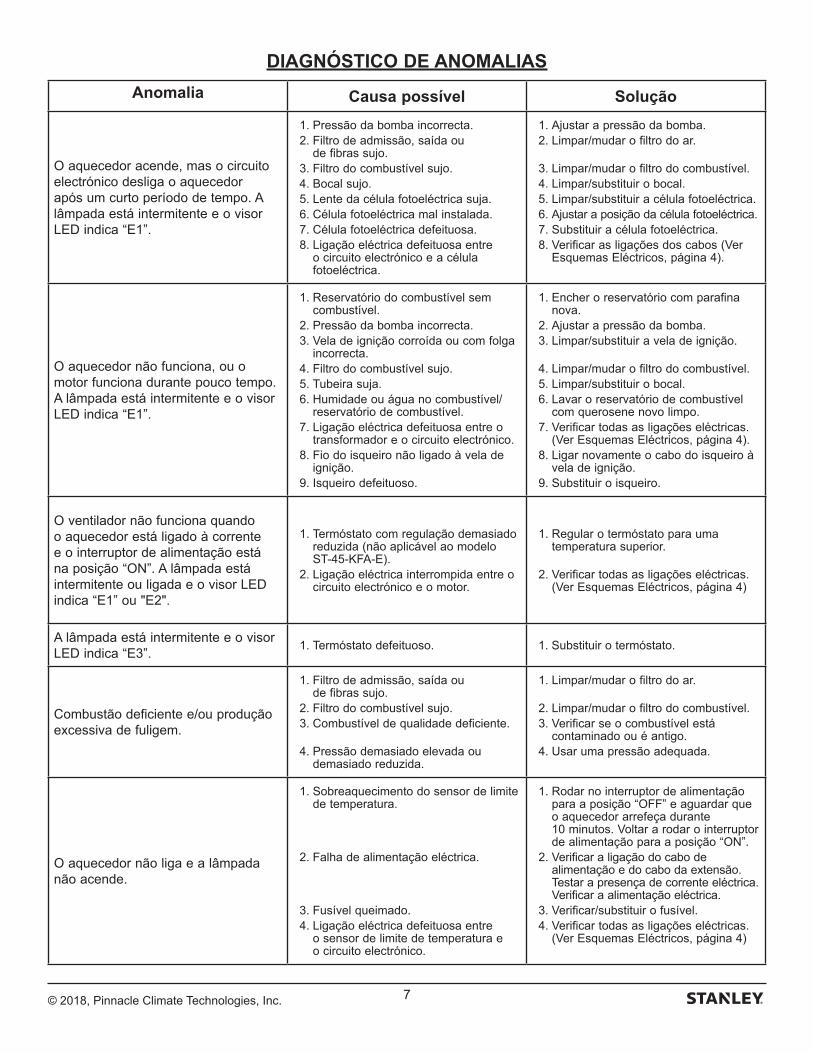
© 2018, Pinnacle Climate Technologies, Inc. 7
DIAGNÓSTICO DE ANOMALIAS
Anomalia Causa possível Solução
O aquecedor acende, mas o circuito electrónico desliga o aquecedor após um curto período de tempo. A lâmpada está intermitente e o visor LED indica “E1”.
1. Pressão da bomba incorrecta. 2. Filtro de admissão, saída ou
de fibras sujo. 3. Filtro do combustível sujo. 4. Bocal sujo. 5. Lente da célula fotoeléctrica suja. 6. Célula fotoeléctrica mal instalada. 7. Célula fotoeléctrica defeituosa. 8. Ligação eléctrica defeituosa entre
o circuito electrónico e a célula fotoeléctrica.
1. Ajustar a pressão da bomba. 2. Limpar/mudar o filtro do ar.
3. Limpar/mudar o filtro do combustível. 4. Limpar/substituir o bocal. 5. Limpar/substituir a célula fotoeléctrica. 6. Ajustar a posição da célula fotoeléctrica. 7. Substituir a célula fotoeléctrica. 8. Verificar as ligações dos cabos (Ver
Esquemas Eléctricos, página 4).
O aquecedor não funciona, ou o motor funciona durante pouco tempo. A lâmpada está intermitente e o visor LED indica “E1”.
1. Reservatório do combustível sem combustível.
2. Pressão da bomba incorrecta. 3. Vela de ignição corroída ou com folga
incorrecta. 4. Filtro do combustível sujo. 5. Tubeira suja. 6. Humidade ou água no combustível/
reservatório de combustível. 7. Ligação eléctrica defeituosa entre o
transformador e o circuito electrónico. 8. Fio do isqueiro não ligado à vela de
ignição. 9. Isqueiro defeituoso.
1. Encher o reservatório com parafina nova.
2. Ajustar a pressão da bomba. 3. Limpar/substituir a vela de ignição.
4. Limpar/mudar o filtro do combustível. 5. Limpar/substituir o bocal. 6. Lavar o reservatório de combustível
com querosene novo limpo. 7. Verificar todas as ligações eléctricas.
(Ver Esquemas Eléctricos, página 4). 8. Ligar novamente o cabo do isqueiro à
vela de ignição. 9. Substituir o isqueiro.
O ventilador não funciona quando o aquecedor está ligado à corrente e o interruptor de alimentação está na posição “ON”. A lâmpada está intermitente ou ligada e o visor LED indica “E1” ou "E2".
1. Termóstato com regulação demasiado reduzida (não aplicável ao modelo ST-45-KFA-E).
2. Ligação eléctrica interrompida entre o circuito electrónico e o motor.
1. Regular o termóstato para uma temperatura superior.
2. Verificar todas as ligações eléctricas. (Ver Esquemas Eléctricos, página 4)
A lâmpada está intermitente e o visor LED indica “E3”.
1. Termóstato defeituoso. 1. Substituir o termóstato.
Combustão deficiente e/ou produção excessiva de fuligem.
1. Filtro de admissão, saída ou de fibras sujo.
2. Filtro do combustível sujo. 3. Combustível de qualidade deficiente.
4. Pressão demasiado elevada ou demasiado reduzida.
1. Limpar/mudar o filtro do ar.
2. Limpar/mudar o filtro do combustível. 3. Verificar se o combustível está
contaminado ou é antigo. 4. Usar uma pressão adequada.
O aquecedor não liga e a lâmpada não acende.
1. Sobreaquecimento do sensor de limite de temperatura.
2. Falha de alimentação eléctrica.
3. Fusível queimado. 4. Ligação eléctrica defeituosa entre
o sensor de limite de temperatura e o circuito electrónico.
1. Rodar no interruptor de alimentação para a posição “OFF” e aguardar que o aquecedor arrefeça durante 10 minutos. Voltar a rodar o interruptor de alimentação para a posição “ON”.
2. Verificar a ligação do cabo de alimentação e do cabo da extensão. Testar a presença de corrente eléctrica. Verificar a alimentação eléctrica.
3. Verificar/substituir o fusível. 4. Verificar todas as ligações eléctricas.
(Ver Esquemas Eléctricos, página 4)
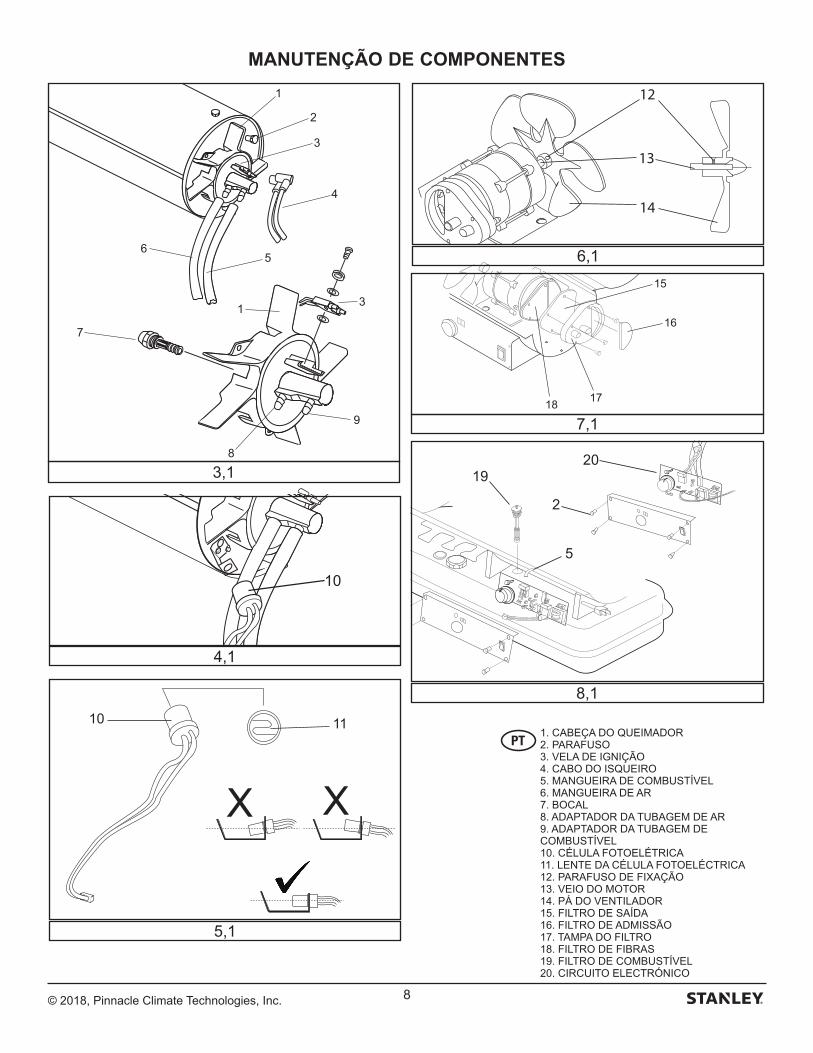
© 2018, Pinnacle Climate Technologies, Inc. 8
MANUTENÇÃO DE COMPONENTES
15
16
1718
12
14
13
XX
10 11
10
20
2
5
19
1
2
3
4
56
7
1 3
9
8
3,1
4,1
5,1
8,1
6,1
7,1
1. CABEÇA DO QUEIMADOR2. PARAFUSO3. VELA DE IGNIÇÃO4. CABO DO ISQUEIRO5. MANGUEIRA DE COMBUSTÍVEL6. MANGUEIRA DE AR7. BOCAL8. ADAPTADOR DA TUBAGEM DE AR9. ADAPTADOR DA TUBAGEM DE COMBUSTÍVEL10. CÉLULA FOTOELÉTRICA11. LENTE DA CÉLULA FOTOELÉCTRICA12. PARAFUSO DE FIXAÇÃO13. VEIO DO MOTOR14. PÁ DO VENTILADOR15. FILTRO DE SAÍDA16. FILTRO DE ADMISSÃO17. TAMPA DO FILTRO18. FILTRO DE FIBRAS19. FILTRO DE COMBUSTÍVEL20. CIRCUITO ELECTRÓNICO
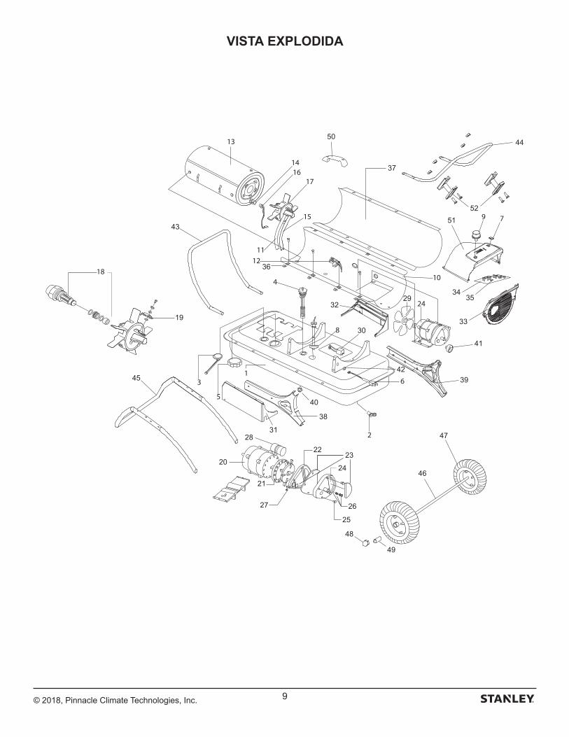
© 2018, Pinnacle Climate Technologies, Inc. 9
VISTA EXPLODIDA
41
43
44
45
46
47
48
49
50
19
20
21
2223
24
25
2627
28
29
30
31
32
33
3435
36
37
38
39
40
42
5152
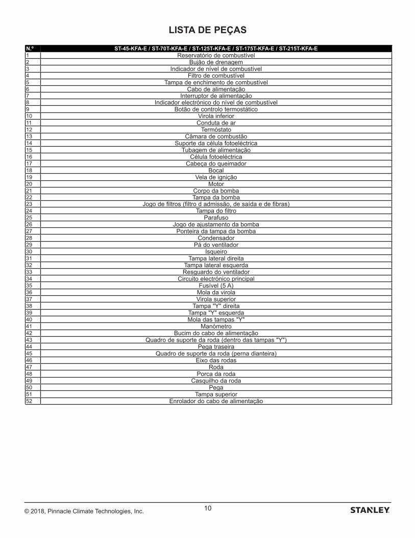
© 2018, Pinnacle Climate Technologies, Inc. 10
LISTA DE PEÇAS
N.º ST-45-KFA-E / ST-70T-KFA-E / ST-125T-KFA-E / ST-175T-KFA-E / ST-215T-KFA-E1 Reservatório de combustível2 Bujão de drenagem3 Indicador de nível de combustível4 Filtro de combustível5 Tampa de enchimento de combustível6 Cabo de alimentação7 Interruptor de alimentação8 Indicador electrónico do nível de combustível9 Botão de controlo termostático10 Virola inferior11 Conduta de ar12 Termóstato13 Câmara de combustão14 Suporte da célula fotoeléctrica15 Tubagem de alimentação16 Célula fotoeléctrica17 Cabeça do queimador18 Bocal19 Vela de ignição20 Motor21 Corpo da bomba22 Tampa da bomba23 Jogo de filtros (filtro d admissão, de saída e de fibras)24 Tampa do filtro25 Parafuso26 Jogo de ajustamento da bomba27 Ponteira da tampa da bomba28 Condensador29 Pá do ventilador30 Isqueiro31 Tampa lateral direita32 Tampa lateral esquerda33 Resguardo do ventilador34 Circuito electrónico principal35 Fusível (5 A)36 Mola da virola37 Virola superior38 Tampa "Y" direita39 Tampa "Y" esquerda40 Mola das tampas "Y"41 Manómetro42 Bucim do cabo de alimentação43 Quadro de suporte da roda (dentro das tampas "Y")44 Pega traseira45 Quadro de suporte da roda (perna dianteira)46 Eixo das rodas47 Roda48 Porca da roda49 Casquilho da roda50 Pega51 Tampa superior52 Enrolador do cabo de alimentação
© 2018, Pinnacle Climate Technologies, Inc. 11
Belgique et LuxembourgBelgië en Luxemburg
E. Walschaertstraat 14 2800 Mechelen Belgium
[email protected]= +32 15 47 37 65BE-FR = +32 15 47 37 64BE Fax: +32 15 47 37 100
Danmark Roskildevej 22 2620 Albertslund
[email protected]: 70224910
Deutschland Richard Klinger Str. 11 65510 Idstein
[email protected]: 06126-21-1Fax: 06126-21-2770
Ελλάς Hμερος Τόπος 2 - Χάνι Αδάμ Ασπρόπυργος -19300 -Αττική - Αττικής
[email protected]Τηλ: +30 210 8985208Φαξ: +30 210 5597598
España Parque de Negocios “Mas Blau”
08820 El Prat de Llobregat (Barcelona)
[email protected]: 934 797 400Fax: 934 797 419
France 5, allée des hêtres BP 30084, 69579 Limonest Cedex
[email protected]: 04 72 20 39 77Fax: 04 72 20 39 00
SchweizSuisse Svizzera
In der Luberzen 42 8902 Urdorf
[email protected]: 044 - 755 60 70Fax: 044 - 730 70 67
Ireland 210 Bath Road; Slough, Berks SL1 3YD UK www.stanleytools.co.ukTel: +44 (0)1753 511234Fax: +44 (0)1753 512365
Italia www.stanley.itTel. 039-9590-200Fax 039-9590-313
Nederlands Stanley Black & Decker Netherlands B.V. Postbus 83 6120 AD Born
[email protected] : +31 164 28 30 63NL Fax: +31 164 28 32 00
Norge Postboks 4613, Nydalen0405 Oslo
[email protected]: 45 25 08 00
Österreich Oberlaaerstrasse 248A-1230 Wien
[email protected]: 01 - 66116 - 0Fax: 01 - 66116 - 14
Portugal Quinta da Fonte - Edifício Q55 D. Diniz Rua dos Malhões, 2 e 2A - Piso 2 Esquerdo 2770 - 071 Paço de Arcos
[email protected]: 214 66 75 00Fax: 214 66 75 75
Suomi PL 47 00521 Helsinki
Puh: 010 400 4333
Sverige Box 94 431 22 Mölndal
[email protected]: 31 68 60 08
United Kingdom 210 Bath Road; Slough, Berks SL1 3YD www.stanleytools.co.ukTel: +44 (0)1753 511234Fax: +44 (0)1753 512365
Hungary Rotel Kft.1163 Budapest,Thököly út 17.
[email protected] +36 1 404-0014Fax+36 1 403-2260
Czech Republic BAND SERVIS CZ s.r.o. K Pasekam 4440 760 01 Zlín, Czech Republic
www.stanleyworks.czhttp://www.bandservis.czTel.: +420 577 008 550Fax.: +420 577 008 559
Slovakia BAND SERVIS s.r.o. Paulinska 22 917 01 Trnava, Slovakia
www.bandservis.skTel.: +421 335 511 063Fax.: +421 335 512 624
Poland Erpatech ul. Bakaliowa 26 05-080 Mościska
www.stanleyworks.plTel.: +48 22 431 05 00Fax.: +48 22 468 87 35
Slovenia G-M&M d.o.o. Brvace 11 1290 Grosuplje Slovenija
[email protected]: +386 01 78 66 500F: +386 01 78 63 023
Cyprus IOANNOU J. 4A Ath.Diakou street 1046- Nicosia -Cyprus
[email protected]Τel : +357 22344302Fax : +357 22348098
Bosnia-Herzegovina G-M&M d.o.o. Brvace 11 1290 Grosuplje Slovenija
[email protected]: +386 01 78 66 500F: +386 01 78 63 023
Bulgaria TASHEV-GALVING LTD 68 KLIMENT OHRIDSKI BLVD.
www.tashev-galving.comT: +359 2 700 45 45 4F: +359 (2) 439 21 12
Croatia G-M&M d.o.o. Brvace 11 1290 Grosuplje Slovenija
[email protected]: +386 01 78 66 500F: +386 01 78 63 023
Estonia AS Tallmac Mustame tee 44, EE-10621 Tallinn
www.tallmac.ee/estT: +372 6562999F: +372 6562855
Latvia LIC GOTUS SIA Ulbrokas Str. LT - 1021 Rīga
www.licgotus.lvT: +371 67556949F: +371 67555140
Lithuania UAB ELREMTA OU Neries kr. 16E LT - 48402 Kaunas
[email protected]: +370-685-29035F: +370-37-406540
Malta Energypark–Building 03 sud, Via Energy Park 6 20871 Vimercate (MB)
www.stanley.itTel. 039-9590-200Fax 039-9590-313
Romania Stanley Black & Decker Phoenicia Business Center Strada Turturelelor, nr 11A, Etaj 6, Modul 15, Sector 3 Bucuresti
www.stanleyworks.roT: +4021.320.61.04/05F: +4037.225.36.84
Serbia G-M&M d.o.o. Brvace 11 1290 Grosuplje Slovenija
[email protected]: +386 01 78 66 500F: +386 01 78 63 023
ASSISTÊNCIA
Energy Park–Building 03 sudVia Energy Park 620871 Vimercate (MB)

Fabricado por:Pinnacle Climate Technologies, Inc.
Sauk Rapids, MN 56379 USA
EC REP
Obelis S.A.Sede social:
Bd. Général Wahis, 53 1030 Brussels, Belgium
© 2018 Stanley Black & Decker, Inc.
ST-45-KFA-E / ST-70T-KFA-E / ST-125T-KFA-E ST-175T-KFA-E / ST-215T-KFA-E
NO DEJE NUNCA EL CALEFACTOR DESATENDIDO MIENTRAS ESTÉ ENCENDIDO, O MIENTRAS ESTÉ CONECTADO A UNA FUENTE DE ALIMENTACIÓN.
ESTE PRODUCTO NO ES ADECUADO PARA FINES DE CALEFACCIÓN PRINCIPAL.
STKA-462
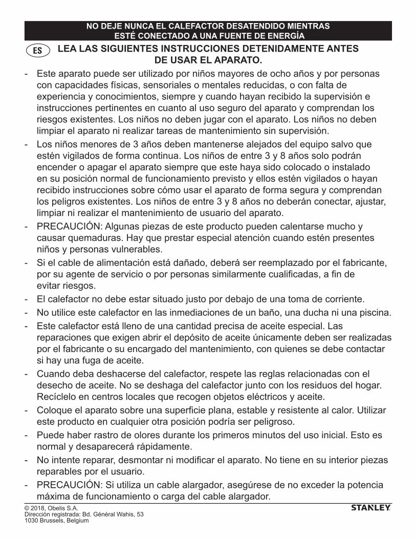
© 2018, Obelis S.A. Dirección registrada: Bd. Général Wahis, 531030 Brussels, Belgium
NO DEJE NUNCA EL CALEFACTOR DESATENDIDO MIENTRAS ESTÉ CONECTADO A UNA FUENTE DE ENERGÍA
LEA LAS SIGUIENTES INSTRUCCIONES DETENIDAMENTE ANTES DE USAR EL APARATO.
- Este aparato puede ser utilizado por niños mayores de ocho años y por personas con capacidades físicas, sensoriales o mentales reducidas, o con falta de experiencia y conocimientos, siempre y cuando hayan recibido la supervisión e instrucciones pertinentes en cuanto al uso seguro del aparato y comprendan los riesgos existentes. Los niños no deben jugar con el aparato. Los niños no deben limpiar el aparato ni realizar tareas de mantenimiento sin supervisión.
- Los niños menores de 3 años deben mantenerse alejados del equipo salvo que estén vigilados de forma continua. Los niños de entre 3 y 8 años solo podrán encender o apagar el aparato siempre que este haya sido colocado o instalado en su posición normal de funcionamiento previsto y ellos estén vigilados o hayan recibido instrucciones sobre cómo usar el aparato de forma segura y comprendan los peligros existentes. Los niños de entre 3 y 8 años no deberán conectar, ajustar, limpiar ni realizar el mantenimiento de usuario del aparato.
- PRECAUCIÓN: Algunas piezas de este producto pueden calentarse mucho y causar quemaduras. Hay que prestar especial atención cuando estén presentes niños y personas vulnerables.
- Si el cable de alimentación está dañado, deberá ser reemplazado por el fabricante, por su agente de servicio o por personas similarmente cualificadas, a fin de evitar riesgos.
- El calefactor no debe estar situado justo por debajo de una toma de corriente.
- No utilice este calefactor en las inmediaciones de un baño, una ducha ni una piscina.
- Este calefactor está lleno de una cantidad precisa de aceite especial. Las reparaciones que exigen abrir el depósito de aceite únicamente deben ser realizadas por el fabricante o su encargado del mantenimiento, con quienes se debe contactar si hay una fuga de aceite.
- Cuando deba deshacerse del calefactor, respete las reglas relacionadas con el desecho de aceite. No se deshaga del calefactor junto con los residuos del hogar. Recíclelo en centros locales que recogen objetos eléctricos y aceite.
- Coloque el aparato sobre una superficie plana, estable y resistente al calor. Utilizar este producto en cualquier otra posición podría ser peligroso.
- Puede haber rastro de olores durante los primeros minutos del uso inicial. Esto es normal y desaparecerá rápidamente.
- No intente reparar, desmontar ni modificar el aparato. No tiene en su interior piezas reparables por el usuario.
- PRECAUCIÓN: Si utiliza un cable alargador, asegúrese de no exceder la potencia máxima de funcionamiento o carga del cable alargador.
ES
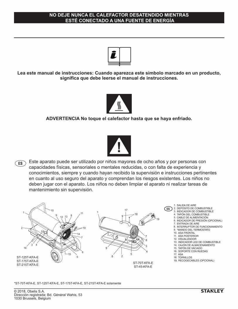
© 2018, Obelis S.A. Dirección registrada: Bd. Général Wahis, 531030 Brussels, Belgium
NO DEJE NUNCA EL CALEFACTOR DESATENDIDO MIENTRAS ESTÉ CONECTADO A UNA FUENTE DE ENERGÍA
Lea este manual de instrucciones: Cuando aparezca este símbolo marcado en un producto, significa que debe leerse el manual de instrucciones.
ADVERTENCIA No toque el calefactor hasta que se haya enfriado.
ES Este aparato puede ser utilizado por niños mayores de ocho años y por personas con capacidades físicas, sensoriales o mentales reducidas, o con falta de experiencia y conocimientos, siempre y cuando hayan recibido la supervisión e instrucciones pertinentes en cuanto al uso seguro del aparato y comprendan los riesgos existentes. Los niños no deben jugar con el aparato. Los niños no deben limpiar el aparato ni realizar tareas de mantenimiento sin supervisión.
5
3
4
6
28
9
17
19
7
118
12
110
19
11
7
6
316
13
4
5
89
14
2
15
ST-70T-KFA-EST-45-KFA-E
ST-125T-KFA-EST-175T-KFA-EST-215T-KFA-E
8.9.10.11.12.13.14.15.16.17.18.19.
SALIDA DE AIREDEPÓSITO DE COMBUSTIBLEINDICADOR DE COMBUSTIBLETAPÓN DEL COMBUSTIBLECABLE DE ALIMENTACIÓNINDICADOR DE PRESIÓN (OPCIONAL)ENTRADA DE AIREINTERRUPTOR DE FUNCIONAMIENTO*MANDO DEL TERMOSTATO ASA FRONTAL ASA POSTERIOR VISUALIZADOR INDICADOR LED DE COMBUSTIBLE CAJÓN DE ALMACENAMIENTO TAPÓN DE VACIADO SOPORTE CON RUEDAS ASA TORNILLOS RECOGECABLES (OPCIONAL)
*ST-70T-KFA-E, ST-125T-KFA-E, ST-175T-KFA-E, ST-215T-KFA-E solamente
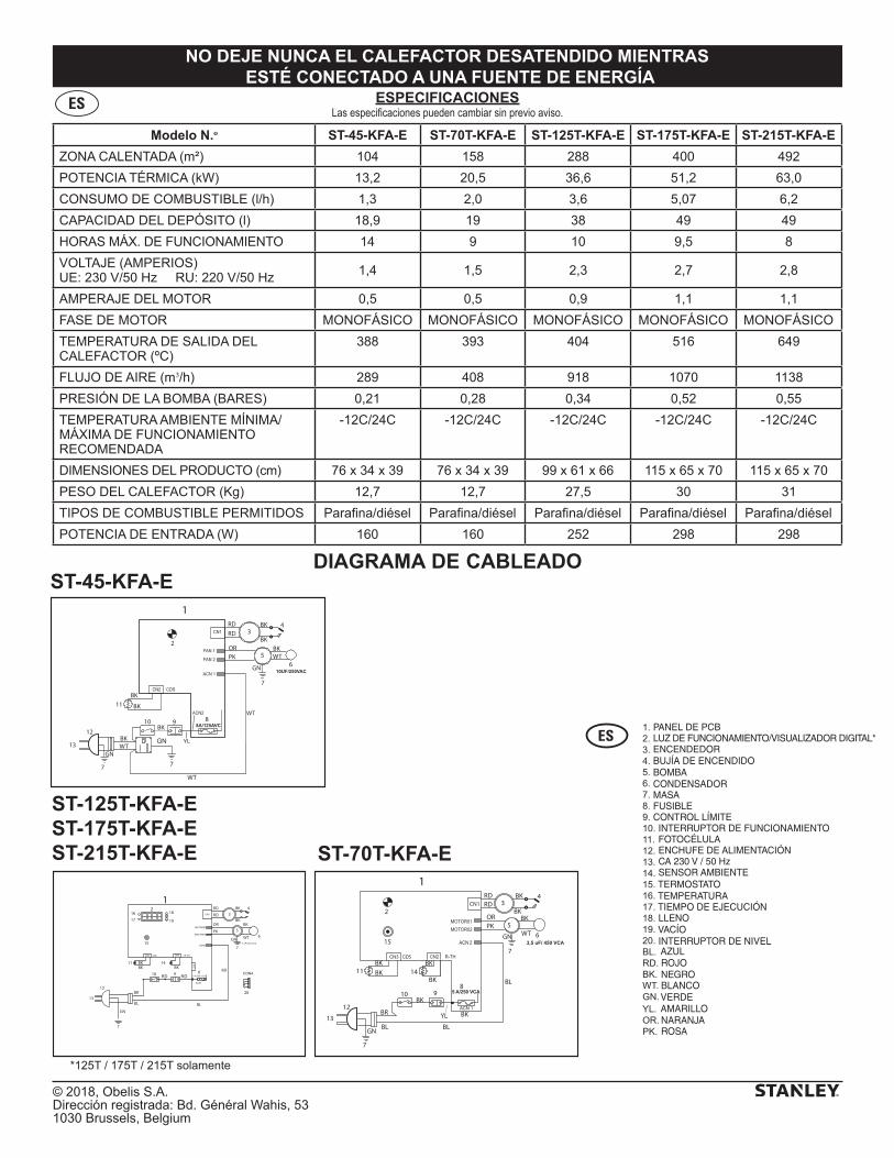
© 2018, Obelis S.A. Dirección registrada: Bd. Général Wahis, 531030 Brussels, Belgium
NO DEJE NUNCA EL CALEFACTOR DESATENDIDO MIENTRAS ESTÉ CONECTADO A UNA FUENTE DE ENERGÍA
Modelo N.o ST-45-KFA-E ST-70T-KFA-E ST-125T-KFA-E ST-175T-KFA-E ST-215T-KFA-E
ZONA CALENTADA (m²) 104 158 288 400 492
POTENCIA TÉRMICA (kW) 13,2 20,5 36,6 51,2 63,0
CONSUMO DE COMBUSTIBLE (l/h) 1,3 2,0 3,6 5,07 6,2
CAPACIDAD DEL DEPÓSITO (l) 18,9 19 38 49 49
HORAS MÁX. DE FUNCIONAMIENTO 14 9 10 9,5 8
VOLTAJE (AMPERIOS)UE: 230 V/50 Hz RU: 220 V/50 Hz 1,4 1,5 2,3 2,7 2,8
AMPERAJE DEL MOTOR 0,5 0,5 0,9 1,1 1,1
FASE DE MOTOR MONOFÁSICO MONOFÁSICO MONOFÁSICO MONOFÁSICO MONOFÁSICO
TEMPERATURA DE SALIDA DEL CALEFACTOR (ºC)
388 393 404 516 649
FLUJO DE AIRE (m3/h) 289 408 918 1070 1138
PRESIÓN DE LA BOMBA (BARES) 0,21 0,28 0,34 0,52 0,55
TEMPERATURA AMBIENTE MÍNIMA/ MÁXIMA DE FUNCIONAMIENTO RECOMENDADA
-12C/24C -12C/24C -12C/24C -12C/24C -12C/24C
DIMENSIONES DEL PRODUCTO (cm) 76 x 34 x 39 76 x 34 x 39 99 x 61 x 66 115 x 65 x 70 115 x 65 x 70
PESO DEL CALEFACTOR (Kg) 12,7 12,7 27,5 30 31
TIPOS DE COMBUSTIBLE PERMITIDOS Parafina/diésel Parafina/diésel Parafina/diésel Parafina/diésel Parafina/diésel
POTENCIA DE ENTRADA (W) 160 160 252 298 298
ESPECIFICACIONESLas especificaciones pueden cambiar sin previo aviso.
ES
DIAGRAMA DE CABLEADO
1
WT
BK
OR
BK 4
2
12
13
GN
7
GN
7
11
10BK
9
BR
BKBK
BL
BL8
5
3
615
14BK
RDRD
BKPK
BK
BL
YL
BKCN1
3,5 uF/ 450 VCA
5 A/250 VCA
RD10
11
12
13
1RD
RD
PK
OR
WT
BK3
4
5
GN
7
6
8 RD
BL
9
GN
7
BR
BL
14BKBK
BK
15
20
RD
BKBK
1617
18
19
2
7 uF/ 450 VCA
5 A/250 VCA
10UF/250VAC
1RD
WT
RD
OR
BK
BK
WT
BK
BK
BK
BK
PKBK
4
2
12
13GN
GN
7
7
11
10 9 8
5
3
6
WT
YLGN
7
WT
8A/125AVC
ST-45-KFA-E
ST-70T-KFA-E
ST-125T-KFA-EST-175T-KFA-EST-215T-KFA-E
PANEL DE PCBLUZ DE FUNCIONAMIENTO/VISUALIZADOR DIGITAL*ENCENDEDORBUJÍA DE ENCENDIDOBOMBACONDENSADORMASAFUSIBLECONTROL LÍMITE INTERRUPTOR DE FUNCIONAMIENTO FOTOCÉLULA ENCHUFE DE ALIMENTACIÓN CA 230 V / 50 Hz SENSOR AMBIENTE TERMOSTATO TEMPERATURA TIEMPO DE EJECUCIÓN LLENO VACÍO INTERRUPTOR DE NIVEL AZUL ROJO NEGRO BLANCO VERDE AMARILLO NARANJA ROSA
*125T / 175T / 215T solamente
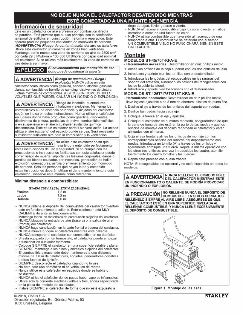
© 2018, Obelis S.A. Dirección registrada: Bd. Général Wahis, 531030 Brussels, Belgium
NO DEJE NUNCA EL CALEFACTOR DESATENDIDO MIENTRAS ESTÉ CONECTADO A UNA FUENTE DE ENERGÍA
Información de seguridadEste es un calefactor de aire a presión por combustión directa de parafina. Está previsto que su uso principal sea la calefacción temporal de edificios en construcción, reforma o reparación. Este aparato produce pequeñas cantidades de monóxido de carbono. ¡ADVERTENCIA! Riesgo de contaminación del aire en interiores. Utilice este calefactor únicamente en zonas bien ventiladas. Mantenga por lo menos una zona de corriente de aire de 2800 cm² por cada 29,3 kW/hora o 100 000 UTB/hora por capacidad nominal del calefactor. Si se utilizan más calefactores, la zona de corriente de aire deberá ser mayor.
¡Riesgo de quemaduras / fuego / explosión! NUNCA utilice en este
calefactor combustibles como gasolina, benceno, alcohol, gasolina blanca, combustible de hornillo de camping, disolventes de pintura u otras mezclas de combustibles. (ESTOS SON COMBUSTIBLES VOLÁTILES QUE PUEDEN CAUSAR UN INCENDIO O EXPLOSIÓN).
Mínima distancia a combustibles:
ST-45-/ 70T-/ 125T-/ 175T-/ 215T-KFA-E Encima 1,2 m Lados 1,2 m Delante 3,0 m
- NUNCA rellene el depósito del combustible del calefactor mientras esté en funcionamiento o caliente. Este calefactor está MUY CALIENTE durante su funcionamiento.
- Mantenga todos los materiales de combustión alejados del calefactor. - NUNCA bloquee la entrada de aire (trasera) o la salida de aire
(frontal) del calefactor. - NUNCA haga canalización en la parte frontal o trasera del calefactor. - NUNCA mueva o toque el calefactor mientras esté caliente. - NUNCA transporte el calefactor con combustible en su depósito. - Si está equipado con un termostato, el calefactor puede empezar
a funcionar en cualquier momento. - Coloque SIEMPRE el calefactor en una superficie estable y plana. - SIEMPRE mantenga a los niños y animales alejados del calefactor. - El combustible almacenado debe mantenerse a una distancia
mínima de 7,6 m de calefactores, sopletes, generadores portátiles u otras fuentes de ignición.
- SIEMPRE desconecte el calefactor cuando no lo use. - No apto para uso doméstico ni en vehículos de recreo. - Nunca utilice este calefactor en espacios donde se habite o
se duerma. - NUNCA utilice el calefactor donde pueda haber vapores inflamables. - Utilice solo la corriente eléctrica (voltaje y frecuencia) especificada
en la placa del modelo del calefactor. - Instale SIEMPRE el calefactor de forma que no esté expuesto a
riego de agua, lluvia, goteras o viento. - NUNCA almacene el combustible bajo luz solar directa, en sitios
cerrados o cerca de una fuente de calor. - NUNCA utilice combustible que haya sido almacenado de una
temporada a otra. El combustible se deteriora con el tiempo. UN COMBUSTIBLE VIEJO NO FUNCIONARÁ BIEN EN ESTE CALEFACTOR.
MontajeMODELOS ST-45/70T-KFA-E- Herramientas necesarias: Destornillador en cruz phillips medio.
1. Alinee los orificios de la caja superior con los dos orificios del asa.
2. Introduzca y apriete bien los tornillos con el destornillador.
3. Introduzca las lengüetas del recogecables en las ranuras del soporte del armazón, alineando los orificios del recogecables con los de la cubierta lateral.
4. Introduzca y apriete bien los tornillos con el destornillador.
MODELOS ST-125T/175T/215T-KFA-E- Herramientas necesarias: Destornillador en cruz phillips medio,
llave inglesa ajustable o de 8 mm de abertura, alicates de punta fina.
1. Deslice el eje a través de los orificios del soporte con ruedas.
2. Deslice las ruedas hacia cada eje.
3. Coloque la tuerca en el eje y ajústela.
4. Coloque el calefactor en el marco montado, asegurándose de que la parte de toma de aire está en la parte de las ruedas y que los orificios de montaje del depósito rebordean el calefactor y están alineados con el marco.
5. Coja el asa frontal y alinee los orificios de montaje con los correspondientes orificios del reborde del depósito/marco con ruedas. Introduzca un tornillo (A) a través de los orificios y ligeramente enrosque una tuerca. Repita la misma operación con los otros tres orificios; una vez introducidos los cuatro, atornille fuertemente los cuatro tornillos y las tuercas.
6. Repita este proceso con el asa trasera.
NOTA: El recogecables es opcional y no está disponible en todos los modelos.
ADVERTENCIA
El envenenamiento por monóxido de car-bono puede ocasionar la muerte.PELIGRO
NUNCA RELLENE EL COMBUSTIBLE DEL CALEFACTOR MIENTRAS ESTÉ
EN FUNCIONAMIENTO O CALIENTE. SE PODRÍA PROVOCAR UN INCENDIO O EXPLOSIÓN.
ADVERTENCIA
NO RELLENE NUNCA EL DEPÓSITO DE COMBUSTIBLE EN SITIOS CERRADOS.
RELLÉNELO SIEMPRE AL AIRE LIBRE. ASEGÚRESE DE QUE EL CALEFACTOR ESTÉ EN UNA SUPERFICIE NIVELADA AL RELLENAR COMBUSTIBLE, Y NUNCA LLENE EXCESIVAMENTE EL DEPÓSITO DE COMBUSTIBLE.
PRECAUCIÓN
Figura 1. Montaje de las asas
No utilice este calefactor hasta que haya leído y entendido perfectamente
estas instrucciones de uso y seguridad. Si no cumple con las precauciones e instrucciones facilitadas con este calefactor puede correr riesgo de muerte, importantes lesiones corporales, daños o pérdida de bienes causados por incendios, generación de hollín, explosión, quemaduras, asfixia o envenenamiento por monóxido de carbono. Solo las personas que hayan leído y entendido estas instrucciones deberán utilizar ni darle mantenimiento a este calefactor. Conserve este manual como referencia.
Riesgo de incendio, quemaduras, inhalación y explosión. Mantenga los
combustibles a una distancia prudencial y alejados del calefactor según se indica en estas instrucciones. Nunca utilice el calefactor en lugares donde haya productos como gasolina, disolventes, disolventes de pintura, partículas de polvo, combustibles volátiles o en suspensión en el aire o cualquier sustancia química desconocida. Este es un calefactor portátil sin ventilación. La unidad utiliza el aire (oxígeno) del espacio donde se usa. Será necesario suministrar suficiente aire para la combustión y la ventilación.
ADVERTENCIA
ADVERTENCIA
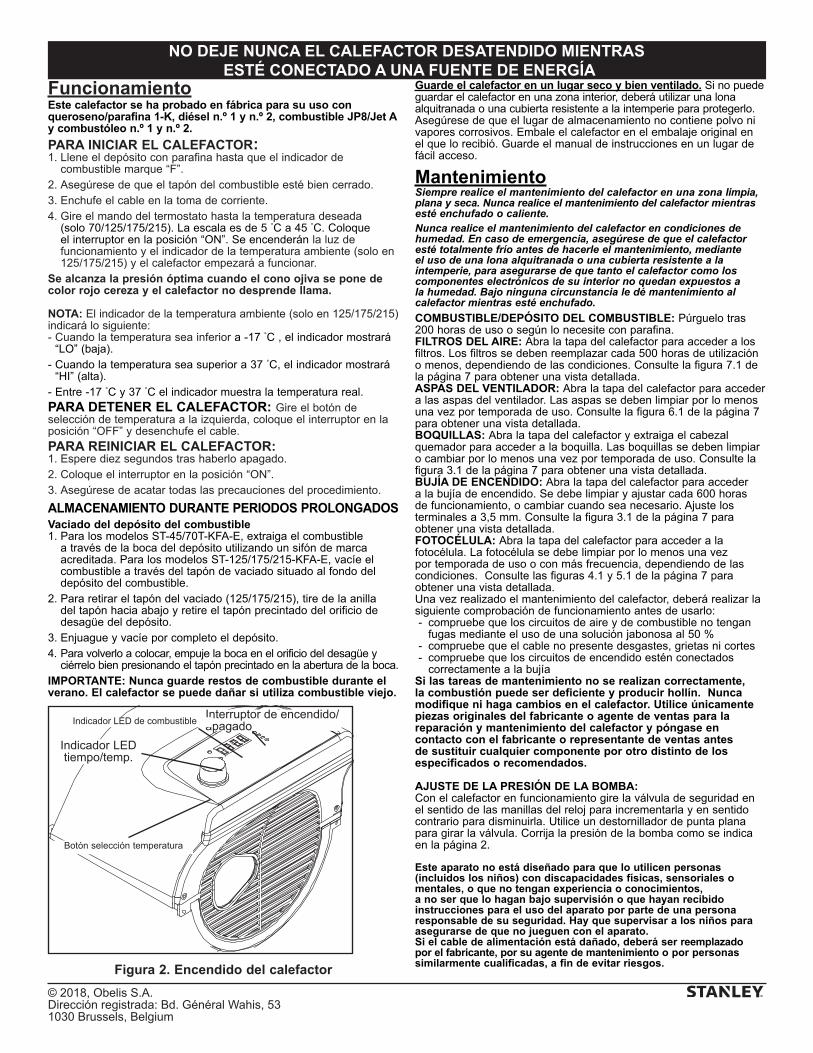
© 2018, Obelis S.A. Dirección registrada: Bd. Général Wahis, 531030 Brussels, Belgium
NO DEJE NUNCA EL CALEFACTOR DESATENDIDO MIENTRAS ESTÉ CONECTADO A UNA FUENTE DE ENERGÍA
FuncionamientoEste calefactor se ha probado en fábrica para su uso con queroseno/parafina 1-K, diésel n.º 1 y n.º 2, combustible JP8/Jet A y combustóleo n.º 1 y n.º 2.
PARA INICIAR EL CALEFACTOR:1. Llene el depósito con parafina hasta que el indicador de
combustible marque “F”.2. Asegúrese de que el tapón del combustible esté bien cerrado.3. Enchufe el cable en la toma de corriente.4. Gire el mando del termostato hasta la temperatura deseada
(solo 70/125/175/215). La escala es de 5 °C a 45 °C. Coloque el interruptor en la posición “ON”. Se encenderán la luz de funcionamiento y el indicador de la temperatura ambiente (solo en 125/175/215) y el calefactor empezará a funcionar.
Se alcanza la presión óptima cuando el cono ojiva se pone de color rojo cereza y el calefactor no desprende llama.
NOTA: El indicador de la temperatura ambiente (solo en 125/175/215) indicará lo siguiente:- Cuando la temperatura sea inferior a -17 °C , el indicador mostrará
“LO” (baja).- Cuando la temperatura sea superior a 37 °C, el indicador mostrará
“HI” (alta).- Entre -17 °C y 37 °C el indicador muestra la temperatura real.PARA DETENER EL CALEFACTOR: Gire el botón de selección de temperatura a la izquierda, coloque el interruptor en la posición “OFF” y desenchufe el cable.
PARA REINICIAR EL CALEFACTOR:1. Espere diez segundos tras haberlo apagado.2. Coloque el interruptor en la posición “ON”.3. Asegúrese de acatar todas las precauciones del procedimiento.
ALMACENAMIENTO DURANTE PERIODOS PROLONGADOSVaciado del depósito del combustible1. Para los modelos ST-45/70T-KFA-E, extraiga el combustible
a través de la boca del depósito utilizando un sifón de marca acreditada. Para los modelos ST-125/175/215-KFA-E, vacíe el combustible a través del tapón de vaciado situado al fondo del depósito del combustible.
2. Para retirar el tapón del vaciado (125/175/215), tire de la anilla del tapón hacia abajo y retire el tapón precintado del orificio de desagüe del depósito.
3. Enjuague y vacíe por completo el depósito.4. Para volverlo a colocar, empuje la boca en el orificio del desagüe y
ciérrelo bien presionando el tapón precintado en la abertura de la boca.IMPORTANTE: Nunca guarde restos de combustible durante el verano. El calefactor se puede dañar si utiliza combustible viejo.
Guarde el calefactor en un lugar seco y bien ventilado. Si no puede guardar el calefactor en una zona interior, deberá utilizar una lona alquitranada o una cubierta resistente a la intemperie para protegerlo.Asegúrese de que el lugar de almacenamiento no contiene polvo ni vapores corrosivos. Embale el calefactor en el embalaje original en el que lo recibió. Guarde el manual de instrucciones en un lugar de fácil acceso.
MantenimientoSiempre realice el mantenimiento del calefactor en una zona limpia, plana y seca. Nunca realice el mantenimiento del calefactor mientras esté enchufado o caliente.Nunca realice el mantenimiento del calefactor en condiciones de humedad. En caso de emergencia, asegúrese de que el calefactor esté totalmente frío antes de hacerle el mantenimiento, mediante el uso de una lona alquitranada o una cubierta resistente a la intemperie, para asegurarse de que tanto el calefactor como los componentes electrónicos de su interior no quedan expuestos a la humedad. Bajo ninguna circunstancia le dé mantenimiento al calefactor mientras esté enchufado.
COMBUSTIBLE/DEPÓSITO DEL COMBUSTIBLE: Púrguelo tras 200 horas de uso o según lo necesite con parafina. FILTROS DEL AIRE: Abra la tapa del calefactor para acceder a los filtros. Los filtros se deben reemplazar cada 500 horas de utilización o menos, dependiendo de las condiciones. Consulte la figura 7.1 de la página 7 para obtener una vista detallada.ASPAS DEL VENTILADOR: Abra la tapa del calefactor para acceder a las aspas del ventilador. Las aspas se deben limpiar por lo menos una vez por temporada de uso. Consulte la figura 6.1 de la página 7 para obtener una vista detallada.BOQUILLAS: Abra la tapa del calefactor y extraiga el cabezal quemador para acceder a la boquilla. Las boquillas se deben limpiar o cambiar por lo menos una vez por temporada de uso. Consulte la figura 3.1 de la página 7 para obtener una vista detallada.BUJÍA DE ENCENDIDO: Abra la tapa del calefactor para acceder a la bujía de encendido. Se debe limpiar y ajustar cada 600 horas de funcionamiento, o cambiar cuando sea necesario. Ajuste los terminales a 3,5 mm. Consulte la figura 3.1 de la página 7 para obtener una vista detallada.FOTOCÉLULA: Abra la tapa del calefactor para acceder a la fotocélula. La fotocélula se debe limpiar por lo menos una vez por temporada de uso o con más frecuencia, dependiendo de las condiciones. Consulte las figuras 4.1 y 5.1 de la página 7 para obtener una vista detallada. Una vez realizado el mantenimiento del calefactor, deberá realizar la siguiente comprobación de funcionamiento antes de usarlo: - compruebe que los circuitos de aire y de combustible no tengan
fugas mediante el uso de una solución jabonosa al 50 % - compruebe que el cable no presente desgastes, grietas ni cortes - compruebe que los circuitos de encendido estén conectados
correctamente a la bujíaSi las tareas de mantenimiento no se realizan correctamente, la combustión puede ser deficiente y producir hollín. Nunca modifique ni haga cambios en el calefactor. Utilice únicamente piezas originales del fabricante o agente de ventas para la reparación y mantenimiento del calefactor y póngase en contacto con el fabricante o representante de ventas antes de sustituir cualquier componente por otro distinto de los especificados o recomendados.
AJUSTE DE LA PRESIÓN DE LA BOMBA:Con el calefactor en funcionamiento gire la válvula de seguridad en el sentido de las manillas del reloj para incrementarla y en sentido contrario para disminuirla. Utilice un destornillador de punta plana para girar la válvula. Corrija la presión de la bomba como se indica en la página 2.
Este aparato no está diseñado para que lo utilicen personas (incluidos los niños) con discapacidades físicas, sensoriales o mentales, o que no tengan experiencia o conocimientos, a no ser que lo hagan bajo supervisión o que hayan recibido instrucciones para el uso del aparato por parte de una persona responsable de su seguridad. Hay que supervisar a los niños para asegurarse de que no jueguen con el aparato.Si el cable de alimentación está dañado, deberá ser reemplazado por el fabricante, por su agente de mantenimiento o por personas similarmente cualificadas, a fin de evitar riesgos.
Figura 2. Encendido del calefactor
Interruptor de encendido/apagado
Indicador LED tiempo/temp.
Botón selección temperatura
Indicador LED de combustible
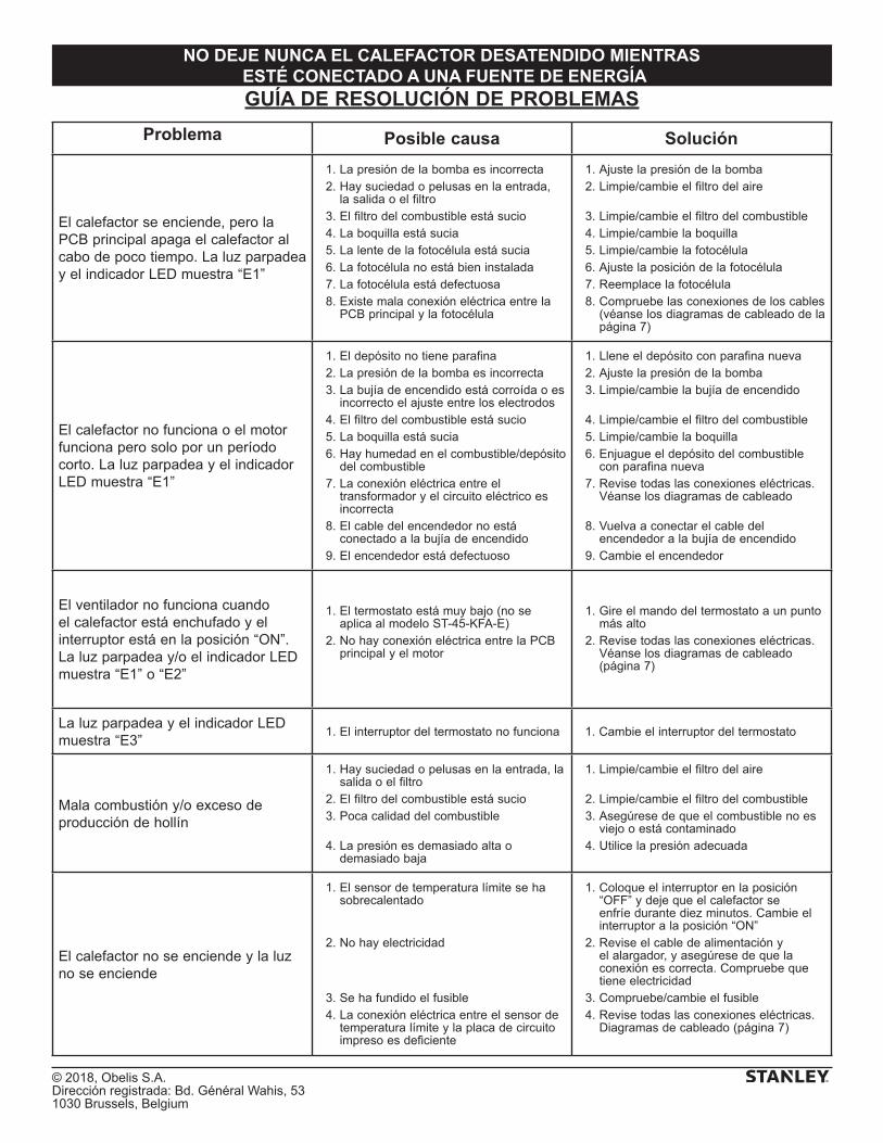
© 2018, Obelis S.A. Dirección registrada: Bd. Général Wahis, 531030 Brussels, Belgium
NO DEJE NUNCA EL CALEFACTOR DESATENDIDO MIENTRAS ESTÉ CONECTADO A UNA FUENTE DE ENERGÍAGUÍA DE RESOLUCIÓN DE PROBLEMAS
Problema Posible causa Solución
El calefactor se enciende, pero la PCB principal apaga el calefactor al cabo de poco tiempo. La luz parpadea y el indicador LED muestra “E1”
1. La presión de la bomba es incorrecta 2. Hay suciedad o pelusas en la entrada,
la salida o el filtro 3. El filtro del combustible está sucio 4. La boquilla está sucia 5. La lente de la fotocélula está sucia 6. La fotocélula no está bien instalada 7. La fotocélula está defectuosa 8. Existe mala conexión eléctrica entre la
PCB principal y la fotocélula
1. Ajuste la presión de la bomba 2. Limpie/cambie el filtro del aire
3. Limpie/cambie el filtro del combustible 4. Limpie/cambie la boquilla 5. Limpie/cambie la fotocélula 6. Ajuste la posición de la fotocélula 7. Reemplace la fotocélula 8. Compruebe las conexiones de los cables
(véanse los diagramas de cableado de la página 7)
El calefactor no funciona o el motor funciona pero solo por un período corto. La luz parpadea y el indicador LED muestra “E1”
1. El depósito no tiene parafina 2. La presión de la bomba es incorrecta 3. La bujía de encendido está corroída o es
incorrecto el ajuste entre los electrodos 4. El filtro del combustible está sucio 5. La boquilla está sucia 6. Hay humedad en el combustible/depósito
del combustible 7. La conexión eléctrica entre el
transformador y el circuito eléctrico es incorrecta
8. El cable del encendedor no está conectado a la bujía de encendido
9. El encendedor está defectuoso
1. Llene el depósito con parafina nueva 2. Ajuste la presión de la bomba 3. Limpie/cambie la bujía de encendido
4. Limpie/cambie el filtro del combustible 5. Limpie/cambie la boquilla 6. Enjuague el depósito del combustible
con parafina nueva 7. Revise todas las conexiones eléctricas.
Véanse los diagramas de cableado
8. Vuelva a conectar el cable del encendedor a la bujía de encendido
9. Cambie el encendedor
El ventilador no funciona cuando el calefactor está enchufado y el interruptor está en la posición “ON”. La luz parpadea y/o el indicador LED muestra “E1” o “E2”
1. El termostato está muy bajo (no se aplica al modelo ST-45-KFA-E)
2. No hay conexión eléctrica entre la PCB principal y el motor
1. Gire el mando del termostato a un punto más alto
2. Revise todas las conexiones eléctricas. Véanse los diagramas de cableado (página 7)
La luz parpadea y el indicador LED muestra “E3”
1. El interruptor del termostato no funciona 1. Cambie el interruptor del termostato
Mala combustión y/o exceso de producción de hollín
1. Hay suciedad o pelusas en la entrada, la salida o el filtro
2. El filtro del combustible está sucio 3. Poca calidad del combustible
4. La presión es demasiado alta o demasiado baja
1. Limpie/cambie el filtro del aire
2. Limpie/cambie el filtro del combustible 3. Asegúrese de que el combustible no es
viejo o está contaminado 4. Utilice la presión adecuada
El calefactor no se enciende y la luz no se enciende
1. El sensor de temperatura límite se ha sobrecalentado
2. No hay electricidad
3. Se ha fundido el fusible 4. La conexión eléctrica entre el sensor de
temperatura límite y la placa de circuito impreso es deficiente
1. Coloque el interruptor en la posición “OFF” y deje que el calefactor se enfríe durante diez minutos. Cambie el interruptor a la posición “ON”
2. Revise el cable de alimentación y el alargador, y asegúrese de que la conexión es correcta. Compruebe que tiene electricidad
3. Compruebe/cambie el fusible 4. Revise todas las conexiones eléctricas.
Diagramas de cableado (página 7)
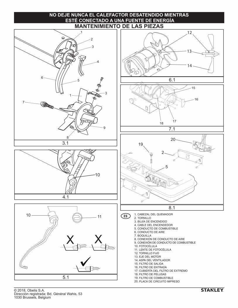
© 2018, Obelis S.A. Dirección registrada: Bd. Général Wahis, 531030 Brussels, Belgium
NO DEJE NUNCA EL CALEFACTOR DESATENDIDO MIENTRAS ESTÉ CONECTADO A UNA FUENTE DE ENERGÍA
MANTENIMIENTO DE LAS PIEZAS
15
16
1718
12
14
13
XX
10 11
10
20
2
5
19
1
2
3
4
56
7
1 3
9
8
3.1
4.1
5.1
8.1
6.1
7.1
CABEZAL DEL QUEMADORTORNILLOBUJÍA DE ENCENDIDOCABLE DEL ENCENDEDORCONDUCTO DE COMBUSTIBLECONDUCTO DE AIREBOQUILLACONEXIÓN DE CONDUCTO DE AIRECONEXIÓN DE CONDUCTO DE COMBUSTIBLE FOTOCÉLULA LENTE DE FOTOCÉLULA TORNILLO FIJO EJE DEL MOTOR ASPA DEL VENTILADOR FILTRO DE SALIDA FILTRO DE ENTRADA CUBIERTA DEL FILTRO DE EXTREMO FILTRO DE PELUSAS FILTRO DE COMBUSTIBLE PLACA DE CIRCUITO IMPRESO
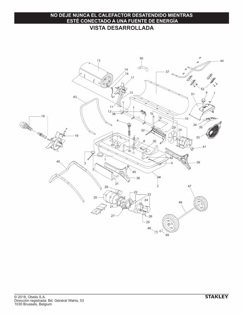
© 2018, Obelis S.A. Dirección registrada: Bd. Général Wahis, 531030 Brussels, Belgium
NO DEJE NUNCA EL CALEFACTOR DESATENDIDO MIENTRAS ESTÉ CONECTADO A UNA FUENTE DE ENERGÍA
VISTA DESARROLLADA
41
43
44
45
46
47
48
49
50
19
20
21
2223
24
25
2627
28
29
30
31
32
33
3435
36
37
38
39
40
42
5152
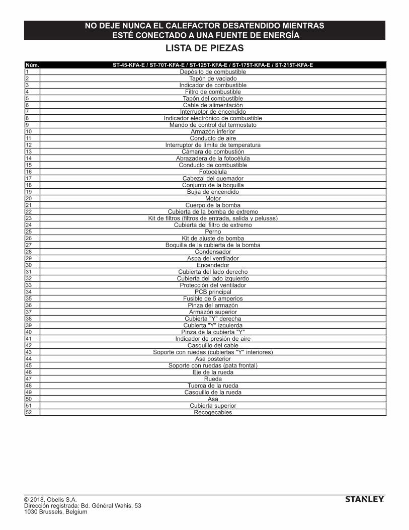
© 2018, Obelis S.A. Dirección registrada: Bd. Général Wahis, 531030 Brussels, Belgium
NO DEJE NUNCA EL CALEFACTOR DESATENDIDO MIENTRAS ESTÉ CONECTADO A UNA FUENTE DE ENERGÍA
LISTA DE PIEZAS
Núm. ST-45-KFA-E / ST-70T-KFA-E / ST-125T-KFA-E / ST-175T-KFA-E / ST-215T-KFA-E1 Depósito de combustible2 Tapón de vaciado3 Indicador de combustible4 Filtro de combustible5 Tapón del combustible6 Cable de alimentación7 Interruptor de encendido8 Indicador electrónico de combustible9 Mando de control del termostato10 Armazón inferior11 Conducto de aire12 Interruptor de límite de temperatura13 Cámara de combustión14 Abrazadera de la fotocélula15 Conducto de combustible16 Fotocélula17 Cabezal del quemador18 Conjunto de la boquilla19 Bujía de encendido20 Motor21 Cuerpo de la bomba22 Cubierta de la bomba de extremo23 Kit de filtros (filtros de entrada, salida y pelusas)24 Cubierta del filtro de extremo25 Perno26 Kit de ajuste de bomba27 Boquilla de la cubierta de la bomba28 Condensador29 Aspa del ventilador30 Encendedor31 Cubierta del lado derecho32 Cubierta del lado izquierdo33 Protección del ventilador34 PCB principal35 Fusible de 5 amperios36 Pinza del armazón37 Armazón superior38 Cubierta "Y" derecha39 Cubierta "Y" izquierda40 Pinza de la cubierta "Y"41 Indicador de presión de aire42 Casquillo del cable43 Soporte con ruedas (cubiertas "Y" interiores)44 Asa posterior45 Soporte con ruedas (pata frontal)46 Eje de la rueda47 Rueda48 Tuerca de la rueda49 Casquillo de la rueda50 Asa51 Cubierta superior52 Recogecables
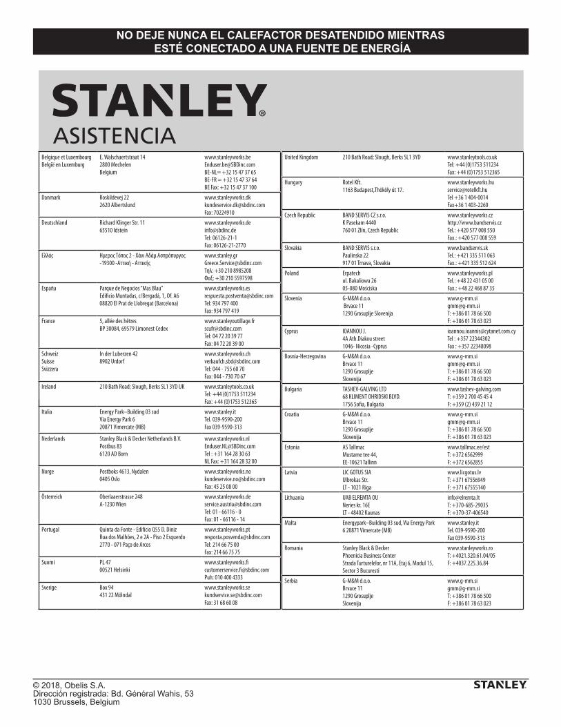
© 2018, Obelis S.A. Dirección registrada: Bd. Général Wahis, 531030 Brussels, Belgium
NO DEJE NUNCA EL CALEFACTOR DESATENDIDO MIENTRAS ESTÉ CONECTADO A UNA FUENTE DE ENERGÍA
Belgique et LuxembourgBelgië en Luxemburg
E. Walschaertstraat 14 2800 Mechelen Belgium
[email protected]= +32 15 47 37 65BE-FR = +32 15 47 37 64BE Fax: +32 15 47 37 100
Danmark Roskildevej 22 2620 Albertslund
[email protected]: 70224910
Deutschland Richard Klinger Str. 11 65510 Idstein
[email protected]: 06126-21-1Fax: 06126-21-2770
Ελλάς Hμερος Τόπος 2 - Χάνι Αδάμ Ασπρόπυργος -19300 -Αττική - Αττικής
[email protected]Τηλ: +30 210 8985208Φαξ: +30 210 5597598
España Parque de Negocios “Mas Blau”
08820 El Prat de Llobregat (Barcelona)
[email protected]: 934 797 400Fax: 934 797 419
France 5, allée des hêtres BP 30084, 69579 Limonest Cedex
[email protected]: 04 72 20 39 77Fax: 04 72 20 39 00
SchweizSuisse Svizzera
In der Luberzen 42 8902 Urdorf
[email protected]: 044 - 755 60 70Fax: 044 - 730 70 67
Ireland 210 Bath Road; Slough, Berks SL1 3YD UK www.stanleytools.co.ukTel: +44 (0)1753 511234Fax: +44 (0)1753 512365
Italia www.stanley.itTel. 039-9590-200Fax 039-9590-313
Nederlands Stanley Black & Decker Netherlands B.V. Postbus 83 6120 AD Born
[email protected] : +31 164 28 30 63NL Fax: +31 164 28 32 00
Norge Postboks 4613, Nydalen0405 Oslo
[email protected]: 45 25 08 00
Österreich Oberlaaerstrasse 248A-1230 Wien
[email protected]: 01 - 66116 - 0Fax: 01 - 66116 - 14
Portugal Quinta da Fonte - Edifício Q55 D. Diniz Rua dos Malhões, 2 e 2A - Piso 2 Esquerdo 2770 - 071 Paço de Arcos
[email protected]: 214 66 75 00Fax: 214 66 75 75
Suomi PL 47 00521 Helsinki
Puh: 010 400 4333
Sverige Box 94 431 22 Mölndal
[email protected]: 31 68 60 08
United Kingdom 210 Bath Road; Slough, Berks SL1 3YD www.stanleytools.co.ukTel: +44 (0)1753 511234Fax: +44 (0)1753 512365
Hungary Rotel Kft.1163 Budapest,Thököly út 17.
[email protected] +36 1 404-0014Fax+36 1 403-2260
Czech Republic BAND SERVIS CZ s.r.o. K Pasekam 4440 760 01 Zlín, Czech Republic
www.stanleyworks.czhttp://www.bandservis.czTel.: +420 577 008 550Fax.: +420 577 008 559
Slovakia BAND SERVIS s.r.o. Paulinska 22 917 01 Trnava, Slovakia
www.bandservis.skTel.: +421 335 511 063Fax.: +421 335 512 624
Poland Erpatech ul. Bakaliowa 26 05-080 Mościska
www.stanleyworks.plTel.: +48 22 431 05 00Fax.: +48 22 468 87 35
Slovenia G-M&M d.o.o. Brvace 11 1290 Grosuplje Slovenija
[email protected]: +386 01 78 66 500F: +386 01 78 63 023
Cyprus IOANNOU J. 4A Ath.Diakou street 1046- Nicosia -Cyprus
[email protected]Τel : +357 22344302Fax : +357 22348098
Bosnia-Herzegovina G-M&M d.o.o. Brvace 11 1290 Grosuplje Slovenija
[email protected]: +386 01 78 66 500F: +386 01 78 63 023
Bulgaria TASHEV-GALVING LTD 68 KLIMENT OHRIDSKI BLVD.
www.tashev-galving.comT: +359 2 700 45 45 4F: +359 (2) 439 21 12
Croatia G-M&M d.o.o. Brvace 11 1290 Grosuplje Slovenija
[email protected]: +386 01 78 66 500F: +386 01 78 63 023
Estonia AS Tallmac Mustame tee 44, EE-10621 Tallinn
www.tallmac.ee/estT: +372 6562999F: +372 6562855
Latvia LIC GOTUS SIA Ulbrokas Str. LT - 1021 Rīga
www.licgotus.lvT: +371 67556949F: +371 67555140
Lithuania UAB ELREMTA OU Neries kr. 16E LT - 48402 Kaunas
[email protected]: +370-685-29035F: +370-37-406540
Malta Energypark–Building 03 sud, Via Energy Park 6 20871 Vimercate (MB)
www.stanley.itTel. 039-9590-200Fax 039-9590-313
Romania Stanley Black & Decker Phoenicia Business Center Strada Turturelelor, nr 11A, Etaj 6, Modul 15, Sector 3 Bucuresti
www.stanleyworks.roT: +4021.320.61.04/05F: +4037.225.36.84
Serbia G-M&M d.o.o. Brvace 11 1290 Grosuplje Slovenija
[email protected]: +386 01 78 66 500F: +386 01 78 63 023
ASISTENCIA
Energy Park–Building 03 sudVia Energy Park 620871 Vimercate (MB)

Fabricado por:Pinnacle Climate Technologies, Inc.
Sauk Rapids, MN 56379 USA
EC REP
Obelis S.A.Dirección registrada:
Bd. Général Wahis, 53, 1030 Brussels, Belgium
© 2018 Stanley Black & Decker, Inc.

ST-45-KFA-E/ST-70T-KFA-E/ST-125T-KFA-E ST-175T-KFA-E/ST-215T-KFA-E
NIGDY NIE POZOSTAWIAĆ PALĄCEGO SIĘ LUB PODŁĄCZONEGO DO ŹRÓDŁA ZASILANIA PROMIENNIKA BEZ NADZORU.
TEN PRODUKT NIE NADAJE SIĘ DO UŻYTKU W CHARAKTERZE PODSTAWOWEGO ŹRÓDŁA OGRZEWANIA.
STKA-462
© 2018 Pinnacle Climate Technologies, Inc. 2
PRZED ROZPOCZĘCIEM EKSPLOATACJI URZĄDZENIA NALEŻY STARANNIE PRZECZYTAĆ PONIŻSZĄ INSTRUKCJĘ.
- Urządzenie może być obsługiwane przez dzieci powyżej 8. roku życia i osoby upośledzone fizycznie, sensorycznie lub psychicznie bądź niemające doświadczenia ani wiedzy wyłącznie pod warunkiem, że pozostają one pod nadzorem lub zostały poinstruowane w zakresie bezpiecznego użytkowania urządzenia i rozumieją związane z nim zagrożenia. Należy dopilnować, aby dzieci nie bawiły się urządzeniem. Dzieci nie powinny czyścić ani przeprowadzać konserwacji urządzenia bez nadzoru.
- Dzieci poniżej 3. roku życia nie powinny być dopuszczane do urządzenia, chyba że będą pod stałym nadzorem. Dzieci w wieku od lat 3 do 8 mogą włączać/wyłączać urządzenie wyłącznie, jeśli zostało ono zamontowane w przewidzianym przez producenta normalnym położeniu roboczym i jeśli pozostają one pod nadzorem lub zostały poinstruowane w zakresie bezpiecznego użytkowania urządzenia i rozumieją związane z nim zagrożenia. Dzieci w wieku od lat 3 do 8 nie mogą podłączać urządzenia do zasilania, regulować go, czyścić ani wykonywać konserwacji.
- PRZESTROGA: Niektóre części tego urządzenia nagrzewają się do bardzo wysokich temperatur i mogą powodować poparzenia. Szczególną ostrożność należy wykazać w obecności dzieci i osób szczególnie narażonych.
- W przypadku uszkodzenia przewodu zasilającego, może być on wymieniany jedynie przez producenta, jego serwisantów lub podobnie wykwalifikowane osoby, co pozwoli uniknąć zagrożeń.
- Nagrzewnica nie może być umieszczana bezpośrednio pod gniazdkiem sieciowym. - Zabrania się eksploatacji nagrzewnicy w pobliżu wanny, prysznica bądź basenu
kąpielowego. - Promiennik jest napełniony dokładnie określoną ilością specjalnego oleju. Naprawy
wymagające otwarcia zbiornika oleju może wykonywać wyłącznie producent lub jego przedstawiciel serwisowy, z którym należy skontaktować się w przypadku wycieku oleju.
- Podczas złomowania promiennika należy przestrzegać przepisów dotyczących utylizacji oleju. Promiennika nie wolno utylizować z odpadami z gospodarstwa domowego. Jeśli istnieją lokalne placówki zbiórki urządzeń elektrycznych i oleju, należy poddać go recyklingowi.
- Urządzenie należy umieszczać na płaskich, stabilnych i odpornych na wysokie temperatury powierzchniach. Użytkowanie produktu w jakimkolwiek innym położeniu może stanowić zagrożenie.
- Podczas pierwszych kilku minut początkowego użytkowania może być wyczuwalny mało intensywny zapach. Jest to normalne, zapach szybko zniknie.
- Urządzenia nie należy naprawiać, demontować ani modyfikować. Części wewnętrzne urządzenia nie są przeznaczone do obsługi przez użytkownika.
- PRZESTROGA – używając przedłużacza, należy pamiętać, aby nie przekraczać jego maksymalnego znamionowego roboczego natężenia prądu/obciążenia.
PL
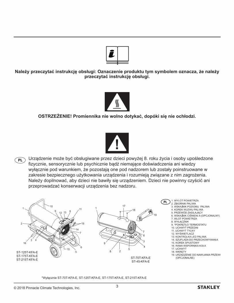
© 2018 Pinnacle Climate Technologies, Inc. 3
Należy przeczytać instrukcję obsługi: Oznaczenie produktu tym symbolem oznacza, że należy przeczytać instrukcję obsługi.
OSTRZEŻENIE! Promiennika nie wolno dotykać, dopóki się nie ochłodzi.
PL Urządzenie może być obsługiwane przez dzieci powyżej 8. roku życia i osoby upośledzone fizycznie, sensorycznie lub psychicznie bądź niemające doświadczenia ani wiedzy wyłącznie pod warunkiem, że pozostają one pod nadzorem lub zostały poinstruowane w zakresie bezpiecznego użytkowania urządzenia i rozumieją związane z nim zagrożenia. Należy dopilnować, aby dzieci nie bawiły się urządzeniem. Dzieci nie powinny czyścić ani przeprowadzać konserwacji urządzenia bez nadzoru.
5
3
4
6
28
9
17
19
7
118
12
110
19
11
7
6
316
13
4
5
89
14
2
15
ST-70T-KFA-EST-45-KFA-E
ST-125T-KFA-EST-175T-KFA-EST-215T-KFA-E
1. WYLOT POWIETRZA2. ZBIORNIK PALIWA3. WSKAŹNIK POZIOMU PALIWA4. KOREK WLEWU PALIWA5. PRZEWÓD ZASILAJĄCY6. WSKAŹNIK CIŚNIENIA (OPCJONALNY)7. WLOT POWIETRZA8. WYŁĄCZNIK9. *POKRĘTŁO TERMOSTATU10. UCHWYT PRZEDNI11. UCHWYT TYLNY12. WYŚWIETLACZ13. KONTROLKA LED PALIWA14. SZUFLADA DO PRZECHOWYWANIA15. KOREK SPUSTOWY16. RAMA WSPORNIKA KOŁA17. UCHWYT18. WKRĘTY19. URZĄDZENIE DO NAWIJANIA PRZEWODU (OPCJONALNE)
*Wyłącznie ST-70T-KFA-E, ST-125T-KFA-E, ST-175T-KFA-E, ST-215T-KFA-E
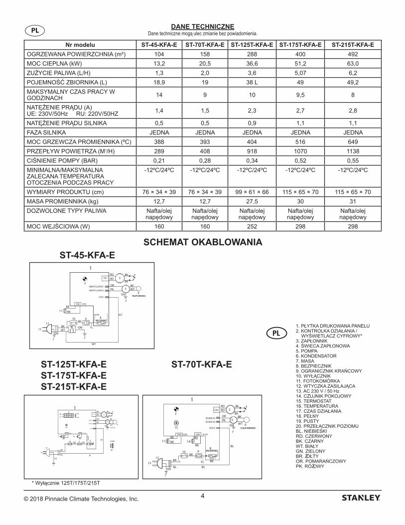
© 2018 Pinnacle Climate Technologies, Inc. 4
Nr modelu ST-45-KFA-E ST-70T-KFA-E ST-125T-KFA-E ST-175T-KFA-E ST-215T-KFA-E
OGRZEWANA POWIERZCHNIA (m²) 104 158 288 400 492
MOC CIEPLNA (kW) 13,2 20,5 36,6 51,2 63,0
ZUŻYCIE PALIWA (L/H) 1,3 2,0 3,6 5,07 6,2
POJEMNOŚĆ ZBIORNIKA (L) 18,9 19 38 L 49 49,2
MAKSYMALNY CZAS PRACY W GODZINACH 14 9 10 9,5 8
NATĘŻENIE PRĄDU (A)UE: 230V/50Hz RU: 220V/50HZ 1,4 1,5 2,3 2,7 2,8
NATĘŻENIE PRĄDU SILNIKA 0,5 0,5 0,9 1,1 1,1
FAZA SILNIKA JEDNA JEDNA JEDNA JEDNA JEDNA
MOC GRZEWCZA PROMIENNIKA (ºC) 388 393 404 516 649
PRZEPŁYW POWIETRZA (M3/H) 289 408 918 1070 1138
CIŚNIENIE POMPY (BAR) 0,21 0,28 0,34 0,52 0,55
MINIMALNA/MAKSYMALNA ZALECANA TEMPERATURA OTOCZENIA PODCZAS PRACY
-12ºC/24ºC -12ºC/24ºC -12ºC/24ºC -12ºC/24ºC -12ºC/24ºC
WYMIARY PRODUKTU (cm) 76 × 34 × 39 76 × 34 × 39 99 × 61 × 66 115 × 65 × 70 115 × 65 × 70
MASA PROMIENNIKA (kg) 12,7 12,7 27,5 30 31
DOZWOLONE TYPY PALIWA Nafta/olej napędowy
Nafta/olej napędowy
Nafta/olej napędowy
Nafta/olej napędowy
Nafta/olej napędowy
MOC WEJŚCIOWA (W) 160 160 252 298 298
DANE TECHNICZNEDane techniczne mogą ulec zmianie bez powiadomienia.PL
SCHEMAT OKABLOWANIA
1
WT
BK
OR
BK 4
2
12
13
GN
7
GN
7
11
10BK
9
BR
BKBK
BL
BL8
5
3
615
14BK
RDRD
BKPK
BK
BL
YL
BKCN1
RD10
11
12
13
1RD
RD
PK
OR
WT
BK3
4
5
GN
7
6
8 RD
BL
9
GN
7
BR
BL
14BKBK
BK
15
20
RD
BKBK
1617
18
19
2
10UF/250VAC
1RD
WT
RD
OR
BK
BK
WT
BK
BK
BK
BK
PKBK
4
2
12
13GN
GN
7
7
11
10 9 8
5
3
6
WT
YLGN
7
WT
8A/125AVC
ST-45-KFA-E
ST-70T-KFA-EST-125T-KFA-EST-175T-KFA-EST-215T-KFA-E
1. PŁYTKA DRUKOWANA PANELU2. KONTROLKA DZIAŁANIA / WYŚWIETLACZ CYFROWY*3. ZAPŁONNIK4. ŚWIECA ZAPŁONOWA5. POMPA6. KONDENSATOR7. MASA8. BEZPIECZNIK9. OGRANICZNIK KRAŃCOWY10. WYŁĄCZNIK11. FOTOKOMÓRKA12. WTYCZKA ZASILAJĄCA13. AC 230 V / 50 Hz14. CZUJNIK POKOJOWY15. TERMOSTAT16. TEMPERATURA17. CZAS DZIAŁANIA18. PEŁNY 19. PUSTY20. PRZEŁĄCZNIK POZIOMUBL. NIEBIESKIRD. CZERWONYBK. CZARNYWT. BIAŁY GN. ZIELONYBR. ŻÓŁTYOR. POMARAŃCZOWYPK. RÓŻOWY
* Wyłącznie 125T/175T/215T
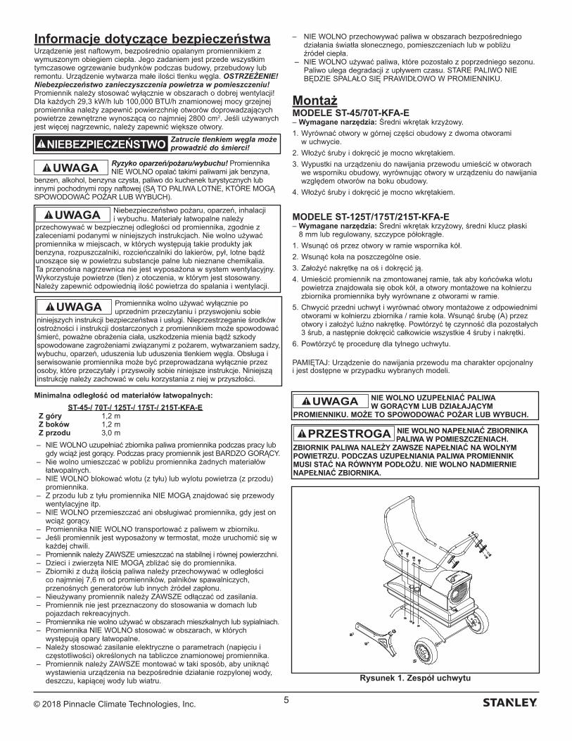
© 2018 Pinnacle Climate Technologies, Inc. 5
Informacje dotyczące bezpieczeństwaUrządzenie jest naftowym, bezpośrednio opalanym promiennikiem z wymuszonym obiegiem ciepła. Jego zadaniem jest przede wszystkim tymczasowe ogrzewanie budynków podczas budowy, przebudowy lub remontu. Urządzenie wytwarza małe ilości tlenku węgla. OSTRZEŻENIE! Niebezpieczeństwo zanieczyszczenia powietrza w pomieszczeniu! Promiennik należy stosować wyłącznie w obszarach o dobrej wentylacji! Dla każdych 29,3 kW/h lub 100,000 BTU/h znamionowej mocy grzejnej promiennika należy zapewnić powierzchnię otworów doprowadzających powietrze zewnętrzne wynoszącą co najmniej 2800 cm2. Jeśli używanych jest więcej nagrzewnic, należy zapewnić większe otwory.
Ryzyko oparzeń/pożaru/wybuchu! Promiennika NIE WOLNO opalać takimi paliwami jak benzyna,
benzen, alkohol, benzyna czysta, paliwo do kuchenek turystycznych lub innymi pochodnymi ropy naftowej (SĄ TO PALIWA LOTNE, KTÓRE MOGĄ SPOWODOWAĆ POŻAR LUB WYBUCH).
Minimalna odległość od materiałów łatwopalnych:
ST-45-/ 70T-/ 125T-/ 175T-/ 215T-KFA-E Z góry 1,2 m Z boków 1,2 m Z przodu 3,0 m
– NIE WOLNO uzupełniać zbiornika paliwa promiennika podczas pracy lub gdy wciąż jest gorący. Podczas pracy promiennik jest BARDZO GORĄCY.
– Nie wolno umieszczać w pobliżu promiennika żadnych materiałów łatwopalnych.
– NIE WOLNO blokować wlotu (z tyłu) lub wylotu powietrza (z przodu) promiennika.
– Z przodu lub z tyłu promiennika NIE MOGĄ znajdować się przewody wentylacyjne itp.
– NIE WOLNO przemieszczać ani obsługiwać promiennika, gdy jest on wciąż gorący.
– Promiennika NIE WOLNO transportować z paliwem w zbiorniku. – Jeśli promiennik jest wyposażony w termostat, może uruchomić się w
każdej chwili. – Promiennik należy ZAWSZE umieszczać na stabilnej i równej powierzchni. – Dzieci i zwierzęta NIE MOGĄ zbliżać się do promiennika. – Zbiorniki z dużą ilością paliwa należy przechowywać w odległości
co najmniej 7,6 m od promienników, palników spawalniczych, przenośnych generatorów lub innych źródeł zapłonu.
– Nieużywany promiennik należy ZAWSZE odłączać od zasilania. – Promiennik nie jest przeznaczony do stosowania w domach lub
pojazdach rekreacyjnych. – Promiennika nie wolno używać w obszarach mieszkalnych lub sypialniach. – Promiennika NIE WOLNO stosować w obszarach, w których
występują opary łatwopalne. – Należy stosować zasilanie elektryczne o parametrach (napięciu i
częstotliwości) określonych na tabliczce znamionowej promiennika. – Promiennik należy ZAWSZE montować w taki sposób, aby uniknąć
wystawienia urządzenia na bezpośrednie działanie rozpylonej wody, deszczu, kapiącej wody lub wiatru.
– NIE WOLNO przechowywać paliwa w obszarach bezpośredniego działania światła słonecznego, pomieszczeniach lub w pobliżu źródeł ciepła.
– NIE WOLNO używać paliwa, które pozostało z poprzedniego sezonu. Paliwo ulega degradacji z upływem czasu. STARE PALIWO NIE BĘDZIE SPALAŁO SIĘ PRAWIDŁOWO W PROMIENNIKU.
MontażMODELE ST-45/70T-KFA-E– Wymagane narzędzia: Średni wkrętak krzyżowy.
1. Wyrównać otwory w górnej części obudowy z dwoma otworami w uchwycie.
2. Włożyć śruby i dokręcić je mocno wkrętakiem.
3. Wypustki na urządzeniu do nawijania przewodu umieścić w otworach we wsporniku obudowy, wyrównując otwory w urządzeniu do nawijania względem otworów na boku obudowy.
4. Włożyć śruby i dokręcić je mocno wkrętakiem.
MODELE ST-125T/175T/215T-KFA-E– Wymagane narzędzia: Średni wkrętak krzyżowy, średni klucz płaski
8 mm lub regulowany, szczypce półokrągłe.
1. Wsunąć oś przez otwory w ramie wspornika kół.
2. Wsunąć koła na poszczególne osie.
3. Założyć nakrętkę na oś i dokręcić ją.
4. Umieścić promiennik na zmontowanej ramie, tak aby końcówka wlotu powietrza znajdowała się obok kół, a otwory montażowe na kołnierzu zbiornika promiennika były wyrównane z otworami w ramie.
5. Chwycić przedni uchwyt i wyrównać otwory montażowe z odpowiednimi otworami w kołnierzu zbiornika / ramie koła. Wsunąć śrubę (A) przez otwory i założyć luźno nakrętkę. Powtórzyć tę czynność dla pozostałych 3 śrub, a następnie dokręcić całkowicie wszystkie 4 śruby i nakrętki.
6. Powtórzyć tę procedurę dla tylnego uchwytu.
PAMIĘTAJ: Urządzenie do nawijania przewodu ma charakter opcjonalny i jest dostępne w przypadku wybranych modeli.
UWAGA
Zatrucie tlenkiem węgla może prowadzić do śmierci!NIEBEZPIECZEŃSTWO
NIE WOLNO UZUPEŁNIAĆ PALIWA W GORĄCYM LUB DZIAŁAJĄCYM
PROMIENNIKU. MOŻE TO SPOWODOWAĆ POŻAR LUB WYBUCH.
UWAGA
NIE WOLNO NAPEŁNIAĆ ZBIORNIKA PALIWA W POMIESZCZENIACH.
ZBIORNIK PALIWA NALEŻY ZAWSZE NAPEŁNIAĆ NA WOLNYM POWIETRZU. PODCZAS UZUPEŁNIANIA PALIWA PROMIENNIK MUSI STAĆ NA RÓWNYM PODŁOŻU. NIE WOLNO NADMIERNIE NAPEŁNIAĆ ZBIORNIKA.
PRZESTROGA
Rysunek 1. Zespół uchwytu
Promiennika wolno używać wyłącznie po uprzednim przeczytaniu i przyswojeniu sobie
niniejszych instrukcji bezpieczeństwa i usługi. Nieprzestrzeganie środków ostrożności i instrukcji dostarczonych z promiennikiem może spowodować śmierć, poważne obrażenia ciała, uszkodzenia mienia bądź szkody spowodowane zagrożeniami związanymi z pożarem, wytwarzaniem sadzy, wybuchu, oparzeń, uduszenia lub uduszenia tlenkiem węgla. Obsługa i serwisowanie promiennika może być przeprowadzana wyłącznie przez osoby, które przeczytały i przyswoiły sobie niniejsze instrukcje. Niniejszą instrukcję należy zachować w celu korzystania z niej w przyszłości.
UWAGA
Niebezpieczeństwo pożaru, oparzeń, inhalacji i wybuchu. Materiały łatwopalne należy
przechowywać w bezpiecznej odległości od promiennika, zgodnie z zaleceniami podanymi w niniejszych instrukcjach. Nie wolno używać promiennika w miejscach, w których występują takie produkty jak benzyna, rozpuszczalniki, rozcieńczalniki do lakierów, pył, lotne bądź unoszące się w powietrzu substancje palne lub nieznane chemikalia. Ta przenośna nagrzewnica nie jest wyposażona w system wentylacyjny. Wykorzystuje powietrze (tlen) z otoczenia, w którym jest stosowany. Należy zapewnić odpowiednią ilość powietrza do spalania i wentylacji.
UWAGA
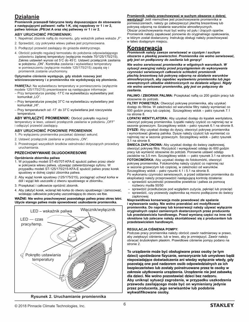
© 2018 Pinnacle Climate Technologies, Inc. 6
DziałaniePromiennik przeszedł fabryczne testy dopuszczające do stosowania z następującymi paliwami: nafta 1-K, olej napędowy nr 1 i nr 2, paliwo lotnicze JP8/Jet A oraz olej paliwowy nr 1 i nr 2.
ABY URUCHOMIĆ PROMIENNIK:1. Napełniać zbiornik naftą do momentu, gdy wskaźnik paliwa wskaże „F”.
2. Sprawdzić, czy pokrywka wlewu paliwa jest przymocowana.
3. Podłączyć przewód zasilający do gniazda elektrycznego.
4. Obrócić pokrętło regulacji termostatu do położenia odpowiadającego ustawieniu żądanej temperatury (wyłącznie modele 70/125/175/215). Zakres ustawień wynosi od 5°C do 45°C. Ustawić przełącznik zasilania w położeniu „ON”. Kontrolka zasilania i wyświetlacz temperatury w pomieszczeniu (wyłącznie modele 125/175/215) zapalą się i promiennik zostanie uruchomiony.
Optymalne ciśnienie występuje, gdy stożek nosowy jest wiśniowoczerwony i z promiennika nie wydobywają się płomienie.
PAMIĘTAJ: Na wyświetlaczu temperatury w pomieszczeniu (wyłącznie modele 125/175/215) prezentowane są następujące informacje:– Przy temperaturze poniżej -17°C na wyświetlaczu wyświetlany jest
komunikat „LO”.
– Przy temperaturze powyżej 37°C na wyświetlaczu wyświetlany jest komunikat „HI”.
– Przy temperaturach od -17° do 37°C wyświetlana jest rzeczywista temperatura.
ABY WYŁĄCZYĆ PROMIENNIK: Obrócić pokrętło regulacji temperatury w lewo, ustawić przełącznik zasilania w położeniu „OFF” i odłączyć przewód zasilający.
ABY URUCHOMIĆ PONOWNIE PROMIENNIK1. Po wyłączeniu promiennika poczekać dziesięć sekund.
2. Ustawić przełącznik zasilania w położeniu „ON”.
3. Przestrzegać wszystkich środków ostrożności dotyczących procedury uruchamiania.
PRZECHOWYWANIE DŁUGOOKRESOWEOpróżnienie zbiornika paliwa1. W przypadku modeli ST-45/70T-KFA-E spuścić paliwo przez otwór
w pokrywce wlewu paliwa, używając zatwierdzonego syfonu. W przypadku modeli ST-125/175/215-KFA-E spuścić paliwo przez korek spustowy w dolnej części zbiornika paliwa.
2. Aby wyjąć korek spustowy (125/175/215), pociągnąć uchwyt korka w dół i wyjąć łeb uszczelki z otworu spustowego w zbiorniku.
3. Przepłukać i całkowicie opróżnić zbiornik.
4. Aby założyć korek, wcisnąć łeb korka do otworu spustowego i zamocować, wciskając całkowicie pokrywkę uszczelniającą do otworu we łbie.
WAŻNE: Nie wolno przechowywać pozostałego paliwa przez okres letni. Użycie starego paliwa może spowodować uszkodzenie promiennika.
Promiennik należy przechowywać w suchym obszarze o dobrej wentylacji! Jeśli niemożliwe jest przechowywanie promiennika w pomieszczeniach, należy go zabezpieczyć płachtą brezentową lub pokrywą odporną na działanie warunków atmosferycznych.Obszar przechowywania musi być wolny od pyłu i żrących oparów. Promiennik należy zapakować ponownie do oryginalnego opakowania, w którym został dostarczony. Instrukcję obsługi należy przechowywać w łatwo dostępnym miejscu.
KonserwacjaPromiennik należy zawsze serwisować w czystym i suchym obszarze o płaskiej powierzchni. Promiennika nie wolno serwisować, gdy jest on podłączony do zasilania lub gorący!
Nie wolno serwisować promiennika w wilgotnych warunkach. W sytuacji awaryjnej należy przed przystąpieniem do wykonywania czynności serwisowych całkowicie schłodzić promiennik płachtą brezentową lub pokrywą odporną na działanie warunków atmosferycznych, aby zapobiec wystawieniu promiennika lub jego wewnętrznych układów elektronicznych na działanie wilgoci. Nigdy nie wolno serwisować promiennika, gdy jest on połączony do zasilania.
PALIWO / ZBIORNIK PALIWA: Przepłukać naftą co 200 godzin pracy lub stosownie do potrzeb. FILTRY POWIETRZA: Otworzyć pokrywę promiennika, aby uzyskać dostęp do filtrów. W zależności od warunków filtry należy wymieniać co 500 godzin pracy lub częściej. Szczegółowy widok – patrz rysunek 7.1 na stronie 8.ŁOPATKI WENTYLATORA: Aby uzyskać dostęp do łopatek wentylatora, otworzyć pokrywę promiennika. Łopatki należy czyścić co najmniej raz w sezonie grzewczym. Szczegółowy widok – patrz rysunek 6.1 na stronie 8.DYSZE: Aby uzyskać dostęp do dyszy, otworzyć pokrywę promiennika i wymontować głowicę palnika. Dysze należy czyścić lub wymieniać co najmniej raz w sezonie grzewczym. Szczegółowy widok – patrz rysunek 3.1 na stronie 8.ŚWIECA ZAPŁONOWA: Aby uzyskać dostęp do świecy zapłonowej, otworzyć pokrywę filtra. Wyczyścić i wyregulować odstęp do 600 godzin pracy lub wymienić stosownie do potrzeb. Ponownie ustawić odstęp zacisków na 3,5 mm. Szczegółowy widok — patrz rysunek 3.1 na stronie 8.FOTOKOMÓRKA: Aby uzyskać dostęp do fotokomórki, otworzyć pokrywę promiennika. Fotokomórkę należy czyścić co najmniej raz w sezonie grzewczym lub częściej, w zależności od warunków. Szczegółowy widok – patrz rysunki 4.1 i 5.1 na stronie 8. Po wykonaniu czynności serwisowych, a przed oddaniem promiennika do eksploatacji należy przeprowadzić następującą kontrolę działania: – sprawdzić szczelność przewodów powietrza i paliwa za pomocą
roztworu mydła 50/50 – sprawdzić przedłużacze pod względem zużycia, pęknięć lub przecięć– sprawdzić, czy przewody zapłonnika są mocno podłączone do świecy
zapłonowejNieprawidłowa konserwacja może powodować złe spalanie i wytwarzanie sadzy. Nie wolno przerabiać ani modyfikować promiennika. Do naprawy lub konserwacji należy używać wyłącznie oryginalnych części zamiennych dostarczonych przez producenta lub przedstawiciela handlowego. Przed wymianą części na inne niż określone lub zalecane należy skontaktować się z producentem lub przedstawicielem handlowym.
REGULACJA CIŚNIENIA POMPY:Podczas pracy promiennika należy obrócić zawór nadmiarowy w prawo, aby zwiększyć ciśnienie, lub w lewo, aby je zmniejszyć. Zawór należy obracać śrubokrętem płaskim. Prawidłowe ciśnienie pompy podano na stronie 2.
To urządzenie może być obsługiwane przez osoby (w tym dzieci) upośledzone fizycznie, sensorycznie lub umysłowo bądź nieposiadające doświadczenia ani wiedzy wyłącznie wtedy, gdy pozostają one pod nadzorem osób odpowiedzialnych za ich bezpieczeństwo lub zostały poinstruowane przez te osoby w zakresie użytkowania urządzenia. Urządzenie nie jest zabawką dla dzieci. Nie wolno pozostawiać dzieci bez nadzoru.Aby uniknąć sytuacji zagrożenia, w przypadku uszkodzenia przewodu zasilającego może być on wymieniany jedynie przez producenta, jego serwisantów lub podobnie wykwalifikowane osoby.
Rysunek 2. Uruchamianie promiennika
Włącznik/wyłącznik
LED — czas pracy/temp.
Pokrętło ustawiania temperatury
LED – wskaźnik paliwa
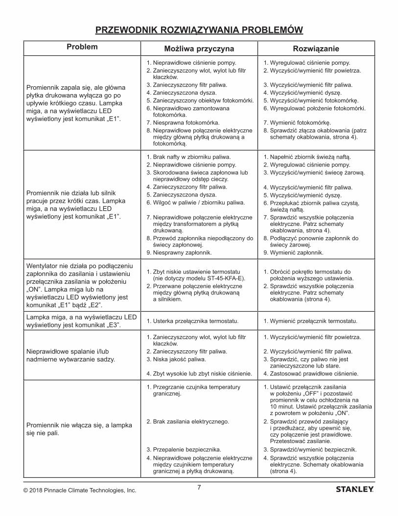
© 2018 Pinnacle Climate Technologies, Inc. 7
PRZEWODNIK ROZWIĄZYWANIA PROBLEMÓW
Problem Możliwa przyczyna Rozwiązanie
Promiennik zapala się, ale główna płytka drukowana wyłącza go po upływie krótkiego czasu. Lampka miga, a na wyświetlaczu LED wyświetlony jest komunikat „E1”.
1. Nieprawidłowe ciśnienie pompy. 2. Zanieczyszczony wlot, wylot lub filtr
kłaczków. 3. Zanieczyszczony filtr paliwa. 4. Zanieczyszczona dysza. 5. Zanieczyszczony obiektyw fotokomórki. 6. Nieprawidłowo zamontowana
fotokomórka. 7. Niesprawna fotokomórka. 8. Nieprawidłowe połączenie elektryczne
między główną płytką drukowaną a fotokomórką.
1. Wyregulować ciśnienie pompy. 2. Wyczyścić/wymienić filtr powietrza.
3. Wyczyścić/wymienić filtr paliwa. 4. Wyczyścić/wymienić dyszę. 5. Wyczyścić/wymienić fotokomórkę. 6. Wyregulować położenie fotokomórki.
7. Wymienić fotokomórkę. 8. Sprawdzić złącza okablowania (patrz
schematy okablowania, strona 4).
Promiennik nie działa lub silnik pracuje przez krótki czas. Lampka miga, a na wyświetlaczu LED wyświetlony jest komunikat „E1”.
1. Brak nafty w zbiorniku paliwa. 2. Nieprawidłowe ciśnienie pompy. 3. Skorodowana świeca zapłonowa lub
nieprawidłowy odstęp cieczy. 4. Zanieczyszczony filtr paliwa. 5. Zanieczyszczona dysza. 6. Wilgoć w paliwie / zbiorniku paliwa.
7. Nieprawidłowe połączenie elektryczne między transformatorem a płytką drukowaną.
8. Przewód zapłonnika niepodłączony do świecy zapłonowej.
9. Niesprawny zapłonnik.
1. Napełnić zbiornik świeżą naftą. 2. Wyregulować ciśnienie pompy. 3. Wyczyścić/wymienić świecę żarową.
4. Wyczyścić/wymienić filtr paliwa. 5. Wyczyścić/wymienić dyszę. 6. Przepłukać zbiornik paliwa czystą,
świeżą naftą. 7. Sprawdzić wszystkie połączenia
elektryczne. Patrz schematy okablowania, strona 4).
8. Podłączyć ponownie zapłonnik do świecy żarowej.
9. Wymienić zapłonnik.
Wentylator nie działa po podłączeniu zapłonnika do zasilania i ustawieniu przełącznika zasilania w położeniu „ON”. Lampka miga lub na wyświetlaczu LED wyświetlony jest komunikat „E1” bądź „E2”.
1. Zbyt niskie ustawienie termostatu (nie dotyczy modelu ST-45-KFA-E).
2. Przerwane połączenie elektryczne między główną płytką drukowaną a silnikiem.
1. Obrócić pokrętło termostatu do położenia wyższego ustawienia.
2. Sprawdzić wszystkie połączenia elektryczne. Patrz schematy okablowania (strona 4).
Lampka miga, a na wyświetlaczu LED wyświetlony jest komunikat „E3”.
1. Usterka przełącznika termostatu. 1. Wymienić przełącznik termostatu.
Nieprawidłowe spalanie i/lub nadmierne wytwarzanie sadzy.
1. Zanieczyszczony wlot, wylot lub filtr kłaczków.
2. Zanieczyszczony filtr paliwa. 3. Niska jakość paliwa.
4. Zbyt wysokie lub zbyt niskie ciśnienie.
1. Wyczyścić/wymienić filtr powietrza.
2. Wyczyścić/wymienić filtr paliwa. 3. Sprawdzić, czy paliwo nie jest
zanieczyszczone lub stare. 4. Zastosować prawidłowe ciśnienie.
Promiennik nie włącza się, a lampka się nie pali.
1. Przegrzanie czujnika temperatury granicznej.
2. Brak zasilania elektrycznego.
3. Przepalenie bezpiecznika.
4. Nieprawidłowe połączenie elektryczne między czujnikiem temperatury granicznej a płytką drukowaną.
1. Ustawić przełącznik zasilania w położeniu „OFF” i pozostawić promiennik w celu ochłodzenia na 10 minut. Ustawić przełącznik zasilania z powrotem w położeniu „ON”.
2. Sprawdzić przewód zasilający i przedłużacz, aby upewnić się, czy połączenie jest prawidłowe. Przetestować zasilanie.
3. Sprawdzić/wymienić bezpiecznik.
4. Sprawdzić wszystkie połączenia elektryczne. Schematy okablowania (strona 4).
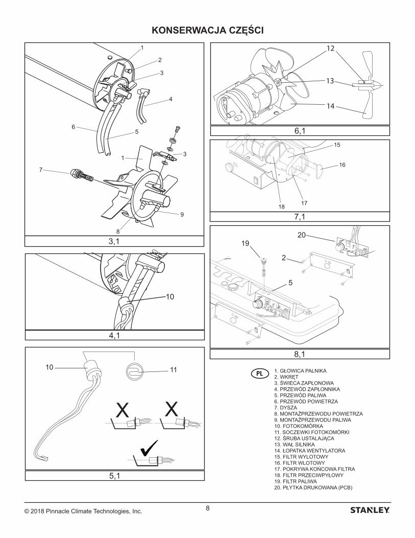
© 2018 Pinnacle Climate Technologies, Inc. 8
KONSERWACJA CZĘŚCI
15
16
1718
12
14
13
XX
10 11
10
20
2
5
19
1
2
3
4
56
7
1 3
9
8
3,1
4,1
5,1
8,1
6,1
7,1
1. GŁOWICA PALNIKA2. WKRĘT3. ŚWIECA ZAPŁONOWA4. PRZEWÓD ZAPŁONNIKA5. PRZEWÓD PALIWA6. PRZEWÓD POWIETRZA7. DYSZA8. MONTAŻ PRZEWODU POWIETRZA9. MONTAŻ PRZEWODU PALIWA10. FOTOKOMÓRKA11. SOCZEWKI FOTOKOMÓRKI12. ŚRUBA USTALAJĄCA13. WAŁ SILNIKA14. ŁOPATKA WENTYLATORA15. FILTR WYLOTOWY16. FILTR WLOTOWY17. POKRYWA KOŃCOWA FILTRA18. FILTR PRZECIWPYŁOWY19. FILTR PALIWA20. PŁYTKA DRUKOWANA (PCB)
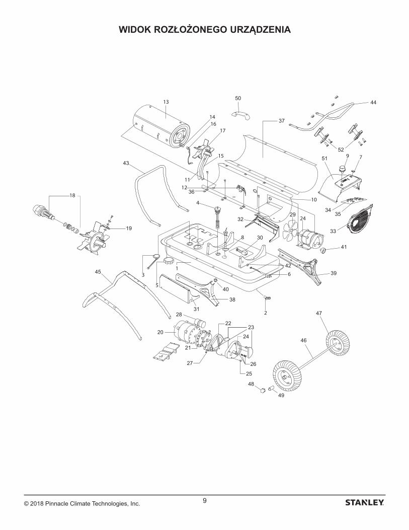
© 2018 Pinnacle Climate Technologies, Inc. 9
WIDOK ROZŁOŻONEGO URZĄDZENIA
41
43
44
45
46
47
48
49
50
19
20
21
2223
24
25
2627
28
29
30
31
32
33
3435
36
37
38
39
40
42
5152
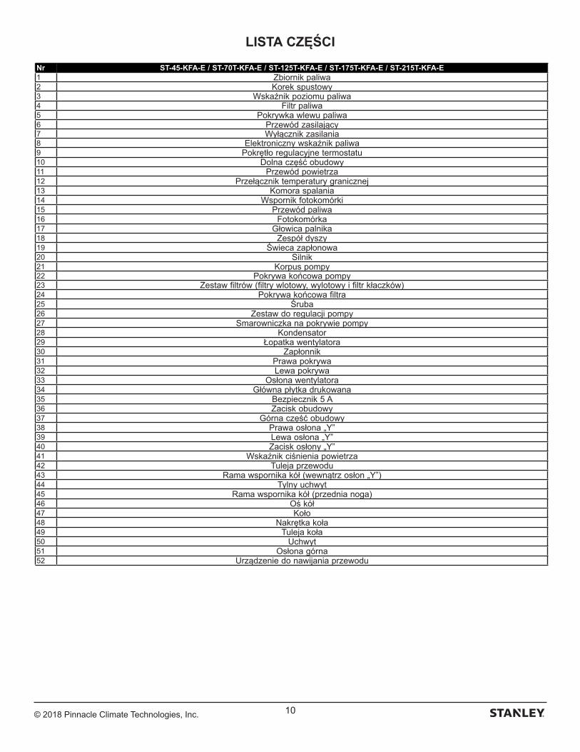
© 2018 Pinnacle Climate Technologies, Inc. 10
LISTA CZĘŚCI
Nr ST-45-KFA-E / ST-70T-KFA-E / ST-125T-KFA-E / ST-175T-KFA-E / ST-215T-KFA-E1 Zbiornik paliwa2 Korek spustowy3 Wskaźnik poziomu paliwa4 Filtr paliwa5 Pokrywka wlewu paliwa6 Przewód zasilający7 Wyłącznik zasilania8 Elektroniczny wskaźnik paliwa9 Pokrętło regulacyjne termostatu10 Dolna część obudowy11 Przewód powietrza12 Przełącznik temperatury granicznej13 Komora spalania14 Wspornik fotokomórki15 Przewód paliwa16 Fotokomórka17 Głowica palnika18 Zespół dyszy19 Świeca zapłonowa20 Silnik21 Korpus pompy22 Pokrywa końcowa pompy23 Zestaw filtrów (filtry wlotowy, wylotowy i filtr kłaczków)24 Pokrywa końcowa filtra25 Śruba26 Zestaw do regulacji pompy27 Smarowniczka na pokrywie pompy28 Kondensator29 Łopatka wentylatora30 Zapłonnik31 Prawa pokrywa32 Lewa pokrywa33 Osłona wentylatora34 Główna płytka drukowana35 Bezpiecznik 5 A36 Zacisk obudowy37 Górna część obudowy38 Prawa osłona „Y”39 Lewa osłona „Y”40 Zacisk osłony „Y”41 Wskaźnik ciśnienia powietrza42 Tuleja przewodu43 Rama wspornika kół (wewnątrz osłon „Y”)44 Tylny uchwyt45 Rama wspornika kół (przednia noga)46 Oś kół47 Koło48 Nakrętka koła49 Tuleja koła50 Uchwyt51 Osłona górna52 Urządzenie do nawijania przewodu
© 2018 Pinnacle Climate Technologies, Inc. 11
Belgique et LuxembourgBelgië en Luxemburg
E. Walschaertstraat 14 2800 Mechelen Belgium
[email protected]= +32 15 47 37 65BE-FR = +32 15 47 37 64BE Fax: +32 15 47 37 100
Danmark Roskildevej 22 2620 Albertslund
[email protected]: 70224910
Deutschland Richard Klinger Str. 11 65510 Idstein
[email protected]: 06126-21-1Fax: 06126-21-2770
Ελλάς Hμερος Τόπος 2 - Χάνι Αδάμ Ασπρόπυργος -19300 -Αττική - Αττικής
[email protected]Τηλ: +30 210 8985208Φαξ: +30 210 5597598
España Parque de Negocios “Mas Blau”
08820 El Prat de Llobregat (Barcelona)
[email protected]: 934 797 400Fax: 934 797 419
France 5, allée des hêtres BP 30084, 69579 Limonest Cedex
[email protected]: 04 72 20 39 77Fax: 04 72 20 39 00
SchweizSuisse Svizzera
In der Luberzen 42 8902 Urdorf
[email protected]: 044 - 755 60 70Fax: 044 - 730 70 67
Ireland 210 Bath Road; Slough, Berks SL1 3YD UK www.stanleytools.co.ukTel: +44 (0)1753 511234Fax: +44 (0)1753 512365
Italia www.stanley.itTel. 039-9590-200Fax 039-9590-313
Nederlands Stanley Black & Decker Netherlands B.V. Postbus 83 6120 AD Born
[email protected] : +31 164 28 30 63NL Fax: +31 164 28 32 00
Norge Postboks 4613, Nydalen0405 Oslo
[email protected]: 45 25 08 00
Österreich Oberlaaerstrasse 248A-1230 Wien
[email protected]: 01 - 66116 - 0Fax: 01 - 66116 - 14
Portugal Quinta da Fonte - Edifício Q55 D. Diniz Rua dos Malhões, 2 e 2A - Piso 2 Esquerdo 2770 - 071 Paço de Arcos
[email protected]: 214 66 75 00Fax: 214 66 75 75
Suomi PL 47 00521 Helsinki
Puh: 010 400 4333
Sverige Box 94 431 22 Mölndal
[email protected]: 31 68 60 08
United Kingdom 210 Bath Road; Slough, Berks SL1 3YD www.stanleytools.co.ukTel: +44 (0)1753 511234Fax: +44 (0)1753 512365
Hungary Rotel Kft.1163 Budapest,Thököly út 17.
[email protected] +36 1 404-0014Fax+36 1 403-2260
Czech Republic BAND SERVIS CZ s.r.o. K Pasekam 4440 760 01 Zlín, Czech Republic
www.stanleyworks.czhttp://www.bandservis.czTel.: +420 577 008 550Fax.: +420 577 008 559
Slovakia BAND SERVIS s.r.o. Paulinska 22 917 01 Trnava, Slovakia
www.bandservis.skTel.: +421 335 511 063Fax.: +421 335 512 624
Poland Erpatech ul. Bakaliowa 26 05-080 Mościska
www.stanleyworks.plTel.: +48 22 431 05 00Fax.: +48 22 468 87 35
Slovenia G-M&M d.o.o. Brvace 11 1290 Grosuplje Slovenija
[email protected]: +386 01 78 66 500F: +386 01 78 63 023
Cyprus IOANNOU J. 4A Ath.Diakou street 1046- Nicosia -Cyprus
[email protected]Τel : +357 22344302Fax : +357 22348098
Bosnia-Herzegovina G-M&M d.o.o. Brvace 11 1290 Grosuplje Slovenija
[email protected]: +386 01 78 66 500F: +386 01 78 63 023
Bulgaria TASHEV-GALVING LTD 68 KLIMENT OHRIDSKI BLVD.
www.tashev-galving.comT: +359 2 700 45 45 4F: +359 (2) 439 21 12
Croatia G-M&M d.o.o. Brvace 11 1290 Grosuplje Slovenija
[email protected]: +386 01 78 66 500F: +386 01 78 63 023
Estonia AS Tallmac Mustame tee 44, EE-10621 Tallinn
www.tallmac.ee/estT: +372 6562999F: +372 6562855
Latvia LIC GOTUS SIA Ulbrokas Str. LT - 1021 Rīga
www.licgotus.lvT: +371 67556949F: +371 67555140
Lithuania UAB ELREMTA OU Neries kr. 16E LT - 48402 Kaunas
[email protected]: +370-685-29035F: +370-37-406540
Malta Energypark–Building 03 sud, Via Energy Park 6 20871 Vimercate (MB)
www.stanley.itTel. 039-9590-200Fax 039-9590-313
Romania Stanley Black & Decker Phoenicia Business Center Strada Turturelelor, nr 11A, Etaj 6, Modul 15, Sector 3 Bucuresti
www.stanleyworks.roT: +4021.320.61.04/05F: +4037.225.36.84
Serbia G-M&M d.o.o. Brvace 11 1290 Grosuplje Slovenija
[email protected]: +386 01 78 66 500F: +386 01 78 63 023
WSPARCIE
Energy Park–Building 03 sudVia Energy Park 620871 Vimercate (MB)

Producent:Pinnacle Climate Technologies, Inc.
Sauk Rapids, MN 56379 Stany Zjednoczone
EC REP
Obelis S.A.Siedziba firmy:
Bd. Général Wahis, 53 1030 Brussels, Belgium
© 2018 Stanley Black & Decker, Inc.

ST-45-KFA-E / ST-70T-KFA-E / ST-125T-KFA-E ST-175T-KFA-E / ST-215T-KFA-E
NEVER LEAVE HEATER UNATTENDED WHILE BURNING, OR WHILE CONNECTED TO A POWER SOURCE.
THIS PRODUCT IS NOT SUITABLE FOR PRIMARY HEATING PURPOSES.
STKA-462
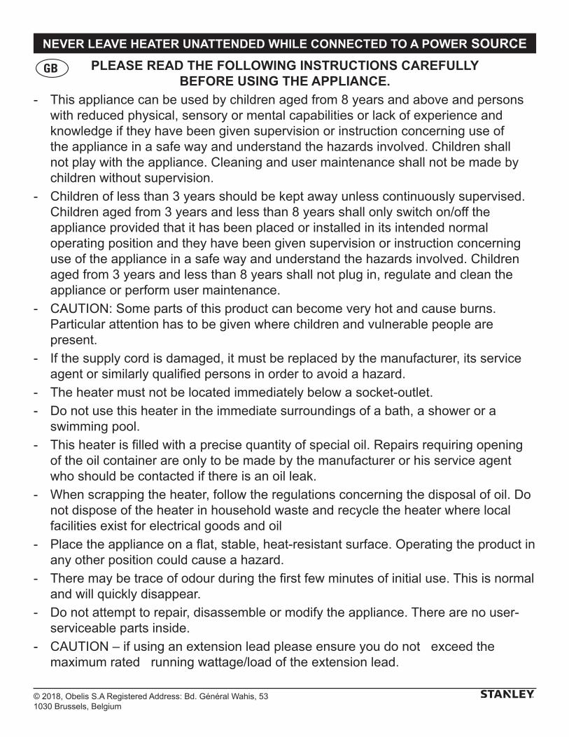
© 2018, Obelis S.A Registered Address: Bd. Général Wahis, 531030 Brussels, Belgium
NEVER LEAVE HEATER UNATTENDED WHILE CONNECTED TO A POWER SOURCE
PLEASE READ THE FOLLOWING INSTRUCTIONS CAREFULLY BEFORE USING THE APPLIANCE.
- This appliance can be used by children aged from 8 years and above and persons with reduced physical, sensory or mental capabilities or lack of experience and knowledge if they have been given supervision or instruction concerning use of the appliance in a safe way and understand the hazards involved. Children shall not play with the appliance. Cleaning and user maintenance shall not be made by children without supervision.
- Children of less than 3 years should be kept away unless continuously supervised. Children aged from 3 years and less than 8 years shall only switch on/off the appliance provided that it has been placed or installed in its intended normal operating position and they have been given supervision or instruction concerning use of the appliance in a safe way and understand the hazards involved. Children aged from 3 years and less than 8 years shall not plug in, regulate and clean the appliance or perform user maintenance.
- CAUTION: Some parts of this product can become very hot and cause burns. Particular attention has to be given where children and vulnerable people are present.
- If the supply cord is damaged, it must be replaced by the manufacturer, its service agent or similarly qualified persons in order to avoid a hazard.
- The heater must not be located immediately below a socket-outlet.
- Do not use this heater in the immediate surroundings of a bath, a shower or a swimming pool.
- This heater is filled with a precise quantity of special oil. Repairs requiring opening of the oil container are only to be made by the manufacturer or his service agent who should be contacted if there is an oil leak.
- When scrapping the heater, follow the regulations concerning the disposal of oil. Do not dispose of the heater in household waste and recycle the heater where local facilities exist for electrical goods and oil
- Place the appliance on a flat, stable, heat-resistant surface. Operating the product in any other position could cause a hazard.
- There may be trace of odour during the first few minutes of initial use. This is normal and will quickly disappear.
- Do not attempt to repair, disassemble or modify the appliance. There are no user-serviceable parts inside.
- CAUTION – if using an extension lead please ensure you do not exceed the maximum rated running wattage/load of the extension lead.
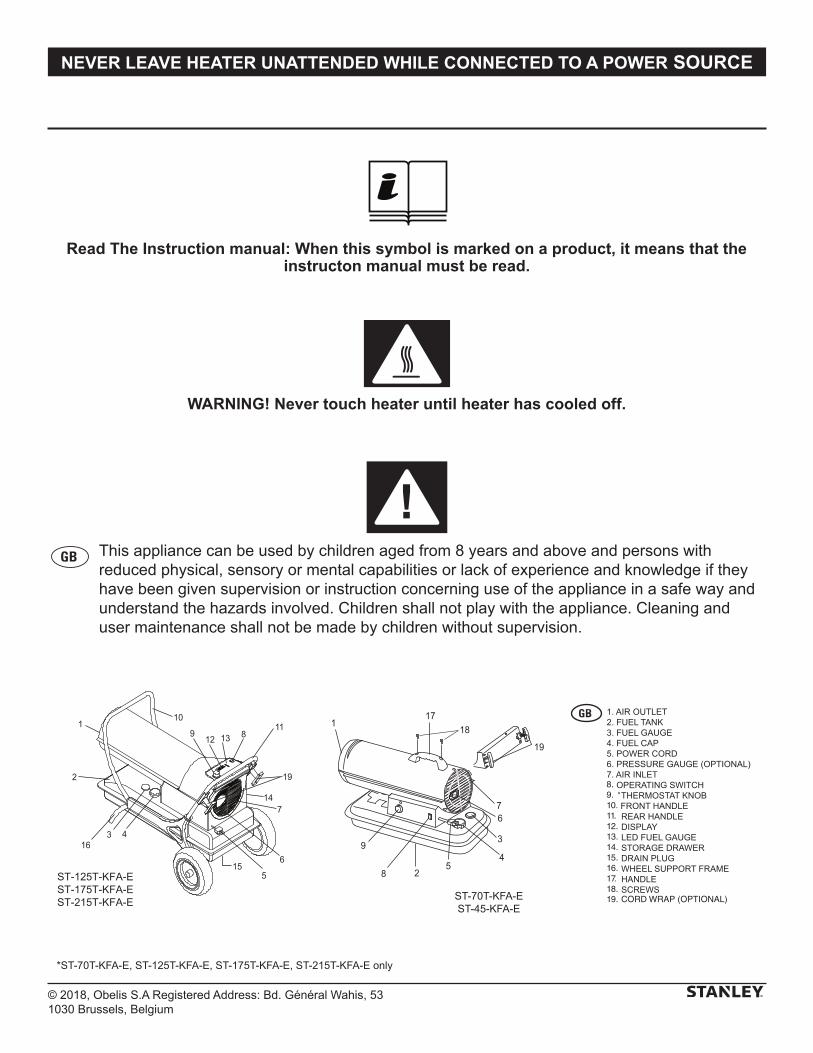
© 2018, Obelis S.A Registered Address: Bd. Général Wahis, 531030 Brussels, Belgium
NEVER LEAVE HEATER UNATTENDED WHILE CONNECTED TO A POWER SOURCE
Read The Instruction manual: When this symbol is marked on a product, it means that the instructon manual must be read.
WARNING! Never touch heater until heater has cooled off.
This appliance can be used by children aged from 8 years and above and persons with reduced physical, sensory or mental capabilities or lack of experience and knowledge if they have been given supervision or instruction concerning use of the appliance in a safe way and understand the hazards involved. Children shall not play with the appliance. Cleaning and user maintenance shall not be made by children without supervision.
5
3
4
6
28
9
17
19
7
118
12
110
19
11
7
6
316
13
4
5
89
14
2
15
ST-70T-KFA-EST-45-KFA-E
ST-125T-KFA-EST-175T-KFA-EST-215T-KFA-E
8.9.10.11.12.13.14.15.16.17.18.
*
19. CORD WRAP (OPTIONAL)
*ST-70T-KFA-E, ST-125T-KFA-E, ST-175T-KFA-E, ST-215T-KFA-E only
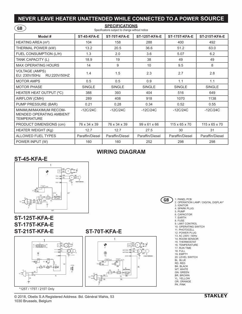
© 2018, Obelis S.A Registered Address: Bd. Général Wahis, 531030 Brussels, Belgium
NEVER LEAVE HEATER UNATTENDED WHILE CONNECTED TO A POWER SOURCE
Model # ST-45-KFA-E ST-70T-KFA-E ST-125T-KFA-E ST-175T-KFA-E ST-215T-KFA-E
HEATING AREA (m²) 104 158 288 400 492
THERMAL POWER (kW) 13.2 20.5 36.6 51.2 63.0
FUEL CONSUMPTION (L/H) 1.3 2.0 3.6 5.07 6.2
TANK CAPACITY (L) 18.9 19 38 49 49
MAX OPERATING HOURS 14 9 10 9.5 8
VOLTAGE (AMPS)EU: 230V/50Hz RU:220V/50HZ
1.4 1.5 2.3 2.7 2.8
MOTOR AMPS 0.5 0.5 0.9 1.1 1.1
MOTOR PHASE SINGLE SINGLE SINGLE SINGLE SINGLE
HEATER HEAT OUTPUT (ºC) 388 393 404 516 649
AIRFLOW (CMH) 289 408 918 1070 1138
PUMP PRESSURE (BAR) 0.21 0.28 0.34 0.52 0.55
MINIMUM/MAXIMUM RECOM-MENDED OPERATING AMBIENT TEMPERATURE
-12C/24C -12C/24C -12C/24C -12C/24C -12C/24C
PRODUCT DIMENSIONS (cm) 76 x 34 x 39 76 x 34 x 39 99 x 61 x 66 115 x 65 x 70 115 x 65 x 70
HEATER WEIGHT (Kg) 12.7 12.7 27.5 30 31
ALLOWED FUEL TYPES Paraffin/Diesel Paraffin/Diesel Paraffin/Diesel Paraffin/Diesel Paraffin/Diesel
POWER INPUT (W) 160 160 252 298 298
SPECIFICATIONSSpecifications subject to change without notice
WIRING DIAGRAM
1
WT
BK
OR
BK 4
2
12
13
GN
7
GN
7
11
10BK
9
BR
BKBK
BL
BL8
5
3
615
14BK
RDRD
BKPK
BK
BL
YL
BKCN1
RD10
11
12
13
1RD
RD
PK
OR
WT
BK3
4
5
GN
7
6
8 RD
BL
9
GN
7
BR
BL
14BKBK
BK
15
20
RD
BKBK
1617
18
19
2
10UF/250VAC
1RD
WT
RD
OR
BK
BK
WT
BK
BK
BK
BK
PKBK
4
2
12
13GN
GN
7
7
11
10 9 8
5
3
6
WT
YLGN
7
WT
8A/125AVC
ST-45-KFA-E
ST-70T-KFA-E
ST-125T-KFA-EST-175T-KFA-EST-215T-KFA-E
/ DIGITAL DISPLAY*
*125T / 175T / 215T Only
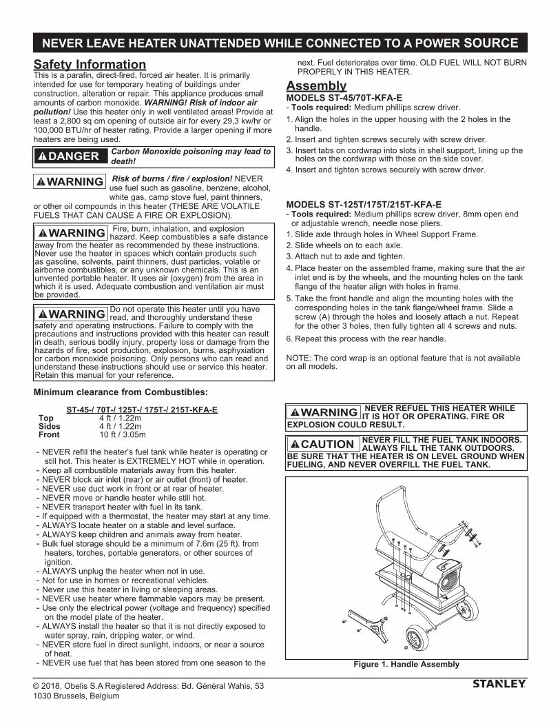
© 2018, Obelis S.A Registered Address: Bd. Général Wahis, 531030 Brussels, Belgium
NEVER LEAVE HEATER UNATTENDED WHILE CONNECTED TO A POWER SOURCE
Safety InformationThis is a parafin, direct-fired, forced air heater. It is primarily intended for use for temporary heating of buildings under construction, alteration or repair. This appliance produces small amounts of carbon monoxide. WARNING! Risk of indoor air pollution! Use this heater only in well ventilated areas! Provide at least a 2,800 sq cm opening of outside air for every 29,3 kw/hr or 100,000 BTU/hr of heater rating. Provide a larger opening if more heaters are being used.
Risk of burns / fire / explosion! NEVER use fuel such as gasoline, benzene, alcohol, white gas, camp stove fuel, paint thinners,
or other oil compounds in this heater (THESE ARE VOLATILE FUELS THAT CAN CAUSE A FIRE OR EXPLOSION).
Minimum clearance from Combustibles:
ST-45-/ 70T-/ 125T-/ 175T-/ 215T-KFA-E Top 4 ft / 1.22m Sides 4 ft / 1.22m Front 10 ft / 3.05m
- NEVER refill the heater’s fuel tank while heater is operating or still hot. This heater is EXTREMELY HOT while in operation.
- Keep all combustible materials away from this heater. - NEVER block air inlet (rear) or air outlet (front) of heater. - NEVER use duct work in front or at rear of heater. - NEVER move or handle heater while still hot. - NEVER transport heater with fuel in its tank. - If equipped with a thermostat, the heater may start at any time. - ALWAYS locate heater on a stable and level surface. - ALWAYS keep children and animals away from heater. - Bulk fuel storage should be a minimum of 7.6m (25 ft). from
heaters, torches, portable generators, or other sources of ignition.
- ALWAYS unplug the heater when not in use. - Not for use in homes or recreational vehicles. - Never use this heater in living or sleeping areas. - NEVER use heater where flam mable vapors may be present. - Use only the electrical power (voltage and frequency) specified
on the model plate of the heater. - ALWAYS install the heater so that it is not directly exposed to
water spray, rain, dripping water, or wind. - NEVER store fuel in direct sunlight, indoors, or near a source
of heat. - NEVER use fuel that has been stored from one season to the
next. Fuel deteriorates over time. OLD FUEL WILL NOT BURN PROPERLY IN THIS HEATER.
AssemblyMODELS ST-45/70T-KFA-E- Tools required: Medium phillips screw driver.
1. Align the holes in the upper housing with the 2 holes in the handle.
2. Insert and tighten screws securely with screw driver.3. Insert tabs on cordwrap into slots in shell support, lining up the holes on the cordwrap with those on the side cover.4. Insert and tighten screws securely with screw driver.
MODELS ST-125T/175T/215T-KFA-E- Tools required: Medium phillips screw driver, 8mm open end
or adjustable wrench, needle nose pliers.1. Slide axle through holes in Wheel Support Frame. 2. Slide wheels on to each axle.3. Attach nut to axle and tighten.
4. Place heater on the assembled frame, making sure that the air inlet end is by the wheels, and the mounting holes on the tank flange of the heater align with holes in frame.
5. Take the front handle and align the mounting holes with the corresponding holes in the tank flange/wheel frame. Slide a screw (A) through the holes and loosely attach a nut. Repeat for the other 3 holes, then fully tighten all 4 screws and nuts.
6. Repeat this process with the rear handle.
NOTE: The cord wrap is an optional feature that is not available on all models.
WARNING
Carbon Monoxide poisoning may lead to death!DANGER
NEVER REFUEL THIS HEATER WHILE IT IS HOT OR OPERATING. FIRE OR
EXPLOSION COULD RESULT.WARNING
NEVER FILL THE FUEL TANK INDOORS. ALWAYS FILL THE TANK OUTDOORS.
BE SURE THAT THE HEATER IS ON LEVEL GROUND WHEN FUELING, AND NEVER OVERFILL THE FUEL TANK.
CAUTION
Figure 1. Handle Assembly
Do not operate this heater until you have read, and thoroughly understand these
safety and operating instructions. Failure to comply with the precautions and instructions provided with this heater can result in death, serious bodily injury, property loss or damage from the hazards of fire, soot production, explosion, burns, asphyxiation or carbon monoxide poisoning. Only persons who can read and understand these instructions should use or service this heater. Retain this manual for your reference.
WARNING
Fire, burn, inhalation, and explosion hazard. Keep combustibles a safe distance
away from the heater as recommended by these instructions. Never use the heater in spaces which contain products such as gasoline, solvents, paint thinners, dust particles, volatile or airborne combustibles, or any unknown chemicals. This is an unvented portable heater. It uses air (oxygen) from the area in which it is used. Adequate combustion and ventilation air must be provided.
WARNING
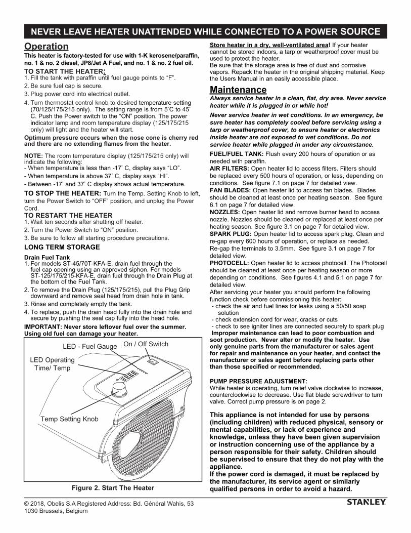
© 2018, Obelis S.A Registered Address: Bd. Général Wahis, 531030 Brussels, Belgium
NEVER LEAVE HEATER UNATTENDED WHILE CONNECTED TO A POWER SOURCE
OperationThis heater is factory-tested for use with 1-K kerosene/paraffin, no. 1 & no. 2 diesel, JP8/Jet A Fuel, and no. 1 & no. 2 fuel oil.
TO START THE HEATER:1. Fill the tank with paraffin until fuel gauge points to “F”.2. Be sure fuel cap is secure.3. Plug power cord into electrical outlet.
4. Turn thermostat control knob to desired temperature setting (70/125/175/215 only). The setting range is from 5°C to 45° C. Push the Power switch to the “ON” position. The power indicator lamp and room temperature display (125/175/215 only) will light and the heater will start.
Optimum pressure occurs when the nose cone is cherry red and there are no extending flames from the heater.
NOTE: The room temperature display (125/175/215 only) will indicate the following:- When temperature is less than -17° C, display says “LO”.- When temperature is above 37° C, display says “HI”.- Between -17° and 37° C display shows actual temperature.
TO STOP THE HEATER: Turn the Temp. Setting Knob to left, turn the Power Switch to “OFF” position, and unplug the Power Cord.TO RESTART THE HEATER1. Wait ten seconds after shutting off heater.2. Turn the Power Switch to “ON” position.3. Be sure to follow all starting procedure precautions.
LONG TERM STORAGE
Drain Fuel Tank1. For models ST-45/70T-KFA-E, drain fuel through the
fuel cap opening using an approved siphon. For models ST-125/175/215-KFA-E, drain fuel through the Drain Plug at the bottom of the Fuel Tank.
2. To remove the Drain Plug (125/175/215), pull the Plug Grip downward and remove seal head from drain hole in tank.
3. Rinse and completely empty the tank.4. To replace, push the drain head fully into the drain hole and
secure by pushing the seal cap fully into the head hole.
IMPORTANT: Never store leftover fuel over the summer. Using old fuel can damage your heater.
Store heater in a dry, well-ventilated area! If your heater cannot be stored indoors, a tarp or weatherproof cover must be used to protect the heater.Be sure that the storage area is free of dust and corrosive vapors. Repack the heater in the original shipping material. Keep the Users Manual in an easily accessible place.
MaintenanceAlways service heater in a clean, flat, dry area. Never service heater while it is plugged in or while hot!
Never service heater in wet conditions. In an emergency, be sure heater has completely cooled before servicing using a tarp or weatherproof cover, to ensure heater or electronics inside heater are not exposed to wet conditions. Do not service heater while plugged in under any circumstance.
FUEL/FUEL TANK: Flush every 200 hours of operation or as needed with paraffin. AIR FILTERS: Open heater lid to access filters. Filters should be replaced every 500 hours of operation, or less, depending on conditions. See figure 7.1 on page 7 for detailed view.FAN BLADES: Open heater lid to access fan blades. Blades should be cleaned at least once per heating season. See figure 6.1 on page 7 for detailed view.NOZZLES: Open heater lid and remove burner head to access nozzle. Nozzles should be cleaned or replaced at least once per heating season. See figure 3.1 on page 7 for detailed view.SPARK PLUG: Open heater lid to access spark plug. Clean and re-gap every 600 hours of operation, or replace as needed. Re-gap the terminals to 3.5mm. See figure 3.1 on page 7 for detailed view.PHOTOCELL: Open heater lid to access photocell. The Photocell should be cleaned at least once per heating season or more depending on conditions. See figures 4.1 and 5.1 on page 7 for detailed view. After servicing your heater you should perform the following function check before commissioning this heater: - check the air and fuel lines for leaks using a 50/50 soap
solution - check extension cord for wear, cracks or cuts - check to see igniter lines are connected securely to spark plugImproper maintenance can lead to poor combustion and
soot production. Never alter or modify the heater. Use only genuine parts from the manufacturer or sales agent for repair and maintenance on your heater, and contact the manufacturer or sales agent before replacing parts other than those specified or recommended.
PUMP PRESSURE ADJUSTMENT:While heater is operating, turn relief valve clockwise to increase, counterclockwise to decrease. Use flat blade screwdriver to turn valve. Correct pump pressure is on page 2.
This appliance is not intended for use by persons (including children) with reduced physical, sensory or mental capabilities, or lack of experience and knowledge, unless they have been given supervision or instruction concerning use of the appliance by a person responsible for their safety. Children should be supervised to ensure that they do not play with the appliance.If the power cord is damaged, it must be replaced by the manufacturer, its service agent or similarly qualified persons in order to avoid a hazard.Figure 2. Start The Heater
On / Off Switch
LED Operating Time/ Temp
Temp Setting Knob
LED - Fuel Gauge
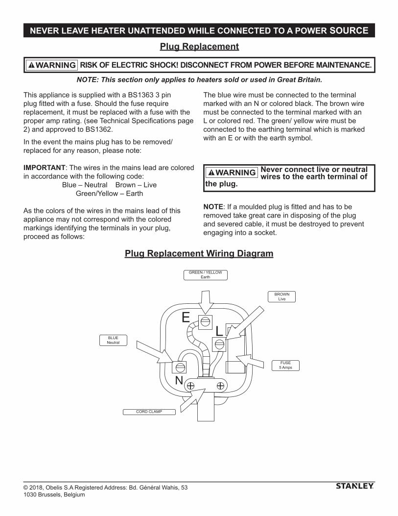
© 2018, Obelis S.A Registered Address: Bd. Général Wahis, 531030 Brussels, Belgium
NEVER LEAVE HEATER UNATTENDED WHILE CONNECTED TO A POWER SOURCE
RISK OF ELECTRIC SHOCK! DISCONNECT FROM POWER BEFORE MAINTENANCE.WARNING
Plug Replacement
NOTE: This section only applies to heaters sold or used in Great Britain.
This appliance is supplied with a BS1363 3 pin plug fitted with a fuse. Should the fuse require replacement, it must be replaced with a fuse with the proper amp rating. (see Technical Specifications page 2) and approved to BS1362.
In the event the mains plug has to be removed/ replaced for any reason, please note:
IMPORTANT: The wires in the mains lead are colored in accordance with the following code:
Blue – Neutral Brown – Live Green/Yellow – Earth
As the colors of the wires in the mains lead of this appliance may not correspond with the colored markings identifying the terminals in your plug, proceed as follows:
The blue wire must be connected to the terminal marked with an N or colored black. The brown wire must be connected to the terminal marked with an L or colored red. The green/ yellow wire must be connected to the earthing terminal which is marked with an E or with the earth symbol.
NOTE: If a moulded plug is fitted and has to be removed take great care in disposing of the plug and severed cable, it must be destroyed to prevent engaging into a socket.
Never connect live or neutral wires to the earth terminal of
the plug.
WARNING
GREEN / YELLOWEarth
BROWNLive
FUSE5 Amps
CORD CLAMP
BLUENeutral
Plug Replacement Wiring Diagram
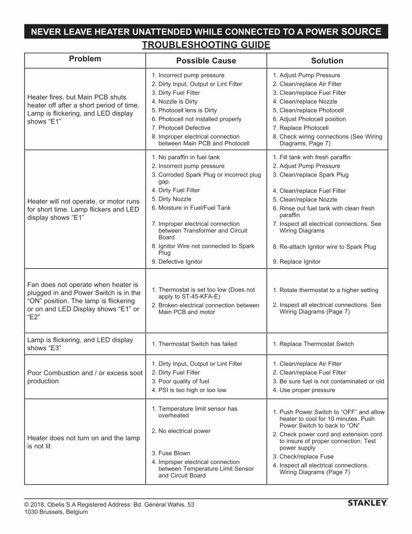
© 2018, Obelis S.A Registered Address: Bd. Général Wahis, 531030 Brussels, Belgium
NEVER LEAVE HEATER UNATTENDED WHILE CONNECTED TO A POWER SOURCETROUBLESHOOTING GUIDE
Problem Possible Cause Solution
Heater fires, but Main PCB shuts heater off after a short period of time. Lamp is flickering, and LED display shows “E1”
1. Incorrect pump pressure
2. Dirty Input, Output or Lint Filter
3. Dirty Fuel Filter
4. Nozzle is Dirty
5. Photocell lens is Dirty
6. Photocell not installed properly
7. Photocell Defective
8. Improper electrical connection between Main PCB and Photocell
1. Adjust Pump Pressure
2. Clean/replace Air Filter
3. Clean/replace Fuel Filter
4. Clean/replace Nozzle
5. Clean/replace Photocell
6. Adjust Photocell position
7. Replace Photocell
8. Check wiring connections (See Wiring Diagrams, Page 7)
Heater will not operate, or motor runs for short time. Lamp flickers and LED display shows “E1”
1. No paraffin in fuel tank
2. Incorrect pump pressure
3. Corroded Spark Plug or incorrect plug gap.
4. Dirty Fuel Filter
5. Dirty Nozzle
6. Moisture in Fuel/Fuel Tank
7. Improper electrical connection between Transformer and Circuit Board
8. Ignitor Wire not connected to Spark Plug
9. Defective Ignitor
1. Fill tank with fresh paraffin
2. Adjust Pump Pressure
3. Clean/replace Spark Plug
4. Clean/replace Fuel Filter
5. Clean/replace Nozzle
6. Rinse out fuel tank with clean fresh paraffin
7. Inspect all electrical connections. See Wiring Diagrams
8. Re-attach Ignitor wire to Spark Plug
9. Replace Ignitor
Fan does not operate when heater is plugged in and Power Switch is in the “ON” position. The lamp is flickering or on and LED Display shows “E1” or “E2”
1. Thermostat is set too low (Does not apply to ST-45-KFA-E)
2. Broken electrical connection between Main PCB and motor
1. Rotate thermostat to a higher setting
2. Inspect all electrical connections. See Wiring Diagrams (Page 7)
Lamp is flickering, and LED display shows “E3”
1. Thermostat Switch has failed 1. Replace Thermostat Switch
Poor Combustion and / or excess soot production
1. Dirty Input, Output or Lint Filter
2. Dirty Fuel Filter
3. Poor quality of fuel
4. PSI is too high or too low
1. Clean/replace Air Filter
2. Clean/replace Fuel Filter
3. Be sure fuel is not contaminated or old
4. Use proper pressure
Heater does not turn on and the lamp is not lit
1. Temperature limit sensor has overheated
2. No electrical power
3. Fuse Blown
4. Improper electrical connection between Temperature Limit Sensor and Circuit Board
1. Push Power Switch to “OFF” and allow heater to cool for 10 minutes. Push Power Switch to back to “ON”
2. Check power cord and extension cord to insure of proper connection. Test power supply
3. Check/replace Fuse
4. Inspect all electrical connections. Wiring Diagrams (Page 7)
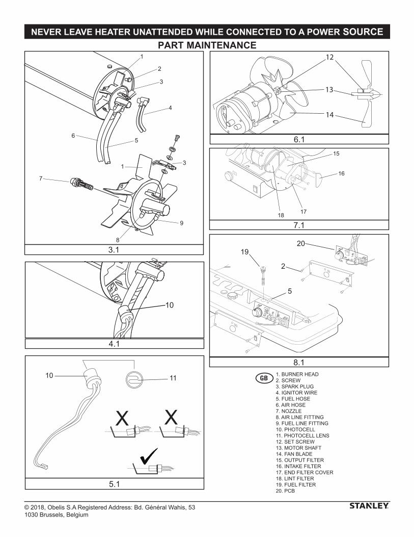
© 2018, Obelis S.A Registered Address: Bd. Général Wahis, 531030 Brussels, Belgium
NEVER LEAVE HEATER UNATTENDED WHILE CONNECTED TO A POWER SOURCE
PART MAINTENANCE
15
16
1718
12
14
13
XX
10 11
10
20
2
5
19
1
2
3
4
56
7
1 3
9
8
3.1
4.1
5.1
8.1
6.1
7.1
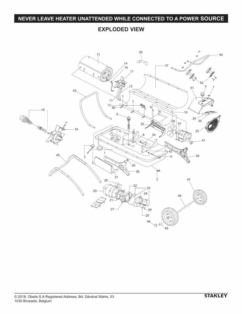
© 2018, Obelis S.A Registered Address: Bd. Général Wahis, 531030 Brussels, Belgium
NEVER LEAVE HEATER UNATTENDED WHILE CONNECTED TO A POWER SOURCE
EXPLODED VIEW
41
43
44
45
46
47
48
49
50
19
20
21
2223
24
25
2627
28
29
30
31
32
33
3435
36
37
38
39
40
42
5152
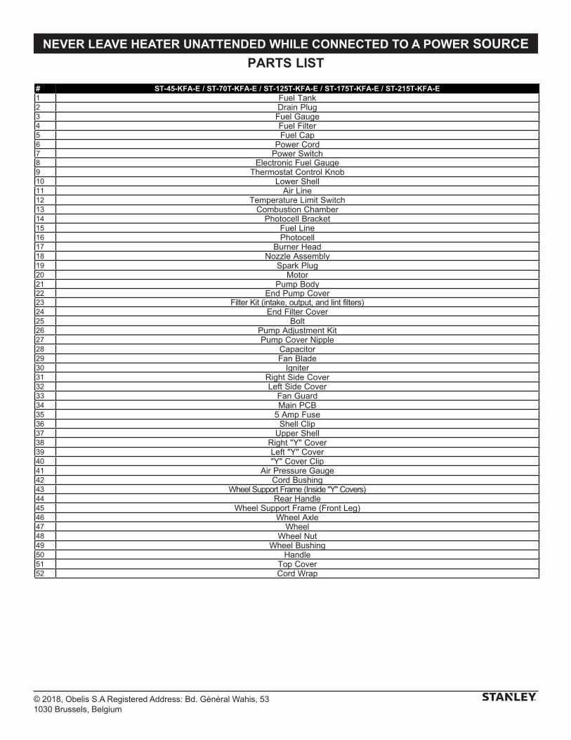
© 2018, Obelis S.A Registered Address: Bd. Général Wahis, 531030 Brussels, Belgium
NEVER LEAVE HEATER UNATTENDED WHILE CONNECTED TO A POWER SOURCE
PARTS LIST
# ST-45-KFA-E / ST-70T-KFA-E / ST-125T-KFA-E / ST-175T-KFA-E / ST-215T-KFA-E1 Fuel Tank2 Drain Plug3 Fuel Gauge4 Fuel Filter5 Fuel Cap6 Power Cord7 Power Switch8 Electronic Fuel Gauge9 Thermostat Control Knob10 Lower Shell11 Air Line12 Temperature Limit Switch13 Combustion Chamber14 Photocell Bracket15 Fuel Line16 Photocell17 Burner Head18 Nozzle Assembly19 Spark Plug20 Motor21 Pump Body22 End Pump Cover23 Filter Kit (intake, output, and lint filters)24 End Filter Cover25 Bolt26 Pump Adjustment Kit27 Pump Cover Nipple28 Capacitor29 Fan Blade30 Igniter31 Right Side Cover32 Left Side Cover33 Fan Guard34 Main PCB35 5 Amp Fuse36 Shell Clip37 Upper Shell38 Right "Y" Cover39 Left "Y" Cover40 "Y" Cover Clip41 Air Pressure Gauge42 Cord Bushing43 Wheel Support Frame (Inside "Y" Covers)44 Rear Handle45 Wheel Support Frame (Front Leg)46 Wheel Axle47 Wheel48 Wheel Nut49 Wheel Bushing50 Handle51 Top Cover52 Cord Wrap
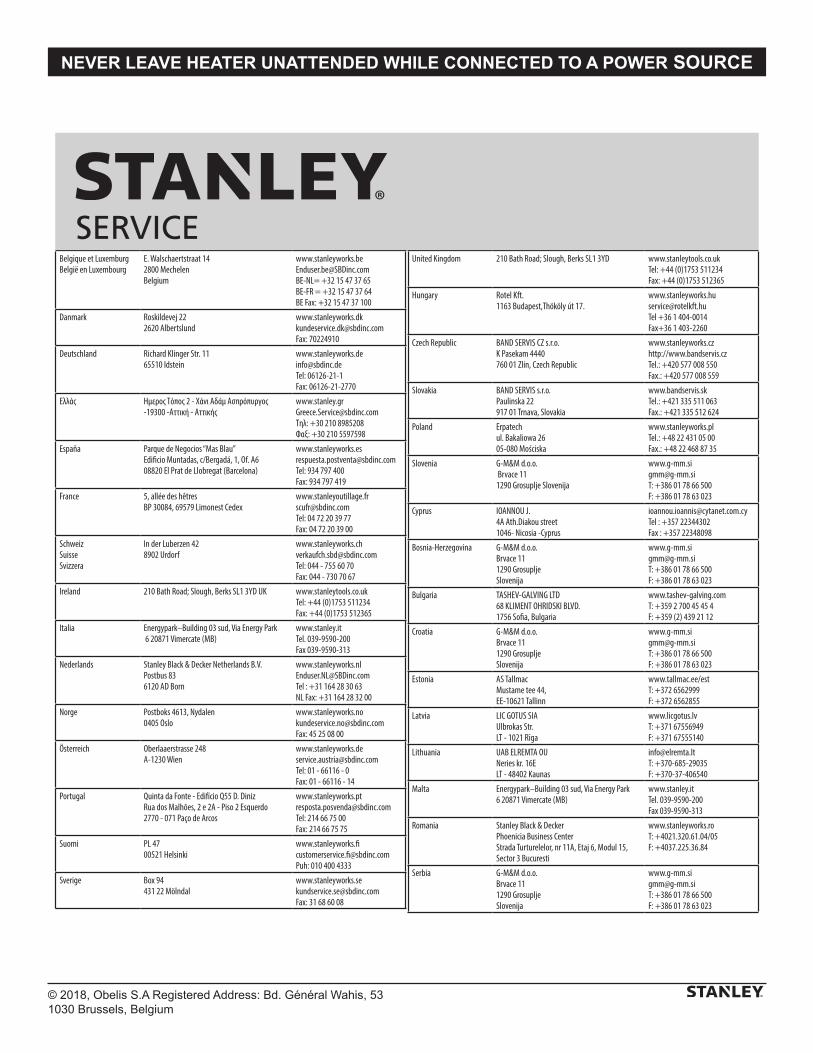
© 2018, Obelis S.A Registered Address: Bd. Général Wahis, 531030 Brussels, Belgium
NEVER LEAVE HEATER UNATTENDED WHILE CONNECTED TO A POWER SOURCE
Belgique et LuxemburgBelgië en Luxembourg
E. Walschaertstraat 14 2800 Mechelen Belgium
[email protected]= +32 15 47 37 65BE-FR = +32 15 47 37 64BE Fax: +32 15 47 37 100
Danmark Roskildevej 22 2620 Albertslund
[email protected]: 70224910
Deutschland Richard Klinger Str. 11 65510 Idstein
[email protected]: 06126-21-1Fax: 06126-21-2770
Ελλάς Hμερος Τόπος 2 - Χάνι Αδάμ Ασπρόπυργος -19300 -Αττική - Αττικής
[email protected]Τηλ: +30 210 8985208Φαξ: +30 210 5597598
España Parque de Negocios “Mas Blau” Edificio Muntadas, c/Bergadá, 1, Of. A6 08820 El Prat de Llobregat (Barcelona)
[email protected]: 934 797 400Fax: 934 797 419
France 5, allée des hêtres BP 30084, 69579 Limonest Cedex
[email protected]: 04 72 20 39 77Fax: 04 72 20 39 00
SchweizSuisse Svizzera
In der Luberzen 42 8902 Urdorf
[email protected]: 044 - 755 60 70Fax: 044 - 730 70 67
Ireland 210 Bath Road; Slough, Berks SL1 3YD UK www.stanleytools.co.ukTel: +44 (0)1753 511234Fax: +44 (0)1753 512365
Italia Energypark–Building 03 sud, Via Energy Park 6 20871 Vimercate (MB)
www.stanley.itTel. 039-9590-200Fax 039-9590-313
Nederlands Stanley Black & Decker Netherlands B.V. Postbus 83 6120 AD Born
[email protected] : +31 164 28 30 63NL Fax: +31 164 28 32 00
Norge Postboks 4613, Nydalen0405 Oslo
[email protected]: 45 25 08 00
Österreich Oberlaaerstrasse 248A-1230 Wien
[email protected]: 01 - 66116 - 0Fax: 01 - 66116 - 14
Portugal Quinta da Fonte - Edifício Q55 D. Diniz Rua dos Malhões, 2 e 2A - Piso 2 Esquerdo 2770 - 071 Paço de Arcos
[email protected]: 214 66 75 00Fax: 214 66 75 75
Suomi PL 47 00521 Helsinki
[email protected]: 010 400 4333
Sverige Box 94 431 22 Mölndal
[email protected]: 31 68 60 08
United Kingdom 210 Bath Road; Slough, Berks SL1 3YD www.stanleytools.co.ukTel: +44 (0)1753 511234Fax: +44 (0)1753 512365
Hungary Rotel Kft.1163 Budapest,Thököly út 17.
[email protected] +36 1 404-0014Fax+36 1 403-2260
Czech Republic BAND SERVIS CZ s.r.o. K Pasekam 4440 760 01 Zlín, Czech Republic
www.stanleyworks.czhttp://www.bandservis.czTel.: +420 577 008 550Fax.: +420 577 008 559
Slovakia BAND SERVIS s.r.o. Paulinska 22 917 01 Trnava, Slovakia
www.bandservis.skTel.: +421 335 511 063Fax.: +421 335 512 624
Poland Erpatech ul. Bakaliowa 26 05-080 Mościska
www.stanleyworks.plTel.: +48 22 431 05 00Fax.: +48 22 468 87 35
Slovenia G-M&M d.o.o. Brvace 11 1290 Grosuplje Slovenija
[email protected]: +386 01 78 66 500F: +386 01 78 63 023
Cyprus IOANNOU J. 4A Ath.Diakou street 1046- Nicosia -Cyprus
[email protected]Τel : +357 22344302Fax : +357 22348098
Bosnia-Herzegovina G-M&M d.o.o. Brvace 11 1290 Grosuplje Slovenija
[email protected]: +386 01 78 66 500F: +386 01 78 63 023
Bulgaria TASHEV-GALVING LTD 68 KLIMENT OHRIDSKI BLVD. 1756 Sofia, Bulgaria
www.tashev-galving.comT: +359 2 700 45 45 4F: +359 (2) 439 21 12
Croatia G-M&M d.o.o. Brvace 11 1290 Grosuplje Slovenija
[email protected]: +386 01 78 66 500F: +386 01 78 63 023
Estonia AS Tallmac Mustame tee 44, EE-10621 Tallinn
www.tallmac.ee/estT: +372 6562999F: +372 6562855
Latvia LIC GOTUS SIA Ulbrokas Str. LT - 1021 Rīga
www.licgotus.lvT: +371 67556949F: +371 67555140
Lithuania UAB ELREMTA OU Neries kr. 16E LT - 48402 Kaunas
[email protected]: +370-685-29035F: +370-37-406540
Malta Energypark–Building 03 sud, Via Energy Park 6 20871 Vimercate (MB)
www.stanley.itTel. 039-9590-200Fax 039-9590-313
Romania Stanley Black & Decker Phoenicia Business Center Strada Turturelelor, nr 11A, Etaj 6, Modul 15, Sector 3 Bucuresti
www.stanleyworks.roT: +4021.320.61.04/05F: +4037.225.36.84
Serbia G-M&M d.o.o. Brvace 11 1290 Grosuplje Slovenija
[email protected]: +386 01 78 66 500F: +386 01 78 63 023
SERVICE

Manufactured by:Pinnacle Climate Technologies, Inc.
Sauk Rapids, MN 56379 USA
EC REP
Obelis S.ARegistered Address:
Bd. Général Wahis, 53, 1030 Brussels, Belgium
© 2018 Stanley Black & Decker, Inc.