spinning series ring and traveller
TRANSCRIPT

Spinning Series
Ring and Traveller
R.Senthil Kumar,
Department of Textile Technology,
KCT, Coimbatore,

Content 1.Ring: • Significance of Ring • Forms Types and materials of Ring • Ring Life • Load on Ring and traveller
2.Traveller: • Task and Functions of Traveller • Traveller Classification • Traveller Mass • Choice of correct traveller selection • Traveller materials • Traveller speed and Yarn Count • Spinning Tension and Traveller • Prerequisite for smooth and stable running of traveller • Spinning Geometry w.r.t Ring and Traveller • Forces Acting on various types of Travellers (“C”, “J”) • Trouble shooting • Traveller Fly • Control of End breakage w.r.t Traveller • Traveller speed and performance.

Modern ring and traveller combination with good fibre lubrication enable
traveller speeds up to 40m/sec.

A good ring in operation should have
• best quality raw material
• good, but not too high, surface smoothness
• an even surface
• exact roundness
• good, even surface hardness, higher than that of the traveller
• should have been run in as per ring manufacturers requirement
• long operating life
• correct relationship between ring and bobbin tube diameters
• perfectly horizontal position
• it should be exactly centered relative to the spindle


The ring should be tough and hard on its exterior. The running surface must
have high and even hardness in the range 800-850 Vickers. The traveller
hardness should be lower (650-700 Vickers)

Ring life
The life of a spinning rings depends on the following factors:
• Type of fibre processed
• Yarn count (traveller weight)
• Spindle speed
• Traveller running time
• General conditions (centering of rings etc.)
With high traveller wear (burnt travellers) the ring lifetime is reduced. On
conventional rings, micro welding is damaging the running track and reduces
the ring life dramatically. A worn out ring surface influences the yarn quality,
specially the yarn hairiness.

Ring load
• During the spinning process there is always a high load on the ring running
track. The travellers centrifugal force (Fc) depends on the traveller weight (m),
the ring radius (r) and the traveller linear speed (v). The centrifugal force is
calculated with the following formula:
FC = (m x v2) / r Ring
• This leads to very high values, compared to the relatively small weight of a
traveller. The centrifugal force can reach a load which is up to 8'000 times the
traveller weight.
• These high loads create heat and leads stress to the ring surface. In order to
prevent premature wear on the running track when working under extremely
high loads or heavy conditions, it is recommended to use a ring treatment with
very high wear resistance

Load on ring and ring traveller
The lifetime of rings and travellers depends on two main parameters:
• raw material processed (lubrication potential) and
• the mechanical and thermal load on ring and traveller (speed, ring diameter,
traveller weight).
The centrifugal force increases in square in proportion to the traveller speed.
The traveller temperature in the contact area of traveller-ring increases in
cube in proportion to traveller speed (1).
0
100
200
300
400
500
600
700
800
900
1000
1100
1200
1300
1400
0
100
200
300
400
500
600
700
25 30 35 40 45 50
cen
trif
ug
al fo
rce
(cN
)
tem
per
atu
re (°
C)
traveller speed (m/s)
traveller centrifugal force traveller speed
traveller temperature (contact area) ring/ringtraveller lifetime


Traveller • In ring spinning, the energy to drive the twisting mechanism is derived from the
bobbin, but the level of twist is controlled by the traveler.
• Each revolution of the traveler inserts one turn of twist into the yarn.
• The mass of the traveler has to be balanced against the yarn linear density, and the so-called ‘traveler weight’ is an important factor in determining the yarn tension.
• The yarn tension, in turn, is an important factor in determining balloon size as well as the end-breakage rate.
• The bobbin rotates faster than the traveler and the trailing yarn drags the traveler behind it. The difference in speed causes the yarn to wind onto the constant speed bobbin.
• Travelers are shaped to accommodate the ring flanges and flowing yarn; they are normally made from small lengths of wire of a variety of cross-sections.


SHAPE OF THE TRAVELLER
• The traveller must be shaped to match exactly with the ring in the contact zone,
so that a single contact surface, with the maximum surface area is created
between ring and traveller.
• The bow of the traveller should be as flat as possible, in order to keep the
centre of gravity low and thereby improve smoothness of running.
• However the flat bow must still leave adequate space for passage of the yarn. If
the yarn clearance opening is too small, rubbing of the yarn on the ring leads to
roughening of the yarn, a high level of fibre loss as fly, deterioration of yarn
quality and formation of melt spots in spinning of synthetic fibre yarns.


Traveller Mass
Traveller mass determines the magnitude of frictional forces between the
traveller and the ring, and these in turn determine the winding and balloon
tension. Mass of the traveller depends upon
• yarn count
• yarn strength
• spindle speed
• material being spun
If traveller weight is too low, the bobbin becomes too soft and the cop
content will be low. If it is unduly high, yarn tension will go up and will
result in end breaks. If a choice is available between two traveller weights,
then the heavier is normally selected, since it will give greater cop weight,
smoother running of the traveller and better transfer of heat out of traveller.
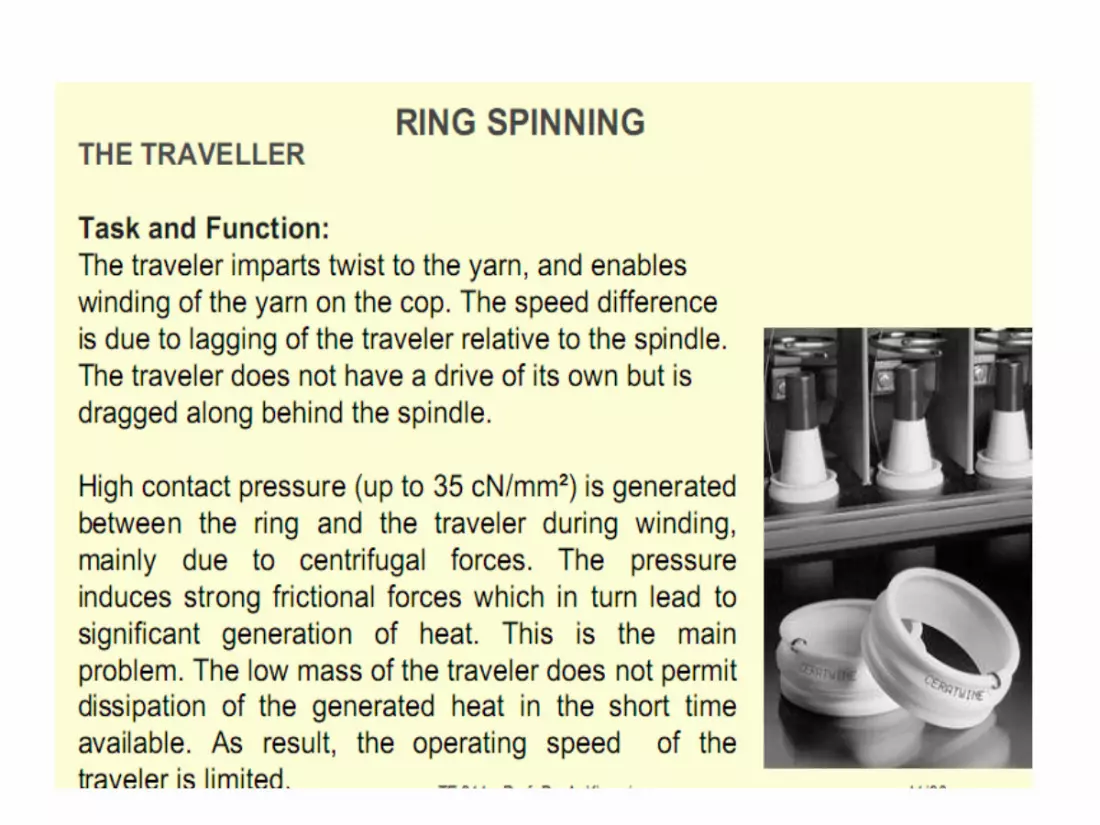
High contact pressure (up to 35 N/square mm)is generated between the ring
and the traveller during winding, mainly due to centrifugal force.

Choice of Correct Traveller Depends on
• Yarn Count
• Ring flange
• Type of ring
• Life of ring
• Material
• Spindle speed

MATERIAL OF THE TRAVELLER
The traveller should:
• generate as little heat as possible
• quickly distribute the generated heat from the area where it develops over
the whole volume of the traveller
• transfer this heat rapidly to the ring and the air
• be elastic, so that the traveller will not break as it is pushed on to the ring
• exhibit high wear resistance
• be less hard than the ring, because the traveller must wear out in use in
preference to the ring

WIRE PROFILE OF THE TRAVELLER
Wire profile influences both the behaviour of the traveller and certain yarn
characteristics, they are
• contact surface of the ring
• smooth running
• thermal transfer
• yarn clearance opening
• roughening effect
• hairiness

Traveller Speed and Yarn Count
15
25
35
45
20 30 40 50
m/s
Ne
When the spindle speed is
increased, the friction work between
ring and traveller (hence the build
up) increases as the 3rd power of
the spindle rpm.
If the traveller speed is raised beyond normal levels , the thermal stress limit of the
traveller is exceeded, a drastic change in the wear behaviour of the ring and traveller
ensues. Owing to the strongly increased adhesion forces between ring and traveller,
welding takes place between the two. These seizures inflict massive damage not
only to the traveller but to the ring as well.

Spinning tension and Traveller
The spinning tension is proportional
• to the friction coefficient between ring and traveller
• to the traveller mass
• to the square of the traveler speed
and inversely proportional
• to the ring diameter
• and the angle between the connecting line from the traveller-spindle axis to
the piece of yarn between the traveller and cop.

TRAVELLER SELECTION FOR COTTON :

TRAVELLER SELECTION FOR SYNTHETICS

PREREQUISITES FOR SMOOTH AND STABLE
RUNNING
• Faultless condition of the support and guide of the
ring rail as well as a steady & smooth traverse
motion. Concentric position of the ring and spindle
as well as anti ballooning ring and yarn guide.
• Spindle rotation without vibration and correct
concentricity of bobbin tube. Ring with exact
roundness and firm seating in horizontal position.
• Correct setting of the Traveller clearer. Space “a” should be 0.2 to 0.3 mm.
• Favorable ratio of ring diameter to Tube diameter.
• Recommended ratio : D : d = 2 : 1 (Ring diameter : D, Tube diameter : d)
• Faultless condition of ring race way

SPINNING GEOMETRY WITH RESPECT
TO RING AND TRAVELLER
Ratio of ring diameter D to tube diameter d
Ideal ratio 2 : 1 The ring Traveller, together with the
yarn as a pull element, is set into motion on the ring by the rotation of the spindle. If the direction of pull deviates too much from the running direction of the Traveller (alpha 0 less than 30 ), the tension load will be too high.
The pulling tension can be reduced by adapting the ring or tube diameter (alpha greater 0 than 30 ), during the winding up on the tube (after doffing, resp. At the top of the conical part of the bobbin).

Ratio of tube length to ring diameter
Ideal ratio 5 : 1
• The tube length determines (with the yarn guide) the maximum balloon
length. This is an important factor for the performance of a ring spinning
machine.
• The shorter the balloon, higher T r a v e l l e r speeds can be achieved.
• In practical use, the ideal ratio of tube length to ring diameter has been
shown to be between 4.5:1 and 5:1.

Forces Acting on Rings - C shaped Travellers
Forces acting on the Traveller (1) in the plane of
the ring are as follows
1. Tangential Force Ff
• This force arises due to the winding tension of
the yarn and always acts tangentially to the
circumference of the cop.
2. Frictional force F
• This force acts between the ring and the
Traveller. In the stationary state i.e. At constant
Traveller speed, the frictional force F is in
equilibrium with the forward component Ft

Forces Acting on Rings - C shaped Travellers
3. Force Fn
This force acts normal to the surface of the ring This force arises due to the
force exerted by the Traveller on the ring.
4. Centrifugal Force FZ


Trouble Shooting

Trouble Shooting

Check points for Controlling End breakage rate
1.Spinning Geometry
• Spinning Geometry plays a vital role in End Breaks and which is directly related with spinning Tension and spinning triangle.
• Perfect spinning Geometry with respect to Material, Count, Speed etc., will help us to achieve the lesser End Breaks.
• Ratio of ring Diameter (D) to tube diameter (d) should be 2:1
• 5:1 would be an ideal ratio in between Tube length to ring diameter.
• The spinning Triangle should be optimum.
2. Disturbances in Traveller Movement
• Improper Ring Race Way: Smoothness of ring race way is a critical factor, which is main limiting factor when you go for higher speeds. Traveller lag will be more when the race way is having pitting marks, rust or damages. End breaks have a direct co-relation on traveller lag. More the traveller lag more is the end breaks.
• Traveller lag is the difference between the spindle speed and traveller speed.
• Smoothening the Ring Race way can be done by doing Short Running in.
• Changing the damaged rings will help to reduce the end breaks.

Traveller fly Traveller fly can occur due to the following reasons 1. Reduced flange width of the ring 2. If Ring Traveller used is too light a. Ring Traveller contact area is close to the toe portion of the traveller. Hence
traveller fly occurs. b. Improper weight to the spinning tension. 3. Ring Traveller contact area is very small (Point Contact). This leads to extreme
wear out and finally the traveller breaks and flies. 4. If the setting between Traveller clearer and Traveller is too close, the traveller
will hit the clearer & fly. a. Traveller clearer setting should be 0.2 to 0.3 mm between Traveller-to- Traveller
Clearer. 5. Cop content is more than recommended 6. Lesser winding length results in faster movement of ring rails. Hence there is a
chance of Traveller fly. a. Increase the winding length with respect to count and spindle speed. 7. If the Center of gravity is higher for the required speed, there is a chance that
Traveller has an unstable running. It leads to traveller fly. a. Hence go for a low bow height traveller.


Yarn Count and Traveller