speedy 14”–56” - prom.st
TRANSCRIPT
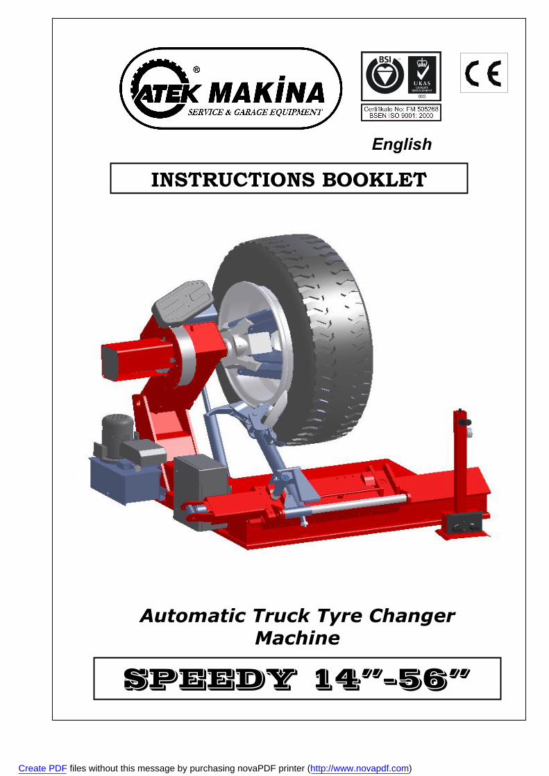
English
INSTRUCTIONS BOOKLET
Automatic Truck Tyre Changer Machine
SPEEDY 14”–56”
Create PDF files without this message by purchasing novaPDF printer (http://www.novapdf.com)
2
WARNINGS
- The presents instructions booklet is an integral part of the product.Carefully study the warnings and instructions contained in it.This information is important for safe use and maintenance.
- Conserve this booklet carefully for further consultation.
SPEEDY 14”-56” Is a tyre changing machine designed and constructed to be used for mounting and demounting tyres on the
whell rims of trucks and light industrial vehicles.
The machine has been designed to operate within the limits described in this booklet and in accordance with the maker’s instructions.
The machine must be used only for the functions for which it was expressly designed.Any other use is considered wrong and therefore unacceptable.
The maker cannot be held responsible for eventual damage casued by improper,erroneous or unacceptable use.
IMPORTANT
SPEEDY may be operated only by suitably trained personnel.Any work on the electrical , hydraulic , pneumatic systems must be conducted only by profesionally qualified personnel.
CONTENTS
PAGE
1 - General Warnings.......................................................................... 2 2 - Technical Characteristics............................................................... 2 3 - Parts Of The Machine...................................................................... 3 4 - Acessory Provided , Movement , Unpacking.................................. 4 5 - Electrical Connection..................................................................... 5 6 - Tubeless and Supersingle Tyres.................................................... 6 7 - Agricultural Tyres........................................................................... 7 8 - Problems , Causes , Remedies..................................................... 8 9 - Demontage Plan............................................................................ 9 10 – Spare Parts List.............................................................................. 12
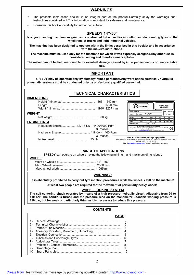
DIMENSIONS Height (min./max.)........................................ 866 - 1540 mm Length .......................................................... 1720 mm Widht (min./max.)......................................... 1910 -2257 mm
WEIGHT Net weight........................................................ 800 kg
ENGINE DATA Reduction Engine .................1.3/1.8 Kw – 1400/3000 Rpm 3 Phases Hydraulic Engine ................................... 1.5 Kw – 1400 Rpm 3 Phases Noise Level ........................................... 75 db
TECHNICAL CHARACTERISTICS
RANGE OF APPLICATIONS SPEEDY can operate on wheels having the following minimum and maximum dimensions :
WHEEL Work on wheels of............................................. 14” – 56” Max. Wheel diameter......................................... 2300 mm Max. Wheel width.............................................. 1065 mm
WARNING !
It is absolutely prohibited to carry out tyre inflation procedures while the wheel is still on the machine!
At least two people are required for the movement of particularly heavy wheels!
WHEEL LOCKING SYSTEM The self-centering chuck operates by means of a high pressure hydraulic circuit adjustable from 20 to 110 bar. The handle is turned and the pressure read on the manometer. Standart working pressure is 110 bar, but for weak or particularly thin rim it is necessary to reduce this pressure.
ATEK MAKİNA Service & Garage Equipments Esenyurt Mah. Cakmaklı Cad. Hadimkoy Asfalti No:14Kirac – Esenyurt – IST / TR
Tel/Fax : +90 212 444 21 31 http // www.atekmakina.com e-mail: [email protected]
SERIAL NUMBER
WEIGHT 33 00 000 PRODUCTION YEAR
ENGINE KW VOLT HZ RPM
HYDRAULIC 1.5 380 50 1400
START 1.3 / 1.8 380 50 1400 / 2800
CONTROL UNIT 380 V - 24 DC
RIM CAPACTY
14” – 56”
TRUCK TYRE CHANGER
ATEK MAKİNA Service & Garage Equipments Esenyurt Mah. Cakmaklı Cad. Hadimkoy Asfalti No:14Kirac – Esenyurt – IST / TR Tel/Fax : +90 212 444 21 31
http // www.atekmakina.com e-mail: [email protected]
Create PDF files without this message by purchasing novaPDF printer (http://www.novapdf.com)
3
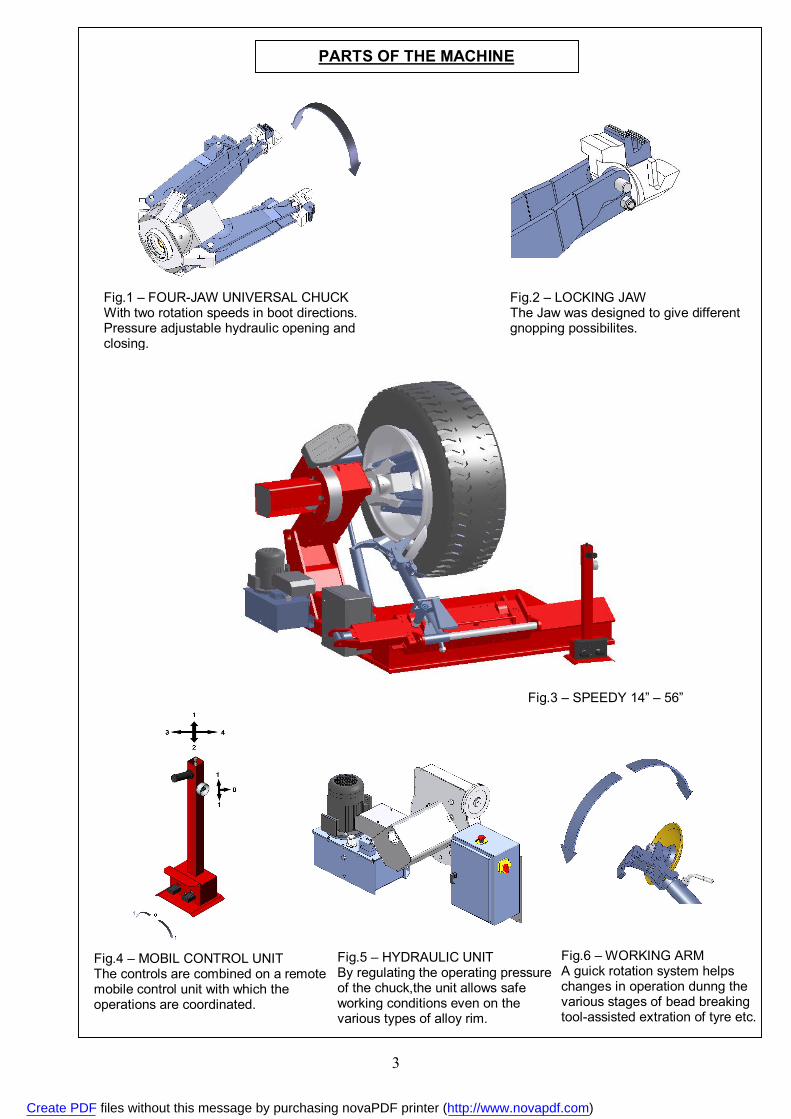
PARTS OF THE MACHINE
Fig.1 – FOUR-JAW UNIVERSAL CHUCK With two rotation speeds in boot directions. Pressure adjustable hydraulic opening and closing.
Fig.2 – LOCKING JAW The Jaw was designed to give different gnopping possibilites.
Fig.3 – SPEEDY 14” – 56”
Fig.4 – MOBIL CONTROL UNIT The controls are combined on a remote mobile control unit with which the operations are coordinated.
Fig.5 – HYDRAULIC UNIT By regulating the operating pressure of the chuck,the unit allows safe working conditions even on the various types of alloy rim.
Fig.6 – WORKING ARM A guick rotation system helps changes in operation dunng the various stages of bead breaking tool-assisted extration of tyre etc.
Create PDF files without this message by purchasing novaPDF printer (http://www.novapdf.com)
4
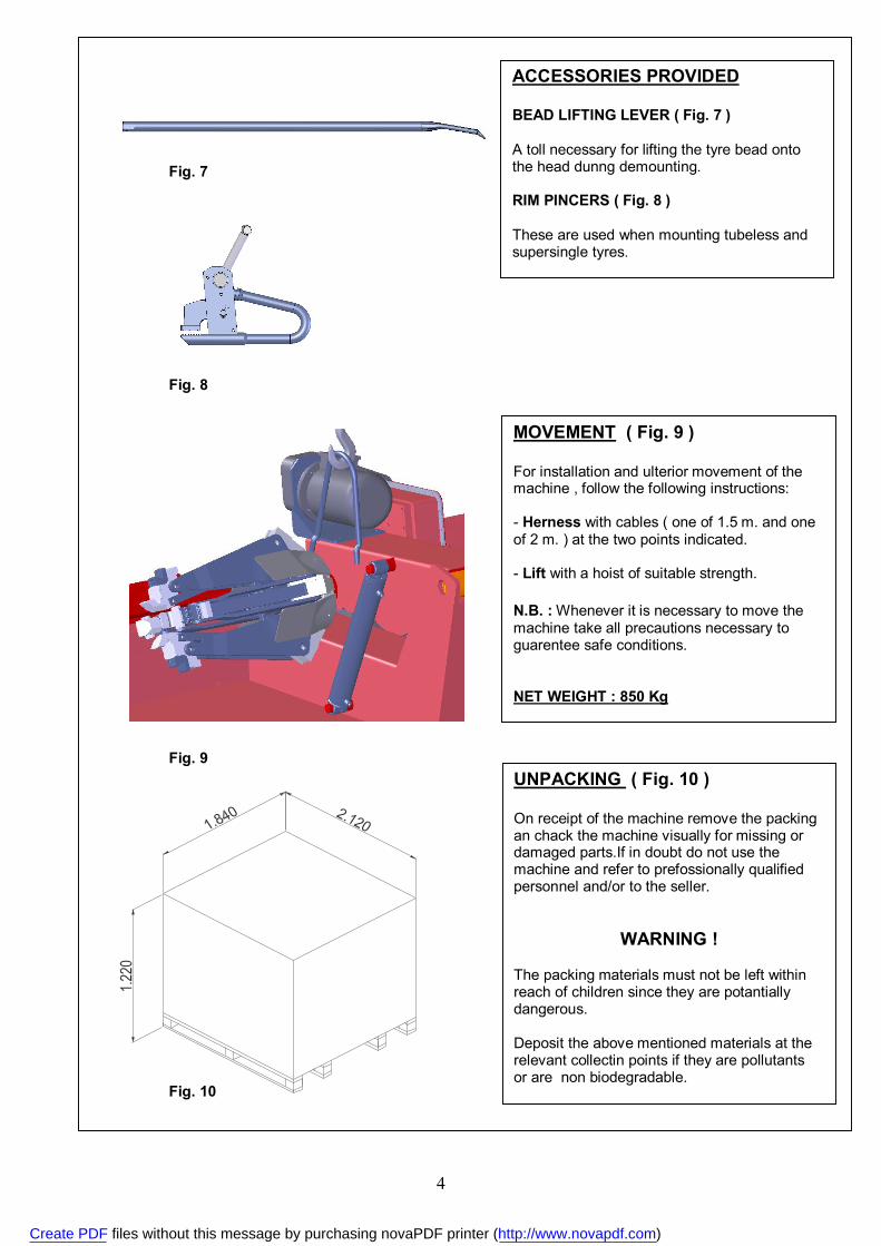
Fig. 7
Fig. 8
ACCESSORIES PROVIDED BEAD LIFTING LEVER ( Fig. 7 ) A toll necessary for lifting the tyre bead onto the head dunng demounting. RIM PINCERS ( Fig. 8 ) These are used when mounting tubeless and supersingle tyres.
MOVEMENT ( Fig. 9 ) For installation and ulterior movement of the machine , follow the following instructions: - Herness with cables ( one of 1.5 m. and one of 2 m. ) at the two points indicated. - Lift with a hoist of suitable strength. N.B. : Whenever it is necessary to move the machine take all precautions necessary to guarentee safe conditions. NET WEIGHT : 850 Kg
Fig. 9
Fig. 10
UNPACKING ( Fig. 10 ) On receipt of the machine remove the packing an chack the machine visually for missing or damaged parts.If in doubt do not use the machine and refer to prefossionally qualified personnel and/or to the seller.
WARNING ! The packing materials must not be left within reach of children since they are potantially dangerous. Deposit the above mentioned materials at the relevant collectin points if they are pollutants or are non biodegradable.
Create PDF files without this message by purchasing novaPDF printer (http://www.novapdf.com)
5
ALL WORK ON THE ELECTRICAL
SYSTEM , INCLUDING MINOR OPERATIONS,
MUST BE CARRIED OUT BY PROFESSIONALLY
QUALIFIED PERSONNEL
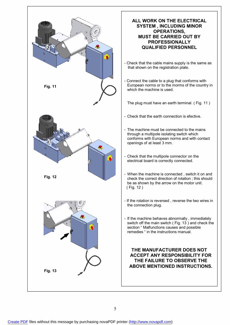
- Check that the cable mains supply is the same as that shown on the registration plate.
- Connect the cable to a plug that conforms with
European norms or to the morms of the country in which the machine is used.
The plug must have an earth terminal. ( Fig. 11 ) - Check that the earth connection is efective. - The machine must be connected to the mains
through a multipole isolating switch which conforms with European norms and with contact openings of at least 3 mm.
- Check that the multipole connector on the
electrical board is correctly connected. - When the machine is connected , switch it on and
check the correct direction of rotation ; this should be as shown by the arrow on the motor unit.
( Fig. 12 ) - If the rotation is reversed , reverse the two wires in
the connection plug. - If the machine behaves abnormally , immediately
switch off the main switch ( Fig. 13 ) and check the section “ Malfunctions causes and possible remedies “ in the instructions manual.
THE MANUFACTURER DOES NOT ACCEPT ANY RESPONSIBILITY FOR
THE FAILURE TO OBSERVE THE ABOVE MENTIONED INSTRUCTIONS.
Fig. 11
Fig. 12
Fig. 13
Create PDF files without this message by purchasing novaPDF printer (http://www.novapdf.com)
6
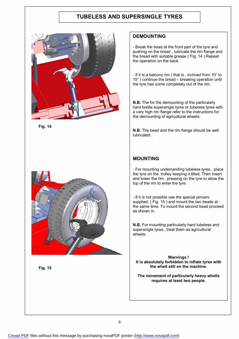
DEMOUNTING - Break the bead at the front part of the tyre and pushing on the bread , lubricate the rim flange and the bread with suitable grease ( Fig. 14 ).Repeat the operation on the back. - If it is a balcony rim ( that is , inclined from 10” to 15” ) continue the bread – breaking operation until the tyre has come completely out of the rim. N.B. The for the demounting of the particularly hard textile supersingle tyres or tubeless tyres with a very high rim flange refer to the instructions for the demounting of agricultural wheels. N.B. The bead and the rim flange should be well lubricated . MOUNTING - For mounting undemanding tubeless tyres , place the tyre on the trolley keeping it tilted. Then insert and lower the rim , pressing on the tyre to allow the top of the rim to enter the tyre. - If it is not possible use the special pincers supplied. ( Fig. 15 ) and mount the two beads at the same time. To mount the second bead proceed as shown in. N.B. For mounting particularly hard tubeless and supersingle tyres , treat them as agricultural wheels.
Warnings ! It is absolutely forbidden to inflate tyres with
the whell still on the machine.
The movement of particularly heavy whells requires at least two people.
TUBELESS AND SUPERSINGLE TYRES
Fig. 14
Fig. 15
Create PDF files without this message by purchasing novaPDF printer (http://www.novapdf.com)
7
AGRICULTURAL TYRES
DEMOUNTING
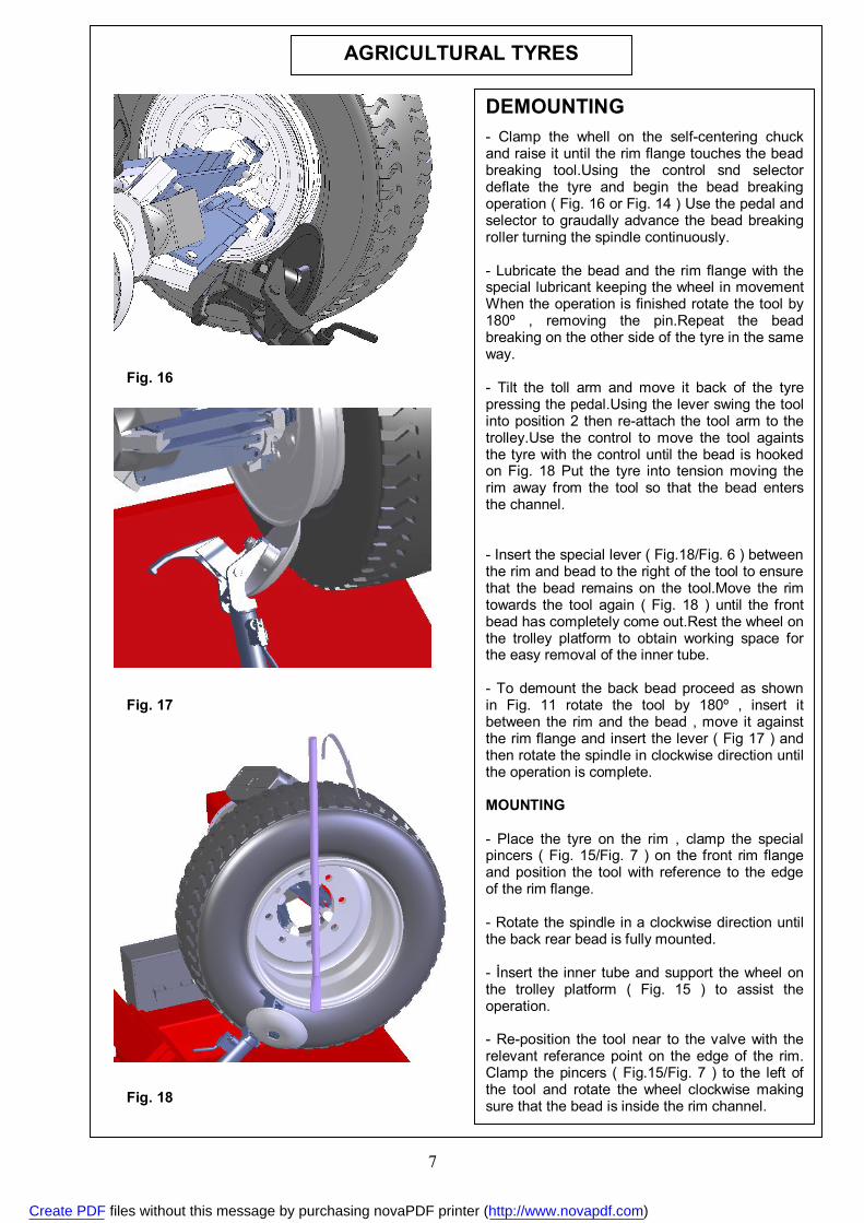
- Clamp the whell on the self-centering chuck and raise it until the rim flange touches the bead breaking tool.Using the control snd selector deflate the tyre and begin the bead breaking operation ( Fig. 16 or Fig. 14 ) Use the pedal and selector to graudally advance the bead breaking roller turning the spindle continuously. - Lubricate the bead and the rim flange with the special lubricant keeping the wheel in movement When the operation is finished rotate the tool by 180º , removing the pin.Repeat the bead breaking on the other side of the tyre in the same way. - Tilt the toll arm and move it back of the tyre pressing the pedal.Using the lever swing the tool into position 2 then re-attach the tool arm to the trolley.Use the control to move the tool againts the tyre with the control until the bead is hooked on Fig. 18 Put the tyre into tension moving the rim away from the tool so that the bead enters the channel. - Insert the special lever ( Fig.18/Fig. 6 ) between the rim and bead to the right of the tool to ensure that the bead remains on the tool.Move the rim towards the tool again ( Fig. 18 ) until the front bead has completely come out.Rest the wheel on the trolley platform to obtain working space for the easy removal of the inner tube. - To demount the back bead proceed as shown in Fig. 11 rotate the tool by 180º , insert it between the rim and the bead , move it against the rim flange and insert the lever ( Fig 17 ) and then rotate the spindle in clockwise direction until the operation is complete. MOUNTING - Place the tyre on the rim , clamp the special pincers ( Fig. 15/Fig. 7 ) on the front rim flange and position the tool with reference to the edge of the rim flange. - Rotate the spindle in a clockwise direction until the back rear bead is fully mounted. - İnsert the inner tube and support the wheel on the trolley platform ( Fig. 15 ) to assist the operation. - Re-position the tool near to the valve with the relevant referance point on the edge of the rim. Clamp the pincers ( Fig.15/Fig. 7 ) to the left of the tool and rotate the wheel clockwise making sure that the bead is inside the rim channel.
Fig. 18
Fig. 17
Fig. 16
Create PDF files without this message by purchasing novaPDF printer (http://www.novapdf.com)
8
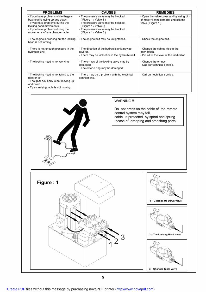
PROBLEMS CAUSES REMEDIES - If you have problems while thegear box head is going up and down. - If you have problems during the locking head movements. - If you have problems during the movements of tyre changer table.
- The pressure valve may be blocked. ( Figure 1 / Valve 1 ) - The pressure valve may be blocked. ( Figure 1 / Valve2 ) - The pressure valve may be blocked. ( Figure 1 / Valve 3 )
- Open the valve cover and by using pim of max 5 mm diameter unblock the valve.( Figure 1 )
- The engine is working but the locking head is not turning.
- The engine belt may be untightened.
- Check the engine belt.
- There is not enough pressure in the hydraulic unit
- The direction of the hydraulic unit may be reverse. - There may be lack of oil in the hydraulic unit.
- Change the cables vice in the connection. - Put oil till the level of the insdicator.
- The locking head is not working.
- The o-rings of the locking valve may be damaged. - The enter o-ring may be damaged.
- Change the o-rings. - Call our technical service.
- The locking head is not turnig to the right or left - The gear box body is not moving up and down. - Tyre carriying table is not moving.
- There may be a problem with the electrical connections.
- Call our technical service.
Figure : 1
1 – Gearbox Up Down Valve
2 – The Locking Head Valve
3 – Changer Table Valve
WARNING !! Do not press on the cable of the remote control system may fall, cable ıs protected by spıral and sprıng ıncase of droppıng and smashıng parts
Create PDF files without this message by purchasing novaPDF printer (http://www.novapdf.com)
9
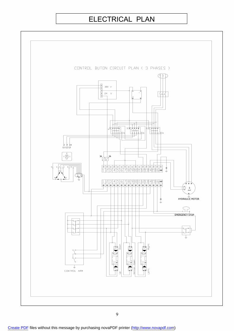
ELECTRICAL PLAN
3
U
W
11 6
V
1 8 13
3A
142 5L3
1
0
L1 L2
2 3A
EMERGENCY STOP
HYDRAULIC MOTOR
MP
MP
Create PDF files without this message by purchasing novaPDF printer (http://www.novapdf.com)
10
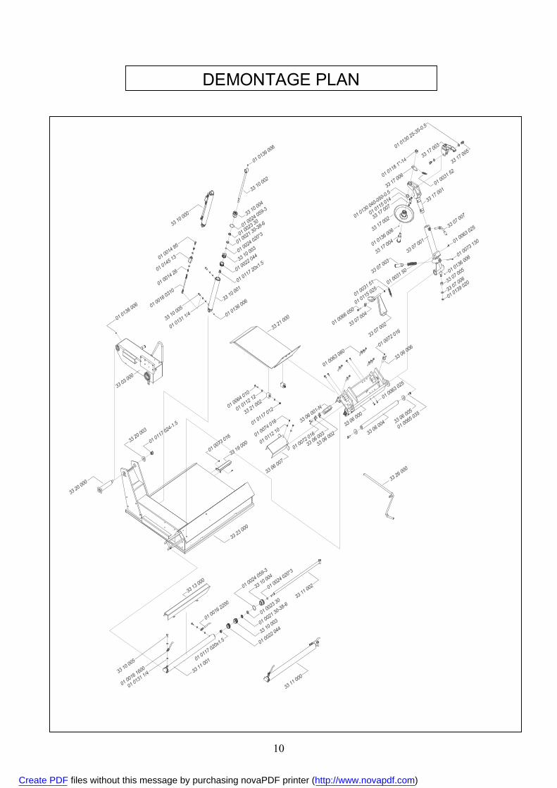
DEMONTAGE PLAN
Create PDF files without this message by purchasing novaPDF printer (http://www.novapdf.com)
11
Create PDF files without this message by purchasing novaPDF printer (http://www.novapdf.com)
12
Create PDF files without this message by purchasing novaPDF printer (http://www.novapdf.com)

13
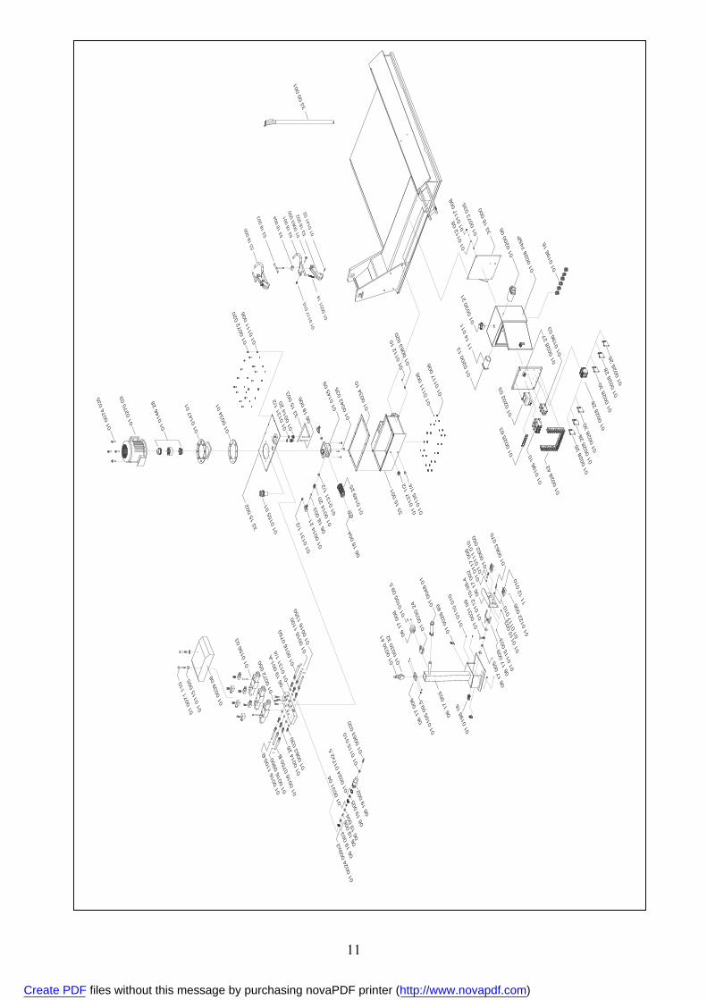
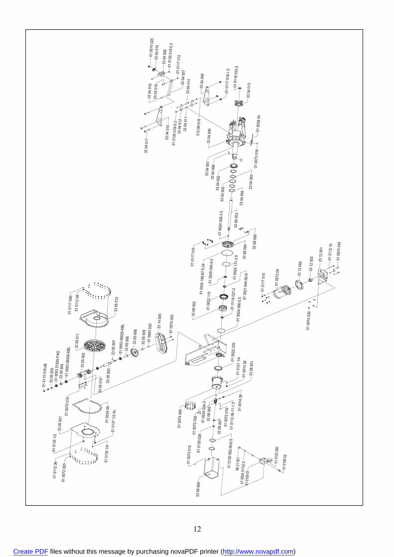
SPARE PARTS LIST FOR SPEEDY ITEM NO ITEM/CODE NUMBER DESCRIPTION
1 33 23 000 BOTTOM BODY GROUP 2 33 20 000 REDUCTION CONNECTION MILE 3 33 20 003 WASHER 4 01 0117 024-1.5 FIBER NUT 5 33 03 000 REDUCTION BODY GROUP 6 01 0136 006 GREASE FITTING 7 33 19 000 RAMP PROFILE GROUP 8 01 0073 016 CYLINDER HEAD SCREW 9 33 13 000 SLIDE SHEET GROUP 10 33 11 000 SLIDE PISTON GROUP 11 33 11 001 CYLINDER GROUP 12 01 0016 1600 SLIDE FRONT HOSE 13 01 0131 1/4 WASHER 14 01 0117 020x1.5 FIBER NUT 15 01 0016 2200 SLIDE BACK HOSE 16 01 0022 044 COMPACT SET 17 33 10 003 TYRE HEAD 18 01 0021 30-38-6 NUTRING 19 01 0023 30 FELT 20 01 0024 059-3 O-RING 21 33 10 004 FRONT COVER 22 01 0024 020x3 O-RING 23 33 11 002 PISTON GROUP 24 33 06 000 SLIDE GROUP 25 33 06 001-N SLIDE RAIL LAMA 26 33 06 002 FELT 27 33 06 003 FELT PRESS TO SHEET 28 01 0072 016 CYLINDER HEAD SCREW 29 33 06 004 SLIDE MILE 30 33 06 005 WASHER 31 01 0065 035 SCREW 32 01 0063 025 SCREW 33 01 0063 080 SCREW 34 33 06 006 SILDE PISTIN GROUP 35 33 06 007 PISTON PROTECTION GROUP 36 01 0112 10 WASHER 37 01 0074 016 CYLINDER HEAD SCREW 38 33 21 000 RAMP GROUP 39 01 0064 010 SCREW 40 01 0112 12 WASHER 41 33 21 002 TYRE 42 01 0117 012 FIBER NUT 43 33 10 000 HEAD UP PISTON GROUP 44 33 10 001 CYLINDER GROUP 45 01 0117 20x1.5 FIBER NUT 46 33 10 003 TYRE HEAD 47 33 10 004 FRONT COVER 48 33 10 002 PISTON GROUP 49 33 10 005 CONNECTION RECORD 50 01 0016 0310 LOCK VALF HOSE 51 01 0014 26 RECORD 52 01 0145 13 LOCK VALF 53 01 0014 95 HOSE RECORD 54 33 07 001 CHANGER GROUP 55 33 07 003 BEEHIVE PISTON GROUP 56 33 07 007 CONNECTION MILE GROUP 57 33 07 005 PULLEY 58 33 07 006 PULLEY WASHER 59 33 07 002 PEDAL GROUP 60 33 07 004 MILE TO SET 61 01 0066 050 SCREW 62 01 0115 025 NUT 63 01 0031 51 PEDAL ARCH 64 01 0031 50 BEEHIVE ARCH 65 01 0073 130 SCREW 66 01 0139 020 MILE SEGMENT 67 33 17 001 BODY GROUP 68 33 17 002 FLANGE GROUP 69 33 17 003 GROUP TO PULL 70 33 17 004 CENTRE MILE 71 33 17 005 CONNECTION MILES 72 01 0031 52 ARCH TO PULL 73 01 0130 25-35-0.5 WASHER 74 33 17 006 ARCH CONNECTION SHEET 75 01 0118 1”-1/4 NUT
Create PDF files without this message by purchasing novaPDF printer (http://www.novapdf.com)

14
SPARE PARTS LIST FOR SPEEDY ITEM NO ITEM / CODE NUMBER DESCRIPTION
76 01 0130 040-050-0.5 WASHER 77 33 15 001 OIL GROUP 78 01 0137 1/2 LEVEL INDICATOR 79 01 0135 1/4 STOPPER 80 01 0111 006 WASHER 81 01 0117 006 FIBER NUT 82 01 0112 10 WASHER 83 01 0063 020 SCREW 84 01 0034 10 DEPOT CLOSURE 85 01 0042 035 CYLINDER HEAD SCREW 86 01 0145 09 PUMP 87 06 18 004 FILTER RECORD 88 01 0149 25 FILTER 89 01 0131 1/2 WASHER 90 01 0014 20 RECORD 91 06 18 003 FILTER CONNECTION HOSE 92 01 0014 21 RECORD 93 06 18 006 DEPOT PIPE 94 33 15 003 PUMP PIPE 95 01 0072 020 CYLINDER HEAD SCREW 96 01 0155 01 DEPOT COVER 97 33 15 002 CAULDRON COVER 98 01 0034 01 ENGINE CLOSURE 99 01 0147 01 BELL 100 01 0146 28 HYDRAULIC PUMP CLUTCH 101 01 0270 02 ENGINE 102 01 0074 35 CYLINDER HEAD SCREW 103 06 19 001-A OIL WEDGE 104 01 0072 050 CYLINDER HEAD SCREW 105 01 0016 0750 HOSE 106 01 0016 1100 HOSE 107 01 0016 1350 HOSE 108 01 0156 03 VALF 109 01 0039 08 VALF CONNECTION COVER 110 01 0115 005 WASHER 111 01 0071 110 CYLINDER HEAD SCREW 112 01 0016 110-B HOSE 113 01 0016 0900 HOSE 114 01 0016 0750-B HOSE 115 01 0063 030 CYLINDER HEAD SCREW 116 06 19 002 PRESSURE SCREW 117 01 0115 010 NUT 118 06 19 005 PASSING FITTING 119 01 0024 017x2.5 O-RING 120 01 0031 04 ARCH 121 06 19 003 ARCH UP HAT 122 06 19 004 ARCH DOWN HAT 123 06 19 006 PRESSURE MILE 124 01 0024 009x2 O-RING 125 06 17 003 BODY PROFILE 126 06 17 006 PROFILE COVER 127 01 0030 41 SWITCH 128 01 0030 32 CONTACT 129 06 17 008 SWITCH PROTECTION 130 01 0105 09.5 SHEET METAL SCREW 131 01 0030 24 BUTON 132 01 0048 01 HANDLE 133 01 0198 16 RECORD (PLASTIC) 134 01 0028 89 SWITCH 135 01 0110 10 SCREW 136 06 17 005 SUPPORT BEEHIVE 137 01 0031 09 ARCH 138 06 17 009 CONTROL PEDAL GROUP 139 01 0112 10-38-4 WASHER 140 01 0115 003 NUT 141 06 17 002 COVER 142 01 0110 003 SCREW 143 01 0062 050 SCREW 144 01 0122 006 SET SCREW 145 11 12 010 PEDAL 146 01 0063 070 SCREW 147 33 00 001 LEVER 148 01 0112 08 WASHER 149 33 16 000 CONTROL CONNECTION BODYS 150 11 14 011 POWER SWITCH PROTECTION
Create PDF files without this message by purchasing novaPDF printer (http://www.novapdf.com)

15
SPARE PARTS LIST FOR SPEEDY ITEM NO ITEM / CODE NUMBER DESCRIPTION
151 01 0200 13 POWER SWITCH 152 01 0030 21 EMERGENCY BUTTON 153 01 0200 06 POWER SWITCH 154 01 0028 74SP ELECTRICAL PANEL 155 01 0198 16 RECORD (PLASTIC) 156 01 0202 03 TRANSFORMER 157 01 0028 27 BRIDGE 158 01 0196 03 CONTACT 159 01 0028 63 RAIL 160 01 0196 10 CONTACT 161 01 0028 42 CABLE CANEL 162 01 0028 26 KLEMENS STOP 163 01 0028 28 KLEMENS GROUND 164 01 0028 30 KLEMENS 165 53 18 000 GROUP TO PRESS 166 53 18 001 BODY GROUP 167 53 18 002 PRESS GROUP 168 53 18 003 PRESS ARM 169 53 18 004 PRESS ARM CONNECTION MILE 170 01 0031 54 PRESS ARCH 171 01 0139 010 SEGMENT 172 01 0141 11 PIN 173 33 08 001 BODY GROUP 174 01 0074 065 CYLINDER HEAD SCREW 175 01 0024 024-3 O-RING 176 33 08 005 LOCK VALF BEEHIVE 177 38 08 007 LOCK VALF WASHER 178 01 0112 06-11-1.5 WASHER 179 01 0139 028 SEGMENT 180 01 0130 062-50-0.5 WASHER 181 01 0073 012 CYLINDER HEAD SCREW 182 33 09 000 CYLINDER CABIN 183 06 21 001 PRESSURE SCREW 184 01 0024 017x2.5 O-RING 185 01 0159 01 LOCK VALF 186 01 0150 250 PRESSURE CLOCK 187 01 0159 02 LOCK VALF KITE 188 01 0024 230 O-RING 189 01 0024 080-5.5 O-RING 190 01 0116 027-2 NUT 191 01 0021 040-050-8 NUTRING 192 01 0272 04 ENGINE 193 33 12 002 ENGINE WASHER 194 33 12 003 ENGINE PULLEY 195 33 12 001 ENGINE CONNECTION GROUP 196 33 08 002 TYRE HEAD 197 01 0022 115 COMPACT SET 198 01 0245 040-9.5 FELT 199 01 0024 189.87-5.34 O-RING 200 01 0024 131-3.5 O-RING 201 33 08 004 CYLINDER COVER 202 33 08 006 DAGGER GROUP 203 01 0024 028-3.5 O-RING 204 33 08 003 PISTON 205 33 04 004 WASHER 206 33 04 003 WASHER 207 33 04 005 FELT TO UNLEAK 208 33 04 002 SUPPORT BRACELET 209 33 04 006 DAGGER 210 33 04 001 MIRROR GROUP 211 33 04 000 MIRROR CYLINDER GROUP 212 01 0073 016 CYLINDER GROUP 213 01 0039 54 PROTECTION 214 33 04 013 CROSS 215 01 0116 033-2 NUT 216 01 0117 018-1.5 FIBER NUT 217 33 04 009 LENGTHENING ARM GROUP 218 01 0198 018 SEGMENT 219 33 04 014 ARM CONNECTION PIN 220 33 04 011 DISTANCE BEEHIVE 221 33 04 012 DISTANCE LENGTHENING MILE 222 33 04 010 LENGTHENING ARM GROUP 223 33 04 017 SCREW 224 33 04 007 PRESS TO LAMA 225 33 04 019 SCREW 226 33 04 016 CONNECTION MILE
Create PDF files without this message by purchasing novaPDF printer (http://www.novapdf.com)

16
SPARE PARTS LIST FOR SPEEDY ITEM NO ITEM / CODE NUMBER DESCRIPTION
227 01 0130 018-0.3 WASHER 228 33 04 008 FOOT TO PRESS 229 33 04 015 PRESS TO NAIL 230 01 0074 020 CYLINDER HEAD SCREW 231 33 14 000 PULLEY PROTECTION 232 01 0063 030 SCREW 233 33 05 009 BIG PULLEY WASHER 234 33 05 008 BIG PULLEY 235 33 05 006 PULLEY SUPPORT BEEHIVE 236 01 0053 06025-KBL BEARING 237 33 05 007 DAGGER 238 33 05 003 SCREW RESPONSE MILE 239 33 05 002 SOLE CONNECTION LAMA 240 33 05 004 BEARING SUPPORT WASHER 241 01 0053 51205-FAG BEARING 242 33 05 005 BEARING BACK SUPPORT WASHER 243 01 0115 016-08 NUT 244 33 05 011 SCREW RESPONSE TOOT HED 245 33 05 012 REDUCTION BODY COVER 246 01 0072 010 CYLINDER HEAD SCREW 247 01 0034 09 REDUCTION CLOSURE 248 33 05 001 REDUCTION CABIN GROUP 249 01 0135 1/2 STOPPER 250 01 0137 1/2 AL LEVEL INDICATOR 251 01 0112 06 WASHER 252 33 26 000 TRACTOR LEVER GROUP 253 33 17 007 SET DISTANCE SCREW 254 01 0115 014 NUT
Create PDF files without this message by purchasing novaPDF printer (http://www.novapdf.com)
17
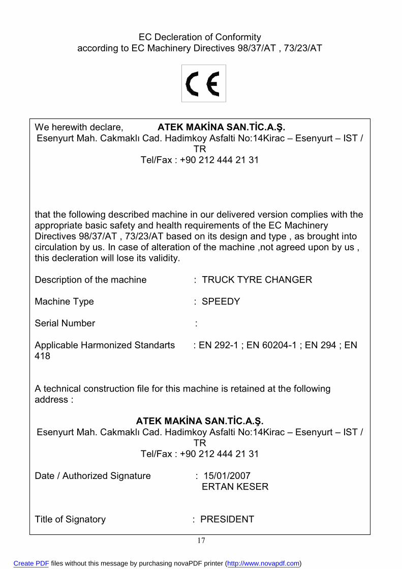
We herewith declare, ATEK MAKİNA SAN.TİC.A.Ş. Esenyurt Mah. Cakmaklı Cad. Hadimkoy Asfalti No:14Kirac – Esenyurt – IST /
TR Tel/Fax : +90 212 444 21 31
that the following described machine in our delivered version complies with the appropriate basic safety and health requirements of the EC Machinery Directives 98/37/AT , 73/23/AT based on its design and type , as brought into circulation by us. In case of alteration of the machine ,not agreed upon by us , this decleration will lose its validity. Description of the machine : TRUCK TYRE CHANGER Machine Type : SPEEDY Serial Number : Applicable Harmonized Standarts : EN 292-1 ; EN 60204-1 ; EN 294 ; EN 418 A technical construction file for this machine is retained at the following address :
ATEK MAKİNA SAN.TİC.A.Ş.
Esenyurt Mah. Cakmaklı Cad. Hadimkoy Asfalti No:14Kirac – Esenyurt – IST / TR
Tel/Fax : +90 212 444 21 31 Date / Authorized Signature : 15/01/2007 ERTAN KESER Title of Signatory : PRESIDENT
EC Decleration of Conformity according to EC Machinery Directives 98/37/AT , 73/23/AT
Create PDF files without this message by purchasing novaPDF printer (http://www.novapdf.com)