specification slave redundancy - profibus.com
TRANSCRIPT
PROFIBUS
Specification
Slave Redundancy
Version 1.2 November 2004
Order No: 2.212
Document Identification: TC4-04-0001 File name: Slave-Redundancy_2212_V12_Nov04
Prepared by the PROFIBUS Working Group 4 “DCS Requirements” in the Technical Committee 4 “System Integration”.
This revised version V1.2 replaces draft version V1.1. There is one change according a change request based on the PNO review in the informative Annex B "GSD requirements": the requirement for Slave_Redundancy_supp is adjusted to GSD specification V5.02. The major changes to V1.0 are described in the introduction.
The attention of adopters is directed to the possibility that compliance with or adoption of PI (PROFIBUS International) specifications may require use of an invention covered by patent rights. PI shall not be responsible for identifying patents for which a license may be required by any PI specification, or for conducting legal inquiries into the legal validity or scope of those patents that are brought to its attention. PI specifications are prospective and advisory only. Prospective users are responsible for protecting themselves against liability for infringement of patents.
NOTICE:
The information contained in this document is subject to change without notice. The material in this document details a PI specification in accordance with the license and notices set forth on this page. This document does not represent a commitment to implement any portion of this specification in any company's products.
WHILE THE INFORMATION IN THIS PUBLICATION IS BELIEVED TO BE ACCURATE, PI MAKES NO WARRANTY OF ANY KIND, EXPRESS OR IMPLIED, WITH REGARD TO THIS MATERIAL INCLUDING, BUT NOT LIMITED TO ANY WARRANTY OF TITLE OR OWNERSHIP, IMPLIED WARRANTY OF MERCHANTABILITY OR WARRANTY OF FITNESS FOR PARTICULAR PURPOSE OR USE.
In no event shall PI be liable for errors contained herein or for indirect, incidental, special, consequential, reliance or cover damages, including loss of profits, revenue, data or use, incurred by any user or any third party. Compliance with this specification does not absolve manufacturers of PROFIBUS or PROFINET equipment, from the requirements of safety and regulatory agencies (TÜV, BIA, UL, CSA, FCC, IEC, etc.).
PROFIBUS® and PROFINET® logos are registered trade marks. The use is restricted for members of Profibus International. More detailed terms for the use can be found on the web page www.profibus.com/libraries.html. Please select button "Presentations & logos".
Publisher: PROFIBUS Nutzerorganisation e.V. Haid-und-Neu-Str. 7 D-76131 Karlsruhe Germany Phone: +49 721 / 96 58 590 Fax: +49 721 / 96 58 589 E-mail: [email protected] Web site: www.profibus.com © No part of this publication may be reproduced or utilized in any form or by any means, electronic or mechanical, including photocopying and microfilm, without permission in writing from the publisher. Copyright by PNO 2003 - All rights reserved. Page 2
Specification Slave Redundancy Version 1.2/November 2004
Contents
1 Scope ............................................................................................................................ 7 2 Normative references..................................................................................................... 7 3 Definitions and Abbreviations ......................................................................................... 8
3.1 Definitions ............................................................................................................ 8 3.1.1 interface.................................................................................................... 8 3.1.2 Channel .................................................................................................... 8 3.1.3 Module ...................................................................................................... 8 3.1.4 MS0 .......................................................................................................... 8 3.1.5 MS1 .......................................................................................................... 8 3.1.6 Signal ....................................................................................................... 8 3.1.7 Index......................................................................................................... 8 3.1.8 Slave Interface Module (SIM) .................................................................... 8 3.1.9 Redundant slave ....................................................................................... 8 3.1.10 Primary slave ............................................................................................ 8 3.1.11 Backup slave............................................................................................. 8 3.1.12 System Redundancy (SR).......................................................................... 9 3.1.13 Flying Redundancy (FR) ............................................................................ 9 3.1.14 RedCom 9
3.2 Abbreviated terms................................................................................................. 9 4 System architecture ..................................................................................................... 10
4.1 Overview ............................................................................................................ 10 4.2 Redundant slave ................................................................................................. 11 4.3 Slave to master connections ............................................................................... 13 4.4 Redundancy aspects........................................................................................... 13
5 Redundant slave behaviour .......................................................................................... 17 5.1 Architectural Model ............................................................................................. 17 5.2 General Description ............................................................................................ 18
5.2.1 Power up................................................................................................. 18 5.2.1.1 Complete redundant slave......................................................... 18 5.2.1.2 Only one slave interface module................................................ 18
5.2.2 Address assignment ................................................................................ 18 5.2.2.1 Using a stored address ............................................................. 18 5.2.2.2 Using a DIP switch .................................................................... 19
5.2.3 Start-up behaviour................................................................................... 19 5.2.3.1 No failure during start-up........................................................... 19 5.2.3.2 One transmit line failed ............................................................. 20 5.2.3.3 One slave interface module failed.............................................. 20 5.2.3.4 MS2-Communication and start-up.............................................. 20
5.2.4 Runtime .................................................................................................. 20 5.2.4.1 Fully configured redundant slave ............................................... 21 5.2.4.2 Receiving configuration ............................................................. 21
5.3 Failure Situations ................................................................................................ 23 5.3.1 Backup slave fails ................................................................................... 23 5.3.2 Primary slave fails ................................................................................... 23 5.3.3 Backup slave receive or transmit line breaks ........................................... 23
Copyright by PNO 2003 - All rights reserved. Page 3
Specification Slave Redundancy Version 1.2/November 2004
5.3.4 Primary slave receive line breaks ............................................................ 23 5.3.5 Primary slave transmit line breaks ........................................................... 24 5.3.6 Master fails ............................................................................................. 24 5.3.7 RedCom fails .......................................................................................... 24
5.4 Redundancy switchover ...................................................................................... 24 5.4.1 Overview of the redundancy procedures .................................................. 25 5.4.2 Definition of the Masters Commands ....................................................... 25 5.4.3 Timers .................................................................................................... 26 5.4.4 Operation Mode of the Master ................................................................. 27 5.4.5 Description of Special Functions of PrmCommands ................................. 28
5.4.5.1 CheckProperties ....................................................................... 28 5.4.5.2 Primary/Backup......................................................................... 28 5.4.5.3 Combined Primary/Backup-Command ....................................... 29 5.4.5.4 Stop_MSAC1S .......................................................................... 29 5.4.5.5 Start_MSAC1S.......................................................................... 29 5.4.5.6 Combined Start_MSAC1S/Stop_MSAC1S.................................. 29
5.4.6 State Diagram ......................................................................................... 29 5.4.7 Interfaces ................................................................................................ 31 5.4.8 State Machine ......................................................................................... 31 5.4.9 Sequence Diagrams ................................................................................ 39
5.5 Coding................................................................................................................ 41 5.5.1 Prm_Command ....................................................................................... 41 5.5.2 Red_State Diagnosis ............................................................................... 44 5.5.3 MS1 additional Error Codes ..................................................................... 45
5.6 Redundant slave options ..................................................................................... 46 Annex A (informative) Alarm Behaviour .............................................................................. 47
A.1 Overview ............................................................................................................ 47 A.2 Description ......................................................................................................... 47
A.2.1 Sequence number ................................................................................... 47 A.2.2 State Diagram ......................................................................................... 48 A.2.3 State machine ......................................................................................... 49 A.2.4 Alarm coupling ........................................................................................ 52 A.2.5 Behaviour after switchover ...................................................................... 52
Annex B (informative) GSD requirements ........................................................................... 54
Copyright by PNO 2004 - All rights reserved. Page 4
Specification Slave Redundancy Version 1.2/November 2004
Figures
Figure 1 – Redundant System Structure ............................................................................. 10 Figure 2 – Redundant Slave Components ........................................................................... 12 Figure 3 – Master Slave Configurations .............................................................................. 13 Figure 4 – Modelling of a redundant system with affected components................................ 17 Figure 5 – Primary Backup selection at Start up ................................................................. 20 Figure 6 – States at Startup ............................................................................................... 22 Figure 7 – Timing after Failure ........................................................................................... 27 Figure 8 – RedSM State Diagram ....................................................................................... 30 Figure 9 – Master Command to switch from Backup to Primary ........................................... 39 Figure 10 – Switchover by Slave internal Communication ................................................... 40 Figure A.1 – AlarmSM State Diagram ................................................................................. 48
Tables
Table 1 – Timer Usage ....................................................................................................... 26 Table 2 – Combinations of PRIMARY/BACKUP and Operation Mode .................................. 27 Table 3 – Events ................................................................................................................ 31 Table 4 – Outputs .............................................................................................................. 31 Table 5 – State Machine of Red-Instance ........................................................................... 32 Table 6 – Structure of SetPrm for PrmCmd ......................................................................... 41 Table 7 – Combinations for Start/Stop_MASAC1S .............................................................. 43 Table 8 – Coding the READ/WRITE PDUs (without SAPs) .................................................. 46 Table 9 – Coding of Error_Code_1 at DPV1........................................................................ 46 Table A.1 – States of Alarm-SM ......................................................................................... 49 Table A.2 – Events of Alarm-SM......................................................................................... 49 Table A.3 – Conditions of Alarm-SM ................................................................................... 49 Table A.4 – Actions of Alarm-SM ........................................................................................ 50 Table A.5 – Alarm State Machine ....................................................................................... 50
Copyright by PNO 2003 - All rights reserved. Page 5
Specification Slave Redundancy Version 1.2/November 2004
Introduction
This Specification describes Slave Redundancy Mechanism for PROFIBUS.
Parts of this document were moved and transformed to other Specification of PROFIBUS International (PI) respectively of International Standards, where the PI-technology is described: • PROFIBUS Data Link Layer [1] • PROFIBUS Application Layer [2] • GSD Description [6]
Major changes in V1.1 compared to V1.0 •
•
•
•
•
Clause 2 Normative references updated to the actual documents and revisions
Clause 4 System architecture
New Subclause 4.1; references to IEC 61784-1 and IEC 61158 Ed.3
minor editorial corrections
Table 5 – State Machine of Red-Instance; revised according IEC 61158 Ed.3
Subclause 5.5.1 Prm_Command; Bit 3 description amended; Bit 7 description revised according IEC 61158 Ed.3
Annex B GSD requirements; revised according ISO 15745-3 (PNO GSD V5.0)
How to read this document:
Names of Data Types are formatted in this document as follows:
First letter as capital, if the data type name is composed of two or more words then the words are separated by an underline and each word starts with a capital letter, e.g.:
Synch_Time
Parameter names are written in capital letter, e.g.: Error_Decode
Services are named as in the appropriate documents.
Copyright by PNO 2004 - All rights reserved. Page 6
Specification Slave Redundancy Version 1.2/November 2004
PROFIBUS Specification Slave Redundancy
1 Scope
Slave Redundancy describes the basic mechanisms for a redundant slave used in several control systems with several master implementations. Only the PROFIBUS part of the slave redundancy will be specified.
Master redundancy and line redundancy is not in the scope of this specification and only mentioned when necessary to understand the concept of the slave redundancy.
2 Normative references
The following normative documents contain provisions which, through reference in this text, constitute provisions of this document. For dated references, subsequent amendments to, or revisions of, any of these publications do not apply. However, parties to agreements based on this specification are encouraged to investigate the possibility of applying the most recent editions of the normative documents indicated below. For undated references, the latest edition of the normative document referred to applies.
/1/ IEC 61158-5, Ed3.0 — Digital data communication for measurement and control – Fieldbus for use in industrial control systems –Application Layer service definition
/2/ IEC 61158-6, Ed3.0 — Digital data communication for measurement and control – Fieldbus for use in industrial control systems –Application Layer protocol specification
/3/ ISO/IEC 7498-1: 1994, Information Technology - Open Systems Interconnection - Basic Reference Model: The Basic Model
/4/ PROFIBUS Guideline “Specification for PROFIBUS Device Description and Device Integration” Volume 1: GSD V4.1: 2001 July
/5/ IEC 61784-1, Ed1: Profile sets for continuous and discrete manufacturing relative to fieldbus use in industrial control systems
/6/ ISO 15745-3, Ed. 1, Industrial automation systems and integration — Open systems application integration framework — Part 3: Reference description for IEC 61158-based control systems
Copyright by PNO 2004 - All rights reserved. Page 7
Specification Slave Redundancy Version 1.2/November 2004
3 Definitions and Abbreviations
3.1 Definitions
3.1.1 interface Address of a module within a DP-Slave.
3.1.2 Channel A single physical or logical connection of inputs or outputs of a DP-Slave to the process.
3.1.3 Module Addressable unit inside the DP-Slave.
3.1.4 MS0 Application relationship between a DP-Master and DP-Slaves to convey I/O-Data(cyclic), Diagnosis and Configuration.
3.1.5 MS1 Application Relationship between a DP-Master (Class 1) and a DP-Slave to convey acyclic Process Data and Alarms.
3.1.6 Signal Process value (sensor value or output value to an actor) at the interface to a module.
3.1.7 Index Address of an object within an application process. An index is a subaddress of a slot.
3.1.8 Slave Interface Module (SIM) PROFIBUS slave device with at least one PROFIBUS connector and one PROFIBUS stack.
3.1.9 Redundant slave Pair of Slave Interface Modules with its (I/O-)Modules where one is the primary and one is the backup slave.
3.1.10 Primary slave Primary Slave Interface Module that works active in the direction of the PROFIBUS and the process I/O.
3.1.11 Backup slave Backup Slave Interface Module that is passive in the direction of the PROFIBUS for MS0, MS1, and the process I/O and is ready to become a primary slave if the current primary fails.
Copyright by PNO 2004 - All rights reserved. Page 8
Specification Slave Redundancy Version 1.2/November 2004
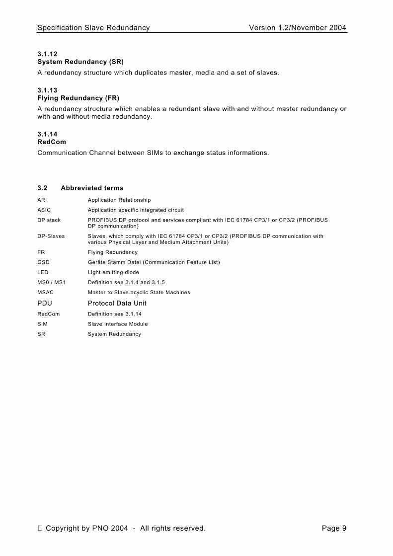
3.1.12 System Redundancy (SR) A redundancy structure which duplicates master, media and a set of slaves.
3.1.13 Flying Redundancy (FR) A redundancy structure which enables a redundant slave with and without master redundancy or with and without media redundancy.
3.1.14 RedCom Communication Channel between SIMs to exchange status informations.
3.2 Abbreviated terms
AR Application Relationship
ASIC Application specific integrated circuit
DP stack PROFIBUS DP protocol and services compliant with IEC 61784 CP3/1 or CP3/2 (PROFIBUS DP communication)
DP-Slaves Slaves, which comply with IEC 61784 CP3/1 or CP3/2 (PROFIBUS DP communication with various Physical Layer and Medium Attachment Units)
FR Flying Redundancy
GSD Geräte Stamm Datei (Communication Feature List)
LED Light emitting diode
MS0 / MS1 Definition see 3.1.4 and 3.1.5
MSAC Master to Slave acyclic State Machines
PDU Protocol Data Unit RedCom Definition see 3.1.14
SIM Slave Interface Module
SR System Redundancy
Copyright by PNO 2004 - All rights reserved. Page 9
Specification Slave Redundancy Version 1.2/November 2004
4 System architecture
4.1 Overview
This subclause gives an overview of the PROFIBUS slave redundancy specified by PROFIBUS International and IEC 61158-5, IEC 61158-6 and IEC 61784-1.
See IEC 61784-1, subclause 7.2.3.2.5.11 Redundancy See IEC 61158-2, Annex J (normative) Type 3: Redundancy of Physical Layer and Medium See IEC 61158-5:2003, subclause 8.1.4 Dynamical behaviour of fieldbus DP See IEC 61158-6:2003, subclause 6.6.1.2, Redundancy behaviour A rough description of the mechanisms and the several error checks is also part of this subclause, which should help to understand the concept. A detailed description of the various slave behaviours as well as a formal description will follow in the next subclauses.
Master Redundancy
Line Redundancy
Slave Redundancy
Line A
Line B
Primary
Backup
Backup
Primary
Non-redundant device
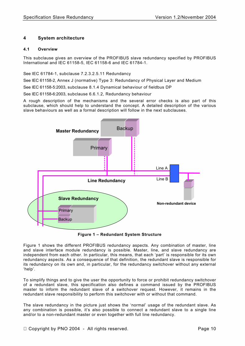
Figure 1 – Redundant System Structure
Figure 1 shows the different PROFIBUS redundancy aspects. Any combination of master, line and slave interface module redundancy is possible. Master, line, and slave redundancy are independent from each other. In particular, this means, that each ‘part’ is responsible for its own redundancy aspects. As a consequence of that definition, the redundant slave is responsible for its redundancy on its own and, in particular, for the redundancy switchover without any external ‘help’.
To simplify things and to give the user the opportunity to force or prohibit redundancy switchover of a redundant slave, this specification also defines a command issued by the PROFIBUS master to inform the redundant slave of a switchover request. However, it remains in the redundant slave responsibility to perform this switchover with or without that command.
The slave redundancy in the picture just shows the ‘normal’ usage of the redundant slave. As any combination is possible, it’s also possible to connect a redundant slave to a single line and/or to a non-redundant master or even together with full line redundancy.
Copyright by PNO 2004 - All rights reserved. Page 10
Specification Slave Redundancy Version 1.2/November 2004
With the help of special switch devices (shown with the blue box in the picture) it is also possible to connect slave interface modules (redundant or not) or master to the line redundancy.
This specification defines only the slave interface module redundancy from the PROFIBUS point of view. The redundancy structure from the process I/O point of view is not part of this specification. In other words, whether there are redundant I/O components or not depends on a particular slave interface module implementation.
In addition this specification sometimes provides alternative or optional mechanisms for some parts of the redundant slave, which enables different slave interface modules to provide a different ‘quality’ of redundancy, e.g. according to switch over timing and master support.
The slave redundancy specification fulfills the following requirements:
• One slave interface module implementation for all redundancy structures (even for non-redundant systems)
• Scalability: Independent master, slave, and line redundancy
• Easy engineering: No additional user efforts, no complex tools necessary
• Complete monitoring of all components
• No influence on bus load and timing
• High reliability
• Short switch over time
• No loss of data during fault tolerance
4.2 Redundant slave
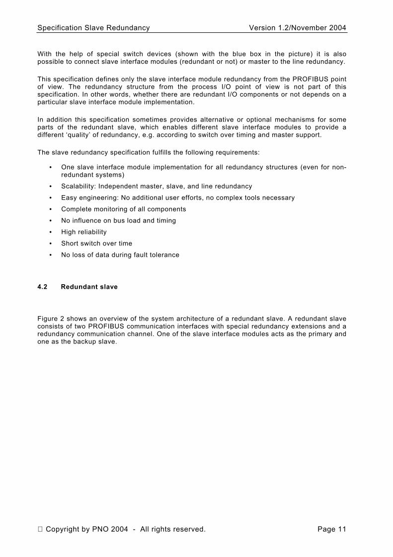
Figure 2 shows an overview of the system architecture of a redundant slave. A redundant slave consists of two PROFIBUS communication interfaces with special redundancy extensions and a redundancy communication channel. One of the slave interface modules acts as the primary and one as the backup slave.
Copyright by PNO 2004 - All rights reserved. Page 11
Specification Slave Redundancy Version 1.2/November 2004
Control system (master)
Process data
Red. extensions
Red. extensions
Primary slave Backup slave
Redundant slave
PROFIBUS PROFIBUS
Figure 2 – Redundant Slave Components
A redundant slave shall have:
• At least two PROFIBUS connections
• Two independent PROFIBUS communication interfaces
• A redundancy communication channel (RedCom)
In addition, a redundant slave may have:
• Independent line redundant PROFIBUS connections
RedCom shall provide a PROFIBUS independent communication between the two slave interface modules. The performance of this redundancy communication channel influences the total switch over time of the redundant slave (see next subclauses).
A slave interface module that does not fulfill the ‘must’ requirements above (e.g. two PROFIBUS connections but only one PROFIBUS slave stack) is not a redundant slave according to this specification.
Copyright by PNO 2004 - All rights reserved. Page 12
Specification Slave Redundancy Version 1.2/November 2004
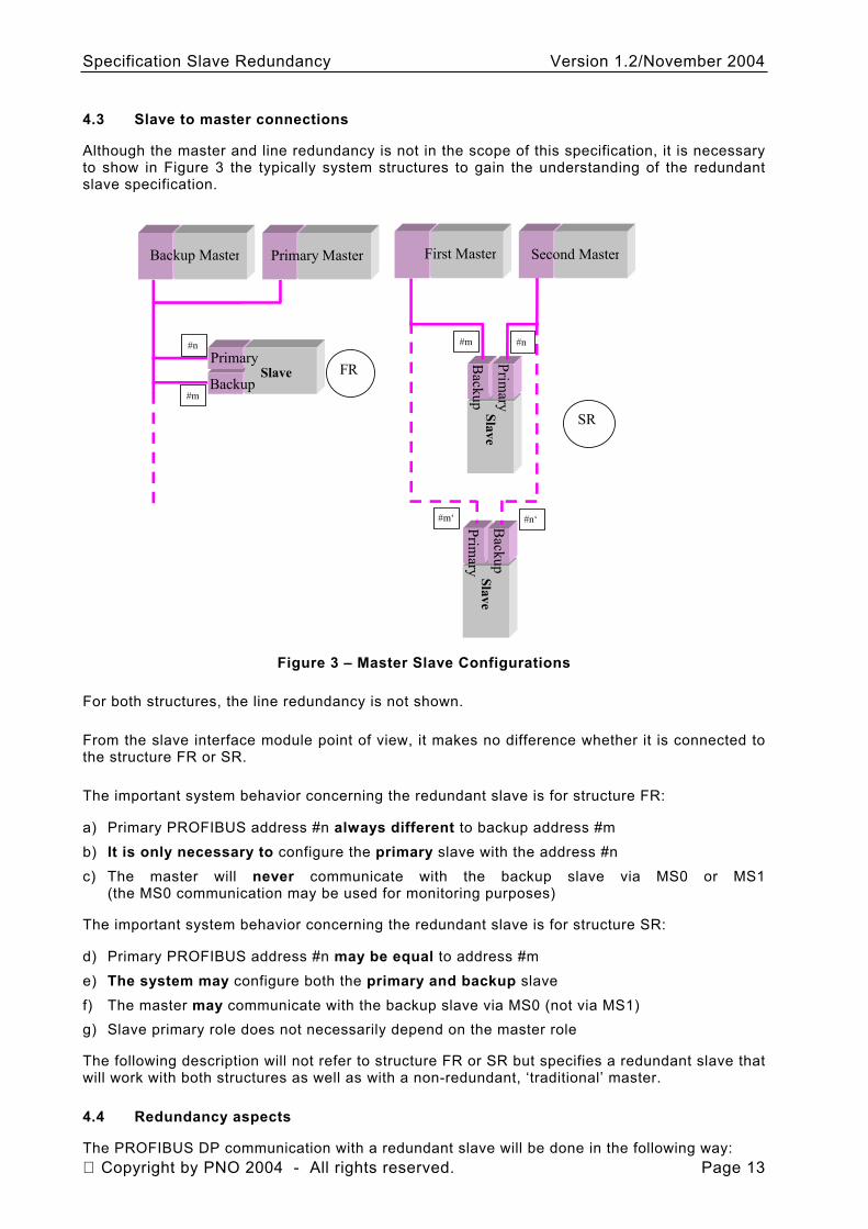
4.3 Slave to master connections
Although the master and line redundancy is not in the scope of this specification, it is necessary to show in Figure 3 the typically system structures to gain the understanding of the redundant slave specification.
Primary
BackupSlave
Backup Master Primary Master
#n
#m
First Master Second Master
#n#m
Slave Prim
ary
Backup
FR
SR
Slave B
ackup
Primary
#m‘ #n‘
Figure 3 – Master Slave Configurations
For both structures, the line redundancy is not shown.
From the slave interface module point of view, it makes no difference whether it is connected to the structure FR or SR.
The important system behavior concerning the redundant slave is for structure FR:
a) Primary PROFIBUS address #n always different to backup address #m
b) It is only necessary to configure the primary slave with the address #n
c) The master will never communicate with the backup slave via MS0 or MS1 (the MS0 communication may be used for monitoring purposes)
The important system behavior concerning the redundant slave is for structure SR:
d) Primary PROFIBUS address #n may be equal to address #m
e) The system may configure both the primary and backup slave
f) The master may communicate with the backup slave via MS0 (not via MS1) g) Slave primary role does not necessarily depend on the master role
The following description will not refer to structure FR or SR but specifies a redundant slave that will work with both structures as well as with a non-redundant, ‘traditional’ master.
4.4 Redundancy aspects
Copyright by PNO 2004 - All rights reserved. Page 13 The PROFIBUS DP communication with a redundant slave will be done in the following way:
Specification Slave Redundancy Version 1.2/November 2004
MS0 (cyclic): The primary slave uses the cyclic communication to send and receive the process values. In addition the primary slave sends all diagnosis information about itself and the backup slave.
The backup slave may also send and receive data with the MS0 services, but these data is not relevant and shall be ignored by the backup slave. The backup slave may transmit its own diagnosis information, but, as said above, it shall also be part of the primary diagnosis.
MS1 (acyclic): Only the primary slave will receive and transmit MS1 services.
When the backup slave receives a MS1 service, it shall respond negative.
MS2 (acyclic): Both the primary and the backup slave may receive acyclic MS2 services. Both slave interface modules shall process these services to allow an individual communication with the specific device. If data will be sent with MS2 services, these data may be sent to one slave interface module only and shall be exchanged with the other using RedCom. Only data, which will be held in both slave interface modules, shall be exchanged to keep them consistent.
Although the MS0 communication of the backup slave is not relevant for the process I/O, it will be used for monitoring purposes. Therefore, also the backup slave shall have its own unique address and shall initialize its PROFIBUS communication interface to be able to communicate. The redundant slave shall be able to handle different addresses for the primary and the backup or the same address for primary and backup.
As mentioned above, it is not always the case that the backup slave can communicate via MS0 services with a master. Therefore, it is necessary to include the diagnosis information of the backup slave in the diagnosis information of the primary. In other words, the primary slave is responsible of sending the complete diagnosis information of the redundant slave.
The monitoring of the PROFIBUS communication ability of the redundant slave will be done by the redundancy enhancements of the master with standard PROFIBUS mechanisms. Therefore, also all communication parts of the backup slave shall be fully operable. They shall be connected to the bus, the driver shall be enabled, and the PROFIBUS ASIC shall be initialized and running.
This definition implies that the quality of the monitoring of (at least) the backup slave and its components is not a quality of the redundant slave but the master. For example, with a standard master without the redundancy enhancements the communication components of the backup slave are not monitored at all (although the slave redundancy will still be available).
If the master redundancy enhancements will detect a communication failure to the primary slave, it will issue a command to the redundant slave to inform it about that fact. The redundant slave may perform a redundancy switchover.
The monitoring of the PROFIBUS communication by the master will work also for a single line failure. That means, when only the receive- or the transmit-line of the primary slave has a failure, the master will also detect this and the command will be sent to the redundant slave. A redundant slave, which will provide its redundancy also with a master without the redundancy enhancements, shall in addition monitor its PROFIBUS reception of the primary and perform a redundancy switchover when the PROFIBUS watchdog expires.
A redundant slave will (although not specified here) usually monitor its internal, not PROFIBUS related components for certain failures and may detect a failure which should lead to a redundancy switchover, because the backup slave could work more proper than the primary. If the redundancy switchover of the redundant slave needs to receive the command from the master redundancy enhancements to perform the switchover, the primary slave may reset its
Copyright by PNO 2004 - All rights reserved. Page 14
Specification Slave Redundancy Version 1.2/November 2004
PROFIBUS communication to force the master to generate the command and to send it to the current backup. If the redundant slave can also perform a redundancy switchover without the help of the command, it may just switch its state.
In general, the responsibility of the role (primary or backup) of the slave interface modules of the redundant slave has the redundant slave, not the master! The command defined from the master redundancy enhancements helps the redundant slave to decide, which slave interface module is primary and which is backup, but the final decision is in the response of the redundant slave.
The command may also be used by special maintenance tools to request the redundancy switchover for some purposes. It’s still in the response of the redundant slave to switch or not depending on its internal state. If both slave interface modules are in the same state, the switchover shall be done as requested.
The primary slave will always receive the standard configuration via the SET_PRM command. The backup slave may or may not receive a SET_PRM. Therefore, the primary slave shall send the parameter via RedCom to the backup.
When MS2 services are used to configure the redundant slave, normally only the primary slave will receive this configuration data. Via RedCom these data shall be transferred to the backup slave. If, however, the backup slave receives its own configuration data, it may overwrite the older data received by its primary. This specification does not restrict the use of different parameters on both SIM sides nor does it specify a method to adjust a system in such a situation. RedCom may be used to exchange additional information in any way (this shall be defined and described by the system implementer.
If the redundant slave shall also be used with existing master without the redundancy enhancements, some of the functionality is not available. Such a master will not monitor the backup slave and will not issue a command for redundancy switchover. Therefore the receive- and transmit components of the backup slave are not monitored at all and, if the slave redundancy switchover will only be done with the reception of the master command, the slave redundancy is not available with such a master.
If at least the slave redundancy shall work with such a master or to tolerate a loss of the master command, the redundant slave shall also perform a redundancy switchover, when its watchdog expires instead of receiving the master command. Without additional effort in the master and redundant slave application, the input and output signals of the redundant slave may become invalid for the takeover time.
NOTE 1 Some older master implementations which are based on specifications before 1998, do not stop polling the slave interface module with DATA_EXCHANGE, when they don’t receive an answer from this slave interface module. Therefore, if only the transmit line from the primary slave to such a master is disturbed, the watchdog in the slave will never expire.
One of the key features of the slave redundancy is, to keep the process input and output signals stable during a redundancy switchover. That means, from the process point of view, a redundancy switchover is invisible. Therefore, the redundant slave shall not change its outputs when it performs a redundancy switchover. When the backup slave becomes the primary (and vice versa) it may use the output signals previously transmitted from the old primary via RedCom or it has to wait for the first data exchange after the switchover to write new values to its outputs. This is due to synchronization problems – the previous output of the backup could be older than the output of the primary. This may cause an additional impulse at the output line which shall be avoided.
NOTE 2 These values shall be newer or equal to the values that the old primary has written to its outputs.
However, the safety aspects shall also be taken into account. If the new primary slave can also not communicate with the master, the safety values shall be written to the process signals after the OutputHoldTime (see below). This implies, that a redundancy switchover may only be enabled, when the backup slave surely knows the safety values for the output signals! It
Copyright by PNO 2004 - All rights reserved. Page 15
Specification Slave Redundancy Version 1.2/November 2004
must be taken into account, that the backup slave, which becomes the primary, will never receive a SET_PRM due to some other failure.
The master or the master application is responsible to keep the input signals of a redundant slave stable during the switchover. This is not part of this specification.
Copyright by PNO 2004 - All rights reserved. Page 16
Specification Slave Redundancy Version 1.2/November 2004
5 Redundant slave behaviour
5.1 Architectural Model
DP-Slaves used in redundant applications can have various structures.
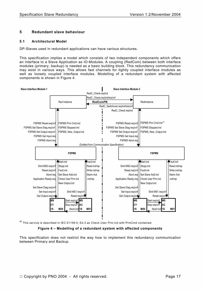
This specification implies a model which consists of two independent components which offers an interface to a Slave Application as IO-Modules. A coupling (RedCom) between both interface modules (primary, backup) is needed as a basic building block. This redundancy communication may exist in various ways. This allows fast channels for tightly coupled interface modules as well as loosely coupled interface modules. Modelling of a redundant system with affected components is shown in Figure 4.
Slave Interface Module 1 Slave Interface Module 2RedC_Check.req/indRedC_Check.req/ind/res/cnf
Red Instance RedComPB RedInstanceRedC_Switchover.req/ind/res/cnf
RedC_Check.req/ind
FSPMS Reset.req/cnf FSPMS Prm Cmd.ind FSPMS Reset.req/cnf FSPMS Prm Cmd.ind a)
FSPMS Set Slave Diag.req/cnf FSPMS Stopped.ind FSPMS Set Slave Diag.req/cnf FSPMS Stopped.indFSPMS Set Output.req/cnf FSPMS_New_Output.ind FSPMS Set Output.req/cnf FSPMS_New_Output.ind
FSPMS Get Input.req FSPMS Get Input.reqFSPMS Abort.req FSPMS Abort.req
(Drafted from Communication Specification)
FSPMS FSPMS
Start.ind Fault.ind Start.ind Fault.indSInit MS0.req/cnf Stopp.ind Read.ind/rsp SInit MS0.req/cnf Stopp.ind Read.ind/rsp
Reset.req/cnf Fault.ind Write.ind/rsp Reset.req/cnf Fault.ind Write.ind/rsAbort.req Set Slave Add.ind Alarm Ack Abort.req Set Slave Add.ind Alarm Ack
Application Ready.req Check User Prm.ind .ind/rsp Application Ready.req Check User Prm.ind .ind/rspNew Output.ind New Output.ind
Set Slave Diag.req/cnf Set Slave Diag.req/cnfSet Input.req/cnf SInit MS1.req/cnf Set Input.req/cnf SInit MS1.req/cnf
Get Output.req/cnf Reset.req/cnf Get Output.req/cnf Reset.req/cnfMS Start.req/cnf MS MS Start.req/cnf MSCY Stop.req/cnf AC CY Stop.req/cnf AC1S MS0 Abort.ind 1S MS1 1S MS0 Abort.ind 1S MS1
p
a) This service is described in IEC 61158-5; Ed.3 as Check User Prm.ind with PrmCmd contained. Figure 4 – Modelling of a redundant system with affected components
This specification does not restrict the way how to implement this redundancy communication between Primary and Backup.
Copyright by PNO 2004 - All rights reserved. Page 17
Specification Slave Redundancy Version 1.2/November 2004
5.2 General Description
5.2.1 Power up
5.2.1.1 Complete redundant slave
If the power will be turned on at the complete redundant slave, the role of primary and backup is undefined. Both slave interface modules change to the PROFIBUS address assignment.
5.2.1.2 Only one slave interface module
If only one slave interface module restarts and the other is already working as the primary slave, the restarted slave interface module may get all necessary information from the primary via RedCom and may change directly to the runtime phase.
If the other slave interface module is still in the address assignment or the start-up phase, the slave interface module with the power interruption may integrate itself via RedCom into these phases and act as described there. The necessary communication via RedCom of the slave interface modules for this purposes are not part of this specification.
5.2.2 Address assignment
The primary and the backup slave will get its own PROFIBUS address. At start-up one of the slave interface modules will start as the primary. Depending from the actual implementation, it will read the ‘main’ PROFIBUS address from its non-volatile memory or a DIP switch or something similar.
If address assignment by the master using Set_Slave_Add shall be used, the assignment shall take place in a point-to-point connection to the master and therefore it is not described in this specification.
After assignment of the address to the primary slave, the backup slave uses the address of the primary manipulated with a configured offset (which might be zero or 64).
Following rules are defined for slave addressing:
- Both addresses of the slave interface module shall be equal to avoid start-up conflicts if the device with the address used as primary is not operable.
- An address offset of 64 is used when requested at start-up. If base address + 64 is greater than 125 a Prm Fault will indicate this situation. A Diagnosis will be sent to identify this situation. To avoid this case addresses less than 62 should be used.
- There shall be an optical indication at the interface modules to indicate which one is the Primary and which is used as Backup. There is no chance to identify the components if this indication is not available.
NOTE According to the specification EN60073 and NAMUR a yellow or white LED should be used for the indication (on = Primary, off = Backup). Alternatives are e.g. power LED on = Primary, off or flashing = backup or the use of an existing LCD display.
Which slave interface module starts as primary and which starts as backup shall be negotiated via RedCom between the slave interface modules.
5.2.2.1 Using a stored address
If the PROFIBUS address is already stored in a non-volatile memory (=primary address), this address might be used and the start-up proceeds.
Copyright by PNO 2004 - All rights reserved. Page 18
Specification Slave Redundancy Version 1.2/November 2004
5.2.2.2 Using a DIP switch
DIP switches shall always be set to the primary address, regardless whether there are one or two switches. One slave interface module starts as the primary and uses this address, the other starts as the backup and the start-up proceeds.
5.2.3 Start-up behaviour
The start-up behaviour of a redundant slave shall take care of the possible failure situations. Therefore, it is described here for three different cases. Before the start-up, the ‘main’ (primary) address shall be known.
So far, two main states are used:
S_Primary The PROFIBUS ASIC and the DP stack are ready to work with the primary address on the line. The application works together with the PROFIBUS communication.
S_Waiting The PROFIBUS ASIC is held in the reset state, no activities to the PROFIBUS are allowed. The application is waiting.
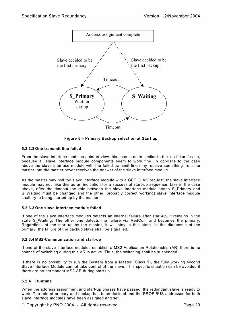
5.2.3.1 No failure during start-up
If both slave interface modules are in a well condition (according to the exchange of status information with RedCom), one of the slave interface modules starts with the state S_Primary with the defined primary PROFIBUS address (see 5.2.2). The other slave interface module starts in the state S_Waiting with the ASIC held in reset.
The primary slave now waits for the PROFIBUS start-up sequence (terminated after valid SET_PRM). If it does not receive the start-up sequence in a certain amount of time (Start_Up_Time), it informs the other slave interface module about that fact and the role of the slave interface modules changes. The Start_Up_Time starts at 2s and will be doubled when the Slave Interface Module becomes Primary until Start_Up_Time is 32s. The slave interface module in the state S_Primary changes to S_Waiting and after that the slave interface module in the state S_Waiting changes to S_Primary. Now the other slave interface module waits for the start-up sequence of the master. If one of the slave interface modules establishes a MS2 Application Relationship (AR) the switching is suspended during this AR is active.
As long as none of the slave interface modules will be started by a master, the slave interface modules toggle between the states S_Primary and S_Waiting.
Once the master has brought one of the slave interface modules into the data exchange state, this slave interface module remains the primary one and informs the other via the RedCom to become the backup slave. If primary- and backup-address are equal (requested by configuration), the redundancy slave waits for the master command.
With the parameterisation, the primary slave also receives information about the address offset of the backup (64) in a flag, which turns the usage of the offset on or off. The usage of the address offset depends on the masters behaviour, it does not depend on a particular slave.
The state machine for the start-up procedure without failure in principle looks like Figure 5. The redundant slave shall guarantee that never both slave interface modules are in the state S_Primary at the same time. This is not shown in the simplified Figure 5.
Copyright by PNO 2004 - All rights reserved. Page 19
Specification Slave Redundancy Version 1.2/November 2004
Address assignment complete
S_PrimaryWait for startup
S_Waiting
Timeout
Timeout
Slave decided to be the first primary
Slave decided to be the first backup
Figure 5 – Primary Backup selection at Start up
5.2.3.2 One transmit line failed
From the slave interface modules point of view this case is quite similar to the ‘no failure’ case, because all slave interface module components seem to work fine. In opposite to the case above the slave interface module with the failed transmit line may receive something from the master, but the master never receives the answer of the slave interface module.
As the master may poll the slave interface module with a GET_DIAG request, the slave interface module may not take this as an indication for a successful start-up sequence. Like in the case above, after the timeout the role between the slave interface module states S_Primary and S_Waiting must be changed and the other (probably correct working) slave interface module shall try to being started up by the master.
5.2.3.3 One slave interface module failed
If one of the slave interface modules detects an internal failure after start-up, it remains in the state S_Waiting. The other one detects the failure via RedCom and becomes the primary. Regardless of the start-up by the master, it will stay in this state. In the diagnostic of the primary, the failure of the backup slave shall be signalled.
5.2.3.4 MS2-Communication and start-up
If one of the slave interface modules establish a MS2 Application Relationship (AR) there is no chance of switching during this AR is active. Thus, the switching shall be suspended.
If there is no possibility to run the System from a Master (Class 1), the fully working second Slave Interface Module cannot take control of the slave. This specific situation can be avoided if there are no permanent MS2-AR during start up.
5.2.4 Runtime
When the address assignment and start-up phases have passed, the redundant slave is ready to work. The role of primary and backup has been decided and the PROFIBUS addresses for both slave interface modules have been assigned and set.
Copyright by PNO 2004 - All rights reserved. Page 20
Specification Slave Redundancy Version 1.2/November 2004
Either none, one or both slave interface modules are in the data exchange mode. If both slave interface modules are in data exchange mode, only the output data of the primary slave is valid. Both slave interface modules may receive global control commands and time synchronization. The time synchronization and global control commands are only of local meaning in each SIM. There is no guarantee of the correct operation of SYNCH and FREEZE in the case of a redundant switchover.
Only the primary slave may monitor its PROFIBUS connection, if it is in the data exchange mode. If the PROFIBUS watchdog expires, a redundancy switchover shall occur without interrupting the output signals. The detailed handling is described in the section ‘Failure situations’.
5.2.4.1 Fully configured redundant slave
When the primary slave is in the data exchange state, it may transfer its configuration data to the backup slave via RedCom.
The backup slave may also be in the data exchange mode or not, depending on the master behaviour. If it is already in the data exchange mode, it can ignore the configuration data from the primary, because it already got valid data from its master (consistency checks may be done of course).
If the backup slave is not in the data exchange mode, it may store the configuration data from the primary and prepare itself for a redundancy switchover. Nevertheless, in case of a redundancy switchover, it will receive the configuration by its master when it will be brought into the data exchange mode.
5.2.4.2 Receiving configuration
When a primary slave is not in the data exchange mode because it will just be configured using acyclic class 2 services, it shall send these configuration data to the backup slave via RedCom, because the backup slave will probably never receive acyclic class 2 services.
At the end of the configuration (Abort service received), the redundant slave shall return to the start-up and wait to become normally started by the master. At this time both slave interface modules should have the same configuration data so either one of them may become the next primary in case of some failure between the configuration time and the normal start.
NOTE this specification does not specify how the configuration data balancing between the two slave interface modules takes place. This is totally in the scope of the specific slave interface module and not in the PROFIBUS specification.
Copyright by PNO 2004 - All rights reserved. Page 21
Specification Slave Redundancy Version 1.2/November 2004
S_Primary
Primary
Backup
S_Waiting
timeout
running
In data exchange mode
S_Primary
Primary
Backup
S_Waiting
timeout
running
Other is in data exchange
Power up of both slaves
Slave A Slave B
C_Configure Class 2 service except abort received
Class 2 abort received or timeout
Class 2 service after connect received
C_Configure
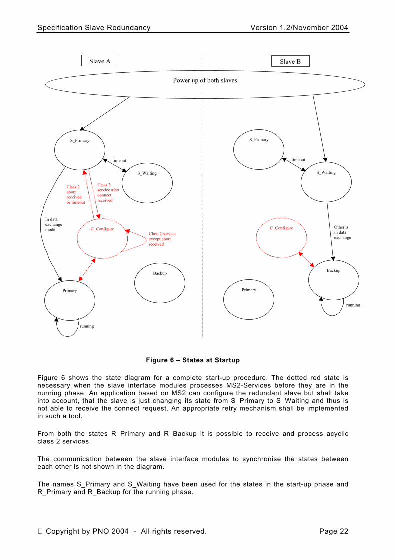
Figure 6 – States at Startup
Figure 6 shows the state diagram for a complete start-up procedure. The dotted red state is necessary when the slave interface modules processes MS2-Services before they are in the running phase. An application based on MS2 can configure the redundant slave but shall take into account, that the slave is just changing its state from S_Primary to S_Waiting and thus is not able to receive the connect request. An appropriate retry mechanism shall be implemented in such a tool.
From both the states R_Primary and R_Backup it is possible to receive and process acyclic class 2 services.
The communication between the slave interface modules to synchronise the states between each other is not shown in the diagram.
The names S_Primary and S_Waiting have been used for the states in the start-up phase and R_Primary and R_Backup for the running phase.
Copyright by PNO 2004 - All rights reserved. Page 22
Specification Slave Redundancy Version 1.2/November 2004
5.3 Failure Situations
In general, the redundant slave shall guarantee, that there is always and at any time only one primary slave on the line. Any internal error in one of the slave interface modules shall not lead to such an erroneous case. The safety ‘position’ is always both slave interface modules in backup state.
5.3.1 Backup slave fails
If the backup slave fails in a way, that it is also disconnected from the PROFIBUS, the behaviour will be the same like described in 5.3.3.
For any other failures, corresponding diagnostic information can (and should) be placed in the diagnostic information of the primary slave.
Any other behaviour like e.g. disabling redundancy switchover and so on are not specified by PROFIBUS International.
5.3.2 Primary slave fails
When the primary slave fails, it will also disconnect itself from the PROFIBUS. Thus the behaviour is the same as if the receive and transmit line of the PROFIBUS breaks.
The master, which was in the data exchange state with the slave interface module, will recognise the failure and is in the responsibility to send appropriate information to the user.
If the master does not support the redundancy enhancements, no information will be sent on the PROFIBUS for this disturbance. For this case, a monitoring in the backup slave shall recognise the failure of the primary and shall perform a redundancy switchover on its own (without master support).
A master, which contains the redundancy enhancements, will send a primary request to the backup if the primary slave disappears from the PROFIBUS. With the reception of this service in the backup slave, the backup slave knows that it should force a redundancy switchover.
5.3.3 Backup slave receive or transmit line breaks
The detection of this error is not in the response of the redundant slave but in the response of the master. If the master does not support the redundancy enhancements, the error may even stay undetected until a slave redundancy switchover occurs. See also Red_Status_2.
A master, which supports the redundancy enhancements, will recognize the disappearance of the slave interface module from its station list. It’s in the response of the master to send information about this failure to the user.
5.3.4 Primary slave receive line breaks
If the receive line of the primary breaks, it will not receive any PROFIBUS frame any longer. From the master point of view, this is the same as if the whole primary slave has failed because the master will not receive anything from the slave interface module any longer.
When the master supports the redundancy enhancements, it will behave like described in 5.3.2.
When the master does not support the redundancy enhancements, the behaviour of the redundant slave is the same like described in 5.3.6.
Copyright by PNO 2004 - All rights reserved. Page 23
Specification Slave Redundancy Version 1.2/November 2004
5.3.5 Primary slave transmit line breaks
If only the transmit line of the primary slave breaks (e.g. transceiver component or one line of an optical link), for the master this is the same case than described in 5.3.4.
If the master supports the redundancy enhancements, also for the redundant slave there is no difference to 5.3.4.
A master, which does not support the redundancy enhancements, may even continue to poll the slave interface module with data exchange requests even it gets no more answers. For this case, the primary slave may force a redundancy switchover on its own if it wants to support such masters too. The indication for the switchover is the expiring of the PROFIBUS watchdog.
5.3.6 Master fails
When the master fails, the behaviour of a redundant slave is the same than the behaviour of a non-redundant slave. If the watchdog is disabled or as long as the watchdog time has not expired, the redundant slave waits to be restarted by a master. If the master appears again or a backup master takes over within the watchdog time, nothing special has to happen.
When there is no communication between both SIM and the assigned DP-Master(s) (Class 1) within Trestart(see 5.4.3) the redundant slave falls back in the start-up phase where it waits to be started by a master and cyclically toggles between the states S_Primary and S_Waiting (see 5.2.3).
5.3.7 RedCom fails
At Startup a SIM with no activity over RedCom will become Primary.
During Operation, the role does not change as long as there is no PrmCmd. If there is no PrmCmd, a Primary break down after a RedCom failure will stop the system.
The Reliability of the Slave depends on the quality of the RedCom. A SIM should be able to distinguish beetween a break down of the PRIMARY and a permanent failure of RedCom.
5.4 Redundancy switchover
In general, the redundant slave itself decides which of the two slave interface modules is the primary and which is the backup slave, following the rules defined below. Nevertheless, a Prm Cmd has been defined to give a master the opportunity to initiate a redundancy switchover and to decrease the redundancy switchover time for a redundant slave.
A redundant slave therefore may only rely on this service. It is sufficient, if the redundancy needs only to work together with PROFIBUS masters with redundancy enhancements.
But, however, for fault tolerance reason (the request may get lost) or for the request to provide the slave redundancy also to already existing masters without the redundancy enhancements, the redundant slave shall implement additional mechanisms to initiate a redundancy switchover (e.g. expiring of the watchdog timer; detection of internal malfunction).
In this case, the redundant slave performs the redundancy switchover without even the knowledge of the PROFIBUS master.
This can simply be done as the primary slave resets its PROFIBUS interface and restarts it with the address of the backup and vice versa (if address change is set). If at that time one of the slave interface modules does not work correctly, it holds its PROFIBUS interface in the reset state and the slave interface module will start like a non-redundant one.
Copyright by PNO 2004 - All rights reserved. Page 24
Specification Slave Redundancy Version 1.2/November 2004
5.4.1 Overview of the redundancy procedures Reason for switchover : 1. Master and or Communication system failure
- Leave the state Data-Exchange at the primary slave (e.g. expiring of the watchdog timer, receive a PRM-indication witch unlock req.)
- Change to clear-mode at the primary-slave (e.g. global control clear, output as fail-safe)
2. Primary failed
- Loss of live counter from the primary slave in the backup slave
- Internal error at primary slave
3. Primary request from Master to backup slave.
Sequence of a switchover When a switchover event like mentioned above occurs, the internal states of the slave have to be checked to ensure that a switchover could be initiated. The following sequence will be executed under regular conditions.
1. One of the slave interface module start the TOH in representative of the redundant slave
2. Only required with address change: Primary slave reset its PROFIBUS interface
3. Internal switchover is executed – (Outputs are controlled by the new primary). Duration depends on Slave Implementation
4. Only with address change require: New primary slave reset its PROFIBUS interface and start it with primary address. Any time: new backup slave start its PROFIBUS interface with backup address.
5. Primary slave get new input data from periphery and copies them to its PROFIBUS interface if primary is in Data-Exchange.
6. Primary slave waits (until TOH) for the state Data-Exchange (in case it is not reached yet) Required without address change: Primary slave waits of primary request from master. Note: If a primary- or backup- request was the reason for the switchover or the first PRM indication to the new primary included the primary request, this condition is fulfilled.
7. New output data is valid and copied to the periphery. Stop the TOH.
8. Acknowledge a receiving master-request (primary or backup) by a diagnosis to the master at the receiving site.
9. Pending alarms are repeated with the same contents, especially the sequence-number. New alarms are sending after repetition.
5.4.2 Definition of the Masters Commands
Redundancy requires different Commands:
Copyright by PNO 2004 - All rights reserved. Page 25
Specification Slave Redundancy Version 1.2/November 2004
1. Primary_Request_MS0_MS1: Resets MSAC1S and Activates MS0/MS1-function invocation (related to Inputs/Outputs, Alarm and Process_Data).
2. Start/Stop_MSAC1: Start/Stop of MSAC1S. MS0, MS2 are not affected.
Conflicts By definition only one command should be invoked at one moment of time either at primary or backup site. Due to asynchronous processing multiple commands may be invoked at primary/backup slave. This commands are processed in sequential order at backup/primary slave.
5.4.3 Timers
Every command execution is monitored for error detection purposes and to guarantee reaction time.
Two timeouts are specified: - MaxTakeOverTime (TMTO): With TMTO the DP-Master shall control a PrmCommand. The
confirmation of the SetPrm invocation will start this timer. A diagnosis with PrmCommandAck will stop this timer. As long as this timer is running, the master shall not mark the slave and its input data as invalid. TMTO Timebase is 100ms.
- OutputHoldTime (TOH): TOH monitors the Master activities. The DP-Slave deduces changes from primary to backup and monitors the switchover with TOH. If there is no Data exchange within TOH the Slave will execute LeaveMaster. During TOH the last outputs are active. TOH Timbase is 10ms. TOH will be set with SetPrm.
Table 1 – Timer Usage
PrmCommand Start/Stop_MSAC1S Primary_Request_MS0_MS1
MaxTakeOverTime (TMTO) Monitoring of DP-Slave by DP-Master.
Monitoring of DP-Slave by DP-Master.
OutputHoldTime (TOH) Not used Monitoring of DP-Master by DP-Slave.
Timer usage is in Table 1.
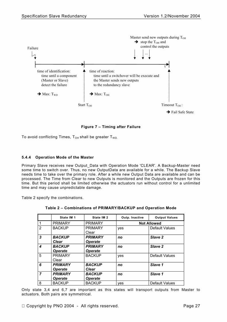
OutputHoldTime (TOH) Events which may cause a change in Primary/Backup role shall be checked before initiate this change. A possible switchover from backup to primary will always start the Output_Hold_Time. The Slave Interface Module always uses the TOH of the last service received.
After a failure the outputs can be hold by last value for a maximum of time, calculate by TRestart=TWD + TOH.
Figure 7 shows the timing after failure.
Copyright by PNO 2004 - All rights reserved. Page 26
Specification Slave Redundancy Version 1.2/November 2004
Failure
ttime of identification:
time until a component (Master or Slave)detect the failure
Max: TWD
time of reaction:time until a switchover will be execute andthe Master sends new outputs to the redundancy slave
Max: TOH
...
Master send new outputs during TOH
stop the TOH and control the outputs
Start TOH Timeout TOH :
Fail Safe State
Figure 7 – Timing after Failure
To avoid conflicting Times, TOH shall be greater TWD.
5.4.4 Operation Mode of the Master
Primary Slave receives new Output_Data with Operation Mode 'CLEAR'. A Backup-Master need some time to switch over. Thus, no new OutputData are available for a while. The Backup Slave needs time to take over the primary role. After a while new Output Data are available and can be processed. The Time from Clear to new Outputs is monitored and the Outputs are frozen for this time. But this period shall be limited otherwise the actuators run without control for a unlimited time and may cause unpredictable damage.
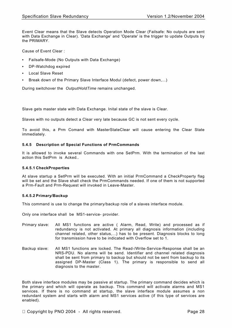
Table 2 specify the combinations.
Table 2 – Combinations of PRIMARY/BACKUP and Operation Mode
State IM 1 State IM 2 Outp. Inactive Output Values
1 PRIMARY PRIMARY Not Allowed 2 BACKUP PRIMARY
Clear yes Default Values
3 BACKUP Clear
PRIMARY Operate
no Slave 2
4 BACKUP Operate
PRIMARY Operate
no Slave 2
5 PRIMARY Clear
BACKUP yes Default Values
6 PRIMARY Operate
BACKUP Clear
no Slave 1
7 PRIMARY Operate
BACKUP Operate
no Slave 1
8 BACKUP BACKUP yes Default Values
Only state 3,4 and 6,7 are important as this states will transport outputs from Master to actuators. Both pairs are symmetrical.
Copyright by PNO 2004 - All rights reserved. Page 27
Specification Slave Redundancy Version 1.2/November 2004
Event Clear means that the Slave detects Operation Mode Clear (Failsafe: No outputs are sent with Data Exchange in Clear). 'Data Exchange' and 'Operate' is the trigger to update Outputs by the PRIMARY.
Cause of Event Clear :
•
•
•
•
Failsafe-Mode (No Outputs with Data Exchange)
DP-Watchdog expired
Local Slave Reset
Break down of the Primary Slave Interface Modul (defect, power down,...)
During switchover the OutputHoldTime remains unchanged.
Slave gets master state with Data Exchange. Inital state of the slave is Clear.
Slaves with no outputs detect a Clear very late because GC is not sent every cycle.
To avoid this, a Prm Comand with MasterStateClear will cause entering the Clear State immediately.
5.4.5 Description of Special Functions of PrmCommands
It is allowed to invoke several Commands with one SetPrm. With the termination of the last action this SetPrm is Acked..
5.4.5.1 CheckProperties
At slave startup a SetPrm will be executed. With an initial PrmCommand a CheckProperty flag will be set and the Slave shall check the PrmCommands needed. If one of them is not supported a Prm-Fault and Prm-Request will invoked in Leave-Master.
5.4.5.2 Primary/Backup
This command is use to change the primary/backup role of a slaves interface module.
Only one interface shall be MS1-service- provider.
Primary slave: All MS1 functions are active ( Alarm, Read, Write) and processed as if redundancy is not activated. At primary all diagnosis information (including channel related, other status,...) has to be present. Diagnosis blocks to long for transmission have to be indicated with Overflow set to 1.
Backup slave: All MS1 functions are locked. The Read-/Write-Service-Response shall be an NRS-PDU. No alarms will be send. Identifier and channel related diagnosis shall be sent from primary to backup but should not be sent from backup to its assigned DP-Master (Class 1). The primary is responsible to send all diagnosis to the master.
Both slave interface modules may be passive at startup. The primary command decides which is the primary and which will operate as backup. This command will activate alarms and MS1 services. If there is no command at startup, the slave interface module assumes a non redundant system and starts with alarm and MS1 services active (if this type of services are enabled).
Copyright by PNO 2004 - All rights reserved. Page 28
Specification Slave Redundancy Version 1.2/November 2004
The new primary slave will send a Red_State diagnosis to the DP-Master to confirm the switchover after the first valid Data Exchange.
Every change in the Red_State will be reported as Red_State diagnosis.
Primary commands of one slave interface module means always backup of the partner interface module. All alarms not acked will be invoked again. Alarm duplication will be detecteced by using the same sequence number. The master will see alarm duplication and will ignore the second one.
Master will send valid output data prior to a primary request.
5.4.5.3 Combined Primary/Backup-Command
The backup command will be executed in this particular case.
5.4.5.4 Stop_MSAC1S
This command shall be used for master redundancy without slave redundancy as well. A backup master will invoke this command to reset the MS1 functions of a DP-Slave. With that feature a seamless takeover of a DP-Slave can be accomplished.
A Stop_MSAC1S command will reset the MS1 AR and locks further MS1 service processing. The alarm processing is also resetted. All not acked alarms will be stored in the DP-Slave but will not result in an alarm service request.
5.4.5.5 Start_MSAC1S
This command shall be used for master redundancy without slave redundancy as well. A backup master will invoke this command to (re-)start the MS1 functions of a DP-Slave. With that feature a seamless takeover of a DP-Slave can be accomplished.
A Start_MSAC1S command will release the MS1 AR and starts further MS1 service processing. The alarm processing is also activated. Stored alarms in the DP-Slave will be processed now.
5.4.5.6 Combined Start_MSAC1S/Stop_MSAC1S
A combined PrmCommands Start/Stop_MSAC1S is possible. Just one acknowledgement will signal the execution of both commands. The Stop command is executed first followed by the Start command.
The combination will result in an Reset_MSAC1S.
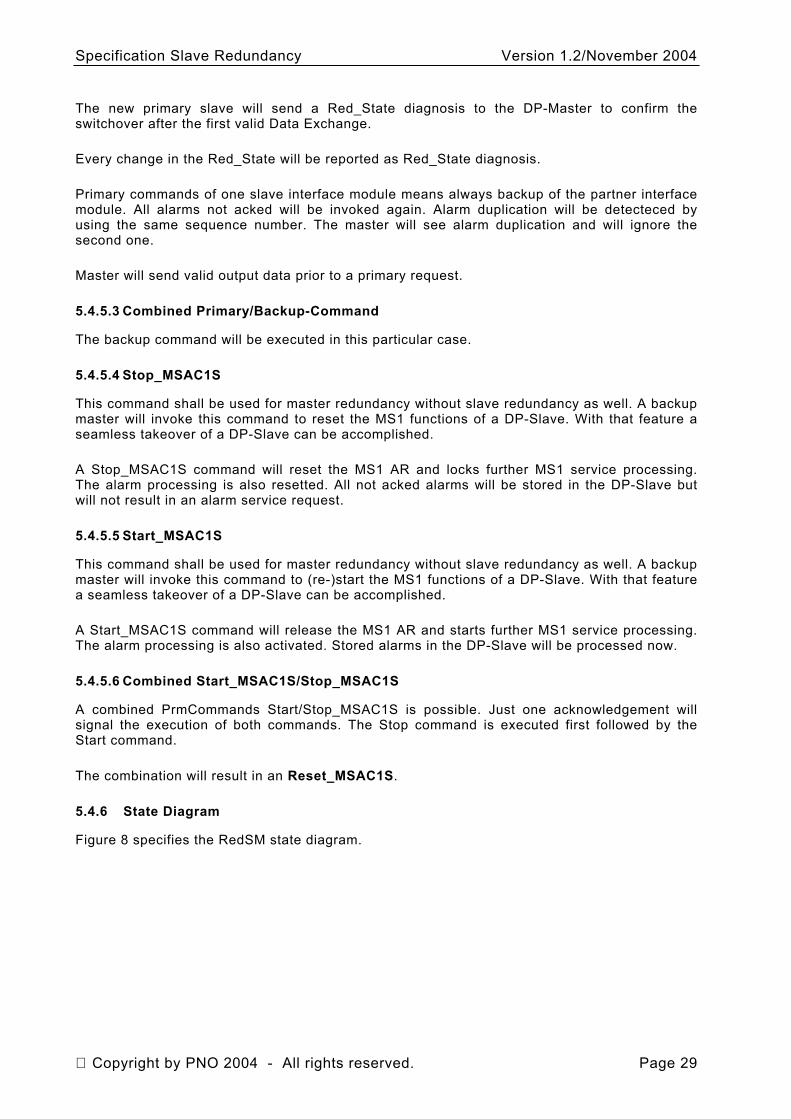
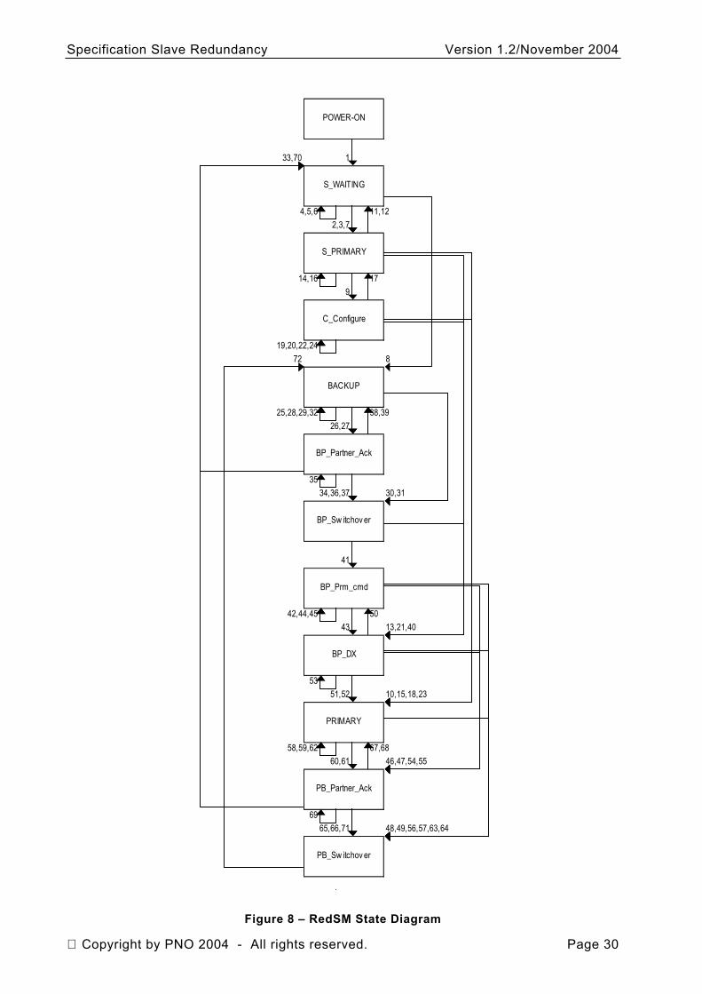
5.4.6 State Diagram
Figure 8 specifies the RedSM state diagram.
Copyright by PNO 2004 - All rights reserved. Page 29
Specification Slave Redundancy Version 1.2/November 2004
POWER-ON
33,70 1
S_WAITING
4,5,6 11,122,3,7
S_PRIMARY
14,16 179
C_Configure
19,20,22,2472 8
BACKUP
25,28,29,32 38,3926,27
BP_Partner_Ack
3534,36,37 30,31
BP_Sw itchov er
41
BP_Prm_cmd
42,44,45 5043 13,21,40
BP_DX
5351,52 10,15,18,23
PRIMARY
58,59,62 67,6860,61 46,47,54,55
PB_Partner_Ack
6965,66,71 48,49,56,57,63,64
PB_Sw itchov er
Figure 8 – RedSM State Diagram
Copyright by PNO 2004 - All rights reserved. Page 30
Specification Slave Redundancy Version 1.2/November 2004
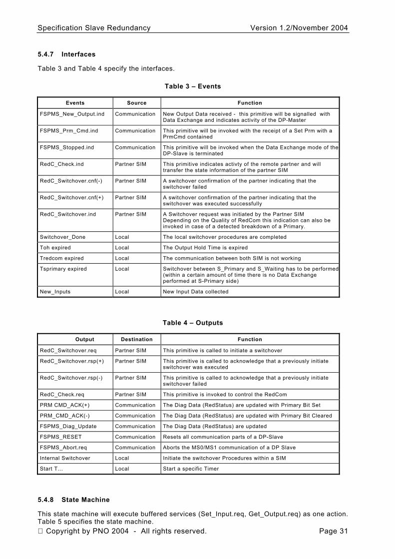
5.4.7 Interfaces
Table 3 and Table 4 specify the interfaces.
Table 3 – Events
Events Source Function
FSPMS_New_Output.ind Communication New Output Data received - this primitive will be signalled with Data Exchange and indicates activity of the DP-Master
FSPMS_Prm_Cmd.ind Communication This primitive will be invoked with the receipt of a Set Prm with a PrmCmd contained
FSPMS_Stopped.ind Communication This primitive will be invoked when the Data Exchange mode of the DP-Slave is terminated
RedC_Check.ind Partner SIM This primitive indicates activty of the remote partner and will transfer the state information of the partner SIM
RedC_Switchover.cnf(-) Partner SIM A switchover confirmation of the partner indicating that the switchover failed
RedC_Switchover.cnf(+) Partner SIM A switchover confirmation of the partner indicating that the switchover was executed successfully
RedC_Switchover.ind Partner SIM A Switchover request was initiated by the Partner SIM Depending on the Quality of RedCom this indication can also be invoked in case of a detected breakdown of a Primary.
Switchover_Done Local The local switchover procedures are completed
Toh expired Local The Output Hold Time is expired
Tredcom expired Local The communication between both SIM is not working
Tsprimary expired Local Switchover between S_Primary and S_Waiting has to be performed(within a certain amount of time there is no Data Exchange performed at S-Primary side)
New_Inputs Local New Input Data collected
Table 4 – Outputs
Output Destination Function
RedC_Switchover.req Partner SIM This primitive is called to initiate a switchover
RedC_Switchover.rsp(+) Partner SIM This primitive is called to acknowledge that a previously initiate switchover was executed
RedC_Switchover.rsp(-) Partner SIM This primitive is called to acknowledge that a previously initiate switchover failed
RedC_Check.req Partner SIM This primitive is invoked to control the RedCom
PRM CMD_ACK(+) Communication The Diag Data (RedStatus) are updated with Primary Bit Set
PRM_CMD_ACK(-) Communication The Diag Data (RedStatus) are updated with Primary Bit Cleared
FSPMS_Diag_Update Communication The Diag Data (RedStatus) are updated
FSPMS_RESET Communication Resets all communication parts of a DP-Slave
FSPMS_Abort.req Communication Aborts the MS0/MS1 communication of a DP Slave
Internal Switchover Local Initiate the switchover Procedures within a SIM
Start T... Local Start a specific Timer
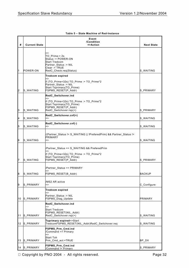
5.4.8 State Machine
This state machine will execute buffered services (Set_Input.req, Get_Output.req) as one action. Table 5 specifies the state machine. Copyright by PNO 2004 - All rights reserved. Page 31
Specification Slave Redundancy Version 1.2/November 2004
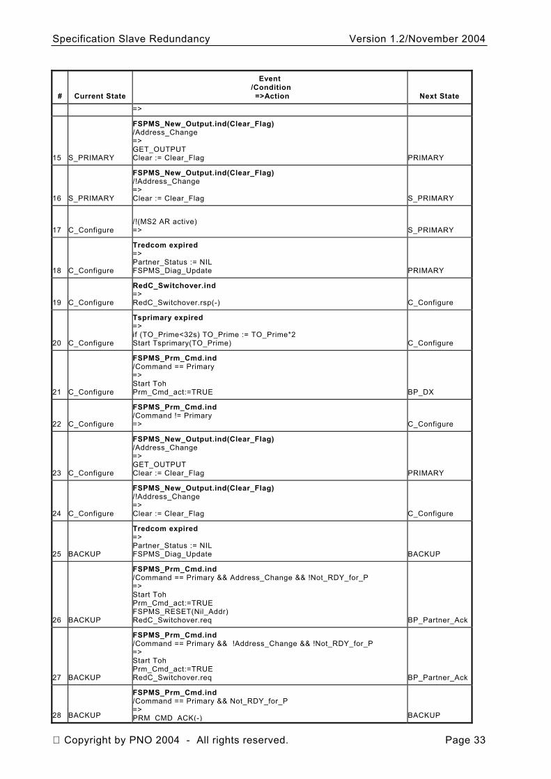
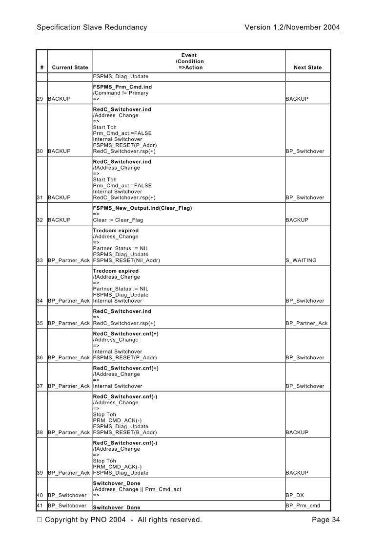
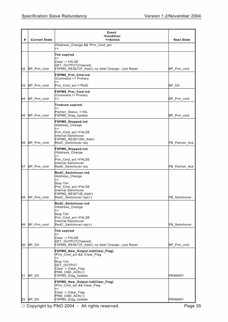
Table 5 – State Machine of Red-Instance
# Current State
Event /Condition =>Action Next State
1 POWER-ON
=> TO_Prime:= 2s Status := POWER-ON Start Tredcom Partner_Status := NIL Clear := TRUE RedC_Check.req(Status) S_WAITING
2 S_WAITING
Tredcom expired => if (TO_Prime<32s) TO_Prime := TO_Prime*2 Partner_Status := NIL Start Tsprimary(TO_Prime) FSPMS_RESET(P_Addr) S_PRIMARY
3 S_WAITING
RedC_Switchover.ind => if (TO_Prime<32s) TO_Prime := TO_Prime*2 Start Tsprimary(TO_Prime) FSPMS_RESET(P_Addr) RedC_Switchover.rsp(+) S_PRIMARY
4 S_WAITING RedC_Switchover.cnf(+) => S_WAITING
5 S_WAITING RedC_Switchover.cnf(-) => S_WAITING
6 S_WAITING
/(Partner_Status != S_WAITING || !PreferedPrim) && Partner_Status != PRIMARY => S_WAITING
7 S_WAITING
/Partner_Status == S_WAITING && PreferedPrim => if (TO_Prime<32s) TO_Prime := TO_Prime*2 Start Tsprimary(TO_Prime) FSPMS_RESET(P_Addr) S_PRIMARY
8 S_WAITING
/Partner_Status == PRIMARY => FSPMS_RESET(B_Addr) BACKUP
9 S_PRIMARY
/MS2 AR active => C_Configure
10 S_PRIMARY
Tredcom expired => Partner_Status := NIL FSPMS_Diag_Update PRIMARY
11 S_PRIMARY
RedC_Switchover.ind => Start Tredcom FSPMS_RESET(NIL_Addr) RedC_Switchover.rsp(+) S_WAITING
12 S_PRIMARY Tsprimary expired=>Start TredcomFSPMS_RESET(NIL_Addr)RedC_Switchover.req S_WAITING
13 S_PRIMARY
FSPMS_Prm_Cmd.ind /Command == Primary => Start Toh Prm_Cmd_act:=TRUE BP_DX
14 S_PRIMARY FSPMS_Prm_Cmd.ind /Command != Primary S_PRIMARY
Copyright by PNO 2004 - All rights reserved. Page 32
Specification Slave Redundancy Version 1.2/November 2004
# Current State
Event /Condition =>Action Next State
=>
15 S_PRIMARY
FSPMS_New_Output.ind(Clear_Flag) /Address_Change => GET_OUTPUT Clear := Clear_Flag PRIMARY
16 S_PRIMARY
FSPMS_New_Output.ind(Clear_Flag) /!Address_Change => Clear := Clear_Flag S_PRIMARY
17 C_Configure
/!(MS2 AR active) => S_PRIMARY
18 C_Configure
Tredcom expired => Partner_Status := NIL FSPMS_Diag_Update PRIMARY
19 C_Configure
RedC_Switchover.ind => RedC_Switchover.rsp(-) C_Configure
20 C_Configure
Tsprimary expired => if (TO_Prime<32s) TO_Prime := TO_Prime*2 Start Tsprimary(TO_Prime) C_Configure
21 C_Configure
FSPMS_Prm_Cmd.ind /Command == Primary => Start Toh Prm_Cmd_act:=TRUE BP_DX
22 C_Configure
FSPMS_Prm_Cmd.ind /Command != Primary => C_Configure
23 C_Configure
FSPMS_New_Output.ind(Clear_Flag) /Address_Change => GET_OUTPUT Clear := Clear_Flag PRIMARY
24 C_Configure
FSPMS_New_Output.ind(Clear_Flag) /!Address_Change => Clear := Clear_Flag C_Configure
25 BACKUP
Tredcom expired => Partner_Status := NIL FSPMS_Diag_Update BACKUP
26 BACKUP
FSPMS_Prm_Cmd.ind /Command == Primary && Address_Change && !Not_RDY_for_P => Start Toh Prm_Cmd_act:=TRUE FSPMS_RESET(Nil_Addr) RedC_Switchover.req BP_Partner_Ack
27 BACKUP
FSPMS_Prm_Cmd.ind /Command == Primary && !Address_Change && !Not_RDY_for_P => Start Toh Prm_Cmd_act:=TRUE RedC_Switchover.req BP_Partner_Ack
28 BACKUP
FSPMS_Prm_Cmd.ind /Command == Primary && Not_RDY_for_P => PRM_CMD_ACK(-) BACKUP
Copyright by PNO 2004 - All rights reserved. Page 33
Specification Slave Redundancy Version 1.2/November 2004
# Current State
Event /Condition =>Action Next State
FSPMS_Diag_Update
29 BACKUP
FSPMS_Prm_Cmd.ind /Command != Primary => BACKUP
30 BACKUP
RedC_Switchover.ind /Address_Change => Start Toh Prm_Cmd_act:=FALSE Internal Switchover FSPMS_RESET(P_Addr) RedC_Switchover.rsp(+) BP_Switchover
31 BACKUP
RedC_Switchover.ind /!Address_Change => Start Toh Prm_Cmd_act:=FALSE Internal Switchover RedC_Switchover.rsp(+) BP_Switchover
32 BACKUP
FSPMS_New_Output.ind(Clear_Flag) => Clear := Clear_Flag BACKUP
33 BP_Partner_Ack
Tredcom expired /Address_Change => Partner_Status := NIL FSPMS_Diag_Update FSPMS_RESET(Nil_Addr) S_WAITING
34 BP_Partner_Ack
Tredcom expired /!Address_Change => Partner_Status := NIL FSPMS_Diag_Update Internal Switchover BP_Switchover
35 BP_Partner_Ack
RedC_Switchover.ind => RedC_Switchover.rsp(+) BP_Partner_Ack
36 BP_Partner_Ack
RedC_Switchover.cnf(+) /Address_Change => Internal Switchover FSPMS_RESET(P_Addr) BP_Switchover
37 BP_Partner_Ack
RedC_Switchover.cnf(+) /!Address_Change => Internal Switchover BP_Switchover
38 BP_Partner_Ack
RedC_Switchover.cnf(-) /Address_Change => Stop Toh PRM_CMD_ACK(-) FSPMS_Diag_Update FSPMS_RESET(B_Addr) BACKUP
39 BP_Partner_Ack
RedC_Switchover.cnf(-) /!Address_Change => Stop Toh PRM_CMD_ACK(-) FSPMS_Diag_Update BACKUP
40 BP_Switchover
Switchover_Done /Address_Change || Prm_Cmd_act => BP_DX
41 BP_Switchover Switchover_Done BP_Prm_cmd
Copyright by PNO 2004 - All rights reserved. Page 34
Specification Slave Redundancy Version 1.2/November 2004
# Current State
Event /Condition =>Action Next State
/!Address_Change && !Prm_Cmd_act =>
42 BP_Prm_cmd
Toh expired => Clear := FALSE GET_OUTPUT(Cleared) FSPMS_RESET(P_Addr); no Addr Change - just Reset BP_Prm_cmd
43 BP_Prm_cmd
FSPMS_Prm_Cmd.ind /Command == Primary => Prm_Cmd_act:=TRUE BP_DX
44 BP_Prm_cmd
FSPMS_Prm_Cmd.ind /Command != Primary => BP_Prm_cmd
45 BP_Prm_cmd
Tredcom expired => Partner_Status := NIL FSPMS_Diag_Update BP_Prm_cmd
46 BP_Prm_cmd
FSPMS_Stopped.ind /Address_Change => Prm_Cmd_act:=FALSE Internal Switchover FSPMS_RESET(Nil_Addr) RedC_Switchover.req PB_Partner_Ack
47 BP_Prm_cmd
FSPMS_Stopped.ind /!Address_Change => Prm_Cmd_act:=FALSE Internal Switchover RedC_Switchover.req PB_Partner_Ack
48 BP_Prm_cmd
RedC_Switchover.ind /Address_Change => Stop Toh Prm_Cmd_act:=FALSE Internal Switchover FSPMS_RESET(B_Addr) RedC_Switchover.rsp(+) PB_Switchover
49 BP_Prm_cmd
RedC_Switchover.ind /!Address_Change => Stop Toh Prm_Cmd_act:=FALSE Internal Switchover RedC_Switchover.rsp(+) PB_Switchover
50 BP_DX
Toh expired => Clear := FALSE GET_OUTPUT(Cleared) FSPMS_RESET(P_Addr); no Addr Change - just Reset BP_Prm_cmd
51 BP_DX
FSPMS_New_Output.ind(Clear_Flag) /Prm_Cmd_act && !Clear_Flag => Stop Toh GET_OUTPUT Clear := Clear_Flag PRM_CMD_ACK(+) FSPMS_Diag_Update PRIMARY
52 BP_DX
FSPMS_New_Output.ind(Clear_Flag) /Prm_Cmd_act && Clear_Flag => Clear := Clear_Flag PRM_CMD_ACK(+) FSPMS_Diag_Update PRIMARY
Copyright by PNO 2004 - All rights reserved. Page 35
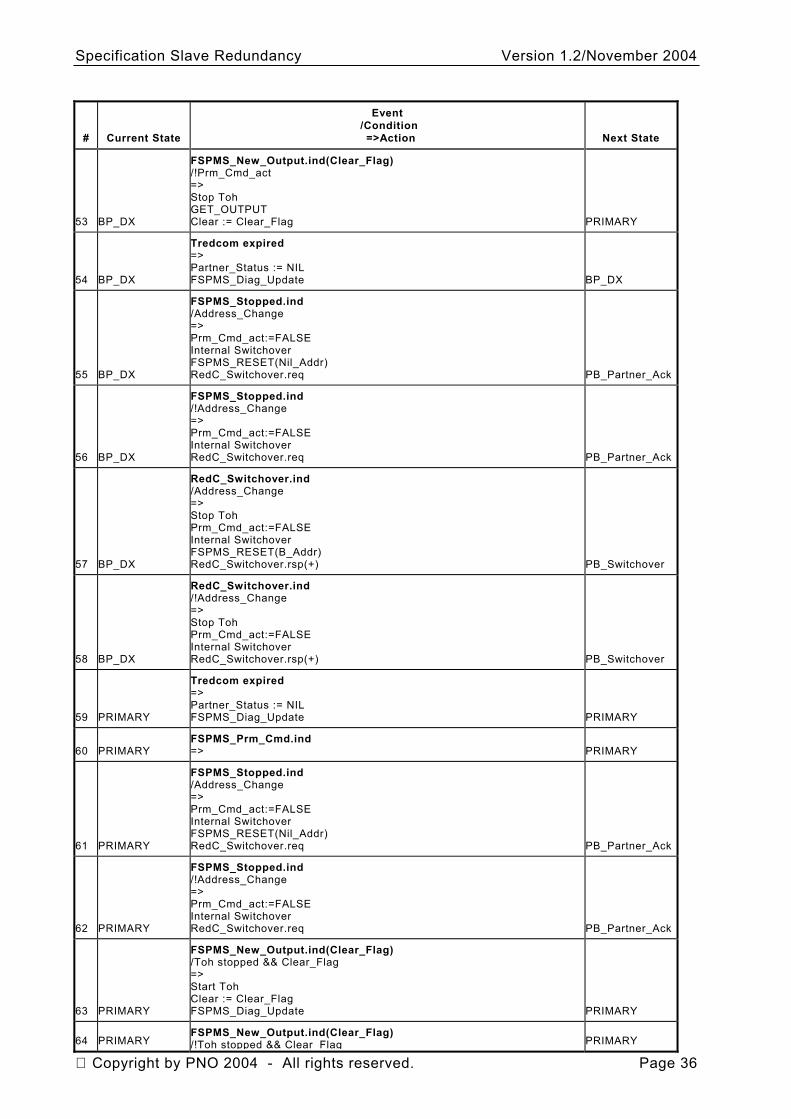
Specification Slave Redundancy Version 1.2/November 2004
# Current State
Event /Condition =>Action Next State
53 BP_DX
FSPMS_New_Output.ind(Clear_Flag) /!Prm_Cmd_act => Stop Toh GET_OUTPUT Clear := Clear_Flag PRIMARY
54 BP_DX
Tredcom expired => Partner_Status := NIL FSPMS_Diag_Update BP_DX
55 BP_DX
FSPMS_Stopped.ind /Address_Change => Prm_Cmd_act:=FALSE Internal Switchover FSPMS_RESET(Nil_Addr) RedC_Switchover.req PB_Partner_Ack
56 BP_DX
FSPMS_Stopped.ind /!Address_Change => Prm_Cmd_act:=FALSE Internal Switchover RedC_Switchover.req PB_Partner_Ack
57 BP_DX
RedC_Switchover.ind /Address_Change => Stop Toh Prm_Cmd_act:=FALSE Internal Switchover FSPMS_RESET(B_Addr) RedC_Switchover.rsp(+) PB_Switchover
58 BP_DX
RedC_Switchover.ind /!Address_Change => Stop Toh Prm_Cmd_act:=FALSE Internal Switchover RedC_Switchover.rsp(+) PB_Switchover
59 PRIMARY
Tredcom expired => Partner_Status := NIL FSPMS_Diag_Update PRIMARY
60 PRIMARY FSPMS_Prm_Cmd.ind => PRIMARY
61 PRIMARY
FSPMS_Stopped.ind /Address_Change => Prm_Cmd_act:=FALSE Internal Switchover FSPMS_RESET(Nil_Addr) RedC_Switchover.req PB_Partner_Ack
62 PRIMARY
FSPMS_Stopped.ind /!Address_Change => Prm_Cmd_act:=FALSE Internal Switchover RedC_Switchover.req PB_Partner_Ack
63 PRIMARY
FSPMS_New_Output.ind(Clear_Flag) /Toh stopped && Clear_Flag => Start Toh Clear := Clear_Flag FSPMS_Diag_Update PRIMARY
64 PRIMARY FSPMS_New_Output.ind(Clear_Flag) /!Toh stopped && Clear_Flag PRIMARY
Copyright by PNO 2004 - All rights reserved. Page 36
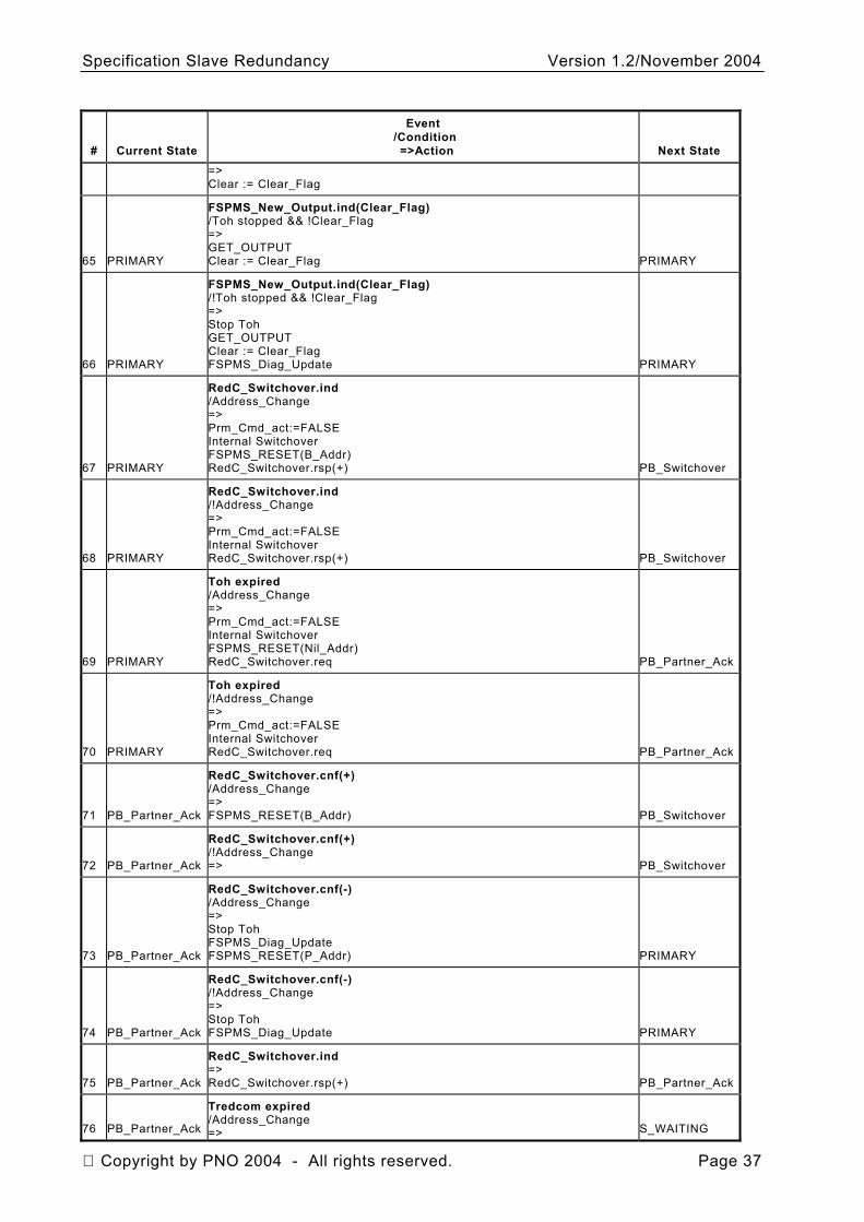
Specification Slave Redundancy Version 1.2/November 2004
# Current State
Event /Condition =>Action Next State
=> Clear := Clear_Flag
65 PRIMARY
FSPMS_New_Output.ind(Clear_Flag) /Toh stopped && !Clear_Flag => GET_OUTPUT Clear := Clear_Flag PRIMARY
66 PRIMARY
FSPMS_New_Output.ind(Clear_Flag) /!Toh stopped && !Clear_Flag => Stop Toh GET_OUTPUT Clear := Clear_Flag FSPMS_Diag_Update PRIMARY
67 PRIMARY
RedC_Switchover.ind /Address_Change => Prm_Cmd_act:=FALSE Internal Switchover FSPMS_RESET(B_Addr) RedC_Switchover.rsp(+) PB_Switchover
68 PRIMARY
RedC_Switchover.ind /!Address_Change => Prm_Cmd_act:=FALSE Internal Switchover RedC_Switchover.rsp(+) PB_Switchover
69 PRIMARY
Toh expired /Address_Change => Prm_Cmd_act:=FALSE Internal Switchover FSPMS_RESET(Nil_Addr) RedC_Switchover.req PB_Partner_Ack
70 PRIMARY
Toh expired /!Address_Change => Prm_Cmd_act:=FALSE Internal Switchover RedC_Switchover.req PB_Partner_Ack
71 PB_Partner_Ack
RedC_Switchover.cnf(+) /Address_Change => FSPMS_RESET(B_Addr) PB_Switchover
72 PB_Partner_Ack
RedC_Switchover.cnf(+) /!Address_Change => PB_Switchover
73 PB_Partner_Ack
RedC_Switchover.cnf(-) /Address_Change => Stop Toh FSPMS_Diag_Update FSPMS_RESET(P_Addr) PRIMARY
74 PB_Partner_Ack
RedC_Switchover.cnf(-) /!Address_Change => Stop Toh FSPMS_Diag_Update PRIMARY
75 PB_Partner_Ack
RedC_Switchover.ind => RedC_Switchover.rsp(+) PB_Partner_Ack
76 PB_Partner_Ack
Tredcom expired /Address_Change => S_WAITING
Copyright by PNO 2004 - All rights reserved. Page 37
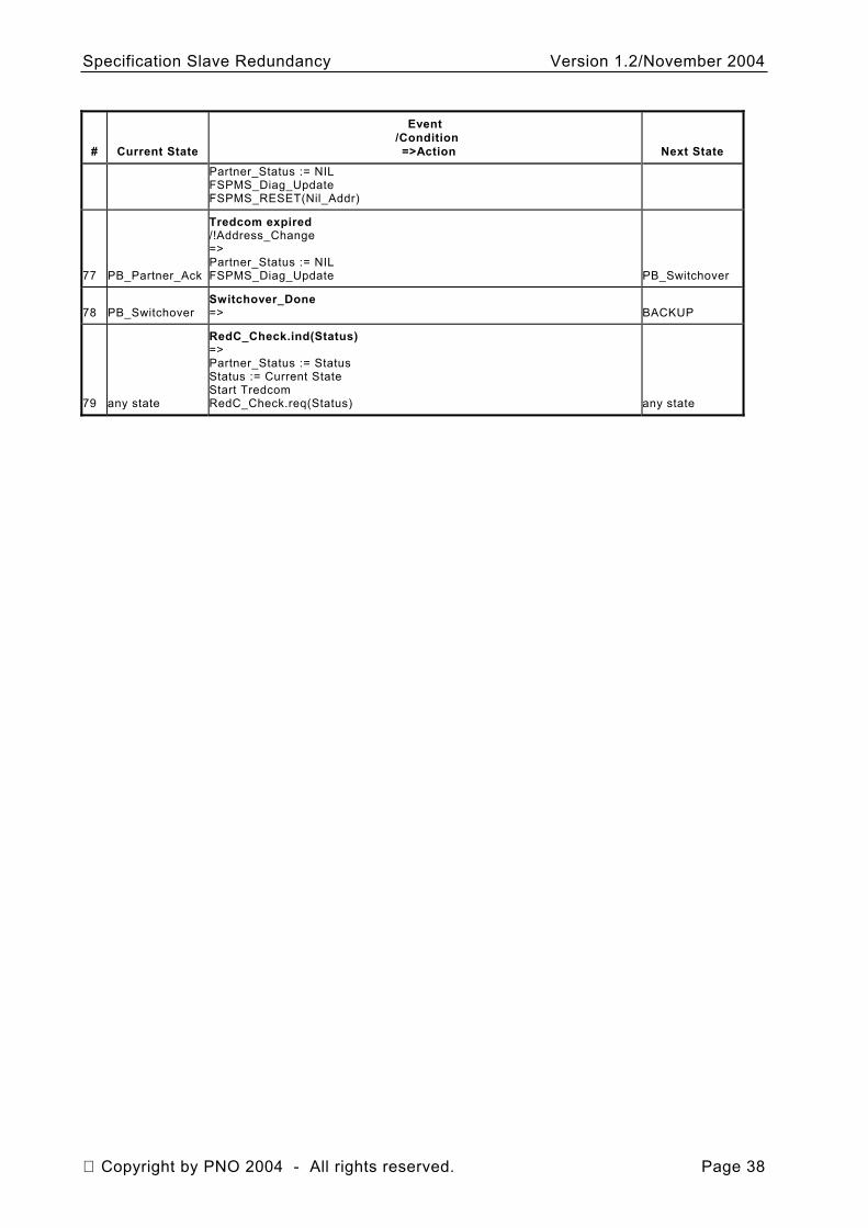
Specification Slave Redundancy Version 1.2/November 2004
# Current State
Event /Condition =>Action Next State
Partner_Status := NIL FSPMS_Diag_Update FSPMS_RESET(Nil_Addr)
77 PB_Partner_Ack
Tredcom expired /!Address_Change => Partner_Status := NIL FSPMS_Diag_Update PB_Switchover
78 PB_Switchover Switchover_Done => BACKUP
79 any state
RedC_Check.ind(Status) => Partner_Status := Status Status := Current State Start Tredcom RedC_Check.req(Status) any state
Copyright by PNO 2004 - All rights reserved. Page 38
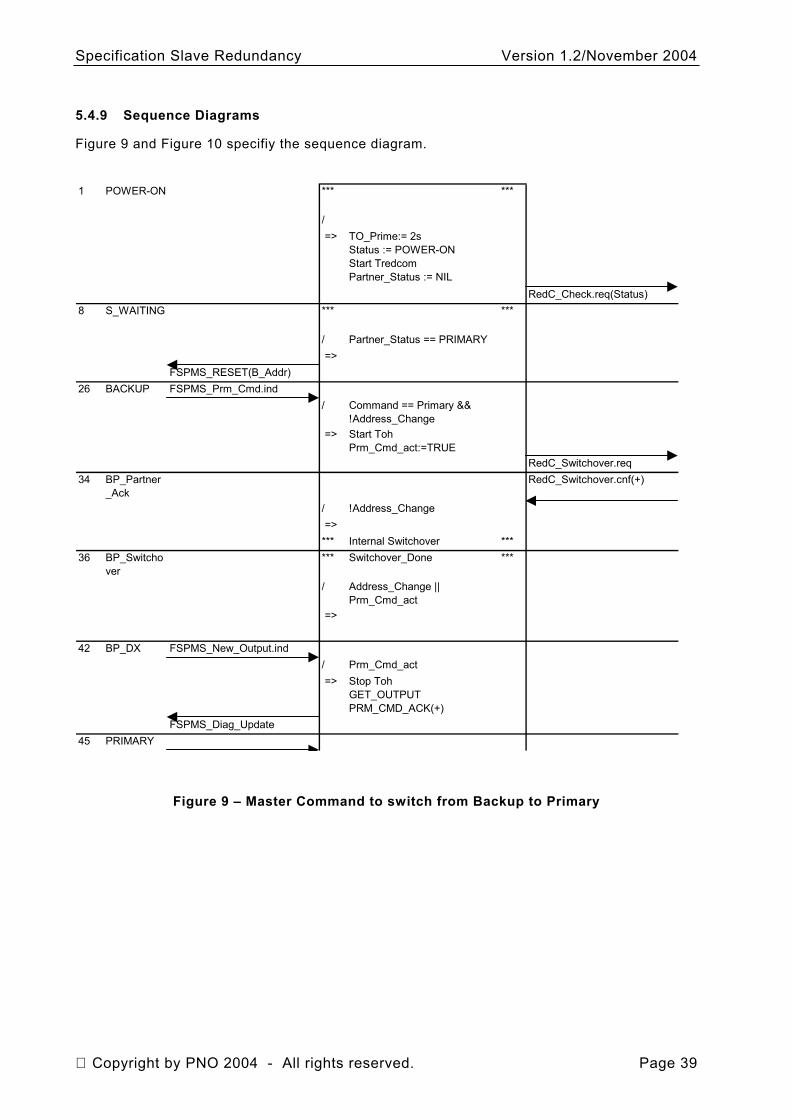
Specification Slave Redundancy Version 1.2/November 2004
5.4.9 Sequence Diagrams
Figure 9 and Figure 10 specifiy the sequence diagram.
1 POWER-ON *** ***
/ => TO_Prime:= 2s
Status := POWER-ONStart TredcomPartner_Status := NIL
RedC_Check.req(Status)8 S_WAITING *** ***
/ Partner_Status == PRIMARY =>
FSPMS_RESET(B_Addr)26 BACKUP FSPMS_Prm_Cmd.ind
/ Command == Primary && !Address_Change
=> Start TohPrm_Cmd_act:=TRUE
RedC_Switchover.req34 BP_Partner
_AckRedC_Switchover.cnf(+)
/ !Address_Change =>*** Internal Switchover ***
36 BP_Switchover
*** Switchover_Done ***
/ Address_Change || Prm_Cmd_act
=>
42 BP_DX FSPMS_New_Output.ind/ Prm_Cmd_act => Stop Toh
GET_OUTPUTPRM_CMD_ACK(+)
FSPMS_Diag_Update45 PRIMARY
Figure 9 – Master Command to switch from Backup to Primary
Copyright by PNO 2004 - All rights reserved. Page 39
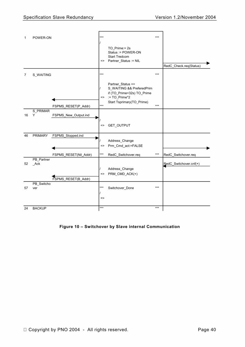
Specification Slave Redundancy Version 1.2/November 2004
1 POWER-ON *** ***/
=>
TO_Prime:= 2sStatus := POWER-ONStart TredcomPartner_Status := NIL
RedC_Check.req(Status)
7 S_WAITING *** ***
/Partner_Status == S_WAITING && PreferedPrim
=>if (TO_Prime<32s) TO_Prime := TO_Prime*2
FSPMS_RESET(P_Addr) ***Start Tsprimary(TO_Prime)
***
16S_PRIMARY FSPMS_New_Output.ind
/ => GET_OUTPUT
46 PRIMARY FSPMS_Stopped.ind/ Address_Change => Prm_Cmd_act:=FALSE
FSPMS_RESET(Nil_Addr) *** RedC_Switchover.req *** RedC_Switchover.req
52PB_Partner_Ack RedC_Switchover.cnf(+)
/ Address_Change => PRM_CMD_ACK(+)
FSPMS_RESET(B_Addr)
57PB_Switchover *** Switchover_Done ***
/ =>
24 BACKUP *** ***
Figure 10 – Switchover by Slave internal Communication
Copyright by PNO 2004 - All rights reserved. Page 40
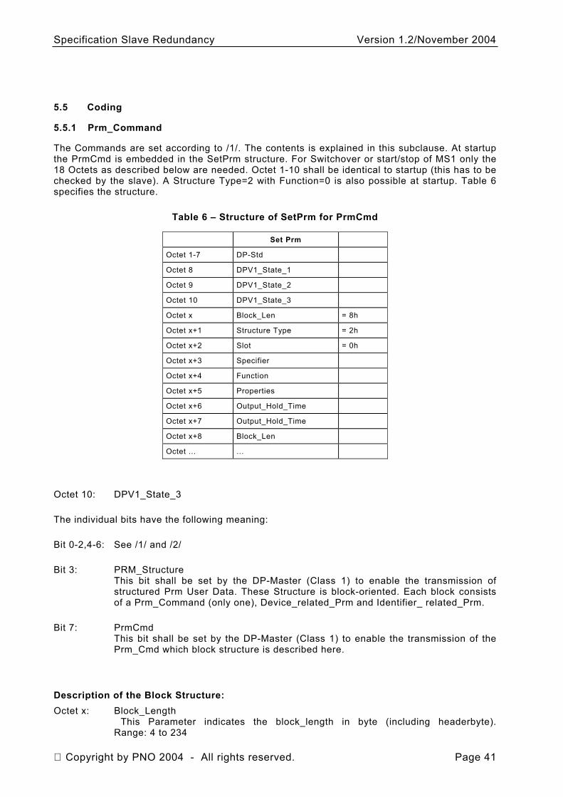
Specification Slave Redundancy Version 1.2/November 2004
5.5 Coding
5.5.1 Prm_Command
The Commands are set according to /1/. The contents is explained in this subclause. At startup the PrmCmd is embedded in the SetPrm structure. For Switchover or start/stop of MS1 only the 18 Octets as described below are needed. Octet 1-10 shall be identical to startup (this has to be checked by the slave). A Structure Type=2 with Function=0 is also possible at startup. Table 6 specifies the structure.
Table 6 – Structure of SetPrm for PrmCmd
Set Prm
Octet 1-7 DP-Std
Octet 8 DPV1_State_1
Octet 9 DPV1_State_2
Octet 10 DPV1_State_3
Octet x Block_Len = 8h
Octet x+1 Structure Type = 2h
Octet x+2 Slot = 0h
Octet x+3 Specifier
Octet x+4 Function
Octet x+5 Properties
Octet x+6 Output_Hold_Time
Octet x+7 Output_Hold_Time
Octet x+8 Block_Len
Octet ... ...
Octet 10: DPV1_State_3
The individual bits have the following meaning:
Bit 0-2,4-6: See /1/ and /2/
Bit 3: PRM_Structure This bit shall be set by the DP-Master (Class 1) to enable the transmission of structured Prm User Data. These Structure is block-oriented. Each block consists of a Prm_Command (only one), Device_related_Prm and Identifier_ related_Prm.
Bit 7: PrmCmd This bit shall be set by the DP-Master (Class 1) to enable the transmission of the Prm_Cmd which block structure is described here.
Description of the Block Structure: Octet x: Block_Length
This Parameter indicates the block_length in byte (including headerbyte). Range: 4 to 234
Copyright by PNO 2004 - All rights reserved. Page 41
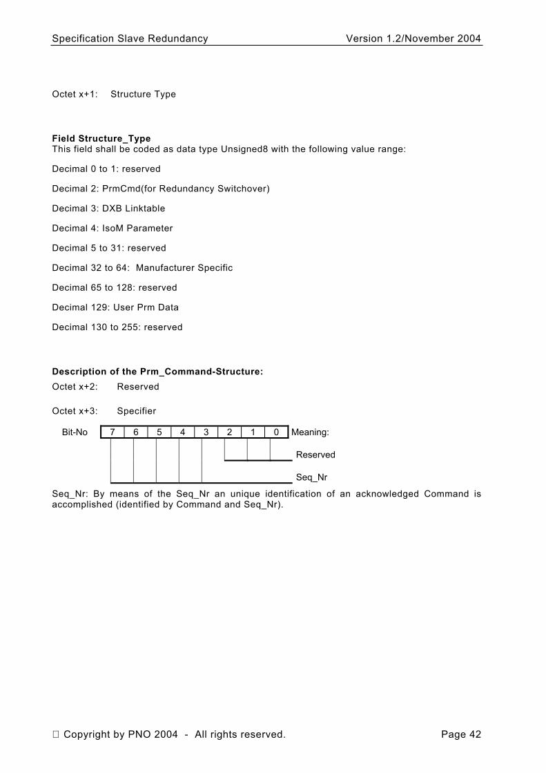
Specification Slave Redundancy Version 1.2/November 2004
Octet x+1: Structure Type
Field Structure_Type This field shall be coded as data type Unsigned8 with the following value range:
Decimal 0 to 1: reserved
Decimal 2: PrmCmd(for Redundancy Switchover)
Decimal 3: DXB Linktable
Decimal 4: IsoM Parameter
Decimal 5 to 31: reserved
Decimal 32 to 64: Manufacturer Specific
Decimal 65 to 128: reserved
Decimal 129: User Prm Data
Decimal 130 to 255: reserved
Description of the Prm_Command-Structure: Octet x+2: Reserved
Octet x+3: Specifier
Bit-No 7 6 5 4 3 2 1 0 Meaning: Reserved Seq_Nr
Seq_Nr: By means of the Seq_Nr an unique identification of an acknowledged Command is accomplished (identified by Command and Seq_Nr).
Copyright by PNO 2004 - All rights reserved. Page 42
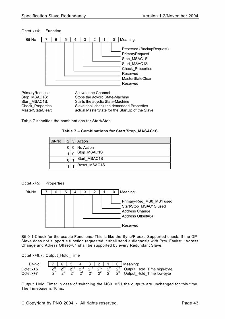
Specification Slave Redundancy Version 1.2/November 2004
Octet x+4: Function
Bit-No 7 6 5 4 3 2 1 0 Meaning: Reserved (BackupRequest) PrimaryRequest Stop_MSAC1S Start_MSAC1S Check_Properties Reserved MasterStateClear Reserved
PrimaryRequest: Activate the Channel Stop_MSAC1S: Stops the acyclic State-Machine Start_MSAC1S: Starts the acyclic State-Machine Check_Properties: Slave shall check the demanded Properties MasterStateClear: actual MasterState for the StartUp of the Slave Table 7 specifies the combinations for Start/Stop.
Table 7 – Combinations for Start/Stop_MASAC1S
Bit-No 2 3 Action
0 0 No Action
1 0 Stop_MSAC1S
0 1 Start_MSAC1S
1 1 Reset_MSAC1S
Octet x+5: Properties
Bit-No 7 6 5 4 3 2 1 0 Meaning: Primary-Req_MS0_MS1 used Start/Stop_MSAC1S used Address Change Address Offset=64 Reserved
Bit 0-1: Check for the usable Functions. This is like the Sync/Freeze-Supported-check. If the DP-Slave does not support a function requested it shall send a diagnosis with Prm_Fault=1. Adress Change and Adress Offset=64 shall be supported by every Redundant Slave.
Octet x+6,7: Output_Hold_Time
Bit-No 7 6 5 4 3 2 1 0 Meaning: Octet x+6 215 214 213 212 211 210 29 28 Output_Hold_Time high-byte Octet x+7 27 26 25 24 23 22 21 20 Output_Hold_Time low-byte
Output_Hold_Time: In case of switching the MS0_MS1 the outputs are unchanged for this time. The Timebase is 10ms.
Copyright by PNO 2004 - All rights reserved. Page 43
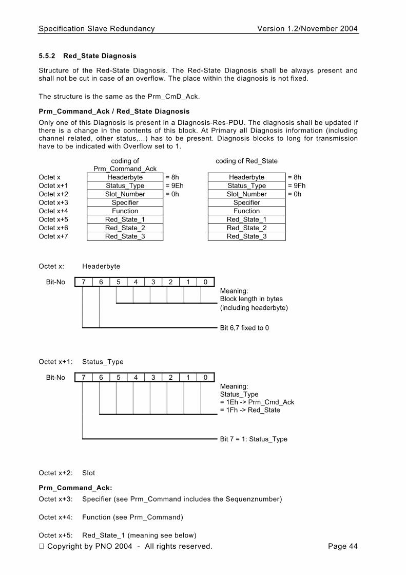
Specification Slave Redundancy Version 1.2/November 2004
5.5.2 Red_State Diagnosis
Structure of the Red-State Diagnosis. The Red-State Diagnosis shall be always present and shall not be cut in case of an overflow. The place within the diagnosis is not fixed.
The structure is the same as the Prm_CmD_Ack.
Prm_Command_Ack / Red_State Diagnosis Only one of this Diagnosis is present in a Diagnosis-Res-PDU. The diagnosis shall be updated if there is a change in the contents of this block. At Primary all Diagnosis information (including channel related, other status,...) has to be present. Diagnosis blocks to long for transmission have to be indicated with Overflow set to 1.
coding of Prm_Command_Ack
coding of Red_State
Octet x Headerbyte = 8h Headerbyte = 8h Octet x+1 Status_Type = 9Eh Status_Type = 9Fh Octet x+2 Slot_Number = 0h Slot_Number = 0h Octet x+3 Specifier Specifier Octet x+4 Function Function Octet x+5 Red_State_1 Red_State_1 Octet x+6 Red_State_2 Red_State_2 Octet x+7 Red_State_3 Red_State_3
Octet x: Headerbyte
Bit-No 7 6 5 4 3 2 1 0 Meaning: Block length in bytes (including headerbyte) Bit 6,7 fixed to 0
Octet x+1: Status_Type
Bit-No 7 6 5 4 3 2 1 0 Meaning: Status_Type
= 1Eh -> Prm_Cmd_Ack = 1Fh -> Red_State
Bit 7 = 1: Status_Type
Octet x+2: Slot
Prm_Command_Ack: Octet x+3: Specifier (see Prm_Command includes the Sequenznumber)
Octet x+4: Function (see Prm_Command)
Octet x+5: Red_State_1 (meaning see below) Copyright by PNO 2004 - All rights reserved. Page 44
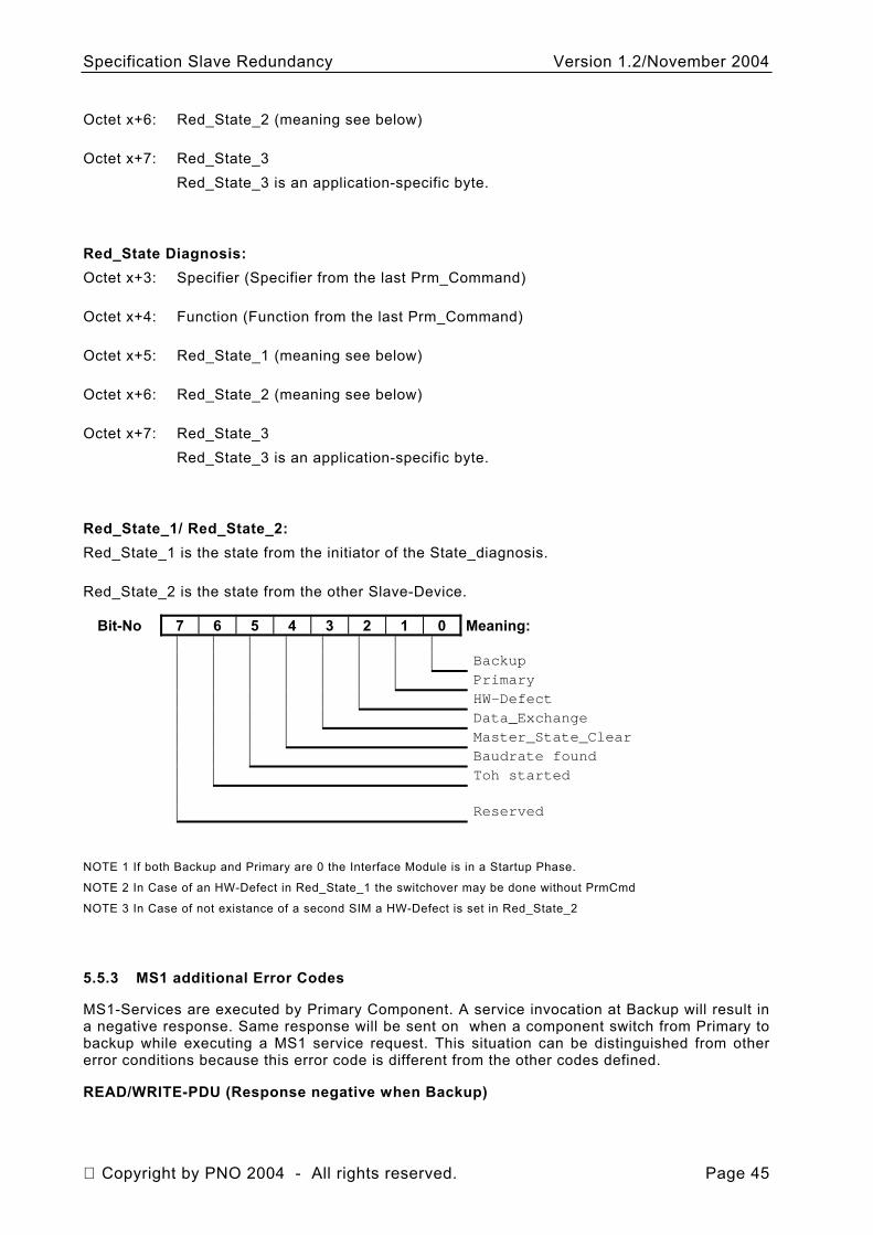
Specification Slave Redundancy Version 1.2/November 2004
Octet x+6: Red_State_2 (meaning see below)
Octet x+7: Red_State_3 Red_State_3 is an application-specific byte.
Red_State Diagnosis: Octet x+3: Specifier (Specifier from the last Prm_Command)
Octet x+4: Function (Function from the last Prm_Command)
Octet x+5: Red_State_1 (meaning see below)
Octet x+6: Red_State_2 (meaning see below)
Octet x+7: Red_State_3 Red_State_3 is an application-specific byte.
Red_State_1/ Red_State_2: Red_State_1 is the state from the initiator of the State_diagnosis.
Red_State_2 is the state from the other Slave-Device.
Bit-No 7 6 5 4 3 2 1 0 Meaning: Backup
Primary
HW-Defect
Data_Exchange
Master_State_Clear
Baudrate found
Toh started
Reserved
NOTE 1 If both Backup and Primary are 0 the Interface Module is in a Startup Phase.
NOTE 2 In Case of an HW-Defect in Red_State_1 the switchover may be done without PrmCmd
NOTE 3 In Case of not existance of a second SIM a HW-Defect is set in Red_State_2
5.5.3 MS1 additional Error Codes
MS1-Services are executed by Primary Component. A service invocation at Backup will result in a negative response. Same response will be sent on when a component switch from Primary to backup while executing a MS1 service request. This situation can be distinguished from other error conditions because this error code is different from the other codes defined.
READ/WRITE-PDU (Response negative when Backup)
Copyright by PNO 2004 - All rights reserved. Page 45
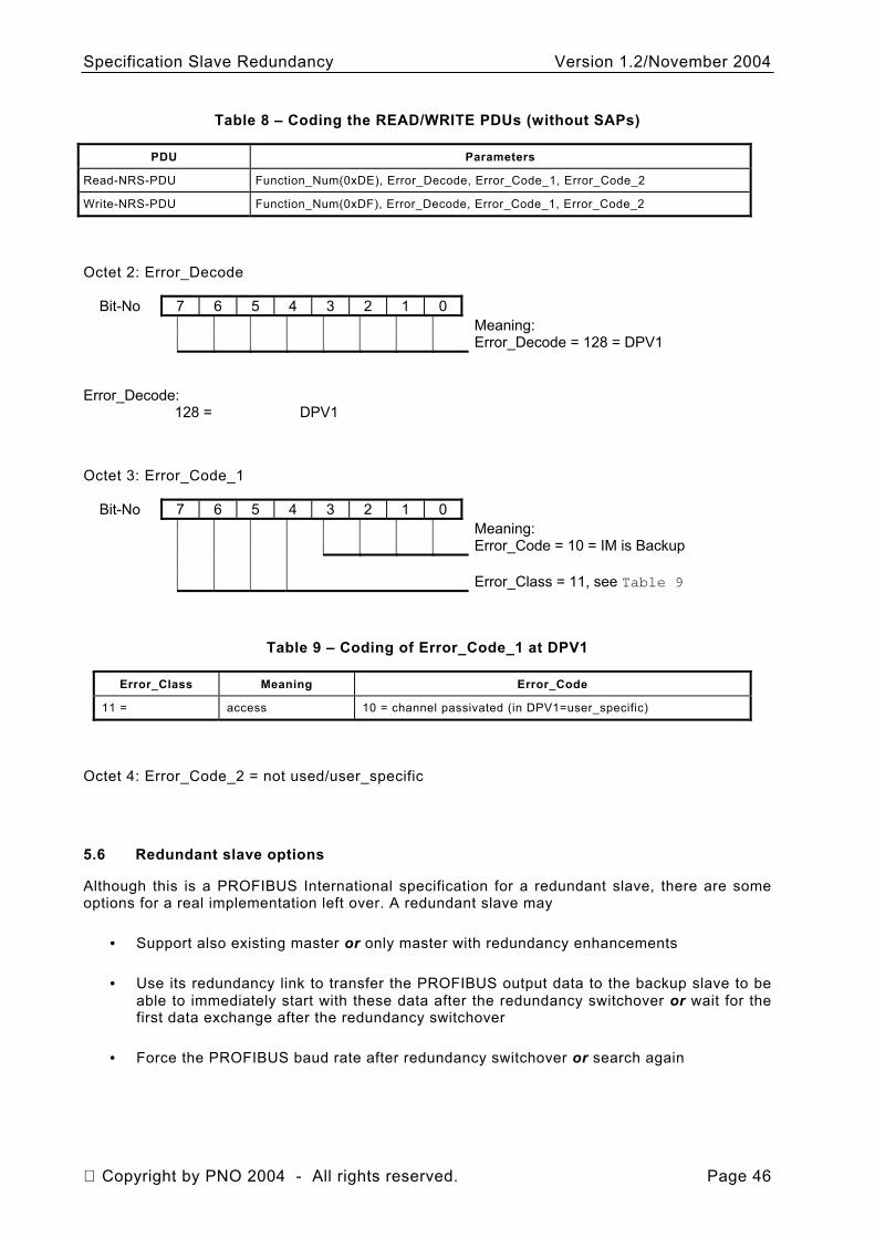
Specification Slave Redundancy Version 1.2/November 2004
Table 8 – Coding the READ/WRITE PDUs (without SAPs)
PDU Parameters
Read-NRS-PDU Function_Num(0xDE), Error_Decode, Error_Code_1, Error_Code_2
Write-NRS-PDU Function_Num(0xDF), Error_Decode, Error_Code_1, Error_Code_2
Octet 2: Error_Decode
Bit-No 7 6 5 4 3 2 1 0 Meaning: Error_Decode = 128 = DPV1
Error_Decode:
128 = DPV1
Octet 3: Error_Code_1
Bit-No 7 6 5 4 3 2 1 0 Meaning: Error_Code = 10 = IM is Backup Error_Class = 11, see Table 9
Table 9 – Coding of Error_Code_1 at DPV1
Error_Class Meaning Error_Code
11 = access 10 = channel passivated (in DPV1=user_specific)
Octet 4: Error_Code_2 = not used/user_specific
5.6 Redundant slave options
Although this is a PROFIBUS International specification for a redundant slave, there are some options for a real implementation left over. A redundant slave may
• Support also existing master or only master with redundancy enhancements
• Use its redundancy link to transfer the PROFIBUS output data to the backup slave to be able to immediately start with these data after the redundancy switchover or wait for the first data exchange after the redundancy switchover
• Force the PROFIBUS baud rate after redundancy switchover or search again
Copyright by PNO 2004 - All rights reserved. Page 46
Specification Slave Redundancy Version 1.2/November 2004
Annex A (informative)
Alarm Behaviour
A.1 Overview
• An Alarm is a device specific diagnosis and will be received by the master with an acyclic service. (For details see /1/ and /2/)
• No alarm can get lost
• An alarm doubling can be checked by the master
• An alarm shall be stored at both SIMs for repetition
A.2 Description
A.2.1 Sequence number
The sequence number will be used for checking of the repetition. For each alarm type an own sequence number is used. The master stores the last sequence number from each type. If the master receives an alarm with the same sequence number as stored, the alarm will be filtered by the master. The master waits for an alarm with the sequence number like stored increased by one.
The slave uses the sequence number from 1 to 31 monotonously increasing for each alarm type. The slave can send a maximum of 30 alarms at the same time or fewer if requested by parameterisation. One sequence number must stay free for correct working of the repetition check. The number 0 is reserved for alarms without repetition control. The master will not filter alarms with the sequence number 0.
After a switchover, the new primary will continue seamlessly with the sequence number. The sequence number is a part of the specifier (Octet 4) of an alarm PDU. /1/
Copyright by PNO 2004 - All rights reserved. Page 47
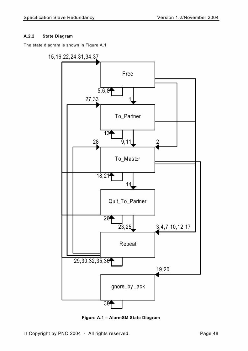
Specification Slave Redundancy Version 1.2/November 2004
A.2.2 State Diagram
The state diagram is shown in Figure A.1
15,16,22,24,31,34,37
Free
5,6,827,33 1
To_Partner
1328 9,11 2
To_Master
18,2114
Quit_To_Partner
2623,25 3,4,7,10,12,17
Repeat
29,30,32,35,3619,20
Ignore_by _ack
38
Figure A.1 – AlarmSM State Diagram
Copyright by PNO 2004 - All rights reserved. Page 48
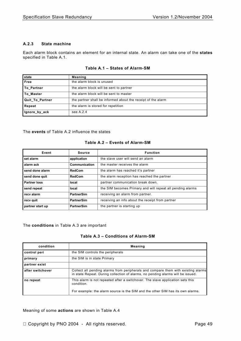
Specification Slave Redundancy Version 1.2/November 2004
A.2.3 State machine
Each alarm block contains an element for an internal state. An alarm can take one of the states specified in Table A.1.
Table A.1 – States of Alarm-SM
state Meaning Free the alarm block is unused
To_Partner the alarm block will be sent to partner
To_Master the alarm block will be sent to master
Quit_To_Partner the partner shall be informed about the receipt of the alarm
Repeat the alarm is stored for repetition
Ignore_by_ack see A.2.4
The events of Table A.2 influence the states
Table A.2 – Events of Alarm-SM
Event Source Function
set alarm application the slave user will send an alarm
alarm ack Communication the master receives the alarm
send done alarm RedCom the alarm has reached it’s partner
send done quit RedCom the alarm reception has reached the partner
Partner loss local partner communication break down.
send repeat local the SIM becomes Primary and will repeat all pending alarms
recv alarm PartnerSim receiving an alarm from partner.
recv quit PartnerSim receiving an info about the receipt from partner
partner start up PartnerSim the partner is starting up
The conditions in Table A.3 are important
Table A.3 – Conditions of Alarm-SM
condition Meaning
control peri the SIM controls the peripherals
primary the SIM is in state Primary
partner exist
after switchover Collect all pending alarms from peripherals and compare them with existing alarmsin state Repeat. During collection of alarms, no pending alarms will be issued.
no repeat This alarm is not repeated after a switchover. The slave application sets this condition. For example: the alarm source is the SIM and the other SIM has its own alarms.
Meaning of some actions are shown in Table A.4
Copyright by PNO 2004 - All rights reserved. Page 49
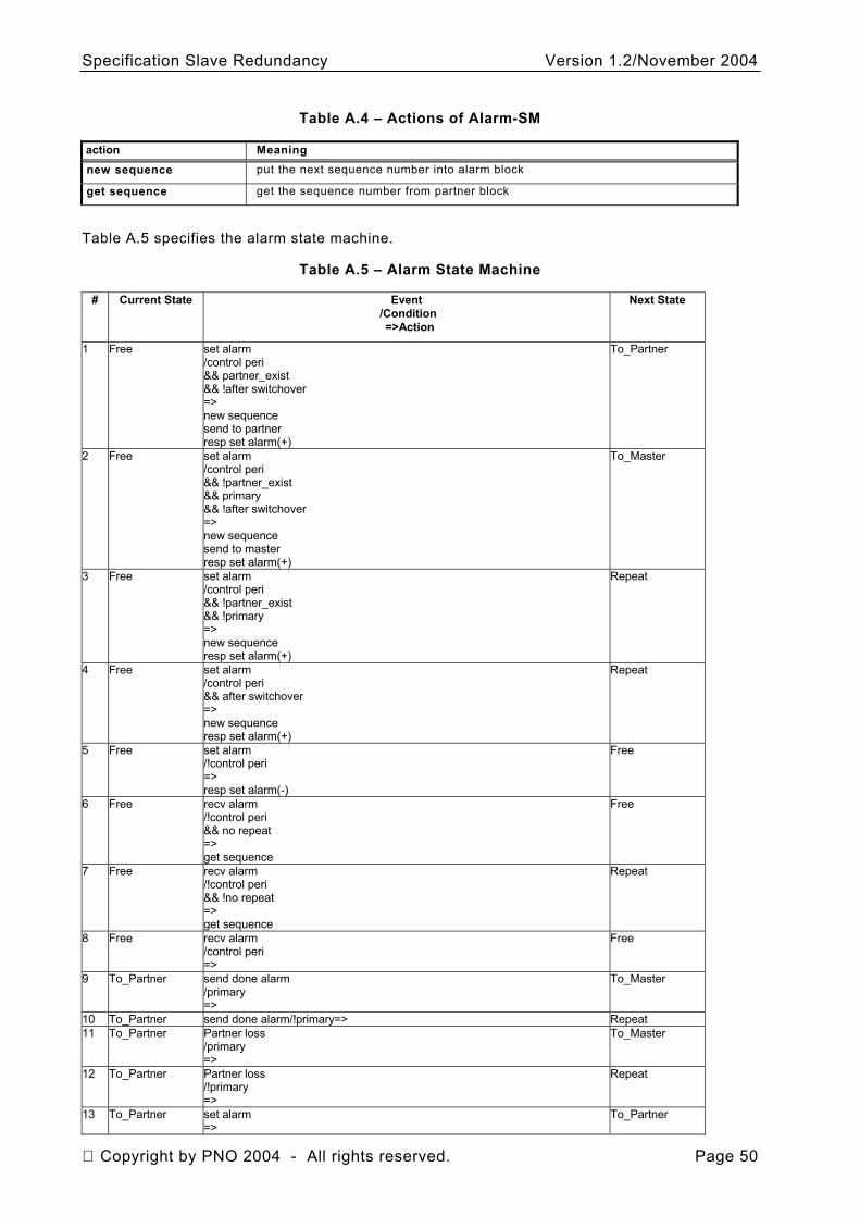
Specification Slave Redundancy Version 1.2/November 2004
Table A.4 – Actions of Alarm-SM
action Meaning new sequence put the next sequence number into alarm block
get sequence get the sequence number from partner block
Table A.5 specifies the alarm state machine.
Table A.5 – Alarm State Machine
# Current State Event /Condition =>Action
Next State
1 Free set alarm /control peri && partner_exist && !after switchover => new sequence send to partner resp set alarm(+)
To_Partner
2 Free set alarm /control peri && !partner_exist && primary && !after switchover => new sequence send to master resp set alarm(+)
To_Master
3 Free set alarm /control peri && !partner_exist && !primary => new sequence resp set alarm(+)
Repeat
4 Free set alarm /control peri && after switchover => new sequence resp set alarm(+)
Repeat
5 Free set alarm /!control peri => resp set alarm(-)
Free
6 Free recv alarm /!control peri && no repeat => get sequence
Free
7 Free recv alarm /!control peri && !no repeat => get sequence
Repeat
8 Free recv alarm /control peri =>
Free
9 To_Partner send done alarm /primary =>
To_Master
10 To_Partner send done alarm/!primary=> Repeat 11 To_Partner Partner loss
/primary =>
To_Master
12 To_Partner Partner loss /!primary =>
Repeat
13 To_Partner set alarm =>
To_Partner
Copyright by PNO 2004 - All rights reserved. Page 50
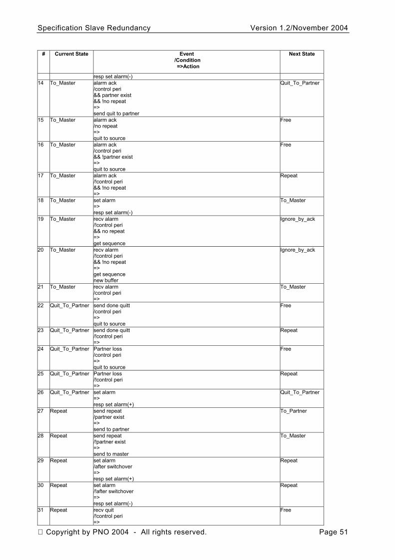
Specification Slave Redundancy Version 1.2/November 2004
# Current State Event /Condition =>Action
Next State
resp set alarm(-) 14 To_Master alarm ack
/control peri && partner exist && !no repeat => send quit to partner
Quit_To_Partner
15 To_Master alarm ack /no repeat => quit to source
Free
16 To_Master alarm ack /control peri && !partner exist => quit to source
Free
17 To_Master alarm ack /!control peri && !no repeat =>
Repeat
18 To_Master set alarm => resp set alarm(-)
To_Master
19 To_Master recv alarm /!control peri && no repeat => get sequence
Ignore_by_ack
20 To_Master recv alarm /!control peri && !no repeat => get sequence new buffer
Ignore_by_ack
21 To_Master recv alarm /control peri =>
To_Master
22 Quit_To_Partner send done quitt /control peri => quit to source
Free
23 Quit_To_Partner send done quitt /!control peri =>
Repeat
24 Quit_To_Partner Partner loss /control peri => quit to source
Free
25 Quit_To_Partner Partner loss /!control peri =>
Repeat
26 Quit_To_Partner set alarm => resp set alarm(+)
Quit_To_Partner
27 Repeat send repeat /partner exist => send to partner
To_Partner
28 Repeat send repeat /!partner exist => send to master
To_Master
29 Repeat set alarm /after switchover => resp set alarm(+)
Repeat
30 Repeat set alarm /!after switchover => resp set alarm(-)
Repeat
31 Repeat recv quit /!control peri =>
Free
Copyright by PNO 2004 - All rights reserved. Page 51
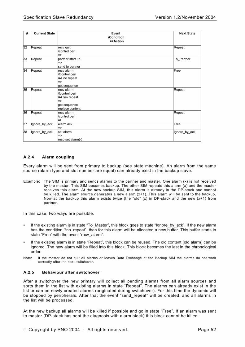
Specification Slave Redundancy Version 1.2/November 2004
# Current State Event /Condition =>Action
Next State
32 Repeat recv quit /control peri =>
Repeat
33 Repeat partner start up => send to partner
To_Partner
34 Repeat recv alarm /!control peri && no repeat => get sequence
Free
35 Repeat recv alarm /!control peri && !no repeat => get sequence replace content
Repeat
36 Repeat recv alarm /control peri =>
Repeat
37 Ignore_by_ack alarm ack =>
Free
38 set alarm => resp set alarm(-)
Ignore_by_ack Ignore_by_ack
A.2.4 Alarm coupling
Every alarm will be sent from primary to backup (see state machine). An alarm from the same source (alarm type and slot number are equal) can already exist in the backup slave.
Example: The SIM is primary and sends alarms to the partner and master. One alarm (x) is not received by the master. This SIM becomes backup. The other SIM repeats this alarm (x) and the master receives this alarm. At the new backup SIM, this alarm is already in the DP-stack and cannot be killed. The alarm source generates a new alarm (x+1). This alarm will be sent to the backup. Now at the backup this alarm exists twice (the “old” (x) in DP-stack and the new (x+1) from partner.
In this case, two ways are possible.
• If the existing alarm is in state “To_Master”, this block goes to state “Ignore_by_ack”. If the new alarm has the condition “!no_repeat”, then for this alarm will be allocated a new buffer. This buffer starts in state “Free” with the event “recv_alarm”.
• If the existing alarm is in state “Repeat”, this block can be reused. The old content (old alarm) can be ignored. The new alarm will be filled into this block. This block becomes the last in the chronological order.
Note: If the master do not quit all alarms or leaves Data Exchange at the Backup SIM the alarms do not work correctly after the next switchover.
A.2.5 Behaviour after switchover
After a switchover the new primary will collect all pending alarms from all alarm sources and sorts them in the list with existing alarms in state “Repeat”. The alarms can already exist in the list or can be newly created alarms (originated during switchover). For this time the dynamic will be stopped by peripherals. After that the event “send_repeat” will be created, and all alarms in the list will be processed.
At the new backup all alarms will be killed if possible and go in state “Free”. If an alarm was sent to master (DP-stack has sent the diagnosis with alarm block) this block cannot be killed.
Copyright by PNO 2004 - All rights reserved. Page 52

Specification Slave Redundancy Version 1.2/November 2004
Explanation: If the alarm block was killed, then a new alarm of this kind can be sent to the master by the DP stack. But the master has now 2 alarms of equal kind. Now the master will suspend the slave. Therefore the alarm must stay in the DP stack and the alarm acknowledge will be expected.
Note: If the SIM leaves the state data exchange this is the same as an alarm acknowledge. But if the SIM initiates a Leave Data Exchange by itsself the master can interpret this as a slave failure. The SIM must wait for master activity (alarm acknowledge or a Prm indication with unlock req)
All pending alarms will be received from partner and a repeat list is created.
Copyright by PNO 2004 - All rights reserved. Page 53
Specification Slave Redundancy Version 1.2/November 2004
Annex B (informative)
GSD requirements
The specification V4.1 for GSD is to amend concerning the need of slave redundancy.
The following issues are required for slave redundancy. These are specified in ISO 15745-3, Ed.1, Annexes B.4, B.5, and B.6, which is equivalent to the GSD Version 5.
PrmCmd_supp Indicates, if the DP-Slave supports PrmCmd.
Type: Boolean (1: True) Max_Switch_Over_Time (TMTO): Time needed within DP-Slave from PrmCmd receipt until the update of diagnosis response with the calculated Red_State.
Type: Unsigned 16 Time base: 100 ms Slave_Redundancy_supp (O starting with GSD_Revision 5): Indicates, if the DP-Slave supports slave redundancy according [11]. Type: unsigned 8 0: not supported 1: Slave is not redundant but can be connected to a flying master. 2 .. 7: Reserved 8: Slave supports redundancy according. 9: Slave supports redundancy according or can be connected to a flying master. If
connected to a flying master, the slave is used not redundant. 10 .. 255: Reserved If the value of "Slave_Redundancy_supp" is not equal to 0, the PrmCmd_supp keyword shall be set to "1" (true).
Copyright by PNO 2004 - All rights reserved. Page 54
Specification Slave Redundancy Version 1.2/November 2004
Redundancy: (D) This value specifies whether a device supports redundant transmission engineering. Type: Boolean 0: No, 1: Redundancy is supported. Max_Switch_Over_Time): Time needed within DP-Slave from PrmCmd receipt until the update of diagnosis with the calculated Red_State.
Type: Unsigned 16 Time base: 100 ms 0: not supported 1: Slave is not redundant but can be connected to a flying master. 2 .. 7: Reserved 8: Slave supports redundancy according. 9: Slave supports redundancy according or can be connected to a flying master. If connected to a flying master, the slave is used not redundant. 10 .. 255: Reserved If the value of "Slave_Redundancy_supp" is not equal to 0, the PrmCmd_supp keyword shall be set to "1" (true).
Copyright by PNO 2004 - All rights reserved. Page 55
Specification Slave Redundancy Version 1.2/November 2004
Copyright by:
PROFIBUS Nutzerorganisation e.V. Haid-und-Neu-Str. 7 D-76131 Karlsruhe Germany Phone: +49 721 / 96 58 590 Fax: +49 721 / 96 58 589 e-mail: [email protected] http://www.profibus.com
Copyright by PNO 2004 - All rights reserved. Page 56

Specification Slave Redundancy Version 1.2/November 2004
Copyright by PNO 2004 - All rights reserved. Page 57