soft error tolerant system
TRANSCRIPT


Page: 2 of 63
To my dearest Parents and my wife Dr. Sanjida Rezwana

Page: 3 of 63
Acknowledgement
First of all, obeisance to the almighty, omnipresent Allah for giving me the strength
and capability for writing the thesis. This thesis would not have been achievable
without the instructions, unconstrained support, guidance and the help of numerous
individuals. First and foremost, my utmost gratitude goes to my supervisor, Dr.
Muhammad Sheikh Sadi, Associate professor, Department of Computer Science and
Engineering, for his continuous supervision, constructive criticism, valuable advice,
instructions and encouragement at all stages of this thesis. I would like to show my
heartiest gratitude to Professor Dr. K. M. Azharul Hasan, Head of the Department of
Computer Science and Engineering, and Dr. Aminul Haque Akhand, Associate
Professor, Department of Computer Science and Engineering for their encouragement
and numerous varieties of supports. I also like to remember the inspiration, supports
and encouragement of my family.
Md. Nazim Uddin
Page: 4 of 63
Abstract
Soft error is a significant reliability concern for nanometer technologies. Shrinking
feature sizes, lower voltage levels, reduced noise margins, and increased clock
frequency improves the performance and lowers the power consumption of integrated
circuit. But it causes the integrated circuit more susceptible to soft error that can
corrupt data and make systems vulnerable. The
error tolerance of the VLSI circuits, as very little energy is needed to change their
states. In digital systems, where the reliability is a great concern, the impact of soft
errors may be very catastrophic. Safety critical systems are very sensitive to soft
errors. A bit flip due to soft error can change the value of critical variable. And
consequently the system control flow can completely be changed which may lead to
system failure. To minimize the soft error risks, critical blocks are identified by
criticality analysis of the blocks and ranking among them. Highest ranked blocks are
considered as critical block. Refactoring is applied to minimize the criticality of the
critical blocks. Then a novel methodology is proposed to detect and recover from soft
errors considering only preceding variables and critical blocks rather than considering
all variables and blocks in the whole program. The proposed method has less time
overhead in comparison to existing dominant approach.
Page: 5 of 63
TABLE OF CONTENTS
CHAPTER I Introduction 07
1.1 Problem Statement 07
1.2 Motivation to This Work 08
1.3 Objectives 09
1.4 Contribution of the Thesis 09
1.5 Scope of the Thesis 09
1.6 Organization 10
CHAPTER II Soft Errors 11
2.1 Introduction 11
2.2 Definition of Soft Errors 11
2.3 Types of Soft Errors 13
2.3.1 Benign Fault 14
2.3.2 Silent Data Corruption (SDC) 14
2.3.3 Detected Unrecoverable Error (DUE) 14
2.4 Sources of Soft Errors 15
2.4.1 IR or L(di/dt) Supply Noise 15
2.4.2 Power Transients 16
2.4.3 Capacitive or Inductive Cross Talk 17
2.4.4 Alpha Particles 18
2.4.5 Cosmic Rays 20
2.4.6 Low-energy Cosmic Neutron Interactions with
10B found in Boro-Phospho-Silicat Glass
22
2.5 Overview of Soft Error Mitigation Techniques 24
2.5.1 Process Technology Solutions 24
2.5.2 Software Based Approaches 25
2.5.3 Hardware Based Approaches 26
2.5.4 Hybrid Approaches 27
Page: 6 of 63
CHAPTER III Criticality Analysis 28
3.1 Introduction 28
3.2 Measuring the Criticality of the Block 28
3.3 Lowering the Criticality of a Block 30
CHAPTER IV Detecting and Correcting Soft Errors 35
4.1 Introduction 35
4.2 Flagging the single Preceding Variables 35
4.3 Identifying Multiple Preceding Variables 37
4.4 Soft Error Detection using Preceding Variables 41
4.5 Recovery from Soft Errors 43
CHAPTER V Experimental Analysis 44
5.1 Introduction 44
5.2. Experimental Setup 44
5.3 Identifying the Critical Blocks 45
5.3.1 Fault Injection 45
5.3.2 Criticality Analysis 46
5.4 Applying Refactoring to Lower the Criticality 46
5.5 Soft Error Detection using Preceding Variables 47
5.5.1 Comparisons with Existing Approaches 48
5.6 Discussion 53
CHAPTER VI Conclusions 54
6.1 Concluding Remarks 54
6.2 Future Recommendations 54
Bibliography 56
Appendix 62
Page: 7 of 63
CHAPTER I
Introduction
1.1 Problems Statement
Embedded system has become an important component of the recent era of computer
technology. Embedded systems are found everywhere from end user electronics such
as cell phones, digital cameras and PDA (Personal Digital Assistants) to medical
equipment- pace maker, home goods- washing machine, microwave ovens etc.
Actually this can be predicted from the current trends of embedded systems that
nearly any device that runs on electricity either already have or will soon have
embedded computing systems are built each year for a variety of purposes. Safety
critical real time applications of embedded systems have expanded to include
automated aircraft, rotorcrafts, ground transportation vehicles, ships, and
submersibles as well as non transport applications such as nuclear power plants,
missiles and medical equipments. As safety critical system has a risk of human
injuries, dependability and safety are major concerns in a safety critical system.
Numerous errors or faults may happen in embedded system depending on types of
damage. They can be (i) permanent errors or faults that cause physical damage to the
systems and (ii) soft errors (transient faults) that does not cause any physical damage
to the systems rather causes of data corruption when executed. Decreased feature
sizes, higher logic densities, shrinking node capacitances, lower supply voltage, and
shorter pipeline depth have significantly increased the susceptibility of soft errors in
embedded systems. The threat of soft error induced system failure is becoming more
prominent and great concern in recent embedded systems implemented in deep
submicron process technologies. The safety critical systems are expected to offer
high reliability and to meet real-time criteria. The undesired change due to soft errors
to the control flow of the system software may be proved catastrophic for the desired
functionalities of the system. Soft errors cannot create physical damage to a device,
but can be catastrophic for the desired functionalities of the system [1], [2], [3].

Page: 8 of 63
Specially, soft error is a matter of great concern in those systems where high
reliability is a necessity [4], [5], [6]. Space programs (where a system cannot
malfunction while in flight), banking transaction (where a momentary failure may
cause a huge difference in balance), automated railway system (where a single bit flip
can cause a drastic accident) [7], mission critical embedded applications, and so forth,
are a few examples where soft errors are severe. Medical equipments that are
implemented in a environment of high radiation are more prone to soft errors and can
cause human injuries and even death. The safety critical systems are expected to offer
high reliability and to meet real-time criteria. A missile consists of a embedded
computing system which computes the rang of attack and time of attack. Say, the
range is set to 136 km, binary 10001000 is stored in internal register. And the missile
will hit at enemy base at a distance 136 km. But the missile hits at region at a distance
of 8 km apart from the place of launch which eventually cause death and injures some
helpless general people. The reason behind the system malfunction was that the most
significant bit of the value 136 km (10001000) representing the ranges stored in
registers is flipped and value change to 00001000 (8 km) and when the program was
executed this cause system malfunction. It eventually causes human deaths and
injuries. Thus soft error has become a great concern for safety critical systems as well
as for general computer systems.
1.2 Motivation of the Thesis
or to lower the risk of soft errors in the system. Prior research into soft errors has
focused primarily on post-design phases, such as circuit level solutions, logic level
solutions, spatial redundancy, temporal redundancy, and/or error correction codes.
However, in all cases, the system is vulnerable to soft error problems in key areas.
Further, in software-based approaches, the complex use of threads presents a difficult
programming model. Hardware and software duplication suffers not only from
overheads due to synchronizing duplicate threads, but also from inherent performance
overheads due to additional hardware. Hardware-based protection techniques based
Page: 9 of 63
on coding or duplication often suffers from high area, time and power overheads.
Moreover, these post-functional design phase approaches are costly as well as
complex to implement. Hence, there is a great need of research to lower the risks and
impacts of the soft errors.
1.3 Objectives of the Thesis
The key objective of the thesis is to develop an approach that detects soft errors and
then develop potential techniques that can recover the system from soft errors before
the system goes to crush. The main objectives of this thesis are summarized as
follows:
To develop a preventive soft error technique, by flagging critical components
(code blocks), that will lower the soft error risks at a great extent.
To devise a novel technique that will detect soft errors in lesser time, cost and
memory requirement.
To recover from soft errors using fresh program from the backup.
1.4 Contributions of the Thesis
The contributions of this thesis are summarized as follows:
Criticality ranking of the program blocks is adopted.
Minimization of the risks of soft errors is done by using refactoring.
Preceding variables are identified by analyzing the variable dependency graph.
Soft errors are detected using preceding variables only.
Time and memory utilization of soft error detection are minimized.
1.5 Scope of the Thesis
This thesis proposes new and efficient soft error detection and recovery techniques. It
detects soft errors by duplicating/ recomputing and comparing the preceding
variables only and recovers from soft errors by copying and replacing the relevant
program blocks from the backup. This thesis deals with soft errors tolerance at
processor, data path, and memory devices of a computer system.
Page: 10 of 63
1.6 Organization
Chapter 2 presents an overview of soft error tolerance, different types of soft errors,
sources of soft errors and also discusses about the existing methodologies to detect
and mitigate soft errors in computing systems.
Chapter 3 discusses about criticality analysis, lowering the criticality using
refactoring model.
Chapter 4 provides the detailed discussion about the soft error detection and
correction techniques. Definition of Preceding variable, algorithm for preceding
variable identification and soft error detection using preceding variable identification
are also outlined in this chapter.
Chapter 5 depicts the experimental setup and results.
Chapter 6 entails the concluding remarks.
Page: 11 of 63
CHAPTER II
Soft Errors
2.1 Introduction
This chapter discusses the definition of soft errors, types of soft errors, sources of soft
errors and an overview of soft error mitigation techniques. These are outlined shortly
as follows.
2.2 Definition of Soft Errors
Temporary unintended changes of states resulting from the latching of single-event
transients (transient voltage fluctuations) create transient faults in a circuit, and when
these faults are executed in the system, the resultant errors are defined as soft errors.
Soft errors, which are also known as Single Event Upsets (SEU), occur for a
relatively short duration. They cannot damage the internal structure of semiconductor
devices; however, corrupted data values resulting from soft errors may crash the
subsequent computation, communication, or memory systems, and may lead to
overall system failure. Soft errors can
Affect the control flow of the program;
Change the system status; and
Modify the data stored in memory.
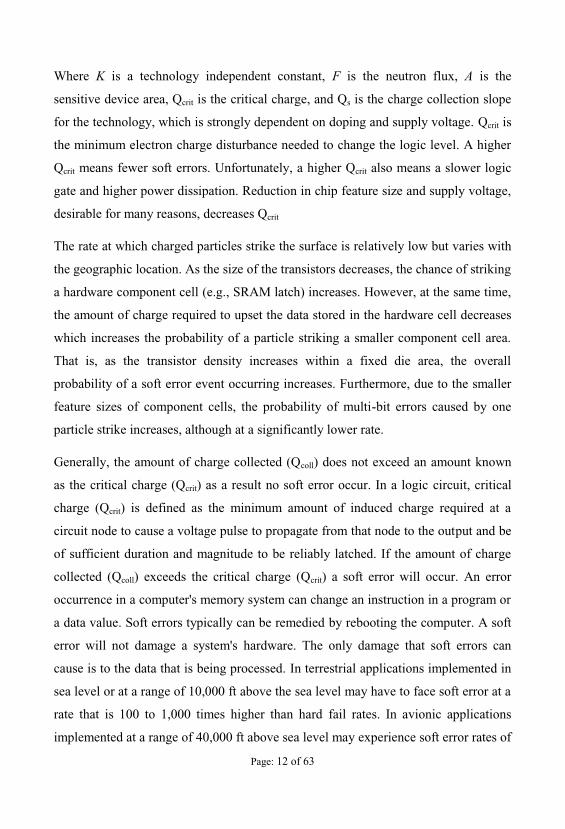
Soft error rate (SER) is the rate at which a device or system encounters or is predicted
to encounter soft errors. It is typically expressed as Failures-in-time (FIT). 1 FIT
corresponds to one error per billion device hours. The typical Soft Error Rate (SER)
of CMOS circuits due to radiation effects can be calculated using the following
equation [8]:
(2.1)xxx)()(
s
crit
Q
Q
crit e AFKQSER
Page: 12 of 63
Where K is a technology independent constant, F is the neutron flux, A is the
sensitive device area, Qcrit is the critical charge, and Qs is the charge collection slope
for the technology, which is strongly dependent on doping and supply voltage. Qcrit is
the minimum electron charge disturbance needed to change the logic level. A higher
Qcrit means fewer soft errors. Unfortunately, a higher Qcrit also means a slower logic
gate and higher power dissipation. Reduction in chip feature size and supply voltage,
desirable for many reasons, decreases Qcrit
The rate at which charged particles strike the surface is relatively low but varies with
the geographic location. As the size of the transistors decreases, the chance of striking
a hardware component cell (e.g., SRAM latch) increases. However, at the same time,
the amount of charge required to upset the data stored in the hardware cell decreases
which increases the probability of a particle striking a smaller component cell area.
That is, as the transistor density increases within a fixed die area, the overall
probability of a soft error event occurring increases. Furthermore, due to the smaller
feature sizes of component cells, the probability of multi-bit errors caused by one
particle strike increases, although at a significantly lower rate.
Generally, the amount of charge collected (Qcoll) does not exceed an amount known
as the critical charge (Qcrit) as a result no soft error occur. In a logic circuit, critical
charge (Qcrit) is defined as the minimum amount of induced charge required at a
circuit node to cause a voltage pulse to propagate from that node to the output and be
of sufficient duration and magnitude to be reliably latched. If the amount of charge
collected (Qcoll) exceeds the critical charge (Qcrit) a soft error will occur. An error
occurrence in a computer's memory system can change an instruction in a program or
a data value. Soft errors typically can be remedied by rebooting the computer. A soft
error will not damage a system's hardware. The only damage that soft errors can
cause is to the data that is being processed. In terrestrial applications implemented in
sea level or at a range of 10,000 ft above the sea level may have to face soft error at a
rate that is 100 to 1,000 times higher than hard fail rates. In avionic applications
implemented at a range of 40,000 ft above sea level may experience soft error rates of
Page: 13 of 63
10,000 to 100,000 times higher than hard fail rates. Hence soft errors have become a
major concern in electronic systems design that requires high reliability and safety
[7].
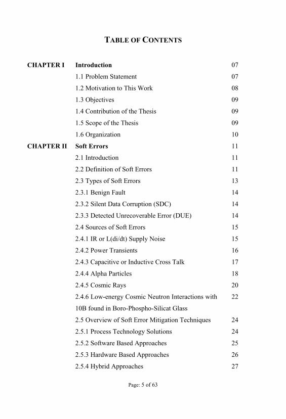
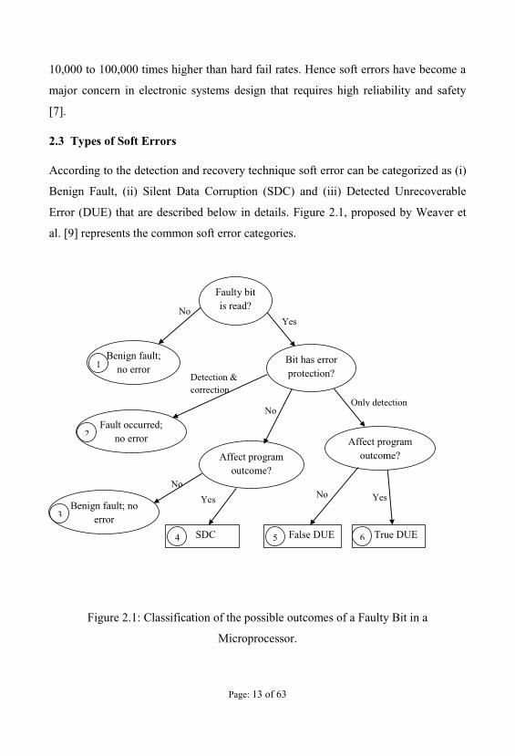
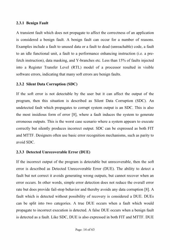
2.3 Types of Soft Errors
According to the detection and recovery technique soft error can be categorized as (i)
Benign Fault, (ii) Silent Data Corruption (SDC) and (iii) Detected Unrecoverable
Error (DUE) that are described below in details. Figure 2.1, proposed by Weaver et
al. [9] represents the common soft error categories.
Figure 2.1: Classification of the possible outcomes of a Faulty Bit in a
Microprocessor.
NoYes
Faulty bitis read?
Bit has errorprotection?
Benign fault;no error
Fault occurred;no error Affect program
outcome?
Benign fault; no error
Affect programoutcome?
SDC False DUE True DUE
Detection &correction
Only detectionNo
No
Yes No Yes
1
2
3
4 5 6
Page: 14 of 63
2.3.1 Benign Fault
A transient fault which does not propagate to affect the correctness of an application
is considered a benign fault. A benign fault can occur for a number of reasons.
Examples include a fault to unused data or a fault to dead (unreachable) code, a fault
to an idle functional unit, a fault to a performance enhancing instruction (i.e. a pre-
fetch instruction), data masking, and Y-branches etc. Less than 15% of faults injected
into a Register Transfer Level (RTL) model of a processor resulted in visible
software errors, indicating that many soft errors are benign faults.
2.3.2 Silent Data Corruption (SDC)
If the soft error is not detectable by the user but it can affect the output of the
program, then this situation is described as Silent Data Corruption (SDC). An
undetected fault which propagates to corrupt system output is an SDC. This is also
the most insidious form of error [8], where a fault induces the system to generate
erroneous outputs. This is the worst case scenario where a system appears to execute
correctly but silently produces incorrect output. SDC can be expressed as both FIT
and MTTF. Designers often use basic error recognition mechanisms, such as parity to
avoid SDC.
2.3.3 Detected Unrecoverable Error (DUE)
If the incorrect output of the program is detectable but unrecoverable, then the soft
error is described as Detected Unrecoverable Error (DUE). The ability to detect a
fault but not correct it avoids generating wrong outputs, but cannot recover when an
error occurs. In other words, simple error detection does not reduce the overall error
rate but does provide fail-stop behavior and thereby avoids any data corruption [8]. A
fault which is detected without possibility of recovery is considered a DUE. DUEs
can be split into two categories. A true DUE occurs when a fault which would
propagate to incorrect execution is detected. A false DUE occurs when a benign fault
is detected as a fault. Like SDC, DUE is also expressed in both FIT and MTTF. DUE
Page: 15 of 63
events are additional subdivided according to whether the detected fault would have
affected the final result of the execution.
2.4 Sources of Soft Errors
There are mainly two types of source of soft error (i) internal sources and (ii) external
sources of soft error. Internal sources of soft error include:
IR or L(di/dt) supply noise,
power transients, and
capacitive or inductive cross talk
Three principal external sources, radiation sources cause soft errors in semiconductor
devices they includes:
Alpha particles from naturally occurring radioactive impurities,
High energy neutrons induced by cosmic rays, and
Low-energy cosmic neutron interactions with 10B found in Boro-Phospho-
Silicat Glass (BPSG).
2.4.1 IR or L(di/dt) Supply Noise
Power supply noise consists of two major components: the IR drop due to wire
resistance, and the L(di/dt) due to wire inductance. Both components can be observed
on the package and on-chip power grid. Generally, the L(di/dt) drop is predominant
on the package, since the package lead resistance is low; while IR drop is
predominant on the chip due to high interconnect resistance.
Due to the resistance of the interconnect constituting the network, there occurs a
voltage drop across the network, commonly referred to as the IR drop. IR drop is
predominantly caused by the parasitic resistance of metal wires constituting the on-
chip power distribution network. The package supplies currents to the pads of the
power grid either by means of package leads in wire-bond chips or through C4
Page: 16 of 63
(controlled collapsed chip connection) bump-array in flip-chip technology. Although
the resistance of package is quite small, the inductance of package leads is significant
which causes a voltage drop at the pad locations due to time-varying currents drawn
by devices on the die. This voltage drop is referred to as the di/dt drop or L(di/dt)
drop. Therefore, the voltage seen at the devices is the supply voltage minus the IR
drop and the L(di/dt) drop.
Shrinking device dimensions, faster switching frequency, and increasing power
consumption in deep submicron technologies cause rapid switching currents. Rapidly
switching currents of the on-chip devices can cause fluctuations in the supply voltage
which can be classified as IR and L(di/dt) drops. The voltage fluctuations in a supply
network can inject noise in a circuit which may lead to functional failures of the
design. Power supply integrity verification is, therefore, a critical concern in high-
performance designs. Also, with decreasing supply voltages, gate-delay is becoming
increasingly sensitive to supply voltage variation. With ever-diminishing clock
periods, accurate analysis of the impact of supply voltage on circuit performance has
also become critical. Increasing power consumption and clock frequency have
exacerbated the L(di/dt) drop in every new technology generation. The L(di/dt) drop
has become the dominant portion of the overall supply-drop in high performance
designs. On-die passive decap, which has traditionally been used for suppressing
L(di/dt), has become expensive due to its area and leakage power overhead.
2.4.2 Power Transients
Higher integration, tighter process requirements and lower voltage requirements are
moving into designs; thus increasing the hazard of precipitating power transient
disturbances caused by Electromagnetic Interference (EMI) and Electrostatic
Discharge (ESD). These power transient disturbances can create a voltage glitch
(transient fault) in a semiconductor device.
Page: 17 of 63
In electrical engineering, spikes are fast, short duration electrical transients in voltage
(voltage spikes), current (current spikes), or transferred energy (energy spikes) in an
electrical circuit. Fast, short duration electrical transients (over voltages) in the
electric potential of a circuit are typically caused by (i) Lightning strikes (ii) Power
outages (iii) Tripped circuit breakers (iv) Short circuits (v) Power transitions in other
large equipment on the same power line (vi) Malfunctions caused by the power
company (vii) Electromagnetic pulses (EMP) with electromagnetic energy distributed
typically up to the 100 kHz and 1 MHz frequency range. (viii) Inductive spikes.
Voltage spikes may be longitudinal (common) mode or metallic (normal or
differential) mode. Some equipment damage from surges and spikes can be prevented
by use of surge protection equipment. Each type of spike requires selective use of
protective equipment. For example a common mode voltage spike may not even be
detected by a protector installed for normal mode transients. An uninterrupted voltage
increase that lasts more than a few seconds is usually called a "voltage surge" rather
than a spike. These are usually caused by malfunctions of the electric power
distribution system.
2.4.3 Capacitive or Inductive Cross Talk
In electronics, crosstalk is any phenomenon by which a signal transmitted on one
circuit or channel of a transmission system creates an undesired effect in another
circuit or channel. Crosstalk is usually caused by undesired capacitive, inductive, or
conductive coupling from one circuit, part of a circuit, or channel, to another. Cross
talk is usually caused by undesired inductive or capacitive coupling. Capacitive
crosstalk arises from a coupling capacitance between interconnects and mutual
inductance between interconnects. In nanometer technologies, interconnect delay
dominates gate delay and accurate estimation of interconnect delay has become an
important design issue. Capacitive and inductive crosstalk is a well-known obstacle
for accurate interconnect delay estimation. Capacitive crosstalk is widely considered
Page: 18 of 63
in current designs, whereas inductive crosstalk noise emerges in recent processes.
Qualitative discussion generally shows that both capacitive and inductive crosstalk
noises will be more significant as the fabrication processes advance. Impact of
capacitive crosstalk is reduced in most of shortened interconnects. Technology
advancement increases capacitive crosstalk noise owning to a larger aspect ratio of
interconnects and sharper signal transition waveforms. In wide and fat global
interconnects, fast transitions including higher signal frequency strengthen inductive
crosstalk effect.
2.4.4 Alpha Particles
Alpha particles mostly occur from the decay of uranium and thorium present within
the packages. When alpha particles hit the silicon bulk, they create minority carriers,
which, if collected by active source/drain diffusions, can generate a voltage glitch of
short duration (transient fault) on such nodes. An alpha particle consists of two
protons and two neutrons bound together into a particle that is identical to a helium
nucleus. Alpha particles are emitted by radioactive nuclei, such as uranium or radium,
in a process known as alpha decay. This sometimes leaves the nucleus in an
energized condition, with the emission of a gamma ray removing the excess energy.
Alpha particles are emitted when the nucleus of an unstable isotope decays to a lower
energy state. These particles show a kinetic energy in the range of 4 to 918 MeV.
There are many radioactive isotopes. Uranium and thorium have the highest activity
among naturally occurring materials. In the terrestrial environment, major sources of
alpha particles are radioactive impurities such as lead-based isotopes in solder bumps
of the flip-chip technology, gold used for bonding wires and lid plating, aluminum in
ceramic packages, lead-frame alloys and interconnect metallization.
Alpha particles are positively charged and when travels through the semiconductor
device, disturbs the regularity of electrons there. A sufficient disturbance can alter a
digital signal from one state to another for example from 0 to 1 and vice versa. In
Page: 19 of 63
combinational logic, this effect is transient, perhaps lasting for a fraction of a
nanosecond. On the contrary in sequential logic such as latches and RAMs, even this
transient upset can become stored for an indefinite time, to be read out later. Alpha
particles and neutrons slightly differ in their interactions with silicon crystals.
Charged alpha particles interact directly with electrons. In contrast, neutrons interact
with silicon via inelastic or elastic collisions. Inelastic collisions cause the incoming
neutrons to lose their identity and create secondary particles, whereas elastic
collisions preserve the identity of the incoming particles. Experimental results show
that inelastic collisions cause the majority of the soft errors due to neutrons; hence
inelastic collisions will be the focus of this section.
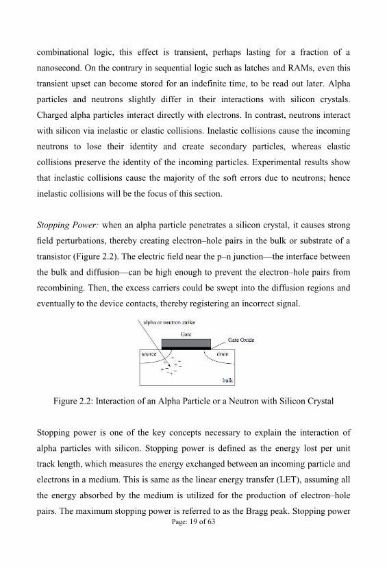
Stopping Power: when an alpha particle penetrates a silicon crystal, it causes strong
eld perturbations, thereby creating electron hole pairs in the bulk or substrate of a
transistor (Figure 2.2 n junction the interface between
the bulk and diffusion can be high enough to prevent the electron hole pairs from
recombining. Then, the excess carriers could be swept into the diffusion regions and
eventually to the device contacts, thereby registering an incorrect signal.
Figure 2.2: Interaction of an Alpha Particle or a Neutron with Silicon Crystal
Stopping power is one of the key concepts necessary to explain the interaction of
alpha particles with silicon. Stopping power is defined as the energy lost per unit
track length, which measures the energy exchanged between an incoming particle and
electrons in a medium. This is same as the linear energy transfer (LET), assuming all
the energy absorbed by the medium is utilized for the production of electron hole
pairs. The maximum stopping power is referred to as the Bragg peak. Stopping power
Page: 20 of 63
quantifies the energy released from the interaction between alpha particles and silicon
crystals, which in turn can generate electron hole pairs. About 3.6 eV of energy is
required to create one such pair. For example, an alpha particle (4He) with a kinetic
energy of 10 MeV has a stopping power of about and hence can roughly
generate about 2.8 × 10⁴ electron The charge on an electron is 1.6 ×
10 19 C, so this generates roughly Whether the
generated charge can actually cause a malfunction or a bit flip depends on two other
factors, namely, charge collection efficiency and critical charge of the circuit.
2.4.5 Cosmic Rays
Cosmic rays originate from outer space. They collide with particles in the atmosphere
resulting in neutron flux. It in turn be accelerated toward the earth and create soft
errors in memory elements, latches and logic circuits. Cosmic rays may be the
predominant cause of soft errors in modern devices. The primary particle of the
cosmic ray does not generally reach the Earth's surface. It creates a shower of
Earth's surface approximately 95% of the particles capable of causing soft errors are
energetic neutrons with the remainder composed of protons and pions. High-energy (
> 1 MeV) neutrons from cosmic radiation can induce soft errors in semiconductor
devices via secondary ions produced by the neutron reaction with silicon nuclei.
Cosmic rays that are of galactic origin react with th
complex cascades of secondary particles. Less than 1% of the primary flux reaches
ground level and the predominant particles include muons, neutrons, protons, and
pions. Because pions and muons are short-lived and proton 19 and electrons are
attenuated by Columbic interaction with the atmosphere, neutrons are the most likely
cosmic radiation sources to cause SEU in deep-submicron semiconductors at the
terrestrial altitudes. The neutron flux is dependent on the altitude above the sea level,
the density of the neutron flux increases with the altitude.
Page: 21 of 63
Cosmic rays are energetic charged subatomic particles, originating in outer space.
They may produce secondary particles that penetrate the Earth's atmosphere and
surface. The term ray is historical as cosmic rays were thought to be electromagnetic
radiation. Most primary cosmic rays (those that enter the atmosphere from deep
space) are composed of familiar stable subatomic particles that normally occur on
Earth, such as protons, atomic nuclei, or electrons. However, a very small fraction is
stable particles of antimatter, such as positrons or antiprotons, and the precise nature
of this remaining fraction is an area of active research.
About 89% of cosmic rays are simple protons or hydrogen nuclei, 10% are helium
nuclei or alpha particles, and 1% are the nuclei of heavier elements. These nuclei
constitute 99% of the cosmic rays. Solitary electrons (much likes beta particles,
although their ultimate source is unknown) constitute much of the remaining 1%.
The variety of particle energies reflects the wide variety of sources. The origins range
from processes on the Sun (and presumably other stars as well), to as yet unknown
physical mechanisms in the farthest reaches of the observable universe. There is
evidence that very high energy cosmic rays are produced over far longer periods than
the explosion of a single star or sudden galactic event, suggesting multiple
accelerating processes that cover very long distances with regard to the size of stars.
The obscure mechanism of cosmic ray production at galactic distances is partly a
result of the fact that (unlike other radiations) magnetic fields in our galaxy and other
galaxies bend cosmic ray direction severely, so that they arrive nearly randomly from
all directions, hiding any clue of the direction of their initial sources. Cosmic rays can
have energies of over 1020 eV, far higher than the 1012 to 1013 eV that Terrestrial
particle accelerators can produce. There has been interest in investigating cosmic rays
of even greater energies.
Cosmic rays are enriched in lithium, beryllium, and boron with regard to the relative
abundance of these elements in the universe compared to hydrogen and helium, and
thus are thought to have a primary role in the synthesis of these three elements
through the process of "cosmic ray nucleosynthesis". They also produce some so-

Page: 23 of 63
10B and 11B of which 10B is unstable. The reaction scheme is shown in [11]. In the
10B and cosmic neutron reaction, the lithium nucleus is emitted with a kinetic energy
of 0.84 MeV 94% of the time and with 1.014 MeV 6% of the time. The gamma
photon has energy of 478 KeV, while the alpha particle is emitted with an energy of
1.47 MeV [11]. This mechanism has recently been found to be the dominant source
microprocessors use highly purified package materials and this radiation mechanism
is greatly reduced, leaving the high-energy cosmic rays as the major reason for soft
errors. The SEU due to activation of 10B can be mitigated by removing BPSG
material from the process flow. For future deep-submicron DRAM generations a
greater suppression of soft error rate is expected for devices made with silicon-on-
insulator (SOI) technologies [12].
In space high-energy neutrons generated from the interaction of cosmic rays with the
atmosphere are the main source of incident radiation. Neutrons cannot cause direct
ionization, but the by-products of nuclear reactions with the silicon generate ionizing
particles that cause soft errors. Soft errors are generally related to random errors or
corruption of data in electronic systems. They are mostly induced by alpha particles
emitted from radioactive impurities in materials such as packaging, solder bumps and
by highly ionizing secondary particles produced from the reaction of both thermal
and high-energy neutrons with component materials. In general, soft errors are
nondestructive functional errors induced by energetic ion strikes and could be fixed
by resetting or re-writing of the device. Soft errors are a subset of single event effects
(SEE) that is caused by single alpha particle as it passes through a semiconductor
material. Alpha particles emitted from nucleus of unstable isotope decays, High
energy neutrons from cosmic radiation, interaction of cosmic ray neutrons and boron
[10] are principal radiation sources cause soft errors in advanced semiconductor
devices [13].

Page: 24 of 63
2.5 An Overview of Soft Error Mitigation Techniques
Soft error tolerant design techniques can be class prevention
and recovery . The methods to protect microchips from soft-errors are the prevention
methods. They are used during the chip design and development. The recovery
methods include on-line recovery mechanisms from soft-errors in order to achieve the
chip robustness requirement. One should note that soft error is not the only reason
why computer systems need to resort to a recovery procedure. Random errors due to
noise, unreliable components, and coupling effects may also require recovery
mechanisms. The need for a recovery mechanism stems from the fact that prevention
techniques may not be enough for contemporary microchips, because the supply
voltage keeps reducing, feature size keeps shrinking, and the clock frequency keeps
increasing. Also, the cost of prevention techniques for a fault tolerant design may be
too high. Representing the broad area of the error-tolerant computing, here we give a
few examples of techniques used for soft error mitigation.
2.5.1 Process Technology Solutions
A significant reduction in the soft error rate of microelectronics can be achieved by
eliminating or reducing the sources of radiation. To reduce the alpha particle
emission in packaged ICs, high purity materials and processes are employed.
Uranium and thorium impurities have been reduced below one hundred parts per
trillion for high reliability.
Going from the conventional IC packaging to an ultra-low alpha packaging materials,
the alpha emission is reduced from 5 10 particles/cm2-hr to less than 0.001
particles/cm2-hr. To reduce the SER induced by the 10B activation by low energy
neutrons, BPSG is replaced by other insulators that do not contain boron. In addition,
any processes using boron precursors are carefully checked for 10B content before
introducing them to the manufacturing process. When these measures are employed
the SER of the IC is reduced dramatically, but the SER caused by the high-energy
cosmic neutron interactions cannot be easily shielded. Radiation Hardened Process
Page: 25 of 63
Technologies SER performance can be greatly improved by adapting a process
technology either to reduce the collected charge (Qcoll) or increase the critical charge
(Qcrit). One approach is to use additional well isolation (triple-well or guard-ring
structure) to reduce the amount of charge collected by creating potential barriers,
which can limit the efficiency of the funneling effect and reduce the likelihood of
parasitic bipolar collection paths.
Another approach replaces bulk silicon well-isolation with silicon-on-insulator (SOI)
substrate material. The direct charge collection is significantly reduced in SOI
devices because the active device volume is greatly reduced (due to thin silicon
device layer on the oxide layer). Recent work shows a 10X reduction in SER
achieved over conventional bulk devices when a fully depleted SOI substrate is used.
Unfortunately, SOI substrates are more expensive than conventional bulk substrates
and phenomena like parasitic bipolar action limit further reduction of SER. Circuit-
level solutions such as the addition of cross-coupled resistors and capacitors to
decrease the bit- time are also employed.
2.5.2 Software Based Approaches
Software based approaches to detect and correct soft errors has become popular. It
includes redundant programs to detect [14], [15], [16], [17] and/or recover from soft
errors [18], duplicating instructions [19], [20], task duplication [21], dual use of super
scalar data paths [22], and Error detection and Correction Codes (ECC) [23] etc.
Redundant programs to detect run redundant copy of the same program and compare
the output to check if a soft error occur. Using Error detection and Correction Codes
(ECC) to detect soft errors is another popular software implemented technique. Chip
level Redundant Threading (CRT) [24] used a load value queue such that redundant
executions can always see an identical view of memory. Although the load value
queue produced identical view of memory for both leading and trailing threads,
integrating this into the chip multiprocessor environment requires significant
changes. Walcott et al. [25] used redundant multi threading to determine the
architectural vulnerability factor, and Shye et al., [26] used process level redundancy
Page: 26 of 63
to detect soft errors. In redundant multi threading, two identical threads are executed
independently over some period and the outputs of the threads are compared to verify
the correctness. EDDI [19] and SWIFT [20] duplicated instructions and program data
to detect soft errors. So, both redundant programs and duplicating instructions create
higher memory requirements and increase register load. Error detection and
Correction Codes (ECC) [23] adds extra bits with the original bit sequence to detect
error. Using ECC to combinational logic blocks makes them complicated, and
requires additional logic and calculations with already timing-critical paths.
2.5.3 Hardware Based Approaches
Hardware approaches for soft errors mitigation mostly include circuit level solutions,
logic level solutions and architectural solutions. At the circuit level, gate sizing
techniques [27], [28], [29], increasing capacitance [30], [31], resistive hardening [32],
are commonly used to increase the critical charge (Qcrit) of the circuit node as high as
possible.
Increasing capacitance of diffusion area is a common ways to reduce soft error rate.
Critical charge (Qcrit) increases as the capacitance raises because the total charge at a
node is the product of its capacitance and voltage. Increasing the size of the device
raises the capacitance of the devices. Also the capacitance can be raised by adding an
explicit capacitor to the diffusion area of the devices.
Radiation hardening is another common technique to reduce soft error rate in
electronic circuit. Radiation hardening increases the diffusion capacitance of storage
cells only, such as SRAM cells or latches. It maintains a redundant copy of data
which provide the correct data after a particle strike as well as help to recover
corrupted section from the upset.
However, these techniques tend to increase power consumption and lower the speed
of the circuit. Logic level solutions [33], [34] mainly propose detection and recovery
in combinational circuits by using redundant or self-checking circuits. Architectural
solutions mainly introduce redundant hardware in the system to make the whole
Page: 27 of 63
system more robust against soft errors. These solutions include dynamic
implementation verification architecture (DIVA) [35], block-level duplication used in
IBM Z-series machines [36] etc. DIVA in its method of fault protection assumed that
mismatch. So, faults in the checker itself must be detected through alternative
techniques.
2.5.4 Hybrid Approaches
Hardware and software combined approaches [36], [37], [29], [18] use the parallel
processing capacity of chip multiprocessors (CMPs) and redundant multi threading to
detect and recover from the problem. Mohamed et al. [38] shows Chip Level
Redundantly Threaded Multiprocessor with Recovery (CRTR), where the basic idea
is to run each program twice, as two identical threads, on a simultaneous
multithreaded processor. One of the more interesting matters in the CRTR scheme is
that there are certain faults from which it cannot recover. If a register value is written
prior to committing an instruction, and if a fault corrupts that register after the
committing of the instruction, then CRTR fails to recover from that problem. In
Simultaneously and Redundantly Threaded processors with Recovery (SRTR)
scheme, there is a probability of fault corrupting both threads since the leading thread
and trailing thread execute on the same processor. However, in all cases the system is
vulnerable to soft errors in key areas.
In contrast, the complex use of threads presents a difficult programming model in
software-based approaches while in hardware-based approaches, duplication suffer
not only from overhead due to synchronizing duplicate threads but also from inherent
performance overhead due to additional hardware. Moreover, these post-functional
design phase approaches can increase time delays and power overhead without
offering any performance gain.

Page: 28 of 63
CHAPTER III
Criticality Analysis
3.1 Introduction
A single soft error in a particular component (program block) could have a greater
effect than multiple soft errors in another or a set of components. For this reason, the
effects of soft errors in the whole system need to be analyzed by injecting transient
faults (which will create soft errors if activated) into each component. This chapter
deals with criticality ranking of the program block by Failure Mode Effects and
Criticality Analysis (FMECA) and lowering the criticality with refactoring.
3.2 Measuring the Criticality of the Block
The criticalities of the block are determined by the Failure Mode Effects and
Criticality Analysis (FMECA) [39] method. FMECA is a procedure for the analysis
of potential failure modes within a system by classifying criticality or determining of
FMECA is an analysis technique that facilitates
the identification of potential problems in the design or process by examining the
effects of lower level failures [40]. Failure causes are any errors or defects in the
process, design, or item. Effects analysis refers to studying the consequences of those
failures. The FMECA determines, by failure mode analysis, the effect of each failure
and ranks each failure according to the criticality of a failure effect. Failure Mode
Effect and Criticality Analysis (FMECA) is analytical and non-compositional
approach. Though it has some traditional limitations like tedious, time consuming and
costly analysis technique, for criticality analysis it is really hard (if not impossible) to
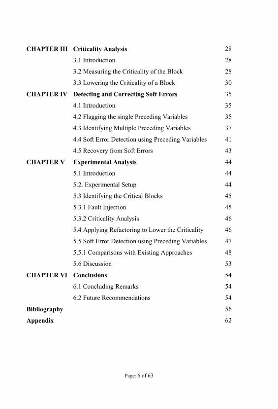
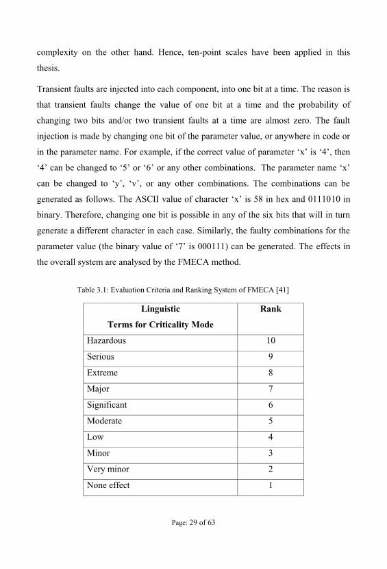
find a suitable alternative. The evaluation criteria and a ranking system for the
criticality of effects, which is suggested by Hosseini et. al. [41] for a design FMECA,
is shown in Table 3.1. Diverse criticality assigning levels (i.e. point of scale) can be
adopted in a design FMECA. However, huge levels increase the programming
Page: 29 of 63
complexity on the other hand. Hence, ten-point scales have been applied in this
thesis.
Transient faults are injected into each component, into one bit at a time. The reason is
that transient faults change the value of one bit at a time and the probability of
changing two bits and/or two transient faults at a time are almost zero. The fault
injection is made by changing one bit of the parameter value, or anywhere in code or
in the parameter name. For example, if the corr
10 in
binary. Therefore, changing one bit is possible in any of the six bits that will in turn
generate a different character in each case. Similarly, the faulty combinations for the
effects in
the overall system are analysed by the FMECA method.
Linguistic
Terms for Criticality Mode
Rank
Hazardous 10
Serious 9
Extreme 8
Major 7
Significant 6
Moderate 5
Low 4
Minor 3
Very minor 2
None effect 1
Table 3.1: Evaluation Criteria and Ranking System of FMECA [41]
Page: 30 of 63
To validate the analysis results, several tests (three to five) are performed for each
component and the average integer (floor) value is taken as the resultant rank of
criticality. If in first three cases, the effects are almost the same then the test is
terminated. The effect in the system functionality is evaluated by FMECA. Failure
modes are classified into one of the ten categories as shown in Table 3.1. To analyze
the cause and effect of the failure in the system better, domain expertise is required.
Hence, the system is studied in detail before performing criticality analysis.
3.3 Lowering the Criticality of a Block
Component criticality suggests to the designer where in the system design changes
are necessary or helpful to minimize soft error risk. These changes can be made by
applying a suitable approach where he/she may change the architecture or
behavioural model of the component to lower its criticality. Refactoring is a good
candidate for this type of approach. The purpose of refactoring is to alter the model
the system unaffected. In each trial of refactoring, it was examined whether the
refactoring could achieve the impact of soft errors in the system maintaining the non-
functional properties like functionality, performance etc. If it fails to do that then the
method of re-factoring is altered and repeated until the goal is achieved. In software
engineering, "refactoring source code
overall results and is sometimes informally referred to as "cleaning it up".
Refactoring neither fixes bugs nor adds new functionality, though it might precede
either activity; rather, it improves the understandability of the code, changes its
internal structure and design, and removes dead code. UML Model refactoring is the
equivalent of source code refactoring at the model level with the objective of
[42]. It re-structures the model to improve quality
factors, such as maintainability, efficiency, fault tolerance, etc., without introducing
any new behaviour at the conceptual level [43]. As the software and hardware
system evolves, almost each change of requirements imposed on a system requires
Page: 31 of 63
the introduction of small adaptations to its design model [44], [45]. However, the
designers face challenges to this adaptation by a single modification in the model. A
possible solution to this problem can be to provide designers with a set of basic
transformations so maintaining model functionality. This set of transformations is
known as refactoring, which can be used gradually to improve the design [44].
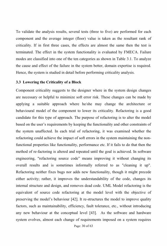
A detailed taxonomy of model transformations has been presented by Mens and Van
Gorp [46], [47]. Model refactoring can be made by replacing components or sub-
systems with ones that are more elegant, merging/splitting the states keeping the
behaviour unchanged, altering code readability or understandability, formal concept
analysis, graph transformation, etc. Model refactoring can be detailed by using an
example, which consists of Figure 3.1 and Figure 3.2.
Pass to Server
Actions
Verify User
User Logged On
Retrieved
[Valid User]
[Else]
Figure 3.1:
Page: 32 of 63
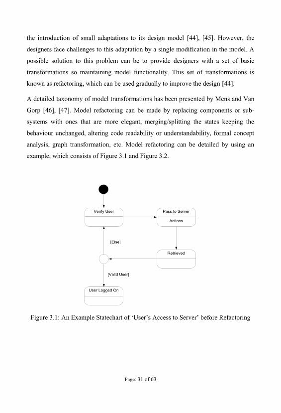
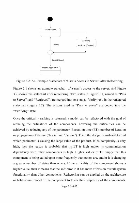
Verifying
Actions (Copied)
Verify User
User Logged On
[Valid User]
[Else]
Figure 3.2:
Figure 3.1 Figure
3.2 shows this statechart after refactoring. Two states in Figure 3.1
to
statechart (Figure 3.2
Once the criticality ranking is returned, a model can be refactored with the goal of
reducing the criticalities of the components. Lowering the criticalities can be
achieved by reducing any of the parameter: Execution time (ET), number of iteration
or propagation of failure ( fan out ). Then, the design is analysed to find
which parameter is causing the large value of the product. If its complexity is very
high, then the reason is probably that its ET is high and/or its communication
dependency with other components is high. Higher values of ET imply that this
component is being called upon more frequently than others are, and/or it is changing
a greater number of states than others. If the criticality of the component shows a
higher value, then it means that the soft error in it has more effects on overall system
functionality than other components. Refactoring can be applied on the architecture
or behavioural model of the component to lower the complexity of the components.

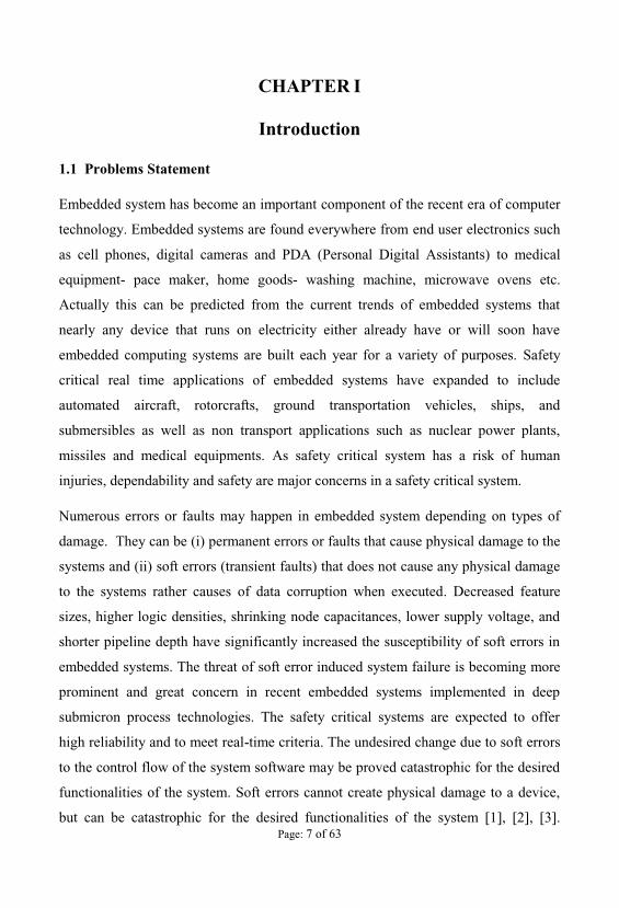
Page: 33 of 63
The methodology of lowering the criticalities of components by refactoring is shown
in Figure 3.3.
As shown in Figure 3.3, initially, the abstract model is created from the given
specifications. The model is then analysed to measure the criticalities of its
components. Component criticalities need to be compared with a threshold value that
users need to determine (for simplicity, the threshold value is ignored in the
guideline for flagging the components as critical. If critical components exist in the
criticalities.
Requirement Specification forEmbedded Systems
Critical ComponentsExist?
Terminate
Abstract Model in UML
Criticalities measured for theComponents in the Model
Refactor the Model
ConstraintsMaintained
CriticalitiesReduced
Apply Metrics
[Yes]
[Yes]
[Yes]
[No]
[No]
Change TheMethodology of
Refactoring
[No]
Figure 3.3: Methodology to Lower the Criticalities of the Components by Refactoring
Special attention needs to be given to the top-ranked components to lower their
criticalities. Other components can be examined in turn later according to their
criticality ranking. Several trial and error iterations are needed to achieve the goal of
lowering a compone criticality. In each trial, checks must be made to ensure the

Page: 34 of 63
refactoring does not interfere with the functionality of the system; otherwise, the
model will have to go through another refactoring method. If these constraints are
maintained, then the l
are sufficiently reduced or not. If the check is successful, then the process will
terminate. If not, another iteration of the above steps will occur.
Page: 35 of 63
CHAPTER IV
Detecting and Correcting Soft Errors
4.1 Introduction
A novel methodology has been proposed to mitigate soft error risk. In this method,
the major working fact consists of three-steps. Throughout 1st step, the proposed
method identifies critical variables. At 2nd step, soft errors are detected by
duplicating and comparing the critical variables only and at 3rd step, soft errors are
recovered by using fresh program from the backup. The details of the approach are
discussed in the subsequent sections.
4.2 Flagging the single Preceding Variables
All variables or blocks are not equally responsible or susceptible to system failure in
a computer program. These can be analyzed according to their significance level and
responsibility to system malfunction or failure. Variables those are of higher levels of
significance are considered most vulnerable.
through adopting and considering some fact like number of recursion, dependencies,
etc. Criticality ranges higher with respect to more dependencies.
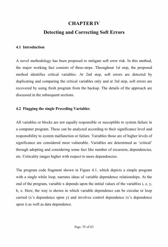
The program code fragment shown in Figure 4.1, which depicts a simple program
with a single while loop, narrates ideas of variable dependence relationships. At the
end of the program, variable x depends upon the initial values of the variables i, z, y,
b, x. Here, the way is shown in which variable dependence can be circular or loop
involves control dependence (x
upon i) as well as data dependence.
Page: 36 of 63
Figure 4.1: An example program-segment to show Variable Dependency
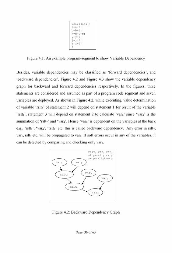
Besides, variable dependencies may be
Figure 4.2 and Figure 4.3 show the variable dependency
graph for backward and forward dependencies respectively. In the figures, three
statements are considered and assumed as part of a program code segment and seven
variables are deployed. As shown in Figure 4.2, while executing, value determination
2 for result of the variable
lt1 0 0
2 4 0 the variables at the back
2 4 1 2,
var1, rslt1 etc. will be propagated to var0. If soft errors occur in any of the variables, it
can be detected by comparing and checking only var0.
Figure 4.2: Backward Dependency Graph
Page: 37 of 63
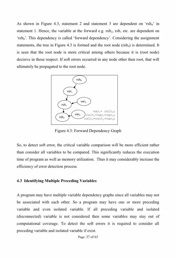
As shown in Figure 4.3 0
statement 1. Hence, the variable at the forward e.g. rslt2, rslt1 etc. are dependent on
0
statements, the tree in Figure 4.3 is formed and the root node (rslt0) is determined. It
is seen that the root node is more critical among others because it is (root node)
decisive in those respect. If soft errors occurred in any node other then root, that will
ultimately be propagated to the root node.
Figure 4.3: Forward Dependency Graph
So, to detect soft error, the critical variable comparison will be more efficient rather
than consider all variables to be compared. This significantly reduces the execution
time of program as well as memory utilization. Thus it may considerably increase the
efficiency of error detection process.
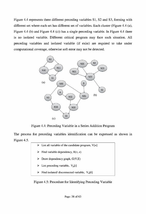
4.3 Identifying Multiple Preceding Variables
A program may have multiple variable dependency graphs since all variables may not
be associated with each other. So a program may have one or more preceding
variable and even isolated variable. If all preceding variable and isolated
(disconnected) variable is not considered then some variables may stay out of
computational coverage. To detect the soft errors it is required to consider all
preceding variable and isolated variable if exist.
Page: 39 of 63
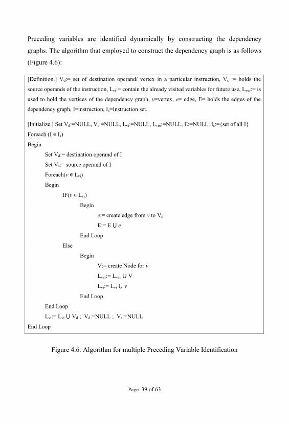
Preceding variables are identified dynamically by constructing the dependency
graphs. The algorithm that employed to construct the dependency graph is as follows
(Figure 4.6):
[Definition.] Vd:= set of destination operand/ vertex in a particular instruction, Vs := holds the
source operands of the instruction, Lvi:= contain the already visited variables for future use, Lver:= is
used to hold the vertices of the dependency graph, v=vertex, e= edge, E= holds the edges of the
dependency graph, I=instruction, Is=Instruction set.
[Initialize.] Set Vd:=NULL, Vs:=NULL, Lvi:=NULL, Lver:=NULL, E:=NULL, Is:={set of all I}
Foreach (I Is)
Begin
Set Vd:= destination operand of I
Set Vs:= source operand of I
Foreach(v Lvi)
Begin
IF(v Lvi)
Begin
e:= create edge from v to Vd
E:= E e
End Loop
Else
Begin
V:= create Node for v
Lver:= Lver V
Lvi:= Lvi v
End Loop
End Loop
Lvi:= Lvi Vd ; Vd:=NULL ; Vs:=NULL
End Loop
Figure 4.6: Algorithm for multiple Preceding Variable Identification
Page: 40 of 63
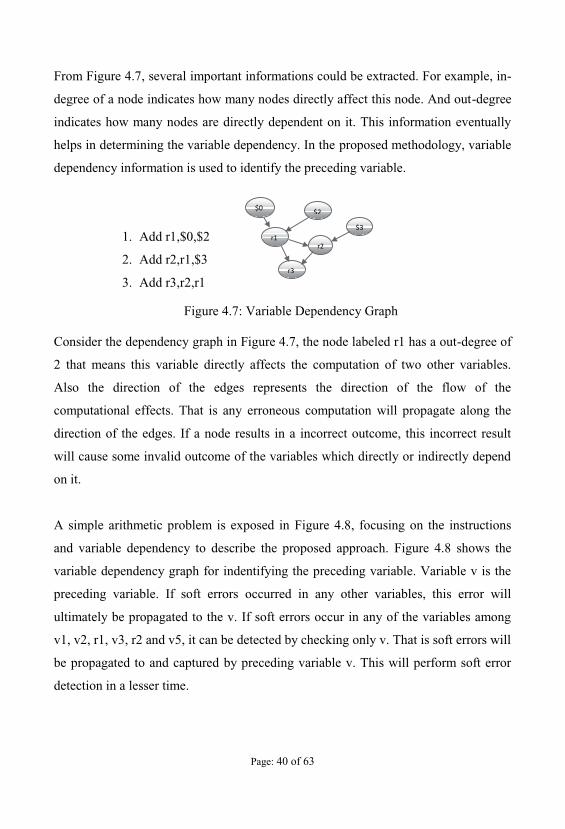
From Figure 4.7, several important informations could be extracted. For example, in-
degree of a node indicates how many nodes directly affect this node. And out-degree
indicates how many nodes are directly dependent on it. This information eventually
helps in determining the variable dependency. In the proposed methodology, variable
dependency information is used to identify the preceding variable.
1. Add r1,$0,$2
2. Add r2,r1,$3
3. Add r3,r2,r1
Figure 4.7: Variable Dependency Graph
Consider the dependency graph in Figure 4.7, the node labeled r1 has a out-degree of
2 that means this variable directly affects the computation of two other variables.
Also the direction of the edges represents the direction of the flow of the
computational effects. That is any erroneous computation will propagate along the
direction of the edges. If a node results in a incorrect outcome, this incorrect result
will cause some invalid outcome of the variables which directly or indirectly depend
on it.
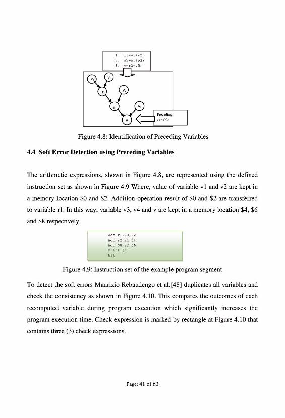
A simple arithmetic problem is exposed in Figure 4.8, focusing on the instructions
and variable dependency to describe the proposed approach. Figure 4.8 shows the
variable dependency graph for indentifying the preceding variable. Variable v is the
preceding variable. If soft errors occurred in any other variables, this error will
ultimately be propagated to the v. If soft errors occur in any of the variables among
v1, v2, r1, v3, r2 and v5, it can be detected by checking only v. That is soft errors will
be propagated to and captured by preceding variable v. This will perform soft error
detection in a lesser time.

Page: 44 of 63
CHAPTER V
Experimental Analysis
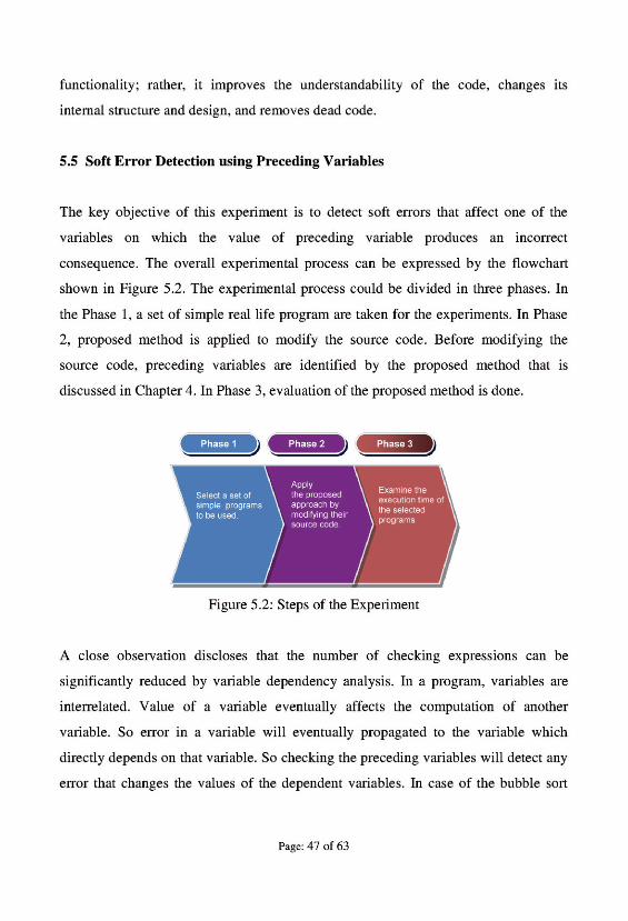
5.1 Introduction
To evaluate the efficiency of the proposed method, the method was experimented on
selected sample programs. The programs are analyzed to determine the variable
dependency, and then dependency graphs are formed. From the variable dependency
graph, preceding variables are identified. After dependency analysis, the program
source code is modified according to the proposed method. Execution time is
examined and compared with previous dominant approach(es).
5.2 Experimental Setup
For experimental work, programs run on Intel Pentium dual core (2.0 MHz), 1GB
RAM, 2GB virtual memory and as a operating system Windows 7 Ultimate are used.
Dot net framework (Microsoft visual studio 2010) is used to develop the selected
program. Since execution time of the program is dependent on several system
specification parameters like processor speed, size of the primary memory and the
number of thread running on the system; so result will be varied at different machine.
and customized simulation tools are used to inject soft errors at the
selected programs.
5.3 Identifying the Critical Blocks
Critical program blocks or components are identified by using the criticality analysis.
A target program is divided in several program segments i.e. blocks. Program blocks
are usually the class, function or methods of the program. To measure the failure
effect, several faults were injected into these blocks. By analyzing the failure effect,
Page: 45 of 63
criticality rankings of the blocks are determined. The fault injection procedure, and
critical block identification by FMECA are shown in the subsequent sections.
5.3.1 Fault Injection
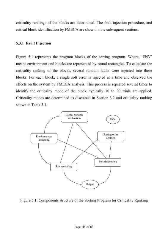
Figure 5.1 represents the program blocks of the sorting program.
means environment and blocks are represented by round rectangles. To calculate the
criticality ranking of the blocks, several random faults were injected into these
blocks. For each block, a single soft error is injected at a time and observed the
effects on the system by FMECA analysis. This process is repeated several times to
identify the criticality mode of the block, typically 10 to 20 trials are applied.
Criticality modes are determined as discussed in Section 3.2 and criticality ranking
shown in Table 3.1.
Figure 5.1: Components structure of the Sorting Program for Criticality Ranking
Global variabledeclaration
Random arrayassigning
Sorting orderdecision
Sort ascending
Sort descending
Output
Page: 46 of 63
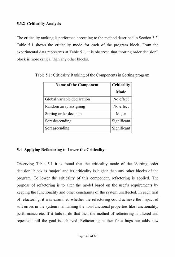
5.3.2 Criticality Analysis
The criticality ranking is performed according to the method described in Section 3.2.
Table 5.1 shows the criticality mode for each of the program block. From the
block is more critical than any other blocks.
Table 5.1: Criticality Ranking of the Components in Sorting program
Name of the Component Criticality
Mode
Global variable declaration No effect
Random array assigning No effect
Sorting order decision Major
Sort descending Significant
Sort ascending Significant
5.4 Applying Refactoring to Lower the Criticality
Observing Table 5.1 it is found
block is major and its criticality is higher than any other blocks of the
program. To lower the criticality of this component, refactoring is applied. The
keeping the functionality and other constraints of the system unaffected. In each trial
of refactoring, it was examined whether the refactoring could achieve the impact of
soft errors in the system maintaining the non-functional properties like functionality,
performance etc. If it fails to do that then the method of refactoring is altered and
repeated until the goal is achieved. Refactoring neither fixes bugs nor adds new

Page: 48 of 63
algorithm, comparing the duplicated array elements after sorting can significantly
reduce the number of checking and thus reduce execution time.
Table 5.2: Source code size of the selected program in bytes
Original
Program
Maurizio
Rebaudengo et
al.
x
Proposed
Method
y
%
Improvement
Matrix
Multiplication
1084 1423 1318 07.40
Bubble Sort 0999 1308 1296 01.00
Quick Sort 1546 3278 2577 21.40
Selection Sort 1052 1545 1530 01.00
Fibonacci 0272 0910 0669 26.50
Series Addition 0955 4490 2000 55.46
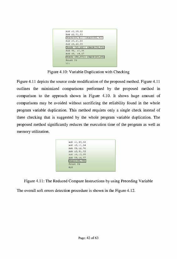
Table 5.2 depicts the changes in source code sizes due to applied transformation on
several program codes according to proposed method and methodology described in
Maurizio Rebaudengo et al. [48] along with original program code. Since the
numbers of checking statements are reduced in proposed method, the transformed
code size is reduced.
5.5.1 Comparisons with Existing Approaches
The figures illustrate at the subsequent section shows the graph of execution time for
Fibonacci, Series addition, Bubble sort, Quick sort, Matrix Multiplication and
Selection sort respectively that are used to evaluate the efficiency of the proposed
method. Original program, whole program duplication (proposed by Rebaudengo et
al. [48]), and proposed methods are applied to evaluate the performance of the
proposed method. Execution time of the program is dependent on several system
Page: 49 of 63
specification parameters like processor speed, size of the primary memory and the
number of thread running on the system; so result will be varied at different
machines. Data are manipulated at the machine with the configuration of Intel dual
core 2.0 GHz processor, 1 GB RAM, 2GB virtual memory and as an operating
system Windows 7 Ultimate is used.
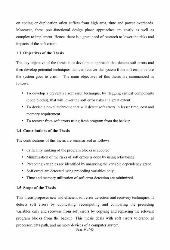
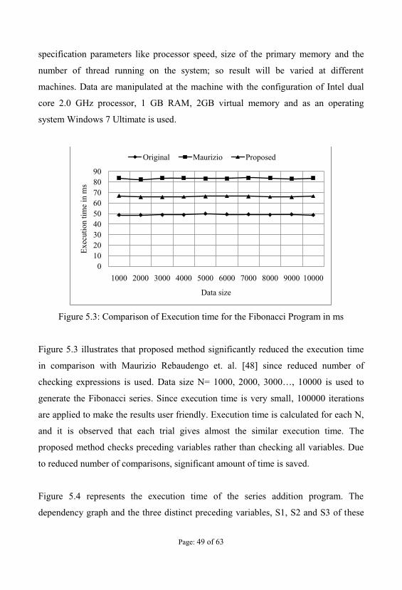
Figure 5.3: Comparison of Execution time for the Fibonacci Program in ms
Figure 5.3 illustrates that proposed method significantly reduced the execution time
in comparison with Maurizio Rebaudengo et. al. [48] since reduced number of
checking expressions is used. Data size N= is used to
generate the Fibonacci series. Since execution time is very small, 100000 iterations
are applied to make the results user friendly. Execution time is calculated for each N,
and it is observed that each trial gives almost the similar execution time. The
proposed method checks preceding variables rather than checking all variables. Due
to reduced number of comparisons, significant amount of time is saved.
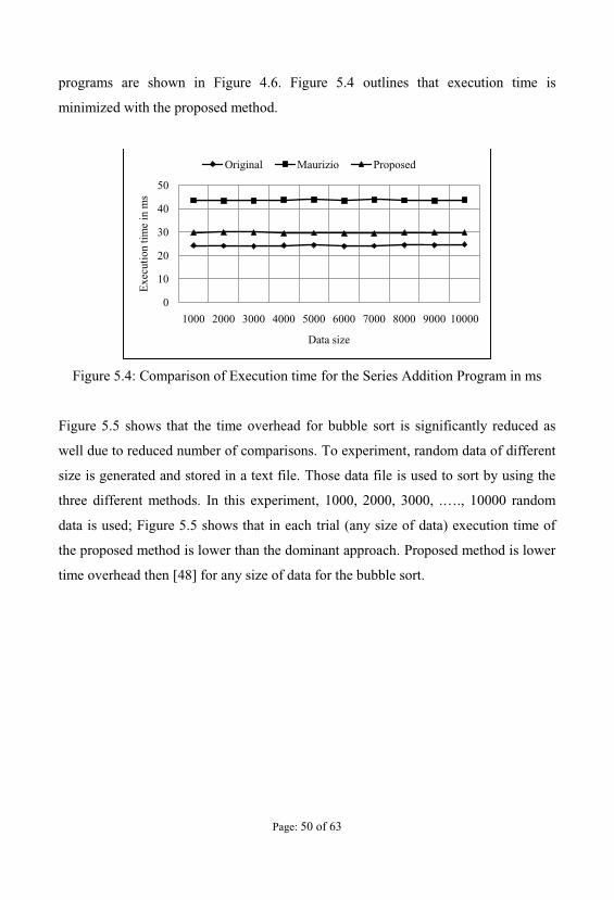
Figure 5.4 represents the execution time of the series addition program. The
dependency graph and the three distinct preceding variables, S1, S2 and S3 of these
0102030405060708090
1000 2000 3000 4000 5000 6000 7000 8000 9000 10000
Exe
cutio
ntim
e in
ms
Data size
Original Maurizio Proposed
Page: 50 of 63
programs are shown in Figure 4.6. Figure 5.4 outlines that execution time is
minimized with the proposed method.
Figure 5.4: Comparison of Execution time for the Series Addition Program in ms
Figure 5.5 shows that the time overhead for bubble sort is significantly reduced as
well due to reduced number of comparisons. To experiment, random data of different
size is generated and stored in a text file. Those data file is used to sort by using the
three different methods. In this experiment, 1000, 2000, 3000, . , 10000 random
data is used; Figure 5.5 shows that in each trial (any size of data) execution time of
the proposed method is lower than the dominant approach. Proposed method is lower
time overhead then [48] for any size of data for the bubble sort.
0
10
20
30
40
50
1000 2000 3000 4000 5000 6000 7000 8000 9000 10000
Exe
cutio
ntim
e in
ms
Data size
Original Maurizio Proposed
Page: 51 of 63
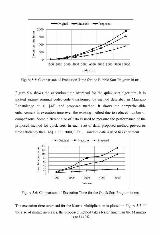
Figure 5.5: Comparison of Execution Time for the Bubble Sort Program in ms.
Figure 5.6 shows the execution time overhead for the quick sort algorithm. It is
plotted against original code; code transformed by method described in Maurizio
Rebaudengo et. al. [48], and proposed method. It shows the comprehensible
enhancement in execution time over the existing method due to reduced number of
comparisons. Some different size of data is used to measure the performance of the
proposed method for quick sort. In each size of data, proposed method proved its
time efficiency then [48]. experiment.
Figure 5.6: Comparison of Execution Time for the Quick Sort Program in ms.
The execution time overhead for the Matrix Multiplication is plotted in Figure 5.7. If
the size of matrix increases, the proposed method takes lesser time than the Maurizio
0
500
1000
1500
2000
1000 2000 3000 4000 5000 6000 7000 8000 9000 10000
Exe
cutio
ntim
e in
ms
Data size
Original Maurizio Proposed
020406080
100120140
1000 2000 3000 4000 5000
Exe
cutio
ntim
e in
ms
Data size
Original Maurizio Proposed
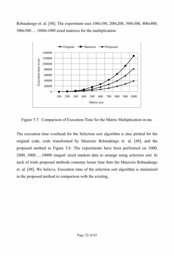
Page: 52 of 63
Rebaudengo et. al. [48]. The experiment uses 100x100, 200x200, 300x300, 400x400,
500x500 matrices for the multiplication.
Figure 5.7: Comparison of Execution Time for the Matrix Multiplication in ms.
The execution time overhead for the Selection sort algorithm is also plotted for the
original code, code transformed by Maurizio Rebaudengo et. al. [48], and the
proposed method in Figure 5.8. The experiments have been performed on 1000,
ranged/ sized random data to arrange using selection sort. In
each of trials proposed methods consume lesser time then the Maurizio Rebaudengo
et. al. [48]. We believe, Execution time of the selection sort algorithm is minimized
in the proposed method in comparison with the existing.
0
20000
40000
60000
80000
100000
120000
140000
100 200 300 400 500 600 700 800 900 1000
Exe
cutio
ntim
e in
ms
Matrix size
Original Maurizio Proposed

Page: 53 of 63
Figure 5.8: Comparison of Execution Time for the Selection Sort Program in ms.
5.6 Discussion
From the
. To lower the
criticality of this block, refactoring is applied. After refactoring, criticality of the
block
Experimental results of the Bubble sort, Quick sort, Selection sort and Matrix
multiplication problem shows that the proposed method consumes lesser time in
every trial than the method proposed by Maurizio Rebaudengo et. at [48]. Execution
time of the Matrix multiplication, Bubble sort and Selection sort increases
exponentially with the increment of data size. Hence, the proposed method minimizes
the risks of soft errors by refactoring critical blocks and then detects the soft errors in
lesser time than [48] by using preceding variable only.
0
100
200
300
400
500
600
700
800
1000 2000 3000 4000 5000 6000 7000 8000 9000 10000
Exe
cutio
ntim
e in
ms
Data size
Original Maurizio Proposed
Page: 54 of 63
CHAPTER VI
Conclusions
6.1 Concluding Remarks
The significant contribution of the proposed method is to lower soft error risks with a
minimum time and space complexity since it works with preceding variables only.
Hence, all the variables in the program code are not considered to be recomputed or
replicated. Preceding variable comparisons can capture the soft errors which could
affect other dependent variables and this approach has no interference to system
performance. The point of interest of the proposed method is the placement of the
detector in the right place to reduce the computational effect without minimizing soft
error coverage significantly.
Although soft errors not only occur inside the variables but also in the command
words or at any other places, the proposed methodology opens the possibility of
determining the dependency among them and then use lesser checks to detect soft
errors. In case of the absence of dependant variables, this method applies check in
each independent variable. Experimental studies show that the proposed method can
provide high-coverage, low-latency (rapid) error detection to preempt uncontrolled
system crash/hang and prevent error propagation. And the soft error detection time is
lesser than the previous dominant approaches.
6.2 Future Recommendations
Few possible steps could be adopted to enhance the performance of the method. The
protection of backup of original program is a great concern to remain soft error free.
For the soft error tolerance of the storage, besides existing techniques such as Error-
Correcting-Code (ECC), Redundant Array of Inexpensive Disks (RAID), several

Page: 55 of 63
enhancements can be explored. Efficiency of the proposed method depends on proper
identification of critical blocks and variables i.e., that is
number of dependency/ branches looping or how
many times severity of i.e., block containing more weighted
variables etc., are wide open to determine the criticality. Hence, much more scopes
are available in the field of critical block and variable identification.
Page: 56 of 63
BIBLIOGRAPHY
[1] A. Timor, A. Mendelson, Y. Birk, and N. Suri, "Using underutilized CPU
resources to enhance its reliability," Dependable and Secure Computing, IEEE
Transactionson, vol. 7, no. 1, pp. 94-109, 2010.
[2] E. L. Rhod, C. A. L. Lisboa, L. Carro, M. S. Reorda, and M. Violante, "Hardware
and Software Transparency in the Protection of Programs Against SEUs and SETs,"
Journal of Electronic Testing, vol. 24, pp. 45-56, 2008.
[3] S. S. Mukherjee, J. Emer, and S. K. Reinhardt, "The soft error problem: an
architectural perspective," In 11th International Symposium on High-Performance
Computer Architecture, San Francisco, CA, USA, pp. 243 - 247, 2005.
[4] R. K. Iyer, N. M. Nakka, Z. T. Kalbarczyk, and S. Mitra, "Recent advances and
new avenues in hardware-level reliability support,"Micro, IEEE, vol. 25, pp. 18-29,
2005.
[5] V. Narayanan and Y. Xie, "Reliability concerns in embedded system designs,"
Computer, vol. 39, pp. 118-120, 2006.
[6] S. Tosun, "Reliability-centric system design for embedded systems" Ph.D. Thesis,
Syracuse University, United States --New York, 2005.
[7] Muhammad Sheikh Sadi, D. G. Myers, Cesar Ortega Sanchez, and Jan Jurjens,
Comput Syst Sci &
Eng, vol 26, no 1, pp. 377-391, 2010.
[8] Shubu Mukherjee, organ Kaufmann
Publishers, ISBN 978-0-12-369529-1, 2008.
Reduce the Soft Error Rate of a High- in31st Annual
International Symposium on Computer Architecture, pp. 264 275, 2004.
Page: 57 of 63
[10]
In Proceeding of
the 33rd Annual Reliability Physics Symposium, pp. 297 302, 1995.
[11] R. Baumann, -Part 1: The
IEEE Trans. Device and Materials Reliability, vol. 1, no.
1, pp. 17 22, 2001.
[12] O. Musseau, - IEEE
Trans. Nuclear Science, vol. 43, no. 2, pp. 603 613, 1996.
[13] M. Genero, M. Piatini, and E. Manso, "Finding "early" indicators of UML class
diagrams understandability and modifiability," in Proceedings - International
Symposium on Empirical Software Engineering, ISESE, 2004, pp. 207-216.
[14] S. S. Mukherjee, M. Kontz and S. K. Reinhardt, "Detailed design and
evaluation of redundant multi-threading alternatives" In Proceeding of the 29th
Annual International Symposium on Computer Architecture, pp. 99-110, 2002.
[15] S. K. Reinhardt and S. S. Mukherjee, "Transient fault detection via simultaneous
multithreading" In Proceeding of the 27th International Symposium on Computer
Architecture, pp. 25-36, 2000.
[16] E. Rotenberg, "AR-SMT: A Micro Architectural Approach to Fault Tolerance in
Microprocessors" In Proceeding of the 29th Annual International Symposium on
Fault-Tolerant Computing, pp. 84-91, 1999.
[17] J. C. Smolens, B. T. Gold, J. Kim, B. Falsafi, J. C. Hoe, and A. G. Nowatzyk,
"Fingerprinting: Bounding soft-error detection latency and bandwidth" In
Proceedings of the 11th International Conference on Architectural Support for
Programming Languages and Operating Systems, ASPLOS XI, New York, NY 10036-
5701, United States, pp. 224-234, 2004.
Page: 58 of 63
[18] T. N. Vijaykumar, I. Pomeranz, and K. Cheng, "Transient-fault recovery using
simultaneous multithreading," In Proceeding of the 29th Annual International
Symposium on Computer Architecture, pp. 87-98, 2002.
[19] N. Oh, P. P. Shirvani, and E. J. McCluskey, "Error detection by duplicated
instructions in super-scalar processors" Reliability, IEEE Transactionson, vol. 51, pp.
63-75, 2002.
[20] G. A. Reis, J. Chang, N. Vachharajani, R. Rangan, and D. I. August, "SWIFT:
software implemented fault tolerance" In Proceeding of the International Symposium
on Code Generation and Optimization, Los Alamitos, CA, USA, pp. 243-54, 2005.
[21] Y. Xie, L. Li, M. Kandemir, N. Vijaykrishnan, and M. J. Irwin, "Reliability-
aware co-synthesis for embedded systems," In Proceeding of the 15th IEEE
International Conference on Application-Specific Systems, Architectures and
Processors, pp. 41-50, 2004.
[22] J. Ray, J. C. Hoe, and B. Falsafi, "Dual use of superscalar datapath for transient-
fault detection and recovery" In Proceeding of the 34th ACM/IEEE International
Symposium on Microarchitecture, pp. 214-224, 2001.
[23] C. L. Chen and M. Y. Hsiao, "Error-Correcting Codes for Semiconductor
Memory Applications: A State-Of-The-Art Review," IBM Journal of Research and
Development, vol. 28, pp. 124-134, 1984.
[24] J. M. a. T. Khoshgoftaar, "Software metrics for reliability assessment," in
Handbook of Software Reliability Eng., M. Lyu ed., Chapter 12ed., pp. 493-529,
1996.
[25] K. R. Walcott, G. Humphreys, and S. Gurumurthi, "Dynamic prediction of
architectural vulnerability from microarchitectural state," in Proceedings of the
International Symposium on Computer Architecture, New York, NY 10016-5997,
United States, pp. 516-527, 2007.
Page: 59 of 63
[26] A. Shye, J. Blomstedt, T. Moseley, V. Janapa Reddi, and D. Connors, "PLR: A
Software Approach to Transient Fault Tolerance for Multi-Core Architectures" In
Proceeding of the IEEE Transactions on Dependable and Secure Computing.pp. 267-
78, 2007.
[27] J. K. Park and J. T. Kim, "A Soft Error Mitigation Technique for Constrained
Gate-level Designs" IEICE Electronics Express, vol. 5, pp. 698-704, 2008.
[28] N. Miskov-Zivanov and D. Marculescu, "MARS-C: modeling and reduction of
soft errors in combinational circuits" In Proceedings of the Design Automation
Conference, Piscataway, NJ, USA, pp. 767-772, 2006.
[29] Z. Quming and K. Mohanram, "Cost-effective radiation hardening technique for
combinational logic" In Proceedings of the International Conference on Computer
Aided Design, Piscataway, NJ, USA, pp. 100-106, 2004.
[30] Martin Omafia. Daniele Rossi. Cecilia Metra, "Novel Transient Fault Hardened
Static Latch," In IEEE International Test Conference (TC), Charlotte, NC, United
states, pp. 886-892, 2003.
[31] S. P. Release. New chip technology from STmicroelectronics eliminates soft
error threat to electronic systems, Available at: http://www.st.com/stonline/
press/news/ year2003/t1394h .htm [Online].
[32] M. Zhang, "Analysis and design of soft-error tolerant circuits" Ph.D. Thesis,
University of Illinois at Urbana-Champaign, United States -- Illinois, 2006.
[33] M. Zhang, S. Mitra, T. M. Mak, N. Seifert, N. J. Wang, Q. Shi, K. S. Kim, N. R.
Shanbhag, and S. J. Patel, "Sequential Element Design With Built-In Soft Error
Resilience" Very Large Scale Integration (VLSI) Systems, IEEE Transactions on, vol.
14, pp. 1368-1378, 2006.
[34] P. J. Meaney, S. B. Swaney, P. N. Sanda, and L. Spainhower, "IBM z990 soft
error detection and recovery " Device and Materials Reliability, IEEE Transactions
on, vol. 5, pp. 419-427, 2005.
Page: 60 of 63
[35] T. M. Austin, "DIVA: A reliable substrate for deep submicron microarchitecture
design," In Proceeding of the 32nd Annual International Symposium on
Microarchitecture, pp. 196-207, 1999.
[36] B. T. Gold, J. Kim, J. C. Smolens, E. S. Chung, V. Liaskovitis, E. Nurvitadhi, B.
Falsafi, J. C. Hoe, and A. G. Nowatzyk, "TRUSS: A reliable, scalable server
architecture" Micro, IEEE, vol. 25, pp. 51-59, 2005.
[37] S. Krishna Mohan, "Efficient techniques for modeling and mitigation of soft
errors in nanometer-scale static CMOS logic circuits" Ph.D. Thesis, Michigan State
University, United States -- Michigan, 2005.
[38] A. G. Mohamed, S. Chad, T. N. Vijaykumar, and P. Irith, "Transient-fault
recovery for chip multiprocessors" IEEE Micro, vol. 23, p. 76, 2003. [35] T. N.
Vijaykumar, I. Pomeranz, and K. Cheng, "Transient-fault recovery using
simultaneous multithreading," in 29th Annual International Symposium on Computer
Architecture, pp. 87-98, 2002.
[39] P. E. Evans, "Failure mode effects and criticality analysis," in Midcon/87
Conference Record, Los Angeles, CA, USA, pp. 168-171, 1987.
[40] T. N. Vijaykumar, I. Pomeranz, and K. Cheng, "Transient-fault recovery using
simultaneous multithreading," in 29th Annual International Symposium on Computer
Architecture, pp. 87-98, 2002.
[41] S. M. Seyed-Hosseini, N. Safaei, and M. J. Asgharpour, "Reprioritization of
failures in a system failure mode and effects analysis by decision making trial and
evaluation laboratory technique," Reliability Engineering & System Safety, vol. 91,
pp. 872-881, 2006.
[42] S. Hosseini and M. A. Azgomi, "UML model refactoring with emphasis on
behavior preservation," in Proceedings of the 2nd IFIP/IEEE International
Symposium on Theoretical Aspects of Software Engineering, Piscataway, NJ 08855-
1331, United States, pp. 125-128, 2008.
Page: 61 of 63
[43] S. Gerson, P. Damien, T. Yves Le, J. Jean-Marc, z, and quel, "Refactoring UML
Models," in Proceedings of the 4th International Conference on The Unified
Modeling Language, Modeling Languages, Concepts, and Tools, ed: Springer-
Verlag, pp. 134-148, 2001.
[44] L. Dobrzanski and L. Kuzniarz, "An approach to refactoring of executable UML
models," in Proceedings of the ACM Symposium on Applied Computing, New York,
NY 10036-5701, United States, pp. 1273-1279, 2006.
[45] M. Boger, T. Sturm, and P. Fragemann, "Refactoring browser for UML," in
Proceedings of the International Conference on Objects, Components, Architectures,
Services, and Applications for a Networked World, Berlin, Germany, 2003, Revised
Papers (Lecture Notes in Computer Science), vol.2591, pp. 366-377, 2003.
[46] T. Mens and P. Van Gorp, "A taxonomy of model transformation," Electronic
Notes in Theoretical Computer Science, vol. 152, pp. 125-142, 2006.
[47] T. Mens, "On the use of graph transformations for model refactoring," Lecture
Notes in Computer Science, vol. 41, LNCS, pp. 219-257, 2006.
[48] Maurizio Rebaudengo, Matteo Sonza Reorda, Marco Torchiano, Massimo
Violante, Soft-error Detection through Software Fault-Tolerance techniques
International Conference on Intelligence in Networks (ICIN), Bordeaux, France,
October, 2001.
Page: 62 of 63
APPENDIX A
TERMS AND DEFINITIONS
BPSG: Borophosphosilicate glass. BPSG is a type of silicate glass that includes
additives containing boron and phosphorus. Silicate glass such as PSG and
borophosphosilicate glass are commonly used in semiconductor device fabrication for
intermetal layers, i.e., for insulating layers deposited between successive metal or
conducting layers.
Critical Charge (Qcrit): The minimum amount of charge that when collected at any
sensitive node will cause the node to change state. The critical charge is usually
generated by incident radiation and its value is dependent on the effective linear
energy transfer, which is usually a function of the angle of incident of the particle
radiation.
ECC: Error correction code, sometimes called Error Detection And Correction
(EDAC).
Electron Volt (eV): One eV is the energy gained by an electron when accelerating
through a potential difference of 1 volt. Energy of radiation is usually in MeV
(106eV).
FIT: Failure in Time; the number of failures per 109 device hours. 1 year MTTF =
109/(24×365)FIT = 114,155 FIT.
MTTF: Mean Time to Failure.
RAID: Redundant Arrays of Inexpensive Disks. RAID is a technology that supports
the integrated use of two or more hard-drives in various configurations for the
purposes of achieving greater performance, reliability through redundancy, and larger
disk volume sizes through aggregation.
Page: 63 of 63
SEE: Single Event Effect. Any measurable or observable change in state or
performance of a microelectronic device, component, subsystem or system resulting
from a single energetic particle strike. SEE include SEU, SEL, SEB and SEFI.
SET: Single Event Transient. A current or voltage transient pulse caused by SEE.
SEU: Single Event Upset. Radiation-induced errors in microelectronic circuits
caused when charged particles (usually from the radiation belts or from cosmic rays)
lose energy by ionizing the medium through which they pass, leaving behind a wake
of electron-hole pairs.
Soft error: A soft error that can be corrected by repeated reading without rewriting
or without the removal of power.
SER: Soft error rate.
SOI: Silicon on insulator.


Buy your books fast and straightforward online - at one of world’s
fastest growing online book stores! Environmentally sound due to
Print-on-Demand technologies.
Buy your books online at
www.get-morebooks.com
Kaufen Sie Ihre Bücher schnell und unkompliziert online – auf einer
der am schnellsten wachsenden Buchhandelsplattformen weltweit!
Dank Print-On-Demand umwelt- und ressourcenschonend produzi-
ert.
Bücher schneller online kaufen
www.morebooks.deVDM Verlagsservicegesellschaft mbH
Heinrich-Böcking-Str. 6-8 Telefon: +49 681 3720 174 [email protected] - 66121 Saarbrücken Telefax: +49 681 3720 1749 www.vdm-vsg.de


