snapshot™ for windows® ce
TRANSCRIPT
Specifications and Ordering Information Part Number 143338-01
Rev. N (03/07)
Page 1 of 18
Snapshot™ for Windows® CE
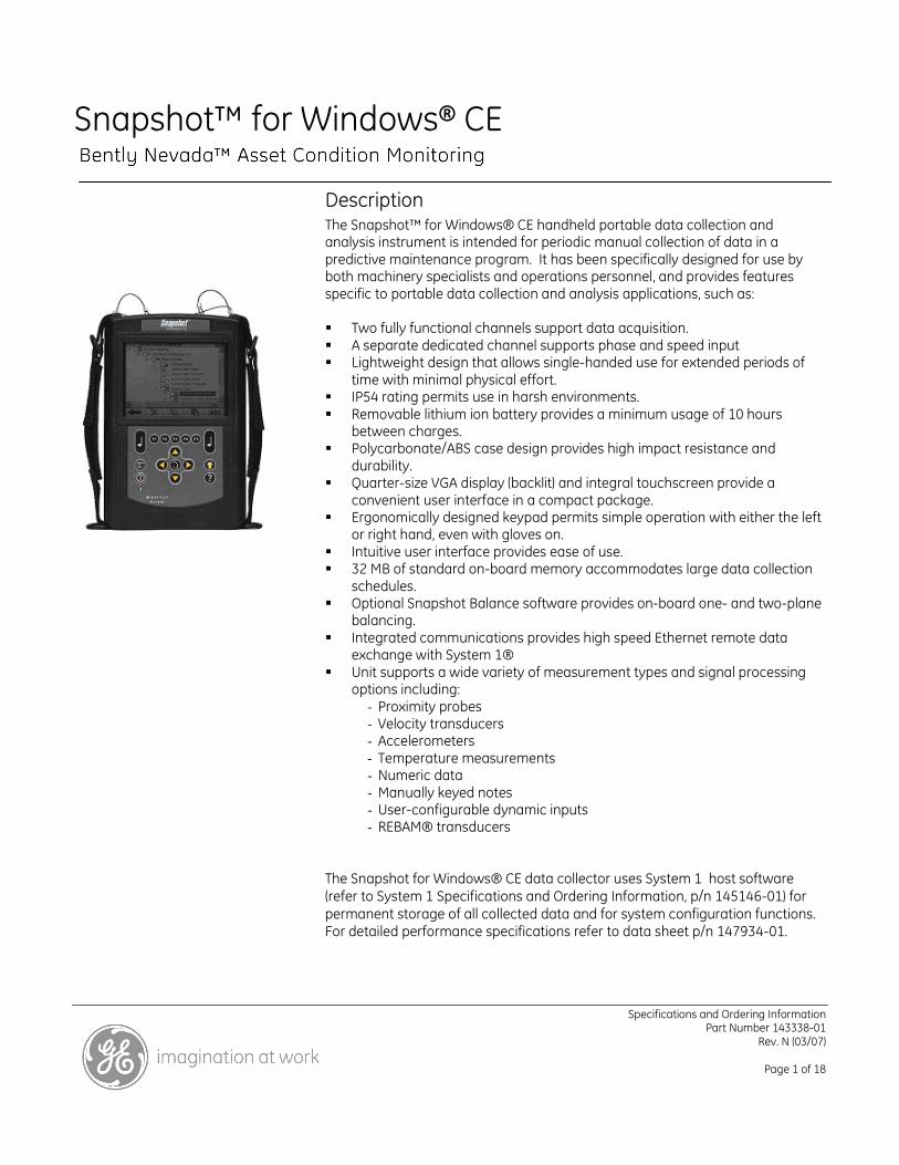
Description The Snapshot™ for Windows® CE handheld portable data collection and analysis instrument is intended for periodic manual collection of data in a predictive maintenance program. It has been specifically designed for use by both machinery specialists and operations personnel, and provides features specific to portable data collection and analysis applications, such as: Two fully functional channels support data acquisition. A separate dedicated channel supports phase and speed input Lightweight design that allows single-handed use for extended periods of
time with minimal physical effort. IP54 rating permits use in harsh environments. Removable lithium ion battery provides a minimum usage of 10 hours
between charges. Polycarbonate/ABS case design provides high impact resistance and
durability. Quarter-size VGA display (backlit) and integral touchscreen provide a
convenient user interface in a compact package. Ergonomically designed keypad permits simple operation with either the left
or right hand, even with gloves on. Intuitive user interface provides ease of use. 32 MB of standard on-board memory accommodates large data collection
schedules. Optional Snapshot Balance software provides on-board one- and two-plane
balancing. Integrated communications provides high speed Ethernet remote data
exchange with System 1® Unit supports a wide variety of measurement types and signal processing
options including: - Proximity probes - Velocity transducers - Accelerometers - Temperature measurements - Numeric data - Manually keyed notes - User-configurable dynamic inputs - REBAM® transducers
The Snapshot for Windows® CE data collector uses System 1 host software (refer to System 1 Specifications and Ordering Information, p/n 145146-01) for permanent storage of all collected data and for system configuration functions. For detailed performance specifications refer to data sheet p/n 147934-01.
Specifications and Ordering Information Part Number 143338-01
Rev. N (03/07)
Page 2 of 18
Specifications
Operating System
Microsoft Windows®CE
System Features
Battery Power:
10 hours minimum, in use
Battery Type:
Lithium Ion
Memory:
32 MB on board.
Local Display Plots Supported
Current value/bar graph
Trend
Direct and Filtered Orbit/Timebase
Direct and Filtered Timebase
Direct and Filtered Orbit
Full spectrum
Half spectrum
1/1 and 1/3 Octave Filter
Spectrum configurations
Frequency resolution, user-selectable from 100, 200, 400, 800, 1600, 3200, 6400 lines
Frequency span, user-selectable ranges between 0-25Hz and 0-40 kHz.
Inputs Supported
Proximity transducers
REBAM transducers
Velocity Seismoprobe® transducers
Velomitor® transducers
Accelerometers
Optical and Proximity Phase
Infrared (IR) Temperature Probe (optional item)
Proportional Voltage
Dynamic inputs
Note: Internal transducer power is
available for –24Vdc and constant current
devices.
Measurements Supported
mm/s2, g – 0-pk, rms
mm/s, in/s – 0-pk, rms
µm, mil – pp
Enveloping
Integrated Velocity
Integrated Displacement
Direct Amplitude
1X & 2X Vectors
REBAM (rotor region and prime spike filters)
Gap
Temperature
Proportional Voltage
Speed (10 to 100,000rpm)
Phase
User-definable low-, high- and band pass filters.
Note: The above measurements can be
applied to user-configurable dynamic data
within an input range of ± 10 volts or 0 to
–24 Vdc
Environmental Limits
Operating Temperature:
-20°C to +55°C (-4°F to +131°F)
Relative Humidity:
To 95%, non-condensing
Specifications and Ordering Information Part Number 143338-01
Rev. N (03/07)
Page 3 of 18
Electro magnetic compatibility:
Complies with EN50081-2 (emission) and EN50082-2 (susceptibility)
Rating:
IP54
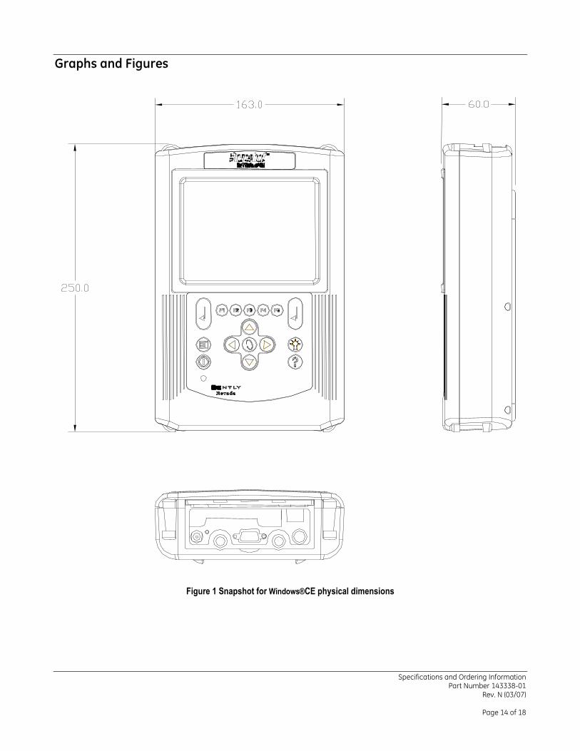
Physical
Length:
250 mm (10.0 in)
Width:
163 mm (6.4 in)
Depth:
60 mm (2.3 in)
All values are specified over the full operating temperature range unless stated otherwise. All voltages are specified with respect to 0V.
Environmental Specification
Temperature & Humidity
Operating
Temperature
range:
-20 to +55 °C (-4 to +131 °C)
Storage
Temperature
Range:
-30 to +85 °C (-22 to +185 °C)
Relative
humidity:
95 % condensing.
Ingress Protection
The Snapshot has been designed and tested to meet the requirements of IP54.
Mechanical Shock & Vibration
Unpackaged shock:
EN 68000-2-27
Unpackaged Vibration:
EN 68000-2-6
Unpackaged Random Vibration:
BS 2011 Pt. 2.1
Packaged Shock:
ISTA 1 & 1A (April 1996)
Packaged Vibration:
ISTA 1 & 1A (April 1996)
Packaged Random Vibration:
BS 2011 Pt. 2
Drop test – free fall
IEC 68-2-32
Impact test
BS 50021
Electromagnetic Compatibility
Emissions:
EN 50081-2
Immunity:
EN 61000-6-2
Hazardous Area Approvals
CSA/NRTL/C:
Class 1, Division 2 Groups A, B, C & D, T4
External Power Input and Battery
Power Input
Nominal Input
Voltage:
+15 Vdc ± 2 %
Specifications and Ordering Information Part Number 143338-01
Rev. N (03/07)
Page 4 of 18
Maximum
Current Draw:
2250 mA
Connector:
2.1 mm Jack, center positive
Battery
Type:
ME202 Li-ion
Capacity:
4500 mAhr
Time Between
Charges:
8 Hrs.
Charge Time:
2 Hrs.
Transducer Power Supplies
Point ID +5 V Power
Voltage:
4.725 to 5.100 Vdc
Current:
0 to 440 mA
Phase Reference Power +5 V
Voltage:
4.731 to 5.100 Vdc
Current:
0 to 120 mA
Phase Reference Power, Transducer Power Channel A & Channel B –24 V
Voltage:
-23.160 to –25.725 Vdc
Current:
0 to 25 mA
Velomitor® & Constant Current Transducers
Power Channel A & Channel B
Voltage:
-19.17 to –22.10 Vdc
Current:
2.44 to 4.97 mA
Signal Inputs
Displacement
Input Impedance:
122.5 kΩ
Input Voltage Range:
0 to –24.25 V
Analysis Application OK Limits:
-4.15 to –16.75 V
DC Accuracy:
± 50 mVdc
AC Accuracy:
Minimum: [100 – Filter attenuation (see p. 7)] % of input signal amplitude
Maximum: [101 % of input signal amplitude + noise offset (see below)] / Scale Factor
AC Accuracy (1X & 2X Vectors):
Note: These specifications apply over the
valid input frequency range of the Phase
Reference (10-100,000 rpm).
Minimum: 98 % of input signal amplitude for inputs greater/ equal to 0.2 Vpp. 95 % of input signal amplitude for inputs less than 0.2 Vpp.
Maximum: 102 % of input signal amplitude + 1.2 mV
Noise Offsets:
Specifications and Ordering Information Part Number 143338-01
Rev. N (03/07)
Page 5 of 18
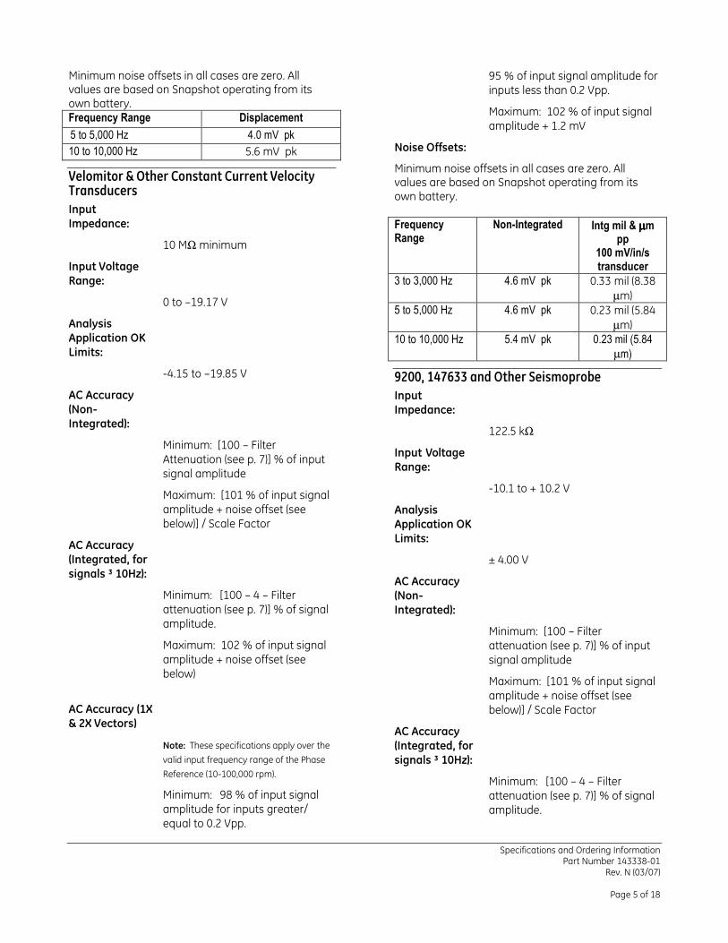
Minimum noise offsets in all cases are zero. All values are based on Snapshot operating from its own battery. Frequency Range Displacement
5 to 5,000 Hz 4.0 mV pk
10 to 10,000 Hz 5.6 mV pk
Velomitor & Other Constant Current Velocity Transducers
Input Impedance:
10 MΩ minimum
Input Voltage Range:
0 to –19.17 V
Analysis Application OK Limits:
-4.15 to –19.85 V
AC Accuracy (Non-Integrated):
Minimum: [100 – Filter Attenuation (see p. 7)] % of input signal amplitude
Maximum: [101 % of input signal amplitude + noise offset (see below)] / Scale Factor
AC Accuracy (Integrated, for signals ³ 10Hz):
Minimum: [100 – 4 – Filter attenuation (see p. 7)] % of signal amplitude.
Maximum: 102 % of input signal amplitude + noise offset (see below)
AC Accuracy (1X & 2X Vectors)
Note: These specifications apply over the
valid input frequency range of the Phase
Reference (10-100,000 rpm).
Minimum: 98 % of input signal amplitude for inputs greater/ equal to 0.2 Vpp.
95 % of input signal amplitude for inputs less than 0.2 Vpp.
Maximum: 102 % of input signal amplitude + 1.2 mV
Noise Offsets:
Minimum noise offsets in all cases are zero. All values are based on Snapshot operating from its own battery. Frequency Range
Non-Integrated Intg mil & µµµµm pp
100 mV/in/s transducer
3 to 3,000 Hz 4.6 mV pk 0.33 mil (8.38 µm)
5 to 5,000 Hz 4.6 mV pk 0.23 mil (5.84 µm)
10 to 10,000 Hz 5.4 mV pk 0.23 mil (5.84
µm)
9200, 147633 and Other Seismoprobe
Input Impedance:
122.5 kΩ
Input Voltage Range:
-10.1 to + 10.2 V
Analysis Application OK Limits:
± 4.00 V
AC Accuracy (Non-Integrated):
Minimum: [100 – Filter attenuation (see p. 7)] % of input signal amplitude
Maximum: [101 % of input signal amplitude + noise offset (see below)] / Scale Factor
AC Accuracy (Integrated, for signals ³ 10Hz):
Minimum: [100 – 4 – Filter attenuation (see p. 7)] % of signal amplitude.
Specifications and Ordering Information Part Number 143338-01
Rev. N (03/07)
Page 6 of 18
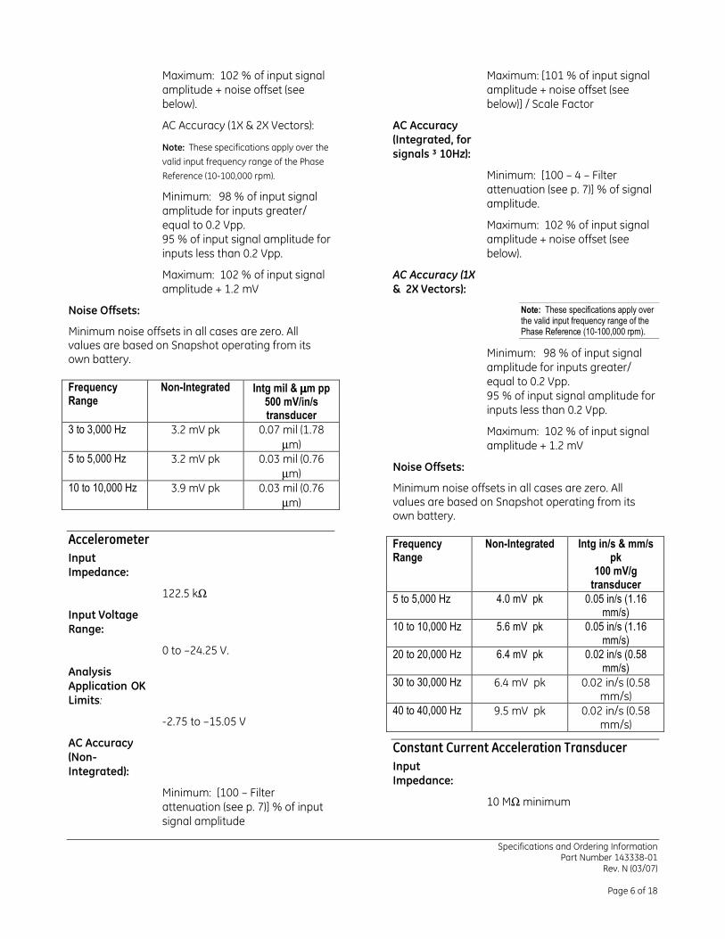
Maximum: 102 % of input signal amplitude + noise offset (see below).
AC Accuracy (1X & 2X Vectors):
Note: These specifications apply over the
valid input frequency range of the Phase
Reference (10-100,000 rpm).
Minimum: 98 % of input signal amplitude for inputs greater/ equal to 0.2 Vpp. 95 % of input signal amplitude for inputs less than 0.2 Vpp.
Maximum: 102 % of input signal amplitude + 1.2 mV
Noise Offsets:
Minimum noise offsets in all cases are zero. All values are based on Snapshot operating from its own battery. Frequency Range
Non-Integrated Intg mil & µµµµm pp 500 mV/in/s transducer
3 to 3,000 Hz 3.2 mV pk 0.07 mil (1.78 µm)
5 to 5,000 Hz 3.2 mV pk 0.03 mil (0.76 µm)
10 to 10,000 Hz 3.9 mV pk 0.03 mil (0.76 µm)
Accelerometer
Input Impedance:
122.5 kΩ
Input Voltage Range:
0 to –24.25 V.
Analysis Application OK Limits:
-2.75 to –15.05 V
AC Accuracy (Non-Integrated):
Minimum: [100 – Filter attenuation (see p. 7)] % of input signal amplitude
Maximum: [101 % of input signal amplitude + noise offset (see below)] / Scale Factor
AC Accuracy (Integrated, for signals ³ 10Hz):
Minimum: [100 – 4 – Filter attenuation (see p. 7)] % of signal amplitude.
Maximum: 102 % of input signal amplitude + noise offset (see below).
AC Accuracy (1X & 2X Vectors):
Note: These specifications apply over the valid input frequency range of the Phase Reference (10-100,000 rpm).
Minimum: 98 % of input signal amplitude for inputs greater/ equal to 0.2 Vpp. 95 % of input signal amplitude for inputs less than 0.2 Vpp.
Maximum: 102 % of input signal amplitude + 1.2 mV
Noise Offsets:
Minimum noise offsets in all cases are zero. All values are based on Snapshot operating from its own battery. Frequency Range
Non-Integrated Intg in/s & mm/s pk
100 mV/g transducer
5 to 5,000 Hz 4.0 mV pk 0.05 in/s (1.16 mm/s)
10 to 10,000 Hz 5.6 mV pk 0.05 in/s (1.16 mm/s)
20 to 20,000 Hz 6.4 mV pk 0.02 in/s (0.58 mm/s)
30 to 30,000 Hz 6.4 mV pk 0.02 in/s (0.58 mm/s)
40 to 40,000 Hz 9.5 mV pk 0.02 in/s (0.58 mm/s)
Constant Current Acceleration Transducer
Input Impedance:
10 MΩ minimum
Specifications and Ordering Information Part Number 143338-01
Rev. N (03/07)
Page 7 of 18
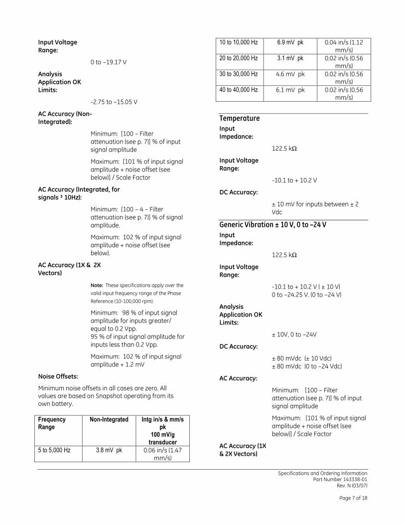
Input Voltage Range:
0 to –19.17 V
Analysis Application OK Limits:
-2.75 to –15.05 V
AC Accuracy (Non-Integrated):
Minimum: [100 – Filter attenuation (see p. 7)] % of input signal amplitude
Maximum: [101 % of input signal amplitude + noise offset (see below)] / Scale Factor
AC Accuracy (Integrated, for signals ³ 10Hz):
Minimum: [100 – 4 – Filter attenuation (see p. 7)] % of signal amplitude.
Maximum: 102 % of input signal amplitude + noise offset (see below).
AC Accuracy (1X & 2X Vectors)
Note: These specifications apply over the
valid input frequency range of the Phase
Reference (10-100,000 rpm).
Minimum: 98 % of input signal amplitude for inputs greater/ equal to 0.2 Vpp. 95 % of input signal amplitude for inputs less than 0.2 Vpp.
Maximum: 102 % of input signal amplitude + 1.2 mV
Noise Offsets:
Minimum noise offsets in all cases are zero. All values are based on Snapshot operating from its own battery. Frequency Range
Non-Integrated Intg in/s & mm/s pk
100 mV/g transducer
5 to 5,000 Hz 3.8 mV pk 0.06 in/s (1.47 mm/s)
10 to 10,000 Hz 6.9 mV pk 0.04 in/s (1.12 mm/s)
20 to 20,000 Hz 3.1 mV pk 0.02 in/s (0.56 mm/s)
30 to 30,000 Hz 4.6 mV pk 0.02 in/s (0.56 mm/s)
40 to 40,000 Hz 6.1 mV pk 0.02 in/s (0.56 mm/s)
Temperature
Input Impedance:
122.5 kΩ
Input Voltage Range:
-10.1 to + 10.2 V
DC Accuracy:
± 10 mV for inputs between ± 2 Vdc
Generic Vibration ± 10 V, 0 to –24 V
Input Impedance:
122.5 kΩ
Input Voltage Range:
-10.1 to + 10.2 V ( ± 10 V) 0 to –24.25 V. (0 to –24 V)
Analysis Application OK Limits:
± 10V, 0 to –24V
DC Accuracy:
± 80 mVdc (± 10 Vdc) ± 80 mVdc (0 to –24 Vdc)
AC Accuracy:
Minimum: [100 – Filter attenuation (see p. 7)] % of input signal amplitude
Maximum: [101 % of input signal amplitude + noise offset (see below)] / Scale Factor
AC Accuracy (1X & 2X Vectors)
Specifications and Ordering Information Part Number 143338-01
Rev. N (03/07)
Page 8 of 18
Note: These specifications apply over the
valid input frequency range of the Phase
Reference (10-100,000 rpm).
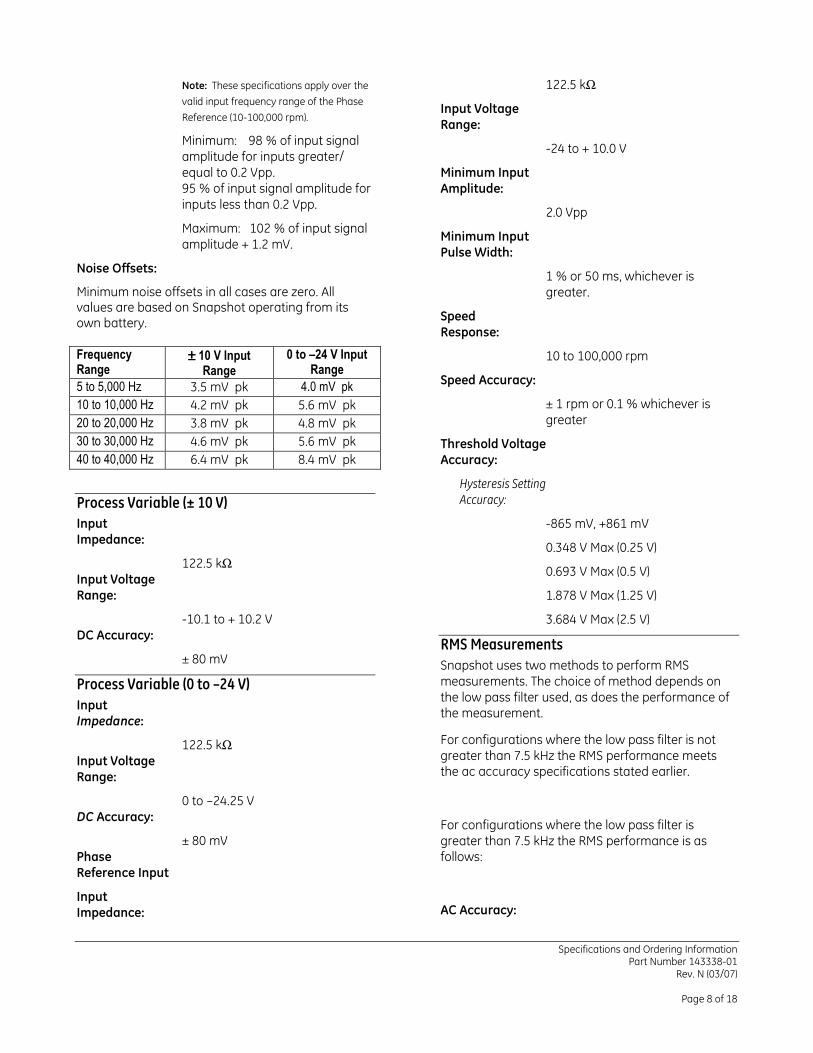
Minimum: 98 % of input signal amplitude for inputs greater/ equal to 0.2 Vpp. 95 % of input signal amplitude for inputs less than 0.2 Vpp.
Maximum: 102 % of input signal amplitude + 1.2 mV.
Noise Offsets:
Minimum noise offsets in all cases are zero. All values are based on Snapshot operating from its own battery. Frequency Range
±±±± 10 V Input Range
0 to –24 V Input Range
5 to 5,000 Hz 3.5 mV pk 4.0 mV pk
10 to 10,000 Hz 4.2 mV pk 5.6 mV pk
20 to 20,000 Hz 3.8 mV pk 4.8 mV pk
30 to 30,000 Hz 4.6 mV pk 5.6 mV pk
40 to 40,000 Hz 6.4 mV pk 8.4 mV pk
Process Variable (± 10 V)
Input Impedance:
122.5 kΩ Input Voltage Range:
-10.1 to + 10.2 V DC Accuracy:
± 80 mV
Process Variable (0 to –24 V)
Input Impedance:
122.5 kΩ Input Voltage Range:
0 to –24.25 V DC Accuracy:
± 80 mV Phase Reference Input
Input Impedance:
122.5 kΩ
Input Voltage Range:
-24 to + 10.0 V
Minimum Input Amplitude:
2.0 Vpp
Minimum Input Pulse Width:
1 % or 50 ms, whichever is greater.
Speed Response:
10 to 100,000 rpm
Speed Accuracy:
± 1 rpm or 0.1 % whichever is greater
Threshold Voltage Accuracy:
Hysteresis Setting
Accuracy:
-865 mV, +861 mV
0.348 V Max (0.25 V)
0.693 V Max (0.5 V)
1.878 V Max (1.25 V)
3.684 V Max (2.5 V)
RMS Measurements
Snapshot uses two methods to perform RMS measurements. The choice of method depends on the low pass filter used, as does the performance of the measurement.
For configurations where the low pass filter is not greater than 7.5 kHz the RMS performance meets the ac accuracy specifications stated earlier.
For configurations where the low pass filter is greater than 7.5 kHz the RMS performance is as follows:
AC Accuracy:
Specifications and Ordering Information Part Number 143338-01
Rev. N (03/07)
Page 9 of 18
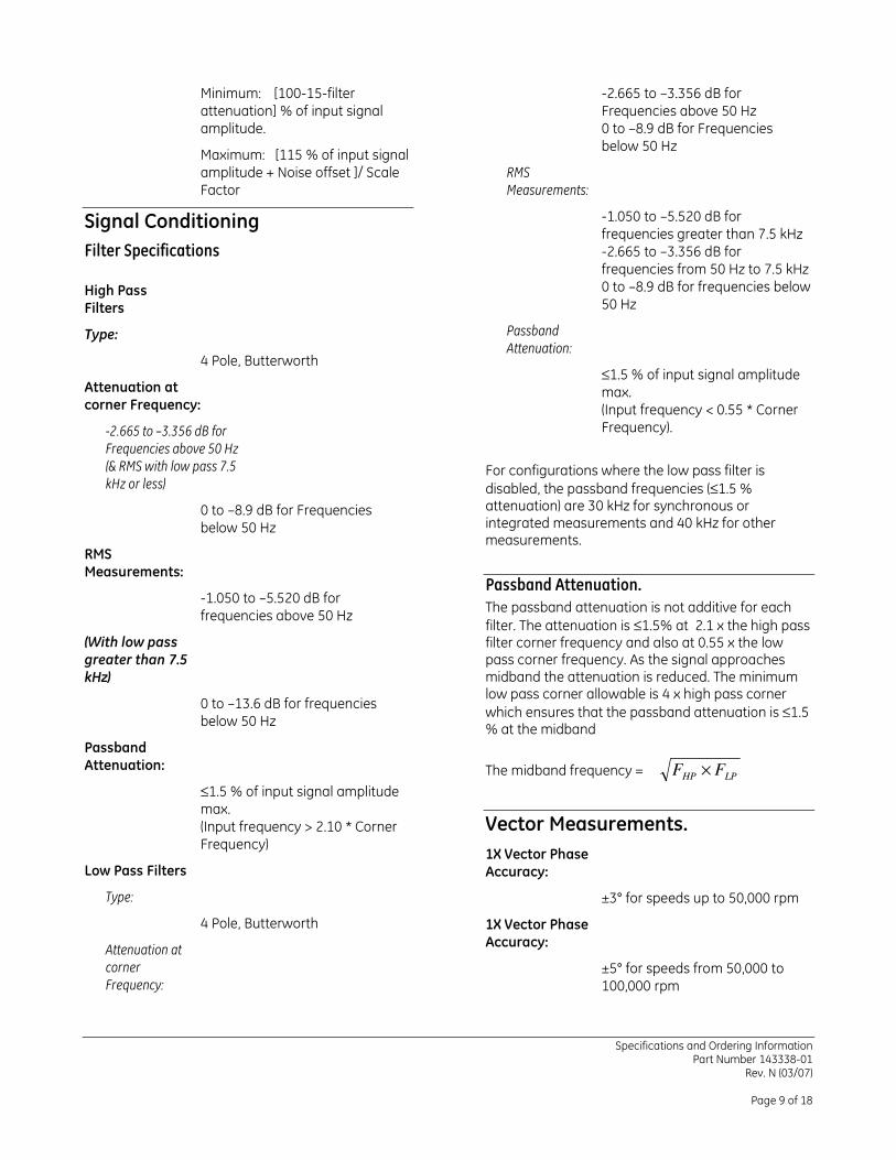
Minimum: [100-15-filter attenuation] % of input signal amplitude.
Maximum: [115 % of input signal amplitude + Noise offset ]/ Scale Factor
Signal Conditioning
Filter Specifications
High Pass Filters
Type:
4 Pole, Butterworth
Attenuation at corner Frequency:
-2.665 to –3.356 dB for
Frequencies above 50 Hz
(& RMS with low pass 7.5
kHz or less)
0 to –8.9 dB for Frequencies below 50 Hz
RMS Measurements:
-1.050 to –5.520 dB for frequencies above 50 Hz
(With low pass greater than 7.5 kHz)
0 to –13.6 dB for frequencies below 50 Hz
Passband Attenuation:
≤1.5 % of input signal amplitude max. (Input frequency > 2.10 * Corner Frequency)
Low Pass Filters
Type:
4 Pole, Butterworth
Attenuation at
corner
Frequency:
-2.665 to –3.356 dB for Frequencies above 50 Hz 0 to –8.9 dB for Frequencies below 50 Hz
RMS
Measurements:
-1.050 to –5.520 dB for frequencies greater than 7.5 kHz -2.665 to –3.356 dB for frequencies from 50 Hz to 7.5 kHz 0 to –8.9 dB for frequencies below 50 Hz
Passband
Attenuation:
≤1.5 % of input signal amplitude max. (Input frequency < 0.55 * Corner Frequency).
For configurations where the low pass filter is disabled, the passband frequencies (≤1.5 % attenuation) are 30 kHz for synchronous or integrated measurements and 40 kHz for other measurements.
Passband Attenuation.
The passband attenuation is not additive for each filter. The attenuation is ≤1.5% at 2.1 x the high pass filter corner frequency and also at 0.55 x the low pass corner frequency. As the signal approaches midband the attenuation is reduced. The minimum low pass corner allowable is 4 x high pass corner which ensures that the passband attenuation is ≤1.5 % at the midband
The midband frequency = LPHP
FF ×
Vector Measurements.
1X Vector Phase Accuracy:
±3° for speeds up to 50,000 rpm
1X Vector Phase Accuracy:
±5° for speeds from 50,000 to 100,000 rpm
Specifications and Ordering Information Part Number 143338-01
Rev. N (03/07)
Page 10 of 18
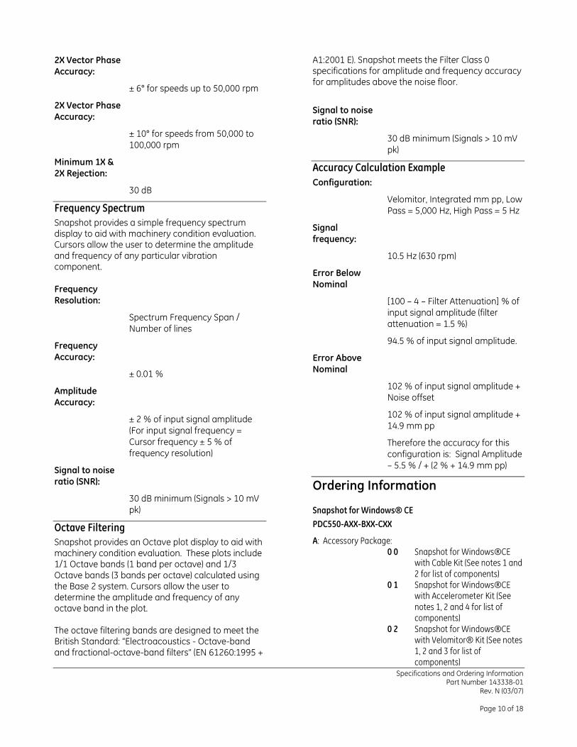
2X Vector Phase Accuracy:
± 6° for speeds up to 50,000 rpm
2X Vector Phase Accuracy:
± 10° for speeds from 50,000 to 100,000 rpm
Minimum 1X & 2X Rejection:
30 dB
Frequency Spectrum
Snapshot provides a simple frequency spectrum display to aid with machinery condition evaluation. Cursors allow the user to determine the amplitude and frequency of any particular vibration component. Frequency Resolution:
Spectrum Frequency Span / Number of lines
Frequency Accuracy:
± 0.01 %
Amplitude Accuracy:
± 2 % of input signal amplitude (For input signal frequency = Cursor frequency ± 5 % of frequency resolution)
Signal to noise ratio (SNR):
30 dB minimum (Signals > 10 mV pk)
Octave Filtering
Snapshot provides an Octave plot display to aid with machinery condition evaluation. These plots include 1/1 Octave bands (1 band per octave) and 1/3 Octave bands (3 bands per octave) calculated using the Base 2 system. Cursors allow the user to determine the amplitude and frequency of any octave band in the plot. The octave filtering bands are designed to meet the British Standard: “Electroacoustics - Octave-band and fractional-octave-band filters” (EN 61260:1995 +
A1:2001 E). Snapshot meets the Filter Class 0 specifications for amplitude and frequency accuracy for amplitudes above the noise floor.
Signal to noise ratio (SNR):
30 dB minimum (Signals > 10 mV pk)
Accuracy Calculation Example
Configuration:
Velomitor, Integrated mm pp, Low Pass = 5,000 Hz, High Pass = 5 Hz
Signal frequency:
10.5 Hz (630 rpm)
Error Below Nominal
[100 – 4 – Filter Attenuation] % of input signal amplitude (filter attenuation = 1.5 %)
94.5 % of input signal amplitude.
Error Above Nominal
102 % of input signal amplitude + Noise offset
102 % of input signal amplitude + 14.9 mm pp
Therefore the accuracy for this configuration is: Signal Amplitude – 5.5 % / + (2 % + 14.9 mm pp)
Ordering Information
Snapshot for Windows® CE
PDC550-AXX-BXX-CXX
A: Accessory Package: 0 0 Snapshot for Windows®CE
with Cable Kit (See notes 1 and 2 for list of components)
0 1 Snapshot for Windows®CE with Accelerometer Kit (See notes 1, 2 and 4 for list of components)
0 2 Snapshot for Windows®CE with Velomitor® Kit (See notes 1, 2 and 3 for list of components)
Specifications and Ordering Information Part Number 143338-01
Rev. N (03/07)
Page 11 of 18
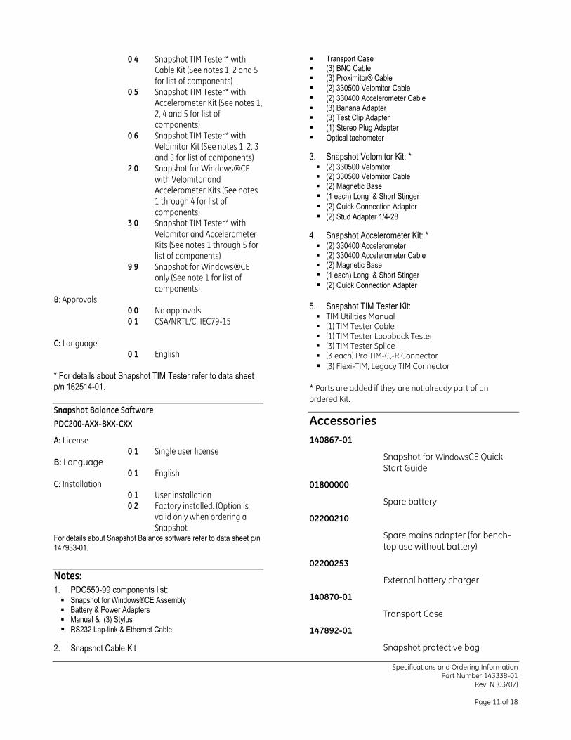
0 4 Snapshot TIM Tester* with Cable Kit (See notes 1, 2 and 5 for list of components)
0 5 Snapshot TIM Tester* with Accelerometer Kit (See notes 1, 2, 4 and 5 for list of components)
0 6 Snapshot TIM Tester* with Velomitor Kit (See notes 1, 2, 3 and 5 for list of components)
2 0 Snapshot for Windows®CE with Velomitor and Accelerometer Kits (See notes 1 through 4 for list of components)
3 0 Snapshot TIM Tester* with Velomitor and Accelerometer Kits (See notes 1 through 5 for list of components)
9 9 Snapshot for Windows®CE only (See note 1 for list of components)
B: Approvals 0 0 No approvals 0 1 CSA/NRTL/C, IEC79-15
C: Language
0 1 English * For details about Snapshot TIM Tester refer to data sheet p/n 162514-01.
Snapshot Balance Software
PDC200-AXX-BXX-CXX
A: License 0 1 Single user license
B: Language 0 1 English
C: Installation 0 1 User installation 0 2 Factory installed. (Option is
valid only when ordering a Snapshot
For details about Snapshot Balance software refer to data sheet p/n 147933-01.
Notes:
1. PDC550-99 components list: Snapshot for Windows®CE Assembly Battery & Power Adapters Manual & (3) Stylus
RS232 Lap-link & Ethernet Cable
2. Snapshot Cable Kit
Transport Case (3) BNC Cable (3) Proximitor® Cable
(2) 330500 Velomitor Cable (2) 330400 Accelerometer Cable (3) Banana Adapter (3) Test Clip Adapter
(1) Stereo Plug Adapter Optical tachometer
3. Snapshot Velomitor Kit: * (2) 330500 Velomitor (2) 330500 Velomitor Cable (2) Magnetic Base
(1 each) Long & Short Stinger (2) Quick Connection Adapter (2) Stud Adapter 1/4-28
4. Snapshot Accelerometer Kit: * (2) 330400 Accelerometer (2) 330400 Accelerometer Cable (2) Magnetic Base
(1 each) Long & Short Stinger (2) Quick Connection Adapter
5. Snapshot TIM Tester Kit: TIM Utilities Manual (1) TIM Tester Cable (1) TIM Tester Loopback Tester (3) TIM Tester Splice (3 each) Pro TIM-C,-R Connector (3) Flexi-TIM, Legacy TIM Connector
* Parts are added if they are not already part of an
ordered Kit.
Accessories
140867-01
Snapshot for WindowsCE Quick Start Guide
01800000
Spare battery
02200210
Spare mains adapter (for bench-top use without battery)
02200253
External battery charger
140870-01
Transport Case
147892-01
Snapshot protective bag
Specifications and Ordering Information Part Number 143338-01
Rev. N (03/07)
Page 12 of 18
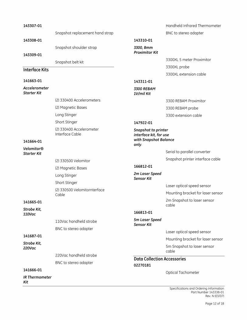
143307-01
Snapshot replacement hand strap
143308-01
Snapshot shoulder strap
143309-01
Snapshot belt kit
Interface Kits
141663-01
Accelerometer Starter Kit
(2) 330400 Accelerometers
(2) Magnetic Bases
Long Stinger
Short Stinger
(2) 330400 Accelerometer Interface Cable
141664-01
Velomitor® Starter Kit
(2) 330500 Velomitor
(2) Magnetic Bases
Long Stinger
Short Stinger
(2) 330500 Velomitornterface Cable
141665-01
Strobe Kit, 110Vac
110Vac handheld strobe
BNC to stereo adapter
141687-01
Strobe Kit, 220Vac
220Vac handheld strobe
BNC to stereo adapter
141666-01
IR Thermometer Kit
Handheld Infrared Thermometer
BNC to stereo adapter
143310-01
3300, 8mm Proximitor Kit
3300XL 5 meter Proximitor
3300XL probe
3300XL extension cable
143311-01
3300 REBAM 1V/mil Kit
3300 REBAM Proximitor
3300 REBAM probe
3300 extension cable
147922-01
Snapshot to printer interface kit, for use with Snapshot Balance only.
Serial to parallel converter
Snapshot printer interface cable
166812-01
2m Laser Speed Sensor Kit
Laser optical speed sensor
Mounting bracket for laser sensor
2m Snapshot to laser sensor cable
166813-01
5m Laser Speed Sensor Kit
Laser optical speed sensor
Mounting bracket for laser sensor
5m Snapshot to laser sensor cable
Data Collection Accessories
02270181
Optical Tachometer
Specifications and Ordering Information Part Number 143338-01
Rev. N (03/07)
Page 13 of 18
145474-01
Mounting bracket for optical tachometer.
02200375
Quick Connect Stud w/ ¼-28 UNF thread to machine
145473-01
¼-28 UNF set screw to attach Quick Connect Stud to machine
02200508
Quick Connect Stud w/ M8x1 thread to machine
145472-01
M8x1 set screw to attach Quick Connect Stud to machine
02200371
Magnetic Base
02200374
Quick Connect Base (for transducer)
141259-01
Short Stinger (for transducer)
141260-01
Long Stinger (for transducer)
141686-01
BNC-to-Stereo Adapter
01609137
BNC-to-Banana Adapter
01600123
BNC-to-Test Clip Adapter
Cables
02200283
RS232 10ft Laplink Cable.
02200230
CAT-5 6ft Ethernet Cable.
02180060
2-Pin Mil-C Cable, for Velomitor®, Coiled.
02180061
3-Pin Mil-C Cable, for 330400 accelerometer, Coiled.
145518-01
2-Pin Mil-C Cable, for Velomitor®, Straight.
145519-01
3-Pin Mil-C Cable, for 330400 accelerometer, Straight.
145520-01
BNC Straight cable.
147856-01
Proximitor Straight Cable.
162491
2m Snapshot to Laser Sensor cable, Straight.
166814
5m Snapshot to Laser Sensor cable, Straight.
Specifications and Ordering Information Part Number 143338-01
Rev. N (03/07)
Page 14 of 18
Graphs and Figures
Figure 1 Snapshot for Windows®CE physical dimensions
Specifications and Ordering Information Part Number 143338-01
Rev. N (03/07)
Page 15 of 18
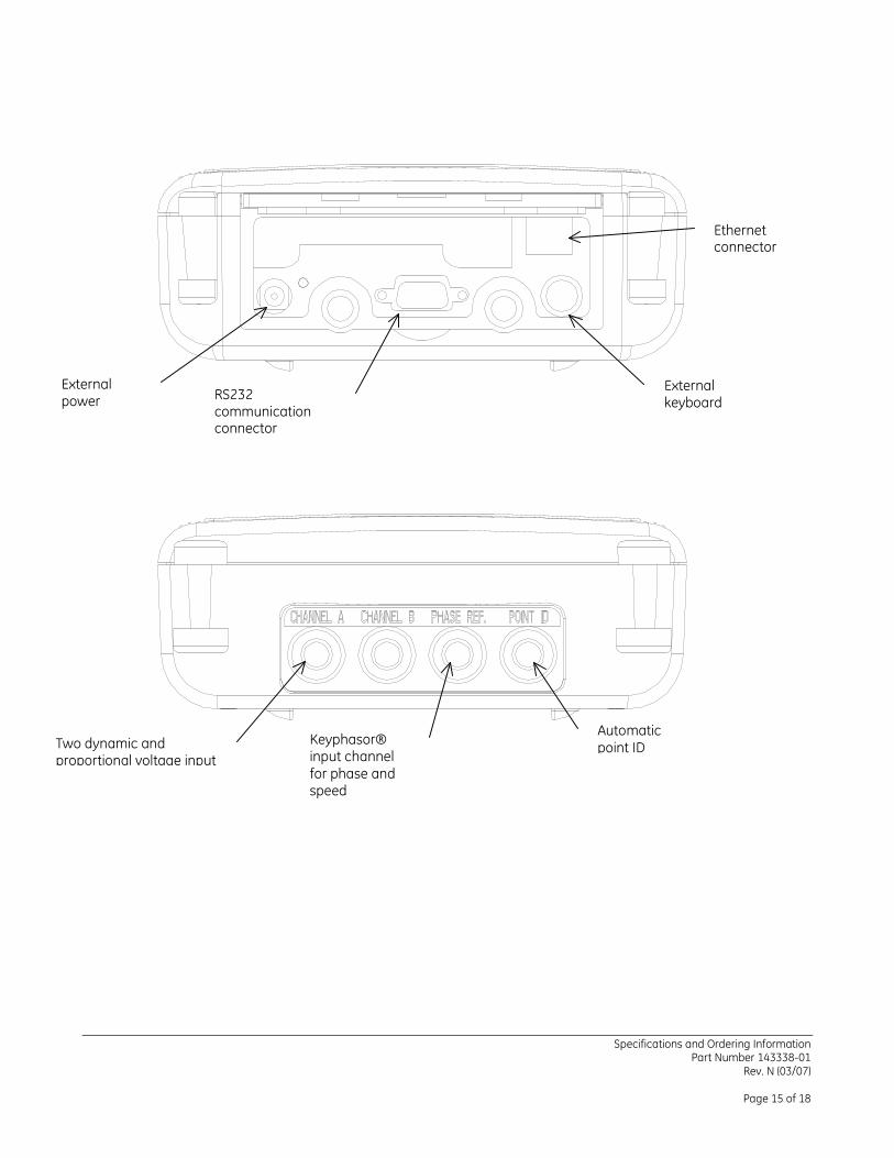
External power socket
RS232 communication connector
External keyboard connector
Ethernet connector
Two dynamic and proportional voltage input
Keyphasor® input channel for phase and speed measurements
Automatic point ID
Specifications and Ordering Information Part Number 143338-01
Rev. N (03/07)
Page 16 of 18
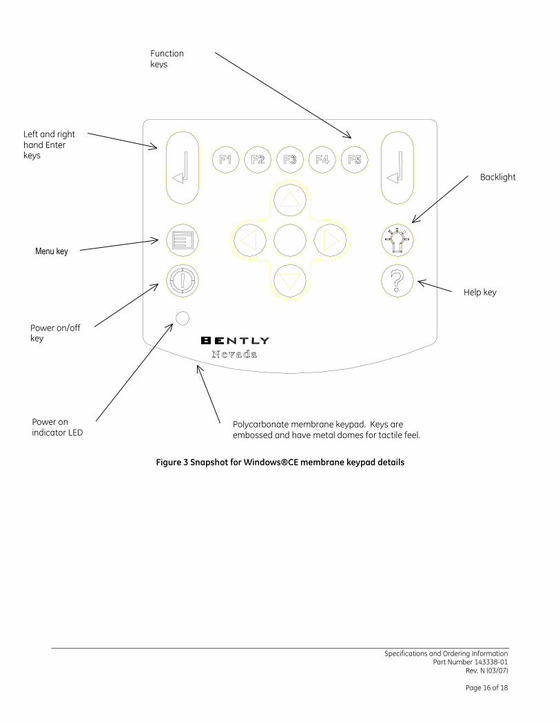
Figure 3 Snapshot for Windows®CE membrane keypad details
Left and right hand Enter keys
Function keys
Power on/off key
Power on indicator LED
Menu key
Backlight on/off
Help key
Polycarbonate membrane keypad. Keys are embossed and have metal domes for tactile feel.
Specifications and Ordering Information Part Number 143338-01
Rev. N (03/07)
Page 17 of 18
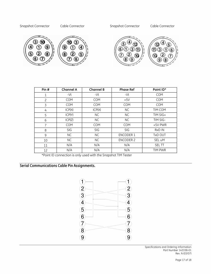
Snapshot Connector Cable Connector Snapshot Connector Cable Connector
Pin # Channel A Channel B Phase Ref Point ID*
1 -Vt -Vt -Vt COM
2 COM COM +5V COM
3 COM COM COM COM
4 ICP(X) ICP(X) NC TIM COM
5 ICP(Y) NC NC TIM SIG+
6 ICP(Z) NC NC TIM SIG-
7 COM COM COM +5V PWR
8 SIG SIG SIG RxD IN
9 NC NC ENCODER 1 TxD OUT
10 NC NC ENCODER 2 SEL uM
11 N/A N/A N/A SEL TT
12 N/A N/A N/A TIM PWR
*Point ID connection is only used with the Snapshot TIM Tester
Serial Communications Cable Pin Assignments.
1
2
4
3
8
7
6
5
9
7
9
8
4
6
5
3
2
1
Specifications and Ordering Information Part Number 143338-01
Rev. N (03/07)
Page 18 of 18
Copyright 2000. Bently Nevada LLC. 1631 Bently Parkway South, Minden, Nevada USA 89423
Phone: 775.782.3611 Fax: 775.215.2873 www.ge-energy.com/bently
All rights reserved.
Bently Nevada, Snapshot, REBAM, Seismoprobe, Velomitor, Proximitor , Keyphasor and System 1 are trademarks of General Electric Company.
Windows is a registered trademark of Microsoft Corporation in the United States and other countries. ICP is a registered trademark of IMI Sensors I don’t find this in the document… please verify.