slc serie adapt x - salicru
TRANSCRIPT
SLC serie ADAPT XUNINTERRUPTIBLE POWER SUPPLY
USER MANUAL
2 SALICRU
General index
1. INTRODUCTION.1.1. THANK YOU LETTER.
2. SAFETY INFORMATION.2.1. USING THIS MANUAL.
2.1.1. Conventions and symbols used.
2.1.2. Safety considerations.
3. QUALITY ASSURANCE AND STANDARDS.3.1. STATEMENT BY THE MANAGEMENT.
3.2. STANDARDS.
3.2.1. First and second environment.
3.2.1.1. First environment.
3.2.1.2. Second environment.
3.3. ENVIRONMENT.
4. PRESENTATION.4.1. VIEWS.
4.1.1. Views of the sub-racks.
4.1.2. Views of the cabinets
4.1.2.1. UPS Cabinets
4.1.2.2. Battery cabinets
4.2. DEFINITION OF THE PRODUCT.
4.2.1. Sub-rack nomenclature and battery module.
4.3. GENERAL DESCRIPTION.
4.3.1. Introduction.
4.3.2. Architecture.
4.3.2.1. Structural diagram.
4.3.2.2. Parallel system.
4.3.3. Operating modes.
4.3.3.1. Normal mode.
4.3.3.2. Battery mode.
4.3.3.3. Auto-start mode (automatic start).
4.3.3.4. Bypass mode.
4.3.3.5. Manual bypass mode (maintenance bypass).
4.3.3.6. Parallel-Redundant mode.
4.3.3.7. ECO mode.
4.3.3.8. Frequency converter (CF) mode.
4.3.4. Battery management (factory default settings).
4.3.4.1. Basic functions.
4.3.4.2. Advanced functions.
4.3.4.3. Protection of batteries.
5. INSTALLATION.5.1. RECEPTION.
5.1.1. Reception, unpacking and contents.
5.1.2. Storage.
5.1.3. Unpacking.
5.1.4. Transport to the site.
5.2. LOCATION.
5.2.1. Location of the ADAPT X.
5.2.2. Room for the batteries.
5.2.3. Physical location.
5.3. ENTRY OF THE CONNECTION CABLES.
5.4. PROTECTIVE DEVICES AND CROSS SECTION OF THE CONNECTION CABLES.
5.4.1. Input, bypass and output.
5.4.2. Battery installation and maintenance.
5.4.2.1. General recommendations.
5.4.2.2. Installing the batteries. Preliminary considerations before connecting them and their protections.
5.4.3. Access to the interior of the sub-rack for its connection.
5.5. CONNECTION.
5.5.1. Connecting the device to the mains.
5.5.2. Independent static bypass line connection. In version B only.
5.5.3. Connection of the output, terminals (X6 to X9).
5.5.4. Connection of the battery terminals of the device with those of the battery module.
5.5.5. Earth terminal connection.
5.5.6. Parallel connection, 6-slot sub-racks only.
5.5.6.1. Parallel bus connection.
5.5.7. Interface and communications.
5.5.7.1. Digital inputs, dry contacts and communications.
5.5.7.2. Analogue input of battery and environment temperature sensors.
5.5.7.3. Signal input of the remote EPO button (Emergency Stop).
5.5.7.4. External manual bypass auxiliary contact input.
5.5.7.5. Signal tripping coil circuit breaker of BCB battery switch and auxiliary contact.
5.5.7.6. Interface to relays.

3
6. OPERATION.6.1. INTRODUCTION.
6.2. STARTING UP THE UPS.
6.2.1. Checks before startup.
6.2.2. Startup.
6.3. TRANSFER PROCEDURES BETWEEN OPERATING MODES.
6.3.1. Transfer from normal mode to bypass mode.
6.3.2. Transfer from bypass mode to normal mode.
6.4. OPERATIONS OF THE MANUAL BYPASS SWITCH (MAINTENANCE).
6.4.1. Procedure to switch from normal mode to maintenance bypass mode.
6.4.2. Procedure to switch from maintenance bypass mode to normal mode.
6.5. EPO PUSH BUTTON (EMERGENCY STOP). PROCEDURE.
6.5.1. Complete stop of the UPS, with EPO.
6.5.2. UPS restart after full stop with EPO.
6.6. AUTOMATIC RESTART.
6.7. OPERATING INSTRUCTIONS FOR MAINTENANCE OF POWER MODULES.
6.7.1. Maintenance guide for power modules.
6.7.1.1. With the system operating in normal mode and the normal bypass voltage and frequency, with at least 1 power module as redundant:
6.7.1.2. No power modules operating as redundant:
6.8. OPERATING INSTRUCTIONS FOR MAINTENANCE OF THE BYPASS AND MONITORING MODULE.
6.8.1.1. With the system operating in Normal Mode and normal bypass voltage and frequency, transfer the load over the manual bypass.
6.9. LANGUAGE SELECTION.
6.10. CHANGING THE CURRENT DATE AND TIME
6.11. LEVEL 1 CONTROL PASSWORD.
7. MONITORING PANEL WITH LCD TOUCH SCREEN.
7.1. INTRODUCTION.
7.2. DIAGRAM OF ENERGY FLOW TO LEDS.
7.2.1. Audible alarm.
7.3. DESCRIPTION OF THE SCREENS SHOWN ON THE LCD TOUCH SCREEN.
7.3.1. Start menu or main screen.
7.3.2. System information menu.
7.3.3. Information menu of the module or power modules (PM).
7.3.4. Setting menu.
7.3.5. Setting menu.
7.3.6. Operation menu.
7.3.6.1. Function icons.
7.3.6.2. Command icons.
7.3.7. Oscilloscope menu.
8. OPTIONAL EXTRAS8.1. INSTALL AN SNMP DRIVE.
8.2. ROOM TEMPERATURE SENSOR.
9. WARRANTY.9.1. WARRANTY CONDITIONS.
9.1.1. Terms of the warranty.
9.1.2. Exclusions.
9.2. TECHNICAL SERVICES NETWORK.
10. ANNEXES.10.1. INTERNATIONAL STANDARDS.
10.2. ENVIRONMENTAL CHARACTERISTICS.
10.3. MECHANICAL CHARACTERISTICS.
10.4. ELECTRICAL CHARACTERISTICS.
10.4.1. Electrical characteristics (rectifier input).
10.4.2. Electrical characteristics (DC Bus or DC).
10.4.3. Electrical characteristics (Inverter output).
10.4.4. Electrical characteristics (Bypass input).
10.5. EFFICIENCY.
SLC ADAPT-X -UNINTERRUPTIBLE POWER SUPPLY SYSTEM-USER MANUAL

4 SALICRU
SALICRU
1. INTRODUCTION.
1.1. THANK YOU LETTER.
We thank you in advance for the trust placed in us in the purchasing of this product. Read this instruction manual carefully in order to familiarise yourself with its content, since the more you know and understand the device the greater your satisfaction, level of safety and optimisation of its functionalities will be.We remain at your disposal for any additional information or queries that you may wish to make.
Yours sincerely.
• The device described here is capable of causing significant physical damage in the event of improper handling. For this reason, its installation, maintenance and/or repair must be carried out exclusively by our staff or qualified personnel.
• Although no effort has been spared to ensure that the information in this user manual is complete and accurate, we accept no liability for any errors or omissions that may exist.The images included in this document are for illustrative purposes and may not exactly represent the parts of the device shown; therefore they are not contractual. However, any divergence that may arise will be remedied or solved with the correct labelling on the unit.
• Following our policy of constant evolution, we reserve the right to modify the characteristics, operations or actions described in this document without prior notice.Consequently, the contents of this manual may differ from the latest version available on our website. Check that you have the latest version of the document (listed on the back cover, on the logo of our brand) and download it from the website.
• Reproduction, copying, assignment to third parties, modification or total or partial translation of this manual or document, in any form or by any means, without previous written permission by us is prohibited, with the company reserving full and exclusive property rights over it.
5
2. SAFETY INFORMATION.
2.1. USING THIS MANUAL.
The latest version of the device’s user manual is available to the customer for download on our website (www.salicru.com). It is necessary to read it carefully before performing any actions, procedures or operations on it.The purpose of the user manual is to provide information about safety and the procedures for device installation and operation. Read it carefully and follow the steps indicated in the order established.
The “Safety Instructions” document EK266*08 is supplied with this user manual. Compliance with these instructions is obligatory, with the user being legally responsible for observing and applying them.
The device is delivered properly labelled for correct identification of each of its parts, which, together with the instructions described in this user manual, allows installation and startup operations to be performed in a simple and organised manner without any doubts whatsoever.
However, because the product is constantly evolving, discrepancies or slight contradictions may arise. If in any doubt, the labelling on the device itself will always prevail.
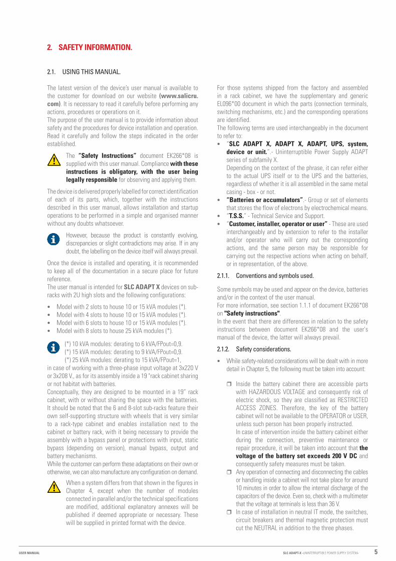
Once the device is installed and operating, it is recommended to keep all of the documentation in a secure place for future reference.The user manual is intended for SLC ADAPT X devices on sub-racks with 2U high slots and the following configurations:
• Model with 2 slots to house 10 or 15 kVA modules (*). • Model with 4 slots to house 10 or 15 kVA modules (*). • Model with 6 slots to house 10 or 15 kVA modules (*). • Model with 8 slots to house 25 kVA modules (*).
(*) 10 kVA modules: derating to 6 kVA/FPout=0,9. (*) 15 kVA modules: derating to 9 kVA/FPout=0,9.
(*) 25 kVA modules: derating to 15 kVA/FPout=1,in case of working with a three-phase input voltage at 3x220 V or 3x208 V., as for its assembly inside a 19 "rack cabinet sharing or not habitat with batteries.Conceptually, they are designed to be mounted in a 19” rack cabinet, with or without sharing the space with the batteries. It should be noted that the 6 and 8-slot sub-racks feature their own self-supporting structure with wheels that is very similar to a rack-type cabinet and enables installation next to the cabinet or battery rack, with it being necessary to provide the assembly with a bypass panel or protections with input, static bypass (depending on version), manual bypass, output and battery mechanisms.While the customer can perform these adaptations on their own or otherwise, we can also manufacture any configuration on demand.
When a system differs from that shown in the figures in Chapter 4, except when the number of modules connected in parallel and/or the technical specifications are modified, additional explanatory annexes will be published if deemed appropriate or necessary. These will be supplied in printed format with the device.
For those systems shipped from the factory and assembled in a rack cabinet, we have the supplementary and generic EL096*00 document in which the parts (connection terminals, switching mechanisms, etc.) and the corresponding operations are identified.The following terms are used interchangeably in the document to refer to: • “SLC ADAPT X, ADAPT X, ADAPT, UPS, system,
device or unit.”.- Uninterruptible Power Supply ADAPT series of subfamily X.Depending on the context of the phrase, it can refer either to the actual UPS itself or to the UPS and the batteries, regardless of whether it is all assembled in the same metal casing - box - or not.
• “Batteries or accumulators”.- Group or set of elements that stores the flow of electrons by electrochemical means.
• “T.S.S.” - Technical Service and Support. • “Customer, installer, operator or user” - These are used
interchangeably and by extension to refer to the installer and/or operator who will carry out the corresponding actions, and the same person may be responsible for carrying out the respective actions when acting on behalf, or in representation, of the above.
2.1.1. Conventions and symbols used.
Some symbols may be used and appear on the device, batteries and/or in the context of the user manual.For more information, see section 1.1.1 of document EK266*08 on "Safety instructions".In the event that there are differences in relation to the safety instructions between document EK266*08 and the user's manual of the device, the latter will always prevail.
2.1.2. Safety considerations.
• While safety-related considerations will be dealt with in more detail in Chapter 5, the following must be taken into account:
� Inside the battery cabinet there are accessible parts with HAZARDOUS VOLTAGE and consequently risk of electric shock, so they are classified as RESTRICTED ACCESS ZONES. Therefore, the key of the battery cabinet will not be available to the OPERATOR or USER, unless such person has been properly instructed.In case of intervention inside the battery cabinet either during the connection, preventive maintenance or repair procedure, it will be taken into account that the voltage of the battery set exceeds 200 V DC and consequently safety measures must be taken.
� Any operation of connecting and disconnecting the cables or handling inside a cabinet will not take place for around 10 minutes in order to allow the internal discharge of the capacitors of the device. Even so, check with a multimeter that the voltage at terminals is less than 36 V.
� In case of installation in neutral IT mode, the switches, circuit breakers and thermal magnetic protection must cut the NEUTRAL in addition to the three phases.
SLC ADAPT-X -UNINTERRUPTIBLE POWER SUPPLY SYSTEM-USER MANUAL
6 SALICRU
3. QUALITY ASSURANCE AND STANDARDS.
3.1. STATEMENT BY THE MANAGEMENT.
Our goal is customer satisfaction, therefore this Management has decided to establish a Quality and Environment Policy, through the implementation of a Quality and Environmental Management System that will enable us to comply with the requirements demanded in the ISO 9001 and ISO 14001 and also by our Customers and Stakeholders.Likewise, the management of the company is committed to the development and improvement of the Quality and Environmental Management System, through: • Communication to the entire company of the importance
of satisfying both the customer's requirements as well as legal and regulatory requirements.
• The dissemination of the Quality and Environment Policy and the setting of the Quality and Environment objectives.
• Conducting reviews by the Management. • Providing the necessary resources.
3.2. STANDARDS.
The SLC ADAPT X product is designed, manufactured and marketed in accordance with EN ISO 9001 Quality Assurance. The marking indicates conformity with EC Directives through the application of the following standards: • 2014/35/EU. - Low voltage safety. • 2014/30/EU. - Electromagnetic Compatibility (EMC). • 2011/65/EU. - Restriction of the use of hazardous substances
in electrical and electronic equipment (RoHS).
In accordance with the specifications of the harmonised standards. Reference standards: • EN-IEC 62040-1. Uninterruptible Power Supplies -UPS-.
Part 1-1: General and safety requirements for UPS used in user access areas.
• EN-IEC 60950-1. Information technology equipment. Safety. Part 1: General requirements.
• EN-IEC 62040-2. Uninterruptible Power Supplies -UPS-. Part 2: EMC requirements.
The manufacturer is not liable in the event of modifica-tion or intervention on the device by the user.
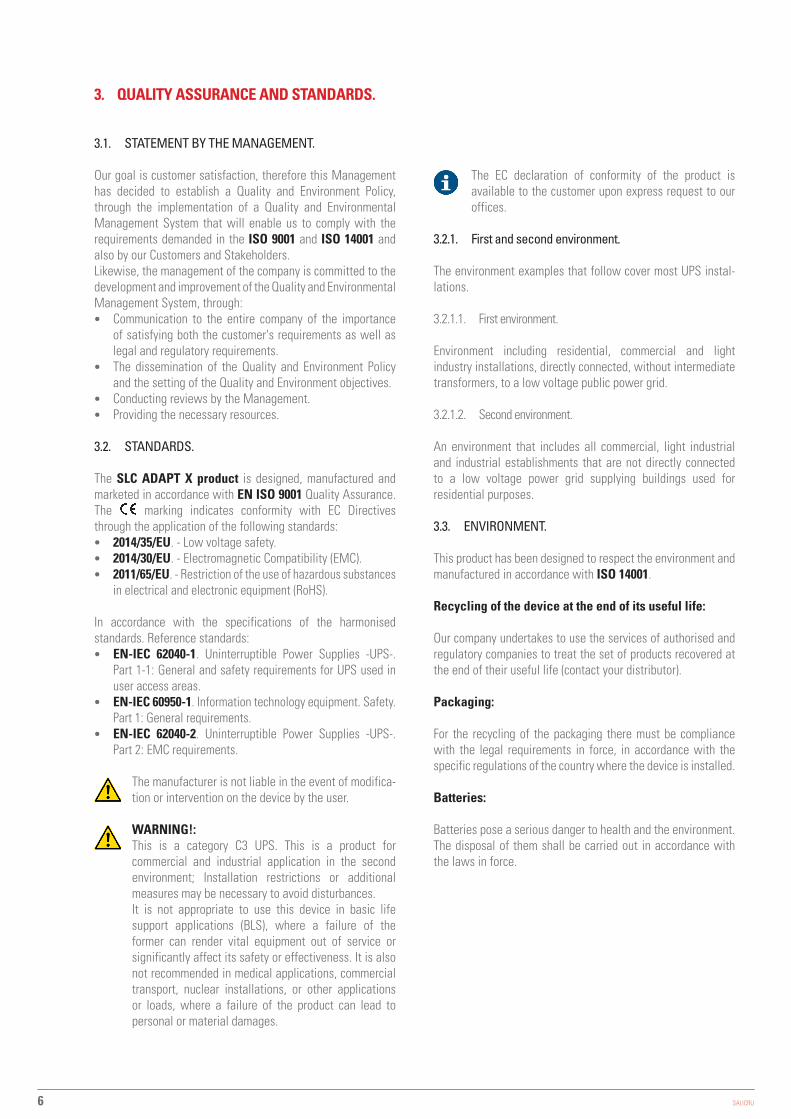
WARNING!: This is a category C3 UPS. This is a product for commercial and industrial application in the second environment; Installation restrictions or additional measures may be necessary to avoid disturbances.It is not appropriate to use this device in basic life support applications (BLS), where a failure of the former can render vital equipment out of service or significantly affect its safety or effectiveness. It is also not recommended in medical applications, commercial transport, nuclear installations, or other applications or loads, where a failure of the product can lead to personal or material damages.
The EC declaration of conformity of the product is available to the customer upon express request to our offices.
3.2.1. First and second environment.
The environment examples that follow cover most UPS instal-lations.
3.2.1.1. First environment.
Environment including residential, commercial and light industry installations, directly connected, without intermediate transformers, to a low voltage public power grid.
3.2.1.2. Second environment.
An environment that includes all commercial, light industrial and industrial establishments that are not directly connected to a low voltage power grid supplying buildings used for residential purposes.
3.3. ENVIRONMENT.
This product has been designed to respect the environment and manufactured in accordance with ISO 14001.
Recycling of the device at the end of its useful life:
Our company undertakes to use the services of authorised and regulatory companies to treat the set of products recovered at the end of their useful life (contact your distributor).
Packaging:
For the recycling of the packaging there must be compliance with the legal requirements in force, in accordance with the specific regulations of the country where the device is installed.
Batteries:
Batteries pose a serious danger to health and the environment. The disposal of them shall be carried out in accordance with the laws in force.

7
4. PRESENTATION.
4.1. VIEWS.
4.1.1. Views of the sub-racks.
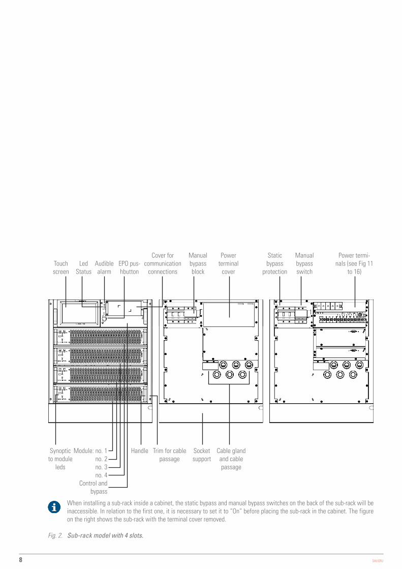
The illustrations in Fig. 1 to 4 are represented with the maximum number of modules installed on each sub-rack, although its unit may differ mainly due to the number of integrated modules, depending on the required power.Basically the operation and technical specifications are the same, except for the indicated power.The strips placed between the connection terminals that can be seen in the illustrations in Fig. 1 to 4, correspond to device with three-phase input and output, with a common input for the rectifier and the static bypass. Fig. 11 to 16 show all possible input and output configurations.The sub-racks incorporate a control panel with 7” colour touch screen as an interface between the device and the user, which provides different information through menus structured in categories (see Chapter 7).In the system of sub-racks connected in parallel, each has its own control panel through which the individual parameters can be verified.
Touch screen
Static bypass
protection
Manual bypass switch
Cover for communication
connections
Power termi-nals (see Fig.
11 to 16)
Power terminal
coverAudible alarm
EPO pus-hbutton
Led Status
Manual bypass block
HandleModule: no. 1 no. 2
Control and bypass
Synoptic to module
leds
Trim for cable passage
Socket support
Cable gland and cable passage
When installing a sub-rack inside a cabinet, the static bypass and manual bypass switches on the back of the sub-rack will be inaccessible. In relation to the first one, it is necessary to set it to “On” before placing the sub-rack in the cabinet. The figure on the right shows the sub-rack with the terminal cover removed.
Fig. 1. Sub-rack model with 2 slots.
SLC ADAPT-X -UNINTERRUPTIBLE POWER SUPPLY SYSTEM-USER MANUAL
8 SALICRU
Touch screen
Static bypass
protection
Manual bypass switch
Cover for communication
connections
Power termi-nals (see Fig 11
to 16)
Power terminal
coverAudible alarm
EPO pus-hbutton
Led Status
Manual bypass block
HandleModule: no. 1 no. 2 no. 3 no. 4
Control and bypass
Synoptic to module
leds
Trim for cable passage
Socket support
Cable gland and cable passage
When installing a sub-rack inside a cabinet, the static bypass and manual bypass switches on the back of the sub-rack will be inaccessible. In relation to the first one, it is necessary to set it to “On” before placing the sub-rack in the cabinet. The figure on the right shows the sub-rack with the terminal cover removed.
Fig. 2. Sub-rack model with 4 slots.

9
Touch screen
Manual bypass switch
Interface ter-minals block
cover J2 - 10
Power termi-nals (see Fig 11
to 16)
Power terminal
coverAudible alarm
EPO pus-hbutton
Led Status
Manual bypass block
HandleModule: no. 1 no. 2 no. 3 no. 4 no. 5 no. 6
Control and bypass
Synoptic to module
leds
Trim for cable passage
Swivel castors
with brake
Cable gland and cable passage
on chassis base
Synoptic LEDs and control panel keys
Slot SNMP RS232 RS485
Access cover to cable gland and cable passage
Parallel bus
cover P1 - 2
Parallel switch cover
SW1 - 2
The figure on the right shows the sub-rack with the terminal cover removed.
Fig. 3. Sub-rack model with 6 slots.
SLC ADAPT-X -UNINTERRUPTIBLE POWER SUPPLY SYSTEM-USER MANUAL
10 SALICRU
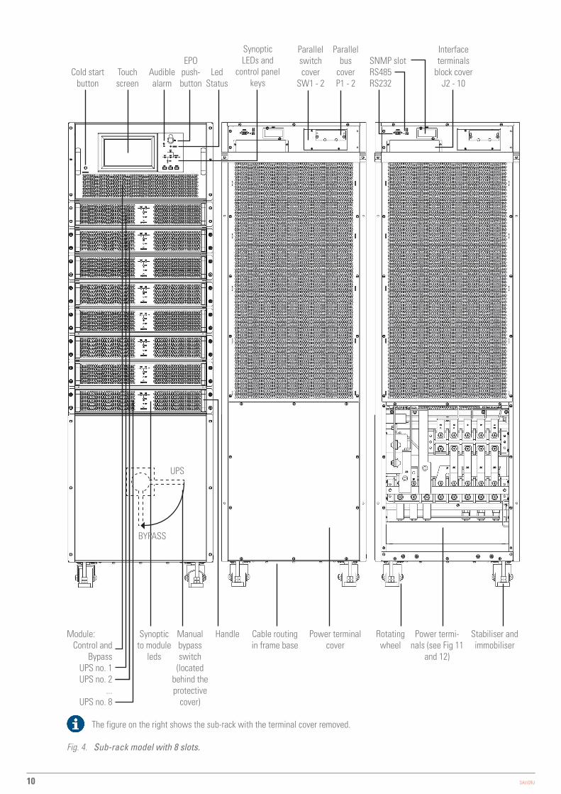
HandleModule:Control and
BypassUPS no. 1UPS no. 2
...UPS no. 8
Synoptic to module
leds
Cable routing in frame base
Cold start button
Interface terminals
block cover J2 - 10
Audible alarm
EPO push-button
Led Status
Synoptic LEDs and
control panel keys
SNMP slot RS485 RS232
Parallel bus
cover P1 - 2
Parallel switch cover
SW1 - 2Touch screen
Power terminal cover
Power termi-nals (see Fig 11
and 12)
Manual bypass switch
(located behind the protective
cover)
Stabiliser and immobiliser
Rotating wheel
UPS
BYPASS
The figure on the right shows the sub-rack with the terminal cover removed.
Fig. 4. Sub-rack model with 8 slots.
11
4.1.2. Views of the cabinets
4.1.2.1. UPS Cabinets
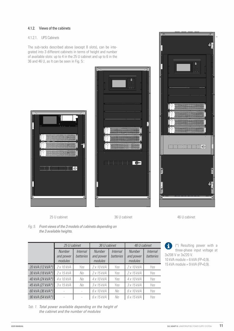
The sub-racks described above (except 8 slots), can be inte-grated into 3 different cabinets in terms of height and number of available slots: up to 4 in the 25 U cabinet and up to 6 in the 36 and 46 U, as It can be seen in Fig. 5::
25 U cabinet 36 U cabinet 46 U cabinet
Fig. 5. Front views of the 3 models of cabinets depending on the 3 available heights.
25 U cabinet 36 U cabinet 46 U cabinetNumber
and power modules
Internal batteries
Number and power modules
Internal batteries
Number and power modules
Internal batteries
20 kVA (12 kVA*) 2 x 10 kVA Yes 2 x 10 kVA Yes 2 x 10 kVA Yes30 kVA (18 kVA*) 2 x 15 kVA No 2 x 15 kVA Yes 2 x 15 kVA Yes40 kVA (24 kVA*) 4 x 10 kVA No 4 x 10 kVA Yes 4 x 10 kVA Yes45 kVA (27 kVA*) 3 x 15 kVA No 3 x 15 kVA Yes 3 x 15 kVA Yes60 kVA (36 kVA*) - - 6 x 10 kVA No 6 x 10 kVA Yes90 kVA (54 kVA*) - - 6 x 15 kVA No 6 x 15 kVA Yes
Tab. 1. Total power available depending on the height of the cabinet and the number of modules
(*) Resulting power with a three-phase input voltage at
3x208 V or 3x220 V.10 kVA module = 6 kVA (FP=0,9).15 kVA module = 9 kVA (FP=0,9).
SLC ADAPT-X -UNINTERRUPTIBLE POWER SUPPLY SYSTEM-USER MANUAL
12 SALICRU
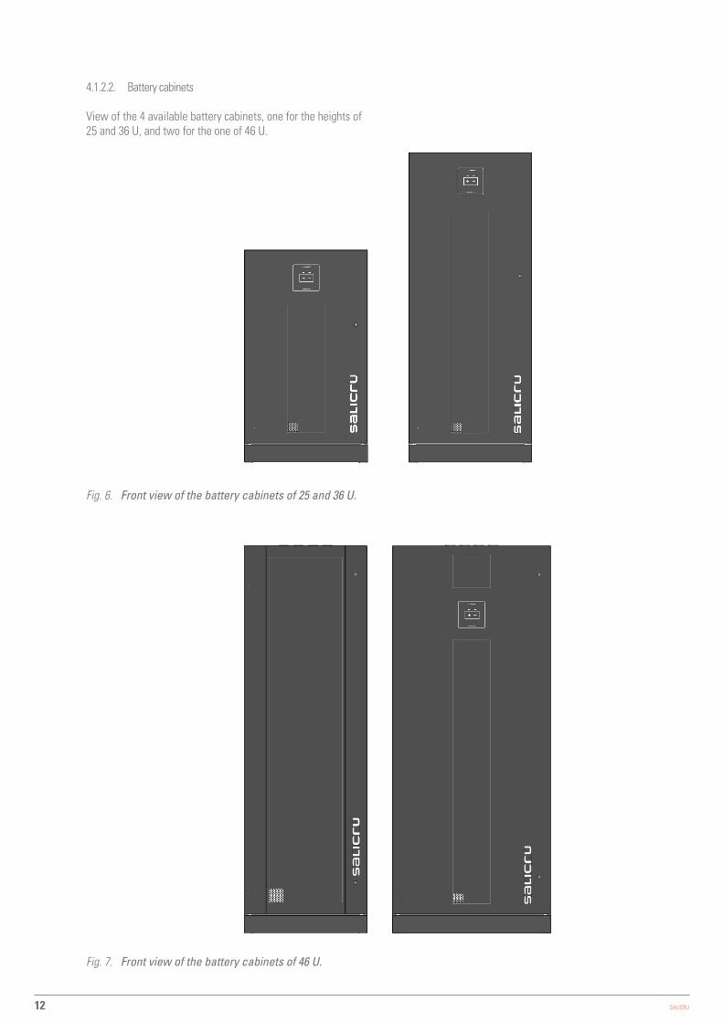
4.1.2.2. Battery cabinets
View of the 4 available battery cabinets, one for the heights of 25 and 36 U, and two for the one of 46 U.
Fig. 6. Front view of the battery cabinets of 25 and 36 U.
Fig. 7. Front view of the battery cabinets of 46 U.

13
+ N −
Cable glands
Battery terminals
Fig. 8. Rear view of battery cabinets.
Disconnector
Fuses
Fig. 9. Front view of battery cabinets.
SLC ADAPT-X -UNINTERRUPTIBLE POWER SUPPLY SYSTEM-USER MANUAL

14 SALICRU
4.2. DEFINITION OF THE PRODUCT.
4.2.1. Sub-rack nomenclature and battery module.
SLC-4+1/6-ADAPT 60X R P2LBDS B1 0/36AB165 COW EE666502
MB ADAPT 3A-0/2x36AB165 100A COW EE666502
EE* Special customer specifications.W Private-label device.CO Marking “Made in Spain” in UPS and packaging (for customs).165 Last three digits of the battery code.AB Letters of the battery family.36 Number of batteries in a single branch. For common battery set, all
of them will be indicated in the system.0/ Device ready for backup or batteries requested.B1 Sub-rack or cabinet with external batteries.S Ambient temperature sensor.D Transient protection filter.B Independent bypass line. Input-output configuration, three-phase-three-phase.L Input-output configuration, single-phase-single-phase.M Input-output configuration, single-phase-three-phase.N Input-output configuration, three-phase-single-phase.2 Parallel sub-rack number.P Parallel kit (device for paralleling sub-racks or cabinets).R In sub-rack format (not integrated inside cabinet).Y IP20 protection rating with open door and keyless lock.X Sub-family of the ADAPT series (2U modules)60 Maximum power installable on sub-rack or in cabinet in kVA.ADAPT UPS Series.6 Maximum number of modules installable on sub-rack or in cabinet.+1/ Redundant modules. Disregard if none.4 Number of factory modules installed, except redundant ones.SLC Acronym abbreviation brand.CF Frequency converter 50/60 or 60/50 Hz.
EE* Special customer specifications.W Private-label device.CO Marking “Made in Spain” in UPS and packaging (for customs).100A Protection size.165 Last three digits of the battery code.AB Letters of the battery family.36 Number of batteries in a single branch*x Number of parallel battery branches. Omit for one.0/ Device ready for backup or batteries requested.A Cabinet type (A: AM262; B: AM261; C: AM263; D: AM264)3 Number of cabinets in the battery configuration.ADAPT UPS Series.MB Battery module.
(B1) The device is supplied without batteries and without the accessories (screws and electric cables). Predictably the batteries will be installed in an external cabinet or rack. On request, the cabinet or rack and the necessary accessories can be supplied.For equipment ordered without batteries, their acquisition, installation and connection will always be borne by the customer and under their responsibility. However, our T.S.S. may be required to intervene in order to carry out the necessary installation and connection work. The data concerning the batteries in terms of number, capacity and voltage are indicated on the battery label affixed to the side of the device rating plate, strictly observe these data and the connection polarity of the batteries. For devices with an independent static bypass line, a galvanic isolation transformer must be inserted between any two power lines of the UPS (rectifier input or static bypass) to prevent direct connection of the neutral of the two lines through the internal connection of the device. This applies only when the two power lines come from two different networks, such as:- Two different electricity companies. - An electricity company and a power generator, etc.

15
4.3. GENERAL DESCRIPTION.
The SLC ADAPT X series is classified as an on-line double conversion Uninterruptible Power Supply with DSP control and three-level IGBT inverter technology, modular topology and great flexibility.
Reliability: The DSP control associated with three-level PWM technology increases the performance of the system and, together with the redundancy of the modules, manages to increase the availability of power to the critical loads, a param-eter that contributes to achieving a good TIER classification for the entire system.
Availability: Its “hot-swap” modules can be added or replaced during operation, thereby improving mean time to repair (MTTR) and reducing maintenance costs. Moreover, both the control display and the bypass module can be replaced without affecting the operation of the device. In addition, the system’s remote management, which can be integrated into any platform, also facilitates operation. The extensive back-up options available, along with smart battery charging, ensure continuous operation of the protected critical loads.
Modularity: Simple and configurable 10 to 90 kVA solutions by installing 10 or 15 kVA modules in 2, 4 or 6-slot sub-racks, or 25 to 200 kVA solutions by installing 25 kVA modules in 8-slot sub-racks. As composite solutions, a certain number of sub-racks can be paralleled depending on each model to obtain higher power systems or “N+n” structures. In any event, it is only possible to install identical modules on the same sub-rack and/or to parallel sub-racks of identical characteristics.Tab 2 shows a summary of the possible configurations of a system, enabling gradual and scaled growth for future expansions depending on the need for “pay as you grow” protection and improving the total cost of ownership (TCO), with a high level of flexibility.At operational level, a sub-rack consisting of “N” modules or different sub-racks connected in parallel is considered as a single UPS.
Any expansion or structural modification in the number of modules is possible even during normal operation, without implying that the hot-swappable system should stop, all with the help of a screwdriver used only to remove or screw the fixing screws of the module(s).Although all of the UPS modules incorporate a battery charger that can allocate up to 20% of its rated power to maintain them at an optimum charge level depending on the type and number of elements, 15 A battery charger modules are available to be installed with the 10 or 15 kVA ADAPT modules.As many charging modules as considered appropriate can be installed, but this will be to the detriment of the total number of UPS modules and, consequently, the total power of the system, which will be reduced.
Input/output configurations (only for 10 kVA modules): A system originally from the factory made up of 10 kVA modules can be implemented with different input/output types and power factor 1, or it can be modified in-situ by our T.S.S. and/or distributors.The types available are as follows: • Three-phase/three-phase. • Single-phase/single-phase. • Single phase/three phase. • Three-phase/single-phase.
It is not allowed or authorized to change the configuration to the user, since this involves the modification of plates between the power terminals by the addition or removal of same to obtain the required configuration, moreover changes are necessary in the variables of the access menus by "Password" through the control panel.
Autonomy: The capacity of the batteries determines the autonomy time of the system that will supply its usual source of energy during the mains failures. The accumulator group is always common to any system assembled in the same sub-rack.Batteries, owned by the customer or supplied together with the UPS, and depending on different factors in addition to the power and/or autonomy requested, can be installed on a rack in one or more cabinets, or in the cabinet of the device itself when the sub-rack is assembled in a 19” rack cabinet.
Power per module (kVA) (**)
No. of lots arranged on the
sub-rack
Power range (kVA) / No. of modules installed in the slots (min. - max.)
Max. no. of parallelable sub-racks
Power range (kVA) for type III / III / Min. - max. no. of
sub-racks in parallel
10
2 10.. 20 / 1.. 2 9 40.. 180 / 2.. 9
4 10.. 40 / 1.. 4 7 80.. 280 / 2.. 7
6 10.. 60 / 1.. 6 5 120.. 300 / 2.. 5
15
2 15.. 30 / 1.. 2 - - - 9 60.. 270 / 2.. 9
4 15.. 45 (*) / 1.. 3 - - - 7 90.. 315 / 2.. 7
6 15.. 90 / 1.. 6 - - - 5 180.. 450 / 2.. 5
25 8 25.. 200 / 1.. 8 - - - 3 200.. 600 / 2.. 3
TypeInput/output voltage
III / III I / I I / III III / I
Input/output voltage (V):3x380.. 3x415 (three phases + N) or 220.. 240 (phase and N)
(*) Although 4 modules can be installed, by limiting the static bypass, only 3 of them can operate, so the system would be a 3+1 (45 + 15 k VA).
Tab. 2. Configurations and power ranges.
(**) See power corrections per module and per system for input voltages at 3x208 V or 3x220 V in Table 1.
SLC ADAPT-X -UNINTERRUPTIBLE POWER SUPPLY SYSTEM-USER MANUAL

16 SALICRU
4.3.1. Introduction.
The SLC ADAPT X series UPS basically consists of: • Sub-rack with 2, 4, 6 or 8 slots to install the power modules. • Power modules, consisting of the following blocks:
� PCF-Rectifier-AC/DC-. � Battery charger. � Inverter -DC/AC-. � Digital control and UPS management.
• Centralized bypass module: control of UPS and parallel parameters.
• Maintenance bypass • Control panel with touch screen (see section 7 for more
information). • Batteries (Number, type and location depending on the
back-up time). • Self-supporting cabinets of 25, 36 and 46 U for the location
of the different subracks
4.3.2. Architecture.
4.3.2.1. Structural diagram.
In Fig.10 it is represented by way of example shows a single-line diagram of the device with three-phase input and output.All sub-rack units are structured according to the same criteria, separate power supply for the PFC-rectifier and static bypass. However, unless otherwise requested, for separate networks originally from the factory, the terminals of the phases of both blocks are connected by means of strips to provide a single common input.
When separate power supplies are required, it is obligatory to remove the strips between the phases of both blocks before connecting the power cables, leaving the connection strip of the neutral terminals.
STATIC BYPASS MODULE
DC / AC INVERTER
MANUAL BYPASS
REC / PFCBAT / DC
DC / DC INVERTER
BYPASS
STATIC BYPASS LINE INPUT -R, S, T-
N
POWER MODULE # 1
DC / AC INVERTER
REC / PFCBAT / DC
DC / DC INVERTER POWER MODULE #N
•••
OUTPUT U, V, W
N
BATTERY MODULE
BCB
BATTERY MODULE
BCB
Connection strips between phases for common network.
Q1
Q2
INLET LINE OF UPS-R, S, T-
Not installed on 6 and 8-slot sub-racks.
The batteries are represented in the structural scheme as they are an essential part of any UPS, although they will never be included in the sub-rack itself. The batteries can be supplied in the same rack cabinet in which the ADAPT sub-rack is assembled, in a separate cabinet, on a rack or when the customer does not have them available, not supply them at all.
Fig. 10. Single-line structural diagram by way of example.

17
4.3.2.1.1. Power modules -PM-.
The power modules are the basic core of the SLC ADAPT X system. Apart from the static bypass block and the LCD touch screen, each power module contains all the converters and functionalities of a traditional UPS. Since this device is structured by a number of variable modules depending on the sub-rack used, a multi-parallel system is obtained with the behaviour equivalent to that of a single mono-bloc UPS and the advantages of a modular UPS.The system supplies power to the critical load (such as communication and data processing equipment) with uninterrupted high quality AC power. The power supplied by the unit is stable, without voltage and/or frequency variations and free from other disturbances such as cuts or micro-cuts, sine wave alterations, electrical noise, anomalies commonly present in the commercial AC network.This is achieved through the double-conversion high frequency Pulse Width Modulation (PWM), in combination with a digital control based on a Digital Signal Processor (DSP), which provides high reliability and availability.As can be seen in Fig.10 , the AC power supplied to the UPS input is converted into DC voltage. This voltage supplies a converter that transforms the voltage type from DC to AC, clean of disturbances and variations of the AC input mains. In case it fails, the PFC-Rectifier changes the input source of the AC network to that of the batteries, feeding similarly through the output of the UPS to the load for a limited time, the back-up time determined by the battery pack.
4.3.2.1.2. Static Bypass.
Static transfer switch.In case of inverter failure, overload or overtemperature, the voltage connected to the static bypass line can supply power to the load connected to the UPS output.The Static Bypass Module identified in Fig.10 contains the power management and control circuits that allow the most optimum decision in each scenario to be made, in order to select the most favourable power to the critical load connected to the output of the UPS, either from the inverter or from the static bypass itself.During normal system operation, the load is connected to the inverter and in case of overload or fault, it will automatically transfer to the static bypass line. In order to provide a clean transfer (without interruption) between the inverter output and the bypass line, they must be fully synchronized during normal operation. This is achieved through real-time digital control of the inverter, so that the frequency of the inverter follows the frequency of the bypass line if the bypass is within the range of acceptable frequencies.In addition, a Manual Bypass, which is very useful during the periods of maintenance or fault, is included and allows continuous feeding of the critical load while the UPS is out of service.
When the UPS is operating in bypass mode (over static bypass), connected devices are not protected against power cuts or micro-cuts, overvoltages, voltage and/or frequency variations as they are powered directly from the AC mains.
Input terminals of the UPS and Static Bypass.
PE
Outp
ut R
Outp
ut S
Outp
ut T
Bypa
ss b
RIn
put m
RBy
pass
bS
Inpu
t mS
Bypa
ss b
TIn
put m
TIn
put N
Inpu
t N
Bat.
+
Bat.
N
Bat.
–
OUTPUT N
Terminal block in 2-slot and 4-slot sub-rack.
BATT + N –
INPUT R S T N
OUTPUT R S T N
Terminal block in 6-slot sub-rack.
BATT NBATT +BATT -
OUTPUT R S T N
INPUT N R S T
PE
Terminal block in 8-slot sub-rack.
Fig. 11. Terminal block for three-phase/three-phase con-figuration and common networks (PFC-rectifier and static bypass).
SLC ADAPT-X -UNINTERRUPTIBLE POWER SUPPLY SYSTEM-USER MANUAL

18 SALICRU
. P
EOu
tput
ROu
tput
SOu
tput
TBy
pass
bR
Inpu
t mR
Bypa
ss b
SIn
put m
SBy
pass
bT
Inpu
t mT
Inpu
t NIn
put N
Bat.
+
Bat.
N
Bat.
–
OUTPUT N
Terminal block in 2-slot and 4-slot sub-rack.
BATT + N –
BYPASS R S T N
INPUT R S T
OUTPUT R S T N
Terminal block in 6-slot sub-rack.
BATT NBATT +BATT -
OUTPUT R S T N
BYPASS N R S T
PE
INPUT R S T
Terminal block in 8-slot sub-rack.
Fig. 12. Terminal block for three-phase/three-phase con-figuration and separate networks (PFC-rectifier and static bypass).
Fig.11 shows the physical layout of the terminal block for 2, 4, 6 and 8-slot sub-racks.These illustrations show the connection plates between the terminals of both networks (PFC-rectifier input and static
bypass) for a common supply, usually the most common one.When separate AC mains are available to separately feed the PFC-rectifier and static bypass inputs, the connection strips between the phases must be removed, depending on the available sub-rack model (see Fig.12).In this configuration, the static bypass and maintenance bypass share the same AC source independent of the PFC-rectifier source.
Although ADAPT devices with 10 kVA modules are configurable as input and output type, any modification by the customer or user is restricted, since, in addition to modifications to the connection strip, it is necessary to make changes through the password-restricted screen exclusively reserved for our T.S.S. or distributors.
The illustrations in Fig.11 and 12 show the arrangement of the connection terminals on three-phase/three-phase input/output devices. For other configurations, see Fig.13 to 16.
4.3.2.1.3. Manual bypass switch for maintenance.
The device has a manual bypass switch useful for periods of preventive maintenance or repair. This switch transfers the load power directly onto the AC input mains, allowing the intervention on the UPS without this preventing further feeding of the loads.
When the UPS is operating in manual bypass mode (maintenance or repair period), the connected devices are not protected against power cuts or micro-cuts, overvoltages, voltage and/or frequency variations as they are powered directly from the AC mains.Before operating this switch it is necessary to transfer the load power over the static bypass through the respective command from the touch screen. The switching of the power mode on the static bypass and from that to the manual bypass is done without interruption in the supply of the load.
When installing a sub-rack inside a cabinet, the installer will be responsible for providing the system with disconnectors and/or protections for input, static bypass (only –B models), output and manual bypass (with mechanical lock). The cabinet must have a front door that prevents access to unauthorised personnel, especially when safety measures so require (protection against direct contact). As an alternative, these mechanisms can be installed in a wall-mounted manual bypass board, which has a door with restricted access to authorised personnel for safety.In all cases, when installing protections, their sizes must be appropriate to the currents indicated on the nameplate and to the selectivity indicated in Chapter 10 of this document.
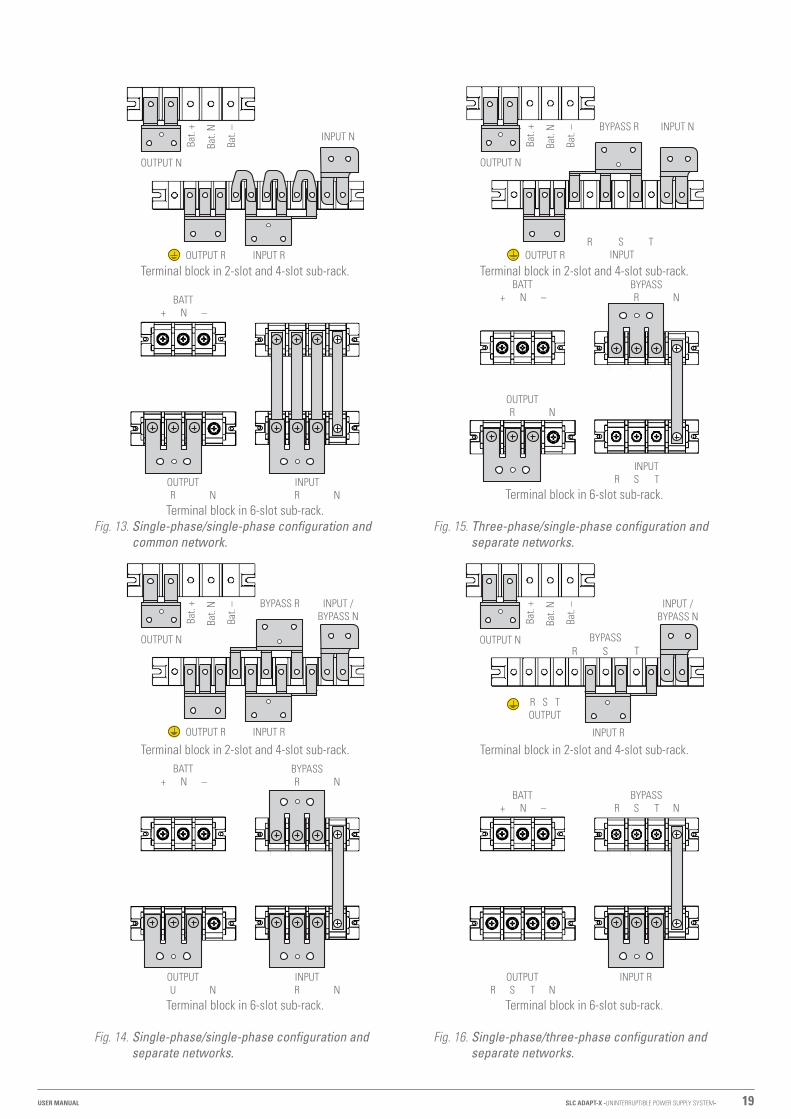
19
Bat.
+
Bat.
N
Bat.
–
OUTPUT N
INPUT N
INPUT R OUTPUT R
Terminal block in 2-slot and 4-slot sub-rack.
BATT + N –
INPUT R N
OUTPUT R N
Terminal block in 6-slot sub-rack.Fig. 13. Single-phase/single-phase configuration and
common network.
Bat.
+
Bat.
N
Bat.
–
OUTPUT N
BYPASS R INPUT / BYPASS N
INPUT R OUTPUT R
Terminal block in 2-slot and 4-slot sub-rack.BATT
+ N –BYPASS
R N
INPUT R N
OUTPUT U N
Terminal block in 6-slot sub-rack.
Fig. 14. Single-phase/single-phase configuration and separate networks.
Bat.
+
Bat.
N
Bat.
–
OUTPUT N
BYPASS R INPUT N
R S TINPUTOUTPUT R
Terminal block in 2-slot and 4-slot sub-rack.BATT
+ N –BYPASS
R N
INPUT R S T
OUTPUT R N
Terminal block in 6-slot sub-rack.
Fig. 15. Three-phase/single-phase configuration and separate networks.
Bat.
+
Bat.
N
Bat.
–
OUTPUT N BYPASS R S T
INPUT / BYPASS N
INPUT R
R S TOUTPUT
Terminal block in 2-slot and 4-slot sub-rack.
INPUT ROUTPUT R S T N
BYPASS R S T N
BATT + N –
Terminal block in 6-slot sub-rack.
Fig. 16. Single-phase/three-phase configuration and separate networks.
SLC ADAPT-X -UNINTERRUPTIBLE POWER SUPPLY SYSTEM-USER MANUAL
20 SALICRU
4.3.2.2. Parallel system.
4.3.2.2.1. Parallel system considerations.
• All UPS modules have hardware and software that is suitable and compatible with the requirements of parallel systems.
• Although all modules installed on a sub-rack are internally connected in parallel, parallel connection between sub-racks is also possible because a communication board is supplied as standard for this function. The resulting power range, according to the input/output type, and the individual power of each module, is shown in Tab 2 .
• The hardware adjustments referring to the change of input and output configuration are reserved exclusively to the manufacturing process itself or subsequently an in-situ process performed by the T.S.S.
• The sub-racks are supplied with terminals or strips for connecting the power cables and a number of connectors for the control bus and interface signals.Using the DB15 signal connectors, the control bus is connected in the form of a closed ring, linking the different sub-racks that configure the system in parallel.Smart parallel logic provides maximum flexibility to the user. For example, switching the inverter to bypass mode or starting up a parallel system (inverters) can be done in any sequence through any sub-rack. In a parallel system as in a single sub-rack, transfers between Normal and Bypass modes and vice versa are synchronized. For example, once an overload of a parallel system is detected and processed, it is automatically transferred to Bypass. If the overload disappears, the parallel system automatically recovers normal operation, transferring the load from Static Bypass to the Inverter.
• Usually the dimensioning of a parallel system is based on the power required for the loads, plus the modules in redundancy that is estimated with the expression N+n; where “N” is the number of modules in parallel in order to obtain the required nominal power and “n” is the number of redundant devices.Beyond this planned over-dimensioning, all the modules are operated by load sharing, delivering the same unit power to obtain the total amount required, which implies a lower performance than desired.In order to solve this problem and increase the efficiency of the system, one of the two sleep modes can be activated at the factory or subsequently by the T.S.S.:
� Smart Sleep. This advanced technology applied to the UPS ADAPT series, allows you to look for the point of maximum performance even when working with low loads. This is achieved by activating one of two possible modes, although each has a different purpose: – Normal Sleep mode. The inverter of the modules
with the option activated is in standby, with its output disconnected from the load. The time for them to finish operating is a few seconds.
– Deep Sleep mode. All the power converters of the modules with the option activated are completely off and the output is disconnected from the load. The time for them to finish operating is a few minutes.
� In addition to this and to obtain a fair ageing of all the modules, the cycling function is available. This consists of alternating the stopped modules with those that are running. The minimum programmable cycling period is three months.
Distribution of the load in normal operation.
Distribution of loads and cycling of the UPSs.
Fig. 17. Graphic example of normal operation or cycling.
• The range of sub-racks for 10 and 15 kVA modules has 15 A chargers in the same format as the UPS. These chargers can be inserted hot into any sub-rack slot or into any of them that configure a system of several of these in parallel.As many chargers as there are slots available in the sub-rack can be installed.
4.3.2.2.2. Features of the parallel system
The performance of an SLC ADAPT X parallel system is similar to a large UPS with the advantage of greater reliability and adaptability. For a system to operate correctly with the load, the following requirements must be met:1. All UPSs must be identical.2. Must be powered by a single AC line.3. In case of devices with an independent bypass line, the
power supply network will be the same for all of them.4. Both feeds, points 2 and 3, must be referenced to the same
neutral potential. Isolation transformers are optionally available for installations where the sources do not share the same neutral reference or where it is not available.
4.3.3. Operating modes.
The modular system described is part of the on-line double-conversion UPS family, with static bypass line and manual maintenance bypass. The available operating modes are: • Normal mode. • Battery mode. • Auto-start mode (automatic start). • Bypass Mode. • Manual bypass mode (maintenance bypass). • Parallel-Redundant Mode. • ECO mode.
During the description of the operating modes the operation is described referring to the PFC-rectifier and inverter parts as functional parts of a module, although there will be as many of them as there are modules connected in parallel.

21
4.3.3.1. Normal mode.
The inverter of the power module installed in the UPS feeds the critical load. The PFC-rectifier, which is supplied by the AC mains, simultaneously supplies direct current to the inverter and the battery charger, which maintains them in an optimal state of charge.
PFC rectifierAC/DC
BAT / DC
DC / DC Battery Charger
InverterDC / AC
Static bypassManual bypass
Batteries
AC inputBypass
AC inputRectifier
AC output
Connection strips between phases for common network.
Fig. 18. Flowchart in Normal Mode.
4.3.3.2. Battery mode.
This mode is activated in the event of any fault in the AC mains, in which the PFC-rectifier switches its AC mains input power to the battery. The inverter, powered from the batteries, supplies power to the critical load. This automatic transition from "Normal Mode" to "Battery Mode" is performed without any interruption of the output voltage.When the AC mains voltage returns, "Normal Mode" is auto-matically reset without any intervention.
PFC rectifierAC/DC
BAT / DC
DC / DC Battery Charger
InverterDC / AC
Static bypassManual bypass
Batteries
AC inputBypass
AC inputRectifier
AC output
Connection strips between phases for common network.
Fig. 19. Flowchart in Battery Mode.
4.3.3.3. Auto-start mode (automatic start).
If there is a failure of the AC input power for an extended period of time, the battery may reach the end of discharge -EOD- and the inverter switches off. If the "Auto Recovery after EOD" (factory default) UPS setting is set, the device will restart after the set time after the AC power is restored.
4.3.3.4. Bypass mode.
If the inverter overload capacity is exceeded in "Normal Mode", or in cases where the inverter-PFC-rectifier set can not supply power to the load for any reason, the "Bypass Mode" will be activated automatically without interruption of service at the exit.
PFC rectifierAC/DC
BAT / DC
DC / DC Battery Charger
InverterDC / AC
Static bypassManual bypass
Batteries
AC inputBypass
AC inputRectifier
AC output
Connection strips between phases for common network.
Fig. 20. Flowchart in Bypass mode.
In case the inverter is not synchronized with the bypass, this transition will be made with a short interruption at the output of a few milliseconds to avoid the occurrence of high current peaks due to the parallel of non-synchronized alternating voltage sources. The time of this interruption is variable, the typical value being less than ¾ parts of the input signal cycle (less than 15 ms for 50 Hz and 12.5 ms for 60 Hz).
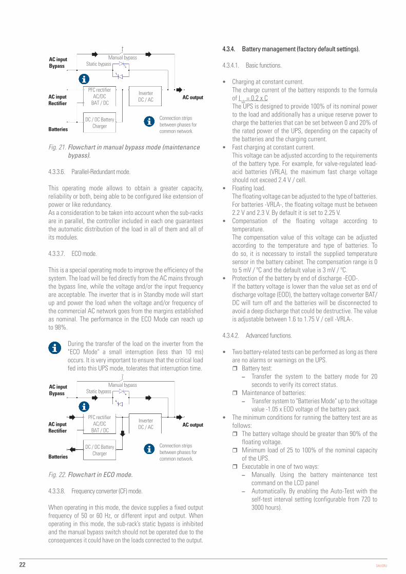
4.3.3.5. Manual bypass mode (maintenance bypass).
If the UPS requires intervention due to breakdown or maintenance (for example, because there is a power module, the bypass or the LCD display with anomalies), there is the possibility of continuing to supply the loads through the internal manual bypass (maintenance bypass).
When the UPS is operating in manual bypass mode (maintenance or repair period), the connected devices are not protected against power cuts or micro-cuts, overvoltages, voltage and/or frequency variations as they are powered directly from the AC mains.
DANGER: During manual bypass mode, the input, output and bypass terminals (version B) are live even if all modules are switched off.It is recommended in this operating mode: – Remove the fastening screws of all power, control
and bypass modules. – Slightly pull the handles on each one until they are
protruding by about 4-5 cm from their housing in order to enable them to be unplugged from their connector located on the backplane of the device.
Before any change of operating mode and after carrying out the possible corrective actions, it is necessary to correctly insert the modules to their original position and fix them with their screws.
SLC ADAPT-X -UNINTERRUPTIBLE POWER SUPPLY SYSTEM-USER MANUAL
22 SALICRU
PFC rectifierAC/DC
BAT / DC
DC / DC Battery Charger
InverterDC / AC
Static bypassManual bypass
Batteries
AC inputBypass
AC inputRectifier
AC output
Connection strips between phases for common network.
Fig. 21. Flowchart in manual bypass mode (maintenance bypass).
4.3.3.6. Parallel-Redundant mode.
This operating mode allows to obtain a greater capacity, reliability or both, being able to be configured like extension of power or like redundancy.As a consideration to be taken into account when the sub-racks are in parallel, the controller included in each one guarantees the automatic distribution of the load in all of them and all of its modules.
4.3.3.7. ECO mode.
This is a special operating mode to improve the efficiency of the system. The load will be fed directly from the AC mains through the bypass line, while the voltage and/or the input frequency are acceptable. The inverter that is in Standby mode will start up and power the load when the voltage and/or frequency of the commercial AC network goes from the margins established as nominal. The performance in the ECO Mode can reach up to 98%.
During the transfer of the load on the inverter from the "ECO Mode" a small interruption (less than 10 ms) occurs. It is very important to ensure that the critical load fed into this UPS mode, tolerates that interruption time.
PFC rectifierAC/DC
BAT / DC
DC / DC Battery Charger
InverterDC / AC
Static bypassManual bypass
Batteries
AC inputBypass
AC inputRectifier
AC output
Connection strips between phases for common network.
Fig. 22. Flowchart in ECO mode.
4.3.3.8. Frequency converter (CF) mode.
When operating in this mode, the device supplies a fixed output frequency of 50 or 60 Hz, or different input and output. When operating in this mode, the sub-rack’s static bypass is inhibited and the manual bypass switch should not be operated due to the consequences it could have on the loads connected to the output.
4.3.4. Battery management (factory default settings).
4.3.4.1. Basic functions.
• Charging at constant current.The charge current of the battery responds to the formula of I ch = 0.2 x CThe UPS is designed to provide 100% of its nominal power to the load and additionally has a unique reserve power to charge the batteries that can be set between 0 and 20% of the rated power of the UPS, depending on the capacity of the batteries and the charging current.
• Fast charging at constant current.This voltage can be adjusted according to the requirements of the battery type. For example, for valve-regulated lead-acid batteries (VRLA), the maximum fast charge voltage should not exceed 2.4 V / cell.
• Floating load.The floating voltage can be adjusted to the type of batteries. For batteries -VRLA-, the floating voltage must be between 2.2 V and 2.3 V. By default it is set to 2.25 V.
• Compensation of the floating voltage according to temperature.The compensation value of this voltage can be adjusted according to the temperature and type of batteries. To do so, it is necessary to install the supplied temperature sensor in the battery cabinet. The compensation range is 0 to 5 mV / ºC and the default value is 3 mV / ºC.
• Protection of the battery by end of discharge -EOD-.If the battery voltage is lower than the value set as end of discharge voltage (EOD), the battery voltage converter BAT/ DC will turn off and the batteries will be disconnected to avoid a deep discharge that could be destructive. The value is adjustable between 1.6 to 1.75 V / cell -VRLA-.
4.3.4.2. Advanced functions.
• Two battery-related tests can be performed as long as there are no alarms or warnings on the UPS.
� Battery test: – Transfer the system to the battery mode for 20
seconds to verify its correct status. � Maintenance of batteries:
– Transfer system to "Batteries Mode" up to the voltage value -1.05 x EOD voltage of the battery pack.
• The minimum conditions for running the battery test are as follows:
� The battery voltage should be greater than 90% of the floating voltage.
� Minimum load of 25 to 100% of the nominal capacity of the UPS.
� Executable in one of two ways: – Manually. Using the battery maintenance test
command on the LCD panel – Automatically. By enabling the Auto-Test with the
self-test interval setting (configurable from 720 to 3000 hours).

23
4.3.4.3. Protection of batteries.
• Low battery alarm.The low battery alarm is activated prior to the end of discharge -EOD- alarm. When activated, it has a few minutes of backup at full load.
• End of discharge protection -EOD-.When the battery voltage reaches this minimum value, the accumulator block is disconnected to avoid the deep discharge that could irreversibly damage them. There are two voltage levels of end of discharge and the actual is calculated by interpolating the following two values:
� -EDO- Voltage / Cell @ 0.6 C Discharge current. By default 1.65 V / cell.
� -EDO- Voltage / Cell @ 0.15 C Discharge current. By default 1.75 V / Cell)
The end of discharge voltage values are factory configurable from 1.6 to 1.75 V / cell.
• Battery protection disconnect alarm -MCB-.This alarm will be available when using the mechanism provided for the external batteries, a circuit breaker -MCB- with coil trip release voltage connected to the control circuit of the UPS. The alarm will be activated if the battery protection -MCB- is switched off.Activation and deactivation of this protection is done through the EPO button on the control panel or remote EPO.
SLC ADAPT-X -UNINTERRUPTIBLE POWER SUPPLY SYSTEM-USER MANUAL

24 SALICRU
5. INSTALLATION.
• Read and respect the Safety Information described in Chapter 2 of this document. Failure to obey some
of the instructions described in this manual can result in a serious or very serious accident to persons in direct contact or in the vicinity, as well as faults in the device and/or loads connected to it.
• The cross sections of the cables used for installation must be in accordance with the currents indicated on the nameplate, in compliance with local and/or national low-voltage electrotechnical regulations.These currents will also determine the minimum sizes of the device’s protections, which will be appropriate to the selectivity indicated in Chapter 10 of this document.
• This chapter introduces the relevant requirements for locating and wiring the SLC ADAPT X modular UPS. Because each site has its peculiarities of location and installation, it is not the purpose of this chapter to provide precise step-by-step instructions, rather it should be used as a guide for general procedures and practices to be observed by qualified personnel (figure recognized and defined in safety instructions EK266*08).
5.1. RECEPTION.
• All sub-racks are supplied on wood pallet mechanically attached to it, with a cardboard envelope or protection wood according to model. While the risk of tipping over is minimised, the sub-racks must be handled with caution, especially those with 6 and 8 slots because of their greater height and when there is slope.
� It is dangerous to manipulate the device on the pallet in an unwise way, as it could overturn and
cause serious or very serious injury to the operators as a result of the impact due to possible fall and/or entrapment. Pay attention to section 1.2.1. of the safety instructions -EK266*08- in all matters relating to the handling, movement and siting of the unit.
• Use the most suitable means to move the UPS while it is packed, with a transpalet or forklift.
• Any manipulation of the device will be done according to the weights indicated in Chapter 10 in the technical characteristics according to model.
5.1.1. Reception, unpacking and contents.
• Reception. Check that: � The data on the label affixed to the packaging
corresponds to that specified on the order. Once the UPS is unpacked, check the previous data with those of the device nameplate.If there are discrepancies, report the issue as soon as possible, citing the device’s manufacturing number and delivery note references.
� It has not suffered any mishaps during transportation (packaging and impact indicator in perfect condition).Otherwise, follow the protocol indicated on the label at-tached to the impact indicator, located on the packaging.
• Unpacking. � To verify the contents it is necessary to remove the
packaging.Complete the unpacking according to the procedure in section 5.1.3.
• Contents. � The device itself. � On sub-racks for parallel connection, the connection
bus cables. • Once the reception is completed, it is advisable to re-pack
the UPS until it is put into service in order to protect it against mechanical shock, dust, dirt, etc.
5.1.2. Storage.
• The device storage shall be done in a dry, ventilated place and protected from rain, dust, water splashes or chemical agents. It is advisable to keep each device in its original packaging as it has been specifically designed to ensure maximum protection during transport and storage.
• Do not store appliances where the ambient temperature exceeds the thresholds given in chapter 10.
• When a battery pack is supplied with the sub-rack of the UPS, either in a cabinet, loose to be installed in a cabinet of its property, to be installed on a rack or in any other way and not installed together immediately, it will be stored in a cool, dry and ventilated place, at a controlled temperature of between 20 and 25ºC.
� In general and except in particular cases when batteries are supplied they are hermetically
sealed lead-calcium batteries. To avoid degradation during storage, they must be recharged at the indicated intervals according to the temperature at which they are exposed (see date of last load noted on the label affixed to the packaging of the battery unit Fig.23).
Fecha carga / Fecha recarga / Charging date : Recharging date:
DY933B00 - 401AF000001
BA
CK
MAT
ERIA
L
MUY IMPORTANTE PARA LA VIDA DE LAS BATERÍAS DE Pb-Ca: Para evitar su degradación deben ser recargadas en los intervalos indicados. Respetar el procedimiento referido en el manual de usuario del equipo.
VERY IMPORTANT FOR THE LIFETIME OF Pb-Ca BATTERIES: In order to avoid their degradation, they must be recharged according to the stated interval times. Respect the procedure referred in the equipment user’s manual.
0 - 20 12 21 - 30 9 31 - 40 5 41 - 50 2,5
Meses / Months
ºC
Charge date shipped from factory.Space to write down the date of the new recharge.
**-**-****
Data label corresponding to the model.
Fig. 23. Label on the packaging of the battery pack.
� After the period of time, connect the batteries with the device and this to the mains following the safety and connection instructions.

25
• To unpack the device, cut the straps of the carton envelope and remove it as if it were a cover (see Fig.24 and 25) or disassemble it with the necessary tools if the casing is made of wood; remove the corners and the plastic sheath and the UPS will be naked on the pallet.
• Remove the screws and/or fixing angles indicated in Fig.26. • With the help of one or two people on each side,
lower it from the wooden pallet. Pay special atten-tion to the sub-rack with 6 and 8 slots, as incorporating wheels could result in it falling from the pallet and causing an accident, beyond the material damage itself.
Fixing screws
Fixing angle
Fig. 26. Device unpacked on a pallet by way of example.
5.1.4. Transport to the site.
• If the receiving area is remote from the installation site, it is recommended to move the ADAPT X using a pallet truck or other suitable means of transport, assessing the distance between the two points, the weight of the unit, the characteristics of the passageway and site (soil type, soil resistance kg/m2,... ).
• The 6 and 8-slot sub-racks incorporate four wheels (with mechanical locking), so it is easy to move it to the installation site once unpacked.
• However, when the distance is considerable, it is recom-mended to move the packaged device to the immediate vi-cinity of the installation site and its subsequent unpacking.
5.2. LOCATION.
5.2.1. Location of the ADAPT X.
• The following premises will be taken into account when locating a modular UPS ADAPT X, as this is a safety device in terms of power and not to prevent or invalidate its own role:
� Not suitable for outdoor installation. Degree of protec-tion by default IP20.
� The location will be in a ventilated room, controlled temperature and humidity to maintain the device in the environmental parameters within the specified operating range. The cooling capacity of the air conditioner will be selected according to the losses of the UPS and other device that can cohabit in the same room.
� Proceed to commissioning. See chapter 6. � Leave it in this mode for at least 12 hours. � Once the battery recharging is complete proceed to stop
the device, disconnect it electrically and save the UPS and the batteries in their original packaging, noting the new date of recharge of the batteries in the box of the label (see Fig.23).
� Units that are part of a parallel system will be treated as individual device for battery recharging and therefore no additional connection is required.
5.1.3. Unpacking.
• The packaging of the device consists of wooden pallet, carton or wood envelope according to cases, polystyrene foamed corners (EPS) or polyethylene foam (EPE), polyethy-lene sheath and strap, all recyclable materials; so if you are going to get rid of them you must do it according to the laws in force. We recommend storing the packaging in case it should be used in the future.
• Fig. 24 to 26 by way of example show illustrations corresponding to a 6-slot sub-rack.
Fig. 24. Example of transfer of packed ADAPT X with pallet jack.
Fig. 25. Example of removal of cardboard box.
SLC ADAPT-X -UNINTERRUPTIBLE POWER SUPPLY SYSTEM-USER MANUAL

26 SALICRU
� The room will have adequate filters to prevent dusty or lint-free environments from contaminating the device and adversely affect its proper operation or generate as a direct or indirect fire with a strict preventive maintenance control.This control will be more rigorous, exhaustive and appropriate to the circumstances, when there may be a dusty environment with conductive materials in suspension.
� The modules are equipped with three internal speed regulated fans. The flow of air flow is channeled from the front to the rear. Do not block the ventilation holes or obstruct the air circulation.The sub-rack modules allow full integration into a rack cabinet without ventilation grilles on the side.
� To allow comfortable operation of personnel, it is recommended to leave a free space on the front of 1 m that allows loosely open the door of a rack cabinet and facilitate the operations of removal or installation of additional modules.It is necessary to leave a minimum of 50 cm in the back for free circulation of ventilation air pushed by the fans.
� When the conditions of the room are extreme, it will be necessary to install an external ventilation system to force the cooling air flow.
� The acoustic level of the ventilation system is high and invalidates the device to install it in the same room where office personnel work.
� Only intended for mounting on cement or other non-combustible surface.
� For the battery cabinets supplied by our brand, the battery trays are extracted frontally. Leave a free space on the front of 1 m for the installation of accumulators and preventive maintenance.
� In general comply with all the conditions indicated in the safety instructions (document EK266*08).
5.2.2. Room for the batteries.
• The batteries generate quantity of hydrogen and oxygen during the charging process, reason why it is indispensable condition to have a good air circulation of the room.
• The stability and ambient temperature of the room where the battery is located is an important factor that determines the capacity to store the energy during the chemical process that occurs during the load. In the same way, these factors influence the reverse chemical process that occurs in the discharge in the event of an energy demand and that they have a significant effect on shortening the useful life of the same.The nominal operating temperature of a battery is 20°C. Operating above this temperature will reduce its duration or life and operating below it will reduce its storage capacity. If the average operating temperature of the battery increases from 20ºC to 30°C, the service life will be reduced by 50%. If the operating temperature exceeds 40°C, the service life will be reduced exponentially.In a normal installation, the battery temperature is main-tained between 15 and 25ºC. Keep batteries away from heat sources or air intakes.
• When external batteries are used, the protections (fuses or circuit breakers) should be mounted as close as possible to the accumulators and their connecting cables between them and the UPS should be as short as possible.
5.2.3. Physical location.
• All of the sub-racks can operate on their own as devices or they can be integrated into a rack-type cabinet.
� 2 and 4-slot models.These can be used as desktop devices. You are recommended to fix them to a solid surface through the holes in the bases (see Fig.27), respecting compliance with the regulation stating “Only intended for mounting on cement or other non-combustible surface” and considering the following premise:
Do not leave the device at ground level as it is usually the area with the highest solid elements in suspension and through the permanent forced ventilation itself penetrate inside causing short or long term breakdowns of all kinds.For obvious reasons, this location is more prone to risk factors such as falling of liquids on the device, unintentional impacts, obstruction of the ventilation grilles by materials placed in front of the device, ..., which can lead to serious or very serious damages. And also leaves the control panel in a plane or inconspicuous position.
To incorporate any of them into a cabinet, it will be necessary to remove the sub-rack’s bases and covers. Its base features fixing holes (see Fig.27). It will, however, be necessary to install a support tray or a number of angles in the cabinet at the desired height, on which the attachment points will be machined.
� 6 and 8-slot models.The structure itself has four wheels with brake for those with 6 slots and without brake for those with 8 slots. The latter has, in the absence of a brake on the wheels, four immobilising feet that are height-adjustable. In all cases, the self-supporting structure gives them an extra benefit as devices in themselves.Once placed in its final location, the brake should be engaged on all four wheels or immobilised by means of its respective elements which in turn act as levellers.
An iron sheet can be placed to distribute the weight over a larger area if deemed appropriate.
To incorporate any of the two in a cabinet, it is ne-cessary to remove the covers and all of the mechanical attachments mounted on its base (brackets, wheels, height-adjustable feet, etc.), and install two angles on either side of the cabinet or a support tray at the desired height. On these supports, machine the fixing points according to each sub-rack base and repre-sented in Fig.27.

27
Depth reserved for different material according to model
608
3636
352 66.366.3
30 x ø12
Seen from below
Device front 30 15
484.6
Base
Dimensions for fixing 2 and 4-slot sub-racks through the bases
30
Handle
605
+25
462.6 1111
M6
Seen from below
Device front 30 15
484.6
12.5
+25
Dimensions for fixing 2 and 4-slot sub-racks through their bases
30 12.5
Depth reserved for different material according to model
Handle
Dimensions for fixing the 6-slot sub-rack through its base
656
462.6 1111
M6
Seen from below
Device front 30 15
484.6 30
Depth reserved for different material according to model
Handle 39.5
39.5
Dimensions for fixing the 8-slot sub-rack through its base
790
37554.8
M10
Seen from below
Device front 30 15
484.6 30Depth reserved for different material according to model
Handle
55
54.8
5530
8.4
-for 2
slo
ts-
485
-for 4
slo
ts-
930
-for 6
slo
ts-
1470
-for
8 s
lots
-
90 90 100
80
Base for 2 and 4-slot models or space for wheels for 6 and 8 slots
Height of the different sub-racks according to the number of slots
Fig. 27. Machining the bases of the sub-racks for fixing.
SLC ADAPT-X -UNINTERRUPTIBLE POWER SUPPLY SYSTEM-USER MANUAL

28 SALICRU
• The installation of a sub-rack inside a cabinet must be carried out as indicated below. The illustrations in Fig. 28 and 29 are a guide and show the general example of a 4-slot sub-rack, although some are included with 6 and 8-slot sub-racks when it is considered necessary.a. Remove the fixing screws from the left-hand trim and
the part itself. On the 8-slot sub-racks the trims are held by magnets instead of screws. Remove one of them by pulling it.
b. Repeat the previous step for the other trim.c. Remove all of the fixing screws of the modules except
for those of the bypass module and control panel.d. Pull the handles of the module located in the highest
part of the sub-rack until it is unplugged from the connector located on the backplane of the sub-rack and pull it out approximately halfway.
Place your hands underneath the module and then lift it off the sub-rack.
Removal of modules must always start with the one located in the highest part of the sub-rack so that the centre of gravity is kept as low as possible.
e. When there are more modules, proceed as in point to remove the remaining ones, continuing with the one located at the highest point of the sub-rack.
a - b
c - d - e
f. Remove the fixing screws from the side covers of the bases on the 2 and 4-slot models or from the supports with wheels on the 6-slot sub-racks.
g. Remove the side covers, bases or supports with wheels from the 6-slot sub-racks.
h. Remove the support attachments from the side covers (only on 8-slot sub-racks).
i. Install two support guides on the sides of the rack cabi-net at the desired height, fix them mechanically and place the sub-rack on top, (see Fig. 29). For the 8-slot sub-rack, a tray must be used instead of side guides.When placing the first module on the sub-rack, start with the lower slot of the system to keep the centre of gravity as low as possible, even if the order of installa-tion is electrically unaffected.Plug each module correctly into its respective connector located on the backplane of the system and, lastly, fix it to the sub-rack using its screws. Repeat the procedure for all modules.
j. Replace the trims indicated at points and except for the one on the right-hand side of the 2 and 4-slot sub-racks, which will be placed at the end of connection as it is possible to route the interface signal cables through its inner channel (see Fig. 36).On 6 and 8-slot devices, the trims only perform this function and the terminal block of the interface is located on the rear side of the sub-rack.

29
f - g - h
Fig. 28. Prior steps to installing the sub-rack in a rack cabinet.
On 8-slot sub-racks, a metal omega clip enables the signal cables to be bundled at the back of the sub-rack. This clip, which can be moved to any height, has a magnet at each end that adheres to the fold of its side
covers. When the covers are removed for installation in a cabinet, this piece loses its functionality.
k. To access the power connection terminals, it is neces-sary to remove the protective cover from the back of the sub-rack.
SLC ADAPT-X -UNINTERRUPTIBLE POWER SUPPLY SYSTEM-USER MANUAL
30 SALICRU
i
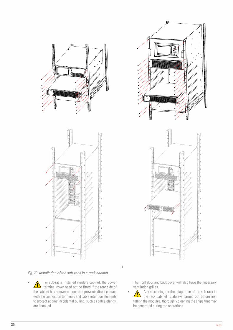
Fig. 29. Installation of the sub-rack in a rack cabinet.
• For sub-racks installed inside a cabinet, the power terminal cover need not be fitted if the rear side of
the cabinet has a cover or door that prevents direct contact with the connection terminals and cable retention elements to protect against accidental pulling, such as cable glands, are installed.
The front door and back cover will also have the necessary ventilation grilles.
• Any machining for the adaptation of the sub-rack in the rack cabinet is always carried out before ins-
talling the modules, thoroughly cleaning the chips that may be generated during the operations.

31
5.3. ENTRY OF THE CONNECTION CABLES.
• The 2-slot and 4-slot sub-racks have a cable gland in the terminal protection cover and an elliptical hole behind a metal part as a cover. Any of them is valid for the routing of connection cables as it prevents the entry of foreign materials and insects into the enclosure, although the cable glands are more suitable when performing the additional function of retaining the cables to protect them against accidental pulling (see Fig. 30).If any of these means is not enough or another mode is preferred, at the base of the sub-rack there is a machinable lid at the user's discretion and in which it can be fitted with larger cable glands than those provided (see Fig.30).
Cable entry through the back cover.
Cable entry through the base.
Fig. 30. Cable entry on 2 and/or 4-slot sub-racks.
• The 6-slot sub-racks have two elliptical holes in the base of the sub-rack (see Fig.31). Make the necessary cuts that allow the passage of cables.
Fig. 31. Cable entry on 6 and 8-slot sub-racks.
SLC ADAPT-X -UNINTERRUPTIBLE POWER SUPPLY SYSTEM-USER MANUAL

32 SALICRU
On the same base and between the two elliptical holes there is a metal plate that can be extracted and machined for the assembly of cable glands.
It is essential to fix the cables to the points provided, as shown in Fig. 31, so as not to obstruct the
ventilation air outlet. • On 8-slot sub-racks, there is a metal sheet in the base
that can be removed and machined for the fitting of cable glands or wall bushings.
5.4. PROTECTIVE DEVICES AND CROSS SECTION OF THE CONNECTION CABLES.
5.4.1. Input, bypass and output.
• The sub-racks do not incorporate protections or disconnec-tors to be operated by the user, except for a manual bypass switch that is useful during preventative maintenance or in case of device failure.This switch is located on the back of the sub-racks in models with up to 6 slots and on the front of 8-slot models, behind a protective cover located under the modules.The 2 and 4-slot models also have a static bypass circuit breaker on the back.This static bypass switch and the manual bypass included in the entire ADAPT X series are not covered by the usual startup and shutdown procedures. It is, however, necessary to set the static bypass to “On” when the sub-rack is started up for the first time or when the sub-rack is installed inside a cabinet and before fitting and securing the cover on the rear side of the sub-rack.
• Protection or external manual bypass board: � It is necessary to have an external protection board
provided with the mechanisms of input, output, and static bypass (the latter only on models with independent static bypass line).In addition it is highly recommended to include a manual bypass mechanism to facilitate preventive maintenance or repair operations, so we will refer to it as a manual bypass board instead of a protection board.
� For parallel sub-rack systems, it is essential to have a manual bypass board. The panel mechanisms must allow a sub-rack to be isolated from the set of systems in parallel in the event of any anomaly and to feed the loads with the rest, either during preventive mainte-nance or during the failure and repair of some of them.
• On request we can supply an external protection board or manual bypass board for a single unit or a manual bypass board for a parallel system.You can also choose to manufacture one, taking into account the version and configuration of the available device or system and the “Recommended installation” documentation that can be downloaded from the website.
• On the nameplate of the sub-rack you can check all the values referring to the main characteristics
related to the device.The sub-rack has two nameplates. One that defines the configuration of the unit supplied and one that identifies the configuration of the highest power model that can be
installed on that sub-rack, that is, considering that it will incorporate all of the modules for which it has capacity. In all cases, the cross sections of the cables and protections must be in accordance with the data on the first one.
• In the documentation downloaded from the website or supplied with the CD-ROM or Pen Drive, the user
manual, the EK266*08 safety instructions and the informa-tion on the "Recommended installation", technical data and single-line diagrams on the connection of the system to the installation, are also available.These data are useful for determining the minimum protections and sections to be installed at the input and output of the ADAPT X, taking into account their nominal working voltage, input-output configuration and the number of modules installed in parallel in the sub-rack.
It is possible to opt for any of the two solutions regarding the size of the panel protections:
a. Protections size according to the power installed in the sub-rack. For future expansions will require the updating of the sizes when the protection is adjusted to the installation.
b. Protections size considering maximum expandable power or up to where future scaling extension is envi-saged. This option is the most economically beneficial if future expansions are envisaged.
It is recommended that the cable cross section of the board be suitable for option “b.”.
• In order to determine the particular technical characteristics of the system in the respective table of specifications, only the number of modules working in parallel will be taken into account, but not those that function in redundant.Pay attention to the notes indicated in the tables and that are conditioning to determine the respective data provided, although the installer will be responsible for defining the particularities of the installation (cables cross sections, protections size, ...), since it is the person who has all the information regarding the system's location environment.All values given in the tables are calculated for a maximum total cable length of 30 m between the distribution board, device and loads.
� For longer lengths correct the cross sections to avoid voltage drops, respecting the regulations or standards corresponding to the country.
� In the same documentation and for each configuration, the information for «N» units in parallel (in 6-slot sub-rack), as well as the characteristics of «Backfeed protection» is available.
• In parallel systems, the length and cross section of the cables from the protection board to each UPS
and from the UPS to the board will be the same for all of them without exception.
• The cross section of the cables must always be considered in relation to the size of the terminals of the terminals terminal block and/or switches, so that they are correctly fastened in their entire section for optimum contact between the two elements.
• Only rated currents are printed on the nameplate of the device as indicated by the EN-IEC 62040-1 safety standard. For the calculation of the input current, the power factor and the device's own performance have been considered.

33
• If peripheral input, output or bypass elements such as transformers or autotransformers are added to the UPS or parallel system, the currents indicated on the nameplates of these elements must be considered in order to use the appropriate sections, in compliance with the local and/or national Low Voltage Electrotechnical Regulation.
• When a galvanic isolation transformer is added to an UPS or parallel system as an option, as standard or installed on its own account, either on the input line, on the bypass line, on the output or in all of them, they must be fitted with protection against indirect contacts (earth leakage breaker) at the output of each transformer, since due to its own insulation characteristic it will prevent the tripping of the protections placed in the primary winding of the transformer in case of electric shock in the secondary winding (output of the isolation transformer).
• We remind you that all the isolation transformers installed or factory supplied, have the output neutral grounded through a bridge between the neutral terminal and ground. If the isolated output neutral is required, this bridge must be removed, taking the precautions indicated in the respective local and/or national low voltage regulations.
• For the passage of cables to the interior of the sub-rack, there are cable glands mounted on the metal structure, in addition a blind plate machinable at the user's discretion.
• In case of installation in neutral IT mode, the switches, circuit breakers and thermal magnetic protection must cut the NEUTRAL in addition to the three phases.
In the case of UPSs with unbalanced input and output frequency or frequency converters, the static bypass is disabled and the manual bypass switch of the device must not be operated, due to the disparity of the input frequency and the frequency required by the load. Do not operate the manual bypass switch on the frequency converters and/or devices where the input and output voltages are unequal because of the effects that this may have on the loads connected to its output, according to its type and/or variations tolerance.
5.4.2. Battery installation and maintenance.
• Batteries are a source of energy, so take into account all recommendations, guidelines and indications in this section and specially when they are owned by the user in which they must be manipulated, installed, connected between them and with the device.
5.4.2.1. General recommendations.
• Precautions for installation, use and maintenance of batteries should be provided by the manufacturers.
• The safety warnings regarding the batteries indicated in sec-tion 1.2.3 of the safety instructions (document EK266*08) in-clude issues that must be taken into account when handling or dealing with devices that incorporates them.
• Additionally consider the following premises: � Before accepting and using the batteries, check their
apparent good condition. If the housing is damaged, broken, deformed or leaking, if the battery terminals are dirty, corroded or rusted, act accordingly or replace with
a new one according to each case. Otherwise, there is a risk of reduced battery capacity, electric leakage or even a potential fire hazard.
� The battery contains sulfuric acid that is confined in its housing. However, when the battery case cracks or breaks due to ill-treatment, there is an acid leak with its fateful consequences. Therefore, when handling batteries, use the appropriate safety PPE.
� At the end of its useful life, there may be increased internal resistance and/or erosions of positive/negative plaques. If this condition continues without replacement, it can overheat resulting in deformations or leaks of the electrolyte. Be sure to replace the battery before this happens.
� If a battery leaks, or if it is physically damaged, it must be replaced, stored in a sulfuric acid resistant container and disposed of in accordance with applicable laws.
5.4.2.2. Installing the batteries. Preliminary considerations before connecting them and their protections.
• The device covered in this user manual does not include batteries as elements installed in the same sub-rack because there is no physical space available. However the installer can carry out the adaptation to integrate both blocks into a rack cabinet, under his responsibility and if he is a qualified person (defined in section 1.2 of document EK266*08).
• The most standard assemblies in rack cabinets made by our firm are represented in document EL096*00.
• For all purposes in section 5.5.4. it is described the connection between the battery pack and the UPS, treated both as separate entities, although they may cohabit in the same cabinet or not, and even share the cabinet, the sub rack and a part of the battery pack.
• In general in this section there are some minimum traces to consider and respect in relation to batteries and their installation, especially when adaptations and/or modifications are made on their own:
� In your installation. – For greater safety, install the external batteries in a
closed cabinet or in a battery room accessible only by qualified personnel.Inside the battery cabinet there are accessible parts with HAZARDOUS VOLTAGE and consequently risk of electric shock, so they are classified as RESTRICTED ACCESS ZONES. Therefore the key of the battery cabinet will not be available to the OPERATOR or USER, unless it has been properly instructed or is a qualified person. This cataloging is applicable to battery rooms, regardless of whether they can be installed in cabinets or on a rack.
– The cabinet is only for sealed maintenance-free valve-regulated lead-acid batteries. For refillable lead-acid batteries, they are expected to be installed on an enabled rack in a specific room.
– Lead acid battery carries chemical hazards. – Reserve a minimum of 1.5 cm between the batteries
and the tray immediately above, allowing free circulation of air around the accumulators. Trays will be pull-out type to simplify maintenance tasks.
SLC ADAPT-X -UNINTERRUPTIBLE POWER SUPPLY SYSTEM-USER MANUAL
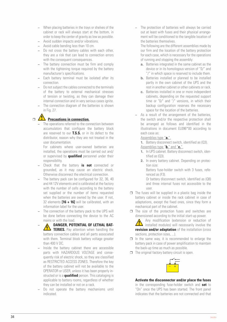
34 SALICRU
– When placing batteries in the trays or shelves of the cabinet or rack will always start at the bottom, in order to keep the center of gravity as low as possible.
– Avoid sudden impacts and/or vibrations. – Avoid cable bending less than 10 cm. – Do not cross the battery cables with each other,
they are a risk that can lead to connection errors with the consequent consequences.
– The battery connection must be firm and comply with the tightening torque required by the battery manufacturer's specifications.
– Each battery terminal must be isolated after its connection.
– Do not subject the cables connected to the terminals of the battery to external mechanical stresses of tension or twisting, as they can damage their internal connection and in very serious cases ignite.
– The connection diagram of the batteries is shown in Fig. 27.
� Precautions in connection. – The operations referred to the connection between
accumulators that configure the battery block are reserved to our T.S.S. or in its defect to the distributor, reason why they are not treated in the user documentation.For cabinets where user-owned batteries are installed, the operations must be carried out and/or supervised by qualified personnel under their responsibility.
– Check that the battery is not connected or grounded, as it may cause an electric shock. Otherwise disconnect the electrical connection.
– The battery pack can be configured for 32, 36, 40 and 44 12V elements and is calibrated at the factory with the number of cells according to the battery set supplied or the number of items requested when the batteries are owned by the user. If not, 32 elements [16 + 16] will be calibrated, with an information label for the user.
– The connection of the battery pack to the UPS will be done before connecting the device to the AC mains or with the load.
– DANGER, POTENTIAL OF LETHAL BAT-TERIES. Pay attention when handling the
battery connection cables and all parts associated with them. Terminal block battery voltage greater than 400 V DC.
– Inside the battery cabinet there are accessible parts with HAZARDOUS VOLTAGE and conse-quently risk of electric shock, so they are classified as RESTRICTED ACCESS ZONES. Therefore the key of the battery cabinet will not be available to the OPERATOR or USER, unless it has been properly in-structed or is a qualified person. This cataloging is applicable to battery rooms, regardless of whether they can be installed or not on a rack.
– Do not operate the battery mechanisms until indicated.
– The protection of batteries will always be carried out at least with fuses and their physical arrange-ment will be conditioned to the tangible location of the batteries themselves.The following are the different assemblies made by our firm and the location of the battery protection for each case, which is necessary for the operations of running and stopping the assembly:a. Batteries integrated in the same cabinet as the
device or in its homologous version of “0/” and “/” in which space is reserved to include them.
b. Batteries installed or planned to be installed partly in the own cabinet of the UPS and the rest in another cabinet or other cabinets or rack.
c. Batteries installed in one or more independent cabinets, depending on the requested support time or "0/" and "/" versions, in which their backup configuration reserves the necessary space for the location of the batteries.
– As a result of the arrangement of the batteries, the switch and/or the respective protection shall be arranged as follows and identified in the illustrations in document EL096*00 according to each case as:Assemblies type “a.”.1. Battery disconnect switch, identified as (Q3).Assemblies type “b.” and “c.”.1. In UPS cabinet. Battery disconnect switch, iden-
tified as (Q3).2. In every battery cabinet. Depending on protec-
tion size:Battery fuse-holder switch with 3 fuses, refe-renced as (F3).Or battery disconnect switch, identified as (Q8) and three internal fuses not accessible to the user.
� The fuses will be supplied in a plastic bag inside the battery cabinet or inside the rack cabinet in case of adaptations, except the fixed ones, since they form a mechanical part of the cabinet.
� The size of the protection fuses and switches are dimensioned according to the initial start-up power.
Any modification (extension or reduction of installed modules) will necessarily involve the
revision and/or adaptation of the installation (cross sections, protection sizes, ...).
� In the same way, it is recommended to enlarge the battery pack in case of power amplification to maintain the back-up time as much as possible.
� The original factory battery circuit is open.
– +
Activate the disconnector and/or place the fuses in the corresponding fuse-holder switch and set to “On” once the UPS has been started. The front panel indicates that the batteries are not connected and that

35
it has been verified that the number of batteries in series of each branch is equal and matches the number of batteries in series configured in the UPS.
• Do not operate the battery fuse holder switch and/or the disconnect switch when the device is running.
In assemblies made by our firm, these mechanisms are not load break type switches.
• When a device or the parallel system is expected to be out of service for an extended period of time, the
complete stop must be carried out beforehand and the 3 fuses of the fuse holder switch of the device or the battery module are removed for safety and stored in a safe place.
5.4.3. Access to the interior of the sub-rack for its connection.
• All sub-rack units in the SLC ADAPT X series have the following connection elements:
� Terminal block for power. Depending on the type of input and output, some connection strips between terminals are supplied to obtain the required configuration (see Fig. 6, 7 and 8).
� Separate terminal block connectors for digital inputs and dry contacts signals.
� Terminal block connector for RS485. � DB9 connector for RS232. � Slot prepared to integrate the SNMP card. � The 6-slot sub-racks also have HDB15 / DB15
connectors for the parallel bus. • All power connection terminals (input, output and batteries)
are located on the back of the sub-racks, behind a protective cover. Only T.S.S. personnel or qualified personnel are authorized to remove these covers for connection.Do not remove more covers than indicated. Access to other internal parts is reserved exclusively for T.S.S.
• The dry contacts connectors are arranged in: � 2-slot and 4-slot sub-racks. On the front of the UPS,
behind the metal cover located next to the control panel. � 6-slot sub-racks. On the back of the UPS, behind a
metal protective cover. • Consider the cross section of the cables and crimped
terminals at their ends, in relation to the surface and size of the terminals, to obtain optimum contact between them.
• At the end of the wiring tasks, the device must be fitted with the corresponding lids firmly attached. This includes the right lateral frontal profile, used as a channel for the passage of the interface cables and related at the point “j.” of section 5.2.3.
5.5. CONNECTION.
• The connection of the device can only be carried out by qualified personnel with the help of the supplied
documentation, however the first start-up of the system is reserved exclusively to our T.S.S. or distributor, as an implicit action that activates the start of the guarantee of the product .Do not apply power to the device before the first start-up.
• This device is suitable for installation in networks with power distribution system TT, TN-S, TN-C or IT, taking into account at the time of installation the particularities of the
system used and the national electrical regulation of the destination country.
• In devices with three-phase input will feed the system with 4 wires (3 phases and Neutral), being
essential the neutral in the power of all three-phase system. Optionally we can supply an isolation transformer to generate the neutral, in those mains supply that do not have it.Only in single-phase devices and in compliance with the nominal supply voltage of the device, it is possible to dispense with the neutral and to replace it with another phase in its absence. In this case and in devices with independent bypass line, as in any equipment, respect the order of the phases when connecting the input and bypass, using the same pair of phases in both networks.
• In devices with three-phase input connected to an IT-type power distribution system, breakers, differentials and magnetothermal protections must cut the NEUTRAL in addition to the three phases.
• All the connections of the device including the control ones will be done with all the switches at rest position and with no power supply (power supply line switch of the device in «Off» position).
• Do not connect ADAPT X devices in parallel with different firmware versions, settings and/or back-up times. Follow all instructions for connecting up to 5 sub-racks in parallel (6-slot sub-racks only).
• The tightening torques of the screw terminals are as follows:
� For screw with M6 thread, tightening torque of 5Nm. � For screw with M8 thread, tightening torque of 13Nm. � For screw with M10 thread, tightening torque of 25Nm.
• The parallel connection of 6-slot sub-racks will be carried out as described in sections 5.5.1 to 5.5.5 and for each one of them, and is subject to having its manual bypass board for both the installation procedure, start-up and future maintenance.
5.5.1. Connecting the device to the mains.
• As it is a device with protection against class I electrical shock, it is essential to install the
protective earth conductor to the terminal identified as . Connect this conductor before supplying voltage to the input terminals.
• In accordance with the safety standard EN-IEC 62040-1, in devices without independent bypass line, the installation must be equipped with an automatic backfeed protection system, such as a contactor, which prevents the occurrence voltage or hazardous energy on the UPS input line during a mains failure.The standard is applicable regardless of whether the power supply is single-phase or three-phase, and for individual units of sub-racks as well as for each of the UPS sub-racks of a parallel system.All values are calculated for a maximum total cable length of 30 m between the distribution board, device and loads.
• There can be no derivation of the line from the Backfeed protection to the UPS, since the safety
SLC ADAPT-X -UNINTERRUPTIBLE POWER SUPPLY SYSTEM-USER MANUAL

36 SALICRU
standard will not be complied with. • Warning labels shall be affixed to all primary power
switches installed in areas remote from the device to alert electrical maintenance personnel of the presence of a UPS in the circuit.The label shall bear the following text or an equivalent:
Before working on the circuit. • Isolate the uninterruptible power supply system (UPS). • Check the voltage between all terminals, including the
protective earth.
Risk of UPS return voltage.
• Connect the input cables to the respective terminals according to the configuration of the available device, considering the illustrations in Fig. 5 to 10 in terms of the connection points of the cables.
� Connection to a three-phase input mains:Connect the R-S-T-N power supply cables to the input terminals, respecting the order of the phases and the neutral indicated on the labelling of the device and in this manual. If the phase order is not respected the device will not work.It is essential to connect the input neutral
� Connection to a single-phase input mains:Connect the R-N power cables to the input terminals, respecting the order of the phases and the neutral indicated on the labelling of the device and in this manual. Failure to observe the phase and neutral order will cause serious damage to the device.
Where there are discrepancies between the labelling and the instructions in this manual, labelling shall always prevail.For systems in parallel, it will be necessary to repeat the connections that go from the panel to each device.
• In general, the devices are supplied ready for powering through a single terminal block (common
power supply for the rectifier and the static bypass line).However, when both functional blocks are powered through two independent lines, it is necessary to remove the bars or strips that connect the terminals of the respective phases and leave the bar or connection strip installed between the two Neutral terminals.
• The input Neutral for the rectifier power supply and the input Neutral for the bypass line power supply
must be the same. In all cases, consider that in the device both will be connected through the bar or strip that joins the two terminals.
• Frequency converter mode. You can use the device with the frequency converter configuration,
activating this function through the control panel menus. For connection purposes, the order of connection of the phase or phase and neutral cables must be respected.
When a device operates as a frequency converter, it is necessary to remove the connection strips
between the input terminals of the UPS and those of the independent bypass line. This will prevent inappropriate transfers of the input on the output in case of operating the manual bypass switch.
5.5.2. Independent static bypass line connection. In version B only.
• As it is a device with protection against class I electrical shock, it is essential to install the
protective earth conductor to the terminal identified as . Connect this conductor before supplying voltage to the input terminals.
• In accordance with safety standard EN-IEC 62040-1, in devices with a static bypass line, the installation must be equipped with an automatic backfeed protection system, such as a contactor, to prevent the presence of voltage or hazardous power on the UPS input line during a mains failure and another for the bypass line.The standard is applicable regardless of whether the power supply is single-phase or three-phase, and for individual units as well as for each of the UPSs in a parallel system.
• There can be no derivation of the line from the Backfeed protection to the UPS, since the safety
standard will not be complied with. • Warning labels shall be affixed to all primary power
switches installed in areas remote from the device to alert electrical maintenance personnel of the presence of a UPS in the circuit.The label shall bear the following text or an equivalent:
Before working on the circuit. • Isolate the uninterruptible power supply system (UPS). • Check the voltage between all terminals, including the
protective earth.
Risk of UPS return voltage.
• Connect the bypass input cables to the respective terminals according to the configuration of the available device, considering the illustrations in Fig. 5 to 10 in terms of the connection points of the cables.
� Connection to a three-phase bypass network:Connect the R-S-T-N power supply cables to the bypass terminals, respecting the order of the phases and the neutral indicated in the labelling of the device and in this manual. If the phase order is not respected the device will not work.It is essential to connect the input neutral.
� Connection to a single-phase bypass network:Connect the R-N power supply cables to the bypass terminals, respecting the order of the phases and the neutral indicated in the labelling of the device and in this manual. Failure to observe the phase and neutral order will cause serious damage to the device.
Where there are discrepancies between the labelling and the instructions in this manual, labelling shall always prevail.For systems in parallel, it will be necessary to repeat the connections that go from the panel to each device.
• Frequency converter mode. With the frequency converter configuration activated, the cables of the
static bypass line must not be connected. With this operation mode, all the functionalities of the static bypass are inhibited.

37
5.5.3. Connection of the output, terminals (X6 to X9).
• As it is a device with protection against class I elec-trical shock, it is essential to install the protective
earth conductor to the terminal identified as . Connect this conductor before supplying voltage to the input terminals.
• Connect the output cables to the respective terminals according to the configuration of the available device, considering the illustrations in Fig. 5 to 10 in terms of the connection points of the cables.
� Three-phase output connection:Connect the loads to the U-V-W-N output terminals, respecting the order of the phases and the neutral indicated in the labelling of the device and in this manual. If the phase order is not respected the device will not work.Where there are discrepancies between the labelling and the instructions in this manual, labelling shall always prevail.
� Single-phase output connection:Connect the loads to the U-N output terminals, respecting the order of the phase and the neutral indicated in the labelling of the device and in this manual. Failure to observe the phase and neutral order will cause serious damage to the device.
Where there are discrepancies between the labelling and the instructions in this manual, labelling shall always prevail.For systems in parallel, it will be necessary to repeat the connections that go from the panel to each device.
• Frequency converter mode. You can use the device with the frequency converter configuration,
activating this function through the control panel menus. For connection purposes, the order of connection of the phase or phase and neutral cables to the load or loads shall be respected.
• With regard to the protection to be placed at the exit of the protection board or manual bypass, we recommend the distribution of the output power in at least four lines. Each of them will have a magneto thermal protection switch of adequate value. This type of output power distribution will ensure that a fault in any of the machines connected to the device that causes a short circuit does not affect more than the line that is faulty. The remaining connected loads will have continuity assured due to the tripping of the protection only in the line affected by the short circuit.
5.5.4. Connection of the battery terminals of the device with those of the battery module.
The battery set can consist of 32, 36, 40 or 44 elements connected in series, but always in even numbers since it is necessary for the internal architecture of the device to have a central point or N neutral medium intake. At the same time, the back-up time together with the power required to feed the loads determines the Ah capacity of the accumulators.
Batteries connected in serial
N
BAT –BAT +
N/2 N/2 +1 N–1 N21
+ N –
Fig. 32. Typical connection of battery set.
• As it is a device with protection against class I elec-trical shock, it is essential to install the protective
earth conductor to the terminal identified as . Connect this conductor before supplying voltage to the input terminals.
• The connection between the terminals of the cabinet or battery pack and the UPS will always be made through the supplied cable hose, respecting the polarity indicated in the labelling of each unit and the colour of the cables or their identification at the ends through heat shrink sleeve (red for positive “+”, blue for common “N” and black for negative “-”).It is imperative to respect this rule and not to extend the hose supplied.
• For extended back-up time in which more than one module or battery cabinets are supplied, the connection will always be in parallel between them and in turn with the device. Respect the rule indicated in the previous point for the connection.
• For the sub-racks of 6 slots in parallel will not change the connection of the batteries with the UPS, since each group of accumulators connects directly with its UPS.However, there is also another possibility, a set of batteries inside a cabinet or installed on a rack, common for a sub-rack system with 6 slots in parallel.
• Danger of electric shock. If after starting up the UPS, it is necessary to disconnect the battery
cabinet, it must carry out a complete stop of the device.Open the battery fuse holder switch (F3) or the battery disconnect switch (Q8) located in the accumulators cabinet and/or the fuse holder switch or disconnect switch (Q3)on the UPS.Wait at least 5 minutes until the filter capacitors have been discharged.
5.5.5. Earth terminal connection.
• As it is a device with protection against class I elec-trical shock, it is essential to install the protective
earth conductor to the terminal identified as . Connect this conductor before supplying voltage to the input terminals.
• Make sure that all loads connected to the UPS are only connected to this ground terminal. Failure to limit the grounding of the load or loads and the cabinet or battery cabinets to this single point will create loops back to ground that will degrade the quality of the power supplied.
SLC ADAPT-X -UNINTERRUPTIBLE POWER SUPPLY SYSTEM-USER MANUAL

38 SALICRU
5.5.6. Parallel connection, 6-slot sub-racks only.
When we talk about parallel in this section we refer to sub-racks, since the parallelization of modules is a characteristic of the entire ADAPT series.It is possible to parallel up to a total of 5 sub-racks of 6 slots regardless or not of the number of them installed in each one, although it is advisable to be uniform numerically, this will depend on the level of redundancy required.
5.5.6.1. Parallel bus connection.
• The COM communications line constitutes a very low voltage safety circuit.
To preserve the quality, it must be installed separately from other lines carrying dangerous voltages (power distribution line).
Parallel connection bus
UPS no. 1
••••••
SW2 P1 P2SW1
UPS No. 'N'
SW2 P1 P2SW1
OFF
ON
OFF
ON
Fig. 33. DB15 connectors on the communication bus.
• Parallel connection bus . Use the 15-wire signal hose with mesh and DB15 connectors at the ends to attach a maximum of 5 sub-racks with the sequence shown in Fig. 28. Each hose has a male and a female connector at the ends, which must be connected between two correlative devices. It is imperative to close the bus loop in parallel.The length of the parallel cable is about 1.5 meters and should not be prolonged under any circumstances due to the risk of interferences and failures in the communication that this would entail.Fig. 28 shows an installation with two devices in parallel. For five, operate similarly to close the communications bus.
• Parallel bus settings . Although up to five devices can be connected in parallel, it is necessary to change the position of the "Mini DIP Switch” SW1 and SW2 located on the back of the device, depending on the number of parallel sub-racks.The device is shipped from the factory adjusted to the requested requirements. When it is necessary to modify the initial configuration in number of units, the position of SW1 and/or SW2 must be changed according to Tab. 2 and through the PC application inform each device. These actions are exclusively reserved for the T.S.S. or the distributor.
Sub-racks in parallel SW1 SW2
1 OFF OFF
2 ON OFF
3 OFF OFF
4 OFF OFF
5 OFF OFF
Tabla 3. SW1 and SW2 selection, units parallel system.
To access them it is necessary to remove the corresponding cover that keeps them from tampering and then reinsert it.
Input circuit breaker
Output circuit breaker
Man
ual B
ypas
s
UPS no. 1 UPS No. 'N'
Input
To loads
•••
Fig. 34. Example of parallel system, with a single AC network and manual bypass board.

39
Output circuit breaker
Man
ual B
ypas
s
UPS no. 1 UPS No. 'N'
Input
To loads
•••
Bypass circuit breakers
Input circuit breakers
Bypass Input
Fig. 35. Example of parallel system, with independent static bypass line and manual bypass board.
• Beyond the communication bus, it is necessary to provide the installation with parallel systems, a board provided with the individual input and output protections and a manual bypass with mechanical locking. See Fig. 29 or 30 depending on whether or not there is an independent static bypass line.For more information see the documentation for the "Recommended installation".
5.5.7. Interface and communications.
• The communications line (COM) constitutes a very low voltage safety circuit and must be installed
separately from other lines carrying dangerous voltages (power distribution line).
5.5.7.1. Digital inputs, dry contacts and communications.
The sub-racks of the ADAPT X series UPS incorporate the following connections as standard for communication with peripherals external to the device or other identical devices: • Four digital inputs through terminal block. • Three relay interface outputs via terminal block. • Communication via RS232 and RS485 ports . • Pre-installation to integrate SNMP card without having to
modify internal wiring.
• DB15 connectors for parallel connection with other identical ADAPT X devices. Only in 6-slot sub-racks.
Cables passed through the decorative
side channel in 2-slot and 4-slot sub-
racks
Fig. 36. Routing of the control cables through the inside of the front trim in 2 and 4-slot models.
All communications related connectors are grouped together on the control panel and are accessible from the front for 2 and 4-slot models after removing the cover that completely covers them (see Fig. 29) or the back of the device for 6-slot models in which only communications through the terminal block have a protective cover (see Fig. 30).In the 2 and 4 slot models, it is possible to route the communi-cation cables through the right side trim of the sub-rack, since the profile of the part itself generates a natural channel that makes it possible, see Fig. 28.The communication module has the following connections via terminal block: • Temperature sensors input.
� Sensor for the compensation of the floating voltage of batteries. Parameter shown on the control panel display.
� Sensor for measuring ambient temperature. Parameter shown on the control panel display.
• Signal input of the external EPO button (*). • Auxiliary contact input of the external manual bypass
switch (maintenance bypass) (*). • Signal trip input of the BCB battery switch (*). • Coil trip release voltage controller of the BCB battery circuit
breaker (*). • Dry contacts, static bypass alarm. • Dry contacts, general alarm. • Dry contacts, mains failure alarm.
(*) In option the mechanisms necessary for their interaction can be provided.
SLC ADAPT-X -UNINTERRUPTIBLE POWER SUPPLY SYSTEM-USER MANUAL

40 SALICRU
Digital inputs connectors and dry contacts
SNMPRS485RS232
Fig. 37. Communication connections in 2 and 4-slot models.
Digital inputs connectors and dry contacts RS485
RS232SNMP DB15 connectors for the parallel bus
Fig. 38. Communication connections in 6 slot models.
All cables connected to the terminal block of digital inputs and dry contacts must be twisted cables with double insulation (shielded) and cross-section between 0.5 and 1.5 mm2 for a length of between 25 and 50 m.
5.5.7.2. Analogue input of battery and environment temperature sensors.
Two connectors are available for the input of external sensors. One placed in the battery pack and utility to compensate the floating voltage depending on the temperature of the batteries. The second optional sensor measures the ambient temperature of the room where it is placed and moves it for reading on the control panel.
J2 J3
TEM
P_BA
T
TEM
P_EN
V
Fig. 39. Terminal block J2 and J3 for connection with sensors.
Pin Reference Function
J2-1 TEMP_BAT Battery temperature sensor (floating voltage compensation)
J2-2 TEMP_COM Common
J3-1 TEMP_ENV Room temperature sensor
J3-2 TEMP_COM Common
Note: The sensors that are designed to be connected to the JP2* and JP3* terminals are identical (R25=5 Ohm, B25/50=3275). However, one is supplied by default, which is connected to the JP2* terminals since due to its functionality it has relevant effects on the batteries. For more information contact our sales department, the T.S.S. or, failing this, the distributor.
Tabla 4. Pinout terminal block for temperature sensors.
5.5.7.3. Signal input of the remote EPO button (Emergency Stop).
The UPS has the EPO function (Emergency Stop). This function can be activated by pressing the button on the control panel of the UPS and protected by a transparent plastic cover to avoid unwanted stops or through a remote EPO provided by the user.The contacts of the external EPO button are connected to the JP4 connector, taking into account the following indications of the adjacent note:
NOTE:
1. The action on the EPO button will completely stop the UPS: the rectifier, the inverter and the static bypass. However, will not disconnect the AC input power source. To disconnect it is necessary to activate the input circuit breaker of the protection board or manual bypass (external of the device) to "Off" position when the EPO is activated.
2. Terminals 1 and 2 of J4 are factory short circuited with a jumper. If the remote EPO function is not used, this jumper will be set and the circuit open between pins 3 and 4. When connecting an external EPO button, the connection with the pushbutton itself will be considered.
3. Regardless of whether you are operating with a single sub-rack or with several sub-racks in parallel in the particular case of 6-slot, points 1 and 2 are applicable on all systems.For parallel systems, connect the same J4 signal from all of them and in parallel to the same EPO push button, see Fig 36.
J4
+24V
EPO_
NC
EPO_
NO
Fig. 40. Terminal block J4 for connection with external EPO.

41
Pin Reference Function
J4.1 EPO_NC Activating the EPO when disconnecting from J4-2
J4.2 +24V +24V,
J4.3 +24V +24V,
J4.4 EPO_NO EPO activation when connected to J4-3
Tabla 5. Pinout terminal block for connection with ex-ternal EPO pushbutton.
J4-3J4-4
J4-3J4-4
J4-3J4-4
Individual sub-rack connection with normally open contact -NO- in EPO.
Individual sub-rack connection with normally closed contact -NC- in EPO.
UPS
J4-1J4-2
UPS
UPS
UPS 'N'
Parallel sub-racks connection with normally open contact -NO- in EPO.
Fig. 41. External EPO connection with device or devices.
5.5.7.4. External manual bypass auxiliary contact input.
When the circuit is closed between these terminals via the auxiliary contact of the external manual bypass switch (normally open NO), the device is informed that the mechanism is in the maintenance position. In this condition the supply of the loads will be direct from the commercial network and any anomaly will be transmitted directly to the load connected to the output of the UPS.
J5
+24V
AUX_NO
Fig. 42. Terminal block J5 for connection with external manual bypass switch.
Pin Reference Function
J5-1 +24V_DRY +24V
J5-2 EXTER_BYPASS Auxiliary contact -NO- of external manual bypass switch
J5-3 GND Common
Table 6. Pinout terminal block for connection with ex-ternal manual bypass.
5.5.7.5. Signal tripping coil circuit breaker of BCB battery switch and auxiliary contact.
A pulsing signal can be supplied via pin J6.1 to switch the battery circuit breaker to "Off" through the EPO. It is not possible to rearm it by the same medium.
J6
+24V
BCB_
DRV
GND
+24V +24V
J7
+ –N
BCB_
ONL
BCB_
CONT
Fig. 43. Terminal block J6 and J7 for connection to BCB.
SLC ADAPT-X -UNINTERRUPTIBLE POWER SUPPLY SYSTEM-USER MANUAL

42 SALICRU
Pin Reference Function
J6.1 BCB_DRV
It provides a pulse signal of +24 V / 20 mA for the remote control of the battery circuit breaker through its coil. This signal activates the “Off” switch.
J6.2 BCB_CONTStatus of the BCB switch. Its normally closed auxiliary contact -NC- can be connected between this pin and the GND.
J7.1 GND + 24V ground reference
J7.2 BCB_ONL Not useful. Not implemented.
Tabla 7. Pinout terminal block for connection to external BCB.
5.5.7.6. Interface to relays.
Switched contacts of three relays, corresponding to three signals of the dry contacts, are supplied through terminal blocks J8, J9 and J10. Tab. 7 shows the pinout of all of them. The voltage and maximum current applicable to these contacts is 250 V AC 3A.
J8J9J10
***_
NC
***_
NO
GND
Fig. 44. Terminal block J8 and J9, and J10 relay interface.
Pin Reference Function
J8-1 BYP_ALM_NC Normally closed (NC) contact, STATIC BYPASS relay interface signal.
J8-2 BYP_ALM_NO Normally open (NO) contact, STATIC BYPASS relay interface signal.
J8-3 GND Common for STATIC BYPASS relay interface signal.
J9-1 ALARM_NC Normally closed (NC) contact, GENERAL ALARM relay interface signal.
J9-2 ALARM_NO Normally open (NO) contact, GENERAL ALARM relay interface signal.
J9-3 GND Common for GENERAL ALARM relay interface signal.
J10-1 UTI_FAIL_NC Normally closed (NC) contact, AC MAINS FAILURE relay interface signal.
J10-2 UTI_FAIL_NO Normally open (NO) contact, AC MAINS FAILURE relay interface signal.
J10-3 GND Common AC MAINS FAILURE relay interface signal.
Tabla 8. Pinout terminal block for relay interface.

43
6. OPERATION.
6.1. INTRODUCTION.
The operating modes of the SLC ADAPT X, in respect to the nature of the output voltage, are defined in the Tab. 9. This chapter describes the different procedures in each operation mode, including transfers between them, the UPS settings and procedures to enable the inverter to "On/Off".
Operating modes Description
Normal mode The load is fed from the UPS inverter.
Bypass Mode (Static bypass)
The load is fed from the static bypass. This mode can be considered a temporary transition between normal mode and the manual bypass or a temporary abnormal operating condition.Note: In this mode the load is not protected, since it is powered directly from the AC network and therefore is subject to the variations thereof.
Maintenance Bypass mode (manual Bypass switch)
The load is powered directly from the AC network through the manual bypass switch, scheduled for periods of maintenance or repair.Note: In this mode the load is not protected, since it is powered directly from the AC network and therefore is subject to the variations thereof.
Tab. 9. Operating modes.
Note: • During the description of the user manual the term bypass
and control module, bypass and monitoring module or MBS is used to refer to the same sub-rack. The same applies to the power module term or PM.
• See chapter 7 [Description of the control panel], for everything related to the functionality of the buttons and the touch screen.
• There are some parameters that can modify the operation of the UPS described in this section. These parameters are set at the factory and are only modifiable later by our T.S.S. staff or the distributor, as they are password protected.
Power switches. • The sub-rack system of 2 and 4 slots incorporates two
switches, circuit breakers, one for the input bypass line and the other for the manual bypass or maintenance line, which by default is mechanically secured to prevent inadvertent triggering. All other transfers are processed automatically using internal control logics.Instead, the 6-slot sub-rack system has only the manual bypass circuit breaker, which by default is also mechanically locked.
• In any case, the installation must have an external panel with the circuit breaker for input, output, a static bypass if applicable and a manual bypass. The protection size will be of the intensity adjusted to the installed power, unless a short-term extension is envisaged, in which it can be adapted to this one.
The "Recommended installation" document supplied with the user manual defines the protection size,
their selectivity, the number of poles according to the input/output configuration and the cross section of the cables of each line. This information is a reference guide and the
user is ultimately responsible for verifying and applying the necessary corrective factors according to the installation itself and the local or national regulations or standards.In the same documentation, the information is also available for the parallel sub-racks of 6 slots, shown by way of example in Fig. 29 and 30.
6.2. STARTING UP THE UPS.
6.2.1. Checks before startup.
Before starting the device: • Check that all the connections have been made correctly
and with sufficient tightening torque, respecting the labelling of the device and the instructions of chapter 5.
• Check that the static bypass switch on the sub-rack, the module or battery modules and the protection board are in the "Off" position.
• Make sure that all loads are "Off". • It is very important to proceed in the established order. • Refer to Fig. 1 to 3 for parts of the device. • Fig. 29 and 30 show a manual bypass board for parallel
system of “N” devices, with common AC line and with independent networks for rectifier and bypass. In both, the installation will match the number of protections to the available parallel sub-rack.Although the internal and external manual bypass switches have the same functionality, the latter is superior in performance because it allows complete isolation of the device during periods of preventive maintenance, repair or replacement.The following sections describe all the steps to be performed considering the availability of a manual bypass board, although for a single sub-rack it may be a protection board [same board but without the manual bypass mechanism].
6.2.2. Startup.
• The first startup of the device or parallel system is exclusively reserved for authorised personnel, either from our T.S.S. or the distributor. This operation activates the start of the product warranty and among other jobs a verification test and calibration "in situ" of the device is also started, but which is not described in this document.
• Follow this procedure to start the UPS from a total stopped position.Proceed as follows:1. Check the correct connection of the phases and neutral
to the input of the device, as well as the static bypass line when it is available. Correct in the case of wrong connection or phase rotation.
During the next manoeuvres described in this section, the output terminals of the UPS will be under potential at some point. If any loads are connected to them, check that it is reliable to apply voltage, otherwise disconnect it securely from the output terminals of the UPS.
SLC ADAPT-X -UNINTERRUPTIBLE POWER SUPPLY SYSTEM-USER MANUAL
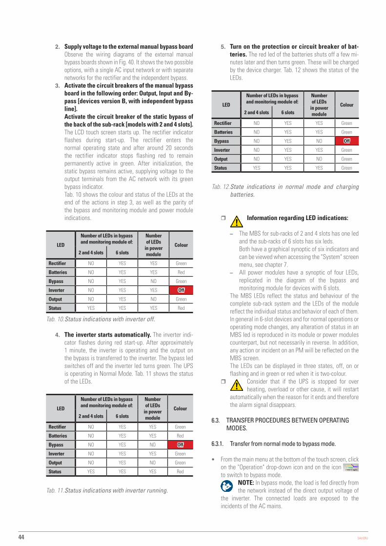
44 SALICRU
2. Supply voltage to the external manual bypass boardObserve the wiring diagrams of the external manual bypass boards shown in Fig. 40. It shows the two possible options, with a single AC input network or with separate networks for the rectifier and the independent bypass.
3. Activate the circuit breakers of the manual bypass board in the following order: Output, Input and By-pass [devices version B, with independent bypass line].Activate the circuit breaker of the static bypass of the back of the sub-rack [models with 2 and 4 slots].The LCD touch screen starts up. The rectifier indicator flashes during start-up. The rectifier enters the normal operating state and after around 20 seconds the rectifier indicator stops flashing red to remain permanently active in green. After initialization, the static bypass remains active, supplying voltage to the output terminals from the AC network with its green bypass indicator.Tab. 10 shows the colour and status of the LEDs at the end of the actions in step 3, as well as the parity of the bypass and monitoring module and power module indications.
LED
Number of LEDs in bypass and monitoring module of:
Number of LEDs
in power module
Colour2 and 4 slots 6 slots
Rectifier NO YES YES Green
Batteries NO YES YES Red
Bypass NO YES NO Green
Inverter NO YES YES Off
Output NO YES NO Green
Status YES YES YES Red
Tab. 10. Status indications with inverter off.
4. The inverter starts automatically. The inverter indi-cator flashes during red start-up. After approximately 1 minute, the inverter is operating and the output on the bypass is transferred to the inverter. The bypass led switches off and the inverter led turns green. The UPS is operating in Normal Mode. Tab. 11 shows the status of the LEDs.
LED
Number of LEDs in bypass and monitoring module of:
Number of LEDs
in power module
Colour2 and 4 slots 6 slots
Rectifier NO YES YES Green
Batteries NO YES YES Red
Bypass NO YES NO Off
Inverter NO YES YES Green
Output NO YES NO Green
Status YES YES YES Red
Tab. 11. Status indications with inverter running.
5. Turn on the protection or circuit breaker of bat-teries. The red led of the batteries shuts off a few mi-nutes later and then turns green. These will be charged by the device charger. Tab. 12 shows the status of the LEDs.
LED
Number of LEDs in bypass and monitoring module of:
Number of LEDs
in power module
Colour2 and 4 slots 6 slots
Rectifier NO YES YES Green
Batteries NO YES YES Green
Bypass NO YES NO Off
Inverter NO YES YES Green
Output NO YES NO Green
Status YES YES YES Green
Tab. 12. State indications in normal mode and charging batteries.
� Information regarding LED indications:
– The MBS for sub-racks of 2 and 4 slots has one led and the sub-racks of 6 slots has six leds.Both have a graphical synoptic of six indicators and can be viewed when accessing the "System" screen menu, see chapter 7.
– All power modules have a synoptic of four LEDs, replicated in the diagram of the bypass and monitoring module for devices with 6 slots.
The MBS LEDs reflect the status and behaviour of the complete sub-rack system and the LEDs of the module reflect the individual status and behavior of each of them.In general in 6-slot devices and for normal operations or operating mode changes, any alteration of status in an MBS led is reproduced in its module or power modules counterpart, but not necessarily in reverse. In addition, any action or incident on an PM will be reflected on the MBS screen.The LEDs can be displayed in three states, off, on or flashing and in green or red when it is two-colour.
� Consider that if the UPS is stopped for over heating, overload or other cause, it will restart
automatically when the reason for it ends and therefore the alarm signal disappears.
6.3. TRANSFER PROCEDURES BETWEEN OPERATING MODES.
6.3.1. Transfer from normal mode to bypass mode.
• From the main menu at the bottom of the touch screen, click on the "Operation" drop-down icon and on the icon to switch to bypass mode.
NOTE: In bypass mode, the load is fed directly from the network instead of the direct output voltage of
the inverter. The connected loads are exposed to the incidents of the AC mains.
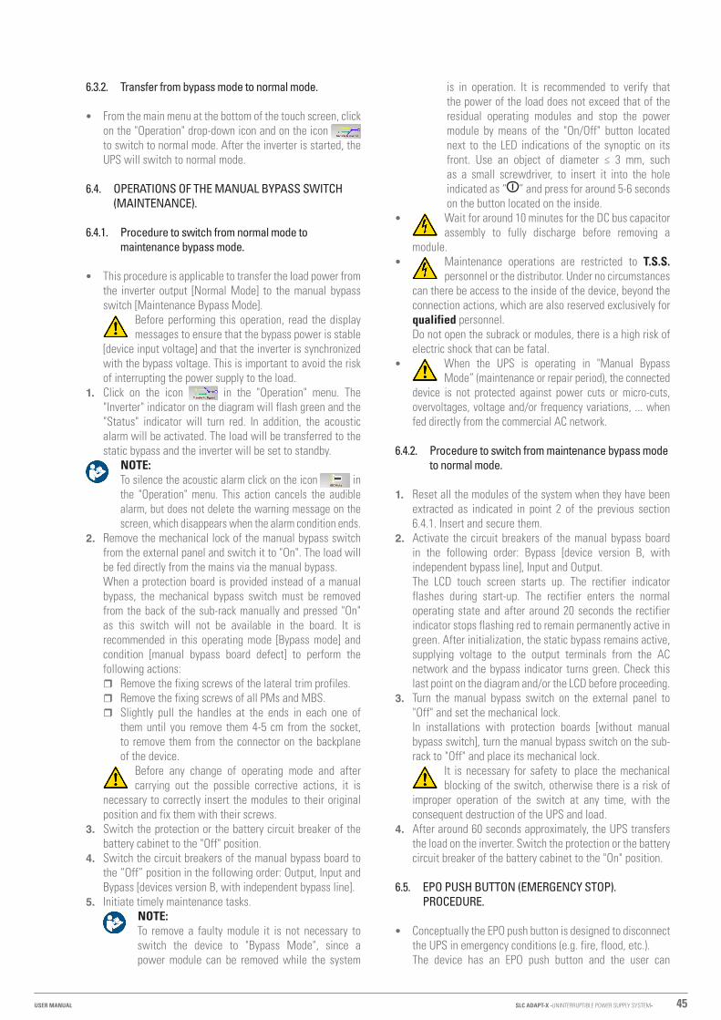
45
6.3.2. Transfer from bypass mode to normal mode.
• From the main menu at the bottom of the touch screen, click on the "Operation" drop-down icon and on the icon to switch to normal mode. After the inverter is started, the UPS will switch to normal mode.
6.4. OPERATIONS OF THE MANUAL BYPASS SWITCH (MAINTENANCE).
6.4.1. Procedure to switch from normal mode to maintenance bypass mode.
• This procedure is applicable to transfer the load power from the inverter output [Normal Mode] to the manual bypass switch [Maintenance Bypass Mode].
Before performing this operation, read the display messages to ensure that the bypass power is stable
[device input voltage] and that the inverter is synchronized with the bypass voltage. This is important to avoid the risk of interrupting the power supply to the load.
1. Click on the icon in the "Operation" menu. The "Inverter" indicator on the diagram will flash green and the "Status" indicator will turn red. In addition, the acoustic alarm will be activated. The load will be transferred to the static bypass and the inverter will be set to standby.
NOTE: To silence the acoustic alarm click on the icon in the "Operation" menu. This action cancels the audible alarm, but does not delete the warning message on the screen, which disappears when the alarm condition ends.
2. Remove the mechanical lock of the manual bypass switch from the external panel and switch it to "On". The load will be fed directly from the mains via the manual bypass.When a protection board is provided instead of a manual bypass, the mechanical bypass switch must be removed from the back of the sub-rack manually and pressed "On" as this switch will not be available in the board. It is recommended in this operating mode [Bypass mode] and condition [manual bypass board defect] to perform the following actions:
� Remove the fixing screws of the lateral trim profiles. � Remove the fixing screws of all PMs and MBS. � Slightly pull the handles at the ends in each one of
them until you remove them 4-5 cm from the socket, to remove them from the connector on the backplane of the device.
Before any change of operating mode and after carrying out the possible corrective actions, it is
necessary to correctly insert the modules to their original position and fix them with their screws.
3. Switch the protection or the battery circuit breaker of the battery cabinet to the "Off" position.
4. Switch the circuit breakers of the manual bypass board to the “Off” position in the following order: Output, Input and Bypass [devices version B, with independent bypass line].
5. Initiate timely maintenance tasks. NOTE: To remove a faulty module it is not necessary to switch the device to "Bypass Mode", since a power module can be removed while the system
is in operation. It is recommended to verify that the power of the load does not exceed that of the residual operating modules and stop the power module by means of the "On/Off" button located next to the LED indications of the synoptic on its front. Use an object of diameter ≤ 3 mm, such as a small screwdriver, to insert it into the hole indicated as “ ” and press for around 5-6 seconds on the button located on the inside.
• Wait for around 10 minutes for the DC bus capacitor assembly to fully discharge before removing a
module. • Maintenance operations are restricted to T.S.S.
personnel or the distributor. Under no circumstances can there be access to the inside of the device, beyond the connection actions, which are also reserved exclusively for qualified personnel.Do not open the subrack or modules, there is a high risk of electric shock that can be fatal.
• When the UPS is operating in "Manual Bypass Mode” (maintenance or repair period), the connected
device is not protected against power cuts or micro-cuts, overvoltages, voltage and/or frequency variations, ... when fed directly from the commercial AC network.
6.4.2. Procedure to switch from maintenance bypass mode to normal mode.
1. Reset all the modules of the system when they have been extracted as indicated in point 2 of the previous section 6.4.1. Insert and secure them.
2. Activate the circuit breakers of the manual bypass board in the following order: Bypass [device version B, with independent bypass line], Input and Output.The LCD touch screen starts up. The rectifier indicator flashes during start-up. The rectifier enters the normal operating state and after around 20 seconds the rectifier indicator stops flashing red to remain permanently active in green. After initialization, the static bypass remains active, supplying voltage to the output terminals from the AC network and the bypass indicator turns green. Check this last point on the diagram and/or the LCD before proceeding.
3. Turn the manual bypass switch on the external panel to "Off" and set the mechanical lock.In installations with protection boards [without manual bypass switch], turn the manual bypass switch on the sub-rack to "Off" and place its mechanical lock.
It is necessary for safety to place the mechanical blocking of the switch, otherwise there is a risk of
improper operation of the switch at any time, with the consequent destruction of the UPS and load.
4. After around 60 seconds approximately, the UPS transfers the load on the inverter. Switch the protection or the battery circuit breaker of the battery cabinet to the "On" position.
6.5. EPO PUSH BUTTON (EMERGENCY STOP). PROCEDURE.
• Conceptually the EPO push button is designed to disconnect the UPS in emergency conditions (e.g. fire, flood, etc.).The device has an EPO push button and the user can
SLC ADAPT-X -UNINTERRUPTIBLE POWER SUPPLY SYSTEM-USER MANUAL

46 SALICRU
install an external one, connected to the device via the communication terminal J4.
• Press the EPO push button, the system stops immediately the rectifier, the inverter and the bypass, and consequently leaves it without power to the load. Batteries are no longer charged or discharged.If the AC input network is present, the UPS control circuit will remain active, but without voltage at the output.
• To completely isolate the UPS, follow the steps in the next section.
6.5.1. Complete stop of the UPS, with EPO.
1. If stopping is planned or scheduled, stop the loads beforehand. In case of emergency, go directly to step 2.
2. Press the EPO button on the bypass and monitoring module.3. Switch the protection or the battery circuit breaker of the
battery cabinet to the "Off" position.4. Switch the circuit breakers of the manual bypass board to
the “Off” position in the following order: Bypass [device version B, with independent bypass line], Input and Output.
The EPO condition will be clear when the input panel switch to "Off" is pressed.
The UPS is completely out of service.
6.5.2. UPS restart after full stop with EPO.
The procedure is used to restore the system after the EPO has been activated and its complete stop:1. Once you press the EPO button, you need to end the
procedure before attempting to restart the system.2. Restart the UPS as described in section 6.2.2.
The EPO condition will disappear when the stop switch of the input switch indicated in the previous
section is performed, since the alarm will be cleared.
6.6. AUTOMATIC RESTART.
When the UPS is operating in Normal Mode and the input mains fails, it will automatically switch to Batteries Mode, where the loads are fed from the inverter from the energy stored in the accumulators. If the mains failure goes on beyond the possible power that the battery pack can supply, the end of discharge is reached and the UPS will stop.The UPS will restart automatically by supplying output voltage:1. After returning the commercial AC network.2. If the parameter "Automatic reset" after EOD is enabled.
Functionality of the switches:� Input circuit breaker.� Static bypass circuit breaker - line 2.� Output circuit breaker.� Manual bypass circuit breaker -maintenance Bypass-.� It is necessary to connect the auxiliary contact of the manual
bypass switch on the external panel, with the J5 terminal block of the communication block of the UPS as a preventive action. In case of improper or untimely switching of the manual bypass switch to "On" with the device in "Normal Mode", this auxiliary contact will force the transfer of the device to "Bypass Mode". In this way avoiding a short circuit and the destructive consequences that can associated with same.If you are purchasing a manual bypass board, you must ensure that you have the auxiliary contact normally open -NO- which should be advanced to the closed position.In parallel systems the manual bypass mechanism will have as many auxiliary contacts as there are parallel units for their separate connection.
UPS network
inputUPS
Output
Input line To loads
�
�
�
External manual bypass board, with common input network for rectifier and static bypass.
To the UPS J5 terminal block
External manual bypass board with separate networks for rectifier and static bypass.
UPS network input
UPS bypass input
UPSOutput
AC1 line input
AC2 line input To loads
� �
�
�
To the UPS J5 terminal block
�
Fig. 45. Internal wiring diagram of an external manual bypass board for a device.
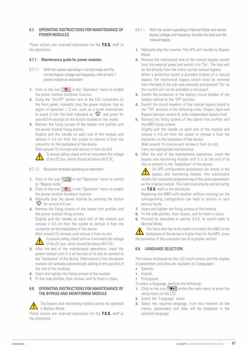
47
6.7. OPERATING INSTRUCTIONS FOR MAINTENANCE OF POWER MODULES.
These actions are reserved exclusively for the T.S.S. staff or the distributor.
6.7.1. Maintenance guide for power modules.
6.7.1.1. With the system operating in normal mode and the normal bypass voltage and frequency, with at least 1 power module as redundant:
1. Click on the icon in the "Operation" menu to enable the power module shutdown function.
2. Using the "On/Off” button next to the LED indications on the front panel, manually stop the power module. Use an object of diameter ≤ 3 mm, such as a small screwdriver, to insert it into the hole indicated as “ ” and press for around 5-6 seconds on the button located on the inside.
3. Remove the fixing screws of the lateral trim profiles and the power module fixing screws.Slightly pull the handle on each end of the module and remove it 4-5 cm from the socket to remove it from the connector on the backplane of the device.Wait around 10 minutes and remove it from its slot.
To ensure safety, check with an instrument the voltage of the DC bus, which should be below 60 V DC.
6.7.1.2. No power modules operating as redundant:
1. Click on the icon in the "Operation" menu to switch to “Bypass mode.”
2. Click on the icon in the "Operation" menu to enable the power module shutdown function.
3. Manually stop the power module by pressing the button “ ” for around 5-6 sec.
4. Remove the fixing screws of the lateral trim profiles and the power module fixing screws.Slightly pull the handle on each end of the module and remove it 4-5 cm from the socket to remove it from the connector on the backplane of the device.Wait around 10 minutes and remove it from its slot.
To ensure safety, check with an instrument the voltage of the DC bus, which should be below 60 V DC.
5. After the end of the maintenance operations, insert the power module until it is at the end of its slot to connect to the "backplane" of the device. After around 2 min the power module will activate automatically adding to the parallel of the rest of the modules.
6. Insert and tighten the fixing screws of the module.7. Fit the side profiles, their screws, and fix them in place.
6.8. OPERATING INSTRUCTIONS FOR MAINTENANCE OF THE BYPASS AND MONITORING MODULE.
The bypass and monitoring module cannot be operated in Battery Mode.
These actions are reserved exclusively for the T.S.S. staff or the distributor.
6.8.1.1. With the system operating in Normal Mode and normal bypass voltage and frequency, transfer the load over the manual bypass.
1. Manually stop the inverter. The UPS will transfer to Bypass Mode.
2. Remove the mechanical lock of the manual bypass switch from the external panel and switch it to "On". The load will be fed directly from the mains via the manual bypass.When a protection board is provided instead of a manual bypass, the mechanical bypass switch must be removed from the back of the sub-rack manually and pressed "On" as this switch will not be available in the board.
3. Switch the protection or the battery circuit breaker of the battery cabinet to the "Off" position.
4. Switch the circuit breakers of the manual bypass board to the “Off” position in the following order: Output, Input and Bypass [devices version B, with independent bypass line].
5. Remove the fixing screws of the lateral trim profiles and the MBS fixing screws.Slightly pull the handle on each end of the module and remove it 4-5 cm from the socket to remove it from the connector on the backplane of the device.Wait around 10 minutes and remove it from its slot.Carry out appropriate maintenance.
6. After the end of the maintenance operations, insert the bypass and monitoring module until it is at the end of its slot to connect to the "backplane" of the device.
All UPS configuration parameters are stored in the bypass and monitoring module. Any substitution
entails the necessary programming of the same parameters as the original module. This task must only be carried out by our T.S.S. staff or the distributor.Replacing one MBS with another without carrying out the corresponding configuration can lead to serious or very serious faults.
7. Insert and tighten the fixing screws of the module.8. Fit the side profiles, their screws, and fix them in place.9. Proceed as described in section 6.4.2. to switch back to
Normal Mode.The force that has to be made to connect the MBS to the backplane of the device is higher than for the MPs, since
the terminals of the connector are of a greater section.
6.9. LANGUAGE SELECTION.
The menus displayed on the LCD touch screen and the display of parameters and data are available in 3 languages: • Spanish. • English. • Portuguese.
To select a language, perform the following:1. Click on the icon within the main menu to enter the
setup menu on the LCD.2. Select the “Language” menu.3. Select the required language. From this moment all the
menus, parameters and data will be displayed in the selected language.
SLC ADAPT-X -UNINTERRUPTIBLE POWER SUPPLY SYSTEM-USER MANUAL

48 SALICRU
6.10. CHANGING THE CURRENT DATE AND TIME
To change the system date and time, perform the following:1. Click on the icon in the "Main" menu to enter the
setup menu on the LCD.2. Select the "Date and Time" menu.3. Enter the new date and time. Press ENTER to confirm.
6.11. LEVEL 1 CONTROL PASSWORD.
The system is password protected to control unauthorized operations. In section 7.3.5 of the "Operation" menu, the various available functions that can be set and the level of the password that limits them are displayed as icons.The user can only perform operations protected by PSW # 1. The default PSW # 1 is 1203.

49
7. MONITORING PANEL WITH LCD TOUCH SCREEN.
This chapter describes the functions and instructions for operation of the monitoring panel with LCD touch screen, including detailed information on the menus, notice screens and list of alarms from the UPS.
7.1. INTRODUCTION.
Physically, the monitoring panel with LCD touch screen and static bypass are part of the same unit as a module, although they are individual entities with their own functionalities. Through the LCD panel you can operate and control the UPS, verify all measurements and parameters, device status and batteries, and historical and event logs. Fig. 46 shows the two monitoring panels available.
Monitoring panel installed in sub-racks of 2 and 4 slots.
Monitoring panel installed in the sub-rack of 6 slots.
Fig. 46. Monitoring panels with LCD touch screen.
Basically the LCD monitoring panel is divided into three functional areas: • LCD touch screen with structured menus. • Flowchart of power LEDs and "Status" indicator and audible
alarm. � The flowchart is only available in the sub-racks of six
slots and is information that appears replicated in the "Cabinet" menu of the touch screen.Additionally each power module has its own energy flowchart, but obviously without the bypass and output indicator.
� The "Status" LED and acoustic alarm are present in all sub-racks.
• EPO emergency stop push button and function keys. � The EPO push button with the protective cover is
available on all devices. � The BYP, INV, and MUTE hotkeys are only available in
six-slot sub-racks.For further information, see Tab. 14.
NOTE: The data and values presented in this document are by way of example, so they will be different from those displayed on your unit.
Indicator Function Availability
REC Rectifier
In 6-slot sub-racks
BAT Batteries
BYP Bypass
INV Inverter
OUTPUT Output to loads
STATUS State In all sub-racks
Tab. 13. Functionality and availability of the LEDs in the sub-rack.
Operation keys Function Availability
EPO Emergency stop push button. Pressing it cuts off the load power for
the rectifier, the inverter and the static bypass. If battery protection with coil trip release voltage is available, the battery power is also cut off by
acting on the mechanism coil.
In all sub-racks
BYP Hotkey for transferring from Normal Mode to
Bypass Mode
In 6-slot sub-racksINV Hotkey for transferring from Bypass Mode to
Normal Mode
MUTE Key to silence the audible alarm
Tab. 14. Functionality and availability of the push buttons on the sub-rack.
7.2. DIAGRAM OF ENERGY FLOW TO LEDS.
The operating mode of the device is represented by the LEDs of the energy flow. The status description of the LEDs is shown in Tab. 15.
LED indicator State Description
RECT - Rectifier
Green Rectifier operation, correct on all modules.
Flashing green At least one of the rectifiers of the modules is starting up.
Red At least one of the rectifiers of the modules is failing.
Flashing red The input of at least one module is incorrect.
Off Rectifier does not work.
SLC ADAPT-X -UNINTERRUPTIBLE POWER SUPPLY SYSTEM-USER MANUAL

50 SALICRU
LED indicator State Description
BAT - Batteries
Green The battery is charging.
Flashing green The battery is being discharged.
Red
Batteries are incorrect (battery fault, battery or inverted batteries) or the battery converter is abnormal (fault, over current or over temperature), EOD.
Flashing red Low battery voltage.
Off Batteries and battery converters are correct, batteries are not being charged.
BYP - Bypass
Green Output supply from the Bypass
Red Bypass module fault or static bypass switch fault.
Flashing red Incorrect Bypass voltage.
Off Bypass voltage is correct, but the Bypass module does not work.
INV - Inverter
Green The inverter is feeding the load.
Flashing green Inverter starting, synchronizing or UPS operating in ECO Mode - Standby -.
RedAt least one inverter of a module is failing. The inverter does not supply voltage to the load connected to the output.
Flashing redAt least one inverter of a module is failing. The inverter supplies voltage to the load connected to the output.
Off The inverter is not running on all modules.
OUTPUT - Load
Green The UPS is supplying output voltage and is correct.
Red Short circuit at the output, no output or maximum output overload time exceeded.
Flashing red Output overload
Off No output voltage
STATUS - Status
Green Correct operation.
Red Fault.
Tab. 15. Description of the Led indications.
7.2.1. Audible alarm.
The acoustic alarm of the UPS has two tones that can be activated during operation, see Tab. 16.
Modulation Availability
Two short beep, followed by one
long beep
Indicates that the system is in a status of general alarm (for example when there is an input fault).
Continuous beep Indicates that the system is in a status of urgent alarm (for example fuse fault or system fault).
Tab. 16. Acoustic alarm tones.
7.3. DESCRIPTION OF THE SCREENS SHOWN ON THE LCD TOUCH SCREEN.
7.3.1. Start menu or main screen.
Fig. 47 by way of example shows a main screen that can display the LCD monitoring panel. It is basically divided into four areas: System information, Power flow, Current warnings or Alarm window, and Main menu.
Information bar of the system
Flow of power
Main menu Current warnings or alarms
Fig. 47. Home screen or main screen.
Icon Description
Main screen: Return to the main menu page.
System information: Bypass, main, output (voltage, current, PF power factor, frequency), battery information (capacity, remaining time, days worked in this mode, battery temperature, ambient temperature) information on the load (percentage of active, reactive load, apparent load).
Information on the power modules: mains, output, load, S-code, module information).
Configuration: Date and time, language, communications, user (passkey 1), selection of batteries, selection of service, selection of parameters, configuration.
Historical record: Shows the events that have occurred.
Actions regarding the system: Mute ON/OFF, clear fault, transfer to bypass, transfer to inverter, allow module “Off”, reset historical data of batteries, restart time of use of dust filters, batteries’ test, maintenance of batteries, recharge equalization of batteries, float batteries, stop test.
Waveforms: Oscillogram of the output voltage, output current, bypass voltage.
Tab. 17. Description of the home or main menu icons.
Fig. 48 shows an expanded view of the map of the menus and sub-menus accessible from the home or main screen.
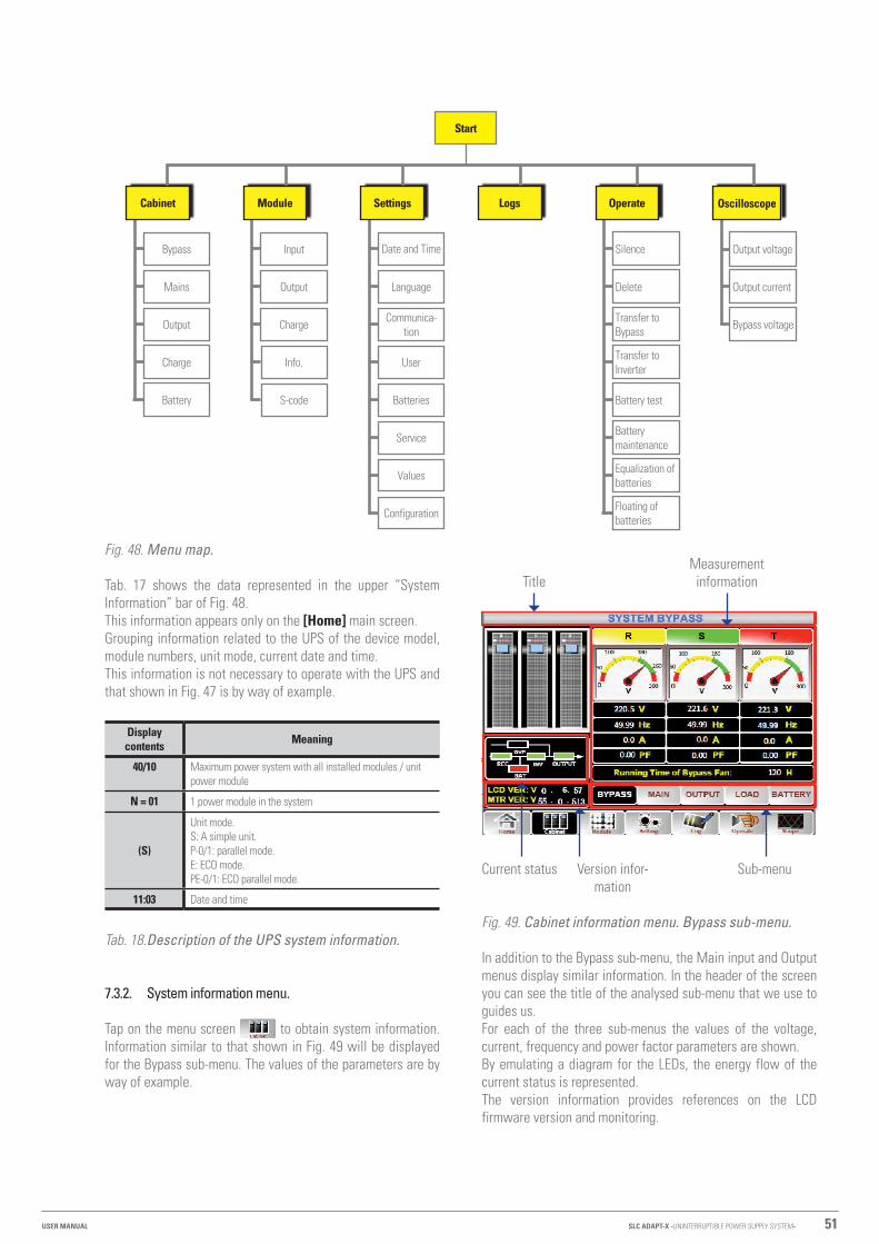
51
Bypass
Mains
Output
Charge
Battery
Input
Output
Charge
Info.
S-code
Silence
Delete
Transfer to Bypass
Transfer to Inverter
Battery test
Battery maintenance
Equalization of batteries
Floating of batteries
Output voltage
Output current
Bypass voltage
Date and Time
Language
Communica-tion
User
Batteries
Service
Values
Configuration
Start
Cabinet Module Settings Logs Operate Oscilloscope
Fig. 48. Menu map.
Tab. 17 shows the data represented in the upper “System Information” bar of Fig. 48.This information appears only on the [Home] main screen.Grouping information related to the UPS of the device model, module numbers, unit mode, current date and time.This information is not necessary to operate with the UPS and that shown in Fig. 47 is by way of example.
Display contents Meaning
40/10 Maximum power system with all installed modules / unit power module
N = 01 1 power module in the system
(S)
Unit mode.S: A simple unit.P-0/1: parallel mode.E: ECO mode.PE-0/1: ECO parallel mode.
11:03 Date and time
Tab. 18. Description of the UPS system information.
7.3.2. System information menu.
Tap on the menu screen to obtain system information. Information similar to that shown in Fig. 49 will be displayed for the Bypass sub-menu. The values of the parameters are by way of example.
TitleMeasurement
information
Version infor-mation
Sub-menuCurrent status
Fig. 49. Cabinet information menu. Bypass sub-menu.
In addition to the Bypass sub-menu, the Main input and Output menus display similar information. In the header of the screen you can see the title of the analysed sub-menu that we use to guides us.For each of the three sub-menus the values of the voltage, current, frequency and power factor parameters are shown.By emulating a diagram for the LEDs, the energy flow of the current status is represented.The version information provides references on the LCD firmware version and monitoring.
SLC ADAPT-X -UNINTERRUPTIBLE POWER SUPPLY SYSTEM-USER MANUAL

52 SALICRU
Fig. 50. Cabinet information menu. Main sub-menu.
Fig. 51. Cabinet information menu. Output sub-menu.
Fig. 52. Cabinet information menu. Load sub-menu.
In the system menu there are two additional sub-menus, Load and Battery. The Load information includes load percentage, active load, reactive load and apparent load (see Fig. 52). The battery information includes the number of batteries, voltage, current, remaining capacity, remaining discharge time, discharge times, operating days, discharge hours, battery temperature and ambient temperature (see Fig. 53).
Fig. 53. Cabinet information menu. Battery sub-menu.
7.3.3. Information menu of the module or power modules (PM).
• Tap on the menu screen to obtain information about the module or power modules.
TitleMeasurement
information
Version infor-mation
Sub-menuPower module(s)
information
Fig. 54. Information menu of the module or power modules. Main sub-menu.
The values of the voltage, current, frequency and PF power factor, input and output parameters, the first two sub-menus are displayed, for input, see Fig. 54, and, for output, see Fig. 55.

53
Fig. 55. Information menu of the module or power modules. Output sub-menu.
Fig. 56. Information menu for the power module or modules. Load sub-menu.
The information in the Load sub-menu includes the load percentage, the active load and the apparent load (see Fig. 56).There are two other sub-menus, those for information and S-Code. The first one provides the following information measured by each module: • Battery voltage [positive and negative]. • Battery currents [positive and negative]. • DC bus voltages [positive and negative]. • Fan operating time. • Operating time of DC capacitors. • Inlet air temperature. • Output air temperature. • Three temperatures of the rectifier IGBT [three-phase]. • Three temperatures of the inverter IGBT [three-phase].
The second, the S-Code, shows the event codes for each power module. It is useful for T.S.S. (see Fig. 58).
Fig. 57. Information menu of the module or power modules. Information sub-menu.
Fig. 58. Information menu for the power module or modules. S-Code sub-menu.
Tab. 18 shows the meaning between the bits and the status of the module [S-Code] and Tab. 19 shows the meaning between the bits and the alarm of the module [A-Code]. The information in the R-Code and the I-Code refers to special rectifier and inverter status bits and the interpretation of their meaning is exclusively restricted to our T.S.S. or the distributor.
SLC ADAPT-X -UNINTERRUPTIBLE POWER SUPPLY SYSTEM-USER MANUAL

54 SALICRU
32 BIT 4 BIT Module INFORMATIONREGISTRATION VALUES
0 1 2 4 8
1
1
Loading status None UPS BYP Another module
2 REC Status Off Soft start Normal work
3 INV status Off Soft start Normal work
4 BYP status Out of range Correct for supply
5 Status of batteries Not connected Increase Floating Discharge Not operational
6 Reserved
72
S (1)
Reserved
8 Reserved
9
3
Status of manual bypass switch Open Closed
10 Reserved
11 Reserved
12 Connection statusPositive battery Not connected Connected
13
4
Negative battery connection status Not connected Connected
14 INV enabled status Activated inhibition Allow it to be turned on
15 INV supply status Do not allow supply Ready for supply Feeding
16 In generator No generator In generator
17
1
Reserved
18 Reserved
19 Reserved
20 Battery protection coil trip release voltage
Tripping signal not activated Active tripping signal
21
2
Battery protection connection status Not connected Connected
22 Battery protection status Open Closed
23 EPO status EPO not activated EPO activated
24 Extracted module Connected Extracted
25
3
INV available INV unavailable Available
26 End of start-up In process of start-up End of start-up process
27 Reserved
28 Reserved
29
4
Reserved
30 Reserved
31 Reserved
32 Reserved
(1) See Tab. 17.
Tabla 19. Meaning between bits and state of the device.
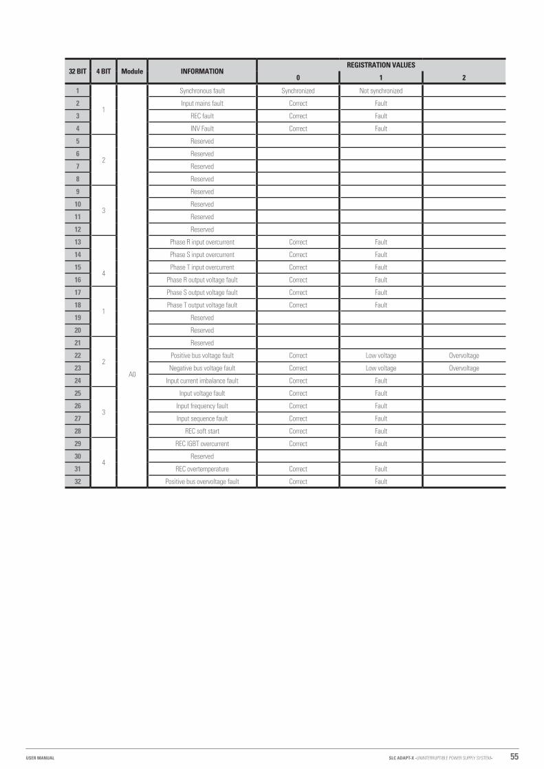
55
32 BIT 4 BIT Module INFORMATIONREGISTRATION VALUES
0 1 2
1
1
Synchronous fault Synchronized Not synchronized
2 Input mains fault Correct Fault
3 REC fault Correct Fault
4 INV Fault Correct Fault
5
2
Reserved
6 Reserved
7 Reserved
8 Reserved
9
3
Reserved
10 Reserved
11 Reserved
12 Reserved
13 Phase R input overcurrent Correct Fault
14 Phase S input overcurrent Correct Fault
154
A0
Phase T input overcurrent Correct Fault
16 Phase R output voltage fault Correct Fault
17
1
Phase S output voltage fault Correct Fault
18 Phase T output voltage fault Correct Fault
19 Reserved
20 Reserved
21
2
Reserved
22 Positive bus voltage fault Correct Low voltage Overvoltage
23 Negative bus voltage fault Correct Low voltage Overvoltage
24 Input current imbalance fault Correct Fault
25
3
Input voltage fault Correct Fault
26 Input frequency fault Correct Fault
27 Input sequence fault Correct Fault
28 REC soft start Correct Fault
29
4
REC IGBT overcurrent Correct Fault
30 Reserved
31 REC overtemperature Correct Fault
32 Positive bus overvoltage fault Correct Fault
SLC ADAPT-X -UNINTERRUPTIBLE POWER SUPPLY SYSTEM-USER MANUAL

56 SALICRU
32 BIT 4 BIT Module INFORMATIONREGISTRATION VALUES
0 1 2
1
1
A1
Negative bus overvoltage fault Correct Fault
2 Fan fault Correct Fault
3 Reserved
4 Reserved
5
2
Positive bus undervoltage fault Correct Fault
6 Negative bus undervoltage fault Correct Fault
7 Positive battery reserved Correct Fault
8 Negative battery reserved Correct Fault
9
3
Reserved
10 Reserved
11 Positive charger voltage fault Correct Undervoltage Overvoltage
12 Negative charger voltage fault Correct Undervoltage Overvoltage
13
4
Reserved
14 Reserved
15 Positive charger fault Correct Fault
16 Negative charger fault Correct Fault
17
1
Low voltage positive batteries Correct Fault
18 Low voltage negative batteries Correct Fault
19 Positive battery EOD Correct Fault
20 Negative battery EOD Correct Fault
21
2
Loss of neutral input Correct Fault
22 BYP sequence fault Correct Fault
23 BYP voltage fault Correct Fault
24 Reserved
253
Reserved
26 Reserved
27 BYP frequency out of range Correct Fault
28 Reserved
29
4
Reserved
30 Overload time exceeded Correct Fault
31 Reserved
32 Reserved

57
32 BIT 4 BIT Module INFORMATIONREGISTRATION VALUES
0 1 2
1
1
A2
Manual stop Normal Stop
2 INV protection Correct Fault
3 Transfer timeout, 1 hour Correct Fault
4 INV power feedback Correct Fault
5
2
Reserved
6 Reserved
7 Reserved
8 INV overtemperature fault Correct Fault
9
3
INV IGBT overcurrent Correct Fault
10 Reserved
11 Overload Normal Overload
12 Relay or INV fuse fault Correct Fault
13
4
Reserved
14 Reserved
15 Reserved
16 Reserved
17
1
Reserved
18 Output short circuit Correct Fault
19 Battery test None Correct Fault
20 Battery maintenance None Correct Fault
21
2
Reserved
22 Reserved
23 Reserved
24 Reserved
25
3
Reserved
26 Reserved
27 Reserved
28 Reserved
29
4
Reserved
30 Reserved
31 Reserved
32 Reserved
Tabla 20. Meaning between bits and state of the device.
SLC ADAPT-X -UNINTERRUPTIBLE POWER SUPPLY SYSTEM-USER MANUAL

58 SALICRU
7.3.4. Setting menu.
Tap on the menu screen to change any of the UPS configuration parameters.The available sub-menus are indicated in Tab. 21:The last four, Battery, Service, Rate and Configure are modifiable only by our T.S.S. or the distributor.
Fig. 59. Setting Menu.
Sub-menu Contents Meaning
DATE & TIMESetting the date format Three possible formats:
(a) year / month / day, (b) month / day / year, (c) day / month / year
Time setting Current date and time settings
LANGUAGECurrent language Language in use.
Language selection Selectable between Spanish, English and Portuguese.
COMM.(Communications)
Device Address Configuring the Communication Address
RS232 protocol selection SNT protocol, ModBus protocol, Dwin (for use in factory) or YD / T protocol.
Transmission speed Setting the Baud Rate of the SNT, ModBus and YD/T: 1,200, 2,400, 4,800, 9,600, 14,400, or 19,200
Modbus Mode Setting mode for Modbus: ASCII and selectable RTU
Modbus parity Parity setting for Modbus: None, Odd or Even
USER(Accessible through
Password 1203)
Output voltage settings Output voltage adjustment from 210 to 230 V
Bypass voltage upper margin, for Bypass available Upper adjustment, Bypass voltage range: +10, +15, +20 or +25% (default to +20%)
Bypass voltage lower range, for available Bypass Lower adjustment, Bypass voltage range: -10, -15, -20, -30 or -40% (default to -20%)
Bypass frequency limitTolerance Bypass frequency setting:
± 1, ± 3, ± 5 Hz or Inhibit - the system accepts any Bypass frequency (default to ± 3 Hz)
Period of maintenance of the dust filter Setting the dust filter maintenance period:From 30 to 3,000 days.
BATTERIES Battery settings. Contact our T.S.S. or the distributor
SERVICE Service settings. Contact our T.S.S. or the distributor
RATED Rated settings. Contact our T.S.S. or the distributor
CONFIGURATION Configuration settings. Contact our T.S.S. or the distributor
Tabla 21. Description of details of the Configure sub-menu.

59
Fig. 60. Setting Menu. Sub-menu language.
Fig. 61. Setting Menu. Communication sub-menu.
7.3.5. Setting menu.
Tap on the menu screen to obtain the UPS log history.Use icons or scroll through the events.Tab. 22 provides a complete list of all events that the UPS can display on the log history screen. When frequent repetitions of events are detected, it is recommended to contact our T.S.S. or the distributor.This menu is of great help to our T.S.S. when it comes to determining certain incidents and/or possible anomalies. The intervention actions involving some events are exclusively reserved for our T.S.S. or the distributor.
NO. UPS events
1 Clear fault
2 Clear log
3 Load on the UPS
4 Load on the Bypass
5 No load
6 Quick-load battery
7 Floating battery
8 Battery in discharge
9 Connected battery
10 Battery is not connected
11 Manual bypass switch "On"
12 Manual Bypass switch "Off"
13 EPO
14 Lack of modules
15 Generator input (it is necessary to configure a digital input to detect this signal)
16 Faulty input
17 Bypass sequence fault
18 Abnormal Bypass voltage
19 Bypass module fault
20 Bypass module overload
21 Time exceeded of the overload Bypass module
22 Bypass frequency out of range.
23 Bypass transfer number exceeded
24 Short circuit to the output
25 Low battery (EOD)
26 Battery test ON
27 Proper battery test
28 Battery maintenance
29 Proper bat maintenance
30 Inserted module
31 Removal of the power module
32 Rectifier fault
33 Inverter fault
34 Rectifier overtemperature
35 Fan fault
36 Output overload
37 Inverter overload time exceeded
38 Inverter overtemperature
39 Inhibited UPS
40 Manual transfer of static bypass
41 Quit manual transfer of static bypass
42 Battery voltage low
43 Incorrect battery polarity
44 Inverter protection
45 Input neutral fault
46 Bypass fan fault
47 Manual shutdown
48 Manual quick load
49 Manual floating load
50 UPS blocked
SLC ADAPT-X -UNINTERRUPTIBLE POWER SUPPLY SYSTEM-USER MANUAL

60 SALICRU
NO. UPS events
51 Parallel cable fault
52 Loss of N + X redundancy
53 End of discharge system inhibited
54 Battery test fault
55 Battery maintenance fault
56 Ambient overtemperature
57 Rectifier bus CAN fault
58 Inverter bus CAN fault
59 Inverter bus CAN data fault
60 Shared load fault
61 Synchronous pulse fault
62 Input voltage detector fault
63 Battery voltage detector fault
64 Output voltage fault
65 Bypass voltage detector fault
66 Inverter IGBT fault
67 Output air temperature fault of a module
68 Unbalanced input current
69 DC bus overvoltage
70 Rectifier soft start fault
71 Connection relay fault
72 Short-circuit relay
73 PWM synchronous fault
74 Module in smart standby
75 Manual transfer to inverter
76 Input overcurrent time exceeded
77 No input temperature sensor
78 No output temperature sensor
79 Overtemperature of the air inlet
80 Reset capacitor time
81 Reset fans’ time
82 Reset battery history
83 Reset time fans’ static bypass
84 Battery overtemperature
85 Life cycle of the static bypass fan worn
86 Life cycle of the capacitors of the modules worn
87 Life cycle of the fan of the power modules worn
88 Driver's Inverter IGBT blocked
89 Batteries dead
90 Bypass bus CAN fault
91 Life cycle of the particle filter exhausted
92 Battery test fault
93 Stopping of the battery test
94 Wave saved
95 Bypass bus CAN fault
96 Firmware fault
97 System configuration fault
98 Static bypass overtemperature
99 Duplicate modules ID
Tabla 22. List of events.
7.3.6. Operation menu.
Tap on the menu screen to access the different functions and commands.
Fig. 62. Setting Menu.
7.3.6.1. Function icons.
• Detail of the functionality of each icon:
� - Mute/un-mute.Direct access without password.
� Manual fault clearing or alarm.Access with PSW # 1 key.
� - Manual transfer to bypass or exit bypass mode.Access with PSW # 1 key.
� Manual transfer to inverter.The difference between touching this icon or leaving the bypass mode is that if for some reason the inverter cannot connect to the output automatically, this icon forces the transfer with an interruption of around 20 ms.Access with PSW # 1 key.
� Activates the “Off” push button on the front of the power module “ ”, to enable the individual stop-page of any of them.Direct access without password.
� Clears battery history data including discharge times and dates and number of discharges. It is usually recommended to reset the battery’s historical data after replacing them with new ones.Access with PSW # 1 key.
� Erases particle filter data including days and maintenance period. This is usually done after changing the filter or cleaning it.Direct access without password.
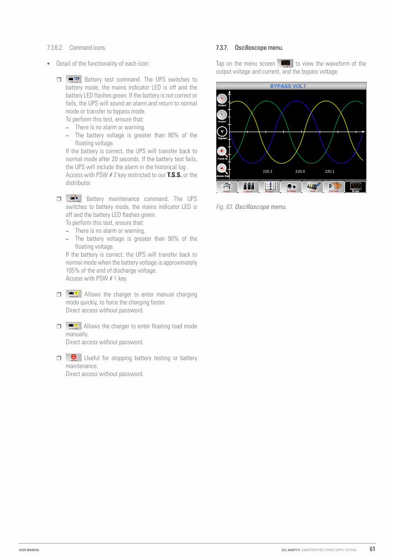
61
7.3.6.2. Command icons.
• Detail of the functionality of each icon:
� Battery test command. The UPS switches to battery mode, the mains indicator LED is off and the battery LED flashes green. If the battery is not correct or fails, the UPS will sound an alarm and return to normal mode or transfer to bypass mode.To perform this test, ensure that: – There is no alarm or warning. – The battery voltage is greater than 90% of the
floating voltage.If the battery is correct, the UPS will transfer back to normal mode after 20 seconds. If the battery test fails, the UPS will include the alarm in the historical log .Access with PSW # 2 key restricted to our T.S.S. or the distributor.
� Battery maintenance command. The UPS switches to battery mode, the mains indicator LED is off and the battery LED flashes green. To perform this test, ensure that: – There is no alarm or warning. – The battery voltage is greater than 90% of the
floating voltage.If the battery is correct, the UPS will transfer back to normal mode when the battery voltage is approximately 105% of the end of discharge voltage.Access with PSW # 1 key.
� Allows the charger to enter manual charging mode quickly, to force the charging faster.Direct access without password.
� Allows the charger to enter floating load mode manually.Direct access without password.
� Useful for stopping battery testing or battery maintenance.Direct access without password.
7.3.7. Oscilloscope menu.
Tap on the menu screen to view the waveform of the output voltage and current, and the bypass voltage.
220.2 220.0 220.1
Fig. 63. Oscilloscope menu.
SLC ADAPT-X -UNINTERRUPTIBLE POWER SUPPLY SYSTEM-USER MANUAL

62 SALICRU
8. OPTIONAL EXTRAS
8.1. INSTALL AN SNMP DRIVE.
All SLC ADAPT X units have a slot for the inclusion of the SNMP electronic unit. Depending on the sub-rack model, the slot is physically located on the front or on the back of the device. • In the sub-racks of 2 and 4 power slots, it is located behind
the cover giving access to the communication connections , located next to the monitoring panel with touch panel (see Fig. 64).
� To install the SNMP card:1. Remove the screws securing the access cover to
the communication connections.2. Remove the cover. The slot is visible.3. Remove the fixing screws of the slot cover and the
part as a cover.4. Install the SNMP card in the slot and fix it with the
screws.5. Make the relevant connections.6. Fit the protective cover of the communication con-
nections and the fixing screws of the communication.
Cover fixing screws
Cover for communication
connectionsSlot cover
Fixing screws of the slot cover
SNMP Slot behind the
cover
Fig. 64. Slot for SNMP in sub-rack of 2 and 4 slots for power modules.
• On the sub-racks of 6 power slots, it is located on the back of the device (see Fig. 65).
� To install the SNMP card:1. Remove the fixing screws of the slot cover and the
part as a cover.2. Install the SNMP card in the slot and fix it with the
screws.3. Make the relevant connections.
Slot cover
Fixing screws of the slot cover
Slot SNMP
Fig. 65. Slot for SNMP in 6-slot sub-rack for power modules.
8.2. ROOM TEMPERATURE SENSOR.
This is a sensor that incorporates a resistance of R = 5k with B25 / 50 = 3275 K ± 1% to display the ambient temperature on the screen.Fig. 66 shows the terminal pinout of the terminal block located on the connector block of the digital inputs and dry contacts for the temperature sensors.The room sensor connects to J3.
J2 J3
TEM
P_BA
T
TEM
P_EN
V
Fig. 66. Terminal block J2 and J3 for connection with sensors.

63
9. WARRANTY.
9.1. WARRANTY CONDITIONS.
9.1.1. Terms of the warranty.
On our website you will find the warranty conditions for the product you have purchased where you can also register it. It is recommended to do so as soon as possible to include it in the database of our Technical Service and Support (T.S.S.). Among other advantages, it will streamline any regulatory procedures for the intervention of T.S.S. in the event of a fault.
9.1.2. Exclusions.
Our company will not be bound by the warranty if it notices that the defect in the product does not exist or was caused by improper use, negligence, improper installation and/or verification, attempts at unauthorised repair or modification, or any other cause beyond the intended use, or by accident, fire, lightning or other hazards. Nor shall it cover any compensation for damages.
9.2. TECHNICAL SERVICES NETWORK.
Information about our national and international Technical Service and Support (T.S.S.) centres can be found on our website.
SLC ADAPT-X -UNINTERRUPTIBLE POWER SUPPLY SYSTEM-USER MANUAL

64 SALICRU
10. ANNEXES.
10.1. INTERNATIONAL STANDARDS.
Information Standards
General and safety requirements for UPS used in user access areas. EN50091-1-1/IEC62040-1-1/AS 62040-1-1
Electromagnetic compatibility (EMC) requirements for UPS EN50091-2/IEC62040-2/AS 62040-2 (C3)
Method of specifying the performance and test requirements of UPS EN50091-3/IEC62040-3/AS 62040-3 (VFI SS 111)
Note: The above product standards incorporate relevant compliance clauses with the generic IEC and EN standards for safety (IEC / EN / AS60950), electromagnetic emissions and immunity (IEC / EN / AS61000 series) and construction (IEC / EN / AS60146 series and 60950).
Tabla 23. Standards applied.
10.2. ENVIRONMENTAL CHARACTERISTICS.
Information Units 10 kVA and 15 kVA 25 kVA
Acoustic noise at 1 metre distance dB 56.0 65,0
Operating altitude m 2400 ≤1000, load derated 1% per 100 m from 1000 and 2000
Relative humidity % 0.. 95%, non-condensing
Operating temperature ºC 0.. 40 (battery life is reduced by 50% for every 10ºC increase over 20ºC)
Storage and transport temperature ºC -20.. +70 (UPS)
Recommended battery storage temperature ºC 0.. 25 (20ºC for optimum storage)
Tabla 24. Environmental characteristics.
10.3. MECHANICAL CHARACTERISTICS.
Cabinet specifications Units 25 U 36 U 46 U SAI Bat.
Dimensions (Depth × Width × Height) mm 881 × 639 × 1103 881 x 639 x 1613 881 x 639 x 2013 Yes Yes
881 x 822 x 2013 No Yes
Colour - RAL 9005
Degree of protection, IEC60529 - IP20
Sub-rack specifications Units 20/10 and 30/15 40/10 and 45/15 60/10 and 90/15 200/25
Dimensions (Depth × Width × Height) mm 745 × 490 × 400 745 × 490 × 580 800 × 490 × 1035 916 × 490 × 1550
Weight Kg. 30.5 41 70 160
Colour - RAL 9005
Degree of protection, IEC60529 - IP20
Power module specifications (PM) Units 10 kVA 15 kVA 25 kVA
Dimensions (Depth × Width × Height) mm 645 × 485 × 85
Weight Kg. 15.3 15.5 18
Colour - RAL 9005
Bypass and monitoring module specifications (MBS) Units 2-slot and 4-slot sub-racks 6-slot sub-rack 8-slot sub-rack
Dimensions (Depth × Width × Height) mm 395 × 485 × 130 380 × 485 × 380 395 × 485 × 520
Weight Kg. 4.5 13.5 18
Colour - RAL 9005
Tabla 25. Mechanical characteristics.

65
10.4. ELECTRICAL CHARACTERISTICS.
10.4.1. Electrical characteristics (rectifier input).
Information Units Parameters
Input ratings V AC 380/400/415 (3-phase, sharing the neutral with the bypass input)
Input voltage range % -40.. +25
Nominal frequency Hz 50/60 (margin: 40.. 70)
Input power factor KW / KVA, full load 0.99
THD THDI % 4
Tabla 26. Rectifier input characteristics.
10.4.2. Electrical characteristics (DC Bus or DC).
Information Units Parameters
Battery bus nominal voltage V DC
Not indicated by user, factory set to ± 192 V (for 32 batteries).± 216 V (for 36 batteries)± 240 V (for 40 batteries)± 264 V (for 44 batteries), margin of each branch: -17.5.. +20%
Number of elements 32.. 44 (for 12V batteries), 192 .. 264 (for 2 V batteries). Even numbers of batteries with centre point connected to Neutral.
Float voltage V / cell (VRL) 2.25 V / cell (selectable from 2.2 to 2.35 V/cell)Mode of charging to current and constant voltage
Voltage compensation according to temperature mV / Cº / cl -3.0 (Selectable: 0.. 5.0 / 25 or 30°C, or inhibited)
Voltage ripple % V floating ≤1
Power ripple % C10 ≤5
Quick load voltage (equalization) V/cell(VRLA)
2.4 V / cell (selectable from 2.30 to 2.45 V / cell)Mode of charging to current and constant voltage
End of discharge voltage V/cell(VRLA)
1.65 V/cell (selectable from 1.60 to 1.750 V/cell) @ 0.6C discharge current 1.75 V/cell (selectable from 1.65 V to 1.8 V/cell) @ 0.15C discharge current(The end of discharge voltage changes linearly within the range set according to the discharge current)
Battery charging power KW 10% * UPS capacity (selectable from 1 to 20% * UPS capacity)
Tabla 27. Characteristics of parameters related to batteries.
10.4.3. Electrical characteristics (Inverter output).
Information Units Parameters
Rated voltage (1) V AC 380/400/415 (3-phase and sharing the neutral with the bypass input and with the rectifier input).
Frequency (2.) Hz 50/60
Overload %
110 (for 1 h)125 (for 10 min.)150 (for 1 min.)> 150 (for 200 ms)
Overcurrent % 300 (overcurrent limitation for 200 ms)
Non-linear load capacity (3.) % 100
Neutral current capacity % 170
Static voltage stability % ± 1 (balanced load)± 1.5 (100% unbalanced load)
Dynamic voltage response (4.) % ± 5
THD % <1 (linear load)
Sync Window - Rated frequency ± 2 Hz (selectable from ±1 to ±5 Hz)
SLC ADAPT-X -UNINTERRUPTIBLE POWER SUPPLY SYSTEM-USER MANUAL
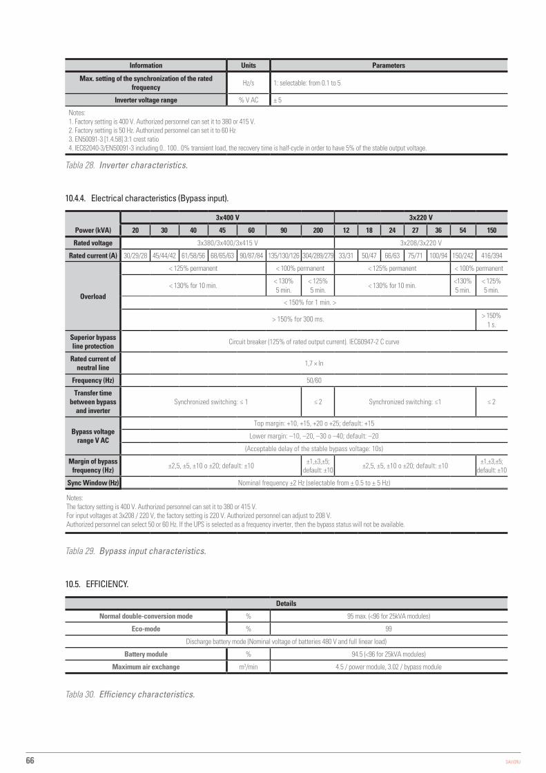
66 SALICRU
Information Units Parameters
Max. setting of the synchronization of the rated frequency Hz/s 1: selectable: from 0.1 to 5
Inverter voltage range % V AC ± 5
Notes:1. Factory setting is 400 V. Authorized personnel can set it to 380 or 415 V.2. Factory setting is 50 Hz. Authorized personnel can set it to 60 Hz3. EN50091-3 [1.4.58] 3:1 crest ratio4. IEC62040-3/EN50091-3 including 0.. 100.. 0% transient load, the recovery time is half-cycle in order to have 5% of the stable output voltage.
Tabla 28. Inverter characteristics.
10.4.4. Electrical characteristics (Bypass input).
Power (kVA)
3x400 V 3x220 V
20 30 40 45 60 90 200 12 18 24 27 36 54 150
Rated voltage 3x380/3x400/3x415 V 3x208/3x220 V
Rated current (A) 30/29/28 45/44/42 61/58/56 68/65/63 90/87/84 135/130/126 304/289/279 33/31 50/47 66/63 75/71 100/94 150/242 416/394
Overload
< 125% permanent < 100% permanent < 125% permanent < 100% permanent
< 130% for 10 min.< 130% 5 min.
< 125% 5 min.
< 130% for 10 min.<130% 5 min.
< 125% 5 min.
< 150% for 1 min. >
> 150% for 300 ms. > 150% 1 s.
Superior bypass line protection Circuit breaker (125% of rated output current). IEC60947-2 C curve
Rated current of neutral line 1,7 × In
Frequency (Hz) 50/60
Transfer time between bypass
and inverter Synchronized switching: ≤ 1 ≤ 2 Synchronized switching: ≤1 ≤ 2
Bypass voltage range V AC
Top margin: +10, +15, +20 o +25; default: +15
Lower margin: –10, –20, –30 o –40; default: –20
(Acceptable delay of the stable bypass voltage: 10s)
Margin of bypass frequency (Hz) ±2,5, ±5, ±10 o ±20; default: ±10 ±1,±3,±5;
default: ±10 ±2,5, ±5, ±10 o ±20; default: ±10 ±1,±3,±5; default: ±10
Sync Window (Hz) Nominal frequency ±2 Hz (selectable from ± 0.5 to ± 5 Hz)
Notes:The factory setting is 400 V. Authorized personnel can set it to 380 or 415 V.For input voltages at 3x208 / 220 V, the factory setting is 220 V. Authorized personnel can adjust to 208 V.Authorized personnel can select 50 or 60 Hz. If the UPS is selected as a frequency inverter, then the bypass status will not be available.
Tabla 29. Bypass input characteristics.
10.5. EFFICIENCY.
Details
Normal double-conversion mode % 95 max. (<96 for 25kVA modules)
Eco-mode % 99
Discharge battery mode (Nominal voltage of batteries 480 V and full linear load)
Battery module % 94.5 (<96 for 25kVA modules)
Maximum air exchange m3/min 4.5 / power module, 3.02 / bypass module
Tabla 30. Efficiency characteristics.

67SLC ADAPT-X -UNINTERRUPTIBLE POWER SUPPLY SYSTEM-USER MANUAL

68 SALICRU
: .............................................................................................................................................................................................................
.........................................................................................................................................................................................................................
.........................................................................................................................................................................................................................
.........................................................................................................................................................................................................................
.........................................................................................................................................................................................................................
.........................................................................................................................................................................................................................
.........................................................................................................................................................................................................................
.........................................................................................................................................................................................................................
.........................................................................................................................................................................................................................
.........................................................................................................................................................................................................................
.........................................................................................................................................................................................................................
.........................................................................................................................................................................................................................
.........................................................................................................................................................................................................................
.........................................................................................................................................................................................................................
.........................................................................................................................................................................................................................
.........................................................................................................................................................................................................................
.........................................................................................................................................................................................................................
.........................................................................................................................................................................................................................
.........................................................................................................................................................................................................................
.........................................................................................................................................................................................................................
.........................................................................................................................................................................................................................
.........................................................................................................................................................................................................................
.........................................................................................................................................................................................................................
.........................................................................................................................................................................................................................
.........................................................................................................................................................................................................................
.........................................................................................................................................................................................................................
.........................................................................................................................................................................................................................
.........................................................................................................................................................................................................................
.........................................................................................................................................................................................................................
.........................................................................................................................................................................................................................

69
: .............................................................................................................................................................................................................
.........................................................................................................................................................................................................................
.........................................................................................................................................................................................................................
.........................................................................................................................................................................................................................
.........................................................................................................................................................................................................................
.........................................................................................................................................................................................................................
.........................................................................................................................................................................................................................
.........................................................................................................................................................................................................................
.........................................................................................................................................................................................................................
.........................................................................................................................................................................................................................
.........................................................................................................................................................................................................................
.........................................................................................................................................................................................................................
.........................................................................................................................................................................................................................
.........................................................................................................................................................................................................................
.........................................................................................................................................................................................................................
.........................................................................................................................................................................................................................
.........................................................................................................................................................................................................................
.........................................................................................................................................................................................................................
.........................................................................................................................................................................................................................
.........................................................................................................................................................................................................................
.........................................................................................................................................................................................................................
.........................................................................................................................................................................................................................
.........................................................................................................................................................................................................................
.........................................................................................................................................................................................................................
.........................................................................................................................................................................................................................
.........................................................................................................................................................................................................................
.........................................................................................................................................................................................................................
.........................................................................................................................................................................................................................
.........................................................................................................................................................................................................................
.........................................................................................................................................................................................................................
SLC ADAPT-X -UNINTERRUPTIBLE POWER SUPPLY SYSTEM-USER MANUAL

Avda. de la Serra 100
08460 Palautordera
BARCELONA
Tel. +34 93 848 24 00
Fax +34 93 848 22 05
SALICRU.COM
www.linkedin.com/company/salicru
@salicru_SA
Product Range
Uninterruptible Power Supplies (UPS)
Lighting Flow Dimmer-Stabilisers
DC Power Systems
Static Inverters
Photovoltaic Inverters
Voltage stabilisers
The Technical Service and Support (T.S.S.) network, com-
mercial network and warranty information are available in
website:
www.salicru.com
REF. EL054J01 REV. J CODE 401*