side-channel attacks and mitigations on mesh interconnects
TRANSCRIPT
Don’t Mesh Around: Side-Channel Attacksand Mitigations on Mesh Interconnects
Miles Dai∗
MITRiccardo Paccagnella∗
UIUCMiguel Gomez-Garcia
MIT
John McCalpinTACC
Mengjia YanMIT
AbstractThis paper studies microarchitectural side-channel attacks
and mitigations on the on-chip mesh interconnect used inmodern, server-class Intel processors. We find that, thoughdifficult to exploit, the mesh interconnect can be abused byan adversary even when known attack vectors inside the coresand caches are closed. We then present novel, non-invasivemitigation mechanisms to interconnect side-channel attacksand offer insights to guide the design of future defenses.
Our analysis starts by thoroughly reverse engineering themesh interconnect to reveal, for the first time, the preciseconditions under which it is susceptible to contention. Weshow that an attacker can use these conditions to build a cross-core covert channel with a capacity of over 1.5 Mbps. Wethen demonstrate the feasibility of side-channel attacks thatleak keys from vulnerable cryptographic implementations bymonitoring mesh interconnect contention. Finally, we presentan analytical model to quantify the vulnerability levels ofdifferent victim and attacker placements on the chip and usethe results to design a software-only mitigation mechanism.
1 Introduction
Microarchitectural attacks have become an increasingly seri-ous threat to system security. In a microarchitectural attack,an attacker infers secrets about a victim program by mon-itoring the side effects of the victim’s execution on sharedhardware resources. These types of attacks can be used to leakcryptographic keys [6,30,61,73,75,101,103], browsing activ-ity [72,83,84], user keystrokes [37,38,56,57,77,78], and othersecret information [35,41,43,98]. Moreover, these attacks canemploy speculative execution to completely bypass memoryisolation and leak arbitrary data [13, 54, 59, 81, 86, 87].
In the past two decades, several hardware resources havebeen exploited to mount microarchitectural attacks, includingcaches [61, 73, 75, 101], branch predictors [2, 22, 23], and exe-cution ports [5, 10, 33]. Fortunately, we have also seen more
∗These authors contributed equally to this work.
practical mitigation mechanisms. For example, to block at-tacks targeting SMT contexts, operating systems can disallowprograms from different security domains from being sched-uled onto the same CPU cores. Multiple effective mitigationsto block cache side-channel attacks have also been proposedvia spatially partitioning shared caches or flushing cache con-tent upon context switches [12, 28, 32, 53, 60, 100, 107].
In this paper, we study an on-chip microarchitectural attacksurface that remains open even if all attack vectors in thecores and caches are closed: the on-chip interconnect. De-spite active research on microarchitectural security, very fewworks [20, 74, 82, 90, 92] have explored attacks and defenseson the on-chip interconnect. Such an interconnect extendsacross the whole chip and is used to connect all on-chip re-sources, including shared caches, DRAM controllers, and I/Oports. Specifically, the majority of accesses to the last-levelcaches and all accesses to DRAM need to travel through cer-tain segments of the on-chip interconnect. Given their highaccessibility, on-chip interconnects are likely to become in-creasingly relevant for microarchitectural security, especiallyas attack vectors inside the cores and caches are closed.
1.1 Challenges of Exploiting Mesh Interconnects
In particular, we explore microarchitectural attacks and miti-gations on the mesh interconnect used in Intel server proces-sors since 2016 [96]. On these processors, on-chip resources,including cores, private caches, and LLC slices, are organizedinto tiles and placed on the die using a 2-dimensional gridlayout, shown in Figure 1. The mesh interconnect provides abidirectional link between each pair of neighboring tiles.
There exist two key challenges to building microarchitec-tural attacks on the mesh interconnect. First, it is difficult tocontend spatially on a mesh topology. For contention to occur,the attacker’s and the victim’s traffic flows must overlap on theinterconnect. Server processors with a mesh interconnect con-tain many cores, providing numerous placement options forthe victim and the attacker. Moreover, the mesh interconnectis designed to distribute traffic to avoid congestion. Consider-
1
ing the numerous placement options and sparsely-distributedtraffic flows, blindly trying to detect interconnect contentionis ineffective. An effective attacker must carefully considerthe scheduling policies used by the mesh interconnect.
Second, it is difficult to create temporal contention. Tem-poral contention happens when the attacker’s and the victim’straffic use a segment of the interconnect simultaneously. Amemory access that misses in the L2 cache and hits in the LLCslice of a neighboring tile may spend 50 cycles in the cachebut only 2 to 3 cycles on the interconnect. The probabilityfor two such memory accesses to contend on the interconnectis low. Moreover, the extra latency caused by interconnectcontention is small and thus is very sensitive to noise.
Taken together, these challenges require the attacker to havea thorough understanding of the mesh interconnect protocols.In fact, we show that uncovering details about the interconnectis not only essential for attacks, but also useful for mitigations.
1.2 This Paper
In this paper, we answer the following two questions. First,is it really feasible to construct side-channel attacks by onlyexploiting contention on a mesh interconnect? Second, arethere non-invasive approaches that can mitigate interconnectside channels without requiring hardware modifications?
We start by reverse engineering previously unknown detailsabout Intel’s mesh interconnect. First, we reverse engineer thelane scheduling policy on the interconnect. We find that eachsegment in the mesh interconnect consists of multiple lanes,and the lane scheduling policy decides which lane a trafficflow will use based on the flow’s source and/or destinationtile. Interestingly, the policies for vertical rings and horizontalrings are completely different. Second, we reverse engineerthe priority arbitration policy used at each tile. We find thatthe priority of a traffic flow is determined by its source tile.The priority information is important since traffic flows witha high priority cannot be delayed by ones with a low priorityand thus cannot be used to observe interconnect contention.
We use the reverse-engineering results to build covert andside-channel attacks that exploit mesh interconnect contention.Our attacks work even if the processor has deployed miti-gations against a wide range of microarchitectural attacks,including attacks targeting SMT resources, private and sharedcaches, and DRAM. Our covert channel can achieve a capac-ity of 1.53 Mbps. Our side-channel attack can extract keysfrom vulnerable ECDSA and RSA implementations.
Finally, we offer insights into mitigating interconnect side-channel attacks. Specifically, we find that the victim and at-tacker placements significantly affect attack efficacy. Impor-tantly, not all the cores are equally vulnerable. We then designan analytical model to quantify vulnerability levels and vali-date this model using our side channel. We use the findingsof our model to guide the design of a non-invasive software-based mitigation to interconnect side-channel attacks.
Disclosure We disclosed our findings to Intel in Q2’21. Intelclassified our attack as a “traditional side-channel attack”, andreferred to their guidance on software-based mitigations [46].
2 Background
2.1 Cache Architecture
The cache is used to store data and instructions for fast access.On modern processors, the cache is typically set-associative.A cache line can reside in any way of a cache set, and thecache set that a line maps to is determined by its address bits.
Modern Intel processors have two levels of private caches(L1 and L2), and a shared L3 cache, also called last-levelcache or LLC. The L1 cache is small (e.g., 32-64 KB) andfast, typically responding within 5 cycles. The L2 cache isslightly bigger (e.g., 256 KB-1 MB) and has a latency of 10-20 cycles. Finally, the shared LLC is large (e.g., several totens of MBs) and has a latency of 40-60 cycles. The LLClatency is still much lower than the main memory (DRAM)access latency, which is on the order of 200-300 cycles.
When a memory access is issued by the core, the L1 cacheis checked to find out if the data is present in the cache. If itis a hit, the data is sent to the core. If it is a miss, the requestis sent to the L2 cache. Similarly, if the request misses in L2,it is further sent to the LLC and then to main memory.
LLC Slice Organization The LLC of modern Intel proces-sors is organized into multiple slices (partitions). In client-class processors, the number of slices is the same as the num-ber of cores. In server-class processors, the number of slicesis sometimes greater than the number of cores (as we see inSection 3). Such an organization is helpful to keep the de-sign modular and scalable. Intel processors map each memoryaddress to a particular slice ID using a proprietary mappingfunction that is designed to keep the distribution of cache linesamong slices as uniform as possible [43,44,48,50,64,67,102].
Cache Inclusiveness The LLC can be inclusive, exclusive,or non-inclusive. In an inclusive LLC, cache lines in the L2caches are also present in the LLC. In an exclusive LLC, acache line is never present in both the L2 caches and the LLC.In a non-inclusive LLC, a cache line in the L2 caches may ormay not be present in the LLC.
2.2 On-chip Interconnect
On multi-core processors, an on-chip interconnect connectsphysical cores, shared caches, and memory controllers. Sincethe late 2000s, Intel has used a ring interconnect architecture,known as a ring bus. However, rising core counts on Intel’shigh-end processors revealed scalability issues which led In-tel to develop the mesh interconnect. This interconnect firstappeared in the Knights Landing microarchitecture in 2016and has since been used by all Intel processors in the XeonScalable server series and the high-end Core X-series [96].
2
IMCTile
IMCTile
CoreTile
CPU CoreL1/L2 caches
LLC slicedirectory slice
CHA
Ring Stop(Router)
(a) Mesh Layout (b) Core Tile
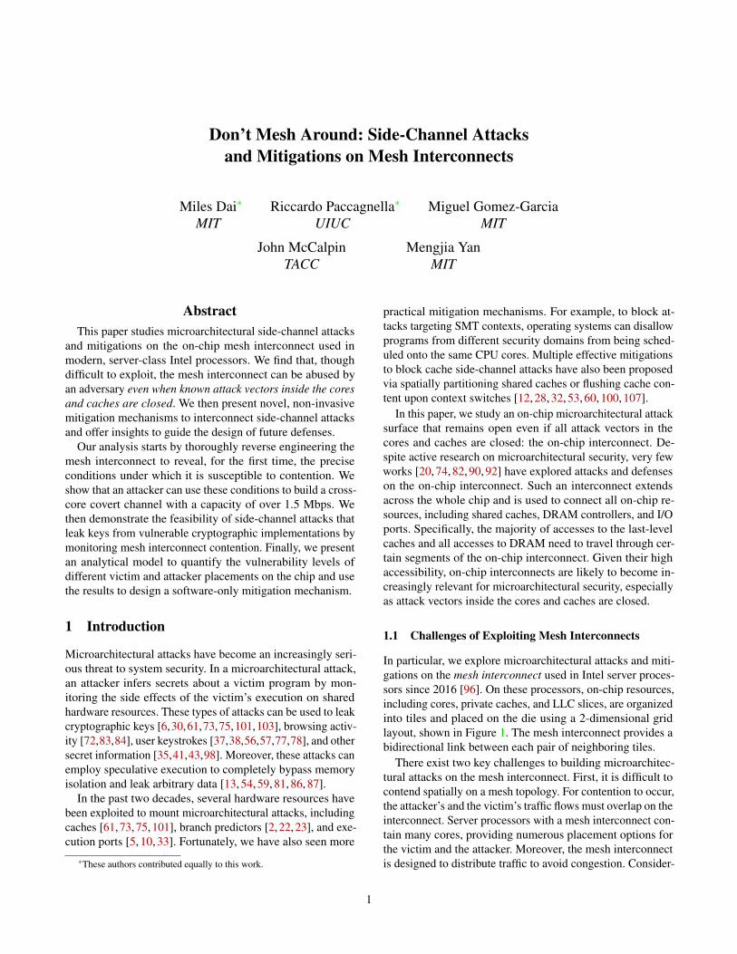
Figure 1: Intel mesh interconnect architecture.
Mesh Topology The interconnect topology determines thephysical layout and connections between hardware modules.We call each hardware module a tile. Intel’s mesh intercon-nect topology, shown in Figure 1(a), organizes tiles into a2-dimensional array and forms a grid. Each tile is directlyconnected to its immediate neighbors [47, 96].
Tile Types Relevant to this paper are two types of tiles:Core tiles and IMC tiles [96]. As shown in Figure 1(b), a Coretile incorporates a CPU core (including L1 and L2), an LLCslice, and a ring stop. The LLC slice includes the data, direc-tory (snoop filter), and a control unit called the Caching/HomeAgent (CHA), used to maintain cache coherency between tiles.The ring stop is responsible for injecting, forwarding, and re-ceiving traffic to/from the interconnect. It is also referred to asa node router or ring station [74]. An IMC tile includes a ringstop and an integrated memory controller that is connected tooff-chip DRAM modules. Cascade Lake processors have twoIMC tiles placed symmetrically on the border of the grid.
2.3 Microarchitectural Side Channels
A microarchitectural side channel involves a transmitter in thevictim’s security domain and a receiver in the attacker’s se-curity domain stealthily communicating with each other. Themedium of the communication channel is some microarchitec-tural structures whose states and occupancy can be modifiedby the transmitter and the receiver’s activities. Similar to priorwork [33, 74], we classify microarchitectural side channelsinto two groups based on the type of resource they exploit:eviction-based attacks and contention-based attacks.
Eviction-based attacks (also called “stateful”) focus onmicroarchitectural resources that hold shared states, such ascaches [1,3,6,17,19,30,37–40,49,52,58,61,65,69,72,73,75,80,83,84,101,105,106], TLBs [34], DRAM row buffers [77],and Branch Target Buffers (BTB) [2, 22, 23]. An eviction-based attack generally involves three steps. First, the receiverexecutes and brings a shared microarchitectural structure intoa known state. Second, the transmitter is triggered to modifythe shared state based on some secret value. Third, the receiverprobes the structure to learn the modified state and infer the
secret. The classical cache attacks such as Flush+Reload [101]and Prime+Probe [73, 75] follow the three steps above.
Contention-based attacks (also called “stateless”) exploitthe finite bandwidth capacity of a resource that is sharedby multiple programs. Such resources include functionalunits [4,93], cache banks [103], execution ports [5,10,33], thememory bus [97], random number generators [21], the on-chipinterconnect [74], and the off-chip interconnect [51]. Whenmultiple parties concurrently use such a resource, delays oc-cur which might result in information leaks. In a contention-based attack, information leakage happens only during thetime when the victim is utilizing the shared resource, in con-trast to an eviction-based attack, where the attacker and thevictim do not need to simultaneously use the shared resource.
3 Target Architecture and Tile Layout
In this section, we describe some basic architectural param-eters of the Intel Xeon Scalable Family Processors on thePurley platform launched in 2017, which implement the meshinterconnect. These parameters include the cache configura-tions, the tile layout, and the tile mapping which are necessaryto reverse engineer the mesh interconnect in Section 6 andcarry out the attacks in Sections 7 and 8. Throughout thepaper, we run our experiments on a 24-core Intel Xeon Gold5220R (Cascade Lake) processor running Ubuntu 18.04.
Cache Configurations Our processor features three levelsof caches. The L1 is 32 KB with 64 sets and 8 ways. The L2is 1 MB with 1024 sets and 16 ways. Each LLC slice is 1.375MB with 2048 sets and 11 ways. Importantly, the shared LLCis non-inclusive. To generate interconnect traffic between twogiven tiles, we need to generate cache accesses that miss inthe private caches and hit in a specific LLC slice. We describehow to do this with a non-inclusive LLC in Section 5.1.
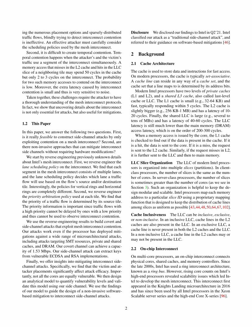
Tile Layout Intel Cascade Lake processors come with threedifferent die configurations, namely, LCC (low core count),HCC (high core count), and XCC (extreme core count). Wefocus our analysis on the XCC configuration, which consistsof 30 tiles, organized into a 5×6 grid, shown in Figure 2.
Prior work [42, 55, 68] provides multiple approaches to re-verse engineer the tile layout. We used an approach similar tothe one from McCalpin [68], that we describe in Appendix B.
Figure 2 shows the results of our reverse engineering. Welabel each tile using a 2D coordinate (x,y), where x indicatesthe row number and y indicates the column number. For ex-ample, tile (0,0) is at the top left corner of the chip.
In this processor, there are two IMC tiles, located symmet-rically at (1,0) and (1,5). The remaining 28 tiles are all Coretiles. Two Core tiles, (3,3) and (4,2), are completely disabled(black), and another two tiles, (4,0) and (4,5), are partiallydisabled (yellow). In a partially disabled Core tile, the LLCslice, directory slice, and CHA are enabled while the core and
3
(0, 0)
cpu 0 slice 0
(0, 1)
cpu 1 slice 4
(0, 2)
cpu 15 slice 9
(0, 3)
cpu 16 slice 13
(0, 4)
cpu 17slice 17
(0, 5)
cpu 12 slice 22
(1, 0)
IMC 0
(1, 1)
cpu 14slice 5
(1, 2)
cpu 9 slice 10
(1, 3)
cpu 10 slice 14
(1, 4)
cpu 11 slice 18
(1, 5)
IMC 1
(2, 0)
cpu 13 slice 1
(2, 1)
cpu 8 slice 6
(2, 2)
cpu 20 slice 11
(2, 3)
cpu 21 slice 15
(2, 4)
cpu 22slice 19
(2, 5)
cpu 23 slice 23
(3, 0)
cpu 7 slice 2
(3, 1)
cpu 19slice 7
(3, 2)
cpu 3 slice 12
(3, 3)
X
(3, 4)
cpu 5 slice 20
(3, 5)
cpu 6 slice 24
(4, 0)
slice 3
(4, 1)
cpu 2 slice 8
(4, 2)
X
(4, 3)
cpu 4 slice 16
(4, 4)
cpu 18slice 21
(4, 5)
slice 25
Figure 2: An example tile layout of an Intel Cascade Lakeprocessor with 24 active cores and 26 active LLC slices.
private caches are disabled. As a result, our processor has 24active cores and 26 active LLC slices.
The position of the disabled tiles may vary between chips ofthe same model [68]. For example, we found that on anotherchip with the same processor model, the completely disabledtiles are located at (3,1) and (4,5) and the partially disabledones at (4,0) and (3,5). We describe how this variability canbe accounted for by an attacker in Appendix B.
Tile Mapping To reverse engineer the mesh interconnectprotocols, we also need to know 1) which tile a given CPUID maps to, and 2) which tile a given LLC slice ID maps to.The CPU ID is used by the operating system (OS). Since our24-core processor has hyper-threading (SMT) enabled, theOS sees 48 logical CPUs. CPU c and CPU c+24 always mapto the same tile. The LLC slice ID is kept internally by thehardware and is referred to as the CHA ID by Intel.
Our approach to inferring the tile mapping information issimilar to the one from McCalpin [68] and is described inAppendix B. Figure 2 shows the two mapping relationshipswe found using such an approach on our processor. For clarity,we use the 2D coordinates to refer to tiles, CPU IDs, andLLC slices in the remainder of this paper. The reader can useFigure 2 to figure out CPU and slice IDs if needed.
To generate and monitor traffic between two tiles (x0,y0)and (x1,y1), we pin a process to Core (x0,y0) and make it per-form cache accesses to LLC slice (x1,y1). For conciseness, weuse the following format to describe the above configuration:
Core(x0,y0)↔ Slice(x1,y1)
The bidirectional arrow represents the multiple traffic flowsin both directions, which we explain in Section 6.
4 Threat Model
Like prior work, we assume that the victim and the attackerare co-located on the same machine and run on the same
processor. They belong to different security domains, do notshare memory [89, 108], and can run on different processesor virtual machines. We assume a restrictive scenario wherethe system has adopted effective defense mechanisms againstknown on-chip side-channel attacks. For example, the systemmay disallow software from different security domains fromconcurrently running on the same core [7, 16, 63] and adoptLLC partitioning to prevent cross-core cache attacks [12, 60,85].1 Assuming the presence of such mechanisms allows usto study the microarchitectural attack surface beyond knownon-chip side-channel attacks. Indeed, the goal is to highlightthat even if known on-chip side channels are mitigated, weare still vulnerable to interconnect side-channel attacks.
In the cross-process setup, we consider an attacker who isable to choose its placement (which core to execute on) usingthe set-affinity command. When targeting cryptographicimplementations, we also make the standard assumption thatthe attacker knows the code of the victim as most crypto-graphic libraries are open source. Finally, we assume thatthe attacker can observe multiple victim executions to leakmultiple bits of the key and increase the efficacy of the attack.
5 Designing Receivers and Transmitters
In this section, we describe the design of the receiver and thetransmitter that we use to reverse engineer the mesh intercon-nect (Section 6) and mount our attacks (Sections 7 and 8).
5.1 Designing the Receiver
The goal of the receiver is to detect contention on the meshinterconnect. Since interconnect contention can be small (afew cycles per load), it is important for the receiver to makeaccurate and reliable measurements.
Baseline Receiver The receiver monitors the interconnectby pinning itself to a given core and accessing addresses thatmap to a given LLC slice. These accesses will travel throughthe mesh interconnect and may be delayed by interconnectcontention from other applications. The receiver can then timethese accesses to determine whether contention happened.
To generate reliable accesses to a given LLC slice, the re-ceiver’s accesses need to miss in the L2 and hit in the LLCwhile avoiding L2 hits and DRAM accesses. To this end,we use two sets of addresses called a monitoring set andan eviction set (EV). The monitoring set monitors traffic be-tween a remote LLC slice and the receiver’s core, and theEV evicts the monitoring set from the L2 cache to the LLC.The addresses in the monitoring set are mapped to the targetLLC slice and to one or more L2 sets. The addresses in theEV are mapped to the receiver’s local LLC slice (to avoid
1This is partially possible on today’s processors using Intel CAT, whichallows the creation of way-based partitions [70]. Additionally, mechanismsthat partition cache directories (to block [99]) have been proposed in theliterature [11, 15, 100] and may be deployed in future hardware.
4
generating unnecessary interconnect traffic) and to the sameL2 set(s) as the monitoring-set addresses. We can obtain ad-dresses that map to the desired L2 set and LLC slice usingprior approaches [74, 102], discussed in Appendix A.
The receiver works in three steps:
1. Preparation: The receiver accesses the addresses in themonitoring set, bringing them into the L2 cache of thereceiver’s core. Since the LLC is non-inclusive, theseaddresses may not be present in the LLC.
2. Eviction: The receiver accesses the addresses in the EVmultiple times to evict the addresses in the monitoring setfrom the L2 cache of the receiver’s core. Any addressesin the monitoring set that were not in the LLC will bewritten back to the corresponding LLC slice [99].
3. Measurement: The receiver accesses the addresses inthe monitoring set and times the latency of each accessusing rdtsc. This latency includes the time for the ac-cesses to travel through the interconnect. Note that thisstep collects multiple latency samples. The number ofsamples is determined by the size of the monitoring set.
The last two steps (Eviction and Measurement) can be re-peated to collect more latency samples.
Tuning the Receiver We tune the following knobs to findthe receiver configuration that gives the most reliable mea-surements: 1) monitoring set size, 2) EV size, and 3) numberof times we access the EV during the Eviction step.
The monitoring set contains addresses that map to multipleL2 sets and multiple addresses mapped to each L2 set. We de-note the number of L2 sets as NL2 and the number of addressesmapped to each L2 set as WL2. The size of the monitoring setis NL2×WL2. Using a larger monitoring set allows for moreconsecutive latency samples in the Measurement step (step 3above), leading to a larger consecutive monitoring window.However, constructing a larger monitoring set takes longerand also requires constructing NL2 eviction sets.
We adjust NL2 and WL2 to tailor the transmitter and receiverto different tasks. In the reverse engineering of Section 6, weset NL2 = 1 to reduce the time spent creating the monitoringset. We set WL2 = 16. Recall that each LLC slice has 11 waysbut has twice as many sets as the L2 cache. Thus, 22 addressesper L2 set could ideally fit in an LLC slice. In practice, wefound that 16 addresses per L2 set works more reliably. Whenmeasuring the receiver’s temporal resolution (Section 7) andexecuting side-channel attacks (Section 8), we set NL2 = 32 tohave a large consecutive monitoring window. For the covert-channel (Section 7), we also design a version of the receiverthat has an infinite monitoring window and does not requireeviction-set accesses, at the cost of a lower sampling density.
Finally, we consider the EV size and the number of times toaccess the EV. The goal of the EV is to evict all the monitoringset addresses from the L2 cache to the LLC. Through experi-mentation, we found that accessing an EV with 16 addressesper L2 set 4 times can achieve 100% eviction rate.
0 5 10 15 20 25Addresses per L2 Set per EV
0
1
2
3
Late
ncy
Incr
ease
(cyc
les)
1 L2 set2 L2 sets, same parity2 L2 sets, diff parity
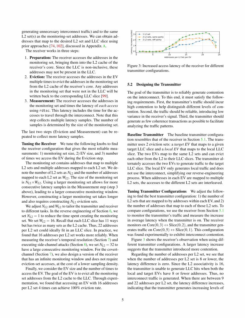
Figure 3: Increased access latency of the receiver for differenttransmitter configurations.
5.2 Designing the Transmitter
The goal of the transmitter is to reliably generate contentionon the interconnect. To this end, it must satisfy the follow-ing requirements. First, the transmitter’s traffic should incurhigh contention to help distinguish different levels of con-tention. Second, the traffic should be reliable, introducing lowvariance in the receiver’s signal. Third, the transmitter shouldgenerate as few coherence transactions as possible to facilitateanalyzing the traffic patterns.
Baseline Transmitter The baseline transmitter configura-tion resembles that of the receiver in Section 5.1. The trans-mitter uses 2 eviction sets: a target EV that maps to a giventarget LLC slice and a local EV that maps to the local LLCslice. The two EVs map to the same L2 sets and can evicteach other from the L2 to their LLC slices. The transmitter al-ternately accesses the two EVs to generate traffic to the targetLLC slice. The local EV only generates local traffic and doesnot use the interconnect, simplifying our reverse-engineeringprocess. When addresses in each EV are mapped to multipleL2 sets, the accesses to the different L2 sets are interleaved.
Tuning Transmitter Configurations We adjust the follow-ing to find the best transmitter configuration: 1) the number ofL2 sets that are mapped to by addresses within each EV, and 2)the number of addresses that map to each of those L2 sets. Tocompare configurations, we use the receiver from Section 5.1to monitor the transmitter’s traffic and measure the increasein average latency when the transmitter is on. The receivermonitors on Core(0,3)↔ Slice(0,2), and the transmitter gen-erates traffic on Core(0,5)↔ Slice(0,1). This configurationwas found experimentally to exhibit interconnect contention.
Figure 3 shows the receiver’s observation when using dif-ferent transmitter configurations. A larger latency increasesuggests that the transmitter introduced more contention.
Regarding the number of addresses per L2 set, we see thatwhen the number of addresses per L2 set is 8 or lower, thelatency difference is zero. Since the L2 associativity is 16,the transmitter is unable to generate LLC hits when both thelocal and target EVs have 8 or fewer addresses. Thus, nointerconnect traffic is generated. When there are between 9and 22 addresses per L2 set, the latency difference increases,indicating that the transmitter generates increasing levels of
5
contention. Above 22 addresses per L2 set, the differencedecreases as the transmitter experiences LLC misses. Theloads are served from DRAM, slowing down the transmitter.
Regarding the number of L2 sets used by each EV, weobserve that when the transmitter uses two L2 sets insteadof one, the receiver observes higher contention. For example,when the transmitter uses two L2 sets and 15 addresses perL2 set, the receiver observes a 2.1-cycle average difference,which is nearly twice the 1.1-cycle average difference whenusing a single L2 set. Further increasing the number of L2sets to 3 or above had negligible impact.
We also found that the parity of the set indices of the two L2sets has an impact on the receiver’s observation. Specifically,when the two sets have both even or both odd set numbers(same parity), the latency difference saturates when the num-ber of addresses per L2 set reaches 15. However, when theparities of the two sets are different, the average latency dif-ference keeps increasing and can reach as high as 3.28 cycles.
Optimal Transmitter Configuration Considering all theabove factors, we pick the following transmitter configurationsince it generates high contention and shows high reliability.
• The addresses in each EV map to two L2 sets.• The two L2 set indices have different parities.• The number of addresses per L2 set is 20.
6 Reverse Engineering the Mesh Interconnect
In this section, we use the transmitter and the receiver fromSection 5 to reverse engineer the characteristics of Intel’smesh interconnect. In particular, we determine the preciseconditions necessary for contention to occur. For both thecovert channel (Section 7) and the side-channel attack (Sec-tion 8), these findings inform the optimal receiver placementto leak data with a low error rate and high bandwidth.
Overview Intel’s mesh interconnect is implemented as a2-dimensional array of ring interconnects [62, 96]. Trafficon this array follows a Y-X routing policy, meaning that italways travels vertically first and then horizontally [68, 96].When changing direction, the traffic must jump from a verticalring to a horizontal ring. Each ring is made of 4 functionally-separate rings: 1) a request ring, also known as address ring,2) a data ring, also known as block ring, 3) an acknowledgering, and 4) an invalidate ring, also known as snoop ring [47].
Intuitively, contention on the mesh interconnect happenswhen two memory accesses use the same physical ring, in thesame direction, and on overlapping segments. However, thisis not sufficient to guarantee observable contention. Determin-ing the precise necessary conditions requires answering thefollowing three questions. First, what traffic flows and ringsare used by different memory transactions? Second, whatis the scheduling policy that allocates these traffic flows tophysical lanes? Prior work [74] found that Intel’s ring inter-connects use a multi-lane organization, but the policy on our
0 1 2 3 4 5
01
23
45
Sour
ce C
ore
Col
umn
Inde
x
Destination Slice Column Index
0 1 2 3 4
01
23
4
Sour
ce C
ore
Row
Inde
x
Destination Slice Row Index
(a) Horizontal Ring (b) Vertical Ring
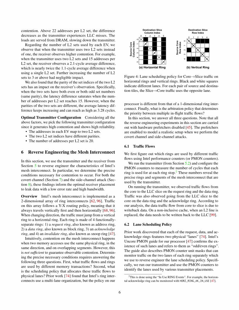
Figure 4: Lane scheduling policy for Core→Slice traffic onhorizontal rings and vertical rings. Black and white squaresindicate different lanes. For each pair of source and destina-tion tiles, the Slice→Core traffic uses the opposite lane.
processor is different from that of a 1-dimensional ring inter-connect. Finally, what is the arbitration policy that determinesthe priority between multiple in-flight traffic flows?
In this section, we answer all three questions. Note that allthe reverse engineering experiments in this section are carriedout with hardware prefetchers disabled [45]. The prefetchersare enabled to model a realistic setup when we perform thecovert channel and side-channel attacks.
6.1 Traffic Flows
We first figure out which rings are used by different trafficflows using Intel performance counters (or PMON counters).
We run the transmitter (from Section 5.2) and configure thePMON counters to measure the number of cycles that eachring is used for at each ring stop.2 These numbers reveal theprecise rings and segments of the mesh interconnect that areused by the transmitter.
On running the transmitter, we observed traffic flows fromthe core to the LLC slice on the request ring and the data ring.Traffic was also observed going from the LLC slice to thecore on the data ring and the acknowledge ring. According toour analysis, the data traffic flow from core to slice is due towriteback data. On a non-inclusive cache, when an L2 line isreplaced, the data needs to be written back to the LLC [99].
6.2 Lane Scheduling Policy
Prior work discovered that each of the request, data, and ac-knowledge rings features two physical “lanes” [74]. Intel’sUncore PMON guide for our processor [47] confirms the ex-istence of such lanes and refers to them as “odd/even rings”.The guide also describes PMON counter unit masks that canmonitor traffic on the two lanes of each ring separately whichwe use to reverse engineer the lane scheduling policy. Specifi-cally, we run our transmitter and use the PMON counters toidentify the lanes used by various transmitter placements.
2This is done using the “In Use RING Events”. For example, the horizon-tal acknowledge ring can be monitored with HORZ_RING_AK_IN_USE [47].
6
East
Out
put P
orts
fromwest
fromnorth
fromsouth
fromcore
from LLCslice
North Output Ports
fromsouth
fromcore
from LLCslice
(a) Horizontal Ring (a) Vertical Ring
traffic from local core and slice
traffic from a different ring
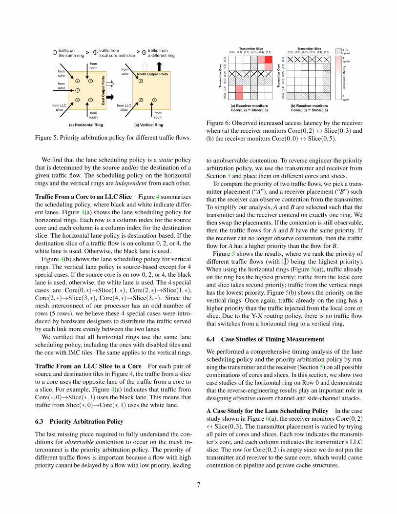
traffic on the same ring > >1 2 3
2 2
22
1
1
3
3
Figure 5: Priority arbitration policy for different traffic flows.
We find that the lane scheduling policy is a static policythat is determined by the source and/or the destination of agiven traffic flow. The scheduling policy on the horizontalrings and the vertical rings are independent from each other.
Traffic From a Core to an LLC Slice Figure 4 summarizesthe scheduling policy, where black and white indicate differ-ent lanes. Figure 4(a) shows the lane scheduling policy forhorizontal rings. Each row is a column index for the sourcecore and each column is a column index for the destinationslice. The horizontal lane policy is destination-based. If thedestination slice of a traffic flow is on column 0, 2, or 4, thewhite lane is used. Otherwise, the black lane is used.
Figure 4(b) shows the lane scheduling policy for verticalrings. The vertical lane policy is source-based except for 4special cases. If the source core is on row 0, 2, or 4, the blacklane is used; otherwise, the white lane is used. The 4 specialcases are Core(0,∗)→Slice(1,∗), Core(2,∗)→Slice(1,∗),Core(2,∗)→Slice(3,∗), Core(4,∗)→Slice(3,∗). Since themesh interconnect of our processor has an odd number ofrows (5 rows), we believe these 4 special cases were intro-duced by hardware designers to distribute the traffic servedby each link more evenly between the two lanes.
We verified that all horizontal rings use the same lanescheduling policy, including the ones with disabled tiles andthe one with IMC tiles. The same applies to the vertical rings.
Traffic From an LLC Slice to a Core For each pair ofsource and destination tiles in Figure 4, the traffic from a sliceto a core uses the opposite lane of the traffic from a core toa slice. For example, Figure 4(a) indicates that traffic fromCore(∗,0)→Slice(∗,1) uses the black lane. This means thattraffic from Slice(∗,0)→Core(∗,1) uses the white lane.
6.3 Priority Arbitration Policy
The last missing piece required to fully understand the con-ditions for observable contention to occur on the mesh in-terconnect is the priority arbitration policy. The priority ofdifferent traffic flows is important because a flow with highpriority cannot be delayed by a flow with low priority, leading
(0,0) (0,1) (0,2) (0,3) (0,4) (0,5)
(0,0
)(0
,1)
(0,2
)(0
,3)
(0,4
)(0
,5)
Tran
smitt
er C
ore
Transmitter Slice
4 cycles
0 cycle
Incr
ease
d La
tenc
y
5-10 cycles(0,0) (0,1) (0,2) (0,3) (0,4) (0,5)
(0,0
)(0
,1)
(0,2
)(0
,3)
(0,4
)(0
,5)
Tran
smitt
er C
ore
Transmitter Slice
(a) Receiver monitors Core(0,2) Slice(0,3)
(b) Receiver monitors Core(0,0) Slice(0,5)
Figure 6: Observed increased access latency by the receiverwhen (a) the receiver monitors Core(0,2)↔ Slice(0,3) and(b) the receiver monitors Core(0,0)↔ Slice(0,5).
to unobservable contention. To reverse engineer the priorityarbitration policy, we use the transmitter and receiver fromSection 5 and place them on different cores and slices.
To compare the priority of two traffic flows, we pick a trans-mitter placement (“A”), and a receiver placement (“B”) suchthat the receiver can observe contention from the transmitter.To simplify our analysis, A and B are selected such that thetransmitter and the receiver contend on exactly one ring. Wethen swap the placements. If the contention is still observable,then the traffic flows for A and B have the same priority. Ifthe receiver can no longer observe contention, then the trafficflow for A has a higher priority than the flow for B.
Figure 5 shows the results, where we rank the priority ofdifferent traffic flows (with 1 being the highest priority).When using the horizontal rings (Figure 5(a)), traffic alreadyon the ring has the highest priority; traffic from the local coreand slice takes second priority; traffic from the vertical ringshas the lowest priority. Figure 5(b) shows the priority on thevertical rings. Once again, traffic already on the ring has ahigher priority than the traffic injected from the local core orslice. Due to the Y-X routing policy, there is no traffic flowthat switches from a horizontal ring to a vertical ring.
6.4 Case Studies of Timing Measurement
We performed a comprehensive timing analysis of the lanescheduling policy and the priority arbitration policy by run-ning the transmitter and the receiver (Section 5) on all possiblecombinations of cores and slices. In this section, we show twocase studies of the horizontal ring on Row 0 and demonstratethat the reverse-engineering results play an important role indesigning effective covert channel and side-channel attacks.
A Case Study for the Lane Scheduling Policy In the casestudy shown in Figure 6(a), the receiver monitors Core(0,2)↔ Slice(0,3). The transmitter placement is varied by tryingall pairs of cores and slices. Each row indicates the transmit-ter’s core, and each column indicates the transmitter’s LLCslice. The row for Core(0,2) is empty since we do not pin thetransmitter and receiver to the same core, which would causecontention on pipeline and private cache structures.
7
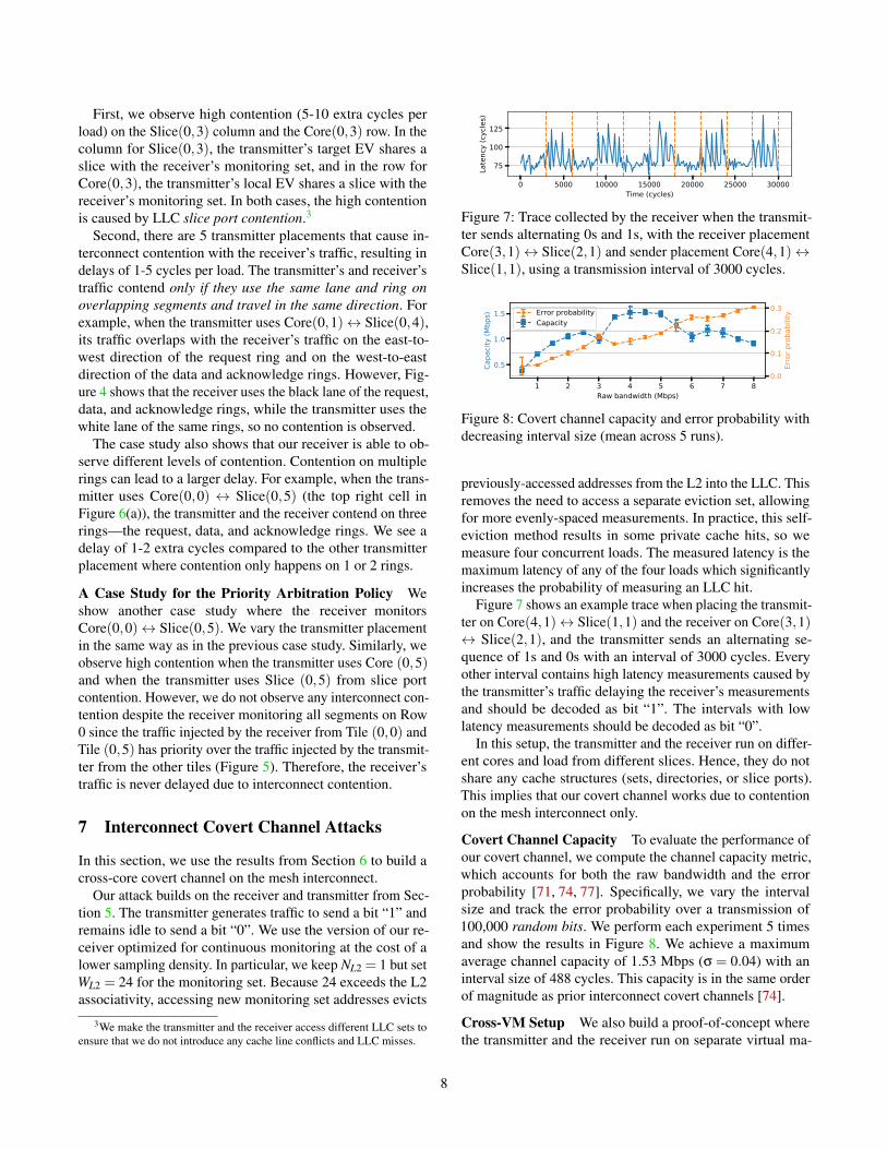
First, we observe high contention (5-10 extra cycles perload) on the Slice(0,3) column and the Core(0,3) row. In thecolumn for Slice(0,3), the transmitter’s target EV shares aslice with the receiver’s monitoring set, and in the row forCore(0,3), the transmitter’s local EV shares a slice with thereceiver’s monitoring set. In both cases, the high contentionis caused by LLC slice port contention.3
Second, there are 5 transmitter placements that cause in-terconnect contention with the receiver’s traffic, resulting indelays of 1-5 cycles per load. The transmitter’s and receiver’straffic contend only if they use the same lane and ring onoverlapping segments and travel in the same direction. Forexample, when the transmitter uses Core(0,1)↔ Slice(0,4),its traffic overlaps with the receiver’s traffic on the east-to-west direction of the request ring and on the west-to-eastdirection of the data and acknowledge rings. However, Fig-ure 4 shows that the receiver uses the black lane of the request,data, and acknowledge rings, while the transmitter uses thewhite lane of the same rings, so no contention is observed.
The case study also shows that our receiver is able to ob-serve different levels of contention. Contention on multiplerings can lead to a larger delay. For example, when the trans-mitter uses Core(0,0) ↔ Slice(0,5) (the top right cell inFigure 6(a)), the transmitter and the receiver contend on threerings—the request, data, and acknowledge rings. We see adelay of 1-2 extra cycles compared to the other transmitterplacement where contention only happens on 1 or 2 rings.
A Case Study for the Priority Arbitration Policy Weshow another case study where the receiver monitorsCore(0,0)↔ Slice(0,5). We vary the transmitter placementin the same way as in the previous case study. Similarly, weobserve high contention when the transmitter uses Core (0,5)and when the transmitter uses Slice (0,5) from slice portcontention. However, we do not observe any interconnect con-tention despite the receiver monitoring all segments on Row0 since the traffic injected by the receiver from Tile (0,0) andTile (0,5) has priority over the traffic injected by the transmit-ter from the other tiles (Figure 5). Therefore, the receiver’straffic is never delayed due to interconnect contention.
7 Interconnect Covert Channel Attacks
In this section, we use the results from Section 6 to build across-core covert channel on the mesh interconnect.
Our attack builds on the receiver and transmitter from Sec-tion 5. The transmitter generates traffic to send a bit “1” andremains idle to send a bit “0”. We use the version of our re-ceiver optimized for continuous monitoring at the cost of alower sampling density. In particular, we keep NL2 = 1 but setWL2 = 24 for the monitoring set. Because 24 exceeds the L2associativity, accessing new monitoring set addresses evicts
3We make the transmitter and the receiver access different LLC sets toensure that we do not introduce any cache line conflicts and LLC misses.
0 5000 10000 15000 20000 25000 30000Time (cycles)
75
100
125
Late
ncy
(cyc
les)
Figure 7: Trace collected by the receiver when the transmit-ter sends alternating 0s and 1s, with the receiver placementCore(3,1)↔ Slice(2,1) and sender placement Core(4,1)↔Slice(1,1), using a transmission interval of 3000 cycles.
1 2 3 4 5 6 7 8Raw bandwidth (Mbps)
0.5
1.0
1.5
Capa
city
(Mbp
s) Error probabilityCapacity
0.0
0.1
0.2
0.3
Erro
r pro
babi
lity
Figure 8: Covert channel capacity and error probability withdecreasing interval size (mean across 5 runs).
previously-accessed addresses from the L2 into the LLC. Thisremoves the need to access a separate eviction set, allowingfor more evenly-spaced measurements. In practice, this self-eviction method results in some private cache hits, so wemeasure four concurrent loads. The measured latency is themaximum latency of any of the four loads which significantlyincreases the probability of measuring an LLC hit.
Figure 7 shows an example trace when placing the transmit-ter on Core(4,1)↔ Slice(1,1) and the receiver on Core(3,1)↔ Slice(2,1), and the transmitter sends an alternating se-quence of 1s and 0s with an interval of 3000 cycles. Everyother interval contains high latency measurements caused bythe transmitter’s traffic delaying the receiver’s measurementsand should be decoded as bit “1”. The intervals with lowlatency measurements should be decoded as bit “0”.
In this setup, the transmitter and the receiver run on differ-ent cores and load from different slices. Hence, they do notshare any cache structures (sets, directories, or slice ports).This implies that our covert channel works due to contentionon the mesh interconnect only.
Covert Channel Capacity To evaluate the performance ofour covert channel, we compute the channel capacity metric,which accounts for both the raw bandwidth and the errorprobability [71, 74, 77]. Specifically, we vary the intervalsize and track the error probability over a transmission of100,000 random bits. We perform each experiment 5 timesand show the results in Figure 8. We achieve a maximumaverage channel capacity of 1.53 Mbps (σ = 0.04) with aninterval size of 488 cycles. This capacity is in the same orderof magnitude as prior interconnect covert channels [74].
Cross-VM Setup We also build a proof-of-concept wherethe transmitter and the receiver run on separate virtual ma-
8
0 50 100 150 200Latency sample ID
57.5
60.0
62.5
Load
late
ncy
(cyc
les)
Figure 9: Temporal resolution trace with the transmitter using16 accesses. For clarity, this plot is averaged across 300 traces.
chines (VMs). We spawn two VMs using QEMU/KVM andpin the transmitter VM to Core (4,1) and the receiver VM toCore (3,1). We use the algorithm described by Yan et al. [99]to construct monitoring and eviction sets and rely on timingmeasurements to determine the mapping of sets to LLC slices.The receiver targets slices near (2,1) while the transmittertargets slices near (1,1). We mounted the attack successfullywith an interval of 1000 cycles and observed a 12.5% aver-age error rate across 4 runs. This corresponds to an averagechannel capacity of 1.00 Mbps (σ = 0.04), confirming thefeasibility of interconnect cross-VM covert channels.
Running the attack in a real cloud environment also re-quires two additional steps: 1) the transmitter and receiverneed to infer the mesh topology and the ID of the physicalcore where they are running; and 2) the transmitter and thereceiver need to perform an agreement phase where they syn-chronize with each other. We discuss how to perform the firststep in Appendix B. For the second step, our VM configura-tion allowed for synchronization via the wall clock, but onmachines where this is not possible, existing synchronizationprotocols based on preambles may be used (e.g., [66]).
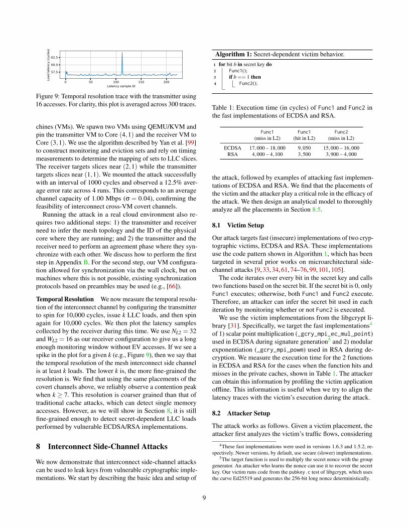
Temporal Resolution We now measure the temporal resolu-tion of the interconnect channel by configuring the transmitterto spin for 10,000 cycles, issue k LLC loads, and then spinagain for 10,000 cycles. We then plot the latency samplescollected by the receiver during this time. We use NL2 = 32and WL2 = 16 as our receiver configuration to give us a longenough monitoring window without EV accesses. If we see aspike in the plot for a given k (e.g., Figure 9), then we say thatthe temporal resolution of the mesh interconnect side channelis at least k loads. The lower k is, the more fine-grained theresolution is. We find that using the same placements of thecovert channels above, we reliably observe a contention peakwhen k ≥ 7. This resolution is coarser grained than that oftraditional cache attacks, which can detect single memoryaccesses. However, as we will show in Section 8, it is stillfine-grained enough to detect secret-dependent LLC loadsperformed by vulnerable ECDSA/RSA implementations.
8 Interconnect Side-Channel Attacks
We now demonstrate that interconnect side-channel attackscan be used to leak keys from vulnerable cryptographic imple-mentations. We start by describing the basic idea and setup of
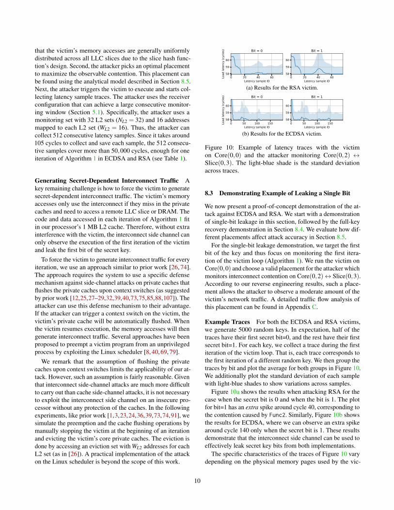
Algorithm 1: Secret-dependent victim behavior.1 for bit b in secret key do2 Func1();3 if b == 1 then4 Func2();
Table 1: Execution time (in cycles) of Func1 and Func2 inthe fast implementations of ECDSA and RSA.
Func1 Func1 Func2(miss in L2) (hit in L2) (miss in L2)
ECDSA 17,000 – 18,000 9,050 15,000 – 16,000RSA 4,000 – 4,100 3,500 3,900 – 4,000
the attack, followed by examples of attacking fast implemen-tations of ECDSA and RSA. We find that the placements ofthe victim and the attacker play a critical role in the efficacy ofthe attack. We then design an analytical model to thoroughlyanalyze all the placements in Section 8.5.
8.1 Victim Setup
Our attack targets fast (insecure) implementations of two cryp-tographic victims, ECDSA and RSA. These implementationsuse the code pattern shown in Algorithm 1, which has beentargeted in several prior works on microarchitectural side-channel attacks [9, 33, 34, 61, 74–76, 99, 101, 105].
The code iterates over every bit in the secret key and callstwo functions based on the secret bit. If the secret bit is 0, onlyFunc1 executes; otherwise, both Func1 and Func2 execute.Therefore, an attacker can infer the secret bit used in eachiteration by monitoring whether or not Func2 is executed.
We use the victim implementations from the libgcrypt li-brary [31]. Specifically, we target the fast implementations4
of 1) scalar point multiplication (_gcry_mpi_ec_mul_point)used in ECDSA during signature generation5 and 2) modularexponentiation (_gcry_mpi_powm) used in RSA during de-cryption. We measure the execution time for the 2 functionsin ECDSA and RSA for the cases when the function hits andmisses in the private caches, shown in Table 1. The attackercan obtain this information by profiling the victim applicationoffline. This information is useful when we try to align thelatency traces with the victim’s execution during the attack.
8.2 Attacker Setup
The attack works as follows. Given a victim placement, theattacker first analyzes the victim’s traffic flows, considering
4These fast implementations were used in versions 1.6.3 and 1.5.2, re-spectively. Newer versions, by default, use secure (slower) implementations.
5The target function is used to multiply the secret nonce with the groupgenerator. An attacker who learns the nonce can use it to recover the secretkey. Our victim runs code from the pubkey.c test of libgcrypt, which usesthe curve Ed25519 and generates the 256-bit long nonce deterministically.
9
that the victim’s memory accesses are generally uniformlydistributed across all LLC slices due to the slice hash func-tion’s design. Second, the attacker picks an optimal placementto maximize the observable contention. This placement canbe found using the analytical model described in Section 8.5.Next, the attacker triggers the victim to execute and starts col-lecting latency sample traces. The attacker uses the receiverconfiguration that can achieve a large consecutive monitor-ing window (Section 5.1). Specifically, the attacker uses amonitoring set with 32 L2 sets (NL2 = 32) and 16 addressesmapped to each L2 set (WL2 = 16). Thus, the attacker cancollect 512 consecutive latency samples. Since it takes around105 cycles to collect and save each sample, the 512 consecu-tive samples cover more than 50,000 cycles, enough for oneiteration of Algorithm 1 in ECDSA and RSA (see Table 1).
Generating Secret-Dependent Interconnect Traffic Akey remaining challenge is how to force the victim to generatesecret-dependent interconnect traffic. The victim’s memoryaccesses only use the interconnect if they miss in the privatecaches and need to access a remote LLC slice or DRAM. Thecode and data accessed in each iteration of Algorithm 1 fitin our processor’s 1 MB L2 cache. Therefore, without extrainterference with the victim, the interconnect side channel canonly observe the execution of the first iteration of the victimand leak the first bit of the secret key.
To force the victim to generate interconnect traffic for everyiteration, we use an approach similar to prior work [26, 74].The approach requires the system to use a specific defensemechanism against side-channel attacks on private caches thatflushes the private caches upon context switches (as suggestedby prior work [12,25,27–29,32,39,40,73,75,85,88,107]). Theattacker can use this defense mechanism to their advantage.If the attacker can trigger a context switch on the victim, thevictim’s private cache will be automatically flushed. Whenthe victim resumes execution, the memory accesses will thengenerate interconnect traffic. Several approaches have beenproposed to preempt a victim program from an unprivilegedprocess by exploiting the Linux scheduler [8, 40, 69, 79].
We remark that the assumption of flushing the privatecaches upon context switches limits the applicability of our at-tack. However, such an assumption is fairly reasonable. Giventhat interconnect side-channel attacks are much more difficultto carry out than cache side-channel attacks, it is not necessaryto exploit the interconnect side channel on an insecure pro-cessor without any protection of the caches. In the followingexperiments, like prior work [1,3,23,24,36,39,73,74,91], wesimulate the preemption and the cache flushing operations bymanually stopping the victim at the beginning of an iterationand evicting the victim’s core private caches. The eviction isdone by accessing an eviction set with WL2 addresses for eachL2 set (as in [26]). A practical implementation of the attackon the Linux scheduler is beyond the scope of this work.
0 20 40 60Latency sample ID
58
59
60
Load
late
ncy
(cyc
les) Bit = 0
0 20 40 60Latency sample ID
58
59
60
Bit = 1
(a) Results for the RSA victim.
0 50 100 150Latency sample ID
58
59
60
Load
late
ncy
(cyc
les) Bit = 0
0 50 100 150Latency sample ID
58
59
60
Bit = 1
(b) Results for the ECDSA victim.
Figure 10: Example of latency traces with the victimon Core(0,0) and the attacker monitoring Core(0,2) ↔Slice(0,3). The light-blue shade is the standard deviationacross traces.
8.3 Demonstrating Example of Leaking a Single Bit
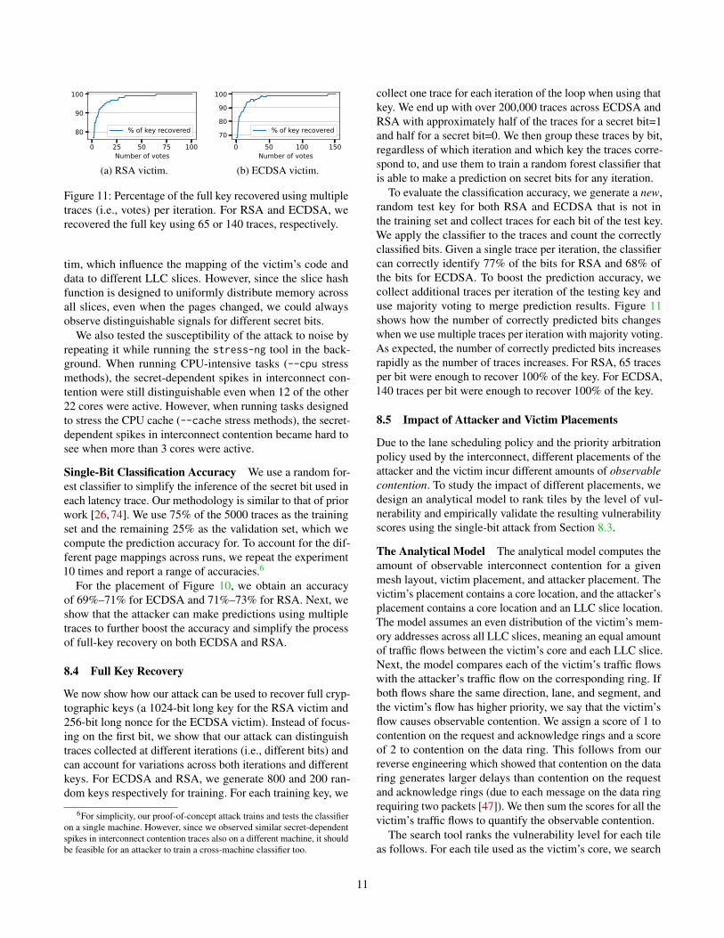
We now present a proof-of-concept demonstration of the at-tack against ECDSA and RSA. We start with a demonstrationof single-bit leakage in this section, followed by the full-keyrecovery demonstration in Section 8.4. We evaluate how dif-ferent placements affect attack accuracy in Section 8.5.
For the single-bit leakage demonstration, we target the firstbit of the key and thus focus on monitoring the first itera-tion of the victim loop (Algorithm 1). We run the victim onCore(0,0) and choose a valid placement for the attacker whichmonitors interconnect contention on Core(0,2)↔ Slice(0,3).According to our reverse engineering results, such a place-ment allows the attacker to observe a moderate amount of thevictim’s network traffic. A detailed traffic flow analysis ofthis placement can be found in Appendix C.
Example Traces For both the ECDSA and RSA victims,we generate 5000 random keys. In expectation, half of thetraces have their first secret bit=0, and the rest have their firstsecret bit=1. For each key, we collect a trace during the firstiteration of the victim loop. That is, each trace corresponds tothe first iteration of a different random key. We then group thetraces by bit and plot the average for both groups in Figure 10.We additionally plot the standard deviation of each samplewith light-blue shades to show variations across samples.
Figure 10a shows the results when attacking RSA for thecase when the secret bit is 0 and when the bit is 1. The plotfor bit=1 has an extra spike around cycle 40, corresponding tothe contention caused by Func2. Similarly, Figure 10b showsthe results for ECDSA, where we can observe an extra spikearound cycle 140 only when the secret bit is 1. These resultsdemonstrate that the interconnect side channel can be used toeffectively leak secret key bits from both implementations.
The specific characteristics of the traces of Figure 10 varydepending on the physical memory pages used by the vic-
10
0 25 50 75 100Number of votes
80
90
100
% of key recovered
(a) RSA victim.
0 50 100 150Number of votes
708090
100
% of key recovered
(b) ECDSA victim.
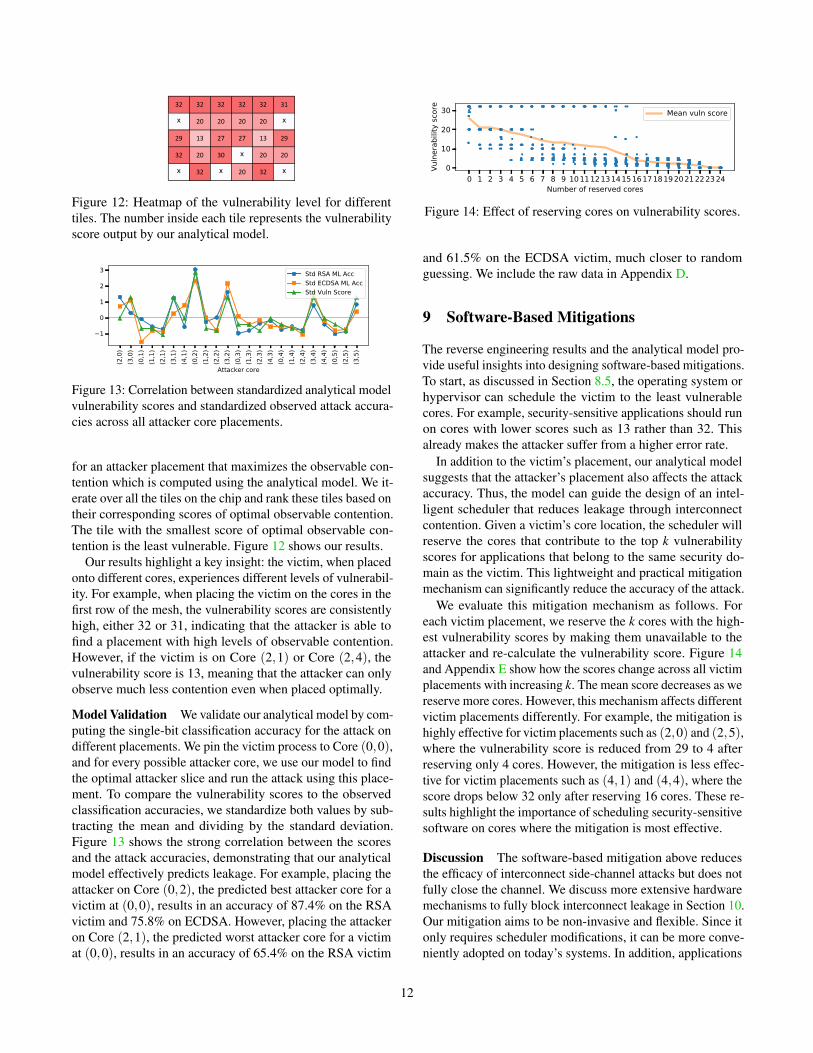
Figure 11: Percentage of the full key recovered using multipletraces (i.e., votes) per iteration. For RSA and ECDSA, werecovered the full key using 65 or 140 traces, respectively.
tim, which influence the mapping of the victim’s code anddata to different LLC slices. However, since the slice hashfunction is designed to uniformly distribute memory acrossall slices, even when the pages changed, we could alwaysobserve distinguishable signals for different secret bits.
We also tested the susceptibility of the attack to noise byrepeating it while running the stress-ng tool in the back-ground. When running CPU-intensive tasks (--cpu stressmethods), the secret-dependent spikes in interconnect con-tention were still distinguishable even when 12 of the other22 cores were active. However, when running tasks designedto stress the CPU cache (--cache stress methods), the secret-dependent spikes in interconnect contention became hard tosee when more than 3 cores were active.
Single-Bit Classification Accuracy We use a random for-est classifier to simplify the inference of the secret bit used ineach latency trace. Our methodology is similar to that of priorwork [26, 74]. We use 75% of the 5000 traces as the trainingset and the remaining 25% as the validation set, which wecompute the prediction accuracy for. To account for the dif-ferent page mappings across runs, we repeat the experiment10 times and report a range of accuracies.6
For the placement of Figure 10, we obtain an accuracyof 69%–71% for ECDSA and 71%–73% for RSA. Next, weshow that the attacker can make predictions using multipletraces to further boost the accuracy and simplify the processof full-key recovery on both ECDSA and RSA.
8.4 Full Key Recovery
We now show how our attack can be used to recover full cryp-tographic keys (a 1024-bit long key for the RSA victim and256-bit long nonce for the ECDSA victim). Instead of focus-ing on the first bit, we show that our attack can distinguishtraces collected at different iterations (i.e., different bits) andcan account for variations across both iterations and differentkeys. For ECDSA and RSA, we generate 800 and 200 ran-dom keys respectively for training. For each training key, we
6For simplicity, our proof-of-concept attack trains and tests the classifieron a single machine. However, since we observed similar secret-dependentspikes in interconnect contention traces also on a different machine, it shouldbe feasible for an attacker to train a cross-machine classifier too.
collect one trace for each iteration of the loop when using thatkey. We end up with over 200,000 traces across ECDSA andRSA with approximately half of the traces for a secret bit=1and half for a secret bit=0. We then group these traces by bit,regardless of which iteration and which key the traces corre-spond to, and use them to train a random forest classifier thatis able to make a prediction on secret bits for any iteration.
To evaluate the classification accuracy, we generate a new,random test key for both RSA and ECDSA that is not inthe training set and collect traces for each bit of the test key.We apply the classifier to the traces and count the correctlyclassified bits. Given a single trace per iteration, the classifiercan correctly identify 77% of the bits for RSA and 68% ofthe bits for ECDSA. To boost the prediction accuracy, wecollect additional traces per iteration of the testing key anduse majority voting to merge prediction results. Figure 11shows how the number of correctly predicted bits changeswhen we use multiple traces per iteration with majority voting.As expected, the number of correctly predicted bits increasesrapidly as the number of traces increases. For RSA, 65 tracesper bit were enough to recover 100% of the key. For ECDSA,140 traces per bit were enough to recover 100% of the key.
8.5 Impact of Attacker and Victim Placements
Due to the lane scheduling policy and the priority arbitrationpolicy used by the interconnect, different placements of theattacker and the victim incur different amounts of observablecontention. To study the impact of different placements, wedesign an analytical model to rank tiles by the level of vul-nerability and empirically validate the resulting vulnerabilityscores using the single-bit attack from Section 8.3.
The Analytical Model The analytical model computes theamount of observable interconnect contention for a givenmesh layout, victim placement, and attacker placement. Thevictim’s placement contains a core location, and the attacker’splacement contains a core location and an LLC slice location.The model assumes an even distribution of the victim’s mem-ory addresses across all LLC slices, meaning an equal amountof traffic flows between the victim’s core and each LLC slice.Next, the model compares each of the victim’s traffic flowswith the attacker’s traffic flow on the corresponding ring. Ifboth flows share the same direction, lane, and segment, andthe victim’s flow has higher priority, we say that the victim’sflow causes observable contention. We assign a score of 1 tocontention on the request and acknowledge rings and a scoreof 2 to contention on the data ring. This follows from ourreverse engineering which showed that contention on the dataring generates larger delays than contention on the requestand acknowledge rings (due to each message on the data ringrequiring two packets [47]). We then sum the scores for all thevictim’s traffic flows to quantify the observable contention.
The search tool ranks the vulnerability level for each tileas follows. For each tile used as the victim’s core, we search
11
32 32 32 32 32 31
x 20 20 20 20 x
29 13 27 27 13 29
32 20 30 x 20 20
x 32 x 20 32 x
Figure 12: Heatmap of the vulnerability level for differenttiles. The number inside each tile represents the vulnerabilityscore output by our analytical model.
(2,0
)(3
,0)
(0,1
)(1
,1)
(2,1
)(3
,1)
(4,1
)(0
,2)
(1,2
)(2
,2)
(3,2
)(0
,3)
(1,3
)(2
,3)
(4,3
)(0
,4)
(1,4
)(2
,4)
(3,4
)(4
,4)
(0,5
)(2
,5)
(3,5
)
Attacker core
1
0
1
2
3 Std RSA ML AccStd ECDSA ML AccStd Vuln Score
Figure 13: Correlation between standardized analytical modelvulnerability scores and standardized observed attack accura-cies across all attacker core placements.
for an attacker placement that maximizes the observable con-tention which is computed using the analytical model. We it-erate over all the tiles on the chip and rank these tiles based ontheir corresponding scores of optimal observable contention.The tile with the smallest score of optimal observable con-tention is the least vulnerable. Figure 12 shows our results.
Our results highlight a key insight: the victim, when placedonto different cores, experiences different levels of vulnerabil-ity. For example, when placing the victim on the cores in thefirst row of the mesh, the vulnerability scores are consistentlyhigh, either 32 or 31, indicating that the attacker is able tofind a placement with high levels of observable contention.However, if the victim is on Core (2,1) or Core (2,4), thevulnerability score is 13, meaning that the attacker can onlyobserve much less contention even when placed optimally.
Model Validation We validate our analytical model by com-puting the single-bit classification accuracy for the attack ondifferent placements. We pin the victim process to Core (0,0),and for every possible attacker core, we use our model to findthe optimal attacker slice and run the attack using this place-ment. To compare the vulnerability scores to the observedclassification accuracies, we standardize both values by sub-tracting the mean and dividing by the standard deviation.Figure 13 shows the strong correlation between the scoresand the attack accuracies, demonstrating that our analyticalmodel effectively predicts leakage. For example, placing theattacker on Core (0,2), the predicted best attacker core for avictim at (0,0), results in an accuracy of 87.4% on the RSAvictim and 75.8% on ECDSA. However, placing the attackeron Core (2,1), the predicted worst attacker core for a victimat (0,0), results in an accuracy of 65.4% on the RSA victim
0 1 2 3 4 5 6 7 8 9 101112131415161718192021222324Number of reserved cores
0
10
20
30
Vuln
erab
ility
scor
e
Mean vuln score
Figure 14: Effect of reserving cores on vulnerability scores.
and 61.5% on the ECDSA victim, much closer to randomguessing. We include the raw data in Appendix D.
9 Software-Based Mitigations
The reverse engineering results and the analytical model pro-vide useful insights into designing software-based mitigations.To start, as discussed in Section 8.5, the operating system orhypervisor can schedule the victim to the least vulnerablecores. For example, security-sensitive applications should runon cores with lower scores such as 13 rather than 32. Thisalready makes the attacker suffer from a higher error rate.
In addition to the victim’s placement, our analytical modelsuggests that the attacker’s placement also affects the attackaccuracy. Thus, the model can guide the design of an intel-ligent scheduler that reduces leakage through interconnectcontention. Given a victim’s core location, the scheduler willreserve the cores that contribute to the top k vulnerabilityscores for applications that belong to the same security do-main as the victim. This lightweight and practical mitigationmechanism can significantly reduce the accuracy of the attack.
We evaluate this mitigation mechanism as follows. Foreach victim placement, we reserve the k cores with the high-est vulnerability scores by making them unavailable to theattacker and re-calculate the vulnerability score. Figure 14and Appendix E show how the scores change across all victimplacements with increasing k. The mean score decreases as wereserve more cores. However, this mechanism affects differentvictim placements differently. For example, the mitigation ishighly effective for victim placements such as (2,0) and (2,5),where the vulnerability score is reduced from 29 to 4 afterreserving only 4 cores. However, the mitigation is less effec-tive for victim placements such as (4,1) and (4,4), where thescore drops below 32 only after reserving 16 cores. These re-sults highlight the importance of scheduling security-sensitivesoftware on cores where the mitigation is most effective.
Discussion The software-based mitigation above reducesthe efficacy of interconnect side-channel attacks but does notfully close the channel. We discuss more extensive hardwaremechanisms to fully block interconnect leakage in Section 10.Our mitigation aims to be non-invasive and flexible. Since itonly requires scheduler modifications, it can be more conve-niently adopted on today’s systems. In addition, applications
12
can adjust their degree of isolation. Less sensitive applicationscan reserve fewer cores to conserve resources.
Since our scheme reduces the flexibility of the scheduler, itmay negatively impact system performance. As we reservecores for a domain, other security domains need to competefor unreserved cores, resulting in potential performance degra-dation. Even intelligently scheduling a multi-threaded victim(e.g., a VM) that runs on n cores may require reserving morethan n cores. In particular, selecting the minimal set of m≥ ncores such that these m cores sufficiently reduce the victim’svulnerability score is a complex (and orthogonal) partitioningproblem. However, considering that modern cloud resourcesare generally over-provisioned [14, 104], we believe that, inpractice, the performance impact of our scheme would be low.
10 Related Work
Attacks We provided a classification of microarchitecturalattacks in Section 2.3. We now discuss prior works that ex-plored the security of on-chip CPU interconnects specifically.
Wang et al. [92] were the first to consider side-channelattacks on the on-chip interconnect. However, their attack wasonly demonstrated on a simplified architectural simulator.
Paccagnella et al. [74] described attacks exploiting con-tention on the ring interconnect used by client-class Intelprocessors. Our work builds on their techniques but is dif-ferent in two main ways. First, we study a more complex,2-dimensional interconnect with different traffic flows andlane scheduling policies, as well as more complex priorityarbitration policies. Second, our work handles a much largernumber of placement options for the attacker. For example,if we fix the victim’s core, there are 598 attacker placementson our processor, as opposed to only 56 placements on an8-core desktop processor. Hence, our work includes a novelanalytical model to find the optimal attacker placement.
Dutta et al. demonstrated a cross-component covert channelthat exploits contention on the ring interconnect [20]. Thereare also works that used information about the on-chip in-terconnect to improve cache side channels [18, 82]. Theseworks demonstrate additional benefits of reverse engineeringthe interconnect to attackers. However, these attacks are fun-damentally dependent on shared cache structures whereas ourwork focuses on side channels outside the cache.
Most recently, concurrent work from Wan et al. [90] de-scribed a side-channel attack that also targets Intel’s mesh in-terconnect. However, their work does not include lane schedul-ing and priority arbitration policy details. Further, given thelarge delays (up to 1000 cycles) they report and the significantmemory footprint of their victim, it is unclear whether theirattack works due to contention on the interconnect or on othershared structures, e.g., shared cache directories or slice ports,both of which are not partitioned by Intel CAT [70]. In con-trast, our work establishes the precise conditions for creating
contention on the mesh interconnect, and our experiments arecarefully designed to rule out other contention sources.
Mitigations Existing mitigations to our attack can be classi-fied into software and hardware mitigations. Among softwaremitigations, the recommended strategy is to use constant-timecryptographic implementations [46]. Mitigations at the hard-ware level that separate the traffic flows of different securitydomains have also been proposed. Wang and Suh investigateddomain-aware priority arbitration policies which give low-security traffic precedence over high-security traffic at therouter [92]. Wassel et al. propose a time-multiplexed schedul-ing policy in which network links may only carry traffic from apredefined security domain at each instant in time [94]. Whileeffective, these approaches require hardware modifications tothe interconnect and cannot be adjusted to accommodate moresecurity domains once deployed. In contrast, our proposedmitigation is non-intrusive and does not require hardwarechanges. Alternatively, a limited form of spatial partitioningmay be accomplished using Intel’s Sub-NUMA Clustering(SNC), which splits the LLC slices into two disjoint clusters,each bound to a single memory controller [48]. However,SNC only focuses on memory mappings, so while it mayreduce interconnect contention in particular cases, it makesno guarantees about isolating interconnect traffic in general.Further, it only supports two domains.
11 Conclusion
In this paper, we reverse engineered the lane scheduling andpriority arbitration policies used by Intel’s mesh interconnect.We demonstrated covert channel and side-channel attacks thatexploit contention on the mesh interconnect. We then usedan analytical model to quantify the vulnerability of differentcores and proposed a non-invasive software mitigation.
Our results underscore that, though difficult to exploit, on-chip interconnects remain an overlooked microarchitecturalattack surface and that additional work is necessary to enforcesecurity-by-design against these attacks in future server pro-cessors. We made a first step towards this goal by introducinga non-invasive mitigation to interconnect side channels. Goingforward, we expect that our work will facilitate future researchinto the security of on-chip interconnects. More broadly, wehope that our findings motivate the development of princi-pled, holistic mitigations against microarchitectural attacks,as opposed to the current per-resource, “spot” mitigations.
Acknowledgments
We thank our shepherd Michael Schwarz and the anony-mous reviewers for their valuable feedback. This work wasfunded in part through NSF grants 2046359 and 1954521, andAFOSR grant FA9550-20-1-0402.
13
References[1] Onur Aciiçmez. Yet another microarchitectural attack: Exploiting
i-cache. In CSAW, 2007.
[2] Onur Acıiçmez, Çetin Kaya Koç, and Jean-Pierre Seifert. Predictingsecret keys via branch prediction. In CT-RSA, 2007.
[3] Onur Acıiçmez and Werner Schindler. A vulnerability in RSA imple-mentations due to instruction cache analysis and its demonstration onOpenSSL. In CT-RSA, 2008.
[4] Onur Acıiçmez and Jean-Pierre Seifert. Cheap hardware parallelismimplies cheap security. In FDTC, 2007.
[5] Alejandro Cabrera Aldaya, Billy Bob Brumley, Sohaib ul Hassan,Cesar Pereida García, and Nicola Tuveri. Port contention for fun andprofit. In S&P, 2019.
[6] Diego F Aranha, Felipe Rodrigues Novaes, Akira Takahashi, MehdiTibouchi, and Yuval Yarom. LadderLeak: Breaking ECDSA with lessthan one bit of nonce leakage. In CCS, 2020.
[7] Lucian Armasu. OpenBSD will disable Intel Hyper-Threading toavoid Spectre-like exploits (updated). https://www.tomshardware.com/news/openbsd-disables-intel-hyper-threading-spectre,37332.html. Accessed on Jun 12, 2022.
[8] C Ashokkumar, Ravi Prakash Giri, and Bernard Menezes. Highlyefficient algorithms for AES key retrieval in cache access attacks. InEuroS&P, 2016.
[9] Naomi Benger, Joop Van de Pol, Nigel P Smart, and Yuval Yarom.“Ooh aah... just a little bit”: A small amount of side channel can go along way. In CHES, 2014.
[10] Atri Bhattacharyya, Alexandra Sandulescu, Matthias Neugschwandt-ner, Alessandro Sorniotti, Babak Falsafi, Mathias Payer, and AnilKurmus. SMoTherSpectre: Exploiting speculative execution throughport contention. In CCS, 2019.
[11] Thomas Bourgeat, Ilia Lebedev, Andrew Wright, Sizhuo Zhang, andSrinivas Devadas. MI6: Secure enclaves in a speculative out-of-orderprocessor. In MICRO, 2019.
[12] Benjamin A Braun, Suman Jana, and Dan Boneh. Robust and ef-ficient elimination of cache and timing side channels. Preprint,arXiv:1506.00189 [cs.CR], 2015.
[13] Claudio Canella, Daniel Genkin, Lukas Giner, Daniel Gruss, MoritzLipp, Marina Minkin, Daniel Moghimi, Frank Piessens, MichaelSchwarz, Berk Sunar, Jo Van Bulck, and Yuval Yarom. Fallout: Leak-ing data on Meltdown-resistant CPUs. In CCS, 2019.
[14] Sivadon Chaisiri, Bu-Sung Lee, and Dusit Niyato. Optimization ofresource provisioning cost in cloud computing. IEEE transactions onservices Computing, 5(2):164–177, 2011.
[15] Mainak Chaudhuri. Zero directory eviction victim: Unbounded co-herence directory and core cache isolation. In HPCA, 2021.
[16] Thomas Claburn. RIP Hyper-Threading? ChromeOS axes key IntelCPU feature over data-leak flaws – Microsoft, Apple suggest snub.https://www.theregister.co.uk/2019/05/14/intel_hyper_threading_mitigations/. Accessed on Jun 12, 2022.
[17] Shaanan Cohney, Andrew Kwong, Shahar Paz, Daniel Genkin, NadiaHeninger, Eyal Ronen, and Yuval Yarom. Pseudorandom black swans:Cache attacks on CTR DRBG. In S&P, 2020.
[18] Guillaume Didier and Clémentine Maurice. Calibration done right:Noiseless Flush+Flush attacks. In DIMVA, 2021.
[19] Craig Disselkoen, David Kohlbrenner, Leo Porter, and Dean Tullsen.Prime+Abort: A Timer-Free High-Precision L3 cache attack usingIntel TSX. In USENIX Security, 2017.
[20] Sankha Baran Dutta, Hoda Naghibijouybari, Nael Abu-Ghazaleh, An-dres Marquez, and Kevin Barker. Leaky buddies: Cross-componentcovert channels on integrated CPU-GPU systems. In ISCA, 2021.
[21] Dmitry Evtyushkin and Dmitry Ponomarev. Covert channels throughrandom number generator: Mechanisms, capacity estimation and miti-gations. In CCS, 2016.
[22] Dmitry Evtyushkin, Dmitry Ponomarev, and Nael Abu-Ghazaleh.Jump over ASLR: Attacking branch predictors to bypass ASLR. InMICRO, 2016.
[23] Dmitry Evtyushkin, Dmitry Ponomarev, and Nael Abu-Ghazaleh. Un-derstanding and mitigating covert channels through branch predictors.TACO, 13(1), 2016.
[24] Dmitry Evtyushkin, Ryan Riley, Nael Abu-Ghazaleh, and DmitryPonomarev. BranchScope: A new side-channel attack on directionalbranch predictor. In ASPLOS, 2018.
[25] Andrew Ferraiuolo, Mark Zhao, Andrew C Myers, and G Edward Suh.HyperFlow: A processor architecture for nonmalleable, timing-safeinformation flow security. In CCS, 2018.
[26] FPSG-UIUC. lotr. https://github.com/FPSG-UIUC/lotr, 2021.Accessed on Jun 12, 2022.
[27] Janosch Frank. The common challenges of secure VMs. https://static.sched.com/hosted_files/kvmforum2020/a3/Janosch%20Frank.pdf, 2020. Accessed on Jun 12, 2022.
[28] Qian Ge, Yuval Yarom, David Cock, and Gernot Heiser. A survey ofmicroarchitectural timing attacks and countermeasures on contempo-rary hardware. JCEN, 8(1), 2018.
[29] Qian Ge, Yuval Yarom, and Gernot Heiser. No security without timeprotection: We need a new hardware-software contract. In APSys,2018.
[30] Daniel Genkin, Luke Valenta, and Yuval Yarom. May the fourth bewith you: A microarchitectural side channel attack on several real-world applications of Curve25519. In CCS, 2017.
[31] GnuPG. Libgcrypt. https://gnupg.org/software/libgcrypt/index.html, 2021. Accessed on Jun 12, 2022.
[32] Michael Godfrey and Mohammad Zulkernine. A server-side solutionto cache-based side-channel attacks in the cloud. In CLOUD, 2013.
[33] Ben Gras, Cristiano Giuffrida, Michael Kurth, Herbert Bos, and KavehRazavi. ABSynthe: Automatic blackbox side-channel synthesis oncommodity microarchitectures. In NDSS, 2020.
[34] Ben Gras, Kaveh Razavi, Herbert Bos, and Cristiano Giuffrida. Trans-lation Leak-aside Buffer: Defeating cache side-channel protectionswith TLB attacks. In USENIX Security, 2018.
[35] Ben Gras, Kaveh Razavi, Erik Bosman, Herbert Bos, and CristianoGiuffrida. ASLR on the line: Practical cache attacks on the MMU. InNDSS, 2017.
[36] Leon Groot Bruinderink, Andreas Hülsing, Tanja Lange, and YuvalYarom. Flush, Gauss, and Reload – A Cache Attack on the BLISSLattice-Based Signature Scheme. In CHES, 2016.
[37] Daniel Gruss, Clémentine Maurice, Klaus Wagner, and Stefan Man-gard. Flush+Flush: A fast and stealthy cache attack. In DIMVA,2016.
[38] Daniel Gruss, Raphael Spreitzer, and Stefan Mangard. Cache templateattacks: Automating attacks on inclusive last-level caches. In USENIXSecurity, 2015.
[39] Roberto Guanciale, Hamed Nemati, Christoph Baumann, and MadsDam. Cache storage channels: Alias-driven attacks and verifiedcountermeasures. In S&P, 2016.
[40] David Gullasch, Endre Bangerter, and Stephan Krenn. Cache games -bringing access-based cache attacks on AES to practice. In S&P,2011.
[41] Berk Gulmezoglu, Andreas Zankl, M Caner Tol, Saad Islam, ThomasEisenbarth, and Berk Sunar. Undermining user privacy on mobiledevices using AI. In CCS, 2019.
14
[42] Marcos Horro, Mahmut T Kandemir, Louis-Noël Pouchet, GabrielRodríguez, and Juan Touriño. Effect of distributed directories in meshinterconnects. In DAC, 2019.
[43] Ralf Hund, Carsten Willems, and Thorsten Holz. Practical timing sidechannel attacks against kernel space ASLR. In S&P, 2013.
[44] Mehmet Sinan Inci, Berk Gülmezoglu, Gorka Irazoqui Apecechea,Thomas Eisenbarth, and Berk Sunar. Seriously, get off my cloud!Cross-VM RSA key recovery in a public cloud. Cryptology ePrintArchive, Report 2015/898, 2015.
[45] Intel. Disclosure of hardware prefetcher control on some Intel pro-cessors. https://software.intel.com/content/www/us/en/develop/articles/disclosure-of-hw-prefetcher-control-on-some-intel-processors.html. Accessed on Jun 8, 2021.
[46] Intel. Guidelines for mitigating timing side channels against crypto-graphic implementations. https://www.intel.com/content/www/us/en/developer/articles/technical/software-security-guidance/secure-coding/mitigate-timing-side-channel-crypto-implementation.html. Accessed on May 27, 2022.
[47] Intel. Intel Xeon Processor Scalable Memory Family Uncore Perfor-mance Monitoring, July 2017.
[48] Intel. Intel 64 and IA-32 Architectures Optimization Reference Man-ual, May 2020.
[49] Gorka Irazoqui, Thomas Eisenbarth, and Berk Sunar. S$A: A sharedcache attack that works across cores and defies VM sandboxing – andits application to AES. In S&P, 2015.
[50] Gorka Irazoqui, Thomas Eisenbarth, and Berk Sunar. Systematicreverse engineering of cache slice selection in Intel processors. InDSD, 2015.
[51] Gorka Irazoqui, Thomas Eisenbarth, and Berk Sunar. Cross processorcache attacks. In ASIACCS, 2016.
[52] Mehmet Kayaalp, Nael Abu-Ghazaleh, Dmitry Ponomarev, and AamerJaleel. A high-resolution side-channel attack on the last level cache.In DAC, 2016.
[53] Taesoo Kim, Marcus Peinado, and Gloria Mainar-Ruiz. StealthMem:System-level protection against cache-based side channel attacks inthe cloud. In USENIX Security, 2012.
[54] Paul Kocher, Jann Horn, Anders Fogh, , Daniel Genkin, Daniel Gruss,Werner Haas, Mike Hamburg, Moritz Lipp, Stefan Mangard, ThomasPrescher, Michael Schwarz, and Yuval Yarom. Spectre attacks: Ex-ploiting speculative execution. In S&P, 2019.
[55] Steve Kommrusch, Marcos Horro, Louis-Noël Pouchet, Gabriel Ro-dríguez, and Juan Touriño. Optimizing coherence traffic in manycoreprocessors using closed-form caching/home agent mappings. IEEEAccess, 9:28930–28945, 2021.
[56] Michael Kurth, Ben Gras, Dennis Andriesse, Cristiano Giuffrida, Her-bert Bos, and Kaveh Razavi. NetCAT: Practical cache attacks fromthe network. In S&P, 2020.
[57] Moritz Lipp, Daniel Gruss, Michael Schwarz, David Bidner, Clémen-tine Maurice, and Stefan Mangard. Practical keystroke timing attacksin sandboxed JavaScript. In ESORICS, 2017.
[58] Moritz Lipp, Vedad Hadžic, Michael Schwarz, Arthur Perais, Clémen-tine Maurice, and Daniel Gruss. Take a way: Exploring the securityimplications of AMD’s cache way predictors. In ASIACCS, 2020.
[59] Moritz Lipp, Michael Schwarz, Daniel Gruss, Thomas Prescher,Werner Haas, Anders Fogh, Jann Horn, Stefan Mangard, Paul Kocher,Daniel Genkin, Yuval Yarom, and Mike Hamburg. Meltdown: Read-ing kernel memory from user space. In USENIX Security, 2018.
[60] Fangfei Liu, Qian Ge, Yuval Yarom, Frank Mckeen, Carlos Rozas,Gernot Heiser, and Ruby B Lee. CATalyst: Defeating last-level cacheside channel attacks in cloud computing. In HPCA, 2016.
[61] Fangfei Liu, Yuval Yarom, Qian Ge, Gernot Heiser, and Ruby B Lee.Last-level cache side-channel attacks are practical. In S&P, 2015.
[62] Yen-Cheng Liu, Jason W Horihan, Krishnakumar Ganapathy, Umit YOgras, Allen W Chu, and Ganapati N Srinivasa. On-chip mesh inter-connect, Patent US20150006776A1, 2013.
[63] Andrew Marshall, Michael Howard, Grant Bugher, and Brian Harden.Security Best Practices For Developing Windows Azure Applications.Microsoft, June 2010.
[64] Clémentine Maurice, Nicolas Le Scouarnec, Christoph Neumann,Olivier Heen, and Aurélien Francillon. Reverse engineering Intellast-level cache complex addressing using performance counters. InRAID, 2015.
[65] Clémentine Maurice, Christoph Neumann, Olivier Heen, and AurélienFrancillon. C5: Cross-cores cache covert channel. In DIMVA, 2015.
[66] Clémentine Maurice, Manuel Weber, Michael Schwarz, Lukas Giner,Daniel Gruss, Carlo Alberto Boano, Stefan Mangard, and Kay Römer.Hello from the other side: SSH over robust cache covert channels inthe cloud. In NDSS, 2017.
[67] John D. McCalpin. Address hashing in Intel processors. In IXPUG,2018.
[68] John D. McCalpin. Mapping core and L3 slice numbering to dielocation in Intel Xeon Scalable processors. Technical report, TexasAdvanced Computing Center (TACC), 2020.
[69] Michael Neve and Jean-Pierre Seifert. Advances on access-drivencache attacks on AES. In SAC, 2006.
[70] Khang T Nguyen. Introduction to cache allocation technology in theIntel Xeon processor E5 v4 family. https://software.intel.com/content/www/us/en/develop/articles/introduction-to-cache-allocation-technology.html. Accessed on Jun 12, 2022.
[71] Hamed Okhravi, Stanley Bak, and Samuel T King. Design, imple-mentation and evaluation of covert channel attacks. In HST, 2010.
[72] Yossef Oren, Vasileios P Kemerlis, Simha Sethumadhavan, and Ange-los D Keromytis. The spy in the sandbox: Practical cache attacks inJavaScript and their implications. In CCS, 2015.
[73] Dag Arne Osvik, Adi Shamir, and Eran Tromer. Cache attacks andcountermeasures: the case of AES. In CT-RSA, 2006.
[74] Riccardo Paccagnella, Licheng Luo, and Christopher W. Fletcher.Lord of the ring(s): Side channel attacks on the CPU on-chip ringinterconnect are practical. In USENIX Security, 2021.
[75] Colin Percival. Cache missing for fun and profit. In BSDCan, 2005.
[76] Cesar Pereida García, Billy Bob Brumley, and Yuval Yarom. Makesure DSA signing exponentiations really are constant-time. In CCS,2016.
[77] Peter Pessl, Daniel Gruss, Clémentine Maurice, Michael Schwarz,and Stefan Mangard. DRAMA: Exploiting DRAM addressing forcross-CPU attacks. In USENIX Security, 2016.
[78] Thomas Ristenpart, Eran Tromer, Hovav Shacham, and Stefan Savage.Hey, you, get off of my cloud: Exploring information leakage in third-party compute clouds. In CCS, 2009.
[79] Bholanath Roy, Ravi Prakash Giri, C Ashokkumar, and BernardMenezes. Design and implementation of an espionage network forcache-based side channel attacks on AES. In ICETE, 2015.
[80] Michael Schwarz, Moritz Lipp, Daniel Gruss, Samuel Weiser, Clé-mentine Maurice, Raphael Spreitzer, and Stefan Mangard. Keydrown:Eliminating software-based keystroke timing side-channel attacks. InNDSS, 2018.
[81] Michael Schwarz, Moritz Lipp, Daniel Moghimi, Jo Van Bulck, JulianStecklina, Thomas Prescher, and Daniel Gruss. ZombieLoad: Cross-privilege-boundary data sampling. In CCS, 2019.
15
[82] Johanna Sepúlveda, Mathieu Gross, Andreas Zankl, and Georg Sigl.Beyond cache attacks: Exploiting the bus-based communication struc-ture for powerful on-chip microarchitectural attacks. TECS, 20(2),2021.
[83] Anatoly Shusterman, Ayush Agarwal, Sioli O’Connell, Daniel Genkin,Yossi Oren, and Yuval Yarom. Prime+Probe 1, JavaScript 0: Over-coming browser-based side-channel defenses. In USENIX Security,2021.
[84] Anatoly Shusterman, Lachlan Kang, Yarden Haskal, Yosef Meltser,Prateek Mittal, Yossi Oren, and Yuval Yarom. Robust website finger-printing through the cache occupancy channel. In USENIX Security,2019.
[85] Read Sprabery, Konstantin Evchenko, Abhilash Raj, Rakesh B Bobba,Sibin Mohan, and Roy Campbell. Scheduling, isolation, and cacheallocation: A side-channel defense. In IC2E, 2018.
[86] Jo Van Bulck, Marina Minkin, Ofir Weisse, Daniel Genkin, BarisKasikci, Frank Piessens, Mark Silberstein, Thomas F. Wenisch, YuvalYarom, and Raoul Strackx. Foreshadow: Extracting the keys to theIntel SGX kingdom with transient out-of-order execution. In USENIXSecurity, 2018.
[87] Jo Van Bulck, Daniel Moghimi, Michael Schwarz, Moritz Lippi, Ma-rina Minkin, Daniel Genkin, Yuval Yarom, Berk Sunar, Daniel Gruss,and Frank Piessens. LVI: Hijacking transient execution through mi-croarchitectural load value injection. In S&P, 2020.
[88] Venkatanathan Varadarajan, Thomas Ristenpart, and Michael Swift.Scheduler-based defenses against cross-VM side-channels. InUSENIX Security, 2014.
[89] VMware Knowledge Base. Security considerations and disallowinginter-virtual machine transparent page sharing (2080735). https://kb.vmware.com/s/article/2080735. Accessed on Jun 12, 2022.
[90] Junpeng Wan, Yanxiang Bi, Zhe Zhou, and Zhou Li. MeshUp: State-less cache side-channel attack on CPU mesh. In S&P, 2022.
[91] Daimeng Wang, Zhiyun Qian, Nael Abu-Ghazaleh, and Srikanth V Kr-ishnamurthy. PAPP: Prefetcher-aware prime and probe side-channelattack. In DAC, 2019.
[92] Yao Wang and G Edward Suh. Efficient timing channel protection foron-chip networks. In NOCS, 2012.
[93] Zhenghong Wang and Ruby B Lee. Covert and side channels due toprocessor architecture. In ACSAC, 2006.
[94] Hassan MG Wassel, Ying Gao, Jason K Oberg, Ted Huffmire, RyanKastner, Frederic T Chong, and Timothy Sherwood. SurfNoC: A lowlatency and provably non-interfering approach to secure networks-on-chip. ACM SIGARCH Computer Architecture News, 41(3), 2013.
[95] WikiChip. Cascade Lake - microarchitectures - Intel. https://en.wikichip.org/wiki/intel/microarchitectures/cascade_lake.Accessed on Jun 12, 2022.
[96] WikiChip. Mesh interconnect architecture - Intel. https://en.wikichip.org/wiki/intel/mesh_interconnect_architecture.Accessed on Jun 12, 2022.
[97] Zhenyu Wu, Zhang Xu, and Haining Wang. Whispers in the Hyper-space: High-speed covert channel attacks in the cloud. In USENIXSecurity, 2012.
[98] Mengjia Yan, Christopher W Fletcher, and Josep Torrellas. Cachetelepathy: Leveraging shared resource attacks to learn DNN architec-tures. In USENIX Security, 2020.
[99] Mengjia Yan, Read Sprabery, Bhargava Gopireddy, ChristopherFletcher, Roy Campbell, and Josep Torrellas. Attack directories, notcaches: Side channel attacks in a non-inclusive world. In S&P, 2019.
[100] Mengjia Yan, Jen-Yang Wen, Christopher W Fletcher, and Josep Tor-rellas. SecDir: A secure directory to defeat directory side-channelattacks. In ISCA, 2019.
[101] Yuval Yarom and Katrina Falkner. Flush+Reload: a high resolution,low noise, L3 cache side-channel attack. In USENIX Security, 2014.
[102] Yuval Yarom, Qian Ge, Fangfei Liu, Ruby B. Lee, and Gernot Heiser.Mapping the Intel last-level cache. Cryptology ePrint Archive, Report2015/905, 2015.
[103] Yuval Yarom, Daniel Genkin, and Nadia Heninger. CacheBleed: Atiming attack on OpenSSL constant time RSA. JCEN, 7(2), 2017.
[104] Zhi-Hui Zhan, Xiao-Fang Liu, Yue-Jiao Gong, Jun Zhang, Henry Shu-Hung Chung, and Yun Li. Cloud computing resource scheduling anda survey of its evolutionary approaches. ACM Computing Surveys(CSUR), 47(4):1–33, 2015.
[105] Yinqian Zhang, Ari Juels, Michael K Reiter, and Thomas Ristenpart.Cross-VM side channels and their use to extract private keys. In CCS,2012.
[106] Yinqian Zhang, Ari Juels, Michael K Reiter, and Thomas Ristenpart.Cross-tenant side-channel attacks in PaaS clouds. In CCS, 2014.
[107] Yinqian Zhang and Michael K Reiter. Düppel: Retrofitting commodityoperating systems to mitigate cache side channels in the cloud. InCCS, 2013.
[108] Ziqiao Zhou, Michael K Reiter, and Yinqian Zhang. A softwareapproach to defeating side channels in last-level caches. In CCS,2016.
Appendix
A Determining Address Mapping
When designing the transmitter and receiver, we need ad-dresses that map to a given L2 set and LLC slice. To determinethe L2 set of a virtual address, we use 2MB hugepages, asin [49,61]. To determine the LLC slice ID of a virtual address,there exist two approaches. If the attacker has root privileges,such as when reverse engineering a local machine, the attackercan use Intel PMON counters, as in prior work [68]. Withoutroot privileges, the attacker can leverage timing informationto map addresses to LLC slices in a coarse-grained fashion.For example, since accesses to the local slice are faster thanaccesses to remote slices, the attacker can pin a program toa core and find addresses that map to the local slice (as inprior work [102]). On our 24-core and 26-slice processor, theattacker will find 26 groups of addresses of which 24 map toslices on active cores and 2 map to partially-disabled tiles. Theattacker then figures out the slice ID of each group based onthe tile-mapping information (as explained in Appendix B).
B Inferring Tile Layout and Mapping
We describe how we reverse-engineered the tile layout andtile mapping of our Intel Xeon Gold 5220R processor shownin Figure 2. Specifically, we want to obtain the following: 1)the positions of disabled tiles; 2) the mapping from an LLCslice ID to a tile; 3) the mapping from a core ID to a tile.
We start by obtaining basic processor information using thelscpu command, which indicates that the chip has 24 cores.Next, we find the number of LLC slices. As documented byIntel [47], bits 27:0 in the CAPID6 register indicate the number
16
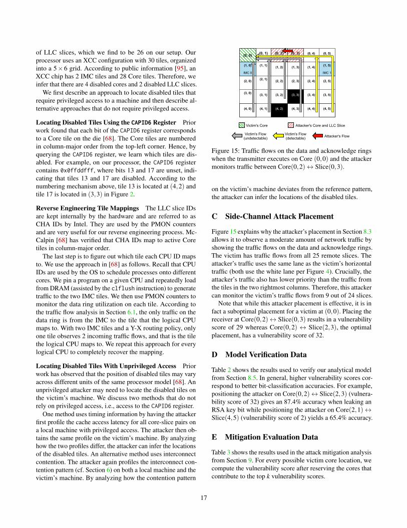
of LLC slices, which we find to be 26 on our setup. Ourprocessor uses an XCC configuration with 30 tiles, organizedinto a 5× 6 grid. According to public information [95], anXCC chip has 2 IMC tiles and 28 Core tiles. Therefore, weinfer that there are 4 disabled cores and 2 disabled LLC slices.
We first describe an approach to locate disabled tiles thatrequire privileged access to a machine and then describe al-ternative approaches that do not require privileged access.
Locating Disabled Tiles Using the CAPID6 Register Priorwork found that each bit of the CAPID6 register correspondsto a Core tile on the die [68]. The Core tiles are numberedin column-major order from the top-left corner. Hence, byquerying the CAPID6 register, we learn which tiles are dis-abled. For example, on our processor, the CAPID6 registercontains 0x0ffddfff, where bits 13 and 17 are unset, indi-cating that tiles 13 and 17 are disabled. According to thenumbering mechanism above, tile 13 is located at (4,2) andtile 17 is located in (3,3) in Figure 2.
Reverse Engineering Tile Mappings The LLC slice IDsare kept internally by the hardware and are referred to asCHA IDs by Intel. They are used by the PMON countersand are very useful for our reverse engineering process. Mc-Calpin [68] has verified that CHA IDs map to active Coretiles in column-major order.
The last step is to figure out which tile each CPU ID mapsto. We use the approach in [68] as follows. Recall that CPUIDs are used by the OS to schedule processes onto differentcores. We pin a program on a given CPU and repeatedly loadfrom DRAM (assisted by the clflush instruction) to generatetraffic to the two IMC tiles. We then use PMON counters tomonitor the data ring utilization on each tile. According tothe traffic flow analysis in Section 6.1, the only traffic on thedata ring is from the IMC to the tile that the logical CPUmaps to. With two IMC tiles and a Y-X routing policy, onlyone tile observes 2 incoming traffic flows, and that is the tilethe logical CPU maps to. We repeat this approach for everylogical CPU to completely recover the mapping.
Locating Disabled Tiles With Unprivileged Access Priorwork has observed that the position of disabled tiles may varyacross different units of the same processor model [68]. Anunprivileged attacker may need to locate the disabled tiles onthe victim’s machine. We discuss two methods that do notrely on privileged access, i.e., access to the CAPID6 register.
One method uses timing information by having the attackerfirst profile the cache access latency for all core-slice pairs ona local machine with privileged access. The attacker then ob-tains the same profile on the victim’s machine. By analyzinghow the two profiles differ, the attacker can infer the locationsof the disabled tiles. An alternative method uses interconnectcontention. The attacker again profiles the interconnect con-tention pattern (cf. Section 6) on both a local machine and thevictim’s machine. By analyzing how the contention pattern
(0, 0) (0, 1) (0, 2) (0, 3) (0, 4) (0, 5)
(1, 0)
IMC 0
(1, 1) (1, 2) (1, 3) (1, 4) (1, 5)
IMC 1
(2, 0) (2, 1) (2, 2) (2, 3) (2, 4) (2, 5)
(3, 0) (3, 1) (3, 2) (3, 3) (3, 4) (3, 5)
(4, 0) (4, 1) (4, 2) (4, 3) (4, 4) (4, 5)
Attacker's FlowVictim's Flow(undetectable)
Victim's Flow(detectable)
Victim's Core Attacker's Core and LLC Slice
Figure 15: Traffic flows on the data and acknowledge ringswhen the transmitter executes on Core (0,0) and the attackermonitors traffic between Core(0,2)↔ Slice(0,3).
on the victim’s machine deviates from the reference pattern,the attacker can infer the locations of the disabled tiles.
C Side-Channel Attack Placement
Figure 15 explains why the attacker’s placement in Section 8.3allows it to observe a moderate amount of network traffic byshowing the traffic flows on the data and acknowledge rings.The victim has traffic flows from all 25 remote slices. Theattacker’s traffic uses the same lane as the victim’s horizontaltraffic (both use the white lane per Figure 4). Crucially, theattacker’s traffic also has lower priority than the traffic fromthe tiles in the two rightmost columns. Therefore, this attackercan monitor the victim’s traffic flows from 9 out of 24 slices.
Note that while this attacker placement is effective, it is infact a suboptimal placement for a victim at (0,0). Placing thereceiver at Core(0,2)↔ Slice(0,3) results in a vulnerabilityscore of 29 whereas Core(0,2) ↔ Slice(2,3), the optimalplacement, has a vulnerability score of 32.
D Model Verification Data
Table 2 shows the results used to verify our analytical modelfrom Section 8.5. In general, higher vulnerability scores cor-respond to better bit-classification accuracies. For example,positioning the attacker on Core(0,2)↔ Slice(2,3) (vulnera-bility score of 32) gives an 87.4% accuracy when leaking anRSA key bit while positioning the attacker on Core(2,1)↔Slice(4,5) (vulnerability score of 2) yields a 65.4% accuracy.
E Mitigation Evaluation Data
Table 3 shows the results used in the attack mitigation analysisfrom Section 9. For every possible victim core location, wecompute the vulnerability score after reserving the cores thatcontribute to the top k vulnerability scores.
17
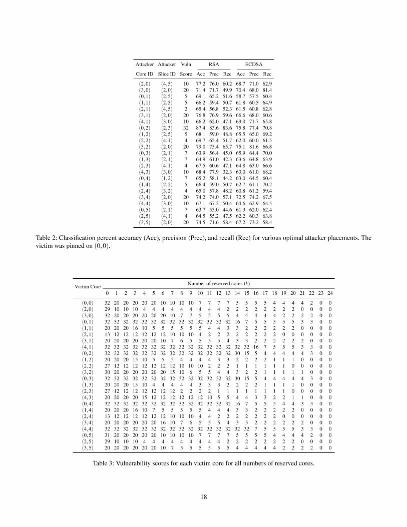
Attacker Attacker Vuln RSA ECDSA
Core ID Slice ID Score Acc Prec Rec Acc Prec Rec
(2,0) (4,5) 10 77.2 76.0 60.2 68.7 71.0 62.9(3,0) (2,0) 20 71.4 71.7 49.9 70.4 68.0 81.4(0,1) (2,5) 5 69.1 65.2 51.6 58.7 57.5 60.4(1,1) (2,5) 5 66.2 59.4 50.7 61.8 60.5 64.9(2,1) (4,5) 2 65.4 56.8 52.3 61.5 60.8 62.8(3,1) (2,0) 20 76.8 76.9 59.6 66.6 68.0 60.6(4,1) (3,0) 10 66.2 62.0 47.1 69.0 71.7 65.8(0,2) (2,3) 32 87.4 83.6 83.6 75.8 77.4 70.8(1,2) (2,5) 5 68.1 59.0 48.8 65.5 65.0 69.2(2,2) (4,1) 4 69.7 65.4 51.7 62.0 60.0 61.5(3,2) (2,0) 20 79.0 75.4 65.7 75.1 81.6 66.8(0,3) (2,1) 7 63.9 56.4 45.0 65.9 64.4 70.0(1,3) (2,1) 7 64.9 61.0 42.3 63.6 64.8 63.9(2,3) (4,1) 4 67.5 60.6 47.1 64.8 63.0 66.6(4,3) (3,0) 10 68.4 77.9 32.3 63.0 61.0 68.2(0,4) (1,2) 7 65.2 58.1 44.2 63.0 64.5 60.4(1,4) (2,2) 5 66.4 59.0 50.7 62.7 61.1 70.2(2,4) (3,2) 4 65.0 57.8 48.2 60.8 61.2 59.4(3,4) (2,0) 20 74.2 74.0 57.1 72.5 74.2 67.5(4,4) (3,0) 10 67.1 67.2 50.4 64.6 62.9 64.5(0,5) (2,1) 7 63.7 53.0 44.6 61.9 62.0 62.4(2,5) (4,1) 4 64.5 55.2 47.5 62.2 60.3 63.8(3,5) (2,0) 20 74.5 71.6 58.4 67.2 73.2 58.4
Table 2: Classification percent accuracy (Acc), precision (Prec), and recall (Rec) for various optimal attacker placements. Thevictim was pinned on (0,0).
Victim Core Number of reserved cores (k)
0 1 2 3 4 5 6 7 8 9 10 11 12 13 14 15 16 17 18 19 20 21 22 23 24
(0,0) 32 20 20 20 20 20 10 10 10 10 7 7 7 7 5 5 5 5 4 4 4 4 2 0 0(2,0) 29 10 10 10 4 4 4 4 4 4 4 4 4 2 2 2 2 2 2 2 2 0 0 0 0(3,0) 32 20 20 20 20 20 20 10 7 7 5 5 5 5 4 4 4 4 4 2 2 2 2 0 0(0,1) 32 32 32 32 32 32 32 32 32 32 32 32 32 32 16 7 5 5 5 5 5 3 3 0 0(1,1) 20 20 20 16 10 5 5 5 5 5 5 4 4 3 3 2 2 2 2 2 2 0 0 0 0(2,1) 13 12 12 12 12 12 12 10 10 10 4 2 2 2 2 2 2 2 2 0 0 0 0 0 0(3,1) 20 20 20 20 20 20 10 7 6 5 5 5 5 4 3 3 2 2 2 2 2 2 0 0 0(4,1) 32 32 32 32 32 32 32 32 32 32 32 32 32 32 32 32 16 7 5 5 5 3 3 0 0(0,2) 32 32 32 32 32 32 32 32 32 32 32 32 32 32 30 15 5 4 4 4 4 4 3 0 0(1,2) 20 20 20 15 10 5 5 5 4 4 4 4 3 3 2 2 2 2 1 1 1 0 0 0 0(2,2) 27 12 12 12 12 12 12 12 10 10 10 2 2 2 1 1 1 1 1 1 0 0 0 0 0(3,2) 30 20 20 20 20 20 20 15 10 6 5 5 4 4 3 2 2 1 1 1 1 1 0 0 0(0,3) 32 32 32 32 32 32 32 32 32 32 32 32 32 32 30 15 5 4 4 4 4 4 3 0 0(1,3) 20 20 20 15 10 4 4 4 4 4 3 3 3 2 2 2 2 1 1 1 1 0 0 0 0(2,3) 27 12 12 12 12 12 12 12 2 2 2 2 1 1 1 1 1 1 1 1 0 0 0 0 0(4,3) 20 20 20 20 15 12 12 12 12 12 12 10 5 5 4 4 3 3 2 2 1 1 0 0 0(0,4) 32 32 32 32 32 32 32 32 32 32 32 32 32 32 16 7 5 5 5 4 4 3 3 0 0(1,4) 20 20 20 16 10 7 5 5 5 5 5 4 4 4 3 3 2 2 2 2 2 0 0 0 0(2,4) 13 12 12 12 12 12 12 10 10 10 4 4 2 2 2 2 2 2 2 0 0 0 0 0 0(3,4) 20 20 20 20 20 20 16 10 7 6 5 5 5 4 3 3 2 2 2 2 2 2 0 0 0(4,4) 32 32 32 32 32 32 32 32 32 32 32 32 32 32 32 32 7 5 5 5 5 3 3 0 0(0,5) 31 20 20 20 20 20 10 10 10 10 7 7 7 7 5 5 5 5 4 4 4 4 2 0 0(2,5) 29 10 10 10 4 4 4 4 4 4 4 4 4 2 2 2 2 2 2 2 2 0 0 0 0(3,5) 20 20 20 20 20 20 10 7 5 5 5 5 5 5 4 4 4 4 4 2 2 2 2 0 0
Table 3: Vulnerability scores for each victim core for all numbers of reserved cores.
18