shunt active power filter implementation using pq theory
TRANSCRIPT
Shunt Active Power Filter Implementation Using PQ
Theory With LabView Faisal Falah Aiwa1, Mahmood T. Alkhayyat2, Mohammed Y. Suliman3
{[email protected], [email protected], [email protected]}
Department of Electrical Power Techniques Engineering, Technical Engineering College, Northern
Technical University, Mosul, Iraq1,2,3
Abstract. A shunt active power filter (SAPF) is a suitable harmonics suppression solution
in power systems. Traditional SAPF researchers have generally used the Matlab/Simulink
platform in the design and implementation. Which is allows validation of the SAPF
algorithm and theoretically simulates the compensation effect. However, such SAPF
cannot apply in practical cases. LabView is a popular application for data collection and
instrument control. With external equipment such as a Data Acquisition Card (DAQ),
LabView can monitor and control the system in real-time. The main goal of the work
presented in this paper is to use the LabView platform with NI USB - 6009 DAQ in the
design and implementation of a shunt active power filter. With the aid of LabView
intelligent control software, the harmonic components of the source current are extracted
using the Instantaneous Active-Reactive Power Theory (PQ) theory. The performance of
a shunt active power filter has been demonstrated in simulation and experimental setup.
Keywords: shunt active power filter(SAPF), LabView, Data acquisition system (DAQ),
total harmonic distortion (THD), power quality, PQ theory.
1 Introduction
Energy users have become more conscious and sensitive to power quality variations as
sensitive electronic equipment has become more common. Harmonics [1] are the primary cause
of power quality degradation. A harmonic is the sine component of a periodic wave whose
frequency is an integer multiple of the fundamental frequency. The total harmonic distortion
(THD) equation [2] is used to calculate harmonic distortion in an electrical power system.
Harmonic distortion in electrical power systems is mostly caused by non-linear loads.
Bridge rectifiers, both uncontrolled and controlled, speed-controlled motor drives, televisions,
led bulbs, personal computers, and uninterruptible power supply (UPSs) [3] are examples.
Reduced power factor, decreased efficiency, power system voltage fluctuations,
communications interference, circuit breaker dysfunction, equipment heating, and breakdown
and injury are some of the effects of harmonics. Harmonics can thus be thought of as a pollutant
that affects the entire power system [4]. Passive filters have traditionally been used to minimise
harmonics, however they have issues and drawbacks such as huge size and weight, greater cost,
fixed compensation, and resonance issues with loads. As a result, a focus on a power electronic
solution, such as shunt active power filters (SAPF), has become necessary in the electrical power
system [5]. Because of its modest physical size and versatility, SAPF is an excellent solution
for power quality issues. In addition, it has a lower cost and operating loss.
Shunt active power filters (SAPF) based on voltage source inverters, as shown in Figure 1,
are appropriate solutions for reducing current harmonics and improving power quality. SAPF's
core concept is to use power electronics to provide current compensation components that
IMDC-IST 2021, September 07-09, Sakarya, TurkeyCopyright © 2022 EAIDOI 10.4108/eai.7-9-2021.2315487
eliminate harmonic current components that develop as a result of non-linear loads [7].
Fig. 1. Principal of SAPF.
Many researchers were worked to improve Power quality based on the harmonic current
detection methods and compensation current control strategies in the literature. The authors in
[8] presented four controls algorithm to control the shunt active filter. The theory (PQ), an
adaptive phase locked loop (PLL), Instantaneous active and reactive current method (DQ), and
Synchronous detection method (SD) are designed in Matlab Simulink to generate the reference
current of SAPF for mitigation of source current harmonics. The authors in [9] have proposed a
DQ-PQ technique for compensating unbalanced nonlinear loads and different in line currents.
As well as, eliminating the negative and zero sequence components of the line currents using
SAPF. Matlab simulation was used in the design and implementation. The research in [10] have
presented the SAPF simulation based on the (PQ) theory in Matlab and LabView software and
compare the results.
In this study, the SAPF control circuit based on (PQ) theory was implemented in real-time
using Laboratory Virtual Instrument Engineering Workbench (LabView) and NI USB - 6009
DAQ to mitigate source current harmonics caused by non-linear loads and improve power
quality by lowering THD.
2 Shunt Active Power Filters (SAPF)
In 1976, Gyugyi and Strycula proposed the notion of shunt active filtering for the first time.
It’s the most popular type of active filter. SAPF converter could be a voltage source inverter or
a current source inverter, and it can be single-phase or three-phase. This filter works as a current
source, injecting the load's harmonic components but with a 180° phase shift [11]. Its controller
calculates the compensating current reference in real time and compels a power electronic
converter to correctly synthesize it. This method allows for selective and adaptive active
filtering. In other words, a SAPF can correct for a nonlinear load's harmonic current and
periodically track changes in its harmonic content [12].
3 Instantaneous Active-Reactive Power Theory (PQ)
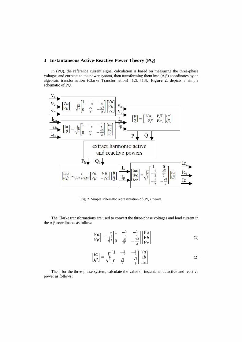
In (PQ), the reference current signal calculation is based on measuring the three-phase
voltages and currents to the power system, then transforming them into (α-β) coordinates by an
algebraic transformation (Clarke Transformation) [12], [13]. Figure 2. depicts a simple
schematic of PQ.
Fig. 2. Simple schematic representation of (PQ) theory.
The Clarke transformations are used to convert the three-phase voltages and load current in
the α-β coordinates as follow:
[𝑉𝛼𝑉𝛽
] = √2
3[1 −1
2−1
2
0 √32
−√3
2
] [𝑉𝑎𝑉𝑏𝑉𝑐
] (1)
[𝑖𝛼𝑖𝛽
] = √2
3[1 −1
2−1
2
0 √32
−√3
2
] [𝑖𝑎𝑖𝑏𝑖𝑐
] (2)
Then, for the three-phase system, calculate the value of instantaneous active and reactive
power as follows:
[𝑝𝑄] = [
𝑉𝛼 𝑉𝛽−𝑉𝛽 𝑉𝛼
] [𝑖𝛼𝑖𝛽
] (3)
Where:
p: real power.
Q: reactive power.
Observing the equation (3) the P and Q can be put them in the following form:
𝑃 = �̅� + �̌� (4)
𝑄 = �̅� + �̌� (5)
Where:
�̅� : is the average component of P and is linked to conventional fundamental active current.
�̌� : is the oscillating part of P and linked with harmonics caused by the oscillating component
of instantaneous real power.
�̅� : is the average part of Q and is linked with reactive power due to the fundamental component
of currents and voltages.
�̌� : is the oscillating part of Q and is linked with harmonic currents from the oscillating
components of instantaneous reactive power.
A low pass filter is used to extract the fluctuating sections of the real and reactive power.
In α-β coordinates, compensating currents are calculated as follows:
[𝑖𝑐𝛼𝑖𝑐𝛽
] = 1
Vα2 + Vβ2 [𝑉𝛼 𝑉𝛽𝑉𝛽 −𝑉𝛼
] [�̌��̌�
] (6)
Finally, the currents in α-β coordinates are converted to a-b-c coordinates as follows:
[𝑖𝑐𝑎𝑖𝑐𝑏𝑖𝑐𝑐
] = √2
3
[
1 0
−1
2
√3
2
−1
2−
√3
2 ]
[𝑖𝑐𝛼𝑖𝑐𝛽
] (7)
After that, the shunt active filter controller uses the three-phase compensation current as a
reference signal.
4 Simulation in LabView
The performance of the SAPF was tested by using the LabView program by designing the
PQ theory and simulated the source voltage and distorted load current using a signal generator
block. Figure 3. shows the PQ theory designed in LabView.
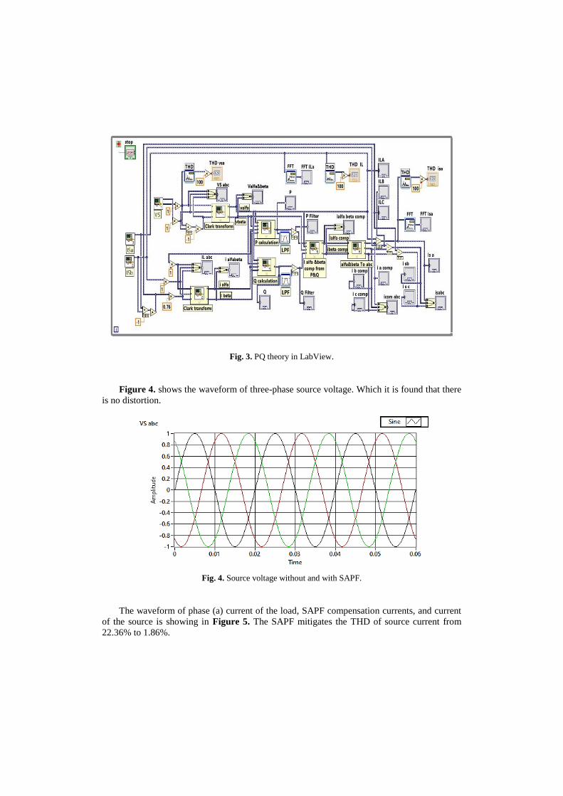
Fig. 3. PQ theory in LabView.
Figure 4. shows the waveform of three-phase source voltage. Which it is found that there
is no distortion.
Fig. 4. Source voltage without and with SAPF.
The waveform of phase (a) current of the load, SAPF compensation currents, and current
of the source is showing in Figure 5. The SAPF mitigates the THD of source current from
22.36% to 1.86%.
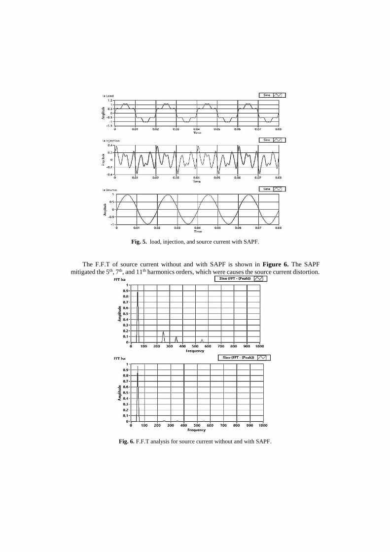
Fig. 5. load, injection, and source current with SAPF.
The F.F.T of source current without and with SAPF is shown in Figure 6. The SAPF
mitigated the 5th, 7th, and 11th harmonics orders, which were causes the source current distortion.
Fig. 6. F.F.T analysis for source current without and with SAPF.
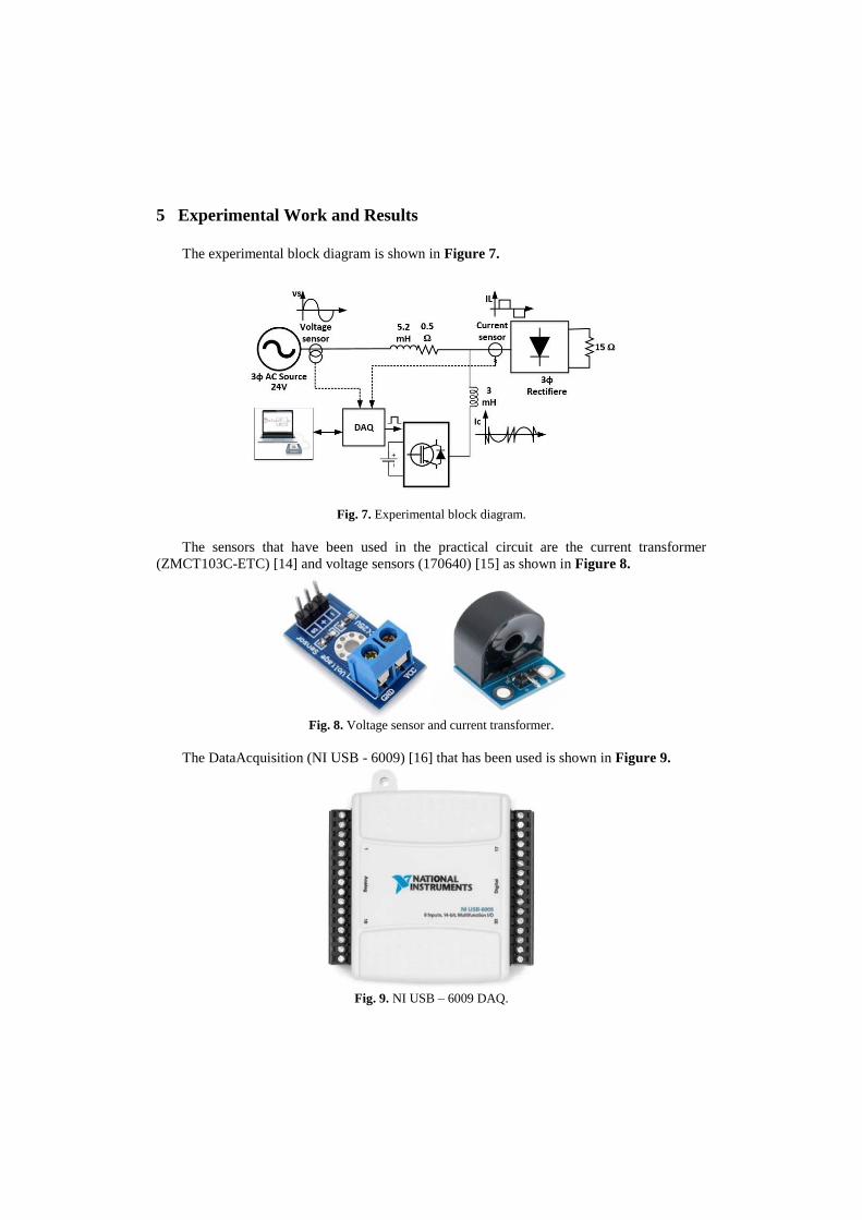
5 Experimental Work and Results
The experimental block diagram is shown in Figure 7.
Fig. 7. Experimental block diagram.
The sensors that have been used in the practical circuit are the current transformer
(ZMCT103C-ETC) [14] and voltage sensors (170640) [15] as shown in Figure 8.
Fig. 8. Voltage sensor and current transformer.
The DataAcquisition (NI USB - 6009) [16] that has been used is shown in Figure 9.
Fig. 9. NI USB – 6009 DAQ.
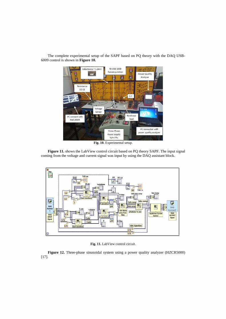
The complete experimental setup of the SAPF based on PQ theory with the DAQ USB-
6009 control is shown in Figure 10.
Fig. 10. Experimental setup.
Figure 11. shows the LabView control circuit based on PQ theory SAPF. The input signal
coming from the voltage and current signal was input by using the DAQ assistant block.
Fig. 11. LabView control circuit.
Figure 12. Three-phase sinusoidal system using a power quality analyzer (HZCR5000)
[17].
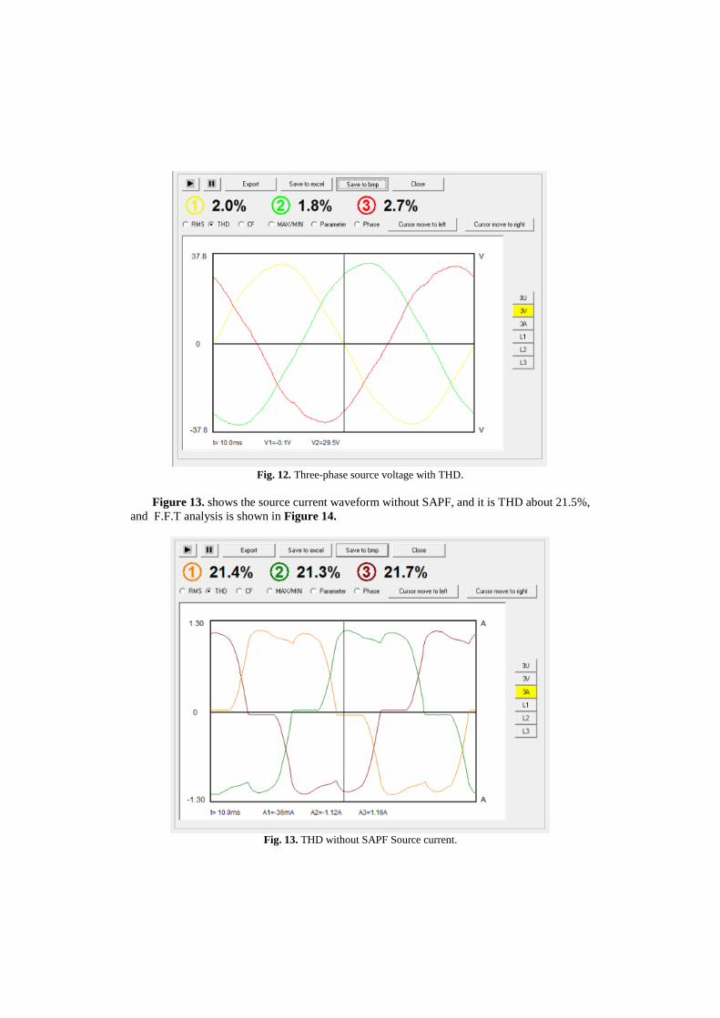
Fig. 12. Three-phase source voltage with THD.
Figure 13. shows the source current waveform without SAPF, and it is THD about 21.5%,
and F.F.T analysis is shown in Figure 14.
Fig. 13. THD without SAPF Source current.
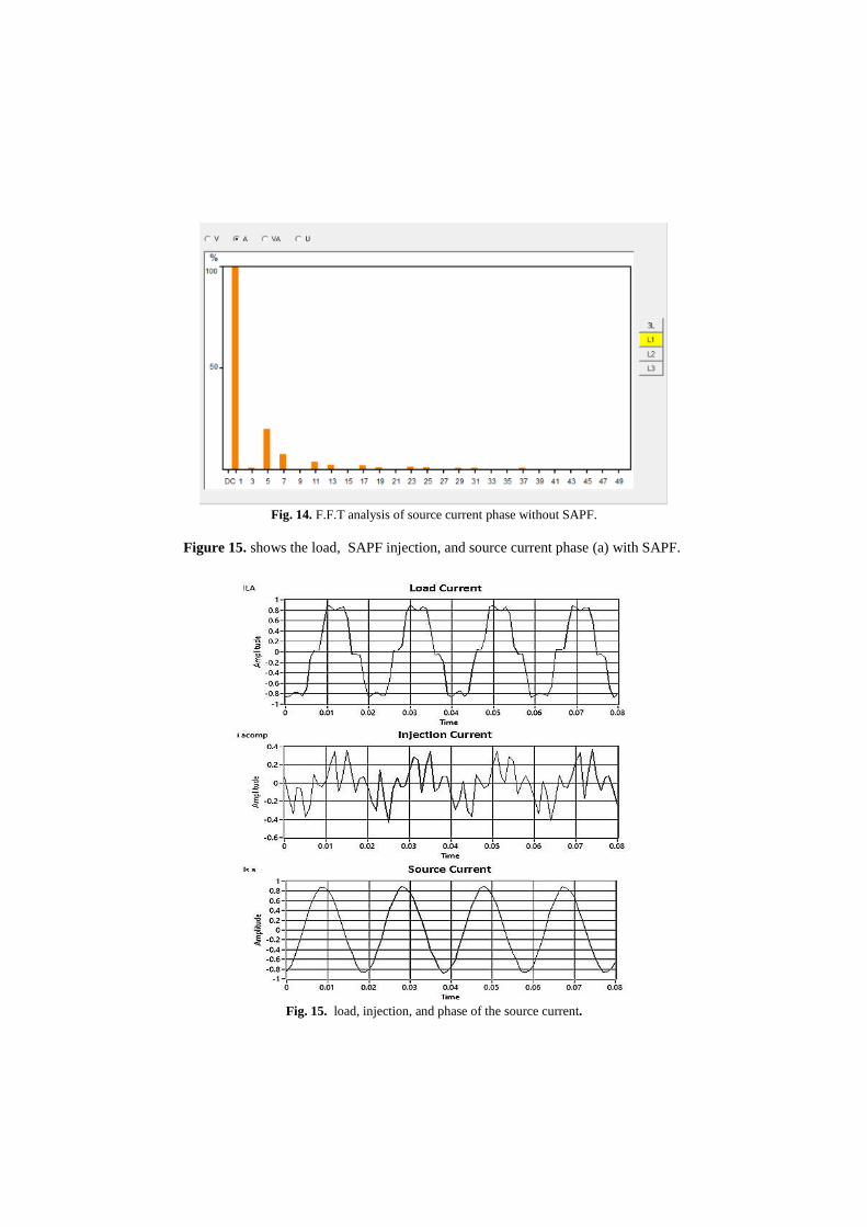
Fig. 14. F.F.T analysis of source current phase without SAPF.
Figure 15. shows the load, SAPF injection, and source current phase (a) with SAPF.
Fig. 15. load, injection, and phase of the source current.
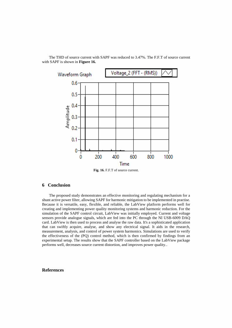
The THD of source current with SAPF was reduced to 3.47%. The F.F.T of source current
with SAPF is shown in Figure 16.
Fig. 16. F.F.T of source current.
6 Conclusion
The proposed study demonstrates an effective monitoring and regulating mechanism for a
shunt active power filter, allowing SAPF for harmonic mitigation to be implemented in practise.
Because it is versatile, easy, flexible, and reliable, the LabView platform performs well for
creating and implementing power quality monitoring systems and harmonic reduction. For the
simulation of the SAPF control circuit, LabView was initially employed. Current and voltage
sensors provide analogue signals, which are fed into the PC through the NI USB-6009 DAQ
card. LabView is then used to process and analyse the raw data. It's a sophisticated application
that can swiftly acquire, analyse, and show any electrical signal. It aids in the research,
measurement, analysis, and control of power system harmonics. Simulations are used to verify
the effectiveness of the (PQ) control method, which is then confirmed by findings from an
experimental setup. The results show that the SAPF controller based on the LabView package
performs well, decreases source current distortion, and improves power quality..
References
[1] Asia’u Talatu Belgore, Bara’u Gafai Najashi. Control Techniques for Shunt Active Power
Filters. International Journal of Engineering Research & Technology (IJERT). 2020. vol. 9 ( no.
09). pp. 1054–1059.
[2] D. M. Soomro, M. A. Omran, and S. K. Alswed. Design of a shunt active power filter to mitigate
the harmonics caused by nonlinear loads. ARPN J. Eng. Appl. Sci. 2015. vol. 10 ( no. 19). pp.
8774–8782.
[3] Z. Salam, P. C. Tan, and A. Jusoh. Harmonics mitigation using active power filter: a
technological review,” Elektrika. 2006. vol. 8 ( no. 2). pp. 17–26.
[4] C. Rejil and A. K. R. Design and Simulation of Three Phase Shunt Active Power Filter Using
SRF Theory. Adv. Electron. Electr. Eng. 2013. vol. 3 (no. 6). pp. 651–660.
[5] N. Booma and S. R. Reddy. Design And Simulation Of Hybrid Active Power Filter For Power
Quality Improvement. i-manager’s J. Electr. Eng. 2012. vol. 6 ( no. 2). pp. 16–21.
[6] Almaita, Eyad KH. Adaptive Radial Basis Function Neural Networks-Based Real Time
Harmonics Estimation and PWM Control for Active Power Filters. Western Michigan
University. 2012. Dissertations. 9.
[7] M. Halawa, B. Abou-zalam, and A. Sobaih. Power Quality Improvement Using a Shunt Active
Power Filter Based on the Hysteresis Current Controller. Int. Electr. Eng. J. 2016. vol. 7 ( no. 5).
pp. 2266–2278.
[8] B. Abd El-Rahman, E. G. Shehata, A.-H. El-Sayed, and Y. S.Mohamad. Performance Analysis
of Active Power Filter Controllers for Harmonics Mitigation in Power Systems. J. Adv. Eng.
Trends. 2020. vol. 39 ( no. 1). pp. 77–88.
[9] M. T. Mahmood Alkhayyat and S. M. Bashi. Mitigation Unbalance Nonlinear Loads and
Dissimilar Line Currents Using Shunt Active Power Filter SAPF. Int. J. Adv. Eng. Manag. Sci.
Infogain Publ. 2016. vol. 2 (no. 10). pp. 2454–1311.
[10] Z. Zhang, H. L. Jiang, H. J. Zhang, and J. P. Wang. Active power filter design and simulation
by combining LabVIEW and Simulink. International Conference on Advanced Power System
Automation and Protection. 2011. vol. 2. pp. 1104–1109.
[11] Ali Emadi, Abdolhosein Nasiri and Stoyan B. Bekiarov. UNINTERRUPTIBLE POWER
SUPPLIES AND ACTIVE FILTERS. Muhammad H. Rashid. United States of America. CRC
Press LLC. 2005. no. 11–12.
[12] M. A. HIROFUMI AKAGI, EDSON HIROKAZUWATANABE. INSTANTANEOUS POWER
THEORYAND APPLICATIONS TO POWER CONDITIONING. Tariq Samad. Inc. Hoboken,
New Jersey. John Wiley & Sons . 2017. 30-45
[13] M. Chakravarthy, S. N. Saxena, and S. Ram. Control of Shunt Active Power Filter Using
LabVIEW. International Journal of Engineering and Innovative Technology (IJEIT). 2012.
Volume 2 (no.3). pp. 2277-3754
[14] [ “ZMCT103C.5A Range AC Current Transformer Current Sensor Module General.”
[15] S. G. Technology, “Model : Voltage Sensor / 170640 Reference Code :,” no. 1000. p. 170640,
2015.
[16] National Instrument Team, “User Guide Ni Usb-6008/6009.”. 2015. pp. 1–26
[17] “HZCR5000-Power-Quality-Analyzer.pdf.” .