service manual - w11296289- side-x-side refrigerator
TRANSCRIPT
SERVICE MANUALWhirlpool®, Maytag®, Amana®, & IKEA®
Refrigerators
W11296289
R-126
ii n Whirlpool®, Maytag®, Amana®, & IKEA® Refrigerators
FORWARDThis Whirlpool Service Manual (Part No. W11296289), provides the In-Home Service Professional with service information for the “Whripool®, Maytag®, Amana®, and IKEA® Refrigerators.”
The Wiring Diagram used in this Service Manual is typical and should be used for training purposes only. Always use the Wiring Diagram supplied with the product tech sheet when servicing the refrigerator.
For specific operating and installation information on the model being serviced, refer to the “Use and Care Guide” or “Installation Instructions” provided with the refrigerator.
GOALS AND OBJECTIVES
The goal of this Service Manual is to provide information that will enable the In-Home Service Professional to properly diagnose malfunctions and repair the “Whripool®, Maytag®, Amana®, and IKEA® Refrigerators.”
The objectives of this Service Manual are to:• Understand and follow proper safety precautions.• Successfully troubleshoot and diagnose malfunctions.• Successfully perform necessary repairs.
WHIRLPOOL CORPORATION assumes no responsibility for any repairs made on our products by anyone other than authorized In-Home Service Professionals.
©2018 Whirlpool Corporation. Benton Harbor, MI 49022
Whirlpool®, Maytag®, Amana® , & IKEA® Refrigerators n iii
TABLE OF CONTENTS Whirlpool®, Maytag®, Amana®, & IKEA® Refrigerators
SECTION 1: GENERAL INFORMATION ........................................................................1-01REFRIGERATOR SAFETY .................................................................................................................... 1-02PRODUCT SPECIFICATIONS ............................................................................................................... 1-03PRODUCT FEATURES ......................................................................................................................... 1-11MODEL & SERIAL NUMBER LOCATION ............................................................................................. 1-12TECH SHEET LOCATION ..................................................................................................................... 1-12MODEL NOMENCLATURE ................................................................................................................. 1-13
SECTION 2: DIAGNOSTICS ..........................................................................................2-01SAFETY .............................................................................................................................................. 2-02DIAGNOSTICS MODE ........................................................................................................................ 2-03SALES DEMO MODE .......................................................................................................................... 2-09
SECTION 3: COMPONENT TESTING ...........................................................................3-01SAFETY .............................................................................................................................................. 3-02WIRING DIAGRAM ............................................................................................................................ 3-03COMPONENT LOCATION .................................................................................................................. 3-09
SECTION 4: COMPONENT ACCESS .............................................................................4-01REMOVING THE FRONT WHEEL........................................................................................................ 4-02ACCESSING INTERIOR OF UNIT ........................................................................................................ 4-03REMOVING THE DAMPER ................................................................................................................. 4-03REMOVING THE FREEZER SHELF ...................................................................................................... 4-05ACCESSING THE FREEZER EVAPORATOR AND COMPONENTS ......................................................... 4-05ACCESSING THE DISPENSER AREA (REMOVING UI) ......................................................................... 4-07ACCESSING THE MACHINE COMPARTMENT .................................................................................... 4-10

iv n Whirlpool®, Maytag®, Amana®, & IKEA® Refrigerators
Notes
GENERAL INFORMATION
Whirlpool®, Maytag®, Amana®, & IKEA® Refrigerators n 1-1
Section 1: General Information
This section provides general safety, parts, and information for the “Whirlpool®, Maytag®, Amana®, and IKEA® Refrigerators.”
Refrigerator Safety
Product Specifications
Product Feature• Control Panel
Model & Serial Label • Location• Model Nomenclature
Tech Sheet Location
GENERAL INFORMATION
1-2 n Whirlpool®, Maytag®, Amana®, & IKEA® Refrigerators
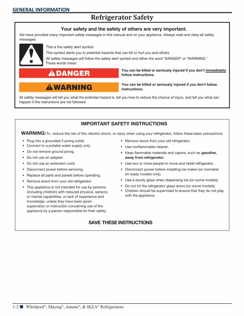
Refrigerator Safety
You can be killed or seriously injured if you don't immediately
You can be killed or seriously injured if you don't follow
All safety messages will tell you what the potential hazard is, tell you how to reduce the chance of injury, and tell you what canhappen if the instructions are not followed.
Your safety and the safety of others are very important.We have provided many important safety messages in this manual and on your appliance. Always read and obey all safety messages.
This is the safety alert symbol.
This symbol alerts you to potential hazards that can kill or hurt you and others.
All safety messages will follow the safety alert symbol and either the word “DANGER” or “WARNING.”These words mean:
follow instructions.
instructions.
DANGER
WARNING
IMPORTANT SAFETY INSTRUCTIONS
WARNING: To reduce the risk of re, electric shock, or injury when using your refrigerator, follow these basic precautions:
Remove doors from your old refrigerator.
Use nonammable cleaner.
Keep ammable materials and vapors, such as gasoline,away from refrigerator.
Use two or more people to move and install refrigerator.
Disconnect power before installing ice maker (on icemakerkit ready models only).
Use a sturdy glass when dispensing ice (on some models).
Do not hit the refrigerator glass doors (on some models). Children should be supervised to ensure that they do not play
with the appliance.
SAVE THESE INSTRUCTIONS
Plug into a grounded 3 prong outlet. Connect to a potable water supply only.
Do not remove ground prong.
Do not use an adapter.
Do not use an extension cord.
Disconnect power before servicing.
Replace all parts and panels before operating.
Remove doors from your old refrigerator
This appliance is not intended for use by persons(including children) with reduced physical, sensoryor mental capabilities, or lack of experience andknowledge, unless they have been givensupervision or instruction concerning use of theappliance by a person responsible for their safety.
GENERAL INFORMATION
Whirlpool®, Maytag®, Amana®, & IKEA® Refrigerators n 1-3
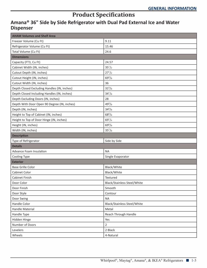
Product SpecificationsAmana® 36" Side by Side Refrigerator with Dual Pad External Ice and Water DispenserAHAM Volumes and Shelf Area
Freezer Volume (Cu Ft) 9.11
Refrigerator Volume (Cu Ft) 15.46
Total Volume (Cu Ft) 24.6
Dimensions
Capacity (FT3, Cu Ft) 24.57
Cabinet Width (IN, inches) 351/2
Cutout Depth (IN, inches) 271/2
Cutout Height (IN, inches) 693/8
Cutout Width (IN, inches) 36
Depth Closed Excluding Handles (IN, inches) 315/8
Depth Closed Including Handles (IN, inches) 341/8
Depth Excluding Doors (IN, inches) 28
Depth With Door Open 90 Degree (IN, inches) 493/8
Depth (IN, inches) 345/8
Height to Top of Cabinet (IN, inches) 685/8
Height to Top of Door Hinge (IN, inches) 691/4
Height (IN, inches) 695/8
Width (IN, inches) 357/8
Description
Type of Refrigerator Side by Side
Details
Advance Foam Insulation NA
Cooling Type Single Evaporator
Exterior
Base Grille Color Black/White
Cabinet Color Black/White
Cabinet Finish Textured
Door Color Black/Stainless Steel/White
Door Finish Smooth
Door Style Contour
Door Swing NA
Handle Color Black/Stainless Steel/White
Handle Material Metal
Handle Type Reach Through Handle
Hidden Hinge Yes
Number of Doors 2
Levelers 2 Black
Wheels 4-Natural
GENERAL INFORMATION
1-4 n Whirlpool®, Maytag®, Amana®, & IKEA® Refrigerators
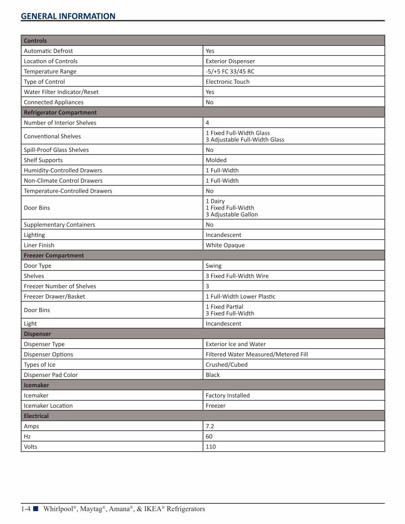
Controls
Automatic Defrost Yes
Location of Controls Exterior Dispenser
Temperature Range -5/+5 FC 33/45 RC
Type of Control Electronic Touch
Water Filter Indicator/Reset Yes
Connected Appliances No
Refrigerator Compartment
Number of Interior Shelves 4
Conventional Shelves 1 Fixed Full-Width Glass 3 Adjustable Full-Width Glass
Spill-Proof Glass Shelves No
Shelf Supports Molded
Humidity-Controlled Drawers 1 Full-Width
Non-Climate Control Drawers 1 Full-Width
Temperature-Controlled Drawers No
Door Bins1 Dairy 1 Fixed Full-Width 3 Adjustable Gallon
Supplementary Containers No
Lighting Incandescent
Liner Finish White Opaque
Freezer Compartment
Door Type Swing
Shelves 3 Fixed Full-Width Wire
Freezer Number of Shelves 3
Freezer Drawer/Basket 1 Full-Width Lower Plastic
Door Bins 1 Fixed Partial 3 Fixed Full-Width
Light Incandescent
Dispenser
Dispenser Type Exterior Ice and Water
Dispenser Options Filtered Water Measured/Metered Fill
Types of Ice Crushed/Cubed
Dispenser Pad Color Black
Icemaker
Icemaker Factory Installed
Icemaker Location Freezer
Electrical
Amps 7.2
Hz 60
Volts 110
GENERAL INFORMATION
Whirlpool®, Maytag®, Amana®, & IKEA® Refrigerators n 1-5
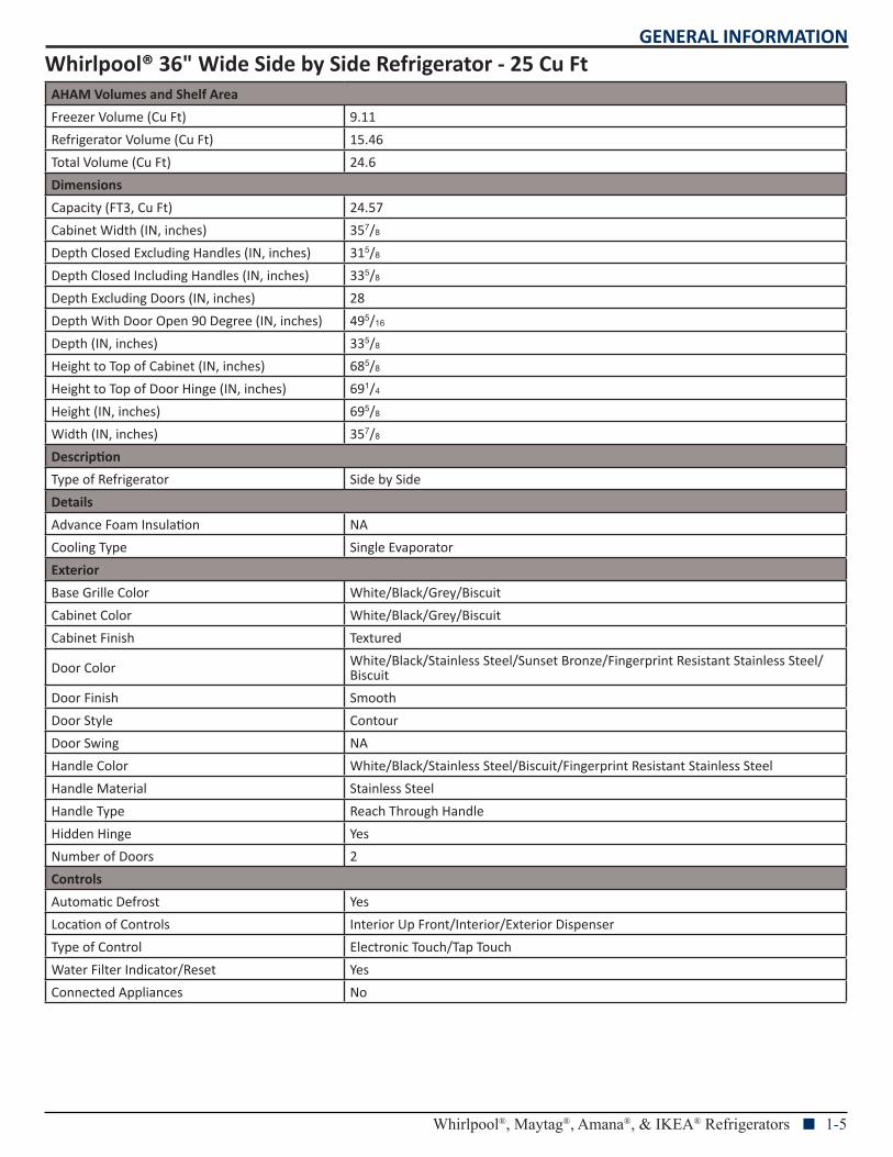
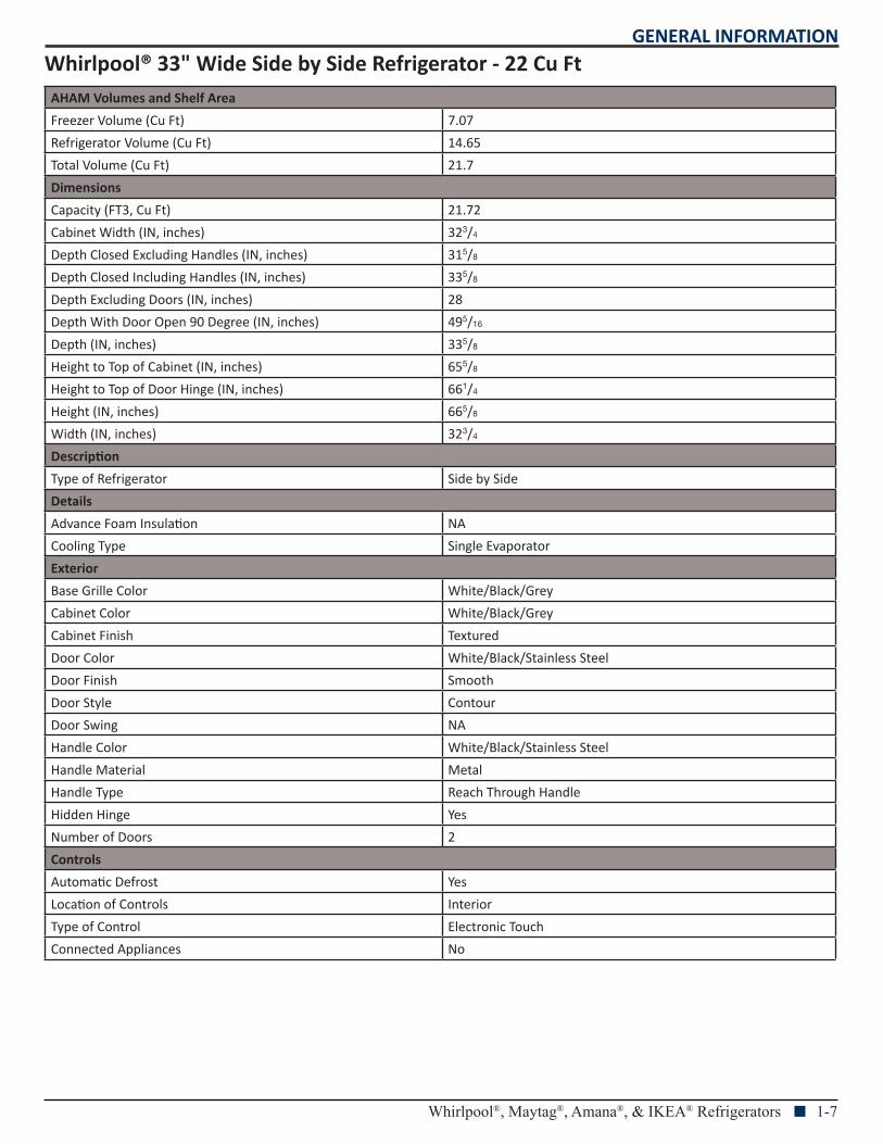
Whirlpool® 36" Wide Side by Side Refrigerator - 25 Cu FtAHAM Volumes and Shelf Area
Freezer Volume (Cu Ft) 9.11
Refrigerator Volume (Cu Ft) 15.46
Total Volume (Cu Ft) 24.6
Dimensions
Capacity (FT3, Cu Ft) 24.57
Cabinet Width (IN, inches) 357/8
Depth Closed Excluding Handles (IN, inches) 315/8
Depth Closed Including Handles (IN, inches) 335/8
Depth Excluding Doors (IN, inches) 28
Depth With Door Open 90 Degree (IN, inches) 495/16
Depth (IN, inches) 335/8
Height to Top of Cabinet (IN, inches) 685/8
Height to Top of Door Hinge (IN, inches) 691/4
Height (IN, inches) 695/8
Width (IN, inches) 357/8
Description
Type of Refrigerator Side by Side
Details
Advance Foam Insulation NA
Cooling Type Single Evaporator
Exterior
Base Grille Color White/Black/Grey/Biscuit
Cabinet Color White/Black/Grey/Biscuit
Cabinet Finish Textured
Door Color White/Black/Stainless Steel/Sunset Bronze/Fingerprint Resistant Stainless Steel/Biscuit
Door Finish Smooth
Door Style Contour
Door Swing NA
Handle Color White/Black/Stainless Steel/Biscuit/Fingerprint Resistant Stainless Steel
Handle Material Stainless Steel
Handle Type Reach Through Handle
Hidden Hinge Yes
Number of Doors 2
Controls
Automatic Defrost Yes
Location of Controls Interior Up Front/Interior/Exterior Dispenser
Type of Control Electronic Touch/Tap Touch
Water Filter Indicator/Reset Yes
Connected Appliances No
GENERAL INFORMATION
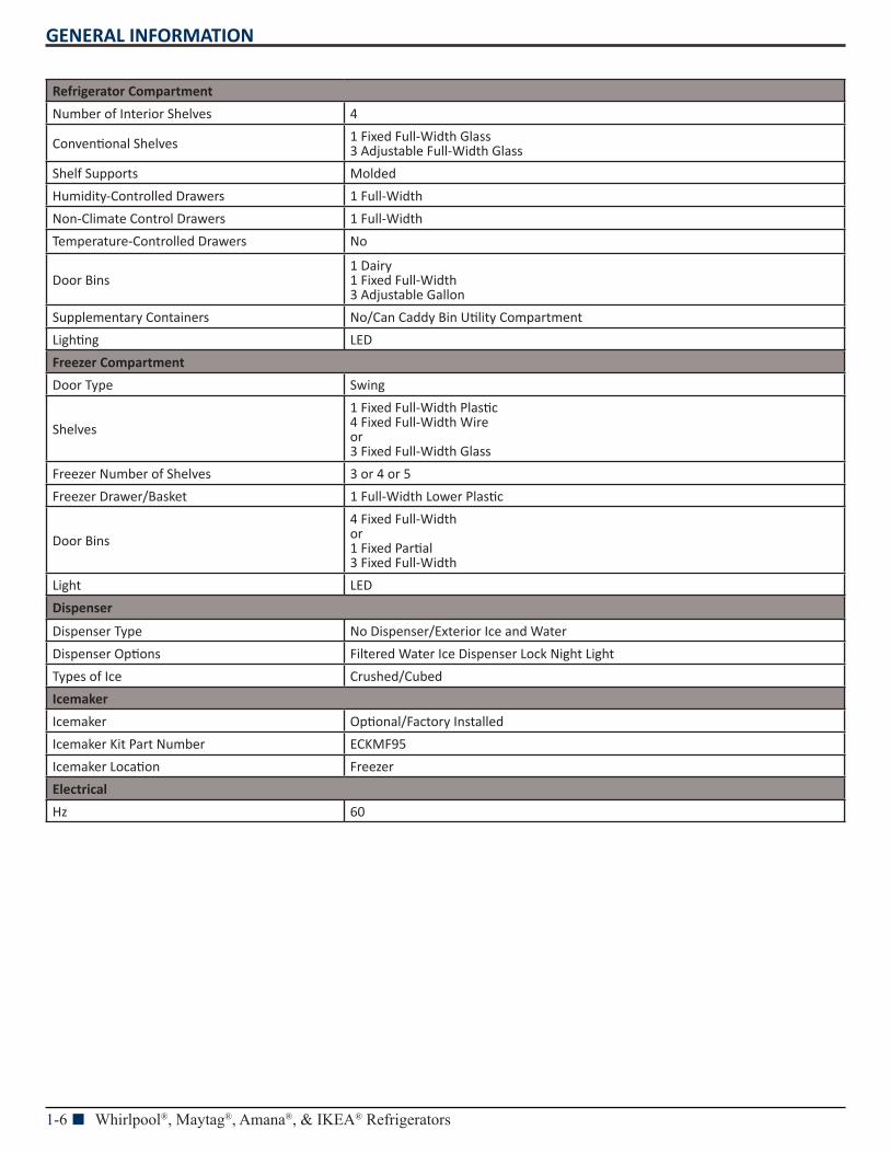
1-6 n Whirlpool®, Maytag®, Amana®, & IKEA® Refrigerators
Refrigerator Compartment
Number of Interior Shelves 4
Conventional Shelves 1 Fixed Full-Width Glass 3 Adjustable Full-Width Glass
Shelf Supports Molded
Humidity-Controlled Drawers 1 Full-Width
Non-Climate Control Drawers 1 Full-Width
Temperature-Controlled Drawers No
Door Bins1 Dairy 1 Fixed Full-Width 3 Adjustable Gallon
Supplementary Containers No/Can Caddy Bin Utility Compartment
Lighting LED
Freezer Compartment
Door Type Swing
Shelves
1 Fixed Full-Width Plastic 4 Fixed Full-Width Wire or 3 Fixed Full-Width Glass
Freezer Number of Shelves 3 or 4 or 5
Freezer Drawer/Basket 1 Full-Width Lower Plastic
Door Bins
4 Fixed Full-Width or 1 Fixed Partial 3 Fixed Full-Width
Light LED
Dispenser
Dispenser Type No Dispenser/Exterior Ice and Water
Dispenser Options Filtered Water Ice Dispenser Lock Night Light
Types of Ice Crushed/Cubed
Icemaker
Icemaker Optional/Factory Installed
Icemaker Kit Part Number ECKMF95
Icemaker Location Freezer
Electrical
Hz 60
GENERAL INFORMATION
Whirlpool®, Maytag®, Amana®, & IKEA® Refrigerators n 1-7
Whirlpool® 33" Wide Side by Side Refrigerator - 22 Cu FtAHAM Volumes and Shelf Area
Freezer Volume (Cu Ft) 7.07
Refrigerator Volume (Cu Ft) 14.65
Total Volume (Cu Ft) 21.7
Dimensions
Capacity (FT3, Cu Ft) 21.72
Cabinet Width (IN, inches) 323/4
Depth Closed Excluding Handles (IN, inches) 315/8
Depth Closed Including Handles (IN, inches) 335/8
Depth Excluding Doors (IN, inches) 28
Depth With Door Open 90 Degree (IN, inches) 495/16
Depth (IN, inches) 335/8
Height to Top of Cabinet (IN, inches) 655/8
Height to Top of Door Hinge (IN, inches) 661/4
Height (IN, inches) 665/8
Width (IN, inches) 323/4
Description
Type of Refrigerator Side by Side
Details
Advance Foam Insulation NA
Cooling Type Single Evaporator
Exterior
Base Grille Color White/Black/Grey
Cabinet Color White/Black/Grey
Cabinet Finish Textured
Door Color White/Black/Stainless Steel
Door Finish Smooth
Door Style Contour
Door Swing NA
Handle Color White/Black/Stainless Steel
Handle Material Metal
Handle Type Reach Through Handle
Hidden Hinge Yes
Number of Doors 2
Controls
Automatic Defrost Yes
Location of Controls Interior
Type of Control Electronic Touch
Connected Appliances No
GENERAL INFORMATION
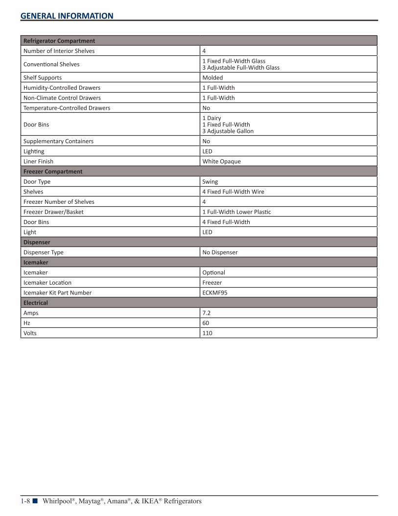
1-8 n Whirlpool®, Maytag®, Amana®, & IKEA® Refrigerators
Refrigerator Compartment
Number of Interior Shelves 4
Conventional Shelves 1 Fixed Full-Width Glass 3 Adjustable Full-Width Glass
Shelf Supports Molded
Humidity-Controlled Drawers 1 Full-Width
Non-Climate Control Drawers 1 Full-Width
Temperature-Controlled Drawers No
Door Bins1 Dairy 1 Fixed Full-Width 3 Adjustable Gallon
Supplementary Containers No
Lighting LED
Liner Finish White Opaque
Freezer Compartment
Door Type Swing
Shelves 4 Fixed Full-Width Wire
Freezer Number of Shelves 4
Freezer Drawer/Basket 1 Full-Width Lower Plastic
Door Bins 4 Fixed Full-Width
Light LED
Dispenser
Dispenser Type No Dispenser
Icemaker
Icemaker Optional
Icemaker Location Freezer
Icemaker Kit Part Number ECKMF95
Electrical
Amps 7.2
Hz 60
Volts 110
GENERAL INFORMATION
Whirlpool®, Maytag®, Amana®, & IKEA® Refrigerators n 1-9
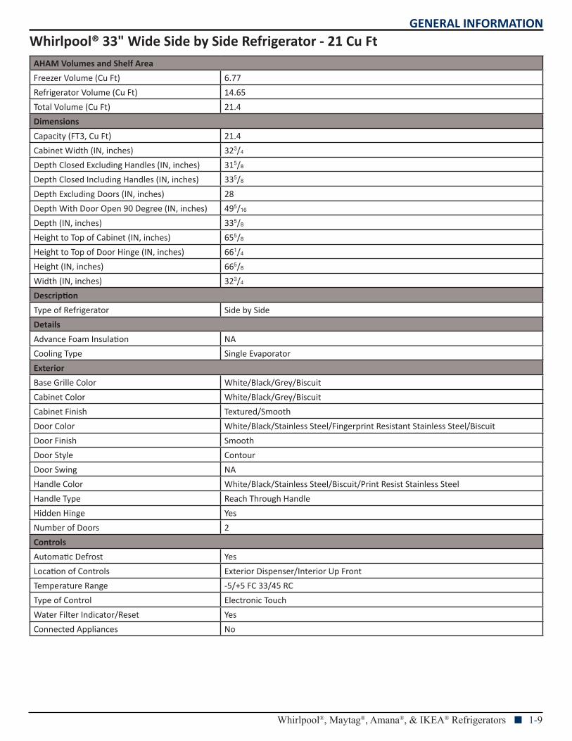
Whirlpool® 33" Wide Side by Side Refrigerator - 21 Cu FtAHAM Volumes and Shelf Area
Freezer Volume (Cu Ft) 6.77
Refrigerator Volume (Cu Ft) 14.65
Total Volume (Cu Ft) 21.4
Dimensions
Capacity (FT3, Cu Ft) 21.4
Cabinet Width (IN, inches) 323/4
Depth Closed Excluding Handles (IN, inches) 315/8
Depth Closed Including Handles (IN, inches) 335/8
Depth Excluding Doors (IN, inches) 28
Depth With Door Open 90 Degree (IN, inches) 495/16
Depth (IN, inches) 335/8
Height to Top of Cabinet (IN, inches) 655/8
Height to Top of Door Hinge (IN, inches) 661/4
Height (IN, inches) 665/8
Width (IN, inches) 323/4
Description
Type of Refrigerator Side by Side
Details
Advance Foam Insulation NA
Cooling Type Single Evaporator
Exterior
Base Grille Color White/Black/Grey/Biscuit
Cabinet Color White/Black/Grey/Biscuit
Cabinet Finish Textured/Smooth
Door Color White/Black/Stainless Steel/Fingerprint Resistant Stainless Steel/Biscuit
Door Finish Smooth
Door Style Contour
Door Swing NA
Handle Color White/Black/Stainless Steel/Biscuit/Print Resist Stainless Steel
Handle Type Reach Through Handle
Hidden Hinge Yes
Number of Doors 2
Controls
Automatic Defrost Yes
Location of Controls Exterior Dispenser/Interior Up Front
Temperature Range -5/+5 FC 33/45 RC
Type of Control Electronic Touch
Water Filter Indicator/Reset Yes
Connected Appliances No
GENERAL INFORMATION
1-10 n Whirlpool®, Maytag®, Amana®, & IKEA® Refrigerators
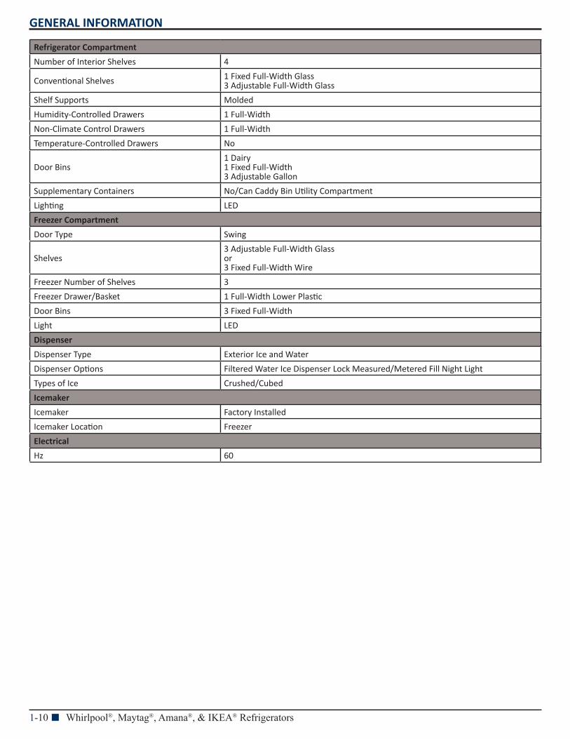
Refrigerator Compartment
Number of Interior Shelves 4
Conventional Shelves 1 Fixed Full-Width Glass 3 Adjustable Full-Width Glass
Shelf Supports Molded
Humidity-Controlled Drawers 1 Full-Width
Non-Climate Control Drawers 1 Full-Width
Temperature-Controlled Drawers No
Door Bins1 Dairy 1 Fixed Full-Width 3 Adjustable Gallon
Supplementary Containers No/Can Caddy Bin Utility Compartment
Lighting LED
Freezer Compartment
Door Type Swing
Shelves3 Adjustable Full-Width Glass or 3 Fixed Full-Width Wire
Freezer Number of Shelves 3
Freezer Drawer/Basket 1 Full-Width Lower Plastic
Door Bins 3 Fixed Full-Width
Light LED
Dispenser
Dispenser Type Exterior Ice and Water
Dispenser Options Filtered Water Ice Dispenser Lock Measured/Metered Fill Night Light
Types of Ice Crushed/Cubed
Icemaker
Icemaker Factory Installed
Icemaker Location Freezer
Electrical
Hz 60
GENERAL INFORMATION
Whirlpool®, Maytag®, Amana®, & IKEA® Refrigerators n 1-11
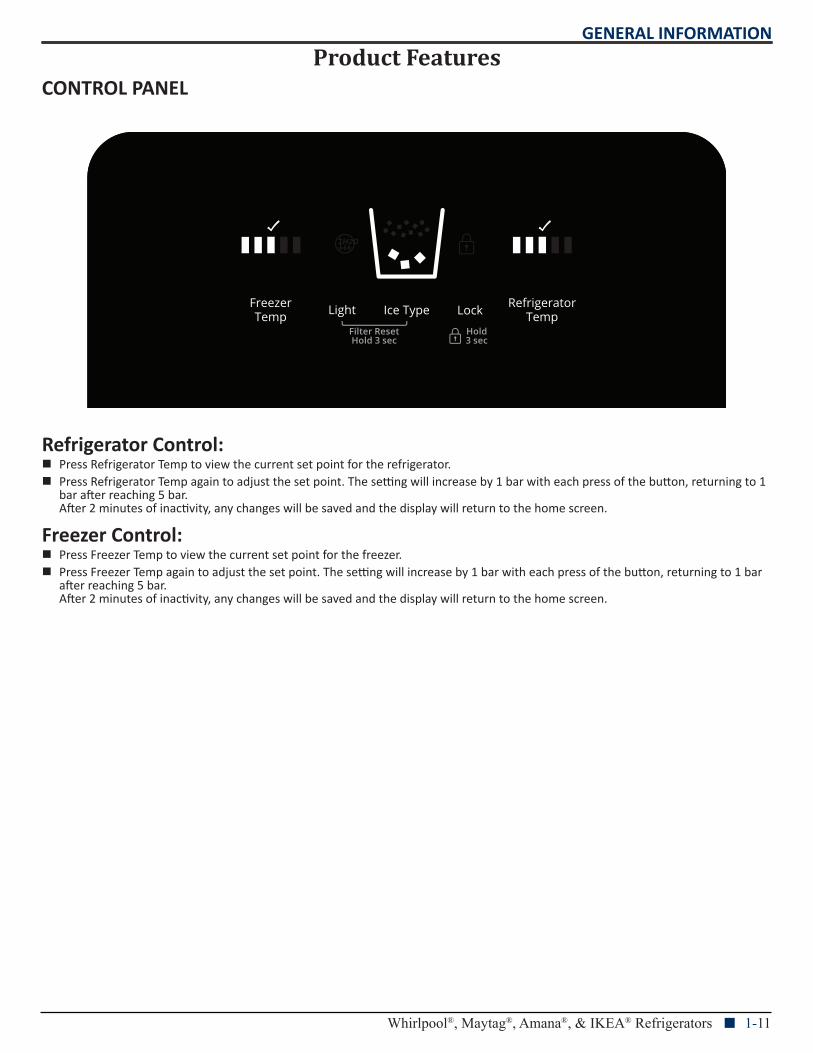
Product FeaturesCONTROL PANEL
Refrigerator Control: n Press Refrigerator Temp to view the current set point for the refrigerator. n Press Refrigerator Temp again to adjust the set point. The setting will increase by 1 bar with each press of the button, returning to 1
bar after reaching 5 bar. After 2 minutes of inactivity, any changes will be saved and the display will return to the home screen.
Freezer Control: n Press Freezer Temp to view the current set point for the freezer. n Press Freezer Temp again to adjust the set point. The setting will increase by 1 bar with each press of the button, returning to 1 bar
after reaching 5 bar. After 2 minutes of inactivity, any changes will be saved and the display will return to the home screen.
GENERAL INFORMATION
1-12 n Whirlpool®, Maytag®, Amana®, & IKEA® Refrigerators
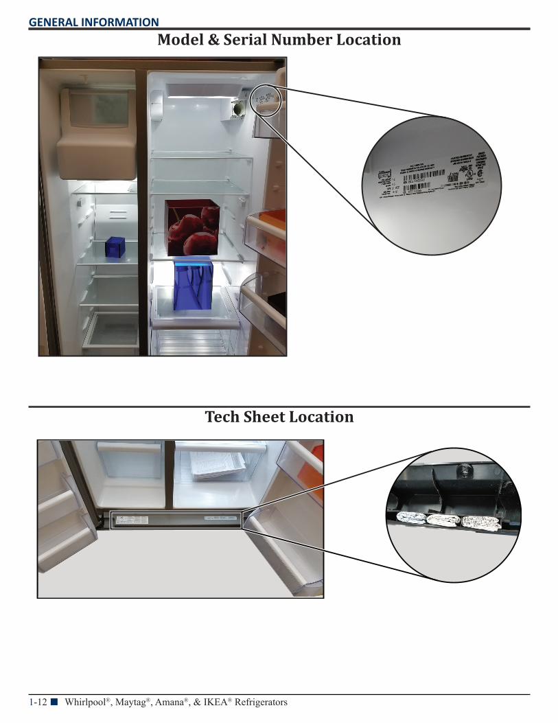
Model & Serial Number Location
Tech Sheet Location
GENERAL INFORMATION
Whirlpool®, Maytag®, Amana®, & IKEA® Refrigerators n 1-13
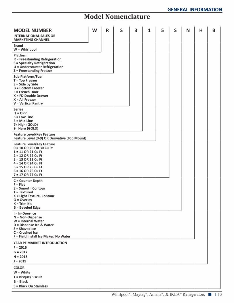
Model Nomenclature
MODEL NUMBERINTERNATIONAL SALES OR MARKETING CHANNEL
W R S 3 1 5 S N H B
BrandW = Whirlpool
PlatformR = Freestanding RefrigerationS = Specialty RefrigerationU = Undercounter RefrigerationZ = Freestanding Freezer
Sub Platform/FuelT = Top FreezerS = Side by SideB = Bottom FreezerF = French DoorX = FD Double DrawerX = All FreezerV = Vertical Pantry
Series1 = OPP 3 = Low Line5 = Mid Line7= High (GOLD)9= Hero (GOLD)
Feature Level/Key FeatureFeature Level (0-9) OR Derivative (Top Mount)
Feature Level/Key Feature0 = 10 OR 20 OR 30 Cu Ft1 = 11 OR 21 Cu Ft2 = 12 OR 22 Cu Ft3 = 13 OR 23 Cu Ft4 = 14 OR 24 Cu Ft5 = 15 OR 25 Cu Ft6 = 16 OR 26 Cu Ft7 = 17 OR 27 Cu Ft
C = Counter DepthF = FlatS = Smooth ContourT = TexturedX = Light Texture, ContourO = OverlayK = Trim KitB = Beveled Edge
I = In-Door-IceN = Non-DispenseW = Internal WaterD = Dispense Ice & WaterS = Shaved IceC = Crushed IceF = Field Install Ice Maker, No Water
YEAR PF MARKET INTRODUCTIONF = 2016G = 2017H = 2018J = 2019
COLORW = WhiteT = Bisque/BiscuitB = BlackS = Black On Stainless
GENERAL INFORMATION
1-14 n Whirlpool®, Maytag®, Amana®, & IKEA® Refrigerators
Notes
DIAGNOSTICS
Whirlpool®, Maytag®, Amana®, & IKEA® Refrigerators n 2-1
Section 2: Diagnostics
This section provides diagnostic mode and sales mode information for the “Whirlpool®, Maytag®, Amana®, and IKEA® Refrigerators.”
Safety
Diagnostics Mode
Sales Mode
For Service Technician Use OnlyDIAGNOSTICS
2-2 n Whirlpool®, Maytag®, Amana®, & IKEA® Refrigerators
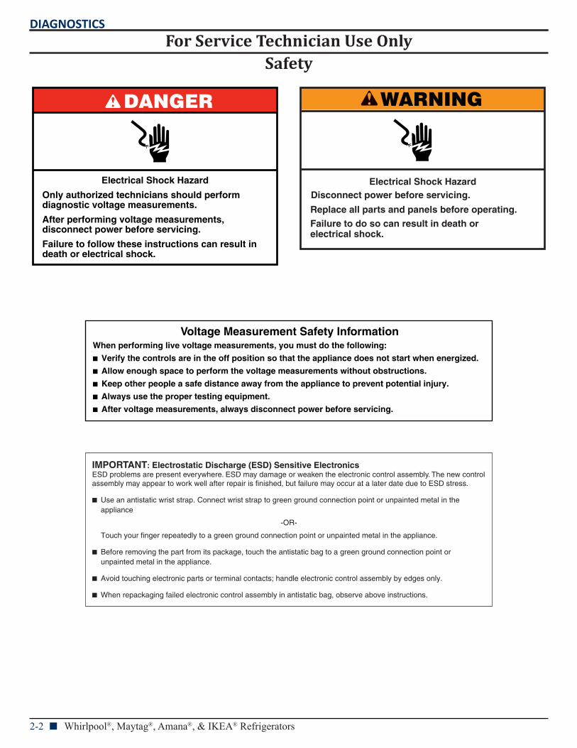
Safety
DANGER
Electrical Shock Hazard
Only authorized technicians should perform diagnostic voltage measurements.
After performing voltage measurements, disconnect power before servicing.
Failure to follow these instructions can result in death or electrical shock.
WARNING
Electrical Shock HazardDisconnect power before servicing.
Failure to do so can result in death orelectrical shock.
Replace all parts and panels before operating.
Voltage Measurement Safety InformationWhen performing live voltage measurements, you must do the following:
Verify the controls are in the off position so that the appliance does not start when energized.
Allow enough space to perform the voltage measurements without obstructions.
Keep other people a safe distance away from the appliance to prevent potential injury.
Always use the proper testing equipment.
After voltage measurements, always disconnect power before servicing.
IMPORTANT: Electrostatic Discharge (ESD) Sensitive ElectronicsESD problems are present everywhere. ESD may damage or weaken the electronic control assembly. The new controlassembly may appear to work well after repair is finished, but failure may occur at a later date due to ESD stress.
Use an antistatic wrist strap. Connect wrist strap to green ground connection point or unpainted metal in the appliance
-OR-
Touch your finger repeatedly to a green ground connection point or unpainted metal in the appliance.
Before removing the part from its package, touch the antistatic bag to a green ground connection point or unpainted metal in the appliance.
Avoid touching electronic parts or terminal contacts; handle electronic control assembly by edges only.
When repackaging failed electronic control assembly in antistatic bag, observe above instructions.
For Service Technician Use OnlyDIAGNOSTICS
Whirlpool®, Maytag®, Amana®, & IKEA® Refrigerators n 2-3
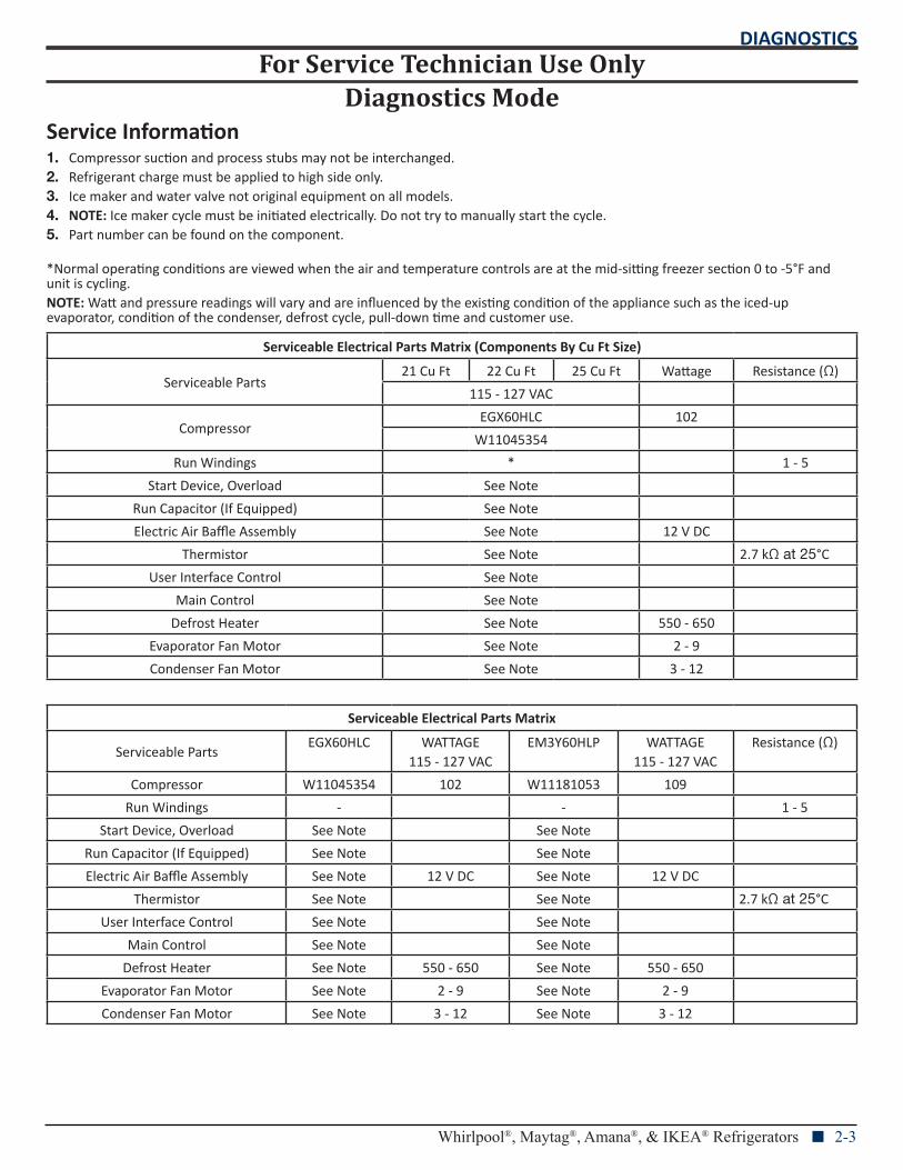
Diagnostics ModeService Information1. Compressor suction and process stubs may not be interchanged.2. Refrigerant charge must be applied to high side only.3. Ice maker and water valve not original equipment on all models.4. NOTE: Ice maker cycle must be initiated electrically. Do not try to manually start the cycle.5. Part number can be found on the component.
*Normal operating conditions are viewed when the air and temperature controls are at the mid-sitting freezer section 0 to -5°F and unit is cycling.NOTE: Watt and pressure readings will vary and are influenced by the existing condition of the appliance such as the iced-up evaporator, condition of the condenser, defrost cycle, pull-down time and customer use.
Serviceable Electrical Parts Matrix (Components By Cu Ft Size)
Serviceable Parts21 Cu Ft 22 Cu Ft 25 Cu Ft Wattage Resistance (Ω)
115 - 127 VAC
CompressorEGX60HLC 102
W11045354
Run Windings * 1 - 5
Start Device, Overload See Note
Run Capacitor (If Equipped) See Note
Electric Air Baffle Assembly See Note 12 V DC
Thermistor See Note 2.7 kΩ at 25°C
User Interface Control See Note
Main Control See Note
Defrost Heater See Note 550 - 650
Evaporator Fan Motor See Note 2 - 9
Condenser Fan Motor See Note 3 - 12
Serviceable Electrical Parts Matrix
Serviceable PartsEGX60HLC WATTAGE
115 - 127 VACEM3Y60HLP WATTAGE
115 - 127 VACResistance (Ω)
Compressor W11045354 102 W11181053 109
Run Windings - - 1 - 5
Start Device, Overload See Note See Note
Run Capacitor (If Equipped) See Note See Note
Electric Air Baffle Assembly See Note 12 V DC See Note 12 V DC
Thermistor See Note See Note 2.7 kΩ at 25°C
User Interface Control See Note See Note
Main Control See Note See Note
Defrost Heater See Note 550 - 650 See Note 550 - 650
Evaporator Fan Motor See Note 2 - 9 See Note 2 - 9
Condenser Fan Motor See Note 3 - 12 See Note 3 - 12
For Service Technician Use OnlyDIAGNOSTICS
2-4 n Whirlpool®, Maytag®, Amana®, & IKEA® Refrigerators
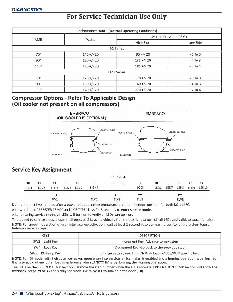
Performance Data * (Normal Operating Conditions)
AMB WattsSystem Pressure (PSIG)
High Side Low Side
EG Series
70° 140 +/- 20 95 +/- 20 - 7 To 3
90° 150 +/- 20 135 +/- 20 - 4 To 3
110° 170 +/- 20 185 +/- 20 - 2 To 4
EM3 Series
70° 120 +/- 20 120 +/- 20 - 6 To 3
90° 130 +/- 20 160 +/- 20 - 4 To 3
110° 140 +/- 20 220 +/- 20 - 2 To 4
Compressor Options - Refer To Applicable Design (Oil cooler not present on all compressors)
Service Key Assignment O CRUSH
LED1
O LED2
OLED3
O LED4
O LED5
O LIGHT
O CUBE O LOCK
LED6
O LED7
O LED8
OLED9
O LED10
SW1 SW2 SW3 SW4 SW5During the first five minutes after a power on, put setting temperature at the minimum position for both RC and FC.Afterward, hold "FREEZER TEMP" and "ICE TYPE" keys for 3 seconds to enter service mode.After entering service mode, all LEDs will turn on to verify all LEDs can turn on.To proceed to service steps, a user shall press all 5 keys individually from left to right to turn off all LEDs and validate touch function.NOTE: For smooth operation of user interface key activation, wait at least 1 second between each press, to let the system toggle between service steps.
KEYS DESCRIPTION
SW2 = Light Key Increment Key: Advance to next step
SW4 = Lock Key Decrement Key: Go back to the previous step
SW5 = RC Temp Key Change Setting Key: Turn ON/OFF load, PAUSE/RUN specific testNOTE: For IDI model with twist tray ice maker, upon entry into service, an ice maker is enabled and a homing operation is performed, this is to avoid of any other load interference when SANKYO IM is performing the Homing operation.The LEDs on the FREEZER TEMP section will show the step number while the LEDs above REFRIGERATION TEMP section will show the feedback. Steps 29 to 35 apply only for models with twist tray maker in the door (IDI).
EMBRACO(OIL COOLER IS OPTIONAL)
EMBRACO
PROCESS TUBE
SUCTION TUBE
DISCHARGE
OIL COOLER
SUCTION TUBE DISCHARGE TUBE
PROCESS TUBE
EM3 SERIESEG SERIES
For Service Technician Use OnlyDIAGNOSTICS
Whirlpool®, Maytag®, Amana®, & IKEA® Refrigerators n 2-5
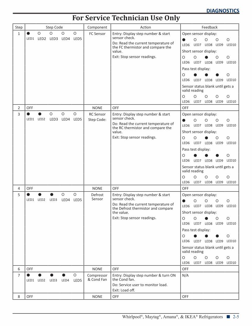
Step Step Code Component Action Feedback
1 LED1
OLED2
O
LED3 O
LED4 O
LED5FC Sensor Entry: Display step number & start
sensor check.Do: Read the current temperature of the FC thermistor and compare the value.Exit: Stop sensor readings.
Open sensor display:
LED6
O LED7
O LED8
O LED9
O LED10
Short sensor display:
O LED6
O LED7
LED8
O LED9
O LED10
Pass test display:
O LED6
LED7
LED8
LED9
O LED10
Sensor status blank until gets a valid reading
O LED6
O LED7
O LED8
O LED9
O LED10
2 OFF NONE OFF OFF
3 LED1
LED2
O
LED3 O
LED4 O
LED5RC SensorStep Code:
Entry: Display step number & start sensor check.Do: Read the current temperature of the RC thermistor and compare the value.Exit: Stop sensor readings.
Open sensor display:
LED6
O LED7
O LED8
O LED9
O LED10
Short sensor display:
O LED6
O LED7
LED8
O LED9
O LED10
Pass test display:
O LED6
LED7
LED8
LED9
O LED10
Sensor status blank until gets a valid reading
O LED6
O LED7
O LED8
O LED9
O LED10
4 OFF NONE OFF OFF
5 LED1
LED2
LED3
O
LED4 O
LED5Defrost Sensor
Entry: Display step number & start sensor check.Do: Read the current temperature of the Defrost thermistor and compare the value.Exit: Stop sensor readings.
Open sensor display:
LED6
O LED7
O LED8
O LED9
O LED10
Short sensor display:
O LED6
O LED7
LED8
O LED9
O LED10
Pass test display:
O LED6
LED7
LED8
LED9
O LED10
Sensor status blank until gets a valid reading
O LED6
O LED7
O LED8
O LED9
O LED10
6 OFF NONE OFF OFF
7 LED1
LED2
LED3
LED4
O
LED5Compressor & Cond Fan
Entry: Display step number & turn ON the Cond fan.Do: Service user to monitor load.Exit: Load off.
N/A
8 OFF NONE OFF OFF
For Service Technician Use OnlyDIAGNOSTICS
2-6 n Whirlpool®, Maytag®, Amana®, & IKEA® Refrigerators
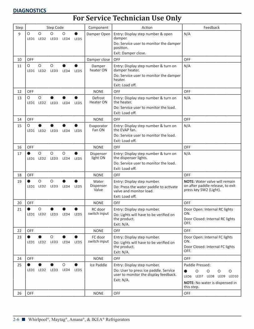
Step Step Code Component Action Feedback
9 O LED1
O LED2
O LED3
O LED4
LED5
Damper Open Entry: Display step number & open damper.Do: Service user to monitor the damper position.Exit: Damper close.
N/A
10 OFF Damper close OFF OFF
11 O LED1
O LED2
O LED3
LED4
LED5
Damper heater ON
Entry: Display step number & turn on damper heater.Do: Service user to monitor the damper heater.Exit: Load off.
N/A
12 OFF NONE OFF OFF
13 O LED1
O LED2
LED3
LED4
LED5
Defrost Heater ON
Entry: Display step number & turn on the heater.Do: Service user to monitor the load.Exit: Load off.
N/A
14 OFF NONE OFF OFF
15 O LED1
LED2
LED3
LED4
LED5
Evaporator Fan ON
Entry: Display step number & turn on the EVAP fan.Do: Service user to monitor the load.Exit: Load off.
N/A
16 OFF NONE OFF OFF
17 LED1
O LED2
O LED3
O LED4
LED5
Dispenser light ON
Entry: Display step number & turn on the dispenser lights.Do: Service user to monitor the load.Exit: Load off.
N/A
18 OFF NONE OFF OFF
19 LED1
O LED2
O LED3
LED4
LED5
Water Dispenser
Valve
Entry: Display step number.Do: Press the water paddle to activate valve and monitor load.Exit: Load off.
NOTE: Water valve will remain on after paddle release, to exit press key SW2 (Light).
20 OFF NONE OFF OFF
21 LED1
O LED2
LED3
LED4
LED5
RC door switch input
Entry: Display step number.Do: Lights will have to be verified on the product.Exit: N/A.
Door Open: Internal RC lights ON.Door Closed: Internal RC lights OFF.
22 OFF NONE OFF OFF
23 LED1
LED2
O LED3
LED4
LED5
FC door switch input
Entry: Display step number.Do: Lights will have to be verified on the product.Exit: N/A.
Door Open: Internal FC lights ON.Door Closed: Internal FC lights OFF.
24 OFF NONE OFF OFF
25 LED1
LED2
LED3
O LED4
LED5
Ice Paddle Entry: Display step number.Do: User to press ice paddle. Service user to monitor the display feedback.Exit: N/A.
Paddle Pressed:
LED6
O LED7
O LED8
O LED9
O LED10
NOTE: No water is dispensed in this step.
26 OFF NONE OFF OFF
For Service Technician Use OnlyDIAGNOSTICS
Whirlpool®, Maytag®, Amana®, & IKEA® Refrigerators n 2-7
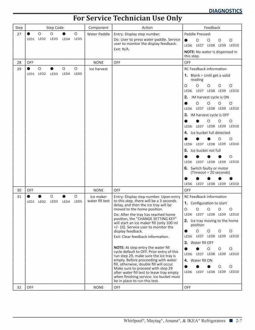
Step Step Code Component Action Feedback
27 LED1
O LED2
O LED3
LED4
O LED5
Water Paddle Entry: Display step number.Do: User to press water paddle. Service user to monitor the display feedback.Exit: N/A.
Paddle Pressed:
LED6
O LED7
O LED8
O LED9
O LED10
NOTE: No water is dispensed in this step.
28 OFF NONE OFF OFF
29 LED1
O LED2
LED3
O LED4
O LED5
Ice harvest RC Feedback information
1. Blank = Until get a valid reading
O LED6
O LED7
O LED8
O LED9
O LED10
2. IM harvest cycle is ON
LED6
O LED7
O LED8
O LED9
O LED10
3. IM harvest cycle is OFF
LED6
LED7
O LED8
O LED9
O LED10
4. Ice bucket full detected
LED6
LED7
LED8
O LED9
O LED10
5. Ice bucket not full
LED6
LED7
LED8
LED9
O LED10
6. Switch faulty or motor (Timeout = 20 seconds)
LED6
LED7
LED8
LED9
LED10
30 OFF NONE OFF OFF
31 LED1
LED2
O LED3
LED4
O LED5
Ice maker water fill test
Entry: Display step number. Upon entry to this step, there will be a 3 seconds delay, and then the ice tray will be moved to the home position.Do: After the tray has reached home position, the "CHANGE SETTING KEY" will start an ice maker fill (only 100 ml +/- 10). Service user to monitor the display feedback.Exit: Clear feedback information.
NOTE: At step entry the water fill cycle default to OFF. Prior entry of this run step 29, make sure the ice tray is empty. Before proceeding with water fill, otherwise, double fill will occur. Make sure to proceed with step 29 after water fill test to leave tray empty when finishing service. Ice bucket must be in place to run this test.
RC Feedback information
1. Configuration to start
O LED6
O LED7
O LED8
O LED9
O LED10
2. Ice tray moving to the home position
LED6
O LED7
O LED8
O LED9
O LED10
3. Water fill OFF
LED6
LED7
O LED8
O LED9
O LED10
4. Water fill ON
LED6
LED7
LED8
O LED9
O LED10
32 OFF NONE OFF OFF
For Service Technician Use OnlyDIAGNOSTICS
2-8 n Whirlpool®, Maytag®, Amana®, & IKEA® Refrigerators
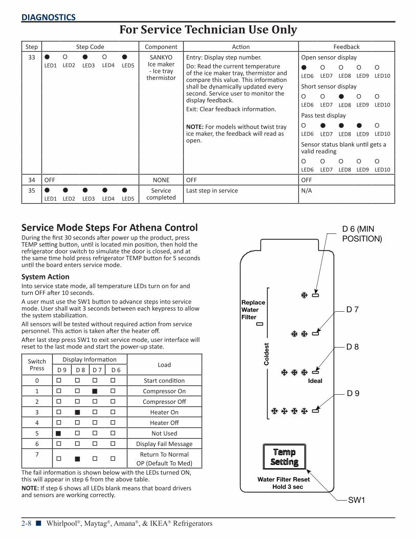
Step Step Code Component Action Feedback
33 LED1
O LED2
LED3
O LED4
LED5
SANKYO Ice maker - Ice tray
thermistor
Entry: Display step number.Do: Read the current temperature of the ice maker tray, thermistor and compare this value. This information shall be dynamically updated every second. Service user to monitor the display feedback.Exit: Clear feedback information.
NOTE: For models without twist tray ice maker, the feedback will read as open.
Open sensor display
LED6
O LED7
O LED8
O LED9
O LED10
Short sensor display
O LED6
O LED7
LED8
O LED9
O LED10
Pass test display
O LED6
LED7
LED8
LED9
O LED10
Sensor status blank until gets a valid reading
O LED6
O LED7
O LED8
O LED9
O LED10
34 OFF NONE OFF OFF
35 LED1
LED2
LED3
LED4
LED5
Service completed
Last step in service N/A
Service Mode Steps For Athena ControlDuring the first 30 seconds after power up the product, press TEMP setting button, until is located min position, then hold the refrigerator door switch to simulate the door is closed, and at the same time hold press refrigerator TEMP button for 5 seconds until the board enters service mode.
System ActionInto service state mode, all temperature LEDs turn on for and turn OFF after 10 seconds.A user must use the SW1 button to advance steps into service mode. User shall wait 3 seconds between each keypress to allow the system stabilization.All sensors will be tested without required action from service personnel. This action is taken after the heater off.After last step press SW1 to exit service mode, user interface will reset to the last mode and start the power-up state.
Switch Press
Display Information Load
D 9 D 8 D 7 D 6
0 Start condition
1 Ƀ Compressor On
2 Compressor Off
3 Ƀ Heater On
4 Heater Off
5 Ƀ Not Used
6 Display Fail Message
7 Ƀ
Return To NormalOP (Default To Med)
The fail information is shown below with the LEDs turned ON, this will appear in step 6 from the above table.NOTE: If step 6 shows all LEDs blank means that board drivers and sensors are working correctly.
D 6 (MIN POSITION)
D 7
D 8
D 9
SW1
Ideal
Co
ldes
t
Replace Water Filter
Water Filter ResetHold 3 sec
For Service Technician Use OnlyDIAGNOSTICS
Whirlpool®, Maytag®, Amana®, & IKEA® Refrigerators n 2-9
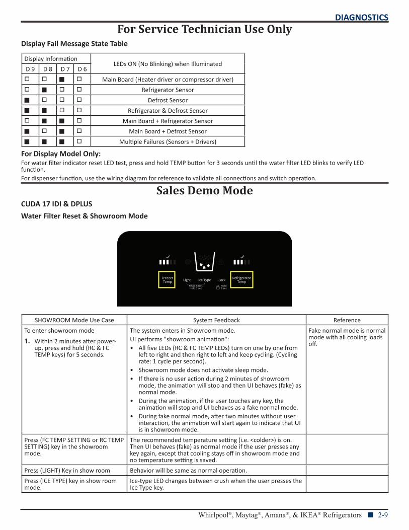
Display Fail Message State Table
Display InformationLEDs ON (No Blinking) when Illuminated
D 9 D 8 D 7 D 6
Ƀ Main Board (Heater driver or compressor driver)
Ƀ Refrigerator Sensor
Ƀ Defrost Sensor
Ƀ Ƀ Refrigerator & Defrost Sensor
Ƀ Ƀ Main Board + Refrigerator Sensor
Ƀ Ƀ Main Board + Defrost Sensor
Ƀ Ƀ Ƀ Multiple Failures (Sensors + Drivers)
For Display Model Only:For water filter indicator reset LED test, press and hold TEMP button for 3 seconds until the water filter LED blinks to verify LED function.For dispenser function, use the wiring diagram for reference to validate all connections and switch operation.
Sales Demo ModeCUDA 17 IDI & DPLUS
Water Filter Reset & Showroom Mode
SHOWROOM Mode Use Case System Feedback Reference
To enter showroom mode
1. Within 2 minutes after power-up, press and hold (RC & FC TEMP keys) for 5 seconds.
The system enters in Showroom mode.UI performs "showroom animation":• All five LEDs (RC & FC TEMP LEDs) turn on one by one from
left to right and then right to left and keep cycling. (Cycling rate: 1 cycle per second).
• Showroom mode does not activate sleep mode.• If there is no user action during 2 minutes of showroom
mode, the animation will stop and then UI behaves (fake) as normal mode.
• During the animation, if the user touches any key, the animation will stop and UI behaves as a fake normal mode.
• During fake normal mode, after two minutes without user interaction, the animation will start again to indicate that UI is in showroom mode.
Fake normal mode is normal mode with all cooling loads off.
Press (FC TEMP SETTING or RC TEMP SETTING) key in the showroom mode.
The recommended temperature setting (i.e. <colder>) is on. Then UI behaves (fake) as normal mode if the user presses any key again, except that cooling stays off in showroom mode and no temperature setting is saved.
Press (LIGHT) Key in show room Behavior will be same as normal operation.
Press (ICE TYPE) key in show room mode.
Ice-type LED changes between crush when the user presses the Ice Type key.
For Service Technician Use OnlyDIAGNOSTICS
2-10 n Whirlpool®, Maytag®, Amana®, & IKEA® Refrigerators
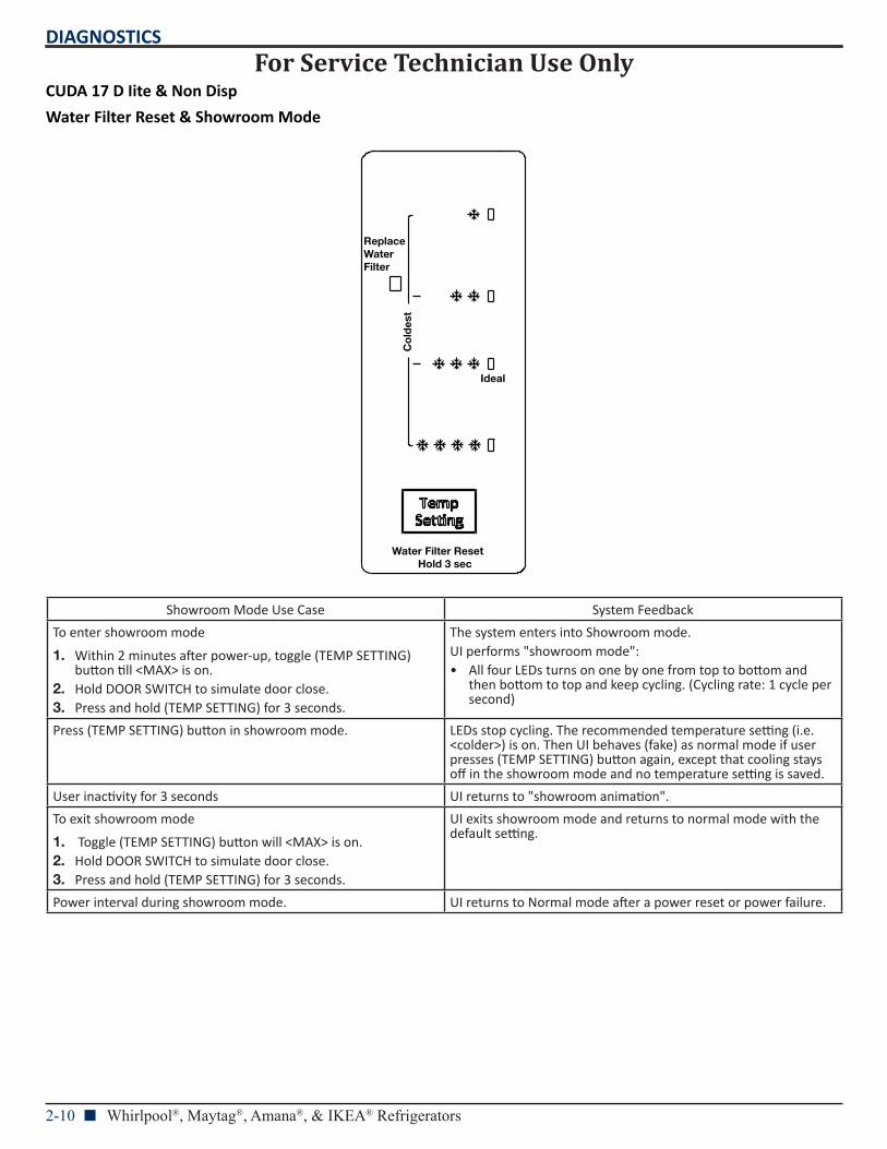
CUDA 17 D Iite & Non Disp
Water Filter Reset & Showroom Mode
Showroom Mode Use Case System Feedback
To enter showroom mode
1. Within 2 minutes after power-up, toggle (TEMP SETTING) button till <MAX> is on.
2. Hold DOOR SWITCH to simulate door close.3. Press and hold (TEMP SETTING) for 3 seconds.
The system enters into Showroom mode.UI performs "showroom mode":• All four LEDs turns on one by one from top to bottom and
then bottom to top and keep cycling. (Cycling rate: 1 cycle per second)
Press (TEMP SETTING) button in showroom mode. LEDs stop cycling. The recommended temperature setting (i.e. <colder>) is on. Then UI behaves (fake) as normal mode if user presses (TEMP SETTING) button again, except that cooling stays off in the showroom mode and no temperature setting is saved.
User inactivity for 3 seconds UI returns to "showroom animation".
To exit showroom mode
1. Toggle (TEMP SETTING) button will <MAX> is on.2. Hold DOOR SWITCH to simulate door close.3. Press and hold (TEMP SETTING) for 3 seconds.
UI exits showroom mode and returns to normal mode with the default setting.
Power interval during showroom mode. UI returns to Normal mode after a power reset or power failure.
Ideal
Co
ldes
t
Replace Water Filter
Water Filter ResetHold 3 sec
For Service Technician Use OnlyDIAGNOSTICS
Whirlpool®, Maytag®, Amana®, & IKEA® Refrigerators n 2-11
Notes
For Service Technician Use OnlyDIAGNOSTICS
2-12 n Whirlpool®, Maytag®, Amana®, & IKEA® Refrigerators
Notes
COMPONENT TESTING
Whirlpool®, Maytag®, Amana®, & IKEA® Refrigerators n 3-1
Section 3: Component Testing
This section provides the wiring diagram and component location for the “Whirlpool®, Maytag®, Amana®, and IKEA® Refrigerators.”
Safety
Wiring Diagram
Component Location
For Service Technician Use OnlyCOMPONENT TESTING
3-2 n Whirlpool®, Maytag®, Amana®, & IKEA® Refrigerators
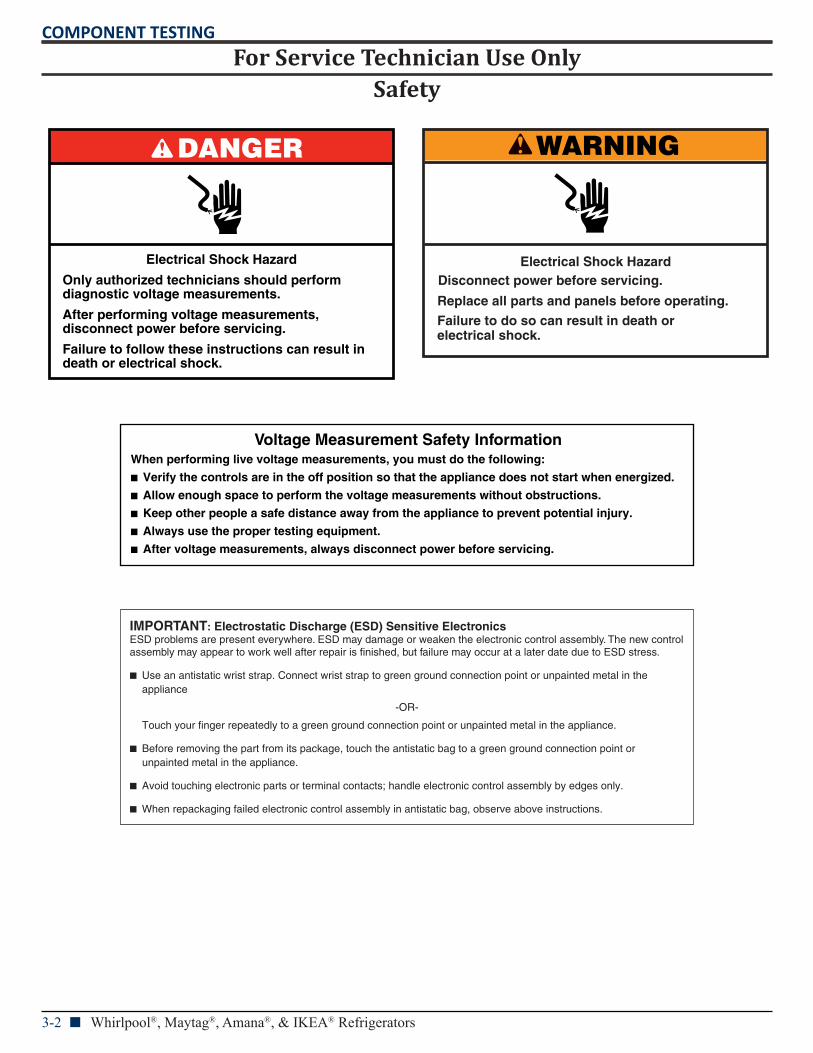
Safety
DANGER
Electrical Shock Hazard
Only authorized technicians should perform diagnostic voltage measurements.
After performing voltage measurements, disconnect power before servicing.
Failure to follow these instructions can result in death or electrical shock.
WARNING
Electrical Shock HazardDisconnect power before servicing.
Failure to do so can result in death orelectrical shock.
Replace all parts and panels before operating.
Voltage Measurement Safety InformationWhen performing live voltage measurements, you must do the following:
Verify the controls are in the off position so that the appliance does not start when energized.
Allow enough space to perform the voltage measurements without obstructions.
Keep other people a safe distance away from the appliance to prevent potential injury.
Always use the proper testing equipment.
After voltage measurements, always disconnect power before servicing.
IMPORTANT: Electrostatic Discharge (ESD) Sensitive ElectronicsESD problems are present everywhere. ESD may damage or weaken the electronic control assembly. The new controlassembly may appear to work well after repair is finished, but failure may occur at a later date due to ESD stress.
Use an antistatic wrist strap. Connect wrist strap to green ground connection point or unpainted metal in the appliance
-OR-
Touch your finger repeatedly to a green ground connection point or unpainted metal in the appliance.
Before removing the part from its package, touch the antistatic bag to a green ground connection point or unpainted metal in the appliance.
Avoid touching electronic parts or terminal contacts; handle electronic control assembly by edges only.
When repackaging failed electronic control assembly in antistatic bag, observe above instructions.
For Service Technician Use OnlyCOMPONENT TESTING
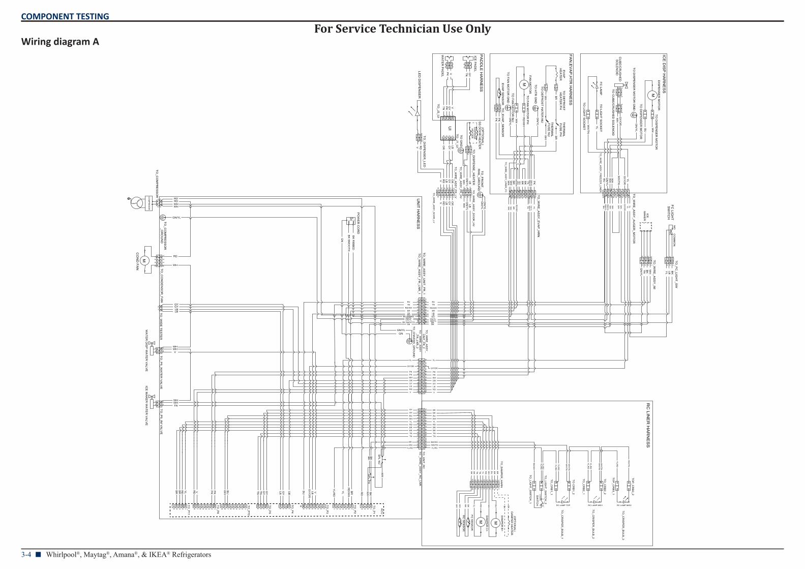
Whirlpool®, Maytag®, Amana®, & IKEA® Refrigerators n 3-3
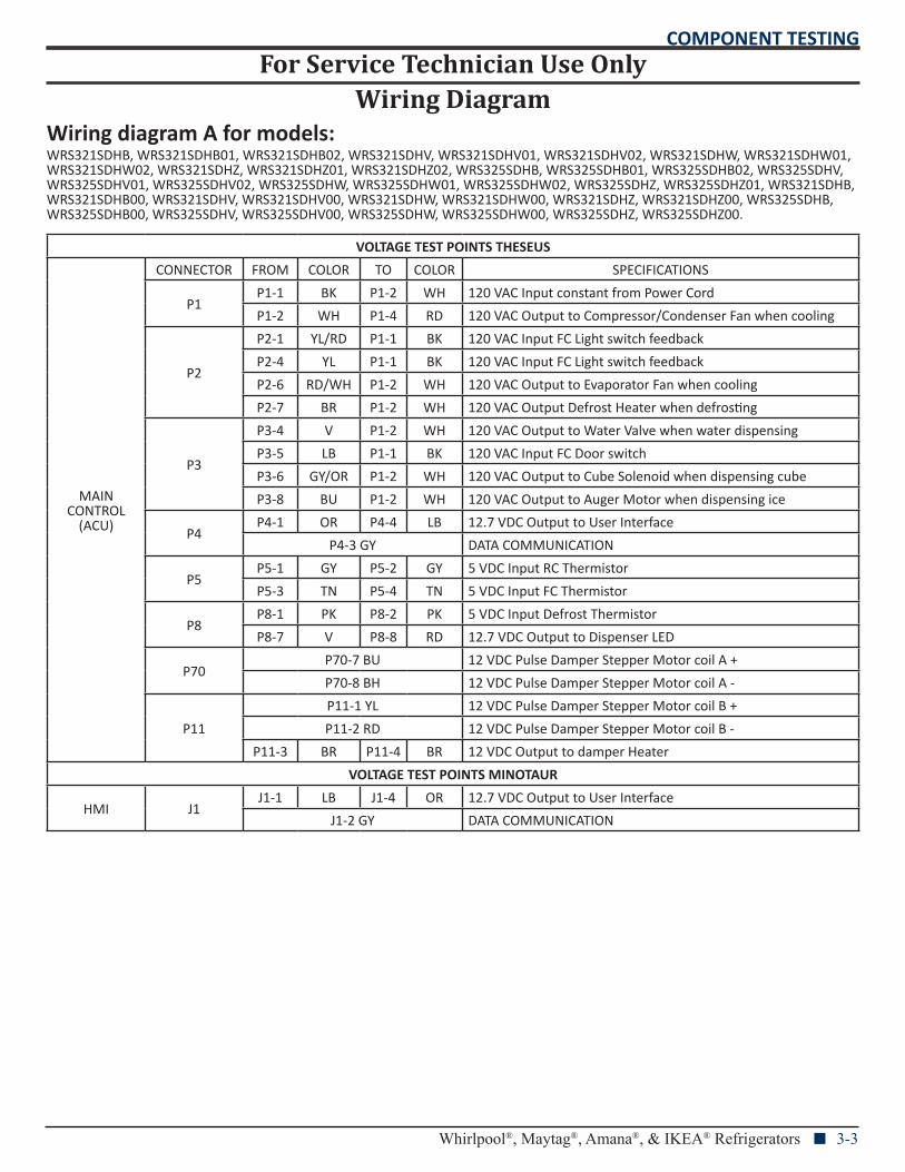
Wiring DiagramWiring diagram A for models:WRS321SDHB, WRS321SDHB01, WRS321SDHB02, WRS321SDHV, WRS321SDHV01, WRS321SDHV02, WRS321SDHW, WRS321SDHW01, WRS321SDHW02, WRS321SDHZ, WRS321SDHZ01, WRS321SDHZ02, WRS325SDHB, WRS325SDHB01, WRS325SDHB02, WRS325SDHV, WRS325SDHV01, WRS325SDHV02, WRS325SDHW, WRS325SDHW01, WRS325SDHW02, WRS325SDHZ, WRS325SDHZ01, WRS321SDHB, WRS321SDHB00, WRS321SDHV, WRS321SDHV00, WRS321SDHW, WRS321SDHW00, WRS321SDHZ, WRS321SDHZ00, WRS325SDHB, WRS325SDHB00, WRS325SDHV, WRS325SDHV00, WRS325SDHW, WRS325SDHW00, WRS325SDHZ, WRS325SDHZ00.
VOLTAGE TEST POINTS THESEUS
MAIN CONTROL
(ACU)
CONNECTOR FROM COLOR TO COLOR SPECIFICATIONS
P1P1-1 BK P1-2 WH 120 VAC Input constant from Power Cord
P1-2 WH P1-4 RD 120 VAC Output to Compressor/Condenser Fan when cooling
P2
P2-1 YL/RD P1-1 BK 120 VAC Input FC Light switch feedback
P2-4 YL P1-1 BK 120 VAC Input FC Light switch feedback
P2-6 RD/WH P1-2 WH 120 VAC Output to Evaporator Fan when cooling
P2-7 BR P1-2 WH 120 VAC Output Defrost Heater when defrosting
P3
P3-4 V P1-2 WH 120 VAC Output to Water Valve when water dispensing
P3-5 LB P1-1 BK 120 VAC Input FC Door switch
P3-6 GY/OR P1-2 WH 120 VAC Output to Cube Solenoid when dispensing cube
P3-8 BU P1-2 WH 120 VAC Output to Auger Motor when dispensing ice
P4P4-1 OR P4-4 LB 12.7 VDC Output to User Interface
P4-3 GY DATA COMMUNICATION
P5P5-1 GY P5-2 GY 5 VDC Input RC Thermistor
P5-3 TN P5-4 TN 5 VDC Input FC Thermistor
P8P8-1 PK P8-2 PK 5 VDC Input Defrost Thermistor
P8-7 V P8-8 RD 12.7 VDC Output to Dispenser LED
P70P70-7 BU 12 VDC Pulse Damper Stepper Motor coil A +
P70-8 BH 12 VDC Pulse Damper Stepper Motor coil A -
P11
P11-1 YL 12 VDC Pulse Damper Stepper Motor coil B +
P11-2 RD 12 VDC Pulse Damper Stepper Motor coil B -
P11-3 BR P11-4 BR 12 VDC Output to damper Heater
VOLTAGE TEST POINTS MINOTAUR
HMI J1J1-1 LB J1-4 OR 12.7 VDC Output to User Interface
J1-2 GY DATA COMMUNICATION
For Service Technician Use OnlyCOMPONENT TESTING
3-4 n Whirlpool®, Maytag®, Amana®, & IKEA® Refrigerators
Wiring diagram A
L1 L2GND
CO
MM
ON
NO
M
M
M
M
DA
MP
ER
B+
M
DA
MP
ER
C+
TO
_CR
ISP
ER
_BU
LB_1
TO
_CR
ISP
ER
_BU
LB_2
TO
_CR
ISP
ER
_BU
LB_3
UI
CO
MM
ON
NO
TH
ER
MA
L F
US
E P
H
TH
ER
MA
L F
US
E N
U
FA
N M
OT
OR
UN
IT H
AR
NE
SS
FA
N,E
VA
P,H
TR
HA
RN
ES
S
RC
LINE
R H
AR
NE
SS
ICE
DIS
P H
AR
NE
SS
PA
DD
LE H
AR
NE
SS
PO
WE
R C
OR
D
DIS
PE
NS
ER
MO
TO
R
CU
BE
/CR
US
HE
DS
OLE
NO
ID
WA
TE
R D
ISP
WA
TE
R V
ALV
EIC
E M
AK
ER
WA
TE
R V
ALV
E
(OP
TIO
NA
L)
AC
U
CO
MP
RE
SO
R
LED
DIS
PE
NS
ER
TO
_CO
MP
RE
SS
OR
12
TO
_CO
ND
EN
SO
R_F
AN
12
34
TO
_P5_W
AT
ER
VA
LVE
21
TO
_P5_IM
VA
LVE
21
TO
_WIR
E_A
SS
Y_F
R_LN
R_1
12
34
56
78
9
TO
_WIR
E_A
SS
Y_LIN
ER
_FC 123456789
TO
DE
FR
OS
T
HE
AT
ER
PH
1
TO
DE
FR
OS
T H
AT
ER
NU
1
TO
_EV
AP
_SE
NS
OR
12
TO
FA
N M
OT
OR
PH
TO
FA
N M
OT
OR
NU
TO
_WIR
E_A
SS
Y_F
RE
EZ
ER
_LINE
R
123456789
TO
DIS
PE
NS
ER
MO
TO
R
TO
DIS
PE
NS
ER
MO
TO
R
TO
LIGH
T S
OC
KE
T
TO
LIGH
T S
OC
KE
T
1234 123
EV
AP
SE
NS
OR12
ICE
M
AK
ER
FC
LIGH
T
SW
ITC
HN
C
12
FC
LAM
P
EV
AP
H
EA
TE
R
1 1
12
12
12
12
CO
ND
FA
N
12
34
TO
_P1
1234
TO
_P2
TO
_P3
1 12 2 3 4 5 6 7345678
TO
_P4
1234
TO
_P5
1234
GN/YL
WH
BK
TO
_WIR
E_A
SS
Y_E
VA
P_H
RN
123456789
TO
_WIR
E_A
SS
Y_A
UG
ER
_MO
TO
R
123456789
TO
_WIR
E_A
SS
Y_IM
1234
TO
_FC
_LIGH
T_S
W123
TO
_WIR
E_A
SS
Y_U
NIT
_FR
_11
23
45
67
89
GY/OR
TO
_LIGH
T_S
WIT
CH
_2
TO
_LIGH
T_S
WIT
CH
_1
BK/WH
TO
_DIS
PE
NS
E_H
EA
TE
R12
TO
_P8
12345678
TO
_P11
12345
TO
_P70
123456789
TO
_WIR
E_A
SS
Y_F
R_LV
123456
TO
_WIR
E_A
SS
Y_D
OO
R_LV
123456
YL/RD YL/RD
TO
_CR
B1_1
TO
CR
B1_2
TO
_CR
B2_1
TO
_CR
B2_2
TO
P_C
RB
3_1
TO
P_C
RB
3_2
RC LAMP TOP RC LAMP MID1 RC LAMP MID2
YL/R
D
WH
/TN
WH/TN
YL
TO
_WIR
E_A
SS
Y_D
OO
R_H
V123
TO
_WIR
E_A
SS
Y_F
R_H
V
123
TO
_J3_UI
1234
TO
_J1_UI
1234
ICE
PA
DE
L
12
WA
TE
R P
AD
EL
121212
FC
SE
NS
OR
DA
MP
ER
HE
AT
ER
BU
WH
RD
YL BKBK
TO
_DIS
PE
NS
ER
_LED
1212
TO
_WIR
E_A
SS
Y_
UN
IT_F
R_2
12
34
56
78
910
1112
TO
_WIR
E_A
SS
Y_F
R_LN
R_2
12
34
56
78
910
1112
TO
_UN
IT_R
C1
23
45
67
89
101112
1314
TO
_WIR
E_A
SS
Y_R
C_LN
R1
23
45
67
89
101112
1314
SW
ITC
H 11
NC
TO
_WID
E T
ES
TE
R
12
WH
SP
L PH
SP
L NU
TO
CU
BE
/CR
US
HE
D S
OLE
NO
ID
1212
TO
_DA
MP
ER
_HA
RN
12345678910
12345678910
RC
SE
NS
OR
12
DIS
PE
NS
E
HE
AT
ER
SS
DO
OR
HE
AT
ER
(OP
TIO
NA
L)
TO
DIS
PE
NS
ER
MO
TO
R G
ND
TO
HT
R G
ND
TO
FA
N M
OT
OR
GN
D
TO
_FR
ON
T_
RA
IL_GR
OU
ND
TO
GN
D
TO
_CH
AS
SIS
_GR
OU
ND
TO
_CO
MP
RE
SS
OR
_GR
OU
ND
WH
BU
GN
/YL
GY
/OR
WH
YL
WH
/TN
YL
GY
/OR
WH
/TN
WH
WH
GN
/YL
BU
BR
WH
BR
WH
PK
GN
/YL
GN
/YL
RD
/WH
WH
PK
PK
GN
/YL
GN
/YL
RD
/WH
BR WH
WH
PK
BK
BK
WH
WH
GY
TNVPK
GY
TN VPK
RDV LBGY
OR
LBG
YO
R
RDV
OR
GY
LBR
DV WH LB
GN
/YL
GN
/YL
WH
LB
GN
/YL
GN
/YL PK
BR
WH
GN
/YL
GN
/YL
RD
/WH
WH
PK
GN
/YL
GN
/YL
GY
/OR
BU
WH
YL
YL
WH
WH
WH
BK
YL
LB
TN
GN
/YL
BK
WH
TN
BR
WHGN/YL
BK
BU
RD/WH
GN/YL
LBLB
BK
GN/YLGN/YL
BK RIBBEDWH
BK SMOOTHBK
TN
RD/WH
LB
BU
BR
GNGN/YL
GN
BK
RIB
BE
D
BK
SM
OO
TH
WHWH
RDRD
WH
RD
GYLB
GY
LB
WH
WHWH
WH
TN
V
PK
WHORGYLB
PK
RDV
GY/OR
WH
YL
ORGYLB
PKPK
RDV
BKBK
TNTN
BUWHYLRDBRBR
GY
GY
TNTN
BUWHYLRDBRBR
BK
BK
RD
BK
WH
RD
/WH
YL/R
D
YL
BR
LBG
Y/O
R
VBUOR
GY
LB
GY
GY
TN
TN
BU
WH
PK
PK
YL
RD
BR
BR
RD V
BK
/WH
YL/R
DY
L/RD
YL/R
DY
L/RD
WH
/TN
WH
/TN
YL/R
DY
L/RD
WH
/TN
WH
/TN
BK
BK
WH
WH
BK
BK
TN
TN
BU
WH
YL
RD
BR
BR
For Service Technician Use OnlyCOMPONENT TESTING
Whirlpool®, Maytag®, Amana®, & IKEA® Refrigerators n 3-5
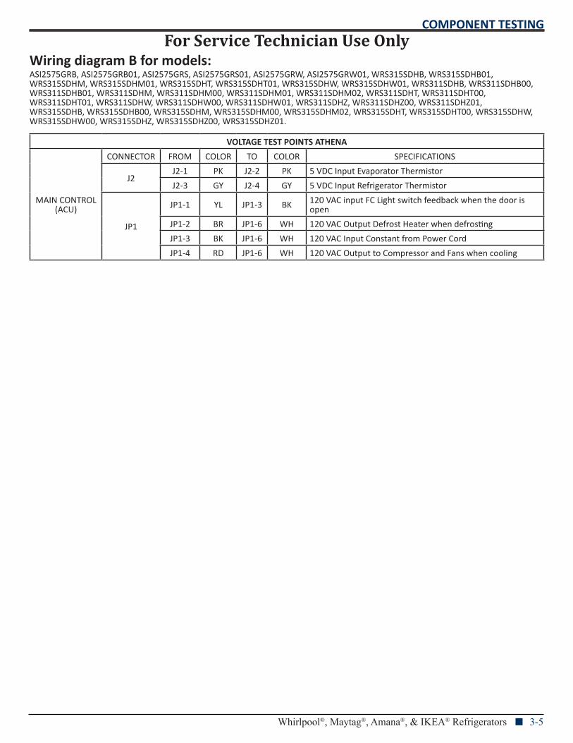
Wiring diagram B for models:ASI2575GRB, ASI2575GRB01, ASI2575GRS, ASI2575GRS01, ASI2575GRW, ASI2575GRW01, WRS315SDHB, WRS315SDHB01, WRS315SDHM, WRS315SDHM01, WRS315SDHT, WRS315SDHT01, WRS315SDHW, WRS315SDHW01, WRS311SDHB, WRS311SDHB00, WRS311SDHB01, WRS311SDHM, WRS311SDHM00, WRS311SDHM01, WRS311SDHM02, WRS311SDHT, WRS311SDHT00, WRS311SDHT01, WRS311SDHW, WRS311SDHW00, WRS311SDHW01, WRS311SDHZ, WRS311SDHZ00, WRS311SDHZ01, WRS315SDHB, WRS315SDHB00, WRS315SDHM, WRS315SDHM00, WRS315SDHM02, WRS315SDHT, WRS315SDHT00, WRS315SDHW, WRS315SDHW00, WRS315SDHZ, WRS315SDHZ00, WRS315SDHZ01.
VOLTAGE TEST POINTS ATHENA
MAIN CONTROL (ACU)
CONNECTOR FROM COLOR TO COLOR SPECIFICATIONS
J2J2-1 PK J2-2 PK 5 VDC Input Evaporator Thermistor
J2-3 GY J2-4 GY 5 VDC Input Refrigerator Thermistor
JP1
JP1-1 YL JP1-3 BK 120 VAC input FC Light switch feedback when the door is open
JP1-2 BR JP1-6 WH 120 VAC Output Defrost Heater when defrosting
JP1-3 BK JP1-6 WH 120 VAC Input Constant from Power Cord
JP1-4 RD JP1-6 WH 120 VAC Output to Compressor and Fans when cooling
For Service Technician Use OnlyCOMPONENT TESTING
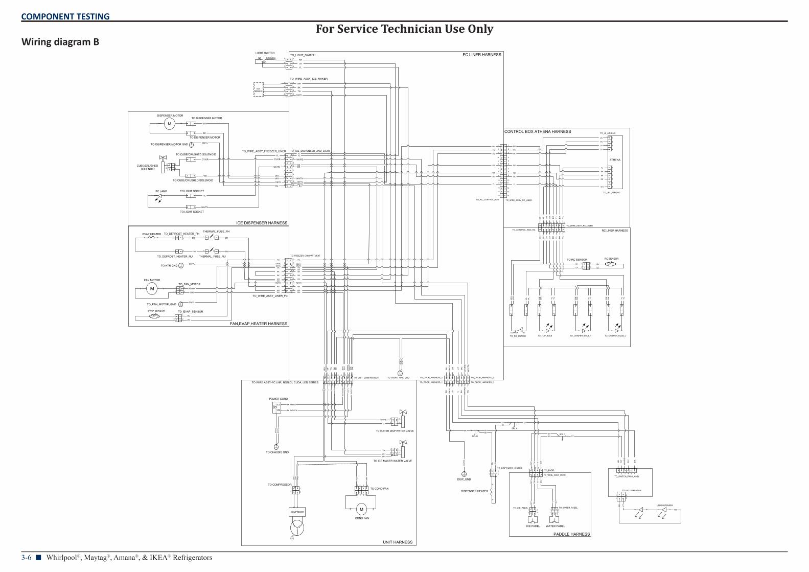
3-6 n Whirlpool®, Maytag®, Amana®, & IKEA® Refrigerators
Wiring diagram B
L1
L2
GN
D
COMMONNO
M
M
M
COMMON NO
ATHENA
COND FAN
POWER CORD
FAN MOTOR
DISPENSER MOTOR
CUBE/CRUSHED SOLENOID
ICE PADEL WATER PADEL
FC LINER HARNESS
ICE DISPENSER HARNESS
FAN,EVAP,HEATER HARNESS
RC LINER HARNESS
CONTROL BOX ATHENA HARNESS
UNIT HARNESS
PADDLE HARNESS
TO RC SENSOR
LED DISPENSER
TO COMPRESSOR1 2 TO COND FAN
1 2 3 4
TO WATER DISP WATER VALVE
TO ICE MAKER WATER VALVE
1
2
TO WIRE ASSY-FC LNR, NONIDI, CUDA, LED SERIES1 2 3 4 5 6 7 8 9
GN
/YL
GN
/YL
GN
/YL
BK SMOOTH
BK
SM
OO
TH
BK RIBBED
BK
RIB
BE
D
WH
/TN
WH/TN
TN
TN
V
V
RD
RD
RD
RD
WH
WHWH
WH
WH
WH
TO_WIRE_ASSY_LINER_FC
1
2
3
4
5
6
7
8
9
TO_DEFROST_HEATER_PH
1
TO_DEFROST_HEATER_NU
TO_EVAP_SENSOR1
2PK
GN/YL
GN/YL
RD/WH
BR
WH
WH
PK
TO_WIRE_ASSY_FREEZER_LINER1
2
3
4
5
6
7
8
9
TO DISPENSER MOTOR
TO DISPENSER MOTOR
TO CUBE/CRUSHED SOLENOID
TO CUBE/CRUSHED SOLENOID
TO LIGHT SOCKET
TO LIGHT SOCKET
YL
YL
GY/ORGY/OR
WH/TN
WH/TN
WH
WH
WHWH
GN/YL
GN/YL
BU
BU
TO_UNIT_COMPARTMENT1 2 3 4 5 6 7 8 9
TO_FREEZER_COMPARTMENT
1
2
3
4
5
6
7
8
9
TO_ICE_DISPENSER_AND_LIGHT1
2
3
4
5
6
7
8
9
TO_DOOR_HARNESS_21 2 3 4
TO_DOOR_HARNESS_21 2 3 4
1
2
3
4
TO_WIRE_ASSY_ICE_MAKER1
2
3
4
1
2
3
TO_LIGHT_SWITCH1
2
3
TO_DOOR_HARNESS_11 2 3
TO_DOOR_HARNESS_11 2 3
BU
GN/YLGN/YL
GN
/YL
WH/TN
WH/RD
WH
TO_DISPENSER_HEATER1 2
TO_SWITCH_PACK_ASSY1 2 3 4 5 6
SPL A
SPL B
BKBK
BK
BK
GN
/YL
LBLB
LB
LB
V
TN
GY
TO_ICE_PADEL1 2
GY
GY
TN
TN
TO_JP1_ATHENA
1
2
3
4
5
6
TO_J2_ATHENA
1
2
3
4
BR
GY
GY
TO_PADEL1 2 3 4
GY
GY
TO_WATER_PADEL1 2
V
V
GY
GY
1 2 1 2
EVAP SENSOR1
2
RC SENSOR
ICE MAKER
LIGHT SWITCH
NC
1
2
DISPENSER HEATER
1 2
FC LAMP
TO_TOP_BULB TO_CRISPER_BULB_1 TO_CRISPER_BULB_2TO_RC_SWTICH
NC
EVAP HEATER1
11
1
2
1
2
1 2
1 2 3 4
WH
TO_WIRE_ASSY_RC_LINER1 2 3 4 5 6 7 8
TO_CONTROL_BOX_RC1 2 3 4 5 6 7 8
TO_RC_CONTROL_BOX
1
2
3
4
56
78
9
1011
12
13
14
TO_WIRE_ASSY_FC_LINER
1
2
3
4
5
6
78
9
1011
12
13
14
PK
PK
PK
PK
TO_WIRE_ASSY_DOOR1 2 3 4
SPL CGY
GY
GY
GY
THERMAL_FUSE_PH
11
11
THERMAL_FUSE_NU
TO_FAN_MOTOR1
2
1
2
1
2
1
2BK
BK
TO LED DISPENSER
1 2
1 2
RD
RD
VT
DISP_GND
TO_FRONT_RAIL_GND
GN
/YL
TO CHASSIS GND
TO_FAN_MOTOR_GND
TO HTR GND
TO DISPENSER MOTOR GND
COMPRESOR
YL
LB
WH
WH
TN
GN/YL
BK
YLYL
BKBK
PK
GN/YLGN/YL
RD/WH
BR
WH
WH
PK
BK
BK
WH
WH
WH
WH
PK
PK
RD/WH
GN/YLGN/YL
BK
BK
BR
WH
BK
1
2
1
2
WH
TN
RD
/WH
GN
/YL
GN
/YL
RD BK
VT
BK BK
WH
BK
BU
WH
/TN
WH
/RD
LB
VT
BK
GN
/YL
BK
GN
/YL
LB V BU
WH
/RD
TN
BK
LB BU
WH
/RD
GY
WH
BK
RD
BR
YL
WH
WH
BK
BK
YL
YL
GY
GY
BK
RD
BR
YL
PK
PK
RD
BK
BR
WH
YL
BK
YL
GY
GY
WH
WH
BK
YL
BK
BK
BK
YL
YL
YL
YL
BK
BK
YL
WH
YL
YL
WH
BK
YL
For Service Technician Use OnlyCOMPONENT TESTING
Whirlpool®, Maytag®, Amana®, & IKEA® Refrigerators n 3-7
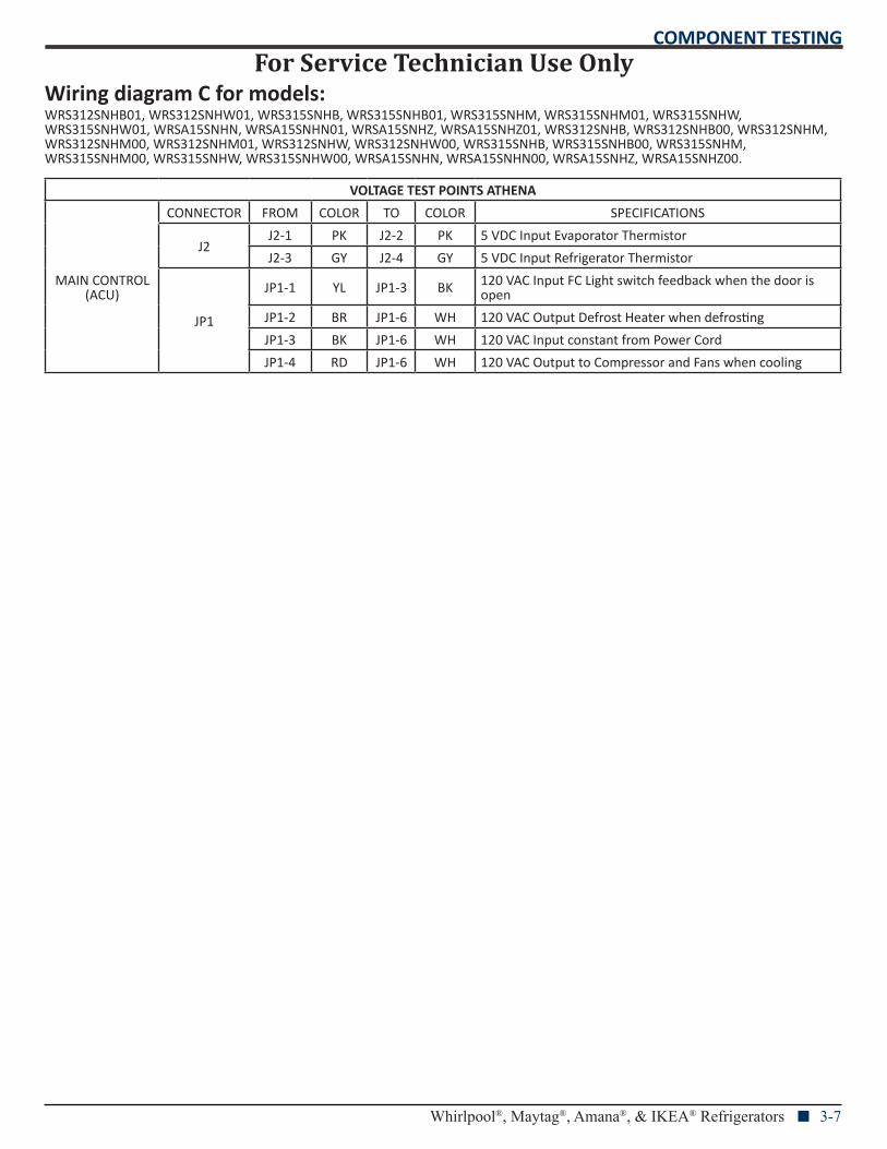
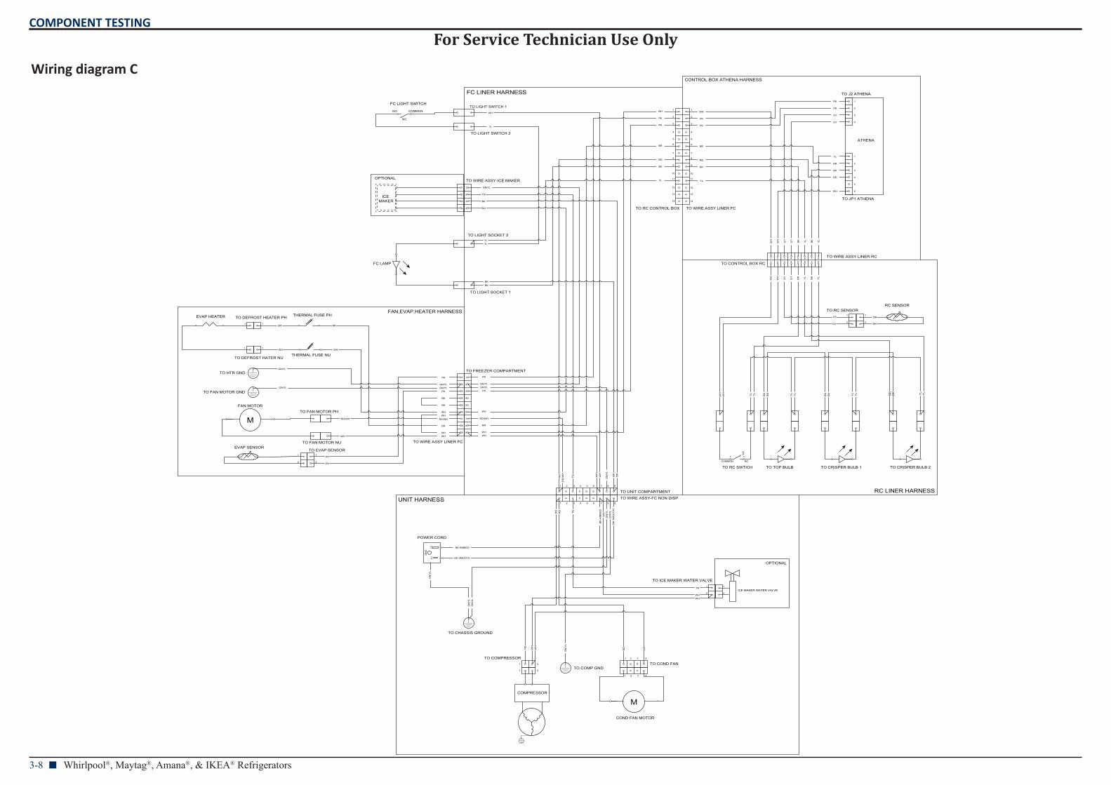
Wiring diagram C for models:WRS312SNHB01, WRS312SNHW01, WRS315SNHB, WRS315SNHB01, WRS315SNHM, WRS315SNHM01, WRS315SNHW, WRS315SNHW01, WRSA15SNHN, WRSA15SNHN01, WRSA15SNHZ, WRSA15SNHZ01, WRS312SNHB, WRS312SNHB00, WRS312SNHM, WRS312SNHM00, WRS312SNHM01, WRS312SNHW, WRS312SNHW00, WRS315SNHB, WRS315SNHB00, WRS315SNHM, WRS315SNHM00, WRS315SNHW, WRS315SNHW00, WRSA15SNHN, WRSA15SNHN00, WRSA15SNHZ, WRSA15SNHZ00.
VOLTAGE TEST POINTS ATHENA
MAIN CONTROL (ACU)
CONNECTOR FROM COLOR TO COLOR SPECIFICATIONS
J2J2-1 PK J2-2 PK 5 VDC Input Evaporator Thermistor
J2-3 GY J2-4 GY 5 VDC Input Refrigerator Thermistor
JP1
JP1-1 YL JP1-3 BK 120 VAC Input FC Light switch feedback when the door is open
JP1-2 BR JP1-6 WH 120 VAC Output Defrost Heater when defrosting
JP1-3 BK JP1-6 WH 120 VAC Input constant from Power Cord
JP1-4 RD JP1-6 WH 120 VAC Output to Compressor and Fans when cooling
For Service Technician Use OnlyCOMPONENT TESTING
3-8 n Whirlpool®, Maytag®, Amana®, & IKEA® Refrigerators
Wiring diagram C
L1L2
GN
D
COMMONNO
M
M
COMMON NO
ATHENA
RC SENSOR
ICE MAKER WATER VALVE
POWER CORD
FAN MOTOR
TO EVAP SENSOR
THERMAL FUSE PH
THERMAL FUSE NU
TO LIGHT SWITCH 1
TO LIGHT SWITCH 2
FC LINER HARNESS
FAN,EVAP,HEATER HARNESS
RC LINER HARNESS
CONTROL BOX ATHENA HARNESS
UNIT HARNESS
TO RC SENSOR
OPTIONAL
OPTIONAL
COMPRESSOR
TO COMPRESSOR1 2 TO COND FAN
1 2 3 4
TO ICE MAKER WATER VALVE1
2
TO WIRE ASSY-FC NON DISP1 2 3 4 5 6 7 8 9
1 2 3 4 5 6 7 8 9
GN
/YL
GN
/YL
GN
/YL
GN
/YL
BK SMOOTH
BK
SM
OO
TH
BK-RIBBED
BK
-RIB
BE
D
TN
TN
RD
RD
RD
RD
GN
/YL
GN
/YL
WH
WHWH
WH
WH
WH
TO WIRE ASSY LINER FC
1
2
3
4
5
6
7
8
9
TO DEFROST HEATER PH1
TO DEFROST HATER NU
1
1
2
TO FAN MOTOR PH
TO FAN MOTOR NU
PK
GN/YL
GN/YL
RD/WH
BR
WH
WH
PK
TO UNIT COMPARTMENT
TO FREEZER COMPARTMENT1
2
3
4
5
6
7
8
9
1
2
3
4
TO WIRE ASSY-ICE MAKER
1
2
3
4 WH
WH
TN
TN
RD
/WH
GN/YL
GN
/YL
RD
BK
BK
BK
BK
BK
YL
YL
BK
BK
BK YL
YL
YL
YL
TO JP1 ATHENA
1
2
3
4
5
6
TO J2 ATHENA
1
2
3
4
BR
BK BK
YL
GY
GY
EVAP SENSOR
1
2
WH
WH
WH
YL
YL
YL
ICE MAKER
FC LIGHT SWITCH
NC
FC LAMP
TO TOP BULB TO CRISPER BULB 1 TO CRISPER BULB 2TO RC SWTICH
11
NC
EVAP HEATER
1
1
1
2
1 2
COND FAN MOTOR
1 2 3 4
WH
TO WIRE ASSY LINER RC1 2 3 4 5 6 7 8
TO CONTROL BOX RC 1 2 3 4 5 6 7 8
TO RC CONTROL BOX
1
2
3
4
5
6
7
8
9
10
11
12
13
14
1
2
3
4
5
6
7
8
9
10
11
12
13
14
TO WIRE ASSY LINER FC
WH BK
YL
TO LIGHT SOCKET 1
TO LIGHT SOCKET 2
1
2
1
2
BK
BK
TO COMP GND
TO CHASSIS GROUND
TO HTR GND
TO FAN MOTOR GND
PK
GN/YLGN/YL
RD/WH
BR
WH
WH
PK
WH
WH
BK
BK
WH
WH
PK
PK
RD/WH
GN/YLGN/YL
BR
WH
PK
PK
RD
BK
BR
WH
YL
WH
BK
RD
BR
YL
PK
PK
WH
BK
RD
GY
GY
BR
YL
PK
PK
WH
WH
BK
BK
GY
GY
YL
YL
BK
YL
GY
GY
WH
WH
BK
YL
For Service Technician Use OnlyCOMPONENT TESTING
Whirlpool®, Maytag®, Amana®, & IKEA® Refrigerators n 3-9
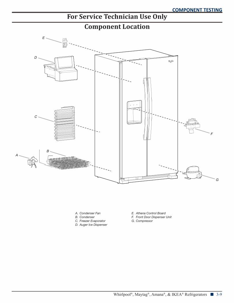
Component Location
E
D
C
BA
F
G
A. Condenser FanB. CondenserC. Freezer EvaporatorD. Auger Ice Dispenser
E. Athena Control BoardF. Front Door Dispenser UnitG. Compressor
For Service Technician Use OnlyCOMPONENT TESTING
3-10 n Whirlpool®, Maytag®, Amana®, & IKEA® Refrigerators
Notes
COMPONENT ACCESS
Whirlpool®, Maytag®, Amana®, & IKEA® Refrigerators n 4-1
Section 4: Component Access
This section provides service parts access, removal, and replacement instructions for the “Whirlpool®, Maytag®, Amana®, and IKEA® Refrigerators.”
n Removing the front wheel
n Accessing the interior of the unit
n Removing the damper
n Removing the freezer shelf
n Removing the dispenser
n Accessing the freezer evaporator and components
n Accessing the dispenser area (removing UI)
n Accessing the machine compartment
COMPONENT ACCESS
4-2 n Whirlpool®, Maytag®, Amana®, & IKEA® Refrigerators
Removing the Front Wheel
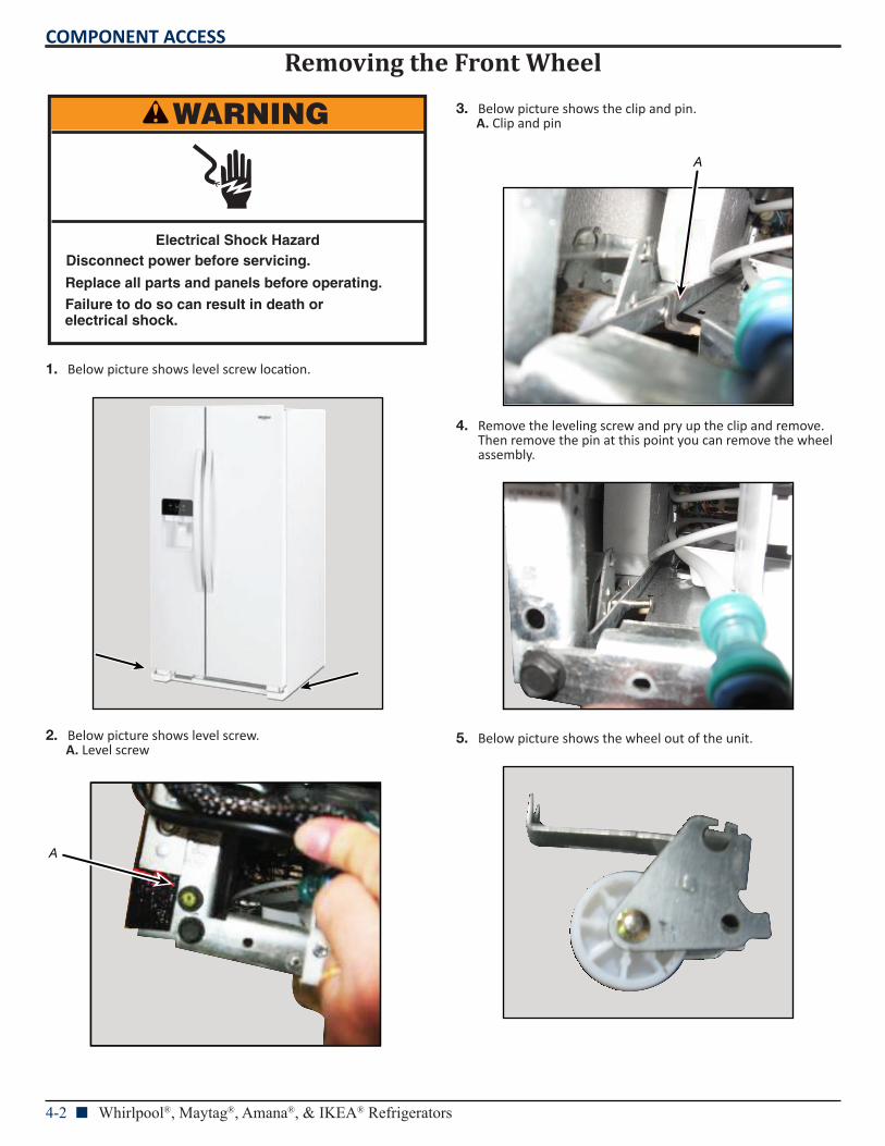
1. Below picture shows level screw location.
2. Below picture shows level screw.A. Level screw
3. Below picture shows the clip and pin.A. Clip and pin
4. Remove the leveling screw and pry up the clip and remove. Then remove the pin at this point you can remove the wheel assembly.
5. Below picture shows the wheel out of the unit.
WARNING
Electrical Shock HazardDisconnect power before servicing.
Failure to do so can result in death orelectrical shock.
Replace all parts and panels before operating.
A
A
COMPONENT ACCESS
Whirlpool®, Maytag®, Amana®, & IKEA® Refrigerators n 4-3
Accessing Interior of Unit
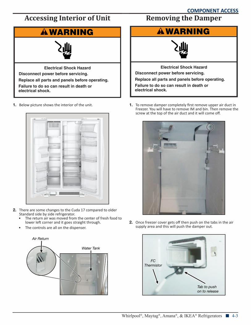
1. Below picture shows the interior of the unit.
2. There are some changes to the Cuda 17 compared to older Standard side by side refrigerator.• The return air was moved from the center of fresh food to
lower left corner and it goes straight through.• The controls are all on the dispenser.
Removing the Damper
1. To remove damper completely first remove upper air duct in Freezer. You will have to remove IM and bin. Then remove the screw at the top of the air duct and it will come off.
2. Once freezer cover gets off then push on the tabs in the air supply area and this will push the damper out.
WARNING
Electrical Shock HazardDisconnect power before servicing.
Failure to do so can result in death orelectrical shock.
Replace all parts and panels before operating.
Air Return
Water Tank
WARNING
Electrical Shock HazardDisconnect power before servicing.
Failure to do so can result in death orelectrical shock.
Replace all parts and panels before operating.
FCThermistor
Tab to push on to release
COMPONENT ACCESS
4-4 n Whirlpool®, Maytag®, Amana®, & IKEA® Refrigerators
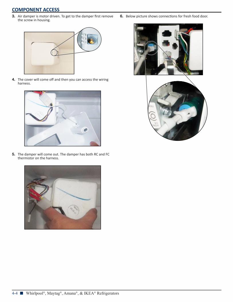
3. Air damper is motor driven. To get to the damper first remove the screw in housing.
4. The cover will come off and then you can access the wiring harness.
5. The damper will come out. The damper has both RC and FC thermistor on the harness.
6. Below picture shows connections for fresh food door.
COMPONENT ACCESS
Whirlpool®, Maytag®, Amana®, & IKEA® Refrigerators n 4-5
Removing the Freezer Shelf
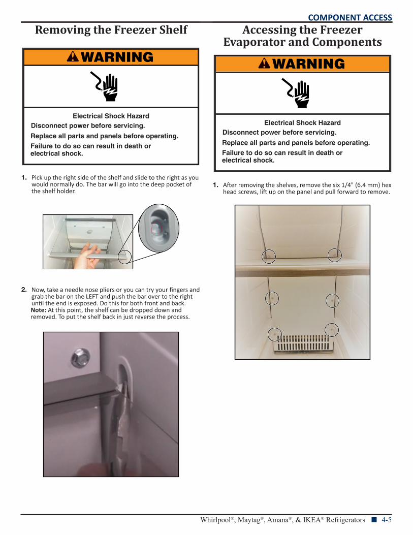
1. Pick up the right side of the shelf and slide to the right as you would normally do. The bar will go into the deep pocket of the shelf holder.
2. Now, take a needle nose pliers or you can try your fingers and grab the bar on the LEFT and push the bar over to the right until the end is exposed. Do this for both front and back.Note: At this point, the shelf can be dropped down and removed. To put the shelf back in just reverse the process.
Accessing the Freezer Evaporator and Components
1. After removing the shelves, remove the six 1/4" (6.4 mm) hex head screws, lift up on the panel and pull forward to remove.
WARNING
Electrical Shock HazardDisconnect power before servicing.
Failure to do so can result in death orelectrical shock.
Replace all parts and panels before operating.
WARNING
Electrical Shock HazardDisconnect power before servicing.
Failure to do so can result in death orelectrical shock.
Replace all parts and panels before operating.
COMPONENT ACCESS
4-6 n Whirlpool®, Maytag®, Amana®, & IKEA® Refrigerators
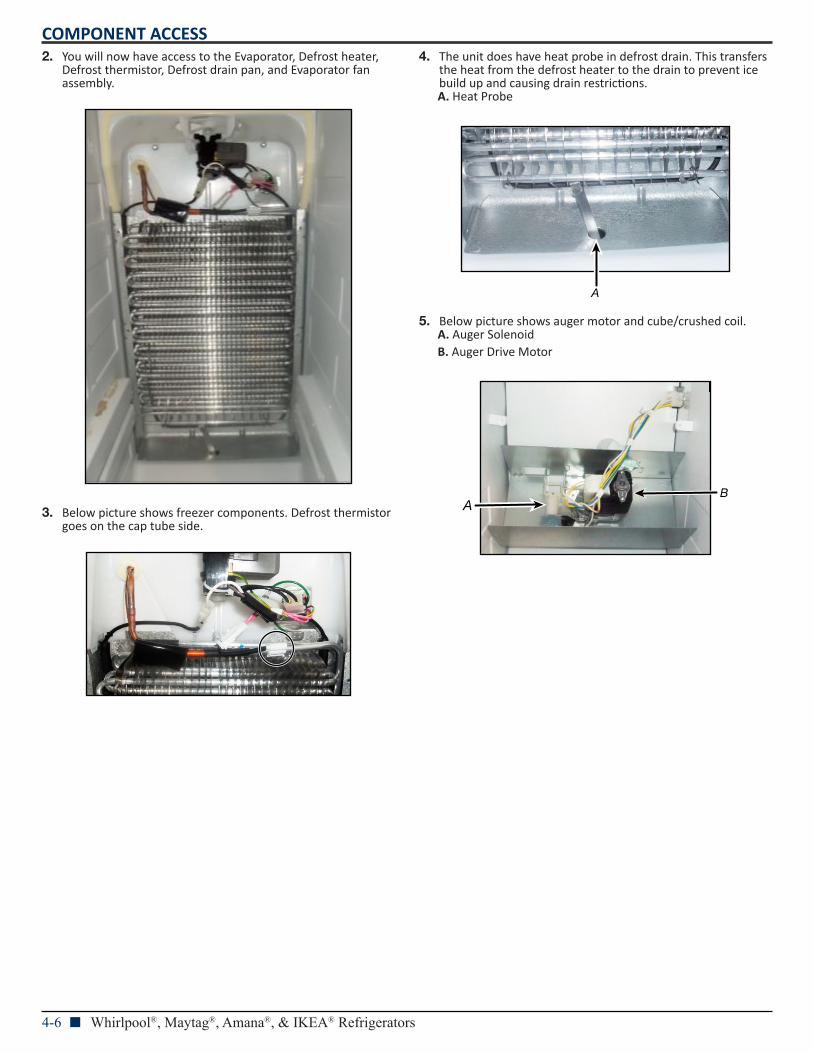
2. You will now have access to the Evaporator, Defrost heater, Defrost thermistor, Defrost drain pan, and Evaporator fan assembly.
3. Below picture shows freezer components. Defrost thermistor goes on the cap tube side.
4. The unit does have heat probe in defrost drain. This transfers the heat from the defrost heater to the drain to prevent ice build up and causing drain restrictions.A. Heat Probe
5. Below picture shows auger motor and cube/crushed coil.A. Auger SolenoidB. Auger Drive Motor
A
AB
COMPONENT ACCESS
Whirlpool®, Maytag®, Amana®, & IKEA® Refrigerators n 4-7
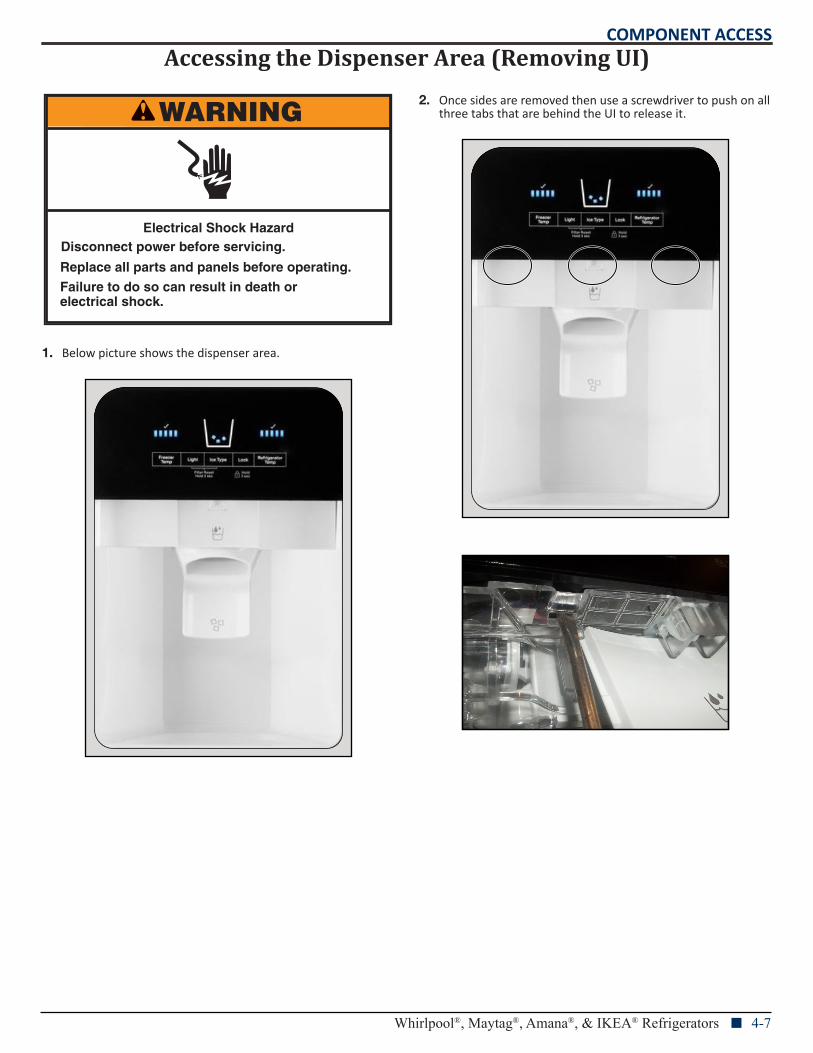
Accessing the Dispenser Area (Removing UI)
1. Below picture shows the dispenser area.
2. Once sides are removed then use a screwdriver to push on all three tabs that are behind the UI to release it.WARNING
Electrical Shock HazardDisconnect power before servicing.
Failure to do so can result in death orelectrical shock.
Replace all parts and panels before operating.
COMPONENT ACCESS
4-8 n Whirlpool®, Maytag®, Amana®, & IKEA® Refrigerators
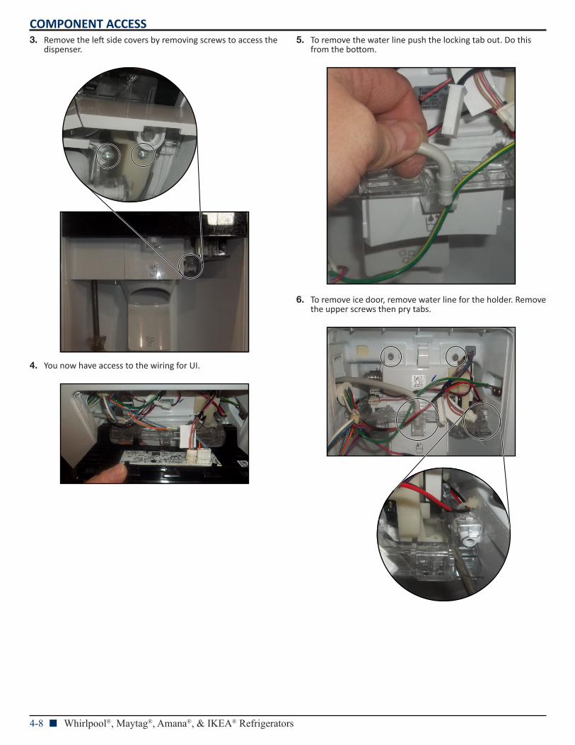
3. Remove the left side covers by removing screws to access the dispenser.
4. You now have access to the wiring for UI.
5. To remove the water line push the locking tab out. Do this from the bottom.
6. To remove ice door, remove water line for the holder. Remove the upper screws then pry tabs.
COMPONENT ACCESS
Whirlpool®, Maytag®, Amana®, & IKEA® Refrigerators n 4-9
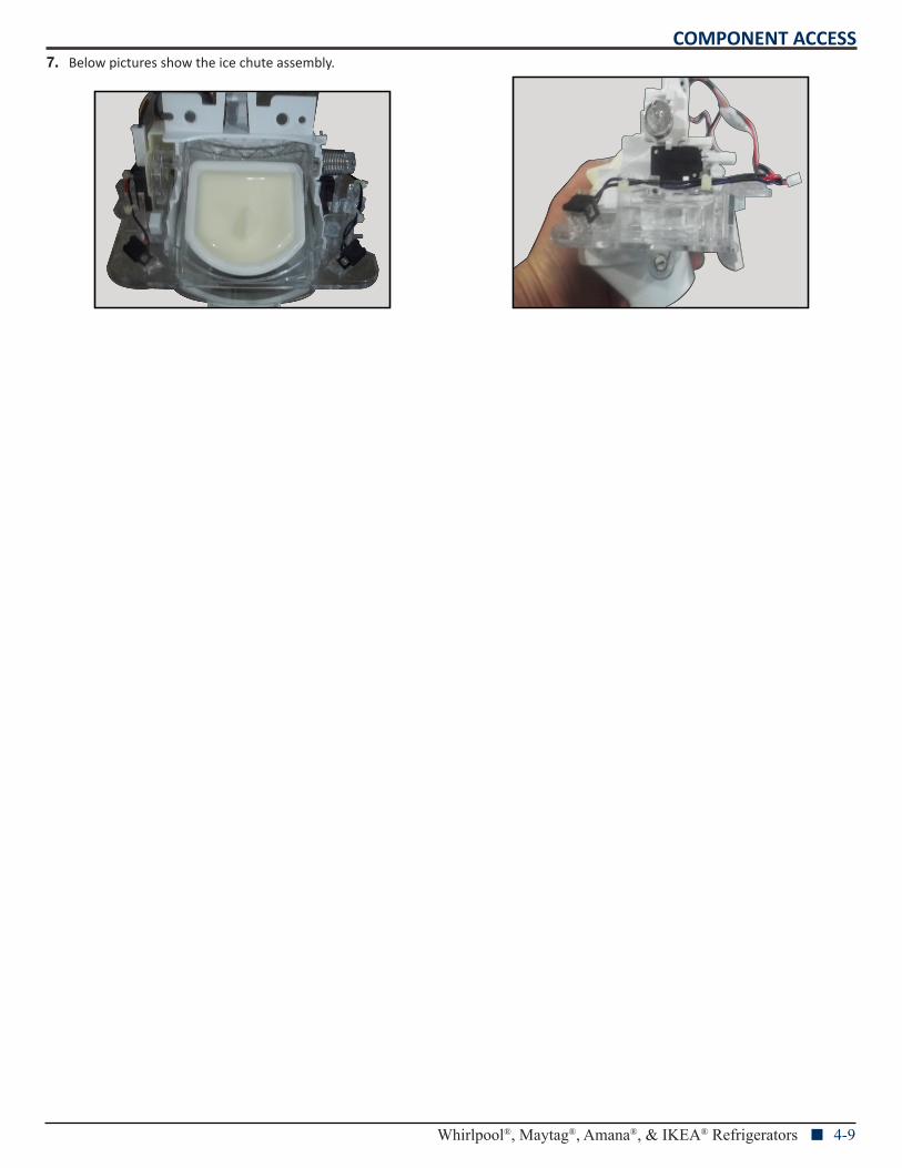
7. Below pictures show the ice chute assembly.
COMPONENT ACCESS
4-10 n Whirlpool®, Maytag®, Amana®, & IKEA® Refrigerators
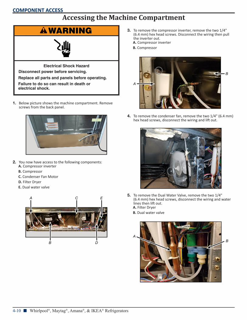
Accessing the Machine Compartment
1. Below picture shows the machine compartment. Remove screws from the back panel.
2. You now have access to the following components:A. Compressor inverterB. CompressorC. Condenser Fan MotorD. Filter DryerE. Dual water valve
3. To remove the compressor inverter, remove the two 1/4" (6.4 mm) hex head screws. Disconnect the wiring then pull the inverter out.A. Compressor inverterB. Compressor
4. To remove the condenser fan, remove the two 1/4" (6.4 mm)hex head screws, disconnect the wiring and lift out.
5. To remove the Dual Water Valve, remove the two 1/4" (6.4 mm) hex head screws, disconnect the wiring and water lines then lift out.A. Filter DryerB. Dual water valve
WARNING
Electrical Shock HazardDisconnect power before servicing.
Failure to do so can result in death orelectrical shock.
Replace all parts and panels before operating.
A
B
C
D
E
A
B
AB
COMPONENT ACCESS
Whirlpool®, Maytag®, Amana®, & IKEA® Refrigerators n 4-11
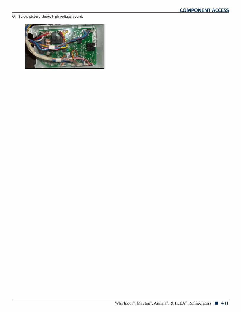
6. Below picture shows high voltage board.
PRODUCT SPECIFICATIONS &WARRANTY INFORMATION SOURCES
IN THE UNITED STATES:FOR PRODUCT SPECIFICATIONS AND WARRANTY INFORMATION CALL:
FOR WHIRLPOOL PRODUCTS: 1-800-253-1301
FOR TECHNICAL ASSISTANCE WHILE AT THE CUSTOMER’S HOME CALL:THE TECHNICAL ASSISTANCE LINE: 1-800-832-7174
HAVE YOUR STORE NUMBER READY TO IDENTIFY YOU AS ANAUTHORIZED IN-HOME SERVICE PROFESSIONAL
FOR LITERATURE ORDERS (CUSTOMER EXPERIENCE CENTER): PHONE: 1-800-851-4605
FOR TECHNICAL INFORMATION AND SERVICE POINTERS: www.servicematters.com
IN CANADA:FOR PRODUCT SPECIFICATIONS AND WARRANTY INFORMATION CALL
1-800-461-5681
FOR TECHNICAL ASSISTANCE WHILE AT THE CUSTOMER’S HOME CALL:THE TECHNICAL ASSISTANCE LINE: 1-800-488-4791
HAVE YOUR STORE NUMBER READY TO IDENTIFY YOU AS AN AUTHORIZED IN-HOME SERVICE PROFESSIONAL