sequential-control-systems – pcs 7 - siemens
TRANSCRIPT

Learn-/Training Document | PA Module P01-08, Edition 02/2020 | Digital Industries, FA
For unrestricted use in educational / R&D institutions. © Siemens 2020. All rights reserved.
Learn-/Training Document
Siemens Automation Cooperates with Education (SCE) | As of Version V9 SP1
siemens.com/sce
PA Module P01-08 SIMATIC PCS 7 – Sequential control systems
Learn-/Training Document | PA Module P01-08, Edition 02/2020 | Digital Industries, FA
For unrestricted use in educational / R&D institutions. © Siemens 2020. All rights reserved. 2
p01-08-sequential-function-chart-v9-tud-0719-en.docx
Matching SCE Trainer Packages for this Learn-/Training Document
• SIMATIC PCS 7 Software Package V9.0 (set of 3)
Order No.: 6ES7650-0XX58-0YS5
• SIMATIC PCS 7 Software Package V9.0 (set of 6)
Order No.: 6ES7650-0XX58-2YS5
• SIMATIC PCS 7 Software Upgrade Packages (set of 3)
Order No.: 6ES7650-0XX58-0YE5 (V8.x V9.0)
• SIMIT Simulation Platform with Dongle V10
(contains SIMIT S & CTE, FLOWNET, CONTEC libraries) – 2500 simulation tags
Order No.: 6DL8913-0AK00-0AS5
• Upgrade SIMIT Simulation Platform V10
(contains SIMIT S & CTE, FLOWNET, CONTEC libraries) from V8.x/V9.x
Order No.: 6DL8913-0AK00-0AS6
• Demo Version SIMIT Simulation Platform V10
Download
• SIMATIC PCS 7 AS RTX Box (PROFIBUS) only in combination with ET 200M for RTX –
Order No.: 6ES7654-0UE23-0XS1
• ET 200M for RTX Box (PROFIBUS) only in combination with PCS 7 AS RTX Box –
Order No.: 6ES7153-2BA10-4AB1
Note that these trainer packages are replaced with successor packages when necessary.
An overview of the currently available SCE packages is available at: siemens.com/sce/tp
Continued training
For regional Siemens SCE continued training, get in touch with your regional SCE contact
siemens.com/sce/contact
Additional information regarding SCE
siemens.com/sce
Information regarding use The SCE Learn-/Training Document for the integrated automation solution Totally Integrated Automation
(TIA) was prepared for the program "Siemens Automation Cooperates with Education (SCE)" specifically
for training purposes for public educational facilities and R&D institutions. Siemens does not guarantee
the contents.
This document is to be used only for initial training on Siemens products/systems, which means it can be
copied in whole or part and given to those being trained for use within the scope of their training.
Circulation or copying this Learn-/Training Document and sharing its content is permitted within public
training and advanced training facilities for training purposes.
Exceptions require written consent from the Siemens. Send all related requests to
Offenders will be held liable. All rights including translation are reserved, particularly if a patent is granted
or a utility model or design is registered.
Use for industrial customer courses is explicitly not permitted. We do not consent to commercial use of
the Learn-/Training Document.
Learn-/Training Document | PA Module P01-08, Edition 02/2020 | Digital Industries, FA
For unrestricted use in educational / R&D institutions. © Siemens 2020. All rights reserved. 3
p01-08-sequential-function-chart-v9-tud-0719-en.docx
We wish to thank the TU Dresden, particularly Prof. Dr.-Ing. Leon Urbas and the Michael Dziallas
Engineering Corporation and all other involved persons for their support during the preparation of this
Learn-/Training Document.
Learn-/Training Document | PA Module P01-08, Edition 02/2020 | Digital Industries, FA
For unrestricted use in educational / R&D institutions. © Siemens 2020. All rights reserved. 4
p01-08-sequential-function-chart-v9-tud-0719-en.docx
Table of contents
1 Goal ................................................................................................................................................. 6
2 Prerequisite ...................................................................................................................................... 6
3 Required hardware and software ...................................................................................................... 7
4 Theory ............................................................................................................................................. 8
4.1 Theory in brief ..........................................................................................................................8
4.2 Continuous and sequential control systems ..............................................................................9
4.3 Structure of sequential function charts ......................................................................................9
4.4 Design of sequential control systems ...................................................................................... 12
4.5 Interaction of sequential control and logic control systems ...................................................... 13
4.6 Protective functions and operating modes in sequential control systems ................................. 14
4.7 Sequential control systems in PCS 7 ...................................................................................... 15
4.8 References ............................................................................................................................. 16
5 Task ............................................................................................................................................... 17
6 Planning ......................................................................................................................................... 18
7 Learning objective .......................................................................................................................... 19
8 Structured step-by-step instructions ................................................................................................ 20
8.1 Creating and configuring an SFC ............................................................................................ 20
8.2 Editing the sequential function chart ........................................................................................ 23
8.3 Editing properties of steps and transitions ............................................................................... 28
8.4 Editing steps and transitions ................................................................................................... 33
8.4.1 Transition: Init_OK .......................................................................................................... 33
8.4.2 Step: EductB003toR001 .................................................................................................. 36
8.4.3 Transition: L001 >= 350 ml .............................................................................................. 44
8.4.4 Step: Heating25°CStir ..................................................................................................... 45
8.4.5 Transition: T001 >= 25°C ................................................................................................ 46
8.4.6 Step: Wait ....................................................................................................................... 47
8.4.7 Step: EduktB002inR002 .................................................................................................. 47
8.4.8 Transition: L002 >= 200 ml .............................................................................................. 49
8.4.9 Step: EductB001toR002 .................................................................................................. 49
Learn-/Training Document | PA Module P01-08, Edition 02/2020 | Digital Industries, FA
For unrestricted use in educational / R&D institutions. © Siemens 2020. All rights reserved. 5
p01-08-sequential-function-chart-v9-tud-0719-en.docx
8.4.10 Transition: L002 >= 350 ml .............................................................................................. 51
8.4.11 Step: Stir ......................................................................................................................... 51
8.4.12 Transition: Parallel_OK ................................................................................................... 53
8.4.13 Step: R002toR001 .......................................................................................................... 55
8.4.14 Transition: L002 <= 50 ml ................................................................................................ 56
8.4.15 Step: Heating28°C .......................................................................................................... 57
8.4.16 Transition: T001 >= 28°C ................................................................................................ 58
8.4.17 Step: R001toProdB001 ................................................................................................... 58
8.4.18 Transition: L001 <= 50 ml ................................................................................................ 60
8.4.19 Step: END....................................................................................................................... 60
8.5 Compiling and downloading objects ........................................................................................ 64
8.6 Testing the SFC...................................................................................................................... 69
8.7 Checklist – step-by-step instruction ......................................................................................... 77
9 Exercises ....................................................................................................................................... 78
9.1 Task ....................................................................................................................................... 78
9.2 Checklist – exercise ................................................................................................................ 78
10 Additional information ..................................................................................................................... 79
Learn-/Training Document | PA Module P01-08, Edition 02/2020 | Digital Industries, FA
For unrestricted use in educational / R&D institutions. © Siemens 2020. All rights reserved. 6
p01-08-sequential-function-chart-v9-tud-0719-en.docx
Sequential control systems
1 Goal
The students can successfully implement sequential control systems using sequential function
charts. They understand the structure and mode of functioning of sequential function charts and
are familiar with corresponding design methods. Their knowledge regarding operating modes and
protective measures will be expanded for sequential control systems. The students understand
the interaction between the programs of basic automation and sequential control systems. They
know how to create sequential controls in PCS 7.
2 Prerequisite
This chapter builds on chapter 'Functional safety'. To implement this chapter, you can use an
existing project from the previous chapter or the archived project 'p01-07-exercise-r1905-en.zip'
provided by SCE. The download of the project(s) is stored on the SCE Internet for the respective
module.
The (optional) simulation for the SIMIT program can be retrieved from the file 'p01-04-plantsim-
v10-r1905-en.simarc'. It can be run in demo mode.
Learn-/Training Document | PA Module P01-08, Edition 02/2020 | Digital Industries, FA
For unrestricted use in educational / R&D institutions. © Siemens 2020. All rights reserved. 7
p01-08-sequential-function-chart-v9-tud-0719-en.docx
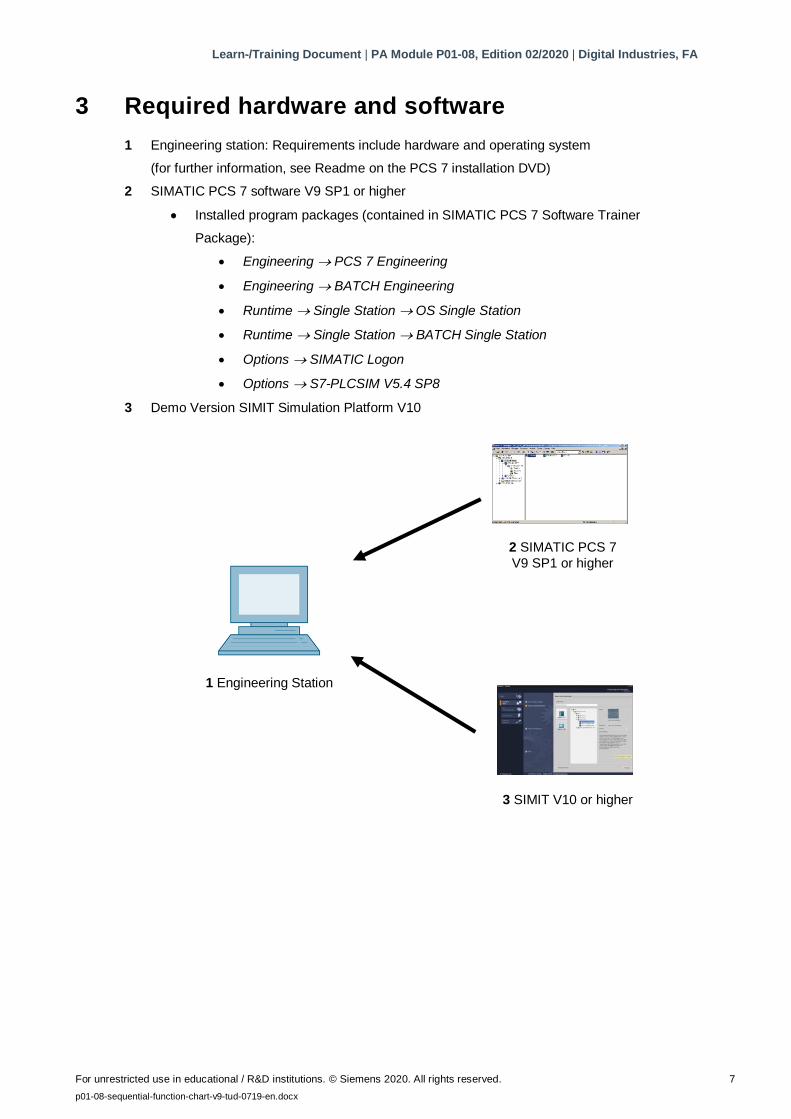
3 Required hardware and software
1 Engineering station: Requirements include hardware and operating system
(for further information, see Readme on the PCS 7 installation DVD)
2 SIMATIC PCS 7 software V9 SP1 or higher
Installed program packages (contained in SIMATIC PCS 7 Software Trainer
Package):
Engineering PCS 7 Engineering
Engineering BATCH Engineering
Runtime Single Station OS Single Station
Runtime Single Station BATCH Single Station
Options SIMATIC Logon
Options S7-PLCSIM V5.4 SP8
3 Demo Version SIMIT Simulation Platform V10
3 SIMIT V10 or higher
1 Engineering Station
2 SIMATIC PCS 7
V9 SP1 or higher
Learn-/Training Document | PA Module P01-08, Edition 02/2020 | Digital Industries, FA
For unrestricted use in educational / R&D institutions. © Siemens 2020. All rights reserved. 8
p01-08-sequential-function-chart-v9-tud-0719-en.docx
4 Theory
4.1 Theory in brief
Sequential control systems allow for time-discrete or event-discrete execution of sequential and
parallel processes. They are used to coordinate various continuous functions as well as to control
complex process sequences. Dependent on defined states or events, changes of operating state
and changes of state are produced in existing logic control systems and the desired sequential
flow is thus implemented. Sequential control systems are implemented with one or more
sequential function charts.
A sequential function chart is an alternating stringing together of steps, which trigger certain
actions and transitions, which initiate the change from one step to another as soon as the
corresponding step enabling condition is met. Each sequential function chart has exactly
one start step and one end step as well as any number of intermediate steps that are each
interconnected by arrows and interposed transitions. The charts may also generate feedback
through loops within the sequential function chart. Likewise, they can contain simultaneous or
alternative branches. However, in this case the design must ensure that the sequence does not
contain uncertain or inaccessible parts.
Formal design methods using state diagrams or Petri nets are particularly suitable for
designing a sequential control system. State diagrams are easy to learn, allow for automatic error
diagnostics and can be easily converted to many existing programming languages for sequential
control systems. However, the design of parallel structures is not possible because state
diagrams have only exactly one active state.
Petri nets are considerably more complex and pose a greater mathematical challenge. However,
all structures that are permitted in sequential control systems can be modeled and extensively
analyzed. Thus, necessary properties of the control system can be verified formally. Petri nets
also permit easy implementation in sequential control systems.
Parameter assignment and activation of lower-level logic control systems by sequential control
systems takes place by the setting of corresponding global control signals. The effect of these
control signals can be temporary or permanent, direct or delayed. Like logic control systems,
sequential control systems must support various operating modes, in which manual control of
transitions and temporary or permanent interruption of process sequences, in particular, must be
possible. In addition, process-specific protective functions are implemented through sequential
control systems.
Sequential control systems are implemented in PCS 7 with sequential function charts
(SFC). SFCs provide efficient operating mode management, high controllability through multiple
switching modes and extensive parameter assignment capability through various execution
options. In PCS 7, SFCs and CFCs interact and are linked by means of process values and
control values. The interaction behavior can also be controlled in detail.
Learn-/Training Document | PA Module P01-08, Edition 02/2020 | Digital Industries, FA
For unrestricted use in educational / R&D institutions. © Siemens 2020. All rights reserved. 9
p01-08-sequential-function-chart-v9-tud-0719-en.docx
4.2 Continuous and sequential control systems
Within the scope of basic automation, various logic control systems are developed that each
implements a limited, clearly defined function. The functions continuously process input signals
and generate corresponding output signals. Activation and parameter assignment of the functions
is possible through various control signals. To implement complex process sequences, such as
manufacturing specifications for products (recipes), the various functions must be coordinated
and activated at the right time with the right parameters. This task can be realized using
sequential control systems.
Sequential control systems enable step-by-step, event-discrete processing of sequential and
parallel processes using sequential function charts (also called sequencers). They
produce changes of operating state and changes of state dependent on defined states or events
in the existing logic control systems and thus implement the desired sequential flow. Sequencers
function charts are also called Sequential function charts.
4.3 Structure of sequential function charts
A sequential function chart is an alternating sequence of steps and transitions. The individual
steps activate certain actions in each case. Transitions control the change from one step to
another.
The first step of a sequential function chart is called the start step. It is the explicit entry point
into the sequence and is always executed for that reason. The last step of a sequential function
chart is correspondingly called the end step. It is the only step in the sequence that does not
have a follow-on transition. After the end step is executed, the sequential function chart is
terminated (completed) or the execution restarts. The latter case is also referred to as sequence
loop.
Steps and transitions are interconnected by directed graphs. A step can be connected to several
follow-on transitions; the reverse is also possible. A transition is enabled when all upstream steps
are active and the step enabling condition is met. In this case, first the directly preceding steps
are deactivated and then the direct follow-on steps are activated.
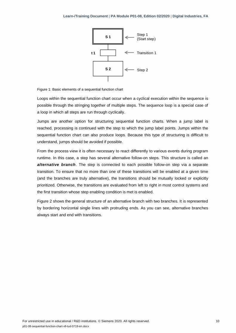
The simplest form of a sequential function chart is the unbranched sequence. Each step is
followed by exactly one transition, which in turn is followed by exactly one follow-on step. Thus, a
purely sequential process sequence is realized. Figure 1 shows the corresponding graphic basic
elements.
Learn-/Training Document | PA Module P01-08, Edition 02/2020 | Digital Industries, FA
For unrestricted use in educational / R&D institutions. © Siemens 2020. All rights reserved. 10
p01-08-sequential-function-chart-v9-tud-0719-en.docx
S 1
S 2
t 1
Step 1(Start step)
Transition 1
Step 2
Figure 1: Basic elements of a sequential function chart
Loops within the sequential function chart occur when a cyclical execution within the sequence is
possible through the stringing together of multiple steps. The sequence loop is a special case of
a loop in which all steps are run through cyclically.
Jumps are another option for structuring sequential function charts. When a jump label is
reached, processing is continued with the step to which the jump label points. Jumps within the
sequential function chart can also produce loops. Because this type of structuring is difficult to
understand, jumps should be avoided if possible.
From the process view it is often necessary to react differently to various events during program
runtime. In this case, a step has several alternative follow-on steps. This structure is called an
alternative branch. The step is connected to each possible follow-on step via a separate
transition. To ensure that no more than one of these transitions will be enabled at a given time
(and the branches are truly alternative), the transitions should be mutually locked or explicitly
prioritized. Otherwise, the transitions are evaluated from left to right in most control systems and
the first transition whose step enabling condition is met is enabled.
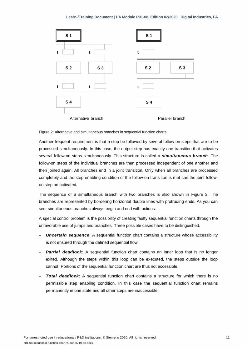
Figure 2 shows the general structure of an alternative branch with two branches. It is represented
by bordering horizontal single lines with protruding ends. As you can see, alternative branches
always start and end with transitions.
Learn-/Training Document | PA Module P01-08, Edition 02/2020 | Digital Industries, FA
For unrestricted use in educational / R&D institutions. © Siemens 2020. All rights reserved. 11
p01-08-sequential-function-chart-v9-tud-0719-en.docx
S 1
t
t
S 4
t
S 2 S 3
t
S 1
t
t
S 4
S 2 S 3
Alternative branch Parallel branch
Figure 2: Alternative and simultaneous branches in sequential function charts
Another frequent requirement is that a step be followed by several follow-on steps that are to be
processed simultaneously. In this case, the output step has exactly one transition that activates
several follow-on steps simultaneously. This structure is called a simultaneous branch. The
follow-on steps of the individual branches are then processed independent of one another and
then joined again. All branches end in a joint transition. Only when all branches are processed
completely and the step enabling condition of the follow-on transition is met can the joint follow-
on step be activated.
The sequence of a simultaneous branch with two branches is also shown in Figure 2. The
branches are represented by bordering horizontal double lines with protruding ends. As you can
see, simultaneous branches always begin and end with actions.
A special control problem is the possibility of creating faulty sequential function charts through the
unfavorable use of jumps and branches. Three possible cases have to be distinguished.
– Uncertain sequence: A sequential function chart contains a structure whose accessibility
is not ensured through the defined sequential flow.
– Partial deadlock: A sequential function chart contains an inner loop that is no longer
exited. Although the steps within this loop can be executed, the steps outside the loop
cannot. Portions of the sequential function chart are thus not accessible.
– Total deadlock: A sequential function chart contains a structure for which there is no
permissible step enabling condition. In this case the sequential function chart remains
permanently in one state and all other steps are inaccessible.
Learn-/Training Document | PA Module P01-08, Edition 02/2020 | Digital Industries, FA
For unrestricted use in educational / R&D institutions. © Siemens 2020. All rights reserved. 12
p01-08-sequential-function-chart-v9-tud-0719-en.docx
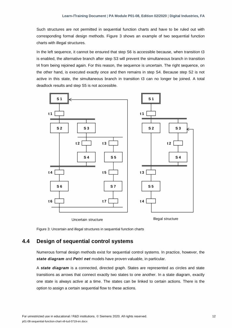
Such structures are not permitted in sequential function charts and have to be ruled out with
corresponding formal design methods. Figure 3 shows an example of two sequential function
charts with illegal structures.
In the left sequence, it cannot be ensured that step S6 is accessible because, when transition t3
is enabled, the alternative branch after step S3 will prevent the simultaneous branch in transition
t4 from being rejoined again. For this reason, the sequence is uncertain. The right sequence, on
the other hand, is executed exactly once and then remains in step S4. Because step S2 is not
active in this state, the simultaneous branch in transition t3 can no longer be joined. A total
deadlock results and step S5 is not accessible.
S 1
t 1
S 2 S 3
t 2
S 4
t 3
S 5
t 5t 4
S 6
t 6
S 7
t 7
Uncertain structure Illegal structure
S 1
t 1
S 2 S 3
t 2
S 4
t 3
S 5
t 4
Figure 3: Uncertain and illegal structures in sequential function charts
4.4 Design of sequential control systems
Numerous formal design methods exist for sequential control systems. In practice, however, the
state diagram and Petri net models have proven valuable, in particular.
A state diagram is a connected, directed graph. States are represented as circles and state
transitions as arrows that connect exactly two states to one another. In a state diagram, exactly
one state is always active at a time. The states can be linked to certain actions. There is the
option to assign a certain sequential flow to these actions.
Learn-/Training Document | PA Module P01-08, Edition 02/2020 | Digital Industries, FA
For unrestricted use in educational / R&D institutions. © Siemens 2020. All rights reserved. 13
p01-08-sequential-function-chart-v9-tud-0719-en.docx
They can be executed once on entering the state or exiting the state, or cyclically as long as the
state is active. State transitions can be subject to transition conditions.
State diagrams can be structured hierarchically and linked to each other. State diagrams are
considered easy to learn and enable automatic error diagnostics, for example, through pair, time
or state monitoring. These diagrams can be easily converted to many existing programming
languages for sequential control systems.
Petri nets are particularly suitable for modeling concurrent processes. A Petri net consists of
places and transitions that are connected to each other through arrows. This also results in a
directed graph. A place is represented with a circle and a transition with a rectangle (often
reduced to a bar). Active places are indicated with tokens; they are represented with a dot within
the circle for the corresponding place.
In contrast to function diagrams, the state in a Petri net is determined by the number of active
places in the entire network. The dynamics of the system is modeled through the movement of
the tokens within the network. The meaning of the places and transitions for the modeled process
(i.e. the semantics of the Petri net) is not defined and has to be specified depending on the
application. Petri nets whose semantics have been specified are called interpreted Petri nets
(IPN). For the control design, signal interpreted Petri nets (SIPN) are generally usable.
Petri nets can be extensively analytically tested. They also allow easy conversion to existing
programming languages for sequential control systems. There are numerous expansions for Petri
nets that are optimized for specific applications or provide for more exact process modeling. For
this reason, Petri nets can become rather complex, which makes them more demanding as a
design method. Nevertheless, based on their structural similarity to sequential function charts and
their ability to model parallel processes, Petri nets offer clear advantages.
The design method that is used depends ultimately on the requirements of the design task as
well on the preference of the developer. Additional information is provided in the pertinent
technical literature.
4.5 Interaction of sequential control and logic control systems
As described above, each step in the sequential function chart can be assigned certain actions.
In general, these actions consist of the parameter assignment and activation of logic control
systems for which corresponding control signals are suited.
Process and control signals that are used by sequential function charts must be declared globally
so that they are equally available to the programs of the sequential control and logic control
systems. The signals are usually listed in a symbol table.
Learn-/Training Document | PA Module P01-08, Edition 02/2020 | Digital Industries, FA
For unrestricted use in educational / R&D institutions. © Siemens 2020. All rights reserved. 14
p01-08-sequential-function-chart-v9-tud-0719-en.docx
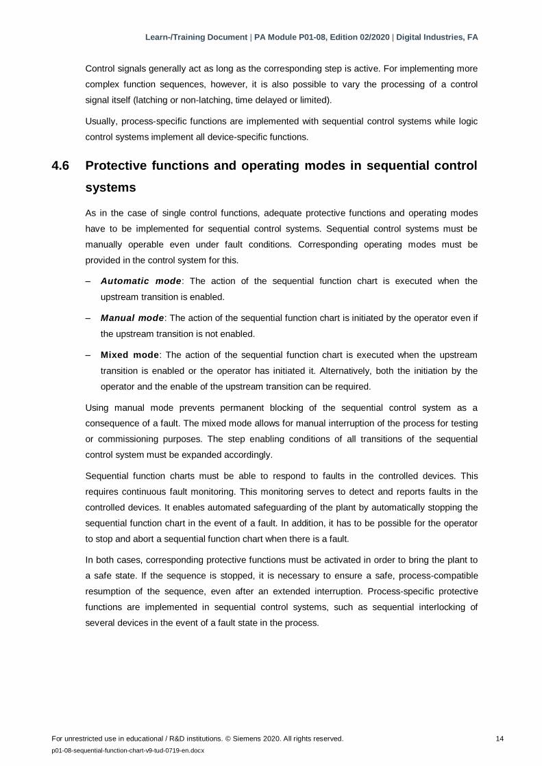
Control signals generally act as long as the corresponding step is active. For implementing more
complex function sequences, however, it is also possible to vary the processing of a control
signal itself (latching or non-latching, time delayed or limited).
Usually, process-specific functions are implemented with sequential control systems while logic
control systems implement all device-specific functions.
4.6 Protective functions and operating modes in sequential control
systems
As in the case of single control functions, adequate protective functions and operating modes
have to be implemented for sequential control systems. Sequential control systems must be
manually operable even under fault conditions. Corresponding operating modes must be
provided in the control system for this.
– Automatic mode: The action of the sequential function chart is executed when the
upstream transition is enabled.
– Manual mode: The action of the sequential function chart is initiated by the operator even if
the upstream transition is not enabled.
– Mixed mode: The action of the sequential function chart is executed when the upstream
transition is enabled or the operator has initiated it. Alternatively, both the initiation by the
operator and the enable of the upstream transition can be required.
Using manual mode prevents permanent blocking of the sequential control system as a
consequence of a fault. The mixed mode allows for manual interruption of the process for testing
or commissioning purposes. The step enabling conditions of all transitions of the sequential
control system must be expanded accordingly.
Sequential function charts must be able to respond to faults in the controlled devices. This
requires continuous fault monitoring. This monitoring serves to detect and reports faults in the
controlled devices. It enables automated safeguarding of the plant by automatically stopping the
sequential function chart in the event of a fault. In addition, it has to be possible for the operator
to stop and abort a sequential function chart when there is a fault.
In both cases, corresponding protective functions must be activated in order to bring the plant to
a safe state. If the sequence is stopped, it is necessary to ensure a safe, process-compatible
resumption of the sequence, even after an extended interruption. Process-specific protective
functions are implemented in sequential control systems, such as sequential interlocking of
several devices in the event of a fault state in the process.
Learn-/Training Document | PA Module P01-08, Edition 02/2020 | Digital Industries, FA
For unrestricted use in educational / R&D institutions. © Siemens 2020. All rights reserved. 15
p01-08-sequential-function-chart-v9-tud-0719-en.docx
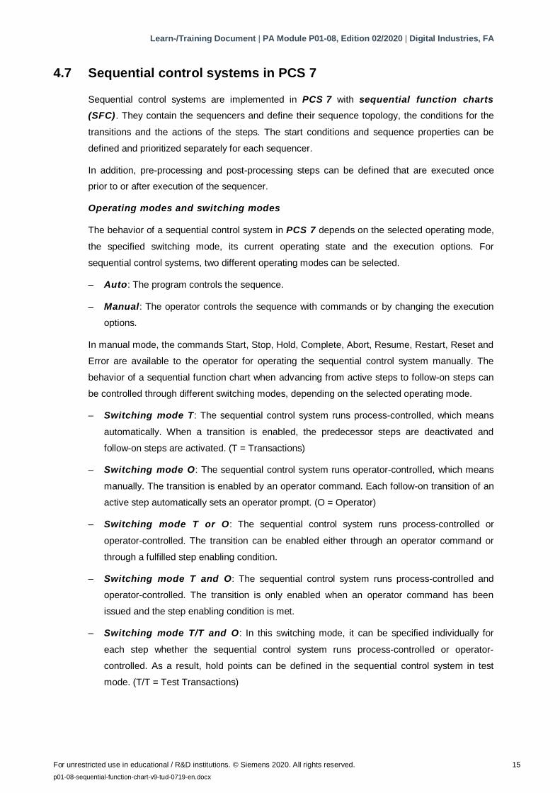
4.7 Sequential control systems in PCS 7
Sequential control systems are implemented in PCS 7 with sequential function charts
(SFC). They contain the sequencers and define their sequence topology, the conditions for the
transitions and the actions of the steps. The start conditions and sequence properties can be
defined and prioritized separately for each sequencer.
In addition, pre-processing and post-processing steps can be defined that are executed once
prior to or after execution of the sequencer.
Operating modes and switching modes
The behavior of a sequential control system in PCS 7 depends on the selected operating mode,
the specified switching mode, its current operating state and the execution options. For
sequential control systems, two different operating modes can be selected.
– Auto: The program controls the sequence.
– Manual: The operator controls the sequence with commands or by changing the execution
options.
In manual mode, the commands Start, Stop, Hold, Complete, Abort, Resume, Restart, Reset and
Error are available to the operator for operating the sequential control system manually. The
behavior of a sequential function chart when advancing from active steps to follow-on steps can
be controlled through different switching modes, depending on the selected operating mode.
– Switching mode T: The sequential control system runs process-controlled, which means
automatically. When a transition is enabled, the predecessor steps are deactivated and
follow-on steps are activated. (T = Transactions)
– Switching mode O: The sequential control system runs operator-controlled, which means
manually. The transition is enabled by an operator command. Each follow-on transition of an
active step automatically sets an operator prompt. (O = Operator)
– Switching mode T or O: The sequential control system runs process-controlled or
operator-controlled. The transition can be enabled either through an operator command or
through a fulfilled step enabling condition.
– Switching mode T and O: The sequential control system runs process-controlled and
operator-controlled. The transition is only enabled when an operator command has been
issued and the step enabling condition is met.
– Switching mode T/T and O: In this switching mode, it can be specified individually for
each step whether the sequential control system runs process-controlled or operator-
controlled. As a result, hold points can be defined in the sequential control system in test
mode. (T/T = Test Transactions)
Learn-/Training Document | PA Module P01-08, Edition 02/2020 | Digital Industries, FA
For unrestricted use in educational / R&D institutions. © Siemens 2020. All rights reserved. 16
p01-08-sequential-function-chart-v9-tud-0719-en.docx
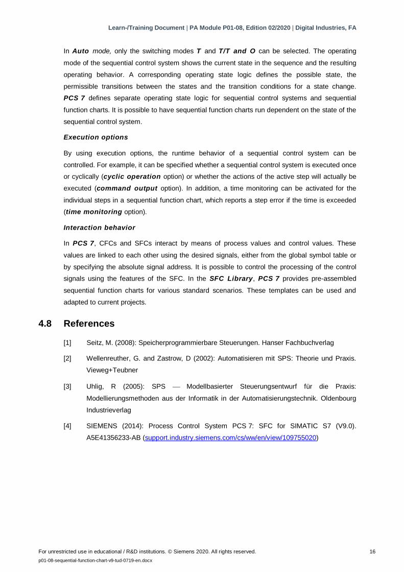
In Auto mode, only the switching modes T and T/T and O can be selected. The operating
mode of the sequential control system shows the current state in the sequence and the resulting
operating behavior. A corresponding operating state logic defines the possible state, the
permissible transitions between the states and the transition conditions for a state change.
PCS 7 defines separate operating state logic for sequential control systems and sequential
function charts. It is possible to have sequential function charts run dependent on the state of the
sequential control system.
Execution options
By using execution options, the runtime behavior of a sequential control system can be
controlled. For example, it can be specified whether a sequential control system is executed once
or cyclically (cyclic operation option) or whether the actions of the active step will actually be
executed (command output option). In addition, a time monitoring can be activated for the
individual steps in a sequential function chart, which reports a step error if the time is exceeded
(time monitoring option).
Interaction behavior
In PCS 7, CFCs and SFCs interact by means of process values and control values. These
values are linked to each other using the desired signals, either from the global symbol table or
by specifying the absolute signal address. It is possible to control the processing of the control
signals using the features of the SFC. In the SFC Library, PCS 7 provides pre-assembled
sequential function charts for various standard scenarios. These templates can be used and
adapted to current projects.
4.8 References
[1] Seitz, M. (2008): Speicherprogrammierbare Steuerungen. Hanser Fachbuchverlag
[2] Wellenreuther, G. and Zastrow, D (2002): Automatisieren mit SPS: Theorie und Praxis.
Vieweg+Teubner
[3] Uhlig, R (2005): SPS Modellbasierter Steuerungsentwurf für die Praxis:
Modellierungsmethoden aus der Informatik in der Automatisierungstechnik. Oldenbourg
Industrieverlag
[4] SIEMENS (2014): Process Control System PCS 7: SFC for SIMATIC S7 (V9.0).
A5E41356233-AB (support.industry.siemens.com/cs/ww/en/view/109755020)
Learn-/Training Document | PA Module P01-08, Edition 02/2020 | Digital Industries, FA
For unrestricted use in educational / R&D institutions. © Siemens 2020. All rights reserved. 17
p01-08-sequential-function-chart-v9-tud-0719-en.docx
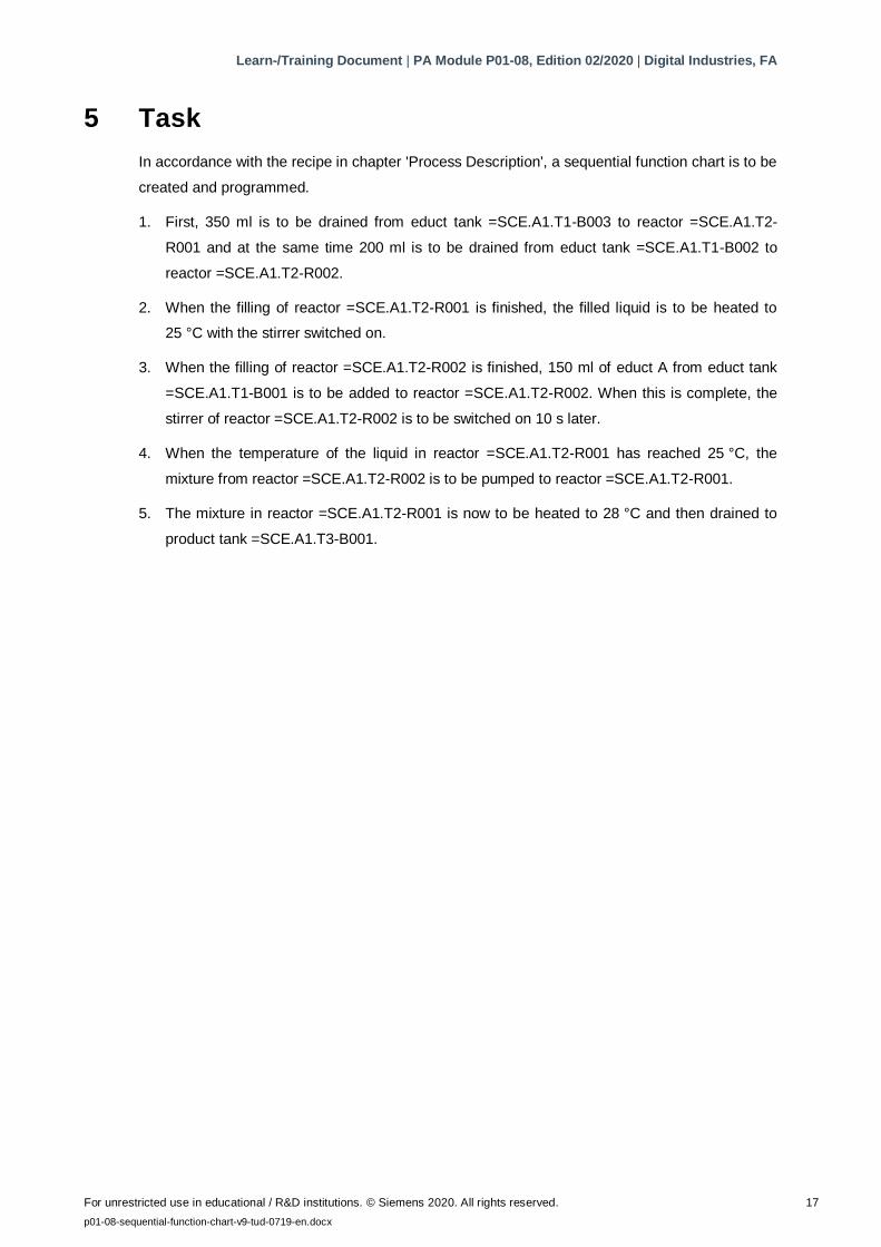
5 Task
In accordance with the recipe in chapter 'Process Description', a sequential function chart is to be
created and programmed.
1. First, 350 ml is to be drained from educt tank =SCE.A1.T1-B003 to reactor =SCE.A1.T2-
R001 and at the same time 200 ml is to be drained from educt tank =SCE.A1.T1-B002 to
reactor =SCE.A1.T2-R002.
2. When the filling of reactor =SCE.A1.T2-R001 is finished, the filled liquid is to be heated to
25 °C with the stirrer switched on.
3. When the filling of reactor =SCE.A1.T2-R002 is finished, 150 ml of educt A from educt tank
=SCE.A1.T1-B001 is to be added to reactor =SCE.A1.T2-R002. When this is complete, the
stirrer of reactor =SCE.A1.T2-R002 is to be switched on 10 s later.
4. When the temperature of the liquid in reactor =SCE.A1.T2-R001 has reached 25 °C, the
mixture from reactor =SCE.A1.T2-R002 is to be pumped to reactor =SCE.A1.T2-R001.
5. The mixture in reactor =SCE.A1.T2-R001 is now to be heated to 28 °C and then drained to
product tank =SCE.A1.T3-B001.
Learn-/Training Document | PA Module P01-08, Edition 02/2020 | Digital Industries, FA
For unrestricted use in educational / R&D institutions. © Siemens 2020. All rights reserved. 18
p01-08-sequential-function-chart-v9-tud-0719-en.docx
6 Planning
All the needed actuators and signals are already implemented and interlocked according to the
safety requirements. They only still have to be appropriately linked to the sequential control
system.
The sequential function chart named in the task description only then has to be converted into
steps and transitions. The following specifics are known:
– Task 1 executes parallel steps (both reactors can operate independent of each other)
– Task 3 names a time condition
– Task 4 merges the two parallel processing steps (in Reactor R001)
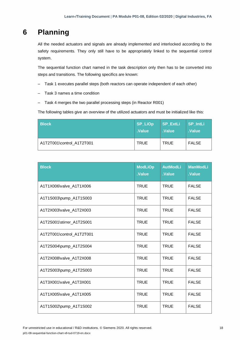
The following tables give an overview of the utilized actuators and must be initialized like this:
Block SP_LiOp
.Value
SP_ExtLi
.Value
SP_IntLi
.Value
A1T2T001\control_A1T2T001 TRUE TRUE FALSE
Block ModLiOp
.Value
AutModLi
.Value
ManModLi
.Value
A1T1X006\valve_A1T1X006 TRUE TRUE FALSE
A1T1S003\pump_A1T1S003 TRUE TRUE FALSE
A1T2X003\valve_A1T2X003 TRUE TRUE FALSE
A1T2S001\stirrer_A1T2S001 TRUE TRUE FALSE
A1T2T001\control_A1T2T001 TRUE TRUE FALSE
A1T2S004\pump_A1T2S004 TRUE TRUE FALSE
A1T2X008\valve_A1T2X008 TRUE TRUE FALSE
A1T2S003\pump_A1T2S003 TRUE TRUE FALSE
A1T3X001\valve_A1T3X001 TRUE TRUE FALSE
A1T1X005\valve_A1T1X005 TRUE TRUE FALSE
A1T1S002\pump_A1T1S002 TRUE TRUE FALSE
Learn-/Training Document | PA Module P01-08, Edition 02/2020 | Digital Industries, FA
For unrestricted use in educational / R&D institutions. © Siemens 2020. All rights reserved. 19
p01-08-sequential-function-chart-v9-tud-0719-en.docx
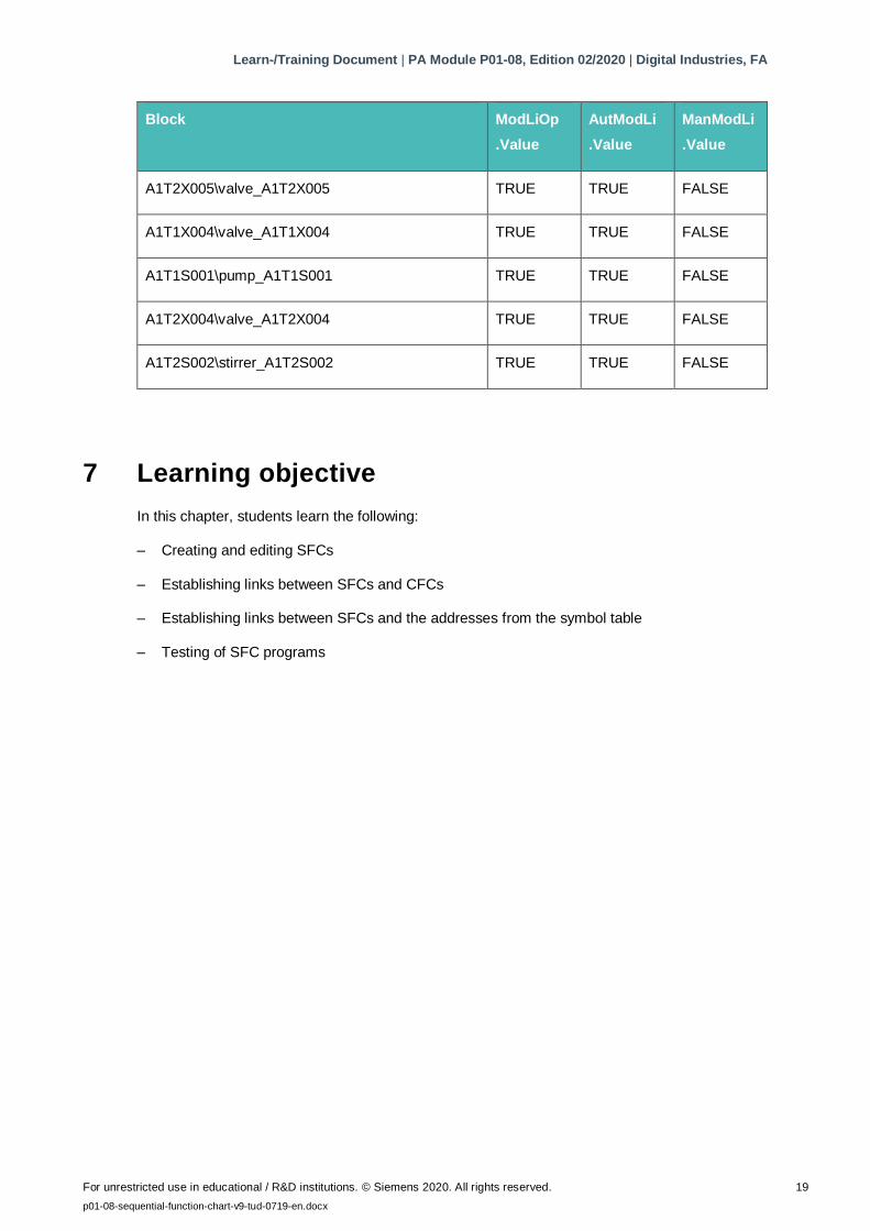
Block ModLiOp
.Value
AutModLi
.Value
ManModLi
.Value
A1T2X005\valve_A1T2X005 TRUE TRUE FALSE
A1T1X004\valve_A1T1X004 TRUE TRUE FALSE
A1T1S001\pump_A1T1S001 TRUE TRUE FALSE
A1T2X004\valve_A1T2X004 TRUE TRUE FALSE
A1T2S002\stirrer_A1T2S002 TRUE TRUE FALSE
7 Learning objective
In this chapter, students learn the following:
– Creating and editing SFCs
– Establishing links between SFCs and CFCs
– Establishing links between SFCs and the addresses from the symbol table
– Testing of SFC programs
Learn-/Training Document | PA Module P01-08, Edition 02/2020 | Digital Industries, FA
For unrestricted use in educational / R&D institutions. © Siemens 2020. All rights reserved. 20
p01-08-sequential-function-chart-v9-tud-0719-en.docx
8 Structured step-by-step instructions
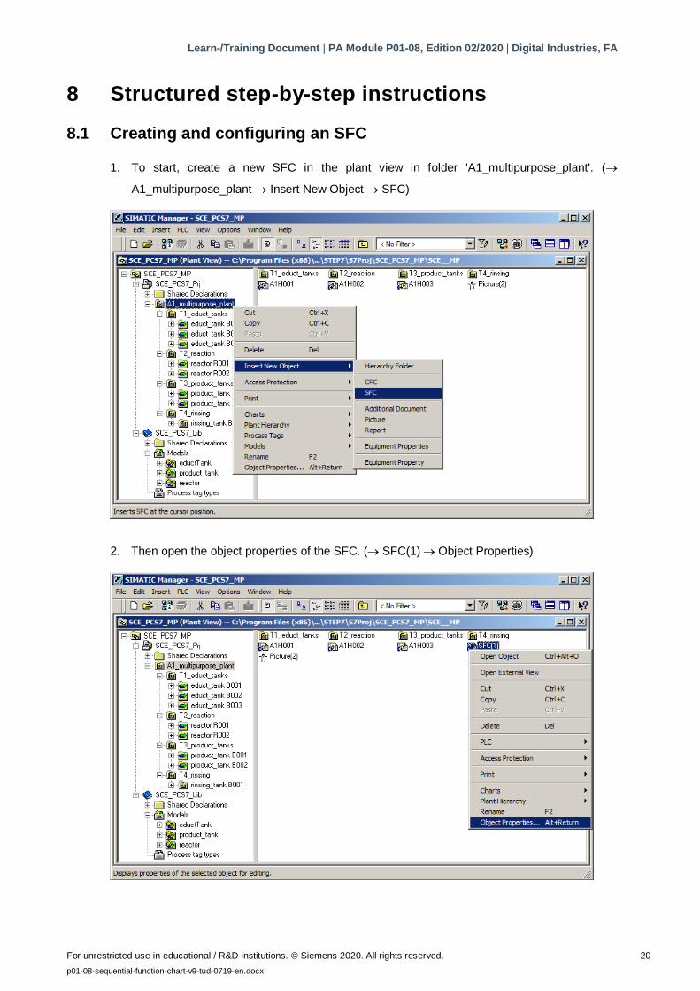
8.1 Creating and configuring an SFC
1. To start, create a new SFC in the plant view in folder 'A1_multipurpose_plant'. (
A1_multipurpose_plant Insert New Object SFC)
2. Then open the object properties of the SFC. ( SFC(1) Object Properties)
Learn-/Training Document | PA Module P01-08, Edition 02/2020 | Digital Industries, FA
For unrestricted use in educational / R&D institutions. © Siemens 2020. All rights reserved. 21
p01-08-sequential-function-chart-v9-tud-0719-en.docx
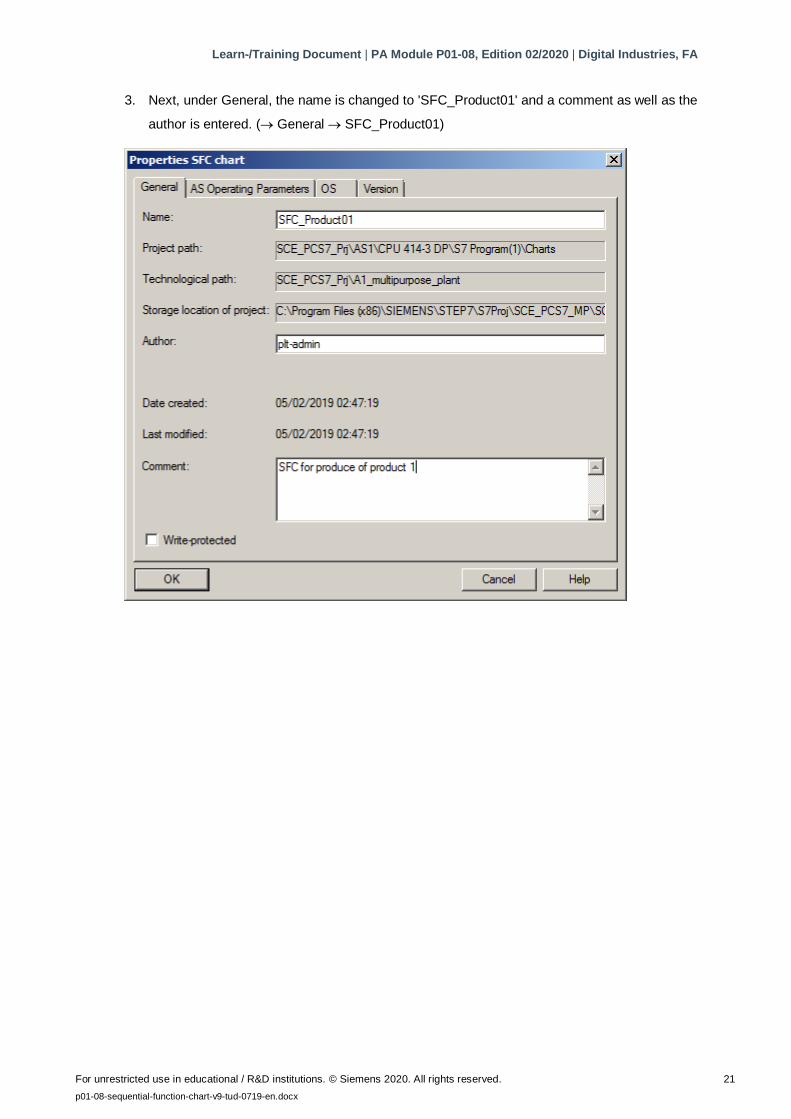
3. Next, under General, the name is changed to 'SFC_Product01' and a comment as well as the
author is entered. ( General SFC_Product01)
Learn-/Training Document | PA Module P01-08, Edition 02/2020 | Digital Industries, FA
For unrestricted use in educational / R&D institutions. © Siemens 2020. All rights reserved. 22
p01-08-sequential-function-chart-v9-tud-0719-en.docx
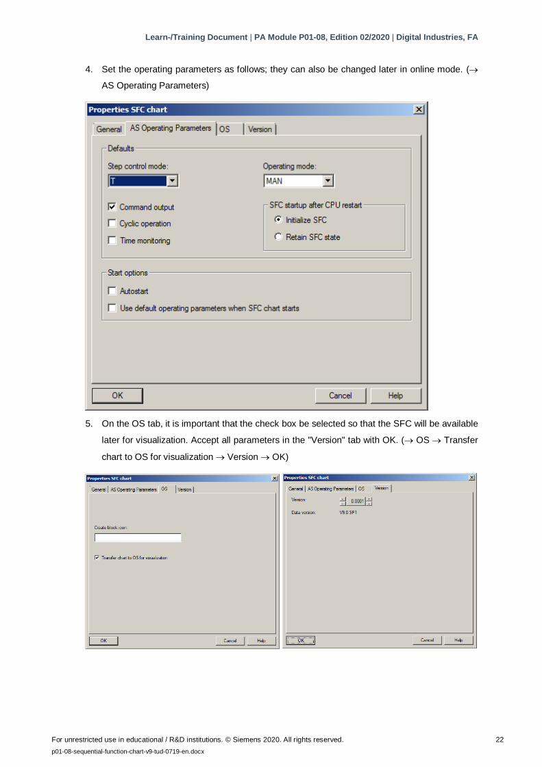
4. Set the operating parameters as follows; they can also be changed later in online mode. (
AS Operating Parameters)
5. On the OS tab, it is important that the check box be selected so that the SFC will be available
later for visualization. Accept all parameters in the "Version" tab with OK. ( OS Transfer
chart to OS for visualization Version OK)
Learn-/Training Document | PA Module P01-08, Edition 02/2020 | Digital Industries, FA
For unrestricted use in educational / R&D institutions. © Siemens 2020. All rights reserved. 23
p01-08-sequential-function-chart-v9-tud-0719-en.docx
Note:
– In the "Create block icon" input field, you can specify the block icon in WinCC that is to be
displayed for this block. You can thus select different variants for the same block type, if
present. Leaving the field blank results in the standard display.
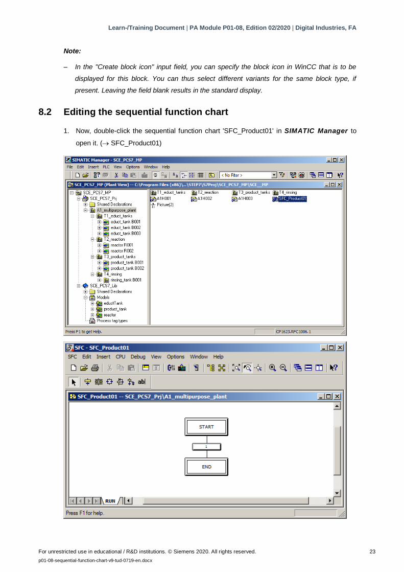
8.2 Editing the sequential function chart
1. Now, double-click the sequential function chart 'SFC_Product01' in SIMATIC Manager to
open it. ( SFC_Product01)
Learn-/Training Document | PA Module P01-08, Edition 02/2020 | Digital Industries, FA
For unrestricted use in educational / R&D institutions. © Siemens 2020. All rights reserved. 24
p01-08-sequential-function-chart-v9-tud-0719-en.docx
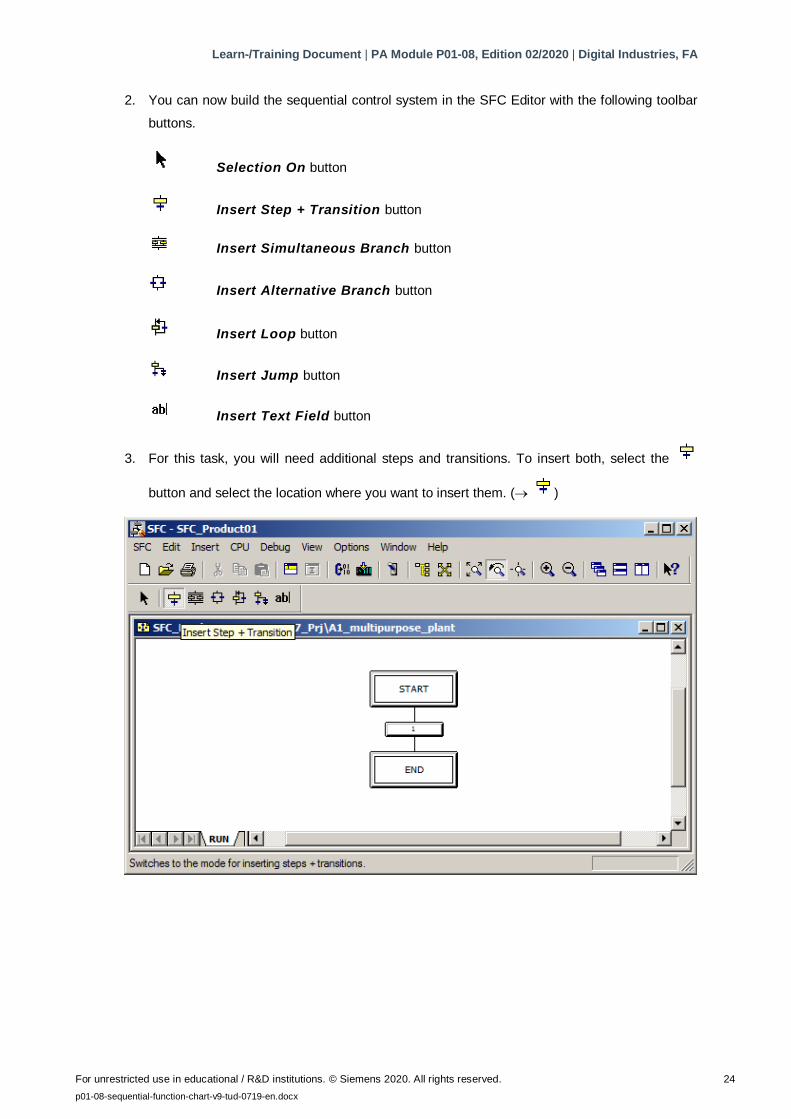
2. You can now build the sequential control system in the SFC Editor with the following toolbar
buttons.
Selection On button
Insert Step + Transition button
Insert Simultaneous Branch button
Insert Alternative Branch button
Insert Loop button
Insert Jump button
Insert Text Field button
3. For this task, you will need additional steps and transitions. To insert both, select the
button and select the location where you want to insert them. ( )
Learn-/Training Document | PA Module P01-08, Edition 02/2020 | Digital Industries, FA
For unrestricted use in educational / R&D institutions. © Siemens 2020. All rights reserved. 25
p01-08-sequential-function-chart-v9-tud-0719-en.docx
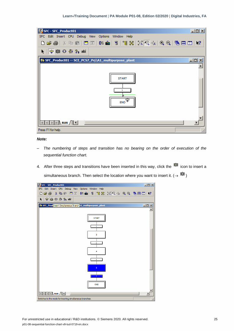
Note:
– The numbering of steps and transition has no bearing on the order of execution of the
sequential function chart.
4. After three steps and transitions have been inserted in this way, click the icon to insert a
simultaneous branch. Then select the location where you want to insert it. ( )
Learn-/Training Document | PA Module P01-08, Edition 02/2020 | Digital Industries, FA
For unrestricted use in educational / R&D institutions. © Siemens 2020. All rights reserved. 26
p01-08-sequential-function-chart-v9-tud-0719-en.docx
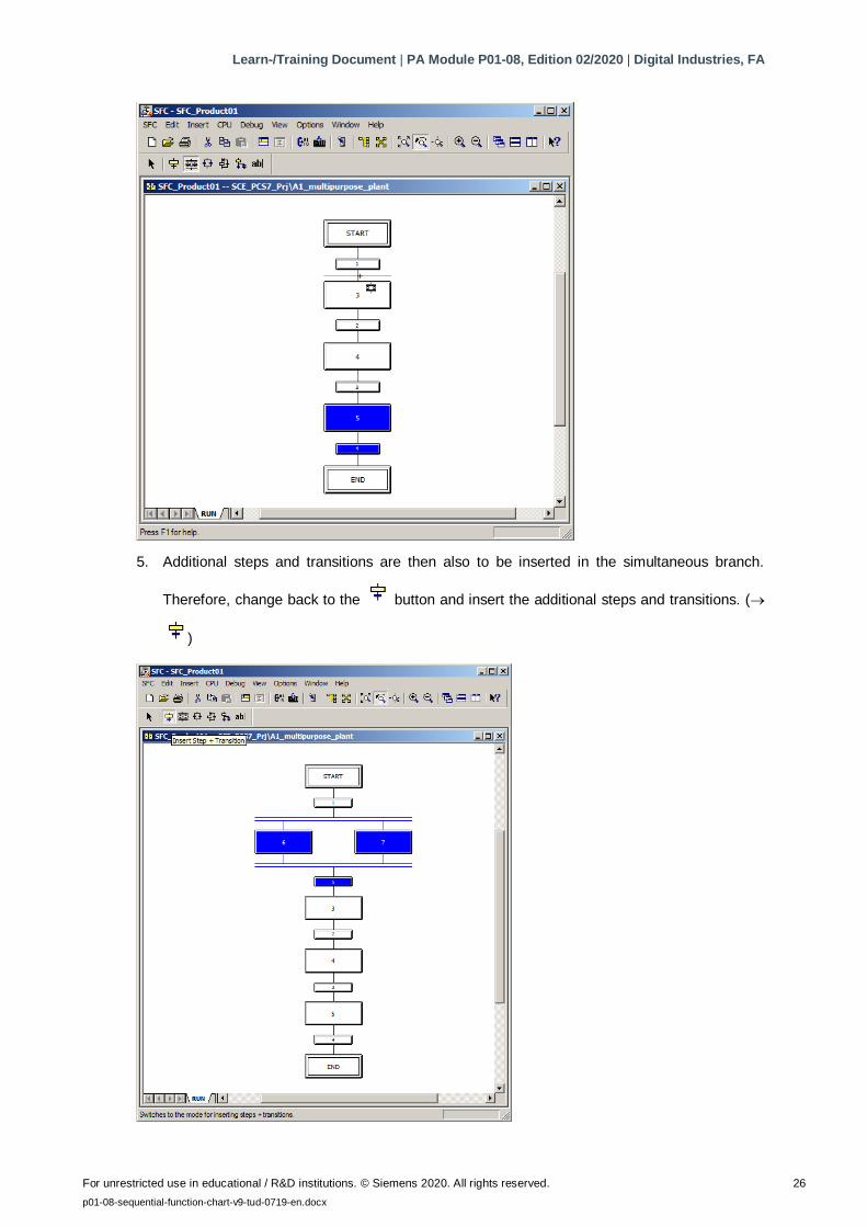
5. Additional steps and transitions are then also to be inserted in the simultaneous branch.
Therefore, change back to the button and insert the additional steps and transitions. (
)
Learn-/Training Document | PA Module P01-08, Edition 02/2020 | Digital Industries, FA
For unrestricted use in educational / R&D institutions. © Siemens 2020. All rights reserved. 27
p01-08-sequential-function-chart-v9-tud-0719-en.docx
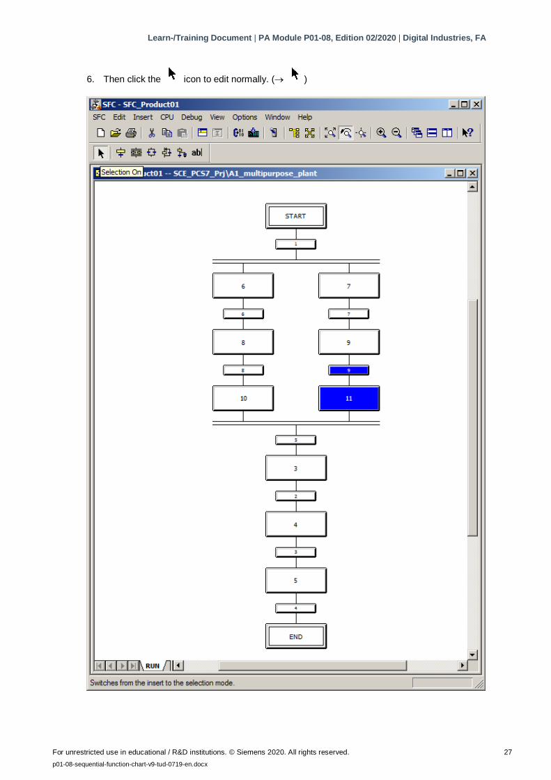
6. Then click the icon to edit normally. ( )
Learn-/Training Document | PA Module P01-08, Edition 02/2020 | Digital Industries, FA
For unrestricted use in educational / R&D institutions. © Siemens 2020. All rights reserved. 28
p01-08-sequential-function-chart-v9-tud-0719-en.docx
8.3 Editing properties of steps and transitions
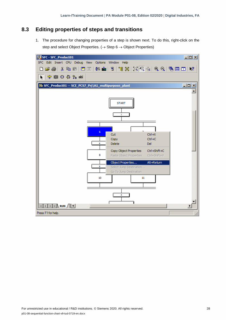
1. The procedure for changing properties of a step is shown next. To do this, right-click on the
step and select Object Properties. ( Step 6 Object Properties)
Learn-/Training Document | PA Module P01-08, Edition 02/2020 | Digital Industries, FA
For unrestricted use in educational / R&D institutions. © Siemens 2020. All rights reserved. 29
p01-08-sequential-function-chart-v9-tud-0719-en.docx
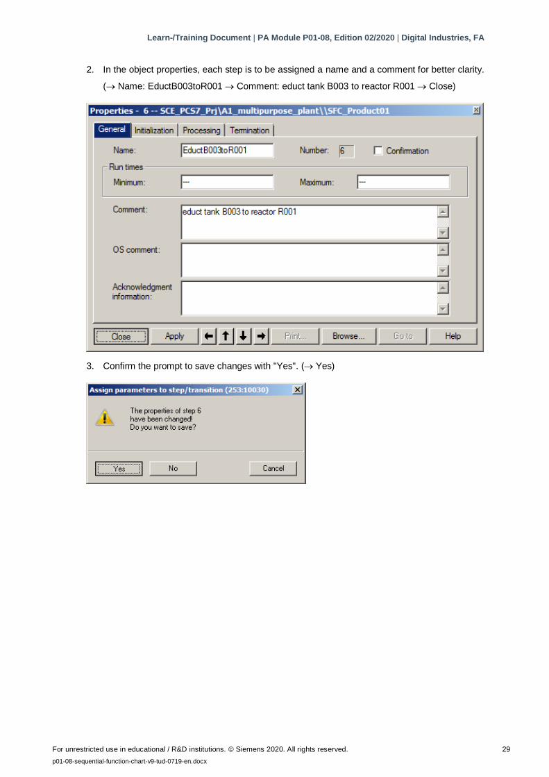
2. In the object properties, each step is to be assigned a name and a comment for better clarity.
( Name: EductB003toR001 Comment: educt tank B003 to reactor R001 Close)
3. Confirm the prompt to save changes with "Yes". ( Yes)
Learn-/Training Document | PA Module P01-08, Edition 02/2020 | Digital Industries, FA
For unrestricted use in educational / R&D institutions. © Siemens 2020. All rights reserved. 30
p01-08-sequential-function-chart-v9-tud-0719-en.docx
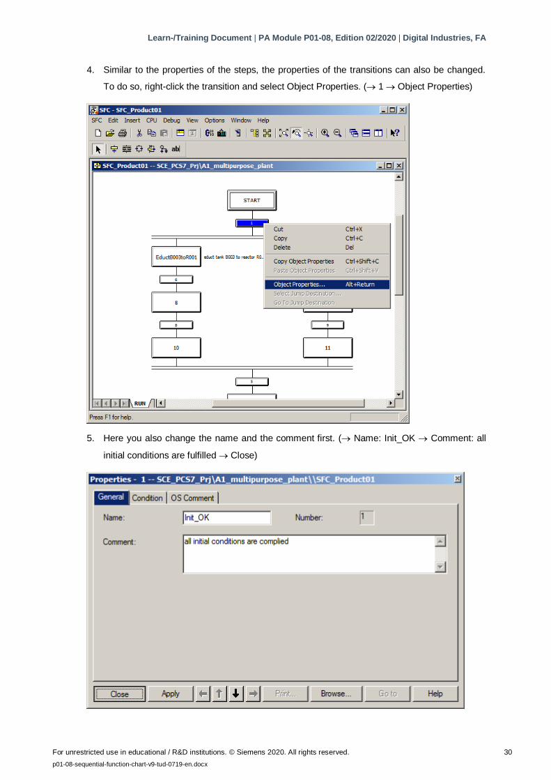
4. Similar to the properties of the steps, the properties of the transitions can also be changed.
To do so, right-click the transition and select Object Properties. ( 1 Object Properties)
5. Here you also change the name and the comment first. ( Name: Init_OK Comment: all
initial conditions are fulfilled Close)
Learn-/Training Document | PA Module P01-08, Edition 02/2020 | Digital Industries, FA
For unrestricted use in educational / R&D institutions. © Siemens 2020. All rights reserved. 31
p01-08-sequential-function-chart-v9-tud-0719-en.docx
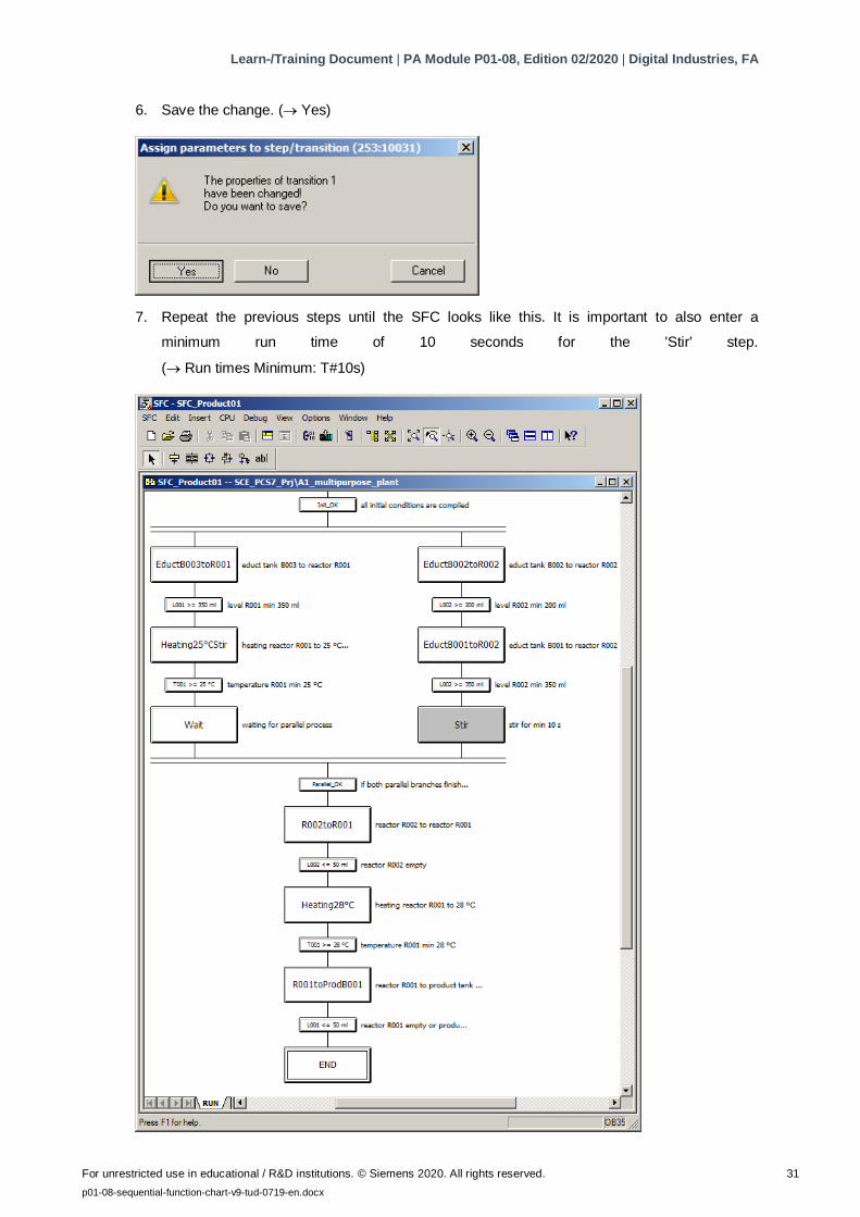
6. Save the change. ( Yes)
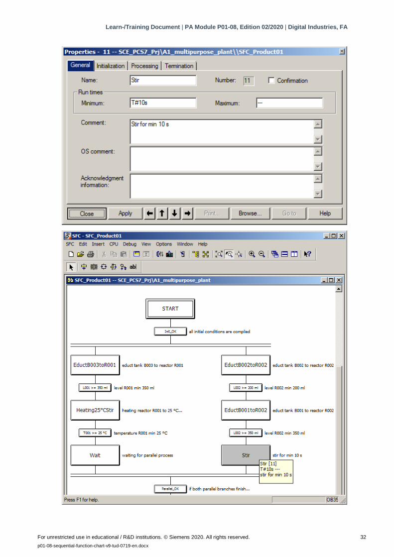
7. Repeat the previous steps until the SFC looks like this. It is important to also enter a
minimum run time of 10 seconds for the 'Stir' step.
( Run times Minimum: T#10s)
Learn-/Training Document | PA Module P01-08, Edition 02/2020 | Digital Industries, FA
For unrestricted use in educational / R&D institutions. © Siemens 2020. All rights reserved. 32
p01-08-sequential-function-chart-v9-tud-0719-en.docx
Learn-/Training Document | PA Module P01-08, Edition 02/2020 | Digital Industries, FA
For unrestricted use in educational / R&D institutions. © Siemens 2020. All rights reserved. 33
p01-08-sequential-function-chart-v9-tud-0719-en.docx
8.4 Editing steps and transitions
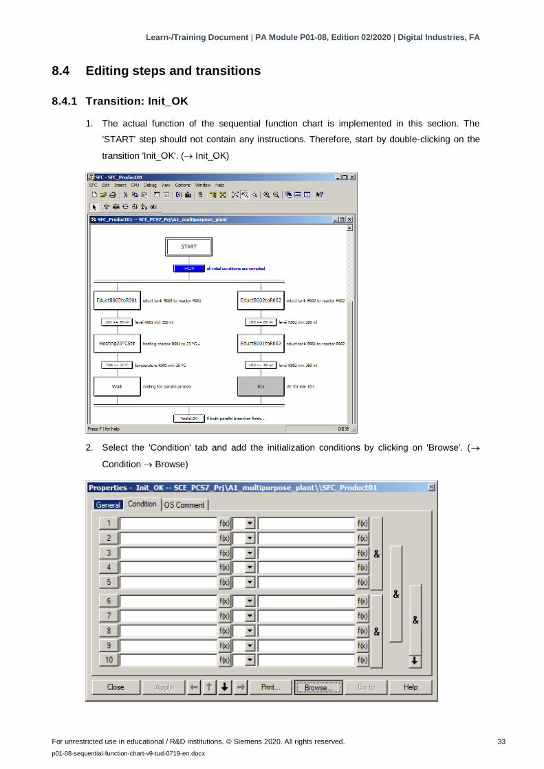
8.4.1 Transition: Init_OK
1. The actual function of the sequential function chart is implemented in this section. The
'START' step should not contain any instructions. Therefore, start by double-clicking on the
transition 'Init_OK'. ( Init_OK)
2. Select the 'Condition' tab and add the initialization conditions by clicking on 'Browse'. (
Condition Browse)
Learn-/Training Document | PA Module P01-08, Edition 02/2020 | Digital Industries, FA
For unrestricted use in educational / R&D institutions. © Siemens 2020. All rights reserved. 34
p01-08-sequential-function-chart-v9-tud-0719-en.docx
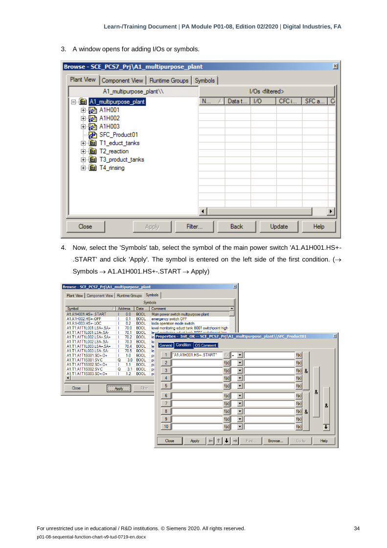
3. A window opens for adding I/Os or symbols.
4. Now, select the 'Symbols' tab, select the symbol of the main power switch 'A1.A1H001.HS+-
.START' and click 'Apply'. The symbol is entered on the left side of the first condition. (
Symbols A1.A1H001.HS+-.START Apply)
Learn-/Training Document | PA Module P01-08, Edition 02/2020 | Digital Industries, FA
For unrestricted use in educational / R&D institutions. © Siemens 2020. All rights reserved. 35
p01-08-sequential-function-chart-v9-tud-0719-en.docx
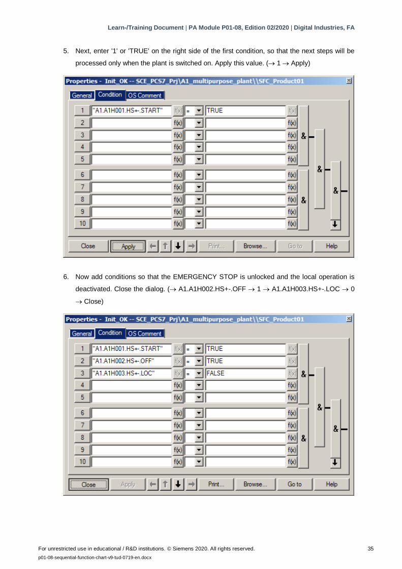
5. Next, enter '1' or 'TRUE' on the right side of the first condition, so that the next steps will be
processed only when the plant is switched on. Apply this value. ( 1 Apply)
6. Now add conditions so that the EMERGENCY STOP is unlocked and the local operation is
deactivated. Close the dialog. ( A1.A1H002.HS+-.OFF 1 A1.A1H003.HS+-.LOC 0
Close)
Learn-/Training Document | PA Module P01-08, Edition 02/2020 | Digital Industries, FA
For unrestricted use in educational / R&D institutions. © Siemens 2020. All rights reserved. 36
p01-08-sequential-function-chart-v9-tud-0719-en.docx
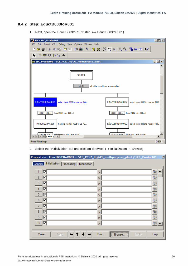
8.4.2 Step: EductB003toR001
1. Next, open the 'EductB003toR001' step. ( EductB003toR001)
2. Select the 'Initialization' tab and click on 'Browse'. ( Initialization Browse)
Learn-/Training Document | PA Module P01-08, Edition 02/2020 | Digital Industries, FA
For unrestricted use in educational / R&D institutions. © Siemens 2020. All rights reserved. 37
p01-08-sequential-function-chart-v9-tud-0719-en.docx
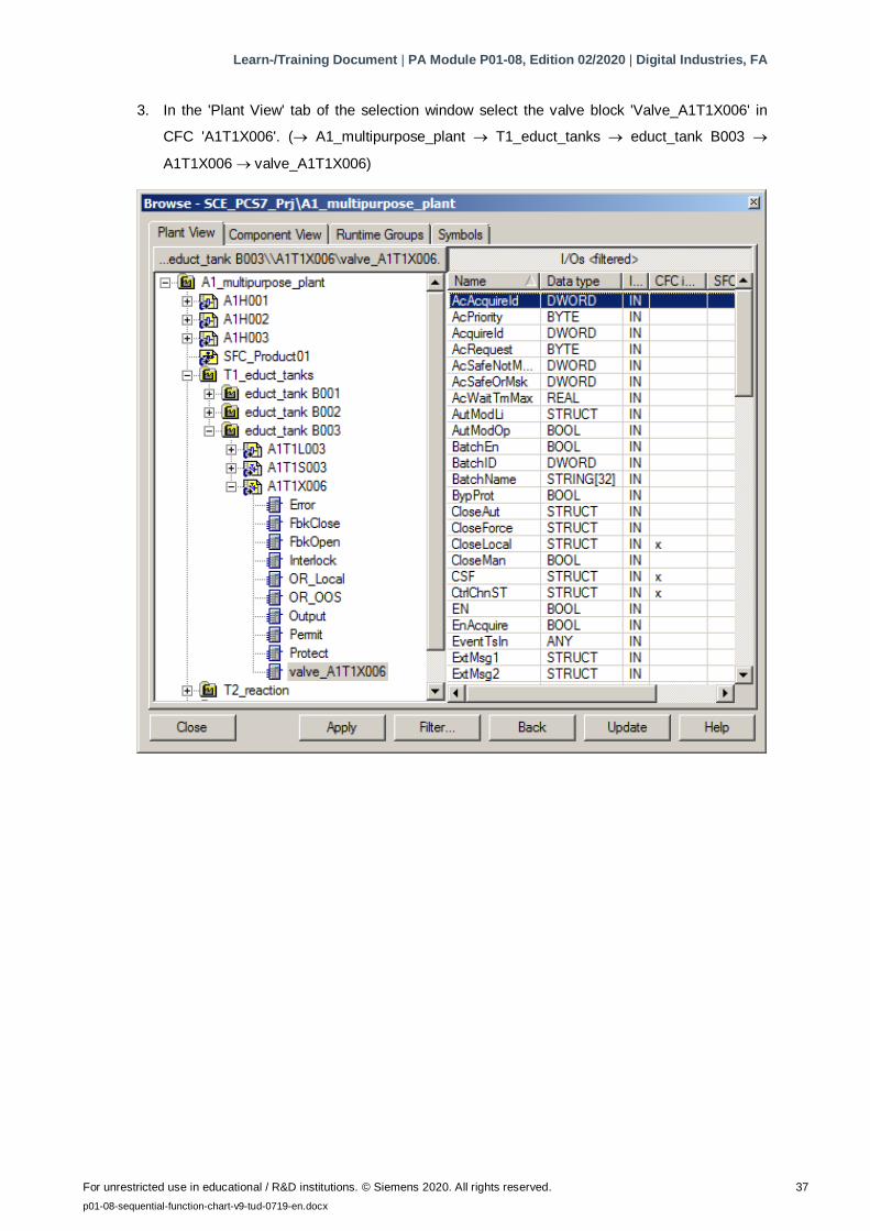
3. In the 'Plant View' tab of the selection window select the valve block 'Valve_A1T1X006' in
CFC 'A1T1X006'. ( A1_multipurpose_plant T1_educt_tanks educt_tank B003
A1T1X006 valve_A1T1X006)
Learn-/Training Document | PA Module P01-08, Edition 02/2020 | Digital Industries, FA
For unrestricted use in educational / R&D institutions. © Siemens 2020. All rights reserved. 38
p01-08-sequential-function-chart-v9-tud-0719-en.docx
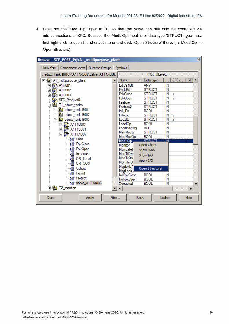
4. First, set the 'ModLiOp' input to '1', so that the valve can still only be controlled via
interconnections or SFC. Because the 'ModLiOp' input is of data type 'STRUCT', you must
first right-click to open the shortcut menu and click 'Open Structure' there. ( ModLiOp
Open Structure)
Learn-/Training Document | PA Module P01-08, Edition 02/2020 | Digital Industries, FA
For unrestricted use in educational / R&D institutions. © Siemens 2020. All rights reserved. 39
p01-08-sequential-function-chart-v9-tud-0719-en.docx
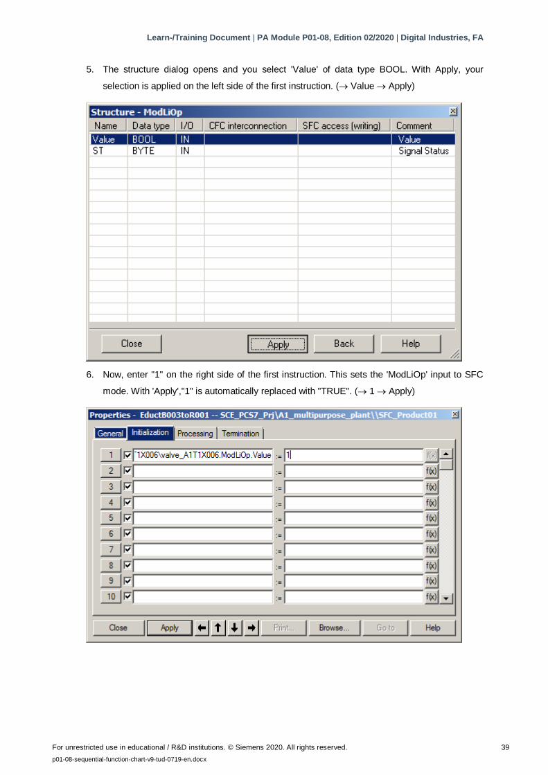
5. The structure dialog opens and you select 'Value' of data type BOOL. With Apply, your
selection is applied on the left side of the first instruction. ( Value Apply)
6. Now, enter "1" on the right side of the first instruction. This sets the 'ModLiOp' input to SFC
mode. With 'Apply',"1" is automatically replaced with "TRUE". ( 1 Apply)
Learn-/Training Document | PA Module P01-08, Edition 02/2020 | Digital Industries, FA
For unrestricted use in educational / R&D institutions. © Siemens 2020. All rights reserved. 40
p01-08-sequential-function-chart-v9-tud-0719-en.docx
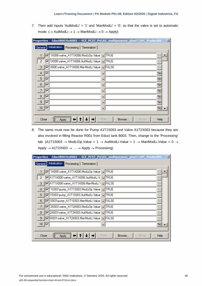
7. Then add inputs 'AutModLi' = '1' and 'ManModLi' = '0', so that the valve is set to automatic
mode. ( AutModLi 1 ManModLi 0 Apply)
8. The same must now be done for Pump A1T1S003 and Valve A1T2X003 because they are
also involved in filling Reactor R001 from Educt tank B003. Then, change to the 'Processing'
tab. (A1T1S003 ModLiOp.Value = 1 AutModLi.Value = 1 ManModLi.Value = 0
Apply A1T2X003 … Apply Processing)
Learn-/Training Document | PA Module P01-08, Edition 02/2020 | Digital Industries, FA
For unrestricted use in educational / R&D institutions. © Siemens 2020. All rights reserved. 41
p01-08-sequential-function-chart-v9-tud-0719-en.docx
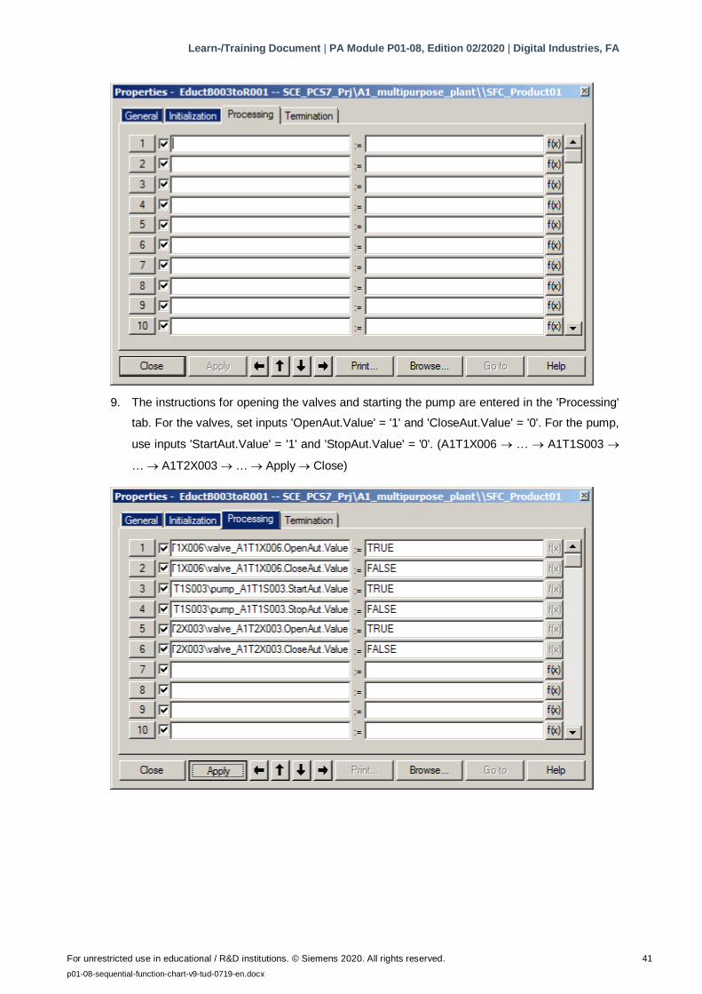
9. The instructions for opening the valves and starting the pump are entered in the 'Processing'
tab. For the valves, set inputs 'OpenAut.Value' = '1' and 'CloseAut.Value' = '0'. For the pump,
use inputs 'StartAut.Value' = '1' and 'StopAut.Value' = '0'. (A1T1X006 … A1T1S003
… A1T2X003 … Apply Close)
Learn-/Training Document | PA Module P01-08, Edition 02/2020 | Digital Industries, FA
For unrestricted use in educational / R&D institutions. © Siemens 2020. All rights reserved. 42
p01-08-sequential-function-chart-v9-tud-0719-en.docx
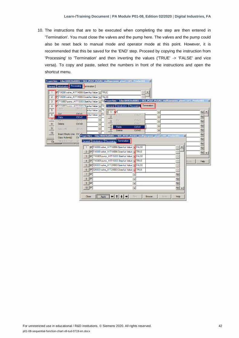
10. The instructions that are to be executed when completing the step are then entered in
'Termination'. You must close the valves and the pump here. The valves and the pump could
also be reset back to manual mode and operator mode at this point. However, it is
recommended that this be saved for the 'END' step. Proceed by copying the instruction from
'Processing' to 'Termination' and then inverting the values ('TRUE' -> 'FALSE' and vice
versa). To copy and paste, select the numbers in front of the instructions and open the
shortcut menu.
Learn-/Training Document | PA Module P01-08, Edition 02/2020 | Digital Industries, FA
For unrestricted use in educational / R&D institutions. © Siemens 2020. All rights reserved. 43
p01-08-sequential-function-chart-v9-tud-0719-en.docx
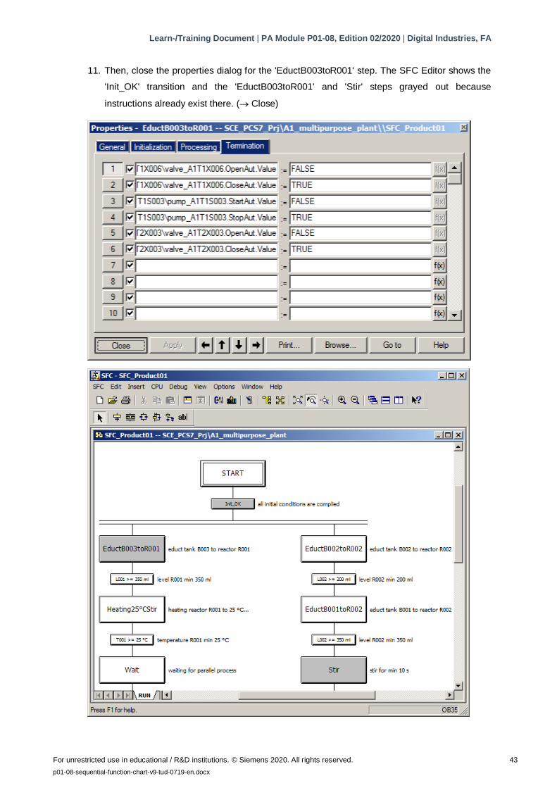
11. Then, close the properties dialog for the 'EductB003toR001' step. The SFC Editor shows the
'Init_OK' transition and the 'EductB003toR001' and 'Stir' steps grayed out because
instructions already exist there. ( Close)
Learn-/Training Document | PA Module P01-08, Edition 02/2020 | Digital Industries, FA
For unrestricted use in educational / R&D institutions. © Siemens 2020. All rights reserved. 44
p01-08-sequential-function-chart-v9-tud-0719-en.docx
8.4.3 Transition: L001 >= 350 ml
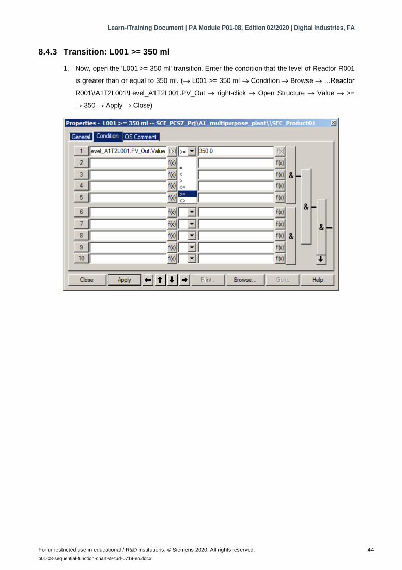
1. Now, open the 'L001 >= 350 ml' transition. Enter the condition that the level of Reactor R001
is greater than or equal to 350 ml. ( L001 >= 350 ml Condition Browse …Reactor
R001\\A1T2L001\Level_A1T2L001.PV_Out right-click Open Structure Value >=
350 Apply Close)
Learn-/Training Document | PA Module P01-08, Edition 02/2020 | Digital Industries, FA
For unrestricted use in educational / R&D institutions. © Siemens 2020. All rights reserved. 45
p01-08-sequential-function-chart-v9-tud-0719-en.docx
8.4.4 Step: Heating25°CStir
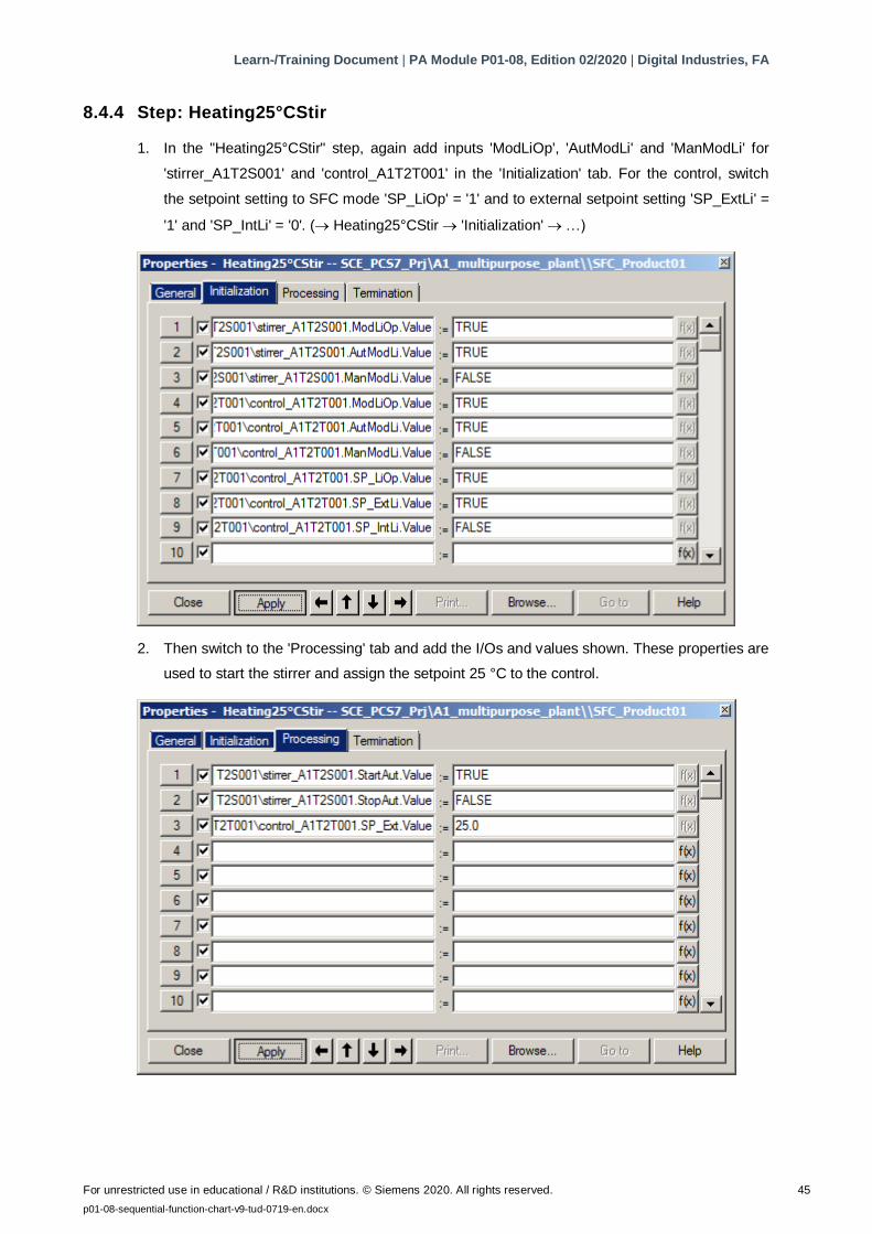
1. In the "Heating25°CStir" step, again add inputs 'ModLiOp', 'AutModLi' and 'ManModLi' for
'stirrer_A1T2S001' and 'control_A1T2T001' in the 'Initialization' tab. For the control, switch
the setpoint setting to SFC mode 'SP_LiOp' = '1' and to external setpoint setting 'SP_ExtLi' =
'1' and 'SP_IntLi' = '0'. ( Heating25°CStir 'Initialization' …)
2. Then switch to the 'Processing' tab and add the I/Os and values shown. These properties are
used to start the stirrer and assign the setpoint 25 °C to the control.
Learn-/Training Document | PA Module P01-08, Edition 02/2020 | Digital Industries, FA
For unrestricted use in educational / R&D institutions. © Siemens 2020. All rights reserved. 46
p01-08-sequential-function-chart-v9-tud-0719-en.docx
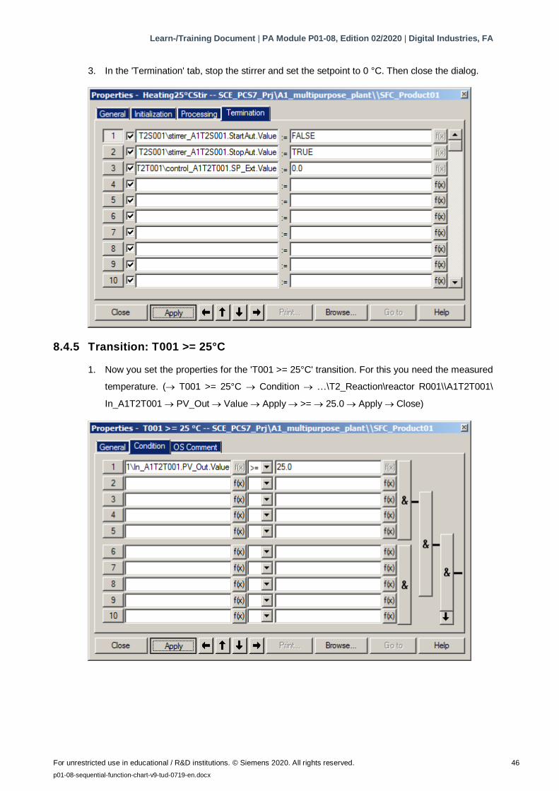
3. In the 'Termination' tab, stop the stirrer and set the setpoint to 0 °C. Then close the dialog.
8.4.5 Transition: T001 >= 25°C
1. Now you set the properties for the 'T001 >= 25°C' transition. For this you need the measured
temperature. ( T001 >= 25°C Condition …\T2_Reaction\reactor R001\\A1T2T001\
In_A1T2T001 PV_Out Value Apply >= 25.0 Apply Close)
Learn-/Training Document | PA Module P01-08, Edition 02/2020 | Digital Industries, FA
For unrestricted use in educational / R&D institutions. © Siemens 2020. All rights reserved. 47
p01-08-sequential-function-chart-v9-tud-0719-en.docx
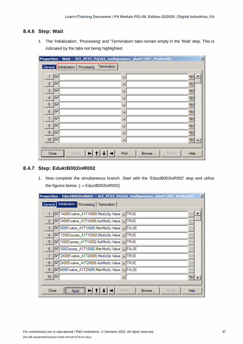
8.4.6 Step: Wait
1. The 'Initialization', 'Processing' and 'Termination' tabs remain empty in the 'Wait' step. This is
indicated by the tabs not being highlighted.
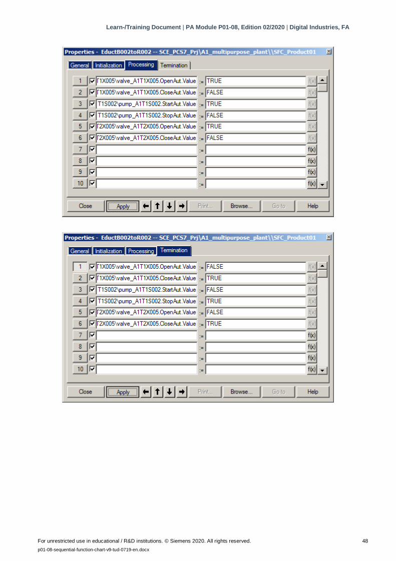
8.4.7 Step: EduktB002inR002
1. Now complete the simultaneous branch. Start with the 'EductB002toR002' step and utilize
the figures below. ( EductB002toR002)
Learn-/Training Document | PA Module P01-08, Edition 02/2020 | Digital Industries, FA
For unrestricted use in educational / R&D institutions. © Siemens 2020. All rights reserved. 48
p01-08-sequential-function-chart-v9-tud-0719-en.docx
Learn-/Training Document | PA Module P01-08, Edition 02/2020 | Digital Industries, FA
For unrestricted use in educational / R&D institutions. © Siemens 2020. All rights reserved. 49
p01-08-sequential-function-chart-v9-tud-0719-en.docx
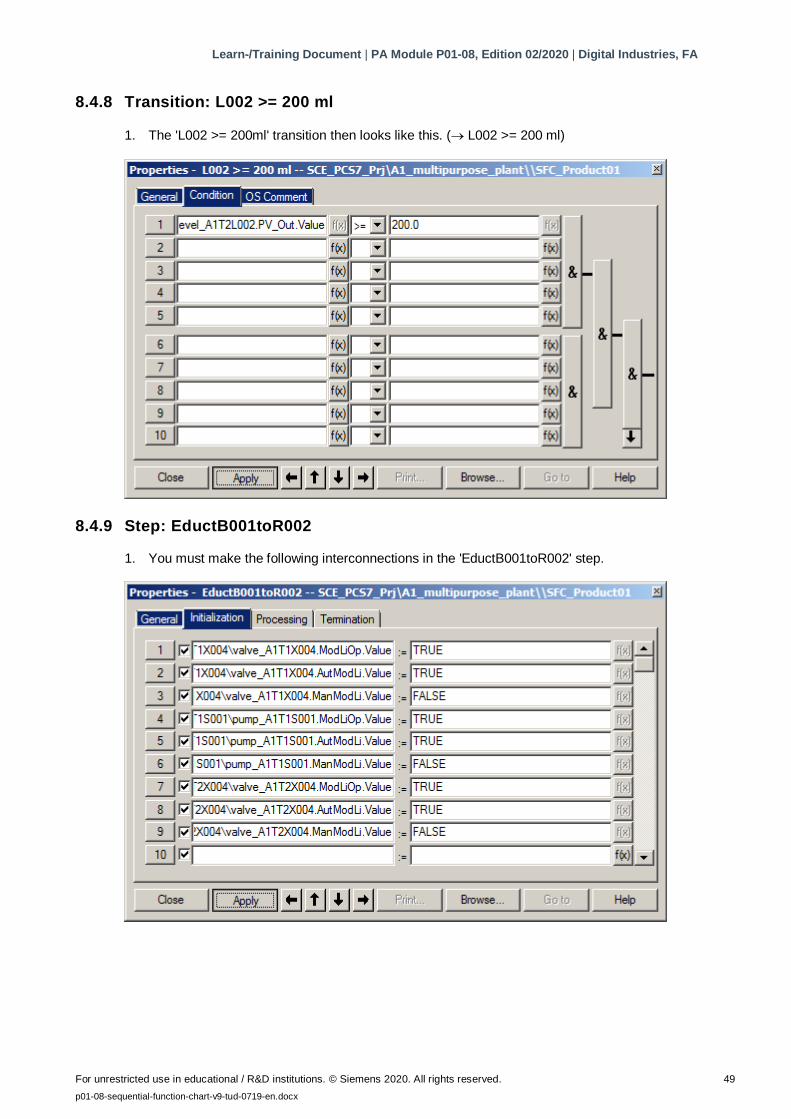
8.4.8 Transition: L002 >= 200 ml
1. The 'L002 >= 200ml' transition then looks like this. ( L002 >= 200 ml)
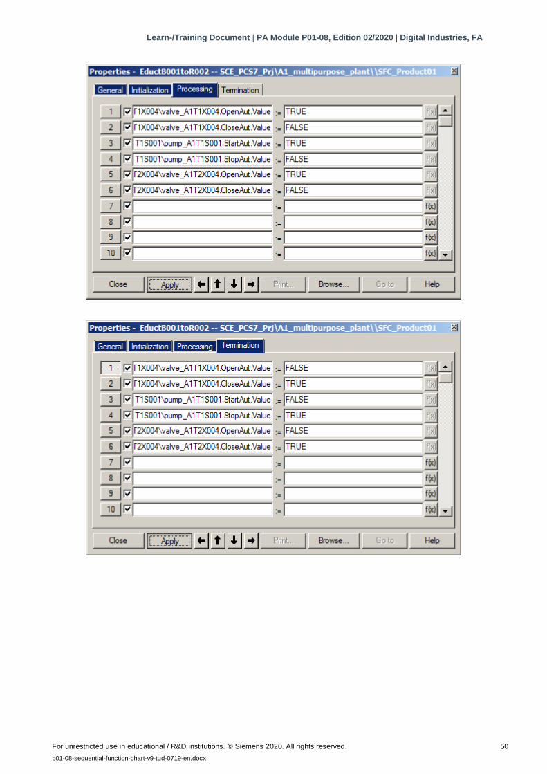
8.4.9 Step: EductB001toR002
1. You must make the following interconnections in the 'EductB001toR002' step.
Learn-/Training Document | PA Module P01-08, Edition 02/2020 | Digital Industries, FA
For unrestricted use in educational / R&D institutions. © Siemens 2020. All rights reserved. 50
p01-08-sequential-function-chart-v9-tud-0719-en.docx
Learn-/Training Document | PA Module P01-08, Edition 02/2020 | Digital Industries, FA
For unrestricted use in educational / R&D institutions. © Siemens 2020. All rights reserved. 51
p01-08-sequential-function-chart-v9-tud-0719-en.docx
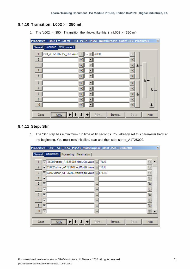
8.4.10 Transition: L002 >= 350 ml
1. The 'L002 >= 350 ml' transition then looks like this. ( L002 >= 350 ml)
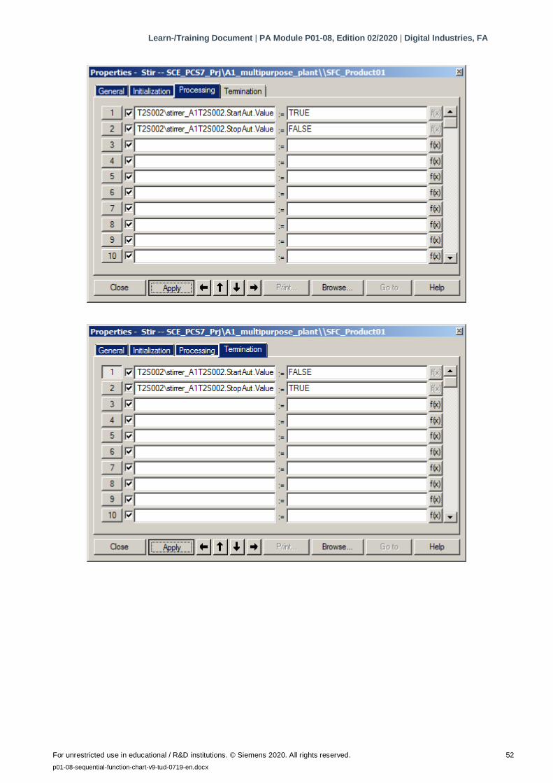
8.4.11 Step: Stir
1. The 'Stir' step has a minimum run time of 10 seconds. You already set this parameter back at
the beginning. You must now initialize, start and then stop stirrer_A1T2S002.
Learn-/Training Document | PA Module P01-08, Edition 02/2020 | Digital Industries, FA
For unrestricted use in educational / R&D institutions. © Siemens 2020. All rights reserved. 52
p01-08-sequential-function-chart-v9-tud-0719-en.docx
Learn-/Training Document | PA Module P01-08, Edition 02/2020 | Digital Industries, FA
For unrestricted use in educational / R&D institutions. © Siemens 2020. All rights reserved. 53
p01-08-sequential-function-chart-v9-tud-0719-en.docx
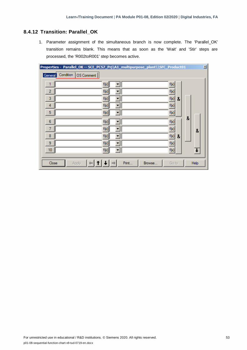
8.4.12 Transition: Parallel_OK
1. Parameter assignment of the simultaneous branch is now complete. The 'Parallel_OK'
transition remains blank. This means that as soon as the 'Wait' and 'Stir' steps are
processed, the 'R002toR001' step becomes active.
Learn-/Training Document | PA Module P01-08, Edition 02/2020 | Digital Industries, FA
For unrestricted use in educational / R&D institutions. © Siemens 2020. All rights reserved. 54
p01-08-sequential-function-chart-v9-tud-0719-en.docx
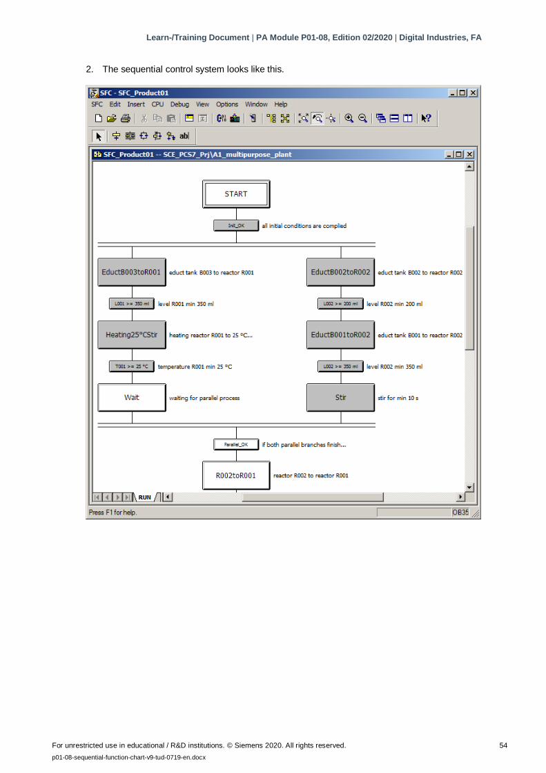
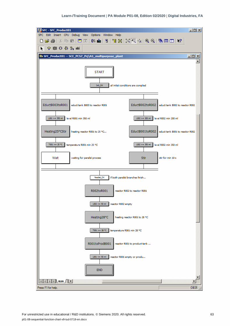
2. The sequential control system looks like this.
Learn-/Training Document | PA Module P01-08, Edition 02/2020 | Digital Industries, FA
For unrestricted use in educational / R&D institutions. © Siemens 2020. All rights reserved. 55
p01-08-sequential-function-chart-v9-tud-0719-en.docx
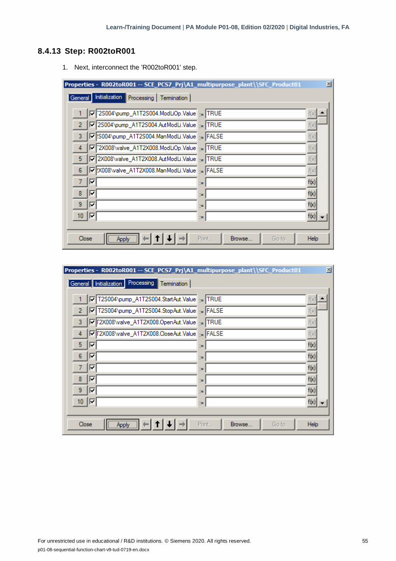
8.4.13 Step: R002toR001
1. Next, interconnect the 'R002toR001' step.
Learn-/Training Document | PA Module P01-08, Edition 02/2020 | Digital Industries, FA
For unrestricted use in educational / R&D institutions. © Siemens 2020. All rights reserved. 56
p01-08-sequential-function-chart-v9-tud-0719-en.docx
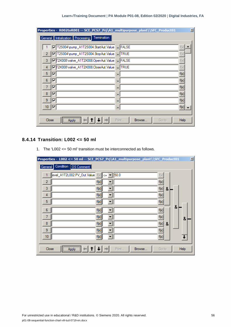
8.4.14 Transition: L002 <= 50 ml
1. The 'L002 <= 50 ml' transition must be interconnected as follows.
Learn-/Training Document | PA Module P01-08, Edition 02/2020 | Digital Industries, FA
For unrestricted use in educational / R&D institutions. © Siemens 2020. All rights reserved. 57
p01-08-sequential-function-chart-v9-tud-0719-en.docx
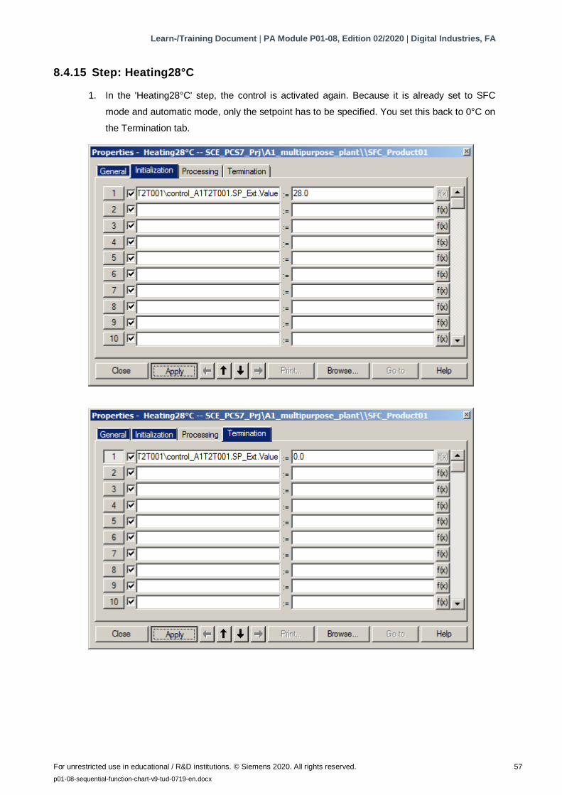
8.4.15 Step: Heating28°C
1. In the 'Heating28°C' step, the control is activated again. Because it is already set to SFC
mode and automatic mode, only the setpoint has to be specified. You set this back to 0°C on
the Termination tab.
Learn-/Training Document | PA Module P01-08, Edition 02/2020 | Digital Industries, FA
For unrestricted use in educational / R&D institutions. © Siemens 2020. All rights reserved. 58
p01-08-sequential-function-chart-v9-tud-0719-en.docx
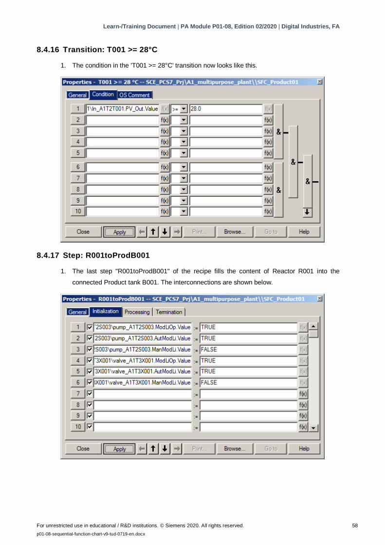
8.4.16 Transition: T001 >= 28°C
1. The condition in the 'T001 >= 28°C' transition now looks like this.
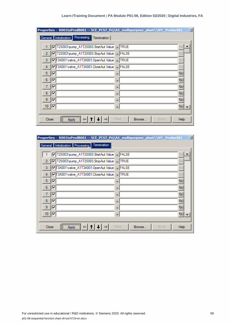
8.4.17 Step: R001toProdB001
1. The last step "R001toProdB001" of the recipe fills the content of Reactor R001 into the
connected Product tank B001. The interconnections are shown below.
Learn-/Training Document | PA Module P01-08, Edition 02/2020 | Digital Industries, FA
For unrestricted use in educational / R&D institutions. © Siemens 2020. All rights reserved. 59
p01-08-sequential-function-chart-v9-tud-0719-en.docx
Learn-/Training Document | PA Module P01-08, Edition 02/2020 | Digital Industries, FA
For unrestricted use in educational / R&D institutions. © Siemens 2020. All rights reserved. 60
p01-08-sequential-function-chart-v9-tud-0719-en.docx
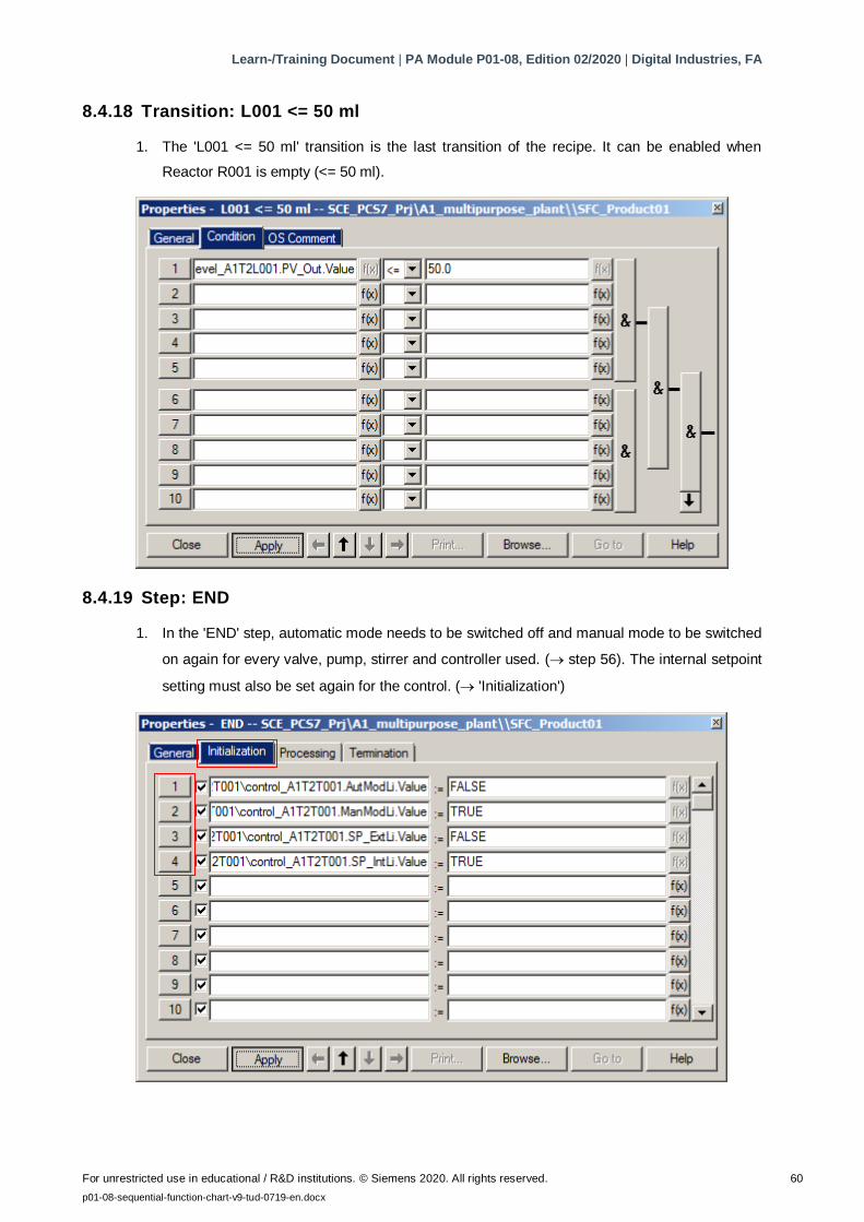
8.4.18 Transition: L001 <= 50 ml
1. The 'L001 <= 50 ml' transition is the last transition of the recipe. It can be enabled when
Reactor R001 is empty (<= 50 ml).
8.4.19 Step: END
1. In the 'END' step, automatic mode needs to be switched off and manual mode to be switched
on again for every valve, pump, stirrer and controller used. ( step 56). The internal setpoint
setting must also be set again for the control. ( 'Initialization')
Learn-/Training Document | PA Module P01-08, Edition 02/2020 | Digital Industries, FA
For unrestricted use in educational / R&D institutions. © Siemens 2020. All rights reserved. 61
p01-08-sequential-function-chart-v9-tud-0719-en.docx
Block AutModLi
.Value
ManModLi
.Value
SP_ExtLi
.Value
SP_IntLi
.Value
A1T2T001\control_A1T2T001 FALSE TRUE FALSE TRUE
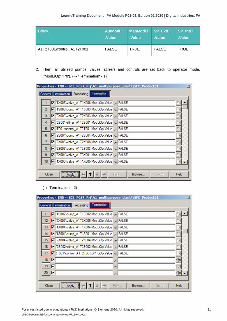
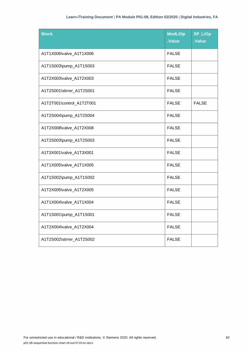
2. Then, all utilized pumps, valves, stirrers and controls are set back to operator mode.
('ModLiOp' = '0'). ( 'Termination' - 1)
( 'Termination' - 2)
Learn-/Training Document | PA Module P01-08, Edition 02/2020 | Digital Industries, FA
For unrestricted use in educational / R&D institutions. © Siemens 2020. All rights reserved. 62
p01-08-sequential-function-chart-v9-tud-0719-en.docx
Block ModLiOp
.Value
SP_LiOp
.Value
A1T1X006\valve_A1T1X006 FALSE
A1T1S003\pump_A1T1S003 FALSE
A1T2X003\valve_A1T2X003 FALSE
A1T2S001\stirrer_A1T2S001 FALSE
A1T2T001\control_A1T2T001 FALSE FALSE
A1T2S004\pump_A1T2S004 FALSE
A1T2X008\valve_A1T2X008 FALSE
A1T2S003\pump_A1T2S003 FALSE
A1T3X001\valve_A1T3X001 FALSE
A1T1X005\valve_A1T1X005 FALSE
A1T1S002\pump_A1T1S002 FALSE
A1T2X005\valve_A1T2X005 FALSE
A1T1X004\valve_A1T1X004 FALSE
A1T1S001\pump_A1T1S001 FALSE
A1T2X004\valve_A1T2X004 FALSE
A1T2S002\stirrer_A1T2S002 FALSE
Learn-/Training Document | PA Module P01-08, Edition 02/2020 | Digital Industries, FA
For unrestricted use in educational / R&D institutions. © Siemens 2020. All rights reserved. 63
p01-08-sequential-function-chart-v9-tud-0719-en.docx
Learn-/Training Document | PA Module P01-08, Edition 02/2020 | Digital Industries, FA
For unrestricted use in educational / R&D institutions. © Siemens 2020. All rights reserved. 64
p01-08-sequential-function-chart-v9-tud-0719-en.docx
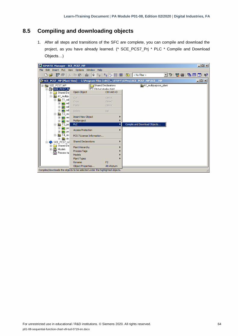
8.5 Compiling and downloading objects
1. After all steps and transitions of the SFC are complete, you can compile and download the
project, as you have already learned. (* SCE_PCS7_Prj * PLC * Compile and Download
Objects…)
Learn-/Training Document | PA Module P01-08, Edition 02/2020 | Digital Industries, FA
For unrestricted use in educational / R&D institutions. © Siemens 2020. All rights reserved. 65
p01-08-sequential-function-chart-v9-tud-0719-en.docx
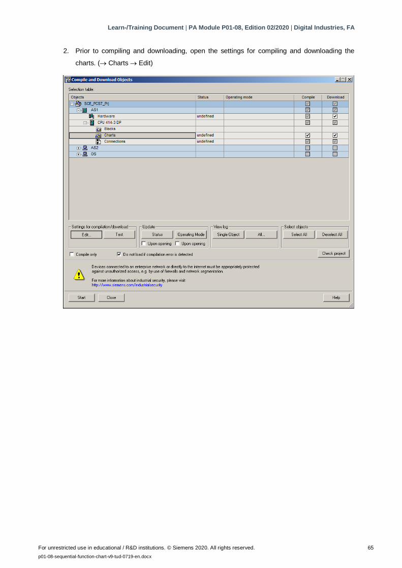
2. Prior to compiling and downloading, open the settings for compiling and downloading the
charts. ( Charts Edit)
Learn-/Training Document | PA Module P01-08, Edition 02/2020 | Digital Industries, FA
For unrestricted use in educational / R&D institutions. © Siemens 2020. All rights reserved. 66
p01-08-sequential-function-chart-v9-tud-0719-en.docx
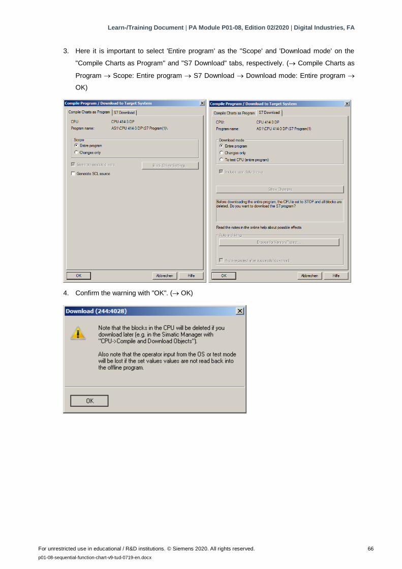
3. Here it is important to select 'Entire program' as the "Scope' and 'Download mode' on the
"Compile Charts as Program" and "S7 Download" tabs, respectively. ( Compile Charts as
Program Scope: Entire program S7 Download Download mode: Entire program
OK)
4. Confirm the warning with "OK". ( OK)
Learn-/Training Document | PA Module P01-08, Edition 02/2020 | Digital Industries, FA
For unrestricted use in educational / R&D institutions. © Siemens 2020. All rights reserved. 67
p01-08-sequential-function-chart-v9-tud-0719-en.docx
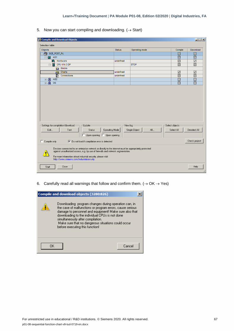
5. Now you can start compiling and downloading. ( Start)
6. Carefully read all warnings that follow and confirm them. ( OK Yes)
Learn-/Training Document | PA Module P01-08, Edition 02/2020 | Digital Industries, FA
For unrestricted use in educational / R&D institutions. © Siemens 2020. All rights reserved. 68
p01-08-sequential-function-chart-v9-tud-0719-en.docx
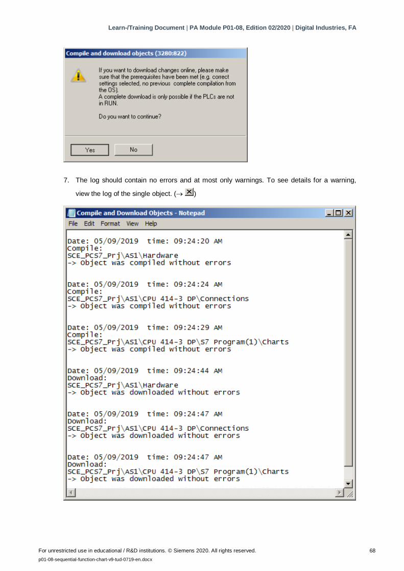
7. The log should contain no errors and at most only warnings. To see details for a warning,
view the log of the single object. ( )
Learn-/Training Document | PA Module P01-08, Edition 02/2020 | Digital Industries, FA
For unrestricted use in educational / R&D institutions. © Siemens 2020. All rights reserved. 69
p01-08-sequential-function-chart-v9-tud-0719-en.docx
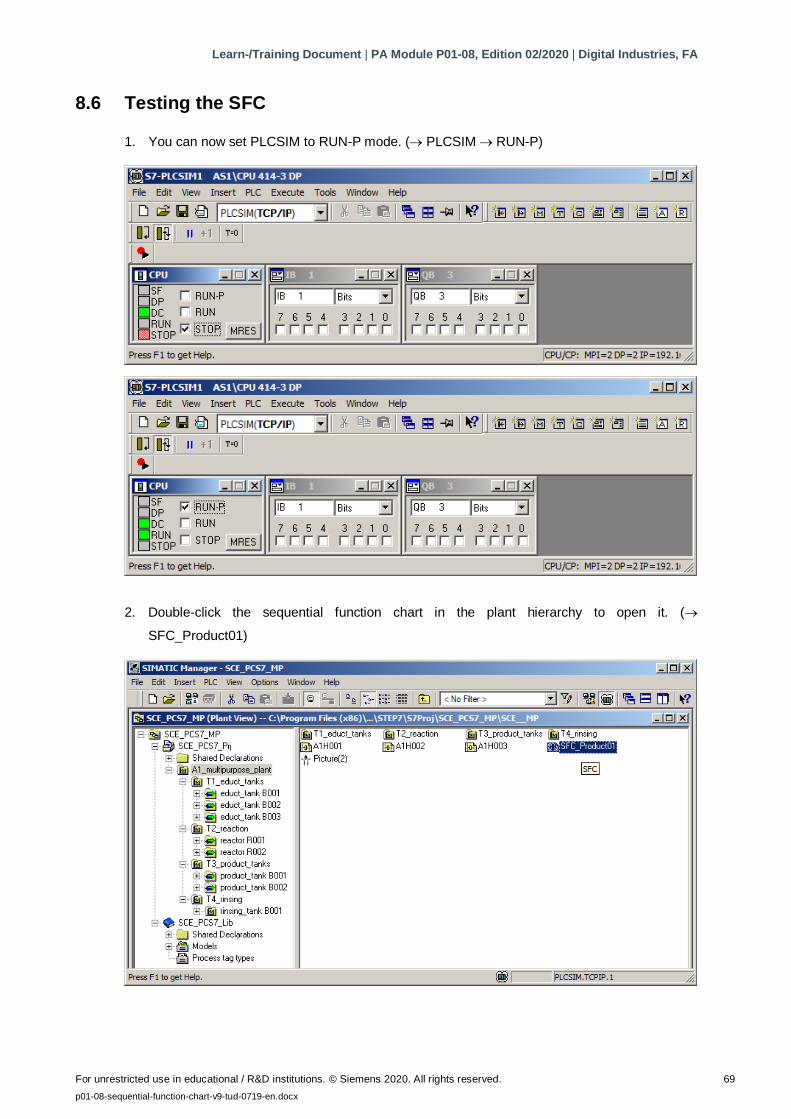
8.6 Testing the SFC
1. You can now set PLCSIM to RUN-P mode. ( PLCSIM RUN-P)
2. Double-click the sequential function chart in the plant hierarchy to open it. (
SFC_Product01)
Learn-/Training Document | PA Module P01-08, Edition 02/2020 | Digital Industries, FA
For unrestricted use in educational / R&D institutions. © Siemens 2020. All rights reserved. 70
p01-08-sequential-function-chart-v9-tud-0719-en.docx
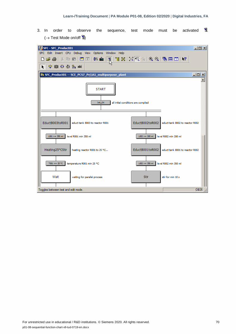
3. In order to observe the sequence, test mode must be activated .
( Test Mode on/off )
Learn-/Training Document | PA Module P01-08, Edition 02/2020 | Digital Industries, FA
For unrestricted use in educational / R&D institutions. © Siemens 2020. All rights reserved. 71
p01-08-sequential-function-chart-v9-tud-0719-en.docx
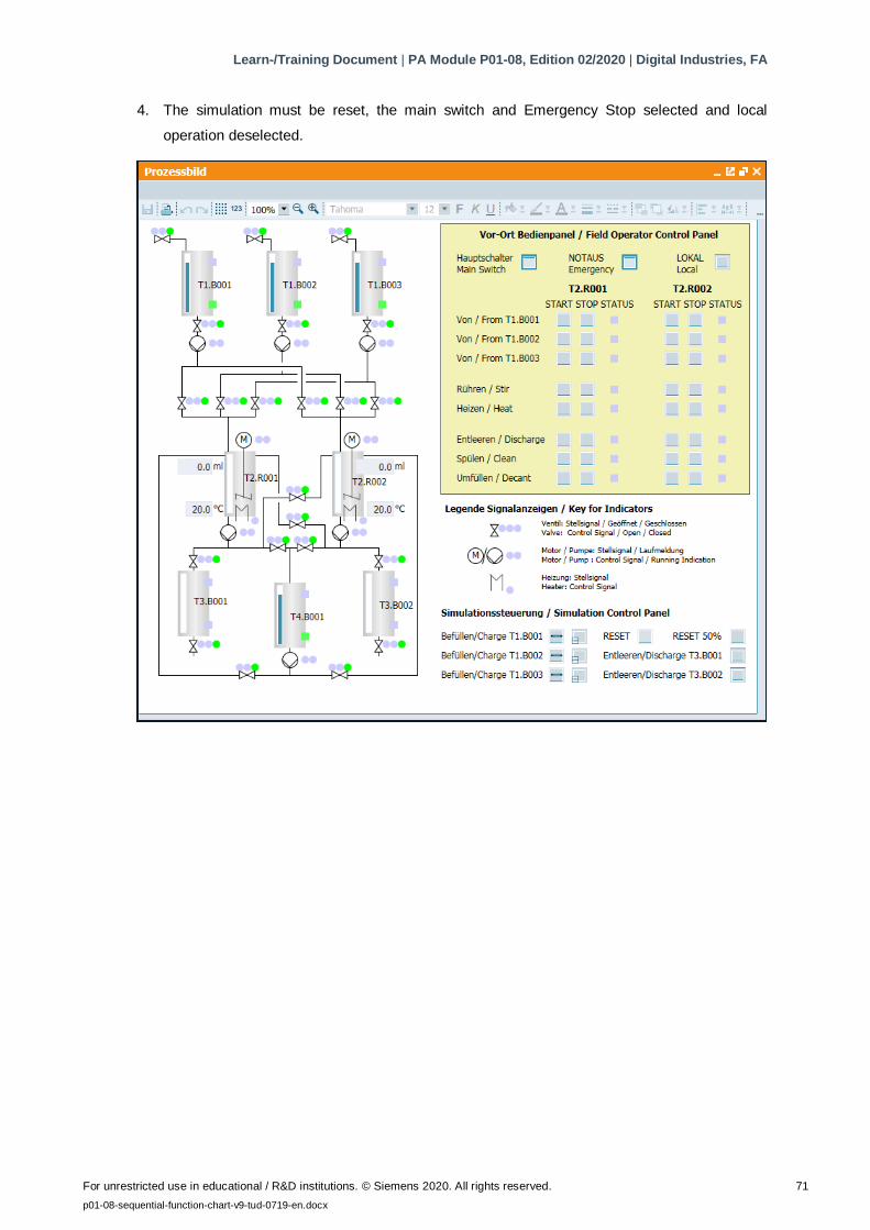
4. The simulation must be reset, the main switch and Emergency Stop selected and local
operation deselected.
Learn-/Training Document | PA Module P01-08, Edition 02/2020 | Digital Industries, FA
For unrestricted use in educational / R&D institutions. © Siemens 2020. All rights reserved. 72
p01-08-sequential-function-chart-v9-tud-0719-en.docx
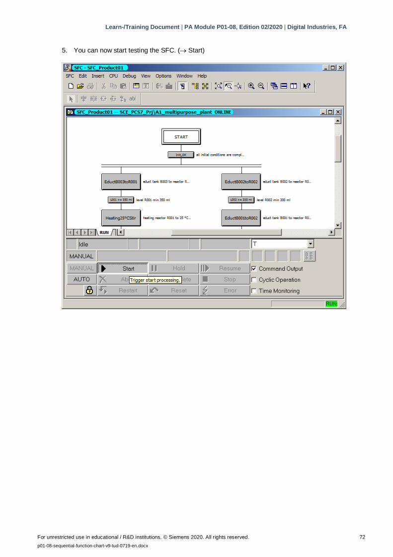
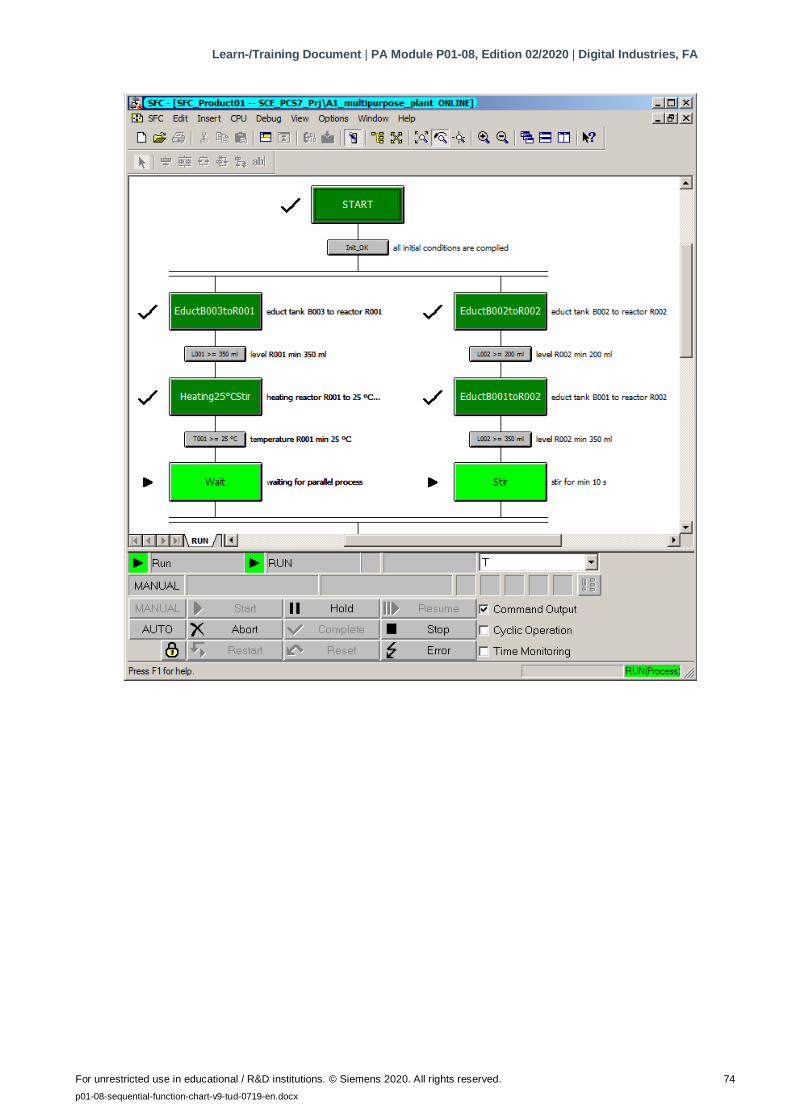
5. You can now start testing the SFC. ( Start)
Learn-/Training Document | PA Module P01-08, Edition 02/2020 | Digital Industries, FA
For unrestricted use in educational / R&D institutions. © Siemens 2020. All rights reserved. 73
p01-08-sequential-function-chart-v9-tud-0719-en.docx
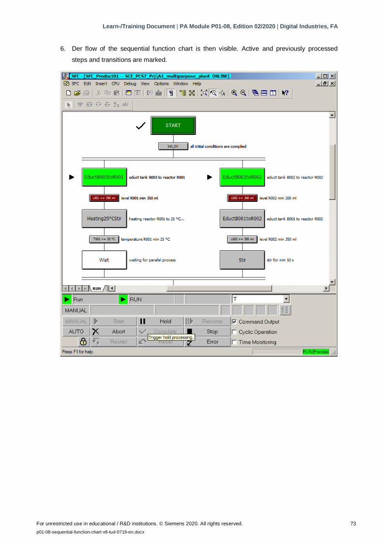
6. Der flow of the sequential function chart is then visible. Active and previously processed
steps and transitions are marked.
Learn-/Training Document | PA Module P01-08, Edition 02/2020 | Digital Industries, FA
For unrestricted use in educational / R&D institutions. © Siemens 2020. All rights reserved. 74
p01-08-sequential-function-chart-v9-tud-0719-en.docx
Learn-/Training Document | PA Module P01-08, Edition 02/2020 | Digital Industries, FA
For unrestricted use in educational / R&D institutions. © Siemens 2020. All rights reserved. 75
p01-08-sequential-function-chart-v9-tud-0719-en.docx
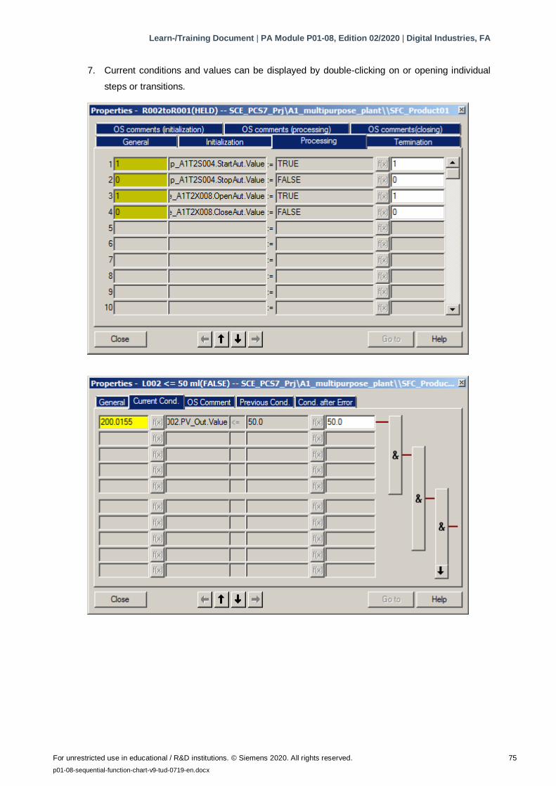
7. Current conditions and values can be displayed by double-clicking on or opening individual
steps or transitions.
Learn-/Training Document | PA Module P01-08, Edition 02/2020 | Digital Industries, FA
For unrestricted use in educational / R&D institutions. © Siemens 2020. All rights reserved. 76
p01-08-sequential-function-chart-v9-tud-0719-en.docx
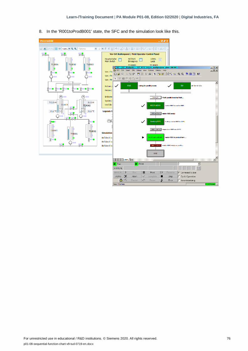
8. In the 'R001toProdB001' state, the SFC and the simulation look like this.
Learn-/Training Document | PA Module P01-08, Edition 02/2020 | Digital Industries, FA
For unrestricted use in educational / R&D institutions. © Siemens 2020. All rights reserved. 77
p01-08-sequential-function-chart-v9-tud-0719-en.docx
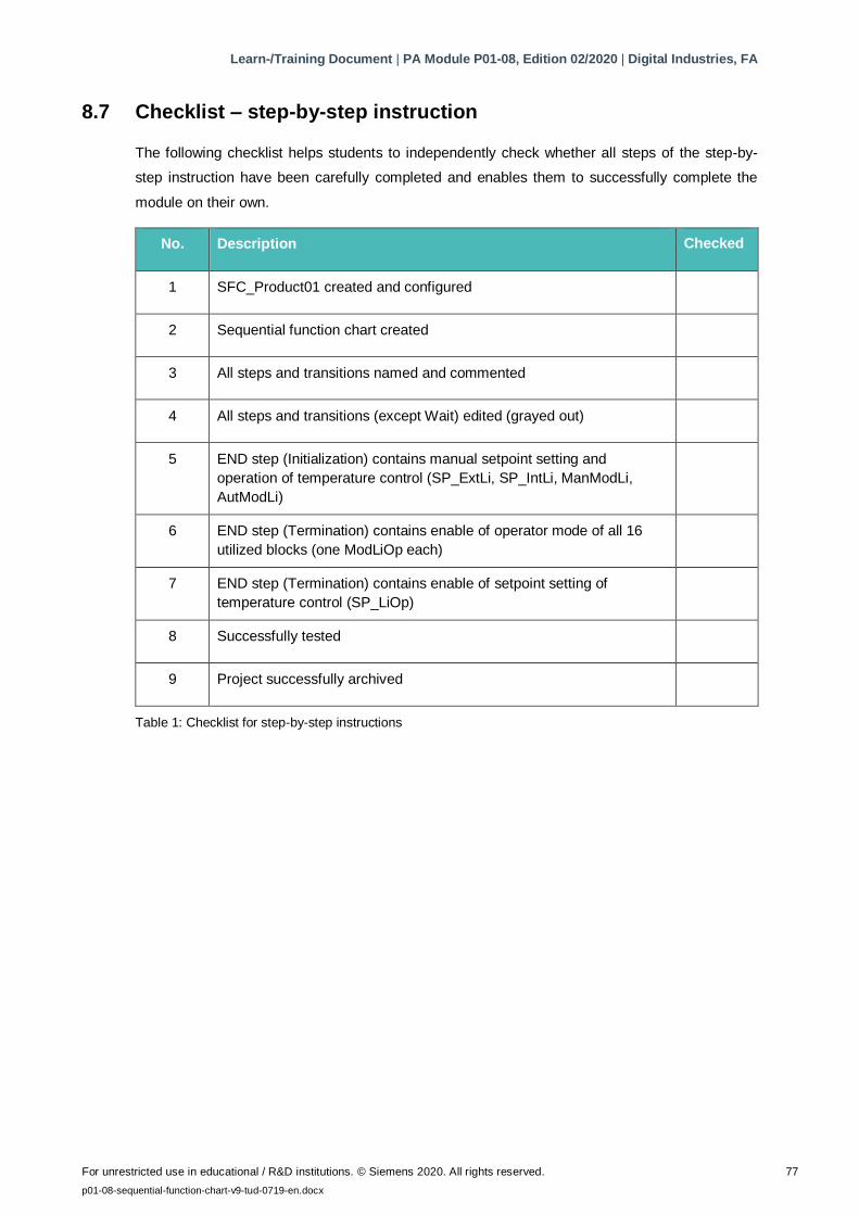
8.7 Checklist – step-by-step instruction
The following checklist helps students to independently check whether all steps of the step-by-
step instruction have been carefully completed and enables them to successfully complete the
module on their own.
No. Description Checked
1 SFC_Product01 created and configured
2 Sequential function chart created
3 All steps and transitions named and commented
4 All steps and transitions (except Wait) edited (grayed out)
5 END step (Initialization) contains manual setpoint setting and
operation of temperature control (SP_ExtLi, SP_IntLi, ManModLi,
AutModLi)
6 END step (Termination) contains enable of operator mode of all 16
utilized blocks (one ModLiOp each)
7 END step (Termination) contains enable of setpoint setting of
temperature control (SP_LiOp)
8 Successfully tested
9 Project successfully archived
Table 1: Checklist for step-by-step instructions
Learn-/Training Document | PA Module P01-08, Edition 02/2020 | Digital Industries, FA
For unrestricted use in educational / R&D institutions. © Siemens 2020. All rights reserved. 78
p01-08-sequential-function-chart-v9-tud-0719-en.docx
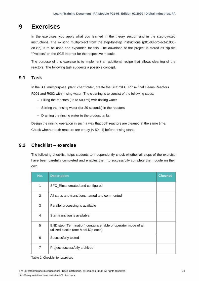
9 Exercises
In the exercises, you apply what you learned in the theory section and in the step-by-step
instructions. The existing multiproject from the step-by-step instructions (p01-08-project-r1905-
en.zip) is to be used and expanded for this. The download of the project is stored as zip file
"Projects" on the SCE Internet for the respective module.
The purpose of this exercise is to implement an additional recipe that allows cleaning of the
reactors. The following task suggests a possible concept.
9.1 Task
In the 'A1_multipurpose_plant' chart folder, create the SFC 'SFC_Rinse' that cleans Reactors
R001 and R002 with rinsing water. The cleaning is to consist of the following steps:
– Filling the reactors (up to 500 ml) with rinsing water
– Stirring the rinsing water (for 20 seconds) in the reactors
– Draining the rinsing water to the product tanks.
Design the rinsing operation in such a way that both reactors are cleaned at the same time.
Check whether both reactors are empty (< 50 ml) before rinsing starts.
9.2 Checklist – exercise
The following checklist helps students to independently check whether all steps of the exercise
have been carefully completed and enables them to successfully complete the module on their
own.
No. Description Checked
1 SFC_Rinse created and configured
2 All steps and transitions named and commented
3 Parallel processing is available
4 Start transition is available
5 END step (Termination) contains enable of operator mode of all
utilized blocks (one ModLiOp each)
6 Successfully tested
7 Project successfully archived
Table 2: Checklist for exercises
Learn-/Training Document | PA Module P01-08, Edition 02/2020 | Digital Industries, FA
For unrestricted use in educational / R&D institutions. © Siemens 2020. All rights reserved. 79
p01-08-sequential-function-chart-v9-tud-0719-en.docx
10 Additional information
More information for further practice and consolidation is available as orientation, for example:
Getting Started, videos, tutorials, apps, manuals, programming guidelines and trial software/
firmware, under the following link:
siemens.com/sce/pcs7
Preview "Additional information"
Learn-/Training Document | PA Module P01-08, Edition 02/2020 | Digital Industries, FA
For unrestricted use in educational / R&D institutions. © Siemens 2020. All rights reserved. 80
p01-08-sequential-function-chart-v9-tud-0719-en.docx
Further Information
Siemens Automation Cooperates with Education
siemens.com/sce
Siemens SIMATIC PCS 7
siemens.com/pcs7
SCE Learn-/Training Documents
siemens.com/sce/documents
SCE Trainer Packages
siemens.com/sce/tp
SCE Contact Partners
siemens.com/sce/contact
Digital Enterprise
siemens.com/digital-enterprise
Industrie 4.0
siemens.com/future-of-manufacturing
Totally Integrated Automation (TIA)
siemens.com/tia
TIA Portal
siemens.com/tia-portal
SIMATIC Controller
siemens.com/controller
SIMATIC Technical Documentation
siemens.com/simatic-docu
Industry Online Support
support.industry.siemens.com
Product catalogue and online ordering system Industry Mall
mall.industry.siemens.com
Siemens
Digital Industries, FA
P.O. Box 4848
90026 Nuremberg
Germany
Subject to change and errors
© Siemens 2020
siemens.com/sce