differential relays - siemens
TRANSCRIPT
Differential Relays
Siemens LSA 2.2.1 . March 1997 1
Application
The 7SD502 line differential protection isa fast and selective differential protectionunit for cables and overhead lines.It is the successor of the 7SD22 and7SD76 static differential protection. Com-bination with 7SD76 or 7SD22 is not pos-sible, i.e. 7SD502s must be used at bothends of the line. The connection between7SD502s is made via a balanced pair ofpilot–wires, i.e. existing pilot–wire con-nections can be used.
Design
Within its compact dimensions the unitcontains all components for analog valueacquisition and evaluation, the summa-tion current transformer, the pilot–wiretrimming resistors, the operating and dis-play panel, the indication and commandoutputs, binary inputs and the auxiliaryvoltage converter.The unit can be supplied in two differenthousings. The one for flush mounting in apanel or cubicle has connections at therear. The other for surface mounting on apanel has screw terminals accessiblefrom the front.
Method of operation
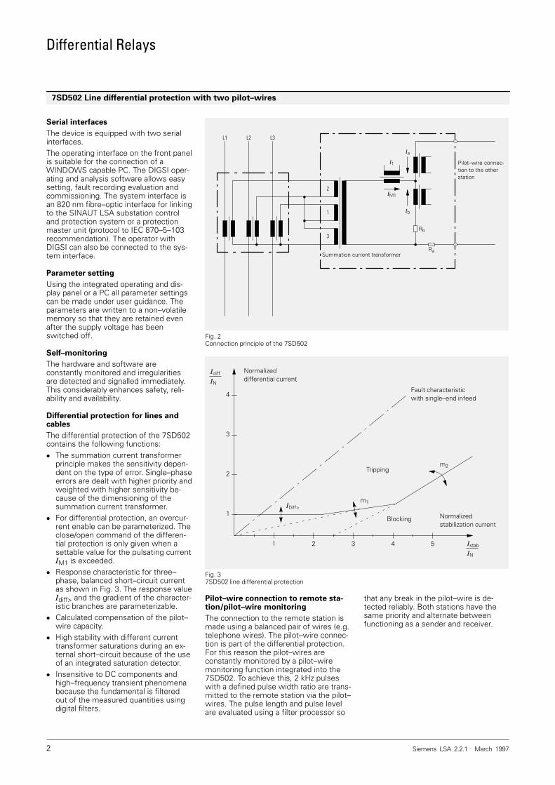
The summation current transformer inte-grated in the housing of the 7SD502 per-mits the connection of any secondarycurrents of the primary current trans-former (see Fig. 2). The three primarywindings of the summation current trans-former have the winding ratio 2 :1 :3.With 1 x �N as the three–phase, balancedshort–circuit current, the secondarysingle–phase current �M1 of the summa-tion current transformer is 20 mA. Thesummation current transformer principlegives different short–circuit sensitivitiesdepending on the connection, e.g. differ-ent weightings can be assigned to theearth fault.The 7SD502 acquires the secondary pul-sating current �M1 of its own substation,the current �a via the pilot–wires and thecurrent �b in the trimming resistor Rb. Thepulsating current �M2 of the remote sta-tion is calculated from these quantities.With three–end protection, the boostingcurrent �boo is acquired at the third lineend and included in the calculation.The line is shut down if the protectionsystem finds that the differential current�diff obtained by adding �M1 and �M2 indi-cates a short–circuit in the protectionzone.Digital measured–value processing withconsistent evaluation of the fundamentalof the measured quantities largely elimi-nates the influence of high frequencytransient phenomena, transient DC com-ponents and differing current transformersaturation.
Features
� Selective short–circuit protection foroverhead lines and cables
� Acquisition of pulsating current behindthe summation current transformerand of currents via the pair of pilot–wires
� Sensitivity to single–phase faults un-der rated current
� 100 % protection against all types ofshort–circuit within the protection zone
� Circuit–breaker intertripping and re-mote tripping of the remote station
� Integrated pilot–wire monitoring� Software–controlled adaptation of the
sensitivity of the differential protectionto different wire resistances. Thismakes pilot–wire trimming unneces-sary
� Overload protection with thermal char-acteristic
� Two–stage definite–time/dependenttime overcurrent protection as standby
� Real–time clock and permanentlystored status and fault indications inthe event of auxiliary voltage failure.VDEW/ZVEI interface to the controlsystem
� Protection of three–end pilot–wireswith two devices at each end of theline is possible.
7SD502 Line differential protection with two pilot–wires
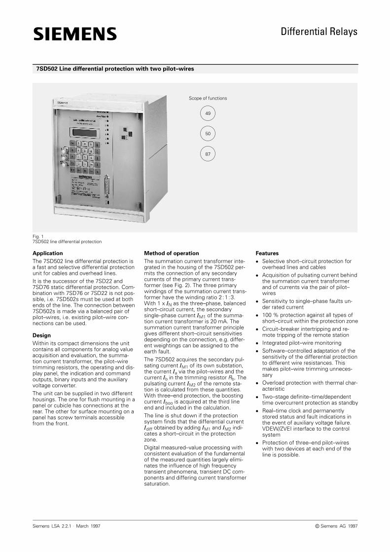
Fig. 17SD502 line differential protection
49
50
87
Scope of functions
Siemens AG 1997�
Differential Relays
Siemens LSA 2.2.1 . March 19972
Serial interfaces
The device is equipped with two serialinterfaces.The operating interface on the front panelis suitable for the connection of aWINDOWS capable PC. The DIGSI oper-ating and analysis software allows easysetting, fault recording evaluation andcommissioning. The system interface isan 820 nm fibre–optic interface for linkingto the SINAUT LSA substation controland protection system or a protectionmaster unit (protocol to IEC 870–5–103recommendation). The operator withDIGSI can also be connected to the sys-tem interface.
Parameter setting
Using the integrated operating and dis-play panel or a PC all parameter settingscan be made under user guidance. Theparameters are written to a non–volatilememory so that they are retained evenafter the supply voltage has beenswitched off.
Self–monitoring
The hardware and software areconstantly monitored and irregularitiesare detected and signalled immediately.This considerably enhances safety, reli-ability and availability.
Differential protection for lines andcables
The differential protection of the 7SD502contains the following functions:� The summation current transformer
principle makes the sensitivity depen-dent on the type of error. Single–phaseerrors are dealt with higher priority andweighted with higher sensitivity be-cause of the dimensioning of thesummation current transformer.
� For differential protection, an overcur-rent enable can be parameterized. Theclose/open command of the differen-tial protection is only given when asettable value for the pulsating current�M1 is exceeded.
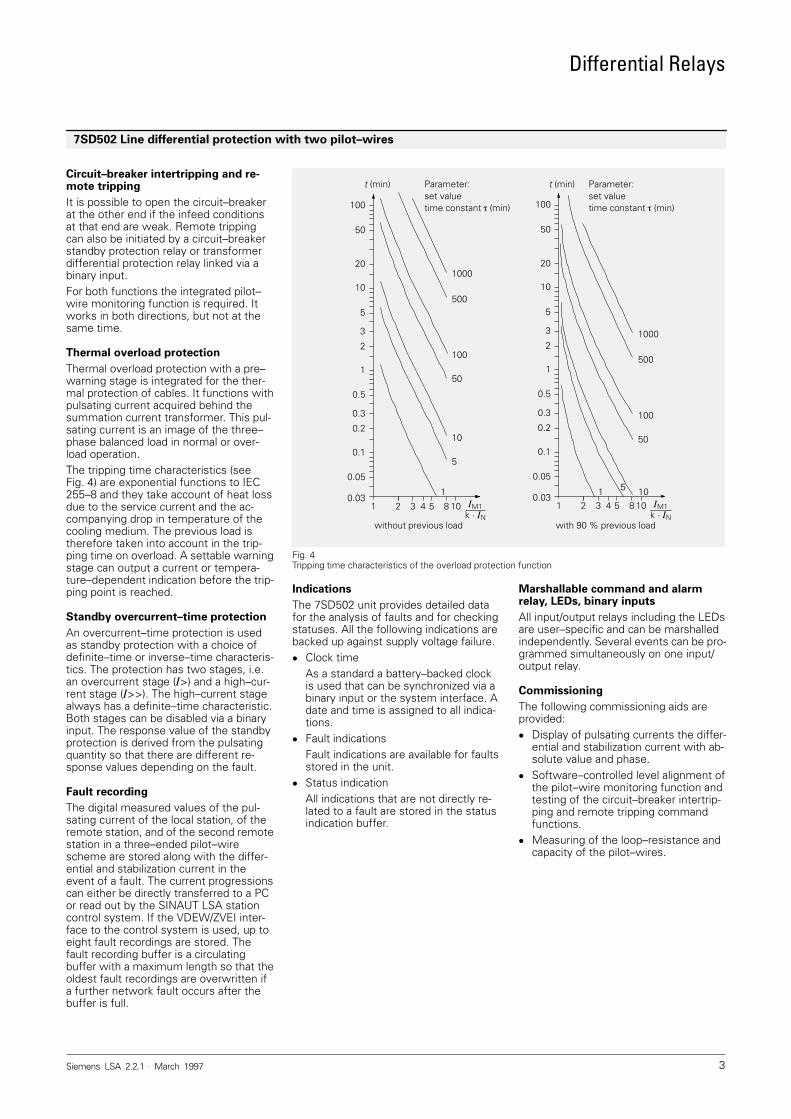
� Response characteristic for three–phase, balanced short–circuit currentas shown in Fig. 3. The response value�diff> and the gradient of the character-istic branches are parameterizable.
� Calculated compensation of the pilot–wire capacity.
� High stability with different currenttransformer saturations during an ex-ternal short–circuit because of the useof an integrated saturation detector.
� Insensitive to DC components andhigh–frequency transient phenomenabecause the fundamental is filteredout of the measured quantities usingdigital filters.
Pilot–wire connection to remote sta-tion/pilot–wire monitoring
The connection to the remote station ismade using a balanced pair of wires (e.g.telephone wires). The pilot–wire connec-tion is part of the differential protection.For this reason the pilot–wires areconstantly monitored by a pilot–wiremonitoring function integrated into the7SD502. To achieve this, 2 kHz pulseswith a defined pulse width ratio are trans-mitted to the remote station via the pilot–wires. The pulse length and pulse levelare evaluated using a filter processor so
that any break in the pilot–wire is de-tected reliably. Both stations have thesame priority and alternate betweenfunctioning as a sender and receiver.
7SD502 Line differential protection with two pilot–wires
Fig. 2Connection principle of the 7SD502
2
L2L1
1
3
L3
Ra
Rb
Ia
IM1
Ib
I1
Summation current transformer
Pilot–wire connec-tion to the otherstation
Fig. 37SD502 line differential protection
1 2 3 4 5 �stab
�N
1
2
3
4
�diff
�N
Normalizeddifferential current
Normalizedstabilization current
Fault characteristicwith single–end infeed
Tripping
Blocking
�Diff>m1
m2
Differential Relays
Siemens LSA 2.2.1 . March 1997 3
Circuit–breaker intertripping and re-mote tripping
It is possible to open the circuit–breakerat the other end if the infeed conditionsat that end are weak. Remote trippingcan also be initiated by a circuit–breakerstandby protection relay or transformerdifferential protection relay linked via abinary input.For both functions the integrated pilot–wire monitoring function is required. Itworks in both directions, but not at thesame time.
Thermal overload protection
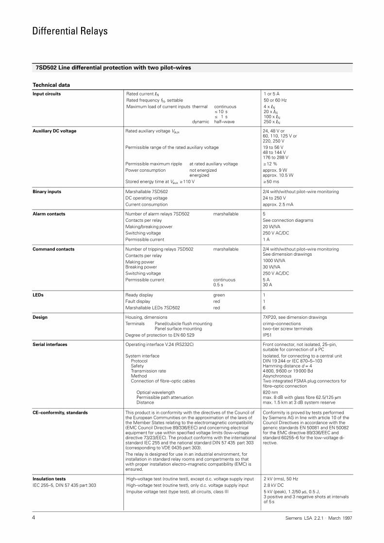
Thermal overload protection with a pre–warning stage is integrated for the ther-mal protection of cables. It functions withpulsating current acquired behind thesummation current transformer. This pul-sating current is an image of the three–phase balanced load in normal or over-load operation.The tripping time characteristics (seeFig. 4) are exponential functions to IEC255–8 and they take account of heat lossdue to the service current and the ac-companying drop in temperature of thecooling medium. The previous load istherefore taken into account in the trip-ping time on overload. A settable warningstage can output a current or tempera-ture–dependent indication before the trip-ping point is reached.
Standby overcurrent–time protection
An overcurrent–time protection is usedas standby protection with a choice ofdefinite–time or inverse–time characteris-tics. The protection has two stages, i.e.an overcurrent stage (�>) and a high–cur-rent stage (�>>). The high–current stagealways has a definite–time characteristic.Both stages can be disabled via a binaryinput. The response value of the standbyprotection is derived from the pulsatingquantity so that there are different re-sponse values depending on the fault.
Fault recording
The digital measured values of the pul-sating current of the local station, of theremote station, and of the second remotestation in a three–ended pilot–wirescheme are stored along with the differ-ential and stabilization current in theevent of a fault. The current progressionscan either be directly transferred to a PCor read out by the SINAUT LSA stationcontrol system. If the VDEW/ZVEI inter-face to the control system is used, up toeight fault recordings are stored. Thefault recording buffer is a circulatingbuffer with a maximum length so that theoldest fault recordings are overwritten ifa further network fault occurs after thebuffer is full.
Indications
The 7SD502 unit provides detailed datafor the analysis of faults and for checkingstatuses. All the following indications arebacked up against supply voltage failure.� Clock time
As a standard a battery–backed clockis used that can be synchronized via abinary input or the system interface. Adate and time is assigned to all indica-tions.
� Fault indicationsFault indications are available for faultsstored in the unit.
� Status indicationAll indications that are not directly re-lated to a fault are stored in the statusindication buffer.
Marshallable command and alarmrelay, LEDs, binary inputs
All input/output relays including the LEDsare user–specific and can be marshalledindependently. Several events can be pro-grammed simultaneously on one input/output relay.
Commissioning
The following commissioning aids areprovided:� Display of pulsating currents the differ-
ential and stabilization current with ab-solute value and phase.
� Software–controlled level alignment ofthe pilot–wire monitoring function andtesting of the circuit–breaker intertrip-ping and remote tripping commandfunctions.
� Measuring of the loop–resistance andcapacity of the pilot–wires.
7SD502 Line differential protection with two pilot–wires
Fig. 4Tripping time characteristics of the overload protection function
t (min) t (min)
100
50
20
10
5
3
2
1
0.5
0.3
0.2
0.1
0.05
0.03
1000
500
100
50
10
5
1
1000
500
100
50
1051�M1
k · �N
1085431
with 90 % previous load
Parameter:set value time constant �� (min)
Parameter:set valuetime constant � (min)
�M1k · �N
100
50
20
10
5
3
2
1
0.5
0.3
0.2
0.1
0.05
0.031085431
without previous load
2 2
Differential Relays
Siemens LSA 2.2.1 . March 19974
Technical data
Input circuits Rated current �N
Rated frequency fN, settableMaximum load of current inputs thermal continuous
�10 s� 1 s
dynamic half–wave
1 or 5 A50 or 60 Hz4 x �N20 x �N100 x �N250 x �N
Auxiliary DC voltage Rated auxiliary voltage Vaux
Permissible range of the rated auxiliary voltage
Permissible maximum ripple at rated auxiliary voltagePower consumption not energized
energizedStored energy time at Vaux �110 V
24, 48 V or60, 110, 125 V or220, 250 V19 to 56 V48 to 144 V176 to 288 V�12 %approx. 9 Wapprox. 10.5 W�50 ms
Binary inputs Marshallable 7SD502DC operating voltageCurrent consumption
2/4 with/without pilot–wire monitoring24 to 250 Vapprox. 2.5 mA
Alarm contacts Number of alarm relays 7SD502 marshallableContacts per relayMaking/breaking powerSwitching voltagePermissible current
5See connection diagrams20 W/VA250 V AC/DC1 A
Command contacts Number of tripping relays 7SD502 marshallableContacts per relayMaking powerBreaking powerSwitching voltagePermissible current continuous
0.5 s
2/4 with/without pilot–wire monitoringSee dimension drawings1000 W/VA30 W/VA250 V AC/DC5 A30 A
LEDs Ready display greenFault display redMarshallable LEDs 7SD502 red
116
Design Housing, dimensionsTerminals Panel/cubicle flush mounting
Panel surface mountingDegree of protection to EN 60 529
7XP20, see dimension drawingscrimp–connectionstwo–tier screw terminalsIP51
Serial interfaces Operating interface V.24 (RS232C)
System interfaceProtocolSafetyTransmission rateMethodConnection of fibre–optic cables
Optical wavelengthPermissible path attenuationDistance
Front connector, not isolated, 25–pin,suitable for connection of a PCIsolated, for connecting to a central unitDIN 19 244 or IEC 870–5–103Hamming distance d = 44 800, 9 600 or 19 000 BdAsynchronousTwo integrated FSMA plug connectors forfibre–optic connection820 nmmax. 8 dB with glass fibre 62.5/125 �mmax. 1.5 km at 3 dB system reserve
CE–conformity, standards This product is in conformity with the directives of the Council ofthe European Communities on the approximation of the laws ofthe Member States relating to the electromagnetic compatibility(EMC Council Directive 89/336/EEC) and concerning electricalequipment for use within specified voltage limits (low–voltagedirective 73/23/EEC). The product conforms with the internationalstandard IEC 255 and the national standard DIN 57 435 part 303(corresponding to VDE 0435 part 303).The relay is designed for use in an industrial environment, forinstallation in standard relay rooms and compartments so thatwith proper installation electro–magnetic compatibility (EMC) isensured.
Conformity is proved by tests performedby Siemens AG in line with article 10 of theCouncil Directives in accordance with thegeneric standards EN 50081 and EN 50082for the EMC directive 89/336/EEC andstandard 60255–6 for the low–voltage di-rective.
Insulation tests
IEC 255–5, DIN 57 435 part 303High–voltage test (routine test), except d.c. voltage supply inputHigh–voltage test (routine test), only d.c. voltage supply inputImpulse voltage test (type test), all circuits, class III
2 kV (rms), 50 Hz2.8 kV DC5 kV (peak), 1.2/50 �s, 0.5 J,3 positive and 3 negative shots at intervalsof 5 s
7SD502 Line differential protection with two pilot–wires
Differential Relays
Siemens LSA 2.2.1 . March 1997 5
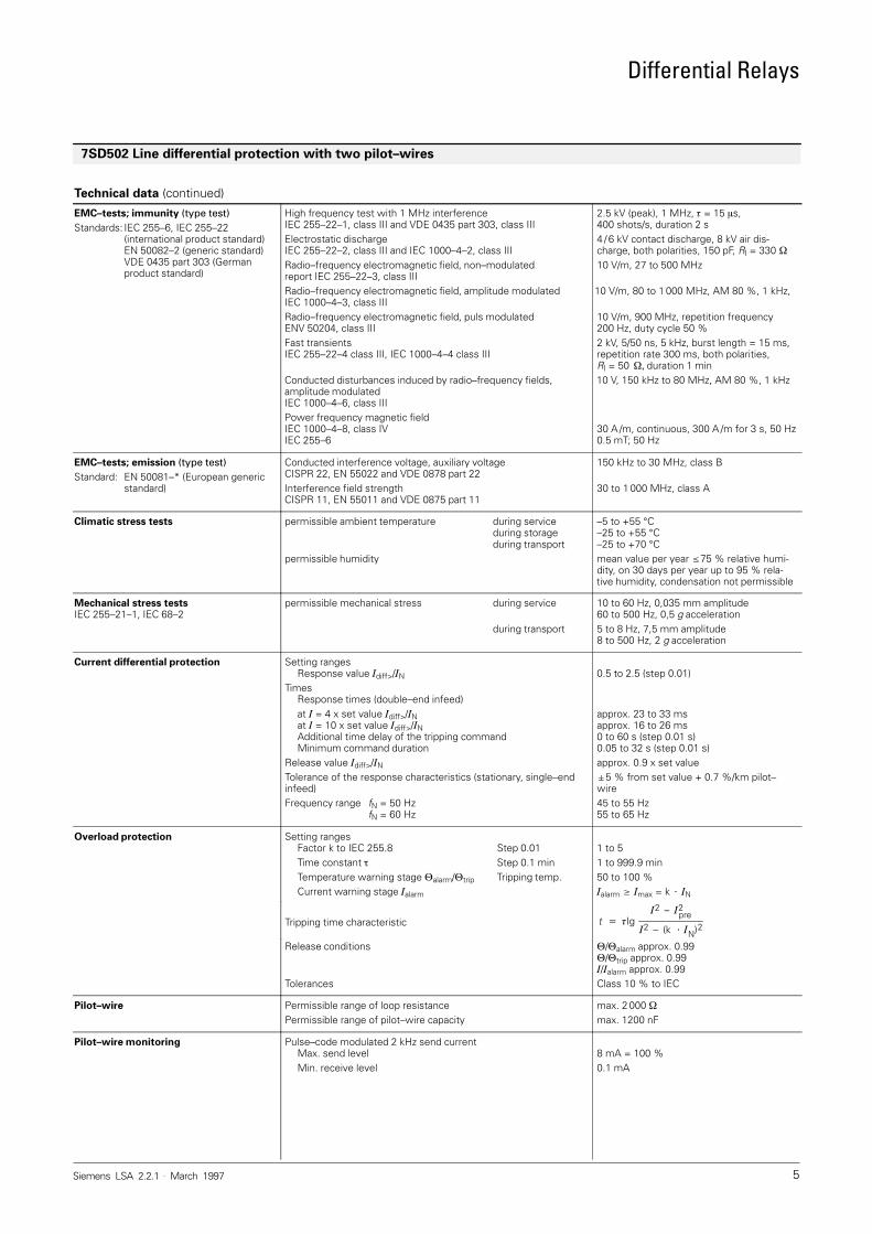
Technical data (continued)
EMC–tests; immunity (type test)
Standards: IEC 255–6, IEC 255–22(international product standard)EN 50082–2 (generic standard)VDE 0435 part 303 (Germanproduct standard)
High frequency test with 1 MHz interferenceIEC 255–22–1, class III and VDE 0435 part 303, class IIIElectrostatic dischargeIEC 255–22–2, class III and IEC 1000–4–2, class IIIRadio–frequency electromagnetic field, non–modulatedreport IEC 255–22–3, class IIIRadio–frequency electromagnetic field, amplitude modulatedIEC 1000–4–3, class IIIRadio–frequency electromagnetic field, puls modulatedENV 50204, class IIIFast transientsIEC 255–22–4 class III, IEC 1000–4–4 class III
Conducted disturbances induced by radio–frequency fields, amplitude modulatedIEC 1000–4–6, class IIIPower frequency magnetic fieldIEC 1000–4–8, class IVIEC 255–6
2.5 kV (peak), 1 MHz, � = 15 �s,400 shots/s, duration 2 s4 / 6 kV contact discharge, 8 kV air dis-charge, both polarities, 150 pF, Rl = 330 �
10 V/m, 27 to 500 MHz
10 V/m, 80 to 1 000 MHz, AM 80 %, 1 kHz,
10 V/m, 900 MHz, repetition frequency 200 Hz, duty cycle 50 %2 kV, 5/50 ns, 5 kHz, burst length = 15 ms,repetition rate 300 ms, both polarities, Rl = 50 ��� duration 1 min10 V, 150 kHz to 80 MHz, AM 80 %, 1 kHz
30 A /m, continuous, 300 A /m for 3 s, 50 Hz0.5 mT; 50 Hz
EMC–tests; emission (type test)
Standard: EN 50081–* (European generic standard)
Conducted interference voltage, auxiliary voltageCISPR 22, EN 55022 and VDE 0878 part 22Interference field strength CISPR 11, EN 55011 and VDE 0875 part 11
150 kHz to 30 MHz, class B
30 to 1 000 MHz, class A
Climatic stress tests permissible ambient temperature during serviceduring storageduring transport
permissible humidity
–5 to +55 °C–25 to +55 °C–25 to +70 °Cmean value per year �75 % relative humi-dity, on 30 days per year up to 95 % rela-tive humidity, condensation not permissible
Mechanical stress testsIEC 255–21–1, IEC 68–2
permissible mechanical stress during service
during transport
10 to 60 Hz, 0,035 mm amplitude60 to 500 Hz, 0,5 g acceleration5 to 8 Hz, 7,5 mm amplitude8 to 500 Hz, 2 g acceleration
Current differential protection Setting rangesResponse value �diff>/�N
TimesResponse times (double–end infeed)at � = 4 x set value �diff>/�N at � = 10 x set value �diff>/�N Additional time delay of the tripping commandMinimum command duration
Release value �diff>/�N
Tolerance of the response characteristics (stationary, single–endinfeed)Frequency range fN = 50 Hz
fN = 60 Hz
0.5 to 2.5 (step 0.01)
approx. 23 to 33 msapprox. 16 to 26 ms0 to 60 s (step 0.01 s)0.05 to 32 s (step 0.01 s)approx. 0.9 x set value�5 % from set value + 0.7 %/km pilot–wire45 to 55 Hz55 to 65 Hz
Overload protection Setting rangesFactor k to IEC 255.8 Step 0.01Time constant � Step 0.1 minTemperature warning stage �alarm/�trip Tripping temp.Current warning stage �alarm
1 to 51 to 999.9 min50 to 100 %�alarm � �max = k � �N
Tripping time characteristic t � �Ig�2 – �2
pre
�2 – (k � �N)2
Release conditions
Tolerances
�/�alarm approx. 0.99�/�trip approx. 0.99�/�alarm approx. 0.99Class 10 % to IEC
Pilot–wire Permissible range of loop resistancePermissible range of pilot–wire capacity
max. 2 000 �max. 1200 nF
Pilot–wire monitoring Pulse–code modulated 2 kHz send currentMax. send levelMin. receive level
8 mA = 100 %0.1 mA
7SD502 Line differential protection with two pilot–wires

Differential Relays
Siemens LSA 2.2.1 . March 19976
Technical data (continued)
Setting ranges
Overcurrent protection definite–time
Overcurrent pulsating current �M1>
High current pulsating current �M1>>
Delay timesTolerances
Response value for currentTiming intervalRelease time
�n1/�N = 0.1 to 30�n1/�N = 0.1 to 300 to 32 s or inactive
�5 % from set value�1 % or �10 msapprox. 30 ms
Overcurrent protection inverse–time Overcurrent pulsating current �M1>
Time multiplier tpEnergizing thresholdCharacteristic to IEC 255–4, Section 3.5.2 or BS 142Linear measuring rangeTolerances
Energizing thresholdTime interval
�p/�N = 0.1 to 200.05 to 32 s6.0 x �p
Normal, strong or extremely dependent40 x �N
�5 %�5 % for 2 (�/�p>) �20 and tp = 1 or 30 ms
Measurement Operating currentsMeasuring rangeTolerances
Overload protection valuesWinding temperatureMeasuring rangeTolerances
�M1, �M2, �M3, �diff, �stab
0 to 240 % �N
�2 % from rated value + 1 % /km pilot–wire
�/�trip calculated0 to 240 %�3 % with respect to �trip
Fault logging Fault indication Storage of the last 8 faults
Fault recording Line currents (instantaneous values)Time resolution of the instantaneous values
Max. number of recordingsSignal start
�M1, �M2, �M3, �diff, �stab
1.66 at fN = 50 Hz1.39 at fN = 60 Hz8 in 19 s recording bufferEnergizing, PC/LSA operation, tripping,binary input
7SD502 Line differential protection with two pilot–wires
Differential Relays
Siemens LSA 2.2.1 . March 1997 7
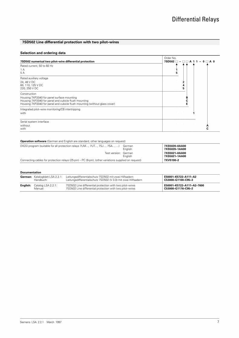
Selection and ordering data
Order No.7SD502 numerical two pilot–wire differential protection 7SD502 � – � � A 1 1 – 0 � A 0
Rated current, 50 to 60 Hz1 A5 A
15
Rated auxiliary voltage24, 48 V DC60, 110, 125 V DC220, 250 V DC
245
ConstructionHousing 7XP2040 for panel surface mountingHousing 7XP2040 for panel and cubicle flush mountingHousing 7XP2040 for panel and cubicle flush mounting (without glass cover)
BCE
Integrated pilot–wire monitoring/CB intertrippingwith
11
Serial system interfacewithoutwith
AC
Operation software (German and English are standard, other languages on request)
DIGSI program (suitable for all protection relays 7UM..., 7UT..., 7SJ..., 7SA..., ...) GermanEnglish
Test version: GermanEnglish
Connecting cables for protection relays (25-pin) – PC (9-pin); (other variations supplied on request)
7XS5020–0AA007XS5020–1AA00
7XS5021–0AA007XS5021–1AA00
7XV5100–2
Documentation
German: Katalogblatt LSA 2.2.1: Leitungsdifferentialschutz 7SD502 mit zwei HilfsadernHandbuch: Leitungsdifferentialschutz 7SD502 (V 3.0) mit zwei Hilfsadern
E50001–K5722–A111–A2C53000–G1100–C95–3
English: Catalog LSA 2.2.1: 7SD502 Line differential protection with two pilot–wiresManual: 7SD502 Line differential protection with two pilot–wires
E50001–K5722–A111–A2–7600C53000–G1176–C95–2
7SD502 Line differential protection with two pilot–wires
Differential Relays
Siemens LSA 2.2.1 . March 19978
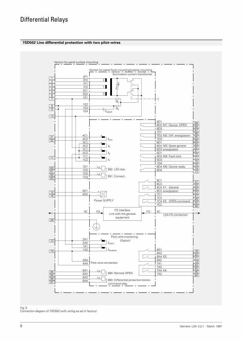
7SD502 Line differential protection with two pilot–wires
Fig. 5Connection diagram of 7SD502 (with wiring as set in factory)
Summation current transformer
56
34
12
13
3132
12
11
60616263
10
1516
87868584
26
7
89
M1: Device: OPEN
M2: Diff. energization
M3: Spare generalenergization
M4: Fault wire
K1: General energization
K2: OPEN command
K3:
K4:
LSA FO connection
M5: Device ready
6968
7574
67969594939291727170
73
182021
2224252347495048
1943454644
==
FO interfaceLink with the general
equipment
Iboo
Ib
Ia
I1
B�2: LED Ack.
B�1: Connect.
Power SUPPLY
Itrans
Ireceive
+–
Pilot–wire monitoring
U2
1
3
Cblock
B�4: Remote OPEN
B�3: Differential protection blockscommand relay
L+
L+
L+
L+
1C1
2F12F21F11F22E12E21E1
1E2
4C14C23C13C22C12C2
4D1
1D21D31D4
4D2
5C
1E4
1D1
1C2
2A12A2
6A16A26A36A4
1A21A1
4A34A4
8D18D28D37D17D27D36D16D26D35D15D25D37D48D46D4
8C18C38C48C27C17C37C47C2
8A18A38A48A27A17A37A47A2
5CFOFO
Pilot–wire connection
Rb
Ra1E3
(Option)
Version for panel flush mounting/cubicle mounting
Version for panel surface mounting
Differential Relays
Siemens LSA 2.2.1 . March 1997 9
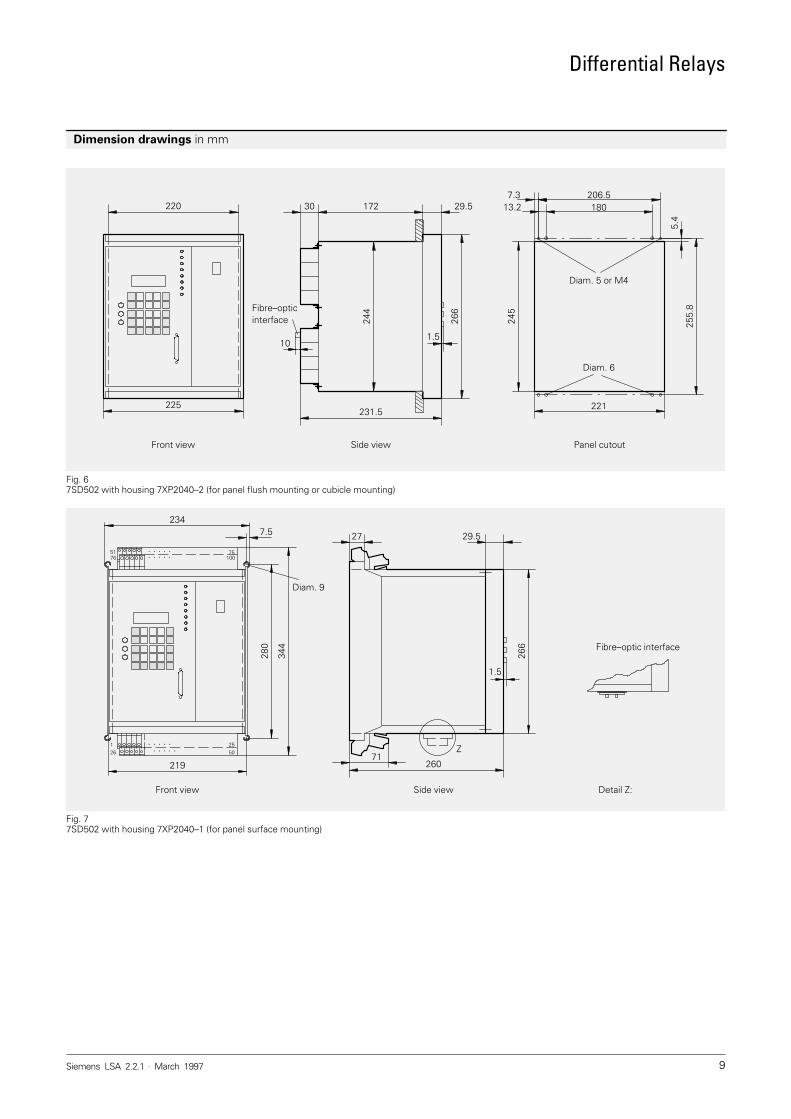
Dimension drawings in mm
Fig. 67SD502 with housing 7XP2040–2 (for panel flush mounting or cubicle mounting)
Front view Side view Panel cutout
206.5180
221
7.313.2
255.
8
245
266
231.5
30 29.5
1.5
5.4
225
220
244
172
10
Fibre–opticinterface
Diam. 5 or M4
Diam. 6
Fig. 77SD502 with housing 7XP2040–1 (for panel surface mounting)
Front view Side view
260
27 29.5
266
71Z
280
344
234
219
Fibre–optic interface
126
1.5
10051 75
5025
76
7.5
. . . . .
. . . . .
. . . . .. . . . .
Diam. 9
Detail Z:
Differential Relays
Siemens LSA 2.2.1 . March 199710
Conditions of Sale and Delivery
Subject to theGeneral Conditions of Supply and Deliveryfor Products and Services of theElectrical and Electronic Industryand to any other conditions agreed uponwith the recipients of catalogs.
�
The technical data, dimensions and weights are subject to change unlessotherwise stated on the individual pagesof this catalog.
The illustrations are for reference only.
We reserve the right to adjust the pricesand shall charge the price applying onthe date of delivery.
Export Regulations
In accordance with present provisions ofthe German Export List and the US Com-mercial Control List, export licences arenot required for the products listed in thiscatalog.
An export licence may however be requi-red due to country–specific application ofthe products.
Relevant are the criteria stated in the de-livery note and the invoice.
Subject to change without notice.
Trademarks
All product designations used are trade-marks or product names of Siemens AGor of other suppliers.
Dimensions
All dimensions in this catalog are given inmm.
Siemens online!
The Power Transmission and DistributionGroup can also be found in the Internet:
http://www.ev.siemens.de
Responsible for
Technical contents: Claus Wagner,Siemens AG, EV S V13, Nürnberg
General editing: Roland Reichel/Claudia Kühn–Sutiono,Siemens AG, EV S SUP22, Nürnberg/EV BK T, Erlangen
Conditions of Sale and Delivery � Export Regulations � Trademarks � Dimensions
A 9.91 a
Siemens Aktiengesellschaft
BereichEnergieübertragung und -verteilungGeschäftsgebiet SekundärsystemePostfach 48 06D-90026 Nürnberg
Order No.: E50001-K5722–A111-A2–7600Printed in GermanyKG K 0397 2.0 SC 10 En 321537 6101/U539
PowerTransmissionand Distribution