sensordrone specs guide - baixardoc
TRANSCRIPT

Sensorcon: Sensordrone, preliminary specifications, REV. B July, 2012
1
Sensordrone: Specifications & Tips
Summary:
This document summarizes known and planned specifications for Sensordrone. It is intended to give
developers and users insight into the capabilities of the various sensors included with the Sensordrone.
General technical specifications and practical tips are presented. After the Sensordrone is released to
the general public, finalized & more detailed specifications/datasheets and application notes for each
individual sensor will be generated & published. In the meantime, it is believed that the data in this
document will be sufficient for initiating development on the majority of sensor applications.
1. Precision Gas Sensor (CO, H2S, Alcohol, Hydrogen, others)…………………………..……….page 2
2. Oxidizing gases (Ozone, NO2, etc.)………………………………………………………………………….page 2
3. Reducing gases (methane, alcohols, other hydrocarbons, etc.)……………………………..page 2
4. Temperature…………………………………………………………………………………………………………..page 4
5. Humidity………………………………………………………………………………………………………………….page 4
6. Pressure ………………..……………………………………………………………………………………………….page 4
7. Infrared Temperature (line of sight object temperature)……………………………………….page 5
8. Proximity Capacitance…………………………………………………………………………………………….page 7
9. Red………………………………………………………………………………………………………………………….page 8
10. Green……………………………………………………………………………………………………………………..page 8
11. Blue…………………………………………………………………………………………………………………………page 8
12. Clear – Illumination…………………………………………………………………………………………………page 8
13. External hardware………………………………………………………………………………………………….page 9
14. Color LEDs………………………………………………………………………………………………………………page 9
A. Bluetooth Communications & Operating System Support……………………………………..page 10
B. Communication Modes………………………………………………………………………………………….page 10
C. Application development suggestions……………………………………………………………………page 11
D. Mechanical Outline…………………………………………………………………………………………………page 12
Sensorcon: Sensordrone, preliminary specifications, REV. B July, 2012
2
1. Precision Gas Sensor
Description:
The precision gas sensor is a professional grade electrochemical sensor (fuel cell sensor) that is very
sensitive to a variety of toxic gases, alcohol, and hydrogen. It comes pre-calibrated for Carbon
Monoxide (CO). The output from the precision gas sensor is given in ppm of CO with the following
specifications.
Resolution: 1ppm
Range: 0-2,000ppm
Accuracy: +/- 10% of reading
Response Time: 10-20 seconds to reach 90% of final signal
Sensitivity to Hydrogen & Other Gases:
Although the precision gas sensor comes pre-calibrated for CO, it will respond to a variety of gases. For
example, the sensitivity to Hydrogen is about 10-20% of CO. What this means in practice is that if the
sensor is exposed to 1,000ppm of Hydrogen, the CO output would give a reading of 100 to 200ppm.
Apps can be made for various gases such as hydrogen, breath alcohol (ethanol) and various others by
simply multiplying the CO output by a suitable sensitivity factor. A selection of sensitivity factors will be
provided in follow on data-sheets.
Power:
The precision gas sensor is a very low power sensor that is always on. Enabling the CO data stream will
have minimal influence on power consumption.
Note on CO vs. CO2: Many consumers get these confused. CO is a toxic gas normally present in the air at
<1ppm, it typically comes from combustion processes. CO2 is a non-toxic gas commonly present in the
air at 100-1,000ppm; it comes from various sources including exhaled breath.
Common Applications:
Indoor CO monitoring, parking garages, exhaust, breath monitoring, Air Quality
2 – 3: Oxidizing & Reducing Gas Sensors
Description:
The Oxidizing and Reducing gas sensors are general purpose semiconductor sensors that respond to a
broad range of gases. They are not as sensitive or accurate as the precision gas sensor, but respond to
more gases, so are particularly suitable for finding gas leaks or gas emitting sources. One sensor is
tuned to respond to oxidizing gases, a second sensor is tuned to respond to reducing gases.
What are Oxidizing & Reducing Gases?
Reducing gases give up an electron during a chemical reaction, Oxidizing gases accept an electron during
a chemical reaction. Common examples are the following:
Common Reducing Gases: Common Oxidizing Gases:
Alcohols Ozone (O3)
Natural Gas Nitrogen Dioxide (NO2)
Hydrocarbons Chlorine (Cl2)
Hydrogen (H2)
Carbon Monoxide (CO)
Volatile Organic Compounds (VOCs)

Sensorcon: Sensordrone, preliminary specifications, REV. B July, 2012
3
General Gas Sensing Implications:
The Good News!
For most consumer applications, general gas sensing is good enough. For example, you can use
the reducing gas sensor to check for a gas leak (e.g. natural gas for heating in the winter or propane for
grilling in the summer). In these applications the user knows what they’re looking for; therefore they have a pretty good idea of what gas should be there when they get a reading from the sensor.
The Bad News… (Otherwise known as technical limitations)
General gas sensing (non-selective) means that if there are 2 gases present (e.g. methane and
CO), there will be a combined response giving an artificially high reading for the reducing gas the user
believes they are measuring. If both a reducing and oxidizing gas is present, they may cancel each other
out, leading to low or no signal. In most consumer applications, this is not usually the case. Since the
general sensors respond to many gases, you will need to characterize them for your specific application
if you require high accuracy. General specifications for CO & NO2 are:
Reducing Gas Sensor: when
sensing CO
Oxidizing Gas Sensor: when
sensing NO2
Min. Detectable concentration: 5ppm 50ppb (0.050ppm)
Range: 1,000ppm 0-5ppm
Response Time: T90/ time to
reach 90% of final signal 30-60 seconds 30-90 seconds
*Note: different performance specifications will exist for other detectable gases
Power:
WARNING! Semiconductor gas sensors use a lot of power. In operation, the Reducing Gas sensor will
use ~75mW of power, and the Oxidizing gas sensor will use ~45mW of power. If left on, these can drain
the battery in a few hours. Applications that use these sensors should most likely be limited to short
durations. Therefore, developers are advised to pay careful attention to the amount of time the
Reducing or Oxidizing gas sensor data stream is enabled. A typical application would turn on the
sensors, let them warm up for 2 to 3 minutes, and then begin providing the user with data for a limited
duration. If a long term data-logging application is run, it is best to use a low duty cycle (e.g. on for 1
minute every 10+ minutes) or operate the Sensordrone while plugged into an external power source.
For better accuracy, it is recommended that the application first request the user establish an accurate
baseline in a clean environment for about 2-3 minutes, and then begin taking readings for leaks or other
applications. The Oxidizing/Reducing sensors are most suited for making measurements against a
recently established baseline, because the baseline can drift somewhat over time.
Common Applications:
Gas leak detection, general air quality, VOC detection, Chlorine or Ozone indicator (Air quality)
Support:
Sensorcon engineers will be available to give extra support for developers for any of the sensors, and we
anticipate most of the questions/requests for help will be related to the gas sensors. Over time, we will
be adding more gas sensor related software to the open software libraries & firmware to enable better
gas selectivity and identification, as well as improving automatic power management features. We are
open for suggestions for improvements/desired features going forward. For any additional support,
please email: [email protected]

Sensorcon: Sensordrone, preliminary specifications, REV. B July, 2012
4
4: Temperature Sensor
Description:
The temperature sensor is a silicon bandgap type.
Accuracy: +/- 0.5oC (+/- 1
oC near lower/upper ends of range)
Range: -20oC to + 60
oC (limit of overall system)
Response Time*: 20-60 seconds to reach 90% of final signal/change in signal
*Response time tip 1: It may take several minutes when transitioning from hot to cold environments.
The worst case will happen when Sensordrone is heated during the initial phases of charging, and then
quickly moved to a cold environment. If fast temperature measurements are required, the infrared
temperature sensor may be a better choice.
Power:
The temperature sensor is a low power device that is on most of the time. Enabling the temperature
sensor data stream will have minimal influence on power consumption.
Applications:
Indoor/outdoor temperature, greenhouses, any ambient temperature application
5: Humidity Sensor
Description:
The humidity sensor is a capacitive type sensor.
Accuracy: +/- 2%RH from 20-80%RH (+/- 4% outside this range)
Range: 0 to 100%RH
Response Time*: 10-180 seconds depending on temperature change
*Response time tip 2: %RH is calculated based on air moisture content and temperature. If the
temperature remains constant and the moisture content changes, %RH response will be fast. If both T &
moisture change dramatically (e.g. moving from indoors to outdoors during winter months in a cold
climate), it may take a several minutes for both the temperature sensor and humidity to stabilize. This is
mainly due to the short time it takes for the local moisture content to change vs. the longer time it takes
for the device temperature to stabilize per response time tip 1.
Power:
The humidity sensor is a low power device that is on most of the time. Enabling the humidity sensor
data stream will have minimal influence on power consumption.
Common Applications:
Weather monitoring, indoor air quality, greenhouse, electronics manufacturing
6: Pressure
Description:
The pressure sensor is a MEMS type pressure sensor that is used for absolute (as opposed to
differential) pressure measurements. It is most suited for measuring changes in ambient pressure.
Accuracy: +/-0.1kPa
Resolution: 1.5Pa (pressure) / 0.3m (altitude)
Range: 30 to 110 kPa
Response Time: ~1 second

Sensorcon: Sensordrone, preliminary specifications, REV. B July, 2012
5
Power:
The pressure sensor is a low power device that is on most of the time. Enabling the pressure sensor
data stream will have minimal influence on power consumption
Common Applications:
Barometry, Altitude, Air Control System, Weather Monitoring, Medical
7: Infrared Temperature (non-contact/line of sight temperature sensor)
Description
The infrared temperature sensor uses a thermopile to absorb infrared energy being emitted from an
object, and uses the corresponding voltage change to determine the temperature of the object. The
infrared temperature sensor can be used to make non-contact temperature measurements.
Accuracy: +/- 1 to 3 o
C (depending on ambient vs. measured object temp, see graph below)
+/-0.2-0.3 o
C (with suitable averaging and stable temperate)
Normal Range: -20oC to + 60
oC (-40
oC to +125
oC with increasing error)
Response Time: 1-5 seconds
Non-contact temperature measurement considerations:
Non-contact means you essentially scan an object for its temperature. To ensure a user is measuring
the object of interest and not the surrounding environment, users must ensure the object of interest is
completely filling the sensor’s responsivity field of view.
Sensorcon: Sensordrone, preliminary specifications, REV. B July, 2012
6
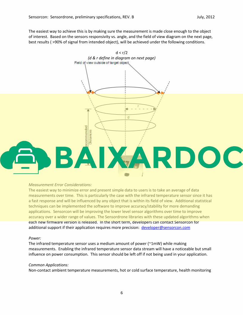
The easiest way to achieve this is by making sure the measurement is made close enough to the object
of interest. Based on the sensors responsivity vs. angle, and the field of view diagram on the next page,
best results ( >90% of signal from intended object), will be achieved under the following conditions.
d < r/2
(d & r define in diagram on next page)
Measurement Error Considerations:
The easiest way to minimize error and present simple data to users is to take an average of data
measurements over time. This is particularly the case with the infrared temperature sensor since it has
a fast response and will be influenced by any object that is within its field of view. Additional statistical
techniques can be implemented the software to improve accuracy/stability for more demanding
applications. Sensorcon will be improving the lower level sensor algorithms over time to improve
accuracy over a wider range of values. The Sensordrone libraries with these updated algorithms when
each new firmware version is released. In the short term, developers can contact Sensorcon for
additional support if their application requires more precision: [email protected]
Power:
The infrared temperature sensor uses a medium amount of power (~1mW) while making
measurements. Enabling the infrared temperature sensor data stream will have a noticeable but small
influence on power consumption. This sensor should be left off if not being used in your application.
Common Applications:
Non-contact ambient temperature measurements, hot or cold surface temperature, health monitoring
Sensorcon: Sensordrone, preliminary specifications, REV. B July, 2012
7
8: Proximity Capacitance
Description:
The proximity capacitance sensor consists of a set of electrodes located underneath the bottom cover of
the Sensordrone, and a capacitance to digital converter circuit. Any material within close proximity to
the electrodes will cause a change in the capacitance between the electrodes.
Resolution: 0.5fF (in lowest range, 12bit of full scale in all other ranges)
Range: 4 selectable ranges (0 to 0.5pF, 0 to 1pF, 0 to 2pF, 0 to 4pF)
Response time: <1 second
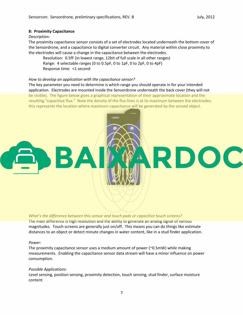
How to develop an application with the capacitance sensor?
The key parameter you need to determine is which range you should operate in for your intended
application. Electrodes are mounted inside the Sensordrone underneath the back cover (they will not
be visible). The figure below gives a graphical representation of their approximate location and the
resulting “capacitive flux.” Note the density of the flux lines is at its maximum between the electrodes; this represents the location where maximum capacitance will be generated by the sensed object.
What’s the difference between this sensor and touch pads or capacitive touch screens?
The main difference is high resolution and the ability to generate an analog signal of various
magnitudes. Touch screens are generally just on/off. This means you can do things like estimate
distances to an object or detect minute changes in water content, like in a stud finder application.
Power:
The proximity capacitance sensor uses a medium amount of power (~0.5mW) while making
measurements. Enabling the capacitance sensor data stream will have a minor influence on power
consumption.
Possible Applications:
Level sensing, position sensing, proximity detection, touch sensing, stud finder, surface moisture
content
Sensorcon: Sensordrone, preliminary specifications, REV. B July, 2012
8
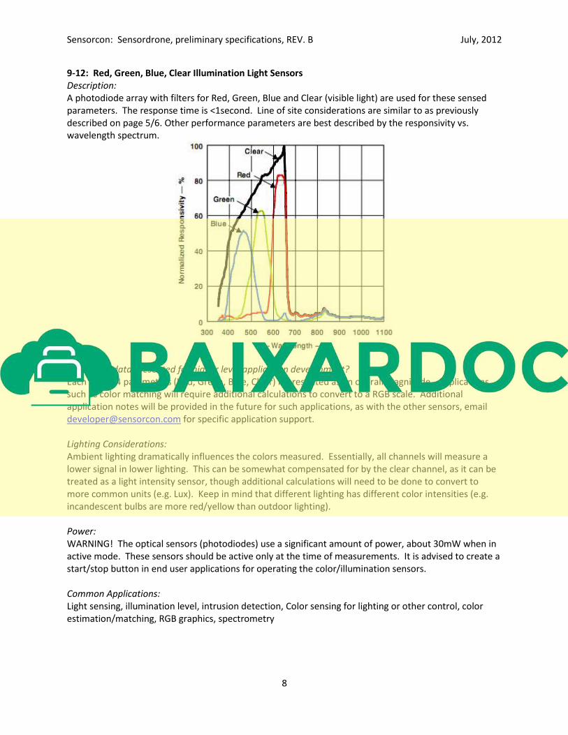
9-12: Red, Green, Blue, Clear Illumination Light Sensors
Description:
A photodiode array with filters for Red, Green, Blue and Clear (visible light) are used for these sensed
parameters. The response time is <1second. Line of site considerations are similar to as previously
described on page 5/6. Other performance parameters are best described by the responsivity vs.
wavelength spectrum.
How is the data presented for higher level application development?
Each of the 4 parameters (Red, Green, Blue, Clear) is presented as an overall magnitude. Applications
such as color matching will require additional calculations to convert to a RGB scale. Additional
application notes will be provided in the future for such applications, as with the other sensors, email
[email protected] for specific application support.
Lighting Considerations:
Ambient lighting dramatically influences the colors measured. Essentially, all channels will measure a
lower signal in lower lighting. This can be somewhat compensated for by the clear channel, as it can be
treated as a light intensity sensor, though additional calculations will need to be done to convert to
more common units (e.g. Lux). Keep in mind that different lighting has different color intensities (e.g.
incandescent bulbs are more red/yellow than outdoor lighting).
Power:
WARNING! The optical sensors (photodiodes) use a significant amount of power, about 30mW when in
active mode. These sensors should be active only at the time of measurements. It is advised to create a
start/stop button in end user applications for operating the color/illumination sensors.
Common Applications:
Light sensing, illumination level, intrusion detection, Color sensing for lighting or other control, color
estimation/matching, RGB graphics, spectrometry

Sensorcon: Sensordrone, preliminary specifications, REV. B July, 2012
9
13: External Hardware
Description:
The Sensordrone supports communication with external hardware (such as other sensors or any other
peripheral that can communicate via the supported protocols). Connection is made via a standard 0.1” (2.54mm) pitch 5 pin receptacle. For development purposes, this should allow direct connection with a
5 pin header into a standard breadboard. The developer must set the external data stream on and
select which communication protocol their external hardware is using, as well as the sampling rate and
Bluetooth transmission frequency. Raw digital data is then provided from the Sensordrone to the
Android interface for application level processing. The pin-out description is below:
Pinout:
1 GND
2 ADC
3 RX/SCL
4 TX/SDA
5 Vcc: 3.3V
**IMPORTANT NOTE:
PINOUT IS SUBJECT TO CHANGE IN PRODUCTION, CONTACT SENSORCON BEFORE DEVELOPING ANY
PERIPHERALS
1. GND: Pin 1 is connected to the Sensordrone’s local ground (0V).
2. ADC: Pin 2 supports analog inputs from 0V (local ground) to 3.3V (local power). The analog voltage is
fed into a 12 bit A/D. Digitized data is sampled at a rate determined by the application, and then
transmitted to the Android application layer at a developer/user defined rate.
3. RX/SCL: The Sensordrone currently supports 2 digital communication standards: RS-232, and I2C. If
RS-232 is used, pin 3 serves as the Receive data line (RX). If I2C is used, pin 3 serves as the clock line
(SCL). The Android application must identify which communication protocol is being used.
4. TX/SDA: If RS-232 is used, pin 2 is the Transmit data line (TX). If I2C, pin 4 is the data line (SDA).
5. Vcc: Regulated 3.3V DC.
14: Color LEDs
2 programmable LEDs are on the Sensordrone. They can be individually adjusted for color based on Red,
Green, & Blue color intensities.

Sensorcon: Sensordrone, preliminary specifications, REV. B July, 2012
10
A. Bluetooth Communications & Operating System Support
Bluetooth
Sensordrone will support Bluetooth 2.1 and Bluetooth 4.0 wireless communication protocols. Beta
versions will have hardware that supports Bluetooth 2.1 only. Production versions will have dual mode
transceivers that support both 2.1 & 4.0.
USB
Initially, Sensordrone will use USB for charging only. In the future, likely with Firmware version Lithium,
USB communications will be supported.
Firmware
Sensordrone’s firmware and lower level support software will be released in versions corresponding to the periodic table. Beta devices will ship with Hydrogen, and support limited upgrades. Production
devices will ship with Helium, and be field upgradeable. Lithium and follow on versions will be
announced at later dates.
Android
Sensordrone will initially ship with support for Android 2.2 (Froyo) and later using Bluetooth 2.1.
Software for Android devices using Bluetooth 4.0 will be available shortly after initial shipments begin
for 2.1 (~1-2 months). An API for Android developers will be available when Beta devices ship. This API
will continuously be updated.
iOS
Sensordrone will support iOS devices using Bluetooth 4.0 only. iOS support is estimated to be available
~2 months after initial shipments supporting Android. An API for iOS will be available when iOS support
starts. This API will continuously be updated.
Windows, Blackberry, Linux
There are plans to support Windows, Blackberry, and Linux devices, but launch dates are currently TBD.
B. Communication Modes
Sensordrone will support 3 modes of communication, which will be easily configured in the API.
1. Call Response Mode: In this mode, data is transmitted only when the App calls it. (Available
with Hydrogen and later)
2. Streaming Mode: Data is sent on continuously at a predefined sample rate (Helium & later)
3. Data Logging Mode: Sensordrone stores data in memory at a predefined sample rate, and data
is later downloaded by mobile device (Helium/Lithium & later). Sensordrone has 1Mb of on-
board memory available for recording sensor data.
3a: Sensordrone Logic: Programmable logic in Sensordrone’s firmware will be supported with Lithium
and later releases. This will enable LED indicator/intelligent sensing & logging algorithms on
Sensordrone without the need for a continuous connection.