selectivity, cascading and coordination guide - explore
TRANSCRIPT
Selectivity, Cascading and Coordination GuideGuide 2021Complementary Technical Information
se.com

CO2 and P&L impact through… Resource PerformanceGreen Premium brings improved resource efficiency throughout an asset’s lifecycle. This includes efficient use of energy and natural resources, along with the minimization of CO2 emissions.
Cost of ownership optimization through… Circular PerformanceWe’re helping our customers optimize the total cost of ownership of their assets. To do this, we provide IoT-enabled solutions, as well as upgrade, repair, retrofit, and remanufacture services.
Peace of mind through… Well-being PerformanceGreen Premium products are RoHS and REACh compliant. We’re going beyond regulatory compliance with step-by-step substitution of certain materials and substances from our products.
Improved sales through… DifferentiationGreen Premium delivers strong value propositions through third-party labels and services. By collaborating with third-party organizations we can support our customers in meeting their sustainability goals such as green building certifications.
The Green Premium program stands for our commitment to deliver customer valued sustainable performance. It has been upgraded with recognized environmental claims and extended to cover all offers including Products, Services and Solutions.
Discover what we mean by greenCheck your products!
An industry leading portfolio of offers delivering sustainable value
Green PremiumTM
More than 75% of our product sales offer superior transparency on the material content, regulatory information and environmental impact of our products:
• RoHS compliance• REACh substance information• Industry leading # of PEP’s*• Circularity instructions
*PEP: Product Environmental Profile (i.e. Environmental Product Declaration)
1
Gen
eral
Intr
oduc
tion
Design and selection of equipment for low voltage electrical installations requires to consider and check the behavior of all devices on the current path in fault situation. High short-circuit current can damage equipment by electrodynamical and thermal effects. Each device can individually withstand the worst effects, but it may require significant oversizing and, on occasion, may be impossible. So the protection of each devices or equipment relies on upstream over-current protective device. In that case the proper “coordination” between the two devices shall be checked.
Lower amplitude faults such as overloads or some earth faults can also create disturbances by causing trips and power interruptions for larger sections of the installation than expected.
European Harmonization document HD60364-5-53 2015 for Low voltage electrical installation provides the following definition of coordination of electrical equipment: 530.3.5 Co-ordination of electrical equipment: correct way of selecting electrical devices in series to ensure safety and continuity of service of the installation taking into account short-circuit protection and/or overload protection and/or selectivity
Schneider Electric provides "co-ordination" performances for two or three low voltage devices in the following cases:
Coordination related to continuity of service b Selectivity (also called discrimination) b Selectivity enhanced by cascading b Motor starter coordination type 2 b Circuit-breaker and LV/LV transformers
Coordination related to safety b Cascading (also called group short-circuit protection, or back up protection) b Motor starter coordination type 1 b Coordination between switch-disconnector and circuit breaker or fuses b Coordination between circuit breaker and busbar trunking (busway) system
For coordination of Surge protection device with upstream overcurrent protection see our Design guide:
https://download.schneider-electric.com/files?p_Doc_Ref=CA903014E
2
The information provided in this Guide contains general co-ordination performances for a selection of low voltage devices of Schneider Electric.
This document is not intended as a substitute for and is not to be used for determining suitability or reliability of these devices for specific user applications. It is the duty of any such user or integrator to perform the appropriate and complete risk analysis, evaluation and testing of the devices with respect to the relevant specific application or use thereof. Schneider Electric reserves the right to make changes or updates with respect to or in the content of the publication or the format thereof at any time without notice.
To the extent permitted by applicable law, no responsibility or liability is assumed by Schneider Electric and its subsidiaries for any errors or omissions in the informational content of this document.
In no case shall Schneider Electric, or any parent, affiliate or subsidiary company of Schneider Electric or their respective officers, directors, or employees be liable for any direct, indirect, consequential, punitive, special, or incidental damages (including, without limitation, damages for loss of business, contract, revenue, data, information or business interruption) resulting from, arising out, or in connection with the use of, or inability to use this document or its content, even if Schneider Electric has been expressly informed of the possibility of such damages.
3
A
B
C
D
E
Selectivity, Cascading and Coordination Guide
Coordination for electrical distribution
Coordination for motor circuits
Use of LV switches
Protection of LV/LV transformers and capacitors
Coordination with electrical busbar trunking
Gen
eral
Con
tent
Link for downloading this guide
www.se.com
4
Coordination for electrical distribution A-2
Coordination between circuit breakers ...........................A-2
Selectivity table .....................................................................A-17220-240/380-415 V AC ...................................................................A-17Ue y 440 V AC ................................................................................A-71Ue: 24-48-60 V DC .......................................................................A-110Ue: 110-125 V DC ........................................................................A-125Ue: 220-250 V DC ........................................................................A-135
Selectivity with fuses - Introduction ..............................A-143
Selectivity tables with fuses ............................................A-148
Cascading (or Back-up protection, or Combined short-circuit protection) ..............................A-159
Cascading tables ................................................................A-162Ue: 380-415 V AC (Ph/N 220-240 V AC) ....................................................................A-164Ue: 440 V AC ...............................................................................A-168Ue: 220-240 V AC .........................................................................A-172
Selectivity enhanced by cascading .............................A-176Ue: 380-415 V AC (Ph/N 220-240 V AC) ......................................A-177Ue: 440 V AC ................................................................................A-183Ue: 220-240 V AC (Ph/N 110-130 V AC) ......................................A-189
Coordination for motor circuits B-1
Motor protection selectivity ..................................................B-1
Motor protection cascading ..............................................B-19
Selectivity enhanced by cascading ...............................B-22
Motor protection coordination ..........................................B-27
Type 2 coordination (IEC 60947-4-1) ............................B-36Ue: 220-240 V AC ...........................................................................B-36Ue: 380-400 V AC ...........................................................................B-38Ue: 415 V AC ..................................................................................B-41Ue: 440 V AC ..................................................................................B-44Ue: 690 V AC ..................................................................................B-47
Type 1 coordination (IEC 60947-4-1) .............................B-52
Selectivity, Cascading and Coordination Guide
www.se.com
5
Selectivity, Cascading and Coordination Guide
Type 1 coordination (IEC 60947-4-1) for AC1 Utilisation category: non-inductive or slightly inductive loads .......................................................................B-60
Protection of motor circuits with fuses: introduction .............................................................................B-61
Type 2 coordination (IEC 60947-4-1) .............................B-64Ue: 380-415 V AC ...........................................................................B-64Ue: 660-690 V AC ...........................................................................B-66
Use of LV switches C-1
Use of LV switches ................................................................. C-1
Choosing a Schneider Electric switch-disconnector . C-4
Switch-disconnector - Circuit breaker coordination .. C-8
Switch-disconnector - Fuse coordination ....................C-35
Protection of LV/LV transformers and capacitors D-2
Protection of LV/LV transformers and capacitors ....... D-2
Coordination with electrical busbar trunking E-2
Coordination tables between circuit breaker and Canalis electrical busbar trunking ............................E-2Ue: 220 or 240 V AC Ph/N ................................................................ E-4Ue: 380-415 V AC ............................................................................. E-5Ue: 660-690 V AC ........................................................................... E-13
Selectivity, Cascading and Coordination Guide www.se.com
Coordination between circuit breakersIntroduction to selectivity
Selectivity (Discrimination)Selectivity is achieved by overcurrent and earth fault protective devices if a fault condition, occurring at any point in the installation, is cleared by the protective device located immediately upstream of the fault, while all the other protective devices remain unaffected.
Selectivity is required for installation supplying critical loads where one fault on one circuit shall not cause the interruption of the supply of other circuits. In the IEC 60364 series it is mandatory for installation supplying safety services (IEC60364-5-56 2009 560.7.4). Selectivity may also be required by some local regulations or for some special applications like:
b Medical location b Marine b High-rise building.
Selectivity is highly recommended when power availability and reliability is critical due to the nature of the loads such as:
b Data centers b Infrastructure (tunnel, airport…) b Critical processes.
From installation point of view: selectivity is achieved when the maximum short-circuit current at a point of installation is below selectivity limit of the circuit breakers supplying this point of installation. Selectivity shall be checked for all circuits supplied by one source and for all types of fault:
b Overload b Short-circuit b Earth fault.
When system can be supplied by different sources (Grid or Generator Set for instance) selectivity shall be checked in both cases.
According to the IEC 60364-5-53:535 2019 standard, selectivity between two circuit breakers can be:
b Partial: up to a specified value according to circuit breakers characteristics (Is) b Full: up to the maximum prospective short-circuit current (Isc_max) on the load
side of the downstream circuit breaker b Total: up to the breaking capacity (Icu or Icn) of the downstream circuit breaker b Enhanced: up to a value higher than the breaking capacity of the downstream
circuit breaker when cascading is applied (See page A-176).
In an electrical installation, selectivity performance depends on the two circuit breakers characteristics and on the installation's maximum short-circuit current on the load side. The table below summarizes the different situations:
Selectivity characteristics of two circuit breakers
Short-circuit current on the load side versus the selectivity limit Is of the two circuit breakers
Selectivity consequence for the electrical installation
Without cascading
Partial Is y Isc_max < Icu (or Icn) "Partial" (Example 1a)
Isc_max < Is < Icu (or Icn) "Full" (Example 1b)
Total Isc_max y Is = Icu (or Icn) "Total" (Example 2)
With cascading
Partial Is < Icu < Isc_max Partial (up to Is)
Total Is = Icu < Isc_max Partial (up to Icu but < Isc_max)
Enhanced Icu < Isc_max y Is_enhanced Enhanced selectivity (up to Is_enhanced) (Example 3)
Selectivity in a given installation according to circuit breakers selectivity performance without or with cascading (or back-up or combined short-circuit protection).
DB4
3071
7.ep
s
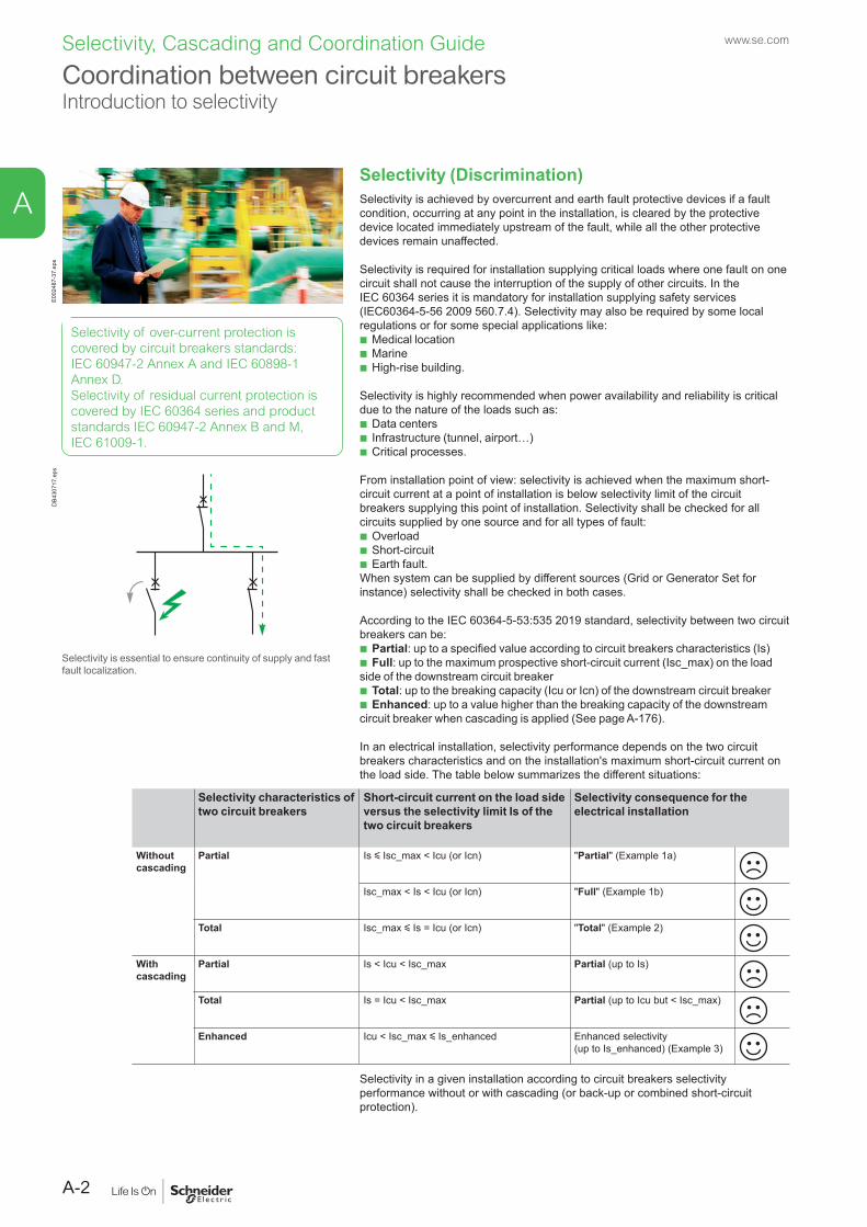
Selectivity is essential to ensure continuity of supply and fast fault localization.
E002
487-
37.e
ps
Selectivity of over-current protection is covered by circuit breakers standards: IEC 60947-2 Annex A and IEC 60898-1 Annex D.Selectivity of residual current protection is covered by IEC 60364 series and product standards IEC 60947-2 Annex B and M, IEC 61009-1.
A-2
A
Selectivity, Cascading and Coordination Guide www.se.com
Coordination between circuit breakersIntroduction to selectivity
Practical examples : b Example 1: ComPact NSX100F (Icu = 36 kA 400 V AC) TMD 100 A & iC60N C
32 A (Icu = 10 kA 400 V AC). Selectivity limit Is = 1 kA (See table page A-77)
v 1a: In a given circuit of an electrical installation where the maximum short-circuit current (Isc_max) downstream iC60N C 32 A is 5 kA the selectivity will be "partial".
v 1b: In a given circuit of an electrical installation where the maximum short-circuit current (Isc_max) downstream iC60N C 32 A is 0.8 kA the selectivity will be "Full".
b Example 2: ComPact NSX100F (36 kA 400 V AC) MicroLogic 2.2 100 A & iC60N (10 kA 400 V AC) C 32 A. Total selectivity (See table page A-76)
v In a given circuit of an electrical installation where the maximum short-circuit current (Isc_max) downstream iC60N C 32 A is y 10 kA the selectivity will be "Total".
b Example 3: ComPact NSX100F (36 kA 400 V AC) Micrologic 100A & iC60N (10 kA 400 V AC) C 32 A. Enhanced selectivity limit = 20 kA, Enhanced breaking capacity Icomb = 20 kA ("20/20" in table page A-76)
v In a given circuit of an electrical installation where the maximum short-circuit current (Isc_max) downstream iC60N C 32 A is 10 kA < Isc_max y 20 kA the selectivity will be "Enhanced".
Icu : breaking capacity of circuit-breaker according to IEC/EN 60947 seriesIcn : breaking capacity of circuit-breaker according to IEC/EN 60898 or IEC/EN 61009 series
Principles of SelectivityDifferent principles are involved to achieve selectivity based on:
b Current b Time b Energy b Logic.
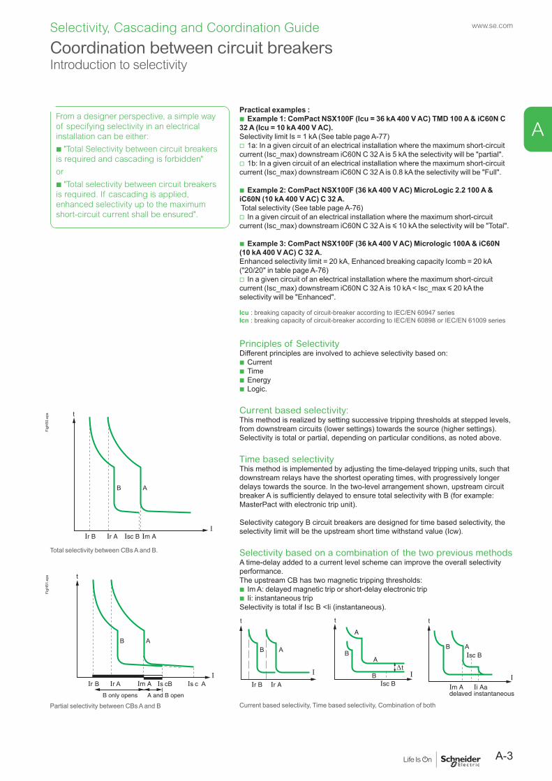
Current based selectivity:This method is realized by setting successive tripping thresholds at stepped levels, from downstream circuits (lower settings) towards the source (higher settings). Selectivity is total or partial, depending on particular conditions, as noted above.
Time based selectivityThis method is implemented by adjusting the time-delayed tripping units, such that downstream relays have the shortest operating times, with progressively longer delays towards the source. In the two-level arrangement shown, upstream circuit breaker A is sufficiently delayed to ensure total selectivity with B (for example: MasterPact with electronic trip unit).
Selectivity category B circuit breakers are designed for time based selectivity, the selectivity limit will be the upstream short time withstand value (Icw).
Selectivity based on a combination of the two previous methodsA time-delay added to a current level scheme can improve the overall selectivity performance.The upstream CB has two magnetic tripping thresholds:
b Im A: delayed magnetic trip or short-delay electronic trip b Ii: instantaneous trip
Selectivity is total if Isc B <Ii (instantaneous).
Ir B Ir A
B A
I
t
I
t
Isc B
A
BA
B∆t
t
IIm Adelayed
Isc BB A
Ii Aainstantaneous
Current based selectivity, Time based selectivity, Combination of both
t
Im A Ir A Ir B
B A
Isc B I
FigH
50.e
ps
Total selectivity between CBs A and B.
t
Im A Is c BIr AIr B
B A
Is c A
I
A and B openB only opens
FigH
51.e
ps
Partial selectivity between CBs A and B
From a designer perspective, a simple way of specifying selectivity in an electricalinstallation can be either:
b "Total Selectivity between circuit breakers is required and cascading is forbidden"
or
b "Total selectivity between circuit breakers is required. If cascading is applied, enhanced selectivity up to the maximum short-circuit current shall be ensured".
A-3
A
Selectivity, Cascading and Coordination Guide www.se.com
Coordination between circuit breakersIntroduction to selectivity
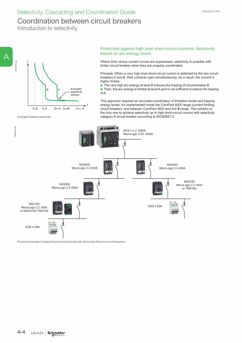
Protection against high level short-circuit currents: Selectivity based on arc-energy levels
Where time versus current curves are superposed, selectivity is possible with limiter circuit breaker when they are properly coordinated.
Principle: When a very high level short-circuit current is detected by the two circuit breakers A and B, their contacts open simultaneously. As a result, the current is highly limited.
b The very high arc-energy at level B induces the tripping of circuit breaker B b Then, the arc-energy is limited at level A and is not sufficient to induce the tripping
of A.
This approach requires an accurate coordination of limitation levels and tripping energy levels. It’s implemented inside the ComPact NSX range (current limiting circuit breaker), and between ComPact NSX and Acti 9 range. This solution is the only one to achieve selectivity up to high short-circuit current with selectivity category A circuit breaker according to IEC60947-2.
DB4
3072
2.ep
s
MTZ1 or 2 1000AMicroLogic 2.0X 1000A
NSX630MicroLogic 2.3 630A
NSX250MicroLogic 2.2 250A
NSX100 MicroLogic 2.2 100A
or NSXm160 TMD100
iC60 y 40A
iC60 y 63A
NSX400MicroLogic 2.3 400A
NSX160MicroLogic 2.2 160A
or TMD160
Practical example of selectivity at several levels with Schneider Electric circuit breakers
t
Im A Is cBIr AIr B
B A
Is c A
I
Energeticselectivitydomain
DB4
3072
1.ep
s
Energetic based selectivity.
A-4
A
Selectivity, Cascading and Coordination Guide www.se.com
Coordination between circuit breakersIntroduction to selectivity
Selectivity enhanced by cascadingCascading between 2 devices is normally achieved by using the tripping of the upstream circuit breaker A to help the downstream circuit breaker B to break the current. By principle cascading is in contradiction with selectivity. But the energy selectivity technology implemented in ComPact NSX circuit breakers allows to improve the breaking capacity of downstream circuit breakers and to keep a high selectivity performance at the same time.The principle is as follows:
b The downstream limiting circuit breaker B sees a very high short-circuit current.The tripping is very fast (<1 ms) and then, the current is limited.
b The upstream circuit breaker A sees a limited short-circuit current compared to its breaking capability, but this current induces a repulsion of the contacts. As a result, the arcing voltage increases the current limitation. However, the arc energy is not high enough to induce the tripping of the circuit breaker. So, the circuit breaker A helps the circuit breaker B to limit and break the short-circuit current, without tripping itself. The selectivity limit can be higher than Icu B and the selectivity becomes total with a reduced cost of the devices.
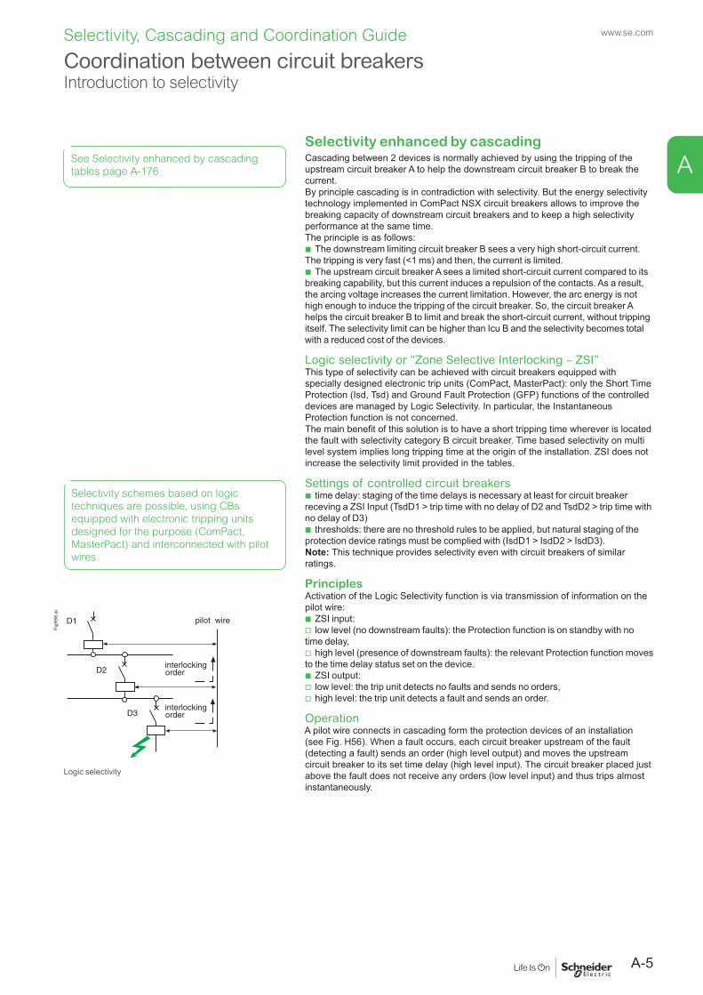
Logic selectivity or “Zone Selective Interlocking – ZSI”This type of selectivity can be achieved with circuit breakers equipped with specially designed electronic trip units (ComPact, MasterPact): only the Short Time Protection (Isd, Tsd) and Ground Fault Protection (GFP) functions of the controlled devices are managed by Logic Selectivity. In particular, the Instantaneous Protection function is not concerned.The main benefit of this solution is to have a short tripping time wherever is located the fault with selectivity category B circuit breaker. Time based selectivity on multi level system implies long tripping time at the origin of the installation. ZSI does not increase the selectivity limit provided in the tables.
Settings of controlled circuit breakers b time delay: staging of the time delays is necessary at least for circuit breaker
receving a ZSI Input (TsdD1 > trip time with no delay of D2 and TsdD2 > trip time with no delay of D3)
b thresholds: there are no threshold rules to be applied, but natural staging of the protection device ratings must be complied with (IsdD1 > IsdD2 > IsdD3).Note: This technique provides selectivity even with circuit breakers of similar ratings.
PrinciplesActivation of the Logic Selectivity function is via transmission of information on the pilot wire:
b ZSI input: v low level (no downstream faults): the Protection function is on standby with no
time delay, v high level (presence of downstream faults): the relevant Protection function moves
to the time delay status set on the device. b ZSI output: v low level: the trip unit detects no faults and sends no orders, v high level: the trip unit detects a fault and sends an order.
OperationA pilot wire connects in cascading form the protection devices of an installation (see Fig. H56). When a fault occurs, each circuit breaker upstream of the fault (detecting a fault) sends an order (high level output) and moves the upstream circuit breaker to its set time delay (high level input). The circuit breaker placed just above the fault does not receive any orders (low level input) and thus trips almost instantaneously.
Selectivity schemes based on logic techniques are possible, using CBs equipped with electronic tripping units designed for the purpose (ComPact, MasterPact) and interconnected with pilot wires
pilot wire
interlockingorder
interlockingorder
D1
D2
D3
FigH
56.a
i
Logic selectivity
See Selectivity enhanced by cascading tables page A-176
A-5
A
Selectivity, Cascading and Coordination Guide www.se.com
Coordination between circuit breakersIntroduction to selectivity
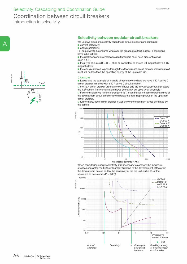
Selectivity between modular circuit breakersWe use two types of selectivity when these circuit breakers are combined:
b current selectivity, b energy selectivity.
For selectivity to be ensured whatever the prospective fault current, 3 conditions have to be fulfilled:
b the upstream and downstream circuit breakers must have different ratings (ratio > 1.3),
b their type of curve (B,C,D ...) shall be consistent to ensure D1 magnetic level > D2 magnetic level,
b the energy allowed to pass through the downstream circuit breaker when it cuts off must still be less than the operating energy of the upstream trip.
Example b Let us take the example of a single phase network where we have a 32 A curve D
circuit breaker in series with a 10 A curve D circuit breaker: v the 32 A circuit breaker protects the 62 cables and the 10 A circuit breaker protects
the 1.52 cables. This combination allows selectivity, but up to what threshold? v if current selectivity is considered (t = f (Ip)) it can be seen that the tripping curve of
the downstream circuit breaker is well below the non-tripping curve of the upstream circuit breaker,
v furthermore, each circuit breaker is well below the maximum stress permitted by the cables.
0,1
1
10
100
1000
10000
11 0 100 1000 10000
Prospective current (kA rms)
Cable 62
MCB 32 ACable 1.52
MCB 10 A
t (s)
DB4
0351
0.ep
s
When considering energy selectivity, it is necessary to compare the maximum stresses characterized by the integrals I2t relative to the development of the arc in the downstream device and by the sensitivity of the trip unit, still in I2t, of the upstream device (curves I2t = f (Ip)).
100
1000
10000
100000
1000000
10000000
0.001 0.01 0.1 1 10 100
10 ms
Cable 62
MCB 32 ACable 1.52
MCB 10 A
Prospective current (kA rms)
Normal operation
Selectivity Is Opening of both circuit breakers
Breaking capacity of the downstream circuit breaker
I fault
Lim
ited
ener
gy (A
2 s)
DB4
0351
2.ep
s
32 A
10 A
6 mm2
1.5
mm
2
D1
D2
DB4
2120
3.ep
s
A-6
A
Selectivity, Cascading and Coordination Guide www.se.com
Coordination between circuit breakersIntroduction to selectivity
Selectivity between ComPact NSX upstream and modular circuit breakers downstreamComPact NSX circuit breakers have been designed to provide total selectivity with Acti9 range.
b Total selectivity between ComPact NSX 100 A with electronic trip unit and Acti9 circuit breaker up to 40 A.
b Total selectivity between ComPact NSX u 160 A with TMD trip unit u 125 A or electronic trip unit and Acti9 up to 63 A.
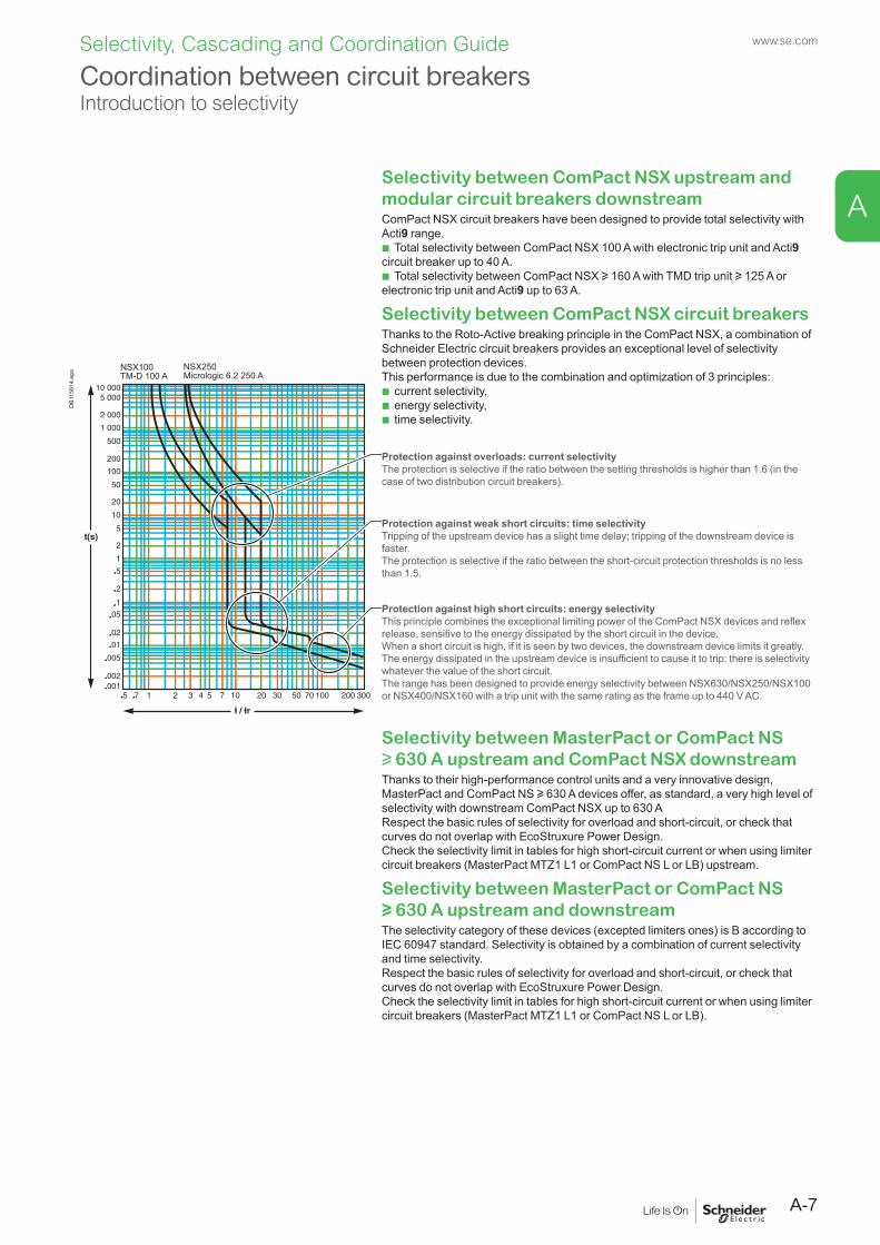
Selectivity between ComPact NSX circuit breakersThanks to the Roto-Active breaking principle in the ComPact NSX, a combination of Schneider Electric circuit breakers provides an exceptional level of selectivity between protection devices.This performance is due to the combination and optimization of 3 principles:
b current selectivity, b energy selectivity, b time selectivity.
DB1
1581
4.ep
s
Protection against overloads: current selectivityThe protection is selective if the ratio between the setting thresholds is higher than 1.6 (in the case of two distribution circuit breakers).
Protection against weak short circuits: time selectivityTripping of the upstream device has a slight time delay; tripping of the downstream device is faster.The protection is selective if the ratio between the short-circuit protection thresholds is no less than 1.5.
Protection against high short circuits: energy selectivityThis principle combines the exceptional limiting power of the ComPact NSX devices and reflex release, sensitive to the energy dissipated by the short circuit in the device.When a short circuit is high, if it is seen by two devices, the downstream device limits it greatly.The energy dissipated in the upstream device is insufficient to cause it to trip: there is selectivity whatever the value of the short circuit.The range has been designed to provide energy selectivity between NSX630/NSX250/NSX100 or NSX400/NSX160 with a trip unit with the same rating as the frame up to 440 V AC.
Selectivity between MasterPact or ComPact NS u 630 A upstream and ComPact NSX downstreamThanks to their high-performance control units and a very innovative design,MasterPact and ComPact NS u 630 A devices offer, as standard, a very high level of selectivity with downstream ComPact NSX up to 630 A Respect the basic rules of selectivity for overload and short-circuit, or check that curves do not overlap with EcoStruxure Power Design.Check the selectivity limit in tables for high short-circuit current or when using limiter circuit breakers (MasterPact MTZ1 L1 or ComPact NS L or LB) upstream.
Selectivity between MasterPact or ComPact NS u 630 A upstream and downstreamThe selectivity category of these devices (excepted limiters ones) is B according to IEC 60947 standard. Selectivity is obtained by a combination of current selectivity and time selectivity.Respect the basic rules of selectivity for overload and short-circuit, or check that curves do not overlap with EcoStruxure Power Design.Check the selectivity limit in tables for high short-circuit current or when using limiter circuit breakers (MasterPact MTZ1 L1 or ComPact NS L or LB).
A-7
A
Selectivity, Cascading and Coordination Guide www.se.com
Coordination between circuit breakersIntroduction to selectivity
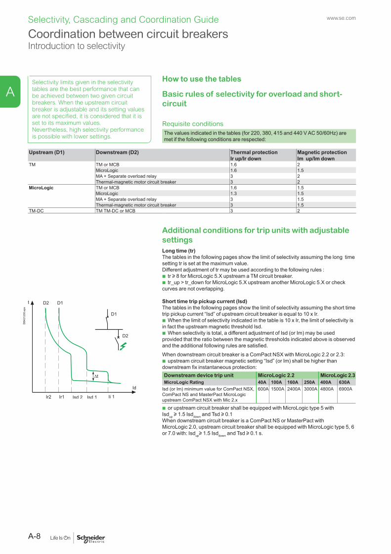
Additional conditions for trip units with adjustable settingsLong time (tr)The tables in the following pages show the limit of selectivity assuming the long time setting tr is set at the maximum value.Different adjustment of tr may be used according to the following rules :
b tr u 8 for MicroLogic 5.X upstream a TM circuit breaker. b tr_up > tr_down for MicroLogic 5.X upstream another MicroLogic 5.X or check
curves are not overlapping.
Short time trip pickup current (Isd)The tables in the following pages show the limit of selectivity assuming the short time trip pickup current “Isd” of upstream circuit breaker is equal to 10 x Ir.
b When the limit of selectivity indicated in the table is 10 x Ir, the limit of selectivity is in fact the upstream magnetic threshold Isd.
b When selectivity is total, a different adjustment of Isd (or Im) may be used provided that the ratio between the magnetic thresholds indicated above is observed and the additional following rules are satisfied.When downstream circuit breaker is a ComPact NSX with MicroLogic 2.2 or 2.3:
b upstream circuit breaker magnetic setting “Isd” (or Im) shall be higher than downstream fix instantaneous protection:Downstream device trip unit MicroLogic 2.2 MicroLogic 2.3MicroLogic Rating 40A 100A 160A 250A 400A 630A
Isd (or Im) minimum value for ComPact NSX, ComPact NS and MasterPact MicroLogic upstream ComPact NSX with Mic 2.x
600A 1500A 2400A 3000A 4800A 6900A
b or upstream circuit breaker shall be equipped with MicroLogic type 5 with Isdup u 1.5 Isddown and Tsd u 0.1When downstream circuit breaker is a ComPact NS or MasterPact with MicroLogic 2.0, upstream circuit breaker shall be equipped with MicroLogic type 5, 6 or 7.0 with: Isdupu 1.5 Isddown and Tsd u 0.1 s.
DB4
2120
0.ep
s
Selectivity limits given in the selectivity tables are the best performance that can be achieved between two given circuit breakers. When the upstream circuit breaker is adjustable and its setting values are not specified, it is considered that it is set to its maximum values. Nevertheless, high selectivity performance is possible with lower settings.
How to use the tables
Basic rules of selectivity for overload and short-circuit
Requisite conditions The values indicated in the tables (for 220, 380, 415 and 440 V AC 50/60Hz) are met if the following conditions are respected:
Upstream (D1) Downstream (D2) Thermal protection Ir up/Ir down
Magnetic protection Im up/Im down
TM TM or MCB 1.6 2MicroLogic 1.6 1.5MA + Separate overload relay 3 2Thermal-magnetic motor circuit breaker 3 2
MicroLogic TM or MCB 1.6 1.5MicroLogic 1.3 1.5MA + Separate overload relay 3 1.5Thermal-magnetic motor circuit breaker 3 1.5
TM-DC TM TM-DC or MCB 3 2
A-8
A
Selectivity, Cascading and Coordination Guide www.se.com
Instantaneous trip pickup current (Ii)The selectivity tables show the limit of selectivity assuming the instantaneous trip pickup current is set to its maximum value or it is inhibited (category B circuit breaker only).
b When the limit of selectivity indicated in the table is 15 x In of the upstream device, the limit of selectivity is in fact the instantaneous trip pickup current of the upstream device.
b When selectivity is total (“T”), a different adjustment of Ii may be used provided that the ratio between the magnetic thresholds indicated above is observed and the additional following rules are applied:
Downstream device trip unit: MicroLogic 2/4/5/6/7 .2 MicroLogic 2/4/5/6/7.3
MicroLogic Rating 40 A 100 A 160 A 250 A 400 A 630 AIi minimum value for ComPact NSX, ComPact NS and MasterPact MicroLogic upstream ComPact NSX
2000 A 2250 A 2500 A 4000 A 6300 A 8000 A
Short time tripping delay (Tsd)When the upstream and downstream circuit breakers are fitted with a MicroLogic 5.x,6.x, 7.x trip unit, the minimum non-tripping time of the upstream device must be superior to the maximum tripping time of the downstream device. This is obtained by staging Tsd: Tsd D1 > Tsd D2 (One band) & I2t OffThe tables show the limit of selectivity assuming function I2t OFF. If this is not thecase, the user must verify that the curves do not overlap.
Ground Fault Protection (GFP) (Ig, Tg)When the upstream and downstream circuit breakers are fitted with a MicroLogic 6.x trip unit, the user must verify current and time selectivity:
b The setting of the tripping threshold of the upstream GFP is greater than that of the downstream GFP.
b The intentional time-delay setting for the upstream GFP is higher than the opening time of the downstream protection device. Furthermore, it is essential that the intentional time-delay applied to the upstream protection device observes the maximum insulation fault elimination time defined by NEC § 230.95 (i.e. 1 s for 3000 A).Ig D1 u 1,3 Ig D2 & Tg D1 > Tg D2 (One band).
Circuit breaker with under-rated protection (MicroLogic trip unit with a lower rating than the frame)ComPact NSX, MasterPact may be equipped with a MicroLogic with a rating lower than the frame (e.g. NSX250N MicroLogic 2.2 160 A).
Except when indicated differently, tables are given for a circuit breaker and a trip unit with the same rated current (e.g. NSX250N MicroLogic 2.2 250 A).
Performance of different configurations can be obtained, when not given in the tables with the following rules:
b For upstream circuit breaker: the column based on the MicroLogic trip unit rating shall be considered
b For downstream circuit breaker: the line based on the circuit breaker frame shall be considered.
Example b Upstream: ComPact NSX630F MicroLogic 2.3 400A b Downstream: ComPact NXS250N MicroLogic 2.2 160A.
Selectivity limit will be equal to NSX400F MicroLogic 400/NSX250N MicroLogic 250 Ir = 160 A.So 4,8 kA according to table page A-79.
Coordination between circuit breakersIntroduction to selectivity
Masterpact MTZ with Micrologic X control unit offers two options for instantaneous trip: "Standard" and Fast". Selectivity tables are provided with "Standard" setting.
See Micrologic X User guide for setting guidelines.
A-9
A
Selectivity, Cascading and Coordination Guide www.se.com
Selectivity of RCDs
When circuit breakers are equipped with RCD function, selectivity tables are valid for short-circuit and earth fault with high amplitude current.
Residual Current Devices are by design very sensitive to fault and shall be coordinated properly to achieve total selectivity in addition to overcurrent protection.
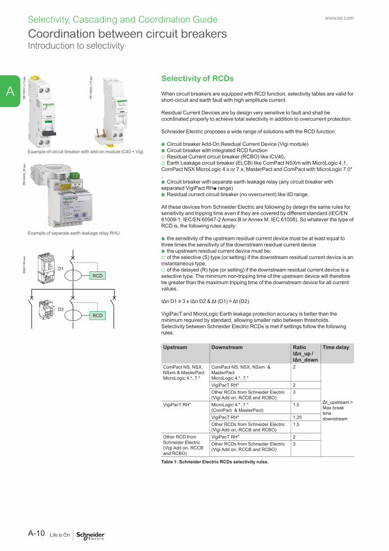
Schneider Electric proposes a wide range of solutions with the RCD function:
b Circuit breaker Add-On Residual Current Device (Vigi module) b Circuit breaker with integrated RCD function v Residual Current circuit breaker (RCBO) like iCV40, v Earth Leakage circuit breaker (ELCB) like ComPact NSXm with MicroLogic 4.1,
ComPact NSX MicroLogic 4.x or 7.x, MasterPact and ComPact with MicroLogic 7.0* ,
b Circuit breaker with separate earth leakage relay (any circuit breaker with separated VigiPact RHp range)
b Residual current circuit breaker (no overcurrent) like iID range.
All these devices from Schneider Electric are following by design the same rules for sensitivity and tripping time even if they are covered by different standard (IEC/EN 61009-1, IEC/EN 60947-2 Annex B or Annex M, IEC 61008). So whatever the type of RCD is, the following rules apply:
b the sensitivity of the upstream residual current device must be at least equal to three times the sensitivity of the downstream residual current device
b the upstream residual current device must be: v of the selective (S) type (or setting) if the downstream residual current device is an
instantaneous type, v of the delayed (R) type (or setting) if the downstream residual current device is a
selective type. The minimum non-tripping time of the upstream device will therefore be greater than the maximum tripping time of the downstream device for all current values.
IΔn D1 u 3 x IΔn D2 & Δt (D1) > Δt (D2).
VigiPacT and MicroLogic Earth leakage protection accuracy is better than the minimum required by standard, allowing smaller ratio between thresholds. Selectivity between Schneider Electric RCDs is met if settings follow the following rules.
Upstream Downstream Ratio IΔn_up / IΔn_down
Time delay
ComPact NS, NSX, NSxm & MasterPactMicroLogic 4.*, 7.*
ComPact NS, NSX, NSxm & MasterPact MicroLogic 4.*, 7.*
2
Δt_upstream >Max break time downstream
VigiPacT RH* 2Other RCDs from Schneider Electric (Vigi Add on, RCCB and RCBO)
3
VigiPacT RH* MicroLogic 4.*, 7.* (ComPact & MasterPact)
1,5
VigiPacT RH* 1,25Other RCDs from Schneider Electric (Vigi Add on, RCCB and RCBO)
1,5
Other RCD from Schneider Electric(Vigi Add on, RCCB and RCBO)
VigiPacT RH* 2Other RCDs from Schneider Electric (Vigi Add on, RCCB and RCBO)
3
Table 1: Schneider Electric RCDs selectivity rules.
Example of circuit breaker with add-on module iC40 + Vigi.
PB10
0436
_26.
eps
Example of separate earth leakage relay RHU.
RCD
RCD
D1
D2
DB4
2119
2.ep
s
Coordination between circuit breakersIntroduction to selectivity
PB11
9531
_L15
.eps
PB11
9549
_L18
.eps
A-10
A
Selectivity, Cascading and Coordination Guide www.se.com
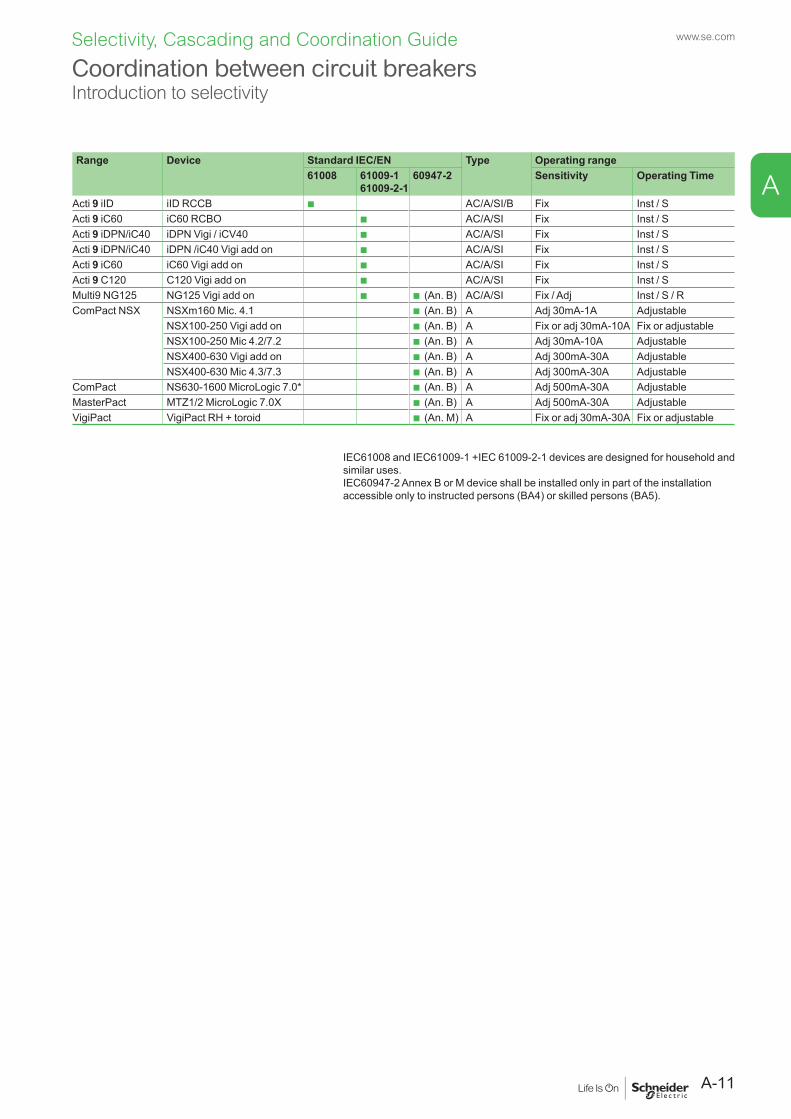
Range Device Standard IEC/EN Type Operating range61008 61009-1
61009-2-160947-2 Sensitivity Operating Time
Acti 9 iID iID RCCB b AC/A/SI/B Fix Inst / SActi 9 iC60 iC60 RCBO b AC/A/SI Fix Inst / SActi 9 iDPN/iC40 iDPN Vigi / iCV40 b AC/A/SI Fix Inst / SActi 9 iDPN/iC40 iDPN /iC40 Vigi add on b AC/A/SI Fix Inst / SActi 9 iC60 iC60 Vigi add on b AC/A/SI Fix Inst / SActi 9 C120 C120 Vigi add on b AC/A/SI Fix Inst / SMulti9 NG125 NG125 Vigi add on b b (An. B) AC/A/SI Fix / Adj Inst / S / RComPact NSX NSXm160 Mic. 4.1 b (An. B) A Adj 30mA-1A Adjustable
NSX100-250 Vigi add on b (An. B) A Fix or adj 30mA-10A Fix or adjustableNSX100-250 Mic 4.2/7.2 b (An. B) A Adj 30mA-10A AdjustableNSX400-630 Vigi add on b (An. B) A Adj 300mA-30A AdjustableNSX400-630 Mic 4.3/7.3 b (An. B) A Adj 300mA-30A Adjustable
ComPact NS630-1600 MicroLogic 7.0* b (An. B) A Adj 500mA-30A AdjustableMasterPact MTZ1/2 MicroLogic 7.0X b (An. B) A Adj 500mA-30A AdjustableVigiPact VigiPact RH + toroid b (An. M) A Fix or adj 30mA-30A Fix or adjustable
Coordination between circuit breakersIntroduction to selectivity
IEC61008 and IEC61009-1 +IEC 61009-2-1 devices are designed for household and similar uses.IEC60947-2 Annex B or M device shall be installed only in part of the installation accessible only to instructed persons (BA4) or skilled persons (BA5).
A-11
A
Selectivity, Cascading and Coordination Guide www.se.com
PB11
9574
_L19
.eps
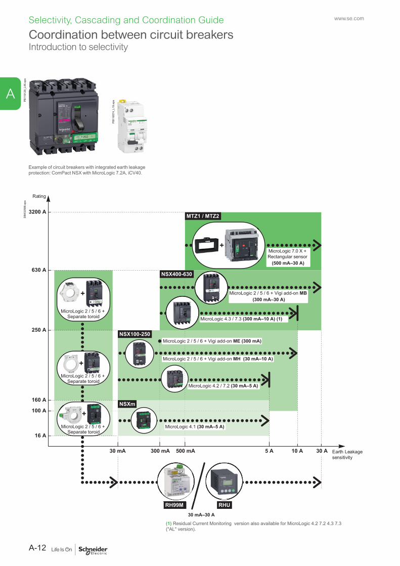
Earth Leakagesensitivity
Rating
5 A 10 A 30 A300 mA30 mA
16 A
160 A
250 A
630 A
3200 A
100 A
NSX100-250
MTZ1 / MTZ2
NSXm
500 mA
30 mA–30 A
RH99M RHU
MicroLogic 7.0 X + Rectangular sensor
(500 mA–30 A)
MicroLogic 2 / 5 / 6 + Vigi add-on MB(300 mA–30 A)
MicroLogic 4.3 / 7.3 (300 mA–10 A) (1)
MicroLogic 2 / 5 / 6 + Vigi add-on ME (300 mA)
MicroLogic 2 / 5 / 6 + Vigi add-on MH (30 mA–10 A)
MicroLogic 4.2 / 7.2 (30 mA–5 A)
MicroLogic 4.1 (30 mA–5 A)
+MicroLogic 2 / 5 / 6 +
Separate toroid
+MicroLogic 2 / 5 / 6 +
Separate toroid
+
+
MicroLogic 2 / 5 / 6 + Separate toroid
NSX400-630
DB4
3258
8.ep
s
Example of circuit breakers with integrated earth leakage protection: ComPact NSX with MicroLogic 7.2A, iCV40.
Coordination between circuit breakersIntroduction to selectivity
(1) Residual Current Monitoring version also available for MicroLogic 4.2 7.2 4.3 7.3 ("AL" version).
PB11
9128
_L46
.eps
A-12
A
Selectivity, Cascading and Coordination Guide www.se.com
EIG
-000
EN-1
_cou
v.eps
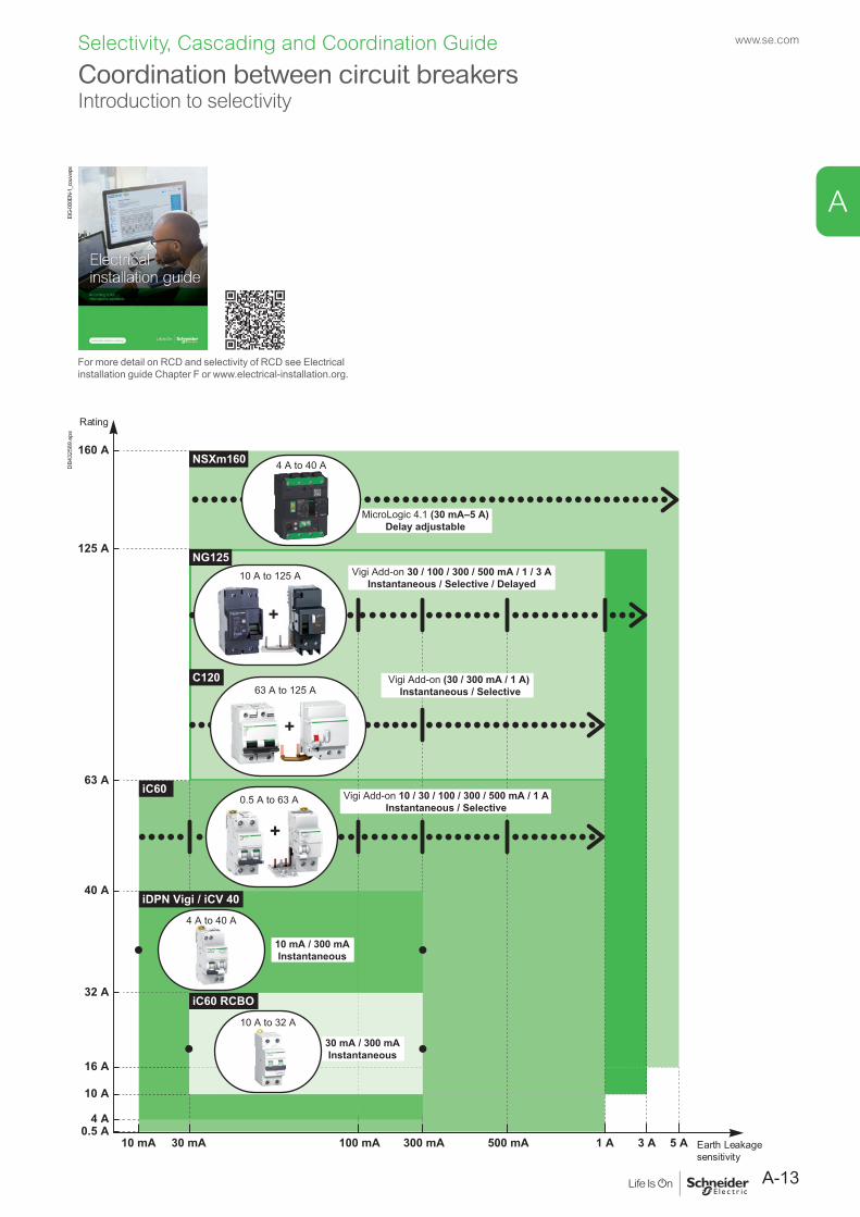
For more detail on RCD and selectivity of RCD see Electrical installation guide Chapter F or www.electrical-installation.org.
Earth Leakage sensitivity
Rating
1 A300 mA30 mA10 mA
10 A
iC60 RCBO
iDPN Vigi / iCV 40
iC60
C120
16 A
4 A0.5 A
32 A
40 A
63 A
125 A
160 A
100 mA 500 mA
10 mA / 300 mAInstantaneous
Vigi Add-on (30 / 300 mA / 1 A) Instantaneous / Selective
4 A to 40 A
NG125
NSXm160
MicroLogic 4.1 (30 mA–5 A)Delay adjustable
4 A to 40 A
3 A 5 A
+
0.5 A to 63 A
30 mA / 300 mAInstantaneous
63 A to 125 A
+
10 A to 125 A
+
Vigi Add-on 10 / 30 / 100 / 300 / 500 mA / 1 AInstantaneous / Selective
Vigi Add-on 30 / 100 / 300 / 500 mA / 1 / 3 AInstantaneous / Selective / Delayed
10 A to 32 A
DB4
3258
9.ep
s
Coordination between circuit breakersIntroduction to selectivity
A-13
A
Selectivity, Cascading and Coordination Guide www.se.com
Coordination between circuit breakersIntroduction to selectivity
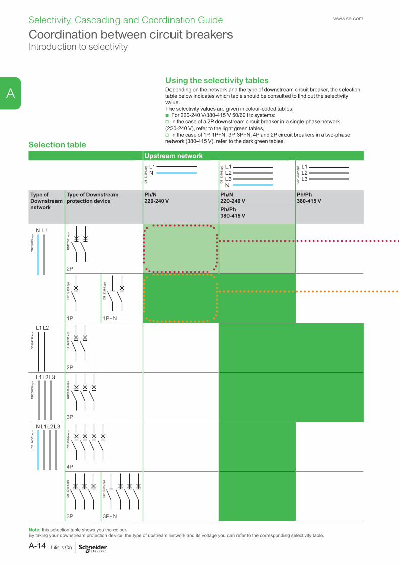
Selection tableUpstream network
L1N
DB1
2399
6.ep
s
L3N
L2L1
DB1
2399
8.ep
s
L3L2L1
DB1
2399
7.ep
s
Type of Downstream network
Type of Downstream protection device
Ph/N 220-240 V
Ph/N 220-240 V
Ph/Ph 380-415 V
Ph/Ph 380-415 V
L1N
DB1
2407
9.ep
s
DB1
2399
1.ep
s
2P
DB1
2419
1.ep
s
1P
DB1
2399
2.ep
s
1P+N
L2L1
DB1
2419
2.ep
s
DB1
2399
1.ep
s
2P
L1L2 L3
DB1
2408
0.ep
s
DB1
2399
3.ep
s
3P
L1N L2L3
DB1
2408
1.ep
s
DB1
2399
4.ep
s
4P
DB1
2399
3.ep
s
3P
DB1
2399
5.ep
s
3P+N
Note: this selection table shows you the colour.By taking your downstream protection device, the type of upstream network and its voltage you can refer to the corresponding selectivity table.
Using the selectivity tablesDepending on the network and the type of downstream circuit breaker, the selection table below indicates which table should be consulted to find out the selectivity value.The selectivity values are given in colour-coded tables.
b For 220-240 V/380-415 V 50/60 Hz systems: v in the case of a 2P downstream circuit breaker in a single-phase network
(220-240 V), refer to the light green tables, v in the case of 1P, 1P+N, 3P, 3P+N, 4P and 2P circuit breakers in a two-phase
network (380-415 V), refer to the dark green tables.
A-14
A
Selectivity, Cascading and Coordination Guide www.se.com
Coordination between circuit breakersIntroduction to selectivity
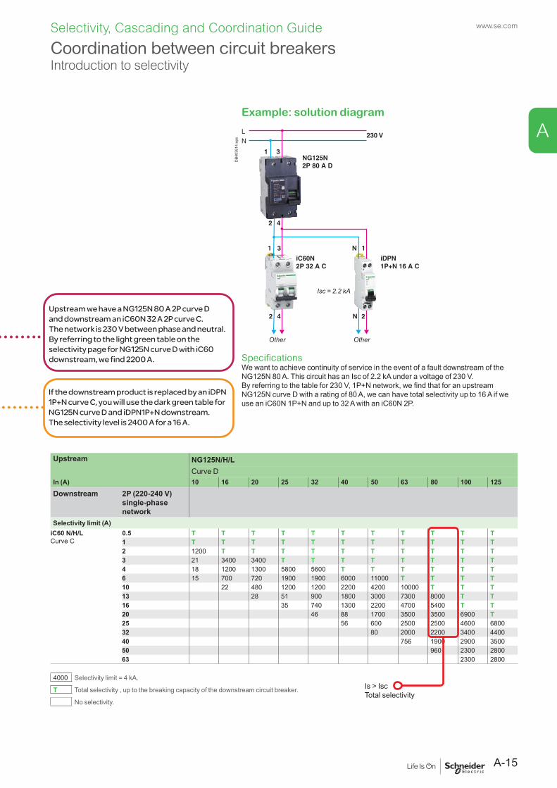
Example: solution diagram
SpecificationsWe want to achieve continuity of service in the event of a fault downstream of the NG125N 80 A. This circuit has an Isc of 2.2 kA under a voltage of 230 V.By referring to the table for 230 V, 1P+N network, we find that for an upstream NG125N curve D with a rating of 80 A, we can have total selectivity up to 16 A if we use an iC60N 1P+N and up to 32 A with an iC60N 2P.
Upstream we have a NG125N 80 A 2P curve D and downstream an iC60N 32 A 2P curve C.The network is 230 V between phase and neutral.By referring to the light green table on the selectivity page for NG125N curve D with iC60 downstream, we find 2200 A.
If the downstream product is replaced by an iDPN 1P+N curve C, you will use the dark green table for NG125N curve D and iDPN1P+N downstream.The selectivity level is 2400 A for a 16 A.
Upstream NG125N/H/LCurve D
In (A) 10 16 20 25 32 40 50 63 80 100 125
Downstream 2P (220-240 V) single-phase network
Selectivity limit (A)iC60 N/H/LCurve C
0.5 T T T T T T T T T T T1 T T T T T T T T T T T2 1200 T T T T T T T T T T3 21 3400 3400 T T T T T T T T4 18 1200 1300 5800 5600 T T T T T T6 15 700 720 1900 1900 6000 11000 T T T T10 22 480 1200 1200 2200 4200 10000 T T T13 28 51 900 1800 3000 7300 8000 T T16 35 740 1300 2200 4700 5400 T T20 46 88 1700 3500 3500 6900 T25 56 600 2500 2500 4600 680032 80 2000 2200 3400 440040 756 1900 2900 350050 960 2300 280063 2300 2800
4000 Selectivity limit = 4 kA.
T Total selectivity , up to the breaking capacity of the downstream circuit breaker.
No selectivity.
Is > IscTotal selectivity
LN
1 3NG125N2P 80 A D
230 V
2 4
31
2 4
1N
N 2
iDPN1P+N 16 A C
iC60N 2P 32 A C
OtherOther
Isc = 2.2 kA
DB4
0351
4.ep
s
A-15
A
Selectivity, Cascading and Coordination Guide www.se.com
Coordination between circuit breakersIntroduction to selectivity
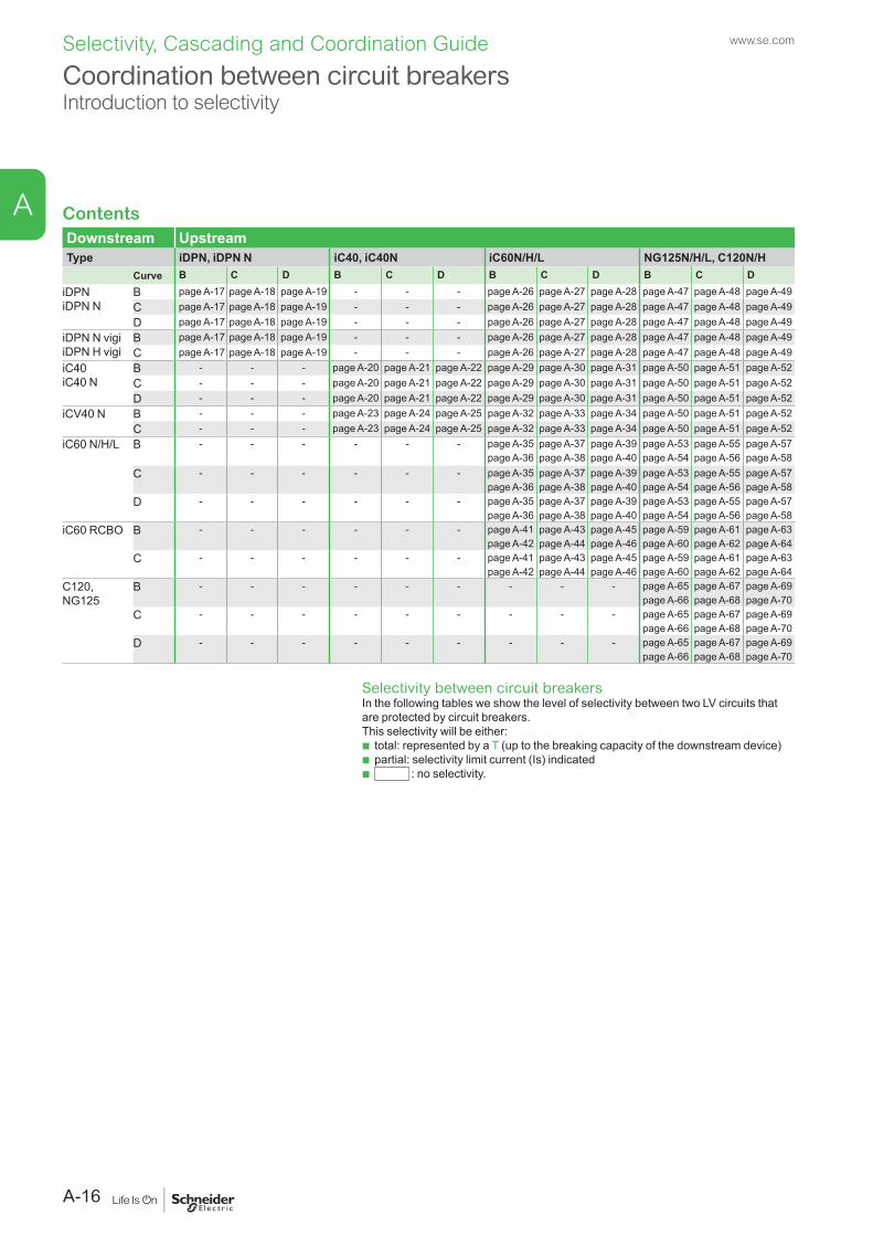
ContentsDownstream UpstreamType iDPN, iDPN N iC40, iC40N iC60N/H/L NG125N/H/L, C120N/H
Curve B C D B C D B C D B C DiDPNiDPN N
B page A-17 page A-18 page A-19 - - - page A-26 page A-27 page A-28 page A-47 page A-48 page A-49C page A-17 page A-18 page A-19 - - - page A-26 page A-27 page A-28 page A-47 page A-48 page A-49D page A-17 page A-18 page A-19 - - - page A-26 page A-27 page A-28 page A-47 page A-48 page A-49
iDPN N vigiiDPN H vigi
B page A-17 page A-18 page A-19 - - - page A-26 page A-27 page A-28 page A-47 page A-48 page A-49C page A-17 page A-18 page A-19 - - - page A-26 page A-27 page A-28 page A-47 page A-48 page A-49
iC40iC40 N
B - - - page A-20 page A-21 page A-22 page A-29 page A-30 page A-31 page A-50 page A-51 page A-52C - - - page A-20 page A-21 page A-22 page A-29 page A-30 page A-31 page A-50 page A-51 page A-52D - - - page A-20 page A-21 page A-22 page A-29 page A-30 page A-31 page A-50 page A-51 page A-52
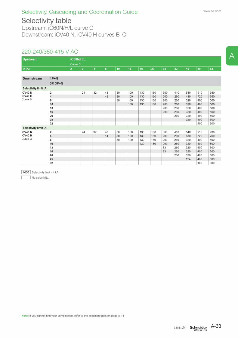
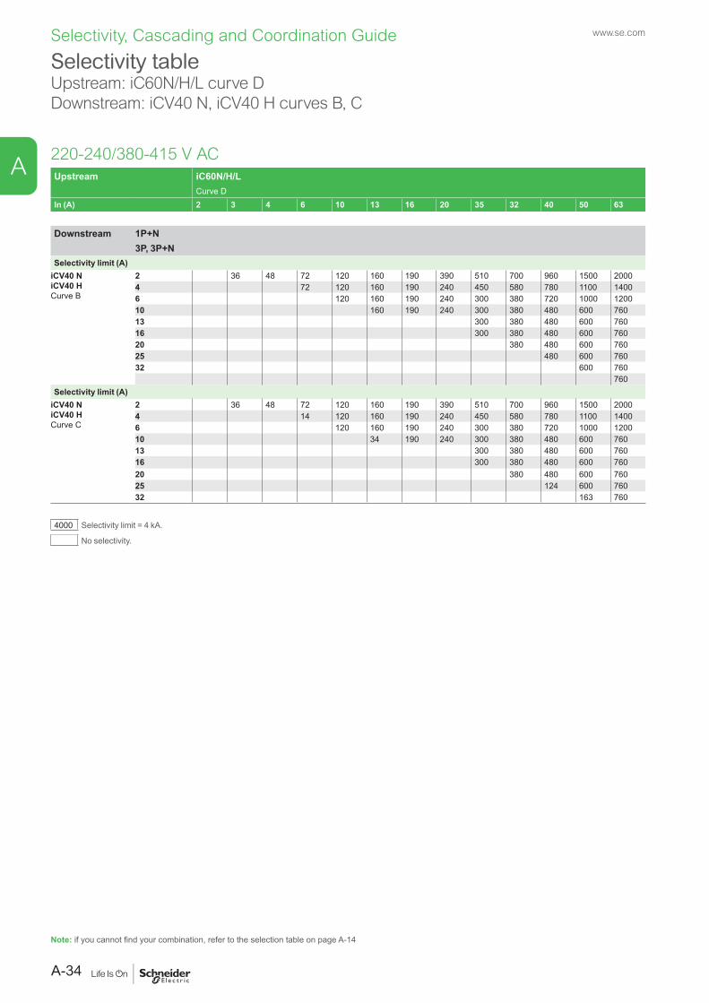
iCV40 N B - - - page A-23 page A-24 page A-25 page A-32 page A-33 page A-34 page A-50 page A-51 page A-52C - - - page A-23 page A-24 page A-25 page A-32 page A-33 page A-34 page A-50 page A-51 page A-52
iC60 N/H/L B - - - - - - page A-35 page A-36
page A-37 page A-38
page A-39 page A-40
page A-53 page A-54
page A-55 page A-56
page A-57 page A-58
C - - - - - - page A-35 page A-36
page A-37 page A-38
page A-39 page A-40
page A-53 page A-54
page A-55 page A-56
page A-57 page A-58
D - - - - - - page A-35 page A-36
page A-37 page A-38
page A-39 page A-40
page A-53 page A-54
page A-55 page A-56
page A-57 page A-58
iC60 RCBO B - - - - - - page A-41page A-42
page A-43page A-44
page A-45page A-46
page A-59page A-60
page A-61page A-62
page A-63page A-64
C - - - - - - page A-41page A-42
page A-43page A-44
page A-45page A-46
page A-59page A-60
page A-61page A-62
page A-63page A-64
C120,NG125
B - - - - - - - - - page A-65 page A-66
page A-67 page A-68
page A-69 page A-70
C - - - - - - - - - page A-65 page A-66
page A-67 page A-68
page A-69 page A-70
D - - - - - - - - - page A-65 page A-66
page A-67 page A-68
page A-69 page A-70
Selectivity between circuit breakersIn the following tables we show the level of selectivity between two LV circuits that are protected by circuit breakers.This selectivity will be either:
b total: represented by a T (up to the breaking capacity of the downstream device) b partial: selectivity limit current (Is) indicated b : no selectivity.
A-16
A
Selectivity, Cascading and Coordination Guide www.se.com
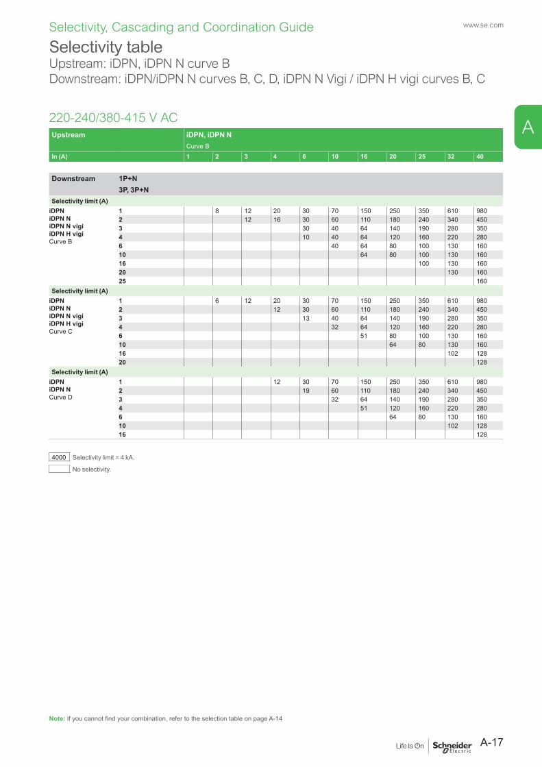
Selectivity table Upstream: iDPN, iDPN N curve BDownstream: iDPN/iDPN N curves B, C, D, iDPN N Vigi / iDPN H vigi curves B, C
220-240/380-415 V ACUpstream iDPN, iDPN N
Curve BIn (A) 1 2 3 4 6 10 16 20 25 32 40
Downstream 1P+N3P, 3P+N
Selectivity limit (A)iDPNiDPN NiDPN N vigiiDPN H vigiCurve B
1 8 12 20 30 70 150 250 350 610 9802 12 16 30 60 110 180 240 340 4503 30 40 64 140 190 280 3504 10 40 64 120 160 220 2806 40 64 80 100 130 16010 64 80 100 130 16016 100 130 16020 130 16025 160
Selectivity limit (A)iDPNiDPN NiDPN N vigiiDPN H vigiCurve C
1 6 12 20 30 70 150 250 350 610 9802 12 30 60 110 180 240 340 4503 13 40 64 140 190 280 3504 32 64 120 160 220 2806 51 80 100 130 16010 64 80 130 16016 102 12820 128
Selectivity limit (A)iDPNiDPN NCurve D
1 12 30 70 150 250 350 610 9802 19 60 110 180 240 340 4503 32 64 140 190 280 3504 51 120 160 220 2806 64 80 130 16010 102 12816 128
4000 Selectivity limit = 4 kA.
No selectivity.
Note: if you cannot find your combination, refer to the selection table on page A-14
A-17
A
Selectivity, Cascading and Coordination Guide www.se.com
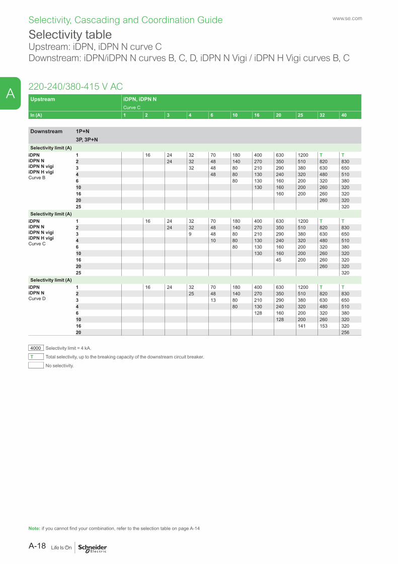
Selectivity tableUpstream: iDPN, iDPN N curve CDownstream: iDPN/iDPN N curves B, C, D, iDPN N Vigi / iDPN H Vigi curves B, C
220-240/380-415 V ACUpstream iDPN, iDPN N
Curve CIn (A) 1 2 3 4 6 10 16 20 25 32 40
Downstream 1P+N3P, 3P+N
Selectivity limit (A)iDPNiDPN NiDPN N vigiiDPN H vigiCurve B
1 16 24 32 70 180 400 630 1200 T T2 24 32 48 140 270 350 510 820 8303 32 48 80 210 290 380 630 6504 48 80 130 240 320 480 5106 80 130 160 200 320 38010 130 160 200 260 32016 160 200 260 32020 260 32025 320
Selectivity limit (A)iDPNiDPN NiDPN N vigiiDPN H vigiCurve C
1 16 24 32 70 180 400 630 1200 T T2 24 32 48 140 270 350 510 820 8303 9 48 80 210 290 380 630 6504 10 80 130 240 320 480 5106 80 130 160 200 320 38010 130 160 200 260 32016 45 200 260 32020 260 32025 320
Selectivity limit (A)iDPNiDPN NCurve D
1 16 24 32 70 180 400 630 1200 T T2 25 48 140 270 350 510 820 8303 13 80 210 290 380 630 6504 80 130 240 320 480 5106 128 160 200 320 38010 128 200 260 32016 141 153 32020 256
4000 Selectivity limit = 4 kA.
T Total selectivity, up to the breaking capacity of the downstream circuit breaker.
No selectivity.
Note: if you cannot find your combination, refer to the selection table on page A-14
A-18
A

Selectivity, Cascading and Coordination Guide www.se.com
Selectivity table Upstream: iDPN, iDPN N curve DDownstream: iDPN/iDPN N curves B, C, D, iDPN N Vigi / iDPN H Vigi curves B, C
220-240/380-415 V ACUpstream iDPN, iDPN N
Curve DIn (A) 1 2 3 4 6 10 16 20 25 32 40
Downstream 1P+N3P, 3P+N
Selectivity limit (A)iDPNiDPN NiDPN N vigiiDPN H vigiCurve B
1 24 36 70 170 380 1200 T T T T2 36 48 130 250 490 780 1100 1600 23003 48 72 210 410 640 890 1400 19004 72 120 330 500 670 970 14006 120 190 390 520 740 100010 190 240 300 580 81016 300 380 48020 380 48025 48032 480
Selectivity limit (A)iDPNiDPN NiDPN N vigiiDPN H vigiCurve C
1 24 36 70 170 380 1200 T T T T2 36 48 130 250 490 780 1100 1600 23003 9 72 210 410 640 890 1400 19004 10 120 330 500 670 970 14006 190 390 520 740 100010 190 240 300 580 81016 300 380 48020 380 48025 480
Selectivity limit (A)iDPNiDPN NCurve D
1 24 36 70 170 380 1200 T T T T2 36 48 130 250 490 780 1100 1600 23003 14 210 410 640 890 1400 19004 10 120 330 500 670 970 14006 120 190 390 520 740 100010 190 240 300 580 81016 300 380 48020 380 48025 480
4000 Selectivity limit = 4 kA.
T Total selectivity, up to the breaking capacity of the downstream circuit breaker.
No selectivity.
Note: if you cannot find your combination, refer to the selection table on page A-14
A-19
A

Selectivity, Cascading and Coordination Guide www.se.com
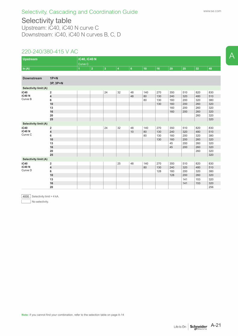
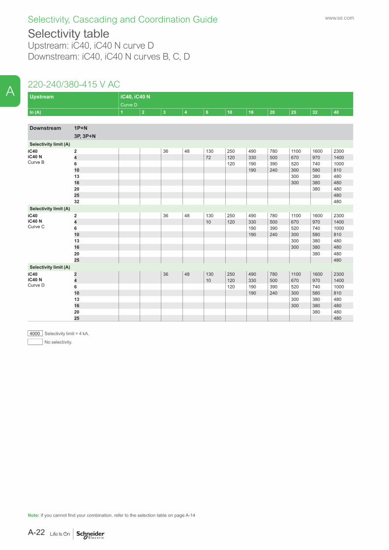
Selectivity table Upstream: iC40, iC40 N curve BDownstream: iC40, iC40 N curves B, C, D
220-240/380-415 V ACUpstream iC40, iC40 N
Curve BIn (A) 1 2 3 4 6 10 16 20 25 32 40
Downstream 1P+N3P, 3P+N
Selectivity limit (A)iC40iC40 NCurve B
2 12 16 30 60 110 180 240 340 4504 10 40 64 120 160 220 2806 40 64 80 100 130 16010 64 80 100 130 16013 100 130 16016 100 130 16020 130 16025 160
Selectivity limit (A)iC40iC40 NCurve C
2 12 30 60 110 180 240 340 4504 32 64 120 160 220 2806 51 80 100 130 16010 64 80 130 16013 102 12816 102 12820 128
Selectivity limit (A)iC40iC40 NCurve D
2 19 60 110 180 240 340 4504 51 120 160 220 2806 64 80 130 16010 102 12813 12816 128
4000 Selectivity limit = 4 kA.
No selectivity.
Note: if you cannot find your combination, refer to the selection table on page A-14
A-20
A
Selectivity, Cascading and Coordination Guide www.se.com
Selectivity tableUpstream: iC40, iC40 N curve CDownstream: iC40, iC40 N curves B, C, D
220-240/380-415 V ACUpstream iC40, iC40 N
Curve CIn (A) 1 2 3 4 6 10 16 20 25 32 40
Downstream 1P+N3P, 3P+N
Selectivity limit (A)iC40iC40 NCurve B
2 24 32 48 140 270 350 510 820 8304 48 80 130 240 320 480 5106 80 130 160 200 320 38010 130 160 200 260 32013 160 200 260 32016 160 200 260 32020 260 32025 320
Selectivity limit (A)iC40iC40 NCurve C
2 24 32 48 140 270 350 510 820 8304 10 80 130 240 320 480 5106 80 130 160 200 320 38010 130 160 200 260 32013 45 200 260 32016 45 200 260 32020 260 32025 320
Selectivity limit (A)iC40iC40 NCurve D
2 25 48 140 270 350 510 820 8304 80 130 240 320 480 5106 128 160 200 320 38010 128 200 260 32013 141 153 32016 141 153 32020 256
4000 Selectivity limit = 4 kA.
No selectivity.
Note: if you cannot find your combination, refer to the selection table on page A-14
A-21
A
Selectivity, Cascading and Coordination Guide www.se.com
Selectivity table Upstream: iC40, iC40 N curve DDownstream: iC40, iC40 N curves B, C, D
220-240/380-415 V ACUpstream iC40, iC40 N
Curve DIn (A) 1 2 3 4 6 10 16 20 25 32 40
Downstream 1P+N3P, 3P+N
Selectivity limit (A)iC40iC40 NCurve B
2 36 48 130 250 490 780 1100 1600 23004 72 120 330 500 670 970 14006 120 190 390 520 740 100010 190 240 300 580 81013 300 380 48016 300 380 48020 380 48025 48032 480
Selectivity limit (A)iC40iC40 NCurve C
2 36 48 130 250 490 780 1100 1600 23004 10 120 330 500 670 970 14006 190 390 520 740 100010 190 240 300 580 81013 300 380 48016 300 380 48020 380 48025 480
Selectivity limit (A)iC40iC40 NCurve D
2 36 48 130 250 490 780 1100 1600 23004 10 120 330 500 670 970 14006 120 190 390 520 740 100010 190 240 300 580 81013 300 380 48016 300 380 48020 380 48025 480
4000 Selectivity limit = 4 kA.
No selectivity.
Note: if you cannot find your combination, refer to the selection table on page A-14
A-22
A

Selectivity, Cascading and Coordination Guide www.se.com
Selectivity table Upstream: iC40, iC40 N curve BDownstream: iCV40 N, iCV40 H curves B, C
220-240/380-415 V ACUpstream iC40, iC40 N
Curve BIn (A) 1 2 3 4 6 10 16 20 25 32 40
Downstream 1P+N3P, 3P+N
Selectivity limit (A)iCV40 NiCV40 HCurve B
2 12 16 30 60 110 180 240 340 4504 10 40 64 120 160 220 2806 40 64 80 100 130 16010 64 80 100 130 16013 100 130 16016 100 130 16020 130 16025 160
Selectivity limit (A)iCV40 NiCV40 HCurve C
2 12 30 60 110 180 240 340 4504 32 64 120 160 220 2806 51 80 100 130 16010 64 80 130 16013 102 12816 102 12820 128
4000 Selectivity limit = 4 kA.
No selectivity.
Note: if you cannot find your combination, refer to the selection table on page A-14
A-23
A

Selectivity, Cascading and Coordination Guide www.se.com
Selectivity tableUpstream: iC40, iC40 N curve CDownstream: iCV40 N, iCV40 H curves B, C
220-240/380-415 V ACUpstream iC40, iC40 N
Curve CIn (A) 1 2 3 4 6 10 16 20 25 32 40
Downstream 1P+N3P, 3P+N
Selectivity limit (A)iCV40 NiCV40 HCurve B
2 24 32 48 140 270 350 510 820 8304 48 80 130 240 320 480 5106 80 130 160 200 320 38010 130 160 200 260 32013 160 200 260 32016 160 200 260 32020 260 32025 320
Selectivity limit (A)iCV40 NiCV40 HCurve C
2 24 32 48 140 270 350 510 820 8304 10 80 130 240 320 480 5106 80 130 160 200 320 38010 130 160 200 260 32013 45 200 260 32016 45 200 260 32020 260 32025 320
4000 Selectivity limit = 4 kA.
No selectivity.
Note: if you cannot find your combination, refer to the selection table on page A-14
A-24
A
Selectivity, Cascading and Coordination Guide www.se.com
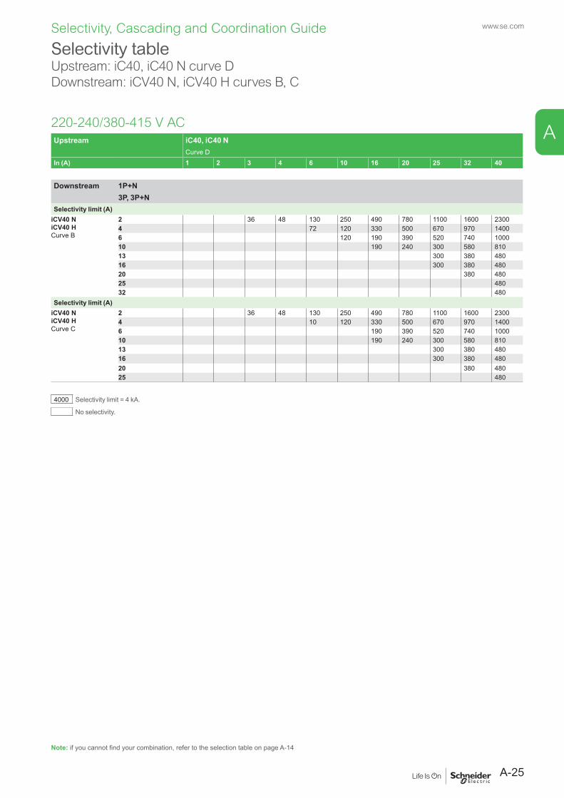
Selectivity table Upstream: iC40, iC40 N curve DDownstream: iCV40 N, iCV40 H curves B, C
220-240/380-415 V ACUpstream iC40, iC40 N
Curve DIn (A) 1 2 3 4 6 10 16 20 25 32 40
Downstream 1P+N3P, 3P+N
Selectivity limit (A)iCV40 NiCV40 HCurve B
2 36 48 130 250 490 780 1100 1600 23004 72 120 330 500 670 970 14006 120 190 390 520 740 100010 190 240 300 580 81013 300 380 48016 300 380 48020 380 48025 48032 480
Selectivity limit (A)iCV40 NiCV40 HCurve C
2 36 48 130 250 490 780 1100 1600 23004 10 120 330 500 670 970 14006 190 390 520 740 100010 190 240 300 580 81013 300 380 48016 300 380 48020 380 48025 480
4000 Selectivity limit = 4 kA.
No selectivity.
Note: if you cannot find your combination, refer to the selection table on page A-14
A-25
A
Selectivity, Cascading and Coordination Guide www.se.com
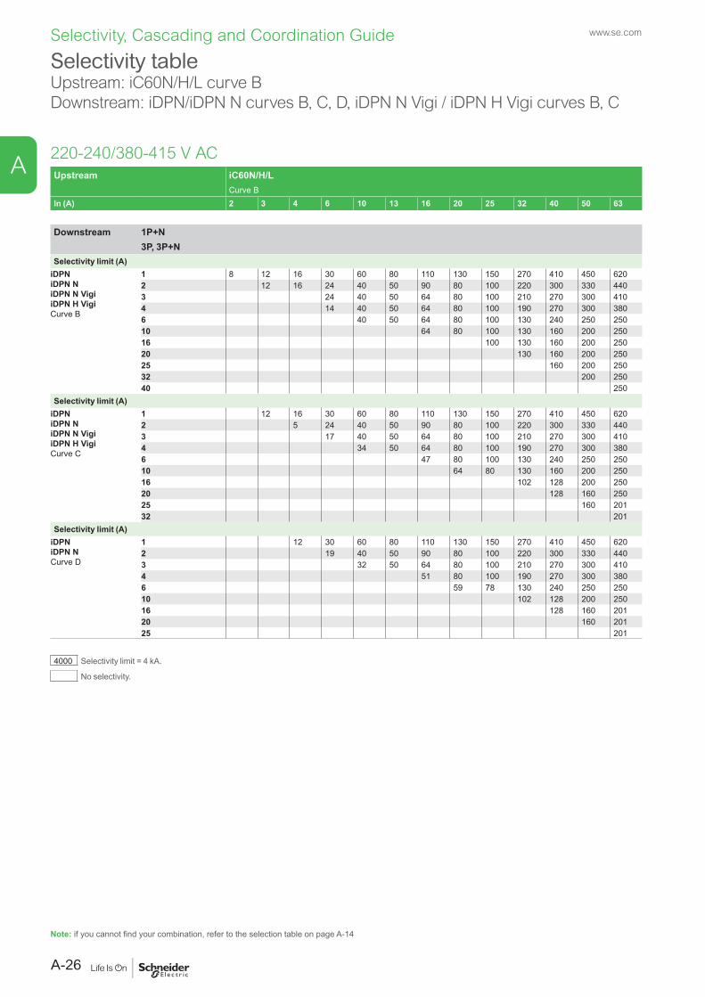
Selectivity table Upstream: iC60N/H/L curve BDownstream: iDPN/iDPN N curves B, C, D, iDPN N Vigi / iDPN H Vigi curves B, C
Upstream iC60N/H/LCurve B
In (A) 2 3 4 6 10 13 16 20 25 32 40 50 63
Downstream 1P+N3P, 3P+N
Selectivity limit (A)iDPNiDPN NiDPN N VigiiDPN H VigiCurve B
1 8 12 16 30 60 80 110 130 150 270 410 450 6202 12 16 24 40 50 90 80 100 220 300 330 4403 24 40 50 64 80 100 210 270 300 4104 14 40 50 64 80 100 190 270 300 3806 40 50 64 80 100 130 240 250 25010 64 80 100 130 160 200 25016 100 130 160 200 25020 130 160 200 25025 160 200 25032 200 25040 250
Selectivity limit (A)iDPNiDPN NiDPN N VigiiDPN H VigiCurve C
1 12 16 30 60 80 110 130 150 270 410 450 6202 5 24 40 50 90 80 100 220 300 330 4403 17 40 50 64 80 100 210 270 300 4104 34 50 64 80 100 190 270 300 3806 47 80 100 130 240 250 25010 64 80 130 160 200 25016 102 128 200 25020 128 160 25025 160 20132 201
Selectivity limit (A)iDPNiDPN NCurve D
1 12 30 60 80 110 130 150 270 410 450 6202 19 40 50 90 80 100 220 300 330 4403 32 50 64 80 100 210 270 300 4104 51 80 100 190 270 300 3806 59 78 130 240 250 25010 102 128 200 25016 128 160 20120 160 20125 201
4000 Selectivity limit = 4 kA.
No selectivity.
220-240/380-415 V AC
Note: if you cannot find your combination, refer to the selection table on page A-14
A-26
A
Selectivity, Cascading and Coordination Guide www.se.com
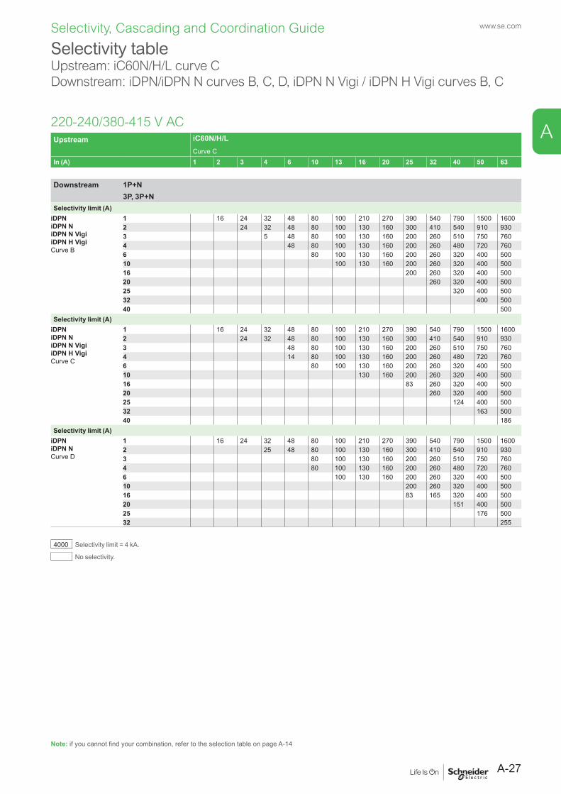
Selectivity table Upstream: iC60N/H/L curve CDownstream: iDPN/iDPN N curves B, C, D, iDPN N Vigi / iDPN H Vigi curves B, C
220-240/380-415 V ACUpstream iC60N/H/L
Curve CIn (A) 1 2 3 4 6 10 13 16 20 25 32 40 50 63
Downstream 1P+N3P, 3P+N
Selectivity limit (A)iDPNiDPN NiDPN N VigiiDPN H VigiCurve B
1 16 24 32 48 80 100 210 270 390 540 790 1500 16002 24 32 48 80 100 130 160 300 410 540 910 9303 5 48 80 100 130 160 200 260 510 750 7604 48 80 100 130 160 200 260 480 720 7606 80 100 130 160 200 260 320 400 50010 100 130 160 200 260 320 400 50016 200 260 320 400 50020 260 320 400 50025 320 400 50032 400 50040 500
Selectivity limit (A)iDPNiDPN NiDPN N VigiiDPN H VigiCurve C
1 16 24 32 48 80 100 210 270 390 540 790 1500 16002 24 32 48 80 100 130 160 300 410 540 910 9303 48 80 100 130 160 200 260 510 750 7604 14 80 100 130 160 200 260 480 720 7606 80 100 130 160 200 260 320 400 50010 130 160 200 260 320 400 50016 83 260 320 400 50020 260 320 400 50025 124 400 50032 163 50040 186
Selectivity limit (A)iDPNiDPN NCurve D
1 16 24 32 48 80 100 210 270 390 540 790 1500 16002 25 48 80 100 130 160 300 410 540 910 9303 80 100 130 160 200 260 510 750 7604 80 100 130 160 200 260 480 720 7606 100 130 160 200 260 320 400 50010 200 260 320 400 50016 83 165 320 400 50020 151 400 50025 176 50032 255
4000 Selectivity limit = 4 kA.
No selectivity.
Note: if you cannot find your combination, refer to the selection table on page A-14
A-27
A
Selectivity, Cascading and Coordination Guide www.se.com
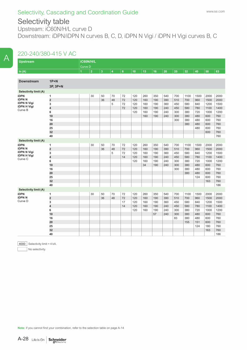
Selectivity tableUpstream: iC60N/H/L curve DDownstream: iDPN/iDPN N curves B, C, D, iDPN N Vigi / iDPN H Vigi curves B, C
220-240/380-415 V ACUpstream iC60N/H/L
Curve DIn (A) 1 2 3 4 6 10 13 16 20 25 32 40 50 63
Downstream 1P+N3P, 3P+N
Selectivity limit (A)iDPNiDPN NiDPN N VigiiDPN H VigiCurve B
1 30 50 70 72 120 260 350 540 700 1100 1500 2000 20002 36 48 72 120 160 190 390 510 700 960 1500 20003 5 72 120 160 190 360 450 580 840 1200 15004 72 120 160 190 240 450 580 780 1100 14006 120 160 190 240 300 380 720 1000 120010 160 190 240 300 380 480 600 76016 300 380 480 600 76020 380 480 600 76025 480 600 76032 600 76040 760
Selectivity limit (A)iDPNiDPN NiDPN N VigiiDPN H VigiCurve C
1 30 50 70 72 120 260 350 540 700 1100 1500 2000 20002 36 48 72 120 160 190 390 510 700 960 1500 20003 5 72 120 160 190 360 450 580 840 1200 15004 14 120 160 190 240 450 580 780 1100 14006 120 160 190 240 300 380 720 1000 120010 34 190 240 300 380 480 600 76016 300 380 480 600 76020 380 480 600 76025 124 600 76032 163 76040 186
Selectivity limit (A)iDPNiDPN NCurve D
1 30 50 70 72 120 260 350 540 700 1100 1500 2000 20002 36 48 72 120 160 190 390 510 700 960 1500 20003 17 120 160 190 360 450 580 840 1200 15004 14 120 160 190 240 450 580 780 1100 14006 120 160 190 240 300 380 720 1000 120010 57 240 300 380 480 600 76016 83 380 480 600 76020 155 151 600 76025 124 180 76032 163 76040 186
4000 Selectivity limit = 4 kA.
No selectivity.
Note: if you cannot find your combination, refer to the selection table on page A-14
A-28
A

Selectivity, Cascading and Coordination Guide www.se.com
Selectivity table Upstream: iC60N/H/L curve BDownstream: iC40, iC40 N curves B, C, D
220-240/380-415 V ACUpstream iC60N/H/L
Curve BIn (A) 2 3 4 6 10 13 16 20 35 32 40 50 63
Downstream 1P+N3P, 3P+N
Selectivity limit (A)iC40iC40 NCurve B
2 12 16 24 40 50 90 80 100 220 300 330 4404 14 40 50 64 80 100 190 270 300 3806 40 50 64 80 100 130 240 250 25010 64 80 100 130 160 200 25013 100 130 160 200 25016 100 130 160 200 25020 130 160 200 25025 160 200 25032 200 25040 250
Selectivity limit (A)iC40iC40 NCurve C
2 5 24 40 50 90 80 100 220 300 330 4404 34 50 64 80 100 190 270 300 3806 47 80 100 130 240 250 25010 64 80 130 160 200 25013 102 128 200 25016 102 128 200 25020 128 160 25025 160 20132 201
Selectivity limit (A)iC40iC40 NCurve D
2 19 40 50 90 80 100 220 300 330 4404 51 80 100 190 270 300 3806 59 78 130 240 250 25010 102 128 200 25016 128 160 20120 160 20125 201
4000 Selectivity limit = 4 kA.
No selectivity.
Note: if you cannot find your combination, refer to the selection table on page A-14
A-29
A
Selectivity, Cascading and Coordination Guide www.se.com
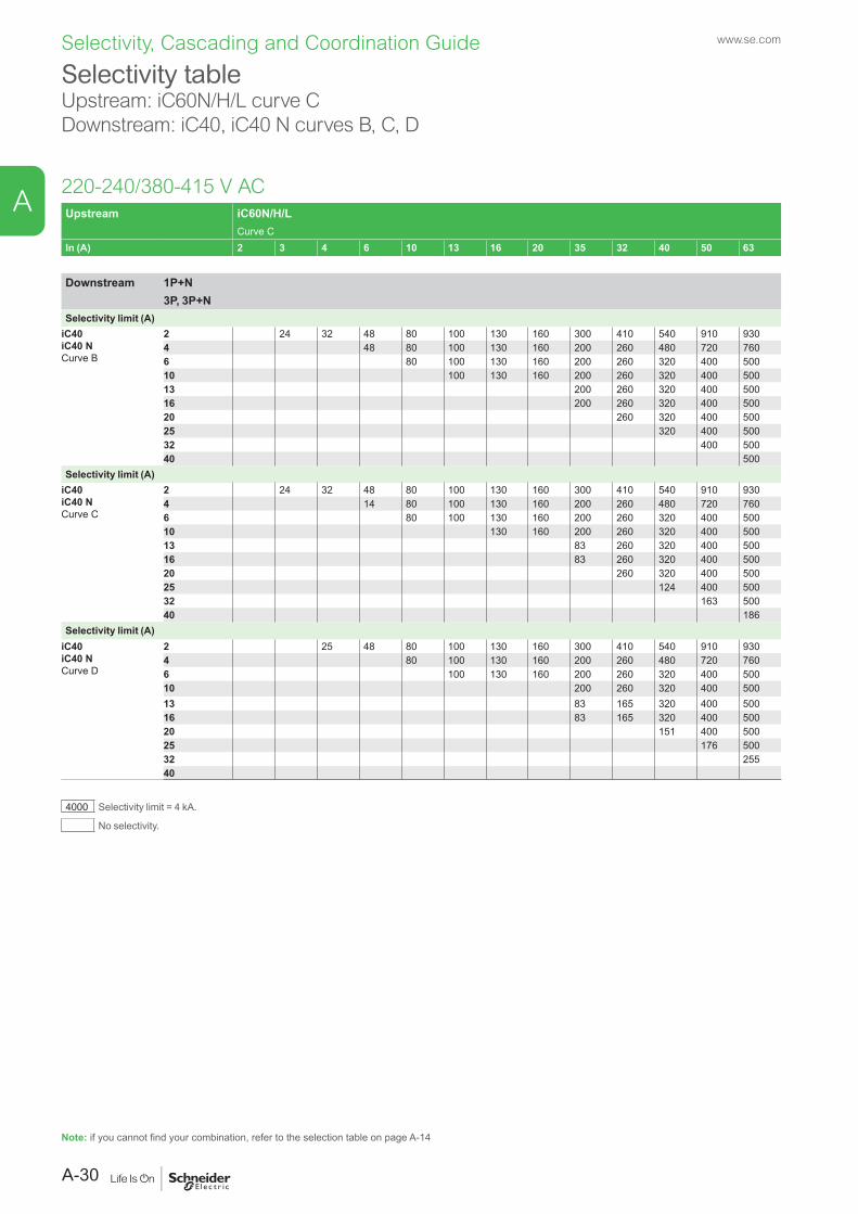
Selectivity tableUpstream: iC60N/H/L curve CDownstream: iC40, iC40 N curves B, C, D
220-240/380-415 V ACUpstream iC60N/H/L
Curve CIn (A) 2 3 4 6 10 13 16 20 35 32 40 50 63
Downstream 1P+N3P, 3P+N
Selectivity limit (A)iC40iC40 NCurve B
2 24 32 48 80 100 130 160 300 410 540 910 9304 48 80 100 130 160 200 260 480 720 7606 80 100 130 160 200 260 320 400 50010 100 130 160 200 260 320 400 50013 200 260 320 400 50016 200 260 320 400 50020 260 320 400 50025 320 400 50032 400 50040 500
Selectivity limit (A)iC40iC40 NCurve C
2 24 32 48 80 100 130 160 300 410 540 910 9304 14 80 100 130 160 200 260 480 720 7606 80 100 130 160 200 260 320 400 50010 130 160 200 260 320 400 50013 83 260 320 400 50016 83 260 320 400 50020 260 320 400 50025 124 400 50032 163 50040 186
Selectivity limit (A)iC40iC40 NCurve D
2 25 48 80 100 130 160 300 410 540 910 9304 80 100 130 160 200 260 480 720 7606 100 130 160 200 260 320 400 50010 200 260 320 400 50013 83 165 320 400 50016 83 165 320 400 50020 151 400 50025 176 50032 25540
4000 Selectivity limit = 4 kA.
No selectivity.
Note: if you cannot find your combination, refer to the selection table on page A-14
A-30
A
Selectivity, Cascading and Coordination Guide www.se.com
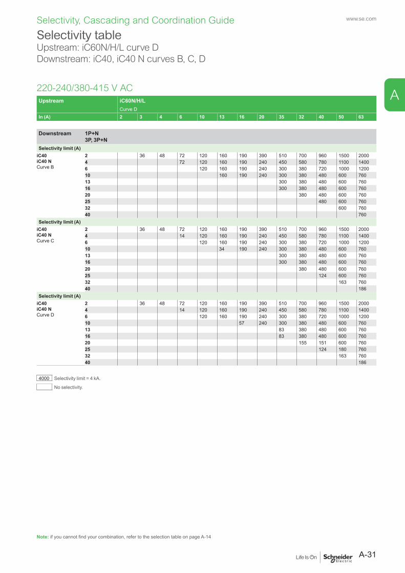
Selectivity table Upstream: iC60N/H/L curve DDownstream: iC40, iC40 N curves B, C, D
220-240/380-415 V ACUpstream iC60N/H/L
Curve DIn (A) 2 3 4 6 10 13 16 20 35 32 40 50 63
Downstream 1P+N 3P, 3P+N
Selectivity limit (A)iC40iC40 NCurve B
2 36 48 72 120 160 190 390 510 700 960 1500 20004 72 120 160 190 240 450 580 780 1100 14006 120 160 190 240 300 380 720 1000 120010 160 190 240 300 380 480 600 76013 300 380 480 600 76016 300 380 480 600 76020 380 480 600 76025 480 600 76032 600 76040 760
Selectivity limit (A)iC40iC40 NCurve C
2 36 48 72 120 160 190 390 510 700 960 1500 20004 14 120 160 190 240 450 580 780 1100 14006 120 160 190 240 300 380 720 1000 120010 34 190 240 300 380 480 600 76013 300 380 480 600 76016 300 380 480 600 76020 380 480 600 76025 124 600 76032 163 76040 186
Selectivity limit (A)iC40iC40 NCurve D
2 36 48 72 120 160 190 390 510 700 960 1500 20004 14 120 160 190 240 450 580 780 1100 14006 120 160 190 240 300 380 720 1000 120010 57 240 300 380 480 600 76013 83 380 480 600 76016 83 380 480 600 76020 155 151 600 76025 124 180 76032 163 76040 186
4000 Selectivity limit = 4 kA.
No selectivity.
Note: if you cannot find your combination, refer to the selection table on page A-14
A-31
A
Selectivity, Cascading and Coordination Guide www.se.com
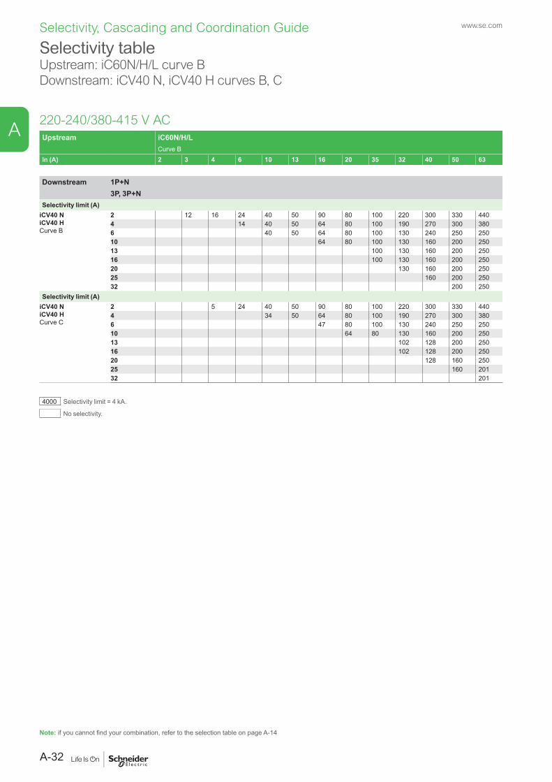
Selectivity table Upstream: iC60N/H/L curve BDownstream: iCV40 N, iCV40 H curves B, C
220-240/380-415 V ACUpstream iC60N/H/L
Curve BIn (A) 2 3 4 6 10 13 16 20 35 32 40 50 63
Downstream 1P+N3P, 3P+N
Selectivity limit (A)iCV40 NiCV40 HCurve B
2 12 16 24 40 50 90 80 100 220 300 330 4404 14 40 50 64 80 100 190 270 300 3806 40 50 64 80 100 130 240 250 25010 64 80 100 130 160 200 25013 100 130 160 200 25016 100 130 160 200 25020 130 160 200 25025 160 200 25032 200 250
Selectivity limit (A)iCV40 NiCV40 HCurve C
2 5 24 40 50 90 80 100 220 300 330 4404 34 50 64 80 100 190 270 300 3806 47 80 100 130 240 250 25010 64 80 130 160 200 25013 102 128 200 25016 102 128 200 25020 128 160 25025 160 20132 201
4000 Selectivity limit = 4 kA.
No selectivity.
Note: if you cannot find your combination, refer to the selection table on page A-14
A-32
A
Selectivity, Cascading and Coordination Guide www.se.com
Selectivity tableUpstream: iC60N/H/L curve CDownstream: iCV40 N, iCV40 H curves B, C
220-240/380-415 V ACUpstream iC60N/H/L
Curve CIn (A) 2 3 4 6 10 13 16 20 35 32 40 50 63
Downstream 1P+N3P, 3P+N
Selectivity limit (A)iCV40 NiCV40 HCurve B
2 24 32 48 80 100 130 160 300 410 540 910 9304 48 80 100 130 160 200 260 480 720 7606 80 100 130 160 200 260 320 400 50010 100 130 160 200 260 320 400 50013 200 260 320 400 50016 200 260 320 400 50020 260 320 400 50025 320 400 50032 400 500
Selectivity limit (A)iCV40 NiCV40 HCurve C
2 24 32 48 80 100 130 160 300 410 540 910 9304 14 80 100 130 160 200 260 480 720 7606 80 100 130 160 200 260 320 400 50010 130 160 200 260 320 400 50013 83 260 320 400 50016 83 260 320 400 50020 260 320 400 50025 124 400 50032 163 500
4000 Selectivity limit = 4 kA.
No selectivity.
Note: if you cannot find your combination, refer to the selection table on page A-14
A-33
A
Selectivity, Cascading and Coordination Guide www.se.com
Selectivity table Upstream: iC60N/H/L curve DDownstream: iCV40 N, iCV40 H curves B, C
220-240/380-415 V ACUpstream iC60N/H/L
Curve DIn (A) 2 3 4 6 10 13 16 20 35 32 40 50 63
Downstream 1P+N3P, 3P+N
Selectivity limit (A)iCV40 NiCV40 HCurve B
2 36 48 72 120 160 190 390 510 700 960 1500 20004 72 120 160 190 240 450 580 780 1100 14006 120 160 190 240 300 380 720 1000 120010 160 190 240 300 380 480 600 76013 300 380 480 600 76016 300 380 480 600 76020 380 480 600 76025 480 600 76032 600 760
760Selectivity limit (A)
iCV40 NiCV40 HCurve C
2 36 48 72 120 160 190 390 510 700 960 1500 20004 14 120 160 190 240 450 580 780 1100 14006 120 160 190 240 300 380 720 1000 120010 34 190 240 300 380 480 600 76013 300 380 480 600 76016 300 380 480 600 76020 380 480 600 76025 124 600 76032 163 760
4000 Selectivity limit = 4 kA.
No selectivity.
Note: if you cannot find your combination, refer to the selection table on page A-14
A-34
A
Selectivity, Cascading and Coordination Guide www.se.com
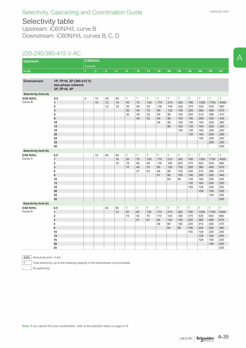
Upstream iC60N/H/LCurve B
In (A) 1 2 3 4 6 10 13 16 20 25 32 40 50 63
Downstream 1P, 1P+N, 2P (380-415 V) two-phase network 3P, 3P+N, 4P
Selectivity limit (A)iC60 N/H/LCurve B
0.5 4 10 40 60 T T T T T T T T T T1 10 12 16 40 70 120 170 210 300 780 1300 1700 40002 12 16 30 60 90 130 140 200 370 520 630 9603 30 40 70 90 120 150 250 380 460 6704 30 40 52 64 80 100 250 310 380 4706 40 52 64 80 100 190 290 300 44010 64 80 100 130 160 200 38013 80 100 130 160 200 25016 100 130 160 200 25020 130 160 200 25025 160 200 25032 200 25040 250
Selectivity limit (A)iC60 N/H/LCurve C
0.5 10 40 60 T T T T T T T T T T1 16 30 70 120 170 210 300 780 1300 1700 40002 16 18 60 90 130 160 200 370 520 630 9603 15 40 70 90 120 150 250 380 460 6704 27 52 64 80 100 250 310 380 4706 51 80 100 190 290 300 44010 64 80 130 160 200 25013 102 160 200 25016 102 128 200 25020 128 160 25025 160 20032 200
Selectivity limit (A)iC60 N/H/LCurve D
0.5 30 50 T T T T T T T T T T1 12 30 60 120 170 210 300 780 1300 1700 40002 19 40 70 110 140 180 370 520 630 8603 31 41 90 120 150 250 380 460 6704 48 80 100 220 310 340 4706 64 80 190 240 300 38010 100 128 200 25013 128 160 25016 128 160 20020 160 20025 200
4000 Selectivity limit = 4 kA.
T Total selectivity, up to the breaking capacity of the downstream circuit breaker.
No selectivity.
Selectivity tableUpstream: iC60N/H/L curve BDownstream: iC60N/H/L curves B, C, D
220-240/380-415 V AC
Note: if you cannot find your combination, refer to the selection table on page A-14
A-35
A
Selectivity, Cascading and Coordination Guide www.se.com
Selectivity tableUpstream: iC60N/H/L curve BDownstream: iC60N/H/L curves B, C, D
220-240/380-415 V AC
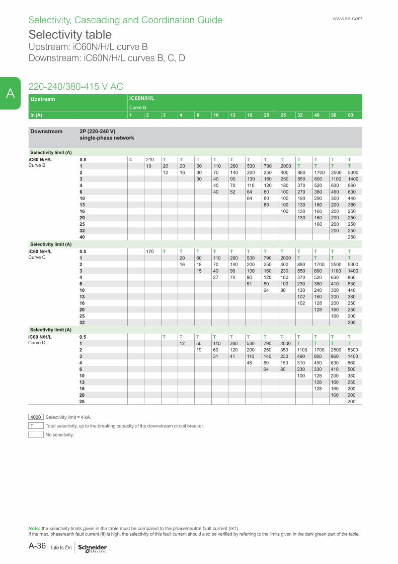
Note: the selectivity limits given in the table must be compared to the phase/neutral fault current (Ik1).If the max. phase/earth fault current (If) is high, the selectivity of this fault current should also be verified by referring to the limits given in the dark green part of the table.
Upstream iC60N/H/LCurve B
In (A) 1 2 3 4 6 10 13 16 20 25 32 40 50 63
Downstream 2P (220-240 V) single-phase network
Selectivity limit (A)iC60 N/H/LCurve B
0.5 4 210 T T T T T T T T T T T T1 10 20 20 60 110 260 530 790 2000 T T T T2 12 16 30 70 140 200 250 400 880 1700 2500 53003 30 40 90 130 160 250 550 800 1100 14004 40 70 110 120 180 370 520 630 9606 40 52 64 80 100 270 380 460 63010 64 80 100 190 290 300 44013 80 100 130 160 200 38016 100 130 160 200 25020 130 160 200 25025 160 200 25032 200 25040 250
Selectivity limit (A)iC60 N/H/LCurve C
0.5 170 T T T T T T T T T T T T1 20 60 110 260 530 790 2000 T T T T2 16 18 70 140 200 250 400 880 1700 2500 53003 15 40 90 130 160 230 550 800 1100 14004 27 70 90 120 180 370 520 630 8606 51 80 100 230 380 410 63010 64 80 130 240 300 44013 102 160 200 38016 102 128 200 25020 128 160 25025 160 20032 200
Selectivity limit (A)iC60 N/H/LCurve D
0.5 T T T T T T T T T T T T1 12 50 110 260 530 790 2000 T T T T2 19 60 120 200 250 350 1100 1700 2500 53003 31 41 110 140 230 490 800 960 14004 48 80 150 310 450 630 8606 64 80 230 330 410 50010 100 128 200 38013 128 160 25016 128 160 20020 160 20025 200
4000 Selectivity limit = 4 kA.
T Total selectivity, up to the breaking capacity of the downstream circuit breaker.
No selectivity.
A-36
A
Selectivity, Cascading and Coordination Guide www.se.com
Selectivity tableUpstream: iC60N/H/L curve CDownstream: iC60N/H/L curves B, C, D
220-240/380-415 V AC
Note: if you cannot find your combination, refer to the selection table on page A-14
Upstream iC60N/H/LCurve C
In (A) 1 2 3 4 6 10 13 16 20 25 32 40 50 63
Downstream 1P, 1P+N, 2P (380-415 V) two-phase network 3P, 3P+N, 4P
Selectivity limit (A)iC60 N/H/LCurve B
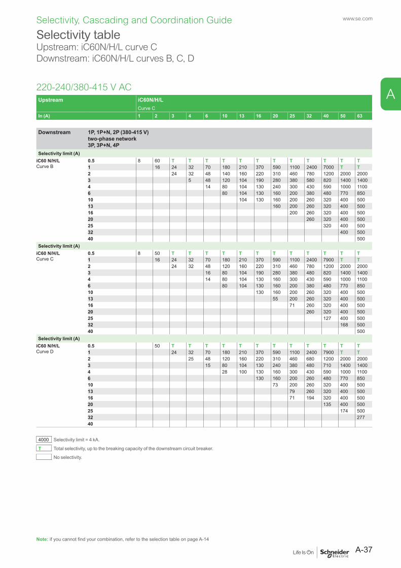
0.5 8 60 T T T T T T T T T T T T1 16 24 32 70 180 210 370 590 1100 2400 7000 T T2 24 32 48 140 160 220 310 460 780 1200 2000 20003 5 48 120 104 190 280 380 580 820 1400 14004 14 80 104 130 240 300 430 590 1000 11006 80 104 130 160 200 380 480 770 85010 104 130 160 200 260 320 400 50013 160 200 260 320 400 50016 200 260 320 400 50020 260 320 400 50025 320 400 50032 400 50040 500
Selectivity limit (A)iC60 N/H/LCurve C
0.5 8 50 T T T T T T T T T T T T1 16 24 32 70 180 210 370 590 1100 2400 7900 T T2 24 32 48 120 160 220 310 460 780 1200 2000 20003 16 80 104 190 280 380 480 820 1400 14004 14 80 104 130 160 300 430 590 1000 11006 80 104 130 160 200 380 480 770 85010 130 160 200 260 320 400 50013 55 200 260 320 400 50016 71 260 320 400 50020 260 320 400 50025 127 400 50032 168 50040 500
Selectivity limit (A)iC60 N/H/LCurve D
0.5 50 T T T T T T T T T T T T1 24 32 70 180 210 370 590 1100 2400 7900 T T2 25 48 120 160 220 310 460 680 1200 2000 20003 15 80 104 130 240 380 480 710 1400 14004 28 100 130 160 300 430 590 1000 11006 130 160 200 260 480 770 85010 73 200 260 320 400 50013 79 260 320 400 50016 71 194 320 400 50020 135 400 50025 174 50032 27740
4000 Selectivity limit = 4 kA.
T Total selectivity, up to the breaking capacity of the downstream circuit breaker.
No selectivity.
A-37
A
Selectivity, Cascading and Coordination Guide www.se.com
Selectivity table Upstream: iC60N/H/L curve CDownstream: iC60N/H/L curves B, C, D
220-240/380-415 V AC
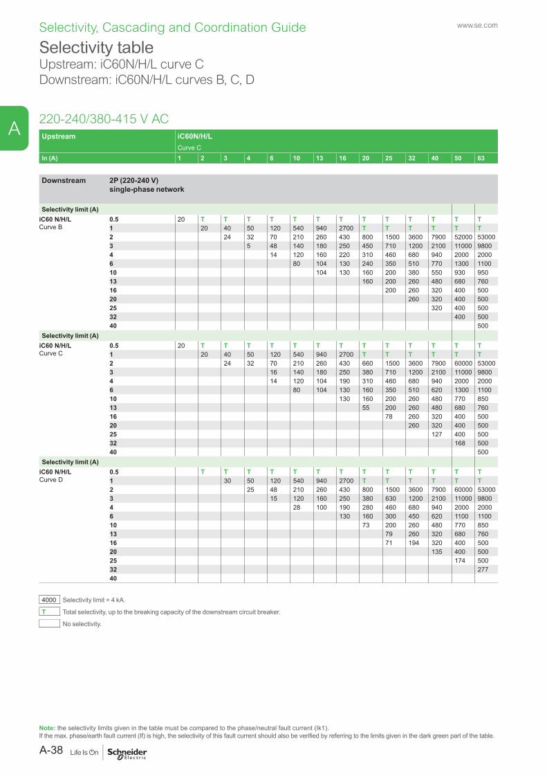
Note: the selectivity limits given in the table must be compared to the phase/neutral fault current (Ik1).If the max. phase/earth fault current (If) is high, the selectivity of this fault current should also be verified by referring to the limits given in the dark green part of the table.
Upstream iC60N/H/LCurve C
In (A) 1 2 3 4 6 10 13 16 20 25 32 40 50 63
Downstream 2P (220-240 V) single-phase network
Selectivity limit (A)iC60 N/H/LCurve B
0.5 20 T T T T T T T T T T T T T1 20 40 50 120 540 940 2700 T T T T T T2 24 32 70 210 260 430 800 1500 3600 7900 52000 530003 5 48 140 180 250 450 710 1200 2100 11000 98004 14 120 160 220 310 460 680 940 2000 20006 80 104 130 240 350 510 770 1300 110010 104 130 160 200 380 550 930 95013 160 200 260 480 680 76016 200 260 320 400 50020 260 320 400 50025 320 400 50032 400 50040 500
Selectivity limit (A)iC60 N/H/LCurve C
0.5 20 T T T T T T T T T T T T T1 20 40 50 120 540 940 2700 T T T T T T2 24 32 70 210 260 430 660 1500 3600 7900 60000 530003 16 140 180 250 380 710 1200 2100 11000 98004 14 120 104 190 310 460 680 940 2000 20006 80 104 130 160 350 510 620 1300 110010 130 160 200 260 480 770 85013 55 200 260 480 680 76016 78 260 320 400 50020 260 320 400 50025 127 400 50032 168 50040 500
Selectivity limit (A)iC60 N/H/LCurve D
0.5 T T T T T T T T T T T T T1 30 50 120 540 940 2700 T T T T T T2 25 48 210 260 430 800 1500 3600 7900 60000 530003 15 120 160 250 380 630 1200 2100 11000 98004 28 100 190 280 460 680 940 2000 20006 130 160 300 450 620 1100 110010 73 200 260 480 770 85013 79 260 320 680 76016 71 194 320 400 50020 135 400 50025 174 50032 27740
4000 Selectivity limit = 4 kA.
T Total selectivity, up to the breaking capacity of the downstream circuit breaker.
No selectivity.
A-38
A
Selectivity, Cascading and Coordination Guide www.se.com
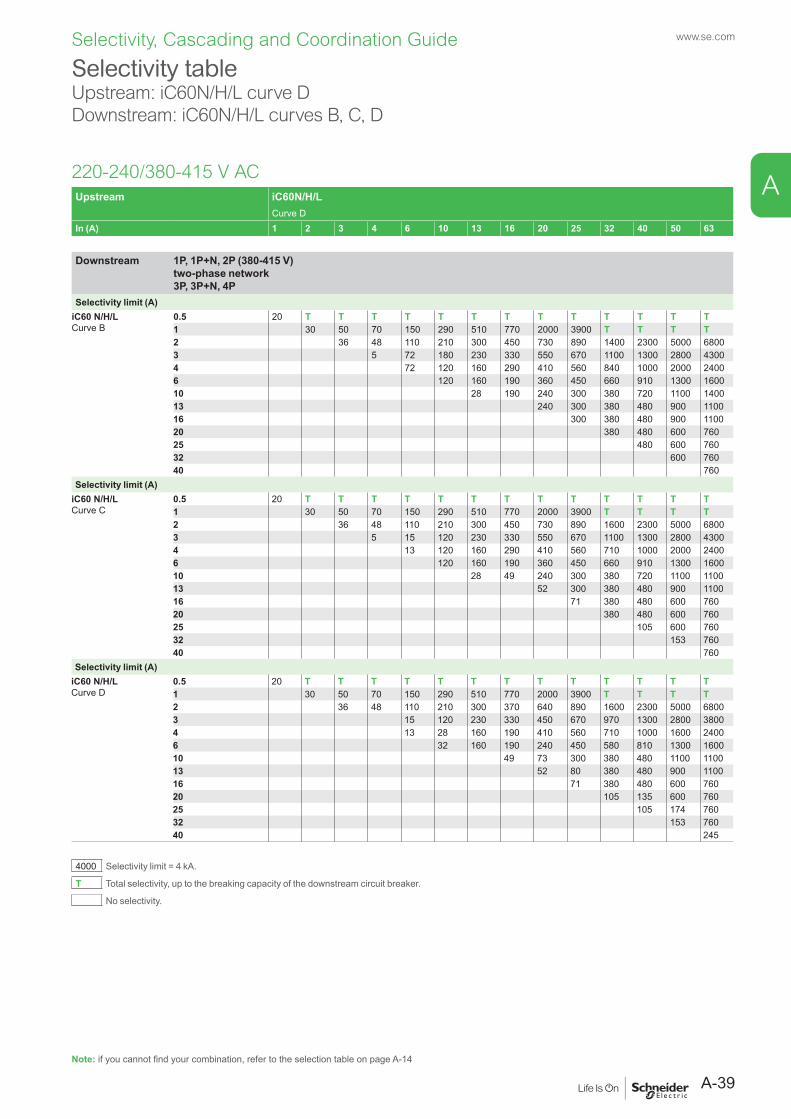
Selectivity tableUpstream: iC60N/H/L curve DDownstream: iC60N/H/L curves B, C, D
220-240/380-415 V AC
Note: if you cannot find your combination, refer to the selection table on page A-14
Upstream iC60N/H/LCurve D
In (A) 1 2 3 4 6 10 13 16 20 25 32 40 50 63
Downstream 1P, 1P+N, 2P (380-415 V) two-phase network 3P, 3P+N, 4P
Selectivity limit (A)iC60 N/H/LCurve B
0.5 20 T T T T T T T T T T T T T1 30 50 70 150 290 510 770 2000 3900 T T T T2 36 48 110 210 300 450 730 890 1400 2300 5000 68003 5 72 180 230 330 550 670 1100 1300 2800 43004 72 120 160 290 410 560 840 1000 2000 24006 120 160 190 360 450 660 910 1300 160010 28 190 240 300 380 720 1100 140013 240 300 380 480 900 110016 300 380 480 900 110020 380 480 600 76025 480 600 76032 600 76040 760
Selectivity limit (A)iC60 N/H/LCurve C
0.5 20 T T T T T T T T T T T T T1 30 50 70 150 290 510 770 2000 3900 T T T T2 36 48 110 210 300 450 730 890 1600 2300 5000 68003 5 15 120 230 330 550 670 1100 1300 2800 43004 13 120 160 290 410 560 710 1000 2000 24006 120 160 190 360 450 660 910 1300 160010 28 49 240 300 380 720 1100 110013 52 300 380 480 900 110016 71 380 480 600 76020 380 480 600 76025 105 600 76032 153 76040 760
Selectivity limit (A)iC60 N/H/LCurve D
0.5 20 T T T T T T T T T T T T T1 30 50 70 150 290 510 770 2000 3900 T T T T2 36 48 110 210 300 370 640 890 1600 2300 5000 68003 15 120 230 330 450 670 970 1300 2800 38004 13 28 160 190 410 560 710 1000 1600 24006 32 160 190 240 450 580 810 1300 160010 49 73 300 380 480 1100 110013 52 80 380 480 900 110016 71 380 480 600 76020 105 135 600 76025 105 174 76032 153 76040 245
4000 Selectivity limit = 4 kA.
T Total selectivity, up to the breaking capacity of the downstream circuit breaker.
No selectivity.
A-39
A

Selectivity, Cascading and Coordination Guide www.se.com
Selectivity table Upstream: iC60N/H/L curve DDownstream: iC60N/H/L curves B, C, D
220-240/380-415 V AC
Note: the selectivity limits given in the table must be compared to the phase/neutral fault current (Ik1).If the max. phase/earth fault current (If) is high, the selectivity of this fault current should also be verified by referring to the limits given in the dark green part of the table.
Upstream iC60N/H/LCurve D
In (A) 1 2 3 4 6 10 13 16 20 25 32 40 50 63
Downstream 2P (220-240 V) single-phase network
Selectivity limit (A)iC60 N/H/LCurve B
0.5 T T T T T T T T T T T T T T1 50 100 130 340 1600 10000 T T T T T T T2 50 80 150 350 650 1100 2600 5800 16000 45000 T T3 5 110 240 370 530 920 1600 3800 9500 T T4 72 180 270 370 640 890 1400 2300 7100 120006 120 160 290 480 590 900 1300 2200 260010 28 190 360 450 660 910 1500 190013 240 450 580 810 1300 160016 300 380 720 1100 140020 380 480 900 110025 480 600 76032 600 76040 760
Selectivity limit (A)iC60 N/H/LCurve C
0.5 T T T T T T T T T T T T T T1 50 100 130 340 1600 10000 T T T T T T T2 50 70 150 350 580 1100 2600 5800 16000 45000 T T3 5 15 240 370 530 920 1600 3800 9500 T T4 13 180 270 370 640 890 1400 1900 7100 120006 120 160 290 480 590 900 1300 2200 260010 28 190 360 450 660 910 1500 190013 52 300 580 810 1300 160016 71 380 720 1100 140020 380 480 900 110025 105 600 76032 153 76040 760
Selectivity limit (A)iC60 N/H/LCurve D
0.5 T T T T T T T T T T T T T T1 40 80 130 340 1600 10000 T T T T T T T2 50 70 150 350 650 1200 2600 5800 16000 45000 T T3 15 210 300 530 920 1600 3800 9500 T T4 13 28 230 370 640 890 1400 1900 7100 120006 32 160 190 420 590 900 1100 2200 260010 49 73 450 660 910 1500 190013 52 300 380 720 1300 160016 71 380 480 1100 140020 105 480 900 110025 105 174 76032 153 76040 245
4000 Selectivity limit = 4 kA.
T Total selectivity, up to the breaking capacity of the downstream circuit breaker.
No selectivity.
A-40
A
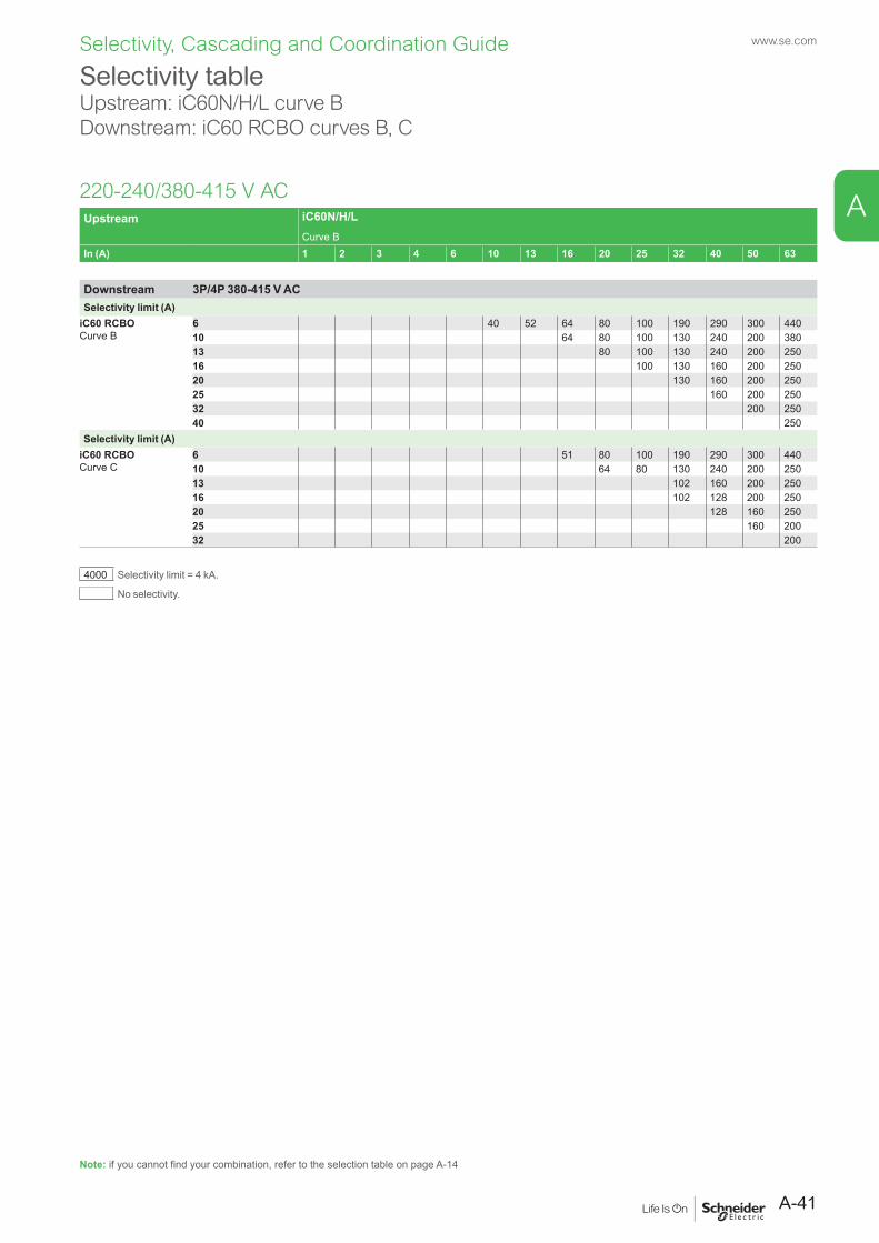
Selectivity, Cascading and Coordination Guide www.se.com
Upstream iC60N/H/LCurve B
In (A) 1 2 3 4 6 10 13 16 20 25 32 40 50 63
Downstream 3P/4P 380-415 V ACSelectivity limit (A)
iC60 RCBOCurve B
6 40 52 64 80 100 190 290 300 44010 64 80 100 130 240 200 38013 80 100 130 240 200 25016 100 130 160 200 25020 130 160 200 25025 160 200 25032 200 25040 250
Selectivity limit (A)iC60 RCBOCurve C
6 51 80 100 190 290 300 44010 64 80 130 240 200 25013 102 160 200 25016 102 128 200 25020 128 160 25025 160 20032 200
4000 Selectivity limit = 4 kA.
No selectivity.
Selectivity tableUpstream: iC60N/H/L curve BDownstream: iC60 RCBO curves B, C
220-240/380-415 V AC
Note: if you cannot find your combination, refer to the selection table on page A-14
A-41
A
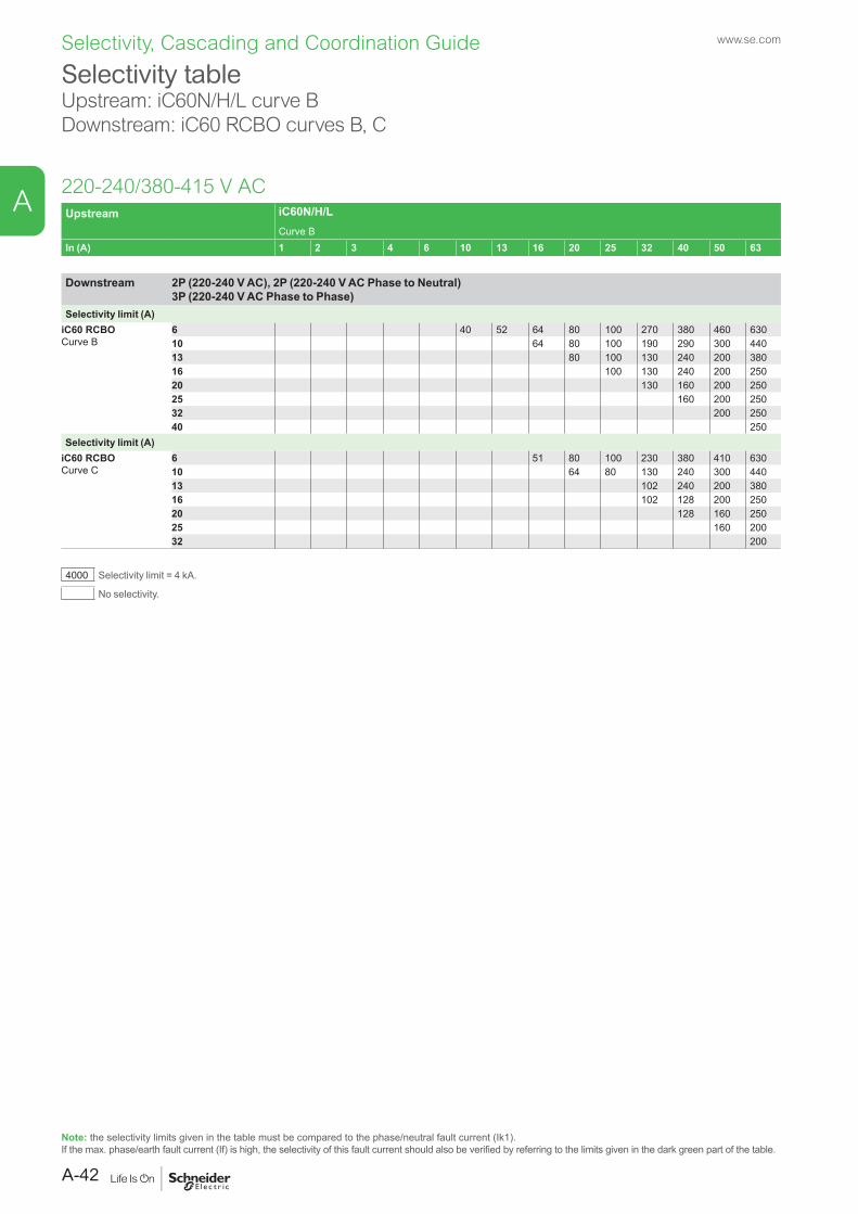
Selectivity, Cascading and Coordination Guide www.se.com
Selectivity tableUpstream: iC60N/H/L curve BDownstream: iC60 RCBO curves B, C
220-240/380-415 V AC
Note: the selectivity limits given in the table must be compared to the phase/neutral fault current (Ik1).If the max. phase/earth fault current (If) is high, the selectivity of this fault current should also be verified by referring to the limits given in the dark green part of the table.
Upstream iC60N/H/LCurve B
In (A) 1 2 3 4 6 10 13 16 20 25 32 40 50 63
Downstream 2P (220-240 V AC), 2P (220-240 V AC Phase to Neutral) 3P (220-240 V AC Phase to Phase)
Selectivity limit (A)iC60 RCBOCurve B
6 40 52 64 80 100 270 380 460 63010 64 80 100 190 290 300 44013 80 100 130 240 200 38016 100 130 240 200 25020 130 160 200 25025 160 200 25032 200 25040 250
Selectivity limit (A)iC60 RCBOCurve C
6 51 80 100 230 380 410 63010 64 80 130 240 300 44013 102 240 200 38016 102 128 200 25020 128 160 25025 160 20032 200
4000 Selectivity limit = 4 kA.
No selectivity.
A-42
A

Selectivity, Cascading and Coordination Guide www.se.com
Selectivity tableUpstream: iC60N/H/L curve CDownstream: iC60 RCBO curves B, C
220-240/380-415 V AC
Note: if you cannot find your combination, refer to the selection table on page A-14
Upstream iC60N/H/LCurve C
In (A) 1 2 3 4 6 10 13 16 20 25 32 40 50 63
Downstream 3P/4P 380-415 V ACSelectivity limit (A)
iC60 RCBOCurve B
6 80 104 130 160 200 380 480 770 85010 104 130 160 200 260 320 680 50013 160 200 260 320 600 50016 200 260 320 600 50020 260 320 400 50025 320 400 50032 400 50040 500
Selectivity limit (A)iC60 RCBOCurve C
6 80 104 130 160 200 380 480 770 85010 130 160 200 260 320 680 50013 55 200 260 320 600 50016 71 260 320 400 50020 260 320 400 50025 127 400 50032 168 50040 500
4000 Selectivity limit = 4 kA.
No selectivity.
A-43
A

Selectivity, Cascading and Coordination Guide www.se.com
Selectivity table Upstream: iC60N/H/L curve CDownstream: iC60 RCBO curves B, C
220-240/380-415 V AC
Note: the selectivity limits given in the table must be compared to the phase/neutral fault current (Ik1).If the max. phase/earth fault current (If) is high, the selectivity of this fault current should also be verified by referring to the limits given in the dark green part of the table.
Upstream iC60N/H/LCurve C
In (A) 1 2 3 4 6 10 13 16 20 25 32 40 50 63
Downstream 2P (220-240 V AC Phase to Neutral) 3P (220-240 V AC Phase to Phase)
Selectivity limit (A)iC60 RCBOCurve B
6 80 104 130 240 350 510 770 1300 110010 104 130 160 200 380 550 930 95013 160 200 260 480 770 76016 200 260 320 400 50020 260 320 400 50025 320 400 50032 400 50040 500
Selectivity limit (A)iC60 RCBOCurve C
6 80 104 130 160 350 510 620 1300 110010 130 160 200 260 480 770 85013 55 200 260 480 770 76016 78 260 320 400 50020 260 320 400 50025 127 400 50032 168 50040 500
4000 Selectivity limit = 4 kA.
No selectivity.
A-44
A

Selectivity, Cascading and Coordination Guide www.se.com
Selectivity tableUpstream: iC60N/H/L curve DDownstream: iC60 RCBO curves B, C
220-240/380-415 V AC
Note: if you cannot find your combination, refer to the selection table on page A-14
Upstream iC60N/H/LCurve D
In (A) 1 2 3 4 6 10 13 16 20 25 32 40 50 63
Downstream 3P/4P 380-415 V ACSelectivity limit (A)
iC60 RCBOCurve B
6 120 160 190 360 450 660 910 1300 160010 28 190 240 300 380 720 1100 140013 240 300 380 480 900 110016 300 380 480 900 110020 380 480 600 76025 480 600 76032 600 76040 760
Selectivity limit (A)iC60 RCBOCurve C
6 120 160 190 360 450 660 910 1300 160010 28 49 240 300 380 720 1100 110013 52 300 380 480 900 110016 71 380 480 900 76020 380 480 600 76025 105 600 76032 153 76040 760
4000 Selectivity limit = 4 kA.
No selectivity.
A-45
A

Selectivity, Cascading and Coordination Guide www.se.com
Selectivity table Upstream: iC60N/H/L curve DDownstream: iC60 RCBO curves B, C
220-240/380-415 V AC
Note: the selectivity limits given in the table must be compared to the phase/neutral fault current (Ik1).If the max. phase/earth fault current (If) is high, the selectivity of this fault current should also be verified by referring to the limits given in the dark green part of the table.
Upstream iC60N/H/LCurve D
In (A) 1 2 3 4 6 10 13 16 20 25 32 40 50 63
Downstream 2P (220-240 V AC Phase to Neutral) 3P (220-240 V AC Phase to Phase)
Selectivity limit (A)iC60 RCBOCurve B
6 120 160 290 480 590 900 1300 2200 260010 28 190 360 450 660 910 1500 190013 240 450 580 810 1300 160016 300 380 720 1100 140020 380 480 900 110025 480 900 76032 600 76040 760
Selectivity limit (A)iC60 RCBOCurve C
6 120 160 290 480 590 900 1300 2200 260010 28 190 360 450 660 910 1500 190013 52 300 580 810 1300 160016 71 380 720 1100 140020 380 480 900 110025 105 600 76032 153 76040 760
4000 Selectivity limit = 4 kA.
No selectivity.
A-46
A

Selectivity, Cascading and Coordination Guide www.se.com
Selectivity tableUpstream: NG125N/H/L, C120N/H curve BDownstream: iDPN/ iDPN N curves B, C, D, iDPN N Vigi / iDPN H Vigi curves B, C
220-240/380-415 V AC
Note: if you cannot find your combination, refer to the selection table on page A-14
Upstream NG125N/H/L, C120N/HCurve B
In (A) 10 16 20 25 32 40 50 63 80 100 125
Downstream 1P+N3P, 3P+N
Selectivity limit (A)iDPNiDPN NiDPN N VigiiDPN H VigiCurve B
1 300 500 700 1000 1500 2000 2500 T T T T2 150 300 500 700 1000 1500 2000 T T T T3 40 64 300 500 700 1000 1500 T T T T4 40 64 80 400 500 700 800 3000 T T T6 40 64 80 400 500 700 800 3000 T T T10 64 80 100 130 500 600 1800 3000 T T16 100 130 160 200 1000 2000 3300 375020 52 160 200 1000 1600 2500 370025 59 200 800 1300 2100 370032 200 600 1000 1800 270040 112 320 1600 2400
Selectivity limit (A)iDPNiDPN NiDPN N VigiiDPN H VigiCurve C
1 300 500 700 1000 1500 2000 2500 T T T T2 150 300 500 700 1000 1500 2000 T T T T3 40 64 300 500 700 1000 1500 T T T T4 40 64 80 400 500 700 800 3000 T T T6 51 80 100 500 700 800 3000 T T T10 80 130 500 600 1800 3000 4000 T16 98 128 200 1000 2000 3300 370020 128 160 1000 1600 2500 370025 160 201 1300 2100 370032 201 256 1800 270040 255 320 2400
Selectivity limit (A)iDPNiDPN NCurve D
1 300 500 700 1000 1500 2000 2500 T T T T2 150 300 500 700 1000 1500 2000 T T T T3 64 300 500 700 1000 1500 T T T T4 80 400 500 700 800 3000 T T T6 500 700 800 3000 T T T10 600 1800 3000 4000 T16 201 2000 3300 370020 201 256 2500 370025 201 256 320 370032 256 320 40040 320 400
4000 Selectivity limit = 4 kA.
T Total selectivity, up to the breaking capacity of the downstream circuit breaker.
No selectivity.
A-47
A
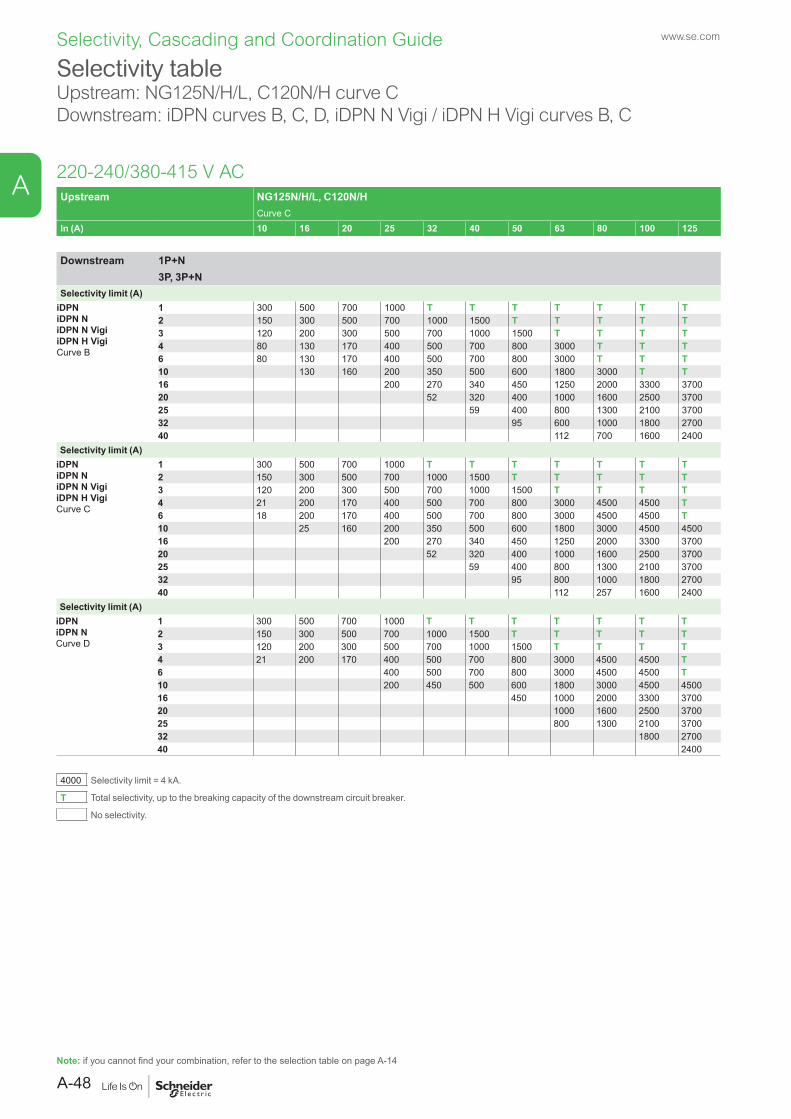
Selectivity, Cascading and Coordination Guide www.se.com
Selectivity tableUpstream: NG125N/H/L, C120N/H curve CDownstream: iDPN curves B, C, D, iDPN N Vigi / iDPN H Vigi curves B, C
Upstream NG125N/H/L, C120N/HCurve C
In (A) 10 16 20 25 32 40 50 63 80 100 125
Downstream 1P+N3P, 3P+N
Selectivity limit (A)iDPNiDPN NiDPN N VigiiDPN H VigiCurve B
1 300 500 700 1000 T T T T T T T2 150 300 500 700 1000 1500 T T T T T3 120 200 300 500 700 1000 1500 T T T T4 80 130 170 400 500 700 800 3000 T T T6 80 130 170 400 500 700 800 3000 T T T10 130 160 200 350 500 600 1800 3000 T T16 200 270 340 450 1250 2000 3300 370020 52 320 400 1000 1600 2500 370025 59 400 800 1300 2100 370032 95 600 1000 1800 270040 112 700 1600 2400
Selectivity limit (A)iDPNiDPN NiDPN N VigiiDPN H VigiCurve C
1 300 500 700 1000 T T T T T T T2 150 300 500 700 1000 1500 T T T T T3 120 200 300 500 700 1000 1500 T T T T4 21 200 170 400 500 700 800 3000 4500 4500 T6 18 200 170 400 500 700 800 3000 4500 4500 T10 25 160 200 350 500 600 1800 3000 4500 450016 200 270 340 450 1250 2000 3300 370020 52 320 400 1000 1600 2500 370025 59 400 800 1300 2100 370032 95 800 1000 1800 270040 112 257 1600 2400
Selectivity limit (A)iDPNiDPN NCurve D
1 300 500 700 1000 T T T T T T T2 150 300 500 700 1000 1500 T T T T T3 120 200 300 500 700 1000 1500 T T T T4 21 200 170 400 500 700 800 3000 4500 4500 T6 400 500 700 800 3000 4500 4500 T10 200 450 500 600 1800 3000 4500 450016 450 1000 2000 3300 370020 1000 1600 2500 370025 800 1300 2100 370032 1800 270040 2400
4000 Selectivity limit = 4 kA.
T Total selectivity, up to the breaking capacity of the downstream circuit breaker.
No selectivity.
220-240/380-415 V AC
Note: if you cannot find your combination, refer to the selection table on page A-14
A-48
A
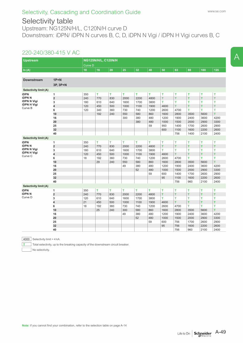
Selectivity, Cascading and Coordination Guide www.se.com
Selectivity tableUpstream: NG125N/H/L, C120N/H curve DDownstream: iDPN/ iDPN N curves B, C, D, iDPN N Vigi / iDPN H Vigi curves B, C
Upstream NG125N/H/L, C120N/HCurve D
In (A) 10 16 20 25 32 40 50 63 80 100 125
Downstream 1P+N3P, 3P+N
Selectivity limit (A)iDPNiDPN NiDPN N VigiiDPN H VigiCurve B
1 350 T T T T T T T T T T2 240 770 830 2000 2200 4800 T T T T T3 180 610 640 1600 1700 3800 T T T T T4 120 450 500 1000 1100 1900 4600 T T T T6 120 340 360 730 740 1200 2600 4700 T T T10 192 240 550 580 860 1600 2800 3500 5600 T16 300 380 480 1200 1900 2400 3600 420020 380 480 1000 1500 2000 2900 330025 59 950 1400 1700 2600 290032 600 1100 1600 2200 260040 756 1400 2100 2400
Selectivity limit (A)iDPNiDPN NiDPN N VigiiDPN H VigiCurve C
1 350 T T T T T T T T T T2 240 770 830 2000 2200 4800 T T T T T3 180 610 640 1600 1700 3800 T T T T T4 120 450 500 1000 1100 1900 4600 T T T T6 18 192 360 730 740 1200 2600 4700 T T T10 29 240 550 580 860 1600 2800 3500 5600 T16 49 380 480 1200 1900 2400 3600 420020 52 480 1000 1500 2000 2900 330025 59 600 1400 1700 2600 290032 95 1100 1600 2200 260040 756 960 2100 2400
Selectivity limit (A)iDPNiDPN NCurve D
1 350 T T T T T T T T T T2 240 770 830 2000 2200 4800 T T T T T3 120 610 640 1600 1700 3800 T T T T T4 21 450 500 1000 1100 1900 4600 T T T T6 18 192 360 730 740 1200 2600 4700 T T T10 25 240 300 580 860 1600 2800 3500 5600 T16 49 380 480 1200 1900 2400 3600 420020 52 480 1000 1500 2000 2900 330025 59 600 756 1700 2600 290032 95 756 1600 2200 260040 756 960 2100 2400
4000 Selectivity limit = 4 kA.
T Total selectivity, up to the breaking capacity of the downstream circuit breaker.
No selectivity.
220-240/380-415 V AC
Note: if you cannot find your combination, refer to the selection table on page A-14
A-49
A

Selectivity, Cascading and Coordination Guide www.se.com
Selectivity tableUpstream: NG125N/H/L, C120N/H curve BDownstream: iC40, iC40 N curves B, C, D & iCV40N curves B, C
220-240/380-415 V AC
Note: if you cannot find your combination, refer to the selection table on page A-14
Upstream NG125N/H/L, C120N/HCurve B
In (A) 10 16 20 25 32 40 50 63 80 100 125
Downstream 1P+N3P, 3P+N
Selectivity limit (A)iC40iC40 NiCV40 NiCV40 HCurve B
2 150 300 500 700 1000 1500 2000 T T T T4 40 64 80 400 500 700 800 3000 T T T6 40 64 80 400 500 700 800 3000 T T T10 64 80 100 130 500 600 1800 3000 T T13 100 130 160 200 1000 2000 3300 375016 100 130 160 200 1000 2000 3300 375020 52 160 200 1000 1600 2500 370025 59 200 800 1300 2100 370032 200 600 1000 1800 270040 112 320 1600 2400
Selectivity limit (A)iC40iC40 NiCV40 NiCV40 HCurve C
2 150 300 500 700 1000 1500 2000 T T T T4 40 64 80 400 500 700 800 3000 T T T6 51 80 100 500 700 800 3000 T T T10 80 130 500 600 1800 3000 4000 T13 98 128 200 1000 2000 3300 370016 98 128 200 1000 2000 3300 370020 128 160 1000 1600 2500 370025 160 201 1300 2100 370032 201 256 1800 270040 255 320 2400
Selectivity limit (A)iC40iC40 NiCV40 HCurve D
2 150 300 500 700 1000 1500 2000 T T T T4 80 400 500 700 800 3000 T T T6 500 700 800 3000 T T T10 600 1800 3000 4000 T13 201 2000 3300 370016 201 2000 3300 370020 201 256 2500 370025 201 256 320 370032 256 320 40040 320 400
4000 Selectivity limit = 4 kA.
T Total selectivity, up to the breaking capacity of the downstream circuit breaker.
No selectivity.
A-50
A

Selectivity, Cascading and Coordination Guide www.se.com
Selectivity tableUpstream: NG125N/H/L, C120N/H curve CDownstream: iC40, iC40 N curves B, C, D & iCV40N curves B, C
Upstream NG125N/H/L, C120N/HCurve C
In (A) 10 16 20 25 32 40 50 63 80 100 125
Downstream 1P+N3P, 3P+N
Selectivity limit (A)iC40iC40 NiCV40 NiCV40 HCurve B
2 150 300 500 700 1000 1500 T T T T T4 80 130 170 400 500 700 800 3000 T T T6 80 130 170 400 500 700 800 3000 T T T10 130 160 200 350 500 600 1800 3000 T T13 200 270 340 450 1250 2000 3300 370016 200 270 340 450 1250 2000 3300 370020 52 320 400 1000 1600 2500 370025 59 400 800 1300 2100 370032 95 600 1000 1800 270040 112 700 1600 2400
Selectivity limit (A)iC40iC40 NiCV40 NiCV40 HCurve C
2 150 300 500 700 1000 1500 T T T T T4 21 200 170 400 500 700 800 3000 4500 4500 T6 18 200 170 400 500 700 800 3000 4500 4500 T10 25 160 200 350 500 600 1800 3000 4500 450013 200 270 340 450 1250 2000 3300 370016 200 270 340 450 1250 2000 3300 370020 52 320 400 1000 1600 2500 370025 59 400 800 1300 2100 370032 95 800 1000 1800 270040 112 257 1600 2400
Selectivity limit (A)iC40iC40 NCurve D
2 150 300 500 700 1000 1500 T T T T T4 21 200 170 400 500 700 800 3000 4500 4500 T6 400 500 700 800 3000 4500 4500 T10 200 450 500 600 1800 3000 4500 450013 450 1000 2000 3300 370016 450 1000 2000 3300 370020 1000 1600 2500 370025 800 1300 2100 370032 1800 270040 2400
4000 Selectivity limit = 4 kA.
T Total selectivity, up to the breaking capacity of the downstream circuit breaker.
No selectivity.
220-240/380-415 V AC
Note: if you cannot find your combination, refer to the selection table on page A-14
A-51
A

Selectivity, Cascading and Coordination Guide www.se.com
Selectivity tableUpstream: NG125N/H/L, C120N/H curve DDownstream: iC40, iC40 N curves B, C, D & iCV40N curves B, C
Upstream NG125N/H/L, C120N/HCurve D
In (A) 10 16 20 25 32 40 50 63 80 100 125
Downstream 1P+N3P, 3P+N
Selectivity limit (A)iC40iC40 NiCV40 NiCV40 HCurve B
2 240 770 830 2000 2200 4800 T T T T T4 120 450 500 1000 1100 1900 4600 T T T T6 120 340 360 730 740 1200 2600 4700 T T T10 192 240 550 580 860 1600 2800 3500 5600 T13 300 380 480 1200 1900 2400 3600 420016 300 380 480 1200 1900 2400 3600 420020 380 480 1000 1500 2000 2900 330025 59 950 1400 1700 2600 290032 600 1100 1600 2200 260040 756 1400 2100 2400
Selectivity limit (A)iC40iC40 NiCV40 NiCV40 HCurve C
2 240 770 830 2000 2200 4800 T T T T T4 120 450 500 1000 1100 1900 4600 T T T T6 18 192 360 730 740 1200 2600 4700 T T T10 29 240 550 580 860 1600 2800 3500 5600 T13 49 380 480 1200 1900 2400 3600 420016 49 380 480 1200 1900 2400 3600 420020 52 480 1000 1500 2000 2900 330025 59 600 1400 1700 2600 290032 95 1100 1600 2200 260040 756 960 2100 2400
Selectivity limit (A)iC40iC40 NCurve D
2 240 770 830 2000 2200 4800 T T T T T4 21 450 500 1000 1100 1900 4600 T T T T6 18 192 360 730 740 1200 2600 4700 T T T10 25 240 300 580 860 1600 2800 3500 5600 T13 49 380 480 1200 1900 2400 3600 420016 49 380 480 1200 1900 2400 3600 420020 52 480 1000 1500 2000 2900 330025 59 600 756 1700 2600 290032 95 756 1600 2200 260040 756 960 2100 2400
4000 Selectivity limit = 4 kA.
T Total selectivity, up to the breaking capacity of the downstream circuit breaker.
No selectivity.
220-240/380-415 V AC
Note: if you cannot find your combination, refer to the selection table on page A-14
A-52
A
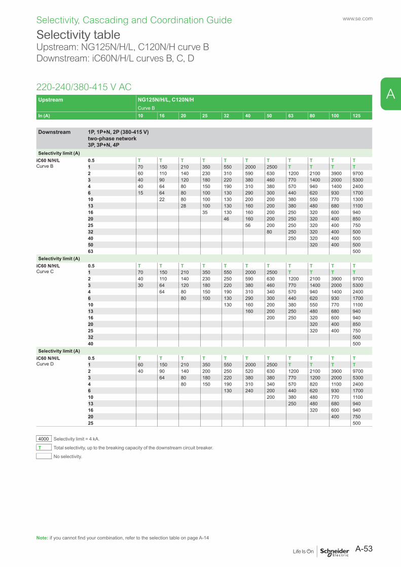
Selectivity, Cascading and Coordination Guide www.se.com
Selectivity table Upstream: NG125N/H/L, C120N/H curve BDownstream: iC60N/H/L curves B, C, D
220-240/380-415 V AC
Note: if you cannot find your combination, refer to the selection table on page A-14
Upstream NG125N/H/L, C120N/HCurve B
In (A) 10 16 20 25 32 40 50 63 80 100 125
Downstream 1P, 1P+N, 2P (380-415 V) two-phase network 3P, 3P+N, 4P
Selectivity limit (A)iC60 N/H/LCurve B
0.5 T T T T T T T T T T T1 70 150 210 350 550 2000 2500 T T T T2 60 110 140 230 310 590 630 1200 2100 3900 97003 40 90 120 180 220 380 460 770 1400 2000 53004 40 64 80 150 190 310 380 570 940 1400 24006 15 64 80 100 130 290 300 440 620 930 170010 22 80 100 130 200 200 380 550 770 130013 28 100 130 160 200 380 480 680 110016 35 130 160 200 250 320 600 94020 46 160 200 250 320 400 85025 56 200 250 320 400 75032 80 250 320 400 50040 250 320 400 50050 320 400 50063 500
Selectivity limit (A)iC60 N/H/LCurve C
0.5 T T T T T T T T T T T1 70 150 210 350 550 2000 2500 T T T T2 40 110 140 230 250 590 630 1200 2100 3900 97003 30 64 120 180 220 380 460 770 1400 2000 53004 64 80 150 190 310 340 570 940 1400 24006 80 100 130 290 300 440 620 930 170010 130 160 200 380 550 770 110013 160 200 250 480 680 94016 200 250 320 600 94020 320 400 85025 320 400 75032 50040 500
Selectivity limit (A)iC60 N/H/LCurve D
0.5 T T T T T T T T T T T1 60 150 210 350 550 2000 2500 T T T T2 40 90 140 200 250 520 630 1200 2100 3900 97003 64 80 180 220 380 380 770 1200 2000 53004 80 150 190 310 340 570 820 1100 24006 130 240 200 440 620 930 170010 200 380 480 770 110013 250 480 680 94016 320 600 94020 400 75025 500
4000 Selectivity limit = 4 kA.
T Total selectivity, up to the breaking capacity of the downstream circuit breaker.
No selectivity.
A-53
A
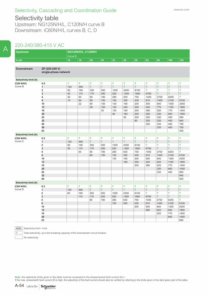
Selectivity, Cascading and Coordination Guide www.se.com
Selectivity table Upstream: NG125N/H/L, C120N/H curve BDownstream: iC60N/H/L curves B, C, D
220-240/380-415 V AC
Note: the selectivity limits given in the table must be compared to the phase/neutral fault current (Ik1).If the max. phase/earth fault current (If) is high, the selectivity of this fault current should also be verified by referring to the limits given in the dark green part of the table.
Upstream NG125N/H/L, C120N/HCurve B
In (A) 10 16 20 25 32 40 50 63 80 100 125
Downstream 2P (220-240 V) single-phase network
Selectivity limit (A)iC60 N/H/LCurve B
0.5 T T T T T T T T T T T1 120 490 T T T T T T T T T2 60 160 350 500 1200 4200 8100 T T T T3 40 110 170 250 520 1300 1900 6700 T T T4 40 64 80 190 280 630 750 1400 2700 6200 T6 15 64 80 150 150 350 430 810 1400 2100 610010 22 80 100 130 160 200 500 840 1300 250013 28 100 130 240 200 440 770 1100 190016 35 130 160 200 380 520 770 140020 46 160 200 250 320 600 100025 56 200 250 320 400 89032 80 250 320 400 84040 250 320 400 79050 320 400 75063 500
Selectivity limit (A)iC60 N/H/LCurve C
0.5 T T T T T T T T T T T1 120 490 T T T T T T T T T2 60 160 350 500 1200 4200 8100 T T T T3 30 110 170 250 520 1300 1900 6700 T T T4 64 80 190 280 630 750 1400 2700 6200 T6 80 150 150 350 430 810 1400 2100 610010 130 160 200 500 840 1300 250013 160 200 440 620 1100 190016 200 380 520 770 140020 320 600 100025 320 400 89032 84040 500
Selectivity limit (A)iC60 N/H/LCurve D
0.5 T T T T T T T T T T T1 120 490 T T T T T T T T T2 60 160 350 500 1200 4200 8100 T T T T3 110 170 250 520 1300 1900 6700 T T T4 80 190 280 630 750 1400 2700 6200 T6 150 350 430 810 1400 2100 610010 200 500 840 1300 250013 380 620 930 190016 520 770 140020 600 100025 890
4000 Selectivity limit = 4 kA.
T Total selectivity, up to the breaking capacity of the downstream circuit breaker.
No selectivity.
A-54
A
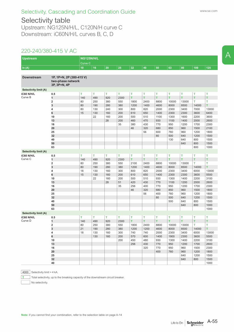
Selectivity, Cascading and Coordination Guide www.se.com
Selectivity table Upstream: NG125N/H/L, C120N/H curve CDownstream: iC60N/H/L curves B, C, D
220-240/380-415 V AC
Note: if you cannot find your combination, refer to the selection table on page A-14
Upstream NG125N/H/LCurve C
In (A) 10 16 20 25 32 40 50 63 80 100 125
Downstream 1P, 1P+N, 2P (380-415 V) two-phase network 3P, 3P+N, 4P
Selectivity limit (A)iC60 N/H/LCurve B
0.5 T T T T T T T T T T T1 140 490 920 2300 T T T T T T T2 80 250 380 550 1800 2400 8800 10000 13000 T T3 80 190 280 380 1200 1400 4600 8000 8500 14000 T4 80 130 240 300 800 820 2000 2300 3400 7000 130006 15 130 160 200 610 650 1400 2300 2300 3600 640010 22 160 200 500 510 1100 1300 1600 2200 360013 28 200 460 470 930 1100 1400 2000 260016 35 380 430 770 950 1200 1700 230020 46 320 680 850 960 1500 210025 56 600 760 960 1200 180032 80 500 640 1200 150040 130 640 800 150050 640 800 150063 800 1000
Selectivity limit (A)iC60 N/H/LCurve C
0.5 T T T T T T T T T T T1 140 490 920 2300 T T T T T T T2 80 250 380 550 2100 2400 8800 10000 13000 T T3 80 190 280 380 1200 1400 4600 8000 8500 14000 T4 18 130 160 300 800 820 2000 2300 3400 6000 130006 15 130 160 200 610 650 1400 2300 2300 3600 550010 22 160 200 500 510 930 1300 1400 2200 310013 28 51 420 430 770 1100 1200 2000 260016 35 256 400 770 950 1200 1700 230020 46 320 680 850 960 1500 180025 56 400 760 960 1200 180032 80 500 640 1200 150040 500 640 800 150050 640 800 100063 1000
Selectivity limit (A)iC60 N/H/LCurve D
0.5 T T T T T T T T T T T1 140 490 920 2300 T T T T T T T2 80 250 380 550 1800 2400 8800 10000 13000 T T3 21 190 280 380 1200 1200 4600 8000 8500 14000 T4 18 130 160 300 740 740 2000 2300 3400 6000 130006 130 160 200 570 600 1400 1900 2300 3600 550010 200 450 480 930 1300 1400 2200 310013 256 430 770 950 1200 1700 260016 320 770 950 960 1500 230020 400 760 960 1200 180025 640 1200 150032 640 800 150040 1000
4000 Selectivity limit = 4 kA.
T Total selectivity, up to the breaking capacity of the downstream circuit breaker.
No selectivity.
A-55
A

Selectivity, Cascading and Coordination Guide www.se.com
Selectivity table Upstream: NG125N/H/L, C120N/H curve CDownstream: iC60N/H/L curves B, C, D
220-240/380-415 V AC
Note: the selectivity limits given in the table must be compared to the phase/neutral fault current (Ik1).If the max. phase/earth fault current (If) is high, the selectivity of this fault current should also be verified by referring to the limits given in the dark green part of the table.
Upstream NG125N/H/LCurve C
In (A) 10 16 20 25 32 40 50 63 80 100 125
Downstream 2P (220-240 V) single-phase network
Selectivity limit (A)iC60 N/H/LCurve B
0.5 T T T T T T T T T T T1 950 T T T T T T T T T T2 210 1900 4200 10000 T T T T T T T3 120 780 1300 4700 T T T T T T T4 80 310 590 1100 4000 13000 T T T T T6 15 190 330 510 1500 2700 7200 9000 9000 T T10 22 160 300 1000 1400 2700 3500 3500 7400 T13 28 200 760 910 2000 2700 2700 4900 810016 35 620 620 1600 2700 2700 3600 550020 46 480 1100 1600 1600 2200 360025 56 930 1200 1200 2000 260032 80 930 960 1700 230040 130 960 1400 200050 640 1200 190063 1200 1700
Selectivity limit (A)iC60 N/H/LCurve C
0.5 T T T T T T T T T T T1 950 T T T T T T T T T T2 210 1900 3500 10000 T T T T T T T3 80 670 1300 4700 T T T T T T T4 18 310 590 1100 3600 13000 T T T T T6 15 190 290 510 1500 2700 7200 9000 9000 T T10 22 160 200 890 1200 2700 3700 3700 6600 T13 28 51 760 770 2000 2700 2700 4000 720016 35 256 620 1600 2700 2700 3600 460020 46 320 1100 1400 1400 2200 360025 56 400 1100 1200 2000 260032 80 500 960 1400 230040 500 640 1200 200050 640 800 170063 1000
Selectivity limit (A)iC60 N/H/LCurve D
0.5 T T T T T T T T T T T1 950 T T T T T T T T T T2 210 1700 3500 10000 T T T T T T T3 21 550 1300 4700 T T T T T T T4 18 310 520 960 3600 13000 T T T T T6 190 240 460 1500 2700 6400 9000 9000 T T10 200 890 1100 2700 3700 3700 6600 T13 256 620 2000 2300 2300 4000 720016 320 1400 2300 2300 3100 460020 400 1400 1400 2200 310025 960 1700 260032 640 1400 200040 1800
4000 Selectivity limit = 4 kA.
T Total selectivity, up to the breaking capacity of the downstream circuit breaker.
No selectivity.
A-56
A
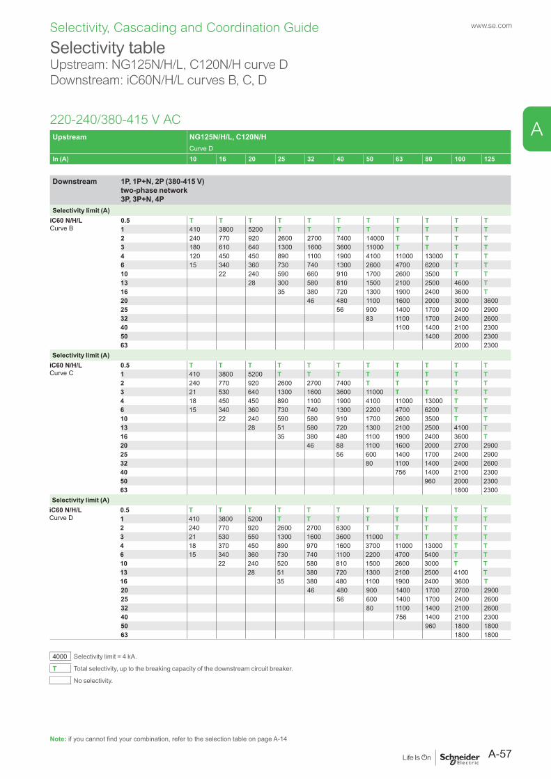
Selectivity, Cascading and Coordination Guide www.se.com
Selectivity tableUpstream: NG125N/H/L, C120N/H curve DDownstream: iC60N/H/L curves B, C, D
220-240/380-415 V ACUpstream NG125N/H/L, C120N/H
Curve DIn (A) 10 16 20 25 32 40 50 63 80 100 125
Downstream 1P, 1P+N, 2P (380-415 V) two-phase network 3P, 3P+N, 4P
Selectivity limit (A)iC60 N/H/LCurve B
0.5 T T T T T T T T T T T1 410 3800 5200 T T T T T T T T2 240 770 920 2600 2700 7400 14000 T T T T3 180 610 640 1300 1600 3600 11000 T T T T4 120 450 450 890 1100 1900 4100 11000 13000 T T6 15 340 360 730 740 1300 2600 4700 6200 T T10 22 240 590 660 910 1700 2600 3500 T T13 28 300 580 810 1500 2100 2500 4600 T16 35 380 720 1300 1900 2400 3600 T20 46 480 1100 1600 2000 3000 360025 56 900 1400 1700 2400 290032 83 1100 1700 2400 260040 1100 1400 2100 230050 1400 2000 230063 2000 2300
Selectivity limit (A)iC60 N/H/LCurve C
0.5 T T T T T T T T T T T1 410 3800 5200 T T T T T T T T2 240 770 920 2600 2700 7400 T T T T T3 21 530 640 1300 1600 3600 11000 T T T T4 18 450 450 890 1100 1900 4100 11000 13000 T T6 15 340 360 730 740 1300 2200 4700 6200 T T10 22 240 590 580 910 1700 2600 3500 T T13 28 51 580 720 1300 2100 2500 4100 T16 35 380 480 1100 1900 2400 3600 T20 46 88 1100 1600 2000 2700 290025 56 600 1400 1700 2400 290032 80 1100 1400 2400 260040 756 1400 2100 230050 960 2000 230063 1800 2300
Selectivity limit (A)iC60 N/H/LCurve D
0.5 T T T T T T T T T T T1 410 3800 5200 T T T T T T T T2 240 770 920 2600 2700 6300 T T T T T3 21 530 550 1300 1600 3600 11000 T T T T4 18 370 450 890 970 1600 3700 11000 13000 T T6 15 340 360 730 740 1100 2200 4700 5400 T T10 22 240 520 580 810 1500 2600 3000 T T13 28 51 380 720 1300 2100 2500 4100 T16 35 380 480 1100 1900 2400 3600 T20 46 480 900 1400 1700 2700 290025 56 600 1400 1700 2400 260032 80 1100 1400 2100 260040 756 1400 2100 230050 960 1800 180063 1800 1800
4000 Selectivity limit = 4 kA.
T Total selectivity, up to the breaking capacity of the downstream circuit breaker.
No selectivity.
Note: if you cannot find your combination, refer to the selection table on page A-14
A-57
A
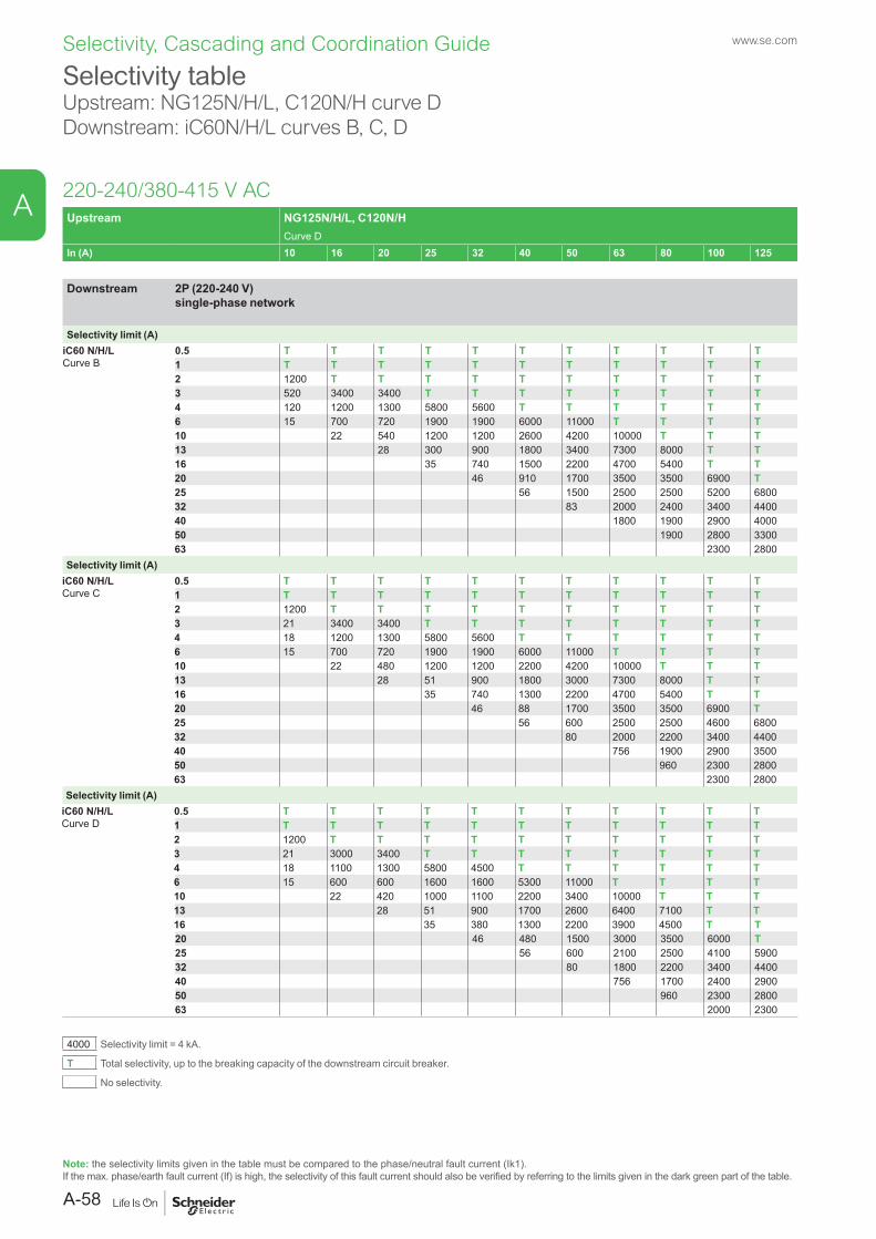
Selectivity, Cascading and Coordination Guide www.se.com
Selectivity table Upstream: NG125N/H/L, C120N/H curve DDownstream: iC60N/H/L curves B, C, D
220-240/380-415 V AC
Note: the selectivity limits given in the table must be compared to the phase/neutral fault current (Ik1).If the max. phase/earth fault current (If) is high, the selectivity of this fault current should also be verified by referring to the limits given in the dark green part of the table.
Upstream NG125N/H/L, C120N/HCurve D
In (A) 10 16 20 25 32 40 50 63 80 100 125
Downstream 2P (220-240 V) single-phase network
Selectivity limit (A)iC60 N/H/LCurve B
0.5 T T T T T T T T T T T1 T T T T T T T T T T T2 1200 T T T T T T T T T T3 520 3400 3400 T T T T T T T T4 120 1200 1300 5800 5600 T T T T T T6 15 700 720 1900 1900 6000 11000 T T T T10 22 540 1200 1200 2600 4200 10000 T T T13 28 300 900 1800 3400 7300 8000 T T16 35 740 1500 2200 4700 5400 T T20 46 910 1700 3500 3500 6900 T25 56 1500 2500 2500 5200 680032 83 2000 2400 3400 440040 1800 1900 2900 400050 1900 2800 330063 2300 2800
Selectivity limit (A)iC60 N/H/LCurve C
0.5 T T T T T T T T T T T1 T T T T T T T T T T T2 1200 T T T T T T T T T T3 21 3400 3400 T T T T T T T T4 18 1200 1300 5800 5600 T T T T T T6 15 700 720 1900 1900 6000 11000 T T T T10 22 480 1200 1200 2200 4200 10000 T T T13 28 51 900 1800 3000 7300 8000 T T16 35 740 1300 2200 4700 5400 T T20 46 88 1700 3500 3500 6900 T25 56 600 2500 2500 4600 680032 80 2000 2200 3400 440040 756 1900 2900 350050 960 2300 280063 2300 2800
Selectivity limit (A)iC60 N/H/LCurve D
0.5 T T T T T T T T T T T1 T T T T T T T T T T T2 1200 T T T T T T T T T T3 21 3000 3400 T T T T T T T T4 18 1100 1300 5800 4500 T T T T T T6 15 600 600 1600 1600 5300 11000 T T T T10 22 420 1000 1100 2200 3400 10000 T T T13 28 51 900 1700 2600 6400 7100 T T16 35 380 1300 2200 3900 4500 T T20 46 480 1500 3000 3500 6000 T25 56 600 2100 2500 4100 590032 80 1800 2200 3400 440040 756 1700 2400 290050 960 2300 280063 2000 2300
4000 Selectivity limit = 4 kA.
T Total selectivity, up to the breaking capacity of the downstream circuit breaker.
No selectivity.
A-58
A
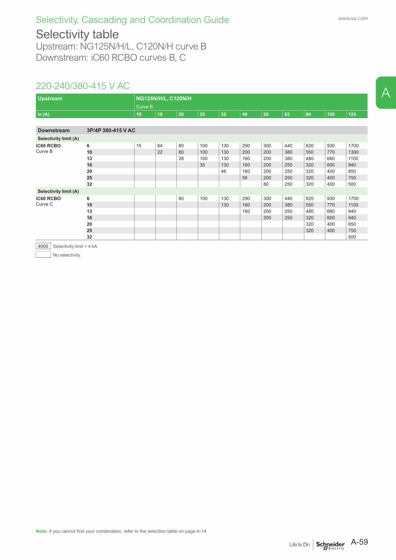
Selectivity, Cascading and Coordination Guide www.se.com
Selectivity table Upstream: NG125N/H/L, C120N/H curve BDownstream: iC60 RCBO curves B, C
220-240/380-415 V AC
Note: if you cannot find your combination, refer to the selection table on page A-14
Upstream NG125N/H/L, C120N/HCurve B
In (A) 10 16 20 25 32 40 50 63 80 100 125
Downstream 3P/4P 380-415 V ACSelectivity limit (A)
iC60 RCBOCurve B
6 15 64 80 100 130 290 300 440 620 930 170010 22 80 100 130 200 200 380 550 770 130013 28 100 130 160 200 380 480 680 110016 35 130 160 200 250 320 600 94020 46 160 200 250 320 400 85025 56 200 250 320 400 75032 80 250 320 400 500
Selectivity limit (A)iC60 RCBOCurve C
6 80 100 130 290 300 440 620 930 170010 130 160 200 380 550 770 110013 160 200 250 480 680 94016 200 250 320 600 94020 320 400 85025 320 400 75032 500
4000 Selectivity limit = 4 kA.
No selectivity.
A-59
A
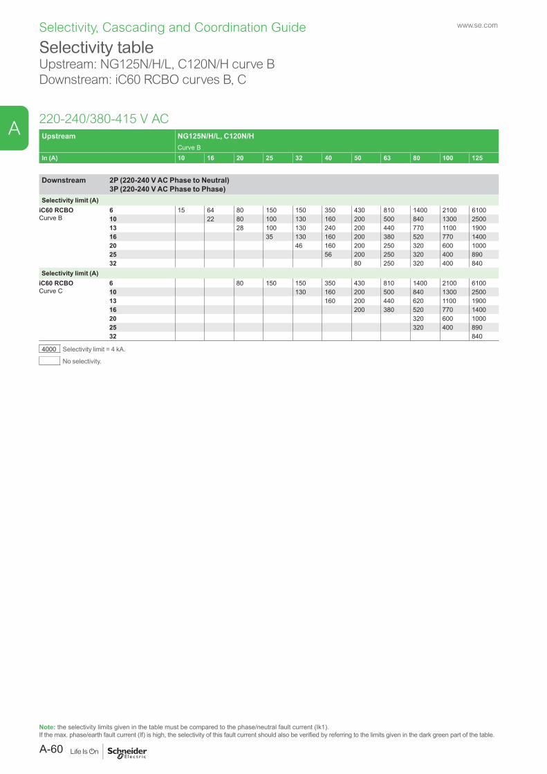
Selectivity, Cascading and Coordination Guide www.se.com
Selectivity table Upstream: NG125N/H/L, C120N/H curve BDownstream: iC60 RCBO curves B, C
220-240/380-415 V AC
Note: the selectivity limits given in the table must be compared to the phase/neutral fault current (Ik1).If the max. phase/earth fault current (If) is high, the selectivity of this fault current should also be verified by referring to the limits given in the dark green part of the table.
Upstream NG125N/H/L, C120N/HCurve B
In (A) 10 16 20 25 32 40 50 63 80 100 125
Downstream 2P (220-240 V AC Phase to Neutral) 3P (220-240 V AC Phase to Phase)
Selectivity limit (A)iC60 RCBOCurve B
6 15 64 80 150 150 350 430 810 1400 2100 610010 22 80 100 130 160 200 500 840 1300 250013 28 100 130 240 200 440 770 1100 190016 35 130 160 200 380 520 770 140020 46 160 200 250 320 600 100025 56 200 250 320 400 89032 80 250 320 400 840
Selectivity limit (A)iC60 RCBOCurve C
6 80 150 150 350 430 810 1400 2100 610010 130 160 200 500 840 1300 250013 160 200 440 620 1100 190016 200 380 520 770 140020 320 600 100025 320 400 89032 840
4000 Selectivity limit = 4 kA.
No selectivity.
A-60
A
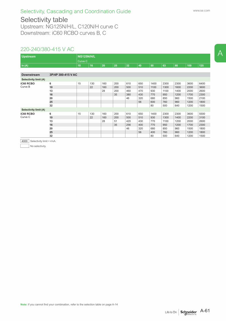
Selectivity, Cascading and Coordination Guide www.se.com
Selectivity table Upstream: NG125N/H/L, C120N/H curve CDownstream: iC60 RCBO curves B, C
220-240/380-415 V AC
Note: if you cannot find your combination, refer to the selection table on page A-14
Upstream NG125N/H/LCurve C
In (A) 10 16 20 25 32 40 50 63 80 100 125
Downstream 3P/4P 380-415 V ACSelectivity limit (A)
iC60 RCBOCurve B
6 15 130 160 200 610 650 1400 2300 2300 3600 640010 22 160 200 500 510 1100 1300 1600 2200 360013 28 200 460 470 930 1100 1400 2000 260016 35 380 430 770 950 1200 1700 230020 46 320 680 850 960 1500 210025 56 600 760 960 1200 180032 80 500 640 1200 1500
Selectivity limit (A)iC60 RCBOCurve C
6 15 130 160 200 610 650 1400 2300 2300 3600 550010 22 160 200 500 510 930 1300 1400 2200 310013 28 51 420 430 770 1100 1200 2000 260016 35 256 400 770 950 1200 1700 230020 46 320 680 850 960 1500 180025 56 400 760 960 1200 180032 80 500 640 1200 1500
4000 Selectivity limit = 4 kA.
No selectivity.
A-61
A
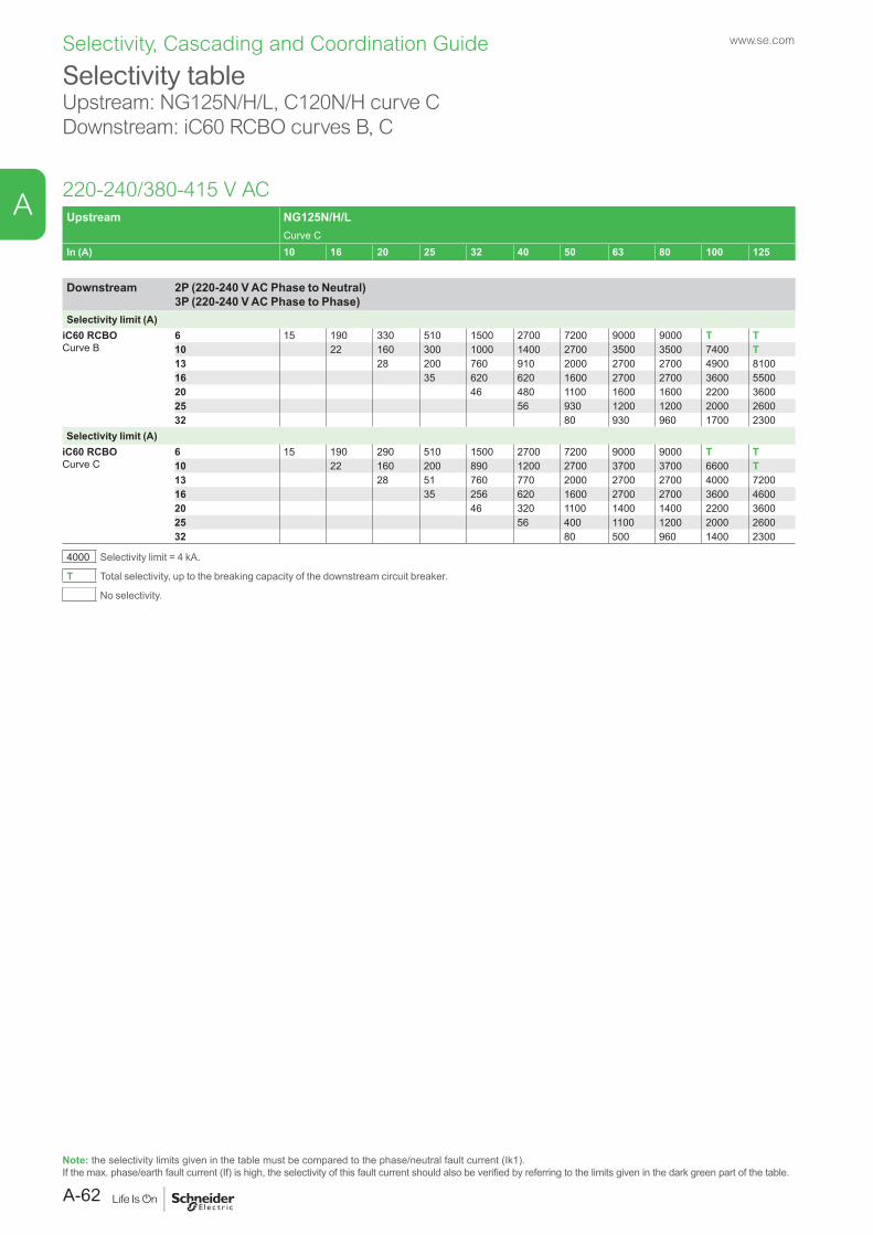
Selectivity, Cascading and Coordination Guide www.se.com
Selectivity table Upstream: NG125N/H/L, C120N/H curve CDownstream: iC60 RCBO curves B, C
220-240/380-415 V AC
Note: the selectivity limits given in the table must be compared to the phase/neutral fault current (Ik1).If the max. phase/earth fault current (If) is high, the selectivity of this fault current should also be verified by referring to the limits given in the dark green part of the table.
Upstream NG125N/H/LCurve C
In (A) 10 16 20 25 32 40 50 63 80 100 125
Downstream 2P (220-240 V AC Phase to Neutral) 3P (220-240 V AC Phase to Phase)
Selectivity limit (A)iC60 RCBOCurve B
6 15 190 330 510 1500 2700 7200 9000 9000 T T10 22 160 300 1000 1400 2700 3500 3500 7400 T13 28 200 760 910 2000 2700 2700 4900 810016 35 620 620 1600 2700 2700 3600 550020 46 480 1100 1600 1600 2200 360025 56 930 1200 1200 2000 260032 80 930 960 1700 2300
Selectivity limit (A)iC60 RCBOCurve C
6 15 190 290 510 1500 2700 7200 9000 9000 T T10 22 160 200 890 1200 2700 3700 3700 6600 T13 28 51 760 770 2000 2700 2700 4000 720016 35 256 620 1600 2700 2700 3600 460020 46 320 1100 1400 1400 2200 360025 56 400 1100 1200 2000 260032 80 500 960 1400 2300
4000 Selectivity limit = 4 kA.
T Total selectivity, up to the breaking capacity of the downstream circuit breaker.
No selectivity.
A-62
A

Selectivity, Cascading and Coordination Guide www.se.com
Selectivity tableUpstream: NG125N/H/L, C120N/H curve DDownstream: iC60 RCBO curves B, C
220-240/380-415 V ACUpstream NG125N/H/L, C120N/H
Curve DIn (A) 10 16 20 25 32 40 50 63 80 100 125
Downstream 3P/4P 380-415 V ACSelectivity limit (A)
iC60 RCBOCurve B
6 15 340 360 730 740 1300 2600 4700 6200 T T10 22 240 590 660 910 1700 2600 3500 T T13 28 300 580 810 1500 2100 2500 4600 T16 35 380 720 1300 1900 2400 3600 T20 46 480 1100 1600 2000 3000 360025 56 900 1400 1700 2400 290032 83 1100 1700 2400 2600
Selectivity limit (A)iC60 RCBOCurve C
6 15 340 360 730 740 1300 2200 4700 6200 T T10 22 240 590 580 910 1700 2600 3500 T T13 28 51 580 720 1300 2100 2500 4100 T16 35 380 480 1100 1900 2400 3600 T20 46 88 1100 1600 2000 2700 290025 56 600 1400 1700 2400 290032 80 1100 1400 2400 2600
4000 Selectivity limit = 4 kA.
T Total selectivity, up to the breaking capacity of the downstream circuit breaker.
No selectivity.
Note: if you cannot find your combination, refer to the selection table on page A-14
A-63
A
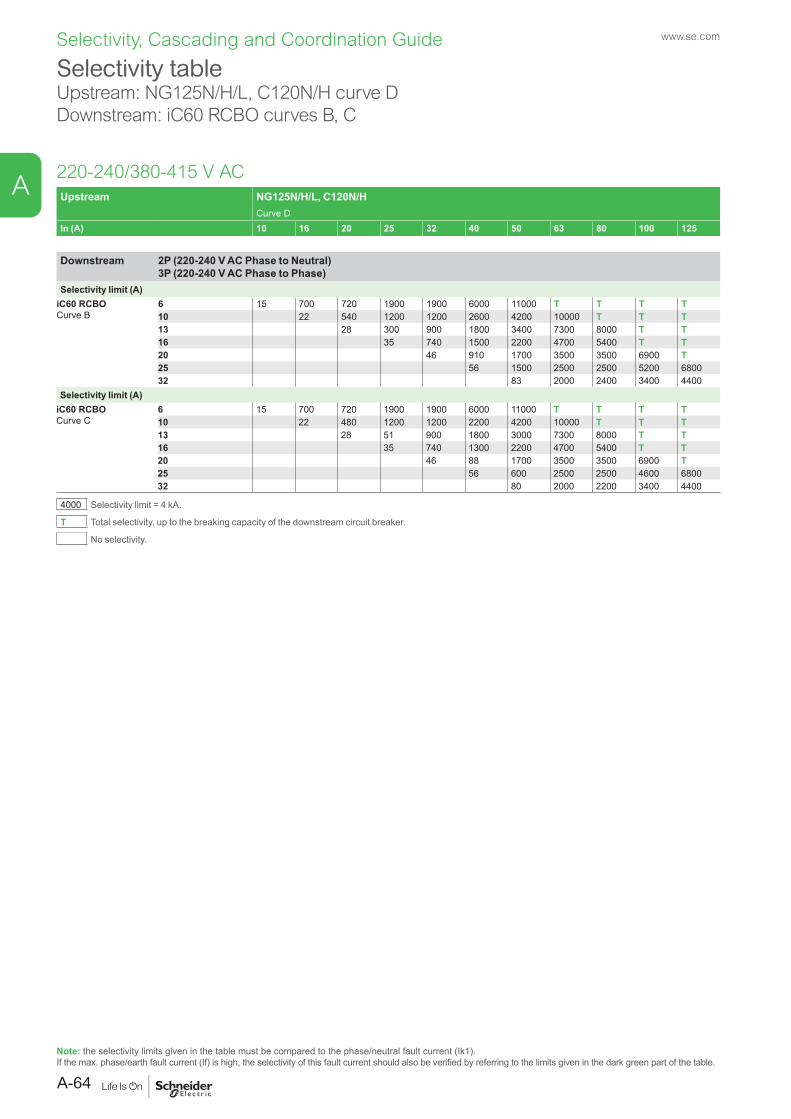
Selectivity, Cascading and Coordination Guide www.se.com
Selectivity table Upstream: NG125N/H/L, C120N/H curve DDownstream: iC60 RCBO curves B, C
220-240/380-415 V AC
Note: the selectivity limits given in the table must be compared to the phase/neutral fault current (Ik1).If the max. phase/earth fault current (If) is high, the selectivity of this fault current should also be verified by referring to the limits given in the dark green part of the table.
Upstream NG125N/H/L, C120N/HCurve D
In (A) 10 16 20 25 32 40 50 63 80 100 125
Downstream 2P (220-240 V AC Phase to Neutral) 3P (220-240 V AC Phase to Phase)
Selectivity limit (A)iC60 RCBOCurve B
6 15 700 720 1900 1900 6000 11000 T T T T10 22 540 1200 1200 2600 4200 10000 T T T13 28 300 900 1800 3400 7300 8000 T T16 35 740 1500 2200 4700 5400 T T20 46 910 1700 3500 3500 6900 T25 56 1500 2500 2500 5200 680032 83 2000 2400 3400 4400
Selectivity limit (A)iC60 RCBOCurve C
6 15 700 720 1900 1900 6000 11000 T T T T10 22 480 1200 1200 2200 4200 10000 T T T13 28 51 900 1800 3000 7300 8000 T T16 35 740 1300 2200 4700 5400 T T20 46 88 1700 3500 3500 6900 T25 56 600 2500 2500 4600 680032 80 2000 2200 3400 4400
4000 Selectivity limit = 4 kA.
T Total selectivity, up to the breaking capacity of the downstream circuit breaker.
No selectivity.
A-64
A
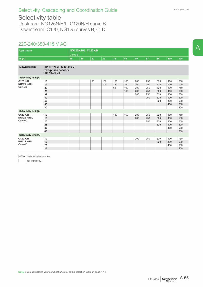
Selectivity, Cascading and Coordination Guide www.se.com
Selectivity tableUpstream: NG125N/H/L, C120N/H curve BDownstream: C120, NG125 curves B, C, D
220-240/380-415 V ACUpstream NG125N/H/L, C120N/H
Curve BIn (A) 10 16 20 25 32 40 50 63 80 100 125
Downstream 1P, 1P+N, 2P (380-415 V) two-phase network 3P, 3P+N, 4P
Selectivity limit (A)C120 N/HNG125 N/H/LCurve B
10 80 100 130 160 200 250 320 400 80016 100 130 160 200 250 320 400 75020 65 160 200 250 320 400 75025 160 200 250 320 400 50032 200 250 320 400 50040 250 320 400 50050 320 400 50063 400 50080 400
Selectivity limit (A)C120 N/HNG125 N/H/LCurve C
10 130 160 200 250 320 400 75016 200 250 320 400 50020 250 320 400 50025 320 400 50032 400 50040 500
Selectivity limit (A)C120 N/HNG125 N/H/LCurve D
10 200 250 320 400 75016 320 400 50020 400 50025 500
4000 Selectivity limit = 4 kA.
No selectivity.
Note: if you cannot find your combination, refer to the selection table on page A-14
A-65
A
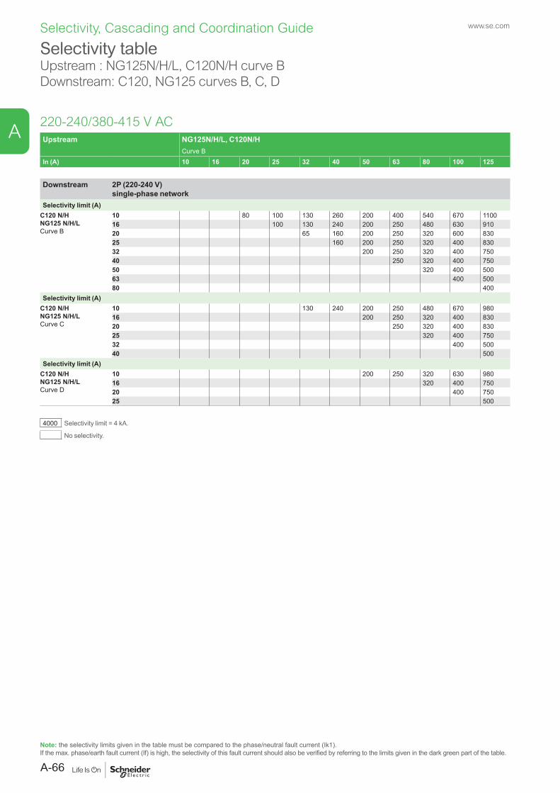
Selectivity, Cascading and Coordination Guide www.se.com
Selectivity tableUpstream : NG125N/H/L, C120N/H curve BDownstream: C120, NG125 curves B, C, D
220-240/380-415 V AC
Note: the selectivity limits given in the table must be compared to the phase/neutral fault current (Ik1).If the max. phase/earth fault current (If) is high, the selectivity of this fault current should also be verified by referring to the limits given in the dark green part of the table.
Upstream NG125N/H/L, C120N/HCurve B
In (A) 10 16 20 25 32 40 50 63 80 100 125
Downstream 2P (220-240 V) single-phase network
Selectivity limit (A)C120 N/HNG125 N/H/LCurve B
10 80 100 130 260 200 400 540 670 110016 100 130 240 200 250 480 630 91020 65 160 200 250 320 600 83025 160 200 250 320 400 83032 200 250 320 400 75040 250 320 400 75050 320 400 50063 400 50080 400
Selectivity limit (A)C120 N/HNG125 N/H/LCurve C
10 130 240 200 250 480 670 98016 200 250 320 400 83020 250 320 400 83025 320 400 75032 400 50040 500
Selectivity limit (A)C120 N/HNG125 N/H/LCurve D
10 200 250 320 630 98016 320 400 75020 400 75025 500
4000 Selectivity limit = 4 kA.
No selectivity.
A-66
A
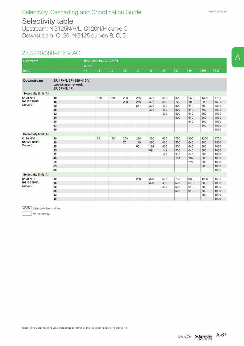
Selectivity, Cascading and Coordination Guide www.se.com
Selectivity tableUpstream: NG125N/H/L, C120N/H curve CDownstream: C120, NG125 curves B, C, D
220-240/380-415 V AC
Note: if you cannot find your combination, refer to the selection table on page A-14
Upstream NG125N/H/L, C120N/HCurve C
In (A) 10 16 20 25 32 40 50 63 80 100 125
Downstream 1P, 1P+N, 2P (380-415 V) two-phase network 3P, 3P+N, 4P
Selectivity limit (A)C120 N/HNG125 N/H/LCurve B
10 130 160 200 260 320 650 820 960 1300 170016 200 260 320 600 760 800 900 150020 65 320 400 500 640 800 150025 320 400 500 640 800 100032 400 500 640 800 100040 500 640 800 100050 640 800 100063 800 100080 1000
Selectivity limit (A)C120 N/HNG125 N/H/LCurve C
10 39 160 200 260 320 650 760 900 1200 170016 70 110 320 400 500 640 800 150020 65 124 400 500 640 800 100025 89 149 500 640 800 100032 123 240 640 800 100040 181 269 800 100050 227 800 100063 800 100080 1000
Selectivity limit (A)C120 N/HNG125 N/H/LCurve D
10 260 320 600 760 900 1200 160016 320 400 500 640 800 100020 400 500 640 800 100025 500 640 800 100032 800 100040 1000
4000 Selectivity limit = 4 kA.
No selectivity.
A-67
A
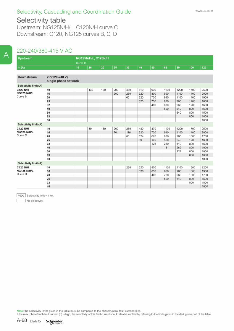
Selectivity, Cascading and Coordination Guide www.se.com
Selectivity tableUpstream: NG125N/H/L, C120N/H curve CDownstream: C120, NG125 curves B, C, D
220-240/380-415 V AC
Note: the selectivity limits given in the table must be compared to the phase/neutral fault current (Ik1).If the max. phase/earth fault current (If) is high, the selectivity of this fault current should also be verified by referring to the limits given in the dark green part of the table.
Upstream NG125N/H/L, C120N/HCurve C
In (A) 10 16 20 25 32 40 50 63 80 100 125
Downstream 2P (220-240 V) single-phase network
Selectivity limit (A)C120 N/HNG125 N/H/LCurve B
10 130 160 200 480 510 930 1100 1200 1700 250016 200 260 320 800 990 1100 1400 200020 65 320 730 910 1100 1400 190025 320 730 830 960 1200 160032 400 830 960 1200 160040 500 640 800 150050 640 800 150063 800 100080 1000
Selectivity limit (A)C120 N/HNG125 N/H/LCurve C
10 39 160 200 260 480 870 1100 1200 1700 250016 70 110 320 730 910 1100 1400 200020 65 124 670 830 960 1300 170025 89 149 500 640 1200 160032 123 240 640 800 150040 181 269 800 100050 227 800 100063 800 100080 1000
Selectivity limit (A)C120 N/HNG125 N/H/LCurve D
10 260 320 800 1100 1100 1600 220016 320 630 830 960 1300 190020 400 760 960 1300 170025 500 640 800 150032 800 150040 1000
4000 Selectivity limit = 4 kA.
No selectivity.
A-68
A
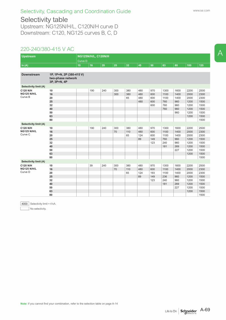
Selectivity, Cascading and Coordination Guide www.se.com
Selectivity tableUpstream: NG125N/H/L, C120N/H curve DDownstream: C120, NG125 curves B, C, D
220-240/380-415 V AC
Note: if you cannot find your combination, refer to the selection table on page A-14
Upstream NG125N/H/L, C120N/HCurve D
In (A) 10 16 20 25 32 40 50 63 80 100 125
Downstream 1P, 1P+N, 2P (380-415 V) two-phase network 3P, 3P+N, 4P
Selectivity limit (A)C120 N/HNG125 N/H/LCurve B
10 190 240 300 380 480 970 1300 1600 2200 250016 300 380 480 600 1100 1400 2000 230020 65 480 600 1100 1400 2000 230025 480 600 760 960 1200 150032 600 760 960 1200 150040 760 960 1200 150050 960 1200 150063 1200 150080 1500
Selectivity limit (A)C120 N/HNG125 N/H/LCurve C
10 190 240 300 380 480 970 1300 1600 2200 250016 70 110 480 600 1100 1400 2000 230020 65 124 600 1100 1400 2000 230025 89 149 760 960 1200 150032 123 240 960 1200 150040 181 269 1200 150050 227 1200 150063 1200 150080 1500
Selectivity limit (A)C120 N/HNG125 N/H/LCurve D
10 39 240 300 380 480 970 1300 1600 2200 250016 70 110 480 600 1100 1400 2000 230020 65 124 193 1100 1400 2000 230025 89 149 236 960 1200 150032 123 240 960 1200 150040 181 269 1200 150050 227 1200 150063 1200 150080 1500
4000 Selectivity limit = 4 kA.
No selectivity.
A-69
A
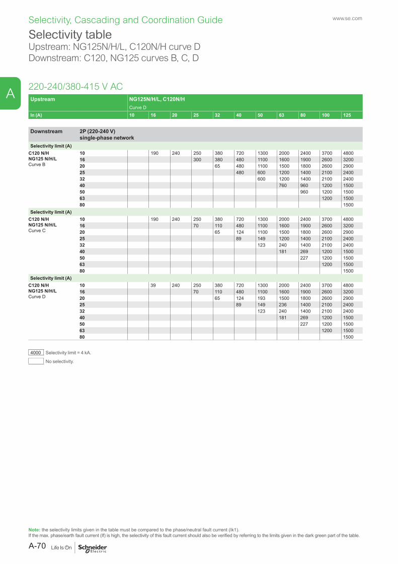
Selectivity, Cascading and Coordination Guide www.se.com
Selectivity table Upstream: NG125N/H/L, C120N/H curve DDownstream: C120, NG125 curves B, C, D
220-240/380-415 V AC
Note: the selectivity limits given in the table must be compared to the phase/neutral fault current (Ik1).If the max. phase/earth fault current (If) is high, the selectivity of this fault current should also be verified by referring to the limits given in the dark green part of the table.
Upstream NG125N/H/L, C120N/HCurve D
In (A) 10 16 20 25 32 40 50 63 80 100 125
Downstream 2P (220-240 V) single-phase network
Selectivity limit (A)C120 N/HNG125 N/H/LCurve B
10 190 240 250 380 720 1300 2000 2400 3700 480016 300 380 480 1100 1600 1900 2600 320020 65 480 1100 1500 1800 2600 290025 480 600 1200 1400 2100 240032 600 1200 1400 2100 240040 760 960 1200 150050 960 1200 150063 1200 150080 1500
Selectivity limit (A)C120 N/HNG125 N/H/LCurve C
10 190 240 250 380 720 1300 2000 2400 3700 480016 70 110 480 1100 1600 1900 2600 320020 65 124 1100 1500 1800 2600 290025 89 149 1200 1400 2100 240032 123 240 1400 2100 240040 181 269 1200 150050 227 1200 150063 1200 150080 1500
Selectivity limit (A)C120 N/HNG125 N/H/LCurve D
10 39 240 250 380 720 1300 2000 2400 3700 480016 70 110 480 1100 1600 1900 2600 320020 65 124 193 1500 1800 2600 290025 89 149 236 1400 2100 240032 123 240 1400 2100 240040 181 269 1200 150050 227 1200 150063 1200 150080 1500
4000 Selectivity limit = 4 kA.
No selectivity.
A-70
A
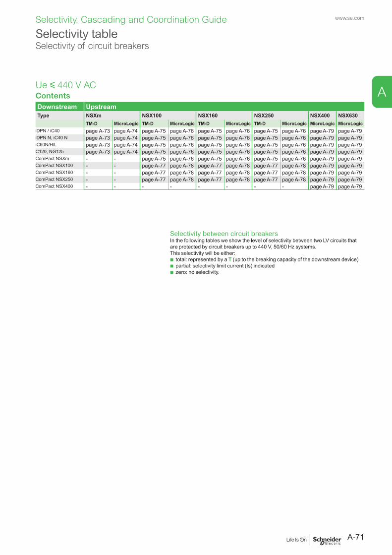
Selectivity tableSelectivity of circuit breakers
ContentsDownstream UpstreamType NSXm NSX100 NSX160 NSX250 NSX400 NSX630
TM-D MicroLogic TM-D MicroLogic TM-D MicroLogic TM-D MicroLogic MicroLogic MicroLogiciDPN / iC40 page A-73 page A-74 page A-75 page A-76 page A-75 page A-76 page A-75 page A-76 page A-79 page A-79iDPN N, iC40 N page A-73 page A-74 page A-75 page A-76 page A-75 page A-76 page A-75 page A-76 page A-79 page A-79iC60N/H/L page A-73 page A-74 page A-75 page A-76 page A-75 page A-76 page A-75 page A-76 page A-79 page A-79C120, NG125 page A-73 page A-74 page A-75 page A-76 page A-75 page A-76 page A-75 page A-76 page A-79 page A-79ComPact NSXm - - page A-75 page A-76 page A-75 page A-76 page A-75 page A-76 page A-79 page A-79ComPact NSX100 - - page A-77 page A-78 page A-77 page A-78 page A-77 page A-78 page A-79 page A-79ComPact NSX160 - - page A-77 page A-78 page A-77 page A-78 page A-77 page A-78 page A-79 page A-79ComPact NSX250 - - page A-77 page A-78 page A-77 page A-78 page A-77 page A-78 page A-79 page A-79ComPact NSX400 - - - - - - - - page A-79 page A-79
Ue y 440 V AC
Selectivity between circuit breakersIn the following tables we show the level of selectivity between two LV circuits that are protected by circuit breakers up to 440 V, 50/60 Hz systems.This selectivity will be either:
b total: represented by a T (up to the breaking capacity of the downstream device) b partial: selectivity limit current (Is) indicated b zero: no selectivity.
A-71
www.se.com
A
Selectivity, Cascading and Coordination Guide
EcoStruxure Power Design (formerly known as Ecodial) is a user-friendly software that helps you optimize your equipment and costs, while managing operating constraints during the electrical installation design phase of your project. It is part of our Customer Lifecycle Software range connected to the EcoStruxure Power platform.
Easier electrical installation design Now it’s easy to draw your single-line diagram and define properties such as load power, polarity, earthing system arrangement, cable length, and operating conditions, for example.
Reliable design Check the consistency of choices between calculated switchgear and recommended equipment, and verify electrical network consistency for improved people safety. Anomalies are identified on the single-line diagram.
Ensure power availability Choose the optimal selectivity plan to ensure maximum uptime and a superior cascading plan for optimized uptime/cost. Define back-up generator mode in case of power shutdown, or supply critical loads through UPS in the event of unexpected power failure.
EcoStruxure Power Design
www.se.com
A-72
A
Selectivity, Cascading and Coordination Guide
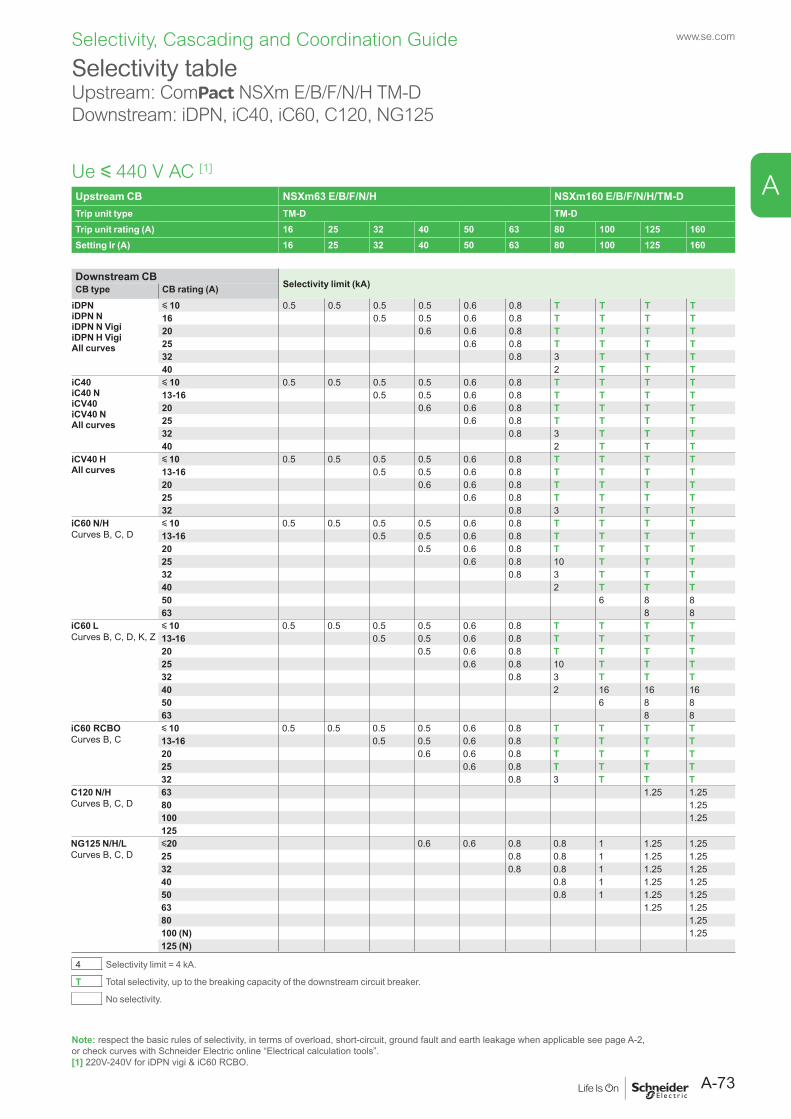
Selectivity tableUpstream: ComPact NSXm E/B/F/N/H TM-DDownstream: iDPN, iC40, iC60, C120, NG125
Ue y 440 V AC [1]
Upstream CB NSXm63 E/B/F/N/H NSXm160 E/B/F/N/H/TM-DTrip unit type TM-D TM-DTrip unit rating (A) 16 25 32 40 50 63 80 100 125 160Setting Ir (A) 16 25 32 40 50 63 80 100 125 160
Downstream CBSelectivity limit (kA)CB type CB rating (A)
iDPNiDPN NiDPN N VigiiDPN H VigiAll curves
y 10 0.5 0.5 0.5 0.5 0.6 0.8 T T T T16 0.5 0.5 0.6 0.8 T T T T20 0.6 0.6 0.8 T T T T25 0.6 0.8 T T T T32 0.8 3 T T T40 2 T T T
iC40iC40 NiCV40iCV40 NAll curves
y 10 0.5 0.5 0.5 0.5 0.6 0.8 T T T T13-16 0.5 0.5 0.6 0.8 T T T T20 0.6 0.6 0.8 T T T T25 0.6 0.8 T T T T32 0.8 3 T T T40 2 T T T
iCV40 HAll curves
y 10 0.5 0.5 0.5 0.5 0.6 0.8 T T T T13-16 0.5 0.5 0.6 0.8 T T T T20 0.6 0.6 0.8 T T T T25 0.6 0.8 T T T T32 0.8 3 T T T
iC60 N/HCurves B, C, D
y 10 0.5 0.5 0.5 0.5 0.6 0.8 T T T T13-16 0.5 0.5 0.6 0.8 T T T T20 0.5 0.6 0.8 T T T T25 0.6 0.8 10 T T T32 0.8 3 T T T40 2 T T T50 6 8 863 8 8
iC60 LCurves B, C, D, K, Z
y 10 0.5 0.5 0.5 0.5 0.6 0.8 T T T T13-16 0.5 0.5 0.6 0.8 T T T T20 0.5 0.6 0.8 T T T T25 0.6 0.8 10 T T T32 0.8 3 T T T40 2 16 16 1650 6 8 863 8 8
iC60 RCBOCurves B, C
y 10 0.5 0.5 0.5 0.5 0.6 0.8 T T T T13-16 0.5 0.5 0.6 0.8 T T T T20 0.6 0.6 0.8 T T T T25 0.6 0.8 T T T T32 0.8 3 T T T
C120 N/HCurves B, C, D
63 1.25 1.2580 1.25100 1.25125
NG125 N/H/LCurves B, C, D
y20 0.6 0.6 0.8 0.8 1 1.25 1.2525 0.8 0.8 1 1.25 1.2532 0.8 0.8 1 1.25 1.2540 0.8 1 1.25 1.2550 0.8 1 1.25 1.2563 1.25 1.2580 1.25100 (N) 1.25125 (N)
4 Selectivity limit = 4 kA.
T Total selectivity, up to the breaking capacity of the downstream circuit breaker.
No selectivity.
Note: respect the basic rules of selectivity, in terms of overload, short-circuit, ground fault and earth leakage when applicable see page A-2, or check curves with Schneider Electric online “Electrical calculation tools”.[1] 220V-240V for iDPN vigi & iC60 RCBO.
A-73
www.se.com
A
Selectivity, Cascading and Coordination Guide
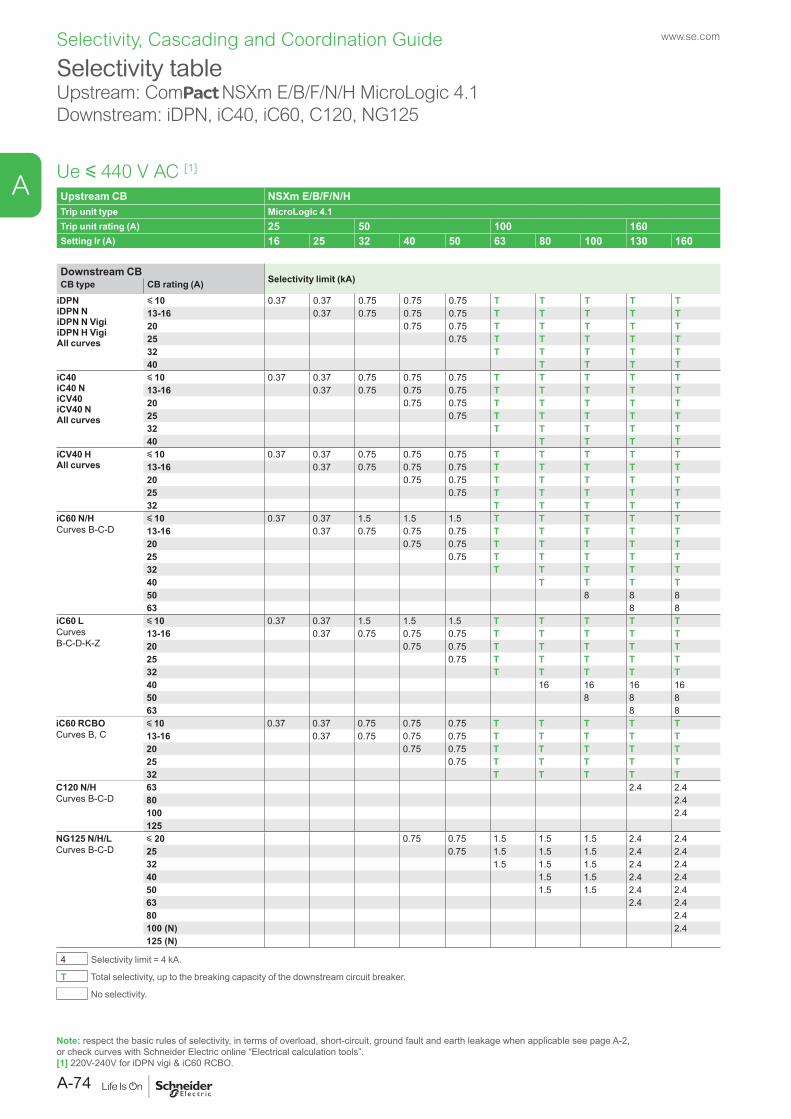
Selectivity tableUpstream: ComPact NSXm E/B/F/N/H MicroLogic 4.1Downstream: iDPN, iC40, iC60, C120, NG125
Ue y 440 V AC [1]
Note: respect the basic rules of selectivity, in terms of overload, short-circuit, ground fault and earth leakage when applicable see page A-2, or check curves with Schneider Electric online “Electrical calculation tools”.[1] 220V-240V for iDPN vigi & iC60 RCBO.
Upstream CB NSXm E/B/F/N/HTrip unit type MicroLogic 4.1Trip unit rating (A) 25 50 100 160Setting Ir (A) 16 25 32 40 50 63 80 100 130 160
Downstream CBSelectivity limit (kA)CB type CB rating (A)
iDPNiDPN NiDPN N VigiiDPN H VigiAll curves
y 10 0.37 0.37 0.75 0.75 0.75 T T T T T13-16 0.37 0.75 0.75 0.75 T T T T T20 0.75 0.75 T T T T T25 0.75 T T T T T32 T T T T T40 T T T T
iC40iC40 NiCV40iCV40 NAll curves
y 10 0.37 0.37 0.75 0.75 0.75 T T T T T13-16 0.37 0.75 0.75 0.75 T T T T T20 0.75 0.75 T T T T T25 0.75 T T T T T32 T T T T T40 T T T T
iCV40 HAll curves
y 10 0.37 0.37 0.75 0.75 0.75 T T T T T13-16 0.37 0.75 0.75 0.75 T T T T T20 0.75 0.75 T T T T T25 0.75 T T T T T32 T T T T T
iC60 N/HCurves B-C-D
y 10 0.37 0.37 1.5 1.5 1.5 T T T T T13-16 0.37 0.75 0.75 0.75 T T T T T20 0.75 0.75 T T T T T25 0.75 T T T T T32 T T T T T40 T T T T50 8 8 863 8 8
iC60 LCurves B-C-D-K-Z
y 10 0.37 0.37 1.5 1.5 1.5 T T T T T13-16 0.37 0.75 0.75 0.75 T T T T T20 0.75 0.75 T T T T T25 0.75 T T T T T32 T T T T T40 16 16 16 1650 8 8 863 8 8
iC60 RCBOCurves B, C
y 10 0.37 0.37 0.75 0.75 0.75 T T T T T13-16 0.37 0.75 0.75 0.75 T T T T T20 0.75 0.75 T T T T T25 0.75 T T T T T32 T T T T T
C120 N/HCurves B-C-D
63 2.4 2.480 2.4100 2.4125
NG125 N/H/LCurves B-C-D
y 20 0.75 0.75 1.5 1.5 1.5 2.4 2.425 0.75 1.5 1.5 1.5 2.4 2.432 1.5 1.5 1.5 2.4 2.440 1.5 1.5 2.4 2.450 1.5 1.5 2.4 2.463 2.4 2.480 2.4100 (N) 2.4125 (N)
4 Selectivity limit = 4 kA.
T Total selectivity, up to the breaking capacity of the downstream circuit breaker.
No selectivity.
www.se.com
A-74
A
Selectivity, Cascading and Coordination Guide
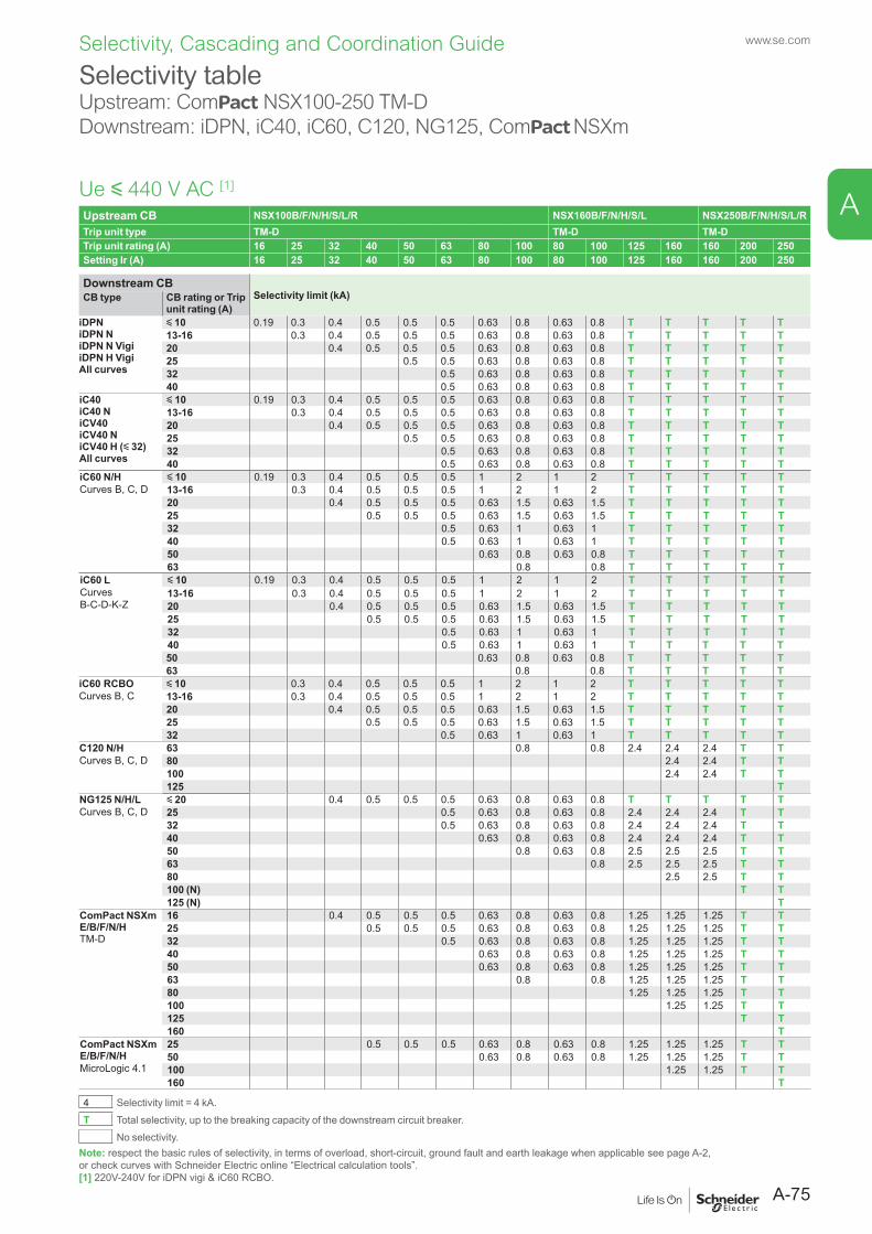
Selectivity tableUpstream: ComPact NSX100-250 TM-DDownstream: iDPN, iC40, iC60, C120, NG125, ComPact NSXm
Ue y 440 V AC [1]
Note: respect the basic rules of selectivity, in terms of overload, short-circuit, ground fault and earth leakage when applicable see page A-2, or check curves with Schneider Electric online “Electrical calculation tools”.[1] 220V-240V for iDPN vigi & iC60 RCBO.
Upstream CB NSX100B/F/N/H/S/L/R NSX160B/F/N/H/S/L NSX250B/F/N/H/S/L/RTrip unit type TM-D TM-D TM-DTrip unit rating (A) 16 25 32 40 50 63 80 100 80 100 125 160 160 200 250Setting Ir (A) 16 25 32 40 50 63 80 100 80 100 125 160 160 200 250
Downstream CBSelectivity limit (kA)CB type CB rating or Trip
unit rating (A)iDPNiDPN NiDPN N VigiiDPN H VigiAll curves
y 10 0.19 0.3 0.4 0.5 0.5 0.5 0.63 0.8 0.63 0.8 T T T T T13-16 0.3 0.4 0.5 0.5 0.5 0.63 0.8 0.63 0.8 T T T T T20 0.4 0.5 0.5 0.5 0.63 0.8 0.63 0.8 T T T T T25 0.5 0.5 0.63 0.8 0.63 0.8 T T T T T32 0.5 0.63 0.8 0.63 0.8 T T T T T40 0.5 0.63 0.8 0.63 0.8 T T T T T
iC40iC40 NiCV40iCV40 NiCV40 H (y 32)All curves
y 10 0.19 0.3 0.4 0.5 0.5 0.5 0.63 0.8 0.63 0.8 T T T T T13-16 0.3 0.4 0.5 0.5 0.5 0.63 0.8 0.63 0.8 T T T T T20 0.4 0.5 0.5 0.5 0.63 0.8 0.63 0.8 T T T T T25 0.5 0.5 0.63 0.8 0.63 0.8 T T T T T32 0.5 0.63 0.8 0.63 0.8 T T T T T40 0.5 0.63 0.8 0.63 0.8 T T T T T
iC60 N/HCurves B, C, D
y 10 0.19 0.3 0.4 0.5 0.5 0.5 1 2 1 2 T T T T T13-16 0.3 0.4 0.5 0.5 0.5 1 2 1 2 T T T T T20 0.4 0.5 0.5 0.5 0.63 1.5 0.63 1.5 T T T T T25 0.5 0.5 0.5 0.63 1.5 0.63 1.5 T T T T T32 0.5 0.63 1 0.63 1 T T T T T40 0.5 0.63 1 0.63 1 T T T T T50 0.63 0.8 0.63 0.8 T T T T T63 0.8 0.8 T T T T T
iC60 LCurvesB-C-D-K-Z
y 10 0.19 0.3 0.4 0.5 0.5 0.5 1 2 1 2 T T T T T13-16 0.3 0.4 0.5 0.5 0.5 1 2 1 2 T T T T T20 0.4 0.5 0.5 0.5 0.63 1.5 0.63 1.5 T T T T T25 0.5 0.5 0.5 0.63 1.5 0.63 1.5 T T T T T32 0.5 0.63 1 0.63 1 T T T T T40 0.5 0.63 1 0.63 1 T T T T T50 0.63 0.8 0.63 0.8 T T T T T63 0.8 0.8 T T T T T
iC60 RCBOCurves B, C
y 10 0.3 0.4 0.5 0.5 0.5 1 2 1 2 T T T T T13-16 0.3 0.4 0.5 0.5 0.5 1 2 1 2 T T T T T20 0.4 0.5 0.5 0.5 0.63 1.5 0.63 1.5 T T T T T25 0.5 0.5 0.5 0.63 1.5 0.63 1.5 T T T T T32 0.5 0.63 1 0.63 1 T T T T T
C120 N/HCurves B, C, D
63 0.8 0.8 2.4 2.4 2.4 T T80 2.4 2.4 T T100 2.4 2.4 T T125 T
NG125 N/H/LCurves B, C, D
y 20 0.4 0.5 0.5 0.5 0.63 0.8 0.63 0.8 T T T T T25 0.5 0.63 0.8 0.63 0.8 2.4 2.4 2.4 T T32 0.5 0.63 0.8 0.63 0.8 2.4 2.4 2.4 T T40 0.63 0.8 0.63 0.8 2.4 2.4 2.4 T T50 0.8 0.63 0.8 2.5 2.5 2.5 T T63 0.8 2.5 2.5 2.5 T T80 2.5 2.5 T T100 (N) T T125 (N) T
ComPact NSXm E/B/F/N/HTM-D
16 0.4 0.5 0.5 0.5 0.63 0.8 0.63 0.8 1.25 1.25 1.25 T T25 0.5 0.5 0.5 0.63 0.8 0.63 0.8 1.25 1.25 1.25 T T32 0.5 0.63 0.8 0.63 0.8 1.25 1.25 1.25 T T40 0.63 0.8 0.63 0.8 1.25 1.25 1.25 T T50 0.63 0.8 0.63 0.8 1.25 1.25 1.25 T T63 0.8 0.8 1.25 1.25 1.25 T T80 1.25 1.25 1.25 T T100 1.25 1.25 T T125 T T160 T
ComPact NSXm E/B/F/N/HMicroLogic 4.1
25 0.5 0.5 0.5 0.63 0.8 0.63 0.8 1.25 1.25 1.25 T T50 0.63 0.8 0.63 0.8 1.25 1.25 1.25 T T100 1.25 1.25 T T160 T
4 Selectivity limit = 4 kA.T Total selectivity, up to the breaking capacity of the downstream circuit breaker.
No selectivity.
A-75
www.se.com
A
Selectivity, Cascading and Coordination Guide
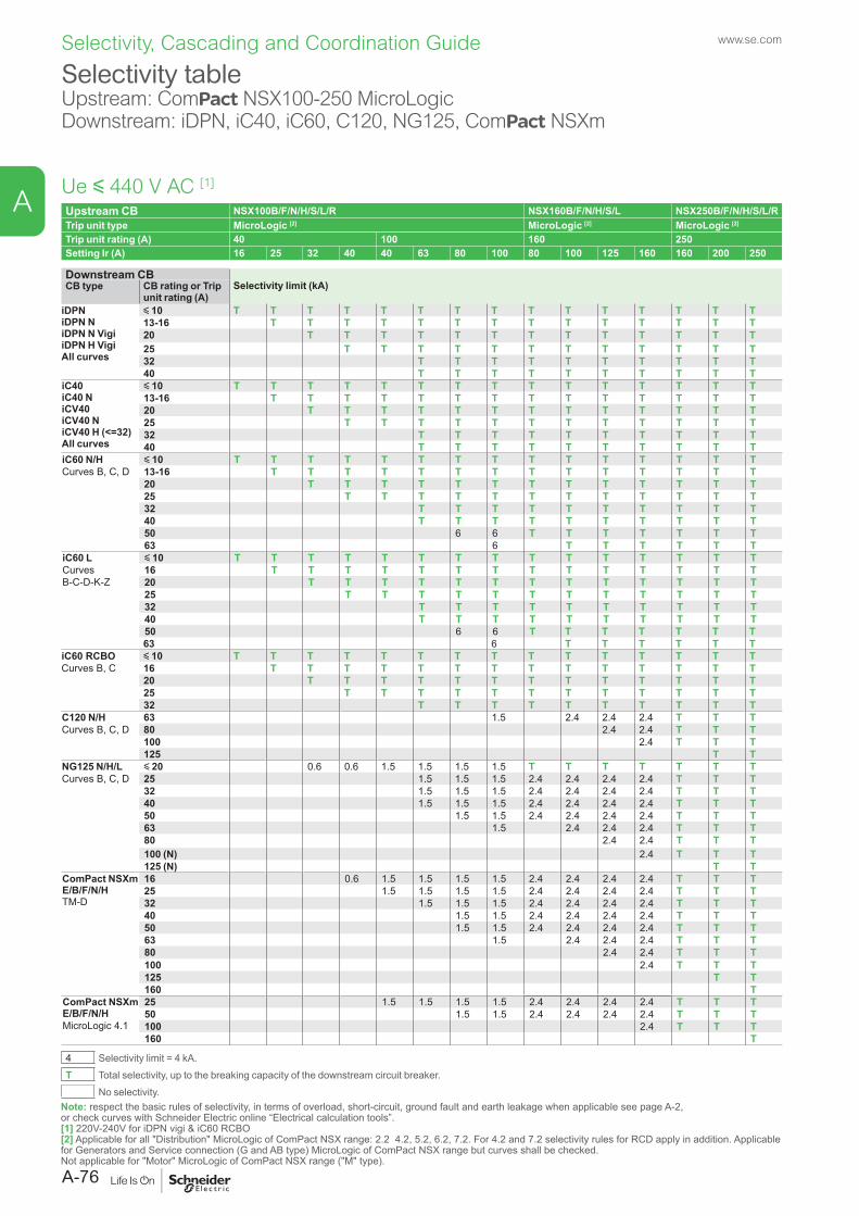
Selectivity tableUpstream: ComPact NSX100-250 MicroLogicDownstream: iDPN, iC40, iC60, C120, NG125, ComPact NSXm
Ue y 440 V AC [1]
Upstream CB NSX100B/F/N/H/S/L/R NSX160B/F/N/H/S/L NSX250B/F/N/H/S/L/RTrip unit type MicroLogic [2] MicroLogic [2] MicroLogic [2]
Trip unit rating (A) 40 100 160 250Setting Ir (A) 16 25 32 40 40 63 80 100 80 100 125 160 160 200 250
Downstream CBSelectivity limit (kA)CB type CB rating or Trip
unit rating (A)iDPNiDPN NiDPN N VigiiDPN H VigiAll curves
y 10 T T T T T T T T T T T T T T T13-16 T T T T T T T T T T T T T T20 T T T T T T T T T T T T T25 T T T T T T T T T T T T32 T T T T T T T T T T40 T T T T T T T T T T
iC40iC40 NiCV40iCV40 NiCV40 H (<=32)All curves
y 10 T T T T T T T T T T T T T T T13-16 T T T T T T T T T T T T T T20 T T T T T T T T T T T T T25 T T T T T T T T T T T T32 T T T T T T T T T T40 T T T T T T T T T T
iC60 N/HCurves B, C, D
y 10 T T T T T T T T T T T T T T T13-16 T T T T T T T T T T T T T T20 T T T T T T T T T T T T T25 T T T T T T T T T T T T32 T T T T T T T T T T40 T T T T T T T T T T50 6 6 T T T T T T T63 6 T T T T T T
iC60 LCurves B-C-D-K-Z
y 10 T T T T T T T T T T T T T T T16 T T T T T T T T T T T T T T20 T T T T T T T T T T T T T25 T T T T T T T T T T T T32 T T T T T T T T T T40 T T T T T T T T T T50 6 6 T T T T T T T63 6 T T T T T T
iC60 RCBOCurves B, C
y 10 T T T T T T T T T T T T T T T16 T T T T T T T T T T T T T T20 T T T T T T T T T T T T T25 T T T T T T T T T T T T32 T T T T T T T T T T
C120 N/HCurves B, C, D
63 1.5 2.4 2.4 2.4 T T T80 2.4 2.4 T T T100 2.4 T T T125 T T
NG125 N/H/LCurves B, C, D
y 20 0.6 0.6 1.5 1.5 1.5 1.5 T T T T T T T25 1.5 1.5 1.5 2.4 2.4 2.4 2.4 T T T32 1.5 1.5 1.5 2.4 2.4 2.4 2.4 T T T40 1.5 1.5 1.5 2.4 2.4 2.4 2.4 T T T50 1.5 1.5 2.4 2.4 2.4 2.4 T T T63 1.5 2.4 2.4 2.4 T T T80 2.4 2.4 T T T100 (N) 2.4 T T T125 (N) T T
ComPact NSXm E/B/F/N/HTM-D
16 0.6 1.5 1.5 1.5 1.5 2.4 2.4 2.4 2.4 T T T25 1.5 1.5 1.5 1.5 2.4 2.4 2.4 2.4 T T T32 1.5 1.5 1.5 2.4 2.4 2.4 2.4 T T T40 1.5 1.5 2.4 2.4 2.4 2.4 T T T50 1.5 1.5 2.4 2.4 2.4 2.4 T T T63 1.5 2.4 2.4 2.4 T T T80 2.4 2.4 T T T100 2.4 T T T125 T T160 T
ComPact NSXm E/B/F/N/HMicroLogic 4.1
25 1.5 1.5 1.5 1.5 2.4 2.4 2.4 2.4 T T T50 1.5 1.5 2.4 2.4 2.4 2.4 T T T100 2.4 T T T160 T
4 Selectivity limit = 4 kA.T Total selectivity, up to the breaking capacity of the downstream circuit breaker.
No selectivity.Note: respect the basic rules of selectivity, in terms of overload, short-circuit, ground fault and earth leakage when applicable see page A-2, or check curves with Schneider Electric online “Electrical calculation tools”.[1] 220V-240V for iDPN vigi & iC60 RCBO[2] Applicable for all "Distribution" MicroLogic of ComPact NSX range: 2.2 4.2, 5.2, 6.2, 7.2. For 4.2 and 7.2 selectivity rules for RCD apply in addition. Applicable for Generators and Service connection (G and AB type) MicroLogic of ComPact NSX range but curves shall be checked.Not applicable for "Motor" MicroLogic of ComPact NSX range ("M" type).
www.se.com
A-76
A
Selectivity, Cascading and Coordination Guide
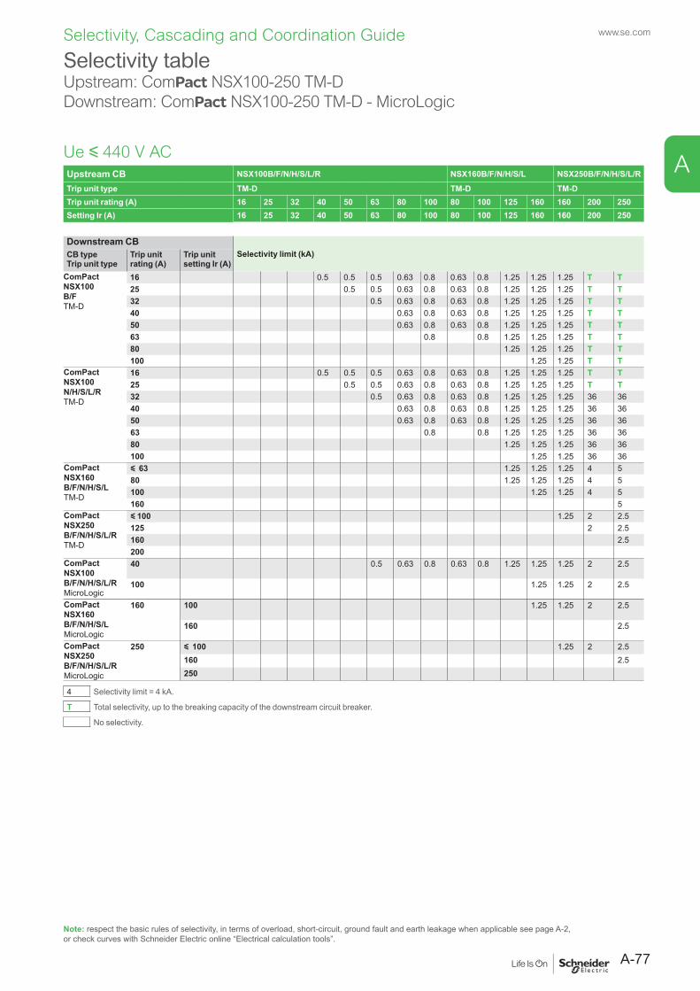
Selectivity tableUpstream: ComPact NSX100-250 TM-DDownstream: ComPact NSX100-250 TM-D - MicroLogic
Ue y 440 V ACUpstream CB NSX100B/F/N/H/S/L/R NSX160B/F/N/H/S/L NSX250B/F/N/H/S/L/RTrip unit type TM-D TM-D TM-DTrip unit rating (A) 16 25 32 40 50 63 80 100 80 100 125 160 160 200 250Setting Ir (A) 16 25 32 40 50 63 80 100 80 100 125 160 160 200 250
Downstream CBSelectivity limit (kA)CB type
Trip unit typeTrip unit rating (A)
Trip unit setting Ir (A)
ComPact NSX100 B/FTM-D
16 0.5 0.5 0.5 0.63 0.8 0.63 0.8 1.25 1.25 1.25 T T25 0.5 0.5 0.63 0.8 0.63 0.8 1.25 1.25 1.25 T T32 0.5 0.63 0.8 0.63 0.8 1.25 1.25 1.25 T T40 0.63 0.8 0.63 0.8 1.25 1.25 1.25 T T50 0.63 0.8 0.63 0.8 1.25 1.25 1.25 T T63 0.8 0.8 1.25 1.25 1.25 T T80 1.25 1.25 1.25 T T100 1.25 1.25 T T
ComPact NSX100 N/H/S/L/RTM-D
16 0.5 0.5 0.5 0.63 0.8 0.63 0.8 1.25 1.25 1.25 T T25 0.5 0.5 0.63 0.8 0.63 0.8 1.25 1.25 1.25 T T32 0.5 0.63 0.8 0.63 0.8 1.25 1.25 1.25 36 3640 0.63 0.8 0.63 0.8 1.25 1.25 1.25 36 3650 0.63 0.8 0.63 0.8 1.25 1.25 1.25 36 3663 0.8 0.8 1.25 1.25 1.25 36 3680 1.25 1.25 1.25 36 36100 1.25 1.25 36 36
ComPact NSX160 B/F/N/H/S/LTM-D
y 63 1.25 1.25 1.25 4 580 1.25 1.25 1.25 4 5100 1.25 1.25 4 5160 5
ComPact NSX250 B/F/N/H/S/L/RTM-D
y 100 1.25 2 2.5125 2 2.5160 2.5200
ComPact NSX100 B/F/N/H/S/L/R MicroLogic
40 0.5 0.63 0.8 0.63 0.8 1.25 1.25 1.25 2 2.5
100 1.25 1.25 2 2.5
ComPact NSX160 B/F/N/H/S/LMicroLogic
160 100 1.25 1.25 2 2.5
160 2.5
ComPact NSX250 B/F/N/H/S/L/RMicroLogic
250 y 100 1.25 2 2.5160 2.5250
4 Selectivity limit = 4 kA.
T Total selectivity, up to the breaking capacity of the downstream circuit breaker.
No selectivity.
Note: respect the basic rules of selectivity, in terms of overload, short-circuit, ground fault and earth leakage when applicable see page A-2, or check curves with Schneider Electric online “Electrical calculation tools”.
A-77
www.se.com
A
Selectivity, Cascading and Coordination Guide
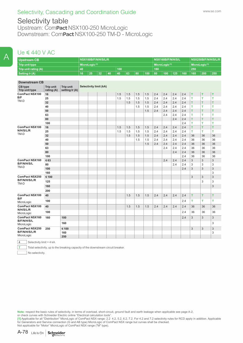
Selectivity tableUpstream: ComPact NSX100-250 MicroLogicDownstream: ComPact NSX100-250 TM-D - MicroLogic
Ue y 440 V ACUpstream CB NSX100B/F/N/H/S/L/R NSX160B/F/N/H/S/L NSX250B/F/N/H/S/L/R
Trip unit type MicroLogic [1] MicroLogic [1] MicroLogic [1]
Trip unit rating (A) 40 100 160 250Setting Ir (A) 16 25 32 40 40 63 80 100 80 100 125 160 160 200 250
Downstream CBSelectivity limit (kA)CB type
Trip unit typeTrip unit rating (A)
Trip unit setting Ir (A)
ComPact NSX100 B/FTM-D
16 1.5 1.5 1.5 1.5 2.4 2.4 2.4 2.4 T T T25 1.5 1.5 1.5 1.5 2.4 2.4 2.4 2.4 T T T32 1.5 1.5 1.5 2.4 2.4 2.4 2.4 T T T40 1.5 1.5 2.4 2.4 2.4 2.4 T T T50 1.5 2.4 2.4 2.4 2.4 T T T63 2.4 2.4 2.4 T T T80 2.4 2.4 T T T100 2.4 T T T
ComPact NSX100 N/H/S/L/RTM-D
16 1.5 1.5 1.5 1.5 2.4 2.4 2.4 2.4 T T T25 1.5 1.5 1.5 1.5 2.4 2.4 2.4 2.4 T T T32 1.5 1.5 1.5 2.4 2.4 2.4 2.4 36 36 3640 1.5 1.5 2.4 2.4 2.4 2.4 36 36 3650 1.5 2.4 2.4 2.4 2.4 36 36 3663 2.4 2.4 2.4 36 36 3680 2.4 2.4 36 36 36100 2.4 36 36 36
ComPact NSX160 B/F/N/H/S/LTM-D
y 63 2.4 2.4 2.4 3 3 380 2.4 2.4 3 3 3100 2.4 3 3 3160 3
ComPact NSX250 B/F/N/H/S/L/RTM-D
y 100 3 3 3125 3 3160 3200
ComPact NSX100 B/F MicroLogic
40 1.5 1.5 1.5 2.4 2.4 2.4 2.4 T T T
100 2.4 T T T
ComPact NSX100 N/H/S/L/R MicroLogic
40 1.5 1.5 1.5 2.4 2.4 2.4 2.4 36 36 36
100 2.4 36 36 36
ComPact NSX160 B/F/N/H/S/LMicroLogic
160 100 2.4 3 3 3
160 3
ComPact NSX250 B/F/N/H/S/L/RMicroLogic
250 y 100 3 3 3160 3250
4 Selectivity limit = 4 kA.
T Total selectivity, up to the breaking capacity of the downstream circuit breaker.
No selectivity.
Note: respect the basic rules of selectivity, in terms of overload, short-circuit, ground fault and earth leakage when applicable see page A-2, or check curves with Schneider Electric online “Electrical calculation tools”.[1] Applicable for all "Distribution" MicroLogic of ComPact NSX range: 2.2 4.2, 5.2, 6.2, 7.2. For 4.2 and 7.2 selectivity rules for RCD apply in addition. Applicable for Generators and Service connection (G and AB type) MicroLogic of ComPact NSX range but curves shall be checked.Not applicable for “Motor” MicroLogic of ComPact NSX range ("M" type).
www.se.com
A-78
A
Selectivity, Cascading and Coordination Guide
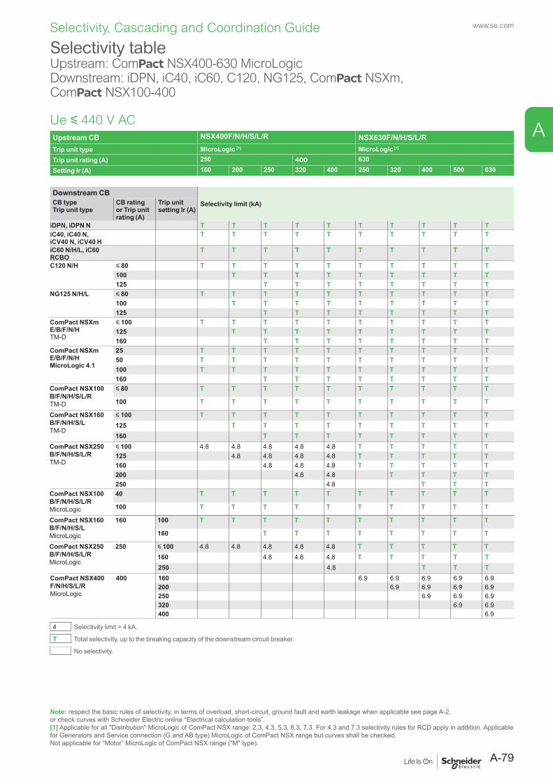
Selectivity table Upstream: ComPact NSX400-630 MicroLogic Downstream: iDPN, iC40, iC60, C120, NG125, ComPact NSXm, ComPact NSX100-400
Ue y 440 V ACUpstream CB NSX400F/N/H/S/L/R NSX630F/N/H/S/L/RTrip unit type MicroLogic [1] MicroLogic [1]
Trip unit rating (A) 250 400 630Setting Ir (A) 160 200 250 320 400 250 320 400 500 630
Downstream CBSelectivity limit (kA)CB type
Trip unit typeCB ratingor Trip unit rating (A)
Trip unit setting Ir (A)
iDPN, iDPN N T T T T T T T T T TiC40, iC40 N, iCV40 N, iCV40 H
T T T T T T T T T T
iC60 N/H/L, iC60 RCBO
T T T T T T T T T T
C120 N/H y 80 T T T T T T T T T T100 T T T T T T T T T125 T T T T T T T T
NG125 N/H/L y 80 T T T T T T T T T T100 T T T T T T T T T125 T T T T T T T T
ComPact NSXm E/B/F/N/H TM-D
y 100 T T T T T T T T T T125 T T T T T T T T T160 T T T T T T T T
ComPact NSXm E/B/F/N/HMicroLogic 4.1
25 T T T T T T T T T T50 T T T T T T T T T T100 T T T T T T T T T T160 T T T T T T T T
ComPact NSX100 B/F/N/H/S/L/R TM-D
y 80 T T T T T T T T T T
100 T T T T T T T T T T
ComPact NSX160 B/F/N/H/S/LTM-D
y 100 T T T T T T T T T T125 T T T T T T T T T160 T T T T T T T T
ComPact NSX250 B/F/N/H/S/L/RTM-D
y 100 4.8 4.8 4.8 4.8 4.8 T T T T T125 4.8 4.8 4.8 4.8 T T T T T160 4.8 4.8 4.8 T T T T T200 4.8 4.8 T T T T250 4.8 T T T
ComPact NSX100 B/F/N/H/S/L/R MicroLogic
40 T T T T T T T T T T
100 T T T T T T T T T T
ComPact NSX160 B/F/N/H/S/LMicroLogic
160 100 T T T T T T T T T T
160 T T T T T T T T
ComPact NSX250 B/F/N/H/S/L/RMicroLogic
250 y 100 4.8 4.8 4.8 4.8 4.8 T T T T T160 4.8 4.8 4.8 T T T T T250 4.8 T T T
ComPact NSX400 F/N/H/S/L/RMicroLogic
400 160 6.9 6.9 6.9 6.9 6.9200 6.9 6.9 6.9 6.9250 6.9 6.9 6.9320 6.9 6.9400 6.9
4 Selectivity limit = 4 kA.
T Total selectivity, up to the breaking capacity of the downstream circuit breaker.
No selectivity.
Note: respect the basic rules of selectivity, in terms of overload, short-circuit, ground fault and earth leakage when applicable see page A-2, or check curves with Schneider Electric online “Electrical calculation tools”.[1] Applicable for all "Distribution" MicroLogic of ComPact NSX range: 2.3, 4.3, 5.3, 6.3, 7.3. For 4.3 and 7.3 selectivity rules for RCD apply in addition. Applicable for Generators and Service connection (G and AB type) MicroLogic of ComPact NSX range but curves shall be checked.Not applicable for “Motor” MicroLogic of ComPact NSX range ("M" type).
A-79
www.se.com
A
Selectivity, Cascading and Coordination Guide
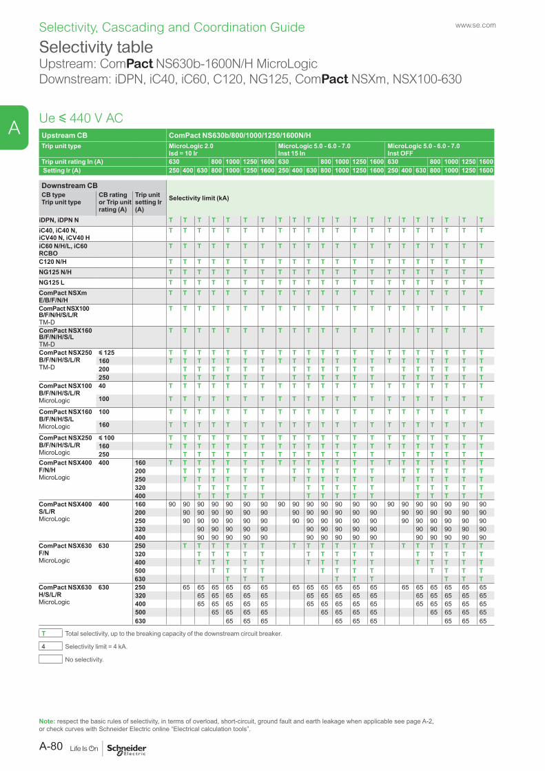
www.se.com
A
Selectivity, Cascading and Coordination Guide
Upstream CB ComPact NS630b/800/1000/1250/1600N/HTrip unit type MicroLogic 2.0
Isd = 10 IrMicroLogic 5.0 - 6.0 - 7.0Inst 15 In
MicroLogic 5.0 - 6.0 - 7.0Inst OFF
Trip unit rating In (A) 630 800 1000 1250 1600 630 800 1000 1250 1600 630 800 1000 1250 1600 Setting Ir (A) 250 400 630 800 1000 1250 1600 250 400 630 800 1000 1250 1600 250 400 630 800 1000 1250 1600
Downstream CBSelectivity limit (kA)CB type
Trip unit typeCB ratingor Trip unit rating (A)
Trip unit setting Ir (A)
iDPN, iDPN N T T T T T T T T T T T T T T T T T T T T TiC40, iC40 N, iCV40 N, iCV40 H
T T T T T T T T T T T T T T T T T T T T T
iC60 N/H/L, iC60 RCBO
T T T T T T T T T T T T T T T T T T T T T
C120 N/H T T T T T T T T T T T T T T T T T T T T TNG125 N/H T T T T T T T T T T T T T T T T T T T T TNG125 L T T T T T T T T T T T T T T T T T T T T TComPact NSXm E/B/F/N/H
T T T T T T T T T T T T T T T T T T T T T
ComPact NSX100 B/F/N/H/S/L/R TM-D
T T T T T T T T T T T T T T T T T T T T T
ComPact NSX160 B/F/N/H/S/L TM-D
T T T T T T T T T T T T T T T T T T T T T
ComPact NSX250 B/F/N/H/S/L/RTM-D
y 125 T T T T T T T T T T T T T T T T T T T T T160 T T T T T T T T T T T T T T T T T T T T T200 T T T T T T T T T T T T T T T T T T250 T T T T T T T T T T T T T T T T T T
ComPact NSX100 B/F/N/H/S/L/RMicroLogic
40 T T T T T T T T T T T T T T T T T T T T T
100 T T T T T T T T T T T T T T T T T T T T T
ComPact NSX160 B/F/N/H/S/LMicroLogic
100 T T T T T T T T T T T T T T T T T T T T T
160 T T T T T T T T T T T T T T T T T T T T T
ComPact NSX250 B/F/N/H/S/L/RMicroLogic
y 100 T T T T T T T T T T T T T T T T T T T T T160 T T T T T T T T T T T T T T T T T T T T T250 T T T T T T T T T T T T T T T T T T T
ComPact NSX400 F/N/H MicroLogic
400 160 T T T T T T T T T T T T T T T T T T T T T200 T T T T T T T T T T T T T T T T T T250 T T T T T T T T T T T T T T T T T T320 T T T T T T T T T T T T T T T400 T T T T T T T T T T T T T T T
ComPact NSX400 S/L/RMicroLogic
400 160 90 90 90 90 90 90 90 90 90 90 90 90 90 90 90 90 90 90 90 90 90200 90 90 90 90 90 90 90 90 90 90 90 90 90 90 90 90 90 90250 90 90 90 90 90 90 90 90 90 90 90 90 90 90 90 90 90 90320 90 90 90 90 90 90 90 90 90 90 90 90 90 90 90400 90 90 90 90 90 90 90 90 90 90 90 90 90 90 90
ComPact NSX630 F/NMicroLogic
630 250 T T T T T T T T T T T T T T T T T T320 T T T T T T T T T T T T T T T400 T T T T T T T T T T T T T T T500 T T T T T T T T T T T T630 T T T T T T T T T
ComPact NSX630 H/S/L/RMicroLogic
630 250 65 65 65 65 65 65 65 65 65 65 65 65 65 65 65 65 65 65320 65 65 65 65 65 65 65 65 65 65 65 65 65 65 65400 65 65 65 65 65 65 65 65 65 65 65 65 65 65 65500 65 65 65 65 65 65 65 65 65 65 65 65630 65 65 65 65 65 65 65 65 65
T Total selectivity, up to the breaking capacity of the downstream circuit breaker.
4 Selectivity limit = 4 kA.
No selectivity.
Note: respect the basic rules of selectivity, in terms of overload, short-circuit, ground fault and earth leakage when applicable see page A-2, or check curves with Schneider Electric online “Electrical calculation tools”.
Ue y 440 V AC
Selectivity tableUpstream: ComPact NS630b-1600N/H MicroLogicDownstream: iDPN, iC40, iC60, C120, NG125, ComPact NSXm, NSX100-630
A-80
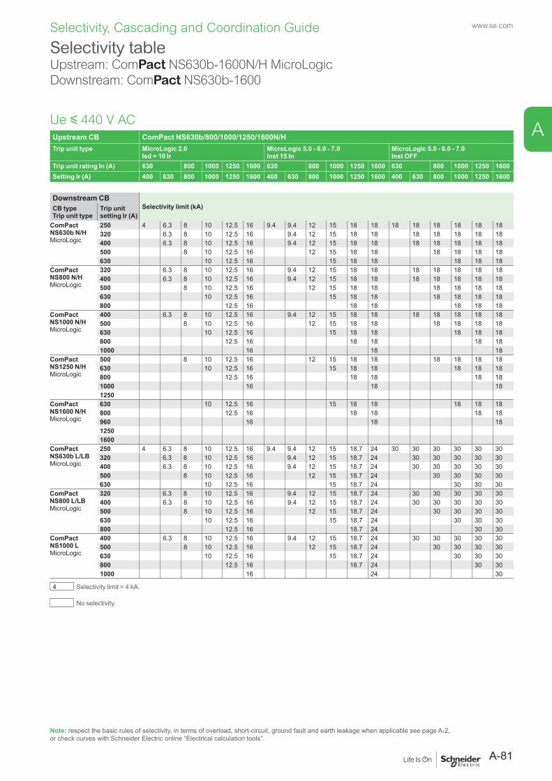
www.se.com
A
Selectivity, Cascading and Coordination Guide
Upstream CB ComPact NS630b/800/1000/1250/1600N/HTrip unit type MicroLogic 2.0
Isd = 10 IrMicroLogic 5.0 - 6.0 - 7.0Inst 15 In
MicroLogic 5.0 - 6.0 - 7.0Inst OFF
Trip unit rating In (A) 630 800 1000 1250 1600 630 800 1000 1250 1600 630 800 1000 1250 1600Setting Ir (A) 400 630 800 1000 1250 1600 400 630 800 1000 1250 1600 400 630 800 1000 1250 1600
Downstream CBSelectivity limit (kA)CB type
Trip unit typeTrip unit setting Ir (A)
ComPact NS630b N/HMicroLogic
250 4 6.3 8 10 12.5 16 9.4 9.4 12 15 18 18 18 18 18 18 18 18320 6.3 8 10 12.5 16 9.4 12 15 18 18 18 18 18 18 18400 6.3 8 10 12.5 16 9.4 12 15 18 18 18 18 18 18 18500 8 10 12.5 16 12 15 18 18 18 18 18 18630 10 12.5 16 15 18 18 18 18 18
ComPact NS800 N/HMicroLogic
320 6.3 8 10 12.5 16 9.4 12 15 18 18 18 18 18 18 18400 6.3 8 10 12.5 16 9.4 12 15 18 18 18 18 18 18 18500 8 10 12.5 16 12 15 18 18 18 18 18 18630 10 12.5 16 15 18 18 18 18 18 18800 12.5 16 18 18 18 18 18
ComPact NS1000 N/HMicroLogic
400 6.3 8 10 12.5 16 9.4 12 15 18 18 18 18 18 18 18500 8 10 12.5 16 12 15 18 18 18 18 18 18630 10 12.5 16 15 18 18 18 18 18800 12.5 16 18 18 18 181000 16 18 18
ComPact NS1250 N/HMicroLogic
500 8 10 12.5 16 12 15 18 18 18 18 18 18630 10 12.5 16 15 18 18 18 18 18800 12.5 16 18 18 18 181000 16 18 181250
ComPact NS1600 N/HMicroLogic
630 10 12.5 16 15 18 18 18 18 18800 12.5 16 18 18 18 18960 16 18 1812501600
ComPact NS630b L/LBMicroLogic
250 4 6.3 8 10 12.5 16 9.4 9.4 12 15 18.7 24 30 30 30 30 30 30320 6.3 8 10 12.5 16 9.4 12 15 18.7 24 30 30 30 30 30400 6.3 8 10 12.5 16 9.4 12 15 18.7 24 30 30 30 30 30500 8 10 12.5 16 12 15 18.7 24 30 30 30 30630 10 12.5 16 15 18.7 24 30 30 30
ComPact NS800 L/LBMicroLogic
320 6.3 8 10 12.5 16 9.4 12 15 18.7 24 30 30 30 30 30400 6.3 8 10 12.5 16 9.4 12 15 18.7 24 30 30 30 30 30500 8 10 12.5 16 12 15 18.7 24 30 30 30 30630 10 12.5 16 15 18.7 24 30 30 30800 12.5 16 18.7 24 30 30
ComPact NS1000 LMicroLogic
400 6.3 8 10 12.5 16 9.4 12 15 18.7 24 30 30 30 30 30500 8 10 12.5 16 12 15 18.7 24 30 30 30 30630 10 12.5 16 15 18.7 24 30 30 30800 12.5 16 18.7 24 30 301000 16 24 30
4 Selectivity limit = 4 kA.
No selectivity.
Ue y 440 V AC
Selectivity tableUpstream: ComPact NS630b-1600N/H MicroLogicDownstream: ComPact NS630b-1600
Note: respect the basic rules of selectivity, in terms of overload, short-circuit, ground fault and earth leakage when applicable see page A-2, or check curves with Schneider Electric online “Electrical calculation tools”.
A-81
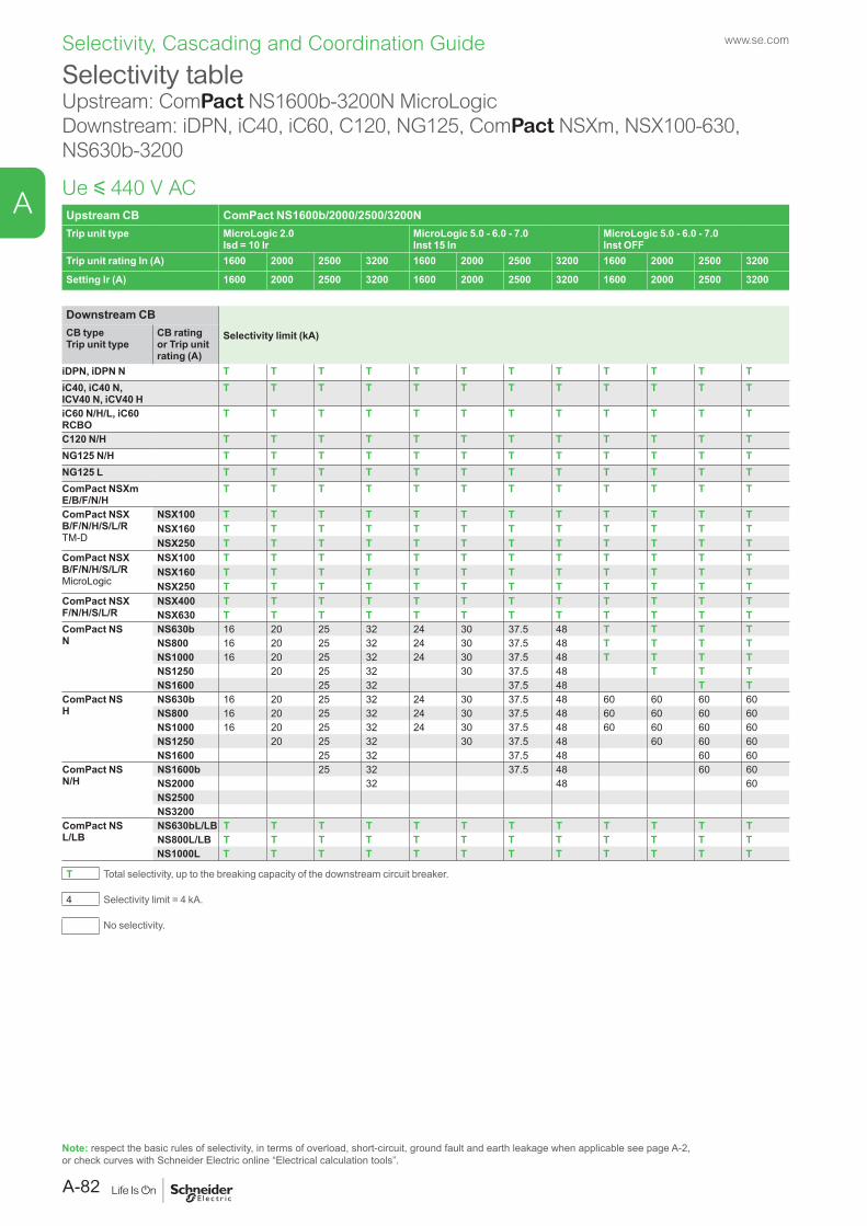
www.se.com
A
Selectivity, Cascading and Coordination Guide
Upstream CB ComPact NS1600b/2000/2500/3200NTrip unit type MicroLogic 2.0
Isd = 10 IrMicroLogic 5.0 - 6.0 - 7.0Inst 15 In
MicroLogic 5.0 - 6.0 - 7.0Inst OFF
Trip unit rating In (A) 1600 2000 2500 3200 1600 2000 2500 3200 1600 2000 2500 3200
Setting Ir (A) 1600 2000 2500 3200 1600 2000 2500 3200 1600 2000 2500 3200
Downstream CBSelectivity limit (kA)CB type
Trip unit typeCB rating or Trip unit rating (A)
iDPN, iDPN N T T T T T T T T T T T TiC40, iC40 N, ICV40 N, iCV40 H
T T T T T T T T T T T T
iC60 N/H/L, iC60 RCBO
T T T T T T T T T T T T
C120 N/H T T T T T T T T T T T TNG125 N/H T T T T T T T T T T T TNG125 L T T T T T T T T T T T TComPact NSXm E/B/F/N/H
T T T T T T T T T T T T
ComPact NSXB/F/N/H/S/L/RTM-D
NSX100 T T T T T T T T T T T TNSX160 T T T T T T T T T T T TNSX250 T T T T T T T T T T T T
ComPact NSXB/F/N/H/S/L/RMicroLogic
NSX100 T T T T T T T T T T T TNSX160 T T T T T T T T T T T TNSX250 T T T T T T T T T T T T
ComPact NSXF/N/H/S/L/R
NSX400 T T T T T T T T T T T TNSX630 T T T T T T T T T T T T
ComPact NSN
NS630b 16 20 25 32 24 30 37.5 48 T T T TNS800 16 20 25 32 24 30 37.5 48 T T T TNS1000 16 20 25 32 24 30 37.5 48 T T T TNS1250 20 25 32 30 37.5 48 T T TNS1600 25 32 37.5 48 T T
ComPact NSH
NS630b 16 20 25 32 24 30 37.5 48 60 60 60 60NS800 16 20 25 32 24 30 37.5 48 60 60 60 60NS1000 16 20 25 32 24 30 37.5 48 60 60 60 60NS1250 20 25 32 30 37.5 48 60 60 60NS1600 25 32 37.5 48 60 60
ComPact NSN/H
NS1600b 25 32 37.5 48 60 60NS2000 32 48 60NS2500NS3200
ComPact NSL/LB
NS630bL/LB T T T T T T T T T T T TNS800L/LB T T T T T T T T T T T TNS1000L T T T T T T T T T T T T
T Total selectivity, up to the breaking capacity of the downstream circuit breaker.
4 Selectivity limit = 4 kA.
No selectivity.
Ue y 440 V AC
Selectivity tableUpstream: ComPact NS1600b-3200N MicroLogicDownstream: iDPN, iC40, iC60, C120, NG125, ComPact NSXm, NSX100-630, NS630b-3200
Note: respect the basic rules of selectivity, in terms of overload, short-circuit, ground fault and earth leakage when applicable see page A-2, or check curves with Schneider Electric online “Electrical calculation tools”.
A-82
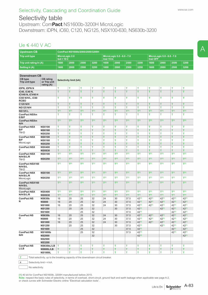
www.se.com
A
Selectivity, Cascading and Coordination Guide
Upstream CB ComPact NS1600b/2000/2500/3200HTrip unit type MicroLogic 2.0
Isd = 10 IrMicroLogic 5.0 - 6.0 - 7.0Inst 15 In
MicroLogic 5.0 - 6.0 - 7.0Inst OFF
Trip unit rating In (A) 1600 2000 2500 3200 1600 2000 2500 3200 1600 2000 2500 3200
Setting Ir (A) 1600 2000 2500 3200 1600 2000 2500 3200 1600 2000 2500 3200
Downstream CBSelectivity limit (kA)CB type
Trip unit typeCB rating or Trip unit rating (A)
iDPN, iDPN N T T T T T T T T T T T TiC40, iC40 N, ICV40 N, iCV40 H
T T T T T T T T T T T T
iC60 N/H/L, iC60 RCBO
T T T T T T T T T T T T
C120 N/H T T T T T T T T T T T TNG125 N/H T T T T T T T T T T T TNG125 L T[1] T[1] T[1] T[1] T[1] T[1] T[1] T[1] T[1] T[1] T[1] T[1]
ComPact NSXm E/B/F
T T T T T T T T T T T T
ComPact NSXm N/H
T[1] T[1] T[1] T[1] T[1] T[1] T[1] T[1] T[1] T[1] T[1] T[1]
ComPact NSXB/FTM-D
NSX100 T T T T T T T T T T T TNSX160 T T T T T T T T T T T TNSX250 T T T T T T T T T T T T
ComPact NSXB/FMicroLogic
NSX100 T T T T T T T T T T T TNSX160 T T T T T T T T T T T TNSX250 T T T T T T T T T T T T
ComPact NSXF
NSX400 T T T T T T T T T T T TNSX630 T T T T T T T T T T T T
ComPact NSXN/H/S/L/RTM-D
NSX100 T[1] T[1] T[1] T[1] T[1] T[1] T[1] T[1] T[1] T[1] T[1] T[1]
NSX250 T[1] T[1] T[1] T[1] T[1] T[1] T[1] T[1] T[1] T[1] T[1] T[1]
ComPact NSX160 N/H/S/LTM-D
T[1] T[1] T[1] T[1] T[1] T[1] T[1] T[1] T[1] T[1] T[1] T[1]
ComPact NSXN/H/S/L/RMicroLogic
NSX100 T[1] T[1] T[1] T[1] T[1] T[1] T[1] T[1] T[1] T[1] T[1] T[1]
NSX250 T[1] T[1] T[1] T[1] T[1] T[1] T[1] T[1] T[1] T[1] T[1] T[1]
ComPact NSX160 N/H/S/LMicroLogic
T[1] T[1] T[1] T[1] T[1] T[1] T[1] T[1] T[1] T[1] T[1] T[1]
ComPact NSXN/H/S/L/R
NSX400 T[1] T[1] T[1] T[1] T[1] T[1] T[1] T[1] T[1] T[1] T[1] T[1]
NSX630 T[1] T[1] T[1] T[1] T[1] T[1] T[1] T[1] T[1] T[1] T[1] T[1]
ComPact NSN
NS630b 16 20 25 32 24 30 37.5 42[1] 42[1] 42[1] 42[1] 42[1]
NS800 16 20 25 32 24 30 37.5 42[1] 42[1] 42[1] 42[1] 42[1]
NS1000 16 20 25 32 24 30 37.5 42[1] 42[1] 42[1] 42[1] 42[1]
NS1250 20 25 32 30 37.5 42[1] 42[1] 42[1] 42[1]
NS1600 25 32 37.5 42[1] 42[1] 42[1]
ComPact NSH
NS630b 16 20 25 32 24 30 37.5 42[1] 42[1] 42[1] 42[1] 42[1]
NS800 16 20 25 32 24 30 37.5 42[1] 42[1] 42[1] 42[1] 42[1]
NS1000 16 20 25 32 24 30 37.5 42[1] 42[1] 42[1] 42[1] 42[1]
NS1250 20 25 32 30 37.5 42[1] 42[1] 42[1] 42[1]
NS1600 25 32 37.5 42[1] 42[1] 42[1]
ComPact NSN/H
NS1600b 25 32 37.5 42[1] 42[1] 42[1]
NS2000 32 42[1] 42[1]
NS2500NS3200
ComPact NSL/LB
NS630bL/LB T T T T T T T T T T T TNS800L/LB T T T T T T T T T T T TNS1000L T T T T T T T T T T T T
T Total selectivity, up to the breaking capacity of the downstream circuit breaker.
4 Selectivity limit = 4 kA.
No selectivity.
Ue y 440 V AC
Selectivity tableUpstream: ComPact NS1600b-3200H MicroLogicDownstream: iDPN, iC60, C120, NG125, NSX100-630, NS630b-3200
[1] 40 kA for ComPact NS1600b..3200H manufactured before 2015.Note: respect the basic rules of selectivity, in terms of overload, short-circuit, ground fault and earth leakage when applicable see page A-2, or check curves with Schneider Electric online “Electrical calculation tools”.
A-83
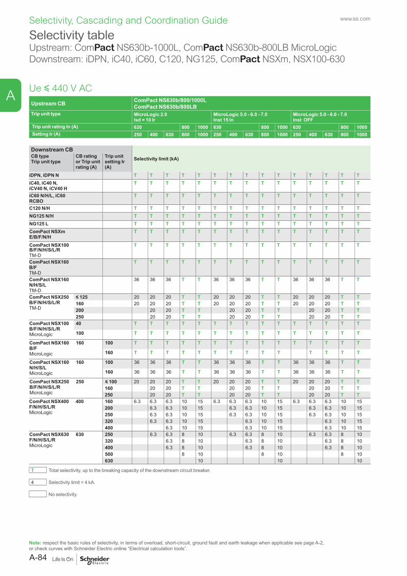
www.se.com
A
Selectivity, Cascading and Coordination Guide
Upstream CB ComPact NS630b/800/1000L ComPact NS630b/800LB
Trip unit type MicroLogic 2.0 Isd = 10 Ir
MicroLogic 5.0 - 6.0 - 7.0Inst 15 In
MicroLogic 5.0 - 6.0 - 7.0Inst OFF
Trip unit rating In (A) 630 800 1000 630 800 1000 630 800 1000 Setting Ir (A) 250 400 630 800 1000 250 400 630 800 1000 250 400 630 800 1000
Downstream CBSelectivity limit (kA)CB type
Trip unit typeCB ratingor Trip unit rating (A)
Trip unit setting Ir (A)
iDPN, iDPN N T T T T T T T T T T T T T T TiC40, iC40 N, iCV40 N, iCV40 H
T T T T T T T T T T T T T T T
iC60 N/H/L, iC60 RCBO
T T T T T T T T T T T T T T T
C120 N/H T T T T T T T T T T T T T T TNG125 N/H T T T T T T T T T T T T T T TNG125 L T T T T T T T T T T T T T T TComPact NSXm E/B/F/N/H
T T T T T T T T T T T T T T T
ComPact NSX100 B/F/N/H/S/L/R TM-D
T T T T T T T T T T T T T T T
ComPact NSX160 B/FTM-D
T T T T T T T T T T T T T T T
ComPact NSX160 N/H/S/LTM-D
36 36 36 T T 36 36 36 T T 36 36 36 T T
ComPact NSX250 B/F/N/H/S/L/RTM-D
y 125 20 20 20 T T 20 20 20 T T 20 20 20 T T160 20 20 20 T T 20 20 20 T T 20 20 20 T T200 20 20 T T 20 20 T T 20 20 T T250 20 20 T T 20 20 T T 20 20 T T
ComPact NSX100 B/F/N/H/S/L/RMicroLogic
40 T T T T T T T T T T T T T T T
100 T T T T T T T T T T T T T T T
ComPact NSX160 B/FMicroLogic
160 100 T T T T T T T T T T T T T T T
160 T T T T T T T T T T T T T T
ComPact NSX160 N/H/S/LMicroLogic
160 100 36 36 36 T T 36 36 36 T T 36 36 36 T T
160 36 36 36 T T 36 36 36 T T 36 36 36 T T
ComPact NSX250 B/F/N/H/S/L/RMicroLogic
250 y 100 20 20 20 T T 20 20 20 T T 20 20 20 T T160 20 20 T T 20 20 T T 20 20 T T250 20 20 T T 20 20 T T 20 20 T T
ComPact NSX400 F/N/H/S/L/RMicroLogic
400 160 6.3 6.3 6.3 10 15 6.3 6.3 6.3 10 15 6.3 6.3 6.3 10 15200 6.3 6.3 10 15 6.3 6.3 10 15 6.3 6.3 10 15250 6.3 6.3 10 15 6.3 6.3 10 15 6.3 6.3 10 15320 6.3 6.3 10 15 6.3 10 15 6.3 10 15400 6.3 10 15 6.3 10 15 6.3 10 15
ComPact NSX630 F/N/H/S/L/RMicroLogic
630 250 6.3 6.3 8 10 6.3 6.3 8 10 6.3 6.3 8 10320 6.3 8 10 6.3 8 10 6.3 8 10400 6.3 8 10 6.3 8 10 6.3 8 10500 8 10 8 10 8 10630 10 10 10
T Total selectivity, up to the breaking capacity of the downstream circuit breaker.
4 Selectivity limit = 4 kA.
No selectivity.
Ue y 440 V AC
Selectivity tableUpstream: ComPact NS630b-1000L, ComPact NS630b-800LB MicroLogicDownstream: iDPN, iC40, iC60, C120, NG125, ComPact NSXm, NSX100-630
Note: respect the basic rules of selectivity, in terms of overload, short-circuit, ground fault and earth leakage when applicable see page A-2, or check curves with Schneider Electric online “Electrical calculation tools”.
A-84
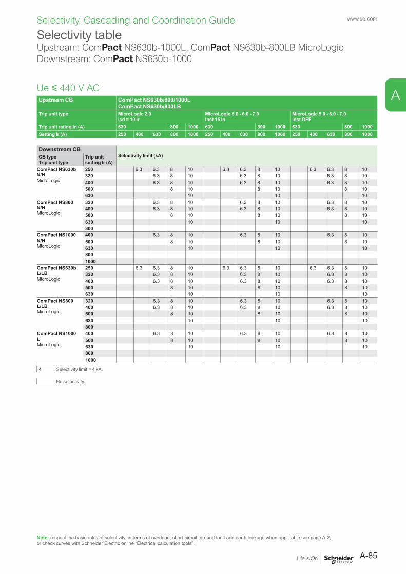
www.se.com
A
Selectivity, Cascading and Coordination Guide
Upstream CB ComPact NS630b/800/1000L ComPact NS630b/800LB
Trip unit type MicroLogic 2.0 Isd = 10 Ir
MicroLogic 5.0 - 6.0 - 7.0Inst 15 In
MicroLogic 5.0 - 6.0 - 7.0Inst OFF
Trip unit rating In (A) 630 800 1000 630 800 1000 630 800 1000Setting Ir (A) 250 400 630 800 1000 250 400 630 800 1000 250 400 630 800 1000
Downstream CBSelectivity limit (kA)CB type
Trip unit typeTrip unit setting Ir (A)
ComPact NS630b N/HMicroLogic
250 6.3 6.3 8 10 6.3 6.3 8 10 6.3 6.3 8 10320 6.3 8 10 6.3 8 10 6.3 8 10400 6.3 8 10 6.3 8 10 6.3 8 10500 8 10 8 10 8 10630 10 10 10
ComPact NS800 N/HMicroLogic
320 6.3 8 10 6.3 8 10 6.3 8 10400 6.3 8 10 6.3 8 10 6.3 8 10500 8 10 8 10 8 10630 10 10 10800
ComPact NS1000 N/HMicroLogic
400 6.3 8 10 6.3 8 10 6.3 8 10500 8 10 8 10 8 10630 10 10 108001000
ComPact NS630b L/LBMicroLogic
250 6.3 6.3 8 10 6.3 6.3 8 10 6.3 6.3 8 10320 6.3 8 10 6.3 8 10 6.3 8 10400 6.3 8 10 6.3 8 10 6.3 8 10500 8 10 8 10 8 10630 10 10 10
ComPact NS800 L/LBMicroLogic
320 6.3 8 10 6.3 8 10 6.3 8 10400 6.3 8 10 6.3 8 10 6.3 8 10500 8 10 8 10 8 10630 10 10 10800
ComPact NS1000 LMicroLogic
400 6.3 8 10 6.3 8 10 6.3 8 10500 8 10 8 10 8 10630 10 10 108001000
4 Selectivity limit = 4 kA.
No selectivity.
Ue y 440 V AC
Selectivity tableUpstream: ComPact NS630b-1000L, ComPact NS630b-800LB MicroLogicDownstream: ComPact NS630b-1000
Note: respect the basic rules of selectivity, in terms of overload, short-circuit, ground fault and earth leakage when applicable see page A-2, or check curves with Schneider Electric online “Electrical calculation tools”.
A-85
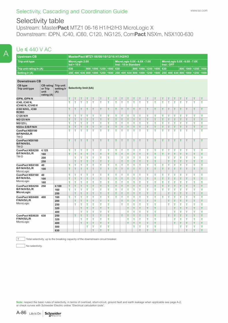
Upstream CB MasterPact MTZ1 06/08/10/12/16 H1/H2/H3 Trip unit type MicroLogic 2.0X
Isd = 10 IrMicroLogic 5.0X - 6.0X - 7.0X Inst : 15 In Standard
MicroLogic 5.0X - 6.0X - 7.0X Inst : OFF
Trip unit rating In (A) 630 800 1000 1250 1600 630 800 1000 1250 1600 630 800 1000 1250 1600Setting Ir (A) 250 400 630 800 1000 1250 1600 250 400 630 800 1000 1250 1600 250 400 630 800 1000 1250 1600
Downstream CB
Selectivity limit (kA)CB typeTrip unit type
CB rating or Trip unit rating (A)
Trip unit setting Ir (A)
iDPN, iDPN N T T T T T T T T T T T T T T T T T T T T TiC40, iC40 N, iCV40 N, iCV40 H
T T T T T T T T T T T T T T T T T T T T T
iC60 N/H/L, iC60 RCBO
T T T T T T T T T T T T T T T T T T T T T
C120 N/H T T T T T T T T T T T T T T T T T T T T TNG125 N/H T T T T T T T T T T T T T T T T T T T T TNG125 L T T T T T T T T T T T T T T T T T T T T TNSXm E/B/F/N/H T T T T T T T T T T T T T T T T T T T T TComPact NSX100 B/F/N/H/S/L/R TM-D
T T T T T T T T T T T T T T T T T T T T T
ComPact NSX160 B/F/N/H/S/L TM-D
T T T T T T T T T T T T T T T T T T T T T
ComPact NSX250 B/F/N/H/S/L/RTM-D
y 125 T T T T T T T T T T T T T T T T T T T T T160 T T T T T T T T T T T T T T T T T T T T T200 T T T T T T T T T T T T T T T T T T250 T T T T T T T T T T T T T T T T T T
ComPact NSX100 B/F/N/H/S/L/RMicroLogic
40 T T T T T T T T T T T T T T T T T T T T T100 T T T T T T T T T T T T T T T T T T T T T
ComPact NSX160 B/F/N/H/S/LMicroLogic
40 T T T T T T T T T T T T T T T T T T T T T100 T T T T T T T T T T T T T T T T T T T T T160 T T T T T T T T T T T T T T T T T T T T T
ComPact NSX250 B/F/N/H/S/L/RMicroLogic
250 y 100 T T T T T T T T T T T T T T T T T T T T T160 T T T T T T T T T T T T T T T T T T T T T250 T T T T T T T T T T T T T T T T T T T
ComPact NSX400 F/N/H/S/L/RMicroLogic
400 160 T T T T T T T T T T T T T T T T T T T T T200 T T T T T T T T T T T T T T T T T T250 T T T T T T T T T T T T T T T T T T320 T T T T T T T T T T T T T T T400 T T T T T T T T T T T T T T T
ComPact NSX630 F/N/H/S/L/RMicroLogic
630 250 T T T T T T T T T T T T T T T T T T320 T T T T T T T T T T T T T T T400 T T T T T T T T T T T T T T T500 T T T T T T T T T T T T630 T T T T T T T T T
T Total selectivity, up to the breaking capacity of the downstream circuit breaker.
No selectivity.
Selectivity tableUpstream: MasterPact MTZ1 06-16 H1/H2/H3 MicroLogic XDownstream: iDPN, iC40, iC60, C120, NG125, ComPact NSXm, NSX100-630
Ue y 440 V AC
Note: respect the basic rules of selectivity, in terms of overload, short-circuit, ground fault and earth leakage when applicable see page A-2, or check curves with Schneider Electric online “Electrical calculation tools”.
www.se.com
A-86
A
Selectivity, Cascading and Coordination Guide
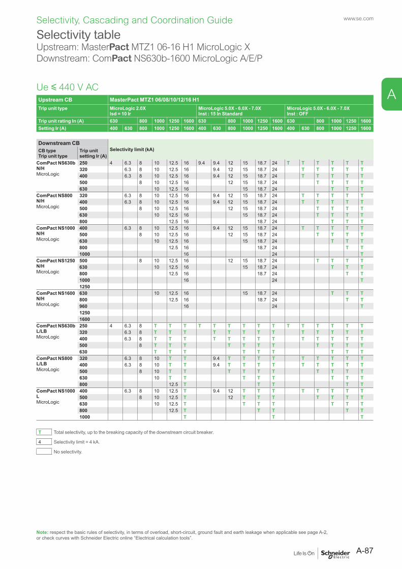
Upstream CB MasterPact MTZ1 06/08/10/12/16 H1Trip unit type MicroLogic 2.0X
Isd = 10 IrMicroLogic 5.0X - 6.0X - 7.0XInst : 15 In Standard
MicroLogic 5.0X - 6.0X - 7.0XInst : OFF
Trip unit rating In (A) 630 800 1000 1250 1600 630 800 1000 1250 1600 630 800 1000 1250 1600Setting Ir (A) 400 630 800 1000 1250 1600 400 630 800 1000 1250 1600 400 630 800 1000 1250 1600
Downstream CBSelectivity limit (kA)CB type
Trip unit typeTrip unit setting Ir (A)
ComPact NS630b N/HMicroLogic
250 4 6.3 8 10 12.5 16 9.4 9.4 12 15 18.7 24 T T T T T T320 6.3 8 10 12.5 16 9.4 12 15 18.7 24 T T T T T400 6.3 8 10 12.5 16 9.4 12 15 18.7 24 T T T T T500 8 10 12.5 16 12 15 18.7 24 T T T T630 10 12.5 16 15 18.7 24 T T T
ComPact NS800 N/HMicroLogic
320 6.3 8 10 12.5 16 9.4 12 15 18.7 24 T T T T T400 6.3 8 10 12.5 16 9.4 12 15 18.7 24 T T T T T500 8 10 12.5 16 12 15 18.7 24 T T T T630 10 12.5 16 15 18.7 24 T T T T800 12.5 16 18.7 24 T T T
ComPact NS1000 N/HMicroLogic
400 6.3 8 10 12.5 16 9.4 12 15 18.7 24 T T T T T500 8 10 12.5 16 12 15 18.7 24 T T T T630 10 12.5 16 15 18.7 24 T T T800 12.5 16 18.7 24 T T1000 16 24 T
ComPact NS1250 N/HMicroLogic
500 8 10 12.5 16 12 15 18.7 24 T T T T630 10 12.5 16 15 18.7 24 T T T800 12.5 16 18.7 24 T T1000 16 24 T1250
ComPact NS1600 N/HMicroLogic
630 10 12.5 16 15 18.7 24 T T T800 12.5 16 18.7 24 T T960 16 24 T12501600
ComPact NS630b L/LBMicroLogic
250 4 6.3 8 T T T T T T T T T T T T T T T320 6.3 8 T T T T T T T T T T T T T400 6.3 8 T T T T T T T T T T T T T500 8 T T T T T T T T T T T630 T T T T T T T T T
ComPact NS800 L/LBMicroLogic
320 6.3 8 10 T T 9.4 T T T T T T T T T400 6.3 8 10 T T 9.4 T T T T T T T T T500 8 10 T T T T T T T T T T630 10 T T T T T T T T800 12.5 T T T T T
ComPact NS1000 LMicroLogic
400 6.3 8 10 12.5 T 9.4 12 T T T T T T T T500 8 10 12.5 T 12 T T T T T T T630 10 12.5 T T T T T T T800 12.5 T T T T T1000 T T T
T Total selectivity, up to the breaking capacity of the downstream circuit breaker.
4 Selectivity limit = 4 kA.
No selectivity.
Selectivity tableUpstream: MasterPact MTZ1 06-16 H1 MicroLogic XDownstream: ComPact NS630b-1600 MicroLogic A/E/P
Ue y 440 V AC
Note: respect the basic rules of selectivity, in terms of overload, short-circuit, ground fault and earth leakage when applicable see page A-2, or check curves with Schneider Electric online “Electrical calculation tools”.
A-87
www.se.com
A
Selectivity, Cascading and Coordination Guide
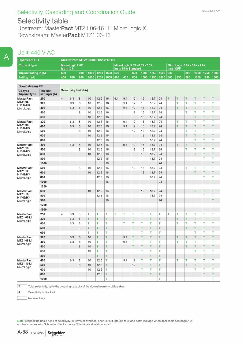
Upstream CB MasterPact MTZ1 06/08/10/12/16 H1 Trip unit type MicroLogic 2.0X
Isd = 10 IrMicroLogic 5.0X - 6.0X - 7.0XInst : 15 In Standard
MicroLogic 5.0X - 6.0X - 7.0XInst : OFF
Trip unit rating In (A) 630 800 1000 1250 1600 630 800 1000 1250 1600 630 800 1000 1250 1600Setting Ir (A) 400 630 800 1000 1250 1600 400 630 800 1000 1250 1600 400 630 800 1000 1250 1600
Downstream CBSelectivity limit (kA)CB type
Trip unit typeTrip unit setting Ir (A)
MasterPact MTZ1 06 H1/H2/H3MicroLogic
250 4 6.3 8 10 12.5 16 9.4 9.4 12 15 18.7 24 T T T T T T320 6.3 8 10 12.5 16 9.4 12 15 18.7 24 T T T T T400 6.3 8 10 12.5 16 9.4 12 15 18.7 24 T T T T T500 8 10 12.5 16 12 15 18.7 24 T T T T630 10 12.5 16 15 18.7 24 T T T
MasterPact MTZ1 08 H1/H2/H3MicroLogic
320 6.3 8 10 12.5 16 9.4 12 15 18.7 24 T T T T T400 6.3 8 10 12.5 16 9.4 12 15 18.7 24 T T T T T500 8 10 12.5 16 12 15 18.7 24 T T T T630 10 12.5 16 15 18.7 24 T T T T800 12.5 16 18.7 24 T T T
MasterPact MTZ1 10 H1/H2/H3MicroLogic
400 6.3 8 10 12.5 16 9.4 12 15 18.7 24 T T T T T500 8 10 12.5 16 12 15 18.7 24 T T T T630 10 12.5 16 15 18.7 24 T T T800 12.5 16 18.7 24 T T1000 16 24 T
MasterPact MTZ1 12 H1/H2/H3MicroLogic
500 8 10 12.5 16 12 15 18.7 24 T T T T630 10 12.5 16 15 18.7 24 T T T800 12.5 16 18.7 24 T T1000 16 24 T1250
MasterPact MTZ1 16 H1/H2/H3MicroLogic
630 10 12.5 16 15 18.7 24 T T T800 12.5 16 18.7 24 T T960 16 24 T12501600
MasterPact MTZ1 06 L1MicroLogic
250 4 6.3 8 T T T T T T T T T T T T T T T320 6.3 8 T T T T T T T T T T T T T400 6.3 8 T T T T T T T T T T T T T500 8 T T T T T T T T T T T630 T T T T T T T T T
MasterPact MTZ1 08 L1MicroLogic
320 6.3 8 10 T T 9.4 T T T T T T T T T400 6.3 8 10 T T 9.4 T T T T T T T T T500 8 10 T T T T T T T T T T630 10 T T T T T T T T800 T T T T T T
MasterPact MTZ1 10 L1MicroLogic
400 6.3 8 10 12.5 T 9.4 12 T T T T T T T T500 8 10 12.5 T 12 T T T T T T T630 10 12.5 T T T T T T T800 12.5 T T T T T1000 T T T
T Total selectivity, up to the breaking capacity of the downstream circuit breaker.
4 Selectivity limit = 4 kA.
No selectivity.
Selectivity tableUpstream: MasterPact MTZ1 06-16 H1 MicroLogic XDownstream: MasterPact MTZ1 06-16
Ue y 440 V AC
Note: respect the basic rules of selectivity, in terms of overload, short-circuit, ground fault and earth leakage when applicable see page A-2, or check curves with Schneider Electric online “Electrical calculation tools”.
www.se.com
A-88
A
Selectivity, Cascading and Coordination Guide
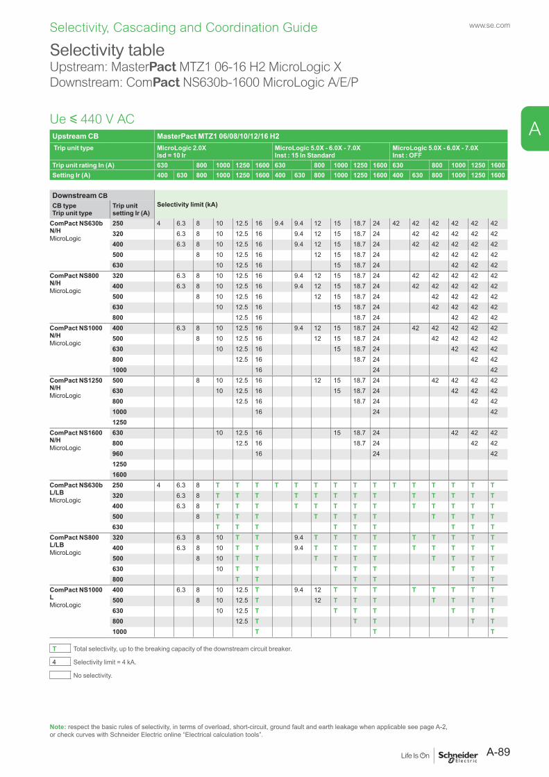
Upstream CB MasterPact MTZ1 06/08/10/12/16 H2 Trip unit type MicroLogic 2.0X
Isd = 10 IrMicroLogic 5.0X - 6.0X - 7.0XInst : 15 In Standard
MicroLogic 5.0X - 6.0X - 7.0XInst : OFF
Trip unit rating In (A) 630 800 1000 1250 1600 630 800 1000 1250 1600 630 800 1000 1250 1600Setting Ir (A) 400 630 800 1000 1250 1600 400 630 800 1000 1250 1600 400 630 800 1000 1250 1600
Downstream CBSelectivity limit (kA)CB type
Trip unit typeTrip unit setting Ir (A)
ComPact NS630b N/HMicroLogic
250 4 6.3 8 10 12.5 16 9.4 9.4 12 15 18.7 24 42 42 42 42 42 42320 6.3 8 10 12.5 16 9.4 12 15 18.7 24 42 42 42 42 42400 6.3 8 10 12.5 16 9.4 12 15 18.7 24 42 42 42 42 42500 8 10 12.5 16 12 15 18.7 24 42 42 42 42630 10 12.5 16 15 18.7 24 42 42 42
ComPact NS800 N/HMicroLogic
320 6.3 8 10 12.5 16 9.4 12 15 18.7 24 42 42 42 42 42400 6.3 8 10 12.5 16 9.4 12 15 18.7 24 42 42 42 42 42500 8 10 12.5 16 12 15 18.7 24 42 42 42 42630 10 12.5 16 15 18.7 24 42 42 42 42800 12.5 16 18.7 24 42 42 42
ComPact NS1000 N/HMicroLogic
400 6.3 8 10 12.5 16 9.4 12 15 18.7 24 42 42 42 42 42500 8 10 12.5 16 12 15 18.7 24 42 42 42 42630 10 12.5 16 15 18.7 24 42 42 42800 12.5 16 18.7 24 42 421000 16 24 42
ComPact NS1250 N/HMicroLogic
500 8 10 12.5 16 12 15 18.7 24 42 42 42 42630 10 12.5 16 15 18.7 24 42 42 42800 12.5 16 18.7 24 42 421000 16 24 421250
ComPact NS1600 N/HMicroLogic
630 10 12.5 16 15 18.7 24 42 42 42800 12.5 16 18.7 24 42 42960 16 24 4212501600
ComPact NS630b L/LBMicroLogic
250 4 6.3 8 T T T T T T T T T T T T T T T320 6.3 8 T T T T T T T T T T T T T400 6.3 8 T T T T T T T T T T T T T500 8 T T T T T T T T T T T630 T T T T T T T T T
ComPact NS800 L/LBMicroLogic
320 6.3 8 10 T T 9.4 T T T T T T T T T400 6.3 8 10 T T 9.4 T T T T T T T T T500 8 10 T T T T T T T T T T630 10 T T T T T T T T800 T T T T T T
ComPact NS1000 LMicroLogic
400 6.3 8 10 12.5 T 9.4 12 T T T T T T T T500 8 10 12.5 T 12 T T T T T T T630 10 12.5 T T T T T T T800 12.5 T T T T T1000 T T T
T Total selectivity, up to the breaking capacity of the downstream circuit breaker.
4 Selectivity limit = 4 kA.
No selectivity.
Selectivity tableUpstream: MasterPact MTZ1 06-16 H2 MicroLogic XDownstream: ComPact NS630b-1600 MicroLogic A/E/P
Ue y 440 V AC
Note: respect the basic rules of selectivity, in terms of overload, short-circuit, ground fault and earth leakage when applicable see page A-2, or check curves with Schneider Electric online “Electrical calculation tools”.
A-89
www.se.com
A
Selectivity, Cascading and Coordination Guide
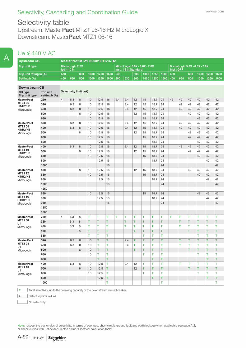
Upstream CB MasterPact MTZ1 06/08/10/12/16 H2Trip unit type MicroLogic 2.0X
Isd = 10 IrMicroLogic 5.0X - 6.0X - 7.0XInst : 15 In Standard
MicroLogic 5.0X - 6.0X - 7.0XInst : OFF
Trip unit rating In (A) 630 800 1000 1250 1600 630 800 1000 1250 1600 630 800 1000 1250 1600Setting Ir (A) 400 630 800 1000 1250 1600 400 630 800 1000 1250 1600 400 630 800 1000 1250 1600
Downstream CBSelectivity limit (kA)CB type
Trip unit typeTrip unit setting Ir (A)
MasterPact MTZ1 06 H1/H2/H3MicroLogic
250 4 6.3 8 10 12.5 16 9.4 9.4 12 15 18.7 24 42 42 42 42 42 42320 6.3 8 10 12.5 16 9.4 12 15 18.7 24 42 42 42 42 42400 6.3 8 10 12.5 16 9.4 12 15 18.7 24 42 42 42 42 42500 8 10 12.5 16 12 15 18.7 24 42 42 42 42630 10 12.5 16 15 18.7 24 42 42 42
MasterPact MTZ1 08 H1/H2/H3MicroLogic
320 6.3 8 10 12.5 16 9.4 12 15 18.7 24 42 42 42 42 42400 6.3 8 10 12.5 16 9.4 12 15 18.7 24 42 42 42 42 42500 8 10 12.5 16 12 15 18.7 24 42 42 42 42630 10 12.5 16 15 18.7 24 42 42 42 42800 12.5 16 18.7 24 42 42 42
MasterPact MTZ1 10 H1/H2/H3MicroLogic
400 6.3 8 10 12.5 16 9.4 12 15 18.7 24 42 42 42 42 42500 8 10 12.5 16 12 15 18.7 24 42 42 42 42630 10 12.5 16 15 18.7 24 42 42 42800 12.5 16 18.7 24 42 421000 16 24 42
MasterPact MTZ1 12 H1/H2/H3MicroLogic
500 8 10 12.5 16 12 15 18.7 24 42 42 42 42630 10 12.5 16 15 18.7 24 42 42 42800 12.5 16 18.7 24 42 421000 16 24 421250
MasterPact MTZ1 16 H1/H2/H3MicroLogic
630 10 12.5 16 15 18.7 24 42 42 42800 12.5 16 18.7 24 42 42960 16 24 4212501600
MasterPact MTZ1 06 L1MicroLogic
250 4 6.3 8 T T T T T T T T T T T T T T T320 6.3 8 T T T T T T T T T T T T T400 6.3 8 T T T T T T T T T T T T T500 8 T T T T T T T T T T T630 T T T T T T T T T
MasterPact MTZ1 08 L1MicroLogic
320 6.3 8 10 T T 9.4 T T T T T T T T T400 6.3 8 10 T T 9.4 T T T T T T T T T500 8 10 T T T T T T T T T T630 10 T T T T T T T T800 T T T T T T
MasterPact MTZ1 10 L1MicroLogic
400 6.3 8 10 12.5 T 9.4 12 T T T T T T T T500 8 10 12.5 T 12 T T T T T T T630 10 12.5 T T T T T T T800 12.5 T T T T T1000 T T T
T Total selectivity, up to the breaking capacity of the downstream circuit breaker.
4 Selectivity limit = 4 kA.
No selectivity.
Selectivity tableUpstream: MasterPact MTZ1 06-16 H2 MicroLogic XDownstream: MasterPact MTZ1 06-16
Ue y 440 V AC
Note: respect the basic rules of selectivity, in terms of overload, short-circuit, ground fault and earth leakage when applicable see page A-2, or check curves with Schneider Electric online “Electrical calculation tools”.
www.se.com
A-90
A
Selectivity, Cascading and Coordination Guide
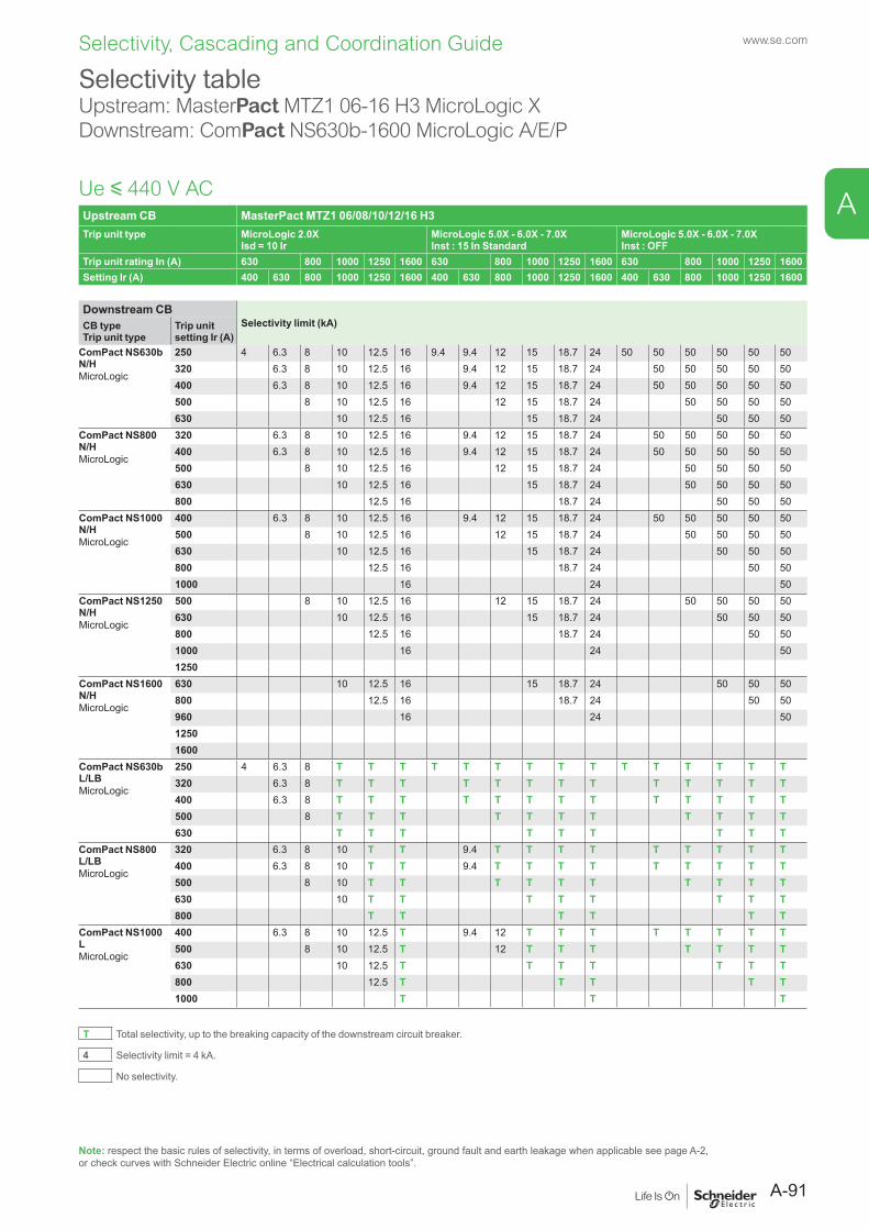
Upstream CB MasterPact MTZ1 06/08/10/12/16 H3Trip unit type MicroLogic 2.0X
Isd = 10 IrMicroLogic 5.0X - 6.0X - 7.0XInst : 15 In Standard
MicroLogic 5.0X - 6.0X - 7.0XInst : OFF
Trip unit rating In (A) 630 800 1000 1250 1600 630 800 1000 1250 1600 630 800 1000 1250 1600Setting Ir (A) 400 630 800 1000 1250 1600 400 630 800 1000 1250 1600 400 630 800 1000 1250 1600
Downstream CBSelectivity limit (kA)CB type
Trip unit typeTrip unit setting Ir (A)
ComPact NS630b N/HMicroLogic
250 4 6.3 8 10 12.5 16 9.4 9.4 12 15 18.7 24 50 50 50 50 50 50320 6.3 8 10 12.5 16 9.4 12 15 18.7 24 50 50 50 50 50400 6.3 8 10 12.5 16 9.4 12 15 18.7 24 50 50 50 50 50500 8 10 12.5 16 12 15 18.7 24 50 50 50 50630 10 12.5 16 15 18.7 24 50 50 50
ComPact NS800 N/HMicroLogic
320 6.3 8 10 12.5 16 9.4 12 15 18.7 24 50 50 50 50 50400 6.3 8 10 12.5 16 9.4 12 15 18.7 24 50 50 50 50 50500 8 10 12.5 16 12 15 18.7 24 50 50 50 50630 10 12.5 16 15 18.7 24 50 50 50 50800 12.5 16 18.7 24 50 50 50
ComPact NS1000 N/HMicroLogic
400 6.3 8 10 12.5 16 9.4 12 15 18.7 24 50 50 50 50 50500 8 10 12.5 16 12 15 18.7 24 50 50 50 50630 10 12.5 16 15 18.7 24 50 50 50800 12.5 16 18.7 24 50 501000 16 24 50
ComPact NS1250 N/HMicroLogic
500 8 10 12.5 16 12 15 18.7 24 50 50 50 50630 10 12.5 16 15 18.7 24 50 50 50800 12.5 16 18.7 24 50 501000 16 24 501250
ComPact NS1600 N/HMicroLogic
630 10 12.5 16 15 18.7 24 50 50 50800 12.5 16 18.7 24 50 50960 16 24 5012501600
ComPact NS630b L/LBMicroLogic
250 4 6.3 8 T T T T T T T T T T T T T T T320 6.3 8 T T T T T T T T T T T T T400 6.3 8 T T T T T T T T T T T T T500 8 T T T T T T T T T T T630 T T T T T T T T T
ComPact NS800 L/LBMicroLogic
320 6.3 8 10 T T 9.4 T T T T T T T T T400 6.3 8 10 T T 9.4 T T T T T T T T T500 8 10 T T T T T T T T T T630 10 T T T T T T T T800 T T T T T T
ComPact NS1000 LMicroLogic
400 6.3 8 10 12.5 T 9.4 12 T T T T T T T T500 8 10 12.5 T 12 T T T T T T T630 10 12.5 T T T T T T T800 12.5 T T T T T1000 T T T
T Total selectivity, up to the breaking capacity of the downstream circuit breaker.
4 Selectivity limit = 4 kA.
No selectivity.
Selectivity tableUpstream: MasterPact MTZ1 06-16 H3 MicroLogic XDownstream: ComPact NS630b-1600 MicroLogic A/E/P
Ue y 440 V AC
Note: respect the basic rules of selectivity, in terms of overload, short-circuit, ground fault and earth leakage when applicable see page A-2, or check curves with Schneider Electric online “Electrical calculation tools”.
A-91
www.se.com
A
Selectivity, Cascading and Coordination Guide
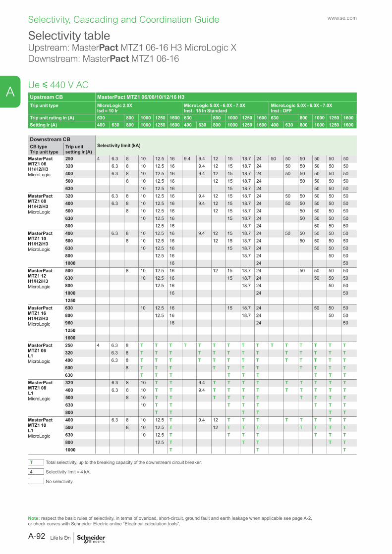
Upstream CB MasterPact MTZ1 06/08/10/12/16 H3Trip unit type MicroLogic 2.0X
Isd = 10 IrMicroLogic 5.0X - 6.0X - 7.0XInst : 15 In Standard
MicroLogic 5.0X - 6.0X - 7.0XInst : OFF
Trip unit rating In (A) 630 800 1000 1250 1600 630 800 1000 1250 1600 630 800 1000 1250 1600Setting Ir (A) 400 630 800 1000 1250 1600 400 630 800 1000 1250 1600 400 630 800 1000 1250 1600
Downstream CBSelectivity limit (kA)CB type
Trip unit typeTrip unit setting Ir (A)
MasterPact MTZ1 06 H1/H2/H3MicroLogic
250 4 6.3 8 10 12.5 16 9.4 9.4 12 15 18.7 24 50 50 50 50 50 50320 6.3 8 10 12.5 16 9.4 12 15 18.7 24 50 50 50 50 50400 6.3 8 10 12.5 16 9.4 12 15 18.7 24 50 50 50 50 50500 8 10 12.5 16 12 15 18.7 24 50 50 50 50630 10 12.5 16 15 18.7 24 50 50 50
MasterPact MTZ1 08 H1/H2/H3MicroLogic
320 6.3 8 10 12.5 16 9.4 12 15 18.7 24 50 50 50 50 50400 6.3 8 10 12.5 16 9.4 12 15 18.7 24 50 50 50 50 50500 8 10 12.5 16 12 15 18.7 24 50 50 50 50630 10 12.5 16 15 18.7 24 50 50 50 50800 12.5 16 18.7 24 50 50 50
MasterPact MTZ1 10 H1/H2/H3MicroLogic
400 6.3 8 10 12.5 16 9.4 12 15 18.7 24 50 50 50 50 50500 8 10 12.5 16 12 15 18.7 24 50 50 50 50630 10 12.5 16 15 18.7 24 50 50 50800 12.5 16 18.7 24 50 501000 16 24 50
MasterPact MTZ1 12 H1/H2/H3MicroLogic
500 8 10 12.5 16 12 15 18.7 24 50 50 50 50630 10 12.5 16 15 18.7 24 50 50 50800 12.5 16 18.7 24 50 501000 16 24 501250
MasterPact MTZ1 16 H1/H2/H3MicroLogic
630 10 12.5 16 15 18.7 24 50 50 50800 12.5 16 18.7 24 50 50960 16 24 5012501600
MasterPact MTZ1 06 L1MicroLogic
250 4 6.3 8 T T T T T T T T T T T T T T T320 6.3 8 T T T T T T T T T T T T T400 6.3 8 T T T T T T T T T T T T T500 8 T T T T T T T T T T T630 T T T T T T T T T
MasterPact MTZ1 08 L1MicroLogic
320 6.3 8 10 T T 9.4 T T T T T T T T T400 6.3 8 10 T T 9.4 T T T T T T T T T500 8 10 T T T T T T T T T T630 10 T T T T T T T T800 T T T T T T
MasterPact MTZ1 10 L1MicroLogic
400 6.3 8 10 12.5 T 9.4 12 T T T T T T T T500 8 10 12.5 T 12 T T T T T T T630 10 12.5 T T T T T T T800 12.5 T T T T T1000 T T T
T Total selectivity, up to the breaking capacity of the downstream circuit breaker.
4 Selectivity limit = 4 kA.
No selectivity.
Selectivity tableUpstream: MasterPact MTZ1 06-16 H3 MicroLogic XDownstream: MasterPact MTZ1 06-16
Ue y 440 V AC
Note: respect the basic rules of selectivity, in terms of overload, short-circuit, ground fault and earth leakage when applicable see page A-2, or check curves with Schneider Electric online “Electrical calculation tools”.
www.se.com
A-92
A
Selectivity, Cascading and Coordination Guide
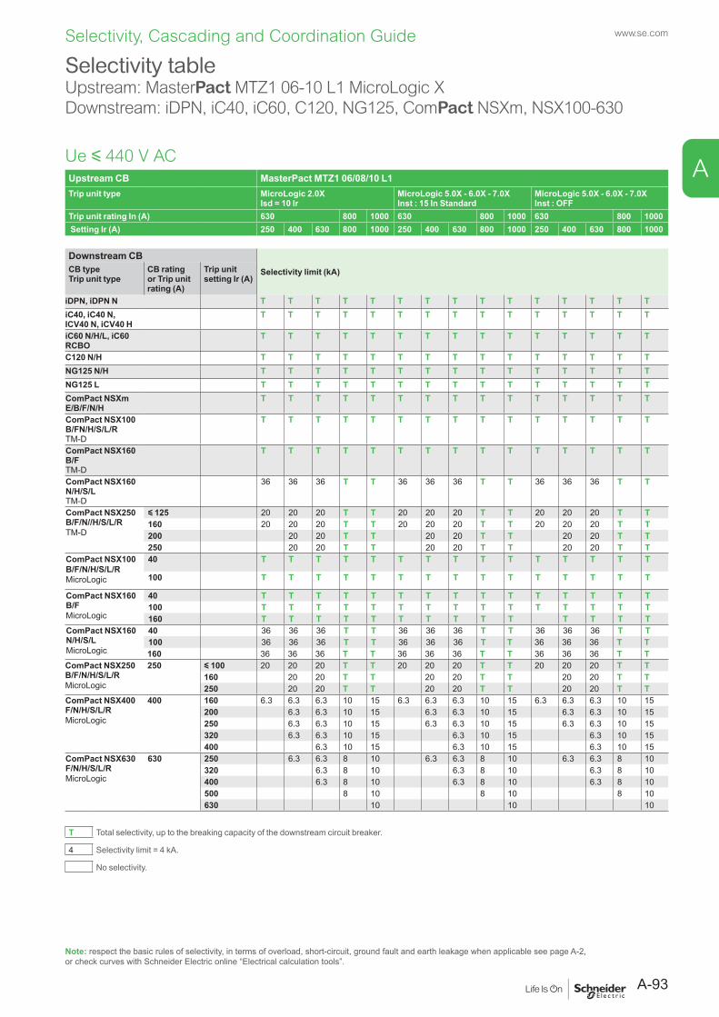
Upstream CB MasterPact MTZ1 06/08/10 L1Trip unit type MicroLogic 2.0X
Isd = 10 IrMicroLogic 5.0X - 6.0X - 7.0XInst : 15 In Standard
MicroLogic 5.0X - 6.0X - 7.0XInst : OFF
Trip unit rating In (A) 630 800 1000 630 800 1000 630 800 1000 Setting Ir (A) 250 400 630 800 1000 250 400 630 800 1000 250 400 630 800 1000
Downstream CBSelectivity limit (kA)CB type
Trip unit typeCB rating or Trip unit rating (A)
Trip unit setting Ir (A)
iDPN, iDPN N T T T T T T T T T T T T T T TiC40, iC40 N, ICV40 N, iCV40 H
T T T T T T T T T T T T T T T
iC60 N/H/L, iC60 RCBO
T T T T T T T T T T T T T T T
C120 N/H T T T T T T T T T T T T T T TNG125 N/H T T T T T T T T T T T T T T TNG125 L T T T T T T T T T T T T T T TComPact NSXm E/B/F/N/H
T T T T T T T T T T T T T T T
ComPact NSX100 B/FN/H/S/L/R TM-D
T T T T T T T T T T T T T T T
ComPact NSX160 B/F TM-D
T T T T T T T T T T T T T T T
ComPact NSX160 N/H/S/L TM-D
36 36 36 T T 36 36 36 T T 36 36 36 T T
ComPact NSX250 B/F/N//H/S/L/RTM-D
y 125 20 20 20 T T 20 20 20 T T 20 20 20 T T160 20 20 20 T T 20 20 20 T T 20 20 20 T T200 20 20 T T 20 20 T T 20 20 T T250 20 20 T T 20 20 T T 20 20 T T
ComPact NSX100 B/F/N/H/S/L/R MicroLogic
40 T T T T T T T T T T T T T T T
100 T T T T T T T T T T T T T T T
ComPact NSX160 B/FMicroLogic
40 T T T T T T T T T T T T T T T100 T T T T T T T T T T T T T T T160 T T T T T T T T T T T T T T
ComPact NSX160 N/H/S/LMicroLogic
40 36 36 36 T T 36 36 36 T T 36 36 36 T T100 36 36 36 T T 36 36 36 T T 36 36 36 T T160 36 36 36 T T 36 36 36 T T 36 36 36 T T
ComPact NSX250 B/F/N/H/S/L/RMicroLogic
250 y 100 20 20 20 T T 20 20 20 T T 20 20 20 T T160 20 20 T T 20 20 T T 20 20 T T250 20 20 T T 20 20 T T 20 20 T T
ComPact NSX400 F/N/H/S/L/RMicroLogic
400 160 6.3 6.3 6.3 10 15 6.3 6.3 6.3 10 15 6.3 6.3 6.3 10 15200 6.3 6.3 10 15 6.3 6.3 10 15 6.3 6.3 10 15250 6.3 6.3 10 15 6.3 6.3 10 15 6.3 6.3 10 15320 6.3 6.3 10 15 6.3 10 15 6.3 10 15400 6.3 10 15 6.3 10 15 6.3 10 15
ComPact NSX630 F/N/H/S/L/RMicroLogic
630 250 6.3 6.3 8 10 6.3 6.3 8 10 6.3 6.3 8 10320 6.3 8 10 6.3 8 10 6.3 8 10400 6.3 8 10 6.3 8 10 6.3 8 10500 8 10 8 10 8 10630 10 10 10
T Total selectivity, up to the breaking capacity of the downstream circuit breaker.
4 Selectivity limit = 4 kA.
No selectivity.
Selectivity tableUpstream: MasterPact MTZ1 06-10 L1 MicroLogic XDownstream: iDPN, iC40, iC60, C120, NG125, ComPact NSXm, NSX100-630
Ue y 440 V AC
Note: respect the basic rules of selectivity, in terms of overload, short-circuit, ground fault and earth leakage when applicable see page A-2, or check curves with Schneider Electric online “Electrical calculation tools”.
A-93
www.se.com
A
Selectivity, Cascading and Coordination Guide
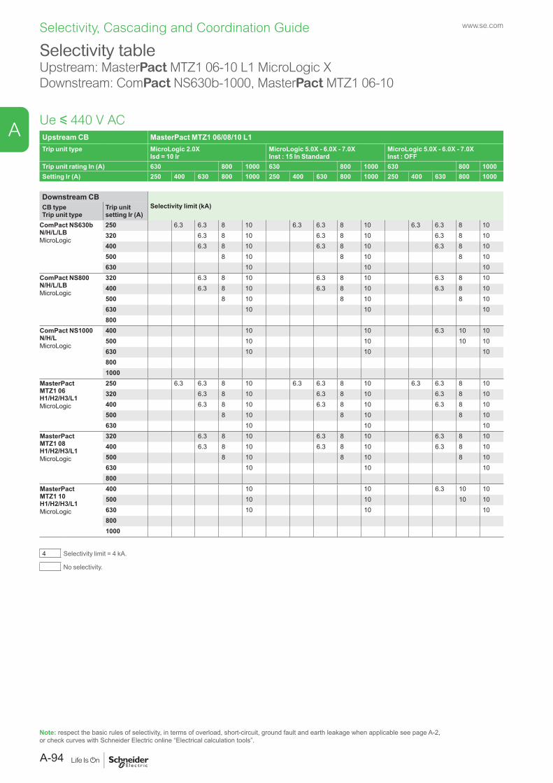
Upstream CB MasterPact MTZ1 06/08/10 L1Trip unit type MicroLogic 2.0X
Isd = 10 IrMicroLogic 5.0X - 6.0X - 7.0XInst : 15 In Standard
MicroLogic 5.0X - 6.0X - 7.0XInst : OFF
Trip unit rating In (A) 630 800 1000 630 800 1000 630 800 1000Setting Ir (A) 250 400 630 800 1000 250 400 630 800 1000 250 400 630 800 1000
Downstream CBSelectivity limit (kA)CB type
Trip unit typeTrip unit setting Ir (A)
ComPact NS630b N/H/L/LBMicroLogic
250 6.3 6.3 8 10 6.3 6.3 8 10 6.3 6.3 8 10320 6.3 8 10 6.3 8 10 6.3 8 10400 6.3 8 10 6.3 8 10 6.3 8 10500 8 10 8 10 8 10630 10 10 10
ComPact NS800 N/H/L/LBMicroLogic
320 6.3 8 10 6.3 8 10 6.3 8 10400 6.3 8 10 6.3 8 10 6.3 8 10500 8 10 8 10 8 10630 10 10 10800
ComPact NS1000 N/H/LMicroLogic
400 10 10 6.3 10 10500 10 10 10 10630 10 10 108001000
MasterPact MTZ1 06 H1/H2/H3/L1MicroLogic
250 6.3 6.3 8 10 6.3 6.3 8 10 6.3 6.3 8 10320 6.3 8 10 6.3 8 10 6.3 8 10400 6.3 8 10 6.3 8 10 6.3 8 10500 8 10 8 10 8 10630 10 10 10
MasterPact MTZ1 08 H1/H2/H3/L1MicroLogic
320 6.3 8 10 6.3 8 10 6.3 8 10400 6.3 8 10 6.3 8 10 6.3 8 10500 8 10 8 10 8 10630 10 10 10800
MasterPact MTZ1 10 H1/H2/H3/L1MicroLogic
400 10 10 6.3 10 10500 10 10 10 10630 10 10 108001000
4 Selectivity limit = 4 kA.
No selectivity.
Selectivity tableUpstream: MasterPact MTZ1 06-10 L1 MicroLogic XDownstream: ComPact NS630b-1000, MasterPact MTZ1 06-10
Ue y 440 V AC
Note: respect the basic rules of selectivity, in terms of overload, short-circuit, ground fault and earth leakage when applicable see page A-2, or check curves with Schneider Electric online “Electrical calculation tools”.
www.se.com
A-94
A
Selectivity, Cascading and Coordination Guide
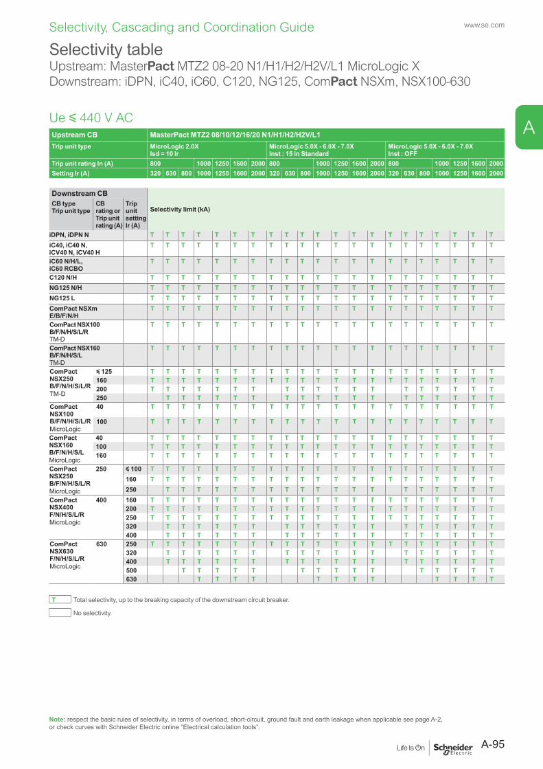
Upstream CB MasterPact MTZ2 08/10/12/16/20 N1/H1/H2/H2V/L1Trip unit type MicroLogic 2.0X
Isd = 10 IrMicroLogic 5.0X - 6.0X - 7.0X Inst : 15 In Standard
MicroLogic 5.0X - 6.0X - 7.0X Inst : OFF
Trip unit rating In (A) 800 1000 1250 1600 2000 800 1000 1250 1600 2000 800 1000 1250 1600 2000Setting Ir (A) 320 630 800 1000 1250 1600 2000 320 630 800 1000 1250 1600 2000 320 630 800 1000 1250 1600 2000
Downstream CB
Selectivity limit (kA)CB typeTrip unit type
CB rating or Trip unit rating (A)
Trip unit setting Ir (A)
iDPN, iDPN N T T T T T T T T T T T T T T T T T T T T TiC40, iC40 N, iCV40 N, iCV40 H
T T T T T T T T T T T T T T T T T T T T T
iC60 N/H/L, iC60 RCBO
T T T T T T T T T T T T T T T T T T T T T
C120 N/H T T T T T T T T T T T T T T T T T T T T TNG125 N/H T T T T T T T T T T T T T T T T T T T T TNG125 L T T T T T T T T T T T T T T T T T T T T TComPact NSXm E/B/F/N/H
T T T T T T T T T T T T T T T T T T T T T
ComPact NSX100 B/F/N/H/S/L/R TM-D
T T T T T T T T T T T T T T T T T T T T T
ComPact NSX160 B/F/N/H/S/L TM-D
T T T T T T T T T T T T T T T T T T T T T
ComPact NSX250 B/F/N/H/S/L/RTM-D
y 125 T T T T T T T T T T T T T T T T T T T T T160 T T T T T T T T T T T T T T T T T T T T T200 T T T T T T T T T T T T T T T T T T T250 T T T T T T T T T T T T T T T T T T
ComPact NSX100 B/F/N/H/S/L/RMicroLogic
40 T T T T T T T T T T T T T T T T T T T T T
100 T T T T T T T T T T T T T T T T T T T T T
ComPact NSX160 B/F/N/H/S/LMicroLogic
40 T T T T T T T T T T T T T T T T T T T T T100 T T T T T T T T T T T T T T T T T T T T T160 T T T T T T T T T T T T T T T T T T T T T
ComPact NSX250 B/F/N/H/S/L/RMicroLogic
250 y 100 T T T T T T T T T T T T T T T T T T T T T160 T T T T T T T T T T T T T T T T T T T T T250 T T T T T T T T T T T T T T T T T T T
ComPact NSX400 F/N/H/S/L/RMicroLogic
400 160 T T T T T T T T T T T T T T T T T T T T T200 T T T T T T T T T T T T T T T T T T T T T250 T T T T T T T T T T T T T T T T T T T T T320 T T T T T T T T T T T T T T T T T T400 T T T T T T T T T T T T T T T T T T
ComPact NSX630 F/N/H/S/L/RMicroLogic
630 250 T T T T T T T T T T T T T T T T T T T T T320 T T T T T T T T T T T T T T T T T T400 T T T T T T T T T T T T T T T T T T500 T T T T T T T T T T T T T T T630 T T T T T T T T T T T T
T Total selectivity, up to the breaking capacity of the downstream circuit breaker.
No selectivity.
Selectivity tableUpstream: MasterPact MTZ2 08-20 N1/H1/H2/H2V/L1 MicroLogic XDownstream: iDPN, iC40, iC60, C120, NG125, ComPact NSXm, NSX100-630
Ue y 440 V AC
Note: respect the basic rules of selectivity, in terms of overload, short-circuit, ground fault and earth leakage when applicable see page A-2, or check curves with Schneider Electric online “Electrical calculation tools”.
A-95
www.se.com
A
Selectivity, Cascading and Coordination Guide
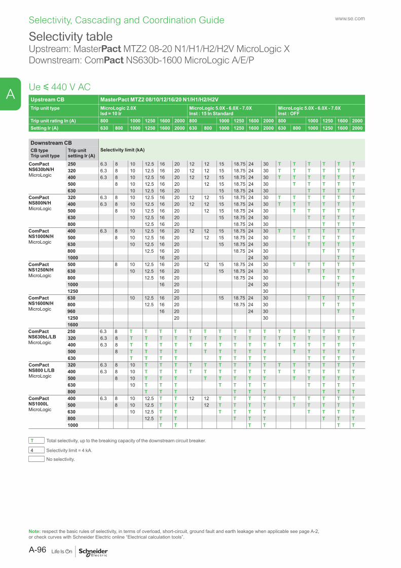
Upstream CB MasterPact MTZ2 08/10/12/16/20 N1/H1/H2/H2VTrip unit type MicroLogic 2.0X
Isd = 10 IrMicroLogic 5.0X - 6.0X - 7.0XInst : 15 In Standard
MicroLogic 5.0X - 6.0X - 7.0XInst : OFF
Trip unit rating In (A) 800 1000 1250 1600 2000 800 1000 1250 1600 2000 800 1000 1250 1600 2000Setting Ir (A) 630 800 1000 1250 1600 2000 630 800 1000 1250 1600 2000 630 800 1000 1250 1600 2000
Downstream CBSelectivity limit (kA)CB type
Trip unit typeTrip unit setting Ir (A)
ComPact NS630bN/HMicroLogic
250 6.3 8 10 12.5 16 20 12 12 15 18.75 24 30 T T T T T T320 6.3 8 10 12.5 16 20 12 12 15 18.75 24 30 T T T T T T400 6.3 8 10 12.5 16 20 12 12 15 18.75 24 30 T T T T T T500 8 10 12.5 16 20 12 15 18.75 24 30 T T T T T630 10 12.5 16 20 15 18.75 24 30 T T T T
ComPact NS800N/HMicroLogic
320 6.3 8 10 12.5 16 20 12 12 15 18.75 24 30 T T T T T T400 6.3 8 10 12.5 16 20 12 12 15 18.75 24 30 T T T T T T500 8 10 12.5 16 20 12 15 18.75 24 30 T T T T T630 10 12.5 16 20 15 18.75 24 30 T T T T800 12.5 16 20 18.75 24 30 T T T
ComPact NS1000N/HMicroLogic
400 6.3 8 10 12.5 16 20 12 12 15 18.75 24 30 T T T T T T500 8 10 12.5 16 20 12 15 18.75 24 30 T T T T T630 10 12.5 16 20 15 18.75 24 30 T T T T800 12.5 16 20 18.75 24 30 T T T1000 16 20 24 30 T T
ComPact NS1250N/HMicroLogic
500 8 10 12.5 16 20 12 15 18.75 24 30 T T T T T630 10 12.5 16 20 15 18.75 24 30 T T T T800 12.5 16 20 18.75 24 30 T T T1000 16 20 24 30 T T1250 20 30 T
ComPact NS1600N/HMicroLogic
630 10 12.5 16 20 15 18.75 24 30 T T T T800 12.5 16 20 18.75 24 30 T T T960 16 20 24 30 T T1250 20 30 T1600
ComPact NS630bL/LBMicroLogic
250 6.3 8 T T T T T T T T T T T T T T T T320 6.3 8 T T T T T T T T T T T T T T T T400 6.3 8 T T T T T T T T T T T T T T T T500 8 T T T T T T T T T T T T T T630 T T T T T T T T T T T T
ComPact NS800 L/LBMicroLogic
320 6.3 8 10 T T T T T T T T T T T T T T T400 6.3 8 10 T T T T T T T T T T T T T T T500 8 10 T T T T T T T T T T T T T630 10 T T T T T T T T T T T800 T T T T T T T T T
ComPact NS1000LMicroLogic
400 6.3 8 10 12.5 T T 12 12 T T T T T T T T T T500 8 10 12.5 T T 12 T T T T T T T T T630 10 12.5 T T T T T T T T T T800 12.5 T T T T T T T T1000 T T T T T T
T Total selectivity, up to the breaking capacity of the downstream circuit breaker.
4 Selectivity limit = 4 kA.
No selectivity.
Selectivity tableUpstream: MasterPact MTZ2 08-20 N1/H1/H2/H2V MicroLogic XDownstream: ComPact NS630b-1600 MicroLogic A/E/P
Ue y 440 V AC
Note: respect the basic rules of selectivity, in terms of overload, short-circuit, ground fault and earth leakage when applicable see page A-2, or check curves with Schneider Electric online “Electrical calculation tools”.
www.se.com
A-96
A
Selectivity, Cascading and Coordination Guide
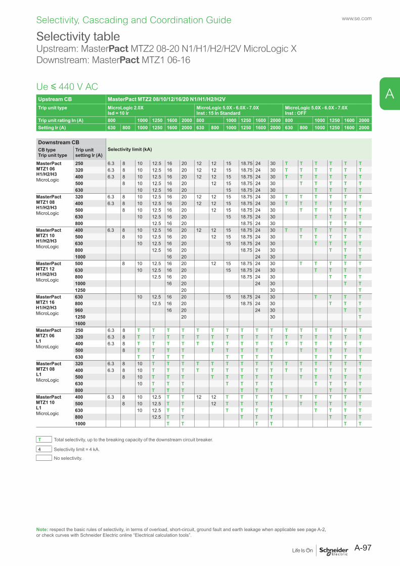
Upstream CB MasterPact MTZ2 08/10/12/16/20 N1/H1/H2/H2VTrip unit type MicroLogic 2.0X
Isd = 10 IrMicroLogic 5.0X - 6.0X - 7.0XInst : 15 In Standard
MicroLogic 5.0X - 6.0X - 7.0XInst : OFF
Trip unit rating In (A) 800 1000 1250 1600 2000 800 1000 1250 1600 2000 800 1000 1250 1600 2000Setting Ir (A) 630 800 1000 1250 1600 2000 630 800 1000 1250 1600 2000 630 800 1000 1250 1600 2000
Downstream CBSelectivity limit (kA)CB type
Trip unit typeTrip unit setting Ir (A)
MasterPact MTZ1 06 H1/H2/H3MicroLogic
250 6.3 8 10 12.5 16 20 12 12 15 18.75 24 30 T T T T T T320 6.3 8 10 12.5 16 20 12 12 15 18.75 24 30 T T T T T T400 6.3 8 10 12.5 16 20 12 12 15 18.75 24 30 T T T T T T500 8 10 12.5 16 20 12 15 18.75 24 30 T T T T T630 10 12.5 16 20 15 18.75 24 30 T T T T
MasterPact MTZ1 08 H1/H2/H3MicroLogic
320 6.3 8 10 12.5 16 20 12 12 15 18.75 24 30 T T T T T T400 6.3 8 10 12.5 16 20 12 12 15 18.75 24 30 T T T T T T500 8 10 12.5 16 20 12 15 18.75 24 30 T T T T T630 10 12.5 16 20 15 18.75 24 30 T T T T800 12.5 16 20 18.75 24 30 T T T
MasterPact MTZ1 10 H1/H2/H3MicroLogic
400 6.3 8 10 12.5 16 20 12 12 15 18.75 24 30 T T T T T T500 8 10 12.5 16 20 12 15 18.75 24 30 T T T T T630 10 12.5 16 20 15 18.75 24 30 T T T T800 12.5 16 20 18.75 24 30 T T T1000 16 20 24 30 T T
MasterPact MTZ1 12 H1/H2/H3MicroLogic
500 8 10 12.5 16 20 12 15 18.75 24 30 T T T T T630 10 12.5 16 20 15 18.75 24 30 T T T T800 12.5 16 20 18.75 24 30 T T T1000 16 20 24 30 T T1250 20 30 T
MasterPact MTZ1 16 H1/H2/H3MicroLogic
630 10 12.5 16 20 15 18.75 24 30 T T T T800 12.5 16 20 18.75 24 30 T T T960 16 20 24 30 T T1250 20 30 T1600
MasterPact MTZ1 06 L1MicroLogic
250 6.3 8 T T T T T T T T T T T T T T T T320 6.3 8 T T T T T T T T T T T T T T T T400 6.3 8 T T T T T T T T T T T T T T T T500 8 T T T T T T T T T T T T T T630 T T T T T T T T T T T T
MasterPact MTZ1 08 L1MicroLogic
320 6.3 8 10 T T T T T T T T T T T T T T T400 6.3 8 10 T T T T T T T T T T T T T T T500 8 10 T T T T T T T T T T T T T630 10 T T T T T T T T T T T800 T T T T T T T T T
MasterPact MTZ1 10 L1MicroLogic
400 6.3 8 10 12.5 T T 12 12 T T T T T T T T T T500 8 10 12.5 T T 12 T T T T T T T T T630 10 12.5 T T T T T T T T T T800 12.5 T T T T T T T T1000 T T T T T T
T Total selectivity, up to the breaking capacity of the downstream circuit breaker.
4 Selectivity limit = 4 kA.
No selectivity.
Selectivity tableUpstream: MasterPact MTZ2 08-20 N1/H1/H2/H2V MicroLogic XDownstream: MasterPact MTZ1 06-16
Ue y 440 V AC
Note: respect the basic rules of selectivity, in terms of overload, short-circuit, ground fault and earth leakage when applicable see page A-2, or check curves with Schneider Electric online “Electrical calculation tools”.
A-97
www.se.com
A
Selectivity, Cascading and Coordination Guide
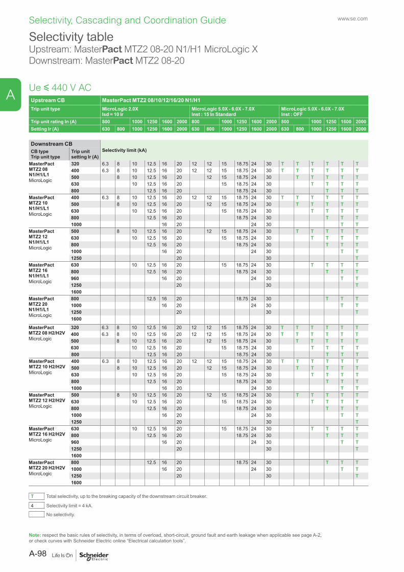
Upstream CB MasterPact MTZ2 08/10/12/16/20 N1/H1Trip unit type MicroLogic 2.0X
Isd = 10 IrMicroLogic 5.0X - 6.0X - 7.0XInst : 15 In Standard
MicroLogic 5.0X - 6.0X - 7.0XInst : OFF
Trip unit rating In (A) 800 1000 1250 1600 2000 800 1000 1250 1600 2000 800 1000 1250 1600 2000Setting Ir (A) 630 800 1000 1250 1600 2000 630 800 1000 1250 1600 2000 630 800 1000 1250 1600 2000
Downstream CBSelectivity limit (kA)CB type
Trip unit typeTrip unit setting Ir (A)
MasterPact MTZ2 08 N1/H1/L1MicroLogic
320 6.3 8 10 12.5 16 20 12 12 15 18.75 24 30 T T T T T T400 6.3 8 10 12.5 16 20 12 12 15 18.75 24 30 T T T T T T500 8 10 12.5 16 20 12 15 18.75 24 30 T T T T T630 10 12.5 16 20 15 18.75 24 30 T T T T800 12.5 16 20 18.75 24 30 T T T
MasterPact MTZ2 10 N1/H1/L1MicroLogic
400 6.3 8 10 12.5 16 20 12 12 15 18.75 24 30 T T T T T T500 8 10 12.5 16 20 12 15 18.75 24 30 T T T T T630 10 12.5 16 20 15 18.75 24 30 T T T T800 12.5 16 20 18.75 24 30 T T T1000 16 20 24 30 T T
MasterPact MTZ2 12 N1/H1/L1MicroLogic
500 8 10 12.5 16 20 12 15 18.75 24 30 T T T T T630 10 12.5 16 20 15 18.75 24 30 T T T T800 12.5 16 20 18.75 24 30 T T T1000 16 20 24 30 T T1250 20 30 T
MasterPact MTZ2 16 N1/H1/L1MicroLogic
630 10 12.5 16 20 15 18.75 24 30 T T T T800 12.5 16 20 18.75 24 30 T T T960 16 20 24 30 T T1250 20 30 T1600
MasterPact MTZ2 20 N1/H1/L1MicroLogic
800 12.5 16 20 18.75 24 30 T T T1000 16 20 24 30 T T1250 20 30 T1600
MasterPact MTZ2 08 H2/H2VMicroLogic
320 6.3 8 10 12.5 16 20 12 12 15 18.75 24 30 T T T T T T400 6.3 8 10 12.5 16 20 12 12 15 18.75 24 30 T T T T T T500 8 10 12.5 16 20 12 15 18.75 24 30 T T T T T630 10 12.5 16 20 15 18.75 24 30 T T T T800 12.5 16 20 18.75 24 30 T T T
MasterPact MTZ2 10 H2/H2VMicroLogic
400 6.3 8 10 12.5 16 20 12 12 15 18.75 24 30 T T T T T T500 8 10 12.5 16 20 12 15 18.75 24 30 T T T T T630 10 12.5 16 20 15 18.75 24 30 T T T T800 12.5 16 20 18.75 24 30 T T T1000 16 20 24 30 T T
MasterPact MTZ2 12 H2/H2VMicroLogic
500 8 10 12.5 16 20 12 15 18.75 24 30 T T T T T630 10 12.5 16 20 15 18.75 24 30 T T T T800 12.5 16 20 18.75 24 30 T T T1000 16 20 24 30 T T1250 20 30 T
MasterPact MTZ2 16 H2/H2VMicroLogic
630 10 12.5 16 20 15 18.75 24 30 T T T T800 12.5 16 20 18.75 24 30 T T T960 16 20 24 30 T T1250 20 30 T1600
MasterPact MTZ2 20 H2/H2VMicroLogic
800 12.5 16 20 18.75 24 30 T T T1000 16 20 24 30 T T1250 20 30 T1600
T Total selectivity, up to the breaking capacity of the downstream circuit breaker.
4 Selectivity limit = 4 kA.
No selectivity.
Selectivity tableUpstream: MasterPact MTZ2 08-20 N1/H1 MicroLogic XDownstream: MasterPact MTZ2 08-20
Ue y 440 V AC
Note: respect the basic rules of selectivity, in terms of overload, short-circuit, ground fault and earth leakage when applicable see page A-2, or check curves with Schneider Electric online “Electrical calculation tools”.
www.se.com
A-98
A
Selectivity, Cascading and Coordination Guide
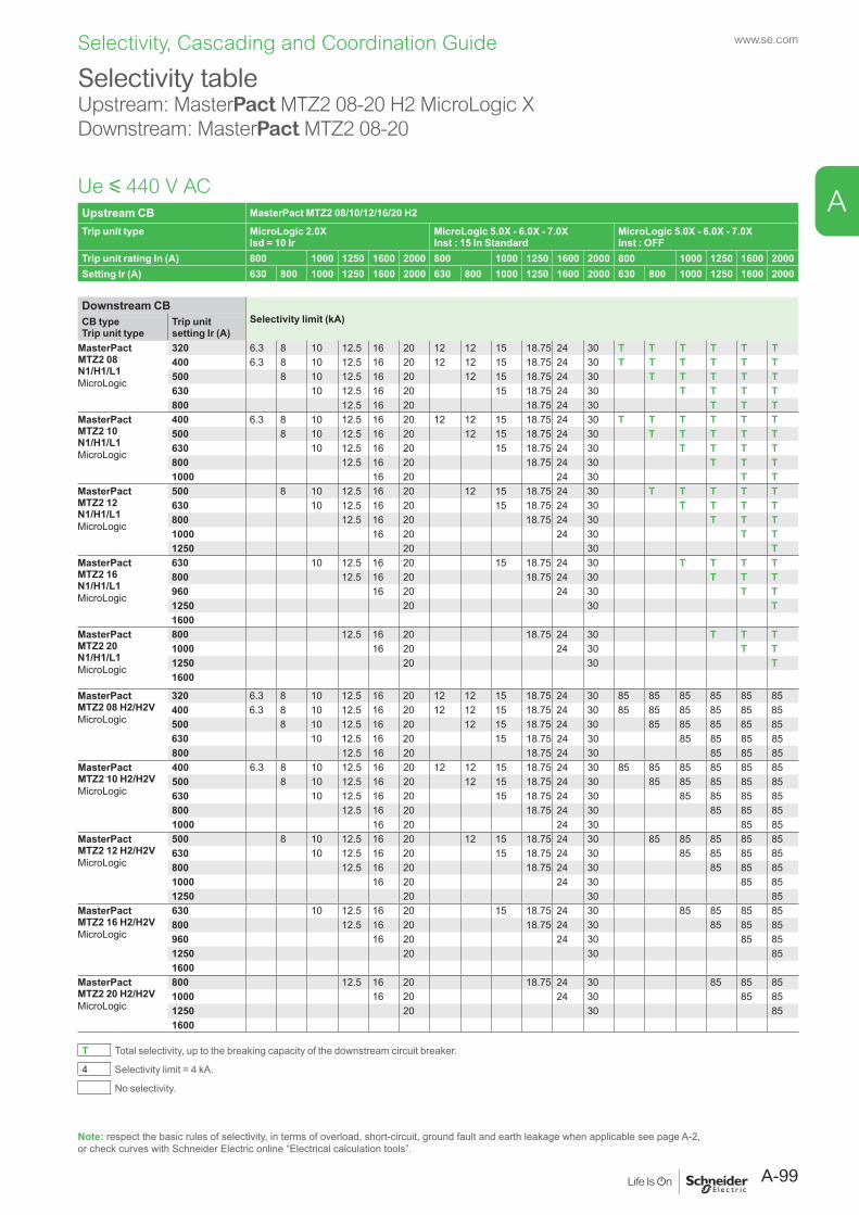
Upstream CB MasterPact MTZ2 08/10/12/16/20 H2
Trip unit type MicroLogic 2.0XIsd = 10 Ir
MicroLogic 5.0X - 6.0X - 7.0XInst : 15 In Standard
MicroLogic 5.0X - 6.0X - 7.0XInst : OFF
Trip unit rating In (A) 800 1000 1250 1600 2000 800 1000 1250 1600 2000 800 1000 1250 1600 2000Setting Ir (A) 630 800 1000 1250 1600 2000 630 800 1000 1250 1600 2000 630 800 1000 1250 1600 2000
Downstream CBSelectivity limit (kA)CB type
Trip unit typeTrip unit setting Ir (A)
MasterPact MTZ2 08 N1/H1/L1MicroLogic
320 6.3 8 10 12.5 16 20 12 12 15 18.75 24 30 T T T T T T400 6.3 8 10 12.5 16 20 12 12 15 18.75 24 30 T T T T T T500 8 10 12.5 16 20 12 15 18.75 24 30 T T T T T630 10 12.5 16 20 15 18.75 24 30 T T T T800 12.5 16 20 18.75 24 30 T T T
MasterPact MTZ2 10 N1/H1/L1MicroLogic
400 6.3 8 10 12.5 16 20 12 12 15 18.75 24 30 T T T T T T500 8 10 12.5 16 20 12 15 18.75 24 30 T T T T T630 10 12.5 16 20 15 18.75 24 30 T T T T800 12.5 16 20 18.75 24 30 T T T1000 16 20 24 30 T T
MasterPact MTZ2 12 N1/H1/L1MicroLogic
500 8 10 12.5 16 20 12 15 18.75 24 30 T T T T T630 10 12.5 16 20 15 18.75 24 30 T T T T800 12.5 16 20 18.75 24 30 T T T1000 16 20 24 30 T T1250 20 30 T
MasterPact MTZ2 16 N1/H1/L1MicroLogic
630 10 12.5 16 20 15 18.75 24 30 T T T T800 12.5 16 20 18.75 24 30 T T T960 16 20 24 30 T T1250 20 30 T1600
MasterPact MTZ2 20 N1/H1/L1MicroLogic
800 12.5 16 20 18.75 24 30 T T T1000 16 20 24 30 T T1250 20 30 T1600
MasterPact MTZ2 08 H2/H2VMicroLogic
320 6.3 8 10 12.5 16 20 12 12 15 18.75 24 30 85 85 85 85 85 85400 6.3 8 10 12.5 16 20 12 12 15 18.75 24 30 85 85 85 85 85 85500 8 10 12.5 16 20 12 15 18.75 24 30 85 85 85 85 85630 10 12.5 16 20 15 18.75 24 30 85 85 85 85800 12.5 16 20 18.75 24 30 85 85 85
MasterPact MTZ2 10 H2/H2VMicroLogic
400 6.3 8 10 12.5 16 20 12 12 15 18.75 24 30 85 85 85 85 85 85500 8 10 12.5 16 20 12 15 18.75 24 30 85 85 85 85 85630 10 12.5 16 20 15 18.75 24 30 85 85 85 85800 12.5 16 20 18.75 24 30 85 85 851000 16 20 24 30 85 85
MasterPact MTZ2 12 H2/H2VMicroLogic
500 8 10 12.5 16 20 12 15 18.75 24 30 85 85 85 85 85630 10 12.5 16 20 15 18.75 24 30 85 85 85 85800 12.5 16 20 18.75 24 30 85 85 851000 16 20 24 30 85 851250 20 30 85
MasterPact MTZ2 16 H2/H2VMicroLogic
630 10 12.5 16 20 15 18.75 24 30 85 85 85 85800 12.5 16 20 18.75 24 30 85 85 85960 16 20 24 30 85 851250 20 30 851600
MasterPact MTZ2 20 H2/H2VMicroLogic
800 12.5 16 20 18.75 24 30 85 85 851000 16 20 24 30 85 851250 20 30 851600
T Total selectivity, up to the breaking capacity of the downstream circuit breaker.
4 Selectivity limit = 4 kA.
No selectivity.
Selectivity tableUpstream: MasterPact MTZ2 08-20 H2 MicroLogic XDownstream: MasterPact MTZ2 08-20
Ue y 440 V AC
Note: respect the basic rules of selectivity, in terms of overload, short-circuit, ground fault and earth leakage when applicable see page A-2, or check curves with Schneider Electric online “Electrical calculation tools”.
A-99
www.se.com
A
Selectivity, Cascading and Coordination Guide
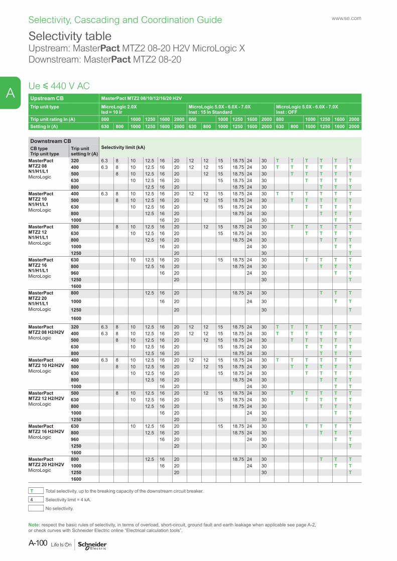
Upstream CB MasterPact MTZ2 08/10/12/16/20 H2V
Trip unit type MicroLogic 2.0XIsd = 10 Ir
MicroLogic 5.0X - 6.0X - 7.0XInst : 15 In Standard
MicroLogic 5.0X - 6.0X - 7.0XInst : OFF
Trip unit rating In (A) 800 1000 1250 1600 2000 800 1000 1250 1600 2000 800 1000 1250 1600 2000Setting Ir (A) 630 800 1000 1250 1600 2000 630 800 1000 1250 1600 2000 630 800 1000 1250 1600 2000
Downstream CBSelectivity limit (kA)CB type
Trip unit typeTrip unit setting Ir (A)
MasterPact MTZ2 08 N1/H1/L1MicroLogic
320 6.3 8 10 12.5 16 20 12 12 15 18.75 24 30 T T T T T T400 6.3 8 10 12.5 16 20 12 12 15 18.75 24 30 T T T T T T500 8 10 12.5 16 20 12 15 18.75 24 30 T T T T T630 10 12.5 16 20 15 18.75 24 30 T T T T800 12.5 16 20 18.75 24 30 T T T
MasterPact MTZ2 10 N1/H1/L1MicroLogic
400 6.3 8 10 12.5 16 20 12 12 15 18.75 24 30 T T T T T T500 8 10 12.5 16 20 12 15 18.75 24 30 T T T T T630 10 12.5 16 20 15 18.75 24 30 T T T T800 12.5 16 20 18.75 24 30 T T T1000 16 20 24 30 T T
MasterPact MTZ2 12 N1/H1/L1MicroLogic
500 8 10 12.5 16 20 12 15 18.75 24 30 T T T T T630 10 12.5 16 20 15 18.75 24 30 T T T T800 12.5 16 20 18.75 24 30 T T T1000 16 20 24 30 T T1250 20 30 T
MasterPact MTZ2 16 N1/H1/L1MicroLogic
630 10 12.5 16 20 15 18.75 24 30 T T T T800 12.5 16 20 18.75 24 30 T T T960 16 20 24 30 T T1250 20 30 T1600
MasterPact MTZ2 20 N1/H1/L1MicroLogic
800 12.5 16 20 18.75 24 30 T T T
1000 16 20 24 30 T T
1250 20 30 T
1600
MasterPact MTZ2 08 H2/H2VMicroLogic
320 6.3 8 10 12.5 16 20 12 12 15 18.75 24 30 T T T T T T400 6.3 8 10 12.5 16 20 12 12 15 18.75 24 30 T T T T T T500 8 10 12.5 16 20 12 15 18.75 24 30 T T T T T630 10 12.5 16 20 15 18.75 24 30 T T T T800 12.5 16 20 18.75 24 30 T T T
MasterPact MTZ2 10 H2/H2VMicroLogic
400 6.3 8 10 12.5 16 20 12 12 15 18.75 24 30 T T T T T T500 8 10 12.5 16 20 12 15 18.75 24 30 T T T T T630 10 12.5 16 20 15 18.75 24 30 T T T T800 12.5 16 20 18.75 24 30 T T T1000 16 20 24 30 T T
MasterPact MTZ2 12 H2/H2VMicroLogic
500 8 10 12.5 16 20 12 15 18.75 24 30 T T T T T630 10 12.5 16 20 15 18.75 24 30 T T T T800 12.5 16 20 18.75 24 30 T T T1000 16 20 24 30 T T1250 20 30 T
MasterPact MTZ2 16 H2/H2VMicroLogic
630 10 12.5 16 20 15 18.75 24 30 T T T T800 12.5 16 20 18.75 24 30 T T T960 16 20 24 30 T T1250 20 30 T1600
MasterPact MTZ2 20 H2/H2VMicroLogic
800 12.5 16 20 18.75 24 30 T T T1000 16 20 24 30 T T1250 20 30 T1600
T Total selectivity, up to the breaking capacity of the downstream circuit breaker.
4 Selectivity limit = 4 kA.
No selectivity.
Selectivity tableUpstream: MasterPact MTZ2 08-20 H2V MicroLogic XDownstream: MasterPact MTZ2 08-20
Ue y 440 V AC
Note: respect the basic rules of selectivity, in terms of overload, short-circuit, ground fault and earth leakage when applicable see page A-2, or check curves with Schneider Electric online “Electrical calculation tools”.
www.se.com
A-100
A
Selectivity, Cascading and Coordination Guide
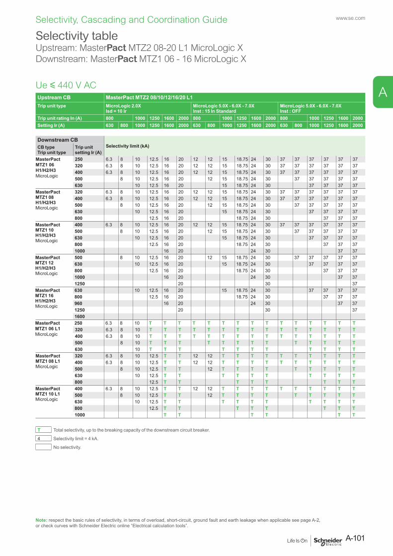
Upstream CB MasterPact MTZ2 08/10/12/16/20 L1Trip unit type MicroLogic 2.0X
Isd = 10 IrMicroLogic 5.0X - 6.0X - 7.0XInst : 15 In Standard
MicroLogic 5.0X - 6.0X - 7.0XInst : OFF
Trip unit rating In (A) 800 1000 1250 1600 2000 800 1000 1250 1600 2000 800 1000 1250 1600 2000Setting Ir (A) 630 800 1000 1250 1600 2000 630 800 1000 1250 1600 2000 630 800 1000 1250 1600 2000
Downstream CBSelectivity limit (kA)CB type
Trip unit typeTrip unit setting Ir (A)
MasterPact MTZ1 06 H1/H2/H3MicroLogic
250 6.3 8 10 12.5 16 20 12 12 15 18.75 24 30 37 37 37 37 37 37320 6.3 8 10 12.5 16 20 12 12 15 18.75 24 30 37 37 37 37 37 37400 6.3 8 10 12.5 16 20 12 12 15 18.75 24 30 37 37 37 37 37 37500 8 10 12.5 16 20 12 15 18.75 24 30 37 37 37 37 37630 10 12.5 16 20 15 18.75 24 30 37 37 37 37
MasterPact MTZ1 08 H1/H2/H3MicroLogic
320 6.3 8 10 12.5 16 20 12 12 15 18.75 24 30 37 37 37 37 37 37400 6.3 8 10 12.5 16 20 12 12 15 18.75 24 30 37 37 37 37 37 37500 8 10 12.5 16 20 12 15 18.75 24 30 37 37 37 37 37630 10 12.5 16 20 15 18.75 24 30 37 37 37 37800 12.5 16 20 18.75 24 30 37 37 37
MasterPact MTZ1 10 H1/H2/H3MicroLogic
400 6.3 8 10 12.5 16 20 12 12 15 18.75 24 30 37 37 37 37 37 37500 8 10 12.5 16 20 12 15 18.75 24 30 37 37 37 37 37630 10 12.5 16 20 15 18.75 24 30 37 37 37 37800 12.5 16 20 18.75 24 30 37 37 371000 16 20 24 30 37 37
MasterPact MTZ1 12 H1/H2/H3MicroLogic
500 8 10 12.5 16 20 12 15 18.75 24 30 37 37 37 37 37630 10 12.5 16 20 15 18.75 24 30 37 37 37 37800 12.5 16 20 18.75 24 30 37 37 371000 16 20 24 30 37 371250 20 30 37
MasterPact MTZ1 16 H1/H2/H3MicroLogic
630 10 12.5 16 20 15 18.75 24 30 37 37 37 37800 12.5 16 20 18.75 24 30 37 37 37960 16 20 24 30 37 371250 20 30 371600
MasterPact MTZ1 06 L1MicroLogic
250 6.3 8 10 T T T T T T T T T T T T T T T320 6.3 8 10 T T T T T T T T T T T T T T T400 6.3 8 10 T T T T T T T T T T T T T T T500 8 10 T T T T T T T T T T T T T630 10 T T T T T T T T T T T
MasterPact MTZ1 08 L1MicroLogic
320 6.3 8 10 12.5 T T 12 12 T T T T T T T T T T400 6.3 8 10 12.5 T T 12 12 T T T T T T T T T T500 8 10 12.5 T T 12 T T T T T T T T T630 10 12.5 T T T T T T T T T T800 12.5 T T T T T T T T
MasterPact MTZ1 10 L1MicroLogic
400 6.3 8 10 12.5 T T 12 12 T T T T T T T T T T500 8 10 12.5 T T 12 T T T T T T T T T630 10 12.5 T T T T T T T T T T800 12.5 T T T T T T T T1000 T T T T T T
T Total selectivity, up to the breaking capacity of the downstream circuit breaker.
4 Selectivity limit = 4 kA.
No selectivity.
Selectivity tableUpstream: MasterPact MTZ2 08-20 L1 MicroLogic XDownstream: MasterPact MTZ1 06 - 16 MicroLogic X
Ue y 440 V AC
Note: respect the basic rules of selectivity, in terms of overload, short-circuit, ground fault and earth leakage when applicable see page A-2, or check curves with Schneider Electric online “Electrical calculation tools”.
A-101
www.se.com
A
Selectivity, Cascading and Coordination Guide
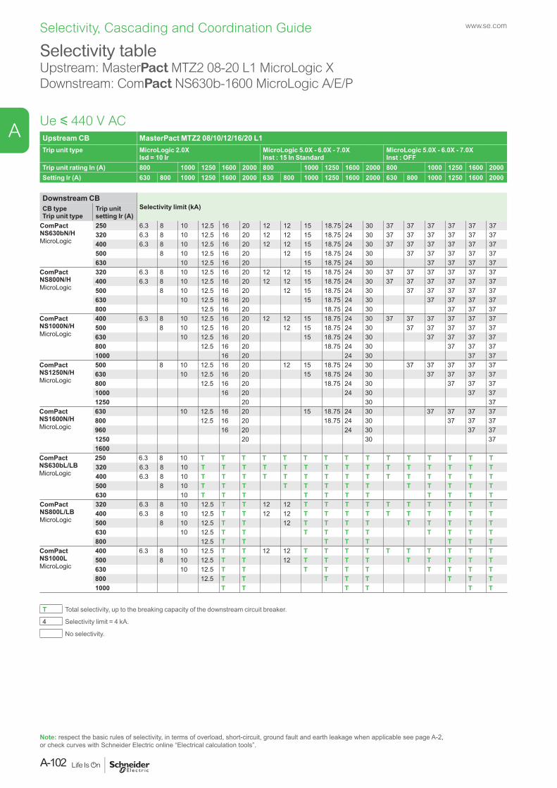
Upstream CB MasterPact MTZ2 08/10/12/16/20 L1Trip unit type MicroLogic 2.0X
Isd = 10 IrMicroLogic 5.0X - 6.0X - 7.0XInst : 15 In Standard
MicroLogic 5.0X - 6.0X - 7.0XInst : OFF
Trip unit rating In (A) 800 1000 1250 1600 2000 800 1000 1250 1600 2000 800 1000 1250 1600 2000Setting Ir (A) 630 800 1000 1250 1600 2000 630 800 1000 1250 1600 2000 630 800 1000 1250 1600 2000
Downstream CBSelectivity limit (kA)CB type
Trip unit typeTrip unit setting Ir (A)
ComPact NS630bN/HMicroLogic
250 6.3 8 10 12.5 16 20 12 12 15 18.75 24 30 37 37 37 37 37 37320 6.3 8 10 12.5 16 20 12 12 15 18.75 24 30 37 37 37 37 37 37400 6.3 8 10 12.5 16 20 12 12 15 18.75 24 30 37 37 37 37 37 37500 8 10 12.5 16 20 12 15 18.75 24 30 37 37 37 37 37630 10 12.5 16 20 15 18.75 24 30 37 37 37 37
ComPact NS800N/HMicroLogic
320 6.3 8 10 12.5 16 20 12 12 15 18.75 24 30 37 37 37 37 37 37400 6.3 8 10 12.5 16 20 12 12 15 18.75 24 30 37 37 37 37 37 37500 8 10 12.5 16 20 12 15 18.75 24 30 37 37 37 37 37630 10 12.5 16 20 15 18.75 24 30 37 37 37 37800 12.5 16 20 18.75 24 30 37 37 37
ComPact NS1000N/HMicroLogic
400 6.3 8 10 12.5 16 20 12 12 15 18.75 24 30 37 37 37 37 37 37500 8 10 12.5 16 20 12 15 18.75 24 30 37 37 37 37 37630 10 12.5 16 20 15 18.75 24 30 37 37 37 37800 12.5 16 20 18.75 24 30 37 37 371000 16 20 24 30 37 37
ComPact NS1250N/HMicroLogic
500 8 10 12.5 16 20 12 15 18.75 24 30 37 37 37 37 37630 10 12.5 16 20 15 18.75 24 30 37 37 37 37800 12.5 16 20 18.75 24 30 37 37 371000 16 20 24 30 37 371250 20 30 37
ComPact NS1600N/HMicroLogic
630 10 12.5 16 20 15 18.75 24 30 37 37 37 37800 12.5 16 20 18.75 24 30 37 37 37960 16 20 24 30 37 371250 20 30 371600
ComPact NS630bL/LBMicroLogic
250 6.3 8 10 T T T T T T T T T T T T T T T320 6.3 8 10 T T T T T T T T T T T T T T T400 6.3 8 10 T T T T T T T T T T T T T T T500 8 10 T T T T T T T T T T T T T630 10 T T T T T T T T T T T
ComPact NS800L/LBMicroLogic
320 6.3 8 10 12.5 T T 12 12 T T T T T T T T T T400 6.3 8 10 12.5 T T 12 12 T T T T T T T T T T500 8 10 12.5 T T 12 T T T T T T T T T630 10 12.5 T T T T T T T T T T800 12.5 T T T T T T T T
ComPact NS1000LMicroLogic
400 6.3 8 10 12.5 T T 12 12 T T T T T T T T T T500 8 10 12.5 T T 12 T T T T T T T T T630 10 12.5 T T T T T T T T T T800 12.5 T T T T T T T T1000 T T T T T T
T Total selectivity, up to the breaking capacity of the downstream circuit breaker.
4 Selectivity limit = 4 kA.
No selectivity.
Selectivity tableUpstream: MasterPact MTZ2 08-20 L1 MicroLogic XDownstream: ComPact NS630b-1600 MicroLogic A/E/P
Ue y 440 V AC
Note: respect the basic rules of selectivity, in terms of overload, short-circuit, ground fault and earth leakage when applicable see page A-2, or check curves with Schneider Electric online “Electrical calculation tools”.
www.se.com
A-102
A
Selectivity, Cascading and Coordination Guide
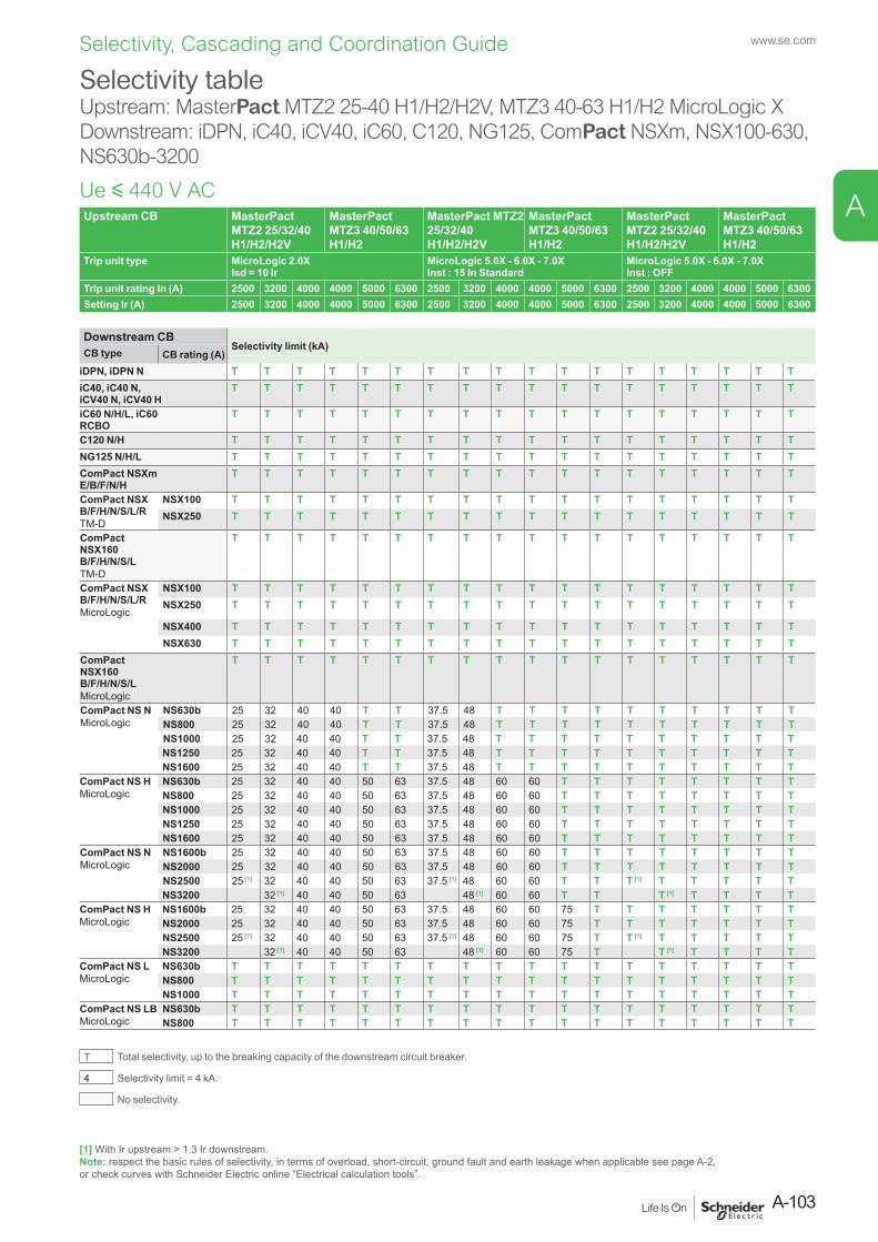
Upstream CB MasterPact MTZ2 25/32/40 H1/H2/H2V
MasterPact MTZ3 40/50/63 H1/H2
MasterPact MTZ2 25/32/40 H1/H2/H2V
MasterPact MTZ3 40/50/63 H1/H2
MasterPact MTZ2 25/32/40 H1/H2/H2V
MasterPact MTZ3 40/50/63 H1/H2
Trip unit type MicroLogic 2.0XIsd = 10 Ir
MicroLogic 5.0X - 6.0X - 7.0XInst : 15 In Standard
MicroLogic 5.0X - 6.0X - 7.0XInst : OFF
Trip unit rating In (A) 2500 3200 4000 4000 5000 6300 2500 3200 4000 4000 5000 6300 2500 3200 4000 4000 5000 6300Setting Ir (A) 2500 3200 4000 4000 5000 6300 2500 3200 4000 4000 5000 6300 2500 3200 4000 4000 5000 6300
Downstream CBSelectivity limit (kA)CB type CB rating (A)
iDPN, iDPN N T T T T T T T T T T T T T T T T T TiC40, iC40 N, iCV40 N, iCV40 H
T T T T T T T T T T T T T T T T T T
iC60 N/H/L, iC60 RCBO
T T T T T T T T T T T T T T T T T T
C120 N/H T T T T T T T T T T T T T T T T T TNG125 N/H/L T T T T T T T T T T T T T T T T T TComPact NSXm E/B/F/N/H
T T T T T T T T T T T T T T T T T T
ComPact NSXB/F/H/N/S/L/RTM-D
NSX100 T T T T T T T T T T T T T T T T T TNSX250 T T T T T T T T T T T T T T T T T T
ComPact NSX160B/F/H/N/S/LTM-D
T T T T T T T T T T T T T T T T T T
ComPact NSXB/F/H/N/S/L/RMicroLogic
NSX100 T T T T T T T T T T T T T T T T T TNSX250 T T T T T T T T T T T T T T T T T T
NSX400 T T T T T T T T T T T T T T T T T TNSX630 T T T T T T T T T T T T T T T T T T
ComPact NSX160B/F/H/N/S/LMicroLogic
T T T T T T T T T T T T T T T T T T
ComPact NS NMicroLogic
NS630b 25 32 40 40 T T 37.5 48 T T T T T T T T T TNS800 25 32 40 40 T T 37.5 48 T T T T T T T T T TNS1000 25 32 40 40 T T 37.5 48 T T T T T T T T T TNS1250 25 32 40 40 T T 37.5 48 T T T T T T T T T TNS1600 25 32 40 40 T T 37.5 48 T T T T T T T T T T
ComPact NS HMicroLogic
NS630b 25 32 40 40 50 63 37.5 48 60 60 T T T T T T T TNS800 25 32 40 40 50 63 37.5 48 60 60 T T T T T T T TNS1000 25 32 40 40 50 63 37.5 48 60 60 T T T T T T T TNS1250 25 32 40 40 50 63 37.5 48 60 60 T T T T T T T TNS1600 25 32 40 40 50 63 37.5 48 60 60 T T T T T T T T
ComPact NS NMicroLogic
NS1600b 25 32 40 40 50 63 37.5 48 60 60 T T T T T T T TNS2000 25 32 40 40 50 63 37.5 48 60 60 T T T T T T T TNS2500 25 [1] 32 40 40 50 63 37.5 [1] 48 60 60 T T T [1] T T T T TNS3200 32 [1] 40 40 50 63 48 [1] 60 60 T T T [1] T T T T
ComPact NS HMicroLogic
NS1600b 25 32 40 40 50 63 37.5 48 60 60 75 T T T T T T TNS2000 25 32 40 40 50 63 37.5 48 60 60 75 T T T T T T TNS2500 25 [1] 32 40 40 50 63 37.5 [1] 48 60 60 75 T T [1] T T T T TNS3200 32 [1] 40 40 50 63 48 [1] 60 60 75 T T [1] T T T T
ComPact NS LMicroLogic
NS630b T T T T T T T T T T T T T T T T T TNS800 T T T T T T T T T T T T T T T T T TNS1000 T T T T T T T T T T T T T T T T T T
ComPact NS LB MicroLogic
NS630b T T T T T T T T T T T T T T T T T TNS800 T T T T T T T T T T T T T T T T T T
T Total selectivity, up to the breaking capacity of the downstream circuit breaker.
4 Selectivity limit = 4 kA.
No selectivity.
Ue y 440 V AC
Selectivity tableUpstream: MasterPact MTZ2 25-40 H1/H2/H2V, MTZ3 40-63 H1/H2 MicroLogic XDownstream: iDPN, iC40, iCV40, iC60, C120, NG125, ComPact NSXm, NSX100-630, NS630b-3200
[1] With Ir upstream > 1.3 Ir downstream.Note: respect the basic rules of selectivity, in terms of overload, short-circuit, ground fault and earth leakage when applicable see page A-2, or check curves with Schneider Electric online “Electrical calculation tools”.
A-103
www.se.com
A
Selectivity, Cascading and Coordination Guide
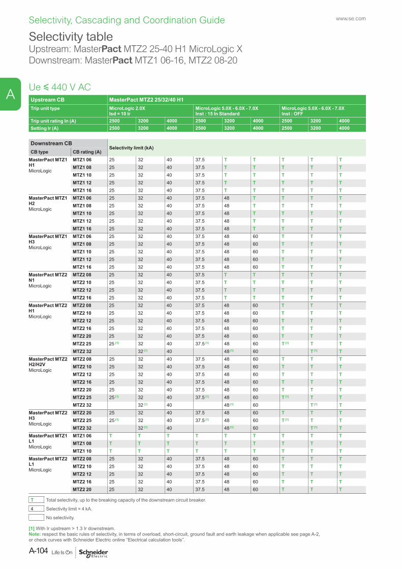
Upstream CB MasterPact MTZ2 25/32/40 H1Trip unit type MicroLogic 2.0X
Isd = 10 IrMicroLogic 5.0X - 6.0X - 7.0XInst : 15 In Standard
MicroLogic 5.0X - 6.0X - 7.0XInst : OFF
Trip unit rating In (A) 2500 3200 4000 2500 3200 4000 2500 3200 4000Setting Ir (A) 2500 3200 4000 2500 3200 4000 2500 3200 4000
Downstream CBSelectivity limit (kA)
CB type CB rating (A)MasterPact MTZ1 H1MicroLogic
MTZ1 06 25 32 40 37.5 T T T T TMTZ1 08 25 32 40 37.5 T T T T TMTZ1 10 25 32 40 37.5 T T T T TMTZ1 12 25 32 40 37.5 T T T T TMTZ1 16 25 32 40 37.5 T T T T T
MasterPact MTZ1H2 MicroLogic
MTZ1 06 25 32 40 37.5 48 T T T TMTZ1 08 25 32 40 37.5 48 T T T TMTZ1 10 25 32 40 37.5 48 T T T TMTZ1 12 25 32 40 37.5 48 T T T TMTZ1 16 25 32 40 37.5 48 T T T T
MasterPact MTZ1H3MicroLogic
MTZ1 06 25 32 40 37.5 48 60 T T TMTZ1 08 25 32 40 37.5 48 60 T T TMTZ1 10 25 32 40 37.5 48 60 T T TMTZ1 12 25 32 40 37.5 48 60 T T TMTZ1 16 25 32 40 37.5 48 60 T T T
MasterPact MTZ2 N1MicroLogic
MTZ2 08 25 32 40 37.5 T T T T TMTZ2 10 25 32 40 37.5 T T T T TMTZ2 12 25 32 40 37.5 T T T T TMTZ2 16 25 32 40 37.5 T T T T T
MasterPact MTZ2H1MicroLogic
MTZ2 08 25 32 40 37.5 48 60 T T TMTZ2 10 25 32 40 37.5 48 60 T T TMTZ2 12 25 32 40 37.5 48 60 T T TMTZ2 16 25 32 40 37.5 48 60 T T TMTZ2 20 25 32 40 37.5 48 60 T T TMTZ2 25 25 [1] 32 40 37.5 [1] 48 60 T [1] T TMTZ2 32 32 [1] 40 48 [1] 60 T [1] T
MasterPact MTZ2H2/H2VMicroLogic
MTZ2 08 25 32 40 37.5 48 60 T T TMTZ2 10 25 32 40 37.5 48 60 T T TMTZ2 12 25 32 40 37.5 48 60 T T TMTZ2 16 25 32 40 37.5 48 60 T T TMTZ2 20 25 32 40 37.5 48 60 T T TMTZ2 25 25 [1] 32 40 37.5 [1] 48 60 T [1] T TMTZ2 32 32 [1] 40 48 [1] 60 T [1] T
MasterPact MTZ2H3MicroLogic
MTZ2 20 25 32 40 37.5 48 60 T T TMTZ2 25 25 [1] 32 40 37.5 [1] 48 60 T [1] T TMTZ2 32 32 [1] 40 48 [1] 60 T [1] T
MasterPact MTZ1L1MicroLogic
MTZ1 06 T T T T T T T T TMTZ1 08 T T T T T T T T TMTZ1 10 T T T T T T T T T
MasterPact MTZ2L1MicroLogic
MTZ2 08 25 32 40 37.5 48 60 T T TMTZ2 10 25 32 40 37.5 48 60 T T TMTZ2 12 25 32 40 37.5 48 60 T T TMTZ2 16 25 32 40 37.5 48 60 T T TMTZ2 20 25 32 40 37.5 48 60 T T T
T Total selectivity, up to the breaking capacity of the downstream circuit breaker.
4 Selectivity limit = 4 kA.
No selectivity.
Ue y 440 V AC
Selectivity tableUpstream: MasterPact MTZ2 25-40 H1 MicroLogic XDownstream: MasterPact MTZ1 06-16, MTZ2 08-20
[1] With Ir upstream > 1.3 Ir downstream.Note: respect the basic rules of selectivity, in terms of overload, short-circuit, ground fault and earth leakage when applicable see page A-2, or check curves with Schneider Electric online “Electrical calculation tools”.
www.se.com
A-104
A
Selectivity, Cascading and Coordination Guide
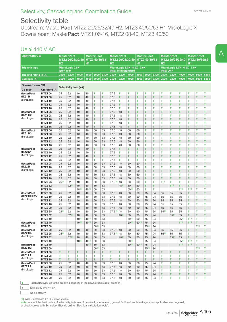
Upstream CB MasterPact MTZ2 20/25/32/40 H2
MasterPact MTZ3 40/50/63 H1
MasterPact MTZ2 20/25/32/40 H2
MasterPact MTZ3 40/50/63 H1
MasterPact MTZ2 20/25/32/40 H2
MasterPact MTZ3 40/50/63 H1
Trip unit type MicroLogic 2.0XIsd = 10 Ir
MicroLogic 5.0X - 6.0X - 7.0XInst : 15 In Standard
MicroLogic 5.0X - 6.0X - 7.0XInst : OFF
Trip unit rating In (A) 2500 3200 4000 4000 5000 6300 2500 3200 4000 4000 5000 6300 2500 3200 4000 4000 5000 6300Setting Ir (A) 2500 3200 4000 4000 5000 6300 2500 3200 4000 4000 5000 6300 2500 3200 4000 4000 5000 6300
Downstream CBSelectivity limit (kA)
CB type CB rating (A)MasterPact MTZ1 H1MicroLogic
MTZ1 06 25 32 40 40 T T 37.5 T T T T T T T T T T TMTZ1 08 25 32 40 40 T T 37.5 T T T T T T T T T T TMTZ1 10 25 32 40 40 T T 37.5 T T T T T T T T T T TMTZ1 12 25 32 40 40 T T 37.5 T T T T T T T T T T TMTZ1 16 25 32 40 40 T T 37.5 T T T T T T T T T T T
MasterPact MTZ1 H2MicroLogic
MTZ1 06 25 32 40 40 T T 37.5 48 T T T T T T T T T TMTZ1 08 25 32 40 40 T T 37.5 48 T T T T T T T T T TMTZ1 10 25 32 40 40 T T 37.5 48 T T T T T T T T T TMTZ1 12 25 32 40 40 T T 37.5 48 T T T T T T T T T TMTZ1 16 25 32 40 40 T T 37.5 48 T T T T T T T T T T
MasterPact MTZ1 H3MicroLogic
MTZ1 06 25 32 40 40 50 63 37.5 48 60 60 T T T T T T T TMTZ1 08 25 32 40 40 50 63 37.5 48 60 60 T T T T T T T TMTZ1 10 25 32 40 40 50 63 37.5 48 60 60 T T T T T T T TMTZ1 12 25 32 40 40 50 63 37.5 48 60 60 T T T T T T T TMTZ1 16 25 32 40 40 50 63 37.5 48 60 60 T T T T T T T T
MasterPact MTZ2 N1MicroLogic
MTZ2 08 25 32 40 40 T T 37.5 T T T T T T T T T T TMTZ2 10 25 32 40 40 T T 37.5 T T T T T T T T T T TMTZ2 12 25 32 40 40 T T 37.5 T T T T T T T T T T TMTZ2 16 25 32 40 40 T T 37.5 T T T T T T T T T T T
MasterPact MTZ2 H1MicroLogic
MTZ2 08 25 32 40 40 50 63 37.5 48 60 60 T T T T T T T TMTZ2 10 25 32 40 40 50 63 37.5 48 60 60 T T T T T T T TMTZ2 12 25 32 40 40 50 63 37.5 48 60 60 T T T T T T T TMTZ2 16 25 32 40 40 50 63 37.5 48 60 60 T T T T T T T TMTZ2 20 25 32 40 40 50 63 37.5 48 60 60 T T T T T T T TMTZ2 25 25 [1] 32 40 40 50 63 37.5 [1] 48 60 60 T T T [1] T T T T TMTZ2 32 32 [1] 40 40 50 63 48 [1] 60 60 T T T [1] T T T TMTZ2 40 40 [1] 40 [1] 50 63 60 [1] 60 T T T [1] T [1] T T
MasterPact MTZ2 H2/H2VMicroLogic
MTZ2 08 25 32 40 40 50 63 37.5 48 60 60 75 94 85 85 85 T T TMTZ2 10 25 32 40 40 50 63 37.5 48 60 60 75 94 85 85 85 T T TMTZ2 12 25 32 40 40 50 63 37.5 48 60 60 75 94 85 85 85 T T TMTZ2 16 25 32 40 40 50 63 37.5 48 60 60 75 94 85 85 85 T T TMTZ2 20 25 32 40 40 50 63 37.5 48 60 60 75 94 85 85 85 T T TMTZ2 25 25 [1] 32 40 40 50 63 37.5 [1] 48 60 60 75 94 85 [1] 85 85 T T TMTZ2 32 32 [1] 40 40 50 63 48 [1] 60 60 75 94 85 [1] 85 T T TMTZ2 40 40 [1] 40 [1] 50 63 60 [1] 60 75 94 85 [1] T [1] T T
MasterPact MTZ3 H1
MTZ3 40 40 [1] 40 [1] 50 63 60 [1] 60 [1] 75 94 T [1] T [1] T TMTZ3 50 50 [1] 63 75 [1] 94 T [1] T
MasterPact MTZ2 H3MicroLogic
MTZ2 20 25 32 40 40 50 63 37.5 48 60 60 75 94 85 85 85 T T TMTZ2 25 25 [1] 32 40 40 50 63 37.5 [1] 48 60 60 75 94 85 [1] 85 85 T T TMTZ2 32 32 [1] 40 40 50 63 48 [1] 60 60 75 94 85 [1] 85 T T TMTZ2 40 40 [1] 40 [1] 50 63 60 [1] 75 94 85 [1] T [1] T T
MasterPact MTZ3 H2
MTZ3 40 40 [1] 50 63 60 [1] 60 [1] 75 94 T [1] T [1] T TMTZ3 50 50 [1] 63 75 [1] 94 T [1] T
MasterPact MTZ1 L1MicroLogic
MTZ1 06 T T T T T T T T T T T T T T T T T TMTZ1 08 T T T T T T T T T T T T T T T T T TMTZ1 10 T T T T T T T T T T T T T T T T T T
MasterPact MTZ2 L1MicroLogic
MTZ2 08 25 32 40 40 50 63 37.5 48 60 60 75 94 T T T T T TMTZ2 10 25 32 40 40 50 63 37.5 48 60 60 75 94 T T T T T TMTZ2 12 25 32 40 40 50 63 37.5 48 60 60 75 94 T T T T T TMTZ2 16 25 32 40 40 50 63 37.5 48 60 60 75 94 T T T T T TMTZ2 20 25 32 40 40 50 63 37.5 48 60 60 75 94 T T T T T T
T Total selectivity, up to the breaking capacity of the downstream circuit breaker.
4 Selectivity limit = 4 kA.
No selectivity.
Ue y 440 V AC
Selectivity tableUpstream: MasterPact MTZ2 20/25/32/40 H2, MTZ3 40/50/63 H1 MicroLogic XDownstream: MasterPact MTZ1 06-16, MTZ2 08-40, MTZ3 40/50
[1] With Ir upstream > 1.3 Ir downstream.Note: respect the basic rules of selectivity, in terms of overload, short-circuit, ground fault and earth leakage when applicable see page A-2, or check curves with Schneider Electric online “Electrical calculation tools”.
A-105
www.se.com
A
Selectivity, Cascading and Coordination Guide
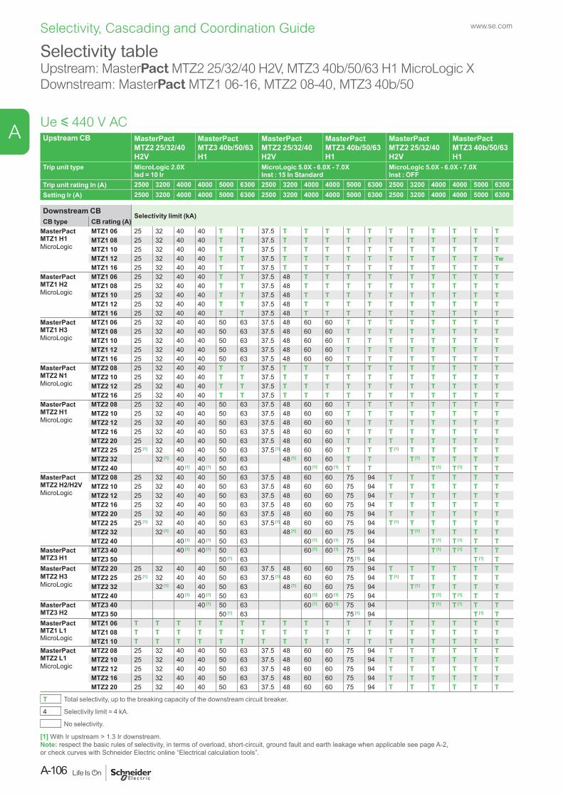
Upstream CB MasterPact MTZ2 25/32/40 H2V
MasterPact MTZ3 40b/50/63 H1
MasterPact MTZ2 25/32/40 H2V
MasterPact MTZ3 40b/50/63 H1
MasterPact MTZ2 25/32/40 H2V
MasterPact MTZ3 40b/50/63 H1
Trip unit type MicroLogic 2.0XIsd = 10 Ir
MicroLogic 5.0X - 6.0X - 7.0XInst : 15 In Standard
MicroLogic 5.0X - 6.0X - 7.0XInst : OFF
Trip unit rating In (A) 2500 3200 4000 4000 5000 6300 2500 3200 4000 4000 5000 6300 2500 3200 4000 4000 5000 6300Setting Ir (A) 2500 3200 4000 4000 5000 6300 2500 3200 4000 4000 5000 6300 2500 3200 4000 4000 5000 6300
Downstream CBSelectivity limit (kA)
CB type CB rating (A)MasterPact MTZ1 H1MicroLogic
MTZ1 06 25 32 40 40 T T 37.5 T T T T T T T T T T TMTZ1 08 25 32 40 40 T T 37.5 T T T T T T T T T T TMTZ1 10 25 32 40 40 T T 37.5 T T T T T T T T T T TMTZ1 12 25 32 40 40 T T 37.5 T T T T T T T T T T TwMTZ1 16 25 32 40 40 T T 37.5 T T T T T T T T T T T
MasterPact MTZ1 H2MicroLogic
MTZ1 06 25 32 40 40 T T 37.5 48 T T T T T T T T T TMTZ1 08 25 32 40 40 T T 37.5 48 T T T T T T T T T TMTZ1 10 25 32 40 40 T T 37.5 48 T T T T T T T T T TMTZ1 12 25 32 40 40 T T 37.5 48 T T T T T T T T T TMTZ1 16 25 32 40 40 T T 37.5 48 T T T T T T T T T T
MasterPact MTZ1 H3MicroLogic
MTZ1 06 25 32 40 40 50 63 37.5 48 60 60 T T T T T T T TMTZ1 08 25 32 40 40 50 63 37.5 48 60 60 T T T T T T T TMTZ1 10 25 32 40 40 50 63 37.5 48 60 60 T T T T T T T TMTZ1 12 25 32 40 40 50 63 37.5 48 60 60 T T T T T T T TMTZ1 16 25 32 40 40 50 63 37.5 48 60 60 T T T T T T T T
MasterPact MTZ2 N1MicroLogic
MTZ2 08 25 32 40 40 T T 37.5 T T T T T T T T T T TMTZ2 10 25 32 40 40 T T 37.5 T T T T T T T T T T TMTZ2 12 25 32 40 40 T T 37.5 T T T T T T T T T T TMTZ2 16 25 32 40 40 T T 37.5 T T T T T T T T T T T
MasterPact MTZ2 H1MicroLogic
MTZ2 08 25 32 40 40 50 63 37.5 48 60 60 T T T T T T T TMTZ2 10 25 32 40 40 50 63 37.5 48 60 60 T T T T T T T TMTZ2 12 25 32 40 40 50 63 37.5 48 60 60 T T T T T T T TMTZ2 16 25 32 40 40 50 63 37.5 48 60 60 T T T T T T T TMTZ2 20 25 32 40 40 50 63 37.5 48 60 60 T T T T T T T TMTZ2 25 25 [1] 32 40 40 50 63 37.5 [1] 48 60 60 T T T [1] T T T T TMTZ2 32 32 [1] 40 40 50 63 48 [1] 60 60 T T T [1] T T T TMTZ2 40 40 [1] 40 [1] 50 63 60 [1] 60 [1] T T T [1] T [1] T T
MasterPact MTZ2 H2/H2VMicroLogic
MTZ2 08 25 32 40 40 50 63 37.5 48 60 60 75 94 T T T T T TMTZ2 10 25 32 40 40 50 63 37.5 48 60 60 75 94 T T T T T TMTZ2 12 25 32 40 40 50 63 37.5 48 60 60 75 94 T T T T T TMTZ2 16 25 32 40 40 50 63 37.5 48 60 60 75 94 T T T T T TMTZ2 20 25 32 40 40 50 63 37.5 48 60 60 75 94 T T T T T TMTZ2 25 25 [1] 32 40 40 50 63 37.5 [1] 48 60 60 75 94 T [1] T T T T TMTZ2 32 32 [1] 40 40 50 63 48 [1] 60 60 75 94 T [1] T T T TMTZ2 40 40 [1] 40 [1] 50 63 60 [1] 60 [1] 75 94 T [1] T [1] T T
MasterPact MTZ3 H1
MTZ3 40 40 [1] 40 [1] 50 63 60 [1] 60 [1] 75 94 T [1] T [1] T TMTZ3 50 50 [1] 63 75 [1] 94 T [1] T
MasterPact MTZ2 H3MicroLogic
MTZ2 20 25 32 40 40 50 63 37.5 48 60 60 75 94 T T T T T TMTZ2 25 25 [1] 32 40 40 50 63 37.5 [1] 48 60 60 75 94 T [1] T T T T TMTZ2 32 32 [1] 40 40 50 63 48 [1] 60 60 75 94 T [1] T T T TMTZ2 40 40 [1] 40 [1] 50 63 60 [1] 60 [1] 75 94 T [1] T [1] T T
MasterPact MTZ3 H2
MTZ3 40 40 [1] 50 63 60 [1] 60 [1] 75 94 T [1] T [1] T TMTZ3 50 50 [1] 63 75 [1] 94 T [1] T
MasterPact MTZ1 L1MicroLogic
MTZ1 06 T T T T T T T T T T T T T T T T T TMTZ1 08 T T T T T T T T T T T T T T T T T TMTZ1 10 T T T T T T T T T T T T T T T T T T
MasterPact MTZ2 L1MicroLogic
MTZ2 08 25 32 40 40 50 63 37.5 48 60 60 75 94 T T T T T TMTZ2 10 25 32 40 40 50 63 37.5 48 60 60 75 94 T T T T T TMTZ2 12 25 32 40 40 50 63 37.5 48 60 60 75 94 T T T T T TMTZ2 16 25 32 40 40 50 63 37.5 48 60 60 75 94 T T T T T TMTZ2 20 25 32 40 40 50 63 37.5 48 60 60 75 94 T T T T T T
T Total selectivity, up to the breaking capacity of the downstream circuit breaker.
4 Selectivity limit = 4 kA.
No selectivity.
Ue y 440 V AC
Selectivity tableUpstream: MasterPact MTZ2 25/32/40 H2V, MTZ3 40b/50/63 H1 MicroLogic XDownstream: MasterPact MTZ1 06-16, MTZ2 08-40, MTZ3 40b/50
[1] With Ir upstream > 1.3 Ir downstream.Note: respect the basic rules of selectivity, in terms of overload, short-circuit, ground fault and earth leakage when applicable see page A-2, or check curves with Schneider Electric online “Electrical calculation tools”.
www.se.com
A-106
A
Selectivity, Cascading and Coordination Guide

Upstream CB MasterPact MTZ2 20/25/32/40 H3
MasterPact MTZ3 40/50/63 H2
MasterPact MTZ2 20/25/32/40 H3
MasterPact MTZ3 40/50/63 H2
MasterPact MTZ2 20/25/32/40 H3
MasterPact MTZ3 40/50/63 H2
Trip unit type MicroLogic 2.0XIsd = 10 Ir
MicroLogic 5.0X - 6.0X - 7.0XInst : 15 In Standard
MicroLogic 5.0X - 6.0X - 7.0XInst : OFF
Trip unit rating In (A) 2000 2500 3200 4000 4000 5000 6300 2000 2500 3200 4000 4000 5000 6300 2000 2500 3200 4000 4000 5000 6300Setting Ir (A) 2000 2500 3200 4000 4000 5000 6300 2000 2500 3200 4000 4000 5000 6300 2000 2500 3200 4000 4000 5000 6300
Downstream CBSelectivity limit (kA)
CB type CB rating (A)iDPN, iDPN N T T T T T T T T T T T T T T T T T T T T TiC40, iC40 N, iCV40 N, iCV40 H
T T T T T T T T T T T T T T T T T T T T T
iC60 N/H/L, iC60 RCBO
T T T T T T T T T T T T T T T T T T T T T
C120 N/H T T T T T T T T T T T T T T T T T T T T TNG125 N/H/L T T T T T T T T T T T T T T T T T T T T TComPact NSXm E/B/F/N/H
T T T T T T T T T T T T T T T T T T T T T
ComPactB/F/H/N/S/L/RTM-D
NSX100 T T T T T T T T T T T T T T T T T T T T T
NSX250 T T T T T T T T T T T T T T T T T T T T T
ComPact NSX160B/F/H/N/S/LTM-D
T T T T T T T T T T T T T T T T T T T T T
ComPactB/F/H/N/S/L/RMicroLogic
NSX100 T T T T T T T T T T T T T T T T T T T T T
NSX250 T T T T T T T T T T T T T T T T T T T T T
ComPact NSX160B/F/H/N/S/LMicroLogic
T T T T T T T T T T T T T T T T T T T T T
ComPactF/H/N/S/L/R
NSX400 T T T T T T T T T T T T T T T T T T T T TNSX630 T T T T T T T T T T T T T T T T T T T T T
ComPact NMicroLogic
NS630b 20 25 32 40 40 T T 30 37.5 48 T T T T T T T T T T TNS800 20 25 32 40 40 T T 30 37.5 48 T T T T T T T T T T TNS1000 20 25 32 40 40 T T 30 37.5 48 T T T T T T T T T T TNS1250 20 25 32 40 40 T T 30 37.5 48 T T T T T T T T T T TNS1600 20 25 32 40 40 T T 30 37.5 48 T T T T T T T T T T T
ComPact HMicroLogic
NS630b 20 25 32 40 40 50 63 30 37.5 48 60 60 T T 65 65 65 65 T T TNS800 20 25 32 40 40 50 63 30 37.5 48 60 60 T T 65 65 65 65 T T TNS1000 20 25 32 40 40 50 63 30 37.5 48 60 60 T T 65 65 65 65 T T TNS1250 20 25 32 40 40 50 63 30 37.5 48 60 60 T T 65 65 65 65 T T TNS1600 20 25 32 40 40 50 63 30 37.5 48 60 60 T T 65 65 65 65 T T T
ComPact NMicroLogic
NS1600b 20 25 32 40 40 50 63 30 37.5 48 60 60 T T 65 65 65 65 T T TNS2000 20 [1] 25 32 40 40 50 63 30 [1] 37.5 48 60 60 T T 65 [1] 65 65 65 T T TNS2500 25 [1] 32 40 40 50 63 37.5 [1] 48 60 60 T T 65 [1] 65 65 T T TNS3200 32 [1] 40 40 50 63 48 [1] 60 60 T T 65 [1] 65 T T T
ComPact HMicroLogic
NS1600b 20 25 32 40 40 50 63 30 37.5 48 60 60 75 T 65 65 65 65 T T TNS2000 20 [1] 25 32 40 40 50 63 30 [1] 37.5 48 60 60 75 T 65 [1] 65 65 65 T T TNS2500 25 [1] 32 40 40 50 63 37.5 [1] 48 60 60 75 T 65 [1] 65 65 T T TNS3200 32 [1] 40 40 50 63 48 [1] 60 60 75 T 65 [1] 65 T T T
ComPact LMicroLogic
NS630b T T T T T T T T T T T T T T T T T T T T TNS800 T T T T T T T T T T T T T T T T T T T T TNS1000 T T T T T T T T T T T T T T T T T T T T T
ComPact LB MicroLogic
NS630b T T T T T T T T T T T T T T T T T T T T TNS800 T T T T T T T T T T T T T T T T T T T T T
T Total selectivity, up to the breaking capacity of the downstream circuit breaker.
4 Selectivity limit = 4 kA.
No selectivity.
Ue y 440 V AC
Selectivity tableUpstream: MasterPact MTZ2 20/25/32/40 H3, MTZ3 40/50/63 H2 MicroLogic XDownstream: iDPN, iC60, iC40, C120, NG125, ComPact NSXm, NSX100-630, NS630b-3200
[1] With Ir upstream > 1.3 Ir downstream.Note: respect the basic rules of selectivity, in terms of overload, short-circuit, ground fault and earth leakage when applicable see page A-2, or check curves with Schneider Electric online “Electrical calculation tools”.
A-107
www.se.com
A
Selectivity, Cascading and Coordination Guide
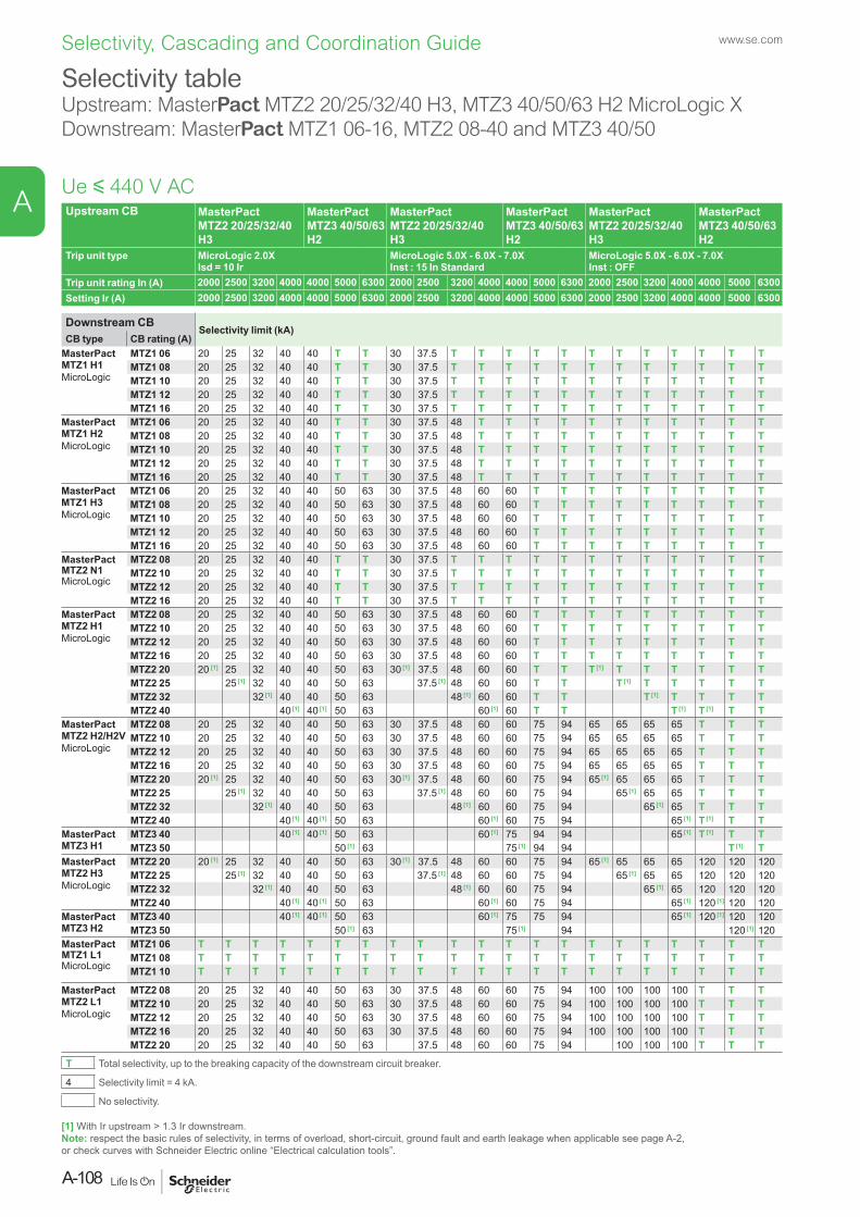
Upstream CB MasterPact MTZ2 20/25/32/40 H3
MasterPact MTZ3 40/50/63 H2
MasterPact MTZ2 20/25/32/40 H3
MasterPact MTZ3 40/50/63 H2
MasterPact MTZ2 20/25/32/40 H3
MasterPact MTZ3 40/50/63 H2
Trip unit type MicroLogic 2.0XIsd = 10 Ir
MicroLogic 5.0X - 6.0X - 7.0XInst : 15 In Standard
MicroLogic 5.0X - 6.0X - 7.0XInst : OFF
Trip unit rating In (A) 2000 2500 3200 4000 4000 5000 6300 2000 2500 3200 4000 4000 5000 6300 2000 2500 3200 4000 4000 5000 6300Setting Ir (A) 2000 2500 3200 4000 4000 5000 6300 2000 2500 3200 4000 4000 5000 6300 2000 2500 3200 4000 4000 5000 6300
Downstream CBSelectivity limit (kA)
CB type CB rating (A)MasterPact MTZ1 H1MicroLogic
MTZ1 06 20 25 32 40 40 T T 30 37.5 T T T T T T T T T T T TMTZ1 08 20 25 32 40 40 T T 30 37.5 T T T T T T T T T T T TMTZ1 10 20 25 32 40 40 T T 30 37.5 T T T T T T T T T T T TMTZ1 12 20 25 32 40 40 T T 30 37.5 T T T T T T T T T T T TMTZ1 16 20 25 32 40 40 T T 30 37.5 T T T T T T T T T T T T
MasterPact MTZ1 H2 MicroLogic
MTZ1 06 20 25 32 40 40 T T 30 37.5 48 T T T T T T T T T T TMTZ1 08 20 25 32 40 40 T T 30 37.5 48 T T T T T T T T T T TMTZ1 10 20 25 32 40 40 T T 30 37.5 48 T T T T T T T T T T TMTZ1 12 20 25 32 40 40 T T 30 37.5 48 T T T T T T T T T T TMTZ1 16 20 25 32 40 40 T T 30 37.5 48 T T T T T T T T T T T
MasterPact MTZ1 H3MicroLogic
MTZ1 06 20 25 32 40 40 50 63 30 37.5 48 60 60 T T T T T T T T TMTZ1 08 20 25 32 40 40 50 63 30 37.5 48 60 60 T T T T T T T T TMTZ1 10 20 25 32 40 40 50 63 30 37.5 48 60 60 T T T T T T T T TMTZ1 12 20 25 32 40 40 50 63 30 37.5 48 60 60 T T T T T T T T TMTZ1 16 20 25 32 40 40 50 63 30 37.5 48 60 60 T T T T T T T T T
MasterPact MTZ2 N1MicroLogic
MTZ2 08 20 25 32 40 40 T T 30 37.5 T T T T T T T T T T T TMTZ2 10 20 25 32 40 40 T T 30 37.5 T T T T T T T T T T T TMTZ2 12 20 25 32 40 40 T T 30 37.5 T T T T T T T T T T T TMTZ2 16 20 25 32 40 40 T T 30 37.5 T T T T T T T T T T T T
MasterPact MTZ2 H1MicroLogic
MTZ2 08 20 25 32 40 40 50 63 30 37.5 48 60 60 T T T T T T T T TMTZ2 10 20 25 32 40 40 50 63 30 37.5 48 60 60 T T T T T T T T TMTZ2 12 20 25 32 40 40 50 63 30 37.5 48 60 60 T T T T T T T T TMTZ2 16 20 25 32 40 40 50 63 30 37.5 48 60 60 T T T T T T T T TMTZ2 20 20 [1] 25 32 40 40 50 63 30 [1] 37.5 48 60 60 T T T [1] T T T T T TMTZ2 25 25 [1] 32 40 40 50 63 37.5 [1] 48 60 60 T T T [1] T T T T TMTZ2 32 32 [1] 40 40 50 63 48 [1] 60 60 T T T [1] T T T TMTZ2 40 40 [1] 40 [1] 50 63 60 [1] 60 T T T [1] T [1] T T
MasterPact MTZ2 H2/H2VMicroLogic
MTZ2 08 20 25 32 40 40 50 63 30 37.5 48 60 60 75 94 65 65 65 65 T T TMTZ2 10 20 25 32 40 40 50 63 30 37.5 48 60 60 75 94 65 65 65 65 T T TMTZ2 12 20 25 32 40 40 50 63 30 37.5 48 60 60 75 94 65 65 65 65 T T TMTZ2 16 20 25 32 40 40 50 63 30 37.5 48 60 60 75 94 65 65 65 65 T T TMTZ2 20 20 [1] 25 32 40 40 50 63 30 [1] 37.5 48 60 60 75 94 65 [1] 65 65 65 T T TMTZ2 25 25 [1] 32 40 40 50 63 37.5 [1] 48 60 60 75 94 65 [1] 65 65 T T TMTZ2 32 32 [1] 40 40 50 63 48 [1] 60 60 75 94 65 [1] 65 T T TMTZ2 40 40 [1] 40 [1] 50 63 60 [1] 60 75 94 65 [1] T [1] T T
MasterPact MTZ3 H1
MTZ3 40 40 [1] 40 [1] 50 63 60 [1] 75 94 94 65 [1] T [1] T TMTZ3 50 50 [1] 63 75 [1] 94 94 T [1] T
MasterPact MTZ2 H3MicroLogic
MTZ2 20 20 [1] 25 32 40 40 50 63 30 [1] 37.5 48 60 60 75 94 65 [1] 65 65 65 120 120 120MTZ2 25 25 [1] 32 40 40 50 63 37.5 [1] 48 60 60 75 94 65 [1] 65 65 120 120 120MTZ2 32 32 [1] 40 40 50 63 48 [1] 60 60 75 94 65 [1] 65 120 120 120MTZ2 40 40 [1] 40 [1] 50 63 60 [1] 60 75 94 65 [1] 120 [1] 120 120
MasterPact MTZ3 H2
MTZ3 40 40 [1] 40 [1] 50 63 60 [1] 75 75 94 65 [1] 120 [1] 120 120MTZ3 50 50 [1] 63 75 [1] 94 120 [1] 120
MasterPact MTZ1 L1MicroLogic
MTZ1 06 T T T T T T T T T T T T T T T T T T T T TMTZ1 08 T T T T T T T T T T T T T T T T T T T T TMTZ1 10 T T T T T T T T T T T T T T T T T T T T T
MasterPact MTZ2 L1MicroLogic
MTZ2 08 20 25 32 40 40 50 63 30 37.5 48 60 60 75 94 100 100 100 100 T T TMTZ2 10 20 25 32 40 40 50 63 30 37.5 48 60 60 75 94 100 100 100 100 T T TMTZ2 12 20 25 32 40 40 50 63 30 37.5 48 60 60 75 94 100 100 100 100 T T TMTZ2 16 20 25 32 40 40 50 63 30 37.5 48 60 60 75 94 100 100 100 100 T T TMTZ2 20 20 25 32 40 40 50 63 37.5 48 60 60 75 94 100 100 100 T T T
T Total selectivity, up to the breaking capacity of the downstream circuit breaker.
4 Selectivity limit = 4 kA.
No selectivity.
Ue y 440 V AC
Selectivity tableUpstream: MasterPact MTZ2 20/25/32/40 H3, MTZ3 40/50/63 H2 MicroLogic XDownstream: MasterPact MTZ1 06-16, MTZ2 08-40 and MTZ3 40/50
[1] With Ir upstream > 1.3 Ir downstream.Note: respect the basic rules of selectivity, in terms of overload, short-circuit, ground fault and earth leakage when applicable see page A-2, or check curves with Schneider Electric online “Electrical calculation tools”.
www.se.com
A-108
A
Selectivity, Cascading and Coordination Guide
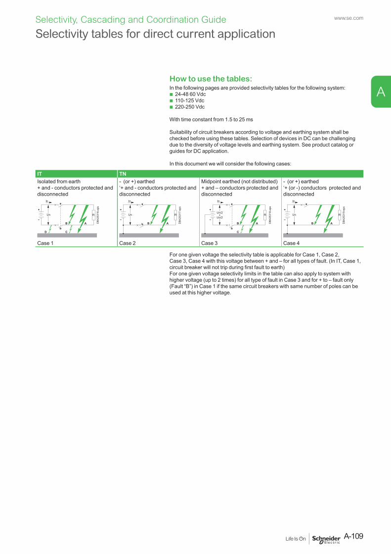
A-109
www.se.com
A
Selectivity, Cascading and Coordination Guide
Selectivity tables for direct current application
How to use the tables:In the following pages are provided selectivity tables for the following system:
b 24-48 60 Vdc b 110-125 Vdc b 220-250 Vdc
With time constant from 1.5 to 25 ms
Suitability of circuit breakers according to voltage and earthing system shall be checked before using these tables. Selection of devices in DC can be challenging due to the diversity of voltage levels and earthing system. See product catalog or guides for DC application.
In this document we will consider the following cases:
IT TNIsolated from earth+ and - conductors protected and disconnected
- (or +) earthed‘+ and - conductors protected and disconnected
Midpoint earthed (not distributed)+ and – conductors protected and disconnected
- (or +) earthed‘+ (or -) conductors protected and disconnected
A
R
a
bB
CD
In
Un
DB4
2531
6.ep
s
AB
In
Un R
a
b DB4
2531
7.ep
s
AB
C
In
Un/2+
Un/2R
a
b
DB4
2531
8.ep
s
AB
In
Un R
a
DB4
2531
9.ep
s
Case 1 Case 2 Case 3 Case 4
For one given voltage the selectivity table is applicable for Case 1, Case 2, Case 3, Case 4 with this voltage between + and – for all types of fault. (In IT, Case 1, circuit breaker will not trip during first fault to earth)For one given voltage selectivity limits in the table can also apply to system with higher voltage (up to 2 times) for all type of fault in Case 3 and for + to – fault only (Fault “B”) in Case 1 if the same circuit breakers with same number of poles can be used at this higher voltage.
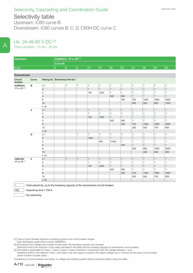
Selectivity tableUpstream: iC60 curve B Downstream: iC60 curves B, C, D, C60H-DC curve C
Time constant: 1.5 ms - 25 msUe: 24-48-60 V DC [3]
Upstream iC60N/H/L, 1P or 2P [1]
Curve BIn (A) 3 4 6 10 16 20 25 32 40 50 63
DownstreamCircuit breaker
Curve Rating (A) Selectivity limit (A) [2]
iC60N/H/L1P or 2P [1]
B y 1 T T T T T T T T T T2 T T T T T T T T3 150 1200 T T T T T T4 500 900 T T T T6 300 700 1000 1800 400010 400 500 800 1000u 16
C y 1 T T T T T T T T T T2 T T T T T T T T3 150 1200 T T T T T T4 400 900 T T T T6 300 700 1000 1800 300010 300 500 700 800u 16
D y 1 T T T T T T T T T2 1600 T T T T T T T3 900 11000 T T T T T4 700 T T T T6 500 800 1800 300010 400 600 800u 16
C60H-DC1P or 2P [1]
C y 1 T T T T T T T T T T2 T T T T T T T T3 150 1200 T T T T T T4 400 900 T T T T6 300 700 1000 1800 300010 300 500 700 800u 16
T : Total selectivity, up to the breaking capacity of the downstream circuit breaker.
700 : Selectivity limit = 700 A
: No selectivity.
[1] Type of circuit breaker depend on earthing system and circuit breaker ranges (see Distribution guide direct current CA908061).
[2] According to the voltage and number of pole used, the breaking capacity can changed. Selectivity limit is the minimum of the value indicated in the table and the breaking capacity of downstream circuit breaker.
[3] This table is applicable for Case 1, Case 2, Case 3, Case 4 defined in introduction with this voltage between + and - Selectivity limits in this table for Case 1 and Case 3 can also apply to system with higher voltage (up to 2 times) for the same circuit breaker (same number of poles used).
Compliancy of circuit breakers according to voltage and earthing system shall be checked before using this table.
www.se.com
A-110
A
Selectivity, Cascading and Coordination Guide
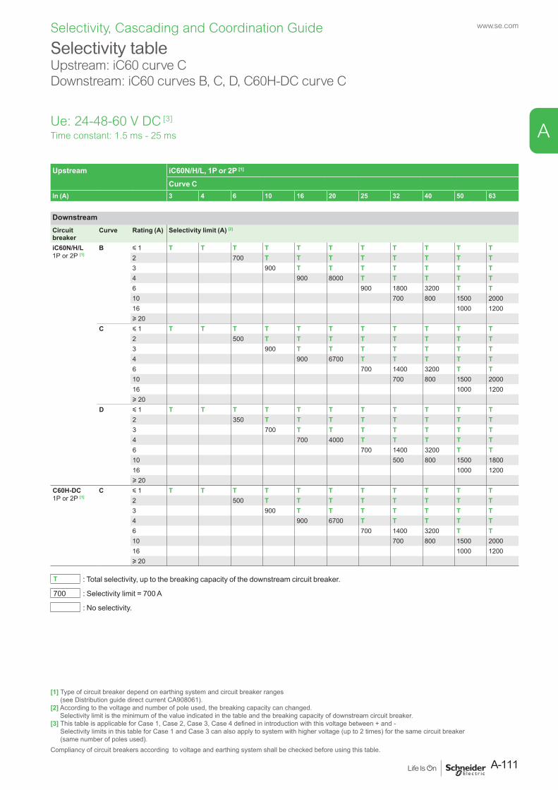
Selectivity tableUpstream: iC60 curve C Downstream: iC60 curves B, C, D, C60H-DC curve C
Time constant: 1.5 ms - 25 msUe: 24-48-60 V DC [3]
Upstream iC60N/H/L, 1P or 2P [1]
Curve CIn (A) 3 4 6 10 16 20 25 32 40 50 63
DownstreamCircuit breaker
Curve Rating (A) Selectivity limit (A) [2]
iC60N/H/L1P or 2P [1]
B y 1 T T T T T T T T T T T2 700 T T T T T T T T3 900 T T T T T T T4 900 8000 T T T T T6 900 1800 3200 T T10 700 800 1500 200016 1000 1200u 20
C y 1 T T T T T T T T T T T2 500 T T T T T T T T3 900 T T T T T T T4 900 6700 T T T T T6 700 1400 3200 T T10 700 800 1500 200016 1000 1200u 20
D y 1 T T T T T T T T T T T2 350 T T T T T T T T3 700 T T T T T T T4 700 4000 T T T T T6 700 1400 3200 T T10 500 800 1500 180016 1000 1200u 20
C60H-DC1P or 2P [1]
C y 1 T T T T T T T T T T T2 500 T T T T T T T T3 900 T T T T T T T4 900 6700 T T T T T6 700 1400 3200 T T10 700 800 1500 200016 1000 1200u 20
T : Total selectivity, up to the breaking capacity of the downstream circuit breaker.
700 : Selectivity limit = 700 A
: No selectivity.
[1] Type of circuit breaker depend on earthing system and circuit breaker ranges (see Distribution guide direct current CA908061).
[2] According to the voltage and number of pole used, the breaking capacity can changed. Selectivity limit is the minimum of the value indicated in the table and the breaking capacity of downstream circuit breaker.
[3] This table is applicable for Case 1, Case 2, Case 3, Case 4 defined in introduction with this voltage between + and - Selectivity limits in this table for Case 1 and Case 3 can also apply to system with higher voltage (up to 2 times) for the same circuit breaker (same number of poles used).
Compliancy of circuit breakers according to voltage and earthing system shall be checked before using this table.
A-111
www.se.com
A
Selectivity, Cascading and Coordination Guide
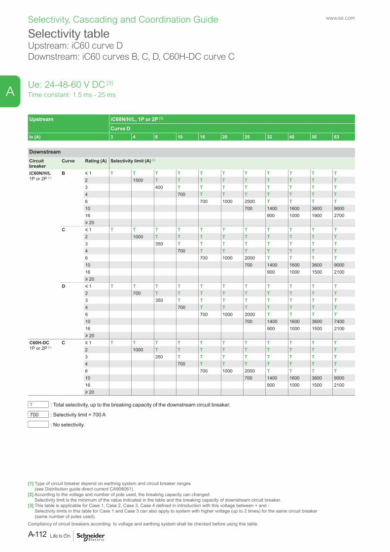
Selectivity tableUpstream: iC60 curve D Downstream: iC60 curves B, C, D, C60H-DC curve C
Ue: 24-48-60 V DC [3]
Time constant: 1.5 ms - 25 ms
Upstream iC60N/H/L, 1P or 2P [1]
Curve DIn (A) 3 4 6 10 16 20 25 32 40 50 63
DownstreamCircuit breaker
Curve Rating (A) Selectivity limit (A) [2]
iC60N/H/L1P or 2P [1]
B y 1 T T T T T T T T T T T2 1500 T T T T T T T T T3 400 T T T T T T T T4 700 T T T T T T T6 700 1000 2500 T T T T10 700 1400 1600 3600 900016 900 1000 1900 2700u 20
C y 1 T T T T T T T T T T T2 1000 T T T T T T T T T3 350 T T T T T T T T4 700 T T T T T T T6 700 1000 2000 T T T T10 700 1400 1600 3600 900016 900 1000 1500 2100u 20
D y 1 T T T T T T T T T T T2 700 T T T T T T T T T3 350 T T T T T T T T4 700 T T T T T T T6 700 1000 2000 T T T T10 700 1400 1600 3600 740016 900 1000 1500 2100u 20
C60H-DC1P or 2P [1]
C y 1 T T T T T T T T T T T2 1000 T T T T T T T T T3 350 T T T T T T T T4 700 T T T T T T T6 700 1000 2000 T T T T10 700 1400 1600 3600 900016 900 1000 1500 2100u 20
T : Total selectivity, up to the breaking capacity of the downstream circuit breaker.
700 : Selectivity limit = 700 A
: No selectivity.
[1] Type of circuit breaker depend on earthing system and circuit breaker ranges (see Distribution guide direct current CA908061).
[2] According to the voltage and number of pole used, the breaking capacity can changed. Selectivity limit is the minimum of the value indicated in the table and the breaking capacity of downstream circuit breaker.
[3] This table is applicable for Case 1, Case 2, Case 3, Case 4 defined in introduction with this voltage between + and - Selectivity limits in this table for Case 1 and Case 3 can also apply to system with higher voltage (up to 2 times) for the same circuit breaker (same number of poles used).
Compliancy of circuit breakers according to voltage and earthing system shall be checked before using this table.
www.se.com
A-112
A
Selectivity, Cascading and Coordination Guide
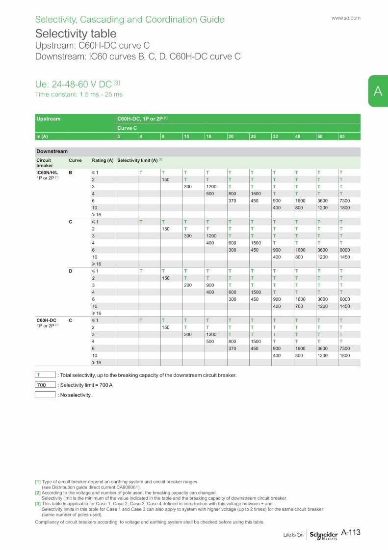
Selectivity tableUpstream: C60H-DC curve CDownstream: iC60 curves B, C, D, C60H-DC curve C
Ue: 24-48-60 V DC [3]
Time constant: 1.5 ms - 25 ms
Upstream C60H-DC, 1P or 2P [1]
Curve CIn (A) 3 4 6 10 16 20 25 32 40 50 63
DownstreamCircuit breaker
Curve Rating (A) Selectivity limit (A) [2]
iC60N/H/L1P or 2P [1]
B y 1 T T T T T T T T T T2 150 T T T T T T T T3 300 1200 T T T T T T4 500 800 1500 T T T T6 370 450 900 1600 3600 730010 400 800 1200 1800u 16
C y 1 T T T T T T T T T T2 150 T T T T T T T T3 300 1200 T T T T T T4 400 600 1500 T T T T6 300 450 900 1600 3600 600010 400 800 1200 1450u 16
D y 1 T T T T T T T T T T2 150 T T T T T T T T3 200 900 T T T T T T4 400 600 1500 T T T T6 300 450 900 1600 3600 600010 400 700 1200 1450u 16
C60H-DC1P or 2P [1]
C y 1 T T T T T T T T T T2 150 T T T T T T T T3 300 1200 T T T T T T4 500 800 1500 T T T T6 370 450 900 1600 3600 730010 400 800 1200 1800u 16
T : Total selectivity, up to the breaking capacity of the downstream circuit breaker.
700 : Selectivity limit = 700 A
: No selectivity.
[1] Type of circuit breaker depend on earthing system and circuit breaker ranges (see Distribution guide direct current CA908061).
[2] According to the voltage and number of pole used, the breaking capacity can changed. Selectivity limit is the minimum of the value indicated in the table and the breaking capacity of downstream circuit breaker.
[3] This table is applicable for Case 1, Case 2, Case 3, Case 4 defined in introduction with this voltage between + and - Selectivity limits in this table for Case 1 and Case 3 can also apply to system with higher voltage (up to 2 times) for the same circuit breaker (same number of poles used).
Compliancy of circuit breakers according to voltage and earthing system shall be checked before using this table.
A-113
www.se.com
A
Selectivity, Cascading and Coordination Guide
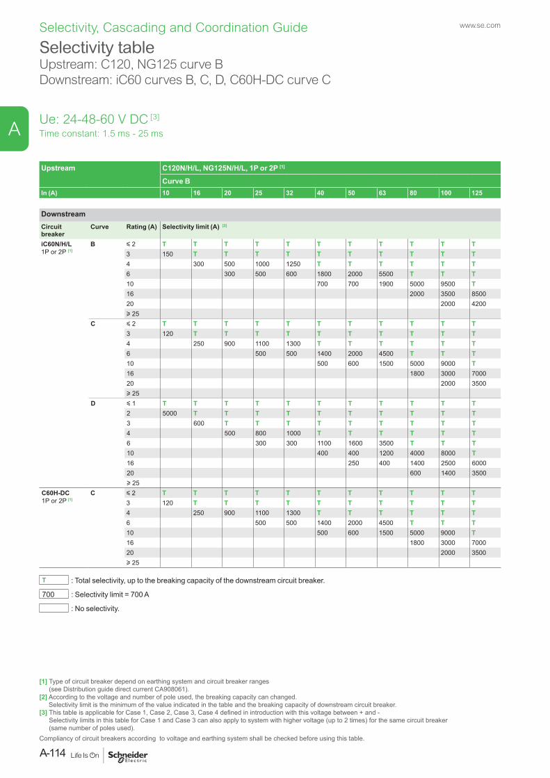
Selectivity tableUpstream: C120, NG125 curve BDownstream: iC60 curves B, C, D, C60H-DC curve C
Time constant: 1.5 ms - 25 msUe: 24-48-60 V DC [3]
Upstream C120N/H/L, NG125N/H/L, 1P or 2P [1]
Curve BIn (A) 10 16 20 25 32 40 50 63 80 100 125
DownstreamCircuit breaker
Curve Rating (A) Selectivity limit (A) [2]
iC60N/H/L1P or 2P [1]
B y 2 T T T T T T T T T T T3 150 T T T T T T T T T T4 300 500 1000 1250 T T T T T T6 300 500 600 1800 2000 5500 T T T10 700 700 1900 5000 9500 T16 2000 3500 850020 2000 4200u 25
C y 2 T T T T T T T T T T T3 120 T T T T T T T T T T4 250 900 1100 1300 T T T T T T6 500 500 1400 2000 4500 T T T10 500 600 1500 5000 9000 T16 1800 3000 700020 2000 3500u 25
D y 1 T T T T T T T T T T T2 5000 T T T T T T T T T T3 600 T T T T T T T T T4 500 800 1000 T T T T T T6 300 300 1100 1600 3500 T T T10 400 400 1200 4000 8000 T16 250 400 1400 2500 600020 600 1400 3500u 25
C60H-DC1P or 2P [1]
C y 2 T T T T T T T T T T T3 120 T T T T T T T T T T4 250 900 1100 1300 T T T T T T6 500 500 1400 2000 4500 T T T10 500 600 1500 5000 9000 T16 1800 3000 700020 2000 3500u 25
T : Total selectivity, up to the breaking capacity of the downstream circuit breaker.
700 : Selectivity limit = 700 A
: No selectivity.
[1] Type of circuit breaker depend on earthing system and circuit breaker ranges (see Distribution guide direct current CA908061).
[2] According to the voltage and number of pole used, the breaking capacity can changed. Selectivity limit is the minimum of the value indicated in the table and the breaking capacity of downstream circuit breaker.
[3] This table is applicable for Case 1, Case 2, Case 3, Case 4 defined in introduction with this voltage between + and - Selectivity limits in this table for Case 1 and Case 3 can also apply to system with higher voltage (up to 2 times) for the same circuit breaker (same number of poles used).
Compliancy of circuit breakers according to voltage and earthing system shall be checked before using this table.
www.se.com
A-114
A
Selectivity, Cascading and Coordination Guide
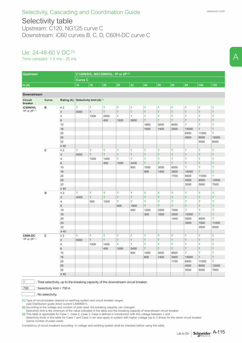
Selectivity tableUpstream: C120, NG125 curve CDownstream: iC60 curves B, C, D, C60H-DC curve C
Time constant: 1.5 ms - 25 msUe: 24-48-60 V DC [3]
Upstream C120N/H/L, NG125N/H/L, 1P or 2P [1]
Curve CIn (A) 10 16 20 25 32 40 50 63 80 100 125
DownstreamCircuit breaker
Curve Rating (A) Selectivity limit (A) [2]
iC60N/H/L1P or 2P [1]
B y 2 T T T T T T T T T T T3 5000 T T T T T T T T T T4 1500 2000 T T T T T T T T6 400 1500 3000 T T T T T T10 1800 3000 8000 T T T16 1000 1400 2500 15000 T T20 6500 11500 T25 4500 8500 1500032 5000 8000u 40
C y 2 T T T T T T T T T T T3 5000 T T T T T T T T T T4 1000 1400 T T T T T T T T6 400 1000 2400 T T T T T T10 800 1500 3000 8500 T T T16 800 1400 3000 15000 T T20 1700 6500 11000 T25 4500 8500 1200032 3000 5000 7000u 40
D y 2 T T T T T T T T T T T3 4000 T T T T T T T T T T4 500 1000 T T T T T T T T6 800 1900 T T T T T T10 600 1200 2500 7000 T T T16 500 1000 2500 12000 T T20 1400 5500 9000 T25 3500 7500 1100032 3500 6000u 40
C60H-DC1P or 2P [1]
C y 2 T T T T T T T T T T T3 5000 T T T T T T T T T T4 1000 1400 T T T T T T T T6 400 1000 2400 T T T T T T10 800 1500 3000 8500 T T T16 800 1400 3000 15000 T T20 1700 6500 11000 T25 4500 8500 1200032 3000 5000 7000u 40
T : Total selectivity, up to the breaking capacity of the downstream circuit breaker.
700 : Selectivity limit = 700 A
: No selectivity.
[1] Type of circuit breaker depend on earthing system and circuit breaker ranges (see Distribution guide direct current CA908061).
[2] According to the voltage and number of pole used, the breaking capacity can changed. Selectivity limit is the minimum of the value indicated in the table and the breaking capacity of downstream circuit breaker.
[3] This table is applicable for Case 1, Case 2, Case 3, Case 4 defined in introduction with this voltage between + and - Selectivity limits in this table for Case 1 and Case 3 can also apply to system with higher voltage (up to 2 times) for the same circuit breaker (same number of poles used).
Compliancy of circuit breakers according to voltage and earthing system shall be checked before using this table.
A-115
www.se.com
A
Selectivity, Cascading and Coordination Guide
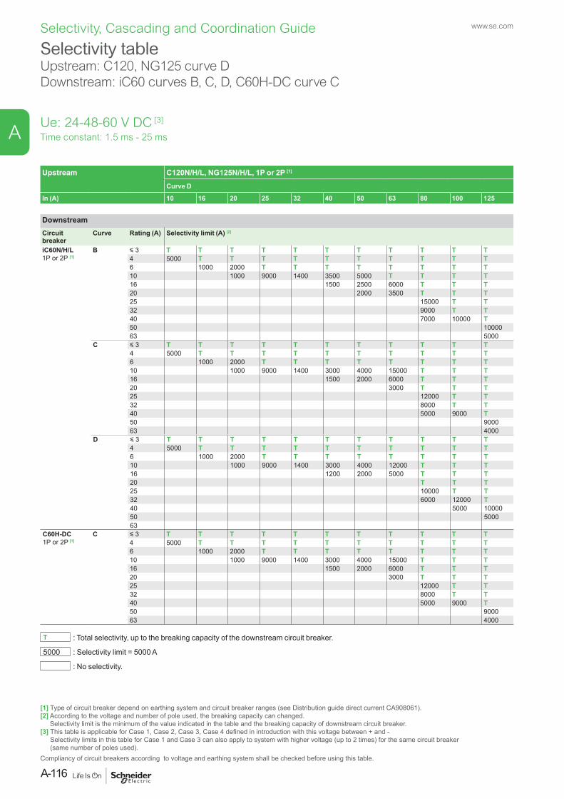
Selectivity tableUpstream: C120, NG125 curve DDownstream: iC60 curves B, C, D, C60H-DC curve C
Time constant: 1.5 ms - 25 msUe: 24-48-60 V DC [3]
Upstream C120N/H/L, NG125N/H/L, 1P or 2P [1]
Curve D
In (A) 10 16 20 25 32 40 50 63 80 100 125
DownstreamCircuit breaker
Curve Rating (A) Selectivity limit (A) [2]
iC60N/H/L1P or 2P [1]
B y 3 T T T T T T T T T T T4 5000 T T T T T T T T T T6 1000 2000 T T T T T T T T10 1000 9000 1400 3500 5000 T T T T16 1500 2500 6000 T T T20 2000 3500 T T T25 15000 T T32 9000 T T40 7000 10000 T50 1000063 5000
C y 3 T T T T T T T T T T T4 5000 T T T T T T T T T T6 1000 2000 T T T T T T T T10 1000 9000 1400 3000 4000 15000 T T T16 1500 2000 6000 T T T20 3000 T T T25 12000 T T32 8000 T T40 5000 9000 T50 900063 4000
D y 3 T T T T T T T T T T T4 5000 T T T T T T T T T T6 1000 2000 T T T T T T T T10 1000 9000 1400 3000 4000 12000 T T T16 1200 2000 5000 T T T20 T T T25 10000 T T32 6000 12000 T40 5000 1000050 500063
C60H-DC1P or 2P [1]
C y 3 T T T T T T T T T T T4 5000 T T T T T T T T T T6 1000 2000 T T T T T T T T10 1000 9000 1400 3000 4000 15000 T T T16 1500 2000 6000 T T T20 3000 T T T25 12000 T T32 8000 T T40 5000 9000 T50 900063 4000
T : Total selectivity, up to the breaking capacity of the downstream circuit breaker.
5000 : Selectivity limit = 5000 A
: No selectivity.
[1] Type of circuit breaker depend on earthing system and circuit breaker ranges (see Distribution guide direct current CA908061).[2] According to the voltage and number of pole used, the breaking capacity can changed.
Selectivity limit is the minimum of the value indicated in the table and the breaking capacity of downstream circuit breaker.[3] This table is applicable for Case 1, Case 2, Case 3, Case 4 defined in introduction with this voltage between + and -
Selectivity limits in this table for Case 1 and Case 3 can also apply to system with higher voltage (up to 2 times) for the same circuit breaker (same number of poles used).
Compliancy of circuit breakers according to voltage and earthing system shall be checked before using this table.
www.se.com
A-116
A
Selectivity, Cascading and Coordination Guide
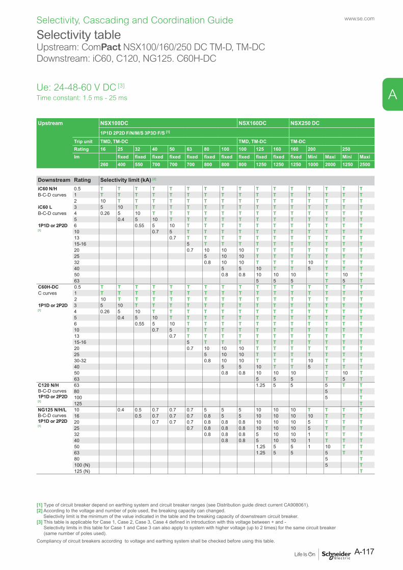
Selectivity tableUpstream: ComPact NSX100/160/250 DC TM-D, TM-DC Downstream: iC60, C120, NG125. C60H-DC
Time constant: 1.5 ms - 25 ms
Upstream NSX100DC NSX160DC NSX250 DC1P1D 2P2D F/N/M/S 3P3D F/S [1]
Trip unit TMD, TM-DC TMD, TM-DC TM-DCRating 16 25 32 40 50 63 80 100 100 125 160 160 200 250Im fixed fixed fixed fixed fixed fixed fixed fixed fixed fixed fixed Mini Maxi Mini Maxi
260 400 550 700 700 700 800 800 800 1250 1250 1250 1000 2000 1250 2500
Downstream Rating Selectivity limit (kA) [2]
iC60 N/H 0.5 T T T T T T T T T T T T T T T TB-C-D curves 1 T T T T T T T T T T T T T T T T
2 10 T T T T T T T T T T T T T T TiC60 L 3 5 10 T T T T T T T T T T T T T TB-C-D curves 4 0.26 5 10 T T T T T T T T T T T T T
5 0.4 5 10 T T T T T T T T T T T T1P1D or 2P2D [1]
6 0.55 5 10 T T T T T T T T T T T10 0.7 5 T T T T T T T T T T T13 0.7 T T T T T T T T T T T15-16 5 T T T T T T T T T T20 0.7 10 10 10 T T T T T T T25 5 10 10 T T T T T T T32 0.8 10 10 T T T 10 T T T40 5 5 10 T T 5 T T T50 0.8 0.8 10 10 10 T 10 T63 5 5 5 T 5 T
C60H-DC 0.5 T T T T T T T T T T T T T T T TC curves 1 T T T T T T T T T T T T T T T T
2 10 T T T T T T T T T T T T T T T1P1D or 2P2D [1]
3 5 10 T T T T T T T T T T T T T T4 0.26 5 10 T T T T T T T T T T T T T5 0.4 5 10 T T T T T T T T T T T T6 0.55 5 10 T T T T T T T T T T T10 0.7 5 T T T T T T T T T T T13 0.7 T T T T T T T T T T T15-16 5 T T T T T T T T T T20 0.7 10 10 10 T T T T T T T25 5 10 10 T T T T T T T30-32 0.8 10 10 T T T 10 T T T40 5 5 10 T T 5 T T T50 0.8 0.8 10 10 10 T 10 T63 5 5 5 T 5 T
C120 N/HB-C-D curves1P1D or 2P2D [1]
63 1.25 5 5 5 T T80 5 T100 5 T125 T
NG125 N/H/LB-C-D curves1P1D or 2P2D [1]
10 0.4 0.5 0.7 0.7 0.7 5 5 5 10 10 10 T T T T16 0.5 0.7 0.7 0.7 0.8 5 5 10 10 10 10 T T T20 0.7 0.7 0.7 0.8 0.8 0.8 10 10 10 5 T T T25 0.7 0.8 0.8 0.8 10 10 10 5 T T T32 0.8 0.8 0.8 5 10 10 1 T T T40 0.8 0.8 5 10 10 1 T T T50 1.25 5 5 1 10 T T63 1.25 5 5 5 T T80 5 T100 (N) 5 T125 (N) T
[1] Type of circuit breaker depend on earthing system and circuit breaker ranges (see Distribution guide direct current CA908061).[2] According to the voltage and number of pole used, the breaking capacity can changed.
Selectivity limit is the minimum of the value indicated in the table and the breaking capacity of downstream circuit breaker.[3] This table is applicable for Case 1, Case 2, Case 3, Case 4 defined in introduction with this voltage between + and -
Selectivity limits in this table for Case 1 and Case 3 can also apply to system with higher voltage (up to 2 times) for the same circuit breaker (same number of poles used).
Compliancy of circuit breakers according to voltage and earthing system shall be checked before using this table.
Ue: 24-48-60 V DC [3]
A-117
www.se.com
A
Selectivity, Cascading and Coordination Guide
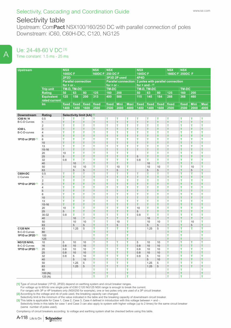
Selectivity tableUpstream: ComPact NSX100/160/250 DC with parallel connection of poles Downstream: iC60, C60H-DC, C120, NG125
Upstream NSX 100DC F
NSX 160DC F
NSX 250 DC F
NSX 100DC F
NSX 160DC F
NSX 250DC F
2P2D 3P3D 2P used 4P4DParallel connection for + or -
Parallel connection for + or -
2 poles with parallel connection for + and - [2]
Trip unit TM-D, TM-DC TM-DC TM-D, TM-DC TM-DCRating 50 63 80 125 160 200 50 63 80 125 160 200Equivalent rated current
125 158 200 313 400 500 115 145 184 288 368 460
Im fixed fixed fixed fixed fixed Mini Maxi fixed fixed fixed fixed fixed Mini Maxi1400 1400 1600 2500 2500 2000 4000 1400 1400 1600 2500 2500 2000 4000
Downstream Rating Selectivity limit (kA) [2]
iC60 N / HB-C-D Curves
0.5 T T T T T T T T T T T T T T1 T T T T T T T T T T T T T T2 T T T T T T T T T T T T T T
iC60 L 3 T T T T T T T T T T T T T TB-C-D-curves 4 T T T T T T T T T T T T T T
5 T T T T T T T T T T T T T T1P1D or 2P2D [1] 6 T T T T T T T T T T T T T T
10 T T T T T T T T T T T T T T13 T T T T T T T T T T T T T T15-16 T T T T T T T T T T T T T T20 10 T T T T T T T T T T T T25 5 T T T T T T 5 T T T T T T32 0.8 T T T T T T 0.8 T T T T T T40 10 T T T T T 10 T T T T T50 10 10 T T 10 T 10 10 T T 10 T63 5 5 T T 5 T 5 5 T T 5 T
C60H-DC 0.5 T T T T T T T T T T T T T TC Curves 1 T T T T T T T T T T T T T T
2 T T T T T T T T T T T T T T1P1D or 2P2D [1] 3 T T T T T T T T T T T T T T
4 T T T T T T T T T T T T T T5 T T T T T T T T T T T T T T6 T T T T T T T T T T T T T T10 T T T T T T T T T T T T T T13 T T T T T T T T T T T T T T15-16 T T T T T T T T T T T T T T20 10 T T T T T T 10 T T T T T T25 5 T T T T T T 5 T T T T T T30-32 0.8 T T T T T T 0.8 T T T T T T40 10 T T T T T 10 T T T T T50 10 10 T T 10 T 10 10 T T 10 T63 5 5 T T 5 T 5 5 T T 5 T
C120 N/H 63 1.25 5 T T T T 1.25 5 T T T TB-C-D Curves 80 T T T T T T1P1D or 2P2D [1] 100 T T T T T T
125 T T T T T TNG125 N/H/L 10 5 10 10 T T T T 5 10 10 T T T TB-C-D Curves 16 0.8 10 10 T T T T 0.8 10 10 T T T T1P1D or 2P2D [1] 20 0.8 10 10 T T T T 0.8 10 10 T T T T
25 0.8 10 10 T T T T 0.8 10 10 T T T T32 0.8 5 10 T T T T 0.8 5 10 T T T T40 5 10 T T T T 5 10 T T T T50 1.25 5 T T T T 1.25 5 T T T T63 1.25 5 T T T T 1.25 5 T T T T80 T T T T T T100 (N) T T T T T T125 (N) T T T T T T
Time constant: 1.5 ms - 25 ms
[1] Type of circuit breaker (1P1D, 2P2D) depend on earthing system and circuit breaker ranges. For voltage up to 60Vdc one single pole of iC60 C120 NG125 NSX range is enough to break the current. For ranges with 3P or 4P breakers only (NSX250 for example), one or two poles only are used of a 3P circuit breaker.
[2] According to the voltage and nb of pole used, the breaking capacity can changed. Selectivity limit is the minimum of the value indicated in the table and the breaking capacity of downstream circuit breaker.
[3] This table is applicable for Case 1, Case 2, Case 3, Case 4 defined in introduction with this voltage between + and -. Selectivity limits in this table for case 1 and Case 3 can also apply to system with higher voltage (up to 2 times) for the same circuit breaker (same number of poles used).
Compliancy of circuit breakers according to voltage and earthing system shall be checked before using this table.
Ue: 24-48-60 V DC [3]
www.se.com
A-118
A
Selectivity, Cascading and Coordination Guide
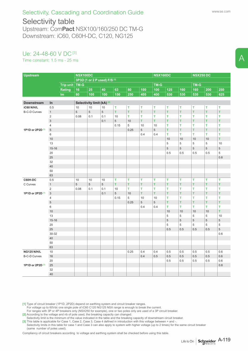
Selectivity tableUpstream: ComPact NSX100/160/250 DC TM-GDownstream: iC60, C60H-DC, C120, NG125
Upstream NSX100DC NSX160DC NSX250 DC3P3D (1 or 2 P used) F/S [1]
Trip unit TM-G TM-G TM-GRating 16 25 40 63 80 100 100 125 160 160 200 250Im 80 100 100 150 250 400 400 530 530 530 530 625
Downstream In Selectivity limit (kA) [2]
iC60 N/H/L 0.5 10 10 10 T T T T T T T T TB-C-D Curves 1 5 5 5 T T T T T T T T T
2 0.08 0.1 0.1 10 T T T T T T T T3 0.1 5 10 T T T T T T T4 0.15 5 10 10 T T T T T
1P1D or 2P2D [1] 5 0.25 5 5 T T T T T6 0.4 0.4 T T T T T10 10 10 10 10 T13 5 5 5 5 10
15-16 5 5 5 5 520 0.5 0.5 0.5 0.5 525 0.632405063
C60H-DC 0.5 10 10 10 T T T T T T T T TC Curves 1 5 5 5 T T T T T T T T T
2 0.08 0.1 0.1 10 T T T T T T T T1P1D or 2P2D [1] 3 0.1 5 10 T T T T T T T
4 0.15 5 10 10 T T T T T5 0.25 5 5 T T T T T6 0.4 0.4 T T T T T10 10 10 10 10 T13 5 5 5 5 1015-16 5 5 5 5 520 5 5 5 5 525 0.5 0.5 0.5 0.5 530-32 0.6405063
NG125 N/H/L 10 0.25 0.4 0.4 0.5 0.5 0.5 0.5 0.6B-C-D Curves 16 0.4 0.5 0.5 0.5 0.5 0.5 0.6
20 0.5 0.5 0.5 0.5 0.61P1D or 2P2D [1] 25 0.6
3240
Time constant: 1.5 ms - 25 ms
[1] Type of circuit breaker (1P1D, 2P2D) depend on earthing system and circuit breaker ranges. For voltage up to 60Vdc one single pole of iC60 C120 NG125 NSX range is enough to break the current. For ranges with 3P or 4P breakers only (NSX250 for example), one or two poles only are used of a 3P circuit breaker.
[2] According to the voltage and nb of pole used, the breaking capacity can changed. Selectivity limit is the minimum of the value indicated in the table and the breaking capacity of downstream circuit breaker.
[3] This table is applicable for Case 1, Case 2, Case 3, Case 4 defined in introduction with this voltage between + and -. Selectivity limits in this table for case 1 and Case 3 can also apply to system with higher voltage (up to 2 times) for the same circuit breaker (same number of poles used).
Compliancy of circuit breakers according to voltage and earthing system shall be checked before using this table.
Ue: 24-48-60 V DC [3]
A-119
www.se.com
A
Selectivity, Cascading and Coordination Guide
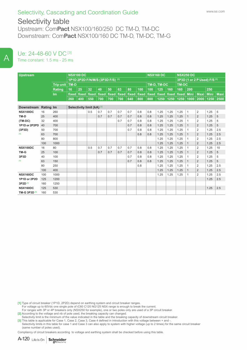
Selectivity tableUpstream: ComPact NSX100/160/250 DC TM-D, TM-DCDownstream: ComPact NSX100/160 DC TM-D, TM-DC, TM-G
Upstream NSX100 DC NSX160 DC NSX250 DC1P1D 2P2D F/N/M/S (3P3D F/S) [1] 3P3D (1 or 2 P Used) F/S [1]
Trip unit TM-D TM-D, TM-DC TM-DCRating 16 25 32 40 50 63 80 100 100 125 160 160 200 250Im fixed fixed fixed fixed fixed fixed fixed fixed fixed fixed fixed fixed Mini Maxi Mini Maxi
260 400 550 700 700 700 640 800 800 1250 1250 1250 1000 2000 1250 2500
Downstream Rating Im Selectivity limit (kA) [2]
NSX100DC 16 260 0.5 0.7 0.7 0.7 0.7 0.8 0.8 1.25 1.25 1.25 1 2 1.25 5TM-D 25 400 0.7 0.7 0.7 0.7 0.8 0.8 1.25 1.25 1.25 1 2 1.25 5(TM-DC) 32 400 0.7 0.7 0.8 0.8 1.25 1.25 1.25 1 2 1.25 51P1D or 2P2PD 40 700 0.7 0.8 0.8 1.25 1.25 1.25 1 2 1.25 5(3P3D) 50 700 0.7 0.8 0.8 1.25 1.25 1.25 1 2 1.25 2.5[1] 63 700 0.8 0.8 1.25 1.25 1.25 1 2 1.25 2.5
80 800 1.25 1.25 1.25 1 2 1.25 2.5100 1000 1.25 1.25 1.25 1 2 1.25 2.5
NSX100DC 16 80 0.5 0.7 0.7 0.7 0.7 0.8 0.8 1.25 1.25 1.25 1 2 1.25 10TM-G 25 100 0.7 0.7 0.7 0.7 0.8 0.8 1.25 1.25 1.25 1 2 1.25 53P3D 40 100 0.7 0.8 0.8 1.25 1.25 1.25 1 2 1.25 5[1] 63 150 0.7 0.8 0.8 1.25 1.25 1.25 1 2 1.25 5
80 250 0.8 1.25 1.25 1.25 1 2 1.25 2.5100 400 1.25 1.25 1.25 1 2 1.25 2.5
NSX160DC 100 1000 1.25 1.25 1.25 1 2 1.25 2.51P1D or 2P2D 125 1200 1.25 2.53P2D [1] 160 1250NSX160DC 125 530 1.25 2.5TM-G 3P3D [1] 160 530
Time constant: 1.5 ms - 25 ms
[1] Type of circuit breaker (1P1D, 2P2D) depend on earthing system and circuit breaker ranges. For voltage up to 60Vdc one single pole of iC60 C120 NG125 NSX range is enough to break the current. For ranges with 3P or 4P breakers only (NSX250 for example), one or two poles only are used of a 3P circuit breaker.
[2] According to the voltage and nb of pole used, the breaking capacity can changed. Selectivity limit is the minimum of the value indicated in the table and the breaking capacity of downstream circuit breaker.
[3] This table is applicable for Case 1, Case 2, Case 3, Case 4 defined in introduction with this voltage between + and -. Selectivity limits in this table for case 1 and Case 3 can also apply to system with higher voltage (up to 2 times) for the same circuit breaker (same number of poles used).
Compliancy of circuit breakers according to voltage and earthing system shall be checked before using this table.
Ue: 24-48-60 V DC [3]
www.se.com
A-120
A
Selectivity, Cascading and Coordination Guide
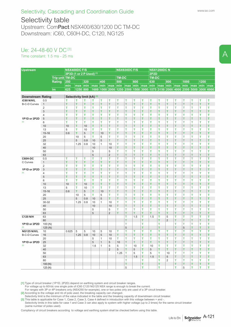
Selectivity tableUpstream: ComPact NSX400/630/1200 DC TM-DCDownstream: iC60, C60H-DC, C120, NG125
Upstream NSX400DC F/S NSX630DC F/S NSX1200DC N3P3D (1 or 2 P Used) [1] 2P2D
Trip unit TM-DC TM-DC TM-DCRating 250 320 400 500 600 630 800 1000 1200
min max min max min max min max min max min max min max min max min maxIm 625 1250 800 1600 1000 2000 1250 2500 1500 3000 1575 3150 2000 4000 2500 5000 3000 6000
Downstream Rating Selectivity limit (kA) [2]
iC60 N/H/L 0.5 T T T T T T T T T T T T T T T T T TB-C-D Curves 1 T T T T T T T T T T T T T T T T T T
2 T T T T T T T T T T T T T T T T T T3 T T T T T T T T T T T T T T T T T T4 T T T T T T T T T T T T T T T T T T
1P1D or 2P2D 5 T T T T T T T T T T T T T T T T T T[1] 6 T T T T T T T T T T T T T T T T T T
10 10 T 10 T T T T T T T T T T T T T T T13 5 T 10 T T T T T T T T T T T T T T T15-16 0.6 T 5 T 10 T T T T T T T T T T T T T20 10 5 T 5 T T T T T T T T T T T T T25 5 0.8 10 5 T T T T T T T T T T T T T32 1.25 0.8 10 1 10 T T T T T T T T T T T T40 10 10 T T T T T T T T T T T T50 5 5 T T T T T T T T T T T T63 5 2 T T T T T T T T T T T T
C60H-DC 0.5 T T T T T T T T T T T T T T T T T TC Curves 1 T T T T T T T T T T T T T T T T T T
2 T T T T T T T T T T T T T T T T T T1P1D or 2P2D 3 T T T T T T T T T T T T T T T T T T[1] 4 T T T T T T T T T T T T T T T T T T
5 T T T T T T T T T T T T T T T T T T6 T T T T T T T T T T T T T T T T T T10 10 T 10 T T T T T T T T T T T T T T T13 5 T 10 T T T T T T T T T T T T T T T15-16 0.6 T 5 T 10 T T T T T T T T T T T T T20 10 5 T 5 T T T T T T T T T T T T T25 5 0.8 10 5 T T T T T T T T T T T T T30-32 1.25 0.8 10 1 10 T T T T T T T T T T T T40 10 10 T T T T T T T T T T T T50 5 5 T T T T T T T T T T T T63 5 2 T T T T T T T T T T T T
C120 N/H 63 T 1.5 T 1.5 T 5 T T T T T80 T T T 2 T T T T T
1P1D or 2P2D 100 (N) T T T T T T T T[1] 125 (N) 5 T T T 5 T T TNG125 N/H/L 10 0.625 5 5 10 5 10 T T T T T T T T T T T TB-C-D Curves 16 1.25 0.8 10 5 10 T T T T T T T T T T T T
20 5 1 10 T T T T T T T T T T T T1P1D or 2P2D 25 5 1 5 10 T T T T T T T T T T T[1] 32 1.6 1 5 5 T 10 T 10 T T T T T T T
40 2 5 T 5 T 5 T T T T T T T50 1.25 T 5 T 5 T 10 T T T T T63 T 1.5 T 1.5 T 5 T T T T T80 T T T 2 T T T T T100 (N) T T T T T T T T125 (N) 5 T T T 5 T T T
Time constant: 1.5 ms - 25 ms
[1] Type of circuit breaker (1P1D, 2P2D) depend on earthing system and circuit breaker ranges. For voltage up to 60Vdc one single pole of iC60 C120 NG125 NSX range is enough to break the current. For ranges with 3P or 4P breakers only (NSX250 for example), one or two poles only are used of a 3P circuit breaker.
[2] According to the voltage and nb of pole used, the breaking capacity can changed. Selectivity limit is the minimum of the value indicated in the table and the breaking capacity of downstream circuit breaker.
[3] This table is applicable for Case 1, Case 2, Case 3, Case 4 defined in introduction with this voltage between + and -. Selectivity limits in this table for case 1 and Case 3 can also apply to system with higher voltage (up to 2 times) for the same circuit breaker (same number of poles used).
Compliancy of circuit breakers according to voltage and earthing system shall be checked before using this table.
Ue: 24-48-60 V DC [3]
A-121
www.se.com
A
Selectivity, Cascading and Coordination Guide
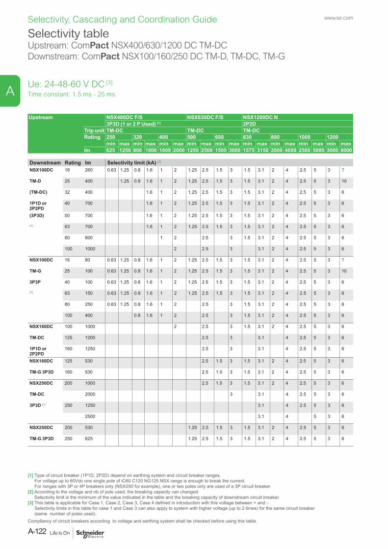
Selectivity tableUpstream: ComPact NSX400/630/1200 DC TM-DCDownstream: ComPact NSX100/160/250 DC TM-D, TM-DC, TM-G
Upstream NSX400DC F/S NSX630DC F/S NSX1200DC N3P3D (1 or 2 P Used) [1] 2P2D
Trip unit TM-DC TM-DC TM-DCRating 250 320 400 500 600 630 800 1000 1200
min max min max min max min max min max min max min max min max min maxIm 625 1250 800 1600 1000 2000 1250 2500 1500 3000 1575 3150 2000 4000 2500 5000 3000 6000
Downstream Rating Im Selectivity limit (kA) [2]
NSX100DC 16 260 0.63 1.25 0.8 1.6 1 2 1.25 2.5 1.5 3 1.5 3.1 2 4 2.5 5 3 T
TM-D 25 400 1.25 0.8 1.6 1 2 1.25 2.5 1.5 3 1.5 3.1 2 4 2.5 5 3 10
(TM-DC) 32 400 1.6 1 2 1.25 2.5 1.5 3 1.5 3.1 2 4 2.5 5 3 6
1P1D or 2P2PD
40 700 1.6 1 2 1.25 2.5 1.5 3 1.5 3.1 2 4 2.5 5 3 6
(3P3D) 50 700 1.6 1 2 1.25 2.5 1.5 3 1.5 3.1 2 4 2.5 5 3 6
[1] 63 700 1.6 1 2 1.25 2.5 1.5 3 1.5 3.1 2 4 2.5 5 3 6
80 800 1 2 2.5 3 1.5 3.1 2 4 2.5 5 3 6
100 1000 2 2.5 3 3.1 2 4 2.5 5 3 6
NSX100DC 16 80 0.63 1.25 0.8 1.6 1 2 1.25 2.5 1.5 3 1.5 3.1 2 4 2.5 5 3 T
TM-G 25 100 0.63 1.25 0.8 1.6 1 2 1.25 2.5 1.5 3 1.5 3.1 2 4 2.5 5 3 10
3P3P 40 100 0.63 1.25 0.8 1.6 1 2 1.25 2.5 1.5 3 1.5 3.1 2 4 2.5 5 3 6
[1] 63 150 0.63 1.25 0.8 1.6 1 2 1.25 2.5 1.5 3 1.5 3.1 2 4 2.5 5 3 6
80 250 0.63 1.25 0.8 1.6 1 2 2.5 3 1.5 3.1 2 4 2.5 5 3 6
100 400 0.8 1.6 1 2 2.5 3 1.5 3.1 2 4 2.5 5 3 6
NSX160DC 100 1000 2 2.5 3 1.5 3.1 2 4 2.5 5 3 6
TM-DC 125 1200 2.5 3 3.1 4 2.5 5 3 6
1P1D or 2P2PD
160 1250 2.5 3 3.1 4 2.5 5 3 6
NSX160DC 125 530 2.5 1.5 3 1.5 3.1 2 4 2.5 5 3 6
TM-G 3P3D 160 530 2.5 1.5 3 1.5 3.1 2 4 2.5 5 3 6
NSX250DC 200 1000 2.5 1.5 3 1.5 3.1 2 4 2.5 5 3 6
TM-DC 2000 3 3.1 4 2.5 5 3 6
3P3D [1] 250 1250 3.1 4 2.5 5 3 6
2500 3.1 4 5 3 6
NSX250DC 200 530 1.25 2.5 1.5 3 1.5 3.1 2 4 2.5 5 3 6
TM-G 3P3D 250 625 1.25 2.5 1.5 3 1.5 3.1 2 4 2.5 5 3 6
Time constant: 1.5 ms - 25 ms
[1] Type of circuit breaker (1P1D, 2P2D) depend on earthing system and circuit breaker ranges. For voltage up to 60Vdc one single pole of iC60 C120 NG125 NSX range is enough to break the current. For ranges with 3P or 4P breakers only (NSX250 for example), one or two poles only are used of a 3P circuit breaker.
[2] According to the voltage and nb of pole used, the breaking capacity can changed. Selectivity limit is the minimum of the value indicated in the table and the breaking capacity of downstream circuit breaker.
[3] This table is applicable for Case 1, Case 2, Case 3, Case 4 defined in introduction with this voltage between + and -. Selectivity limits in this table for case 1 and Case 3 can also apply to system with higher voltage (up to 2 times) for the same circuit breaker (same number of poles used).
Compliancy of circuit breakers according to voltage and earthing system shall be checked before using this table.
Ue: 24-48-60 V DC [3]
www.se.com
A-122
A
Selectivity, Cascading and Coordination Guide
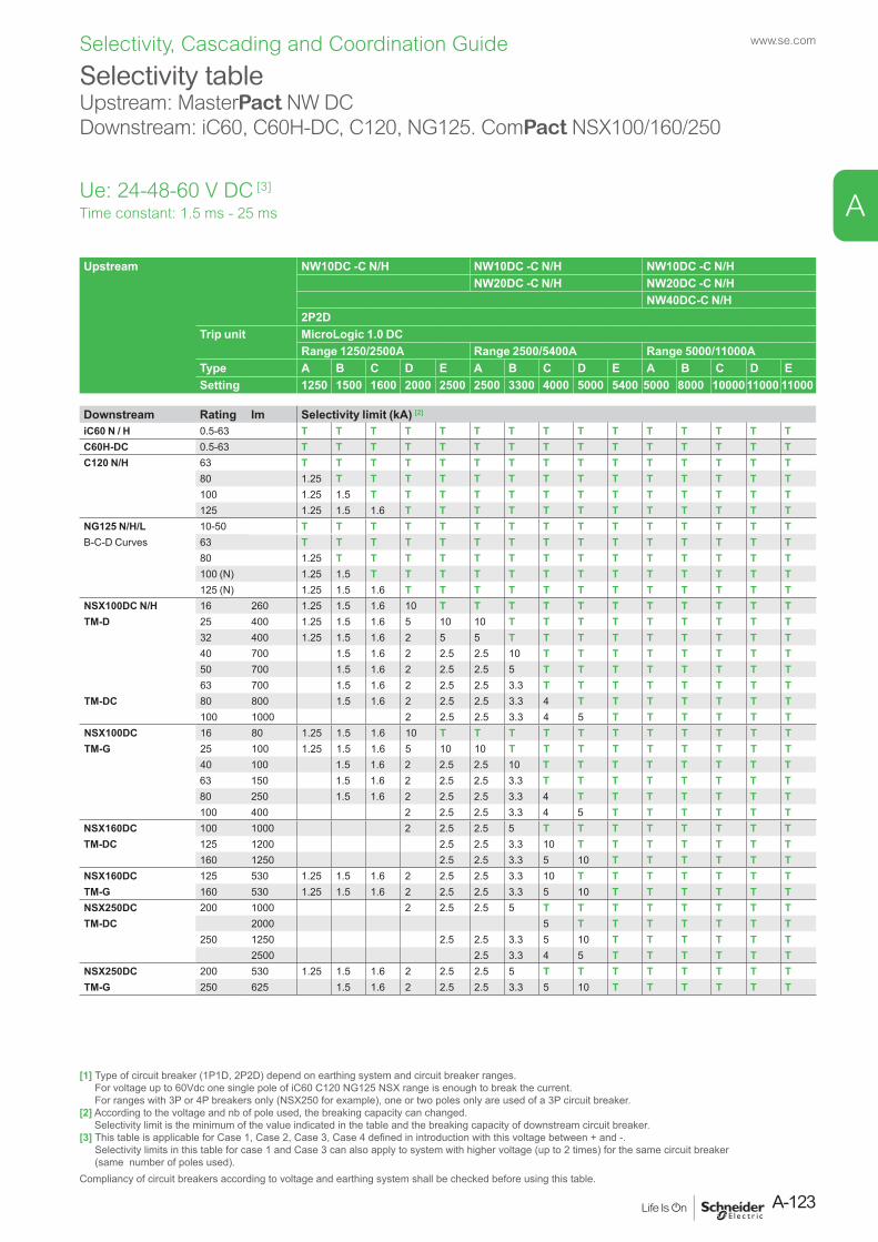
Selectivity tableUpstream: MasterPact NW DCDownstream: iC60, C60H-DC, C120, NG125. ComPact NSX100/160/250
Upstream NW10DC -C N/H NW10DC -C N/H NW10DC -C N/HNW20DC -C N/H NW20DC -C N/H
NW40DC-C N/H2P2D
Trip unit MicroLogic 1.0 DCRange 1250/2500A Range 2500/5400A Range 5000/11000A
Type A B C D E A B C D E A B C D ESetting 1250 1500 1600 2000 2500 2500 3300 4000 5000 5400 5000 8000 10000 11000 11000
Downstream Rating Im Selectivity limit (kA) [2]
iC60 N / H 0.5-63 T T T T T T T T T T T T T T TC60H-DC 0.5-63 T T T T T T T T T T T T T T TC120 N/H 63 T T T T T T T T T T T T T T T
80 1.25 T T T T T T T T T T T T T T100 1.25 1.5 T T T T T T T T T T T T T125 1.25 1.5 1.6 T T T T T T T T T T T T
NG125 N/H/L 10-50 T T T T T T T T T T T T T T TB-C-D Curves 63 T T T T T T T T T T T T T T T
80 1.25 T T T T T T T T T T T T T T100 (N) 1.25 1.5 T T T T T T T T T T T T T125 (N) 1.25 1.5 1.6 T T T T T T T T T T T T
NSX100DC N/H 16 260 1.25 1.5 1.6 10 T T T T T T T T T T TTM-D 25 400 1.25 1.5 1.6 5 10 10 T T T T T T T T T
32 400 1.25 1.5 1.6 2 5 5 T T T T T T T T T40 700 1.5 1.6 2 2.5 2.5 10 T T T T T T T T50 700 1.5 1.6 2 2.5 2.5 5 T T T T T T T T63 700 1.5 1.6 2 2.5 2.5 3.3 T T T T T T T T
TM-DC 80 800 1.5 1.6 2 2.5 2.5 3.3 4 T T T T T T T100 1000 2 2.5 2.5 3.3 4 5 T T T T T T
NSX100DC 16 80 1.25 1.5 1.6 10 T T T T T T T T T T TTM-G 25 100 1.25 1.5 1.6 5 10 10 T T T T T T T T T
40 100 1.5 1.6 2 2.5 2.5 10 T T T T T T T T63 150 1.5 1.6 2 2.5 2.5 3.3 T T T T T T T T80 250 1.5 1.6 2 2.5 2.5 3.3 4 T T T T T T T100 400 2 2.5 2.5 3.3 4 5 T T T T T T
NSX160DC 100 1000 2 2.5 2.5 5 T T T T T T T TTM-DC 125 1200 2.5 2.5 3.3 10 T T T T T T T
160 1250 2.5 2.5 3.3 5 10 T T T T T TNSX160DC 125 530 1.25 1.5 1.6 2 2.5 2.5 3.3 10 T T T T T T TTM-G 160 530 1.25 1.5 1.6 2 2.5 2.5 3.3 5 10 T T T T T TNSX250DC 200 1000 2 2.5 2.5 5 T T T T T T T TTM-DC 2000 5 T T T T T T T
250 1250 2.5 2.5 3.3 5 10 T T T T T T2500 2.5 3.3 4 5 T T T T T T
NSX250DC 200 530 1.25 1.5 1.6 2 2.5 2.5 5 T T T T T T T TTM-G 250 625 1.5 1.6 2 2.5 2.5 3.3 5 10 T T T T T T
Time constant: 1.5 ms - 25 ms
[1] Type of circuit breaker (1P1D, 2P2D) depend on earthing system and circuit breaker ranges. For voltage up to 60Vdc one single pole of iC60 C120 NG125 NSX range is enough to break the current. For ranges with 3P or 4P breakers only (NSX250 for example), one or two poles only are used of a 3P circuit breaker.
[2] According to the voltage and nb of pole used, the breaking capacity can changed. Selectivity limit is the minimum of the value indicated in the table and the breaking capacity of downstream circuit breaker.
[3] This table is applicable for Case 1, Case 2, Case 3, Case 4 defined in introduction with this voltage between + and -. Selectivity limits in this table for case 1 and Case 3 can also apply to system with higher voltage (up to 2 times) for the same circuit breaker (same number of poles used).
Compliancy of circuit breakers according to voltage and earthing system shall be checked before using this table.
Ue: 24-48-60 V DC [3]
A-123
www.se.com
A
Selectivity, Cascading and Coordination Guide
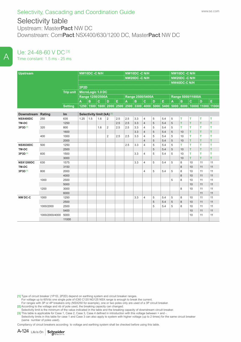
Selectivity tableUpstream: MasterPact NW DCDownstream: ComPact NSX400/630/1200 DC, MasterPact NW DC
Upstream NW10DC -C N/H NW10DC -C N/H NW10DC -C N/HNW20DC -C N/H NW20DC -C N/H
NW40DC-C N/H2P2D
Trip unit MicroLogic 1.0 DCRange 1250/2500A Range 2500/5400A Range 5000/11000AA B C D E A B C D E A B C D E
Setting 1250 1500 1600 2000 2500 2500 3300 4000 5000 5400 5000 8000 10000 11000 11000
Downstream Rating Im Selectivity limit (kA) [2]
NSX400DC 250 635 1.25 1.5 1.6 2 2.5 2.5 3.3 4 5 5.4 5 T T T TTM-DC 1250 2.5 2.5 3.3 4 5 5.4 5 T T T T3P3D [1] 320 800 1.6 2 2.5 2.5 3.3 4 5 5.4 5 T T T T
1600 3.3 4 5 5.4 5 10 T T T400 1000 2 2.5 2.5 3.3 4 5 5.4 5 10 T T T
2000 4 5 5.4 5 10 T T TNSX630DC 500 1250 2.5 3.3 4 5 5.4 5 T T T TTM-DC 2500 5 5.4 5 10 T T T3P3D [1] 600 1500 3.3 4 5 5.4 5 10 T T T
3000 10 T T TNSX1200DC 630 1575 3.3 4 5 5.4 5 8 10 11 11TM-DC 3150 8 10 11 113P3D [1] 800 2000 4 5 5.4 5 8 10 11 11
4000 8 10 11 111000 2500 5 8 10 11 11
5000 10 11 111200 3000 8 10 11 11
6000 11 11NW DC-C 1000 1250 3.3 4 5 5.4 5 8 10 11 11
2500 5 5.4 5 8 10 11 111000/2000 2500 5 5.4 5 8 10 11 11
5400 10 11 111000/2000/4000 5000 10 11 11
11000
Time constant: 1.5 ms - 25 ms
[1] Type of circuit breaker (1P1D, 2P2D) depend on earthing system and circuit breaker ranges. For voltage up to 60Vdc one single pole of iC60 C120 NG125 NSX range is enough to break the current. For ranges with 3P or 4P breakers only (NSX250 for example), one or two poles only are used of a 3P circuit breaker.
[2] According to the voltage and nb of pole used, the breaking capacity can changed. Selectivity limit is the minimum of the value indicated in the table and the breaking capacity of downstream circuit breaker.
[3] This table is applicable for Case 1, Case 2, Case 3, Case 4 defined in introduction with this voltage between + and -. Selectivity limits in this table for case 1 and Case 3 can also apply to system with higher voltage (up to 2 times) for the same circuit breaker (same number of poles used).
Compliancy of circuit breakers according to voltage and earthing system shall be checked before using this table.
Ue: 24-48-60 V DC [3]
www.se.com
A-124
A
Selectivity, Cascading and Coordination Guide
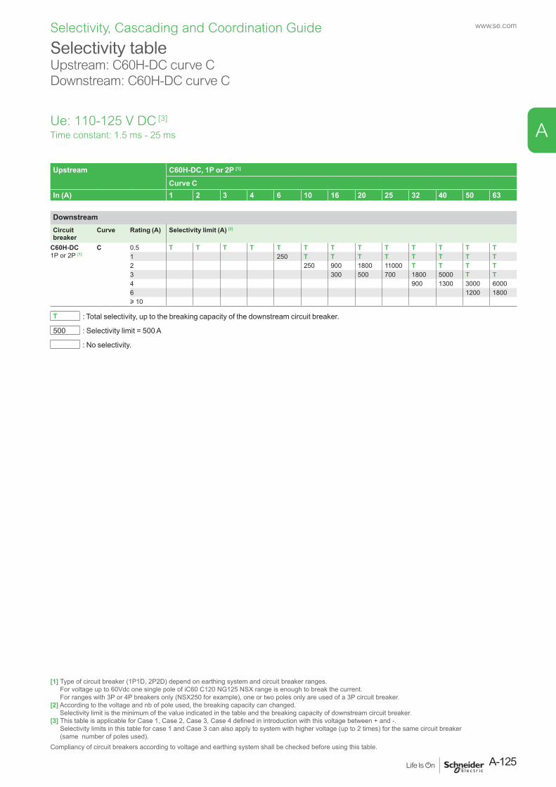
Selectivity tableUpstream: C60H-DC curve C Downstream: C60H-DC curve C
Ue: 110-125 V DC [3]
Time constant: 1.5 ms - 25 ms
Upstream C60H-DC, 1P or 2P [1]
Curve CIn (A) 1 2 3 4 6 10 16 20 25 32 40 50 63
DownstreamCircuit breaker
Curve Rating (A) Selectivity limit (A) [2]
C60H-DC1P or 2P [1]
C 0.5 T T T T T T T T T T T T T1 250 T T T T T T T T2 250 900 1800 11000 T T T T3 300 500 700 1800 5000 T T4 900 1300 3000 60006 1200 1800u 10
T : Total selectivity, up to the breaking capacity of the downstream circuit breaker.
500 : Selectivity limit = 500 A
: No selectivity.
[1] Type of circuit breaker (1P1D, 2P2D) depend on earthing system and circuit breaker ranges. For voltage up to 60Vdc one single pole of iC60 C120 NG125 NSX range is enough to break the current. For ranges with 3P or 4P breakers only (NSX250 for example), one or two poles only are used of a 3P circuit breaker.
[2] According to the voltage and nb of pole used, the breaking capacity can changed. Selectivity limit is the minimum of the value indicated in the table and the breaking capacity of downstream circuit breaker.
[3] This table is applicable for Case 1, Case 2, Case 3, Case 4 defined in introduction with this voltage between + and -. Selectivity limits in this table for case 1 and Case 3 can also apply to system with higher voltage (up to 2 times) for the same circuit breaker (same number of poles used).
Compliancy of circuit breakers according to voltage and earthing system shall be checked before using this table.
A-125
www.se.com
A
Selectivity, Cascading and Coordination Guide
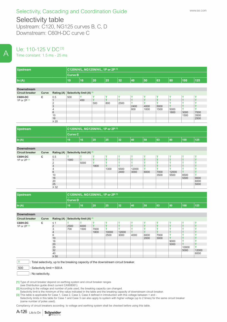
Selectivity tableUpstream: C120, NG125 curves B, C, D Downstream: C60H-DC curve C
Ue: 110-125 V DC [3]
Time constant: 1.5 ms - 25 ms
Upstream C120N/H/L, NG125N/H/L, 1P or 2P [1]
Curve BIn (A) 10 16 20 25 32 40 50 63 80 100 125
DownstreamCircuit breaker Curve Rating (A) Selectivity limit (A) [2]
C60H-DC1P or 2P [1]
C 0.5 500 T T T T T T T T T T1 450 T T T T T T T T T2 500 800 2500 T T T T T T3 2400 4000 5000 T T T4 800 1000 1500 5000 T T6 1800 3000 700010 1500 350016 2500u 20
Upstream C120N/H/L, NG125N/H/L, 1P or 2P [1]
Curve CIn (A) 10 16 20 25 32 40 50 63 80 100 125
DownstreamCircuit breaker Curve Rating (A) Selectivity limit (A) [2]
C60H-DC1P or 2P [1]
C 0.5 T T T T T T T T T T T1 1000 T T T T T T T T T T2 5000 T T T T T T T T T3 1800 T T T T T T T T4 1300 5500 12000 T T T T T6 2400 3000 6000 7000 12000 T T10 3500 5500 8500 T16 5500 900020 600025 5000u 32
Upstream C120N/H/L, NG125N/H/L, 1P or 2P [1]
Curve DIn (A) 10 16 20 25 32 40 50 63 80 100 125
DownstreamCircuit breaker Curve Rating (A) Selectivity limit (A) [2]
C60H-DC1P or 2P [1]
C y 1 T T T T T T T T T T T2 2500 6000 T T T T T T T T T3 700 1500 7000 T T T T T T T T4 1800 10000 12000 T T T T T T6 2500 3000 4000 6000 7000 T T T10 2000 3000 T T T16 9000 T T20 5000 T T25 10000 T32 5000 1200040 6000u 50
T : Total selectivity, up to the breaking capacity of the downstream circuit breaker.
500 : Selectivity limit = 500 A
: No selectivity.
[1] Type of circuit breaker depend on earthing system and circuit breaker ranges (see Distribution guide direct current CA908061).
[2] According to the voltage and number of pole used, the breaking capacity can changed. Selectivity limit is the minimum of the value indicated in the table and the breaking capacity of downstream circuit breaker.
[3] This table is applicable for Case 1, Case 2, Case 3, Case 4 defined in introduction with this voltage between + and - Selectivity limits in this table for Case 1 and Case 3 can also apply to system with higher voltage (up to 2 times) for the same circuit breaker (same number of poles used).
Compliancy of circuit breakers according to voltage and earthing system shall be checked before using this table.
www.se.com
A-126
A
Selectivity, Cascading and Coordination Guide
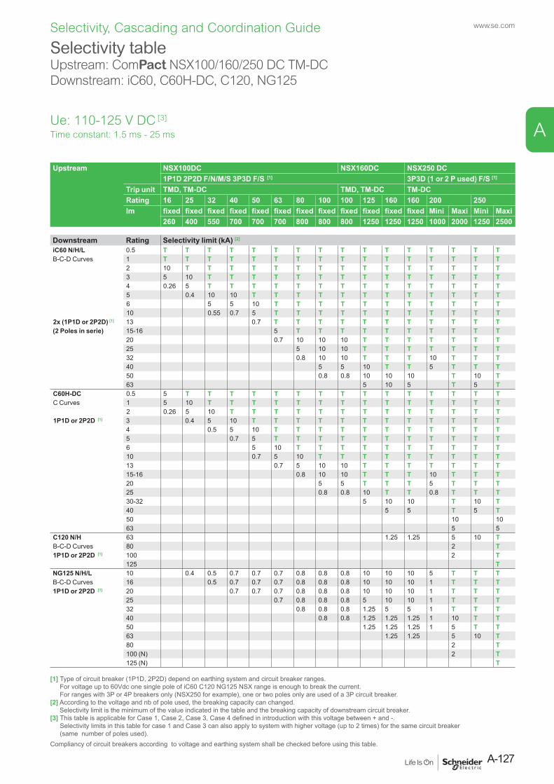
Selectivity tableUpstream: ComPact NSX100/160/250 DC TM-DCDownstream: iC60, C60H-DC, C120, NG125
Ue: 110-125 V DC [3]
Upstream NSX100DC NSX160DC NSX250 DC 1P1D 2P2D F/N/M/S 3P3D F/S [1] 3P3D (1 or 2 P used) F/S [1]
Trip unit TMD, TM-DC TMD, TM-DC TM-DCRating 16 25 32 40 50 63 80 100 100 125 160 160 200 250Im fixed fixed fixed fixed fixed fixed fixed fixed fixed fixed fixed fixed Mini Maxi Mini Maxi
260 400 550 700 700 700 800 800 800 1250 1250 1250 1000 2000 1250 2500
Downstream Rating Selectivity limit (kA) [2]
iC60 N/H/L 0.5 T T T T T T T T T T T T T T T TB-C-D Curves 1 T T T T T T T T T T T T T T T T
2 10 T T T T T T T T T T T T T T T3 5 10 T T T T T T T T T T T T T T4 0.26 5 T T T T T T T T T T T T T T5 0.4 10 10 T T T T T T T T T T T T6 5 5 10 T T T T T T T T T T T10 0.55 0.7 5 T T T T T T T T T T T
2x (1P1D or 2P2D) [1] 13 0.7 T T T T T T T T T T T(2 Poles in serie) 15-16 5 T T T T T T T T T T
20 0.7 10 10 10 T T T T T T T25 5 10 10 T T T T T T T32 0.8 10 10 T T T 10 T T T40 5 5 10 T T 5 T T T50 0.8 0.8 10 10 10 T 10 T63 5 10 5 T 5 T
C60H-DC 0.5 5 T T T T T T T T T T T T T T TC Curves 1 5 10 T T T T T T T T T T T T T T
2 0.26 5 10 T T T T T T T T T T T T T1P1D or 2P2D [1] 3 0.4 5 10 T T T T T T T T T T T T
4 0.5 5 10 T T T T T T T T T T T5 0.7 5 T T T T T T T T T T T6 5 10 T T T T T T T T T T10 0.7 5 10 T T T T T T T T T13 0.7 5 10 10 T T T T T T T15-16 0.8 10 10 T T T 10 T T T20 5 5 T T T 5 T T T25 0.8 0.8 10 T T 0.8 T T T30-32 5 10 10 T 10 T40 5 5 T 5 T50 10 1063 5 5
C120 N/H 63 1.25 1.25 5 10 TB-C-D Curves 80 2 T1P1D or 2P2D [1] 100 2 T
125 TNG125 N/H/L 10 0.4 0.5 0.7 0.7 0.7 0.8 0.8 0.8 10 10 10 5 T T TB-C-D Curves 16 0.5 0.7 0.7 0.7 0.8 0.8 0.8 10 10 10 1 T T T1P1D or 2P2D [1] 20 0.7 0.7 0.7 0.8 0.8 0.8 10 10 10 1 T T T
25 0.7 0.8 0.8 0.8 5 10 10 1 T T T32 0.8 0.8 0.8 1.25 5 5 1 T T T40 0.8 0.8 1.25 1.25 1.25 1 10 T T50 1.25 1.25 1.25 1 5 T T63 1.25 1.25 5 10 T80 2 T100 (N) 2 T125 (N) T
Time constant: 1.5 ms - 25 ms
[1] Type of circuit breaker (1P1D, 2P2D) depend on earthing system and circuit breaker ranges. For voltage up to 60Vdc one single pole of iC60 C120 NG125 NSX range is enough to break the current. For ranges with 3P or 4P breakers only (NSX250 for example), one or two poles only are used of a 3P circuit breaker.
[2] According to the voltage and nb of pole used, the breaking capacity can changed. Selectivity limit is the minimum of the value indicated in the table and the breaking capacity of downstream circuit breaker.
[3] This table is applicable for Case 1, Case 2, Case 3, Case 4 defined in introduction with this voltage between + and -. Selectivity limits in this table for case 1 and Case 3 can also apply to system with higher voltage (up to 2 times) for the same circuit breaker (same number of poles used).
Compliancy of circuit breakers according to voltage and earthing system shall be checked before using this table.
A-127
www.se.com
A
Selectivity, Cascading and Coordination Guide
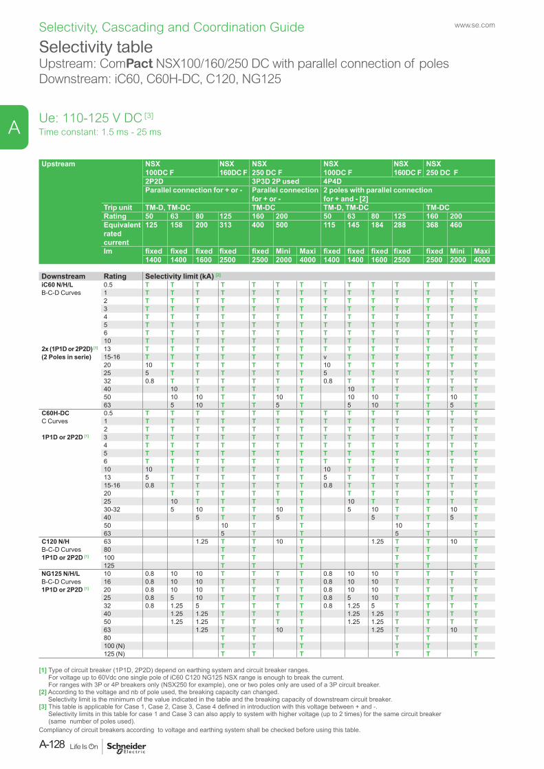
Selectivity tableUpstream: ComPact NSX100/160/250 DC with parallel connection of polesDownstream: iC60, C60H-DC, C120, NG125
Ue: 110-125 V DC [3]
Upstream NSX 100DC F
NSX 160DC F
NSX 250 DC F
NSX 100DC F
NSX 160DC F
NSX 250 DC F
2P2D 3P3D 2P used 4P4DParallel connection for + or - Parallel connection
for + or -2 poles with parallel connection for + and - [2]
Trip unit TM-D, TM-DC TM-DC TM-D, TM-DC TM-DCRating 50 63 80 125 160 200 50 63 80 125 160 200Equivalent rated current
125 158 200 313 400 500 115 145 184 288 368 460
Im fixed fixed fixed fixed fixed Mini Maxi fixed fixed fixed fixed fixed Mini Maxi1400 1400 1600 2500 2500 2000 4000 1400 1400 1600 2500 2500 2000 4000
Downstream Rating Selectivity limit (kA) [2]
iC60 N/H/L 0.5 T T T T T T T T T T T T T TB-C-D Curves 1 T T T T T T T T T T T T T T
2 T T T T T T T T T T T T T T3 T T T T T T T T T T T T T T4 T T T T T T T T T T T T T T5 T T T T T T T T T T T T T T6 T T T T T T T T T T T T T T10 T T T T T T T T T T T T T T
2x (1P1D or 2P2D) [1] 13 T T T T T T T T T T T T T T(2 Poles in serie) 15-16 T T T T T T T v T T T T T T
20 10 T T T T T T 10 T T T T T T25 5 T T T T T T 5 T T T T T T32 0.8 T T T T T T 0.8 T T T T T T40 10 T T T T T 10 T T T T T50 10 10 T T 10 T 10 10 T T 10 T63 5 10 T T 5 T 5 10 T T 5 T
C60H-DC 0.5 T T T T T T T T T T T T T TC Curves 1 T T T T T T T T T T T T T T
2 T T T T T T T T T T T T T T1P1D or 2P2D [1] 3 T T T T T T T T T T T T T T
4 T T T T T T T T T T T T T T5 T T T T T T T T T T T T T T6 T T T T T T T T T T T T T T10 10 T T T T T T 10 T T T T T T13 5 T T T T T T 5 T T T T T T15-16 0.8 T T T T T T 0.8 T T T T T T20 T T T T T T T T T T T T25 10 T T T T T 10 T T T T T30-32 5 10 T T 10 T 5 10 T T 10 T40 5 T T 5 T 5 T T 5 T50 10 T T 10 T T63 5 T T 5 T T
C120 N/H 63 1.25 T T 10 T 1.25 T T 10 TB-C-D Curves 80 T T T T T T1P1D or 2P2D [1] 100 T T T T T T
125 T T T T T TNG125 N/H/L 10 0.8 10 10 T T T T 0.8 10 10 T T T TB-C-D Curves 16 0.8 10 10 T T T T 0.8 10 10 T T T T1P1D or 2P2D [1] 20 0.8 10 10 T T T T 0.8 10 10 T T T T
25 0.8 5 10 T T T T 0.8 5 10 T T T T32 0.8 1.25 5 T T T T 0.8 1.25 5 T T T T40 1.25 1.25 T T T T 1.25 1.25 T T T T50 1.25 1.25 T T T T 1.25 1.25 T T T T63 1.25 T T 10 T 1.25 T T 10 T80 T T T T T T100 (N) T T T T T T125 (N) T T T T T T
Time constant: 1.5 ms - 25 ms
[1] Type of circuit breaker (1P1D, 2P2D) depend on earthing system and circuit breaker ranges. For voltage up to 60Vdc one single pole of iC60 C120 NG125 NSX range is enough to break the current. For ranges with 3P or 4P breakers only (NSX250 for example), one or two poles only are used of a 3P circuit breaker.
[2] According to the voltage and nb of pole used, the breaking capacity can changed. Selectivity limit is the minimum of the value indicated in the table and the breaking capacity of downstream circuit breaker.
[3] This table is applicable for Case 1, Case 2, Case 3, Case 4 defined in introduction with this voltage between + and -. Selectivity limits in this table for case 1 and Case 3 can also apply to system with higher voltage (up to 2 times) for the same circuit breaker (same number of poles used).
Compliancy of circuit breakers according to voltage and earthing system shall be checked before using this table.
www.se.com
A-128
A
Selectivity, Cascading and Coordination Guide
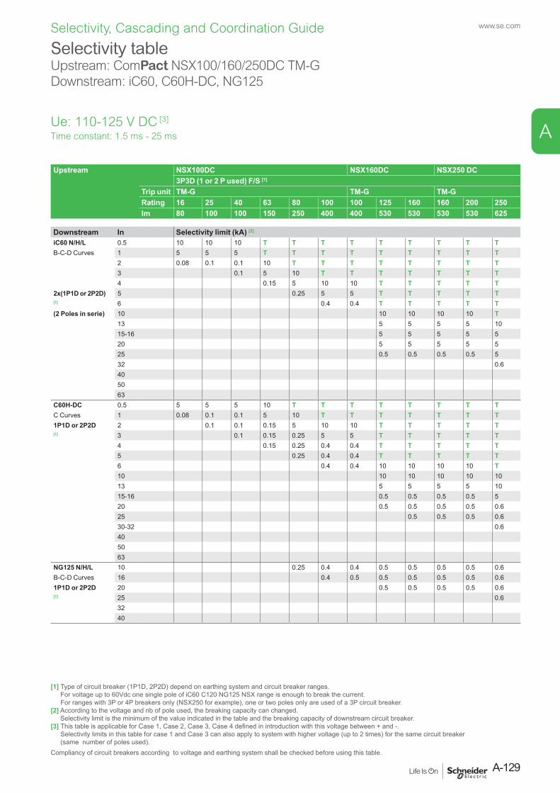
Selectivity tableUpstream: ComPact NSX100/160/250DC TM-GDownstream: iC60, C60H-DC, NG125
Upstream NSX100DC NSX160DC NSX250 DC3P3D (1 or 2 P used) F/S [1]
Trip unit TM-G TM-G TM-GRating 16 25 40 63 80 100 100 125 160 160 200 250Im 80 100 100 150 250 400 400 530 530 530 530 625
Downstream In Selectivity limit (kA) [2]
iC60 N/H/L 0.5 10 10 10 T T T T T T T T TB-C-D Curves 1 5 5 5 T T T T T T T T T
2 0.08 0.1 0.1 10 T T T T T T T T3 0.1 5 10 T T T T T T T4 0.15 5 10 10 T T T T T
2x(1P1D or 2P2D) 5 0.25 5 5 T T T T T[1] 6 0.4 0.4 T T T T T(2 Poles in serie) 10 10 10 10 10 T
13 5 5 5 5 1015-16 5 5 5 5 520 5 5 5 5 525 0.5 0.5 0.5 0.5 532 0.6405063
C60H-DC 0.5 5 5 5 10 T T T T T T T TC Curves 1 0.08 0.1 0.1 5 10 T T T T T T T1P1D or 2P2D 2 0.1 0.1 0.15 5 10 10 T T T T T[1] 3 0.1 0.15 0.25 5 5 T T T T T
4 0.15 0.25 0.4 0.4 T T T T T5 0.25 0.4 0.4 T T T T T6 0.4 0.4 10 10 10 10 T10 10 10 10 10 1013 5 5 5 5 1015-16 0.5 0.5 0.5 0.5 520 0.5 0.5 0.5 0.5 0.625 0.5 0.5 0.5 0.630-32 0.6405063
NG125 N/H/L 10 0.25 0.4 0.4 0.5 0.5 0.5 0.5 0.6B-C-D Curves 16 0.4 0.5 0.5 0.5 0.5 0.5 0.61P1D or 2P2D 20 0.5 0.5 0.5 0.5 0.6[1] 25 0.6
3240
Time constant: 1.5 ms - 25 ms
[1] Type of circuit breaker (1P1D, 2P2D) depend on earthing system and circuit breaker ranges. For voltage up to 60Vdc one single pole of iC60 C120 NG125 NSX range is enough to break the current. For ranges with 3P or 4P breakers only (NSX250 for example), one or two poles only are used of a 3P circuit breaker.
[2] According to the voltage and nb of pole used, the breaking capacity can changed. Selectivity limit is the minimum of the value indicated in the table and the breaking capacity of downstream circuit breaker.
[3] This table is applicable for Case 1, Case 2, Case 3, Case 4 defined in introduction with this voltage between + and -. Selectivity limits in this table for case 1 and Case 3 can also apply to system with higher voltage (up to 2 times) for the same circuit breaker (same number of poles used).
Compliancy of circuit breakers according to voltage and earthing system shall be checked before using this table.
Ue: 110-125 V DC [3]
A-129
www.se.com
A
Selectivity, Cascading and Coordination Guide

Selectivity tableUpstream: ComPact NSX100/160/250 DC TM-D, TM-DCDownstream: ComPact NSX100/160 DC TM-D, TM-DC, TM-G
Upstream NSX100 DC NSX160 DC NSX250 DC1P1D 2P2D F/N/M/S (3P3D F/S) [1] 3P3D (1 or 2 P Used) F/S [1]
Trip unit TM-D TM-D, TM-DC TM-DCRating 16 25 32 40 50 63 80 100 80 100 125 160 160 200 250
fixed fixed fixed fixed fixed fixed fixed fixed fixed fixed fixed fixed fixed Mini Maxi Mini MaxiIm 260 400 550 700 700 700 640 800 640 800 1250 1250 1250 1000 2000 1250 2500
Downstream Rating Im Selectivity limit (kA) [2]
NSX100DC 16 260 0.5 0.7 0.7 0.7 0.7 0.8 0.7 0.8 1.25 1.25 1.25 1 2 1.25 5TM-D 25 400 0.7 0.7 0.7 0.7 0.8 0.7 0.8 1.25 1.25 1.25 1 2 1.25 5(TM-DC) 32 400 0.7 0.7 0.8 0.7 0.8 1.25 1.25 1.25 1 2 1.25 51P1D or 2P2PD(3P3D)[1]
40 700 0.7 0.8 0.7 0.8 1.25 1.25 1.25 1 2 1.25 2.550 700 0.7 0.8 0.7 0.8 1.25 1.25 1.25 1 2 1.25 2.563 700 0.8 0.8 1.25 1.25 1.25 1 2 1.25 2.580 800 1.25 1.25 1.25 1 2 1.25 2.5100 1000 1.25 1.25 1.25 1 2 1.25 2.5
NSX100DC 16 80 0.5 0.7 0.7 0.7 0.7 0.8 0.7 0.8 1.25 1.25 1.25 1 2 1.25 10TM-G 25 100 0.7 0.7 0.7 0.7 0.8 0.7 0.8 1.25 1.25 1.25 1 2 1.25 53P3D 40 100 0.7 0.8 0.7 0.8 1.25 1.25 1.25 1 2 1.25 5[1] 63 150 0.7 0.8 0.8 1.25 1.25 1.25 1 2 1.25 5
80 250 0.8 1.25 1.25 1.25 1 2 1.25 2.5100 400 1.25 1.25 1.25 1 2 1.25 2.5
NSX160DC 100 1000 1.25 1.25 1.25 1 2 1.25 2.51P1D or 2P2D 125 1200 1.25 2.53P2D [1] 160 1250NSX160DC 125 530 1.25 2.5TM-G 3P3D [1] 160 530
Time constant: 1.5 ms - 25 ms
[1] Type of circuit breaker (1P1D, 2P2D) depend on earthing system and circuit breaker ranges. For voltage up to 60Vdc one single pole of iC60 C120 NG125 NSX range is enough to break the current. For ranges with 3P or 4P breakers only (NSX250 for example), one or two poles only are used of a 3P circuit breaker.
[2] According to the voltage and nb of pole used, the breaking capacity can changed. Selectivity limit is the minimum of the value indicated in the table and the breaking capacity of downstream circuit breaker.
[3] This table is applicable for Case 1, Case 2, Case 3, Case 4 defined in introduction with this voltage between + and -. Selectivity limits in this table for Case 1 and Case 3 can also apply to system with higher voltage (up to 2 times) for the same circuit breaker (same number of poles used).
Compliancy of circuit breakers according to voltage and earthing system shall be checked before using this table.
Ue: 110-125 V DC [3]
www.se.com
A-130
A
Selectivity, Cascading and Coordination Guide
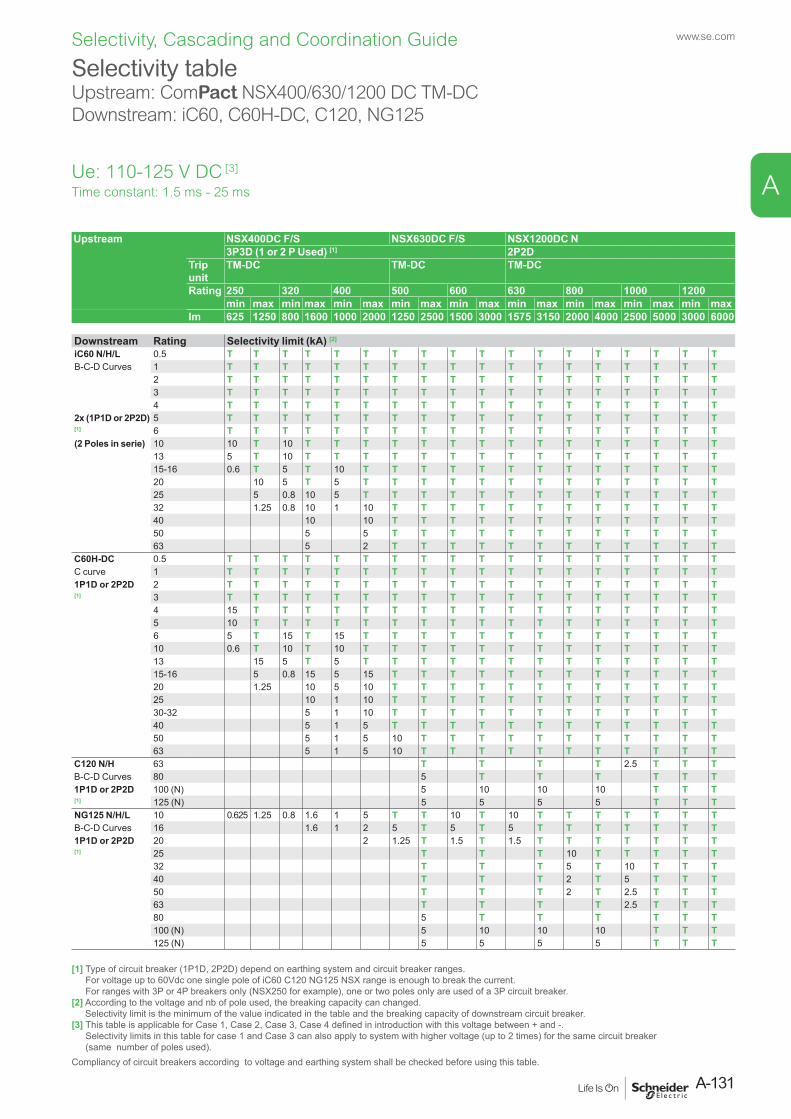
Selectivity tableUpstream: ComPact NSX400/630/1200 DC TM-DCDownstream: iC60, C60H-DC, C120, NG125
Upstream NSX400DC F/S NSX630DC F/S NSX1200DC N3P3D (1 or 2 P Used) [1] 2P2D
Trip unit
TM-DC TM-DC TM-DC
Rating 250 320 400 500 600 630 800 1000 1200min max min max min max min max min max min max min max min max min max
Im 625 1250 800 1600 1000 2000 1250 2500 1500 3000 1575 3150 2000 4000 2500 5000 3000 6000
Downstream Rating Selectivity limit (kA) [2]
iC60 N/H/L 0.5 T T T T T T T T T T T T T T T T T TB-C-D Curves 1 T T T T T T T T T T T T T T T T T T
2 T T T T T T T T T T T T T T T T T T3 T T T T T T T T T T T T T T T T T T4 T T T T T T T T T T T T T T T T T T
2x (1P1D or 2P2D) 5 T T T T T T T T T T T T T T T T T T[1] 6 T T T T T T T T T T T T T T T T T T(2 Poles in serie) 10 10 T 10 T T T T T T T T T T T T T T T
13 5 T 10 T T T T T T T T T T T T T T T15-16 0.6 T 5 T 10 T T T T T T T T T T T T T20 10 5 T 5 T T T T T T T T T T T T T25 5 0.8 10 5 T T T T T T T T T T T T T32 1.25 0.8 10 1 10 T T T T T T T T T T T T40 10 10 T T T T T T T T T T T T50 5 5 T T T T T T T T T T T T63 5 2 T T T T T T T T T T T T
C60H-DC 0.5 T T T T T T T T T T T T T T T T T TC curve 1 T T T T T T T T T T T T T T T T T T1P1D or 2P2D 2 T T T T T T T T T T T T T T T T T T[1] 3 T T T T T T T T T T T T T T T T T T
4 15 T T T T T T T T T T T T T T T T T5 10 T T T T T T T T T T T T T T T T T6 5 T 15 T 15 T T T T T T T T T T T T T10 0.6 T 10 T 10 T T T T T T T T T T T T T13 15 5 T 5 T T T T T T T T T T T T T15-16 5 0.8 15 5 15 T T T T T T T T T T T T20 1.25 10 5 10 T T T T T T T T T T T T25 10 1 10 T T T T T T T T T T T T30-32 5 1 10 T T T T T T T T T T T T40 5 1 5 T T T T T T T T T T T T50 5 1 5 10 T T T T T T T T T T T63 5 1 5 10 T T T T T T T T T T T
C120 N/H 63 T T T T 2.5 T T TB-C-D Curves 80 5 T T T T T T1P1D or 2P2D 100 (N) 5 10 10 10 T T T[1] 125 (N) 5 5 5 5 T T TNG125 N/H/L 10 0.625 1.25 0.8 1.6 1 5 T T 10 T 10 T T T T T T TB-C-D Curves 16 1.6 1 2 5 T 5 T 5 T T T T T T T1P1D or 2P2D 20 2 1.25 T 1.5 T 1.5 T T T T T T T[1] 25 T T T 10 T T T T T
32 T T T 5 T 10 T T T40 T T T 2 T 5 T T T50 T T T 2 T 2.5 T T T63 T T T T 2.5 T T T80 5 T T T T T T100 (N) 5 10 10 10 T T T125 (N) 5 5 5 5 T T T
Time constant: 1.5 ms - 25 ms
[1] Type of circuit breaker (1P1D, 2P2D) depend on earthing system and circuit breaker ranges. For voltage up to 60Vdc one single pole of iC60 C120 NG125 NSX range is enough to break the current. For ranges with 3P or 4P breakers only (NSX250 for example), one or two poles only are used of a 3P circuit breaker.
[2] According to the voltage and nb of pole used, the breaking capacity can changed. Selectivity limit is the minimum of the value indicated in the table and the breaking capacity of downstream circuit breaker.
[3] This table is applicable for Case 1, Case 2, Case 3, Case 4 defined in introduction with this voltage between + and -. Selectivity limits in this table for case 1 and Case 3 can also apply to system with higher voltage (up to 2 times) for the same circuit breaker (same number of poles used).
Compliancy of circuit breakers according to voltage and earthing system shall be checked before using this table.
Ue: 110-125 V DC [3]
A-131
www.se.com
A
Selectivity, Cascading and Coordination Guide
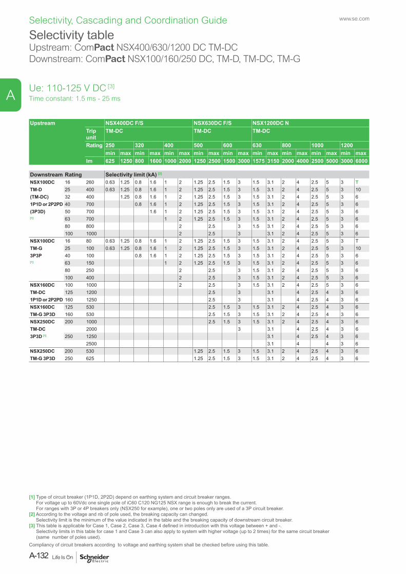
Selectivity tableUpstream: ComPact NSX400/630/1200 DC TM-DCDownstream: ComPact NSX100/160/250 DC, TM-D, TM-DC, TM-G
Upstream NSX400DC F/S NSX630DC F/S NSX1200DC NTrip unit
TM-DC TM-DC TM-DC
Rating 250 320 400 500 600 630 800 1000 1200min max min max min max min max min max min max min max min max min max
Im 625 1250 800 1600 1000 2000 1250 2500 1500 3000 1575 3150 2000 4000 2500 5000 3000 6000
Downstream Rating Selectivity limit (kA) [2]
NSX100DC 16 260 0.63 1.25 0.8 1.6 1 2 1.25 2.5 1.5 3 1.5 3.1 2 4 2.5 5 3 TTM-D 25 400 0.63 1.25 0.8 1.6 1 2 1.25 2.5 1.5 3 1.5 3.1 2 4 2.5 5 3 10(TM-DC) 32 400 1.25 0.8 1.6 1 2 1.25 2.5 1.5 3 1.5 3.1 2 4 2.5 5 3 61P1D or 2P2PD 40 700 0.8 1.6 1 2 1.25 2.5 1.5 3 1.5 3.1 2 4 2.5 5 3 6(3P3D) 50 700 1.6 1 2 1.25 2.5 1.5 3 1.5 3.1 2 4 2.5 5 3 6[1] 63 700 1 2 1.25 2.5 1.5 3 1.5 3.1 2 4 2.5 5 3 6
80 800 2 2.5 3 1.5 3.1 2 4 2.5 5 3 6100 1000 2 2.5 3 3.1 2 4 2.5 5 3 6
NSX100DC 16 80 0.63 1.25 0.8 1.6 1 2 1.25 2.5 1.5 3 1.5 3.1 2 4 2.5 5 3 TTM-G 25 100 0.63 1.25 0.8 1.6 1 2 1.25 2.5 1.5 3 1.5 3.1 2 4 2.5 5 3 103P3P 40 100 0.8 1.6 1 2 1.25 2.5 1.5 3 1.5 3.1 2 4 2.5 5 3 6[1] 63 150 1 2 1.25 2.5 1.5 3 1.5 3.1 2 4 2.5 5 3 6
80 250 2 2.5 3 1.5 3.1 2 4 2.5 5 3 6100 400 2 2.5 3 1.5 3.1 2 4 2.5 5 3 6
NSX160DC 100 1000 2 2.5 3 1.5 3.1 2 4 2.5 5 3 6TM-DC 125 1200 2.5 3 3.1 4 2.5 4 3 61P1D or 2P2PD 160 1250 2.5 3 3.1 4 2.5 4 3 6NSX160DC 125 530 2.5 1.5 3 1.5 3.1 2 4 2.5 4 3 6TM-G 3P3D 160 530 2.5 1.5 3 1.5 3.1 2 4 2.5 4 3 6NSX250DC 200 1000 2.5 1.5 3 1.5 3.1 2 4 2.5 4 3 6TM-DC 2000 3 3.1 4 2.5 4 3 63P3D [1] 250 1250 3.1 4 2.5 4 3 6
2500 3.1 4 4 3 6NSX250DC 200 530 1.25 2.5 1.5 3 1.5 3.1 2 4 2.5 4 3 6TM-G 3P3D 250 625 1.25 2.5 1.5 3 1.5 3.1 2 4 2.5 4 3 6
Time constant: 1.5 ms - 25 ms
[1] Type of circuit breaker (1P1D, 2P2D) depend on earthing system and circuit breaker ranges. For voltage up to 60Vdc one single pole of iC60 C120 NG125 NSX range is enough to break the current. For ranges with 3P or 4P breakers only (NSX250 for example), one or two poles only are used of a 3P circuit breaker.
[2] According to the voltage and nb of pole used, the breaking capacity can changed. Selectivity limit is the minimum of the value indicated in the table and the breaking capacity of downstream circuit breaker.
[3] This table is applicable for Case 1, Case 2, Case 3, Case 4 defined in introduction with this voltage between + and -. Selectivity limits in this table for case 1 and Case 3 can also apply to system with higher voltage (up to 2 times) for the same circuit breaker (same number of poles used).
Compliancy of circuit breakers according to voltage and earthing system shall be checked before using this table.
Ue: 110-125 V DC [3]
www.se.com
A-132
A
Selectivity, Cascading and Coordination Guide

Selectivity tableUpstream: MasterPact NW DCDownstream: iC60, C60H-DC, C120, NG125. ComPact NSX100/160/250
Upstream NW10DC -C N/H NW10DC -C N/H NW10DC -C N/HNW20DC -C N/H NW20DC -C N/H
NW40DC-C N/H2P2D
Trip unit MicroLogic 1.0 DC Range 1250/2500A Range 2500/5400A Range 5000/11000A
Type A B C D E A B C D E A B C D ESetting 1250 1500 1600 2000 2500 2500 3300 4000 5000 5400 5kA 8kA 10kA 11kA 11kA
Downstream Rating Im Selectivity limit (kA) [2]
iC60 N/H/L 2x (1P1D or 2P2D) [1]
0.5-63 T T T T T T T T T T T T T T T
C60H-DC [1] 0.5-63 T T T T T T T T T T T T T T TC120 N/H 63 T T T T T T T T T T T T T T T1P1D or 2P2D 80 1.25 T T T T T T T T T T T T T T[1] 100 1.25 1.5 T T T T T T T T T T T T T
125 1.25 1.5 1.6 T T T T T T T T T T T TNG125 N/H/L 10-50 T T T T T T T T T T T T T T TB-C-D Curves 63 T T T T T T T T T T T T T T T1P1D or 2P2D 80 1.25 T T T T T T T T T T T T T T[1] 100 (N) 1.25 1.5 T T T T T T T T T T T T T
125 N) 1.25 1.5 1.6 T T T T T T T T T T T TNSX100DC N/H 16 260 1.25 1.5 1.6 10 T T T T T T T T T T TTM-D 25 400 1.25 1.5 1.6 5 10 10 T T T T T T T T T
32 400 1.25 1.5 1.6 2 5 5 T T T T T T T T T40 700 1.5 1.6 2 2.5 2.5 10 T T T T T T T T50 700 1.5 1.6 2 2.5 2.5 5 T T T T T T T T63 700 1.5 1.6 2 2.5 2.5 3.3 T T T T T T T T
TM-DC 80 800 1.5 1.6 2 2.5 2.5 3.3 4 T T T T T T T100 1000 2 2.5 2.5 3.3 4 5 T T T T T T
NSX100DC 16 80 1.25 1.5 1.6 10 T T T T T T T T T T TTM-G 25 100 1.25 1.5 1.6 5 10 10 T T T T T T T T T
40 100 1.5 1.6 2 2.5 2.5 10 T T T T T T T T63 150 1.5 1.6 2 2.5 2.5 3.3 T T T T T T T T80 250 1.5 1.6 2 2.5 2.5 3.3 4 T T T T T T T100 400 2 2.5 2.5 3.3 4 5 T T T T T T
NSX160DC 100 1000 2 2.5 2.5 5 T T T T T T T TTM-DC 125 1200 2.5 2.5 3.3 10 T T T T T T T
160 1250 2.5 2.5 3.3 5 10 T T T T T TNSX160DC 125 530 1.25 1.5 1.6 2 2.5 2.5 3.3 10 T T T T T T TTM-G 160 530 1.25 1.5 1.6 2 2.5 2.5 3.3 5 10 T T T T T TNSX250DC 200 1000 2 2.5 2.5 5 T T T T T T T TTM-DC 2000 4 5 T T T T T T
250 1250 2.5 2.5 3.3 5 10 T T T T T T2500 2.5 3.3 4 5 T T T T T T
NSX250DC 200 530 1.25 1.5 1.6 2 2.5 2.5 5 T T T T T T T TTM-G 250 625 1.5 1.6 2 2.5 2.5 3.3 5 10 T T T T T T
Time constant: 1.5 ms - 25 ms
[1] Type of circuit breaker (1P1D, 2P2D) depend on earthing system and circuit breaker ranges. For voltage up to 60Vdc one single pole of iC60 C120 NG125 NSX range is enough to break the current. For ranges with 3P or 4P breakers only (NSX250 for example), one or two poles only are used of a 3P circuit breaker.
[2] According to the voltage and nb of pole used, the breaking capacity can changed. Selectivity limit is the minimum of the value indicated in the table and the breaking capacity of downstream circuit breaker.
[3] This table is applicable for Case 1, Case 2, Case 3, Case 4 defined in introduction with this voltage between + and -. Selectivity limits in this table for case 1 and Case 3 can also apply to system with higher voltage (up to 2 times) for the same circuit breaker (same number of poles used).
Compliancy of circuit breakers according to voltage and earthing system shall be checked before using this table.
Ue: 110-125 V DC [3]
A-133
www.se.com
A
Selectivity, Cascading and Coordination Guide

Selectivity tableUpstream: MasterPact NW DCDownstream: ComPact NSX400/630/1200 DC, MasterPact NW DC
Upstream NW10DC -C N/H NW10DC -C N/H NW10DC -C N/HNW20DC -C N/H NW20DC -C N/H
NW40DC-C N/H2P2D
Trip unit MicroLogic 1.0 DC Range 1250/2500A Range 2500/5400A Range 5000/11000A
Type A B C D E A B C D E A B C D ESetting 1250 1500 1600 2000 2500 2500 3300 4000 5000 5400 5000 8000 10000 11000 11000
Downstream Rating Im Selectivity limit (kA) [2]
NSX400DC 250 635 1.25 1.5 1.6 2 2.5 2.5 3.3 4 5 5.4 5 T T T TTM-DC 1250 2.5 2.5 3.3 4 5 5.4 5 T T T T3P3D [1] 320 800 1.6 2 2.5 2.5 3.3 4 5 5.4 5 T T T T
1600 3.3 4 5 5.4 5 10 T T T400 1000 2 2.5 2.5 3.3 4 5 5.4 5 10 T T T
2000 4 5 5.4 5 10 T T TNSX630DC 500 1250 2.5 3.3 4 5 5.4 5 T T T TTM-DC 2500 5 5.4 5 10 T T T3P3D [1] 600 1500 3.3 4 5 5.4 5 10 T T T
3000 10 T T TNSX1200DC 630 1575 3.3 4 5 5.4 5 8 10 11 11TM-DC 3150 8 10 11 113P3D [1] 800 2000 4 5 5.4 5 8 10 11 11
4000 8 10 11 111000 2500 5 8 10 11 11
5000 10 11 111200 3000 8 10 11 11
6000 11 11NW DC-C 1000 1250 3.3 4 5 5.4 5 8 10 11 11
2500 5 5.4 5 8 10 11 111000/2000 2500 5 5.4 5 8 10 11 11
5400 10 11 111000/2000/4000 5000 10 11 11
11000
Time constant: 1.5 ms - 25 ms
[1] Type of circuit breaker (1P1D, 2P2D) depend on earthing system and circuit breaker ranges. For voltage up to 60Vdc one single pole of iC60 C120 NG125 NSX range is enough to break the current. For ranges with 3P or 4P breakers only (NSX250 for example), one or two poles only are used of a 3P circuit breaker.
[2] According to the voltage and nb of pole used, the breaking capacity can changed. Selectivity limit is the minimum of the value indicated in the table and the breaking capacity of downstream circuit breaker.
[3] This table is applicable for Case 1, Case 2, Case 3, Case 4 defined in introduction with this voltage between + and -. Selectivity limits in this table for case 1 and Case 3 can also apply to system with higher voltage (up to 2 times) for the same circuit breaker (same number of poles used).
Compliancy of circuit breakers according to voltage and earthing system shall be checked before using this table.
Ue: 110-125 V DC [3]
www.se.com
A-134
A
Selectivity, Cascading and Coordination Guide
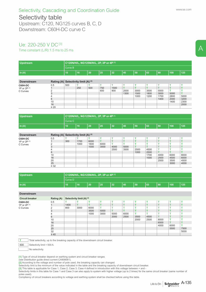
Ue: 220-250 V DC [3]
Time constant (L/R):1.5 ms to 25 ms
Upstream C120N/H/L, NG125N/H/L, 2P, 3P or 4P [1]
Curve B
In (A) 10 16 20 25 32 40 50 63 80 100 125
Downstream Rating (A) Selectivity limit (A) [2]
C60H-DC1P or 2P [1]
C Curves
0.5 500 T T T T T T T T T T1 250 500 750 1500 T T T T T T2 600 900 2000 3000 3500 5500 T T3 1300 1500 1800 3000 5000 T4 1000 1200 1700 2800 50006 1400 2000 320010 1400 230016 2000u 20
Upstream C120N/H/L, NG125N/H/L, 2P, 3P or 4P [1]
Curve C
In (A) 10 16 20 25 32 40 50 63 80 100 125
Downstream Rating (A) Selectivity limit (A) [2]
C60H-DC1P or 2P [1]
C Curves
0.5 T T T T T T T T T T T1 300 1700 6000 T T T T T T T T2 1000 1600 6000 T T T T T T T3 1000 3000 4000 5000 T T T T T4 2500 3500 2500 4500 T T T6 1000 2500 T T T10 1700 4000 6000 800016 1000 2500 4500 600020 2000 3500 450025 3000 4000u 32
Upstream C120N/H/L, NG125N/H/L, 2P, 3P or 4P [1]
Curve D
In (A) 10 16 20 25 32 40 50 63 80 100 125
DownstreamCircuit breaker Rating (A) Selectivity limit (A) [2]
C60H-DC1P or 2P [1]
C Curves
0.5 T T T T T T T T T T T1 1400 T T T T T T T T T T2 800 3000 6000 T T T T T T T T3 3500 5000 T T T T T T T4 1000 3000 5000 6000 T T T T T6 2000 2500 3500 4500 T T T10 2000 2500 8000 T T16 6500 T T20 4000 6000 T25 5500 750032 5000u 40
T Total selectivity, up to the breaking capacity of the downstream circuit breaker.
500 Selectivity limit = 500 A.
No selectivity.
Selectivity tableUpstream: C120, NG125 curves B, C, DDownstream: C60H-DC curve C
[1] Type of circuit breaker depend on earthing system and circuit breaker ranges (see Distribution guide direct current CA908061).[2] According to the voltage and number of pole used, the breaking capacity can changed. Selectivity limit is the minimum of the value indicated in the table and the breaking capacity of downstream circuit breaker.[3] This table is applicable for Case 1, Case 2, Case 3, Case 4 defined in introduction with this voltage between + and - Selectivity limits in this table for Case 1 and Case 3 can also apply to system with higher voltage (up to 2 times) for the same circuit breaker (same number of poles used). Compliancy of circuit breakers according to voltage and earthing system shall be checked before using this table.
A-135
www.se.com
A
Selectivity, Cascading and Coordination Guide
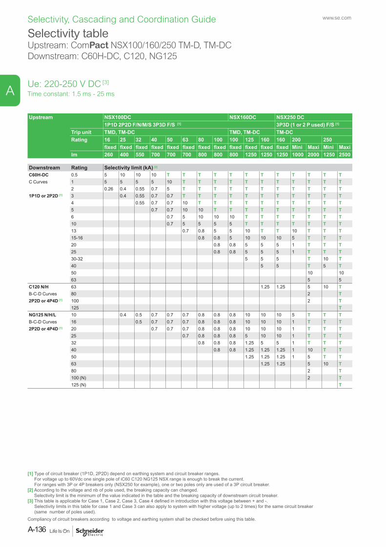
Selectivity tableUpstream: ComPact NSX100/160/250 TM-D, TM-DCDownstream: C60H-DC, C120, NG125
Ue: 220-250 V DC [3]
Upstream NSX100DC NSX160DC NSX250 DC 1P1D 2P2D F/N/M/S 3P3D F/S [1] 3P3D (1 or 2 P used) F/S [1]
Trip unit TMD, TM-DC TMD, TM-DC TM-DCRating 16 25 32 40 50 63 80 100 100 125 160 160 200 250
fixed fixed fixed fixed fixed fixed fixed fixed fixed fixed fixed fixed Mini Maxi Mini MaxiIm 260 400 550 700 700 700 800 800 800 1250 1250 1250 1000 2000 1250 2500
Downstream Rating Selectivity limit (kA) [2]
C60H-DC 0.5 5 10 10 10 T T T T T T T T T T T TC Curves 1 5 5 5 5 10 T T T T T T T T T T T
2 0.26 0.4 0.55 0.7 5 T T T T T T T T T T T1P1D or 2P2D [1] 3 0.4 0.55 0.7 0.7 T T T T T T T T T T T
4 0.55 0.7 0.7 10 T T T T T T T T T T5 0.7 0.7 10 10 T T T T T T T T T6 0.7 5 10 10 10 T T T T T T T10 0.7 5 5 5 5 T T T T T T T13 0.7 0.8 5 5 10 T T 10 T T T15-16 0.8 0.8 5 10 10 10 5 T T T20 0.8 0.8 5 5 5 1 T T T25 0.8 0.8 5 5 5 1 T T T30-32 5 5 5 T 10 T40 5 5 T 5 T50 10 1063 5 5
C120 N/H 63 1.25 1.25 5 10 TB-C-D Curves 80 2 T2P2D or 4P4D [1] 100 2 T
125 TNG125 N/H/L 10 0.4 0.5 0.7 0.7 0.7 0.8 0.8 0.8 10 10 10 5 T T TB-C-D Curves 16 0.5 0.7 0.7 0.7 0.8 0.8 0.8 10 10 10 1 T T T2P2D or 4P4D [1] 20 0.7 0.7 0.7 0.8 0.8 0.8 10 10 10 1 T T T
25 0.7 0.8 0.8 0.8 5 10 10 1 T T T32 0.8 0.8 0.8 1.25 5 5 1 T T T40 0.8 0.8 1.25 1.25 1.25 1 10 T T50 1.25 1.25 1.25 1 5 T T63 1.25 1.25 5 10 T80 2 T100 (N) 2 T125 (N) T
Time constant: 1.5 ms - 25 ms
[1] Type of circuit breaker (1P1D, 2P2D) depend on earthing system and circuit breaker ranges. For voltage up to 60Vdc one single pole of iC60 C120 NG125 NSX range is enough to break the current. For ranges with 3P or 4P breakers only (NSX250 for example), one or two poles only are used of a 3P circuit breaker.
[2] According to the voltage and nb of pole used, the breaking capacity can changed. Selectivity limit is the minimum of the value indicated in the table and the breaking capacity of downstream circuit breaker.
[3] This table is applicable for Case 1, Case 2, Case 3, Case 4 defined in introduction with this voltage between + and -. Selectivity limits in this table for case 1 and Case 3 can also apply to system with higher voltage (up to 2 times) for the same circuit breaker (same number of poles used).
Compliancy of circuit breakers according to voltage and earthing system shall be checked before using this table.
www.se.com
A-136
A
Selectivity, Cascading and Coordination Guide
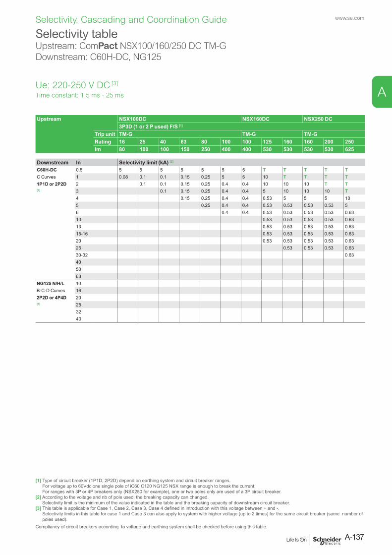
Selectivity tableUpstream: ComPact NSX100/160/250 DC TM-GDownstream: C60H-DC, NG125
Ue: 220-250 V DC [3]
Upstream NSX100DC NSX160DC NSX250 DC3P3D (1 or 2 P used) F/S [1]
Trip unit TM-G TM-G TM-GRating 16 25 40 63 80 100 100 125 160 160 200 250Im 80 100 100 150 250 400 400 530 530 530 530 625
Downstream In Selectivity limit (kA) [2]
C60H-DC 0.5 5 5 5 5 5 5 5 T T T T TC Curves 1 0.08 0.1 0.1 0.15 0.25 5 5 10 T T T T1P1D or 2P2D 2 0.1 0.1 0.15 0.25 0.4 0.4 10 10 10 T T[1] 3 0.1 0.15 0.25 0.4 0.4 5 10 10 10 T
4 0.15 0.25 0.4 0.4 0.53 5 5 5 105 0.25 0.4 0.4 0.53 0.53 0.53 0.53 56 0.4 0.4 0.53 0.53 0.53 0.53 0.6310 0.53 0.53 0.53 0.53 0.6313 0.53 0.53 0.53 0.53 0.6315-16 0.53 0.53 0.53 0.53 0.6320 0.53 0.53 0.53 0.53 0.6325 0.53 0.53 0.53 0.6330-32 0.63405063
NG125 N/H/L 10B-C-D Curves 162P2D or 4P4D 20[1] 25
3240
Time constant: 1.5 ms - 25 ms
[1] Type of circuit breaker (1P1D, 2P2D) depend on earthing system and circuit breaker ranges. For voltage up to 60Vdc one single pole of iC60 C120 NG125 NSX range is enough to break the current. For ranges with 3P or 4P breakers only (NSX250 for example), one or two poles only are used of a 3P circuit breaker.
[2] According to the voltage and nb of pole used, the breaking capacity can changed. Selectivity limit is the minimum of the value indicated in the table and the breaking capacity of downstream circuit breaker.
[3] This table is applicable for Case 1, Case 2, Case 3, Case 4 defined in introduction with this voltage between + and -. Selectivity limits in this table for case 1 and Case 3 can also apply to system with higher voltage (up to 2 times) for the same circuit breaker (same number of poles used).
Compliancy of circuit breakers according to voltage and earthing system shall be checked before using this table.
A-137
www.se.com
A
Selectivity, Cascading and Coordination Guide
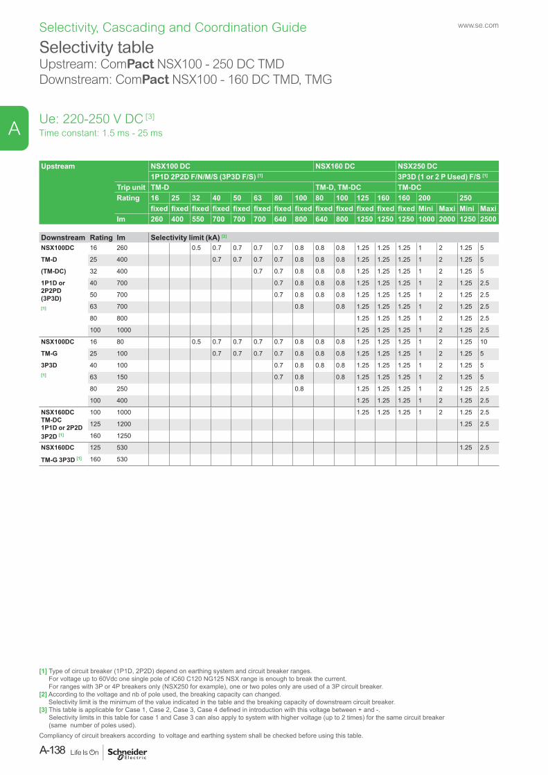
Selectivity tableUpstream: ComPact NSX100 - 250 DC TMDDownstream: ComPact NSX100 - 160 DC TMD, TMG
Ue: 220-250 V DC [3]
Upstream NSX100 DC NSX160 DC NSX250 DC1P1D 2P2D F/N/M/S (3P3D F/S) [1] 3P3D (1 or 2 P Used) F/S [1]
Trip unit TM-D TM-D, TM-DC TM-DCRating 16 25 32 40 50 63 80 100 80 100 125 160 160 200 250
fixed fixed fixed fixed fixed fixed fixed fixed fixed fixed fixed fixed fixed Mini Maxi Mini MaxiIm 260 400 550 700 700 700 640 800 640 800 1250 1250 1250 1000 2000 1250 2500
Downstream Rating Im Selectivity limit (kA) [2]
NSX100DC 16 260 0.5 0.7 0.7 0.7 0.7 0.8 0.8 0.8 1.25 1.25 1.25 1 2 1.25 5
TM-D 25 400 0.7 0.7 0.7 0.7 0.8 0.8 0.8 1.25 1.25 1.25 1 2 1.25 5
(TM-DC) 32 400 0.7 0.7 0.8 0.8 0.8 1.25 1.25 1.25 1 2 1.25 5
1P1D or 2P2PD(3P3D)[1]
40 700 0.7 0.8 0.8 0.8 1.25 1.25 1.25 1 2 1.25 2.5
50 700 0.7 0.8 0.8 0.8 1.25 1.25 1.25 1 2 1.25 2.5
63 700 0.8 0.8 1.25 1.25 1.25 1 2 1.25 2.5
80 800 1.25 1.25 1.25 1 2 1.25 2.5
100 1000 1.25 1.25 1.25 1 2 1.25 2.5
NSX100DC 16 80 0.5 0.7 0.7 0.7 0.7 0.8 0.8 0.8 1.25 1.25 1.25 1 2 1.25 10
TM-G 25 100 0.7 0.7 0.7 0.7 0.8 0.8 0.8 1.25 1.25 1.25 1 2 1.25 5
3P3D[1]
40 100 0.7 0.8 0.8 0.8 1.25 1.25 1.25 1 2 1.25 5
63 150 0.7 0.8 0.8 1.25 1.25 1.25 1 2 1.25 5
80 250 0.8 1.25 1.25 1.25 1 2 1.25 2.5
100 400 1.25 1.25 1.25 1 2 1.25 2.5
NSX160DC TM-DC1P1D or 2P2D3P2D [1]
100 1000 1.25 1.25 1.25 1 2 1.25 2.5
125 1200 1.25 2.5
160 1250
NSX160DC 125 530 1.25 2.5
TM-G 3P3D [1] 160 530
Time constant: 1.5 ms - 25 ms
[1] Type of circuit breaker (1P1D, 2P2D) depend on earthing system and circuit breaker ranges. For voltage up to 60Vdc one single pole of iC60 C120 NG125 NSX range is enough to break the current. For ranges with 3P or 4P breakers only (NSX250 for example), one or two poles only are used of a 3P circuit breaker.
[2] According to the voltage and nb of pole used, the breaking capacity can changed. Selectivity limit is the minimum of the value indicated in the table and the breaking capacity of downstream circuit breaker.
[3] This table is applicable for Case 1, Case 2, Case 3, Case 4 defined in introduction with this voltage between + and -. Selectivity limits in this table for case 1 and Case 3 can also apply to system with higher voltage (up to 2 times) for the same circuit breaker (same number of poles used).
Compliancy of circuit breakers according to voltage and earthing system shall be checked before using this table.
www.se.com
A-138
A
Selectivity, Cascading and Coordination Guide
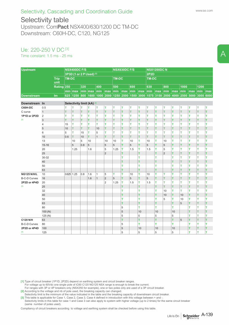
Selectivity tableUpstream: ComPact NSX400/630/1200 DC TM-DCDownstream: C60H-DC, C120, NG125
Ue: 220-250 V DC [3]
Upstream NSX400DC F/S NSX630DC F/S NSX1200DC N3P3D (1 or 2 P Used) [1] 2P2D
Trip unit
TM-DC TM-DC TM-DC
Rating 250 320 400 500 600 630 800 1000 1200min max min max min max min max min max min max min max min max min max
Downstream Im 625 1250 800 1600 1000 2000 1250 2500 1500 3000 1575 3150 2000 4000 2500 5000 3000 6000
Downstream In Selectivity limit (kA) [2]
C60H-DC 0.5 T T T T T T T T T T T T T T T T T TC curve 1 T T T T T T T T T T T T T T T T T T1P1D or 2P2D 2 T T T T T T T T T T T T T T T T T T[1] 3 T T T T T T T T T T T T T T T T T T
4 15 T T T T T T T T T T T T T T T T T5 10 T T T 10 T T T T T T T T T T T T T6 5 T 15 T 5 T T T T T T T T T T T T T10 0.6 T 10 T 1 T T T T T T T T T T T T T13 10 5 10 10 10 T 10 T 10 T 10 T T T T T15-16 5 0.8 5 5 5 T 5 T 5 T 5 T T T T T20 1.25 1.6 5 1.25 T 1.5 T 1.5 T 5 T T T T T25 2 T T T 2 T T T T T30-32 T T T T T T T T40 T T T T T T T T50 T T T T T T T T63 T T T T T T T T
NG125 N/H/L 10 0.625 1.25 0.8 1.6 1 5 T T 10 T 10 T T T T T T TB-C-D Curves 16 1.6 1 2 5 T 5 T 5 T T T T T T T2P2D or 4P4D 20 2 1.25 T 1.5 T 1.5 T T T T T T T[1] 25 T T T T T T T T T
32 T T T 10 T T T T T40 T T T 10 T 10 T T T50 T T T 5 T 10 T T T63 T T T T 5 T T T80 5 T T T T T T100 (N) 5 10 10 10 T T T125 (N) 5 5 5 5 T T T
C120 N/H 63 T T T T 5 T T TB-C-D Curves 80 5 T T T T T T2P2D or 4P4D 100 5 10 10 10 T T T[1] 125 5 5 5 5 T T T
Time constant: 1.5 ms - 25 ms
[1] Type of circuit breaker (1P1D, 2P2D) depend on earthing system and circuit breaker ranges. For voltage up to 60Vdc one single pole of iC60 C120 NG125 NSX range is enough to break the current. For ranges with 3P or 4P breakers only (NSX250 for example), one or two poles only are used of a 3P circuit breaker.
[2] According to the voltage and nb of pole used, the breaking capacity can changed. Selectivity limit is the minimum of the value indicated in the table and the breaking capacity of downstream circuit breaker.
[3] This table is applicable for Case 1, Case 2, Case 3, Case 4 defined in introduction with this voltage between + and -. Selectivity limits in this table for case 1 and Case 3 can also apply to system with higher voltage (up to 2 times) for the same circuit breaker (same number of poles used).
Compliancy of circuit breakers according to voltage and earthing system shall be checked before using this table.
A-139
www.se.com
A
Selectivity, Cascading and Coordination Guide

Selectivity tableUpstream: ComPact NSX400/630/1200 DC TM-DCDownstream: ComPact NSX100/160 DC TM-D, TM-DC, TM-G
Ue: 220-250 V DC [3]
Upstream NSX400DC F/S NSX630DC F/S NSX1200DC NTrip unit
TM-DC TM-DC TM-DC
Rating 250 320 400 500 600 630 800 1000 1200min max min max min max min max min max min max min max min max min max
Im 625 1250 800 1600 1000 2000 1250 2500 1500 3000 1575 3150 2000 4000 2500 5000 3000 6000
Downstream Rating Im Selectivity limit (kA) [2]
NSX100DC 16 260 0.63 1.25 0.8 1.6 1 2 1.25 2.5 1.5 3 1.5 3.1 2 4 2.5 5 3 TTM-D 25 400 0.63 1.25 1 1.6 1 2 1.25 2.5 1.5 3 1.5 3.1 2 4 2.5 5 3 10(TM-DC) 32 400 1.25 1 1.6 1 2 1.25 2.5 1.5 3 1.5 3.1 2 4 2.5 5 3 61P1D or 2P2PD 40 700 1 1.6 1 2 1.25 2.5 1.5 3 1.5 3.1 2 4 2.5 5 3 6(3P3D) 50 700 1.6 1 2 1.25 2.5 1.5 3 1.5 3.1 2 4 2.5 5 3 6[1] 63 700 1 2 1.25 2.5 1.5 3 1.5 3.1 2 4 2.5 5 3 6
80 800 2 2.5 3 1.5 3.1 2 4 2.5 5 3 6100 1000 2 2.5 3 3.1 2 4 2.5 5 3 6
NSX100DC 16 80 0.63 1.25 0.8 1.6 1 2 1.25 2.5 1.5 3 1.5 3.1 2 4 2.5 5 3 TTM-G 25 100 0.63 1.25 1 1.6 1 2 1.25 2.5 1.5 3 1.5 3.1 2 4 2.5 5 3 103P3D [1] 40 100 1 1.6 1 2 1.25 2.5 1.5 3 1.5 3.1 2 4 2.5 5 3 6
63 150 1 2 1.25 2.5 1.5 3 1.5 3.1 2 4 2.5 5 3 680 250 2 2.5 3 1.5 3.1 2 4 2.5 5 3 6100 400 2 2.5 3 1.5 3.1 2 4 2.5 5 3 6
NSX160DC 100 1000 2 2.5 3 1.5 3.1 2 4 2.5 5 3 6TM-DC 125 1200 2.5 3 3.1 4 2.5 4 3 61P1D or 2P2PD 160 1250 2.5 3 3.1 4 2.5 4 3 6NSX160DC 125 530 2.5 1.5 3 1.5 3.1 2 4 2.5 4 3 6TM-G 3P3D 160 530 2.5 1.5 3 1.5 3.1 2 4 2.5 4 3 6NSX250DC 200 1000 2.5 1.5 3 1.5 3.1 2 4 2.5 4 3 6TM-DC 2000 3 3.1 4 2.5 4 3 63P3D [1] 250 1250 3.1 4 2.5 4 3 6
2500 3.1 4 4 3 6NSX250DC 200 530 1.25 2.5 1.5 3 1.5 3.1 2 4 2.5 4 3 6TM-G 3P3D 250 625 1.25 2.5 1.5 3 1.5 3.1 2 4 2.5 4 3 6
Time constant: 1.5 ms - 25 ms
[1] Type of circuit breaker (1P1D, 2P2D) depend on earthing system and circuit breaker ranges. For voltage up to 60Vdc one single pole of iC60 C120 NG125 NSX range is enough to break the current. For ranges with 3P or 4P breakers only (NSX250 for example), one or two poles only are used of a 3P circuit breaker.
[2] According to the voltage and nb of pole used, the breaking capacity can changed. Selectivity limit is the minimum of the value indicated in the table and the breaking capacity of downstream circuit breaker.
[3] This table is applicable for Case 1, Case 2, Case 3, Case 4 defined in introduction with this voltage between + and -. Selectivity limits in this table for case 1 and Case 3 can also apply to system with higher voltage (up to 2 times) for the same circuit breaker (same number of poles used).
Compliancy of circuit breakers according to voltage and earthing system shall be checked before using this table.
www.se.com
A-140
A
Selectivity, Cascading and Coordination Guide
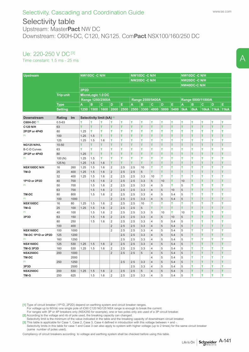
Selectivity tableUpstream: MasterPact NW DCDownstream: C60H-DC, C120, NG125. ComPact NSX100/160/250 DC
Ue: 220-250 V DC [3]
Upstream NW10DC -C N/H NW10DC -C N/H NW10DC -C N/HNW20DC -C N/H NW20DC -C N/H
NW40DC-C N/H2P2D
Trip unit MicroLogic 1.0 DC Range 1250/2500A Range 2500/5400A Range 5000/11000A
Type A B C D E A B C D E A B C D ESetting 1250 1500 1600 2000 2500 2500 3300 4000 5000 5400 5kA 8kA 10kA 11kA 11kA
Downstream Rating Im Selectivity limit (kA) [2]
C60H-DC [1] 0.5-63 T T T T T T T T T T T T T T TC120 N/H 63 T T T T T T T T T T T T T T T2P/2P or 4P4D 80 1.25 T T T T T T T T T T T T T T[1] 100 1.25 1.5 T T T T T T T T T T T T T
125 1.25 1.5 1.6 T T T T T T T T T T T TNG125 N/H/L 10-50 T T T T T T T T T T T T T T TB-C-D Curves 63 T T T T T T T T T T T T T T T2P/2P or 4P4D 80 1.25 T T T T T T T T T T T T T T[1] 100 (N) 1.25 1.5 T T T T T T T T T T T T T
125 N) 1.25 1.5 1.6 T T T T T T T T T T T TNSX100DC N/H 16 260 1.25 1.5 1.6 2 2.5 2.5 10 T T T T T T T TTM-D 25 400 1.25 1.5 1.6 2 2.5 2.5 5 T T T T T T T T
32 400 1.25 1.5 1.6 2 2.5 2.5 3.3 10 T T T T T T T1P1D or 2P2D 40 700 1.5 1.6 2 2.5 2.5 3.3 5 10 T 10 T T T T[1] 50 700 1.5 1.6 2 2.5 2.5 3.3 4 5 T 5 T T T T
63 700 1.5 1.6 2 2.5 2.5 3.3 4 5 10 5 T T T TTM-DC 80 800 1.5 1.6 2 2.5 2.5 3.3 4 5 5.4 5 T T T T[1] 100 1000 2 2.5 2.5 3.3 4 5 5.4 5 T T T TNSX100DC 16 80 1.25 1.5 1.6 2 2.5 2.5 10 T T T T T T T TTM-G 25 100 1.25 1.5 1.6 2 2.5 2.5 5 T T T T T T T T[1] 40 100 1.5 1.6 2 2.5 2.5 3.3 5 10 T 10 T T T T3P3D 63 150 1.5 1.6 2 2.5 2.5 3.3 4 5 10 5 T T T T
80 250 1.5 1.6 2 2.5 2.5 3.3 4 5 5.4 5 T T T T100 400 2 2.5 2.5 3.3 4 5 5.4 5 T T T T
NSX160DC 100 1000 2 2.5 2.5 3.3 4 5 5.4 5 T T T TTM-DC 1P1D or 2P2D 125 1200 2.5 2.5 3.3 4 5 5.4 5 T T T T[1] 160 1250 2.5 2.5 3.3 4 5 5.4 5 T T T TNSX160DC 125 530 1.25 1.5 1.6 2 2.5 2.5 3.3 4 5 5.4 5 T T T TTM-G 3P3D 160 530 1.25 1.5 1.6 2 2.5 2.5 3.3 4 5 5.4 5 T T T TNSX250DC 200 1000 2 2.5 2.5 5 4 5 5.4 5 T T T TTM-DC 2000 4 5 5.4 5 T T T T[1] 250 1250 2.5 2.5 3.3 4 5 5.4 5 T T T T3P3D 2500 2.5 3.3 4 5 5.4 5 T T T TNSX250DC 200 530 1.25 1.5 1.6 2 2.5 2.5 5 4 5 5.4 5 T T T TTM-G 250 625 1.5 1.6 2 2.5 2.5 3.3 4 5 5.4 5 T T T T
Time constant: 1.5 ms - 25 ms
[1] Type of circuit breaker (1P1D, 2P2D) depend on earthing system and circuit breaker ranges. For voltage up to 60Vdc one single pole of iC60 C120 NG125 NSX range is enough to break the current. For ranges with 3P or 4P breakers only (NSX250 for example), one or two poles only are used of a 3P circuit breaker.
[2] According to the voltage and nb of pole used, the breaking capacity can changed. Selectivity limit is the minimum of the value indicated in the table and the breaking capacity of downstream circuit breaker.
[3] This table is applicable for Case 1, Case 2, Case 3, Case 4 defined in introduction with this voltage between + and -. Selectivity limits in this table for case 1 and Case 3 can also apply to system with higher voltage (up to 2 times) for the same circuit breaker (same number of poles used).
Compliancy of circuit breakers according to voltage and earthing system shall be checked before using this table.
A-141
www.se.com
A
Selectivity, Cascading and Coordination Guide
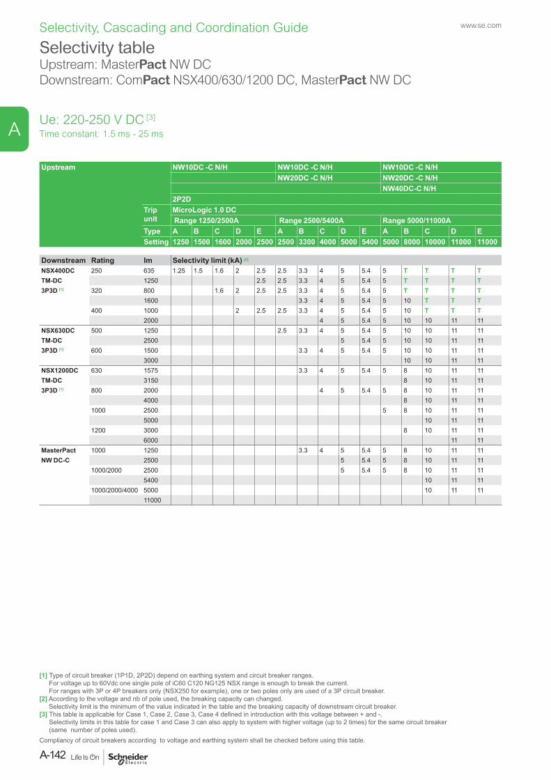
Selectivity tableUpstream: MasterPact NW DC Downstream: ComPact NSX400/630/1200 DC, MasterPact NW DC
Ue: 220-250 V DC [3]
Upstream NW10DC -C N/H NW10DC -C N/H NW10DC -C N/HNW20DC -C N/H NW20DC -C N/H
NW40DC-C N/H2P2D
Trip unit
MicroLogic 1.0 DC Range 1250/2500A Range 2500/5400A Range 5000/11000A
Type A B C D E A B C D E A B C D ESetting 1250 1500 1600 2000 2500 2500 3300 4000 5000 5400 5000 8000 10000 11000 11000
Downstream Rating Im Selectivity limit (kA) [2]
NSX400DC 250 635 1.25 1.5 1.6 2 2.5 2.5 3.3 4 5 5.4 5 T T T TTM-DC 1250 2.5 2.5 3.3 4 5 5.4 5 T T T T3P3D [1] 320 800 1.6 2 2.5 2.5 3.3 4 5 5.4 5 T T T T
1600 3.3 4 5 5.4 5 10 T T T400 1000 2 2.5 2.5 3.3 4 5 5.4 5 10 T T T
2000 4 5 5.4 5 10 10 11 11NSX630DC 500 1250 2.5 3.3 4 5 5.4 5 10 10 11 11TM-DC 2500 5 5.4 5 10 10 11 113P3D [1] 600 1500 3.3 4 5 5.4 5 10 10 11 11
3000 10 10 11 11NSX1200DC 630 1575 3.3 4 5 5.4 5 8 10 11 11TM-DC 3150 8 10 11 113P3D [1] 800 2000 4 5 5.4 5 8 10 11 11
4000 8 10 11 111000 2500 5 8 10 11 11
5000 10 11 111200 3000 8 10 11 11
6000 11 11MasterPact 1000 1250 3.3 4 5 5.4 5 8 10 11 11NW DC-C 2500 5 5.4 5 8 10 11 11
1000/2000 2500 5 5.4 5 8 10 11 115400 10 11 11
1000/2000/4000 5000 10 11 1111000
Time constant: 1.5 ms - 25 ms
[1] Type of circuit breaker (1P1D, 2P2D) depend on earthing system and circuit breaker ranges. For voltage up to 60Vdc one single pole of iC60 C120 NG125 NSX range is enough to break the current. For ranges with 3P or 4P breakers only (NSX250 for example), one or two poles only are used of a 3P circuit breaker.
[2] According to the voltage and nb of pole used, the breaking capacity can changed. Selectivity limit is the minimum of the value indicated in the table and the breaking capacity of downstream circuit breaker.
[3] This table is applicable for Case 1, Case 2, Case 3, Case 4 defined in introduction with this voltage between + and -. Selectivity limits in this table for case 1 and Case 3 can also apply to system with higher voltage (up to 2 times) for the same circuit breaker (same number of poles used).
Compliancy of circuit breakers according to voltage and earthing system shall be checked before using this table.
www.se.com
A-142
A
Selectivity, Cascading and Coordination Guide
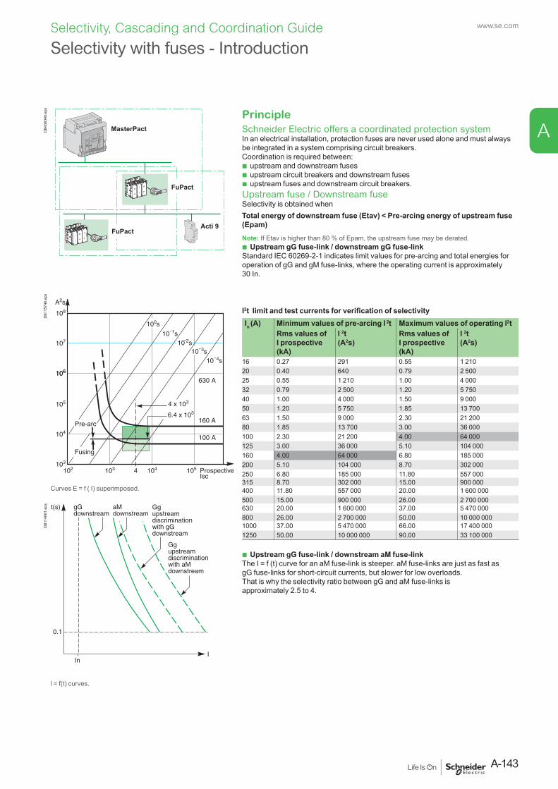
Selectivity with fuses - IntroductionD
B438
348.
eps
PrincipleSchneider Electric offers a coordinated protection systemIn an electrical installation, protection fuses are never used alone and must always be integrated in a system comprising circuit breakers. Coordination is required between:
b upstream and downstream fuses b upstream circuit breakers and downstream fuses b upstream fuses and downstream circuit breakers.
Upstream fuse / Downstream fuseSelectivity is obtained whenTotal energy of downstream fuse (Etav) < Pre-arcing energy of upstream fuse (Epam)Note: If Etav is higher than 80 % of Epam, the upstream fuse may be derated.
b Upstream gG fuse-link / downstream gG fuse-linkStandard IEC 60269-2-1 indicates limit values for pre-arcing and total energies for operation of gG and gM fuse-links, where the operating current is approximately 30 In.
DB1
1574
6.ep
s
I2t limit and test currents for verification of selectivityIn (A) Minimum values of pre-arcing I 2t Maximum values of operating I2t
Rms values of I prospective (kA)
I 2t (A2s)
Rms values of I prospective (kA)
I 2t (A2s)
16 0.27 291 0.55 1 21020 0.40 640 0.79 2 50025 0.55 1 210 1.00 4 00032 0.79 2 500 1.20 5 75040 1.00 4 000 1.50 9 00050 1.20 5 750 1.85 13 70063 1.50 9 000 2.30 21 20080 1.85 13 700 3.00 36 000100 2.30 21 200 4.00 64 000125 3.00 36 000 5.10 104 000160 4.00 64 000 6.80 185 000200 5.10 104 000 8.70 302 000250 6.80 185 000 11.80 557 000315 8.70 302 000 15.00 900 000
Curves E = f ( I) superimposed. 400 11.80 557 000 20.00 1 600 000500 15.00 900 000 26.00 2 700 000
DB1
1488
1.ep
s
630 20.00 1 600 000 37.00 5 470 000800 26.00 2 700 000 50.00 10 000 0001000 37.00 5 470 000 66.00 17 400 0001250 50.00 10 000 000 90.00 33 100 000
b Upstream gG fuse-link / downstream aM fuse-linkThe I = f (t) curve for an aM fuse-link is steeper. aM fuse-links are just as fast as gG fuse-links for short-circuit currents, but slower for low overloads.That is why the selectivity ratio between gG and aM fuse-links is approximately 2.5 to 4.
l = f(t) curves.
A-143
www.se.com
A
Selectivity, Cascading and Coordination Guide
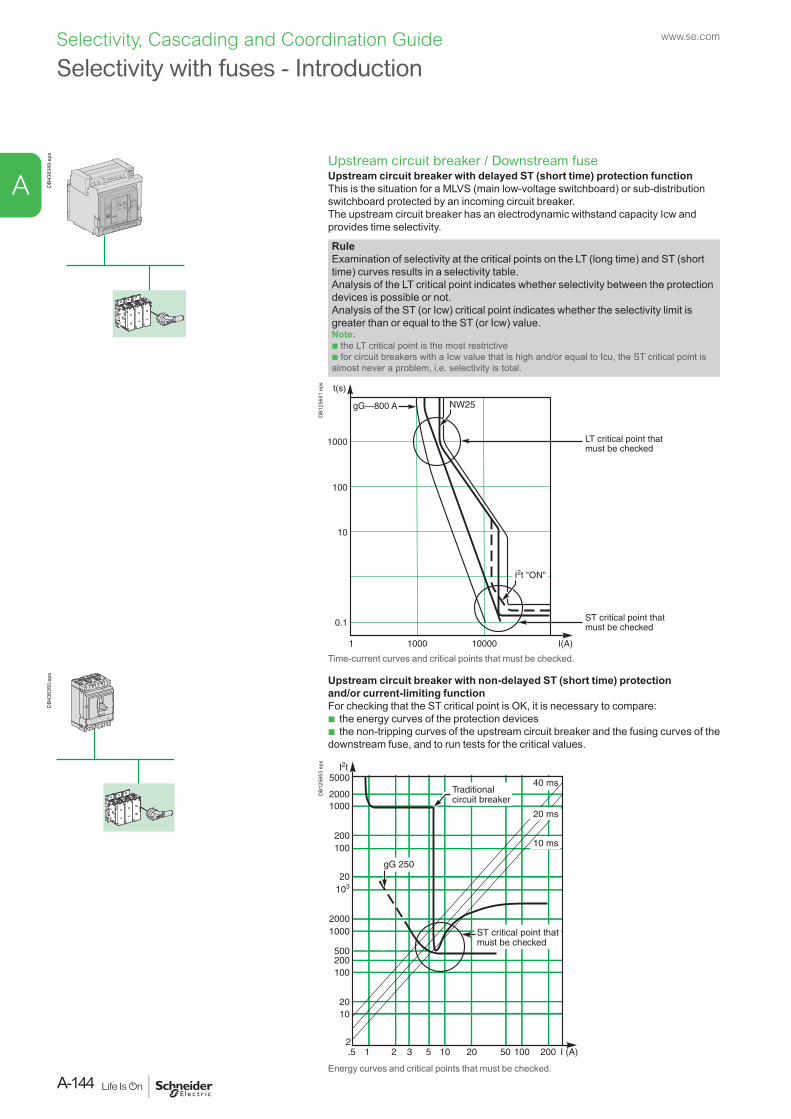
Selectivity with fuses - IntroductionD
B438
349.
eps
Upstream circuit breaker / Downstream fuse Upstream circuit breaker with delayed ST (short time) protection functionThis is the situation for a MLVS (main low-voltage switchboard) or sub-distribution switchboard protected by an incoming circuit breaker.The upstream circuit breaker has an electrodynamic withstand capacity Icw and provides time selectivity.
RuleExamination of selectivity at the critical points on the LT (long time) and ST (short time) curves results in a selectivity table.Analysis of the LT critical point indicates whether selectivity between the protection devices is possible or not.Analysis of the ST (or Icw) critical point indicates whether the selectivity limit is greater than or equal to the ST (or Icw) value.Note:b the LT critical point is the most restrictiveb for circuit breakers with a Icw value that is high and/or equal to Icu, the ST critical point is almost never a problem, i.e. selectivity is total.
DB1
2565
1.ep
s
Time-current curves and critical points that must be checked.
DB4
3835
0.ep
s
Upstream circuit breaker with non-delayed ST (short time) protection and/or current-limiting functionFor checking that the ST critical point is OK, it is necessary to compare:
b the energy curves of the protection devices b the non-tripping curves of the upstream circuit breaker and the fusing curves of the
downstream fuse, and to run tests for the critical values.
DB1
2565
3.ep
s
Energy curves and critical points that must be checked.
www.se.com
A-144
A
Selectivity, Cascading and Coordination Guide
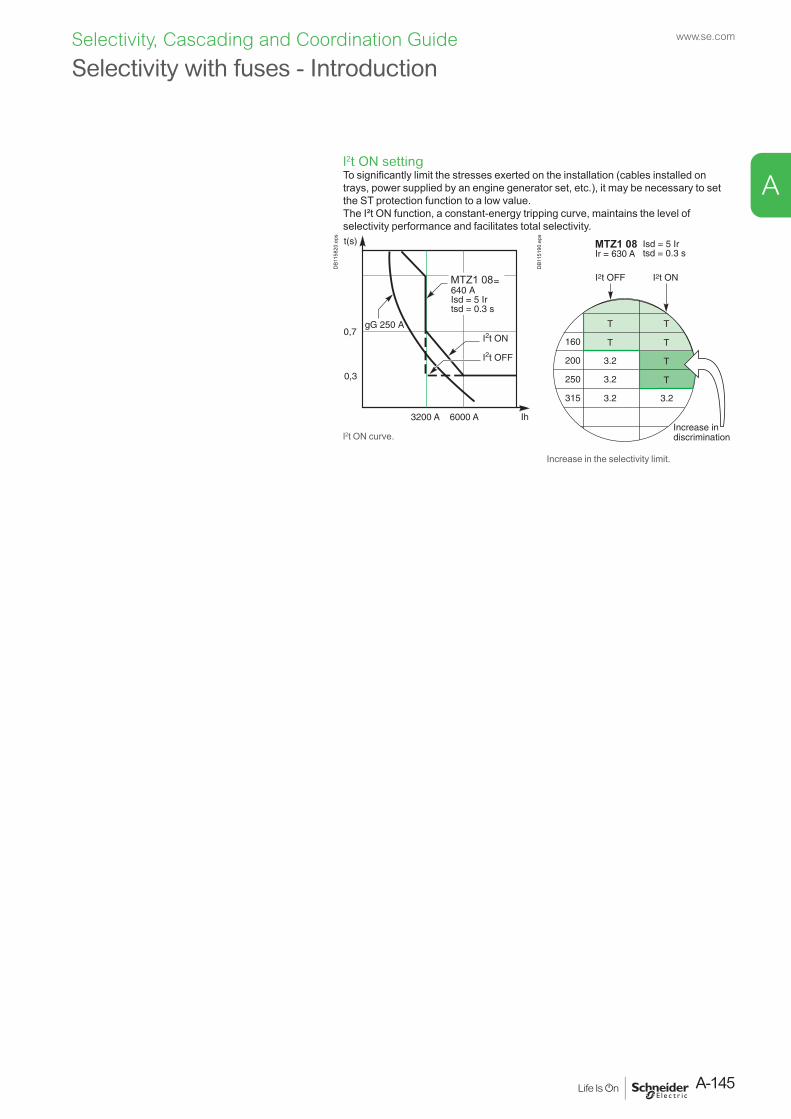
Selectivity with fuses - Introduction
l2t ON settingTo significantly limit the stresses exerted on the installation (cables installed on trays, power supplied by an engine generator set, etc.), it may be necessary to set the ST protection function to a low value.The I²t ON function, a constant-energy tripping curve, maintains the level of selectivity performance and facilitates total selectivity.
MTZ1 08
DB1
1582
0.ep
s
MTZ1 08
DB1
1519
0.ep
s
l2t ON curve.
Increase in the selectivity limit.
A-145
www.se.com
A
Selectivity, Cascading and Coordination Guide
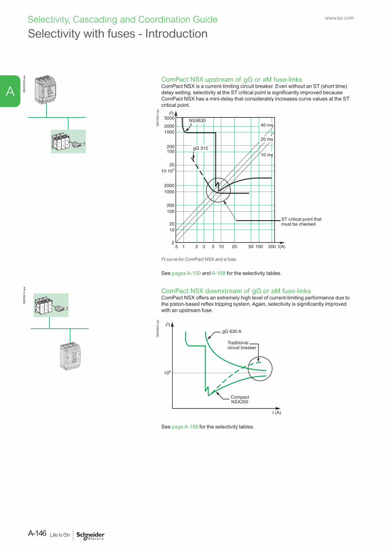
Selectivity with fuses - IntroductionD
B438
350.
eps
ComPact NSX upstream of gG or aM fuse-linksComPact NSX is a current-limiting circuit breaker. Even without an ST (short time) delay setting, selectivity at the ST critical point is significantly improved because ComPact NSX has a mini-delay that considerably increases curve values at the ST critical point.
DB4
1990
7.ep
s
I2t curve for ComPact NSX and a fuse.
See pages A-150 and A-158 for the selectivity tables.
DB4
3841
3.ep
s
ComPact NSX downstream of gG or aM fuse-linksComPact NSX offers an extremely high level of current-limiting performance due to the piston-based reflex tripping system. Again, selectivity is significantly improved with an upstream fuse.
DB4
0380
2.ep
s
See page A-158 for the selectivity tables.
www.se.com
A-146
A
Selectivity, Cascading and Coordination Guide
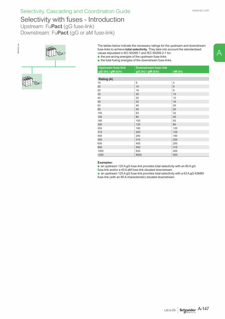
Selectivity with fuses - IntroductionUpstream: FuPact (gG fuse-link) Downstream: FuPact (gG or aM fuse-link)
DB4
3835
1.ep
s
The tables below indicate the necessary ratings for the upstream and downstream fuse-links to achieve total selectivity. They take into account the standardised values stipulated in IEC 60269-1 and IEC 60269-2-1 for:
b the pre-arcing energies of the upstream fuse-links b the total fusing energies of the downstream fuse-links.
Upstream fuse-link Downstream fuse-link gG (In) / gM (Ich) gG (In) / gM (Ich) aM (In)
Rating (A)16 6 420 10 625 16 832 20 1040 25 1250 32 1663 40 2080 50 25100 63 32125 80 40160 100 63200 125 80250 160 125315 200 125400 250 160500 315 200630 400 250800 500 3151000 630 4001250 8000 500
Examples: b an upstream 125 A gG fuse-link provides total selectivity with an 80 A gG
fuse-link and/or a 40 A aM fuse-link situated downstream b an upstream 125 A gG fuse-link provides total selectivity with a 63 A gG 63M80
fuse-link (with an 80 A characteristic) situated downstream.
A-147
www.se.com
A
Selectivity, Cascading and Coordination Guide
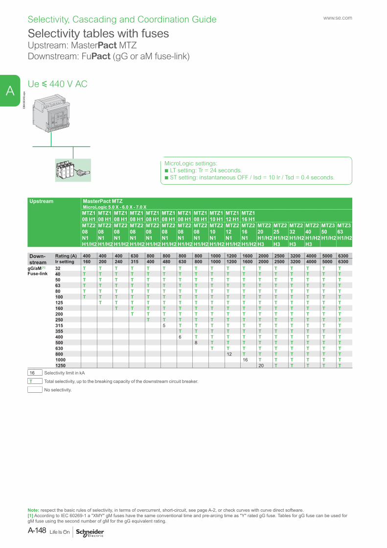
Selectivity tables with fusesUpstream: MasterPact MTZDownstream: FuPact (gG or aM fuse-link)
DB4
3834
9.ep
s
Upstream MasterPact MTZMicroLogic 5.0 X - 6.0 X - 7.0 XMTZ1 08 H1
MTZ1 08 H1
MTZ1 08 H1
MTZ1 08 H1
MTZ1 08 H1
MTZ1 08 H1
MTZ1 08 H1
MTZ1 08 H1
MTZ1 10 H1
MTZ1 12 H1
MTZ1 16 H1
MTZ2 08 N1 H1/H2
MTZ2 08 N1 H1/H2
MTZ2 08 N1 H1/H2
MTZ2 08 N1 H1/H2
MTZ2 08 N1 H1/H2
MTZ2 08 N1 H1/H2
MTZ2 08 N1 H1/H2
MTZ2 08 N1 H1/H2
MTZ2 10 N1 H1/H2
MTZ2 12 N1 H1/H2
MTZ2 16 N1 H1/H2
MTZ2 20 H1/H2 H3
MTZ2 25 H1/H2 H3
MTZ2 32 H1/H2 H3
MTZ2 40 H1/H2 H3
MTZ3 50 H1/H2
MTZ3 63 H1/H2
Down-stream
Rating (A) 400 400 400 630 800 800 800 800 1000 1200 1600 2000 2500 3200 4000 5000 6300Ir setting 160 200 240 315 400 480 630 800 1000 1200 1600 2000 2500 3200 4000 5000 6300
gG/aM [1]
Fuse-link 32 T T T T T T T T T T T T T T T T T40 T T T T T T T T T T T T T T T T T50 T T T T T T T T T T T T T T T T T63 T T T T T T T T T T T T T T T T T80 T T T T T T T T T T T T T T T T T100 T T T T T T T T T T T T T T T T T125 T T T T T T T T T T T T T T T T160 T T T T T T T T T T T T T T T200 T T T T T T T T T T T T T T250 T T T T T T T T T T T T T315 5 T T T T T T T T T T T355 T T T T T T T T T T T400 6 T T T T T T T T T T500 8 T T T T T T T T T630 T T T T T T T T T800 12 T T T T T T T1000 16 T T T T T T1250 20 T T T T T
16 Selectivity limit in kA
T Total selectivity, up to the breaking capacity of the downstream circuit breaker.
No selectivity.
Note: respect the basic rules of selectivity, in terms of overcurrent, short-circuit, see page A-2, or check curves with curve direct software. [1] According to IEC 60269-1 a "XMY" gM fuses have the same conventional time and pre-arcing time as "Y" rated gG fuse. Tables for gG fuse can be used for gM fuse using the second number of gM for the gG equivalent rating.
Ue y 440 V AC
MicroLogic settings:b LT setting: Tr = 24 seconds.b ST setting: instantaneous OFF / Isd = 10 Ir / Tsd = 0.4 seconds.
www.se.com
A-148
A
Selectivity, Cascading and Coordination Guide
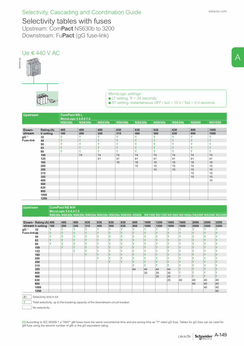
Selectivity tables with fusesUpstream: ComPact NS630b to 3200 Downstream: FuPact (gG fuse-link)
DB4
3835
2.ep
s
Upstream ComPact NS LMicroLogic 5.0-6.0-7.0NS630b NS630b NS630b NS630b NS630b NS630b NS630b NS800 NS1000
Down- stream
Rating (A) 400 400 400 630 630 630 630 800 1000Ir setting 160 200 240 315 400 500 630 800 1000
gG [1]
Fuse-link 32 T T T T T T T T T40 T T T T T T T T T50 T T T T T T T T T63 T T T T T T T T T80 T T T T T T T T T100 74 74 74 74 74 74 74 74125 41 41 41 41 41 41 41160 16 16 16 16 16 16200 10 10 10 10 10250 10 10 10 10315 10 10355 10 10400 1050063080010001250
Upstream ComPact NS N/HMicroLogic 5.0-6.0-7.0NS630b NS630b NS630b NS630b NS630b NS630b NS630b NS800 NS1000 NS1250 NS1600 NS1600b NS2000 NS2500 NS3200
Down- stream
Rating (A) 400 400 400 630 630 630 630 800 1000 1200 1600 1600 2000 2500 3200Ir setting 160 200 240 315 400 500 630 800 1000 1200 1600 1600 2000 2500 3200
gG [1]
Fuse-link 32 T T T T T T T T T T T T T T T40 T T T T T T T T T T T T T T T50 T T T T T T T T T T T T T T T63 T T T T T T T T T T T T T T T80 T T T T T T T T T T T T T T T100 T T T T T T T T T T T T T T125 T T T T T T T T T T T T T160 T T T T T T T T T T T T200 T T T T T T T T T T T250 T T T T T T T T T T315 T T T T T T T T355 44 44 44 44 T T T T400 35 35 35 T T T T500 25 25 T T T T630 25 40 40 40 40800 40 40 401000 40 401250 40
41 Selectivity limit in kA
T Total selectivity, up to the breaking capacity of the downstream circuit breaker.
No selectivity.
Ue y 440 V AC
MicroLogic settings:b LT setting: Tr = 24 seconds.b ST setting: instantaneous OFF / Isd = 10 Ir / Tsd = 0.4 seconds.
[1] According to IEC 60269-1 a "XMY" gM fuses have the same conventional time and pre-arcing time as "Y" rated gG fuse. Tables for gG fuse can be used for gM fuse using the second number of gM or the gG equivalent rating.
A-149
www.se.com
A
Selectivity, Cascading and Coordination Guide
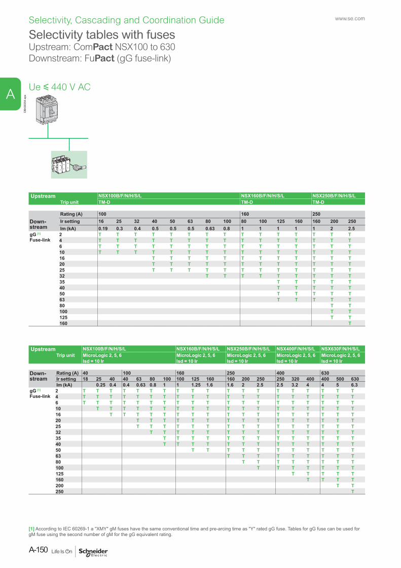
Selectivity tables with fusesUpstream: ComPact NSX100 to 630 Downstream: FuPact (gG fuse-link)
DB4
3835
4.ep
s
Upstream NSX100B/F/N/H/S/L NSX160B/F/N/H/S/L NSX250B/F/N/H/S/LTrip unit TM-D TM-D TM-D
Rating (A) 100 160 250Down-stream
Ir setting 16 25 32 40 50 63 80 100 80 100 125 160 160 200 250Im (kA) 0.19 0.3 0.4 0.5 0.5 0.5 0.63 0.8 1 1 1 1 1 2 2.5
gG [1]
Fuse-link 2 T T T T T T T T T T T T T T T4 T T T T T T T T T T T T T T T6 T T T T T T T T T T T T T T T10 T T T T T T T T T T T T T T T16 T T T T T T T T T T T T20 T T T T T T T T T T T T25 T T T T T T T T T T T T32 T T T T T T T T T35 T T T T T40 T T T T T50 T T T T T63 T T T T T80 T T100 T T125 T T160 T
Upstream NSX100B/F/N/H/S/L NSX160B/F/N/H/S/L NSX250B/F/N/H/S/L NSX400F/N/H/S/L NSX630F/N/H/S/LTrip unit MicroLogic 2, 5, 6 MicroLogic 2, 5, 6 MicroLogic 2, 5, 6 MicroLogic 2, 5, 6 MicroLogic 2, 5, 6
Isd = 10 Ir Isd = 10 Ir Isd = 10 Ir Isd = 10 Ir Isd = 10 Ir
Down-stream
Rating (A) 40 100 160 250 400 630Ir setting 18 25 40 40 63 80 100 100 125 160 160 200 250 250 320 400 400 500 630Im (kA) 0.25 0.4 0.4 0.63 0.8 1 1 1.25 1.6 1.6 2 2.5 2.5 3.2 4 4 5 6.3
gG [1]
Fuse-link 2 T T T T T T T T T T T T T T T T T T T4 T T T T T T T T T T T T T T T T T T T6 T T T T T T T T T T T T T T T T T T T10 T T T T T T T T T T T T T T T T T T16 T T T T T T T T T T T T T T T T T20 T T T T T T T T T T T T T T T25 T T T T T T T T T T T T T T T32 T T T T T T T T T T T T T T35 T T T T T T T T T T T T T40 T T T T T T T T T T T T T50 T T T T T T T T T T T63 T T T T T T T T T80 T T T T T T T T100 T T T T T T T125 T T T T T160 T T T T200 T T250 T
Ue y 440 V AC
[1] According to IEC 60269-1 a "XMY" gM fuses have the same conventional time and pre-arcing time as "Y" rated gG fuse. Tables for gG fuse can be used for gM fuse using the second number of gM for the gG equivalent rating.
www.se.com
A-150
A
Selectivity, Cascading and Coordination Guide
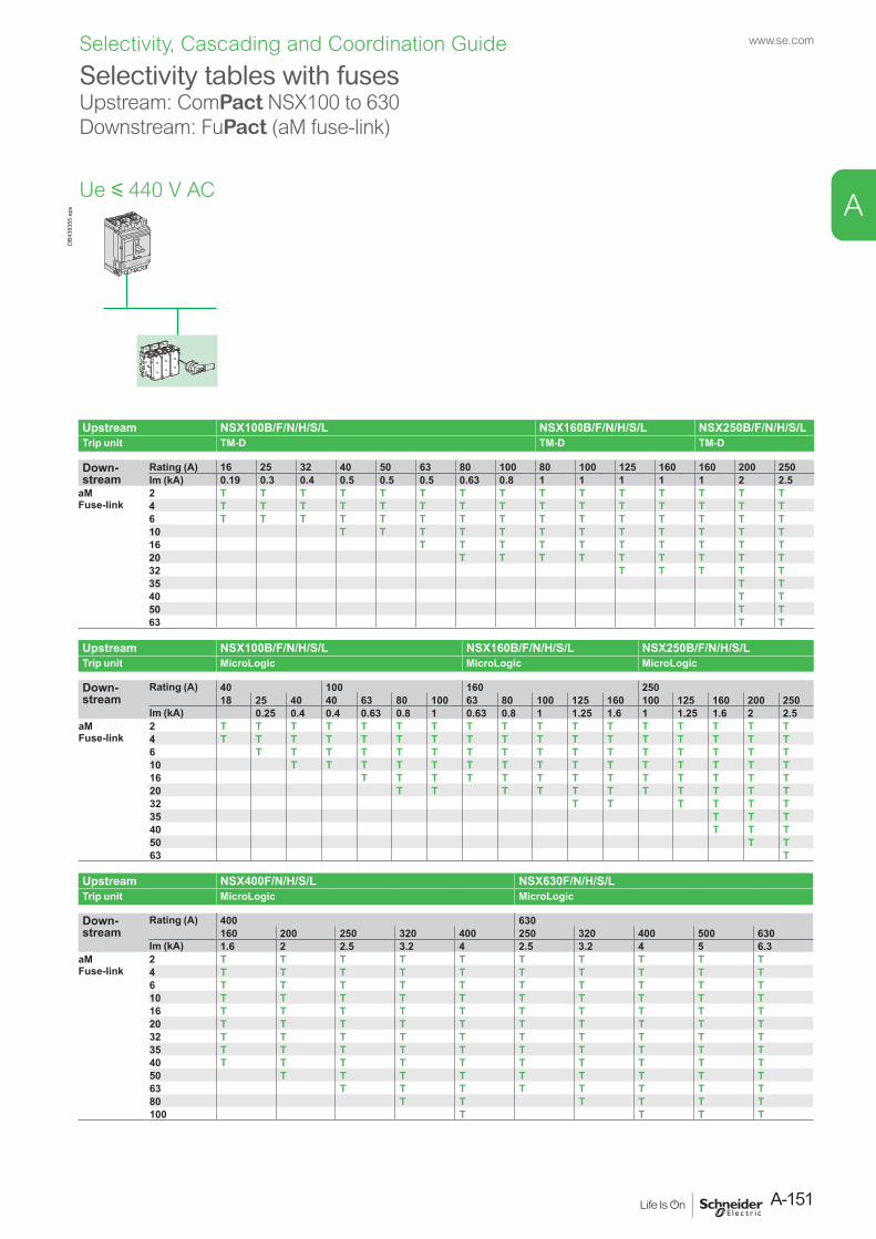
Ue y 440 V AC
Selectivity tables with fusesUpstream: ComPact NSX100 to 630 Downstream: FuPact (aM fuse-link)
DB4
3835
5.ep
s
Upstream NSX100B/F/N/H/S/L NSX160B/F/N/H/S/L NSX250B/F/N/H/S/LTrip unit TM-D TM-D TM-D
Down-stream
Rating (A) 16 25 32 40 50 63 80 100 80 100 125 160 160 200 250Im (kA) 0.19 0.3 0.4 0.5 0.5 0.5 0.63 0.8 1 1 1 1 1 2 2.5
aMFuse-link
2 T T T T T T T T T T T T T T T4 T T T T T T T T T T T T T T T6 T T T T T T T T T T T T T T T10 T T T T T T T T T T T T16 T T T T T T T T T T20 T T T T T T T T T32 T T T T T35 T T40 T T50 T T63 T T
Upstream NSX100B/F/N/H/S/L NSX160B/F/N/H/S/L NSX250B/F/N/H/S/LTrip unit MicroLogic MicroLogic MicroLogic
Down-stream
Rating (A) 40 100 160 25018 25 40 40 63 80 100 63 80 100 125 160 100 125 160 200 250
Im (kA) 0.25 0.4 0.4 0.63 0.8 1 0.63 0.8 1 1.25 1.6 1 1.25 1.6 2 2.5aMFuse-link
2 T T T T T T T T T T T T T T T T T4 T T T T T T T T T T T T T T T T T6 T T T T T T T T T T T T T T T T10 T T T T T T T T T T T T T T T16 T T T T T T T T T T T T T20 T T T T T T T T T T T32 T T T T T T35 T T T40 T T T50 T T63 T
Upstream NSX400F/N/H/S/L NSX630F/N/H/S/LTrip unit MicroLogic MicroLogic
Down-stream
Rating (A) 400 630160 200 250 320 400 250 320 400 500 630
Im (kA) 1.6 2 2.5 3.2 4 2.5 3.2 4 5 6.3aMFuse-link
2 T T T T T T T T T T4 T T T T T T T T T T6 T T T T T T T T T T10 T T T T T T T T T T16 T T T T T T T T T T20 T T T T T T T T T T32 T T T T T T T T T T35 T T T T T T T T T T40 T T T T T T T T T T50 T T T T T T T T T63 T T T T T T T T80 T T T T T T100 T T T T
A-151
www.se.com
A
Selectivity, Cascading and Coordination Guide
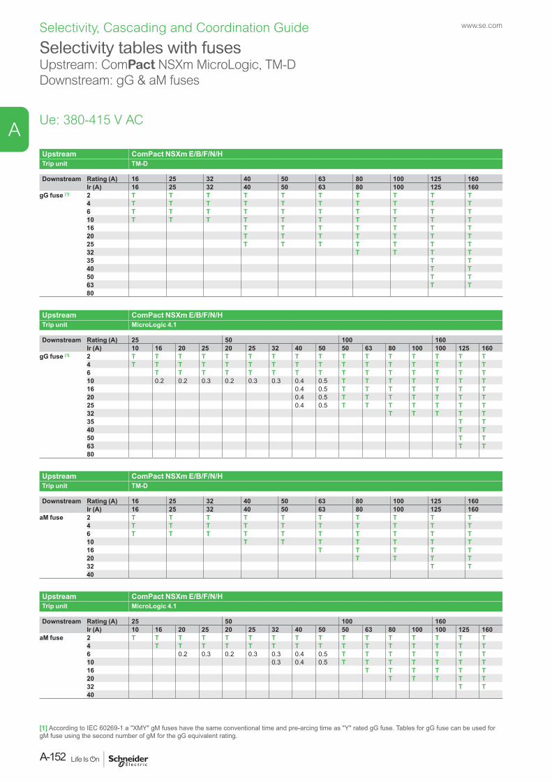
Selectivity tables with fusesUpstream: ComPact NSXm MicroLogic, TM-D Downstream: gG & aM fuses
Ue: 380-415 V AC
Upstream ComPact NSXm E/B/F/N/HTrip unit TM-D
Downstream Rating (A) 16 25 32 40 50 63 80 100 125 160Ir (A) 16 25 32 40 50 63 80 100 125 160
gG fuse [1] 2 T T T T T T T T T T4 T T T T T T T T T T6 T T T T T T T T T T10 T T T T T T T T T T16 T T T T T T T20 T T T T T T T25 T T T T T T T32 T T T T35 T T40 T T50 T T63 T T80
Upstream ComPact NSXm E/B/F/N/HTrip unit MicroLogic 4.1
Downstream Rating (A) 25 50 100 160Ir (A) 10 16 20 25 20 25 32 40 50 50 63 80 100 100 125 160
gG fuse [1] 2 T T T T T T T T T T T T T T T T4 T T T T T T T T T T T T T T T T6 T T T T T T T T T T T T T T T10 0.2 0.2 0.3 0.2 0.3 0.3 0.4 0.5 T T T T T T T16 0.4 0.5 T T T T T T T20 0.4 0.5 T T T T T T T25 0.4 0.5 T T T T T T T32 T T T T T35 T T40 T T50 T T63 T T80
Upstream ComPact NSXm E/B/F/N/HTrip unit TM-D
Downstream Rating (A) 16 25 32 40 50 63 80 100 125 160Ir (A) 16 25 32 40 50 63 80 100 125 160
aM fuse 2 T T T T T T T T T T4 T T T T T T T T T T6 T T T T T T T T T T10 T T T T T T T16 T T T T T20 T T T T32 T T40
Upstream ComPact NSXm E/B/F/N/HTrip unit MicroLogic 4.1
Downstream Rating (A) 25 50 100 160Ir (A) 10 16 20 25 20 25 32 40 50 50 63 80 100 100 125 160
aM fuse 2 T T T T T T T T T T T T T T T T4 T T T T T T T T T T T T T T T6 0.2 0.3 0.2 0.3 0.3 0.4 0.5 T T T T T T T10 0.3 0.4 0.5 T T T T T T T16 T T T T T T20 T T T T T32 T T40
[1] According to IEC 60269-1 a "XMY" gM fuses have the same conventional time and pre-arcing time as "Y" rated gG fuse. Tables for gG fuse can be used for gM fuse using the second number of gM for the gG equivalent rating.
www.se.com
A-152
A
Selectivity, Cascading and Coordination Guide
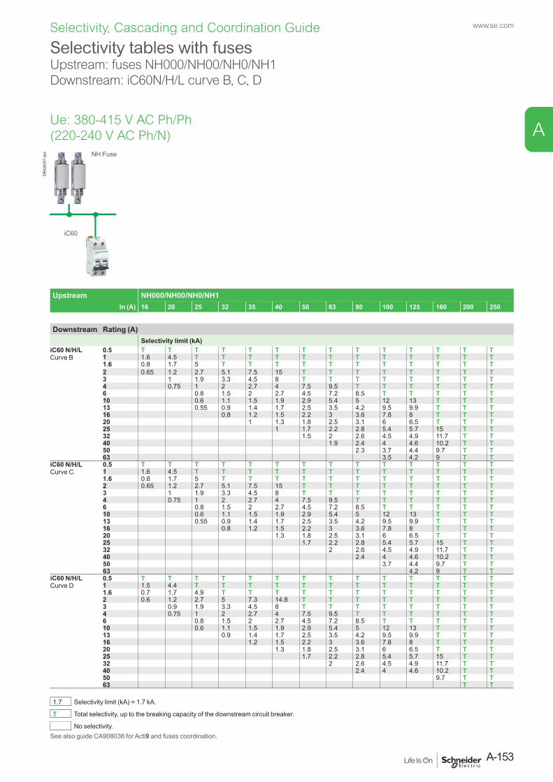
Selectivity tables with fusesUpstream: fuses NH000/NH00/NH0/NH1Downstream: iC60N/H/L curve B, C, D
Upstream NH000/NH00/NH0/NH1In (A) 16 20 25 32 35 40 50 63 80 100 125 160 200 250
Downstream Rating (A)Selectivity limit (kA)
iC60 N/H/LCurve B
0.5 T T T T T T T T T T T T T T1 1.6 4.5 T T T T T T T T T T T T1.6 0.8 1.7 5 T T T T T T T T T T T2 0.65 1.2 2.7 5.1 7.5 15 T T T T T T T T3 1 1.9 3.3 4.5 8 T T T T T T T T4 0.75 1 2 2.7 4 7.5 9.5 T T T T T T6 0.8 1.5 2 2.7 4.5 7.2 8.5 T T T T T10 0.6 1.1 1.5 1.9 2.9 5.4 5 12 13 T T T13 0.55 0.9 1.4 1.7 2.5 3.5 4.2 9.5 9.9 T T T16 0.8 1.2 1.5 2.2 3 3.6 7.8 8 T T T20 1 1.3 1.8 2.5 3.1 6 6.5 T T T25 1 1.7 2.2 2.8 5.4 5.7 15 T T32 1.5 2 2.6 4.5 4.9 11.7 T T40 1.9 2.4 4 4.6 10.2 T T50 2.3 3.7 4.4 9.7 T T63 3.5 4.2 9 T T
iC60 N/H/LCurve C
0.5 T T T T T T T T T T T T T T1 1.6 4.5 T T T T T T T T T T T T1.6 0.8 1.7 5 T T T T T T T T T T T2 0.65 1.2 2.7 5.1 7.5 15 T T T T T T T T3 1 1.9 3.3 4.5 8 T T T T T T T T4 0.75 1 2 2.7 4 7.5 9.5 T T T T T T6 0.8 1.5 2 2.7 4.5 7.2 8.5 T T T T T10 0.6 1.1 1.5 1.9 2.9 5.4 5 12 13 T T T13 0.55 0.9 1.4 1.7 2.5 3.5 4.2 9.5 9.9 T T T16 0.8 1.2 1.5 2.2 3 3.6 7.8 8 T T T20 1.3 1.8 2.5 3.1 6 6.5 T T T25 1.7 2.2 2.8 5.4 5.7 15 T T32 2 2.6 4.5 4.9 11.7 T T40 2.4 4 4.6 10.2 T T50 3.7 4.4 9.7 T T63 4.2 9 T T
iC60 N/H/LCurve D
0.5 T T T T T T T T T T T T T T1 1.5 4.4 T T T T T T T T T T T T1.6 0.7 1.7 4.9 T T T T T T T T T T T2 0.6 1.2 2.7 5 7.3 14.8 T T T T T T T T3 0.9 1.9 3.3 4.5 8 T T T T T T T T4 0.75 1 2 2.7 4 7.5 9.5 T T T T T T6 0.8 1.5 2 2.7 4.5 7.2 8.5 T T T T T10 0.6 1.1 1.5 1.9 2.9 5.4 5 12 13 T T T13 0.9 1.4 1.7 2.5 3.5 4.2 9.5 9.9 T T T16 1.2 1.5 2.2 3 3.6 7.8 8 T T T20 1.3 1.8 2.5 3.1 6 6.5 T T T25 1.7 2.2 2.8 5.4 5.7 15 T T32 2 2.6 4.5 4.9 11.7 T T40 2.4 4 4.6 10.2 T T50 9.7 T T63 T T
1.7 Selectivity limit (kA) = 1.7 kA.
T Total selectivity, up to the breaking capacity of the downstream circuit breaker.
No selectivity.See also guide CA908036 for Acti9 and fuses coordination.
Ue: 380-415 V AC Ph/Ph (220-240 V AC Ph/N)
iC60
NH Fuse
DB4
2825
7.ep
s
A-153
www.se.com
A
Selectivity, Cascading and Coordination Guide
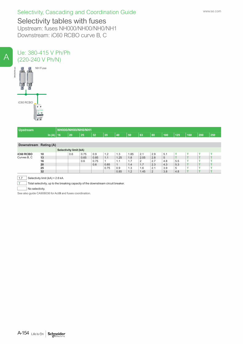
Selectivity tables with fusesUpstream: fuses NH000/NH00/NH0/NH1Downstream: iC60 RCBO curve B, C
Upstream NH000/NH00/NH0/NH1In (A) 16 20 25 32 35 40 50 63 80 100 125 160 200 250
Downstream Rating (A)Selectivity limit (kA)
iC60 RCBOCurves B, C
10 0.6 0.75 0.9 1.2 1.3 1.85 2.1 2.9 5.1 T T T T13 0.65 0.85 1.1 1.25 1.8 2.05 2.8 5 T T T T16 0.6 0.75 1 1.1 1.7 2 2.7 4.8 5.5 T T T20 0.6 0.85 1 1.4 1.7 2.3 4.3 5.3 T T T25 0.75 0.9 1.3 1.6 2.1 3.9 5 T T T32 0.85 1.2 1.45 2 3.8 4.8 T T T
1.7 Selectivity limit (kA) = 2.6 kA.
T Total selectivity, up to the breaking capacity of the downstream circuit breaker.
No selectivity.See also guide CA908036 for Acti9 and fuses coordination.
Ue: 380-415 V Ph/Ph (220-240 V Ph/N)
NH Fuse
iC60 RCBO
DB4
2825
8.ep
swww.se.com
A-154
A
Selectivity, Cascading and Coordination Guide
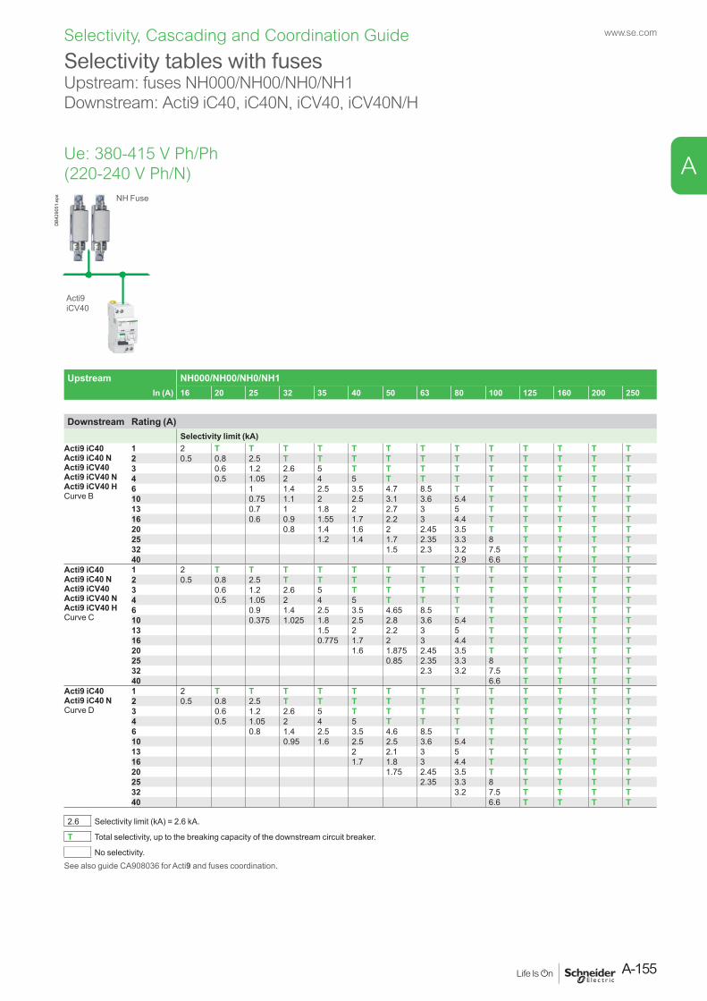
Selectivity tables with fusesUpstream: fuses NH000/NH00/NH0/NH1Downstream: Acti9 iC40, iC40N, iCV40, iCV40N/H
Upstream NH000/NH00/NH0/NH1In (A) 16 20 25 32 35 40 50 63 80 100 125 160 200 250
Downstream Rating (A)Selectivity limit (kA)
Acti9 iC40Acti9 iC40 NActi9 iCV40Acti9 iCV40 NActi9 iCV40 HCurve B
1 2 T T T T T T T T T T T T T2 0.5 0.8 2.5 T T T T T T T T T T T3 0.6 1.2 2.6 5 T T T T T T T T T4 0.5 1.05 2 4 5 T T T T T T T T6 1 1.4 2.5 3.5 4.7 8.5 T T T T T T10 0.75 1.1 2 2.5 3.1 3.6 5.4 T T T T T13 0.7 1 1.8 2 2.7 3 5 T T T T T16 0.6 0.9 1.55 1.7 2.2 3 4.4 T T T T T20 0.8 1.4 1.6 2 2.45 3.5 T T T T T25 1.2 1.4 1.7 2.35 3.3 8 T T T T32 1.5 2.3 3.2 7.5 T T T T40 2.9 6.6 T T T T
Acti9 iC40Acti9 iC40 NActi9 iCV40Acti9 iCV40 NActi9 iCV40 HCurve C
1 2 T T T T T T T T T T T T T2 0.5 0.8 2.5 T T T T T T T T T T T3 0.6 1.2 2.6 5 T T T T T T T T T4 0.5 1.05 2 4 5 T T T T T T T T6 0.9 1.4 2.5 3.5 4.65 8.5 T T T T T T10 0.375 1.025 1.8 2.5 2.8 3.6 5.4 T T T T T13 1.5 2 2.2 3 5 T T T T T16 0.775 1.7 2 3 4.4 T T T T T20 1.6 1.875 2.45 3.5 T T T T T25 0.85 2.35 3.3 8 T T T T32 2.3 3.2 7.5 T T T T40 6.6 T T T T
Acti9 iC40Acti9 iC40 NCurve D
1 2 T T T T T T T T T T T T T2 0.5 0.8 2.5 T T T T T T T T T T T3 0.6 1.2 2.6 5 T T T T T T T T T4 0.5 1.05 2 4 5 T T T T T T T T6 0.8 1.4 2.5 3.5 4.6 8.5 T T T T T T10 0.95 1.6 2.5 2.5 3.6 5.4 T T T T T13 2 2.1 3 5 T T T T T16 1.7 1.8 3 4.4 T T T T T20 1.75 2.45 3.5 T T T T T25 2.35 3.3 8 T T T T32 3.2 7.5 T T T T40 6.6 T T T T
2.6 Selectivity limit (kA) = 2.6 kA.
T Total selectivity, up to the breaking capacity of the downstream circuit breaker.
No selectivity.See also guide CA908036 for Acti9 and fuses coordination.
Ue: 380-415 V Ph/Ph (220-240 V Ph/N)
NH Fuse
Acti9 iCV40
DB4
2905
1.ep
s
A-155
www.se.com
A
Selectivity, Cascading and Coordination Guide
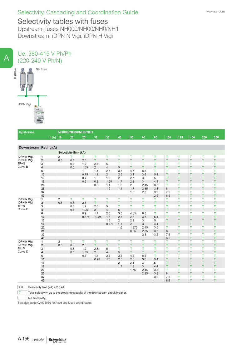
Selectivity tables with fusesUpstream: fuses NH000/NH00/NH0/NH1Downstream: iDPN N Vigi, iDPN H Vigi
Upstream NH000/NH00/NH0/NH1In (A) 16 20 25 32 35 40 50 63 80 100 125 160 200 250
Downstream Rating (A)Selectivity limit (kA)
iDPN N VigiiDPN H Vigi1P+NCurve B
1 2 T T T T T T T T T T T T T2 0.5 0.8 2.5 T T T T T T T T T T T3 0.6 1.2 2.6 5 T T T T T T T T T4 0.5 1.05 2 4 5 T T T T T T T T6 1 1.4 2.5 3.5 4.7 8.5 T T T T T T10 0.75 1.1 2 2.5 3.1 3.6 5.4 T T T T T13 0.7 1 1.8 2 2.7 3 5 T T T T T16 0.6 0.9 1.55 1.7 2.2 3 4.4 T T T T T20 0.8 1.4 1.6 2 2.45 3.5 T T T T T25 1.2 1.4 1.7 2.35 3.3 8 T T T T32 1.5 2.3 3.2 7.5 T T T T40 2.9 6.6 T T T T
iDPN N VigiiDPN H Vigi1P+NCurve C
1 2 T T T T T T T T T T T T T2 0.5 0.8 2.5 T T T T T T T T T T T3 0.6 1.2 2.6 5 T T T T T T T T T4 0.5 1.05 2 4 5 T T T T T T T T6 0.9 1.4 2.5 3.5 4.65 8.5 T T T T T T10 0.375 1.025 1.8 2.5 2.8 3.6 5.4 T T T T T13 1.5 2 2.2 3 5 T T T T T16 0.775 1.7 2 3 4.4 T T T T T20 1.6 1.875 2.45 3.5 T T T T T25 0.85 2.35 3.3 8 T T T T32 2.3 3.2 7.5 T T T T40 6.6 T T T T
iDPN N VigiiDPN H Vigi1P+NCurve D
1 2 T T T T T T T T T T T T T2 0.5 0.8 2.5 T T T T T T T T T T T3 0.6 1.2 2.6 5 T T T T T T T T T4 0.5 1.05 2 4 5 T T T T T T T T6 0.8 1.4 2.5 3.5 4.6 8.5 T T T T T T10 0.95 1.6 2.5 2.5 3.6 5.4 T T T T T13 2 2.1 3 5 T T T T T16 1.7 1.8 3 4.4 T T T T T20 1.75 2.45 3.5 T T T T T25 2.35 3.3 8 T T T T32 3.2 7.5 T T T T40 6.6 T T T T
2.6 Selectivity limit (kA) = 2.6 kA.
T Total selectivity, up to the breaking capacity of the downstream circuit breaker.
No selectivity.See also guide CA908036 for Acti9 and fuses coordination.
Ue: 380-415 V Ph/Ph (220-240 V Ph/N)
NH Fuse
iDPN Vigi
DB4
2825
9.ep
swww.se.com
A-156
A
Selectivity, Cascading and Coordination Guide
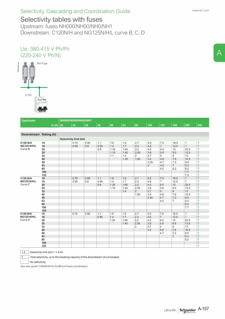
Ue: 380-415 V Ph/Ph (220-240 V Ph/N)
Upstream NH000/NH00/NH0/NH1In (A) 25 32 35 40 50 63 80 100 125 160 200 250
Downstream Rating (A)Selectivity limit (kA)
C120 N/HNG125 N/H/LCurve B
10 0.75 0.95 1.1 1.6 1.9 2.7 5.5 7.5 18.5 T T16 0.55 0.8 0.95 1.4 1.7 2.3 4.6 7 12.5 T T20 0.9 1.35 1.65 2.2 4.5 6.5 12 22.5 T25 1.15 1.45 2.05 3.8 5.8 9.5 13.5 T32 1.1 1.4 2 3.7 5 9 13 T40 1.35 1.85 3.4 4.8 7.6 10.5 T50 3.25 4.7 7.2 9.5 T63 3 4.5 7 9.3 T80 4.2 6.2 8.2 T100 7.7 T125 7.5 T
C120 N/HNG125 N/H/LCurve C
10 0.75 0.95 1.1 1.6 1.9 2.7 5.5 7.5 18.5 T T16 0.55 0.8 0.95 1.4 1.7 2.3 4.6 7 12.5 T T20 0.9 1.35 1.65 2.2 4.5 6.5 12 22.5 T25 1.15 1.45 2.05 3.8 5.8 9.5 13.5 T32 1.4 2 3.7 5 9 13 T40 1.85 3.4 4.8 7.6 10.5 T50 3.25 4.7 7.2 9.5 T63 4.5 7 9.3 T80 8.2 T100 7.7 T125 T
C120 N/HNG125 N/H/LCurve D
10 0.75 0.95 1.1 1.6 1.9 2.7 5.5 7.5 18.5 T T16 0.95 1.4 1.7 2.3 4.6 7 12.5 T T20 1.35 1.65 2.2 4.5 6.5 12 22.5 T25 1.45 2.05 3.8 5.8 9.5 13.5 T32 2 3.7 5 9 13 T40 3.4 4.8 7.6 10.5 T50 4.7 7.2 9.5 T63 7 9.3 T80 8.2 T100 T125 T
1.4 Selectivity limit (kA) = 1.4 kA.
T Total selectivity, up to the breaking capacity of the downstream circuit breaker.
No selectivity.See also guide CA908036 for Acti9 and fuses coordination.
Selectivity tables with fusesUpstream: fuses NH000/NH00/NH0/NH1Downstream: C120N/H and NG125N/H/L curve B, C, D
NH Fuse
C120
DB4
2826
0.ep
s
A-157
www.se.com
A
Selectivity, Cascading and Coordination Guide
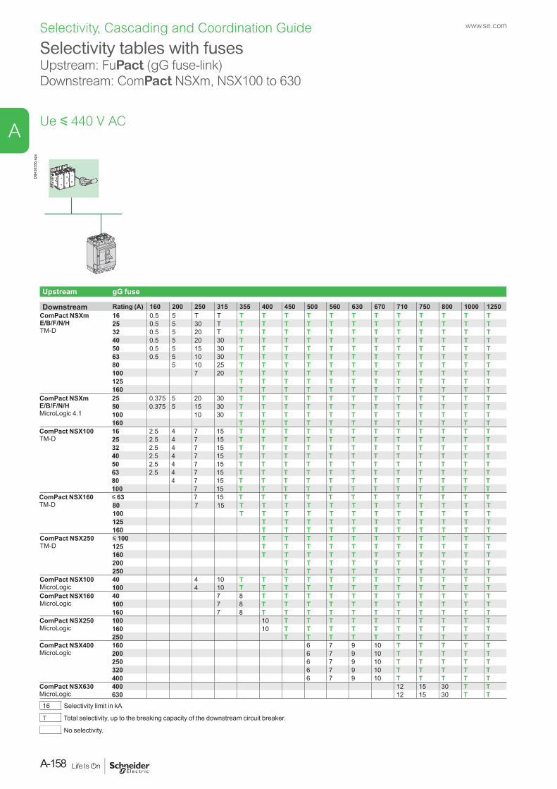
Selectivity tables with fusesUpstream: FuPact (gG fuse-link)Downstream: ComPact NSXm, NSX100 to 630
DB4
3835
6.ep
s
Upstream gG fuse
Downstream Rating (A) 160 200 250 315 355 400 450 500 560 630 670 710 750 800 1000 1250ComPact NSXm E/B/F/N/HTM-D
16 0.5 5 T T T T T T T T T T T T T T25 0.5 5 30 T T T T T T T T T T T T T32 0.5 5 20 T T T T T T T T T T T T T40 0.5 5 20 30 T T T T T T T T T T T T50 0.5 5 15 30 T T T T T T T T T T T T63 0.5 5 10 30 T T T T T T T T T T T T80 5 10 25 T T T T T T T T T T T T100 7 20 T T T T T T T T T T T T125 T T T T T T T T T T T T160 T T T T T T T T T T T T
ComPact NSXm E/B/F/N/HMicroLogic 4.1
25 0.375 5 20 30 T T T T T T T T T T T T50 0.375 5 15 30 T T T T T T T T T T T T100 10 30 T T T T T T T T T T T T160 T T T T T T T T T T T T
ComPact NSX100TM-D
16 2.5 4 7 15 T T T T T T T T T T T T25 2.5 4 7 15 T T T T T T T T T T T T32 2.5 4 7 15 T T T T T T T T T T T T40 2.5 4 7 15 T T T T T T T T T T T T50 2.5 4 7 15 T T T T T T T T T T T T63 2.5 4 7 15 T T T T T T T T T T T T80 4 7 15 T T T T T T T T T T T T100 7 15 T T T T T T T T T T T T
ComPact NSX160TM-D
y 63 7 15 T T T T T T T T T T T T80 7 15 T T T T T T T T T T T T100 T T T T T T T T T T T T125 T T T T T T T T T T T160 T T T T T T T T T T T
ComPact NSX250TM-D
y 100 T T T T T T T T T T T125 T T T T T T T T T T T160 T T T T T T T T T T T200 T T T T T T T T T T250 T T T T T T T T T T
ComPact NSX100MicroLogic
40 4 10 T T T T T T T T T T T T100 4 10 T T T T T T T T T T T T
ComPact NSX160MicroLogic
40 7 8 T T T T T T T T T T T100 7 8 T T T T T T T T T T T160 7 8 T T T T T T T T T T T
ComPact NSX250MicroLogic
100 10 T T T T T T T T T T160 10 T T T T T T T T T T250 T T T T T T T T T T
ComPact NSX400MicroLogic
160 6 7 9 10 T T T T T200 6 7 9 10 T T T T T250 6 7 9 10 T T T T T320 6 7 9 10 T T T T T400 6 7 9 10 T T T T T
ComPact NSX630MicroLogic
400 12 15 30 T T630 12 15 30 T T
16 Selectivity limit in kA
T Total selectivity, up to the breaking capacity of the downstream circuit breaker.
No selectivity.
Ue y 440 V AC
www.se.com
A-158
A
Selectivity, Cascading and Coordination Guide
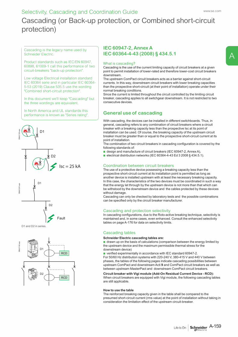
IEC 60947-2, Annex A IEC 60364-4-43 (2008) § 434.5.1
What is cascading?Cascading is the use of the current limiting capacity of circuit breakers at a given point to permit installation of lower-rated and therefore lower-cost circuit breakers downstream. The upstream ComPact circuit breakers acts as a barrier against short-circuit currents. In this way, downstream circuit breakers with lower breaking capacities than the prospective short-circuit (at their point of installation) operate under their normal breaking conditions.Since the current is limited throughout the circuit controlled by the limiting circuit breaker, cascading applies to all switchgear downstream. It is not restricted to two consecutive devices.
General use of cascading
With cascading, the devices can be installed in different switchboards. Thus, in general, cascading refers to any combination of circuit breakers where a circuit breaker with a breaking capacity less than the prospective Isc at its point of installation can be used. Of course, the breaking capacity of the upstream circuit breaker must be greater than or equal to the prospective short-circuit current at its point of installation.The combination of two circuit breakers in cascading configuration is covered by the following standards of:
b design and manufacture of circuit breakers (IEC 60947-2, Annex A), b electrical distribution networks (IEC 60364-4-43 Ed 3 2008 § 434.5.1).
Coordination between circuit breakersThe use of a protective device possessing a breaking capacity less than the prospective short-circuit current at its installation point is permitted as long as another device is installed upstream with at least the necessary breaking capacity.In this case, the characteristics of the two devices must be coordinated in such a way that the energy let through by the upstream device is not more than that which can be withstood by the downstream device and the cables protected by these devices without damage.Cascading can only be checked by laboratory tests and the possible combinations can be specified only by the circuit breaker manufacturer.
Cascading and protection selectivityIn cascading configurations, due to the Roto-active breaking technique, selectivity is maintained and, in some cases, even enhanced. Consult the enhanced selectivity tables on page A-176 for data on selectivity limits.
Cascading tablesSchneider Electric cascading tables are:
b drawn up on the basis of calculations (comparison between the energy limited by the upstream device and the maximum permissible thermal stress for the downstream device)
b verified experimentally in accordance with IEC standard 60947-2.For 50/60 Hz distribution systems with 220-240 V, 380-415 V and 440 V between phases, the tables of the following pages indicate cascading possibilities between upstream ComPact and downstream Acti 9 and ComPact circuit breakers as well as between upstream MasterPact and downstream ComPact circuit breakers.Circuit breaker with Vigi module (Add-On Residual Current Device - RCD): When circuit breakers are equipped with Vigi module, the following cascading tables are still applicable.
How to use the tableThe reinforced breaking capacity given in the table shall be compared to the presumed short-circuit current (rms value) at the point of installation without taking in consideration the limitation effect of the upstream circuit-breaker.
Isc = 25 kA
DB4
2119
3.ep
s
RCD
RCD
D1
D2
DB4
2119
2.ep
s
Cascading (or Back-up protection, or Combined short-circuit protection)
D2
D1
Fault
DB4
2120
1.ep
s
D1 and D2 in series.
Cascading is the legacy name used by Schneider Electric.
Product standards such as IEC/EN 60947, 60898, 61009-1 call this performance of two circuit-breakers "back-up protection".
Low voltage Electrical installation standard IEC 60364 serie and in particular IEC 60364-5-53 (2019) Clause 535.5 use the wording "Combined short-circuit protection".
In this document we'll keep "Cascading" but the three wordings are equivalent.
In North America and UL standards this performance is known as "Series rating".
A-159
www.se.com
A
Selectivity, Cascading and Coordination Guide
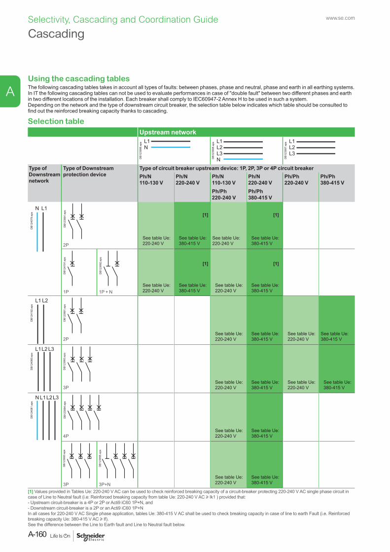
Using the cascading tablesThe following cascading tables takes in account all types of faults: between phases, phase and neutral, phase and earth in all earthing systems.In IT the following cascading tables can not be used to evaluate performances in case of "double fault" between two different phases and earth in two different locations of the installation. Each breaker shall comply to IEC60947-2 Annex H to be used in such a system.Depending on the network and the type of downstream circuit breaker, the selection table below indicates which table should be consulted to find out the reinforced breaking capacity thanks to cascading.
Selection tableUpstream network
L1N
DB1
2399
6.ep
s
L3N
L2L1
DB1
2399
8.ep
s
L3L2L1
DB1
2399
7.ep
s
Type of Downstream network
Type of Downstream protection device
Type of circuit breaker upstream device: 1P, 2P, 3P or 4P circuit breakerPh/N 110-130 V
Ph/N 220-240 V
Ph/N 110-130 V
Ph/N 220-240 V
Ph/Ph 220-240 V
Ph/Ph 380-415 V
Ph/Ph 220-240 V
Ph/Ph 380-415 V
L1N
DB1
2407
9.ep
s
DB1
2399
1.ep
s
2PSee table Ue:220-240 V
See table Ue:380-415 V
See table Ue:220-240 V
See table Ue:380-415 V
DB1
2419
1.ep
s
1P
DB1
2399
2.ep
s
1P + NSee table Ue:220-240 V
See table Ue:380-415 V
See table Ue:220-240 V
See table Ue:380-415 V
L2L1
DB1
2419
2.ep
s
DB1
2399
1.ep
s
2PSee table Ue:220-240 V
See table Ue:380-415 V
See table Ue:220-240 V
See table Ue:380-415 V
L1L2 L3
DB1
2408
0.ep
s
DB1
2399
3.ep
s
3PSee table Ue:220-240 V
See table Ue:380-415 V
See table Ue:220-240 V
See table Ue:380-415 V
L1N L2L3
DB1
2408
1.ep
s
DB1
2399
4.ep
s
4PSee table Ue:220-240 V
See table Ue:380-415 V
DB1
2399
3.ep
s
3P
DB1
2399
5.ep
s
3P+NSee table Ue:220-240 V
See table Ue:380-415 V
[1] Values provided in Tables Ue: 220-240 V AC can be used to check reinforced breaking capacity of a circuit-breaker protecting 220-240 V AC single phase circuit in case of Line to Neutral fault (i.e: Reinforced breaking capacity from table Ue: 220-240 V AC u Ik1 ) provided that:- Upstream circuit-breaker is a 4P or 2P or Acti9 iC60 1P+N, and - Downstream circuit-breaker is a 2P or an Acti9 iC60 1P+N In all cases for 220-240 V AC Single phase application, tables Ue: 380-415 V AC shall be used to check breaking capacity in case of line to earth Fault (i.e. Reinforced breaking capacity Ue: 380-415 V AC u If). See the difference between the Line to Earth fault and Line to Neutral fault below.
[1]
[1]
[1]
[1]
Cascadingwww.se.com
A-160
A
Selectivity, Cascading and Coordination Guide
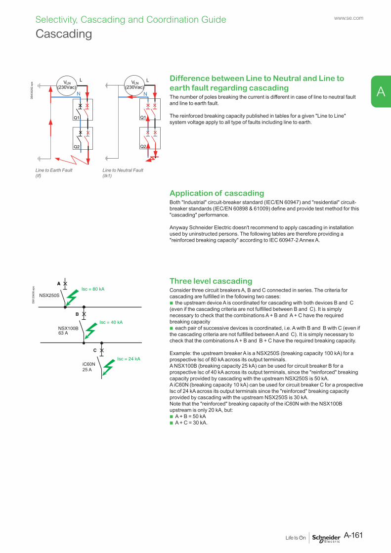
Three level cascadingConsider three circuit breakers A, B and C connected in series. The criteria for cascading are fulfilled in the following two cases:
b the upstream device A is coordinated for cascading with both devices B and C (even if the cascading criteria are not fulfilled between B and C). It is simply necessary to check that the combinations A + B and A + C have the required breaking capacity
b each pair of successive devices is coordinated, i.e. A with B and B with C (even if the cascading criteria are not fulfilled between A and C). It is simply necessary to check that the combinations A + B and B + C have the required breaking capacity.
Example: the upstream breaker A is a NSX250S (breaking capacity 100 kA) for a prospective lsc of 80 kA across its output terminals. A NSX100B (breaking capacity 25 kA) can be used for circuit breaker B for a prospective lsc of 40 kA across its output terminals, since the "reinforced" breaking capacity provided by cascading with the upstream NSX250S is 50 kA. A iC60N (breaking capacity 10 kA) can be used for circuit breaker C for a prospective lsc of 24 kA across its output terminals since the "reinforced" breaking capacity provided by cascading with the upstream NSX250S is 30 kA. Note that the "reinforced" breaking capacity of the iC60N with the NSX100B upstream is only 20 kA, but:
b A + B = 50 kA b A + C = 30 kA.
Difference between Line to Neutral and Line to earth fault regarding cascadingThe number of poles breaking the current is different in case of line to neutral fault and line to earth fault.
The reinforced breaking capacity published in tables for a given "Line to Line" system voltage apply to all type of faults including line to earth.
Application of cascadingBoth "Industrial" circuit-breaker standard (IEC/EN 60947) and "residential" circuit-breaker standards (IEC/EN 60898 & 61009) define and provide test method for this "cascading" performance.
Anyway Schneider Electric doesn't recommend to apply cascading in installation used by uninstructed persons. The following tables are therefore providing a "reinforced breaking capacity" according to IEC 60947-2 Annex A.
DB1
2060
8.ep
sCascading
VLN
Q1
Q2
Q1
Q2
L
N
L
N(230Vac)
VLN (230Vac)
DB4
3828
2.ep
s
Line to Earth Fault(If)
Line to Neutral Fault(Ik1)
A-161
www.se.com
A
Selectivity, Cascading and Coordination Guide
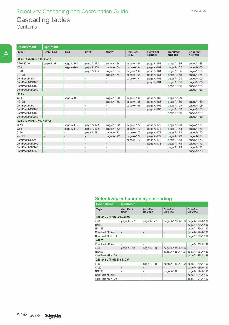
Downstream UpstreamType iDPN, iC40 iC60 C120 NG125 ComPact
NSXmComPact NSX100
ComPact NSX160
ComPact NSX250
380-415 V (Ph/N 220-240 V)iDPN, iC40 page A-164 page A-164 page A-164 page A-164 page A-164 page A-164 page A-165 page A-165iC60 - page A-164 page A-164 page A-164 page A-164 page A-164 page A-165 page A-165C120 - - page A-164 page A-164 page A-164 page A-164 page A-165 page A-165NG125 - - - page A-164 page A-164 page A-164 page A-165 page A-165ComPact NSXm - - - - page A-164 page A-164 page A-165 page A-165ComPact NSX100 - - - - - page A-164 page A-165 page A-165ComPact NSX160 - - - - - - page A-165 page A-165ComPact NSX250 - - - - - - - page A-165440 V
iC60 - page A-168 - page A-168 page A-168 page A-168 page A-169 -NG125 - - - page A-168 page A-168 page A-168 page A-169 page A-169ComPact NSXm - - - - page A-168 page A-168 page A-169 page A-169ComPact NSX100 - - - - - page A-168 page A-169 page A-169ComPact NSX160 - - - - - - page A-169 page A-169ComPact NSX250 - - - - - - - page A-169220-240 V (Ph/N 110-130 V)
iDPN - page A-172 page A-172 page A-172 page A-172 page A-172 page A-173 page A-173iC60 - page A-172 page A-172 page A-172 page A-172 page A-172 page A-173 page A-173C120 - - page A-172 page A-172 page A-172 page A-172 page A-173 page A-173NG125 - - - page A-172 page A-172 page A-172 page A-173 page A-173ComPact NSXm - - - - page A-172 page A-172 page A-173 page A-173ComPact NSX100 - - - - - page A-172 page A-173 page A-173ComPact NSX160 - - - - - - page A-173 page A-173ComPact NSX250 - - - - - - - page A-173
Selectivity enhanced by cascadingDownstream UpstreamType ComPact
NSXmComPact NSX100
ComPact NSX160
ComPact NSX250
380-415 V (Ph/N 220-240 V)iC60 page A-177 page A-177 page A-179-A-180 page A-179-A-180C120 - - - page A-179-A-180NG125 - - - page A-179-A-180ComPact NSXm - - - page A-179-A-180ComPact NSX100 - - - page A-179-A-180440 V
ComPact NSXm - - - page A-185-A-186iC60 page A-183 page A-183 page A-185-A-186 -NG125 - - page A-185-A-186 page A-185-A-186ComPact NSX100 - - - page A-185-A-186220-240 V (Ph/N 110-130 V)
iC60 - page A-190 page A-189-A-190 page A-189-A-190C120 - - - page A-189-A-190NG125 - - page A-189 page A-189-A-190ComPact NSXm - - - page A-191-A-192ComPact NSX100 - - - page A-191-A-192
Cascading tablesContents
www.se.com
A-162
A
Selectivity, Cascading and Coordination Guide
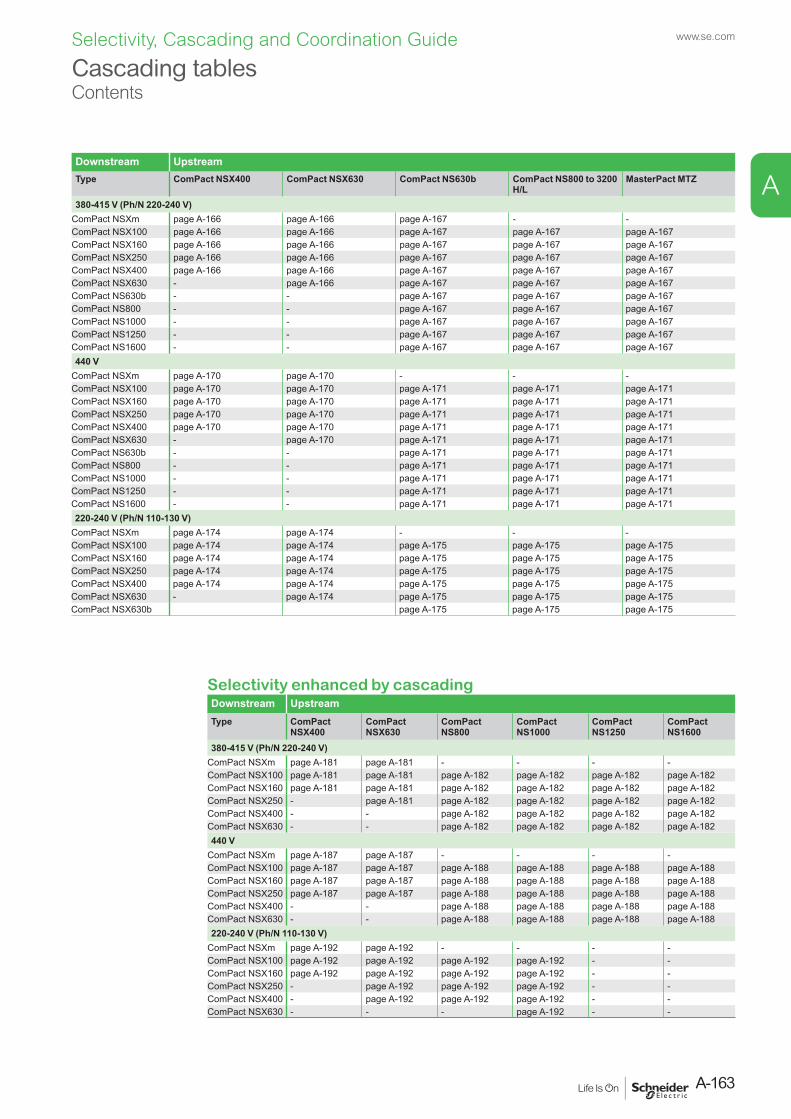
Downstream UpstreamType ComPact NSX400 ComPact NSX630 ComPact NS630b ComPact NS800 to 3200
H/LMasterPact MTZ
380-415 V (Ph/N 220-240 V)ComPact NSXm page A-166 page A-166 page A-167 - -ComPact NSX100 page A-166 page A-166 page A-167 page A-167 page A-167ComPact NSX160 page A-166 page A-166 page A-167 page A-167 page A-167ComPact NSX250 page A-166 page A-166 page A-167 page A-167 page A-167ComPact NSX400 page A-166 page A-166 page A-167 page A-167 page A-167ComPact NSX630 - page A-166 page A-167 page A-167 page A-167ComPact NS630b - - page A-167 page A-167 page A-167ComPact NS800 - - page A-167 page A-167 page A-167ComPact NS1000 - - page A-167 page A-167 page A-167ComPact NS1250 - - page A-167 page A-167 page A-167ComPact NS1600 - - page A-167 page A-167 page A-167440 V
ComPact NSXm page A-170 page A-170 - - -ComPact NSX100 page A-170 page A-170 page A-171 page A-171 page A-171ComPact NSX160 page A-170 page A-170 page A-171 page A-171 page A-171ComPact NSX250 page A-170 page A-170 page A-171 page A-171 page A-171ComPact NSX400 page A-170 page A-170 page A-171 page A-171 page A-171ComPact NSX630 - page A-170 page A-171 page A-171 page A-171ComPact NS630b - - page A-171 page A-171 page A-171ComPact NS800 - - page A-171 page A-171 page A-171ComPact NS1000 - - page A-171 page A-171 page A-171ComPact NS1250 - - page A-171 page A-171 page A-171ComPact NS1600 - - page A-171 page A-171 page A-171220-240 V (Ph/N 110-130 V)
ComPact NSXm page A-174 page A-174 - - -ComPact NSX100 page A-174 page A-174 page A-175 page A-175 page A-175ComPact NSX160 page A-174 page A-174 page A-175 page A-175 page A-175ComPact NSX250 page A-174 page A-174 page A-175 page A-175 page A-175ComPact NSX400 page A-174 page A-174 page A-175 page A-175 page A-175ComPact NSX630 - page A-174 page A-175 page A-175 page A-175ComPact NSX630b page A-175 page A-175 page A-175
Selectivity enhanced by cascadingDownstream UpstreamType ComPact
NSX400ComPact NSX630
ComPact NS800
ComPact NS1000
ComPact NS1250
ComPact NS1600
380-415 V (Ph/N 220-240 V)ComPact NSXm page A-181 page A-181 - - - -ComPact NSX100 page A-181 page A-181 page A-182 page A-182 page A-182 page A-182ComPact NSX160 page A-181 page A-181 page A-182 page A-182 page A-182 page A-182ComPact NSX250 - page A-181 page A-182 page A-182 page A-182 page A-182ComPact NSX400 - - page A-182 page A-182 page A-182 page A-182ComPact NSX630 - - page A-182 page A-182 page A-182 page A-182440 V
ComPact NSXm page A-187 page A-187 - - - -ComPact NSX100 page A-187 page A-187 page A-188 page A-188 page A-188 page A-188ComPact NSX160 page A-187 page A-187 page A-188 page A-188 page A-188 page A-188ComPact NSX250 page A-187 page A-187 page A-188 page A-188 page A-188 page A-188ComPact NSX400 - - page A-188 page A-188 page A-188 page A-188ComPact NSX630 - - page A-188 page A-188 page A-188 page A-188220-240 V (Ph/N 110-130 V)
ComPact NSXm page A-192 page A-192 - - - -ComPact NSX100 page A-192 page A-192 page A-192 page A-192 - -ComPact NSX160 page A-192 page A-192 page A-192 page A-192 - -ComPact NSX250 - page A-192 page A-192 page A-192 - -ComPact NSX400 - page A-192 page A-192 page A-192 - -ComPact NSX630 - - - page A-192 - -
Cascading tablesContents
A-163
www.se.com
A
Selectivity, Cascading and Coordination Guide
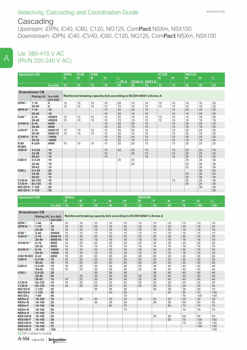
Upstream CB iDPN iC40 iC60 iC120 NG125N N N H L N H N H L
y 25 A 32/40 A 50/63 AIcu (kA) 10 10 10 15 25 20 15 10 15 25 36 50
Downstream CBReinforced breaking capacity (kA) according to IEC/EN 60947-2 Annex ARating (A) Icu (kA)
(Icn (A))iDPN[1] 1-16 6 10 10 10 10 20 15 10 10 10 10 16 20
25-40 6 10 10 10 10 15 10 10 10 10 10 16 20iDPN N[1] 1-16 10 15 25 20 15 15 20 20 25
25-40 10 15 20 15 15 15 16 20 25iC40[1] 2-16 4500/6 10 10 10 10 20 15 10 10 10 10 16 20
20-40 4500/6 10 10 10 10 15 10 10 10 10 10 16 16iCV40 N [1]
6-16 6000 15 25 20 15 15 20 20 2520-40 6000 15 20 15 15 15 16 16 20
iC40 N[1] 2-16 6000/10 10 10 10 15 25 20 15 15 20 20 2520-40 6000/10 10 10 10 15 20 15 15 15 16 16 20
iCV40 H [1]
6-16 10000 15 25 20 15 15 20 20 2520-32 10000 15 20 15 15 15 16 16 20
iC60 RCBO
6-32A 6000 10 10 10 15 25 20 15 15 25 25 25
iC60 N 0.5-25 10 15 25 20 15 15 25 25 2532-40 10 15 20 15 15 25 25 2550-63 10 15 15 15 25 25 25
iC60 H 0.5-25 15 25 20 25 36 3632-40 15 20 25 36 3650-63 15 25 36 36
iC60 L 0.5-25 25 36 5032-40 20 25 36 5050-63 15 25 36 36
C120 N 63-125 10 15 25 25 36C120 H 63-125 15 25 25 36NG125 N 1-125 25 36 36NG125 H 1-125 36 50
Upstream CB NSXm NSX100E B F N H B F N H S L
Icu (kA) 16 25 36 50 70 25 36 50 70 100 150
Downstream CBReinforced breaking capacity (kA) according to IEC/EN 60947-2 Annex ARating (A) Icu (kA)
(Icn (A))iDPN [1] 1-40 6 10 10 10 10 10 10 10 10 10 10 10iDPN N [1] 1-16 10 16 20 20 20 20 20 20 20 20 20 20
25-40 10 16 16 16 16 16 16 16 16 16 16 16iC40 [1] 2-40 4500/6 10 10 10 10 10 10 10 10 10 10 10iC40 N [1] 2-16 6000/10 16 20 20 20 20 20 20 20 20 20 20
20-40 6000/10 16 16 16 16 16 16 16 16 16 16 16iCV40 N [1] 6-16 6000 16 20 20 20 20 20 20 20 20 20 20
20-32 6000 16 16 16 16 16 16 16 16 16 16 16iCV40 H [1] 6-16 10000 16 20 20 20 20 20 20 20 20 20 20
20-32 10000 16 16 16 16 16 16 16 16 16 16 16iC60 RCBO 6-32 6000 16 20 20 20 20 20 20 20 20 20 20iC60 N 0.5-40 10 16 20 25 30 30 20 25 30 30 30 30
50-63 10 16 20 25 30 30 20 25 30 30 30 30iC60 H 0.5-40 15 16 25 36 36 36 25 36 40 40 40 40
50-63 15 16 25 36 36 36 25 36 40 40 40 40iC60 L 0.5-25 25 36 36 36 36 40 40 40 40
32-40 20 25 36 36 36 25 36 40 40 40 4050-63 15 16 25 36 36 36 25 36 40 40 40 40
C120 N 63-125 10 16 25 25 25 25 25 25 25 25 25 25C120 H 63-125 15 16 25 25 25 25 25 25 25 25 25 25NG125 N 1-125 25 36 36 36 36 36 36 50 70NG125 H 1-125 36 40 50 40 50 70 100NG125 L 1-80 50 70 70 100 150NSXm E 16-160 16 25 30 30 30 25 25 30 30 30 30NSXm B 16-160 25 36 36 50 36 36 50 50 50NSXm F 16-160 36 50 70 50 70 70 70NSXm N 16-160 50 70 70 70 70NSXm H 16-160 70NSX100 B 16-100 25 36 36 50 50 50NSX100 F 16-100 36 50 70 100 150NSX100 N 16-100 50 70 100 150NSX100 H 16-100 70 100 150NSX100 S 16-100 100 150
CascadingUpstream: iDPN, iC40, iC60, C120, NG125, ComPact NSXm, NSX100Downstream: iDPN, iC40, iCV40, iC60, C120, NG125, ComPact NSXm, NSX100
Ue: 380-415 V AC (Ph/N 220-240 V AC)
[1] 230 V phase to neutral
www.se.com
A-164
A
Selectivity, Cascading and Coordination Guide
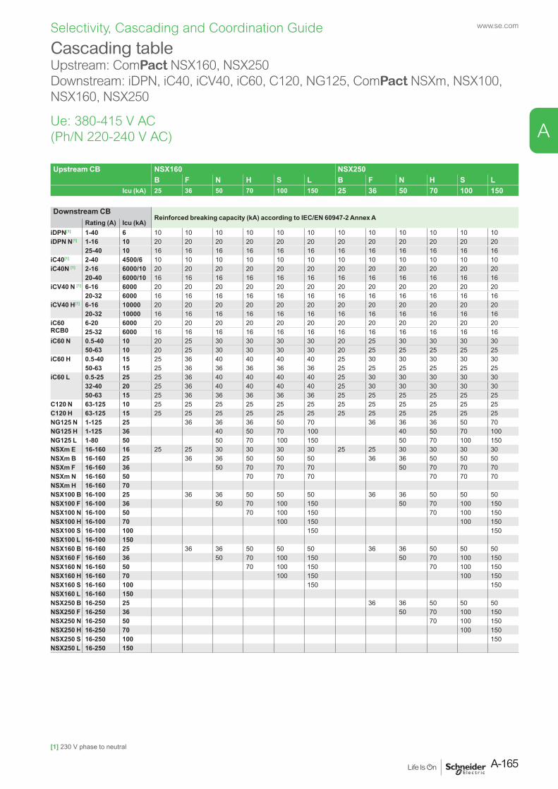
Upstream CB NSX160 NSX250B F N H S L B F N H S L
Icu (kA) 25 36 50 70 100 150 25 36 50 70 100 150
Downstream CBReinforced breaking capacity (kA) according to IEC/EN 60947-2 Annex A
Rating (A) Icu (kA) iDPN[1] 1-40 6 10 10 10 10 10 10 10 10 10 10 10 10iDPN N[1] 1-16 10 20 20 20 20 20 20 20 20 20 20 20 20
25-40 10 16 16 16 16 16 16 16 16 16 16 16 16iC40[1] 2-40 4500/6 10 10 10 10 10 10 10 10 10 10 10 10iC40N [1] 2-16 6000/10 20 20 20 20 20 20 20 20 20 20 20 20
20-40 6000/10 16 16 16 16 16 16 16 16 16 16 16 16iCV40 N [1] 6-16 6000 20 20 20 20 20 20 20 20 20 20 20 20
20-32 6000 16 16 16 16 16 16 16 16 16 16 16 16iCV40 H[1] 6-16 10000 20 20 20 20 20 20 20 20 20 20 20 20
20-32 10000 16 16 16 16 16 16 16 16 16 16 16 16iC60 RCB0
6-20 6000 20 20 20 20 20 20 20 20 20 20 20 2025-32 6000 16 16 16 16 16 16 16 16 16 16 16 16
iC60 N 0.5-40 10 20 25 30 30 30 30 20 25 30 30 30 3050-63 10 20 25 30 30 30 30 20 25 25 25 25 25
iC60 H 0.5-40 15 25 36 40 40 40 40 25 30 30 30 30 3050-63 15 25 36 36 36 36 36 25 25 25 25 25 25
iC60 L 0.5-25 25 25 36 40 40 40 40 25 30 30 30 30 3032-40 20 25 36 40 40 40 40 25 30 30 30 30 3050-63 15 25 36 36 36 36 36 25 25 25 25 25 25
C120 N 63-125 10 25 25 25 25 25 25 25 25 25 25 25 25C120 H 63-125 15 25 25 25 25 25 25 25 25 25 25 25 25NG125 N 1-125 25 36 36 36 50 70 36 36 36 50 70NG125 H 1-125 36 40 50 70 100 40 50 70 100NG125 L 1-80 50 50 70 100 150 50 70 100 150NSXm E 16-160 16 25 25 30 30 30 30 25 25 30 30 30 30NSXm B 16-160 25 36 36 50 50 50 36 36 50 50 50NSXm F 16-160 36 50 70 70 70 50 70 70 70NSXm N 16-160 50 70 70 70 70 70 70NSXm H 16-160 70NSX100 B 16-100 25 36 36 50 50 50 36 36 50 50 50NSX100 F 16-100 36 50 70 100 150 50 70 100 150NSX100 N 16-100 50 70 100 150 70 100 150NSX100 H 16-100 70 100 150 100 150NSX100 S 16-100 100 150 150NSX100 L 16-100 150NSX160 B 16-160 25 36 36 50 50 50 36 36 50 50 50NSX160 F 16-160 36 50 70 100 150 50 70 100 150NSX160 N 16-160 50 70 100 150 70 100 150NSX160 H 16-160 70 100 150 100 150NSX160 S 16-160 100 150 150NSX160 L 16-160 150NSX250 B 16-250 25 36 36 50 50 50NSX250 F 16-250 36 50 70 100 150NSX250 N 16-250 50 70 100 150NSX250 H 16-250 70 100 150NSX250 S 16-250 100 150NSX250 L 16-250 150
Cascading tableUpstream: ComPact NSX160, NSX250Downstream: iDPN, iC40, iCV40, iC60, C120, NG125, ComPact NSXm, NSX100, NSX160, NSX250
Ue: 380-415 V AC (Ph/N 220-240 V AC)
[1] 230 V phase to neutral
A-165
www.se.com
A
Selectivity, Cascading and Coordination Guide
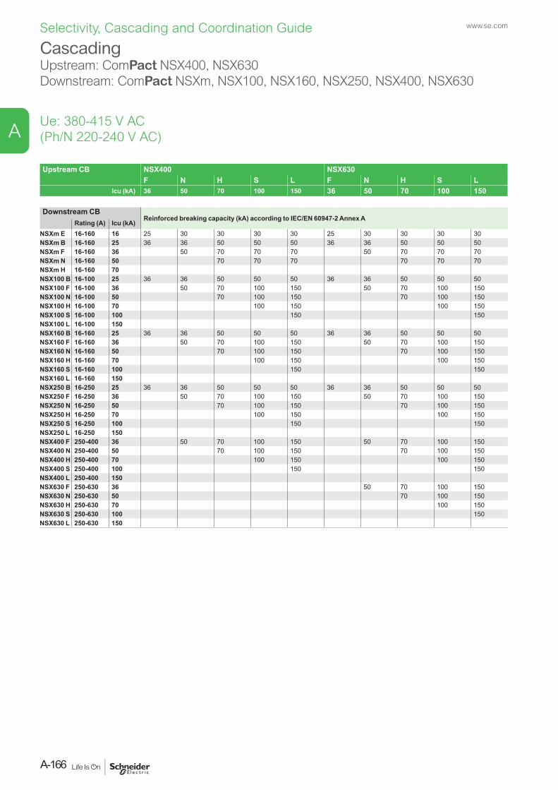
Upstream CB NSX400 NSX630F N H S L F N H S L
Icu (kA) 36 50 70 100 150 36 50 70 100 150
Downstream CBReinforced breaking capacity (kA) according to IEC/EN 60947-2 Annex A
Rating (A) Icu (kA) NSXm E 16-160 16 25 30 30 30 30 25 30 30 30 30NSXm B 16-160 25 36 36 50 50 50 36 36 50 50 50NSXm F 16-160 36 50 70 70 70 50 70 70 70NSXm N 16-160 50 70 70 70 70 70 70NSXm H 16-160 70NSX100 B 16-100 25 36 36 50 50 50 36 36 50 50 50NSX100 F 16-100 36 50 70 100 150 50 70 100 150NSX100 N 16-100 50 70 100 150 70 100 150NSX100 H 16-100 70 100 150 100 150NSX100 S 16-100 100 150 150NSX100 L 16-100 150NSX160 B 16-160 25 36 36 50 50 50 36 36 50 50 50NSX160 F 16-160 36 50 70 100 150 50 70 100 150NSX160 N 16-160 50 70 100 150 70 100 150NSX160 H 16-160 70 100 150 100 150NSX160 S 16-160 100 150 150NSX160 L 16-160 150NSX250 B 16-250 25 36 36 50 50 50 36 36 50 50 50NSX250 F 16-250 36 50 70 100 150 50 70 100 150NSX250 N 16-250 50 70 100 150 70 100 150NSX250 H 16-250 70 100 150 100 150NSX250 S 16-250 100 150 150NSX250 L 16-250 150NSX400 F 250-400 36 50 70 100 150 50 70 100 150NSX400 N 250-400 50 70 100 150 70 100 150NSX400 H 250-400 70 100 150 100 150NSX400 S 250-400 100 150 150NSX400 L 250-400 150NSX630 F 250-630 36 50 70 100 150NSX630 N 250-630 50 70 100 150NSX630 H 250-630 70 100 150NSX630 S 250-630 100 150NSX630 L 250-630 150
Cascading Upstream: ComPact NSX400, NSX630Downstream: ComPact NSXm, NSX100, NSX160, NSX250, NSX400, NSX630
Ue: 380-415 V AC (Ph/N 220-240 V AC)
www.se.com
A-166
A
Selectivity, Cascading and Coordination Guide
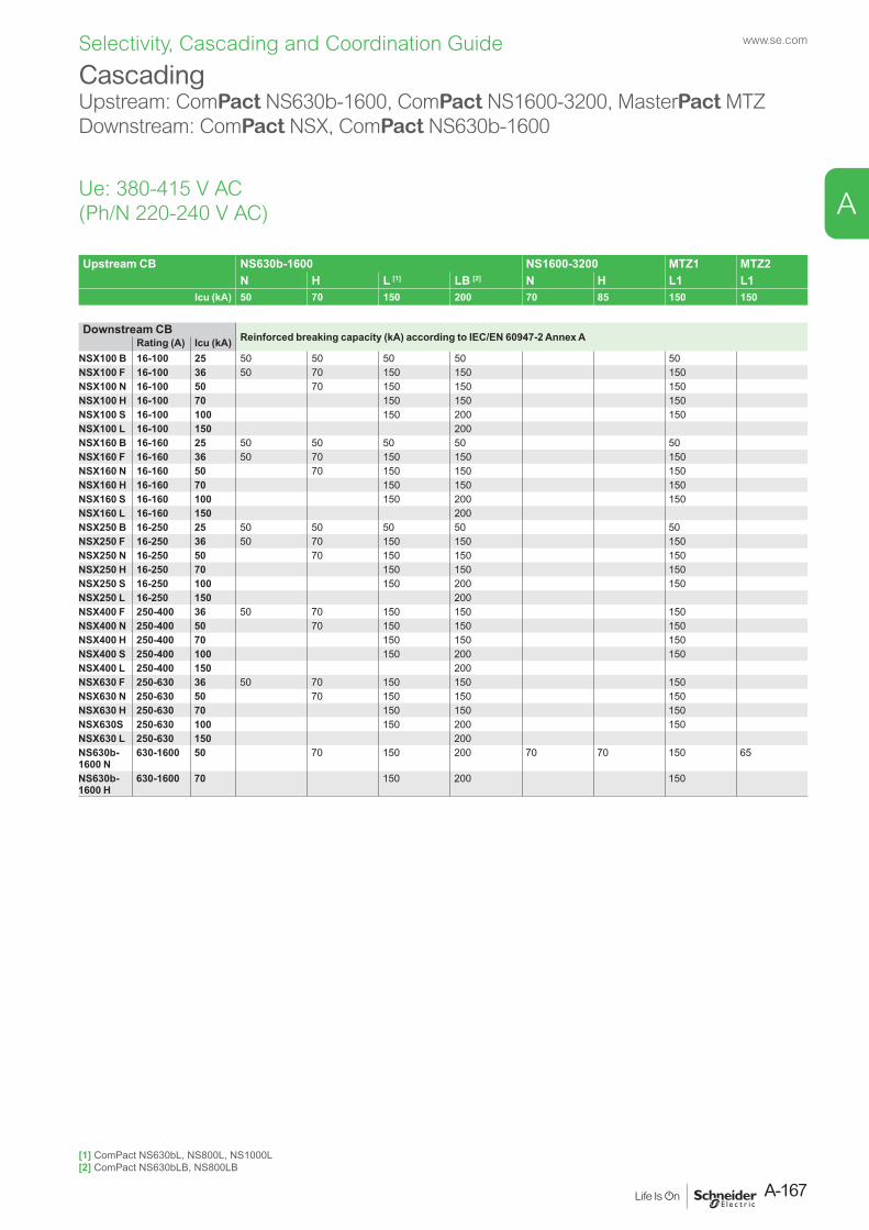
Upstream CB NS630b-1600 NS1600-3200 MTZ1 MTZ2N H L [1] LB [2] N H L1 L1
Icu (kA) 50 70 150 200 70 85 150 150
Downstream CBReinforced breaking capacity (kA) according to IEC/EN 60947-2 Annex ARating (A) Icu (kA)
NSX100 B 16-100 25 50 50 50 50 50NSX100 F 16-100 36 50 70 150 150 150NSX100 N 16-100 50 70 150 150 150NSX100 H 16-100 70 150 150 150NSX100 S 16-100 100 150 200 150NSX100 L 16-100 150 200NSX160 B 16-160 25 50 50 50 50 50NSX160 F 16-160 36 50 70 150 150 150NSX160 N 16-160 50 70 150 150 150NSX160 H 16-160 70 150 150 150NSX160 S 16-160 100 150 200 150NSX160 L 16-160 150 200NSX250 B 16-250 25 50 50 50 50 50NSX250 F 16-250 36 50 70 150 150 150NSX250 N 16-250 50 70 150 150 150NSX250 H 16-250 70 150 150 150NSX250 S 16-250 100 150 200 150NSX250 L 16-250 150 200NSX400 F 250-400 36 50 70 150 150 150NSX400 N 250-400 50 70 150 150 150NSX400 H 250-400 70 150 150 150NSX400 S 250-400 100 150 200 150NSX400 L 250-400 150 200NSX630 F 250-630 36 50 70 150 150 150NSX630 N 250-630 50 70 150 150 150NSX630 H 250-630 70 150 150 150NSX630S 250-630 100 150 200 150NSX630 L 250-630 150 200NS630b- 1600 N
630-1600 50 70 150 200 70 70 150 65
NS630b- 1600 H
630-1600 70 150 200 150
CascadingUpstream: ComPact NS630b-1600, ComPact NS1600-3200, MasterPact MTZDownstream: ComPact NSX, ComPact NS630b-1600
Ue: 380-415 V AC (Ph/N 220-240 V AC)
[1] ComPact NS630bL, NS800L, NS1000L[2] ComPact NS630bLB, NS800LB
A-167
www.se.com
A
Selectivity, Cascading and Coordination Guide
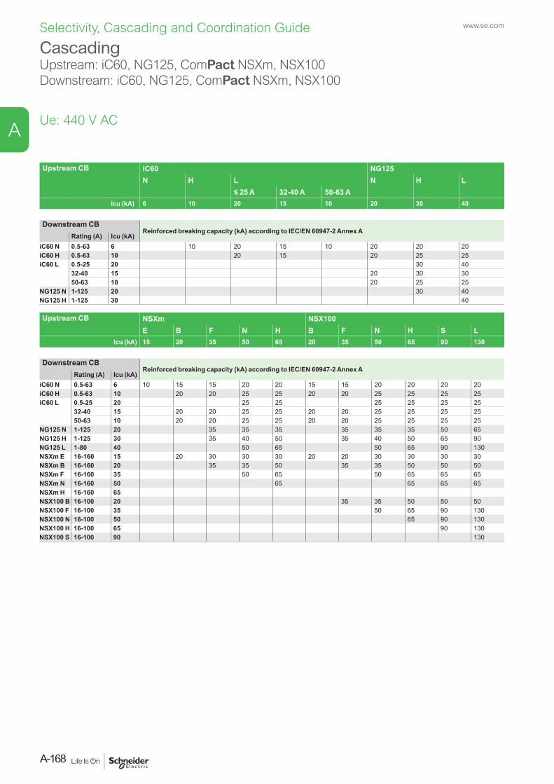
Upstream CB iC60 NG125N H L N H L
y 25 A 32-40 A 50-63 AIcu (kA) 6 10 20 15 10 20 30 40
Downstream CBReinforced breaking capacity (kA) according to IEC/EN 60947-2 Annex A
Rating (A) Icu (kA) iC60 N 0.5-63 6 10 20 15 10 20 20 20iC60 H 0.5-63 10 20 15 20 25 25iC60 L 0.5-25 20 30 40
32-40 15 20 30 3050-63 10 20 25 25
NG125 N 1-125 20 30 40NG125 H 1-125 30 40
Upstream CB NSXm NSX100E B F N H B F N H S L
Icu (kA) 15 20 35 50 65 20 35 50 65 90 130
Downstream CBReinforced breaking capacity (kA) according to IEC/EN 60947-2 Annex A
Rating (A) Icu (kA) iC60 N 0.5-63 6 10 15 15 20 20 15 15 20 20 20 20iC60 H 0.5-63 10 20 20 25 25 20 20 25 25 25 25iC60 L 0.5-25 20 25 25 25 25 25 25
32-40 15 20 20 25 25 20 20 25 25 25 2550-63 10 20 20 25 25 20 20 25 25 25 25
NG125 N 1-125 20 35 35 35 35 35 35 50 65NG125 H 1-125 30 35 40 50 35 40 50 65 90NG125 L 1-80 40 50 65 50 65 90 130NSXm E 16-160 15 20 30 30 30 20 20 30 30 30 30NSXm B 16-160 20 35 35 50 35 35 50 50 50NSXm F 16-160 35 50 65 50 65 65 65NSXm N 16-160 50 65 65 65 65NSXm H 16-160 65NSX100 B 16-100 20 35 35 50 50 50NSX100 F 16-100 35 50 65 90 130NSX100 N 16-100 50 65 90 130NSX100 H 16-100 65 90 130NSX100 S 16-100 90 130
CascadingUpstream: iC60, NG125, ComPact NSXm, NSX100Downstream: iC60, NG125, ComPact NSXm, NSX100
Ue: 440 V AC
www.se.com
A-168
A
Selectivity, Cascading and Coordination Guide
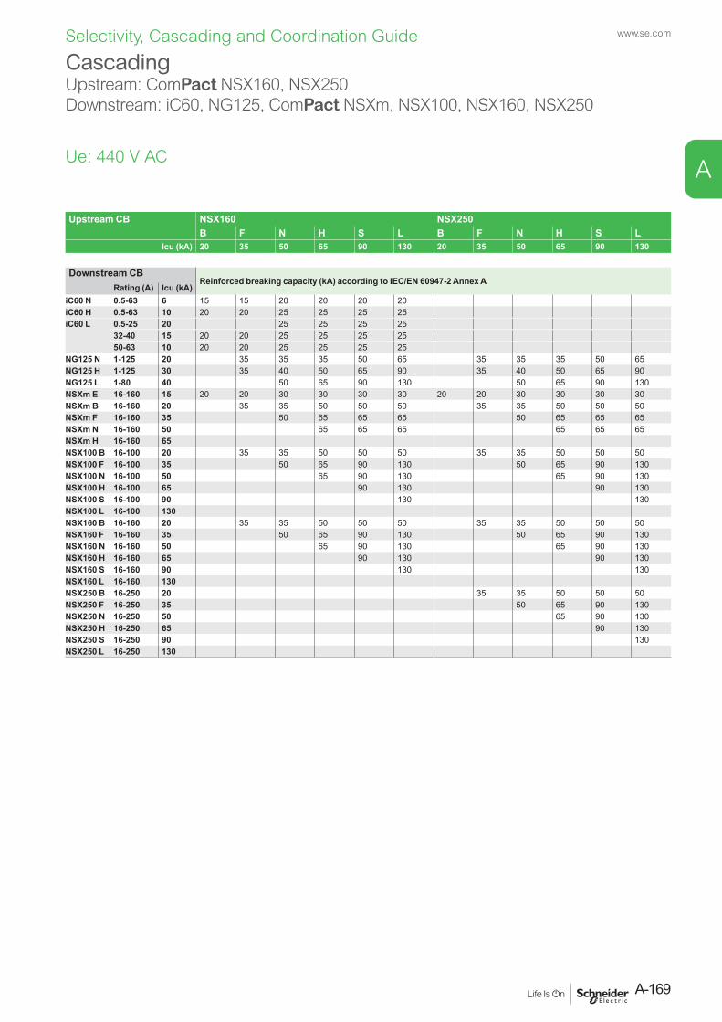
CascadingUpstream: ComPact NSX160, NSX250Downstream: iC60, NG125, ComPact NSXm, NSX100, NSX160, NSX250
Ue: 440 V AC
Upstream CB NSX160 NSX250B F N H S L B F N H S L
Icu (kA) 20 35 50 65 90 130 20 35 50 65 90 130
Downstream CBReinforced breaking capacity (kA) according to IEC/EN 60947-2 Annex A
Rating (A) Icu (kA) iC60 N 0.5-63 6 15 15 20 20 20 20iC60 H 0.5-63 10 20 20 25 25 25 25iC60 L 0.5-25 20 25 25 25 25
32-40 15 20 20 25 25 25 2550-63 10 20 20 25 25 25 25
NG125 N 1-125 20 35 35 35 50 65 35 35 35 50 65NG125 H 1-125 30 35 40 50 65 90 35 40 50 65 90NG125 L 1-80 40 50 65 90 130 50 65 90 130NSXm E 16-160 15 20 20 30 30 30 30 20 20 30 30 30 30NSXm B 16-160 20 35 35 50 50 50 35 35 50 50 50NSXm F 16-160 35 50 65 65 65 50 65 65 65NSXm N 16-160 50 65 65 65 65 65 65NSXm H 16-160 65NSX100 B 16-100 20 35 35 50 50 50 35 35 50 50 50NSX100 F 16-100 35 50 65 90 130 50 65 90 130NSX100 N 16-100 50 65 90 130 65 90 130NSX100 H 16-100 65 90 130 90 130NSX100 S 16-100 90 130 130NSX100 L 16-100 130NSX160 B 16-160 20 35 35 50 50 50 35 35 50 50 50NSX160 F 16-160 35 50 65 90 130 50 65 90 130NSX160 N 16-160 50 65 90 130 65 90 130NSX160 H 16-160 65 90 130 90 130NSX160 S 16-160 90 130 130NSX160 L 16-160 130NSX250 B 16-250 20 35 35 50 50 50NSX250 F 16-250 35 50 65 90 130NSX250 N 16-250 50 65 90 130NSX250 H 16-250 65 90 130NSX250 S 16-250 90 130NSX250 L 16-250 130
A-169
www.se.com
A
Selectivity, Cascading and Coordination Guide

Upstream CB NSX400 NSX630F N H S L F N H S L
Icu (kA) 30 42 65 90 130 30 42 65 90 130
Downstream CBReinforced breaking capacity (kA) according to IEC/EN 60947-2 Annex ARating (A) Icu (kA)
NSXm E 16-160 10 20 30 30 30 30 20 30 30 30 30NSXm B 16-160 20 30 30 50 50 50 30 30 50 50 50NSXm F 16-160 35 42 65 65 65 42 65 65 65NSXm N 16-160 50 65 65 65 65 65 65NSXm H 16-160 65NSX100 B 16-100 20 30 30 50 50 50 30 30 50 50 50NSX100 F 16-100 35 42 65 90 130 42 65 90 130NSX100 N 16-100 50 65 90 130 65 90 130NSX100 H 16-100 65 90 130 90 130NSX100 S 16-100 90 130 130NSX100 L 16-100 130NSX160 B 16-160 20 30 30 50 50 50 30 30 50 50 50NSX160 F 16-160 35 42 65 90 130 42 65 90 130NSX160 N 16-160 50 65 90 130 65 90 130NSX160 H 16-160 65 90 130 90 130NSX160 S 16-160 90 130 130NSX160 L 16-160 130NSX250 B 16-250 20 30 30 50 50 50 30 30 50 50 50NSX250 F 16-250 35 42 65 90 130 42 65 90 130NSX250 N 16-250 50 65 90 130 65 90 130NSX250 H 16-250 65 90 130 90 130NSX250 S 16-250 90 130 130NSX250 L 16-250 130NSX400 F 250-400 30 42 65 90 130 42 65 90 130NSX400 N 250-400 42 65 90 130 65 90 130NSX400 H 250-400 65 90 130 90 130NSX400 S 250-400 90 130 130NSX400 L 250-400 130NSX630 F 250-630 30 42 65 90 130NSX630 N 250-630 42 65 90 130NSX630 H 250-630 65 90 130NSX630 S 250-630 90 130NSX630 L 250-630 130
CascadingUpstream: ComPact NSX400, NSX630 Downstream: ComPact NSXm, NSX100, NSX160, NSX250, NSX400, NSX630
Ue: 440 V AC
www.se.com
A-170
A
Selectivity, Cascading and Coordination Guide

Upstream CB NS630b-1600 NS1600-3200 MTZ1 MTZ2N H L [1] LB [2] N H L1 L1
Icu (kA) 50 65 130 200 65 85 130 150
Downstream CBReinforced breaking capacity (kA) according to IEC/EN 60947-2 Annex A
Rating (A) Icu (kA) NSX100 B 16-100 20 50 50 50 50 50NSX100 F 16-100 35 50 65 130 130 130NSX100 N 16-100 50 65 130 130 130NSX100 H 16-100 65 130 130 130NSX100 S 16-100 90 130 200 130NSX100 L 16-100 130 200NSX160 B 16-160 20 50 50 50 50 50NSX160 F 16-160 35 50 65 130 130 130NSX160 N 16-160 50 65 130 130 130NSX160 H 16-160 65 130 130 130NSX160 S 16-160 90 130 200 130NSX160 L 16-160 130 200NSX250 B 16-250 20 50 50 50 50 50NSX250 F 16-250 35 50 65 130 130 130NSX250 N 16-250 50 65 130 130 130NSX250 H 16-250 65 130 130 130NSX250 S 16-250 90 130 200 130NSX250 L 16-250 130 200NSX400 F 250-400 30 50 65 130 130 130NSX400 N 250-400 42 65 130 130 130NSX400 H 250-400 65 130 130 130NSX400 S 250-400 90 130 200 130NSX400 L 250-400 130 200NSX630 F 250-630 30 50 65 130 130 130NSX630 N 250-630 42 65 130 130 130NSX630 H 250-630 65 130 130 130NSX630 S 250-630 90 130 200 130NSX630 L 250-630 130 200NS630b- 1600 N
630-1600 50 65 130 200 65 65 130 65
NS630b- 1600 H
630-1600 65 130 200 130
Cascading Upstream: ComPact NS630b-1600, ComPact NS1600-3200, MasterPact MTZ Downstream: ComPact NSX, ComPact NS630b-1600
Ue: 440 V AC
[1] ComPact NS630bL, NS800L, NS1000L[2] ComPact NS630bLB, NS800LB
A-171
www.se.com
A
Selectivity, Cascading and Coordination Guide
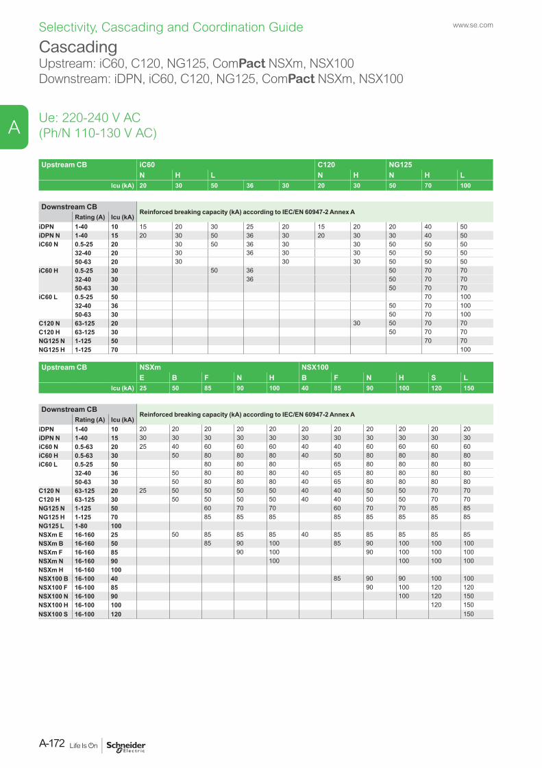
Upstream CB iC60 C120 NG125N H L N H N H L
Icu (kA) 20 30 50 36 30 20 30 50 70 100
Downstream CBReinforced breaking capacity (kA) according to IEC/EN 60947-2 Annex A
Rating (A) Icu (kA) iDPN 1-40 10 15 20 30 25 20 15 20 20 40 50iDPN N 1-40 15 20 30 50 36 30 20 30 30 40 50iC60 N 0.5-25 20 30 50 36 30 30 50 50 50
32-40 20 30 36 30 30 50 50 5050-63 20 30 30 30 50 50 50
iC60 H 0.5-25 30 50 36 50 70 7032-40 30 36 50 70 7050-63 30 50 70 70
iC60 L 0.5-25 50 70 10032-40 36 50 70 10050-63 30 50 70 100
C120 N 63-125 20 30 50 70 70C120 H 63-125 30 50 70 70NG125 N 1-125 50 70 70NG125 H 1-125 70 100
Upstream CB NSXm NSX100E B F N H B F N H S L
Icu (kA) 25 50 85 90 100 40 85 90 100 120 150
Downstream CBReinforced breaking capacity (kA) according to IEC/EN 60947-2 Annex A
Rating (A) Icu (kA) iDPN 1-40 10 20 20 20 20 20 20 20 20 20 20 20iDPN N 1-40 15 30 30 30 30 30 30 30 30 30 30 30iC60 N 0.5-63 20 25 40 60 60 60 40 40 60 60 60 60iC60 H 0.5-63 30 50 80 80 80 40 50 80 80 80 80iC60 L 0.5-25 50 80 80 80 65 80 80 80 80
32-40 36 50 80 80 80 40 65 80 80 80 8050-63 30 50 80 80 80 40 65 80 80 80 80
C120 N 63-125 20 25 50 50 50 50 40 40 50 50 70 70C120 H 63-125 30 50 50 50 50 40 40 50 50 70 70NG125 N 1-125 50 60 70 70 60 70 70 85 85NG125 H 1-125 70 85 85 85 85 85 85 85 85NG125 L 1-80 100NSXm E 16-160 25 50 85 85 85 40 85 85 85 85 85NSXm B 16-160 50 85 90 100 85 90 100 100 100NSXm F 16-160 85 90 100 90 100 100 100NSXm N 16-160 90 100 100 100 100NSXm H 16-160 100NSX100 B 16-100 40 85 90 90 100 100NSX100 F 16-100 85 90 100 120 120NSX100 N 16-100 90 100 120 150NSX100 H 16-100 100 120 150NSX100 S 16-100 120 150
Cascading Upstream: iC60, C120, NG125, ComPact NSXm, NSX100Downstream: iDPN, iC60, C120, NG125, ComPact NSXm, NSX100
Ue: 220-240 V AC(Ph/N 110-130 V AC)
www.se.com
A-172
A
Selectivity, Cascading and Coordination Guide
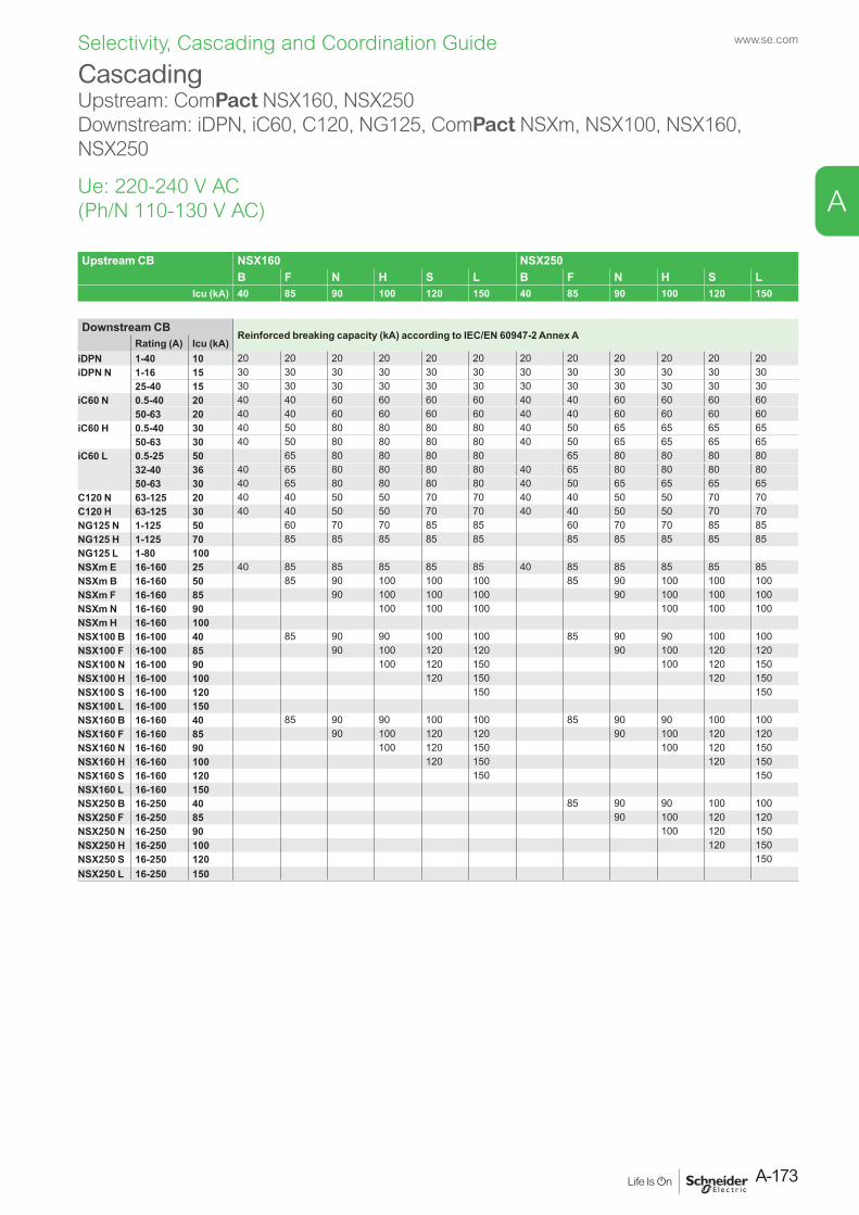
Upstream CB NSX160 NSX250B F N H S L B F N H S L
Icu (kA) 40 85 90 100 120 150 40 85 90 100 120 150
Downstream CBReinforced breaking capacity (kA) according to IEC/EN 60947-2 Annex A
Rating (A) Icu (kA) iDPN 1-40 10 20 20 20 20 20 20 20 20 20 20 20 20iDPN N 1-16 15 30 30 30 30 30 30 30 30 30 30 30 30
25-40 15 30 30 30 30 30 30 30 30 30 30 30 30iC60 N 0.5-40 20 40 40 60 60 60 60 40 40 60 60 60 60
50-63 20 40 40 60 60 60 60 40 40 60 60 60 60iC60 H 0.5-40 30 40 50 80 80 80 80 40 50 65 65 65 65
50-63 30 40 50 80 80 80 80 40 50 65 65 65 65iC60 L 0.5-25 50 65 80 80 80 80 65 80 80 80 80
32-40 36 40 65 80 80 80 80 40 65 80 80 80 8050-63 30 40 65 80 80 80 80 40 50 65 65 65 65
C120 N 63-125 20 40 40 50 50 70 70 40 40 50 50 70 70C120 H 63-125 30 40 40 50 50 70 70 40 40 50 50 70 70NG125 N 1-125 50 60 70 70 85 85 60 70 70 85 85NG125 H 1-125 70 85 85 85 85 85 85 85 85 85 85NG125 L 1-80 100NSXm E 16-160 25 40 85 85 85 85 85 40 85 85 85 85 85NSXm B 16-160 50 85 90 100 100 100 85 90 100 100 100NSXm F 16-160 85 90 100 100 100 90 100 100 100NSXm N 16-160 90 100 100 100 100 100 100NSXm H 16-160 100NSX100 B 16-100 40 85 90 90 100 100 85 90 90 100 100NSX100 F 16-100 85 90 100 120 120 90 100 120 120NSX100 N 16-100 90 100 120 150 100 120 150NSX100 H 16-100 100 120 150 120 150NSX100 S 16-100 120 150 150NSX100 L 16-100 150NSX160 B 16-160 40 85 90 90 100 100 85 90 90 100 100NSX160 F 16-160 85 90 100 120 120 90 100 120 120NSX160 N 16-160 90 100 120 150 100 120 150NSX160 H 16-160 100 120 150 120 150NSX160 S 16-160 120 150 150NSX160 L 16-160 150NSX250 B 16-250 40 85 90 90 100 100NSX250 F 16-250 85 90 100 120 120NSX250 N 16-250 90 100 120 150NSX250 H 16-250 100 120 150NSX250 S 16-250 120 150NSX250 L 16-250 150
CascadingUpstream: ComPact NSX160, NSX250Downstream: iDPN, iC60, C120, NG125, ComPact NSXm, NSX100, NSX160, NSX250
Ue: 220-240 V AC(Ph/N 110-130 V AC)
A-173
www.se.com
A
Selectivity, Cascading and Coordination Guide
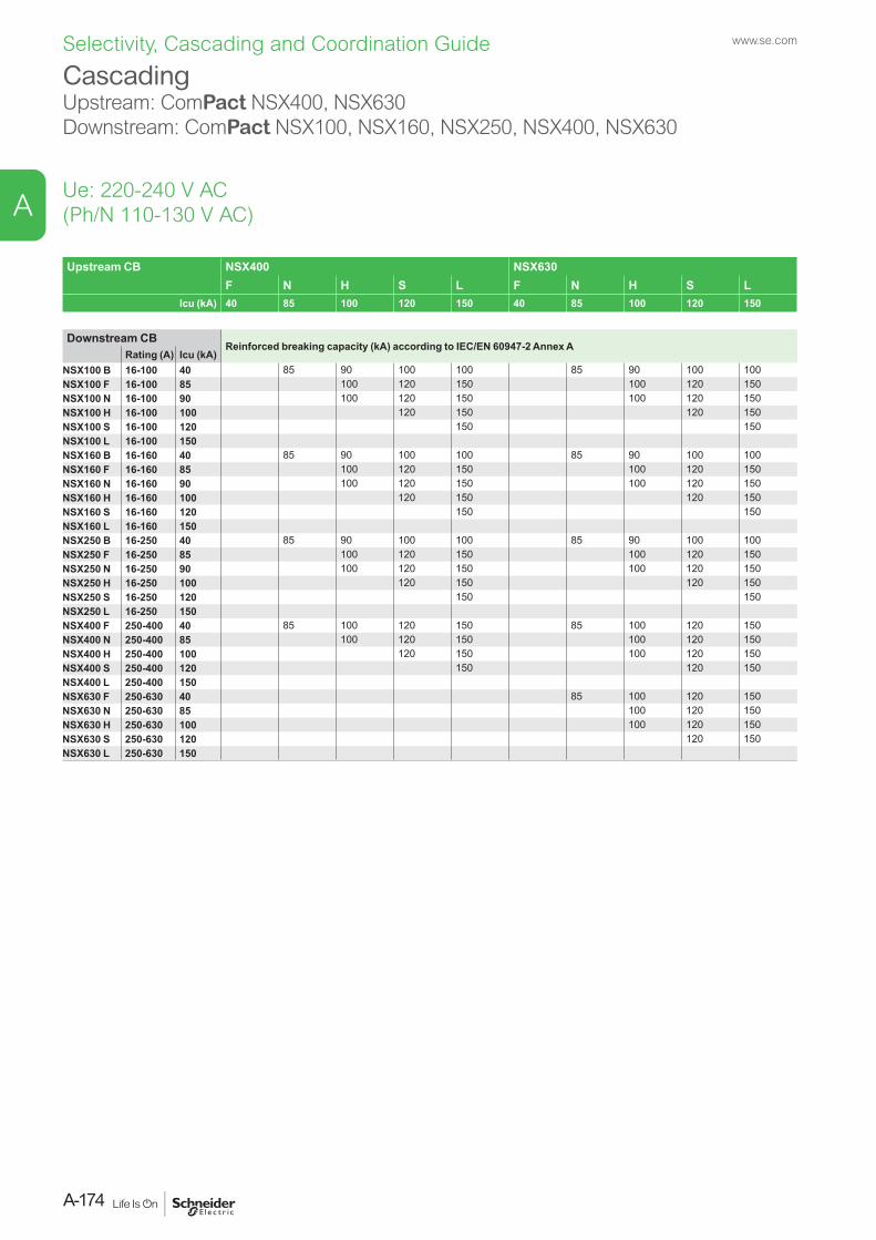
Upstream CB NSX400 NSX630F N H S L F N H S L
Icu (kA) 40 85 100 120 150 40 85 100 120 150
Downstream CBReinforced breaking capacity (kA) according to IEC/EN 60947-2 Annex A
Rating (A) Icu (kA) NSX100 B 16-100 40 85 90 100 100 85 90 100 100NSX100 F 16-100 85 100 120 150 100 120 150NSX100 N 16-100 90 100 120 150 100 120 150NSX100 H 16-100 100 120 150 120 150NSX100 S 16-100 120 150 150NSX100 L 16-100 150NSX160 B 16-160 40 85 90 100 100 85 90 100 100NSX160 F 16-160 85 100 120 150 100 120 150NSX160 N 16-160 90 100 120 150 100 120 150NSX160 H 16-160 100 120 150 120 150NSX160 S 16-160 120 150 150NSX160 L 16-160 150NSX250 B 16-250 40 85 90 100 100 85 90 100 100NSX250 F 16-250 85 100 120 150 100 120 150NSX250 N 16-250 90 100 120 150 100 120 150NSX250 H 16-250 100 120 150 120 150NSX250 S 16-250 120 150 150NSX250 L 16-250 150NSX400 F 250-400 40 85 100 120 150 85 100 120 150NSX400 N 250-400 85 100 120 150 100 120 150NSX400 H 250-400 100 120 150 100 120 150NSX400 S 250-400 120 150 120 150NSX400 L 250-400 150NSX630 F 250-630 40 85 100 120 150NSX630 N 250-630 85 100 120 150NSX630 H 250-630 100 100 120 150NSX630 S 250-630 120 120 150NSX630 L 250-630 150
Cascading Upstream: ComPact NSX400, NSX630Downstream: ComPact NSX100, NSX160, NSX250, NSX400, NSX630
Ue: 220-240 V AC(Ph/N 110-130 V AC)
www.se.com
A-174
A
Selectivity, Cascading and Coordination Guide
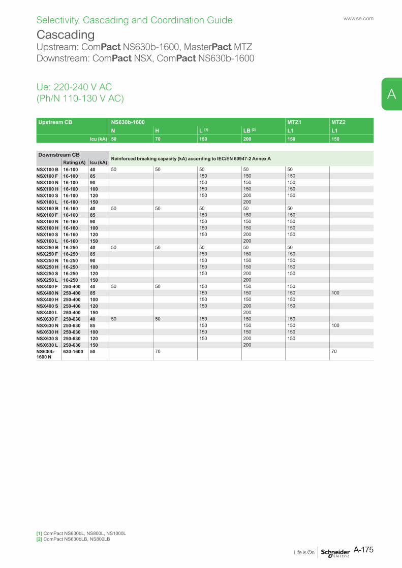
Upstream CB NS630b-1600 MTZ1 MTZ2N H L [1] LB [2] L1 L1
Icu (kA) 50 70 150 200 150 150
Downstream CBReinforced breaking capacity (kA) according to IEC/EN 60947-2 Annex A
Rating (A) Icu (kA) NSX100 B 16-100 40 50 50 50 50 50NSX100 F 16-100 85 150 150 150NSX100 N 16-100 90 150 150 150NSX100 H 16-100 100 150 150 150NSX100 S 16-100 120 150 200 150NSX100 L 16-100 150 200NSX160 B 16-160 40 50 50 50 50 50NSX160 F 16-160 85 150 150 150NSX160 N 16-160 90 150 150 150NSX160 H 16-160 100 150 150 150NSX160 S 16-160 120 150 200 150NSX160 L 16-160 150 200NSX250 B 16-250 40 50 50 50 50 50NSX250 F 16-250 85 150 150 150NSX250 N 16-250 90 150 150 150NSX250 H 16-250 100 150 150 150NSX250 S 16-250 120 150 200 150NSX250 L 16-250 150 200NSX400 F 250-400 40 50 50 150 150 150NSX400 N 250-400 85 150 150 150 100NSX400 H 250-400 100 150 150 150NSX400 S 250-400 120 150 200 150NSX400 L 250-400 150 200NSX630 F 250-630 40 50 50 150 150 150NSX630 N 250-630 85 150 150 150 100NSX630 H 250-630 100 150 150 150NSX630 S 250-630 120 150 200 150NSX630 L 250-630 150 200NS630b- 1600 N
630-1600 50 70 70
CascadingUpstream: ComPact NS630b-1600, MasterPact MTZDownstream: ComPact NSX, ComPact NS630b-1600
Ue: 220-240 V AC(Ph/N 110-130 V AC)
[1] ComPact NS630bL, NS800L, NS1000L[2] ComPact NS630bLB, NS800LB
A-175
www.se.com
A
Selectivity, Cascading and Coordination Guide
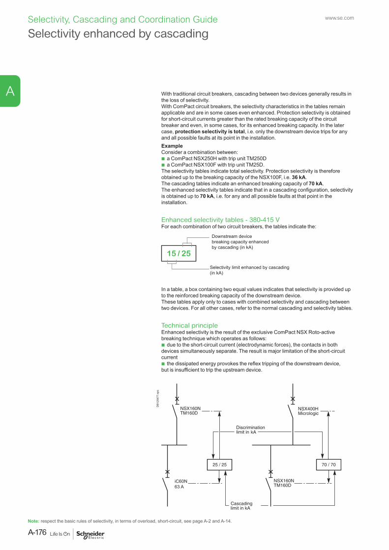
Note: respect the basic rules of selectivity, in terms of overload, short-circuit, see page A-2 and A-14.
With traditional circuit breakers, cascading between two devices generally results in the loss of selectivity.With ComPact circuit breakers, the selectivity characteristics in the tables remain applicable and are in some cases even enhanced. Protection selectivity is obtained for short-circuit currents greater than the rated breaking capacity of the circuit breaker and even, in some cases, for its enhanced breaking capacity. In the later case, protection selectivity is total, i.e. only the downstream device trips for any and all possible faults at its point in the installation.ExampleConsider a combination between:
b a ComPact NSX250H with trip unit TM250D b a ComPact NSX100F with trip unit TM25D.
The selectivity tables indicate total selectivity. Protection selectivity is therefore obtained up to the breaking capacity of the NSX100F, i.e. 36 kA.The cascading tables indicate an enhanced breaking capacity of 70 kA.The enhanced selectivity tables indicate that in a cascading configuration, selectivity is obtained up to 70 kA, i.e. for any and all possible faults at that point in the installation.
Enhanced selectivity tables - 380-415 VFor each combination of two circuit breakers, the tables indicate the:
Selectivity limit enhanced by cascading (in kA)
Downstream device breaking capacity enhanced by cascading (in kA)
15 / 25
In a table, a box containing two equal values indicates that selectivity is provided up to the reinforced breaking capacity of the downstream device.These tables apply only to cases with combined selectivity and cascading between two devices. For all other cases, refer to the normal cascading and selectivity tables.
Technical principleEnhanced selectivity is the result of the exclusive ComPact NSX Roto-active breaking technique which operates as follows:
b due to the short-circuit current (electrodynamic forces), the contacts in both devices simultaneously separate. The result is major limitation of the short-circuit current
b the dissipated energy provokes the reflex tripping of the downstream device, but is insufficient to trip the upstream device.
iC60N63 A
DB1
2567
7.ep
s
Selectivity enhanced by cascadingwww.se.com
A-176
A
Selectivity, Cascading and Coordination Guide
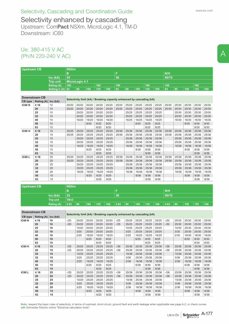
Selectivity enhanced by cascadingUpstream: ComPact NSXm, MicroLogic 4.1, TM-DDownstream: iC60
Ue: 380-415 V AC (Ph/N 220-240 V AC)
Note: respect the basic rules of selectivity, in terms of overload, short-circuit, ground fault and earth leakage when applicable see page A-2, or check curves with Schneider Electric online "Electrical calculation tools".
Upstream CB NSXm B F N/H
Icu (kA) 25 36 50/70Trip unit MicroLogic 4.1Rating (A) 100 160 100 160 100 160Setting Ir (A) 63 80 100 125 160 63 80 100 125 160 63 80 100 125 160
Downstream CB Selectivity limit (kA) / Breaking capacity enhanced by cascading (kA)CB type Rating (A) Icu (kA)iC60 N y 16 10 20/20 20/20 20/20 20/20 20/20 25/25 25/25 25/25 25/25 25/25 25/30 25/30 25/30 25/30 25/30
20 10 20/20 20/20 20/20 20/20 20/20 25/25 25/25 25/25 25/25 25/25 25/30 25/30 25/30 25/30 25/3025 10 20/20 20/20 20/20 20/20 25/25 25/25 25/25 25/25 25/30 25/30 25/30 25/3032 10 20/20 20/20 20/20 20/20 25/25 25/25 25/25 25/25 25/30 25/30 25/30 25/3040 10 16/20 16/20 16/20 16/20 16/25 16/25 16/25 16/25 16/30 16/30 16/30 16/3050 10 8/20 8/20 8/20 8/25 8/25 8/25 8/30 8/30 8/3063 10 8/20 8/20 8/25 8/25 8/30 8/30
iC60 H y 16 15 25/25 25/25 25/25 25/25 25/25 25/36 25/36 25/36 25/36 25/36 25/36 25/36 25/36 25/36 25/3620 15 25/25 25/25 25/25 25/25 25/25 25/36 25/36 25/36 25/36 25/36 25/36 25/36 25/36 25/36 25/3625 15 25/25 25/25 25/25 25/25 25/36 25/36 25/36 25/36 25/36 25/36 25/36 25/3632 15 25/25 25/25 25/25 25/25 25/36 25/36 25/36 25/36 25/36 25/36 25/36 25/3640 15 16/25 16/25 16/25 16/25 16/36 16/36 16/36 16/36 16/36 16/36 16/36 16/3650 15 8/25 8/25 8/25 8/36 8/36 8/36 8/36 8/36 8/3663 15 8/25 8/25 8/36 8/36 8/36 8/36
iC60 L y 16 25 25/25 25/25 25/25 25/25 25/25 25/36 25/36 25/36 25/36 25/36 25/36 25/36 25/36 25/36 25/3620 25 25/25 25/25 25/25 25/25 25/25 25/36 25/36 25/36 25/36 25/36 25/36 25/36 25/36 25/36 25/3625 25 25/25 25/25 25/25 25/25 25/36 25/36 25/36 25/36 25/36 25/36 25/36 25/3632 20 25/25 25/25 25/25 25/25 25/36 25/36 25/36 25/36 25/36 25/36 25/36 25/3640 20 16/25 16/25 16/25 16/25 16/36 16/36 16/36 16/36 16/36 16/36 16/36 16/3650 15 8/25 8/25 8/25 8/36 8/36 8/36 8/36 8/36 8/3663 15 8/25 8/25 8/36 8/36 8/36 8/36
Upstream CB NSXm B F N/H
Icu (kA) 25 36 50/70Trip unit TM-DRating (A) y 63 80 100 125 160 y 63 80 100 125 160 y 63 80 100 125 160
Downstream CBSelectivity limit (kA) / Breaking capacity enhanced by cascading (kA)
CB type Rating (A) Icu (kA)iC60 N y 16 10 -/20 20/20 20/20 20/20 20/20 -/25 25/25 25/25 25/25 25/25 -/30 25/30 25/30 25/30 25/30
20 10 -/20 20/20 20/20 20/20 20/20 -/25 25/25 25/25 25/25 25/25 -/30 25/30 25/30 25/30 25/3025 10 10/20 20/20 20/20 20/20 10/25 25/25 25/25 25/25 10/30 25/30 25/30 25/3032 10 3/20 20/20 20/20 20/20 3/25 25/25 25/25 25/25 3/30 25/30 25/30 25/3040 10 2/20 16/20 16/20 16/20 2/25 16/25 16/25 16/25 2/30 16/30 16/30 16/3050 10 6/20 8/20 8/20 6/25 8/25 8/25 6/30 8/30 8/3063 10 8/20 8/20 8/25 8/25 8/30 8/30
iC60 H y 16 15 -/25 25/25 25/25 25/25 25/25 -/36 25/36 25/36 25/36 25/36 -/36 25/36 25/36 25/36 25/3620 15 -/25 25/25 25/25 25/25 25/25 -/36 25/36 25/36 25/36 25/36 -/36 25/36 25/36 25/36 25/3625 15 10/25 25/25 25/25 25/25 10/36 25/36 25/36 25/36 10/36 25/36 25/36 25/3632 15 3/25 25/25 25/25 25/25 3/36 25/36 25/36 25/36 3/36 25/36 25/36 25/3640 15 2/25 16/25 16/25 16/25 2/36 16/36 16/36 16/36 2/36 16/36 16/36 16/3650 15 6/25 8/25 8/25 6/36 8/36 8/36 6/36 8/36 8/3663 15 8/25 8/25 8/36 8/36 8/36 8/36
iC60 L y 16 25 -/25 25/25 25/25 25/25 25/25 -/36 25/36 25/36 25/36 25/36 -/36 25/36 25/36 25/36 25/3620 25 -/25 25/25 25/25 25/25 25/25 -/36 25/36 25/36 25/36 25/36 -/36 25/36 25/36 25/36 25/3625 25 10/25 25/25 25/25 25/25 10/36 25/36 25/36 25/36 10/36 25/36 25/36 25/3632 20 3/25 25/25 25/25 25/25 3/36 25/36 25/36 25/36 3/36 25/36 25/36 25/3640 20 2/25 16/25 16/25 16/25 2/36 16/36 16/36 16/36 2/36 16/36 16/36 16/3650 15 6/25 8/25 8/25 6/36 8/36 8/36 6/36 8/36 8/3663 15 8/25 8/25 8/36 8/36 8/36 8/36
A-177
www.se.com
A
Selectivity, Cascading and Coordination Guide
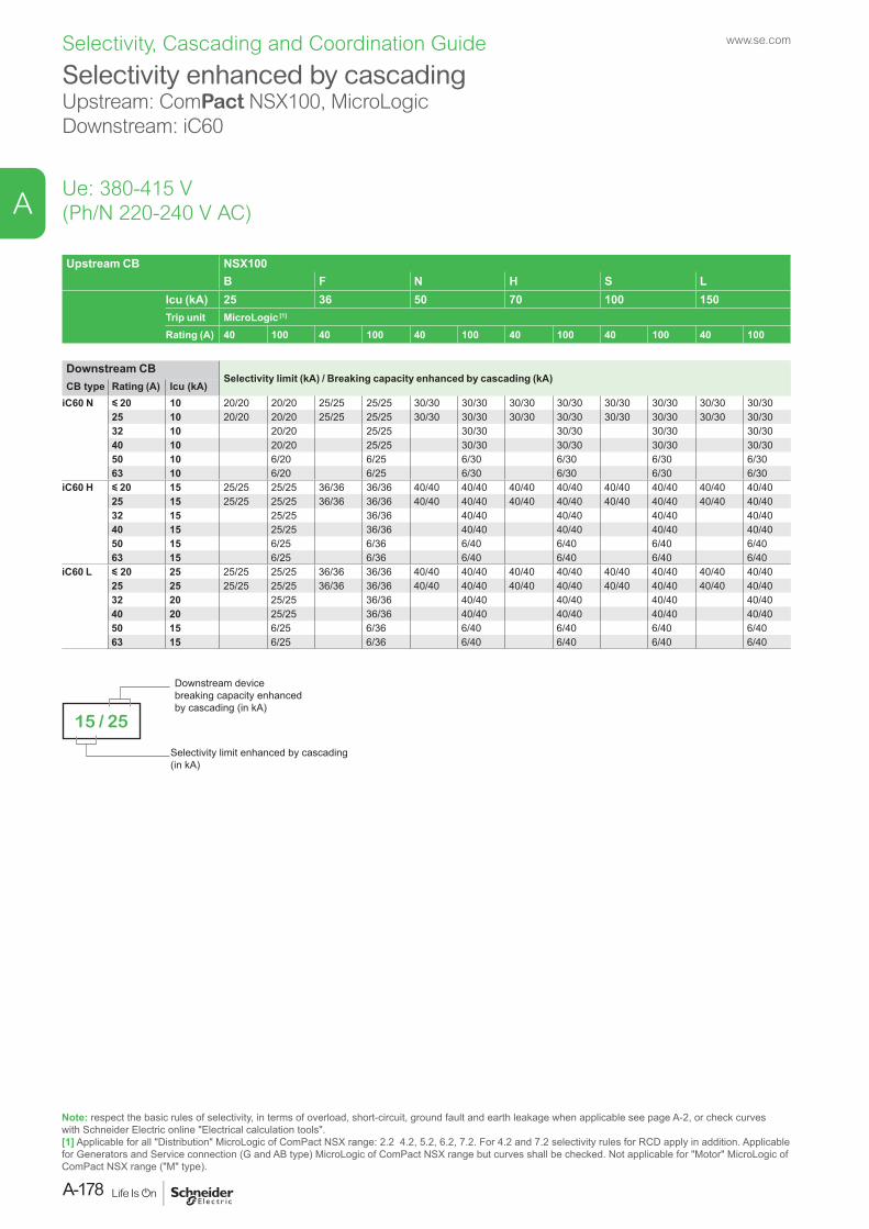
Selectivity enhanced by cascadingUpstream: ComPact NSX100, MicroLogicDownstream: iC60
Ue: 380-415 V(Ph/N 220-240 V AC)
Upstream CB NSX100B F N H S L
Icu (kA) 25 36 50 70 100 150Trip unit MicroLogic [1]
Rating (A) 40 100 40 100 40 100 40 100 40 100 40 100
Downstream CBSelectivity limit (kA) / Breaking capacity enhanced by cascading (kA)
CB type Rating (A) Icu (kA)iC60 N y 20 10 20/20 20/20 25/25 25/25 30/30 30/30 30/30 30/30 30/30 30/30 30/30 30/30
25 10 20/20 20/20 25/25 25/25 30/30 30/30 30/30 30/30 30/30 30/30 30/30 30/3032 10 20/20 25/25 30/30 30/30 30/30 30/3040 10 20/20 25/25 30/30 30/30 30/30 30/3050 10 6/20 6/25 6/30 6/30 6/30 6/3063 10 6/20 6/25 6/30 6/30 6/30 6/30
iC60 H y 20 15 25/25 25/25 36/36 36/36 40/40 40/40 40/40 40/40 40/40 40/40 40/40 40/4025 15 25/25 25/25 36/36 36/36 40/40 40/40 40/40 40/40 40/40 40/40 40/40 40/4032 15 25/25 36/36 40/40 40/40 40/40 40/4040 15 25/25 36/36 40/40 40/40 40/40 40/4050 15 6/25 6/36 6/40 6/40 6/40 6/4063 15 6/25 6/36 6/40 6/40 6/40 6/40
iC60 L y 20 25 25/25 25/25 36/36 36/36 40/40 40/40 40/40 40/40 40/40 40/40 40/40 40/4025 25 25/25 25/25 36/36 36/36 40/40 40/40 40/40 40/40 40/40 40/40 40/40 40/4032 20 25/25 36/36 40/40 40/40 40/40 40/4040 20 25/25 36/36 40/40 40/40 40/40 40/4050 15 6/25 6/36 6/40 6/40 6/40 6/4063 15 6/25 6/36 6/40 6/40 6/40 6/40
Note: respect the basic rules of selectivity, in terms of overload, short-circuit, ground fault and earth leakage when applicable see page A-2, or check curves with Schneider Electric online "Electrical calculation tools".[1] Applicable for all "Distribution" MicroLogic of ComPact NSX range: 2.2 4.2, 5.2, 6.2, 7.2. For 4.2 and 7.2 selectivity rules for RCD apply in addition. Applicable for Generators and Service connection (G and AB type) MicroLogic of ComPact NSX range but curves shall be checked. Not applicable for "Motor" MicroLogic of ComPact NSX range ("M" type).
Selectivity limit enhanced by cascading (in kA)
Downstream device breaking capacity enhanced by cascading (in kA)
15 / 25
www.se.com
A-178
A
Selectivity, Cascading and Coordination Guide
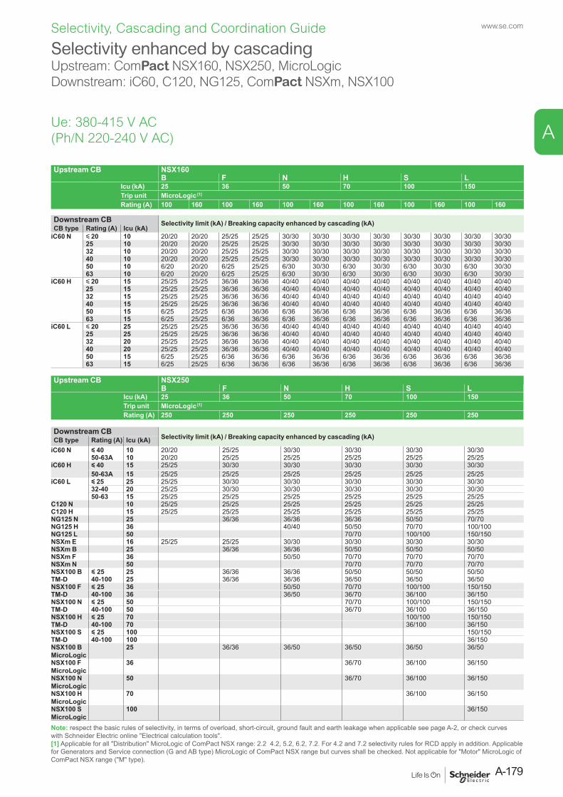
Upstream CB NSX160B F N H S L
Icu (kA) 25 36 50 70 100 150Trip unit MicroLogic [1]
Rating (A) 100 160 100 160 100 160 100 160 100 160 100 160
Downstream CB Selectivity limit (kA) / Breaking capacity enhanced by cascading (kA)CB type Rating (A) Icu (kA)
iC60 N y 20 10 20/20 20/20 25/25 25/25 30/30 30/30 30/30 30/30 30/30 30/30 30/30 30/3025 10 20/20 20/20 25/25 25/25 30/30 30/30 30/30 30/30 30/30 30/30 30/30 30/3032 10 20/20 20/20 25/25 25/25 30/30 30/30 30/30 30/30 30/30 30/30 30/30 30/3040 10 20/20 20/20 25/25 25/25 30/30 30/30 30/30 30/30 30/30 30/30 30/30 30/3050 10 6/20 20/20 6/25 25/25 6/30 30/30 6/30 30/30 6/30 30/30 6/30 30/3063 10 6/20 20/20 6/25 25/25 6/30 30/30 6/30 30/30 6/30 30/30 6/30 30/30
iC60 H y 20 15 25/25 25/25 36/36 36/36 40/40 40/40 40/40 40/40 40/40 40/40 40/40 40/4025 15 25/25 25/25 36/36 36/36 40/40 40/40 40/40 40/40 40/40 40/40 40/40 40/4032 15 25/25 25/25 36/36 36/36 40/40 40/40 40/40 40/40 40/40 40/40 40/40 40/4040 15 25/25 25/25 36/36 36/36 40/40 40/40 40/40 40/40 40/40 40/40 40/40 40/4050 15 6/25 25/25 6/36 36/36 6/36 36/36 6/36 36/36 6/36 36/36 6/36 36/3663 15 6/25 25/25 6/36 36/36 6/36 36/36 6/36 36/36 6/36 36/36 6/36 36/36
iC60 L y 20 25 25/25 25/25 36/36 36/36 40/40 40/40 40/40 40/40 40/40 40/40 40/40 40/4025 25 25/25 25/25 36/36 36/36 40/40 40/40 40/40 40/40 40/40 40/40 40/40 40/4032 20 25/25 25/25 36/36 36/36 40/40 40/40 40/40 40/40 40/40 40/40 40/40 40/4040 20 25/25 25/25 36/36 36/36 40/40 40/40 40/40 40/40 40/40 40/40 40/40 40/4050 15 6/25 25/25 6/36 36/36 6/36 36/36 6/36 36/36 6/36 36/36 6/36 36/3663 15 6/25 25/25 6/36 36/36 6/36 36/36 6/36 36/36 6/36 36/36 6/36 36/36
Upstream CB NSX250B F N H S L
Icu (kA) 25 36 50 70 100 150Trip unit MicroLogic [1]
Rating (A) 250 250 250 250 250 250
Downstream CBSelectivity limit (kA) / Breaking capacity enhanced by cascading (kA)CB type Rating (A) Icu (kA)
iC60 N y 40 10 20/20 25/25 30/30 30/30 30/30 30/3050-63A 10 20/20 25/25 25/25 25/25 25/25 25/25
iC60 H y 40 15 25/25 30/30 30/30 30/30 30/30 30/3050-63A 15 25/25 25/25 25/25 25/25 25/25 25/25
iC60 L y 25 25 25/25 30/30 30/30 30/30 30/30 30/3032-40 20 25/25 30/30 30/30 30/30 30/30 30/3050-63 15 25/25 25/25 25/25 25/25 25/25 25/25
C120 N 10 25/25 25/25 25/25 25/25 25/25 25/25C120 H 15 25/25 25/25 25/25 25/25 25/25 25/25NG125 N 25 36/36 36/36 36/36 50/50 70/70NG125 H 36 40/40 50/50 70/70 100/100NG125 L 50 70/70 100/100 150/150NSXm E 16 25/25 25/25 30/30 30/30 30/30 30/30NSXm B 25 36/36 36/36 50/50 50/50 50/50NSXm F 36 50/50 70/70 70/70 70/70NSXm N 50 70/70 70/70 70/70NSX100 BTM-D
y 25 25 36/36 36/36 50/50 50/50 50/5040-100 25 36/36 36/36 36/50 36/50 36/50
NSX100 FTM-D
y 25 36 50/50 70/70 100/100 150/15040-100 36 36/50 36/70 36/100 36/150
NSX100 NTM-D
y 25 50 70/70 100/100 150/15040-100 50 36/70 36/100 36/150
NSX100 HTM-D
y 25 70 100/100 150/15040-100 70 36/100 36/150
NSX100 STM-D
y 25 100 150/15040-100 100 36/150
NSX100 B MicroLogic
25 36/36 36/50 36/50 36/50 36/50
NSX100 F MicroLogic
36 36/70 36/100 36/150
NSX100 N MicroLogic
50 36/70 36/100 36/150
NSX100 H MicroLogic
70 36/100 36/150
NSX100 S MicroLogic
100 36/150
Selectivity enhanced by cascadingUpstream: ComPact NSX160, NSX250, MicroLogicDownstream: iC60, C120, NG125, ComPact NSXm, NSX100
Ue: 380-415 V AC(Ph/N 220-240 V AC)
Note: respect the basic rules of selectivity, in terms of overload, short-circuit, ground fault and earth leakage when applicable see page A-2, or check curves with Schneider Electric online "Electrical calculation tools".[1] Applicable for all "Distribution" MicroLogic of ComPact NSX range: 2.2 4.2, 5.2, 6.2, 7.2. For 4.2 and 7.2 selectivity rules for RCD apply in addition. Applicable for Generators and Service connection (G and AB type) MicroLogic of ComPact NSX range but curves shall be checked. Not applicable for "Motor" MicroLogic of ComPact NSX range ("M" type).
A-179
www.se.com
A
Selectivity, Cascading and Coordination Guide
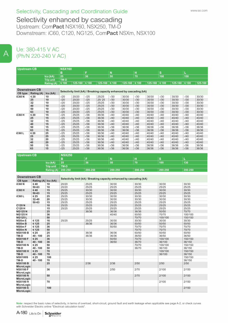
Upstream CB NSX160B F N H S L
Icu (kA) 25 36 50 70 100 150Trip unit TM-DRating (A) y 100 125-160 y 100 125-160 y 100 125-160 y 100 125-160 y 100 125-160 y 100 125-160
Downstream CB Selectivity limit (kA) / Breaking capacity enhanced by cascading (kA)CB type Rating (A) Icu (kA)iC60 N y 20 10 -/20 20/20 -/25 25/25 -/30 30/30 -/30 30/30 -/30 30/30 -/30 30/30
25 10 -/20 20/20 -/25 25/ 25 -/30 30/30 -/30 30/30 -/30 30/30 -/30 30/3032 10 -/20 20/20 -/25 25/25 -/30 30/30 -/30 30/30 -/30 30/30 -/30 30/3040 10 -/20 20/20 -/25 25/25 -/30 30/30 -/30 30/30 -/30 30/30 -/30 30/3050 10 -/20 20/20 -/25 25/25 -/30 30/30 -/30 30/30 -/30 30/30 -/30 30/3063 10 -/20 20/20 -/25 25/25 -/30 30/30 -/30 30/30 -/30 30/30 -/30 30/30
iC60 H y 20 15 -/25 25/25 -/36 36/36 -/40 40/40 -/40 40/40 -/40 40/40 -/40 40/4025 15 -/25 25/25 -/36 36/36 -/40 40/40 -/40 40/40 -/40 40/40 -/40 40/4032 15 -/25 25/25 -/36 36/36 -/40 40/40 -/40 40/40 -/40 40/40 -/40 40/4040 15 -/25 25/25 -/36 36/36 -/40 40/40 -/40 40/40 -/40 40/40 -/40 40/4050 15 -/25 25/25 -/36 36/36 -/36 36/36 -/36 36/36 -/36 36/36 -/36 36/3663 15 -/25 25/25 -/36 36/36 -/36 36/36 -/36 36/36 -/36 36/36 -/36 36/36
iC60 L y 20 25 -/25 25/25 -/36 36/36 -/40 40/40 -/40 40/40 -/40 40/40 -/40 40/4025 25 -/25 25/25 -/36 36/36 -/40 40/40 -/40 40/40 -/40 40/40 -/40 40/4032 20 -/25 25/25 -/36 36/36 -/40 40/40 -/40 40/40 -/40 40/40 -/40 40/4040 20 -/25 25/25 -/36 36/36 -/40 40/40 -/40 40/40 -/40 40/40 -/40 40/4050 15 -/25 25/25 -/36 36/36 -/36 36/36 -/36 36/36 -/36 36/36 -/36 36/3663 15 -/25 25/25 -/36 36/36 -/36 36/36 -/36 36/36 -/36 36/36 -/36 36/36
Upstream CB NSX250 B F N H S L
Icu (kA) 25 36 50 70 100 130Trip unit TM-DRating (A) 200-250 200-250 200-250 200-250 200-250 200-250
Downstream CB Selectivity limit (kA) / Breaking capacity enhanced by cascading (kA)CB type Rating (A) Icu (kA)
iC60 N y 40 10 20/20 25/25 30/30 30/30 30/30 30/3050-63 10 20/20 25/25 25/25 25/25 25/25 25/25
iC60 H y 40 15 25/25 30/30 30/30 30/30 30/30 30/3050-63 15 25/25 25/25 25/25 25/25 25/25 25/25
iC60 L y 25 25 25/25 30/30 30/30 30/30 30/30 30/3032-40 20 25/25 30/30 30/30 30/30 30/30 30/3050-63 15 25/25 25/25 25/25 25/25 25/25 25/25
C120 N 10 25/25 25/25 25/25 25/25 25/25 25/25C120 H 15 25/25 25/25 25/25 25/25 25/25 25/25NG125 N 25 36/36 36/36 36/36 50/50 70/70NG125 H 36 40/40 50/50 70/70 100/100NG125 L 50 70/70 100/100 150/150NSXm E y 125 16 25/25 25/25 30/30 30/30 30/30 30/30NSXm B y 125 25 36/36 36/36 50/50 50/50 50/50NSXm F y 125 36 50/50 70/70 70/70 70/70NSXm N y 125 50 70/70 70/70 70/70NSX100 BTM-D
y 25 25 36/36 36/36 50/50 50/50 50/5040 - 100 25 36/36 36/36 36/50 36/50 36/50
NSX100 FTM-D
y 25 36 50/50 70/70 100/100 150/15040 - 100 36 36/50 36/70 36/100 36/150
NSX100 NTM-D
y 25 50 70/70 100/100 150/15040 - 100 50 36/70 36/100 36/150
NSX100 HTM-D
y 25 70 100/100 150/15040 - 100 70 36/100 36/150
NSX100STM-D
y 25 100 150/15040 - 100 70 36/150
NSX100 B MicroLogic
25 2/36 2/36 2/50 2/50 2/50
NSX100 F MicroLogic
36 2/50 2/70 2/100 2/150
NSX100 N MicroLogic
50 2/70 2/100 2/150
NSX100 H MicroLogic
70 2/100 2/150
NSX100 S MicroLogic
100 2/150
Selectivity enhanced by cascadingUpstream: ComPact NSX160, NSX250, TM-DDownstream: iC60, C120, NG125, ComPact NSXm, NSX100
Ue: 380-415 V AC(Ph/N 220-240 V AC)
Note: respect the basic rules of selectivity, in terms of overload, short-circuit, ground fault and earth leakage when applicable see page A-2, or check curves with Schneider Electric online "Electrical calculation tools".
www.se.com
A-180
A
Selectivity, Cascading and Coordination Guide
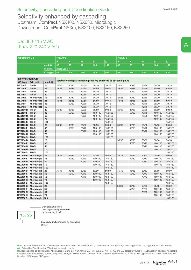
Selectivity enhanced by cascadingUpstream: ComPact NSX400, NSX630, MicroLogicDownstream: ComPact NSXm, NSX100, NSX160, NSX250
Ue: 380-415 V AC(Ph/N 220-240 V AC)
Upstream CB NSX400 NSX630F N H S L F N H S L
Icu (kA) 36 50 70 100 150 36 50 70 100 150Trip unit MicroLogic [1]
Rating (A) 400 400 400 400 400 630 630 630 630 630
Downstream CBSelectivity limit (kA) / Breaking capacity enhanced by cascading (kA)CB type Trip unit Icu (kA)
NSXm E TM-D 16 25/25 30/30 30/30 30/30 30/30 25/25 30/30 30/30 30/30 30/30NSXm B TM-D 25 36/36 36/36 50/50 50/50 50/50 36/36 36/36 50/50 50/50 50/50NSXm F TM-D 36 50/50 70/70 70/70 70/70 50/50 70/70 70/70 70/70NSXm N TM-D 50 70/70 70/70 70/70 70/70 70/70 70/70NSXm E MicroLogic 16 25/25 30/30 30/30 30/30 30/30 25/25 30/30 30/30 30/30 30/30NSXm B MicroLogic 25 36/36 36/36 50/50 50/50 50/50 36/36 36/36 50/50 50/50 50/50NSXm F MicroLogic 36 50/50 70/70 70/70 70/70 50/50 70/70 70/70 70/70NSXm N MicroLogic 50 70/70 70/70 70/70 70/70 70/70 70/70NSX100 B TM-D 25 36/36 36/36 50/50 50/50 50/50 36/36 36/36 50/50 50/50 50/50NSX100 F TM-D 36 50/50 70/70 100/100 150/150 50/50 70/70 100/100 150/150NSX100 N TM-D 50 70/70 100/100 150/150 70/70 100/100 150/150NSX100 H TM-D 70 100/100 150/150 100/100 150/150NSX100 S TM-D 100 150/150 150/150NSX160 B TM-D 25 36/36 36/36 50/50 50/50 50/50 36/36 36/36 50/50 50/50 50/50NSX160 F TM-D 36 50/50 70/70 100/100 150/150 50/50 70/70 100/100 150/150NSX160 N TM-D 50 70/70 100/100 150/150 70/70 100/100 150/150NSX160 H TM-D 70 100/100 150/150 100/100 150/150NSX160 S TM-D 100 150/150 150/150NSX250 B TM-D 25 36/36 36/36 50/50 50/50 50/50NSX250 F TM-D 36 50/50 70/70 100/100 150/150NSX250 N TM-D 50 70/70 100/100 150/150NSX250 H TM-D 70 100/100 150/150NSX250 S TM-D 100 150/150NSX100 B MicroLogic 25 36/36 36/36 50/50 50/50 50/50 36/36 36/36 50/50 50/50 50/50NSX100 F MicroLogic 36 50/50 70/70 100/100 150/150 50/50 70/70 100/100 150/150NSX100 N MicroLogic 50 70/70 100/100 150/150 70/70 100/100 150/150NSX100 H MicroLogic 70 100/100 150/150 100/100 150/150NSX100 S MicroLogic 100 150/150 150/150NSX160 B MicroLogic 25 36/36 36/36 50/50 50/50 50/50 36/36 36/36 50/50 50/50 50/50NSX160 F MicroLogic 36 50/50 70/70 100/100 150/150 50/50 70/70 100/100 150/150NSX160 N MicroLogic 50 70/70 100/100 150/150 70/70 100/100 150/150NSX160 H MicroLogic 70 100/100 150/150 100/100 150/150NSX160 S MicroLogic 100 150/150 150/150NSX250 B MicroLogic 25 36/36 36/36 50/50 50/50 50/50NSX250 F MicroLogic 36 50/50 70/70 100/100 150/150NSX250 N MicroLogic 50 70/70 100/100 150/150NSX250 H MicroLogic 70 100/100 150/150NSX250 S MicroLogic 100 150/150
Note: respect the basic rules of selectivity, in terms of overload, short-circuit, ground fault and earth leakage when applicable see page A-2, or check curves with Schneider Electric online "Electrical calculation tools".[1] Applicable for all "Distribution" MicroLogic of ComPact NSX range: 2.3 4.3, 5.3, 6.3, 7.3. For 4.3 and 7.3 selectivity rules for RCD apply in addition. Applicable for Generators and Service connection (G and AB type) MicroLogic of ComPact NSX range but curves shall be checked Not applicable for "Motor" MicroLogic of ComPact NSX range ("M" type).
Selectivity limit enhanced by cascading (in kA)
Downstream device breaking capacity enhanced by cascading (in kA)
15 / 25
A-181
www.se.com
A
Selectivity, Cascading and Coordination Guide
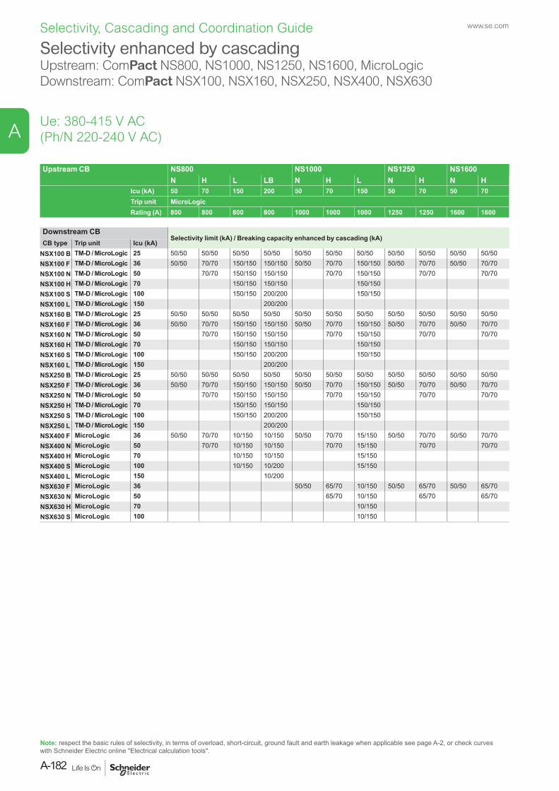
Selectivity enhanced by cascadingUpstream: ComPact NS800, NS1000, NS1250, NS1600, MicroLogicDownstream: ComPact NSX100, NSX160, NSX250, NSX400, NSX630
Ue: 380-415 V AC(Ph/N 220-240 V AC)
Upstream CB NS800 NS1000 NS1250 NS1600N H L LB N H L N H N H
Icu (kA) 50 70 150 200 50 70 150 50 70 50 70Trip unit MicroLogicRating (A) 800 800 800 800 1000 1000 1000 1250 1250 1600 1600
Downstream CBSelectivity limit (kA) / Breaking capacity enhanced by cascading (kA)
CB type Trip unit Icu (kA)NSX100 B TM-D / MicroLogic 25 50/50 50/50 50/50 50/50 50/50 50/50 50/50 50/50 50/50 50/50 50/50NSX100 F TM-D / MicroLogic 36 50/50 70/70 150/150 150/150 50/50 70/70 150/150 50/50 70/70 50/50 70/70NSX100 N TM-D / MicroLogic 50 70/70 150/150 150/150 70/70 150/150 70/70 70/70NSX100 H TM-D / MicroLogic 70 150/150 150/150 150/150NSX100 S TM-D / MicroLogic 100 150/150 200/200 150/150NSX100 L TM-D / MicroLogic 150 200/200NSX160 B TM-D / MicroLogic 25 50/50 50/50 50/50 50/50 50/50 50/50 50/50 50/50 50/50 50/50 50/50NSX160 F TM-D / MicroLogic 36 50/50 70/70 150/150 150/150 50/50 70/70 150/150 50/50 70/70 50/50 70/70NSX160 N TM-D / MicroLogic 50 70/70 150/150 150/150 70/70 150/150 70/70 70/70NSX160 H TM-D / MicroLogic 70 150/150 150/150 150/150NSX160 S TM-D / MicroLogic 100 150/150 200/200 150/150NSX160 L TM-D / MicroLogic 150 200/200NSX250 B TM-D / MicroLogic 25 50/50 50/50 50/50 50/50 50/50 50/50 50/50 50/50 50/50 50/50 50/50NSX250 F TM-D / MicroLogic 36 50/50 70/70 150/150 150/150 50/50 70/70 150/150 50/50 70/70 50/50 70/70NSX250 N TM-D / MicroLogic 50 70/70 150/150 150/150 70/70 150/150 70/70 70/70NSX250 H TM-D / MicroLogic 70 150/150 150/150 150/150NSX250 S TM-D / MicroLogic 100 150/150 200/200 150/150NSX250 L TM-D / MicroLogic 150 200/200NSX400 F MicroLogic 36 50/50 70/70 10/150 10/150 50/50 70/70 15/150 50/50 70/70 50/50 70/70NSX400 N MicroLogic 50 70/70 10/150 10/150 70/70 15/150 70/70 70/70NSX400 H MicroLogic 70 10/150 10/150 15/150NSX400 S MicroLogic 100 10/150 10/200 15/150NSX400 L MicroLogic 150 10/200NSX630 F MicroLogic 36 50/50 65/70 10/150 50/50 65/70 50/50 65/70NSX630 N MicroLogic 50 65/70 10/150 65/70 65/70NSX630 H MicroLogic 70 10/150NSX630 S MicroLogic 100 10/150
Note: respect the basic rules of selectivity, in terms of overload, short-circuit, ground fault and earth leakage when applicable see page A-2, or check curves with Schneider Electric online "Electrical calculation tools".
www.se.com
A-182
A
Selectivity, Cascading and Coordination Guide
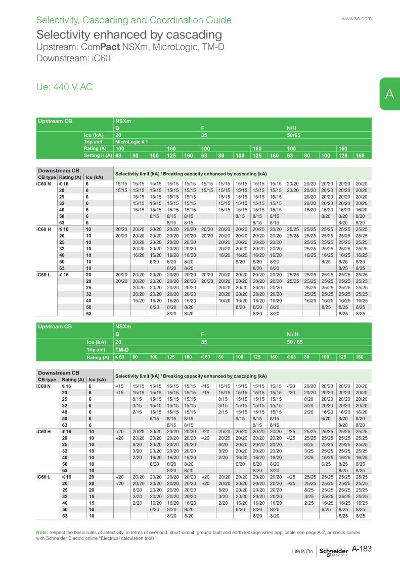
Ue: 440 V AC
Selectivity enhanced by cascadingUpstream: ComPact NSXm, MicroLogic, TM-DDownstream: iC60
Note: respect the basic rules of selectivity, in terms of overload, short-circuit, ground fault and earth leakage when applicable see page A-2, or check curves with Schneider Electric online "Electrical calculation tools".
Upstream CB NSXmB F N/H
Icu (kA) 20 35 50/65Trip unit MicroLogic 4.1Rating (A) 100 160 100 160 100 160Setting Ir (A) 63 80 100 125 160 63 80 100 125 160 63 80 100 125 160
Downstream CB Selectivity limit (kA) / Breaking capacity enhanced by cascading (kA)CB type Rating (A) Icu (kA)
iC60 N y 16 6 15/15 15/15 15/15 15/15 15/15 15/15 15/15 15/15 15/15 15/15 20/20 20/20 20/20 20/20 20/2020 6 15/15 15/15 15/15 15/15 15/15 15/15 15/15 15/15 15/15 15/15 20/20 20/20 20/20 20/20 20/2025 6 15/15 15/15 15/15 15/15 15/15 15/15 15/15 15/15 20/20 20/20 20/20 20/2032 6 15/15 15/15 15/15 15/15 15/15 15/15 15/15 15/15 20/20 20/20 20/20 20/2040 6 15/15 15/15 15/15 15/15 15/15 15/15 15/15 15/15 16/20 16/20 16/20 16/2050 6 8/15 8/15 8/15 8/15 8/15 8/15 8/20 8/20 8/2063 6 8/15 8/15 8/15 8/15 8/20 8/20
iC60 H y 16 10 20/20 20/20 20/20 20/20 20/20 20/20 20/20 20/20 20/20 20/20 25/25 25/25 25/25 25/25 25/2520 10 20/20 20/20 20/20 20/20 20/20 20/20 20/20 20/20 20/20 20/20 25/25 25/25 25/25 25/25 25/2525 10 20/20 20/20 20/20 20/20 20/20 20/20 20/20 20/20 25/25 25/25 25/25 25/2532 10 20/20 20/20 20/20 20/20 20/20 20/20 20/20 20/20 25/25 25/25 25/25 25/2540 10 16/20 16/20 16/20 16/20 16/20 16/20 16/20 16/20 16/25 16/25 16/25 16/2550 10 8/20 8/20 8/20 8/20 8/20 8/20 8/25 8/25 8/2563 10 8/20 8/20 8/20 8/20 8/25 8/25
iC60 L y 16 20 20/20 20/20 20/20 20/20 20/20 20/20 20/20 20/20 20/20 20/20 25/25 25/25 25/25 25/25 25/2520 20/20 20/20 20/20 20/20 20/20 20/20 20/20 20/20 20/20 20/20 25/25 25/25 25/25 25/25 25/2525 20/20 20/20 20/20 20/20 20/20 20/20 20/20 20/20 25/25 25/25 25/25 25/2532 20/20 20/20 20/20 20/20 20/20 20/20 20/20 20/20 25/25 25/25 25/25 25/2540 16/20 16/20 16/20 16/20 16/20 16/20 16/20 16/20 16/25 16/25 16/25 16/2550 8/20 8/20 8/20 8/20 8/20 8/20 8/25 8/25 8/2563 8/20 8/20 8/20 8/20 8/25 8/25
Upstream CB NSXm B F N / H
Icu (kA) 20 35 50 / 65Trip unit TM-DRating (A) y 63 80 100 125 160 y 63 80 100 125 160 y 63 80 100 125 160
Downstream CB Selectivity limit (kA) / Breaking capacity enhanced by cascading (kA)CB type Rating (A) Icu (kA)
iC60 N y 16 6 -/15 15/15 15/15 15/15 15/15 -/15 15/15 15/15 15/15 15/15 -/20 20/20 20/20 20/20 20/2020 6 -/15 15/15 15/15 15/15 15/15 -/15 15/15 15/15 15/15 15/15 -/20 20/20 20/20 20/20 20/2025 6 8/15 15/15 15/15 15/15 8/15 15/15 15/15 15/15 8/20 20/20 20/20 20/2032 6 3/15 15/15 15/15 15/15 3/15 15/15 15/15 15/15 3/20 20/20 20/20 20/2040 6 2/15 15/15 15/15 15/15 2/15 15/15 15/15 15/15 2/20 16/20 16/20 16/2050 6 6/15 8/15 8/15 6/15 8/15 8/15 6/20 8/20 8/2063 6 8/15 8/15 8/15 8/15 8/20 8/20
iC60 H y 16 10 -/20 20/20 20/20 20/20 20/20 -/20 20/20 20/20 20/20 20/20 -/25 25/25 25/25 25/25 25/2520 10 -/20 20/20 20/20 20/20 20/20 -/20 20/20 20/20 20/20 20/20 -/25 25/25 25/25 25/25 25/2525 10 8/20 20/20 20/20 20/20 8/20 20/20 20/20 20/20 8/25 25/25 25/25 25/2532 10 3/20 20/20 20/20 20/20 3/20 20/20 20/20 20/20 3/25 25/25 25/25 25/2540 10 2/20 16/20 16/20 16/20 2/20 16/20 16/20 16/20 2/25 16/25 16/25 16/2550 10 6/20 8/20 8/20 6/20 8/20 8/20 6/25 8/25 8/2563 10 8/20 8/20 8/20 8/20 8/25 8/25
iC60 L y 16 20 -/20 20/20 20/20 20/20 20/20 -/20 20/20 20/20 20/20 20/20 -/25 25/25 25/25 25/25 25/2520 20 -/20 20/20 20/20 20/20 20/20 -/20 20/20 20/20 20/20 20/20 -/25 25/25 25/25 25/25 25/2525 20 8/20 20/20 20/20 20/20 8/20 20/20 20/20 20/20 8/25 25/25 25/25 25/2532 15 3/20 20/20 20/20 20/20 3/20 20/20 20/20 20/20 3/25 25/25 25/25 25/2540 15 2/20 16/20 16/20 16/20 2/20 16/20 16/20 16/20 2/25 16/25 16/25 16/2550 10 6/20 8/20 8/20 6/20 8/20 8/20 6/25 8/25 8/2563 10 8/20 8/20 8/20 8/20 8/25 8/25
A-183
www.se.com
A
Selectivity, Cascading and Coordination Guide
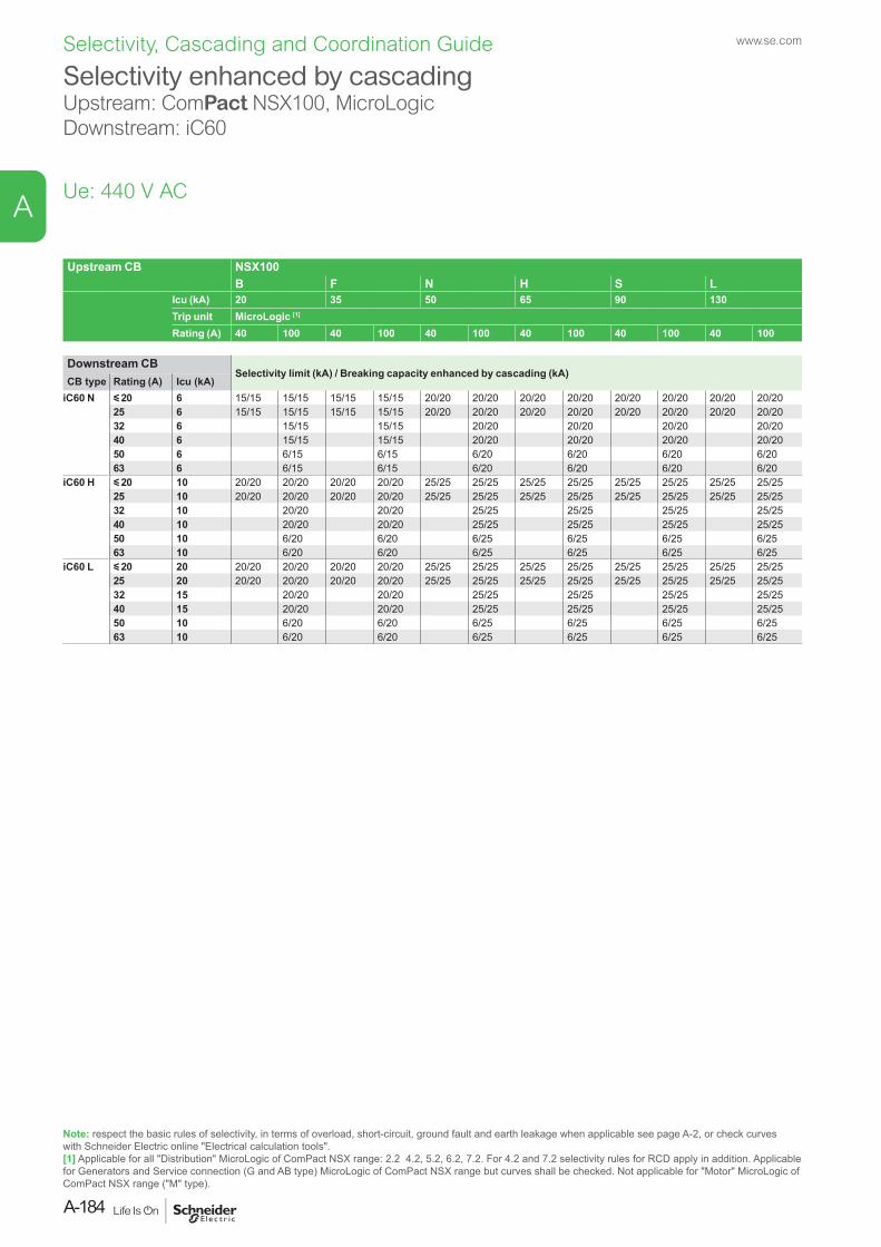
Selectivity enhanced by cascadingUpstream: ComPact NSX100, MicroLogicDownstream: iC60
Ue: 440 V AC
Upstream CB NSX100B F N H S L
Icu (kA) 20 35 50 65 90 130Trip unit MicroLogic [1]
Rating (A) 40 100 40 100 40 100 40 100 40 100 40 100
Downstream CBSelectivity limit (kA) / Breaking capacity enhanced by cascading (kA)
CB type Rating (A) Icu (kA)iC60 N y 20 6 15/15 15/15 15/15 15/15 20/20 20/20 20/20 20/20 20/20 20/20 20/20 20/20
25 6 15/15 15/15 15/15 15/15 20/20 20/20 20/20 20/20 20/20 20/20 20/20 20/2032 6 15/15 15/15 20/20 20/20 20/20 20/2040 6 15/15 15/15 20/20 20/20 20/20 20/2050 6 6/15 6/15 6/20 6/20 6/20 6/2063 6 6/15 6/15 6/20 6/20 6/20 6/20
iC60 H y 20 10 20/20 20/20 20/20 20/20 25/25 25/25 25/25 25/25 25/25 25/25 25/25 25/2525 10 20/20 20/20 20/20 20/20 25/25 25/25 25/25 25/25 25/25 25/25 25/25 25/2532 10 20/20 20/20 25/25 25/25 25/25 25/2540 10 20/20 20/20 25/25 25/25 25/25 25/2550 10 6/20 6/20 6/25 6/25 6/25 6/2563 10 6/20 6/20 6/25 6/25 6/25 6/25
iC60 L y 20 20 20/20 20/20 20/20 20/20 25/25 25/25 25/25 25/25 25/25 25/25 25/25 25/2525 20 20/20 20/20 20/20 20/20 25/25 25/25 25/25 25/25 25/25 25/25 25/25 25/2532 15 20/20 20/20 25/25 25/25 25/25 25/2540 15 20/20 20/20 25/25 25/25 25/25 25/2550 10 6/20 6/20 6/25 6/25 6/25 6/2563 10 6/20 6/20 6/25 6/25 6/25 6/25
Note: respect the basic rules of selectivity, in terms of overload, short-circuit, ground fault and earth leakage when applicable see page A-2, or check curves with Schneider Electric online "Electrical calculation tools".[1] Applicable for all "Distribution" MicroLogic of ComPact NSX range: 2.2 4.2, 5.2, 6.2, 7.2. For 4.2 and 7.2 selectivity rules for RCD apply in addition. Applicable for Generators and Service connection (G and AB type) MicroLogic of ComPact NSX range but curves shall be checked. Not applicable for "Motor" MicroLogic of ComPact NSX range ("M" type).
www.se.com
A-184
A
Selectivity, Cascading and Coordination Guide
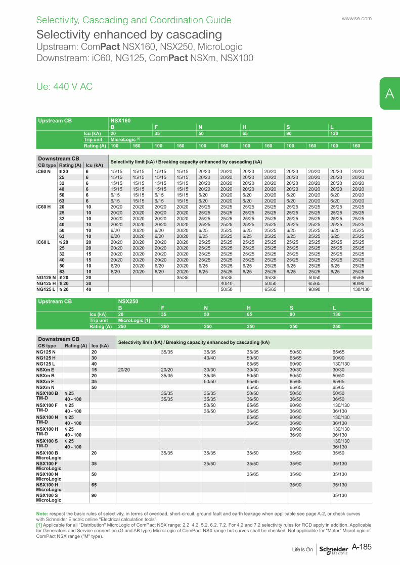
Upstream CB NSX160B F N H S L
Icu (kA) 20 35 50 65 90 130Trip unit MicroLogic [1]
Rating (A) 100 160 100 160 100 160 100 160 100 160 100 160
Downstream CB Selectivity limit (kA) / Breaking capacity enhanced by cascading (kA)CB type Rating (A) Icu (kA)
iC60 N y 20 6 15/15 15/15 15/15 15/15 20/20 20/20 20/20 20/20 20/20 20/20 20/20 20/2025 6 15/15 15/15 15/15 15/15 20/20 20/20 20/20 20/20 20/20 20/20 20/20 20/2032 6 15/15 15/15 15/15 15/15 20/20 20/20 20/20 20/20 20/20 20/20 20/20 20/2040 6 15/15 15/15 15/15 15/15 20/20 20/20 20/20 20/20 20/20 20/20 20/20 20/2050 6 6/15 15/15 6/15 15/15 6/20 20/20 6/20 20/20 6/20 20/20 6/20 20/2063 6 6/15 15/15 6/15 15/15 6/20 20/20 6/20 20/20 6/20 20/20 6/20 20/20
iC60 H 20 10 20/20 20/20 20/20 20/20 25/25 25/25 25/25 25/25 25/25 25/25 25/25 25/2525 10 20/20 20/20 20/20 20/20 25/25 25/25 25/25 25/25 25/25 25/25 25/25 25/2532 10 20/20 20/20 20/20 20/20 25/25 25/25 25/25 25/25 25/25 25/25 25/25 25/2540 10 20/20 20/20 20/20 20/20 25/25 25/25 25/25 25/25 25/25 25/25 25/25 25/2550 10 6/20 20/20 6/20 20/20 6/25 25/25 6/25 25/25 6/25 25/25 6/25 25/2563 10 6/20 20/20 6/20 20/20 6/25 25/25 6/25 25/25 6/25 25/25 6/25 25/25
iC60 L y 20 20 20/20 20/20 20/20 20/20 25/25 25/25 25/25 25/25 25/25 25/25 25/25 25/2525 20 20/20 20/20 20/20 20/20 25/25 25/25 25/25 25/25 25/25 25/25 25/25 25/2532 15 20/20 20/20 20/20 20/20 25/25 25/25 25/25 25/25 25/25 25/25 25/25 25/2540 15 20/20 20/20 20/20 20/20 25/25 25/25 25/25 25/25 25/25 25/25 25/25 25/2550 10 6/20 20/20 6/20 20/20 6/25 25/25 6/25 25/25 6/25 25/25 6/25 25/2563 10 6/20 20/20 6/20 20/20 6/25 25/25 6/25 25/25 6/25 25/25 6/25 25/25
NG125 N y 20 20 35/35 35/35 35/35 50/50 65/65NG125 H y 20 30 40/40 50/50 65/65 90/90NG125 L y 20 40 50/50 65/65 90/90 130/130
Upstream CB NSX250B F N H S L
Icu (kA) 20 35 50 65 90 130Trip unit MicroLogic [1]Rating (A) 250 250 250 250 250 250
Downstream CB Selectivity limit (kA) / Breaking capacity enhanced by cascading (kA)CB type Rating (A) Icu (kA)
NG125 N 20 35/35 35/35 35/35 50/50 65/65NG125 H 30 40/40 50/50 65/65 90/90NG125 L 40 65/65 90/90 130/130NSXm E 15 20/20 20/20 30/30 30/30 30/30 30/30NSXm B 20 35/35 35/35 50/50 50/50 50/50NSXm F 35 50/50 65/65 65/65 65/65NSXm N 50 65/65 65/65 65/65NSX100 BTM-D
y 25 35/35 35/35 50/50 50/50 50/5040 - 100 35/35 35/35 36/50 36/50 36/50
NSX100 FTM-D
y 25 50/50 65/65 90/90 130/13040 - 100 36/50 36/65 36/90 36/130
NSX100 NTM-D
y 25 65/65 90/90 130/13040 - 100 36/65 36/90 36/130
NSX100 HTM-D
y 25 90/90 130/13040 - 100 36/90 36/130
NSX100 STM-D
y 25 130/13040 - 100 36/130
NSX100 B MicroLogic
20 35/35 35/35 35/50 35/50 35/50
NSX100 F MicroLogic
35 35/50 35/50 35/90 35/130
NSX100 N MicroLogic
50 35/65 35/90 35/130
NSX100 H MicroLogic
65 35/90 35/130
NSX100 S MicroLogic
90 35/130
Selectivity enhanced by cascadingUpstream: ComPact NSX160, NSX250, MicroLogicDownstream: iC60, NG125, ComPact NSXm, NSX100
Ue: 440 V AC
Note: respect the basic rules of selectivity, in terms of overload, short-circuit, ground fault and earth leakage when applicable see page A-2, or check curves with Schneider Electric online "Electrical calculation tools".[1] Applicable for all "Distribution" MicroLogic of ComPact NSX range: 2.2 4.2, 5.2, 6.2, 7.2. For 4.2 and 7.2 selectivity rules for RCD apply in addition. Applicable for Generators and Service connection (G and AB type) MicroLogic of ComPact NSX range but curves shall be checked. Not applicable for "Motor" MicroLogic of ComPact NSX range ("M" type).
A-185
www.se.com
A
Selectivity, Cascading and Coordination Guide
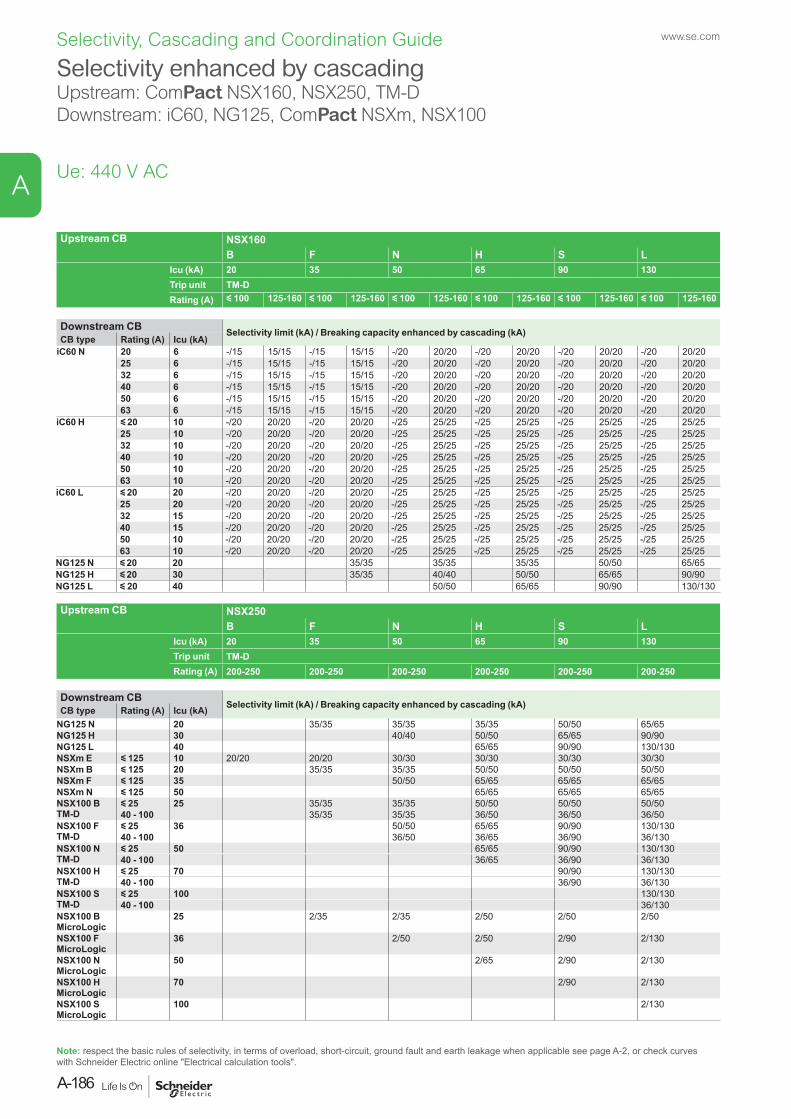
Upstream CB NSX160B F N H S L
Icu (kA) 20 35 50 65 90 130Trip unit TM-DRating (A) y 100 125-160 y 100 125-160 y 100 125-160 y 100 125-160 y 100 125-160 y 100 125-160
Downstream CB Selectivity limit (kA) / Breaking capacity enhanced by cascading (kA)CB type Rating (A) Icu (kA)
iC60 N 20 6 -/15 15/15 -/15 15/15 -/20 20/20 -/20 20/20 -/20 20/20 -/20 20/2025 6 -/15 15/15 -/15 15/15 -/20 20/20 -/20 20/20 -/20 20/20 -/20 20/2032 6 -/15 15/15 -/15 15/15 -/20 20/20 -/20 20/20 -/20 20/20 -/20 20/2040 6 -/15 15/15 -/15 15/15 -/20 20/20 -/20 20/20 -/20 20/20 -/20 20/2050 6 -/15 15/15 -/15 15/15 -/20 20/20 -/20 20/20 -/20 20/20 -/20 20/2063 6 -/15 15/15 -/15 15/15 -/20 20/20 -/20 20/20 -/20 20/20 -/20 20/20
iC60 H y 20 10 -/20 20/20 -/20 20/20 -/25 25/25 -/25 25/25 -/25 25/25 -/25 25/2525 10 -/20 20/20 -/20 20/20 -/25 25/25 -/25 25/25 -/25 25/25 -/25 25/2532 10 -/20 20/20 -/20 20/20 -/25 25/25 -/25 25/25 -/25 25/25 -/25 25/2540 10 -/20 20/20 -/20 20/20 -/25 25/25 -/25 25/25 -/25 25/25 -/25 25/2550 10 -/20 20/20 -/20 20/20 -/25 25/25 -/25 25/25 -/25 25/25 -/25 25/2563 10 -/20 20/20 -/20 20/20 -/25 25/25 -/25 25/25 -/25 25/25 -/25 25/25
iC60 L y 20 20 -/20 20/20 -/20 20/20 -/25 25/25 -/25 25/25 -/25 25/25 -/25 25/2525 20 -/20 20/20 -/20 20/20 -/25 25/25 -/25 25/25 -/25 25/25 -/25 25/2532 15 -/20 20/20 -/20 20/20 -/25 25/25 -/25 25/25 -/25 25/25 -/25 25/2540 15 -/20 20/20 -/20 20/20 -/25 25/25 -/25 25/25 -/25 25/25 -/25 25/2550 10 -/20 20/20 -/20 20/20 -/25 25/25 -/25 25/25 -/25 25/25 -/25 25/2563 10 -/20 20/20 -/20 20/20 -/25 25/25 -/25 25/25 -/25 25/25 -/25 25/25
NG125 N y 20 20 35/35 35/35 35/35 50/50 65/65NG125 H y 20 30 35/35 40/40 50/50 65/65 90/90NG125 L y 20 40 50/50 65/65 90/90 130/130
Upstream CB NSX250B F N H S L
Icu (kA) 20 35 50 65 90 130Trip unit TM-DRating (A) 200-250 200-250 200-250 200-250 200-250 200-250
Downstream CBSelectivity limit (kA) / Breaking capacity enhanced by cascading (kA)CB type Rating (A) Icu (kA)
NG125 N 20 35/35 35/35 35/35 50/50 65/65NG125 H 30 40/40 50/50 65/65 90/90NG125 L 40 65/65 90/90 130/130NSXm E y 125 10 20/20 20/20 30/30 30/30 30/30 30/30NSXm B y 125 20 35/35 35/35 50/50 50/50 50/50NSXm F y 125 35 50/50 65/65 65/65 65/65NSXm N y 125 50 65/65 65/65 65/65NSX100 BTM-D
y 25 25 35/35 35/35 50/50 50/50 50/5040 - 100 35/35 35/35 36/50 36/50 36/50
NSX100 FTM-D
y 25 36 50/50 65/65 90/90 130/13040 - 100 36/50 36/65 36/90 36/130
NSX100 NTM-D
y 25 50 65/65 90/90 130/13040 - 100 36/65 36/90 36/130
NSX100 HTM-D
y 25 70 90/90 130/13040 - 100 36/90 36/130
NSX100 STM-D
y 25 100 130/13040 - 100 36/130
NSX100 B MicroLogic
25 2/35 2/35 2/50 2/50 2/50
NSX100 F MicroLogic
36 2/50 2/50 2/90 2/130
NSX100 N MicroLogic
50 2/65 2/90 2/130
NSX100 H MicroLogic
70 2/90 2/130
NSX100 S MicroLogic
100 2/130
Selectivity enhanced by cascadingUpstream: ComPact NSX160, NSX250, TM-DDownstream: iC60, NG125, ComPact NSXm, NSX100
Ue: 440 V AC
Note: respect the basic rules of selectivity, in terms of overload, short-circuit, ground fault and earth leakage when applicable see page A-2, or check curves with Schneider Electric online "Electrical calculation tools".
www.se.com
A-186
A
Selectivity, Cascading and Coordination Guide
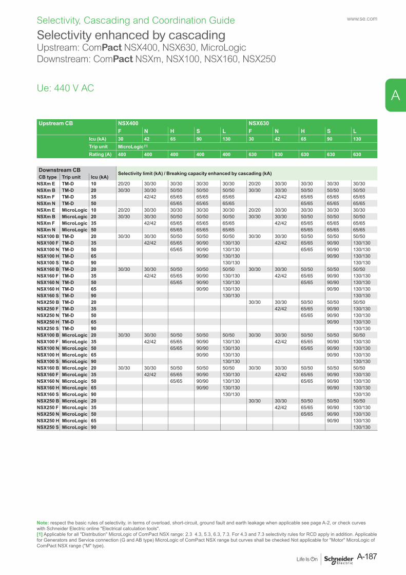
Upstream CB NSX400 NSX630F N H S L F N H S L
Icu (kA) 30 42 65 90 130 30 42 65 90 130Trip unit MicroLogic [1]
Rating (A) 400 400 400 400 400 630 630 630 630 630
Downstream CB Selectivity limit (kA) / Breaking capacity enhanced by cascading (kA)CB type Trip unit Icu (kA)
NSXm E TM-D 10 20/20 30/30 30/30 30/30 30/30 20/20 30/30 30/30 30/30 30/30NSXm B TM-D 20 30/30 30/30 50/50 50/50 50/50 30/30 30/30 50/50 50/50 50/50NSXm F TM-D 35 42/42 65/65 65/65 65/65 42/42 65/65 65/65 65/65NSXm N TM-D 50 65/65 65/65 65/65 65/65 65/65 65/65NSXm E MicroLogic 10 20/20 30/30 30/30 30/30 30/30 20/20 30/30 30/30 30/30 30/30NSXm B MicroLogic 20 30/30 30/30 50/50 50/50 50/50 30/30 30/30 50/50 50/50 50/50NSXm F MicroLogic 35 42/42 65/65 65/65 65/65 42/42 65/65 65/65 65/65NSXm N MicroLogic 50 65/65 65/65 65/65 65/65 65/65 65/65NSX100 B TM-D 20 30/30 30/30 50/50 50/50 50/50 30/30 30/30 50/50 50/50 50/50NSX100 F TM-D 35 42/42 65/65 90/90 130/130 42/42 65/65 90/90 130/130NSX100 N TM-D 50 65/65 90/90 130/130 65/65 90/90 130/130NSX100 H TM-D 65 90/90 130/130 90/90 130/130NSX100 S TM-D 90 130/130 130/130NSX160 B TM-D 20 30/30 30/30 50/50 50/50 50/50 30/30 30/30 50/50 50/50 50/50NSX160 F TM-D 35 42/42 65/65 90/90 130/130 42/42 65/65 90/90 130/130NSX160 N TM-D 50 65/65 90/90 130/130 65/65 90/90 130/130NSX160 H TM-D 65 90/90 130/130 90/90 130/130NSX160 S TM-D 90 130/130 130/130NSX250 B TM-D 20 30/30 30/30 50/50 50/50 50/50NSX250 F TM-D 35 42/42 65/65 90/90 130/130NSX250 N TM-D 50 65/65 90/90 130/130NSX250 H TM-D 65 90/90 130/130NSX250 S TM-D 90 130/130NSX100 B MicroLogic 20 30/30 30/30 50/50 50/50 50/50 30/30 30/30 50/50 50/50 50/50NSX100 F MicroLogic 35 42/42 65/65 90/90 130/130 42/42 65/65 90/90 130/130NSX100 N MicroLogic 50 65/65 90/90 130/130 65/65 90/90 130/130NSX100 H MicroLogic 65 90/90 130/130 90/90 130/130NSX100 S MicroLogic 90 130/130 130/130NSX160 B MicroLogic 20 30/30 30/30 50/50 50/50 50/50 30/30 30/30 50/50 50/50 50/50NSX160 F MicroLogic 35 42/42 65/65 90/90 130/130 42/42 65/65 90/90 130/130NSX160 N MicroLogic 50 65/65 90/90 130/130 65/65 90/90 130/130NSX160 H MicroLogic 65 90/90 130/130 90/90 130/130NSX160 S MicroLogic 90 130/130 130/130NSX250 B MicroLogic 20 30/30 30/30 50/50 50/50 50/50NSX250 F MicroLogic 35 42/42 65/65 90/90 130/130NSX250 N MicroLogic 50 65/65 90/90 130/130NSX250 H MicroLogic 65 90/90 130/130NSX250 S MicroLogic 90 130/130
Selectivity enhanced by cascadingUpstream: ComPact NSX400, NSX630, MicroLogicDownstream: ComPact NSXm, NSX100, NSX160, NSX250
Ue: 440 V AC
Note: respect the basic rules of selectivity, in terms of overload, short-circuit, ground fault and earth leakage when applicable see page A-2, or check curves with Schneider Electric online "Electrical calculation tools".[1] Applicable for all "Distribution" MicroLogic of ComPact NSX range: 2.3 4.3, 5.3, 6.3, 7.3. For 4.3 and 7.3 selectivity rules for RCD apply in addition. Applicable for Generators and Service connection (G and AB type) MicroLogic of ComPact NSX range but curves shall be checked Not applicable for "Motor" MicroLogic of ComPact NSX range ("M" type).
A-187
www.se.com
A
Selectivity, Cascading and Coordination Guide
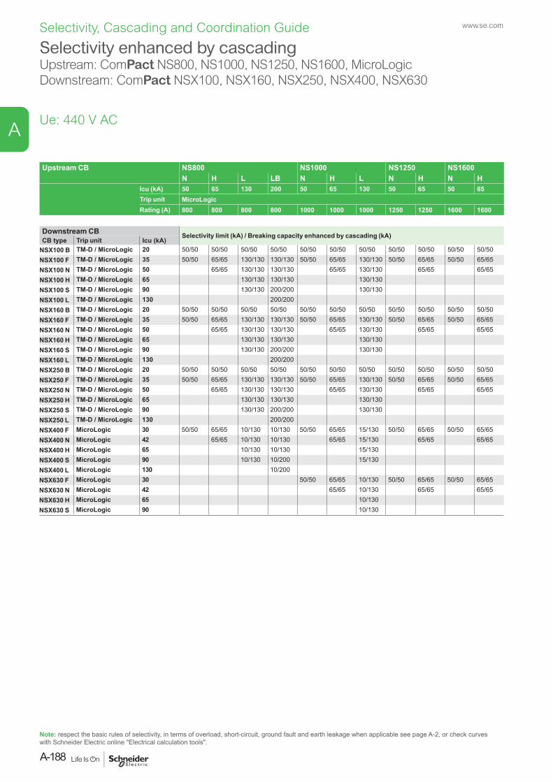
Upstream CB NS800 NS1000 NS1250 NS1600N H L LB N H L N H N H
Icu (kA) 50 65 130 200 50 65 130 50 65 50 65 Trip unit MicroLogicRating (A) 800 800 800 800 1000 1000 1000 1250 1250 1600 1600
Downstream CB Selectivity limit (kA) / Breaking capacity enhanced by cascading (kA)CB type Trip unit Icu (kA)
NSX100 B TM-D / MicroLogic 20 50/50 50/50 50/50 50/50 50/50 50/50 50/50 50/50 50/50 50/50 50/50NSX100 F TM-D / MicroLogic 35 50/50 65/65 130/130 130/130 50/50 65/65 130/130 50/50 65/65 50/50 65/65NSX100 N TM-D / MicroLogic 50 65/65 130/130 130/130 65/65 130/130 65/65 65/65NSX100 H TM-D / MicroLogic 65 130/130 130/130 130/130NSX100 S TM-D / MicroLogic 90 130/130 200/200 130/130NSX100 L TM-D / MicroLogic 130 200/200NSX160 B TM-D / MicroLogic 20 50/50 50/50 50/50 50/50 50/50 50/50 50/50 50/50 50/50 50/50 50/50NSX160 F TM-D / MicroLogic 35 50/50 65/65 130/130 130/130 50/50 65/65 130/130 50/50 65/65 50/50 65/65NSX160 N TM-D / MicroLogic 50 65/65 130/130 130/130 65/65 130/130 65/65 65/65NSX160 H TM-D / MicroLogic 65 130/130 130/130 130/130NSX160 S TM-D / MicroLogic 90 130/130 200/200 130/130NSX160 L TM-D / MicroLogic 130 200/200NSX250 B TM-D / MicroLogic 20 50/50 50/50 50/50 50/50 50/50 50/50 50/50 50/50 50/50 50/50 50/50NSX250 F TM-D / MicroLogic 35 50/50 65/65 130/130 130/130 50/50 65/65 130/130 50/50 65/65 50/50 65/65NSX250 N TM-D / MicroLogic 50 65/65 130/130 130/130 65/65 130/130 65/65 65/65NSX250 H TM-D / MicroLogic 65 130/130 130/130 130/130NSX250 S TM-D / MicroLogic 90 130/130 200/200 130/130NSX250 L TM-D / MicroLogic 130 200/200NSX400 F MicroLogic 30 50/50 65/65 10/130 10/130 50/50 65/65 15/130 50/50 65/65 50/50 65/65NSX400 N MicroLogic 42 65/65 10/130 10/130 65/65 15/130 65/65 65/65NSX400 H MicroLogic 65 10/130 10/130 15/130NSX400 S MicroLogic 90 10/130 10/200 15/130NSX400 L MicroLogic 130 10/200NSX630 F MicroLogic 30 50/50 65/65 10/130 50/50 65/65 50/50 65/65NSX630 N MicroLogic 42 65/65 10/130 65/65 65/65NSX630 H MicroLogic 65 10/130NSX630 S MicroLogic 90 10/130
Selectivity enhanced by cascadingUpstream: ComPact NS800, NS1000, NS1250, NS1600, MicroLogicDownstream: ComPact NSX100, NSX160, NSX250, NSX400, NSX630
Ue: 440 V AC
Note: respect the basic rules of selectivity, in terms of overload, short-circuit, ground fault and earth leakage when applicable see page A-2, or check curves with Schneider Electric online "Electrical calculation tools".
www.se.com
A-188
A
Selectivity, Cascading and Coordination Guide
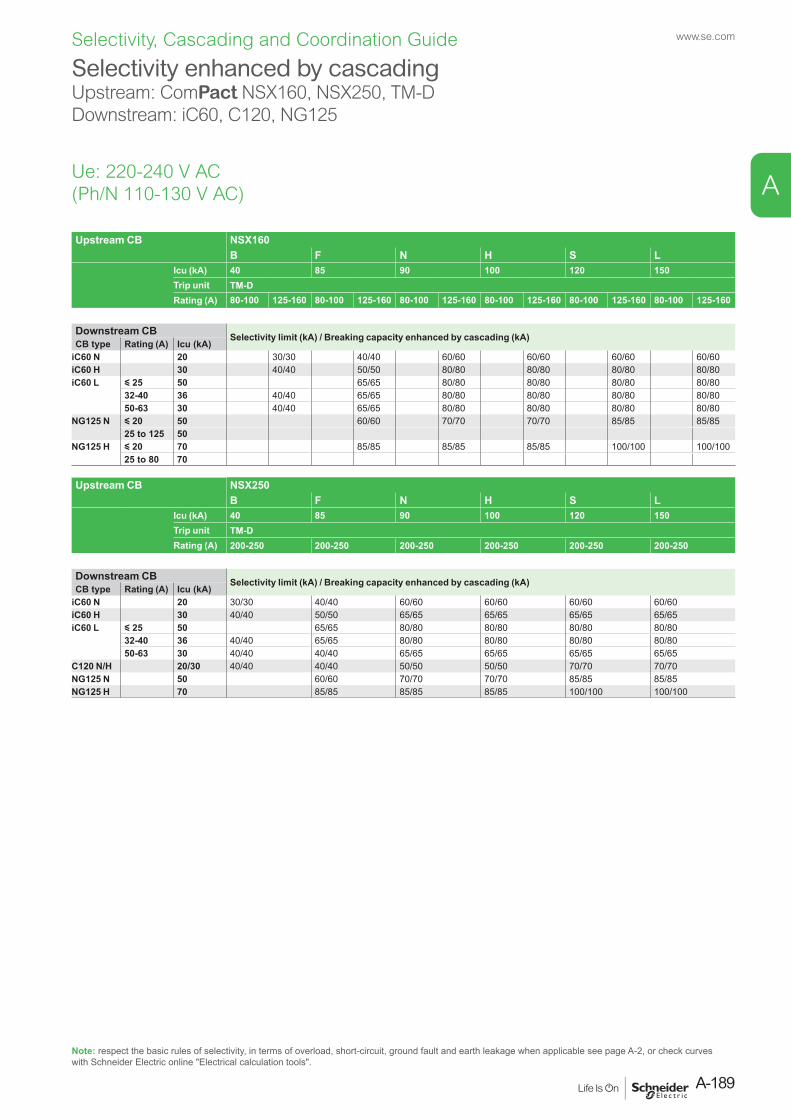
Upstream CB NSX160B F N H S L
Icu (kA) 40 85 90 100 120 150Trip unit TM-DRating (A) 80-100 125-160 80-100 125-160 80-100 125-160 80-100 125-160 80-100 125-160 80-100 125-160
Downstream CB Selectivity limit (kA) / Breaking capacity enhanced by cascading (kA)CB type Rating (A) Icu (kA)
iC60 N 20 30/30 40/40 60/60 60/60 60/60 60/60iC60 H 30 40/40 50/50 80/80 80/80 80/80 80/80iC60 L y 25 50 65/65 80/80 80/80 80/80 80/80
32-40 36 40/40 65/65 80/80 80/80 80/80 80/8050-63 30 40/40 65/65 80/80 80/80 80/80 80/80
NG125 N y 20 50 60/60 70/70 70/70 85/85 85/8525 to 125 50
NG125 H y 20 70 85/85 85/85 85/85 100/100 100/10025 to 80 70
Upstream CB NSX250B F N H S L
Icu (kA) 40 85 90 100 120 150Trip unit TM-DRating (A) 200-250 200-250 200-250 200-250 200-250 200-250
Downstream CB Selectivity limit (kA) / Breaking capacity enhanced by cascading (kA)CB type Rating (A) Icu (kA)
iC60 N 20 30/30 40/40 60/60 60/60 60/60 60/60iC60 H 30 40/40 50/50 65/65 65/65 65/65 65/65iC60 L y 25 50 65/65 80/80 80/80 80/80 80/80
32-40 36 40/40 65/65 80/80 80/80 80/80 80/8050-63 30 40/40 40/40 65/65 65/65 65/65 65/65
C120 N/H 20/30 40/40 40/40 50/50 50/50 70/70 70/70NG125 N 50 60/60 70/70 70/70 85/85 85/85NG125 H 70 85/85 85/85 85/85 100/100 100/100
Selectivity enhanced by cascadingUpstream: ComPact NSX160, NSX250, TM-DDownstream: iC60, C120, NG125
Ue: 220-240 V AC (Ph/N 110-130 V AC)
Note: respect the basic rules of selectivity, in terms of overload, short-circuit, ground fault and earth leakage when applicable see page A-2, or check curves with Schneider Electric online "Electrical calculation tools".
A-189
www.se.com
A
Selectivity, Cascading and Coordination Guide
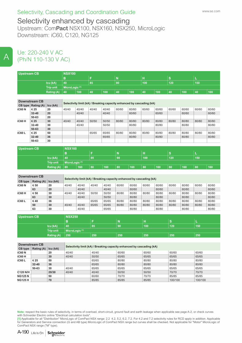
Ue: 220-240 V AC (Ph/N 110-130 V AC)
Upstream CB NSX100B F N H S L
Icu (kA) 40 85 90 100 120 150Trip unit MicroLogic [1]
Rating (A) 40 100 40 100 40 100 40 100 40 100 40 100
Downstream CB Selectivity limit (kA) / Breaking capacity enhanced by cascading (kA)CB type Rating (A) Icu (kA)
iC60 N y 25 20 40/40 40/40 40/40 40/40 60/60 60/60 60/60 60/60 60/60 60/60 60/60 60/6032-40 20 40/40 40/40 60/60 60/60 60/60 60/6050-63 20
iC60 H y 25 30 40/40 40/40 50/50 50/50 80/80 80/80 80/80 80/80 80/80 80/80 80/80 80/8032-40 30 40/40 50/50 80/80 80/80 80/80 80/8050-63 30
iC60 L y 25 50 65/65 65/65 80/80 80/80 80/80 80/80 80/80 80/80 80/80 80/8032-40 36 65/65 80/80 80/80 80/80 80/8050-63 30
Upstream CB NSX160B F N H S L
Icu (kA) 40 85 90 100 120 150Trip unit MicroLogic [1]
Rating (A) 80 160 80 160 80 160 80 160 80 160 80 160
Downstream CBSelectivity limit (kA) / Breaking capacity enhanced by cascading (kA)
CB type Rating (A) Icu (kA)iC60 N y 50 20 40/40 40/40 40/40 40/40 60/60 60/60 60/60 60/60 60/60 60/60 60/60 60/60
63 20 40/40 40/40 60/60 60/60 60/60 60/60iC60 H y 50 30 40/40 40/40 50/50 50/50 80/80 80/80 80/80 80/80 80/80 80/80 80/80 80/80
63 30 40/40 50/50 80/80 80/80 80/80 80/80iC60 L y 40 36 65/65 65/65 80/80 80/80 80/80 80/80 80/80 80/80 80/80 80/80
50 30 40/40 40/40 65/65 65/65 80/80 80/80 80/80 80/80 80/80 80/80 80/80 80/8063 30 40/40 65/65 80/80 80/80 80/80 80/80
Upstream CB NSX250B F N H S L
Icu (kA) 40 85 90 100 120 150Trip unit MicroLogic [1]
Rating (A) 250 250 250 250 250 250
Downstream CB Selectivity limit (kA) / Breaking capacity enhanced by cascading (kA)CB type Rating (A) Icu (kA)
iC60 N 20 40/40 40/40 60/60 60/60 60/60 60/60iC60 H 30 40/40 50/50 65/65 65/65 65/65 65/65iC60 L y 25 50 65/65 80/80 80/80 80/80 80/80
32-40 36 65/65 80/80 80/80 80/80 80/8050-63 30 40/40 65/65 65/65 65/65 65/65 65/65
C120 N/H 20/30 40/40 40/40 50/50 50/50 70/70 70/70NG125 N 50 60/60 70/70 70/70 85/85 85/85NG125 H 70 85/85 85/85 85/85 100/100 100/100
Selectivity enhanced by cascadingUpstream: ComPact NSX100, NSX160, NSX250, MicroLogicDownstream: iC60, C120, NG125
Note: respect the basic rules of selectivity, in terms of overload, short-circuit, ground fault and earth leakage when applicable see page A-2, or check curves with Schneider Electric online "Electrical calculation tools".[1] Applicable for all "Distribution" MicroLogic of ComPact NSX range: 2.2 4.2, 5.2, 6.2, 7.2. For 4.2 and 7.2 selectivity rules for RCD apply in addition. Applicable for Generators and Service connection (G and AB type) MicroLogic of ComPact NSX range but curves shall be checked. Not applicable for "Motor" MicroLogic of ComPact NSX range ("M" type).
www.se.com
A-190
A
Selectivity, Cascading and Coordination Guide
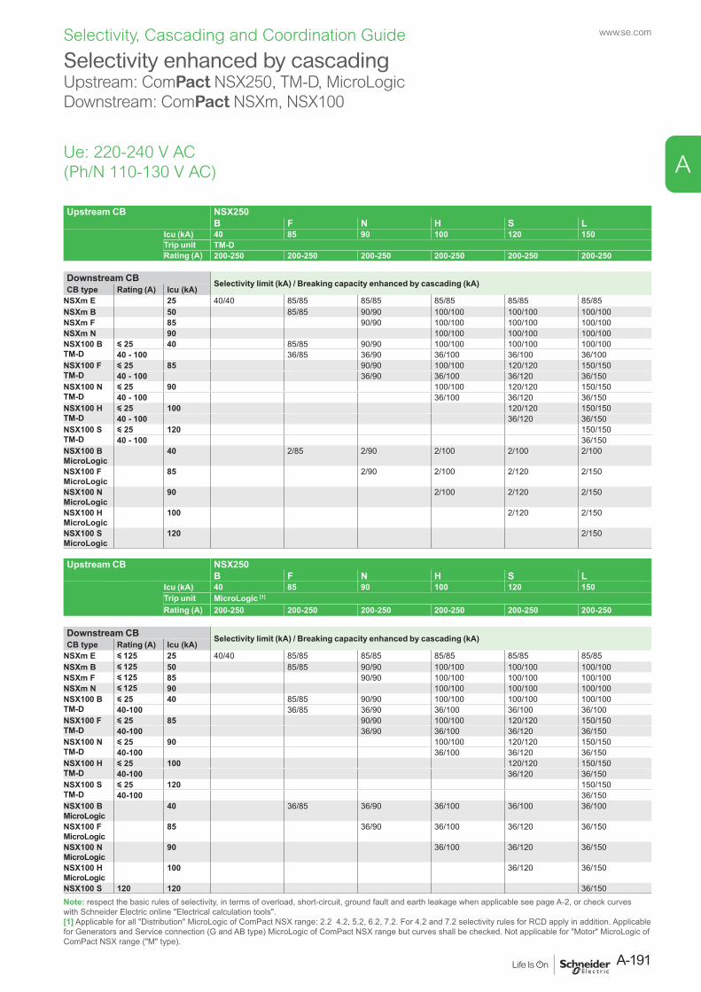
Upstream CB NSX250B F N H S L
Icu (kA) 40 85 90 100 120 150Trip unit TM-DRating (A) 200-250 200-250 200-250 200-250 200-250 200-250
Downstream CB Selectivity limit (kA) / Breaking capacity enhanced by cascading (kA)CB type Rating (A) Icu (kA)
NSXm E 25 40/40 85/85 85/85 85/85 85/85 85/85NSXm B 50 85/85 90/90 100/100 100/100 100/100NSXm F 85 90/90 100/100 100/100 100/100NSXm N 90 100/100 100/100 100/100NSX100 BTM-D
y 25 40 85/85 90/90 100/100 100/100 100/10040 - 100 36/85 36/90 36/100 36/100 36/100
NSX100 FTM-D
y 25 85 90/90 100/100 120/120 150/15040 - 100 36/90 36/100 36/120 36/150
NSX100 NTM-D
y 25 90 100/100 120/120 150/15040 - 100 36/100 36/120 36/150
NSX100 HTM-D
y 25 100 120/120 150/15040 - 100 36/120 36/150
NSX100 STM-D
y 25 120 150/15040 - 100 36/150
NSX100 B MicroLogic
40 2/85 2/90 2/100 2/100 2/100
NSX100 F MicroLogic
85 2/90 2/100 2/120 2/150
NSX100 N MicroLogic
90 2/100 2/120 2/150
NSX100 H MicroLogic
100 2/120 2/150
NSX100 S MicroLogic
120 2/150
Upstream CB NSX250B F N H S L
Icu (kA) 40 85 90 100 120 150Trip unit MicroLogic [1]
Rating (A) 200-250 200-250 200-250 200-250 200-250 200-250
Downstream CB Selectivity limit (kA) / Breaking capacity enhanced by cascading (kA)CB type Rating (A) Icu (kA)
NSXm E y 125 25 40/40 85/85 85/85 85/85 85/85 85/85NSXm B y 125 50 85/85 90/90 100/100 100/100 100/100NSXm F y 125 85 90/90 100/100 100/100 100/100NSXm N y 125 90 100/100 100/100 100/100NSX100 BTM-D
y 25 40 85/85 90/90 100/100 100/100 100/10040-100 36/85 36/90 36/100 36/100 36/100
NSX100 FTM-D
y 25 85 90/90 100/100 120/120 150/15040-100 36/90 36/100 36/120 36/150
NSX100 NTM-D
y 25 90 100/100 120/120 150/15040-100 36/100 36/120 36/150
NSX100 HTM-D
y 25 100 120/120 150/15040-100 36/120 36/150
NSX100 STM-D
y 25 120 150/15040-100 36/150
NSX100 B MicroLogic
40 36/85 36/90 36/100 36/100 36/100
NSX100 F MicroLogic
85 36/90 36/100 36/120 36/150
NSX100 N MicroLogic
90 36/100 36/120 36/150
NSX100 H MicroLogic
100 36/120 36/150
NSX100 S 120 120 36/150
Selectivity enhanced by cascadingUpstream: ComPact NSX250, TM-D, MicroLogicDownstream: ComPact NSXm, NSX100
Ue: 220-240 V AC(Ph/N 110-130 V AC)
Note: respect the basic rules of selectivity, in terms of overload, short-circuit, ground fault and earth leakage when applicable see page A-2, or check curves with Schneider Electric online "Electrical calculation tools".[1] Applicable for all "Distribution" MicroLogic of ComPact NSX range: 2.2 4.2, 5.2, 6.2, 7.2. For 4.2 and 7.2 selectivity rules for RCD apply in addition. Applicable for Generators and Service connection (G and AB type) MicroLogic of ComPact NSX range but curves shall be checked. Not applicable for "Motor" MicroLogic of ComPact NSX range ("M" type).
A-191
www.se.com
A
Selectivity, Cascading and Coordination Guide
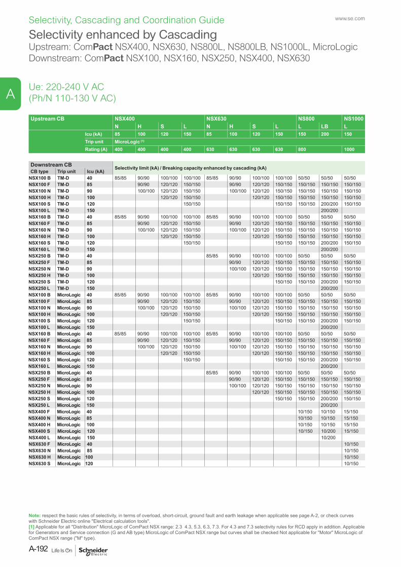
Upstream CB NSX400 NSX630 NS800 NS1000N H S L N H S L L LB L
Icu (kA) 85 100 120 150 85 100 120 150 150 200 150Trip unit MicroLogic [1]
Rating (A) 400 400 400 400 630 630 630 630 800 1000
Downstream CB Selectivity limit (kA) / Breaking capacity enhanced by cascading (kA)CB type Trip unit Icu (kA)
NSX100 B TM-D 40 85/85 90/90 100/100 100/100 85/85 90/90 100/100 100/100 50/50 50/50 50/50NSX100 F TM-D 85 90/90 120/120 150/150 90/90 120/120 150/150 150/150 150/150 150/150NSX100 N TM-D 90 100/100 120/120 150/150 100/100 120/120 150/150 150/150 150/150 150/150NSX100 H TM-D 100 120/120 150/150 120/120 150/150 150/150 150/150 150/150NSX100 S TM-D 120 150/150 150/150 150/150 200/200 150/150NSX100 L TM-D 150 200/200NSX160 B TM-D 40 85/85 90/90 100/100 100/100 85/85 90/90 100/100 100/100 50/50 50/50 50/50NSX160 F TM-D 85 90/90 120/120 150/150 90/90 120/120 150/150 150/150 150/150 150/150NSX160 N TM-D 90 100/100 120/120 150/150 100/100 120/120 150/150 150/150 150/150 150/150NSX160 H TM-D 100 120/120 150/150 120/120 150/150 150/150 150/150 150/150NSX160 S TM-D 120 150/150 150/150 150/150 200/200 150/150NSX160 L TM-D 150 200/200NSX250 B TM-D 40 85/85 90/90 100/100 100/100 50/50 50/50 50/50NSX250 F TM-D 85 90/90 120/120 150/150 150/150 150/150 150/150NSX250 N TM-D 90 100/100 120/120 150/150 150/150 150/150 150/150NSX250 H TM-D 100 120/120 150/150 150/150 150/150 150/150NSX250 S TM-D 120 150/150 150/150 200/200 150/150NSX250 L TM-D 150 200/200NSX100 B MicroLogic 40 85/85 90/90 100/100 100/100 85/85 90/90 100/100 100/100 50/50 50/50 50/50NSX100 F MicroLogic 85 90/90 120/120 150/150 90/90 120/120 150/150 150/150 150/150 150/150NSX100 N MicroLogic 90 100/100 120/120 150/150 100/100 120/120 150/150 150/150 150/150 150/150NSX100 H MicroLogic 100 120/120 150/150 120/120 150/150 150/150 150/150 150/150NSX100 S MicroLogic 120 150/150 150/150 150/150 200/200 150/150NSX100 L MicroLogic 150 200/200NSX160 B MicroLogic 40 85/85 90/90 100/100 100/100 85/85 90/90 100/100 100/100 50/50 50/50 50/50NSX160 F MicroLogic 85 90/90 120/120 150/150 90/90 120/120 150/150 150/150 150/150 150/150NSX160 N MicroLogic 90 100/100 120/120 150/150 100/100 120/120 150/150 150/150 150/150 150/150NSX160 H MicroLogic 100 120/120 150/150 120/120 150/150 150/150 150/150 150/150NSX160 S MicroLogic 120 150/150 150/150 150/150 200/200 150/150NSX160 L MicroLogic 150 200/200NSX250 B MicroLogic 40 85/85 90/90 100/100 100/100 50/50 50/50 50/50NSX250 F MicroLogic 85 90/90 120/120 150/150 150/150 150/150 150/150NSX250 N MicroLogic 90 100/100 120/120 150/150 150/150 150/150 150/150NSX250 H MicroLogic 100 120/120 150/150 150/150 150/150 150/150NSX250 S MicroLogic 120 150/150 150/150 200/200 150/150NSX250 L MicroLogic 150 200/200NSX400 F MicroLogic 40 10/150 10/150 15/150NSX400 N MicroLogic 85 10/150 10/150 15/150NSX400 H MicroLogic 100 10/150 10/150 15/150NSX400 S MicroLogic 120 10/150 10/200 15/150NSX400 L MicroLogic 150 10/200NSX630 F MicroLogic 40 10/150NSX630 N MicroLogic 85 10/150NSX630 H MicroLogic 100 10/150NSX630 S MicroLogic 120 10/150
Selectivity enhanced by CascadingUpstream: ComPact NSX400, NSX630, NS800L, NS800LB, NS1000L, MicroLogic Downstream: ComPact NSX100, NSX160, NSX250, NSX400, NSX630
Ue: 220-240 V AC (Ph/N 110-130 V AC)
Note: respect the basic rules of selectivity, in terms of overload, short-circuit, ground fault and earth leakage when applicable see page A-2, or check curves with Schneider Electric online "Electrical calculation tools".[1] Applicable for all "Distribution" MicroLogic of ComPact NSX range: 2.3 4.3, 5.3, 6.3, 7.3. For 4.3 and 7.3 selectivity rules for RCD apply in addition. Applicable for Generators and Service connection (G and AB type) MicroLogic of ComPact NSX range but curves shall be checked Not applicable for "Motor" MicroLogic of ComPact NSX range ("M" type).
www.se.com
A-192
A
Selectivity, Cascading and Coordination Guide
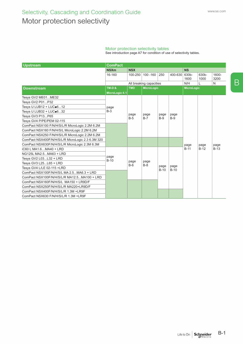
B
Motor protection selectivity
Motor protection selectivity tablesSee introduction page A7 for condition of use of selectivity tables.
Upstream ComPactNSXm NSX NS16-160 100-250 100 -160 250 400-630 630b-
1600630b-1000
1600-3200
All breaking capacities N/H L NDownstream TM-D &
MicroLogic 4.1
TMD MicroLogic MicroLogic
Tesys GV2 ME01...ME32
page B-3
page B-5
page B-7
page B-9
page B-9
page B-11
page B-12
page B-13
Tesys GV2 P01...P32Tesys U LUB12 + LUCp6...12Tesys U LUB32 + LUCp6...32Tesys GV3 P13...P65Tesys GV4 P/PE/PEM 02-115ComPact NSX100 F/N/H/S/L/R MicroLogic 2.2M 6.2MComPact NSX160 F/N/H/S/L MicroLogic 2.2M 6.2MComPact NSX250 F/N/H/S/L/R MicroLogic 2.2M 6.2MComPact NSX400F/N/H/S/L/R MicroLogic 2.3 6.3M 320ComPact NSX630F/N/H/S/L/R MicroLogic 2.3M 6.3MiC60 L MA1.6…MA40 + LRD
page B-10 page
B-6page B-8 page
B-10page B-10
NG125L MA2.5...MA63 + LRDTesys GV2 L03...L32 + LRDTesys GV3 L25...L65 + LRDTesys GV4 L/LE 02-115 +LRDComPact NSX100F/N/H/S/L MA 2.5...MA6.3 + LRDComPact NSX100F/N/H/S/L/R MA12.5...MA100 + LRDComPact NSX160F/N/H/S/L MA150 + LR9D/FComPact NSX250F/N/H/S/L/R MA220+LR9D/FComPact NSX400F/N/H/S/L/R 1.3M +LR9FComPact NSX630 F/N/H/S/L/R 1.3M +LR9F
B-1
www.se.comSelectivity, Cascading and Coordination Guide
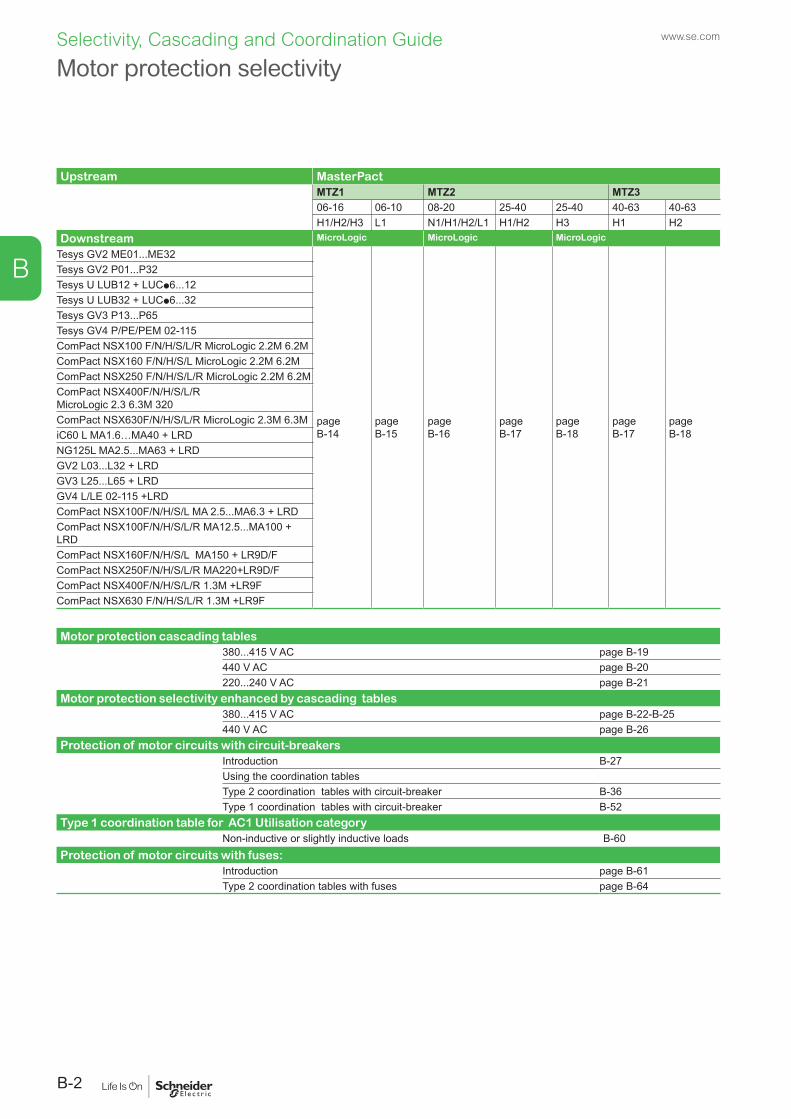
B
Motor protection cascading tables380...415 V AC page B-19440 V AC page B-20220...240 V AC page B-21
Motor protection selectivity enhanced by cascading tables380...415 V AC page B-22-B-25440 V AC page B-26
Protection of motor circuits with circuit-breakersIntroduction B-27Using the coordination tablesType 2 coordination tables with circuit-breaker B-36Type 1 coordination tables with circuit-breaker B-52
Type 1 coordination table for AC1 Utilisation categoryNon-inductive or slightly inductive loads B-60
Protection of motor circuits with fuses: Introduction page B-61Type 2 coordination tables with fuses page B-64
Upstream MasterPactMTZ1 MTZ2 MTZ306-16 06-10 08-20 25-40 25-40 40-63 40-63H1/H2/H3 L1 N1/H1/H2/L1 H1/H2 H3 H1 H2
Downstream MicroLogic MicroLogic MicroLogic
Tesys GV2 ME01...ME32
page B-14
page B-15
page B-16
page B-17
page B-18
page B-17
page B-18
Tesys GV2 P01...P32Tesys U LUB12 + LUCp6...12Tesys U LUB32 + LUCp6...32Tesys GV3 P13...P65Tesys GV4 P/PE/PEM 02-115ComPact NSX100 F/N/H/S/L/R MicroLogic 2.2M 6.2MComPact NSX160 F/N/H/S/L MicroLogic 2.2M 6.2MComPact NSX250 F/N/H/S/L/R MicroLogic 2.2M 6.2MComPact NSX400F/N/H/S/L/R MicroLogic 2.3 6.3M 320ComPact NSX630F/N/H/S/L/R MicroLogic 2.3M 6.3MiC60 L MA1.6…MA40 + LRDNG125L MA2.5...MA63 + LRDGV2 L03...L32 + LRDGV3 L25...L65 + LRDGV4 L/LE 02-115 +LRDComPact NSX100F/N/H/S/L MA 2.5...MA6.3 + LRDComPact NSX100F/N/H/S/L/R MA12.5...MA100 + LRDComPact NSX160F/N/H/S/L MA150 + LR9D/FComPact NSX250F/N/H/S/L/R MA220+LR9D/FComPact NSX400F/N/H/S/L/R 1.3M +LR9FComPact NSX630 F/N/H/S/L/R 1.3M +LR9F
Motor protection selectivitywww.se.com
B-2
Selectivity, Cascading and Coordination Guide
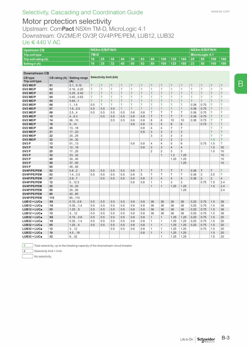
www.se.com
B-3
B
Selectivity, Cascading and Coordination Guide
Motor protection selectivityUpstream: ComPact NSXm TM-D, MicroLogic 4.1 Downstream: GV2ME/P, GV3P, GV4P/PE/PEM, LUB12, LUB32Ue y 440 V ACUpstream CB NSXm E/B/F/N/H NSXm E/B/F/N/H Trip unit type TM-D MicroLogic 4.1Trip unit rating (A) 16 25 32 40 50 63 80 100 125 160 25 50 100 160Setting Ir (A) 16 25 32 40 50 63 80 100 125 160 23 50 100 160
Downstream CBSelectivity limit (kA)CB type
Trip unit typeCB rating (A) Setting range
(A)GV2 ME/P 01 0.1...0.16 T T T T T T T T T T T T T TGV2 ME/P 02 0.16...0.25 T T T T T T T T T T T T T TGV2 ME/P 03 0.25...0.40 T T T T T T T T T T T T T TGV2 ME/P 04 0.40...0.63 T T T T T T T T T T T T T TGV2 ME/P 05 0.63...1 T T T T T T T T T T T T T TGV2 ME/P 06 1...1.6 0.5 T T T T T T T T T 0.38 0.75 T TGV2 ME/P 07 1.6...2.5 0.5 0.5 0.5 T T T T T T T 0.38 0.75 T TGV2 ME/P 08 2.5...4 0.5 0.5 0.5 0.5 0.6 0.8 T T T T 0.38 0.75 T TGV2 ME/P 10 4...6.3 0.5 0.5 0.5 0.6 0.8 T T T T 0.38 0.75 T TGV2 ME/P 14 06...10 0.5 0.5 0.6 0.8 8 8 10 10 0.38 0.75 T TGV2 ME/P 16 9...14 0.6 0.8 5 5 8 8 0.75 T TGV2 ME/P 20 13...18 0.8 4 4 7 7 T TGV2 ME/P 21 17...23 0.8 3 3 3 3 T TGV2 ME/P 22 20...25 3 3 3 3 T TGV2 ME/P 32 24...32 2 2 2 1.5 TGV3 P 13 01...13 0.6 0.8 4 4 5 6 0.75 1.5 TGV3 P 18 12...18 0.8 3 3 4 4 1.5 30GV3 P 25 17...25 2 2 3 3 1.5 10GV3 P 32 23...32 1 1.2 1.25 10GV3 P 40 30...40 1.25 1.25 10GV3 P 50 37...50 1.25 10GV3 P 65 48...65GV4P/PE/PEM 02 0.8...2 0.5 0.5 0.5 0.5 0.6 T T T T T 0.38 T T TGV4P/PE/PEM 03 1.4...3.5 0.5 0.5 0.5 0.5 0.6 5 T T T T 0.38 3 3.5 TGV4P/PE/PEM 07 2.9...7 0.5 0.5 0.5 0.6 0.8 3 4 4 4 0.38 2 2 4GV4P/PE/PEM 12 5...12.5 0.6 0.8 1 1 3 3 0.75 1.5 2.4GV4P/PE/PEM 25 10...25 1 1 1.25 1.25 1.5 2.4GV4P/PE/PEM 50 20...50 1.25 2.4GV4P/PE/PEM 80 40...80GV4P/PE/PEM 115 65...115LUB12 + LUCp X6 0.15...0.6 0.5 0.5 0.5 0.5 0.6 0.8 36 36 36 36 0.25 0.75 1.5 36LUB12 + LUCp 1X 0.35…1.4 0.5 0.5 0.5 0.5 0.6 0.8 36 36 36 36 0.25 0.75 1.5 36LUB12 + LUCp 05 1.25…5 0.5 0.5 0.5 0.5 0.6 0.8 36 36 36 36 0.25 0.75 1.5 36LUB12 + LUCp 12 3…12 0.5 0.5 0.5 0.5 0.6 0.8 36 36 36 36 0.25 0.75 1.5 36LUB32 + LUCp X6 0.15…0.6 0.5 0.5 0.5 0.5 0.6 0.8 1 1 1.25 1.25 0.25 0.75 1.5 20LUB32 + LUCp 1X 0.35…1.4 0.5 0.5 0.5 0.5 0.6 0.8 1 1 1.25 1.25 0.25 0.75 1.5 20LUB32 + LUCp 05 1.25…5 0.5 0.5 0.5 0.5 0.6 0.8 1 1 1.25 1.25 0.25 0.75 1.5 20LUB32 + LUCp 12 3…12 0.5 0.5 0.6 0.8 1 1 1.25 1.25 0.75 1.5 20LUB32 + LUCp 18 4.5…18 0.8 1 1 1.25 1.25 1.5 20LUB32 + LUCp 32 8…32 1 1.25 1.25 1.5 20
T Total selectivity, up to the breaking capacity of the downstream circuit breaker.
4 Selectivity limit = 4 kA.
No selectivity.
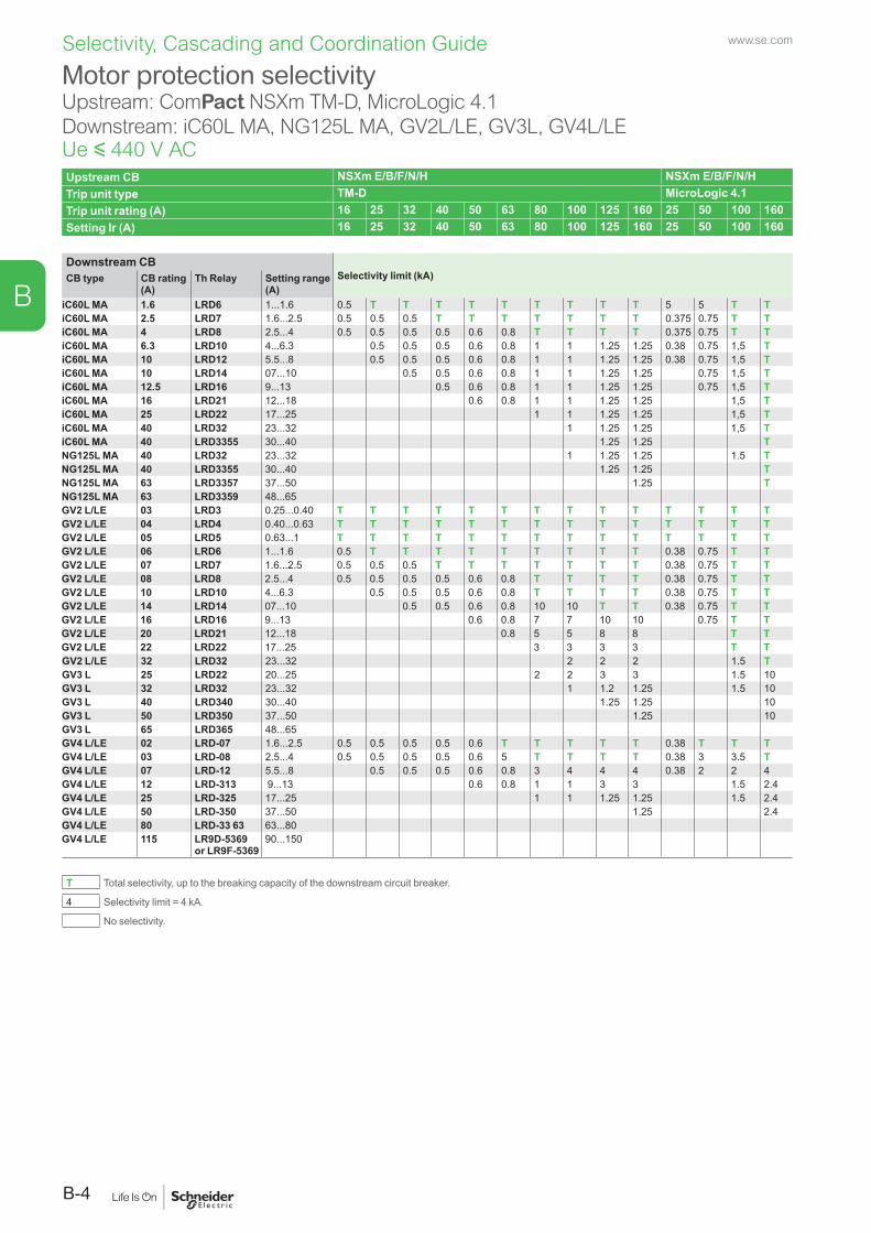
www.se.com
B-4
B
Selectivity, Cascading and Coordination Guide
Motor protection selectivityUpstream: ComPact NSXm TM-D, MicroLogic 4.1Downstream: iC60L MA, NG125L MA, GV2L/LE, GV3L, GV4L/LEUe y 440 V ACUpstream CB NSXm E/B/F/N/H NSXm E/B/F/N/H Trip unit type TM-D MicroLogic 4.1Trip unit rating (A) 16 25 32 40 50 63 80 100 125 160 25 50 100 160Setting Ir (A) 16 25 32 40 50 63 80 100 125 160 25 50 100 160
Downstream CBSelectivity limit (kA)CB type CB rating
(A)Th Relay Setting range
(A)iC60L MA 1.6 LRD6 1...1.6 0.5 T T T T T T T T T 5 5 T TiC60L MA 2.5 LRD7 1.6...2.5 0.5 0.5 0.5 T T T T T T T 0.375 0.75 T TiC60L MA 4 LRD8 2.5...4 0.5 0.5 0.5 0.5 0.6 0.8 T T T T 0.375 0.75 T TiC60L MA 6.3 LRD10 4...6.3 0.5 0.5 0.5 0.6 0.8 1 1 1.25 1.25 0.38 0.75 1,5 TiC60L MA 10 LRD12 5.5...8 0.5 0.5 0.5 0.6 0.8 1 1 1.25 1.25 0.38 0.75 1,5 TiC60L MA 10 LRD14 07...10 0.5 0.5 0.6 0.8 1 1 1.25 1.25 0.75 1,5 TiC60L MA 12.5 LRD16 9...13 0.5 0.6 0.8 1 1 1.25 1.25 0.75 1,5 TiC60L MA 16 LRD21 12...18 0.6 0.8 1 1 1.25 1.25 1,5 TiC60L MA 25 LRD22 17...25 1 1 1.25 1.25 1,5 TiC60L MA 40 LRD32 23...32 1 1.25 1.25 1,5 TiC60L MA 40 LRD3355 30...40 1.25 1.25 TNG125L MA 40 LRD32 23...32 1 1.25 1.25 1.5 TNG125L MA 40 LRD3355 30...40 1.25 1.25 TNG125L MA 63 LRD3357 37...50 1.25 TNG125L MA 63 LRD3359 48...65GV2 L/LE 03 LRD3 0.25...0.40 T T T T T T T T T T T T T TGV2 L/LE 04 LRD4 0.40...0.63 T T T T T T T T T T T T T TGV2 L/LE 05 LRD5 0.63...1 T T T T T T T T T T T T T TGV2 L/LE 06 LRD6 1...1.6 0.5 T T T T T T T T T 0.38 0.75 T TGV2 L/LE 07 LRD7 1.6...2.5 0.5 0.5 0.5 T T T T T T T 0.38 0.75 T TGV2 L/LE 08 LRD8 2.5...4 0.5 0.5 0.5 0.5 0.6 0.8 T T T T 0.38 0.75 T TGV2 L/LE 10 LRD10 4...6.3 0.5 0.5 0.5 0.6 0.8 T T T T 0.38 0.75 T TGV2 L/LE 14 LRD14 07...10 0.5 0.5 0.6 0.8 10 10 T T 0.38 0.75 T TGV2 L/LE 16 LRD16 9...13 0.6 0.8 7 7 10 10 0.75 T TGV2 L/LE 20 LRD21 12...18 0.8 5 5 8 8 T TGV2 L/LE 22 LRD22 17...25 3 3 3 3 T TGV2 L/LE 32 LRD32 23...32 2 2 2 1.5 TGV3 L 25 LRD22 20...25 2 2 3 3 1.5 10GV3 L 32 LRD32 23...32 1 1.2 1.25 1.5 10GV3 L 40 LRD340 30...40 1.25 1.25 10GV3 L 50 LRD350 37...50 1.25 10GV3 L 65 LRD365 48...65GV4 L/LE 02 LRD-07 1.6...2.5 0.5 0.5 0.5 0.5 0.6 T T T T T 0.38 T T TGV4 L/LE 03 LRD-08 2.5...4 0.5 0.5 0.5 0.5 0.6 5 T T T T 0.38 3 3.5 TGV4 L/LE 07 LRD-12 5.5...8 0.5 0.5 0.5 0.6 0.8 3 4 4 4 0.38 2 2 4GV4 L/LE 12 LRD-313 9...13 0.6 0.8 1 1 3 3 1.5 2.4GV4 L/LE 25 LRD-325 17...25 1 1 1.25 1.25 1.5 2.4GV4 L/LE 50 LRD-350 37...50 1.25 2.4GV4 L/LE 80 LRD-33 63 63...80GV4 L/LE 115 LR9D-5369
or LR9F-536990...150
T Total selectivity, up to the breaking capacity of the downstream circuit breaker.
4 Selectivity limit = 4 kA.
No selectivity.
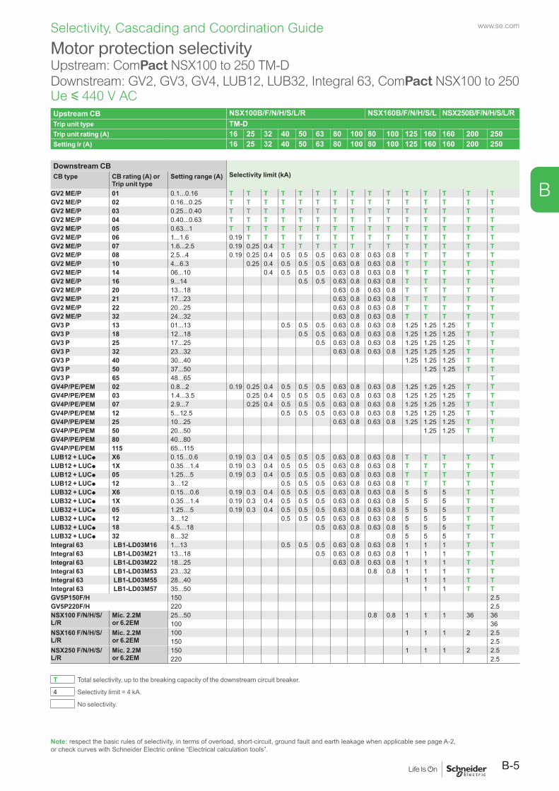
www.se.com
B-5
B
Selectivity, Cascading and Coordination Guide
Note: respect the basic rules of selectivity, in terms of overload, short-circuit, ground fault and earth leakage when applicable see page A-2, or check curves with Schneider Electric online “Electrical calculation tools”.
Motor protection selectivityUpstream: ComPact NSX100 to 250 TM-DDownstream: GV2, GV3, GV4, LUB12, LUB32, Integral 63, ComPact NSX100 to 250Ue y 440 V ACUpstream CB NSX100B/F/N/H/S/L/R NSX160B/F/N/H/S/L NSX250B/F/N/H/S/L/RTrip unit type TM-DTrip unit rating (A) 16 25 32 40 50 63 80 100 80 100 125 160 160 200 250Setting Ir (A) 16 25 32 40 50 63 80 100 80 100 125 160 160 200 250
Downstream CBSelectivity limit (kA)CB type CB rating (A) or
Trip unit typeSetting range (A)
GV2 ME/P 01 0.1...0.16 T T T T T T T T T T T T T T TGV2 ME/P 02 0.16...0.25 T T T T T T T T T T T T T T TGV2 ME/P 03 0.25...0.40 T T T T T T T T T T T T T T TGV2 ME/P 04 0.40...0.63 T T T T T T T T T T T T T T TGV2 ME/P 05 0.63...1 T T T T T T T T T T T T T T TGV2 ME/P 06 1...1.6 0.19 T T T T T T T T T T T T T TGV2 ME/P 07 1.6...2.5 0.19 0.25 0.4 T T T T T T T T T T T TGV2 ME/P 08 2.5...4 0.19 0.25 0.4 0.5 0.5 0.5 0.63 0.8 0.63 0.8 T T T T TGV2 ME/P 10 4...6.3 0.25 0.4 0.5 0.5 0.5 0.63 0.8 0.63 0.8 T T T T TGV2 ME/P 14 06...10 0.4 0.5 0.5 0.5 0.63 0.8 0.63 0.8 T T T T TGV2 ME/P 16 9...14 0.5 0.5 0.63 0.8 0.63 0.8 T T T T TGV2 ME/P 20 13...18 0.63 0.8 0.63 0.8 T T T T TGV2 ME/P 21 17...23 0.63 0.8 0.63 0.8 T T T T TGV2 ME/P 22 20...25 0.63 0.8 0.63 0.8 T T T T TGV2 ME/P 32 24...32 0.63 0.8 0.63 0.8 T T T T TGV3 P 13 01...13 0.5 0.5 0.5 0.63 0.8 0.63 0.8 1.25 1.25 1.25 T TGV3 P 18 12...18 0.5 0.5 0.63 0.8 0.63 0.8 1.25 1.25 1.25 T TGV3 P 25 17...25 0.5 0.63 0.8 0.63 0.8 1.25 1.25 1.25 T TGV3 P 32 23...32 0.63 0.8 0.63 0.8 1.25 1.25 1.25 T TGV3 P 40 30...40 1.25 1.25 1.25 T TGV3 P 50 37...50 1.25 1.25 T TGV3 P 65 48...65 TGV4P/PE/PEM 02 0.8...2 0.19 0.25 0.4 0.5 0.5 0.5 0.63 0.8 0.63 0.8 1.25 1.25 1.25 T TGV4P/PE/PEM 03 1.4...3.5 0.25 0.4 0.5 0.5 0.5 0.63 0.8 0.63 0.8 1.25 1.25 1.25 T TGV4P/PE/PEM 07 2.9...7 0.25 0.4 0.5 0.5 0.5 0.63 0.8 0.63 0.8 1.25 1.25 1.25 T TGV4P/PE/PEM 12 5...12.5 0.5 0.5 0.5 0.63 0.8 0.63 0.8 1.25 1.25 1.25 T TGV4P/PE/PEM 25 10...25 0.63 0.8 0.63 0.8 1.25 1.25 1.25 T TGV4P/PE/PEM 50 20...50 1.25 1.25 T TGV4P/PE/PEM 80 40...80 TGV4P/PE/PEM 115 65...115LUB12 + LUCp X6 0.15...0.6 0.19 0.3 0.4 0.5 0.5 0.5 0.63 0.8 0.63 0.8 T T T T TLUB12 + LUCp 1X 0.35…1.4 0.19 0.3 0.4 0.5 0.5 0.5 0.63 0.8 0.63 0.8 T T T T TLUB12 + LUCp 05 1.25…5 0.19 0.3 0.4 0.5 0.5 0.5 0.63 0.8 0.63 0.8 T T T T TLUB12 + LUCp 12 3…12 0.5 0.5 0.5 0.63 0.8 0.63 0.8 T T T T TLUB32 + LUCp X6 0.15…0.6 0.19 0.3 0.4 0.5 0.5 0.5 0.63 0.8 0.63 0.8 5 5 5 T TLUB32 + LUCp 1X 0.35…1.4 0.19 0.3 0.4 0.5 0.5 0.5 0.63 0.8 0.63 0.8 5 5 5 T TLUB32 + LUCp 05 1.25…5 0.19 0.3 0.4 0.5 0.5 0.5 0.63 0.8 0.63 0.8 5 5 5 T TLUB32 + LUCp 12 3…12 0.5 0.5 0.5 0.63 0.8 0.63 0.8 5 5 5 T TLUB32 + LUCp 18 4.5…18 0.5 0.63 0.8 0.63 0.8 5 5 5 T TLUB32 + LUCp 32 8…32 0.8 0.8 5 5 5 T TIntegral 63 LB1-LD03M16 1...13 0.5 0.5 0.5 0.63 0.8 0.63 0.8 1 1 1 T TIntegral 63 LB1-LD03M21 13...18 0.5 0.63 0.8 0.63 0.8 1 1 1 T TIntegral 63 LB1-LD03M22 18...25 0.63 0.8 0.63 0.8 1 1 1 T TIntegral 63 LB1-LD03M53 23...32 0.8 0.8 1 1 1 T TIntegral 63 LB1-LD03M55 28...40 1 1 1 T TIntegral 63 LB1-LD03M57 35...50 1 1 T TGV5P150F/H 150 2.5GV5P220F/H 220 2.5NSX100 F/N/H/S/L/R
Mic. 2.2M or 6.2EM
25...50 0.8 0.8 1 1 1 36 36100 36
NSX160 F/N/H/S/L/R
Mic. 2.2M or 6.2EM
100 1 1 1 2 2.5150 2.5
NSX250 F/N/H/S/L/R
Mic. 2.2M or 6.2EM
150 1 1 1 2 2.5220 2.5
T Total selectivity, up to the breaking capacity of the downstream circuit breaker.
4 Selectivity limit = 4 kA.
No selectivity.
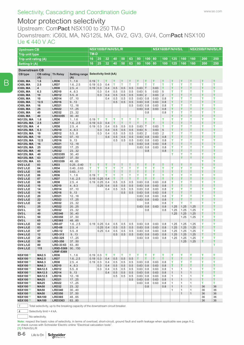
www.se.com
B-6
B
Selectivity, Cascading and Coordination Guide
Note: respect the basic rules of selectivity, in terms of overload, short-circuit, ground fault and earth leakage when applicable see page A-2, or check curves with Schneider Electric online “Electrical calculation tools”. [1] F/N/H/S/L/R
Motor protection selectivityUpstream: ComPact NSX100 to 250 TM-DDownstream: iC60L MA, NG125L MA, GV2, GV3, GV4, ComPact NSX100Ue y 440 V ACUpstream CB NSX100B/F/N/H/S/L/R NSX160B/F/N/H/S/L NSX250B/F/N/H/S/L/RTrip unit type TM-DTrip unit rating (A) 16 25 32 40 50 63 80 100 80 100 125 160 160 200 250Setting Ir (A) 16 25 32 40 50 63 80 100 80 100 125 160 160 200 250
Downstream CBSelectivity limit (kA)CB type CB rating
(A)Th Relay Setting range
(A)iC60L MA 1.6 LRD6 1...1.6 0.19 T T T T T T T T T T T T T TiC60L MA 2.5 LRD7 1.6...2.5 0.19 0.3 0.4 T T T T T T T T T T T TiC60L MA 4 LRD8 2.5...4 0.19 0.3 0.4 0.5 0.5 0.5 0.63 T 0.63 T T T T T TiC60L MA 6.3 LRD10 4...6.3 0.3 0.4 0.5 0.5 0.5 0.63 5 0.63 5 T T T T TiC60L MA 10 LRD12 5.5...8 0.3 0.4 0.5 0.5 0.5 0.63 2 0.63 2 T T T T TiC60L MA 10 LRD14 07...10 0.4 0.5 0.5 0.5 0.63 0.8 0.63 0.8 T T T T TiC60L MA 12.5 LRD16 9...13 0.5 0.5 0.5 0.63 0.8 0.63 0.8 T T T T TiC60L MA 16 LRD21 12...18 0.5 0.63 0.8 0.63 0.8 T T T T TiC60L MA 25 LRD22 17...25 0.63 0.8 0.63 0.8 T T T T TiC60L MA 40 LRD32 23...32 0.8 0.8 T T T T TiC60L MA 40 LRD3355 30...40 T T T T TNG125L MA 1.6 LRD6 1...1.6 0.19 T T T T T T T T T T T T T TNG125L MA 2.5 LRD7 1.6...2.5 0.19 0.3 0.4 T T T T T T T T T T T TNG125L MA 4 LRD8 2.5...4 0.19 0.3 0.4 0.5 0.5 0.5 0.63 T 0.63 T T T T T TNG125L MA 6.3 LRD10 4...6.3 0.3 0.4 0.5 0.5 0.5 0.63 5 0.63 5 T T T T TNG125L MA 10 LRD12 5.5...8 0.3 0.4 0.5 0.5 0.5 0.63 2 0.63 2 T T T T TNG125L MA 10 LRD14 07...10 0.4 0.5 0.5 0.5 0.63 0.8 0.63 0.8 T T T T TNG125L MA 12.5 LRD16 9...13 0.5 0.5 0.5 0.63 0.8 0.63 0.8 T T T T TNG125L MA 16 LRD21 12...18 0.5 0.63 0.8 0.63 0.8 T T T T TNG125L MA 25 LRD22 17...25 0.63 0.8 0.63 0.8 T T T T TNG125L MA 40 LRD32 23...32 0.8 0.8 T T T T TNG125L MA 40 LRD3355 30...40 T T T T TNG125L MA 63 LRD3357 37...50 T T T TNG125L MA 63 LRD3359 48...65 T TGV2 L/LE 03 LRD3 0.25...0.40 T T T T T T T T T T T T T T TGV2 L/LE 04 LRD4 0.40...0.63 T T T T T T T T T T T T T T TGV2 L/LE 05 LRD5 0.63...1 T T T T T T T T T T T T T T TGV2 L/LE 06 LRD6 1...1.6 0.19 T T T T T T T T T T T T T TGV2 L/LE 07 LRD7 1.6...2.5 0.19 0.25 0.4 T T T T T T T T T T T TGV2 L/LE 08 LRD8 2.5...4 0.19 0.25 0.4 0.5 0.5 0.5 0.63 0.8 0.63 0.8 T T T T TGV2 L/LE 10 LRD10 4...6.3 0.25 0.4 0.5 0.5 0.5 0.63 0.8 0.63 0.8 T T T T TGV2 L/LE 14 LRD14 07...10 0.4 0.5 0.5 0.5 0.63 0.8 0.63 0.8 T T T T TGV2 L/LE 16 LRD16 9...13 0.5 0.5 0.63 0.8 0.63 0.8 T T T T TGV2 L/LE 20 LRD21 12...18 0.63 0.8 0.63 0.8 T T T T TGV2 L/LE 22 LRD22 17...25 0.63 0.8 0.63 0.8 T T T T TGV2 L/LE 32 LRD32 23...32 0.8 0.8 T T T T TGV3 L 25 LRD22 20...25 0.63 0.8 0.63 0.8 1.25 1.25 1.25 T TGV3 L 32 LRD32 23...32 0.8 0.8 1.25 1.25 1.25 T TGV3 L 40 LRD340 30...40 1.25 1.25 1.25 T TGV3 L 50 LRD350 37...50 1.25 1.25 T TGV3 L 65 LRD365 48...65 T TGV4 L/LE 02 LRD-07 1.6...2.5 0.19 0.25 0.4 0.5 0.5 0.5 0.63 0.8 0.63 0.8 1.25 1.25 1.25 T TGV4 L/LE 03 LRD-08 2.5...4 0.25 0.4 0.5 0.5 0.5 0.63 0.8 0.63 0.8 1.25 1.25 1.25 T TGV4 L/LE 07 LRD-12 5.5...8 0.25 0.4 0.5 0.5 0.5 0.63 0.8 0.63 0.8 1.25 1.25 1.25 T TGV4 L/LE 12 LRD-313 9...13 0.5 0.5 0.5 0.63 0.8 0.63 0.8 1.25 1.25 1.25 T TGV4 L/LE 25 LRD-325 17...25 0.63 0.8 0.63 0.8 1.25 1.25 1.25 T TGV4 L/LE 50 LRD-350 37...50 1.25 1.25 T TGV4 L/LE 80 LRD-33 63 63...80 TGV4 L/LE 115 LR9D-5369
LR9F-536990...150
NSX100 [1] MA2.5 LRD6 1...1.6 0.19 0.3 T T T T T T T T T T T T TNSX100 [1] MA2.5 LRD7 1.6...2.5 0.19 0.3 0.4 0.5 0.5 0.5 T T T T T T T T TNSX100 [1] MA6.3 LRD8 2.5...4 0.19 0.3 0.4 0.5 0.5 0.5 0.63 0.8 0.63 0.8 T T T T TNSX100 [1] MA6.3 LRD10 4...6.3 0.3 0.4 0.5 0.5 0.5 0.63 0.8 0.63 0.8 T T T T TNSX100 [1] MA12.5 LRD12 5.5...8 0.3 0.4 0.5 0.5 0.5 0.63 0.8 0.63 0.8 1 1 1 T TNSX100 [1] MA12.5 LRD14 9...13 0.4 0.5 0.5 0.5 0.63 0.8 0.63 0.8 1 1 1 T TNSX100 [1] MA12.5 LRD16 12...18 0.5 0.5 0.5 0.63 0.8 0.63 0.8 1 1 1 T TNSX100 [1] MA25 LRD21 17...25 0.5 0.63 0.8 0.63 0.8 1 1 1 T TNSX100 [1] MA25 LRD22 17...25 0.63 0.8 0.63 0.8 1 1 1 T TNSX100 [1] MA50 LRD32 23...32 0.8 0.8 1 1 1 36 36NSX100 [1] MA50 LRD340 30...40 1 1 1 36 36NSX100 [1] MA50 LRD350 37...50 1 1 36 36NSX100 [1] MA100 LRD365 48...65 36 36NSX100 [1] MA100 LRD3363 63...80 36 36
T Total selectivity, up to the breaking capacity of the downstream circuit breaker.
4 Selectivity limit = 4 kA.
No selectivity.
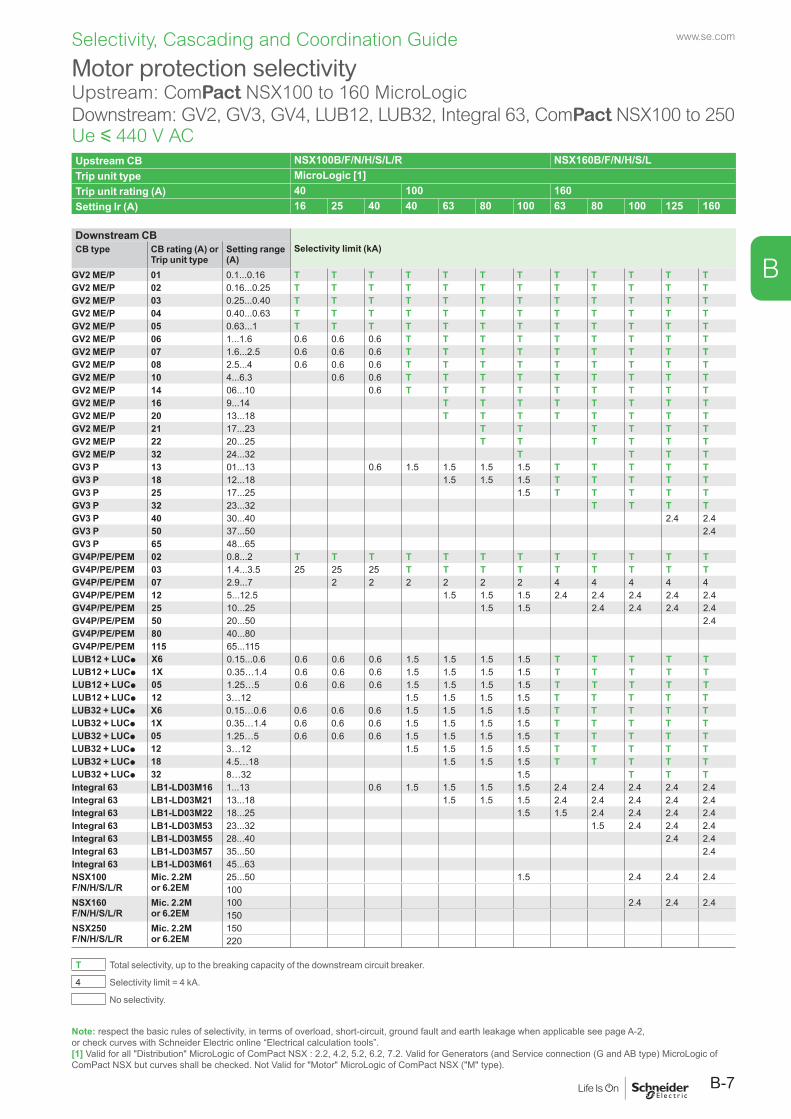
www.se.com
B-7
B
Selectivity, Cascading and Coordination Guide
Note: respect the basic rules of selectivity, in terms of overload, short-circuit, ground fault and earth leakage when applicable see page A-2, or check curves with Schneider Electric online “Electrical calculation tools”.[1] Valid for all "Distribution" MicroLogic of ComPact NSX : 2.2, 4.2, 5.2, 6.2, 7.2. Valid for Generators (and Service connection (G and AB type) MicroLogic of ComPact NSX but curves shall be checked. Not Valid for "Motor" MicroLogic of ComPact NSX ("M" type).
Motor protection selectivityUpstream: ComPact NSX100 to 160 MicroLogicDownstream: GV2, GV3, GV4, LUB12, LUB32, Integral 63, ComPact NSX100 to 250Ue y 440 V ACUpstream CB NSX100B/F/N/H/S/L/R NSX160B/F/N/H/S/LTrip unit type MicroLogic [1]Trip unit rating (A) 40 100 160Setting Ir (A) 16 25 40 40 63 80 100 63 80 100 125 160
Downstream CBSelectivity limit (kA)CB type CB rating (A) or
Trip unit typeSetting range (A)
GV2 ME/P 01 0.1...0.16 T T T T T T T T T T T TGV2 ME/P 02 0.16...0.25 T T T T T T T T T T T TGV2 ME/P 03 0.25...0.40 T T T T T T T T T T T TGV2 ME/P 04 0.40...0.63 T T T T T T T T T T T TGV2 ME/P 05 0.63...1 T T T T T T T T T T T TGV2 ME/P 06 1...1.6 0.6 0.6 0.6 T T T T T T T T TGV2 ME/P 07 1.6...2.5 0.6 0.6 0.6 T T T T T T T T TGV2 ME/P 08 2.5...4 0.6 0.6 0.6 T T T T T T T T TGV2 ME/P 10 4...6.3 0.6 0.6 T T T T T T T T TGV2 ME/P 14 06...10 0.6 T T T T T T T T TGV2 ME/P 16 9...14 T T T T T T T TGV2 ME/P 20 13...18 T T T T T T T TGV2 ME/P 21 17...23 T T T T T TGV2 ME/P 22 20...25 T T T T T TGV2 ME/P 32 24...32 T T T TGV3 P 13 01...13 0.6 1.5 1.5 1.5 1.5 T T T T TGV3 P 18 12...18 1.5 1.5 1.5 T T T T TGV3 P 25 17...25 1.5 T T T T TGV3 P 32 23...32 T T T TGV3 P 40 30...40 2.4 2.4GV3 P 50 37...50 2.4GV3 P 65 48...65GV4P/PE/PEM 02 0.8...2 T T T T T T T T T T T TGV4P/PE/PEM 03 1.4...3.5 25 25 25 T T T T T T T T TGV4P/PE/PEM 07 2.9...7 2 2 2 2 2 2 4 4 4 4 4GV4P/PE/PEM 12 5...12.5 1.5 1.5 1.5 2.4 2.4 2.4 2.4 2.4GV4P/PE/PEM 25 10...25 1.5 1.5 2.4 2.4 2.4 2.4GV4P/PE/PEM 50 20...50 2.4GV4P/PE/PEM 80 40...80GV4P/PE/PEM 115 65...115LUB12 + LUCp X6 0.15...0.6 0.6 0.6 0.6 1.5 1.5 1.5 1.5 T T T T TLUB12 + LUCp 1X 0.35…1.4 0.6 0.6 0.6 1.5 1.5 1.5 1.5 T T T T TLUB12 + LUCp 05 1.25…5 0.6 0.6 0.6 1.5 1.5 1.5 1.5 T T T T TLUB12 + LUCp 12 3…12 1.5 1.5 1.5 1.5 T T T T TLUB32 + LUCp X6 0.15…0.6 0.6 0.6 0.6 1.5 1.5 1.5 1.5 T T T T TLUB32 + LUCp 1X 0.35…1.4 0.6 0.6 0.6 1.5 1.5 1.5 1.5 T T T T TLUB32 + LUCp 05 1.25…5 0.6 0.6 0.6 1.5 1.5 1.5 1.5 T T T T TLUB32 + LUCp 12 3…12 1.5 1.5 1.5 1.5 T T T T TLUB32 + LUCp 18 4.5…18 1.5 1.5 1.5 T T T T TLUB32 + LUCp 32 8…32 1.5 T T TIntegral 63 LB1-LD03M16 1...13 0.6 1.5 1.5 1.5 1.5 2.4 2.4 2.4 2.4 2.4Integral 63 LB1-LD03M21 13...18 1.5 1.5 1.5 2.4 2.4 2.4 2.4 2.4Integral 63 LB1-LD03M22 18...25 1.5 1.5 2.4 2.4 2.4 2.4Integral 63 LB1-LD03M53 23...32 1.5 2.4 2.4 2.4Integral 63 LB1-LD03M55 28...40 2.4 2.4Integral 63 LB1-LD03M57 35...50 2.4Integral 63 LB1-LD03M61 45...63NSX100 F/N/H/S/L/R
Mic. 2.2M or 6.2EM
25...50 1.5 2.4 2.4 2.4100
NSX160 F/N/H/S/L/R
Mic. 2.2M or 6.2EM
100 2.4 2.4 2.4150
NSX250 F/N/H/S/L/R
Mic. 2.2M or 6.2EM
150220
T Total selectivity, up to the breaking capacity of the downstream circuit breaker.
4 Selectivity limit = 4 kA.
No selectivity.
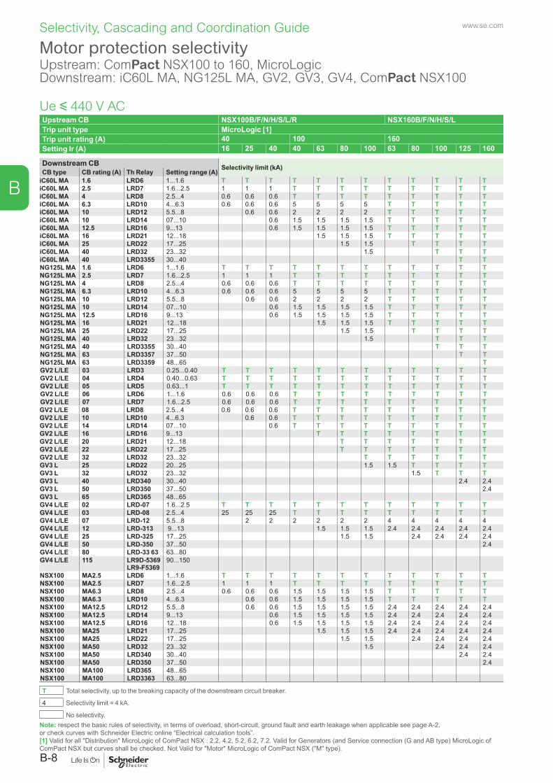
www.se.com
B-8
B
Selectivity, Cascading and Coordination Guide
Note: respect the basic rules of selectivity, in terms of overload, short-circuit, ground fault and earth leakage when applicable see page A-2, or check curves with Schneider Electric online “Electrical calculation tools”.[1] Valid for all "Distribution" MicroLogic of ComPact NSX : 2.2, 4.2, 5.2, 6.2, 7.2. Valid for Generators (and Service connection (G and AB type) MicroLogic of ComPact NSX but curves shall be checked. Not Valid for "Motor" MicroLogic of ComPact NSX ("M" type).
Motor protection selectivityUpstream: ComPact NSX100 to 160, MicroLogicDownstream: iC60L MA, NG125L MA, GV2, GV3, GV4, ComPact NSX100
Upstream CB NSX100B/F/N/H/S/L/R NSX160B/F/N/H/S/LTrip unit type MicroLogic [1]Trip unit rating (A) 40 100 160Setting Ir (A) 16 25 40 40 63 80 100 63 80 100 125 160
Downstream CB Selectivity limit (kA)CB type CB rating (A) Th Relay Setting range (A)
iC60L MA 1.6 LRD6 1...1.6 T T T T T T T T T T T TiC60L MA 2.5 LRD7 1.6...2.5 1 1 1 T T T T T T T T TiC60L MA 4 LRD8 2.5...4 0.6 0.6 0.6 T T T T T T T T TiC60L MA 6.3 LRD10 4...6.3 0.6 0.6 0.6 5 5 5 5 T T T T TiC60L MA 10 LRD12 5.5...8 0.6 0.6 2 2 2 2 T T T T TiC60L MA 10 LRD14 07...10 0.6 1.5 1.5 1.5 1.5 T T T T TiC60L MA 12.5 LRD16 9...13 0.6 1.5 1.5 1.5 1.5 T T T T TiC60L MA 16 LRD21 12...18 1.5 1.5 1.5 T T T T TiC60L MA 25 LRD22 17...25 1.5 1.5 T T T TiC60L MA 40 LRD32 23...32 1.5 T T TiC60L MA 40 LRD3355 30...40 T TNG125L MA 1.6 LRD6 1...1.6 T T T T T T T T T T T TNG125L MA 2.5 LRD7 1.6...2.5 1 1 1 T T T T T T T T TNG125L MA 4 LRD8 2.5...4 0.6 0.6 0.6 T T T T T T T T TNG125L MA 6.3 LRD10 4...6.3 0.6 0.6 0.6 5 5 5 5 T T T T TNG125L MA 10 LRD12 5.5...8 0.6 0.6 2 2 2 2 T T T T TNG125L MA 10 LRD14 07...10 0.6 1.5 1.5 1.5 1.5 T T T T TNG125L MA 12.5 LRD16 9...13 0.6 1.5 1.5 1.5 1.5 T T T T TNG125L MA 16 LRD21 12...18 1.5 1.5 1.5 T T T T TNG125L MA 25 LRD22 17...25 1.5 1.5 T T T TNG125L MA 40 LRD32 23...32 1.5 T T TNG125L MA 40 LRD3355 30...40 T T TNG125L MA 63 LRD3357 37...50 T TNG125L MA 63 LRD3359 48...65 TGV2 L/LE 03 LRD3 0.25...0.40 T T T T T T T T T T T TGV2 L/LE 04 LRD4 0.40...0.63 T T T T T T T T T T T TGV2 L/LE 05 LRD5 0.63...1 T T T T T T T T T T T TGV2 L/LE 06 LRD6 1...1.6 0.6 0.6 0.6 T T T T T T T T TGV2 L/LE 07 LRD7 1.6...2.5 0.6 0.6 0.6 T T T T T T T T TGV2 L/LE 08 LRD8 2.5...4 0.6 0.6 0.6 T T T T T T T T TGV2 L/LE 10 LRD10 4...6.3 0.6 0.6 T T T T T T T T TGV2 L/LE 14 LRD14 07...10 0.6 T T T T T T T T TGV2 L/LE 16 LRD16 9...13 T T T T T T T TGV2 L/LE 20 LRD21 12...18 T T T T T T TGV2 L/LE 22 LRD22 17...25 T T T T T T TGV2 L/LE 32 LRD32 23...32 T T T T T TGV3 L 25 LRD22 20...25 1.5 1.5 T T T TGV3 L 32 LRD32 23...32 1.5 T T TGV3 L 40 LRD340 30...40 2.4 2.4GV3 L 50 LRD350 37...50 2.4GV3 L 65 LRD365 48...65GV4 L/LE 02 LRD-07 1.6...2.5 T T T T T T T T T T T TGV4 L/LE 03 LRD-08 2.5...4 25 25 25 T T T T T T T T TGV4 L/LE 07 LRD-12 5.5...8 2 2 2 2 2 2 4 4 4 4 4GV4 L/LE 12 LRD-313 9...13 1.5 1.5 1.5 2.4 2.4 2.4 2.4 2.4GV4 L/LE 25 LRD-325 17...25 1.5 1.5 2.4 2.4 2.4 2.4GV4 L/LE 50 LRD-350 37...50 2.4GV4 L/LE 80 LRD-33 63 63...80GV4 L/LE 115 LR9D-5369
LR9-F536990...150
NSX100 MA2.5 LRD6 1...1.6 T T T T T T T T T T T TNSX100 MA2.5 LRD7 1.6...2.5 1 1 1 T T T T T T T T TNSX100 MA6.3 LRD8 2.5...4 0.6 0.6 0.6 1.5 1.5 1.5 1.5 T T T T TNSX100 MA6.3 LRD10 4...6.3 0.6 0.6 1.5 1.5 1.5 1.5 T T T T TNSX100 MA12.5 LRD12 5.5...8 0.6 0.6 1.5 1.5 1.5 1.5 2.4 2.4 2.4 2.4 2.4NSX100 MA12.5 LRD14 9...13 0.6 1.5 1.5 1.5 1.5 2.4 2.4 2.4 2.4 2.4NSX100 MA12.5 LRD16 12...18 0.6 1.5 1.5 1.5 1.5 2.4 2.4 2.4 2.4 2.4NSX100 MA25 LRD21 17...25 1.5 1.5 1.5 2.4 2.4 2.4 2.4 2.4NSX100 MA25 LRD22 17...25 1.5 1.5 2.4 2.4 2.4 2.4NSX100 MA50 LRD32 23...32 1.5 2.4 2.4 2.4NSX100 MA50 LRD340 30...40 2.4 2.4NSX100 MA50 LRD350 37...50 2.4NSX100 MA100 LRD365 48...65NSX100 MA100 LRD3363 63...80
T Total selectivity, up to the breaking capacity of the downstream circuit breaker.
4 Selectivity limit = 4 kA.
No selectivity.
Ue y 440 V AC
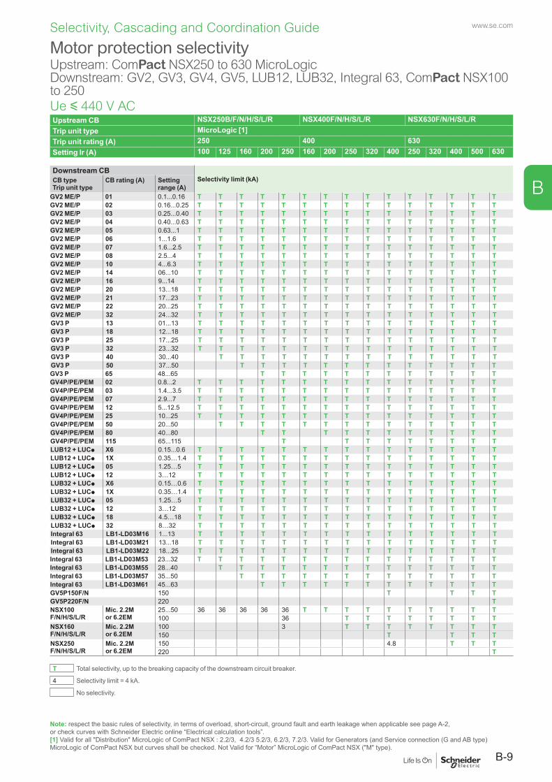
www.se.com
B-9
B
Selectivity, Cascading and Coordination Guide
Note: respect the basic rules of selectivity, in terms of overload, short-circuit, ground fault and earth leakage when applicable see page A-2, or check curves with Schneider Electric online “Electrical calculation tools”.[1] Valid for all "Distribution" MicroLogic of ComPact NSX : 2.2/3, 4.2/3 5.2/3, 6.2/3, 7.2/3. Valid for Generators (and Service connection (G and AB type) MicroLogic of ComPact NSX but curves shall be checked. Not Valid for “Motor” MicroLogic of ComPact NSX ("M" type).
Motor protection selectivityUpstream: ComPact NSX250 to 630 MicroLogicDownstream: GV2, GV3, GV4, GV5, LUB12, LUB32, Integral 63, ComPact NSX100 to 250
Upstream CB NSX250B/F/N/H/S/L/R NSX400F/N/H/S/L/R NSX630F/N/H/S/L/RTrip unit type MicroLogic [1]Trip unit rating (A) 250 400 630Setting Ir (A) 100 125 160 200 250 160 200 250 320 400 250 320 400 500 630
Downstream CBSelectivity limit (kA)CB type
Trip unit typeCB rating (A) Setting
range (A)GV2 ME/P 01 0.1...0.16 T T T T T T T T T T T T T T TGV2 ME/P 02 0.16...0.25 T T T T T T T T T T T T T T TGV2 ME/P 03 0.25...0.40 T T T T T T T T T T T T T T TGV2 ME/P 04 0.40...0.63 T T T T T T T T T T T T T T TGV2 ME/P 05 0.63...1 T T T T T T T T T T T T T T TGV2 ME/P 06 1...1.6 T T T T T T T T T T T T T T TGV2 ME/P 07 1.6...2.5 T T T T T T T T T T T T T T TGV2 ME/P 08 2.5...4 T T T T T T T T T T T T T T TGV2 ME/P 10 4...6.3 T T T T T T T T T T T T T T TGV2 ME/P 14 06...10 T T T T T T T T T T T T T T TGV2 ME/P 16 9...14 T T T T T T T T T T T T T T TGV2 ME/P 20 13...18 T T T T T T T T T T T T T T TGV2 ME/P 21 17...23 T T T T T T T T T T T T T T TGV2 ME/P 22 20...25 T T T T T T T T T T T T T T TGV2 ME/P 32 24...32 T T T T T T T T T T T T T T TGV3 P 13 01...13 T T T T T T T T T T T T T T TGV3 P 18 12...18 T T T T T T T T T T T T T T TGV3 P 25 17...25 T T T T T T T T T T T T T T TGV3 P 32 23...32 T T T T T T T T T T T T T T TGV3 P 40 30...40 T T T T T T T T T T T T T TGV3 P 50 37...50 T T T T T T T T T T T T TGV3 P 65 48...65 T T T T T T T T T T T TGV4P/PE/PEM 02 0.8...2 T T T T T T T T T T T T T T TGV4P/PE/PEM 03 1.4...3.5 T T T T T T T T T T T T T T TGV4P/PE/PEM 07 2.9...7 T T T T T T T T T T T T T T TGV4P/PE/PEM 12 5...12.5 T T T T T T T T T T T T T T TGV4P/PE/PEM 25 10...25 T T T T T T T T T T T T T T TGV4P/PE/PEM 50 20...50 T T T T T T T T T T T T T TGV4P/PE/PEM 80 40...80 T T T T T T T T T T TGV4P/PE/PEM 115 65...115 T T T T T T T T TLUB12 + LUCp X6 0.15...0.6 T T T T T T T T T T T T T T TLUB12 + LUCp 1X 0.35…1.4 T T T T T T T T T T T T T T TLUB12 + LUCp 05 1.25…5 T T T T T T T T T T T T T T TLUB12 + LUCp 12 3…12 T T T T T T T T T T T T T T TLUB32 + LUCp X6 0.15…0.6 T T T T T T T T T T T T T T TLUB32 + LUCp 1X 0.35…1.4 T T T T T T T T T T T T T T TLUB32 + LUCp 05 1.25…5 T T T T T T T T T T T T T T TLUB32 + LUCp 12 3…12 T T T T T T T T T T T T T T TLUB32 + LUCp 18 4.5…18 T T T T T T T T T T T T T T TLUB32 + LUCp 32 8…32 T T T T T T T T T T T T T T TIntegral 63 LB1-LD03M16 1...13 T T T T T T T T T T T T T T TIntegral 63 LB1-LD03M21 13...18 T T T T T T T T T T T T T T TIntegral 63 LB1-LD03M22 18...25 T T T T T T T T T T T T T T TIntegral 63 LB1-LD03M53 23...32 T T T T T T T T T T T T T T TIntegral 63 LB1-LD03M55 28...40 T T T T T T T T T T T T T TIntegral 63 LB1-LD03M57 35...50 T T T T T T T T T T T T TIntegral 63 LB1-LD03M61 45...63 T T T T T T T T T T T TGV5P150F/N 150 T T T TGV5P220F/N 220 TNSX100 F/N/H/S/L/R
Mic. 2.2M or 6.2EM
25...50 36 36 36 36 36 T T T T T T T T T T100 36 T T T T T T T T
NSX160 F/N/H/S/L/R
Mic. 2.2M or 6.2EM
100 3 T T T T T T T T150 T T T T
NSX250 F/N/H/S/L/R
Mic. 2.2M or 6.2EM
150 4.8 T T T220 T
T Total selectivity, up to the breaking capacity of the downstream circuit breaker.
4 Selectivity limit = 4 kA.
No selectivity.
Ue y 440 V AC
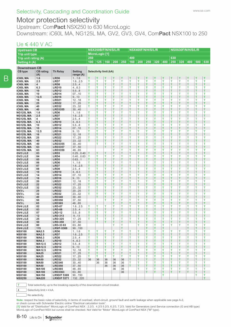
www.se.com
B-10
B
Selectivity, Cascading and Coordination Guide
Motor protection selectivityUpstream: ComPact NSX250 to 630 MicroLogicDownstream: iC60L MA, NG125L MA, GV2, GV3, GV4, ComPact NSX100 to 250
Upstream CB NSX250B/F/N/H/S/L/R NSX400F/N/H/S/L/R NSX630F/N/H/S/L/RTrip unit type MicroLogic [1]Trip unit rating (A) 250 400 630Setting Ir (A) 100 125 160 200 250 160 200 250 320 400 250 320 400 500 630
Downstream CBSelectivity limit (kA)CB type CB rating
(A)Th Relay Setting
range (A)iC60L MA 1.6 LRD6 1...1.6 T T T T T T T T T T T T T T TiC60L MA 2.5 LRD7 1.6...2.5 T T T T T T T T T T T T T T TiC60L MA 4 LRD8 2.5...4 T T T T T T T T T T T T T T TiC60L MA 6.3 LRD10 4...6.3 T T T T T T T T T T T T T T TiC60L MA 10 LRD12 5.5...8 T T T T T T T T T T T T T T TiC60L MA 10 LRD14 07...10 T T T T T T T T T T T T T T TiC60L MA 12.5 LRD16 9...13 T T T T T T T T T T T T T T TiC60L MA 16 LRD21 12...18 T T T T T T T T T T T T T T TiC60L MA 25 LRD22 17...25 T T T T T T T T T T T T T T TiC60L MA 40 LRD32 23...32 T T T T T T T T T T T T T T TiC60L MA 40 LRD3355 30...40 T T T T T T T T T T T T T TNG125L MA 1.6 LRD6 1...1.6 T T T T T T T T T T T T T T TNG125L MA 2.5 LRD7 1.6...2.5 T T T T T T T T T T T T T T TNG125L MA 4 LRD8 2.5...4 T T T T T T T T T T T T T T TNG125L MA 6.3 LRD10 4...6.3 T T T T T T T T T T T T T T TNG125L MA 10 LRD12 5.5...8 T T T T T T T T T T T T T T TNG125L MA 10 LRD14 07...10 T T T T T T T T T T T T T T TNG125L MA 12.5 LRD16 9...13 T T T T T T T T T T T T T T TNG125L MA 16 LRD21 12...18 T T T T T T T T T T T T T T TNG125L MA 25 LRD22 17...25 T T T T T T T T T T T T T T TNG125L MA 40 LRD32 23...32 T T T T T T T T T T T T T T TNG125L MA 40 LRD3355 30...40 T T T T T T T T T T T T T TNG125L MA 63 LRD3357 37...50 T T T T T T T T T T T T TNG125L MA 63 LRD3359 48...65 T T T T T T T T T T T TGV2 L/LE 03 LRD3 0.25...0.40 T T T T T T T T T T T T T T TGV2 L/LE 04 LRD4 0.40...0.63 T T T T T T T T T T T T T T TGV2 L/LE 05 LRD5 0.63...1 T T T T T T T T T T T T T T TGV2 L/LE 06 LRD6 1...1.6 T T T T T T T T T T T T T T TGV2 L/LE 07 LRD7 1.6...2.5 T T T T T T T T T T T T T T TGV2 L/LE 08 LRD8 2.5...4 T T T T T T T T T T T T T T TGV2 L/LE 10 LRD10 4...6.3 T T T T T T T T T T T T T T TGV2 L/LE 14 LRD14 07...10 T T T T T T T T T T T T T T TGV2 L/LE 16 LRD16 9...13 T T T T T T T T T T T T T T TGV2 L/LE 20 LRD21 12...18 T T T T T T T T T T T T T T TGV2 L/LE 22 LRD22 17...25 T T T T T T T T T T T T T T TGV2 L/LE 32 LRD32 23...32 T T T T T T T T T T T T T T TGV3 L 25 LRD22 20...25 T T T T T T T T T T T T T T TGV3 L 32 LRD32 23...32 T T T T T T T T T T T T T T TGV3 L 40 LRD340 30...40 T T T T T T T T T T T T T TGV3 L 50 LRD350 37...50 T T T T T T T T T T T T TGV3 L 65 LRD365 48...65 T T T T T T T T T T T TGV4 L/LE 02 LRD-07 1.6...2.5 T T T T T T T T T T T T T T TGV4 L/LE 03 LRD-08 2.5...4 T T T T T T T T T T T T T T TGV4 L/LE 07 LRD-12 5.5...8 T T T T T T T T T T T T T T TGV4 L/LE 12 LRD-313 9...13 T T T T T T T T T T T T T T TGV4 L/LE 25 LRD-325 17...25 T T T T T T T T T T T T T T TGV4 L/LE 50 LRD-350 37...50 T T T T T T T T T T T T T TGV4 L/LE 80 LRD-33 63 63...80 T T T T T T T T T T TGV4 L/LE 115 LR9/F-5369 90...150 T T T T T T TNSX100 MA2.5 LRD6 1...1.6 T T T T T T T T T T T T T T TNSX100 MA2.5 LRD7 1.6...2.5 T T T T T T T T T T T T T T TNSX100 MA6.3 LRD8 2.5...4 T T T T T T T T T T T T T T TNSX100 MA6.3 LRD10 4...6.3 T T T T T T T T T T T T T T TNSX100 MA12.5 LRD12 5.5...8 T T T T T T T T T T T T T T TNSX100 MA12.5 LRD14 9...13 T T T T T T T T T T T T T T TNSX100 MA12.5 LRD16 12...18 T T T T T T T T T T T T T T TNSX100 MA25 LRD21 17...25 T T T T T T T T T T T T T T TNSX100 MA25 LRD22 17...25 T T T T T T T T T T T T T T TNSX100 MA50 LRD32 23...32 36 36 36 36 36 T T T T T T T T T TNSX100 MA50 LRD340 30...40 36 36 36 36 T T T T T T T T T TNSX100 MA50 LRD350 37...50 36 36 36 T T T T T T T T T TNSX100 MA100 LRD365 48...65 36 36 T T T T T T T T TNSX100 MA100 LRD3363 63...80 36 T T T T T T T TNSX160 MA150 LR9D/F 5369 90...150 T T TNSX250 MA220 LR9D/F 5371 132...220 T
T Total selectivity, up to the breaking capacity of the downstream circuit breaker.
4 Selectivity limit = 4 kA.
No selectivity.
Note: respect the basic rules of selectivity, in terms of overload, short-circuit, ground fault and earth leakage when applicable see page A-2, or check curves with Schneider Electric online “Electrical calculation tools”.[1] Valid for all "Distribution" MicroLogic of ComPact NSX : 2.2/3, 4.2/3 5.2/3, 6.2/3, 7.2/3. Valid for Generators (and Service connection (G and AB type) MicroLogic of ComPact NSX but curves shall be checked. Not Valid for “Motor” MicroLogic of ComPact NSX ("M" type).
Ue y 440 V AC
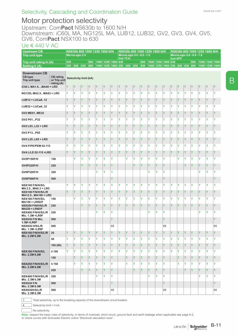
www.se.com
B-11
B
Selectivity, Cascading and Coordination Guide
Upstream CB NS630b 800 1000 1250 1600 N/H NS630b 800 1000 1250 1600 N/H NS630b 800 1000 1250 1600 N/HTrip unit type MicroLogic 2.0 MicroLogic 5.0 - 6.0 - 7.0
Inst 15 InMicroLogic 5.0 - 6.0 - 7.0Inst OFF
Trip unit rating In (A) 630 800 1000 1250 1600 630 800 1000 1250 1600 630 800 1000 1250 1600Setting Ir (A) 250 400 630 800 1000 1250 1600 250 400 630 800 1000 1250 1600 250 400 630 800 1000 1250 1600
Downstream CBSelectivity limit (kA)CB type
Trip unit typeCB rating or Trip unit rating (A)
iC60 L MA1.6…MA40 + LRD T T T T T T T T T T T T T T T T T T T T T
NG125L MA2.5...MA63 + LRD T T T T T T T T T T T T T T T T T T T T T
LUB12 + LUCp6..12 T T T T T T T T T T T T T T T T T T T T T
LUB32 + LUCp6..32 T T T T T T T T T T T T T T T T T T T T T
GV2 ME01..ME32 T T T T T T T T T T T T T T T T T T T T T
GV2 P01...P32 T T T T T T T T T T T T T T T T T T T T T
GV2 L03..L32 + LRD T T T T T T T T T T T T T T T T T T T T T
GV3 P13...P65 T T T T T T T T T T T T T T T T T T T T T
GV3 L25..L65 + LRD T T T T T T T T T T T T T T T T T T T T T
GV4 P/PE/PEM 02-115 T T T T T T T T T T T T T T T T T T T T T
GV4 L/LE 02-115 +LRD T T T T T T T T T T T T T T T T T T T T T
GV5P150F/H 150 T T T T T T T T T T T T T T T T T T
GV5P220F/H 220 T T T T T T T T T T T T T T T
GV6P320F/H 320 T T T T T T T T T
GV6P500F/H 500 T T T
NSX100 F/N/H/S/L MA 2.5...MA6.3 + LRD
T T T T T T T T T T T T T T T T T T T T T
NSX100 F/N/H/S/L/R MA12.5...MA100 + LRD
T T T T T T T T T T T T T T T T T T T T T
NSX160 F/N/H/S/L MA150 + LR9D/F
150 T T T T T T T T T T T T T T T T T T T T
NSX250 F/N/H/S/L/R MA220 + LR9D/F
220 T T T T T T T T T T T T T T T T T T T
NSX400 F/N/H/S/L/R Mic. 1.3M +LR9F
320 T T T T T T T T T
NSX630 F/N Mic. 1.3M +LR9F
500 T T T
NSX630 H/S/L/R Mic. 1.3M +LR9F
500 65 65 65
NSX100 F/N/H/S/L/RMic. 2.2M 6.2M
25 T T T T T T T T T T T T T T T T T T T T T
50 T T T T T T T T T T T T T T T T T T T T T
100 (80) T T T T T T T T T T T T T T T T T T T T T
NSX160 F/N/H/S/LMic. 2.2M 6.2M
y 100 T T T T T T T T T T T T T T T T T T T T T
150 T T T T T T T T T T T T T T T T T T
NSX250 F/N/H/S/L/RMic. 2.2M 6.2M
y 150 T T T T T T T T T T T T T T T T T T
220 T T T T T T T T T T T T T T T
NSX400 F/N/H/S/L/R Mic. 2.3M 6.3M
320 T T T T T T T T T
NSX630 F/N Mic. 2.3M 6.3M
500 T T T
NSX630H/S/L/R Mic. 2.3M 6.3M
500 65 65 65
T Total selectivity, up to the breaking capacity of the downstream circuit breaker.
4 Selectivity limit = 4 kA.
No selectivity.
Motor protection selectivityUpstream: ComPact NS630b to 1600 N/HDownstream: iC60L MA, NG125L MA, LUB12, LUB32, GV2, GV3, GV4, GV5, GV6, ComPact NSX100 to 630Ue y 440 V AC
Note: respect the basic rules of selectivity, in terms of overload, short-circuit, ground fault and earth leakage when applicable see page A-2, or check curves with Schneider Electric online “Electrical calculation tools”.
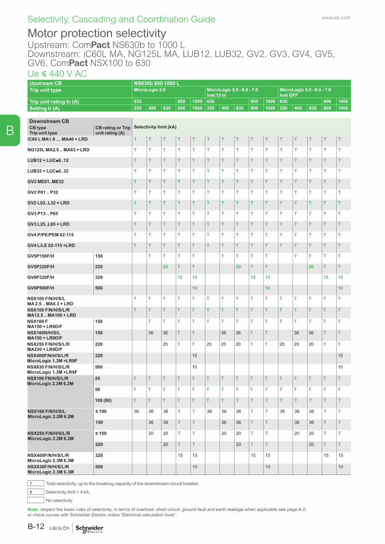
www.se.com
B-12
B
Selectivity, Cascading and Coordination Guide
Upstream CB NS630b 800 1000 LTrip unit type MicroLogic 2.0 MicroLogic 5.0 - 6.0 - 7.0
Inst 15 In MicroLogic 5.0 - 6.0 - 7.0Inst OFF
Trip unit rating In (A) 630 800 1000 630 800 1000 630 800 1000Setting Ir (A) 250 400 630 800 1000 250 400 630 800 1000 250 400 630 800 1000
Downstream CBSelectivity limit (kA)CB type
Trip unit typeCB rating or Trip unit rating (A)
iC60 L MA1.6 … MA40 + LRD T T T T T T T T T T T T T T T
NG125L MA2.5 .. MA63 + LRD T T T T T T T T T T T T T T T
LUB12 + LUCp6..12 T T T T T T T T T T T T T T T
LUB32 + LUCp6..32 T T T T T T T T T T T T T T T
GV2 ME01..ME32 T T T T T T T T T T T T T T T
GV2 P01 .. P32 T T T T T T T T T T T T T T T
GV2 L03..L32 + LRD T T T T T T T T T T T T T T T
GV3 P13 .. P65 T T T T T T T T T T T T T T T
GV3 L25..L65 + LRD T T T T T T T T T T T T T T T
GV4 P/PE/PEM 02-115 T T T T T T T T T T T T T T T
GV4 L/LE 02-115 +LRD T T T T T T T T T T T T T T T
GV5P150F/H 150 T T T T T T T T T T T T
GV5P220F/H 220 20 T T 20 T T 20 T T
GV6P320F/H 320 15 15 15 15 15 15
GV6P500F/H 500 10 10 10
NSX100 F/N/H/S/L MA 2.5 .. MA6.3 + LRD
T T T T T T T T T T T T T T T
NSX100 F/N/H/S/L/R MA12.5 .. MA100 + LRD
T T T T T T T T T T T T T T T
NSX160 F MA150 + LR9D/F
150 T T T T T T T T T T T T T T
NSX160N/H/S/L MA150 + LR9D/F
150 36 36 T T 36 36 T T 36 36 T T
NSX250 F/N/H/S/L/R MA220 + LR9D/F
220 20 T T 20 20 20 T T 20 20 20 T T
NSX400F/N/H/S/L/R MicroLogic 1.3M +LR9F
320 15 15
NSX630 F/N/H/S/L/R MicroLogic 1.3M +LR9F
500 10 10
NSX100 FN/H/S/L/RMicroLogic 2.2M 6.2M
25 T T T T T T T T T T T T T T T
50 T T T T T T T T T T T T T T T
100 (80) T T T T T T T T T T T T T T T
NSX160 F/N/H/S/LMicroLogic 2.2M 6.2M
y 100 36 36 36 T T 36 36 36 T T 36 36 36 T T
150 36 36 T T 36 36 T T 36 36 T T
NSX250 F/N/H/S/L/RMicroLogic 2.2M 6.2M
y 150 20 20 T T 20 20 T T 20 20 T T
220 20 T T 20 T T 20 T T
NSX400F/N/H/S/L/R MicroLogic 2.3M 6.3M
320 15 15 15 15 15 15
NSX630F/N/H/S/L/R MicroLogic 2.3M 6.3M
500 10 10 10
T Total selectivity, up to the breaking capacity of the downstream circuit breaker.
4 Selectivity limit = 4 kA.
No selectivity.
Motor protection selectivityUpstream: ComPact NS630b to 1000 LDownstream: iC60L MA, NG125L MA, LUB12, LUB32, GV2, GV3, GV4, GV5, GV6, ComPact NSX100 to 630Ue y 440 V AC
Note: respect the basic rules of selectivity, in terms of overload, short-circuit, ground fault and earth leakage when applicable see page A-2, or check curves with Schneider Electric online “Electrical calculation tools”.
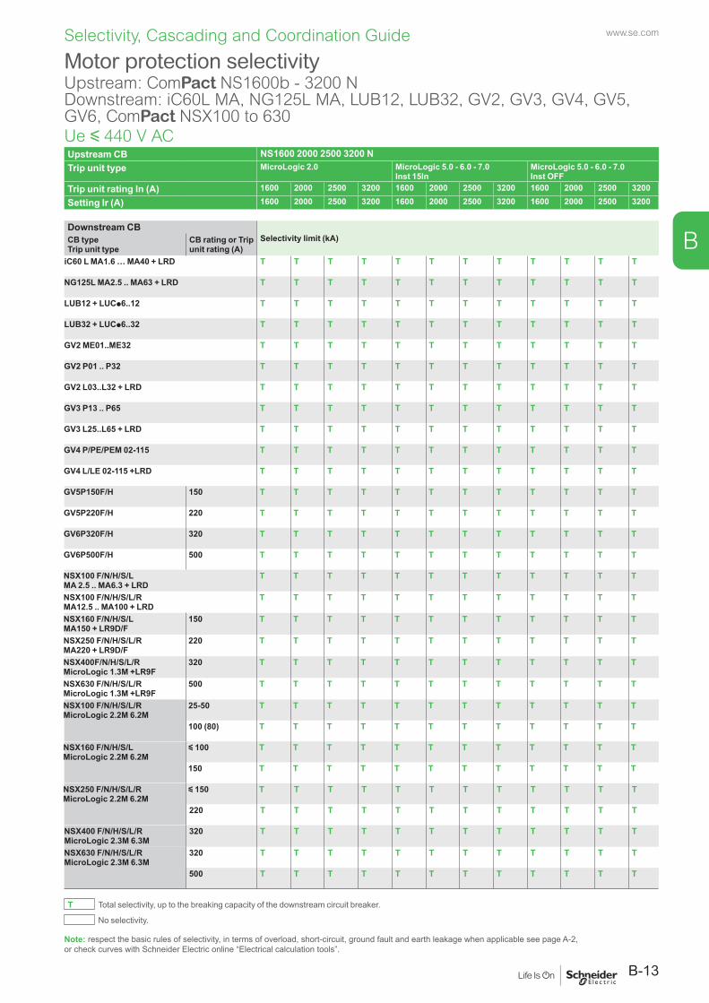
www.se.com
B-13
B
Selectivity, Cascading and Coordination Guide
Upstream CB NS1600 2000 2500 3200 NTrip unit type MicroLogic 2.0 MicroLogic 5.0 - 6.0 - 7.0
Inst 15InMicroLogic 5.0 - 6.0 - 7.0Inst OFF
Trip unit rating In (A) 1600 2000 2500 3200 1600 2000 2500 3200 1600 2000 2500 3200
Setting Ir (A) 1600 2000 2500 3200 1600 2000 2500 3200 1600 2000 2500 3200
Downstream CBSelectivity limit (kA)CB type
Trip unit typeCB rating or Trip unit rating (A)
iC60 L MA1.6 … MA40 + LRD T T T T T T T T T T T T
NG125L MA2.5 .. MA63 + LRD T T T T T T T T T T T T
LUB12 + LUCp6..12 T T T T T T T T T T T T
LUB32 + LUCp6..32 T T T T T T T T T T T T
GV2 ME01..ME32 T T T T T T T T T T T T
GV2 P01 .. P32 T T T T T T T T T T T T
GV2 L03..L32 + LRD T T T T T T T T T T T T
GV3 P13 .. P65 T T T T T T T T T T T T
GV3 L25..L65 + LRD T T T T T T T T T T T T
GV4 P/PE/PEM 02-115 T T T T T T T T T T T T
GV4 L/LE 02-115 +LRD T T T T T T T T T T T T
GV5P150F/H 150 T T T T T T T T T T T T
GV5P220F/H 220 T T T T T T T T T T T T
GV6P320F/H 320 T T T T T T T T T T T T
GV6P500F/H 500 T T T T T T T T T T T T
NSX100 F/N/H/S/L MA 2.5 .. MA6.3 + LRD
T T T T T T T T T T T T
NSX100 F/N/H/S/L/R MA12.5 .. MA100 + LRD
T T T T T T T T T T T T
NSX160 F/N/H/S/L MA150 + LR9D/F
150 T T T T T T T T T T T T
NSX250 F/N/H/S/L/R MA220 + LR9D/F
220 T T T T T T T T T T T T
NSX400F/N/H/S/L/R MicroLogic 1.3M +LR9F
320 T T T T T T T T T T T T
NSX630 F/N/H/S/L/R MicroLogic 1.3M +LR9F
500 T T T T T T T T T T T T
NSX100 F/N/H/S/L/RMicroLogic 2.2M 6.2M
25-50 T T T T T T T T T T T T
100 (80) T T T T T T T T T T T T
NSX160 F/N/H/S/LMicroLogic 2.2M 6.2M
y 100 T T T T T T T T T T T T
150 T T T T T T T T T T T T
NSX250 F/N/H/S/L/RMicroLogic 2.2M 6.2M
y 150 T T T T T T T T T T T T
220 T T T T T T T T T T T T
NSX400 F/N/H/S/L/R MicroLogic 2.3M 6.3M
320 T T T T T T T T T T T T
NSX630 F/N/H/S/L/RMicroLogic 2.3M 6.3M
320 T T T T T T T T T T T T
500 T T T T T T T T T T T T
T Total selectivity, up to the breaking capacity of the downstream circuit breaker.
No selectivity.
Motor protection selectivityUpstream: ComPact NS1600b - 3200 NDownstream: iC60L MA, NG125L MA, LUB12, LUB32, GV2, GV3, GV4, GV5, GV6, ComPact NSX100 to 630Ue y 440 V AC
Note: respect the basic rules of selectivity, in terms of overload, short-circuit, ground fault and earth leakage when applicable see page A-2, or check curves with Schneider Electric online “Electrical calculation tools”.
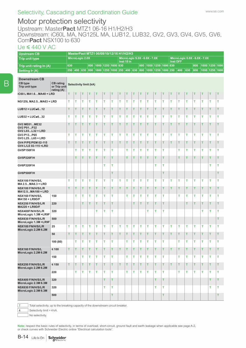
www.se.com
B-14
B
Selectivity, Cascading and Coordination Guide
Upstream CB MasterPact MTZ1 06/08/10/12/16 H1/H2/H3Trip unit type MicroLogic 2.0X MicroLogic 5.0X - 6.0X - 7.0X
Inst 15 In MicroLogic 5.0X - 6.0X - 7.0XInst OFF
Trip unit rating In (A) 630 800 1000 1250 1600 630 800 1000 1250 1600 630 800 1000 1250 1600
Setting Ir (A) 250 400 630 800 1000 1250 1600 250 400 630 800 1000 1250 1600 250 400 630 800 1000 1250 1600
Downstream CBSelectivity limit (kA)CB type
Trip unit typeCB rating or Trip unit rating (A)
iC60 L MA1.6…MA40 + LRD T T T T T T T T T T T T T T T T T T T T T
NG125L MA2.5...MA63 + LRD T T T T T T T T T T T T T T T T T T T T T
LUB12 + LUCp6...12 T T T T T T T T T T T T T T T T T T T T T
LUB32 + LUCp6...32 T T T T T T T T T T T T T T T T T T T T T
GV2 ME01...ME32GV2 P01...P32GV2 L03...L32 + LRD
T T T T T T T T T T T T T T T T T T T T T
GV3 P13...P65GV3 L25...L65 + LRD
T T T T T T T T T T T T T T T T T T T T T
GV4 P/PE/PEM 02-115GV4 L/LE 02-115 +LRD
T T T T T T T T T T T T T T T T T T T T T
GV5P150F/H T T T T T T T T T T T T T T T T T T
GV5P220F/H T T T T T T T T T T T T T T T T T T
GV6P320F/H T T T T T T
GV6P500F/H T T T
NSX100 F/N/H/S/L MA 2.5...MA6.3 + LRD
T T T T T T T T T T T T T T T T T T T T T
NSX100 F/N/H/S/L/R MA12.5...MA100 + LRD
T T T T T T T T T T T T T T T T T T T T T
NSX160 F/N/H/S/L MA150 + LR9D/F
150 T T T T T T T T T T T T T T T T T T
NSX250 F/N/H/S/L/R MA220 + LR9D/F
220 T T T T T T T T T T T T T T T
NSX400F/N/H/S/L/R MicroLogic 1.3M +LR9F
320 T T T T T T T T T
NSX630 F/N/H/S/L/R MicroLogic 1.3M +LR9F
500 T
NSX100 FN/H/S/L/RMicroLogic 2.2M 6.2M
25 T T T T T T T T T T T T T T T T T T T T T
50 T T T T T T T T T T T T T T T T T T T T T
100 (80) T T T T T T T T T T T T T T T T T T
NSX160 F/N/H/S/LMicroLogic 2.2M 6.2M
y 100 T T T T T T T T T T T T T T T T T T T T T
150 T T T T T T T T T T T T T T T T T T
NSX250 F/N/H/S/L/RMicroLogic 2.2M 6.2M
y 150 T T T T T T T T T T T T T T T T T T T T T
220 T T T T T T T T T T T T T T T T T T
NSX400 F/N/H/S/L/R MicroLogic 2.3M 6.3M
320 T T T T T T
NSX630 F/N/H/S/L/RMicroLogic 2.3M 6.3M
320 T T T T T T
500 T T T
T Total selectivity, up to the breaking capacity of the downstream circuit breaker. 4 Selectivity limit = 4 kA.
No selectivity.
Motor protection selectivityUpstream: MasterPact MTZ1 06-16 H1/H2/H3Downstream: iC60L MA, NG125L MA, LUB12, LUB32, GV2, GV3, GV4, GV5, GV6, ComPact NSX100 to 630Ue y 440 V AC
Note: respect the basic rules of selectivity, in terms of overload, short-circuit, ground fault and earth leakage when applicable see page A-2, or check curves with Schneider Electric online “Electrical calculation tools”.
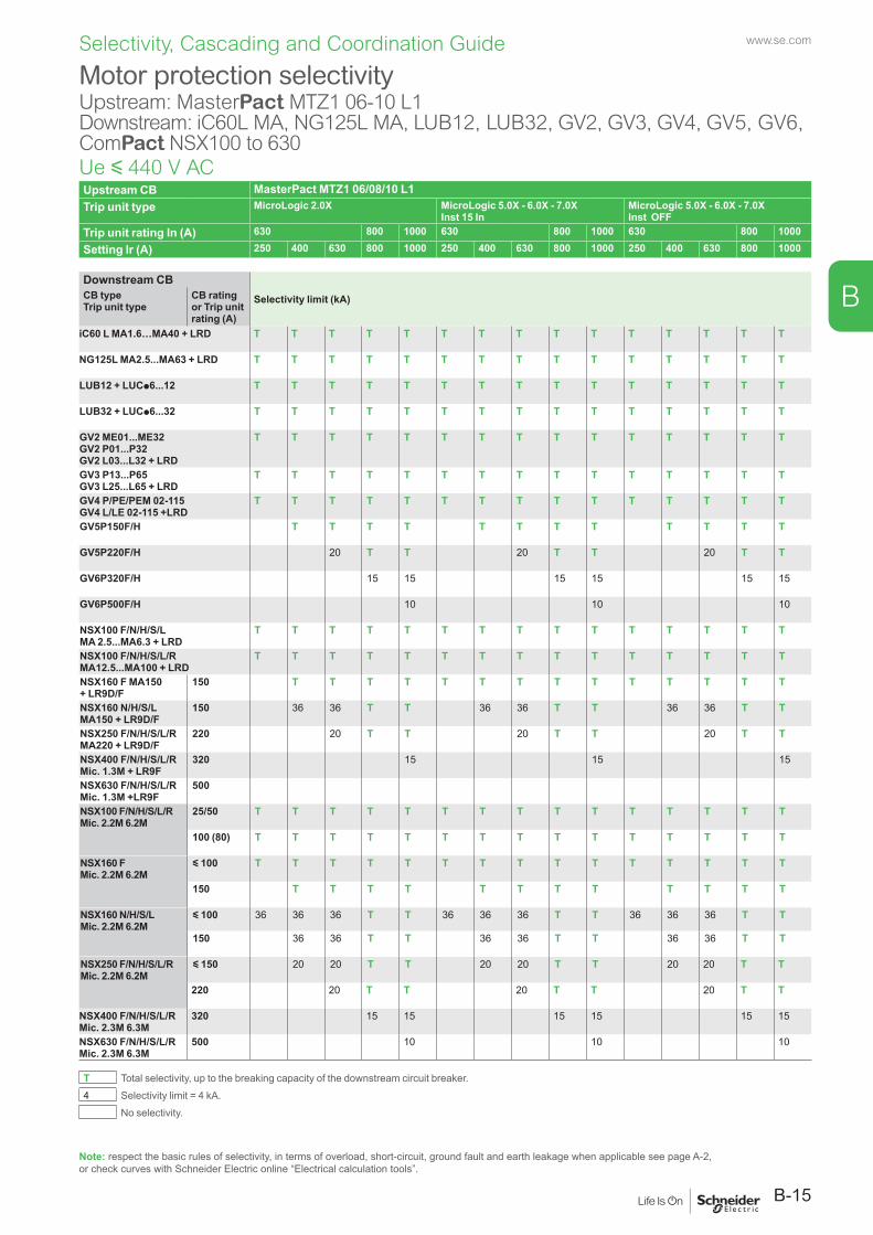
www.se.com
B-15
B
Selectivity, Cascading and Coordination Guide
Upstream CB MasterPact MTZ1 06/08/10 L1Trip unit type MicroLogic 2.0X MicroLogic 5.0X - 6.0X - 7.0X
Inst 15 InMicroLogic 5.0X - 6.0X - 7.0XInst OFF
Trip unit rating In (A) 630 800 1000 630 800 1000 630 800 1000
Setting Ir (A) 250 400 630 800 1000 250 400 630 800 1000 250 400 630 800 1000
Downstream CBSelectivity limit (kA)CB type
Trip unit typeCB rating or Trip unit rating (A)
iC60 L MA1.6…MA40 + LRD T T T T T T T T T T T T T T T
NG125L MA2.5...MA63 + LRD T T T T T T T T T T T T T T T
LUB12 + LUCp6...12 T T T T T T T T T T T T T T T
LUB32 + LUCp6...32 T T T T T T T T T T T T T T T
GV2 ME01...ME32GV2 P01...P32GV2 L03...L32 + LRD
T T T T T T T T T T T T T T T
GV3 P13...P65GV3 L25...L65 + LRD
T T T T T T T T T T T T T T T
GV4 P/PE/PEM 02-115GV4 L/LE 02-115 +LRD
T T T T T T T T T T T T T T T
GV5P150F/H T T T T T T T T T T T T
GV5P220F/H 20 T T 20 T T 20 T T
GV6P320F/H 15 15 15 15 15 15
GV6P500F/H 10 10 10
NSX100 F/N/H/S/L MA 2.5...MA6.3 + LRD
T T T T T T T T T T T T T T T
NSX100 F/N/H/S/L/R MA12.5...MA100 + LRD
T T T T T T T T T T T T T T T
NSX160 F MA150 + LR9D/F
150 T T T T T T T T T T T T T T
NSX160 N/H/S/L MA150 + LR9D/F
150 36 36 T T 36 36 T T 36 36 T T
NSX250 F/N/H/S/L/R MA220 + LR9D/F
220 20 T T 20 T T 20 T T
NSX400 F/N/H/S/L/R Mic. 1.3M + LR9F
320 15 15 15
NSX630 F/N/H/S/L/R Mic. 1.3M +LR9F
500
NSX100 F/N/H/S/L/RMic. 2.2M 6.2M
25/50 T T T T T T T T T T T T T T T
100 (80) T T T T T T T T T T T T T T T
NSX160 FMic. 2.2M 6.2M
y 100 T T T T T T T T T T T T T T T
150 T T T T T T T T T T T T
NSX160 N/H/S/L Mic. 2.2M 6.2M
y 100 36 36 36 T T 36 36 36 T T 36 36 36 T T
150 36 36 T T 36 36 T T 36 36 T T
NSX250 F/N/H/S/L/RMic. 2.2M 6.2M
y 150 20 20 T T 20 20 T T 20 20 T T
220 20 T T 20 T T 20 T T
NSX400 F/N/H/S/L/R Mic. 2.3M 6.3M
320 15 15 15 15 15 15
NSX630 F/N/H/S/L/R Mic. 2.3M 6.3M
500 10 10 10
T Total selectivity, up to the breaking capacity of the downstream circuit breaker. 4 Selectivity limit = 4 kA.
No selectivity.
Motor protection selectivityUpstream: MasterPact MTZ1 06-10 L1Downstream: iC60L MA, NG125L MA, LUB12, LUB32, GV2, GV3, GV4, GV5, GV6, ComPact NSX100 to 630Ue y 440 V AC
Note: respect the basic rules of selectivity, in terms of overload, short-circuit, ground fault and earth leakage when applicable see page A-2, or check curves with Schneider Electric online “Electrical calculation tools”.
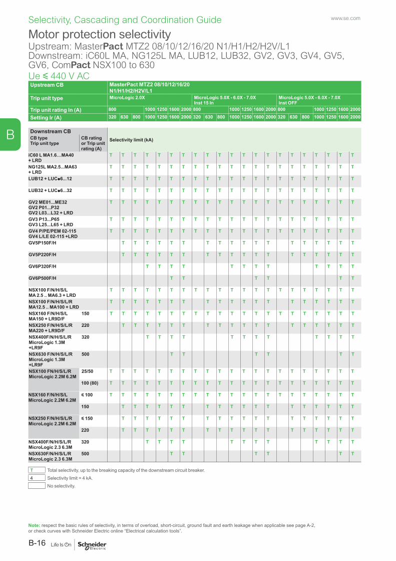
www.se.com
B-16
B
Selectivity, Cascading and Coordination Guide
Upstream CB MasterPact MTZ2 08/10/12/16/20 N1/H1/H2/H2V/L1
Trip unit type MicroLogic 2.0X MicroLogic 5.0X - 6.0X - 7.0XInst 15 In
MicroLogic 5.0X - 6.0X - 7.0XInst OFF
Trip unit rating In (A) 800 1000 1250 1600 2000 800 1000 1250 1600 2000 800 1000 1250 1600 2000
Setting Ir (A) 320 630 800 1000 1250 1600 2000 320 630 800 1000 1250 1600 2000 320 630 800 1000 1250 1600 2000
Downstream CBSelectivity limit (kA)CB type
Trip unit typeCB rating or Trip unit rating (A)
iC60 L MA1.6…MA40 + LRD
T T T T T T T T T T T T T T T T T T T T T
NG125L MA2.5...MA63 + LRD
T T T T T T T T T T T T T T T T T T T T T
LUB12 + LUCp6...12 T T T T T T T T T T T T T T T T T T T T T
LUB32 + LUCp6...32 T T T T T T T T T T T T T T T T T T T T T
GV2 ME01...ME32GV2 P01...P32GV2 L03...L32 + LRD
T T T T T T T T T T T T T T T T T T T T T
GV3 P13...P65GV3 L25...L65 + LRD
T T T T T T T T T T T T T T T T T T T T T
GV4 P/PE/PEM 02-115GV4 L/LE 02-115 +LRD
T T T T T T T T T T T T T T T T T T T T T
GV5P150F/H T T T T T T T T T T T T T T T T T T
GV5P220F/H T T T T T T T T T T T T T T T T T T
GV6P320F/H T T T T T T T T T T T T
GV6P500F/H T T T T T T
NSX100 F/N/H/S/L MA 2.5 .. MA6.3 + LRD
T T T T T T T T T T T T T T T T T T T T T
NSX100 F/N/H/S/L/R MA12.5 .. MA100 + LRD
T T T T T T T T T T T T T T T T T T T
NSX160 F/N/H/S/L MA150 + LR9D/F
150 T T T T T T T T T T T T T T T T T T T T T
NSX250 F/N/H/S/L/R MA220 + LR9D/F
220 T T T T T T T T T T T T T T T T T T
NSX400F/N/H/S/L/R MicroLogic 1.3M +LR9F
320 T T T T T T T T T T T T
NSX630 F/N/H/S/L/R MicroLogic 1.3M +LR9F
500 T T T T T T
NSX100 FN/H/S/L/RMicroLogic 2.2M 6.2M
25/50 T T T T T T T T T T T T T T T T T T T T T
100 (80) T T T T T T T T T T T T T T T T T T T T T
NSX160 F/N/H/S/LMicroLogic 2.2M 6.2M
y 100 T T T T T T T T T T T T T T T T T T T T T
150 T T T T T T T T T T T T T T T T T T
NSX250 F/N/H/S/L/RMicroLogic 2.2M 6.2M
y 150 T T T T T T T T T T T T T T T T T T
220 T T T T T T T T T T T T T T T T T T
NSX400F/N/H/S/L/R MicroLogic 2.3 6.3M
320 T T T T T T T T T T T T
NSX630F/N/H/S/L/R MicroLogic 2.3 6.3M
500 T T T T T T
T Total selectivity, up to the breaking capacity of the downstream circuit breaker. 4 Selectivity limit = 4 kA.
No selectivity.
Motor protection selectivityUpstream: MasterPact MTZ2 08/10/12/16/20 N1/H1/H2/H2V/L1Downstream: iC60L MA, NG125L MA, LUB12, LUB32, GV2, GV3, GV4, GV5, GV6, ComPact NSX100 to 630Ue y 440 V AC
Note: respect the basic rules of selectivity, in terms of overload, short-circuit, ground fault and earth leakage when applicable see page A-2, or check curves with Schneider Electric online “Electrical calculation tools”.
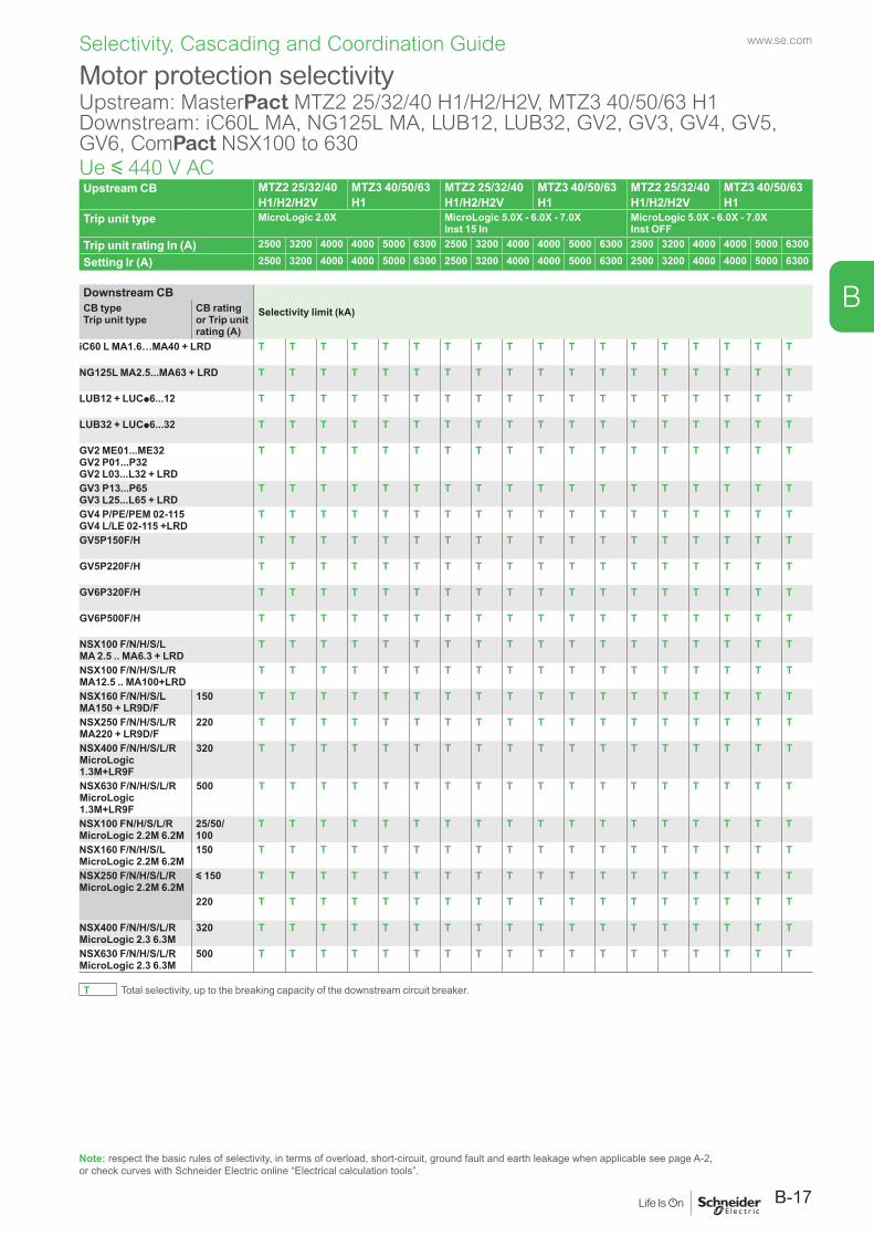
www.se.com
B-17
B
Selectivity, Cascading and Coordination Guide
Upstream CB MTZ2 25/32/40 MTZ3 40/50/63 MTZ2 25/32/40 MTZ3 40/50/63 MTZ2 25/32/40 MTZ3 40/50/63H1/H2/H2V H1 H1/H2/H2V H1 H1/H2/H2V H1
Trip unit type MicroLogic 2.0X MicroLogic 5.0X - 6.0X - 7.0XInst 15 In
MicroLogic 5.0X - 6.0X - 7.0XInst OFF
Trip unit rating In (A) 2500 3200 4000 4000 5000 6300 2500 3200 4000 4000 5000 6300 2500 3200 4000 4000 5000 6300
Setting Ir (A) 2500 3200 4000 4000 5000 6300 2500 3200 4000 4000 5000 6300 2500 3200 4000 4000 5000 6300
Downstream CBSelectivity limit (kA)CB type
Trip unit typeCB rating or Trip unit rating (A)
iC60 L MA1.6…MA40 + LRD T T T T T T T T T T T T T T T T T T
NG125L MA2.5...MA63 + LRD T T T T T T T T T T T T T T T T T T
LUB12 + LUCp6...12 T T T T T T T T T T T T T T T T T T
LUB32 + LUCp6...32 T T T T T T T T T T T T T T T T T T
GV2 ME01...ME32GV2 P01...P32GV2 L03...L32 + LRD
T T T T T T T T T T T T T T T T T T
GV3 P13...P65GV3 L25...L65 + LRD
T T T T T T T T T T T T T T T T T T
GV4 P/PE/PEM 02-115GV4 L/LE 02-115 +LRD
T T T T T T T T T T T T T T T T T T
GV5P150F/H T T T T T T T T T T T T T T T T T T
GV5P220F/H T T T T T T T T T T T T T T T T T T
GV6P320F/H T T T T T T T T T T T T T T T T T T
GV6P500F/H T T T T T T T T T T T T T T T T T T
NSX100 F/N/H/S/L MA 2.5 .. MA6.3 + LRD
T T T T T T T T T T T T T T T T T T
NSX100 F/N/H/S/L/R MA12.5 .. MA100+LRD
T T T T T T T T T T T T T T T T T T
NSX160 F/N/H/S/L MA150 + LR9D/F
150 T T T T T T T T T T T T T T T T T T
NSX250 F/N/H/S/L/R MA220 + LR9D/F
220 T T T T T T T T T T T T T T T T T T
NSX400 F/N/H/S/L/R MicroLogic 1.3M+LR9F
320 T T T T T T T T T T T T T T T T T T
NSX630 F/N/H/S/L/R MicroLogic 1.3M+LR9F
500 T T T T T T T T T T T T T T T T T T
NSX100 FN/H/S/L/R MicroLogic 2.2M 6.2M
25/50/ 100
T T T T T T T T T T T T T T T T T T
NSX160 F/N/H/S/L MicroLogic 2.2M 6.2M
150 T T T T T T T T T T T T T T T T T T
NSX250 F/N/H/S/L/RMicroLogic 2.2M 6.2M
y 150 T T T T T T T T T T T T T T T T T T
220 T T T T T T T T T T T T T T T T T T
NSX400 F/N/H/S/L/R MicroLogic 2.3 6.3M
320 T T T T T T T T T T T T T T T T T T
NSX630 F/N/H/S/L/R MicroLogic 2.3 6.3M
500 T T T T T T T T T T T T T T T T T T
T Total selectivity, up to the breaking capacity of the downstream circuit breaker.
Motor protection selectivityUpstream: MasterPact MTZ2 25/32/40 H1/H2/H2V, MTZ3 40/50/63 H1Downstream: iC60L MA, NG125L MA, LUB12, LUB32, GV2, GV3, GV4, GV5, GV6, ComPact NSX100 to 630Ue y 440 V AC
Note: respect the basic rules of selectivity, in terms of overload, short-circuit, ground fault and earth leakage when applicable see page A-2, or check curves with Schneider Electric online “Electrical calculation tools”.
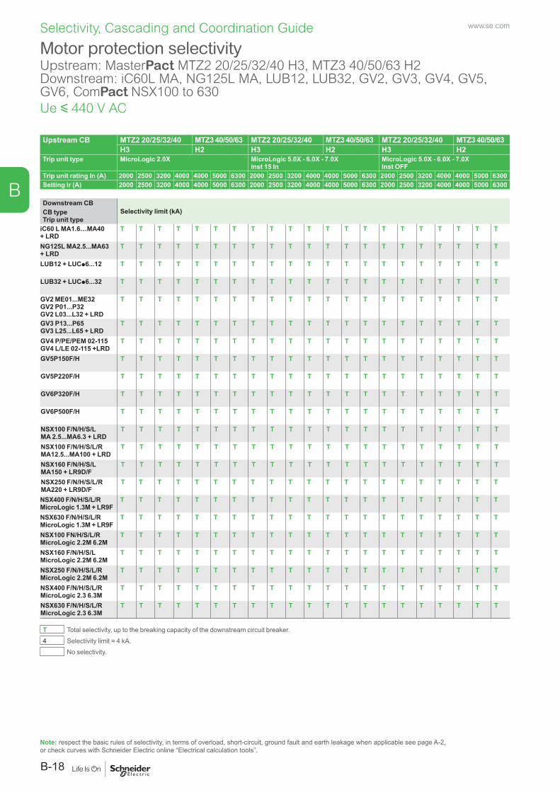
www.se.com
B-18
B
Selectivity, Cascading and Coordination Guide
Upstream CB MTZ2 20/25/32/40 MTZ3 40/50/63 MTZ2 20/25/32/40 MTZ3 40/50/63 MTZ2 20/25/32/40 MTZ3 40/50/63H3 H2 H3 H2 H3 H2
Trip unit type MicroLogic 2.0X MicroLogic 5.0X - 6.0X - 7.0XInst 15 In
MicroLogic 5.0X - 6.0X - 7.0XInst OFF
Trip unit rating In (A) 2000 2500 3200 4000 4000 5000 6300 2000 2500 3200 4000 4000 5000 6300 2000 2500 3200 4000 4000 5000 6300Setting Ir (A) 2000 2500 3200 4000 4000 5000 6300 2000 2500 3200 4000 4000 5000 6300 2000 2500 3200 4000 4000 5000 6300
Downstream CBSelectivity limit (kA)CB type
Trip unit typeiC60 L MA1.6…MA40 + LRD
T T T T T T T T T T T T T T T T T T T T T
NG125L MA2.5...MA63 + LRD
T T T T T T T T T T T T T T T T T T T T T
LUB12 + LUCp6...12 T T T T T T T T T T T T T T T T T T T T T
LUB32 + LUCp6...32 T T T T T T T T T T T T T T T T T T T T T
GV2 ME01...ME32GV2 P01...P32GV2 L03...L32 + LRD
T T T T T T T T T T T T T T T T T T T T T
GV3 P13...P65GV3 L25...L65 + LRD
T T T T T T T T T T T T T T T T T T T T T
GV4 P/PE/PEM 02-115GV4 L/LE 02-115 +LRD
T T T T T T T T T T T T T T T T T T T T T
GV5P150F/H T T T T T T T T T T T T T T T T T T T T T
GV5P220F/H T T T T T T T T T T T T T T T T T T T T T
GV6P320F/H T T T T T T T T T T T T T T T T T T T T T
GV6P500F/H T T T T T T T T T T T T T T T T T T T T T
NSX100 F/N/H/S/L MA 2.5...MA6.3 + LRD
T T T T T T T T T T T T T T T T T T T T T
NSX100 F/N/H/S/L/R MA12.5...MA100 + LRD
T T T T T T T T T T T T T T T T T T T T T
NSX160 F/N/H/S/L MA150 + LR9D/F
T T T T T T T T T T T T T T T T T T T T T
NSX250 F/N/H/S/L/R MA220 + LR9D/F
T T T T T T T T T T T T T T T T T T T T T
NSX400 F/N/H/S/L/R MicroLogic 1.3M + LR9F
T T T T T T T T T T T T T T T T T T T T T
NSX630 F/N/H/S/L/R MicroLogic 1.3M + LR9F
T T T T T T T T T T T T T T T T T T T T T
NSX100 FN/H/S/L/R MicroLogic 2.2M 6.2M
T T T T T T T T T T T T T T T T T T T T T
NSX160 F/N/H/S/L MicroLogic 2.2M 6.2M
T T T T T T T T T T T T T T T T T T T T T
NSX250 F/N/H/S/L/RMicroLogic 2.2M 6.2M
T T T T T T T T T T T T T T T T T T T T T
NSX400 F/N/H/S/L/R MicroLogic 2.3 6.3M
T T T T T T T T T T T T T T T T T T T T T
NSX630 F/N/H/S/L/R MicroLogic 2.3 6.3M
T T T T T T T T T T T T T T T T T T T T T
T Total selectivity, up to the breaking capacity of the downstream circuit breaker. 4 Selectivity limit = 4 kA.
No selectivity.
Motor protection selectivityUpstream: MasterPact MTZ2 20/25/32/40 H3, MTZ3 40/50/63 H2Downstream: iC60L MA, NG125L MA, LUB12, LUB32, GV2, GV3, GV4, GV5, GV6, ComPact NSX100 to 630Ue y 440 V AC
Note: respect the basic rules of selectivity, in terms of overload, short-circuit, ground fault and earth leakage when applicable see page A-2, or check curves with Schneider Electric online “Electrical calculation tools”.
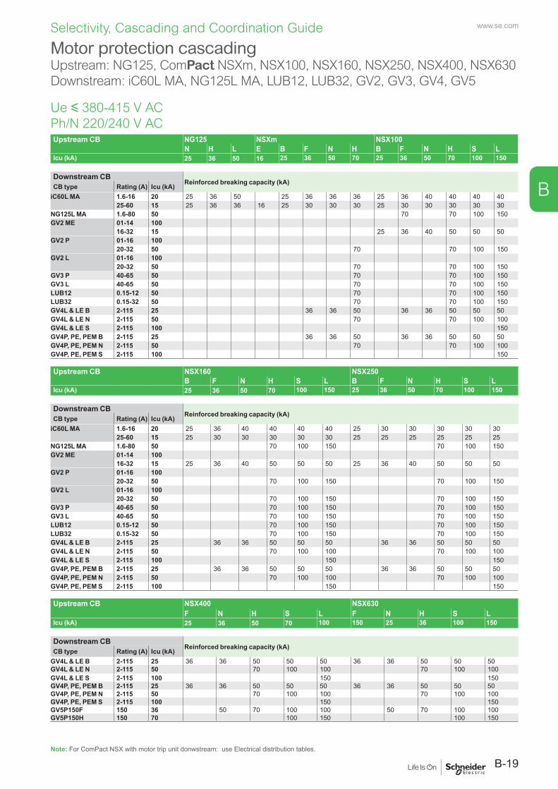
www.se.com
B-19
B
Selectivity, Cascading and Coordination Guide
Note: For ComPact NSX with motor trip unit donwstream: use Electrical distribution tables.
Upstream CB NG125 NSXm NSX100N H L E B F N H B F N H S L
Icu (kA) 25 36 50 16 25 36 50 70 25 36 50 70 100 150
Downstream CBReinforced breaking capacity (kA) CB type Rating (A) Icu (kA)
iC60L MA 1.6-16 20 25 36 50 25 36 36 36 25 36 40 40 40 4025-60 15 25 36 36 16 25 30 30 30 25 30 30 30 30 30
NG125L MA 1.6-80 50 70 70 100 150GV2 ME 01-14 100
16-32 15 25 36 40 50 50 50GV2 P 01-16 100
20-32 50 70 70 100 150GV2 L 01-16 100
20-32 50 70 70 100 150GV3 P 40-65 50 70 70 100 150GV3 L 40-65 50 70 70 100 150LUB12 0.15-12 50 70 70 100 150LUB32 0.15-32 50 70 70 100 150GV4L & LE B 2-115 25 36 36 50 36 36 50 50 50GV4L & LE N 2-115 50 70 70 100 100GV4L & LE S 2-115 100 150GV4P, PE, PEM B 2-115 25 36 36 50 36 36 50 50 50GV4P, PE, PEM N 2-115 50 70 70 100 100GV4P, PE, PEM S 2-115 100 150
Upstream CB NSX160 NSX250B F N H S L B F N H S L
Icu (kA) 25 36 50 70 100 150 25 36 50 70 100 150
Downstream CBReinforced breaking capacity (kA) CB type Rating (A) Icu (kA)
iC60L MA 1.6-16 20 25 36 40 40 40 40 25 30 30 30 30 3025-60 15 25 30 30 30 30 30 25 25 25 25 25 25
NG125L MA 1.6-80 50 70 100 150 70 100 150GV2 ME 01-14 100
16-32 15 25 36 40 50 50 50 25 36 40 50 50 50GV2 P 01-16 100
20-32 50 70 100 150 70 100 150GV2 L 01-16 100
20-32 50 70 100 150 70 100 150GV3 P 40-65 50 70 100 150 70 100 150GV3 L 40-65 50 70 100 150 70 100 150LUB12 0.15-12 50 70 100 150 70 100 150LUB32 0.15-32 50 70 100 150 70 100 150GV4L & LE B 2-115 25 36 36 50 50 50 36 36 50 50 50GV4L & LE N 2-115 50 70 100 100 70 100 100GV4L & LE S 2-115 100 150 150GV4P, PE, PEM B 2-115 25 36 36 50 50 50 36 36 50 50 50GV4P, PE, PEM N 2-115 50 70 100 100 70 100 100GV4P, PE, PEM S 2-115 100 150 150
Upstream CB NSX400 NSX630F N H S L F N H S L
Icu (kA) 25 36 50 70 100 150 25 36 100 150
Downstream CBReinforced breaking capacity (kA) CB type Rating (A) Icu (kA)
GV4L & LE B 2-115 25 36 36 50 50 50 36 36 50 50 50GV4L & LE N 2-115 50 70 100 100 70 100 100GV4L & LE S 2-115 100 150 150GV4P, PE, PEM B 2-115 25 36 36 50 50 50 36 36 50 50 50GV4P, PE, PEM N 2-115 50 70 100 100 70 100 100GV4P, PE, PEM S 2-115 100 150 150GV5P150F 150 36 50 70 100 100 50 70 100 100GV5P150H 150 70 100 150 100 150
Motor protection cascadingUpstream: NG125, ComPact NSXm, NSX100, NSX160, NSX250, NSX400, NSX630Downstream: iC60L MA, NG125L MA, LUB12, LUB32, GV2, GV3, GV4, GV5
Ue y 380-415 V AC Ph/N 220/240 V AC
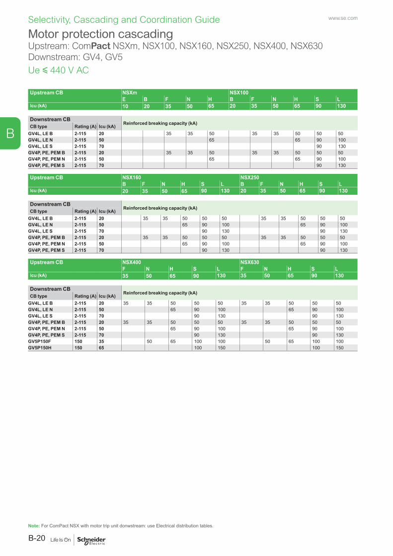
www.se.com
B-20
B
Selectivity, Cascading and Coordination Guide
Upstream CB NSXm NSX100E B F N H B F N H S L
Icu (kA) 10 20 35 50 65 20 35 50 65 90 130
Downstream CBReinforced breaking capacity (kA) CB type Rating (A) Icu (kA)
GV4L, LE B 2-115 20 35 35 50 35 35 50 50 50GV4L, LE N 2-115 50 65 65 90 100GV4L, LE S 2-115 70 90 130GV4P, PE, PEM B 2-115 20 35 35 50 35 35 50 50 50GV4P, PE, PEM N 2-115 50 65 65 90 100GV4P, PE, PEM S 2-115 70 90 130
Upstream CB NSX160 NSX250B F N H S L B F N H S L
Icu (kA) 20 35 50 65 90 130 20 35 50 65 90 130
Downstream CBReinforced breaking capacity (kA) CB type Rating (A) Icu (kA)
GV4L, LE B 2-115 20 35 35 50 50 50 35 35 50 50 50GV4L, LE N 2-115 50 65 90 100 65 90 100GV4L, LE S 2-115 70 90 130 90 130GV4P, PE, PEM B 2-115 20 35 35 50 50 50 35 35 50 50 50GV4P, PE, PEM N 2-115 50 65 90 100 65 90 100GV4P, PE, PEM S 2-115 70 90 130 90 130
Upstream CB NSX400 NSX630F N H S L F N H S L
Icu (kA) 35 50 65 90 130 35 50 65 90 130
Downstream CBReinforced breaking capacity (kA) CB type Rating (A) Icu (kA)
GV4L, LE B 2-115 20 35 35 50 50 50 35 35 50 50 50GV4L, LE N 2-115 50 65 90 100 65 90 100GV4L, LE S 2-115 70 90 130 90 130GV4P, PE, PEM B 2-115 20 35 35 50 50 50 35 35 50 50 50GV4P, PE, PEM N 2-115 50 65 90 100 65 90 100GV4P, PE, PEM S 2-115 70 90 130 90 130GV5P150F 150 35 50 65 100 100 50 65 100 100GV5P150H 150 65 100 150 100 150
Motor protection cascadingUpstream: ComPact NSXm, NSX100, NSX160, NSX250, NSX400, NSX630Downstream: GV4, GV5
Ue y 440 V AC
Note: For ComPact NSX with motor trip unit donwstream: use Electrical distribution tables.
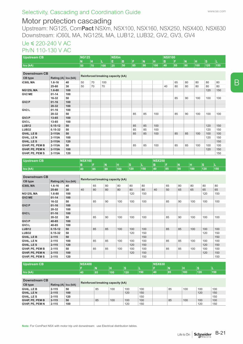
www.se.com
B-21
B
Selectivity, Cascading and Coordination Guide
Upstream CB NG125 NSXm NSX100N H L E B F N H B F N H S L
Icu (kA) 50 70 100 25 50 85 90 100 40 85 90 100 120 150
Downstream CBReinforced breaking capacity (kA) CB type Rating (A) Icu (kA)
iC60L MA 1.6-16 40 50 70 100 65 80 80 80 8025-60 30 50 70 70 40 80 80 80 80 80
NG125L MA 1.6-80 100 120 150GV2 ME 01-14 100
16-32 50 85 90 100 100 100GV2 P 01-16 100
20-32 100GV2 L 01-16 100
20-32 50 85 85 100 85 90 100 100 100GV3 P 13-65 100GV3 L 13-65 100LUB12 0.15-12 50 85 85 100 120 150LUB32 0.15-32 50 85 85 100 120 150GV4L, LE B 2-115A 50 85 85 100 85 85 100 100 100GV4L, LE N 2-115A 100 120 150GV4L, LE S 2-115A 120 150GV4P, PE, PEM B 2-115A 50 85 85 100 85 85 100 100 100GV4P, PE, PEM N 2-115A 100 120 150GV4P, PE, PEM S 2-115A 120 150
Upstream CB NSX160 NSX250B F N H S L B F N H S L
Icu (kA) 40 85 90 100 120 150 40 85 90 100 120 150
Downstream CBReinforced breaking capacity (kA) CB type Rating (A) Icu (kA)
iC60L MA 1.6-16 40 65 80 80 80 80 65 80 80 80 8025-60 30 40 80 80 80 80 80 40 50 65 65 65 65
NG125L MA 1.6-80 100 120 150 120 150GV2 ME 01-14 100
16-32 50 85 90 100 100 100 85 90 100 100 100GV2 P 01-16 100
20-32 100GV2 L 01-16 100
20-32 50 85 90 100 100 100 85 90 100 100 100GV3 P 40-65 100GV3 L 40-65 100LUB12 0.15-12 50 85 85 100 100 100 85 85 100 100 100LUB32 0.15-32 50 120 150 120 150GV4L, LE B 2-115 50 150 150GV4L, LE N 2-115 100 85 85 100 100 100 85 85 100 100 100GV4L, LE S 2-115 120 120 150 120 150GV4P, PE, PEM B 2-115 50 85 85 100 100 100 85 85 100 100 100GV4P, PE, PEM N 2-115 100 120 150 120 150GV4P, PE, PEM S 2-115 120 150 150
Upstream CB NSX400 NSX630F N H S L F N H S L
Icu (kA) 40 85 100 120 150 40 85 100 120 150
Downstream CBReinforced breaking capacity (kA) CB type Rating (A) Icu (kA)
GV4L, LE B 2-115 50 85 100 100 100 85 100 100 100GV4L, LE N 2-115 100 120 150 120 150GV4L, LE S 2-115 120 150 150GV4P, PE, PEM B 2-115 50 85 100 100 100 85 100 100 100GV4P, PE, PEM N 2-115 100 120 150 120 150
Motor protection cascadingUpstream: NG125, ComPact NSXm, NSX100, NSX160, NSX250, NSX400, NSX630Downstream: iC60L MA, NG125L MA, LUB12, LUB32, GV2, GV3, GV4
Ue y 220-240 V AC Ph/N 110-130 V AC
Note: For ComPact NSX with motor trip unit donwstream: use Electrical distribution tables.
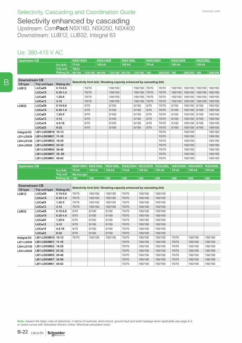
www.se.com
B-22
B
Selectivity, Cascading and Coordination Guide
Upstream CB NSX160H NSX160S NSX160L NSX250H NSX250S NSX250LIcu (kA) 70 kA 100 kA 150 kA 70 kA 100 kA 150 kATrip unit TM-DRating (A) 80/100 125/160 80/100 125/160 80/100 125/160 160 200/250 160 200/250 160 200/250
Downstream CB Selectivity limit (kA) / Breaking capacity enhanced by cascading (kA)CB type Trip unit type Rating (A)
LUB12 LUCpX6 0.15-0.6 70/70 100/100 150/150 70/70 70/70 100/100 100/100 100/100 100/100LUCp1X 0.35-1.4 70/70 100/100 150/150 70/70 70/70 100/100 100/100 100/100 100/100LUCp05 1.25-5 70/70 100/100 150/150 70/70 70/70 100/100 100/100 100/100 100/100LUCp12 3-12 70/70 100/100 150/150 70/70 70/70 100/100 100/100 100/100 100/100
LUB32 LUCpX6 0.15-0.6 5/70 5/100 5/150 5/70 70/70 5/100 100/100 5/100 100/100LUCp1X 0.35-1.4 5/70 5/100 5/150 5/70 70/70 5/100 100/100 5/100 100/100LUCp05 1.25-5 5/70 5/100 5/150 5/70 70/70 5/100 100/100 5/100 100/100LUCp12 3-12 5/70 5/100 5/150 5/70 70/70 5/100 100/100 5/100 100/100LUCp18 4.5-18 5/70 5/100 5/150 5/70 70/70 5/100 100/100 5/100 100/100LUCp32 8-32 5/70 5/100 5/150 5/70 70/70 5/100 100/100 5/100 100/100
Integral 63 LB1-LD03M16 10-13 70/70 100/100 150/150LD1-LD030 LB1-LD03M21 11-18 70/70 100/100 150/150LD4-LD130 LB1-LD03M22 18-25 70/70 100/100 150/150LD4-LD030 LB1-LD03M53 23-32 70/70 100/100 150/150
LB1-LD03M55 28-40 70/70 100/100 150/150LB1-LD03M57 35- 50 70/70 100/100 150/150LB1-LD03M61 45-63 70/70 100/100 150/150
Upstream CB NSX160H NSX160L NSX160L NSX250H NSX250S NSX250L NSX400H NSX400S NSX400LIcu (kA) 70 kA 100 kA 150 kA 70 kA 100 kA 150 kA 70 kA 100 kA 150 kATrip unit MicroLogicRating (A) 160 160 160 250 250 250 400 400 400
Downstream CB Selectivity limit (kA) / Breaking capacity enhanced by cascading (kA)CB type Trip unit type Rating (A)LUB12 LUCpX6 0.15-0.6 70/70 100/100 150/150 70/70 100/100 100/100
LUCp1X 0.35-1.4 70/70 100/100 150/150 70/70 100/100 100/100LUCp05 1.25-5 70/70 100/100 150/150 70/70 100/100 100/100LUCp12 3-12 70/70 100/100 150/150 70/70 100/100 100/100
LUB32 LUCpX6 0.15-0.6 5/70 5/100 5/150 70/70 100/100 100/100LUCp1X 0.35-1.4 5/70 5/100 5/150 70/70 100/100 100/100LUCp05 1.25-5 5/70 5/100 5/150 70/70 100/100 100/100LUCp12 3-12 5/70 5/100 5/150 70/70 100/100 100/100LUCp18 4.5-18 5/70 5/100 5/150 70/70 100/100 100/100LUCp32 8-32 5/70 5/100 5/150 70/70 100/100 100/100
Integral 63 LB1-LD03M16 10-13 70/70 100/100 150/150 70/70 100/100 150/150 70/70 100/100 150/150LD1-LD030 LB1-LD03M21 11-18 70/70 100/100 150/150 70/70 100/100 150/150LD4-LD130 LB1-LD03M22 18-25 70/70 100/100 150/150 70/70 100/100 150/150LD4-LD030 LB1-LD03M53 23-32 70/70 100/100 150/150 70/70 100/100 150/150
LB1-LD03M55 28-40 70/70 100/100 150/150 70/70 100/100 150/150LB1-LD03M57 35-50 70/70 100/100 150/150 70/70 100/100 150/150LB1-LD03M61 45-63 70/70 100/100 150/150 70/70 100/100 150/150
Selectivity enhanced by cascadingUpstream: ComPact NSX160, NSX250, NSX400Downstream: LUB12, LUB32, Integral 63
Ue: 380-415 V AC
Note: respect the basic rules of selectivity, in terms of overload, short-circuit, ground fault and earth leakage when applicable see page A-2, or check curves with Schneider Electric online “Electrical calculation tools”.
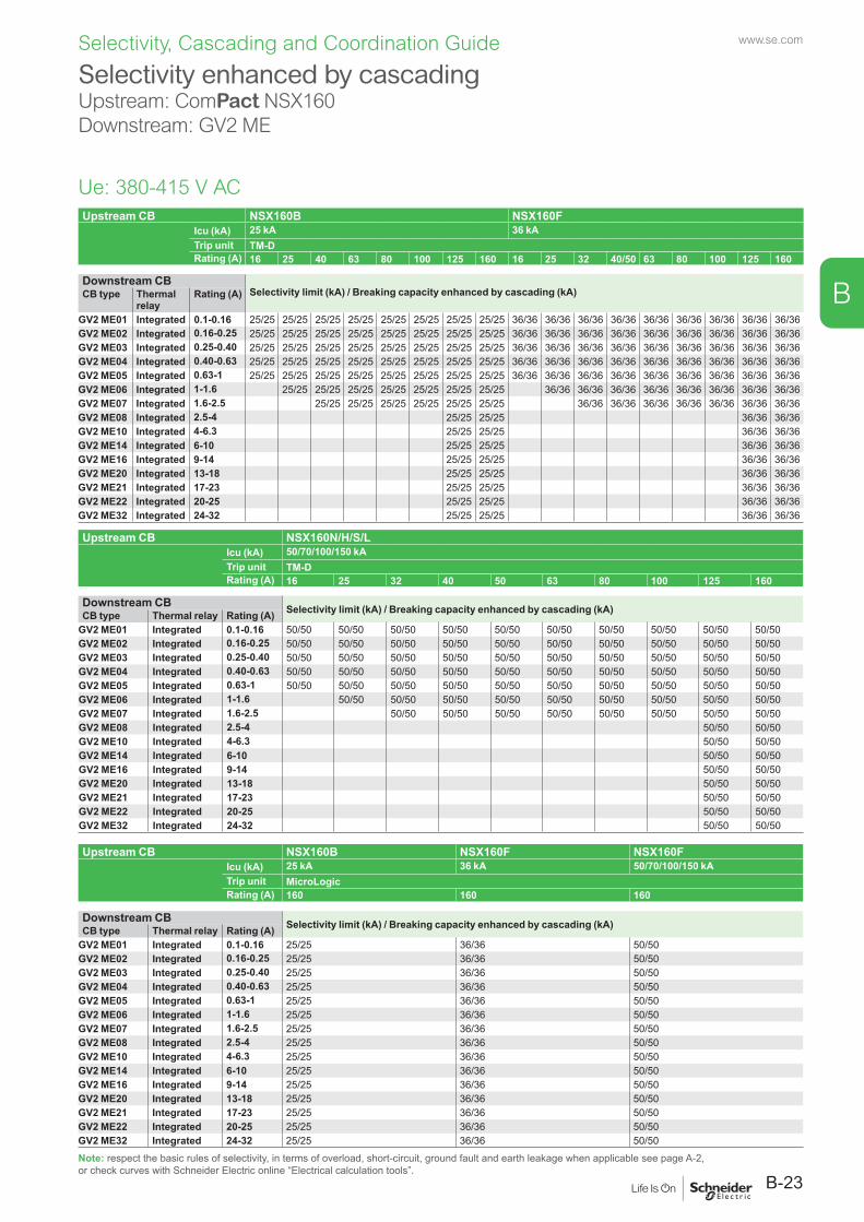
www.se.com
B-23
B
Selectivity, Cascading and Coordination Guide
Upstream CB NSX160B NSX160FIcu (kA) 25 kA 36 kATrip unit TM-DRating (A) 16 25 40 63 80 100 125 160 16 25 32 40/50 63 80 100 125 160
Downstream CBSelectivity limit (kA) / Breaking capacity enhanced by cascading (kA)CB type Thermal
relayRating (A)
GV2 ME01 Integrated 0.1-0.16 25/25 25/25 25/25 25/25 25/25 25/25 25/25 25/25 36/36 36/36 36/36 36/36 36/36 36/36 36/36 36/36 36/36GV2 ME02 Integrated 0.16-0.25 25/25 25/25 25/25 25/25 25/25 25/25 25/25 25/25 36/36 36/36 36/36 36/36 36/36 36/36 36/36 36/36 36/36GV2 ME03 Integrated 0.25-0.40 25/25 25/25 25/25 25/25 25/25 25/25 25/25 25/25 36/36 36/36 36/36 36/36 36/36 36/36 36/36 36/36 36/36GV2 ME04 Integrated 0.40-0.63 25/25 25/25 25/25 25/25 25/25 25/25 25/25 25/25 36/36 36/36 36/36 36/36 36/36 36/36 36/36 36/36 36/36GV2 ME05 Integrated 0.63-1 25/25 25/25 25/25 25/25 25/25 25/25 25/25 25/25 36/36 36/36 36/36 36/36 36/36 36/36 36/36 36/36 36/36GV2 ME06 Integrated 1-1.6 25/25 25/25 25/25 25/25 25/25 25/25 25/25 36/36 36/36 36/36 36/36 36/36 36/36 36/36 36/36GV2 ME07 Integrated 1.6-2.5 25/25 25/25 25/25 25/25 25/25 25/25 36/36 36/36 36/36 36/36 36/36 36/36 36/36GV2 ME08 Integrated 2.5-4 25/25 25/25 36/36 36/36GV2 ME10 Integrated 4-6.3 25/25 25/25 36/36 36/36GV2 ME14 Integrated 6-10 25/25 25/25 36/36 36/36GV2 ME16 Integrated 9-14 25/25 25/25 36/36 36/36GV2 ME20 Integrated 13-18 25/25 25/25 36/36 36/36GV2 ME21 Integrated 17-23 25/25 25/25 36/36 36/36GV2 ME22 Integrated 20-25 25/25 25/25 36/36 36/36GV2 ME32 Integrated 24-32 25/25 25/25 36/36 36/36
Upstream CB NSX160N/H/S/LIcu (kA) 50/70/100/150 kATrip unit TM-DRating (A) 16 25 32 40 50 63 80 100 125 160
Downstream CB Selectivity limit (kA) / Breaking capacity enhanced by cascading (kA)CB type Thermal relay Rating (A)GV2 ME01 Integrated 0.1-0.16 50/50 50/50 50/50 50/50 50/50 50/50 50/50 50/50 50/50 50/50GV2 ME02 Integrated 0.16-0.25 50/50 50/50 50/50 50/50 50/50 50/50 50/50 50/50 50/50 50/50GV2 ME03 Integrated 0.25-0.40 50/50 50/50 50/50 50/50 50/50 50/50 50/50 50/50 50/50 50/50GV2 ME04 Integrated 0.40-0.63 50/50 50/50 50/50 50/50 50/50 50/50 50/50 50/50 50/50 50/50GV2 ME05 Integrated 0.63-1 50/50 50/50 50/50 50/50 50/50 50/50 50/50 50/50 50/50 50/50GV2 ME06 Integrated 1-1.6 50/50 50/50 50/50 50/50 50/50 50/50 50/50 50/50 50/50GV2 ME07 Integrated 1.6-2.5 50/50 50/50 50/50 50/50 50/50 50/50 50/50 50/50GV2 ME08 Integrated 2.5-4 50/50 50/50GV2 ME10 Integrated 4-6.3 50/50 50/50GV2 ME14 Integrated 6-10 50/50 50/50GV2 ME16 Integrated 9-14 50/50 50/50GV2 ME20 Integrated 13-18 50/50 50/50GV2 ME21 Integrated 17-23 50/50 50/50GV2 ME22 Integrated 20-25 50/50 50/50GV2 ME32 Integrated 24-32 50/50 50/50
Upstream CB NSX160B NSX160F NSX160FIcu (kA) 25 kA 36 kA 50/70/100/150 kATrip unit MicroLogicRating (A) 160 160 160
Downstream CB Selectivity limit (kA) / Breaking capacity enhanced by cascading (kA)CB type Thermal relay Rating (A)GV2 ME01 Integrated 0.1-0.16 25/25 36/36 50/50GV2 ME02 Integrated 0.16-0.25 25/25 36/36 50/50GV2 ME03 Integrated 0.25-0.40 25/25 36/36 50/50GV2 ME04 Integrated 0.40-0.63 25/25 36/36 50/50GV2 ME05 Integrated 0.63-1 25/25 36/36 50/50GV2 ME06 Integrated 1-1.6 25/25 36/36 50/50GV2 ME07 Integrated 1.6-2.5 25/25 36/36 50/50GV2 ME08 Integrated 2.5-4 25/25 36/36 50/50GV2 ME10 Integrated 4-6.3 25/25 36/36 50/50GV2 ME14 Integrated 6-10 25/25 36/36 50/50GV2 ME16 Integrated 9-14 25/25 36/36 50/50GV2 ME20 Integrated 13-18 25/25 36/36 50/50GV2 ME21 Integrated 17-23 25/25 36/36 50/50GV2 ME22 Integrated 20-25 25/25 36/36 50/50GV2 ME32 Integrated 24-32 25/25 36/36 50/50
Selectivity enhanced by cascading Upstream: ComPact NSX160Downstream: GV2 ME
Ue: 380-415 V AC
Note: respect the basic rules of selectivity, in terms of overload, short-circuit, ground fault and earth leakage when applicable see page A-2, or check curves with Schneider Electric online “Electrical calculation tools”.
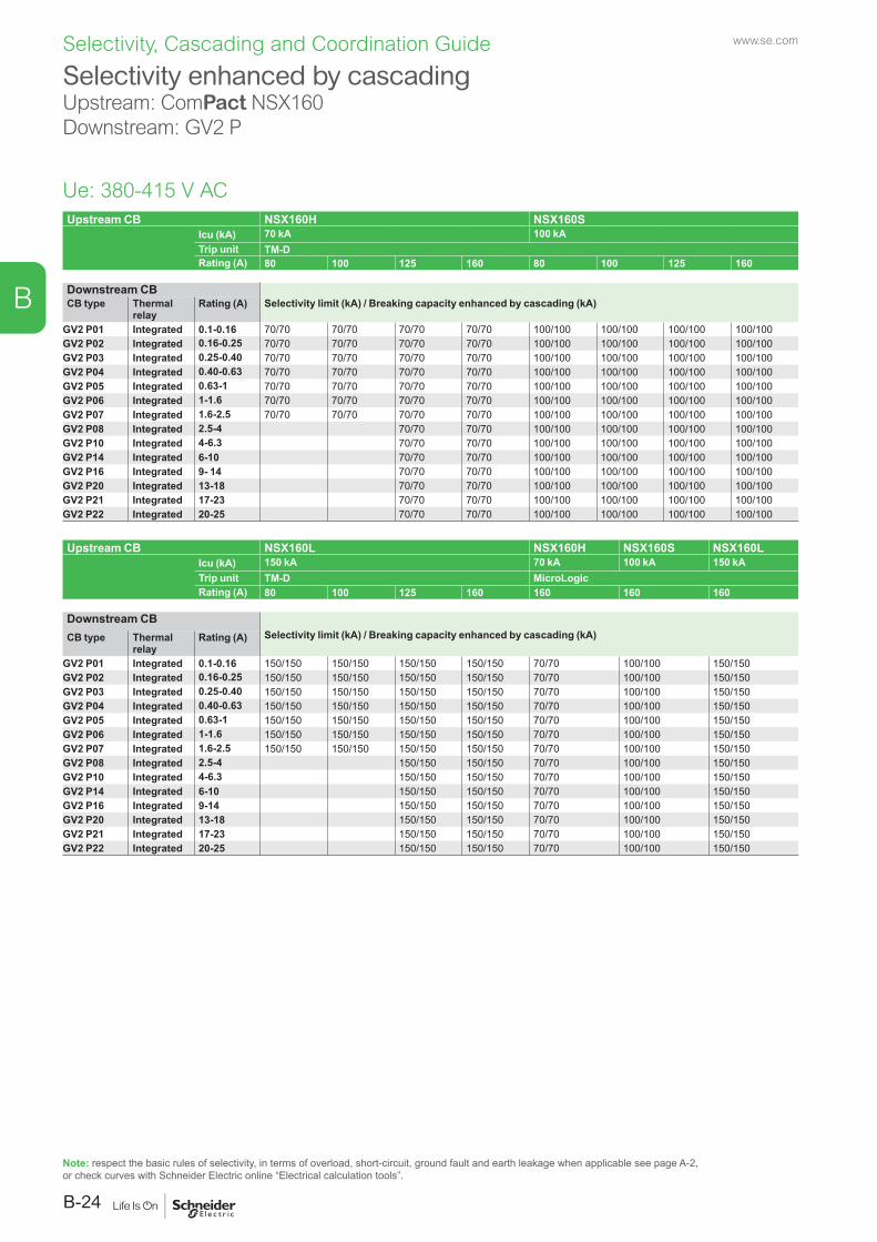
www.se.com
B-24
B
Selectivity, Cascading and Coordination Guide
Upstream CB NSX160H NSX160SIcu (kA) 70 kA 100 kATrip unit TM-DRating (A) 80 100 125 160 80 100 125 160
Downstream CBSelectivity limit (kA) / Breaking capacity enhanced by cascading (kA)CB type Thermal
relayRating (A)
GV2 P01 Integrated 0.1-0.16 70/70 70/70 70/70 70/70 100/100 100/100 100/100 100/100GV2 P02 Integrated 0.16-0.25 70/70 70/70 70/70 70/70 100/100 100/100 100/100 100/100GV2 P03 Integrated 0.25-0.40 70/70 70/70 70/70 70/70 100/100 100/100 100/100 100/100GV2 P04 Integrated 0.40-0.63 70/70 70/70 70/70 70/70 100/100 100/100 100/100 100/100GV2 P05 Integrated 0.63-1 70/70 70/70 70/70 70/70 100/100 100/100 100/100 100/100GV2 P06 Integrated 1-1.6 70/70 70/70 70/70 70/70 100/100 100/100 100/100 100/100GV2 P07 Integrated 1.6-2.5 70/70 70/70 70/70 70/70 100/100 100/100 100/100 100/100GV2 P08 Integrated 2.5-4 70/70 70/70 100/100 100/100 100/100 100/100GV2 P10 Integrated 4-6.3 70/70 70/70 100/100 100/100 100/100 100/100GV2 P14 Integrated 6-10 70/70 70/70 100/100 100/100 100/100 100/100GV2 P16 Integrated 9- 14 70/70 70/70 100/100 100/100 100/100 100/100GV2 P20 Integrated 13-18 70/70 70/70 100/100 100/100 100/100 100/100GV2 P21 Integrated 17-23 70/70 70/70 100/100 100/100 100/100 100/100GV2 P22 Integrated 20-25 70/70 70/70 100/100 100/100 100/100 100/100
Upstream CB NSX160L NSX160H NSX160S NSX160LIcu (kA) 150 kA 70 kA 100 kA 150 kATrip unit TM-D MicroLogicRating (A) 80 100 125 160 160 160 160
Downstream CBSelectivity limit (kA) / Breaking capacity enhanced by cascading (kA)CB type Thermal
relayRating (A)
GV2 P01 Integrated 0.1-0.16 150/150 150/150 150/150 150/150 70/70 100/100 150/150GV2 P02 Integrated 0.16-0.25 150/150 150/150 150/150 150/150 70/70 100/100 150/150GV2 P03 Integrated 0.25-0.40 150/150 150/150 150/150 150/150 70/70 100/100 150/150GV2 P04 Integrated 0.40-0.63 150/150 150/150 150/150 150/150 70/70 100/100 150/150GV2 P05 Integrated 0.63-1 150/150 150/150 150/150 150/150 70/70 100/100 150/150GV2 P06 Integrated 1-1.6 150/150 150/150 150/150 150/150 70/70 100/100 150/150GV2 P07 Integrated 1.6-2.5 150/150 150/150 150/150 150/150 70/70 100/100 150/150GV2 P08 Integrated 2.5-4 150/150 150/150 70/70 100/100 150/150GV2 P10 Integrated 4-6.3 150/150 150/150 70/70 100/100 150/150GV2 P14 Integrated 6-10 150/150 150/150 70/70 100/100 150/150GV2 P16 Integrated 9-14 150/150 150/150 70/70 100/100 150/150GV2 P20 Integrated 13-18 150/150 150/150 70/70 100/100 150/150GV2 P21 Integrated 17-23 150/150 150/150 70/70 100/100 150/150GV2 P22 Integrated 20-25 150/150 150/150 70/70 100/100 150/150
Selectivity enhanced by cascading Upstream: ComPact NSX160Downstream: GV2 P
Ue: 380-415 V AC
Note: respect the basic rules of selectivity, in terms of overload, short-circuit, ground fault and earth leakage when applicable see page A-2, or check curves with Schneider Electric online “Electrical calculation tools”.
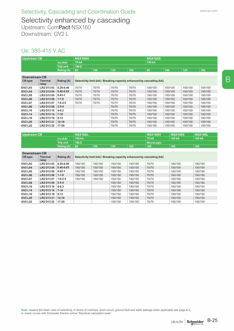
www.se.com
B-25
B
Selectivity, Cascading and Coordination Guide
Upstream CB NSX160H NSX160SIcu (kA) 70 kA 100 kATrip unit TM-DRating (A) 80 100 125 160 80 100 125 160
Downstream CBSelectivity limit (kA) / Breaking capacity enhanced by cascading (kA)CB type Thermal
relayRating (A)
GV2 L03 LR2 D13 03 0.25-0.40 70/70 70/70 70/70 70/70 100/100 100/100 100/100 100/100GV2 L04 LR2 D13 04 0.40-0.63 70/70 70/70 70/70 70/70 100/100 100/100 100/100 100/100GV2 L05 LR2 D13 05 0.63-1 70/70 70/70 70/70 70/70 100/100 100/100 100/100 100/100GV2 L06 LR2 D13 06 1-1.6 70/70 70/70 70/70 70/70 100/100 100/100 100/100 100/100GV2 L07 LR2 D13 07 1.6-2.5 70/70 70/70 70/70 70/70 100/100 100/100 100/100 100/100GV2 L08 LR2 D13 08 2.5-4 70/70 70/70 100/100 100/100 100/100 100/100GV2 L10 LR2 D13 10 4-6.3 70/70 70/70 100/100 100/100 100/100 100/100GV2 L14 LR2 D13 14 7-10 70/70 70/70 100/100 100/100 100/100 100/100GV2 L16 LR2 D13 16 9-13 70/70 70/70 100/100 100/100 100/100 100/100GV2 L20 LR2 D13 21 12-18 70/70 70/70 100/100 100/100 100/100 100/100GV2 L22 LR2 D13 22 17-25 70/70 70/70 100/100 100/100 100/100 100/100
Upstream CB NSX160L NSX160H NSX160S NSX160LIcu (kA) 150 kA 70 kA 100 kA 150 kATrip unit TM-D MicroLogicRating (A) 80 100 125 160 160 160 160
Downstream CBSelectivity limit (kA) / Breaking capacity enhanced by cascading (kA)CB type Thermal
relayRating (A)
GV2 L03 LR2 D13 03 0.25-0.40 150/150 150/150 150/150 150/150 70/70 100/100 150/150GV2 L04 LR2 D13 04 0.40-0.63 150/150 150/150 150/150 150/150 70/70 100/100 150/150GV2 L05 LR2 D13 05 0.63-1 150/150 150/150 150/150 150/150 70/70 100/100 150/150GV2 L06 LR2 D13 06 1-1.6 150/150 150/150 150/150 150/150 70/70 100/100 150/150GV2 L07 LR2 D13 07 1.6-2.5 150/150 150/150 150/150 150/150 70/70 100/100 150/150GV2 L08 LR2 D13 08 2.5-4 150/150 150/150 70/70 100/100 150/150GV2 L10 LR2 D13 10 4-6.3 150/150 150/150 70/70 100/100 150/150GV2 L14 LR2 D13 14 7-10 150/150 150/150 70/70 100/100 150/150GV2 L16 LR2 D13 16 9-13 150/150 150/150 70/70 100/100 150/150GV2 L20 LR2 D13 21 12-18 150/150 150/150 70/70 100/100 150/150GV2 L22 LR2 D13 22 17-25 150/150 150/150 70/70 100/100 150/150
Selectivity enhanced by cascadingUpstream: ComPact NSX160Downstream: GV2 L
Ue: 380-415 V AC
Note: respect the basic rules of selectivity, in terms of overload, short-circuit, ground fault and earth leakage when applicable see page A-2, or check curves with Schneider Electric online “Electrical calculation tools”.
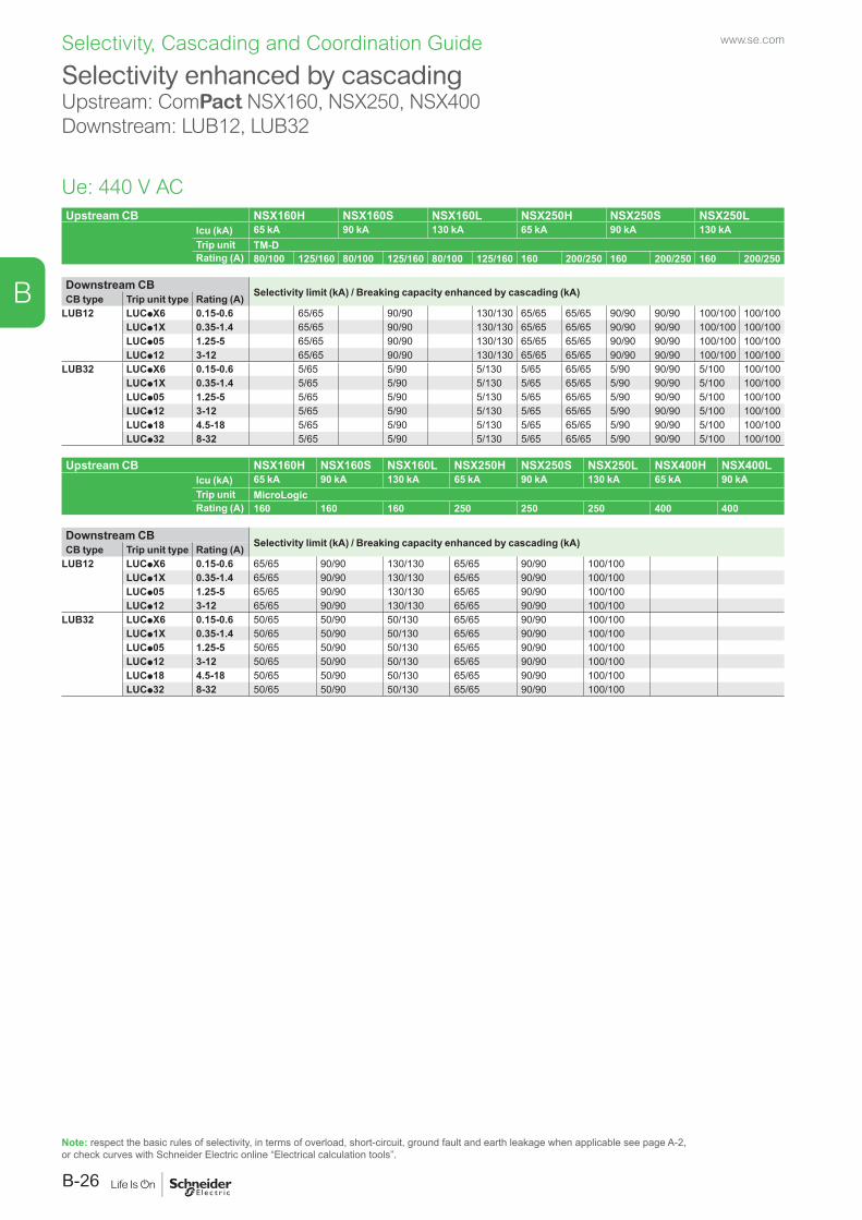
www.se.com
B-26
B
Selectivity, Cascading and Coordination Guide
Upstream CB NSX160H NSX160S NSX160L NSX250H NSX250S NSX250LIcu (kA) 65 kA 90 kA 130 kA 65 kA 90 kA 130 kATrip unit TM-DRating (A) 80/100 125/160 80/100 125/160 80/100 125/160 160 200/250 160 200/250 160 200/250
Downstream CB Selectivity limit (kA) / Breaking capacity enhanced by cascading (kA)CB type Trip unit type Rating (A)LUB12 LUCpX6 0.15-0.6 65/65 90/90 130/130 65/65 65/65 90/90 90/90 100/100 100/100
LUCp1X 0.35-1.4 65/65 90/90 130/130 65/65 65/65 90/90 90/90 100/100 100/100LUCp05 1.25-5 65/65 90/90 130/130 65/65 65/65 90/90 90/90 100/100 100/100LUCp12 3-12 65/65 90/90 130/130 65/65 65/65 90/90 90/90 100/100 100/100
LUB32 LUCpX6 0.15-0.6 5/65 5/90 5/130 5/65 65/65 5/90 90/90 5/100 100/100LUCp1X 0.35-1.4 5/65 5/90 5/130 5/65 65/65 5/90 90/90 5/100 100/100LUCp05 1.25-5 5/65 5/90 5/130 5/65 65/65 5/90 90/90 5/100 100/100LUCp12 3-12 5/65 5/90 5/130 5/65 65/65 5/90 90/90 5/100 100/100LUCp18 4.5-18 5/65 5/90 5/130 5/65 65/65 5/90 90/90 5/100 100/100LUCp32 8-32 5/65 5/90 5/130 5/65 65/65 5/90 90/90 5/100 100/100
Upstream CB NSX160H NSX160S NSX160L NSX250H NSX250S NSX250L NSX400H NSX400LIcu (kA) 65 kA 90 kA 130 kA 65 kA 90 kA 130 kA 65 kA 90 kATrip unit MicroLogicRating (A) 160 160 160 250 250 250 400 400
Downstream CB Selectivity limit (kA) / Breaking capacity enhanced by cascading (kA)CB type Trip unit type Rating (A)LUB12 LUCpX6 0.15-0.6 65/65 90/90 130/130 65/65 90/90 100/100
LUCp1X 0.35-1.4 65/65 90/90 130/130 65/65 90/90 100/100LUCp05 1.25-5 65/65 90/90 130/130 65/65 90/90 100/100LUCp12 3-12 65/65 90/90 130/130 65/65 90/90 100/100
LUB32 LUCpX6 0.15-0.6 50/65 50/90 50/130 65/65 90/90 100/100LUCp1X 0.35-1.4 50/65 50/90 50/130 65/65 90/90 100/100LUCp05 1.25-5 50/65 50/90 50/130 65/65 90/90 100/100LUCp12 3-12 50/65 50/90 50/130 65/65 90/90 100/100LUCp18 4.5-18 50/65 50/90 50/130 65/65 90/90 100/100LUCp32 8-32 50/65 50/90 50/130 65/65 90/90 100/100
Selectivity enhanced by cascadingUpstream: ComPact NSX160, NSX250, NSX400Downstream: LUB12, LUB32
Ue: 440 V AC
Note: respect the basic rules of selectivity, in terms of overload, short-circuit, ground fault and earth leakage when applicable see page A-2, or check curves with Schneider Electric online “Electrical calculation tools”.
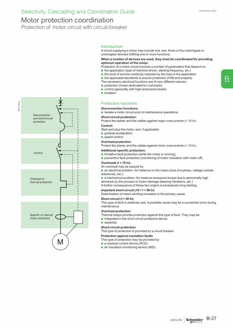
IntroductionA circuit supplying a motor may include one, two, three or four switchgear or controlgear devices fulfilling one or more functions.When a number of devices are used, they must be coordinated for providing optimum operation of the motor.Protection of a motor circuit involves a number of parameters that depend on:
b the application (type of machine driven, starting frequency, etc.) b the level of service continuity imposed by the load or the application b the applicable standards to ensure protection of life and property.
The necessary electrical functions are of very different natures: b protection (motor-dedicated for overloads) b control (generally with high endurance levels) b isolation.
Protection functionsDisconnection functions:
b Isolate a motor circuit prior to maintenance operations.Short-circuit protection:Protect the starter and the cables against major overcurrents (> 10 In).Control:Start and stop the motor, and, if applicable:
b gradual acceleration b speed control.
Overload protection:Protect the starter and the cables against minor overcurrents (< 10 In).Additional specific protection:
b limitative fault protection (while the motor is running) b preventive fault protection (monitoring of motor insulation with motor off).
Overloads (I < 10 In).An overload may be caused by:
b an electrical problem, for instance on the mains (loss of a phase, voltage outside tolerances, etc.)
b a mechanical problem, for instance excessive torque due to abnormally high demands by the process or motor damage (bearing vibrations, etc.)A further consequence of these two origins is excessively long starting.Impedant short-circuit (10 < I < 50 In)Deterioration of motor-winding insulation is the primary cause.Short-circuit (I > 50 In)This type of fault is relatively rare. A possible cause may be a connection error during maintenance.Overload protectionThermal relays provide protection against this type of fault. They may be:
b integrated in the short-circuit protective device b separate.
Short-circuit protectionThis type of protection is provided by a circuit breaker.Protection against insulation faultsThis type of protection may be provided by:
b a residual current device (RCD) b an insulation monitoring device (IMD).
Motor protection coordinationProtection of motor circuit with circuit-breaker
DB1
1519
8.ep
s
B-27
www.se.com
B
Selectivity, Cascading and Coordination Guide
Applicable standardsA circuit supplying a motor must comply with the general rules set out in IEC standard 60947-4-1 and in particular with those concerning contactors, motor starters and their protection as stipulated in IEC 60947-4-1, notably:
b coordination of the components of the motor circuit b trip class for thermal relays b contactor utilisation categories b coordination of insulation.
Coordination of the components of the motor circuitTwo types of coordinationThe standard defines tests at different current levels. The purpose of these tests is to place the switchgear and controlgear in extreme conditions. Depending on the state of the components following the tests, the standard defines two types of coordination:
b type 1: Deterioration of the contactor and the relay is acceptable under two conditions:
v no danger to operating personnel v no danger to any components other than the contactor and the relay b type 2:
Only minor welding of the contactor or starter contacts is permissible and the contacts must be easily separated.
v following type-2 coordination tests, the switchgear and controlgear functions must be fully operational.Which type of coordination is needed?Selection of a type of coordination depends on the operating conditions encountered.The goal is to achieve the best balance between the user’s needs and the cost of the installation.
b type 1: v qualified maintenance service v low cost of switchgear and controlgear v continuity of service is not imperative or may be obtained by simply replacing the
faulty motor drawer b type 2: v continuity of service is imperative v limited maintenance service v specifications stipulating type 2.
Motor protection coordinationProtection of motor circuit with circuit-breaker
www.se.com
B-28
B
Selectivity, Cascading and Coordination Guide
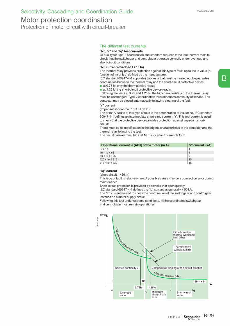
The different test currents"Ic", "r" and "Iq" test currentsTo qualify for type-2 coordination, the standard requires three fault-current tests to check that the switchgear and controlgear operates correctly under overload and short-circuit conditions."Ic" current (overload I < 10 In)The thermal relay provides protection against this type of fault, up to the Ic value (a function of Im or Isd) defined by the manufacturer.IEC standard 60947-4-1 stipulates two tests that must be carried out to guarantee coordination between the thermal relay and the short-circuit protective device:
b at 0.75 Ic, only the thermal relay reacts b at 1.25 Ic, the short-circuit protective device reacts.
Following the tests at 0.75 and 1.25 Ic, the trip characteristics of the thermal relay must be unchanged. Type-2 coordination thus enhances continuity of service. The contactor may be closed automatically following clearing of the faul."r" current (Impedant short-circuit 10 < I < 50 In)The primary cause of this type of fault is the deterioration of insulation. IEC standard 60947-4-1 defines an intermediate short-circuit current “r”. This test current is used to check that the protective device provides protection against impedant short-circuits.There must be no modification in the original characteristics of the contactor and the thermal relay following the test.The circuit breaker must trip in y 10 ms for a fault current u 15 In.
Operational current Ie (AC3) of the motor (in A) "r" current (kA)Ie y 16 116 < Ie y 63 363 < Ie y 125 5125 < Ie y 315 10315 < Ie < 630 18
“Iq” current (short-circuit I > 50 In)This type of fault is relatively rare. A possible cause may be a connection error during maintenance.Short-circuit protection is provided by devices that open quickly.IEC standard 60947-4-1 defines the “Iq” current as generally u 50 kA.The “Iq” current is used to check the coordination of the switchgear and controlgear installed on a motor supply circuit.Following this test under extreme conditions, all the coordinated switchgear and controlgear must remain operational.
DB1
1519
9.ep
s
Motor protection coordinationProtection of motor circuit with circuit-breaker
B-29
www.se.com
B
Selectivity, Cascading and Coordination Guide
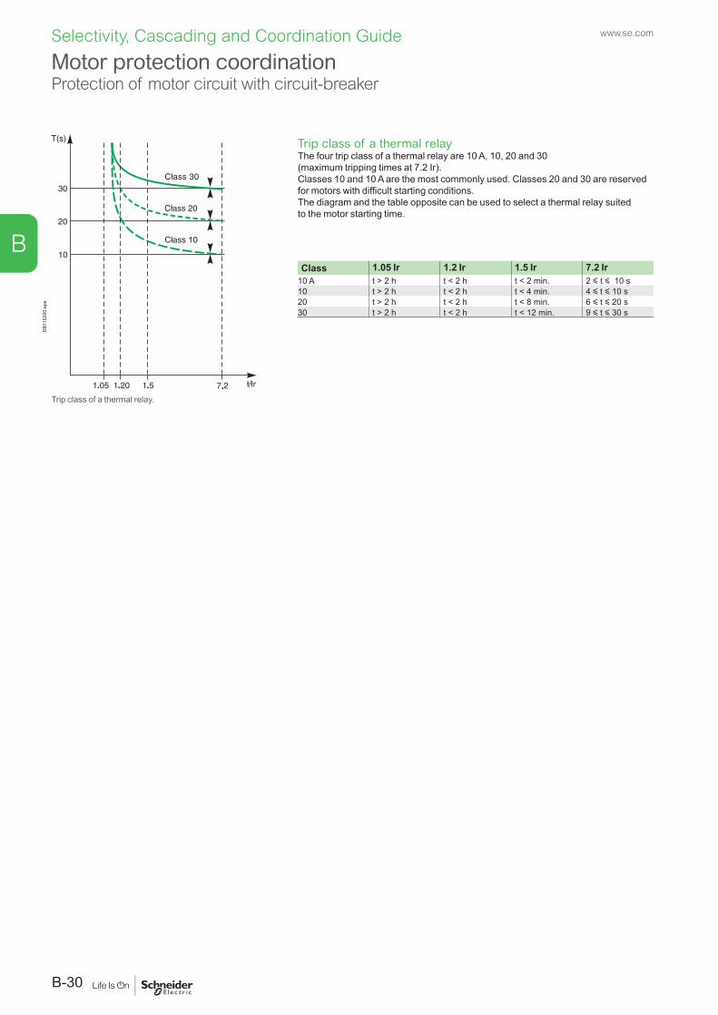
DB1
1520
0.ep
s
Trip class of a thermal relay.
Trip class of a thermal relayThe four trip class of a thermal relay are 10 A, 10, 20 and 30 (maximum tripping times at 7.2 Ir).Classes 10 and 10 A are the most commonly used. Classes 20 and 30 are reserved for motors with difficult starting conditions.The diagram and the table opposite can be used to select a thermal relay suited to the motor starting time.
Class 1.05 Ir 1.2 Ir 1.5 Ir 7.2 Ir10 A t > 2 h t < 2 h t < 2 min. 2 y t y 10 s10 t > 2 h t < 2 h t < 4 min. 4 y t y 10 s20 t > 2 h t < 2 h t < 8 min. 6 y t y 20 s30 t > 2 h t < 2 h t < 12 min. 9 y t y 30 s
Motor protection coordinationProtection of motor circuit with circuit-breaker
www.se.com
B-30
B
Selectivity, Cascading and Coordination Guide
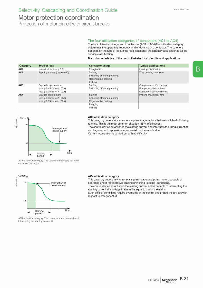
The four utilisation categories of contactors (AC1 to AC4)The four utilisation categories of contactors (AC1 to AC4)The utilisation category determines the operating frequency and endurance of a contactor. The category depends on the type of load. If the load is a motor; the category also depends on the service classification.Main characteristics of the controlled electrical circuits and applications
Category Type of load Contactor usage Typical applicationsAC1 No-inductive (cos φ 0.8) Energisation Heating, distributionAC2 Slip-ring motors (cos φ 0.65) Starting Wire drawing machines
Switching off during runningRegenerative brakingInching
AC3 Squirrel-cage motors Starting Compressors, lifts, mixing(cos φ 0.45 for le y 100A) Switching off during running Pumps, escalators, fans,(cos φ 0.35 for le > 100A) Conveyers, air-conditioning
AC4 Squirrel-cage motors Starting Printing machines, wire(cos φ 0.45 for le y 100A) Switching off during running(cos φ 0.35 for le > 100A) Regenerative braking
PluggingInching
AC3 utilisation categoryThis category covers asynchronous squirrel-cage motors that are switched off during running. This is the most common situation (85 % of all cases).The control device establishes the starting current and interrupts the rated current at a voltage equal to approximately one-sixth of the rated value.Current interruption is carried out with no difficulty.
AC4 utilisation categoryThis category covers asynchronous squirrel-cage or slip-ring motors capable of operating under regenerative-braking or inching (jogging) conditions.The control device establishes the starting current and is capable of interrupting the starting current at a voltage that may be equal to that of the mains.Such difficult conditions require oversizing of the control and protective devices with respect to category AC3.
DB1
1520
1.ep
s
AC3 utilisation category. The contactor interrupts the rated current of the motor.
DB1
1520
2.ep
s
AC4 utilisation category. The contactor must be capable of interrupting the starting current id.
Motor protection coordinationProtection of motor circuit with circuit-breaker
B-31
www.se.com
B
Selectivity, Cascading and Coordination Guide
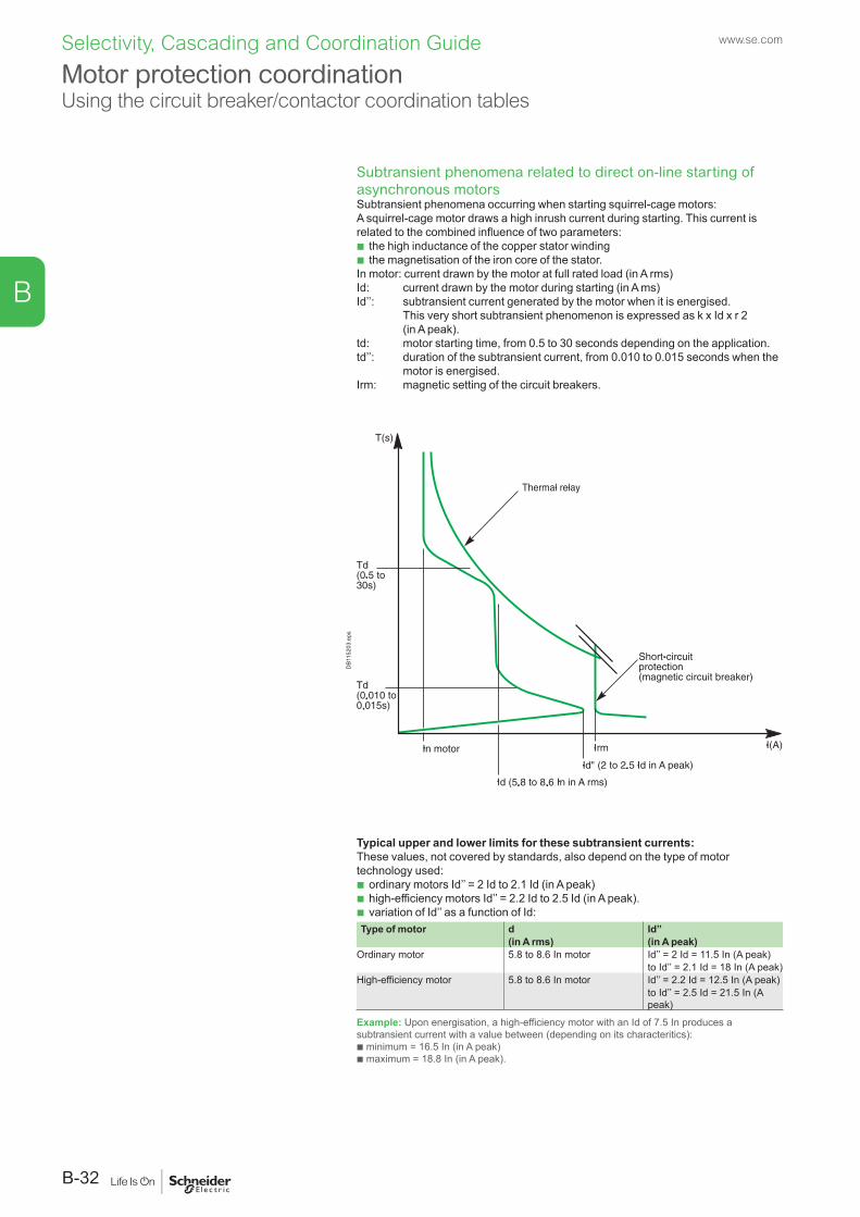
Subtransient phenomena related to direct on-line starting of asynchronous motorsSubtransient phenomena occurring when starting squirrel-cage motors:A squirrel-cage motor draws a high inrush current during starting. This current is related to the combined influence of two parameters:
b the high inductance of the copper stator winding b the magnetisation of the iron core of the stator.
In motor: current drawn by the motor at full rated load (in A rms)Id: current drawn by the motor during starting (in A ms)Id’’: subtransient current generated by the motor when it is energised. This very short subtransient phenomenon is expressed as k x Id x r 2
(in A peak).td: motor starting time, from 0.5 to 30 seconds depending on the application.td’’: duration of the subtransient current, from 0.010 to 0.015 seconds when the
motor is energised.Irm: magnetic setting of the circuit breakers.
Typical upper and lower limits for these subtransient currents:These values, not covered by standards, also depend on the type of motor technology used:
b ordinary motors Id’’ = 2 Id to 2.1 Id (in A peak) b high-efficiency motors Id’’ = 2.2 Id to 2.5 Id (in A peak). b variation of Id’’ as a function of Id:
Type of motor d Id’’(in A rms) (in A peak)
Ordinary motor 5.8 to 8.6 In motor Id’’ = 2 Id = 11.5 In (A peak)to Id’’ = 2.1 Id = 18 In (A peak)
High-efficiency motor 5.8 to 8.6 In motor Id’’ = 2.2 Id = 12.5 In (A peak)to Id’’ = 2.5 Id = 21.5 In (A peak)
Example: Upon energisation, a high-efficiency motor with an Id of 7.5 In produces a subtransient current with a value between (depending on its characteritics): b minimum = 16.5 In (in A peak) b maximum = 18.8 In (in A peak).
DB1
1520
3.ep
s
Motor protection coordinationUsing the circuit breaker/contactor coordination tables
www.se.com
B-32
B
Selectivity, Cascading and Coordination Guide
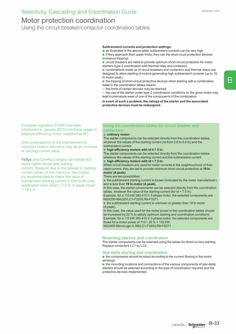
Subtransient currents and protection settings: b as illustrated in the above table, subtransient currents can be very high. b If they approach their upper limits, they can trip short-cicuit protection devices
(nuisance tripping) b circuit breakers are rated to provide optimum short-circuit protection for motor
starters (type 2 coordination with thermal relay and contactor) b combinations made up of circuit breakers and contactors and thermal relays are
designed to allow starting of motors generating high subtransient currents (up to 19 In motor peak)
b the tripping of short-circuit protective devices when starting with a combination listed in the coordination tables means:
v the limits of certain devices may be reached v the use of the starter under type 2 coordination conditions on the given motor may
lead to premature wear of one of the components of the combination.In event of such a problem, the ratings of the starter and the associated protective devices must be redesigned.
Using the coordination tables for circuit breaker and contactors:
b ordinary motor:The starter components can be selected directly from the coordination tables, whatever the values of the starting current (Id from 5.8 to 8.6 In) and the subtransient current
b high-efficiency motors with Id y 7.5 In:The starter components can be selected directly from the coordination tables, whatever the values of the starting current and the subtransient current
b high-efficiency motors with Id > 7.5 In:When circuit breakers are used for motor currents in the neighbourhood of their rated current, they are set to provide minimum short-circuit protection at 19 In motor (A peak).There are two possibilities:
b the subtransient starting current is known (indicated by the motor manufacturer) and is less than 19 In motor (A peak).In this case, the starter components can be selected directly from the coordination tables, whatever the value of the starting current (for Id > 7.5 In).Example: for a 110 kW 380-415 V 3-phase motor, the selected components are:NSX250-MA220/LC1-F225/LR9-F5371.
b the subtransient starting current is unknown or greater than 19 In motor (A peak).In this case, the value used for the motor power in the coordination tables should be increased by 20 % to satisfy optimum starting and coordination conditions.Example: for a 110 kW 380-415 V 3-phase motor, the selected components are those for a motor power of 110 + 20 % = 132 kW: NSX400 MicroLogic 4.3M/LC1-F265/LR9-F5371
Reversing starters and coordinationThe starter components can be selected using the tables for direct-on-line starting. Replace contactors LC1 by LC2.
Star-delta starting and coordination b the components should be sized according to the current flowing in the motor
windings b the mounting locations and connections of the various components of star-delta
starters should be selected according to the type of coordination required and the protective devices implemented.
Motor protection coordinationUsing the circuit breaker/contactor coordination tables
European regulation EC640 has been introduced in January 2015 to enforce usage of premium efficiency motor classified as IE3.
One consequence of the improvement of induction motor's efficiency may be an increase of starting current value.
TeSys and ComPact ranges can handle IE3 motor higher inrush and startingcurrent. However, due to the spread of starting current values of the motors on the market, it's recommended to check the value of subtransient starting current in Direct-On-Line application when Istart > 7.5 In or Ipeak inrush > 19 x In.
B-33
www.se.com
B
Selectivity, Cascading and Coordination Guide
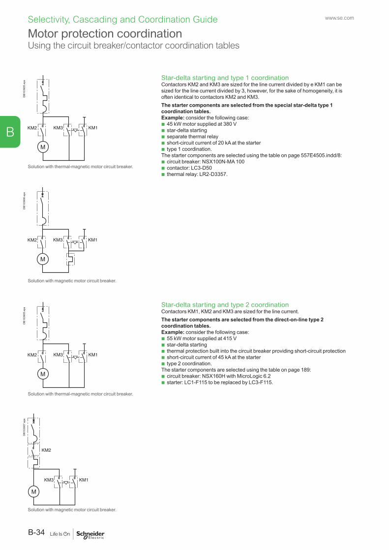
Star-delta starting and type 1 coordinationContactors KM2 and KM3 are sized for the line current divided by e KM1 can be sized for the line current divided by 3, however, for the sake of homogeneity, it is often identical to contactors KM2 and KM3. The starter components are selected from the special star-delta type 1 coordination tables.Example: consider the following case:
b 45 kW motor supplied at 380 V b star-delta starting b separate thermal relay b short-circuit current of 20 kA at the starter b type 1 coordination.
The starter components are selected using the table on page 557E4505.indd/8: b circuit breaker: NSX100N-MA 100 b contactor: LC3-D50 b thermal relay: LR2-D3357.
Star-delta starting and type 2 coordinationContactors KM1, KM2 and KM3 are sized for the line current.The starter components are selected from the direct-on-line type 2 coordination tables.Example: consider the following case:
b 55 kW motor supplied at 415 V b star-delta starting b thermal protection built into the circuit breaker providing short-circuit protection b short-circuit current of 45 kA at the starter b type 2 coordination.
The starter components are selected using the table on page 189: b circuit breaker: NSX160H with MicroLogic 6.2 b starter: LC1-F115 to be replaced by LC3-F115.
DB1
0390
5.ep
s
Solution with thermal-magnetic motor circuit breaker.
DB1
0390
6.ep
s
Solution with magnetic motor circuit breaker.
DB1
0390
5.ep
s
Solution with thermal-magnetic motor circuit breaker.
DB1
0390
7.ep
s
Solution with magnetic motor circuit breaker.
Motor protection coordinationUsing the circuit breaker/contactor coordination tables
www.se.com
B-34
B
Selectivity, Cascading and Coordination Guide
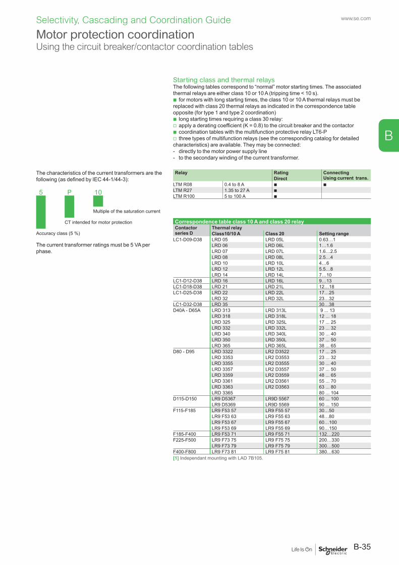
Relay Rating Connecting Using current trans. Direct
LTM R08 0.4 to 8 A b b LTM R27 1.35 to 27 A b LTM R100 5 to 100 A b
The characteristics of the current transformers are the following (as defined by IEC 44-1/44-3):
5 P 10
Multiple of the saturation current
CT intended for motor protection
Accuracy class (5 %)
The current transformer ratings must be 5 VA per phase.
Starting class and thermal relaysThe following tables correspond to “normal” motor starting times. The associated thermal relays are either class 10 or 10 A (tripping time < 10 s).
b for motors with long starting times, the class 10 or 10 A thermal relays must be replaced with class 20 thermal relays as indicated in the correspondence table opposite (for type 1 and type 2 coordination)
b long starting times requiring a class 30 relay: v apply a derating coefficient (K = 0.8) to the circuit breaker and the contactor b coordination tables with the multifunction protective relay LT6-P v three types of multifunction relays (see the corresponding catalog for detailed
characteristics) are available. They may be connected: - directly to the motor power supply line - to the secondary winding of the current transformer.
Correspondence table class 10 A and class 20 relay Contactor series D
Thermal relayClass10/10 A Class 20 Setting range
LC1-D09-D38 LRD 05 LRD 05L 0.63…1LRD 06 LRD 06L 1…1.6LRD 07 LRD 07L 1.6…2.5LRD 08 LRD 08L 2.5…4LRD 10 LRD 10L 4…6LRD 12 LRD 12L 5.5…8LRD 14 LRD 14L 7…10
LC1-D12-D38 LRD 16 LRD 16L 9…13LC1-D18-D38 LRD 21 LRD 21L 12…18LC1-D25-D38 LRD 22 LRD 22L 17…25
LRD 32 LRD 32L 23…32LC1-D32-D38 LRD 35 30…38D40A - D65A LRD 313 LRD 313L 9 ... 13
LRD 318 LRD 318L 12 ... 18LRD 325 LRD 325L 17 ... 25LRD 332 LRD 332L 23 ... 32LRD 340 LRD 340L 30 ... 40LRD 350 LRD 350L 37 ... 50LRD 365 LRD 365L 38 ... 65
D80 - D95 LRD 3322 LR2 D3522 17 ... 25LRD 3353 LR2 D3553 23 ... 32LRD 3355 LR2 D3555 30 ... 40LRD 3357 LR2 D3557 37 ... 50LRD 3359 LR2 D3559 48 ... 65LRD 3361 LR2 D3561 55 ... 70LRD 3363 LR2 D3563 63 ... 80LRD 3365 80 ... 104
D115-D150 LR9 D5367 LR9D 5567 60 ... 100LR9 D5369 LR9D 5569 90 ... 150
F115-F185 LR9 F53 57 LR9 F55 57 30…50LR9 F53 63 LR9 F55 63 48…80LR9 F53 67 LR9 F55 67 60…100LR9 F53 69 LR9 F55 69 90…150
F185-F400 LR9 F53 71 LR9 F55 71 132…220F225-F500 LR9 F73 75 LR9 F75 75 200…330
LR9 F73 79 LR9 F75 79 300…500F400-F800 LR9 F73 81 LR9 F75 81 380…630[1] Independant mounting with LAD 7B105.
Motor protection coordinationUsing the circuit breaker/contactor coordination tables
B-35
www.se.com
B
Selectivity, Cascading and Coordination Guide
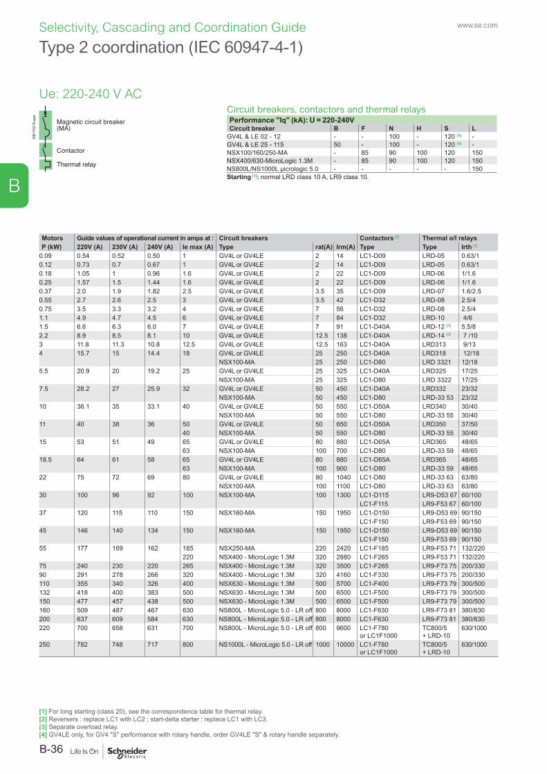
DB1
1521
9.ep
s
Type 2 coordination (IEC 60947-4-1)
Circuit breakers, contactors and thermal relaysPerformance "Iq" (kA): U = 220-240VCircuit breaker B F N H S L
GV4L & LE 02 - 12 - - 100 - 120 [4] -GV4L & LE 25 - 115 50 - 100 - 120 [4] -NSX100/160/250-MA - 85 90 100 120 150NSX400/630-MicroLogic 1.3M - 85 90 100 120 150NS800L/NS1000L µicrologic 5.0 - - - - - 150Starting [1]: normal LRD class 10 A, LR9 class 10.
Motors Guide values of operational current in amps at : Circuit breakers Contactors [2] Thermal o/l relaysP (kW) 220V (A) 230V (A) 240V (A) Ie max (A) Type rat(A) Irm(A) Type Type Irth [1]
0.09 0.54 0.52 0.50 1 GV4L or GV4LE 2 14 LC1-D09 LRD-05 0.63/10.12 0.73 0.7 0.67 1 GV4L or GV4LE 2 14 LC1-D09 LRD-05 0.63/10.18 1.05 1 0.96 1.6 GV4L or GV4LE 2 22 LC1-D09 LRD-06 1/1.60.25 1.57 1.5 1.44 1.6 GV4L or GV4LE 2 22 LC1-D09 LRD-06 1/1.60.37 2.0 1.9 1.82 2.5 GV4L or GV4LE 3.5 35 LC1-D09 LRD-07 1.6/2.50.55 2.7 2.6 2.5 3 GV4L or GV4LE 3.5 42 LC1-D32 LRD-08 2.5/40.75 3.5 3.3 3.2 4 GV4L or GV4LE 7 56 LC1-D32 LRD-08 2.5/41.1 4.9 4.7 4.5 6 GV4L or GV4LE 7 84 LC1-D32 LRD-10 4/61.5 6.6 6.3 6.0 7 GV4L or GV4LE 7 91 LC1-D40A LRD-12 [3] 5.5/82.2 8.9 8.5 8.1 10 GV4L or GV4LE 12.5 138 LC1-D40A LRD-14 [3] 7 /103 11.8 11.3 10.8 12.5 GV4L or GV4LE 12.5 163 LC1-D40A LRD313 9/134 15.7 15 14.4 18 GV4L or GV4LE 25 250 LC1-D40A LRD318 12/18
NSX100-MA 25 250 LC1-D80 LRD 3321 12/185.5 20.9 20 19.2 25 GV4L or GV4LE 25 325 LC1-D40A LRD325 17/25
NSX100-MA 25 325 LC1-D80 LRD 3322 17/257.5 28.2 27 25.9 32 GV4L or GV4LE 50 450 LC1-D40A LRD332 23/32
NSX100-MA 50 450 LC1-D80 LRD-33 53 23/3210 36.1 35 33.1 40 GV4L or GV4LE 50 550 LC1-D50A LRD340 30/40
NSX100-MA 50 550 LC1-D80 LRD-33 55 30/4011 40 38 36 50 GV4L or GV4LE 50 650 LC1-D50A LRD350 37/50
40 NSX100-MA 50 550 LC1-D80 LRD-33 55 30/4015 53 51 49 65 GV4L or GV4LE 80 880 LC1-D65A LRD365 48/65
63 NSX100-MA 100 700 LC1-D80 LRD-33 59 48/6518.5 64 61 58 65 GV4L or GV4LE 80 880 LC1-D65A LRD365 48/65
63 NSX100-MA 100 900 LC1-D80 LRD-33 59 48/6522 75 72 69 80 GV4L or GV4LE 80 1040 LC1-D80 LRD-33 63 63/80
NSX100-MA 100 1100 LC1-D80 LRD-33 63 63/8030 100 96 92 100 NSX100-MA 100 1300 LC1-D115 LR9-D53 67 60/100
LC1-F115 LR9-F53 67 60/10037 120 115 110 150 NSX160-MA 150 1950 LC1-D150 LR9-D53 69 90/150
LC1-F150 LR9-F53 69 90/15045 146 140 134 150 NSX160-MA 150 1950 LC1-D150 LR9-D53 69 90/150
LC1-F150 LR9-F53 69 90/15055 177 169 162 185 NSX250-MA 220 2420 LC1-F185 LR9-F53 71 132/220
220 NSX400 - MicroLogic 1.3M 320 2880 LC1-F265 LR9-F53 71 132/22075 240 230 220 265 NSX400 - MicroLogic 1.3M 320 3500 LC1-F265 LR9-F73 75 200/33090 291 278 266 320 NSX400 - MicroLogic 1.3M 320 4160 LC1-F330 LR9-F73 75 200/330110 355 340 326 400 NSX630 - MicroLogic 1.3M 500 5700 LC1-F400 LR9-F73 79 300/500132 418 400 383 500 NSX630 - MicroLogic 1.3M 500 6500 LC1-F500 LR9-F73 79 300/500150 477 457 438 500 NSX630 - MicroLogic 1.3M 500 6500 LC1-F500 LR9-F73 79 300/500160 509 487 467 630 NS800L - MicroLogic 5.0 - LR off 800 8000 LC1-F630 LR9-F73 81 380/630200 637 609 584 630 NS800L - MicroLogic 5.0 - LR off 800 8000 LC1-F630 LR9-F73 81 380/630220 700 658 631 700 NS800L - MicroLogic 5.0 - LR off 800 9600 LC1-F780
or LC1F1000TC800/5 + LRD-10
630/1000
250 782 748 717 800 NS1000L - MicroLogic 5.0 - LR off 1000 10000 LC1-F780 or LC1F1000
TC800/5 + LRD-10
630/1000
[1] For long starting (class 20), see the correspondence table for thermal relay.[2] Reversers : replace LC1 with LC2 ; start-delta starter : replace LC1 with LC3.[3] Separate overload relay.[4] GV4LE only, for GV4 "S" performance with rotary handle, order GV4LE "S" & rotary handle separately.
www.se.com
B-36
B
Selectivity, Cascading and Coordination Guide
Ue: 220-240 V AC
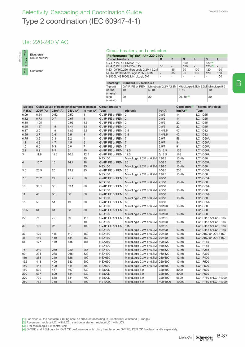
Circuit breakers, and contactorsPerformance "Iq" (kA): U = 220-240VCircuit breakers B F N H S L
GV4 P, PE & PEM 02 - 12 - - 100 - 120 [4] -GV4 P, PE & PEM 25 - 115 50 - 100 - 120 [4] -NSX100/160/250 MicroLogic 2.2M / 6.2M - 85 90 100 120 150NSX400/630 MicroLogic 2.3M / 6.3M - 85 90 100 120 150NS800L/NS1000L MicroLogic 5.0 - - - - - 150
Starting [1] Standard IEC 60947-4-1Trip unit GV4P, PE or PEM MicroLogic 2.2M / 2.3M MicroLogic 6.2M / 6.3M Mircologic 5.0normal (classe)
10 5. 10 5. 10 10
long (classe)
20 20 20. 30 [1] 20
Type 2 coordination (IEC 60947-4-1)
Motors Guide values of operational current in amps at : Circuit breakers Contactors [2] Thermal o/l relaysP (kW) 220V (A) 230V (A) 240V (A) Ie max (A) Type trip unit Irth(A) Irm(A) [3] Type
0.09 0.54 0.52 0.50 1 GV4P, PE or PEM 2 0.8/2 14 LC1-D250.12 0.73 0.7 0.67 1 GV4P, PE or PEM 2 0.8/2 14 LC1-D250.18 1.05 1 0.96 1.6 GV4P, PE or PEM 2 0.8/2 22 LC1-D250.25 1.57 1.5 1.44 1.6 GV4P, PE or PEM 2 0.8/2 22 LC1-D250.37 2.0 1.9 1.82 2.5 GV4P, PE or PEM 3.5 1.4/3.5 42 LC1-D320.55 2.7 2.6 2.5 3 GV4P, PE or PEM 3.5 1.4/3.5 42 LC1-D320.75 3.5 3.3 3.2 4 GV4P, PE or PEM 7 2.9/7 56 LC1-D50A1.1 4.9 4.7 4.5 6 GV4P, PE or PEM 7 2.9/7 84 LC1-D50A1.5 6.6 6.3 6.0 7 GV4P, PE or PEM 7 2.9/7 91 LC1-D50A2.2 8.9 8.5 8.1 10 GV4P, PE or PEM 12.5 5/12.5 138 LC1-D50A3 11.8 11.3 10.8 12.5 GV4P, PE or PEM 12.5 5/12.5 163 LC1-D50A
25 NSX100 MicroLogic 2.2M or 6.2M 12/25 13Irth LC1-D804 15.7 15 14.4 18 GV4P, PE or PEM 25 10/25 250 LC1-D65A
25 NSX100 MicroLogic 2.2M or 6.2M 12/25 13Irth LC1-D805.5 20.9 20 19.2 25 GV4P, PE or PEM 25 10/25 250 LC1-D65A
NSX100 MicroLogic 2.2M or 6.2M 12/25 13Irth LC1-D807.5 28.2 27 25.9 50 GV4P, PE or PEM 50 20/50 LC1-D65A
NSX100 MicroLogic 2.2M or 6.2M 25/50 13Irth LC1-D8010 36.1 35 33.1 50 GV4P, PE or PEM 50 20/50 LC1-D65A
NSX100 MicroLogic 2.2M or 6.2M 25/50 13Irth LC1-D8011 40 38 36 50 GV4P, PE or PEM 50 20/50 LC1-D65A
NSX100 MicroLogic 2.2M or 6.2M 25/50 13Irth LC1-D8015 53 51 49 80 GV4P, PE or PEM 80 40/80 LC1-D65A
NSX100 MicroLogic 2.2M or 6.2M 50/100 13Irth LC1-D8018.5 64 61 58 80 GV4P, PE or PEM 80 40/80 LC1-D80
NSX100 MicroLogic 2.2M or 6.2M 50/100 13Irth LC1-D8022 75 72 69 115 GV4P, PE or PEM 115 65/115 LC1-D115 or LC1-F115
100 NSX100 MicroLogic 2.2M or 6.2M 50/100 13Irth LC1-D115 or LC1-F11530 100 96 92 100 GV4P, PE or PEM 115 65/115 LC1-D115 or LC1-F115
NSX100 MicroLogic 2.2M or 6.2M 50/100 13Irth LC1-D115 or LC1-F11537 120 115 110 150 NSX160 MicroLogic 2.2M or 6.2M 70/150 13Irth LC1D150 or LC1-F15045 146 140 134 150 NSX160 MicroLogic 2.2M or 6.2M 70/150 13Irth LC1D150 or LC1-F15055 177 169 185 185 NSX250 MicroLogic 2.2M or 6.2M 100/220 13Irth LC1-F185
NSX400 MicroLogic 2.3M or 6.3M 160/320 13Irth LC1-F18575 240 230 220 265 NSX400 MicroLogic 2.3M or 6.3M 160/320 13Irth LC1-F26590 291 278 266 320 NSX400 MicroLogic 2.3M or 6.3M 160/320 13Irth LC1-F330110 355 340 326 400 NSX630 MicroLogic 2.3M or 6.3M 250/500 13Irth LC1-F400132 418 400 383 500 NSX630 MicroLogic 2.3M or 6.3M 250/500 13Irth LC1-F500150 448 429 411 500 NSX630 MicroLogic 2.3M or 6.3M 250/500 13Irth LC1-F500160 509 487 467 630 NS800L MicroLogic 5.0 320/800 8000 LC1-F630200 637 609 584 630 NS800L MicroLogic 5.0 320/800 8000 LC1-F630220 700 658 631 700 NS800L MicroLogic 5.0 320/800 9600 LC1-F780 or LC1F1000250 782 748 717 800 NS1000L MicroLogic 5.0 400/1000 10000 LC1-F780 or LC1F1000
DB1
1521
8.ep
s
[1] For class 30 the contacteur rating shall be checked according to 30s thermal withstand (F range).[2] Reversers : replace LC1 with LC2 ; start-delta starter : replace LC1 with LC3.[3] Ii for MicroLogic 5.0 control unit.[4] GV4PE and PEM only, for GV4 "S" performance with rotary handle, order GV4PE, PEM "S" & rotary handle separately.
B-37
www.se.com
B
Selectivity, Cascading and Coordination Guide
Ue: 220-240 V AC
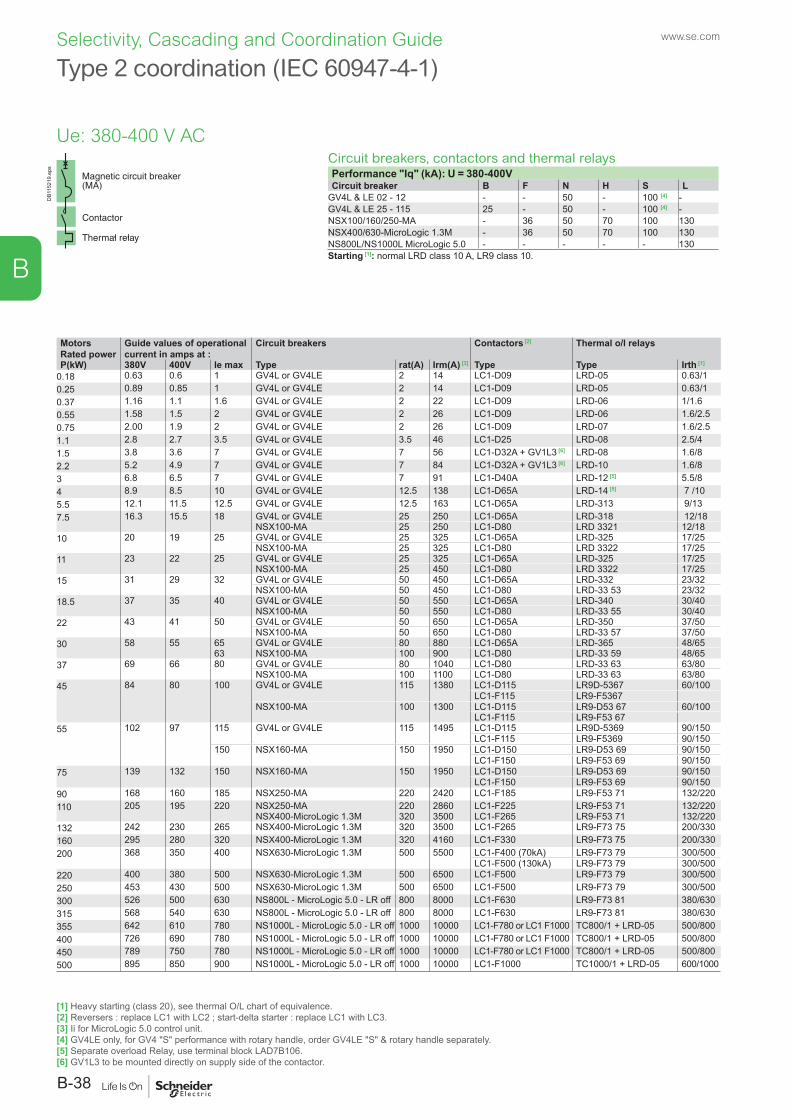
DB1
1521
9.ep
s
Type 2 coordination (IEC 60947-4-1)
Circuit breakers, contactors and thermal relaysPerformance "Iq" (kA): U = 380-400VCircuit breaker B F N H S L
GV4L & LE 02 - 12 - - 50 - 100 [4] -GV4L & LE 25 - 115 25 - 50 - 100 [4] -NSX100/160/250-MA - 36 50 70 100 130NSX400/630-MicroLogic 1.3M - 36 50 70 100 130NS800L/NS1000L MicroLogic 5.0 - - - - - 130Starting [1]: normal LRD class 10 A, LR9 class 10.
MotorsRated power
Guide values of operational current in amps at :
Circuit breakers Contactors [2] Thermal o/l relays
P(kW) 380V 400V Ie max Type rat(A) Irm(A) [3] Type Type Irth [1]
0.18 0.63 0.6 1 GV4L or GV4LE 2 14 LC1-D09 LRD-05 0.63/10.25 0.89 0.85 1 GV4L or GV4LE 2 14 LC1-D09 LRD-05 0.63/10.37 1.16 1.1 1.6 GV4L or GV4LE 2 22 LC1-D09 LRD-06 1/1.60.55 1.58 1.5 2 GV4L or GV4LE 2 26 LC1-D09 LRD-06 1.6/2.50.75 2.00 1.9 2 GV4L or GV4LE 2 26 LC1-D09 LRD-07 1.6/2.51.1 2.8 2.7 3.5 GV4L or GV4LE 3.5 46 LC1-D25 LRD-08 2.5/41.5 3.8 3.6 7 GV4L or GV4LE 7 56 LC1-D32A + GV1L3 [6] LRD-08 1.6/82.2 5.2 4.9 7 GV4L or GV4LE 7 84 LC1-D32A + GV1L3 [6] LRD-10 1.6/83 6.8 6.5 7 GV4L or GV4LE 7 91 LC1-D40A LRD-12 [5] 5.5/84 8.9 8.5 10 GV4L or GV4LE 12.5 138 LC1-D65A LRD-14 [5] 7 /105.5 12.1 11.5 12.5 GV4L or GV4LE 12.5 163 LC1-D65A LRD-313 9/137.5 16.3 15.5 18 GV4L or GV4LE 25 250 LC1-D65A LRD-318 12/18
NSX100-MA 25 250 LC1-D80 LRD 3321 12/1810 20 19 25 GV4L or GV4LE 25 325 LC1-D65A LRD-325 17/25
NSX100-MA 25 325 LC1-D80 LRD 3322 17/2511 23 22 25 GV4L or GV4LE 25 325 LC1-D65A LRD-325 17/25
NSX100-MA 25 450 LC1-D80 LRD 3322 17/2515 31 29 32 GV4L or GV4LE 50 450 LC1-D65A LRD-332 23/32
NSX100-MA 50 450 LC1-D80 LRD-33 53 23/3218.5 37 35 40 GV4L or GV4LE 50 550 LC1-D65A LRD-340 30/40
NSX100-MA 50 550 LC1-D80 LRD-33 55 30/4022 43 41 50 GV4L or GV4LE 50 650 LC1-D65A LRD-350 37/50
NSX100-MA 50 650 LC1-D80 LRD-33 57 37/5030 58 55 65 GV4L or GV4LE 80 880 LC1-D65A LRD-365 48/65
63 NSX100-MA 100 900 LC1-D80 LRD-33 59 48/6537 69 66 80 GV4L or GV4LE 80 1040 LC1-D80 LRD-33 63 63/80
NSX100-MA 100 1100 LC1-D80 LRD-33 63 63/8045 84 80 100 GV4L or GV4LE 115 1380 LC1-D115 LR9D-5367 60/100
LC1-F115 LR9-F5367NSX100-MA 100 1300 LC1-D115 LR9-D53 67 60/100
LC1-F115 LR9-F53 6755 102 97 115 GV4L or GV4LE 115 1495 LC1-D115 LR9D-5369 90/150
LC1-F115 LR9-F5369 90/150150 NSX160-MA 150 1950 LC1-D150 LR9-D53 69 90/150
LC1-F150 LR9-F53 69 90/15075 139 132 150 NSX160-MA 150 1950 LC1-D150 LR9-D53 69 90/150
LC1-F150 LR9-F53 69 90/15090 168 160 185 NSX250-MA 220 2420 LC1-F185 LR9-F53 71 132/220110 205 195 220 NSX250-MA 220 2860 LC1-F225 LR9-F53 71 132/220
NSX400-MicroLogic 1.3M 320 3500 LC1-F265 LR9-F53 71 132/220132 242 230 265 NSX400-MicroLogic 1.3M 320 3500 LC1-F265 LR9-F73 75 200/330160 295 280 320 NSX400-MicroLogic 1.3M 320 4160 LC1-F330 LR9-F73 75 200/330200 368 350 400 NSX630-MicroLogic 1.3M 500 5500 LC1-F400 (70kA) LR9-F73 79 300/500
LC1-F500 (130kA) LR9-F73 79 300/500220 400 380 500 NSX630-MicroLogic 1.3M 500 6500 LC1-F500 LR9-F73 79 300/500250 453 430 500 NSX630-MicroLogic 1.3M 500 6500 LC1-F500 LR9-F73 79 300/500300 526 500 630 NS800L - MicroLogic 5.0 - LR off 800 8000 LC1-F630 LR9-F73 81 380/630315 568 540 630 NS800L - MicroLogic 5.0 - LR off 800 8000 LC1-F630 LR9-F73 81 380/630355 642 610 780 NS1000L - MicroLogic 5.0 - LR off 1000 10000 LC1-F780 or LC1 F1000 TC800/1 + LRD-05 500/800400 726 690 780 NS1000L - MicroLogic 5.0 - LR off 1000 10000 LC1-F780 or LC1 F1000 TC800/1 + LRD-05 500/800450 789 750 780 NS1000L - MicroLogic 5.0 - LR off 1000 10000 LC1-F780 or LC1 F1000 TC800/1 + LRD-05 500/800500 895 850 900 NS1000L - MicroLogic 5.0 - LR off 1000 10000 LC1-F1000 TC1000/1 + LRD-05 600/1000
[1] Heavy starting (class 20), see thermal O/L chart of equivalence.[2] Reversers : replace LC1 with LC2 ; start-delta starter : replace LC1 with LC3.[3] Ii for MicroLogic 5.0 control unit.[4] GV4LE only, for GV4 "S" performance with rotary handle, order GV4LE "S" & rotary handle separately.[5] Separate overload Relay, use terminal block LAD7B106.[6] GV1L3 to be mounted directly on supply side of the contactor.
www.se.com
B-38
B
Selectivity, Cascading and Coordination Guide
Ue: 380-400 V AC
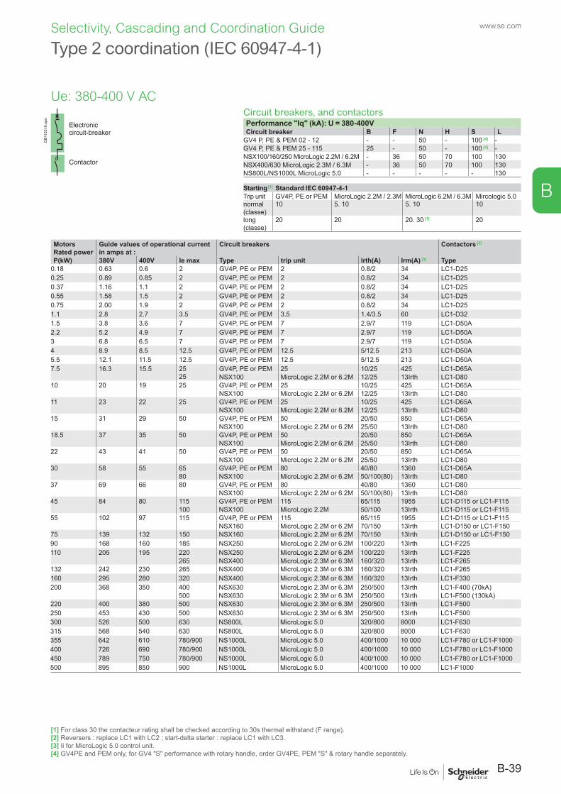
Type 2 coordination (IEC 60947-4-1)
Circuit breakers, and contactorsPerformance "Iq" (kA): U = 380-400VCircuit breaker B F N H S L
GV4 P, PE & PEM 02 - 12 - - 50 - 100 [4] -GV4 P, PE & PEM 25 - 115 25 - 50 - 100 [4] -NSX100/160/250 MicroLogic 2.2M / 6.2M - 36 50 70 100 130NSX400/630 MicroLogic 2.3M / 6.3M - 36 50 70 100 130NS800L/NS1000L MicroLogic 5.0 - - - - - 130
Starting [1] Standard IEC 60947-4-1Trip unit GV4P, PE or PEM MicroLogic 2.2M / 2.3M MicroLogic 6.2M / 6.3M Mircologic 5.0normal (classe)
10 5. 10 5. 10 10
long (classe)
20 20 20. 30 [1] 20
MotorsRated power
Guide values of operational current in amps at :
Circuit breakers Contactors [2]
P(kW) 380V 400V Ie max Type trip unit Irth(A) Irm(A) [3] Type0.18 0.63 0.6 2 GV4P, PE or PEM 2 0.8/2 34 LC1-D250.25 0.89 0.85 2 GV4P, PE or PEM 2 0.8/2 34 LC1-D250.37 1.16 1.1 2 GV4P, PE or PEM 2 0.8/2 34 LC1-D250.55 1.58 1.5 2 GV4P, PE or PEM 2 0.8/2 34 LC1-D250.75 2.00 1.9 2 GV4P, PE or PEM 2 0.8/2 34 LC1-D251.1 2.8 2.7 3.5 GV4P, PE or PEM 3.5 1.4/3.5 60 LC1-D321.5 3.8 3.6 7 GV4P, PE or PEM 7 2.9/7 119 LC1-D50A2.2 5.2 4.9 7 GV4P, PE or PEM 7 2.9/7 119 LC1-D50A3 6.8 6.5 7 GV4P, PE or PEM 7 2.9/7 119 LC1-D50A4 8.9 8.5 12.5 GV4P, PE or PEM 12.5 5/12.5 213 LC1-D50A5.5 12.1 11.5 12.5 GV4P, PE or PEM 12.5 5/12.5 213 LC1-D50A7.5 16.3 15.5 25
25GV4P, PE or PEM 25 10/25 425 LC1-D65ANSX100 MicroLogic 2.2M or 6.2M 12/25 13Irth LC1-D80
10 20 19 25 GV4P, PE or PEM 25 10/25 425 LC1-D65ANSX100 MicroLogic 2.2M or 6.2M 12/25 13Irth LC1-D80
11 23 22 25 GV4P, PE or PEM 25 10/25 425 LC1-D65ANSX100 MicroLogic 2.2M or 6.2M 12/25 13Irth LC1-D80
15 31 29 50 GV4P, PE or PEM 50 20/50 850 LC1-D65ANSX100 MicroLogic 2.2M or 6.2M 25/50 13Irth LC1-D80
18.5 37 35 50 GV4P, PE or PEM 50 20/50 850 LC1-D65ANSX100 MicroLogic 2.2M or 6.2M 25/50 13Irth LC1-D80
22 43 41 50 GV4P, PE or PEM 50 20/50 850 LC1-D65ANSX100 MicroLogic 2.2M or 6.2M 25/50 13Irth LC1-D80
30 58 55 65 GV4P, PE or PEM 80 40/80 1360 LC1-D65A80 NSX100 MicroLogic 2.2M or 6.2M 50/100(80) 13Irth LC1-D80
37 69 66 80 GV4P, PE or PEM 80 40/80 1360 LC1-D80NSX100 MicroLogic 2.2M or 6.2M 50/100(80) 13Irth LC1-D80
45 84 80 115 GV4P, PE or PEM 115 65/115 1955 LC1-D115 or LC1-F115100 NSX100 MicroLogic 2.2M 50/100 13Irth LC1-D115 or LC1-F115
55 102 97 115 GV4P, PE or PEM 115 65/115 1955 LC1-D115 or LC1-F115NSX160 MicroLogic 2.2M or 6.2M 70/150 13Irth LC1-D150 or LC1-F150
75 139 132 150 NSX160 MicroLogic 2.2M or 6.2M 70/150 13Irth LC1-D150 or LC1-F15090 168 160 185 NSX250 MicroLogic 2.2M or 6.2M 100/220 13Irth LC1-F225110 205 195 220 NSX250 MicroLogic 2.2M or 6.2M 100/220 13Irth LC1-F225
265 NSX400 MicroLogic 2.3M or 6.3M 160/320 13Irth LC1-F265132 242 230 265 NSX400 MicroLogic 2.3M or 6.3M 160/320 13Irth LC1-F265160 295 280 320 NSX400 MicroLogic 2.3M or 6.3M 160/320 13Irth LC1-F330200 368 350 400 NSX630 MicroLogic 2.3M or 6.3M 250/500 13Irth LC1-F400 (70kA)
500 NSX630 MicroLogic 2.3M or 6.3M 250/500 13Irth LC1-F500 (130kA)220 400 380 500 NSX630 MicroLogic 2.3M or 6.3M 250/500 13Irth LC1-F500250 453 430 500 NSX630 MicroLogic 2.3M or 6.3M 250/500 13Irth LC1-F500300 526 500 630 NS800L MicroLogic 5.0 320/800 8000 LC1-F630315 568 540 630 NS800L MicroLogic 5.0 320/800 8000 LC1-F630355 642 610 780/900 NS1000L MicroLogic 5.0 400/1000 10 000 LC1-F780 or LC1-F1000400 726 690 780/900 NS1000L MicroLogic 5.0 400/1000 10 000 LC1-F780 or LC1-F1000450 789 750 780/900 NS1000L MicroLogic 5.0 400/1000 10 000 LC1-F780 or LC1-F1000500 895 850 900 NS1000L MicroLogic 5.0 400/1000 10 000 LC1-F1000
DB1
1521
8.ep
s
[1] For class 30 the contacteur rating shall be checked according to 30s thermal withstand (F range).[2] Reversers : replace LC1 with LC2 ; start-delta starter : replace LC1 with LC3.[3] Ii for MicroLogic 5.0 control unit.[4] GV4PE and PEM only, for GV4 "S" performance with rotary handle, order GV4PE, PEM "S" & rotary handle separately.
B-39
www.se.com
B
Selectivity, Cascading and Coordination Guide
Ue: 380-400 V AC
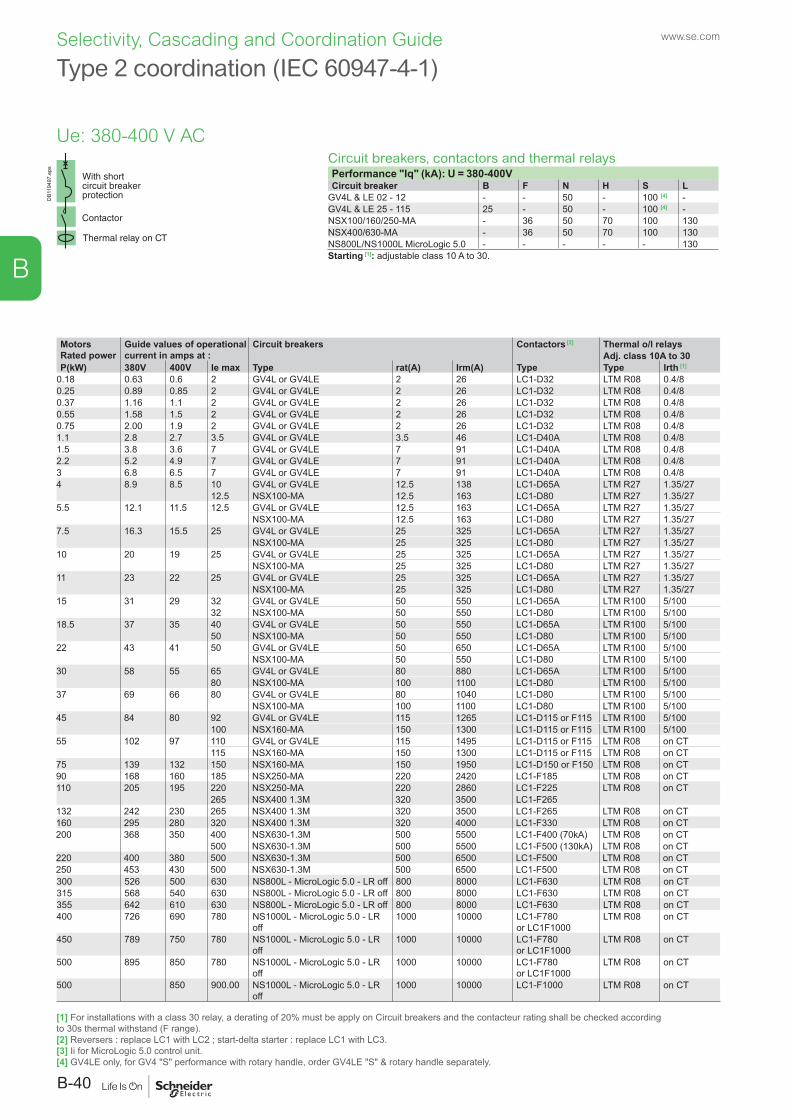
DB1
1949
7.ep
s
Type 2 coordination (IEC 60947-4-1)
Circuit breakers, contactors and thermal relaysPerformance "Iq" (kA): U = 380-400VCircuit breaker B F N H S L
GV4L & LE 02 - 12 - - 50 - 100 [4] -GV4L & LE 25 - 115 25 - 50 - 100 [4] -NSX100/160/250-MA - 36 50 70 100 130NSX400/630-MA - 36 50 70 100 130NS800L/NS1000L MicroLogic 5.0 - - - - - 130Starting [1]: adjustable class 10 A to 30.
MotorsRated power
Guide values of operational current in amps at :
Circuit breakers Contactors [2] Thermal o/l relaysAdj. class 10A to 30
P(kW) 380V 400V Ie max Type rat(A) Irm(A) Type Type Irth [1]
0.18 0.63 0.6 2 GV4L or GV4LE 2 26 LC1-D32 LTM R08 0.4/80.25 0.89 0.85 2 GV4L or GV4LE 2 26 LC1-D32 LTM R08 0.4/80.37 1.16 1.1 2 GV4L or GV4LE 2 26 LC1-D32 LTM R08 0.4/80.55 1.58 1.5 2 GV4L or GV4LE 2 26 LC1-D32 LTM R08 0.4/80.75 2.00 1.9 2 GV4L or GV4LE 2 26 LC1-D32 LTM R08 0.4/81.1 2.8 2.7 3.5 GV4L or GV4LE 3.5 46 LC1-D40A LTM R08 0.4/81.5 3.8 3.6 7 GV4L or GV4LE 7 91 LC1-D40A LTM R08 0.4/82.2 5.2 4.9 7 GV4L or GV4LE 7 91 LC1-D40A LTM R08 0.4/83 6.8 6.5 7 GV4L or GV4LE 7 91 LC1-D40A LTM R08 0.4/84 8.9 8.5 10 GV4L or GV4LE 12.5 138 LC1-D65A LTM R27 1.35/27
12.5 NSX100-MA 12.5 163 LC1-D80 LTM R27 1.35/275.5 12.1 11.5 12.5 GV4L or GV4LE 12.5 163 LC1-D65A LTM R27 1.35/27
NSX100-MA 12.5 163 LC1-D80 LTM R27 1.35/277.5 16.3 15.5 25 GV4L or GV4LE 25 325 LC1-D65A LTM R27 1.35/27
NSX100-MA 25 325 LC1-D80 LTM R27 1.35/2710 20 19 25 GV4L or GV4LE 25 325 LC1-D65A LTM R27 1.35/27
NSX100-MA 25 325 LC1-D80 LTM R27 1.35/2711 23 22 25 GV4L or GV4LE 25 325 LC1-D65A LTM R27 1.35/27
NSX100-MA 25 325 LC1-D80 LTM R27 1.35/2715 31 29 32 GV4L or GV4LE 50 550 LC1-D65A LTM R100 5/100
32 NSX100-MA 50 550 LC1-D80 LTM R100 5/10018.5 37 35 40 GV4L or GV4LE 50 550 LC1-D65A LTM R100 5/100
50 NSX100-MA 50 550 LC1-D80 LTM R100 5/10022 43 41 50 GV4L or GV4LE 50 650 LC1-D65A LTM R100 5/100
NSX100-MA 50 550 LC1-D80 LTM R100 5/10030 58 55 65 GV4L or GV4LE 80 880 LC1-D65A LTM R100 5/100
80 NSX100-MA 100 1100 LC1-D80 LTM R100 5/10037 69 66 80 GV4L or GV4LE 80 1040 LC1-D80 LTM R100 5/100
NSX100-MA 100 1100 LC1-D80 LTM R100 5/10045 84 80 92 GV4L or GV4LE 115 1265 LC1-D115 or F115 LTM R100 5/100
100 NSX160-MA 150 1300 LC1-D115 or F115 LTM R100 5/10055 102 97 110 GV4L or GV4LE 115 1495 LC1-D115 or F115 LTM R08 on CT
115 NSX160-MA 150 1300 LC1-D115 or F115 LTM R08 on CT75 139 132 150 NSX160-MA 150 1950 LC1-D150 or F150 LTM R08 on CT90 168 160 185 NSX250-MA 220 2420 LC1-F185 LTM R08 on CT110 205 195 220 NSX250-MA 220 2860 LC1-F225 LTM R08 on CT
265 NSX400 1.3M 320 3500 LC1-F265132 242 230 265 NSX400 1.3M 320 3500 LC1-F265 LTM R08 on CT160 295 280 320 NSX400 1.3M 320 4000 LC1-F330 LTM R08 on CT200 368 350 400 NSX630-1.3M 500 5500 LC1-F400 (70kA) LTM R08 on CT
500 NSX630-1.3M 500 5500 LC1-F500 (130kA) LTM R08 on CT220 400 380 500 NSX630-1.3M 500 6500 LC1-F500 LTM R08 on CT250 453 430 500 NSX630-1.3M 500 6500 LC1-F500 LTM R08 on CT300 526 500 630 NS800L - MicroLogic 5.0 - LR off 800 8000 LC1-F630 LTM R08 on CT315 568 540 630 NS800L - MicroLogic 5.0 - LR off 800 8000 LC1-F630 LTM R08 on CT355 642 610 630 NS800L - MicroLogic 5.0 - LR off 800 8000 LC1-F630 LTM R08 on CT400 726 690 780 NS1000L - MicroLogic 5.0 - LR
off1000 10000 LC1-F780
or LC1F1000LTM R08 on CT
450 789 750 780 NS1000L - MicroLogic 5.0 - LR off
1000 10000 LC1-F780 or LC1F1000
LTM R08 on CT
500 895 850 780 NS1000L - MicroLogic 5.0 - LR off
1000 10000 LC1-F780 or LC1F1000
LTM R08 on CT
500 850 900.00 NS1000L - MicroLogic 5.0 - LR off
1000 10000 LC1-F1000 LTM R08 on CT
[1] For installations with a class 30 relay, a derating of 20% must be apply on Circuit breakers and the contacteur rating shall be checked according to 30s thermal withstand (F range).[2] Reversers : replace LC1 with LC2 ; start-delta starter : replace LC1 with LC3.[3] Ii for MicroLogic 5.0 control unit.[4] GV4LE only, for GV4 "S" performance with rotary handle, order GV4LE "S" & rotary handle separately.
www.se.com
B-40
B
Selectivity, Cascading and Coordination Guide
Ue: 380-400 V AC
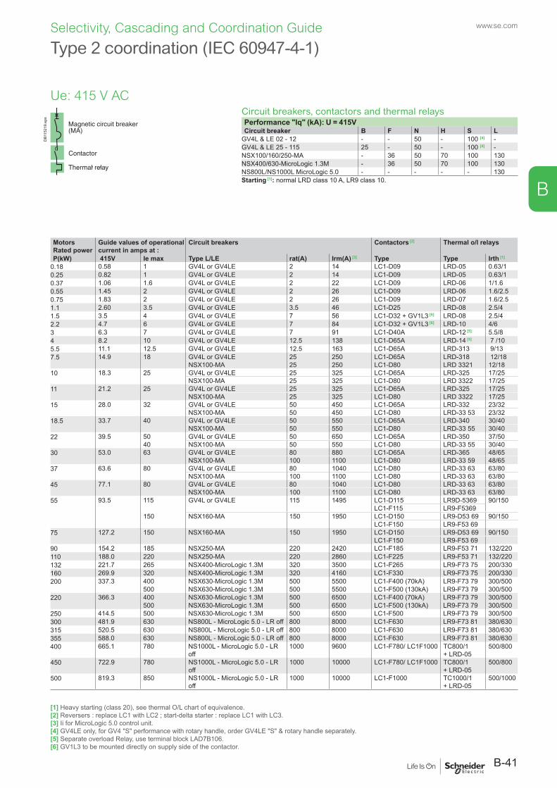
DB1
1521
9.ep
s
Type 2 coordination (IEC 60947-4-1)
Circuit breakers, contactors and thermal relaysPerformance "Iq" (kA): U = 415VCircuit breaker B F N H S L
GV4L & LE 02 - 12 - - 50 - 100 [4] -GV4L & LE 25 - 115 25 - 50 - 100 [4] -NSX100/160/250-MA - 36 50 70 100 130NSX400/630-MicroLogic 1.3M - 36 50 70 100 130NS800L/NS1000L MicroLogic 5.0 - - - - - 130Starting [1]: normal LRD class 10 A, LR9 class 10.
MotorsRated power
Guide values of operational current in amps at :
Circuit breakers Contactors [2] Thermal o/l relays
P(kW) 415V Ie max Type L/LE rat(A) Irm(A) [3] Type Type Irth [1]
0.18 0.58 1 GV4L or GV4LE 2 14 LC1-D09 LRD-05 0.63/10.25 0.82 1 GV4L or GV4LE 2 14 LC1-D09 LRD-05 0.63/10.37 1.06 1.6 GV4L or GV4LE 2 22 LC1-D09 LRD-06 1/1.60.55 1.45 2 GV4L or GV4LE 2 26 LC1-D09 LRD-06 1.6/2.50.75 1.83 2 GV4L or GV4LE 2 26 LC1-D09 LRD-07 1.6/2.51.1 2.60 3.5 GV4L or GV4LE 3.5 46 LC1-D25 LRD-08 2.5/41.5 3.5 4 GV4L or GV4LE 7 56 LC1-D32 + GV1L3 [6] LRD-08 2.5/42.2 4.7 6 GV4L or GV4LE 7 84 LC1-D32 + GV1L3 [6] LRD-10 4/63 6.3 7 GV4L or GV4LE 7 91 LC1-D40A LRD-12 [5] 5.5/84 8.2 10 GV4L or GV4LE 12.5 138 LC1-D65A LRD-14 [5] 7 /105.5 11.1 12.5 GV4L or GV4LE 12.5 163 LC1-D65A LRD-313 9/137.5 14.9 18 GV4L or GV4LE 25 250 LC1-D65A LRD-318 12/18
NSX100-MA 25 250 LC1-D80 LRD 3321 12/1810 18.3 25 GV4L or GV4LE 25 325 LC1-D65A LRD-325 17/25
NSX100-MA 25 325 LC1-D80 LRD 3322 17/2511 21.2 25 GV4L or GV4LE 25 325 LC1-D65A LRD-325 17/25
NSX100-MA 25 325 LC1-D80 LRD 3322 17/2515 28.0 32 GV4L or GV4LE 50 450 LC1-D65A LRD-332 23/32
NSX100-MA 50 450 LC1-D80 LRD-33 53 23/3218.5 33.7 40 GV4L or GV4LE 50 550 LC1-D65A LRD-340 30/40
NSX100-MA 50 550 LC1-D80 LRD-33 55 30/4022 39.5 50 GV4L or GV4LE 50 650 LC1-D65A LRD-350 37/50
40 NSX100-MA 50 550 LC1-D80 LRD-33 55 30/4030 53.0 63 GV4L or GV4LE 80 880 LC1-D65A LRD-365 48/65
NSX100-MA 100 1100 LC1-D80 LRD-33 59 48/6537 63.6 80 GV4L or GV4LE 80 1040 LC1-D80 LRD-33 63 63/80
NSX100-MA 100 1100 LC1-D80 LRD-33 63 63/8045 77.1 80 GV4L or GV4LE 80 1040 LC1-D80 LRD-33 63 63/80
NSX100-MA 100 1100 LC1-D80 LRD-33 63 63/8055 93.5 115 GV4L or GV4LE 115 1495 LC1-D115 LR9D-5369 90/150
LC1-F115 LR9-F5369150 NSX160-MA 150 1950 LC1-D150 LR9-D53 69 90/150
LC1-F150 LR9-F53 6975 127.2 150 NSX160-MA 150 1950 LC1-D150 LR9-D53 69 90/150
LC1-F150 LR9-F53 6990 154.2 185 NSX250-MA 220 2420 LC1-F185 LR9-F53 71 132/220110 188.0 220 NSX250-MA 220 2860 LC1-F225 LR9-F53 71 132/220132 221.7 265 NSX400-MicroLogic 1.3M 320 3500 LC1-F265 LR9-F73 75 200/330160 269.9 320 NSX400-MicroLogic 1.3M 320 4160 LC1-F330 LR9-F73 75 200/330200 337.3 400 NSX630-MicroLogic 1.3M 500 5500 LC1-F400 (70kA) LR9-F73 79 300/500
500 NSX630-MicroLogic 1.3M 500 5500 LC1-F500 (130kA) LR9-F73 79 300/500220 366.3 400 NSX630-MicroLogic 1.3M 500 6500 LC1-F400 (70kA) LR9-F73 79 300/500
500 NSX630-MicroLogic 1.3M 500 6500 LC1-F500 (130kA) LR9-F73 79 300/500250 414.5 500 NSX630-MicroLogic 1.3M 500 6500 LC1-F500 LR9-F73 79 300/500300 481.9 630 NS800L - MicroLogic 5.0 - LR off 800 8000 LC1-F630 LR9-F73 81 380/630315 520.5 630 NS800L - MicroLogic 5.0 - LR off 800 8000 LC1-F630 LR9-F73 81 380/630355 588.0 630 NS800L - MicroLogic 5.0 - LR off 800 8000 LC1-F630 LR9-F73 81 380/630400 665.1 780 NS1000L - MicroLogic 5.0 - LR
off1000 9600 LC1-F780/ LC1F1000 TC800/1
+ LRD-05500/800
450 722.9 780 NS1000L - MicroLogic 5.0 - LR off
1000 10000 LC1-F780/ LC1F1000 TC800/1 + LRD-05
500/800
500 819.3 850 NS1000L - MicroLogic 5.0 - LR off
1000 10000 LC1-F1000 TC1000/1 + LRD-05
500/1000
[1] Heavy starting (class 20), see thermal O/L chart of equivalence.[2] Reversers : replace LC1 with LC2 ; start-delta starter : replace LC1 with LC3.[3] Ii for MicroLogic 5.0 control unit.[4] GV4LE only, for GV4 "S" performance with rotary handle, order GV4LE "S" & rotary handle separately.[5] Separate overload Relay, use terminal block LAD7B106.[6] GV1L3 to be mounted directly on supply side of the contactor.
Ue: 415 V AC
B-41
www.se.com
B
Selectivity, Cascading and Coordination Guide
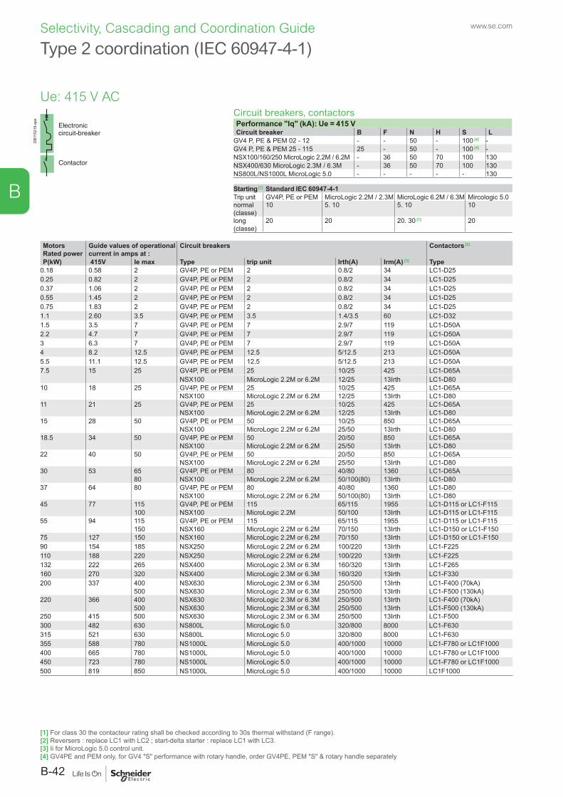
DB1
1521
8.ep
s
Type 2 coordination (IEC 60947-4-1)
Circuit breakers, contactorsPerformance "Iq" (kA): Ue = 415 VCircuit breaker B F N H S L
GV4 P, PE & PEM 02 - 12 - - 50 - 100 [4] -GV4 P, PE & PEM 25 - 115 25 - 50 - 100 [4] -NSX100/160/250 MicroLogic 2.2M / 6.2M - 36 50 70 100 130NSX400/630 MicroLogic 2.3M / 6.3M - 36 50 70 100 130NS800L/NS1000L MicroLogic 5.0 - - - - - 130
Starting [1] Standard IEC 60947-4-1Trip unit GV4P, PE or PEM MicroLogic 2.2M / 2.3M MicroLogic 6.2M / 6.3M Mircologic 5.0normal (classe)
10 5. 10 5. 10 10
long (classe)
20 20 20. 30 [1] 20
MotorsRated power
Guide values of operational current in amps at :
Circuit breakers Contactors [2]
P(kW) 415V Ie max Type trip unit Irth(A) Irm(A) [3] Type0.18 0.58 2 GV4P, PE or PEM 2 0.8/2 34 LC1-D250.25 0.82 2 GV4P, PE or PEM 2 0.8/2 34 LC1-D250.37 1.06 2 GV4P, PE or PEM 2 0.8/2 34 LC1-D250.55 1.45 2 GV4P, PE or PEM 2 0.8/2 34 LC1-D250.75 1.83 2 GV4P, PE or PEM 2 0.8/2 34 LC1-D251.1 2.60 3.5 GV4P, PE or PEM 3.5 1.4/3.5 60 LC1-D321.5 3.5 7 GV4P, PE or PEM 7 2.9/7 119 LC1-D50A2.2 4.7 7 GV4P, PE or PEM 7 2.9/7 119 LC1-D50A3 6.3 7 GV4P, PE or PEM 7 2.9/7 119 LC1-D50A4 8.2 12.5 GV4P, PE or PEM 12.5 5/12.5 213 LC1-D50A5.5 11.1 12.5 GV4P, PE or PEM 12.5 5/12.5 213 LC1-D50A7.5 15 25 GV4P, PE or PEM 25 10/25 425 LC1-D65A
NSX100 MicroLogic 2.2M or 6.2M 12/25 13Irth LC1-D8010 18 25 GV4P, PE or PEM 25 10/25 425 LC1-D65A
NSX100 MicroLogic 2.2M or 6.2M 12/25 13Irth LC1-D8011 21 25 GV4P, PE or PEM 25 10/25 425 LC1-D65A
NSX100 MicroLogic 2.2M or 6.2M 12/25 13Irth LC1-D8015 28 50 GV4P, PE or PEM 50 10/25 850 LC1-D65A
NSX100 MicroLogic 2.2M or 6.2M 25/50 13Irth LC1-D8018.5 34 50 GV4P, PE or PEM 50 20/50 850 LC1-D65A
NSX100 MicroLogic 2.2M or 6.2M 25/50 13Irth LC1-D8022 40 50 GV4P, PE or PEM 50 20/50 850 LC1-D65A
NSX100 MicroLogic 2.2M or 6.2M 25/50 13Irth LC1-D8030 53 65 GV4P, PE or PEM 80 40/80 1360 LC1-D65A
80 NSX100 MicroLogic 2.2M or 6.2M 50/100(80) 13Irth LC1-D8037 64 80 GV4P, PE or PEM 80 40/80 1360 LC1-D80
NSX100 MicroLogic 2.2M or 6.2M 50/100(80) 13Irth LC1-D8045 77 115 GV4P, PE or PEM 115 65/115 1955 LC1-D115 or LC1-F115
100 NSX100 MicroLogic 2.2M 50/100 13Irth LC1-D115 or LC1-F11555 94 115 GV4P, PE or PEM 115 65/115 1955 LC1-D115 or LC1-F115
150 NSX160 MicroLogic 2.2M or 6.2M 70/150 13Irth LC1-D150 or LC1-F15075 127 150 NSX160 MicroLogic 2.2M or 6.2M 70/150 13Irth LC1-D150 or LC1-F15090 154 185 NSX250 MicroLogic 2.2M or 6.2M 100/220 13Irth LC1-F225110 188 220 NSX250 MicroLogic 2.2M or 6.2M 100/220 13Irth LC1-F225132 222 265 NSX400 MicroLogic 2.3M or 6.3M 160/320 13Irth LC1-F265160 270 320 NSX400 MicroLogic 2.3M or 6.3M 160/320 13Irth LC1-F330200 337 400 NSX630 MicroLogic 2.3M or 6.3M 250/500 13Irth LC1-F400 (70kA)
500 NSX630 MicroLogic 2.3M or 6.3M 250/500 13Irth LC1-F500 (130kA)220 366 400 NSX630 MicroLogic 2.3M or 6.3M 250/500 13Irth LC1-F400 (70kA)
500 NSX630 MicroLogic 2.3M or 6.3M 250/500 13Irth LC1-F500 (130kA)250 415 500 NSX630 MicroLogic 2.3M or 6.3M 250/500 13Irth LC1-F500300 482 630 NS800L MicroLogic 5.0 320/800 8000 LC1-F630315 521 630 NS800L MicroLogic 5.0 320/800 8000 LC1-F630355 588 780 NS1000L MicroLogic 5.0 400/1000 10000 LC1-F780 or LC1F1000400 665 780 NS1000L MicroLogic 5.0 400/1000 10000 LC1-F780 or LC1F1000450 723 780 NS1000L MicroLogic 5.0 400/1000 10000 LC1-F780 or LC1F1000500 819 850 NS1000L MicroLogic 5.0 400/1000 10000 LC1F1000
Ue: 415 V AC
[1] For class 30 the contacteur rating shall be checked according to 30s thermal withstand (F range).[2] Reversers : replace LC1 with LC2 ; start-delta starter : replace LC1 with LC3.[3] Ii for MicroLogic 5.0 control unit.[4] GV4PE and PEM only, for GV4 "S" performance with rotary handle, order GV4PE, PEM "S" & rotary handle separately
www.se.com
B-42
B
Selectivity, Cascading and Coordination Guide
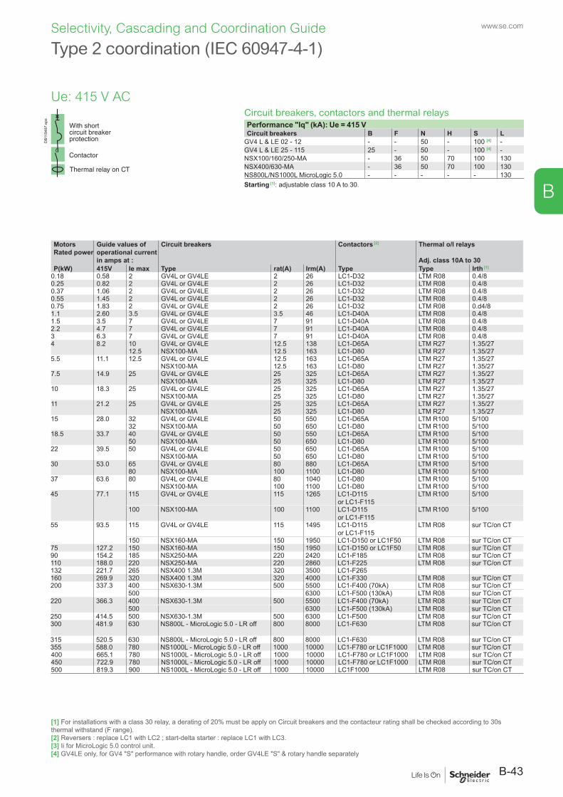
Circuit breakers, contactors and thermal relaysPerformance "Iq" (kA): Ue = 415 VCircuit breakers B F N H S L
GV4 L & LE 02 - 12 - - 50 - 100 [4] -GV4 L & LE 25 - 115 25 - 50 - 100 [4] -NSX100/160/250-MA - 36 50 70 100 130NSX400/630-MA - 36 50 70 100 130NS800L/NS1000L MicroLogic 5.0 - - - - - 130Starting [1]: adjustable class 10 A to 30.
DB1
1949
7.ep
s
Type 2 coordination (IEC 60947-4-1)
MotorsRated power
Guide values of operational current in amps at :
Circuit breakers Contactors [2] Thermal o/l relays
Adj. class 10A to 30P(kW) 415V Ie max Type rat(A) Irm(A) Type Type Irth [1]
0.18 0.58 2 GV4L or GV4LE 2 26 LC1-D32 LTM R08 0.4/80.25 0.82 2 GV4L or GV4LE 2 26 LC1-D32 LTM R08 0.4/80.37 1.06 2 GV4L or GV4LE 2 26 LC1-D32 LTM R08 0.4/80.55 1.45 2 GV4L or GV4LE 2 26 LC1-D32 LTM R08 0.4/80.75 1.83 2 GV4L or GV4LE 2 26 LC1-D32 LTM R08 0.d4/81.1 2.60 3.5 GV4L or GV4LE 3.5 46 LC1-D40A LTM R08 0.4/81.5 3.5 7 GV4L or GV4LE 7 91 LC1-D40A LTM R08 0.4/82.2 4.7 7 GV4L or GV4LE 7 91 LC1-D40A LTM R08 0.4/83 6.3 7 GV4L or GV4LE 7 91 LC1-D40A LTM R08 0.4/84 8.2 10 GV4L or GV4LE 12.5 138 LC1-D65A LTM R27 1.35/27
12.5 NSX100-MA 12.5 163 LC1-D80 LTM R27 1.35/275.5 11.1 12.5 GV4L or GV4LE 12.5 163 LC1-D65A LTM R27 1.35/27
NSX100-MA 12.5 163 LC1-D80 LTM R27 1.35/277.5 14.9 25 GV4L or GV4LE 25 325 LC1-D65A LTM R27 1.35/27
NSX100-MA 25 325 LC1-D80 LTM R27 1.35/2710 18.3 25 GV4L or GV4LE 25 325 LC1-D65A LTM R27 1.35/27
NSX100-MA 25 325 LC1-D80 LTM R27 1.35/2711 21.2 25 GV4L or GV4LE 25 325 LC1-D65A LTM R27 1.35/27
NSX100-MA 25 325 LC1-D80 LTM R27 1.35/2715 28.0 32 GV4L or GV4LE 50 550 LC1-D65A LTM R100 5/100
32 NSX100-MA 50 650 LC1-D80 LTM R100 5/10018.5 33.7 40 GV4L or GV4LE 50 550 LC1-D65A LTM R100 5/100
50 NSX100-MA 50 650 LC1-D80 LTM R100 5/10022 39.5 50 GV4L or GV4LE 50 650 LC1-D65A LTM R100 5/100
NSX100-MA 50 650 LC1-D80 LTM R100 5/10030 53.0 65 GV4L or GV4LE 80 880 LC1-D65A LTM R100 5/100
80 NSX100-MA 100 1100 LC1-D80 LTM R100 5/10037 63.6 80 GV4L or GV4LE 80 1040 LC1-D80 LTM R100 5/100
NSX100-MA 100 1100 LC1-D80 LTM R100 5/10045 77.1 115 GV4L or GV4LE 115 1265 LC1-D115
or LC1-F115LTM R100 5/100
100 NSX100-MA 100 1100 LC1-D115 or LC1-F115
LTM R100 5/100
55 93.5 115 GV4L or GV4LE 115 1495 LC1-D115 or LC1-F115
LTM R08 sur TC/on CT
150 NSX160-MA 150 1950 LC1-D150 or LC1F50 LTM R08 sur TC/on CT75 127.2 150 NSX160-MA 150 1950 LC1-D150 or LC1F50 LTM R08 sur TC/on CT90 154.2 185 NSX250-MA 220 2420 LC1-F185 LTM R08 sur TC/on CT110 188.0 220 NSX250-MA 220 2860 LC1-F225 LTM R08 sur TC/on CT132 221.7 265 NSX400 1.3M 320 3500 LC1-F265160 269.9 320 NSX400 1.3M 320 4000 LC1-F330 LTM R08 sur TC/on CT200 337.3 400 NSX630-1.3M 500 5500 LC1-F400 (70kA) LTM R08 sur TC/on CT
500 6300 LC1-F500 (130kA) LTM R08 sur TC/on CT220 366.3 400 NSX630-1.3M 500 5500 LC1-F400 (70kA) LTM R08 sur TC/on CT
500 6300 LC1-F500 (130kA) LTM R08 sur TC/on CT250 414.5 500 NSX630-1.3M 500 6300 LC1-F500 LTM R08 sur TC/on CT300 481.9 630 NS800L - MicroLogic 5.0 - LR off 800 8000 LC1-F630 LTM R08 sur TC/on CT
315 520.5 630 NS800L - MicroLogic 5.0 - LR off 800 8000 LC1-F630 LTM R08 sur TC/on CT355 588.0 780 NS1000L - MicroLogic 5.0 - LR off 1000 10000 LC1-F780 or LC1F1000 LTM R08 sur TC/on CT400 665.1 780 NS1000L - MicroLogic 5.0 - LR off 1000 10000 LC1-F780 or LC1F1000 LTM R08 sur TC/on CT450 722.9 780 NS1000L - MicroLogic 5.0 - LR off 1000 10000 LC1-F780 or LC1F1000 LTM R08 sur TC/on CT500 819.3 900 NS1000L - MicroLogic 5.0 - LR off 1000 10000 LC1F1000 LTM R08 sur TC/on CT
Ue: 415 V AC
[1] For installations with a class 30 relay, a derating of 20% must be apply on Circuit breakers and the contacteur rating shall be checked according to 30s thermal withstand (F range).[2] Reversers : replace LC1 with LC2 ; start-delta starter : replace LC1 with LC3.[3] Ii for MicroLogic 5.0 control unit.[4] GV4LE only, for GV4 "S" performance with rotary handle, order GV4LE "S" & rotary handle separately
B-43
www.se.com
B
Selectivity, Cascading and Coordination Guide
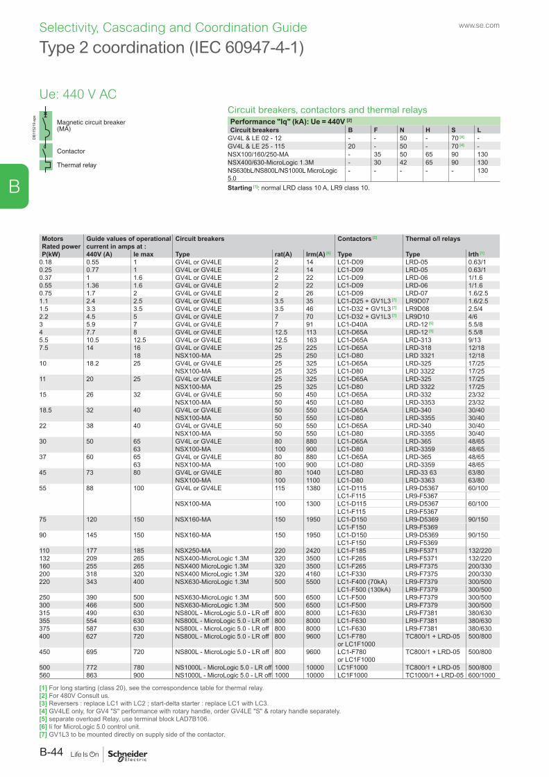
DB1
1521
9.ep
s
Type 2 coordination (IEC 60947-4-1)
Circuit breakers, contactors and thermal relaysPerformance "Iq" (kA): Ue = 440V [2]
Circuit breakers B F N H S LGV4L & LE 02 - 12 - - 50 - 70 [4] -GV4L & LE 25 - 115 20 - 50 - 70 [4] -NSX100/160/250-MA - 35 50 65 90 130NSX400/630-MicroLogic 1.3M - 30 42 65 90 130NS630bL/NS800L/NS1000L MicroLogic 5.0
- - - - - 130
Starting [1]: normal LRD class 10 A, LR9 class 10.
MotorsRated power
Guide values of operational current in amps at :
Circuit breakers Contactors [2] Thermal o/l relays
P(kW) 440V (A) Ie max Type rat(A) Irm(A) [6] Type Type Irth [1]
0.18 0.55 1 GV4L or GV4LE 2 14 LC1-D09 LRD-05 0.63/10.25 0.77 1 GV4L or GV4LE 2 14 LC1-D09 LRD-05 0.63/10.37 1 1.6 GV4L or GV4LE 2 22 LC1-D09 LRD-06 1/1.60.55 1.36 1.6 GV4L or GV4LE 2 22 LC1-D09 LRD-06 1/1.60.75 1.7 2 GV4L or GV4LE 2 26 LC1-D09 LRD-07 1.6/2.51.1 2.4 2.5 GV4L or GV4LE 3.5 35 LC1-D25 + GV1L3 [7] LR9D07 1.6/2.51.5 3.3 3.5 GV4L or GV4LE 3.5 46 LC1-D32 + GV1L3 [7] LR9D08 2.5/42.2 4.5 5 GV4L or GV4LE 7 70 LC1-D32 + GV1L3 [7] LR9D10 4/63 5.9 7 GV4L or GV4LE 7 91 LC1-D40A LRD-12 [5] 5.5/84 7.7 8 GV4L or GV4LE 12.5 113 LC1-D65A LRD-12 [5] 5.5/85.5 10.5 12.5 GV4L or GV4LE 12.5 163 LC1-D65A LRD-313 9/137.5 14 16 GV4L or GV4LE 25 225 LC1-D65A LRD-318 12/18
18 NSX100-MA 25 250 LC1-D80 LRD 3321 12/1810 18.2 25 GV4L or GV4LE 25 325 LC1-D65A LRD-325 17/25
NSX100-MA 25 325 LC1-D80 LRD 3322 17/2511 20 25 GV4L or GV4LE 25 325 LC1-D65A LRD-325 17/25
NSX100-MA 25 325 LC1-D80 LRD 3322 17/2515 26 32 GV4L or GV4LE 50 450 LC1-D65A LRD-332 23/32
NSX100-MA 50 450 LC1-D80 LRD-3353 23/3218.5 32 40 GV4L or GV4LE 50 550 LC1-D65A LRD-340 30/40
NSX100-MA 50 550 LC1-D80 LRD-3355 30/4022 38 40 GV4L or GV4LE 50 550 LC1-D65A LRD-340 30/40
NSX100-MA 50 550 LC1-D80 LRD-3355 30/4030 50 65 GV4L or GV4LE 80 880 LC1-D65A LRD-365 48/65
63 NSX100-MA 100 900 LC1-D80 LRD-3359 48/6537 60 65 GV4L or GV4LE 80 880 LC1-D65A LRD-365 48/65
63 NSX100-MA 100 900 LC1-D80 LRD-3359 48/6545 73 80 GV4L or GV4LE 80 1040 LC1-D80 LRD-33 63 63/80
NSX100-MA 100 1100 LC1-D80 LRD-3363 63/8055 88 100 GV4L or GV4LE 115 1380 LC1-D115 LR9-D5367 60/100
LC1-F115 LR9-F5367NSX100-MA 100 1300 LC1-D115 LR9-D5367 60/100
LC1-F115 LR9-F536775 120 150 NSX160-MA 150 1950 LC1-D150 LR9-D5369 90/150
LC1-F150 LR9-F536990 145 150 NSX160-MA 150 1950 LC1-D150 LR9-D5369 90/150
LC1-F150 LR9-F5369110 177 185 NSX250-MA 220 2420 LC1-F185 LR9-F5371 132/220132 209 265 NSX400-MicroLogic 1.3M 320 3500 LC1-F265 LR9-F5371 132/220160 255 265 NSX400 MicroLogic 1.3M 320 3500 LC1-F265 LR9-F7375 200/330200 318 320 NSX400 MicroLogic 1.3M 320 4160 LC1-F330 LR9-F7375 200/330220 343 400 NSX630-MicroLogic 1.3M 500 5500 LC1-F400 (70kA) LR9-F7379 300/500
LC1-F500 (130kA) LR9-F7379 300/500250 390 500 NSX630-MicroLogic 1.3M 500 6500 LC1-F500 LR9-F7379 300/500300 466 500 NSX630-MicroLogic 1.3M 500 6500 LC1-F500 LR9-F7379 300/500315 490 630 NS800L - MicroLogic 5.0 - LR off 800 8000 LC1-F630 LR9-F7381 380/630355 554 630 NS800L - MicroLogic 5.0 - LR off 800 8000 LC1-F630 LR9-F7381 380/630375 587 630 NS800L - MicroLogic 5.0 - LR off 800 8000 LC1-F630 LR9-F7381 380/630400 627 720 NS800L - MicroLogic 5.0 - LR off 800 9600 LC1-F780
or LC1F1000TC800/1 + LRD-05 500/800
450 695 720 NS800L - MicroLogic 5.0 - LR off 800 9600 LC1-F780 or LC1F1000
TC800/1 + LRD-05 500/800
500 772 780 NS1000L - MicroLogic 5.0 - LR off 1000 10000 LC1F1000 TC800/1 + LRD-05 500/800560 863 900 NS1000L - MicroLogic 5.0 - LR off 1000 10000 LC1F1000 TC1000/1 + LRD-05 600/1000
Ue: 440 V AC
[1] For long starting (class 20), see the correspondence table for thermal relay.[2] For 480V Consult us.[3] Reversers : replace LC1 with LC2 ; start-delta starter : replace LC1 with LC3.[4] GV4LE only, for GV4 "S" performance with rotary handle, order GV4LE "S" & rotary handle separately.[5] separate overload Relay, use terminal block LAD7B106.[6] Ii for MicroLogic 5.0 control unit.[7] GV1L3 to be mounted directly on supply side of the contactor.
www.se.com
B-44
B
Selectivity, Cascading and Coordination Guide

Type 2 coordination (IEC 60947-4-1)
Circuit breakers, and contactorsPerformance "Iq" (kA): Ue = 440V [2]
Circuit breaker B F N H S LGV4 P, PE & PEM 02 - 12 - - 50 - 70 [5] -GV4 P, PE & PEM 25 - 115 20 50 - 70 [5] -NSX100/160/250-MA - 35 42 65 90 130NSX400/630-MA - 30 42 65 90 130NS630bL/NS800L/NS1000L MicroLogic 5.0 - - - - - 130
Starting [1] Standard IEC 60947-4-1Trip unit GV4P, PE or PEM MicroLogic 2.2M / 2.3M MicroLogic 6.2M / 6.3M Mircologic 5.0normal (classe)
10 5. 10 5. 10 10
long (classe)
20 20 20. 30 [1] 20
MotorsRated power
Guide values of operational current in amps at :
Circuit breakers Contactors [2]
P(kW) 440V (A) Ie max (A) Type trip unit Irth(A) Irm(A) [4] Type0.18 0.55 2 GV4P, PE or PEM 2 0.8/2 34 LC1-D250.25 0.77 2 GV4P, PE or PEM 2 0.8/2 34 LC1-D250.37 1 2 GV4P, PE or PEM 2 0.8/2 34 LC1-D250.55 1.36 2 GV4P, PE or PEM 2 0.8/2 34 LC1-D250.75 1.7 2 GV4P, PE or PEM 2 0.8/2 34 LC1-D251.1 2.4 2.5 GV4P, PE or PEM 3.5 1.4/3.5 60 LC1-D321.5 3.3 3.5 GV4P, PE or PEM 3.5 1.4/3.5 60 LC1-D322.2 4.5 7 GV4P, PE or PEM 7 2.9/7 119 LC1-D65A3 5.9 7 GV4P, PE or PEM 7 2.9/7 119 LC1-D65A4 7.7 12.5 GV4P, PE or PEM 12.5 5/12.5 213 LC1-D65A5.5 10.5 12.5 GV4P, PE or PEM 12.5 5/12.5 213 LC1-D65A7.5 14 25 GV4P, PE or PEM 25 10/25 425 LC1-D65A
20 NSX100 MicroLogic 2.2M / 6.2M 12/20 13Irth LC1-D8010 18.2 25 GV4P, PE or PEM 25 10/25 425 LC1-D65A
NSX100 MicroLogic 2.2M / 6.2M 15/25 13Irth LC1-D8011 20 25 GV4P, PE or PEM 25 10/25 425 LC1-D65A
NSX100 MicroLogic 2.2M / 6.2M 15/25 13Irth LC1-D8015 26 50 GV4P, PE or PEM 50 20/50 850 LC1-D65A
40 NSX100 MicroLogic 2.2M / 6.2M 24/40 13Irth LC1-D8018.5 32 50 GV4P, PE or PEM 50 20/50 850 LC1-D65A
40 NSX100 MicroLogic 2.2M / 6.2M 24/40 13Irth LC1-D8022 38 50 GV4P, PE or PEM 50 20/50 850 LC1-D65A
40 NSX100 MicroLogic 2.2M / 6.2M 24/40 13Irth LC1-D8030 50 63 GV4P, PE or PEM 80 40/80 1360 LC1-D65A
80 NSX100 MicroLogic 2.2M / 6.2M 48/80 13Irth LC1-D8037 60 63 GV4P, PE or PEM 80 40/80 1360 LC1-D65A
80 NSX100 MicroLogic 2.2M / 6.2M 48/80 13Irth LC1-D8045 73 80 GV4P, PE or PEM 80 40/80 1360 LC1-D80
NSX100 MicroLogic 2.2M / 6.2M 48/80 13Irth LC1-D8055 88 100 GV4P, PE or PEM 115 65/115 1955 LC1-D115 or LC1-F115
NSX100 MicroLogic 2.2M / 6.2M 60/100 13Irth LC1-D115 or LC1-F11575 120 150 NSX160 MicroLogic 2.2M / 6.2M 90/150 13Irth LC1-D150 or LC1-F15090 145 150 NSX160 MicroLogic 2.2M / 6.2M 90/150 13Irth LC1-D150 or LC1-F150110 177 185 NSX250 MicroLogic 2.2M / 6.2M 131/220 13Irth LC1-F225132 209 265 NSX400 MicroLogic 2.3M / 6.3M 160/320 13Irth LC1-F265160 255 265 NSX400 MicroLogic 2.3M / 6.3M 160/320 13Irth LC1-F265200 318 320 NSX400 MicroLogic 2.3M / 6.3M 160/320 13Irth LC1-F330220 343 400
500NSX630 MicroLogic 2.3M / 6.3M 250/500 13Irth LC1-F400 (70kA)
LC1-F500 (130kA)250 390 400 NSX630 MicroLogic 2.3M / 6.3M 250/500 13Irth LC1-F500300 466 500 NSX630 MicroLogic 2.3M / 6.3M 250/500 13Irth LC1-F500315 490 630 NS800L MicroLogic 5.0 320/800 8000 LC1-F630355 554 630 NS800L MicroLogic 5.0 320/800 8000 LC1-F630375 587 630 NS800L MicroLogic 5.0 320/800 8000 LC1-F630400 627 720 NS800L MicroLogic 5.0 320/800 9600 LC1-F780 or LC1F1000450 695 720 NS800L MicroLogic 5.0 320/800 9600 LC1-F780 or LC1F1000500 772 800 NS1000L MicroLogic 5.0 400/1000 10000 LC1-F1000560 863 900 NS1000L MicroLogic 5.0 400/1000 10000 LC1-F1000
DB1
1521
8.ep
s
Ue: 440 V AC
[1] For class 30 the contacteur rating shall be checked according to 30s thermal withstand (F range).[2] For 480V Consult us.[3] Reversers : replace LC1 with LC2 ; start-delta starter : replace LC1 with LC3.[4] Ii for MicroLogic 5.0 control unit.[5] GV4PE only, for GV4 "S" performance with rotary handle, order GV4PE "S" & rotary handle separately.
B-45
www.se.com
B
Selectivity, Cascading and Coordination Guide
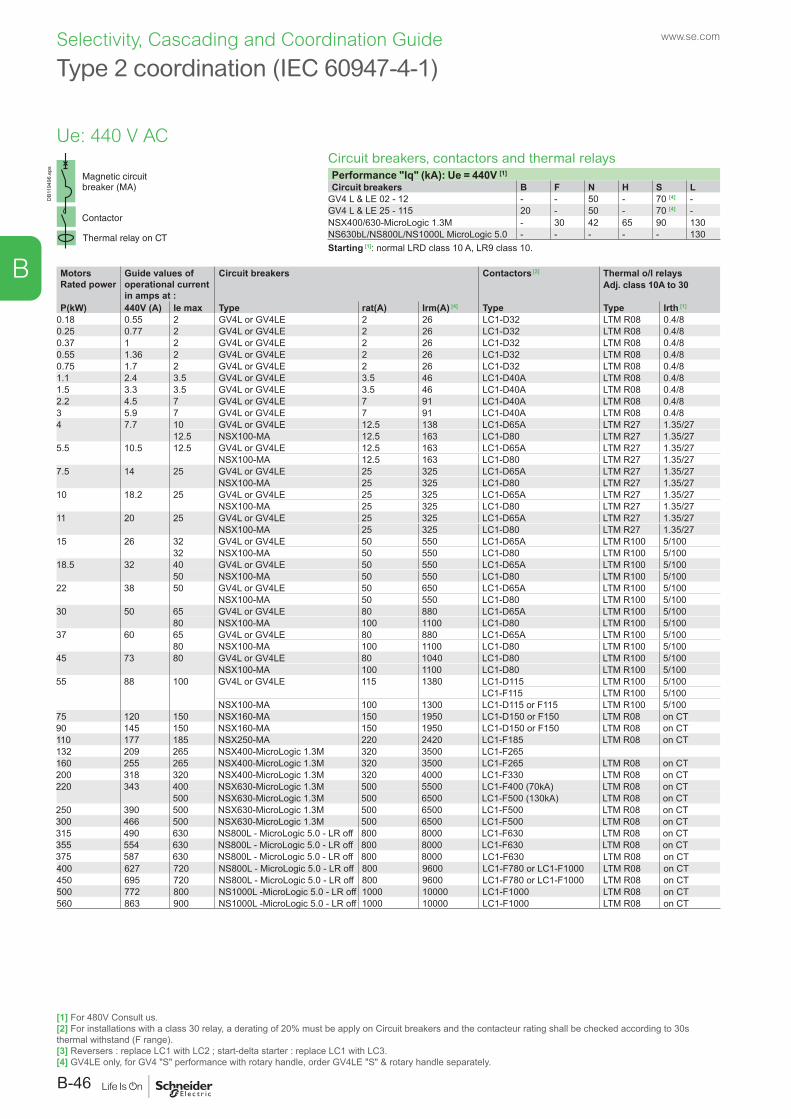
DB1
1949
6.ep
s
Type 2 coordination (IEC 60947-4-1)
Circuit breakers, contactors and thermal relaysPerformance "Iq" (kA): Ue = 440V [1]
Circuit breakers B F N H S LGV4 L & LE 02 - 12 - - 50 - 70 [4] -GV4 L & LE 25 - 115 20 - 50 - 70 [4] -NSX400/630-MicroLogic 1.3M - 30 42 65 90 130NS630bL/NS800L/NS1000L MicroLogic 5.0 - - - - - 130Starting [1]: normal LRD class 10 A, LR9 class 10.
MotorsRated power
Guide values of operational current in amps at :
Circuit breakers Contactors [2] Thermal o/l relaysAdj. class 10A to 30
P(kW) 440V (A) Ie max Type rat(A) Irm(A) [4] Type Type Irth [1]
0.18 0.55 2 GV4L or GV4LE 2 26 LC1-D32 LTM R08 0.4/80.25 0.77 2 GV4L or GV4LE 2 26 LC1-D32 LTM R08 0.4/80.37 1 2 GV4L or GV4LE 2 26 LC1-D32 LTM R08 0.4/80.55 1.36 2 GV4L or GV4LE 2 26 LC1-D32 LTM R08 0.4/80.75 1.7 2 GV4L or GV4LE 2 26 LC1-D32 LTM R08 0.4/81.1 2.4 3.5 GV4L or GV4LE 3.5 46 LC1-D40A LTM R08 0.4/81.5 3.3 3.5 GV4L or GV4LE 3.5 46 LC1-D40A LTM R08 0.4/82.2 4.5 7 GV4L or GV4LE 7 91 LC1-D40A LTM R08 0.4/83 5.9 7 GV4L or GV4LE 7 91 LC1-D40A LTM R08 0.4/84 7.7 10 GV4L or GV4LE 12.5 138 LC1-D65A LTM R27 1.35/27
12.5 NSX100-MA 12.5 163 LC1-D80 LTM R27 1.35/275.5 10.5 12.5 GV4L or GV4LE 12.5 163 LC1-D65A LTM R27 1.35/27
NSX100-MA 12.5 163 LC1-D80 LTM R27 1.35/277.5 14 25 GV4L or GV4LE 25 325 LC1-D65A LTM R27 1.35/27
NSX100-MA 25 325 LC1-D80 LTM R27 1.35/2710 18.2 25 GV4L or GV4LE 25 325 LC1-D65A LTM R27 1.35/27
NSX100-MA 25 325 LC1-D80 LTM R27 1.35/2711 20 25 GV4L or GV4LE 25 325 LC1-D65A LTM R27 1.35/27
NSX100-MA 25 325 LC1-D80 LTM R27 1.35/2715 26 32 GV4L or GV4LE 50 550 LC1-D65A LTM R100 5/100
32 NSX100-MA 50 550 LC1-D80 LTM R100 5/10018.5 32 40 GV4L or GV4LE 50 550 LC1-D65A LTM R100 5/100
50 NSX100-MA 50 550 LC1-D80 LTM R100 5/10022 38 50 GV4L or GV4LE 50 650 LC1-D65A LTM R100 5/100
NSX100-MA 50 550 LC1-D80 LTM R100 5/10030 50 65 GV4L or GV4LE 80 880 LC1-D65A LTM R100 5/100
80 NSX100-MA 100 1100 LC1-D80 LTM R100 5/10037 60 65 GV4L or GV4LE 80 880 LC1-D65A LTM R100 5/100
80 NSX100-MA 100 1100 LC1-D80 LTM R100 5/10045 73 80 GV4L or GV4LE 80 1040 LC1-D80 LTM R100 5/100
NSX100-MA 100 1100 LC1-D80 LTM R100 5/10055 88 100 GV4L or GV4LE 115 1380 LC1-D115 LTM R100 5/100
LC1-F115 LTM R100 5/100NSX100-MA 100 1300 LC1-D115 or F115 LTM R100 5/100
75 120 150 NSX160-MA 150 1950 LC1-D150 or F150 LTM R08 on CT90 145 150 NSX160-MA 150 1950 LC1-D150 or F150 LTM R08 on CT110 177 185 NSX250-MA 220 2420 LC1-F185 LTM R08 on CT132 209 265 NSX400-MicroLogic 1.3M 320 3500 LC1-F265160 255 265 NSX400-MicroLogic 1.3M 320 3500 LC1-F265 LTM R08 on CT200 318 320 NSX400-MicroLogic 1.3M 320 4000 LC1-F330 LTM R08 on CT220 343 400 NSX630-MicroLogic 1.3M 500 5500 LC1-F400 (70kA) LTM R08 on CT
500 NSX630-MicroLogic 1.3M 500 6500 LC1-F500 (130kA) LTM R08 on CT250 390 500 NSX630-MicroLogic 1.3M 500 6500 LC1-F500 LTM R08 on CT300 466 500 NSX630-MicroLogic 1.3M 500 6500 LC1-F500 LTM R08 on CT315 490 630 NS800L - MicroLogic 5.0 - LR off 800 8000 LC1-F630 LTM R08 on CT355 554 630 NS800L - MicroLogic 5.0 - LR off 800 8000 LC1-F630 LTM R08 on CT375 587 630 NS800L - MicroLogic 5.0 - LR off 800 8000 LC1-F630 LTM R08 on CT400 627 720 NS800L - MicroLogic 5.0 - LR off 800 9600 LC1-F780 or LC1-F1000 LTM R08 on CT450 695 720 NS800L - MicroLogic 5.0 - LR off 800 9600 LC1-F780 or LC1-F1000 LTM R08 on CT500 772 800 NS1000L -MicroLogic 5.0 - LR off 1000 10000 LC1-F1000 LTM R08 on CT560 863 900 NS1000L -MicroLogic 5.0 - LR off 1000 10000 LC1-F1000 LTM R08 on CT
Ue: 440 V AC
[1] For 480V Consult us.[2] For installations with a class 30 relay, a derating of 20% must be apply on Circuit breakers and the contacteur rating shall be checked according to 30s thermal withstand (F range).[3] Reversers : replace LC1 with LC2 ; start-delta starter : replace LC1 with LC3.[4] GV4LE only, for GV4 "S" performance with rotary handle, order GV4LE "S" & rotary handle separately.
www.se.com
B-46
B
Selectivity, Cascading and Coordination Guide
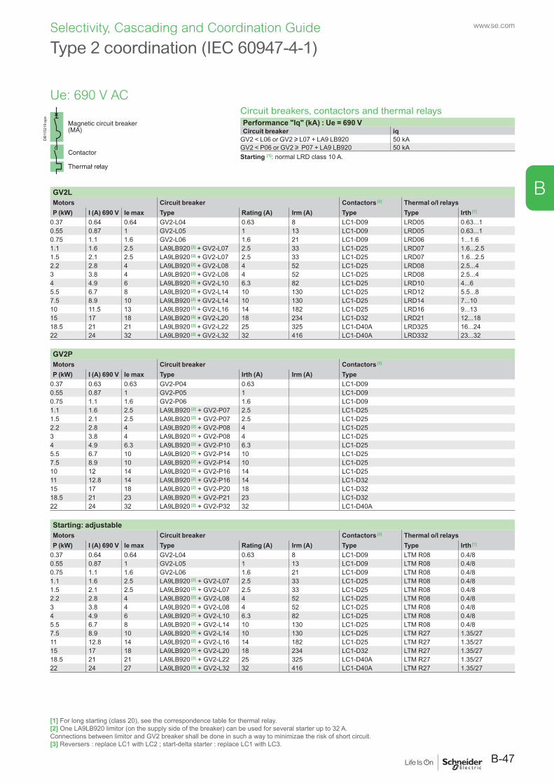
Circuit breakers, contactors and thermal relaysPerformance "Iq" (kA) : Ue = 690 VCircuit breaker iq
GV2 < L06 or GV2 u L07 + LA9 LB920 50 kAGV2 < P06 or GV2 u P07 + LA9 LB920 50 kAStarting [1]: normal LRD class 10 A.
GV2LMotors Circuit breaker Contactors [3] Thermal o/l relaysP (kW) I (A) 690 V Ie max Type Rating (A) Irm (A) Type Type Irth [1]
0.37 0.64 0.64 GV2-L04 0.63 8 LC1-D09 LRD05 0.63...10.55 0.87 1 GV2-L05 1 13 LC1-D09 LRD05 0.63...10.75 1.1 1.6 GV2-L06 1.6 21 LC1-D09 LRD06 1...1.61.1 1.6 2.5 LA9LB920 [2] + GV2-L07 2.5 33 LC1-D25 LRD07 1.6...2.51.5 2.1 2.5 LA9LB920 [2] + GV2-L07 2.5 33 LC1-D25 LRD07 1.6...2.52.2 2.8 4 LA9LB920 [2] + GV2-L08 4 52 LC1-D25 LRD08 2.5...43 3.8 4 LA9LB920 [2] + GV2-L08 4 52 LC1-D25 LRD08 2.5...44 4.9 6 LA9LB920 [2] + GV2-L10 6.3 82 LC1-D25 LRD10 4...65.5 6.7 8 LA9LB920 [2] + GV2-L14 10 130 LC1-D25 LRD12 5.5...87.5 8.9 10 LA9LB920 [2] + GV2-L14 10 130 LC1-D25 LRD14 7...1010 11.5 13 LA9LB920 [2] + GV2-L16 14 182 LC1-D25 LRD16 9...1315 17 18 LA9LB920 [2] + GV2-L20 18 234 LC1-D32 LRD21 12...1818.5 21 21 LA9LB920 [2] + GV2-L22 25 325 LC1-D40A LRD325 16...2422 24 32 LA9LB920 [2] + GV2-L32 32 416 LC1-D40A LRD332 23...32
GV2PMotors Circuit breaker Contactors [3]
P (kW) I (A) 690 V Ie max Type Irth (A) Irm (A) Type0.37 0.63 0.63 GV2-P04 0.63 LC1-D090.55 0.87 1 GV2-P05 1 LC1-D090.75 1.1 1.6 GV2-P06 1.6 LC1-D091.1 1.6 2.5 LA9LB920 [2] + GV2-P07 2.5 LC1-D251.5 2.1 2.5 LA9LB920 [2] + GV2-P07 2.5 LC1-D252.2 2.8 4 LA9LB920 [2] + GV2-P08 4 LC1-D253 3.8 4 LA9LB920 [2] + GV2-P08 4 LC1-D254 4.9 6.3 LA9LB920 [2] + GV2-P10 6.3 LC1-D255.5 6.7 10 LA9LB920 [2] + GV2-P14 10 LC1-D257.5 8.9 10 LA9LB920 [2] + GV2-P14 10 LC1-D2510 12 14 LA9LB920 [2] + GV2-P16 14 LC1-D2511 12.8 14 LA9LB920 [2] + GV2-P16 14 LC1-D3215 17 18 LA9LB920 [2] + GV2-P20 18 LC1-D3218.5 21 23 LA9LB920 [2] + GV2-P21 23 LC1-D3222 24 32 LA9LB920 [2] + GV2-P32 32 LC1-D40A
Starting: adjustableMotors Circuit breaker Contactors [3] Thermal o/l relaysP (kW) I (A) 690 V Ie max Type Rating (A) Irm (A) Type Type Irth [1]
0.37 0.64 0.64 GV2-L04 0.63 8 LC1-D09 LTM R08 0.4/80.55 0.87 1 GV2-L05 1 13 LC1-D09 LTM R08 0.4/80.75 1.1 1.6 GV2-L06 1.6 21 LC1-D09 LTM R08 0.4/81.1 1.6 2.5 LA9LB920 [2] + GV2-L07 2.5 33 LC1-D25 LTM R08 0.4/81.5 2.1 2.5 LA9LB920 [2] + GV2-L07 2.5 33 LC1-D25 LTM R08 0.4/82.2 2.8 4 LA9LB920 [2] + GV2-L08 4 52 LC1-D25 LTM R08 0.4/83 3.8 4 LA9LB920 [2] + GV2-L08 4 52 LC1-D25 LTM R08 0.4/84 4.9 6 LA9LB920 [2] + GV2-L10 6.3 82 LC1-D25 LTM R08 0.4/85.5 6.7 8 LA9LB920 [2] + GV2-L14 10 130 LC1-D25 LTM R08 0.4/87.5 8.9 10 LA9LB920 [2] + GV2-L14 10 130 LC1-D25 LTM R27 1.35/2711 12.8 14 LA9LB920 [2] + GV2-L16 14 182 LC1-D25 LTM R27 1.35/2715 17 18 LA9LB920 [2] + GV2-L20 18 234 LC1-D32 LTM R27 1.35/2718.5 21 21 LA9LB920 [2] + GV2-L22 25 325 LC1-D40A LTM R27 1.35/2722 24 27 LA9LB920 [2] + GV2-L32 32 416 LC1-D40A LTM R27 1.35/27
[1] For long starting (class 20), see the correspondence table for thermal relay.[2] One LA9LB920 limitor (on the supply side of the breaker) can be used for several starter up to 32 A.Connections between limitor and GV2 breaker shall be done in such a way to minimizae the risk of short circuit.[3] Reversers : replace LC1 with LC2 ; start-delta starter : replace LC1 with LC3.
DB1
1521
9.ep
s
Type 2 coordination (IEC 60947-4-1)
Ue: 690 V AC
B-47
www.se.com
B
Selectivity, Cascading and Coordination Guide
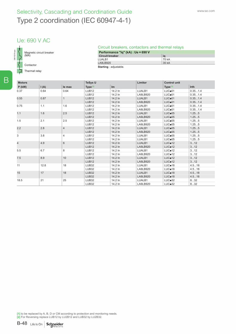
Circuit breakers, contactors and thermal relaysPerformance "Iq" (kA) : Ue = 690 VCircuit breaker iq
LUALB1 70 kALA9LB920 35 kAStarting : adjustable.
Motors TeSys U Limitor Control unitP (kW) I (A) Ie max Type [2] Im Type [1] Irth
0.37 0.64 0.64 LUB12 14.2 In LUALB1 LUCp01 0.35...1.4LUB12 14.2 In LA9LB920 LUCp01 0.35...1.4
0.55 0.87 1 LUB12 14.2 In LUALB1 LUCp01 0.35...1.4LUB12 14.2 In LA9LB920 LUCp01 0.35...1.4
0.75 1.1 1.6 LUB12 14.2 In LUALB1 LUCp01 0.35...1.4LUB12 14.2 In LA9LB920 LUCp01 0.35...1.4
1.1 1.6 2.5 LUB12 14.2 In LUALB1 LUCp05 1.25...5LUB12 14.2 In LA9LB920 LUCp05 1.25...5
1.5 2.1 2.5 LUB12 14.2 In LUALB1 LUCp05 1.25...5LUB12 14.2 In LA9LB920 LUCp05 1.25...5
2.2 2.8 4 LUB12 14.2 In LUALB1 LUCp05 1.25...5LUB12 14.2 In LA9LB920 LUCp05 1.25...5
3 3.8 4 LUB12 14.2 In LUALB1 LUCp05 1.25...5LUB12 14.2 In LUALB1 LUCp05 1.25...5
4 4.9 6 LUB12 14.2 In LUALB1 LUCp12 3...12LUB12 14.2 In LA9LB920 LUCp12 3...12
5.5 6.7 8 LUB12 14.2 In LUALB1 LUCp12 3...12LUB12 14.2 In LA9LB920 LUCp12 3...12
7.5 8.9 10 LUB12 14.2 In LUALB1 LUCp12 3...12LUB12 14.2 In LA9LB920 LUCp12 3...12
11 12.8 18 LUB32 14.2 In LUALB1 LUCp18 4.5...18LUB32 14.2 In LA9LB920 LUCp18 4.5...18
15 17 18 LUB32 14.2 In LUALB1 LUCp18 4.5...18LUB32 14.2 In LA9LB920 LUCp18 4.5...18
18.5 21 25 LUB32 14.2 In LUALB1 LUCp32 8...32LUB32 14.2 In LA9LB920 LUCp32 8...32
Type 2 coordination (IEC 60947-4-1)D
B115
219.
eps
Ue: 690 V AC
[1] to be replaced by A, B, D or CM according to protection and monitoring needs.[2] For Reversing replace LUB12 by LU2B12 and LUB32 by LU2B32.
www.se.com
B-48
B
Selectivity, Cascading and Coordination Guide
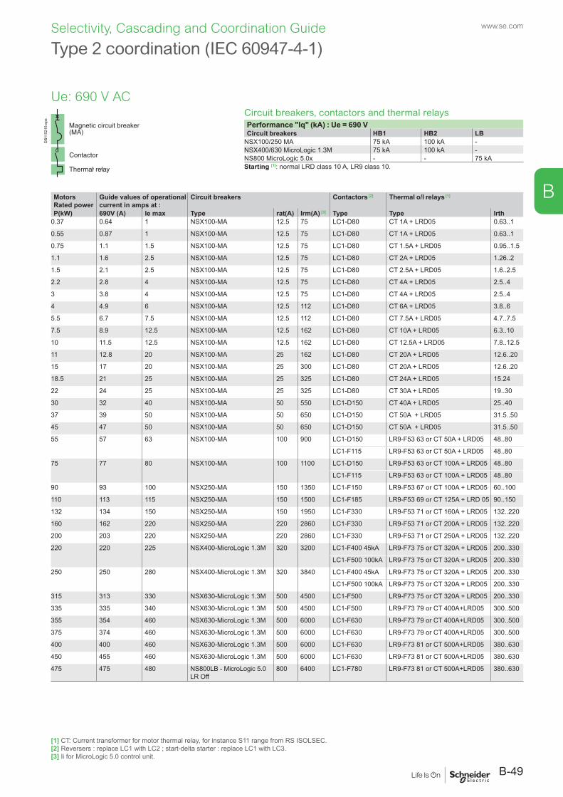
Circuit breakers, contactors and thermal relaysPerformance "Iq" (kA) : Ue = 690 VCircuit breakers HB1 HB2 LB
NSX100/250 MA 75 kA 100 kA -NSX400/630 MicroLogic 1.3M 75 kA 100 kA -NS800 MicroLogic 5.0x - - 75 kAStarting [1]: normal LRD class 10 A, LR9 class 10.
DB1
1521
9.ep
s
Type 2 coordination (IEC 60947-4-1)
MotorsRated power
Guide values of operational current in amps at :
Circuit breakers Contactors [2] Thermal o/l relays [1]
P(kW) 690V (A) Ie max Type rat(A) Irm(A) [3] Type Type Irth0.37 0.64 1 NSX100-MA 12.5 75 LC1-D80 CT 1A + LRD05 0.63..1
0.55 0.87 1 NSX100-MA 12.5 75 LC1-D80 CT 1A + LRD05 0.63..1
0.75 1.1 1.5 NSX100-MA 12.5 75 LC1-D80 CT 1.5A + LRD05 0.95..1.5
1.1 1.6 2.5 NSX100-MA 12.5 75 LC1-D80 CT 2A + LRD05 1.26..2
1.5 2.1 2.5 NSX100-MA 12.5 75 LC1-D80 CT 2.5A + LRD05 1.6..2.5
2.2 2.8 4 NSX100-MA 12.5 75 LC1-D80 CT 4A + LRD05 2.5..4
3 3.8 4 NSX100-MA 12.5 75 LC1-D80 CT 4A + LRD05 2.5..4
4 4.9 6 NSX100-MA 12.5 112 LC1-D80 CT 6A + LRD05 3.8..6
5.5 6.7 7.5 NSX100-MA 12.5 112 LC1-D80 CT 7.5A + LRD05 4.7..7.5
7.5 8.9 12.5 NSX100-MA 12.5 162 LC1-D80 CT 10A + LRD05 6.3..10
10 11.5 12.5 NSX100-MA 12.5 162 LC1-D80 CT 12.5A + LRD05 7.8..12.5
11 12.8 20 NSX100-MA 25 162 LC1-D80 CT 20A + LRD05 12.6..20
15 17 20 NSX100-MA 25 300 LC1-D80 CT 20A + LRD05 12.6..20
18.5 21 25 NSX100-MA 25 325 LC1-D80 CT 24A + LRD05 15.24
22 24 25 NSX100-MA 25 325 LC1-D80 CT 30A + LRD05 19..30
30 32 40 NSX100-MA 50 550 LC1-D150 CT 40A + LRD05 25..40
37 39 50 NSX100-MA 50 650 LC1-D150 CT 50A + LRD05 31.5..50
45 47 50 NSX100-MA 50 650 LC1-D150 CT 50A + LRD05 31.5..50
55 57 63 NSX100-MA 100 900 LC1-D150 LR9-F53 63 or CT 50A + LRD05 48..80
LC1-F115 LR9-F53 63 or CT 50A + LRD05 48..80
75 77 80 NSX100-MA 100 1100 LC1-D150 LR9-F53 63 or CT 100A + LRD05 48..80
LC1-F115 LR9-F53 63 or CT 100A + LRD05 48..80
90 93 100 NSX250-MA 150 1350 LC1-F150 LR9-F53 67 or CT 100A + LRD05 60..100
110 113 115 NSX250-MA 150 1500 LC1-F185 LR9-F53 69 or CT 125A + LRD 05 90..150
132 134 150 NSX250-MA 150 1950 LC1-F330 LR9-F53 71 or CT 160A + LRD05 132..220
160 162 220 NSX250-MA 220 2860 LC1-F330 LR9-F53 71 or CT 200A + LRD05 132..220
200 203 220 NSX250-MA 220 2860 LC1-F330 LR9-F53 71 or CT 250A + LRD05 132..220
220 220 225 NSX400-MicroLogic 1.3M 320 3200 LC1-F400 45kA LR9-F73 75 or CT 320A + LRD05 200..330
LC1-F500 100kA LR9-F73 75 or CT 320A + LRD05 200..330
250 250 280 NSX400-MicroLogic 1.3M 320 3840 LC1-F400 45kA LR9-F73 75 or CT 320A + LRD05 200..330
LC1-F500 100kA LR9-F73 75 or CT 320A + LRD05 200..330
315 313 330 NSX630-MicroLogic 1.3M 500 4500 LC1-F500 LR9-F73 75 or CT 320A + LRD05 200..330
335 335 340 NSX630-MicroLogic 1.3M 500 4500 LC1-F500 LR9-F73 79 or CT 400A+LRD05 300..500
355 354 460 NSX630-MicroLogic 1.3M 500 6000 LC1-F630 LR9-F73 79 or CT 400A+LRD05 300..500
375 374 460 NSX630-MicroLogic 1.3M 500 6000 LC1-F630 LR9-F73 79 or CT 400A+LRD05 300..500
400 400 460 NSX630-MicroLogic 1.3M 500 6000 LC1-F630 LR9-F73 81 or CT 500A+LRD05 380..630
450 455 460 NSX630-MicroLogic 1.3M 500 6000 LC1-F630 LR9-F73 81 or CT 500A+LRD05 380..630
475 475 480 NS800LB - MicroLogic 5.0 LR Off
800 6400 LC1-F780 LR9-F73 81 or CT 500A+LRD05 380..630
Ue: 690 V AC
[1] CT: Current transformer for motor thermal relay, for instance S11 range from RS ISOLSEC.[2] Reversers : replace LC1 with LC2 ; start-delta starter : replace LC1 with LC3.[3] Ii for MicroLogic 5.0 control unit.
B-49
www.se.com
B
Selectivity, Cascading and Coordination Guide
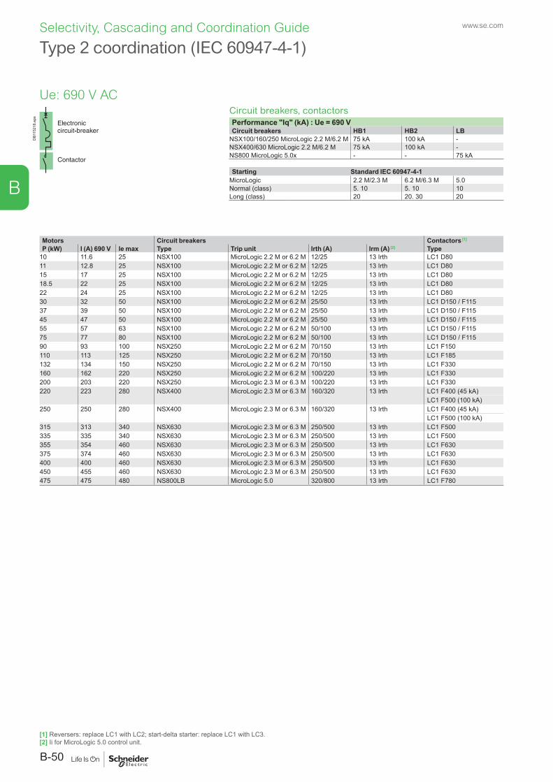
Circuit breakers, contactorsPerformance "Iq" (kA) : Ue = 690 VCircuit breakers HB1 HB2 LB
NSX100/160/250 MicroLogic 2.2 M/6.2 M 75 kA 100 kA -NSX400/630 MicroLogic 2.2 M/6.2 M 75 kA 100 kA -NS800 MicroLogic 5.0x - - 75 kA
Starting Standard IEC 60947-4-1MicroLogic 2.2 M/2.3 M 6.2 M/6.3 M 5.0Normal (class) 5. 10 5. 10 10Long (class) 20 20. 30 20
Motors Circuit breakers Contactors [1]
P (kW) I (A) 690 V Ie max Type Trip unit Irth (A) Irm (A) [2] Type10 11.6 25 NSX100 MicroLogic 2.2 M or 6.2 M 12/25 13 Irth LC1 D8011 12.8 25 NSX100 MicroLogic 2.2 M or 6.2 M 12/25 13 Irth LC1 D8015 17 25 NSX100 MicroLogic 2.2 M or 6.2 M 12/25 13 Irth LC1 D8018.5 22 25 NSX100 MicroLogic 2.2 M or 6.2 M 12/25 13 Irth LC1 D8022 24 25 NSX100 MicroLogic 2.2 M or 6.2 M 12/25 13 Irth LC1 D8030 32 50 NSX100 MicroLogic 2.2 M or 6.2 M 25/50 13 Irth LC1 D150 / F11537 39 50 NSX100 MicroLogic 2.2 M or 6.2 M 25/50 13 Irth LC1 D150 / F11545 47 50 NSX100 MicroLogic 2.2 M or 6.2 M 25/50 13 Irth LC1 D150 / F11555 57 63 NSX100 MicroLogic 2.2 M or 6.2 M 50/100 13 Irth LC1 D150 / F11575 77 80 NSX100 MicroLogic 2.2 M or 6.2 M 50/100 13 Irth LC1 D150 / F11590 93 100 NSX250 MicroLogic 2.2 M or 6.2 M 70/150 13 Irth LC1 F150110 113 125 NSX250 MicroLogic 2.2 M or 6.2 M 70/150 13 Irth LC1 F185132 134 150 NSX250 MicroLogic 2.2 M or 6.2 M 70/150 13 Irth LC1 F330160 162 220 NSX250 MicroLogic 2.2 M or 6.2 M 100/220 13 Irth LC1 F330200 203 220 NSX250 MicroLogic 2.3 M or 6.3 M 100/220 13 Irth LC1 F330220 223 280 NSX400 MicroLogic 2.3 M or 6.3 M 160/320 13 Irth LC1 F400 (45 kA)
LC1 F500 (100 kA)250 250 280 NSX400 MicroLogic 2.3 M or 6.3 M 160/320 13 Irth LC1 F400 (45 kA)
LC1 F500 (100 kA)315 313 340 NSX630 MicroLogic 2.3 M or 6.3 M 250/500 13 Irth LC1 F500335 335 340 NSX630 MicroLogic 2.3 M or 6.3 M 250/500 13 Irth LC1 F500355 354 460 NSX630 MicroLogic 2.3 M or 6.3 M 250/500 13 Irth LC1 F630375 374 460 NSX630 MicroLogic 2.3 M or 6.3 M 250/500 13 Irth LC1 F630400 400 460 NSX630 MicroLogic 2.3 M or 6.3 M 250/500 13 Irth LC1 F630450 455 460 NSX630 MicroLogic 2.3 M or 6.3 M 250/500 13 Irth LC1 F630475 475 480 NS800LB MicroLogic 5.0 320/800 13 Irth LC1 F780
DB1
1521
8.ep
s
Type 2 coordination (IEC 60947-4-1)
Ue: 690 V AC
[1] Reversers: replace LC1 with LC2; start-delta starter: replace LC1 with LC3.[2] Ii for MicroLogic 5.0 control unit.
www.se.com
B-50
B
Selectivity, Cascading and Coordination Guide
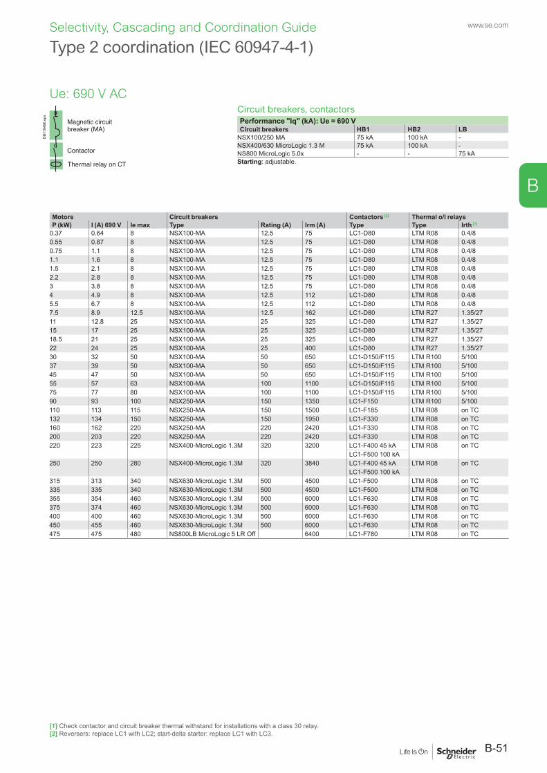
Circuit breakers, contactorsPerformance "Iq" (kA): Ue = 690 VCircuit breakers HB1 HB2 LB
NSX100/250 MA 75 kA 100 kA -NSX400/630 MicroLogic 1.3 M 75 kA 100 kA -NS800 MicroLogic 5.0x - - 75 kAStarting: adjustable.
DB1
1949
6.ep
s
Motors Circuit breakers Contactors [2] Thermal o/l relaysP (kW) I (A) 690 V Ie max Type Rating (A) Irm (A) Type Type Irth [1]
0.37 0.64 8 NSX100-MA 12.5 75 LC1-D80 LTM R08 0.4/80.55 0.87 8 NSX100-MA 12.5 75 LC1-D80 LTM R08 0.4/80.75 1.1 8 NSX100-MA 12.5 75 LC1-D80 LTM R08 0.4/81.1 1.6 8 NSX100-MA 12.5 75 LC1-D80 LTM R08 0.4/81.5 2.1 8 NSX100-MA 12.5 75 LC1-D80 LTM R08 0.4/82.2 2.8 8 NSX100-MA 12.5 75 LC1-D80 LTM R08 0.4/83 3.8 8 NSX100-MA 12.5 75 LC1-D80 LTM R08 0.4/84 4.9 8 NSX100-MA 12.5 112 LC1-D80 LTM R08 0.4/85.5 6.7 8 NSX100-MA 12.5 112 LC1-D80 LTM R08 0.4/87.5 8.9 12.5 NSX100-MA 12.5 162 LC1-D80 LTM R27 1.35/2711 12.8 25 NSX100-MA 25 325 LC1-D80 LTM R27 1.35/2715 17 25 NSX100-MA 25 325 LC1-D80 LTM R27 1.35/2718.5 21 25 NSX100-MA 25 325 LC1-D80 LTM R27 1.35/2722 24 25 NSX100-MA 25 400 LC1-D80 LTM R27 1.35/2730 32 50 NSX100-MA 50 650 LC1-D150/F115 LTM R100 5/10037 39 50 NSX100-MA 50 650 LC1-D150/F115 LTM R100 5/10045 47 50 NSX100-MA 50 650 LC1-D150/F115 LTM R100 5/10055 57 63 NSX100-MA 100 1100 LC1-D150/F115 LTM R100 5/10075 77 80 NSX100-MA 100 1100 LC1-D150/F115 LTM R100 5/10090 93 100 NSX250-MA 150 1350 LC1-F150 LTM R100 5/100110 113 115 NSX250-MA 150 1500 LC1-F185 LTM R08 on TC132 134 150 NSX250-MA 150 1950 LC1-F330 LTM R08 on TC160 162 220 NSX250-MA 220 2420 LC1-F330 LTM R08 on TC200 203 220 NSX250-MA 220 2420 LC1-F330 LTM R08 on TC220 223 225 NSX400-MicroLogic 1.3M 320 3200 LC1-F400 45 kA LTM R08 on TC
LC1-F500 100 kA250 250 280 NSX400-MicroLogic 1.3M 320 3840 LC1-F400 45 kA LTM R08 on TC
LC1-F500 100 kA315 313 340 NSX630-MicroLogic 1.3M 500 4500 LC1-F500 LTM R08 on TC335 335 340 NSX630-MicroLogic 1.3M 500 4500 LC1-F500 LTM R08 on TC355 354 460 NSX630-MicroLogic 1.3M 500 6000 LC1-F630 LTM R08 on TC375 374 460 NSX630-MicroLogic 1.3M 500 6000 LC1-F630 LTM R08 on TC400 400 460 NSX630-MicroLogic 1.3M 500 6000 LC1-F630 LTM R08 on TC450 455 460 NSX630-MicroLogic 1.3M 500 6000 LC1-F630 LTM R08 on TC475 475 480 NS800LB MicroLogic 5 LR Off 6400 LC1-F780 LTM R08 on TC
Type 2 coordination (IEC 60947-4-1)
Ue: 690 V AC
[1] Check contactor and circuit breaker thermal withstand for installations with a class 30 relay.[2] Reversers: replace LC1 with LC2; start-delta starter: replace LC1 with LC3.
B-51
www.se.com
B
Selectivity, Cascading and Coordination Guide
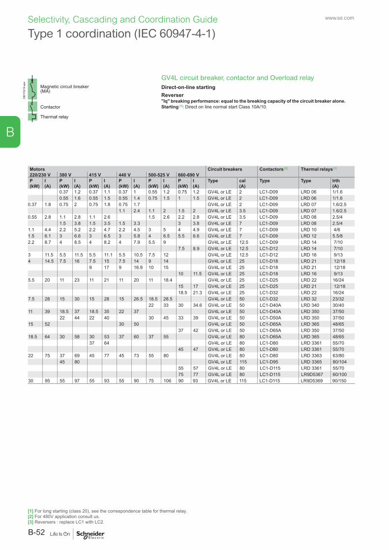
GV4L circuit breaker, contactor and Overload relayDirect-on-line startingReverser"Iq" breaking performance: equal to the breaking capacity of the circuit breaker alone.Starting [1]: Direct on line normal start Class 10A/10.
DB1
1521
9.ep
s
Type 1 coordination (IEC 60947-4-1)
Motors Circuit breakers Contactors [3] Thermal relays [1]
220/230 V 380 V 415 V 440 V 500-525 V 660-690 VP(kW)
I(A)
P(kW)
I(A)
P(kW)
I(A)
P(kW)
I(A)
P(kW)
I(A)
P(kW)
I(A)
Type cal (A)
Type Type Irth (A)
0.37 1.2 0.37 1.1 0.37 1 0.55 1.2 0.75 1.2 GV4L or LE 2 LC1-D09 LRD 06 1/1.60.55 1.6 0.55 1.5 0.55 1.4 0.75 1.5 1 1.5 GV4L or LE 2 LC1-D09 LRD 06 1/1.6
0.37 1.8 0.75 2 0.75 1.8 0.75 1.7 GV4L or LE 2 LC1-D09 LRD 07 1.6/2.51.1 2.4 1.1 2 1.5 2 GV4L or LE 3.5 LC1-D09 LRD 07 1.6/2.5
0.55 2.8 1.1 2.8 1.1 2.6 1.5 2.6 2.2 2.8 GV4L or LE 3.5 LC1-D09 LRD 08 2.5/41.5 3.8 1.5 3.5 1.5 3.3 3 3.8 GV4L or LE 7 LC1-D09 LRD 08 2.5/4
1.1 4.4 2.2 5.2 2.2 4.7 2.2 4.5 3 5 4 4.9 GV4L or LE 7 LC1-D09 LRD 10 4/61.5 6.1 3 6.6 3 6.5 3 5.8 4 6.5 5.5 6.6 GV4L or LE 7 LC1-D09 LRD 12 5.5/82.2 8.7 4 8.5 4 8.2 4 7.9 5.5 9 GV4L or LE 12.5 LC1-D09 LRD 14 7/10
7.5 8.9 GV4L or LE 12.5 LC1-D12 LRD 14 7/103 11.5 5.5 11.5 5.5 11.1 5.5 10.5 7.5 12 GV4L or LE 12.5 LC1-D12 LRD 16 9/134 14.5 7.5 16 7.5 15 7.5 14 9 14 GV4L or LE 25 LC1-D18 LRD 21 12/18
9 17 9 16.9 10 15 GV4L or LE 25 LC1-D18 LRD 21 12/1810 11.5 GV4L or LE 25 LC1-D18 LRD 16 9/13
5.5 20 11 23 11 21 11 20 11 18.4 GV4L or LE 25 LC1-D25 LRD 22 16/2415 17 GV4L or LE 25 LC1-D25 LRD 21 12/1818.5 21.3 GV4L or LE 25 LC1-D32 LRD 22 16/24
7.5 28 15 30 15 28 15 26.5 18.5 28.5 GV4L or LE 50 LC1-D32 LRD 32 23/3222 33 30 34.6 GV4L or LE 50 LC1-D40A LRD 340 30/40
11 39 18.5 37 18.5 35 22 37 GV4L or LE 50 LC1-D40A LRD 350 37/5022 44 22 40 30 45 33 39 GV4L or LE 50 LC1-D50A LRD 350 37/50
15 52 30 50 GV4L or LE 50 LC1-D65A LRD 365 48/6537 42 GV4L or LE 50 LC1-D65A LRD 350 37/50
18.5 64 30 58 30 53 37 60 37 55 GV4L or LE 80 LC1-D65A LRD 365 48/6537 64 GV4L or LE 80 LC1-D80 LRD 3361 55/70
45 47 GV4L or LE 80 LC1-D80 LRD 3361 55/7022 75 37 69 45 77 45 73 55 80 GV4L or LE 80 LC1-D80 LRD 3363 63/80
45 80 GV4L or LE 115 LC1-D95 LRD 3365 80/10455 57 GV4L or LE 80 LC1-D115 LRD 3361 55/7075 77 GV4L or LE 80 LC1-D115 LR9D5367 60/100
30 95 55 97 55 93 55 90 75 106 90 93 GV4L or LE 115 LC1-D115 LR9D5369 90/150
[1] For long starting (class 20), see the correspondence table for thermal relay.[2] For 480V application consult us.[3] Reversers : replace LC1 with LC2.
www.se.com
B-52
B
Selectivity, Cascading and Coordination Guide
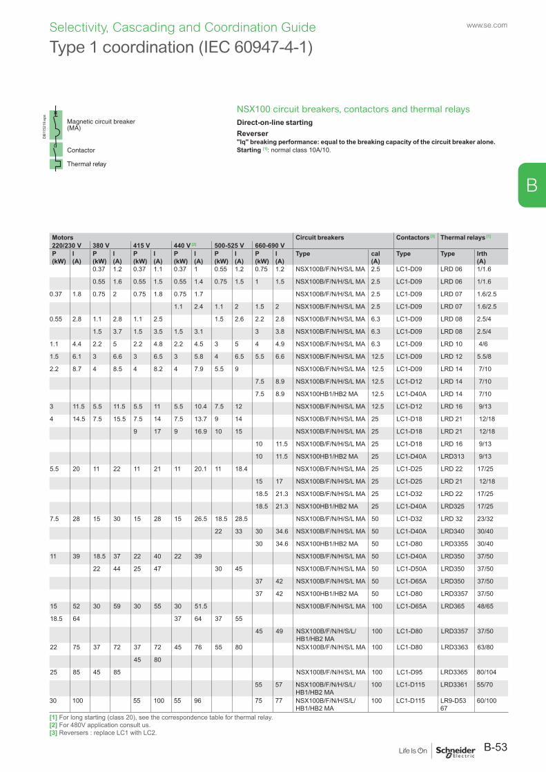
NSX100 circuit breakers, contactors and thermal relaysDirect-on-line startingReverser"Iq" breaking performance: equal to the breaking capacity of the circuit breaker alone.Starting [1]: normal class 10A/10.
DB1
1521
9.ep
s
Type 1 coordination (IEC 60947-4-1)
Motors Circuit breakers Contactors [3] Thermal relays [1]
220/230 V 380 V 415 V 440 V [2] 500-525 V 660-690 VP(kW)
I(A)
P(kW)
I(A)
P(kW)
I(A)
P(kW)
I(A)
P(kW)
I(A)
P(kW)
I(A)
Type cal (A)
Type Type Irth (A)
0.37 1.2 0.37 1.1 0.37 1 0.55 1.2 0.75 1.2 NSX100B/F/N/H/S/L MA 2.5 LC1-D09 LRD 06 1/1.6
0.55 1.6 0.55 1.5 0.55 1.4 0.75 1.5 1 1.5 NSX100B/F/N/H/S/L MA 2.5 LC1-D09 LRD 06 1/1.6
0.37 1.8 0.75 2 0.75 1.8 0.75 1.7 NSX100B/F/N/H/S/L MA 2.5 LC1-D09 LRD 07 1.6/2.5
1.1 2.4 1.1 2 1.5 2 NSX100B/F/N/H/S/L MA 2.5 LC1-D09 LRD 07 1.6/2.5
0.55 2.8 1.1 2.8 1.1 2.5 1.5 2.6 2.2 2.8 NSX100B/F/N/H/S/L MA 6.3 LC1-D09 LRD 08 2.5/4
1.5 3.7 1.5 3.5 1.5 3.1 3 3.8 NSX100B/F/N/H/S/L MA 6.3 LC1-D09 LRD 08 2.5/4
1.1 4.4 2.2 5 2.2 4.8 2.2 4.5 3 5 4 4.9 NSX100B/F/N/H/S/L MA 6.3 LC1-D09 LRD 10 4/6
1.5 6.1 3 6.6 3 6.5 3 5.8 4 6.5 5.5 6.6 NSX100B/F/N/H/S/L MA 12.5 LC1-D09 LRD 12 5.5/8
2.2 8.7 4 8.5 4 8.2 4 7.9 5.5 9 NSX100B/F/N/H/S/L MA 12.5 LC1-D09 LRD 14 7/10
7.5 8.9 NSX100B/F/N/H/S/L MA 12.5 LC1-D12 LRD 14 7/10
7.5 8.9 NSX100HB1/HB2 MA 12.5 LC1-D40A LRD 14 7/10
3 11.5 5.5 11.5 5.5 11 5.5 10.4 7.5 12 NSX100B/F/N/H/S/L MA 12.5 LC1-D12 LRD 16 9/13
4 14.5 7.5 15.5 7.5 14 7.5 13.7 9 14 NSX100B/F/N/H/S/L MA 25 LC1-D18 LRD 21 12/18
9 17 9 16.9 10 15 NSX100B/F/N/H/S/L MA 25 LC1-D18 LRD 21 12/18
10 11.5 NSX100B/F/N/H/S/L MA 25 LC1-D18 LRD 16 9/13
10 11.5 NSX100HB1/HB2 MA 25 LC1-D40A LRD313 9/13
5.5 20 11 22 11 21 11 20.1 11 18.4 NSX100B/F/N/H/S/L MA 25 LC1-D25 LRD 22 17/25
15 17 NSX100B/F/N/H/S/L MA 25 LC1-D25 LRD 21 12/18
18.5 21.3 NSX100B/F/N/H/S/L MA 25 LC1-D32 LRD 22 17/25
18.5 21.3 NSX100HB1/HB2 MA 25 LC1-D40A LRD325 17/25
7.5 28 15 30 15 28 15 26.5 18.5 28.5 NSX100B/F/N/H/S/L MA 50 LC1-D32 LRD 32 23/32
22 33 30 34.6 NSX100B/F/N/H/S/L MA 50 LC1-D40A LRD340 30/40
30 34.6 NSX100HB1/HB2 MA 50 LC1-D80 LRD3355 30/40
11 39 18.5 37 22 40 22 39 NSX100B/F/N/H/S/L MA 50 LC1-D40A LRD350 37/50
22 44 25 47 30 45 NSX100B/F/N/H/S/L MA 50 LC1-D50A LRD350 37/50
37 42 NSX100B/F/N/H/S/L MA 50 LC1-D65A LRD350 37/50
37 42 NSX100HB1/HB2 MA 50 LC1-D80 LRD3357 37/50
15 52 30 59 30 55 30 51.5 NSX100B/F/N/H/S/L MA 100 LC1-D65A LRD365 48/65
18.5 64 37 64 37 55
45 49 NSX100B/F/N/H/S/L/HB1/HB2 MA
100 LC1-D80 LRD3357 37/50
22 75 37 72 37 72 45 76 55 80 NSX100B/F/N/H/S/L MA 100 LC1-D80 LRD3363 63/80
45 80
25 85 45 85 NSX100B/F/N/H/S/L MA 100 LC1-D95 LRD3365 80/104
55 57 NSX100B/F/N/H/S/L/HB1/HB2 MA
100 LC1-D115 LRD3361 55/70
30 100 55 100 55 96 75 77 NSX100B/F/N/H/S/L/HB1/HB2 MA
100 LC1-D115 LR9-D53 67
60/100
[1] For long starting (class 20), see the correspondence table for thermal relay.[2] For 480V application consult us.[3] Reversers : replace LC1 with LC2.
B-53
www.se.com
B
Selectivity, Cascading and Coordination Guide
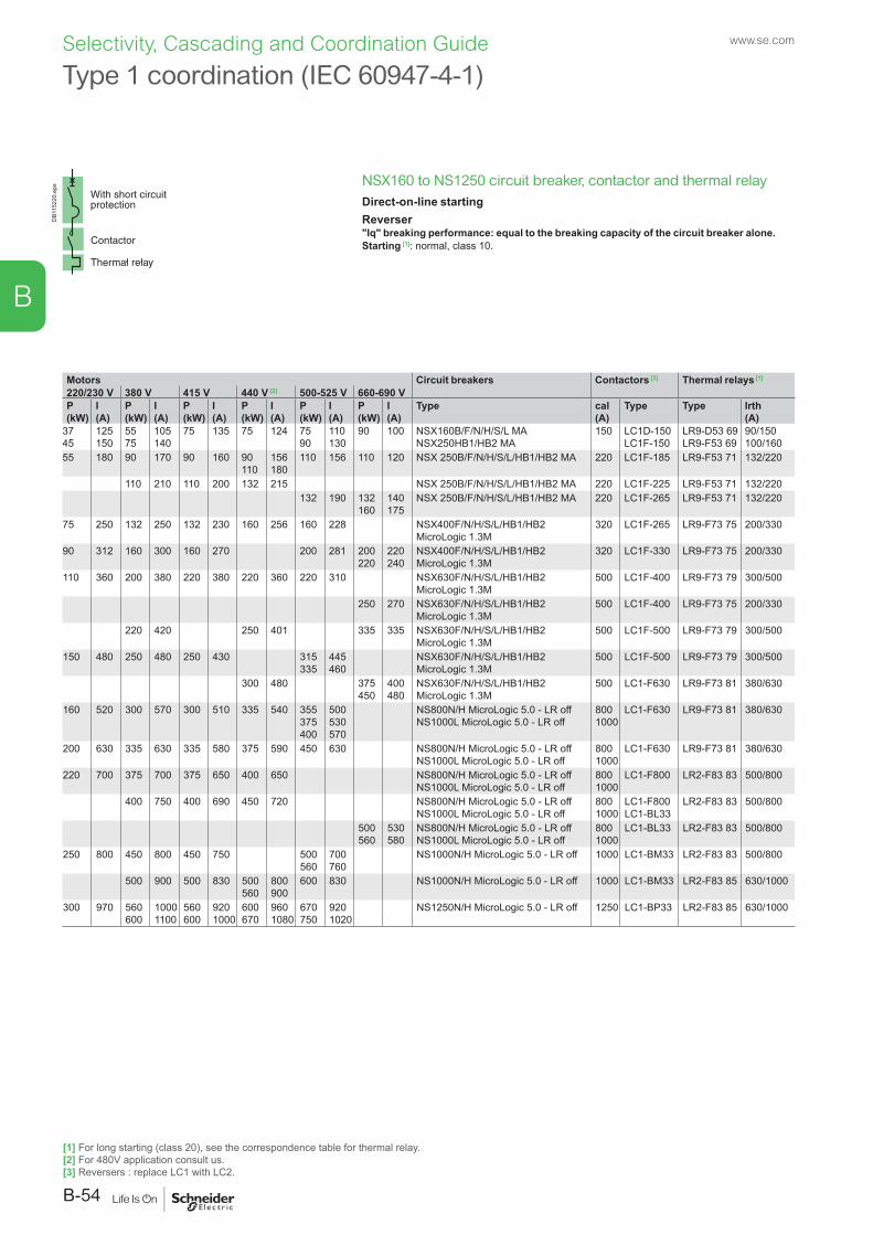
NSX160 to NS1250 circuit breaker, contactor and thermal relayDirect-on-line startingReverser"Iq" breaking performance: equal to the breaking capacity of the circuit breaker alone.Starting [1]: normal, class 10.
DB1
1522
0.ep
s
Type 1 coordination (IEC 60947-4-1)
Motors Circuit breakers Contactors [3] Thermal relays [1]
220/230 V 380 V 415 V 440 V [2] 500-525 V 660-690 VP(kW)
I(A)
P(kW)
I(A)
P(kW)
I(A)
P(kW)
I(A)
P(kW)
I(A)
P(kW)
I(A)
Type cal (A)
Type Type Irth (A)
3745
125150
5575
105140
75 135 75 124 7590
110130
90 100 NSX160B/F/N/H/S/L MANSX250HB1/HB2 MA
150 LC1D-150LC1F-150
LR9-D53 69LR9-F53 69
90/150100/160
55 180 90 170 90 160 90110
156180
110 156 110 120 NSX 250B/F/N/H/S/L/HB1/HB2 MA 220 LC1F-185 LR9-F53 71 132/220
110 210 110 200 132 215 NSX 250B/F/N/H/S/L/HB1/HB2 MA 220 LC1F-225 LR9-F53 71 132/220132 190 132
160140175
NSX 250B/F/N/H/S/L/HB1/HB2 MA 220 LC1F-265 LR9-F53 71 132/220
75 250 132 250 132 230 160 256 160 228 NSX400F/N/H/S/L/HB1/HB2 MicroLogic 1.3M
320 LC1F-265 LR9-F73 75 200/330
90 312 160 300 160 270 200 281 200220
220240
NSX400F/N/H/S/L/HB1/HB2 MicroLogic 1.3M
320 LC1F-330 LR9-F73 75 200/330
110 360 200 380 220 380 220 360 220 310 NSX630F/N/H/S/L/HB1/HB2 MicroLogic 1.3M
500 LC1F-400 LR9-F73 79 300/500
250 270 NSX630F/N/H/S/L/HB1/HB2 MicroLogic 1.3M
500 LC1F-400 LR9-F73 75 200/330
220 420 250 401 335 335 NSX630F/N/H/S/L/HB1/HB2 MicroLogic 1.3M
500 LC1F-500 LR9-F73 79 300/500
150 480 250 480 250 430 315335
445460
NSX630F/N/H/S/L/HB1/HB2 MicroLogic 1.3M
500 LC1F-500 LR9-F73 79 300/500
300 480 375450
400480
NSX630F/N/H/S/L/HB1/HB2 MicroLogic 1.3M
500 LC1-F630 LR9-F73 81 380/630
160 520 300 570 300 510 335 540 355375400
500530570
NS800N/H MicroLogic 5.0 - LR off NS1000L MicroLogic 5.0 - LR off
8001000
LC1-F630 LR9-F73 81 380/630
200 630 335 630 335 580 375 590 450 630 NS800N/H MicroLogic 5.0 - LR offNS1000L MicroLogic 5.0 - LR off
8001000
LC1-F630 LR9-F73 81 380/630
220 700 375 700 375 650 400 650 NS800N/H MicroLogic 5.0 - LR offNS1000L MicroLogic 5.0 - LR off
8001000
LC1-F800 LR2-F83 83 500/800
400 750 400 690 450 720 NS800N/H MicroLogic 5.0 - LR offNS1000L MicroLogic 5.0 - LR off
8001000
LC1-F800LC1-BL33
LR2-F83 83 500/800
500560
530580
NS800N/H MicroLogic 5.0 - LR offNS1000L MicroLogic 5.0 - LR off
8001000
LC1-BL33 LR2-F83 83 500/800
250 800 450 800 450 750 500560
700760
NS1000N/H MicroLogic 5.0 - LR off 1000 LC1-BM33 LR2-F83 83 500/800
500 900 500 830 500560
800900
600 830 NS1000N/H MicroLogic 5.0 - LR off 1000 LC1-BM33 LR2-F83 85 630/1000
300 970 560600
10001100
560600
9201000
600670
9601080
670750
9201020
NS1250N/H MicroLogic 5.0 - LR off 1250 LC1-BP33 LR2-F83 85 630/1000
[1] For long starting (class 20), see the correspondence table for thermal relay.[2] For 480V application consult us.[3] Reversers : replace LC1 with LC2.
www.se.com
B-54
B
Selectivity, Cascading and Coordination Guide
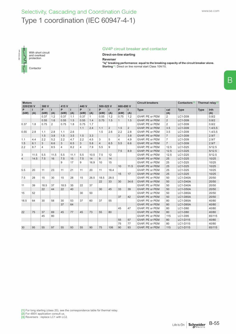
GV4P circuit breaker and contactorDirect-on-line startingReverser"Iq" breaking performance: equal to the breaking capacity of the circuit breaker alone.Starting [1]: Direct on line normal start Class 10A/10.
DB1
1522
2.ep
s
Type 1 coordination (IEC 60947-4-1)
Motors Circuit breakers Contactors [3] Thermal relay [1]
220/230 V 380 V 415 V 440 V 500-525 V 660-690 VP(kW)
I(A)
P(kW)
I(A)
P(kW)
I(A)
P(kW)
I(A)
P(kW)
I(A)
P(kW)
I(A)
Type cal (A)
Type Type Irth (A)
0.37 1.2 0.37 1.1 0.37 1 0.55 1.2 0.75 1.2 GV4P, PE or PEM 2 LC1-D09 0.8/20.55 1.6 0.55 1.5 0.55 1.4 0.75 1.5 1 1.5 GV4P, PE or PEM 2 LC1-D09 0.8/2
0.37 1.8 0.75 2 0.75 1.8 0.75 1.7 GV4P, PE or PEM 2 LC1-D09 0.8/21.1 2.4 1.1 2 1.5 2 GV4P, PE or PEM 3.5 LC1-D09 1.4/3.5
0.55 2.8 1.1 2.8 1.1 2.6 1.5 2.6 2.2 2.8 GV4P, PE or PEM 3.5 LC1-D09 1.4/3.51.5 3.8 1.5 3.5 1.5 3.3 3 3.8 GV4P, PE or PEM 7 LC1-D09 2.9/7
1.1 4.4 2.2 5.2 2.2 4.7 2.2 4.5 3 5 4 4.9 GV4P, PE or PEM 7 LC1-D09 2.9/71.5 6.1 3 6.6 3 6.5 3 5.8 4 6.5 5.5 6.6 GV4P, PE or PEM 7 LC1-D09 2.9/72.2 8.7 4 8.5 4 8.2 4 7.9 5.5 9 GV4P, PE or PEM 12.5 LC1-D25 5/12.5
7.5 8.9 GV4P, PE or PEM 12.5 LC1-D25 5/12.53 11.5 5.5 11.5 5.5 11.1 5.5 10.5 7.5 12 GV4P, PE or PEM 12.5 LC1-D25 5/12.54 14.5 7.5 16 7.5 15 7.5 14 9 14 GV4P, PE or PEM 25 LC1-D25 10/25
9 17 9 16.9 10 15 GV4P, PE or PEM 25 LC1-D25 10/2510 11.5 GV4P, PE or PEM 25 LC1-D25 10/25
5.5 20 11 23 11 21 11 20 11 18.4 GV4P, PE or PEM 25 LC1-D25 10/2515 17 GV4P, PE or PEM 25 LC1-D25 10/25
7.5 28 15 30 15 28 15 26.5 18.5 28.5 GV4P, PE or PEM 50 LC1-D40A 20/5022 33 30 34.6 GV4P, PE or PEM 50 LC1-D40A 20/50
11 39 18.5 37 18.5 35 22 37 GV4P, PE or PEM 50 LC1-D40A 20/5022 44 22 40 30 45 33 39 GV4P, PE or PEM 50 LC1-D50A 20/50
15 52 30 50 GV4P, PE or PEM 50 LC1-D65A 20/5037 42 GV4P, PE or PEM 50 LC1-D65A 20/50
18.5 64 30 58 30 53 37 60 37 55 GV4P, PE or PEM 80 LC1-D65A 40/8037 64 GV4P, PE or PEM 80 LC1-D65A 40/80
45 47 GV4P, PE or PEM 80 LC1-D80 40/8022 75 37 69 45 77 45 73 55 80 GV4P, PE or PEM 80 LC1-D80 40/80
45 80 GV4P, PE or PEM 115 LC1-D95 65/11555 57 GV4P, PE or PEM 80 LC1-D115 40/8075 77 GV4P, PE or PEM 80 LC1-D115 40/80
30 95 55 97 55 93 55 90 75 106 90 93 GV4P, PE or PEM 115 LC1-D115 65/115
[1] For long starting (class 20), see the correspondence table for thermal relay.[2] For 480V application consult us.[3] Reversers : replace LC1 with LC2.
B-55
www.se.com
B
Selectivity, Cascading and Coordination Guide
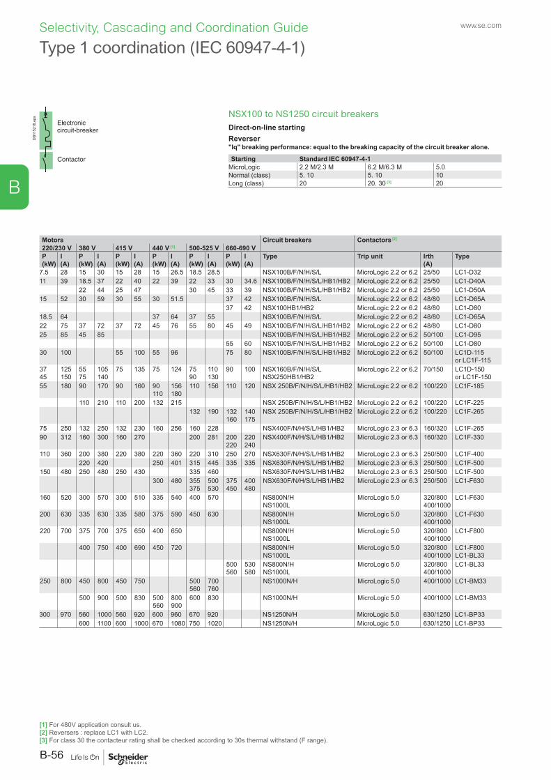
NSX100 to NS1250 circuit breakersDirect-on-line startingReverser"Iq" breaking performance: equal to the breaking capacity of the circuit breaker alone.
Starting Standard IEC 60947-4-1MicroLogic 2.2 M/2.3 M 6.2 M/6.3 M 5.0Normal (class) 5. 10 5. 10 10Long (class) 20 20. 30 [3] 20
DB1
1521
8.ep
s
Type 1 coordination (IEC 60947-4-1)
Motors Circuit breakers Contactors [2]
220/230 V 380 V 415 V 440 V [1] 500-525 V 660-690 VP(kW)
I(A)
P(kW)
I(A)
P(kW)
I(A)
P(kW)
I(A)
P(kW)
I(A)
P(kW)
I(A)
Type Trip unit Irth(A)
Type
7.5 28 15 30 15 28 15 26.5 18.5 28.5 NSX100B/F/N/H/S/L MicroLogic 2.2 or 6.2 25/50 LC1-D3211 39 18.5 37 22 40 22 39 22 33 30 34.6 NSX100B/F/N/H/S/L/HB1/HB2 MicroLogic 2.2 or 6.2 25/50 LC1-D40A
22 44 25 47 30 45 33 39 NSX100B/F/N/H/S/L/HB1/HB2 MicroLogic 2.2 or 6.2 25/50 LC1-D50A15 52 30 59 30 55 30 51.5 37 42 NSX100B/F/N/H/S/L MicroLogic 2.2 or 6.2 48/80 LC1-D65A
37 42 NSX100HB1/HB2 MicroLogic 2.2 or 6.2 48/80 LC1-D8018.5 64 37 64 37 55 NSX100B/F/N/H/S/L MicroLogic 2.2 or 6.2 48/80 LC1-D65A22 75 37 72 37 72 45 76 55 80 45 49 NSX100B/F/N/H/S/L/HB1/HB2 MicroLogic 2.2 or 6.2 48/80 LC1-D8025 85 45 85 NSX100B/F/N/H/S/L/HB1/HB2 MicroLogic 2.2 or 6.2 50/100 LC1-D95
55 60 NSX100B/F/N/H/S/L/HB1/HB2 MicroLogic 2.2 or 6.2 50/100 LC1-D8030 100 55 100 55 96 75 80 NSX100B/F/N/H/S/L/HB1/HB2 MicroLogic 2.2 or 6.2 50/100 LC1D-115
or LC1F-1153745
125150
5575
105140
75 135 75 124 7590
110130
90 100 NSX160B/F/N/H/S/LNSX250HB1/HB2
MicroLogic 2.2 or 6.2 70/150 LC1D-150 or LC1F-150
55 180 90 170 90 160 90110
156180
110 156 110 120 NSX 250B/F/N/H/S/L/HB1/HB2 MicroLogic 2.2 or 6.2 100/220 LC1F-185
110 210 110 200 132 215 NSX 250B/F/N/H/S/L/HB1/HB2 MicroLogic 2.2 or 6.2 100/220 LC1F-225132 190 132
160140175
NSX 250B/F/N/H/S/L/HB1/HB2 MicroLogic 2.2 or 6.2 100/220 LC1F-265
75 250 132 250 132 230 160 256 160 228 NSX400F/N/H/S/L/HB1/HB2 MicroLogic 2.3 or 6.3 160/320 LC1F-26590 312 160 300 160 270 200 281 200
220220240
NSX400F/N/H/S/L/HB1/HB2 MicroLogic 2.3 or 6.3 160/320 LC1F-330
110 360 200 380 220 380 220 360 220 310 250 270 NSX630F/N/H/S/L/HB1/HB2 MicroLogic 2.3 or 6.3 250/500 LC1F-400220 420 250 401 315 445 335 335 NSX630F/N/H/S/L/HB1/HB2 MicroLogic 2.3 or 6.3 250/500 LC1F-500
150 480 250 480 250 430 335 460 NSX630F/N/H/S/L/HB1/HB2 MicroLogic 2.3 or 6.3 250/500 LC1F-500300 480 355
375500530
375450
400480
NSX630F/N/H/S/L/HB1/HB2 MicroLogic 2.3 or 6.3 250/500 LC1-F630
160 520 300 570 300 510 335 540 400 570 NS800N/HNS1000L
MicroLogic 5.0 320/800400/1000
LC1-F630
200 630 335 630 335 580 375 590 450 630 NS800N/HNS1000L
MicroLogic 5.0 320/800400/1000
LC1-F630
220 700 375 700 375 650 400 650 NS800N/HNS1000L
MicroLogic 5.0 320/800400/1000
LC1-F800
400 750 400 690 450 720 NS800N/HNS1000L
MicroLogic 5.0 320/800400/1000
LC1-F800LC1-BL33
500560
530580
NS800N/HNS1000L
MicroLogic 5.0 320/800400/1000
LC1-BL33
250 800 450 800 450 750 500560
700760
NS1000N/H MicroLogic 5.0 400/1000 LC1-BM33
500 900 500 830 500560
800900
600 830 NS1000N/H MicroLogic 5.0 400/1000 LC1-BM33
300 970 560 1000 560 920 600 960 670 920 NS1250N/H MicroLogic 5.0 630/1250 LC1-BP33600 1100 600 1000 670 1080 750 1020 NS1250N/H MicroLogic 5.0 630/1250 LC1-BP33
[1] For 480V application consult us.[2] Reversers : replace LC1 with LC2.[3] For class 30 the contacteur rating shall be checked according to 30s thermal withstand (F range).
www.se.com
B-56
B
Selectivity, Cascading and Coordination Guide
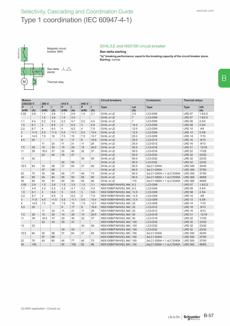
GV4L/LE and NSX100 circuit breakerStar-delta starting"Iq" breaking performance: equal to the breaking capacity of the circuit breaker alone.Starting: normal.
DB4
3255
5.ep
s
Type 1 coordination (IEC 60947-4-1)
Motors Circuit breakers Contactors Thermal relays220/230 V 380 V 415 V 440 V [1]
P(kW)
I(A)
P(kW)
I(A)
P(kW)
I(A)
P(kW)
I(A)
Type cal (A)
Type Type Irth (A)
0.55 2.8 1.1 2.8 1.1 2.6 1.5 3.1 GV4L or LE 3.5 LC3-D09 LRD 07 1.6/2.51.5 3.8 1.5 3.5 GV4L or LE 7 LC3-D09 LRD 07 1.6/2.5
1.1 4.4 2.2 5.2 2.2 4.7 2.2 4.5 GV4L or LE 7 LC3-D09 LRD 08 2.5/41.5 6.1 3 6.6 3 6.5 3 5.8 GV4L or LE 12.5 LC3-D09 LRD 08 2.5/42.2 8.7 4 8.5 4 8.2 4 7.9 GV4L or LE 12.5 LC3-D09 LRD 10 4/63 11.5 5.5 11.5 5.5 11.1 5.5 10.4 GV4L or LE 12.5 LC3-D09 LRD 12 5.5/84 14.5 7.5 16 7.5 15 7.5 13.7 GV4L or LE 25.0 LC3-D09 LRD 14 7/105.5 20 9 17 9 16.9 GV4L or LE 25.0 LC3-D12 LRD 16 9/13
11 23 11 21 11 20 GV4L or LE 25.0 LC3-D12 LRD 16 9/137.5 28 15 30 15 28 15 26.5 GV4L or LE 50.0 LC3-D18 LRD 21 12/1811 39 18.5 37 22 40 22 37 GV4L or LE 50.0 LC3-D18 LRD 22 17/25
22 44 25 47 GV4L or LE 50.0 LC3-D32 LRD 32 23/3215 52 30 50 GV4L or LE 80.0 LC3-D32 LRD 32 23/32
30 53 GV4L or LE 80.0 LC3-D32 LRD 32 23/3218.5 64 30 58 37 64 37 60 GV4L or LE 80.0 3xLC1-D40A LRD 340 30/40
37 69 GV4L or LE 80.0 3xLC1-D40A LRD 350 37/5022 75 45 80 45 77 45 73 GV4L or LE 80.0 2xLC1-D50A + 1 xLC1D40A LRD 350 37/5030 95 45 80 55 93 55 90 GV4L or LE 80.0 2xLC1-D65A + 1 xLC1D40A LRD 365 48/6530 95 55 97 55 93 55 90 GV4L or LE 115 2xLC1-D65A + 1 xLC1D40A LRD 365 48/650.55 2.8 1.5 3.8 1.5 3.5 1.5 3.1 NSX100B/F/N/H/S/L MA 6.3 LC3-D09 LRD 07 1.6/2.51.1 4.4 2.2 5.2 2.2 4.7 2.2 4.5 NSX100B/F/N/H/S/L MA 6.3 LC3-D09 LRD 08 2.5/41.5 6.1 3 6.6 3 6.5 3 5.8 NSX100B/F/N/H/S/L MA 12.5 LC3-D09 LRD 08 2.5/42.2 8.7 4 8.5 4 8.2 4 7.9 NSX100B/F/N/H/S/L MA 12.5 LC3-D09 LRD 10 4/63 11.5 5.5 11.5 5.5 11.1 5.5 10.4 NSX100B/F/N/H/S/L MA 12.5 LC3-D09 LRD 12 5.5/84 14.5 7.5 16 7.5 15 7.5 13.7 NSX100B/F/N/H/S/L MA 25 LC3-D09 LRD 14 7/105.5 20 9 17 9 16.9 NSX100B/F/N/H/S/L MA 25 LC3-D12 LRD 16 9/13
11 23 11 21 11 20 NSX100B/F/N/H/S/L MA 25 LC3-D12 LRD 16 9/137.5 28 15 30 15 28 15 26.5 NSX100B/F/N/H/S/L MA 50 LC3-D18 LRD 21 12/1811 39 18.5 37 22 40 22 37 NSX100B/F/N/H/S/L MA 50 LC3-D18 LRD 22 17/25
22 44 25 47 NSX100B/F/N/H/S/L MA 100 LC3-D32 LRD 32 23/3215 52 30 50 NSX100B/F/N/H/S/L MA 100 LC3-D32 LRD 32 23/32
30 53 NSX100B/F/N/H/S/L MA 100 LC3-D32 LRD 32 23/3218.5 64 30 58 37 64 37 60 NSX100B/F/N/H/S/L MA 100 3xLC1-D40A LRD 340 30/40
37 69 NSX100B/F/N/H/S/L MA 100 3xLC1-D40A LRD 350 37/5022 75 45 80 45 77 45 73 NSX100B/F/N/H/S/L MA 100 2xLC1-D50A + 1 xLC1D40A LRD 350 37/5030 100 55 100 55 96 NSX100B/F/N/H/S/L MA 100 2xLC1-D65A + 1 xLC1D40A LRD 365 48/65
[1] 480V application : Consult us.
B-57
www.se.com
B
Selectivity, Cascading and Coordination Guide
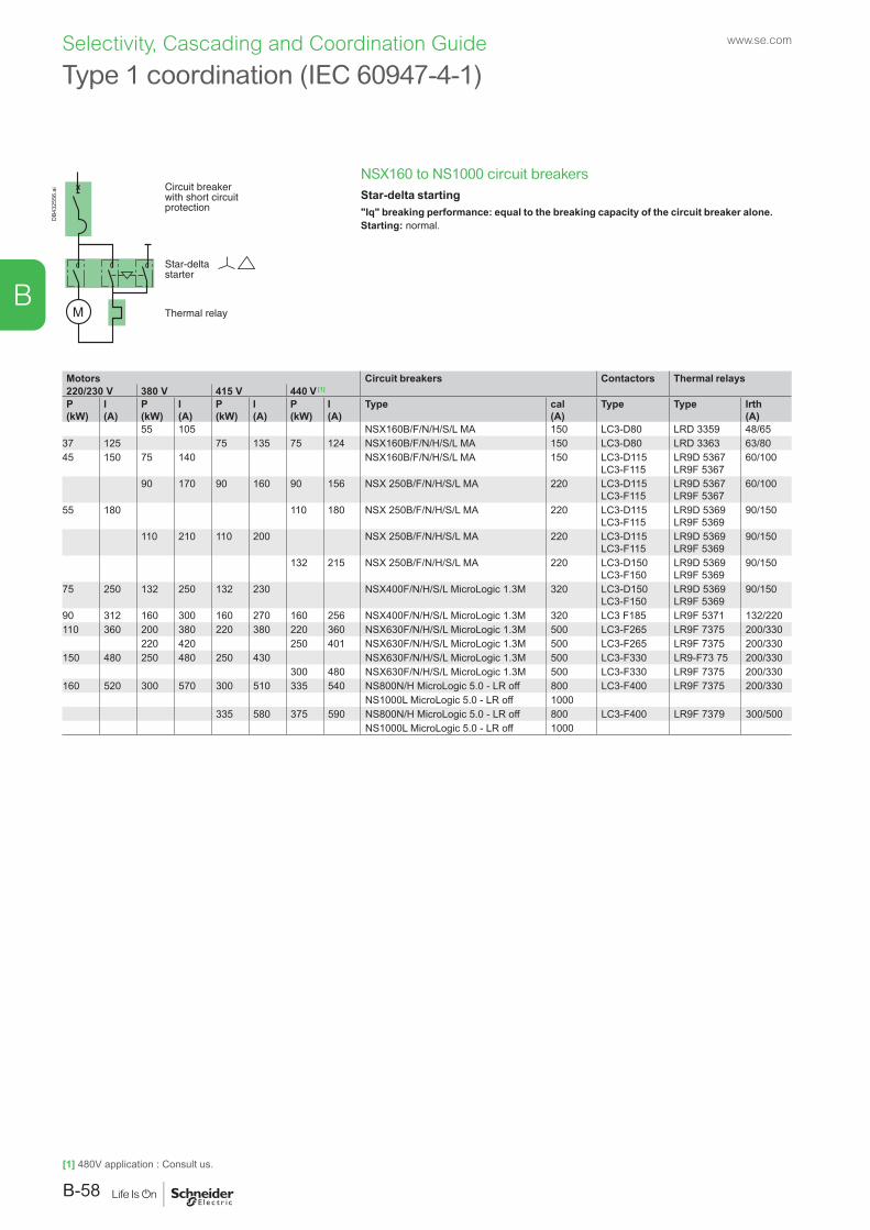
NSX160 to NS1000 circuit breakersStar-delta starting"Iq" breaking performance: equal to the breaking capacity of the circuit breaker alone.Starting: normal.
DB4
3255
6.ai
Type 1 coordination (IEC 60947-4-1)
Motors Circuit breakers Contactors Thermal relays220/230 V 380 V 415 V 440 V [1]
P(kW)
I(A)
P(kW)
I(A)
P(kW)
I(A)
P(kW)
I(A)
Type cal (A)
Type Type Irth (A)
55 105 NSX160B/F/N/H/S/L MA 150 LC3-D80 LRD 3359 48/6537 125 75 135 75 124 NSX160B/F/N/H/S/L MA 150 LC3-D80 LRD 3363 63/8045 150 75 140 NSX160B/F/N/H/S/L MA 150 LC3-D115
LC3-F115LR9D 5367 LR9F 5367
60/100
90 170 90 160 90 156 NSX 250B/F/N/H/S/L MA 220 LC3-D115LC3-F115
LR9D 5367LR9F 5367
60/100
55 180 110 180 NSX 250B/F/N/H/S/L MA 220 LC3-D115LC3-F115
LR9D 5369LR9F 5369
90/150
110 210 110 200 NSX 250B/F/N/H/S/L MA 220 LC3-D115LC3-F115
LR9D 5369LR9F 5369
90/150
132 215 NSX 250B/F/N/H/S/L MA 220 LC3-D150LC3-F150
LR9D 5369LR9F 5369
90/150
75 250 132 250 132 230 NSX400F/N/H/S/L MicroLogic 1.3M 320 LC3-D150LC3-F150
LR9D 5369LR9F 5369
90/150
90 312 160 300 160 270 160 256 NSX400F/N/H/S/L MicroLogic 1.3M 320 LC3 F185 LR9F 5371 132/220110 360 200 380 220 380 220 360 NSX630F/N/H/S/L MicroLogic 1.3M 500 LC3-F265 LR9F 7375 200/330
220 420 250 401 NSX630F/N/H/S/L MicroLogic 1.3M 500 LC3-F265 LR9F 7375 200/330150 480 250 480 250 430 NSX630F/N/H/S/L MicroLogic 1.3M 500 LC3-F330 LR9-F73 75 200/330
300 480 NSX630F/N/H/S/L MicroLogic 1.3M 500 LC3-F330 LR9F 7375 200/330160 520 300 570 300 510 335 540 NS800N/H MicroLogic 5.0 - LR off 800 LC3-F400 LR9F 7375 200/330
NS1000L MicroLogic 5.0 - LR off 1000335 580 375 590 NS800N/H MicroLogic 5.0 - LR off 800 LC3-F400 LR9F 7379 300/500
NS1000L MicroLogic 5.0 - LR off 1000
[1] 480V application : Consult us.
www.se.com
B-58
B
Selectivity, Cascading and Coordination Guide
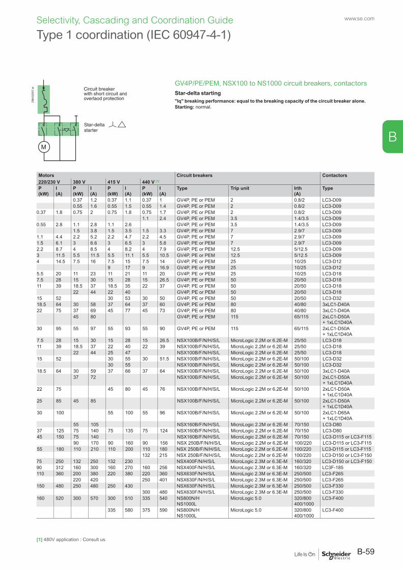
GV4P/PE/PEM, NSX100 to NS1000 circuit breakers, contactorsStar-delta starting"Iq" breaking performance: equal to the breaking capacity of the circuit breaker alone.Starting: normal.
DB4
3255
7.ai
Type 1 coordination (IEC 60947-4-1)
Motors Circuit breakers Contactors220/230 V 380 V 415 V 440 V [1]
P(kW)
I(A)
P(kW)
I(A)
P(kW)
I(A)
P(kW)
I(A)
Type Trip unit Irth(A)
Type
0.37 1.2 0.37 1.1 0.37 1 GV4P, PE or PEM 2 0.8/2 LC3-D090.55 1.6 0.55 1.5 0.55 1.4 GV4P, PE or PEM 2 0.8/2 LC3-D09
0.37 1.8 0.75 2 0.75 1.8 0.75 1.7 GV4P, PE or PEM 2 0.8/2 LC3-D091.1 2.4 GV4P, PE or PEM 3.5 1.4/3.5 LC3-D09
0.55 2.8 1.1 2.8 1.1 2.6 GV4P, PE or PEM 3.5 1.4/3.5 LC3-D091.5 3.8 1.5 3.5 1.5 3.3 GV4P, PE or PEM 7 2.9/7 LC3-D09
1.1 4.4 2.2 5.2 2.2 4.7 2.2 4.5 GV4P, PE or PEM 7 2.9/7 LC3-D091.5 6.1 3 6.6 3 6.5 3 5.8 GV4P, PE or PEM 7 2.9/7 LC3-D092.2 8.7 4 8.5 4 8.2 4 7.9 GV4P, PE or PEM 12.5 5/12.5 LC3-D093 11.5 5.5 11.5 5.5 11.1 5.5 10.5 GV4P, PE or PEM 12.5 5/12.5 LC3-D094 14.5 7.5 16 7.5 15 7.5 14 GV4P, PE or PEM 25 10/25 LC3-D12
9 17 9 16.9 GV4P, PE or PEM 25 10/25 LC3-D125.5 20 11 23 11 21 11 20 GV4P, PE or PEM 25 10/25 LC3-D187.5 28 15 30 15 28 15 26.5 GV4P, PE or PEM 50 20/50 LC3-D1811 39 18.5 37 18.5 35 22 37 GV4P, PE or PEM 50 20/50 LC3-D18
22 44 22 40 GV4P, PE or PEM 50 20/50 LC3-D1815 52 30 53 30 50 GV4P, PE or PEM 50 20/50 LC3-D3218.5 64 30 58 37 64 37 60 GV4P, PE or PEM 80 40/80 3xLC1-D40A22 75 37 69 45 77 45 73 GV4P, PE or PEM 80 40/80 3xLC1-D40A
45 80 GV4P, PE or PEM 115 65/115 2xLC1-D50A + 1xLC1D40A
30 95 55 97 55 93 55 90 GV4P, PE or PEM 115 65/115 2xLC1-D50A + 1xLC1D40A
7.5 28 15 30 15 28 15 26.5 NSX100B/F/N/H/S/L MicroLogic 2.2M or 6.2E-M 25/50 LC3-D1811 39 18.5 37 22 40 22 39 NSX100B/F/N/H/S/L MicroLogic 2.2M or 6.2E-M 25/50 LC3-D18
22 44 25 47 NSX100B/F/N/H/S/L MicroLogic 2.2M or 6.2E-M 25/50 LC3-D1815 52 30 55 30 51.5 NSX100B/F/N/H/S/L MicroLogic 2.2M or 6.2E-M 50/100 LC3-D32
30 55 NSX100B/F/N/H/S/L MicroLogic 2.2M or 6.2E-M 50/100 LC3-D3218.5 64 30 59 37 66 37 64 NSX100B/F/N/H/S/L MicroLogic 2.2M or 6.2E-M 50/100 3xLC1-D40A
37 72 NSX100B/F/N/H/S/L MicroLogic 2.2M or 6.2E-M 50/100 2xLC1-D50A + 1xLC1D40A
22 75 45 80 45 76 NSX100B/F/N/H/S/L MicroLogic 2.2M or 6.2E-M 50/100 2xLC1-D50A + 1xLC1D40A
25 85 45 85 NSX100B/F/N/H/S/L MicroLogic 2.2M or 6.2E-M 50/100 2xLC1-D50A + 1xLC1D40A
30 100 55 100 55 96 NSX100B/F/N/H/S/L MicroLogic 2.2M or 6.2E-M 50/100 2xLC1-D65A + 1xLC1D40A
55 105 NSX160B/F/N/H/S/L MicroLogic 2.2M or 6.2E-M 70/150 LC3-D8037 125 75 140 75 135 75 124 NSX160B/F/N/H/S/L MicroLogic 2.2M or 6.2E-M 70/150 LC3-D8045 150 75 140 NSX160B/F/N/H/S/L MicroLogic 2.2M or 6.2E-M 70/150 LC3-D115 or LC3-F115
90 170 90 160 90 156 NSX 250B/F/N/H/S/L MicroLogic 2.2M or 6.2E-M 100/220 LC3-D115 or LC3-F11555 180 110 210 110 200 110 180 NSX 250B/F/N/H/S/L MicroLogic 2.2M or 6.2E-M 100/220 LC3-D115 or LC3-F115
132 215 NSX 250B/F/N/H/S/L MicroLogic 2.2M or 6.2E-M 100/220 LC3-D150 or LC3-F15075 250 132 250 132 230 NSX400F/N/H/S/L MicroLogic 2.3M or 6.3E-M 160/320 LC3-D150 or LC3-F15090 312 160 300 160 270 160 256 NSX400F/N/H/S/L MicroLogic 2.3M or 6.3E-M 160/320 LC3F-185110 360 200 380 220 380 220 360 NSX630F/N/H/S/L MicroLogic 2.3M or 6.3E-M 250/500 LC3-F265
220 420 250 401 NSX630F/N/H/S/L MicroLogic 2.3M or 6.3E-M 250/500 LC3-F265150 480 250 480 250 430 NSX630F/N/H/S/L MicroLogic 2.3M or 6.3E-M 250/500 LC3-F330
300 480 NSX630F/N/H/S/L MicroLogic 2.3M or 6.3E-M 250/500 LC3-F330160 520 300 570 300 510 335 540 NS800N/H
NS1000LMicroLogic 5.0 320/800
400/1000LC3-F400
335 580 375 590 NS800N/HNS1000L
MicroLogic 5.0 320/800400/1000
LC3-F400
[1] 480V application : Consult us.
B-59
www.se.com
B
Selectivity, Cascading and Coordination Guide
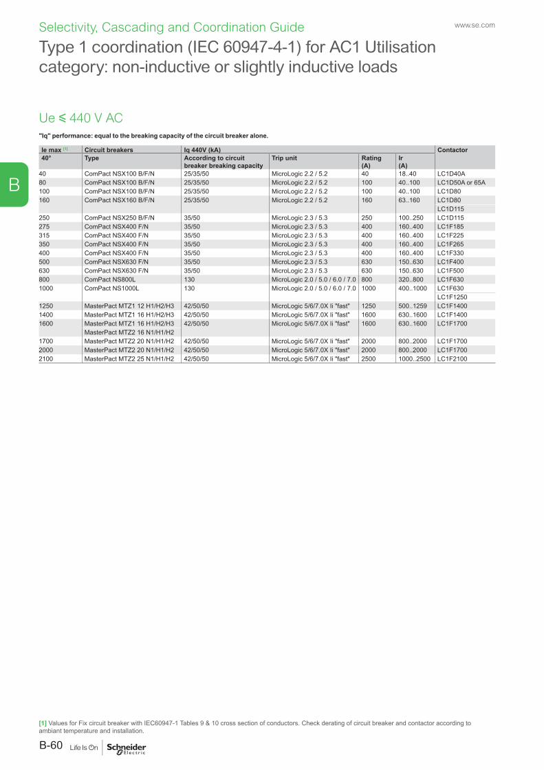
"Iq" performance: equal to the breaking capacity of the circuit breaker alone.
Type 1 coordination (IEC 60947-4-1) for AC1 Utilisation category: non-inductive or slightly inductive loads
Ie max [1] Circuit breakers Iq 440V (kA) Contactor40° Type According to circuit
breaker breaking capacityTrip unit Rating
(A)Ir (A)
40 ComPact NSX100 B/F/N 25/35/50 MicroLogic 2.2 / 5.2 40 18..40 LC1D40A 80 ComPact NSX100 B/F/N 25/35/50 MicroLogic 2.2 / 5.2 100 40..100 LC1D50A or 65A100 ComPact NSX100 B/F/N 25/35/50 MicroLogic 2.2 / 5.2 100 40..100 LC1D80160 ComPact NSX160 B/F/N 25/35/50 MicroLogic 2.2 / 5.2 160 63..160 LC1D80
LC1D115250 ComPact NSX250 B/F/N 35/50 MicroLogic 2.3 / 5.3 250 100..250 LC1D115275 ComPact NSX400 F/N 35/50 MicroLogic 2.3 / 5.3 400 160..400 LC1F185315 ComPact NSX400 F/N 35/50 MicroLogic 2.3 / 5.3 400 160..400 LC1F225350 ComPact NSX400 F/N 35/50 MicroLogic 2.3 / 5.3 400 160..400 LC1F265400 ComPact NSX400 F/N 35/50 MicroLogic 2.3 / 5.3 400 160..400 LC1F330500 ComPact NSX630 F/N 35/50 MicroLogic 2.3 / 5.3 630 150..630 LC1F400630 ComPact NSX630 F/N 35/50 MicroLogic 2.3 / 5.3 630 150..630 LC1F500800 ComPact NS800L 130 MicroLogic 2.0 / 5.0 / 6.0 / 7.0 800 320..800 LC1F6301000 ComPact NS1000L 130 MicroLogic 2.0 / 5.0 / 6.0 / 7.0 1000 400..1000 LC1F630
LC1F12501250 MasterPact MTZ1 12 H1/H2/H3 42/50/50 MicroLogic 5/6/7.0X Ii "fast" 1250 500..1259 LC1F14001400 MasterPact MTZ1 16 H1/H2/H3 42/50/50 MicroLogic 5/6/7.0X Ii "fast" 1600 630..1600 LC1F14001600 MasterPact MTZ1 16 H1/H2/H3 42/50/50 MicroLogic 5/6/7.0X Ii "fast" 1600 630..1600 LC1F1700
MasterPact MTZ2 16 N1/H1/H21700 MasterPact MTZ2 20 N1/H1/H2 42/50/50 MicroLogic 5/6/7.0X Ii "fast" 2000 800..2000 LC1F17002000 MasterPact MTZ2 20 N1/H1/H2 42/50/50 MicroLogic 5/6/7.0X Ii "fast" 2000 800..2000 LC1F17002100 MasterPact MTZ2 25 N1/H1/H2 42/50/50 MicroLogic 5/6/7.0X Ii "fast" 2500 1000..2500 LC1F2100
Ue y 440 V AC
[1] Values for Fix circuit breaker with IEC60947-1 Tables 9 & 10 cross section of conductors. Check derating of circuit breaker and contactor according to ambiant temperature and installation.
www.se.com
B-60
B
Selectivity, Cascading and Coordination Guide
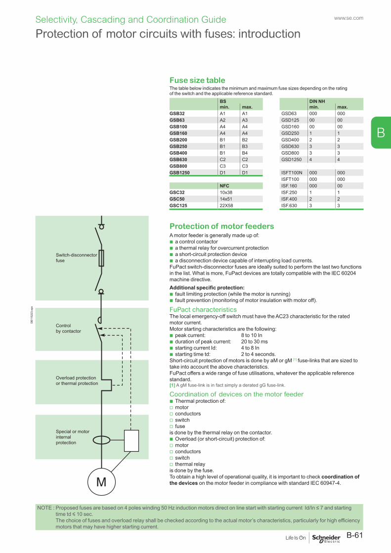
B
Protection of motor circuits with fuses: introduction
Fuse size tableThe table below indicates the minimum and maximum fuse sizes depending on the rating of the switch and the applicable reference standard.
BS DIN NHmin. max. min. max.
GSB32 A1 A1 GSD63 000 000GSB63 A2 A3 GSD125 00 00GSB100 A4 A4 GSD160 00 00GSB160 A4 A4 GSD250 1 1GSB200 B1 B2 GSD400 2 2GSB250 B1 B3 GSD630 3 3GSB400 B1 B4 GSD800 3 3GSB630 C2 C2 GSD1250 4 4GSB800 C3 C3GSB1250 D1 D1 ISFT100N 000 000
ISFT100 000 000NFC ISF.160 000 00
GSC32 10x38 ISF.250 1 1GSC50 14x51 ISF.400 2 2GSC125 22X58 ISF.630 3 3
Switch-disconnector fuse
Control by contactor
Overload protectionor thermal protection
Special or motor internalprotection
DB1
1522
3.ep
s
Protection of motor feedersA motor feeder is generally made up of:
b a control contactor b a thermal relay for overcurrent protection b a short-circuit protection device b a disconnection device capable of interrupting load currents.
FuPact switch-disconnector fuses are ideally suited to perform the last two functions in the list. What is more, FuPact devices are totally compatible with the IEC 60204 machine directive.Additional specific protection:
b fault limiting protection (while the motor is running) b fault prevention (monitoring of motor insulation with motor off).
FuPact characteristicsThe local emergency-off switch must have the AC23 characteristic for the rated motor current.Motor starting characteristics are the following:
b peak current: 8 to 10 In b duration of peak current: 20 to 30 ms b starting current Id: 4 to 8 In b starting time td: 2 to 4 seconds.
Short-circuit protection of motors is done by aM or gM [1] fuse-links that are sized to take into account the above characteristics.FuPact offers a wide range of fuse utilisations, whatever the applicable reference standard.[1] A gM fuse-link is in fact simply a derated gG fuse-link.
Coordination of devices on the motor feeder b Thermal protection of: v motor v conductors v switch v fuse
is done by the thermal relay on the contactor. b Overload (or short-circuit) protection of: v motor v conductors v switch v thermal relay
is done by the fuse.To obtain a high level of operational quality, it is important to check coordination of the devices on the motor feeder in compliance with standard IEC 60947-4.
NOTE : Proposed fuses are based on 4 poles winding 50 Hz induction motors direct on line start with starting current Id/In ≤ 7 and starting time td y 10 sec. The choice of fuses and overload relay shall be checked according to the actual motor’s characteristics, particularly for high efficiency motors that may have higher starting current.
B-61
www.se.comSelectivity, Cascading and Coordination Guide
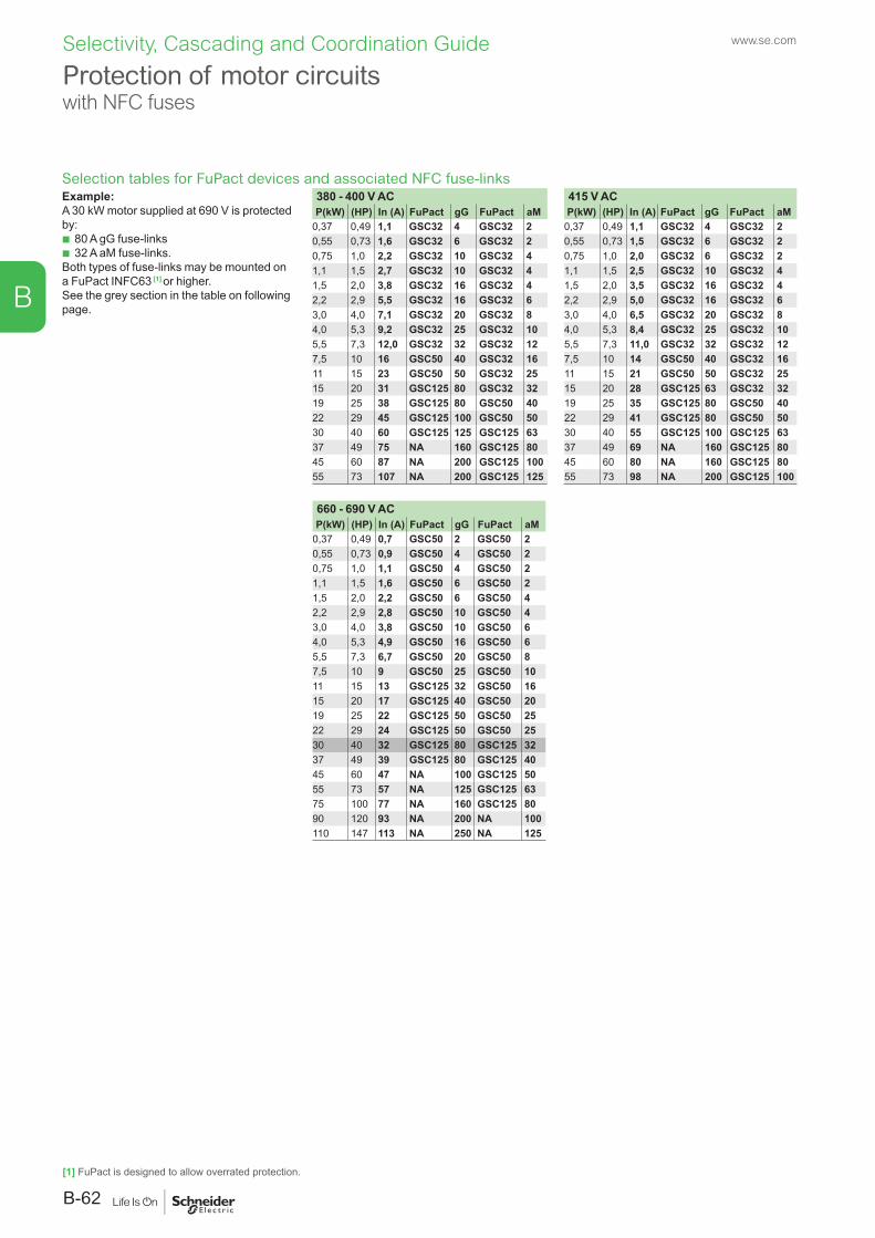
B
Protection of motor circuits with NFC fuses
Selection tables for FuPact devices and associated NFC fuse-linksExample:A 30 kW motor supplied at 690 V is protected by:
b 80 A gG fuse-links b 32 A aM fuse-links.
Both types of fuse-links may be mounted on a FuPact INFC63 [1] or higher.See the grey section in the table on following page.
380 - 400 V AC 415 V ACP(kW) (HP) In (A) FuPact gG FuPact aM P(kW) (HP) In (A) FuPact gG FuPact aM
0,37 0,49 1,1 GSC32 4 GSC32 2 0,37 0,49 1,1 GSC32 4 GSC32 20,55 0,73 1,6 GSC32 6 GSC32 2 0,55 0,73 1,5 GSC32 6 GSC32 20,75 1,0 2,2 GSC32 10 GSC32 4 0,75 1,0 2,0 GSC32 6 GSC32 21,1 1,5 2,7 GSC32 10 GSC32 4 1,1 1,5 2,5 GSC32 10 GSC32 41,5 2,0 3,8 GSC32 16 GSC32 4 1,5 2,0 3,5 GSC32 16 GSC32 42,2 2,9 5,5 GSC32 16 GSC32 6 2,2 2,9 5,0 GSC32 16 GSC32 63,0 4,0 7,1 GSC32 20 GSC32 8 3,0 4,0 6,5 GSC32 20 GSC32 84,0 5,3 9,2 GSC32 25 GSC32 10 4,0 5,3 8,4 GSC32 25 GSC32 105,5 7,3 12,0 GSC32 32 GSC32 12 5,5 7,3 11,0 GSC32 32 GSC32 127,5 10 16 GSC50 40 GSC32 16 7,5 10 14 GSC50 40 GSC32 1611 15 23 GSC50 50 GSC32 25 11 15 21 GSC50 50 GSC32 2515 20 31 GSC125 80 GSC32 32 15 20 28 GSC125 63 GSC32 3219 25 38 GSC125 80 GSC50 40 19 25 35 GSC125 80 GSC50 4022 29 45 GSC125 100 GSC50 50 22 29 41 GSC125 80 GSC50 5030 40 60 GSC125 125 GSC125 63 30 40 55 GSC125 100 GSC125 6337 49 75 NA 160 GSC125 80 37 49 69 NA 160 GSC125 8045 60 87 NA 200 GSC125 100 45 60 80 NA 160 GSC125 8055 73 107 NA 200 GSC125 125 55 73 98 NA 200 GSC125 100
660 - 690 V ACP(kW) (HP) In (A) FuPact gG FuPact aM
0,37 0,49 0,7 GSC50 2 GSC50 20,55 0,73 0,9 GSC50 4 GSC50 20,75 1,0 1,1 GSC50 4 GSC50 21,1 1,5 1,6 GSC50 6 GSC50 21,5 2,0 2,2 GSC50 6 GSC50 42,2 2,9 2,8 GSC50 10 GSC50 43,0 4,0 3,8 GSC50 10 GSC50 64,0 5,3 4,9 GSC50 16 GSC50 65,5 7,3 6,7 GSC50 20 GSC50 87,5 10 9 GSC50 25 GSC50 1011 15 13 GSC125 32 GSC50 1615 20 17 GSC125 40 GSC50 2019 25 22 GSC125 50 GSC50 2522 29 24 GSC125 50 GSC50 2530 40 32 GSC125 80 GSC125 3237 49 39 GSC125 80 GSC125 4045 60 47 NA 100 GSC125 5055 73 57 NA 125 GSC125 6375 100 77 NA 160 GSC125 8090 120 93 NA 200 NA 100110 147 113 NA 250 NA 125
[1] FuPact is designed to allow overrated protection.
www.se.com
B-62
Selectivity, Cascading and Coordination Guide
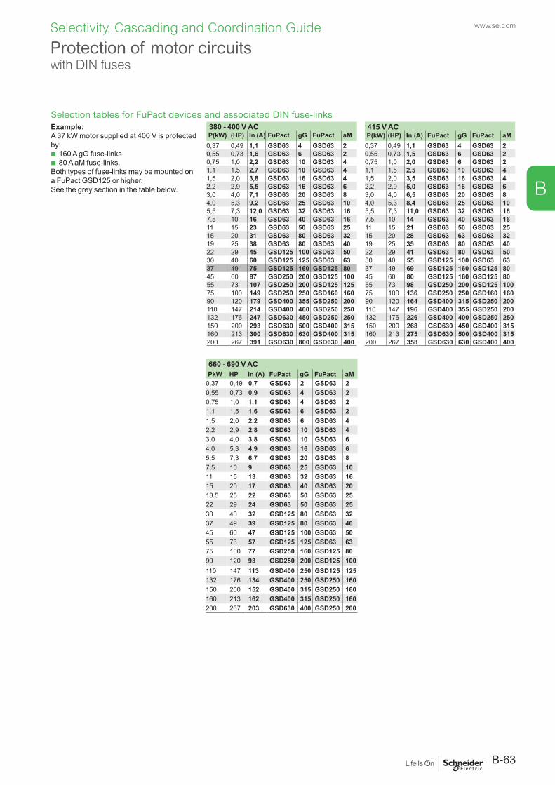
B
Selection tables for FuPact devices and associated DIN fuse-linksExample:A 37 kW motor supplied at 400 V is protected by:
b 160 A gG fuse-links b 80 A aM fuse-links.
Both types of fuse-links may be mounted on a FuPact GSD125 or higher.See the grey section in the table below.
380 - 400 V AC 415 V ACP(kW) (HP) In (A) FuPact gG FuPact aM P(kW) (HP) In (A) FuPact gG FuPact aM
0,37 0,49 1,1 GSD63 4 GSD63 2 0,37 0,49 1,1 GSD63 4 GSD63 20,55 0,73 1,6 GSD63 6 GSD63 2 0,55 0,73 1,5 GSD63 6 GSD63 20,75 1,0 2,2 GSD63 10 GSD63 4 0,75 1,0 2,0 GSD63 6 GSD63 21,1 1,5 2,7 GSD63 10 GSD63 4 1,1 1,5 2,5 GSD63 10 GSD63 41,5 2,0 3,8 GSD63 16 GSD63 4 1,5 2,0 3,5 GSD63 16 GSD63 42,2 2,9 5,5 GSD63 16 GSD63 6 2,2 2,9 5,0 GSD63 16 GSD63 63,0 4,0 7,1 GSD63 20 GSD63 8 3,0 4,0 6,5 GSD63 20 GSD63 84,0 5,3 9,2 GSD63 25 GSD63 10 4,0 5,3 8,4 GSD63 25 GSD63 105,5 7,3 12,0 GSD63 32 GSD63 16 5,5 7,3 11,0 GSD63 32 GSD63 167,5 10 16 GSD63 40 GSD63 16 7,5 10 14 GSD63 40 GSD63 1611 15 23 GSD63 50 GSD63 25 11 15 21 GSD63 50 GSD63 2515 20 31 GSD63 80 GSD63 32 15 20 28 GSD63 63 GSD63 3219 25 38 GSD63 80 GSD63 40 19 25 35 GSD63 80 GSD63 4022 29 45 GSD125 100 GSD63 50 22 29 41 GSD63 80 GSD63 5030 40 60 GSD125 125 GSD63 63 30 40 55 GSD125 100 GSD63 6337 49 75 GSD125 160 GSD125 80 37 49 69 GSD125 160 GSD125 8045 60 87 GSD250 200 GSD125 100 45 60 80 GSD125 160 GSD125 8055 73 107 GSD250 200 GSD125 125 55 73 98 GSD250 200 GSD125 10075 100 149 GSD250 250 GSD160 160 75 100 136 GSD250 250 GSD160 16090 120 179 GSD400 355 GSD250 200 90 120 164 GSD400 315 GSD250 200110 147 214 GSD400 400 GSD250 250 110 147 196 GSD400 355 GSD250 200132 176 247 GSD630 450 GSD250 250 132 176 226 GSD400 400 GSD250 250150 200 293 GSD630 500 GSD400 315 150 200 268 GSD630 450 GSD400 315160 213 300 GSD630 630 GSD400 315 160 213 275 GSD630 500 GSD400 315200 267 391 GSD630 800 GSD630 400 200 267 358 GSD630 630 GSD400 400
660 - 690 V ACPkW HP In (A) FuPact gG FuPact aM
0,37 0,49 0,7 GSD63 2 GSD63 20,55 0,73 0,9 GSD63 4 GSD63 20,75 1,0 1,1 GSD63 4 GSD63 21,1 1,5 1,6 GSD63 6 GSD63 21,5 2,0 2,2 GSD63 6 GSD63 42,2 2,9 2,8 GSD63 10 GSD63 43,0 4,0 3,8 GSD63 10 GSD63 64,0 5,3 4,9 GSD63 16 GSD63 65,5 7,3 6,7 GSD63 20 GSD63 87,5 10 9 GSD63 25 GSD63 1011 15 13 GSD63 32 GSD63 1615 20 17 GSD63 40 GSD63 2018.5 25 22 GSD63 50 GSD63 2522 29 24 GSD63 50 GSD63 2530 40 32 GSD125 80 GSD63 3237 49 39 GSD125 80 GSD63 4045 60 47 GSD125 100 GSD63 5055 73 57 GSD125 125 GSD63 6375 100 77 GSD250 160 GSD125 8090 120 93 GSD250 200 GSD125 100110 147 113 GSD400 250 GSD125 125132 176 134 GSD400 250 GSD250 160150 200 152 GSD400 315 GSD250 160160 213 162 GSD400 315 GSD250 160200 267 203 GSD630 400 GSD250 200
Protection of motor circuits with DIN fuses
B-63
www.se.comSelectivity, Cascading and Coordination Guide
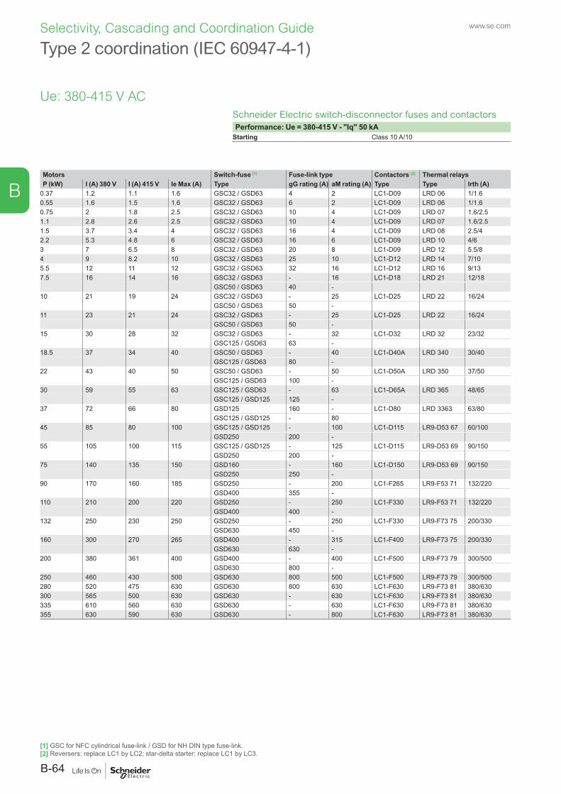
B
Type 2 coordination (IEC 60947-4-1)
Schneider Electric switch-disconnector fuses and contactorsPerformance: Ue = 380-415 V - "Iq" 50 kA
Starting Class 10 A/10
Motors Switch-fuse [1] Fuse-link type Contactors [2] Thermal relaysP (kW) I (A) 380 V I (A) 415 V Ie Max (A) Type gG rating (A) aM rating (A) Type Type Irth (A)
0.37 1.2 1.1 1.6 GSC32 / GSD63 4 2 LC1-D09 LRD 06 1/1.60.55 1.6 1.5 1.6 GSC32 / GSD63 6 2 LC1-D09 LRD 06 1/1.60.75 2 1.8 2.5 GSC32 / GSD63 10 4 LC1-D09 LRD 07 1.6/2.51.1 2.8 2.6 2.5 GSC32 / GSD63 10 4 LC1-D09 LRD 07 1.6/2.51.5 3.7 3.4 4 GSC32 / GSD63 16 4 LC1-D09 LRD 08 2.5/42.2 5.3 4.8 6 GSC32 / GSD63 16 6 LC1-D09 LRD 10 4/63 7 6.5 8 GSC32 / GSD63 20 8 LC1-D09 LRD 12 5.5/84 9 8.2 10 GSC32 / GSD63 25 10 LC1-D12 LRD 14 7/105.5 12 11 12 GSC32 / GSD63 32 16 LC1-D12 LRD 16 9/137.5 16 14 16 GSC32 / GSD63 - 16 LC1-D18 LRD 21 12/18
GSC50 / GSD63 40 -10 21 19 24 GSC32 / GSD63 - 25 LC1-D25 LRD 22 16/24
GSC50 / GSD63 50 -11 23 21 24 GSC32 / GSD63 - 25 LC1-D25 LRD 22 16/24
GSC50 / GSD63 50 -15 30 28 32 GSC32 / GSD63 - 32 LC1-D32 LRD 32 23/32
GSC125 / GSD63 63 -18.5 37 34 40 GSC50 / GSD63 - 40 LC1-D40A LRD 340 30/40
GSC125 / GSD63 80 -22 43 40 50 GSC50 / GSD63 - 50 LC1-D50A LRD 350 37/50
GSC125 / GSD63 100 -30 59 55 63 GSC125 / GSD63 - 63 LC1-D65A LRD 365 48/65
GSC125 / GSD125 125 -37 72 66 80 GSD125 160 - LC1-D80 LRD 3363 63/80
GSC125 / GSD125 - 8045 85 80 100 GSC125 / GSD125 - 100 LC1-D115 LR9-D53 67 60/100
GSD250 200 -55 105 100 115 GSC125 / GSD125 - 125 LC1-D115 LR9-D53 69 90/150 GSD250 200 - 75 140 135 150 GSD160 - 160 LC1-D150 LR9-D53 69 90/150
GSD250 250 -90 170 160 185 GSD250 - 200 LC1-F265 LR9-F53 71 132/220
GSD400 355 -110 210 200 220 GSD250 - 250 LC1-F330 LR9-F53 71 132/220
GSD400 400 - 132 250 230 250 GSD250 - 250 LC1-F330 LR9-F73 75 200/330
GSD630 450 - 160 300 270 265 GSD400 - 315 LC1-F400 LR9-F73 75 200/330
GSD630 630 -200 380 361 400 GSD400 - 400 LC1-F500 LR9-F73 79 300/500
GSD630 800 -250 460 430 500 GSD630 800 500 LC1-F500 LR9-F73 79 300/500280 520 475 630 GSD630 800 630 LC1-F630 LR9-F73 81 380/630300 565 500 630 GSD630 - 630 LC1-F630 LR9-F73 81 380/630335 610 560 630 GSD630 - 630 LC1-F630 LR9-F73 81 380/630355 630 590 630 GSD630 - 800 LC1-F630 LR9-F73 81 380/630
Ue: 380-415 V AC
[1] GSC for NFC cylindrical fuse-link / GSD for NH DIN type fuse-link.[2] Reversers: replace LC1 by LC2; star-delta starter: replace LC1 by LC3.
www.se.com
B-64
Selectivity, Cascading and Coordination Guide
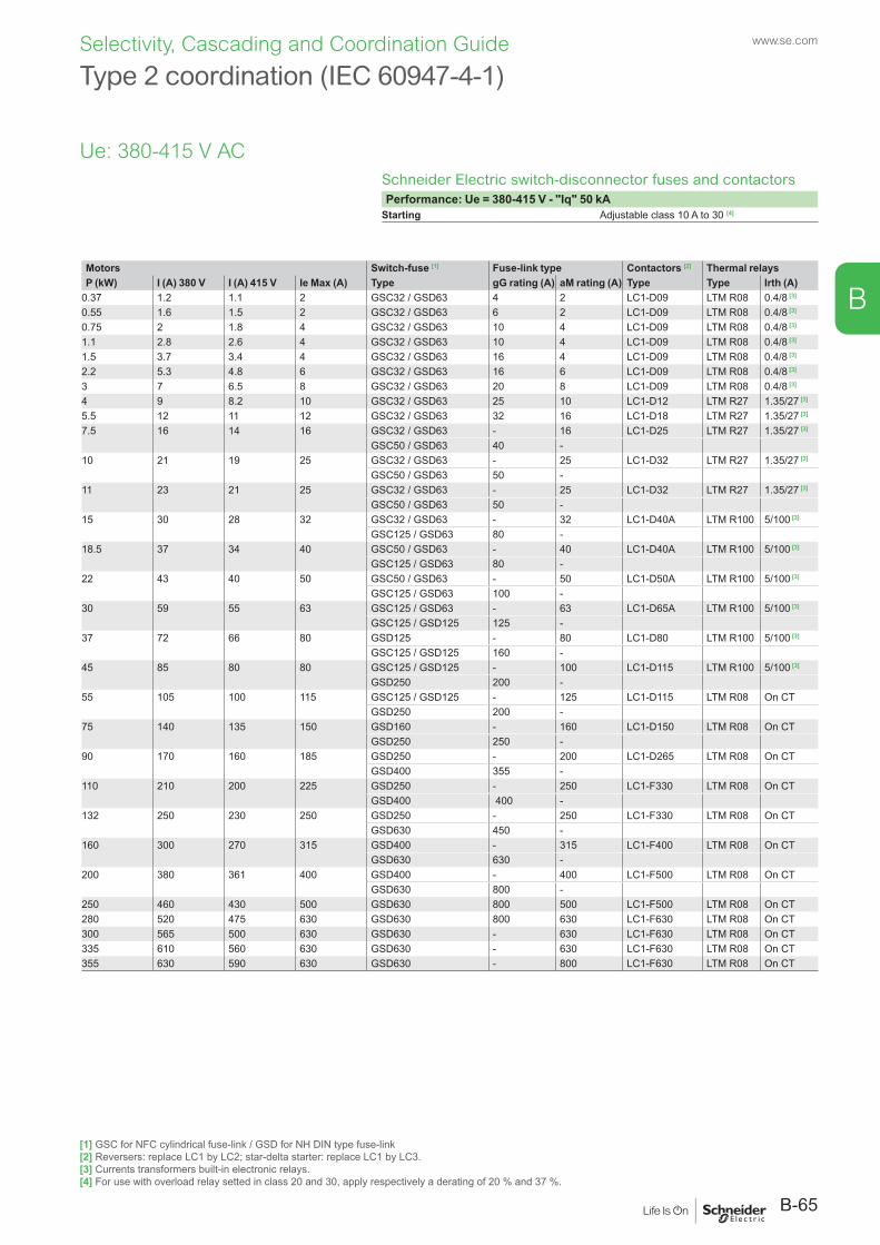
B
Type 2 coordination (IEC 60947-4-1)
Schneider Electric switch-disconnector fuses and contactorsPerformance: Ue = 380-415 V - "Iq" 50 kA
Starting Adjustable class 10 A to 30 [4]
Motors Switch-fuse [1] Fuse-link type Contactors [2] Thermal relaysP (kW) I (A) 380 V I (A) 415 V Ie Max (A) Type gG rating (A) aM rating (A) Type Type Irth (A)
0.37 1.2 1.1 2 GSC32 / GSD63 4 2 LC1-D09 LTM R08 0.4/8 [3]
0.55 1.6 1.5 2 GSC32 / GSD63 6 2 LC1-D09 LTM R08 0.4/8 [3]
0.75 2 1.8 4 GSC32 / GSD63 10 4 LC1-D09 LTM R08 0.4/8 [3]
1.1 2.8 2.6 4 GSC32 / GSD63 10 4 LC1-D09 LTM R08 0.4/8 [3]
1.5 3.7 3.4 4 GSC32 / GSD63 16 4 LC1-D09 LTM R08 0.4/8 [3]
2.2 5.3 4.8 6 GSC32 / GSD63 16 6 LC1-D09 LTM R08 0.4/8 [3]
3 7 6.5 8 GSC32 / GSD63 20 8 LC1-D09 LTM R08 0.4/8 [3]
4 9 8.2 10 GSC32 / GSD63 25 10 LC1-D12 LTM R27 1.35/27 [3]
5.5 12 11 12 GSC32 / GSD63 32 16 LC1-D18 LTM R27 1.35/27 [3]
7.5 16 14 16 GSC32 / GSD63 - 16 LC1-D25 LTM R27 1.35/27 [3]
GSC50 / GSD63 40 -10 21 19 25 GSC32 / GSD63 - 25 LC1-D32 LTM R27 1.35/27 [3]
GSC50 / GSD63 50 -11 23 21 25 GSC32 / GSD63 - 25 LC1-D32 LTM R27 1.35/27 [3]
GSC50 / GSD63 50 -15 30 28 32 GSC32 / GSD63 - 32 LC1-D40A LTM R100 5/100 [3]
GSC125 / GSD63 80 -18.5 37 34 40 GSC50 / GSD63 - 40 LC1-D40A LTM R100 5/100 [3]
GSC125 / GSD63 80 -22 43 40 50 GSC50 / GSD63 - 50 LC1-D50A LTM R100 5/100 [3]
GSC125 / GSD63 100 -30 59 55 63 GSC125 / GSD63 - 63 LC1-D65A LTM R100 5/100 [3]
GSC125 / GSD125 125 -37 72 66 80 GSD125 - 80 LC1-D80 LTM R100 5/100 [3]
GSC125 / GSD125 160 -45 85 80 80 GSC125 / GSD125 - 100 LC1-D115 LTM R100 5/100 [3]
GSD250 200 -55 105 100 115 GSC125 / GSD125 - 125 LC1-D115 LTM R08 On CT
GSD250 200 -75 140 135 150 GSD160 - 160 LC1-D150 LTM R08 On CT GSD250 250 -90 170 160 185 GSD250 - 200 LC1-D265 LTM R08 On CT GSD400 355 -110 210 200 225 GSD250 - 250 LC1-F330 LTM R08 On CT
GSD400 400 - 132 250 230 250 GSD250 - 250 LC1-F330 LTM R08 On CT
GSD630 450 -160 300 270 315 GSD400 - 315 LC1-F400 LTM R08 On CT
GSD630 630 -200 380 361 400 GSD400 - 400 LC1-F500 LTM R08 On CT
GSD630 800 -250 460 430 500 GSD630 800 500 LC1-F500 LTM R08 On CT280 520 475 630 GSD630 800 630 LC1-F630 LTM R08 On CT300 565 500 630 GSD630 - 630 LC1-F630 LTM R08 On CT335 610 560 630 GSD630 - 630 LC1-F630 LTM R08 On CT355 630 590 630 GSD630 - 800 LC1-F630 LTM R08 On CT
Ue: 380-415 V AC
[1] GSC for NFC cylindrical fuse-link / GSD for NH DIN type fuse-link[2] Reversers: replace LC1 by LC2; star-delta starter: replace LC1 by LC3.[3] Currents transformers built-in electronic relays.[4] For use with overload relay setted in class 20 and 30, apply respectively a derating of 20 % and 37 %.
B-65
www.se.comSelectivity, Cascading and Coordination Guide
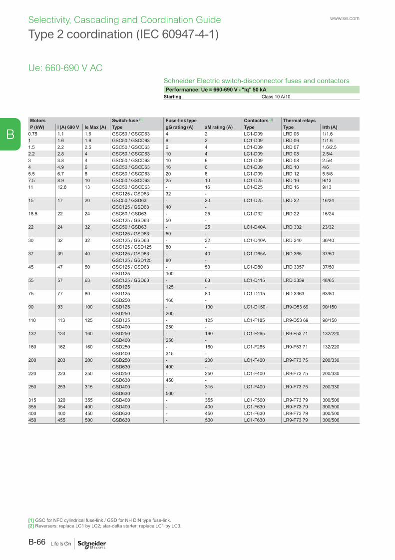
B
Type 2 coordination (IEC 60947-4-1)
Schneider Electric switch-disconnector fuses and contactorsPerformance: Ue = 660-690 V - "Iq" 50 kA
Starting Class 10 A/10
Motors Switch-fuse [1] Fuse-link type Contactors [2] Thermal relaysP (kW) I (A) 690 V Ie Max (A) Type gG rating (A) aM rating (A) Type Type Irth (A)
0.75 1.1 1.6 GSC50 / GSCD63 4 2 LC1-D09 LRD 06 1/1.61 1.6 1.6 GSC50 / GSCD63 6 2 LC1-D09 LRD 06 1/1.61.5 2.2 2.5 GSC50 / GSCD63 6 4 LC1-D09 LRD 07 1.6/2.52.2 2.8 4 GSC50 / GSCD63 10 4 LC1-D09 LRD 08 2.5/43 3.8 4 GSC50 / GSCD63 10 6 LC1-D09 LRD 08 2.5/44 4.9 6 GSC50 / GSCD63 16 6 LC1-D09 LRD 10 4/65.5 6.7 8 GSC50 / GSCD63 20 8 LC1-D09 LRD 12 5.5/87.5 8.9 10 GSC50 / GSCD63 25 10 LC1-D25 LRD 16 9/1311 12.8 13 GSC50 / GSCD63 - 16 LC1-D25 LRD 16 9/13
GSC125 / GSD63 32 -15 17 20 GSC50 / GSD63 - 20 LC1-D25 LRD 22 16/24
GSC125 / GSD63 40 -18.5 22 24 GSC50 / GSD63 - 25 LC1-D32 LRD 22 16/24
GSC125 / GSD63 50 -22 24 32 GSC50 / GSD63 - 25 LC1-D40A LRD 332 23/32
GSC125 / GSD63 50 -30 32 32 GSC125 / GSD63 - 32 LC1-D40A LRD 340 30/40
GSC125 / GSD125 80 -37 39 40 GSC125 / GSD63 - 40 LC1-D65A LRD 365 37/50
GSC125 / GSD125 80 -45 47 50 GSC125 / GSD63 - 50 LC1-D80 LRD 3357 37/50
GSD125 100 -55 57 63 GSC125 / GSD63 - 63 LC1-D115 LRD 3359 48/65
GSD125 125 -75 77 80 GSD125 - 80 LC1-D115 LRD 3363 63/80
GSD250 160 -90 93 100 GSD125 - 100 LC1-D150 LR9-D53 69 90/150
GSD250 200 -110 113 125 GSD125 - 125 LC1-F185 LR9-D53 69 90/150
GSD400 250 -132 134 160 GSD250 - 160 LC1-F265 LR9-F53 71 132/220
GSD400 250 -160 162 160 GSD250 - 160 LC1-F265 LR9-F53 71 132/220
GSD400 315 -200 203 200 GSD250 - 200 LC1-F400 LR9-F73 75 200/330
GSD630 400 -220 223 250 GSD250 - 250 LC1-F400 LR9-F73 75 200/330
GSD630 450 -250 253 315 GSD400 - 315 LC1-F400 LR9-F73 75 200/330
GSD630 500 -315 320 355 GSD400 - 355 LC1-F500 LR9-F73 79 300/500355 354 400 GSD400 - 400 LC1-F630 LR9-F73 79 300/500400 400 450 GSD630 - 450 LC1-F630 LR9-F73 79 300/500450 455 500 GSD630 - 500 LC1-F630 LR9-F73 79 300/500
Ue: 660-690 V AC
[1] GSC for NFC cylindrical fuse-link / GSD for NH DIN type fuse-link.[2] Reversers: replace LC1 by LC2; star-delta starter: replace LC1 by LC3.
www.se.com
B-66
Selectivity, Cascading and Coordination Guide
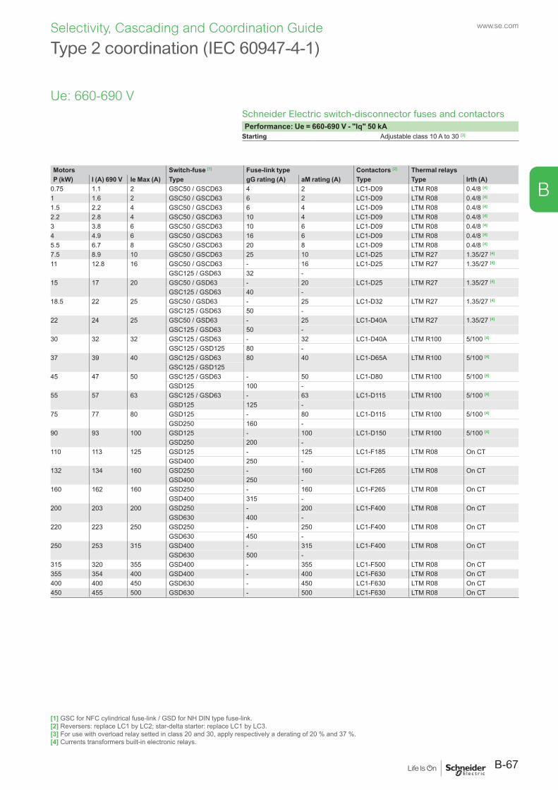
B
Schneider Electric switch-disconnector fuses and contactorsPerformance: Ue = 660-690 V - "Iq" 50 kA
Starting Adjustable class 10 A to 30 [3]
Motors Switch-fuse [1] Fuse-link type Contactors [2] Thermal relaysP (kW) I (A) 690 V Ie Max (A) Type gG rating (A) aM rating (A) Type Type Irth (A)
0.75 1.1 2 GSC50 / GSCD63 4 2 LC1-D09 LTM R08 0.4/8 [4]
1 1.6 2 GSC50 / GSCD63 6 2 LC1-D09 LTM R08 0.4/8 [4]
1.5 2.2 4 GSC50 / GSCD63 6 4 LC1-D09 LTM R08 0.4/8 [4]
2.2 2.8 4 GSC50 / GSCD63 10 4 LC1-D09 LTM R08 0.4/8 [4]
3 3.8 6 GSC50 / GSCD63 10 6 LC1-D09 LTM R08 0.4/8 [4]
4 4.9 6 GSC50 / GSCD63 16 6 LC1-D09 LTM R08 0.4/8 [4]
5.5 6.7 8 GSC50 / GSCD63 20 8 LC1-D09 LTM R08 0.4/8 [4]
7.5 8.9 10 GSC50 / GSCD63 25 10 LC1-D25 LTM R27 1.35/27 [4]
11 12.8 16 GSC50 / GSCD63 - 16 LC1-D25 LTM R27 1.35/27 [4]
GSC125 / GSD63 32 -15 17 20 GSC50 / GSD63 - 20 LC1-D25 LTM R27 1.35/27 [4]
GSC125 / GSD63 40 -18.5 22 25 GSC50 / GSD63 - 25 LC1-D32 LTM R27 1.35/27 [4]
GSC125 / GSD63 50 -22 24 25 GSC50 / GSD63 - 25 LC1-D40A LTM R27 1.35/27 [4]
GSC125 / GSD63 50 -30 32 32 GSC125 / GSD63 - 32 LC1-D40A LTM R100 5/100 [4]
GSC125 / GSD125 80 -37 39 40 GSC125 / GSD63 80 40 LC1-D65A LTM R100 5/100 [4]
GSC125 / GSD12545 47 50 GSC125 / GSD63 - 50 LC1-D80 LTM R100 5/100 [4]
GSD125 100 -55 57 63 GSC125 / GSD63 - 63 LC1-D115 LTM R100 5/100 [4]
GSD125 125 -75 77 80 GSD125 - 80 LC1-D115 LTM R100 5/100 [4]
GSD250 160 -90 93 100 GSD125 - 100 LC1-D150 LTM R100 5/100 [4]
GSD250 200 -110 113 125 GSD125 - 125 LC1-F185 LTM R08 On CT
GSD400 250 -132 134 160 GSD250 - 160 LC1-F265 LTM R08 On CT
GSD400 250 -160 162 160 GSD250 - 160 LC1-F265 LTM R08 On CT
GSD400 315 -200 203 200 GSD250 - 200 LC1-F400 LTM R08 On CT
GSD630 400 -220 223 250 GSD250 - 250 LC1-F400 LTM R08 On CT
GSD630 450 -250 253 315 GSD400 - 315 LC1-F400 LTM R08 On CT
GSD630 500 -315 320 355 GSD400 - 355 LC1-F500 LTM R08 On CT355 354 400 GSD400 - 400 LC1-F630 LTM R08 On CT400 400 450 GSD630 - 450 LC1-F630 LTM R08 On CT450 455 500 GSD630 - 500 LC1-F630 LTM R08 On CT
Type 2 coordination (IEC 60947-4-1)
Ue: 660-690 V
[1] GSC for NFC cylindrical fuse-link / GSD for NH DIN type fuse-link.[2] Reversers: replace LC1 by LC2; star-delta starter: replace LC1 by LC3.[3] For use with overload relay setted in class 20 and 30, apply respectively a derating of 20 % and 37 %.[4] Currents transformers built-in electronic relays.
B-67
www.se.comSelectivity, Cascading and Coordination Guide
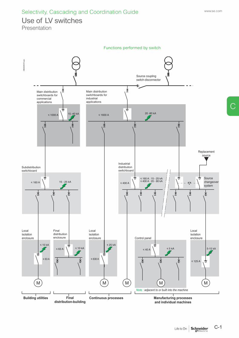
C-1
www.se.com
C
Selectivity, Cascading and Coordination Guide
Functions performed by switch
DB4
0206
1R.e
psUse of LV switchesPresentation
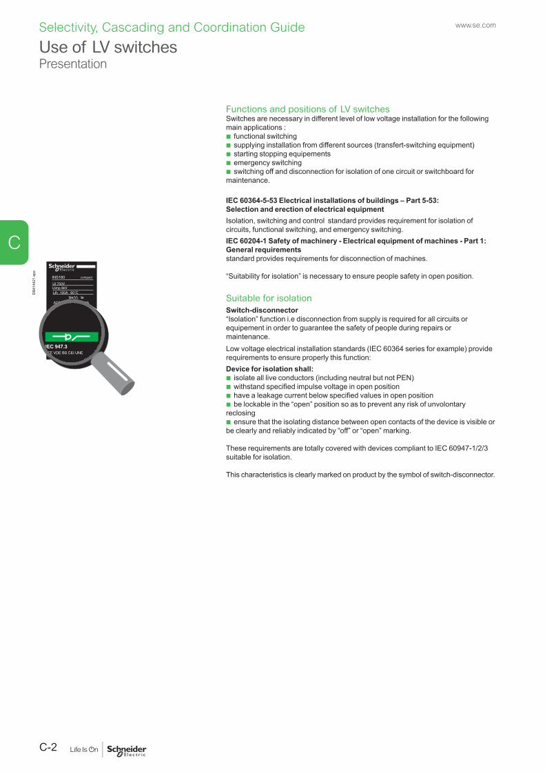
www.se.com
C-2
C
Selectivity, Cascading and Coordination Guide
Functions and positions of LV switchesSwitches are necessary in different level of low voltage installation for the following main applications :
b functional switching b supplying installation from different sources (transfert-switching equipment) b starting stopping equipements b emergency switching b switching off and disconnection for isolation of one circuit or switchboard for
maintenance.
IEC 60364-5-53 Electrical installations of buildings – Part 5-53: Selection and erection of electrical equipmentIsolation, switching and control standard provides requirement for isolation of circuits, functional switching, and emergency switching.IEC 60204-1 Safety of machinery - Electrical equipment of machines - Part 1: General requirementsstandard provides requirements for disconnection of machines.
“Suitability for isolation” is necessary to ensure people safety in open position.
Suitable for isolationSwitch-disconnector“Isolation” function i.e disconnection from supply is required for all circuits or equipement in order to guarantee the safety of people during repairs or maintenance.Low voltage electrical installation standards (IEC 60364 series for example) provide requirements to ensure properly this function: Device for isolation shall:
b isolate all live conductors (including neutral but not PEN) b withstand specified impulse voltage in open position b have a leakage current below specified values in open position b be lockable in the “open” position so as to prevent any risk of unvolontary
reclosing b ensure that the isolating distance between open contacts of the device is visible or
be clearly and reliably indicated by “off” or “open” marking.
These requirements are totally covered with devices compliant to IEC 60947-1/2/3 suitable for isolation.
This characteristics is clearly marked on product by the symbol of switch-disconnector.
DC23A 250 100A
IEC 947.3UTE VDE BS CEI UNE
INS160 compact
DB4
1442
1.ep
s
Use of LV switchesPresentation
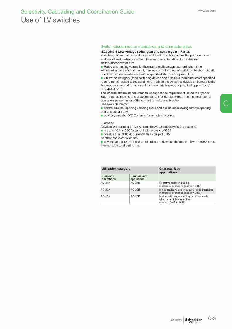
C-3
www.se.com
C
Selectivity, Cascading and Coordination Guide
Switch-disconnector standards and characteristicsIEC60947-3 Low-voltage switchgear and controlgear – Part 3: Switches, disconnectors and fuse-combination units specifies the performances and test of switch-disconnector. The main characteristics of an industrial switch-disconnector are:
b Rated and limiting values for the main circuit: voltage, current, short time withstand in case of short circuit, making current in case of switch on-to short-circuit, rated conditional short-circuit with a specified short-circuit protection.
b Utilization category (for a switching device or a fuse) is a “combination of specified requirements related to the conditions in which the switching device or the fuse fulfils its purpose, selected to represent a characteristic group of practical applications” [IEV 441-17-19]This characteristic (alphanumerical code) defines requirement linked to a type of load, such as making and breaking current for durability test, minimum number of operation, power factor of the current to make and breake. See example below.
b control circuits: opening / closing Coils and auxiliaries allowing remote opening and/or closing if any.
b auxiliary circuits: O/C Contacts for remote signaling.
Example:A switch with a rating of 125 A, from the AC23 category must be able to:
b make a 10 In (1250 A) current with a cos φ of 0.35 b break a 8 In (1000 A) current with a cos φ of 0.35.
Its other characteristics are: b to withstand a 12 In - 1 s short-circuit current, which defines the Icw = 1500 A r.m.s.
thermal withstand during 1 s.
Utilization category Characteristic applications
Frequentoperations
Non frequentoperations
AC-21A AC-21B Resistive loads including moderate overloads (cos φ = 0.95)
AC-22A AC-22B Mixed resistive and inductive loads includingmoderate overloads (cos φ = 0.65)
AC-23A AC-23B Motors with cage winding or orther loads which are highly inductive (cos φ = 0.45 or 0.35)
Use of LV switches
www.se.com
C-4
C
Selectivity, Cascading and Coordination Guide
The switch must be chosen according to:b the characteristics of the network on which it is installed,b the location and the application,b coordination with the upstream protection devices (in particular overload and short-circuit).
Choice criteriaNetwork characteristicsNominal voltage, nominal frequency and nominal current are determined in the same way as for a circuit breaker:
b nominal voltage = nominal voltage of the network b frequency = network frequency b nominal current = rated current of a value immediately higher than the
downstream load current. Note that the rated current is defined for a given ambient temperature and that a derating may have to be taken into account.Location and applicationThis determines the type and characteristics or main functions that the switch must possess. There are 3 function levels (see table opposite):
b basic functions, virtually common to all switch types: v isolation, control, padlocking, safety. b additional characteristic functions v direct formulation of the needs of the user and of the switch environment, i.e.:
- industrial type performance - need for emergency stopping - lsc level - type of interlocking - type of control - utilization category - mounting system. b specific functions v linked to operation and to installation requirements, i.e.:
- earth leakage protection - motor mechanisms - remote opening (“emergency stop” function) - withdrawability.
The following table enables choice of switch according to requirements. b choice table
Comparison of the application table K (see page C-5) and the switch technical data table M (see page C-7) lets you specify which switch range should be used.
CoordinationAll switches must be protected by an overcurrent protection device placed upstream.
The tables below give the coordination performance of circuit breakers and switch-disconnector of main Schneider Electric ranges: in the event of an overload or a short-circuit the circuit breaker proposed in the table will protect the switch-disconnector according to its electrodynamic withstand and short-time and permanent withstand.
Choosing a Schneider Electric switch-disconnector
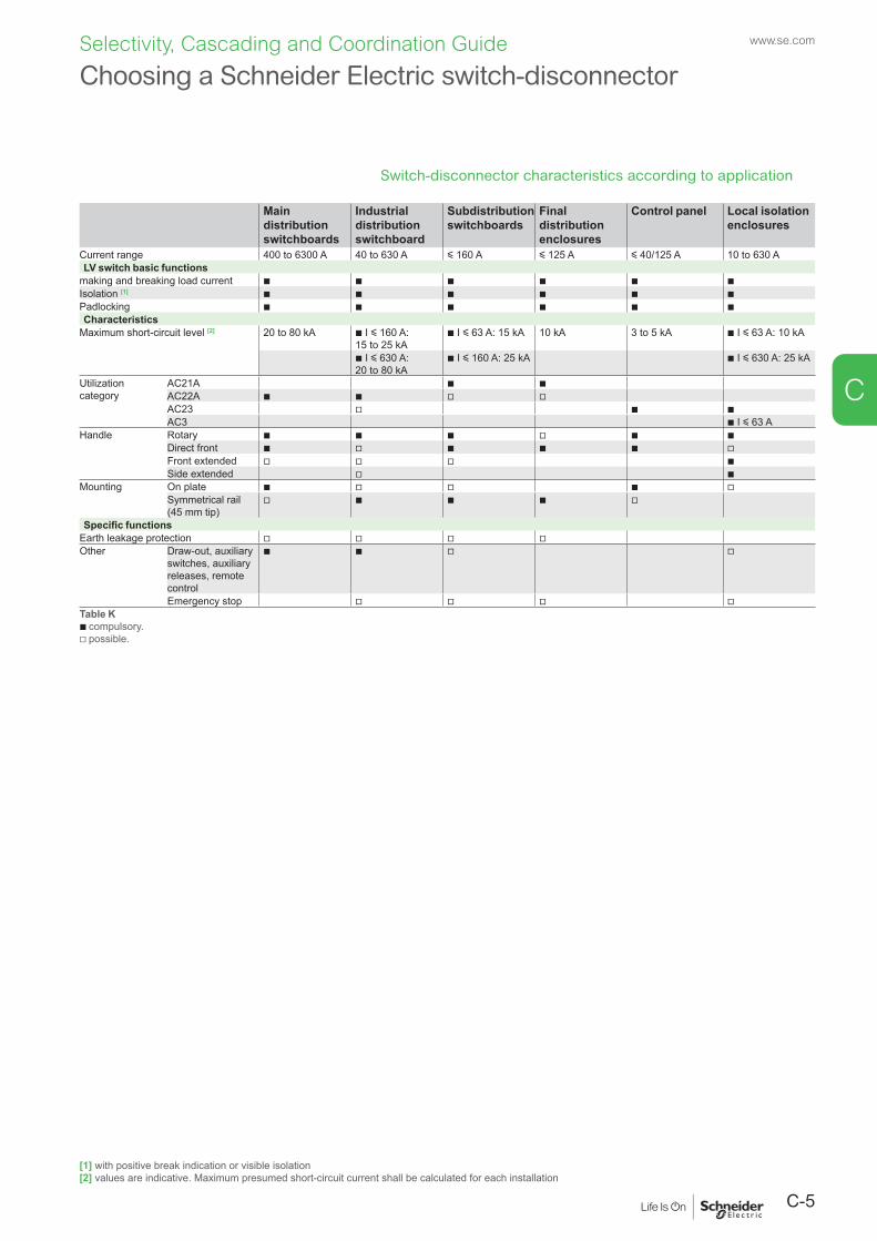
C-5
www.se.com
C
Selectivity, Cascading and Coordination Guide
Switch-disconnector characteristics according to application
Main distribution switchboards
Industrial distribution switchboard
Subdistribution switchboards
Final distribution enclosures
Control panel Local isolation enclosures
Current range 400 to 6300 A 40 to 630 A y 160 A y 125 A y 40/125 A 10 to 630 ALV switch basic functions
making and breaking load current b b b b b bIsolation [1] b b b b b bPadlocking b b b b b bCharacteristics
Maximum short-circuit level [2] 20 to 80 kA b I y 160 A: 15 to 25 kA
b I y 63 A: 15 kA 10 kA 3 to 5 kA b I y 63 A: 10 kA
b I y 630 A: 20 to 80 kA
b I y 160 A: 25 kA b I y 630 A: 25 kA
Utilization category
AC21A b bAC22A b b v vAC23 v b bAC3 b I y 63 A
Handle
Rotary b b b v b bDirect front b v b b b vFront extended v v v bSide extended v b
Mounting On plate b v v b vSymmetrical rail(45 mm tip)
v b b b v
Specific functionsEarth leakage protection v v v vOther Draw-out, auxiliary
switches, auxiliary releases, remote control
b b v v
Emergency stop v v v vTable Kb compulsory.v possible.
Choosing a Schneider Electric switch-disconnector
[1] with positive break indication or visible isolation[2] values are indicative. Maximum presumed short-circuit current shall be calculated for each installation
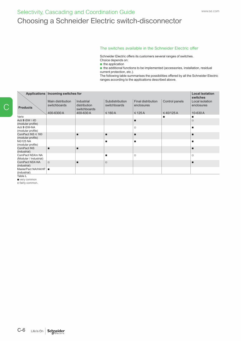
www.se.com
C-6
C
Selectivity, Cascading and Coordination Guide
The switches available in the Schneider Electric offer
Schneider Electric offers its customers several ranges of switches.Choice depends on:
b the application b the additional functions to be implemented (accessories, installation, residual
current protection, etc.).The following table summarises the possibilities offered by all the Schneider Electric ranges according to the applications described above.
Applications
Products
Incoming switches for Local isolation switches
Main distribution switchboards
Industrial distribution switchboards
Subdistribution switchboards
Final distribution enclosures
Control panels Local isolation enclosures
400-6300 A 400-630 A y 160 A y 125 A y 40/125 A 10-630 AVario b bActi 9 iSW / iID (modular profile)
b v
Acti 9 iSW-NA(modular profile)
v b
ComPact INS y 160 (modular profile)
b b b b
NG125 NA (modular profile)
b b b
ComPact INS (industrial)
b b b
ComPact NSXm NA(Modular / Industrial)
b v v
ComPact NSX-NA (industrial)
v b v b
MasterPact NA/HA/HF (industrial)
b
Table Lb very commonv fairly common.
Choosing a Schneider Electric switch-disconnector
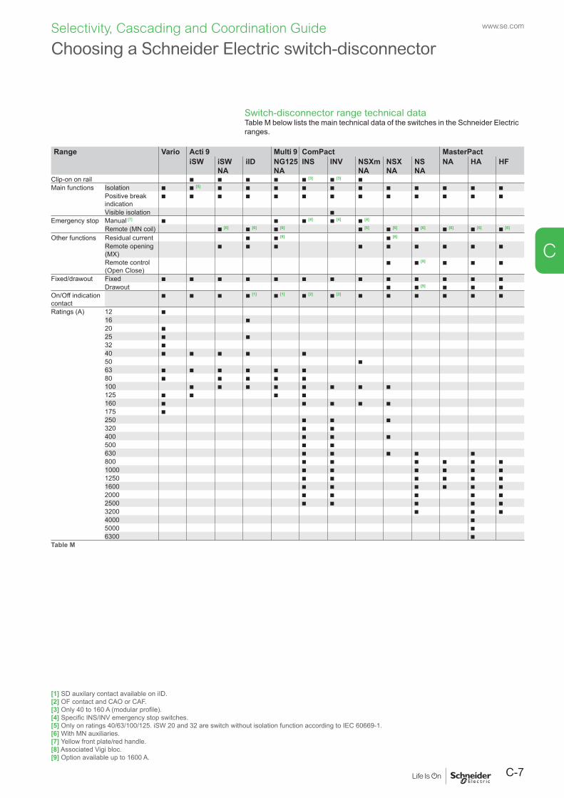
C-7
www.se.com
C
Selectivity, Cascading and Coordination Guide
Switch-disconnector range technical dataTable M below lists the main technical data of the switches in the Schneider Electric ranges.
Range Vario Acti 9 Multi 9 ComPact MasterPactiSW iSW
NAiID NG125
NAINS INV NSXm
NANSX NA
NS NA
NA HA HF
Clip-on on rail b b b b b [3] b [3] bMain functions Isolation b b [5] b b b b b b b b b b b
Positive break indication
b b b b b b b b b b b b b
Visible isolation bEmergency stop Manual [7] b b b [4] b [4] b [4]
Remote (MN coil) b [6] b [6] b [6] b [6] b [6] b [6] b [6] b [6] b [6]
Other functions Residual current b b [8] b [8]
Remote opening (MX)
b b b b b b b b b
Remote control (Open Close)
b b [9] b b b
Fixed/drawout Fixed b b b b b b b b b b b b bDrawout b b [9] b b b
On/Off indication contact
b b b b [1] b [1] b [2] b [2] b b b b b b
Ratings (A) 12 b16 b20 b25 b b32 b40 b b b b b50 b63 b b b b b b80 b b b b b100 b b b b b b b b125 b b b b160 b b b b b175 b250 b b b320 b b400 b b b500 b b630 b b b b b800 b b b b b b1000 b b b b b b1250 b b b b b b1600 b b b b b b2000 b b b b b2500 b b b b b3200 b b b4000 b5000 b6300 b
Table M
Choosing a Schneider Electric switch-disconnector
[1] SD auxilary contact available on iID.[2] OF contact and CAO or CAF.[3] Only 40 to 160 A (modular profile).[4] Specific INS/INV emergency stop switches.[5] Only on ratings 40/63/100/125. iSW 20 and 32 are switch without isolation function according to IEC 60669-1.[6] With MN auxiliaries.[7] Yellow front plate/red handle.[8] Associated Vigi bloc.[9] Option available up to 1600 A.
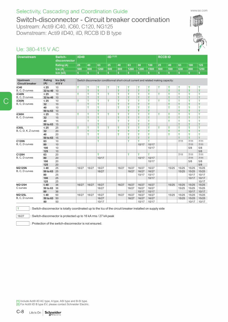
www.se.com
C-8
C
Selectivity, Cascading and Coordination Guide
Switch-disconnector - Circuit breaker coordinationUpstream: Acti9 iC40, iC60, C120, NG125Downstream: Acti9 iID40, iID, RCCB ID B type
Downstream Switch-disconnector
iID40 iID [1] [2] RCCB ID
Rating (A) 25 40 63 25 40 63 80 100 25 40 63 100 125Icw (A) 500 800 1260 500 800 1260 1200 1500 500 500 630 800 1250Icm (kÂ) 5 5 5 5 5 5 5 5 5 5 5 5 5
Upstream Rating (A)
Icu (kA) Switch disconnector conditionnal short-circuit current and related making capacity:Circuit breaker 415 V
iC40B, C, D curves
y 25 10 T T T T T T T T T T T T T32 to 40 10 T T T T T T T T T T
iC40NB, C, D curves
y 25 10 T T T T T T T T T T T T T32 to 40 10 T T T T T T T T T T
iC60NB, C, D curves
y 25 10 T T T T T T T T T T T T T32 10 T T T T T T T T T T40 10 T T T T T T T T T T50 to 63 10 T T T T T T T
iC60HB, C, D curves
y 25 15 T T T T T T T T T T T T T32 15 T T T T T T T T T T40 15 T T T T T T T T T T50 to 63 15 T T T T T T T
iC60LB, C, D, K, Z curves
y 25 25 T T T T T T T T T T T T T32 20 T T T T T T T T T T40 20 T T T T T T T T T T50 to 63 15 T T T T T T T
C120NB, C, D curves
63 10 T T T T 7/11 7/11 7/1180 10 10/17 10/17 7/11 7/11100 10 10/17 5/8 5/8125 10 5/8
C120HB, C, D curves
63 20 T T T T 7/11 7/11 7/1180 20 10/17 10/17 10/17 7/11 7/11100 20 10/17 5/8 5/8125 20 5/8
NG125NB, C, D curves
y 40 25 16/27 16/27 16/27 16/27 16/27 16/27 16/27 15/25 15/25 15/25 15/2550 to 63 25 16/27 16/27 16/27 16/27 15/25 15/25 15/2580 25 10/17 10/17 10/17 10/17100 25 10/17 10/17 10/17125 25 10/17
NG125HC curves
y 40 36 16/27 16/27 16/27 16/27 16/27 16/27 16/27 15/25 15/25 15/25 15/2550 to 63 36 16/27 16/27 16/27 16/27 15/25 15/25 15/2580 36 10/17 10/17 10/17 10/17
NG125LB, C, D curves
y 40 50 16/27 16/27 16/27 16/27 16/27 16/27 16/27 15/25 15/25 15/25 15/2550 to 63 50 16/27 16/27 16/27 16/27 15/25 15/25 15/2580 50 10/17 10/17 10/17 10/17 10/17
T : Switch-disconnector is totally coordinated up to the Icu of the circuit breaker installed on supply side
16/27 : Switch-disconnector is protected up to 16 kA rms / 27 kA peak
: Protection of the switch-disconnector is not ensured.
Ue: 380-415 V AC
DB4
2598
0.ep
s
[1] Include Acti9 iID AC type, A type, ASI type and B-SI type.[2] For Acti9 iID B type EV, please contact Schneider Electric.
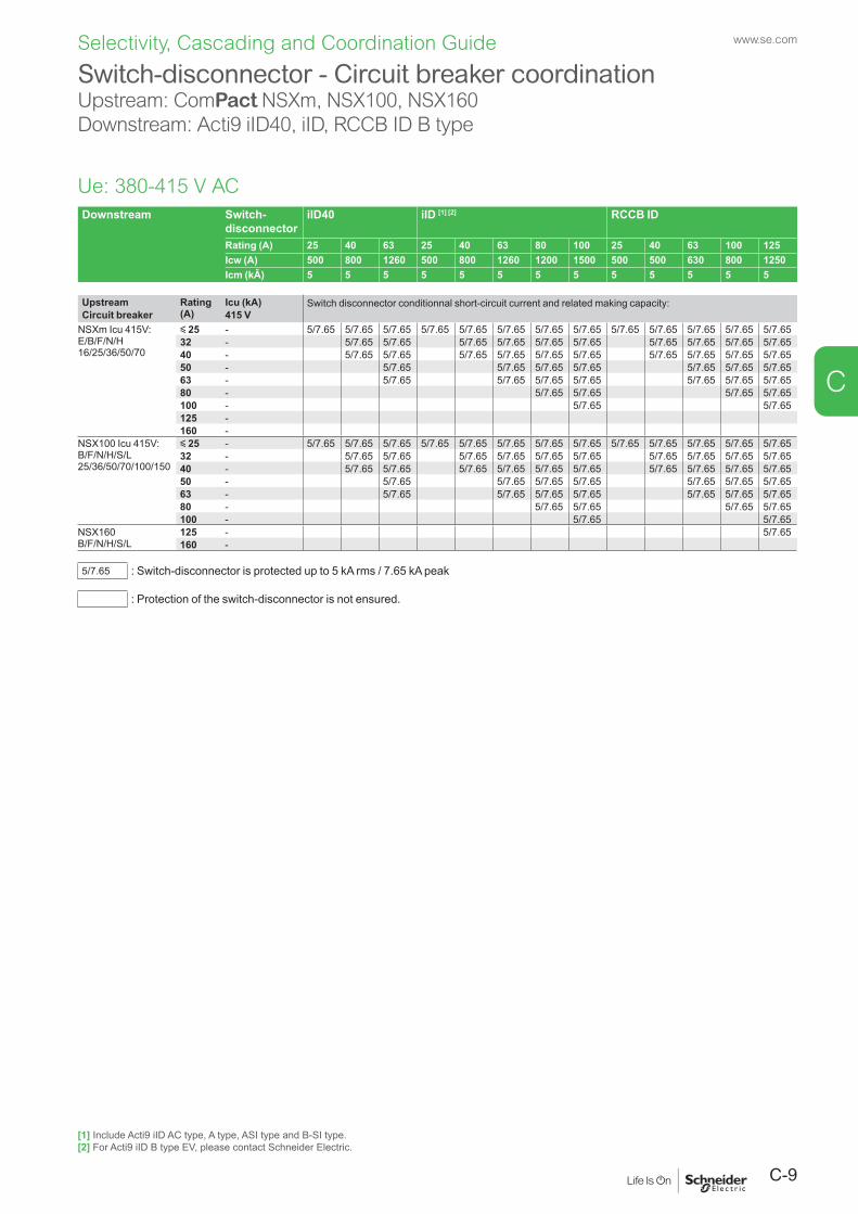
C-9
www.se.com
C
Selectivity, Cascading and Coordination Guide
Switch-disconnector - Circuit breaker coordinationUpstream: ComPact NSXm, NSX100, NSX160Downstream: Acti9 iID40, iID, RCCB ID B type
Downstream Switch-disconnector
iID40 iID [1] [2] RCCB ID
Rating (A) 25 40 63 25 40 63 80 100 25 40 63 100 125Icw (A) 500 800 1260 500 800 1260 1200 1500 500 500 630 800 1250Icm (kÂ) 5 5 5 5 5 5 5 5 5 5 5 5 5
Upstream Rating (A)
Icu (kA) Switch disconnector conditionnal short-circuit current and related making capacity:Circuit breaker 415 V
NSXm Icu 415V:E/B/F/N/H 16/25/36/50/70
y 25 - 5/7.65 5/7.65 5/7.65 5/7.65 5/7.65 5/7.65 5/7.65 5/7.65 5/7.65 5/7.65 5/7.65 5/7.65 5/7.6532 - 5/7.65 5/7.65 5/7.65 5/7.65 5/7.65 5/7.65 5/7.65 5/7.65 5/7.65 5/7.6540 - 5/7.65 5/7.65 5/7.65 5/7.65 5/7.65 5/7.65 5/7.65 5/7.65 5/7.65 5/7.6550 - 5/7.65 5/7.65 5/7.65 5/7.65 5/7.65 5/7.65 5/7.6563 - 5/7.65 5/7.65 5/7.65 5/7.65 5/7.65 5/7.65 5/7.6580 - 5/7.65 5/7.65 5/7.65 5/7.65100 - 5/7.65 5/7.65125 -160 -
NSX100 Icu 415V:B/F/N/H/S/L 25/36/50/70/100/150
y 25 - 5/7.65 5/7.65 5/7.65 5/7.65 5/7.65 5/7.65 5/7.65 5/7.65 5/7.65 5/7.65 5/7.65 5/7.65 5/7.6532 - 5/7.65 5/7.65 5/7.65 5/7.65 5/7.65 5/7.65 5/7.65 5/7.65 5/7.65 5/7.6540 - 5/7.65 5/7.65 5/7.65 5/7.65 5/7.65 5/7.65 5/7.65 5/7.65 5/7.65 5/7.6550 - 5/7.65 5/7.65 5/7.65 5/7.65 5/7.65 5/7.65 5/7.6563 - 5/7.65 5/7.65 5/7.65 5/7.65 5/7.65 5/7.65 5/7.6580 - 5/7.65 5/7.65 5/7.65 5/7.65100 - 5/7.65 5/7.65
NSX160B/F/N/H/S/L
125 - 5/7.65160 -
5/7.65 : Switch-disconnector is protected up to 5 kA rms / 7.65 kA peak
: Protection of the switch-disconnector is not ensured.
Ue: 380-415 V AC
[1] Include Acti9 iID AC type, A type, ASI type and B-SI type.[2] For Acti9 iID B type EV, please contact Schneider Electric.
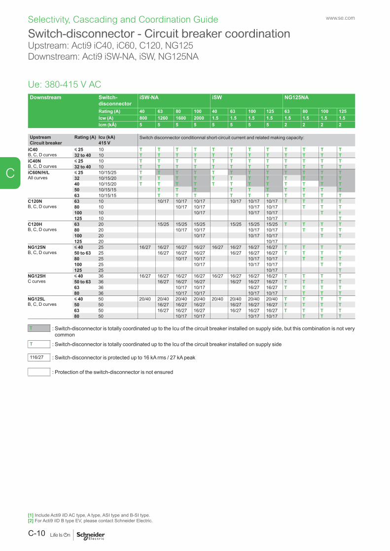
www.se.com
C-10
C
Selectivity, Cascading and Coordination Guide
Switch-disconnector - Circuit breaker coordinationUpstream: Acti9 iC40, iC60, C120, NG125Downstream: Acti9 iSW-NA, iSW, NG125NA
Downstream Switch-disconnector
iSW-NA iSW NG125NA
Rating (A) 40 63 80 100 40 63 100 125 63 80 100 125Icw (A) 800 1260 1600 2000 1.5 1.5 1.5 1.5 1.5 1.5 1.5 1.5Icm (kÂ) 5 5 5 5 5 5 5 5 2 2 2 2
Upstream Rating (A) Icu (kA) Switch disconnector conditionnal short-circuit current and related making capacity:Circuit breaker 415 V
iC40B, C, D curves
y 25 10 T T T T T T T T T T T T32 to 40 10 T T T T T T T T T T T T
iC40NB, C, D curves
y 25 10 T T T T T T T T T T T T32 to 40 10 T T T T T T T T T T T T
iC60N/H/L All curves
y 25 10/15/25 T T T T T T T T T T T T32 10/15/20 T T T T T T T T T T T T40 10/15/20 T T T T T T T T T T T T50 10/15/15 T T T T T T T T T T63 10/15/15 T T T T T T T T T T
C120NB, C, D curves
63 10 10/17 10/17 10/17 10/17 10/17 10/17 T T T T80 10 10/17 10/17 10/17 10/17 T T T100 10 10/17 10/17 10/17 T T125 10 10/17 T
C120HB, C, D curves
63 20 15/25 15/25 15/25 15/25 15/25 15/25 T T T T80 20 10/17 10/17 10/17 10/17 T T T100 20 10/17 10/17 10/17 T T125 20 10/17
NG125NB, C, D curves
y 40 25 16/27 16/27 16/27 16/27 16/27 16/27 16/27 16/27 T T T T50 to 63 25 16/27 16/27 16/27 16/27 16/27 16/27 T T T T80 25 10/17 10/17 10/17 10/17 T T T100 25 10/17 10/17 10/17 T T125 25 10/17 T
NG125HC curves
y 40 36 16/27 16/27 16/27 16/27 16/27 16/27 16/27 16/27 T T T T50 to 63 36 16/27 16/27 16/27 16/27 16/27 16/27 T T T T63 36 10/17 10/17 16/27 16/27 T T T T80 36 10/17 10/17 10/17 10/17 T T T
NG125LB, C, D curves
y 40 50 20/40 20/40 20/40 20/40 20/40 20/40 20/40 20/40 T T T T50 50 16/27 16/27 16/27 16/27 16/27 16/27 T T T T63 50 16/27 16/27 16/27 16/27 16/27 16/27 T T T T80 50 10/17 10/17 10/17 10/17 T T T
T : Switch-disconnector is totally coordinated up to the Icu of the circuit breaker installed on supply side, but this combination is not very common
T : Switch-disconnector is totally coordinated up to the Icu of the circuit breaker installed on supply side
116/27 : Switch-disconnector is protected up to 16 kA rms / 27 kA peak
: Protection of the switch-disconnector is not ensured
Ue: 380-415 V AC
[1] Include Acti9 iID AC type, A type, ASI type and B-SI type.[2] For Acti9 iID B type EV, please contact Schneider Electric.
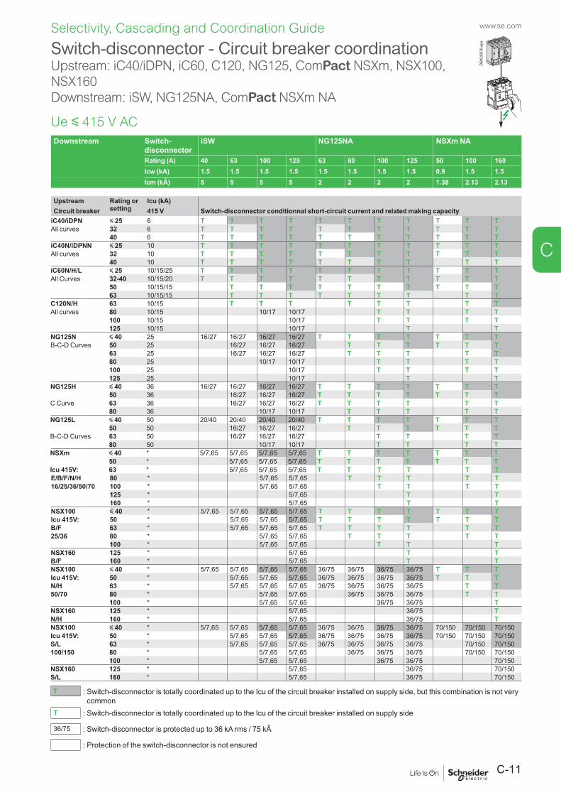
C-11
www.se.com
C
Selectivity, Cascading and Coordination Guide
Switch-disconnector - Circuit breaker coordinationUpstream: iC40/iDPN, iC60, C120, NG125, ComPact NSXm, NSX100, NSX160Downstream: iSW, NG125NA, ComPact NSXm NA
Ue y 415 V ACDownstream Switch-
disconnectoriSW NG125NA NSXm NA
Rating (A) 40 63 100 125 63 80 100 125 50 100 160Icw (kA) 1.5 1.5 1.5 1.5 1.5 1.5 1.5 1.5 0.9 1.5 1.5Icm (kÂ) 5 5 5 5 2 2 2 2 1.38 2.13 2.13
Upstream Rating or setting
Icu (kA)Circuit breaker 415 V Switch-disconnector conditionnal short-circuit current and related making capacity
iC40/iDPN y 25 6 T T T T T T T T T T TAll curves 32 6 T T T T T T T T T T T
40 6 T T T T T T T T T T TiC40N/iDPNN y 25 10 T T T T T T T T T T TAll curves 32 10 T T T T T T T T T T T
40 10 T T T T T T T T T TiC60N/H/L y 25 10/15/25 T T T T T T T T T T TAll Curves 32-40 10/15/20 T T T T T T T T T T T
50 10/15/15 T T T T T T T T T T63 10/15/15 T T T T T T T T T
C120N/H 63 10/15 T T T T T T T TAll curves 80 10/15 10/17 10/17 T T T T
100 10/15 10/17 T T T T125 10/15 10/17 T T
NG125N y 40 25 16/27 16/27 16/27 16/27 T T T T T T TB-C-D Curves 50 25 16/27 16/27 16/27 T T T T T T
63 25 16/27 16/27 16/27 T T T T T80 25 10/17 10/17 T T T T100 25 10/17 T T T T125 25 10/17 T T
NG125H y 40 36 16/27 16/27 16/27 16/27 T T T T T T T50 36 16/27 16/27 16/27 T T T T T T T
C Curve 63 36 16/27 16/27 16/27 T T T T T T80 36 10/17 10/17 T T T T T
NG125L y 40 50 20/40 20/40 20/40 20/40 T T T T T T T50 50 16/27 16/27 16/27 T T T T T T
B-C-D Curves 63 50 16/27 16/27 16/27 T T T T80 50 10/17 10/17 T T T T
NSXm y 40 * 5/7,65 5/7,65 5/7,65 5/7,65 T T T T T T T50 * 5/7,65 5/7,65 5/7,65 T T T T T T T
Icu 415V: 63 * 5/7,65 5/7,65 5/7,65 T T T T T TE/B/F/N/H 80 * 5/7,65 5/7,65 T T T T T16/25/36/50/70 100 * 5/7,65 5/7,65 T T T T
125 * 5/7,65 T T160 * 5/7,65 T T
NSX100 y 40 * 5/7,65 5/7,65 5/7,65 5/7,65 T T T T T T TIcu 415V: 50 * 5/7,65 5/7,65 5/7,65 T T T T T T TB/F 63 * 5/7,65 5/7,65 5/7,65 T T T T T T25/36 80 * 5/7,65 5/7,65 T T T T T
100 * 5/7,65 5/7,65 T T TNSX160 125 * 5/7,65 T TB/F 160 * 5/7,65 T TNSX100 y 40 * 5/7,65 5/7,65 5/7,65 5/7,65 36/75 36/75 36/75 36/75 T T TIcu 415V: 50 * 5/7,65 5/7,65 5/7,65 36/75 36/75 36/75 36/75 T T TN/H 63 * 5/7,65 5/7,65 5/7,65 36/75 36/75 36/75 36/75 T T50/70 80 * 5/7,65 5/7,65 36/75 36/75 36/75 T T
100 * 5/7,65 5/7,65 36/75 36/75 TNSX160 125 * 5/7,65 36/75 TN/H 160 * 5/7,65 36/75 TNSX100 y 40 * 5/7,65 5/7,65 5/7,65 5/7,65 36/75 36/75 36/75 36/75 70/150 70/150 70/150Icu 415V: 50 * 5/7,65 5/7,65 5/7,65 36/75 36/75 36/75 36/75 70/150 70/150 70/150S/L 63 * 5/7,65 5/7,65 5/7,65 36/75 36/75 36/75 36/75 70/150 70/150100/150 80 * 5/7,65 5/7,65 36/75 36/75 36/75 70/150 70/150
100 * 5/7,65 5/7,65 36/75 36/75 70/150NSX160 125 * 5/7,65 36/75 70/150S/L 160 * 5/7,65 36/75 70/150
T : Switch-disconnector is totally coordinated up to the Icu of the circuit breaker installed on supply side, but this combination is not very common
T : Switch-disconnector is totally coordinated up to the Icu of the circuit breaker installed on supply side
36/75 : Switch-disconnector is protected up to 36 kA rms / 75 kÂ
: Protection of the switch-disconnector is not ensured
DB4
2597
9.ep
s
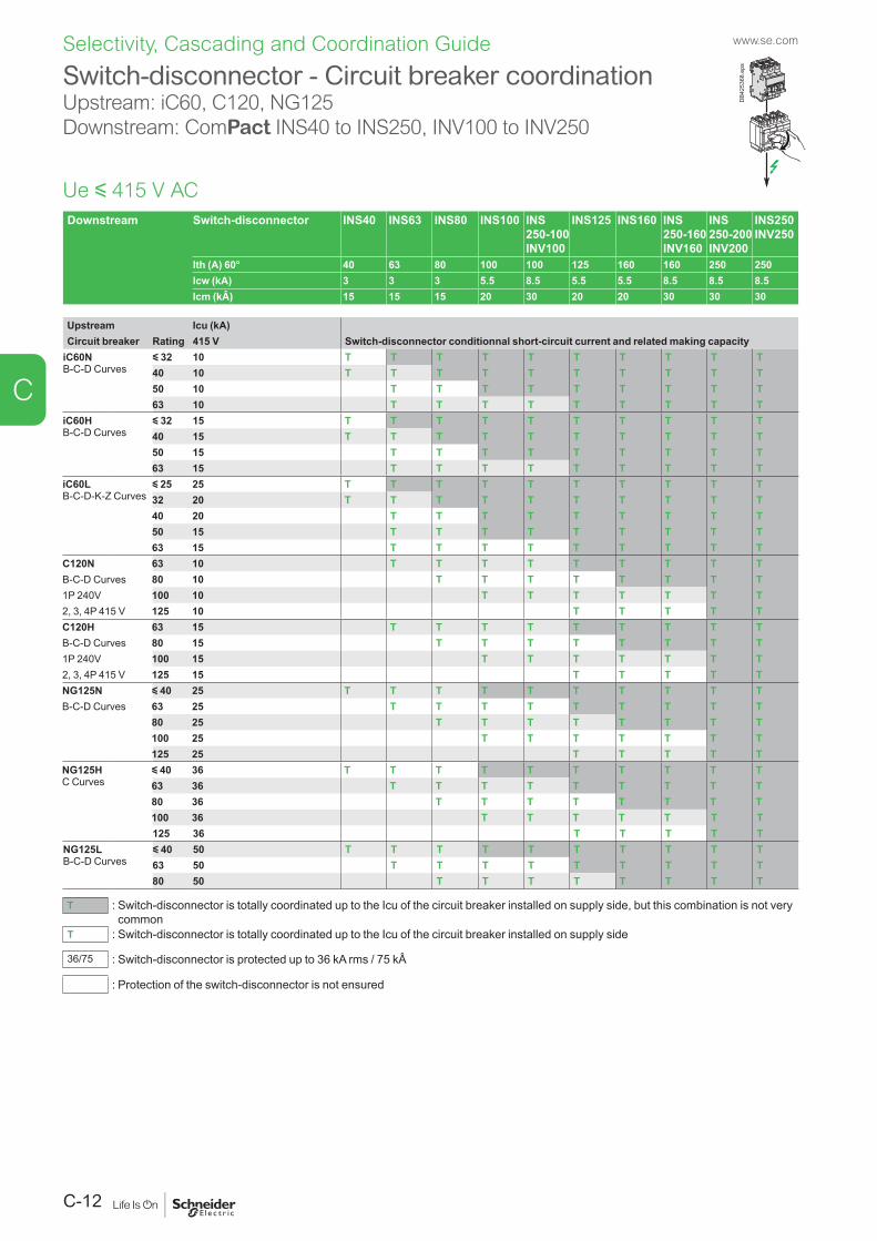
www.se.com
C-12
C
Selectivity, Cascading and Coordination Guide
Downstream Switch-disconnector INS40 INS63 INS80 INS100 INS 250-100 INV100
INS125 INS160 INS 250-160 INV160
INS 250-200 INV200
INS250 INV250
Ith (A) 60° 40 63 80 100 100 125 160 160 250 250Icw (kA) 3 3 3 5.5 8.5 5.5 5.5 8.5 8.5 8.5Icm (kÂ) 15 15 15 20 30 20 20 30 30 30
Upstream Icu (kA)Circuit breaker Rating 415 V Switch-disconnector conditionnal short-circuit current and related making capacity
iC60NB-C-D Curves
y 32 10 T T T T T T T T T T40 10 T T T T T T T T T T50 10 T T T T T T T T T63 10 T T T T T T T T T
iC60HB-C-D Curves
y 32 15 T T T T T T T T T T40 15 T T T T T T T T T T50 15 T T T T T T T T T63 15 T T T T T T T T T
iC60LB-C-D-K-Z Curves
y 25 25 T T T T T T T T T T32 20 T T T T T T T T T T40 20 T T T T T T T T T50 15 T T T T T T T T T63 15 T T T T T T T T T
C120N 63 10 T T T T T T T T TB-C-D Curves 80 10 T T T T T T T T1P 240V 100 10 T T T T T T T2, 3, 4P 415 V 125 10 T T T T TC120H 63 15 T T T T T T T T TB-C-D Curves 80 15 T T T T T T T T1P 240V 100 15 T T T T T T T2, 3, 4P 415 V 125 15 T T T T TNG125N y 40 25 T T T T T T T T T TB-C-D Curves 63 25 T T T T T T T T T
80 25 T T T T T T T T100 25 T T T T T T T125 25 T T T T T
NG125HC Curves
y 40 36 T T T T T T T T T T63 36 T T T T T T T T T80 36 T T T T T T T T100 36 T T T T T T T125 36 T T T T T
NG125LB-C-D Curves
y 40 50 T T T T T T T T T T63 50 T T T T T T T T T80 50 T T T T T T T T
T : Switch-disconnector is totally coordinated up to the Icu of the circuit breaker installed on supply side, but this combination is not very common
T : Switch-disconnector is totally coordinated up to the Icu of the circuit breaker installed on supply side
36/75 : Switch-disconnector is protected up to 36 kA rms / 75 kÂ
: Protection of the switch-disconnector is not ensured
Switch-disconnector - Circuit breaker coordinationUpstream: iC60, C120, NG125Downstream: ComPact INS40 to INS250, INV100 to INV250
Ue y 415 V AC
DB4
2536
8.ep
s
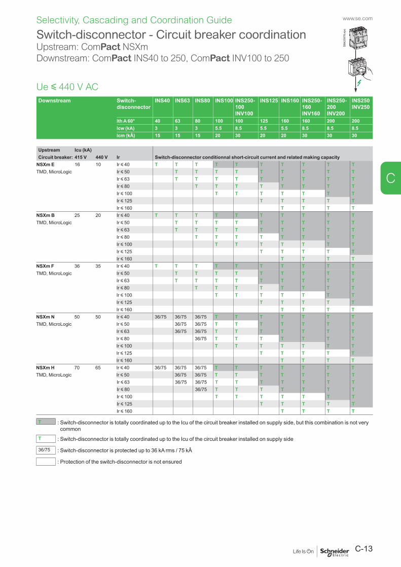
C-13
www.se.com
C
Selectivity, Cascading and Coordination Guide
Switch-disconnector - Circuit breaker coordinationUpstream: ComPact NSXmDownstream: ComPact INS40 to 250, ComPact INV100 to 250
Ue y 440 V ACDownstream Switch-
disconnectorINS40 INS63 INS80 INS100 INS250-
100 INV100
INS125 INS160 INS250-160 INV160
INS250-200 INV200
INS250 INV250
Ith A 60° 40 63 80 100 100 125 160 160 200 200Icw (kA) 3 3 3 5.5 8.5 5.5 5.5 8.5 8.5 8.5Icm (kÂ) 15 15 15 20 30 20 20 30 30 30
Upstream Icu (kA)Circuit breaker: 415 V 440 V Ir Switch-disconnector conditionnal short-circuit current and related making capacity
NSXm E 16 10 Ir y 40 T T T T T T T T T TTMD, MicroLogic Ir y 50 T T T T T T T T T
Ir y 63 T T T T T T T T TIr y 80 T T T T T T T TIr y 100 T T T T T T TIr y 125 T T T T TIr y 160 T T T T
NSXm B 25 20 Ir y 40 T T T T T T T T T TTMD, MicroLogic Ir y 50 T T T T T T T T T
Ir y 63 T T T T T T T T TIr y 80 T T T T T T T TIr y 100 T T T T T T TIr y 125 T T T T TIr y 160 T T T T
NSXm F 36 35 Ir y 40 T T T T T T T T T TTMD, MicroLogic Ir y 50 T T T T T T T T T
Ir y 63 T T T T T T T T TIr y 80 T T T T T T T TIr y 100 T T T T T T TIr y 125 T T T T TIr y 160 T T T T
NSXm N 50 50 Ir y 40 36/75 36/75 36/75 T T T T T T TTMD, MicroLogic Ir y 50 36/75 36/75 T T T T T T T
Ir y 63 36/75 36/75 T T T T T T TIr y 80 36/75 T T T T T T TIr y 100 T T T T T T TIr y 125 T T T T TIr y 160 T T T T
NSXm H 70 65 Ir y 40 36/75 36/75 36/75 T T T T T T TTMD, MicroLogic Ir y 50 36/75 36/75 T T T T T T T
Ir y 63 36/75 36/75 T T T T T T TIr y 80 36/75 T T T T T T TIr y 100 T T T T T T TIr y 125 T T T T TIr y 160 T T T T
T : Switch-disconnector is totally coordinated up to the Icu of the circuit breaker installed on supply side, but this combination is not very common
T : Switch-disconnector is totally coordinated up to the Icu of the circuit breaker installed on supply side
36/75 : Switch-disconnector is protected up to 36 kA rms / 75 kÂ
: Protection of the switch-disconnector is not ensured
DB4
2597
8.ep
s
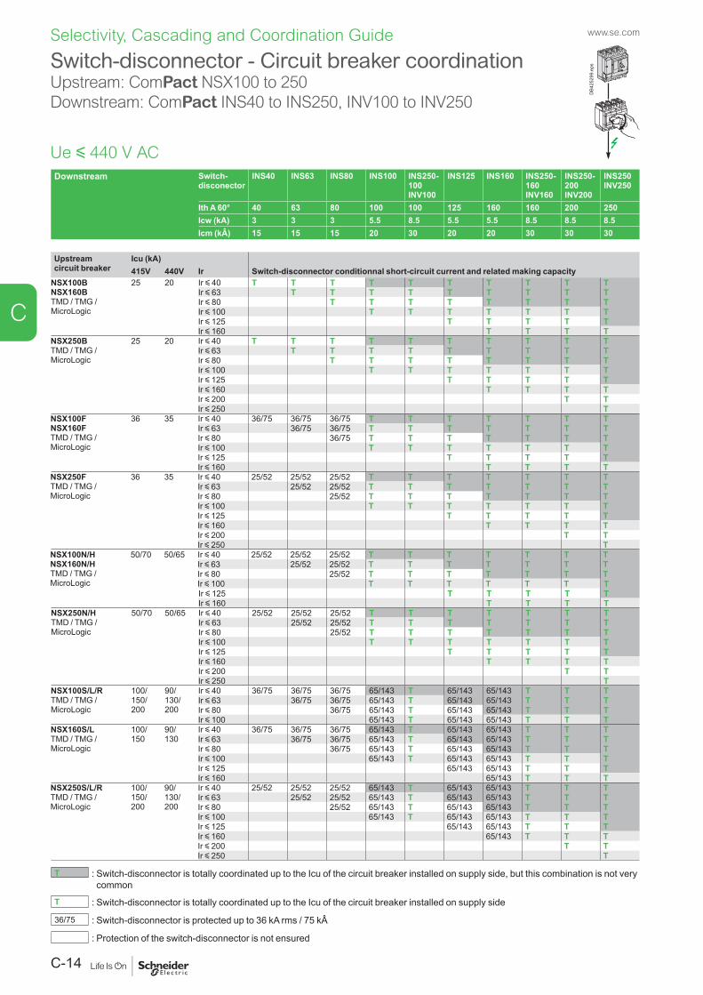
www.se.com
C-14
C
Selectivity, Cascading and Coordination Guide
Downstream Switch-disconector
INS40 INS63 INS80 INS100 INS250-100 INV100
INS125 INS160 INS250-160 INV160
INS250-200 INV200
INS250 INV250
Ith A 60° 40 63 80 100 100 125 160 160 200 250Icw (kA) 3 3 3 5.5 8.5 5.5 5.5 8.5 8.5 8.5Icm (kÂ) 15 15 15 20 30 20 20 30 30 30
Upstream circuit breaker
Icu (kA)415V 440V Ir Switch-disconnector conditionnal short-circuit current and related making capacity
NSX100BNSX160BTMD / TMG / MicroLogic
25 20 Ir y 40 T T T T T T T T T TIr y 63 T T T T T T T T TIr y 80 T T T T T T T TIr y 100 T T T T T T TIr y 125 T T T T TIr y 160 T T T T
NSX250BTMD / TMG / MicroLogic
25 20 Ir y 40 T T T T T T T T T TIr y 63 T T T T T T T T TIr y 80 T T T T T T T TIr y 100 T T T T T T TIr y 125 T T T T TIr y 160 T T T TIr y 200 T TIr y 250 T
NSX100FNSX160FTMD / TMG / MicroLogic
36 35 Ir y 40 36/75 36/75 36/75 T T T T T T TIr y 63 36/75 36/75 T T T T T T TIr y 80 36/75 T T T T T T TIr y 100 T T T T T T TIr y 125 T T T T TIr y 160 T T T T
NSX250FTMD / TMG / MicroLogic
36 35 Ir y 40 25/52 25/52 25/52 T T T T T T TIr y 63 25/52 25/52 T T T T T T TIr y 80 25/52 T T T T T T TIr y 100 T T T T T T TIr y 125 T T T T TIr y 160 T T T TIr y 200 T TIr y 250 T
NSX100N/HNSX160N/HTMD / TMG / MicroLogic
50/70 50/65 Ir y 40 25/52 25/52 25/52 T T T T T T TIr y 63 25/52 25/52 T T T T T T TIr y 80 25/52 T T T T T T TIr y 100 T T T T T T TIr y 125 T T T T TIr y 160 T T T T
NSX250N/HTMD / TMG / MicroLogic
50/70 50/65 Ir y 40 25/52 25/52 25/52 T T T T T T TIr y 63 25/52 25/52 T T T T T T TIr y 80 25/52 T T T T T T TIr y 100 T T T T T T TIr y 125 T T T T TIr y 160 T T T TIr y 200 T TIr y 250 T
NSX100S/L/RTMD / TMG / MicroLogic
100/ 150/ 200
90/ 130/ 200
Ir y 40 36/75 36/75 36/75 65/143 T 65/143 65/143 T T TIr y 63 36/75 36/75 65/143 T 65/143 65/143 T T TIr y 80 36/75 65/143 T 65/143 65/143 T T TIr y 100 65/143 T 65/143 65/143 T T T
NSX160S/LTMD / TMG / MicroLogic
100/ 150
90/ 130
Ir y 40 36/75 36/75 36/75 65/143 T 65/143 65/143 T T TIr y 63 36/75 36/75 65/143 T 65/143 65/143 T T TIr y 80 36/75 65/143 T 65/143 65/143 T T TIr y 100 65/143 T 65/143 65/143 T T TIr y 125 65/143 65/143 T T TIr y 160 65/143 T T T
NSX250S/L/RTMD / TMG / MicroLogic
100/ 150/ 200
90/ 130/ 200
Ir y 40 25/52 25/52 25/52 65/143 T 65/143 65/143 T T TIr y 63 25/52 25/52 65/143 T 65/143 65/143 T T TIr y 80 25/52 65/143 T 65/143 65/143 T T TIr y 100 65/143 T 65/143 65/143 T T TIr y 125 65/143 65/143 T T TIr y 160 65/143 T T TIr y 200 T TIr y 250 T
T : Switch-disconnector is totally coordinated up to the Icu of the circuit breaker installed on supply side, but this combination is not very common
T : Switch-disconnector is totally coordinated up to the Icu of the circuit breaker installed on supply side
36/75 : Switch-disconnector is protected up to 36 kA rms / 75 kÂ
: Protection of the switch-disconnector is not ensured
Switch-disconnector - Circuit breaker coordinationUpstream: ComPact NSX100 to 250Downstream: ComPact INS40 to INS250, INV100 to INV250
Ue y 440 V AC
DB4
2529
9.ep
s
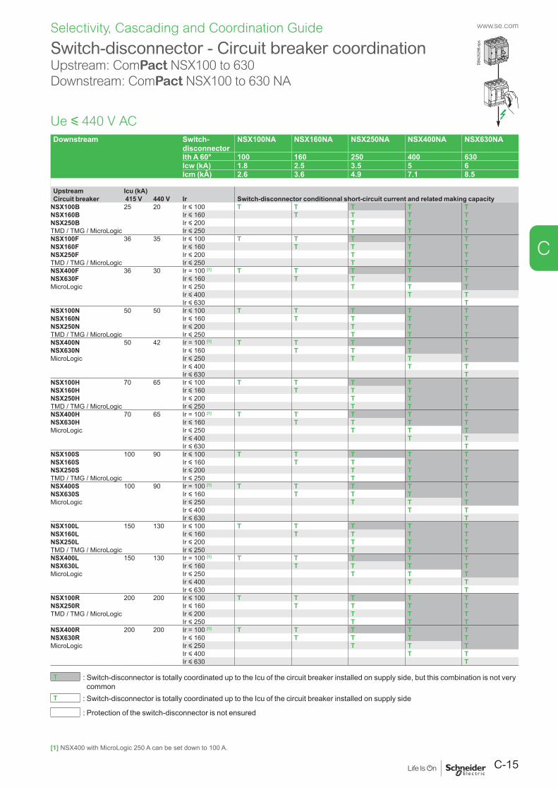
C-15
www.se.com
C
Selectivity, Cascading and Coordination Guide
Switch-disconnector - Circuit breaker coordinationUpstream: ComPact NSX100 to 630Downstream: ComPact NSX100 to 630 NA
Downstream Switch-disconnector
NSX100NA NSX160NA NSX250NA NSX400NA NSX630NA
Ith A 60° 100 160 250 400 630Icw (kA) 1.8 2.5 3.5 5 6Icm (kÂ) 2.6 3.6 4.9 7.1 8.5
Upstream Icu (kA)Circuit breaker 415 V 440 V Ir Switch-disconnector conditionnal short-circuit current and related making capacity
NSX100B 25 20 Ir y 100 T T T T TNSX160B Ir y 160 T T T TNSX250B Ir y 200 T T TTMD / TMG / MicroLogic Ir y 250 T T TNSX100F 36 35 Ir y 100 T T T T TNSX160F Ir y 160 T T T TNSX250F Ir y 200 T T TTMD / TMG / MicroLogic Ir y 250 T T TNSX400F 36 30 Ir = 100 [1] T T T T TNSX630F Ir y 160 T T T TMicroLogic Ir y 250 T T T
Ir y 400 T TIr y 630 T
NSX100N 50 50 Ir y 100 T T T T TNSX160N Ir y 160 T T T TNSX250N Ir y 200 T T TTMD / TMG / MicroLogic Ir y 250 T T TNSX400N 50 42 Ir = 100 [1] T T T T TNSX630N Ir y 160 T T T TMicroLogic Ir y 250 T T T
Ir y 400 T TIr y 630 T
NSX100H 70 65 Ir y 100 T T T T TNSX160H Ir y 160 T T T TNSX250H Ir y 200 T T TTMD / TMG / MicroLogic Ir y 250 T T TNSX400H 70 65 Ir = 100 [1] T T T T TNSX630H Ir y 160 T T T TMicroLogic Ir y 250 T T T
Ir y 400 T TIr y 630 T
NSX100S 100 90 Ir y 100 T T T T TNSX160S Ir y 160 T T T TNSX250S Ir y 200 T T TTMD / TMG / MicroLogic Ir y 250 T T TNSX400S 100 90 Ir = 100 [1] T T T T TNSX630S Ir y 160 T T T TMicroLogic Ir y 250 T T T
Ir y 400 T TIr y 630 T
NSX100L 150 130 Ir y 100 T T T T TNSX160L Ir y 160 T T T TNSX250L Ir y 200 T T TTMD / TMG / MicroLogic Ir y 250 T T TNSX400L 150 130 Ir = 100 [1] T T T T TNSX630L Ir y 160 T T T TMicroLogic Ir y 250 T T T
Ir y 400 T TIr y 630 T
NSX100R 200 200 Ir y 100 T T T T TNSX250R Ir y 160 T T T TTMD / TMG / MicroLogic Ir y 200 T T T
Ir y 250 T T TNSX400R 200 200 Ir = 100 [1] T T T T TNSX630R Ir y 160 T T T TMicroLogic Ir y 250 T T T
Ir y 400 T TIr y 630 T
T : Switch-disconnector is totally coordinated up to the Icu of the circuit breaker installed on supply side, but this combination is not very common
T : Switch-disconnector is totally coordinated up to the Icu of the circuit breaker installed on supply side
: Protection of the switch-disconnector is not ensured
Ue y 440 V AC
DB4
2529
8.ep
s
[1] NSX400 with MicroLogic 250 A can be set down to 100 A.
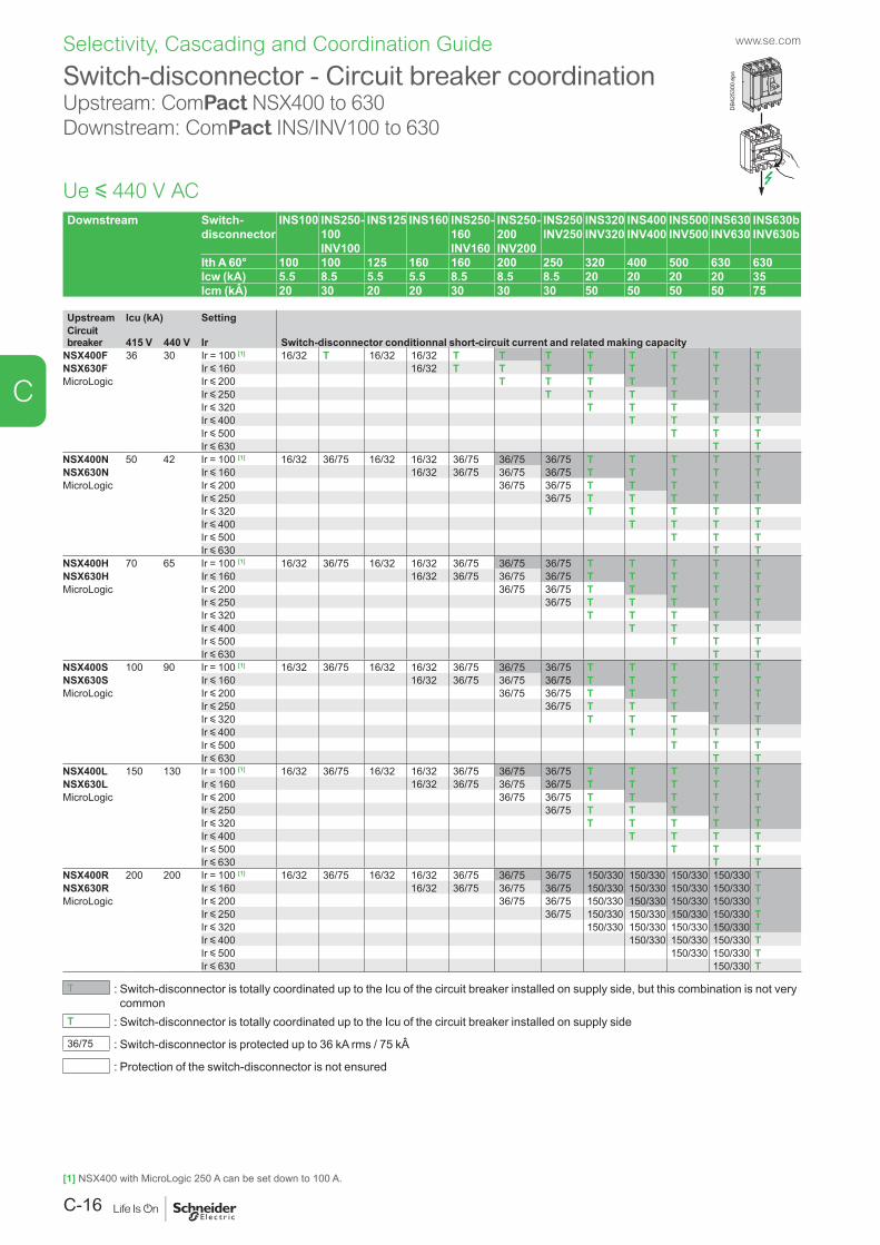
www.se.com
C-16
C
Selectivity, Cascading and Coordination Guide
Downstream Switch-disconnector
INS100 INS250- 100 INV100
INS125 INS160 INS250-160 INV160
INS250-200 INV200
INS250 INV250
INS320 INV320
INS400 INV400
INS500 INV500
INS630 INV630
INS630b INV630b
Ith A 60° 100 100 125 160 160 200 250 320 400 500 630 630Icw (kA) 5.5 8.5 5.5 5.5 8.5 8.5 8.5 20 20 20 20 35Icm (kÂ) 20 30 20 20 30 30 30 50 50 50 50 75
Upstream Icu (kA) SettingCircuit breaker
415 V
440 V Ir Switch-disconnector conditionnal short-circuit current and related making capacity
NSX400F 36 30 Ir = 100 [1] 16/32 T 16/32 16/32 T T T T T T T TNSX630F Ir y 160 16/32 T T T T T T T TMicroLogic Ir y 200 T T T T T T T
Ir y 250 T T T T T TIr y 320 T T T T TIr y 400 T T T TIr y 500 T T TIr y 630 T T
NSX400N 50 42 Ir = 100 [1] 16/32 36/75 16/32 16/32 36/75 36/75 36/75 T T T T TNSX630N Ir y 160 16/32 36/75 36/75 36/75 T T T T TMicroLogic Ir y 200 36/75 36/75 T T T T T
Ir y 250 36/75 T T T T TIr y 320 T T T T TIr y 400 T T T TIr y 500 T T TIr y 630 T T
NSX400H 70 65 Ir = 100 [1] 16/32 36/75 16/32 16/32 36/75 36/75 36/75 T T T T TNSX630H Ir y 160 16/32 36/75 36/75 36/75 T T T T TMicroLogic Ir y 200 36/75 36/75 T T T T T
Ir y 250 36/75 T T T T TIr y 320 T T T T TIr y 400 T T T TIr y 500 T T TIr y 630 T T
NSX400S 100 90 Ir = 100 [1] 16/32 36/75 16/32 16/32 36/75 36/75 36/75 T T T T TNSX630S Ir y 160 16/32 36/75 36/75 36/75 T T T T TMicroLogic Ir y 200 36/75 36/75 T T T T T
Ir y 250 36/75 T T T T TIr y 320 T T T T TIr y 400 T T T TIr y 500 T T TIr y 630 T T
NSX400L 150 130 Ir = 100 [1] 16/32 36/75 16/32 16/32 36/75 36/75 36/75 T T T T TNSX630L Ir y 160 16/32 36/75 36/75 36/75 T T T T TMicroLogic Ir y 200 36/75 36/75 T T T T T
Ir y 250 36/75 T T T T TIr y 320 T T T T TIr y 400 T T T TIr y 500 T T TIr y 630 T T
NSX400R 200 200 Ir = 100 [1] 16/32 36/75 16/32 16/32 36/75 36/75 36/75 150/330 150/330 150/330 150/330 TNSX630R Ir y 160 16/32 36/75 36/75 36/75 150/330 150/330 150/330 150/330 TMicroLogic Ir y 200 36/75 36/75 150/330 150/330 150/330 150/330 T
Ir y 250 36/75 150/330 150/330 150/330 150/330 TIr y 320 150/330 150/330 150/330 150/330 TIr y 400 150/330 150/330 150/330 TIr y 500 150/330 150/330 TIr y 630 150/330 T
T : Switch-disconnector is totally coordinated up to the Icu of the circuit breaker installed on supply side, but this combination is not very common
T : Switch-disconnector is totally coordinated up to the Icu of the circuit breaker installed on supply side
36/75 : Switch-disconnector is protected up to 36 kA rms / 75 kÂ
: Protection of the switch-disconnector is not ensured
Switch-disconnector - Circuit breaker coordinationUpstream: ComPact NSX400 to 630Downstream: ComPact INS/INV100 to 630
Ue y 440 V AC
DB4
2530
0.ep
s
[1] NSX400 with MicroLogic 250 A can be set down to 100 A.
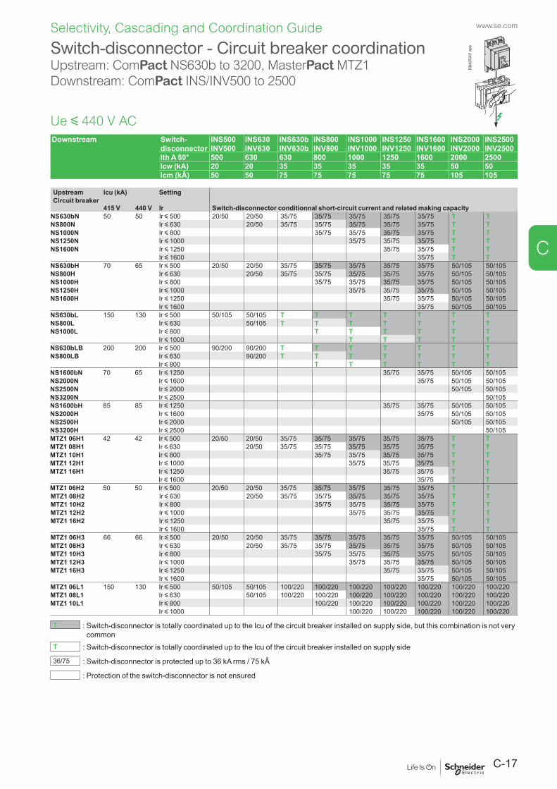
C-17
www.se.com
C
Selectivity, Cascading and Coordination Guide
Switch-disconnector - Circuit breaker coordinationUpstream: ComPact NS630b to 3200, MasterPact MTZ1Downstream: ComPact INS/INV500 to 2500
Downstream Switch-disconnector
INS500 INV500
INS630 INV630
INS630b INV630b
INS800 INV800
INS1000 INV1000
INS1250 INV1250
INS1600 INV1600
INS2000 INV2000
INS2500 INV2500
Ith A 60° 500 630 630 800 1000 1250 1600 2000 2500Icw (kA) 20 20 35 35 35 35 35 50 50Icm (kÂ) 50 50 75 75 75 75 75 105 105
Upstream Icu (kA) SettingCircuit breaker
415 V 440 V Ir Switch-disconnector conditionnal short-circuit current and related making capacity
NS630bN 50 50 Ir y 500 20/50 20/50 35/75 35/75 35/75 35/75 35/75 T TNS800N Ir y 630 20/50 35/75 35/75 35/75 35/75 35/75 T TNS1000N Ir y 800 35/75 35/75 35/75 35/75 T TNS1250N Ir y 1000 35/75 35/75 35/75 T TNS1600N Ir y 1250 35/75 35/75 T T
Ir y 1600 35/75 T TNS630bH 70 65 Ir y 500 20/50 20/50 35/75 35/75 35/75 35/75 35/75 50/105 50/105NS800H Ir y 630 20/50 35/75 35/75 35/75 35/75 35/75 50/105 50/105NS1000H Ir y 800 35/75 35/75 35/75 35/75 50/105 50/105NS1250H Ir y 1000 35/75 35/75 35/75 50/105 50/105NS1600H Ir y 1250 35/75 35/75 50/105 50/105
Ir y 1600 35/75 50/105 50/105NS630bL 150 130 Ir y 500 50/105 50/105 T T T T T T TNS800L Ir y 630 50/105 T T T T T T TNS1000L Ir y 800 T T T T T T
Ir y 1000 T T T T TNS630bLB 200 200 Ir y 500 90/200 90/200 T T T T T T TNS800LB Ir y 630 90/200 T T T T T T T
Ir y 800 T T T T T TNS1600bN 70 65 Ir y 1250 35/75 35/75 50/105 50/105NS2000N Ir y 1600 35/75 50/105 50/105NS2500N Ir y 2000 50/105 50/105NS3200N Ir y 2500 50/105NS1600bH 85 85 Ir y 1250 35/75 35/75 50/105 50/105NS2000H Ir y 1600 35/75 50/105 50/105NS2500H Ir y 2000 50/105 50/105NS3200H Ir y 2500 50/105MTZ1 06H1 42 42 Ir y 500 20/50 20/50 35/75 35/75 35/75 35/75 35/75 T TMTZ1 08H1 Ir y 630 20/50 35/75 35/75 35/75 35/75 35/75 T TMTZ1 10H1 Ir y 800 35/75 35/75 35/75 35/75 T TMTZ1 12H1 Ir y 1000 35/75 35/75 35/75 T TMTZ1 16H1 Ir y 1250 35/75 35/75 T T
Ir y 1600 35/75 T TMTZ1 06H2 50 50 Ir y 500 20/50 20/50 35/75 35/75 35/75 35/75 35/75 T TMTZ1 08H2 Ir y 630 20/50 35/75 35/75 35/75 35/75 35/75 T TMTZ1 10H2 Ir y 800 35/75 35/75 35/75 35/75 T TMTZ1 12H2 Ir y 1000 35/75 35/75 35/75 T TMTZ1 16H2 Ir y 1250 35/75 35/75 T T
Ir y 1600 35/75 T TMTZ1 06H3 66 66 Ir y 500 20/50 20/50 35/75 35/75 35/75 35/75 35/75 50/105 50/105MTZ1 08H3 Ir y 630 20/50 35/75 35/75 35/75 35/75 35/75 50/105 50/105MTZ1 10H3 Ir y 800 35/75 35/75 35/75 35/75 50/105 50/105MTZ1 12H3 Ir y 1000 35/75 35/75 35/75 50/105 50/105MTZ1 16H3 Ir y 1250 35/75 35/75 50/105 50/105
Ir y 1600 35/75 50/105 50/105MTZ1 06L1 150 130 Ir y 500 50/105 50/105 100/220 100/220 100/220 100/220 100/220 100/220 100/220MTZ1 08L1 Ir y 630 50/105 100/220 100/220 100/220 100/220 100/220 100/220 100/220MTZ1 10L1 Ir y 800 100/220 100/220 100/220 100/220 100/220 100/220
Ir y 1000 100/220 100/220 100/220 100/220 100/220
T : Switch-disconnector is totally coordinated up to the Icu of the circuit breaker installed on supply side, but this combination is not very common
T : Switch-disconnector is totally coordinated up to the Icu of the circuit breaker installed on supply side
36/75 : Switch-disconnector is protected up to 36 kA rms / 75 kÂ
: Protection of the switch-disconnector is not ensured
Ue y 440 V AC
DB4
2530
1.ep
s
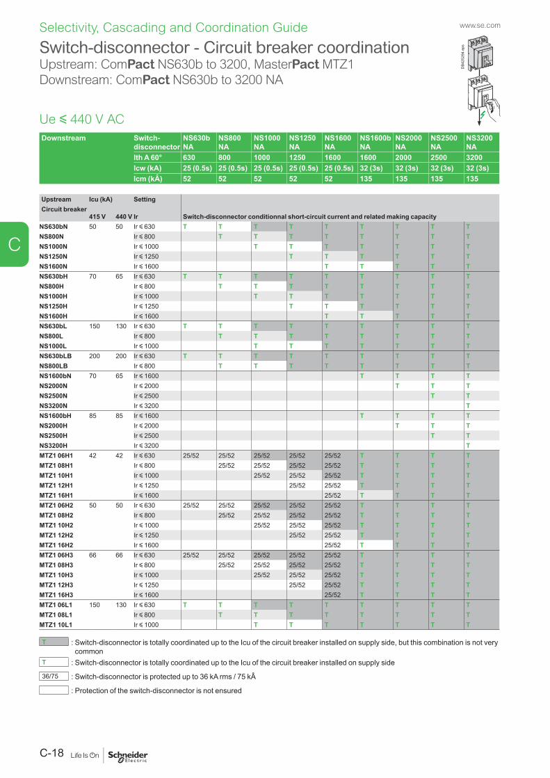
www.se.com
C-18
C
Selectivity, Cascading and Coordination Guide
Downstream Switch-disconnector
NS630b NA
NS800 NA
NS1000 NA
NS1250 NA
NS1600 NA
NS1600b NA
NS2000 NA
NS2500 NA
NS3200 NA
Ith A 60° 630 800 1000 1250 1600 1600 2000 2500 3200Icw (kA) 25 (0.5s) 25 (0.5s) 25 (0.5s) 25 (0.5s) 25 (0.5s) 32 (3s) 32 (3s) 32 (3s) 32 (3s)Icm (kÂ) 52 52 52 52 52 135 135 135 135
Upstream Icu (kA) SettingCircuit breaker
415 V 440 V Ir Switch-disconnector conditionnal short-circuit current and related making capacity
NS630bN 50 50 Ir y 630 T T T T T T T T TNS800N Ir y 800 T T T T T T T TNS1000N Ir y 1000 T T T T T T TNS1250N Ir y 1250 T T T T T TNS1600N Ir y 1600 T T T T TNS630bH 70 65 Ir y 630 T T T T T T T T TNS800H Ir y 800 T T T T T T T TNS1000H Ir y 1000 T T T T T T TNS1250H Ir y 1250 T T T T T TNS1600H Ir y 1600 T T T T TNS630bL 150 130 Ir y 630 T T T T T T T T TNS800L Ir y 800 T T T T T T T TNS1000L Ir y 1000 T T T T T T TNS630bLB 200 200 Ir y 630 T T T T T T T T TNS800LB Ir y 800 T T T T T T T TNS1600bN 70 65 Ir y 1600 T T T TNS2000N Ir y 2000 T T TNS2500N Ir y 2500 T TNS3200N Ir y 3200 TNS1600bH 85 85 Ir y 1600 T T T TNS2000H Ir y 2000 T T TNS2500H Ir y 2500 T TNS3200H Ir y 3200 TMTZ1 06H1 42 42 Ir y 630 25/52 25/52 25/52 25/52 25/52 T T T TMTZ1 08H1 Ir y 800 25/52 25/52 25/52 25/52 T T T TMTZ1 10H1 Ir y 1000 25/52 25/52 25/52 T T T TMTZ1 12H1 Ir y 1250 25/52 25/52 T T T TMTZ1 16H1 Ir y 1600 25/52 T T T TMTZ1 06H2 50 50 Ir y 630 25/52 25/52 25/52 25/52 25/52 T T T TMTZ1 08H2 Ir y 800 25/52 25/52 25/52 25/52 T T T TMTZ1 10H2 Ir y 1000 25/52 25/52 25/52 T T T TMTZ1 12H2 Ir y 1250 25/52 25/52 T T T TMTZ1 16H2 Ir y 1600 25/52 T T T TMTZ1 06H3 66 66 Ir y 630 25/52 25/52 25/52 25/52 25/52 T T T TMTZ1 08H3 Ir y 800 25/52 25/52 25/52 25/52 T T T TMTZ1 10H3 Ir y 1000 25/52 25/52 25/52 T T T TMTZ1 12H3 Ir y 1250 25/52 25/52 T T T TMTZ1 16H3 Ir y 1600 25/52 T T T TMTZ1 06L1 150 130 Ir y 630 T T T T T T T T TMTZ1 08L1 Ir y 800 T T T T T T T TMTZ1 10L1 Ir y 1000 T T T T T T T
T : Switch-disconnector is totally coordinated up to the Icu of the circuit breaker installed on supply side, but this combination is not very common
T : Switch-disconnector is totally coordinated up to the Icu of the circuit breaker installed on supply side
36/75 : Switch-disconnector is protected up to 36 kA rms / 75 kÂ
: Protection of the switch-disconnector is not ensured
Switch-disconnector - Circuit breaker coordinationUpstream: ComPact NS630b to 3200, MasterPact MTZ1Downstream: ComPact NS630b to 3200 NA
Ue y 440 V AC
DB4
2529
4.ep
s
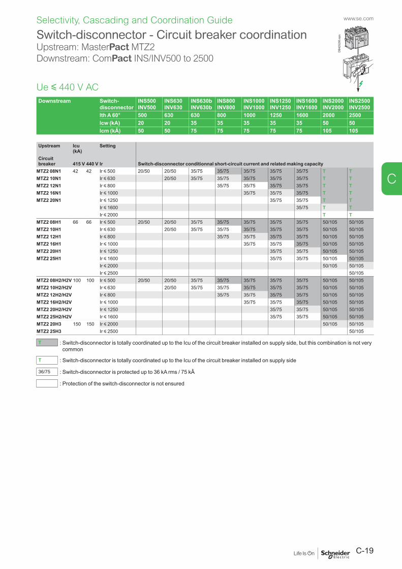
C-19
www.se.com
C
Selectivity, Cascading and Coordination Guide
Downstream Switch-disconnector
INS500 INV500
INS630 INV630
INS630b INV630b
INS800 INV800
INS1000 INV1000
INS1250 INV1250
INS1600 INV1600
INS2000 INV2000
INS2500 INV2500
Ith A 60° 500 630 630 800 1000 1250 1600 2000 2500Icw (kA) 20 20 35 35 35 35 35 50 50Icm (kÂ) 50 50 75 75 75 75 75 105 105
Upstream Icu (kA)
Setting
Circuit breaker
415 V
440 V Ir Switch-disconnector conditionnal short-circuit current and related making capacity
MTZ2 08N1 42 42 Ir y 500 20/50 20/50 35/75 35/75 35/75 35/75 35/75 T TMTZ2 10N1 Ir y 630 20/50 35/75 35/75 35/75 35/75 35/75 T TMTZ2 12N1 Ir y 800 35/75 35/75 35/75 35/75 T TMTZ2 16N1 Ir y 1000 35/75 35/75 35/75 T TMTZ2 20N1 Ir y 1250 35/75 35/75 T T
Ir y 1600 35/75 T TIr y 2000 T T
MTZ2 08H1 66 66 Ir y 500 20/50 20/50 35/75 35/75 35/75 35/75 35/75 50/105 50/105MTZ2 10H1 Ir y 630 20/50 35/75 35/75 35/75 35/75 35/75 50/105 50/105MTZ2 12H1 Ir y 800 35/75 35/75 35/75 35/75 50/105 50/105MTZ2 16H1 Ir y 1000 35/75 35/75 35/75 50/105 50/105MTZ2 20H1 Ir y 1250 35/75 35/75 50/105 50/105MTZ2 25H1 Ir y 1600 35/75 35/75 50/105 50/105
Ir y 2000 50/105 50/105Ir y 2500 50/105
MTZ2 08H2/H2V 100 100 Ir y 500 20/50 20/50 35/75 35/75 35/75 35/75 35/75 50/105 50/105MTZ2 10H2/H2V Ir y 630 20/50 35/75 35/75 35/75 35/75 35/75 50/105 50/105MTZ2 12H2/H2V Ir y 800 35/75 35/75 35/75 35/75 50/105 50/105MTZ2 16H2/H2V Ir y 1000 35/75 35/75 35/75 50/105 50/105MTZ2 20H2/H2V Ir y 1250 35/75 35/75 50/105 50/105MTZ2 25H2/H2V Ir y 1600 35/75 35/75 50/105 50/105MTZ2 20H3 150 150 Ir y 2000 50/105 50/105MTZ2 25H3 Ir y 2500 50/105
T : Switch-disconnector is totally coordinated up to the Icu of the circuit breaker installed on supply side, but this combination is not very common
T : Switch-disconnector is totally coordinated up to the Icu of the circuit breaker installed on supply side
36/75 : Switch-disconnector is protected up to 36 kA rms / 75 kÂ
: Protection of the switch-disconnector is not ensured
Switch-disconnector - Circuit breaker coordinationUpstream: MasterPact MTZ2Downstream: ComPact INS/INV500 to 2500
Ue y 440 V AC
DB4
2529
5.ep
s
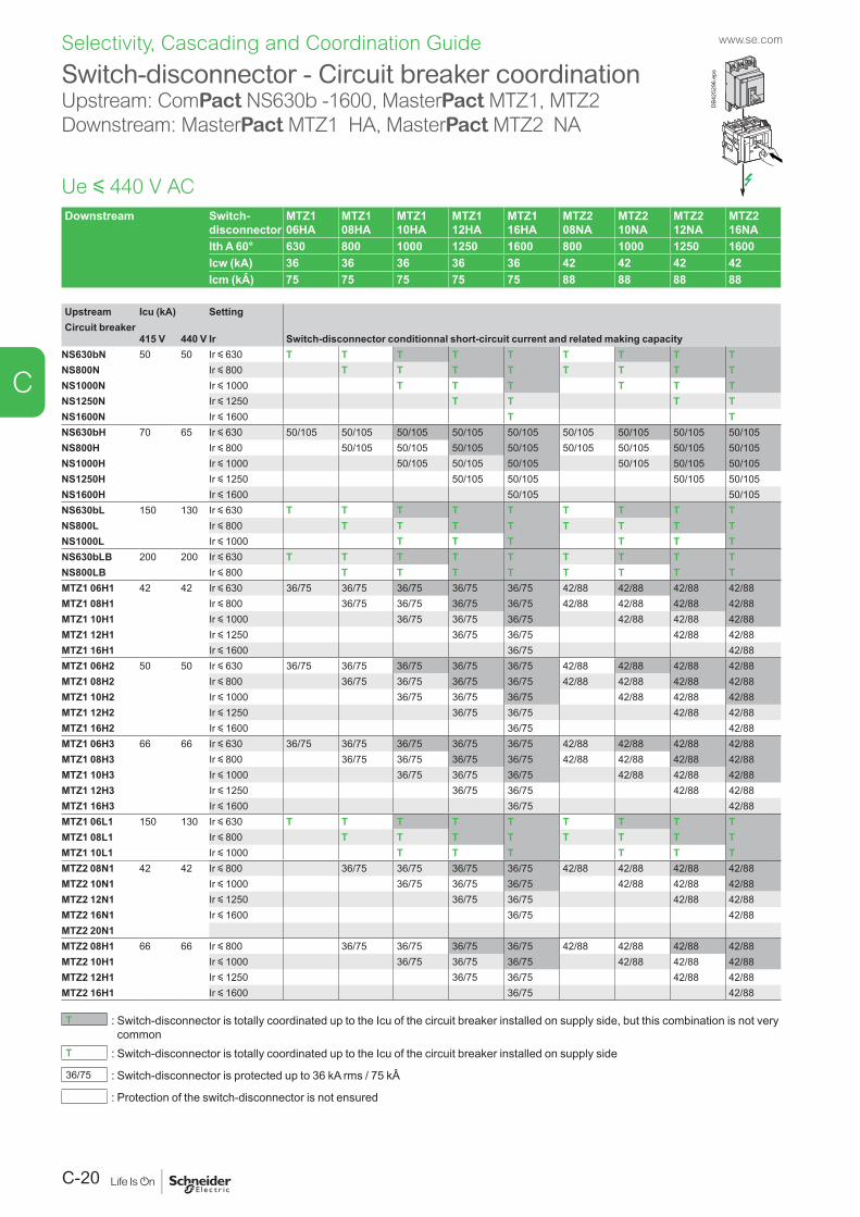
www.se.com
C-20
C
Selectivity, Cascading and Coordination Guide
Switch-disconnector - Circuit breaker coordinationUpstream: ComPact NS630b -1600, MasterPact MTZ1, MTZ2 Downstream: MasterPact MTZ1 HA, MasterPact MTZ2 NA
Ue y 440 V ACDownstream Switch-
disconnectorMTZ1 06HA
MTZ1 08HA
MTZ1 10HA
MTZ1 12HA
MTZ1 16HA
MTZ2 08NA
MTZ2 10NA
MTZ2 12NA
MTZ2 16NA
Ith A 60° 630 800 1000 1250 1600 800 1000 1250 1600Icw (kA) 36 36 36 36 36 42 42 42 42Icm (kÂ) 75 75 75 75 75 88 88 88 88
Upstream Icu (kA) SettingCircuit breaker
415 V 440 V Ir Switch-disconnector conditionnal short-circuit current and related making capacity
NS630bN 50 50 Ir y 630 T T T T T T T T TNS800N Ir y 800 T T T T T T T TNS1000N Ir y 1000 T T T T T TNS1250N Ir y 1250 T T T TNS1600N Ir y 1600 T TNS630bH 70 65 Ir y 630 50/105 50/105 50/105 50/105 50/105 50/105 50/105 50/105 50/105NS800H Ir y 800 50/105 50/105 50/105 50/105 50/105 50/105 50/105 50/105NS1000H Ir y 1000 50/105 50/105 50/105 50/105 50/105 50/105NS1250H Ir y 1250 50/105 50/105 50/105 50/105NS1600H Ir y 1600 50/105 50/105NS630bL 150 130 Ir y 630 T T T T T T T T TNS800L Ir y 800 T T T T T T T TNS1000L Ir y 1000 T T T T T TNS630bLB 200 200 Ir y 630 T T T T T T T T TNS800LB Ir y 800 T T T T T T T TMTZ1 06H1 42 42 Ir y 630 36/75 36/75 36/75 36/75 36/75 42/88 42/88 42/88 42/88MTZ1 08H1 Ir y 800 36/75 36/75 36/75 36/75 42/88 42/88 42/88 42/88MTZ1 10H1 Ir y 1000 36/75 36/75 36/75 42/88 42/88 42/88MTZ1 12H1 Ir y 1250 36/75 36/75 42/88 42/88MTZ1 16H1 Ir y 1600 36/75 42/88MTZ1 06H2 50 50 Ir y 630 36/75 36/75 36/75 36/75 36/75 42/88 42/88 42/88 42/88MTZ1 08H2 Ir y 800 36/75 36/75 36/75 36/75 42/88 42/88 42/88 42/88MTZ1 10H2 Ir y 1000 36/75 36/75 36/75 42/88 42/88 42/88MTZ1 12H2 Ir y 1250 36/75 36/75 42/88 42/88MTZ1 16H2 Ir y 1600 36/75 42/88MTZ1 06H3 66 66 Ir y 630 36/75 36/75 36/75 36/75 36/75 42/88 42/88 42/88 42/88MTZ1 08H3 Ir y 800 36/75 36/75 36/75 36/75 42/88 42/88 42/88 42/88MTZ1 10H3 Ir y 1000 36/75 36/75 36/75 42/88 42/88 42/88MTZ1 12H3 Ir y 1250 36/75 36/75 42/88 42/88MTZ1 16H3 Ir y 1600 36/75 42/88MTZ1 06L1 150 130 Ir y 630 T T T T T T T T TMTZ1 08L1 Ir y 800 T T T T T T T TMTZ1 10L1 Ir y 1000 T T T T T TMTZ2 08N1 42 42 Ir y 800 36/75 36/75 36/75 36/75 42/88 42/88 42/88 42/88MTZ2 10N1 Ir y 1000 36/75 36/75 36/75 42/88 42/88 42/88MTZ2 12N1 Ir y 1250 36/75 36/75 42/88 42/88MTZ2 16N1 Ir y 1600 36/75 42/88MTZ2 20N1MTZ2 08H1 66 66 Ir y 800 36/75 36/75 36/75 36/75 42/88 42/88 42/88 42/88MTZ2 10H1 Ir y 1000 36/75 36/75 36/75 42/88 42/88 42/88MTZ2 12H1 Ir y 1250 36/75 36/75 42/88 42/88MTZ2 16H1 Ir y 1600 36/75 42/88
T : Switch-disconnector is totally coordinated up to the Icu of the circuit breaker installed on supply side, but this combination is not very common
T : Switch-disconnector is totally coordinated up to the Icu of the circuit breaker installed on supply side
36/75 : Switch-disconnector is protected up to 36 kA rms / 75 kÂ
: Protection of the switch-disconnector is not ensured
DB4
2529
6.ep
s
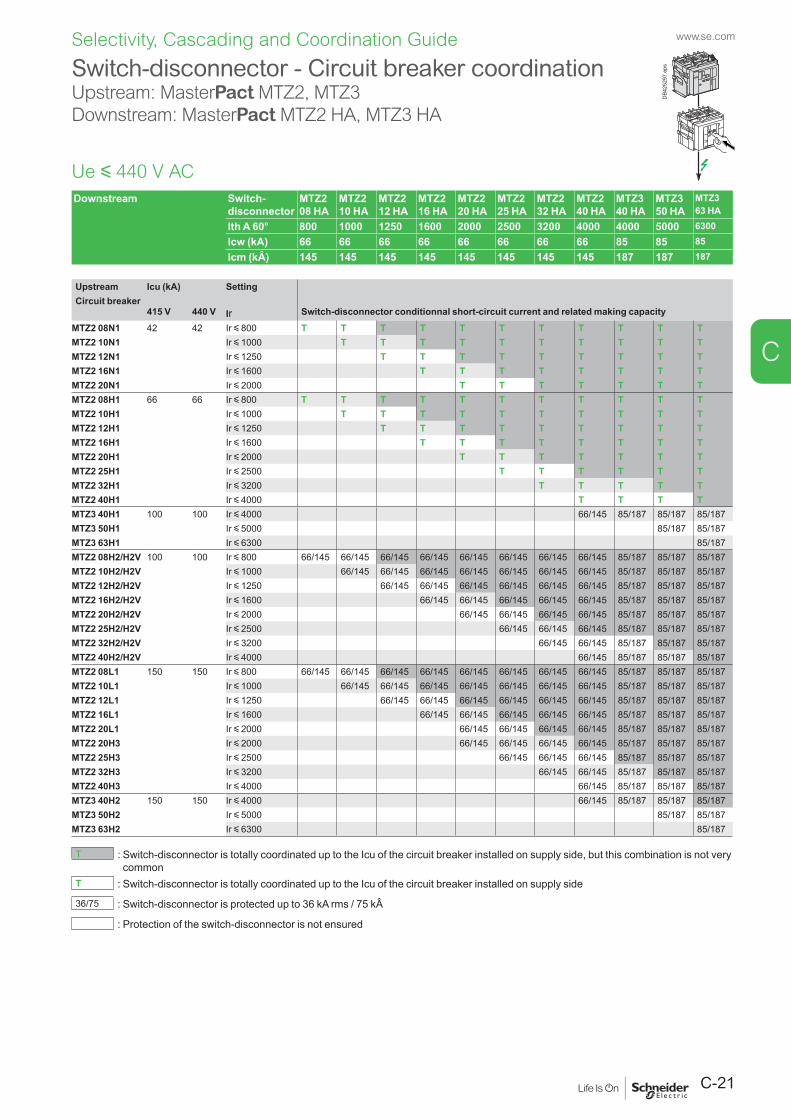
C-21
www.se.com
C
Selectivity, Cascading and Coordination Guide
Switch-disconnector - Circuit breaker coordinationUpstream: MasterPact MTZ2, MTZ3 Downstream: MasterPact MTZ2 HA, MTZ3 HA
Ue y 440 V ACDownstream Switch-
disconnectorMTZ2 08 HA
MTZ2 10 HA
MTZ2 12 HA
MTZ2 16 HA
MTZ2 20 HA
MTZ2 25 HA
MTZ2 32 HA
MTZ2 40 HA
MTZ3 40 HA
MTZ3 50 HA
MTZ3 63 HA
Ith A 60° 800 1000 1250 1600 2000 2500 3200 4000 4000 5000 6300Icw (kA) 66 66 66 66 66 66 66 66 85 85 85Icm (kÂ) 145 145 145 145 145 145 145 145 187 187 187
Upstream Icu (kA) SettingCircuit breaker
415 V 440 V Ir Switch-disconnector conditionnal short-circuit current and related making capacity
MTZ2 08N1 42 42 Ir y 800 T T T T T T T T T T TMTZ2 10N1 Ir y 1000 T T T T T T T T T TMTZ2 12N1 Ir y 1250 T T T T T T T T TMTZ2 16N1 Ir y 1600 T T T T T T T TMTZ2 20N1 Ir y 2000 T T T T T T TMTZ2 08H1 66 66 Ir y 800 T T T T T T T T T T TMTZ2 10H1 Ir y 1000 T T T T T T T T T TMTZ2 12H1 Ir y 1250 T T T T T T T T TMTZ2 16H1 Ir y 1600 T T T T T T T TMTZ2 20H1 Ir y 2000 T T T T T T TMTZ2 25H1 Ir y 2500 T T T T T TMTZ2 32H1 Ir y 3200 T T T T TMTZ2 40H1 Ir y 4000 T T T TMTZ3 40H1 100 100 Ir y 4000 66/145 85/187 85/187 85/187MTZ3 50H1 Ir y 5000 85/187 85/187MTZ3 63H1 Ir y 6300 85/187MTZ2 08H2/H2V 100 100 Ir y 800 66/145 66/145 66/145 66/145 66/145 66/145 66/145 66/145 85/187 85/187 85/187MTZ2 10H2/H2V Ir y 1000 66/145 66/145 66/145 66/145 66/145 66/145 66/145 85/187 85/187 85/187MTZ2 12H2/H2V Ir y 1250 66/145 66/145 66/145 66/145 66/145 66/145 85/187 85/187 85/187MTZ2 16H2/H2V Ir y 1600 66/145 66/145 66/145 66/145 66/145 85/187 85/187 85/187MTZ2 20H2/H2V Ir y 2000 66/145 66/145 66/145 66/145 85/187 85/187 85/187MTZ2 25H2/H2V Ir y 2500 66/145 66/145 66/145 85/187 85/187 85/187MTZ2 32H2/H2V Ir y 3200 66/145 66/145 85/187 85/187 85/187MTZ2 40H2/H2V Ir y 4000 66/145 85/187 85/187 85/187MTZ2 08L1 150 150 Ir y 800 66/145 66/145 66/145 66/145 66/145 66/145 66/145 66/145 85/187 85/187 85/187MTZ2 10L1 Ir y 1000 66/145 66/145 66/145 66/145 66/145 66/145 66/145 85/187 85/187 85/187MTZ2 12L1 Ir y 1250 66/145 66/145 66/145 66/145 66/145 66/145 85/187 85/187 85/187MTZ2 16L1 Ir y 1600 66/145 66/145 66/145 66/145 66/145 85/187 85/187 85/187MTZ2 20L1 Ir y 2000 66/145 66/145 66/145 66/145 85/187 85/187 85/187MTZ2 20H3 Ir y 2000 66/145 66/145 66/145 66/145 85/187 85/187 85/187MTZ2 25H3 Ir y 2500 66/145 66/145 66/145 85/187 85/187 85/187MTZ2 32H3 Ir y 3200 66/145 66/145 85/187 85/187 85/187MTZ2 40H3 Ir y 4000 66/145 85/187 85/187 85/187MTZ3 40H2 150 150 Ir y 4000 66/145 85/187 85/187 85/187MTZ3 50H2 Ir y 5000 85/187 85/187MTZ3 63H2 Ir y 6300 85/187
T : Switch-disconnector is totally coordinated up to the Icu of the circuit breaker installed on supply side, but this combination is not very common
T : Switch-disconnector is totally coordinated up to the Icu of the circuit breaker installed on supply side
36/75 : Switch-disconnector is protected up to 36 kA rms / 75 kÂ
: Protection of the switch-disconnector is not ensured
DB4
2529
7.ep
s
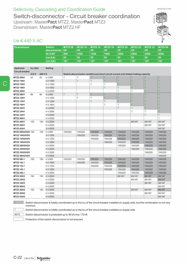
www.se.com
C-22
C
Selectivity, Cascading and Coordination Guide
Switch-disconnector - Circuit breaker coordinationUpstream: MasterPact MTZ2, MasterPact MTZ3 Downstream: MasterPact MTZ2 HF
Downstream Switch-disconnector
MTZ2 08 HF
MTZ2 10 HF
MTZ2 12 HF
MTZ2 16 HF
MTZ2 20 HF
MTZ2 25 HF
MTZ2 32 HF
MTZ2 40 HF
Ith A 60° 800 1000 1250 1600 2000 2500 3200 4000Icw (kA) 85 85 85 85 85 85 85 85Icm (kÂ) 187 187 187 187 187 187 187 187
Upstream Icu (kA) SettingCircuit breaker
415 V 440 V Ir Switch-disconnector conditionnal short-circuit current and related making capacity
MTZ2 08N1 42 42 Ir y 800 T T T T T T T TMTZ2 10N1 Ir y 1000 T T T T T T TMTZ2 12N1 Ir y 1250 T T T T T TMTZ2 16N1 Ir y 1600 T T T T TMTZ2 20N1 Ir y 2000 T T T TMTZ2 08H1 66 66 Ir y 800 T T T T T T T TMTZ2 10H1 Ir y 1000 T T T T T T TMTZ2 12H1 Ir y 1250 T T T T T TMTZ2 16H1 Ir y 1600 T T T T TMTZ2 20H1 Ir y 2000 T T T TMTZ2 25H1 Ir y 2500 T T TMTZ2 32H1 Ir y 3200 T TMTZ2 40H1 Ir y 4000 TMTZ3 40H1 100 100 Ir y 2500 85/187 85/187 85/187MTZ3 50H1 Ir y 3200 85/187 85/187MTZ3 63H1 Ir y 4000 85/187MTZ2 08H2/H2V 100 100 Ir y 800 100/220 100/220 100/220 100/220 100/220 100/220 100/220 100/220MTZ2 10H2/H2V Ir y 1000 100/220 100/220 100/220 100/220 100/220 100/220 100/220MTZ2 12H2/H2V Ir y 1250 100/220 100/220 100/220 100/220 100/220 100/220MTZ2 16H2/H2V Ir y 1600 100/220 100/220 100/220 100/220 100/220MTZ2 20H2/H2V Ir y 2000 100/220 100/220 100/220 100/220MTZ2 25H2/H2V Ir y 2500 100/220 100/220 100/220MTZ2 32H2/H2V Ir y 3200 100/220 100/220MTZ2 40H2/H2V Ir y 4000 100/220MTZ2 08L1 150 150 Ir y 800 100/220 100/220 100/220 100/220 100/220 100/220 100/220 100/220MTZ2 10L1 Ir y 1000 100/220 100/220 100/220 100/220 100/220 100/220 100/220MTZ2 12L1 Ir y 1250 100/220 100/220 100/220 100/220 100/220 100/220MTZ2 16L1 Ir y 1600 100/220 100/220 100/220 100/220 100/220MTZ2 20L1 Ir y 2000 100/220 100/220 100/220 100/220MTZ2 20H3 150 150 Ir y 2000 85/187 85/187 85/187 85/187MTZ2 25H3 Ir y 2500 85/187 85/187 85/187MTZ2 32H3 Ir y 3200 85/187 85/187MTZ2 40H3 Ir y 4000 85/187MTZ3 40H2 150 150 Ir y 2500 85/187 85/187 85/187MTZ3 50H2 Ir y 3200 85/187 85/187MTZ3 63H2 Ir y 4000 85/187
T : Switch-disconnector is totally coordinated up to the Icu of the circuit breaker installed on supply side, but this combination is not very common
T : Switch-disconnector is totally coordinated up to the Icu of the circuit breaker installed on supply side
36/75 : Switch-disconnector is protected up to 36 kA rms / 75 kÂ
: Protection of the switch-disconnector is not ensured
DB4
2529
7.ep
s
Ue y 440 V AC
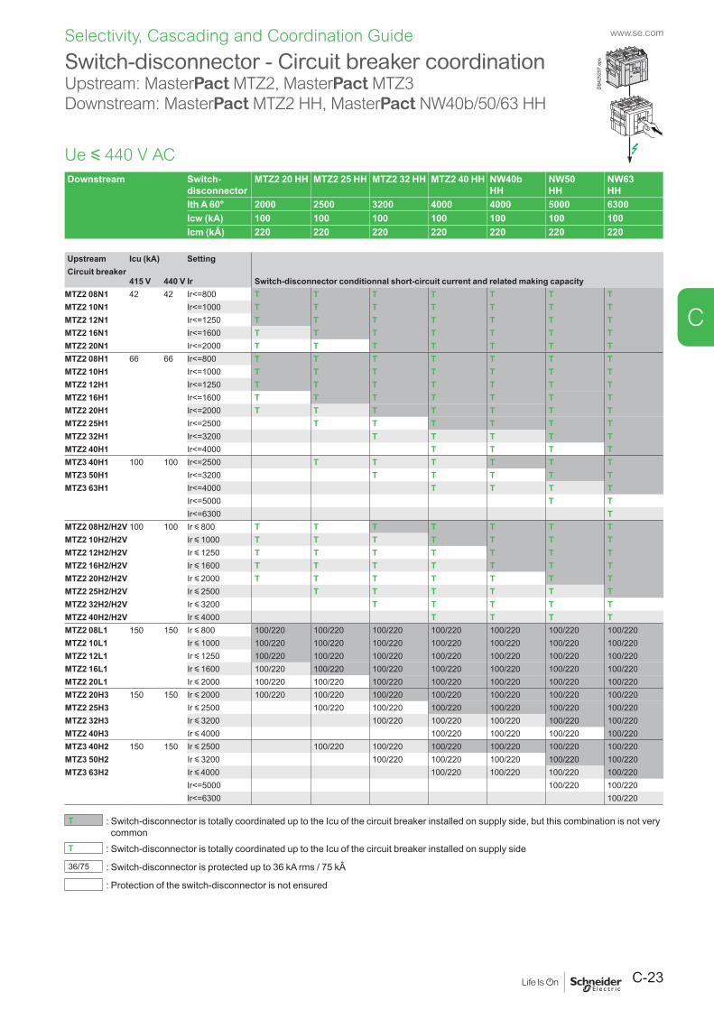
C-23
www.se.com
C
Selectivity, Cascading and Coordination Guide
Switch-disconnector - Circuit breaker coordinationUpstream: MasterPact MTZ2, MasterPact MTZ3 Downstream: MasterPact MTZ2 HH, MasterPact NW40b/50/63 HH
Downstream Switch-disconnector
MTZ2 20 HH MTZ2 25 HH MTZ2 32 HH MTZ2 40 HH NW40b HH
NW50 HH
NW63 HH
Ith A 60° 2000 2500 3200 4000 4000 5000 6300Icw (kA) 100 100 100 100 100 100 100Icm (kÂ) 220 220 220 220 220 220 220
Upstream Icu (kA) SettingCircuit breaker
415 V 440 V Ir Switch-disconnector conditionnal short-circuit current and related making capacity
MTZ2 08N1 42 42 Ir<=800 T T T T T T TMTZ2 10N1 Ir<=1000 T T T T T T TMTZ2 12N1 Ir<=1250 T T T T T T TMTZ2 16N1 Ir<=1600 T T T T T T TMTZ2 20N1 Ir<=2000 T T T T T T TMTZ2 08H1 66 66 Ir<=800 T T T T T T TMTZ2 10H1 Ir<=1000 T T T T T T TMTZ2 12H1 Ir<=1250 T T T T T T TMTZ2 16H1 Ir<=1600 T T T T T T TMTZ2 20H1 Ir<=2000 T T T T T T TMTZ2 25H1 Ir<=2500 T T T T T TMTZ2 32H1 Ir<=3200 T T T T TMTZ2 40H1 Ir<=4000 T T T TMTZ3 40H1 100 100 Ir<=2500 T T T T T TMTZ3 50H1 Ir<=3200 T T T T TMTZ3 63H1 Ir<=4000 T T T T
Ir<=5000 T TIr<=6300 T
MTZ2 08H2/H2V 100 100 Ir y 800 T T T T T T TMTZ2 10H2/H2V Ir y 1000 T T T T T T TMTZ2 12H2/H2V Ir y 1250 T T T T T T TMTZ2 16H2/H2V Ir y 1600 T T T T T T TMTZ2 20H2/H2V Ir y 2000 T T T T T T TMTZ2 25H2/H2V Ir y 2500 T T T T T TMTZ2 32H2/H2V Ir y 3200 T T T T TMTZ2 40H2/H2V Ir y 4000 T T T TMTZ2 08L1 150 150 Ir y 800 100/220 100/220 100/220 100/220 100/220 100/220 100/220MTZ2 10L1 Ir y 1000 100/220 100/220 100/220 100/220 100/220 100/220 100/220MTZ2 12L1 Ir y 1250 100/220 100/220 100/220 100/220 100/220 100/220 100/220MTZ2 16L1 Ir y 1600 100/220 100/220 100/220 100/220 100/220 100/220 100/220MTZ2 20L1 Ir y 2000 100/220 100/220 100/220 100/220 100/220 100/220 100/220MTZ2 20H3 150 150 Ir y 2000 100/220 100/220 100/220 100/220 100/220 100/220 100/220MTZ2 25H3 Ir y 2500 100/220 100/220 100/220 100/220 100/220 100/220MTZ2 32H3 Ir y 3200 100/220 100/220 100/220 100/220 100/220MTZ2 40H3 Ir y 4000 100/220 100/220 100/220 100/220MTZ3 40H2 150 150 Ir y 2500 100/220 100/220 100/220 100/220 100/220 100/220MTZ3 50H2 Ir y 3200 100/220 100/220 100/220 100/220 100/220MTZ3 63H2 Ir y 4000 100/220 100/220 100/220 100/220
Ir<=5000 100/220 100/220Ir<=6300 100/220
T : Switch-disconnector is totally coordinated up to the Icu of the circuit breaker installed on supply side, but this combination is not very common
T : Switch-disconnector is totally coordinated up to the Icu of the circuit breaker installed on supply side
36/75 : Switch-disconnector is protected up to 36 kA rms / 75 kÂ
: Protection of the switch-disconnector is not ensured
DB4
2529
7.ep
s
Ue y 440 V AC
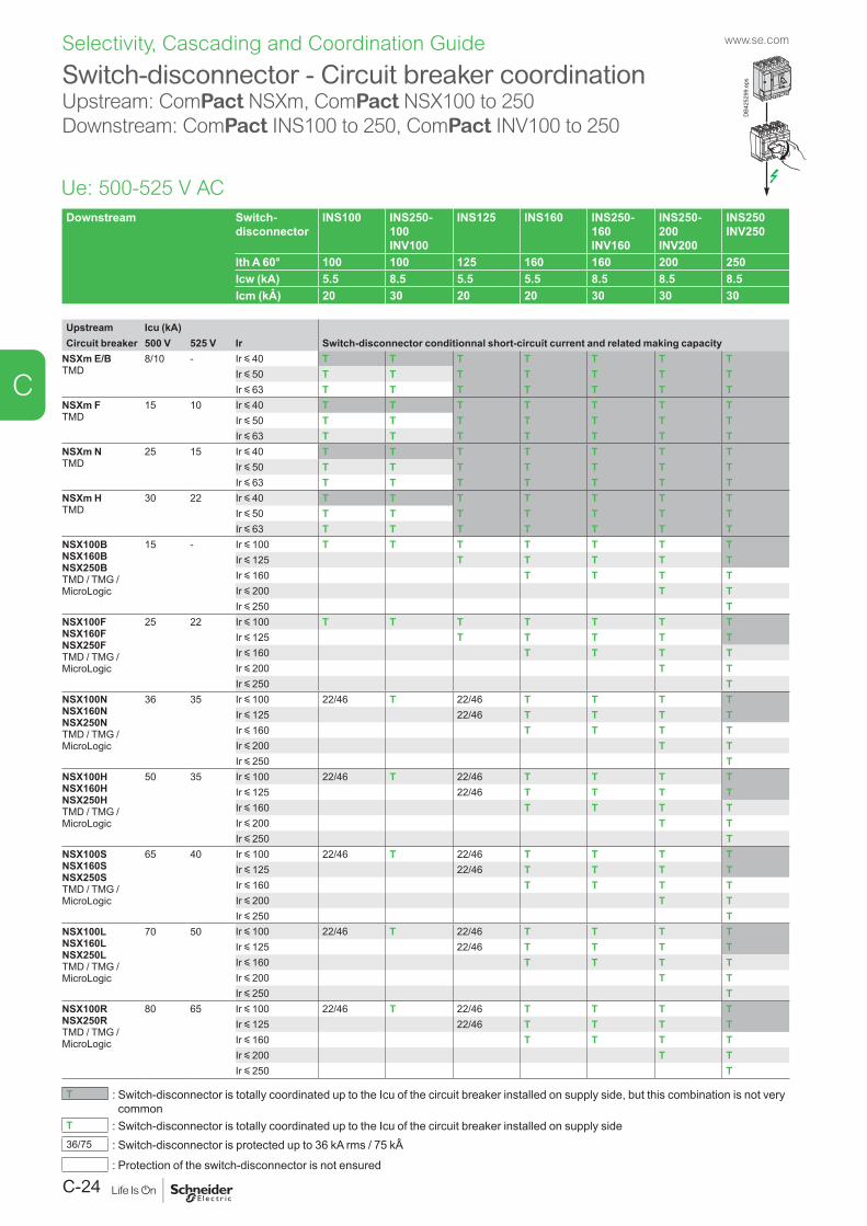
www.se.com
C-24
C
Selectivity, Cascading and Coordination Guide
Downstream Switch-disconnector
INS100 INS250-100 INV100
INS125 INS160 INS250-160 INV160
INS250-200 INV200
INS250 INV250
Ith A 60° 100 100 125 160 160 200 250Icw (kA) 5.5 8.5 5.5 5.5 8.5 8.5 8.5Icm (kÂ) 20 30 20 20 30 30 30
Upstream Icu (kA)Switch-disconnector conditionnal short-circuit current and related making capacityCircuit breaker 500 V 525 V Ir
NSXm E/BTMD
8/10 - Ir y 40 T T T T T T TIr y 50 T T T T T T TIr y 63 T T T T T T T
NSXm FTMD
15 10 Ir y 40 T T T T T T TIr y 50 T T T T T T TIr y 63 T T T T T T T
NSXm NTMD
25 15 Ir y 40 T T T T T T TIr y 50 T T T T T T TIr y 63 T T T T T T T
NSXm HTMD
30 22 Ir y 40 T T T T T T TIr y 50 T T T T T T TIr y 63 T T T T T T T
NSX100BNSX160BNSX250BTMD / TMG / MicroLogic
15 - Ir y 100 T T T T T T TIr y 125 T T T T TIr y 160 T T T TIr y 200 T TIr y 250 T
NSX100FNSX160FNSX250FTMD / TMG / MicroLogic
25 22 Ir y 100 T T T T T T TIr y 125 T T T T TIr y 160 T T T TIr y 200 T TIr y 250 T
NSX100NNSX160NNSX250NTMD / TMG / MicroLogic
36 35 Ir y 100 22/46 T 22/46 T T T TIr y 125 22/46 T T T TIr y 160 T T T TIr y 200 T TIr y 250 T
NSX100HNSX160HNSX250HTMD / TMG / MicroLogic
50 35 Ir y 100 22/46 T 22/46 T T T TIr y 125 22/46 T T T TIr y 160 T T T TIr y 200 T TIr y 250 T
NSX100SNSX160SNSX250STMD / TMG / MicroLogic
65 40 Ir y 100 22/46 T 22/46 T T T TIr y 125 22/46 T T T TIr y 160 T T T TIr y 200 T TIr y 250 T
NSX100LNSX160LNSX250LTMD / TMG / MicroLogic
70 50 Ir y 100 22/46 T 22/46 T T T TIr y 125 22/46 T T T TIr y 160 T T T TIr y 200 T TIr y 250 T
NSX100RNSX250RTMD / TMG / MicroLogic
80 65 Ir y 100 22/46 T 22/46 T T T TIr y 125 22/46 T T T TIr y 160 T T T TIr y 200 T TIr y 250 T
T : Switch-disconnector is totally coordinated up to the Icu of the circuit breaker installed on supply side, but this combination is not very common
T : Switch-disconnector is totally coordinated up to the Icu of the circuit breaker installed on supply side36/75 : Switch-disconnector is protected up to 36 kA rms / 75 kÂ
: Protection of the switch-disconnector is not ensured
Switch-disconnector - Circuit breaker coordinationUpstream: ComPact NSXm, ComPact NSX100 to 250Downstream: ComPact INS100 to 250, ComPact INV100 to 250
Ue: 500-525 V AC
DB4
2529
9.ep
s
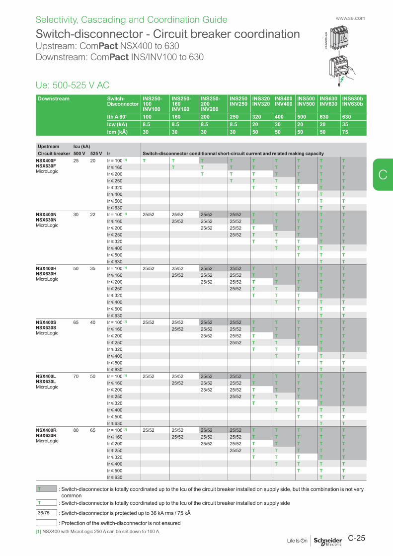
C-25
www.se.com
C
Selectivity, Cascading and Coordination Guide
Downstream Switch- Disconnector
INS250-100 INV100
INS250-160 INV160
INS250-200 INV200
INS250 INV250
INS320 INV320
INS400 INV400
INS500 INV500
INS630 INV630
INS630b INV630b
Ith A 60° 100 160 200 250 320 400 500 630 630Icw (kA) 8.5 8.5 8.5 8.5 20 20 20 20 35Icm (kÂ) 30 30 30 30 50 50 50 50 75
Upstream Icu (kA)Switch-disconnector conditionnal short-circuit current and related making capacityCircuit breaker 500 V 525 V Ir
NSX400FNSX630FMicroLogic
25 20 Ir = 100 [1] T T T T T T T T TIr y 160 T T T T T T T TIr y 200 T T T T T T TIr y 250 T T T T T TIr y 320 T T T T TIr y 400 T T T TIr y 500 T T TIr y 630 T T
NSX400NNSX630NMicroLogic
30 22 Ir = 100 [1] 25/52 25/52 25/52 25/52 T T T T TIr y 160 25/52 25/52 25/52 T T T T TIr y 200 25/52 25/52 T T T T TIr y 250 25/52 T T T T TIr y 320 T T T T TIr y 400 T T T TIr y 500 T T TIr y 630 T T
NSX400HNSX630HMicroLogic
50 35 Ir = 100 [1] 25/52 25/52 25/52 25/52 T T T T TIr y 160 25/52 25/52 25/52 T T T T TIr y 200 25/52 25/52 T T T T TIr y 250 25/52 T T T T TIr y 320 T T T T TIr y 400 T T T TIr y 500 T T TIr y 630 T T
NSX400SNSX630SMicroLogic
65 40 Ir = 100 [1] 25/52 25/52 25/52 25/52 T T T T TIr y 160 25/52 25/52 25/52 T T T T TIr y 200 25/52 25/52 T T T T TIr y 250 25/52 T T T T TIr y 320 T T T T TIr y 400 T T T TIr y 500 T T TIr y 630 T T
NSX400LNSX630LMicroLogic
70 50 Ir = 100 [1] 25/52 25/52 25/52 25/52 T T T T TIr y 160 25/52 25/52 25/52 T T T T TIr y 200 25/52 25/52 T T T T TIr y 250 25/52 T T T T TIr y 320 T T T T TIr y 400 T T T TIr y 500 T T TIr y 630 T T
NSX400RNSX630RMicroLogic
80 65 Ir = 100 [1] 25/52 25/52 25/52 25/52 T T T T TIr y 160 25/52 25/52 25/52 T T T T TIr y 200 25/52 25/52 T T T T TIr y 250 25/52 T T T T TIr y 320 T T T T TIr y 400 T T T TIr y 500 T T TIr y 630 T T
T : Switch-disconnector is totally coordinated up to the Icu of the circuit breaker installed on supply side, but this combination is not very common
T : Switch-disconnector is totally coordinated up to the Icu of the circuit breaker installed on supply side
36/75 : Switch-disconnector is protected up to 36 kA rms / 75 kÂ
: Protection of the switch-disconnector is not ensured
Switch-disconnector - Circuit breaker coordinationUpstream: ComPact NSX400 to 630Downstream: ComPact INS/INV100 to 630
Ue: 500-525 V AC
DB4
2530
0.ep
s
[1] NSX400 with MicroLogic 250 A can be set down to 100 A.
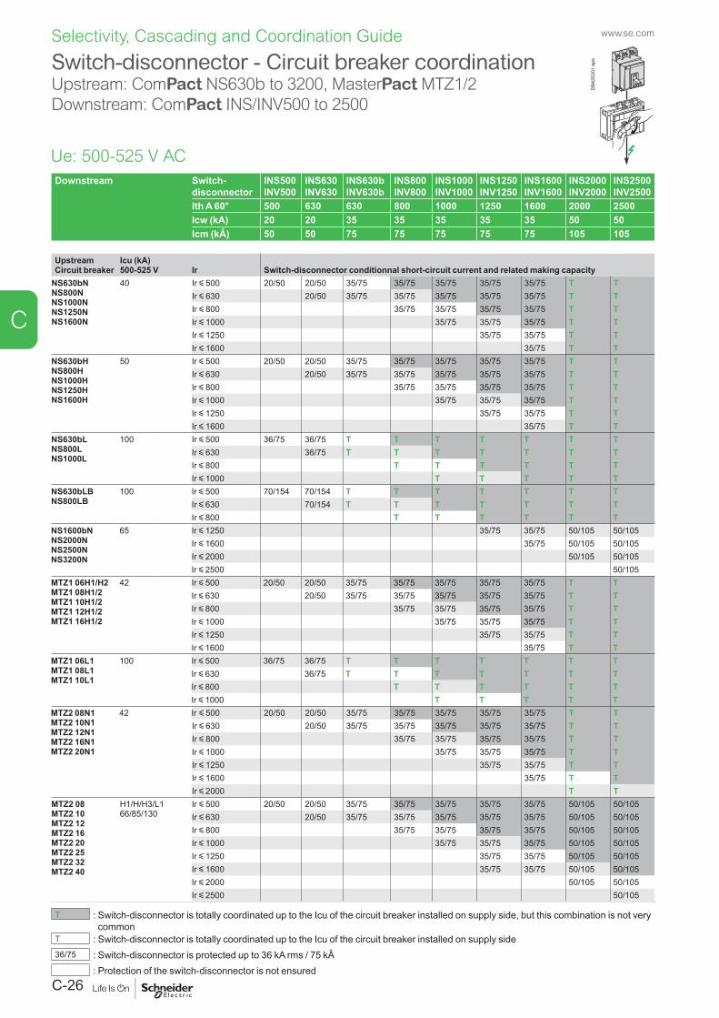
www.se.com
C-26
C
Selectivity, Cascading and Coordination Guide
Downstream Switch-disconnector
INS500 INV500
INS630 INV630
INS630b INV630b
INS800 INV800
INS1000 INV1000
INS1250 INV1250
INS1600 INV1600
INS2000 INV2000
INS2500 INV2500
Ith A 60° 500 630 630 800 1000 1250 1600 2000 2500Icw (kA) 20 20 35 35 35 35 35 50 50Icm (kÂ) 50 50 75 75 75 75 75 105 105
UpstreamCircuit breaker
Icu (kA)500-525 V Ir Switch-disconnector conditionnal short-circuit current and related making capacity
NS630bNNS800NNS1000NNS1250NNS1600N
40 Ir y 500 20/50 20/50 35/75 35/75 35/75 35/75 35/75 T TIr y 630 20/50 35/75 35/75 35/75 35/75 35/75 T TIr y 800 35/75 35/75 35/75 35/75 T TIr y 1000 35/75 35/75 35/75 T TIr y 1250 35/75 35/75 T TIr y 1600 35/75 T T
NS630bHNS800HNS1000HNS1250HNS1600H
50 Ir y 500 20/50 20/50 35/75 35/75 35/75 35/75 35/75 T TIr y 630 20/50 35/75 35/75 35/75 35/75 35/75 T TIr y 800 35/75 35/75 35/75 35/75 T TIr y 1000 35/75 35/75 35/75 T TIr y 1250 35/75 35/75 T TIr y 1600 35/75 T T
NS630bLNS800LNS1000L
100 Ir y 500 36/75 36/75 T T T T T T TIr y 630 36/75 T T T T T T TIr y 800 T T T T T TIr y 1000 T T T T T
NS630bLBNS800LB
100 Ir y 500 70/154 70/154 T T T T T T TIr y 630 70/154 T T T T T T TIr y 800 T T T T T T
NS1600bNNS2000NNS2500NNS3200N
65 Ir y 1250 35/75 35/75 50/105 50/105Ir y 1600 35/75 50/105 50/105Ir y 2000 50/105 50/105Ir y 2500 50/105
MTZ1 06H1/H2MTZ1 08H1/2MTZ1 10H1/2MTZ1 12H1/2MTZ1 16H1/2
42 Ir y 500 20/50 20/50 35/75 35/75 35/75 35/75 35/75 T TIr y 630 20/50 35/75 35/75 35/75 35/75 35/75 T TIr y 800 35/75 35/75 35/75 35/75 T TIr y 1000 35/75 35/75 35/75 T TIr y 1250 35/75 35/75 T TIr y 1600 35/75 T T
MTZ1 06L1MTZ1 08L1MTZ1 10L1
100 Ir y 500 36/75 36/75 T T T T T T TIr y 630 36/75 T T T T T T TIr y 800 T T T T T TIr y 1000 T T T T T
MTZ2 08N1MTZ2 10N1MTZ2 12N1MTZ2 16N1MTZ2 20N1
42 Ir y 500 20/50 20/50 35/75 35/75 35/75 35/75 35/75 T TIr y 630 20/50 35/75 35/75 35/75 35/75 35/75 T TIr y 800 35/75 35/75 35/75 35/75 T TIr y 1000 35/75 35/75 35/75 T TIr y 1250 35/75 35/75 T TIr y 1600 35/75 T TIr y 2000 T T
MTZ2 08MTZ2 10MTZ2 12MTZ2 16MTZ2 20MTZ2 25MTZ2 32MTZ2 40
H1/H/H3/L166/85/130
Ir y 500 20/50 20/50 35/75 35/75 35/75 35/75 35/75 50/105 50/105Ir y 630 20/50 35/75 35/75 35/75 35/75 35/75 50/105 50/105Ir y 800 35/75 35/75 35/75 35/75 50/105 50/105Ir y 1000 35/75 35/75 35/75 50/105 50/105Ir y 1250 35/75 35/75 50/105 50/105Ir y 1600 35/75 35/75 50/105 50/105Ir y 2000 50/105 50/105Ir y 2500 50/105
T : Switch-disconnector is totally coordinated up to the Icu of the circuit breaker installed on supply side, but this combination is not very common
T : Switch-disconnector is totally coordinated up to the Icu of the circuit breaker installed on supply side36/75 : Switch-disconnector is protected up to 36 kA rms / 75 kÂ
: Protection of the switch-disconnector is not ensured
Switch-disconnector - Circuit breaker coordinationUpstream: ComPact NS630b to 3200, MasterPact MTZ1/2 Downstream: ComPact INS/INV500 to 2500
Ue: 500-525 V AC
DB4
2530
1.ep
s
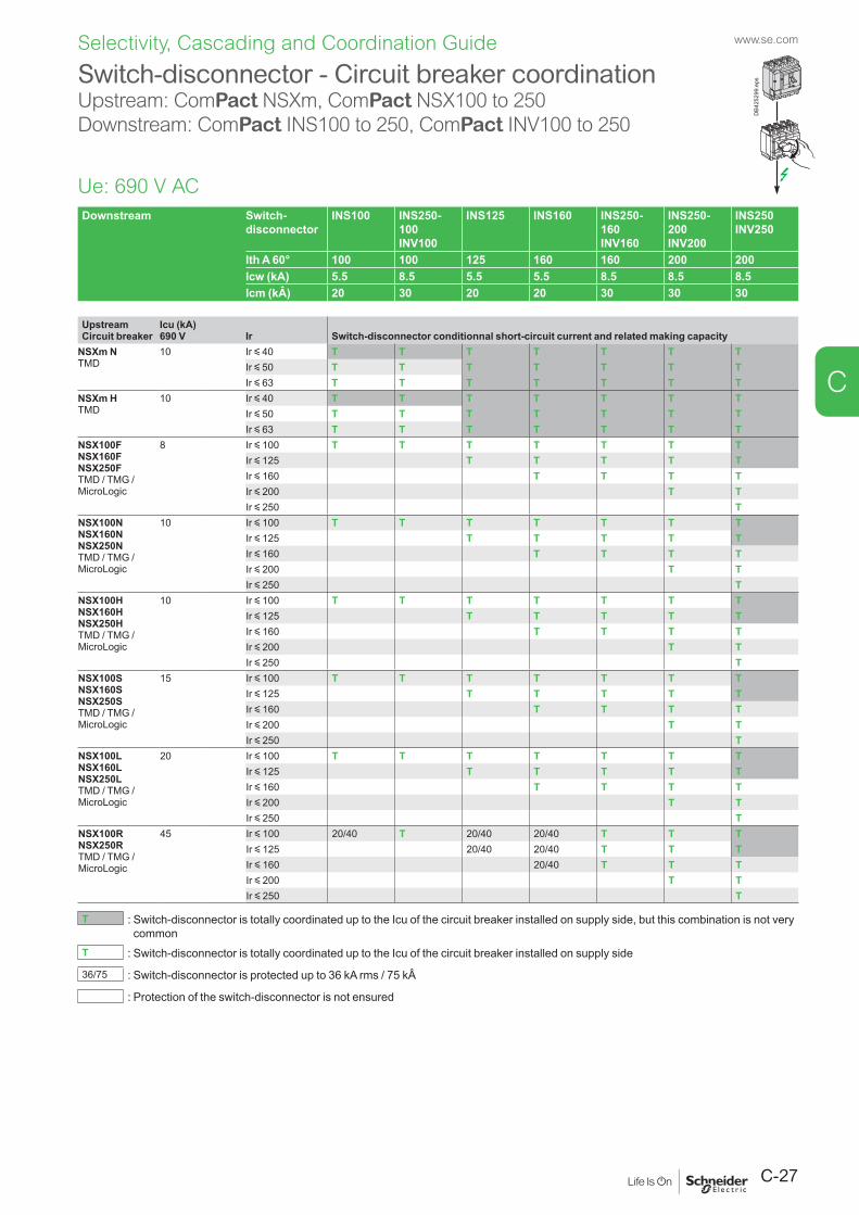
C-27
www.se.com
C
Selectivity, Cascading and Coordination Guide
Downstream Switch-disconnector
INS100 INS250-100 INV100
INS125 INS160 INS250-160 INV160
INS250-200 INV200
INS250 INV250
Ith A 60° 100 100 125 160 160 200 200Icw (kA) 5.5 8.5 5.5 5.5 8.5 8.5 8.5Icm (kÂ) 20 30 20 20 30 30 30
UpstreamCircuit breaker
Icu (kA)690 V Ir Switch-disconnector conditionnal short-circuit current and related making capacity
NSXm NTMD
10 Ir y 40 T T T T T T TIr y 50 T T T T T T TIr y 63 T T T T T T T
NSXm HTMD
10 Ir y 40 T T T T T T TIr y 50 T T T T T T TIr y 63 T T T T T T T
NSX100FNSX160FNSX250FTMD / TMG / MicroLogic
8 Ir y 100 T T T T T T TIr y 125 T T T T TIr y 160 T T T TIr y 200 T TIr y 250 T
NSX100NNSX160NNSX250NTMD / TMG / MicroLogic
10 Ir y 100 T T T T T T TIr y 125 T T T T TIr y 160 T T T TIr y 200 T TIr y 250 T
NSX100HNSX160HNSX250HTMD / TMG / MicroLogic
10 Ir y 100 T T T T T T TIr y 125 T T T T TIr y 160 T T T TIr y 200 T TIr y 250 T
NSX100SNSX160SNSX250STMD / TMG / MicroLogic
15 Ir y 100 T T T T T T TIr y 125 T T T T TIr y 160 T T T TIr y 200 T TIr y 250 T
NSX100LNSX160LNSX250LTMD / TMG / MicroLogic
20 Ir y 100 T T T T T T TIr y 125 T T T T TIr y 160 T T T TIr y 200 T TIr y 250 T
NSX100RNSX250RTMD / TMG / MicroLogic
45 Ir y 100 20/40 T 20/40 20/40 T T TIr y 125 20/40 20/40 T T TIr y 160 20/40 T T TIr y 200 T TIr y 250 T
T : Switch-disconnector is totally coordinated up to the Icu of the circuit breaker installed on supply side, but this combination is not very common
T : Switch-disconnector is totally coordinated up to the Icu of the circuit breaker installed on supply side
36/75 : Switch-disconnector is protected up to 36 kA rms / 75 kÂ
: Protection of the switch-disconnector is not ensured
Switch-disconnector - Circuit breaker coordinationUpstream: ComPact NSXm, ComPact NSX100 to 250Downstream: ComPact INS100 to 250, ComPact INV100 to 250
Ue: 690 V AC
DB4
2529
9.ep
s
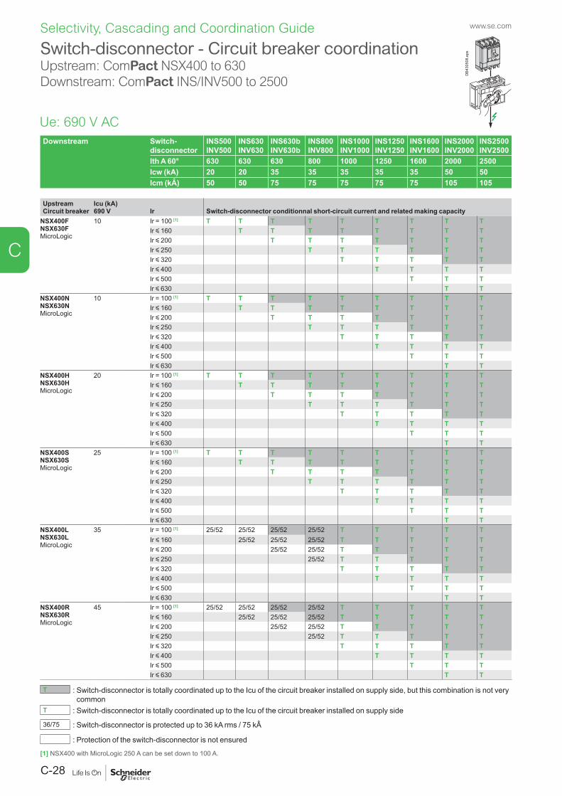
www.se.com
C-28
C
Selectivity, Cascading and Coordination Guide
Downstream Switch-disconnector
INS500 INV500
INS630 INV630
INS630b INV630b
INS800 INV800
INS1000 INV1000
INS1250 INV1250
INS1600 INV1600
INS2000 INV2000
INS2500 INV2500
Ith A 60° 630 630 630 800 1000 1250 1600 2000 2500Icw (kA) 20 20 35 35 35 35 35 50 50Icm (kÂ) 50 50 75 75 75 75 75 105 105
UpstreamCircuit breaker
Icu (kA)690 V Ir Switch-disconnector conditionnal short-circuit current and related making capacity
NSX400FNSX630FMicroLogic
10 Ir = 100 [1] T T T T T T T T TIr y 160 T T T T T T T TIr y 200 T T T T T T TIr y 250 T T T T T TIr y 320 T T T T TIr y 400 T T T TIr y 500 T T TIr y 630 T T
NSX400NNSX630NMicroLogic
10 Ir = 100 [1] T T T T T T T T TIr y 160 T T T T T T T TIr y 200 T T T T T T TIr y 250 T T T T T TIr y 320 T T T T TIr y 400 T T T TIr y 500 T T TIr y 630 T T
NSX400HNSX630HMicroLogic
20 Ir = 100 [1] T T T T T T T T TIr y 160 T T T T T T T TIr y 200 T T T T T T TIr y 250 T T T T T TIr y 320 T T T T TIr y 400 T T T TIr y 500 T T TIr y 630 T T
NSX400SNSX630SMicroLogic
25 Ir = 100 [1] T T T T T T T T TIr y 160 T T T T T T T TIr y 200 T T T T T T TIr y 250 T T T T T TIr y 320 T T T T TIr y 400 T T T TIr y 500 T T TIr y 630 T T
NSX400LNSX630LMicroLogic
35 Ir = 100 [1] 25/52 25/52 25/52 25/52 T T T T TIr y 160 25/52 25/52 25/52 T T T T TIr y 200 25/52 25/52 T T T T TIr y 250 25/52 T T T T TIr y 320 T T T T TIr y 400 T T T TIr y 500 T T TIr y 630 T T
NSX400RNSX630RMicroLogic
45 Ir = 100 [1] 25/52 25/52 25/52 25/52 T T T T TIr y 160 25/52 25/52 25/52 T T T T TIr y 200 25/52 25/52 T T T T TIr y 250 25/52 T T T T TIr y 320 T T T T TIr y 400 T T T TIr y 500 T T TIr y 630 T T
T : Switch-disconnector is totally coordinated up to the Icu of the circuit breaker installed on supply side, but this combination is not very common
T : Switch-disconnector is totally coordinated up to the Icu of the circuit breaker installed on supply side
36/75 : Switch-disconnector is protected up to 36 kA rms / 75 kÂ
: Protection of the switch-disconnector is not ensured
Switch-disconnector - Circuit breaker coordinationUpstream: ComPact NSX400 to 630Downstream: ComPact INS/INV500 to 2500
Ue: 690 V AC
DB4
3050
8.ep
s
[1] NSX400 with MicroLogic 250 A can be set down to 100 A.
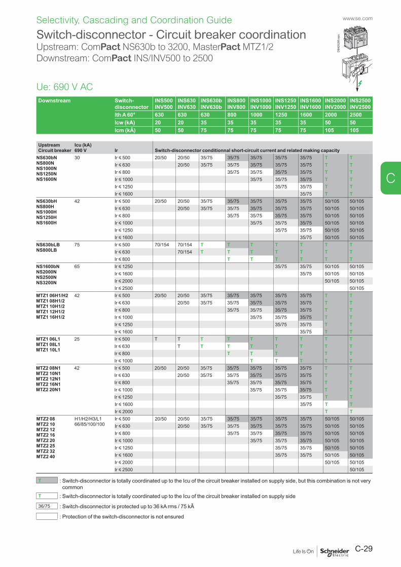
C-29
www.se.com
C
Selectivity, Cascading and Coordination Guide
Switch-disconnector - Circuit breaker coordinationUpstream: ComPact NS630b to 3200, MasterPact MTZ1/2 Downstream: ComPact INS/INV500 to 2500
Ue: 690 V AC
DB4
2529
5.ep
s
Downstream Switch-disconnector
INS500 INV500
INS630 INV630
INS630b INV630b
INS800 INV800
INS1000 INV1000
INS1250 INV1250
INS1600 INV1600
INS2000 INV2000
INS2500 INV2500
Ith A 60° 630 630 630 800 1000 1250 1600 2000 2500Icw (kA) 20 20 35 35 35 35 35 50 50Icm (kÂ) 50 50 75 75 75 75 75 105 105
UpstreamCircuit breaker
Icu (kA)690 V Ir Switch-disconnector conditionnal short-circuit current and related making capacity
NS630bNNS800NNS1000NNS1250NNS1600N
30 Ir y 500 20/50 20/50 35/75 35/75 35/75 35/75 35/75 T TIr y 630 20/50 35/75 35/75 35/75 35/75 35/75 T TIr y 800 35/75 35/75 35/75 35/75 T TIr y 1000 35/75 35/75 35/75 T TIr y 1250 35/75 35/75 T TIr y 1600 35/75 T T
NS630bHNS800HNS1000HNS1250HNS1600H
42 Ir y 500 20/50 20/50 35/75 35/75 35/75 35/75 35/75 50/105 50/105Ir y 630 20/50 35/75 35/75 35/75 35/75 35/75 50/105 50/105Ir y 800 35/75 35/75 35/75 35/75 50/105 50/105Ir y 1000 35/75 35/75 35/75 50/105 50/105Ir y 1250 35/75 35/75 50/105 50/105Ir y 1600 35/75 50/105 50/105
NS630bLBNS800LB
75 Ir y 500 70/154 70/154 T T T T T T TIr y 630 70/154 T T T T T T TIr y 800 T T T T T T
NS1600bNNS2000NNS2500NNS3200N
65 Ir y 1250 35/75 35/75 50/105 50/105Ir y 1600 35/75 50/105 50/105Ir y 2000 50/105 50/105Ir y 2500 50/105
MTZ1 06H1/H2MTZ1 08H1/2MTZ1 10H1/2MTZ1 12H1/2MTZ1 16H1/2
42 Ir y 500 20/50 20/50 35/75 35/75 35/75 35/75 35/75 T TIr y 630 20/50 35/75 35/75 35/75 35/75 35/75 T TIr y 800 35/75 35/75 35/75 35/75 T TIr y 1000 35/75 35/75 35/75 T TIr y 1250 35/75 35/75 T TIr y 1600 35/75 T T
MTZ1 06L1MTZ1 08L1MTZ1 10L1
25 Ir y 500 T T T T T T T T TIr y 630 T T T T T T T TIr y 800 T T T T T TIr y 1000 T T T T T
MTZ2 08N1MTZ2 10N1MTZ2 12N1MTZ2 16N1MTZ2 20N1
42 Ir y 500 20/50 20/50 35/75 35/75 35/75 35/75 35/75 T TIr y 630 20/50 35/75 35/75 35/75 35/75 35/75 T TIr y 800 35/75 35/75 35/75 35/75 T TIr y 1000 35/75 35/75 35/75 T TIr y 1250 35/75 35/75 T TIr y 1600 35/75 T TIr y 2000 T T
MTZ2 08MTZ2 10MTZ2 12MTZ2 16MTZ2 20MTZ2 25MTZ2 32MTZ2 40
H1/H2/H3/L166/85/100/100
Ir y 500 20/50 20/50 35/75 35/75 35/75 35/75 35/75 50/105 50/105Ir y 630 20/50 35/75 35/75 35/75 35/75 35/75 50/105 50/105Ir y 800 35/75 35/75 35/75 35/75 50/105 50/105Ir y 1000 35/75 35/75 35/75 50/105 50/105Ir y 1250 35/75 35/75 50/105 50/105Ir y 1600 35/75 35/75 50/105 50/105Ir y 2000 50/105 50/105Ir y 2500 50/105
T : Switch-disconnector is totally coordinated up to the Icu of the circuit breaker installed on supply side, but this combination is not very common
T : Switch-disconnector is totally coordinated up to the Icu of the circuit breaker installed on supply side
36/75 : Switch-disconnector is protected up to 36 kA rms / 75 kÂ
: Protection of the switch-disconnector is not ensured
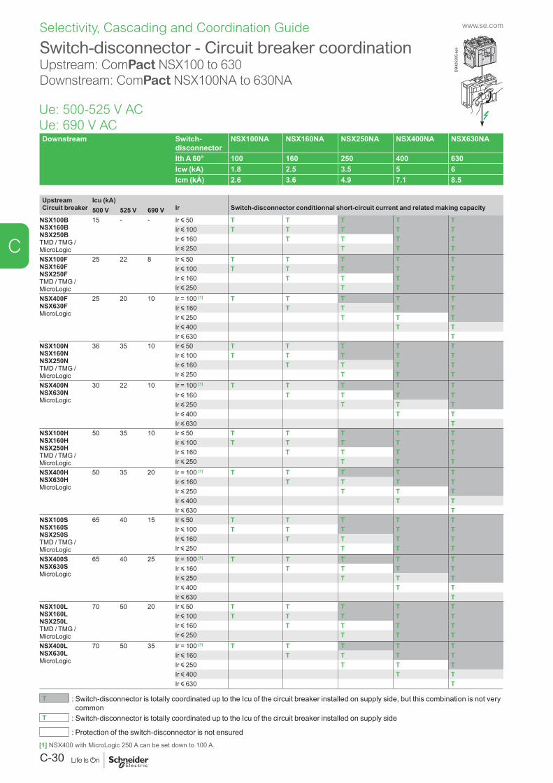
www.se.com
C-30
C
Selectivity, Cascading and Coordination Guide
Downstream Switch-disconnector
NSX100NA NSX160NA NSX250NA NSX400NA NSX630NA
Ith A 60° 100 160 250 400 630Icw (kA) 1.8 2.5 3.5 5 6Icm (kÂ) 2.6 3.6 4.9 7.1 8.5
UpstreamCircuit breaker
Icu (kA)Ir Switch-disconnector conditionnal short-circuit current and related making capacity500 V 525 V 690 V
NSX100BNSX160BNSX250BTMD / TMG / MicroLogic
15 - - Ir y 50 T T T T TIr y 100 T T T T TIr y 160 T T T TIr y 250 T T T
NSX100FNSX160FNSX250FTMD / TMG / MicroLogic
25 22 8 Ir y 50 T T T T TIr y 100 T T T T TIr y 160 T T T TIr y 250 T T T
NSX400FNSX630FMicroLogic
25 20 10 Ir = 100 [1] T T T T TIr y 160 T T T TIr y 250 T T TIr y 400 T TIr y 630 T
NSX100NNSX160NNSX250NTMD / TMG / MicroLogic
36 35 10 Ir y 50 T T T T TIr y 100 T T T T TIr y 160 T T T TIr y 250 T T T
NSX400NNSX630NMicroLogic
30 22 10 Ir = 100 [1] T T T T TIr y 160 T T T TIr y 250 T T TIr y 400 T TIr y 630 T
NSX100HNSX160HNSX250HTMD / TMG / MicroLogic
50 35 10 Ir y 50 T T T T TIr y 100 T T T T TIr y 160 T T T TIr y 250 T T T
NSX400HNSX630HMicroLogic
50 35 20 Ir = 100 [1] T T T T TIr y 160 T T T TIr y 250 T T TIr y 400 T TIr y 630 T
NSX100SNSX160SNSX250STMD / TMG / MicroLogic
65 40 15 Ir y 50 T T T T TIr y 100 T T T T TIr y 160 T T T TIr y 250 T T T
NSX400SNSX630SMicroLogic
65 40 25 Ir = 100 [1] T T T T TIr y 160 T T T TIr y 250 T T TIr y 400 T TIr y 630 T
NSX100LNSX160LNSX250LTMD / TMG / MicroLogic
70 50 20 Ir y 50 T T T T TIr y 100 T T T T TIr y 160 T T T TIr y 250 T T T
NSX400LNSX630LMicroLogic
70 50 35 Ir = 100 [1] T T T T TIr y 160 T T T TIr y 250 T T TIr y 400 T TIr y 630 T
T : Switch-disconnector is totally coordinated up to the Icu of the circuit breaker installed on supply side, but this combination is not very common
T : Switch-disconnector is totally coordinated up to the Icu of the circuit breaker installed on supply side
: Protection of the switch-disconnector is not ensured
Switch-disconnector - Circuit breaker coordinationUpstream: ComPact NSX100 to 630Downstream: ComPact NSX100NA to 630NA
Ue: 500-525 V AC Ue: 690 V AC
DB4
2529
5.ep
s
[1] NSX400 with MicroLogic 250 A can be set down to 100 A.
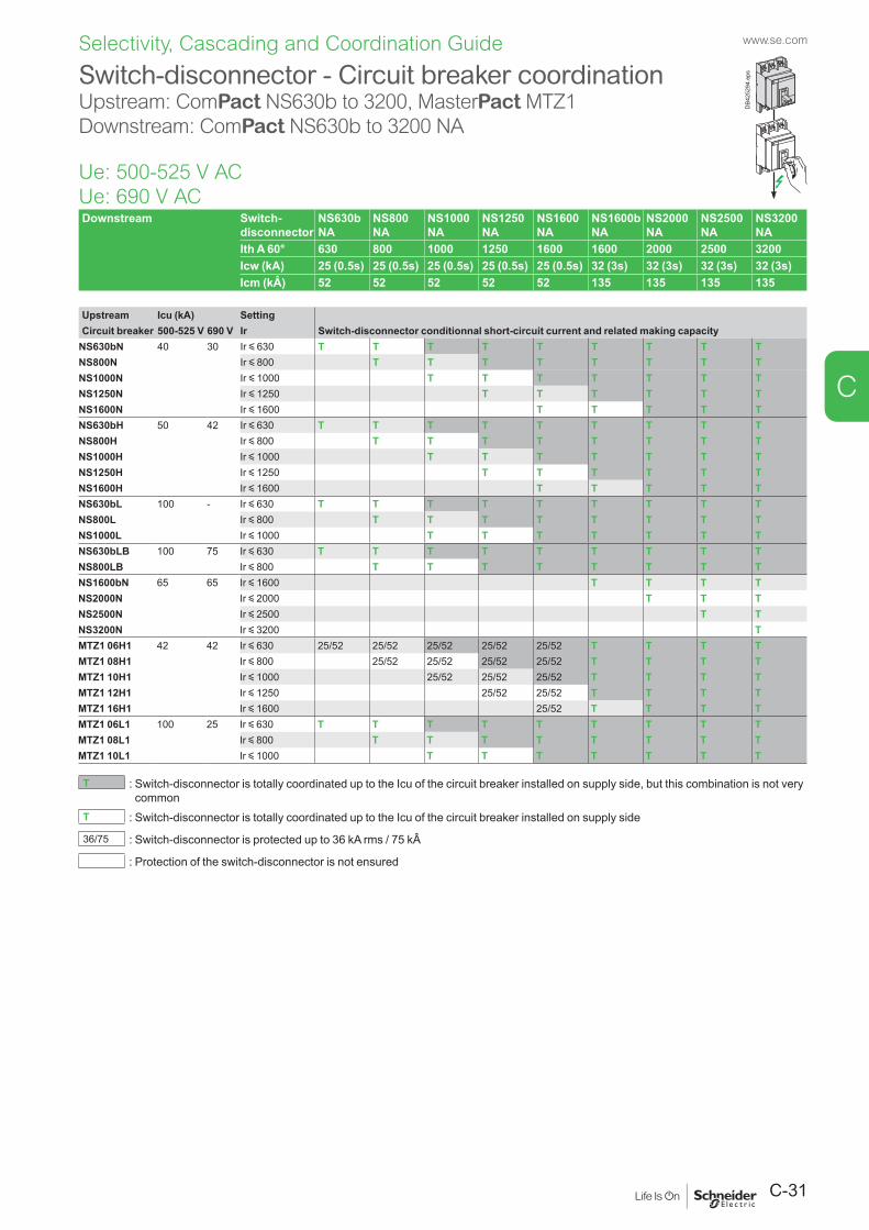
C-31
www.se.com
C
Selectivity, Cascading and Coordination Guide
Downstream Switch-disconnector
NS630b NA
NS800 NA
NS1000 NA
NS1250 NA
NS1600 NA
NS1600b NA
NS2000 NA
NS2500 NA
NS3200 NA
Ith A 60° 630 800 1000 1250 1600 1600 2000 2500 3200Icw (kA) 25 (0.5s) 25 (0.5s) 25 (0.5s) 25 (0.5s) 25 (0.5s) 32 (3s) 32 (3s) 32 (3s) 32 (3s)Icm (kÂ) 52 52 52 52 52 135 135 135 135
Upstream Icu (kA) SettingCircuit breaker 500-525 V 690 V Ir Switch-disconnector conditionnal short-circuit current and related making capacity
NS630bN 40 30 Ir y 630 T T T T T T T T TNS800N Ir y 800 T T T T T T T TNS1000N Ir y 1000 T T T T T T TNS1250N Ir y 1250 T T T T T TNS1600N Ir y 1600 T T T T TNS630bH 50 42 Ir y 630 T T T T T T T T TNS800H Ir y 800 T T T T T T T TNS1000H Ir y 1000 T T T T T T TNS1250H Ir y 1250 T T T T T TNS1600H Ir y 1600 T T T T TNS630bL 100 - Ir y 630 T T T T T T T T TNS800L Ir y 800 T T T T T T T TNS1000L Ir y 1000 T T T T T T TNS630bLB 100 75 Ir y 630 T T T T T T T T TNS800LB Ir y 800 T T T T T T T TNS1600bN 65 65 Ir y 1600 T T T TNS2000N Ir y 2000 T T TNS2500N Ir y 2500 T TNS3200N Ir y 3200 TMTZ1 06H1 42 42 Ir y 630 25/52 25/52 25/52 25/52 25/52 T T T TMTZ1 08H1 Ir y 800 25/52 25/52 25/52 25/52 T T T TMTZ1 10H1 Ir y 1000 25/52 25/52 25/52 T T T TMTZ1 12H1 Ir y 1250 25/52 25/52 T T T TMTZ1 16H1 Ir y 1600 25/52 T T T TMTZ1 06L1 100 25 Ir y 630 T T T T T T T T TMTZ1 08L1 Ir y 800 T T T T T T T TMTZ1 10L1 Ir y 1000 T T T T T T T
T : Switch-disconnector is totally coordinated up to the Icu of the circuit breaker installed on supply side, but this combination is not very common
T : Switch-disconnector is totally coordinated up to the Icu of the circuit breaker installed on supply side
36/75 : Switch-disconnector is protected up to 36 kA rms / 75 kÂ
: Protection of the switch-disconnector is not ensured
Switch-disconnector - Circuit breaker coordinationUpstream: ComPact NS630b to 3200, MasterPact MTZ1 Downstream: ComPact NS630b to 3200 NA
Ue: 500-525 V AC Ue: 690 V AC
DB4
2529
4.ep
s
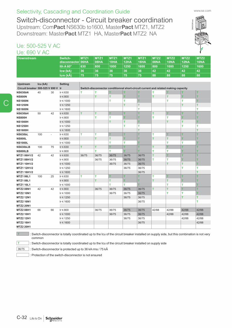
www.se.com
C-32
C
Selectivity, Cascading and Coordination Guide
Switch-disconnector - Circuit breaker coordinationUpstream: ComPact NS630b to1600, MasterPact MTZ1, MTZ2 Downstream: MasterPact MTZ1 HA, MasterPact MTZ2 NA
Ue: 500-525 V AC Ue: 690 V AC
DB4
2529
6.ep
s
Downstream Switch-disconnector
MTZ1 06HA
MTZ1 08HA
MTZ1 10HA
MTZ1 12HA
MTZ1 16HA
MTZ2 08NA
MTZ2 10NA
MTZ2 12NA
MTZ2 16NA
Ith A 60° 630 800 1000 1250 1600 800 1000 1250 1600Icw (kA) 36 36 36 36 36 42 42 42 42Icm (kÂ) 75 75 75 75 75 88 88 88 88
Upstream Icu (kA) SettingCircuit breaker 500-525 V 690 V Ir Switch-disconnector conditionnal short-circuit current and related making capacity
NS630bN 40 30 Ir y 630 T T T T T T T T TNS800N Ir y 800 T T T T T T T TNS1000N Ir y 1000 T T T T T TNS1250N Ir y 1250 T T T TNS1600N Ir y 1600 T TNS630bH 50 42 Ir y 630 T T T T T T T T TNS800H Ir y 800 T T T T T T T TNS1000H Ir y 1000 T T T T T TNS1250H Ir y 1250 T T T TNS1600H Ir y 1600 T TNS630bL 100 - Ir y 630 T T T T T T T T TNS800L Ir y 800 T T T T T T T TNS1000L Ir y 1000 T T T T T TNS630bLB 100 75 Ir y 630 T T T T T T T T TNS800LB Ir y 800 T T T T T T T TMTZ1 06H1/2 42 42 Ir y 630 36/75 36/75 36/75 36/75 36/75 T T T TMTZ1 08H1/2 Ir y 800 36/75 36/75 36/75 36/75 T T T TMTZ1 10H1/2 Ir y 1000 36/75 36/75 36/75 T T TMTZ1 12H1/2 Ir y 1250 36/75 36/75 T TMTZ1 16H1/2 Ir y 1600 36/75 TMTZ1 06L1 100 25 Ir y 630 T T T T T T T T TMTZ1 08L1 Ir y 800 T T T T T T T TMTZ1 10L1 Ir y 1000 T T T T T TMTZ2 08N1 42 42 Ir y 800 36/75 36/75 36/75 36/75 T T T TMTZ2 10N1 Ir y 1000 36/75 36/75 36/75 T T TMTZ2 12N1 Ir y 1250 36/75 36/75 T TMTZ2 16N1 Ir y 1600 36/75 TMTZ2 20N1MTZ2 08H1 66 66 Ir y 800 36/75 36/75 36/75 36/75 42/88 42/88 42/88 42/88MTZ2 10H1 Ir y 1000 36/75 36/75 36/75 42/88 42/88 42/88MTZ2 12H1 Ir y 1250 36/75 36/75 42/88 42/88MTZ2 16H1 Ir y 1600 36/75 42/88MTZ2 20H1
T : Switch-disconnector is totally coordinated up to the Icu of the circuit breaker installed on supply side, but this combination is not very common
T : Switch-disconnector is totally coordinated up to the Icu of the circuit breaker installed on supply side
36/75 : Switch-disconnector is protected up to 36 kA rms / 75 kÂ
: Protection of the switch-disconnector is not ensured
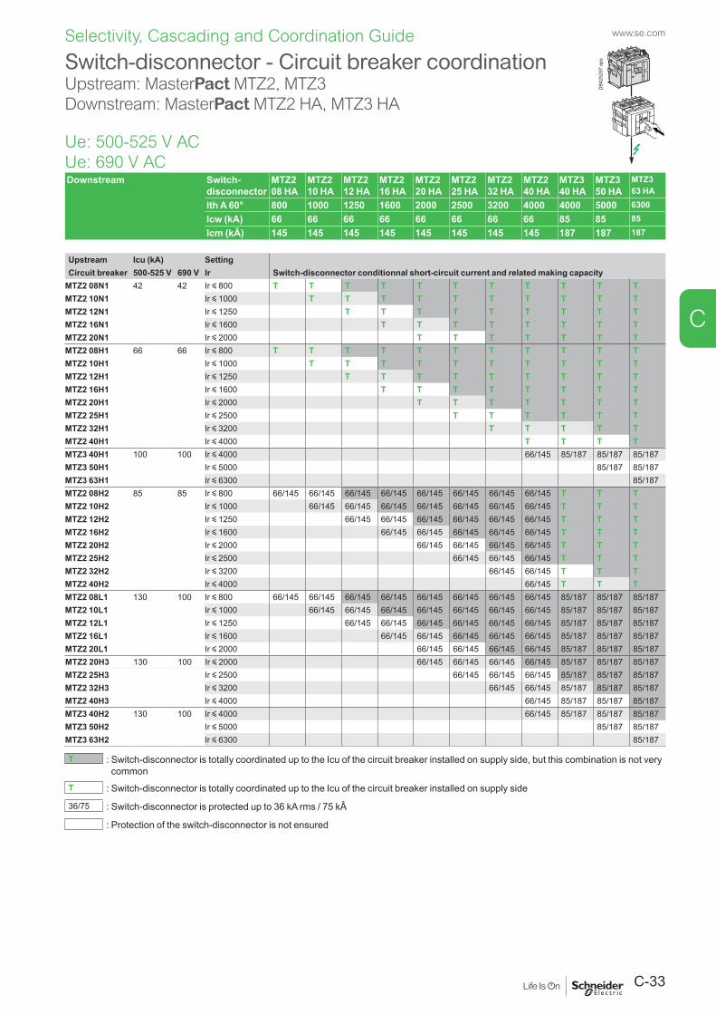
C-33
www.se.com
C
Selectivity, Cascading and Coordination Guide
Downstream Switch-disconnector
MTZ2 08 HA
MTZ2 10 HA
MTZ2 12 HA
MTZ2 16 HA
MTZ2 20 HA
MTZ2 25 HA
MTZ2 32 HA
MTZ2 40 HA
MTZ3 40 HA
MTZ3 50 HA
MTZ3 63 HA
Ith A 60° 800 1000 1250 1600 2000 2500 3200 4000 4000 5000 6300Icw (kA) 66 66 66 66 66 66 66 66 85 85 85Icm (kÂ) 145 145 145 145 145 145 145 145 187 187 187
Upstream Icu (kA) SettingCircuit breaker 500-525 V 690 V Ir Switch-disconnector conditionnal short-circuit current and related making capacity
MTZ2 08N1 42 42 Ir y 800 T T T T T T T T T T TMTZ2 10N1 Ir y 1000 T T T T T T T T T TMTZ2 12N1 Ir y 1250 T T T T T T T T TMTZ2 16N1 Ir y 1600 T T T T T T T TMTZ2 20N1 Ir y 2000 T T T T T T TMTZ2 08H1 66 66 Ir y 800 T T T T T T T T T T TMTZ2 10H1 Ir y 1000 T T T T T T T T T TMTZ2 12H1 Ir y 1250 T T T T T T T T TMTZ2 16H1 Ir y 1600 T T T T T T T TMTZ2 20H1 Ir y 2000 T T T T T T TMTZ2 25H1 Ir y 2500 T T T T T TMTZ2 32H1 Ir y 3200 T T T T TMTZ2 40H1 Ir y 4000 T T T TMTZ3 40H1 100 100 Ir y 4000 66/145 85/187 85/187 85/187MTZ3 50H1 Ir y 5000 85/187 85/187MTZ3 63H1 Ir y 6300 85/187MTZ2 08H2 85 85 Ir y 800 66/145 66/145 66/145 66/145 66/145 66/145 66/145 66/145 T T TMTZ2 10H2 Ir y 1000 66/145 66/145 66/145 66/145 66/145 66/145 66/145 T T TMTZ2 12H2 Ir y 1250 66/145 66/145 66/145 66/145 66/145 66/145 T T TMTZ2 16H2 Ir y 1600 66/145 66/145 66/145 66/145 66/145 T T TMTZ2 20H2 Ir y 2000 66/145 66/145 66/145 66/145 T T TMTZ2 25H2 Ir y 2500 66/145 66/145 66/145 T T TMTZ2 32H2 Ir y 3200 66/145 66/145 T T TMTZ2 40H2 Ir y 4000 66/145 T T TMTZ2 08L1 130 100 Ir y 800 66/145 66/145 66/145 66/145 66/145 66/145 66/145 66/145 85/187 85/187 85/187MTZ2 10L1 Ir y 1000 66/145 66/145 66/145 66/145 66/145 66/145 66/145 85/187 85/187 85/187MTZ2 12L1 Ir y 1250 66/145 66/145 66/145 66/145 66/145 66/145 85/187 85/187 85/187MTZ2 16L1 Ir y 1600 66/145 66/145 66/145 66/145 66/145 85/187 85/187 85/187MTZ2 20L1 Ir y 2000 66/145 66/145 66/145 66/145 85/187 85/187 85/187MTZ2 20H3 130 100 Ir y 2000 66/145 66/145 66/145 66/145 85/187 85/187 85/187MTZ2 25H3 Ir y 2500 66/145 66/145 66/145 85/187 85/187 85/187MTZ2 32H3 Ir y 3200 66/145 66/145 85/187 85/187 85/187MTZ2 40H3 Ir y 4000 66/145 85/187 85/187 85/187MTZ3 40H2 130 100 Ir y 4000 66/145 85/187 85/187 85/187MTZ3 50H2 Ir y 5000 85/187 85/187MTZ3 63H2 Ir y 6300 85/187
T : Switch-disconnector is totally coordinated up to the Icu of the circuit breaker installed on supply side, but this combination is not very common
T : Switch-disconnector is totally coordinated up to the Icu of the circuit breaker installed on supply side
36/75 : Switch-disconnector is protected up to 36 kA rms / 75 kÂ
: Protection of the switch-disconnector is not ensured
Switch-disconnector - Circuit breaker coordinationUpstream: MasterPact MTZ2, MTZ3 Downstream: MasterPact MTZ2 HA, MTZ3 HA
Ue: 500-525 V AC Ue: 690 V AC
DB4
2529
7.ep
s
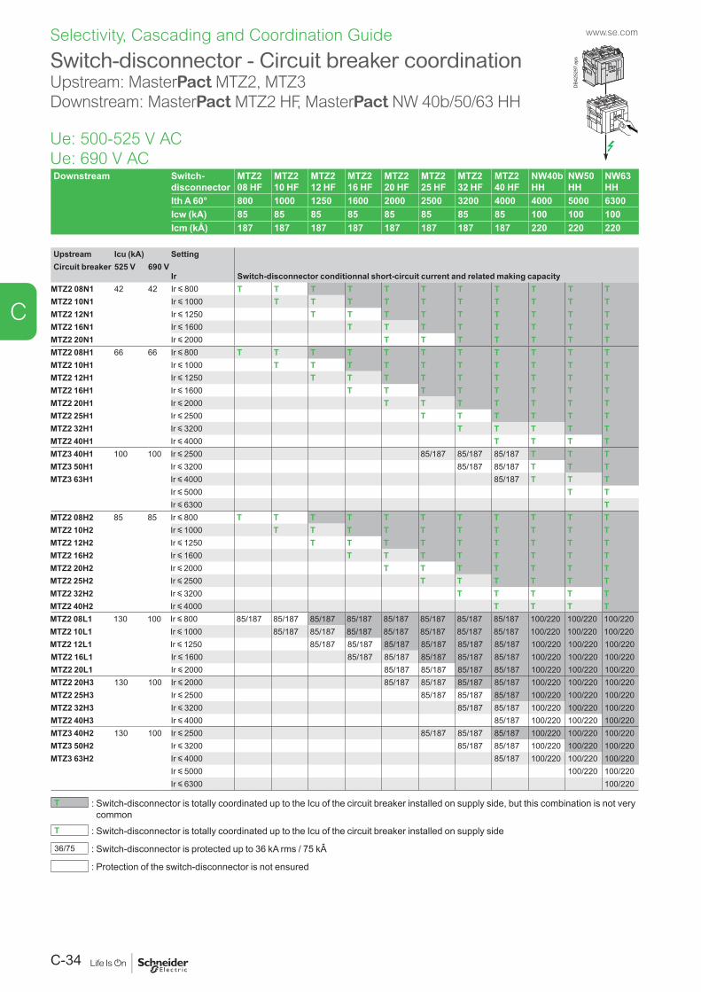
www.se.com
C-34
C
Selectivity, Cascading and Coordination Guide
Downstream Switch-disconnector
MTZ2 08 HF
MTZ2 10 HF
MTZ2 12 HF
MTZ2 16 HF
MTZ2 20 HF
MTZ2 25 HF
MTZ2 32 HF
MTZ2 40 HF
NW40b HH
NW50 HH
NW63 HH
Ith A 60° 800 1000 1250 1600 2000 2500 3200 4000 4000 5000 6300Icw (kA) 85 85 85 85 85 85 85 85 100 100 100Icm (kÂ) 187 187 187 187 187 187 187 187 220 220 220
Upstream Icu (kA) SettingCircuit breaker 525 V 690 V
Ir Switch-disconnector conditionnal short-circuit current and related making capacityMTZ2 08N1 42 42 Ir y 800 T T T T T T T T T T TMTZ2 10N1 Ir y 1000 T T T T T T T T T TMTZ2 12N1 Ir y 1250 T T T T T T T T TMTZ2 16N1 Ir y 1600 T T T T T T T TMTZ2 20N1 Ir y 2000 T T T T T T TMTZ2 08H1 66 66 Ir y 800 T T T T T T T T T T TMTZ2 10H1 Ir y 1000 T T T T T T T T T TMTZ2 12H1 Ir y 1250 T T T T T T T T TMTZ2 16H1 Ir y 1600 T T T T T T T TMTZ2 20H1 Ir y 2000 T T T T T T TMTZ2 25H1 Ir y 2500 T T T T T TMTZ2 32H1 Ir y 3200 T T T T TMTZ2 40H1 Ir y 4000 T T T TMTZ3 40H1 100 100 Ir y 2500 85/187 85/187 85/187 T T TMTZ3 50H1 Ir y 3200 85/187 85/187 T T TMTZ3 63H1 Ir y 4000 85/187 T T T
Ir y 5000 T TIr y 6300 T
MTZ2 08H2 85 85 Ir y 800 T T T T T T T T T T TMTZ2 10H2 Ir y 1000 T T T T T T T T T TMTZ2 12H2 Ir y 1250 T T T T T T T T TMTZ2 16H2 Ir y 1600 T T T T T T T TMTZ2 20H2 Ir y 2000 T T T T T T TMTZ2 25H2 Ir y 2500 T T T T T TMTZ2 32H2 Ir y 3200 T T T T TMTZ2 40H2 Ir y 4000 T T T TMTZ2 08L1 130 100 Ir y 800 85/187 85/187 85/187 85/187 85/187 85/187 85/187 85/187 100/220 100/220 100/220MTZ2 10L1 Ir y 1000 85/187 85/187 85/187 85/187 85/187 85/187 85/187 100/220 100/220 100/220MTZ2 12L1 Ir y 1250 85/187 85/187 85/187 85/187 85/187 85/187 100/220 100/220 100/220MTZ2 16L1 Ir y 1600 85/187 85/187 85/187 85/187 85/187 100/220 100/220 100/220MTZ2 20L1 Ir y 2000 85/187 85/187 85/187 85/187 100/220 100/220 100/220MTZ2 20H3 130 100 Ir y 2000 85/187 85/187 85/187 85/187 100/220 100/220 100/220MTZ2 25H3 Ir y 2500 85/187 85/187 85/187 100/220 100/220 100/220MTZ2 32H3 Ir y 3200 85/187 85/187 100/220 100/220 100/220MTZ2 40H3 Ir y 4000 85/187 100/220 100/220 100/220MTZ3 40H2 130 100 Ir y 2500 85/187 85/187 85/187 100/220 100/220 100/220MTZ3 50H2 Ir y 3200 85/187 85/187 100/220 100/220 100/220MTZ3 63H2 Ir y 4000 85/187 100/220 100/220 100/220
Ir y 5000 100/220 100/220Ir y 6300 100/220
T : Switch-disconnector is totally coordinated up to the Icu of the circuit breaker installed on supply side, but this combination is not very common
T : Switch-disconnector is totally coordinated up to the Icu of the circuit breaker installed on supply side
36/75 : Switch-disconnector is protected up to 36 kA rms / 75 kÂ
: Protection of the switch-disconnector is not ensured
Switch-disconnector - Circuit breaker coordinationUpstream: MasterPact MTZ2, MTZ3 Downstream: MasterPact MTZ2 HF, MasterPact NW 40b/50/63 HH
Ue: 500-525 V AC Ue: 690 V AC
DB4
2529
7.ep
s
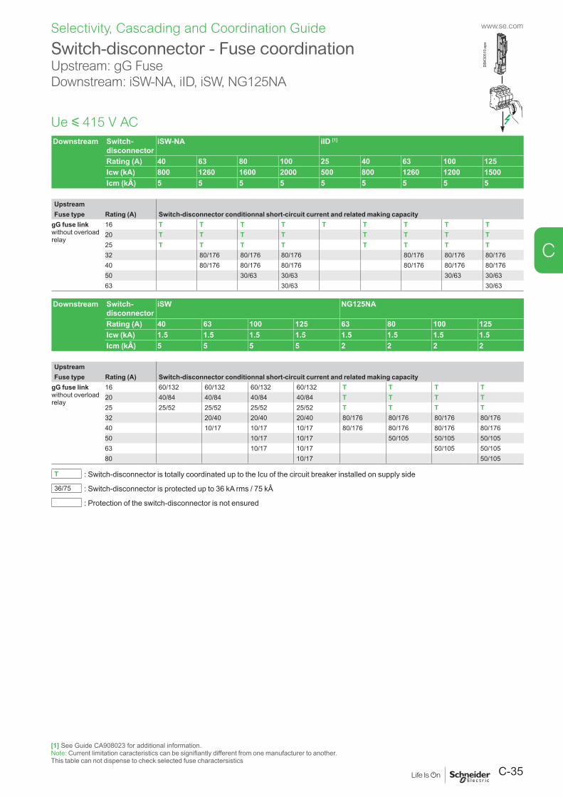
C-35
www.se.com
C
Selectivity, Cascading and Coordination Guide
Downstream Switch-disconnector
iSW-NA iID [1]
Rating (A) 40 63 80 100 25 40 63 100 125Icw (kA) 800 1260 1600 2000 500 800 1260 1200 1500Icm (kÂ) 5 5 5 5 5 5 5 5 5
UpstreamFuse type Rating (A) Switch-disconnector conditionnal short-circuit current and related making capacity
gG fuse linkwithout overloadrelay
16 T T T T T T T T T20 T T T T T T T T25 T T T T T T T T32 80/176 80/176 80/176 80/176 80/176 80/17640 80/176 80/176 80/176 80/176 80/176 80/17650 30/63 30/63 30/63 30/6363 30/63 30/63
Downstream Switch-disconnector
iSW NG125NA
Rating (A) 40 63 100 125 63 80 100 125Icw (kA) 1.5 1.5 1.5 1.5 1.5 1.5 1.5 1.5Icm (kÂ) 5 5 5 5 2 2 2 2
UpstreamFuse type Rating (A) Switch-disconnector conditionnal short-circuit current and related making capacity
gG fuse linkwithout overloadrelay
16 60/132 60/132 60/132 60/132 T T T T20 40/84 40/84 40/84 40/84 T T T T25 25/52 25/52 25/52 25/52 T T T T32 20/40 20/40 20/40 80/176 80/176 80/176 80/17640 10/17 10/17 10/17 80/176 80/176 80/176 80/17650 10/17 10/17 50/105 50/105 50/10563 10/17 10/17 50/105 50/10580 10/17 50/105
T : Switch-disconnector is totally coordinated up to the Icu of the circuit breaker installed on supply side
36/75 : Switch-disconnector is protected up to 36 kA rms / 75 kÂ
: Protection of the switch-disconnector is not ensured
Switch-disconnector - Fuse coordinationUpstream: gG FuseDownstream: iSW-NA, iID, iSW, NG125NA
Ue y 415 V AC
[1] See Guide CA908023 for additional information.Note: Current limitation caracteristics can be signifiantly different from one manufacturer to another.This table can not dispense to check selected fuse charactersistics
DB4
3051
0.ep
s
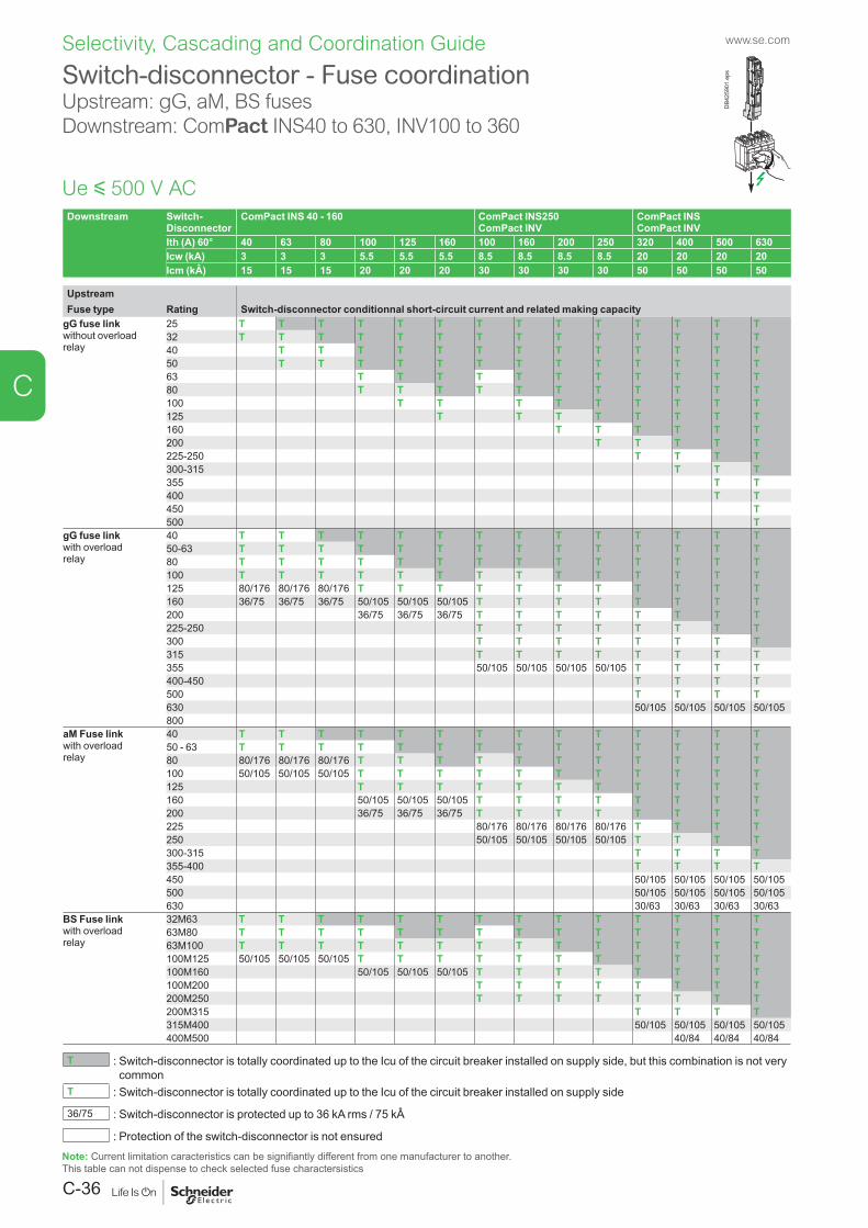
www.se.com
C-36
C
Selectivity, Cascading and Coordination Guide
Downstream Switch- Disconnector
ComPact INS 40 - 160 ComPact INS250 ComPact INV
ComPact INS ComPact INV
Ith (A) 60° 40 63 80 100 125 160 100 160 200 250 320 400 500 630Icw (kA) 3 3 3 5.5 5.5 5.5 8.5 8.5 8.5 8.5 20 20 20 20Icm (kÂ) 15 15 15 20 20 20 30 30 30 30 50 50 50 50
UpstreamFuse type Rating Switch-disconnector conditionnal short-circuit current and related making capacity
gG fuse linkwithout overloadrelay
25 T T T T T T T T T T T T T T32 T T T T T T T T T T T T T T40 T T T T T T T T T T T T T50 T T T T T T T T T T T T T63 T T T T T T T T T T T80 T T T T T T T T T T T100 T T T T T T T T T125 T T T T T T T T160 T T T T T T200 T T T T T225-250 T T T T300-315 T T T355 T T400 T T450 T500 T
gG fuse linkwith overloadrelay
40 T T T T T T T T T T T T T T50-63 T T T T T T T T T T T T T T80 T T T T T T T T T T T T T T100 T T T T T T T T T T T T T T125 80/176 80/176 80/176 T T T T T T T T T T T160 36/75 36/75 36/75 50/105 50/105 50/105 T T T T T T T T200 36/75 36/75 36/75 T T T T T T T T225-250 T T T T T T T T300 T T T T T T T T315 T T T T T T T T355 50/105 50/105 50/105 50/105 T T T T400-450 T T T T500 T T T T630 50/105 50/105 50/105 50/105800
aM Fuse linkwith overloadrelay
40 T T T T T T T T T T T T T T50 - 63 T T T T T T T T T T T T T T80 80/176 80/176 80/176 T T T T T T T T T T T100 50/105 50/105 50/105 T T T T T T T T T T T125 T T T T T T T T T T T160 50/105 50/105 50/105 T T T T T T T T200 36/75 36/75 36/75 T T T T T T T T225 80/176 80/176 80/176 80/176 T T T T250 50/105 50/105 50/105 50/105 T T T T300-315 T T T T355-400 T T T T450 50/105 50/105 50/105 50/105500 50/105 50/105 50/105 50/105630 30/63 30/63 30/63 30/63
BS Fuse linkwith overloadrelay
32M63 T T T T T T T T T T T T T T63M80 T T T T T T T T T T T T T T63M100 T T T T T T T T T T T T T T100M125 50/105 50/105 50/105 T T T T T T T T T T T100M160 50/105 50/105 50/105 T T T T T T T T100M200 T T T T T T T T200M250 T T T T T T T T200M315 T T T T315M400 50/105 50/105 50/105 50/105400M500 40/84 40/84 40/84
T : Switch-disconnector is totally coordinated up to the Icu of the circuit breaker installed on supply side, but this combination is not very common
T : Switch-disconnector is totally coordinated up to the Icu of the circuit breaker installed on supply side
36/75 : Switch-disconnector is protected up to 36 kA rms / 75 kÂ
: Protection of the switch-disconnector is not ensured
Switch-disconnector - Fuse coordinationUpstream: gG, aM, BS fuses Downstream: ComPact INS40 to 630, INV100 to 360
Ue y 500 V AC
DB4
2590
1.ep
s
Note: Current limitation caracteristics can be signifiantly different from one manufacturer to another. This table can not dispense to check selected fuse charactersistics
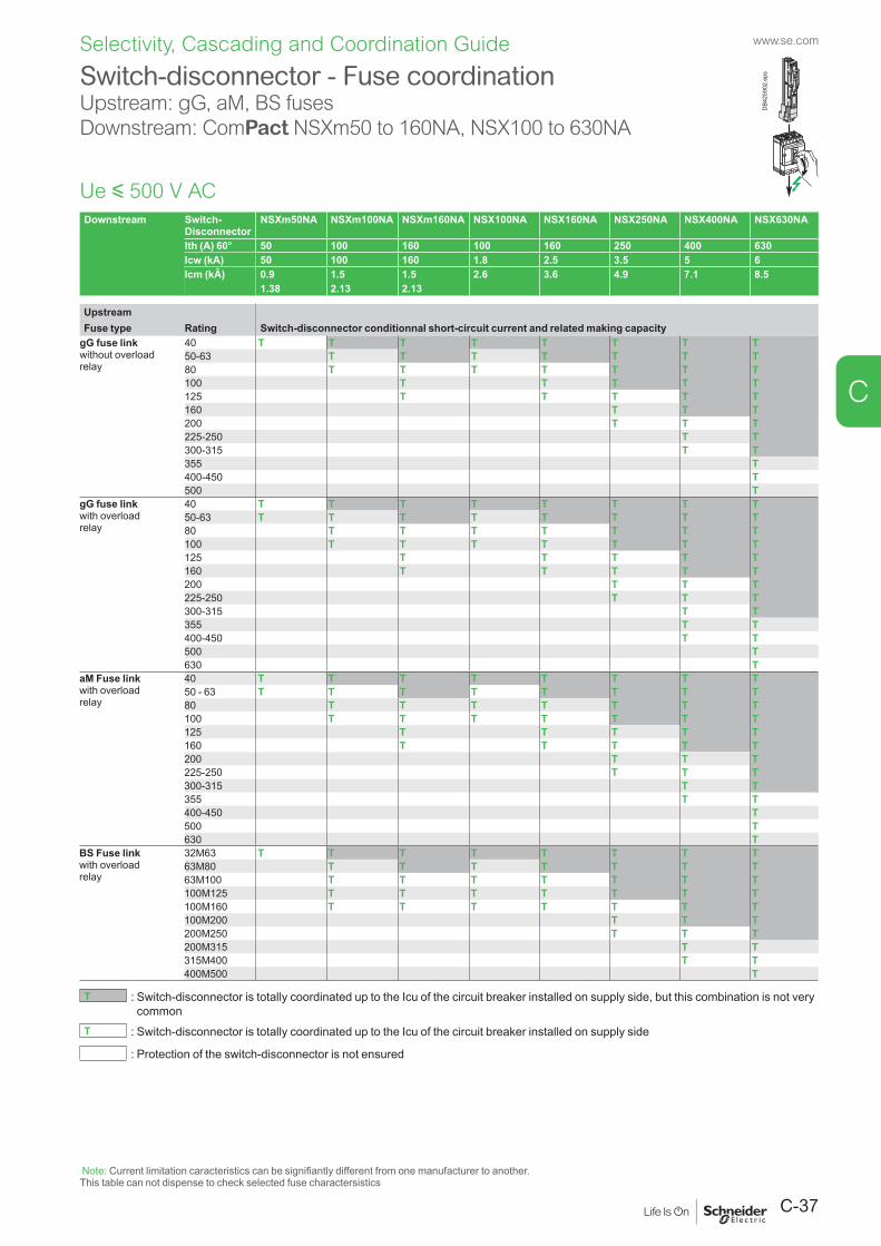
C-37
www.se.com
C
Selectivity, Cascading and Coordination Guide
Downstream Switch- Disconnector
NSXm50NA NSXm100NA NSXm160NA NSX100NA NSX160NA NSX250NA NSX400NA NSX630NA
Ith (A) 60° 50 100 160 100 160 250 400 630Icw (kA) 50 100 160 1.8 2.5 3.5 5 6Icm (kÂ) 0.9 1.5 1.5 2.6 3.6 4.9 7.1 8.5
1.38 2.13 2.13
UpstreamFuse type Rating Switch-disconnector conditionnal short-circuit current and related making capacity
gG fuse linkwithout overloadrelay
40 T T T T T T T T50-63 T T T T T T T80 T T T T T T T100 T T T T T125 T T T T T160 T T T200 T T T225-250 T T300-315 T T355 T400-450 T500 T
gG fuse linkwith overloadrelay
40 T T T T T T T T50-63 T T T T T T T T80 T T T T T T T100 T T T T T T T125 T T T T T160 T T T T T200 T T T225-250 T T T300-315 T T355 T T400-450 T T500 T630 T
aM Fuse linkwith overloadrelay
40 T T T T T T T T50 - 63 T T T T T T T T80 T T T T T T T100 T T T T T T T125 T T T T T160 T T T T T200 T T T225-250 T T T300-315 T T355 T T400-450 T500 T630 T
BS Fuse linkwith overloadrelay
32M63 T T T T T T T T63M80 T T T T T T T63M100 T T T T T T T100M125 T T T T T T T100M160 T T T T T T T100M200 T T T200M250 T T T200M315 T T315M400 T T400M500 T
T : Switch-disconnector is totally coordinated up to the Icu of the circuit breaker installed on supply side, but this combination is not very common
T : Switch-disconnector is totally coordinated up to the Icu of the circuit breaker installed on supply side
: Protection of the switch-disconnector is not ensured
Switch-disconnector - Fuse coordinationUpstream: gG, aM, BS fusesDownstream: ComPact NSXm50 to 160NA, NSX100 to 630NA
Ue y 500 V AC
DB4
2590
2.ep
s
Note: Current limitation caracteristics can be signifiantly different from one manufacturer to another.This table can not dispense to check selected fuse charactersistics
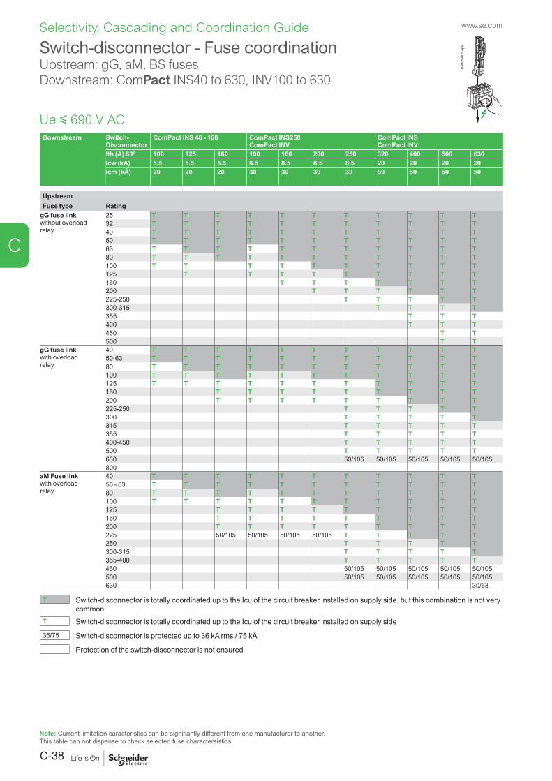
www.se.com
C-38
C
Selectivity, Cascading and Coordination Guide
Downstream Switch- Disconnector
ComPact INS 40 - 160 ComPact INS250 ComPact INV
ComPact INS ComPact INV
Ith (A) 60° 100 125 160 100 160 200 250 320 400 500 630Icw (kA) 5.5 5.5 5.5 8.5 8.5 8.5 8.5 20 20 20 20Icm (kÂ) 20 20 20 30 30 30 30 50 50 50 50
UpstreamFuse type Rating
gG fuse linkwithout overloadrelay
25 T T T T T T T T T T T32 T T T T T T T T T T T40 T T T T T T T T T T T50 T T T T T T T T T T T63 T T T T T T T T T T T80 T T T T T T T T T T T100 T T T T T T T T T T125 T T T T T T T T T160 T T T T T T T200 T T T T T T225-250 T T T T T300-315 T T T T355 T T T400 T T T450 T T500 T T
gG fuse linkwith overloadrelay
40 T T T T T T T T T T T50-63 T T T T T T T T T T T80 T T T T T T T T T T T100 T T T T T T T T T T T125 T T T T T T T T T T T160 T T T T T T T T T200 T T T T T T T T T225-250 T T T T T300 T T T T T315 T T T T T355 T T T T T400-450 T T T T T500 T T T T T630 50/105 50/105 50/105 50/105 50/105800
aM Fuse linkwith overloadrelay
40 T T T T T T T T T T T50 - 63 T T T T T T T T T T T80 T T T T T T T T T T T100 T T T T T T T T T T T125 T T T T T T T T T160 T T T T T T T T T200 T T T T T T T T T225 50/105 50/105 50/105 50/105 T T T T T250 T T T T T300-315 T T T T T355-400 T T T T T450 50/105 50/105 50/105 50/105 50/105500 50/105 50/105 50/105 50/105 50/105630 30/63
T : Switch-disconnector is totally coordinated up to the Icu of the circuit breaker installed on supply side, but this combination is not very common
T : Switch-disconnector is totally coordinated up to the Icu of the circuit breaker installed on supply side
36/75 : Switch-disconnector is protected up to 36 kA rms / 75 kÂ
: Protection of the switch-disconnector is not ensured
Switch-disconnector - Fuse coordinationUpstream: gG, aM, BS fuses Downstream: ComPact INS40 to 630, INV100 to 630
Ue y 690 V AC
DB4
2590
1.ep
s
Note: Current limitation caracteristics can be signifiantly different from one manufacturer to another. This table can not dispense to check selected fuse charactersistics.
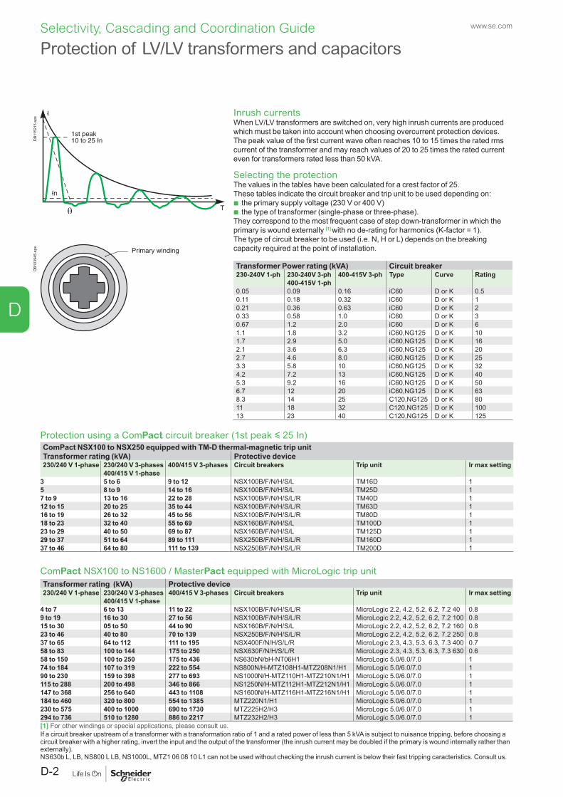
D
Protection of LV/LV transformers and capacitors
Inrush currentsWhen LV/LV transformers are switched on, very high inrush currents are produced which must be taken into account when choosing overcurrent protection devices.The peak value of the first current wave often reaches 10 to 15 times the rated rms current of the transformer and may reach values of 20 to 25 times the rated current even for transformers rated less than 50 kVA.
Selecting the protectionThe values in the tables have been calculated for a crest factor of 25. These tables indicate the circuit breaker and trip unit to be used depending on:
b the primary supply voltage (230 V or 400 V) b the type of transformer (single-phase or three-phase).
They correspond to the most frequent case of step down-transformer in which the primary is wound externally [1] with no de-rating for harmonics (K-factor = 1).The type of circuit breaker to be used (i.e. N, H or L) depends on the breaking capacity required at the point of installation.
Protection using a ComPact circuit breaker (1st peak y 25 In)ComPact NSX100 to NSX250 equipped with TM-D thermal-magnetic trip unitTransformer rating (kVA) Protective device230/240 V 1-phase 230/240 V 3-phases 400/415 V 3-phases Circuit breakers Trip unit Ir max setting
400/415 V 1-phase3 5 to 6 9 to 12 NSX100B/F/N/H/S/L TM16D 15 8 to 9 14 to 16 NSX100B/F/N/H/S/L TM25D 17 to 9 13 to 16 22 to 28 NSX100B/F/N/H/S/L/R TM40D 112 to 15 20 to 25 35 to 44 NSX100B/F/N/H/S/L/R TM63D 116 to 19 26 to 32 45 to 56 NSX100B/F/N/H/S/L/R TM80D 118 to 23 32 to 40 55 to 69 NSX160B/F/N/H/S/L TM100D 123 to 29 40 to 50 69 to 87 NSX160B/F/N/H/S/L TM125D 129 to 37 51 to 64 89 to 111 NSX250B/F/N/H/S/L/R TM160D 137 to 46 64 to 80 111 to 139 NSX250B/F/N/H/S/L/R TM200D 1
ComPact NSX100 to NS1600 / MasterPact equipped with MicroLogic trip unitTransformer rating (kVA) Protective device230/240 V 1-phase 230/240 V 3-phases 400/415 V 3-phases Circuit breakers Trip unit Ir max setting
400/415 V 1-phase4 to 7 6 to 13 11 to 22 NSX100B/F/N/H/S/L/R MicroLogic 2.2, 4.2, 5.2, 6.2, 7.2 40 0.89 to 19 16 to 30 27 to 56 NSX100B/F/N/H/S/L/R MicroLogic 2.2, 4.2, 5.2, 6.2, 7.2 100 0.815 to 30 05 to 50 44 to 90 NSX160B/F/N/H/S/L MicroLogic 2.2, 4.2, 5.2, 6.2, 7.2 160 0.823 to 46 40 to 80 70 to 139 NSX250B/F/N/H/S/L/R MicroLogic 2.2, 4.2, 5.2, 6.2, 7.2 250 0.837 to 65 64 to 112 111 to 195 NSX400F/N/H/S/L/R MicroLogic 2.3, 4.3, 5.3, 6.3, 7.3 400 0.758 to 83 100 to 144 175 to 250 NSX630F/N/H/S/L/R MicroLogic 2.3, 4.3, 5.3, 6.3, 7.3 630 0.658 to 150 100 to 250 175 to 436 NS630bN/bH-NT06H1 MicroLogic 5.0/6.0/7.0 174 to 184 107 to 319 222 to 554 NS800N/H-MTZ108H1-MTZ208N1/H1 MicroLogic 5.0/6.0/7.0 190 to 230 159 to 398 277 to 693 NS1000N/H-MTZ110H1-MTZ210N1/H1 MicroLogic 5.0/6.0/7.0 1115 to 288 200 to 498 346 to 866 NS1250N/H-MTZ112H1-MTZ212N1/H1 MicroLogic 5.0/6.0/7.0 1147 to 368 256 to 640 443 to 1108 NS1600N/H-MTZ116H1-MTZ216N1/H1 MicroLogic 5.0/6.0/7.0 1184 to 460 320 to 800 554 to 1385 MTZ220N1/H1 MicroLogic 5.0/6.0/7.0 1230 to 575 400 to 1000 690 to 1730 MTZ225H2/H3 MicroLogic 5.0/6.0/7.0 1294 to 736 510 to 1280 886 to 2217 MTZ232H2/H3 MicroLogic 5.0/6.0/7.0 1[1] For other windings or special applications, please consult us.If a circuit breaker upstream of a transformer with a transformation ratio of 1 and a rated power of less than 5 kVA is subject to nuisance tripping, before choosing a circuit breaker with a higher rating, invert the input and the output of the transformer (the inrush current may be doubled if the primary is wound internally rather than externally).NS630b L, LB, NS800 L LB, NS1000L, MTZ1 06 08 10 L1 can not be used without checking the inrush current is below their fast tripping caracteristics. Consult us.
DB1
1521
5.ep
sD
B103
945.
eps
Transformer Power rating (kVA) Circuit breaker230-240V 1-ph 230-240V 3-ph 400-415V 3-ph Type Curve Rating
400-415V 1-ph0.05 0.09 0.16 iC60 D or K 0.50.11 0.18 0.32 iC60 D or K 10.21 0.36 0.63 iC60 D or K 20.33 0.58 1.0 iC60 D or K 30.67 1.2 2.0 iC60 D or K 61.1 1.8 3.2 iC60,NG125 D or K 101.7 2.9 5.0 iC60,NG125 D or K 162.1 3.6 6.3 iC60,NG125 D or K 202.7 4.6 8.0 iC60,NG125 D or K 253.3 5.8 10 iC60,NG125 D or K 324.2 7.2 13 iC60,NG125 D or K 405.3 9.2 16 iC60,NG125 D or K 506.7 12 20 iC60,NG125 D or K 638.3 14 25 C120,NG125 D or K 8011 18 32 C120,NG125 D or K 10013 23 40 C120,NG125 D or K 125
www.se.com
D-2
Selectivity, Cascading and Coordination Guide
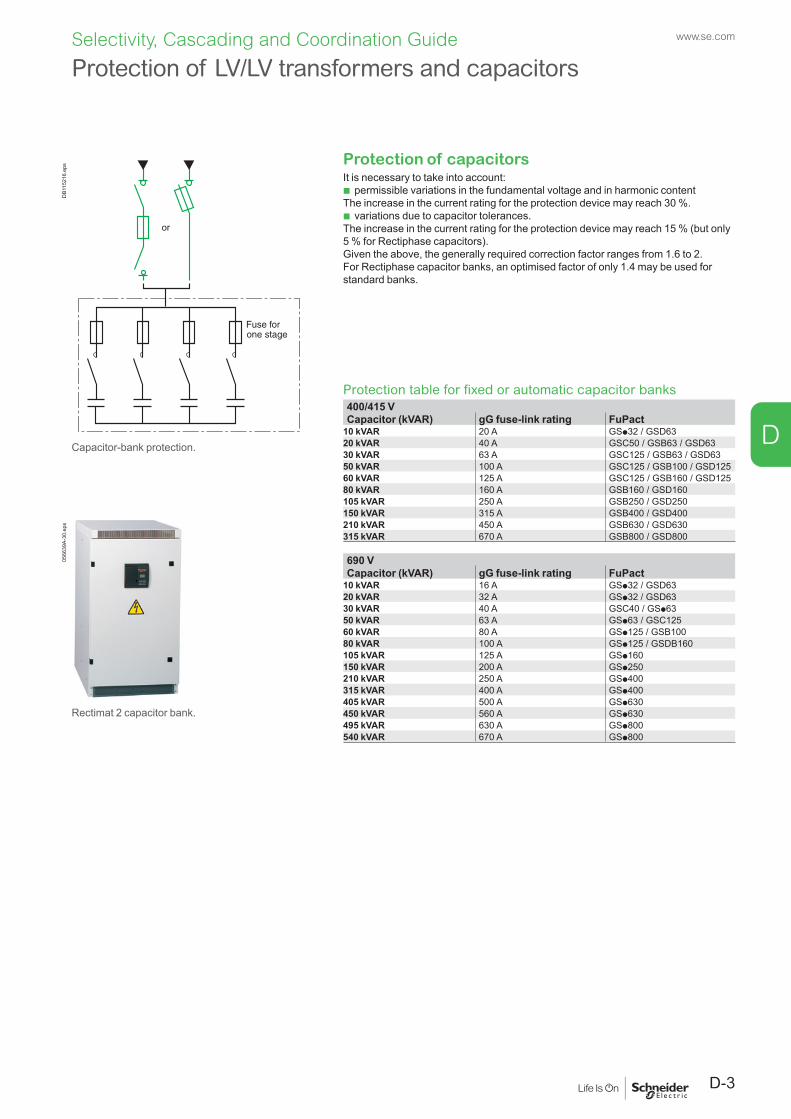
D
Protection of LV/LV transformers and capacitors
Protection of capacitorsIt is necessary to take into account:
b permissible variations in the fundamental voltage and in harmonic contentThe increase in the current rating for the protection device may reach 30 %.
b variations due to capacitor tolerances.The increase in the current rating for the protection device may reach 15 % (but only 5 % for Rectiphase capacitors).Given the above, the generally required correction factor ranges from 1.6 to 2.For Rectiphase capacitor banks, an optimised factor of only 1.4 may be used for standard banks.
Protection table for fixed or automatic capacitor banks400/415 VCapacitor (kVAR) gG fuse-link rating FuPact
10 kVAR 20 A GSp32 / GSD6320 kVAR 40 A GSC50 / GSB63 / GSD6330 kVAR 63 A GSC125 / GSB63 / GSD6350 kVAR 100 A GSC125 / GSB100 / GSD12560 kVAR 125 A GSC125 / GSB160 / GSD12580 kVAR 160 A GSB160 / GSD160105 kVAR 250 A GSB250 / GSD250150 kVAR 315 A GSB400 / GSD400210 kVAR 450 A GSB630 / GSD630315 kVAR 670 A GSB800 / GSD800
690 VCapacitor (kVAR) gG fuse-link rating FuPact
10 kVAR 16 A GSp32 / GSD6320 kVAR 32 A GSp32 / GSD6330 kVAR 40 A GSC40 / GSp6350 kVAR 63 A GSp63 / GSC12560 kVAR 80 A GSp125 / GSB10080 kVAR 100 A GSp125 / GSDB160105 kVAR 125 A GSp160150 kVAR 200 A GSp250210 kVAR 250 A GSp400315 kVAR 400 A GSp400405 kVAR 500 A GSp630450 kVAR 560 A GSp630495 kVAR 630 A GSp800540 kVAR 670 A GSp800
DB1
1521
6.ep
s
Capacitor-bank protection.
0566
39A-
30.e
ps
Rectimat 2 capacitor bank.
D-3
www.se.comSelectivity, Cascading and Coordination Guide
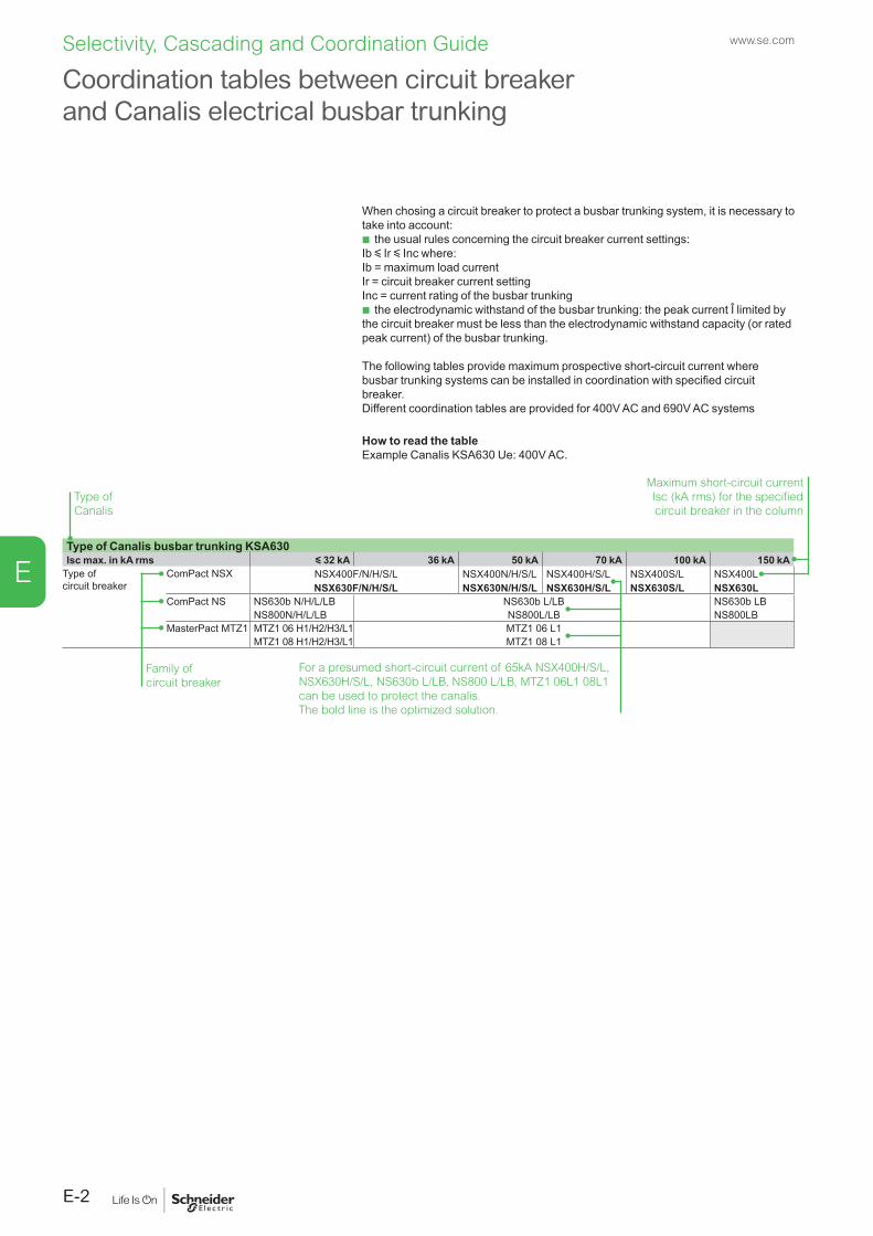
www.se.com
E-2
E
Selectivity, Cascading and Coordination Guide
When chosing a circuit breaker to protect a busbar trunking system, it is necessary to take into account:
b the usual rules concerning the circuit breaker current settings:Ib y Ir y Inc where:Ib = maximum load currentIr = circuit breaker current settingInc = current rating of the busbar trunking
b the electrodynamic withstand of the busbar trunking: the peak current Î limited by the circuit breaker must be less than the electrodynamic withstand capacity (or rated peak current) of the busbar trunking.
The following tables provide maximum prospective short-circuit current where busbar trunking systems can be installed in coordination with specified circuit breaker.Different coordination tables are provided for 400V AC and 690V AC systems
How to read the table Example Canalis KSA630 Ue: 400V AC.
Coordination tables between circuit breaker and Canalis electrical busbar trunking
Type of Canalis busbar trunking KSA630Isc max. in kA rms y 32 kA 36 kA 50 kA 70 kA 100 kA 150 kA
Type of circuit breaker
ComPact NSX NSX400F/N/H/S/L NSX400N/H/S/L NSX400H/S/L NSX400S/L NSX400LNSX630F/N/H/S/L NSX630N/H/S/L NSX630H/S/L NSX630S/L NSX630L
ComPact NS NS630b N/H/L/LB NS630b L/LB NS630b LBNS800N/H/L/LB NS800L/LB NS800LB
MasterPact MTZ1 MTZ1 06 H1/H2/H3/L1 MTZ1 06 L1MTZ1 08 H1/H2/H3/L1 MTZ1 08 L1
Type of Canalis
Family of circuit breaker
Maximum short-circuit current Isc (kA rms) for the specified circuit breaker in the column
For a presumed short-circuit current of 65kA NSX400H/S/L, NSX630H/S/L, NS630b L/LB, NS800 L/LB, MTZ1 06L1 08L1 can be used to protect the canalis.The bold line is the optimized solution.
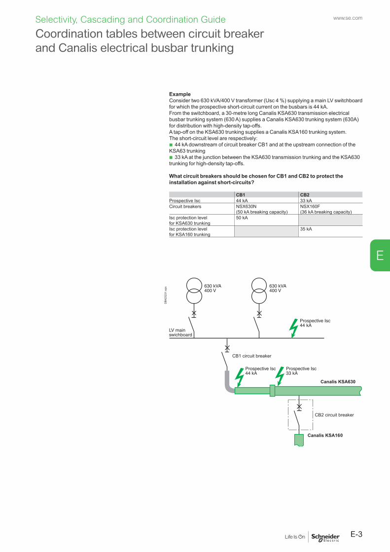
E-3
www.se.com
E
Selectivity, Cascading and Coordination Guide
ExampleConsider two 630 kVA/400 V transformer (Usc 4 %) supplying a main LV switchboard for which the prospective short-circuit current on the busbars is 44 kA.From the switchboard, a 30-metre long Canalis KSA630 transmission electrical busbar trunking system (630 A) supplies a Canalis KSA630 trunking system (630A) for distribution with high-density tap-offs. A tap-off on the KSA630 trunking supplies a Canalis KSA160 trunking system.The short-circuit level are respectively:
b 44 kA downstream of circuit breaker CB1 and at the upstream connection of the KSA63 trunking
b 33 kA at the junction between the KSA630 transmission trunking and the KSA630 trunking for high-density tap-offs.
What circuit breakers should be chosen for CB1 and CB2 to protect the installation against short-circuits?
CB1 CB2Prospective Isc 44 kA 33 kACircuit breakers NSX630N
(50 kA breaking capacity)NSX160F(36 kA breaking capacity)
Isc protection levelfor KSA630 trunking
50 kA
Isc protection levelfor KSA160 trunking
35 kA
CB1 circuit breaker
CB2 circuit breaker
Canalis KSA630
DB4
2323
1.ep
s
Coordination tables between circuit breaker and Canalis electrical busbar trunking
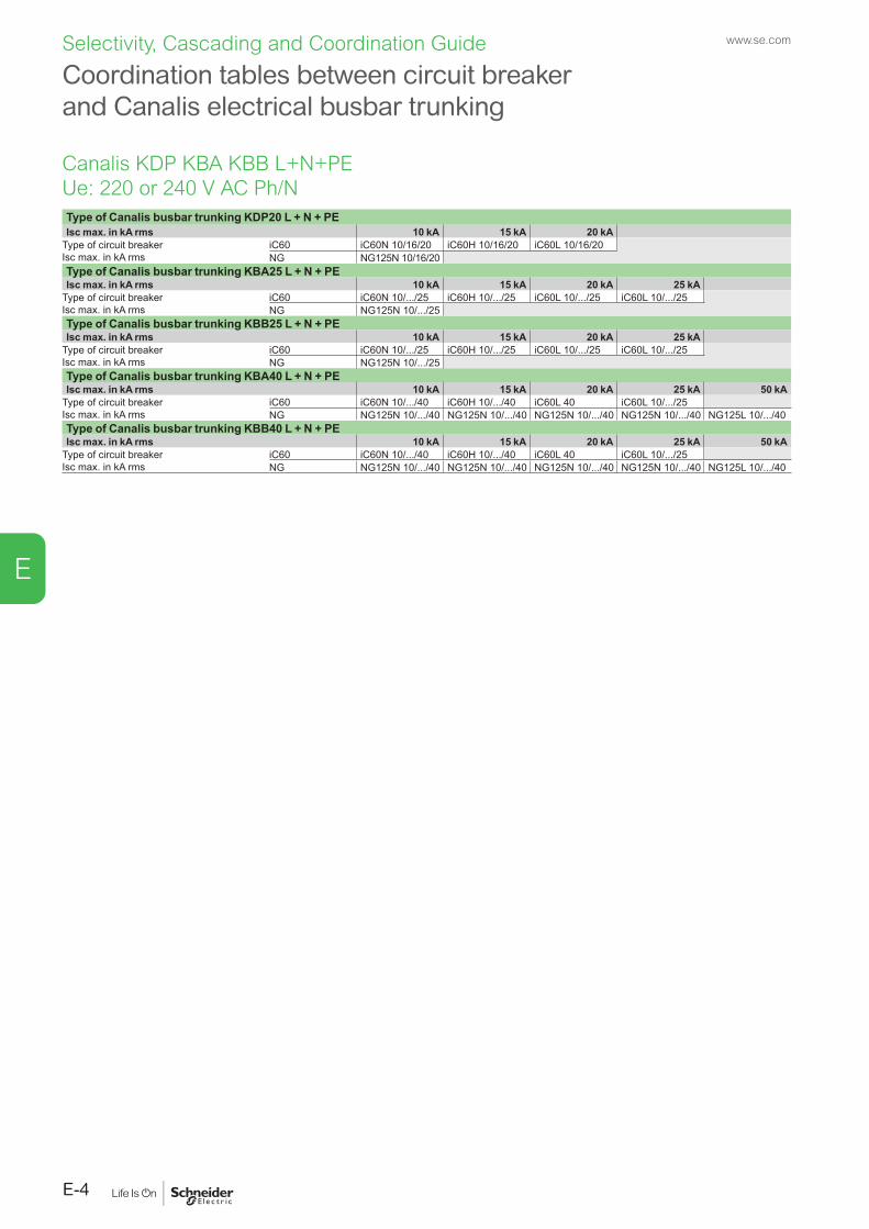
www.se.com
E-4
E
Selectivity, Cascading and Coordination Guide
Type of Canalis busbar trunking KDP20 L + N + PEIsc max. in kA rms 10 kA 15 kA 20 kA
Type of circuit breakerIsc max. in kA rms
iC60 iC60N 10/16/20 iC60H 10/16/20 iC60L 10/16/20NG NG125N 10/16/20
Type of Canalis busbar trunking KBA25 L + N + PEIsc max. in kA rms 10 kA 15 kA 20 kA 25 kA
Type of circuit breakerIsc max. in kA rms
iC60 iC60N 10/.../25 iC60H 10/.../25 iC60L 10/.../25 iC60L 10/.../25NG NG125N 10/.../25
Type of Canalis busbar trunking KBB25 L + N + PEIsc max. in kA rms 10 kA 15 kA 20 kA 25 kA
Type of circuit breakerIsc max. in kA rms
iC60 iC60N 10/.../25 iC60H 10/.../25 iC60L 10/.../25 iC60L 10/.../25NG NG125N 10/.../25
Type of Canalis busbar trunking KBA40 L + N + PEIsc max. in kA rms 10 kA 15 kA 20 kA 25 kA 50 kA
Type of circuit breakerIsc max. in kA rms
iC60 iC60N 10/.../40 iC60H 10/.../40 iC60L 40 iC60L 10/.../25NG NG125N 10/.../40 NG125N 10/.../40 NG125N 10/.../40 NG125N 10/.../40 NG125L 10/.../40
Type of Canalis busbar trunking KBB40 L + N + PEIsc max. in kA rms 10 kA 15 kA 20 kA 25 kA 50 kA
Type of circuit breakerIsc max. in kA rms
iC60 iC60N 10/.../40 iC60H 10/.../40 iC60L 40 iC60L 10/.../25NG NG125N 10/.../40 NG125N 10/.../40 NG125N 10/.../40 NG125N 10/.../40 NG125L 10/.../40
Coordination tables between circuit breaker and Canalis electrical busbar trunking
Canalis KDP KBA KBB L+N+PEUe: 220 or 240 V AC Ph/N
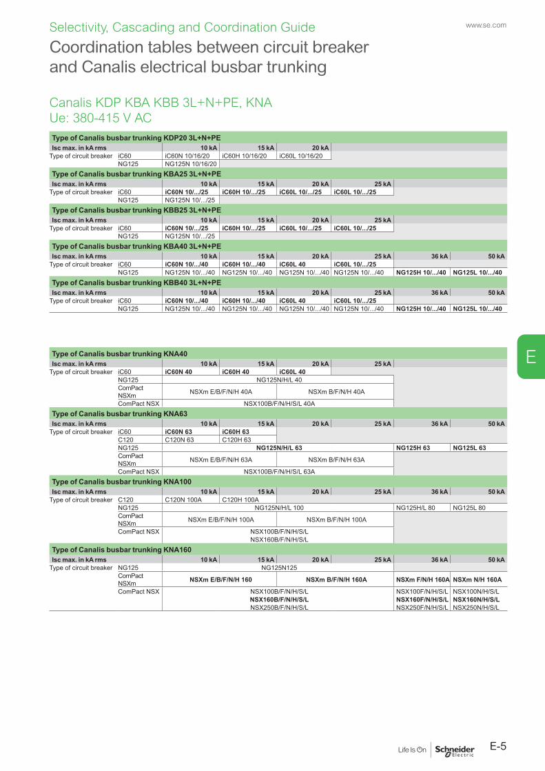
E-5
www.se.com
E
Selectivity, Cascading and Coordination Guide
Coordination tables between circuit breaker and Canalis electrical busbar trunking
Type of Canalis busbar trunking KDP20 3L+N+PEIsc max. in kA rms 10 kA 15 kA 20 kA
Type of circuit breaker iC60 iC60N 10/16/20 iC60H 10/16/20 iC60L 10/16/20NG125 NG125N 10/16/20
Type of Canalis busbar trunking KBA25 3L+N+PEIsc max. in kA rms 10 kA 15 kA 20 kA 25 kA
Type of circuit breaker iC60 iC60N 10/.../25 iC60H 10/.../25 iC60L 10/.../25 iC60L 10/.../25NG125 NG125N 10/.../25
Type of Canalis busbar trunking KBB25 3L+N+PEIsc max. in kA rms 10 kA 15 kA 20 kA 25 kA
Type of circuit breaker iC60 iC60N 10/.../25 iC60H 10/.../25 iC60L 10/.../25 iC60L 10/.../25NG125 NG125N 10/.../25
Type of Canalis busbar trunking KBA40 3L+N+PEIsc max. in kA rms 10 kA 15 kA 20 kA 25 kA 36 kA 50 kA
Type of circuit breaker iC60 iC60N 10/.../40 iC60H 10/.../40 iC60L 40 iC60L 10/.../25NG125 NG125N 10/.../40 NG125N 10/.../40 NG125N 10/.../40 NG125N 10/.../40 NG125H 10/.../40 NG125L 10/.../40
Type of Canalis busbar trunking KBB40 3L+N+PEIsc max. in kA rms 10 kA 15 kA 20 kA 25 kA 36 kA 50 kA
Type of circuit breaker iC60 iC60N 10/.../40 iC60H 10/.../40 iC60L 40 iC60L 10/.../25NG125 NG125N 10/.../40 NG125N 10/.../40 NG125N 10/.../40 NG125N 10/.../40 NG125H 10/.../40 NG125L 10/.../40
Type of Canalis busbar trunking KNA40Isc max. in kA rms 10 kA 15 kA 20 kA 25 kA
Type of circuit breaker iC60 iC60N 40 iC60H 40 iC60L 40NG125 NG125N/H/L 40ComPact NSXm NSXm E/B/F/N/H 40A NSXm B/F/N/H 40A
ComPact NSX NSX100B/F/N/H/S/L 40AType of Canalis busbar trunking KNA63Isc max. in kA rms 10 kA 15 kA 20 kA 25 kA 36 kA 50 kA
Type of circuit breaker iC60 iC60N 63 iC60H 63C120 C120N 63 C120H 63NG125 NG125N/H/L 63 NG125H 63 NG125L 63ComPact NSXm NSXm E/B/F/N/H 63A NSXm B/F/N/H 63A
ComPact NSX NSX100B/F/N/H/S/L 63AType of Canalis busbar trunking KNA100Isc max. in kA rms 10 kA 15 kA 20 kA 25 kA 36 kA 50 kA
Type of circuit breaker C120 C120N 100A C120H 100ANG125 NG125N/H/L 100 NG125H/L 80 NG125L 80ComPact NSXm NSXm E/B/F/N/H 100A NSXm B/F/N/H 100A
ComPact NSX NSX100B/F/N/H/S/LNSX160B/F/N/H/S/L
Type of Canalis busbar trunking KNA160 Isc max. in kA rms 10 kA 15 kA 20 kA 25 kA 36 kA 50 kA
Type of circuit breaker NG125 NG125N125ComPact NSXm NSXm E/B/F/N/H 160 NSXm B/F/N/H 160A NSXm F/N/H 160A NSXm N/H 160A
ComPact NSX NSX100B/F/N/H/S/L NSX100F/N/H/S/L NSX100N/H/S/LNSX160B/F/N/H/S/L NSX160F/N/H/S/L NSX160N/H/S/LNSX250B/F/N/H/S/L NSX250F/N/H/S/L NSX250N/H/S/L
Canalis KDP KBA KBB 3L+N+PE, KNAUe: 380-415 V AC
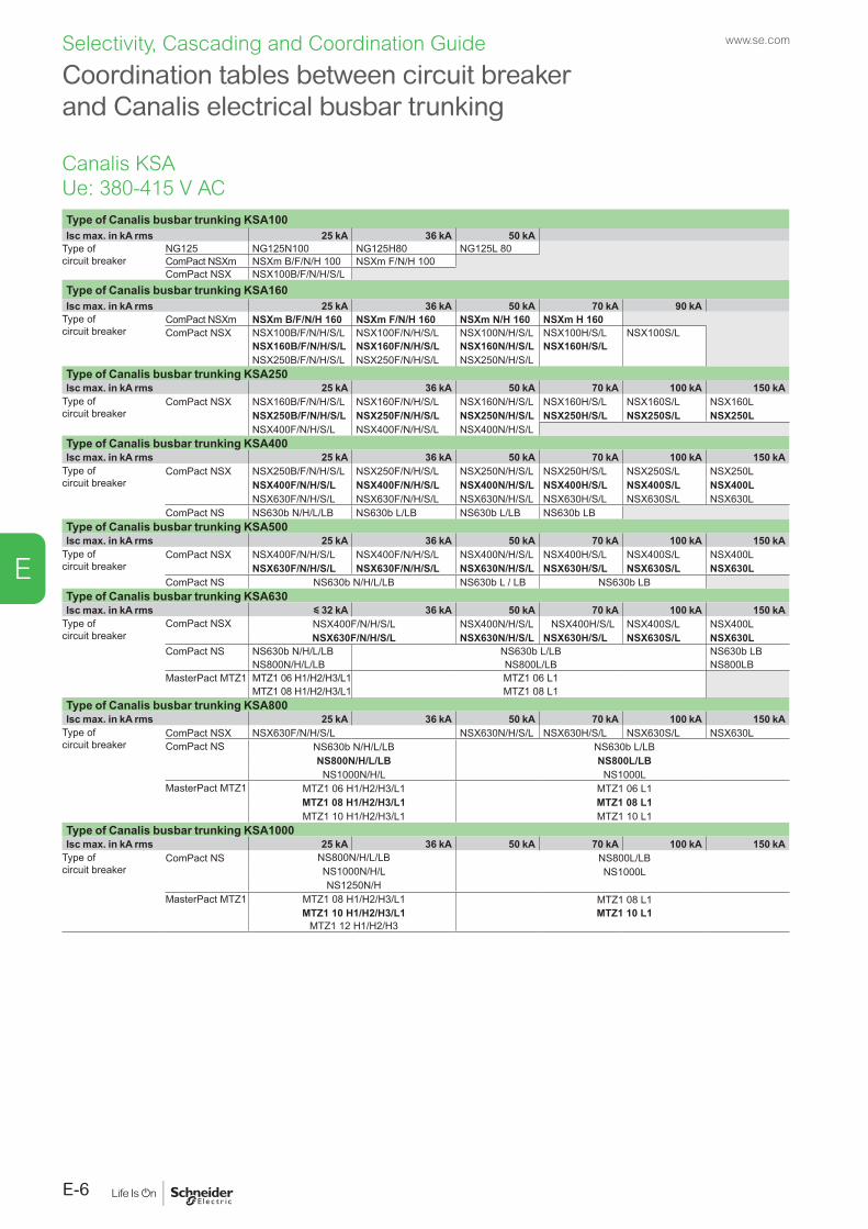
www.se.com
E-6
E
Selectivity, Cascading and Coordination Guide
Coordination tables between circuit breaker and Canalis electrical busbar trunking
Type of Canalis busbar trunking KSA100Isc max. in kA rms 25 kA 36 kA 50 kA
Type of circuit breaker
NG125 NG125N 100 NG125H 80 NG125L 80ComPact NSXm NSXm B/F/N/H 100 NSXm F/N/H 100ComPact NSX NSX100B/F/N/H/S/L
Type of Canalis busbar trunking KSA160Isc max. in kA rms 25 kA 36 kA 50 kA 70 kA 90 kA
Type of circuit breaker
ComPact NSXm NSXm B/F/N/H 160 NSXm F/N/H 160 NSXm N/H 160 NSXm H 160ComPact NSX NSX100B/F/N/H/S/L NSX100F/N/H/S/L NSX100N/H/S/L NSX100H/S/L NSX100S/L
NSX160B/F/N/H/S/L NSX160F/N/H/S/L NSX160N/H/S/L NSX160H/S/LNSX250B/F/N/H/S/L NSX250F/N/H/S/L NSX250N/H/S/L
Type of Canalis busbar trunking KSA250Isc max. in kA rms 25 kA 36 kA 50 kA 70 kA 100 kA 150 kA
Type of circuit breaker
ComPact NSX NSX160B/F/N/H/S/L NSX160F/N/H/S/L NSX160N/H/S/L NSX160H/S/L NSX160S/L NSX160LNSX250B/F/N/H/S/L NSX250F/N/H/S/L NSX250N/H/S/L NSX250H/S/L NSX250S/L NSX250LNSX400F/N/H/S/L NSX400F/N/H/S/L NSX400N/H/S/L
Type of Canalis busbar trunking KSA400Isc max. in kA rms 25 kA 36 kA 50 kA 70 kA 100 kA 150 kA
Type of circuit breaker
ComPact NSX NSX250B/F/N/H/S/L NSX250F/N/H/S/L NSX250N/H/S/L NSX250H/S/L NSX250S/L NSX250LNSX400F/N/H/S/L NSX400F/N/H/S/L NSX400N/H/S/L NSX400H/S/L NSX400S/L NSX400L NSX630F/N/H/S/L NSX630F/N/H/S/L NSX630N/H/S/L NSX630H/S/L NSX630S/L NSX630L
ComPact NS NS630b N/H/L/LB NS630b L/LB NS630b L/LB NS630b LBType of Canalis busbar trunking KSA500Isc max. in kA rms 25 kA 36 kA 50 kA 70 kA 100 kA 150 kA
Type of circuit breaker
ComPact NSX NSX400F/N/H/S/L NSX400F/N/H/S/L NSX400N/H/S/L NSX400H/S/L NSX400S/L NSX400LNSX630F/N/H/S/L NSX630F/N/H/S/L NSX630N/H/S/L NSX630H/S/L NSX630S/L NSX630L
ComPact NS NS630b N/H/L/LB NS630b L / LB NS630b LBType of Canalis busbar trunking KSA630Isc max. in kA rms y 32 kA 36 kA 50 kA 70 kA 100 kA 150 kA
Type of circuit breaker
ComPact NSX NSX400F/N/H/S/L NSX400N/H/S/L NSX400H/S/L NSX400S/L NSX400LNSX630F/N/H/S/L NSX630N/H/S/L NSX630H/S/L NSX630S/L NSX630L
ComPact NS NS630b N/H/L/LB NS630b L/LB NS630b LBNS800N/H/L/LB NS800L/LB NS800LB
MasterPact MTZ1 MTZ1 06 H1/H2/H3/L1 MTZ1 06 L1MTZ1 08 H1/H2/H3/L1 MTZ1 08 L1
Type of Canalis busbar trunking KSA800Isc max. in kA rms 25 kA 36 kA 50 kA 70 kA 100 kA 150 kA
Type of circuit breaker
ComPact NSX NSX630F/N/H/S/L NSX630N/H/S/L NSX630H/S/L NSX630S/L NSX630LComPact NS NS630b N/H/L/LB NS630b L/LB
NS800N/H/L/LB NS800L/LBNS1000N/H/L NS1000L
MasterPact MTZ1 MTZ1 06 H1/H2/H3/L1 MTZ1 06 L1MTZ1 08 H1/H2/H3/L1 MTZ1 08 L1MTZ1 10 H1/H2/H3/L1 MTZ1 10 L1
Type of Canalis busbar trunking KSA1000Isc max. in kA rms 25 kA 36 kA 50 kA 70 kA 100 kA 150 kA
Type of circuit breaker
ComPact NS NS800N/H/L/LB NS800L/LBNS1000N/H/L NS1000LNS1250N/H
MasterPact MTZ1 MTZ1 08 H1/H2/H3/L1 MTZ1 08 L1MTZ1 10 H1/H2/H3/L1 MTZ1 10 L1
MTZ1 12 H1/H2/H3
Canalis KSAUe: 380-415 V AC
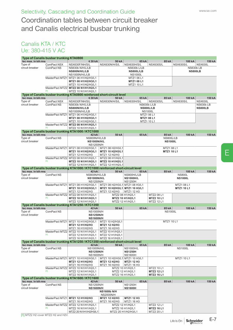
E-7
www.se.com
E
Selectivity, Cascading and Coordination Guide
Type of Canalis busbar trunking KTA0800Isc max. in kA rms y 30 kA 50 kA 65 kA 85 kA 100 kA 150 kA
Type of circuit breaker
ComPact NSX NSX630F/NH/S/L NSX630N/H/S/L NSX630H/S/L NSX630S/L NSX630S/L NSX630LComPact NS NS630b N/H/L/LB NS630b L/LB NS630b LB
NS800N/H/L/LB NS800L/LB NS800LBNS1000N/H/L/LB NS1000L
MasterPact MTZ1 MTZ1 06 H1/H2/H3/L1 MTZ1 06 L1MTZ1 08 H1/H2/H3/L1 MTZ1 08 L1MTZ1 10 H1/H2/H3/L1 MTZ1 10 L1
MasterPact MTZ2 MTZ2 08 N1/H1/H2/L1[1] MTZ2 10 N1/H1/H2/L1
Type of Canalis busbar trunking KTA0800 reinforced short-circuit levelIsc max. in kA rms y 30 kA 50 kA 65 kA 85 kA 100 kA 150 kA
Type of circuit breaker
ComPact NSX NSX630F/NH/S/L NSX630N/H/S/L NSX630H/S/L NSX630S/L NSX630S/L NSX630LComPact NS NS630b N/H/L/LB NS630b L/LB NS630b LB
NS800N/H/L/LB NS800L/LB NS800LBNS1000N/H/L/LB NS1000L
MasterPact MTZ1 MTZ1 06 H1/H2/H3/L1 MTZ1 06 L1MTZ1 08 H1/H2/H3/L1 MTZ1 08 L1MTZ1 10 H1/H2/H3/L1 MTZ1 10 L1
MasterPact MTZ2 MTZ2 08 N1/H1/H2/L1[1] MTZ2 10 N1/H1/H2/L1
Type of Canalis busbar trunking KTA1000 / KTC1000Isc max. in kA rms 42 kA 50 kA 65 kA 85 kA 100 kA 150 kA
Type of circuit breaker
ComPact NS NS800N/H/L/LB NS800L/LBNS1000N/H/L NS1000LNS1250N/H
MasterPact MTZ1 MTZ1 08 H1/H2/H3/L1 MTZ1 08 H2/H3/L1 MTZ1 08 L1MTZ1 10 H1/H2/H3/L1 MTZ1 10 H2/H3/L1 MTZ1 10 L1MTZ1 12 H1/H2/H3 MTZ1 12 H2/H3
MasterPact MTZ2 MTZ2 08 N1/H1/H2/L1 MTZ2 08 H1/H2/L1[1] MTZ2 10 N1/H1/H2/L1 MTZ2 10 H1/H2/L1
MTZ2 12 N1/H1/H2/L1 MTZ2 12 H1/H2/L1Type of Canalis busbar trunking KTA1000 / KTC1000 reinforced short-circuit levelIsc max. in kA rms 42 kA 50 kA 65 kA 85 kA 100 kA 150 kA
Type of circuit breaker
ComPact NS NS800N/H/L/LB NS800H/L/LB NS800LNS1000N/H/L NS1000H/L NS1000LNS1250N/H NS1250H
MasterPact MTZ1 MTZ1 08 H1/H2/H3/L1 MTZ1 08 H2/H3/L1 MTZ1 08 H3/L1 MTZ1 08 L1MTZ1 10 H1/H2/H3/L1 MTZ1 10 H2/H3/L1 MTZ1 10 H3/L1 MTZ1 10 L1MTZ1 12 H1/H2/H3 MTZ1 12 H2/H3 MTZ1 12 H3
MasterPact MTZ2 MTZ2 08 N1/H1/H2/L1 MTZ2 08 H1/H2/L1 MTZ2 08 L1[1] MTZ2 10 N1/H1/H2/L1 MTZ2 10 H1/H2/L1 MTZ2 10 L1
MTZ2 12 N1/H1/H2/L1 MTZ2 12 H1/H2/L1 MTZ2 12 L1Type of Canalis busbar trunking KTA1250 / KTC1350Isc max. in kA rms 42 kA 50 kA 65 kA 85 kA 100 kA 150 kA
Type of circuit breaker
ComPact NS NS1000N/H NS1000LNS1250N/HNS1600N/H
MasterPact MTZ1 MTZ1 10 H1/H2/H3/L1 MTZ1 10 H2/H3/L1 MTZ1 10 L1MTZ1 12 H1/H2/H3 MTZ1 12 H2/H3MTZ1 16 H1/H2/H3 MTZ1 16 H2/H3
MasterPact MTZ2 MTZ2 10 N1/H1/H2/L1 MTZ2 10 H1/H2/L1[1] MTZ2 12 N1/H1/H2/L1 MTZ2 12 H1/H2/L1
MTZ2 16 N1/H1/H2/L1 MTZ2 16 H1/H2/L1Type of Canalis busbar trunking KTA1250 / KTC1350 reinforced short-circuit levelIsc max. in kA rms 42 kA 50 kA 65 kA 85 kA 100 kA 150 kA
Type of circuit breaker
ComPact NS NS1000N/H/L NS1000H/L NS1000LNS1250N/H NS1250HNS1600N/H NS1600H
MasterPact MTZ1 MTZ1 10 H1/H2/H3/L1 MTZ1 10 H2/H3/L1 MTZ1 10 H3/L1 MTZ1 10 L1MTZ1 12 H1/H2/H3 MTZ1 12 H2/H3 MTZ1 12 H3MTZ1 16 H1/H2/H3 MTZ1 16 H2/H3 MTZ1 16 H3
MasterPact MTZ2 MTZ2 10 N1/H1/H2/L1 MTZ2 10 H1/H2/L1 MTZ2 10 L1[1] MTZ2 12 N1/H1/H2/L1 MTZ2 12 H1/H2/L1 MTZ2 12 L1
MTZ2 16 N1/H1/H2/L1 MTZ2 16 H1/H2/L1 MTZ2 16 L1Type of Canalis busbar trunking KTA1600 / KTC1600Isc max. in kA rms 42 kA 50 kA 65 kA 85 kA 100 kA 150 kA
Type of circuit breaker
ComPact NS NS1250N/H NS1250HNS1600N/H NS1600H
NS1600b N/HNS2000N/H
MasterPact MTZ1 MTZ1 12 H1/H2/H3 MTZ1 12 H2/H3 MTZ1 12 H3MTZ1 16 H1/H2/H3 MTZ1 16 H2/H3 MTZ1 16 H3
MasterPact MTZ2 MTZ2 12 N1/H1/H2/L1 MTZ2 12 H1/H2/L1 MTZ2 12 L1[1] MTZ2 16 N1/H1/H2/L1 MTZ2 16 H1/H2/L1 MTZ2 16 L1
MTZ2 20 N1/H1/H2/H3/L1 MTZ2 20 H1/H2/H3/L1 MTZ2 20 L1[1] MTZ2 H2 cover MTZ2 H2 and H2V.
Coordination tables between circuit breaker and Canalis electrical busbar trunking
Canalis KTA / KTCUe: 380-415 V AC
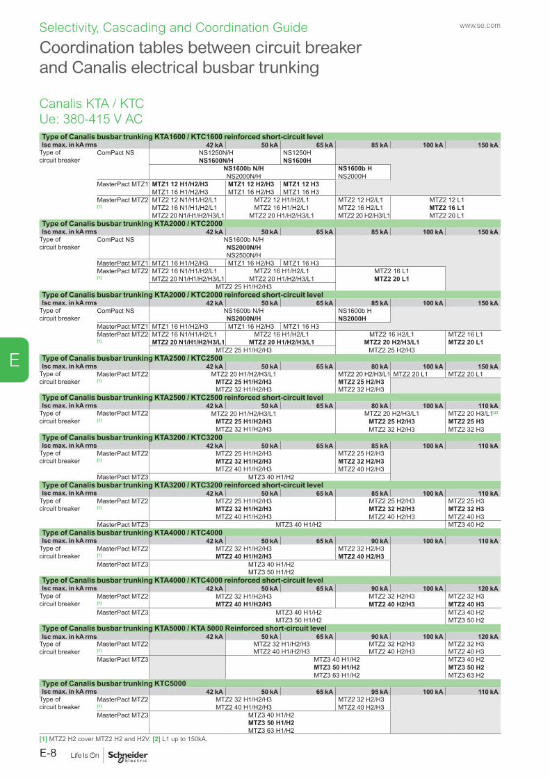
www.se.com
E-8
E
Selectivity, Cascading and Coordination Guide
Type of Canalis busbar trunking KTA1600 / KTC1600 reinforced short-circuit levelIsc max. in kA rms 42 kA 50 kA 65 kA 85 kA 100 kA 150 kA
Type of circuit breaker
ComPact NS NS1250N/H NS1250HNS1600N/H NS1600H
NS1600b N/H NS1600b HNS2000N/H NS2000H
MasterPact MTZ1 MTZ1 12 H1/H2/H3 MTZ1 12 H2/H3 MTZ1 12 H3MTZ1 16 H1/H2/H3 MTZ1 16 H2/H3 MTZ1 16 H3
MasterPact MTZ2 MTZ2 12 N1/H1/H2/L1 MTZ2 12 H1/H2/L1 MTZ2 12 H2/L1 MTZ2 12 L1[1] MTZ2 16 N1/H1/H2/L1 MTZ2 16 H1/H2/L1 MTZ2 16 H2/L1 MTZ2 16 L1
MTZ2 20 N1/H1/H2/H3/L1 MTZ2 20 H1/H2/H3/L1 MTZ2 20 H2/H3/L1 MTZ2 20 L1Type of Canalis busbar trunking KTA2000 / KTC2000Isc max. in kA rms 42 kA 50 kA 65 kA 85 kA 100 kA 150 kA
Type of circuit breaker
ComPact NS NS1600b N/HNS2000N/HNS2500N/H
MasterPact MTZ1 MTZ1 16 H1/H2/H3 MTZ1 16 H2/H3 MTZ1 16 H3MasterPact MTZ2 MTZ2 16 N1/H1/H2/L1 MTZ2 16 H1/H2/L1 MTZ2 16 L1[1] MTZ2 20 N1/H1/H2/H3/L1 MTZ2 20 H1/H2/H3/L1 MTZ2 20 L1
MTZ2 25 H1/H2/H3Type of Canalis busbar trunking KTA2000 / KTC2000 reinforced short-circuit levelIsc max. in kA rms 42 kA 50 kA 65 kA 85 kA 100 kA 150 kA
Type of circuit breaker
ComPact NS NS1600b N/H NS1600b HNS2000N/H NS2000H
MasterPact MTZ1 MTZ1 16 H1/H2/H3 MTZ1 16 H2/H3 MTZ1 16 H3MasterPact MTZ2 MTZ2 16 N1/H1/H2/L1 MTZ2 16 H1/H2/L1 MTZ2 16 H2/L1 MTZ2 16 L1[1] MTZ2 20 N1/H1/H2/H3/L1 MTZ2 20 H1/H2/H3/L1 MTZ2 20 H2/H3/L1 MTZ2 20 L1
MTZ2 25 H1/H2/H3 MTZ2 25 H2/H3Type of Canalis busbar trunking KTA2500 / KTC2500Isc max. in kA rms 42 kA 50 kA 65 kA 80 kA 100 kA 150 kA
Type of circuit breaker
MasterPact MTZ2 MTZ2 20 H1/H2/H3/L1 MTZ2 20 H2/H3/L1 MTZ2 20 L1 MTZ2 20 L1[1] MTZ2 25 H1/H2/H3 MTZ2 25 H2/H3
MTZ2 32 H1/H2/H3 MTZ2 32 H2/H3Type of Canalis busbar trunking KTA2500 / KTC2500 reinforced short-circuit levelIsc max. in kA rms 42 kA 50 kA 65 kA 80 kA 100 kA 110 kA
Type of circuit breaker
MasterPact MTZ2 MTZ2 20 H1/H2/H3/L1MTZ2 25 H1/H2/H3MTZ2 32 H1/H2/H3
MTZ2 20 H2/H3/L1 MTZ2 20 H3/L1[2]
[1] MTZ2 25 H2/H3 MTZ2 25 H3MTZ2 32 H2/H3 MTZ2 32 H3
Type of Canalis busbar trunking KTA3200 / KTC3200Isc max. in kA rms 42 kA 50 kA 65 kA 85 kA 100 kA 110 kA
Type of circuit breaker
MasterPact MTZ2 MTZ2 25 H1/H2/H3MTZ2 32 H1/H2/H3MTZ2 40 H1/H2/H3
MTZ2 25 H2/H3[1] MTZ2 32 H2/H3
MTZ2 40 H2/H3MasterPact MTZ3 MTZ3 40 H1/H2
Type of Canalis busbar trunking KTA3200 / KTC3200 reinforced short-circuit levelIsc max. in kA rms 42 kA 50 kA 65 kA 85 kA 100 kA 110 kA
Type of circuit breaker
MasterPact MTZ2 MTZ2 25 H1/H2/H3MTZ2 32 H1/H2/H3MTZ2 40 H1/H2/H3
MTZ2 25 H2/H3 MTZ2 25 H3[1] MTZ2 32 H2/H3 MTZ2 32 H3
MTZ2 40 H2/H3 MTZ2 40 H3MasterPact MTZ3 MTZ3 40 H1/H2 MTZ3 40 H2
Type of Canalis busbar trunking KTA4000 / KTC4000Isc max. in kA rms 42 kA 50 kA 65 kA 90 kA 100 kA 110 kA
Type of circuit breaker
MasterPact MTZ2 MTZ2 32 H1/H2/H3MTZ2 40 H1/H2/H3
MTZ2 32 H2/H3[1] MTZ2 40 H2/H3MasterPact MTZ3 MTZ3 40 H1/H2
MTZ3 50 H1/H2Type of Canalis busbar trunking KTA4000 / KTC4000 reinforced short-circuit levelIsc max. in kA rms 42 kA 50 kA 65 kA 90 kA 100 kA 120 kA
Type of circuit breaker
MasterPact MTZ2 MTZ2 32 H1/H2/H3MTZ2 40 H1/H2/H3
MTZ2 32 H2/H3 MTZ2 32 H3[1] MTZ2 40 H2/H3 MTZ2 40 H3MasterPact MTZ3 MTZ3 40 H1/H2
MTZ3 50 H1/H2MTZ3 40 H2MTZ3 50 H2
Type of Canalis busbar trunking KTA5000 / KTA 5000 Reinforced short-circuit levelIsc max. in kA rms 42 kA 50 kA 65 kA 90 kA 100 kA 120 kA
Type of circuit breaker
MasterPact MTZ2 MTZ2 32 H1/H2/H3 MTZ2 32 H2/H3 MTZ2 32 H3[1] MTZ2 40 H1/H2/H3 MTZ2 40 H2/H3 MTZ2 40 H3MasterPact MTZ3 MTZ3 40 H1/H2 MTZ3 40 H2
MTZ3 50 H1/H2 MTZ3 50 H2MTZ3 63 H1/H2 MTZ3 63 H2
Type of Canalis busbar trunking KTC5000Isc max. in kA rms 42 kA 50 kA 65 kA 95 kA 100 kA 110 kA
Type of circuit breaker
MasterPact MTZ2 MTZ2 32 H1/H2/H3MTZ2 40 H1/H2/H3
MTZ2 32 H2/H3[1] MTZ2 40 H2/H3MasterPact MTZ3 MTZ3 40 H1/H2
MTZ3 50 H1/H2MTZ3 63 H1/H2
Coordination tables between circuit breaker and Canalis electrical busbar trunking
[1] MTZ2 H2 cover MTZ2 H2 and H2V. [2] L1 up to 150kA.
Canalis KTA / KTCUe: 380-415 V AC
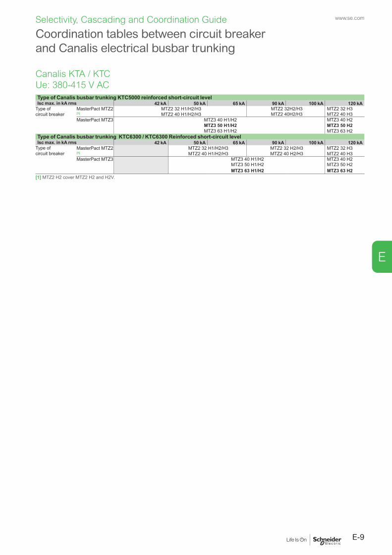
E-9
www.se.com
E
Selectivity, Cascading and Coordination Guide
Type of Canalis busbar trunking KTC5000 reinforced short-circuit levelIsc max. in kA rms 42 kA 50 kA 65 kA 90 kA 100 kA 120 kA
Type of circuit breaker
MasterPact MTZ2 MTZ2 32 H1/H2/H3MTZ2 40 H1/H2/H3
MTZ2 32H2/H3 MTZ2 32 H3[1] MTZ2 40H2/H3 MTZ2 40 H3MasterPact MTZ3 MTZ3 40 H1/H2
MTZ3 50 H1/H2MTZ3 63 H1/H2
MTZ3 40 H2MTZ3 50 H2MTZ3 63 H2
Type of Canalis busbar trunking KTC6300 / KTC6300 Reinforced short-circuit levelIsc max. in kA rms 42 kA 50 kA 65 kA 90 kA 100 kA 120 kA
Type of circuit breaker
MasterPact MTZ2 MTZ2 32 H1/H2/H3 MTZ2 32 H2/H3MTZ2 40 H2/H3
MTZ2 32 H3[1] MTZ2 40 H1/H2/H3 MTZ2 40 H3MasterPact MTZ3 MTZ3 40 H1/H2 MTZ3 40 H2
MTZ3 50 H1/H2 MTZ3 50 H2MTZ3 63 H1/H2 MTZ3 63 H2
[1] MTZ2 H2 cover MTZ2 H2 and H2V.
Coordination tables between circuit breaker and Canalis electrical busbar trunking
Canalis KTA / KTCUe: 380-415 V AC
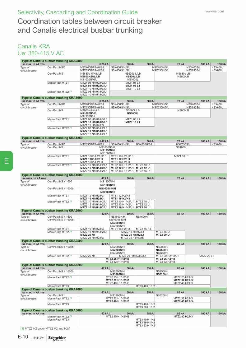
www.se.com
E-10
E
Selectivity, Cascading and Coordination Guide
Type of Canalis busbar trunking KRA0800Isc max. in kA rms y 25 kA 50 kA 60 kA 70 kA 100 kA 150 kA
Type of circuit breaker
ComPact NSX NSX400B/F/N/H/S/L NSX400N/H/S/L NSX400H/S/L NSX400S/L NSX400LNSX630B/F/N/H/S/L NSX630N/H/S/L NSX630H/S/L NSX630S/L NSX630L
ComPact NS NS630b N/H/L/LB NS630b L/LB NS630b LBNS800N/H/L/LB NS800L/LB NS800LBNS1000N/H/L NS1000L
MasterPact MTZ1 MTZ1 06 H1/H2/H3/L1 MTZ1 06 L1MTZ1 08 H1/H2/H3/L1 MTZ1 08 L1MTZ1 10 H1/H2/H3/L1 MTZ1 10 L1
MasterPact MTZ2 [1] MTZ2 08 N1/H1/H2/L1MTZ2 10 N1/H1/H2/L1
Type of Canalis busbar trunking KRA1000Isc max. in kA rms y 25 kA 50 kA 60 kA 70 kA 100 kA 150 kA
Type of circuit breaker
ComPact NSX NSX400B/F/N/H/S/L NSX400N/H/S/L NSX400H/S/L NSX400S/L NSX400LNSX630B/F/N/H/S/L NSX630N/H/S/L NSX630H/S/L NSX630S/L NSX630L
ComPact NS NS800N/H/L/LB NS800L/LB NS800LBNS1000N/H/L NS1000LNS1250N/H
MasterPact MTZ1 MTZ1 08 H1/H2/H3/L1 MTZ1 08 L1MTZ1 10 H1/H2/H3/L1 MTZ1 10 L1MTZ1 12 H1/H2/H3
MasterPact MTZ2 [1] MTZ2 08 N1/H1/H2/L1MTZ2 10 N1/H1/H2/L1MTZ2 12 N1/H1/H2/L1
Type of Canalis busbar trunking KRA1250Isc max. in kA rms y 42 kA 50 kA 60 kA 70 kA 100 kA 150 kA
Type of circuit breaker
ComPact NSX NSX630B/F/N/H/S/L NSX630N/H/S/L NSX630H/S/L NSX630S/L NSX630LComPact NS NS1000N/H/L NS1000L
NS1250N/HNS1600N/H
MasterPact MTZ1 MTZ1 10H1/H2/H3/L1 MTZ1 10 H2/H3/L1 MTZ1 10 L1MTZ1 12H1/H2/H3 MTZ1 12 H2/H3MTZ1 16H1/H2/H3 MTZ1 16 H2/H3
MasterPact MTZ2 [1] MTZ2 10 N1/H1/H2/L1 MTZ2 10 H1/H2/L1 MTZ2 10 L1MTZ2 12 N1/H1/H2/L1 MTZ2 12 H1/H2/L1 MTZ2 12 L1MTZ2 16 N1/H1/H2/L1 MTZ2 16 H1/H2/L1 MTZ2 16 L1
Type of Canalis busbar trunking KRA1600Isc max. in kA rms 42 kA 50 kA 60 kA 70 kA 100 kA 150 kA
Type of circuit breaker
ComPact NS y 1600 NS1250N/HNS1600N/H
ComPact NS u 1600b NS1600b N/HNS2000N/H
MasterPact MTZ1 MTZ1 12 H1/H2/H3 MTZ1 12 H2/H3MTZ1 16 H1/H2/H3 MTZ1 16 H2/H3
MasterPact MTZ2 [1] MTZ2 10 N1/H1/H2/L1 MTZ2 10 H1/H2/L1 MTZ2 10 L1MTZ2 12 N1/H1/H2/L1 MTZ2 12 H1/H2/L1 MTZ2 12 L1MTZ2 16 N1/H1/H2/L1 MTZ2 16 H1/H2/L1 MTZ2 16 L1
Type of Canalis busbar trunking KRA2000Isc max. in kA rms 42 kA 50 kA 65 kA 85 kA 100 kA 150 kA
Type of circuit breaker
ComPact NS y 1600 NS1600N/H NS1600HComPact NS u 1600b NS1600b N/H
NS2000N/HNS2500N/H
MasterPact MTZ1 MTZ1 16 H1/H2/H3 MTZ1 16 H2/H3 MTZ1 16 H3MasterPact MTZ2 [1] MTZ2 16 N1/H1/H2/L1 MTZ2 16 H1/H2/L1 MTZ2 16 L1
MTZ2 20 N1 MTZ2 20 H1/H2/L1 MTZ2 20 L1MTZ2 25 H1/H2/H3 MTZ2 25 H1/H2/H3
Type of Canalis busbar trunking KRA2500Isc max. in kA rms 42 kA 50 kA 65 kA 80 kA 100 kA 150 kA
Type of circuit breaker
ComPact NS u 1600b NS2000N/H NS2000HNS2500N/H NS2500HNS3200N/H NS3200H
MasterPact MTZ2 [1] MTZ2 20 N1 MTZ2 20 H1/H2/H3/L1 MTZ2 20 H2/H3/L1 MTZ2 20 L1MTZ2 25 H1/H2/H3 MTZ2 25 H2/H3MTZ2 32 H1/H2/H3 MTZ2 32 H2/H3
Type of Canalis busbar trunking KRA3200Isc max. in kA rms 42 kA 50 kA 65 kA 85 kA 100 kA 150 kA
Type of circuit breaker
ComPact NS u 1600b NS2500N/H NS2500HNS3200N/H NS3200H
MasterPact MTZ2 [1] MTZ2 25 H1/H2/H3 MTZ2 25 H2/H3MTZ2 32 H1/H2/H3 MTZ2 32 H2/H3MTZ2 40 H1/H2/H3 MTZ2 40 H2/H3
MasterPact MTZ3 MTZ3 40 H1/H2Type of Canalis busbar trunking KRA4000Isc max. in kA rms 42 kA 50 kA 65 kA 85 kA 100 kA 150 kA
Type of circuit breaker
ComPact NS NS3200N/H NS3200HMasterPact MTZ2 [1] MTZ2 32 H1/H2/H3 MTZ2 32 H2/H3
MTZ2 40 H1/H2/H3 MTZ2 40 H2/H3MasterPact MTZ3 MTZ3 40 H1/H2
MTZ3 50 H1/H2Type of Canalis busbar trunking KRA5000Isc max. in kA rms 42 kA 50 kA 65 kA 85 kA 100 kA 150 kA
MasterPact MTZ2 [1] MTZ2 40 H1/H2/H3 MTZ2 40 H2/H3MasterPact MTZ3 MTZ3 40 H1/H2
MTZ3 50 H1/H2MTZ3 63 H1/H2
[1] MTZ2 H2 cover MTZ2 H2 and H2V.
Coordination tables between circuit breaker and Canalis electrical busbar trunking
Canalis KRAUe: 380-415 V AC
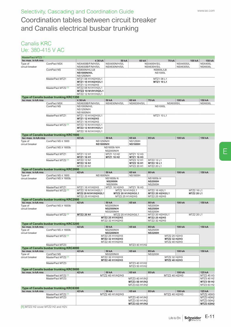
E-11
www.se.com
E
Selectivity, Cascading and Coordination Guide
Coordination tables between circuit breaker and Canalis electrical busbar trunking
MasterPact MTZ2 [1]
Isc max. in kA rms y 36 kA 50 kA 60 kA 70 kA 100 kA 150 kAType of circuit breaker
ComPact NSX NSX400B/F/N/H/S/L NSX400N/H/S/L NSX400H/S/L NSX400S/L NSX400LNSX630B/F/N/H/S/L NSX630N/H/S/L NSX630H/S/L NSX630S/L NSX630L
ComPact NS NS800N/H/L/LB NS800L/LBNS1000N/H/L NS1000LNS1250N/H
MasterPact MTZ1 MTZ1 08 H1/H2/H3/L1 MTZ1 08 L1MTZ1 10 H1/H2/H3/L1 MTZ1 10 L1MTZ1 12 H1/H2/H3
MasterPact MTZ2 [1] MTZ2 08 N1/H1/H2/L1MTZ2 10 N1/H1/H2/L1MTZ2 12 N1/H1/H2/L1
Type of Canalis busbar trunking KRC1350Isc max. in kA rms y 36 kA 50 kA 60 kA 70 kA 100 kA 150 kA
ComPact NSX NSX630B/F/N/H/S/L NSX630N/H/S/L NSX630H/S/L NSX630S/L NSX630LComPact NS NS1000N/H/L NS1000L
NS1250N/HNS1600N/H
MasterPact MTZ1 MTZ1 10 H1/H2/H3/L1 MTZ1 10 L1MTZ1 12 H1/H2/H3MTZ1 16 H1/H2/H3
MasterPact MTZ2 [1] MTZ2 10 N1/H1/H2/L1MTZ2 12 N1/H1/H2/L1MTZ2 16 N1/H1/H2/L1
Type of Canalis busbar trunking KRC1600Isc max. in kA rms 42 kA 50 kA 65 kA 85 kA 100 kA 150 kA
Type of circuit breaker
ComPact NS y 1600 NS1250N/H NS1250HNS1600N/H NS1600H
ComPact NS u 1600b NS1600b N/HNS2000N/H
MasterPact MTZ1 MTZ1 12 H1 MTZ1 12 H2 MTZ1 12 H3MTZ1 16 H1 MTZ1 16 H2 MTZ1 16 H3
MasterPact MTZ2 [1] MTZ2 12 N1 MTZ2 12 H1 MTZ2 12 L1MTZ2 16 N1 MTZ2 16 H1 MTZ2 16 L1MTZ2 20 N1 MTZ2 20 H1 MTZ2 20 L1
Type of Canalis busbar trunking KRC2000Isc max. in kA rms 42 kA 50 kA 65 kA 80 kA 100 kA 150 kA
Type of circuit breaker
ComPact NS y 1600 NS1600N/H NS1600HComPact NS u 1600b NS1600b N NS1600b H
NS2000N NS2000HNS2500N NS2500H
MasterPact MTZ1 MTZ1 16 H1/H2/H3 MTZ1 16 H2/H3 MTZ1 16 H3MasterPact MTZ2 [1] MTZ2 16 N1/H1/H2/L1 MTZ2 16 H1/H2/L1 MTZ2 16 H2/L1 MTZ2 16 L1
MTZ2 20 N1/H1/H2/H3/L1 MTZ2 20 H1/H2/H3/L1 MTZ2 20 H2/H3/L1 MTZ2 20 L1MTZ2 25 H1/H2/H3 MTZ2 25 H1/H2/H3 MTZ2 25 H2/H3
Type of Canalis busbar trunking KRC2500Isc max. in kA rms 42 kA 50 kA 65 kA 80 kA 100 kA 150 kA
Type of circuit breaker
ComPact NS u 1600b NS2000N/H NS2000HNS2500N/H NS2500HNS3200N/H NS3200H
MasterPact MTZ2 [1] MTZ2 20 N1 MTZ2 20 H1/H2/H3/L1 MTZ2 20 H2/H3/L1 MTZ2 20 L1MTZ2 25 H1/H2/H3 MTZ2 25 H2/H3MTZ2 32 H1/H2/H3 MTZ2 32 H2/H3
Type of Canalis busbar trunking KRC3200Isc max. in kA rms 42 kA 50 kA 65 kA 85 kA 100 kA 150 kA
Type of circuit breaker
ComPact NS u 1600b NS2500N/H NS2500HNS3200N/H NS3200H
MasterPact MTZ2 [1] MTZ2 25 H1/H2/H3 MTZ2 25 H2/H3MTZ2 32 H1/H2/H3 MTZ2 32 H2/H3MTZ2 40 H1/H2/H3 MTZ2 40 H2/H3
MasterPact MTZ3 MTZ3 40 H1/H2Type of Canalis busbar trunking KRC4000Isc max. in kA rms 42 kA 50 kA 65 kA 85 kA 100 kA 150 kA
Type of circuit breaker
ComPact NS NS3200N/H NS3200HMasterPact MTZ2 [1] MTZ2 32 H1/H2/H3 MTZ2 32 H2/H3
MTZ2 40 H1/H2/H3 MTZ2 40 H2/H3MasterPact MTZ3 MTZ3 40 H1/H2
MTZ3 50 H1/H2Type of Canalis busbar trunking KRC5000Isc max. in kA rms 42 kA 50 kA 65 kA 85 kA 100 kA 125 kA
MasterPact MTZ2 [1] MTZ2 40 H1/H2/H3 MTZ2 40 H2/H3 MTZ2 40 H3MasterPact MTZ3 MTZ3 40 H1/H2 MTZ3 40 H2
MTZ3 50 H1/H2 MTZ3 50 H2MTZ3 63 H1/H2 MTZ3 63 H2
Type of Canalis busbar trunking KRC6300Isc max. in kA rms 42 kA 50 kA 65 kA 85 kA 100 kA 125 kA
MasterPact MTZ2 [1] MTZ2 40 H1/H2/H3 MTZ2 40 H2/H3 MTZ2 40H3MasterPact MTZ3 MTZ3 40 H1/H2 MTZ3 40H2
MTZ3 50 H1/H2 MTZ3 50H2MTZ3 63 H1/H2 MTZ3 63H2
[1] MTZ2 H2 cover MTZ2 H2 and H2V.
Canalis KRCUe: 380-415 V AC
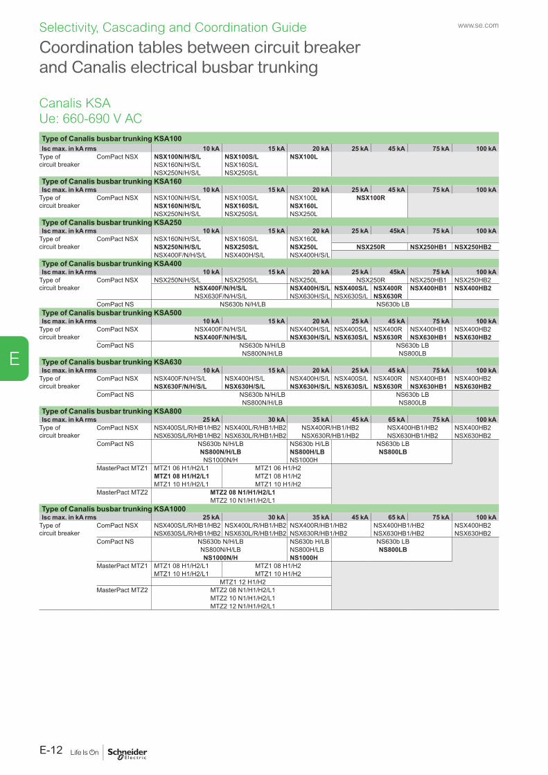
www.se.com
E-12
E
Selectivity, Cascading and Coordination Guide
Type of Canalis busbar trunking KSA100Isc max. in kA rms 10 kA 15 kA 20 kA 25 kA 45 kA 75 kA 100 kA
Type of circuit breaker
ComPact NSX NSX100N/H/S/L NSX100S/L NSX100LNSX160N/H/S/L NSX160S/LNSX250N/H/S/L NSX250S/L
Type of Canalis busbar trunking KSA160Isc max. in kA rms 10 kA 15 kA 20 kA 25 kA 45 kA 75 kA 100 kA
Type of circuit breaker
ComPact NSX NSX100N/H/S/L NSX100S/L NSX100L NSX100RNSX160N/H/S/L NSX160S/L NSX160LNSX250N/H/S/L NSX250S/L NSX250L
Type of Canalis busbar trunking KSA250Isc max. in kA rms 10 kA 15 kA 20 kA 25 kA 45kA 75 kA 100 kA
Type of circuit breaker
ComPact NSX NSX160N/H/S/L NSX160S/L NSX160LNSX250N/H/S/L NSX250S/L NSX250L NSX250R NSX250HB1 NSX250HB2NSX400F/N/H/S/L NSX400H/S/L NSX400H/S/L
Type of Canalis busbar trunking KSA400Isc max. in kA rms 10 kA 15 kA 20 kA 25 kA 45kA 75 kA 100 kA
Type of circuit breaker
ComPact NSX NSX250N/H/S/L NSX250S/L NSX250L NSX250R NSX250HB1 NSX250HB2NSX400F/N/H/S/L NSX400H/S/L NSX400S/L NSX400R NSX400HB1 NSX400HB2NSX630F/N/H/S/L NSX630H/S/L NSX630S/L NSX630R
ComPact NS NS630b N/H/LB NS630b LBType of Canalis busbar trunking KSA500Isc max. in kA rms 10 kA 15 kA 20 kA 25 kA 45 kA 75 kA 100 kA
Type of circuit breaker
ComPact NSX NSX400F/N/H/S/L NSX400H/S/L NSX400S/L NSX400R NSX400HB1 NSX400HB2NSX400F/N/H/S/L NSX630H/S/L NSX630S/L NSX630R NSX630HB1 NSX630HB2
ComPact NS NS630b N/H/LB NS630b LBNS800N/H/LB NS800LB
Type of Canalis busbar trunking KSA630Isc max. in kA rms 10 kA 15 kA 20 kA 25 kA 45 kA 75 kA 100 kA
Type of circuit breaker
ComPact NSX NSX400F/N/H/S/L NSX400H/S/L NSX400H/S/L NSX400S/L NSX400R NSX400HB1 NSX400HB2NSX630F/N/H/S/L NSX630H/S/L NSX630H/S/L NSX630S/L NSX630R NSX630HB1 NSX630HB2
ComPact NS NS630b N/H/LB NS630b LBNS800N/H/LB NS800LB
Type of Canalis busbar trunking KSA800Isc max. in kA rms 25 kA 30 kA 35 kA 45 kA 65 kA 75 kA 100 kA
Type of circuit breaker
ComPact NSX NSX400S/L/R/HB1/HB2 NSX400L/R/HB1/HB2 NSX400R/HB1/HB2 NSX400HB1/HB2 NSX400HB2NSX630S/L/R/HB1/HB2 NSX630L/R/HB1/HB2 NSX630R/HB1/HB2 NSX630HB1/HB2 NSX630HB2
ComPact NS NS630b N/H/LB NS630b H/LB NS630b LBNS800N/H/LB NS800H/LB NS800LBNS1000N/H NS1000H
MasterPact MTZ1 MTZ1 06 H1/H2/L1 MTZ1 06 H1/H2MTZ1 08 H1/H2/L1 MTZ1 08 H1/H2MTZ1 10 H1/H2/L1 MTZ1 10 H1/H2
MasterPact MTZ2 MTZ2 08 N1/H1/H2/L1MTZ2 10 N1/H1/H2/L1
Type of Canalis busbar trunking KSA1000Isc max. in kA rms 25 kA 30 kA 35 kA 45 kA 65 kA 75 kA 100 kA
Type of circuit breaker
ComPact NSX NSX400S/L/R/HB1/HB2 NSX400L/R/HB1/HB2 NSX400R/HB1/HB2 NSX400HB1/HB2 NSX400HB2NSX630S/L/R/HB1/HB2 NSX630L/R/HB1/HB2 NSX630R/HB1/HB2 NSX630HB1/HB2 NSX630HB2
ComPact NS NS630b N/H/LB NS630b H/LB NS630b LBNS800N/H/LB NS800H/LB NS800LBNS1000N/H NS1000H
MasterPact MTZ1 MTZ1 08 H1/H2/L1 MTZ1 08 H1/H2MTZ1 10 H1/H2/L1 MTZ1 10 H1/H2
MTZ1 12 H1/H2MasterPact MTZ2 MTZ2 08 N1/H1/H2/L1
MTZ2 10 N1/H1/H2/L1MTZ2 12 N1/H1/H2/L1
Coordination tables between circuit breaker and Canalis electrical busbar trunking
Canalis KSAUe: 660-690 V AC
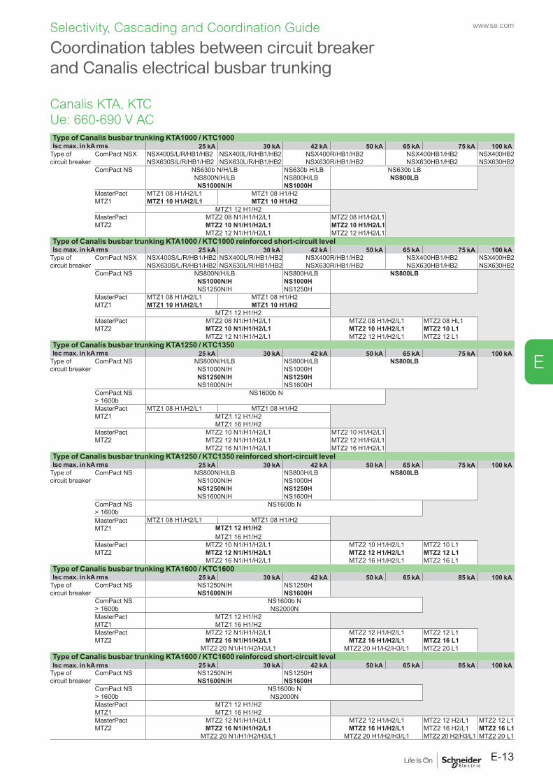
E-13
www.se.com
E
Selectivity, Cascading and Coordination Guide
Type of Canalis busbar trunking KTA1000 / KTC1000Isc max. in kA rms 25 kA 30 kA 42 kA 50 kA 65 kA 75 kA 100 kA
Type of circuit breaker
ComPact NSX NSX400S/L/R/HB1/HB2 NSX400L/R/HB1/HB2 NSX400R/HB1/HB2 NSX400HB1/HB2 NSX400HB2NSX630S/L/R/HB1/HB2 NSX630L/R/HB1/HB2 NSX630R/HB1/HB2 NSX630HB1/HB2 NSX630HB2
ComPact NS NS630b N/H/LB NS630b H/LB NS630b LBNS800N/H/LB NS800H/LB NS800LBNS1000N/H NS1000H
MasterPact MTZ1
MTZ1 08 H1/H2/L1 MTZ1 08 H1/H2MTZ1 10 H1/H2/L1 MTZ1 10 H1/H2
MTZ1 12 H1/H2MasterPact MTZ2
MTZ2 08 N1/H1/H2/L1 MTZ2 08 H1/H2/L1MTZ2 10 N1/H1/H2/L1 MTZ2 10 H1/H2/L1MTZ2 12 N1/H1/H2/L1 MTZ2 12 H1/H2/L1
Type of Canalis busbar trunking KTA1000 / KTC1000 reinforced short-circuit levelIsc max. in kA rms 25 kA 30 kA 42 kA 50 kA 65 kA 75 kA 100 kA
Type of circuit breaker
ComPact NSX NSX400S/L/R/HB1/HB2 NSX400L/R/HB1/HB2 NSX400R/HB1/HB2 NSX400HB1/HB2 NSX400HB2NSX630S/L/R/HB1/HB2 NSX630L/R/HB1/HB2 NSX630R/HB1/HB2 NSX630HB1/HB2 NSX630HB2
ComPact NS NS800N/H/LB NS800H/LB NS800LBNS1000N/H NS1000HNS1250N/H NS1250H
MasterPact MTZ1
MTZ1 08 H1/H2/L1 MTZ1 08 H1/H2MTZ1 10 H1/H2/L1 MTZ1 10 H1/H2
MTZ1 12 H1/H2MasterPact MTZ2
MTZ2 08 N1/H1/H2/L1 MTZ2 08 H1/H2/L1 MTZ2 08 HL1MTZ2 10 N1/H1/H2/L1 MTZ2 10 H1/H2/L1 MTZ2 10 L1MTZ2 12 N1/H1/H2/L1 MTZ2 12 H1/H2/L1 MTZ2 12 L1
Type of Canalis busbar trunking KTA1250 / KTC1350Isc max. in kA rms 25 kA 30 kA 42 kA 50 kA 65 kA 75 kA 100 kA
Type of circuit breaker
ComPact NS NS800N/H/LB NS800H/LB NS800LBNS1000N/H NS1000HNS1250N/H NS1250HNS1600N/H NS1600H
ComPact NS > 1600b
NS1600b N
MasterPact MTZ1
MTZ1 08 H1/H2/L1 MTZ1 08 H1/H2MTZ1 12 H1/H2MTZ1 16 H1/H2
MasterPact MTZ2
MTZ2 10 N1/H1/H2/L1 MTZ2 10 H1/H2/L1MTZ2 12 N1/H1/H2/L1 MTZ2 12 H1/H2/L1MTZ2 16 N1/H1/H2/L1 MTZ2 16 H1/H2/L1
Type of Canalis busbar trunking KTA1250 / KTC1350 reinforced short-circuit levelIsc max. in kA rms 25 kA 30 kA 42 kA 50 kA 65 kA 75 kA 100 kA
Type of circuit breaker
ComPact NS NS800N/H/LB NS800H/LB NS800LBNS1000N/H NS1000HNS1250N/H NS1250HNS1600N/H NS1600H
ComPact NS > 1600b
NS1600b N
MasterPact MTZ1
MTZ1 08 H1/H2/L1 MTZ1 08 H1/H2MTZ1 12 H1/H2MTZ1 16 H1/H2
MasterPact MTZ2
MTZ2 10 N1/H1/H2/L1 MTZ2 10 H1/H2/L1 MTZ2 10 L1MTZ2 12 N1/H1/H2/L1 MTZ2 12 H1/H2/L1 MTZ2 12 L1MTZ2 16 N1/H1/H2/L1 MTZ2 16 H1/H2/L1 MTZ2 16 L1
Type of Canalis busbar trunking KTA1600 / KTC1600Isc max. in kA rms 25 kA 30 kA 42 kA 50 kA 65 kA 85 kA 100 kA
Type of circuit breaker
ComPact NS NS1250N/H NS1250HNS1600N/H NS1600H
ComPact NS > 1600b
NS1600b NNS2000N
MasterPact MTZ1
MTZ1 12 H1/H2MTZ1 16 H1/H2
MasterPact MTZ2
MTZ2 12 N1/H1/H2/L1 MTZ2 12 H1/H2/L1 MTZ2 12 L1MTZ2 16 N1/H1/H2/L1 MTZ2 16 H1/H2/L1 MTZ2 16 L1
MTZ2 20 N1/H1/H2/H3/L1 MTZ2 20 H1/H2/H3/L1 MTZ2 20 L1Type of Canalis busbar trunking KTA1600 / KTC1600 reinforced short-circuit levelIsc max. in kA rms 25 kA 30 kA 42 kA 50 kA 65 kA 85 kA 100 kA
Type of circuit breaker
ComPact NS NS1250N/H NS1250HNS1600N/H NS1600H
ComPact NS > 1600b
NS1600b NNS2000N
MasterPact MTZ1
MTZ1 12 H1/H2MTZ1 16 H1/H2
MasterPact MTZ2
MTZ2 12 N1/H1/H2/L1 MTZ2 12 H1/H2/L1 MTZ2 12 H2/L1 MTZ2 12 L1MTZ2 16 N1/H1/H2/L1 MTZ2 16 H1/H2/L1 MTZ2 16 H2/L1 MTZ2 16 L1
MTZ2 20 N1/H1/H2/H3/L1 MTZ2 20 H1/H2/H3/L1 MTZ2 20 H2/H3/L1 MTZ2 20 L1
Coordination tables between circuit breaker and Canalis electrical busbar trunking
Canalis KTA, KTCUe: 660-690 V AC
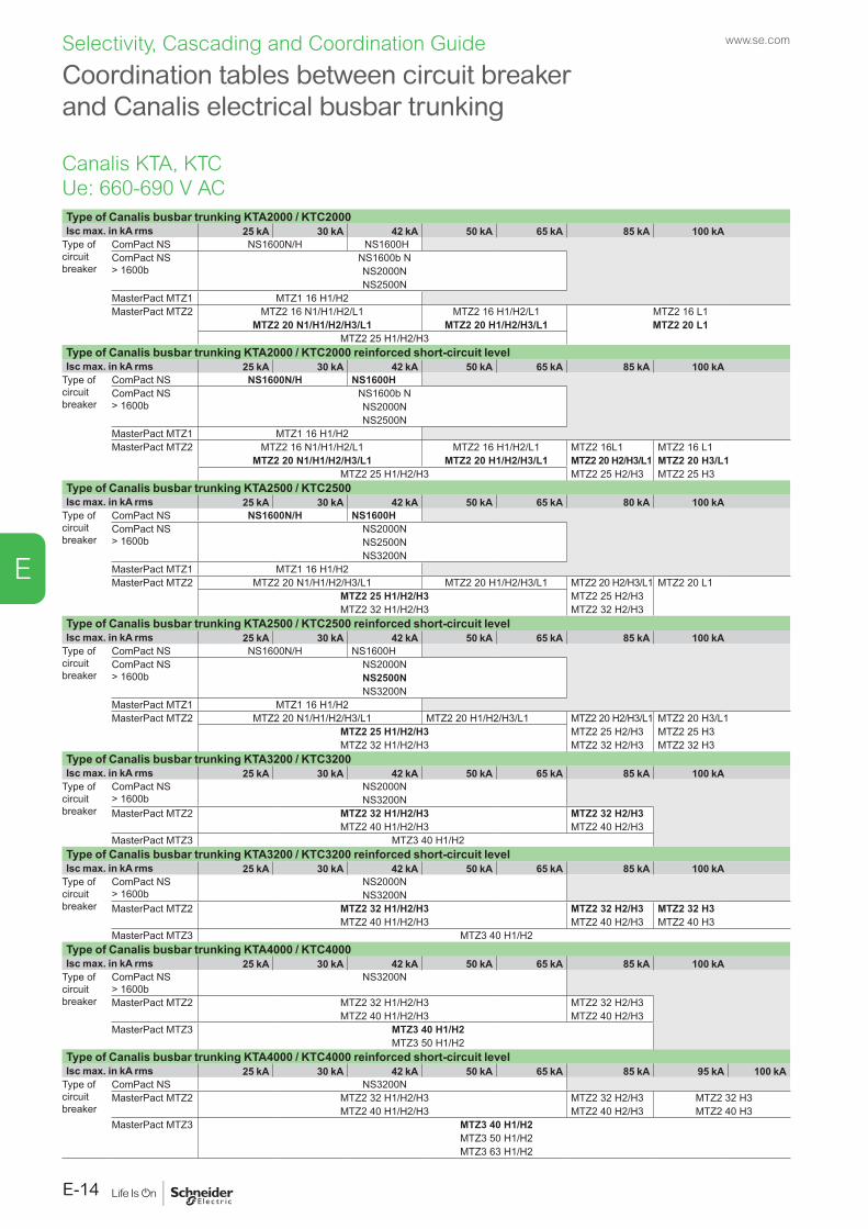
www.se.com
E-14
E
Selectivity, Cascading and Coordination Guide
Type of Canalis busbar trunking KTA2000 / KTC2000Isc max. in kA rms 25 kA 30 kA 42 kA 50 kA 65 kA 85 kA 100 kA
Type of circuit breaker
ComPact NS NS1600N/H NS1600HComPact NS > 1600b
NS1600b NNS2000NNS2500N
MasterPact MTZ1 MTZ1 16 H1/H2MasterPact MTZ2 MTZ2 16 N1/H1/H2/L1 MTZ2 16 H1/H2/L1 MTZ2 16 L1
MTZ2 20 N1/H1/H2/H3/L1 MTZ2 20 H1/H2/H3/L1 MTZ2 20 L1MTZ2 25 H1/H2/H3
Type of Canalis busbar trunking KTA2000 / KTC2000 reinforced short-circuit levelIsc max. in kA rms 25 kA 30 kA 42 kA 50 kA 65 kA 85 kA 100 kA
Type of circuit breaker
ComPact NS NS1600N/H NS1600HComPact NS > 1600b
NS1600b NNS2000NNS2500N
MasterPact MTZ1 MTZ1 16 H1/H2MasterPact MTZ2 MTZ2 16 N1/H1/H2/L1 MTZ2 16 H1/H2/L1 MTZ2 16L1 MTZ2 16 L1
MTZ2 20 N1/H1/H2/H3/L1 MTZ2 20 H1/H2/H3/L1 MTZ2 20 H2/H3/L1 MTZ2 20 H3/L1MTZ2 25 H1/H2/H3 MTZ2 25 H2/H3 MTZ2 25 H3
Type of Canalis busbar trunking KTA2500 / KTC2500Isc max. in kA rms 25 kA 30 kA 42 kA 50 kA 65 kA 80 kA 100 kA
Type of circuit breaker
ComPact NS NS1600N/H NS1600HComPact NS > 1600b
NS2000NNS2500NNS3200N
MasterPact MTZ1 MTZ1 16 H1/H2MasterPact MTZ2 MTZ2 20 N1/H1/H2/H3/L1 MTZ2 20 H1/H2/H3/L1 MTZ2 20 H2/H3/L1 MTZ2 20 L1
MTZ2 25 H1/H2/H3 MTZ2 25 H2/H3MTZ2 32 H1/H2/H3 MTZ2 32 H2/H3
Type of Canalis busbar trunking KTA2500 / KTC2500 reinforced short-circuit levelIsc max. in kA rms 25 kA 30 kA 42 kA 50 kA 65 kA 85 kA 100 kA
Type of circuit breaker
ComPact NS NS1600N/H NS1600HComPact NS > 1600b
NS2000NNS2500NNS3200N
MasterPact MTZ1 MTZ1 16 H1/H2MasterPact MTZ2 MTZ2 20 N1/H1/H2/H3/L1 MTZ2 20 H1/H2/H3/L1 MTZ2 20 H2/H3/L1 MTZ2 20 H3/L1
MTZ2 25 H1/H2/H3 MTZ2 25 H2/H3 MTZ2 25 H3MTZ2 32 H1/H2/H3 MTZ2 32 H2/H3 MTZ2 32 H3
Type of Canalis busbar trunking KTA3200 / KTC3200Isc max. in kA rms 25 kA 30 kA 42 kA 50 kA 65 kA 85 kA 100 kA
Type of circuit breaker
ComPact NS > 1600b
NS2000NNS3200N
MasterPact MTZ2 MTZ2 32 H1/H2/H3 MTZ2 32 H2/H3MTZ2 40 H1/H2/H3 MTZ2 40 H2/H3
MasterPact MTZ3 MTZ3 40 H1/H2Type of Canalis busbar trunking KTA3200 / KTC3200 reinforced short-circuit levelIsc max. in kA rms 25 kA 30 kA 42 kA 50 kA 65 kA 85 kA 100 kA
Type of circuit breaker
ComPact NS > 1600b
NS2000NNS3200N
MasterPact MTZ2 MTZ2 32 H1/H2/H3 MTZ2 32 H2/H3 MTZ2 32 H3MTZ2 40 H1/H2/H3 MTZ2 40 H2/H3 MTZ2 40 H3
MasterPact MTZ3 MTZ3 40 H1/H2Type of Canalis busbar trunking KTA4000 / KTC4000Isc max. in kA rms 25 kA 30 kA 42 kA 50 kA 65 kA 85 kA 100 kA
Type of circuit breaker
ComPact NS > 1600b
NS3200N
MasterPact MTZ2 MTZ2 32 H1/H2/H3 MTZ2 32 H2/H3MTZ2 40 H1/H2/H3 MTZ2 40 H2/H3
MasterPact MTZ3 MTZ3 40 H1/H2MTZ3 50 H1/H2
Type of Canalis busbar trunking KTA4000 / KTC4000 reinforced short-circuit levelIsc max. in kA rms 25 kA 30 kA 42 kA 50 kA 65 kA 85 kA 95 kA 100 kA
Type of circuit breaker
ComPact NS NS3200NMasterPact MTZ2 MTZ2 32 H1/H2/H3 MTZ2 32 H2/H3 MTZ2 32 H3
MTZ2 40 H1/H2/H3 MTZ2 40 H2/H3 MTZ2 40 H3MasterPact MTZ3 MTZ3 40 H1/H2
MTZ3 50 H1/H2MTZ3 63 H1/H2
Coordination tables between circuit breaker and Canalis electrical busbar trunking
Canalis KTA, KTCUe: 660-690 V AC
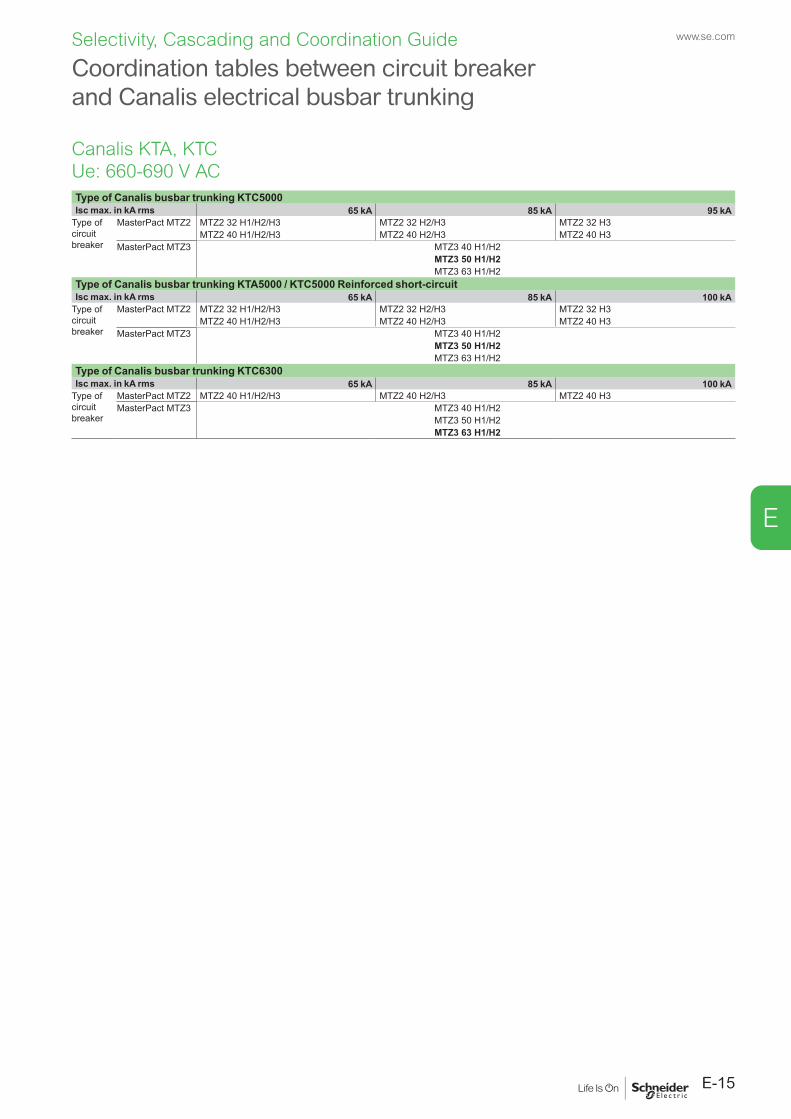
E-15
www.se.com
E
Selectivity, Cascading and Coordination Guide
Type of Canalis busbar trunking KTC5000Isc max. in kA rms 65 kA 85 kA 95 kA
Type of circuit breaker
MasterPact MTZ2 MTZ2 32 H1/H2/H3 MTZ2 32 H2/H3 MTZ2 32 H3MTZ2 40 H1/H2/H3 MTZ2 40 H2/H3 MTZ2 40 H3
MasterPact MTZ3 MTZ3 40 H1/H2MTZ3 50 H1/H2MTZ3 63 H1/H2
Type of Canalis busbar trunking KTA5000 / KTC5000 Reinforced short-circuitIsc max. in kA rms 65 kA 85 kA 100 kA
Type of circuit breaker
MasterPact MTZ2 MTZ2 32 H1/H2/H3 MTZ2 32 H2/H3 MTZ2 32 H3MTZ2 40 H1/H2/H3 MTZ2 40 H2/H3 MTZ2 40 H3
MasterPact MTZ3 MTZ3 40 H1/H2MTZ3 50 H1/H2MTZ3 63 H1/H2
Type of Canalis busbar trunking KTC6300Isc max. in kA rms 65 kA 85 kA 100 kA
Type of circuit breaker
MasterPact MTZ2 MTZ2 40 H1/H2/H3 MTZ2 40 H2/H3 MTZ2 40 H3MasterPact MTZ3 MTZ3 40 H1/H2
MTZ3 50 H1/H2MTZ3 63 H1/H2
Coordination tables between circuit breaker and Canalis electrical busbar trunking
Canalis KTA, KTCUe: 660-690 V AC
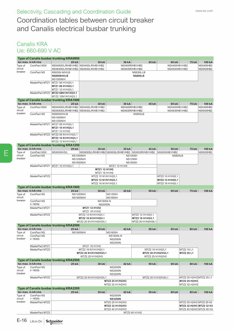
www.se.com
E-16
E
Selectivity, Cascading and Coordination Guide
Coordination tables between circuit breaker and Canalis electrical busbar trunking
Type of Canalis busbar trunking KRA0800Isc max. in kA rms 25 kA 30 kA 36 kA 45 kA 65 kA 75 kA 100 kA
Type of circuit breaker
ComPact NSX NSX400S/L/R/HB1/HB2 NSX400L/R/HB1/HB2 NSX400R/HB1/HB2 NSX400HB1/HB2 NSX400HB2NSX630S/L/R/HB1/HB2 NSX630L/R/HB1/HB2 NSX630R/HB1/HB2 NSX630HB1/HB2 NSX630HB2
ComPact NS NS630b N/H/LB NS630b LBNS800N/H/LB NS800LBNS1000N/H
MasterPact MTZ1 MTZ1 06 H1/H2/L1MTZ1 08 H1/H2/L1MTZ1 10 H1/H2/L1
MasterPact MTZ2 MTZ2 08N1/H1/H2/L1MTZ2 10N1/H1/H2/L1
Type of Canalis busbar trunking KRA1000Isc max. in kA rms 25 kA 30 kA 36 kA 45 kA 65 kA 75 kA 100 kA
Type of circuit breaker
ComPact NSX NSX400S/L/R/HB1/HB2 NSX400L/R/HB1/HB2 NSX400R/HB1/HB2 NSX400HB1/HB2 NSX400HB2NSX630S/L/R/HB1/HB2 NSX630L/R/HB1/HB2 NSX630R/HB1/HB2 NSX630HB1/HB2 NSX630HB2
ComPact NS NS800N/H/LB NS800LBNS1000N/HNS1250N/H
MasterPact MTZ1 MTZ1 08 H1/H2/L1MTZ1 10 H1/H2/L1MTZ1 12 H1/H2
MasterPact MTZ2 MTZ2 08 N1/H1/H2/L1MTZ2 10 N1/H1/H2/L1MTZ2 12 N1/H1/H2/L1
Type of Canalis busbar trunking KRA1250Isc max. in kA rms 25 kA 30 kA 35 kA 42 kA 50 kA 75 kA 100 kA
Type of circuit breaker
ComPact NSX NSX630H/S/L NSX630S/L/R/HB1/HB2 NSX630L/R/HB1/HB2 NSX630R/HB1/HB2 NSX630HB1/HB2 NSX630HB2ComPact NS NS1000N/H NS1000H NS800LB
NS1250N/H NS1250HNS1600N/H NS1600H
MasterPact MTZ1 MTZ1 10 H1/H2/L1 MTZ1 10 H1/H2MTZ1 12 H1/H2MTZ1 16 H1/H2
MasterPact MTZ2 MTZ2 10 N1/H1/H2/L1 MTZ2 10 H1/H2/L1MTZ2 12 N1/H1/H2/L1 MTZ2 12 H1/H2/L1MTZ2 16 N1/H1/H2/L1 MTZ2 16 H1/H2/L1
Type of Canalis busbar trunking KRA1600Isc max. in kA rms 25 kA 30 kA 42 kA 50 kA 65 kA 75 kA 100 kA
Type of circuit breaker
ComPact NS NS1250N/H NS1250HNS1600N/H NS1600H
ComPact NS u 1600b
NS1600b NNS2000N
MasterPact MTZ1 MTZ1 12 H1/H2MTZ1 16 H1/H2
MasterPact MTZ2 MTZ2 12 N1/H1/H2/L1 MTZ2 12 H1/H2/L1MTZ2 16 N1/H1/H2/L1 MTZ2 16 H1/H2/L1
MTZ2 20 N1/H1/H2/H3/L1 MTZ2 20 H1/H2/H3/L1Type of Canalis busbar trunking KRA2000Isc max. in kA rms 25 kA 30 kA 42 kA 50 kA 65 kA 80 kA 100 kA
Type of circuit breaker
ComPact NS NS1600N/H NS1600HComPact NS u 1600b
NS1600b NNS2000NNS2500N
MasterPact MTZ1 MTZ1 16 H1/H2MasterPact MTZ2 MTZ2 16 N1/H1/H2/L1 MTZ2 16 H1/H2/L1 MTZ2 16 L1
MTZ2 20 N1/H1/H2/H3/L1 MTZ2 20 H1/H2/H3/L1 MTZ2 20 L1MTZ2 25 H1/H2/H3 MTZ2 25 H1/H2/H3
Type of Canalis busbar trunking KRA2500Isc max. in kA rms 25 kA 30 kA 42 kA 50 kA 65 kA 80 kA 100 kA
Type of circuit breaker
ComPact NS u 1600b
NS2000NNS2500NNS3200N
MasterPact MTZ2 MTZ2 20 N1/H1/H2/H3/L1 MTZ2 20 H1/H2/H3/L1 MTZ2 20 H2/H3 MTZ2 20 L1MTZ2 25 H1/H2/H3 MTZ2 25 H2/H3MTZ2 32 H1/H2/H3 MTZ2 32 H2/H3
Type of Canalis busbar trunking KRA3200Isc max. in kA rms 25 kA 30 kA 42 kA 50 kA 65 kA 85 kA 100 kA
Type of circuit breaker
ComPact NS > 1600b
NS2500NNS3200N
MasterPact MTZ2 MTZ2 25 H1/H2/H3 MTZ2 25 H2/H3 MTZ2 25 H3MTZ2 32 H1/H2/H3 MTZ2 32 H2/H3 MTZ2 32 H3MTZ2 40 H1/H2/H3 MTZ2 40 H2/H3 MTZ2 40 H3
MasterPact MTZ3 MTZ3 40 H1/H2
Canalis KRAUe: 660-690 V AC
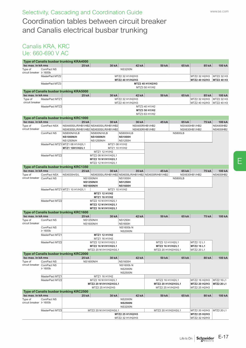
E-17
www.se.com
E
Selectivity, Cascading and Coordination Guide
Coordination tables between circuit breaker and Canalis electrical busbar trunking
Type of Canalis busbar trunking KRA4000Isc max. in kA rms 25 kA 30 kA 42 kA 50 kA 65 kA 85 kA 100 kA
Type of circuit breaker
ComPact NS u 1600b
NS3200N
MasterPact MTZ2 MTZ2 32 H1/H2/H3 MTZ2 32 H2/H3 MTZ2 32 H3MTZ2 40 H1/H2/H3 MTZ2 40 H2/H3 MTZ2 40 H3
MasterPact MTZ3 MTZ2 40 H1/H2/H3MTZ3 50 H1/H2
Type of Canalis busbar trunking KRA5000Isc max. in kA rms 25 kA 30 kA 42 kA 50 kA 65 kA 85 kA 100 kAType of circuit breaker
MasterPact MTZ1 MTZ2 32 H1/H2/H3 MTZ2 32 H2/H3 MTZ2 32 H3MTZ2 40 H1/H2/H3 MTZ2 40 H2/H3 MTZ2 40 H3
MasterPact MTZ2 MTZ3 40 H1/H2MTZ3 50 H1/H2MTZ3 63 H1/H2
Type of Canalis busbar trunking KRC1000Isc max. in kA rms 25 kA 30 kA 36 kA 45 kA 65 kA 75 kA 100 kA
Type of circuit breaker
ComPact NSX NSX400S/L/R/HB1/HB2 NSX400S/L/R/HB1/HB2 NSX400R/HB1/HB2 NSX400HB1/HB2 NSX400HB2NSX630S/L/R/HB1/HB2 NSX630S/L/R/HB1/HB2 NSX630R/HB1/HB2 NSX630HB1/HB2 NSX630HB2
ComPact NS NS800N/H/LB NS800N/H/LB NS800H/LB NS800LBNS1000N/H NS1000N/H NS1000HNS1250N/H NS1250N/H NS1250H
MasterPact MTZ1 MTZ1 08 H1/H2/L1 MTZ1 08 H1/H2MTZ1 10H1/H2/L1 MTZ1 10 H1/H2
MTZ1 12 H1/H2MasterPact MTZ2 MTZ2 08 N1/H1/H2/L1
MTZ2 10 N1/H1/H2/L1MTZ2 12 N1/H1/H2/L1
Type of Canalis busbar trunking KRC1350Isc max. in kA rms 25 kA 30 kA 35 kA 45 kA 65 kA 75 kA 100 kA
Type of circuit breaker
ComPact NSX NSX630H/S/L NSX630S/L/R/HB1/HB2 NSX630L/R/HB1/HB2 NSX630R/HB1/HB2 NSX630HB1/HB2 NSX630HB2ComPact NS NS1000N/H NS1000H NS800LB
NS1250N/H NS1250HNS1600N/H NS1600H
MasterPact MTZ1 MTZ1 10 H1/H2/L1 MTZ1 10 H1/H2MTZ1 12 H1/H2MTZ1 16 H1/H2
MasterPact MTZ2 MTZ2 10 N1/H1/H2/L1MTZ2 12 N1/H1/H2/L1MTZ2 16 N1/H1/H2/L1
Type of Canalis busbar trunking KRC1600Isc max. in kA rms 25 kA 30 kA 42 kA 50 kA 65 kA 75 kA 100 kA
Type of circuit breaker
ComPact NS NS1250N/H NS1250HNS1600N/H NS1600H
ComPact NS u 1600b
NS1600b NNS2000N
MasterPact MTZ1 MTZ1 12 H1/H2MTZ1 16 H1/H2
MasterPact MTZ2 MTZ2 12 N1/H1/H2/L1 MTZ2 12 H1/H2/L1 MTZ2 12 L1MTZ2 16 N1/H1/H2/L1 MTZ2 16 H1/H2/L1 MTZ2 16 L1
MTZ2 20 N1/H1/H2/H3/L1 MTZ2 20 H1/H2/H3/L1 MTZ2 20 L1Type of Canalis busbar trunking KRC2000Isc max. in kA rms 25 kA 30 kA 42 kA 50 kA 65 kA 80 kA 100 kA
Type of circuit breaker
ComPact NS NS1600N/H NS1600HComPact NS u 1600b
NS1600b NNS2000NNS2500N
MasterPact MTZ1 MTZ1 16 H1/H2MasterPact MTZ2 MTZ2 16 N1/H1/H2/L1 MTZ2 16 H1/H2/L1 MTZ2 16 H2/H3 MTZ2 16 L1
MTZ2 20 N1/H1/H2/H3/L1 MTZ2 20 H1/H2/H3/L1 MTZ2 20 H2/H3 MTZ2 20 L1MTZ2 25 H1/H2/H3 MTZ2 25 H1/H2/H3 MTZ2 25 H2/H3
Type of Canalis busbar trunking KRC2500Isc max. in kA rms 25 kA 30 kA 42 kA 50 kA 65 kA 80 kA 100 kA
Type of circuit breaker
ComPact NS u 1600b
NS2000NNS2500NNS3200N
MasterPact MTZ2 MTZ2 20 N1/H1/H2/H3/L1 MTZ2 20 H1/H2/H3/L1 MTZ2 20 H2/H3 MTZ2 20 L1MTZ2 25 H1/H2/H3 MTZ2 25 H2/H3MTZ2 32 H1/H2/H3 MTZ2 32 H2/H3
Canalis KRA, KRCUe: 660-690 V AC
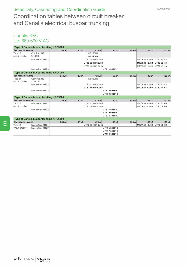
www.se.com
E-18
E
Selectivity, Cascading and Coordination Guide
Coordination tables between circuit breaker and Canalis electrical busbar trunking
Type of Canalis busbar trunking KRC3200Isc max. in kA rms 25 kA 30 kA 42 kA 50 kA 65 kA 85 kA 100 kA
Type of circuit breaker
ComPact NS u 1600b
NS2500NNS3200N
MasterPact MTZ2 MTZ2 25 H1/H2/H3 MTZ2 25 H2/H3 MTZ2 25 H3MTZ2 32 H1/H2/H3 MTZ2 32 H2/H3 MTZ2 32 H3MTZ2 40 H1/H2/H3 MTZ2 40 H2/H3 MTZ2 40 H3
MasterPact MTZ3 MTZ3 40 H1/H2Type of Canalis busbar trunking KRC4000Isc max. in kA rms 25 kA 30 kA 42 kA 50 kA 65 kA 85 kA 100 kA
Type of circuit breaker
ComPact NS u 1600b
NS3200N
MasterPact MTZ2 MTZ2 32 H1/H2/H3 MTZ2 32 H2/H3 MTZ2 32 H3MTZ2 40 H1/H2/H3 MTZ2 40 H2/H3 MTZ2 40 H3
MasterPact MTZ3 MTZ3 40 H1/H2MTZ3 50 H1/H2
Type of Canalis busbar trunking KRC5000Isc max. in kA rms 25 kA 30 kA 42 kA 50 kA 65 kA 85 kA 100 kA
Type of circuit breaker
MasterPact MTZ1 MTZ2 32 H1/H2/H3 MTZ2 32 H2/H3 MTZ2 32 H3MTZ2 40 H1/H2/H3 MTZ2 40 H2/H3 MTZ2 40 H3
MasterPact MTZ2 MTZ3 40 H1/H2MTZ3 50 H1/H2MTZ3 63 H1/H2
Type of Canalis busbar trunking KRC6300Isc max. in kA rms 25 kA 30 kA 42 kA 50 kA 65 kA 85 kA 100 kA
Type of circuit breaker
MasterPact MTZ1 MTZ2 40 H1/H2/H3 MTZ2 40 H2/H3 MTZ2 40 H3MasterPact MTZ2 MTZ3 40 H1/H2
MTZ3 50 H1/H2MTZ3 63 H1/H2
Canalis KRCUe: 660-690 V AC

02-2016
As standards, specifications and designs change from time to time, please ask for confirmation of the information given in this publication.
Publication: Schneider Electric Industries SASPhotos: Schneider ElectricPrinted:
This document has been printed on ecological paper.
10-31-1247
Schneider Electric Industries SAS35, rue Joseph MonierCS 3032392506 Rueil Malmaison Cedex France
RCS Nanterre 954 503 439Capital social 896 313 776 €www.schneider-electric.com
© 2
016
- Sch
neid
er E
lect
ric -
All r
ight
s re
serv
ed.
557EN
03-2021© 2021- Schneider Electric. All Rights Reserved.All trademarks are owned by Schneider Electric Industries SAS or its affiliated companies.Document reference: LVPED318033EN
Schneider Electric Industries SAS
35, rue Joseph MonierCS 3032392506 Rueil Malmaison Cedex France
RCS Nanterre 954 503 439Capital social 928 298 512 €www.se.com
This document has beenprinted on recycled paper