seismic behaviour of hybrid systems made of pr composite frames coupled with dissipative bracings
TRANSCRIPT

EARTHQUAKE ENGINEERING AND STRUCTURAL DYNAMICSEarthquake Engng Struct. Dyn. 2008; 37:861–879Published online 14 January 2008 in Wiley InterScience (www.interscience.wiley.com). DOI: 10.1002/eqe.790
Seismic behaviour of hybrid systems made of PR compositeframes coupled with dissipative bracings
C. Amadio1, I. Clemente1, L. Macorini1,∗,† and M. Fragiacomo2
1Department of Civil and Environmental Engineering, University of Trieste, P.le Europa 1, 34127 Trieste, Italy2Department of Architecture and Planning, University of Sassari, Piazza Duomo 6, 07041 Alghero, Italy
SUMMARY
The paper investigates the dynamic behaviour of hybrid systems made of partially restrained (PR) steel–concrete composite frames coupled with viscoelastic dissipative bracings. A numerical model that accountsfor both the resisting mechanisms of the joint and the viscoelastic contribution of the dissipative bracing isintroduced and briefly discussed. The model is first validated against experimental outcomes obtained ona one-storey two-bay composite frame with partial strength semi-rigid joints subjected to free vibrations.A number of time-history analyses under different earthquake ground motions and peak ground accelera-tions are then carried out on the same type of frame. The purpose is to investigate the influence of the typeof beam-to-column connection and property of the viscoelastic bracing on the performance of the hybridsystem. The inherent stiffness of the bare PR frame and the plastic hysteresis of the beam-to-column joints,which always lead to only limited damage in the joint, are found to provide a significant contribution tothe overall structural performance even under destructive earthquakes. This remark leads to the conclusionthat the viscoelastic bracing can be effectively used within the hybrid system. Copyright q 2008 JohnWiley & Sons, Ltd.
Received 20 November 2006; Revised 16 November 2007; Accepted 28 November 2007
KEY WORDS: steel–concrete composite frame; semi-rigid joints; component modelling; viscoelasticdissipative bracing; dynamic analysis; hybrid system
1. INTRODUCTION
Modern design approaches in earthquake engineering are based on the use of energy concepts[1, 2]. In a satisfactory seismic design it is required that the energy demand during an earthquake,i.e. the total energy transferred by the earthquake to the structure, be smaller than the energy
∗Correspondence to: L. Macorini, Department of Civil and Environmental Engineering, University of Trieste,P.le Europa 1, 34127 Trieste, Italy.
†E-mail: [email protected]
Contract/grant sponsor: Italian research grant; contract/grant number: MIUR-PRIN 2004
Copyright q 2008 John Wiley & Sons, Ltd.
862 C. AMADIO ET AL.
supply, which is defined as the sum of the stored elastic energy with the energy that the structuralsystem is able to dissipate. Different strategies can be followed to achieve a satisfactory seismicbehaviour. The reduction of the input energy using base isolation systems is one possible way.Another approach is to increase the dissipative capacity of the structure and, therefore, the energysupply.
The second strategy is commonly used for ordinary structures since it is cheaper than the useof base isolation systems. According to the traditional design approach, recommended by most ofthe current codes of practice [3–5], the increase in dissipative capacity can be obtained by plastichysteresis. The aim is to design the structure so that the maximum global ductility ratio can beachieved and, at the same time, the cost of the structure is still economically convenient. Theenergy dissipation by hysteresis can be achieved by allowing the structure to enter the post-elasticphase so that large plastic strains induced by medium to high-intensity earthquakes can be absorbedwithout any failure. This approach, based on the concept of controlled ductility, cannot be acceptedwhen the structural damage would result in significant economical losses due to the downtime andretrofit costs.
The modern design approach, the so-called performance-based seismic design (PBSD) [6], isbased on damage control and is aimed to reduce the economical losses due to a seismic event. Theuse of innovative strategies is required to achieve this result [7, 8]. With the purpose of reducingresidual damage in ductile buildings, the use of prefabricated elements made of precast concrete[9] or steel [10] prestressed with unbonded tendons has been proposed. The damage controlcan be also achieved using dissipative devices, which are added to the conventional structuralsystem in order to improve the seismic response [11, 12]. The added energy dissipation systems,which generally dissipate most of the earthquake-induced energy, do not form part of the gravityframing system and can be easily removed and substituted if damaged at the end of the seismicevent. The seismic behaviour of the coupled systems, i.e. the conventional structural systemscoupled with the dissipative devices, is characterized by reduced floor accelerations, small inter-storey drifts and reduced plastic deformations. Extensive research has recently been devoted to thestudy of innovative mechanical systems for damage control of both new and existing buildings inearthquake-prone areas [13–16]. Obtained results have led to the development of effective passivedamping systems and to the formulation of analysis procedures for structural design [17, 18]. Suchdamping devices can be classified according to the dissipation mechanisms [12] in friction systems,elastoplastic systems, viscous and viscoelastic dampers. The first two systems exhibit hystereticbehaviour, i.e. their responses depend upon the displacement experienced by the device. The lattersystems are instead characterized by viscous behaviour, and their response depends upon the strainrate of the component material.
According to the PBSD, in order to reduce the damage, the conventional structural systemcould be designed so as to behave elastically under both low and high-intensity earthquake groundmotions. All the damage would therefore be concentrated into the dissipative devices. However, thisdesign would be highly uneconomic, resulting in significant increases of the construction cost dueto the need of introducing a high number of added dissipative devices. The use of hybrid systemswhere the input seismic energy is dissipated by both passive protection devices and componentsof the gravity framing system is therefore preferable in many cases. The design of such hybridsystems is however complex, and makes the use of advanced analysis tools necessary.
Within the hybrid systems, the partially restrained (PR) steel–concrete composite frame coupledwith dissipative bracings is a particularly interesting solution. Unbraced composite frames withpartial strength beam-to-column connections represent, in fact, a structural system more convenient
Copyright q 2008 John Wiley & Sons, Ltd. Earthquake Engng Struct. Dyn. 2008; 37:861–879DOI: 10.1002/eqe

SEISMIC BEHAVIOUR OF HYBRID SYSTEMS 863
than frames with full strength connections since the construction cost is markedly lower with, at thesame time, effective seismic performance. The formation of plastic hinges in the beam-to-columnconnections with stable and fat hysteresis loops allows the structural system to dissipate a highquantity of energy. A lot of research, both experimental and numerical, has been carried out todate on the design of such systems [19–21]. However, the large flexibility and significant jointdamageability may prevent their use when the limitation of damage is the main design criterion.
Traditional (for example concentric) bracing systems can be used to overcome the aforemen-tioned drawbacks. In this way the contribution of the PR frame to the seismic resistance becomesalmost negligible, and the dynamic performance of the system depends upon the stiffness, strength,and ductility of the bracing. However, also the braced frame is subjected to significant damageunder high-intensity shakings due to flexural buckling of the compressed diagonals. Such damagemay be unacceptable, according to the PBSD, for buildings where the activities cannot be disruptedto allow for a proper structural repair after the seismic event. In order to significantly reduce thestructural damage and the downtime, the PR frames can be coupled with a dissipative bracingsystem. The so obtained hybrid systems can be particularly effective in earthquake-prone regionsnot only due to the increase in stiffness, which is significantly lower with respect to a traditionalbracing systems, but most of all thanks to the possibility to dissipate energy as a result of viscousbehaviour of the viscoelastic devices and controlled (limited) damage of the PR frame. Not onlycan the hybrid system be used for new buildings, but also for seismic retrofit of existing framestructures when those were formerly designed only for ultimate limit state irrespective of anyPBSD considerations.
The paper investigates the performance of hybrid systems made of PR steel–concrete compositeframes coupled with a viscoelastic dissipative bracing. The first part describes the numerical modelemployed in the analyses, including the validation against the outcomes of experimental tests [22]on a one-storey frame system. In the second part, the results of a number of time-history analysescarried out on the same type of frame with different types of joints and number of dissipaters arepresented, critically discussed and compared with a concentric diagonal braced frame.
2. NUMERICAL MODELLING
The seismic behaviour of a PR frame coupled with a viscoelastic dissipative bracing may beanalysed using the finite element method [23]. In this method the displacement response at the timet is represented by a set of variables, which can be considered as the components of a generalizedrelative displacement vector u(t). The dimension N of the displacement vector corresponds to thenumber of degrees of freedom of the whole structural system. The N equations of motion for thediscretized system subjected to a generic base excitation can be expressed as
Cf+Cdb=−m· ug (1)
Cf=m · u+Cf ·u+Kf(u) ·u (2)
Cdb=Cd(u, u) ·u+Kd(u, u) ·u (3)
where Cf and Cdb are two vectorial operators that model the dynamic forces of the bare PRframe and the dissipative bracing, respectively, m represents the mass matrix of the whole system,assumed the same as the mass of the PR bare frame since the mass of the bracing system is usually
Copyright q 2008 John Wiley & Sons, Ltd. Earthquake Engng Struct. Dyn. 2008; 37:861–879DOI: 10.1002/eqe

864 C. AMADIO ET AL.
negligible, and ug is a vector that contains the rigid body contribution of the seismic grounddisplacements. Equation (2) shows that the dynamic behaviour of the PR bare frame, describedby the differential operator Cf, depends in general on the non-linear stiffness matrix Kf(u) andon the damping coefficient matrix Cf. Equation (3) provides the operator Cdb in the limit yetrealistic case of bracing stiffness infinitely larger than the stiffness of the viscoelastic device. Inthis case the contribution of the dissipation device will depend upon the effective stiffness matrixKd(u, u) and damping matrix Cd(u, u) of the viscoelastic device, which generally depend onboth the displacement and velocity vectors. Equation (3) is a simplified formula since the actualdynamic behaviour of a viscoelastic device is affected by several other quantities such as thetemperature, frequency, and amplitude of the motion [12], and would require the use of advancedconstitutive models purposely formulated [24]. The simplification introduced in Equation (3),which is suggested by the most up-to-date codes of practice [17, 18], leads however to accurateresults in most of the cases of technical importance.
Figure 1 displays a mechanical model representing in a synthetic yet effective way the behaviourof a hybrid single-degree-of-freedom system made of a PR frame coupled with a dissipativebracing. The PR bare frame is schematized by a Saint Venant model in parallel with a dashpotrepresenting the damping of the frame. The Saint Venant model is made of a linear spring inseries with a skidding block introduced in order to model the plastic behaviour of the frame.The mechanical model of the PR bare frame is linked in parallel with the viscoelastic bracingsystem, which is modelled by a standard linear solid model, i.e. an elastic spring, representingthe bare bracing, connected in series with a Kelvin element schematizing, in a simplified way, theviscoelastic device. Figures 1(b) and (c) display the hysteretic models introduced for the PR bareframe and dissipative device. The energies dissipated by the two systems are also highlighted:Ehf, signifying the hysteretic (plastic) energy dissipated by the PR bare frame, and Evd, signifyingthe viscous energy dissipated by the viscoelastic device. Since the stiffness of the bracing Kb ismarkedly larger than the stiffness of the viscoelastic device Kd and the two systems are linked inseries, the structural response of the hybrid system is almost not affected by the bracing, which inconclusion is mainly required to hold the viscoelastic device.
A sophisticated numerical model has been developed to account for the cyclic inelastic behaviourof the beam-to-column joint, which represents the main source of hysteretic dissipation in the PR
Figure 1. (a) Mechanical model representing the behaviour of the single-degree-of-freedom hybrid system,(b) Saint Venant model and force–displacement relationship schematizing the dissipative behaviour of thebare PR frame, and (c) Kelvin model and force–displacement hysteretic loop for a viscoelastic device.
Copyright q 2008 John Wiley & Sons, Ltd. Earthquake Engng Struct. Dyn. 2008; 37:861–879DOI: 10.1002/eqe

SEISMIC BEHAVIOUR OF HYBRID SYSTEMS 865
bare frame. The model is briefly described herein after together with the main features of themodelling used for the viscoelastic dissipative bracing.
2.1. Modelling of the PR frame
The PR frame with steel–concrete composite beams and beam-to-column connections has beenmodelled using the ABAQUS finite element code [25]. The joint has been modelled using anadvanced mechanical model defined as ‘spring model’ or ‘component model’, which is based onthe use of rigid and flexible (spring) elements appropriately linked to each other [26–30]. Themodel is capable to predict the cyclic behaviour of the beam-to-column connection since everyresistant part of the joint (column web panel, steel beam-to-column connection, reinforced concreteslab) is schematized using a set of trilinear axial springs with kinematic hardening (Figure 2).The proposed schematization can be used to model any type of beam-to-column connection, bothwelded and bolted. In the following, composite joints with bolted end-plate will be consideredsince they represent the most used type of connection. The meaning of each component spring isdescribed herein after for the joint displayed in Figure 2. A detailed description of the adoptedconstitutive laws, out of the scope of the paper, can be found in Clemente [30].
Spring No. 1 models the behaviour of the end-plate in the lower row of bolts. The flexuralbehaviour of the lower connection and the possible opening of such a connection are modelled bymeans of an equivalent T-stub [31]. The force–displacement relationship under cyclic loading forthe spring No. 1 is depicted in Figure 2(b). Such a relationship is asymmetric due to element No. 9,in parallel with the spring. Element No. 9 schematizes the contact in compression of a genericT-stub on the column flange, and is modelled by a cyclic asymmetric bilinear force–displacementrelationship. The elastic stiffness in compression Kel is assumed two orders of magnitude largerthan the stiffness of the T-stub springs, with unlimited elastic strength. In tension, a very lowstiffness is assumed. For spring No. 1 and the other component springs, the first yielding is assumedat two-thirds of the plastic strength, whereas the stiffness of the second branch is considered asone-third of the initial elastic stiffness.
Spring No. 2 models the web and flange behaviour of the column. The cyclic force–displacementrelationship is trilinear and asymmetric in tension and compression due to the different stiffness and
Figure 2. (a) Schematic of the component model used for an interior beam-to-column composite joint and(b) trilinear force–displacement relationships of some of the components in the joint.
Copyright q 2008 John Wiley & Sons, Ltd. Earthquake Engng Struct. Dyn. 2008; 37:861–879DOI: 10.1002/eqe

866 C. AMADIO ET AL.
strength values, as can be observed in Figure 2(b). Spring No. 3 models the behaviour of the end-plate in the intermediate row of bolts, which is represented by means of an equivalent T-stub. Thestiffness and strength evaluation is carried out similarly to spring No. 1, by computing the effectivewidth of the T-stub according to Eurocode 3 [31]. Spring No. 4 models the shear connectionbetween the concrete slab and the steel beam. Only the shear connectors located between the jointand the point of beam contraflexure are considered. The constitutive law is assumed as symmetricand trilinear.
Spring No. 5 models the shear behaviour of the column web panel, characterized by a symmetrictrilinear cyclic force–displacement relationship. This component was found to markedly affectthe global joint response. Spring Nos. 6–7 model the reinforced concrete slab under axial forces.The overall cyclic constitutive law is trilinear and asymmetric (Figure 2(b)). Two separate springswere employed at first: spring No. 6, representing the contribution of reinforcing bars, and springNo. 7, representing the contribution of the concrete slab. In order to simplify the analysis ofinterior joints, such springs have been assembled in one spring only, denoted as Nos. 6–7, repre-senting the behaviour of reinforcement in tension and the behaviour of the concrete slab incompression.
Spring No. 8, defined as the ‘redirection’ spring, models the slab-to-column interaction underunbalanced bending moment applied on the composite beam. Based on the outcomes of recentinvestigations performed on such a component, Annex C of Eurocode 8 [3] reports the possibletransfer mechanisms of the force from the slab to the column in both cases of exterior and interiorjoints. If the exterior joint is subjected to sagging bending moment (compressed concrete slab),independently of the presence of an edge beam, the moment transfer can be obtained accordingto one of the following:
• Mechanism No. 1: direct compression of the concrete on the column.• Mechanism No. 2: strut-and-tie mechanism with 45◦ inclined struts on the column side and
transversal reinforcing bar tie.
The same couple of transfer mechanisms above seen can be achieved also in the case of an interiorcolumn joints. In this case the two parts of concrete slab on the left- and right-hand side of thecolumn are linked to each other, and the interaction with the column is modelled by means of asingle redirection spring (Figure 2). The mechanism No. 1 due to the brittle failure of concretefor crushing should generally be avoided. The joint should hence be designed in such a way thatthe failure mechanism No. 2 occurs first. If the concrete failure for crushing is postponed, theredirection spring can be modelled by an elastoplastic spring, which can effectively represent thejoint behaviour until the brittle failure of concrete occurs (Figure 2(b)). The strength of the springis given by the lowest value between the compressive strength of concrete in contact with thecolumn flange and the compressive strength of the column web.
2.2. Modelling of the viscoelastic dissipation device
The mechanical model used to represent the dissipation device is based on Equation (3) anddepicted in Figure 1(c). Such a mechanical model is based on the schematization suggested bythe American technical provisions [17, 18] for velocity-dependent dampers. The force Fd in thedamper can be calculated using the equation:
Fd=Kd ·ud+Cd · ud (4)
Copyright q 2008 John Wiley & Sons, Ltd. Earthquake Engng Struct. Dyn. 2008; 37:861–879DOI: 10.1002/eqe

SEISMIC BEHAVIOUR OF HYBRID SYSTEMS 867
where the quantities Kd and Cd signify, respectively, the effective stiffness and damping coef-ficient. Such properties can be evaluated by subjecting the viscoelastic device to a cyclicforce–displacement experimental loop, measuring the largest positive and negative displacements,ud+ and ud−, and energy Evd dissipated in one cycle, and using the formulas:
Kd= |Fd+|+|Fd−||ud+|+|ud−| , Cd= Evd
�·� · ud with ud= |ud+|+|ud−|2
(5)
The quantities Kd and Cd can also be evaluated using the modal strain energy method [32]. Thedamping ratio �i of the global frame-dissipative bracing system for the i th vibration mode isgiven by
�i =�f+ (�d−2�f)
2
�Ti Kbd�i
mi�2i
(6)
where �f is the damping ratio of the bare frame, Kbd is the equivalent stiffness of the dissipativebracing, mi is the mass excited by the i th mode, and �i is the circular frequency of the i th vibrationmode.
The stiffness Kd and the loss factor �d for the viscoelastic device can be easily computed usingEquation (6) when the structure is made of frames equipped with dissipative bracings characterized,in dynamic conditions, by only a predominant vibration mode. The quantities in Equation (6),which characterize the dynamic behaviour of the bare frame (�f,�f) and equipped system (�,�),can be measured on the basis of the free vibrations of the two systems. Hence the quantities Kdand �d can be computed using the following equations drawn for single-degree-of-freedom systemswhen Kb�Kd:
Kd=m ·(�2−�2f ), �d= 2m�2
Kd·(�−�f)+2 ·�f, Cd= �d ·Kd
�(7)
where m is the entire mass, � is the circular frequency of the whole equipped system, �f is thecircular frequency of the bare frame, and � is the damping ratio of the equipped system.
2.3. Validation of the model: numerical–experimental comparisons
The component model of the beam-to-column semi-rigid joint was extensively validated on anumber of numerical–experimental comparisons including cyclic tests performed on connectionsand dynamic tests on a full scale multi-storey PR composite frame. The outcomes of thosecomparisons, which demonstrate the capability of the model to accurately predict the cyclicbehaviour of beam-to-column semi-rigid connections, are reported in previous papers [28–30].
In this paper, only the validation of the finite element model for the coupled system is presented.The experimental results of the tests carried out by Dall’Asta et al. [22] are considered for thecomparisons. The analysed structure is made of two one-storey two-bay steel–concrete compositemoment-resisting frames, arranged in parallel, coupled with two dissipative bracings (Figure 3(a)).The interstorey height and span lengths are, respectively, H =3m and L=4.2m, whereas the totalweight acting on each frame is W =130.43kN.
The beam-to-column connection of the main frames is a semi-rigid composite joint with partialstrength (Figure 3(b)). A bolted end-plate is used for the connection between the steel beam andthe column, which is stiffened by means of two horizontal metal plates welded on the web. The
Copyright q 2008 John Wiley & Sons, Ltd. Earthquake Engng Struct. Dyn. 2008; 37:861–879DOI: 10.1002/eqe
868 C. AMADIO ET AL.
O133x6Ø
24
HE
A16
0
HEA160
L L
H
2+2 M16 PLATE160x182x8
HE
A16
0
HEA160
5565
4φ12
(CSEJ)
0 0.2 0.4 0.6 0.8 1 1.2 1.4time [s]
-12
-8
-4
0
4
8
12
16
Dis
plac
emen
t[m
m]
experimentalnumerical
0 0.2 0.4 0.6 0.8 1 1.2 1.4time [s]
-12
-8
-4
0
4
8
12
16
Dis
plac
emen
t[m
m]
experimentalnumerical
(a) (b)
(d)(c)
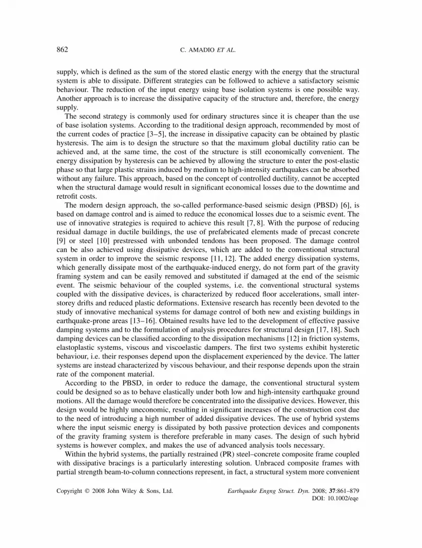
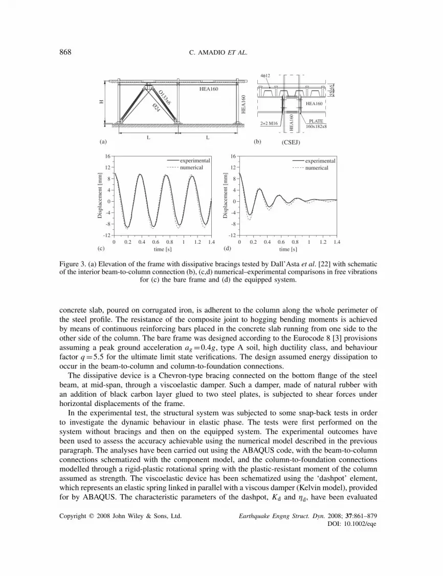
Figure 3. (a) Elevation of the frame with dissipative bracings tested by Dall’Asta et al. [22] with schematicof the interior beam-to-column connection (b), (c,d) numerical–experimental comparisons in free vibrations
for (c) the bare frame and (d) the equipped system.
concrete slab, poured on corrugated iron, is adherent to the column along the whole perimeter ofthe steel profile. The resistance of the composite joint to hogging bending moments is achievedby means of continuous reinforcing bars placed in the concrete slab running from one side to theother side of the column. The bare frame was designed according to the Eurocode 8 [3] provisionsassuming a peak ground acceleration ag =0.4g, type A soil, high ductility class, and behaviourfactor q=5.5 for the ultimate limit state verifications. The design assumed energy dissipation tooccur in the beam-to-column and column-to-foundation connections.
The dissipative device is a Chevron-type bracing connected on the bottom flange of the steelbeam, at mid-span, through a viscoelastic damper. Such a damper, made of natural rubber withan addition of black carbon layer glued to two steel plates, is subjected to shear forces underhorizontal displacements of the frame.
In the experimental test, the structural system was subjected to some snap-back tests in orderto investigate the dynamic behaviour in elastic phase. The tests were first performed on thesystem without bracings and then on the equipped system. The experimental outcomes havebeen used to assess the accuracy achievable using the numerical model described in the previousparagraph. The analyses have been carried out using the ABAQUS code, with the beam-to-columnconnections schematized with the component model, and the column-to-foundation connectionsmodelled through a rigid-plastic rotational spring with the plastic-resistant moment of the columnassumed as strength. The viscoelastic device has been schematized using the ‘dashpot’ element,which represents an elastic spring linked in parallel with a viscous damper (Kelvin model), providedfor by ABAQUS. The characteristic parameters of the dashpot, Kd and �d, have been evaluated
Copyright q 2008 John Wiley & Sons, Ltd. Earthquake Engng Struct. Dyn. 2008; 37:861–879DOI: 10.1002/eqe

SEISMIC BEHAVIOUR OF HYBRID SYSTEMS 869
through Equation (7) by using the experimental data measured for the damping ratio (about 0.5%)and the natural period of both bare frame and equipped system [22].
Figures 3(c) and (d) display some numerical–experimental comparisons for the dynamic responseof the bare frame (Figure 3(c)) and equipped system (Figure 3(d), Kd=2917kN/m and �d=0.58) infree vibrations when an interstorey drift of 10mm, which is almost half of the ultimate displacementof the device, is applied and the system is then released. Numerical and experimental curves arevery close, proving the accuracy of the proposed numerical modelling for dynamic elastic analysesof both bare frame and equipped system.
3. TIME-HISTORY ANALYSES
3.1. Seismic performance of the hybrid system
A number of time-history analyses have been carried out on the equipped frame described in theprevious paragraph. The aim is to investigate the seismic performance of this simple hybrid system,which may also be assumed to approximate the behaviour of more complex multi-storey frameswhen they mainly vibrate according to the first mode. The numerical model of the frame has beensubjected to two different recorded earthquake ground motions (Figure 4(c)), El Centro 1940 andFriuli, Tolmezzo 1976, characterized by a different frequency content. Two peak ground accelera-tions have been assumed for each ground motion: ag =0.15g and 0.40g, the latter one representingthe design acceleration of the bare frame. A different number of dampers have been considered in theviscoelastic bracing: one, two, three, and four, where the number of dampers denotes the quantity ofrubber layers used in the device. Since the rubber layers are assembled in parallel, the stiffness Kdof the dissipative bracing will be proportional to the number of rubber layers. For two dampers likein the reference frame tested by Dall’Asta et al. [22] and analysed in the previous paragraph, thestiffness Kd was 2917kN/m. Since the elastic lateral stiffness Kf of the bare frame was 7500kN/m,the ratio Kd/Kf between the stiffness of the viscoelastic device and, therefore, of the dissipativebracing, and the elastic lateral stiffness of the bare frame are 0.19, 0.39, 0.58, and 0.78 for one, two,three, and four dampers in parallel, respectively. Such values demonstrate that the use of dissipativebracings leads to a limited increment of stiffness, unlike for structures with traditional bracingsystems.
Different types of composite joints have also been analysed in order to investigate theinfluence of stiffness and dissipation capacities of the joints on the dynamic response ofthe hybrid system. In addition to the composite stiffened end-plate joint (CSEJ) tested byDall’Asta et al. [22] (Figure 3(b)), a composite welded joint (CWJ), a steel welded joint (SWJ),a composite non-stiffened end-plate joint (CEJ) (Figure 4(a)), and a perfectly pinned joint(PJ) have been considered. The CSEJ, CWJ, and CEJ joints are characterized by the sameconcrete slab as for the CSEJ one, and differ only in the steel beam-to-column connection.The CWJ joint is a rigid composite joint with full penetration butt welds, whereas the SWJjoint has a concrete slab discontinuous around the beam-to-column connection. The CEJ jointdiffers from the CSEJ joint only in the horizontal stiffeners on the column web which aremissing in the former joint. The PJ joint represents a limit case of beam-to-column connec-tion with no strength and stiffness. In the bare frame with PJ joints, therefore, the dissipationof plastic energy is only due to the formation of plastic hinges in the column-to-foundationconnections.
Copyright q 2008 John Wiley & Sons, Ltd. Earthquake Engng Struct. Dyn. 2008; 37:861–879DOI: 10.1002/eqe

870 C. AMADIO ET AL.
4φ12
6555
HEA160
HE
A16
0
PLATE 160x182x8
2+2 M16
HE
A16
0
HEA160
5565
4φ12
6555
HEA160
HE
A16
0
(CWJ) (CEJ) (SWJ)
0.00 0.02 0.04 0.06 0.08 0.10Displacement [m]
0
30
60
90
120
Shea
r Fo
rce
[kN
]
CWJCSEJCEJSWJPJ
0 0.5 1 1.5 2 2.5 3time [s]
0.0
1.0
2.0
3.0
4.0
S a/a
g
El CentroTolmezzo
0 1 2 3 4No. of dampers
0.2
0.3
0.4
0.5
0.6
0.7
Nat
ural
per
iod
T [
s]
PJSWJCEJCSEJCWJ
0 1 2 3 4No. of dampers
0.00
0.05
0.10
0.15
0.20
0.25
Dam
ping
rat
io ξ
PJSWJCEJCSEJCWJ
(a)
(b) (c)
(d) (e)
Figure 4. (a) Schematics of composite joints analysed, (b) push-over curves for the bare frames withdifferent beam-to-column composite joints, (c) El Centro and Tolmezzo pseudo-acceleration responsespectra, (d) natural period of the hybrid system vs number of dampers curves, and (e) damping ratio of
the hybrid system vs number of dampers curves.
Figure 4(b) displays the outcomes of the non-linear static analyses carried out on the bare frameswith different types of joint. The push-over curves have been obtained by increasing the lateralforce applied on the first floor up to the attainment of 3% interstorey drift, as recommended byFEMA 273 [17] for ultimate limit state of life safety. The comparison among the curves highlightsthe stiffness and strength properties of the frame for different types of joint. The actual collapse ofthe bare frame has not been computed since it is irrelevant. Coupled frames are, in fact, designedso as to ensure the failure of the dissipative device, which must occur for interstorey drifts lesserthan 3% in order to reduce the ductility demand of the PR bare frame.
The frames with composite joints (CSEJ, CEJ, CWJ) are characterized by curves close to eachother, with the rigid composite joint (CWJ) showing only a slightly larger stiffness and strength.The difference between the monotonic static responses of the CSEJ and CEJ joints is small. Thehorizontal column web stiffeners were found to affect the strength and stiffness of both the T-stub
Copyright q 2008 John Wiley & Sons, Ltd. Earthquake Engng Struct. Dyn. 2008; 37:861–879DOI: 10.1002/eqe

SEISMIC BEHAVIOUR OF HYBRID SYSTEMS 871
components of the bolted connection and the column web [31]; however, the global effect on thejoint is negligible.
The column web stiffeners are crucial for achieving a cyclic behaviour characterized by highductility and rotational capacity. This is of the maximum relevance for the design of bare frameswhere there is no other source of energy dissipation. However, in hybrid systems the rotationdemand in the joints is lower due to the dissipation devices that make the column web stiffeners nolonger so crucial. The use of the SWJ joint leads to less stiff and strong frames due to the lack of theconcrete slab component with, consequently, a reduced lever arm in the joint. It is also importantto point out that the stiffness contribution provided by the bare frame with PJ in the hybrid systemis markedly lesser (about half) than all other types of connections. Conversely, the use of a simpleand economic semi-rigid composite joint such as the CEJ joint significantly increases the stiffnessof the bare frame that, therefore, has to be taken into account when evaluating the response of thehybrid system.
Figures 4(d) and (e) display, respectively, the trends of natural period and damping ratio of hybridsystems for different number of dissipaters and types of beam-to-column connection. The naturalperiod decreases when the number of dampers increases for every type of joint. The dampingratios have been computed by subjecting the bare and equipped frames to free vibrations analysesand by interpolating the obtained peak displacements with an exponential relationship dependentupon the unknown damping ratios [33]. It was found that for every type of joint the damping ratiosmarkedly increase with a decreasing gradient when the number of dampers increases. The rangeof values is between 0.5% for bare frames to about 24% for frames equipped with four damperswith PJ beam-to-column connections.
Figures 5 and 6 report some outcomes of the time-history analyses carried out on the bareframe and on the equipped frame experimentally tested by Dall’Asta et al. [22]. The frames arecharacterized by CSEJ joints, with two dampers in the equipped frame, and have been analysedunder both the El Centro 1940 and Tolmezzo 1976 earthquake ground motions scaled on a peakground acceleration ag =0.40g.
Figure 5 displays the trend in time of the non-dimensional energy dissipated by the bare(Figures 5(a) and (b)) and equipped frame (Figures 5(c) and (d)). The non-dimensional energy isobtained by dividing the energy by the product of the strength of the bare frame, as calculatedfrom the push-over analysis (Figure 4(b)), Fy=92kN, by the top floor displacement �y=30mm.Such a quantity is the displacement corresponding to the force Fy experienced by a single-degree-of-freedom system equivalent to the bare frame in a non-linear static (push-over) analysis [3].The figures highlight the more favourable behaviour of the equipped frame, characterized byless total input energy. The equipped and bare frames dissipate energy according to differentmechanisms. The dissipated energy is mainly viscous for the former frames, and plastic forthe latter one. If the mechanical properties of the dissipative device are carefully selected, theequipped frame can behave elastically even under high-peak ground accelerations ag . The anal-ysed equipped frame remains in elastic phase for ag =0.40g under El Centro earthquake groundmotion, whereas a plasticization is attained under Tolmezzo ground motion. The plasticizationis, however, fairly limited since only the column web panel of the beam-to-column connectionexceeds the elastic limit. Conversely, the bare frame enters the plastic phase even for low-peakground acceleration (ag =0.15g) and mainly dissipates hysteretic plastic energy. The plasticiza-tion first occurs in the column web panel of the beam-to-column connection, and then spreads tothe other components of the beam-to-column connection and, also, to the column-to-foundationconnection.
Copyright q 2008 John Wiley & Sons, Ltd. Earthquake Engng Struct. Dyn. 2008; 37:861–879DOI: 10.1002/eqe

872 C. AMADIO ET AL.
0 4 8 12 16 20Time [s]
0.0
1.0
2.0
3.0
4.0
E/(
F yδ y
)
TotalViscousPlastic EL Centro - ag = 0.40g
Bare frame
0 4 8 12 16 20Time [s]
0.0
1.0
2.0
3.0
4.0
E/(
F yδ y
)
TotalViscousPlastic
Tolmezzo - ag = 0.40gBare frame
0 4 8 12 16 20Time [s]
0.0
0.5
1.0
1.5
2.0
2.5
E/(
F yδ y
)
TotalViscous tot.PlasticVisc.device
EL Centro - ag = 0.40gEquipped frame
0 4 8 12 16 20Time [s]
0.0
0.5
1.0
1.5
2.0
2.5
E/(
F yδ y
)
TotalViscous tot.PlasticVisc.device
Tolmezzo - ag = 0.40gEquipped frame
(a) (b)
(d)(c)
Figure 5. Time histories of the energies for bare (a,b) and equipped (c,d) frames with CSEJ joints andtwo viscous dissipaters subjected to El Centro (a,c) and Tolmezzo (b,d) earthquake ground motions.
The time histories of the top floor displacement–interstorey height ratios are reported inFigures 6(a) and (b) for, respectively, the bare and the equipped frames. The introduction ofthe dissipative bracing into the moment-resisting frame leads to a considerable reduction of thedisplacement demand. The Tolmezzo earthquake ground motion with a peak ground acceler-ation ag =0.40g would cause the plasticization of the column in the bare frame with a finalresidual displacement of about 20mm. Conversely, the equipped frame would experience onlysmall displacements even for the high-intensity shakings. Figures 6(c) and (d) compare the time-histories of the non-dimensional base shear for the bare and equipped frames with CSEJ jointssubjected to the El Centro and Tolmezzo earthquake ground motions, respectively. The use of thedissipative bracings leads to a base shear demand only slightly lower than the corresponding sheardemand for the bare frame.
Figure 7 displays the outcomes of the parametric analysis carried out on the hybrid system withdifferent number of dissipaters, type of composite joints, shakings, and peak ground accelerationssubjected to El Centro ground motion. It can be observed that the inherent stiffness of the bareframe is crucial in order to reduce the displacement demand of the equipped frame. Figures 7(a)and (b) highlights that the displacement demand, in term of non-dimensional top displacement,in the case of pinned beam-to-column connections (PJ) is much larger than that of the otherframes with different composite joints, especially for one, two, or no dampers. Furthermore, forthe equipped frames, the response of the composite semi-rigid joint (CEJ) is very close to that ofthe rigid joint (CWJ).
It has to be underlined that during the design process of the hybrid frame, the maximuminterstorey displacement needs to be controlled and kept below the design value of the specific
Copyright q 2008 John Wiley & Sons, Ltd. Earthquake Engng Struct. Dyn. 2008; 37:861–879DOI: 10.1002/eqe

SEISMIC BEHAVIOUR OF HYBRID SYSTEMS 873
0 2.5 5 7.5 10 12.5 15 17.5 20Time [s]
-0.015
-0.010
-0.005
0.000
0.005
0.010
0.015
Dis
plac
emen
tδ
/H
bare frameeq. frame
El Centro - ag = 0.40g
0 2.5 5 7.5 10 12.5 15 17.5 20Time [s]
-0.025
-0.020
-0.015
-0.010
-0.005
0.000
0.005
0.010
0.015
Dis
plac
emen
tδ
/H
bare frameeq. frame
Tolmezzo - ag = 0.40g
0 2.5 5 7.5 10 12.5 15 17.5 20Time [s]
-1.5
-1
-0.5
0
0.5
1
1.5
Shea
rFo
rce
F/F
y
bare frameeq. frame
El Centro - ag = 0.40g
0 2.5 5 7.5 10 12.5 15 17.5 20Time [s]
-1.5
-1
-0.5
0
0.5
1
1.5
Shea
rFo
rce
F/F
y
bare frameeq. frame
Tolmezzo - ag = 0.40g
(a) (b)
(c) (d)
Figure 6. Time-histories of (a,b) top floor displacement–interstorey height ratios and (c,d) non-dimensionalbase shear for the bare and equipped frames with CSEJ joints subjected to the (a,c) El Centro and (b,d)
Tolmezzo earthquake ground motions.
dissipater employed (20mm for the case under study) in order to prevent the failure of the dissipater.This condition can be met either using more dampers and ignoring the stiffness contribution ofthe bare frame, or taking into account the stiffness contribution provided by the bare frame withpartial strength connections. The latter condition can be achieved by introducing in the frame asimple and cost-effective semi-rigid composite joint such as the CEJ joint. The use of such a typeof joint, in fact, would lead to a significant reduction in the displacement demand and, therefore,would make the hybrid system effective also under high-intensity shakings.
The analyses carried out have also shown a significant reduction in the base shear demand forthe shakings with peak ground acceleration ag =0.15g when the number of dampers is increased.For the shakings with ag =0.40g, however, the reduction is less prominent (Figure 7(c)). For a peakground acceleration of ag =0.40g, all the analysed bare frames experienced a remarkable damagewhich changed the frame stiffness and therefore their dynamic responses with respect to the sameframe when undamaged or only slightly damaged. The outcomes of the analysis demonstrate thatthe use of dissipative bracings does not lead to a significant increase in base shear and, therefore,in load on the foundation like in the case of traditional bracing systems. The dissipative bracings,in fact, mainly introduce an increase in damping, whereas the increase in stiffness is limited.
Figures 7(d–f) display, respectively, the demands of total, viscous, and plastic energy in thecase of ag =0.40g. The demand of total energy Etot can be markedly reduced when the number ofdampers, especially for frames with PJ joints, is increased. For the other types of joint, a significantreduction can be observed mainly from no dampers to the case of frame equipped with one damper
Copyright q 2008 John Wiley & Sons, Ltd. Earthquake Engng Struct. Dyn. 2008; 37:861–879DOI: 10.1002/eqe

874 C. AMADIO ET AL.
0.000
0.005
0.010
0.015
0.020
0.025
δ max
/ H
0 1 2 3 4No. of dampers
PJSWJCEJCSEJCWJ
El Centro - ag = 0.15g
0.000
0.005
0.010
0.015
0.020
0.025
0.030
0.035
δ max
/ H
0 1 2 3 4No. of dampers
PJSWJCEJCSEJCWJ
El Centro - ag = 0.40g
0.00
0.20
0.40
0.60
0.80
1.00
1.20
F h /
W
0 1 2 3 4
PJSWJCEJCSEJCWJ
El Centro - ag = 0.40g
0.00
4.00
8.00
12.00
16.00
20.00
24.00
Eto
t [Κ
J]
0 1 2 3 4No. of dampersNo. of dampers
PJSWJCEJCSEJCWJ
El Centro - ag = 0.40g
0.00
2.00
4.00
6.00
8.00
10.00
12.00
14.00
Ev [
ΚJ]
0 1 2 3 4No. of dampers
PJSWJCEJCSEJCWJ
El Centro - ag = 0.40g
0.00
4.00
8.00
12.00
16.00
20.00
Ep [
ΚJ ]
0 1 2 3 4No. of dampers
PJSWJCEJCSEJCWJ
El Centro - ag = 0.40g
(a) (b)
(c) (d)
(e) (f)
Figure 7. (a,b) Non-dimensional displacement demand for the bare and equipped frames with differenttypes of joint subjected to El Centro with ag =0.15g (a) and ag =0.40g (b), non-dimensional base shear
(c), total energy (d), viscous energy (e) and plastic energy (f) demands for ag =0.40g.
only. Figure 7(e) highlights that the viscous dissipation is already significant for the hybrid frameswith rigid and semi-rigid joints when only one dissipater is used (�=7%), while a larger numberof dissipaters (�=16%) does not markedly improve the behaviour. Conversely, a larger number ofdissipaters are needed in the hybrid system with PJ joints in order to make the viscous dissipationmore effective. In this case, the demand of total energy is significantly reduced (see Figure 7(d)).The outcomes in terms of plastic energy highlight the effectiveness of the dissipaters in reducing theplastic damage of the frame for low-intensity earthquakes (ag =0.15g), when the system behaveselastically in all the cases analysed. For high-intensity earthquakes (Figure 7(f)), a cost-effectivesystem with few (one) dampers can be used. The system will experience only a limited damagelocalized in the beam-to-column connection, which can be controlled using the numerical modelpreviously introduced.
Copyright q 2008 John Wiley & Sons, Ltd. Earthquake Engng Struct. Dyn. 2008; 37:861–879DOI: 10.1002/eqe

SEISMIC BEHAVIOUR OF HYBRID SYSTEMS 875
Based on the outcomes of the dynamic analyses, it can be concluded that the best performancewith the least cost is achieved in coupled systems with global damping lesser than 10%. Thiscorresponds to the use of one damper only and, therefore, to an economically convenient solutionwith, at the same time, low interstorey drift demand, elastic behaviour of the gravity load-resistingsystem (the PR frame) under frequent shakings (ag =0.15g), and only limited damage under rareshakings (ag =0.40g). To eliminate any structural damage at ultimate limit state, a global dampingof 15–20% should be achieved, with a need for four dampers and, consequently, a significantincrease in cost.
3.2. Comparison between the hybrid and a traditional braced frame system
In order to highlight the advantages of using dissipative bracings, a comparison with traditionalbraced frame systems has been carried out. The performance of the bare frame with CSEJ joints,already investigated in the previous section, has been analysed when coupled with a traditionalconcentric bracing [34] (Figure 8(a)). The diagonals have been designed in accordance withEurocode 8 by carrying out a simplified linear elastic analysis, neglecting the contribution ofthe compressed member, assuming a behaviour factor q=4 and the same quantities used in thedesign of the bare frame (ag =0.4g, type A soil, same mass). The resulting cross-sectional areaof the diagonal in tension, Ap=300mm2, has then been used for both diagonals (in tensionand compression). Non-linear time-history analyses have been carried out under El Centro andTolmezzo earthquake ground motions with a peak ground acceleration ag =0.40g. The contribution
HE
A16
0
HEA160
L L
H
Ap
Ap
0.000 0.004 0.008 0.012 0.016
δ/Η
0.00
0.25
0.50
0.75
1.00
1.25
1.50
Fh/W
braced fr. λ=2bare frame
-0.015 -0.007 0.000 0.007 0.015
δ/Η
-0.50
-0.25
0.00
0.25
0.50
0.75
1.00
1.25
Nb/ N
pl
braced fr. λ=2
-0.015 -0.007 0.000 0.007 0.015
δ/Η
-1.50
-1.00
-0.50
0.00
0.50
1.00
1.50
Fh/W
braced fr. λ=2
(a) (b)
(d)(c)
Figure 8. (a) Elevation of the frame with diagonal bracings, (b) push-over curves for the bare frame(CSEJ) and for the braced frame, (c,d) cyclic displacement response: (c) axial load in one of the diagonals
and (d) base shear vs interstorey drift.
Copyright q 2008 John Wiley & Sons, Ltd. Earthquake Engng Struct. Dyn. 2008; 37:861–879DOI: 10.1002/eqe

876 C. AMADIO ET AL.
of the compressed diagonal to the seismic resistance of the frame has been considered by anaccurate modelling of flexural buckling using ABAQUS [25], which accounts for mechanical andgeometric nonlinearities. The flexural buckling of the diagonal in compression depends upon theslenderness of the member, represented in Eurocode 3 by the non-dimensional slenderness �,defined for non-slender cross-sections by the quantity (Npl/Ncr)
0.5,Npl and Ncr being the plasticsection capacity and elastic (Euler) buckling load, respectively. The actual behaviour of the bracedframe markedly depends upon the non-dimensional slenderness �: larger values of such quantitylead to lower buckling loads, which would make the contribution of the compressed membernegligible within the whole braced frame. Different values of the non-dimensional slenderness �(1, 2, and 4) have been considered in the analyses, assuming the same cross-sectional area Ap.Eurocode 8 limits the value of � to 2 for more than two-storey buildings to 2 in order to avoidlocal buckling and brittle failures due to cyclic behaviour of the system, whereas no limitationis given for less than two-storey buildings. Figures 8(b–d) display, respectively, the monotonic(Figure 8(b), push-over curve) and cyclic (Figures 8(c) and (d)) response of the concentricallybraced frame with �=2. The figures highlight the significant increase in stiffness of the bracedsystem with respect to the bare frame (Figure 8(a)) due to the use of the diagonals, as well as thepeculiar cyclic behaviour, strongly affected by the flexural buckling of the compressed diagonal.
Figures 9(a–d) compare the seismic performance of the bare frame, the hybrid system withtwo dissipaters (see Section 3.1), and the concentrically braced frame. The performance of theconcentrically braced frames in terms of reduction in interstorey drift (Figure 9(a)) is similar tothat of the hybrid system with viscoelastic devices. The hybrid system, however, allows a betterprotection against the earthquake since the plastic energy is far less than for the braced system
0.000
0.004
0.008
0.012
0.016
0.020
δ max
/ H
bare
fra
me
eq. f
ram
e 2
dam
pers
brac
ed f
ram
e λ=
1
brac
ed f
ram
e λ=
2
brac
ed f
ram
e λ=
4
Tolmezzo - ag=0.40gEl Centro - ag=0.40g
0.00
2.00
4.00
6.00
8.00
10.00
Ep
[kJ
]
bare
fra
me
eq. f
ram
e 2
dam
pers
brac
ed f
ram
e λ=
1
brac
ed f
ram
e λ=
2
brac
ed f
ram
e λ=
4
Tolmezzo - ag=0.40gEl Centro - ag=0.40g
0.00
0.25
0.50
0.75
1.00
1.25
1.50
F h/ W
bare
fra
me
eq. f
ram
e 2
dam
pers
brac
ed f
ram
e λ=
1
brac
ed f
ram
e λ=
2
brac
ed f
ram
e λ=
4
Tolmezzo - ag=0.40gEl Centro - ag=0.40g
0.00
0.50
1.00
1.50
2.00
2.50
3.00
Nm
ax/ W
bare
fra
me
eq. f
ram
e 2
dam
pers
brac
ed f
ram
e λ=
1
brac
ed f
ram
e λ=
2
brac
ed f
ram
e λ=
4
Tolmezzo - ag=0.40gEl Centro - ag=0.40g
(a) (b)
(c) (d)
Figure 9. Comparisons between the seismic responses of concentrically braced frames and equipped framewith two dampers: (a) interstorey drift, (b) plastic energy demand, (c) base shear demand, and (d) axial
force demand in the interior column.
Copyright q 2008 John Wiley & Sons, Ltd. Earthquake Engng Struct. Dyn. 2008; 37:861–879DOI: 10.1002/eqe

SEISMIC BEHAVIOUR OF HYBRID SYSTEMS 877
(Figure 9(b)). The damage of the former system is minimal even under high-intensity shakings,whereas evident damage would take place in the concentric bracings. The damage would occurmainly in the diagonals due to the elasto-plastic buckling, and would lead to the need to replacethem after the earthquake, whereas the beam-to-column joints would not overcome the elasticlimit. The demand on the foundation in terms of maximum base shear and axial force is plotted inFigures 9(c) and (d). The concentrically braced frame shows a significant increase in base shear(more than twice the value of the hybrid system for �=1) and axial force demand on the interiorcolumn. In the case of �>1, the flexural buckling of the compressed diagonal could cause anincrease in the axial force of the interior column of more than twice the maximum values of thebare frame and of the frame equipped with dissipative bracings.
Finally, it has to be pointed out that for a single-storey frame the increase in stiffness due to theuse of the concentric bracing reduces, in the analysed case, the seismic action (see the pseudo-acceleration response spectra in Figure 4(c)) with respect to both the bare and the hybrid frames,both characterized by natural periods (Figure 4(d)) higher than the values for concentrically bracedframes (T =0.157s for �=2). Conversely, this trend reverses for multi-storey frames since thenatural periods generally are in the descending branch of the pseudo-acceleration spectra, leadingin this case to even more significant benefits of the hybrid system with respect to traditionalconcentric bracings.
4. CONCLUDING REMARKS
The paper presents the outcomes of an extensive numerical analysis carried out on a one-storeyPR steel–concrete composite frames coupled with viscoelastic dissipative bracings. Different typesof joint, number of dampers, peak ground acceleration, and recorded earthquake ground motionhave been considered in the analyses. A comparison with traditional concentric braced frames hasalso been performed. Numerical–experimental comparisons demonstrate the accuracy achievableusing the proposed model, where the properties of the viscoelastic device have been computedusing experimental data and the method of modal energy. The semi-rigid composite joint has beenschematized using the component method.
The main outcome of the time-history analyses carried out is that considerable reduction inboth displacement demand and structural damage can be achieved using the dissipative bracing.Such devices, in fact, increase the dissipated viscous energy and reduce both the plastic hystereticand the total input energy. The contribution in terms of stiffness given by the PR composite framein the equipped system is relevant especially under high-intensity earthquake ground motions,where a reduction in the lateral displacement demand is needed in order to prevent the failureof the dissipation device. The use of semi-rigid joints with partial strength, simple yet effectivein terms of stiffness and dissipation capacity, leads to the possibility to use a reduced numberof dampers, with a significant benefit in terms of cost reduction. The structural damage, whichwill take place only in the beam-to-column joint, can be effectively controlled using the proposednumerical model.
Based on the outcomes of the analyses, it can be concluded that the hybrid system is aneffective solution for both new construction and retrofit of existing frame systems when the latterwere designed only to achieve the life safety performance objective under rare earthquake groundmotions (ultimate limit state) and, therefore, the frames do not satisfy the criteria of PBSD. For newconstruction, the use of the hybrid system has significant benefit in terms of damage limitation and,
Copyright q 2008 John Wiley & Sons, Ltd. Earthquake Engng Struct. Dyn. 2008; 37:861–879DOI: 10.1002/eqe

878 C. AMADIO ET AL.
therefore, reduction in downtime. For retrofit of existing frames, the hybrid systems have the meritof reduced interstorey drift demands and limited damage in the non-structural components withalmost no increase in base shear and, therefore, no increase in strength demand on foundations,unlike traditional bracing systems. This last point is quite important since expensive and time-consuming strengthening works on foundations are not needed when the proposed system is used.
The numerical model discussed in this paper can be used for accurate analyses and design ofthe hybrid frames since it allows the user to account for the coupling between dissipater and PRframe, with full control the damage experienced by the frame. A simplified design based on anelastic behaviour of the frame under high-intensity earthquake ground motions would lead to theneed for dissipaters with high damping and therefore to expensive devices characterized by largequantities of rubber.
Further analyses are still needed. Dynamic numerical–experimental comparisons to collapse(failure of the dissipater) should be carried out on the hybrid frame in order to integrate thevalidation of the model. Dynamic analyses on multi-storey hybrid frames should also be carried outin order to investigate the influence of higher vibration modes and draw a final design procedurewhere the plasticization of the frame can be accounted for.
The model discussed in the paper will also be used to carry out a cost analysis where the perfor-mances of hybrid frames with limited plasticization and no damage in the gravity load-resistingframe under high-intensity shakings are compared with each other and with the performance oftraditional concentrically braced frames. The global cost will be compared for new constructionand retrofit of existing structures by taking into account material and labour costs as well as costsof downtime and business losses.
ACKNOWLEDGEMENTS
This work has been supported by the Italian research grant MIUR-PRIN 2004.
REFERENCES
1. Housner GW. Limit design of structures to resist earthquakes. Proceedings of the World Conference on EarthquakeEngineering, Berkeley, CA, U.S.A., 1956; 5.1–5.13.
2. Uang CM, Bertero VV. Use of energy as a design criterion in earthquake-resistant design. Report UCB/EERC-88/18, Earthquake Research Centre University of California, Berkeley, U.S.A., 1988.
3. European Committee for Standardisation (CEN). Eurocode 8. Design Provisions for Earthquake ResistanceStructure. Part 1: General Rules, Seismic Actions and Rules for Buildings, EN 1998-1. European Committee forStandardisation (CEN), 2002.
4. International Council of Building Code Officials. Uniform Building Code (UBC), Whittier, CA, 1997.5. Federal Emergency Management Agency. NEHRP Recommended Provisions for Seismic Regulations for New
Buildings and Other Structures, 2000 Edition: Part 1—Provisions (FEMA 368), Part 2—Commentary (FEMA369), Washington, DC, 2001.
6. SEAOC. Vision 2000—Performance Based Seismic Engineering of Buildings. Structural Engineers Associationof California, Sacramento, U.S.A., 1995.
7. Oliveto G. Innovative Approaches to Earthquake Engineering. WIT Press: Southampton, U.K., 2002.8. Wada A, Huang Y, Bertero VV. Innovative strategies in earthquake engineering. In Earthquake Engineering
from Engineering Seismology to Performance-Based Engineering, Bozorgnia Y, Bertero VV (eds). CRC Press:New York, 2004.
9. Priestley MJN, Sritharan S, Conley JR, Pampanin S. Preliminary results and conclusions from the PRESSSfive-story precast concrete test-building. PCI Journal 1999; 44(6):42–67.
10. Christopoulos C, Filiatrault A, Uang CM, Folz B. Post-tensioned energy dissipating connections for momentresisting steel frames. Journal of Structural Engineering (ASCE) 2002; 128(9):1111–1120.
Copyright q 2008 John Wiley & Sons, Ltd. Earthquake Engng Struct. Dyn. 2008; 37:861–879DOI: 10.1002/eqe

SEISMIC BEHAVIOUR OF HYBRID SYSTEMS 879
11. Whittaker A, Costantinou M. Seismic energy dissipation system for buildings earthquake. In Engineeringfrom Engineering Seismology to Performance-Based Engineering, Bozorgnia Y, Bertero VV (eds). CRC Press:New York, 2004.
12. Soong TT, Dargush GF. Passive Energy Dissipation Systems in Structural Engineering. Wiley: New York, U.S.A.,1997.
13. Pekcan G, Mander JB, Chen SS. Fundamental considerations for the design of non-linear viscous dampers.Earthquake Engineering and Structural Dynamics 1999; 28:1405–1425.
14. Lu X, Qiang ZQ. Dynamic analysis method of a combined energy dissipation system and its experimentalverification. Earthquake Engineering and Structural Dynamics 2002; 31:1251–1265.
15. Lin WH, Chopra AK. Earthquake response of elastic SDF systems with fluid viscous dampers. EarthquakeEngineering and Structural Dynamics 2002; 31:1623–1642.
16. Dolce M, Cardone D, Felice C, Ponzo C, Valente C. Shaking table tests on reinforced concrete frames withoutand with passive control system. Earthquake Engineering and Structural Dynamics 2005; 34:1687–1717.
17. Federal Emergency Management Agency. NEHRP Guidelines for the Seismic Rehabilitation of Buildings, ReportNo. FEMA 273 (Guidelines) and FEMA 274 (Commentary), Washington, DC, U.S.A., 1997.
18. Federal Emergency Management Agency. Prestandard and Commentary for the Seismic Rehabilitation ofBuildings, Report No. FEMA 356, Washington, DC, 2000.
19. Leon RT, Hajjar JF, Gustafson MA. Seismic response of composite moment-resisting connection. I: performance.Journal of Structural Engineering 1998; 124(8):868–876.
20. Bursi OS, Caramelli S, Fabbrocino G, Pinto AV, Salvatore W, Taucer F, Tremblay R, Zandonini R. Pseudo-dynamictesting of a 3D full-scale high ductile steel–concrete composite MR frame structure at ELSA. Proceedings ofthe 13th World Conference on Earthquake Engineering, Vancouver, Canada, 2004, Paper No. 507.
21. Salvatore W, Bursi OS, Lucchesi D. Design, testing and analysis of high ductile partial-strength steel–concretecomposite beam-to-column. Computers and Structures 2005; 83:2334–2352.
22. Dall’Asta A, Dezi L, Giacchetti R, Leoni G, Ragni L. Dynamic response of composite frames with rubber-baseddissipating devices: experimental tests. Proceedings of the ICASS’05 Conference, Shanghai, China, 2005.
23. Bathe KJ. Finite Element Procedures. Prentice-Hall: Upper Saddle River, NJ, U.S.A., 1996.24. Dall’Asta A, Ragni L. Experimental tests and analytical model of high damping rubber dissipating devices.
Engineering Structures 2006; 28:1874–1884.25. ABAQUS User’s Manual—Version 6.2.4. Hibbit, Karlsson & Sorenson: Pawtucket, RI, U.S.A., 2001.26. Tschemmernegg F, Rubin D, Pavlov A. Application of the component method to composite joints. Proceedings
of the International Conference COST C1 ‘Control of the Semi-rigid Behaviour of Civil Engineering StructuralConnections’, Liege, 1998.
27. Rassati GA, Leon RT, Noe S. Component modelling of PR composite joints under cyclic and dynamic loading.Journal of Structural Engineering 2004; 130(2):343–351.
28. Amadio C, Clemente I, Fragiacomo M, Macorini L, Noe S, Pasquale D. Problems with semi-rigid steel framesmodelling in seismic regions. Costruzioni Metalliche 2004; 3:44–51.
29. Amadio C, Clemente I, Macorini L, Fragiacomo M. Modelling of steel–concrete composite frames with partiallyrestrained joints by means of the component method. Proceedings XX CTA, Ischia, Italy, 2005; 9–16.
30. Clemente I. Partially restrained bare-steel and steel–concrete composite frames under seismic loading. Ph.D.Thesis, University of Trieste, 2005 (in Italian).
31. European Committee for Standardisation (CEN). Eurocode 3. Design of Steel Structures—Parts 1–8: Design ofJoints, prEN 1993-1-8. European Committee for Standardisation (CEN). 2003.
32. Shen KL, Soong TT, Chang KC, Lai ML. Seismic behaviour of reinforced concrete frame with added viscoelasticdampers. Engineering Structures 1995; 17(5):372–380.
33. Clough RW, Penzien J. Dynamic of Structures (2nd edn). McGraw-Hill: New York, 1993.34. Elghazouli AY. Seismic performance of concentrically braced steel frames. Proceedings of the 12th European
Conference on Earthquake Engineering, London, U.K., 2002, Paper Reference 520.
Copyright q 2008 John Wiley & Sons, Ltd. Earthquake Engng Struct. Dyn. 2008; 37:861–879DOI: 10.1002/eqe