secure cms (central management system) user manual
TRANSCRIPT

SECURE CMS
(Central Management System)
User Manual

II V 1.5 (2020-07-13)
Issue: 1.5 Date: 2020/07/13

V 1.5 (2020-07-13) I
Introduction
Overview This document describes in detail the configuration and use of the video management of CMS.
Reader This document is intended for:
l Technical Support Engineer l System Manager l System Operator
Symbol Convention The following symbols may appear in this document, and their meanings are as follows:
Symbol Description
Alert you to a high risk hazard that could, if not avoided,result in death or serious injury。
Alert you to a medium or low risk hazard that could, if not avoided, result in moderate or minor injury.
Alert you to a potentially hazardous situation which, if not avoided, result in equipment damage, data loss, performance deterioration, or unanticipated results.
Provide a tip that may help in solving a problem or saving time.
Provide additional information to emphasize or supplement important points in the main text.
Server Name
Acronym Full Name Note
CMU Central Manager Unit Central Manager Server
MDU Media Distribution Unit Media Distribution Server
IAU Intelligent Analysis Unit Intelligent Analysis Server
II V 1.5 (2020-07-13)
Content Introduction .................................................................................................................................... I
Content .......................................................................................................................................... II
1 Platform Description ................................................................................................................ 1
1.1 System Function .................................................................................................................................................... 1 1.2 System Components .............................................................................................................................................. 2
1.2.1 Central Management Server .......................................................................................................................... 2 1.2.2 Database Server ............................................................................................................................................. 2 1.2.3 Media Distribution Server ............................................................................................................................. 2 1.2.4 Intelligent Analysis Server ............................................................................................................................. 2 1.2.5 Client .............................................................................................................................................................. 4
1.3 System Requirement ............................................................................................................................................. 5 1.4 Deployment Planning ............................................................................................................................................ 6
1.4.1 Mini Method (Standalone Deployment) ........................................................................................................ 6 1.4.2 Middle Method (Distributed Deployment) .................................................................................................... 7 1.4.3 Large Method (Distributed Deployment) ...................................................................................................... 7
2 Installation .................................................................................................................................. 9
2.1 One-Click Installation ........................................................................................................................................... 9 2.2 Custom Installation ............................................................................................................................................... 9 2.3 Retrieve password ............................................................................................................................................... 12
3 Login .......................................................................................................................................... 13
4 Quick Start ................................................................................................................................ 14
4.1 Monitoring Application Configuration Process .................................................................................................. 14 4.1.1 Add Front-end Device .................................................................................................................................. 14 4.1.2 Add User Permissions .................................................................................................................................. 15
4.2 Intelligent Application Configuration Process .................................................................................................... 16 4.2.1 Add Front-End Device ................................................................................................................................. 16 4.2.2 Add Face Database ....................................................................................................................................... 16 4.2.3 Add User Permissions .................................................................................................................................. 17
5 Main Menu Page ..................................................................................................................... 19
6 Basic Functions ........................................................................................................................ 24
6.1 Live view ............................................................................................................................................................. 24 6.1.1 Layout .......................................................................................................................................................... 25 6.1.2 Device .......................................................................................................................................................... 25 6.1.3 Operation ..................................................................................................................................................... 25
6.2 Playback .............................................................................................................................................................. 27 6.2.1 Playback the Device Video .......................................................................................................................... 29 6.2.2 Back up the Device Video ............................................................................................................................ 30
6.3 Real-Time Alarm ................................................................................................................................................. 31 6.4 Alarm Search ....................................................................................................................................................... 33
V 1.5 (2020-07-13) III
6.5 Layout Management ........................................................................................................................................... 35 6.6 E-Map .................................................................................................................................................................. 36
6.6.1 Add Electronic Map ..................................................................................................................................... 37 6.6.2 Edit Map ...................................................................................................................................................... 38 6.6.3 Deploy Monitoring Site ............................................................................................................................... 39 6.6.4 Quick Navigation ......................................................................................................................................... 39
6.7 Report Statistics .................................................................................................................................................. 42 6.8 Monitoring Center ............................................................................................................................................... 43 6.9 Alarm Linkage ..................................................................................................................................................... 44 6.10 TV Wall ............................................................................................................................................................. 46
7 Configuration Maintenance .................................................................................................. 48
7.1 Devices ................................................................................................................................................................ 48 7.1.1 Auto Search .................................................................................................................................................. 49 7.1.2 Manual Add .................................................................................................................................................. 49 7.1.3 Export and Import Device ............................................................................................................................ 51 7.1.4 Device Status ............................................................................................................................................... 51
7.2 Device Configuration .......................................................................................................................................... 52 7.3 Group .................................................................................................................................................................. 53
7.3.1 Add Group .................................................................................................................................................... 53 7.4 Log Management ................................................................................................................................................ 54 7.5 User ..................................................................................................................................................................... 55
7.5.1 Add User ...................................................................................................................................................... 56 7.5.2 Add Role ...................................................................................................................................................... 57
7.6 Servers Management ........................................................................................................................................... 59 7.6.1 Central Management Server ........................................................................................................................ 60 7.6.2 Data Backup ................................................................................................................................................. 62 7.6.3 Date Recovery .............................................................................................................................................. 63 7.6.4 Media Distribution Server ........................................................................................................................... 63 7.6.5 Distribution Status ....................................................................................................................................... 64 7.6.6 Intelligent Analysis Server ........................................................................................................................... 64
7.7 Alarm Mail .......................................................................................................................................................... 65
8 Face Recognition ..................................................................................................................... 66
8.1 Face Recognition ................................................................................................................................................. 66 8.2 Face Library Manage .......................................................................................................................................... 68
8.2.1 Add Face Library ......................................................................................................................................... 73 8.3 Face Match Configuration .................................................................................................................................. 79
8.3.1 Face Comparison Configuration .................................................................................................................. 80 8.4 Face Search ......................................................................................................................................................... 81
8.4.1 Image Searching .......................................................................................................................................... 82 8.4.2 Track ............................................................................................................................................................ 83
8.5 Classification Data Query ................................................................................................................................... 84
9 License Plate Recognition ...................................................................................................... 87
9.1 License Plate Manage ......................................................................................................................................... 87 9.1.1 Add license Plate Library ............................................................................................................................. 88
IV V 1.5 (2020-07-13)
9.1.2 Add License Plate Information .................................................................................................................... 88 9.2 License Plate Configuration ................................................................................................................................ 89 9.3 Vehicle Identify ................................................................................................................................................... 91 9.4 License Plate Search ........................................................................................................................................... 92
10 Multi-target Recognition ..................................................................................................... 93
10.1 AI Recognition .................................................................................................................................................. 93 10.2 Person and Car Search ...................................................................................................................................... 96 10.3 Traffic Statistics ................................................................................................................................................ 97
11 Attendance .............................................................................................................................. 99
11.1 Attendance Configuration ................................................................................................................................. 99 11.1.1 Attendance Group .................................................................................................................................... 100 11.1.2 Schdule Manage ....................................................................................................................................... 101 11.1.3 Attendance Setting ................................................................................................................................... 103
11.2 Attendance Preview ......................................................................................................................................... 106 11.3 Attendance Statistics ....................................................................................................................................... 108
12 Temperature Monitor ......................................................................................................... 109
12.1 Temperature Screening .................................................................................................................................... 109 12.2 Temperature Configuration ............................................................................................................................. 115 12.3 Temperature Search ......................................................................................................................................... 116 12.4 Health Archives ............................................................................................................................................... 118
12.4.1 Arrchives Manage .................................................................................................................................... 118 12.4.2 Archives Search ....................................................................................................................................... 119
12.5 Temperature Statistics ..................................................................................................................................... 120 12.5.1 Organization Over Temperature ............................................................................................................... 120 12.5.2 Personnel Grouping Over Temperature ................................................................................................... 121 12.5.3 Over Temperature of Personnel ............................................................................................................... 121
13 Thermal Imaging ................................................................................................................. 123
13.1 Thermal Image History ................................................................................................................................... 123 13.2 Thermal Image Configuration ......................................................................................................................... 124 13.3 Thermal Image Search .................................................................................................................................... 125

V 1.5 (2020-07-13) 1
1 Platform Description The platform can be used for video management of different monitoring scales. It supports centralized management, distributed deployment, multi-user remote access. With user management, device management, server management, alarm management, map management, device configuration, real-time video, video playback, personnel archive management, data statistics, face recognition and other functions. Meets a variety of video surveillance solutions.
1.1 System Function Ø Multiple front-end devices can be connected. Support IPC, NVR, face capture camera, panda camera. Ø Centralized management and distributed deployment. Unified management of resources such as users
and devices, and distributed deployment of servers. Ø Authority management. Different users can be assigned different functional rights. Ø Device management. Support automatic search, manual addition, batch import of devices. Ø User rating management. Support the combination of administrative organization structure to achieve
user hierarchical management. The superior can manage the subordinates. Ø Organizational management. Users of a specific organization can be restricted to only view the content
of their organization's camera. Ø Real-time monitoring. Support multi-screen layout preview, round tour preview. Ø Video playback. Support multi-picture video synchronous playback. Ø Video download. Support downloading NVR and DVR recordings to local clients. Ø Map management. Support for electronic map-based video preview. Ø Real-time alarm. Support alarm display of front-end devices. Ø Data statistics. It can count the alarm data of the platform equipment and online rate of the equipment. Ø Personnel information management. The fundamental library for face recognition supports multi-level
management and batch import. Ø Face recognition comparison. The face of the face capture machine is displayed in real-time and
determined by comparing with the fundamental library. Ø Search by image. Support fuzzy search for faces and support for finding similar faces through faces of
library. Ø Attendance management. Support face library for attendance. Ø AI recognition. Statistics of vehicle, human, etc. Ø Health archives. Manage the health information of personnel, and show the chosen person’s temperature. Ø Vehicle identify. Real-time view of the vehicle license plate snapshot pictures, relevant warehousing
information. Ø Attendance management. The face detection cameras can be used to manage employee attendance and
face recognition punching. Ø Body temperature monitoring. Support human body thermometer to monitor body temperature in the
face database to form a health archive. Ø Thermal temperature management. Support for thermal imaging capture, snap search and historical
retrieval. Ø Monitoring center. Comprehensive monitoring center, visual comprehensive management interface,
which mainly displays the current main data of the platform, conventional monitoring, AI intelligence, etc.
Ø Temperature screening. Support preview real-time temperature measurement video, view temperature measurement personnel information, summary statistics of the number of temperature measurement on the day.
Ø Classification query. Support retrieval of picture data of strangers, registered personnel, and filtered personnel, and view detailed information of captured pictures.
Ø Personnel track: Support to view the action tracking of the captured person in the Gis map. Ø Target on-screen persons. Support to view the associated faces in the target on-screen person, export and
add to face library. Ø Event Linkage:set the action of linkage, it will send the alarm if the condition is meeting of setting.
Control the external alarm system, or set E-mail to inform the users.
2 V 1.5 (2020-07-13)
Ø TV wall: set TV wall layout, bind the channels to TV wall, push the stream of channels through decoder. The live video will show on TV wall immediately.
Ø
1.2 System Components 1.2.1 Central Management Server
The central management server centralizes user management, authority management, device management, server management, alarm management, electronic map management, face database management, etc.; Running as a server, can be installed on a separate physical server or installed with other components. Users must first connect to the central management server for permission authentication, and then connect to the media distribution server, intelligent analytics server to use the relevant features.
1.2.2 Database Server The central management server and intelligent analysis server use the MySQL database storage system configuration; and run as a server, and are installed with the central management server.
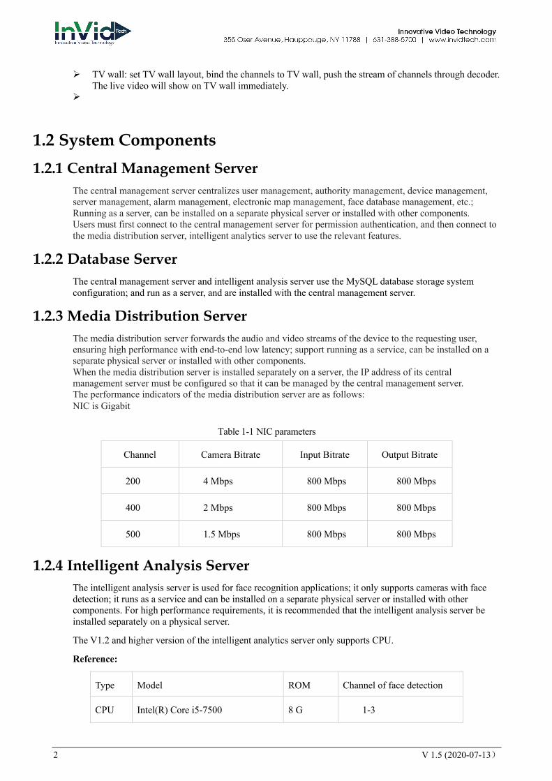
1.2.3 Media Distribution Server The media distribution server forwards the audio and video streams of the device to the requesting user, ensuring high performance with end-to-end low latency; support running as a service, can be installed on a separate physical server or installed with other components. When the media distribution server is installed separately on a server, the IP address of its central management server must be configured so that it can be managed by the central management server. The performance indicators of the media distribution server are as follows: NIC is Gigabit
Table 1-1 NIC parameters
Channel Camera Bitrate Input Bitrate Output Bitrate
200 4 Mbps 800 Mbps 800 Mbps
400 2 Mbps 800 Mbps 800 Mbps
500 1.5 Mbps 800 Mbps 800 Mbps
1.2.4 Intelligent Analysis Server The intelligent analysis server is used for face recognition applications; it only supports cameras with face detection; it runs as a service and can be installed on a separate physical server or installed with other components. For high performance requirements, it is recommended that the intelligent analysis server be installed separately on a physical server.
The V1.2 and higher version of the intelligent analytics server only supports CPU.
Reference:
Type Model ROM Channel of face detection
CPU Intel(R) Core i5-7500 8 G 1-3

V 1.5 (2020-07-13) 3
CPU Intel(R) Core i7-8700 8 G 2-8
CPU Intel(R) Xeon(R) cpu E5-2630 v4 16 G 4-10
Face-box
Intel(R) Core i5-8500
Face-box *4
8G 6-12
In the same configuration, the fewer the access cameras, the higher quality of real-time video, the denser the flow of people (human faces), the worse quality of real-time video, and can be adjusted according to actual needs. This is only a reference, please refer to actual configure.
1.2.4.1 Server Management Tool The server management tool is used to manage the platform server components, which exclude the client; displaying the running status of the component, it can also control the startup, stop, and delete the component; you can manually add the service. If the service component does not start normally, it will flash a reminder in the system tray to find the problem in time. The tool will launch as soon as the installation is successful. As shown in figure 1-1.
Server Management UI
Configuration:configure the servers(IAU and MDU) are associated with the corresponding the CMU server.
Export log: export the logs of servers to local folder.
4 V 1.5 (2020-07-13)
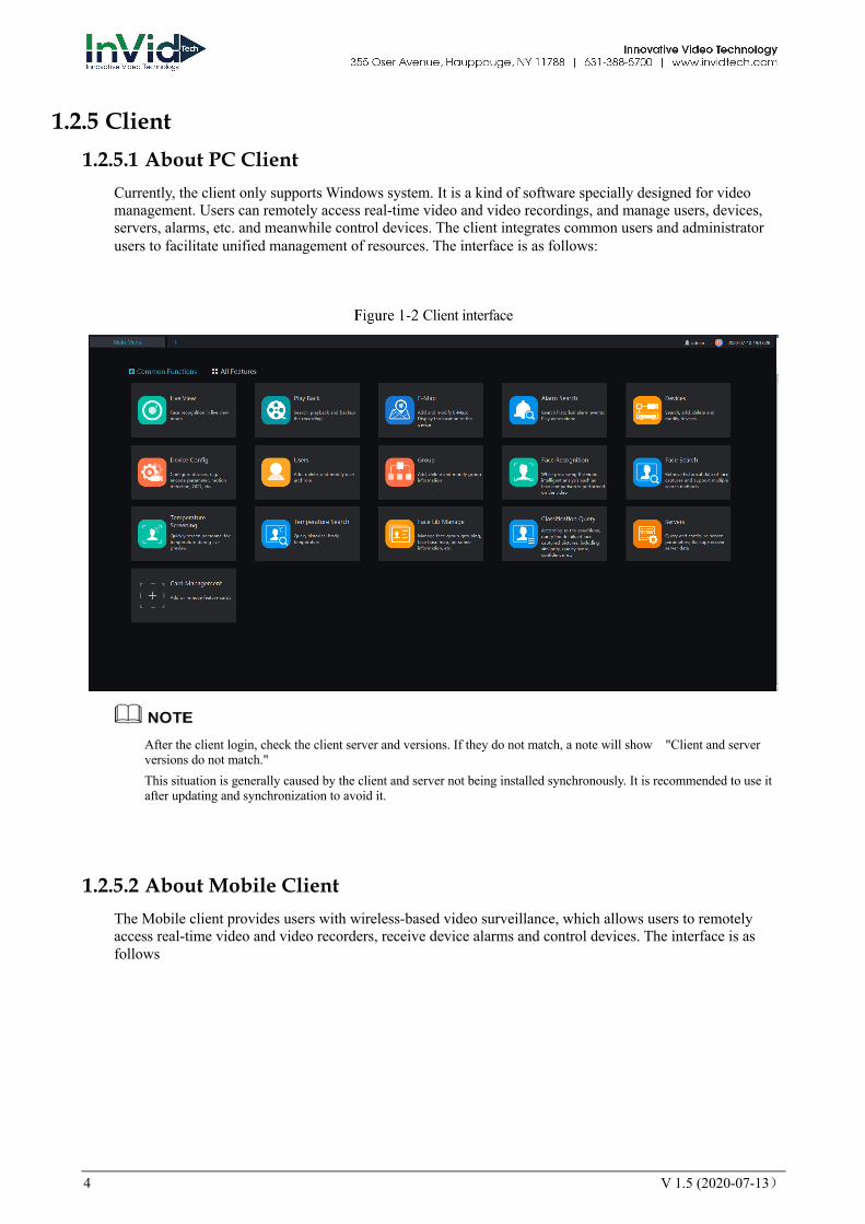
1.2.5 Client 1.2.5.1 About PC Client
Currently, the client only supports Windows system. It is a kind of software specially designed for video management. Users can remotely access real-time video and video recordings, and manage users, devices, servers, alarms, etc. and meanwhile control devices. The client integrates common users and administrator users to facilitate unified management of resources. The interface is as follows:
Client interface
After the client login, check the client server and versions. If they do not match, a note will show "Client and server versions do not match." This situation is generally caused by the client and server not being installed synchronously. It is recommended to use it after updating and synchronization to avoid it.
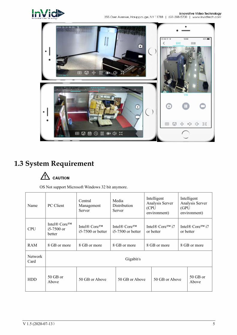
1.2.5.2 About Mobile Client The Mobile client provides users with wireless-based video surveillance, which allows users to remotely access real-time video and video recorders, receive device alarms and control devices. The interface is as follows
V 1.5 (2020-07-13) 5
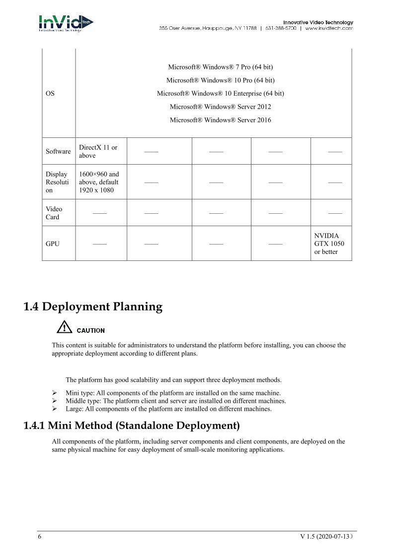
1.3 System Requirement
OS Not support Microsoft Windows 32 bit anymore.
Name PC Client Central Management Server
Media Distribution Server
Intelligent Analysis Server (CPU environment)
Intelligent Analysis Server (GPU environment)
CPU Intel® Core™ i5-7500 or better
Intel® Core™ i5-7500 or better
Intel® Core™ i5-7500 or better
Intel® Core™ i7 or better
Intel® Core™ i7 or better
RAM 8 GB or more 8 GB or more 8 GB or more 8 GB or more 8 GB or more
Network Card Gigabit/s
HDD 50 GB or Above 50 GB or Above 50 GB or Above 50 GB or Above 50 GB or
Above
6 V 1.5 (2020-07-13)
OS
Microsoft® Windows® 7 Pro (64 bit)
Microsoft® Windows® 10 Pro (64 bit)
Microsoft® Windows® 10 Enterprise (64 bit)
Microsoft® Windows® Server 2012
Microsoft® Windows® Server 2016
Software DirectX 11 or above —— —— —— ——
Display Resolution
1600×960 and above, default 1920 x 1080
—— —— —— ——
Video Card —— —— —— —— ——
GPU —— —— —— —— NVIDIA GTX 1050 or better
1.4 Deployment Planning
This content is suitable for administrators to understand the platform before installing, you can choose the appropriate deployment according to different plans.
The platform has good scalability and can support three deployment methods.
Ø Mini type: All components of the platform are installed on the same machine. Ø Middle type: The platform client and server are installed on different machines. Ø Large: All components of the platform are installed on different machines.
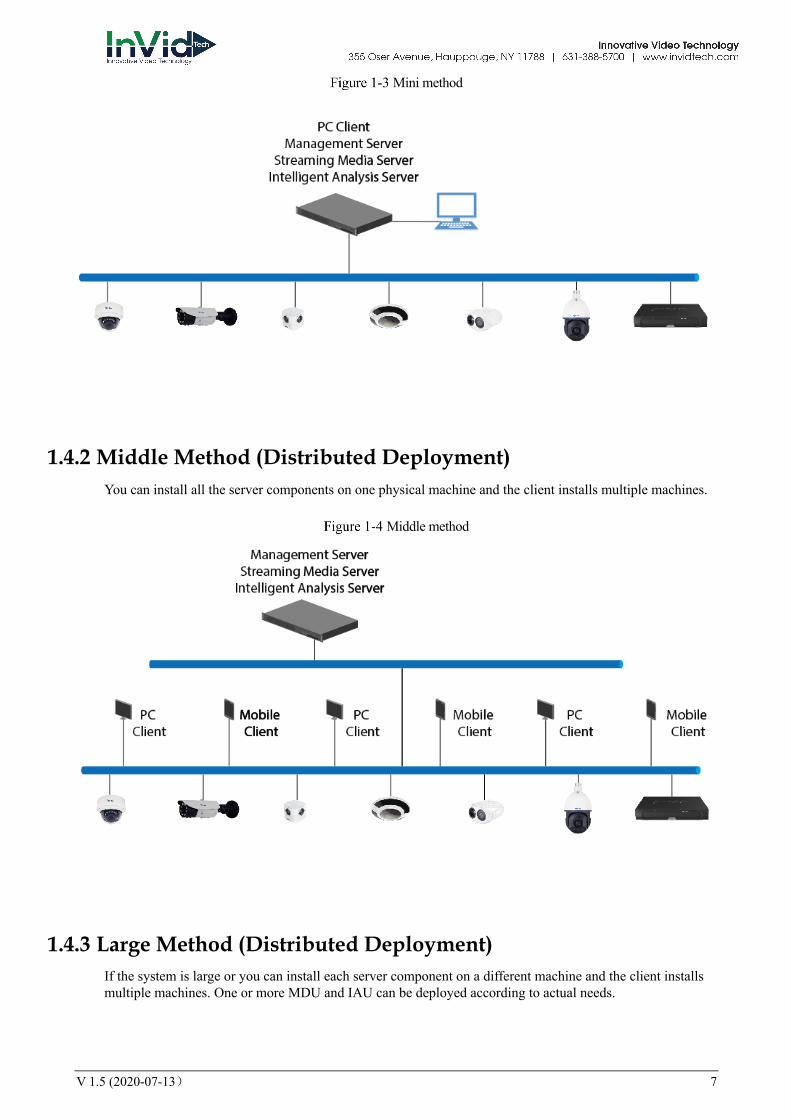
1.4.1 Mini Method (Standalone Deployment) All components of the platform, including server components and client components, are deployed on the same physical machine for easy deployment of small-scale monitoring applications.
V 1.5 (2020-07-13) 7
Mini method
1.4.2 Middle Method (Distributed Deployment) You can install all the server components on one physical machine and the client installs multiple machines.
Middle method
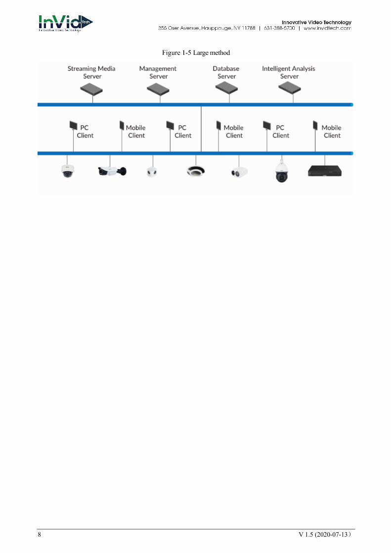
1.4.3 Large Method (Distributed Deployment) If the system is large or you can install each server component on a different machine and the client installs multiple machines. One or more MDU and IAU can be deployed according to actual needs.
8 V 1.5 (2020-07-13)
Large method

V 1.5 (2020-07-13) 9
2 Installation
2.1 One-Click Installation One-click installation is a simplified installation of the Mini type, and the installation process does not require any configuration. The platform is quickly installed on a single machine and is installed by default in the system disk C:\Program Files (x86)\CMS directory. After installation, the server component and client program are automatically started.
One click installation
2.2 Custom Installation Custom installation supports flexible installation. You can choose three installation methods, which correspond to the three deployment modes of the platform. The way is as follows:
Ø Mini method: All components of the platform can be installed on a single machine; it is similar to “one click installation”.
10 V 1.5 (2020-07-13)
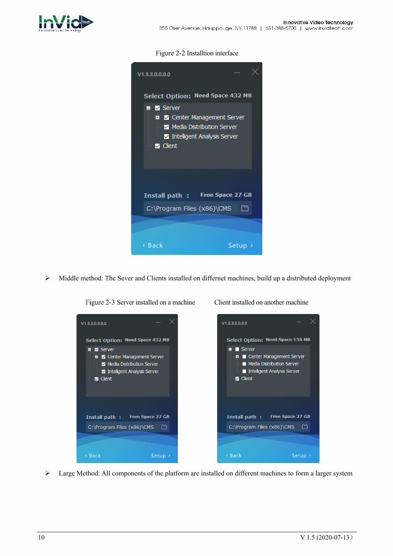
Installtion interface
Ø Middle method: The Sever and Clients installed on differnet machines, build up a distributed deployment
Server installed on a machine Client installed on another machine
Ø Large Method: All components of the platform are installed on different machines to form a larger system
V 1.5 (2020-07-13) 11
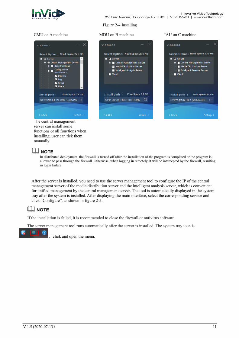
Installing
CMU on A machine
The central management server can install some functions or all functions when installing, user can tick them manually.
MDU on B machine
IAU on C machine
In distributed deployment, the firewall is turned off after the installation of the program is completed or the program is allowed to pass through the firewall. Otherwise, when logging in remotely, it will be intercepted by the firewall, resulting in login failure.
After the server is installed, you need to use the server management tool to configure the IP of the central management server of the media distribution server and the intelligent analysis server, which is convenient for unified management by the central management server. The tool is automatically displayed in the system tray after the system is installed. After displaying the main interface, select the corresponding service and click “Configure”, as shown in figure 2-5.
If the installation is failed, it is recommended to close the firewall or antivirus software.
The server management tool runs automatically after the server is installed. The system tray icon is
,click and open the menu.
12 V 1.5 (2020-07-13)
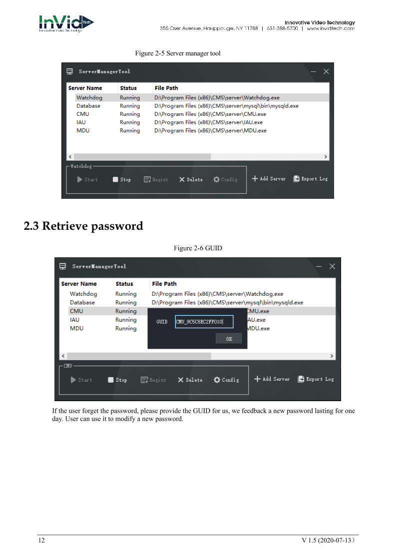
Server manager tool
2.3 Retrieve password
GUID
If the user forget the password, please provide the GUID for us, we feedback a new password lasting for one day. User can use it to modify a new password.

V 1.5 (2020-07-13) 13
3 Login Server installation is complete, double click on the desktop icon , input the user, password, and central management server IP, click "Login", the login interface is shown in figure 3-1
The default user name and password are both admin. You should modify after first login to make sure safety of system.
Login interface
14 V 1.5 (2020-07-13)
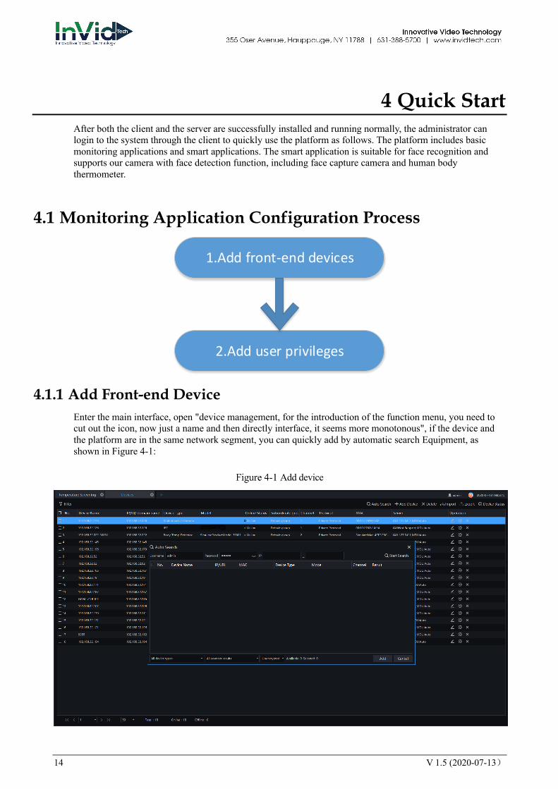
4 Quick Start After both the client and the server are successfully installed and running normally, the administrator can login to the system through the client to quickly use the platform as follows. The platform includes basic monitoring applications and smart applications. The smart application is suitable for face recognition and supports our camera with face detection function, including face capture camera and human body thermometer.
4.1 Monitoring Application Configuration Process
4.1.1 Add Front-end Device Enter the main interface, open "device management, for the introduction of the function menu, you need to cut out the icon, now just a name and then directly interface, it seems more monotonous", if the device and the platform are in the same network segment, you can quickly add by automatic search Equipment, as shown in Figure 4-1:
Add device
1.Add front-end devices
2.Add user privileges

V 1.5 (2020-07-13) 15
After selecting the device, click “Add” and the camera can assign the specified server. Figure as below:
4.1.2 Add User Permissions The system has administrator and operator roles by default. You can create users based on the default roles directly. You can assign menu permissions and channel permissions to users. As shown in Figure 4-2:
The monitoring application does not have to assign personnel file permissions, which is used for smart (face recognition) applications.
Add user
16 V 1.5 (2020-07-13)
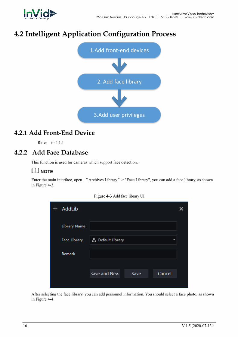
4.2 Intelligent Application Configuration Process
4.2.1 Add Front-End Device Refer to 4.1.1
4.2.2 Add Face Database This function is used for cameras which support face detection.
Enter the main interface, open “Archives Library”> "Face Library", you can add a face library, as shown in Figure 4-3.
Add face library UI
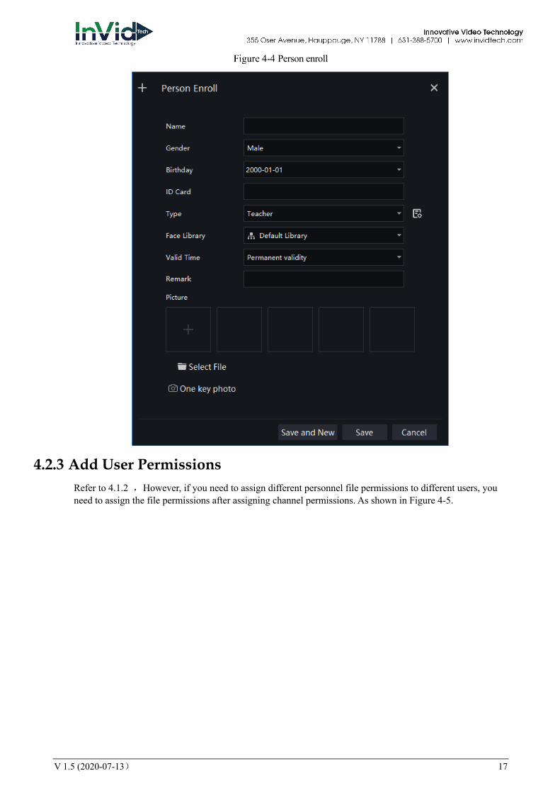
After selecting the face library, you can add personnel information. You should select a face photo, as shown in Figure 4-4
2. Add face library
1.Add front-end devices
3.Add user privileges
V 1.5 (2020-07-13) 17
Person enroll
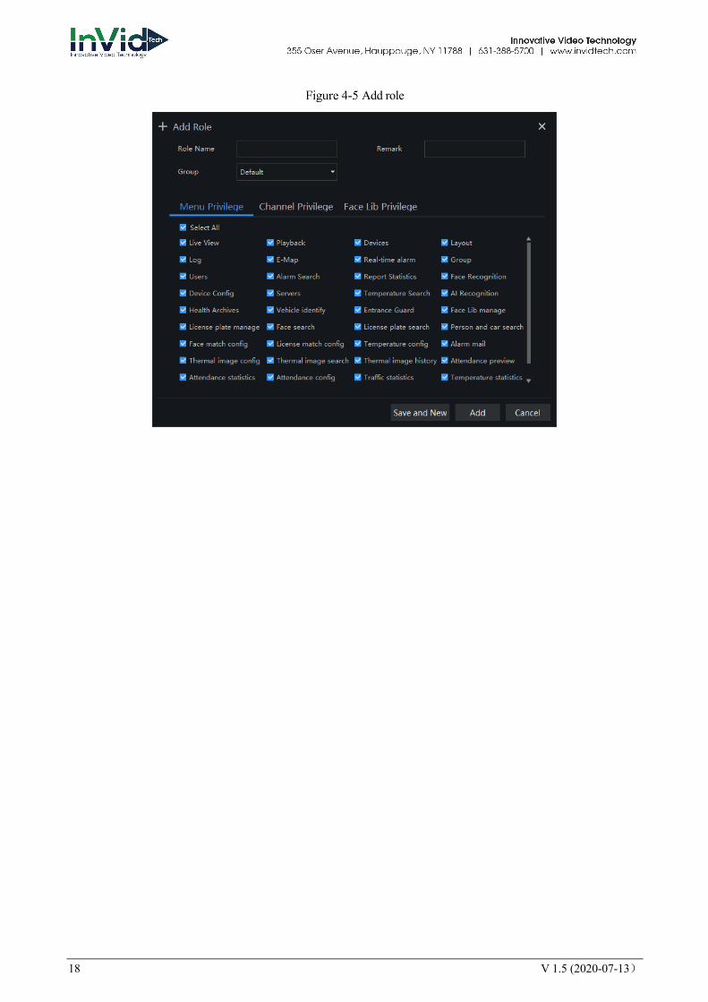
4.2.3 Add User Permissions Refer to 4.1.2 ,However, if you need to assign different personnel file permissions to different users, you need to assign the file permissions after assigning channel permissions. As shown in Figure 4-5.
18 V 1.5 (2020-07-13)
Add role
V 1.5 (2020-07-13) 19
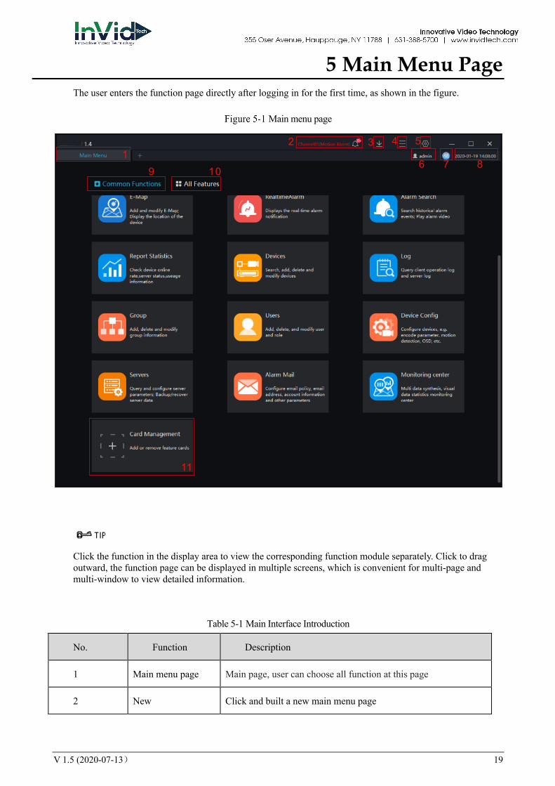
5 Main Menu Page The user enters the function page directly after logging in for the first time, as shown in the figure.
Main menu page
Click the function in the display area to view the corresponding function module separately. Click to drag outward, the function page can be displayed in multiple screens, which is convenient for multi-page and multi-window to view detailed information.
Table 5-1 Main Interface Introduction
No. Function Description
1 Main menu page Main page, user can choose all function at this page
2 New Click and built a new main menu page
12 3 4 5
6 7 89 10
11
20 V 1.5 (2020-07-13)
No. Function Description
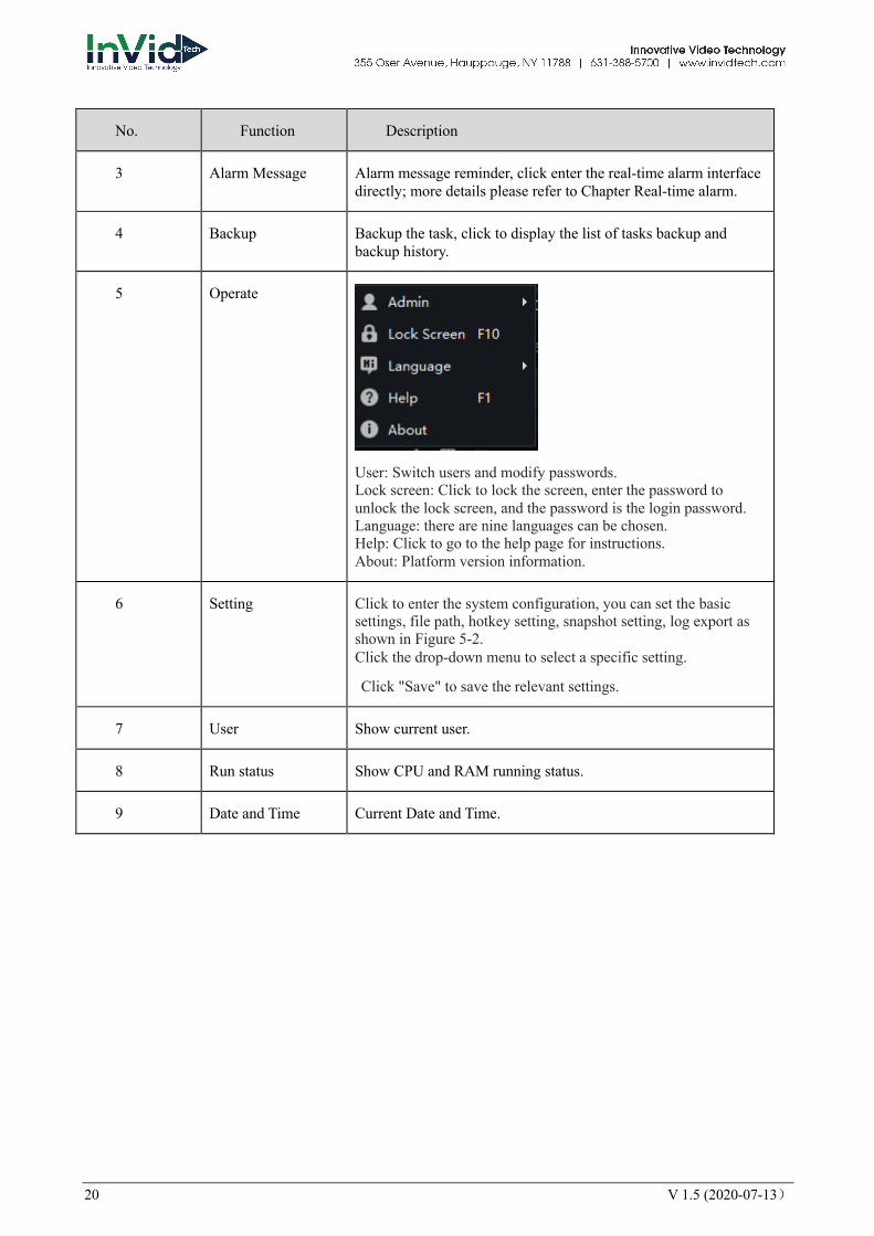
3 Alarm Message Alarm message reminder, click enter the real-time alarm interface directly; more details please refer to Chapter Real-time alarm.
4 Backup Backup the task, click to display the list of tasks backup and backup history.
5 Operate
User: Switch users and modify passwords. Lock screen: Click to lock the screen, enter the password to unlock the lock screen, and the password is the login password. Language: there are nine languages can be chosen. Help: Click to go to the help page for instructions. About: Platform version information.
6 Setting Click to enter the system configuration, you can set the basic settings, file path, hotkey setting, snapshot setting, log export as shown in Figure 5-2. Click the drop-down menu to select a specific setting.
Click "Save" to save the relevant settings.
7 User Show current user.
8 Run status Show CPU and RAM running status.
9 Date and Time Current Date and Time.
V 1.5 (2020-07-13) 21
No. Function Description
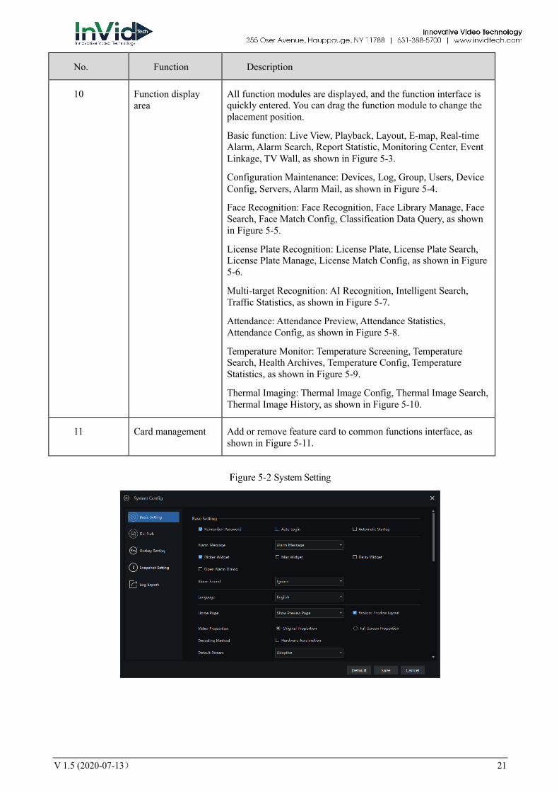
10 Function display area
All function modules are displayed, and the function interface is quickly entered. You can drag the function module to change the placement position.
Basic function: Live View, Playback, Layout, E-map, Real-time Alarm, Alarm Search, Report Statistic, Monitoring Center, Event Linkage, TV Wall, as shown in Figure 5-3.
Configuration Maintenance: Devices, Log, Group, Users, Device Config, Servers, Alarm Mail, as shown in Figure 5-4.
Face Recognition: Face Recognition, Face Library Manage, Face Search, Face Match Config, Classification Data Query, as shown in Figure 5-5.
License Plate Recognition: License Plate, License Plate Search, License Plate Manage, License Match Config, as shown in Figure 5-6.
Multi-target Recognition: AI Recognition, Intelligent Search, Traffic Statistics, as shown in Figure 5-7.
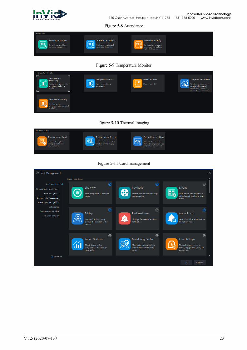
Attendance: Attendance Preview, Attendance Statistics, Attendance Config, as shown in Figure 5-8.
Temperature Monitor: Temperature Screening, Temperature Search, Health Archives, Temperature Config, Temperature Statistics, as shown in Figure 5-9.
Thermal Imaging: Thermal Image Config, Thermal Image Search, Thermal Image History, as shown in Figure 5-10.
11 Card management Add or remove feature card to common functions interface, as shown in Figure 5-11.
System Setting

22 V 1.5 (2020-07-13)
Basic Functions
Configuration Maintenance
Face Recognition
License Plate Recognition
Multi-target Recognition
V 1.5 (2020-07-13) 23
Attendance
Temperature Monitor
Thermal Imaging
Card management

24 V 1.5 (2020-07-13)
6 Basic Functions
6.1 Live view At live view interface, you can watch the real-time video , real-time cruise video, local video, set screenshot ,open the audio, start the voice intercom, zoom in the video, switch the code stream, save the layout, 3D positioning, and control the PTZ. The right-click menu can quickly set video parameters.
On the main menu page, click to enter detailed page, as shown in Figure 6-1
Support opening up to maximum 4 live view windows simultaneously, and can use mouse to drag out, convenient for multiple screens display synchronously.
Live view UI
Table 6-1 Live view
No. Function Description
1 Layout Video display format, add the layout.
2 Operation Set dome device PTZ/ Image parameter.
1
2
3 4 5
V 1.5 (2020-07-13) 25
No. Function Description
3 Video display layout
Start the cruise, save the current layout, single screen, four screens, support maximum 64 screens
4 Operation Set dome device PTZ/ Image parameter.
5 Full screen Full screen
6.1.1 Layout “Layout function interface” can be used to add layout to bind the channel and window, enter “Function preview interface” click layout list , the complete layout list will be shown, double click a layout name , real-time videos of all the channels in this layout will be displayed.
6.1.2 Device Display the device list under current user account, users can watch the real-time video by double clicking or dragging and dropping the mouse at online channel.
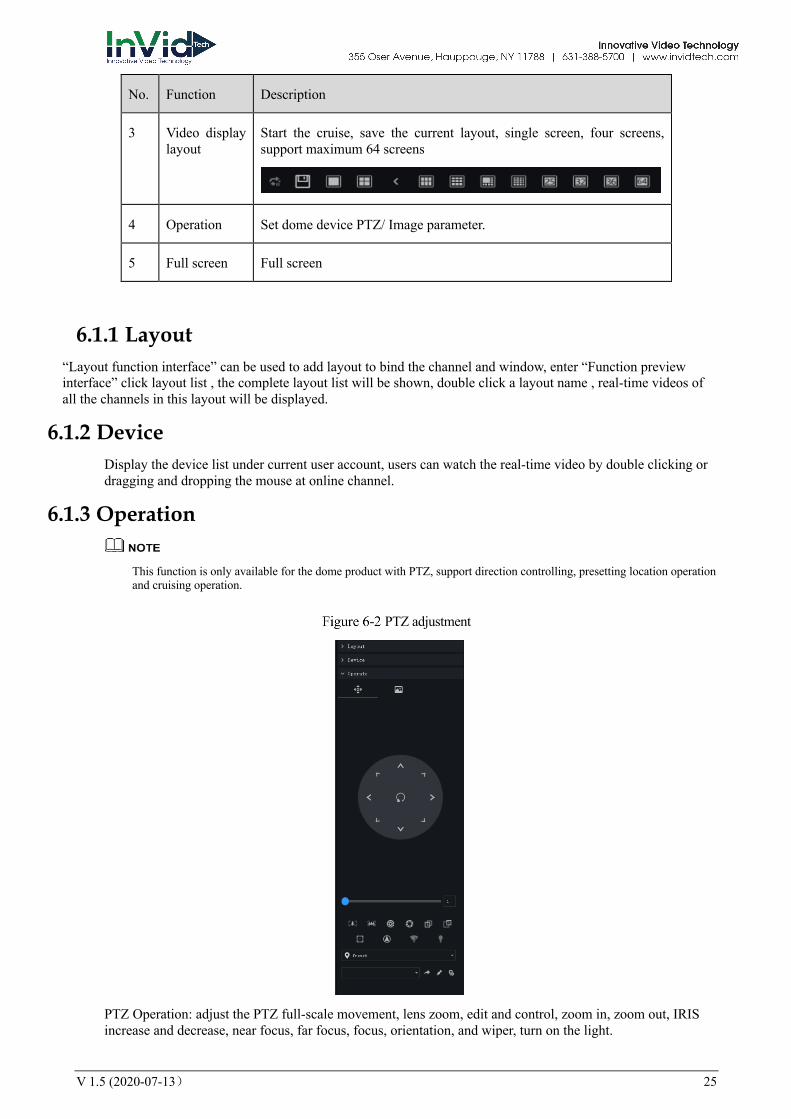
6.1.3 Operation
This function is only available for the dome product with PTZ, support direction controlling, presetting location operation and cruising operation.
PTZ adjustment
PTZ Operation: adjust the PTZ full-scale movement, lens zoom, edit and control, zoom in, zoom out, IRIS increase and decrease, near focus, far focus, focus, orientation, and wiper, turn on the light.

26 V 1.5 (2020-07-13)
Cruise: cycle the preset positions according the order.
Preset position: set the preset position name and set the current position as the preset position to facilitate the cruise operation.
Image operation: adjust image brightness, sharpness, saturation and contrast. The default values are all 50. Focus is changed by dragging the right side of the slider or clicking the left and right axes to change the value, the range is 0-100.
Image adjustment

V 1.5 (2020-07-13) 27
6.2 Playback At the playback function interface, the video from the front-end device can be played back and backed up, support multiple channels synchronous playback, support playback control operations.
On the main menu page, click to enter the detailed page, as shown in Figure 6-4
Playback interface
Table 6-1 Playback
No. Function Description
1 Device Show devices on the platform as organizational structure
2 Calendar Display date, there is a green bar below the date to indicate that there is a recording on this date.
Positioning can manually enter the time and position.
3 Operation Close or open the calendar/ Video grid
1
2
3 4

28 V 1.5 (2020-07-13)
No. Function Description
4 Toolbar operation Video operation: operation, timeline, display. For example
,Rewind
, Pause/Play
, Stop
, Next frame
, Backward 30s/ Forward 30s
, Several fold speed slow release, fast release
, Layout display
, Full screen
, Download back up device video, specific steps please refer to chapter 9.3
, Bath backup, choose multiple channels to backup the video.
, Select progress bar format
V 1.5 (2020-07-13) 29
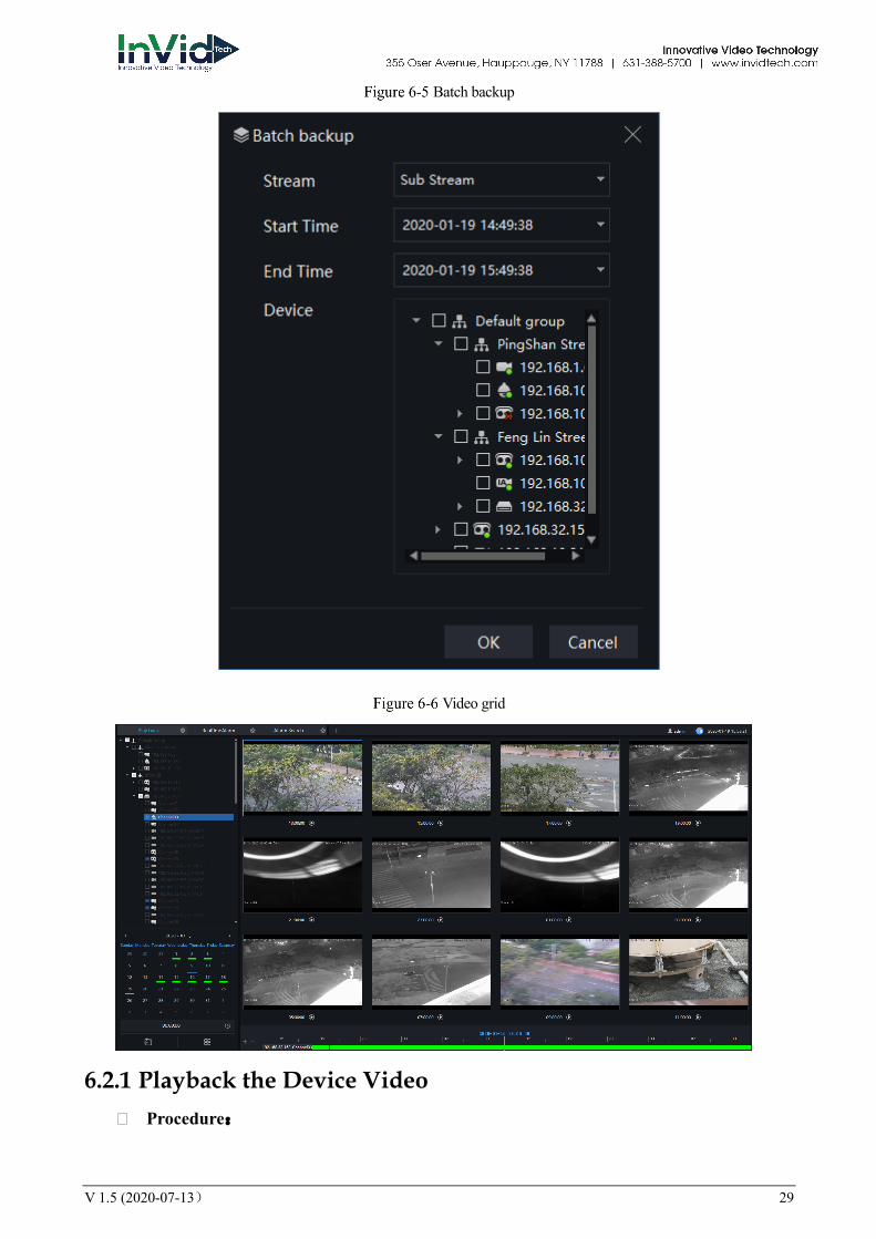
Batch backup
Video grid
6.2.1 Playback the Device Video � Procedure:

30 V 1.5 (2020-07-13)
Step 1 Select display layout mode, support multiple devices synchronous playback
Step 2 Select the device in the device list that needs to be played back, video at the current time will be automatically queried and played back
Step 3 Select the way as shown in the picture on the timeline ,can play back the video by selecting different progress bar formats.
Step 4 Select the operation tool in the toolbar to watch the video playback according to one’s needs.
6.2.2 Back up the Device Video Procedure:
Step 1 Click , the video starts to back up, the icon shows, drag the time scale can copy the video quickly, download the video with MP4 format.
Step 2 Click the checkmark to complete the selection and copy of the video, and jump to the download interface as shown in Figure 6-7
Download interface
Step 3 Click "Downloaded" on the top right corner of interface to view the start and end time of the downloaded video, and the store path.
File path
V 1.5 (2020-07-13) 31
6.3 Real-Time Alarm At the interface of real-time alarm, alarm information from the front-end equipment in real-time could be received, and enable to handle single or batch of alarms.
On the main menu page, please click to enter the detailed interface, as shown in Figure 6-9
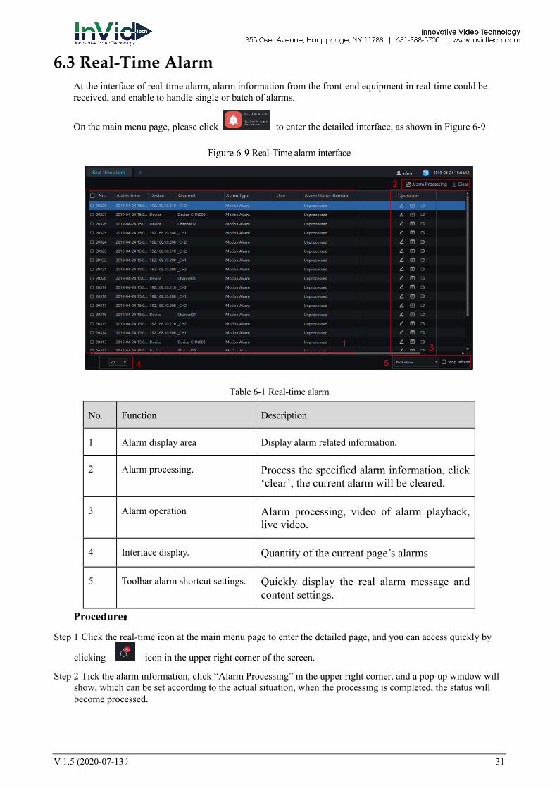
Real-Time alarm interface
Table 6-1 Real-time alarm
No. Function Description
1 Alarm display area Display alarm related information.
2 Alarm processing. Process the specified alarm information, click ‘clear’, the current alarm will be cleared.
3 Alarm operation Alarm processing, video of alarm playback, live video.
4 Interface display. Quantity of the current page’s alarms
5 Toolbar alarm shortcut settings. Quickly display the real alarm message and content settings.
Procedure:
Step 1 Click the real-time icon at the main menu page to enter the detailed page, and you can access quickly by
clicking icon in the upper right corner of the screen.
Step 2 Tick the alarm information, click “Alarm Processing” in the upper right corner, and a pop-up window will show, which can be set according to the actual situation, when the processing is completed, the status will become processed.
1
2
3
4 5
32 V 1.5 (2020-07-13)
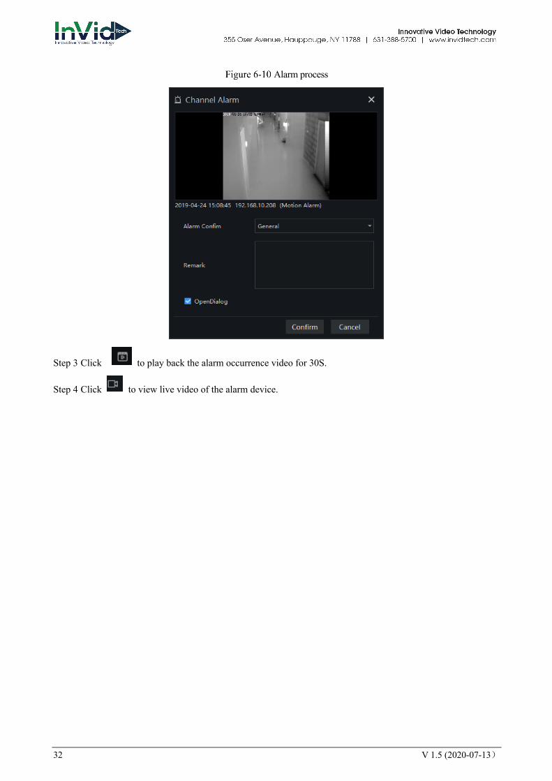
Alarm process
Step 3 Click to play back the alarm occurrence video for 30S.
Step 4 Click to view live video of the alarm device.
V 1.5 (2020-07-13) 33
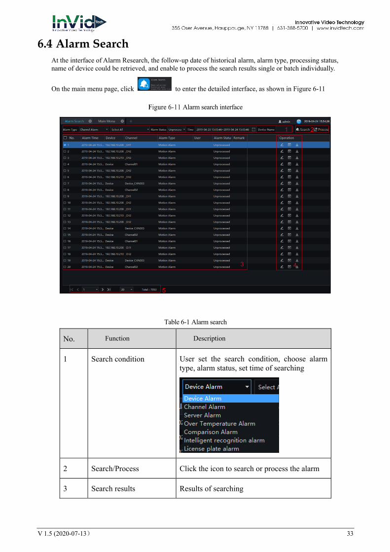
6.4 Alarm Search At the interface of Alarm Research, the follow-up date of historical alarm, alarm type, processing status, name of device could be retrieved, and enable to process the search results single or batch individually.
On the main menu page, click to enter the detailed interface, as shown in Figure 6-11
Alarm search interface
Table 6-1 Alarm search
No. Function Description
1 Search condition User set the search condition, choose alarm type, alarm status, set time of searching
2 Search/Process Click the icon to search or process the alarm
3 Search results Results of searching
3
1 2
4
5
34 V 1.5 (2020-07-13)
No. Function Description
4 Operation Edit, playback, process, backup task
5 Interface display Show the current page of the alarm, and the page displays the number of alarms, switch to next page to show alarm information
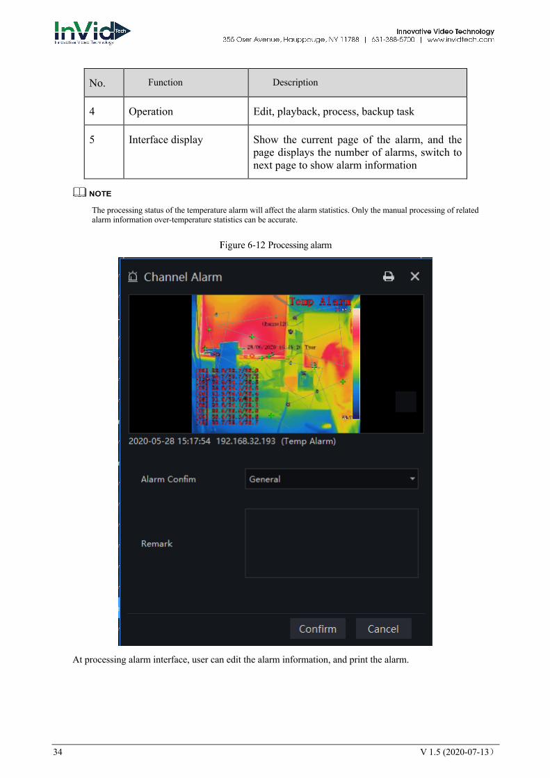
The processing status of the temperature alarm will affect the alarm statistics. Only the manual processing of related alarm information over-temperature statistics can be accurate.
Processing alarm
At processing alarm interface, user can edit the alarm information, and print the alarm.
V 1.5 (2020-07-13) 35
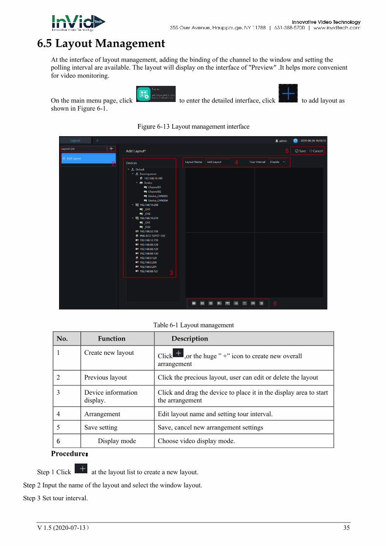
6.5 Layout Management At the interface of layout management, adding the binding of the channel to the window and setting the polling interval are available. The layout will display on the interface of "Preview" .It helps more convenient for video monitoring.
On the main menu page, click to enter the detailed interface, click to add layout as shown in Figure 6-1.
Layout management interface
Table 6-1 Layout management
No. Function Description
1 Create new layout Click ,or the huge ” +” icon to create new overall arrangement
2 Previous layout Click the precious layout, user can edit or delete the layout
3 Device information display.
Click and drag the device to place it in the display area to start the arrangement
4 Arrangement Edit layout name and setting tour interval.
5 Save setting Save, cancel new arrangement settings
6 Display mode Choose video display mode.
Procedure:
Click at the layout list to create a new layout.
Input the name of the layout and select the window layout.
Set tour interval.
1
2
3
4
5
6
36 V 1.5 (2020-07-13)
Choose and hold the mouse to set the channel to display at layout window, you could bind multiple channels at the same window and enable tour interval, so that users view several cameras.
Click "Save" to save settings.
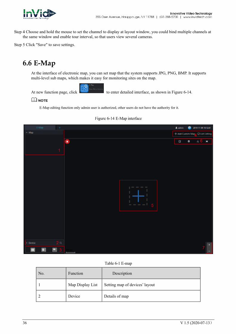
6.6 E-Map At the interface of electronic map, you can set map that the system supports JPG, PNG, BMP. It supports multi-level sub maps, which makes it easy for monitoring sites on the map.
At new function page, click to enter detailed interface, as shown in Figure 6-14.
E-Map editing function only admin user is authorized, other users do not have the authority for it.
E-Map interface
Table 6-1 E-map
No. Function Description
1 Map Display List Setting map of devices’ layout
2 Device Details of map
1
23
4
5
6
7
V 1.5 (2020-07-13) 37
No. Function Description
3 Video Display Map and layout of video display
4 Add map Add custom map, edit the maps
5 Zoom in/ zoom out
Zoom the map to set monitoring points
6 Operation of Map User can operate the devices of map.
7 Zoom in/zoom out
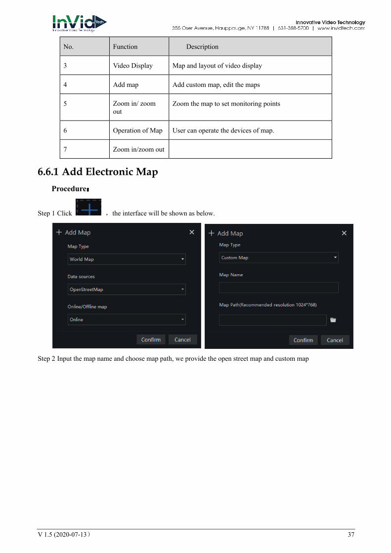
6.6.1 Add Electronic Map Procedure:
Step 1 Click ,the interface will be shown as below.
Step 2 Input the map name and choose map path, we provide the open street map and custom map
38 V 1.5 (2020-07-13)
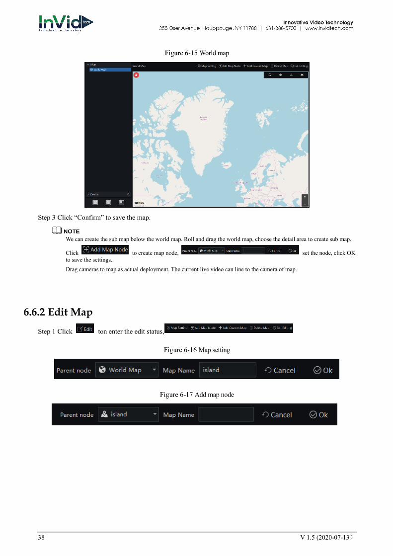
World map
Step 3 Click “Confirm” to save the map.
We can create the sub map below the world map. Roll and drag the world map, choose the detail area to create sub map.
Click to create map node, set the node, click OK to save the settings.. Drag cameras to map as actual deployment. The current live video can line to the camera of map.
6.6.2 Edit Map
Step 1 Click ton enter the edit status,
Map setting
Add map node

V 1.5 (2020-07-13) 39
Custom Map
Delete map
Step 2 Click to save the edit.
6.6.3 Deploy Monitoring Site Procedure:
Step 1 If cannot be edited, please click editing icon to switch to editable.
Step 2 Select the map for monitoring deployment
Step 3 Drag camera icon on the map with mouse, the monitoring direction and the size of area can also be controlled with mouse.
6.6.4 Quick Navigation
Step 1 Click at tar.
Step 2 Drag mouse to select the area, and the resulte shows on pop-up window, as shown in figure.
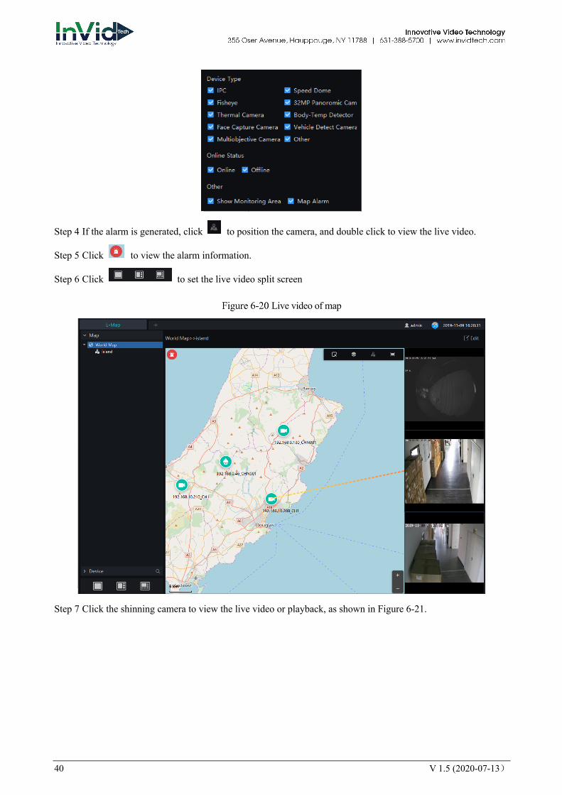
Step 3 Click to filter the devices.
40 V 1.5 (2020-07-13)
Step 4 If the alarm is generated, click to position the camera, and double click to view the live video.
Step 5 Click to view the alarm information.
Step 6 Click to set the live video split screen
Live video of map
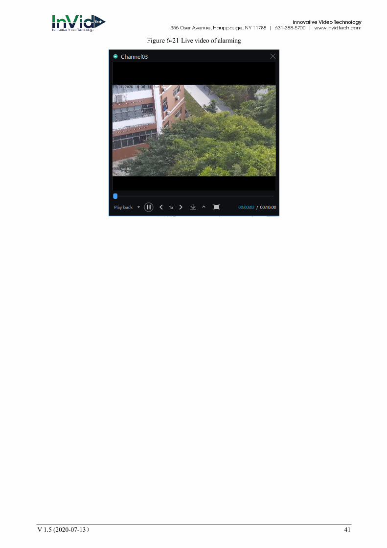
Step 7 Click the shinning camera to view the live video or playback, as shown in Figure 6-21.
V 1.5 (2020-07-13) 41
Live video of alarming
42 V 1.5 (2020-07-13)
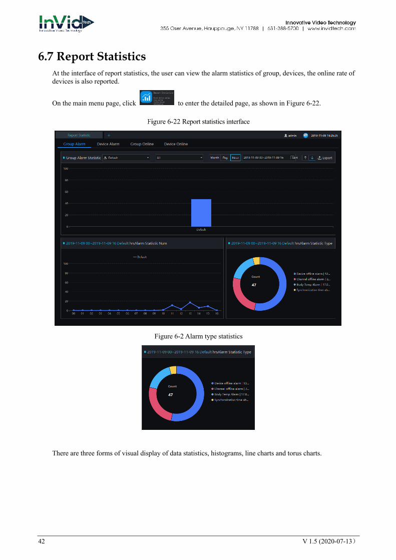
6.7 Report Statistics At the interface of report statistics, the user can view the alarm statistics of group, devices, the online rate of devices is also reported.
On the main menu page, click to enter the detailed page, as shown in Figure 6-22.
Report statistics interface
Figure 6-2 Alarm type statistics
There are three forms of visual display of data statistics, histograms, line charts and torus charts.
V 1.5 (2020-07-13) 43
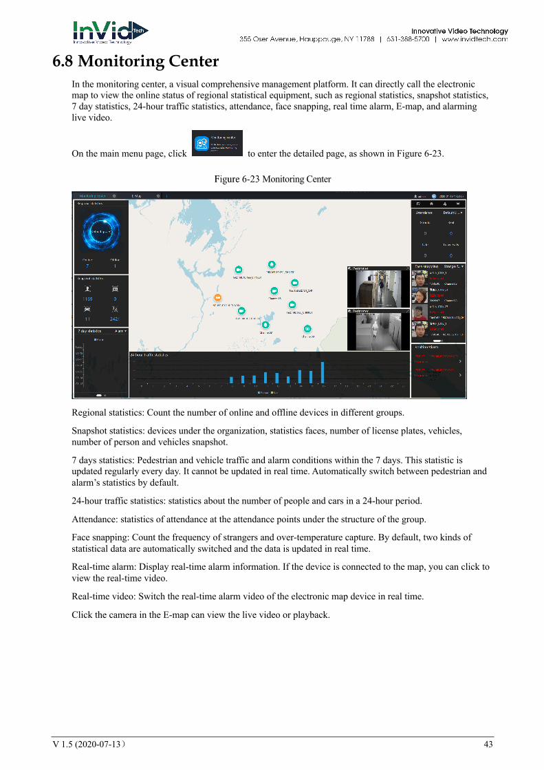
6.8 Monitoring Center In the monitoring center, a visual comprehensive management platform. It can directly call the electronic map to view the online status of regional statistical equipment, such as regional statistics, snapshot statistics, 7 day statistics, 24-hour traffic statistics, attendance, face snapping, real time alarm, E-map, and alarming live video.
On the main menu page, click to enter the detailed page, as shown in Figure 6-23.
Monitoring Center
Regional statistics: Count the number of online and offline devices in different groups.
Snapshot statistics: devices under the organization, statistics faces, number of license plates, vehicles, number of person and vehicles snapshot.
7 days statistics: Pedestrian and vehicle traffic and alarm conditions within the 7 days. This statistic is updated regularly every day. It cannot be updated in real time. Automatically switch between pedestrian and alarm’s statistics by default.
24-hour traffic statistics: statistics about the number of people and cars in a 24-hour period.
Attendance: statistics of attendance at the attendance points under the structure of the group.
Face snapping: Count the frequency of strangers and over-temperature capture. By default, two kinds of statistical data are automatically switched and the data is updated in real time.
Real-time alarm: Display real-time alarm information. If the device is connected to the map, you can click to view the real-time video.
Real-time video: Switch the real-time alarm video of the electronic map device in real time.
Click the camera in the E-map can view the live video or playback.

44 V 1.5 (2020-07-13)
6.9 Alarm Linkage User can set the alarm linkage action at alarm linkage interface, such as send E-mail, PTZ, IO output, as shown in Figure 6-24.
Alarm Linkage
Click to add the new event linkage strategy.
Enable the strategy, set the name of strategy.
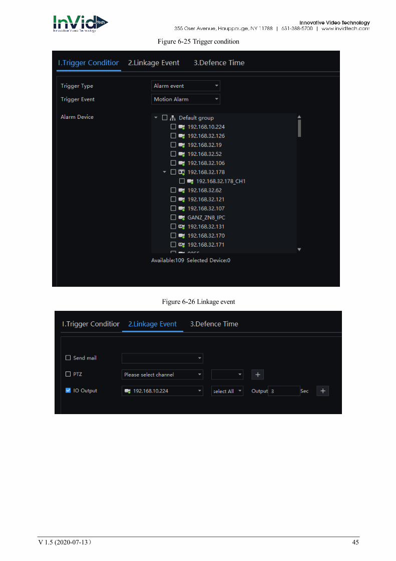
Choose trigger type( alarm event or timing), as shown in Figure 6-25.
Timing, user need to set trigger time or tick repeat.
Alarm event, user need to choose event and alarm devices, as shown in Figure 6-26.
Click “Next” to set linkage event, choose one or more to alarm, as shown in Figure 6-27.
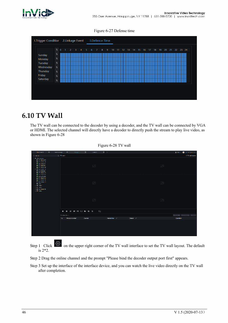
Click “Next” to set defense time.
Click “ Apply” to save the setting.
V 1.5 (2020-07-13) 45
Trigger condition
Linkage event
46 V 1.5 (2020-07-13)
Defense time
6.10 TV Wall The TV wall can be connected to the decoder by using a decoder, and the TV wall can be connected by VGA or HDMI. The selected channel will directly have a decoder to directly push the stream to play live video, as shown in Figure 6-28
TV wall
Click on the upper right corner of the TV wall interface to set the TV wall layout. The default is 2*2.
Drag the online channel and the prompt "Please bind the decoder output port first" appears.
Set up the interface of the interface device, and you can watch the live video directly on the TV wall after completion.
V 1.5 (2020-07-13) 47
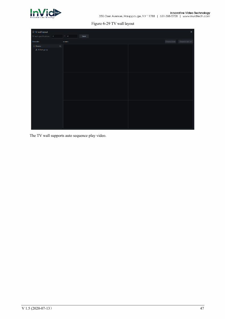
TV wall layout
The TV wall supports auto sequence play video.
48 V 1.5 (2020-07-13)
7 Configuration Maintenance
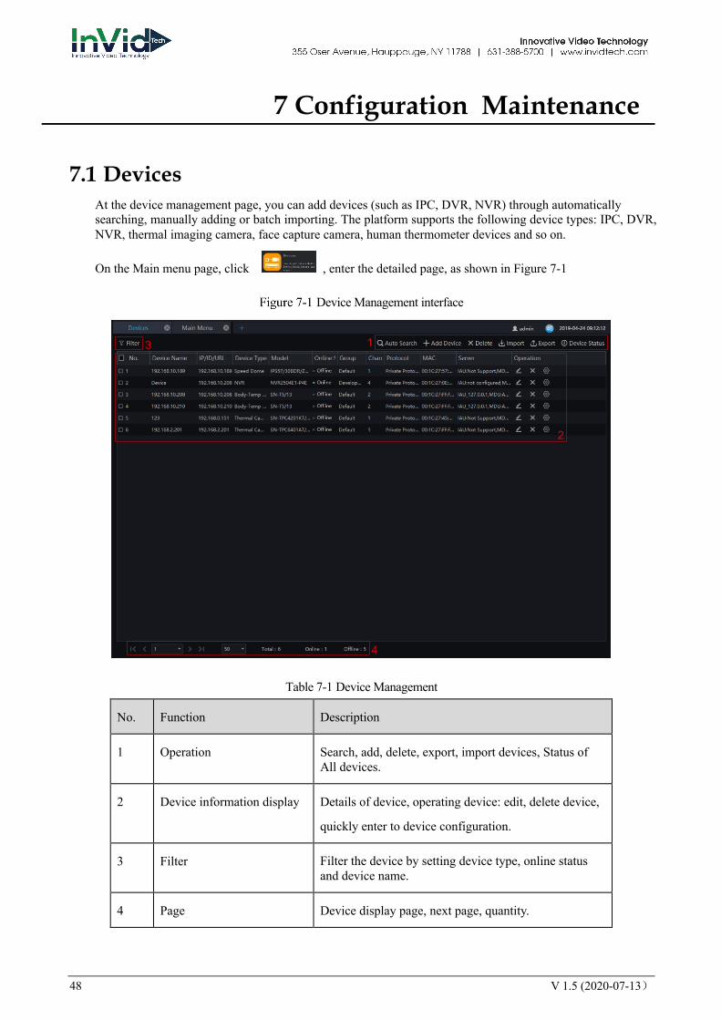
7.1 Devices At the device management page, you can add devices (such as IPC, DVR, NVR) through automatically searching, manually adding or batch importing. The platform supports the following device types: IPC, DVR, NVR, thermal imaging camera, face capture camera, human thermometer devices and so on.
On the Main menu page, click , enter the detailed page, as shown in Figure 7-1
Device Management interface
Table 7-1 Device Management
No. Function Description
1 Operation Search, add, delete, export, import devices, Status of All devices.
2 Device information display Details of device, operating device: edit, delete device,
quickly enter to device configuration.
3 Filter Filter the device by setting device type, online status and device name.
4 Page Device display page, next page, quantity.
1
2
3
4
V 1.5 (2020-07-13) 49
7.1.1 Auto Search The device and the server are on the same network segment.
Procedure:
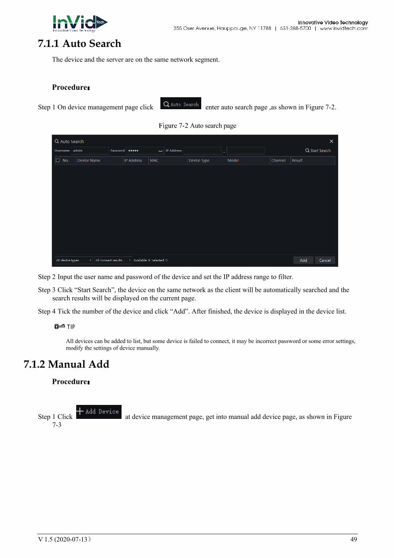
Step 1 On device management page click enter auto search page ,as shown in Figure 7-2.
Auto search page
Step 2 Input the user name and password of the device and set the IP address range to filter.
Step 3 Click “Start Search”, the device on the same network as the client will be automatically searched and the search results will be displayed on the current page.
Step 4 Tick the number of the device and click “Add”. After finished, the device is displayed in the device list.
All devices can be added to list, but some device is failed to connect, it may be incorrect password or some error settings, modify the settings of device manually.
7.1.2 Manual Add Procedure:
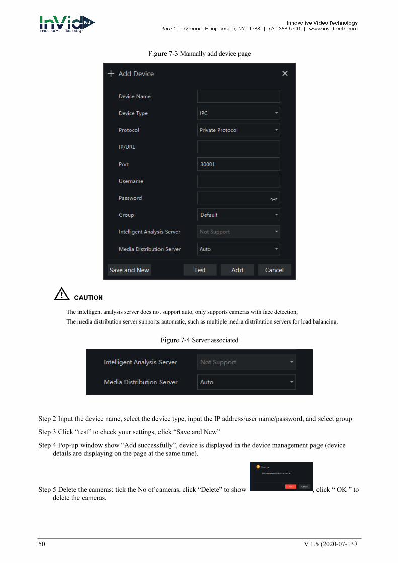
Step 1 Click at device management page, get into manual add device page, as shown in Figure 7-3
50 V 1.5 (2020-07-13)
Manually add device page
The intelligent analysis server does not support auto, only supports cameras with face detection; The media distribution server supports automatic, such as multiple media distribution servers for load balancing.
Server associated
Step 2 Input the device name, select the device type, input the IP address/user name/password, and select group
Step 3 Click “test” to check your settings, click “Save and New”
Step 4 Pop-up window show “Add successfully”, device is displayed in the device management page (device details are displaying on the page at the same time).
Step 5 Delete the cameras: tick the No of cameras, click “Delete” to show , click “ OK ” to delete the cameras.

V 1.5 (2020-07-13) 51
7.1.3 Export and Import Device Procedure:
Step 1 Click “Export”.
Step 2 Click “Export Template”, edit information at template page.
Step 3 Click “Import”.
Step 4 Select files to be imported , click “Save” , import device successfully.
--End
7.1.4 Device Status Procedure:
Step 1 Click “Device Status”.
Step 2 The pop-up window show the status of devices as shown in Figure 7-5.
Device Status
Step 3 Click “Export”.
Step 4 Set the save folder to save the status log.
--End

52 V 1.5 (2020-07-13)
7.2 Device Configuration At the interface of device configuration, you can view and set the parameter of the front-end device, such as bit rate parameters, motion detection parameters, OSD parameters, image parameters, thermal parameters, etc. For more devices configuration, click on "Link Web" to enter the device.
The configuration function is related to the firmware version of the device. Please refer to the actual situation.
On the main menu page, click to enter the detailed page, as shown in Figure 7-6.
Device configuration interface
Table 7-1 Device configuration
No. Function Description
1 Organization structure Show organizational structure information
2 Basic Information Show basic information
3 Edit / Device upgrade/ Link Web
Edit : edit the device information
Device upgrade: click to upgrade the device immediately.
Link web: user can login to the device’s web directly.
4 Device configuration information
Show and set the device configuration information, click “Apply” to save the information.
1
2
3
4

V 1.5 (2020-07-13) 53
7.3 Group For surveillance of a certain scale, an group tree can be created to run a hierarchical management on devices, the system default setting is a root group which supports 6 layers.
On the main menu page, click to enter detailed page, as shown in Figure 7-7
Organization interface
Table 7-1 Organization
No. Function Description
1 Group Display group tree, new group can be added by clicking
2 Basic Information Display basic information of device or group
3 Edit Basic information can be edited by clicking “Edit”
4 Display area of user or device
Display information of user or device
7.3.1 Add Group Procedure:
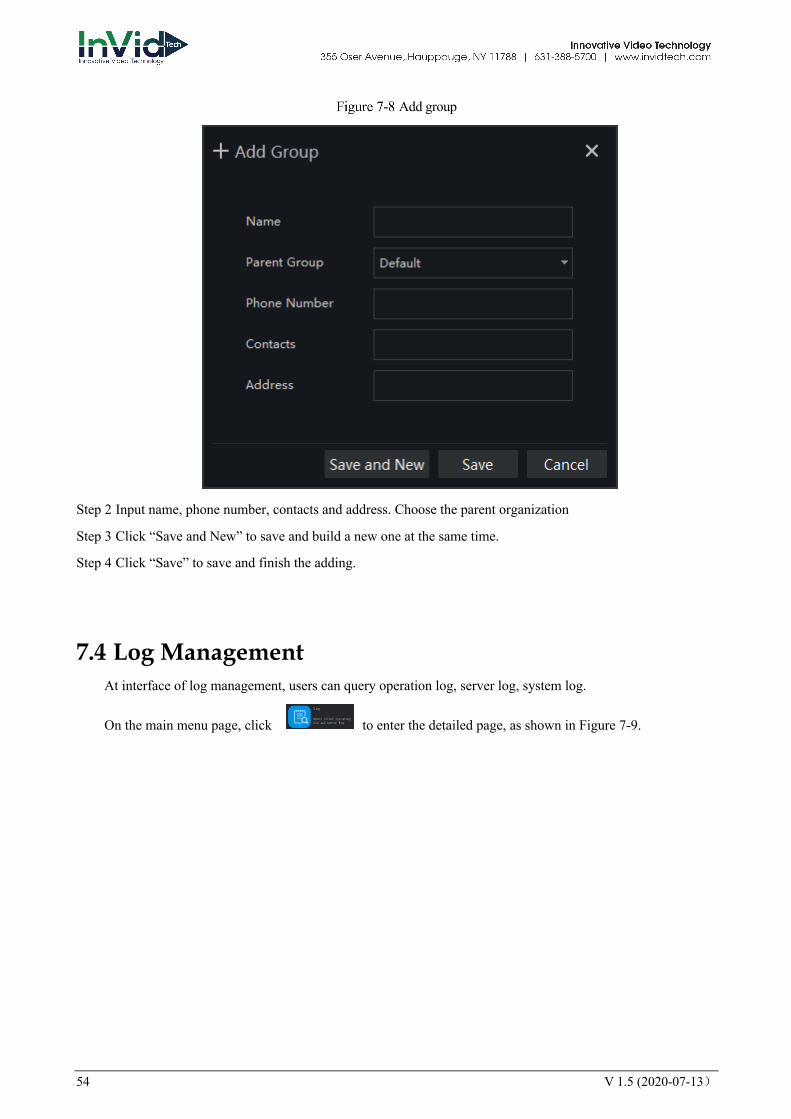
Step 1 Click the add icon to add a new group. The screen shows as Figure 7-8 .
12
3
4
54 V 1.5 (2020-07-13)
Add group
Step 2 Input name, phone number, contacts and address. Choose the parent organization
Step 3 Click “Save and New” to save and build a new one at the same time.
Step 4 Click “Save” to save and finish the adding.
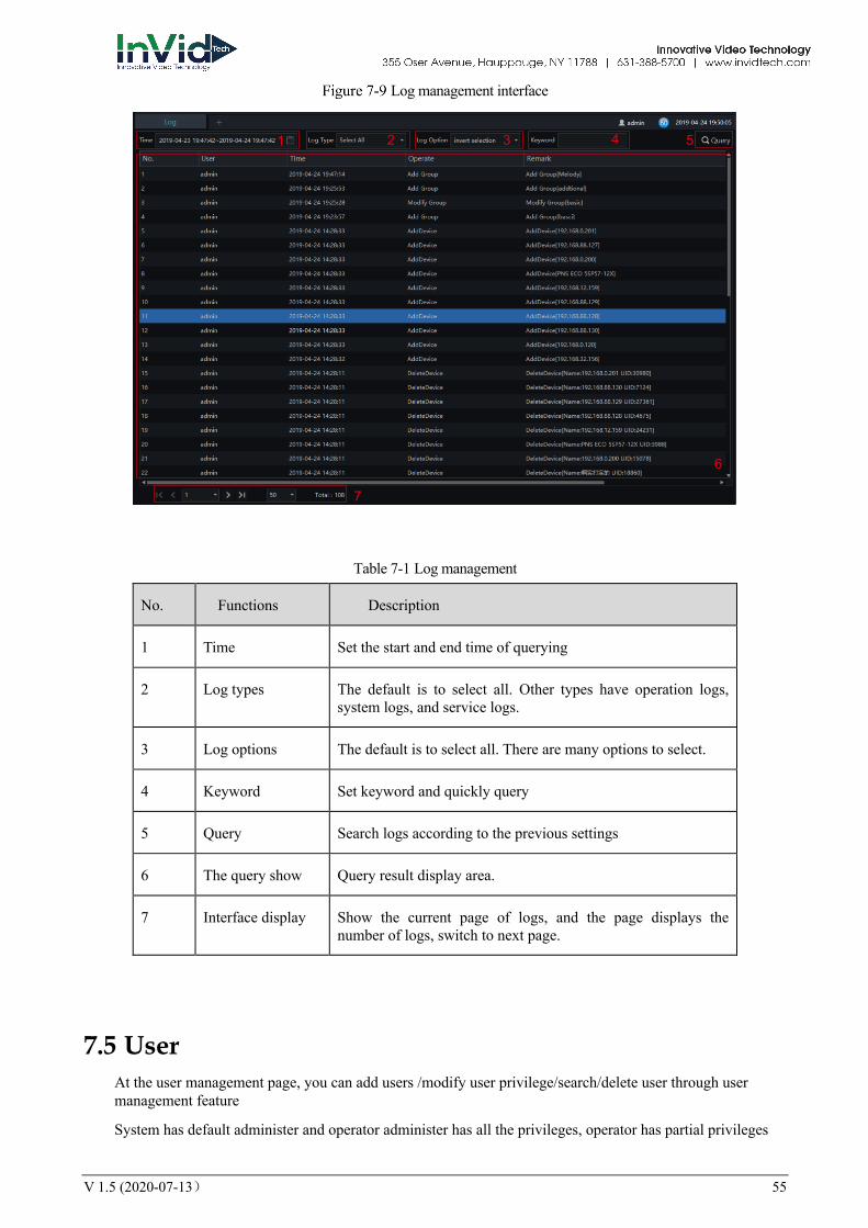
7.4 Log Management At interface of log management, users can query operation log, server log, system log.
On the main menu page, click to enter the detailed page, as shown in Figure 7-9.
V 1.5 (2020-07-13) 55
Log management interface
Table 7-1 Log management
No. Functions Description
1 Time Set the start and end time of querying
2 Log types The default is to select all. Other types have operation logs, system logs, and service logs.
3 Log options The default is to select all. There are many options to select.
4 Keyword Set keyword and quickly query
5 Query Search logs according to the previous settings
6 The query show Query result display area.
7 Interface display Show the current page of logs, and the page displays the number of logs, switch to next page.
7.5 User At the user management page, you can add users /modify user privilege/search/delete user through user management feature
System has default administer and operator administer has all the privileges, operator has partial privileges
1 2 3 4 5
6
7

56 V 1.5 (2020-07-13)
On the main menu page, Click , go to detailed page as shown in Figure 7-10.
User management interface
Table 7-1 User management
No. Function Description
1 User and role Choose user or role to operate.
2 Add/Delete Add/delete user or role.
3 Display area Display user/role information
4 Edit/Delete Click edit/delete icon to operate current roles or users
7.5.1 Add User Procedure:
Step 1 At the user management interface, click “Add” to add user.
12
3 4
V 1.5 (2020-07-13) 57
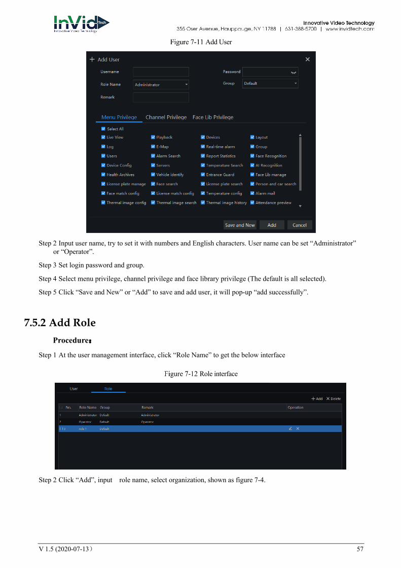
Add User
Step 2 Input user name, try to set it with numbers and English characters. User name can be set “Administrator” or “Operator”.
Step 3 Set login password and group.
Step 4 Select menu privilege, channel privilege and face library privilege (The default is all selected).
Step 5 Click “Save and New” or “Add” to save and add user, it will pop-up “add successfully”.
7.5.2 Add Role Procedure:
Step 1 At the user management interface, click “Role Name” to get the below interface
Role interface
Step 2 Click “Add”, input role name, select organization, shown as figure 7-4.
58 V 1.5 (2020-07-13)
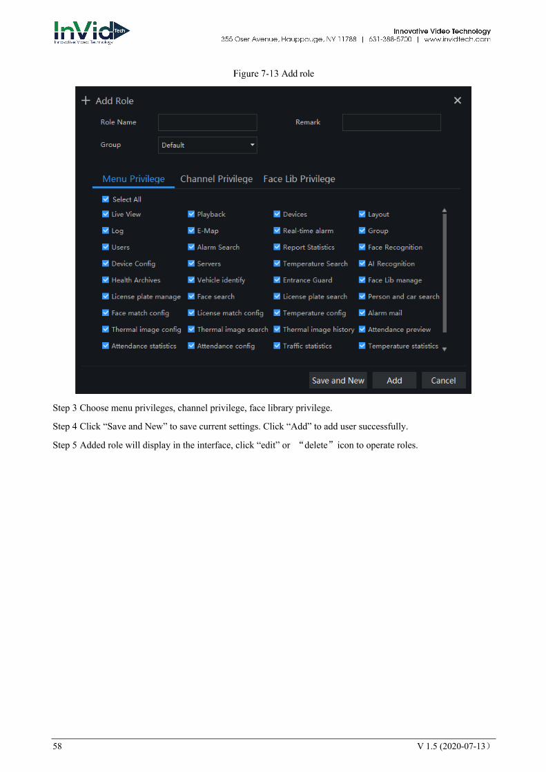
Add role
Step 3 Choose menu privileges, channel privilege, face library privilege.
Step 4 Click “Save and New” to save current settings. Click “Add” to add user successfully.
Step 5 Added role will display in the interface, click “edit” or “delete”icon to operate roles.
V 1.5 (2020-07-13) 59
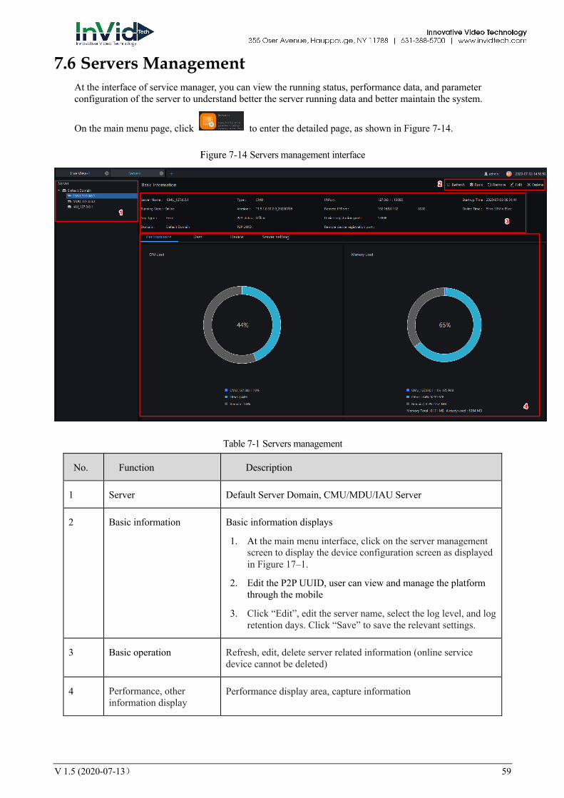
7.6 Servers Management At the interface of service manager, you can view the running status, performance data, and parameter configuration of the server to understand better the server running data and better maintain the system.
On the main menu page, click to enter the detailed page, as shown in Figure 7-14.
Servers management interface
Table 7-1 Servers management
No. Function Description
1 Server Default Server Domain, CMU/MDU/IAU Server
2 Basic information Basic information displays
1. At the main menu interface, click on the server management screen to display the device configuration screen as displayed in Figure 17–1.
2. Edit the P2P UUID, user can view and manage the platform through the mobile
3. Click “Edit”, edit the server name, select the log level, and log retention days. Click “Save” to save the relevant settings.
3 Basic operation Refresh, edit, delete server related information (online service device cannot be deleted)
4 Performance, other information display
Performance display area, capture information

60 V 1.5 (2020-07-13)
7.6.1 Central Management Server Data backup and recovery normally is used for system migration, which requires data backup first and recovery then. The backup data contains data from database, like users, device, server, alarm, log, face photos, etc.
Data backup means it will download data from the server where the VMS installed. Data recovery means it will upload the backup data to the servers, it includes perform recovery operations and ensure the system resume normal work.
Server setting, user can set the general parameters of snapshot face capture threshold, the parameters can be used to all cameras with these functions, as shown in Figure 7-15.
Server Setting
V 1.5 (2020-07-13) 61
There are four settings for server, they are basic setting, save setting, snapshot setting, face capture threshold.
Basic Setting: synchronization device time, temperature selection unit, device registration protocol (the alarm box can add to platform by private protocol encrypted ).
Save Setting: log save days, data save days, over temperature capture retention time, other temperature capture retention time, large image storage mode, snapshot path.
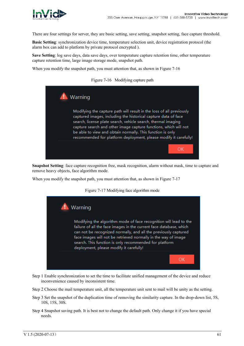
When you modify the snapshot path, you must attention that, as shown in Figure 7-16
Modifying capture path
Snapshot Setting: face capture recognition free, mask recognition, alarm without mask, time to capture and remove heavy objects, face algorithm mode.
When you modify the snapshot path, you must attention that, as shown in Figure 7-17
Modifying face algorithm mode
Enable synchronization to set the time to facilitate unified management of the device and reduce inconvenience caused by inconsistent time.
Choose the mail temperature unit, all the temperature unit sent to mail will be unity as the setting.
Set the snapshot of the duplication time of removing the similarity capture. In the drop-down list, 5S, 10S, 15S, 30S.
Snapshot saving path. It is best not to change the default path. Only change it if you have special needs.
62 V 1.5 (2020-07-13)
Enable face capture recognition free, the system will measurement the temperature only, it will save the performance of system.
Enable mask recognition, the system will recognition the face wear mask.
If the mask recognition is enable, user can enable the alarm without mask, when recognize someone is without mask, it will send alarm information.
The face algorithm mode can choose local IAU and face algorithm box.
Face capture threshold, ambiguity, confidence coefficient, face size length and width.
Click "OK" to save the settings.
Enable face capture recognition free, skip face recognition operation and only perform temperature measurement management. All captured faces will be treated as strangers and cannot be searched by the image search function. The recognition-free mode is suitable for scenarios that do not pay attention to the identification of personnel, such as airport, subway, station and other bayonet entrances, parks, and public service agencies. Capture retention time: Over-temperature capture retention time: delete over-temperature data in the server and database at the same time. Other temperature snapshot retention time: delete other temperature data in the server and database at the same time.
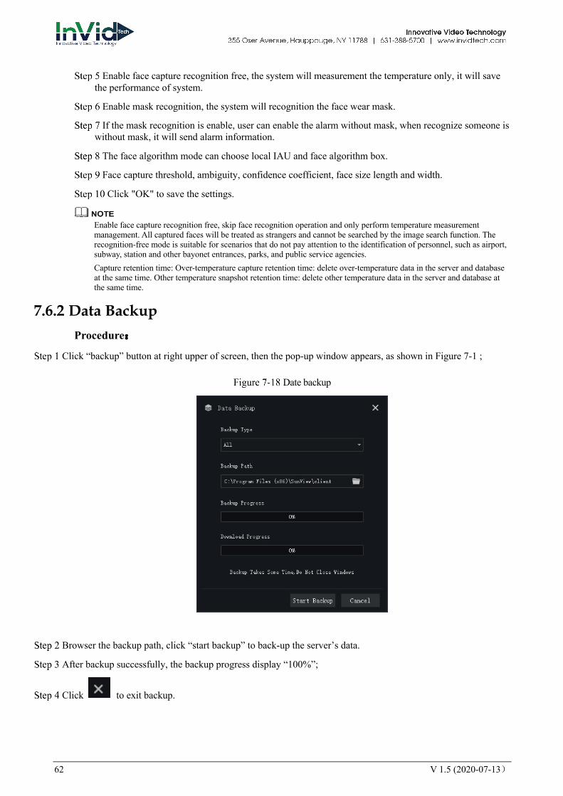
7.6.2 Data Backup Procedure:
Click “backup” button at right upper of screen, then the pop-up window appears, as shown in Figure 7-1 ;
Date backup
Browser the backup path, click “start backup” to back-up the server’s data.
After backup successfully, the backup progress display “100%”;
Click to exit backup.
V 1.5 (2020-07-13) 63
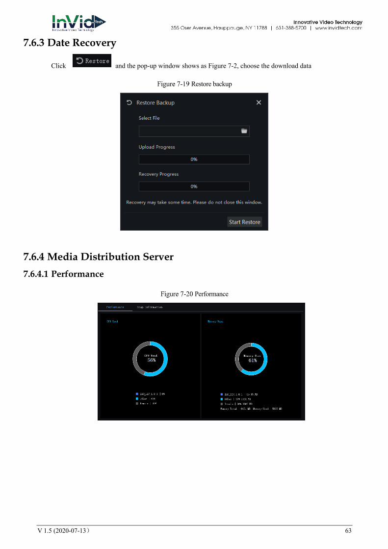
7.6.3 Date Recovery
Click and the pop-up window shows as Figure 7-2, choose the download data
Restore backup
7.6.4 Media Distribution Server 7.6.4.1 Performance
Performance

64 V 1.5 (2020-07-13)
7.6.5 Distribution Status
Distribution Status
7.6.6 Intelligent Analysis Server 7.6.6.1 Performance
Please refer to chapter 18.2.1
7.6.6.2 Snap Information
This function is generally applicable to the face capture device, it can analyze image if the device captures normally. If the number of captured face is 0, please check whether the camera is configured correctly. The details are shown as Figure 7-22.
Snap information

V 1.5 (2020-07-13) 65
7.7 Alarm Mail Set the alarm information sender information and recipient information. When sending an alarm, it can be pushed to the corresponding personnel by email.
On the main menu page, click to enter the detailed page, as shown in Figure 7-23.
Alarm mail
Step 1 Click to add the new strategy.
Step 2 Input the name and information of SNMP.
Step 3 Click to test the settings.
Step 4 Click to save the settings.

66 V 1.5 (2020-07-13)
8 Face Recognition The face recognition can transfer the parameter of AI NVR, such as face library, thermal temperature measurement, face search, and so on.
Face recognition supports algorithm calculation using CPU or face box, which can be configured on the server management interface.
8.1 Face Recognition On the Face Recognition function page, you can view the results of face capture and face comparison in real time. This function needs to add a face image in advance through the "Personnel Information Management" function page. Can be broadcast by device voice.
On the main menu page, click to enter the detailed page, as shown in Figure 8-1.
Face recognition
Table 8-1 Face recognition
No. Function Description
1 Devices list Show the devices with face recognition function.
2 Layout Choose the layout of video.
3 Alarm snapshot Alarm information About over-temperature face capture display, you can choose to stop refresh.

V 1.5 (2020-07-13) 67
No. Function Description
4 Face comparison The snapshot face compare with the library. Filter the device of capture the face, you can correspond channel quickly, if set the filter.
Set the broadcast Figure 8-3.
Filter device
Step 1 The devices have face capture function that automatically captures the face. The snapshot show on the area of face comparison.
Step 2 Click the search icon in the lower right corner of the snapshot image to go directly to the smart search interface.
Step 3 Similar faces of the face database appear again in the picture, and faces higher than the set similarity will be compared in the comparison area and related information is displayed.
Step 4 Click “+” that appears on the picture to add it directly to the face database.
68 V 1.5 (2020-07-13)
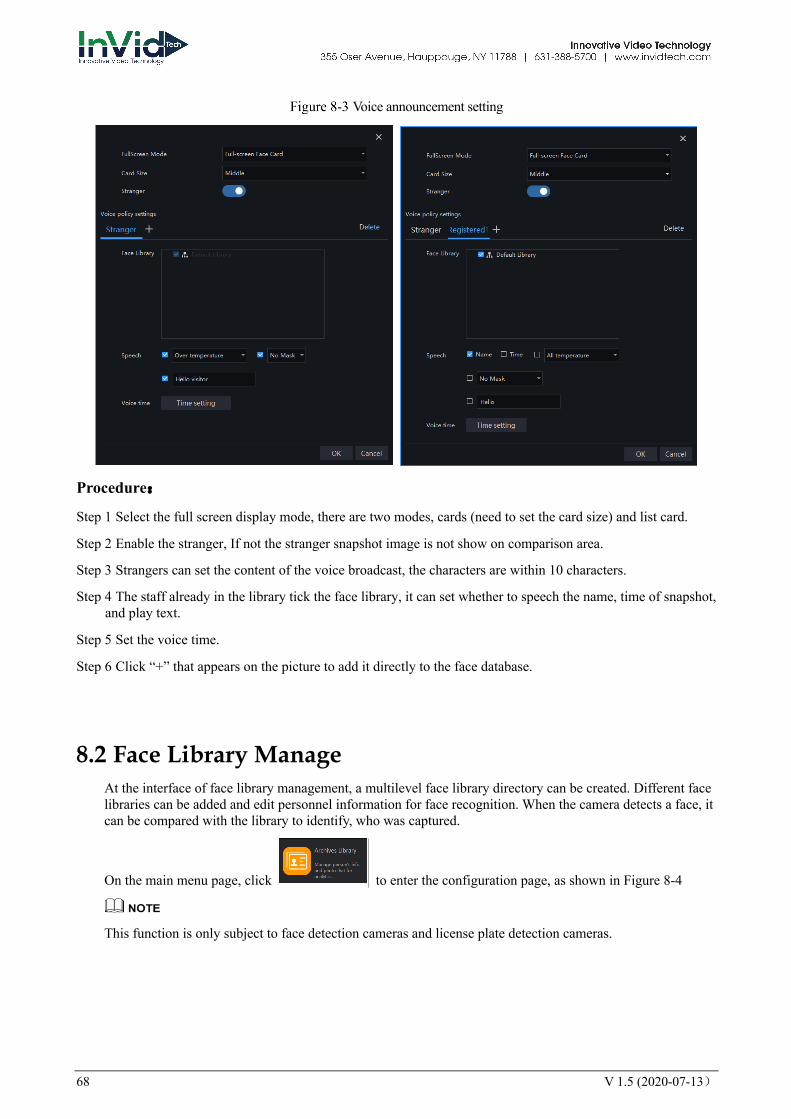
Voice announcement setting
Procedure:
Step 1 Select the full screen display mode, there are two modes, cards (need to set the card size) and list card.
Step 2 Enable the stranger, If not the stranger snapshot image is not show on comparison area.
Step 3 Strangers can set the content of the voice broadcast, the characters are within 10 characters.
Step 4 The staff already in the library tick the face library, it can set whether to speech the name, time of snapshot, and play text.
Step 5 Set the voice time.
Step 6 Click “+” that appears on the picture to add it directly to the face database.
8.2 Face Library Manage At the interface of face library management, a multilevel face library directory can be created. Different face libraries can be added and edit personnel information for face recognition. When the camera detects a face, it can be compared with the library to identify, who was captured.
On the main menu page, click to enter the configuration page, as shown in Figure 8-4
This function is only subject to face detection cameras and license plate detection cameras.
V 1.5 (2020-07-13) 69
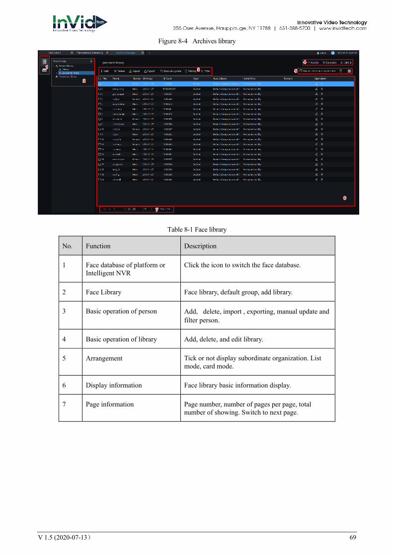
Archives library
Table 8-1 Face library
No. Function Description
1 Face database of platform or Intelligent NVR
Click the icon to switch the face database.
2 Face Library Face library, default group, add library.
3 Basic operation of person Add, delete, import , exporting, manual update and filter person.
4 Basic operation of library Add, delete, and edit library.
5 Arrangement Tick or not display subordinate organization. List mode, card mode.
6 Display information Face library basic information display.
7 Page information Page number, number of pages per page, total number of showing. Switch to next page.
70 V 1.5 (2020-07-13)
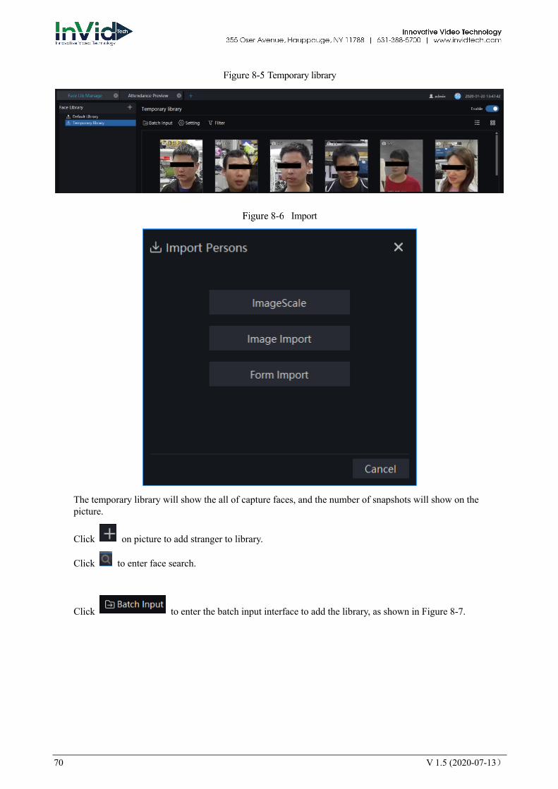
Temporary library
Import
The temporary library will show the all of capture faces, and the number of snapshots will show on the picture.
Click on picture to add stranger to library.
Click to enter face search.
Click to enter the batch input interface to add the library, as shown in Figure 8-7.
V 1.5 (2020-07-13) 71
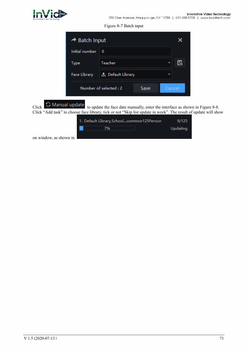
Batch input
Click to update the face date manually, enter the interface as shown in Figure 8-8. Click “Add task” to choose face library, tick or not “Skip list update in week”. The result of update will show
on window, as shown in
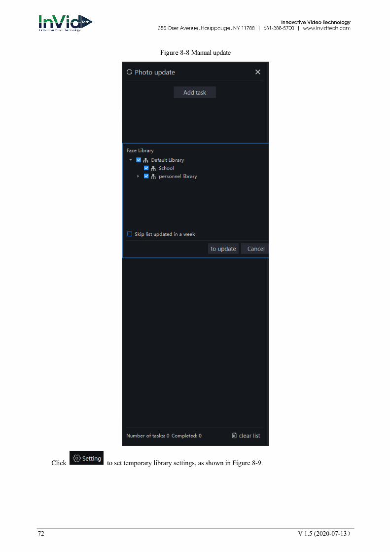
72 V 1.5 (2020-07-13)
Manual update
Click to set temporary library settings, as shown in Figure 8-9.

V 1.5 (2020-07-13) 73
Temporary library setting
Click to set filter, as shown in Figure 8-10.
Filter
The temporary library is live update.
8.2.1 Add Face Library Procedure:
Step 1 Click to add face library.
Step 2 Input library name, remark, choose library , as shown in Figure 8-11.
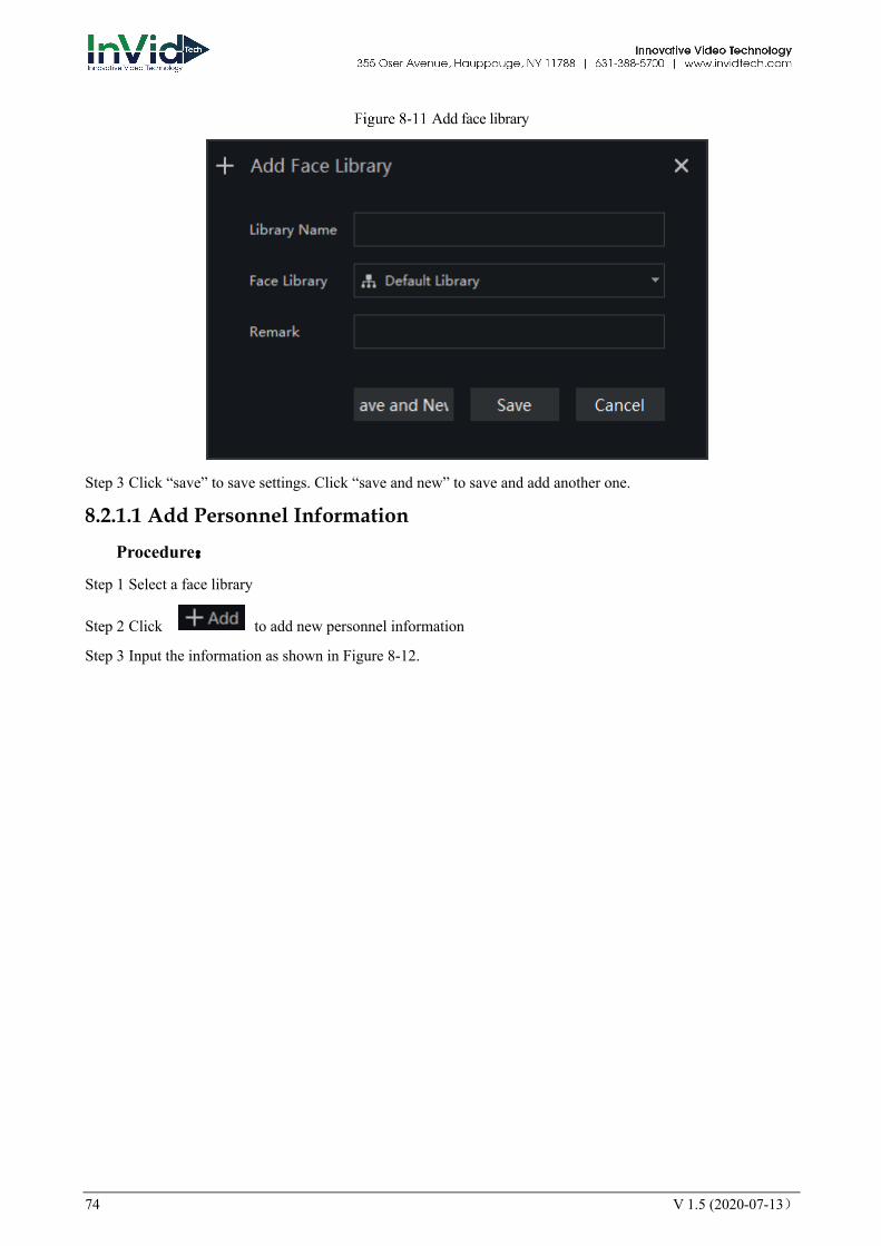
74 V 1.5 (2020-07-13)
Add face library
Step 3 Click “save” to save settings. Click “save and new” to save and add another one.
8.2.1.1 Add Personnel Information
Procedure:
Step 1 Select a face library
Step 2 Click to add new personnel information
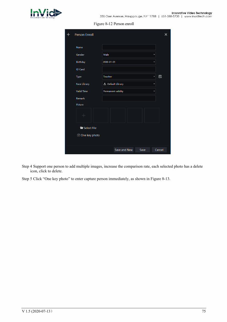
Step 3 Input the information as shown in Figure 8-12.
V 1.5 (2020-07-13) 75
Person enroll
Step 4 Support one person to add multiple images, increase the comparison rate, each selected photo has a delete icon, click to delete.
Step 5 Click “One key photo” to enter capture person immediately, as shown in Figure 8-13.
76 V 1.5 (2020-07-13)
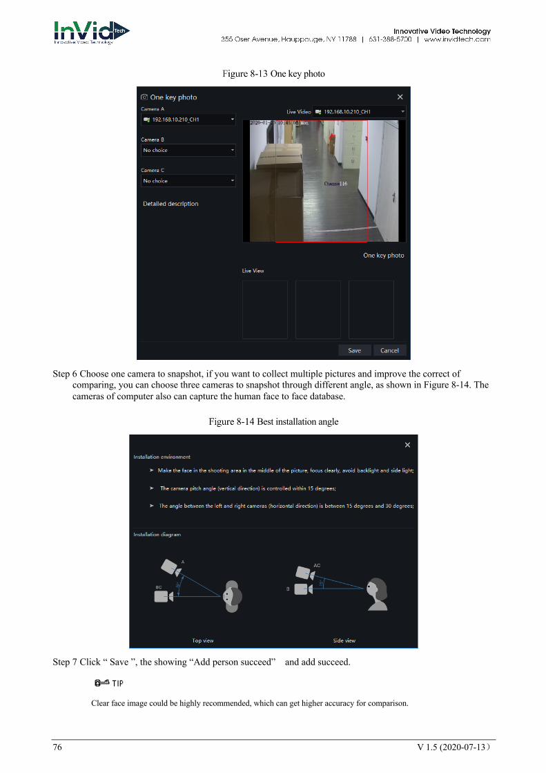
One key photo
Step 6 Choose one camera to snapshot, if you want to collect multiple pictures and improve the correct of comparing, you can choose three cameras to snapshot through different angle, as shown in Figure 8-14. The cameras of computer also can capture the human face to face database.
Best installation angle
Step 7 Click “ Save ”, the showing “Add person succeed” and add succeed.
Clear face image could be highly recommended, which can get higher accuracy for comparison.
V 1.5 (2020-07-13) 77
8.2.1.2 Batch Import
Procedure:
Step 1 Click “Export ” , select “Export template”.
Step 2 Edit above Export template, and save.
Step 3 Click above edited Export template to import all personnel information.
8.2.1.3 Batch Export
Procedure:
Step 1 Click “Export” to get into the Export interface.
Step 2 Choose the save path, and click “ save” to save the settings.
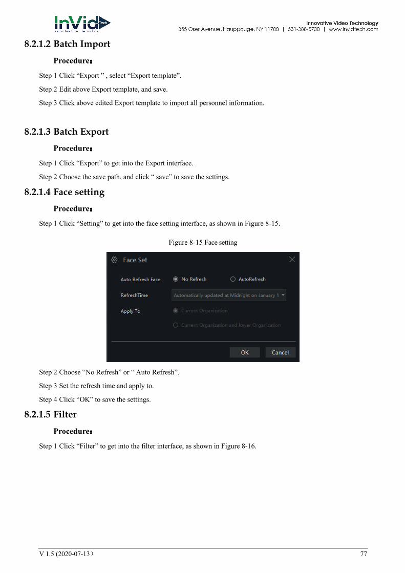
8.2.1.4 Face setting
Procedure:
Step 1 Click “Setting” to get into the face setting interface, as shown in Figure 8-15.
Face setting
Step 2 Choose “No Refresh” or “ Auto Refresh”.
Step 3 Set the refresh time and apply to.
Step 4 Click “OK” to save the settings.
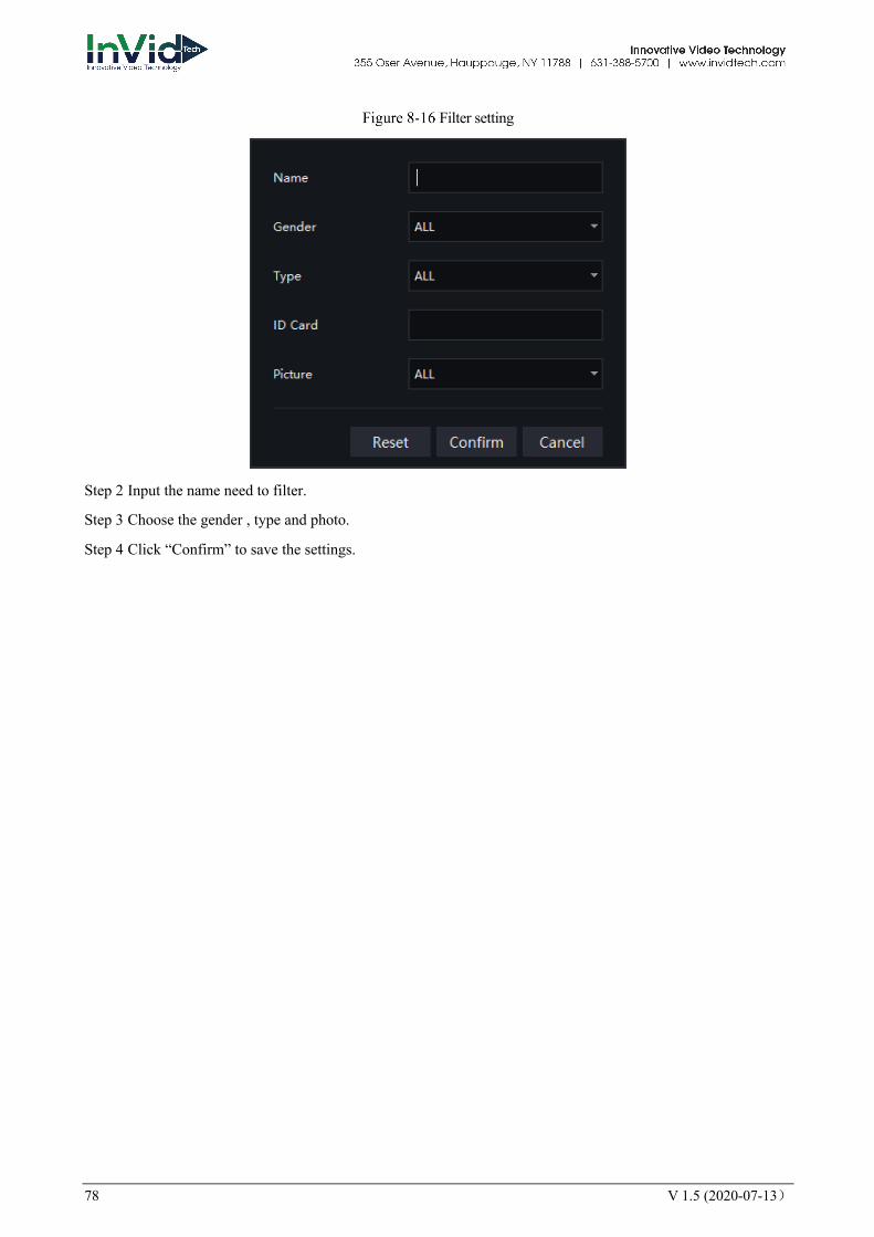
8.2.1.5 Filter
Procedure:
Step 1 Click “Filter” to get into the filter interface, as shown in Figure 8-16.
78 V 1.5 (2020-07-13)
Filter setting
Step 2 Input the name need to filter.
Step 3 Choose the gender , type and photo.
Step 4 Click “Confirm” to save the settings.
V 1.5 (2020-07-13) 79
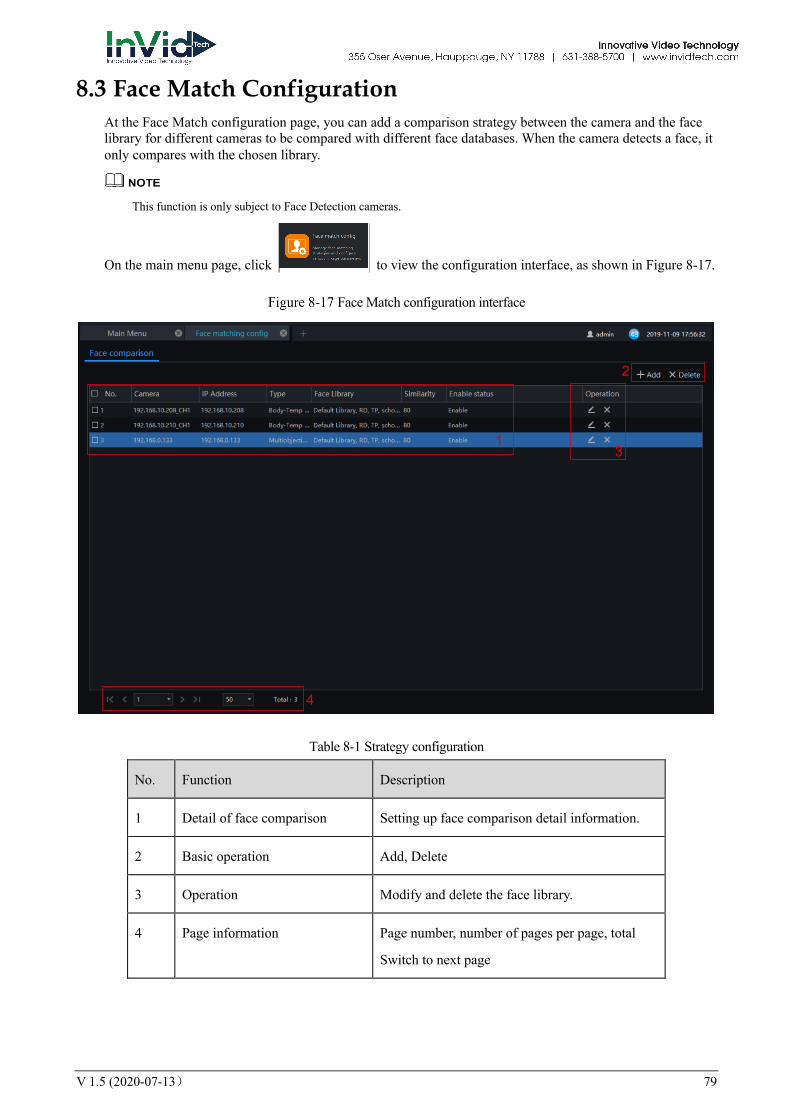
8.3 Face Match Configuration At the Face Match configuration page, you can add a comparison strategy between the camera and the face library for different cameras to be compared with different face databases. When the camera detects a face, it only compares with the chosen library.
This function is only subject to Face Detection cameras.
On the main menu page, click to view the configuration interface, as shown in Figure 8-17.
Face Match configuration interface
Table 8-1 Strategy configuration
No. Function Description
1 Detail of face comparison Setting up face comparison detail information.
2 Basic operation Add, Delete
3 Operation Modify and delete the face library.
4 Page information Page number, number of pages per page, total
Switch to next page
1
2
3
4

80 V 1.5 (2020-07-13)
8.3.1 Face Comparison Configuration
Procedure:
Step 1 Click icon of strategy configuration in new page, into the interface.
Step 2 Click “Add” to get into new face comparison, as shown in Figure 8-18.
Add strategy
.
Step 3 Check camera and face library.
Step 4 Set up Similarity and activate Stranger mode.
Step 5 Click to confirm the success of adding face comparison, relative devices showing in the list and executable for both Edit and Delete.
User can tick the linkage conditions, such as over temperature personnel, no mask, these two conditions only use for body temperature cameras.
Linkage scheme can tick App subscribe, Send mail, IO output (choose ID, set duration).
Defense time
V 1.5 (2020-07-13) 81
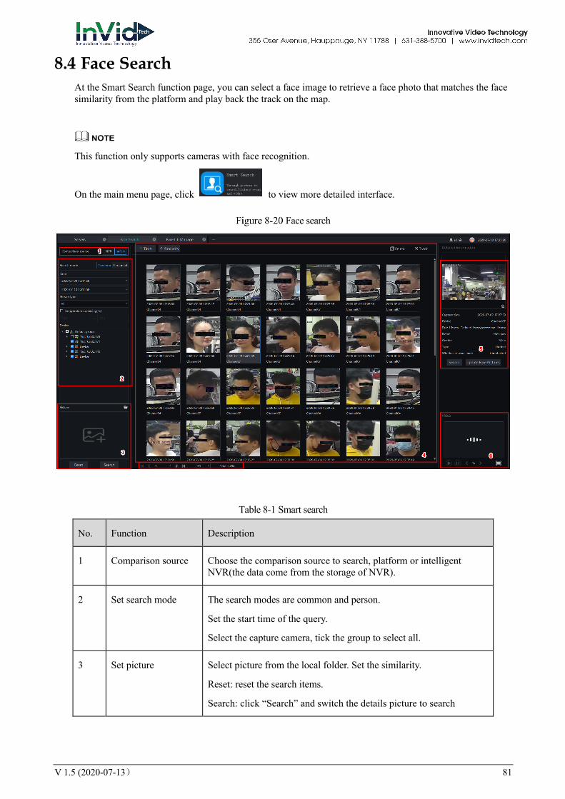
8.4 Face Search At the Smart Search function page, you can select a face image to retrieve a face photo that matches the face similarity from the platform and play back the track on the map.
This function only supports cameras with face recognition.
On the main menu page, click to view more detailed interface.
Face search
Table 8-1 Smart search
No. Function Description
1 Comparison source Choose the comparison source to search, platform or intelligent NVR(the data come from the storage of NVR).
2 Set search mode The search modes are common and person.
Set the start time of the query.
Select the capture camera, tick the group to select all.
3 Set picture Select picture from the local folder. Set the similarity.
Reset: reset the search items.
Search: click “Search” and switch the details picture to search
82 V 1.5 (2020-07-13)
No. Function Description
4 Display information The information can be displayed by time, similarity in row, behavior track.
5 Details Click on the image of the query result to display the panorama in the captured state.
The captured picture can be entered into the face database.
Search directly with snap shots.
Enroll: click to enroll the searched picture.
Enter the face database and search for images. The pictures captured by the camera are generally stored in the snap folder by default.
6 Switch picture to search
If there is a record, you can directly play the video before and after the snapshot.
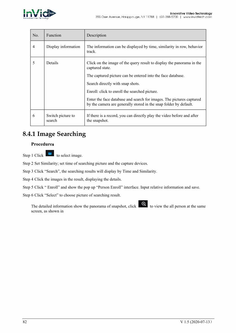
8.4.1 Image Searching Procedure:
Step 1 Click to select image.
Step 2 Set Similarity; set time of searching picture and the capture devices.
Step 3 Click “Search”, the searching results will display by Time and Similarity.
Step 4 Click the images in the result, displaying the details.
Step 5 Click “ Enroll” and show the pop up “Person Enroll” interface. Input relative information and save.
Step 6 Click “Select” to choose picture of searching result.
The detailed information show the panorama of snapshot, click to view the all person at the same screen, as shown in
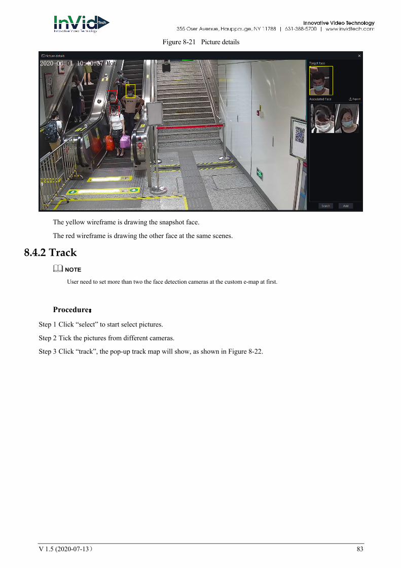
V 1.5 (2020-07-13) 83
Picture details
The yellow wireframe is drawing the snapshot face.
The red wireframe is drawing the other face at the same scenes.
8.4.2 Track
User need to set more than two the face detection cameras at the custom e-map at first.
Procedure:
Step 1 Click “select” to start select pictures.
Step 2 Tick the pictures from different cameras.
Step 3 Click “track”, the pop-up track map will show, as shown in Figure 8-22.
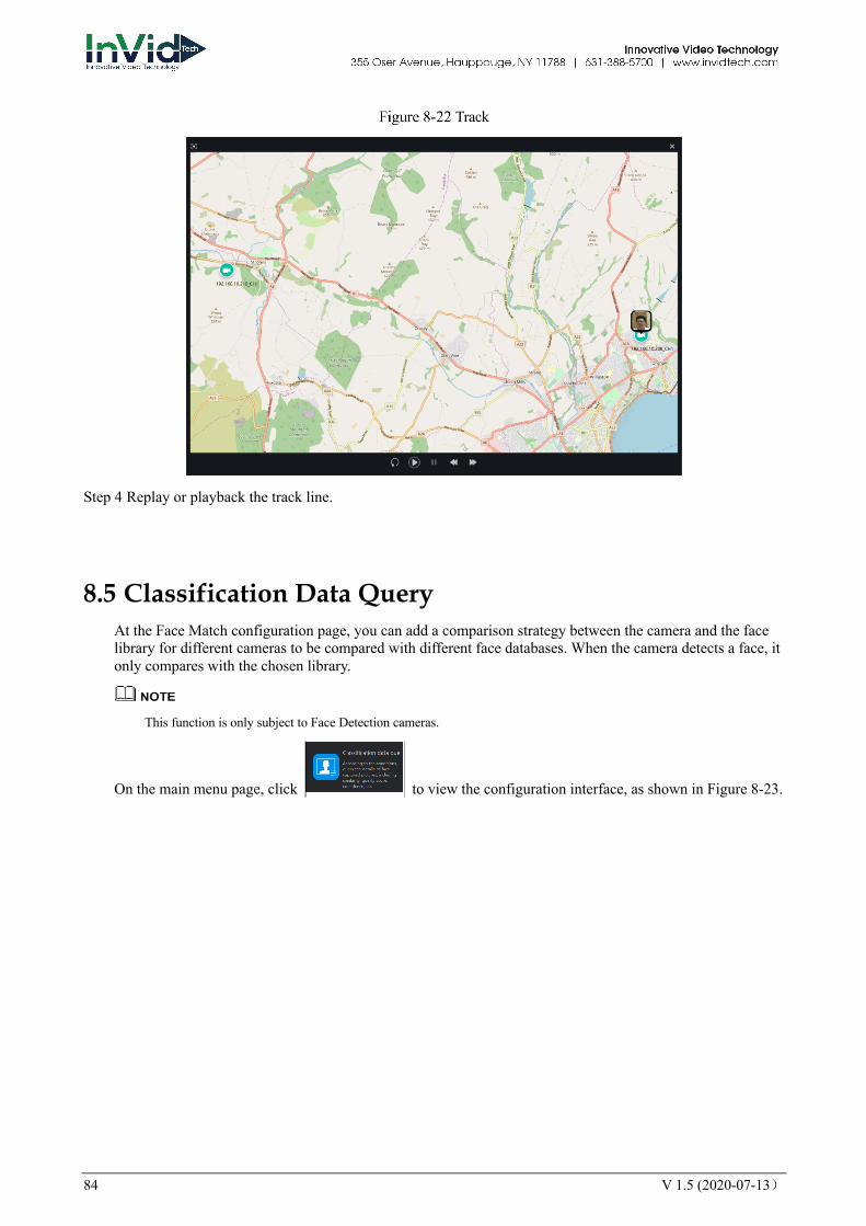
84 V 1.5 (2020-07-13)
Track
Step 4 Replay or playback the track line.
8.5 Classification Data Query At the Face Match configuration page, you can add a comparison strategy between the camera and the face library for different cameras to be compared with different face databases. When the camera detects a face, it only compares with the chosen library.
This function is only subject to Face Detection cameras.
On the main menu page, click to view the configuration interface, as shown in Figure 8-23.

V 1.5 (2020-07-13) 85
Classification data query
Table 8-1 Smart search
No. Function Description
1 Basic conditions of querying
Start time and end time, tick the devices and modes of face libraries.
2 More conditions Set similarity, quality score, confidence, face size range, pupil distance range, yaw angle, pitch angle, roll angle.
3 Operation of library The basic operation of license plate library.
4 Detailed information The result of querying, show the detail information.
Procedure:
Step 1 Set the query start time and select the device.
Step 2 Tick the devices of the query. The default is to select all.
Step 3 Set the classification query conditions and search accurately.
Step 4 Click “Query” and the result of the query is now displayed.
Step 5 Click “Reset” to reset the query criteria.
1
23
4
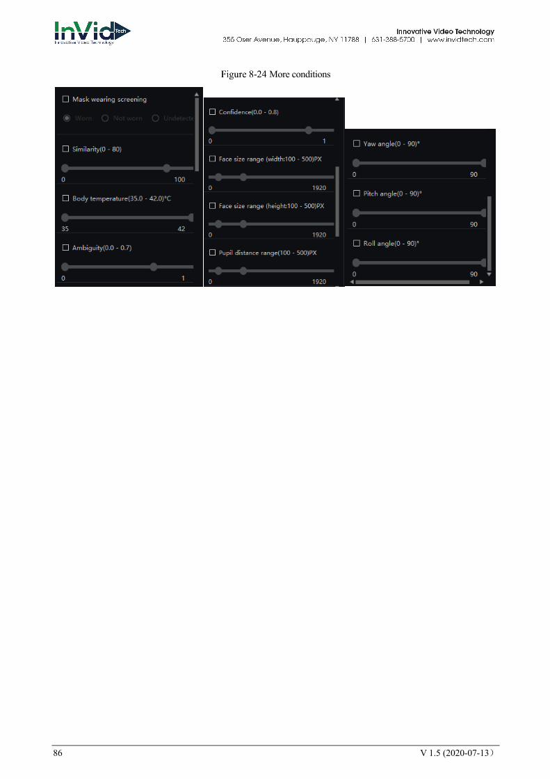
86 V 1.5 (2020-07-13)
More conditions

V 1.5 (2020-07-13) 87
9 License Plate Recognition
9.1 License Plate Manage The license plate library can add license plate library to identify the matching license plates and manage the vehicle entry and exit. Different levels of license plate face libraries are established according to different needs.
This function only supports cameras with license plate recognition.
On the main menu page, click to view more detailed interface.
License plate manage interface
Table 9-1 Smart search
No. Function Description
1 License plate library Click “add” to add the library of license plate. Show the libraries.
2 Operation of license The basic operation of license plate.
3 Operation of library The basic operation of license plate library.
1
2
34
5
6
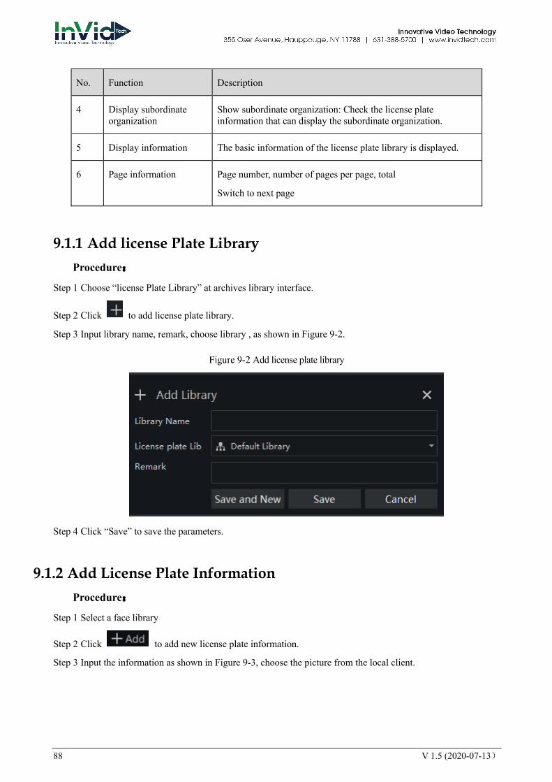
88 V 1.5 (2020-07-13)
No. Function Description
4 Display subordinate organization
Show subordinate organization: Check the license plate information that can display the subordinate organization.
5 Display information The basic information of the license plate library is displayed.
6 Page information Page number, number of pages per page, total
Switch to next page
9.1.1 Add license Plate Library Procedure:
Step 1 Choose “license Plate Library” at archives library interface.
Step 2 Click to add license plate library.
Step 3 Input library name, remark, choose library , as shown in Figure 9-2.
Add license plate library
Step 4 Click “Save” to save the parameters.
9.1.2 Add License Plate Information Procedure:
Step 1 Select a face library
Step 2 Click to add new license plate information.
Step 3 Input the information as shown in Figure 9-3, choose the picture from the local client.

V 1.5 (2020-07-13) 89
Add license plate
Step 4 Click “ Save ”, will show “Add license plate succeed”.
The operations such as import, export, delete license plate library are same as face library, please refer to chapter 8.2.
9.2 License Plate Configuration The license plate recognition function camera is selected in the license plate comparison configuration, so that the vehicle identify can call the configuration.
This function only supports cameras with license plate recognition.
On the main menu page, click to view more detailed interface.
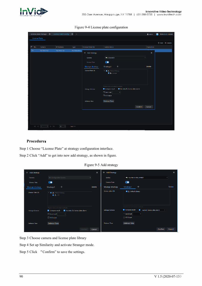
90 V 1.5 (2020-07-13)
License plate configuration
Procedure:
Step 1 Choose “License Plate” at strategy configuration interface.
Step 2 Click “Add” to get into new add strategy, as shown in figure.
Add strategy
.
Step 3 Choose camera and license plate library
Step 4 Set up Similarity and activate Stranger mode.
Step 5 Click “Confirm” to save the settings.
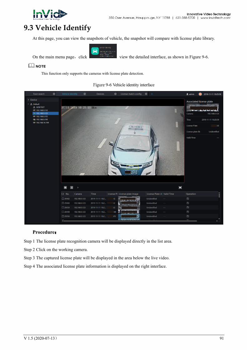
V 1.5 (2020-07-13) 91
9.3 Vehicle Identify At this page, you can view the snapshots of vehicle, the snapshot will compare with license plate library.
On the main menu page,click view the detailed interface, as shown in Figure 9-6.
This function only supports the cameras with license plate detection.
Vehicle identity interface
Procedure:
Step 1 The license plate recognition camera will be displayed directly in the list area.
Step 2 Click on the working camera.
Step 3 The captured license plate will be displayed in the area below the live video.
Step 4 The associated license plate information is displayed on the right interface.
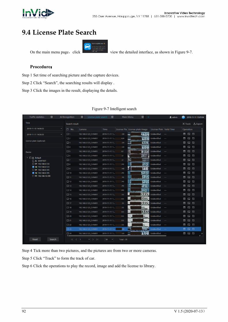
92 V 1.5 (2020-07-13)
9.4 License Plate Search
On the main menu page,click view the detailed interface, as shown in Figure 9-7.
Procedure:
Step 1 Set time of searching picture and the capture devices.
Step 2 Click “Search”, the searching results will display .
Step 3 Click the images in the result, displaying the details.
Intelligent search
Step 4 Tick more than two pictures, and the pictures are from two or more cameras.
Step 5 Click “Track” to form the track of car.
Step 6 Click the operations to play the record, image and add the license to library.
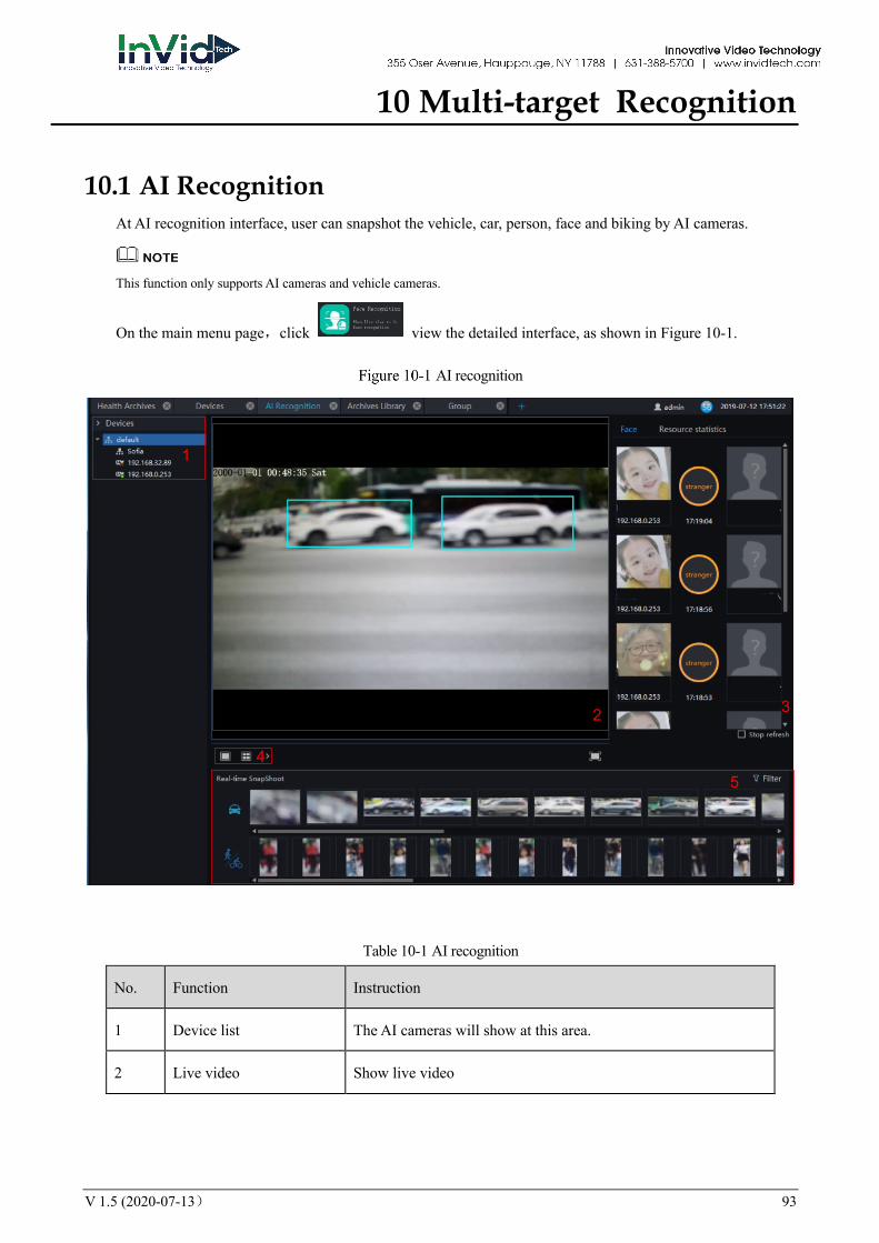
V 1.5 (2020-07-13) 93
10 Multi-target Recognition
10.1 AI Recognition At AI recognition interface, user can snapshot the vehicle, car, person, face and biking by AI cameras.
This function only supports AI cameras and vehicle cameras.
On the main menu page,click view the detailed interface, as shown in Figure 10-1.
AI recognition
Table 10-1 AI recognition
No. Function Instruction
1 Device list The AI cameras will show at this area.
2 Live video Show live video
1
2 3
45
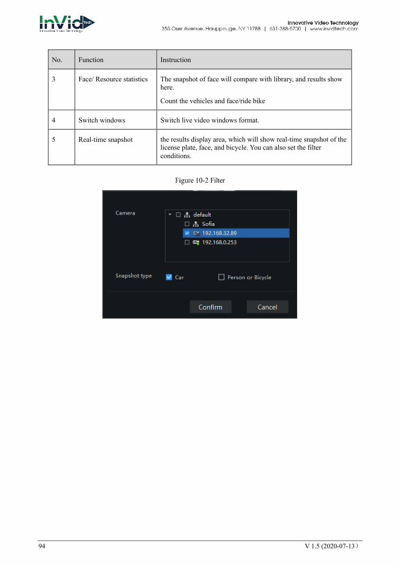
94 V 1.5 (2020-07-13)
No. Function Instruction
3 Face/ Resource statistics The snapshot of face will compare with library, and results show here.
Count the vehicles and face/ride bike
4 Switch windows Switch live video windows format.
5 Real-time snapshot the results display area, which will show real-time snapshot of the license plate, face, and bicycle. You can also set the filter conditions.
Filter

V 1.5 (2020-07-13) 95
Resource statistics
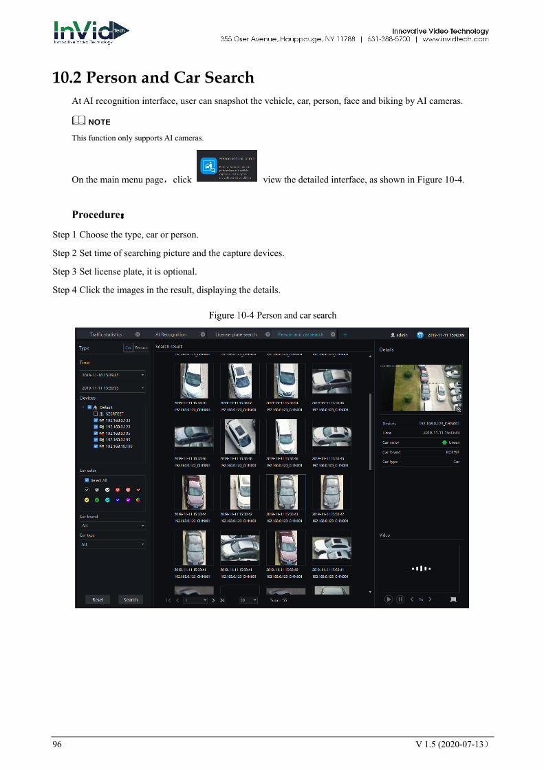
96 V 1.5 (2020-07-13)
10.2 Person and Car Search At AI recognition interface, user can snapshot the vehicle, car, person, face and biking by AI cameras.
This function only supports AI cameras.
On the main menu page,click view the detailed interface, as shown in Figure 10-4.
Procedure:
Step 1 Choose the type, car or person.
Step 2 Set time of searching picture and the capture devices.
Step 3 Set license plate, it is optional.
Step 4 Click the images in the result, displaying the details.
Person and car search
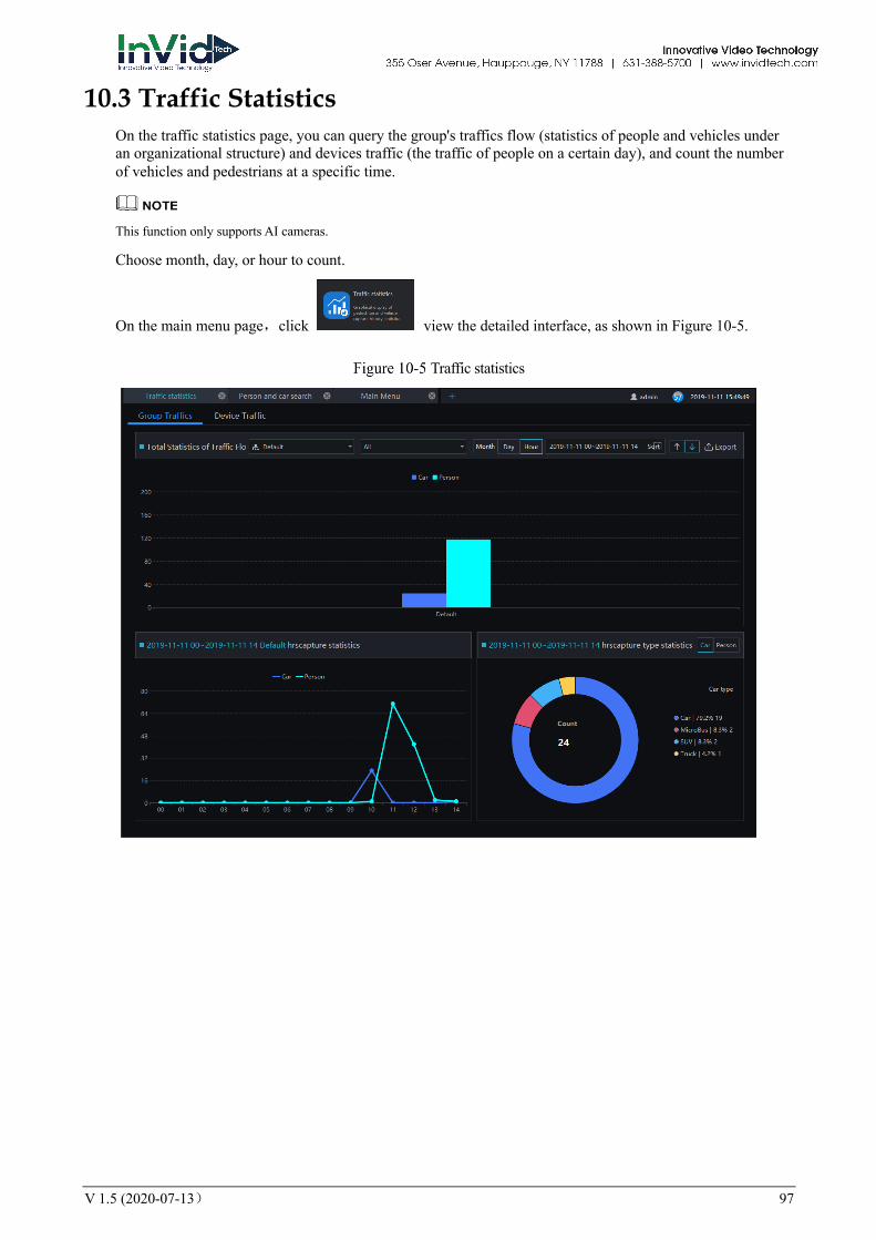
V 1.5 (2020-07-13) 97
10.3 Traffic Statistics On the traffic statistics page, you can query the group's traffics flow (statistics of people and vehicles under an organizational structure) and devices traffic (the traffic of people on a certain day), and count the number of vehicles and pedestrians at a specific time.
This function only supports AI cameras.
Choose month, day, or hour to count.
On the main menu page,click view the detailed interface, as shown in Figure 10-5.
Traffic statistics
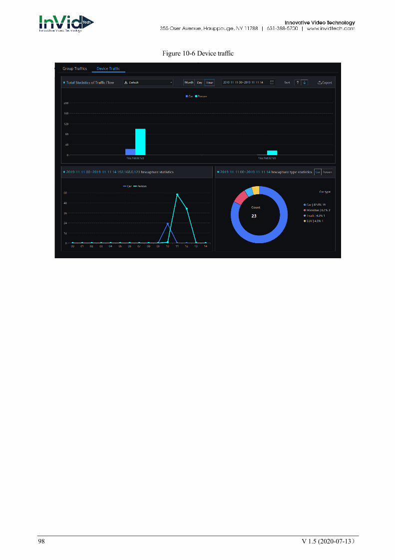
98 V 1.5 (2020-07-13)
Device traffic
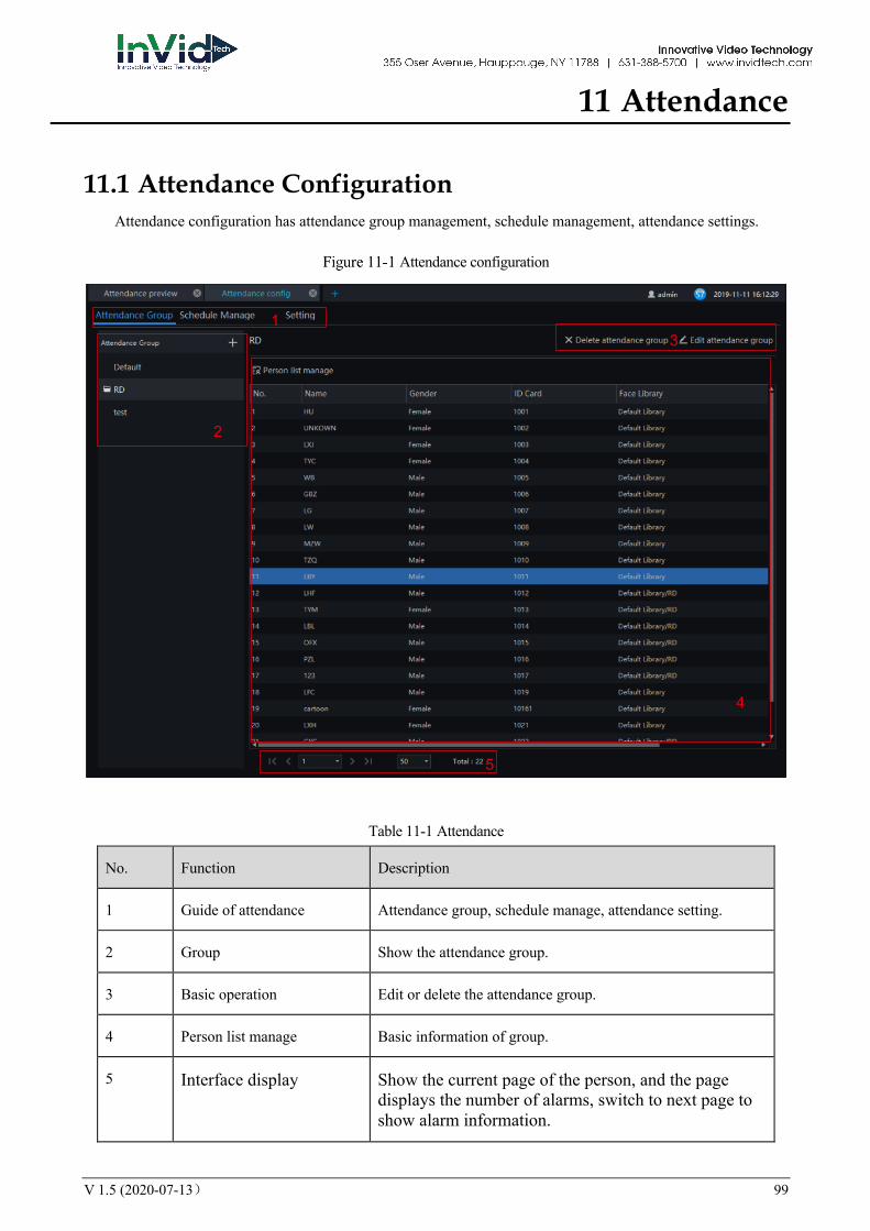
V 1.5 (2020-07-13) 99
11 Attendance
11.1 Attendance Configuration Attendance configuration has attendance group management, schedule management, attendance settings.
Attendance configuration
Table 11-1 Attendance
No. Function Description
1 Guide of attendance Attendance group, schedule manage, attendance setting.
2 Group Show the attendance group.
3 Basic operation Edit or delete the attendance group.
4 Person list manage Basic information of group.
5 Interface display Show the current page of the person, and the page displays the number of alarms, switch to next page to show alarm information.
1
2
3
4
5
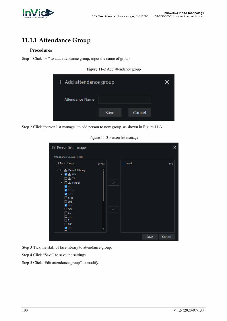
100 V 1.5 (2020-07-13)
11.1.1 Attendance Group Procedure:
Step 1 Click “+ ” to add attendance group, input the name of group.
Add attendance group
Step 2 Click “person list manage” to add person to new group, as shown in Figure 11-3.
Person list manage
Step 3 Tick the staff of face library to attendance group.
Step 4 Click “Save” to save the settings.
Step 5 Click “Edit attendance group” to modify.
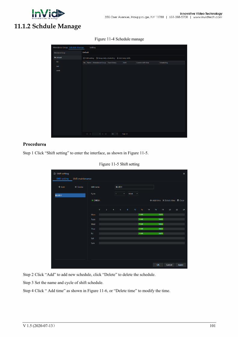
V 1.5 (2020-07-13) 101
11.1.2 Schdule Manage
Schedule manage
Procedure:
Step 1 Click “Shift setting” to enter the interface, as shown in Figure 11-5.
Shift setting
Step 2 Click “Add” to add new schedule, click “Delete” to delete the schedule.
Step 3 Set the name and cycle of shift schedule.
Step 4 Click “ Add time” as shown in Figure 11-6, or “Delete time” to modify the time.
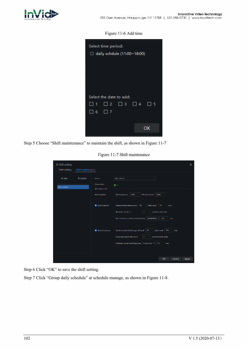
102 V 1.5 (2020-07-13)
Add time
Step 5 Choose “Shift maintenance” to maintain the shift, as shown in Figure 11-7
Shift maintenance
Step 6 Click “OK” to save the shift setting.
Step 7 Click “Group daily schedule” at schedule manage, as shown in Figure 11-8.
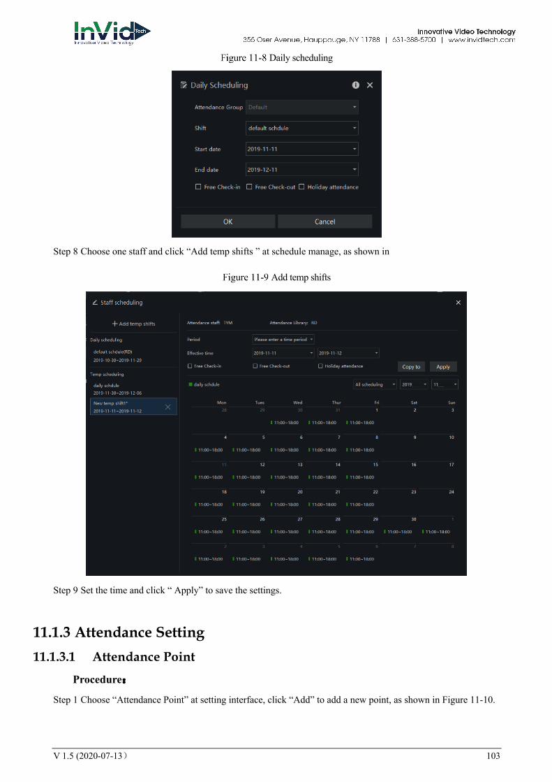
V 1.5 (2020-07-13) 103
Daily scheduling
Step 8 Choose one staff and click “Add temp shifts ” at schedule manage, as shown in
Add temp shifts
Step 9 Set the time and click “ Apply” to save the settings.
11.1.3 Attendance Setting 11.1.3.1 Attendance Point
Procedure:
Step 1 Choose “Attendance Point” at setting interface, click “Add” to add a new point, as shown in Figure 11-10.
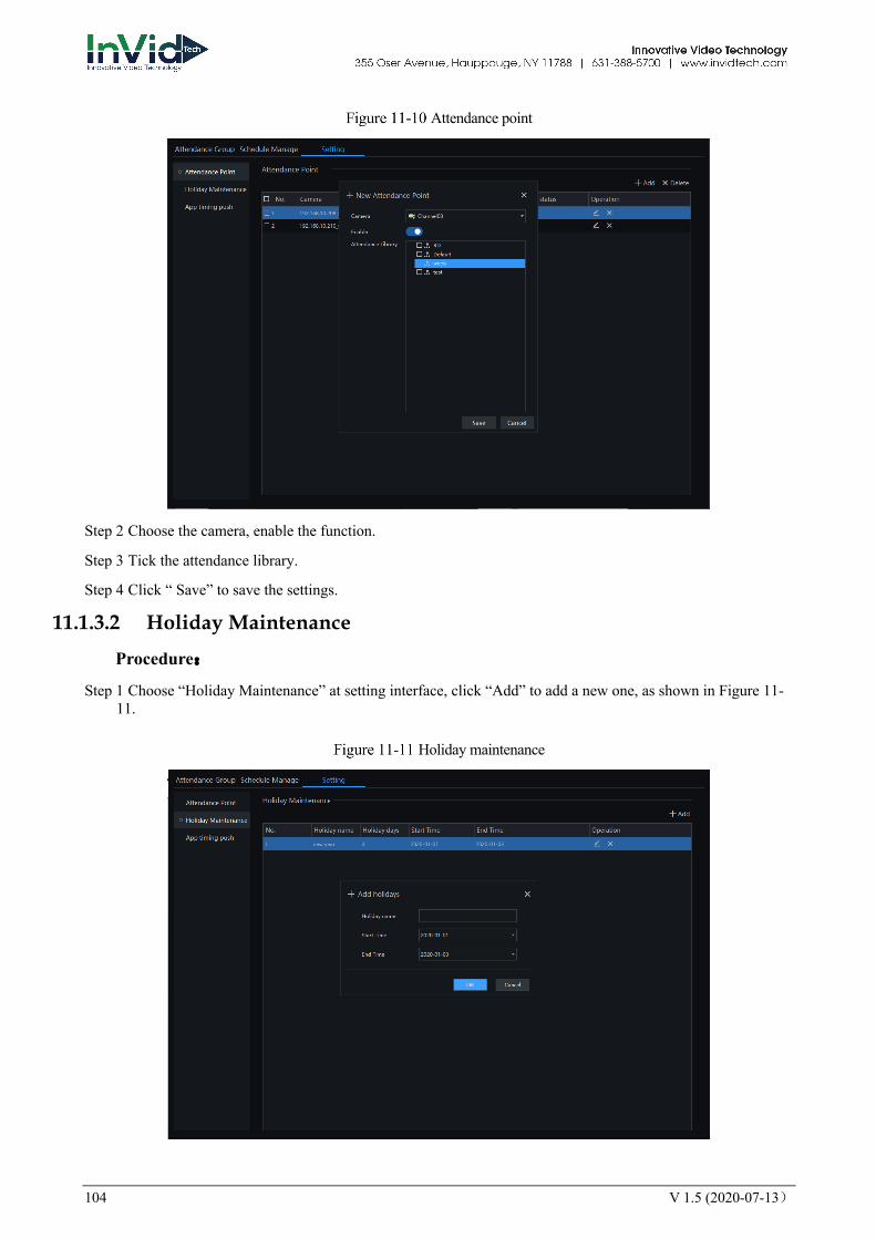
104 V 1.5 (2020-07-13)
Attendance point
Step 2 Choose the camera, enable the function.
Step 3 Tick the attendance library.
Step 4 Click “ Save” to save the settings.
11.1.3.2 Holiday Maintenance
Procedure:
Step 1 Choose “Holiday Maintenance” at setting interface, click “Add” to add a new one, as shown in Figure 11-11.
Holiday maintenance

V 1.5 (2020-07-13) 105
Step 2 Input the holiday name.
Step 3 Set the start time and end time.
Step 4 Click “ OK” to save the settings.
11.1.3.3 App Timing Push
Procedure:
Step 1 Choose “App timing push” at setting interface, click “Add” to add a new one, as shown in Figure 11-12.
App timing push
Step 2 Choose the attendance group, enable “Push Status”.
Step 3 Tick the push contents, and select notice to send.
Step 4 Click “ OK” to save the settings.
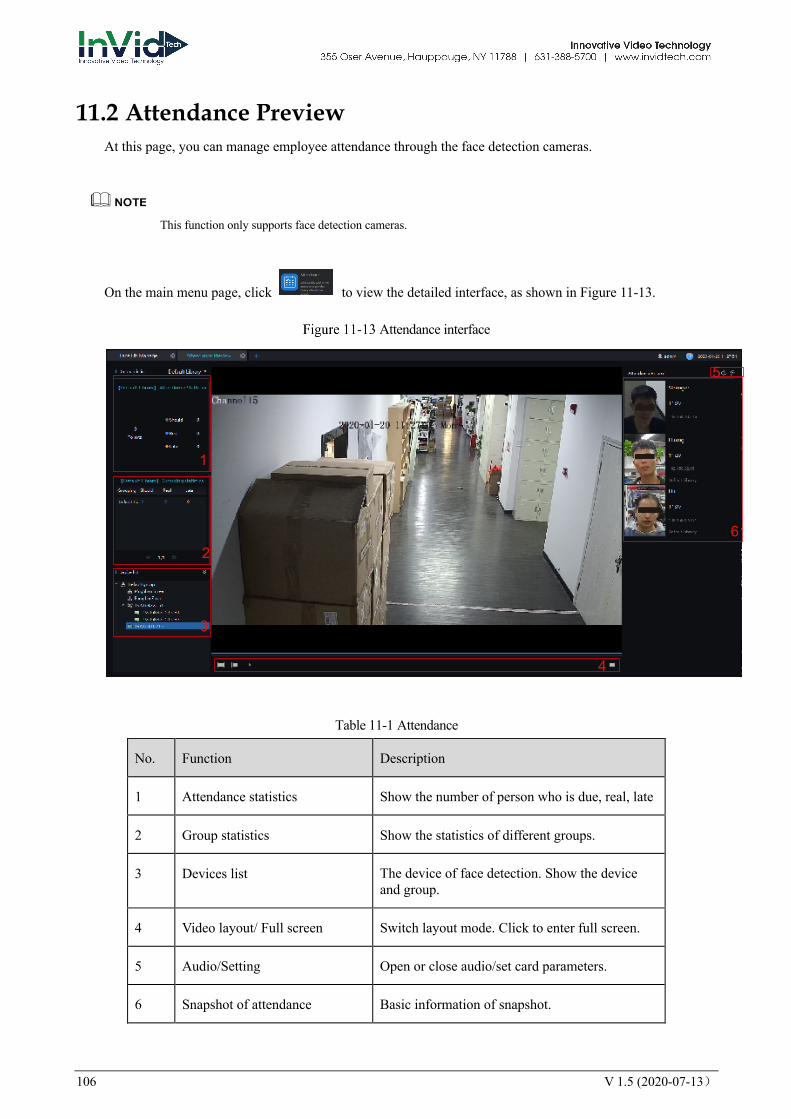
106 V 1.5 (2020-07-13)
11.2 Attendance Preview At this page, you can manage employee attendance through the face detection cameras.
This function only supports face detection cameras.
On the main menu page, click to view the detailed interface, as shown in Figure 11-13.
Attendance interface
Table 11-1 Attendance
No. Function Description
1 Attendance statistics Show the number of person who is due, real, late
2 Group statistics Show the statistics of different groups.
3 Devices list The device of face detection. Show the device and group.
4 Video layout/ Full screen Switch layout mode. Click to enter full screen.
5 Audio/Setting Open or close audio/set card parameters.
6 Snapshot of attendance Basic information of snapshot.
2
1
3
4
5
6
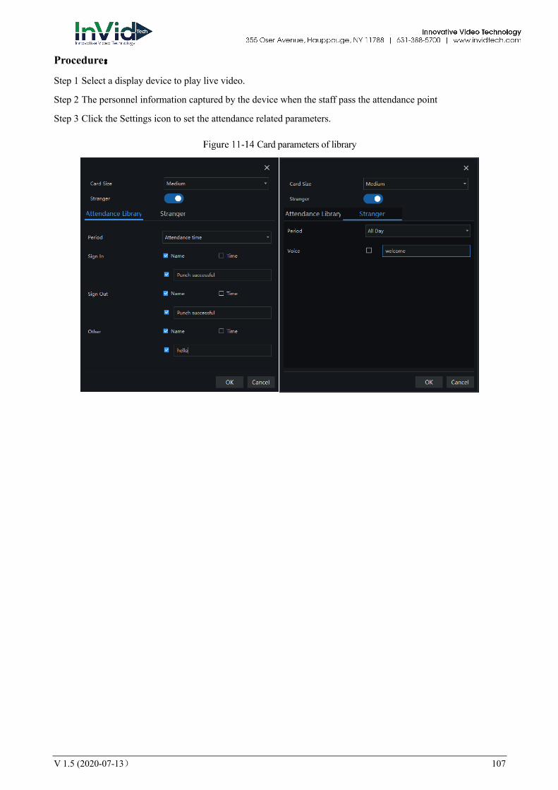
V 1.5 (2020-07-13) 107
Procedure:
Step 1 Select a display device to play live video.
Step 2 The personnel information captured by the device when the staff pass the attendance point
Step 3 Click the Settings icon to set the attendance related parameters.
Card parameters of library

108 V 1.5 (2020-07-13)
11.3 Attendance Statistics In the attendance statistics interface, users can set the query conditions to quickly find relevant statistics.
On the main menu page, click to view the detailed interface, as shown in Figure 11-15.
Attendance data
Procedure:
Step 1 Select personnel of library.
Step 2 Choose time or set customer time.
Step 3 Select query type; click “Search” to query.
Step 4 Result show in area 3.
Step 5 Click “Export” to export the result.
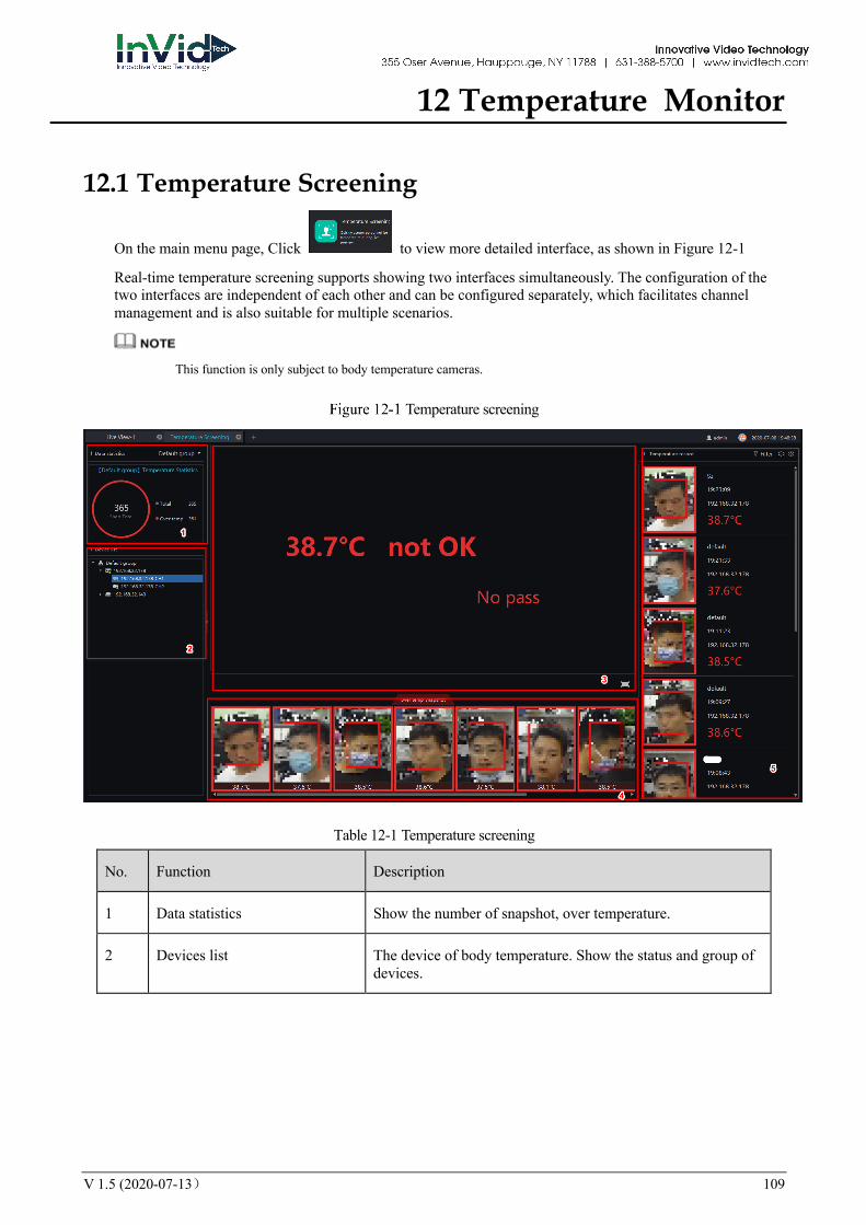
V 1.5 (2020-07-13) 109
12 Temperature Monitor
12.1 Temperature Screening
On the main menu page, Click to view more detailed interface, as shown in Figure 12-1
Real-time temperature screening supports showing two interfaces simultaneously. The configuration of the two interfaces are independent of each other and can be configured separately, which facilitates channel management and is also suitable for multiple scenarios.
This function is only subject to body temperature cameras.
Temperature screening
Table 12-1 Temperature screening
No. Function Description
1 Data statistics Show the number of snapshot, over temperature.
2 Devices list The device of body temperature. Show the status and group of devices.
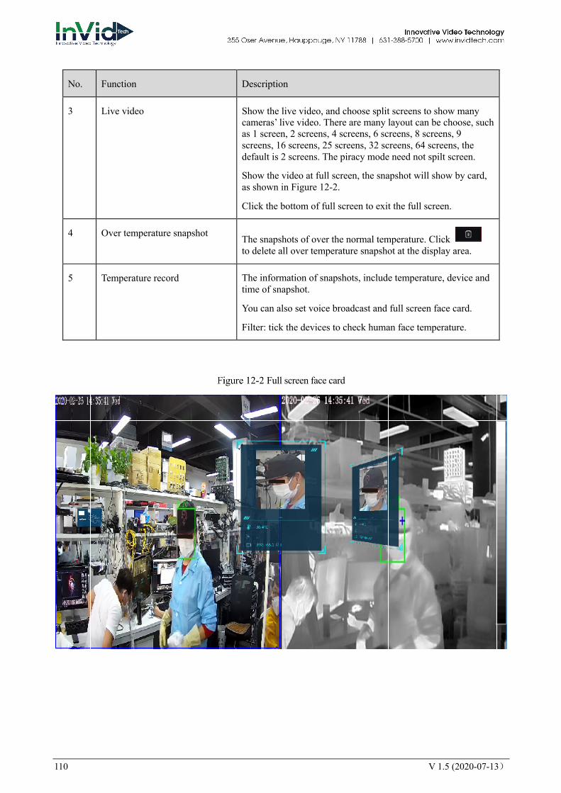
110 V 1.5 (2020-07-13)
No. Function Description
3 Live video Show the live video, and choose split screens to show many cameras’ live video. There are many layout can be choose, such as 1 screen, 2 screens, 4 screens, 6 screens, 8 screens, 9 screens, 16 screens, 25 screens, 32 screens, 64 screens, the default is 2 screens. The piracy mode need not spilt screen.
Show the video at full screen, the snapshot will show by card, as shown in Figure 12-2.
Click the bottom of full screen to exit the full screen.
4 Over temperature snapshot The snapshots of over the normal temperature. Click to delete all over temperature snapshot at the display area.
5 Temperature record The information of snapshots, include temperature, device and time of snapshot.
You can also set voice broadcast and full screen face card.
Filter: tick the devices to check human face temperature.
Full screen face card
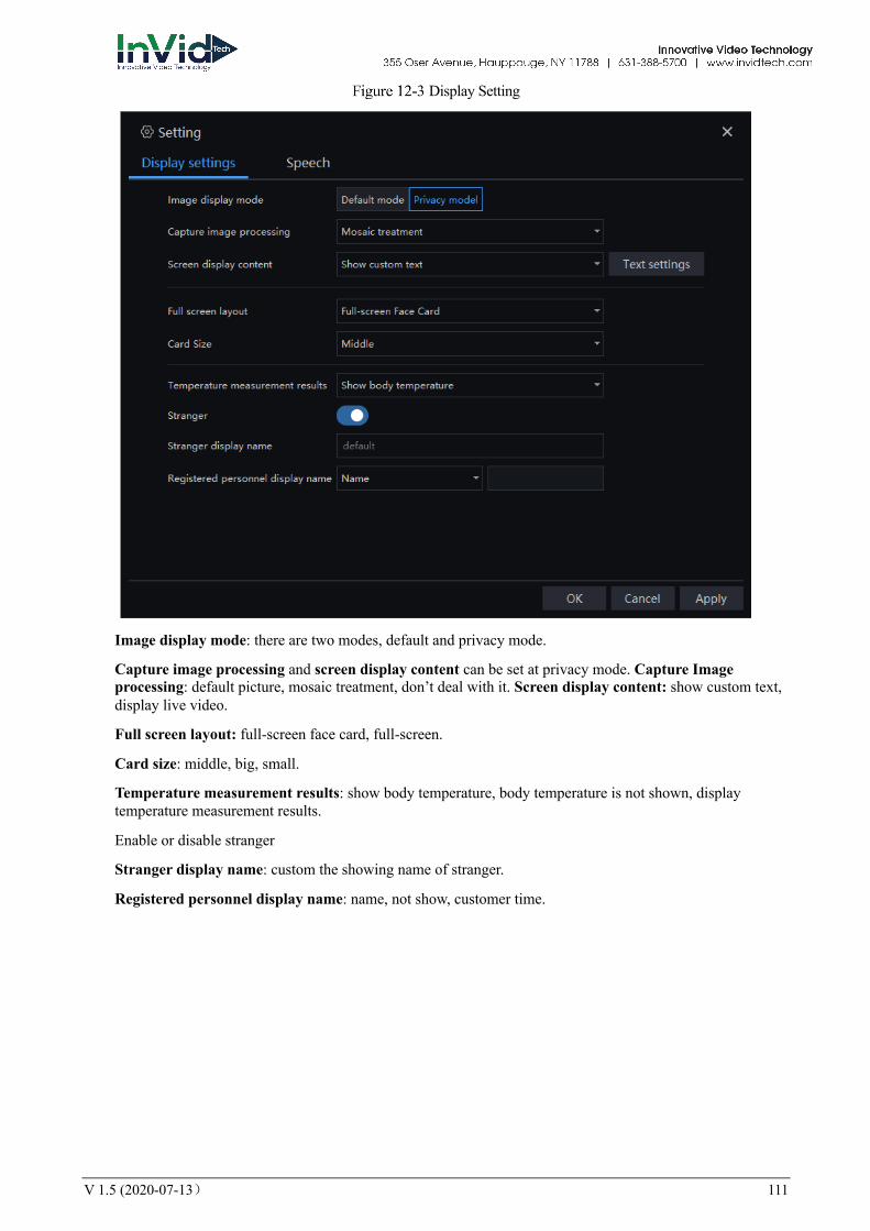
V 1.5 (2020-07-13) 111
Display Setting
Image display mode: there are two modes, default and privacy mode.
Capture image processing and screen display content can be set at privacy mode. Capture Image processing: default picture, mosaic treatment, don’t deal with it. Screen display content: show custom text, display live video.
Full screen layout: full-screen face card, full-screen.
Card size: middle, big, small.
Temperature measurement results: show body temperature, body temperature is not shown, display temperature measurement results.
Enable or disable stranger
Stranger display name: custom the showing name of stranger.
Registered personnel display name: name, not show, customer time.
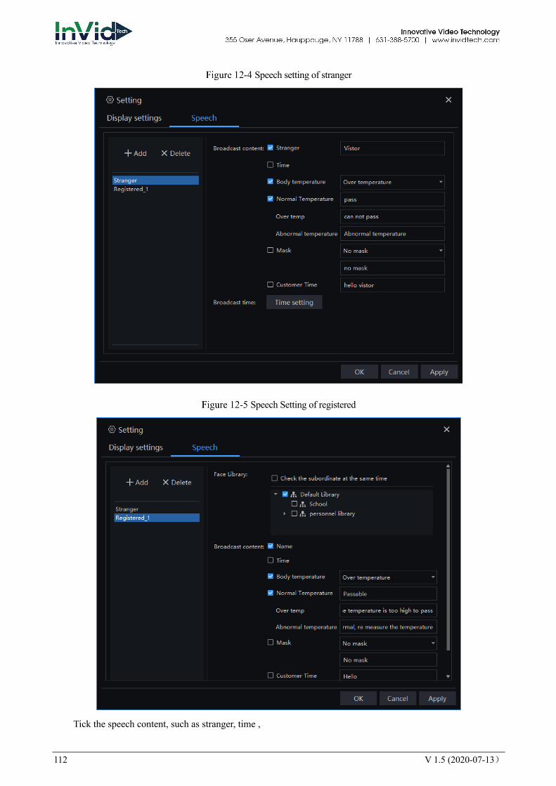
112 V 1.5 (2020-07-13)
Speech setting of stranger
Speech Setting of registered
Tick the speech content, such as stranger, time ,
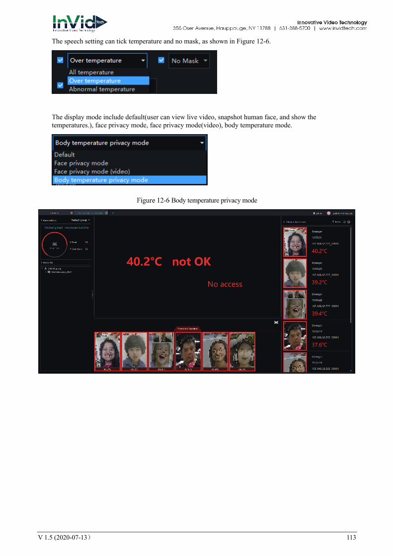
V 1.5 (2020-07-13) 113
The speech setting can tick temperature and no mask, as shown in Figure 12-6.
The display mode include default(user can view live video, snapshot human face, and show the temperatures.), face privacy mode, face privacy mode(video), body temperature mode.
Body temperature privacy mode

114 V 1.5 (2020-07-13)
Face privacy mode
Face privacy mode (video)
The reminder of no mask is set at “Server > CMU > Setting”interface. Enable the mask recognition. If the
function is disable, the will not appear.
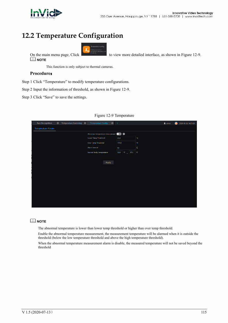
V 1.5 (2020-07-13) 115
12.2 Temperature Configuration
On the main menu page, Click to view more detailed interface, as shown in Figure 12-9. This function is only subject to thermal cameras.
Procedure:
Step 1 Click “Temperature” to modify temperature configurations.
Step 2 Input the information of threshold, as shown in Figure 12-9.
Step 3 Click “Save” to save the settings.
Temperature
The abnormal temperature is lower than lower temp threshold or higher than over temp threshold. Enable the abnormal temperature measurement, the measurement temperature will be alarmed when it is outside the threshold (below the low temperature threshold and above the high temperature threshold). When the abnormal temperature measurement alarm is disable, the measured temperature will not be saved beyond the threshold
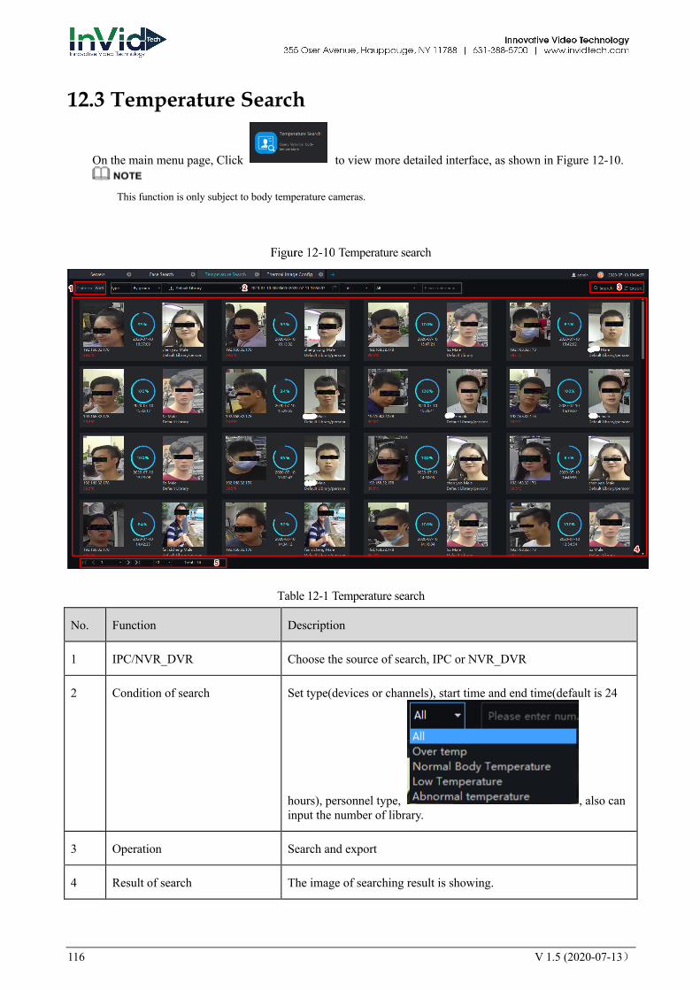
116 V 1.5 (2020-07-13)
12.3 Temperature Search
On the main menu page, Click to view more detailed interface, as shown in Figure 12-10.
This function is only subject to body temperature cameras.
Temperature search
Table 12-1 Temperature search
No. Function Description
1 IPC/NVR_DVR Choose the source of search, IPC or NVR_DVR
2 Condition of search Set type(devices or channels), start time and end time(default is 24
hours), personnel type, , also can input the number of library.
3 Operation Search and export
4 Result of search The image of searching result is showing.
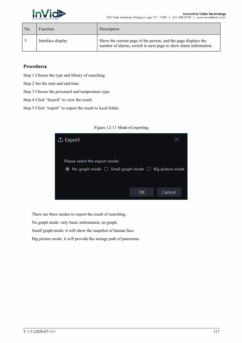
V 1.5 (2020-07-13) 117
No. Function Description
5 Interface display Show the current page of the person, and the page displays the number of alarms, switch to next page to show alarm information.
Procedure:
Step 1 Choose the type and library of searching.
Step 2 Set the start and end time.
Step 3 Choose the personnel and temperature type.
Step 4 Click “Search” to view the result.
Step 5 Click “export” to export the result to local folder.
Mode of exporting
There are three modes to export the result of searching.
No graph mode: only basic information, no graph.
Small graph mode: it will show the snapshot of human face.
Big picture mode: it will provide the storage path of panorama.
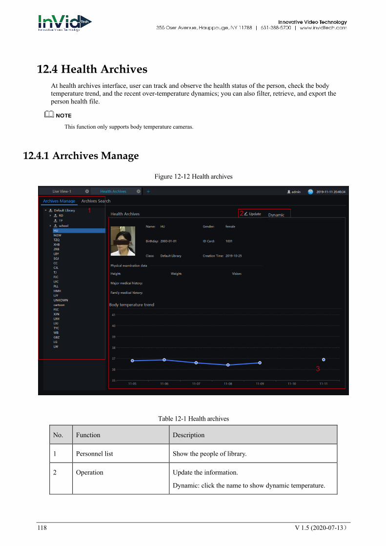
118 V 1.5 (2020-07-13)
12.4 Health Archives At health archives interface, user can track and observe the health status of the person, check the body temperature trend, and the recent over-temperature dynamics; you can also filter, retrieve, and export the person health file.
This function only supports body temperature cameras.
12.4.1 Arrchives Manage
Health archives
Table 12-1 Health archives
No. Function Description
1 Personnel list Show the people of library.
2 Operation Update the information.
Dynamic: click the name to show dynamic temperature.
1 2
3
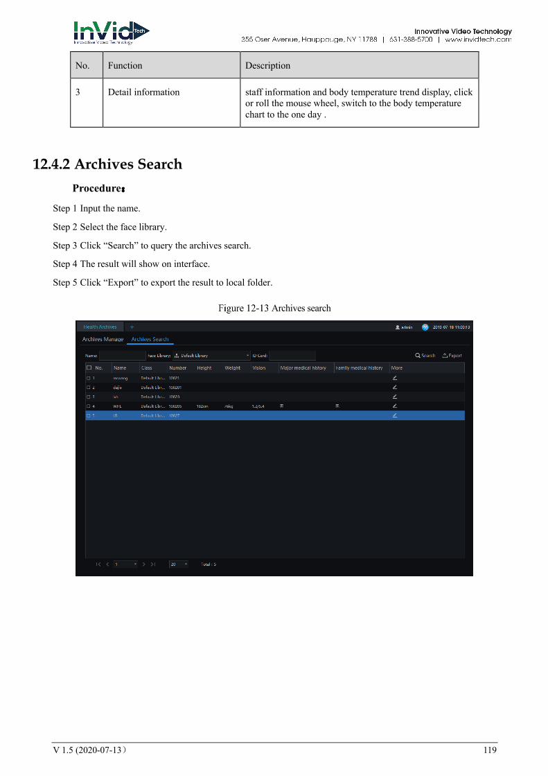
V 1.5 (2020-07-13) 119
No. Function Description
3 Detail information staff information and body temperature trend display, click or roll the mouse wheel, switch to the body temperature chart to the one day .
12.4.2 Archives Search Procedure:
Step 1 Input the name.
Step 2 Select the face library.
Step 3 Click “Search” to query the archives search.
Step 4 The result will show on interface.
Step 5 Click “Export” to export the result to local folder.
Archives search

120 V 1.5 (2020-07-13)
12.5 Temperature Statistics
On the main menu page, Click to view more detailed interface, as shown in Figure 12-14.
This function only supports temperature detection cameras. Only processed over-temperature alarms are counted in the statistics. The pie chart can be showed by temperature, or mask.
Temperature Statistics
The pie chart can show by temperature or mask.
12.5.1 Organization Over Temperature Procedure:
Step 1 Select the face database and summarize the type. You can view a summary of the month or day.
Step 2 Set the display sort type.
Step 3 User can click “ Export” to export the statistics.
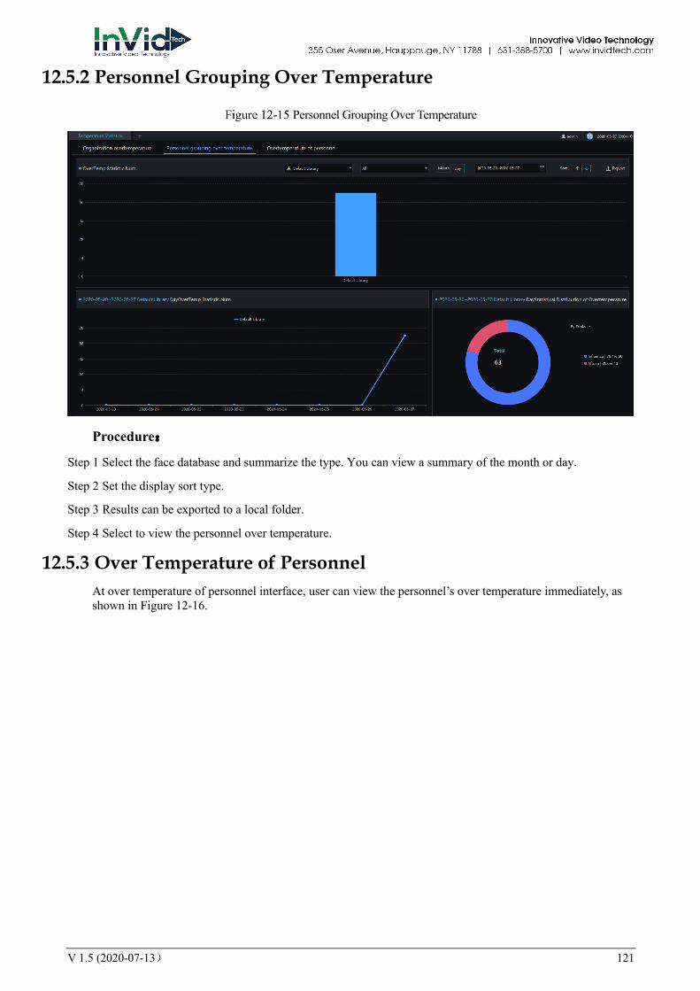
V 1.5 (2020-07-13) 121
12.5.2 Personnel Grouping Over Temperature
Personnel Grouping Over Temperature
Procedure:
Step 1 Select the face database and summarize the type. You can view a summary of the month or day.
Step 2 Set the display sort type.
Step 3 Results can be exported to a local folder.
Step 4 Select to view the personnel over temperature.
12.5.3 Over Temperature of Personnel At over temperature of personnel interface, user can view the personnel’s over temperature immediately, as shown in Figure 12-16.

122 V 1.5 (2020-07-13)
Person Over Temperature

V 1.5 (2020-07-13) 123
13 Thermal Imaging
13.1 Thermal Image History At the thermal temperature interface, you can search the temperature recording of thermal temperature cameras
This function only supports temperature detection cameras.
On the main menu page, Click to view more detailed interface, as shown in Figure 13-1.
Thermal image interface
Table 13-1 Temperature alarm
No. Function Instruction
1 The showing mode List or curve graph
2 IPC/NVR_DVR Choose the source of search, IPC or NVR_DVR
3 Temperature querying setting
Setting temperature search structure, Starting / Ending time, processing status
4 Querying condition Start and end time, interval and keyword
5 Search Search by the setting conditions
6 Displaying information Basic information display of temperature alarm

124 V 1.5 (2020-07-13)
No. Function Instruction
7 Page information Page number, number of pages per page, total
Switch to next page
Procedure:
Step 1 Choose the group / Organization .
Step 2 Setting Searching starting / ending time, processing.
Step 3 Click “ Search” the temperature alarm recording.
13.2 Thermal Image Configuration
On the main menu page, Click to view more detailed interface, as shown in Figure 13-2。
This function is only subject to thermal cameras.
Thermal image configuration
Procedure:
Step 1 Select the camera you want to set in the thermal imaging device list.
Step 2 Turn on the over-temperature alarm capture, set the capture interval and the count of captures.
Step 3 Set the arming time, you can pull the mouse, or select all.
Step 4 Click Copy to to copy the setup parameters to other cameras.
Step 5 Click “Apply “ to save settings.

V 1.5 (2020-07-13) 125
Step 6 Click “Copy to”, as shown in Figure 13-3
Copy to
13.3 Thermal Image Search At this page, you can search the body temperature from the recording.
This function only subject to the body temperature detection cameras.
On the main menu page, click to view more detailed interface, as shown in Figure 13-4.
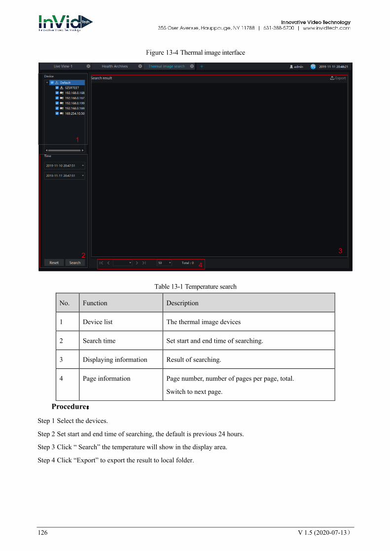
126 V 1.5 (2020-07-13)
Thermal image interface
Table 13-1 Temperature search
No. Function Description
1 Device list The thermal image devices
2 Search time Set start and end time of searching.
3 Displaying information Result of searching.
4 Page information Page number, number of pages per page, total.
Switch to next page.
Procedure:
Step 1 Select the devices.
Step 2 Set start and end time of searching, the default is previous 24 hours.
Step 3 Click “ Search” the temperature will show in the display area.
Step 4 Click “Export” to export the result to local folder.
1
2 3
4

V 1.5 (2020-07-13) 127