section vi technical schedules - kenya power
TRANSCRIPT
SECTION VI
TECHNICAL SCHEDULES
Kenya Power and Lighting Company VI 4.3 - i Contract A28/29/30
KENYA POWER IFC Projects Technical Specifications and Drawings
4.3Contr A39ABCD-Section VI-techsched-subst R1 July 2103 Kenya Power
TECHNICAL SCHEDULES ....................................................................................................................................................... 1 PREAMBLE ............................................................................................................................................................................. 1
TECHNICAL SCHEDULES SUBSTATIONS ............................................................................................................................. 2
SCHEDULE VI-1a TECHNICAL GUARANTEES, OUTDOOR SWITCHGEAR .................................................................... 2 SCHEDULE VI-2a TECHNICAL GUARANTEES, INDOOR MV INDOOR SWITCHGEAR ................................................. 8 SCHEDULE VI-2 GAURANTEE TECHNICAL SCHEDULE MV INDOOR VOLTAGE SWITCHGEAR ............................ 13 SCHEDULE VI 3a TECHNICAL GUARANTEES, CONTROL SYSTEM ............................................................................. 14 SCHEDULE VI 3b INFORMATIVE DATA, CONTROL SYSTEM ....................................................................................... 15 SCHEDULE VI 4a TECHNICAL GUARANTEES, PROTECTION ETC. ............................................................................. 16 SCHEDULE VI 4b INFORMATIVE DATA, PROTECTION ETC. ....................................................................................... 19 SCHEDULE VI 5b INFORMATIVE DATA, CABLES .......................................................................................................... 21 SCHEDULE VI 5b INFORMATIVE DATA, CABLES .......................................................................................................... 22 SCHEDULE VI 6a TECHNICAL GUARANTEES, EARTHING ........................................................................................... 23 SCHEDULE VI 6b INFORMATIVE DATA, EARTHING ..................................................................................................... 24
TECHNICAL SCHEDULES TRANSFORMERS ..................................................................................................................... 25
SCHEDULE VI 7a - TECHNICAL GUARANTEES, POWER TRANSFORMERS................................................................. 25 SCHEDULE VI-7b - INFORMATIVE DATA, POWER TRANSFORMERS .......................................................................... 32 SCHEDULE VI 8a - TECHNICAL GUARANTEES, DISTRIBUTION TRANSFORMERS ................................................... 41 SCHEDULE VI-8b - INFORMATIVE DATA, DISTRIBUTION TRANSFORMER .............................................................. 43
SCHEDULE VI-9A- GAURANTEE DATA TELECOMMUNICATIONS SYSTEM: .......................................................... 45
SCHEDULE VI-10A- GAURANTEE DATA 66KV SURGE ARRESTERS ........................................................................... 50
SCHEDULE VI-11A- GAURANTEE DATA 66KV DISCONNECTOR (ISOLATOR) PART 1:SUBSTATION TYPE ... 51
12 TABLE OF CONFORMANCE ........................................................................................................................................... 55
Kenya Power and Lighting Company VI 4.3 - 1 Contract A28/29/30
KENYA POWER IFC Projects Technical Specifications and Drawings
4.3Contr A39ABCD-Section VI-techsched-subst R1 July 2103 Kenya Power
TECHNICAL SCHEDULES
PREAMBLE
1.1 All data entered in the Schedules of Technical Guarantees are guaranteed values by the Bidder and cannot
be departed from whatsoever.
1.2 All data entered in the Schedules of Informative. Data are also guaranteed values by the Bidder. These data
may only be altered following the Project Manager's written consent.
Kenya Power and Lighting Company VI 4.3 - 2 Contract A28/29/30
KENYA POWER IFC Projects Technical Specifications and Drawings
4.3Contr A39ABCD-Section VI-techsched-subst R1 July 2103 Kenya Power
TECHNICAL SCHEDULES SUBSTATIONS
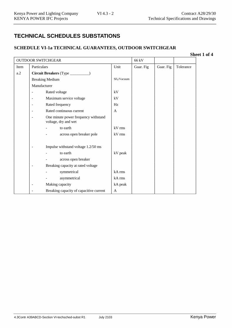
SCHEDULE VI-1a TECHNICAL GUARANTEES, OUTDOOR SWITCHGEAR
Sheet 1 of 4
OUTDOOR SWITCHGEAR 66 kV
Item Particulars Unit Guar. Fig Guar. Fig Tolerance
a.2 Circuit Breakers (Type __________)
Breaking Medium SF6/Vacuum
Manufacturer
- Rated voltage kV
- Maximum service voltage kV
- Rated frequency Hz
- Rated continuous current A
- One minute power frequency withstand
voltage, dry and wet
- to earth kV rms
- across open breaker pole kV rms
- Impulse withstand voltage 1.2/50 ms
- to earth kV peak
- across open breaker
- Breaking capacity at rated voltage
- symmetrical kA rms
- asymmetrical kA rms
- Making capacity kA peak
- Breaking capacity of capacitive current A
Kenya Power and Lighting Company VI 4.3 - 3 Contract A28/29/30
KENYA POWER IFC Projects Technical Specifications and Drawings
4.3Contr A39ABCD-Section VI-techsched-subst R1 July 2103 Kenya Power
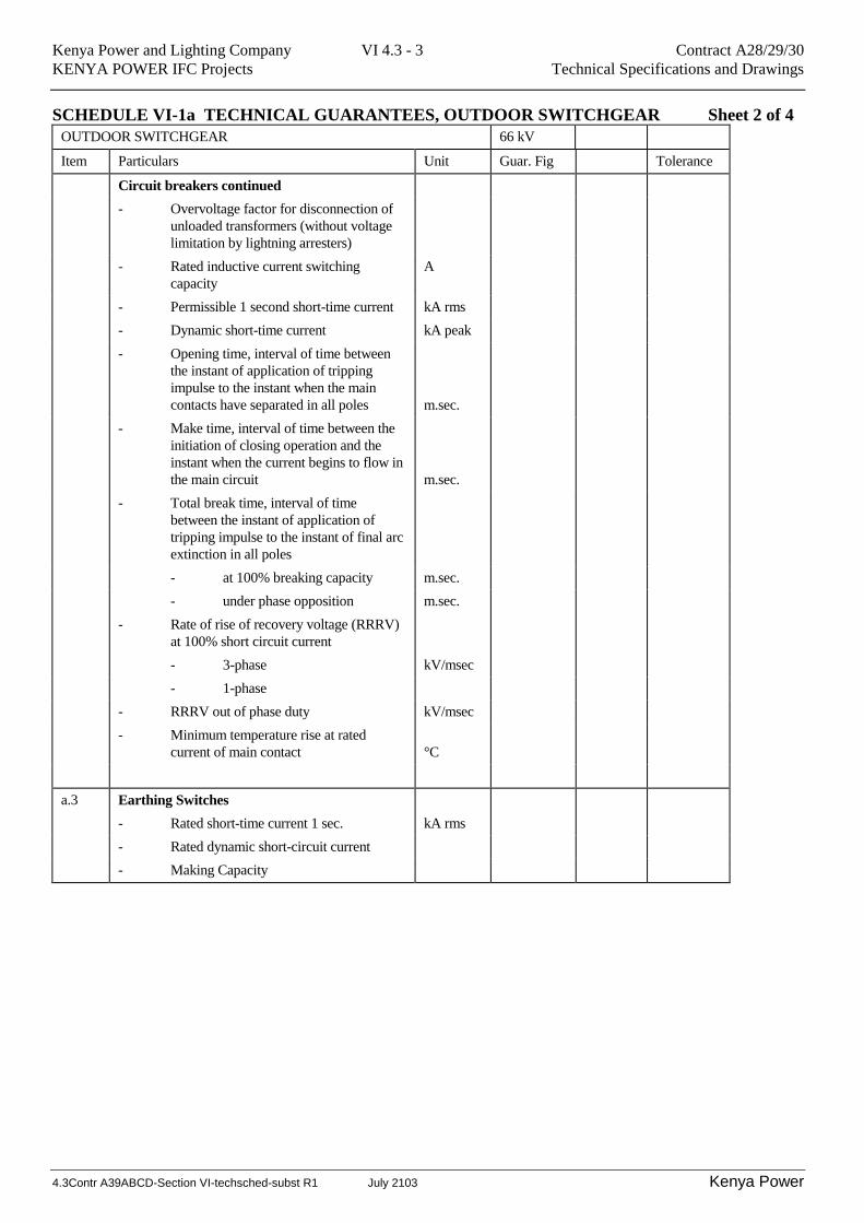
SCHEDULE VI-1a TECHNICAL GUARANTEES, OUTDOOR SWITCHGEAR Sheet 2 of 4
OUTDOOR SWITCHGEAR 66 kV
Item Particulars Unit Guar. Fig Tolerance
Circuit breakers continued
- Overvoltage factor for disconnection of
unloaded transformers (without voltage
limitation by lightning arresters)
- Rated inductive current switching
capacity
A
- Permissible 1 second short-time current kA rms
- Dynamic short-time current kA peak
- Opening time, interval of time between
the instant of application of tripping
impulse to the instant when the main
contacts have separated in all poles
m.sec.
- Make time, interval of time between the
initiation of closing operation and the
instant when the current begins to flow in
the main circuit
m.sec.
- Total break time, interval of time
between the instant of application of
tripping impulse to the instant of final arc
extinction in all poles
- at 100% breaking capacity m.sec.
- under phase opposition m.sec.
- Rate of rise of recovery voltage (RRRV)
at 100% short circuit current
- 3-phase kV/msec
- 1-phase
- RRRV out of phase duty kV/msec
- Minimum temperature rise at rated
current of main contact
°C
a.3 Earthing Switches
- Rated short-time current 1 sec. kA rms
- Rated dynamic short-circuit current
- Making Capacity
Kenya Power and Lighting Company VI 4.3 - 4 Contract A28/29/30
KENYA POWER IFC Projects Technical Specifications and Drawings
4.3Contr A39ABCD-Section VI-techsched-subst R1 July 2103 Kenya Power
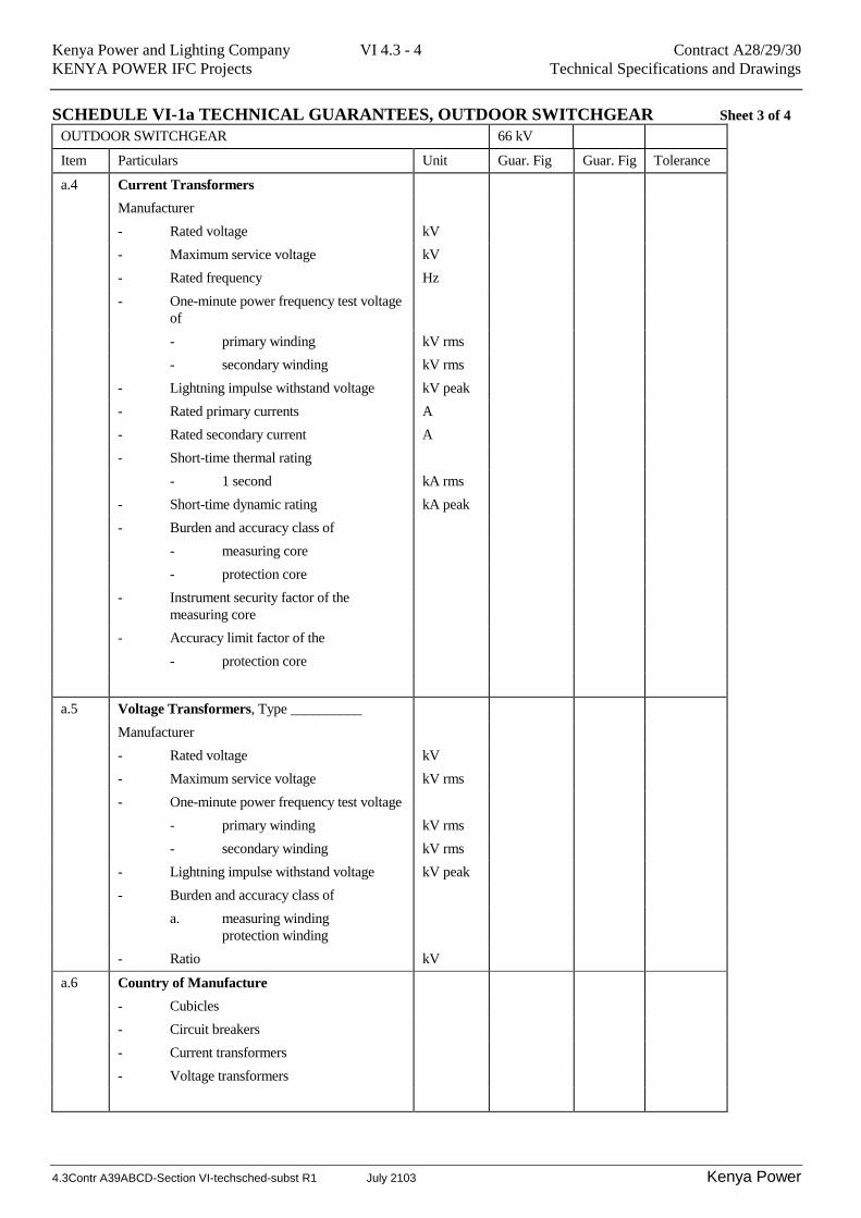
SCHEDULE VI-1a TECHNICAL GUARANTEES, OUTDOOR SWITCHGEAR Sheet 3 of 4
OUTDOOR SWITCHGEAR 66 kV
Item Particulars Unit Guar. Fig Guar. Fig Tolerance
a.4 Current Transformers
Manufacturer
- Rated voltage kV
- Maximum service voltage kV
- Rated frequency Hz
- One-minute power frequency test voltage
of
- primary winding kV rms
- secondary winding kV rms
- Lightning impulse withstand voltage kV peak
- Rated primary currents A
- Rated secondary current A
- Short-time thermal rating
- 1 second kA rms
- Short-time dynamic rating kA peak
- Burden and accuracy class of
- measuring core
- protection core
- Instrument security factor of the
measuring core
- Accuracy limit factor of the
- protection core
a.5 Voltage Transformers, Type __________
Manufacturer
- Rated voltage kV
- Maximum service voltage kV rms
- One-minute power frequency test voltage
- primary winding kV rms
- secondary winding kV rms
- Lightning impulse withstand voltage kV peak
- Burden and accuracy class of
a. measuring winding
protection winding
- Ratio kV
a.6 Country of Manufacture
- Cubicles
- Circuit breakers
- Current transformers
- Voltage transformers
Kenya Power and Lighting Company VI 4.3 - 5 Contract A28/29/30
KENYA POWER IFC Projects Technical Specifications and Drawings
4.3Contr A39ABCD-Section VI-techsched-subst R1 July 2103 Kenya Power
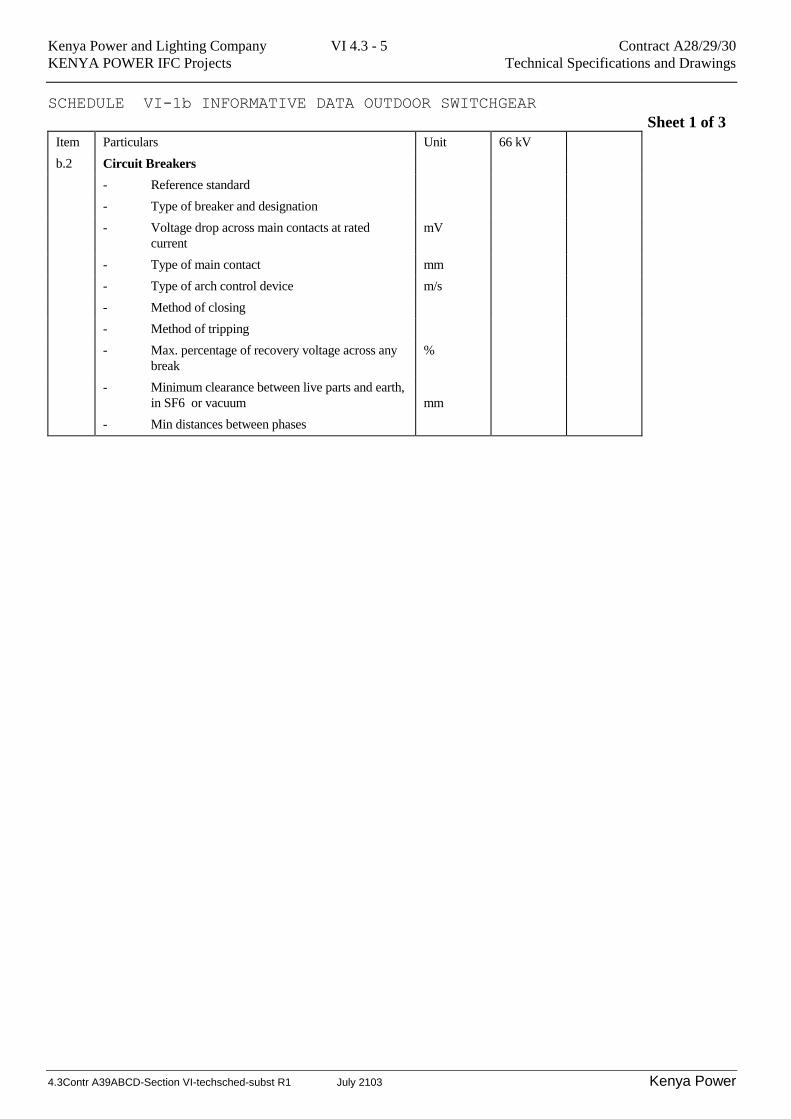
SCHEDULE VI-1b INFORMATIVE DATA OUTDOOR SWITCHGEAR
Sheet 1 of 3
Item Particulars Unit 66 kV
b.2 Circuit Breakers
- Reference standard
- Type of breaker and designation
- Voltage drop across main contacts at rated
current
mV
- Type of main contact mm
- Type of arch control device m/s
- Method of closing
- Method of tripping
- Max. percentage of recovery voltage across any
break
%
- Minimum clearance between live parts and earth,
in SF6 or vacuum
mm
- Min distances between phases
Kenya Power and Lighting Company VI 4.3 - 6 Contract A28/29/30
KENYA POWER IFC Projects Technical Specifications and Drawings
4.3Contr A39ABCD-Section VI-techsched-subst R1 July 2103 Kenya Power
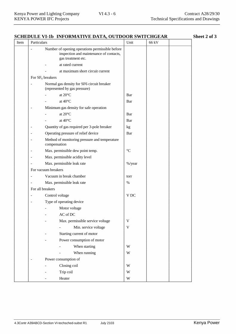
SCHEDULE VI-1b INFORMATIVE DATA, OUTDOOR SWITCHGEAR Sheet 2 of 3
Item Particulars Unit 66 kV
- Number of opening operations permissible before
inspection and maintenance of contacts,
gas treatment etc.
- at rated current
- at maximum short circuit current
For SF6 breakers
- Normal gas density for SF6 circuit breaker
(represented by gas pressure)
- at 20°C Bar
- at 40°C Bar
- Minimum gas density for safe operation
- at 20°C Bar
- at 40°C Bar
- Quantity of gas required per 3-pole breaker kg
- Operating pressure of relief device Bar
- Method of monitoring pressure and temperature
compensation
- Max. permissible dew point temp. °C
- Max. permissible acidity level
- Max. permissible leak rate %/year
For vacuum breakers
- Vacuum in break chamber torr
- Max. permissible leak rate %
For all breakers
- Control voltage V DC
- Type of operating device
- Motor voltage
- AC of DC
- Max. permissible service voltage V
- Min. service voltage V
- Starting current of motor
- Power consumption of motor
- When starting W
- When running W
- Power consumption of
- Closing coil W
- Trip coil W
- Heater W
Kenya Power and Lighting Company VI 4.3 - 7 Contract A28/29/30
KENYA POWER IFC Projects Technical Specifications and Drawings
4.3Contr A39ABCD-Section VI-techsched-subst R1 July 2103 Kenya Power
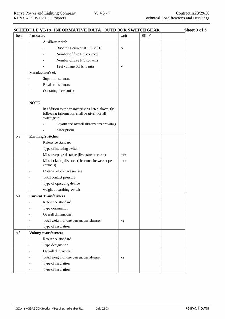
SCHEDULE VI-1b INFORMATIVE DATA, OUTDOOR SWITCHGEAR Sheet 3 of 3
Item Particulars Unit 66 kV
- Auxiliary switch
- Rupturing current at 110 V DC A
- Number of free NO contacts
- Number of free NC contacts
- Test voltage 50Hz, 1 min. V
Manufacturer's of:
- Support insulators
- Breaker insulators
- Operating mechanism
NOTE
- In addition to the characteristics listed above, the
following information shall be given for all
switchgear:
- Layout and overall dimensions drawings
- descriptions
b.3 Earthing Switches
- Reference standard
- Type of isolating switch
- Min. creepage distance (live parts to earth) mm
- Min. isolating distance (clearance between open
contacts)
mm
- Material of contact surface
- Total contact pressure
- Type of operating device
- weight of earthing switch
b.4 Current Transformers
- Reference standard
- Type designation
- Overall dimensions
- Total weight of one current transformer kg
- Type of insulation
b.5 Voltage transformers
- Reference standard
- Type designation
- Overall dimensions
- Total weight of one current transformer kg
- Type of insulation
- Type of insulation
Kenya Power and Lighting Company VI 4.3 - 8 Contract A28/29/30
KENYA POWER IFC Projects Technical Specifications and Drawings
4.3Contr A39ABCD-Section VI-techsched-subst R1 July 2103 Kenya Power
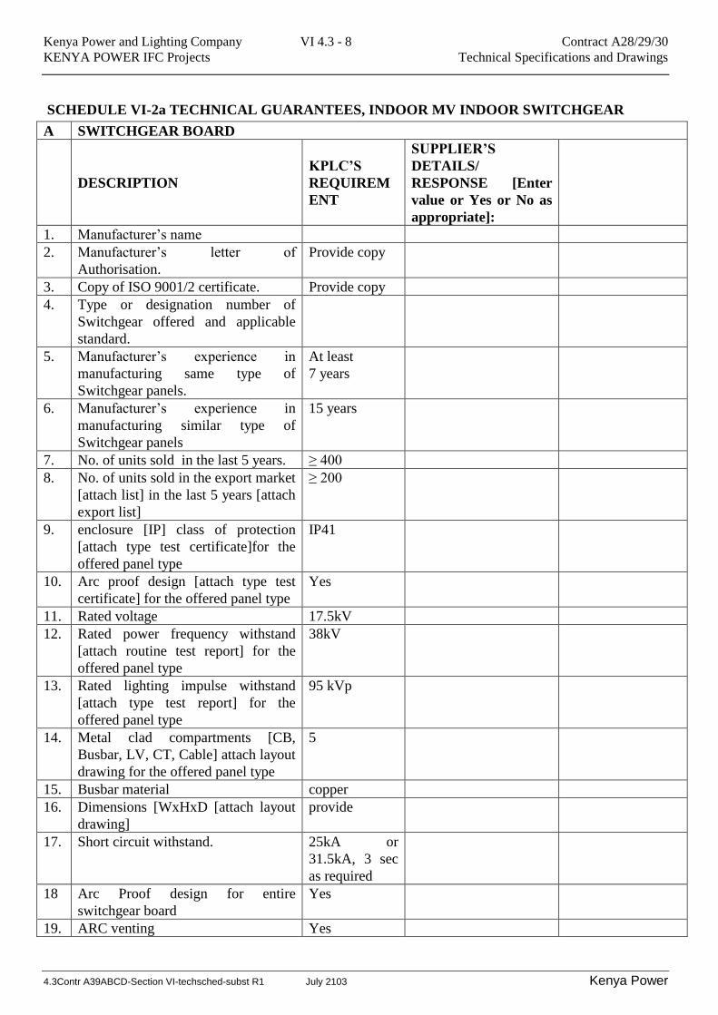
SCHEDULE VI-2a TECHNICAL GUARANTEES, INDOOR MV INDOOR SWITCHGEAR
A SWITCHGEAR BOARD
DESCRIPTION
KPLC’S
REQUIREM
ENT
SUPPLIER’S
DETAILS/
RESPONSE [Enter
value or Yes or No as
appropriate]:
1. Manufacturer’s name
2. Manufacturer’s letter of
Authorisation.
Provide copy
3. Copy of ISO 9001/2 certificate. Provide copy
4. Type or designation number of
Switchgear offered and applicable
standard.
5. Manufacturer’s experience in
manufacturing same type of
Switchgear panels.
At least
7 years
6. Manufacturer’s experience in
manufacturing similar type of
Switchgear panels
15 years
7. No. of units sold in the last 5 years. ≥ 400
8. No. of units sold in the export market
[attach list] in the last 5 years [attach
export list]
≥ 200
9. enclosure [IP] class of protection
[attach type test certificate]for the
offered panel type
IP41
10. Arc proof design [attach type test
certificate] for the offered panel type
Yes
11. Rated voltage 17.5kV
12. Rated power frequency withstand
[attach routine test report] for the
offered panel type
38kV
13. Rated lighting impulse withstand
[attach type test report] for the
offered panel type
95 kVp
14. Metal clad compartments [CB,
Busbar, LV, CT, Cable] attach layout
drawing for the offered panel type
5
15. Busbar material copper
16. Dimensions [WxHxD [attach layout
drawing]
provide
17. Short circuit withstand. 25kA or
31.5kA, 3 sec
as required
18 Arc Proof design for entire
switchgear board
Yes
19. ARC venting Yes
Kenya Power and Lighting Company VI 4.3 - 9 Contract A28/29/30
KENYA POWER IFC Projects Technical Specifications and Drawings
4.3Contr A39ABCD-Section VI-techsched-subst R1 July 2103 Kenya Power
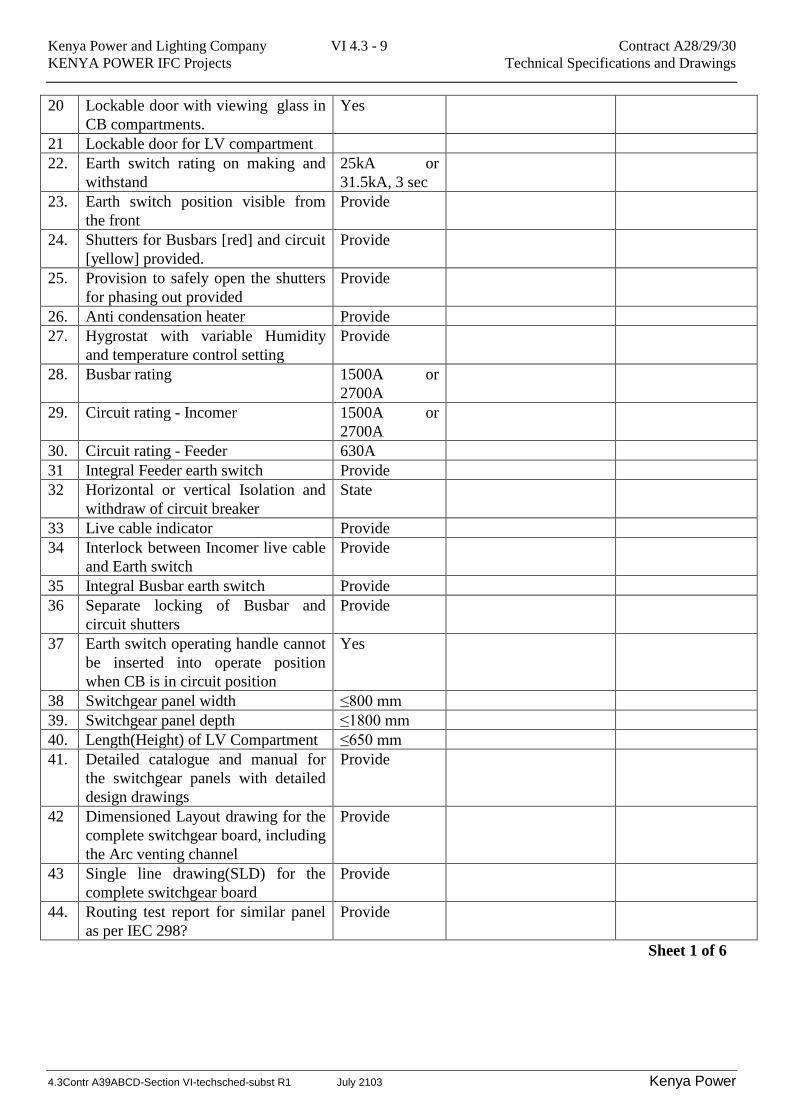
20 Lockable door with viewing glass in
CB compartments.
Yes
21 Lockable door for LV compartment
22. Earth switch rating on making and
withstand
25kA or
31.5kA, 3 sec
23. Earth switch position visible from
the front
Provide
24. Shutters for Busbars [red] and circuit
[yellow] provided.
Provide
25. Provision to safely open the shutters
for phasing out provided
Provide
26. Anti condensation heater Provide
27. Hygrostat with variable Humidity
and temperature control setting
Provide
28. Busbar rating 1500A or
2700A
29. Circuit rating - Incomer 1500A or
2700A
30. Circuit rating - Feeder 630A
31 Integral Feeder earth switch Provide
32 Horizontal or vertical Isolation and
withdraw of circuit breaker
State
33 Live cable indicator Provide
34 Interlock between Incomer live cable
and Earth switch
Provide
35 Integral Busbar earth switch Provide
36 Separate locking of Busbar and
circuit shutters
Provide
37 Earth switch operating handle cannot
be inserted into operate position
when CB is in circuit position
Yes
38 Switchgear panel width ≤800 mm
39. Switchgear panel depth ≤1800 mm
40. Length(Height) of LV Compartment ≤650 mm
41. Detailed catalogue and manual for
the switchgear panels with detailed
design drawings
Provide
42 Dimensioned Layout drawing for the
complete switchgear board, including
the Arc venting channel
Provide
43 Single line drawing(SLD) for the
complete switchgear board
Provide
44. Routing test report for similar panel
as per IEC 298?
Provide
Sheet 1 of 6
Kenya Power and Lighting Company VI 4.3 - 10 Contract A28/29/30
KENYA POWER IFC Projects Technical Specifications and Drawings
4.3Contr A39ABCD-Section VI-techsched-subst R1 July 2103 Kenya Power
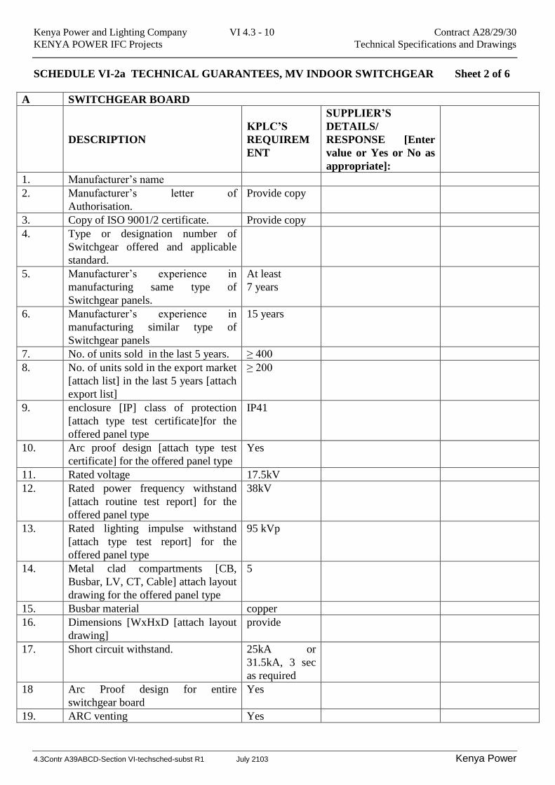
SCHEDULE VI-2a TECHNICAL GUARANTEES, MV INDOOR SWITCHGEAR Sheet 2 of 6
A SWITCHGEAR BOARD
DESCRIPTION
KPLC’S
REQUIREM
ENT
SUPPLIER’S
DETAILS/
RESPONSE [Enter
value or Yes or No as
appropriate]:
1. Manufacturer’s name
2. Manufacturer’s letter of
Authorisation.
Provide copy
3. Copy of ISO 9001/2 certificate. Provide copy
4. Type or designation number of
Switchgear offered and applicable
standard.
5. Manufacturer’s experience in
manufacturing same type of
Switchgear panels.
At least
7 years
6. Manufacturer’s experience in
manufacturing similar type of
Switchgear panels
15 years
7. No. of units sold in the last 5 years. ≥ 400
8. No. of units sold in the export market
[attach list] in the last 5 years [attach
export list]
≥ 200
9. enclosure [IP] class of protection
[attach type test certificate]for the
offered panel type
IP41
10. Arc proof design [attach type test
certificate] for the offered panel type
Yes
11. Rated voltage 17.5kV
12. Rated power frequency withstand
[attach routine test report] for the
offered panel type
38kV
13. Rated lighting impulse withstand
[attach type test report] for the
offered panel type
95 kVp
14. Metal clad compartments [CB,
Busbar, LV, CT, Cable] attach layout
drawing for the offered panel type
5
15. Busbar material copper
16. Dimensions [WxHxD [attach layout
drawing]
provide
17. Short circuit withstand. 25kA or
31.5kA, 3 sec
as required
18 Arc Proof design for entire
switchgear board
Yes
19. ARC venting Yes
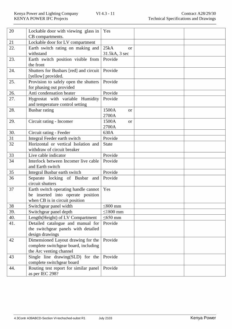
Kenya Power and Lighting Company VI 4.3 - 11 Contract A28/29/30
KENYA POWER IFC Projects Technical Specifications and Drawings
4.3Contr A39ABCD-Section VI-techsched-subst R1 July 2103 Kenya Power
20 Lockable door with viewing glass in
CB compartments.
Yes
21 Lockable door for LV compartment
22. Earth switch rating on making and
withstand
25kA or
31.5kA, 3 sec
23. Earth switch position visible from
the front
Provide
24. Shutters for Busbars [red] and circuit
[yellow] provided.
Provide
25. Provision to safely open the shutters
for phasing out provided
Provide
26. Anti condensation heater Provide
27. Hygrostat with variable Humidity
and temperature control setting
Provide
28. Busbar rating 1500A or
2700A
29. Circuit rating - Incomer 1500A or
2700A
30. Circuit rating - Feeder 630A
31 Integral Feeder earth switch Provide
32 Horizontal or vertical Isolation and
withdraw of circuit breaker
State
33 Live cable indicator Provide
34 Interlock between Incomer live cable
and Earth switch
Provide
35 Integral Busbar earth switch Provide
36 Separate locking of Busbar and
circuit shutters
Provide
37 Earth switch operating handle cannot
be inserted into operate position
when CB is in circuit position
Yes
38 Switchgear panel width ≤800 mm
39. Switchgear panel depth ≤1800 mm
40. Length(Height) of LV Compartment ≤650 mm
41. Detailed catalogue and manual for
the switchgear panels with detailed
design drawings
Provide
42 Dimensioned Layout drawing for the
complete switchgear board, including
the Arc venting channel
Provide
43 Single line drawing(SLD) for the
complete switchgear board
Provide
44. Routing test report for similar panel
as per IEC 298?
Provide
Kenya Power and Lighting Company VI 4.3 - 12 Contract A28/29/30
KENYA POWER IFC Projects Technical Specifications and Drawings
4.3Contr A39ABCD-Section VI-techsched-subst R1 July 2103 Kenya Power
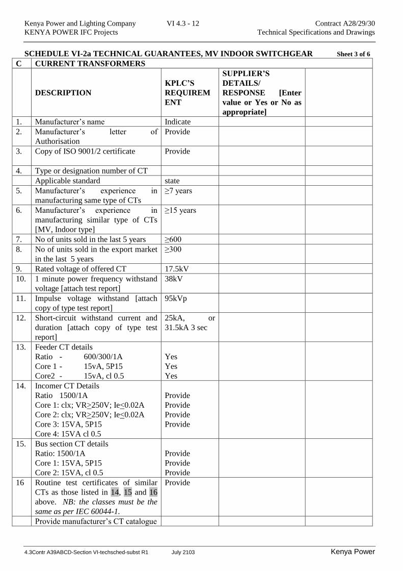
SCHEDULE VI-2a TECHNICAL GUARANTEES, MV INDOOR SWITCHGEAR Sheet 3 of 6
C CURRENT TRANSFORMERS
DESCRIPTION
KPLC’S
REQUIREM
ENT
SUPPLIER’S
DETAILS/
RESPONSE [Enter
value or Yes or No as
appropriate]
1. Manufacturer’s name Indicate
2. Manufacturer’s letter of
Authorisation
Provide
3. Copy of ISO 9001/2 certificate Provide
4. Type or designation number of CT
Applicable standard state
5. Manufacturer’s experience in
manufacturing same type of CTs
≥7 years
6. Manufacturer’s experience in
manufacturing similar type of CTs
[MV, Indoor type]
≥15 years
7. No of units sold in the last 5 years ≥600
8. No of units sold in the export market
in the last 5 years
≥300
9. Rated voltage of offered CT 17.5kV
10. 1 minute power frequency withstand
voltage [attach test report]
38kV
11. Impulse voltage withstand [attach
copy of type test report]
95kVp
12. Short-circuit withstand current and
duration [attach copy of type test
report]
25kA, or
31.5kA 3 sec
13. Feeder CT details
Ratio - 600/300/1A
Core 1 - 15vA, 5P15
Core2 - 15vA, cl 0.5
Yes
Yes
Yes
14. Incomer CT Details
Ratio 1500/1A
Core 1: clx; VR>250V; Ie<0.02A
Core 2: clx; VR>250V; Ie<0.02A
Core 3: 15VA, 5P15
Core 4: 15VA cl 0.5
Provide
Provide
Provide
Provide
15. Bus section CT details
Ratio: 1500/1A
Core 1: 15VA, 5P15
Core 2: 15VA, cl 0.5
Provide
Provide
Provide
16 Routine test certificates of similar
CTs as those listed in 14, 15 and 16
above. NB: the classes must be the
same as per IEC 60044-1.
Provide
Provide manufacturer’s CT catalogue
Kenya Power and Lighting Company VI 4.3 - 13 Contract A28/29/30
KENYA POWER IFC Projects Technical Specifications and Drawings
4.3Contr A39ABCD-Section VI-techsched-subst R1 July 2103 Kenya Power
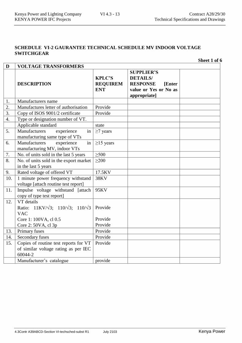
SCHEDULE VI-2 GAURANTEE TECHNICAL SCHEDULE MV INDOOR VOLTAGE
SWITCHGEAR
Sheet 1 of 6
D VOLTAGE TRANSFORMERS
DESCRIPTION
KPLC’S
REQUIREM
ENT
SUPPLIER’S
DETAILS/
RESPONSE [Enter
value or Yes or No as
appropriate]
1. Manufacturers name
2. Manufactures letter of authorisation Provide
3. Copy of ISOS 9001/2 certificate Provide
4. Type or designation number of VT.
Applicable standard state
5. Manufacturers experience in
manufacturing same type of VTs
≥7 years
6. Manufacturers experience in
manufacturing MV, indoor VTs
≥15 years
7. No. of units sold in the last 5 years ≥500
8. No. of units sold in the export market
in the last 5 years
≥200
9. Rated voltage of offered VT 17.5KV
10. 1 minute power frequency withstand
voltage [attach routine test report]
38KV
11. Impulse voltage withstand [attach
copy of type test report]
95KV
12. VT details
Ratio: 11KV/3; 110/3; 110/3
VAC
Core 1: 100VA, cl 0.5
Core 2: 50VA, cl 3p
Provide
Provide
Provide
13. Primary fuses Provide
14. Secondary fuses Provide
15. Copies of routine test reports for VT
of similar voltage rating as per IEC
60044-2
Provide
Manufacturer’s catalogue provide
Kenya Power and Lighting Company VI 4.3 - 14 Contract A28/29/30
KENYA POWER IFC Projects Technical Specifications and Drawings
4.3Contr A39ABCD-Section VI-techsched-subst R1 July 2103 Kenya Power
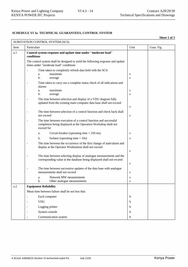
SCHEDULE VI 3a TECHNICAL GUARANTEES, CONTROL SYSTEM
Sheet 1 of 1
SUBSTATION CONTROL SYSTEM (SCS)
Item Particulars Unit Guar. Fig
a.1 Control system response and update time under "moderate load"
conditions
The control system shall be designed to yield the following response and update
times under "moderate load" conditions
- Time taken to completely refresh data held with the SCS:
a. maximum
b. average
s
s
- Time taken to carry out a complete status check of all indications and
alarms
a. maximum
b. average
s
s
- The time between selection and display of a VDU diagram fully
updated from the existing main computer data base shall not exceed
s
- The time between selection of a control function and check back shall
not exceed
s
- The time between execution of a control function and successful
completion being displayed at the Operation Workshop shall not
exceed for
a. Circuit breaker (operating time = 250 ms) s
b. Isolator (operating time = 10s) s
- The time between the occurrence of the first change of state/alarm and
display at the Operator Workstation shall not exceed
s
- The time between selecting display of analogue measurements and the
corresponding value in the database being displayed shall not exceed
s
- The time between successive updates of the data base with analogue
measurements shall not exceed
s
a. Network MW measurements
b. Other analogue measurements
s
s
a.2 Equipment Reliability
Mean time between failure shall be not less that:
- Each computer h
- VDU h
- Logging printer h
- System console h
- Communication system h
Kenya Power and Lighting Company VI 4.3 - 15 Contract A28/29/30
KENYA POWER IFC Projects Technical Specifications and Drawings
4.3Contr A39ABCD-Section VI-techsched-subst R1 July 2103 Kenya Power
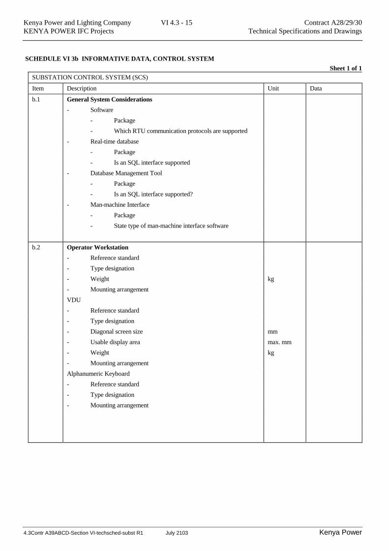
SCHEDULE VI 3b INFORMATIVE DATA, CONTROL SYSTEM
Sheet 1 of 1
SUBSTATION CONTROL SYSTEM (SCS)
Item Description Unit Data
b.1 General System Considerations
- Software
- Package
- Which RTU communication protocols are supported
- Real-time database
- Package
- Is an SQL interface supported
- Database Management Tool
- Package
- Is an SQL interface supported?
- Man-machine Interface
- Package
- State type of man-machine interface software
b.2 Operator Workstation
- Reference standard
- Type designation
- Weight kg
- Mounting arrangement
VDU
- Reference standard
- Type designation
- Diagonal screen size mm
- Usable display area max. mm
- Weight kg
- Mounting arrangement
Alphanumeric Keyboard
- Reference standard
- Type designation
- Mounting arrangement

Kenya Power and Lighting Company VI 4.3 - 16 Contract A28/29/30
KENYA POWER IFC Projects Technical Specifications and Drawings
4.3Contr A39ABCD-Section VI-techsched-subst R1 July 2103 Kenya Power
SCHEDULE VI 4a TECHNICAL GUARANTEES, PROTECTION ETC.
Sheet 1 of 3
CONTROL, PROTECTION, METERING, SIGNALLING
Item Particulars Unit Guar. Fig Tolerance
a.1 Indicating Instruments
- To be filled in for each AC and DC Ampere meter
and Voltmeter and for each Wattmeter, VAr-meter,
Frequency-meter and other indicating instruments:
- Instrument for:
(A, V (AC), V (DC), W, etc.)
- Error %
- Max. admissible current %.IN
- Max. admissible voltage %.IN
a.2 Meters
- To be filled in for each meter
- Meter for (MWh, MVArh):
- Error with 5% load %
- Error with 10% load %
- Error with 20% load %
- Error with 100% load %
- Max. admissible current
%.IN
a.3 Metering Converters (Transducers)
- Converter for (MW, MVAr, A, etc):
- Error %
- Linearity %
- Max. admissible current for 0.5 seconds %.IN
- Max. admissible current continuously %.IN
- Max. admissible voltage for 0.5 seconds %.IN
- Max. admissible voltage continuously
%.IN
Kenya Power and Lighting Company VI 4.3 - 17 Contract A28/29/30
KENYA POWER IFC Projects Technical Specifications and Drawings
4.3Contr A39ABCD-Section VI-techsched-subst R1 July 2103 Kenya Power
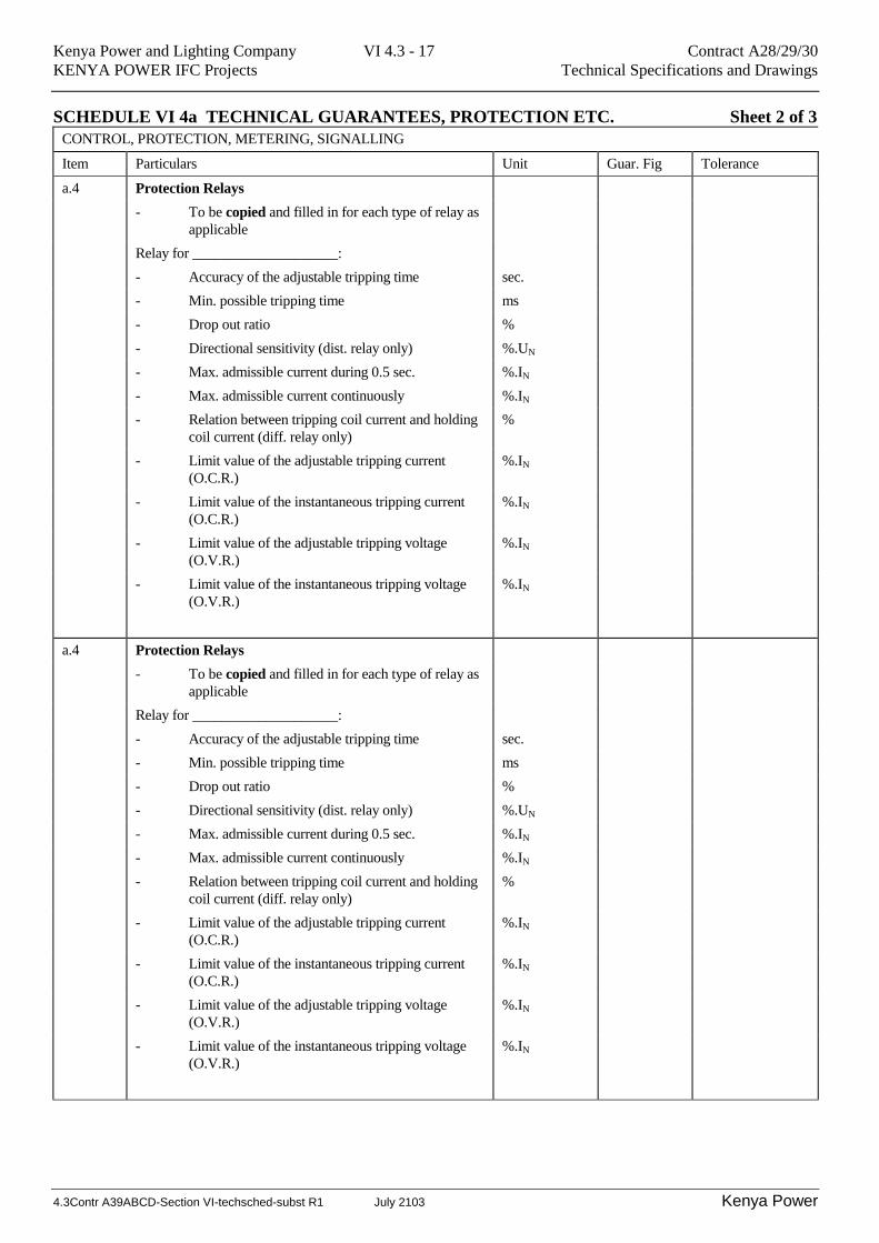
SCHEDULE VI 4a TECHNICAL GUARANTEES, PROTECTION ETC. Sheet 2 of 3
CONTROL, PROTECTION, METERING, SIGNALLING
Item Particulars Unit Guar. Fig Tolerance
a.4 Protection Relays
- To be copied and filled in for each type of relay as
applicable
Relay for ____________________:
- Accuracy of the adjustable tripping time sec.
- Min. possible tripping time ms
- Drop out ratio %
- Directional sensitivity (dist. relay only) %.UN
- Max. admissible current during 0.5 sec. %.IN
- Max. admissible current continuously %.IN
- Relation between tripping coil current and holding
coil current (diff. relay only)
%
- Limit value of the adjustable tripping current
(O.C.R.)
%.IN
- Limit value of the instantaneous tripping current
(O.C.R.)
%.IN
- Limit value of the adjustable tripping voltage
(O.V.R.)
%.IN
- Limit value of the instantaneous tripping voltage
(O.V.R.)
%.IN

Kenya Power and Lighting Company VI 4.3 - 18 Contract A28/29/30
KENYA POWER IFC Projects Technical Specifications and Drawings
4.3Contr A39ABCD-Section VI-techsched-subst R1 July 2103 Kenya Power
SCHEDULE VI 4a TECHNICAL GUARANTEES, PROTECTION ETC. Sheet 3 of 3
CONTROL, PROTECTION, METERING, SIGNALLING
Item Particulars Unit Guar. Fig Tolerance
a.5 Auxiliary Circuit Breakers
- To be filled in for each type of AC and DC
breaker:
- Min. operating voltage %.UN
- Max. operating voltage %.UN
- Drop out voltage V
- Service life (min. number of contact
operation)
a.6 Manufacturer's Name
- Control room boards
- Local relay boards
- Protection relays
- Auxiliary contactors
a.7 Country of Manufacture
- Control room boards
- Local relay boards
- Protection relays
- Auxiliary contactors
Kenya Power and Lighting Company VI 4.3 - 19 Contract A28/29/30
KENYA POWER IFC Projects Technical Specifications and Drawings
4.3Contr A39ABCD-Section VI-techsched-subst R1 July 2103 Kenya Power
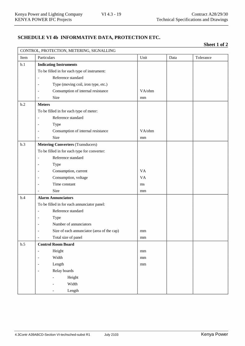
SCHEDULE VI 4b INFORMATIVE DATA, PROTECTION ETC.
Sheet 1 of 2
CONTROL, PROTECTION, METERING, SIGNALLING
Item Particulars Unit Data Tolerance
b.1 Indicating Instruments
To be filled in for each type of instrument:
- Reference standard
- Type (moving coil, iron type, etc.)
- Consumption of internal resistance VA/ohm
- Size mm
b.2 Meters
To be filled in for each type of meter:
- Reference standard
- Type
- Consumption of internal resistance VA/ohm
- Size mm
b.3 Metering Converters (Transducers)
To be filled in for each type for converter:
- Reference standard
- Type
- Consumption, current VA
- Consumption, voltage VA
- Time constant ms
- Size mm
b.4 Alarm Annunciators
To be filled in for each annunciator panel:
- Reference standard
- Type
- Number of annunciators
- Size of each annunciator (area of the cap) mm
- Total size of panel mm
b.5 Control Room Board
- Height mm
- Width mm
- Length mm
- Relay boards
- Height
- Width
- Length
Kenya Power and Lighting Company VI 4.3 - 20 Contract A28/29/30
KENYA POWER IFC Projects Technical Specifications and Drawings
4.3Contr A39ABCD-Section VI-techsched-subst R1 July 2103 Kenya Power
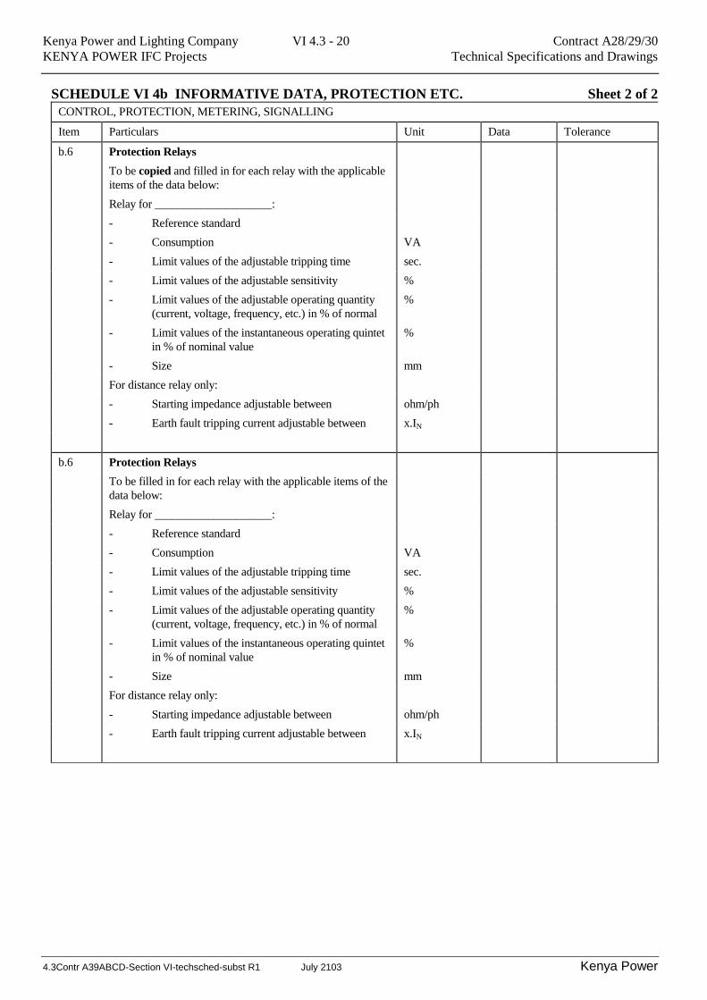
SCHEDULE VI 4b INFORMATIVE DATA, PROTECTION ETC. Sheet 2 of 2
CONTROL, PROTECTION, METERING, SIGNALLING
Item Particulars Unit Data Tolerance
b.6 Protection Relays
To be copied and filled in for each relay with the applicable
items of the data below:
Relay for ____________________:
- Reference standard
- Consumption VA
- Limit values of the adjustable tripping time sec.
- Limit values of the adjustable sensitivity %
- Limit values of the adjustable operating quantity
(current, voltage, frequency, etc.) in % of normal
%
- Limit values of the instantaneous operating quintet
in % of nominal value
%
- Size mm
For distance relay only:
- Starting impedance adjustable between ohm/ph
- Earth fault tripping current adjustable between x.IN
b.6 Protection Relays
To be filled in for each relay with the applicable items of the
data below:
Relay for ____________________:
- Reference standard
- Consumption VA
- Limit values of the adjustable tripping time sec.
- Limit values of the adjustable sensitivity %
- Limit values of the adjustable operating quantity
(current, voltage, frequency, etc.) in % of normal
%
- Limit values of the instantaneous operating quintet
in % of nominal value
%
- Size mm
For distance relay only:
- Starting impedance adjustable between ohm/ph
- Earth fault tripping current adjustable between x.IN
Kenya Power and Lighting Company VI 4.3 - 21 Contract A28/29/30
KENYA POWER IFC Projects Technical Specifications and Drawings
4.3Contr A39ABCD-Section VI-techsched-subst R1 July 2103 Kenya Power
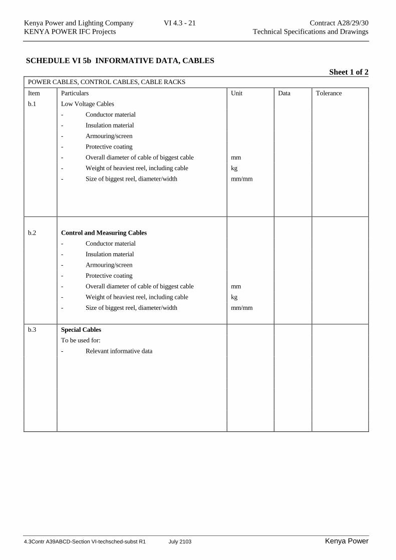
SCHEDULE VI 5b INFORMATIVE DATA, CABLES
Sheet 1 of 2
POWER CABLES, CONTROL CABLES, CABLE RACKS
Item Particulars Unit Data Tolerance
b.1 Low Voltage Cables
- Conductor material
- Insulation material
- Armouring/screen
- Protective coating
- Overall diameter of cable of biggest cable mm
- Weight of heaviest reel, including cable kg
- Size of biggest reel, diameter/width
mm/mm
b.2
Control and Measuring Cables
- Conductor material
- Insulation material
- Armouring/screen
- Protective coating
- Overall diameter of cable of biggest cable mm
- Weight of heaviest reel, including cable kg
- Size of biggest reel, diameter/width
mm/mm
b.3 Special Cables
To be used for:
- Relevant informative data

Kenya Power and Lighting Company VI 4.3 - 22 Contract A28/29/30
KENYA POWER IFC Projects Technical Specifications and Drawings
4.3Contr A39ABCD-Section VI-techsched-subst R1 July 2103 Kenya Power
SCHEDULE VI 5b INFORMATIVE DATA, CABLES
Sheet 2 of 2
POWER CABLES, CONTROL CABLES, CABLE RACKS
Item Particulars Unit Data Tolerance
11 kV Voltage Cables
- Conductor material
- Insulation material
- Armouring/screen
- Protective coating
- Overall diameter of cable of biggest cable mm
- Weight of heaviest reel, including cable kg
- Size of biggest reel, diameter/width
mm/mm
33 kV Voltage Cables
- Conductor material
- Insulation material
- Armouring/screen
- Protective coating
- Overall diameter of cable of biggest cable mm
- Weight of heaviest reel, including cable kg
- Size of biggest reel, diameter/width
mm/mm
66 kV Voltage Cables
- Conductor material
- Insulation material
- Armouring/screen
- Protective coating
- Overall diameter of cable of biggest cable mm
- Weight of heaviest reel, including cable kg
- Size of biggest reel, diameter/width
mm/mm
Special Cables, Optical fibre
- Relevant informative data
Kenya Power and Lighting Company VI 4.3 - 23 Contract A28/29/30
KENYA POWER IFC Projects Technical Specifications and Drawings
4.3Contr A39ABCD-Section VI-techsched-subst R1 July 2103 Kenya Power
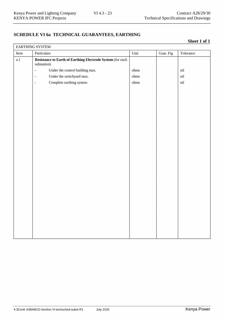
SCHEDULE VI 6a TECHNICAL GUARANTEES, EARTHING
Sheet 1 of 1
EARTHING SYSTEM
Item Particulars Unit Guar. Fig Tolerance
a.1 Resistance to Earth of Earthing Electrode System (for each
substation)
- Under the control building max. ohms nil
- Under the switchyard max. ohms nil
- Complete earthing system ohms nil
Kenya Power and Lighting Company VI 4.3 - 24 Contract A28/29/30
KENYA POWER IFC Projects Technical Specifications and Drawings
4.3Contr A39ABCD-Section VI-techsched-subst R1 July 2103 Kenya Power
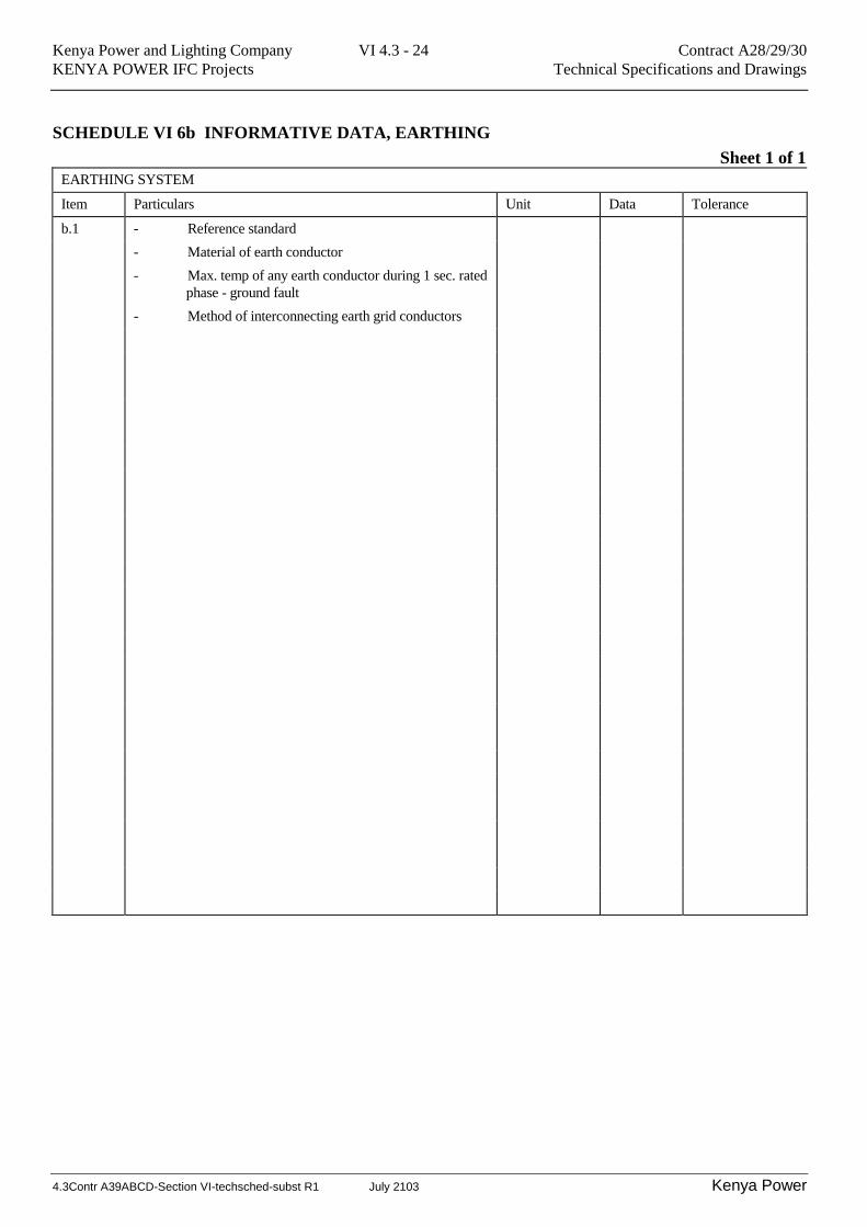
SCHEDULE VI 6b INFORMATIVE DATA, EARTHING
Sheet 1 of 1
EARTHING SYSTEM
Item Particulars Unit Data Tolerance
b.1 - Reference standard
- Material of earth conductor
- Max. temp of any earth conductor during 1 sec. rated
phase - ground fault
- Method of interconnecting earth grid conductors

Kenya Power and Lighting Company VI 4.3 - 25 Contract A28/29/30
KENYA POWER IFC Projects Technical Specifications and Drawings
4.3Contr A39ABCD-Section VI-techsched-subst R1 July 2103 Kenya Power
TECHNICAL SCHEDULES TRANSFORMERS
SCHEDULE VI 7a - TECHNICAL GUARANTEES, POWER TRANSFORMERS
Sheet 1 of 7
HV POWER TRANSFORMERS Guaranteed Data
Item Description Unit 23/15_MVA
1. Continuous maximum rating on any tapping
when operation under the ambient
conditions specified in Section VI, Clause
4.1.3.2.1 Design criteria:
With ONAN cooling;
HV winding MVA
LV winding MVA
TV winding MVA -
With ONAF cooling;
HV winding MVA
LV winding MVA
TV winding MVA -
2. Rated frequency Hz
3. Rated no-load voltage at rated frequency on:
HV, principal tapping kV
HV, extreme plus tapping kV
HV, extreme minus tapping kV
LV, kV
TV, kV -
4. Tapping ranges from principal tapping:
HV, no of plus tappings -
HV, no of minus tappings -
HV, steps in % of rated voltage %
5. No-load losses at rated voltage and
frequency
kW
6. No-load current at rated voltage and
frequency
A
Kenya Power and Lighting Company VI 4.3 - 26 Contract A28/29/30
KENYA POWER IFC Projects Technical Specifications and Drawings
4.3Contr A39ABCD-Section VI-techsched-subst R1 July 2103 Kenya Power
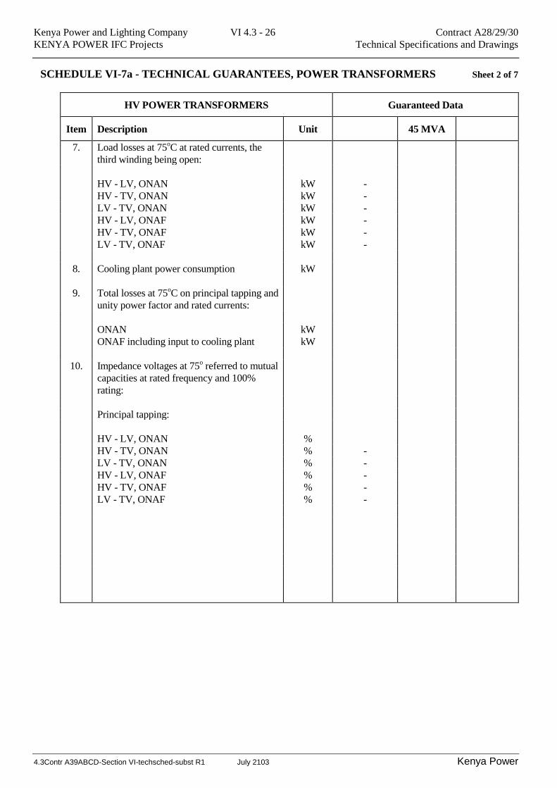
SCHEDULE VI-7a - TECHNICAL GUARANTEES, POWER TRANSFORMERS Sheet 2 of 7
HV POWER TRANSFORMERS Guaranteed Data
Item Description Unit 45 MVA
7. Load losses at 75oC at rated currents, the
third winding being open:
HV - LV, ONAN kW -
HV - TV, ONAN kW -
LV - TV, ONAN kW -
HV - LV, ONAF kW -
HV - TV, ONAF kW -
LV - TV, ONAF kW -
8. Cooling plant power consumption kW
9. Total losses at 75oC on principal tapping and
unity power factor and rated currents:
ONAN kW
ONAF including input to cooling plant kW
10. Impedance voltages at 75o referred to mutual
capacities at rated frequency and 100%
rating:
Principal tapping:
HV - LV, ONAN %
HV - TV, ONAN % -
LV - TV, ONAN % -
HV - LV, ONAF % -
HV - TV, ONAF % -
LV - TV, ONAF % -
Kenya Power and Lighting Company VI 4.3 - 27 Contract A28/29/30
KENYA POWER IFC Projects Technical Specifications and Drawings
4.3Contr A39ABCD-Section VI-techsched-subst R1 July 2103 Kenya Power
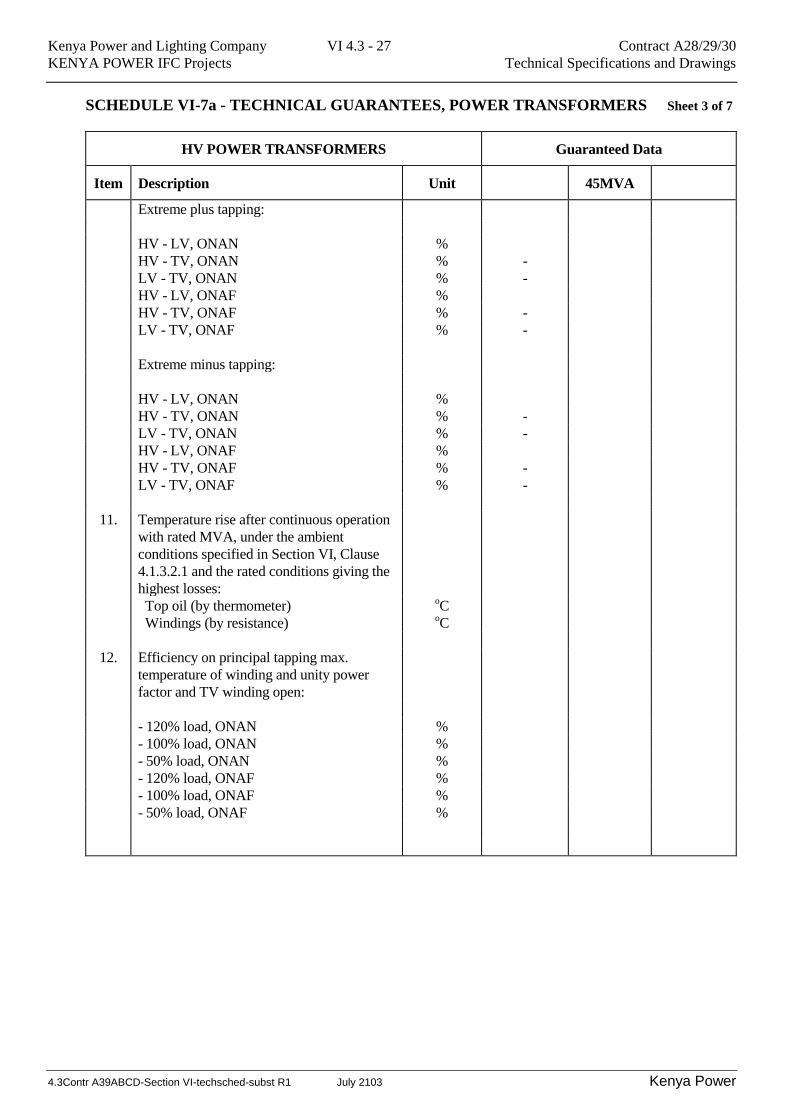
SCHEDULE VI-7a - TECHNICAL GUARANTEES, POWER TRANSFORMERS Sheet 3 of 7
HV POWER TRANSFORMERS Guaranteed Data
Item Description Unit 45MVA
Extreme plus tapping:
HV - LV, ONAN %
HV - TV, ONAN % -
LV - TV, ONAN % -
HV - LV, ONAF %
HV - TV, ONAF % -
LV - TV, ONAF % -
Extreme minus tapping:
HV - LV, ONAN %
HV - TV, ONAN % -
LV - TV, ONAN % -
HV - LV, ONAF %
HV - TV, ONAF % -
LV - TV, ONAF % -
11. Temperature rise after continuous operation
with rated MVA, under the ambient
conditions specified in Section VI, Clause
4.1.3.2.1 and the rated conditions giving the
highest losses:
Top oil (by thermometer) oC
Windings (by resistance) oC
12. Efficiency on principal tapping max.
temperature of winding and unity power
factor and TV winding open:
- 120% load, ONAN %
- 100% load, ONAN %
- 50% load, ONAN %
- 120% load, ONAF %
- 100% load, ONAF %
- 50% load, ONAF %
Kenya Power and Lighting Company VI 4.3 - 28 Contract A28/29/30
KENYA POWER IFC Projects Technical Specifications and Drawings
4.3Contr A39ABCD-Section VI-techsched-subst R1 July 2103 Kenya Power
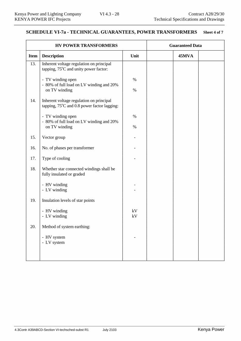
SCHEDULE VI-7a - TECHNICAL GUARANTEES, POWER TRANSFORMERS Sheet 4 of 7
HV POWER TRANSFORMERS Guaranteed Data
Item Description Unit 45MVA
13. Inherent voltage regulation on principal
tapping, 75oC and unity power factor:
- TV winding open %
- 80% of full load on LV winding and 20%
on TV winding
%
14. Inherent voltage regulation on principal
tapping, 75oC and 0.8 power factor lagging:
- TV winding open %
- 80% of full load on LV winding and 20%
on TV winding
%
15. Vector group -
16. No. of phases per transformer -
17. Type of cooling -
18. Whether star connected windings shall be
fully insulated or graded
- HV winding -
- LV winding -
19. Insulation levels of star points
- HV winding kV
- LV winding kV
20. Method of system earthing:
- HV system -
- LV system

Kenya Power and Lighting Company VI 4.3 - 29 Contract A28/29/30
KENYA POWER IFC Projects Technical Specifications and Drawings
4.3Contr A39ABCD-Section VI-techsched-subst R1 July 2103 Kenya Power
SCHEDULE VI-7a - TECHNICAL GUARANTEES, POWER TRANSFORMERS Sheet 5 of 7
HV POWER TRANSFORMERS Guaranteed Data
Item Description Unit 45MVA
21. Method of transformer earthing:
- HV windings - star point -
- LV windings - star point -
- TV winding - one corner of closed delta -
22. Whether TV windings are to be brought out
to separate bushing insulators
-
23. Indoor or outdoor installation -
24. System highest voltage according to IEC:
- HV kV
- LV kV
- TV kV -
25. Maximum flux density at rated voltage on
principal tapping and rated frequency:
- Transformer legs T
- Transformer yokes T
26. Maximum flux density at most onerous
voltage and frequency conditions:
- Transformer legs T
- Transformer yokes T
27. Specific core loss W/kg
Kenya Power and Lighting Company VI 4.3 - 30 Contract A28/29/30
KENYA POWER IFC Projects Technical Specifications and Drawings
4.3Contr A39ABCD-Section VI-techsched-subst R1 July 2103 Kenya Power
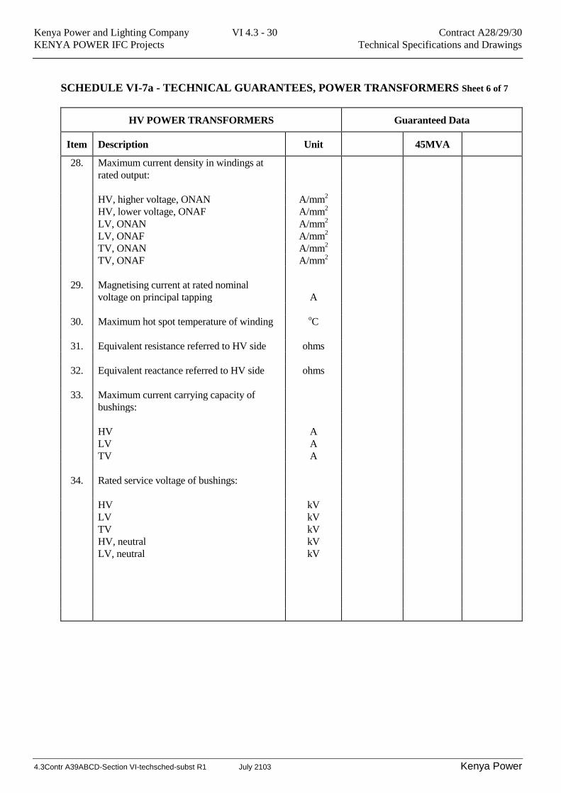
SCHEDULE VI-7a - TECHNICAL GUARANTEES, POWER TRANSFORMERS Sheet 6 of 7
HV POWER TRANSFORMERS Guaranteed Data
Item Description Unit 45MVA
28. Maximum current density in windings at
rated output:
HV, higher voltage, ONAN A/mm2
HV, lower voltage, ONAF A/mm2
LV, ONAN A/mm2
LV, ONAF A/mm2
TV, ONAN A/mm2
TV, ONAF A/mm2
29. Magnetising current at rated nominal
voltage on principal tapping
A
30. Maximum hot spot temperature of winding oC
31. Equivalent resistance referred to HV side ohms
32. Equivalent reactance referred to HV side ohms
33. Maximum current carrying capacity of
bushings:
HV A
LV A
TV A
34. Rated service voltage of bushings:
HV kV
LV kV
TV kV
HV, neutral kV
LV, neutral kV
Kenya Power and Lighting Company VI 4.3 - 31 Contract A28/29/30
KENYA POWER IFC Projects Technical Specifications and Drawings
4.3Contr A39ABCD-Section VI-techsched-subst R1 July 2103 Kenya Power
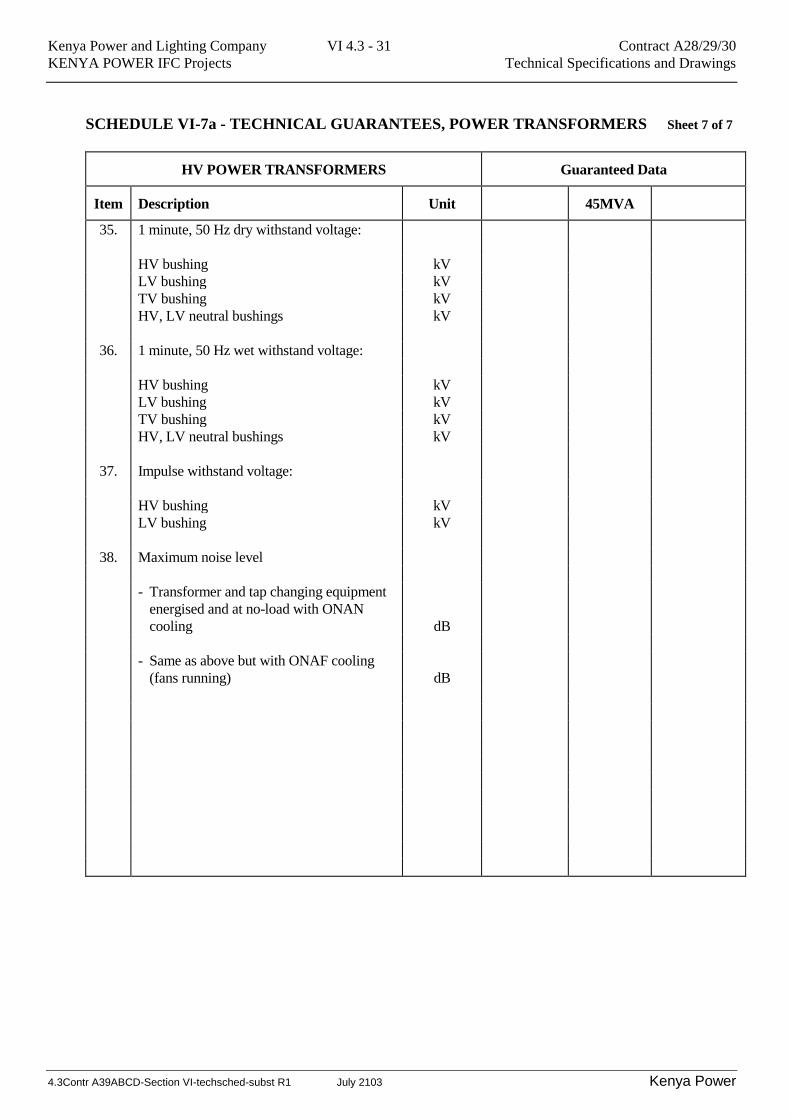
SCHEDULE VI-7a - TECHNICAL GUARANTEES, POWER TRANSFORMERS Sheet 7 of 7
HV POWER TRANSFORMERS Guaranteed Data
Item Description Unit 45MVA
35. 1 minute, 50 Hz dry withstand voltage:
HV bushing kV
LV bushing kV
TV bushing kV
HV, LV neutral bushings kV
36. 1 minute, 50 Hz wet withstand voltage:
HV bushing kV
LV bushing kV
TV bushing kV
HV, LV neutral bushings kV
37. Impulse withstand voltage:
HV bushing kV
LV bushing kV
38. Maximum noise level
- Transformer and tap changing equipment
energised and at no-load with ONAN
cooling
dB
- Same as above but with ONAF cooling
(fans running)
dB
Kenya Power and Lighting Company VI 4.3 - 32 Contract A28/29/30
KENYA POWER IFC Projects Technical Specifications and Drawings
4.3Contr A39ABCD-Section VI-techsched-subst R1 July 2103 Kenya Power
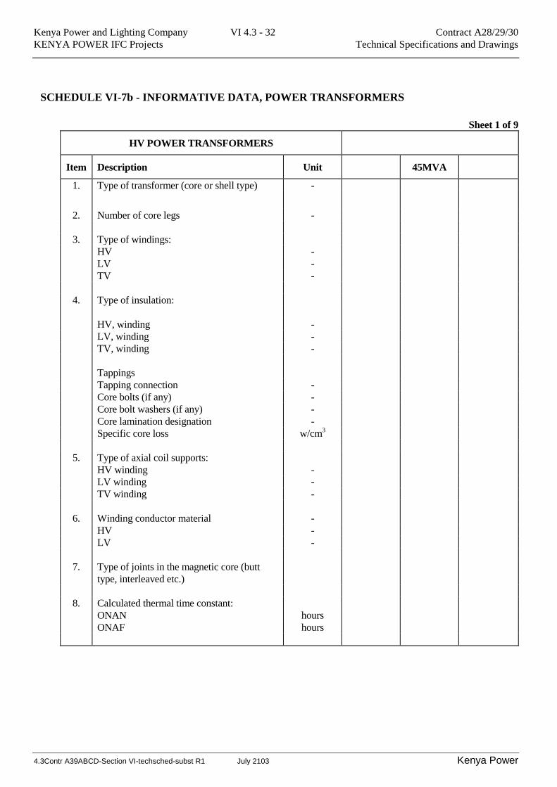
SCHEDULE VI-7b - INFORMATIVE DATA, POWER TRANSFORMERS
Sheet 1 of 9
HV POWER TRANSFORMERS
Item Description Unit 45MVA
1. Type of transformer (core or shell type) -
2. Number of core legs -
3. Type of windings:
HV -
LV -
TV -
4. Type of insulation:
HV, winding -
LV, winding -
TV, winding -
Tappings
Tapping connection -
Core bolts (if any) -
Core bolt washers (if any) -
Core lamination designation -
Specific core loss w/cm3
5. Type of axial coil supports:
HV winding -
LV winding -
TV winding -
6. Winding conductor material -
HV -
LV -
7. Type of joints in the magnetic core (butt
type, interleaved etc.)
8. Calculated thermal time constant:
ONAN hours
ONAF hours
Kenya Power and Lighting Company VI 4.3 - 33 Contract A28/29/30
KENYA POWER IFC Projects Technical Specifications and Drawings
4.3Contr A39ABCD-Section VI-techsched-subst R1 July 2103 Kenya Power
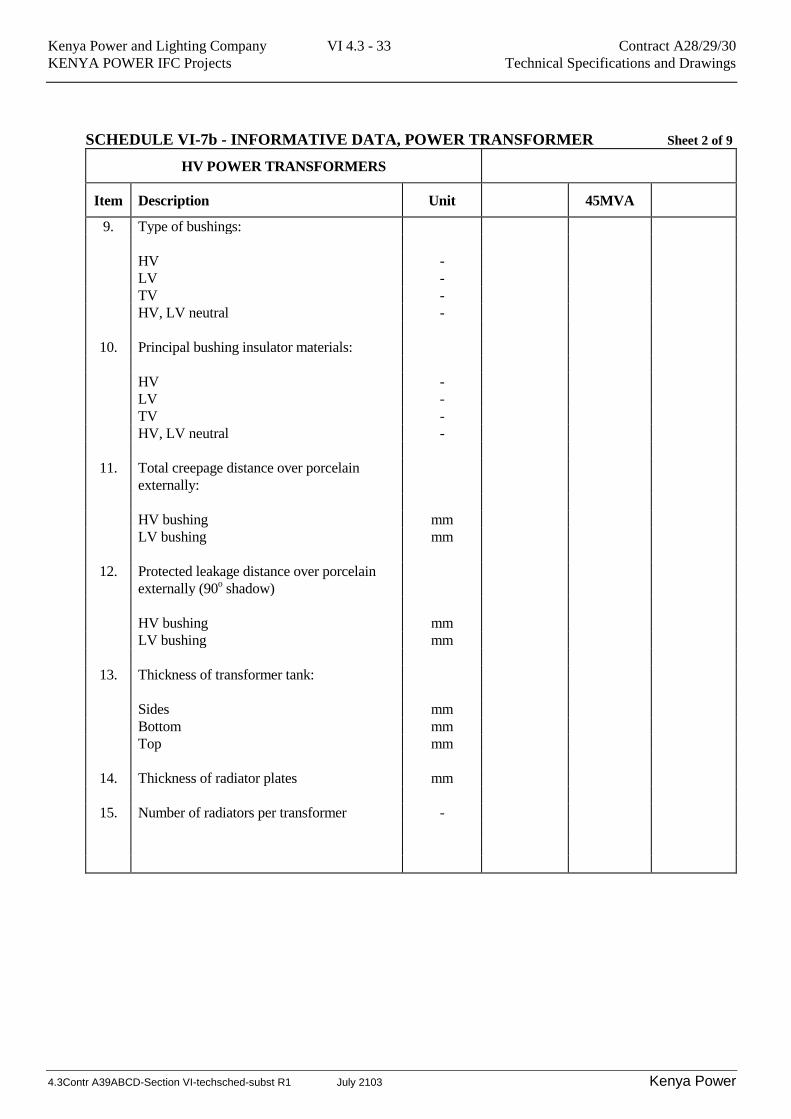
SCHEDULE VI-7b - INFORMATIVE DATA, POWER TRANSFORMER Sheet 2 of 9
HV POWER TRANSFORMERS
Item Description Unit 45MVA
9. Type of bushings:
HV -
LV -
TV -
HV, LV neutral -
10. Principal bushing insulator materials:
HV -
LV -
TV -
HV, LV neutral -
11. Total creepage distance over porcelain
externally:
HV bushing mm
LV bushing mm
12. Protected leakage distance over porcelain
externally (90o shadow)
HV bushing mm
LV bushing mm
13. Thickness of transformer tank:
Sides mm
Bottom mm
Top mm
14. Thickness of radiator plates mm
15. Number of radiators per transformer -
Kenya Power and Lighting Company VI 4.3 - 34 Contract A28/29/30
KENYA POWER IFC Projects Technical Specifications and Drawings
4.3Contr A39ABCD-Section VI-techsched-subst R1 July 2103 Kenya Power
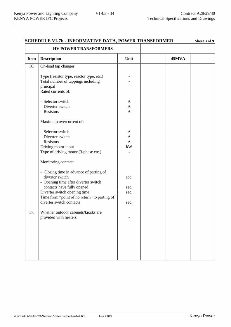
SCHEDULE VI-7b - INFORMATIVE DATA, POWER TRANSFORMER Sheet 3 of 9
HV POWER TRANSFORMERS
Item Description Unit 45MVA
16. On-load tap changer:
Type (resistor type, reactor type, etc.) -
Total number of tappings including
principal
-
Rated currents of:
- Selector switch A
- Diverter switch A
- Resistors A
Maximum overcurrent of:
- Selector switch A
- Diverter switch A
- Resistors A
Driving motor input kW
Type of driving motor (3-phase etc.) -
Monitoring contact:
- Closing time in advance of parting of
diverter switch
sec.
- Opening time after diverter switch
contacts have fully opened
sec.
Diverter switch opening time sec.
Time from “point of no return” to parting of
diverter switch contacts
sec.
17. Whether outdoor cabinets/kiosks are
provided with heaters
-
Kenya Power and Lighting Company VI 4.3 - 35 Contract A28/29/30
KENYA POWER IFC Projects Technical Specifications and Drawings
4.3Contr A39ABCD-Section VI-techsched-subst R1 July 2103 Kenya Power
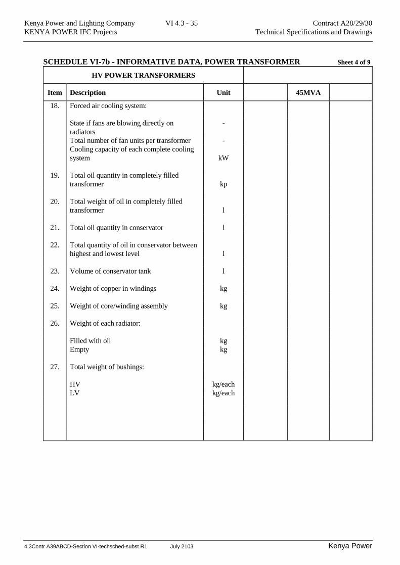
SCHEDULE VI-7b - INFORMATIVE DATA, POWER TRANSFORMER Sheet 4 of 9
HV POWER TRANSFORMERS
Item Description Unit 45MVA
18. Forced air cooling system:
State if fans are blowing directly on
radiators
-
Total number of fan units per transformer -
Cooling capacity of each complete cooling
system
kW
19. Total oil quantity in completely filled
transformer
kp
20. Total weight of oil in completely filled
transformer
l
21. Total oil quantity in conservator l
22. Total quantity of oil in conservator between
highest and lowest level
l
23. Volume of conservator tank l
24. Weight of copper in windings kg
25. Weight of core/winding assembly kg
26. Weight of each radiator:
Filled with oil kg
Empty kg
27. Total weight of bushings:
HV kg/each
LV kg/each
Kenya Power and Lighting Company VI 4.3 - 36 Contract A28/29/30
KENYA POWER IFC Projects Technical Specifications and Drawings
4.3Contr A39ABCD-Section VI-techsched-subst R1 July 2103 Kenya Power
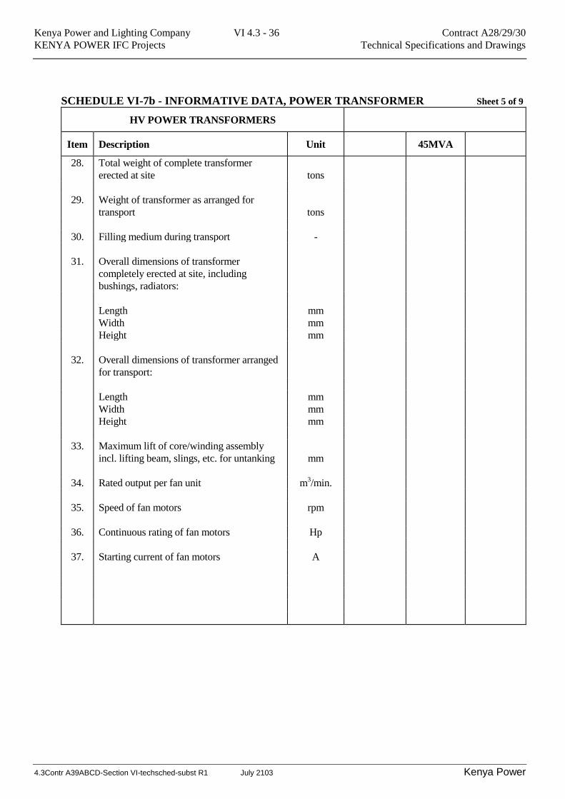
SCHEDULE VI-7b - INFORMATIVE DATA, POWER TRANSFORMER Sheet 5 of 9
HV POWER TRANSFORMERS
Item Description Unit 45MVA
28. Total weight of complete transformer
erected at site
tons
29. Weight of transformer as arranged for
transport
tons
30. Filling medium during transport -
31. Overall dimensions of transformer
completely erected at site, including
bushings, radiators:
Length mm
Width mm
Height mm
32. Overall dimensions of transformer arranged
for transport:
Length mm
Width mm
Height mm
33. Maximum lift of core/winding assembly
incl. lifting beam, slings, etc. for untanking
mm
34. Rated output per fan unit m3/min.
35. Speed of fan motors rpm
36. Continuous rating of fan motors Hp
37. Starting current of fan motors A
Kenya Power and Lighting Company VI 4.3 - 37 Contract A28/29/30
KENYA POWER IFC Projects Technical Specifications and Drawings
4.3Contr A39ABCD-Section VI-techsched-subst R1 July 2103 Kenya Power
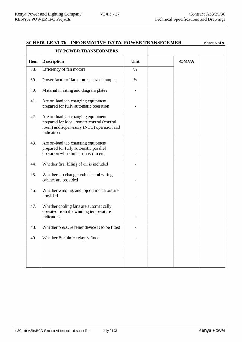
SCHEDULE VI-7b - INFORMATIVE DATA, POWER TRANSFORMER Sheet 6 of 9
HV POWER TRANSFORMERS
Item Description Unit 45MVA
38. Efficiency of fan motors %
39. Power factor of fan motors at rated output %
40. Material in rating and diagram plates -
41. Are on-load tap changing equipment
prepared for fully automatic operation
-
42. Are on-load tap changing equipment
prepared for local, remote control (control
room) and supervisory (NCC) operation and
indication
-
43. Are on-load tap changing equipment
prepared for fully automatic parallel
operation with similar transformers
-
44. Whether first filling of oil is included -
45. Whether tap changer cubicle and wiring
cabinet are provided
-
46. Whether winding, and top oil indicators are
provided
-
47. Whether cooling fans are automatically
operated from the winding temperature
indicators
-
48. Whether pressure relief device is to be fitted -
49. Whether Buchholz relay is fitted -
Kenya Power and Lighting Company VI 4.3 - 38 Contract A28/29/30
KENYA POWER IFC Projects Technical Specifications and Drawings
4.3Contr A39ABCD-Section VI-techsched-subst R1 July 2103 Kenya Power
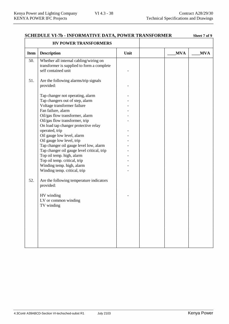
SCHEDULE VI-7b - INFORMATIVE DATA, POWER TRANSFORMER Sheet 7 of 9
HV POWER TRANSFORMERS
Item Description Unit ____MVA ____MVA
50. Whether all internal cabling/wiring on
transformer is supplied to form a complete
self contained unit
-
51. Are the following alarms/trip signals
provided:
-
Tap changer not operating, alarm -
Tap changers out of step, alarm -
Voltage transformer failure -
Fan failure, alarm -
Oil/gas flow transformer, alarm -
Oil/gas flow transformer, trip -
On load tap changer protective relay
operated, trip
-
Oil gauge low level, alarm -
Oil gauge low level, trip -
Tap changer oil gauge level low, alarm -
Tap changer oil gauge level critical, trip -
Top oil temp. high, alarm -
Top oil temp. critical, trip -
Winding temp. high, alarm -
Winding temp. critical, trip -
52. Are the following temperature indicators
provided:
HV winding -
LV or common winding
TV winding
Kenya Power and Lighting Company VI 4.3 - 39 Contract A28/29/30
KENYA POWER IFC Projects Technical Specifications and Drawings
4.3Contr A39ABCD-Section VI-techsched-subst R1 July 2103 Kenya Power
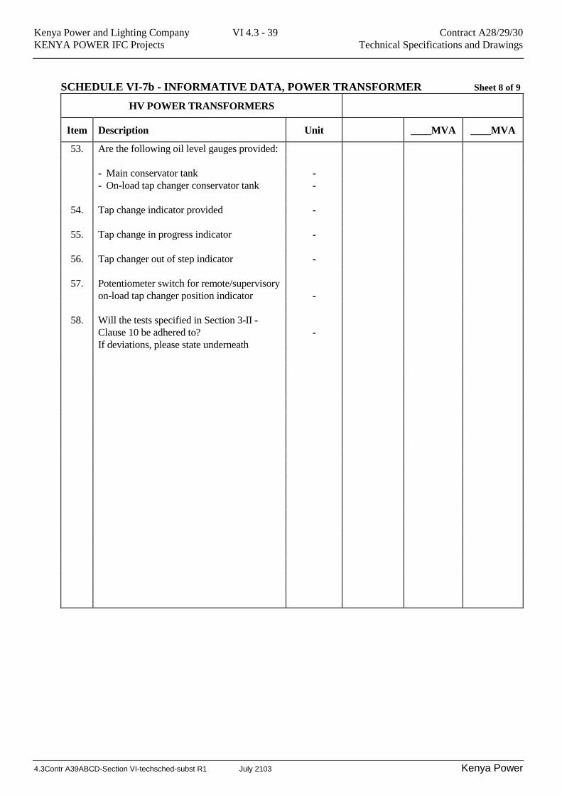
SCHEDULE VI-7b - INFORMATIVE DATA, POWER TRANSFORMER Sheet 8 of 9
HV POWER TRANSFORMERS
Item Description Unit ____MVA ____MVA
53. Are the following oil level gauges provided:
- Main conservator tank -
- On-load tap changer conservator tank -
54. Tap change indicator provided -
55. Tap change in progress indicator -
56. Tap changer out of step indicator -
57. Potentiometer switch for remote/supervisory
on-load tap changer position indicator
-
58. Will the tests specified in Section 3-II -
Clause 10 be adhered to?
-
If deviations, please state underneath

Kenya Power and Lighting Company VI 4.3 - 40 Contract A28/29/30
KENYA POWER IFC Projects Technical Specifications and Drawings
4.3Contr A39ABCD-Section VI-techsched-subst R1 July 2103 Kenya Power
SCHEDULE VI-7b - INFORMATIVE DATA, POWER TRANSFORMER Sheet 9 of 9
HV POWER TRANSFORMERS
Item Description Unit 45MVA
59. State all Standards applied underneath:
60. State identity of transformer manufacturer
and all sub-manufacturers including the
parts manufactured below:
Transformer:
Cooling equipment
On-load tap changer
Current transformers
Bushings
Core steel
Oil
Buchholz relay
Breather
Thermometer
Other equipment to be listed by the Bidder:
-
-
-
-
-
Kenya Power and Lighting Company VI 4.3 - 41 Contract A28/29/30
KENYA POWER IFC Projects Technical Specifications and Drawings
4.3Contr A39ABCD-Section VI-techsched-subst R1 July 2103 Kenya Power
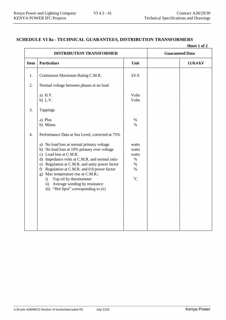
SCHEDULE VI 8a - TECHNICAL GUARANTEES, DISTRIBUTION TRANSFORMERS
Sheet 1 of 2
DISTRIBUTION TRANSFORMER Guaranteed Data
Item Particulars Unit 11/0.4 kV
1. Continuous Maximum Rating C.M.R. kVA
2. Normal voltage between phases at no load
a) H.V. Volts
b) L.V. Volts
3. Tappings
a) Plus %
b) Minus %
4. Performance Data at Sea Level, corrected at 75%
a) No load loss at normal primary voltage watts
b) No load loss at 10% primary over voltage watts
c) Load loss at C.M.R. watts
d) Impedance volts at C.M.R. and normal ratio %
e) Regulation at C.M.R. and unity power factor %
f) Regulation at C.M.R. and 0.8 power factor %
g) Max temperature rise at C.M.R.:
i) Top oil by thermometer oC
ii) Average winding by resistance
iii) “Hot Spot” corresponding to (ii)
Kenya Power and Lighting Company VI 4.3 - 42 Contract A28/29/30
KENYA POWER IFC Projects Technical Specifications and Drawings
4.3Contr A39ABCD-Section VI-techsched-subst R1 July 2103 Kenya Power
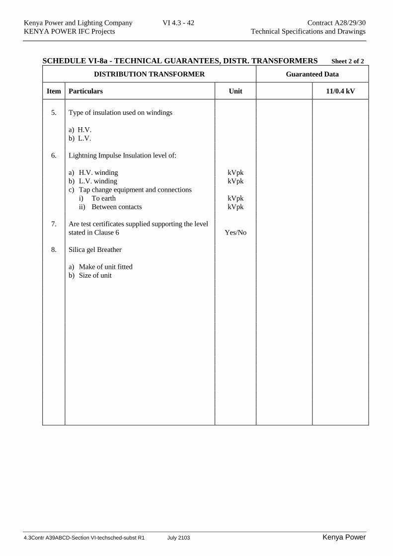
SCHEDULE VI-8a - TECHNICAL GUARANTEES, DISTR. TRANSFORMERS Sheet 2 of 2
DISTRIBUTION TRANSFORMER Guaranteed Data
Item Particulars Unit 11/0.4 kV
5. Type of insulation used on windings
a) H.V.
b) L.V.
6. Lightning Impulse Insulation level of:
a) H.V. winding kVpk
b) L.V. winding kVpk
c) Tap change equipment and connections
i) To earth kVpk
ii) Between contacts kVpk
7. Are test certificates supplied supporting the level
stated in Clause 6
Yes/No
8. Silica gel Breather
a) Make of unit fitted
b) Size of unit
Kenya Power and Lighting Company VI 4.3 - 43 Contract A28/29/30
KENYA POWER IFC Projects Technical Specifications and Drawings
4.3Contr A39ABCD-Section VI-techsched-subst R1 July 2103 Kenya Power
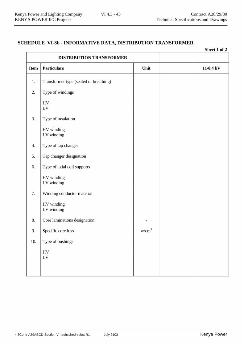
SCHEDULE VI-8b - INFORMATIVE DATA, DISTRIBUTION TRANSFORMER
Sheet 1 of 2
DISTRIBUTION TRANSFORMER
Item Particulars Unit 11/0.4 kV
1. Transformer type (sealed or breathing)
2. Type of windings
HV
LV
3. Type of insulation
HV winding
LV winding
4. Type of tap changer
5. Tap changer designation
6. Type of axial coil supports
HV winding
LV winding
7. Winding conductor material
HV winding
LV winding
8. Core laminations designation -
9. Specific core loss w/cm3
10. Type of bushings
HV
LV
Kenya Power and Lighting Company VI 4.3 - 44 Contract A28/29/30
KENYA POWER IFC Projects Technical Specifications and Drawings
4.3Contr A39ABCD-Section VI-techsched-subst R1 July 2103 Kenya Power
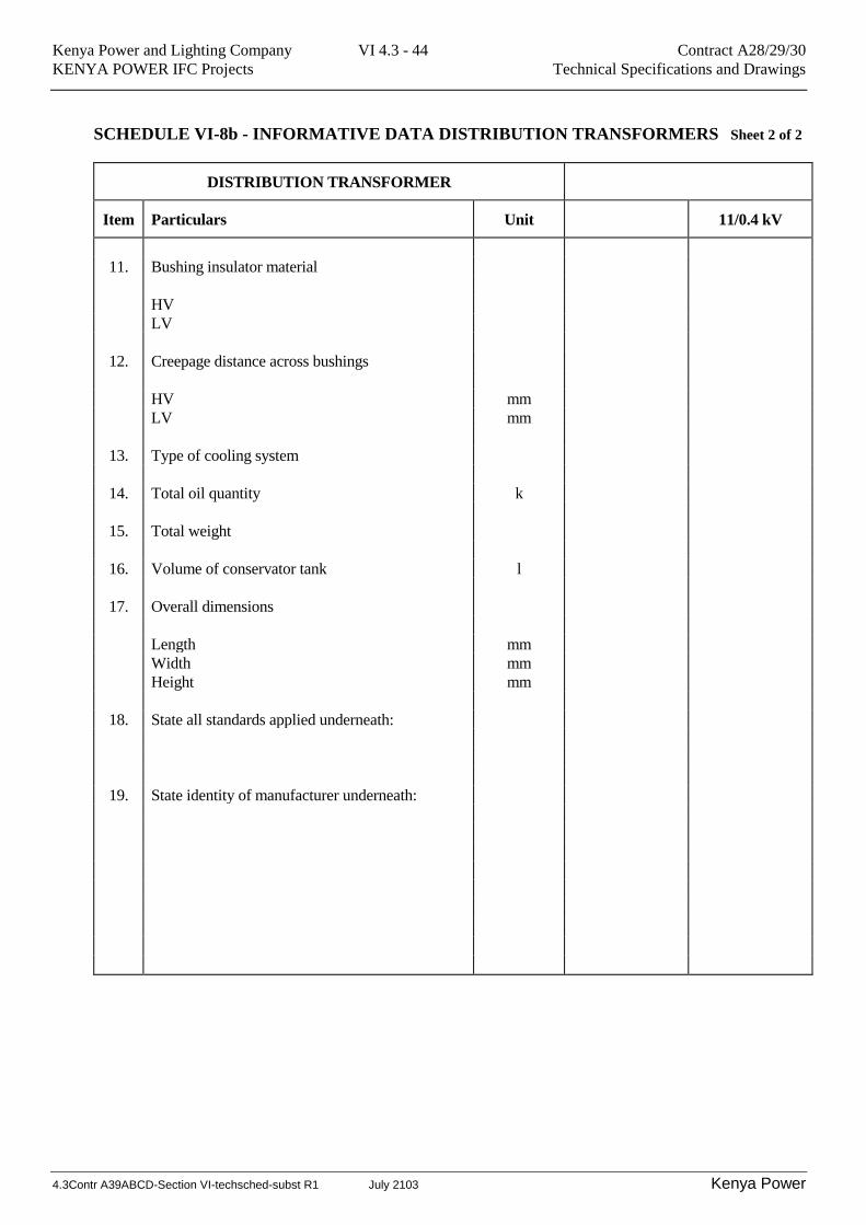
SCHEDULE VI-8b - INFORMATIVE DATA DISTRIBUTION TRANSFORMERS Sheet 2 of 2
DISTRIBUTION TRANSFORMER
Item Particulars Unit 11/0.4 kV
11. Bushing insulator material
HV
LV
12. Creepage distance across bushings
HV mm
LV mm
13. Type of cooling system
14. Total oil quantity k
15. Total weight
16. Volume of conservator tank l
17. Overall dimensions
Length mm
Width mm
Height mm
18. State all standards applied underneath:
19. State identity of manufacturer underneath:
Kenya Power and Lighting Company VI 4.3 - 45 Contract A28/29/30
KENYA POWER IFC Projects Technical Specifications and Drawings
4.3Contr A39ABCD-Section VI-techsched-subst R1 July 2103 Kenya Power
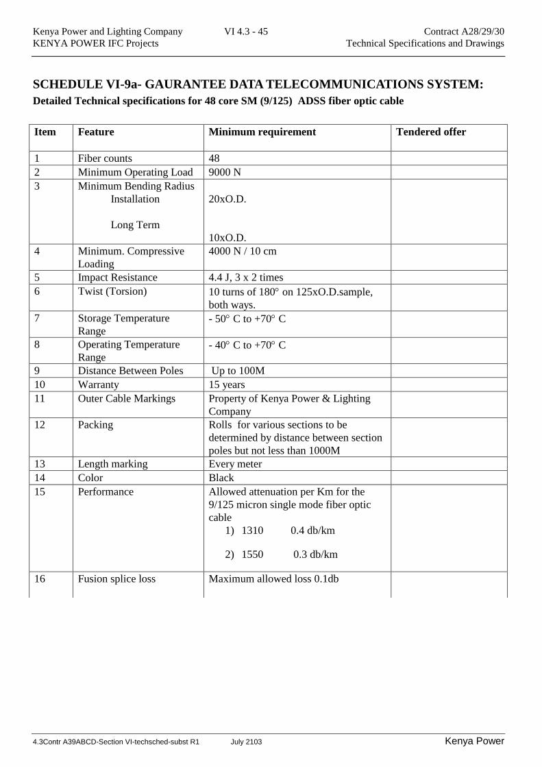
SCHEDULE VI-9a- GAURANTEE DATA TELECOMMUNICATIONS SYSTEM:
Detailed Technical specifications for 48 core SM (9/125) ADSS fiber optic cable
Item Feature Minimum requirement Tendered offer
1 Fiber counts 48
2 Minimum Operating Load 9000 N
3 Minimum Bending Radius
Installation
Long Term
20xO.D.
10xO.D.
4 Minimum. Compressive
Loading
4000 N / 10 cm
5 Impact Resistance 4.4 J, 3 x 2 times
6 Twist (Torsion) 10 turns of 180 on 125xO.D.sample,
both ways.
7 Storage Temperature
Range - 50 C to +70 C
8 Operating Temperature
Range - 40 C to +70 C
9 Distance Between Poles Up to 100M
10 Warranty 15 years
11 Outer Cable Markings Property of Kenya Power & Lighting
Company
12 Packing Rolls for various sections to be
determined by distance between section
poles but not less than 1000M
13 Length marking Every meter
14 Color Black
15 Performance Allowed attenuation per Km for the
9/125 micron single mode fiber optic
cable
1) 1310 0.4 db/km
2) 1550 0.3 db/km
16 Fusion splice loss
Maximum allowed loss 0.1db
Kenya Power and Lighting Company VI 4.3 - 46 Contract A28/29/30
KENYA POWER IFC Projects Technical Specifications and Drawings
4.3Contr A39ABCD-Section VI-techsched-subst R1 July 2103 Kenya Power
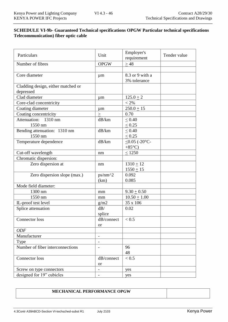
SCHEDULE VI-9b- Guaranteed Technical specifications OPGW Particular technical specifications
Telecommunication) fiber optic cable
Particulars Unit Employer's
requirement Tender value
Number of fibres OPGW > 48
Core diameter µm 8.3 or 9 with a
3% tolerance
Cladding design, either matched or
depressed
Clad diameter µm 125.0 + 2
Core-clad concentricity < 2%
Coating diameter µm 250.0 + 15
Coating concentricity > 0.70
Attenuation: 1310 nm
1550 nm
dB/km < 0.40
< 0.25
Bending attenuation: 1310 nm
1550 nm
dB/km < 0.40
< 0.25
Temperature dependence dB/km <0.05 (-20°C-
+85°C)
Cut-off wavelength nm < 1250
Chromatic dispersion:
Zero dispersion at nm 1310 + 12
1550 + 15
Zero dispersion slope (max.) ps/nm^2
(km)
0.092
0.085
Mode field diameter:
1300 nm mm 9.30 + 0.50
1550 nm mm 10.50 + 1.00
IL-proof test level g/m2 35 x 106
Splice attenuation dB/
splice
0.02
Connector loss dB/connect
or
< 0.5
ODF
Manufacturer -
Type -
Number of fiber interconnections - 96
48
Connector loss dB/connect
or
< 0.5
Screw on type connectors - yes
designed for 19” cubicles - yes
MECHANICAL PERFORMANCE OPGW
Kenya Power and Lighting Company VI 4.3 - 47 Contract A28/29/30
KENYA POWER IFC Projects Technical Specifications and Drawings
4.3Contr A39ABCD-Section VI-techsched-subst R1 July 2103 Kenya Power
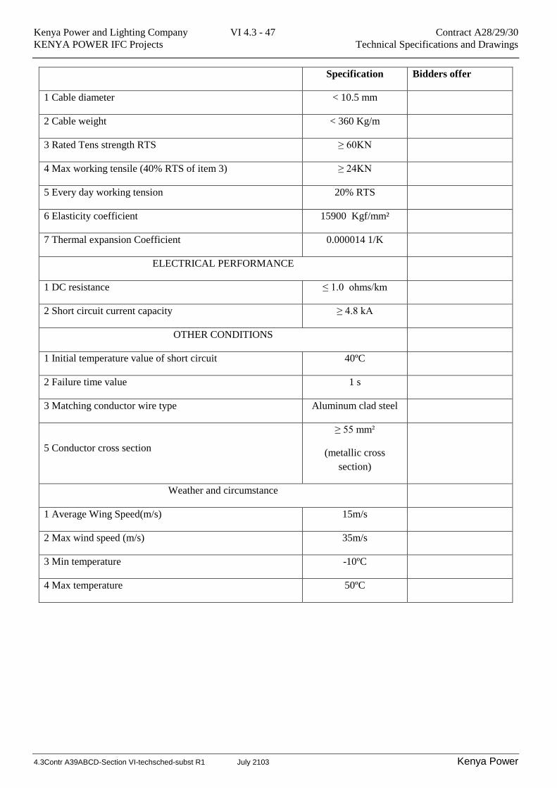
Specification Bidders offer
1 Cable diameter < 10.5 mm
2 Cable weight < 360 Kg/m
3 Rated Tens strength RTS ≥ 60KN
4 Max working tensile (40% RTS of item 3) ≥ 24KN
5 Every day working tension 20% RTS
6 Elasticity coefficient 15900 Kgf/mm²
7 Thermal expansion Coefficient 0.000014 1/K
ELECTRICAL PERFORMANCE
1 DC resistance ≤ 1.0 ohms/km
2 Short circuit current capacity ≥ 4.8 kA
OTHER CONDITIONS
1 Initial temperature value of short circuit 40ºC
2 Failure time value 1 s
3 Matching conductor wire type Aluminum clad steel
5 Conductor cross section
≥ 55 mm²
(metallic cross
section)
Weather and circumstance
1 Average Wing Speed(m/s) 15m/s
2 Max wind speed (m/s) 35m/s
3 Min temperature -10ºC
4 Max temperature 50ºC
Kenya Power and Lighting Company VI 4.3 - 48 Contract A28/29/30
KENYA POWER IFC Projects Technical Specifications and Drawings
4.3Contr A39ABCD-Section VI-techsched-subst R1 July 2103 Kenya Power
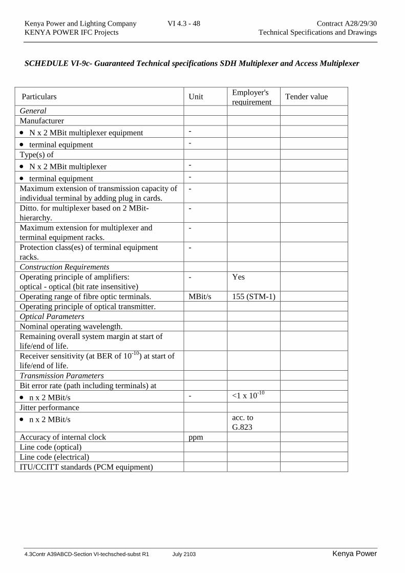
SCHEDULE VI-9c- Guaranteed Technical specifications SDH Multiplexer and Access Multiplexer
Particulars Unit Employer's
requirement Tender value
General
Manufacturer
N x 2 MBit multiplexer equipment -
terminal equipment -
Type(s) of
N x 2 MBit multiplexer -
terminal equipment -
Maximum extension of transmission capacity of
individual terminal by adding plug in cards.
-
Ditto. for multiplexer based on 2 MBit-
hierarchy.
-
Maximum extension for multiplexer and
terminal equipment racks.
-
Protection class(es) of terminal equipment
racks.
-
Construction Requirements
Operating principle of amplifiers:
optical - optical (bit rate insensitive)
- Yes
Operating range of fibre optic terminals. MBit/s 155 (STM-1)
Operating principle of optical transmitter.
Optical Parameters
Nominal operating wavelength.
Remaining overall system margin at start of
life/end of life.
Receiver sensitivity (at BER of 10-10
) at start of
life/end of life.
Transmission Parameters
Bit error rate (path including terminals) at
n x 2 MBit/s - <1 x 10⁻¹⁰
Jitter performance
n x 2 MBit/s acc. to
G.823
Accuracy of internal clock ppm
Line code (optical)
Line code (electrical)
ITU/CCITT standards (PCM equipment)

Kenya Power and Lighting Company VI 4.3 - 49 Contract A28/29/30
KENYA POWER IFC Projects Technical Specifications and Drawings
4.3Contr A39ABCD-Section VI-techsched-subst R1 July 2103 Kenya Power
SCHEDULE VI-9d- Technical specifications Base radio – The offered Radio shall be equivalent to:
NO. DESCRIPTION part/model
NUMBER
SUPPLIER Offered
1. MOTOROLA BASE
STATION XTL1500
DIGITAL VHF RADIO
Freq;138-150MHZ:
Flashport code:
5080080004885.
Complete with:13.5VDC
PWR cable, desk
microphone, desk Tray
M28KSS9PW1A
N
Motorola USA
2. Fiberglass: COLLINEAR
base station omni-directional
3db antenna 138-150MHZ
range
3. 30 METERS RG 213
COAXIAL CABLE
TELDOR
4. Mini-UHF Crimp type
connector/N-MALE RG213,
2Mtr RG58 N-Male/Mini-
UHF connector Jumper
5. ASTRON POWER SUPPLY
UNIT/BATTERY
CHARGER
RS 20A-220-BB ASTRON
CORPORATION
USA
www.astroncorp.com
6. RS-232 Motorola CPS
Programming cable
HKN6183 MOTOROLA-USA
7. Motorola CPS Programming
software NB; VERSION 17
MOTOROLA-USA
8. 75 or 70 AH 12V DC Free
maintenance battery
ATLAS-MF
9. 65 meter electricity wooden
pole
10. 20 ft GI galvanized steel pipe
Kenya Power and Lighting Company VI 4.3 - 50 Contract A28/29/30
KENYA POWER IFC Projects Technical Specifications and Drawings
4.3Contr A39ABCD-Section VI-techsched-subst R1 July 2103 Kenya Power
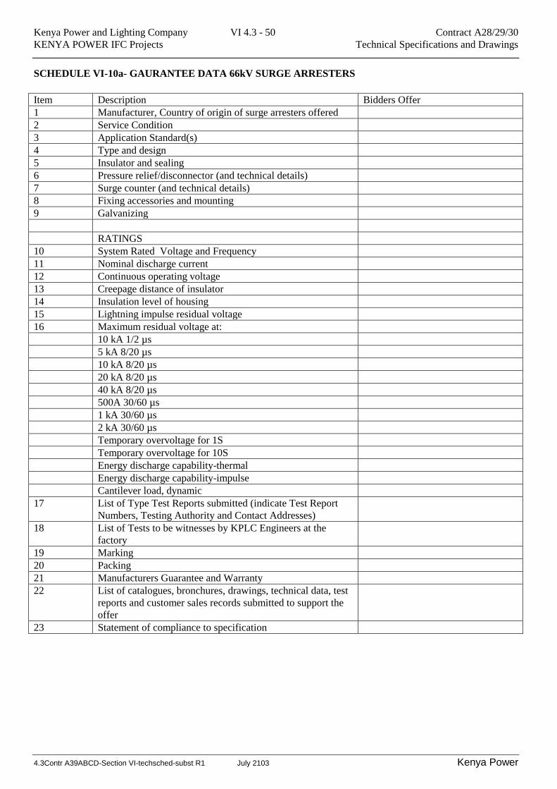
SCHEDULE VI-10a- GAURANTEE DATA 66kV SURGE ARRESTERS
Item Description Bidders Offer
1 Manufacturer, Country of origin of surge arresters offered
2 Service Condition
3 Application Standard(s)
4 Type and design
5 Insulator and sealing
6 Pressure relief/disconnector (and technical details)
7 Surge counter (and technical details)
8 Fixing accessories and mounting
9 Galvanizing
RATINGS
10 System Rated Voltage and Frequency
11 Nominal discharge current
12 Continuous operating voltage
13 Creepage distance of insulator
14 Insulation level of housing
15 Lightning impulse residual voltage
16 Maximum residual voltage at:
10 kA 1/2 µs
5 kA 8/20 µs
10 kA 8/20 µs
20 kA 8/20 µs
40 kA 8/20 µs
500A 30/60 µs
1 kA 30/60 µs
2 kA 30/60 µs
Temporary overvoltage for 1S
Temporary overvoltage for 10S
Energy discharge capability-thermal
Energy discharge capability-impulse
Cantilever load, dynamic
17 List of Type Test Reports submitted (indicate Test Report
Numbers, Testing Authority and Contact Addresses)
18 List of Tests to be witnesses by KPLC Engineers at the
factory
19 Marking
20 Packing
21 Manufacturers Guarantee and Warranty
22 List of catalogues, bronchures, drawings, technical data, test
reports and customer sales records submitted to support the
offer
23 Statement of compliance to specification
Kenya Power and Lighting Company VI 4.3 - 51 Contract A28/29/30
KENYA POWER IFC Projects Technical Specifications and Drawings
4.3Contr A39ABCD-Section VI-techsched-subst R1 July 2103 Kenya Power
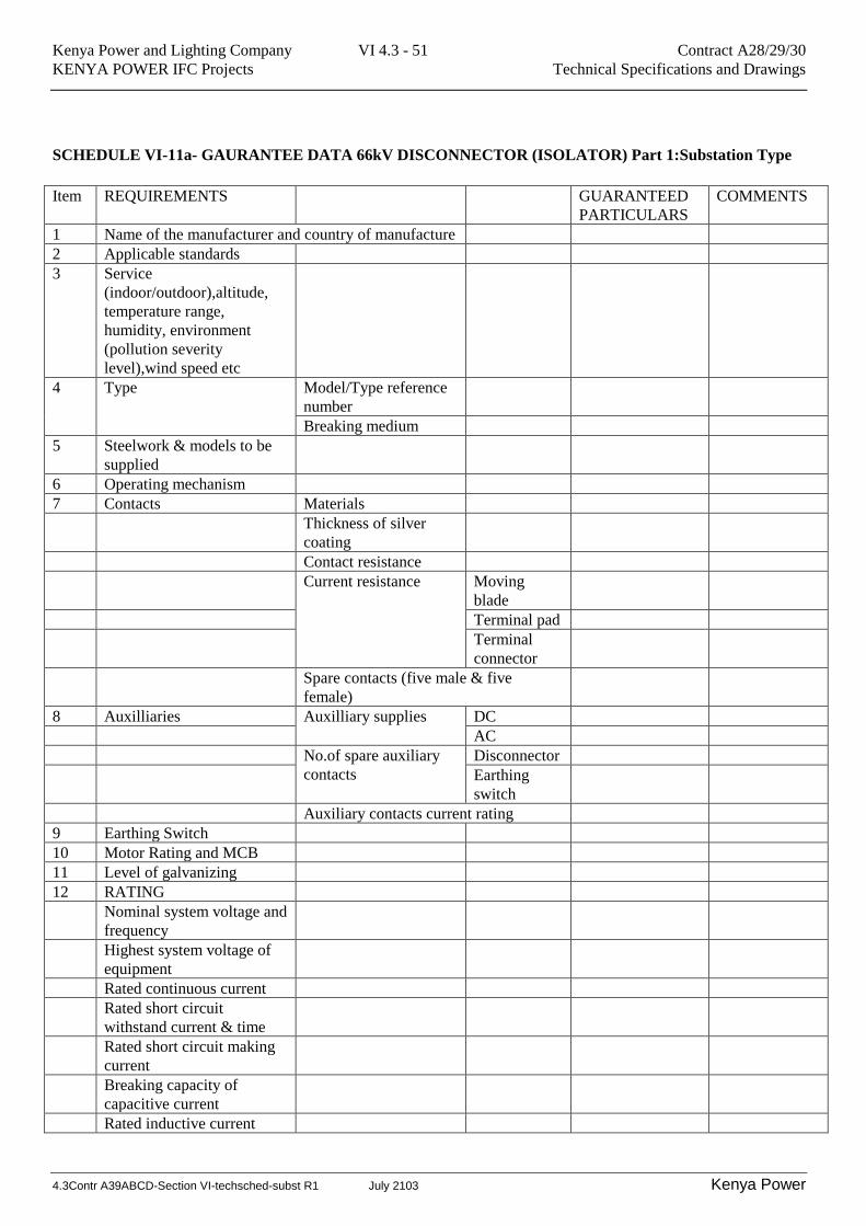
SCHEDULE VI-11a- GAURANTEE DATA 66kV DISCONNECTOR (ISOLATOR) Part 1:Substation Type
Item REQUIREMENTS GUARANTEED
PARTICULARS
COMMENTS
1 Name of the manufacturer and country of manufacture
2 Applicable standards
3 Service
(indoor/outdoor),altitude,
temperature range,
humidity, environment
(pollution severity
level),wind speed etc
4
Type Model/Type reference
number
Breaking medium
5 Steelwork & models to be
supplied
6 Operating mechanism
7 Contacts Materials
Thickness of silver
coating
Contact resistance
Current resistance Moving
blade
Terminal pad
Terminal
connector
Spare contacts (five male & five
female)
8 Auxilliaries Auxilliary supplies DC
AC
No.of spare auxiliary
contacts
Disconnector
Earthing
switch
Auxiliary contacts current rating
9 Earthing Switch
10 Motor Rating and MCB
11 Level of galvanizing
12 RATING
Nominal system voltage and
frequency
Highest system voltage of
equipment
Rated continuous current
Rated short circuit
withstand current & time
Rated short circuit making
current
Breaking capacity of
capacitive current
Rated inductive current
Kenya Power and Lighting Company VI 4.3 - 52 Contract A28/29/30
KENYA POWER IFC Projects Technical Specifications and Drawings
4.3Contr A39ABCD-Section VI-techsched-subst R1 July 2103 Kenya Power
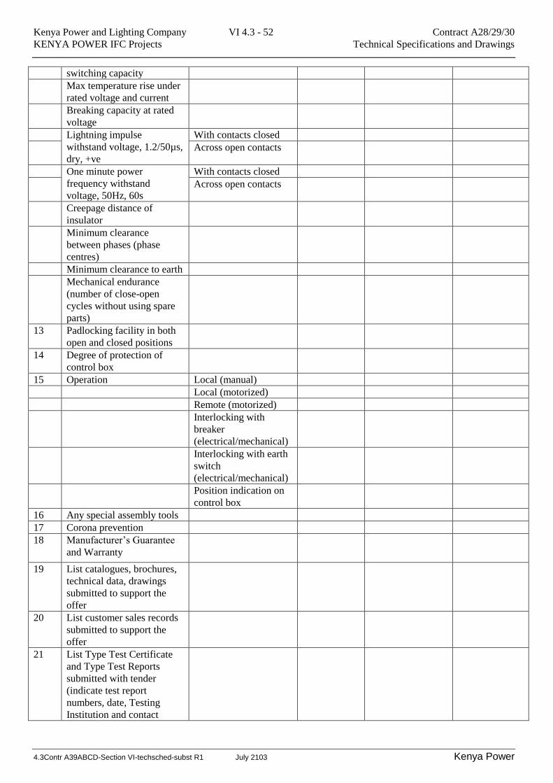
switching capacity
Max temperature rise under
rated voltage and current
Breaking capacity at rated
voltage
Lightning impulse
withstand voltage, 1.2/50µs,
dry, +ve
With contacts closed
Across open contacts
One minute power
frequency withstand
voltage, 50Hz, 60s
With contacts closed
Across open contacts
Creepage distance of
insulator
Minimum clearance
between phases (phase
centres)
Minimum clearance to earth
Mechanical endurance
(number of close-open
cycles without using spare
parts)
13 Padlocking facility in both
open and closed positions
14 Degree of protection of
control box
15 Operation Local (manual)
Local (motorized)
Remote (motorized)
Interlocking with
breaker
(electrical/mechanical)
Interlocking with earth
switch
(electrical/mechanical)
Position indication on
control box
16 Any special assembly tools
17 Corona prevention
18 Manufacturer’s Guarantee
and Warranty
19 List catalogues, brochures,
technical data, drawings
submitted to support the
offer
20 List customer sales records
submitted to support the
offer
21 List Type Test Certificate
and Type Test Reports
submitted with tender
(indicate test report
numbers, date, Testing
Institution and contact
Kenya Power and Lighting Company VI 4.3 - 53 Contract A28/29/30
KENYA POWER IFC Projects Technical Specifications and Drawings
4.3Contr A39ABCD-Section VI-techsched-subst R1 July 2103 Kenya Power
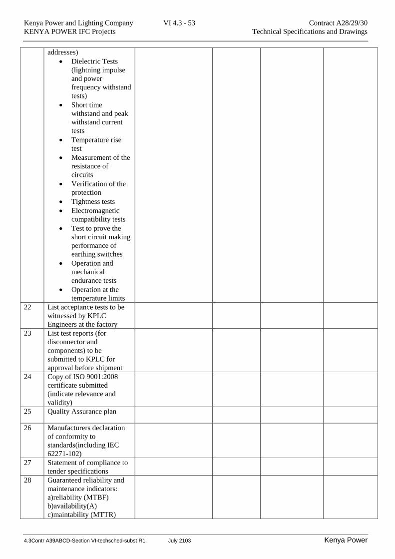
addresses)
Dielectric Tests
(lightning impulse
and power
frequency withstand
tests)
Short time
withstand and peak
withstand current
tests
Temperature rise
test
Measurement of the
resistance of
circuits
Verification of the
protection
Tightness tests
Electromagnetic
compatibility tests
Test to prove the
short circuit making
performance of
earthing switches
Operation and
mechanical
endurance tests
Operation at the
temperature limits
22 List acceptance tests to be
witnessed by KPLC
Engineers at the factory
23 List test reports (for
disconnector and
components) to be
submitted to KPLC for
approval before shipment
24 Copy of ISO 9001:2008
certificate submitted
(indicate relevance and
validity)
25 Quality Assurance plan
26 Manufacturers declaration
of conformity to
standards(including IEC
62271-102)
27 Statement of compliance to
tender specifications
28 Guaranteed reliability and
maintenance indicators:
a)reliability (MTBF)
b)availability(A)
c)maintability (MTTR)
Kenya Power and Lighting Company VI 4.3 - 54 Contract A28/29/30
KENYA POWER IFC Projects Technical Specifications and Drawings
4.3Contr A39ABCD-Section VI-techsched-subst R1 July 2103 Kenya Power
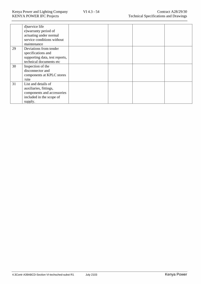
d)service life
e)warranty period of
actuating under normal
service conditions without
maintenance
29 Deviations from tender
specifications and
supporting data, test reports,
technical documents etc
30 Inspection of the
disconnector and
components at KPLC stores
/site
31 List and details of
auxiliaries, fittings,
components and accessories
included in the scope of
supply.
Kenya Power and Lighting Company VI 4.3 - 55 Contract A28/29/30
KENYA POWER IFC Projects Technical Specifications and Drawings
4.3Contr A39ABCD-Section VI-techsched-subst R1 July 2103 Kenya Power
12 Table of Conformance
Include a Table of conformance for each item in the specifications indicating fully conformed, partial and
Reasons and Non-conformance with reasons.