sapphire portable multi-gas detector operation manual
TRANSCRIPT
ENMET 680 Fairfield Court Ann Arbor, MI 48108 734.761.1270 Fax 734.761.3220 www.enmet.com
SAPPHIRE Portable Multi-Gas Detector
Operation Manual
SAPPHIRE ENMET
Manual Release Date – June 15, 2017 P a g e | 1 Manual Part No. – 80006-024
Table of Contents 1.0 INTRODUCTION…………………………………………………………………………………………………………………...3
1.1 UNPACK ............................................................................................................................................................................................ 3 1.2 CHECK ORDER .................................................................................................................................................................................. 3 1.3 SERIAL NUMBERS ............................................................................................................................................................................. 3
2.0 FEATURES…………………………………………………………………………………………………………………………..4
2.1 SAPPHIRE ELEMENTS ..................................................................................................................................................................... 4 2.2 ALARMS ............................................................................................................................................................................................ 5 2.3 STEL/TWA ALARMS ....................................................................................................................................................................... 5
3.0 OPERATION INSTRUCTIONS……………………………………………………………………………………………………6
3.1 POWER ON ......................................................................................................................................................................................... 6 3.2 POWER OFF ....................................................................................................................................................................................... 6
3.3.1 Charging the Battery ................................................................................................................................................................. 7 3.4 BASIC OPERATION ............................................................................................................................................................................ 7
3.4.1 Bump test ................................................................................................................................................................................... 8 3.4.2 Gas detection ............................................................................................................................................................................ 8 3.4.3 Status review ............................................................................................................................................................................. 8
4.0 SAPPHIRE MENU SYSTEM……………………………………………………………………………………………..……….9 4.1 COMMON MENU ................................................................................................................................................................................ 9 4.2 ADVANCED MENU 1........................................................................................................................................................................ 10
4.2.1 Menu Screen............................................................................................................................................................................ 10 4.2.2 Zero calibration ...................................................................................................................................................................... 11
4.3 ADVANCED MENU 2........................................................................................................................................................................ 11 4.3.1 Enter Menu 2........................................................................................................................................................................... 11 4.3.2 Calibration: Single Channel ................................................................................................................................................... 11 4.3.3 Zero calibration ...................................................................................................................................................................... 11 4.3.4 Span Calibration ..................................................................................................................................................................... 12 4.3.5 Span Calibration VOC ............................................................................................................................................................ 14 Note: The instrument must be in the calibration menu for 10 minutes before starting span calibration. ........................................ 14 4.3.6 Calibration: Multi-Channel: ................................................................................................................................................... 16
4.4 ALARM POINT SETTING ................................................................................................................................................................... 16 4.5 CHANNEL SETTING .......................................................................................................................................................................... 17
5.0 PASSWORD SETTINGS……………………………………………………………………………………..……………………17
6.0 MAINTENANCE…………………………………………………………………………………………………………………...18
6.1 BATTERY REPLACEMENT ................................................................................................................................................................ 18 6.2 REPLACEMENT OF SENSOR MODULES……………………………………………………………………………………..19
6.2.1 SENSOR REPLACEMENT................................................................................................................................................................ 19 7.0 STANDARD ACCESSORIES……………………………………………………………………………………………………...20
8.0 TROUBLESHOOTING……………………………………………………………………………………………………………20
9.0 TECHNICAL DATA AND SPECIFICATIONS…………………………………………………………………………………21
APPENDIX A: ISEA STATEMENT………………………………………………………………………………………………….22
Reference Information: NOTE: [important information about use of instrument] CAUTION: [affects equipment – if not followed may cause damage to instrument, sensor etc.…] WARNING: [affects personnel safety – if not followed may cause bodily injury or death.]
Attention / Warning
Earth Ground
!
SAPPHIRE ENMET
Manual Release Date – June 15, 2017 P a g e | 2 Manual Part No. – 80006-024
List of Illustrations FIGURE 1: SAPPHIRE FEATURES ............................................................................................................................................. 4 FIGURE 2: SAPPHIRE DISPLAY FEATURES .............................................................................................................................. 5 FIGURE 3: SAPPHIRE SENSOR LIST ....................................................................................................................................... 21
SAFETY INFORMATION Please first read the below safety information carefully before using and then operating this device.
• Please don't use a defective device. • It is suggested that the user carry out a "Bump Test" before using the device as described by ISEA standard.
Periodic Bump test will test the response feature of the sensor. Please make sure that the visual, audible and vibration alarm signals are functioning properly.
• Only the charger which is specified for SAPPHIRE can be used. It's forbidden to charge the device in a dangerous environment.
• Long term or repeated exposure to toxic and combustible gases above the range of the sensors may influence the performance or damage the sensors.
• Exposing the SAPPHIRE to environments consisting of leaded compound, sulfocompound, organic phosphorus compound or silicon, will cause the combustible gas sensor to be poisoned.
• Do not expose the device to electric shock, strong magnetic field or serious continuous mechanic shocking. • There is a lithium battery inside the device. Please do not discard a defective battery in the regular garbage disposal.
The defective battery should be recycled per your local regulations. • Avoid dropping or seriously shocking the instrument.
Main Features
• Advanced 16 digit MCU with low consumption
• Ultra-wide angle LCM screen
• Adjustable 2-level alarm points
• Adjustable calibration point
• Self-protection design for combustible gas sensor
• Battery low voltage alert function
• Real-time clock
• Interchangeable smart sensor module design
• Audible, visual and vibrating alarm signals
• STEL/TWA alarm for toxic gases
• Designed with self-test, self-diagnostics
• Password management
• Intrinsically safe design
SAPPHIRE ENMET
Manual Release Date – June 15, 2017 P a g e | 3 Manual Part No. – 80006-024
1.0 Introduction SAPPHIRE is a compact and lightweight multi gas detector that continuously measures combustibles, O2, CO, H2S and other toxic gases in ambient air. By using 6 sensors, it can detect at most 7 gases simultaneously. Its functional and watertight design (IP 66) incorporates a durable, shock resistant rubberized housing to meet the toughest requirements of harsh environments. NOTE: All specifications stated in this manual may change without notice.
1.1 Unpack Unpack the SAPPHIRE and examine it for shipping damage. If such damage is observed, notify both ENMET customer service personnel and the commercial carrier involved immediately. Regarding Damaged Shipments: NOTE: It is your responsibility to follow these instructions. If they are not followed, the carrier will not honor any claims for damage.
• This shipment was carefully inspected, verified and properly packaged at our company and delivered to the carrier in good
condition. • When it was picked up by the carrier at ENMET, it legally became your company’s property. • If your shipment arrives damaged:
o Keep the items, packing material, and carton “As Is.” Within 5 days of receipt, notify the carrier’s local office and request immediate inspection of the carton and the contents.
o After the inspection and after you have received written acknowledgment of the damage from the carrier, contact ENMET Customer Service for return authorization and further instructions. Please have your Purchase Order and Sales Order numbers available. If you can take a picture of the damage, please take one and send to ENMET for review.
• ENMET either repairs or replaces damaged equipment and invoices the carrier to the extent of the liability coverage, usually $100.00. Repair or replacement charges above that value are your company’s responsibility.
• The shipping company may offer optional insurance coverage. ENMET only insures shipments with the shipping company when asked to do so in writing by our customer. If you need your shipments insured, please forward a written request to ENMET Customer Service.
Regarding Shortages If there are any shortages or questions regarding this shipment, please notify ENMET Customer Service within 5 days of receipt at the following address.
ENMET 680 Fairfield Court
Ann Arbor, MI 48108 734-761-1270 734-761-3220 Fax
1.2 Check Order Check, the contents of the shipment against the purchase order. Verify that the SAPPHIRE is received as ordered. If there are accessories on the order, ascertain that they are present. Check the contents of calibration kits. Notify ENMET customer service personnel of any discrepancy immediately.
1.3 Serial Numbers Each SAPPHIRE is serialized. These numbers are on labels on the equipment and are on record in an ENMET database.
SAPPHIRE ENMET
Manual Release Date – June 15, 2017 P a g e | 4 Manual Part No. – 80006-024
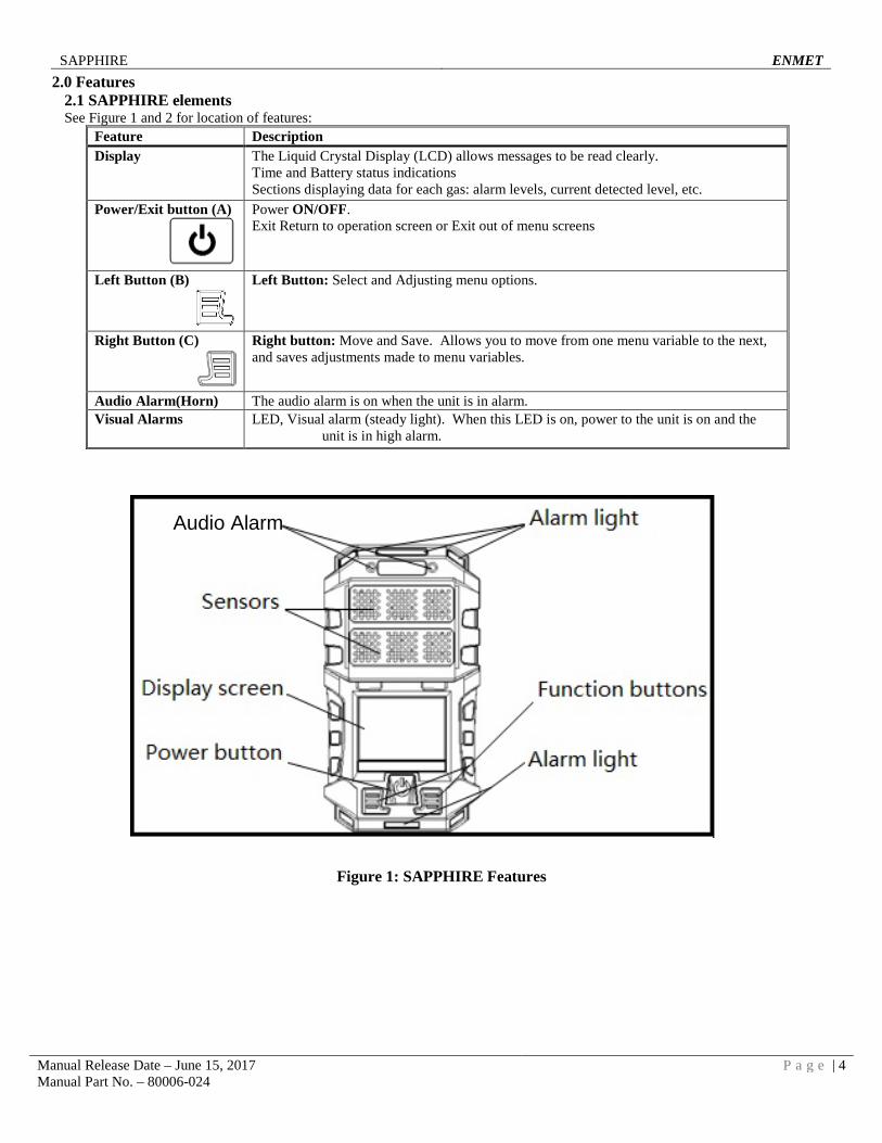
2.0 Features 2.1 SAPPHIRE elements See Figure 1 and 2 for location of features:
Feature Description Display The Liquid Crystal Display (LCD) allows messages to be read clearly.
Time and Battery status indications Sections displaying data for each gas: alarm levels, current detected level, etc.
Power/Exit button (A)
Power ON/OFF. Exit Return to operation screen or Exit out of menu screens
Left Button (B)
Left Button: Select and Adjusting menu options.
Right Button (C)
Right button: Move and Save. Allows you to move from one menu variable to the next, and saves adjustments made to menu variables.
Audio Alarm(Horn) The audio alarm is on when the unit is in alarm. Visual Alarms LED, Visual alarm (steady light). When this LED is on, power to the unit is on and the
unit is in high alarm.
Figure 1: SAPPHIRE Features
Audio Alarm
SAPPHIRE ENMET
Manual Release Date – June 15, 2017 P a g e | 5 Manual Part No. – 80006-024
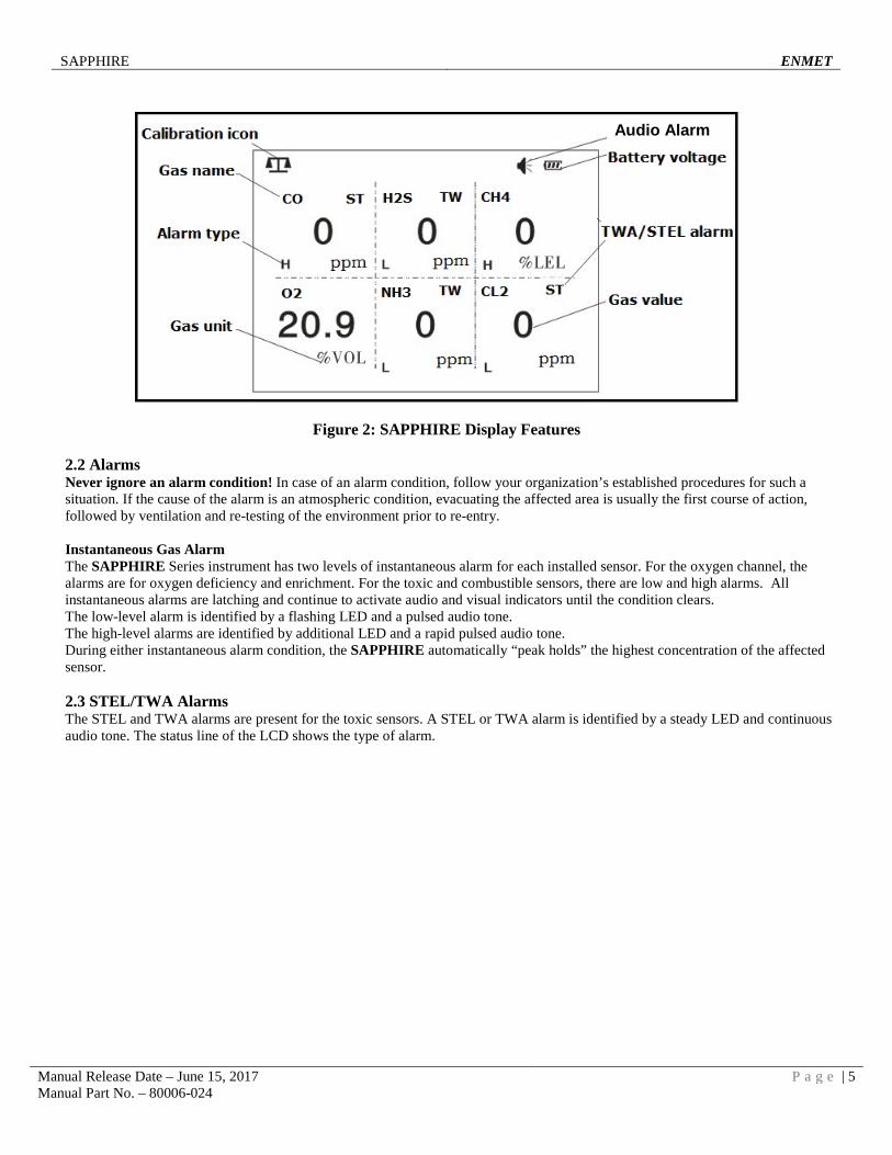
Figure 2: SAPPHIRE Display Features
2.2 Alarms Never ignore an alarm condition! In case of an alarm condition, follow your organization’s established procedures for such a situation. If the cause of the alarm is an atmospheric condition, evacuating the affected area is usually the first course of action, followed by ventilation and re-testing of the environment prior to re-entry. Instantaneous Gas Alarm The SAPPHIRE Series instrument has two levels of instantaneous alarm for each installed sensor. For the oxygen channel, the alarms are for oxygen deficiency and enrichment. For the toxic and combustible sensors, there are low and high alarms. All instantaneous alarms are latching and continue to activate audio and visual indicators until the condition clears. The low-level alarm is identified by a flashing LED and a pulsed audio tone. The high-level alarms are identified by additional LED and a rapid pulsed audio tone. During either instantaneous alarm condition, the SAPPHIRE automatically “peak holds” the highest concentration of the affected sensor.
2.3 STEL/TWA Alarms The STEL and TWA alarms are present for the toxic sensors. A STEL or TWA alarm is identified by a steady LED and continuous audio tone. The status line of the LCD shows the type of alarm.
Audio Alarm
SAPPHIRE ENMET
Manual Release Date – June 15, 2017 P a g e | 6 Manual Part No. – 80006-024
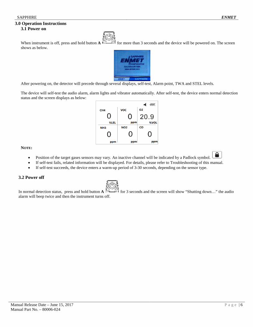
3.0 Operation Instructions 3.1 Power on
When instrument is off, press and hold button A for more than 3 seconds and the device will be powered on. The screen shows as below.
After powering on, the detector will precede through several displays, self-test, Alarm point, TWA and STEL levels. The device will self-test the audio alarm, alarm lights and vibrator automatically. After self-test, the device enters normal detection status and the screen displays as below:
NOTE:
• Position of the target gases sensors may vary. An inactive channel will be indicated by a Padlock symbol. • If self-test fails, related information will be displayed. For details, please refer to Troubleshooting of this manual. • If self-test succeeds, the device enters a warm-up period of 3-30 seconds, depending on the sensor type.
3.2 Power off
In normal detection status, press and hold button A for 3 seconds and the screen will show “Shutting down…” the audio alarm will beep twice and then the instrument turns off.
SAPPHIRE ENMET
Manual Release Date – June 15, 2017 P a g e | 7 Manual Part No. – 80006-024
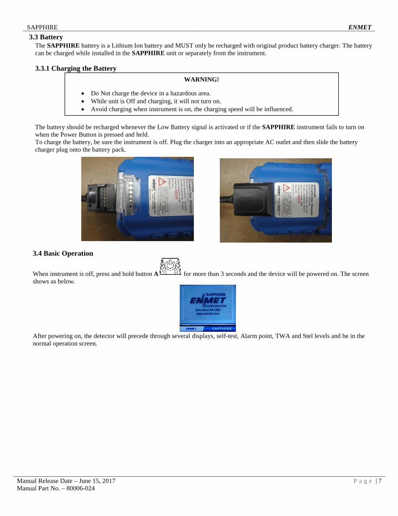
3.3 Battery The SAPPHIRE battery is a Lithium Ion battery and MUST only be recharged with original product battery charger. The battery can be charged while installed in the SAPPHIRE unit or separately from the instrument.
3.3.1 Charging the Battery
The battery should be recharged whenever the Low Battery signal is activated or if the SAPPHIRE instrument fails to turn on when the Power Button is pressed and held. To charge the battery, be sure the instrument is off. Plug the charger into an appropriate AC outlet and then slide the battery charger plug onto the battery pack.
3.4 Basic Operation
When instrument is off, press and hold button A for more than 3 seconds and the device will be powered on. The screen shows as below.
After powering on, the detector will precede through several displays, self-test, Alarm point, TWA and Stel levels and be in the normal operation screen.
WARNING!
• Do Not charge the device in a hazardous area. • While unit is Off and charging, it will not turn on. • Avoid charging when instrument is on, the charging speed will be influenced.
SAPPHIRE ENMET
Manual Release Date – June 15, 2017 P a g e | 8 Manual Part No. – 80006-024
3.4.1 Bump test It is recommended that every day before using the device, the user should carry out a bump test, to check if the device is working normally. Test method: When the device is powered on, expose it to a level of gas greater than the lower level alarm points. This should be done for each of the active sensors in the instrument. If all the device’s functions are ok, then device can be used in the working area. NOTE:
• If any reading on the active channels fails to respond, please follow section 4.3 of this manual to recalibrate it. • It is suggested the device be recalibrated a minimum of once every 6 months.
3.4.2 Gas detection The device monitors and displays gas concentration in real time. Once the gas concentration reaches the preset alarm point, it will initiate alarms. NOTE:
• Do not block sensors during operation • Clean Air reading: Long term storage, severe physical shock and excessively high gas concentrations may cause zero
drift of the gas sensors. If the reading in clean air is not zero, perform a zero calibration by following section 4.3.3.
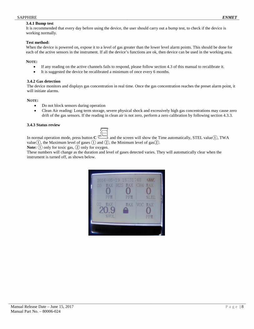
3.4.3 Status review
In normal operation mode, press button C and the screen will show the Time automatically, STEL value①, TWA value①, the Maximum level of gases ① and ②, the Minimum level of gas②. Note: ① only for toxic gas, ② only for oxygen. These numbers will change as the duration and level of gases detected varies. They will automatically clear when the instrument is turned off, as shown below.
SAPPHIRE ENMET
Manual Release Date – June 15, 2017 P a g e | 9 Manual Part No. – 80006-024
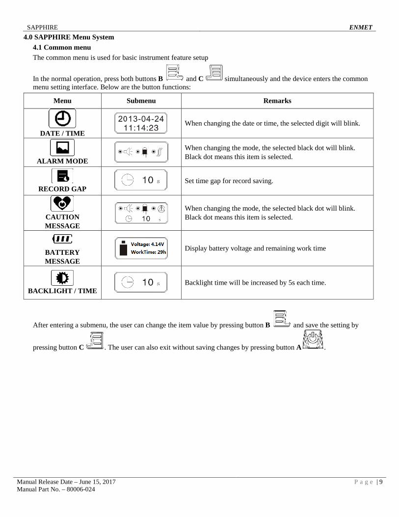
4.0 SAPPHIRE Menu System 4.1 Common menu The common menu is used for basic instrument feature setup
In the normal operation, press both buttons B and C simultaneously and the device enters the common menu setting interface. Below are the button functions:
Menu Submenu Remarks
DATE / TIME
When changing the date or time, the selected digit will blink.
ALARM MODE
When changing the mode, the selected black dot will blink. Black dot means this item is selected.
RECORD GAP
Set time gap for record saving.
CAUTION MESSAGE
When changing the mode, the selected black dot will blink. Black dot means this item is selected.
BATTERY MESSAGE
Display battery voltage and remaining work time
BACKLIGHT / TIME
Backlight time will be increased by 5s each time.
After entering a submenu, the user can change the item value by pressing button B and save the setting by
pressing button C . The user can also exit without saving changes by pressing button A .
SAPPHIRE ENMET
Manual Release Date – June 15, 2017 P a g e | 10 Manual Part No. – 80006-024
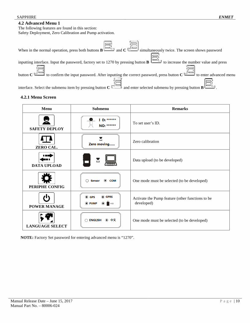
4.2 Advanced Menu 1 The following features are found in this section: Safety Deployment, Zero Calibration and Pump activation.
When in the normal operation, press both buttons B and C simultaneously twice. The screen shows password
inputting interface. Input the password, factory set to 1270 by pressing button B to increase the number value and press
button C to confirm the input password. After inputting the correct password, press button C to enter advanced menu
interface. Select the submenu item by pressing button C and enter selected submenu by pressing button B .
4.2.1 Menu Screen
Menu Submenu Remarks
SAFETY DEPLOY
To set user’s ID.
ZERO CAL.
Zero calibration
DATA UPLOAD
Data upload (to be developed)
PERIPHE CONFIG
One mode must be selected (to be developed)
POWER MANAGE
Activate the Pump feature (other functions to be developed)
LANGUAGE SELECT
One mode must be selected (to be developed)
NOTE: Factory Set password for entering advanced menu is “1270”.
SAPPHIRE ENMET
Manual Release Date – June 15, 2017 P a g e | 11 Manual Part No. – 80006-024
4.2.2 Zero calibration
In normal operation mode, press both buttons B and C simultaneously twice. The device requests for inputting password. After entering correct password, the device enters advanced menu interface.
Move the cursor to icon and press button B to enter auto zero calibration interface. Zero calibration is automatic and takes 1 to 10 minutes depending on the sensor configuration. When finished, a “√” icon displays for gases that succeed and “×” for gases that failed.
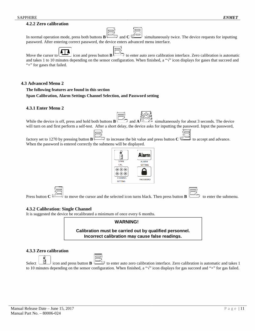
4.3 Advanced Menu 2 The following features are found in this section Span Calibration, Alarm Settings Channel Selection, and Password setting 4.3.1 Enter Menu 2
While the device is off, press and hold both buttons B and A simultaneously for about 3 seconds. The device will turn on and first perform a self-test. After a short delay, the device asks for inputting the password. Input the password,
factory set to 1270 by pressing button B to increase the bit value and press button C to accept and advance. When the password is entered correctly the submenu will be displayed.
Press button C to move the cursor and the selected icon turns black. Then press button B to enter the submenu. 4.3.2 Calibration: Single Channel It is suggested the device be recalibrated a minimum of once every 6 months.
4.3.3 Zero calibration
Select icon and press button B to enter auto zero calibration interface. Zero calibration is automatic and takes 1 to 10 minutes depending on the sensor configuration. When finished, a “√” icon displays for gas succeed and “×” for gas failed.
WARNING!
Calibration must be carried out by qualified personnel. Incorrect calibration may cause false readings.
SAPPHIRE ENMET
Manual Release Date – June 15, 2017 P a g e | 12 Manual Part No. – 80006-024
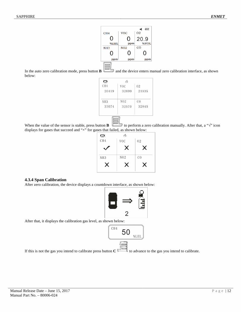
In the auto zero calibration mode, press button B and the device enters manual zero calibration interface, as shown below:
When the value of the sensor is stable, press button B to perform a zero calibration manually. After that, a “√” icon displays for gases that succeed and “×” for gases that failed, as shown below:
4.3.4 Span Calibration After zero calibration, the device displays a countdown interface, as shown below:
After that, it displays the calibration gas level, as shown below:
If this is not the gas you intend to calibrate press button C to advance to the gas you intend to calibrate.
SAPPHIRE ENMET
Manual Release Date – June 15, 2017 P a g e | 13 Manual Part No. – 80006-024
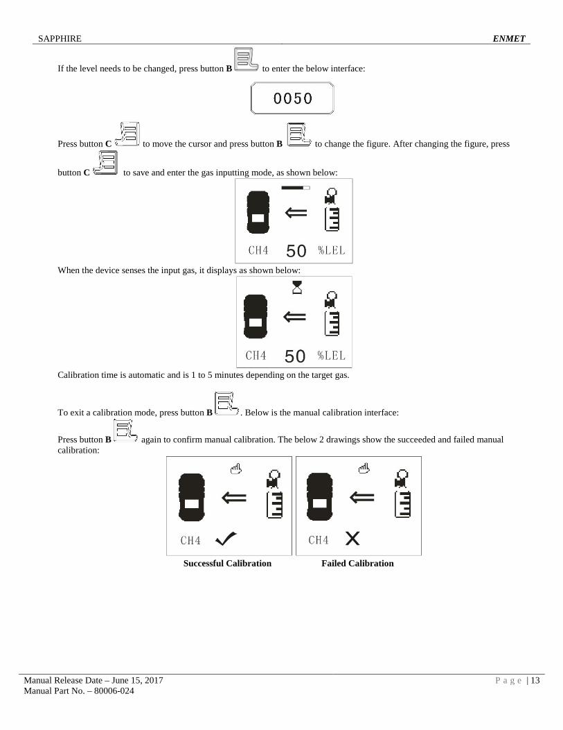
If the level needs to be changed, press button B to enter the below interface:
Press button C to move the cursor and press button B to change the figure. After changing the figure, press
button C to save and enter the gas inputting mode, as shown below:
When the device senses the input gas, it displays as shown below:
Calibration time is automatic and is 1 to 5 minutes depending on the target gas.
To exit a calibration mode, press button B . Below is the manual calibration interface:
Press button B again to confirm manual calibration. The below 2 drawings show the succeeded and failed manual calibration:
Successful Calibration Failed Calibration
SAPPHIRE ENMET
Manual Release Date – June 15, 2017 P a g e | 14 Manual Part No. – 80006-024
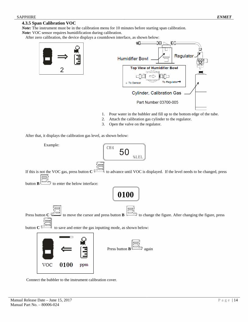
4.3.5 Span Calibration VOC Note: The instrument must be in the calibration menu for 10 minutes before starting span calibration. Note: VOC sensor requires humidification during calibration.
After zero calibration, the device displays a countdown interface, as shown below:
After that, it displays the calibration gas level, as shown below:
Example:
If this is not the VOC gas, press button C to advance until VOC is displayed. If the level needs to be changed, press
button B to enter the below interface:
Press button C to move the cursor and press button B to change the figure. After changing the figure, press
button C to save and enter the gas inputting mode, as shown below:
Press button B again
Connect the bubbler to the instrument calibration cover.
1. Pour water in the bubbler and fill up to the bottom edge of the tube. 2. Attach the calibration gas cylinder to the regulator. 3. Open the valve on the regulator.
0100
SAPPHIRE ENMET
Manual Release Date – June 15, 2017 P a g e | 15 Manual Part No. – 80006-024
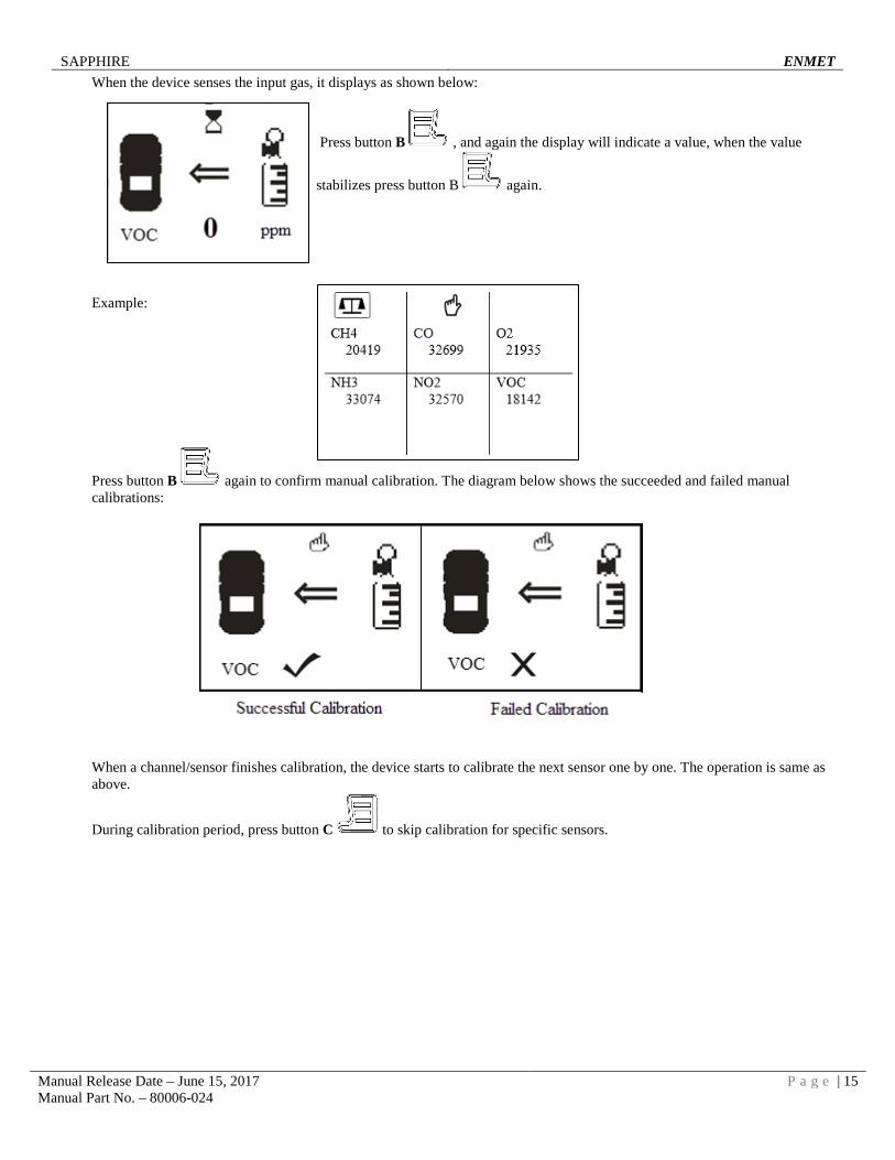
When the device senses the input gas, it displays as shown below:
Press button B , and again the display will indicate a value, when the value
stabilizes press button B again. Example:
Press button B again to confirm manual calibration. The diagram below shows the succeeded and failed manual calibrations:
When a channel/sensor finishes calibration, the device starts to calibrate the next sensor one by one. The operation is same as above.
During calibration period, press button C to skip calibration for specific sensors.
SAPPHIRE ENMET
Manual Release Date – June 15, 2017 P a g e | 16 Manual Part No. – 80006-024
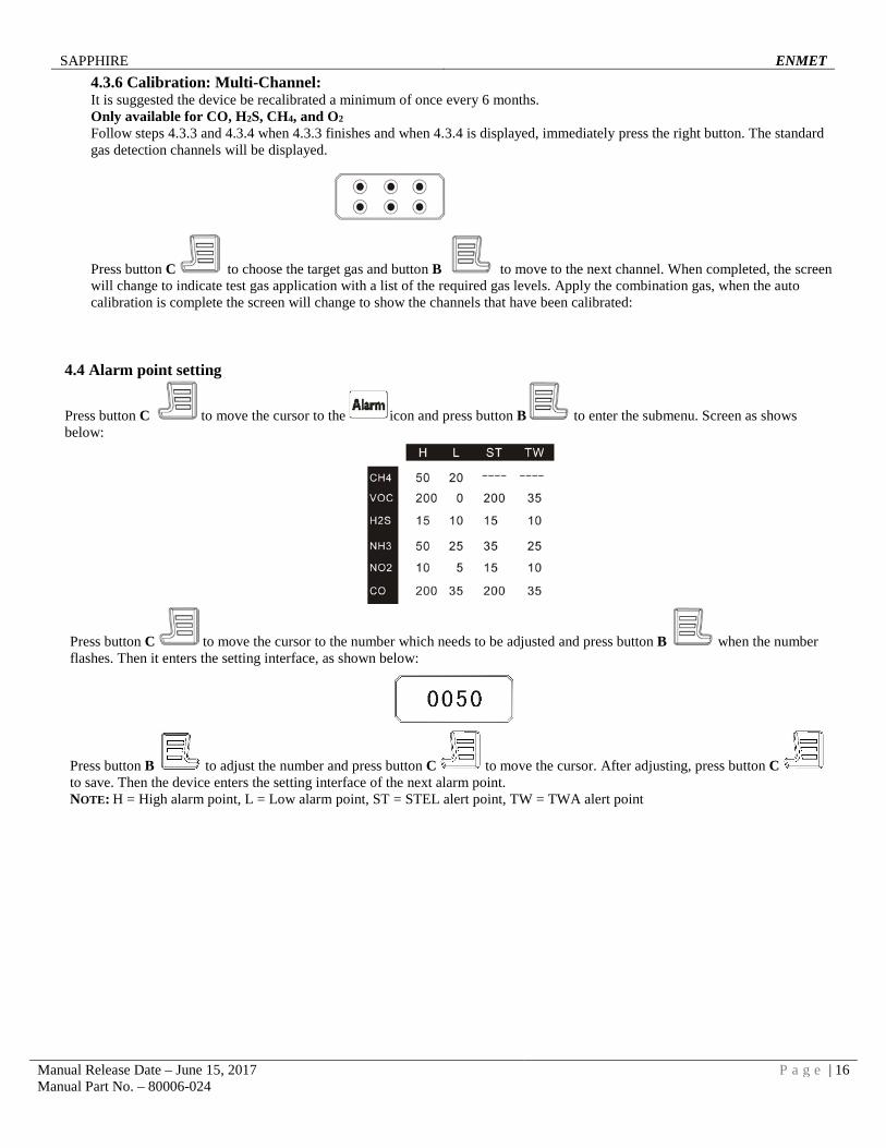
4.3.6 Calibration: Multi-Channel: It is suggested the device be recalibrated a minimum of once every 6 months. Only available for CO, H2S, CH4, and O2 Follow steps 4.3.3 and 4.3.4 when 4.3.3 finishes and when 4.3.4 is displayed, immediately press the right button. The standard gas detection channels will be displayed.
Press button C to choose the target gas and button B to move to the next channel. When completed, the screen will change to indicate test gas application with a list of the required gas levels. Apply the combination gas, when the auto calibration is complete the screen will change to show the channels that have been calibrated:
4.4 Alarm point setting
Press button C to move the cursor to the icon and press button B to enter the submenu. Screen as shows below:
Press button C to move the cursor to the number which needs to be adjusted and press button B when the number flashes. Then it enters the setting interface, as shown below:
Press button B to adjust the number and press button C to move the cursor. After adjusting, press button C to save. Then the device enters the setting interface of the next alarm point. NOTE: H = High alarm point, L = Low alarm point, ST = STEL alert point, TW = TWA alert point
SAPPHIRE ENMET
Manual Release Date – June 15, 2017 P a g e | 17 Manual Part No. – 80006-024
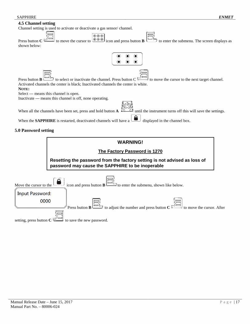
4.5 Channel setting Channel setting is used to activate or deactivate a gas sensor/ channel.
Press button C to move the cursor to icon and press button B to enter the submenu. The screen displays as shown below:
Press button B to select or inactivate the channel. Press button C to move the cursor to the next target channel. Activated channels the center is black; Inactivated channels the center is white. NOTE: Select --- means this channel is open. Inactivate --- means this channel is off, none operating.
When all the channels have been set, press and hold button A until the instrument turns off this will save the settings.
When the SAPPHIRE is restarted, deactivated channels will have a displayed in the channel box.
5.0 Password setting
Move the cursor to the icon and press button B to enter the submenu, shown like below.
Press button B to adjust the number and press button C to move the cursor. After
setting, press button C to save the new password.
WARNING!
The Factory Password is 1270
Resetting the password from the factory setting is not advised as loss of password may cause the SAPPHIRE to be inoperable
SAPPHIRE ENMET
Manual Release Date – June 15, 2017 P a g e | 18 Manual Part No. – 80006-024
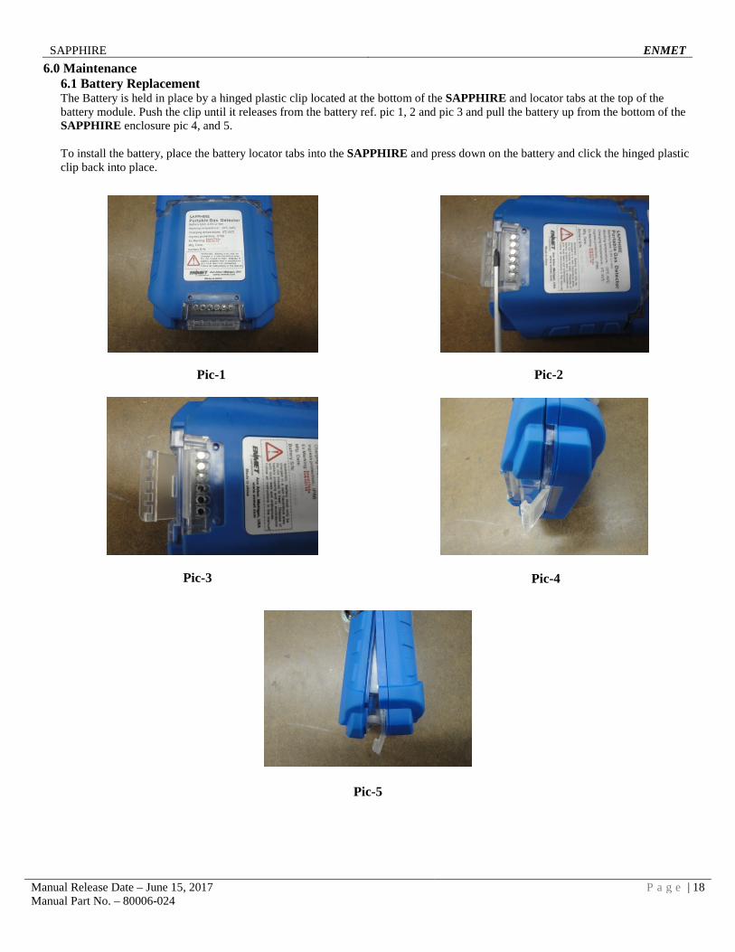
6.0 Maintenance 6.1 Battery Replacement The Battery is held in place by a hinged plastic clip located at the bottom of the SAPPHIRE and locator tabs at the top of the battery module. Push the clip until it releases from the battery ref. pic 1, 2 and pic 3 and pull the battery up from the bottom of the SAPPHIRE enclosure pic 4, and 5. To install the battery, place the battery locator tabs into the SAPPHIRE and press down on the battery and click the hinged plastic clip back into place.
Pic-4
Pic-1
Pic-4
Pic-2
Pic-5
Pic-3
SAPPHIRE ENMET
Manual Release Date – June 15, 2017 P a g e | 19 Manual Part No. – 80006-024
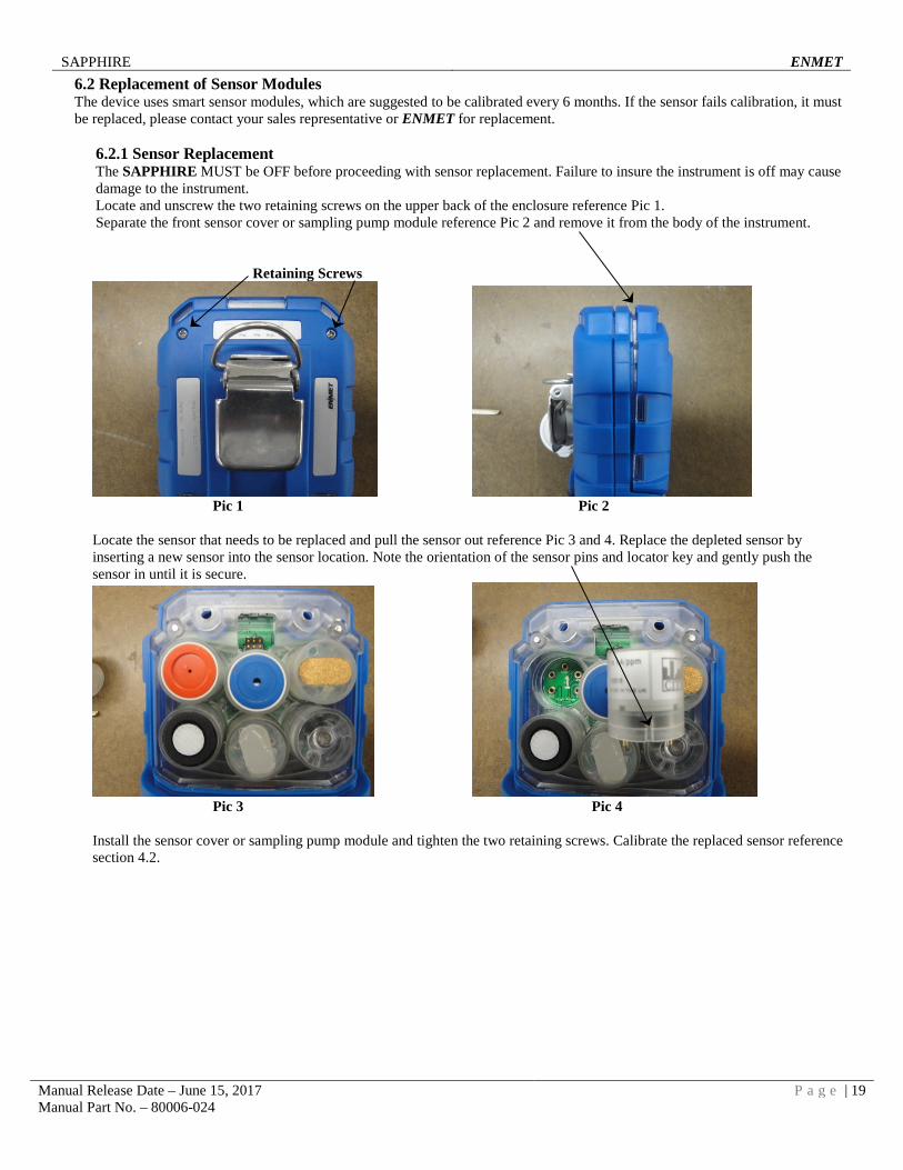
6.2 Replacement of Sensor Modules The device uses smart sensor modules, which are suggested to be calibrated every 6 months. If the sensor fails calibration, it must be replaced, please contact your sales representative or ENMET for replacement.
6.2.1 Sensor Replacement The SAPPHIRE MUST be OFF before proceeding with sensor replacement. Failure to insure the instrument is off may cause damage to the instrument. Locate and unscrew the two retaining screws on the upper back of the enclosure reference Pic 1. Separate the front sensor cover or sampling pump module reference Pic 2 and remove it from the body of the instrument.
Retaining Screws
Pic 1 Pic 2 Locate the sensor that needs to be replaced and pull the sensor out reference Pic 3 and 4. Replace the depleted sensor by inserting a new sensor into the sensor location. Note the orientation of the sensor pins and locator key and gently push the sensor in until it is secure.
Pic 3 Pic 4 Install the sensor cover or sampling pump module and tighten the two retaining screws. Calibrate the replaced sensor reference section 4.2.
SAPPHIRE ENMET
Manual Release Date – June 15, 2017 P a g e | 20 Manual Part No. – 80006-024
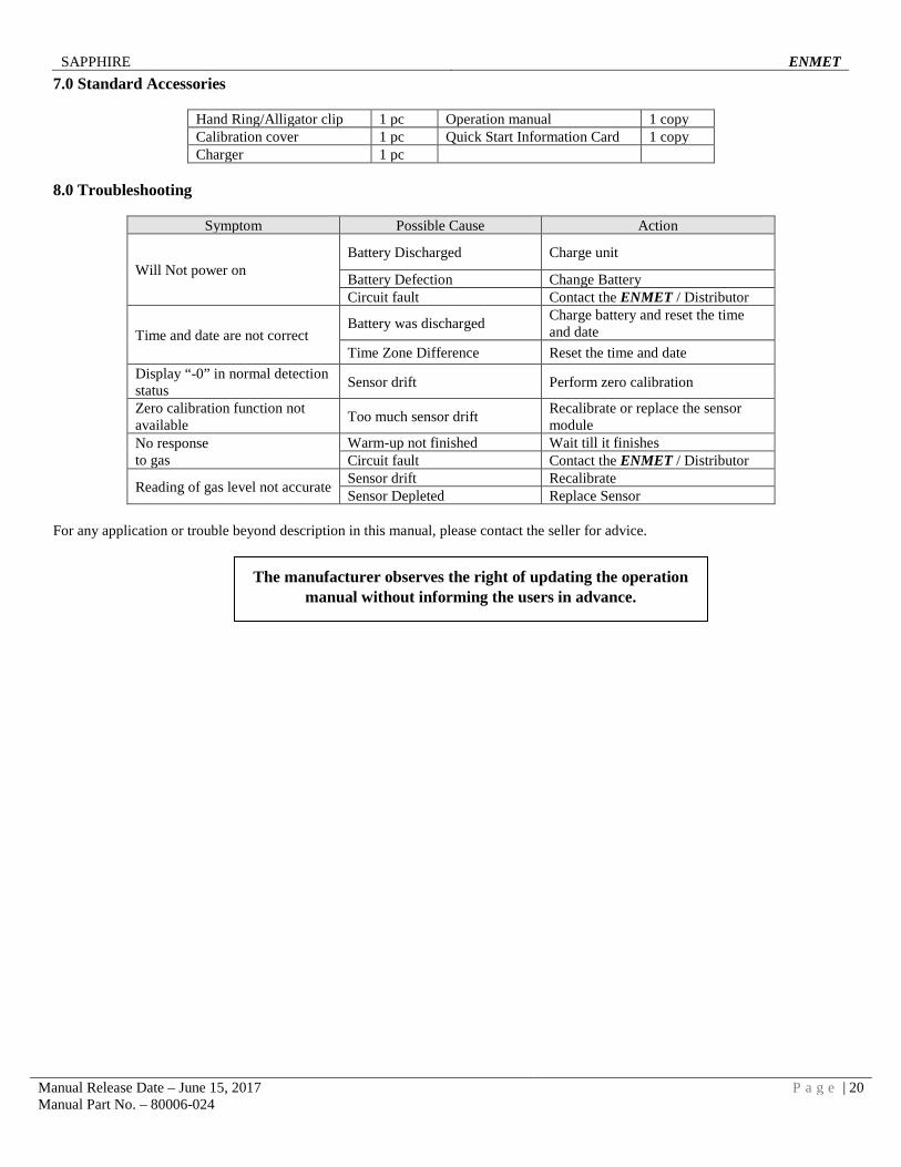
7.0 Standard Accessories
Hand Ring/Alligator clip 1 pc Operation manual 1 copy Calibration cover 1 pc Quick Start Information Card 1 copy Charger 1 pc
8.0 Troubleshooting
Symptom Possible Cause Action
Will Not power on Battery Discharged Charge unit
Battery Defection Change Battery Circuit fault Contact the ENMET / Distributor
Time and date are not correct Battery was discharged Charge battery and reset the time
and date Time Zone Difference Reset the time and date
Display “-0” in normal detection status Sensor drift Perform zero calibration
Zero calibration function not available Too much sensor drift Recalibrate or replace the sensor
module No response to gas
Warm-up not finished Wait till it finishes Circuit fault Contact the ENMET / Distributor
Reading of gas level not accurate Sensor drift Recalibrate Sensor Depleted Replace Sensor
For any application or trouble beyond description in this manual, please contact the seller for advice.
The manufacturer observes the right of updating the operation manual without informing the users in advance.
SAPPHIRE ENMET
Manual Release Date – June 15, 2017 P a g e | 21 Manual Part No. – 80006-024
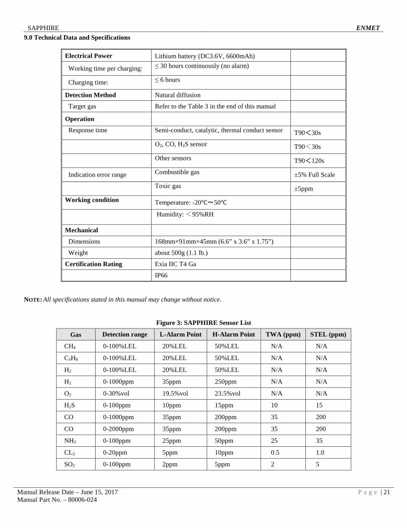
9.0 Technical Data and Specifications
Electrical Power Lithium battery (DC3.6V, 6600mAh)
Working time per charging: ≤ 30 hours continuously (no alarm)
Charging time: ≤ 6 hours
Detection Method Natural diffusion
Target gas Refer to the Table 3 in the end of this manual
Operation
Response time Semi-conduct, catalytic, thermal conduct sensor T90<30s
O2, CO, H2S sensor T90<30s
Other sensors T90<120s
Indication error range Combustible gas ±5% Full Scale
Toxic gas ±5ppm
Working condition Temperature: -20℃~50℃
Humidity: <95%RH
Mechanical
Dimensions 168mm×91mm×45mm (6.6” x 3.6” x 1.75”)
Weight about 500g (1.1 lb.)
Certification Rating Exia IIC T4 Ga
IP66
NOTE: All specifications stated in this manual may change without notice.
Figure 3: SAPPHIRE Sensor List
Gas Detection range L-Alarm Point H-Alarm Point TWA (ppm) STEL (ppm)
CH4 0-100%LEL 20%LEL 50%LEL N/A N/A
C3H8 0-100%LEL 20%LEL 50%LEL N/A N/A
H2 0-100%LEL 20%LEL 50%LEL N/A N/A
H2 0-1000ppm 35ppm 250ppm N/A N/A
O2 0-30%vol 19.5%vol 23.5%vol N/A N/A
H2S 0-100ppm 10ppm 15ppm 10 15
CO 0-1000ppm 35ppm 200ppm 35 200
CO 0-2000ppm 35ppm 200ppm 35 200
NH3 0-100ppm 25ppm 50ppm 25 35
CL2 0-20ppm 5ppm 10ppm 0.5 1.0
SO2 0-100ppm 2ppm 5ppm 2 5
SAPPHIRE ENMET
Manual Release Date – June 15, 2017 P a g e | 22 Manual Part No. – 80006-024
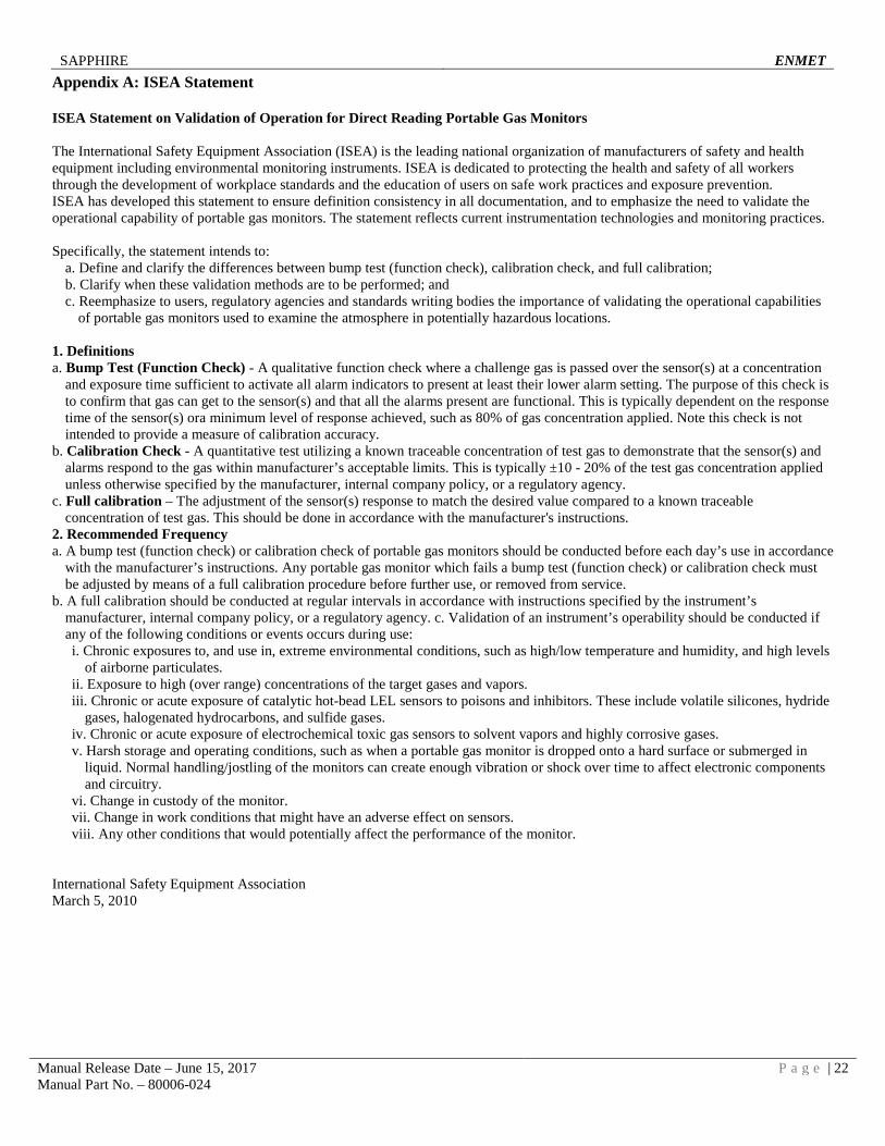
Appendix A: ISEA Statement ISEA Statement on Validation of Operation for Direct Reading Portable Gas Monitors The International Safety Equipment Association (ISEA) is the leading national organization of manufacturers of safety and health equipment including environmental monitoring instruments. ISEA is dedicated to protecting the health and safety of all workers through the development of workplace standards and the education of users on safe work practices and exposure prevention. ISEA has developed this statement to ensure definition consistency in all documentation, and to emphasize the need to validate the operational capability of portable gas monitors. The statement reflects current instrumentation technologies and monitoring practices. Specifically, the statement intends to:
a. Define and clarify the differences between bump test (function check), calibration check, and full calibration; b. Clarify when these validation methods are to be performed; and c. Reemphasize to users, regulatory agencies and standards writing bodies the importance of validating the operational capabilities
of portable gas monitors used to examine the atmosphere in potentially hazardous locations.
1. Definitions a. Bump Test (Function Check) - A qualitative function check where a challenge gas is passed over the sensor(s) at a concentration
and exposure time sufficient to activate all alarm indicators to present at least their lower alarm setting. The purpose of this check is to confirm that gas can get to the sensor(s) and that all the alarms present are functional. This is typically dependent on the response time of the sensor(s) ora minimum level of response achieved, such as 80% of gas concentration applied. Note this check is not intended to provide a measure of calibration accuracy.
b. Calibration Check - A quantitative test utilizing a known traceable concentration of test gas to demonstrate that the sensor(s) and alarms respond to the gas within manufacturer’s acceptable limits. This is typically ±10 - 20% of the test gas concentration applied unless otherwise specified by the manufacturer, internal company policy, or a regulatory agency.
c. Full calibration – The adjustment of the sensor(s) response to match the desired value compared to a known traceable concentration of test gas. This should be done in accordance with the manufacturer's instructions.
2. Recommended Frequency a. A bump test (function check) or calibration check of portable gas monitors should be conducted before each day’s use in accordance
with the manufacturer’s instructions. Any portable gas monitor which fails a bump test (function check) or calibration check must be adjusted by means of a full calibration procedure before further use, or removed from service.
b. A full calibration should be conducted at regular intervals in accordance with instructions specified by the instrument’s manufacturer, internal company policy, or a regulatory agency. c. Validation of an instrument’s operability should be conducted if any of the following conditions or events occurs during use: i. Chronic exposures to, and use in, extreme environmental conditions, such as high/low temperature and humidity, and high levels
of airborne particulates. ii. Exposure to high (over range) concentrations of the target gases and vapors. iii. Chronic or acute exposure of catalytic hot-bead LEL sensors to poisons and inhibitors. These include volatile silicones, hydride
gases, halogenated hydrocarbons, and sulfide gases. iv. Chronic or acute exposure of electrochemical toxic gas sensors to solvent vapors and highly corrosive gases. v. Harsh storage and operating conditions, such as when a portable gas monitor is dropped onto a hard surface or submerged in
liquid. Normal handling/jostling of the monitors can create enough vibration or shock over time to affect electronic components and circuitry.
vi. Change in custody of the monitor. vii. Change in work conditions that might have an adverse effect on sensors. viii. Any other conditions that would potentially affect the performance of the monitor.
International Safety Equipment Association March 5, 2010
SAPPHIRE ENMET
Manual Release Date – June 15, 2017 P a g e | 23 Manual Part No. – 80006-024
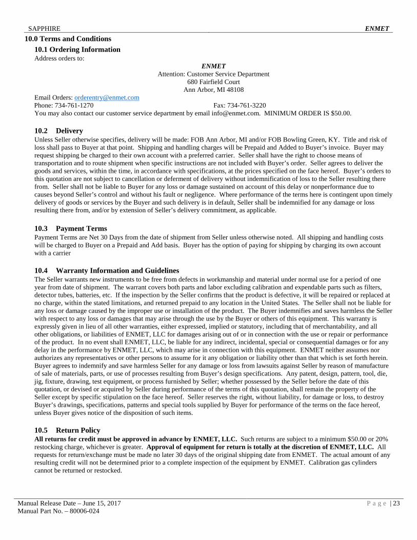
10.0 Terms and Conditions 10.1 Ordering Information Address orders to:
ENMET Attention: Customer Service Department
680 Fairfield Court Ann Arbor, MI 48108
Email Orders: [email protected] Phone: 734-761-1270 Fax: 734-761-3220 You may also contact our customer service department by email [email protected]. MINIMUM ORDER IS $50.00.
10.2 Delivery Unless Seller otherwise specifies, delivery will be made: FOB Ann Arbor, MI and/or FOB Bowling Green, KY. Title and risk of loss shall pass to Buyer at that point. Shipping and handling charges will be Prepaid and Added to Buyer’s invoice. Buyer may request shipping be charged to their own account with a preferred carrier. Seller shall have the right to choose means of transportation and to route shipment when specific instructions are not included with Buyer’s order. Seller agrees to deliver the goods and services, within the time, in accordance with specifications, at the prices specified on the face hereof. Buyer’s orders to this quotation are not subject to cancellation or deferment of delivery without indemnification of loss to the Seller resulting there from. Seller shall not be liable to Buyer for any loss or damage sustained on account of this delay or nonperformance due to causes beyond Seller’s control and without his fault or negligence. Where performance of the terms here is contingent upon timely delivery of goods or services by the Buyer and such delivery is in default, Seller shall be indemnified for any damage or loss resulting there from, and/or by extension of Seller’s delivery commitment, as applicable.
10.3 Payment Terms Payment Terms are Net 30 Days from the date of shipment from Seller unless otherwise noted. All shipping and handling costs will be charged to Buyer on a Prepaid and Add basis. Buyer has the option of paying for shipping by charging its own account with a carrier
10.4 Warranty Information and Guidelines The Seller warrants new instruments to be free from defects in workmanship and material under normal use for a period of one year from date of shipment. The warrant covers both parts and labor excluding calibration and expendable parts such as filters, detector tubes, batteries, etc. If the inspection by the Seller confirms that the product is defective, it will be repaired or replaced at no charge, within the stated limitations, and returned prepaid to any location in the United States. The Seller shall not be liable for any loss or damage caused by the improper use or installation of the product. The Buyer indemnifies and saves harmless the Seller with respect to any loss or damages that may arise through the use by the Buyer or others of this equipment. This warranty is expressly given in lieu of all other warranties, either expressed, implied or statutory, including that of merchantability, and all other obligations, or liabilities of ENMET, LLC for damages arising out of or in connection with the use or repair or performance of the product. In no event shall ENMET, LLC, be liable for any indirect, incidental, special or consequential damages or for any delay in the performance by ENMET, LLC, which may arise in connection with this equipment. ENMET neither assumes nor authorizes any representatives or other persons to assume for it any obligation or liability other than that which is set forth herein. Buyer agrees to indemnify and save harmless Seller for any damage or loss from lawsuits against Seller by reason of manufacture of sale of materials, parts, or use of processes resulting from Buyer’s design specifications. Any patent, design, pattern, tool, die, jig, fixture, drawing, test equipment, or process furnished by Seller; whether possessed by the Seller before the date of this quotation, or devised or acquired by Seller during performance of the terms of this quotation, shall remain the property of the Seller except by specific stipulation on the face hereof. Seller reserves the right, without liability, for damage or loss, to destroy Buyer’s drawings, specifications, patterns and special tools supplied by Buyer for performance of the terms on the face hereof, unless Buyer gives notice of the disposition of such items. 10.5 Return Policy All returns for credit must be approved in advance by ENMET, LLC. Such returns are subject to a minimum $50.00 or 20% restocking charge, whichever is greater. Approval of equipment for return is totally at the discretion of ENMET, LLC. All requests for return/exchange must be made no later 30 days of the original shipping date from ENMET. The actual amount of any resulting credit will not be determined prior to a complete inspection of the equipment by ENMET. Calibration gas cylinders cannot be returned or restocked.
SAPPHIRE ENMET
Manual Release Date – June 15, 2017 P a g e | 24 Manual Part No. – 80006-024
11.0 Instructions for Returning an Instrument for Service Contact the ENMET Service Department for all service requests. Phone: 734-761-1270 Email: [email protected] Fill out the “Service Request Form” found at the end of this manual and return with your instrument for all needs. Please send your instrument for service to the site in which the product was purchased. A new “Service Request Form” may be requested if the one found in the manual is not available. All instruments should be shipped prepaid to ENMET. Address for Service:
Michigan Location: ENMET
Attention: Service Department 680 Fairfield Court
Ann Arbor, MI 48108 Kentucky Location:
ENMET 62 Corporate Court
Bowling Green, KY 42103 Providing the “Service Request Form” assists in the expedient service and return of your unit and failure to provide this information can result in processing delays. ENMET charges a one hour minimum billing for all approved repairs with additional time billed to the closest tenth of an hour. All instruments sent to ENMET are subject to a minimum evaluation fee, even if returned unrepaired. Unclaimed instruments that ENMET has received without appropriate paperwork or attempts to advise repair costs that have been unanswered after a period of 60 days may, be disposed of or returned unrepaired COD and the customer will be expected to pay the evaluation fee. Serviced instruments are returned by UPS/FedEx Ground and are not insured unless otherwise specified. If expedited shipping methods or insurance is required, it must be stated in your paperwork. NOTE: Warranty of customer installed components. For Warranty Repairs, please reference ENMET’s “Warranty Information and Guidelines” (found earlier in this section).
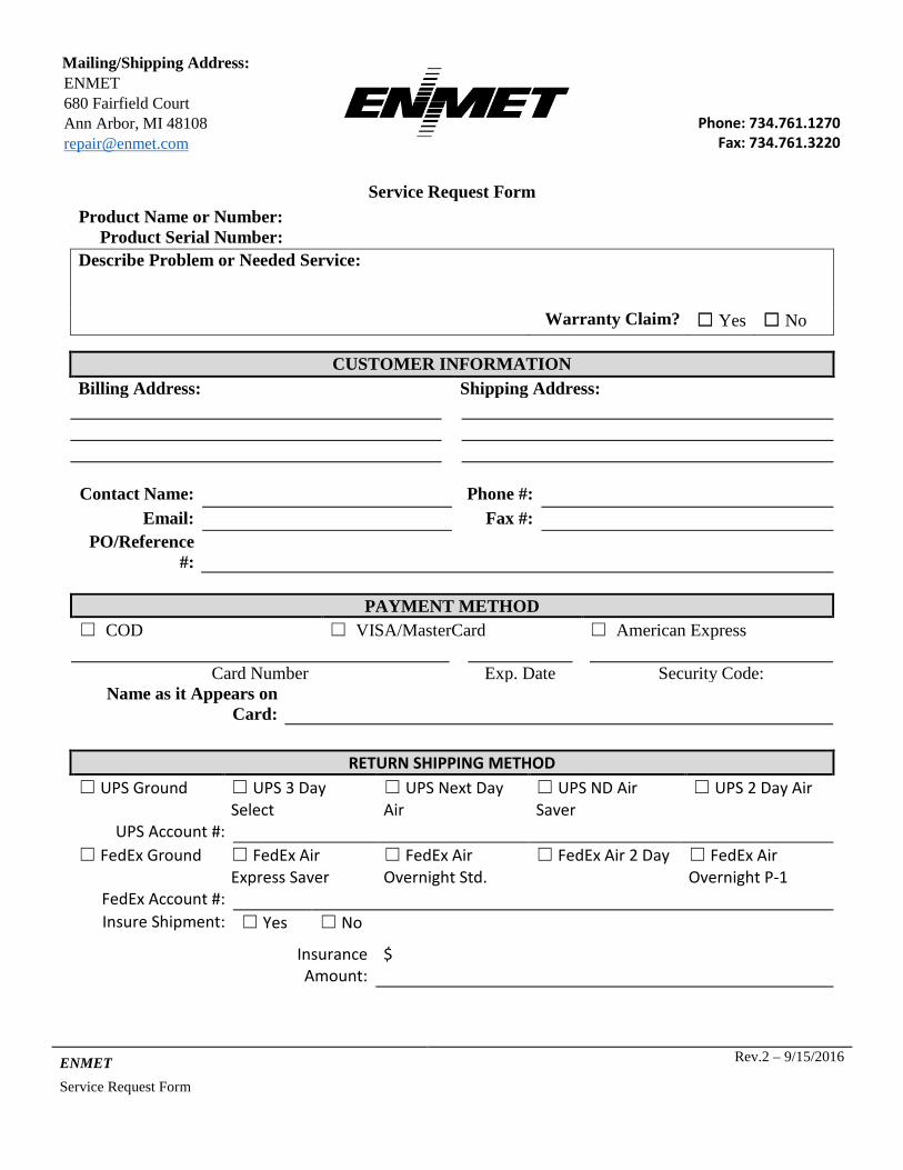
Mailing/Shipping Address: ENMET 680 Fairfield Court Ann Arbor, MI 48108 [email protected] Phone: 734.761.1270
Fax: 734.761.3220
ENMET Rev.2 – 9/15/2016
Service Request Form
Service Request Form
PAYMENT METHOD
☐ COD ☐ VISA/MasterCard ☐ American Express
Card Number Exp. Date Security Code: Name as it Appears on
Card:
RETURN SHIPPING METHOD ☐ UPS Ground ☐ UPS 3 Day
Select ☐ UPS Next Day Air
☐ UPS ND Air Saver
☐ UPS 2 Day Air
UPS Account #: ☐ FedEx Ground
☐ FedEx Air Express Saver
☐ FedEx Air Overnight Std.
☐ FedEx Air 2 Day ☐ FedEx Air Overnight P-1
FedEx Account #: Insure Shipment: ☐ Yes ☐ No
Insurance Amount:
$
Product Name or Number: Product Serial Number:
Describe Problem or Needed Service:
Warranty Claim? ☐ Yes ☐ No
CUSTOMER INFORMATION Billing Address: Shipping Address: Contact Name: Phone #:
Email: Fax #: PO/Reference
#: