rx series lcd digital operator user's manual - omron edata
TRANSCRIPT

Inverter
RX Series
LCD Digital Operator
User’s Manual
I579-E1-02
3G3AX-OP05

OMRON, 2013All rights reserved. No part of this publication may be reproduced, stored in a retrieval system, or transmitted, in any form, or by any means, mechanical, electronic, photocopying, recording, or otherwise, without the prior written permission of OMRON.
No patent liability is assumed with respect to the use of the information contained herein. Moreover, because OMRON is constantly striving to improve its high-quality products, the information contained in this manual is subject to change without notice. Every precaution has been taken in the preparation of this manual. Nevertheless, OMRON assumes no responsibility for errors or omissions. Neither is any liability assumed for damages resulting from the use of the information contained in this publication.

1
Introduction
LCD Digital Operator User’s Manual (I579)
Introduction
Thank you for purchasing the LCD Digital Operator (Model: 3G3AX-OP05).
This manual explains how to set parameters required to use the LCD Digital Operator (Model: 3G3AX-OP05), operation procedures and the remedies needed if problems occur.
For the use of the LCD Digital Operator 3G3AX-OP05, please refer also to High-function General-purpose Inverter 3G3RX--V1 User’s Manual (I578).
This manual is intended for the following individuals.
Those who have electrical knowledge (certified electricians or individuals who have equivalent knowl-edge) and also are qualified for one of the following:
• Introducing control equipment
• Designing control systems
• Installing and connecting control systems
• Managing control systems and facilities
This manual contains information you need to know in order to correctly use the LCD Digital Operator 3G3AX-OP05.
Before using the LCD Digital Operator (Model: 3G3AX-OP05), read this manual and gain a full under-standing of the information provided herein.
After you finished reading this manual, keep it in a convenient place so that it can be referenced at any time.
Make sure this manual is delivered to the end user.
Intended Readers
Notice

Manual Configuration
2 LCD Digital Operator User’s Manual (I579)
Manual Configuration
This manual is compiled section by section for user’s convenience as follows.
Overview
Section 1 Overview This section provides features and specifications of the LCD Digital Operator.
Section 2 Part Names and Functions This section describes the part names and functions of the LCD Digital Operator.
Section 3 Installation and Wiring This section provides information on the installation and wiring of the LCD Digital Operator.
Section 4 Operation Procedures This section provides an overview of the display modes supported by LCD Digital Operator and how to operate the LCD Digital Operator in each display mode.
Section 5 LCD Digital Operator Related Parameters
This section describes the Inverter parameters related to the LCD Digital Operator.
Section 6 Read/Write Functions This section describes how to read and write Inverter parameter settings using the LCD Digital Operator.
Section 7 Error Messages and Troubleshooting
This section describes the error messages and troubleshooting of the LCD Digital Operator.
Section 8 Maintenance This section provides information on the maintenance of the LCD Digital Operator.

3
Manual Structure
LCD Digital Operator User’s Manual (I579)
Manual Structure
The following page structure and symbol icons are used in this manual.
Note The above page is only a sample for illustrative purposes. It is not the actual content of the manual.
Page Structure and Symbol Icons
4 Operation Procedures
4 - 2 LCD Digital Operator User’s Manual
4-1 Overview of Display Modes
The LCD Digital Operator basically displays its screens in four modes as shown below.
Each mode has two levels: the higher Navigation level and the lower Edit level. The user can move between each mode in the Navigation level only.• Monitor Mode A: The mode to display and set a single monitor function and a single parameter function.• Monitor Mode B: The mode to display up to four monitor functions on a single screen.• Function Mode: The mode to set parameter settings. The screen also displays the parameter name
and setting range.• Trip Mode: The mode to display the trip and warning information.
In addition to the above, the LCD Digital Operator has the following three called modes. At any of the above levels and in any operating state, you can call these modes by pressing the key(s) shown to the right of the down arrow above each screen, as shown below. After calling these screens, you can press the ESC key to restore the operating state before the call.• All Read: The mode to read all Inverter parameter settings and DriveProgramming data from the
Inverter.• All Write: The mode to write all the stored Inverter parameter setting and DriveProgramming program
data to the Inverter.• Option Mode: The mode to set the LCD Digital Operator.
4-1-1 Transition of Screens
Monitor
Mode A
Monitor
Mode B
Function
Mode
Trip
Mode
Select the monitor item.Select the setting item.
Select the setting line.
Select the setting item.
Monitor the overall trip history.
Monitor
Mode A
Monitor
Mode B
Function
Mode
Trip
Mode
Monitor
Mode A
Monitor
Mode B
Function
Mode
Change the set value. Change the set value. Change the set value.
Nav
igat
ion
leve
lE
dit l
evel
Level 2 heading
Level 3 heading
Level 1 heading
Manual Name
Level 2 heading
Section Number of Level 1 heading
Level 3 heading
Shows which section the content of the current page belongs to.
Shows which sub-section the content of the current page belongs to.
Shows which paragraph the content of the current page belongs to.
Note, Supplementary Information, Reference Target
A note, supplementary information, reference target, etc. are provided with difference icons.
Operation StepsDescribes the operation steps.
4 Operation Procedures
4 - 8LCD Digital Operator User’s Manual
1 At the Navigation level, press the orkey to select the Trip Mode screen.
2 Press the key. Now, the screen shows information on the past trips (six trip errors) recorded in the Inverter and the warning information (for a single occurrence).The trip information for a single occurrence comprises two pages.To switch from page 1 (P1) to page 2 (P2),
press the or key.
To display the information on the past six trip errors,
press the or key.
3 If you press the key when ERR1 is being
displayed or press the key when ERR6 is being displayed, the screen changes to the Warning Mode.
Precautions for Correct UsePrecautions for Correct Use
If a trip occurs, the ALARM LED lights up. Then, press the key to reset the Inverter.
4-5 Operation in the Trip M
ode
4
4-1-2 Basic O
peration

Manual Structure
4 LCD Digital Operator User’s Manual (I579)
Special information in this manual is classified as follows:
Precautions for Safe Use
Precautions on what to do and what not to do to ensure safe usage of the product.
Precautions for Correct UsePrecautions for Correct Use
Precautions on what to do and what not to do to ensure proper operation and performance.
Additional Information
Additional information to read as required.
This information is provided to increase understanding or make operation easier.
Special Information

5
Sections in this Manual
LCD Digital Operator User’s Manual (I579)
1
2
3
4
5
6
7
8
1
2
3
4
5
6
7
8
Overview
Part Names and Functions
Installation and Wiring
Operation Procedures
LCD Digital Operator Related Parameters
Read/Write Functions
Error Messages and Troubleshooting
Maintenance
I
I
Index
Sections in this Manual

6 LCD Digital Operator User’s Manual (I579)
CONTENTS
CONTENTS
Introduction ..............................................................................................................1
Manual Configuration ..............................................................................................2
Manual Structure ......................................................................................................3
Sections in this Manual ...........................................................................................5
CONTENTS................................................................................................................6
Terms and Conditions Agreement ..........................................................................8
Safety Precautions .................................................................................................10
Precautions for Safe Use.......................................................................................13
Precautions for Correct Use..................................................................................15
Regulations and Standards ...................................................................................16
Items to Check after Unpacking............................................................................17
Related Manuals .....................................................................................................18
Revision History .....................................................................................................19
Section 1 Overview
1-1 Features.................................................................................................................................. 1-2
1-2 Supported Models ................................................................................................................. 1-4
1-3 Specifications ........................................................................................................................ 1-5
1-4 External Dimensions ............................................................................................................. 1-6
1-5 Recommended Cables .......................................................................................................... 1-7
Section 2 Part Names and Functions
2-1 Part Names............................................................................................................................. 2-2
2-2 Operation Keys ...................................................................................................................... 2-4
2-3 LCD Display ........................................................................................................................... 2-6
Section 3 Installation and Wiring
3-1 Installation on the Inverter.................................................................................................... 3-23-1-1 Direct Installation on the Inverter ................................................................................................ 3-33-1-2 Installation on the Inverter via Cable........................................................................................... 3-43-1-3 Checking the Operation After Installation.................................................................................... 3-63-1-4 Date and Time Setting ................................................................................................................ 3-73-1-5 Other Settings ............................................................................................................................. 3-7

7LCD Digital Operator User’s Manual (I579)
CONTENTS
Section 4 Operation Procedures
4-1 Overview of Display Modes .................................................................................................. 4-24-1-1 Transition of Screens.................................................................................................................. 4-24-1-2 Overview of Each Mode.............................................................................................................. 4-34-1-3 Changing the Display in Each Mode........................................................................................... 4-5
4-2 Operation in the Monitor Mode A......................................................................................... 4-6
4-3 Operation in the Monitor Mode B......................................................................................... 4-7
4-4 Operation in the Function Mode .......................................................................................... 4-8
4-5 Operation in the Trip Mode ................................................................................................... 4-9
Section 5 LCD Digital Operator Related Parameters
5-1 Parameter Setting.................................................................................................................. 5-25-1-1 Operation in the Option Mode..................................................................................................... 5-25-1-2 Details of Each Option Mode Parameter .................................................................................... 5-4
5-2 Related Inverter Parameters................................................................................................. 5-6
Section 6 Read/Write Functions
6-1 Single READ Function .......................................................................................................... 6-2
6-2 Single WRITE Function ......................................................................................................... 6-3
6-3 Quad READ Function ............................................................................................................ 6-4
6-4 Quad VERIFY Function ......................................................................................................... 6-6
6-5 Quad WRITE Function........................................................................................................... 6-8
6-6 Conditions for the Read/Write Operations........................................................................ 6-10
Section 7 Error Messages and Troubleshooting
7-1 Error Messages and Remedies ............................................................................................ 7-27-1-1 Inverter Error Messages ............................................................................................................. 7-27-1-2 LCD Digital Operator Error Messages ........................................................................................ 7-2
7-2 Troubleshooting .................................................................................................................... 7-5
Section 8 Maintenance
8-1 Battery Replacement............................................................................................................. 8-2
Index
Terms and Conditions Agreement
8 LCD Digital Operator User’s Manual (I579)
Terms and Conditions Agreement
Please read and understand this catalog before purchasing the products. Please consult your OMRON representative if you have any questions or comments.
Exclusive Warranty
Omron’s exclusive warranty is that the Products will be free from defects in materials and workman-ship for a period of twelve months from the date of sale by Omron (or such other period expressed in writing by Omron). Omron disclaims all other warranties, express or implied.
Limitations
OMRON MAKES NO WARRANTY OR REPRESENTATION, EXPRESS OR IMPLIED, ABOUT NON-INFRINGEMENT, MERCHANTABILITY OR FITNESS FOR A PARTICULAR PURPOSE OF THE PRODUCTS. BUYER ACKNOWLEDGES THAT IT ALONE HAS DETERMINED THAT THE PRODUCTS WILL SUITABLY MEET THE REQUIREMENTS OF THEIR INTENDED USE.
Omron further disclaims all warranties and responsibility of any type for claims or expenses based on infringement by the Products or otherwise of any intellectual property right.
Buyer Remedy
Omron’s sole obligation hereunder shall be, at Omron’s election, to (i) replace (in the form originally shipped with Buyer responsible for labor charges for removal or replacement thereof) the non-com-plying Product, (ii) repair the non-complying Product, or (iii) repay or credit Buyer an amount equal to the purchase price of the non-complying Product; provided that in no event shall Omron be responsible for warranty, repair, indemnity or any other claims or expenses regarding the Products unless Omron’s analysis confirms that the Products were properly handled, stored, installed and maintained and not subject to contamination, abuse, misuse or inappropriate modification. Return of any Products by Buyer must be approved in writing by Omron before shipment. Omron Companies shall not be liable for the suitability or unsuitability or the results from the use of Products in combi-nation with any electrical or electronic components, circuits, system assemblies or any other materi-als or substances or environments. Any advice, recommendations or information given orally or in writing, are not to be construed as an amendment or addition to the above warranty.
See http://www.omron.com/global/ or contact your Omron representative for published information.
OMRON COMPANIES SHALL NOT BE LIABLE FOR SPECIAL, INDIRECT, INCIDENTAL, OR CON-SEQUENTIAL DAMAGES, LOSS OF PROFITS OR PRODUCTION OR COMMERCIAL LOSS IN ANY WAY CONNECTED WITH THE PRODUCTS, WHETHER SUCH CLAIM IS BASED IN CONTRACT, WARRANTY, NEGLIGENCE OR STRICT LIABILITY.
Further, in no event shall liability of Omron Companies exceed the individual price of the Product on which liability is asserted.
Read and understand this Manual
Warranty, Limitations of Liability
Warranties
Limitation on Liability; Etc

9
Terms and Conditions Agreement
LCD Digital Operator User’s Manual (I579)
Omron Companies shall not be responsible for conformity with any standards, codes or regulations which apply to the combination of the Product in the Buyer’s application or use of the Product. At Buyer’s request, Omron will provide applicable third party certification documents identifying ratings and limitations of use which apply to the Product. This information by itself is not sufficient for a com-plete determination of the suitability of the Product in combination with the end product, machine, sys-tem, or other application or use. Buyer shall be solely responsible for determining appropriateness of the particular Product with respect to Buyer’s application, product or system. Buyer shall take applica-tion responsibility in all cases.
NEVER USE THE PRODUCT FOR AN APPLICATION INVOLVING SERIOUS RISK TO LIFE OR PROPERTY WITHOUT ENSURING THAT THE SYSTEM AS A WHOLE HAS BEEN DESIGNED TO ADDRESS THE RISKS, AND THAT THE OMRON PRODUCT(S) IS PROPERLY RATED AND INSTALLED FOR THE INTENDED USE WITHIN THE OVERALL EQUIPMENT OR SYSTEM.
Omron Companies shall not be responsible for the user’s programming of a programmable Product, or any consequence thereof.
Data presented in Omron Company websites, catalogs and other materials is provided as a guide for the user in determining suitability and does not constitute a warranty. It may represent the result of Omron’s test conditions, and the user must correlate it to actual application requirements. Actual perfor-mance is subject to the Omron’s Warranty and Limitations of Liability.
Product specifications and accessories may be changed at any time based on improvements and other reasons. It is our practice to change part numbers when published ratings or features are changed, or when significant construction changes are made. However, some specifications of the Product may be changed without any notice. When in doubt, special part numbers may be assigned to fix or establish key specifications for your application. Please consult with your Omron’s representative at any time to confirm actual specifications of purchased Product.
Information presented by Omron Companies has been checked and is believed to be accurate; how-ever, no responsibility is assumed for clerical, typographical or proofreading errors or omissions.
Application Considerations
Suitability of Use
Programmable Products
Disclaimers
Performance Data
Change in Specifications
Errors and Omissions

Safety Precautions
10 LCD Digital Operator User’s Manual (I579)
Safety Precautions
This manual uses the following precautionary symbols and signal words to ensure the safe use of the LCD Digital Operator. The precautions explained in this section describe important information regard-ing safety and must be followed without fail.
The precautionary symbols and signal words used in this manual and their meanings are explained below.
Indications and Meanings of Safety Information
Meanings of Signal Words
WARNINGIndicates an imminently hazardous situation which, if not avoided, is likely to result in serious injury or may result in death. Additionally there may be severe property damage.
CautionIndicates a potentially hazardous situation which, if not avoided, may result in minor or moderate injury or in property damage.
Explanation of Symbols
This symbol indicates a prohibited item (an item you must not do).
The specific instruction is indicated using an illustration or text inside or near .
The symbol shown to the left indicates “disassembly prohibited”.
This symbol indicates danger and caution.
The specific instruction is indicated using an illustration or text inside or near .
The symbol shown to the left indicates “beware of electric shock”.
This symbol indicates danger and caution.
The specific instruction is indicated using an illustration or text inside or near .
The symbol shown to the left indicates a “non-specific general danger”.
This symbol indicates caution (including warning).
The specific instruction is indicated using an illustration or text inside or near .
The symbol shown to the left indicates “risk of hot surface”.
This symbol indicates a compulsory item (an item that must be done).
The specific instruction is indicated using an illustration or text inside or near .
The symbol shown to the left indicates a “general compulsory item”.
This symbol indicates a compulsory item (an item that must be done).
The specific instruction is indicated using an illustration or text inside or near .
The symbol shown to the left indicates “grounding required”.

11
Safety Precautions
LCD Digital Operator User’s Manual (I579)
WARNINGTurn off the power supply and implement wiring correctly.
Not doing so may result in a serious injury due to an electric shock.
Wiring work must be carried out only by qualified personnel.
Not doing so may result in a serious injury due to an electric shock.
Do not change wiring and slide switches (SW1), put on or take off Operator and optional devices, replace cooling fans while the input power is being supplied. Doing so may result in a serious injury due to an electric shock.
Be sure to ground the unit.
Not doing so may result in a serious injury due to an electric shock or fire.
(200V class: type-D grounding, 400V class: type-C grounding)
Do not remove the terminal cover during the power supply and 10 minutes after the power shut off.
Doing so may result in a serious injury due to an electric shock.
Do not operate the Operator or switches with wet hands.
Doing so may result in a serious injury due to an electric shock.
Inspection of the Inverter must be conducted after the power supply has been turned off. Not doing so may result in a serious injury due to an electric shock.
The main power supply is not necessarily shut off even if the emergency shut off function is activated.
Do not touch the Inverter fins, braking resistors and the motor, which become too hot during the power supply and for some time after the power shut off. Doing so may result in a burn.
Safety Precautions
12 LCD Digital Operator User’s Manual (I579)
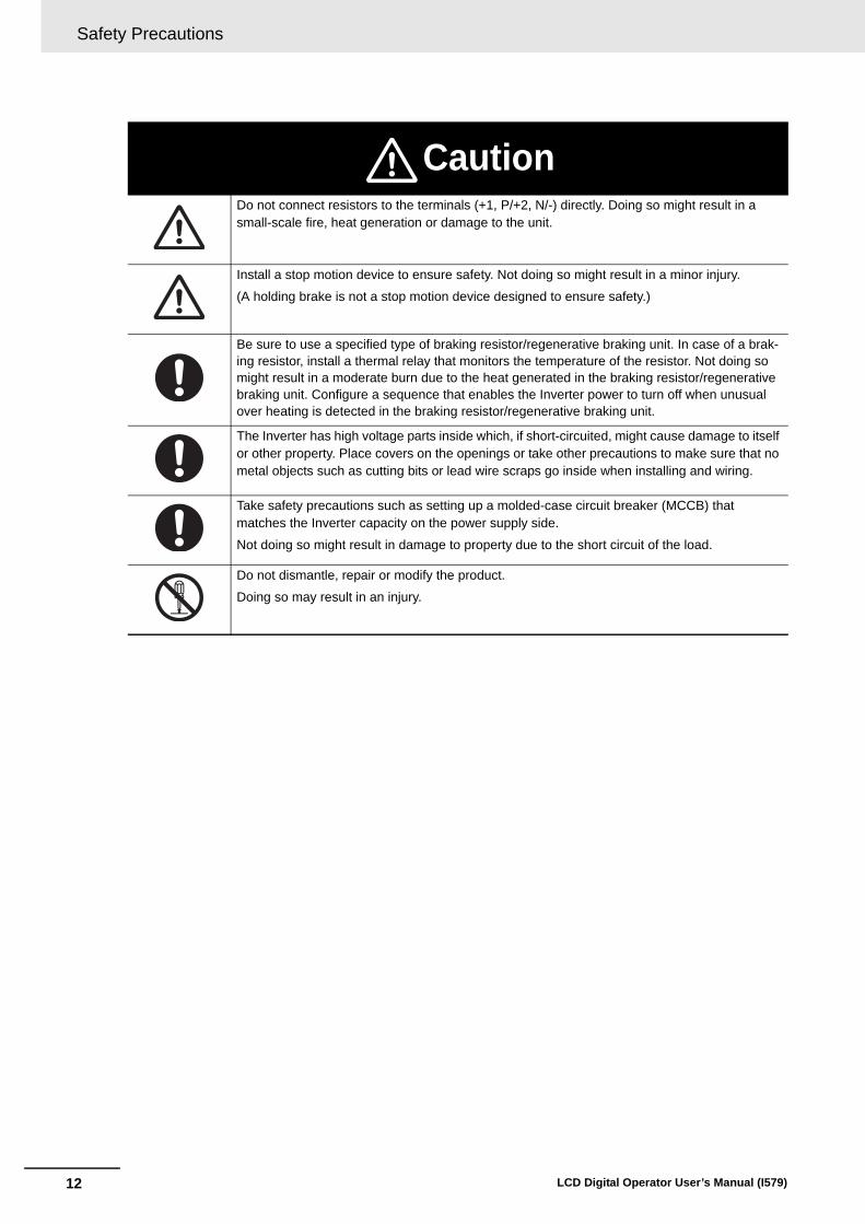
CautionDo not connect resistors to the terminals (+1, P/+2, N/-) directly. Doing so might result in a small-scale fire, heat generation or damage to the unit.
Install a stop motion device to ensure safety. Not doing so might result in a minor injury.
(A holding brake is not a stop motion device designed to ensure safety.)
Be sure to use a specified type of braking resistor/regenerative braking unit. In case of a brak-ing resistor, install a thermal relay that monitors the temperature of the resistor. Not doing so might result in a moderate burn due to the heat generated in the braking resistor/regenerative braking unit. Configure a sequence that enables the Inverter power to turn off when unusual over heating is detected in the braking resistor/regenerative braking unit.
The Inverter has high voltage parts inside which, if short-circuited, might cause damage to itself or other property. Place covers on the openings or take other precautions to make sure that no metal objects such as cutting bits or lead wire scraps go inside when installing and wiring.
Take safety precautions such as setting up a molded-case circuit breaker (MCCB) that matches the Inverter capacity on the power supply side.
Not doing so might result in damage to property due to the short circuit of the load.
Do not dismantle, repair or modify the product.
Doing so may result in an injury.

13
Precautions for Safe Use
LCD Digital Operator User’s Manual (I579)
Precautions for Safe Use
Do not store or use the product in the following places.
• Locations subject to direct sunlight.
• Locations subject to ambient temperature exceeding the specifications.
• Locations subject to relative humidity exceeding the specifications.
• Locations subject to condensation due to severe temperature fluctuations.
• Locations subject to corrosive or flammable gases.
• Locations subject to exposure to combustibles.
• Locations subject to dust (especially iron dust) or salts.
• Locations subject to exposure to water, oil, or chemicals.
• Locations subject to shock or vibration.
• Take sufficient shielding measures when using the product in the following locations. Not doing so may result in damage to the product.
Locations subject to static electricity or other forms of noise.
Locations subject to strong magnetic fields.
Locations close to power lines.
• If a parameter is set incorrectly when starting up, adjusting, maintaining, or replacing, an unexpected operation may occur.
Perform the operation after enough confirmation.
• If the clock command is used in DriveProgramming, an unexpected operation may occur due to weak battery. Take measures such as detecting a weak battery by a check that the clock data returns to the initial setting and stopping the Inverter or programs. When the LCD Digital Operator is removed or disconnected, DriveProgramming is in a waiting status by the clock command.
Installation and Storage
Transporting, Installation, and Wiring
Operation and Adjustment

Precautions for Safe Use
14 LCD Digital Operator User’s Manual (I579)
• When disposing of LCD digital operators and wasted batteries, follow the applicable ordinances of your local government.
When disposing of the battery, insulate it using tape.
• Do not short + and -, charge, disassemble, heat, put into the fire, or apply strong impact on the bat-tery. The battery may leak, explode, produce heat or fire. Never use the battery which was applied strong impact due to such as fall on the floor, it may leak.
• UL standards establish that the battery shall be replaced by an expert engineer.
The expert engineer must be in charge of the replacement and also replace the battery according to the method described in this manual.
• When the display of LCD Digital Operator can not be recognized due to the service life, replace the LCD Digital Operator.
Maintenance and Inspection
The following display must be indicated when products using lithium primary batteries (with more than 6 ppb of perchlorate) are transport to or through the State of California, USA.
The 3G3AX-OP05 has the lithium primary battery (with more than 6 ppb of perchlorate). Label or mark the above display on the exterior of all outer shipping packages of your products when exporting your products which the 3G3AX-OP05 are installed to the State of California, USA.
Perchlorate Material - special handling may apply.
See www.dtsc.ca.gov/hazardouswaste/perchlorate
15
Precautions for Correct Use
LCD Digital Operator User’s Manual (I579)
Precautions for Correct Use
• Be sure to confirm the RUN signal is turned off before resetting the alarm because the machine may abruptly start.
• Provide a separate emergency stop switch because the STOP Key on the Operator is valid only when function settings are performed.
Retry Selection Function
Operation Stop Command

Regulations and Standards
16 LCD Digital Operator User’s Manual (I579)
Regulations and Standards
To export (or provide to nonresident aliens) any part of this product that falls under the category of goods (or technologies) for which an export certificate or license is mandatory according to the Foreign Exchange and Foreign Trade Control Law of Japan, an export certificate or license (or service transac-tion approval) according to this law is required.
Overseas Use

17
Items to Check after Unpacking
LCD Digital Operator User’s Manual (I579)
Items to Check after Unpacking
After unpacking the product, check the following items:
• Is this the model you ordered?
• Was there any damage sustained during shipment?
The product has the following nameplate labels on its rear face.
Checking the Nameplate
Checking the Model
3 G 3 A X - O P 0 5
LCD Digital Operator

Related Manuals
18 LCD Digital Operator User’s Manual (I579)
Related Manuals
To operate this product, you must be familiar with the equipment connected to it.
Please refer to the following manual for information on the related product.
Additional Information
For Inverter operation, please refer to the manual for the Inverter.
Name Catalog No.
High-function General-purpose Inverter 3G3RX--V1 User’s Manual I578-E1

19
Revision History
LCD Digital Operator User’s Manual (I579)
Revision History
The manual revision code is a number appended to the end of the catalog number found in the bottom right-hand corner of the front and back covers.
Example
Revision Code
Revision Date Revised Content
01 April 2013 Original production
02 August 2013 Typographical errors etc. corrected
Cat. No. I579-E1-02Revision code

Revision History
20 LCD Digital Operator User’s Manual (I579)

1 - 1
1
LCD Digital Operator User’s Manual (I579)
This section provides features and specifications of the LCD Digital Operator.
1-1 Features . . . . . . . . . . . . . . . . . . . . . . . . . . . . . . . . . . . . . . . . . . . . . . . . . . . . . 1-2
1-2 Supported Models . . . . . . . . . . . . . . . . . . . . . . . . . . . . . . . . . . . . . . . . . . . . . 1-4
1-3 Specifications . . . . . . . . . . . . . . . . . . . . . . . . . . . . . . . . . . . . . . . . . . . . . . . . . 1-5
1-4 External Dimensions . . . . . . . . . . . . . . . . . . . . . . . . . . . . . . . . . . . . . . . . . . . 1-6
1-5 Recommended Cables . . . . . . . . . . . . . . . . . . . . . . . . . . . . . . . . . . . . . . . . . . 1-7
Overview

1 Overview
1 - 2 LCD Digital Operator User’s Manual (I579)
1-1 Features
This LCD Digital Operator is intended for use with the 3G3RX-series Type V1 Inverter.
It can be connected with the 3G3RX-series Type V1 Inverter either directly or via cable (optional).
The LCD Digital Operator provides the following features:
A large 5-line LCD displays the name and setting range of parameters as well as the parameter num-ber, which improves the user’s recognition performance during parameter setting and adjustment.
In addition, the display of up to four monitor functions enables you to check the status, adjust the Inverter, and etc.
In case of a trip warning, both the code and name of warning are displayed so that you can perform early troubleshooting.
The all READ function enables to read all the parameter setting data stored in the Inverter. Up to four sets of Inverter parameter setting data can be read and stored in the internal memory of the LCD Digital Operator.
The parameter setting data in the memory can be all written, only if the Inverters are of the same model and version.
Using this feature, the time for setting parameters can be reduced when the same devices are started up or specifications are changed.
Or it is possible to store, upload and download up to a single set of Inverter parameter setting data and a DriveProgramming program.
This function enables to compare and verify parameters of the connected Inverter, DriveProgram-ming, and data stored in the internal memory of the LCD Digital Operator. It is useful when checking conditions before shipment or in case of a trouble.
Using the optional cable (Model: 3G3AX-OPCN1/OPCN3) enables you to mount the LCD Digital Operator on the surface of system panel. You can check and adjust the system status from outside the control panel.
The LCD Digital Operator has the built-in clock function and a backup battery.
This enables the display of time information on the Current Time Monitor (d031).
This clock function is also available in the DriveProgramming program.
5-Line English LCD
All Read/Write Functions for Inverter Parameters and DriveProgramming
VERIFY Function for Inverter Parameters and DriveProgramming
Installation on the System Panel
Built-in Clock Function

1 - 3
1 Overview
LCD Digital Operator User’s Manual (I579)
1-1 Featu
res
1
Precautions for Safe Use
• If the clock command is used in DriveProgramming, an unexpected operation may occur due to weak battery. Take measures such as detecting a weak battery by a check that the clock data returns to the initial setting and stopping the Inverter or programs. When the LCD Digital Operator is removed or disconnected, DriveProgramming is in a waiting status by the clock command.
Precautions for Correct Use
• Although this LCD Digital Operator can be connected with the 3G3RX-series Type V1 Inverter, it cannot be connected with conventional models of the 3G3RX-series. Check the specification nameplate of the Inverter to ensure that the model is 3G3RX--V1 or the version is Ver. 2.0.
• The all WRITE function is available to write inverter parameters and DriveProgramming only with Inverters of the same model and version.
If the all WRITE function does not work, check the Inverter models and versions and, if they are different, consider using the Inverter/Servo Parameter Support Tool CX-Drive.
1 Overview
1 - 4 LCD Digital Operator User’s Manual (I579)
1-2 Supported Models
High-function General-purpose Inverter (Model: 3G3RX--V1)

1 - 5
1 Overview
LCD Digital Operator User’s Manual (I579)
1-3 Sp
ecificatio
ns
1
1-3 Specifications
Item Specification
Electrical specifications
Input power supply voltage
4.9 to 5.2 VDC
Transmission method RS-422 (R45)
Transmission rate 19.2 Kbps/4,800 bps (switching)
Environment Ambient operating temperature
–10 to 50°C
Ambient operating humidity
20% to 90% (with no condensation)
Ambient storage temperature
–20 to 65°C
Location of use 1,000 m or less in height (at a place with no corrosive gas and dust)
Installation External dimensions 123 (H) 80 (W) 21 (D) mm
Connection type Direct or via cable (3G3AX-OPCN1/OPCN3)
Weight 0.1 kg
Display specifications
Display Digital display on LCD (132 64 dots)
Display language English
Others Number of writes to built-in EEPROM during service life
100,000 times
Battery specifications Coin type lithium battery CR1220 (Recommended manufacturer: Hitachi Maxell)
* During power-off, the built-in battery will back up the internal data for a period of approximately 2 years (calculated value for a fresh battery).
The battery included in the LCD Digital Operator when purchased is intended for operational checks.
Clock accuracy Error per month: –1.5 to 1.5 min

1 Overview
1 - 6 LCD Digital Operator User’s Manual (I579)
1-4 External Dimensions
The following figures show the dimensions of LCD Digital Operator and panel cut dimensions to install.
When installing the LCD Digital Operator to the control panel, secure it from the back side using M3 screws (5 mm).
The recommended torque is 0.9 to 1.0 N·m.
80
18
2-ø4
26.5
18
210
36.
5
External Appearance of the LCD Digital Operator Panel Cutout Diagram

1 - 7
1 Overview
LCD Digital Operator User’s Manual (I579)
1-5 Reco
mm
end
ed
Cab
les
1
1-5 Recommended Cables
Use any of the following cables to use the LCD Digital Operator separated from the Inverter.
Digital Operator cables
• 3G3AX-OPCN1 (Cable length: 1 m)
• 3G3AX-OPCN3 (Cable length: 3 m)

1 Overview
1 - 8 LCD Digital Operator User’s Manual (I579)

2 - 1
2
LCD Digital Operator User’s Manual (I579)
This section describes the part names and functions of the LCD Digital Operator.
2-1 Part Names . . . . . . . . . . . . . . . . . . . . . . . . . . . . . . . . . . . . . . . . . . . . . . . . . . . 2-2
2-2 Operation Keys . . . . . . . . . . . . . . . . . . . . . . . . . . . . . . . . . . . . . . . . . . . . . . . . 2-4
2-3 LCD Display . . . . . . . . . . . . . . . . . . . . . . . . . . . . . . . . . . . . . . . . . . . . . . . . . . 2-6
Part Names and Functions
2 Part Names and Functions
2 - 2 LCD Digital Operator User’s Manual (I579)
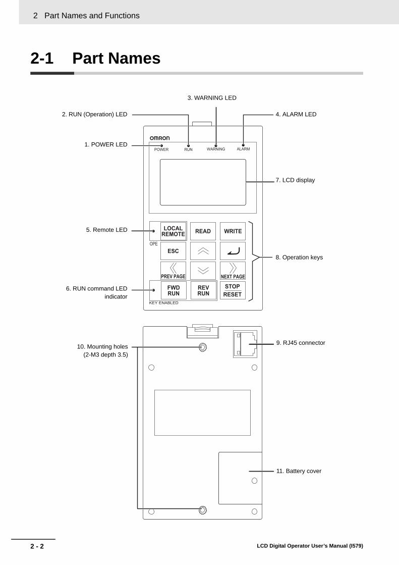
2-1 Part Names
4. ALARM LED
1. POWER LED
2. RUN (Operation) LED
3. WARNING LED
7. LCD display
8. Operation keys
5. Remote LED
6. RUN command LEDindicator
10. Mounting holes(2-M3 depth 3.5)
9. RJ45 connector
11. Battery cover

2 - 3
2 Part Names and Functions
LCD Digital Operator User’s Manual (I579)
2-1 Part N
ames
2
Precautions for Correct Use
• Determine whether the operation keys (FWD RUN, REV RUN, and STOP/RESET keys) are enabled based on the ON/OFF status of the RUN command LED indicator. Remember that the operation keys may be enabled even when the remote LED is not lit.
• The remote LED lights only when the forced operator function is enabled by pressing the LOCAL REMOTE key for 2 seconds or more.
Note that the remote LED does not light if the forced operator function is enabled by the multi-function input which is set the forced operator function (OPE).
In this case, determine whether the forced operator function (OPE) is enabled based on the status of the multi-function input terminal.
No. Name Color Description
1 POWER LED Green Lights when power is supplied to the LCD Digital Operator.
2 RUN (Operation) LED
Green Lights during Inverter operation.
3 WARNING LED Red Lights when the Inverter parameter settings are incorrect.
4 ALARM LED Red Lights when the Inverter trips.
5 Remote (OPE) LED
Green Lights when the forced operator function is enabled by the LOCAL REMOTE key. (Press the LOCAL REMOTE key for 2 seconds or more.).
6 RUN command LED indicator
Green Lights when the RUN command is enabled on the LCD Digital Operator. At this time, the FWD RUN, REV RUN, and STOP/RESET keys can be used to operate the Inverter.
7 LCD display Displays various parameter settings, frequency, or other information. For details, refer to Section 4 Operation Procedures, Section 5 LCD Digital Operator Related Parameters, and Section 6 Read/Write Functions.
8 Operation keys These keys are used for display and setting. For details, refer to Section 4 Operation Procedures, Section 5 LCD Digital Operator Related Parame-ters, and Section 6 Read/Write Functions.
9 RJ45 connector Connects the LCD Digital Operator with the Inverter directly or via cable (sold separately).
10 Mounting holes Use these holes to install the LCD Digital Operator on the control panel. Secure it from the back side using M3 screws.
11 Battery cover Refer to Section 8 Maintenance for the procedure to replace the built-in battery.

2 Part Names and Functions
2 - 4 LCD Digital Operator User’s Manual (I579)
2-2 Operation Keys
No. Key image Name Function
1LOCAL REMOTE
key
Switches between the Local and Remote modes. If the key is pressed for 2 seconds or more, the mode is switched; from Local to Remote or from Remote to Local. When the LCD Dig-ital Operator is in the Local mode, the Remote (OPE) LED is lit. Use the Local mode to operate the Inverter using the LCD Digital Operator’s operation keys (FWD RUN, REV RUN, and STOP/RESET).
2 READ key
Reads all the parameter setting data into the LCD Digital Operator’s memory. For details, refer to Section 5 LCD Digital Operator Related Parameters.
3 WRITE key
Copies a single set of Inverter parameter setting data, or a sin-gle set of Inverter parameter setting data and a DriveProgram-ming program, stored on the LCD Digital Operator into the Inverter. For details, refer to Section 5 LCD Digital Operator Related Parameters.
4 ESC key
Returns to a screen in the one level higher layer.
If pressed during a parameter change, the LCD Digital Opera-tor displays the previous screen with the change cancelled.
5 Enter key
Brings you forward to the screen that is one level lower in the hierarchy.
If pressed during a parameter change, the LCD Digital Opera-tor displays the previous screen with the change fixed and stored.
6 Increment key
Moves the cursor up.
It is also used to increase the parameter number or parameter value.
Operation keys

2 - 5
2 Part Names and Functions
LCD Digital Operator User’s Manual (I579)
2-2 Op
eration
Keys
2
*1. Check the KEY ENABLED indicator (RUN command LED indicator).
Precautions for Safe Use
• Provide a separate emergency stop switch because the STOP key on the operator is valid only when function settings are performed.
• The FWD RUN, REV RUN, and STOP/RESET keys are disabled while the Inverter parame-ter settings are all read or written. Perform the all read/write functions during Inverter stop.
7 Decrement key
Moves the cursor down.
It is also used to decrease the parameter number or parameter value.
8 PREV PAGE key
Moves the cursor to the left.
In Navigation level display mode, moves to the previous mode.
9 NEXT PAGE key
Moves the cursor to the right.
In Navigation level display mode, moves to the next mode.
10 FWR RUN key *1
Runs the motor in the forward direction.
This key is enabled in the following cases.
• The remote mode is enabled by pressing the LOCAL REMOTE key for 2 seconds (the remote LED is lit).
• RUN Command Selection (A002) is set to “02: Digital operator”.
• The forced operator function is enabled by the multi-function input which is set the forced operator function (OPE).
11 REV RUN key *1
Runs the motor in the reverse direction.
This key is enabled in the following cases.
• The remote mode is enabled by pressing the LOCAL REMOTE key for 2 seconds (the remote LED is lit).
• RUN Command Selection (A002) is set to “02: Digital operator”.
• The forced operator function is enabled by the multi-function input which is set the forced operator function (OPE).
12 STOP/RESET key
Stops the motor, or resets the alarm.
When the parameter b087 (Stop key selection) is set to “01: Disable,” this key is enabled in the following cases only.
• The remote mode is enabled by pressing the LOCAL REMOTE key for 2 seconds (the remote LED is lit).
• RUN Command Selection (A002) is set to “02: Digital operator”.
• The forced operator function is enabled by the multi-function input which is set the forced operator function (OPE).
No. Key image Name Function

2 Part Names and Functions
2 - 6 LCD Digital Operator User’s Manual (I579)
2-3 LCD Display
The LCD display has two backlight colors; white and orange.
The color of the backlight indicates the state of the Inverter, as shown in the following table.
The first line of LCD display always shows the display mode, the selected motor, the Inverter RUN sta-tus, and the display selection.
Backlight
Backlight color State
White Normal (No relation to the RUN/Stop state of the Inverter)
Orange Warning (Parameter mismatch)
White/Orange(Flashing alternately at intervals of 1 second)
Trip (Same as the ALARM LED)
LCD Display
Item Display item Description
Display mode
MONITOR-A Monitor Mode A
MONITOR-B Monitor Mode B
FUNCTION Function Mode
TRIP Trip Mode (Error)
WARNING Warning Mode (Warning)
READ Read Mode
WRITE Write Mode
OPTION Option Mode
Control target No.
M1 1st control (Normal)
M2 2nd control (allocate Multi-function Input S1 to S8 Selection (C001 to C008) to “08: SET” and turn ON to switch)
M3 3rd control (allocate Multi-function Input S1 to S8 Selection (C001 to C008) to “17: SET3” and turn ON to switch)
Inverter RUN status
STOP Stop
FWD Forward
REV Reverse
Control target No.
Display mode Inverter RUN status
Display selection

2 - 7
2 Part Names and Functions
LCD Digital Operator User’s Manual (I579)
2-3 LC
D D
isplay
2
Setting in b037 (Display Selection)
ALL Complete display
UTL Individual display of functions
USR User setting display
CMP Data comparison display
BAS Basic display
Item Display item Description

2 Part Names and Functions
2 - 8 LCD Digital Operator User’s Manual (I579)

3 - 1
3
LCD Digital Operator User’s Manual (I579)
This section provides information on the installation and wiring of the LCD Digital Operator.
3-1 Installation on the Inverter . . . . . . . . . . . . . . . . . . . . . . . . . . . . . . . . . . . . . . 3-23-1-1 Direct Installation on the Inverter . . . . . . . . . . . . . . . . . . . . . . . . . . . . . . . . . . . 3-3
3-1-2 Installation on the Inverter via Cable . . . . . . . . . . . . . . . . . . . . . . . . . . . . . . . . . 3-4
3-1-3 Checking the Operation After Installation . . . . . . . . . . . . . . . . . . . . . . . . . . . . . 3-6
3-1-4 Date and Time Setting . . . . . . . . . . . . . . . . . . . . . . . . . . . . . . . . . . . . . . . . . . . 3-7
3-1-5 Other Settings . . . . . . . . . . . . . . . . . . . . . . . . . . . . . . . . . . . . . . . . . . . . . . . . . . 3-7
Installation and Wiring

3 Installation and Wiring
3 - 2 LCD Digital Operator User’s Manual (I579)
3-1 Installation on the Inverter
This section shows how to install the LCD Digital Operator on the 3G3RX-series Type V1 Inverter.
The installation procedure differs with installation methods. This section describes the following 2 methods.
• Direct installation on the Inverter
• Installation on the Inverter via cable
Precautions for Correct Use
• Shut off the power supply to the Inverter before installing or removing the LCD Digital Opera-tor. Not doing so may result in failure.
• The LCD Digital Operator cannot be installed directly on an Inverter that is already mounted with a Communications Unit.
Section Title Description
3-1-1 Direct installation on the Inverter Describes the procedure for installing the LCD Digital Operator directly on the Inverter.
3-1-2 Installation on the Inverter via Cable
Describes the procedure for installing the LCD Digital Operator on the Inverter via cable in situations where:
• The LCD Digital Operator is installed on the control panel.
• The use of a Communications Unit prevents direct installation on the Inverter.
3 - 3
3 Installation and Wiring
LCD Digital Operator User’s Manual (I579)
3-1 Installatio
n o
n th
e Inverter
3
3-1-1 Direct In
stallation on the Inverte
r
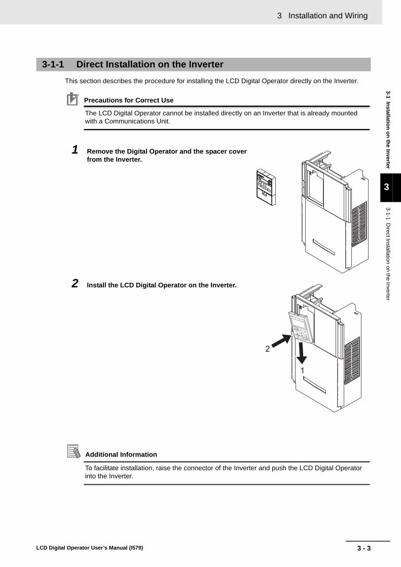
This section describes the procedure for installing the LCD Digital Operator directly on the Inverter.
Precautions for Correct Use
The LCD Digital Operator cannot be installed directly on an Inverter that is already mounted with a Communications Unit.
1 Remove the Digital Operator and the spacer cover from the Inverter.
2 Install the LCD Digital Operator on the Inverter.
Additional Information
To facilitate installation, raise the connector of the Inverter and push the LCD Digital Operator into the Inverter.
3-1-1 Direct Installation on the Inverter

3 Installation and Wiring
3 - 4 LCD Digital Operator User’s Manual (I579)
1 If necessary, mount the LCD Digital Operator to the panel. Cut out the panel according to the panel cutout diagram and, using M3 screws, secure the LCD Digital Operator to the panel from the back side.
The recommended torque is 0.9 to 1.0 N·m.
For panel cutout dimensions, refer to 1-4 External Dimensions on page 1-6.
2 Remove the Digital Operator and the operator connector from the Inverter.
3-1-2 Installation on the Inverter via Cable

3 - 5
3 Installation and Wiring
LCD Digital Operator User’s Manual (I579)
3-1 Installatio
n o
n th
e Inverter
3
3-1-2 Installation
on the Inverter via C
able
3 Connect the LCD Digital Operator with the Inverter via cable.
• Recommended cable models:
3G3AX-OPCN1 (Cable length: 1 m)
3G3AX-OPCN3 (Cable length: 3 m)

3 Installation and Wiring
3 - 6 LCD Digital Operator User’s Manual (I579)
After checking that the system and surrounding areas are safe, turn ON the power supply to the Inverter.
Check the LCD Digital Operator display.
The installation is completed successfully if the following Monitor screen is displayed.
However, when the power is supplied to the LCD Digital Operator for the first time after purchase, when the built-in battery is consumed, or when the power supply is turned on for the first time after battery replacement, the following screen appears, which prompts you to set the clock. If this screen is dis-played, press the ESC key to move to the normal screen and perform the Date and Time setting from the OPTION MODE menu. For the Date and Time setting, refer to 3-1-4 Date and Time Setting on page 3-7.
The LCD Digital Operator may display the COM ERROR screen, or the Read & Copy only screen when the power is supplied. In this case, choose INV Type Select from the OPTION MODE menu and set the type of the Inverter to be used.
For details, refer to 5-1-2 Details of Each Option Mode Parameter on page 5-4.
Precautions for Correct Use
• The LCD Digital Operator can be used without configuring the Date and Time setting.However, if the clock command is used in DriveProgramming, configure the Date and Time setting. Not doing so may result in an unexpected operation due to the lack of the correct date and time information.
• The available display language is only English on this LCD Digital Operator. Be sure to set the Language option to “01: English”.If the language display is abnormal, check from the OPTION MODE menu to be sure that the Language is set to “01: English”.For details, refer to 5-1-1 Operation in the Option Mode on page 5-2.
3-1-3 Checking the Operation After Installation
3 - 7
3 Installation and Wiring
LCD Digital Operator User’s Manual (I579)
3-1 Installatio
n o
n th
e Inverter
3
3-1-4 Date and T
ime S
etting
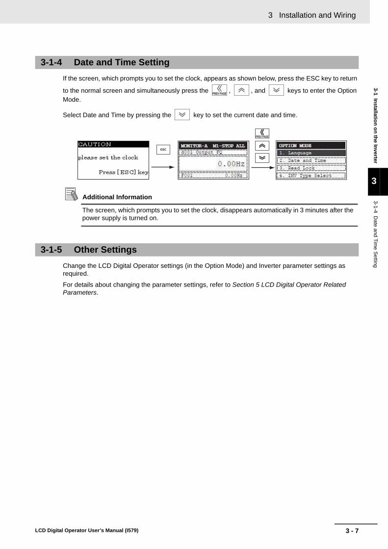
If the screen, which prompts you to set the clock, appears as shown below, press the ESC key to return
to the normal screen and simultaneously press the , , and keys to enter the Option Mode.
Select Date and Time by pressing the key to set the current date and time.
Additional Information
The screen, which prompts you to set the clock, disappears automatically in 3 minutes after the power supply is turned on.
Change the LCD Digital Operator settings (in the Option Mode) and Inverter parameter settings as required.
For details about changing the parameter settings, refer to Section 5 LCD Digital Operator Related Parameters.
3-1-4 Date and Time Setting
3-1-5 Other Settings

3 Installation and Wiring
3 - 8 LCD Digital Operator User’s Manual (I579)
4 - 1
4
LCD Digital Operator User’s Manual (I579)
This section provides an overview of the display modes supported by LCD Digital Operator and how to operate the LCD Digital Operator in each display mode.For the Option Mode, refer to Section 5 LCD Digital Operator Related Parameters. For the Read/Write Mode, refer to Section 6 Read/Write Functions.
4-1 Overview of Display Modes . . . . . . . . . . . . . . . . . . . . . . . . . . . . . . . . . . . . . . 4-24-1-1 Transition of Screens . . . . . . . . . . . . . . . . . . . . . . . . . . . . . . . . . . . . . . . . . . . . 4-2
4-1-2 Overview of Each Mode . . . . . . . . . . . . . . . . . . . . . . . . . . . . . . . . . . . . . . . . . . 4-3
4-1-3 Changing the Display in Each Mode . . . . . . . . . . . . . . . . . . . . . . . . . . . . . . . . . 4-5
4-2 Operation in the Monitor Mode A . . . . . . . . . . . . . . . . . . . . . . . . . . . . . . . . . 4-6
4-3 Operation in the Monitor Mode B . . . . . . . . . . . . . . . . . . . . . . . . . . . . . . . . . 4-7
4-4 Operation in the Function Mode . . . . . . . . . . . . . . . . . . . . . . . . . . . . . . . . . . 4-8
4-5 Operation in the Trip Mode . . . . . . . . . . . . . . . . . . . . . . . . . . . . . . . . . . . . . . 4-9
Operation Procedures

4 Operation Procedures
4 - 2 LCD Digital Operator User’s Manual (I579)
4-1 Overview of Display Modes
The basic display screens of LCD Digital Operator are displayed in four modes as shown below.
Each mode has two levels: the higher Navigation level and the lower Edit level. The user can move between each mode in the Navigation level only.
• Monitor Mode A: The mode to display and set a single monitor function and a single parameter function.
• Monitor Mode B: The mode to display up to four monitor functions on a single screen.
• Function Mode: The mode to set parameter settings. The screen also displays the parameter name and setting range.
• Trip Mode: The mode to display the trip and warning information.
In addition to the above, the LCD Digital Operator has the following three called modes. At any of the above levels and in any operating state, you can call these modes by pressing the key(s) shown to the right of the down arrow above each screen, as shown on the next page. After calling these screens, you can press the ESC key to restore the operating state before the call.
• All Read: The mode to read all Inverter parameter settings and DriveProgramming data from the Inverter.
• All Write: The mode to write all Inverter parameter setting and DriveProgramming data to the Inverter.
• Option Mode: The mode to set the LCD Digital Operator.
4-1-1 Transition of Screens
Nav
igat
ion
leve
lE
dit l
evel
Monitor
Mode A
Monitor
Mode B
Function
Mode
Trip
Mode
Select the monitor item.Select the setting item.
Select the setting line.
Select the setting item.
Monitor the overall trip history.
Monitor
Mode A
Monitor
Mode B
Function
Mode
Trip
Mode
Monitor
Mode A
Monitor
Mode B
Function
Mode
Change the set value. Change the set value. Change the set value.

4 - 3
4 Operation Procedures
LCD Digital Operator User’s Manual (I579)
4-1 O
verview o
f Disp
lay Mo
des
4
4-1-2 Overview
of Each M
ode
In this mode, one “d” group Inverter monitor function and one “F to U” group Inverter parameter are displayed on the same screen.The content of “d” group Inverter monitor function is displayed in a large font size. The parameter number such as “F001” and the content of “F to U” parameter are displayed without the function name.
In this mode, four “d” group Inverter monitor functions can be displayed on the same screen.At this time, the parameter numbers are not displayed.
These modes can be called at any level and in any operating state.
Press the ESC key to restore the operating state before the call.
4-1-2 Overview of Each Mode
Monitor Mode A
Monitor Mode B
Read
Mode
Write
Mode
Option
Mode
Option
Mode
Option
Mode
Change the set values of the LCD Digital Operator.
Select the setting item.
Press three keys simultaneously.

4 Operation Procedures
4 - 4 LCD Digital Operator User’s Manual (I579)
In this mode, “F to U” group Inverter parameters can be dis-played and set.
The screen shows the parameter number, function name, parameter data and setting range of the parameter.
Precautions for Correct Use
In the Function Mode, “d” group Inverter monitor functions cannot be displayed and set.
Trip information and warning information are displayed in this mode.If a trip or a warning occurs in the Inverter, the trip screen is displayed from any display mode.
In the Option Mode, Read Mode, and Write Mode, the trip screen is not displayed even if an Inverter trip or warning occurs.
The ALARM or WARNING LED lights up.
In this mode, a single set of Inverter parameter settings, or a single set of parameter settings and a DriveProgramming pro-gram, can be all read and stored in the LCD Digital Operator.
Select a single set or four sets of storage data by 5. R/W Stor-age Mode in the OPTION MODE menu.
For details about the Read Mode, refer to Section 6 Read/Write Functions.
Function Mode
Trip Mode
Read Mode
Case: 5. R/W Storage Mode = “01 :Single”
Case: 5. R/W Storage Mode = “02: Quad”
4 - 5
4 Operation Procedures
LCD Digital Operator User’s Manual (I579)
4-1 O
verview o
f Disp
lay Mo
des
4
4-1-3 Changing the D
isplay in Each M
ode
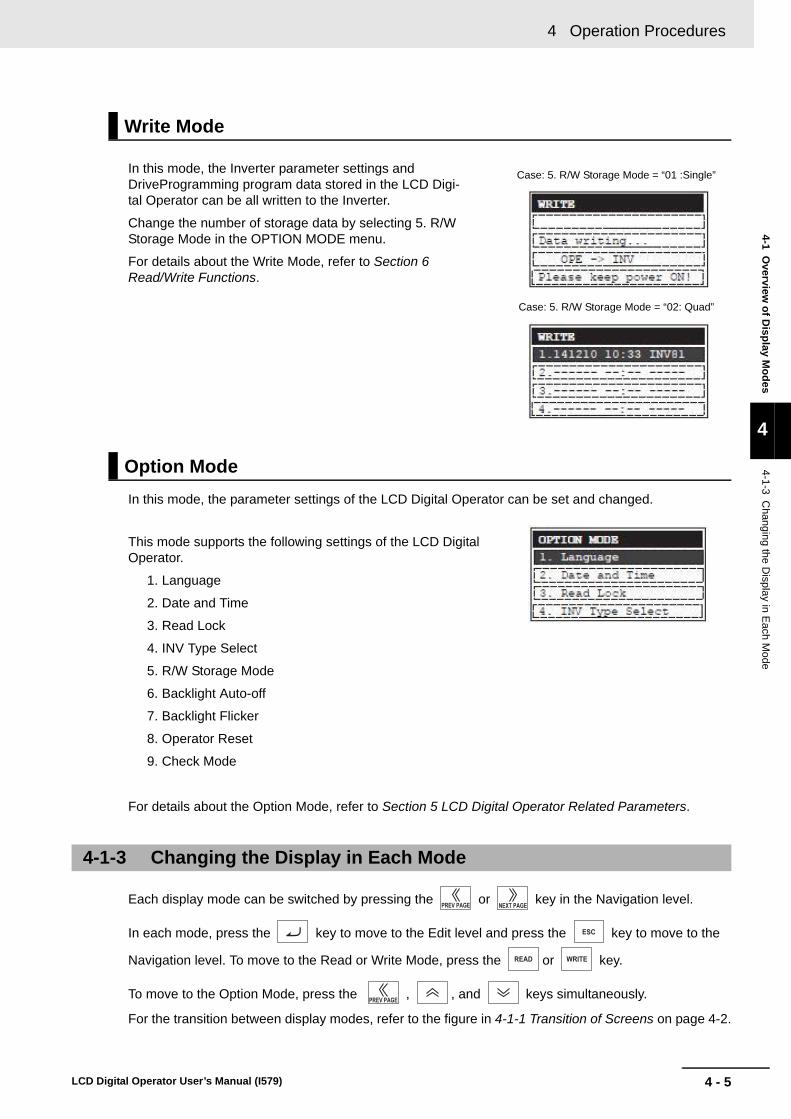
In this mode, the Inverter parameter settings and DriveProgramming program data stored in the LCD Digi-tal Operator can be all written to the Inverter.
Change the number of storage data by selecting 5. R/W Storage Mode in the OPTION MODE menu.
For details about the Write Mode, refer to Section 6 Read/Write Functions.
In this mode, the parameter settings of the LCD Digital Operator can be set and changed.
This mode supports the following settings of the LCD Digital Operator.
1. Language
2. Date and Time
3. Read Lock
4. INV Type Select
5. R/W Storage Mode
6. Backlight Auto-off
7. Backlight Flicker
8. Operator Reset
9. Check Mode
For details about the Option Mode, refer to Section 5 LCD Digital Operator Related Parameters.
Each display mode can be switched by pressing the or key in the Navigation level.
In each mode, press the key to move to the Edit level and press the key to move to the
Navigation level. To move to the Read or Write Mode, press the or key.
To move to the Option Mode, press the , , and keys simultaneously.
For the transition between display modes, refer to the figure in 4-1-1 Transition of Screens on page 4-2.
Write Mode
Option Mode
4-1-3 Changing the Display in Each Mode
Case: 5. R/W Storage Mode = “01 :Single”
Case: 5. R/W Storage Mode = “02: Quad”

4 Operation Procedures
4 - 6 LCD Digital Operator User’s Manual (I579)
4-2 Operation in the Monitor Mode A
1 At the Navigation level, press the or
key to select the Monitor Mode A (MONITOR-A) screen.
Press the key to show the cursor on the “d” group monitor function.
2 Press the or key to select the monitor
function to display on the MONITOR-A screen.Select the parameter number corresponding to the monitor function to display.
• Press the key to return to the Navigation level.
3 To move the cursor position displayed on the
screen, press the or key.When the cursor moves to the Inverter parameter number displayed on the last line (in this case, F001), you can change the parameter number by
the or key.
• Press the key to return to the Navigation level.
4 After changing the Inverter parameter number,
press the key to move the cursor to the parameter data position.
Change the parameter data using the or
key.
• To save the change, press the key. The cursor returns to the parameter number.
• To cancel the change, press the key. The cursor returns to the parameter number.
Press the key to return to the Navigation level.
,

4 - 7
4 Operation Procedures
LCD Digital Operator User’s Manual (I579)
4-3 Op
eration
in th
e Mo
nito
r Mo
de
B
4
4-3 Operation in the Monitor Mode B
1 At the Navigation level, press the or
key to select the Monitor Mode B (MONITOR-B) screen.
2 Press the key to show the cursor in the first
parameter line of the “d” group monitor function.
Press the or key to move between the four inverter parameters.
• Press the key to return to the Navigation level.
3 Select the parameter to change and press the
key.The cursor moves to the parameter number of the selected “d” group monitor function.
Press the or key to select the parame-ter number to monitor.
• To register the parameter number, press the key. The screen returns to the parameter display screen.
• To cancel the change, press the key. The screen returns to the parameter display screen.
• Press the key again to return to the Navigation level.
or

4 Operation Procedures
4 - 8 LCD Digital Operator User’s Manual (I579)
4-4 Operation in the Function Mode
1 At the Navigation level, press the or
key to select the Function Mode screen.
2 Press the key. The cursor moves to the
parameter number. Then, press the , ,
, or key to select the parameter No. to change.
• Press the key to return to the Navigation level.
3 Press the key. The cursor is now placed over
the parameter data. Press the or key to select the value to set.
• To save the parameter value, press the key. When saved, the cursor moves to the parameter number.
• To cancel the change, press the key. The cursor moves to the parameter number.
or

4 - 9
4 Operation Procedures
LCD Digital Operator User’s Manual (I579)
4-5 Op
eration
in th
e Trip M
od
e
4
4-5 Operation in the Trip Mode
1 At the Navigation level, press the or
key to select the Trip Mode screen.
2 Press the key to show the information on the
past trips (six trip errors) recorded in the Inverter and the information on the warning (one warning).
The information on one trip error comprises two pages.To switch from page 1 (P1) to page 2 (P2),
press the or key.
To display the information on the past six trip errors,
press the or key.
3 If you press the key when ERR1 is displayed
or press the key when ERR6 is displayed, the screen switches to the Warning Mode.
Precautions for Correct Use
If a trip occurs, the ALARM LED lights up. Then, press the key to reset the Inverter.

4 Operation Procedures
4 - 10 LCD Digital Operator User’s Manual (I579)

5 - 1
5
LCD Digital Operator User’s Manual (I579)
This section describes the Inverter parameters related to the LCD Digital Operator.
5-1 Parameter Setting . . . . . . . . . . . . . . . . . . . . . . . . . . . . . . . . . . . . . . . . . . . . . 5-25-1-1 Operation in the Option Mode . . . . . . . . . . . . . . . . . . . . . . . . . . . . . . . . . . . . . . 5-2
5-1-2 Details of Each Option Mode Parameter . . . . . . . . . . . . . . . . . . . . . . . . . . . . . 5-4
5-2 Related Inverter Parameters . . . . . . . . . . . . . . . . . . . . . . . . . . . . . . . . . . . . . 5-6
LCD Digital Operator Related Parameters

5 LCD Digital Operator Related Parameters
5 - 2 LCD Digital Operator User’s Manual (I579)
5-1 Parameter Setting
The LCD Digital Operator parameters can be set and changed in the Option Mode.
The Option Mode provides the following nine settings:
1. Language
2. Date and Time
3. Read Lock
4. INV Type Select
5. R/W Storage Mode
6. Backlight Auto-off
7. Backlight Flicker
8. Operator Reset
9. Check Mode
The next section describes how to operate in the Option Mode.
1 Press the , , and keys simultane-
ously to enter the Option Mode.
The cursor appears in the first line of the OPTION
MODE menu. Press the or key to move between the OPTION MODE menu.
To return to the Navigation level, press the key.
2 Select Language and press the key. The cur-
sor moves to the Language setting.
Press the or key to change the set value.
• To save the change, press the key. The screen returns to the OPTION MODE menu.
• To cancel the change, press the key. The screen returns to the OPTION MODE menu.
Precautions for Correct Use
The available display language is only English on this LCD Digital Operator. Even if other lan-guage is set, the screen is displayed in English.
In the Language setting, always select “01: English”.
5-1-1 Operation in the Option Mode
or

5 - 3
5 LCD Digital Operator Related Parameters
LCD Digital Operator User’s Manual (I579)
5-1 Param
eter Settin
g
5
5-1-1 Operation in the O
ption Mode
3 Press the to move the cursor over 2. Date
and Time in the second line.
4 In 2. Date and Time, press the key. The cur-
sor moves over the date and time data.
Press the or key to move among the day, month, year, and time data. When the cursor is placed over any of these data, you can change the value by
the or key.
• To save the change, press the key. The screen returns to the OPTION MODE menu.
• To cancel the change, press the key. The screen returns to the OPTION MODE menu.
or
5 LCD Digital Operator Related Parameters
5 - 4 LCD Digital Operator User’s Manual (I579)
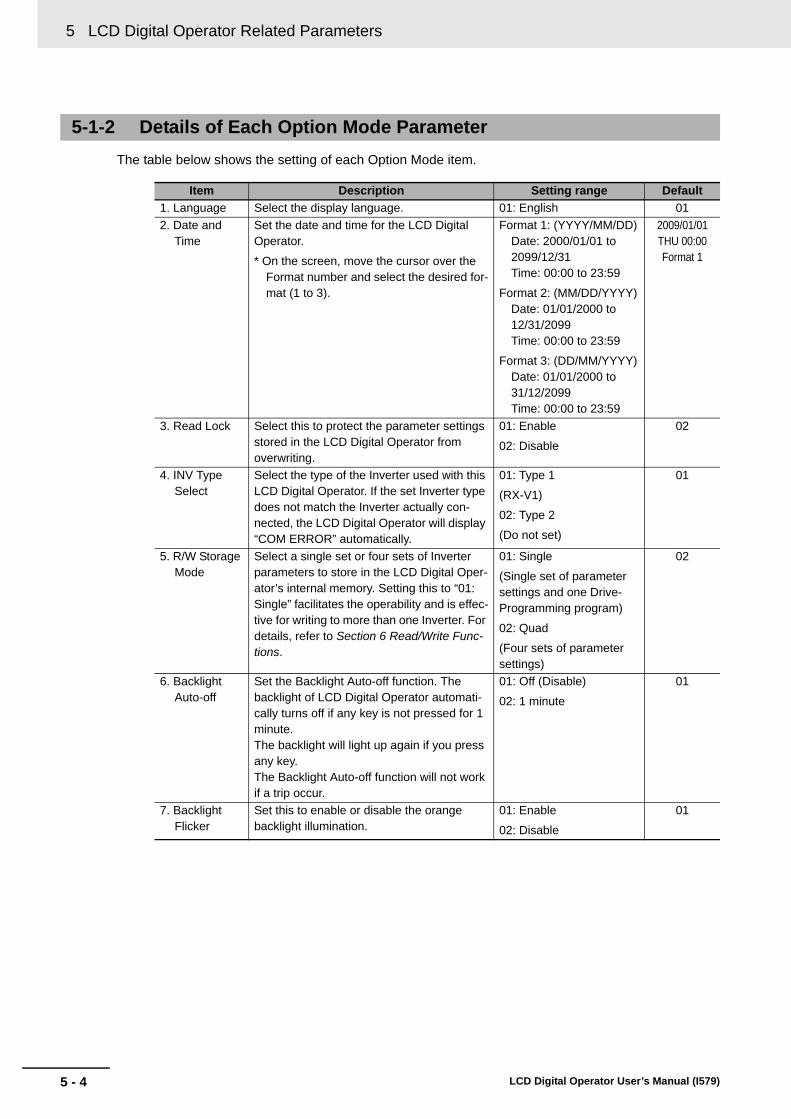
The table below shows the setting of each Option Mode item.
5-1-2 Details of Each Option Mode Parameter
Item Description Setting range Default
1. Language Select the display language. 01: English 01
2. Date and Time
Set the date and time for the LCD Digital Operator.
* On the screen, move the cursor over the Format number and select the desired for-mat (1 to 3).
Format 1: (YYYY/MM/DD)Date: 2000/01/01 to 2099/12/31Time: 00:00 to 23:59
Format 2: (MM/DD/YYYY)Date: 01/01/2000 to 12/31/2099Time: 00:00 to 23:59
Format 3: (DD/MM/YYYY)Date: 01/01/2000 to 31/12/2099Time: 00:00 to 23:59
2009/01/01THU 00:00Format 1
3. Read Lock Select this to protect the parameter settings stored in the LCD Digital Operator from overwriting.
01: Enable
02: Disable
02
4. INV Type Select
Select the type of the Inverter used with this LCD Digital Operator. If the set Inverter type does not match the Inverter actually con-nected, the LCD Digital Operator will display “COM ERROR” automatically.
01: Type 1
(RX-V1)
02: Type 2
(Do not set)
01
5. R/W Storage Mode
Select a single set or four sets of Inverter parameters to store in the LCD Digital Oper-ator’s internal memory. Setting this to “01: Single” facilitates the operability and is effec-tive for writing to more than one Inverter. For details, refer to Section 6 Read/Write Func-tions.
01: Single
(Single set of parameter settings and one Drive-Programming program)
02: Quad
(Four sets of parameter settings)
02
6. Backlight Auto-off
Set the Backlight Auto-off function. The backlight of LCD Digital Operator automati-cally turns off if any key is not pressed for 1 minute.The backlight will light up again if you press any key.The Backlight Auto-off function will not work if a trip occur.
01: Off (Disable)
02: 1 minute
01
7. Backlight Flicker
Set this to enable or disable the orange backlight illumination.
01: Enable
02: Disable
01

5 - 5
5 LCD Digital Operator Related Parameters
LCD Digital Operator User’s Manual (I579)
5-1 Param
eter Settin
g
5
5-1-2 Details of E
ach Option M
ode P
arameter
Precautions for Correct Use
• The applicable Language option is “01: English” only.The LCD Digital Operator may not provide the expected operation with other settings.
• Do not enable the EEPROM check. If you perform the EEPROM check, the data (parameter setting and DriveProgramming program data) stored in the LCD Digital Operator will be lost.
8. Operator Reset
Use this function to reset the LCD Digital Operator to its default settings.
The following items will be reset:
1) Language: English
2) Date and Time: 2009/01/01 THU 00:00
3) Time Format: 01: YY/MM/DD
4) Read Lock: Disable
5) R/W Storage Mode: Quad
6) Backlight Auto-off: Off
7) Backlight Flicker: Enable
After resetting the LCD Digital Operator, you need to perform the Date and Time setting again.
01: YES
02: NO
02
9. Check Mode Select this to check whether the LEDs, keys etc. work normally.
1: Key&Led Check
2: Lcd Check
3: RTC Check
4: EEPROM Check
5: Serial Loopback
6: Debug Mode
7: Firmware Version
–
Item Description Setting range Default

5 LCD Digital Operator Related Parameters
5 - 6 LCD Digital Operator User’s Manual (I579)
5-2 Related Inverter Parameters
The table below shows the 3G3RX-series Type V1 Inverter parameters related to the LCD Digital Operator.
For details, refer to “High-function General-purpose Inverter 3G3RX--V1 User’s Manual (I578)”.
*1. Setting b166 (Data Read/Write Selection) to “01: R/W protected” disables the all read/write functions and thus data can-not be read/written from the LCD Digital Operator.
Parameter No. Function name DataDefault value
Unit
F001/F201/F301
Output Frequency Setting 0.0: Starting frequency to 1st/2nd/3rd maximum frequency
0.0 to 100.0 (Available when PID function is enabled.)
– Hz
A001 Frequency Reference Selection
00: Operator (volume)
(Enabled when 3G3AX-OP01 is used.)
01: Control circuit terminal block
02: Operator (F001)
03: Modbus communication (Modbus-RTU)
04: Option 1
05: Option 2
06: Pulse train frequency
07: DriveProgramming
10: Operation function result
02 –
A002 RUN Command Selection 01: Control circuit terminal block
02: Operator (F001)
03: Modbus communication (Modbus-RTU)
04: Option 1
05: Option 2
02 –
b031 Soft Lock Selection 00: Data other than b031 cannot be changed when ter-minal SFT is ON.
01: Data other than b031 and set frequency cannot be changed when terminal SFT is ON.
02: Data other than b031 cannot be changed.
03: Data other than b031 and set frequency cannot be changed.
10: Data can be changed during RUN.
01 –
b037 Display Selection 00: Complete display
01: Individual display of functions
02: User setting + b037
03: Data comparison display
04: Basic display
00 –
b038 Initial Screen Selection 000: Screen on which the Enter key was last pressed 001 to 060: d001 to d060
201: F001
202: Do not set
001 –
b087 STOP Key Selection 00: Enable
01: Disable
02: Only resetting enabled
00 –
b166 Data Read/Write
Selection*1
00: R/W OK
01: R/W protected
00 –

5 - 7
5 LCD Digital Operator Related Parameters
LCD Digital Operator User’s Manual (I579)
5-2 Related
Inv
erter Param
eters
5
Parameter No. Function name DataDefault value
Unit
C001 Multi-function Input S1 Selection 08: SET (2nd control)
17: SET3 (3rd control)
31: OPE (forced operator)
51: F-TM (forced terminal)
01 –
C002 Multi-function Input S2 Selection 18 –
C003 Multi-function Input S3 Selection 12 –
C004 Multi-function Input S4 Selection 02 –
C005 Multi-function Input S5 Selection 03 –
C006 Multi-function Input S6 Selection 04 –
C007 Multi-function Input S7 Selection 05 –
C008 Multi-function Input S8 Selection 06 –

5 LCD Digital Operator Related Parameters
5 - 8 LCD Digital Operator User’s Manual (I579)

6 - 1
6
LCD Digital Operator User’s Manual (I579)
This section describes how to read and write Inverter parameter settings using the LCD Digital Operator.
6-1 Single READ Function . . . . . . . . . . . . . . . . . . . . . . . . . . . . . . . . . . . . . . . . . . 6-2
6-2 Single WRITE Function . . . . . . . . . . . . . . . . . . . . . . . . . . . . . . . . . . . . . . . . . 6-3
6-3 Quad READ Function . . . . . . . . . . . . . . . . . . . . . . . . . . . . . . . . . . . . . . . . . . . 6-4
6-4 Quad VERIFY Function . . . . . . . . . . . . . . . . . . . . . . . . . . . . . . . . . . . . . . . . . 6-6
6-5 Quad WRITE Function . . . . . . . . . . . . . . . . . . . . . . . . . . . . . . . . . . . . . . . . . . 6-8
6-6 Conditions for the Read/Write Operations . . . . . . . . . . . . . . . . . . . . . . . . 6-10
Read/Write Functions

6 Read/Write Functions
6 - 2 LCD Digital Operator User’s Manual (I579)
6-1 Single READ Function
The Single READ function is enabled when 5. R/W Storage Mode in the OPTION MODE menu is set to “01: Single”.
The Single Read function is executed immediately just by pressing the key.
The Single READ function reads a single set of Inverter parameter setting data and a DriveProgram-ming program and stores them to the LCD Digital Operator. When reading is completed, the screen returns to the previous screen.
This is time-saving when you need to repeat the all read/write operations.
Precautions for Correct Use
• The Single READ function cannot be executed by pressing the key in the Write Mode or Option Mode.
Use this function in other modes.
• The Single READ function overwrites the data existing in the LCD Digital Operator because its memory is set to store a single set of Inverter data.
• This function attempts to read a DriveProgramming program even when it is not stored in the Inverter. At that time, it stores the status of no DriveProgramming program.
After a read operation is completed, the screen returns to the previous screen automatically.
Reading parameter setting data
Reading a DriveProgramming program
Automatic transition
Automatic transition
Reading completed

6 - 3
6 Read/Write Functions
LCD Digital Operator User’s Manual (I579)
6-2 S
ing
le W
RIT
E F
un
ction
6
6-2 Single WRITE Function
The Single WRITE function is enabled when 5. R/W Storage Mode in the OPTION MODE menu is set to “01: Single”.
The Single WRITE function is executed immediately just by pressing the key.
The Single WRITE function writes a single set of Inverter parameter setting data and a DriveProgram-ming program stored in the LCD Digital Operator to the connected Inverter.
When writing is completed, the screen returns to the previous screen.
This is time-saving when you need to repeat the all read/write operations.
Precautions for Correct Use
• The Single WRITE function cannot be executed by pressing the key in the READ Mode or Option Mode.
Use this function in other modes.
• The Single WRITE function is available only with Inverters of the same model and of the same version.
If the all WRITE function does not work, check the Inverter models and versions and, if they are different, consider using the Inverter/Servo Parameter Support Tool CX-Drive.
After write operation is completed, the screen returns to the previous screen in 2 seconds.
Writing parameter setting data
Writing a DriveProgramming program
Automatic transition
Automatic transition
Writing completed
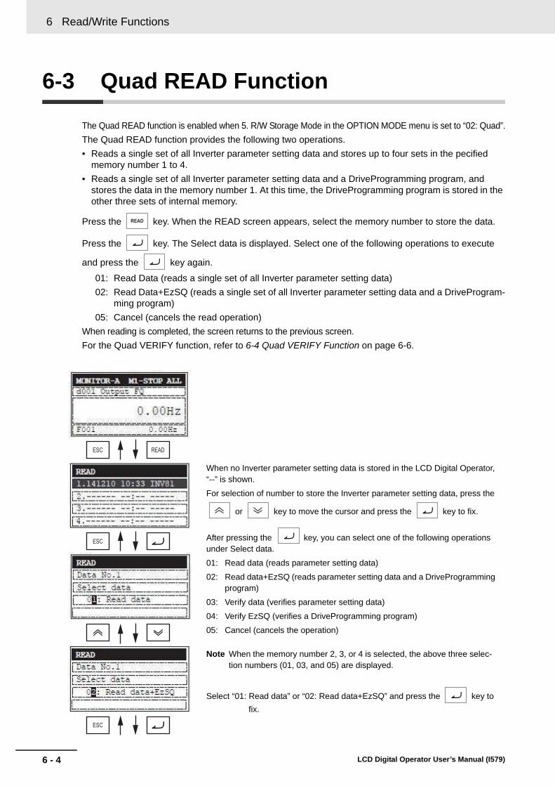
6 Read/Write Functions
6 - 4 LCD Digital Operator User’s Manual (I579)
6-3 Quad READ Function
The Quad READ function is enabled when 5. R/W Storage Mode in the OPTION MODE menu is set to “02: Quad”.
The Quad READ function provides the following two operations.
• Reads a single set of all Inverter parameter setting data and stores up to four sets in the pecified memory number 1 to 4.
• Reads a single set of all Inverter parameter setting data and a DriveProgramming program, and stores the data in the memory number 1. At this time, the DriveProgramming program is stored in the other three sets of internal memory.
Press the key. When the READ screen appears, select the memory number to store the data.
Press the key. The Select data is displayed. Select one of the following operations to execute
and press the key again.
01: Read Data (reads a single set of all Inverter parameter setting data)
02: Read Data+EzSQ (reads a single set of all Inverter parameter setting data and a DriveProgram-ming program)
05: Cancel (cancels the read operation)
When reading is completed, the screen returns to the previous screen.
For the Quad VERIFY function, refer to 6-4 Quad VERIFY Function on page 6-6.
When no Inverter parameter setting data is stored in the LCD Digital Operator, “--” is shown.
For selection of number to store the Inverter parameter setting data, press the
or key to move the cursor and press the key to fix.
After pressing the key, you can select one of the following operations under Select data.
01: Read data (reads parameter setting data)
02: Read data+EzSQ (reads parameter setting data and a DriveProgramming program)
03: Verify data (verifies parameter setting data)
04: Verify EzSQ (verifies a DriveProgramming program)
05: Cancel (cancels the operation)
Note When the memory number 2, 3, or 4 is selected, the above three selec-tion numbers (01, 03, and 05) are displayed.
Select “01: Read data” or “02: Read data+EzSQ” and press the key to
fix.
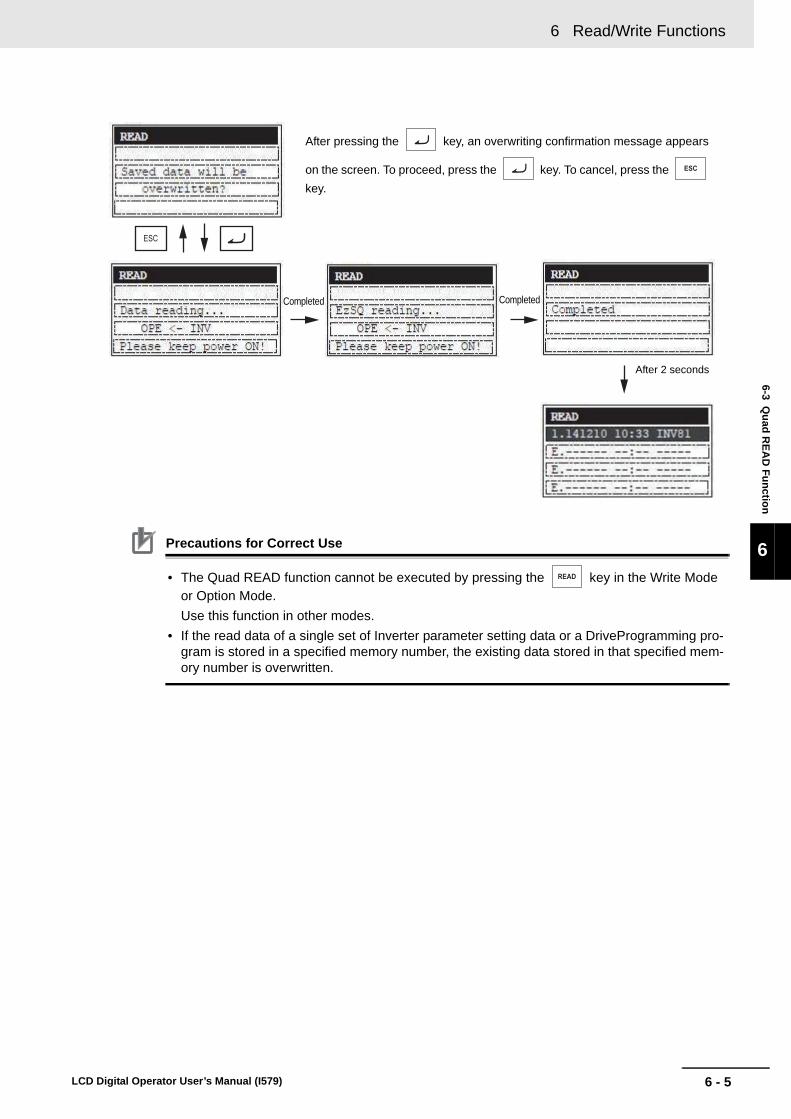
6 - 5
6 Read/Write Functions
LCD Digital Operator User’s Manual (I579)
6-3 Qu
ad R
EA
D F
un
ction
6
Precautions for Correct Use
• The Quad READ function cannot be executed by pressing the key in the Write Mode or Option Mode.
Use this function in other modes.
• If the read data of a single set of Inverter parameter setting data or a DriveProgramming pro-gram is stored in a specified memory number, the existing data stored in that specified mem-ory number is overwritten.
Completed Completed
After 2 seconds
After pressing the key, an overwriting confirmation message appears
on the screen. To proceed, press the key. To cancel, press the
key.

6 Read/Write Functions
6 - 6 LCD Digital Operator User’s Manual (I579)
6-4 Quad VERIFY Function
The Quad VERIFY function is enabled when 5. R/W Storage Mode in the OPTION MODE menu is set to “02: Quad”.The Quad VERIFY function provides the following operations.• Verifies the read data of a single set of Inverter parameter setting data and the parameter data stored
in a specified memory number.• Verifies a read DriveProgramming program and the program stored in the memory number 1.
Press the key. When the READ screen appears, select the memory number to verify the data.
Press the key. The Select Data is displayed. Select one of the following operations to execute
and press the key again.
03: Verify Data (verifies a single set of Inverter parameter setting data)
04: Verify EzSQ (verifies a DriveProgramming program)
05: Cancel (cancels the verify operation)
When verification is completed, the result appears. Press the key to return to the previous screen.
After pressing the key, you can select one of the following operations under Select data.
01: Read data (reads parameter setting data)
02: Read data+EzSQ (reads parameter setting data and a DriveProgramming program)
03: Verify data (verifies parameter setting data)
04: Verify EzSQ (verifies a DriveProgramming program)
05: Cancel (cancels the operation)
Note When the memory number 2, 3, or 4 is selected, the above three selec-tion numbers (01, 03, and 05) are displayed.
When no Inverter parameter setting data is stored in the LCD Digital Operator, “--” is shown.
For selection of number to store the Inverter parameter setting data, press the
or key to move the cursor and press the key to fix.
Select “03: Verify data” or “04: Verify EzSQ” and press the
key to fix.

6 - 7
6 Read/Write Functions
LCD Digital Operator User’s Manual (I579)
6-4 Qu
ad V
ER
IFY
Fu
nctio
n
6
Precautions for Correct Use
• The Quad VERIFY function cannot be executed by pressing the key in the Write Mode or Option Mode.
Use this function in other modes.
• In the following cases, the screen returns to the first display of the Quad READ when the Quad VERIFY cannot be executed.
1) If the data to compare is not stored in the LCD Digital Operator.
2) If the DriveProgramming has a password set.
When the verification of the param-eter setting data or DriveProgram-ming program is completed, the result appears.
• Match: matched
• Unmatch: unmatched
Automatic transition
Automatic transition

6 Read/Write Functions
6 - 8 LCD Digital Operator User’s Manual (I579)
6-5 Quad WRITE Function
The Quad WRITE function is enabled when 5. R/W Storage Mode in the OPTION MODE menu is set to “02: Quad”.
The Quad WRITE function provides the following two operations.
• Writes a single set of all Inverter parameter setting data, which is stored in a specified memory num-ber 1 to 4, to the connected Inverter.
• Writes a single set of all Inverter parameter setting data and a DriveProgramming program, which are stored in the memory number 1, to the connected Inverter.
Press the key. Select a memory number from1 to 4 to write a set of Inverter parameter setting data stored in the LCD Digital Operator.
Press the key. The Select Data is displayed. Select one of the following operations to execute
and press the key again.
01: Write data (writes a single set of all Inverter parameter setting data)
02: Write data+EzSQ (writes a single set of all Inverter parameter setting data and a single Drive-Programming program)
03: Cancel (cancels the write operation)
When writing is completed, the screen returns to the previous screen.
When no Inverter parameter setting data is stored in the LCD Digital Operator, “--” is shown.
For selection of number to store the Inverter parameter setting data, press the
or key to move the cursor and press the key to fix.

6 - 9
6 Read/Write Functions
LCD Digital Operator User’s Manual (I579)
6-5 Qu
ad W
RIT
E F
un
ction
6
Precautions for Correct Use
• The Quad WRITE function cannot be executed by pressing the key in the Read Mode or Option Mode.
Use this function in other modes.
• The Quad WRITE function is available only with Inverters of the same model and of the same version.
If the all WRITE function does not work, check the Inverter models and versions and, if they are different, consider using the Inverter/Servo Parameter Support Tool CX-Drive.
After pressing the key, you
can select one of the following opera-tions under Select data.
01: Write data (writes parameter set-ting data)
02: Write data+EzSQ (writes param-eter setting data and a DrivePro-gramming program)
03: Cancel (cancels the operation)
Note When the memory number 2, 3, or 4 is selected, the above selecion numbers (01 and 03) are displayed.
Note If you select “02” when no DriveProgramming program is stored in the memory number 1, the screen returns to the first display of Quad WRITE.
Automatic transition
Automatic transition
Automatic transition

6 Read/Write Functions
6 - 10 LCD Digital Operator User’s Manual (I579)
6-6 Conditions for the Read/Write Operations
The read/write operations may not be executed depending on the state and setting of the Inverter.
The operation conditions are shown below.
Conditions for Read/Verify Operations (from Inverter to LCD Digital Operator)
*1. Only the verification of DriveProgramming data is possible if “R/W protected” is selected in b166 (Data Read/Write Selection).
Conditions for Write Operation (from LCD Digital Operator to Inverter)
Inverter state and setting Parameter settings onlyParameter setting data and DriveProgramming program
Inverter is running, DriveProgramming program is running, writing disabled
Executable Executable
Soft lock enabled in b031 (Soft Lock Selection) Executable Executable
Display restricted in b037 (Display Selection) Executable Executable
During password setting Executable Not executable
Read/Write-protected in b166 (Data Read/Write Selection)
Not executable Not executable*1
Trip occurred Executable Executable
Inverter state and setting Parameter settings onlyParameter setting data and DriveProgramming program
Inverter is running, DriveProgramming program is running, writing disabled
Not executable Not executable
Soft lock enabled in b031 (Soft Lock Selection) Not executable Not executable
Display restricted in b037 (Display Selection) Executable Executable
During password setting Executable Not executable
Read/Write-protected in b166 (Data Read/Write Selection)
Not executable Not executable
Trip occurred Not executable Not executable

7 - 1
7
LCD Digital Operator User’s Manual (I579)
This section describes the error messages and troubleshooting of the LCD Digital Operator.
7-1 Error Messages and Remedies . . . . . . . . . . . . . . . . . . . . . . . . . . . . . . . . . . . 7-27-1-1 Inverter Error Messages . . . . . . . . . . . . . . . . . . . . . . . . . . . . . . . . . . . . . . . . . . 7-2
7-1-2 LCD Digital Operator Error Messages . . . . . . . . . . . . . . . . . . . . . . . . . . . . . . . 7-2
7-2 Troubleshooting . . . . . . . . . . . . . . . . . . . . . . . . . . . . . . . . . . . . . . . . . . . . . . . 7-5
Error Messages and Troubleshooting

7 Error Messages and Troubleshooting
7 - 2 LCD Digital Operator User’s Manual (I579)
7-1 Error Messages and Remedies
The error messages that appear on the LCD Digital Operator screen are categorized into the following three:
For details about Inverter errors (trip and warning), refer to “High-function General-purpose Inverter 3G3RX--V1 User’s Manual (I578)”.
7-1-1 Inverter Error Messages
7-1-2 LCD Digital Operator Error Messages
Message Cause Check items Remedies Reset method
COM ERROR • The LCD Digital Operator could not establish communi-cations with the Inverter for 4 sec-onds or more.
• The issue of the RESET signal con-tinues for 5 seconds or more.
• The settings of the LCD Digital Opera-tor and those of the connected Inverter are different.
• A connector is dis-connected.
• The cable is broken.
• Limit the issue of the RESET signal to less than 4 seconds.
• In the Option Mode, set the INV Type Select to “01: Type 1”.
• Reconnect the cable appropriately.
• Replace the cable.
Press the STOP/RESET key.
Inverter Trip Inverter Warning LCD Digital Operator Error
* Screen flashes alternately in white and orange
* Screen is illuminated in orange * Screen remains in white

7 - 3
7 Error Messages and Troubleshooting
LCD Digital Operator User’s Manual (I579)
7-1 E
rror M
essages an
d R
emed
ies
7
7-1-2 LC
D D
igital O
perator Error M
essages
INV in RUN mode
• An attempt was made to write param-eter data during Inverter operation.
• The soft lock func-tion is enabled.
• The Inverter data is read/write-protected.
• The DriveProgram-ming is activated.
• The DriveProgram-ming has a pass-word set.
• The WRITE key was pressed during Inverter operation.
• The soft lock func-tion is enabled in b031 (Soft lock selection).
• The data is read/write-protected in b166 (Data Read/Write Selection).
• The start signal of the DriveProgram-ming is ON.
• The DriveProgram-ming has a pass-word set.
• Press the WRITE key when the Inverter is stopped.
• Disable the soft lock on the Inverter parameter data.
• Disable the read/write-protection.
• Stop the DrivePro-gramming.
• Disable a password of the DrivePro-gramming.
Press the STOP/RESET key.
INV in TRIP mode
• An attempt was made to write parameter data dur-ing Inverter trip.
• Check the state of the Inverter trip.
• Remove the error cause of the Inverter trip and reset the Inverter.
INV Type Un-match
• An attempt was made to write all parameter data to a wrong Inverter.
• Check the data to write and the con-nected Inverter model and version.
• If the model or ver-sion does not match, use CX-Drive.
Read lock enabled
• The Inverter data is read/write-protected.
• The data is read/write-protected in b166 (Data Read/Write Selection).
• Disable the read/write protection.
Data Check Sum Error
• The EEPROM check data (checksum value) is abnormal.
• The EEPROM reached the maxi-mum number of writes.
• Turn OFF and then ON the power sup-ply again to see if the value is reset to normal.
• In the Option Mode, execute the Opera-tor Reset function to see if the value is reset to normal.
• If the error cannot be cleared, replace the LCD Digital Operator.
Turn OFF and then ON the power supply again.
Or replace the LCD Digital Operator.
INV Check Sum Error
• The parameter data to write to the Inverter does not match that stored in the LCD Digital
Operator.*1
• Retry writing all the parameter data again.
• If the error cannot be cleared by retrying after initializing the Inverter, consider replacing the Inverter.
Consider replac-ing the Inverter.
EEPROM Error • An EEPROM error occurred in the LCD Digital Operator.
• Turn OFF and then ON the power supply again to see if the writing is possible.
• If the copy function is required, replace the LCD Digital Operator.
–
not support • The Inverter is not supported.
• Check the Inverter model.
• Connect with a 3G3RX--V1 Inverter, or use CX-Drive.
–
Message Cause Check items Remedies Reset method

7 Error Messages and Troubleshooting
7 - 4 LCD Digital Operator User’s Manual (I579)
*1. This may occur if an attempt is made to write data to an Inverter whose voltage class and capacity are differ-ent. For the troubleshooting of Inverter problems, refer to “High-function General-purpose Inverter 3G3RX--V1 User’s Manual (I578)”.
*2. The screen disappears automatically in 3 minutes after the power supply is turned on.
Read & Copy only
• Writing to the Inverter is disabled.
• In the Option Mode, set the INV Type Select to "01: Type 1".
• The soft lock func-tion is enabled in b031 (Soft Lock Selection).
• The data is read/write-protected in b166 (Data Read/Write Selection).
• Stop the Inverter and DriveProgramming if they are running.
• Reset the trip state if the Inverter is tripped.
• Disable the soft lock function.
• Disable the read/write protection.
Press the STOP/RESET key.
change the battery
• The built-in battery voltage dropped.
• Check the current date and time in d031 (Current Time Monitor).
• Replace the battery with a new one and set the date and time again.
–
please set the
clock*2
• The current date and time are not set.
• The current date and time are not set by selecting Date and Time in the Option Mode.
• The date and time data cannot be backed up because the built-in battery voltage is com-pletely dropped.
• Perform the date and time setting.
• Replace the battery with a new one and set the date and time again. –
Message Cause Check items Remedies Reset method
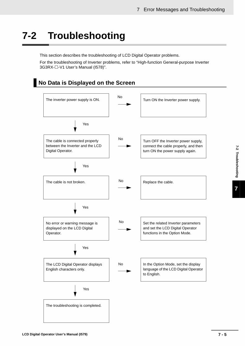
7 - 5
7 Error Messages and Troubleshooting
LCD Digital Operator User’s Manual (I579)
7-2 Tro
ub
lesho
otin
g
7
7-2 Troubleshooting
This section describes the troubleshooting of LCD Digital Operator problems.
For the troubleshooting of Inverter problems, refer to “High-function General-purpose Inverter 3G3RX--V1 User’s Manual (I578)”.
No Data is Displayed on the Screen
The inverter power supply is ON.
The cable is connected properly between the Inverter and the LCD Digital Operator.
The cable is not broken.
No error or warning message is displayed on the LCD Digital Operator.
The LCD Digital Operator displays English characters only.
The troubleshooting is completed.
Turn ON the Inverter power supply.
Replace the cable.
Set the related Inverter parameters and set the LCD Digital Operator functions in the Option Mode.
In the Option Mode, set the display language of the LCD Digital Operator to English.
Yes
Yes
Yes
Yes
Yes
No
No
No
No
No
Turn OFF the Inverter power supply, connect the cable properly, and then turn ON the power supply again.

7 Error Messages and Troubleshooting
7 - 6 LCD Digital Operator User’s Manual (I579)
Key Operations are Ignored
The Inverter operation is normal.
The cable is connected properly between the Inverter and the LCD Digital Operator.
The cable is not broken.
• The LCD Digital Operator is not in the Read, Write, or Option Mode.
• No error message is displayed on the screen.
The LCD Digital Operator is broken. Replace the LCD Digital Operator.
Reset the Inverter.
Turn OFF the Inverter power supply, connect the cable properly, and then turn ON the power supply again.
Replace the cable.
Yes
Yes
Yes
Yes
No
No
No
No• Press the key to move to
the Navigation level and move to the desired screen.
• Press the key to move to
the normal display mode and clear the error.

7 - 7
7 Error Messages and Troubleshooting
LCD Digital Operator User’s Manual (I579)
7-2 Tro
ub
lesho
otin
g
7
LCD Digital Operator has a Dark Screen or Displays Unreadable Characters
The cable is connected properly between the Inverter and the LCD Digital Operator.
The recommended cable is used.
The cable may be affected by inductive noise. Keep the cable at least 15 cm away from other cables.
The LCD Digital Operator is broken. Replace the LCD Digital Operator.
The LCD Digital Operator is defective. Replace the LCD Digital Operator.
Use the recommended cable.
Yes
Yes
If normal state cannot be restored
No
No
If normal state cannot be restored

7 Error Messages and Troubleshooting
7 - 8 LCD Digital Operator User’s Manual (I579)

8 - 1
8
LCD Digital Operator User’s Manual (I579)
This section provides information on the maintenance of the LCD Digital Operator.
8-1 Battery Replacement . . . . . . . . . . . . . . . . . . . . . . . . . . . . . . . . . . . . . . . . . . . 8-2
Maintenance

8 Maintenance
8 - 2 LCD Digital Operator User’s Manual (I579)
8-1 Battery Replacement
The LCD Digital Operator contains a battery, which is a service part. This built-in battery is used as a backup for the clock function of the LCD Digital Operator. Below is the procedure for replacing this part.
This LCD Digital Operator has a built-in real time clock IC for the date and time information. When the external power supply is OFF, the power is supplied from this built-in battery to update the date and time information.
If the battery life expires, the date and time informamation is not updated when power supply to the LCD Digital Operator is OFF. In this case, the date and time information stored in the real time clock IC is reset to the default value (THU 00:00, January 1, 2009) when the power supply to the LCD Digital Operator is turned ON. Therefore, when you turn ON the LCD Digital Operator for the first time after purchase or battery replacement, set the correct time and date in the Option Mode. Otherwise, the LCD Digital Operator does not show the date and time information correctly in the Trip Mode, Read Mode, and Write Mode.
Except for the current date and time display, a battery voltage drop will not affect the normal operation of the LCD Digital Operator.
Precautions for Safe Use
• If the clock command is used in DriveProgramming, an unexpected operation may occur due to weak battery. Take measures such as detecting a weak battery by a check that the clock data returns to the initial setting and stopping the Inverter or programs. When the LCD Digital Operator is removed or disconnected, DriveProgramming is in a waiting status by the clock command.
1 Turn OFF the Inverter power supply.
2 Remove the LCD Digital Operator from the Inverter (or panel), if installed on the Inverter (or panel).
Disconnect the cable from the LCD Digital Operator, if connected via cable.
Purpose of the Built-in Battery
Battery Replacement Procedure

8 - 3
8 Maintenance
LCD Digital Operator User’s Manual (I579)
8-1 Battery R
eplacem
ent
8
3 Remove the battery cover screw located on the rear face of the LCD Digital Operator to open the battery cover.
4 Remove the old battery using a thin slotted screwdriver.
5 Install a new battery, with attention paid to the positive and negative sides of the battery.
6 Reinstall the battery cover by reversing the procedure described in step 3.
7 Install or connect the LCD Digital Operator with the Inverter as before.
8 Turn ON the Inverter power supply and set the date and time on the LCD Digital Operator.
Be careful not to damage the PCB and its parts.
When disposing of the old battery, insulate it using such as tape according to the specified method to prevent short-circuit.
Type of replacement battery: Coin type lithium battery CR1220

8 Maintenance
8 - 4 LCD Digital Operator User’s Manual (I579)
Precautions for Safe Use
• When disposing of LCD digital operators and wasted batteries, follow the applicable ordi-nances of your local government.
When disposing of the battery, insulate it using tape.
• Do not short + and -, charge, disassemble, heat, put into the fire, or apply strong impact on the battery. The battery may leak, explode, produce heat or fire. Never use the battery which was applied strong impact due to such as fall on the floor, it may leak.
• UL standards establish that the battery shall be replaced by an expert engineer.
The expert engineer must be in charge of the replacement and also replace the battery according to the method described in this manual.
• When the display of LCD Digital Operator can not be recognized due to the service life, replace the LCD Digital Operator.
The following display must be indicated when products using lithium primary batteries (with more than 6 ppb of perchlorate) are transport to or through the State of California, USA.
The 3G3AX-OP05 has the lithium primary battery (with more than 6 ppb of perchlorate). Label or mark the above display on the exterior of all outer shipping packages of your products when exporting your products which the 3G3AX-OP05 are installed to the State of California, USA.
Perchlorate Material - special handling may apply.
See www.dtsc.ca.gov/hazardouswaste/perchlorate

Index-1
I
LCD Digital Operator User’s Manual (I579)
Index

Index-2 LCD Digital Operator User’s Manual (I579)
Index
Index
B
Backlight ......................................................................... 2-6
F
Function Mode ......................................................... 4-4, 4-8
M
Monitor Mode A ....................................................... 4-3, 4-6Monitor Mode B ....................................................... 4-3, 4-7
O
Option Mode ............................................................ 4-5, 5-2
P
Purpose of the Built-in Battery ........................................ 8-2
R
Read Mode ..................................................................... 4-4
T
Trip Mode ................................................................ 4-4, 4-9
W
wasted batteries ............................................................. 8-4Write Mode ..................................................................... 4-5


Authorized Distributor:
In the interest of product improvement, specifications are subject to change without notice.
Cat. No. I579-E1-02 0813
© OMRON Corporation 2013 All Rights Reserved.
OMRON Corporation Industrial Automation Company
OMRON ELECTRONICS LLCOne Commerce Drive Schaumburg,IL 60173-5302 U.S.A.Tel: (1) 847-843-7900/Fax: (1) 847-843-7787
Regional HeadquartersOMRON EUROPE B.V.Wegalaan 67-69-2132 JD HoofddorpThe NetherlandsTel: (31)2356-81-300/Fax: (31)2356-81-388
Contact: www.ia.omron.comTokyo, JAPAN
OMRON ASIA PACIFIC PTE. LTD.No. 438A Alexandra Road # 05-05/08 (Lobby 2), Alexandra Technopark, Singapore 119967Tel: (65) 6835-3011/Fax: (65) 6835-2711
OMRON (CHINA) CO., LTD.Room 2211, Bank of China Tower, 200 Yin Cheng Zhong Road, PuDong New Area, Shanghai, 200120, ChinaTel: (86) 21-5037-2222/Fax: (86) 21-5037-2200